

2
Ú Table of contents
Ú Instructions for connecting gas and gas conversion (for After-Sales Service only)
Measures to note ....................................................................... 2
Choose which side of the appliance to connect the gas on (*
optional)................................................................................................2
Gas connection.......................................................................... 3
Approved connections.......................................................................3
Natural gas connection (NG)............................................................3
Liquefied gas connection (LPG) ......................................................4
Conversion to a different gas type........................................... 4
Converting to a different gas type ...................................................4
Functional parts for the gas conversion.........................................4
Replacing the burner nozzles...........................................................5
Adjusting or replacing the burner bypass screws and setting
the small flame ....................................................................................5
Converting the appliance from natural gas to liquefied gas ......5
Conversion from liquid gas to natural gas.....................................6
Removing the control panel..............................................................6
Replacing bypass screws .................................................................7
Fitting the control panel.....................................................................7
Replacing the oven burners (optional) ...........................................7
Leak test and function test ....................................................... 8
Check the gas connection ................................................................8
Checking the burner nozzles............................................................8
Checking the bypass valves.............................................................8
Checking the oven burner nozzle (option).....................................8
Check the grill burner nozzle (option) ............................................8
Correct flame formation ............................................................ 9
Burner ...................................................................................................9
Oven ......................................................................................................9
Technical data – Gas ................................................................. 9
Measures to note
The appliance may only be converted to a different gas type
by an approved specialist, in accordance with the
instructions in this manual.
Incorrect connection and incorrect settings may cause
serious damage to the appliance. The appliance
manufacturer accepts no liability for damage and
malfunctions of this kind.
Pay close attention to the symbols indicated on the rating plate.
If there is no symbol for your country, follow the technical
guidelines that apply in your country when making settings.
Before setting up the appliance, determine the gas type and
pressure in the local supply network. Before using the
appliance for the first time, make sure that all settings have
been made correctly.
Pay attention to local and international rules and regulations.
All connection data can be found on the rating plate on the rear
of the appliance.
Enter the data in the following table:
Product number (E no.),
Manufacturing number (FD),
Enter the factory settings for gas type/gas pressure, as well as
the settings for gas type/pressure that apply after the gas
conversion, in the following table.
The changes made to the appliance and the type of connection
play an important role in ensuring that the appliance operates
correctly and safely.
: Risk of gas escape!
■ After connecting the appliance to the gas supply, always
check the connection for leak tightness. The manufacturer
accepts no responsibility for the escape of gas from a gas
connection which has been previously tampered with.
Risk of gas leak!
■ Do not move the appliance by pulling on the gas pipe
(collector). This could damage the gas pipe.
Risk of gas leak!
■ The appliance must not be moved once it has been installed.
If you do move the appliance once it has been installed,
check that the connection is leak-tight.
Switch off the power and gas supply before carrying out any
work.
This appliance must not be installed on boats or in vehicles.
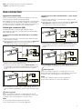
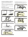
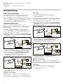
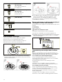
Choose which side of the appliance to
connect the gas on (* optional)
The gas supply to the appliance can be connected on the left
or right. The side on which the gas supply is connected can be
changed if necessary.
Connect the main gas supply.
If you change the side on which the gas supply is connected,
the gas connection piece on the side that is not being used
must be sealed with a blind plug.
To do this:
1. Place the new seal in the blind plug. Make sure the seal is
seated correctly.
2. Secure the gas connection piece to the appliance using a 22
mm spanner and place the blind plug onto the connection
piece using a 24 mm spanner.
Once the side on which the gas supply is connected has been
changed, check that the connection is leak-tight. See the
section entitled "Leak testing" for more information about this.
E no. FD no.
After-sales service
O
Type of gas / gas pressure
Data on the rating plate
Type of gas / gas pressure
Data after gas conversion
1P
6:
6:

3
Note: Use a torque wrench to connect the appliance.
* Option: Only valid for some models.
Gas connection
Approved connections
These instructions apply only when the appliance is set up in
countries that are indicated on the rating plate.
If the appliance is set up, connected and used in a country that
is not indicated on the rating plate, installation and assembly
instructions must be used that contain data and information on
the valid connection conditions in the relevant country.
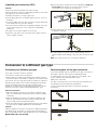
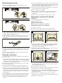
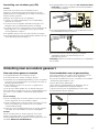
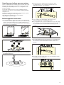
Natural gas connection (NG)
If natural has (NG) is used, the gas supply should be
connected via a gas pipe or a safety gas hose with threaded
fittings at both ends.
Connection in accordance with EN ISO 228 G
^ (TS EN ISO
228 G
^ )
1. Place the new seal in the connection piece. Make sure the
seal is seated correctly.
2. Secure the gas connection piece to the appliance using a 22
mm spanner and place the connection piece into the
connection piece using a 24 mm spanner.
3. Place the new seal into the gas pipe or safety gas hose.
Make sure the seal is seated correctly.
4. Secure the connection piece using a 24 mm spanner. Use a
24 mm spanner to place the threaded fitting of the gas pipe
or safety gas hose on the connection piece and tighten it
firmly.
5. For information on how to carry out leak testing, see the
section entitled "Leak testing". Open the gas connection shut-
off.
: Risk of gas leak!
When connecting the gas pipe or safety gas hose, do not
tighten the gas connection piece on the appliance using a 22
m spanner. This may damage the connection piece.
Notes
■ *G^: EN ISO 228 G^ (TS EN ISO 228 G^)
■ Use a torque wrench to connect the appliance.
Connection in accordance with EN 10226 R
^ (TS 61-210 EN
10226 R
^ )
1. Place the new seal in the connection piece. Make sure the
seal is seated correctly.
2. Secure the gas connection piece to the appliance using a 22
mm spanner and place the connection piece into the
connection piece using a 24 mm spanner.
3. Secure the connection piece using a 24 mm spanner. Use a
24 mm spanner to place the threaded fitting of the gas pipe
or safety gas hose on the connection piece and tighten it
firmly.
4. For information on how to carry out leak testing, see the
section entitled "Leak testing". Open the gas connection shut-
off.
: Risk of gas leak!
When connecting the gas pipe or safety gas hose, do not
tighten the gas connection piece on the appliance using a 22
m spanner. This may damage the connection piece.
Notes
■ *R^: EN 10226 R^ (TS 61-210 EN 10226 R^)
■ Use a torque wrench to connect the appliance.
6:
6:
1P
*ê
1***
6:
6:
*ê
1***
1P
6:
6:
1P
1***
5ê
6:
6:
1***
1P
5ê

4
Liquefied gas connection (LPG)
Caution!
Observe the specific guidelines for each country.
If liquid gas (LPG) is used, the gas supply should be connected
via a gas hose or a fixed connector.
Important information on using a gas hose:
■ Use a safety gas hose or a plastic gas hose (8 or 10 mm in
diameter).
■ It must be attached to the gas connection using an approved
connecting device (e.g. a hose clamp).
■ The hose must be short and completely leak-tight. The hose
must not be longer than 1.5 m. Observe the applicable
guidelines.
■ The gas hose must be replaced once a year.
1. Place the new seal in the connection piece. Make sure the
seal is seated correctly.
2. Secure the gas connection piece to the appliance using a 22
mm spanner and place the connection piece into the
connection piece using a 24 mm spanner.
3. Fit the safety gas hose and use a pipe union or cable clamp
to tighten it securely.
4. For information on how to carry out leak testing, see the
section entitled "Leak testing". Open the gas connection shut-
off.
Note: Use a torque wrench to connect the appliance.
Conversion to a different gas type
Converting to a different gas type
■ The gas connection must be replaced.
■ The burner nozzles must be replaced.
■ Depending on the factory gas setting, the bypass screws in
the burner valves must either be replaced, or screwed in fully.
■ If present, the oven and grill nozzles must also be replaced.
Numbers are printed on the nozzles indicating their diameter.
Further information about the gas types suitable for the
appliance, as well as the corresponding gas nozzles, can be
found in the section entitled "Technical properties - gas".
After the conversion
■ After the appliance has been converted to a different gas
type, you must perform a leak test. See the section entitled
"Leak test".
■ After the appliance has been converted to a different gas
type, the correct flame formation must be tested. See the
section entitled "Correct flame formation".
■ Enter the newly-set type of gas and gas pressure in the table.
See the section entitled "Measures to be observed".
Caution!
After the appliance has been converted to a different gas type,
the labels giving information on the gas type and showing a
star must be affixed at the appropriate point on the rating plate
MAKE SURE THAT YOU DO THIS.
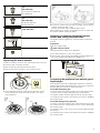
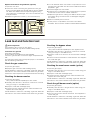
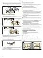
Functional parts for the gas conversion
The functional parts that are required for the gas conversion in
accordance with the instructions are displayed below.
You will find the correct nozzle diameters in the table in the
section entitled "Technical properties - gas".
Always use new seals.
The gas connecting piece to be used may vary depending on
the gas type and country-specific regulations.
(*) These functional parts must be used when the gas is
connected.
6:
/3***
6:
1P
Bypass screw
Burner nozzle
(*) Seal

5
Replacing the burner nozzles
1. Make sure all the knobs on the control panel are turned off.
2. Close the gas connection shut-off.
3. Remove the pan supports and burner parts.
4. Remove the burner nozzles (7 mm socket wrench).
5. If your appliance features a wok burner with side access,
remove the burner nozzle as shown below (7 mm open-
ended spanner).
6. The burner nozzles can be found in the table; see the section
entitled "Technical data – Gas".
Fit the new nozzles into the appropriate burners.
After replacing the nozzles, check that there are no leaks. See
the section entitled "Testing for leaks".
Adjusting or replacing the burner bypass
screws and setting the small flame
The bypass screws regulate the minimum flame height of the
burners.
Preparation
Shut off the gas supply.
: Risk of electric shock!
Interrupt the power supply to the appliance.
1. Turn off the switches on the control panel.
2. Remove the control knobs individually by holding tightly on to
the control panel and pulling them straight out.
Converting the appliance from natural gas to
liquefied gas
If the appliance was set to natural gas at the time of delivery
(factory setting) (NG: G20, G25) and is now being converted to
liquefied gas for the first time (LPG: G30, G31):
For models with safety pilot:
In order to reach the bypass nozzles, the control panel must be
removed. See the section "Removing the control panel".
The bypass nozzles must be tightened as far as they will go.
You must then carry out the work steps in the section "Installing
the control panel".
For models with gas oven (optional):
In order to reach the bypass nozzle underneath the burner tap,
you must remove the control panel. See the section "Removing
the control panel".
The bypass nozzle on the oven burner must be tightened as far
as it will go.
You must then carry out the work steps in the section "Installing
the control panel".
(*) Connecting piece for natural
gas
(NG: G20, G25)
TS 61-210 EN 10226 R
^
EN 10226 R^
(*) Connecting piece for natural
gas
(NG: G20, G25)
TS EN ISO 228 G
^
EN ISO 228 G^
(*) Connecting piece for liquid gas
(LPG: G30, G31)
Gas connecting piece
Dummy plug (shut-off piece)
6:

6
Conversion from liquid gas to natural gas
If the appliance is to be converted from liquid gas
(LPG: G30, G31) to natural gas (NG: G20, G25), or this
conversion has already been performed and is now to be
reversed:
All bypass nozzles on the appliance must be replaced. To do
this, read the section entitled "Removing the control panel".
The instructions in the section entitled "Replacing the bypass
screws" must then be followed.
Then, follow the instructions in the section entitled "Attaching
the control panel".
Removing the control panel
1. If the appliance has an upper cover, remove this.To remove
the cover, open it, take hold of it at the sides with both hands,
and pull it upwards. The upper cover will come away. Take
care not to lose the hinges.
2. Remove the pan supports and burner parts.
3. If there are any burner connection screws in the hob, remove
them all.
4. Remove the two screws (T20) at the front right and left of the
hob panel. Do not remove the plastic parts underneath.
5. For models with a wok burner (optional): Remove the four
screws (M4) from the wok burner.
6. Hold the hob panel at the front and tilt it upwards at an angle
of no more than 30°. Use the profile bar, which can be
positioned upright on the front burner fastening, to prop up
the hob panel.
7. Remove the plastic covers from the front profiles on the right
and left (without scuffing or scratching them). Unscrew the
screws (T20) underneath them.
8. Remove the two screws (M4) that are uncovered when you
remove the control knobs (T15).
9. Take hold of the front panel with both hands and slowly pull it
upwards. Release it from its fastening clips. Then carefully
pull the panel forwards to remove it. Ensure that the cables
are not damaged and the connections do not come loose.

7
Replacing bypass screws
1. Loosen the bypass screws with a flat screwdriver (no. 2).
Remove the bypass screws.
2. You can use the table to determine the new bypass screws
that you will need after the gas conversion. See the section
entitled "Technical properties - gas".
3. Check whether the seals on the bypass screw are correctly
seated and work precisely. Only use bypass screws with
intact seals.
4. Insert the new bypass screws and tighten them. Make sure
that all bypass screws are connected to the correct shut-off
valves.
5. At this point, it is essential to carry out a leak test. See the
section entitled "Leak test".
Fitting the control panel
To fit the control panel, follow the instructions for removing it in
the reverse order.
1. Take hold of the front panel with both hands and carefully fit
it into place. Ensure that the cables are not damaged and the
connections do not come loose.Lower the front panel slightly
and place it in the fastening brackets.
2. Screw the two screws (T15 and M4) that you removed from
the control panel back in.
3. Screw the screws (T20) that you removed from the front
profiles back in on the right and left.Refit the plastic covers.
4. Fit the hob panel carefully. Make sure that the plastic parts
underneath the screws do not fall out. Screw the two screws
(T20) back in at the front right and left of the hob panel. If
there are any burner connection screws, screw them all into
the hob panel.
5. For models with a wok burner (optional): Screw the four Torx
screws (M4) that you removed from the wok burner back in.
6. If your cooker has an upper cover, take hold of it on both
sides, hold it upright and push it straight down into the
holder.
7. Fit burner housings of the correct size onto each burner, and
ensure that the spark plug is inserted into the opening on the
edge of the burner housing. Place the enamelled burner caps
in the centre of the matching burner bases.
8. Refit the pan supports. Make sure that the 80 mm-wide pan
support is fitted on the auxiliary burner.
9. Fit the control knobs carefully.
10.At this stage, it is important to check that the burners are
burning correctly; see section entitled "Correct burner
behaviour".
11.Check whether the appliance is functioning correctly.
Replacing the oven burners (optional)
Preparation
Turn off all switches on the control panel.
Shut off the gas supply.
: Risk of electric shock!
Interrupt the power supply to the appliance.
Replacing the nozzle for the oven burner
1. Open the oven door.
2. Loosen the front securing screw in the bottom plate.
3. Hold the bottom plate firmly at the front, lift and remove it.
4. Loosen the burner securing screw and carefully remove the
oven burner. The burner nozzles are now freely accessible.
Make sure that the thermocouple and ignition plug
connections are not damaged.
5. Release the nozzle at the burner access on the rear side of
the oven (using a 7 mm socket wrench).
6. You can use the table to determine the new nozzle that you
will need after the gas conversion. See the section entitled
"Technical properties - gas".
7. Insert and tighten the new nozzle.
8. At this point, it is essential to carry out a leak test. To perform
a leak test, see the section entitled "Leak test".
9. Replace the oven burner, making sure that the thermocouple
and ignition plug connections are not damaged. Retighten
the securing screw.
10.At this point, it is important to check the burner flame
formation. See the section entitled "Correct flame formation".
11.Replace the bottom plate.

8
Replace the nozzle for the grill burner (optional)
1. Open the oven door.
2. Loosen the screw connecting the grill burner to the grill
burner mounting plate and carefully pull the burner straight
out. Make sure that the thermocouple and ignition plug
connections are not damaged. The burner nozzles are now
freely accessible.
3. Release the grill burner nozzle (7 mm socket wrench).
4. You can ascertain which new nozzle is required for the new
gas type using the table. See the section entitled "Technical
properties - gas".
5. Insert and tighten the new nozzle.
6. At this point, it is essential to carry out a leak test. To perform
a leak test, see the section entitled "Leak test".
7. Replace the grill burner, making sure that the thermocouple
and ignition plug connections are not damaged. Retighten
the screws.
8. Slide the seal fully into the burner.
9. At this point, it is important to check the burner flame
formation. See the section entitled "Correct flame formation".
Leak test and function test
: Risk of explosion!
Avoid sparking. Do not use an open flame.
Perform the leak test only with a suitable leakage spray.
In the event of a gas leak
Shut off the gas supply.
Ensure that the room affected is well ventilated.
Check the gas and valve connections again. Repeat the leak
test.
The leak test must be performed by two people, in accordance
with the following instructions.
Check the gas connection
1. Open the gas supply.
2. Spray the gas connection with a leakage spray.
If small bubbles or foam form, indicating a gas leak, follow the
instructions in the section entitled "In the event of a gas leak".
Perform the same steps for the part closed with the blind plug.
Checking the burner nozzles
1. Open the gas supply.
Carry out the leak test separately for each nozzle.
2. Carefully close the hole in the burner nozzle to be checked
using your finger or a suitable device.
3. Spray the nozzle with a leakage spray.
4. Press the function selector and turn it anti-clockwise. This
supplies the nozzle with gas.
If small bubbles or foam form, indicating a gas leak, follow the
instructions in the section entitled "In the event of a gas leak".
Checking the bypass valves
1. Open the gas supply.
Carry out the leak test separately for each bypass screw.
2. Carefully close the hole in the burner nozzle to be checked
using your finger or a suitable device.
3. Spray the nozzle in the burner to be checked with a leakage
spray.
4. Push the control knob and turn it anti-clockwise. This supplies
the nozzle with gas.
If small bubbles or foam form, indicating a gas leak, follow the
instructions in the section entitled "In the event of a gas leak".
Checking the oven burner nozzle (option)
1. Open the gas supply.
2. Carefully close the hole in the oven burner nozzle using your
finger or a suitable device.
3. Spray the nozzle with a leakage spray.
4. Press the function selector and turn it anti-clockwise. This
supplies the nozzle with gas.
If small bubbles or foam form, indicating a gas leak, follow the
instructions in the section entitled "In the event of a gas leak".
Check the grill burner nozzle (option)
1. Open the gas supply.
2. Carefully close the hole in the grill burner nozzle using your
finger or a suitable device.
3. Spray the nozzle with a leakage spray.
4. Turn the oven function selector clockwise. This supplies the
nozzle with gas.
If small bubbles or foam form, indicating a gas leak, follow the
instructions in the section entitled "In the event of a gas leak".

9
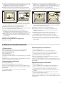
Correct flame formation
Burner
The flame formation and temperature development must be
checked for each burner after the appliance is converted to a
different gas type.
In the event of a problem, compare the nozzle values to the
values in the table.
Only for models without safety pilot
1. Ignite the hob burner as described in the operating
instructions.
2. Check the large and small flames for the correct flame
formation. The flame must burn evenly and continuously.
3. Using the burner knob, switch quickly between the large and
small frame. Repeat this process a few times. The gas flame
must not flicker or go out.
Only for models with safety pilot
1. Ignite the hob burner as described in the operating
instructions.
2. Turn the burner knob to the small flame setting.
Check whether the ignition is activated by holding the knob in
the "small flame" position for approximately 1 minute.
3. Check the large and small flames for the correct flame
formation. The flame must burn evenly and continuously.
4. Using the burner knob, switch quickly between the large and
small frame. Repeat this process a few times. The gas flame
must not flicker or go out.
Oven
Lower gas burner or grill burner (optional)
1. Ignite the lower gas burner as described in the operating
instructions.
2. Check the flame formation with the oven door open:
The flame must burn evenly throughout (it may be slightly
uneven in the first few minutes, but after a few minutes, the
flames should burn constantly).
3. To check that the thermocouple is functioning correctly, let
the appliance run for a few minutes.
If necessary, check the settings. If it is not functioning
correctly, replace the bypass screw in the burner.
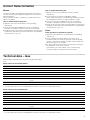
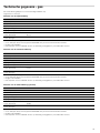
Technical data – Gas
Different types of gas and the corresponding values are listed
here.
Nozzle values for the auxiliary burner
Nozzle values for the standard burner
*G20/G25 G20 G20 G25 G25 G30/G31 **G30 G25.1 G27 G30
Gas pressure (mbar) 20/25 20 25 20 25 28-30/37 50 25 20 37
Nozzle (mm) 0.72 0.72 0.68 0.77 0.72 0.50 0.43 0.72 0.77 0.47
Bypass nozzle (mm) 0.50 0.50 0.50 0.50 0.50 0.30 0.30 0.50 0.50 0.30
Max. input power (kW) 1 1 1 1 1 1 1 1 1 1
Min. input power (kW) ≤ 0.55 ≤ 0.55 ≤ 0.55 ≤ 0.55 ≤ 0.55 ≤ 0.55 ≤ 0.55 ≤ 0.55 ≤ 0.55 ≤ 0.55
Gas flow at 15 °C and 1013 mbar m³/h 0.095/
0.111
0.095 0.095 0.111 0.111 - - 0.111 0.116 -
Gas flow at 15 °C and 1013 mbar g/h - - - - - 73 73 - - 73
* For France and Belgium
** For G30 (50 mbar), nozzle set HEZ298070 must be ordered from our after-sales service.
*G20/G25 G20 G20 G25 G25 G30/G31 **G30 G25.1 G27 G30
Gas pressure (mbar) 20/25 20 25 20 25 28-30/37 50 25 20 37
Nozzle (mm) 0.97 0.97 0.91 1 0.94 0.65 0.58 0.94 1.00 0.62
Bypass nozzle (mm) 0.58 0.58 0.58 0.58 0.58 0.38 0.38 0.58 0.58 0.38
Max. input power (kW) 1.75 1.75 1.75 1.75 1.75 1.75 1.75 1.75 1.75 1.75
Min. input power (kW) ≤ 0.9 ≤ 0.9 ≤ 0.9 ≤ 0.9 ≤ 0.9 ≤ 0.9 ≤ 0.9 ≤ 0.9 ≤ 0.9 ≤ 0.9
Gas flow at 15 °C and 1013 mbar m³/h 0.167/
0.194
0.167 0.167 0.194 0.194 - - 0.194 0.203 -
Gas flow at 15 °C and 1013 mbar g/h - - - - - 127 127 - - 127
* For France and Belgium
** For G30 (50 mbar), nozzle set HEZ298070 must be ordered from our after-sales service.

10
Nozzle values for the wok burner (optional)
Nozzle values for the high output burner (optional)
Nozzle values for the gas grill burner in the gas oven
(optional)
Nozzle values for the lower burner on the gas oven with
thermostat (optional)
*G20/G25 G20 G20 G25 G25 G30/G31 **G30 G25.1 G27 G30
Gas pressure (mbar) 20/25 20 25 20 25 28-30/37 50 25 20 37
Nozzle (mm) 1.35 1.35 1.20 1.45 1.40 0.96 0.75 1.40 1.46 0.90
Bypass nozzle (mm) 0.88 0.88 0.88 0.88 0.88 0.55 0.55 0.88 0.88 0.55
Max. input power (kW) 3.6 3.6 3.6 3.6 3.6 3.6 3.6 3.6 3.6 3.6
Min. input power (kW) ≤ 1.7 ≤ 1.7 ≤ 1.7 ≤ 1.7 ≤ 1.7 ≤ 1.7 ≤ 1.7 ≤ 1.7 ≤ 1.7 ≤ 1.7
Gas flow at 15 °C and 1013 mbar m³/h 0.342/
0.398
0.342 0.342 0.398 0.398 - - 0.398 0.418 -
Gas flow at 15 °C and 1013 mbar g/h - - - - - 261 261 - - 261
* For France and Belgium
** For G30 (50 mbar), nozzle set HEZ298070 must be ordered from our after-sales service.
*G20/G25 G20 G20 G25 G25 G30/G31 **G30 G25.1 G27 G30
Gas pressure (mbar) 20/25 20 25 20 25 28-30/37 50 25 20 37
Nozzle (mm) 1.16 1.16 1.10 1.34 1.21 0.85 0.75 1.21 1.38 0.80
Bypass nozzle (mm) 0.75 0.75 0.75 0.75 0.75 0.46 0.46 0.75 0.75 0.46
Max. input power (kW) 3 3 3 3 3 3 3 3 3 3
Min. input power (kW) ≤ 1.3 ≤ 1.3 ≤ 1.3 ≤ 1.3 ≤ 1.3 ≤ 1.3 ≤ 1.3 ≤ 1.3 ≤ 1.3 ≤ 1.3
Gas flow at 15 °C and 1013 mbar m³/h 0.285/
0.332
0.285 0.285 0.332 0.332 - - 0.332 0.348 -
Gas flow at 15 °C and 1013 mbar g/h - - - - - 218 218 - - 218
* For France and Belgium
** For G30 (50 mbar), nozzle set HEZ298070 must be ordered from our after-sales service.
*G20/G25 G20 G20 G25 G25 G30 **G30 G25.1
Gas pressure (mbar) 20/25 20 25 20 25 28-30 50 25
Nozzle (mm) 1.00 1.00 0.98 1.13 1.10 0.70 0.62 1.10
Bypass nozzle (mm) - - - - - - - -
Max. input power (kW) 2.1 2.1 2.1 2.1 2.1 2.1 2.1 2.1
Min. input power (kW) - - - - - - - -
Gas flow at 15 °C and 1013 mbar m³/h 0.2/0.233 0.2 0.2 0.233 0.233 - - 0.233
Gas flow at 15 °C and 1013 mbar g/h - - - - - 153 153 -
* For France and Belgium
** For G30 (50 mbar), nozzle set HEZ298070 must be ordered from our after-sales service.
*G20/G25 G20 G20 G25 G25 G30 **G30 G25.1
Gas pressure (mbar) 20/25 20 25 20 25 28-30 50 25
Nozzle (mm) 1.16 1.16 1.10 1.34 1.21 0.85 0.75 1.21
Bypass nozzle (mm) 0.76 0.76 0.67 0.80 0.70 0.48 0.45 0.70
Max. input power (kW) 3 3 3 3 3 3 3 3
Min. input power (kW) - - - - - - - -
Gas flow at 15 °C and 1013 mbar m³/h 0.285/
0.332
0.285 0.285 0.332 0.332 - - 0.332
Gas flow at 15 °C and 1013 mbar g/h - - - - - 218 218 -
* For France and Belgium
** For G30 (50 mbar), nozzle set HEZ298070 must be ordered from our after-sales service.

11
é Inhoudsopgave
é Aanwijzing voor de gasaansluiting en -omschakeling (Alleen voor de klantenservice)
Te nemen maatregelen.............................................................11
De kant van de gasaansluiting kiezen (* optioneel) ................. 11
Gasaansluiting..........................................................................12
Toegestane aansluitingen .............................................................. 12
Aardgasaansluiting (NG) ................................................................ 12
Aansluiting voor vloeibaar gas (LPG) .......................................... 13
Omzetting naar een andere gassoort .....................................13
Naar een andere gassoort omzetten ........................................... 13
Functieonderdelen voor de gasomzetting .................................. 13
Branderkoppen vervangen ............................................................ 14
Bypass-schroeven van de brander instellen of vervangen en
kleine vlam instellen ........................................................................ 14
Omschakeling van aardgas naar vloeibaar gas........................ 14
Omzetting van vloeibaar gas naar aardgas ............................... 15
Bedieningspaneel demonteren ..................................................... 15
Bypass-schroeven vervangen ....................................................... 16
Bedieningspaneel monteren.......................................................... 16
Ovenbranders vervangen (optie).................................................. 16
Lektest en functiecontrole.......................................................17
Gasaansluiting controleren ............................................................ 17
Brandersproeiers controleren........................................................ 17
Bypass-schroeven controleren...................................................... 17
De sproeier van de ovenbrander (optie) controleren ............... 18
Grillbrandersproeier controleren (optie)...................................... 18
Correcte vlamvorming .............................................................18
Branders ............................................................................................ 18
Bakoven.............................................................................................18
Technische gegevens - gas .....................................................19
Te nemen maatregelen
De omzetting van het apparaat naar een andere gassoort
mag uitsluitend door een erkende installateur volgens de
instructies in dit handboek worden uitgevoerd.
Een verkeerde aansluiting en verkeerde instellingen kunnen
ernstige schade aan het apparaat veroorzaken. De fabrikant
van het apparaat aanvaardt geen aansprakelijkheid voor
schade en storingen die als gevolg hiervan zijn ontstaan.
Neem de symbolen op het typeplaatje nauwkeurig in acht.
Indien voor uw land geen symbool aanwezig is, moet u zich bij
de instellingen houden aan de technische richtlijnen van uw
land.
Voordat u het apparaat opstelt, moet u bij uw gasleverancier
informatie inwinnen over de gassoort en gasdruk. Verzeker u
vóór de inbedrijfstelling van het apparaat ervan dat alle
instellingen correct zijn uitgevoerd.
Plaatselijke en internationale regelingen en voorschriften
dienen opgevolgd te worden.
Alle aansluitgegevens staan op het typeplaatje aan de
achterzijde van het apparaat.
Noteer de gegevens in de volgende tabel:
Productnummer (E-nr.),
Fabrieksnummer (FD),
Noteer in de volgende tabel de standaardinstellingen voor de
gassoort/gasdruk alsook de instellingen die na de
gasomzetting voor de gassoort/gasdruk gelden.
De aan het apparaat uitgevoerde wijzigingen en de soort
aansluiting spelen een belangrijke rol met betrekking tot het
juiste en veilige gebruik ervan.
: Risico van het ontsnappen van gas!
■ Na werkzaamheden aan de gasaansluiting dient deze altijd
op dichtheid te worden gecontroleerd. De fabrikant aanvaardt
geen aansprakelijkheid voor het ontsnappen van gas bij een
gasaansluiting die eerder gemanipuleerd is.
Risico van een gaslek!
■ Verplaats het apparaat niet door aan de gasleiding (collector)
te trekken.De gasleiding kan dan beschadigd raken.
Risico van een gaslek!
■ Het apparaat mag na de installatie niet meer verplaatst
worden.
Wanneer u het apparaat na de installatie verplaatst,
controleer de aansluiting dan op lekkage.
Sluit voor aanvang van alle werkzaamheden altijd de stroom-
en gastoevoer af.
Dit toestel niet bij boten of vaartuigen inbouwen.
De kant van de gasaansluiting kiezen (*
optioneel)
De gasaansluiting van het apparaat kan rechts of links
plaatsvinden. De kant van de aansluiting kan zo nodig worden
veranderd.
De hoofdgastoevoer sluiten.
Wordt de kant van de gasaansluiting veranderd, dan moet het
gasaansluitstuk aan de niet-gebruikte kant worden afgesloten
met een blindstop.
Hiervoor:
1. De nieuwe afdichting in de blindstop plaatsen. Let erop dat
de afdichting correct bevestigd is.
2. Het gasaansluitstuk op het apparaat met steeksleutel SW22
vasthouden en de blindstop met SW24 steeksleutel aan het
aansluitstuk bevestigen.
Na verandering van de kant van de aansluiting dient een lektest
te worden uitgevoerd. Zie hiervoor het hoofdstuk “Dichtheids-
controle".
Enr. FD
Servicedienst
O
Gassoort/gasdruk
Gegevens op het typeplaatje
Gassoort/gasdruk
Gegevens na de gasomzetting
1P
6:
6:

12
Aanwijzing: Gebruik een draaimomentsleutel om het apparaat
aan te sluiten.
* Optie: Alleen voor bepaalde modellen geldig.
Gasaansluiting
Toegestane aansluitingen
Deze instructies gelden alleen voor de opstelling van het
apparaat in landen die op het typeplaatje staan vermeld.
Indien het apparaat in een land opgesteld, aangesloten en
gebruikt moet worden dat niet op het typeplaatje vermeld staat,
moet er een installatie- en montagehandleiding worden gebruikt
die de gegevens en informatie over de geldige
aansluitvoorwaarden van dat betreffende land bevat.
Aardgasaansluiting (NG)
Wanneer er aardgas (NG) wordt gebruikt, moet de
gasaansluiting via een gasleiding of een veiligheidsgasslang
aan beide uiteinden met een schroefverbinding tot stand
worden gebracht.
Aansluiting volgens EN ISO 228 G
^ (TS EN ISO 228 G^ )
1. De nieuwe afdichting in het verbindingsstuk plaatsen.Let erop
dat de afdichting goed bevestigd is.
2. Het gasaansluitstuk van het apparaat met steeksleutel SW22
vasthouden en het verbindingsstuk met steeksleutel SW24 in
het aansluitstuk plaatsen.
3. De nieuwe afdichting in de gasbuis of de veiligheidsgasslang
plaatsen. Let erop dat de afdichting correct bevestigd is.
4. Het verbindingsstuk met steeksleutel SW24 vasthouden en
de schroefdraadaansluiting van de gasbuis of de
veiligheidsgasslang met steeksleutel SW24 op het
verbindingsstuk bevestigen en vastdraaien.
5. Zie voor het uitvoeren van de lektest het hoofdstuk
“Dichtheids-controle". De sluitinrichting voor de
gasaansluiting openen.
: Risico van een gaslek!
Bij aansluiting van de gasbuis of de veiligheidsgasslang het
gasaansluitstuk op het apparaat in geen geval vastdraaien met
steeksleutel SW22.Het gasaansluitstuk kan beschadigd raken.
Aanwijzingen
■ *G^: EN ISO 228 G^ (TS EN ISO 228 G^)
■ Gebruik voor de aansluiting van het apparaat een
draaimomentsleutel.
Aansluiting volgens EN 10226 R
^ (TS 61-210 EN 10226 R^ )
1. De nieuwe afdichting in het verbindingsstuk plaatsen.Let erop
dat de afdichting goed bevestigd is.
2. Het gasaansluitstuk op het apparaat met steeksleutel SW22
vasthouden en het verbindingsstuk met steeksleutel SW24 in
het aansluitstuk plaatsen.
3. Het verbindingsstuk met steeksleutel SW24 vasthouden en
de schroefdraadaansluiting van de gasbuis of de
veiligheidsgasslang met steeksleutel SW24 op het
verbindingsstuk bevestigen en vastdraaien.
4. Zie voor het uitvoeren van de lektest het hoofdstuk
“Dichtheids-controle". De sluitinrichting voor de
gasaansluiting openen.
: Risico van een gaslek!
Bij aansluiting van de gasbuis of de veiligheidsgasslang het
gasaansluitstuk op het apparaat in geen geval vastdraaien met
steeksleutel SW22.Het gasaansluitstuk kan beschadigd raken.
Aanwijzingen
■ *R^: EN 10226 R^ (TS 61-210 EN 10226 R^)
■ Gebruik voor de aansluiting van het apparaat een
draaimomentsleutel.
6:
6:
1P
*ê
1***
6:
6:
*ê
1***
1P
6:
6:
1P
1***
5ê
6:
6:
1***
1P
5ê

13
Aansluiting voor vloeibaar gas (LPG)
Attentie!
Houd u aan de richtljnen van het betreffende land.
Wanneer er vloeibaar gas (LPG) wordt gebruikt, dient de
gasaansluiting via een gasslang of een vaste verbinding tot
stand te worden gebracht.
Belangrijk bij het gebruik van een gasslang:
■ Gebruik een veiligheidsgasslang of een kunststofslang
(diameter 8 of 10 mm).
■ Hij moet met een toegestane aansluitinrichting (bijv. een
slangklem) aan de gasaansluiting worden bevestigd.
■ De slang dient kort en volledig dicht te zijn. De lengte van de
slang mag max. 1,5 m bedragen.Houd u aan de op dat
moment geldende richtlijnen.
■ De gasslang dient één keer per jaar te worden vervangen.
1. De nieuwe afdichting in het verbindingsstuk plaatsen.Let erop
dat de afdichting goed bevestigd is.
2. Het gasaansluitstuk van het apparaat met steeksleutel SW22
vasthouden en het verbindingsstuk met steeksleutel SW24 in
het aansluitstuk plaatsen.
3. De veiligheidsgasslang plaatsen en goed vastzetten met een
schroefdraadverbinding of een klem.
4. Zie voor het uitvoeren van de lektest het hoofdstuk
“Dichtheids-controle". De sluitinrichting voor de
gasaansluiting openen.
Aanwijzing: Gebruik een draaimomentsleutel om het apparaat
aan te sluiten.
Omzetting naar een andere gassoort
Naar een andere gassoort omzetten
■ Het gasaansluitstuk moet vervangen worden.
■ De brandersproeiers moeten vervangen worden.
■ Afhankelijk van de standaardgasinstelling moeten de bypass-
schroeven van de branderkranen óf vervangen óf tot aan de
aanslag ingedraaid worden.
■ Indien aanwezig moeten ook de oven- en grillsproeiers
worden vervangen.
Op de sproeiers staan getallen die de diameter aangeven.
Meer informatie over gassoorten die voor het apparaat geschikt
zijn, vindt u in het hoofdstuk “Technische eigenschappen -
gas".
Na de omzetting
■ Na de omzetting naar een andere gassoort moet een lektest
worden uitgevoerd. Zie het hoofdstuk “Lektest".
■ Na de omzetting naar een andere gassoort moet de correcte
vlamvorming worden gecontroleerd. Zie het hoofdstuk
“Correcte vlamvorming".
■ Noteer de nieuw ingestelde gassoort en de nieuwe gasdruk
in de tabel. Zie het hoofdstuk “Te nemen maatregelen".
Attentie!
Na de omzetting naar een andere gassoort moet op de
daarvoor bedoelde plaats op het typeplaatje een sticker
worden geplakt waarop de gegevens over de gassoort en een
ster staan ABSOLUUT NOODZAKELIJK.
Functieonderdelen voor de gasomzetting
De functieonderdelen die volgens deze handleiding voor de
gasomzetting nodig zijn, staan hieronder afgebeeld.
De juiste sproeierdiameters vindt u in de tabel in het hoofdstuk
“Technische eigenschappen - gas".
Gebruik altijd nieuwe afdichtingen.
Het te gebruiken gasaansluitstuk kan afhankelijk van de
gassoort en landspecifieke bepalingen afwijken.
(*) Bij de uitvoering van de gasaansluiting moeten deze
functieonderdelen worden gebruikt.
6:
/3***
6:
1P
Bypass-schroef
Brandersproeier
(*) Afdichting

14
Branderkoppen vervangen
1. Alle knoppen van het bedieningspaneel uitzetten.
2. Sluitinrichting voor de gasaansluiting sluiten.
3. Pannenhouders en branderonderdelen verwijderen.
4. Branderkoppen demonteren (steeksleutel 7).
5. Beschikt uw apparaat over een wokbrander met toegang
vanaf de zijkant, verwijder de branderkop dan zoals hieronder
afgebeeld, (steeksleutel 7)
6. In de tabellen vindt u informatie over de branderkoppen. Zie
hiervoor het hoofdstuk “Technische gegevens – gas".
Nieuwe koppen in de betreffende branders monteren.
Na vervanging controleren op dichtheid. Zie het hoofdstuk
“Controleren op dichtheid" .
Bypass-schroeven van de brander instellen of
vervangen en kleine vlam instellen
De bypass-schroeven regelen de minimale vlamhoogte van de
brander.
Voorbereiding
Sluit de gastoevoer.
: Gevaar voor elektrische schok!
Onderbreek de stroomtoevoer naar het apparaat.
1. Schakel de schakelaars op het bedieningspaneel uit.
2. Verwijder een voor een de schakelknoppen door deze dicht
tegen het bedieningspaneel vast te houden en vervolgens
recht eruit te trekken.
Omschakeling van aardgas naar vloeibaar
gas.
Wanneer het apparaat bij levering (standaardinstelling) op
aardgas (NG: G20, G25) was ingesteld en nu voor het eerst
naar vloeibaar gas (LPG: G30, G31) wordt omgeschakeld:
Voor modellen met ontbrandingsbeveiliging:
Om bij de bypass-koppen te kunnen komen moet het
bedieningspaneel worden gedemonteerd. Zie het hoofdstuk
„Bedieningspaneel demonteren”.
De bypass-koppen dienen tot de aanslag te worden
vastgedraaid.
Vervolgens moet u de stappen uitvoeren die worden
beschreven in het hoofdstuk „Bedieningspaneel monteren“.
Voor modellen met gas-oven (optie):
Om bij de bypass-kop onder de branderkraan te kunnen
komen, moet u het bedieningspaneel demonteren. Zie het
hoofdstuk „Bedieningspaneel demonteren”.
De bypass-kop van de ovenbrander moet tot de aanslag
worden vastgedraaid.
Vervolgens moet u de stappen uitvoeren die worden
beschreven in het hoofdstuk „Bedieningspaneel monteren“.
(*) Aansluitstuk voor aardgas
(NG: G20, G25)
TS 61-210 EN 10226 R
^
EN 10226 R^
(*) Aansluitstuk voor aardgas
(NG: G20, G25)
TS EN ISO 228 G
^
EN ISO 228 G^
(*) Aansluitstuk voor vloeibaar gas
(LPG: G30, G31)
Gasaansluitstuk
Blindstop (afsluitstuk)
6:

15
Omzetting van vloeibaar gas naar aardgas
Indien het apparaat van vloeibaar gas (LPG: G30, G31) naar
aardgas (NG: G20, G25) moet worden omgezet of als deze
omzetting al heeft plaatsgevonden en nu ongedaan moet
worden gemaakt:
moeten alle bypass-schroeven van het apparaat worden
vervangen. Lees hiervoor het hoofdstuk “Bedieningspaneel
verwijderen" na.
Aansluitend moeten de instructies in het hoofdstuk “Bypass-
schroeven vervangen" worden uitgevoerd.
Volg daarna de instructies op in het hoofdstuk
“Bedieningspaneel bevestigen".
Bedieningspaneel demonteren
1. Als het apparaat een afscherming aan de bovenkant heeft,
dient deze te worden afgenomen. Hiervoor de afscherming
openen, met beide handen aan de zijkant vasthouden en
naar boven trekken. De afscherming komt los. Let erop dat
de scharnieren niet kwijtraken.
2. Pannenhouders en branderonderdelen verwijderen.
3. Alle mogelijk aanwezige brander-aansluitschroeven van de
kookplaat verwijderen.
4. De twee schroeven (T20) rechts- en linksvoor op de
kookplaat afnemen. De kunststof onderdelen die zich
daaronder bevinden niet verwijderen.
5. Voor modellen met wokbrander (optioneel): de vier
schroeven (M4) van de wokbrander nemen.
6. De kookplaat aan de voorkant vastpakken en max. 30° naar
boven draaien. De kookplaat ondersteunen met de profielrail,
die horizontaal op de voorste branderbevestiging wordt
geplaatst.
7. De kunstof afschermingen aan de linker- en rechterkant van
de frontprofielen afnemen (zonder krassen te veroorzaken).
De schroeven die zich daaronder bevinden (T20) eruit
draaien.
8. De beide schroeven (M4) die te zien zijn na afname van de
schakelaars (T15) verwijderen.

16
9. Het voorpaneel met beide handen vasthouden en langzaam
naar boven trekken. Uit de bevestigingsklemmen nemen.
Daarna het paneel voorzichtig naar voren toe verwijderen. Let
erop dat de kabels niet beschadigd en de verbindingen niet
losraken.
Bypass-schroeven vervangen
1. Draai de bypass-schroeven met een platte schroevendraaier
(nr. 2) los. Draai de bypass-schroeven eruit.
2. De nieuwe bypass-schroeven, die u na de omzetting naar
een andere gassoort nodig hebt, kunt u met behulp van de
tabel bepalen. Zie het hoofdstuk “Technische
eigenschappen - gas".
3. Controleer of de afdichtingen van de bypass-schroef goed
zitten en foutloos functioneren. Gebruik alleen bypass-
schroeven met intacte afdichtingen.
4. Plaats de nieuwe bypass-schroeven en draai deze stevig aan.
Verzeker u ervan dat alle bypass-schroeven op de juiste
afsluitkranen zijn aangesloten.
5. Vervolgens moet nu beslist een lektest worden uitgevoerd.
Zie het hoofdstuk “Lektest".
Bedieningspaneel monteren
Montage in omgekeerde volgorde.
1. Het voorpaneel met beide handen vasthouden en voorzichtig
inbrengen. Let erop dat de kabels niet beschadigd en de
verbindingen niet losraken.Licht naar onderen bewegen en in
de bevestigingsklemmen plaatsen.
2. De beide schroeven (T15) (M4), die van het
bedieningspaneel zijn afgenomen, weer indraaien.
3. De schroeven (T20) die aan de rechter- en linkerkant uit de
frontprofielen zijn gehaald weer inbrengen. De kunststof
afschermingen weer aanbrengen.
4. De kookplaat voorzichtig inbrengen. Let erop dat de kunststof
onderdelen onder de schroeven er niet uitvallen. De beide
schroeven (T20) rechts- en linksvoor op de kookplaat weer
indraaien. Alle aanwezige brander-aansluitschroeven in de
kookplaat draaien.
5. Voor modellen met wokbrander (optioneel): de 4 torx-
schroeven (M4), die van de wokbrander verwijderd zijn weer
indraaien.
6. De bovenste fornuisafscherming (indien aanwezig) aan beide
kanten vasthouden en loodrecht naar beneden in de houder
plaatsen.
7. De branderbehuizingen inbrengen, daarbij letten op de juiste
afmetingen en ervoor zorgen dat de ontstekingskaars in de
opening aan de rand van de branderbehuizing wordt
ingebracht. De branderdeksels midden op de juiste
branderonderdelen plaatsen.
8. Pannenhouders weer inbrengen. Zorg ervoor dat de
pannenhouder met een spanbreedte van 80 mm op de extra
brander wordt gezet.
9. De schakelaars voorzichtig inbrengen.
10.In deze fase dient beslist de werking van de branders te
worden gecontroleerd. Zie hiervoor het hoofdstuk "Correcte
werking van de branders".
11.Controleer of het apparaat goed werkt.
Ovenbranders vervangen (optie)
Voorbereiding
Schakel alle schakelaars op het bedieningspaneel uit.
Sluit de gastoevoer.
: Gevaar voor elektrische schok!
Onderbreek de stroomtoevoer naar het apparaat.
Vervang de sproeier voor de ovenbrander
1. Open de ovendeur.
2. Draai de voorste bevestigingsschroef van de bodemplaat los.
3. Houd de bodemplaat vooraan vast, licht hem op en trek hem
eruit.

17
4. Draai de bevestigingsschroef van de brander los en neem de
ovenbrander voorzichtig eruit. De brandersproeiers zijn nu vrij
toegankelijk. Let erop dat het thermo-element en de
bougieaansluitingen niet worden beschadigd.
5. Draai de sproeier aan de branderingang op de achterzijde
van de oven los (met behulp van een steeksleutel van 7 mm).
6. De nieuwe sproeier, die u na de omzetting naar een andere
gassoort nodig hebt, kunt u met behulp van de tabel bepalen.
Zie het hoofdstuk “Technische eigenschappen - gas".
7. Plaats de nieuwe sproeier en draai deze vast.
8. Voer nu in ieder geval een lektest uit. Lees voor de uitvoering
van een lektest het hoofdstuk “Lektest" na.
9. Plaats de ovenbrander weer terug. Let erop dat de
aansluitingen van het thermo-element en de bougie niet
beschadigd worden. Draai de bevestigingsschroef weer vast.
10.Vervolgens moet in ieder geval de vlamvorming van de
brander worden gecontroleerd. Zie het hoofdstuk “Correcte
vlamvorming".
11.Monteer de bodemplaat weer.
Sproeier voor de grillbrander vervangen (optie)
1. Open de ovendeur.
2. Draai de schroef los die de bevestigingsplaat van de
grillbrander en de grillbrander met elkaar verbindt en trek de
brander voorzichtig recht eruit. Let erop dat het thermo-
element en de bougieaansluitingen niet worden beschadigd.
De brandersproeiers zijn nu vrij toegankelijk.
3. Draai de sproeier van de grillbrander los (steeksleutel van 7
mm).
4. De nieuwe sproeier die voor de omgezette gassoort nodig is,
kunt u met behulp van de tabel bepalen. Zie het hoofdstuk
“Technische eigenschappen - gas".
5. Plaats de nieuwe sproeier en draai deze vast.
6. Vervolgens moet nu in ieder geval een lektest worden
uitgevoerd. Lees voor de uitvoering van een lektest het
hoofdstuk “Lektest" na.
7. Plaats de grillbrander weer terug. Let erop dat de
aansluitingen van het thermo-element en de bougie niet
beschadigd worden. Draai de schroeven weer aan.
8. Schuif de afdichting in de brander tot aan de aanslag erin.
9. Vervolgens moet nu in ieder geval de vlamvorming van de
brander worden gecontroleerd. Zie het hoofdstuk “Correcte
vlamvorming".
Lektest en functiecontrole
: Explosiegevaar!
Vermijd vonkvorming. Een open vuur is niet toegestaan.
Voer de lektest alleen met een geschikte lekspray uit.
Wat te doen bij een gaslek
Sluit de gastoevoer.
Lucht het vertrek goed door.
Controleer nog eens de gas- en sproeieraansluitingen. Herhaal
de lektest.
De lektest moet door twee personen met inachtneming van de
volgende instructies worden uitgevoerd.
Gasaansluiting controleren
1. Open de gastoevoer.
2. Bespuit de gasaansluiting met een lekspray.
Indien zich kleine belletjes of schuim vormen, duidt dit op een
gaslek. Volg de instructies op in het hoofdstuk “Wat te doen bij
een gaslek ".
Voer dezelfde stappen uit voor het met een blindstop
afgesloten onderdeel.
Brandersproeiers controleren
1. Open de gastoevoer.
Voer de lektest voor elke sproeier afzonderlijk uit.
2. Sluit de opening van de te controleren brandersproeier
voorzichtig met een vinger of een geschikt voorwerp.
3. Bespuit de sproeier met een lekspray.
4. Druk de functiekiezer in en draai deze linksom. Hierdoor
stroomt er gas naar de sproeier.
Indien zich kleine belletjes of schuim vormen duidt dit op een
gaslek. Volg de instructies op in het hoofdstuk“Wat te doen bij
een gaslek ".
Bypass-schroeven controleren
1. Open de gastoevoer.
Voer de lektest voor elke bypass-schroef afzonderlijk uit.
2. Sluit de opening van de te controleren brandersproeier
voorzichtig met een vinger of een geschikt voorwerp.
3. Bespuit de sproeier van de te controleren brander met een
lekspray.
4. Druk de schakelknop in en draai deze linksom. Hierdoor
stroomt er gas naar de sproeier.
Indien zich kleine belletjes of schuim vormen, duidt dit op een
gaslek. Volg de instructies op in het hoofdstuk “Wat te doen bij
een gaslek ".

18
De sproeier van de ovenbrander (optie)
controleren
1. Open de gastoevoer.
2. Sluit de sproeieropening van de ovenbrander voorzichtig met
een vinger of een geschikt voorwerp.
3. Bespuit de sproeier met een lekspray.
4. Druk de functiekiezer in en draai deze linksom. Hierdoor
stroomt er gas naar de sproeier.
Indien zich kleine belletjes of schuim vormen, duidt dit op een
gaslek. Volg de instructies op in het hoofdstuk “Wat te doen bij
een gaslek ".
Grillbrandersproeier controleren (optie)
1. Open de gastoevoer.
2. Sluit de opening van de grillbrandersproeier voorzichtig met
een vinger of een geschikt voorwerp.
3. Bespuit de sproeier met een lekspray.
4. Draai de functiekiezer van de oven rechtsom. Hierdoor
stroomt er gas naar de sproeier.
Indien zich kleine belletjes of schuim vormen, duidt dit op een
gaslek. Volg de instructies op in het hoofdstuk “Wat te doen bij
een gaslek ".
Correcte vlamvorming
Branders
Na de omzetting naar een andere gassoort moet voor elke
brander de vlamvorming en temperatuurontwikkeling worden
gecontroleerd.
Vergelijk in geval van een probleem de sproeierwaarden met
de waarden in de tabel.
Alleen voor modellen zonder ontstekingsbeveiliging
1. Ontsteek de kookplaatbrander zoals beschreven in de
handleiding.
2. Controleer de correcte vlamvorming bij de grote en kleine
vlam. De vlam moet constant en gelijkmatig branden.
3. Schakel met de branderschakelaar snel heen en weer tussen
de grote en kleine vlam. Herhaal deze procedure enkele
malen. De gasvlam mag niet doven of flakkeren.
Alleen voor modellen met ontstekingsbeveiliging
1. Ontsteek de kookplaatbrander zoals beschreven in de
handleiding.
2. Draai de branderschakelaar op de kleine vlam.
Controleer of de ontstekingsbeveiliging is geactiveerd door
de schakelaar ongeveer 1 minuut lang in de stand “kleine
vlam" te houden.
3. Controleer de correcte vlamvorming bij de grote en kleine
vlam. De vlam moet constant en gelijkmatig branden.
4. Schakel met de branderschakelaar snel heen en weer tussen
de grote en kleine vlam. Herhaal deze procedure enkele
malen. De gasvlam mag niet doven of flakkeren.
Bakoven
Onderste gasbrander of grillbrander (optie)
1. Ontsteek de onderste gasbrander zoals beschreven in de
handleiding.
2. Controleer bij geopende deur de vlamvorming:
De vlam moet overal gelijkmatig branden (in de eerste
minuten kunnen zich lichte haperingen voordoen, maar na
enkele minuten moeten de vlammen constant branden).
3. Laat het apparaat enkele minuten aan staan om te kunnen
controleren of het thermo-element goed werkt.
Controleer indien nodig de instellingen. Vervang bij een niet-
correcte werking de bypass-schroef van de brander.

19
Technische gegevens - gas
De verschillende gastypen en overeenkomstige waarden zijn
opgenomen in een lijst.
Waarden voor de hulpbranderkop
Waarden voor de normale branderkop
Waarden voor de wokbranderkop (optioneel)
*G20/G25 ****G20 G20 G25 G25 G30/G31 **G30 G25.1 G27 G30 ***G25.3
Gasdruk (mbar) 20/25 20 25 20 25 28-30/37 50 25 20 37 25
Kop (mm) 0,72 0,72 0,68 0,77 0,72 0,50 0,43 0,72 0,77 0,47 0,72
Bypass-kop (mm) 0,50 0,50 0,50 0,50 0,50 0,30 0,30 0,50 0,50 0,30 0,50
Ingangsvermogen max. (kW) 1 1 1 1 1 1 1 1 1 1 1
Ingangsvermogen min. (kW) ≤0,55 ≤0,55 ≤0,55 ≤0,55 ≤0,55 ≤0,55 ≤0,55 ≤0,55 ≤0,55 ≤0,55 ≤0,55
Gasverbruik bij 15°C en
1013 mbar m³/h
0,095/
0,111
0,095 0,095 0,111 0,111 - - 0,111 0,116 - 0,108
Gasverbruik bij 15°C en
1013 mbar g/h
-----7373--73-
* Voor Frankrijk en België
** Voor G30 (50 mbar) moet koppenset HEZ298070 bij de servicedienst worden besteld.
***Volgens de NTA8837
****De inspuiter set voor G20/20 mbar is op aanvraag verkrijgbaar bij onze after sales service
*G20/G25 ****G20 G20 G25 G25 G30/G31 **G30 G25.1 G27 G30 ***G25.3
Gasdruk (mbar) 20/25 20 25 20 25 28-30/37 50 25 20 37 25
Kop (mm) 0,97 0,97 0,91 1 0,94 0,65 0,58 0,94 1,00 0,62 0,94
Bypass-kop (mm) 0,58 0,58 0,58 0,58 0,58 0,38 0,38 0,58 0,58 0,38 0,58
Ingangsvermogen max. (kW) 1,75 1,75 1,75 1,75 1,75 1,75 1,75 1,75 1,75 1,75 1,75
Ingangsvermogen min. (kW) ≤0,9 ≤0,9 ≤0,9 ≤0,9 ≤0,9 ≤0,9 ≤0,9 ≤0,9 ≤0,9 ≤0,9 ≤0,9
Gasverbruik bij 15°C en
1013 mbar m³/h
0,167/
0,194
0,167 0,167 0,194 0,194 - - 0,194 0,203 - 0,190
Gasverbruik bij 15°C en
1013 mbar g/h
- - - - - 127 127 - - 127 -
* Voor Frankrijk en België
** Voor G30 (50 mbar) moet koppenset HEZ298070 bij de servicedienst worden besteld.
***Volgens de NTA8837
****De inspuiter set voor G20/20 mbar is op aanvraag verkrijgbaar bij onze after sales service
*G20/G25 ****G20 G20 G25 G25 G30/G31 **G30 G25.1 G27 G30 ***G25.3
Gasdruk (mbar) 20/25 20 25 20 25 28-30/37 50 25 20 37 25
Kop (mm) 1,35 1,35 1,20 1,45 1,40 0,96 0,75 1,40 1,46 0,90 1,40
Bypass-kop (mm) 0,88 0,88 0,88 0,88 0,88 0,55 0,55 0,88 0,88 0,55 0,88
Ingangsvermogen max. (kW) 3,6 3,6 3,6 3,6 3,6 3,6 3,6 3,6 3,6 3,6 3,6
Ingangsvermogen min. (kW) ≤1,7 ≤1,7 ≤1,7 ≤1,7 ≤1,7 ≤1,7 ≤1,7 ≤1,7 ≤1,7 ≤1,7 ≤1,7
Gasverbruik bij 15°C en
1013 mbar m³/h
0,342/
0,398
0,342 0,342 0,398 0,398 - - 0,398 0,418 - 0,391
Gasverbruik bij 15°C en
1013 mbar g/h
- - - - - 261 261 - - 261 -
* Voor Frankrijk en België
** Voor G30 (50 mbar) moet koppenset HEZ298070 bij de servicedienst worden besteld.
***Volgens de NTA8837
****De inspuiter set voor G20/20 mbar is op aanvraag verkrijgbaar bij onze after sales service

20
Waarden voor de sterke branderkop (optioneel)
Waarden voor de gasgrillbranderkop - gasoven (optioneel)
Waarden voor de kop van de onderste brander van de
gasoven met thermostaat (optioneel)
*G20/G25 ****G20 G20 G25 G25 G30/G31 **G30 G25.1 G27 G30 ***G25.3
Gasdruk (mbar) 20/25 20 25 20 25 28-30/37 50 25 20 37 25
Kop (mm) 1,16 1,16 1,10 1,34 1,21 0,85 0,75 1,21 1,38 0,80 1,21
Bypass-kop (mm) 0,75 0,75 0,75 0,75 0,75 0,46 0,46 0,75 0,75 0,46 0,75
Ingangsvermogen max. (kW) 3 3 3 3 3 3 3 3 3 3 3
Ingangsvermogen min. (kW) ≤1,3 ≤1,3 ≤1,3 ≤1,3 ≤1,3 ≤1,3 ≤1,3 ≤1,3 ≤1,3 ≤1,3 ≤1,3
Gasverbruik bij 15°C en
1013 mbar m³/h
0,285/
0,332
0,285 0,285 0,332 0,332 - - 0,332 0,348 - 0,325
Gasverbruik bij 15°C en
1013 mbar g/h
- - - - - 218 218 - - 218 -
* Voor Frankrijk en België
** Voor G30 (50 mbar) moet koppenset HEZ298070 bij de servicedienst worden besteld.
***Volgens de NTA8837
****De inspuiter set voor G20/20 mbar is op aanvraag verkrijgbaar bij onze after sales service
*G20/G25 ****G20 G20 G25 G25 G30 **G30 G25.1 ***G25.3
Gasdruk (mbar) 20/25 20 25 20 25 28-30 50 25 25
Kop (mm) 1,00 1,00 0,98 1,13 1,10 0,70 0,62 1,10 1,10
Bypass-kop (mm) - - - - - - - - -
Ingangsvermogen max. (kW) 2,1 2,1 2,1 2,1 2,1 2,1 2,1 2,1 2,1
Ingangsvermogen min. (kW) - - - - - - - - -
Gasverbruik bij 15°C en
1013 mbar m³/h
0,2/0,233 0,2 0,2 0,233 0,233 - - 0,233 0,228
Gasverbruik bij 15°C en
1013 mbar g/h
- - - - - 153 153 - -
* Voor Frankrijk en België
** Voor G30 (50 mbar) moet koppenset HEZ298070 bij de servicedienst worden besteld.
***Volgens de NTA8837
****De inspuiter set voor G20/20 mbar is op aanvraag verkrijgbaar bij onze after sales service
*G20/G25 ****G20 G20 G25 G25 G30 **G30 G25.1 ***G25.3
Gasdruk (mbar) 20/25 20 25 20 25 28-30 50 25 25
Kop (mm) 1,16 1,16 1,10 1,34 1,21 0,85 0,75 1,21 1,21
Bypass-kop (mm) 0,76 0,76 0,67 0,80 0,70 0,48 0,45 0,70 0,70
Ingangsvermogen max. (kW) 3 3 3 3 3 3 3 3 3
Ingangsvermogen min. (kW) - - - - - - - - -
Gasverbruik bij 15°C en
1013 mbar m³/h
0,285/
0,332
0,285 0,285 0,332 0,332 - - 0,332 0,325
Gasverbruik bij 15°C en
1013 mbar g/h
- - - - - 218 218 - -
* Voor Frankrijk en België
** Voor G30 (50 mbar) moet koppenset HEZ298070 bij de servicedienst worden besteld.
***Volgens de NTA8837
****De inspuiter set voor G20/20 mbar is op aanvraag verkrijgbaar bij onze after sales service


*9000713468*
9000713468
-
 1
1
-
 2
2
-
 3
3
-
 4
4
-
 5
5
-
 6
6
-
 7
7
-
 8
8
-
 9
9
-
 10
10
-
 11
11
-
 12
12
-
 13
13
-
 14
14
-
 15
15
-
 16
16
-
 17
17
-
 18
18
-
 19
19
-
 20
20
-
 21
21
-
 22
22
-
 23
23
-
 24
24


in andere talen
- English: Siemens HX725220N/02 User manual
Gerelateerde papieren
Andere documenten
-
Bosch HSG142GEU/25 de handleiding
-
Scholtes PMG 42 de handleiding
-
Bosch HSB738155Z Handleiding
-
Scholtes B PMG 41 DCDR Series de handleiding
-
-
Bartscher 1051993 Handleiding
-
Pebble Time Steel Handleiding
-
Bartscher 2831021 Handleiding
-
-
Modular 316102 Handleiding