
E
NL
PL
D
MODE D’EMPLOI
GEBRAUCHSANWEISUNG
INSTRUCCIONES
GEBRUIKSAANWIJZING
INSTRUKCJA OBSLUGI
I
ISTRUZIONI PER L’USO
INSTRUCTIONS FOR USE
EN
F
INSTRUÇÕES DE USO
HASZNÁLATI ÚTMUTATÓ
PT
HU
7042LCD

2
BETA UTENSILI S.p.A.
Via Alessandro Volta, 18
20845 Sovico (MB) ITALY
Tel. +39 039.2077.1 - Fax +39 039.2010742
www.beta-tools.com - info@beta-tools.com
- DICHIARAZIONE DI CONFORMITÀ
- DECLARATION OF CONFORMITY
- DÉCLARATION DE CONFORMITÉ
- KONFORMITÄTSERKLÄRUNG
- DECLARACIÓN DE CONFORMIDAD
- DECLARAÇÃO DE CONFORMIDADE
- VERKLARING VAN CONFORMITEIT
- DEKLARACJA ZGODNOŚCI
- MEGFELELŐSÉGI NYILATKOZAT
- Ogni intervento o modica non autorizzati dalla BETA UTENSILI faranno decadere la validità di questa dichiarazione.
- Any tampering or change unauthorized by BETA UTENSILI shall immediately invalidate this statement.
- Toute opération ou modication non autorisées par BETA UTENSILI feront déchoir la validité de cette déclaration.
- Eingriffe und Änderungen ohne die Genehmigung von BETA UTENSILI machen die vorliegende Erklärung ungültig.
- Cualquier intervención o modicación no autorizadas por BETA UTENSILI, anularán la validez de esta declaración.
- Qualquer intervenção ou modicação que não seja autorizada pela BETA UTENSILI anularà a validade desta declração.
- Ledere niet door BETA UTENSILI geautoriseerde ingreep of wijziging doet de geldigheid van deze verklaring vervallen.
- Jakakolwiek ingerencja lub zmiana nie autoryzowana przez BETA UTENSILI natychmiast unieważnia to oświadczenie.
- Minden, a BETA UTENSILI által nem felhatalmazott beavatkozás vagy módosítás érvényteleníti ezt a nyilatkozatot
- Si dichiara che l’apparecchio tipo
- We hereby state that the machine type
- On déclare que la machine type
- Wir erklären, dass das Gerät Typ
- Declara que el aparato tipo
- Declara-se que a máquina tipo
- Verklaard wordt dat het apparaat type
- Niniejszym oświadczamy, że urządzenie typu
- Kimondja, hogy a berendezés típusát
}
MODEL 7042LCD
MASSIMO CICERI
( Member of the board)
}
è conforme alle norme
is in compliance with the rulls
est conforme aux normes
den Normen entspricht
es conforme a las normas
é conforme as normas
overeenkomstig de richtlijnen
jest zgodne z zasady
megfelel a szabályok
EN 175
EN379
MILANO
Notied body number 0196 :
DIN CERTCO Gesellschaft fuer Konformitaetsbewertung mbH - Alboinstrasse 56 - 12103 Berlin

Caratteristiche della maschera 7042LCD
1- L’alimentazione con batterie al litio/alcaline e a celle solari, garantisce una vita utile di 5000 ore. 15-20
minuti di spegnimento ininterrotto.
2- Con i comandi interni o esterni si selezionano manualmente le tonalità 9-13 di oscuramento, sensibilità
e ritardo dell’oscuramento, e funzione di saldatura/smerigliatura.
3- la tecnologia a doppi sensori fotoelettrici, doppio LCD e fi ltro di alta qualità offrono al saldatore una
chiara area di visione e una protezione effi cace dai raggi ultravioletti fi no a DIN13.
4- velocissima nell’oscurare l’LCD. Il tempo di oscuramento del fi ltro è di soli 1/1000s EN 379 (1/25000s,
ANSI Z87.1) standard, per proteggere gli occhi dai danni da archi elettrici.
5- a schermo chiaro il grado di protezione è a livello DIN4, il tempo di rischiaramento è pari a 0,1-1,0s alla
scomparsa di archi elettrici di fronte ai sensori.
6- La temperatura di esercizio è di -5 °C a +55 °C.
7- Vasto campo di applicazioni, per esempio saldatura ad arco manuale, saldatura ad arco sotto prote
zione di gas e taglio ad arco-plasma.
8- Calotta interna completamente regolabile, per un maggior confort e un ridotto affaticamento.
Istruzioni per l’uso
1. Prima di procedere alla saldatura assicurarsi che:
1.1 la pellicola protettiva sia stata tolta dallo schermo interno ed esterno
1.2 l’alimentazione sia suffi ciente (indicatore di batteria scarica all’interno della maschera)
1.3 le pellicole protettive siano integre, la cella solare non sia danneggiata od ostruita dalla polvere.
1.4 i componenti operativi non siano deteriorati o danneggiati. Eventuali componenti graffi ati o rotti devo-
no essere sostituiti immediatamente, per evitare danni personali;
1.5 la maschera sia stata adeguatamente riposta e conservata prima di ogni utilizzo.
1.6 Scegliere il numero di tonalità adeguato in base al tipo di macchina e alla corrente di saldatura.
2. Selezione della tonalità (DIN9-13)
2.1 Il numero di tonalità può essere impostato manualmente da 9 a 13; la manopola di regolazione è
esterna alla maschera. Per impostare il numero di tonalità adeguato ruotare la manopola di regolazio-
ne facendo attenzione a non impostare la funzione di smerigliatura (grinding)
2.2 Regolare la maschera per ottenere la tonalità corretta per il processo di saldatura facendo riferimento
alla (fi g. 1).
Fig. 1
ISTRUZIONI PER L’USO - Testo originale
I
3
0.5 2.5 10 20 40 80 125 175 225 275 350 450
1 5 15
30 60 100 150 200 250 300 400 500
AMPERES
DIN
SMAW/MMA
MIG
TIG,GTAW
MAG/CO
2
PAC
PAW
9 10 11 12 13
10 11 12 13
10 11 12 13
11 12 13
9 10 11 12 13
8 9 10 11 12 13

ISTRUZIONI PER L’USO
I
4
3. Tempo di ritardo
È il tempo richiesto dalla maschera per tornare, dallo stato di oscuramento, allo stato di rischiara-
mento completo.
3.1 Selezionando il valore minimo, il tempo di ritardo è impostato su 0,1-0,25s, adatto per saldatura a
punti, saldatura rapida o saldatura continua.
3.2 Selezionando il valore massimo, il tempo di ritardo è impostato su 0,85-1,0s, adatto per saldatura ad
alta corrente o per prevenire l’affaticamento degli occhi dovuto agli archi elettrici o a visione ravvici-
nata di pezzi ancora incandescenti.
3.3 Il valore medio è adatto alla maggior parte delle operazioni di saldatura .
4. Sensibilità
In base al processo di saldatura e alla luce ambiente, mediante la regolazione della manopola “SEN-
SIBILITÀ”, si seleziona la quantità di luce minima necessaria , applicata ai sensori frontali, per oscu-
rare il fi ltro LCD.
4.1 Selezionare Min. per saldatura ad alta corrente in un ambiente di saldatura luminoso o in un ambiente
con altre fonti di interferenza.
4.2 Selezionare Max. per saldatura a bassa corrente o in un ambiente di saldatura poco luminoso, in
particolare in caso di saldatura ad arco in atmosfera di argon a bassa corrente.
4.3 Selezione intermedia, adatta per la maggior parte delle operazioni di saldatura interne ed esterne.
5. Funzione di saldatura / smerigliatura
Durante le fasi di taglio o smerigliatura occorre ruotare la manopola in posizione “smerigliatura”.
6. Test
6.1. Impostare il numero di tonalità su un valore compreso tra 9 e 13, premere il pulsante TEST, verifi care
se lo schermo LCD passa in modalità di oscuramento e torna poi automaticamente in modalità di
rischiaramento.
7. Regolazione della calotta
7.1 La misura della calotta interna a banda può essere regolata manualmente. Premere leggermente la
ghiera e regolare la tensione in modo da garantire il massimo confort. Il meccanismo girevole è
dotato di funzione di auto-bloccaggio. Non girare la ghiera senza prima aver sbloccato il fermo per
evitare di danneggiare il meccanismo di regolazione.
7.2 Sui lati della maschera sono presenti dei fori di posizionamento; la regolazione della piastra fi ssa nei
fori laterali consente di modifi care l’angolo di visuale.
7.3 Regolando il serraggio della vite è possibile modifi care l’angolo della maschera di protezione, ed è
anche possibile alzarla o abbassarla. L’angolo ideale di saldatura è quello perpendicolare del fi ltro
rispetto la superfi cie sotto saldatura.
8. Sostituzione della batteria
8.1 La maschera per saldatura a oscuramento automatico funziona con 2 batterie al litio da 3V.
NB: Le batterie di scarto devono essere smaltite in conformità alle normative locali e i fi ltri devono
essere smaltiti in conformità ai processi di trattamento dei materiali di scarto elettronici.
8.2 La batteria può essere utilizzata continuativamente per 5000 ore in condizioni normali. la batteria
deve essere sostituita quando si accende la spia di bassa tensione.
Manutenzione
1 Per pulire il fi ltro utilizzare fazzoletti di carta, carta per lenti o cotone morbido pulito con un detergente
neutro.

ISTRUZIONI PER L’USO
I
5
Attenzione
1 La maschera per saldatura a oscuramento automatico non è adatta per la saldatura a laser e la sal-
datura ossiacetilenica.
2 La piastra protettiva trasparente deve sempre essere installata per proteggere il fi ltro da danni.
3 Non apportare modifi che o sostituzioni alla maschera di saldatura.
4 Interrompere immediatamente l’utilizzo se il fi ltro non riesce a passare in modalità di oscuramento e
contattare il rivenditore.
5 Per pulire il fi ltro non usare alcool, benzina o solventi; non immergerlo in acqua.
6 Temperatura di esercizio: -5 °C ÷ + 55 °C ( 23 °F ÷ 131 ° F,); il tempo di reazione della maschera per
saldatura a oscuramento automatico sarà ridotto se la temperatura ambiente è troppo bassa.
7 Sostituire le pellicole protettive immediatamente qualora siano rotte o graffi ate, poiché potrebbero
compromettere la visuale e ridurre seriamente l’effi cienza della protezione.
8 Sostituire il dispositivo di protezione immediatamente qualora sia rotto o graffi ato. Non utilizzare oggetti
duri a contatto con la superfi cie della lente del fi ltro.
9 Pulire regolarmente la superfi cie del fi ltro, i sensori e le celle solari.
10 La maschera non può prevenire gravi danni dovuti a urti o liquidi esplosivi o corrosivi. Se indossati
sopra occhiali oftalmici possono trasmettere impatti generando un pericolo per il portatore.
11 I materiali di questa maschera, che potrebbero venire a contatto con la pelle, possono causare reazio-
ni allergiche nelle persone sensibili.
NB: Il mancato rispetto delle suddette precauzioni può determinare gravi lesioni fi siche.
SIGNIFICATO DELLA MARCATURA
Marcatura della maschera di saldatura: BETA EN175 F (BETA=identifi cativo del produttore, EN175=norma
di riferimento, F=impatto a bassa energia, 45m/s)
Marcatura della protezione frontale: BETA F (BETA= identifi cativo del produttore, F= impatto a bassa
energia, 45m/s)
Marcatura della protezione posteriore: BETA 1 F (BETA= identifi cativo del produttore, 1=classe ottica, F=
impatto a bassa energia, 45m/s)
Marcatura del fi ltro automatic autoscurente: 4/9-13 BETA 1/1/1/3/379 (4=stato trasparente, 9-13=stato
oscurato, BETA= identifi cativo del produttore, 1=classe ottica, 1=classe di diffusione di luce, 1=classe di
omogeneità, 3=classe dell’angolo di diffusione, 379=norma di riferimento)”
Nota: se è richiesta la protezione contro particelle a temperature estreme, ad alta velocità, il protettore
deve essere marcato con la lettera T subito dopo la lettera identifi cativa della resistenza all’impatto. Cioè
FT, BT o AT.
Se la lettera identifi cativa della resistenza all’impatto non è seguita dalla lettera T il protettore va usato
esclusivamente per particelle ad alta velocità a temperatura ambiente.
Usare la maschera sempre con il fi ltro trasparente interno installato

ISTRUZIONI PER L’USO
I
6
RISOLUZIONE DEI PROBLEMI
FAQ
CAUSE
SOLUZIONI
I fi ltri non si
oscurano o sfarfallano
Il dispositivo di protezione è danneggiato Pulirlo o sostituirlo
Il sensore ad arco non è pulito Pulire la superfi cie del sensore
La corrente di saldatura è troppo bassa
Regolare la sensibilità al valore
massimo
La batteria è scarica Sostituire la batteria
Reazione lenta
La temperatura ambiente è troppo bassa
Non utilizzare a una temperatura
inferiore a -5 °C
La sensibilità è impostata su un valore troppo
basso
Aumentare adeguatamente la
sensibilità
Il fi ltro non è pulito
Il dispositivo di protezione è macchiato
Pulire o sostituire il dispositivo di
protezione
La pellicola protettiva non è stata tolta Rimuovere la pellicola protettiva
Le lenti del fi ltro presentano macchie
Pulire entrambi i lati delle lenti del
fi ltro
ATTENZIONE! Qualora non sia possibile trovare una soluzione alle suddette domande, interrompere im-
mediatamente l’utilizzo del prodotto e contattare il rivenditore.
GARANZIA
12 mesi dalla data d’acquisto – la garanzia consiste nella riparazione o sostituzione gratuita presso la
nostra sede – sono escluse le sostituzioni o riparazioni di parti soggette a normale usura dovuta al fun-
zionamento – la garanzia non si applica quando l’apparecchio riporti danneggiamenti causati da un uso
improprio.
1. Corpo della maschera
2. Calotta interna
3. Manopole di regolazione
dell’angolo della calotta interna.
4. Manopole di regolazione
della calotta interna.
5. Regolazione del numero di tonalità
6. Piastra protettiva
7. Pannello solare
8 Piastra fi ssa
9. Cornice frontale
10. Filtro UV/IR
9
10
5
6
7
8
1
2
3
4

1. Pulsante test automatico
2. Manopola di controllo tempo di ritardo
3. Manopola di controllo sensibilità
4. LCD
5. Batterie al litio
6. Indicatore di bassa tensione
7. Cella solare
8. Filtro UV/IR
9. Sensore d’arco elettrico
ISTRUZIONI PER L’USO
I
7
1 2 3 4 5 6 7 8 9
MODELLO
7042LCD
AREA DI VISUALE (mm) 98 x 43
DIMENSIONI CARTUCCIA (mm) 110 x 90 x9
STATO DI RISCHIARAMENTO DIN 4
OSCURAMENTO 9-13
TEMPO DI COMMUTAZIONE (s) 1/1000s (EN 379)
DA SCURO A CHIARO (s) 0.25~1.0
ACCENSIONE E SPEGNIMENTO AUTOMATICO
ALIMENTAZIONE: CELLA SOLARE. 2 X BATTERIE AL LITIO CR2032
PROTEZIONE UV/IR: DIN 13
SENSORI D’ARCO: 2
BASSO AMPERAGGIO TIG: 5 AMP
TEMPERATURA DI ESERCIZIO: -5 °c~+55 °c
TEMPERATURA DI STOCCAGGIO: -20 °c~+70 °c
PESO(g): 480
DIMENSIONI SCATOLA (mm): 330x230x230
PROCESSI DI SALDATURA:
SALDATURA MMA,MIG,MAG/CO2, TIG E AL PLASMA,
EROSIONE AD ARCO, TAGLIO AL PLASMA

0.5 2.5 10 20 40 80 125 175 225 275 350 450
1 5 15
30 60 100 150 200 250 300 400 500
AMPERES
DIN
SMAW/MMA
MIG
TIG,GTAW
MAG/CO
2
PAC
PAW
9 10 11 12 13
10 11 12 13
10 11 12 13
11 12 13
9 10 11 12 13
8 9 10 11 12 13
Features of welding helmet 7042LCD
1- Lithium/alkaline battery and solar cell power supply provides a service life of 5,000 hours, 15-20 minu-
tes with automatic closing function.
2- The internal or external control knobs can be used to manually select shades 9-13, sensitivity and
delay time control, welding/grinding functions.
3- Dual photoelectric sensor technology, high-quality dual LCD and fi lter provide the welder with a clear
fi eld of view and effective UV ray protection, up to grade DIN13.
4- Ultra-quick LCD darkening. The fi lter switch time from light to dark is no more than 1/1000s EN 379
(1/25000s, ANSI Z87.1) standard, so as to protect the eyes from arc damage.
5- In the LCD bright state, the degree of protection is DIN4; it takes 0.1-1.0s from dark state to bright state
when arcs disappear with sensors.
6- The operating temperature is -5 °C ÷ +55 °C.
7- Broad scope of applications - for example, manual arc welding, gas shielded arc welding and plasma
cutting.
8- Fully adjustable headgear, for increased comfort and reduced fatigue.
Operating instructions
1. Before welding, please make sure that:
1.1 the protective fi lm has been removed from the internal and external screen;
1.2 the power is suffi cient (fl at battery indicator in the helmet);
1.3 the protective fi lms are complete, the solar cell is not damaged or blocked by dust;
1.4 the operating parts are not worn off or damaged. Any scratched or broken parts should be replaced
immediately, so as not to incur any personal injury;
1.5 the welding helmet is properly replaced and stored before each use;
1.6 Choose the right shade number according to machine type and welding current.
2. Shade number selection (DIN9-13)
2.1 The shade number can be manually set from 9 to 13; the adjusting knob is outside the mask. To set the
proper shading number, rotate the adjusting knob, being careful not to set the grinding function.
2.2 Adjust the helmet to the correct shade for the welding process by referring to (Table 1).
Table 1
INSTRUCTIONS FOR USE
EN
8

9
3. Delay time
The amount of time required by the helmet to switch back from full dark to full light.
3.1 If the minimum value is selected, the delay time will be set to 0.1-0.25s, suitable for spot welding,
short welding or seam welding.
3.2 If the maximum value is selected, the delay time will be set to 0.85-1.0s, suitable for high current
welding or preventing eye fatigue from electric arcs or close viewing of incandescent pieces.
3.3 The medium value is suitable for most welding operations.
4. Sensitivity
According to the welding process and the ambient light, adjusting the “SENSITIVITY” knob will allow the
minimum amount of light - applied to the front sensors - needed to darken the LCD fi lter to be selected.
4.1 Select Min. for high current welding in a bright welding environment or in an environment with other
sources of interference.
4.2 Select Max. for low current welding or in a low light environment in welding, especially low current
argon arc welding.
4.3 Mid-range selection, suitable for most indoor and outdoor welding operations.
5. Welding / grinding feature
While cutting or grinding, the knob should be turned into the “Grind” position.
6. Test
6.1. Set the shading number to a value ranging from 9 to 13; press the TEST button; check whether the
LCD changes from light to dark, and then automatically returns to the bright state.
7. Adjusting the hood
7.1 The headband size can be adjusted manually. Press the rotary gear moderately and adjust tightness
to provide maximum comfort. The rotating gear is fi tted with a self-locking mechanism. Do not rotate
the gear before unlocking the clamp, to avoid damaging the adjustment mechanism.
7.2 The sides of the helmet accommodate positioning holes; adjusting the fi xed plate into the lateral holes
allows the viewing angle to be changed.
7.3 Adjusting screw tightness allows the face mask angle to be changed, and the face mask can be
turned up or down. The ideal welding angle is eyes and joints connected by a straight line perpendi-
cular to the fi lter.
8. Battery replacement
8.1 The auto-darkening welding helmet runs with 2 3V lithium batteries.
Note: Waste batteries should be disposed of in compliance with local laws, and the fi lters should be
disposed of in accordance with electronic waste material processing procedures.
8.2 The battery can be used continuously for 5,000 hours under normal conditions. The battery should be
replaced when the low voltage lamp is on.
Maintenance
1 To clean the fi lter, use tissues, lens paper or clean soft cotton with neutral detergent.
INSTRUCTIONS FOR USE
EN

10
Caution!
1 The auto-darkening welding helmet is suitable for neither laser welding nor oxygen acetylene welding.
2 The clear, protective plate should always be installed to protect the fi lter from damage.
3 Do not make changes or replacements to the welding helmet.
4 Stop using immediately if the fi lter cannot change to dark, and contact the dealer.
5 Do not use alcohol, petrol or thinners to clean the fi lter; do not immerse it in water.
6 Operating temperature: -5 °C ÷ + 55 °C (23 °F ÷ 131 °F); the reaction of the auto-darkening welding
helmet will be slow if the ambient temperature is too low.
7 Replace the protective fi lms immediately if they are broken or scratched, since they may affect the view
and seriously reduce the protective performance.
8 Replace the protector immediately if it is broken or scratched. Do not use any hard objects in contact
with the surface of the fi lter lens.
9 Clean the fi lter surface, sensors and solar cells regularly.
10 The helmet cannot prevent serious impact, explosive or corrosive liquid damage. If it is worn on
ophthalmic glasses, it can transmit impact, thereby causing a hazard for the wearer.
11 The materials of this helmet, which may come into contact with the skin, can cause allergic reactions
in sensitive people.
Note: Failure to take the above-mentioned precautions may result in serious personal injury.
The meaning of the marking
Marking for welding helmet: BETA EN175 F (BETA = manufacturer identifi cation, EN175 = testing stan-
dard, F = low energy impact, 45m/s)
Marking for Front Cover: BETA F (BETA = manufacturer identifi cation, F = low energy impact, 45m/s)
Marking for Back cover: BETA 1 F (BETA = manufacturer identifi cation, 1 = optical class, F = low energy
impact, 45m/s)
Marking for Automatic darkening fi lter: 4/9-13 BETA 1/1/1/3/379 (4 = light state, 9-13 = dark states, BETA
= manufacturer identifi cation, 1= optical class, 1= diffusion of light class, 1= homogeneity class, 3 = angle
dependence class, 379 = testing standard)”
Note: if protection against high speed particles at extremes of temperature is required then the selected
eye-protector should be marked with the letter T immediately after the impact letter.
If the impact letter is not followed by the letter T then the eye protector shall be used against high speed
particles at room temperature.
Always wear the helmet with the internal clear fi lter.
INSTRUCTIONS FOR USE
EN

11
TROUBLESHOOTING
FAQs
CAUSES
SOLUTIONS
Filters do not darken, or
fl ickers
Protector is damaged Clean or replace it
Arc sensor is not clear Clean sensor surface
Welding current is too low Adjust sensitivity to maximum
Battery is low Replace battery
Reaction is slow
Ambient temperature is too low Do not use below -5 °C
Sensitivity setting is too low Raise sensitivity properly
Filter is not clear
Protector is stained Clean or replace protector
Protective fi lm has not been removed Remove protective fi lm
Filter lenses have stains Wipe both sides of fi lter lenses
CAUTION! If the above-mentioned questions cannot be solved, stop using the product immediately and
contact the dealer.
PRODUCT GUARANTEE
12 months from date of purchase – The warranty consists in free repairs or replacments at our headquar-
ters – The warranty does not cover replacements or repairs of any parts subject to normal wear and tear
as the result of operation – The warranty will not apply if the device is damaged through misuse.
1. Helmet body
2. Headgear
3. Headgear angle adjusting knobs
4. Headgear adjusting knob
5. Shade number adjustment
6. Protective plate
7. Solar panel
8. Fixed plate
9. Front frame
10. UV/IR fi lter
INSTRUCTIONS FOR USE
EN
9
10
5
6
7
8
1
2
3
4

12
1. Self-test button
2. Delay time control knob
3. Sensitivity control knob
4. LCD
5. Lithium batteries
6. Low voltage indicator
7. Solar cell
8. UV/IR fi lter
9. Arc sensor
MODEL
7042 LCD
VIEWING AREA (mm) 98 x 43
CARTRIDGE SIZE (mm) 110 x 90 x9
LIGHT STATE DIN 4
DARK STATE 9-13
SWITCH TIME (s) 1/1000s (EN 379)
DARK TO LIGHT (s) 0.25~1.0
POWER ON/OFF: AUTOMATIC
POWER SUPPLY: SOLAR CELL. 2 X CR2032 LITHIUM BATTERIES
UV/IR PROTECTION: DIN 13
ARC SENSORS: 2
LOW TIG AMPERAGE: 5 AMP
OPERATING TEMPERATURE: -5 °c~+55 °c
STORING TEMPERATURE: -20 °c~+70 °c
WEIGHT(g): 480
BOX SIZE (mm): 330x230x230
WELDING PROCESSES:
MMA,MIG,MAG/CO2, TIG AND PLASMA WELDING, ARC
GOUGING, PLASMA CUTTING
INSTRUCTIONS FOR USE
EN
1 2 3 4 5 6 7 8 9

Caractéristiques du masque 7042LCD
1- L’alimentation avec batteries au lithium/alcaline et à cellules solaires garantit une vie utile de 5000
heures. 15-20 minutes d’arrêt ininterrompu.
2- Avec les commandes internes ou externes sont manuellement sélectionnées les tonalités 9-13 d’ob
scurcissement, de sensibilité et de retard de l’obscurcissement, et de fonction de soudage/meulage.
3- La Technologie à double capteur photoélectrique, double LCD et fi ltre de haute qualité offre au sou
deur une zone claire de vision et une protection effi cace contre les rayons ultraviolets jusqu’à DIN13.
4- Vitesse d’obscurcissement du LCD. Le temps d’obscurcissement du fi ltre est de 1/25000 s seulement,
ANSI Z87.1 standard, pour protéger les yeux contre les dommages des arcs électriques.
5- Lorsque l’écran est clair, le degré de protection est au niveau DIN4, le délai d’éclaircissement est égal
à 0,1-1,0s lorsque disparaissent les arcs électriques face aux capteurs.
6- La température de fonctionnement va de -5 °C à +55 °C.
7- Vaste champ d’application, par exemple soudage à l’arc manuel, soudage à l’arc sous protection de
gaz et découpe à l’arc-plasma.
8- Calotte intérieure complètement réglable pour un plus grand confort et une moindre fatigue.
Notices d’utilisation
1. Avant de procéder au soudage, s’assurer que :
1.1- le fi lm de protection ait été ôté de l’écran intérieur et extérieur ;
1.2- l’alimentation soit suffi sante (indicateur de batterie déchargée à l’intérieur du masque) ;
1.3- les fi lms de protection soient intègres, la cellule solaire ne soit pas endommagée ou obstruée par
la poussière ;
1.4- les composants pour le fonctionnement ne soient pas détériorés ou endommagés. Les composants
éventuellement rayés ou cassés doivent être immédiatement remplacés afi n d’éviter les dommages
aux personnes ;
1.5- le masque ait été convenablement rangé et conservé avant chaque utilisation ;
1.6- le choix du numéro de tonalité soit adapté au type de machine et au courant de soudage.
2. Sélection de la tonalité (DIN9-13)
2.1- Le numéro de tonalité peut être réglé manuellement de 9 a 13 ; la poignée de réglage se trouve à
l’extérieur du masque. Pour régler le numéro de tonalité approprié, tourner la poignée de réglage en
prenant soin de ne pas programmer la fonction de meulage (grinding) ;
2.2- Régler le masque pour obtenir la juste tonalité pour le processus de soudage en se référant à la
(Grille 1).
Grille 1
MODE D’EMPLOI
F
13
0.5 2.5 10 20 40 80 125 175 225 275 350 450
1 5 15
30 60 100 150 200 250 300 400 500
AMPERES
DIN
SMAW/MMA
MIG
TIG,GTAW
MAG/CO
2
PAC
PAW
9 10 11 12 13
10 11 12 13
10 11 12 13
11 12 13
9 10 11 12 13
8 9 10 11 12 13

14
3. Temps de retard
Il s’agit du temps requis par le masque pour retourner de l’état d’obscurcissement à l’état d’éclaircisse-
ment complet.
3.1- En sélectionnant la valeur minimum, le temps de retard est réglé sur 0,1-0,25 s, ce qui convient au
soudage à points, au soudage rapide ou au soudage continu.
3.2- En sélectionnant la valeur maximum, le temps de retard est réglé sur 0,85-1,0 s, ce qui convient au
soudage à haut ampérage ou pour prévenir la fatigue des yeux due aux arcs électriques ou au vision
rapprochée de pièces encore incandescentes.
3.3- La valeur moyenne est adaptée à la plupart des opérations de soudage.
4. Sensibilité
Selon le procédé de soudage à faible ampérage et à la lumière ambiante, à l’aide du bouton “SENSIBI-
LITÉ”, il est possible de sélectionner la quantité de lumière minimum nécessaire, appliquée aux capteurs
avant, pour obscurcir le fi ltre LCD.
4.1- Sélectionner Min. pour le soudage à haut ampérage dans un milieu de soudage lumineux ou dans
un milieu avec d’autres sources d’interférence.
4.2- Sélectionner Max. pour soudage à faible ampérage ou dans un milieu de soudage peu lumineux,
notamment en cas de soudage à l’arc en atmosphère d’argon à faible ampérage.
4.3- Sélectionner intermédiaire, adapté pour la plupart des opérations de soudage interne et externe.
5. Fonction de soudage / meulage
Lors des phases de découpe ou de meulage, placer le bouton sur “meulage”.
6. Test
6.1- Régler le numéro de tonalité sur une valeur comprise entre 9 et 13, appuyer sur la touche TEST, véri
fi er si l’écran LCD passe en modalité d’obscurcissement et revient ensuite automatiquement en
modalité d’éclaircissement.
7. Réglage de la hotte
7.1- La mesure de la calotte interne à bande peut être réglée manuellement. Appuyer légèrement sur la
douille et régler la tension de sorte à garantir le confort maximum. Le mécanisme rotatif est doté
d’une fonction de blocage automatique. Ne pas tourner la douille avant d’avoir débloqué le cran pour
éviter d’endommager le mécanisme de réglage.
7.2- Sur les côtés du masque sont présents des orifi ces de positionnement ; le réglage de la plaque fi xe
dans les orifi ces latéraux permet de modifi er l’angle du champ de vision.
7.3- En réglant le serrage de la vis, il est possible de modifi er l’angle du masque de protection, mais
aussi de le lever et de l’abaisser. L’angle idéal est perpendiculaire au fi ltre par rapport à la surface
sous soudage.
8. Remplacement de la batterie
8.1- Le masque de soudage à obscurcissement automatique fonctionne avec deux batteries au lithium
de 3V.
NB : Les batteries usées doivent être écoulées conformément aux normes locales et les fi ltres
doivent être écoulés conformément aux processus de traitement des matériaux électroniques
usés.
8.2- La batterie peut être utilisée en continu pendant 5.000 heures en conditions normales. La batterie doit
être remplacée lorsque le voyant de basse tension s’éclaire.
MODE D’EMPLOI
F

15
Maintenance
1- Pour nettoyer le fi ltre, utiliser des mouchoirs en papier, du papier pour verre ou du coton souple avec
un détergent neutre.
Attention
1- Le masque de soudage à obscurcissement automatique n’est pas adapté au soudage au laser et au
soudage oxyacétylénique.
2- La plaque de protection transparente doit toujours être installée pour protéger le fi ltre contre les dom
mages.
3- Ne pas apporter de modifi cations et ne pas remplacer les composants du masque à souder.
4- Interrompre immédiatement l’utilisation si le fi ltre ne parvient pas à passer en modalité d’obscurcisse
ment. Contacter le revendeur.
5- Pour nettoyer le fi ltre, ne pas utiliser d’alcool, d’essence ou de solvants ; ne pas le plonger dans l’eau.
6- Température de fonctionnement : -5 °C ÷ +55 °C (23 °F ÷ 131 °F) ; le temps de réaction du masque
de soudage à obscurcissement automatique sera réduit si la température ambiante est trop basse.
7- Remplacer immédiatement les fi lms de protection en cas de rupture ou de rayure car cela pourrait
compromettre la clarté de la vision et réduire sensiblement l’effi cience de la protection.
8- Remplacer immédiatement le dispositif de protection en cas de rupture ou de rayure. Ne pas utiliser
d’objets durs en contact avec la surface du verre du fi ltre.
9- Nettoyer régulièrement la surface du fi ltre, les capteurs et les cellules solaires.
10- Le masque ne peut pas prévenir les dommages graves dus aux chocs ou aux liquides explosifs ou
corrosifs. Si ces lunettes sont portées par dessus des lunettes de vue, elles peuvent transmettre les
potentiels impacts et représenter un risque pour l’opérateur.
11- Les matériaux de ce masque, qui pourraient se trouver en contact avec la peau, peuvent causer des
réactions allergiques aux personnes sensibles.
NB : Le non-respect des précautions susmentionnées peut causer de graves lésions physiques.
Signifi cation du marquage
Marquage du masque à souder : BETA EN175 F (BETA = code d’identifi cation du fabricant, EN175 =
norme de référence, F = impact à faible énergie, 45 m/s).
Marquage de la protection avant : BETA F (BETA = code d’identifi cation du fabricant, F = impact à faible
énergie, 45 m/s)
Marquage de la protection arrière : BETA 1 F (BETA = code d’identifi cation du fabricant, 1 = classe opti-
que, F = impact à faible énergie, 45 m/s).
Marquage du fi ltre automatique auto-obscurcissant : 4/9-13 BETA 1/1/1/3/379 (4 = état transparent, 9-13
= état obscurci, BETA = code d’identifi cation du fabricant, 1 = classe optique, 1 = classe de diffusion
de la lumière, 1 = classe d’homogénéité, 3 = classe de l’angle de diffusion, 379 = norme de référence).
Note : si la protection contre les particules à températures extrêmes est requise, à haute vitesse, le
protecteur doit être marqué de la lettre T immédiatement après la lettre d’identifi cation de la résistance à
l’impact, à savoir FT, BT ou AT.
Si la lettre d’identifi cation de la résistance à l’impact n’est pas suivie de la lettre T, le protecteur doit être
utilisé exclusivement pour les particules à haute vitesse à température ambiante.
Utiliser le masque systématiquement avec le fi ltre interne installé.
MODE D’EMPLOI
F

16
DÉPANNAGE
FAQ
CAUSES
SOLUTIONS
Les fi ltres ne s’obscurcis-
sent pas / papillotement
Le dispositif de protection est endommagé Le nettoyer ou le remplacer
Le capteur à l’arc n’est pas propre Nettoyer la surface du capteur
Le courant de soudage est trop faible
Régler la sensibilité à la valeur
maximum
La batterie est déchargée Remplacer la batterie
Réaction lente
La température ambiante est trop basse
Ne pas utiliser à une température
inférieure à -5°C
La sensibilité est réglée sur une valeur trop
basse
Augmenter la sensibilité de manière
appropriée
Le fi ltre n’est pas propre
Le dispositif de protection est taché
Nettoyer ou remplacer le dispositif
de protection
Le fi lm de protection n’a pas été ôté Ôter le fi lm de protection
Les verres du fi ltre présentent des taches
Nettoyer les deux côtés des verres
du fi ltre
ATTENTION ! Si certaines des questions ci-dessus restent sans solution, interrompre immédiatement
l’utilisation du produit et contacter le revendeur.
Garantie du produit
12 mois à compter de la date d’achat – la garantie prévoit la réparation ou le remplacement gratuit à notre
siège – la garantie ne couvre pas les remplacements ou les réparations des parties sujettes à l’usure nor-
male due au fonctionnement de la lampe – la garantie ne couvre pas les dommages dus à une utilisation
incorrecte.
1. Corps du masque
2. Calotte interne
3. Poignée de réglage de l’angle de la
calotte interne
4. Poignée de réglage de la calotte
interne
5. Réglage du numéro de tonalité
6. Plaque de protection
7. Panneau solaire
8. Plaque fi xe
9. Cadre avant
10. Filtre UV/IR
MODE D’EMPLOI
F
9
10
5
6
7
8
1
2
3
4

17
1. Touche test automatique
2. Poignée de contrôle temps de retard
3. Poignée de contrôle sensibilité
4. LCD
5. Batteries au lithium
6. Indicateur de basse tension
7. Cellule solaire
8. Filtre UV/IR
9. Capteur d’arc électrique
MODE D’EMPLOI
F
1 2 3 4 5 6 7 8 9
MODÈLE
7042 LCD
CHAMP DE VISION (mm) 98 x 43
DIMENSIONS CARTOUCHE (mm) 110 x 90 x9
ÉTAT D’ÉCLAIRCISSEMENT DIN 4
ÉTAT D’OBSCURCISSEMENT 9-13
TEMPS DE PASSAGE (s) 1/25000 (ANSI Z87.1)
DE FONCÉ À CLAIR (s) 0.25~1.0
MISE EN MARCHE ET ARRÊT AUTOMATIQUES
ALIMENTATION :
CELLULE SOLAIRE. 2 X BATTERIES AU
LITHIUM CR2032
PROTECTION UV/IR : DIN 13
CAPTEURS D’ARC : 2
FAIBLE AMPÉRAGE TIG : 5 AMP
TEMPÉRATURE DE FONCTIONNE-
MENT :
-5 °c~+55 °c
TEMPÉRATURE DE STOCKAGE : -20 °c~+70 °c
POIDS (g) : 480
DIMENSIONS EMBALLAGE (mm) : 330x230x230
PROCÉDÉS DE SOUDAGE :
SOUDAGE MMA, MIG, MAG/CO2, TIG ET AU PLASMA,
ÉROSION À L’ARC, DÉCOUPE AU PLASMA

Eigenschaften der Schweißermaske 7042LCD
1- Die Stromversorgung mit Lithium-Alkalin-Batterien und mit Solarzellen garantiert eine Lebensdauer
von 5000 Stunden. 15-20 Minuten ununterbrochenes Ausschalten.
2- Mit den internen und externen Bedienelementen können die 9-13 Verdunklungsstufen, die Empfi ndli
chkeit und der Verzug der Verdunklung sowie die Schweiß-/Schleiffunktion manuell ausgewählt werden.
3- Die Technologie mit Doppel-Fotosensoren, Doppel-LCD und hochwertigem Filter bieten dem Sch
weißer ein klares Sichtfeld und einen wirksamen Schutz vor den UV-Strahlen bis DIN13.
4- Sehr schnelle Abdunklung des LCD. Die Verdunklungszeit des Filters beträgt nur 1/25000s, ANSI
Z87.1 standard, um die Augen vor den Lichtbögen zu schützen.
5- Bei hellem Schirm ist die Schutzstufe DIN4, die Aufhellzeit ist 0,1-1,0s bei Verschwinden der Lichtbö
gen vor den Sensoren.
6- Die Betriebstemperatur beträgt -5 °C bis +55 °C.
7- Breit gefächertes Anwendungsfeld, wie zum Beispiel manuelles Bogenschweißen, Bogenschweißen
unter Schutzgas und Bogen-Plasma-Schneiden.
8- Innenschale komplett verstellbar, für einen höheren Tragekomfort und weniger Ermüdung.
Bedienungsanleitung
1. Vor dem Schweißen sicherstellen, dass:
1.1 die Schutzfolie von der inneren und äußeren Vorsatzscheibe entfernt worden ist
1.2 die Spannungsversorgung ausreicht (Anzeige Batterie leer im Helm)
1.3 die Schutzfolien unversehrt sind, die Solarzelle nicht beschädigt oder durch Staub verstopft ist.
1.4 die Betriebskomponenten nicht verschlissen oder beschädigt sind. Eventuell verkratzte oder gebro
chene Komponenten müssen sofort erneuert werden, um Verletzungen zu vermeiden;
1.5 die Maske bzw. der Helm vor jedem Gebrauch korrekt weggelegt und aufbewahrt wurde.
1.6 Die richtige Verdunklungsstufe anhand der Maschine und dem Schweißstrom auswählen.
2. Wahl der Verdunklungsstufe (DIN9-13)
2.1 Die Verdunklungs- bzw. Schutzstufe lässt sich manuell von 9-13 einstellen; der Regler ist extern am
Helm angebracht. Zur Einstellung der angemessenen Schutzstufe den Einstellknopf drehen, wobei
darauf zu achten ist, nicht die Schleiffunktion (Grinding) einzustellen.
2.2 Anhand der (Tabelle 1) die für das entsprechende Schweißverfahren geeignete Verdunklungsstufe
einstellen.
GEBRAUCHSANWEISUNG
D
18
0.5 2.5 10 20 40 80 125 175 225 275 350 450
1 5 15
30 60 100 150 200 250 300 400 500
AMPERES
DIN
SMAW/MMA
MIG
TIG,GTAW
MAG/CO
2
PAC
PAW
9 10 11 12 13
10 11 12 13
10 11 12 13
11 12 13
9 10 11 12 13
8 9 10 11 12 13
Tabelle 1

GEBRAUCHSANWEISUNG
D
19
3. Verzögerungszeit
Die erforderliche Zeit, um die Schaltzeit vom Dunkelzustand in den kompletten Hellzustand anzupas
sen.
3.1 Bei Auswahl des Mindestwerts ist die Verzögerungszeit auf 0,1-0,25s eingestellt, geeignet für
Punktschweißen, Schnell- oder Dauerschweißen.
3.2 Bei Auswahl des Höchstwerts ist die Verzögerungszeit auf 0,85-1,0s eingestellt, geeignet für Hoch
stromschweißen oder zum Vermeiden von Ermüdungserscheinungen der Augen infolge von Lichtbö
gen oder zu großer Nähe zu noch glühenden Werkstücken.
3.3 Der mittlere Wert ist für die meisten Schweißvorgänge geeignet.
4. Empfi ndlichkeit
Mithilfe des Einstellknopfs “EMPFINDLICHKEIT” kann je nach Schweißverfahren und dem Umge
bungslicht die erforderliche Mindestlichtmenge an den vorderen Sensoren ausgewählt werden, um
den LCD-Filter zu verdunkeln.
4.1 Min. auswählen für das Hochstromschweißen in einer hellen Umgebung oder in einer Umgebung mit
anderen Störungsquellen.
4.2 Max. auswählen für das Niederstromschweißen oder in einer schlecht beleuchteten Schweißerumge
bung, insbesondere bei Bogenschweißen in Argon-Atmosphäre bei Niedrigstrom.
4.3 Der mittlere Wert eignet sich für die meisten internen und externen Schweißvorgänge.
5. Schweiß / Schleif Funktion
Während der Schneid- oder Schleifphasen muss der Einstellknopf auf “Schleifen” gestellt werden.
6. Test
6.1. Die Verdunklungsstufe auf einem Wert zwischen 9 und 13 einstellen, die Test-Taste drücken, über
prüfen, ob der LCD-Schirm sich in den Verdunklungsmodus stellt und automatisch wieder in den
Aufhellmodus zurückkehrt.
7. Einstellung der Haube
7.1 Die Größe der Innenschale mit Band kann manuell eingestellt werden. Die Nutmutter leicht andrücken
und die Spannung so regeln, dass der maximale Tragekomfort gewährleistet ist. Der Drehmechani
smus ist mit einem Selbstverrieglungsmechanismus ausgestattet. Die Nutmutter nicht drehen, wenn
Sie nicht vorab den Sperrstift entriegelt haben, um Beschädigungen am Einstellmechanismus zu
vermeiden.
7.2 An den Seiten des Helms sind Positionierlöcher angebracht; die Einstellung der festen Scheibe in
den seitlichen Löchern ermöglicht die Verstellung des Sichtwinkels.
7.3 Durch Regulieren des Anziehmoments der Schraube kann der Winkel der Schutzmaske geändert
werden. Zudem ist es möglich, sie anzuheben oder zu senken. Der ideale Schweißwinkel ist der
senkrechte Winkel des Filters zur Schweißoberfl äche.
8. Batteriewechsel
8.1 Der Schweißhelm mit automatischer Verdunklung funktioniert mit 2 Lithium-Batterien 3V.
Hinweis: Die erschöpften Batterien müssen in Übereinstimmung mit den lokalen Vorschriften
entsorgt werden und die Filter in Übereinstimmung mit den Behandlungsverfahren der elektroni-
schen Materialien.
8.2 Die Batterie kann unter normalen Bedingungen 5000 Stunden kontinuierlich verwendet werden. Die
Batterie muss erneut werden, wenn die Niederspannungsanzeige aufl euchtet.

GEBRAUCHSANWEISUNG
D
20
Instandhaltung
1 Zur Reinigung des Filters Taschentücher, Reinigungstücher für Brillen oder saubere weiche Baumwolle
mit einem neutralen Reinigungsmittel verwenden.
Attenzione
1 Der Automatik-Schweißhelm eignet sich nicht für das Laserschweißen und Autogenschweißen.
2 Die durchsichtige Schutzscheibe muss immer installiert sein, um den Filter vor Schäden zu schützen.
3 Keine Änderungen am Schweißhelm vornehmen oder Teile austauschen.
4 Sofort den Gebrauch einstellen, wenn der Filter nicht in den Verdunklungsmodus schaltet und den
Händler kontaktieren.
5 Zur Reinigung des Filters keinen Alkohol, Benzin oder Lösemittel verwenden; nicht in Wasser eintau
chen.
6 Betriebstemperatur: -5 °C ÷ + 55 °C (23 °F ÷ 131 °F); die Reaktionszeit des Schweißhelms mit auto
matischer Verdunklung ist langsamer, wenn die Umgebungstemperatur zu niedrig ist.
7 Die Vorsatzschutzscheiben sofort austauschen, wenn sie verkratzt oder beschädigt sind, da die Sicht
beeinträchtigt und die Effi zienz des Schutzes sehr reduziert sein könnten.
8 Die Schutzvorrichtung sofort austauschen, wenn sie verkratzt oder beschädigt ist. Keine harten Ge
genständer in Berührung mit der Oberfl äche der Filterscheibe verwenden.
9 Die Oberfl äche des Filters, die Sensoren und die Solarzellen regelmäßig reinigen.
10 Der Helm kann keine schweren Schäden infolge von Stößen oder explosionsfähigen oder ätzenden
Flüssigkeiten verhindern. Wenn die Brille über einer Sehbrille getragen wird, kann sie Stöße übertragen
und so eine Gefahr für den Träger sein.
11 Die Materialien dieses Helms, die in Berührung mit der Haut kommen könnten, können bei empfi ndli
chen Personen allergische Reaktionen herbeiführen.
Hinweis: Die Nichtbeachtung der oben genannten Vorsichtsmaßnahmen kann zu schweren körperlichen
Verletzungen führen.
Bedeutung der Kennzeichnung
Kennzeichnung der Schweißermaske: BETA EN175 F (BETA=Herstellerzeichen, EN175=Bezugsnorm,
F=schwache Stoßbelastung, 45m/s)
Kennzeichnung der vorderen Schale: BETA F (BETA= Herstellerzeichen, F= schwache Stoßbelastung,
45m/s)
Kennzeichnung der hinteren Schale: BETA 1 F (BETA= Herstellerzeichen, 1=optische Klasse, F= schwa-
che Stoßbelastung, 45m/s)
Kennzeichnung des automatischen Abdunklungsfi lters: 4/9-13 BETA 1/1/1/3/379 (4=Hellzustand,
9-13=Dunkelzustand, BETA= Herstellerzeichen, 1=optische Klasse, 1=Lichtstreuungsklasse, 1=Klasse
Homogenität, 3=Streuwinkelklasse, 379=Bezugsnorm)
Anmerkung: Bei Bedarf eines Schutzes gegen Hochgeschwindigkeitsteilchen bei extremen Temperatu-
ren muss das Schutzelement mit dem Buchstaben, sofort nach dem Buchstaben, der die Stoßfestigkeit
anzeigt (FT, BT oder AT), gekennzeichnet sein.Wenn dem Buchstaben, der die Stoßfestigkeit anzeigt,
nicht der Buchstabe T folgt, darf das Schutzelement nur für Hochgeschwindigkeitsteilchen bei Raumtem-
peratur eingesetzt werden.
Den Schweißhelm immer mit dem intern installierten transparenten Filter verwenden.

GEBRAUCHSANWEISUNG
D
21
FEHLERBEHEBUNG
FAQ
URSACHEN
LÖSUNGEN
Die Filter verdunkeln sich
nicht oder fl immern
Die Schutzvorrichtung ist beschädigt
Die Schutzvorrichtung reinigen oder
ersetzen
Der Bogensensor ist nicht sauber Die Oberfl äche des Sensors reinigen
Der Schweißstrom ist zu niedrig
Die Empfi ndlichkeit auf den Höch-
stwert einstellen
Die Batterie ist erschöpft Die Batterie austauschen
Langsame Reaktion
Die Umgebungstemperatur ist zu niedrig
Nicht bei einer Temperatur unter -5
°C benutzen
Die Empfi ndlichkeit ist zu niedrig eingestellt Die Empfi ndlichkeit richtig einstellen
Der Filter ist nicht sauber
Die Schutzvorrichtung hat Flecken
Die Schutzvorrichtung reinigen oder
erneuern
Die Schutzfolie wurde nicht entfernt Die Schutzfolie entfernen
Die Filterscheiben haben Flecken
Beide Seiten der Filterscheiben
reinigen
ACHTUNG! Falls es nicht möglich sein sollte, eine Lösung zu den oben genannten Fragen zu fi n-
den, sofort den Gebrauch des Produkts einstellen und den Händler kontaktieren.
Produktgarantie
12 Monate ab dem Kaufdatum – die Garantie beinhaltet die kostenlose Reparatur oder den kostenlosen
Ersatz in unserem Firmensitz – von der Garantie ausgenommen ist der Ersatz oder die Reparatur von
betriebsbedingt verschleißanfälligen Teilen – die Garantie erstreckt sich nicht auf durch einen unsach-
gemäßen Gebrauch hervorgerufene Geräteschäden.
1. Gehäuse des Helms
2. Innenschale
3. Einstellknopf des Winkels der
Innenschale
4. Einstellknopf der Innenschale
5. Einstellung der Verdunklungsstufe
6. Schutzscheibe
7. Solarzelle
8. Feste Scheibe
9. Frontrahmen
10. UV/IR-Filter
9
10
5
6
7
8
1
2
3
4

GEBRAUCHSANWEISUNG
D
22
1. Automatik-Testtaste
2. Einstellknopf Verzögerungszeit
3. Einstellknopf Empfi ndlichkeit
4. LCD
5. Lithium-Batterien
6. Niederspannungsanzeige
7. Solarzelle
8. UV/IR-Filter
9. Lichtbogensensor
1 2 3 4 5 6 7 8 9
MODELL
7042LCD
SICHTFELD (mm) 98 x 43
ABMESSUNGEN FILTERKASSETTE
(mm)
110 x 90 x9
HELLZUSTAND DIN 4
DUNKELZUSTAND 9-13
UMSCHALTZEIT (s) 1/25000 (ANSI Z87.1)
VON DUNKEL AUF HELL (s) 0.25~1.0
EIN- UND AUSSCHALTUNG: AUTOMATISCHE
SPANNUNGSVERSORGUNG: SOLARZELLE. 2 X LITHIUM-BATTERIEN CR2032
UV/IR-SCHUTZSTUFE: DIN 13
LICHTBOGENSENSOREN: 2
NIEDERAMPEREBEREICH TIG: 5 AMP
BETRIEBSTEMPERATUR: -5 °c~+55 °c
LAGERTEMPERATUR: -20 °c~+70 °c
GEWICHT(g): 480
ABMESSUNGEN SCHACHTEL (mm): 330x230x230
SCHWEIßVERFAHREN:
MMA,MIG,MAG/CO2, TIG UND PLASMASCHWEISSEN,
BOGENEROSION, PLASMASCHNEIDEN

Características de la máscara 7042LCD
1- La alimentación con baterías de litio/alcalinas y de células solares asegura una vida útil de 5000 horas.
15-20 minutos de apagado ininterrumpido.
2- Con los mandos internos o externos se seleccionan manualmente los tonos 9-13 de oscurecimiento,
sensibilidad y retraso del oscurecimiento, así como la función de soldadura/esmerilado.
3- La tecnología de sensores dobles fotoeléctricos, LCD doble y fi ltro de alta calidad ofrecen al soldador
un área de visión clara así como una protección efi caz de los rayos ultravioleta hasta DIN13.
4- Muy rápida en oscurecer el LCD. El tiempo de oscurecimiento del fi ltro es de tan sólo 1/25000s, ANSI
Z87.1 Standard, para proteger los ojos de los daños producidos por los arcos eléctricos.
5- Con la pantalla clara el grado de protección es a nivel DIN4, el tiempo de aclaramiento es de 0,1-1,0s
al desaparecer arcos eléctricos ante los sensores.
6- La temperatura de funcionamiento es de -5 °C a +55 °C.
7- Amplio campo de aplicaciones, entre otras, soldadura de arco manual, soldadura de arco bajo pro
tección de gas y corte de arco-plasma.
8- Casquete interno completamente ajustable, para mayor confort y menor cansancio.
Instrucciones de uso
1. Antes de soldar asegúrese que:
1.1 se haya retirado de la pantalla interna y externa la película protectora
1.2 la alimentación sea sufi ciente (indicador de batería descargada dentro de la máscara)
1.3 las películas protectoras estén íntegras, la célula solar no esté dañado u obstruida por el polvo.
1.4 los componentes operativos no estén deteriorados o dañados. De estar rayados o rotos algunos
componentes, los mismos han de sustituirse inmediatamente para evitar daños personales;
1.5 la máscara se haya guardado y conservado de la manera adecuada antes de cada uso.
1.6 Seleccione el número de tono adecuado dependiendo del tipo de máquina y la corriente de solda
dura.
2. Selección del tono (DIN9-13)
2.1 El número de tono puede seleccionarse manualmente de 9 a 13; el botón de selección está fuera
de la máscara. Para seleccionar el número de tono adecuado gire el botón de ajuste prestando
atención para no seleccionar la función de esmerilado (grinding).
2.2 Ajuste la máscara para lograr el tono correcto para el proceso de soldadura refi riéndose a la
Tabla 1.
INSTRUCCIONES
E
23
0.5 2.5 10 20 40 80 125 175 225 275 350 450
1 5 15
30 60 100 150 200 250 300 400 500
AMPERES
DIN
SMAW/MMA
MIG
TIG,GTAW
MAG/CO
2
PAC
PAW
9 10 11 12 13
10 11 12 13
10 11 12 13
11 12 13
9 10 11 12 13
8 9 10 11 12 13
Tabla 1

INSTRUCCIONES
E
24
3. Tiempo de retraso
Es el tiempo que necesita la máscara para volver del estado de oscurecimiento al estado de aclara
miento completo.
3.1 Seleccionando el valor mínimo, el tiempo de retraso es de 0,1-0,25s, adecuado para soldadura por
puntos, soldadura ultra-rápida o soldadura continua.
3.2 Seleccionando el valor máximo, el tiempo de retraso es de 0,85-1,0s, adecuado para soldadura de
alta corriente o para prevenir el cansancio de los ojos debido a los arcos eléctricos o a la visión muy
de cerca de piezas aún incandescentes.
3.3 El valor medio es adecuado para la mayoría de operaciones de soldadura.
4. Sensibilidad
Dependiendo del proceso de soldadura y la luz ambiente, regulando el botón “SENSIBILIDAD”, se
selecciona la cantidad de luz mínima necesaria, aplicada a los sensores frontales, para oscurecer
el fi ltro LCD.
4.1 Seleccione Mín. para soldadura de alta corriente en un medio de soldadura luminoso o en un medio
con otras fuentes de interferencia.
4.2 Seleccione Máx. para soldadura de baja corriente o en un medio de soldadura poco luminoso, con
cretamente en caso de soldadura de arco en atmósfera de argón de baja corriente.
4.3 La selección intermedia es adecuada para la mayoría de operaciones de soldadura tanto en interio
res como en exteriores.
5. Función de soldadura / esmerilado
Durante las fases de corte o esmerilado cabe girar el botón en posición “esmerilado”.
6. Prueba
6.1. Seleccione el número de tono en un valor entre 9 y 13, pulse la tecla TEST, compruebe que la pantalla
LCD pase al modo de oscurecimiento y a continuación vuelva automáticamente al modo de aclara
miento.
7. Ajuste de la campana
7.1 La medida del casquete interno de banda puede ajustarse manualmente. Pulse ligeramente la aran
dela y ajuste la tensión para asegurar el máximo confort. El mecanismo giratorio está dotado de fun
ción de auto-bloqueo. No gire la arandela sin haber desbloqueado el retén para no dañar el meca
nismo de ajuste.
7.2 En los lados de la máscara hay unos agujeros de posicionamiento; el ajuste de la place fi ja en los
agujeros laterales permite modifi car el ángulo de visión.
7.3 Ajustando el apriete del tornillo se puede modifi car el ángulo de la máscara de protección y también
es posible levantarla o bajarla. El ángulo ideal de soldadura es el perpendicular del fi ltro con respecto
a la superfi cie que se está soldando.
8. Sustitución de la batería
8.1 La máscara para soldar auto-oscurecible funciona con 2 baterías de litio de 3V.
NB: Las baterías desechadas han de eliminarse con arreglo a la normativa local y los fi ltros
han de eliminarse de acuerdo a las formas de procesamiento de los materiales de desecho
electrónicos.
8.2 La batería puede utilizarse continuamente durante 5000 horas en condiciones normales. La batería
ha de sustituirse cuando se enciende el piloto de baja tensión.

INSTRUCCIONES
E
25
Mantenimiento
1 Para limpiar el fi ltro utilice pañuelos de papel, papel para lentes o algodón suave limpio con un de
tergente neutro.
Atención
1 La máscara para soldar auto-oscurecible no es adecuada para soldadura a láser y soldadura oxia
cetilénica.
2 La placa de protección transparente ha de instalarse siempre para proteger el fi ltro de daños.
3 No aporte modifi caciones o sustituciones a la máscara para soldar.
4 Interrumpa inmediatamente la utilización de no lograr pasar el fi ltro al modo de oscurecimiento y
acuda al revendedor.
5 Para limpiar el fi ltro no utilice alcohol, gasolina o disolventes; no lo sumerja en agua.
6 Temperatura de funcionamiento: -5 °C ÷ + 55 °C (23 °F ÷ 131 °F); el tiempo de reacción de la máscara
para soldar auto-oscurecible se reduce cuando la temperatura ambiente es demasiado baja.
7 Sustituya inmediatamente las películas protectoras de estar las mismas rotas o rayadas, porque po
drían perjudicar la visión y reducir seriamente la efi ciencia de la protección.
8 Sustituya el dispositivo de protección inmediatamente de estar el mismo roto o rayado. No utilice
objetos duros en contacto con la superfi cie de la lente del fi ltro.
9 Limpie regularmente la superfi cie del fi ltro, los sensores y las células solares.
10 La máscara no puede prevenir daños graves producidos por choques o líquidos explosivos o corro
sivos. De llevarse sobre gafas oftálmicas pueden transmitir los impactos ocasionando un peligro para
el portador.
11 Los materiales de esta máscara, que podrían entrar en contacto con la piel, pueden producir reaccio
nes alérgicas en personas sensibles.
NB: De no respetar la mencionadas precauciones podrían producirse lesiones físicas graves.
Signifi cado de la marcación
Marcación de la máscara para soldar: BETA EN175 F (BETA=identifi cación del fabricante, EN175=norma
de referencia, F=impacto de baja energía, 45m/s)
Marcación de la protección frontal: BETA F (BETA= identifi cación del fabricante, F= impacto de baja
energía, 45m/s)
Marcación de la protección trasera: BETA 1 F (BETA= identifi cación del fabricante, 1=clase óptica, F=
impacto de baja energía, 45m/s)
Marcación del fi ltro automático auto-oscurecible: 4/9-13 BETA 1/1/1/3/379 (4=estado transparente,
9-13=estado oscurecido, BETA= identifi cación del fabricante, 1= clase óptica, 1=clase de difusión de
luz, 1=clase de homogeneidad, 3=clase del ángulo de difusión, 379=norma de referencia)
Nota: de ser necesaria una protección contra partículas a temperaturas extremas, de alta velocidad, el
protector ha de marcarse con la letra T inmediatamente después de la letra de identifi cación de la resi-
stencia al impacto. A saber FT, BT o AT.
De no seguir la letra de identifi cación de la resistencia al impacto la letra T, el protector hay que utilizarlo
exclusivamente para partículas de alta velocidad a temperatura ambiente.
Utilice la máscara siempre con fi ltro trasparente interno instalado.

INSTRUCCIONES
E
26
SOLUCIÓN DE PROBLEMAS
FAQ
CAUSAS
SOLUCIONES
Los fi ltros no se oscurecen
o se produce un parpadeo
El dispositivo de protección está dañado Límpielo o sustitúyalo
El sensor de arco no está limpio Limpie la superfi cie del sensor
La corriente de soldadura es demasiado baja
Seleccione la sensibilidad al valor
máximo
La batería está descargada Sustituya la batería
Reacción lenta
La temperatura ambiente es demasiado baja
No utilice a una temperatura inferior
a -5 °C
La sensibilidad está seleccionada en un valor
demasiado bajo
Aumente adecuadamente la sensi-
bilidad
El fi ltro no está limpio
El dispositivo de protección está manchado
Limpie o sustituya el dispositivo de
protección
La película protectora no se ha retirado Retire la película protectora
Las lentes del fi ltro presentan manchas
Limpie ambos lados de las lentes
del fi ltro
¡ATENCIÓN! De no ser posible encontrar una solución a las preguntas mencionadas arriba, inter-
rumpa inmediatamente la utilización del producto y acuda al revendedor.
Garantía del producto
12 meses a partir de la fecha de compra – la garantía consiste en la reparación o sustitución gratuita en
nuestra sede – quedan excluidas las sustituciones o reparaciones de partes sujetas a un desgaste normal
debido al funcionamiento – la garantía no se aplica cuando el aparato presenta daños producidos por un
uso impropio.
1. Cuerpo de la máscara
2. Casquete interno
3. Botones de ajuste del ángulo del
casquete interno
4. Botón de ajuste del casquete interno.
5. Ajuste del número de tonos
6. Placa protectora
7. Panel solar
8. Placa fi ja
9. Marco frontal
10. Filtro UV/IR
9
10
5
6
7
8
1
2
3
4

INSTRUCCIONES
E
27
1. Pulsador de prueba automático
2. Botón del control tiempo de retraso
3. Botón de control sensibilidad
4. LCD
5. Baterías de litio
6. Indicador de baja tensión
7. Célula solar
8. Filtro UV/IR
9. Sensor de arco eléctrico
1 2 3 4 5 6 7 8 9
MODELO
7042 LCD
ÁREA DE VISIÓN (mm) 98 x 43
TAMAÑO CARTUCHO (mm) 110 x 90 x9
ESTADO DE ACLARAMIENTO DIN 4
ESTADO DE OSCURECIMIENTO 9-13
TIEMPO DE CONMUTACIÓN (s) 1/25000 ( ANSI Z87.1)
DE OSCURO A CLARO (s) 0.25~1.0
ENCENDIDO Y APAGADO : AUTOMÁTICOS
ALIMENTACIÓN: CÉLULA SOLAR. 2 X BATERÍAS DE LITIO CR2032
PROTECCIÓN UV/IR: DIN 13
SENSORES DE ARCO: 2
BAJO AMPERAJE TIG: 5 AMP
TEMPERATURA DE FUNCINAMIENTO: -5 °c~+55 °c
TEMPERATURA DE ALMACENAJE: -20 °c~+70 °c
PESO(g): 480
TAMAÑO CAJA (mm): 330x230x230
PROCESOS DE SOLDADURA:
SOLDADURA MMA,MIG,MAG/CO2, TIG Y AL PLASMA,
EROSIÓN DE ARCO, CORTE AL PLASMA

Características da máscara 7042LCD
1- A alimentação com baterias ao lítio/alcalinas e com células solares, garante uma vida útil de 5000
horas. 15-20 minutos de desligamento sem interrupção.
2- Com os comandos internos ou externos selecionam-se manualmente as tonalidades 9-13 de escure
cimento, sensibilidade e atraso do escurecimento, e função de soldadura/esmerilagem.
3- A tecnologia com sensores fotoelétricos duplos, LCD duplo e fi ltro de alta qualidade oferecem ao
soldador uma área clara de visão e uma proteção efi caz contra os raios ultravioleta até DIN13.
4- Escurecimento rápido do LCD. O tempo de escurecimento do fi ltro é de apenas 1/25000s, ANSI Z87.1
standard, para proteger os olhos dos danos de arcos eléctricos.
5- Com viseira clara o grau de proteção é de nível DIN4, o tempo de clarear é igual 0,1-1,0s no desapa
recimento de arcos eléctricos na frente dos sensores.
6- A temperatura de funcionamento é de -5 °C até +55 °C.
7- Amplo campo de aplicações, por exemplo, soldadura manual por arco, soldadura por arco sob pro
teção de gás e corte por arco-plasma.
8- Faixa interna totalmente regulável, para maior conforto e uma tensão reduzida.
Instruções de uso
1. Antes de efetuar a soldadura verifi car que:
1.1 a película de proteção tenha sido removida da viseira interna e externa
1.2 a alimentação seja sufi ciente (indicador de bateria descarregada no interior da máscara)
1.3 as películas protetoras estejam perfeitas, a célula solar não esteja danifi cada ou obstruída por
poeira.
1.4 os componentes operacionais não estejam deteriorados ou danifi cados. Eventuais componentes
riscados ou quebrados devem ser substituídos imediatamente, para evitar danos pessoais.
1.5 a máscara tenha sido recolocada e guardada adequadamente antes de cada utilização.
1.6 Escolher o número de tonalidades adequado segundo o tipo de máquina e a corrente de soldadura.
2. Seleção da tonalidade (DIN9-13)
2.1 O número de tonalidades pode ser confi gurado manualmente de 9 até 13. O manípulo de ajuste está
na parte externa da máscara. Para confi gurar o número de tonalidades adequado virar o manípulo
de ajuste e prestar atenção para não confi gurar a função de esmerilagem (grinding).
2.2 Regular a máscara para obter a tonalidade correta para o processo de soldadura usando como
referência a (Tabela 1).
INSTRUÇÕES DE USO
PT
28
0.5 2.5 10 20 40 80 125 175 225 275 350 450
1 5 15
30 60 100 150 200 250 300 400 500
AMPERES
DIN
SMAW/MMA
MIG
TIG,GTAW
MAG/CO
2
PAC
PAW
9 10 11 12 13
10 11 12 13
10 11 12 13
11 12 13
9 10 11 12 13
8 9 10 11 12 13
Tabela 1

INSTRUÇÕES DE USO
PT
29
3. Tempo de atraso
É o tempo exigido pela máscara para voltar do estado de escurecimento ao estado de aclaramento
completo.
3.1 Selecionando o valor mínimo, o tempo de atraso é confi gurado em 0,1-0,25s, apropriado para solda
dura por pontos, soldadura rápida ou soldadura contínua.
3.2 Selecionando o valor máximo, o tempo de atraso é confi gurado em 0,85-1,0s, apropriado para
soldadura de alta corrente ou para prevenir o esforço dos olhos devido aos arcos eléctricos ou visão
aproximada de peças ainda incandescentes.
3.3 O valor médio é apropriado à maior parte das operações de soldadura.
4. Sensibilidade
Segundo o processo de soldadura e a luz ambiente, mediante o ajuste do manípulo “SENSIBI
LIDADE”, seleciona-se a quantidade de luz mínima necessária, aplicada nos sensores frontais, para
escurecer o fi ltro LCD.
4.1 Selecionar Min. para soldadura de alta corrente num ambiente de soldadura luminoso ou num am
biente com outras fontes de interferência.
4.2 Selecionar Max. para soldadura de baixa corrente ou num ambiente de soldadura pouco luminoso,
especifi camente no caso de soldadura por arco em atmosfera de árgon com baixa corrente.
4.3 Seleção intermediária, apropriada para a maior parte das operações de soldadura internas e exter
nas.
5. Função de soldadura / esmerilagem
Durante as fases de corte ou esmerilagem é preciso virar o manípulo na posição “esmerilagem”.
6. Teste
6.1. Confi gurar o número de tonalidade num valor compreendido entre 9 e 13, apertar o botão TESTE,
verifi car se a viseira LCD passa na modalidade de escurecimento e depois volta automaticamente
na modalidade de aclaramento.
7. Ajustar o capô
7.1 A medida da faixa interna, tipo banda, pode ser ajustada manualmente. Carregar ligeiramente o
anel e regular a tensão de forma a garantir o máximo conforto. O mecanismo rotativo é equipado
com função de autobloqueio. Não virar o anel sem antes ter desbloqueado o retentor para evitar de
danifi car o mecanismo de ajuste.
7.2 Nas laterais da máscara estão presentes alguns furos de posicionamento. A regulação da placa fi xa
nos furos laterais permite modifi car o ângulo de visual.
7.3 Regulando o aperto do parafuso pode-se modifi car o ângulo da máscara de proteção e é possível
também elevá-la e abaixá-la. O ângulo ideal de soldadura é aquele perpendicular do fi ltro em re
lação à superfície em baixo da soldadura.
8. Troca da bateria
8.1 A máscara para soldadura de escurecimento automático funciona com 2 baterias ao lítio de 3V.
OBS.: As baterias de descarte devem ser eliminadas de conformidade com as normas locais
e os fi ltros devem ser eliminados de conformidade com os processos de tratamento dos ma
teriais electrónicos de descarte.
8.2 A bateria pode ser utilizada seguidamente durante 5000 horas em condições normais. A bateria
deve ser trocada quando acende a luz piloto de baixa tensão.

INSTRUÇÕES DE USO
PT
30
Manutenção
1 Para limpar o fi ltro utilizar lenços de papel, papel para lentes ou algodão macio limpo com um deter
gente neutro.
Atenção
1 A máscara para soldadura de escurecimento automático não é apropriada para a soldadura a laser
e a soldadura oxiacetilénica.
2 A placa de proteção transparente deve sempre ser instalada para proteger o fi ltro contra danos.
3 Não efetuar alterações ou substituições na máscara de soldadura.
4 Interromper imediatamente a utilização se o fi ltro não consegue passar na modalidade de escureci
mento e contatar o revendedor.
5 Para limpar o fi ltro usar álcool, benzina ou solventes. Não deve ser mergulhado em água.
6 Temperatura de funcionamento: -5 °C ÷ + 55 °C (23 °F ÷ 131 °F); o tempo de reação da máscara
para soldadura de escurecimento automático será reduzido se a temperatura ambiente está muito
baixa.
7 Substituir as películas protetoras imediatamente se estiverem quebradas ou riscadas, pois poderão
comprometer o visual e reduzir seriamente a efi ciência da proteção.
8 Substituir o dispositivo de proteção imediatamente se estiver quebrado ou riscado. Não utilizar obje
tos duros em contato com a superfície da lente do fi ltro.
9 Limpar regularmente a superfície do fi ltro, os sensores e as células solares.
10 A máscara não pode prevenir danos graves devido a batidas ou líquidos explosivos ou corrosivos.
Se usados por cima de óculos oftálmicos podem transmitir impactos e geram um perigo para o por
tador.
11 Os materiais desta máscara, que podem entrar em contato com a pele, poderão causar reações
alérgicas nas pessoas sensíveis.
OBS.: A falta de respeito das precauções acima citadas pode causar graves ferimentos físicos.
Signifi cado da marcação
Marcação da máscara de soldadura: BETA EN175 F (BETA=identifi cativo do fabricante, EN175=norma
de referência, F=impacto de baixa energia, 45m/s)
Marcação da proteção frontal: BETA F (BETA= identifi cativo do fabricante, F= impacto de baixa energia,
45m/s)
Marcação da proteção traseira: BETA 1 F (BETA= identifi cativo do fabricante, 1=classe óptica, F= impac-
to de baixa energia, 45m/s)
Marcação do fi ltro automático de auto-escurecimento: 4/9-13 BETA 1/1/1/3/379 (4=estado transparente,
9-13=estado escurecido, BETA= identifi cativo do fabricante, 1=classe óptica, 1=classe de difusão da
luz, 1=classe de homogeneidade, 3=classe do ângulo de difusão, 379=norma de referência)
Nota: se for exigida a proteção contra partículas com temperaturas extremas, em alta velocidade, o
protetor deve ser marcado com a letra T logo depois da letra de identifi cação da resistência ao impacto.
Ou seja, FT, BT ou AT.
Se a letra de identifi cação da resistência ao impacto não for seguida pela letra T o protetor deve ser
usado exclusivamente para partículas em alta velocidade em temperatura ambiente.
Usar a máscara sempre com o fi ltro transparente interno instalado.

INSTRUÇÕES DE USO
PT
31
SOLUÇÃO DE PROBLEMAS
PROBLEMA
CAUSAS
SOLUÇÕES
Os fi ltros não
escurecem ou oscilam
O dispositivo de proteção está danifi cado Limpá-lo ou substituí-lo
O sensor de arco não está limpo Limpar a superfície do sensor
A corrente de soldadura está muito baixa
Regular a sensibilidade no valor
máximo
A bateria está descarregada Substituir a bateria
Reação lenta
A temperatura ambiente está muito baixa
Não utilizar com uma temperatura
inferior a -5 °C
A sensibilidade está confi gurada num valor
muito baixo
Aumentar adequadamente a sensi-
bilidade
O fi ltro não está impo
O dispositivo de proteção está manchado
Limpar ou substituir o dispositivo de
proteção
A película de proteção não foi removida Remover a película de proteção
As lentes do fi ltro contêm manchas
Limpar ambos os lados das lentes
do fi ltro
ATENÇÃO! Se não for possível encontrar uma solução aos problemas acima, interromper imediatamente
a utilização do produto e contatar o revendedor.
Garantia do produto
12 meses a partir da data da compra – a garantia consiste na reparação ou substituição gratuita na nossa
sede – são excluídas as substituições ou reparações de partes sujeitas a desgaste normal devido ao
funcionamento – a garantia não é aplicada quando o aparelho tiver danos causados por um uso impróprio.
1. Corpo da máscara
2. Faixa interna
3. Manípulos de ajuste do ângulo da
faixa interna
4. Manípulo de ajuste da faixa interna
5. Ajuste do número de tonalidade
6. Placa de proteção
7. Painel solar
8. Placa fi xa
9. Estrutura frontal
10. Filtro UV/IR
9
10
5
6
7
8
1
2
3
4

INSTRUÇÕES DE USO
PT
32
1. Botão teste automático
2. Manípulo de controlo tempo de atraso
3. Manípulo de controlo sensibilidade
4. LCD
5. Baterias ao lítio
6. Indicador de baixa tensão
7. Célula solar
8. Filtro UV/IR
9. Sensor de arco eléctrico
1 2 3 4 5 6 7 8 9
MODELO
7042LCD
ÁREA DE VISUAL (mm) 98 x 43
MEDIDAS CARTUCHO (mm) 110 x 90 x9
ESTADO DE ACLARAMENTO DIN 4
ESTADO DE ESCURECIMENTO 9-13
TEMPO DE COMUTAÇÃO (s) 1/25000 (ANSI Z87.1)
DE ESCURO A CLARO (s) 0.25~1.0
LIGAÇÃO E DESLIGAMENTO : AUTOMÁTICOS
ALIMENTAÇÃO CÉLULA SOLAR. 2 X BATERIAS AO LÍTIO CR2032
PROTEÇÃO UV/IR: DIN 13
SENSORES DE ARCO: 2
BAIXA AMPERAGEM TIG: 5 AMP
TEMPERATURA DE FUNCIONAMENTO: -5 °c~+55 °c
TEMPERATURA DE ARMAZENAMENTO: -20 °c~+70 °c
PESO(g): 480
MEDIDAS DA CAIXA (mm): 330x230x230
PROCESSOS DE SOLDADURA:
SOLDADURA MMA,MIG,MAG/CO2, TIG E POR
PLASMA, EROSÃO POR ARCO, CORTE PLASMA

Kenmerken van het masker 7042LCD
1- De voeding met lithium/alkalinebatterijen en met zonnecellen garandeert een levenscyclus van 5000
uur. 15-20 minuten onafgebroken uitschakeling.
2- Met de interne of externe bedieningen kiest u handmatig 9-13 verduisteringstinten, de gevoeligheid,
de vertraging van de verduistering en de las/slijpfunctie.
3- De technologie met dubbele foto-elektrische sensoren, dubbele LCD en een hoogwaardig fi lter zorgen
bij het lassen voor een duidelijk zichtgebied en een doeltreffende bescherming tegen ultraviolette
straling tot DIN13.
4- zeer snel in het verduisteren van de LCD. De verduisteringstijd van het fi lter is slechts 1/25000s, ANSI
Z87.1 standard, om de ogen tegen schade door elektrische bogen te beschermen.
5- bij licht scherm is het beschermingsniveau DIN4. Het duurt bij het verdwijnen van de elektrische bo
gen voor de sensoren 0,1-1,0s eer het masker weer licht wordt.
6- De werktemperatuur gaat van -5 °C tot +55 °C.
7- Ruim toepassingsgebied, bijvoorbeeld handmatig booglassen, booglassen onder beschermgas en
plasma-boogsnijden.
8- Volledig verstelbare interne kap voor een groter comfort en minder vermoeidheid.
Gebruiksaanwijzing
1. Voordat u begint te lassen, verzekert u zich ervan dat:
1.1 het beschermfolie van het interne en externe scherm is verwijderd
1.2 de voeding voldoende is (controlelampje voor lege batterij binnenin het masker)
1.3 de beschermfolies heel zijn, de zonnecel niet beschadigd of geblokkeerd is door stof.
1.4 de operationele componenten niet versleten of beschadigd zijn. Eventuele bekraste of kapotte onder
delen moeten onmiddellijk worden vervangen om persoonlijke schade te voorkomen;
1.5 het masker voor ieder gebruik goed is opgeborgen en bewaard.
1.6 Kies het geschikte tintnummer op grond van het type machine en de lasstroom.
2. De tint kiezen (DIN9-13)
2.1 Het tintnummer kan handmatig van 9 tot 13 worden ingesteld; de regelknop bevindt zich aan de
buitenkant van het masker. Om het geschikte tintnummer in te stellen draait u aan de regelknop en
kijkt u goed uit dat u de slijpfunctie (grinding) niet instelt
2.2 Stel het masker voor de voor het lasproces juiste tint af en raadpleeg hiervoor (Tabel 1).
GEBRUIKSAANWIJZING
NL
33
0.5 2.5 10 20 40 80 125 175 225 275 350 450
1 5 15
30 60 100 150 200 250 300 400 500
AMPERES
DIN
SMAW/MMA
MIG
TIG,GTAW
MAG/CO
2
PAC
PAW
9 10 11 12 13
10 11 12 13
10 11 12 13
11 12 13
9 10 11 12 13
8 9 10 11 12 13
Tabel 1

GEBRUIKSAANWIJZING
NL
34
3. Vertragingstijd
Dit is de tijd die het masker nodig heeft om van de verduisteringsstaat terug te keren naar de compleet
lichte staat.
3.1 Als u de minimumwaarde kiest, is de vertragingstijd ingesteld op 0,1-0,25s, geschikt voor puntlassen,
snellassen of continu lassen.
3.2 Als u de maximumwaarde kiest, is de vertragingstijd ingesteld op 0,85-1,0s,geschikt voor hoge stro
om lassen of om vermoeidheid van de ogen te voorkomen veroorzaakt door de elektrische bogen of
door het van dichtbij kijken naar nog roodgloeiende stukken.
3.3 De middelste waarde is geschikt voor de meeste laswerkzaamheden.
4. Gevoeligheid
Afhankelijk van het lasproces en het omgevingslicht kiest u met de knop “GEVOELIGHEID” de
noodzakelijke minimum hoeveelheid licht, die op de sensoren aan de voorkant wordt toegepast om
het LCD-fi lter te verduisteren.
4.1 Kies Min. voor hoge stroom lassen in een lichte lasomgeving of in een omgeving met andere interfe
rentiebronnen.
4.2 Kies Max. voor lage stroom lassen of lassen in een weinig verlichte omgeving, vooral bij booglassen
in argon atmosfeer bij lage stroom.
4.3 Kies de middelste stand die geschikt is voor de meeste laswerkzaamheden binnen en buiten.
5. Las- / slijpfunctie
Tijdens de snijd- of lasfasen moet de knop op de stand “slijpen” worden gedraaid.
6. Test
6.1 Stel het tintnummer in op een waarde tussen de 9 en 13, druk op de TEST-knop en controleer of het
LCD-scherm op de verduisteringsstand overgaat en automatisch weer licht wordt.
7. Instellen hood
7.1 De maat van de interne kap met band kan met de hand worden afgesteld. Druk lichtjes op de ring en
stel de spanning op de meest comfortabele stand af. Het draaimechanisme is voorzien van een zel
fvergrendelende functie. Draai niet aan de ring zonder eerst de vergrendeling te hebben gedeblok
keerd om te voorkomen dat het afstelmechanisme wordt beschadigd.
7.2 Aan beide kanten van het masker bevinden zich plaatsingsopeningen; Door de vaste plaat in de
openingen aan de zijkanten te doen kan de gezichtshoek worden gewijzigd.
7.3 Door het aandraaien van de schroef te regelen kan de hoek van het beschermingsmasker worden
gewijzigd en kan het ook omhoog of omlaag worden gehaald. De ideale lashoek is wanneer het fi lter
loodrecht staat ten opzichte van het oppervlak dat wordt gelast.
8. De batterij vervangen
8.1 Het lasmasker voor automatische verduistering werkt op 2 lithiumbatterijen van 3V.
NB: De lege batterijen moeten overeenkomstig de plaatselijke voorschriften worden wegge
gooid en de fi lters in overeenstemming met de behandelingsprocessen voor elektronisch afval.
8.2 De batterij kan onder normale omstandigheden continu gedurende 5000 uur worden gebruikt. De
batterij moet worden vervangen wanneer het controlelampje voor lage spanning gaat branden.

GEBRUIKSAANWIJZING
NL
35
Onderhoud
1 Gebruik papieren zakdoekjes, lenspapier of zachte schone watten met een neutraal reinigingsmiddel
om het fi lter te reinigen.
Let op
1 Het lasmasker met automatische verduistering is niet geschikt voor laserlassen en autogeen lassen.
2 De doorzichtige beschermplaat moet altijd worden aangebracht om het fi lter tegen schade te be
schermen.
3 Geen wijzigingen aanbrengen en geen onderdelen van het lasmasker vervangen.
4 Stop het gebruik onmiddellijk wanneer het fi lter niet op de verduisterde stand overgaat en neem con
tact op met de dealer.
5 Gebruik geen alcohol, benzine of oplosmiddelen om het fi lter te reinigen; dompel het niet onder in
water.
6 Werktemperatuur: -5 °C ÷ + 55 °C (23 °F ÷ 131 °F); de reactietijd van het lasmasker met automatische
verduistering wordt korter wanneer de omgevingstemperatuur te laag is.
7 Vervang de beschermfolies onmiddellijk wanneer ze kapot of bekrast zijn, omdat dat het zicht kan
schaden en de doelmatigheid van de bescherming ernstig kan verminderen.
8 Vervang het beschermingsmechanisme onmiddellijk wanneer het kapot of bekrast is. Gebruik geen
harde voorwerpen in aanraking met het oppervlak van de lens van het fi lter.
9 Reinig het oppervlak van het fi lter, de sensoren en de zonnecellen regelmatig.
10 Het masker kan geen ernstige schade voorkomen veroorzaakt door stoten of explosieve of bijtende
vloeistoffen. Indien hij over een (kijk) bril wordt gedragen kan hij een klap overbrengen, wat een ge
vaar kan inhouden voor de drager.
11 De materialen van dit masker, die in aanraking zouden kunnen komen met de huid, kunnen allergische
reacties veroorzaken bij hiervoor gevoelige personen.
NB: Wanneer bovenbeschreven voorzorgsmaatregelen niet in acht worden genomen, kan dat ernstig lic
hamelijke letsel veroorzaken.
Betekenis van de markering
Markering van het lasmasker: BETA EN175 F (BETA=identifi catie van de fabrikant, EN175=referentienorm,
F=lage energie inslag, 45m/s)
Markering van de frontbeschermingsinrichting: BETA F (BETA=identifi catie van de fabrikant, F=lage ener-
gie inslag, 45m/s)
Markering van de beschermingsinrichting aan de achterzijde: BETA 1 F (BETA=identifi catie van de fabri-
kant, 1=optische klasse, F=lage energie inslag, 45m/s)
Markering van het automatische donkerkleurende fi lter: 4/9-13 BETA 1/1/1/3/379 (4=doorzichtige staat,
9-13=verduisterde staat, BETA= identifi catie van de fabrikant, 1=optische klasse, 1=lichtdiffusieklasse,
1=homogeniteitsklasse, 3=hoekafhankelijkheidssklasse, 379= referentienorm)
Opmerking: als bescherming nodig is tegen deeltjes met extreme temperaturen, hoge snelheid, moet de
beschermer onmiddellijk na de letter die de slagvastheid aangeeft worden gemarkeerd met de letter T.
Dat wil dus zeggen FT, BT of AT.
Wanneer de letter die de slagvastheid aangeeft niet door de letter T wordt gevolgd, mag de beschermer
uitsluitend worden gebruikt voor deeltjes met hoge snelheid op omgevingstemperatuur.
Gebruik de bescherming altijd met aangebracht doorzichtig intern fi lter.

GEBRUIKSAANWIJZING
NL
36
PROBLEMEN OPLOSSEN
FAQ
OORZAKEN
OPLOSSINGEN
De fi lters worden niet
donker of fl ikkeren
Het beschermingsmechanisme is beschadigd Reinig of vervang het
De boogsensor is niet schoon Reinig het oppervlak van de sensor
De lasstroom is te laag.
Stel de gevoeligheid van de maxi-
mumwaarde af
De batterij is leeg Vervang de batterij
Trage reactie
De omgevingstemperatuur is te laag
Niet gebruiken bij een temperatuur
die lager is dan -5 °C
De gevoeligheid is op een te lage waarde
ingesteld
Verhoog de gevoeligheid
Het fi lter is niet schoon
Het beschermingsmechanisme is gevlekt
Reinig of vervang het bescher-
mingsmechanisme
Het beschermfolie is niet verwijderd Verwijder het beschermfolie
Er zitten vlekken op de lenzen van het fi lter
Reinig beide kanten van de lenzen
van het fi lter
LET OP! Wanneer het niet mogelijk is een oplossing voor bovenstaande vragen te vinden, stopt u het ge-
bruik van het product onmiddellijk en neemt u contact op met de dealer.
Productgarantie
12 maanden vanaf de aankoopdatum. De garantie bestaat uit de gratis reparatie in onze fabriek of uit
vervanging. Niet in de garantie inbegrepen zijn onderdelen die aan normale slijtage onderhevig zijn, ve-
roorzaakt door de werking. De garantie is niet van toepassing als het apparaat schade heeft, veroorzaakt
door een oneigenlijk gebruik.
1. Maskerbehuizing
2. Binnenkap
3. Knoppen voor de afstelling van de
hoek van de binnenkap
4. Regelknop van de binnenkap
5. Instelling van het tintnummer
6. Beschermplaat
7. Zonnepaneel
8. Vaste plaat
9. Frontframe
10. UV/IR fi lter
9
10
5
6
7
8
1
2
3
4

GEBRUIKSAANWIJZING
NL
37
1. Knop voor automatische test
2. Controleknop vertragingstijd
3. Controleknop gevoeligheid
4. LCD
5. Lithiumbatterij
6. Controlelampje lage spanning
7. Zonnecel
8. UV/IR fi lter
9. Sensor elektrische boog
1 2 3 4 5 6 7 8 9
MODEL
7042LCD
ZICHTSGEBIED (mm) 98 x 43
AFMETINGEN VAN HET PATROON 110 x 90 x9
LICHTE STAAT DIN 4
VERDUISTERDE STAAT 9-13
SCHAKELTIJD (s) 1/25000 (ANSI Z87.1)
VAN DONKER NAAR LICHT (s) 0.25~1.0
IN- EN UITSCHAKELING: AUTOMATISCHE
VOEDING: ZONNECEL. 2 LITHIUMBATTERIJEN CR2032
UV/IR BESCHERMING: DIN 13
BOOGSENSOREN: 2
LAAG AMPERAGE TIG: 5 AMP
WERKTEMPERATUUR: -5 °c~+55 °c
OPSLAGTEMPERATUUR: -20 °c~+70 °c
GEWICHT (g): 480
AFMETINGEN DOOS (mm): 330x230x230
LASPROCESSEN:
MMA,MIG,MAG/CO2, TIG EN PLASMALASSEN,
BOOGEROSIE, PLASMASNIJDEN

Charakterystyka przyłbicy 7042LCD
1- Zasilanie na baterie litowe/alkaliczne i ogniwa słoneczne, zapewnia okres użytkowania 5000 godzin.
15-20 minut nieprzerwanego zasilania.
2- Za pomocą wewnętrznych lub zewnętrznych pokręteł wybiera się ręcznie stopień zaciemnienia 9-13,
czułość i opóźnienie zaciemnienia oraz funkcję spawania/szlifowania.
3- Technologia o podwójnych czujnikach fotoelektrycznych, podwójnym wyświetlacz LCD oraz wysokiej
jakości fi ltrem oferuje spawaczowi wyraźny obszar widzenia i skuteczną ochrony przed promieniowa
niem ultrafi oletowym nawet do DIN 13.
4- bardzo szybkie zaciemnianie ekranu LCD. Czas zaciemniania fi ltra wynosi jedynie 1/25000s, ANSI
Z87.1 standard, aby skutecznie chronić oczy przed obrażeniami spowodowanymi łukiem elektrycznym.
5- przy ekranie transparentnym stopień ochrony jest na poziomie DIN 4, czas rozjaśniania wynosi 0,1-1,0
s po zaniku łuku elektrycznego naprzeciw czujników.
6- Temperatura użytkowania od -5 °C do +55 °C.
7- Szeroki zakres zastosowania, na przykład ręczne spawanie łukowe, spawanie łukowe z osłonową
atmosferą gazu czy łukowe cięcie plazmowe.
8- Wewnętrzne nagłowie przyłbicy jest całkowicie regulowane, dla zapewnienia lepszego komfortu i zm
niejszenia zmęczenia.
Instrukcja obsługi
1. Przed przystąpieniem do spawania upewnić się, że:
1.1 folia ochronna została usunięta z zewnątrznego i wewnętrznego ekranu
1.2 moc jest wystarczająca (wskaźnik wyczerpania baterii wewnątrz maski)
1.3 folie ochronne są w stanie nienaruszonym, ogniwo słoneczne nie jest uszkodzone lub zablokowane
przez kurz.
1.4 komponenty operacyjne nie są zużyte lub uszkodzone. Wszelkie popękane lub uszkodzone części
należy natychmiast wymienić, aby zapobiec obrażeniom ciała;
1.5 przyłbica została właściwie przechowywana i konserwowana przed każdym użyciem.
1.6 Wybrać odpowiedni stopień zaciemnienia w zależności od typu maszyny i prądu spawania.
2. Wybór stopnia zaciemnienia (DIN 9-13)
2.1 Stopień zaciemnienia ustawiany jest ręcznie od 9 do 13; pokrętło regulacji znajduje się na zewnątrz
przyłbicy. Aby ustawić odpowiedni stopień zaciemnienia obrócić pokrętło regulacji uważając, aby nie
ustawić funkcji szlifowania (grinding)
2.2 Wyregulować przyłbicę do uzyskania zaciemnienia odpowiedniego do procesu spawania, według
(Tabeli 1).
INSTRUKCJA OBSLUGI
PL
38
0.5 2.5 10 20 40 80 125 175 225 275 350 450
1 5 15
30 60 100 150 200 250 300 400 500
AMPERES
DIN
SMAW/MMA
MIG
TIG,GTAW
MAG/CO
2
PAC
PAW
9 10 11 12 13
10 11 12 13
10 11 12 13
11 12 13
9 10 11 12 13
8 9 10 11 12 13
Tabeli 1

INSTRUKCJA OBSLUGI
PL
39
3. Czas opóźnienia
Jest to czas potrzebny do powrotu przyłbicy ze stanu zaciemnienia do stanu pełnego rozjaśnienia
(transparentnego).
3.1 Wybierając wartość minimalną, czas opóźnienia jest ustawiony na 0,1-0,25s, nadaje się do zgrzewa
nia punktowego, spawania szybkiego lub spawania ciągłego.
3.2 Wybierając wartość maksymalną, czas opóźnienia jest ustawiony na 0,85-1,0 s, nadaje się do spa
wania wysokim prądem lub, aby zapobiec zmęczeniu oczu na skutek łuku elektrycznego lub do bli
skiego oglądania elementów jeszcze jarzących.
3.3 Średnia wartość nadaje się dla większości operacji spawania.
4. Czułość
W zależności od procesu spawania i oświetlenia otoczenia, regulując pokrętłem “CZUŁOŚĆ”, wybiera
się minimalną wartość wymaganego światła, aby przyciemnić fi ltr LCD, w odniesieniu do przednich
czujników.
4.1 Wybrać Min. do spawania wysokim prądem w środowisku o bardzo dobrym oświetleniu lub w
środowisku z innymi źródłami zakłóceń.
4.2 Selezionare Max. do spawania przy niskim prądzie lub w warunkach słabego oświetlenia, w
szczególności w przypadku spawania łukowego w atmosferze argonu na niski prąd.
4.3 Wybór pośredni, nadaje się do większości operacji spawania wewnętrznego i zewnętrznego.
5. Funkcja spawania / szlifowania
Podczas cięcia lub szlifowania, należy przekręcić pokrętło na „szlifowanie”.
6. Test
6.1. Ustawić stopień zaciemnienia o wartości pomiędzy 9 i 13, nacisnąć przycisk TEST i sprawdzić, czy
ekran LCD przechodzi do stanu zaciemnienia, a następnie automatycznie powraca do stanu
rozjaśnienia.
7. Regulacja kaptura
7.1 Rozmiar wewnętrznego nagłowia na opaskę może być regulowany ręcznie. Nacisnąć lekko pokrętło i
wyregulować napięcie tak, aby zapewnić maksymalny komfort. Mechanizm obrotowy wyposażony
jest w automatyczną blokadę. Aby zapobiec uszkodzeniu mechanizmu regulacji, nie obracać pokrętła
bez uprzedniego odblokowania zatrzasku.
7.2 Po bokach przyłbicy znajdują się otwory ustawiania; regulacja stałej płytki w otworach bocznych
umożliwia modyfi kację kąta obserwacji.
7.3 Regulując dokręcenie śruby można zmieniać kąt przyłbicy, a także można podnieść ją lub obniżyć.
Idealny kąt spawania jest przy fi ltrze w pozycji prostopadłej w stosunku do powierzchni objętej spa
waniem.
8. Wymiana baterii
8.1 Przyłbica spawalnicza o automatycznym zaciemnieniu działa na 2 baterie litowe 3V.
NB: Zużyte baterie muszą być unieszkodliwione zgodnie z lokalnymi przepisami i fi ltry muszą
być utylizowane zgodnie z procesami traktowania odpadów elektronicznych.
8.2 Bateria może być używany w sposób ciągły przez 5000 godzin w normalnych warunkach. Baterię
należy wymienić, gdy włączy się światło kontrolne niskiego napięcia.

INSTRUKCJA OBSLUGI
PL
40
Konserwacja
1 Do czyszczenia fi ltra używać chusteczek higienicznych, chusteczek do obiektywów lub miękkiej
bawełnianej szmatki z łagodnym detergentem.
Uwaga
1 Przyłbica spawalnicza o automatycznym zaciemnieniu nie nadaje się do spawania laserowego i spa
wania acetylenowo-tlenowego.
2 Przezroczysta płytka ochronna musi być zainstalowana w celu ochrony przed uszkodzeniem fi ltra.
3 Nie wolno dokonywać modyfi kacji lub zmian na przyłbicy spawalniczej.
4 Natychmiast przerwać stosowanie, jeśli fi ltr nie przechodzi w stan zaciemnienia i skontaktować się z
odsprzedawcą.
5 Do czyszczenia fi ltra nie należy używać alkoholu, benzyny czy rozpuszczalników; nie zanurzać go w
wodzie.
6 Temperatura pracy: -5 °C ÷ +55 °C (23 °F ÷ 131 °F); czas reakcji przyłbicy spawalniczej o automat
ycznym zaciemnieniu będzie obniżony, gdy temperatura otoczenia jest zbyt niska.
7 Natychmiast wymienić folie ochronne, jeśli są one uszkodzone lub porysowane, ponieważ może to
zagrozić widoczności i poważnie zmniejszyć skuteczność ochrony.
8 Wymień natychmiast urządzenie ochronne, jeśli jest uszkodzone lub porysowane. Nie należy stosować
twardych przedmiotów w kontakcie z powierzchnią soczewki fi ltra.
9 Regularnie czyścić powierzchnię fi ltra, czujników i ogniw słonecznych.
10 Przyłbica nie może zapobiec poważnym obrażeniom spowodowanym uderzeniami lub substancjami
wybuchowymi lub żrącymi. Noszone na okularach korekcyjnych mogą przesyłać uderzenia generując
zagrożenie dla użytkownika.
11 Materiały przyłbicy, które mogą być w kontakcie ze skórą, mogą wywołać reakcje alergiczne u osób
wrażliwych.
NB: Nieprzestrzeganie powyższych zaleceń może spowodować poważne obrażenia ciała.
Znaczenie oznakowania
Oznakowanie maski lutowniczej: BETA EN175 F (BETA=identyfi kator producenta, EN175=norma referen-
cyjna, F=niska energia uderzenia, 45m/s)
Oznakowanie przedniej osłony: BETA F (BETA= identyfi kator producenta, F= niska energia uderzenia,
45m/s)
Oznakowanie tylniej osłony: BETA 1 F (BETA= identyfi kator producenta, 1=klasa optyczna, F= niska ener-
gia uderzenia, 45m/s)
Oznakowanie fi ltra automatycznego przyciemniania: 4/9-13 BETA 1/1/1/3/379 (4=stan przezroczysty,
9-13=stan przyciemniony, BETA= identyfi kator producenta, 1=klasa optyczna, 1=klasa rozproszenia
światła, 1=klasa jednorodności, 3=klasa kąta rozpraszania, 379=norma referencyjna)
Zauważ: jeśli wymagana jest ochrona przed cząstkami w skrajnych temperaturach, o dużej prędkości,
ochraniacz powinien być oznaczony literą T bezpośrednio po literze określającej odporność na uderzenia.
To znaczy FT, BT lub AT.
Jeśli po literze identyfi kującej odporność na uderzenia, nie następuje litera T, ochraniacz może być wykor-
zystywany wyłącznie do cząstek o dużych prędkości w temperaturze pokojowej.
Maskę należy zawsze stosować z zainstalowanym wewnątrz przezroczystym fi ltrem.

INSTRUKCJA OBSLUGI
PL
41
ROZWIĄZYWANIE PROBLEMÓW
FAQ
PRZYCZYNY
ROZWIĄZANIA
Filtry nie
zaciemniają się lub migają
Urządzenie ochronne jest uszkodzone Wyczyścić je lub wymienić
Czujnik łuku nie jest czysty Wyczyścić powierzchnię czujnika
Prąd spawania jest zbyt niski
Ustawić czułość na wartość
maksymalną
Bateria jest wyładowana Wymienić baterię
Powolna reakcja
Temperatura otoczenia jest zbyt niska
Nie używać w temperaturze poniżej
-5 °C
Czułość jest ustawiona na zbyt niskiej wartości Zwiększyć odpowiednio czułość
Filtr nie jest czysty
Urządzenie ochronne jest zaplamione
Wyczyścić lub wymienić urządzenie
ochronne
Folia ochronna nie została usunięta Usunąć folię ochronną
Soczewki fi ltra są zaplamione
Wyczyścić obie strony soczewek
fi ltra
UWAGA! Jeśli nie można znaleźć rozwiązania na powyższe problemy, należy natychmiast
zaprzestać używania produktu i skontaktować się z odsprzedawcą.
Gwarancji produktu
12 miesięcy od daty zakupu – Gwarancja obejmuje bezpłatne naprawy lub wymianę przez autoryzowany
serwis – Gwarancja nie obejmuje naprawy lub wymiany części, które ulegają normalnemu zużyciu w
trakcie użytkowania – Gwarancja nie obejmuje uszkodzeń, wynikających z niewłaściwego użytkowania.
1. Korpus przyłbicy
2. Wewnętrzne nagłowie
3. Pokrętło do regulowania kąta
wewnętrznego nagłowia
4. Pokrętło do regulowania
wewnętrznego nagłowia
5. Regulacja stopnia zaciemnienia
6. Płytka ochronna
7. Panel słoneczny
8. Płytka stała
9. Rama przednia
10. Filtr UV/IR
9
10
5
6
7
8
1
2
3
4

INSTRUKCJA OBSLUGI
PL
42
1. Przycisk testu automatycznego
2. Pokrętło wyboru czasu opóźnienia
3. Pokrętło wyboru czułości
4. LCD
5. Baterie litowe
6. Wskaźnik niskiego napięcia
7. Ogniwo słoneczne
8. Filtr UV/IR
9. Czujnik łuku elektrycznego
1 2 3 4 5 6 7 8 9
MODEL
7042LCD
POLE WIDZENIA (mm) 98 x 43
WYMIARY WKŁADU (mm) 110 x 90 x9
STAN ROZJAŚNIENIA DIN 4
STAN ZACIEMNIENIA 9-13
CZAS PRZEJŚCIA (s) 1/25000 (ANSI Z87.1)
OD STANU ZACIEMNIENIA DO
ROZJAŚNIENIA (s
0.25~1.0
WŁĄCZANIE I WYŁĄCZANIE: AUTOMATYCZNE
ZASILANIE: OGNIWO SŁONECZNE. 2 BATERIE LITOWE CR2032
OCHRONA UV/IR: DIN 13
CZUJNIKI ŁUKU: 2
NISKI AMPERAŻ TIG: 5 AMP
TEMPERATURA UŻYTKOWANIA: -5 °c~+55 °c
TEMPERATURA PRZECHOWYWANIA: -20 °c~+70 °c
WAGA (g): 480
WYMIARY OPAKOWANIA 330x230x230
PROCESY SPAWANIA:
SPAWANIE MMA, MIG, MAG/CO2, TIG I PLAZMOWE,
ELEKTROŻŁOBIENIE, CIĘCIE PLAZMOWE

A hegesztőmaszk tulajdonságai 7042LCD
1- A lítium/alkalin és napcellás akkumulátor 5000 órás élettartamot biztosít. 15-20 perces megszakítás
nélküli kikapcsolt állapot mellett.
2- A belső és külső vezérlőn manuálisan választható ki a 9-13 közti elsötétítési tonalitás, érzékenység és
késleltetés, a hegesztési/csiszolási funkció.
3- Dupla fotó-elektrikus szenzorral, dupla LCD kijelzővel és magas felbontású szűrővel kialakított tech
nológiai megoldás a hegesztő személynek jó minőségű hegesztőfelületet, biztos védelmet biztosít az
ultraviola sugarak ellen is, DIN13 mértékig.
4- Az LCD kijelző rövid időn belül elsötétül. A szűrő elsötétedésének ideje 1/25000s, ANSI Z87.1 stan-
dard, amely hatásosan védi meg a szemet az elektromos ívek által okozott sérülésektől.
5- kivilágosodott maszk esetén, a védelem szintje DIN4, a felület kivilágosodásához, az elektromos ívek
eltűnéséhez a szenzorokról 0,1-1,0s időre van szükség.
6- A felhasználási hőmérséklet -5 °C és +55 °C fok közé kell essen.
7- A termék felhasználási köre igen széles, felhasználható kézi ívhegesztéshez, gáz védelem alatti ívhe
gesztéshez vagy ív-plazma vágás esetén is.
8- A belső kalotta teljes mértékben állítható, kényelmes viseletet és csökkentett terhelést biztosítva.
Használati útmutató
1. A hegesztés megkezdése előtt bizonyosodjunk meg arról, hogy:
1.1 a fedőfólia eltávolításra került az arcvédő külső és belső felületéről
1.2 az energia ellátás megfelelő szintű (a maszk belsejében az akkumulátor töltésének szintje alacsony)
1.3 a védőrétegek épek, a napcellák sérülés mentesek és nincs por elakadva bennük.
1.4 a működési komponensek épek, sérülés jele rajtuk nincs. Az esetleges sérült vagy felkarcolt elemeket
ki kell cserélni, megelőzve így a személyi sérüléseket;
1.5 a maszkot a felhasználás előtt megfelelően tárolták.
1.6 a védelmi tonalitás mértékét a munkához felhasznált gép és a hegesztési feszültség mértékének
függvényében kell megválasztani.
2. A tonalitás kiválasztása (DIN9-13)
2.1 A tonalitás mértéke manuálisan választható ki 9 és 13 érték között; a beállító gomb a maszk külső
részén található. A beállításhoz a gombot a kívánt tonalitási értékre kell állítani, vigyázva, hogy ne
állítsa a csiszolási funkcióra
2.2 Állítsuk be a maszk tonalitását a hegesztési folyamatnak megfelelően, ehhez vegyük fi gyelembe az 1
Táblázatban feltüntetetteket.
HASZNÁLATI ÚTMUTATÓ
HU
43
0.5 2.5 10 20 40 80 125 175 225 275 350 450
1 5 15
30 60 100 150 200 250 300 400 500
AMPERES
DIN
SMAW/MMA
MIG
TIG,GTAW
MAG/CO
2
PAC
PAW
9 10 11 12 13
10 11 12 13
10 11 12 13
11 12 13
9 10 11 12 13
8 9 10 11 12 13
az 1

HASZNÁLATI ÚTMUTATÓ
HU
44
3. Késleltetési idő
Az az időtartam, amelyre a maszknak szüksége van, hogy teljesen elsötétüljön vagy kivilágosodjon.
3.1 A legalsóbb értéket kiválasztva, a késleltetési idő 0,1-0,25s, pont hegesztéshez, gyors hegesztéshez
vagy vonal hegesztéshez szükséges idő.
3.2 A legmagasabb értéket kiválasztva, a késleltetési idő 0,85-1,0s, magasfeszültségű hegesztéshez
szükséges idő vagy a szem megvédéséhez szükséges az elektromos ívekkel szemben vagy a még
izzó pontok egész közeli vizsgálatához szükséges.
3.3 A középső érték felel meg leginkább a hegesztési munkák legnagyobb részének.
4. Érzékenység e
A hegesztési folyamattól és a környezeti fényviszonyoktól függően, az “ÉRZÉKENYSÉG” gomb beál
lításával lehet kiválasztani a szükséges legalacsonyabb fény mennyiséget, amelyet az elülső szenzo
rok biztosítanak az LCD szűrők elsötétítéséhez.
4.1 Jól megvilágított környezetben vagy magas interferenciákat adó környezetben végzett,
magasfeszültségű hegesztés esetén válasszuk ki a Min. feliratot.
4.2 Kevéssé megvilágított környezetben, alacsonyfeszültségű hegesztés esetén, különösen argon gázzal
alacsony feszültségen végzett hegesztés esetén válasszuk ki a Max. feliratot.
4.3 A középső érték felel meg leginkább a külső és belső hegesztési munkák legnagyobb részének.
5. Hegesztési/csiszolási funkció
A vágási vagy csiszolási munkák alatt el kell fordítani a gombot a “csiszolás” feliratra
6. Test
6.1. Állítsuk a tonalitási értéket 9 és 13 közé eső értékre, nyomjuk meg a TESZT gombot, bizonyosodjunk
meg arról, hogy az LCD képernyő elsötétedik majd automatikusan elkezd kivilágosodni.
7. Beállítása Hood
7.1 A belső kalotta és a gumiszalag mérete manuálisan állítható. Nyomjuk le a rögzítő kapcsot, majd
szabályozzuk a szalag feszítettségét, úgy, hogy az a legnagyobb kényelmet biztosítsa. Az elforgatható
egység auto-blokk funkcióval van ellátva. Ne forgassa el úgy a rögzítő kapcsot, hogy előtte nem en
gedte ki a rögzítő egységet, így megelőzi, hogy tönkre menjen a beállító mechanizmus.
7.2 A maszk oldalán beállítási lyukak vannak; az oldalsó lyukak alatti fi x lemezekkel lehet beállítani a
látószöget.
7.3 A csavar feszítettségét megváltoztatva állíthatjuk be a maszk döntési szögét, felemelhetjük vagy leen
gedhetjük. Hegesztéskor ideális ha a szűrő merőlegesen áll a hegesztendő felülethez képest.
8. Az akkumulátor cseréje
8.1 Az automatikus elsötétítési funkcióval működő hegesztési maszk 2 darab 3V-os lítium akkumulátorral
működik.
NB: A kimerült akkumulátorokat minden esetben a helyi normatíváknak megfelelően kell fel
dolgozni, a szűrőket pedig az elektromos hulladék feldolgozására érvényes normatívák betar
tása mellett dolgozható fel.
8.2 Az akkumulátor, normál körülmények közt folyamatosan 5000 órán át használható fel. Amikor kigyullad
az alacsony feszültséget jelző lámpa, az akkumulátort ki kell cserélni.

HASZNÁLATI ÚTMUTATÓ
HU
45
Karbantartás
1. A szűrő megtisztításához használhat tiszta papír zsebkendőt, a lencsékhez használhat papírtörlőt vagy
puha törlőruhát és semleges tisztítószert.
Figyelem
1 Az automatikusan elsötétedő hegesztőmaszkot tilos lézerrel, illetve oxi-acetilénnel történő hege
sztéshez használni.
2 A lapos védőlapot minden esetben használni kell, hogy megvédje a szűrőt az esetleges sérülésektől.
3 Tilos a maszkot módosítani vagy azon változtatásokat eszközölni.
4 A hegesztést azonnal fel kell függeszteni ha a maszk nem tud automatikusan elsötétülni, és fel kell
venni a kapcsolatot a viszonteladóval.
5 A szűrő megtisztításához ne használjon alkoholt, benzint vagy hígítót; nem szabad vízbe mártani.
6 Felhasználási hőmérséklet: -5 °C ÷ + 55 °C (23 °F ÷ 131 °F); a hegesztőmaszk elsötétedési reakciói
deje le fog csökkenni abban az esetben ha a környezet hőmérséklete túl alacsony.
7 Abban az esetben ha a védőfólia megsérülne, azt azonnal ki kell cserélni, mivel ezek a karcolások és
sérülések lecsökkenthetik a maszk látófelületének hatásosságát és védelmét.
8 A védő egység sérülése esetén azt azonnal ki kell cserélni. A lencse és a szűrő felületét ne sértsük meg
kemény tárgyakkal.
9 A szűrő, a szenzorok és a nap cellák felületét rendszeresen meg kell tisztítani.
10 A maszk nem tudja megelőzni az ütközésből vagy robbanékony vagy maró folyadékok által okozott
sérüléseket. Ha látáskorrigáló szemüveg felett viseljük, bármilyen ütés komoly veszélyt jelenthet a
viselőre nézve.
11 Az érzékenybőrű felhasználók esetén a maszk belső felülete esetleg bőrallergiát idézhet elő.
NB: A fennemlített előírások fi gyelmen kívül hagyása komoly személyi sérüléseket okozhat.
A markírozás jelentése
A hegesztő maszk markírozása: BETA EN175 F (BETA= a gyártó megkülönböztető jele, EN175= technikai
irányelv hivatkozási száma, F= alacsony energiájú terhelés, 45m/s)
Elülső védelem markírozása: BETA F (BETA= a gyártó megkülönböztető jele, F= alacsony energiájú terhe-
lés, 45m/s)
Hátulsó védelem markírozása: BETA 1 F (BETA= a gyártó megkülönböztető jele, 1=optikai osztály, F=
alacsony energiájú terhelés, 45m/s)
Az automata önállóan sötétedő szűrő markírozása: 4/9-13 BETA 1/1/1/3/379 (4=átlátszó fokozat,
9-13=sötét fokozat, BETA= a gyártó megkülönböztető jele, 1= optikai osztály, 1=fényáteresztőségi osztály,
1=homogenitási osztály, 3= fényáteresztőségi szög osztálya, 379= irányelv hivatkozási száma)
Megjegyzés: Abban az esetben, ha a magas hőmérsékletű, nagysebességű részek ellen is használható
védelmi eszközt szeretnénk használni, a kiválasztott munkaeszköz markírozásán a megkülönböztető jel
után közvetlenül egy T betűnek kell állnia. Tehát FT, BT vagy AT megkülönböztetéssel.
Abban az esetben, ha a terhelési ellenállás megkülönböztető jele után nem T betű állna, a védőmaszkot
kizárólag szobahőmérsékletű nagysebességű részek jelenlétében szabad használni.
A védőmaszkot minden esetben a belső átlátszó szűrővel együtt kell használni.

HASZNÁLATI ÚTMUTATÓ
HU
46
HIBAELHÁRÍTÁS
FAQ
OKOK
MEGOLDÁSOK
A szűrők nem sötétednek el
A védelmi egység megsérült
Meg kell tisztítani vagy ki kell
cserélni
Az ív érzékelő nem tiszta Tisztítsuk meg a szenzor felületét
A hegesztési feszültség túl alacsony
Állítsuk maximumra a hegesztési
érzékenységet
Az akkumulátor lemerült Cseréljük le az akkumulátort
Túl lassan reagál
A környezeti hőmérséklet túl alacsony
Ne használjuk -5 °C fok alatti
hőmérsékleten
Az érzékenység mértéke túl alacsonyra lett
állítva
Emeljük meg az érzékenység beál-
lított mértékét
A szűrő nem tiszta
A védelmi egység foltos
Tisztítsuk meg vagy cseréljük ki a
védelmi egységet
A védelmi egység védőfóliája nem került
eltávolításra
Távolítsuk el a védőfóliát
A szűrő lencséin foltok vannak
Tisztítsuk meg a lencse és a szűrő
minkét oldalát
FIGYELEM! Abban az esetben ha a fennemlített kérdésekre nem kapna megfelelő választ, azonnal füg-
gessze fel a termék használatát és forduljon a viszonteladóhoz.
A termék garanciája
A vásárlástól számított 12 hónap – a garancia a vállalatunknál elvégzett javításból vagy ingyenes cseréből
áll – kivételt képeznek a működésből eredő rendes kopásoknak kitett részek cseréje vagy javítása – a
garancia nem érvényesül, ha a készülék nem megfelelő használat következményeként sérül meg.
1. A maszk teste
2. Belső kalotta
3. A belső kalotta szögét szabályzó
4. A belső kalottát beállító gomb
5. Tonalitás értékének beállítása
6. Védőlemez
7. Nap panel
8. Fix lemez
9. Elülső keret
10. UV/IR Szűrő
9
10
5
6
7
8
1
2
3
4

HASZNÁLATI ÚTMUTATÓ
HU
47
1. Automatikus teszt gomb
2. Késleltetési időt beállító gomb
3. Érzékenység mértékét beállító gomb
4. LCDképernyő
5. Lítium akkumulátor
6. Alacsony feszültség jelző
7. Nap cellák
8. UV/IR Szűrő
9. Elektromos ív szenzor
1 2 3 4 5 6 7 8 9
MODEL
7042LCD
LÁTÓSZÖG (mm) 98 x 43
PATRON MÉRET (mm) 110 x 90 x9
KIVILÁGOSODÁSI ÁLLAPOT DIN 4
ELSÖTÉTEDÉSI ÁLLAPOT 9-13
ÁTÁLLÁSI IDŐ (s) 1/25000 (ANSI Z87.1)
SÖTÉTBŐL VILÁGOSRA (s) 0.25~1.0
KI- ÉS BEKAPCSOLÁS: AUTOMATIKUS
ÁRAM ELLÁTÁS: NAP CELLÁK. 2 X CR2032 LÍTIUM AKKUMULÁTOR
UV/IR VÉDELEM: DIN 13
ÍV SZENZOROK: 2
ALACSONY AMPER ÉRTÉK TIG: 5 AMP
FELHASZNÁLÁSI HŐMÉRSÉKLET: -5 °c~+55 °c
TÁROLÁSI HŐMÉRSÉKLET: -20 °c~+70 °c
SÚLY(g): 480
DOBOZ MÉRETEI (mm): 330x230x230
HEGSZETÉSI FOLYAMATOK:
MMA,MIG,MAG/CO2 HEGESZTÉS, TIG ÉS PLAZMA,
ERÓZIÓS ÉS ÍV HEGESZTÉS, PLAZMA VÁGÁS

48
Informazione agli utenti
Il simbolo del cassonetto barrato riportato sull’ apparecchiatura o sulla confezione indica che il prodotto, alla fine
della sua vita utile, deve essere smaltito separatamente dagli altri rifiuti urbani.
L’utilizzatore che intendesse smaltire questo strumento può:
– consegnarlo presso un centro di raccolta di rifiuti elettronici od elettrotecnici
– riconsegnarlo al proprio rivenditore al momento dell’acquisto di uno strumento equivalente.
– nel caso di prodotti ad uso esclusivo professionale, contattare il produttore che dovrà disporre una procedura per
il corretto smaltimento.
Il corretto smaltimento di questo prodotto permette il riutilizzo delle materie prime in esso contenute ed evita danni
all’ambiente ed alla salute umana.
Lo smaltimento abusivo del prodotto costituisce una violazione della norma sullo smaltimento di rifiuti pericolosi,
comporta l’applicazione delle sanzioni previste.
User Information
The crossed-out wheeled bin symbol on either the equipment or the packaging means that the product must be dispo-
sed of separately from other urban waste at the end of its service life.
Any user who plans to dispose of this instrument may:
– deposit it at an electronic or electrotechnical waste collection point
– return it to the dealer upon purchase of an equivalent instrument
– in case of products for professional use only, contact the manufacturer, who will have to arrange for proper disposal.
Properly disposing of this product allows the raw materials used in it to be reused and prevents damage to the
environment and human health.
Unauthorized disposal of the product constitutes a breach of the provision concerning hazardous waste disposal and
involves enforcing the sanctions provided for by law.
Information pour les utilisateurs
Le symbole de la poubelle barrée présent sur l’équipement ou son emballage indique que le produit doit, lorsqu’il a
atteint la fin de sa vie utile, être éliminé séparément des déchets urbains classiques.
L’utilisateur qui décide de procéder à l’élimination de cet appareil peut:
– le déposer dans un centre de collecte des déchets électroniques ou électrotechniques;
– le remettre à son revendeur au moment de l’achat d’un appareil équivalent;
– dans le cas de produits à usage professionnel, contacter le constructeur qui devra entreprendre une procédure
d’élimination ad hoc.
L’élimination correcte de ce produit permet de réutiliser les matières premières qu’il contient et évite de porter préjudi-
ce à l’environnement et à la santé de l’homme.
Toute élimination abusive de ce produit est une violation de la norme en matière d’élimination des déchets dangereux
et entraine l’application des sanctions prévues.
Informationen für Benutzer
Der durchgestrichene Abfallcontainer auf dem Gerät oder auf der Packung bedeutet, dass das Produkt am Ende
seiner Lebensdauer getrennt von anderem Müll entsorgt werden muss.
Der Benutzer kann dieses Gerät wie folgt entsorgen:
– es an eine Sammelstelle für elektronische und elektrotechnische Abfälle bringen;
– das alte Gerät beim Kauf eines neuen gleichwertigen Geräts dem Händler übergeben;
– bei ausschließlich für berufliche Zwecke vorgesehenen Produkten, den Hersteller für die Anordnung eines Verfah-
rens für die korrekte Entsorgung einschalten.
Die korrekte Entsorgung dieses Produkts ermöglicht die Wiederverwertung der in ihm enthaltenen Rohstoffe und
vermeidet Umwelt- und Gesundheitsschäden.
Die unbefugte Entsorgung des Produkts stellt eine Verletzung der Vorschrift für die Entsorgung von gefährlichen
Abfällen dar und hat die Anwendung der vorgesehenen Strafen zur Folge.
Información a los usuarios
El símbolo del contenedor de residuos con la cruz que viene en el envase o en el equipo significa que el producto, al
final de su vida útil, ha de eliminarse separado de otros residuos urbanos.
El usuario que tiene la intención de eliminar este instrumento puede:
– llevarlo a un centro de recogida de residuos electrónicos o electrotécnicos
– llevarlo a su revendedor cuando compra un equipo equivalente
– en caso de productos de uso profesional exclusivo, contacte con el fabricante que tendrá que adoptar un procedi-
miento para la eliminación correcta.
La eliminación correcta de este producto permite volver a utilizar las materias primas que el mismo contiene y evita
daños al medio ambiente y a la salud humana.
La eliminación abusiva del producto supone una violación de la normativa sobre la eliminación de residuos peligrosos,
asícomo la aplicación de las sanciones previstas.
Informação aos utentes
O símbolo do caixote de lixo barrado contido no aparelho ou na embalagem indica que o produto, no fim da sua
vida útil, deve ser eliminado separadamente dos outros lixos urbanos.
O utilizador que pretende eliminar este instrumento pode:
- entregá-lo junto a um ponto de colecta de lixos electrónicos ou electrotécnicos
- devolvê-lo ao próprio revendedor no momento da compra de outro instrumento equivalente
- no caso de produtos de uso exclusivamente profissional, contactar o produtor que deverá dispor um procedimento
para a eliminação correcta.
A eliminação correcta deste produto possibilita a reutilização das matérias-primas contidas no mesmo e evita
danos ao ambiente e à saúde humana.
A eliminação do produto de maneira irregular constitui uma violação da norma sobre a eliminação de lixos perigo-
sos e comporta a aplicação das sanções previstas.
I
EN
F
D
E
PT

49
Informatie voor de gebruikers
Het symbool van de doorgestreepte vuilnisbak op het apparaat of op de verpakking geeft aan dat het product op het
einde van zijn levenscyclus afzonderlijk van het gemeentelijk afval moet worden afgedankt.
De gebruiker die dit instrument wenst af te danken, kan:
– het bij een centrum voor afvalophaling voor elektrische en elektronische afval afgeven.
– het terugbezorgen aan de eigen verkoper op het moment waarop een nieuw gelijkwaardig instrument wordt gekocht
– in geval van producten voor uitsluitend professioneel gebruik contact opnemen met de fabrikant, die een goede
afdankprocedure moet voorschrijven.
Door dit product op de goede manier af te danken, kunnen de grondstoffen ervan worden gerecycled, en schade aan
het milieu en de gezondheid worden voorkomen.
Illegaal afdanken van het product houdt een overtreding van de voorschriften betreffende het afdanken van gevaarlijk
afval in, waarvoor de voorziene sancties worden toegepast.
Informacje dla użytkowników
Symbol skreślonego kubła naniesiony na urządzeniu lub na opakowaniu oznacza, że wyrób po zakończeniu swojej
użytecznej funkcji musi być likwidowany oddzielnie od innych odpadów komunalnych.
Użytkownik, który zamierza zlikwidować to narządzie, może:
– dostarczyć je do centrum zbiórki odpadów elektronicznych lub elektrotechnicznych,
– oddać je w punkcie sprzedaży, przy zakupie nowego równoważnego narzędzia,
– w przypadku produktów wyłącznie do użycia profesjonalnego, skontaktować się z producentem, który powinien
dysponować odpowiednią procedurą do prawidłowej likwidacji.
Prawidłowa likwidacja tego produktu pozwoli na na ponowne wykorzystanie surowców w nim zawartych i uchroni od
szkód wobec środowiska i zdrowia człowieka.
Nielegalne usuwanie produktu stanowi naruszenie prawa dotyczącego likwidacji odpadów niebezpiecznych i powo-
duje zastosowanie przewidzianych sankcji.
Felhasználói információk
A készüléken vagy a csomagoláson feltüntetett áthúzott négyszög szimbólum azt jelzi, hogy a terméket hasznos
életciklusa végén a többi városi hulladéktól elkülönítve kell feldolgozni.
A felhasználó, amennyiben ennek az eszköznek a feldolgozását szeretné, a következőket teheti:
- leadhatja egy elektronikus és elektrotechnikus hulladékokat gyűjtő központban
- visszaadhatja a saját viszonteladójának egy egyenértékű eszköz vásárlásakor
- kifejezetten professzionális használatra szánt termékek esetén vegye fel a kapcsolatot a gyártóval, amelynek
rendelkeznie kell egy megfelelő eljárással a termék helyes feldolgozására.
Ennek a terméknek a helyes feldolgozása lehetővé teszi az abban található alapanyagok újrahasznosítását, és így
elkerülhetőek a környezeti és az emberi egészséget veszélyeztető károk.
A termék engedély nélküli feldolgozása megsérti a veszélyes hulladékok feldolgozásának szabályozását, az előírt
szankciók alkalmazását vonja maga után.
NL
PL
HU

50

51

BETA UTENSILI S.p.A.
via Alessandro Volta, 18 - 20845 Sovico (MB) ITALY
Tel. +39 039.2077.1 - Fax +39 039.2010742
www.beta-tools.com - info@beta-tools.com
-
 1
1
-
 2
2
-
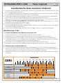 3
3
-
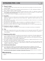 4
4
-
 5
5
-
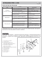 6
6
-
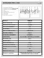 7
7
-
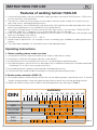 8
8
-
 9
9
-
 10
10
-
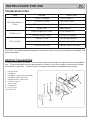 11
11
-
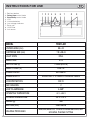 12
12
-
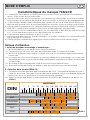 13
13
-
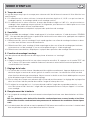 14
14
-
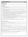 15
15
-
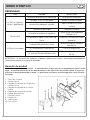 16
16
-
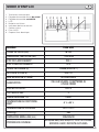 17
17
-
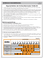 18
18
-
 19
19
-
 20
20
-
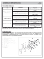 21
21
-
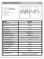 22
22
-
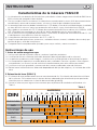 23
23
-
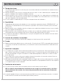 24
24
-
 25
25
-
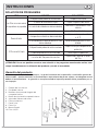 26
26
-
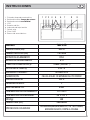 27
27
-
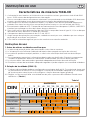 28
28
-
 29
29
-
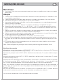 30
30
-
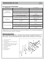 31
31
-
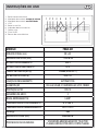 32
32
-
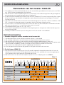 33
33
-
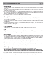 34
34
-
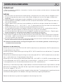 35
35
-
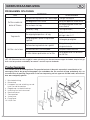 36
36
-
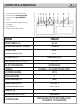 37
37
-
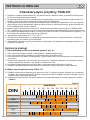 38
38
-
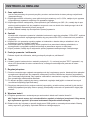 39
39
-
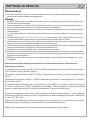 40
40
-
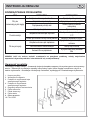 41
41
-
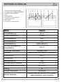 42
42
-
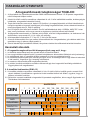 43
43
-
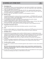 44
44
-
 45
45
-
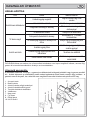 46
46
-
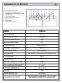 47
47
-
 48
48
-
 49
49
-
 50
50
-
 51
51
-
 52
52


in andere talen
- italiano: Beta 7042LCD Istruzioni per l'uso
- français: Beta 7042LCD Mode d'emploi
- español: Beta 7042LCD Instrucciones de operación
- Deutsch: Beta 7042LCD Bedienungsanleitung
- português: Beta 7042LCD Instruções de operação
- polski: Beta 7042LCD Instrukcja obsługi
Gerelateerde papieren
Andere documenten
-
Parkside PSHL 2 B1 Operation And Safety Notes Translation Of The Original Instructions
-
Ferm WEA1057 de handleiding
-
 JBM 53415 Gebruikershandleiding
-
Parkside PSHL 2 A2 Operation And Safety Notes Translation Of The Original Instructions
-
GYS LCD GYSMATIC 9-13 G HELMET de handleiding
-
GYS LCD PANORAMIC 3XL HELMET de handleiding
-
GYS LCD HERMES 9/13 G SILVER de handleiding
-
-
-
GYS LCD MASTER IRON 9-13 G WELDING HELMET de handleiding
