
MODE UNIT
ZERO
EN
Mini Coating Thickness Gauge
2-10
FR
Détecteur d’épaisseurs de peinture
11-19
DE
Lackschichtdicken-Messgerät
20-28
RU
Прибор для измерения толщины
покрытий
29-37
NL
Coating diktemeter
38-46
IT
Rilevatore di spessore della vernice
47-55
V3_29/03/2021
www.gys.fr

INTRODUCTION
This product is a portable coating thickness gauge, which
can quickly, nondestructively, and accurately measure
non-metallic coating thickness (such as paint, lm, etc.)
of metal substrate. It Is widely used in detection areas
like manufacturing industry, Car washing industry, metal
processing industry, chemical industry,and commodity ins-
pection.
FUNCTIONS
1. Measure coating thickness of metal substrate surface
2. Two modes: Car/User
3. Three measurement ways: single measurement, conti-
nuous measurement, dierence value measurement
4. Three calibration functions: zero calibration, two-point
calibration, and basic calibration
5. Metric unit and imperial unit
6. Auto power o
TECHNOLOGICAL PARAMETERS
Measurement range 0~1.80mm/0~71.0mil
Car mode resolution 0.05mm/2mil
User mode resolution 0.01mm/1mil
Measurement error ±0.1mm
Minimum diameter of
substrate
50mm
Minimum thickness
of substrate
0.5mm
Temperature range 18~30°C
Work humidity range 10~80%RH
Power 2*1.5V AAA batteries
2

LCD DISPLAY AND BUTTON FUNCTIONS
⑴
⑹
⑸
⑺
⑷
⑽
⑵
⑻
⑶
⑼
1- nFe : Not in use
2- SNG : Single measurement
3- CTN : Continuous measurement
4- DIF : Dierence value measurement
5- Display area of measured value
6- Power indicator
7- μm : Not in use
8- mil : Imperial unit (1mil = 0.0254mm)
9- C. : Enter into calibration state
10- mm : Metric unit (1mm = 39.4mil)
A
B
D
C
F
E
MODE UNIT
ZERO
A- LCD display
B-
Switch button of measurement
mode/increase button of calibration mode
C-
Switch button of measurement
unit/decrease button of calibration mode
D- Power button/zero calibration button
E- Measuring probe
F- Battery door
3

OPERATION INSTRUCTION
1. Turn on: Short press power button to turn on
the instrument. After LCD full-screen display, mode
information will show on the screen (indicator Car
appears under Car mode, no indicator appears under
User mode), then follows measurement interface.
2. Select mode: Long press MODE buttonunder
measurement interface to switch Car/User mode
3. Car mode: Car mode can be used without calibration,
which can measure coating thickness ofthree substrate
materials-iron, aluminum and zinc, suitable for measuring
the coating thickness of cars.
4. User mode: User mode requires calibration before
use, which can measure coating thickness ofsubstrate
material for calibration.
5. Auto power o: The instrument will power o
automatically in two mins of no measurement, or in ve
mins after measurement.
MEASUREMENT OF COATING THICKNESS
1. Press power button in the air to turn on the instrument,
after LCD full-screen display follows a BI sound,
which means that measurement state begins. Every
time of power on is regarded as single measurement.
2. Press the probe lightly on the coated metal substrate,
the instrument will let out two sounds of BI-BI, with
LCD showing the measured value of coating thickness.
3. Press MODE button to select measurement way.
There are three measurement ways to choose from:
ingle measurement, continuous measurement,
dierence value measurement.
4. Single measurement means one data each time.
Continuous measurement means as long as probe does
not leave suface of substrate, the instrument will keep
measuring. Dierence value measurement means the
dierence value between this time and last time of
measurement.
5. Press UNIT button to choose unit. There are metric
unit (mm) and imperial unit(mil) to choose from.
4

6. If you turn on the instrument on metal substrate,
ERR (error) will show after LCD full-screen display, then
the instrument will power o because of wrong start-
up way.
THREE CALIBRATION WAYS UNDER USER
MODE
1 - Basic calibration: if the instrument is in the rst
use or not in use for a long time, or substrate material
to be measured is changed, substrate calibration should
be taken. There are seven calibration points for basic
calibration, the unit during calibration is mm.
a : Prepare 6 standard calibration lms, the thickness
of which is 0.05, 0.10, 0.25, 0.50, 1.00, 2 mm, and the
unit is mm. At the same time, prepare the corresponding
metal substrate.If you need to measure thecoating
or lm thicknesson surface of zinc, use zinc block as
substrate.The same to iron and aluminum.
Attention: the diameter of substrate should be longer
than 50mm.iron substrate will be taken as an example
to illustrate the basic calibration process in the following
part:
Main unit Calibration film
5

b: Press MODE button to maintain, then press power
button, after LCD full-screen display follows a BI sound.
LCD screen shows 0.00, and the lower right part of
LCD shows indicator C. which means entering into
calibration interface :
c: The probe is lightly
pressed on iron
substrate without
coating on the
surface, then LCD
shows 0.00, followed
by two sounds of
BI-BI, which is 0.00
calibration.
d: Remove the probe, and LCD shows 0.05mm. Now
start the second calibration byputtingthe 0.05mm
calibration lm on the ironsubstrate and pressing the
probe lightly on the ironsubstrate. After two sounds of
BI-BI, the second Calibration point is nished.
0.05
mm
6

e: Remove the probe, the LCD shows the third data,
do calibration in turn according to the previous method.
Until the last calibration lm is calibrated, LCD displays
OVER, the instrument turns o after two sounds of BI-
BI, and the basic calibration is complete.
0.10
mm
0.25
mm
0.50
mm
1.00
mm
1- 2-
3- 4-
2.00
mm
5-
f: After basic calibration is completed, the coating
thickness of the same material as the calibrated
substrate can be measured.
7

2. Zero calibration: after turning on the instrument in the
air, choose User mode and then gently press the probe on
the surface of substrate. Short press ZERO button, LCD
displays 0.00, and zero calibration is completed.
3. Two-point calibration
a. First carry out zero calibration
b. Take a calibration lm (such as 1.00mm), measured
value of which is 1.05mm. Do not remove the probe,
pressingincrease or decrease buttonof calibration data,
until LCD displays 1.00mm. Remove the probe and two-
point calibration is completed.
OTHER ITEMS
Attention:
1. Factors inuence accuracy of measurement and related
instruction:
a. Metal thickness of substrate: Each instrument has a
critical thickness for a substrate metal. If the thickness
is greater than this value, the measurement will not
be aected by thickness of substrate metal. Refer to
requirementsonproduct specications for critical thickness
of the instrument (≥0.5mm).
b. Edge eect: The instrument is sensitive to the steep
change of the specimen’s surface shape. So it is unreliable
to make measurement near the edge or inner corner of the
object under measurement.
c. Curvature: The curvature of object under measurement
has inuence on the measurement. This inuence always
increases signicantly as the curvature radius decreases.
d. Surface roughness: Surface roughness of substrate
metal and coating has inuence on measurement.
As the degree of roughness increases, the inuence
increases. Rough surfaces can cause system errors and
accidental errors. In each measurement,users should
conduct moretimes of measurement at dierent places to
overcome this kind of accidental error. If substrate metal is
rough, users must take a few spots on uncoated substrate
metal with similar surface roughness to calibrate zero point
of the instrument; or dissolve and remove coating with a
solvent that does not corrode substrate metal, then
calibrate zero point.
e. Surface cleanliness: Before measurement, any attached
substances such as dust, grease and corrosive substances
8

on the surface should be removed, but do not remove any
coating material.
f. The instrument cannot distinguish iron substrate from
nonferrous substrate.
g. The instrument can only measure non-metallic coating.
NOTICE FOR USERS
1/ Since Car mode has built-in data, the user can no longer
conduct calibration. Car mode can directly measurecoating
thicknessof iron, aluminum, zinc substrate, suitable for
measuring thecoating thickness of cars.
2/ Under User mode, after calibrating metal substrate,
user can only measure coating thickness of this metal’s
surface, not other metals. For example, if you calibrate an
iron substrate, you cannot measure coating thickness of
aluminum substrate.
3/ User mode calibration will not inuence Car mode.
4/ Car mode is default factory setting.
5/ Default factory setting uses iron substrate to calibrate
User model.
6/ Calibrating under User model, diameter of substrate
should be≥50mm, substrate thickness should be≥0.5mm.
Specic Declarations:
Our company shall hold no any responisibility resulting
from using output from this product as an direct or
indirectevidence.
We reserves the right to modify product design and
specication without notice.
Device(s) compliant with European directives.
The certicate of compliance is available on
our website.
This hardware is subject to waste collec-
tion according to the European directives
2002/96/UE. Do not throw out in a domestic
bin !
9

WARRANTY
The warranty covers faulty workmanship for 2 years from
the date of purchase (parts and labour).
The warranty does not cover:
• Transit damage.
• Normal wear of parts (eg. : cables, clamps, etc..).
• Damages due to misuse (power supply error, dropping of
equipment, disassembling).
• Environment related failures (pollution, rust, dust).
In case of failure, return the unit to your distributor
together with:
- The proof of purchase (receipt etc ...)
- A description of the fault reported
10

INTRODUCTION
Ce produit est un détecteur portable d’épaisseur de pein-
ture, qui peut rapidement, de manière non destructive,
et précisément, mesurer l’épaisseur de revêtements non
métalliques (tels que peinture, lm, etc…) sur un substrat
métallique. Ce produit est largement utilisé dans l’indus-
trie manufacturière, le lavage de voitures, l’industrie de
traitement de métaux, l’industrie chimique et l’inspection
de marchandises.
FONCTIONS
1. Mesurer l’épaisseur de revêtements à la surface de
substrats métalliques.
2. Trois façons de mesurer : mesure simple, mesure conti-
nue, mesure d’une diérence d’épaisseur.
3. Trois fonctions de calibration : calibration zéro, calibra-
tion 2-points, et calibration basique.
4. Unités métriques et impériales.
5. Arrêt automatique du produit.
PARAMÈTRES TECHNOLOGIQUES
Plage de mesure 0~1.80mm/0~71.0mil
Résolution 0.05mm/2mil
Erreur de mesure ±0.1mm
Diamètre minimum de
substrat
50mm
Épaisseur minimum de
substrat
0.5mm
Plage de température 18~30°C
Plage d’humidité 10~80%RH
Alimentation 2*1.5V AAA (piles)
11

AFFICHEUR LCD ET BOUTONS DE FONC-
TIONS
⑴
⑹
⑸
⑺
⑷
⑽
⑵
⑻
⑶
⑼
1- nFe : non utilisé
2- SNG : mesure simple
3- CTN : mesure continue
4- DIF : mesure diérentielle
5- Aire d’achage de la valeur mesurée
6- Indicateur de puissance batterie
7- μm : non utilisé
8- mil : mesures impériales (1mil = 0.0254mm)
9- C. : entrée en mode calibration
10- mm : unités métriques (1mm = 39.4mil)
A
B
D
C
F
E
MODE UNIT
ZERO
A- écran LCD
B-
utilisé pour basculer entre les diérents
modes de mesure , ou pour incrémenter
les données en mode calibration.
C-
utilisé pour basculer entre les unités de
mesure, ou pour incrémenter les données
en mode calibration.
12

D- Bouton On/O, calibration point zéro.
E- Capteur
F- Capet logement piles
INSTRUCTIONS D’UTILISATION
1. Mise en route : Appuyez brièvement sur le bouton On/
O pour allumer l’instrument. L’écran LCD s’allume et les
informations sur le mode s’achent sur l’écran.
2. Sélection des modes : Appuyer longuement sur le
bouton MODE pour changer de mode.
3. Mode voiture : Le mode voiture peut être utilisé sans
calibrage. Il peut mesurer l’épaisseur de revêtement de trois
substrats : fer, aluminium et zinc.
4. Mode utilisateur : Le mode utilisateur nécessite un
étalonnage avant l’utilisation, ce qui permet de mesurer
l’épaisseur du revêtement du matériau de substrat pour
l’étalonnage.
5. Mise hors tension automatique : L’instrument s’éteint
automatiquement en deux minutes sans mesure ou en cinq
minutes après mesure.
MESURE DE L’ÉPAISSEUR DU REVÊTEMENT
1. Allumer le produit par un appui court sur le bouton
« Zéro ». Un BIP peut être entendu et l’écran ache
tous les champs un court instant. Le détecteur est
prêt à mesurer. A chaque allumage du produit, le
détecteur est en mode mesure simple (SNG), par défaut.
2. Placer le détecteur délicatement sur le revêtement d’un
substrat métallique sans revêtement. Le détecteur bipe
2 fois. L’acheur LCD ache la mesure d’épaisseur de
revêtement.
3. La touche MODE peut être pressée pour sélectionner un
mode diérent. Mesure simple, mesure continue, et mesure
diérentielle.
4. La mesure simple signie qu’une seule mesure est eectuée
à chaque mesure. En mode continu, le détecteur mesure en
continu l’épaisseur jusqu’à ce que le détecteur soit retiré de
la surface du substrat. En mesure diérentielle la diérence
entre la mesure en cours et la dernière mesure est achée.
13

5. Presser le bouton UNIT pour sélectionner la mesure en
mm ou en millième d’inch.
6. Si le détecteur est allumé alors qu’il est placé sur le
substrat métallique, alors l’acheur LCD achera le
message ERR et le détecteur s’éteindra automatiquement.
Cela signie que l’allumage du produit est incorrect.
CALIBRATION
1 - Calibration basique : à la 1ère utilisation, ou si
l’appareil n’a pas été utilisé depuis longtemps, ou si le
matériau substrat est diérent, une nouvelle calibration
devra être eectuée. Il y a 7 points de calibration pour la
calibration basique ; l’unité de mesure pour la calibration
est le mm.
a : préparer les 6 lms de calibration standard, dont
l’épaisseur est 0.05mm, 0.10mm, 0.25mm, 0.50mm,
1.00mm et 2.00mm. En même temps, préparer le substrat
correspondant. Si vous devez mesurer l’épaisseur de
revêtement sur un substrat en acier, utiliser le substrat
en acier. Si vous devez mesurer l’épaisseur de revêtement
sur un substrat en Aluminium, utiliser le substrat en
Aluminium.
Attention: le diamètre du substrat doit être plus long
que 50mm. Un substrat en acier sera pris en exemple
pour illustrer le procédé de base de calibration dans les
paragraphes suivants :
Unité principale Films de calibration
b: produit éteint, maintenir pressé le bouton MODE, tout
en pressant le bouton Power / Zéro. Le produit émet un
14

bip et ache 0.00. En bas à gauche de l’écran apparait
la lettre C, ce qui signie une entrée dans l’interface de
calibration :
c: Le détecteur doit
être légèrement
pressé sur le
substrat en acier
sans revêtement en
surface ; alors l’écran
ache 0.00, suivi de
2 sons BIP-BIP, ce
qui correspond à la
calibration 0.00.
d: Retirer le détecteur, et l’acheur ache 0.05mm.
Commencez maintenant la seconde calibration en posant
le lm de calibration 0.05mm sur le substrat métallique et
pressez légèrement le détecteur sur le substrat. Après 2
sons BIP-BIP, le second point de calibration est terminé.
0.05
mm
15

e: Retirer le détecteur, l’acheur indique la troisième
épaisseur à calibrer : 0.10mm. Eectuer la calibration,
en utilisant le lm avec l’épaisseur correspondante.
Recommencer ces opérations pour les épaisseurs 0.25mm,
0.50mm, 1.00mm, 2.00mm. Alors l’acheur LCD indique «
OVER », et le produit s’éteint après avoir émis 2 sons BIP-
BIP. La calibration basique est terminée.
0.10
mm
0.25
mm
0.50
mm
1.00
mm
1- 2-
3- 4-
2.00
mm
5-
16

f: Après que la calibration basique soit terminée, l’épaisseur
de revêtement sur le même type de substrat que le substrat
utilisé pour la calibration peut être mesurée.
2. Calibration zéro : après avoir allumé le produit en l’air,
choisir SNG, et poser délicatement le détecteur sur la surface
du substrat. Presser le bouton ZERO, l’acheur ache 0.00,
et la calibration zéro est eectuée.
3. Calibration 2 points :
a. eectuer d’abord une calibration zéro.
b. prendre un lm de calibration (tel que 1.00mm), pour
lequel la mesure est 1.05mm. Ne pas retirer le détecteur,
et appuyer sur les touches haut (Mode) et bas (Unit) pour
amener l’achage à 1.00mm. Retirer le détecteur et la
calibration 2 points est réalisée.
AUTRES CONSIDÉRATIONS
Attention:
1. Facteurs inuençant la précision de mesure et instructions
relatives :
a. Épaisseur du substrat métallique. Chaque instrument
a une épaisseur critique pour le substrat métallique. Si
l’épaisseur est plus grande que cette valeur, la mesure ne
sera pas aectée par l’épaisseur du substrat métallique. Se
référer aux exigences mentionnées dans les spécications du
produit pour cette épaisseur critique (> 0.5mm).
b. Eets de bord : l’instrument est sensible aux changements
prononcés de la forme de surface du substrat. Ainsi, le
détecteur est moins précis pour réaliser des mesures près
des bords ou coins intérieurs de l’objet à mesurer.
c. Courbure : la courbure de l’objet à mesurer a une inuence
sur la mesure. Cette inuence augmente toujours de manière
signicative lorsque le rayon décroit.
d. Surface rugueuse : la rugosité de la surface du substrat
et du revêtement a une inuence sur la mesure. Lorsque
la rugosité augmente, l’inuence augmente. Les surfaces
rugueuses peuvent causer des erreurs de mesure et des
erreurs accidentelles. A chaque mesure, l’utilisateur devra
eectuer plusieurs mesures à diérents endroits pour
s’aranchir de ce risque d’erreur. Si la surface du substrat
est rugueuse, l’utilisateur devra prendre plusieurs points de
mesure sur un substrat métallique sans revêtement avec une
surface de rugosité équivalente pour eectuer la calibration.
Ou dissoudre et enlever le revêtement avec un solvant qui
n’attaque pas le substrat métallique, et eectuer ensuite une
calibration à cet endroit.
17

e. Propreté de la surface : avant chaque mesure, toute
substance attachée, telle que de la poussière, de la graisse
et des substances corrosives en surface, doit être retirée,
mais le revêtement en lui-même ne doit pas être atteint.
f. Le détecteur ne peut pas faire la distinction entre un
substrat en acier ou en Aluminium.
g. le détecteur ne peut mesurer que les revêtements non
métalliques.
AVIS AUX UTILISATEURS
1/ Le mode «Voiture» a des données intégrées donc
l’utilisateur ne peut pas eectuer d’étalonnage dans ce
mode.
2/ En mode «Utilisateur», après avoir calibré le substrat
métallique, l’utilisateur ne peut mesurer que l’épaisseur
du revêtement de la surface de ce métal, et non d’autres
métaux. Par exemple, si vous étalonnez un substrat en fer,
vous ne pouvez pas mesurer l’épaisseur du revêtement du
substrat en aluminium.
3/ L’étalonnage du mode Utilisateur n’aura pas d’inuence
sur le mode Voiture.
4/ Le mode Voiture est réglé par défaut en usine.
5/ Le réglage d’usine par défaut utilise un substrat de fer
pour calibrer le modèle utilisateur.
6/ Calibrage sous le modèle utilisateur, le diamètre du
substrat doit être ≥50 mm, l’épaisseur du substrat doit
être ≥0.5mm.
Déclarations spéciques :
Notre société ne saurait être tenue responsable de
l’utilisation des résultats de mesure comme preuve directe
ou indirecte. Nous nous réservons le droit de modier
le design du produit, ainsi que ses spécications sans
information préalable.
Matériel conforme aux directives euro-
péennes. La déclaration UE de conformité est
disponible sur notre site.
Ce matériel fait l’objet d’une collecte sélective
selon la directive européenne 2012/19/UE. Ne
pas jeter dans une poubelle domestique !
18

GARANTIE
La garantie couvre tous défauts ou vices de fabrication
pendant 2 ans, à compter de la date d’achat (pièces et
main d’oeuvre).
La garantie ne couvre pas :
• Toutes autres avaries dues au transport.
• L’usure normale des pièces (Ex. : câbles, pinces, etc.).
• Les incidents dus à un mauvais usage (erreur
d’alimentation, chute, démontage).
• Les pannes liées à l’environnement (pollution, rouille,
poussière).
En cas de panne, retourner l’appareil à votre distributeur,
en y joignant :
- un justicatif d’achat daté (ticket de sortie de caisse,
facture….)
- une note explicative de la panne.
19

EINFÜHRUNG
Dieses Gerät ist ein tragbares Messgerät zur einfachen und
schnellen zerstörungsfreien Messung von unmagnetischen
Beschichtungen (Lackierung oder Folie) auf metallischen
Oberächen. Dieses Gerät wird z.B. in den Bereichen der
verarbeitenden Industrie, Autoreparatur, Metallbearbei-
tung, Chemieindustrie oder Warenuntersuchung angewen-
det.
FUNKTIONEN
1. Die Dicke von Beschichtungen auf metallischen Ober-
ächen messen.
2. Drei Messmodi: einfache Messung, kontinuierliche Mes-
sung, Dierenz-Messung.
3. Drei Kalibrierungsfunktionen: Nullkalibrierung, 2-Pu-
nkt-Kalibrierung, einfache Kalibrierung.
4. Metrische und imperiale Einheiten.
5. Das Gerät schaltet sich automatisch aus.
TECHNISCHE DATEN
Messbereich 0~1.80mm/0~71.0mil
Auösung 0.05mm/2mil
Messabweichung ±0.1mm
Minimaler Durchmesser
der Oberäche
50mm
Minimale Stärke der
Oberäche
0.5mm
Betriebstemperatur 18~30°C
Feuchtigkeitsbereich 10~80%RH
Spannungsversorgung 2*1.5V AAA (piles)
20

LCD-ANZEIGE UND TASTEN
⑴
⑹
⑸
⑺
⑷
⑽
⑵
⑻
⑶
⑼
1- nFe : nicht verwendet
2- SNG : einfache Messung
3- CTN : kontinuierliche Messung
4- DIF : Dierenz-Messung
5- Anzeige des gemessenen Wertes
6- Anzeige des Batteriezustandes
7- μm : nicht verwendet
8- mil : imperiale Einheiten (1mil = 0,0254mm)
9- C. : Kalibrierungsmodus
10- mm : metrische Einheiten (1mm = 39,4mil)
A
B
D
C
F
E
MODE UNIT
ZERO
A- LCD-Anzeige
B-
Wechsel zwischen den Messmodi, oder
um die Daten im Kalibrierungsmodus zu
ändern.
C-
Wechsel zwischen den Messmodi, oder
um die Daten im Kalibrierungsmodus zu
ändern.
D- Ein-/Aus-Taste, Nullpunkt für Kalibrierung.
21

E- Sensor
F- Deckel des Batteriefachs
ANWENDUNGSHINWEISE
1. Inbetriebnahme: Um das Gerät zu starten drücken
Sie die Ein-/Aus-Taste kurz. Die LCD-Anzeige leuchtet und
die Informationen über den Messmodus werden angezeigt.
2. Auswahl der Messmodi : drücken Sie die MODE-Taste
lang, um die Messmodus zu wechseln.
3. Fahrzeug-Modus: Dieser kann ohne Kalibrierung
benutzt werden. Er kann die Schichtdicke auf drei
Materialien messen: Eisen, Aluminium und Zink.
4. Anwender-Modus: Der Anwender-Modus benötigt
eine Kalibrierung vor der Anwendung.
5. Automatisches Ausschalten: Das Gerät schaltet
automatisch nach zwei Minuten ohne Messung oder nach
fünf Minuten nach einer Messung aus.
MESSUNG DER SCHICHTDICKE
1. Das Gerät mit kurzem Drücken der Ein-/Aus-Taste
starten. Das Gerät darf sich dabei nicht auf einer Oberäche
benden. Ein Tonsignal erklingt, und auf der LCD-Anzeige
werden alle Felder kurz angezeigt. Das Messgerät ist
betriebsbereit. Nach dem Einschalten ist per Voreinstellung
das Gerät im Modus «einfache Messung» (SNG).
2. Das Messgerät auf die Beschichtung einer metallischen
Oberäche setzen. Das Gerät piept zweimal. Auf der LCD-
Anzeige wird die Schichtdicke angezeigt.
3. Die MODE-Taste drücken, um den Modus zu wechseln.
Einfache Messung, kontinuierliche Messung, Dierenz-
Messung.
4. Im Modus «einfache Messung» wird nur eine Messung
ausgeführt. Im kontinuierlichen Modus wird die Schichtdicke
kontinuierlich gemessen und angezeigt, bis das Messgerät
von der Oberäche des Materials abgenommen wird. Bei
der Dierenz-Messung wird der Unterschied zwischen der
laufenden Messung und der letzten Messung angezeigt.
5. Die UNIT-Taste drücken, um die Messeinheit Millimeter
(mm) oder Tausendstel Zoll (mil) auszuwählen.
22

6. Wird das Messgerät eingeschaltet, während es sich
auf einer Oberäche bendet, so zeigt die LCD-Anzeige
die Fehlermeldung ERR an und das Gerät schaltet sich
automatisch aus. Das heißt, der Startvorgang kann nicht
erfolgen.
KALIBRIERUNG
1 - Einfache Kalibrierung : bei der ersten Anwendung,
wenn das Gerät längere Zeit nicht benutzt worden ist, oder
wenn die Dicke eines anderen Schichtmaterials gemessen
werden soll, muss das Gerät kalibriert werden. Sieben
Kalibrierungspunkte sind erforderlich für die einfache
Kalibrierung. Die Messeinheit für die Kalibrierung ist der
Millimeter.
a: Standardmäßige Kalibrierungsfolien mit folgender
Dicken vorbereiten: 0.05mm, 0.10mm, 0.25mm, 0.50mm,
1.00mm und 2.00mm. Bereiten Sie gleichzeitig eine
entsprechende Oberäche vor. Wollen Sie die Schichtdicke
auf Stahl messen, so verwenden Sie ein Stahlobjekt. Wollen
Sie die Schichtdicke auf Aluminium messen, so verwenden
Sie ein Aluminiumobjekt.
Achtung: der Durchmesser der Oberäche muss grösser
als 50 mm sein. Das Vorgehen bei einer Kalibrierung wird
beispielhaft anhand eines Stahlobjekts in der nächsten
Abschnitten vorgestellt :
Unité principale Films de calibration
b: Wenn das Gerät ausgeschaltet ist, halten Sie die MODE-
Taste gedrückt und drücken Sie die Taste «Zero» (dies ist
die Ein-/Aus-Taste). Das Gerät piept und zeigt 0.00 an. In
der LCD-Anzeige unten rechts erscheint der Buchstabe C,
d.h. das Gerät ist im Kalibrierungsmodus.
23

c: Das Gerät muss
nun auf die Oberäche
ohne Folie gesetzt
und dabei leicht
angedrückt werden.
Dann wird 0.00
angezeigt, und das
Gerät piept zweimal
BIP-BIP. Somit ist
die Kalibrierung 0.00
erfolgt.
d: Das Gerät von der Oberäche entfernen. Nun
wird 0.05mm angezeigt. Jetzt können Sie die zweite
Kalibrierung vornehmen, indem Sie die 0,05mm-Folie auf
die Oberäche legen und das Messgerät dabei leicht auf
der Folie andrücken. Nach zwei Tonsignalen ist der zweite
Kalibrierungspunkt registriert.
0.05
mm
e: Das Gerät entfernen, nun wird die dritte zu kalibrierende
Schichtdicke angezeigt: 0.10mm. Die Kalibrierung mit
der entsprechender Folie durchführen. Wiederholen Sie
24

diesen Vorgang mit den Dicken 0,25mm, 0,50mm, 1,00mm,
2,00mm. Dann wird « OVER » angezeigt, und das Gerät
schaltet nach zwei Tonsignalen BIP-BIP automatisch aus.
Die einfache Kalibrierung ist somit abgeschlossen.
0.10
mm
0.25
mm
0.50
mm
1.00
mm
1- 2-
3- 4-
2.00
mm
5-
f: Nachdem die einfache Kalibrierung erfolgt ist, können
Schichtdicken auf dem gleichen Material wie das für die
Kalibrierung verwendete gemessen werden.
2. Nullkalibrierung: halten Sie das Gerät frei in der Hand
25

(ohne es auf eine Oberäche aufzusetzen), schalten Sie
das Gerät ein, wählen Sie den SNG-Modus und drücken
Sie das Gerät leicht auf die Oberäche. Die ZERO-Taste
drücken. Es wird 0.00 angezeigt, und die Nullkalibrierung
ist erfolgt.
3. 2-Punkt-Kalibrierung
a. Führen Sie eine Nullkalibrierung durch.
b. eine Kalibrierungsfolie nehmen (z.B. 1,00mm). Das Gerät
nicht entfernen, und mit den Pfeiltasten oben (Mode) oder
unten (Unit) die Anzeige auf die Dicke der Kalibrierungsfolie
bringen. Das Gerät entfernen. Die 2-Punk-Kalibrierung ist
erfolgt.
WEITERE HINWEISE
Achtung:
1. Faktoren, die die Messgenauigkeit beeinussen können
und diesbezügliche Hinweise:
a. Stärke des metallischen Objekts. Jedes Messgerät hat
eine kritische Materialstärke für die metallische Oberäche.
Wenn die Stärke des Objekts grösser als dieser Wert ist,
dann wird die Stärke des Materials keine Auswirkung auf
die Messung haben. Beachten Sie das in den technischen
Daten genannte Kriterium zu der kritischen Stärke (>
0.5mm).
b. Randeekt : das Gerät ist empndlich auf die starken
Formänderungen in der Oberäche. Daher ist das Messgerät
für Messungen an Ränden oder in Ecken weniger genau.
c. Biegung : die Biegung des zu messenden
Werkstücks beeinusst die Messung. Je geringer der
Biegungshalbmesser, desto höher der Einuss.
d. Rauhe Oberäche: die Rauheit der Oberäche und
der Beschichtung beeinusst die Messung. Je höher die
Rauheit, desto höher der Einuss. Die rauhen Oberächen
können zu Messabweichungen oder Fehlern führen. Für
jede Messung soll der Anwender mehrere Messungen an
verschiedenen Stellen durchführen, so dass das Fehlerrisiko
vermindert wird. Wenn die Oberäche rauh ist, muss der
Anwender mehrere Messpunkte auf einer metallischen
Oberäche ohne Beschichtung mit gleich rauher Oberäche
aufnehmen, um das Gerät zu kalibrieren. Alternativ
können Sie die Beschichtung an einer Stelle mit einem
Lösungsmittel entfernen, das das Metall nicht angreift, und
an dieser Stelle die Kalibrierung durchführen.
e. Sauberkeit der Oberäche: vor jeder Messung müssen
26

alle Stoe auf der Oberäche wie Staub, Fett oder
Ätzmittel entfernt werden, aber die Beschichtung darf nicht
angegrien werden.
f. Das Messgerät kann nicht zwischen Stahl- und
Aluminiumoberäche unterscheiden.
g. Das Messgerät kann nur die Dicke von nichtmetallischen
Beschichtungen messen.
HINWEISE
1/ Der Fahrzeug-Modus enthält vordenierte Daten. Der
Anwender kann daher keine Kalibrierung durchführen in
diesem Modus.
2/ Im Anwender-Modus kann nur die Dicke der Beschichtung
auf einem Objekt gemessen werden, das aus demselben
Metall besteht wie das, mit dem kalibriert wurde. Wenn
Sie z.B. das Gerät mit Stahl kalibrieren, so können Sie mit
dem Gerät nicht Beschichtungen auf anderen metallischen
Objekten messen.
3/ Die Kalibrierung im Anwender-Modus hat keine
Auswirkung auf den Fahrzeug-Modus.
4/ Der Fahrzeug-Modus ist durch Werkseinstellungen
bestimmt.
5/ Die standardmäßige Kalibrierung für den Anwender-
Modus ist mit einem Stahlobjekt durchgeführt worden.
6/ Für die Kalibrierung im Anwender-Modus müssen der
Durchmesser der Objekts ≥50 mm und die Stärke des
Objekts ≥0.5mm sein.
Spezische Erklärungen:
GYS kann nicht für die Nutzung der Messergebnisse als
direkter oder indirekter Beweis haftbar gemacht werden.
Produktänderungen, auch ohne vorherige Ankündigung,
vorbehalten.
Gerät entspricht europäischen Richtlinien. Die
Konformitätserklärung nden Sie auf unserer
Webseite.
Für die Entsorgung Ihres Gerätes gelten be-
sondere Bestimmungen gemäß europäischer
Richtlinie 2012/19/EU. Es darf nicht mit dem
Hausmüll entsorgt werden!
27

GARANTIE
Die Garantieleistung des Herstellers erfolgt ausschließlich
bei Fabrikations- oder Materialfehlern, die binnen 24
Monate nach Kauf angezeigt werden (Nachweis Kaufbeleg).
Die Garantieleistung erfolgt nicht bei:
• Durch Transport verursachten Beschädigungen.
• Normalem Verschleiß der Teile (z.B. : Kabel, Klemmen,
usw.) sowie Gebrauchsspuren.
• Von unsachgemäßem Gebrauch verursachten Defekten
(Sturz, harte Stöße, Demontage).
• Durch Umwelteinüsse entstandene Defekte
(Verschmutzung, Rost, Staub).
Die Reparatur erfolgt erst nach Erhalt einer schriftlichen
Akzeptanz (Unterschrift) des zuvor vorgelegten
Kostenvoranschlages durch den Besteller. Im Fall einer
Garantieleistung trägt GYS ausschließlich die Kosten für
den Rückversand an den Fachhändler.
- une note explicative de la panne.
28

ВВЕДЕНИЕ
Этот прибор для измерения толщины покрытий может
быстро и точно неразрушающим методом измерить
толщину неметаллических покрытий (краска, пленка и
т.д.), нанесенных на металлическую поверхность (далее
- субстрат). Он широко применяется на производствах,
на автомойках, в металлообрабатывающей, химической
промышленности и при товарном контроле.
ФУНКЦИИ
1. Измерение толщины покрытия на металлических
субстратах.
2. Доступны режимы: единичное измерение,
продолжительное измерение и дифференциальное
измерение.
3. Три вида калибровки: калибровка по нулевой точке,
калибровка по двум точкам и базовая калибровка.
4. Метрические и дюймовые режимы отображения.
5. Автоматическое отключение.
ТЕХНИЧЕСКИЕ ПАРАМЕТРЫ
Диапазон измерения 0~1.80mm/0~71.0mil
Разрешение 0.05mm/2mil
Ошибка измерения ±0.1mm
Минимальный диаметр
субстрата
50mm
Минимальная толщина
субстрата
0.5mm
Температурный
диапазон
18~30°C
Диапазон влажности 10~80%RH
Питание 2*1.5V AAA батареи
29

ЖИДКОКРИСТАЛЛИЧЕСКИЙ ЭКРАН И
КНОПКИ УПРАВЛЕНИЯ
⑴
⑹
⑸
⑺
⑷
⑽
⑵
⑻
⑶
⑼
1- nFe: не используется
2- SNG: единичное измерение
3- CTN: продолжительное измерение
4- DIF: дифференциальное измерение
5- Индикатор значения измеренной величины
6- Indicateur de puissance batterie
7- μm: не используется
8-
mil: дюймовая единица измерения (1 mil =
0.0254 мм)
9- C. : статус "в режиме калибровки"
10-
mm: метрическая единица измерения (1 мм =
39.4 mil)
A
B
D
C
F
E
MODE UNIT
ZERO
A- Жидкокристаллический экран
B-
используется для переключения
между режимами измерения или для
инкрементации значений во время
калибровки
30

C-
используется для переключения
между режимами измерения или для
инкрементации значений во время
калибровки
D-
Кнопка ВКЛ/ВЫКЛ, калибровка по
нулевой точке
E- Датчик
F- Батарейный отсек
ИНСТРУКЦИИ ПО ИСПОЛЬЗОВАНИЮ
1. Запуск: Коротко нажмите на кнопку ВЛК/ВЫКЛ,
чтобы включить прибор. Включается ЖК-дисплей и
на экране появляется информация об используемом
режиме.
2. Выбор режима: Долгое нажатие на кнопку MODE
позволяет поменять режим.
3. Автомобильный режим: может использоваться
без калибровки. Он может измерить толщину
покрытия трех поверхностей: железной, алюминиевой
и цинковой.
4. Пользовательский режим: Перед
использованием этот режим требует калибровки, что
позволяет измерить толщину покрытия субстрата для
калибровки.
5. Автоматическое отключение: Прибор
автоматически отключается за 2 минуты, если
измерения не происходит, или за 5 минут после
измерения.
ИЗМЕРЕНИЕ ТОЛЩИНЫ ПОКРЫТИЯ
1. Включите прибор коротким нажатием на кнопку
« Zero ». Раздается звуковой сигнал и на экране в
течение короткого времени появляются все поля.
Прибор готов к работе. При каждом включении
прибор по умолчанию открывает в режим единичного
измерения (SNG).
2. Аккуратно приставьте измеритель к покрытию
металлического субстрата. Прозвучит двойной
звуковой сигнал. ЖК-дисплее отобразит измеренную
толщину покрытия.
31

3. Нажмите на кнопку MODE для выбора другого
режима. Для выбора доступны: единичное измерение,
продолжительное измерение и дифференциальное
измерение.
4. Единичное измерение означает, что при каждом
измерении производится один замер. В режиме
продолжительного измерения прибор будет измерять
толщину покрытия, пока он не будет отдален от
поверхности. В режиме дифференциального измерения
на дисплей будет выводиться разница между текущим
измерением и предыдущим.
5. Нажмите на кнопку UNIT, чтобы перейти от
измерения в мм к mil (одна тысячная дюйма).
6. Если прибор включается, когда его прижимают к
металлической поверхности, то на дисплее появится
сообщение ERR и прибор автоматически отключится.
Это означает, что толщинометр использован
неправильно.
ПРОЦЕДУРА КАЛИБРОВКА
1 - Базовая калибровка: она требуется при первом
использовании, если прибор не эксплуатировался
длительное время или при использовании другого
материала субстрата. Для базовой калибровки
существует 7 точек. Единица измерения для
калибровки - миллиметр.
a : подготовьте 6 стандартных пластинок толщиной
0.05 мм, 0.10 мм, 0.25 мм, 0.50 мм, 1.00 мм и 2.00 мм.
Также подготовьте соответствующий субстрат. Если
нужно измерить толщину покрытия на субстрате из
стали, то используйте стальную пластинку. Если нужно
измерить толщину покрытия на субстрате из алюминия,
то используйте алюминиевую пластинку.
Внимание: диаметр субстрата должен быть больше 50
мм. Рассмотрим типовой метод калибровки на примере
стального субстрата:
32

Прибор Защитные пленки
b: при выключенном приборе нажмите и удерживайте
кнопку MODE. Вместе с ней нажмите на кнопку Power
/ Zéro. Раздастся единичный звуковой сигнал и экран
покажет 0.00. В левом нижнем углу появится буква
C, означающая, что прибор находится в режиме
калибровки:
c: Аккуратно
приставьте
измеритель к
стальному субстрату
без какого-либо
покрытия. Прибор
покажет 0.00 и
прозвучит двойной
звуковой сигнал.
Калибровка по 0.00
выполнена.
d: Уберите измеритель от субстрата. Экран покажет
0.05 мм. Приступите к следующей калибровке.
Положите калибровочную пластину толщиной 0.05
мм на металлический субстрат и слегка прижмите
прибор к субстрату. После двойного звукового сигнала
калибровка выполнена.
33

0.05
mm
e: Уберите измеритель от субстрата. Экран покажет
следующую толщину 0.10 мм. Проведите калибровку,
используя пластинку соответствующей толщины.
Повторите эту операцию для толщин 0.25 мм, 0.50 мм,
1.00 мм, 2.00 мм. После всех калибровок на дисплее
появится надпись « OVER » и прибор издаст двойной
звуковой сигнал и автоматически выключится. Базовая
калибровка выполнена.
0.10
mm
0.25
mm
0.50
mm
1.00
mm
1- 2-
3- 4-
34

2.00
mm
5-
f: После завершения процесса базовой калибровки
прибор может быть использован для измерения
толщины покрытия, нанесенного на такой же металл,
из которого изготовлен калибровочный субстрат.
2. Калибровка по нулевой точке: включите прибор,
держа его на весу, выберите SNG и аккуратно
приложите прибор к поверхности субстрата. Нажмите
на кнопку ZERO, на дисплее появится 0.00. Калибровка
по нулевой точке выполнена.
3. Калибровка по двум точкам:
a. выполните сначала калибровку по нулевой точке.
b. возьмите калибровочную пластину (например, 1.00
мм), измерение которой равно 1.05 мм. Не убирайте
толщиномер и нажмите на верхнюю кнопку (Mode) и
нижнюю кнопку (Unit), пока дисплей не покажет 1.00
мм. Уберите измеритель. Калибровка по двум точкам
выполнена.
ДРУГИЕ РЕКОМЕНДАЦИИ
Внимание:
1. Факторы, влияющие на точность измерений, и
соответствующие рекомендации:
a. Толщина металлического субстрата. Каждый
инструмент имеет критическую толщину для
металлического субстрата. Если толщина больше этого
значения, то толщина металлического субстрата не
повлияет на измерение. См. требования, изложенные
в спецификации изделия для данной критической
толщины (> 0.5 мм).
b. Эффект грани: измеритель чувствителен к резкому
изменению формы поверхности субстрата. Поэтому
измерения возле грани или во внутренних углах
35

не такие точные. Кривизна: кривизна измеряемой
поверхности влияет на результаты измерений. Этот
эффект возрастает с уменьшением радиуса кривизны.
d. Шероховатость поверхности: шероховатость обеих
поверхностей (и металлического субстрата и покрытия)
влияет на результаты измерений Этот эффект
увеличивается пропорционально шероховатости
поверхностей. Излишняя шероховатость поверхности
ведет к системным и случайным ошибкам. Поэтому
необходимо производить несколько замеров в разных
точках одной области, чтобы избежать влияния
этого фактора. Если металл субстрата шероховатый,
рекомендуется произвести нулевую калибровку в
нескольких точках без покрытия и с одинаковой
шероховатостью. В случае необходимости, снять слой
покрытия растворителем, которые не агрессивен к
металлическому субстрату, и затем выполнить в этом
месте калибровку.
e. Чистота поверхности: перед произведением
измерений рекомендуется очистить измеряемую
поверхность от инородных субстанций (пыль, смазка,
ржавчина), но само покрытие должно остаться
нетронутым.
f. Измерительный прибор не отличает стальной
субстрат от алюминиевого.
g. Он может измерять только не металлические
покрытия.
ИНФОРМАЦИЯ ДЛЯ ПОЛЬЗОВАТЕЛЯ
1/ «Автомобильный» режим имеет встроенные данные
и пользователь не может выполнять калибровку в этом
режиме.
2/ В «Пользовательском» режиме после выполнения
калибровки металлического субстрата пользователь
может измерить толщину покрытия только этого
металла, но не других металлов. Например, если вы
выполняете калибровку железного субстрата, то вы не
сможете измерить толщину покрытия алюминиевого
субстрата.
3/ Калибровка в Пользовательском режиме не повлияет
на Автомобильный режим.
4/ Автомобильный режим по умолчанию настроен на
заводе-производителе.
36

5/ Заводская настройка по умолчанию выполнена
на основе железного субстрата для калибровки
пользовательской модели.
6/ При калибровке в Пользовательской модели диаметр
субстрата должен быть ≥50 мм и толщина субстрата
должна быть ≥0.5 мм.
Заявление изготовителя:
Наша компания не несет ответственность за
использование результатов измерений в качестве
прямых или косвенных доказательств. Мы оставляем
за собой право изменять дизайн прибора, а также его
технических характеристик без предупреждения.
Устройство соответствует директивам
Евросоюза. Декларация UE о соответствии
доступна для просмотра на нашем сайте.
Это оборудование подлежит переработке
согласно директиве Евросоюза 2012/19/UE.
Не выбрасывать в общий мусоросборник!
ГАРАНТИЯ
Гарантия распространяется на любой заводской дефект
или брак в течение 2х лет с даты покупки изделия
(запчасти и рабочая сила).
Гарантия не распространяется на:
• Любые поломки, вызванные транспортировкой.
• Нормальный износ деталей (Например : кабели,
зажимы и т.д.).
• Случаи неправильного использования (ошибка
питания, падение, разборка).
• Случаи выхода из строя из-за окружающей среды
(загрязнение воздуха, коррозия, пыль).
При выходе из строя, обратитесь в пункт покупки
аппарата с предъявлением следующих документов:
- документ, подтверждающий покупку (с датой):
кассовый чек, инвойс....
- описание поломки.
37

INTRODUCTIE
Dit apparaat is een draagbare coating dikte-meter, die snel
en zonder schade aan te richten zeer precies de dikte van
niet-metalen coatings (zoals verf, folie enz.) op een metalen
substraat kan meten. Dit apparaat wordt veel gebruikt bij
industriële processen, het wassen van auto’s, in de metaal-
verwerkende industrie, de chemische industrie en bij de
inspectie van goederen.
FUNCTIES
1. Het meten van de dikte van coatings op metalen subs-
traten.
2. Drie verschillende meet-modules : eenvoudige meting,
continue meting, en dierentiële meting.
3. Drie ijk-functies: zero ijken, 2-punts ijken en basis-ijken.
4. Metrische en Britse eenheden.
5. Automatisch uitschakelen van het apparaat.
TECHNOLOGISCHE INSTELLINGEN
Meetbereik 0~1.80mm/0~71.0mil
Resolutie 0.05mm/2mil
Meetfout ±0.1mm
Minimum diameter van
het substraat
50mm
Minimum dikte van het
substraat
0.5mm
Temperatuurbereik 18~30°C
Vochtigheidsbereik 10~80%RH
Voeding 2*1,5V AAA-batterijen
38

LCD SCHERM EN FUNCTIEKNOPPEN
⑴
⑹
⑸
⑺
⑷
⑽
⑵
⑻
⑶
⑼
1- nFe : niet in gebruik
2- SNG : eenvoudige meting
3- CTN : continue meting
4- DIF : dierentiële meting
5- Toont de gemeten waarde
6- Toont de staat van de batterij
7- μm : niet in gebruik
8- mil : Britse eenheden (1mil = 0.0254mm)
9- C. : ingang in de ijk-module
10- mm : metrische eenheden (1mm = 39.4mil)
A
B
D
C
F
E
MODE UNIT
ZERO
A- LCD scherm
B-
gebruikt om tussen de verschillende
meet-modules te navigeren, of om de
gegevens in de ijk-module te verhogen.
C-
gebruikt om tussen de verschillende
meet-modules te navigeren, of om de
gegevens in de ijk-module te verhogen.
D- On/O knop, ijkpunt nul.
E- Sensor
F- Klepje batterij-houder
39

GEBRUIKSINSTRUCTIES
1. In werking stellen : Druk kort op de On/O knop om
het apparaat in werking te stellen. Het LCD-scherm gaat
aan en de informatie over de module wordt op het scherm
getoond.
2. Keuze van de modules : Druk iets langer op de
MODULE-knop om naar een andere module te gaan.
3. Module auto : De auto-module kan worden gebruikt
zonder te ijken. Deze kan de dikte van coatings op drie
verschillende ondergronden meten : ijzer, aluminium en
zink.
4. Gebruikersmodule : Voor de gebruikersmodule is voor
gebruik een ijking nodig. Zo kan de dikte van de coating van
het metalen substraat gemeten worden.
5. Automatische buitenwerkingstelling : Het apparaat
schakelt zichzelf na twee minuten automatisch uit zonder
meting, of na vijf minuten na een meting.
HET METEN VAN DE DIKTE VAN EEN COATING
1. Schakel het apparaat aan door een korte druk op de
« Zero ».knop. Het apparaat laat een PIEP horen en het
scherm toont een kort moment alle velden. De detector
is klaar om te meten. Iedere keer wanneer het apparaat
aangeschakeld wordt staat de detector automatisch in de
module eenvoudig meten (SNG).
2. Plaats de detector voorzichtig op de coating van een
metalen substraat. De detector geeft twee keer een piep te
horen. Het LCD scherm toont de gemeten dikte.
3. De gebruiker kan op de MODULE-knop drukken om een
andere module te kiezen. Eenvoudige meting, continue
meting, en dierentiële meting.
4. De eenvoudige meting betekent dat er één enkele meting
wordt verricht. Bij een continue meting meet de detector
continu de dikte totdat de detector van het oppervlakte
teruggetrokken wordt. Bij het dierentieel meten wordt het
verschil tussen de huidige meting en de laatst uitgevoerde
meting getoond.
5. Druk op de knop UNIT om te kiezen tussen mm of
duizendste inch.
40

6. Als de detector wordt aangeschakeld wanneer deze op
de metalen substraat is geplaatst, zal het LCD scherm ERR
aangeven en zal de detector zich automatisch uitschakelen.
Dit betekent dat het aanzetten van het apparaat niet correct
is verlopen.
IJKEN
1 - Basis ijken : bij het eerste gebruik, of wanneer een
apparaat langere tijd niet gebruikt is, of als het substraat
niet van dezelfde materie is als bij het laatste gebruik, moet
er opnieuw geijkt worden. Er zijn 7 ijkpunten voor de basis-
ijking ; de meet-eenheid voor het ijken is de mm.
a : bereid de 6 ijkfolies voor, met de diktes 0.05mm,
0.10mm, 0.25mm, 0.50mm, 1.00mm en 2.00mm. Bereid
tevens het substraat voor. Als u de dikte van een coating
op een stalen substraat wilt gaan meten, moet u deze ijk-
procedure uitvoeren op een stalen substraat. Als u de dikte
van een coating op een aluminium substraat gaat meten,
gebruik dan een aluminium substraat.
Waarschuwing : de diameter van het substraat moet
langer zijn dan 50mm. In de volgende paragrafen zal
een stalen substraat als voorbeeld dienen om de basis-
procedure voor het ijken te tonen :
Hoofd-unit Beschermende folie
b: apparaat staat uit, houd de MODULE-knop ingedrukt, en
druk tegelijkertijd op de knop Power / Zero. Het apparaat
laat een pieptoon horen en toont 0.00. Linksonder op het
scherm verschijnt de letter C, dit geeft het opstarten van
de ijkprocedure aan :
41

c: De detector
moet lichtjes op
het stalen substraat
zonder coating
worden gedrukt :
het scherm toont
0.00, gevolgd door 2
PIEP-PIEP tonen, wat
overeenkomt met de
ijking 0.00.
d: Trek de detector terug, het display toont 0.05mm.
Start nu de tweede ijking door het ijk-folie 0.05mm op het
metalen substraat te leggen, en druk lichtjes de detector
op het substraat. Na 2 PIEP-PIEP tonen is het tweede
ijkpunt voltooid.
0.05
mm
e: Trek de detector terug, het display geeft de derde te
ijken dikte aan : 0.10mm. Voer de ijking uit, door het
folie met de overeenkomstige dikte te gebruiken. Voer de
42

ijkingen ook uit voor de diktes 0.25mm, 0.50mm, 1.00mm,
2.00mm. Het LCD scherm toont « OVER », en het apparaat
schakelt zichzelf uit na 2 PIEP-PIEP tonen. Het basis-ijken
is voltooid.
0.10
mm
0.25
mm
0.50
mm
1.00
mm
1- 2-
3- 4-
2.00
mm
5-
f: Nadat het basis-ijken is voltooid, kan de dikte van de
coating op hetzelfde type substraat als dat gebruikt is
tijdens de basis-ijking gemeten worden.
43

2. IJking zero : nadat de gebruiker het apparaat heeft
ingeschakeld, kies SNG, en plaats voorzichtig de detector
op het oppervlak van het substraat. Druk op de knop ZERO,
het display toont 0.00, en de ijking zero wordt getoond.
3. Tweepunts ijking :
a. voer eerst een ijking zero uit.
b. neem een ijk-folie (bijvoorbeeld 1.00mm), waarvoor de
meting 1.05mm. is. Trek de detector niet terug, en druk
op de toetsen omhoog (Module) en omlaag (Unit) om
het getoonde naar 1.00mm. te brengen. Trek de detector
terug, de tweepunts ijking is gerealiseerd.
OVERIGE OPMERKINGEN
Waarschuwing:
1. Factoren die de nauwkeurigheid van de meting kunnen
beïnvloeden en overige instructies : Dikte van het metalen
substraat. Ieder apparaat heeft een kritische dikte voor het
metalen substraat. Als de dikte groter is dan deze waarde,
zal de meting niet beïnvloed worden door de dikte van
het metalen substraat. Zie de eisen zoals vermeld in de
specicaties van het apparaat voor deze kritieke dikte (>
0.5mm).
b. Randeecten : het apparaat is gevoelig voor grotere
veranderingen van de vorm van het oppervlak van het
substraat. De detector is dan minder nauwkeurig wanneer
er dichtbij de randen of in de binnenhoeken van het te meten
voorwerp gemeten moet worden. Kromming : de kromming
van het te meten voorwerp beïnvloedt de resultaten
van de meting. Deze invloed wordt aanmerkelijk groter
naarmate de straal afneemt. Ruw oppervlak : de ruwheid
van het oppervlak van een substraat en van de coating
heeft invloed op de meting. Hoe ruwer het oppervlak, hoe
groter de invloed. Ruwe oppervlaktes kunnen foutieve
meetresultaten geven Bij iedere meting moet de gebruiker
meerdere metingen op verschillende plaatsen uitvoeren,
om zo het risico op foutieve meetresultaten te verkleinen.
Als het oppervlak van een substraat ruw is, moet de
gebruiker verschillende meetpunten op een metalen
substraat zonder coating met een gelijkwaardige ruwheid
meten om de ijking uit te voeren. De gebruiker kan ook
de coating oplossen en verwijderen met een oplosmiddel
dat het metalen substraat niet aantast, en vervolgens een
ijking op deze plek uitvoeren. Voor iedere meting moet de
44

gebruiker er voor zorgen dat stof, vet, roest en bijtende
stoen verwijderd zijn. Het oppervlakte zelf mag echter
niet aangetast worden. De detector kan geen onderscheid
maken tussen een stalen of een aluminium substraat.
g. de detector kan enkel niet-metalen coatings meten.
WAARSCHUWING VOOR DE GEBRUIKERS :
1/ De module «Auto» heeft geïntegreerde gegevens, de
gebruiker kan dus geen ijking uitvoeren in deze module.
2/ In de module «Gebruiker», kan de gebruiker, na het
metalen substraat geijkt te hebben, alleen de dikte van de
coating op het oppervlak van dit metaal meten, en niet de
oppervlaktes van andere metaalsoorten. Bij voorbeeld : als
u een substraat op ijzer ijkt, kunt u niet de dikte van de
coating van een substraat in aluminium meten.
3/ Het ijken van de module Gebruiker zal geen invloed
hebben op de module Auto.
4/ De module Auto wordt standaard ingesteld in de fabriek.
5/ De fabrieksinstelling gebruikt een ijzeren substraat voor
het ijken van het gebruikersmodel.
6/ IJken onder het gebruikersmodel ; de diameter van het
substraat moet ≥50 mm. zijn, de dikte van het substraat
moet ≥0.5mm.zijn.
Specieke verklaringen :
Ons bedrijf kan niet aansprakelijk worden gehouden voor
het gebruik van de meetresultaten als direct of indirect
bewijsmateriaal. Wij behouden ons het recht voor om het
ontwerp en/of de specicaties van het apparaat zonder
voorafgaande kennisgeving te wijzigen.
Deze apparatuur voldoet aan de eisen van
de Europese regelgeving. De EU verklaring
van overeenstemming kunt u vinden op onze
website.
Gescheiden inzamelen, volgens de Europese
richtlijn 212/19/UE. Niet weggooien met het
huishoudelijk afval !
45

GARANTIE
De garantie dekt alle gebreken en fabricagefouten
gedurende twee jaar vanaf de aankoopdatum (onderdelen
en arbeidsloon).
De garantie dekt niet :
• Alle overige schade als gevolg van vervoer.
• De gebruikelijke slijtage van onderdelen (Bijvoorbeeld :
kabels, klemmen, enz.).
• Incidenten als gevolg van verkeerd gebruik (verkeerde
elektrische voeding, vallen, ontmanteling).
• Gebreken ten gevolge van de gebruiksomgeving
(vervuiling, roest, stof).
In geval van storing moet het apparaat teruggestuurd
worden naar uw distributeur, samen met:
- Een gedateerd aankoopbewijs (betaalbewijs, factuur ...).
- Een beschrijving van de storing.
46

47
INTRODUZIONE
Questo prodotto è un rilevatore di spessore della vernice
che può rapidamente, in modo preciso e non distruttivo,
misurare lo spessore del rivestimento non metallico (come
vernice, lm, ecc....) su un substrato metallico. Questo pro-
dotto è largamente utilizzato nell’industria manifatturiera,
nel lavaggio delle automobili, nell’industria di lavorazione dei
metalli, nell’industria chimica e per l’ispezione delle merci.
FUNZIONI
1. Misurare lo spessore di rivestimenti sulla supercie di
substrati metallici.
2. Tre modi di misurazione : misurazione semplice, misura-
zione continua, misurazione di una dierenza di spessore.
3. Tre funzioni di calibratura : calibratura zero, calibratura
2-punti, e calibratura di base.
4. Unità metriche e imperiali.
5. Stop automatico del prodotto.
PARAMETRI TECNOLOGICI
Intervallo di misurazione 0~1.80mm/0~71.0mil
Risoluzione 0.05mm/2mil
Errore di misurazione ±0.1mm
Diametro minimo di
substrato
50mm
Spessore minimo di
substrato
0.5mm
Intervallo di temperatura 18~30°C
Intervallo d'umidità 10~80%RH
Alimentazione 2*1,5V batterie AAA

SCHERMO LCD E PULSANTE DELLE FUNZIONI
⑴
⑹
⑸
⑺
⑷
⑽
⑵
⑻
⑶
⑼
1- nFe : non utilizzato
2- SNG : misurazioni semplice
3- CTN : misura continua
4- DIF : misura dierenziale
5- Area di visualizzazione del valore misurato
6- Indicatore di potenza della batteria
7- μm: non utilizzato
8- mil: misure imperiali (1mil = 0.0254mm)
9- C. : entrata in modalità calibrazione
10- mm: unità metriche (1mm=39.4mil)
A
B
D
C
F
E
MODE UNIT
ZERO
A- schermo LCD
B-
usato per passare tra le diverse modalità
di misurazione o per incrementare i dati in
modalità calibrazione.
C-
usato per passare tra le diverse modalità
di misurazione o per incrementare i dati in
modalità calibrazione.
D- Pulsante On/O, calibrazione punto zero.
48

E- Sensore
F- Vano batteria
ISTRUZIONI D’USO
1. Avviamento: Premere brevemente sul pulsante ON/
OFF per accendere lo strumento. Lo schermo LCD si
accende e vi appaiono le informazioni sulla modalità.
2. Selezione delle modalità: Premere a lungo sul
pulsante MODE per cambiare la modalità.
3. Modalità macchina: la modalità macchina può essere
utilizzato senza calibratura. Può misurare lo spessore del
rivesimento di tre substrati: ferro, allumini e zinco.
4. Modalità utilizzatore: La modalità necessita di una
calibratura prima dell’utilizzo, questo permette di misurare
lo spessore del rivestimento del materiale del substrato per
la calibratura.
5. Spegnimento automatico: Lo strumento si spegne
automaticamente in due minuti senza aver eettuato una
misurazione o cinque minuti dopo la misurazione.
MISURAZIONE DELLO SPESSORE DEL RIVES-
TIMENTO
1. Accendere il prodotto con una breve pressione sul
pulsante « Zero ». Si avvertirà un BIP e lo schermo
visualizzerà tutti i campi in un breve istante. Il rilevatore è
pronto per eettuare le misurazioni. A ciascuna accensione
del prodotto il rilevatore è preimpostato in modalità
semplice (SNG).
2. Posizionare il rilevatore delicatamente sul rivestimento
di un substrato metallico senza rivestimento. Il rilevatore
suona due volte. Lo schermo LCD visualizza la misura dello
spessore del rivestimento.
3. Il tasto MODE può essere premuto per selezionare
una modalità diversa. Misura semplice, misura continua e
misura dierenzialef
4. La misura semplice signica che viene eettuata una
sola misurazione a ciascuna misura. In modalità continua,
il rilevatore misura in continuo lo spessore no a che il
49

rilevatore non viene rimosso dalla superice del substrato.
In misura dierenziale viene visualizzata la dierenza tra la
misura in corso e l’ultima eseguita.
5. Premere il tasto UNIT per selezionare la misura in mm o
in millesimi di pollice
6. Se il rilevatore è acceso quando viene posizionato sul
substrato metallico, lo schermo visualizzerà il messaggio
ERR e il rilevatore si spegnerà automaticamente. Ciò
signica che l’accesione del prodotto non è corretta.
CALIBRATURA
1 - Calibratura di base: al primo utilizzo, o se
l’apparecchio non è stato utilizzato da molto tempo, o se
il materiale di substrato è diverso, dovrà essere eettuata
una nuova calibratura. Ci sono 7 punti di calibratura per
la calibratura di base; l’unità di misura per la calibratura
è il mm.
a : preparare le 6 pellicole di calibratura standard dove
lo spessore è di 0.05mm, 0.10mm, 0.25mm, 0.50mm,
1.00mm e 2.00mm. Contemporaneamente, preparare il
substrato corrispondente. Se dovete misurare lo spessore
del rivestimento su un substrato in acciaio, utilizzare il
substrato in acciaio. Se dovete misurare lo spessore del
rivestimento su un substrato in alluminio, utilizzare il
substrato in alluminio.
Attenzione: il diametro del substrato deve essere più
lungo di 50mm. Un substrato in acciaio sarà preso come
esempio per illustrare il procedimento di base della
calibratura nei paragra seguenti:
50

Unità principale Pellicole di protezione
b: prodotto spento, mantenere premuto il pulsante
MODE, premendo contemporaneamente Power/Zero.
Il prodotto emette un bip e visualizza 0.00. In basso a
sinistra dello schermo appare la lettera C, che signica
un’entrata nell’interfaccia di calibratura:
c: Il rilevatore deve
essere leggermente
premuto sul substrato
in acciaio senza
rivestimento in
supercie; allora lo
schermo visualizza
0.00, seguito da 2
suoni BIP-BIP, che
corrisponde alla
calibratura 0.00.
d: Rilasciare il rilevatore e lo schermo visualizza
0.05mm. Cominciare ora la seconda calibratura
posizionando la protezione di calibratura 0.05mm e
premete leggermente il rilevatore sul substrato. Dopo
2 suoni BIP BIP, il secondo punto di calibratura è
51

terminato.
0.05
mm
e: Rilasciare il rilevatore, lo schermo indica il terzo spessore
da calibrare: 0.10mm. Eettuare la calibratura utilizzando
la pellicola con lo spessore corrispondente. Ricominciare
queste operazioni per gli spessori 0.25mm, 0.50mm,
1.00mm. 2.00mm. Quindi lo schermo LCD indica «OVER» e
il prodotto si spegne dopo aver emesso 2 suoni BIP-BIP. La
calibratura di base è terminata.
0.10
mm
0.25
mm
0.50
mm
1.00
mm
1- 2-
3- 4-
52

2.00
mm
5-
f: Dopo che la calibratura di base è terminata, può essere
misurato lo spessore di rivestimento sullo stesso tipo di
substrato del substrato utilizzato per la calibratura.
2. Calibratura zero : dopo aver acceso il prodotto a vuoto,
scegliere SNG, e appoggiare delicatamente il rilevatore
sulla supercie del substrato. Premere il pulsante ZERO, lo
schermo visualizza 0.00, e la calibratura zero è eettuata.
3. Calibratura 2 punti :
a. eettuare prima una calibratura zero.
b. prendere un lm di calibratura (come 1.00mm), per il
quale la misurazione è 1.05mm. Non togliere il rilevatore,
e premere sui tasti Alto(mode) e basso(unit) per portare lo
schermo a 1.00mm.
Rimuovere il rilevatore e verrà eseguita la calibrazione a
2 punti.
ALTRE CONSIDERAZIONI
Attenzione:
1. Fattori inuenzanti Spessore del substrato metallico.
Ciascun strumento ha uno spessore critico per il substrato
metallico. Se lo spessore è più grande di questo valore,
la misura non sarà aetta dallo spessore del substrato
metallico. Riferirsi alle esigenze menzionate nelle specice
del prodotto per questo spessore criico (> 0.5 mm).
Eetti di bordo: lo strumento è sensibile ai cambiamenti
pronunciati dalla forma della supercie del substrato. Così,
il rilevatore è meno preciso per realizzare delle misure
vicino ai bordi o angoli interiori dell’oggetto da misurare.
Curvatura: la curvatura dell’oggetto da misurare ha
un’inuenza sulla misurazione. Questa inuenza aumenta
in maniera signicativa quando il raggio diminuisce.
Superce rugosa: la rugosità della supercie del substrato
53

e del rivettamento ha un’inuenza sulla misura. Quando
aumenta la rugosità, aumenta l’inuenza. Le superci
rugose possono causare errori di misura e errori
accidentali. A ciascuna misura , l’utilizzatore dovrà
eettuare molteplici misure in luoghi diversi per superare
questo rischio di errore. Se la superce del substrato è
rugosa, l’utilizzatore dovrà prendere più punti di misura su
un substrato metallico senza rivetti con una supercie di
rugosità equivalente per eettuare la calibrazione
Oppure sciogliere e rimuovere il rivestimento con un
solvente che non attacca il substrato metallico, quindi
eseguire una calibrazione lì. Pulizia della supercie: Prima
di ogni misurazione, è necessario rimuovere qualsiasi
sostanza attaccata, come polvere, grasso e sostanze
corrosive sulla supercie, ma il rivestimento stesso non
deve essere raggiunto. Il rilevatore non può distinguere tra
un substrato di acciaio o di alluminio.
g. il rilevatore può misurare solo rivestimenti non metallici.
AVVISO AGLI UTILIZZATORI
1 / La modalità «Car» ha dati incorporati in modo che
l’utente non possa eseguire la calibrazione in questa
modalità.
2 / Nella modalità «Utente», dopo aver calibrato il substrato
metallico, l’utente può misurare solo lo spessore del
rivestimento della supercie di questo metallo e non altri
metalli. Ad esempio, se si sta calibrando un substrato di
ferro, non è possibile misurare lo spessore del rivestimento
del substrato di alluminio.
3 / La calibrazione della modalità utente non inuirà sulla
modalità auto.
4 / La modalità auto è impostata di fabbrica in fabbrica.
5 / L’impostazione predenita di fabbrica utilizza un
substrato di ferro per calibrare il modello utente.
6 / Calibrazione sotto il modello utente, il diametro del
substrato deve essere ≥50 mm, lo spessore del substrato
deve essere ≥0,5mm.
Dichiarazioni speciche:
La nostra azienda non può essere ritenuta responsabile
per l’uso dei risultati delle misurazioni come prove dirette
o indirette. Ci riserviamo il diritto di modicare il design del
prodotto e le sue speciche senza preavviso.
54

Materiale conforme alle Direttive europee La
dichiarazione UE di conformità è disponibile
sul nostro sito internet
Questo materiale è soggetto alla raccolta
dierenziata secondo la direttiva euro-
pea 2012/19/UE. Non smaltire con i riuti
domestici.
GARANZIA
La garanzia copre qualsiasi difetto di fabbricazione per 2
anni, a partire dalla data d’acquisto (pezzi e mano d’opera).
La garanzia non copre:
• Danni dovuti al trasporto.
• La normale usura dei pezzi (Es. : cavi, morsetti, ecc.).
• Gli incidenti causati da uso improprio (errore di
alimentazione, cadute, smontaggio).
• I guasti legati all’ambiente (inquinamento, ruggine,
polvere).
In caso di guasto, rinviare il dispositivo al distributore,
allegando:
- la prova d’acquisto con data (scontrino, fattura...)
- una nota esplicativa del guasto.
55

JBDC
1, rue de la Croix des Landes - CS 54159
53941 SAINT-BERTHEVIN Cedex
FRANCE
ICÔNES / ICONOS /ICONEN / ICONE
- Attention ! Lire le manuel d’instruction avant utilisation.
- Caution ! Read the user manual.
- ¡Atención! Lea el manual de instrucciones antes de usar.
- Waarschuwing ! Lees voor gebruik de handleiding.
- Attenzione! Leggere il manuale di istruzioni prima dell’uso.
- Utiliser des gants qui garantissent l’isolation électrique et thermique.
- Use gloves that guarantee electrical and thermal insulation.
- Utilizar guantes que garanticen el aislamiento eléctrico y térmico.
- Draag handschoenen die de elektrische en thermische isolatie garanderen.
- Utilizzare guanti che garantiscono l’isolamento elettrico e termico.
- Utiliser un casque de protection, si le niveau sonore est au dessus
de la limite autorisée (ainsi que pour toute personne se trouvant
dans la zone de travail).
- Use a noise helmet if the sanding reaches a noise level above the authorized limit (the same applies
to anyone in the work area).
- Utilice un casco protector si el nivel de ruido esta superior al límite autorizado (así como para
cualquier persona en el área de trabajo).
- Gebruik een veiligheidshelm indien het geluidsniveau hoger ligt dan het toegestane niveau (dit
geldt ook voor ieder persoon
die zich binnen de werkzone bevindt).
- Utilizzare un casco protettivo se il livello di rumore è superiore al limite autorizzato (così come per
chiunque si trovi nell’area di lavoro).
- Lunettes de protection obligatoires.
- Mandatory safety glasses.
- Gafas de seguridad obligatorias
- Het dragen van een veiligheidsbril is verplicht.
- Occhiali di sicurezza obbligatori.
- Marque de conformité EAC (Communauté économique Eurasienne).
- Conformity mark EAC (Eurasian Economic Commission).
- EAC-Konformitätszeichen (Eurasische Wirtschaftsgemeinschaft).
- Marca de conformidad EAC (Comunidad económica euroasiática).
- Маркировка соответствия EAC (Евразийское экономическое сообщество).
- Marchio conformità EAC (Commissione economica eurasiatica).
- EAC (Euraziatische Economische Gemeenschap) merkteken van overeenstemming
- Matériel conforme aux exigences britanniques. La déclaration de conformité britannique est
disponible sur notre site (voir à la page de couverture).
- Equipment in compliance with British requirements. The British Declaration of Conformity is
available on our website (see home page).
- Das Gerät entspricht den britischen Richtlinien und Normen. Die Konformitätserklärung für
Grossbritannien ist auf unserer Internetseite verfügbar (siehe Titelseite).
- Equipo conforme a los requisitos británicos. La Declaración de Conformidad Británica está
disponible en nuestra página web (véase la portada).
- Материал соответствует требованиям Великобритании. Заявление о соответствии для
Великобритании доступно на нашем веб-сайте (см. главную страницу).
- Materiaal conform aan de Britse eisen. De Britse verklaring van overeenkomt is beschikbaar op
onze website (zie omslagpagina).
- Materiale conforme alla esigenze britanniche. La dichiarazione di conformità britannica è disponi
-
bile sul nostro sito (vedere pagina di copertina).
- CMIM : Certication Marocaine
- CMIM : Moroccan Certication
- CMIM : Marokkanische Zertizierung
- CMIM : Certicación Marroquí
- CMIM : Марокканская сертификация
- CMIM : Marokkaanse certicering
- CMIM : Certicazione Marocchina
- Appareil conforme aux directives européennes. La déclaration de conformité est disponible sur
notre site internet (www.gys.fr)
- Devicecompliant with European directives. The certicate of compliance is available on our website
(www.gys-welding.com)
- El aparato cumple con las directivas europeas. La declaración de conformidad está disponible en
nuestra página web (www.gys.fr)
- Dit apparaat is vervaardigd in overeenstemming met de eisen van de Europese regelgeving. De
verklaring van overeenstemming is beschikbaar op onze internet site (www.gys-welding.com)
- Il dispositivo è conforme alle direttive europee. La dichiarazione di conformità è disponibile sul
nostro sito web (www.gys.fr).
- Produit recyclable qui relève d’une consigne de tri selon le décret n°2014-1577.
- This product should be recycled appropriately.
- Producto reciclable que está sujeto a una instrucción de clasicación según el decreto n°2014-1577.
- Apparaat kan gerecycled worden, niet weggooien met het huishoudelijk afval.
- Questo prodotto deve essere riciclato in modo appropriato.
Documenttranscriptie
MODE UNIT ZERO EN Mini Coating Thickness Gauge 2-10 FR Détecteur d’épaisseurs de peinture 11-19 DE Lackschichtdicken-Messgerät 20-28 RU Прибор для измерения толщины покрытий 29-37 NL Coating diktemeter 38-46 IT Rilevatore di spessore della vernice 47-55 V3_29/03/2021 www.gys.fr INTRODUCTION This product is a portable coating thickness gauge, which can quickly, nondestructively, and accurately measure non-metallic coating thickness (such as paint, film, etc.) of metal substrate. It Is widely used in detection areas like manufacturing industry, Car washing industry, metal processing industry, chemical industry,and commodity inspection. FUNCTIONS 1. Measure coating thickness of metal substrate surface 2. Two modes: Car/User 3. Three measurement ways: single measurement, continuous measurement, difference value measurement 4. Three calibration functions: zero calibration, two-point calibration, and basic calibration 5. Metric unit and imperial unit 6. Auto power off TECHNOLOGICAL PARAMETERS 2 Measurement range 0~1.80mm/0~71.0mil Car mode resolution 0.05mm/2mil User mode resolution 0.01mm/1mil Measurement error ±0.1mm Minimum diameter of substrate 50mm Minimum thickness of substrate 0.5mm Temperature range 18~30°C Work humidity range 10~80%RH Power 2*1.5V AAA batteries LCD DISPLAY AND BUTTON FUNCTIONS ⑸ ⑹ ⑺ ⑻ ⑼ ⑴ ⑵ ⑶ ⑷ ⑽ 12345678910- nFe : Not in use SNG : Single measurement CTN : Continuous measurement DIF : Difference value measurement Display area of measured value Power indicator μm : Not in use mil : Imperial unit (1mil = 0.0254mm) C. : Enter into calibration state mm : Metric unit (1mm = 39.4mil) A B MODE UNIT F ZERO D C E ABC- LCD display Switch button of measurement mode/increase button of calibration mode Switch button of measurement unit/decrease button of calibration mode D- Power button/zero calibration button E- Measuring probe F- Battery door 3 OPERATION INSTRUCTION 1. Turn on: Short press power button to turn on the instrument. After LCD full-screen display, mode information will show on the screen (indicator Car appears under Car mode, no indicator appears under User mode), then follows measurement interface. 2. Select mode: Long press MODE buttonunder measurement interface to switch Car/User mode 3. Car mode: Car mode can be used without calibration, which can measure coating thickness ofthree substrate materials-iron, aluminum and zinc, suitable for measuring the coating thickness of cars. 4. User mode: User mode requires calibration before use, which can measure coating thickness ofsubstrate material for calibration. 5. Auto power off: The instrument will power off automatically in two mins of no measurement, or in five mins after measurement. MEASUREMENT OF COATING THICKNESS 1. Press power button in the air to turn on the instrument, after LCD full-screen display follows a BI sound, which means that measurement state begins. Every time of power on is regarded as single measurement. 2. Press the probe lightly on the coated metal substrate, the instrument will let out two sounds of BI-BI, with LCD showing the measured value of coating thickness. 3. Press MODE button to select measurement way. There are three measurement ways to choose from: ingle measurement, continuous measurement, difference value measurement. 4. Single measurement means one data each time. Continuous measurement means as long as probe does not leave suface of substrate, the instrument will keep measuring. Difference value measurement means the difference value between this time and last time of measurement. 4 5. Press UNIT button to choose unit. There are metric unit (mm) and imperial unit(mil) to choose from. 6. If you turn on the instrument on metal substrate, ERR (error) will show after LCD full-screen display, then the instrument will power off because of wrong startup way. THREE CALIBRATION WAYS UNDER USER MODE 1 - Basic calibration: if the instrument is in the first use or not in use for a long time, or substrate material to be measured is changed, substrate calibration should be taken. There are seven calibration points for basic calibration, the unit during calibration is mm. a : Prepare 6 standard calibration films, the thickness of which is 0.05, 0.10, 0.25, 0.50, 1.00, 2 mm, and the unit is mm. At the same time, prepare the corresponding metal substrate.If you need to measure thecoating or film thicknesson surface of zinc, use zinc block as substrate.The same to iron and aluminum. Attention: the diameter of substrate should be longer than 50mm.iron substrate will be taken as an example to illustrate the basic calibration process in the following part: Main unit Calibration film 5 b: Press MODE button to maintain, then press power button, after LCD full-screen display follows a BI sound. LCD screen shows 0.00, and the lower right part of LCD shows indicator C. which means entering into calibration interface : c: The probe is lightly pressed on iron substrate without coating on the surface, then LCD shows 0.00, followed by two sounds of BI-BI, which is 0.00 calibration. d: Remove the probe, and LCD shows 0.05mm. Now start the second calibration byputtingthe 0.05mm calibration film on the ironsubstrate and pressing the probe lightly on the ironsubstrate. After two sounds of BI-BI, the second Calibration point is finished. 0.05 mm 6 e: Remove the probe, the LCD shows the third data, do calibration in turn according to the previous method. Until the last calibration film is calibrated, LCD displays OVER, the instrument turns off after two sounds of BIBI, and the basic calibration is complete. 1- 2- 0.25 mm 0.10 mm 3- 4- 1.00 mm 0.50 mm 5- 2.00 mm f: After basic calibration is completed, the coating thickness of the same material as the calibrated substrate can be measured. 7 2. Zero calibration: after turning on the instrument in the air, choose User mode and then gently press the probe on the surface of substrate. Short press ZERO button, LCD displays 0.00, and zero calibration is completed. 3. Two-point calibration a. First carry out zero calibration b. Take a calibration film (such as 1.00mm), measured value of which is 1.05mm. Do not remove the probe, pressingincrease or decrease buttonof calibration data, until LCD displays 1.00mm. Remove the probe and twopoint calibration is completed. OTHER ITEMS Attention: 1. Factors influence accuracy of measurement and related instruction: a. Metal thickness of substrate: Each instrument has a critical thickness for a substrate metal. If the thickness is greater than this value, the measurement will not be affected by thickness of substrate metal. Refer to requirementsonproduct specifications for critical thickness of the instrument (≥0.5mm). b. Edge effect: The instrument is sensitive to the steep change of the specimen’s surface shape. So it is unreliable to make measurement near the edge or inner corner of the object under measurement. c. Curvature: The curvature of object under measurement has influence on the measurement. This influence always increases significantly as the curvature radius decreases. d. Surface roughness: Surface roughness of substrate metal and coating has influence on measurement. As the degree of roughness increases, the influence increases. Rough surfaces can cause system errors and accidental errors. In each measurement,users should conduct moretimes of measurement at different places to overcome this kind of accidental error. If substrate metal is rough, users must take a few spots on uncoated substrate metal with similar surface roughness to calibrate zero point of the instrument; or dissolve and remove coating with a solvent that does not corrode substrate metal, then calibrate zero point. e. Surface cleanliness: Before measurement, any attached substances such as dust, grease and corrosive substances 8 on the surface should be removed, but do not remove any coating material. f. The instrument cannot distinguish iron substrate from nonferrous substrate. g. The instrument can only measure non-metallic coating. NOTICE FOR USERS 1/ Since Car mode has built-in data, the user can no longer conduct calibration. Car mode can directly measurecoating thicknessof iron, aluminum, zinc substrate, suitable for measuring thecoating thickness of cars. 2/ Under User mode, after calibrating metal substrate, user can only measure coating thickness of this metal’s surface, not other metals. For example, if you calibrate an iron substrate, you cannot measure coating thickness of aluminum substrate. 3/ User mode calibration will not influence Car mode. 4/ Car mode is default factory setting. 5/ Default factory setting uses iron substrate to calibrate User model. 6/ Calibrating under User model, diameter of substrate should be≥50mm, substrate thickness should be≥0.5mm. Specific Declarations: Our company shall hold no any responisibility resulting from using output from this product as an direct or indirectevidence. We reserves the right to modify product design and specification without notice. Device(s) compliant with European directives. The certificate of compliance is available on our website. This hardware is subject to waste collection according to the European directives 2002/96/UE. Do not throw out in a domestic bin ! 9 WARRANTY The warranty covers faulty workmanship for 2 years from the date of purchase (parts and labour). The warranty does not cover: • Transit damage. • Normal wear of parts (eg. : cables, clamps, etc..). • Damages due to misuse (power supply error, dropping of equipment, disassembling). • Environment related failures (pollution, rust, dust). In case of failure, return the unit to your distributor together with: - The proof of purchase (receipt etc ...) - A description of the fault reported 10 INTRODUCTION Ce produit est un détecteur portable d’épaisseur de peinture, qui peut rapidement, de manière non destructive, et précisément, mesurer l’épaisseur de revêtements non métalliques (tels que peinture, film, etc…) sur un substrat métallique. Ce produit est largement utilisé dans l’industrie manufacturière, le lavage de voitures, l’industrie de traitement de métaux, l’industrie chimique et l’inspection de marchandises. FONCTIONS 1. Mesurer l’épaisseur de revêtements à la surface de substrats métalliques. 2. Trois façons de mesurer : mesure simple, mesure continue, mesure d’une différence d’épaisseur. 3. Trois fonctions de calibration : calibration zéro, calibration 2-points, et calibration basique. 4. Unités métriques et impériales. 5. Arrêt automatique du produit. PARAMÈTRES TECHNOLOGIQUES Plage de mesure 0~1.80mm/0~71.0mil Résolution 0.05mm/2mil Erreur de mesure ±0.1mm Diamètre minimum de substrat 50mm Épaisseur minimum de substrat 0.5mm Plage de température 18~30°C Plage d’humidité 10~80%RH Alimentation 2*1.5V AAA (piles) 11 AFFICHEUR LCD ET BOUTONS DE FONCTIONS ⑸ ⑹ ⑺ ⑻ ⑼ ⑴ ⑵ ⑶ ⑷ ⑽ 12345678910- nFe : non utilisé SNG : mesure simple CTN : mesure continue DIF : mesure différentielle Aire d’affichage de la valeur mesurée Indicateur de puissance batterie μm : non utilisé mil : mesures impériales (1mil = 0.0254mm) C. : entrée en mode calibration mm : unités métriques (1mm = 39.4mil) A B MODE UNIT F ZERO D C E ABC- 12 écran LCD utilisé pour basculer entre les différents modes de mesure , ou pour incrémenter les données en mode calibration. utilisé pour basculer entre les unités de mesure, ou pour incrémenter les données en mode calibration. D- Bouton On/Off, calibration point zéro. E- Capteur F- Capet logement piles INSTRUCTIONS D’UTILISATION 1. Mise en route : Appuyez brièvement sur le bouton On/ Off pour allumer l’instrument. L’écran LCD s’allume et les informations sur le mode s’affichent sur l’écran. 2. Sélection des modes : Appuyer longuement sur le bouton MODE pour changer de mode. 3. Mode voiture : Le mode voiture peut être utilisé sans calibrage. Il peut mesurer l’épaisseur de revêtement de trois substrats : fer, aluminium et zinc. 4. Mode utilisateur : Le mode utilisateur nécessite un étalonnage avant l’utilisation, ce qui permet de mesurer l’épaisseur du revêtement du matériau de substrat pour l’étalonnage. 5. Mise hors tension automatique : L’instrument s’éteint automatiquement en deux minutes sans mesure ou en cinq minutes après mesure. MESURE DE L’ÉPAISSEUR DU REVÊTEMENT 1. Allumer le produit par un appui court sur le bouton « Zéro ». Un BIP peut être entendu et l’écran affiche tous les champs un court instant. Le détecteur est prêt à mesurer. A chaque allumage du produit, le détecteur est en mode mesure simple (SNG), par défaut. 2. Placer le détecteur délicatement sur le revêtement d’un substrat métallique sans revêtement. Le détecteur bipe 2 fois. L’afficheur LCD affiche la mesure d’épaisseur de revêtement. 3. La touche MODE peut être pressée pour sélectionner un mode différent. Mesure simple, mesure continue, et mesure différentielle. 4. La mesure simple signifie qu’une seule mesure est effectuée à chaque mesure. En mode continu, le détecteur mesure en continu l’épaisseur jusqu’à ce que le détecteur soit retiré de la surface du substrat. En mesure différentielle la différence entre la mesure en cours et la dernière mesure est affichée.13 5. Presser le bouton UNIT pour sélectionner la mesure en mm ou en millième d’inch. 6. Si le détecteur est allumé alors qu’il est placé sur le substrat métallique, alors l’afficheur LCD affichera le message ERR et le détecteur s’éteindra automatiquement. Cela signifie que l’allumage du produit est incorrect. CALIBRATION 1 - Calibration basique : à la 1ère utilisation, ou si l’appareil n’a pas été utilisé depuis longtemps, ou si le matériau substrat est différent, une nouvelle calibration devra être effectuée. Il y a 7 points de calibration pour la calibration basique ; l’unité de mesure pour la calibration est le mm. a : préparer les 6 films de calibration standard, dont l’épaisseur est 0.05mm, 0.10mm, 0.25mm, 0.50mm, 1.00mm et 2.00mm. En même temps, préparer le substrat correspondant. Si vous devez mesurer l’épaisseur de revêtement sur un substrat en acier, utiliser le substrat en acier. Si vous devez mesurer l’épaisseur de revêtement sur un substrat en Aluminium, utiliser le substrat en Aluminium. Attention: le diamètre du substrat doit être plus long que 50mm. Un substrat en acier sera pris en exemple pour illustrer le procédé de base de calibration dans les paragraphes suivants : Unité principale Films de calibration b: produit éteint, maintenir pressé le bouton MODE, tout en pressant le bouton Power / Zéro. Le produit émet un 14 bip et affiche 0.00. En bas à gauche de l’écran apparait la lettre C, ce qui signifie une entrée dans l’interface de calibration : c: Le détecteur doit être légèrement pressé sur le substrat en acier sans revêtement en surface ; alors l’écran affiche 0.00, suivi de 2 sons BIP-BIP, ce qui correspond à la calibration 0.00. d: Retirer le détecteur, et l’afficheur affiche 0.05mm. Commencez maintenant la seconde calibration en posant le film de calibration 0.05mm sur le substrat métallique et pressez légèrement le détecteur sur le substrat. Après 2 sons BIP-BIP, le second point de calibration est terminé. 0.05 mm 15 e: Retirer le détecteur, l’afficheur indique la troisième épaisseur à calibrer : 0.10mm. Effectuer la calibration, en utilisant le film avec l’épaisseur correspondante. Recommencer ces opérations pour les épaisseurs 0.25mm, 0.50mm, 1.00mm, 2.00mm. Alors l’afficheur LCD indique « OVER », et le produit s’éteint après avoir émis 2 sons BIPBIP. La calibration basique est terminée. 1- 2- 0.25 mm 0.10 mm 3- 4- 1.00 mm 0.50 mm 5- 2.00 mm 16 f: Après que la calibration basique soit terminée, l’épaisseur de revêtement sur le même type de substrat que le substrat utilisé pour la calibration peut être mesurée. 2. Calibration zéro : après avoir allumé le produit en l’air, choisir SNG, et poser délicatement le détecteur sur la surface du substrat. Presser le bouton ZERO, l’afficheur affiche 0.00, et la calibration zéro est effectuée. 3. Calibration 2 points : a. effectuer d’abord une calibration zéro. b. prendre un film de calibration (tel que 1.00mm), pour lequel la mesure est 1.05mm. Ne pas retirer le détecteur, et appuyer sur les touches haut (Mode) et bas (Unit) pour amener l’affichage à 1.00mm. Retirer le détecteur et la calibration 2 points est réalisée. AUTRES CONSIDÉRATIONS Attention: 1. Facteurs influençant la précision de mesure et instructions relatives : a. Épaisseur du substrat métallique. Chaque instrument a une épaisseur critique pour le substrat métallique. Si l’épaisseur est plus grande que cette valeur, la mesure ne sera pas affectée par l’épaisseur du substrat métallique. Se référer aux exigences mentionnées dans les spécifications du produit pour cette épaisseur critique (> 0.5mm). b. Effets de bord : l’instrument est sensible aux changements prononcés de la forme de surface du substrat. Ainsi, le détecteur est moins précis pour réaliser des mesures près des bords ou coins intérieurs de l’objet à mesurer. c. Courbure : la courbure de l’objet à mesurer a une influence sur la mesure. Cette influence augmente toujours de manière significative lorsque le rayon décroit. d. Surface rugueuse : la rugosité de la surface du substrat et du revêtement a une influence sur la mesure. Lorsque la rugosité augmente, l’influence augmente. Les surfaces rugueuses peuvent causer des erreurs de mesure et des erreurs accidentelles. A chaque mesure, l’utilisateur devra effectuer plusieurs mesures à différents endroits pour s’affranchir de ce risque d’erreur. Si la surface du substrat est rugueuse, l’utilisateur devra prendre plusieurs points de mesure sur un substrat métallique sans revêtement avec une surface de rugosité équivalente pour effectuer la calibration. Ou dissoudre et enlever le revêtement avec un solvant qui n’attaque pas le substrat métallique, et effectuer ensuite une calibration à cet endroit. 17 e. Propreté de la surface : avant chaque mesure, toute substance attachée, telle que de la poussière, de la graisse et des substances corrosives en surface, doit être retirée, mais le revêtement en lui-même ne doit pas être atteint. f. Le détecteur ne peut pas faire la distinction entre un substrat en acier ou en Aluminium. g. le détecteur ne peut mesurer que les revêtements non métalliques. AVIS AUX UTILISATEURS 1/ Le mode «Voiture» a des données intégrées donc l’utilisateur ne peut pas effectuer d’étalonnage dans ce mode. 2/ En mode «Utilisateur», après avoir calibré le substrat métallique, l’utilisateur ne peut mesurer que l’épaisseur du revêtement de la surface de ce métal, et non d’autres métaux. Par exemple, si vous étalonnez un substrat en fer, vous ne pouvez pas mesurer l’épaisseur du revêtement du substrat en aluminium. 3/ L’étalonnage du mode Utilisateur n’aura pas d’influence sur le mode Voiture. 4/ Le mode Voiture est réglé par défaut en usine. 5/ Le réglage d’usine par défaut utilise un substrat de fer pour calibrer le modèle utilisateur. 6/ Calibrage sous le modèle utilisateur, le diamètre du substrat doit être ≥50 mm, l’épaisseur du substrat doit être ≥0.5mm. Déclarations spécifiques : Notre société ne saurait être tenue responsable de l’utilisation des résultats de mesure comme preuve directe ou indirecte. Nous nous réservons le droit de modifier le design du produit, ainsi que ses spécifications sans information préalable. Matériel conforme aux directives européennes. La déclaration UE de conformité est disponible sur notre site. Ce matériel fait l’objet d’une collecte sélective selon la directive européenne 2012/19/UE. Ne pas jeter dans une poubelle domestique ! 18 GARANTIE La garantie couvre tous défauts ou vices de fabrication pendant 2 ans, à compter de la date d’achat (pièces et main d’oeuvre). La garantie ne couvre pas : • Toutes autres avaries dues au transport. • L’usure normale des pièces (Ex. : câbles, pinces, etc.). • Les incidents dus à un mauvais usage (erreur d’alimentation, chute, démontage). • Les pannes liées à l’environnement (pollution, rouille, poussière). En cas de panne, retourner l’appareil à votre distributeur, en y joignant : - un justificatif d’achat daté (ticket de sortie de caisse, facture….) - une note explicative de la panne. 19 EINFÜHRUNG Dieses Gerät ist ein tragbares Messgerät zur einfachen und schnellen zerstörungsfreien Messung von unmagnetischen Beschichtungen (Lackierung oder Folie) auf metallischen Oberflächen. Dieses Gerät wird z.B. in den Bereichen der verarbeitenden Industrie, Autoreparatur, Metallbearbeitung, Chemieindustrie oder Warenuntersuchung angewendet. FUNKTIONEN 1. Die Dicke von Beschichtungen auf metallischen Oberflächen messen. 2. Drei Messmodi: einfache Messung, kontinuierliche Messung, Differenz-Messung. 3. Drei Kalibrierungsfunktionen: Nullkalibrierung, 2-Punkt-Kalibrierung, einfache Kalibrierung. 4. Metrische und imperiale Einheiten. 5. Das Gerät schaltet sich automatisch aus. TECHNISCHE DATEN 20 Messbereich 0~1.80mm/0~71.0mil Auflösung 0.05mm/2mil Messabweichung ±0.1mm Minimaler Durchmesser der Oberfläche 50mm Minimale Stärke der Oberfläche 0.5mm Betriebstemperatur 18~30°C Feuchtigkeitsbereich 10~80%RH Spannungsversorgung 2*1.5V AAA (piles) LCD-ANZEIGE UND TASTEN ⑸ ⑹ ⑺ ⑻ ⑼ ⑴ ⑵ ⑶ ⑷ ⑽ 12345678910- nFe : nicht verwendet SNG : einfache Messung CTN : kontinuierliche Messung DIF : Differenz-Messung Anzeige des gemessenen Wertes Anzeige des Batteriezustandes μm : nicht verwendet mil : imperiale Einheiten (1mil = 0,0254mm) C. : Kalibrierungsmodus mm : metrische Einheiten (1mm = 39,4mil) A B MODE UNIT F ZERO D C E ABCD- LCD-Anzeige Wechsel zwischen den Messmodi, oder um die Daten im Kalibrierungsmodus zu ändern. Wechsel zwischen den Messmodi, oder um die Daten im Kalibrierungsmodus zu ändern. Ein-/Aus-Taste, Nullpunkt für Kalibrierung. 21 E- Sensor F- Deckel des Batteriefachs ANWENDUNGSHINWEISE 1. Inbetriebnahme: Um das Gerät zu starten drücken Sie die Ein-/Aus-Taste kurz. Die LCD-Anzeige leuchtet und die Informationen über den Messmodus werden angezeigt. 2. Auswahl der Messmodi : drücken Sie die MODE-Taste lang, um die Messmodus zu wechseln. 3. Fahrzeug-Modus: Dieser kann ohne Kalibrierung benutzt werden. Er kann die Schichtdicke auf drei Materialien messen: Eisen, Aluminium und Zink. 4. Anwender-Modus: Der Anwender-Modus benötigt eine Kalibrierung vor der Anwendung. 5. Automatisches Ausschalten: Das Gerät schaltet automatisch nach zwei Minuten ohne Messung oder nach fünf Minuten nach einer Messung aus. MESSUNG DER SCHICHTDICKE 1. Das Gerät mit kurzem Drücken der Ein-/Aus-Taste starten. Das Gerät darf sich dabei nicht auf einer Oberfläche befinden. Ein Tonsignal erklingt, und auf der LCD-Anzeige werden alle Felder kurz angezeigt. Das Messgerät ist betriebsbereit. Nach dem Einschalten ist per Voreinstellung das Gerät im Modus «einfache Messung» (SNG). 2. Das Messgerät auf die Beschichtung einer metallischen Oberfläche setzen. Das Gerät piept zweimal. Auf der LCDAnzeige wird die Schichtdicke angezeigt. 3. Die MODE-Taste drücken, um den Modus zu wechseln. Einfache Messung, kontinuierliche Messung, DifferenzMessung. 4. Im Modus «einfache Messung» wird nur eine Messung ausgeführt. Im kontinuierlichen Modus wird die Schichtdicke kontinuierlich gemessen und angezeigt, bis das Messgerät von der Oberfläche des Materials abgenommen wird. Bei der Differenz-Messung wird der Unterschied zwischen der laufenden Messung und der letzten Messung angezeigt. 5. Die UNIT-Taste drücken, um die Messeinheit Millimeter 22(mm) oder Tausendstel Zoll (mil) auszuwählen. 6. Wird das Messgerät eingeschaltet, während es sich auf einer Oberfläche befindet, so zeigt die LCD-Anzeige die Fehlermeldung ERR an und das Gerät schaltet sich automatisch aus. Das heißt, der Startvorgang kann nicht erfolgen. KALIBRIERUNG 1 - Einfache Kalibrierung : bei der ersten Anwendung, wenn das Gerät längere Zeit nicht benutzt worden ist, oder wenn die Dicke eines anderen Schichtmaterials gemessen werden soll, muss das Gerät kalibriert werden. Sieben Kalibrierungspunkte sind erforderlich für die einfache Kalibrierung. Die Messeinheit für die Kalibrierung ist der Millimeter. a: Standardmäßige Kalibrierungsfolien mit folgender Dicken vorbereiten: 0.05mm, 0.10mm, 0.25mm, 0.50mm, 1.00mm und 2.00mm. Bereiten Sie gleichzeitig eine entsprechende Oberfläche vor. Wollen Sie die Schichtdicke auf Stahl messen, so verwenden Sie ein Stahlobjekt. Wollen Sie die Schichtdicke auf Aluminium messen, so verwenden Sie ein Aluminiumobjekt. Achtung: der Durchmesser der Oberfläche muss grösser als 50 mm sein. Das Vorgehen bei einer Kalibrierung wird beispielhaft anhand eines Stahlobjekts in der nächsten Abschnitten vorgestellt : Unité principale Films de calibration b: Wenn das Gerät ausgeschaltet ist, halten Sie die MODETaste gedrückt und drücken Sie die Taste «Zero» (dies ist die Ein-/Aus-Taste). Das Gerät piept und zeigt 0.00 an. In der LCD-Anzeige unten rechts erscheint der Buchstabe C, d.h. das Gerät ist im Kalibrierungsmodus. 23 c: Das Gerät muss nun auf die Oberfläche ohne Folie gesetzt und dabei leicht angedrückt werden. Dann wird 0.00 angezeigt, und das Gerät piept zweimal BIP-BIP. Somit ist die Kalibrierung 0.00 erfolgt. d: Das Gerät von der Oberfläche entfernen. Nun wird 0.05mm angezeigt. Jetzt können Sie die zweite Kalibrierung vornehmen, indem Sie die 0,05mm-Folie auf die Oberfläche legen und das Messgerät dabei leicht auf der Folie andrücken. Nach zwei Tonsignalen ist der zweite Kalibrierungspunkt registriert. 0.05 mm e: Das Gerät entfernen, nun wird die dritte zu kalibrierende Schichtdicke angezeigt: 0.10mm. Die Kalibrierung mit der entsprechender Folie durchführen. Wiederholen Sie 24 diesen Vorgang mit den Dicken 0,25mm, 0,50mm, 1,00mm, 2,00mm. Dann wird « OVER » angezeigt, und das Gerät schaltet nach zwei Tonsignalen BIP-BIP automatisch aus. Die einfache Kalibrierung ist somit abgeschlossen. 1- 2- 0.25 mm 0.10 mm 3- 4- 1.00 mm 0.50 mm 5- 2.00 mm f: Nachdem die einfache Kalibrierung erfolgt ist, können Schichtdicken auf dem gleichen Material wie das für die Kalibrierung verwendete gemessen werden. 2. Nullkalibrierung: halten Sie das Gerät frei in der Hand 25 (ohne es auf eine Oberfläche aufzusetzen), schalten Sie das Gerät ein, wählen Sie den SNG-Modus und drücken Sie das Gerät leicht auf die Oberfläche. Die ZERO-Taste drücken. Es wird 0.00 angezeigt, und die Nullkalibrierung ist erfolgt. 3. 2-Punkt-Kalibrierung a. Führen Sie eine Nullkalibrierung durch. b. eine Kalibrierungsfolie nehmen (z.B. 1,00mm). Das Gerät nicht entfernen, und mit den Pfeiltasten oben (Mode) oder unten (Unit) die Anzeige auf die Dicke der Kalibrierungsfolie bringen. Das Gerät entfernen. Die 2-Punk-Kalibrierung ist erfolgt. WEITERE HINWEISE Achtung: 1. Faktoren, die die Messgenauigkeit beeinflussen können und diesbezügliche Hinweise: a. Stärke des metallischen Objekts. Jedes Messgerät hat eine kritische Materialstärke für die metallische Oberfläche. Wenn die Stärke des Objekts grösser als dieser Wert ist, dann wird die Stärke des Materials keine Auswirkung auf die Messung haben. Beachten Sie das in den technischen Daten genannte Kriterium zu der kritischen Stärke (> 0.5mm). b. Randeffekt : das Gerät ist empfindlich auf die starken Formänderungen in der Oberfläche. Daher ist das Messgerät für Messungen an Ränden oder in Ecken weniger genau. c. Biegung : die Biegung des zu messenden Werkstücks beeinflusst die Messung. Je geringer der Biegungshalbmesser, desto höher der Einfluss. d. Rauhe Oberfläche: die Rauheit der Oberfläche und der Beschichtung beeinflusst die Messung. Je höher die Rauheit, desto höher der Einfluss. Die rauhen Oberflächen können zu Messabweichungen oder Fehlern führen. Für jede Messung soll der Anwender mehrere Messungen an verschiedenen Stellen durchführen, so dass das Fehlerrisiko vermindert wird. Wenn die Oberfläche rauh ist, muss der Anwender mehrere Messpunkte auf einer metallischen Oberfläche ohne Beschichtung mit gleich rauher Oberfläche aufnehmen, um das Gerät zu kalibrieren. Alternativ können Sie die Beschichtung an einer Stelle mit einem Lösungsmittel entfernen, das das Metall nicht angreift, und an dieser Stelle die Kalibrierung durchführen. e. Sauberkeit der Oberfläche: vor jeder Messung müssen 26 alle Stoffe auf der Oberfläche wie Staub, Fett oder Ätzmittel entfernt werden, aber die Beschichtung darf nicht angegriffen werden. f. Das Messgerät kann nicht zwischen Stahl- und Aluminiumoberfläche unterscheiden. g. Das Messgerät kann nur die Dicke von nichtmetallischen Beschichtungen messen. HINWEISE 1/ Der Fahrzeug-Modus enthält vordefinierte Daten. Der Anwender kann daher keine Kalibrierung durchführen in diesem Modus. 2/ Im Anwender-Modus kann nur die Dicke der Beschichtung auf einem Objekt gemessen werden, das aus demselben Metall besteht wie das, mit dem kalibriert wurde. Wenn Sie z.B. das Gerät mit Stahl kalibrieren, so können Sie mit dem Gerät nicht Beschichtungen auf anderen metallischen Objekten messen. 3/ Die Kalibrierung im Anwender-Modus hat keine Auswirkung auf den Fahrzeug-Modus. 4/ Der Fahrzeug-Modus ist durch Werkseinstellungen bestimmt. 5/ Die standardmäßige Kalibrierung für den AnwenderModus ist mit einem Stahlobjekt durchgeführt worden. 6/ Für die Kalibrierung im Anwender-Modus müssen der Durchmesser der Objekts ≥50 mm und die Stärke des Objekts ≥0.5mm sein. Spezifische Erklärungen: GYS kann nicht für die Nutzung der Messergebnisse als direkter oder indirekter Beweis haftbar gemacht werden. Produktänderungen, auch ohne vorherige Ankündigung, vorbehalten. Gerät entspricht europäischen Richtlinien. Die Konformitätserklärung finden Sie auf unserer Webseite. Für die Entsorgung Ihres Gerätes gelten besondere Bestimmungen gemäß europäischer Richtlinie 2012/19/EU. Es darf nicht mit dem Hausmüll entsorgt werden! 27 GARANTIE Die Garantieleistung des Herstellers erfolgt ausschließlich bei Fabrikations- oder Materialfehlern, die binnen 24 Monate nach Kauf angezeigt werden (Nachweis Kaufbeleg). Die Garantieleistung erfolgt nicht bei: • Durch Transport verursachten Beschädigungen. • Normalem Verschleiß der Teile (z.B. : Kabel, Klemmen, usw.) sowie Gebrauchsspuren. • Von unsachgemäßem Gebrauch verursachten Defekten (Sturz, harte Stöße, Demontage). • Durch Umwelteinflüsse entstandene Defekte (Verschmutzung, Rost, Staub). Die Reparatur erfolgt erst nach Erhalt einer schriftlichen Akzeptanz (Unterschrift) des zuvor vorgelegten Kostenvoranschlages durch den Besteller. Im Fall einer Garantieleistung trägt GYS ausschließlich die Kosten für den Rückversand an den Fachhändler. - une note explicative de la panne. 28 ВВЕДЕНИЕ Этот прибор для измерения толщины покрытий может быстро и точно неразрушающим методом измерить толщину неметаллических покрытий (краска, пленка и т.д.), нанесенных на металлическую поверхность (далее - субстрат). Он широко применяется на производствах, на автомойках, в металлообрабатывающей, химической промышленности и при товарном контроле. ФУНКЦИИ 1. Измерение толщины покрытия на металлических субстратах. 2. Доступны режимы: единичное измерение, продолжительное измерение и дифференциальное измерение. 3. Три вида калибровки: калибровка по нулевой точке, калибровка по двум точкам и базовая калибровка. 4. Метрические и дюймовые режимы отображения. 5. Автоматическое отключение. ТЕХНИЧЕСКИЕ ПАРАМЕТРЫ Диапазон измерения 0~1.80mm/0~71.0mil Разрешение 0.05mm/2mil Ошибка измерения ±0.1mm Минимальный диаметр субстрата 50mm Минимальная толщина субстрата 0.5mm Температурный диапазон 18~30°C Диапазон влажности 10~80%RH Питание 2*1.5V AAA батареи 29 ЖИДКОКРИСТАЛЛИЧЕСКИЙ ЭКРАН И КНОПКИ УПРАВЛЕНИЯ ⑸ ⑹ ⑺ ⑻ ⑼ ⑴ ⑵ ⑶ ⑷ ⑽ 12345678910- nFe: не используется SNG: единичное измерение CTN: продолжительное измерение DIF: дифференциальное измерение Индикатор значения измеренной величины Indicateur de puissance batterie μm: не используется mil: дюймовая единица измерения (1 mil = 0.0254 мм) C. : статус "в режиме калибровки" mm: метрическая единица измерения (1 мм = 39.4 mil) A B MODE UNIT F ZERO D C E A- Жидкокристаллический экран B- используется для переключения между режимами измерения или для инкрементации значений во время калибровки 30 CD- используется для переключения между режимами измерения или для инкрементации значений во время калибровки Кнопка ВКЛ/ВЫКЛ, калибровка по нулевой точке E- Датчик F- Батарейный отсек ИНСТРУКЦИИ ПО ИСПОЛЬЗОВАНИЮ 1. Запуск: Коротко нажмите на кнопку ВЛК/ВЫКЛ, чтобы включить прибор. Включается ЖК-дисплей и на экране появляется информация об используемом режиме. 2. Выбор режима: Долгое нажатие на кнопку MODE позволяет поменять режим. 3. Автомобильный режим: может использоваться без калибровки. Он может измерить толщину покрытия трех поверхностей: железной, алюминиевой и цинковой. 4. Пользовательский режим: Перед использованием этот режим требует калибровки, что позволяет измерить толщину покрытия субстрата для калибровки. 5. Автоматическое отключение: Прибор автоматически отключается за 2 минуты, если измерения не происходит, или за 5 минут после измерения. ИЗМЕРЕНИЕ ТОЛЩИНЫ ПОКРЫТИЯ 1. Включите прибор коротким нажатием на кнопку « Zero ». Раздается звуковой сигнал и на экране в течение короткого времени появляются все поля. Прибор готов к работе. При каждом включении прибор по умолчанию открывает в режим единичного измерения (SNG). 2. Аккуратно приставьте измеритель к покрытию металлического субстрата. Прозвучит двойной звуковой сигнал. ЖК-дисплее отобразит измеренную толщину покрытия. 31 3. Нажмите на кнопку MODE для выбора другого режима. Для выбора доступны: единичное измерение, продолжительное измерение и дифференциальное измерение. 4. Единичное измерение означает, что при каждом измерении производится один замер. В режиме продолжительного измерения прибор будет измерять толщину покрытия, пока он не будет отдален от поверхности. В режиме дифференциального измерения на дисплей будет выводиться разница между текущим измерением и предыдущим. 5. Нажмите на кнопку UNIT, чтобы перейти от измерения в мм к mil (одна тысячная дюйма). 6. Если прибор включается, когда его прижимают к металлической поверхности, то на дисплее появится сообщение ERR и прибор автоматически отключится. Это означает, что толщинометр использован неправильно. ПРОЦЕДУРА КАЛИБРОВКА 1 - Базовая калибровка: она требуется при первом использовании, если прибор не эксплуатировался длительное время или при использовании другого материала субстрата. Для базовой калибровки существует 7 точек. Единица измерения для калибровки - миллиметр. a : подготовьте 6 стандартных пластинок толщиной 0.05 мм, 0.10 мм, 0.25 мм, 0.50 мм, 1.00 мм и 2.00 мм. Также подготовьте соответствующий субстрат. Если нужно измерить толщину покрытия на субстрате из стали, то используйте стальную пластинку. Если нужно измерить толщину покрытия на субстрате из алюминия, то используйте алюминиевую пластинку. Внимание: диаметр субстрата должен быть больше 50 мм. Рассмотрим типовой метод калибровки на примере стального субстрата: 32 Прибор Защитные пленки b: при выключенном приборе нажмите и удерживайте кнопку MODE. Вместе с ней нажмите на кнопку Power / Zéro. Раздастся единичный звуковой сигнал и экран покажет 0.00. В левом нижнем углу появится буква C, означающая, что прибор находится в режиме калибровки: c: Аккуратно приставьте измеритель к стальному субстрату без какого-либо покрытия. Прибор покажет 0.00 и прозвучит двойной звуковой сигнал. Калибровка по 0.00 выполнена. d: Уберите измеритель от субстрата. Экран покажет 0.05 мм. Приступите к следующей калибровке. Положите калибровочную пластину толщиной 0.05 мм на металлический субстрат и слегка прижмите прибор к субстрату. После двойного звукового сигнала 33 калибровка выполнена. 0.05 mm e: Уберите измеритель от субстрата. Экран покажет следующую толщину 0.10 мм. Проведите калибровку, используя пластинку соответствующей толщины. Повторите эту операцию для толщин 0.25 мм, 0.50 мм, 1.00 мм, 2.00 мм. После всех калибровок на дисплее появится надпись « OVER » и прибор издаст двойной звуковой сигнал и автоматически выключится. Базовая калибровка выполнена. 1- 2- 4- 1.00 mm 0.50 mm 34 0.25 mm 0.10 mm 3- 5- 2.00 mm f: После завершения процесса базовой калибровки прибор может быть использован для измерения толщины покрытия, нанесенного на такой же металл, из которого изготовлен калибровочный субстрат. 2. Калибровка по нулевой точке: включите прибор, держа его на весу, выберите SNG и аккуратно приложите прибор к поверхности субстрата. Нажмите на кнопку ZERO, на дисплее появится 0.00. Калибровка по нулевой точке выполнена. 3. Калибровка по двум точкам: a. выполните сначала калибровку по нулевой точке. b. возьмите калибровочную пластину (например, 1.00 мм), измерение которой равно 1.05 мм. Не убирайте толщиномер и нажмите на верхнюю кнопку (Mode) и нижнюю кнопку (Unit), пока дисплей не покажет 1.00 мм. Уберите измеритель. Калибровка по двум точкам выполнена. ДРУГИЕ РЕКОМЕНДАЦИИ Внимание: 1. Факторы, влияющие на точность измерений, и соответствующие рекомендации: a. Толщина металлического субстрата. Каждый инструмент имеет критическую толщину для металлического субстрата. Если толщина больше этого значения, то толщина металлического субстрата не повлияет на измерение. См. требования, изложенные в спецификации изделия для данной критической толщины (> 0.5 мм). b. Эффект грани: измеритель чувствителен к резкому изменению формы поверхности субстрата. Поэтому измерения возле грани или во внутренних углах 35 не такие точные. Кривизна: кривизна измеряемой поверхности влияет на результаты измерений. Этот эффект возрастает с уменьшением радиуса кривизны. d. Шероховатость поверхности: шероховатость обеих поверхностей (и металлического субстрата и покрытия) влияет на результаты измерений Этот эффект увеличивается пропорционально шероховатости поверхностей. Излишняя шероховатость поверхности ведет к системным и случайным ошибкам. Поэтому необходимо производить несколько замеров в разных точках одной области, чтобы избежать влияния этого фактора. Если металл субстрата шероховатый, рекомендуется произвести нулевую калибровку в нескольких точках без покрытия и с одинаковой шероховатостью. В случае необходимости, снять слой покрытия растворителем, которые не агрессивен к металлическому субстрату, и затем выполнить в этом месте калибровку. e. Чистота поверхности: перед произведением измерений рекомендуется очистить измеряемую поверхность от инородных субстанций (пыль, смазка, ржавчина), но само покрытие должно остаться нетронутым. f. Измерительный прибор не отличает стальной субстрат от алюминиевого. g. Он может измерять только не металлические покрытия. ИНФОРМАЦИЯ ДЛЯ ПОЛЬЗОВАТЕЛЯ 1/ «Автомобильный» режим имеет встроенные данные и пользователь не может выполнять калибровку в этом режиме. 2/ В «Пользовательском» режиме после выполнения калибровки металлического субстрата пользователь может измерить толщину покрытия только этого металла, но не других металлов. Например, если вы выполняете калибровку железного субстрата, то вы не сможете измерить толщину покрытия алюминиевого субстрата. 3/ Калибровка в Пользовательском режиме не повлияет на Автомобильный режим. 4/ Автомобильный режим по умолчанию настроен на заводе-производителе. 36 5/ Заводская настройка по умолчанию выполнена на основе железного субстрата для калибровки пользовательской модели. 6/ При калибровке в Пользовательской модели диаметр субстрата должен быть ≥50 мм и толщина субстрата должна быть ≥0.5 мм. Заявление изготовителя: Наша компания не несет ответственность за использование результатов измерений в качестве прямых или косвенных доказательств. Мы оставляем за собой право изменять дизайн прибора, а также его технических характеристик без предупреждения. Устройство соответствует директивам Евросоюза. Декларация UE о соответствии доступна для просмотра на нашем сайте. Это оборудование подлежит переработке согласно директиве Евросоюза 2012/19/UE. Не выбрасывать в общий мусоросборник! ГАРАНТИЯ Гарантия распространяется на любой заводской дефект или брак в течение 2х лет с даты покупки изделия (запчасти и рабочая сила). Гарантия не распространяется на: • Любые поломки, вызванные транспортировкой. • Нормальный износ деталей (Например : кабели, зажимы и т.д.). • Случаи неправильного использования (ошибка питания, падение, разборка). • Случаи выхода из строя из-за окружающей среды (загрязнение воздуха, коррозия, пыль). При выходе из строя, обратитесь в пункт покупки аппарата с предъявлением следующих документов: - документ, подтверждающий покупку (с датой): кассовый чек, инвойс.... - описание поломки. 37 INTRODUCTIE Dit apparaat is een draagbare coating dikte-meter, die snel en zonder schade aan te richten zeer precies de dikte van niet-metalen coatings (zoals verf, folie enz.) op een metalen substraat kan meten. Dit apparaat wordt veel gebruikt bij industriële processen, het wassen van auto’s, in de metaalverwerkende industrie, de chemische industrie en bij de inspectie van goederen. FUNCTIES 1. Het meten van de dikte van coatings op metalen substraten. 2. Drie verschillende meet-modules : eenvoudige meting, continue meting, en differentiële meting. 3. Drie ijk-functies: zero ijken, 2-punts ijken en basis-ijken. 4. Metrische en Britse eenheden. 5. Automatisch uitschakelen van het apparaat. TECHNOLOGISCHE INSTELLINGEN 38 Meetbereik 0~1.80mm/0~71.0mil Resolutie 0.05mm/2mil Meetfout ±0.1mm Minimum diameter van het substraat 50mm Minimum dikte van het substraat 0.5mm Temperatuurbereik 18~30°C Vochtigheidsbereik 10~80%RH Voeding 2*1,5V AAA-batterijen LCD SCHERM EN FUNCTIEKNOPPEN ⑸ ⑹ ⑺ ⑻ ⑼ ⑴ ⑵ ⑶ ⑷ ⑽ 12345678910- nFe : niet in gebruik SNG : eenvoudige meting CTN : continue meting DIF : differentiële meting Toont de gemeten waarde Toont de staat van de batterij μm : niet in gebruik mil : Britse eenheden (1mil = 0.0254mm) C. : ingang in de ijk-module mm : metrische eenheden (1mm = 39.4mil) A B MODE UNIT F ZERO D C E ABC- LCD scherm gebruikt om tussen de verschillende meet-modules te navigeren, of om de gegevens in de ijk-module te verhogen. gebruikt om tussen de verschillende meet-modules te navigeren, of om de gegevens in de ijk-module te verhogen. D- On/Off knop, ijkpunt nul. E- Sensor F- Klepje batterij-houder 39 GEBRUIKSINSTRUCTIES 1. In werking stellen : Druk kort op de On/Off knop om het apparaat in werking te stellen. Het LCD-scherm gaat aan en de informatie over de module wordt op het scherm getoond. 2. Keuze van de modules : Druk iets langer op de MODULE-knop om naar een andere module te gaan. 3. Module auto : De auto-module kan worden gebruikt zonder te ijken. Deze kan de dikte van coatings op drie verschillende ondergronden meten : ijzer, aluminium en zink. 4. Gebruikersmodule : Voor de gebruikersmodule is voor gebruik een ijking nodig. Zo kan de dikte van de coating van het metalen substraat gemeten worden. 5. Automatische buitenwerkingstelling : Het apparaat schakelt zichzelf na twee minuten automatisch uit zonder meting, of na vijf minuten na een meting. HET METEN VAN DE DIKTE VAN EEN COATING 1. Schakel het apparaat aan door een korte druk op de « Zero ».knop. Het apparaat laat een PIEP horen en het scherm toont een kort moment alle velden. De detector is klaar om te meten. Iedere keer wanneer het apparaat aangeschakeld wordt staat de detector automatisch in de module eenvoudig meten (SNG). 2. Plaats de detector voorzichtig op de coating van een metalen substraat. De detector geeft twee keer een piep te horen. Het LCD scherm toont de gemeten dikte. 3. De gebruiker kan op de MODULE-knop drukken om een andere module te kiezen. Eenvoudige meting, continue meting, en differentiële meting. 4. De eenvoudige meting betekent dat er één enkele meting wordt verricht. Bij een continue meting meet de detector continu de dikte totdat de detector van het oppervlakte teruggetrokken wordt. Bij het differentieel meten wordt het verschil tussen de huidige meting en de laatst uitgevoerde meting getoond. 5. Druk op de knop UNIT om te kiezen tussen mm of duizendste inch. 40 6. Als de detector wordt aangeschakeld wanneer deze op de metalen substraat is geplaatst, zal het LCD scherm ERR aangeven en zal de detector zich automatisch uitschakelen. Dit betekent dat het aanzetten van het apparaat niet correct is verlopen. IJKEN 1 - Basis ijken : bij het eerste gebruik, of wanneer een apparaat langere tijd niet gebruikt is, of als het substraat niet van dezelfde materie is als bij het laatste gebruik, moet er opnieuw geijkt worden. Er zijn 7 ijkpunten voor de basisijking ; de meet-eenheid voor het ijken is de mm. a : bereid de 6 ijkfolies voor, met de diktes 0.05mm, 0.10mm, 0.25mm, 0.50mm, 1.00mm en 2.00mm. Bereid tevens het substraat voor. Als u de dikte van een coating op een stalen substraat wilt gaan meten, moet u deze ijkprocedure uitvoeren op een stalen substraat. Als u de dikte van een coating op een aluminium substraat gaat meten, gebruik dan een aluminium substraat. Waarschuwing : de diameter van het substraat moet langer zijn dan 50mm. In de volgende paragrafen zal een stalen substraat als voorbeeld dienen om de basisprocedure voor het ijken te tonen : Hoofd-unit Beschermende folie b: apparaat staat uit, houd de MODULE-knop ingedrukt, en druk tegelijkertijd op de knop Power / Zero. Het apparaat laat een pieptoon horen en toont 0.00. Linksonder op het scherm verschijnt de letter C, dit geeft het opstarten van de ijkprocedure aan : 41 c: De detector moet lichtjes op het stalen substraat zonder coating worden gedrukt : het scherm toont 0.00, gevolgd door 2 PIEP-PIEP tonen, wat overeenkomt met de ijking 0.00. d: Trek de detector terug, het display toont 0.05mm. Start nu de tweede ijking door het ijk-folie 0.05mm op het metalen substraat te leggen, en druk lichtjes de detector op het substraat. Na 2 PIEP-PIEP tonen is het tweede ijkpunt voltooid. 0.05 mm e: Trek de detector terug, het display geeft de derde te ijken dikte aan : 0.10mm. Voer de ijking uit, door het folie met de overeenkomstige dikte te gebruiken. Voer de 42 ijkingen ook uit voor de diktes 0.25mm, 0.50mm, 1.00mm, 2.00mm. Het LCD scherm toont « OVER », en het apparaat schakelt zichzelf uit na 2 PIEP-PIEP tonen. Het basis-ijken is voltooid. 1- 2- 0.25 mm 0.10 mm 3- 4- 1.00 mm 0.50 mm 5- 2.00 mm f: Nadat het basis-ijken is voltooid, kan de dikte van de coating op hetzelfde type substraat als dat gebruikt is tijdens de basis-ijking gemeten worden. 43 2. IJking zero : nadat de gebruiker het apparaat heeft ingeschakeld, kies SNG, en plaats voorzichtig de detector op het oppervlak van het substraat. Druk op de knop ZERO, het display toont 0.00, en de ijking zero wordt getoond. 3. Tweepunts ijking : a. voer eerst een ijking zero uit. b. neem een ijk-folie (bijvoorbeeld 1.00mm), waarvoor de meting 1.05mm. is. Trek de detector niet terug, en druk op de toetsen omhoog (Module) en omlaag (Unit) om het getoonde naar 1.00mm. te brengen. Trek de detector terug, de tweepunts ijking is gerealiseerd. OVERIGE OPMERKINGEN Waarschuwing: 1. Factoren die de nauwkeurigheid van de meting kunnen beïnvloeden en overige instructies : Dikte van het metalen substraat. Ieder apparaat heeft een kritische dikte voor het metalen substraat. Als de dikte groter is dan deze waarde, zal de meting niet beïnvloed worden door de dikte van het metalen substraat. Zie de eisen zoals vermeld in de specificaties van het apparaat voor deze kritieke dikte (> 0.5mm). b. Randeffecten : het apparaat is gevoelig voor grotere veranderingen van de vorm van het oppervlak van het substraat. De detector is dan minder nauwkeurig wanneer er dichtbij de randen of in de binnenhoeken van het te meten voorwerp gemeten moet worden. Kromming : de kromming van het te meten voorwerp beïnvloedt de resultaten van de meting. Deze invloed wordt aanmerkelijk groter naarmate de straal afneemt. Ruw oppervlak : de ruwheid van het oppervlak van een substraat en van de coating heeft invloed op de meting. Hoe ruwer het oppervlak, hoe groter de invloed. Ruwe oppervlaktes kunnen foutieve meetresultaten geven Bij iedere meting moet de gebruiker meerdere metingen op verschillende plaatsen uitvoeren, om zo het risico op foutieve meetresultaten te verkleinen. Als het oppervlak van een substraat ruw is, moet de gebruiker verschillende meetpunten op een metalen substraat zonder coating met een gelijkwaardige ruwheid meten om de ijking uit te voeren. De gebruiker kan ook de coating oplossen en verwijderen met een oplosmiddel dat het metalen substraat niet aantast, en vervolgens een ijking op deze plek uitvoeren. Voor iedere meting moet de 44 gebruiker er voor zorgen dat stof, vet, roest en bijtende stoffen verwijderd zijn. Het oppervlakte zelf mag echter niet aangetast worden. De detector kan geen onderscheid maken tussen een stalen of een aluminium substraat. g. de detector kan enkel niet-metalen coatings meten. WAARSCHUWING VOOR DE GEBRUIKERS : 1/ De module «Auto» heeft geïntegreerde gegevens, de gebruiker kan dus geen ijking uitvoeren in deze module. 2/ In de module «Gebruiker», kan de gebruiker, na het metalen substraat geijkt te hebben, alleen de dikte van de coating op het oppervlak van dit metaal meten, en niet de oppervlaktes van andere metaalsoorten. Bij voorbeeld : als u een substraat op ijzer ijkt, kunt u niet de dikte van de coating van een substraat in aluminium meten. 3/ Het ijken van de module Gebruiker zal geen invloed hebben op de module Auto. 4/ De module Auto wordt standaard ingesteld in de fabriek. 5/ De fabrieksinstelling gebruikt een ijzeren substraat voor het ijken van het gebruikersmodel. 6/ IJken onder het gebruikersmodel ; de diameter van het substraat moet ≥50 mm. zijn, de dikte van het substraat moet ≥0.5mm.zijn. Specifieke verklaringen : Ons bedrijf kan niet aansprakelijk worden gehouden voor het gebruik van de meetresultaten als direct of indirect bewijsmateriaal. Wij behouden ons het recht voor om het ontwerp en/of de specificaties van het apparaat zonder voorafgaande kennisgeving te wijzigen. Deze apparatuur voldoet aan de eisen van de Europese regelgeving. De EU verklaring van overeenstemming kunt u vinden op onze website. Gescheiden inzamelen, volgens de Europese richtlijn 212/19/UE. Niet weggooien met het huishoudelijk afval ! 45 GARANTIE De garantie dekt alle gebreken en fabricagefouten gedurende twee jaar vanaf de aankoopdatum (onderdelen en arbeidsloon). De garantie dekt niet : • Alle overige schade als gevolg van vervoer. • De gebruikelijke slijtage van onderdelen (Bijvoorbeeld : kabels, klemmen, enz.). • Incidenten als gevolg van verkeerd gebruik (verkeerde elektrische voeding, vallen, ontmanteling). • Gebreken ten gevolge van de gebruiksomgeving (vervuiling, roest, stof). In geval van storing moet het apparaat teruggestuurd worden naar uw distributeur, samen met: - Een gedateerd aankoopbewijs (betaalbewijs, factuur ...). - Een beschrijving van de storing. 46 INTRODUZIONE Questo prodotto è un rilevatore di spessore della vernice che può rapidamente, in modo preciso e non distruttivo, misurare lo spessore del rivestimento non metallico (come vernice, film, ecc....) su un substrato metallico. Questo prodotto è largamente utilizzato nell’industria manifatturiera, nel lavaggio delle automobili, nell’industria di lavorazione dei metalli, nell’industria chimica e per l’ispezione delle merci. FUNZIONI 1. Misurare lo spessore di rivestimenti sulla superficie di substrati metallici. 2. Tre modi di misurazione : misurazione semplice, misurazione continua, misurazione di una differenza di spessore. 3. Tre funzioni di calibratura : calibratura zero, calibratura 2-punti, e calibratura di base. 4. Unità metriche e imperiali. 5. Stop automatico del prodotto. PARAMETRI TECNOLOGICI Intervallo di misurazione 0~1.80mm/0~71.0mil Risoluzione 0.05mm/2mil Errore di misurazione ±0.1mm Diametro minimo di substrato 50mm Spessore minimo di substrato 0.5mm Intervallo di temperatura 18~30°C Intervallo d'umidità 10~80%RH Alimentazione 2*1,5V batterie AAA 47 SCHERMO LCD E PULSANTE DELLE FUNZIONI ⑸ ⑹ ⑺ ⑻ ⑼ ⑴ ⑵ ⑶ ⑷ ⑽ 12345678910- nFe : non utilizzato SNG : misurazioni semplice CTN : misura continua DIF : misura differenziale Area di visualizzazione del valore misurato Indicatore di potenza della batteria μm: non utilizzato mil: misure imperiali (1mil = 0.0254mm) C. : entrata in modalità calibrazione mm: unità metriche (1mm=39.4mil) A B MODE UNIT F ZERO D C E ABCD48 schermo LCD usato per passare tra le diverse modalità di misurazione o per incrementare i dati in modalità calibrazione. usato per passare tra le diverse modalità di misurazione o per incrementare i dati in modalità calibrazione. Pulsante On/Off, calibrazione punto zero. E- Sensore F- Vano batteria ISTRUZIONI D’USO 1. Avviamento: Premere brevemente sul pulsante ON/ OFF per accendere lo strumento. Lo schermo LCD si accende e vi appaiono le informazioni sulla modalità. 2. Selezione delle modalità: Premere a lungo sul pulsante MODE per cambiare la modalità. 3. Modalità macchina: la modalità macchina può essere utilizzato senza calibratura. Può misurare lo spessore del rivesimento di tre substrati: ferro, allumini e zinco. 4. Modalità utilizzatore: La modalità necessita di una calibratura prima dell’utilizzo, questo permette di misurare lo spessore del rivestimento del materiale del substrato per la calibratura. 5. Spegnimento automatico: Lo strumento si spegne automaticamente in due minuti senza aver effettuato una misurazione o cinque minuti dopo la misurazione. MISURAZIONE DELLO SPESSORE DEL RIVESTIMENTO 1. Accendere il prodotto con una breve pressione sul pulsante « Zero ». Si avvertirà un BIP e lo schermo visualizzerà tutti i campi in un breve istante. Il rilevatore è pronto per effettuare le misurazioni. A ciascuna accensione del prodotto il rilevatore è preimpostato in modalità semplice (SNG). 2. Posizionare il rilevatore delicatamente sul rivestimento di un substrato metallico senza rivestimento. Il rilevatore suona due volte. Lo schermo LCD visualizza la misura dello spessore del rivestimento. 3. Il tasto MODE può essere premuto per selezionare una modalità diversa. Misura semplice, misura continua e misura differenzialef 4. La misura semplice significa che viene effettuata una sola misurazione a ciascuna misura. In modalità continua, il rilevatore misura in continuo lo spessore fino a che il 49 rilevatore non viene rimosso dalla superifice del substrato. In misura differenziale viene visualizzata la differenza tra la misura in corso e l’ultima eseguita. 5. Premere il tasto UNIT per selezionare la misura in mm o in millesimi di pollice 6. Se il rilevatore è acceso quando viene posizionato sul substrato metallico, lo schermo visualizzerà il messaggio ERR e il rilevatore si spegnerà automaticamente. Ciò significa che l’accesione del prodotto non è corretta. CALIBRATURA 1 - Calibratura di base: al primo utilizzo, o se l’apparecchio non è stato utilizzato da molto tempo, o se il materiale di substrato è diverso, dovrà essere effettuata una nuova calibratura. Ci sono 7 punti di calibratura per la calibratura di base; l’unità di misura per la calibratura è il mm. a : preparare le 6 pellicole di calibratura standard dove lo spessore è di 0.05mm, 0.10mm, 0.25mm, 0.50mm, 1.00mm e 2.00mm. Contemporaneamente, preparare il substrato corrispondente. Se dovete misurare lo spessore del rivestimento su un substrato in acciaio, utilizzare il substrato in acciaio. Se dovete misurare lo spessore del rivestimento su un substrato in alluminio, utilizzare il substrato in alluminio. Attenzione: il diametro del substrato deve essere più lungo di 50mm. Un substrato in acciaio sarà preso come esempio per illustrare il procedimento di base della calibratura nei paragrafi seguenti: 50 Unità principale Pellicole di protezione b: prodotto spento, mantenere premuto il pulsante MODE, premendo contemporaneamente Power/Zero. Il prodotto emette un bip e visualizza 0.00. In basso a sinistra dello schermo appare la lettera C, che significa un’entrata nell’interfaccia di calibratura: c: Il rilevatore deve essere leggermente premuto sul substrato in acciaio senza rivestimento in superficie; allora lo schermo visualizza 0.00, seguito da 2 suoni BIP-BIP, che corrisponde alla calibratura 0.00. d: Rilasciare il rilevatore e lo schermo visualizza 0.05mm. Cominciare ora la seconda calibratura posizionando la protezione di calibratura 0.05mm e premete leggermente il rilevatore sul substrato. Dopo 2 suoni BIP BIP, il secondo punto di calibratura è 51 terminato. 0.05 mm e: Rilasciare il rilevatore, lo schermo indica il terzo spessore da calibrare: 0.10mm. Effettuare la calibratura utilizzando la pellicola con lo spessore corrispondente. Ricominciare queste operazioni per gli spessori 0.25mm, 0.50mm, 1.00mm. 2.00mm. Quindi lo schermo LCD indica «OVER» e il prodotto si spegne dopo aver emesso 2 suoni BIP-BIP. La calibratura di base è terminata. 1- 2- 4- 1.00 mm 0.50 mm 52 0.25 mm 0.10 mm 3- 5- 2.00 mm f: Dopo che la calibratura di base è terminata, può essere misurato lo spessore di rivestimento sullo stesso tipo di substrato del substrato utilizzato per la calibratura. 2. Calibratura zero : dopo aver acceso il prodotto a vuoto, scegliere SNG, e appoggiare delicatamente il rilevatore sulla superficie del substrato. Premere il pulsante ZERO, lo schermo visualizza 0.00, e la calibratura zero è effettuata. 3. Calibratura 2 punti : a. effettuare prima una calibratura zero. b. prendere un film di calibratura (come 1.00mm), per il quale la misurazione è 1.05mm. Non togliere il rilevatore, e premere sui tasti Alto(mode) e basso(unit) per portare lo schermo a 1.00mm. Rimuovere il rilevatore e verrà eseguita la calibrazione a 2 punti. ALTRE CONSIDERAZIONI Attenzione: 1. Fattori influenzanti Spessore del substrato metallico. Ciascun strumento ha uno spessore critico per il substrato metallico. Se lo spessore è più grande di questo valore, la misura non sarà affetta dallo spessore del substrato metallico. Riferirsi alle esigenze menzionate nelle specifice del prodotto per questo spessore criico (> 0.5 mm). Effetti di bordo: lo strumento è sensibile ai cambiamenti pronunciati dalla forma della superficie del substrato. Così, il rilevatore è meno preciso per realizzare delle misure vicino ai bordi o angoli interiori dell’oggetto da misurare. Curvatura: la curvatura dell’oggetto da misurare ha un’influenza sulla misurazione. Questa influenza aumenta in maniera significativa quando il raggio diminuisce. Superfice rugosa: la rugosità della superficie del substrato 53 e del rivettamento ha un’influenza sulla misura. Quando aumenta la rugosità, aumenta l’influenza. Le superfici rugose possono causare errori di misura e errori accidentali. A ciascuna misura , l’utilizzatore dovrà effettuare molteplici misure in luoghi diversi per superare questo rischio di errore. Se la superfice del substrato è rugosa, l’utilizzatore dovrà prendere più punti di misura su un substrato metallico senza rivetti con una superficie di rugosità equivalente per effettuare la calibrazione Oppure sciogliere e rimuovere il rivestimento con un solvente che non attacca il substrato metallico, quindi eseguire una calibrazione lì. Pulizia della superficie: Prima di ogni misurazione, è necessario rimuovere qualsiasi sostanza attaccata, come polvere, grasso e sostanze corrosive sulla superficie, ma il rivestimento stesso non deve essere raggiunto. Il rilevatore non può distinguere tra un substrato di acciaio o di alluminio. g. il rilevatore può misurare solo rivestimenti non metallici. AVVISO AGLI UTILIZZATORI 1 / La modalità «Car» ha dati incorporati in modo che l’utente non possa eseguire la calibrazione in questa modalità. 2 / Nella modalità «Utente», dopo aver calibrato il substrato metallico, l’utente può misurare solo lo spessore del rivestimento della superficie di questo metallo e non altri metalli. Ad esempio, se si sta calibrando un substrato di ferro, non è possibile misurare lo spessore del rivestimento del substrato di alluminio. 3 / La calibrazione della modalità utente non influirà sulla modalità auto. 4 / La modalità auto è impostata di fabbrica in fabbrica. 5 / L’impostazione predefinita di fabbrica utilizza un substrato di ferro per calibrare il modello utente. 6 / Calibrazione sotto il modello utente, il diametro del substrato deve essere ≥50 mm, lo spessore del substrato deve essere ≥0,5mm. Dichiarazioni specifiche: La nostra azienda non può essere ritenuta responsabile per l’uso dei risultati delle misurazioni come prove dirette o indirette. Ci riserviamo il diritto di modificare il design del prodotto e le sue specifiche senza preavviso. 54 Materiale conforme alle Direttive europee La dichiarazione UE di conformità è disponibile sul nostro sito internet Questo materiale è soggetto alla raccolta differenziata secondo la direttiva europea 2012/19/UE. Non smaltire con i rifiuti domestici. GARANZIA La garanzia copre qualsiasi difetto di fabbricazione per 2 anni, a partire dalla data d’acquisto (pezzi e mano d’opera). La garanzia non copre: • Danni dovuti al trasporto. • La normale usura dei pezzi (Es. : cavi, morsetti, ecc.). • Gli incidenti causati da uso improprio (errore di alimentazione, cadute, smontaggio). • I guasti legati all’ambiente (inquinamento, ruggine, polvere). In caso di guasto, rinviare il dispositivo al distributore, allegando: - la prova d’acquisto con data (scontrino, fattura...) - una nota esplicativa del guasto. 55 ICÔNES / ICONOS /ICONEN / ICONE - Attention ! Lire le manuel d’instruction avant utilisation. Caution ! Read the user manual. ¡Atención! Lea el manual de instrucciones antes de usar. Waarschuwing ! Lees voor gebruik de handleiding. Attenzione! Leggere il manuale di istruzioni prima dell’uso. - Utiliser des gants qui garantissent l’isolation électrique et thermique. Use gloves that guarantee electrical and thermal insulation. Utilizar guantes que garanticen el aislamiento eléctrico y térmico. Draag handschoenen die de elektrische en thermische isolatie garanderen. Utilizzare guanti che garantiscono l’isolamento elettrico e termico. Utiliser un casque de protection, si le niveau sonore est au dessus de la limite autorisée (ainsi que pour toute personne se trouvant dans la zone de travail). - Use a noise helmet if the sanding reaches a noise level above the authorized limit (the same applies to anyone in the work area). - Utilice un casco protector si el nivel de ruido esta superior al límite autorizado (así como para cualquier persona en el área de trabajo). - Gebruik een veiligheidshelm indien het geluidsniveau hoger ligt dan het toegestane niveau (dit geldt ook voor ieder persoon die zich binnen de werkzone bevindt). - Utilizzare un casco protettivo se il livello di rumore è superiore al limite autorizzato (così come per chiunque si trovi nell’area di lavoro). - Lunettes de protection obligatoires. Mandatory safety glasses. Gafas de seguridad obligatorias Het dragen van een veiligheidsbril is verplicht. Occhiali di sicurezza obbligatori. - Marque de conformité EAC (Communauté économique Eurasienne). Conformity mark EAC (Eurasian Economic Commission). EAC-Konformitätszeichen (Eurasische Wirtschaftsgemeinschaft). Marca de conformidad EAC (Comunidad económica euroasiática). Маркировка соответствия EAC (Евразийское экономическое сообщество). Marchio conformità EAC (Commissione economica eurasiatica). EAC (Euraziatische Economische Gemeenschap) merkteken van overeenstemming - Matériel conforme aux exigences britanniques. La déclaration de conformité britannique est disponible sur notre site (voir à la page de couverture). - Equipment in compliance with British requirements. The British Declaration of Conformity is available on our website (see home page). - Das Gerät entspricht den britischen Richtlinien und Normen. Die Konformitätserklärung für Grossbritannien ist auf unserer Internetseite verfügbar (siehe Titelseite). - Equipo conforme a los requisitos británicos. La Declaración de Conformidad Británica está disponible en nuestra página web (véase la portada). - Материал соответствует требованиям Великобритании. Заявление о соответствии для Великобритании доступно на нашем веб-сайте (см. главную страницу). - Materiaal conform aan de Britse eisen. De Britse verklaring van overeenkomt is beschikbaar op onze website (zie omslagpagina). - Materiale conforme alla esigenze britanniche. La dichiarazione di conformità britannica è disponibile sul nostro sito (vedere pagina di copertina). - CMIM CMIM CMIM CMIM : : : : Certification Marocaine Moroccan Certification Marokkanische Zertifizierung Certificación Marroquí - CMIM : Марокканская сертификация - CMIM : Marokkaanse certificering - CMIM : Certificazione Marocchina - Appareil conforme aux directives européennes. La déclaration de conformité est disponible sur notre site internet (www.gys.fr) - Devicecompliant with European directives. The certificate of compliance is available on our website (www.gys-welding.com) - El aparato cumple con las directivas europeas. La declaración de conformidad está disponible en nuestra página web (www.gys.fr) - Dit apparaat is vervaardigd in overeenstemming met de eisen van de Europese regelgeving. De verklaring van overeenstemming is beschikbaar op onze internet site (www.gys-welding.com) - Il dispositivo è conforme alle direttive europee. La dichiarazione di conformità è disponibile sul nostro sito web (www.gys.fr). - Produit recyclable qui relève d’une consigne de tri selon le décret n°2014-1577. - This product should be recycled appropriately. - Producto reciclable que está sujeto a una instrucción de clasificación según el decreto n°2014-1577. - Apparaat kan gerecycled worden, niet weggooien met het huishoudelijk afval. - Questo prodotto deve essere riciclato in modo appropriato. JBDC 1, rue de la Croix des Landes - CS 54159 53941 SAINT-BERTHEVIN Cedex FRANCE-
 1
1
-
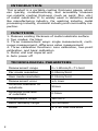 2
2
-
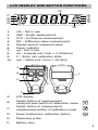 3
3
-
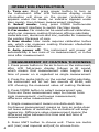 4
4
-
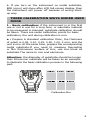 5
5
-
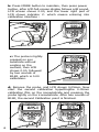 6
6
-
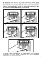 7
7
-
 8
8
-
 9
9
-
 10
10
-
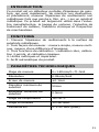 11
11
-
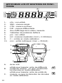 12
12
-
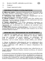 13
13
-
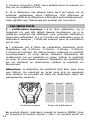 14
14
-
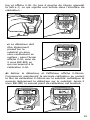 15
15
-
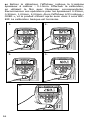 16
16
-
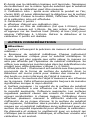 17
17
-
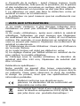 18
18
-
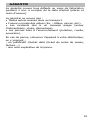 19
19
-
 20
20
-
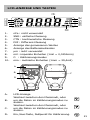 21
21
-
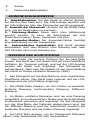 22
22
-
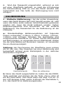 23
23
-
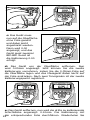 24
24
-
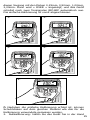 25
25
-
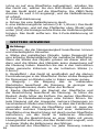 26
26
-
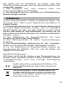 27
27
-
 28
28
-
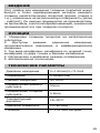 29
29
-
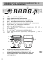 30
30
-
 31
31
-
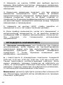 32
32
-
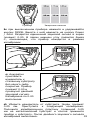 33
33
-
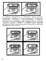 34
34
-
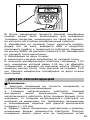 35
35
-
 36
36
-
 37
37
-
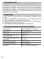 38
38
-
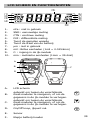 39
39
-
 40
40
-
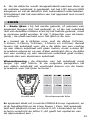 41
41
-
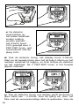 42
42
-
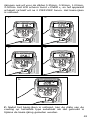 43
43
-
 44
44
-
 45
45
-
 46
46
-
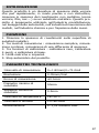 47
47
-
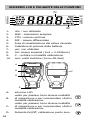 48
48
-
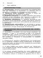 49
49
-
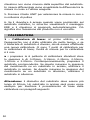 50
50
-
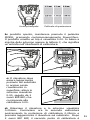 51
51
-
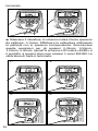 52
52
-
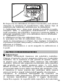 53
53
-
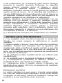 54
54
-
 55
55
-
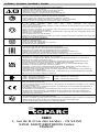 56
56


GYS PAINT-THICKNESS SENSOR de handleiding
- Type
- de handleiding
- Deze handleiding is ook geschikt voor
in andere talen
Gerelateerde papieren
Andere documenten
-
Extech Instruments CG204 Handleiding
-
VOLTCRAFT SDM-115 Operating Instructions Manual
-
Elcometer 456 Handleiding
-
3M Allergen Protein ELISA Kit Handleiding
-
-
Laserliner CoatingTest-Master Handleiding
-
Parkside PMML 5 A1 Operation and Safety Notes
-
Hach DR300 Handleiding