

NEDERLANDS

3. www.ecotap.nl 16/03/22
INHOUDSOPGAVE
1 Inleiding 4
2 Algemeen 4
2.1 Garantie 4
2.2 Symbolen in deze handleiding en laadsysteem 5
3 Apparaat omschrijving 5
3.1 Toepassing 5
3.2 Accessoires 5
3.3 Veiligheidsvoorzieningen 6
4 Veiligheid 6
4.1 Veiligheidsvoorschriften 6
5 Verplichte controles voor ingebruikname 7
6 Gebruik / installatie handleiding 7
6.1 Openen van de deur 7
6.2 Montage op de fundatie 7
6.3 Kabelinvoer en vastzetten trekontlasting 9
6.4 Load Balancer 9
7 Onderhoud 10
8 Transport en opslag 10
9 Storing uitleg 10
10 Werking en bediening laadsysteem 10
11 Technische specificaties 11
12 Contactgegevens leverancier 14
13 EU-Conformiteitsverklaring 14
NEDERLANDS

4. www.ecotap.nl 16/03/22
1. INLEIDING
Hartelijk dank dat u heeft gekozen voor een DC lader van Ecotap® .
Deze handleiding beschrijft de DC lader.
In deze handleiding staat belangrijke informatie voor een goede en veilige installatie en
gebruik van de DC lader.
Het laadstation is ontworpen om voertuigen die voorzien zijn van een mode 4 laadsysteem
met stekkersysteem conform een CHAdeMO connector dan wel een CCS2 connector te
laden. Het laadstation zal samen met het voertuig en installatie de veiligste keuze maken
waardoor het voertuig snel en veilig kan worden opgeladen.
Het gehele laadstation voldoet aan de richtlijn 2014/35/EU betreffende de harmonisatie
van de wetgevingen inzake elektrisch materiaal binnen bepaalde spanningsgrenzen
(herschikking van alle eerdere uitgebrachte versies).
Deze handleiding geeft inzicht hoe het laadstation veilig geïnstalleerd en gebruikt kan
worden. Deze handleiding is opgesteld zodat de werking en technische levensduur van het
laadstation maximaal zal zijn.
Deze handleiding is met grote zorg opgesteld. Echter, mochten er toch nog
onduidelijkheden zijn, neem dan contact op met uw leverancier alvorens u het laadstation
gaat installeren.
Het goed functioneren van het laadstation kan uitsluitend worden gegarandeerd indien het
laadstation door een gemachtigde en erkende installateur / monteur wordt aangesloten.
Lees deze handleiding nauwkeurig door voordat u het laadsysteem gaat installeren
en gebruiken. Bewaar deze handleiding in de omgeving van het laadsysteem zodat de
instructies en veiligheidsvoorschriften altijd voorhanden zijn.
2. ALGEMEEN
2.1 Garantie
Hier gelden de Algemene leveringsvoorwaarde van Ecotap® B.V.
Ecotap® B.V. kan niet aansprakelijk worden gesteld voor letsel of schade indien het
laadsysteem wordt gewijzigd, beschadigd, omgebouwd of wordt uitgebreid met andere
componenten of niet wordt gebruikt volgens de gestelde instructies en voorwaarden.
NEDERLANDS

5. www.ecotap.nl 16/03/22
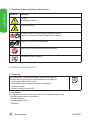
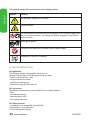
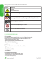
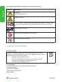
2.2 Symbolen in deze handleiding en laadsysteem
Symbool Betekenis
Let op!
Belangrijke instructie.
Elektrisch gevaar.
Bij onderhoud: eerst spanningsvrij maken en diverse
meettesten uitvoeren alvorens onderhoud te plegen.
Dragen van speciale handschoenen.
Spanningsvrij maken van elektrische installatie.
Handleiding lezen verplicht.
3. APPARAAT OMSCHRIJVING
3.1 Toepassing
Het laadstation is speciaal ontworpen voor intensief gebruik.
Locaties die niet geschikt zijn om het laadstation te plaatsen:
- Kleine afgesloten ruimtes < 8m3
- Gronden die tijdens hoogwater kunnen onderlopen
- Laad en los kade
- Schuine helling meer dan 4%
3.2 Accessoires
De volgende accessoires maken geen deel uit van de leveringsomvang:
- Gereedschappen voor het monteren
- Fundatie element
- Montage bouten (M12)
- Snelbeton
NEDERLANDS

6. www.ecotap.nl 16/03/22
3.3 Veiligheidsvoorzieningen
- Hoofdschakelaar, zekeringhouders, aardlekbeveiliging.
- IP54.
- Afsluitbaar door middel van euro profielcilinder (half)
- Zekeringhouders / aardlekautomaten.
- 12/24 Volt stuurspanning
- Componenten minimaal IP2
- Trekontlastingen
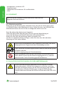
4. VEILIGHEID
Lees de volgende veiligheidsvoorschriften goed door voordat u het laadsys-
teem gaat installeren en in gebruik gaat nemen.
4.1 Veiligheidsvoorschriften
Voordat u het laadstation gaat plaatsen maak u de locatie veilig voor omstanders. Laat op
deze werkplek NOOIT kinderen toe. Zorg dat NIEMAND die niets met de werkzaamheden
heeft te maken op de werkplek komt.
Laat u nooit afleiden tijdens de werkzaamheden.
Zorg te allen tijde voor een gezonde houding tijdens u werkzaamheden.
Laat gereedschappen en onderdelen van het laadstation niet onbeheerd.
Zorg dat het gereedschap schoon en droog is.
Tijdens slecht weer met regenval zorgen dat het laadstation, gereedschap en onderdelen
droog blijven.
Tijdens de montage werkzaamheden zorgdragen dat er geen struikelgevaar
ontstaat door objecten of materialen.
Draag tijdens de gehele handeling van het plaatsen en aansluiten goede en
geschikte handschoenen bij bijzondere handelingen.
Zorg te allen tijde dat bij het spanning vrij maken van de installatie dat het
meetinstrument, dat voor het controleren hiervan, meerdere malen wordt
gecontroleerd op werking.
NEDERLANDS

7. www.ecotap.nl 16/03/22
5. VERPLICHTE CONTROLES VOOR INGEBRUIKNAME
De volgende controles zijn verplicht voor de installatie / ingebruikname
van het laadstation. Gebruik het laadstation NOOIT als de bij 1 of meerdere
controles blijkt dat stroomtoevoer of stabiliteit van het laadstation niet
voldoet.
Voer de onderstaande controles altijd uit voordat er spanning op het laad-
station wordt gezet.
√ Alle onderstaande werkzaamheden volledig conform NEN 3140.
√ Controleer bij de aansluitklemmen of de juiste volgorde is gehandhaafd.
√ Controleer of de aders goed vast zijn gedraaid, zie 6.3.
√ Controleer of de aardverbinding is gemonteerd op de aansluitklem geheel
volgens de Norm NEN1010/EU/35.
√ Controleer de stabiliteit van het geplaatste laadstation.
√ Controleer of de afdichtingen goed zijn gemonteerd tijdens de montage
(IP54).
√ Houd de omgeving van de werkplek vrij van obstakels
Voordat er spanning op het laadstation wordt gezet is het noodzakelijk om (Ma – Vr
09:00 tot 16:00) contact op te nemen met de back office provider (zie telefoon nummer
op het laadstation) zodat het laadstation softwarematig kan worden geactiveerd. Het
unieke laadstation nummer is hierbij benodigd.
6. GEBRUIK / INSTALLATIE HANDLEIDING
6.1 Openen van de deur
Voor het openmaken van de deur gaat u als volgt te werk:
Steek de bijgeleverd sleutel in het slot en draai deze totdat de hendel ontgrendelt. Draai de
hendel zodat de deur ontgrendeld wordt.
Voor deze stappen in tegengestelde richting uit om de deur te sluiten.
6.2 Montage op de fundatie
Voor het installeren van de fundatie is een gat van ongeveer
L 750 mm x D 450 mm x H 530 mm nodig. De bodem dient stabiel en vlak te zijn
gemaakt.
Plaats de fundatie waterpas in het gat. De bovenzijde van de fundatie moet gelijk zijn met
de bovenzijde van het maaiveld / straatwerk. De fundatie moet vervolgens verstevigd
worden met minimaal 2 keer 20 kg snelbeton welke in de hoeken van de fundatie moeten
worden toegevoegd.
Nadat het snelbeton is uitgehard kan het laadstation op de fundatie gemonteerd worden
met de bijgeleverde bouten en moeren (moeren aan de bovenzijde).
NEDERLANDS

8. www.ecotap.nl 16/03/22
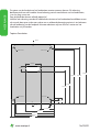
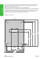
De gaten van de fundatie en het laadstation moeten overeen komen. Zie tekening
bovenaanzicht van de fundatie. Houd rekening met de aansluitkant van het laadstation,
i.v.m. bv. heg, muur enz.
Zorg altijd dat de deuren volledig open zijn!
Houd er ook rekening mee dat er voldoende ruimte om het laadstation beschikbaar moet
zijn om de deur open te kunnen maken en er voldoende bewegingsruimte is ten behoeve
van de bediening van de laadpaal. Hiervoor adviseren wij ten minste 1 meter om het
laadstation vrij te houden.
Topview Foundation
Front
Back
750mm
690mm
60mm
410mm
470mm
44mm
706mm
44mm
60mm
172mm
352mm
470mm
486mm
530mm
DIA 8mm
DIA 8mm DIA 8mm
DIA 8mm
60mm
180mm
NEDERLANDS

9. www.ecotap.nl 16/03/22
6.3 Kabelinvoer en vastzetten van de trekontlasting
Voedingskabel t.b.v. omhoog laten komen middels een mantelbuis aansluit compartiment.
Sluit de aders van de kabel aan op de aanwezige klemmen (max. 15 tot 22Nm bout m8 of
30 tot 44Nm bout s10).
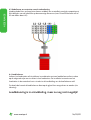
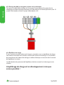
6.4 Load balancer
Indien u het laadstation wilt installeren in combinatie met een load balancer dient u deze
op de volgende wijze aan te sluiten in het laadstation. De installatie instructie van het
laadstation in de meterkast kunt u vinden in de handleiding van de load balancer zelf.
De data kabel vanuit de load balancer dient op de grijze klem aangesloten te worden (zie
tekening).
Loadbalancing is in ontwikkeling, maar nu nog niet mogelijk!
NEDERLANDS

10. www.ecotap.nl 16/03/22
7. ONDERHOUD
Maak het laadstation altijd spanningsvrij en lees de gebruiksaanwijzing
voordat je onderhoud of storingen gaat behandelen.
Reparatie of vervangen van componenten mag alleen met de door de
leverancier goed bevonden producten. Reparaties en vervangingen
dienen altijd door een bevoegd / specialist worden uitgevoerd.
Het onderhoud moet altijd voldoen en worden uitgevoerd conform
NEN3140 en NEN 50110 laagspanning Euro-norm.
Controleer het laadstation op lekkages. Contoleer de aansluitingen van de
hoofdstroombekabeling en zorg voor een vaste verbinding, zie 6.3.
Beschadigingen aan het laadpunt behandelen met roestwerende verf.
8. TRANSPORT EN OPSLAG
Vervoer het laadstation vlak en in de bijgeleverde doos en voorkom dat de lak beschadigt.
Dit zal roestvorming kunnen veroorzaken.
Het opslaan van het laadstation bij voorkeur in een droge, niet vochtige ruimte. Voor het
takelen van het laadstation bevinden zich 2 bevestigingsgaten t.b.v. hijsogen bovenop aan
de zijkanten van het laadstation. De hijsogen kunnen er na plaatsen afgeschroefd worden.
Enkel een bevoegde monteur mag het laadstation hijsen, om zo een veilige werkomgeving
te kunnen garanderen.
9. STORING UITLEG
Bij niet functioneren van het laadstation, direct contact opnemen met de desbetreffende
back office provider.
Maak onder geen beding zelf het laadstation open!
Dit is levensgevaarlijk.
Alleen gecertificeerde monteurs / installateurs welke beschikken over de juiste meet
gereedschappen mogen de lader aansluiten en voor reparaties openen.
LET OP!
Alle werkzaamheden en aanpassingen aan het laadstation dienen minimaal te voldoen aan
de NEN1010
10. WERKING EN BEDIENING LAADPUNT
Het laadstation is te bedienen met een laadpas.
De laadpas uitvoering dient nog wel te worden geregistreerd in het desbetreffende
Backoffice systeem.
Deze noodzakelijke registratie kan tijdens werktijden telefonisch worden gedaan bij de
desbetreffende back office provider waarvan het telefoonnummer op het laadsysteen is
NEDERLANDS

11. www.ecotap.nl 16/03/22
vermeld.
Zodra de registratie is voltooid kan het laadstation met elke Elektrische Vervoer laadpas
(EV laadpas) of andere geschikte pasjes, mobiel of sleutelhouder gebruikt worden.
10.1 Werking
U neemt de stekker uit de houder van het laadstation welke geschikt is voor uw voertuig.
Plaats deze in uw voertuig. In het geval dat zowel een CHAdeMO als CCS stekker De start/
stop procedure start door middel van de laadpas voor het scanpunt te houden.
Als eerste wordt de stekker vergrendeld in het voertuig.
Daarna communiceert het laadstation met het voertuig en het BackOffice systeem. Als
alle veiligheid en betalingsvoorschriften zijn gecontroleerd, wordt de maximale toelaatbare
laadstroom doorgegeven. Na enige tijd kan het voorkomen dat het laadstation de daarvoor
aanwezige koeling systemen activeert om de overtollige warmte via het ontluchtingskanaal
af te voeren.
De laadprocedure wordt nu automatisch ingeschakeld en het DC laadproces proces is te
volgen op het scherm.
10.2 Noodstop
In geval van nood moet gebruik gemaakt worden van de daarvoor aanwezige noodknop.
Bij het activeren van de noodknop wordt het laad proces direct zowel software als hardware
matig afgebroken.
Na zorgvuldige inspectie zal het desbetreffende backoffice systeem de noodstand resetten.
Hiervoor zal ook op locatie de noodknop gedeactiveerd moeten worden.
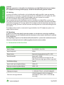
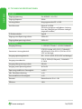
11. TECHNISCHE SPECIFICATIES
AC INPUT
Input voltage: 3 x 400VAC + N ± 10%
Input frequentie: 50Hz
Power factor: Nominale uitgangsbelasting PF ≥ 0.99
Aansluitwaarde: Minimaal 3 x 225A
(Bij lager beschikbaar vermogen kan de
lader softwarematig lager worden ingesteld)
Aardlekbeveiliging: Type B
Input onder spanningsbeveiliging: 255V ±5V
Ingang overspanningsbeveiliging: 490V ±5V
DC OUTPUT
Uitgangsvermogen: 1 - 150 kW CCS of 1 - 60 kW CHAdeMO
Constant vermogensbereik:
CCS 120KW@400-500V CHAdeMO
60KW@400-500V (300 -1000vdc op
aanvraag)
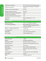
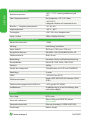
NEDERLANDS

12. www.ecotap.nl 16/03/22
Uitgangsspanningsbereik: 150~500V (200-1000vdc op aanvraag)
Uitgangsstroombereik: CCS: 0~250A (500A peak) , CHAdeMO:
0~130A
Uitgang overspanningsbeveiliging: 510±5V
Uitgang onderspanning alarm: 140V±2V
Voltage gestabiliseerde nauwkeurigheid: ≤±0.5%
Max. opstart overschrijding: ≤±1%
Huidige gestabiliseerde nauwkeurigheid: ≤±1%
Opstart tijd: Normaal gesproken 3s ≤ t ≤ 8s
Efficiency: >96%
WERKOMGEVING
Bedrijfstemperatuur: -30°C ~ 70°C, reductie vanaf 55°C
Oververhittingsbeveiliging: Bij een temperatuur van >70°C±4°C of
<-40°C±4°C, zal het laadstation zich auto-
matisch uitschakelen.
Bedrijfs- / omgevingstemperatuur: -25° tot 60°
Laad temperatuur: - 40°C ~ 85°C
Vochtigheid: ≤ 95% RH, zonder condensatie
Druk / hoogte: 79kPa~106kPa/2000m
FYSIEKE EIGENSCHAPPEN
Akoestisch geluid: < 51dB
Koeling: Luchtkoeling ventilatoren
Afmetingen (HxBxD): 1802 mm x 730 mm x 750 mm
Europese normen: EN 61851-1 2011, EN 6185123-2014, CE
Materiaal behuizing: Staal >3 mm
Behandeling: Anti-corrosie en Poedercoating
Standaard kleur: RAL 6018 / RAL 9016 / RAL 9005
Gewicht: 465 kg
Aantal laadpunten: 2 (Combinatie uit CCS en CHADEMO)
Kabel lengte: 3 meter
MTBF: > 500000 uur (40°C)
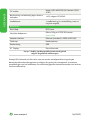
NEDERLANDS

13. www.ecotap.nl 16/03/22
DC stekker: Mode 4 (IEC-61851-23/24) Combo-2 (DIN
10121)
Bescherming van behuizing tegen externe
invloeden: > IK10 volgens IEC 62262
Loadbalancer: -Loadbalancing is in ontwikkeling, maar nu
nog niet mogelijk
BEDIENING
Start-Stop: RFID-kaart
Geschikte laadpassen: Mifare, NTag en iCODE SLI kaarten
( meer info )
Netwerk interface: Ethernet (standard) / GPRS-UMTS (3G)
Drukknop: Noodstopknop
Positionering: GPS
10” Display: Extra informatie
Let op ! Aarding (aardverspreidingsweerstand) geheel
volgens de geldende normeringen.
Ecotap® B.V. behoudt zich het recht voor om zonder voorafgaande kennisgeving de
bovenstaande technische gegevens te wijzigen als gevolg van voortgaande, innovatieve
ontwikkelingen van het laadstation. De technische gegevens kunnen bovendien van land tot
land verschillend zijn.
NEDERLANDS

14. www.ecotap.nl 16/03/22
12. CONTACTGEGEVENS LEVERANCIER
Ecotap® B.V.
Kruisbroeksestraat 23
5281RV Boxtel – The Netherlands
Tel.: 0031 (0) 411-210210
E-mail: info@ecotap.nl
13. EU-CONFORMITEITSVERKLARING CE 2019
(richtlijn 2014/35/EU, Bijlage II blz.96/369, EMC 2014/30/EU)
Hierbij verklaart Ecotap® B.V. Kruisbroeksestraat 23, 5281RV Boxtel, dat het hierna
genoemde laadstation overeenstemt met de eisen van de hierna genoemde richtlijnen en
Normen.
Type: Ecotap® DC 150 Bouwjaar : 2019
Gehanteerde EU-Richtlijnen:
- Laagspanning richtlijn 2014/35/EU
- EMC-richtlijn 2014/30/EU
Gebruikte Normen als referentie:
• EN 61851-23-2014
• EN 61851-1-2012
• EN 61851-21-2 : 2016
• EN 61000-3-11 2000
• IEC 61000-3-12-2011
• EN 61000-4-2-2009
• EN 61000-4-3-2006
• EN61000-4-4 2012
• EN_61000-4-5-2014
• EN 61000-4-6-2014
• EN 61000-04.08.2010
• EN 61000-4-11-2004
• NEN/EN/IEC 60529
• IEC 62262
• NEN/EN/IEC 61439-1
• IEC/TS 61439-7
Toegepaste geharmoniseerde standaarden:
NL NEN-EN-IEC 61851-1 / NEN-EN-IEC 61851-22
FR NF-EN-IEC 61851-1 / NF-EN-IEC 61851-22
DE DIN-EN 61851-1 / DIN-EN 61851-22
GB BS-EN 61851-1 :2019 / BS-EN 61851-22
IT IEC-EN 61851-1 / IEC-EN 61851-22
Boxtel, April 2019
Ir.Ing. P.F.A. van der Putten
NEDERLANDS

ENGLISH

16. www.ecotap.nl 16/03/22
TABLE OF CONTENTS
14 Introduction 17
15 General 17
15.1 Warranty 17
15.2 Symbols used in this manual 18
16 Device description 18
16.1 Application 18
16.2 Accessories 18
16.3 Safety device 18
17 Safety 19
17.1 Safety instructions 19
18 Mandatory checks before initial use 19
19 Operation / installation manual 20
19.1 Open the door 20
19.2 Mounting on foundation 20
19.3 Insert cable and attach strain relief 22
19.4 Loadbalancer 22
20 Maintenance 23
21 Transportation and storage 23
22 Resolving problems 23
23 Operation of the charging station 24
24 Technical specifications 24
25 Contact details supplier 27
26 EG conformity statement 27
ENGLISH

17. www.ecotap.nl 16/03/22
14. INTRODUCTION
Thank you for choosing an Ecotap® DC charger.
This manual describes the DC charger.
This manual contains important information for the proper and safe installation and
operation of the DC charger.
The charging station is designed for vehicles fitted with a mode-4 charging system in line
with IEC 61851-1 (edition 2.0) using a connector jack system as per VDE-AR-E 2623-2-2 /
IEC 62196-2. Together with the vehicle and system, the charging station will select the best
option for charging the vehicle quickly and safely.
The entire charging station complies with EU Directive 2014/35/EU relating to the
harmonisation of legislation on electrical equipment within certain voltage limits (re-rating
of all versions issued previously).
This manual provides insight into how to install and operate the charging station safely.
This manual is drawn up to maximise the function and technical design life of the charging
station.
It has been drawn up with the utmost care. However, if there are still any uncertainties,
contact your supplier before installing the charging station.
We can only guarantee the functioning of the charging station if the charging station is
connected by an authorized or certified fitter/technician.
Read this manual carefully before installing and operating this charging station. Store this
manual in the vicinity of the charging station so that the instructions and safety guidelines
are always to hand.
© Copyright
No part of this publication may be copied, reproduced or saved in a retrieval system without
Ecotap® B.V.’s prior written consent.
This manual is an English translation. The original manual was written in Dutch.
15. GENERAL
15.1 Warranty
The Ecotap® B.V. General Delivery Conditions apply.
Ecotap® B.V. cannot be held responsible for injury or damages as a result of the charging
station being changed, damaged, converted, or expanded with other components, or if it is
not being used in accordance with the specified instructions and conditions.
ENGLISH

18. www.ecotap.nl 16/03/22
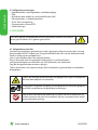
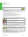
15.2 Symbols used in this manual and on the charging system
Symbol Meaning
Pay attention! Important instruction
Electrical hazard
For maintenance: first disconnect the installation from its power supply and
test it to make sure there is no voltage left, before engaging in any mainte-
nance activities
Wear special gloves.
Disconnect the electrical installation from its power supply
Reading this manual is mandatory
16. DEVICE DESCRIPTION
16.1 Application
This charging station is designed for intensive use.
Locations not suitable for installing the charging station:
- Small enclosed spaces < 8m3
- All grounds that can flood
- Loading/unloading quay
- Slope at an angle of more than 4%
16.2 Accessories
The following accessories are not included in the scope of delivery:
- Tools
- Foundation element
- Mounting bolts (M12)
- Fast-setting concrete
16.3 Safety features
- Lockable using a euro profile cylinder (half)
- Fuse holders / circuit breakers.
- 12/24 Volt control voltage
ENGLISH

19. www.ecotap.nl 16/03/22
- Component minimum IP2
- Strain relief
- Minimum 3.3 mm steel casing
- IP54.
17. SAFETY
Read the following safety regulations carefully before you install and use the
charging station.
17.1 Safety instructions
Before you install the charging station, you must make sure the location is safe for all
bystanders. NEVER allow children onto this worksite. Never allow ANYONE who has nothing
to do with the work onto the worksite.
- Never be distracted while you are performing the work.
- Make sure you maintain a healthy posture at all times while doing the work.
- Do not leave any tools or charging station components unattended.
- Make sure any tools you are using are clean and dry.
- Make sure that the charging station, tools and components will stay dry
when it is raining.
Make sure that there is no danger of anyone tripping over objects or paving
while you are digging the hole for the foundation.
Make sure to wear good, suitable gloves for any special actions throughout
the entire installation and connection process.
Always check any measuring instruments you will be using to disconnect
the installation from its power supply before you use them, checking them
several times to make sure they are working properly.
18. MANDATORY CHECKS BEFORE INITIAL USE
The following checks must be carried out for commissioning of the charging
station. NEVER use the charging station if one or more checks indicate
that the power supply or stability of the charging station do not meet
requirements. Check the insulation resistance between the phases as per
NEN1010, provision 61.3.3.
√ All work described below is in compliance with NEN 3140.
√ Check whether the wires have been connected to the terminals in the right order.
√ Check whether the cores have been properly tightened, see 19.3.
ENGLISH

20.www.ecotap.nl 16/03/22
√ Check whether the earth connection is mounted on the connection terminal in
accordance with the NEN1010/EU/35 standard.
√ Check whether the cable thickness of the power cable matches the fused
current rating.
√ Check whether the charging station is tightly and properly secured.
√ Check whether the station is sufficiently waterproof.
√ Keep the immediate environment of the work area free from obstacles.
Before the power is connected to the charging station, you must first call Ecotap® B.V.
on +31 (0)411 745 020 (Mo – Fr 09:00 to 16:00) so that we can activate its software (this
requires the unique charging station number).
19. OPERATING / INSTALLATION MANUAL
19.1 Open the door
The door can be opened in the following way.
Insert the key supplied and turn it until the handle unlocks.
Turn the handle so the door will unlock.
Carry out these steps in reverse to close and lock the door.
19.2 Mounting on the foundation
To fit the foundation, a hole must be dug of roughly L 750 mm x D 450 mm x H 530 mm.
The bottom of the hole must be stable and levelled.
Place the foundation base level in the hole. The upper surface of the base must be flush with
the upper surface of the grade / paving. The foundation must then be reinforced by adding
at least two 20 kg bags of fast-setting concrete in the corners of the foundation.
After the fast-setting concrete has cured, the charging station can be mounted on its
foundation using the nuts and bolts provided (nuts to the top).
The hole in the foundation and the charging station must be lined up. See drawing of the
topview of the foundation base. Take account of the connection face of the charging station
in relation to walls, hedges, etc.
Always ensure that the doors are fully open!
Also keep in mind that there is sufficient space for the operation of the charging station. For
this we advise to keep at least 1 meter of free space around the charging station.
ENGLISH

21. www.ecotap.nl 16/03/22
Topview Foundation
Front
Back
750mm
690mm
60mm
410mm
470mm
44mm
706mm
44mm
60mm
172mm
352mm
470mm
486mm
530mm
DIA 8mm
DIA 8mm DIA 8mm
DIA 8mm
60mm
180mm
ENGLISH

22. www.ecotap.nl 16/03/22
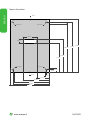
19.3 Inserting cable and securing with strain relief
Secure the power cable in the foundation using the cable gland.
Connect the conductors of the cable to the existing main switch terminals (max. 15 to 22Nm
bolt m8 oder 30 to 44Nm bolt s10).
Below is an overview of the wiring diagram
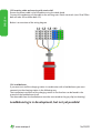
19.4 Load balancer
If you want to install the charging station in combination with a load balancer you must
connect it to the charging station in the following way.
The installation instruction of the charging station in the fuse box can be found in the
manual of the load balancer itself.
The data cable from the load balancer must be connected to the gray clip (see drawing).
Loadbalancing is in devolopment, but not yet possible!
ENGLISH

23. www.ecotap.nl 16/03/22
20. MAINTENANCE
Always disconnect the charging station from the power supply and read the
manual before performing maintenance or fixing a malfunction.
Only products approved by the supplier can be used to repair or replace components.
Repairs and replacements should always be carried out by a certified specialist.
Maintenance should always comply with and be carried out in accordance with NEN3140
and NEN50110 low voltage EU regulations.
Check the charging station for leaks.
Check the connection of the main power cable and ensure a tight connection, see 19.3.
Treat any damage to the charging station with anti-corrosion paint.
21. TRANSPORTATION AND STORAGE
Transport the charging station (technical core) upright and prevent the paint from being
damaged, as this could cause rust.
The covers may be transported in various ways as long as they are protected from damage.
Preferably store the charging station in a dry, non-humid space.
When hoisting the charging station into position, there are 2 securing holes for lifting eyes
on the top of each corner of the charging station. The lifting eyes can be removed after
fitting. To ensure a safe work setting, only a certified fitter may hoist the charging station.
22. RESOLVING PROBLEMS
If the charging station malfunctions, immediately contact the Ecotap® helpdesk, open
24/7 (telephone number: +31 (0)411 745 020) or a certified technician who possesses the
necessary measuring and en testing equipment with auto-simulation.
NOTE!
All work on and modifications to the charging station must comply with at least NEN1010.
ENGLISH

24. www.ecotap.nl 16/03/22
23. OPERATION AND FUNCTIONING OF THE CHARGING STATION
The charging station is operated using a charging card.
The charging card must be registered in the relevant back-office system.
This required registration can also be done during office hours by calling
Ecotap® B.V. Tel. +31 (0)411 745 020. Once registration is complete, the
charging station can be used with any Electric Transport charging card (EV
charging card) or other suitable cards, both mobile and tag.
23.1 Operation
Take the plug from the holder of the charging station that is suited to your vehicle.
Then insert it in your vehicle. If both CHAdeMO and CCS charging points are available, only
one can be used at a time.
Initiate the start/stop procedure by holding your charging card up to the scanning point.
Firstly the plug is locked onto the vehicle.
The charging station then communicates with the vehicle and the back-office system. Once
all security and payment guidelines have been checked, the maximum permissible charging
current is forwarded. After some time, it can occur that the charging station activates the
cooling systems fitted for this purpose to dissipate the excess heat via the venting duct.
The charging procedure is now activated automatically and the DC charging process can be
followed on the screen. The AC charging process is indicated by a small light.
To stop the charging process, hold your card up to the scanning point. The charging process
then stops. You can now remove the plug and hang it back up in the available holder.
23.2 Emergency stop
In case of emergency, the emergency stop button must always be used.
When activating the emergency stop button, the charging process is disconnected directly,
both in terms of software and hardware.
After careful inspection, the back-office system concerned will reset the emergency setting.
The emergency stop button will also have to be deactivated on site for this purpose.
24. TECHNICAL SPECIFICATIONS
AC INPUT
Input voltage: 3 x 400VAC + N ± 10%
Input frequency: 50Hz
Power factor: Rated output load PF ≥ 0.99
Connection value: Minimal 3 x 225A
(With a lower available capacity, the charger
can be set lower by software)
RCD: Type B
Input under voltage protection: 255V ±5V
ENGLISH

25. www.ecotap.nl 16/03/22
Input overvoltage protection: 535V ±5V
DC OUTPUT
Output power: 1 - 150 kW CCS or 1 - 60 kW CHAdeMO
Constant power range:
CCS 120KW @ 400-500V CHAdeMO
60KW @ 400-500V (300 -1000vdc on
request)
Output voltage range: 150 ~ 500V (200-1000vdc on request)
Output current range: CCS: 0~250A (500A peak) , CHAdeMO:
0~130A
Output overvoltage protection: 510±5V
Output under voltage alarm: 140V±2V
Voltage stabilized accuracy: ≤±0.5%
Max. startup overshoot: ≤±1%
Current stabilized accuracy: ≤±1%
Startup Time: Normally 3s ≤ t ≤ 8s
Efficiency: >96%
OPERATING ENVIRONMENT
Operating temperature: -30°C ~ 70°C, derating from 55°C
Overtemperature protection: On temperature >70°C±4°C or <-40°C±4°C,
charger will shut down automatically
Operating/ambient temperature: -25°- to 60°
Storage temperature: - 40°C ~ 85°C
Humidity: ≤ 95% RH, without condensation
Pressure/Altitude: 79kPa~106kPa/2000m
PHYSICAL CHARACTERISTICS
Acoustic Noise: < 51dB
Cooling: Air Cooling fans
Dimensions (HxWxD): 1802 mm x 730 mm x 750 mm
European Standards: EN 61851-1 2011, EN 6185123-2014, CE
Casing material: Steel >3 mm
Treatment: Anti-corrosion and powder coating
Standard colour: RAL 6018 / RAL 9016 / RAL 9005
ENGLISH

26. www.ecotap.nl 16/03/22
Weight: 465 kg
Number of charging points: 2 (Combination from CCS and CHADEMO)
Cable length: 3 meter
MTBF: > 500000 hrs (40°C)
DC power plug: Mode 4 (IEC-61851-23/24) Combo-2 (DIN
10121)
Enclosure protection against external
impacts: > IK10 according to IEC 62262
Loadbalancer: Loadbalancing is in devolopment, but not
yet possible
CONTROL
Start-Stop: RFID-card
Suitable charge cards: Mifare, NTag and iCODE SLI cards
( more info )
Network interface: Ethernet (standard) / GPRS-UMTS (3G)
Push button: Emergency stop button
Positioning: GPS
10” Display: Additional information
Pay attention ! Earthing (earth dispersion resistance) completely
in accordance with the applicable standards.
Ecotap® B.V. reserves the right to change technical details due to continual, innovative
development of the charging station, without publishing this in advance. The technical
details might also differ from country to country.
ENGLISH

27. www.ecotap.nl 16/03/22
25. CONTACT DETAILS SUPPLIER
Ecotap® B.V.
Kruisbroeksestraat 23
5281RV Boxtel – The Netherlands
Tel.: 0031 (0) 411-210210
E-mail: info@ecotap.nl
26. EU CONFORMITY STATEMENT
(Directive 2014/35/EU, Annex II page 96/369, EMC 2014/30/EU)
Ecotap® B.V. Kruisbroeksestraat 23, 5281RV Boxtel, the Netherlands, hereby states that the
following charging station meets the requirements of the listed directives and standards.
Type: Ecotap® DC 150 Year of construction: 2019
EU directives used:
- Low-voltage directive 2014/35/EU
- EMC directive 2014/30/EU
Standards used as reference:
• EN 61851-23-2014
• EN 61851-1-2012
• EN 61851-21-2 : 2016
• EN 61000-3-11 2000
• IEC 61000-3-12-2011
• EN 61000-4-2-2009
• EN 61000-4-3-2006
• EN61000-4-4 2012
• EN_61000-4-5-2014
• EN 61000-4-6-2014
• EN 61000-04.08.2010
• EN 61000-4-11-2004
• NEN/EN/IEC 60529
• IEC 62262
• NEN/EN/IEC 61439-1
• IEC/TS 61439-7
Used harmonisation standards:
NL NEN-EN-IEC 61851-1 / NEN-EN-IEC 61851-22
FR NF-EN-IEC 61851-1 / NF-EN-IEC 61851-22
DE DIN-EN 61851-1 / DIN-EN 61851-22
GB BS-EN 61851-1 :2019 / BS-EN 61851-22
IT IEC-EN 61851-1 / IEC-EN 61851-22
Boxtel, April 2019
Ir.Ing. P.F.A. van der Putten
ENGLISH

DEUTSCH

29. www.ecotap.nl 16/03/22
INHALTSVERZEICHNIS
27 Einleitung 30
28 Allgemein 30
28.1 Garantie 30
28.2 Symbole in diesem Handbuch und der Ladestation 31
29 Gerätebeschreibung 31
29.1 Anwendung 31
29.2 Zubehör 31
29.3 Sicherheitsvorrichtungen 31
30 Sicherheit 32
30.1 Sicherheitsvorschriften 32
31 Obligatorische Prüfungen vor der Inbetriebnahme 32
32 Betriebs-/Installationshandbuch 33
32.1 Öffnen der Tür 33
32.2 Montage auf dem Fundament 33
32.3 Kabel einführen und sichern (mit Zugentlastung) 35
32.4 Load Balancer 35
33 Wartung 36
34 Transport und Lagerung 36
35 Erläuterung zu Störungen 36
36 Bedienung und Funktionsweise der Ladestation 37
37 Technische Spezifikationen 38
38 Kontaktdaten des Lieferanten 40
39 EU-Konformitätserklärung 41
DEUTSCH

30.www.ecotap.nl 16/03/22
27. EINLEITUNG
Zunächst einmal herzlichen Dank dafür, dass Sie sich für die DC Ladestation von Ecotap®
entschieden haben.
In diesem Bedienerhandbuch wird die DC Ladestation beschrieben.
Das Bedienerhandbuch enthält wichtige Informationen für einen korrekte und sichere
Installation und den sicheren Gebrauch der Ladestation.
Die Ladestation ist zum Laden von Fahrzeugen ausgelegt, die mit einem Mode 4
Ladesystem mit einem Stecksystem, gemäß einem CHAdeMO-Stecker oder einem
CCS-Stecker ausgestattet sind. Zusammen mit dem Fahrzeug und der Installation ist die
Ladestation die sicherste Wahl, damit das Fahrzeug schnell und sicher aufgeladen werden
kann.
Die gesamte Ladestation entspricht der Richtlinie 2014/35/EU zur Harmonisierung
der Gesetze über elektrische Betriebsmittel innerhalb bestimmter Spannungsgrenzen
(Neufassung aller früheren Versionen).
Dieses Handbuch gibt einen Überblick über die sichere Installation und Nutzung der
Ladestation. Es wurde für einen möglichst optimalen Betrieb und eine maximale technische
Lebensdauer der Ladestation zusammengestellt.
Dieses Bedienerhandbuch wurde mit größter Sorgfalt erstellt. Sollten dennoch Unklarheiten
auftreten, wenden Sie sich bitte vor der Installation der Ladestation an Ihren Lieferanten.
Die einwandfreie Funktion der Ladestation kann nur gewährleistet werden, wenn sie von
einem autorisierten und zugelassenen Installateur / Techniker angeschlossen wird.
Bitte lesen Sie dieses Handbuch sorgfältig durch, bevor Sie die Ladestation installieren
und nutzen.
Bewahren Sie dieses Handbuch in der Nähe der Ladestation auf, damit das
Bedienerhandbuch und auch die Sicherheitshinweise immer im Zugriff sind.
28. ALLGEMEIN
28.1 Garantie
Hier gelten die Allgemeinen Lieferbedingungen von Ecotap® B.V.
Ecotap® B.V. kann nicht für Personen- oder Sachschäden haftbar gemacht werden, die
durch eine modifizierte, beschädigte oder umgerüstete Ladestation verursacht wurden
oder durch eine, die mit anderen Bauteilen ausgerüstet wurde oder nicht entsprechend der
angegebenen Anweisungen und Bestimmung verwendet wurde.
DEUTSCH

31. www.ecotap.nl 16/03/22
28.2 Symbole in diesem Handbuch und der Ladestation
Symbol Bedeutung
Achtung!
Wichtige Anweisung
Elektrische Gefährdung.
Während der Wartung: erst von der Stromversorgung trennen und die
Spannungsfreiheit prüfen bevor Wartungsarbeiten durchgeführt werden.
Tragen Sie spezielle Handschuhe.
Elektrische Anlage spannungsfrei schalten
Das Lesen des Handbuchs ist Pflicht
29. GERÄTEBESCHREIBUNG
29.1 Anwendung
Die Ladestation wurde speziell für den intensiven Gebrauch entwickelt.
Stellen, die nicht für die Aufstellung der Ladestation geeignet sind:
- Kleine geschlossene Räume < 8m3
- Böden, die bei Hochwasser überfluten können
- Be- und Entlade-Kaianlagen
- Hänge mit mehr als 4% Neigung
29.2 Zubehör
Folgendes Zubehör ist nicht im Lieferumfang enthalten:
- Werkzeug
- Fundamentelement
- Montagebolzen (M12)
- Schnellbeton
29.3 Sicherheitsvorrichtungen
- Abschließbar durch Euro-Profilzylinder (halb)
- Sicherungshalter / Fehlerstromschutzschalter
- 12/24 Volt Steuerspannung
DEUTSCH

32. www.ecotap.nl 16/03/22
- Komponenten, mindestens IP2
- Zugentlastungen
- Stahlgehäuse mit mindestens 3,3 mm Blechdicke
- IP54
30. SICHERHEIT
Lesen Sie vor der Installation und dem Betrieb der Ladestation die
folgenden Sicherheitsrichtlinien.
30.1 Sicherheitsvorschriften
Stellen Sie vor der Platzierung der Ladestation sicher, dass der Ort für Passanten sicher
ist. NIEMALS Kinder in den Arbeitsbereich lassen. Stellen Sie sicher, dass NIEMAND den
Arbeitsbereich betritt, der nicht mit der zu erledigenden Arbeit zu tun hat.
Seien Sie während der Arbeit niemals abgelenkt.
Halten Sie während der Arbeit die ganze Zeit eine gesunde Körperhaltung ein.
Lassen Sie Werkzeuge und Teile der Ladestation nicht unbeaufsichtigt.
Stellen Sie sicher, dass die Werkzeuge sauber und trocken sind.
Im Falle von schlechtem Wetter mit Regen, stellen Sie sicher, dass die Ladestation,
Werkzeug und Teile trocken bleiben.
Während der Aushubarbeiten für das Fundament sicherstellen, dass keine
Stolpergefahr durch Gegenstände oder Straßenbeläge entsteht.
Tragen Sie bei der Durchführung bestimmter Aktionen während der ganzen
Installation und dem
Anschlussvorgang geeignete Schutzhandschuhe.
Stellen Sie jederzeit sicher, dass die verwendeten Prüfinstrumente zum
Testen, ob das System von der Stromversorgung getrennt ist, mehrfach
getestet wurden, sodass Sie ordnungsgemäß funktionieren.
31. OBLIGATORISCHE PRÜFUNGEN VOR DER INBETRIEBNAHME
Vor der Inbetriebnahme der Ladestation müssen folgende Prüfungen
durchgeführt werden. NIEMALS die Ladestation verwenden, wenn eine
oder mehr Prüfungen anzeigen, dass die Stromversorgung oder Stabilität
der Ladestation nicht den Anforderungen entspricht. Prüfen Sie den
Isolationswiderstand zwischen den Phasen nach der Norm DIN VDE 0100-
600.
DEUTSCH

33. www.ecotap.nl 16/03/22
Vor der Verbindung der Ladestation mit der Stromversorgung immer die
untenstehenden Prüfungen durchführen
√ Alle im Folgenden aufgeführten Arbeiten sind in voller Übereinstimmung
mit DIN EN 50110-1 durchzuführen.
√ Überprüfen Sie an den Anschlussklemmen, ob bei den angeschlossenen
Kabeln die korrekte Reihenfolge eingehalten wurde.
√ Überprüfen Sie, ob die Adern in den Klemmen angezogen sind, Siehe
32.3
√ Kontrollieren Sie, ob der Erdungsanschluss an der entsprechend kodierten
Klemme angeschlossen und mit dem Erdungsstab oder der
mitgelieferten Erdung verbunden ist. Die gesamte muss der
Niederspannungsrichtlinie 2014/35/EU entsprechen.
√ Überprüfen Sie, ob die installierte Ladestation wirklich stabil steht und in
sich stabil ist.
√ Überprüfen Sie, ob die Dichtungen der Ladestation bei der Installation
richtig angebracht wurden (IP54).
√ Halten Sie die Arbeitsumgebung von Hindernissen frei.
Vor Anlegen einer Spannung an die Ladestation ist es erforderlich, die angegebene
Telefonnummer in der Ladesäule zu kontaktieren, sodass wir die Ladestation über die
Software aktivieren können. Dabei ist uns die eindeutige Nummer der Ladestation
mitzuteilen.
32. BETRIEBS-/INSTALLATIONSHANDBUCH
32.1 Öffnen der Tür
Um die Tür zu öffnen, gehen Sie wie folgt vor:
Stecken Sie den mitgelieferten Schlüssel in das Schloss und drehen Sie ihn, bis der Hebel
entriegelt ist.
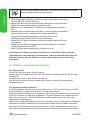
Drehen Sie den Griff so, dass die Tür entriegelt ist.
Um die Tür zu schließen, führen Sie bitte diese Schritte sinngemäß in umgekehrter
Reihenfolge durch.
32.2 Montage auf dem Fundament
Für die Montage des Fundaments ist eine Grube von ca. L 750 mm x D 450 mm x H 530
mm erforderlich. Der Boden der Grube muss stabil und flach sein.
Legen Sie die Wasserwage für das Fundament in die Grube. Die Oberseite des Fundaments
muss sich auf Höhe der Oberseite des Bodens / Pflasters befinden. Das Fundament muss
dann mit mindestens 2 x 20 kg Schnellbeton verstärkt werden, der in den Ecken des
Fundaments anzubringen ist.
Nach Aushärtung des Schnellbetons kann die Ladestation mit den mitgelieferten Schrauben
und Muttern auf dem Fundament montiert werden (Muttern kommen dabei nach oben).
Die Löcher im Fundament müssen mit den Löchern an der Ladestation übereinstimmen.
Siehe Zeichnung der Vorderseite des Fundaments. Berücksichtigen Sie die Anschlussseite
DEUTSCH

34. www.ecotap.nl 16/03/22
der Ladestation, in Zusammenhang mit z.B. Hecken, Wänden usw.
Stellen Sie immer sicher, dass die Türen vollständig geöffnet sind!
Beachten Sie auch, dass ausreichend Platz für den Betrieb der Ladestation vorhanden ist. Zu
diesem Zweck empfehlen wir, mindestens 1 Meter freien Platz um die Ladestation herum zu
haben.
Draufsicht Stiftung
Front
Back
750mm
690mm
60mm
410mm
470mm
44mm
706mm
44mm
60mm
172mm
352mm
470mm
486mm
530mm
DIA 8mm
DIA 8mm DIA 8mm
DIA 8mm
60mm
180mm
ENGLISH
DEUTSCH

35. www.ecotap.nl 16/03/22
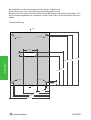
32.3 Kabel einführen und sichern (mit Zugentlastung)
Sichern Sie das Stromkabel mit der Kabelverschraubung im Fundament
Verbinden Sie die Leiter des Kabels mit den vorhandenen Hauptschalterklemmen (max. 15
bis 22Nm Schraube m8 oder 30 bis 44Nm Schraube s10).
Übersicht über das Anschlussschema
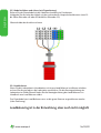
32.4 Load balancer
Wenn Sie die Ladestation in Kombination mit einem Load Balancer installieren möchten,
müssen Sie die wie folgt an die Ladestation anschließen. Für die Montageanleitung der
Ladestation im Zählerschrank finden Sie die Montageanleitung des Load Balancers im
Handbuch zum Load Balancer selbst.
Das Datenkabel vom Load Balancer muss an die graue Klemme angeschlossen werden
(siehe Zeichnung).
Loadbalancing ist in der Entwicklung, aber noch nicht möglich!
DEUTSCH

36. www.ecotap.nl 16/03/22
33. WARTUNG
Trennen Sie die Ladestation immer vom Stromnetz und lesen Sie die
Betriebsanleitung, bevor Sie irgendwelche Wartungsarbeiten vornehmen
oder Störungen beheben.
Bei Reparaturen oder dem Austausch von Komponenten dürfen nur vom
Lieferanten zugelassene Produkte verwendet werden. Wenden Sie sich im
Zweifelsfall bitte an Ecotap®.
Reparaturen und Austauscharbeiten dürfen immer nur von einem autorisierten Mitarbeiter /
Spezialisten durchgeführt werden.
Wartungsarbeiten müssen immer gemäß der Norm DIN EN 50110-1 (VDE 0105-1),
europäische Niederspannungsnorm durchgeführt werden.
Überprüfen Sie die Ladestation auf Undichtigkeiten.
Überprüfen Sie die Anschlüsse der Hauptstromverkabelung und achten Sie auf einen festen
Sitz von mindestens 6 Nm.
Beschädigungen der Ladestation sind durch korrosionsbeständige Lackierung in der richtigen
Farbe (Ecotap® Grün RAL 6018 und Weiß RAL 9016) zu überstreichen.
Bei Bedarf sollten Zylinderschlösser mit Graphitpulver oder geeignetem Öl geschmiert
werden.
34. TRANSPORT UND LAGERUNG
Transportieren Sie die Ladestation (Kern mit Technik) aufrecht und vermeiden Sie
Lackschäden, da sie zu Korrosion führen können.
Die Abdeckungen können in mehreren Positionen transportiert werden, sofern sie vor
Beschädigungen geschützt sind. Lagern Sie die Ladestation möglichst in einem trockenen,
nicht feuchten Bereich.
Zum Anheben der Ladestation befinden sich 2 Befestigungslöcher für Hebe Ösen an
der Oberseite jeder Ecke der Ladestation. Die Hebe Ösen können nach der Montage
abgeschraubt werden. Die Ladestation darf nur von einem qualifi¬zier¬ten Techniker
angehoben werden, damit eine möglichst sichere Arbeitsumgebung gewährleistet ist.
35. ERLÄUTERUNG ZU STÖRUNGEN
Bei Störungen der Funktion der Ladestation wenden Sie sich direkt an den desbetreffenden
Backoffice Provider, deren Telefonnummer auf dem Ladesystem angezeigt wird, oder an
einen qualifizierten Techniker, der über Mess- und Prüfgeräte mit automatischer Simulation
verfügt.
ACHTUNG!
Alle Arbeiten und Anpassungen an der Ladestation müssen mindestens der VDE 0100
entsprechen.
DEUTSCH

37. www.ecotap.nl 16/03/22
36. BEDIENUNG UND FUNKTIONSWEISE DER LADESTATION
36.1 Bedienung
Die Ladestation kann mit einer Ladekarte betrieben werden.
Die Details des Ladepasses sind allerdings noch im entsprechenden Backoffice System zu
registrieren.
Diese notwendige Registrierung kann während der Arbeitszeit telefonisch bei Ecotap® B.V.
vorgenommen werden (Tel. 0031 (0) 411-745 020).
Nach Abschluss der Registrierung kann die Ladestation mit einem Ecotap Ladekarte oder
anderen geeigneten Karten, Mobiltelefonen oder Schlüsselanhängern verwendet werden.
36.2 Funktionsweise
Ziehen Sie den Stecker aus dem für Ihr Fahrzeug geeigneten Halter an der Ladestation.
Stecken Sie ihn in Ihr Fahrzeug. Falls sowohl ein CHAdeMO- als auch ein CCS-Stecker
vorhanden sind, kann nur ein Stecker verwendet werden.
Der Start-/Stopp-Vorgang beginnt damit, dass Sie den Ladekarte vor den Scanpunkt
halten.
Als erstes wird der Stecker im Fahrzeug verriegelt.
Danach kommuniziert die Ladestation mit dem Fahrzeug und dem BackOffice-System.
Nachdem alle Sicherheits- und Zahlungsanweisungen überprüft wurden, wird das Fahrzeug
mit dem maximal zulässigen Ladestrom geladen. Es ist möglich, dass die Ladestation nach
einiger Zeit die zu diesem Zweck installierten Kühlsysteme aktiviert, um überschüssige
Wärme über den Lüftungskanal abzuführen.
Der Ladevorgang schaltet sich nun automatisch ein und der DC Ladeprozess kann auf
dem Bildschirm verfolgt werden. Der AC Ladeprozess wird mittels einer Kontrollleuchte
angezeigt.
Um den Ladevorgang zu stoppen, halten Sie die Ladekarte vor den Scanpunkt, Sie können
den Stecker jetzt abziehen und ihn wieder in seine Halterung hängen.
36.3 Not-Aus
Im Notfall ist der dafür vorgesehene Not-Aus-Schalter zu betätigen.
Bei Aktivierung des Not-Aus-Schalters wird der Ladevorgang sowohl softwareseitig als auch
hardwareseitig abgebrochen.
Nach sorgfältiger Prüfung wird der Notbetrieb vom entsprechenden Backoffice-System
zurückgesetzt. Dazu muss auch der Not-Aus-Schalter vor Ort deaktiviert werden.
DEUTSCH

38.www.ecotap.nl 16/03/22
37. TECHNISCHE SPEZIFIKATIONEN
AC INPUT
Eingangsspannung: 3 x 400VAC + N ± 10%
Eingangsfrequenz: 50Hz
Leistungsfaktor: Ausgangsnennlast PF ≥ 0.99
Anschlusswert: Minimal 3 x 225A
(Mit einer geringeren verfügbaren Leistung
kann das Ladegerät per Software niedriger
eingestellt werden)
FI-Schutzschalter: Type B
Eingang unter Spannungsschutz: 255V ±5V
Eingangsüberspannungsschutz: 535V ±5V
DC OUTPUT
Ausgangsleistung: 1 - 150 kW CCS oder 1 - 60 kW CHAdeMO
Konstanter Leistungsbereich:
CCS 120 kW bei 400-500 V CHAdeMO
60 kW bei 400 bis 500 V (300 bis 1000
VDC auf Anfrage)
Ausgangsspannungsbereich: 150 ~ 500 V (200-1000 VDC auf Anfrage)
Ausgangsstrombereich: CCS: 0~250A (500A peak) , CHAdeMO:
0~130A
Ausgangsüberspannungsschutz: 510±5V
Ausgang unter Spannungsalarm: 140V±2V
Spannungsstabilisierte Genauigkeit: ≤±0.5%
Max. Startüberschreitung: ≤±1%
Stromstabilisierte Genauigkeit: ≤±1%
Startzeit: Normalerweise 3s ≤ t ≤ 8s
Effizienz: >96%
DEUTSCH

39. www.ecotap.nl 16/03/22
BETRIEBSUMGEBUNG
Betriebstemperatur: -30°C ~ 70°C, Leistungsreduzierung ab
55°C
Über Temperaturschutz: Auf temperatur >70°C±4°C oder
<-40°C±4°C,
Ladegerät schaltet sich automatisch aus
Betriebs- / Umgebungstemperatur: -25°- bis 60°
Lagertemperatur: - 40°C ~ 85°C
Feuchtigkeit: ≤ 95% RH, ohne Kondensation
Druck / Höhe: 79kPa~106kPa/2000m
PHYSIKALISCHE EIGENSCHAFTEN
Akustische Geräusche: < 51dB
Kühlung: Luftkühlung Ventilation
Maße (HxBxT): 1802 mm x 730 mm x 750 mm
Europäische Normen: EN 61851-1 2011, EN 6185123-2014, CE
Gehäusematerial: Stahl >3 mm
Behandlung: Korrosionsschutz und Pulverbeschichtung
Standardfarbe: RAL 6018 / RAL 9016 / RAL 9005
Gewicht: 465 kg
Anzahl der Ladepunkte: 2 (Kombination aus CCS und CHADEMO)
Kabellänge: 3 meter
MTBF: > 500000 hrs (40°C)
Gleichstromstecker: Mode 4 (IEC-61851-23/24) Combo-2 (DIN
10121)
Gehäuseschutz gegen äußere Einflüsse: > IK10 gemäß IEC 62262
Loadbalancer: Loadbalancing ist in der Entwicklung, aber
noch nicht möglich
BETRIEB
Start-Stop: RFID-Karte
Passende Ladekarten: Mifare, NTag und iCODE SLI Karten
( mehr Infos )
Netzwerkschnittstelle: Ethernet (standard) / GPRS-UMTS (3G)
Druckknopf: Notaus-Knopf
DEUTSCH

40.www.ecotap.nl 16/03/22
Positionierung: GPS
10” Anzeige: Zusätzliche Information
Passt auf ! Erdung (Erdausbreitungswiderstand) vollständig
nach den geltenden Normen.
Ecotap® B.V. behält sich das Recht vor, die oben stehenden technischen Daten infolge der
innovativen Weiterentwicklung der Ladestationen ohne vorherige Benachrichtigung zu
ändern. Die technischen Daten können außerdem von Land zu Land unterschiedlich sein.
38. KONTAKTDATEN DES LIEFERANTEN
Ecotap® B.V.
Kruisbroeksestraat 23
5281RV Boxtel – Niederlande
Tel.: 0031 (0) 411-210210
E-mail: info@ecotap.nl
© Copyright
Kein Teil dieser Publikation darf ohne schriftliche Genehmigung von Ecotap® B.V. kopiert,
reproduziert oder in einem Datenabrufsystem gespeichert werden.
Dies ist eine deutsche Übersetzung der in niederländischer Sprache geschriebenen Original-
Bedienungsanleitung.
DEUTSCH

41. www.ecotap.nl 16/03/22
39. EU-KONFORMITÄTSERKLÄRUNG CE 2019
(Richtlinie 2014/35/EU, Anhang II, S. 96/369, EMC 2014/30/EU)
Hiermit erklärt Ecotap® B.V., Kruisbroeksestraat 23, 5281RV Boxtel, Niederlande, dass die
folgende Ladestation den Anforderungen der nachfolgend benannten Richtlinien und
Normen entspricht.
Typ: Ecotap® DC 150 Baujahr: 2019
Angewandte EU-Richtlinien:
- Niederspannungsrichtlinie 2014/35/EU
- EMV-Richtlinie 2014/30/EU
Angewandte Normen als Referenz:
• EN 61851-23-2014
• EN 61851-1-2012
• EN 61851-21-2 : 2016
• EN 61000-3-11 2000
• IEC 61000-3-12-2011
• EN 61000-4-2-2009
• EN 61000-4-3-2006
• EN61000-4-4 2012
• EN_61000-4-5-2014
• EN 61000-4-6-2014
• EN 61000-04.08.2010
• EN 61000-4-11-2004
• NEN/EN/IEC 60529
• IEC 62262
• NEN/EN/IEC 61439-1
• IEC/TS 61439-7
Angewandte harmonisierte Normen:
NL NEN-EN-IEC 61851-1 / NEN-EN-IEC 61851-22
FR NF-EN-IEC 61851-1 / NF-EN-IEC 61851-22
DE DIN-EN 61851-1 / DIN-EN 61851-22
GB BS-EN 61851-1 :2019 / BS-EN 61851-22
IT IEC-EN 61851-1 / IEC-EN 61851-22
Boxtel, April 2019
Ir.Ing. P.F.A. van der Putten
DEUTSCH

FRANÇAIS

43. www.ecotap.nl 16/03/22
SOMMAIRE
40 Introduction 44
41 Généralités 44
41.1 Garantie 44
41.2 Symboles utilisés dans ce manuel et le système 45
42 Description de l’appareil 45
42.1 Mise en œuvre 45
42.2 Accessoires 45
42.3 Équipements de sécurité 46
43 Sécurité 46
43.1 Consignes de sécurité 46
44 Contrôles obligatoires avant la mise en service 47
45 Manuel d’utilisation / d’installation 47
45.1 Ouverture de la porte 47
45.2 Montage sur la fondation 47
45.3 Passage de câble système d’anti-arrachement 49
45.4 Équilibreur de charge 49
46 Entretien 50
47 Transport et stockage 50
48 Explication des pannes 50
49 Fonctionnement et exploitation du borne de recharge 50
50 Caractéristiques techniques 51
51 Coordonnées du fournisseur 54
52 Déclaration de conformité CE 54
FRANÇAIS

44. www.ecotap.nl 16/03/22
40. INTRODUCTION
Nous tenons tout d’abord à vous remercier d’avoir choisi la borne de recharge DC d’Ecotap®.
Ce manuel décrit la borne de recharge DC.
Vous trouverez dans ce manuel toutes les informations nécessaires à la bonne installation
ainsi qu’à la bonne utilisation en sécurité de la borne de recharge DC.
La borne de recharge est conçue pour permettre la recharge de véhicules équipés d’un
système de recharge de mode 4 avec un système de prise conforme, soit avec un
connecteur CHAdeMO
ou un connecteur CCS2. La borne de recharge veillera à choisir le mode de recharge le plus
sûr en fonction du véhicule et de l’installation pour recharger le véhicule rapidement et en
toute sécurité.
La borne de recharge est entièrement conforme à la directive 2014/35/UE concernant
l’harmonisation des législations relatives aux matériels électriques dans certaines limites de
tension (refonte de toutes les versions précédentes).
Ce manuel donne un aperçu de la manière dont la borne de recharge peut être installée et
utilisée en toute sécurité. Ce manuel a été élaboré de manière à obtenir des caractéristiques
de fonctionnement et de durée de vie optimales de la borne de recharge.
Ce manuel a été constitué avec le plus grand soin. Si malgré tout des incertitudes persistent,
n’hésitez pas à contacter votre fournisseur avant de procéder à l’installation de la borne de
recharge.
Le bon fonctionnement de la borne de recharge ne peut être garanti que si le raccordement
a été réalisé par un installateur / monteur agréé et reconnu.
Lire attentivement ce manuel avant de procéder à l’installation et à l’utilisation du système
de recharge. Conserver ce manuel à proximité du système de recharge de manière à ce
que les instructions et les consignes de sécurité soient à portée de main.
41. GÉNÉRALITÉS
41.1 Garantie
Les conditions générales de livraison d’Ecotap® B.V. s’appliquent.
Ecotap® B.V. ne pourra en aucun cas être tenu pour responsable en cas de blessures
ou de dommages consécutifs à une modification du système de recharge, à son
endommagement, sa transformation ou s’il a fait l’objet d’une extension avec d’autres
composants ou s’il n’a pas été utilisé conformément aux instructions et conditions définies.
FRANÇAIS

45. www.ecotap.nl 16/03/22
41.2 Symboles utilisés dans ce manuel et le système de recharge
Symbole Signification
Attention !
Instruction importante.
Danger électrique.
Lors de l’entretien : commencer par couper l’alimentation et effectuer diver-
ses mesures de vérification avant d’entreprendre toute opération d’entre-
tien..
Porter des gants spéciaux.
Mettre l’installation électrique hors tension.
Lecture du manuel obligatoire.
42. DESCRIPTION DE L’APPAREIL
42.1 Mise en œuvre
La borne de recharge a spécialement été conçue pour une utilisation
intensive. Certains emplacements ne sont pas appropriés pour la mise en
place de la borne de recharge, comme :
- De petits espaces fermés < 8m3
- Des sols susceptibles de s’affaisser en cas de fortes pluies
- Des quais de chargement et de déchargement
- Des sols en pente de plus de 4 %
42.2 Accessoires
Les accessoires suivants ne font pas partie de la livraison :
- Outils de montage
- Élément de fondation
- Boulons de montage (M12)
- Béton rapide
FRANÇAIS

46. www.ecotap.nl 16/03/22
42.3 Équipements de sécurité
- Disjoncteur principal, porte-fusibles, disjoncteur différentiel
- IP54.
- Verrouillage par cylindre de serrure profil Euro (demi)
- Porte-fusibles / automates différentiels.
- Tension de commande 12/24 V
- Composants minimal IP2
- Dispositif d’anti-arrachement
43. SÉCURITÉ
Lire attentivement les consignes de sécurité avant de procéder à
l’installation et à l’utilisation du système de recharge.
43.1 Consignes de sécurité
Avant de procéder à la mise en place de la borne de recharge, sécurisez l’endroit pour les
passants. Ne laissez JAMAIS les enfants accéder au lieu de travail. Veillez à ce que AUCUNE
PERSONNE non concernée par les travaux n’accède sur le lieu de travail.
Ne vous laissez jamais distraire pendant les travaux.
Conservez en permanence une posture saine pendant les travaux. Ne laissez jamais les
outils et composants de la borne de recharge sans surveillance. Veillez à ce que les outils
restent propres et secs.
En cas de mauvais temps et de pluie, veiller à ce que la borne de recharge, les outils et les
composants restent secs.
Pendant les travaux de montage, s’assurer que les objets et matériaux ne
représentent pas des risques de trébuchement.
Porter pendant toutes les phases de positionnement et de raccordement
des gants adaptés et de bonne qualité en cas d’opérations particulières.
Vérifier régulièrement lors de la mise hors tension de l’installation,
que l’instrument de mesure utilisé pour faire les contrôles fonctionne
correctement.
FRANÇAIS

47. www.ecotap.nl 16/03/22
44. CONTRÔLES OBLIGATOIRES PRÉALABLES À LA MISE EN SERVICE
Les contrôles suivants sont obligatoires avant l’installation / la mise en
service de la borne de recharge. Ne JAMAIS utiliser la borne de recharge si 1
ou plusieurs points de contrôle indiquent que l’alimentation électrique ou la
stabilité de la borne de recharge ne sont pas satisfaisantes.
Effectuer les vérifications suivantes toujours avant que la borne de recharge
soit mise sous tension.
√ Tous les travaux ci-dessus ont entièrement été effectués conformément à la norme NEN
3140.
√ Vérifier que le bon ordre a été respecté au niveau des bornes de raccordement.
√ Vérifier que les fils sont bien serrés, voir 6.3.
√ Vérifier que le raccordement à la terre a bien été effectué conformément à la Norme
NEN1010/EU/35.
√ Vérifier la stabilité de la borne de recharge mise en place.
√ Vérifier que les joints d’étanchéité ont bien été correctement mis en place pendant le
montage (IP54).
√ Retirer tous les éventuels obstacles du lieu de travail.
Avant que la borne de recharge puisse être mise sous tension, il est nécessaire de prendre
contact avec le Service d’assistance du fournisseur (Lu – Ve de 09:00 à 16:00 - voir le
numéro de téléphone sur la borne de recharge) de manière à ce que la borne de recharge
puisse être activée par logiciel. La communication du numéro unique de la borne de
recharge est nécessaire pour cela.
45. MANUEL D’INSTALLATION ET D’UTILISATION
45.1 Ouverture de la porte
Procéder à l’ouverture de la porte de la manière suivante :
Introduire la clé fournie dans la serrure et la tourner jusqu’à ce que la poignée soit
déverrouillée. Tourner la poignée de manière à déverrouiller la porte.
Effectuer ces étapes dans l’ordre inverse pour refermer la porte.
45.2 Montage sur la fondation
Pour installer la fondation, un trou d’environ
L 750 mm x P 450 mm x H 530 mm est nécessaire. Le sol doit être stable et plat.
Placer la fondation dans le trou de niveau. La partie supérieure de la fondation doit arriver
au niveau de la partie supérieure du sol ou de la route. La fondation doit ensuite être scellée
avec au moins 2 fois 20 kg de béton rapide à ajouter dans les coins de la fondation.
Lorsque le béton est dur, la borne de recharge peut être montée
sur la fondation à l’aide des boulons et écrous (écrous au-dessus).
FRANÇAIS

48.www.ecotap.nl 16/03/22
Les trous de la fondation et de la borne de recharge doivent correspondre. Voir le schéma
vue de dessus de la fondation. Tenir compte du côté de raccordement de la borne, par
rapport à par ex. une haie un mur etc.
Veiller à ce que les portes puissent toujours s’ouvrir complètement !
Veiller également à ce qu’il y ait suffisamment d’espace disponible au niveau de la borne de
recharge pour que la porte puisse être ouverte et pour permettre le mouvement nécessaire
à l’actionnement du poteau de rechargement. Pour cela, nous conseillons de laisser un
espace libre d’au moins 1 mètre autour de la borne de recharge.
Fondation vue de dessus
Front
Back
750mm
690mm
60mm
410mm
470mm
44mm
706mm
44mm
60mm
172mm
352mm
470mm
486mm
530mm
DIA 8mm
DIA 8mm DIA 8mm
DIA 8mm
60mm
180mm
FRANÇAIS

49. www.ecotap.nl 16/03/22
45.3 Passage de câble et serrage du système anti-arrachement
Faire passer le câble d’alimentation vers le haut par l’intermédiaire d’une gaine dans le
compartiment de branchement. Brancher les fils du câble sur les bornes présentes (max. 15
jusqu’à 22Nm boulon m8 ou 30 jusqu’à 44Nm boulon s10).
45.4 Équilibreur de charge
Si vous souhaitez installer la borne de charge en association avec un équilibreur de charge,
vous devez le raccorder de la manière suivante dans la borne de recharge. Les instructions
de raccordement de la borne de recharge au tableau électrique se trouvent dans le manuel
de l’équilibreur lui-même.
Le câble de données provenant de l’équilibreur doit être raccordé sur la borne grise (voir
schéma).
L’équilibrage de charge est en développement, mais pas
encore possible !
FRANÇAIS

50.www.ecotap.nl 16/03/22
46. ENTRETIEN
Mettre toujours la borne de recharge hors tension et lire les instructions
d’utilisation avant de procéder à toute opération d’entretien ou à toute
action de dépannage.
Toute action de réparation ou de remplacement de composants ne
peut être réalisée qu’à l’aide de produits qui ont été jugés bons par le
fournisseur. Les réparations et remplacements doivent toujours être
réalisés par un spécialiste agréé.
L’entretien doit toujours être réalisé conformément aux normes
Européennes basse tension NEN 3140 et NEN 50110.
Vérifier l’éventuelle présence de fuites au niveau de la borne de recharge. Vérifier les
raccordements du câble d’alimentation principal et s’assurer que les bornes sont bien
serrées, voir 45.3.
Traiter les dommages effectués sur le point de recharge avec de la peinture antirouille.
47. TRANSPORT ET STOCKAGE
Transporter la borne de recharge à plat dans son emballage de livraison et éviter
d’endommager la peinture. Ceci peut entraîner la formation de rouille.
Entreposer la borne de recharge de préférence dans un emplacement sec, non humide.
Pour hisser la borne de recharge, 2 trous de fixation pour anneaux de levage se trouvent en
haut sur les côtés de la
borne de recharge. Les anneaux de levage pourront être dévissés après la mise en place.
Seul un monteur compétent peut procéder au levage de la borne de recharge, de manière à
garantir un environnement de travail sécurisé.
48. EXPLICATION DES PANNES
En cas de non fonctionnement de la borne de recharge, veuillez prendre immédiatement
contact avec le service après-vente du fournisseur.
N’ouvrez en aucun cas la borne de recharge vous-même ! Ceci présente des risques
d’accident mortel.
Seuls des monteurs / installateurs certifiés disposant des outils de mesure appropriés
peuvent raccorder la borne de recharge et l’ouvrir pour des réparations.
ATTENTION !
Tous les travaux et toutes les modifications doivent au minimum être conformes à la norme
NEN1010
49. FONCTIONNEMENT ET EXPLOITATION DU POINT DE RECHARGE
L’exploitation de la borne de recharge se fait à l’aide d’une carte de recharge.
FRANÇAIS

51. www.ecotap.nl 16/03/22
La carte de recharge doit de plus être enregistrée dans le système du Backoffice
correspondant.
Ce nécessaire enregistrement peut être effectué téléphoniquement pendant les horaires
de bureau auprès du backoffice du fournisseur correspondant dont le numéro est indiqué
sur le système de recharge.
Dès que l’enregistrement est effectué, la borne de recharge peut être utilisée avec une
carte de recharge de Transport Électrique (carte de recharge TE) ou un autre badge
approprié, mobile ou porte-clés.
49.1 Fonctionnement
Vous décrochez la prise adaptée à votre véhicule de son support sur la borne de recharge.
Placez-la sur votre véhicule. Pour le cas ou se trouvent aussi bien une prise CHAdeMO
qu’une prise CCS. La procédure démarre dès que la carte de recharge est maintenue un bref
instant en face du scanneur.
La prise doit être tout d’abord être verrouillée dans le véhicule.
La borne de recharge communique ensuite avec le véhicule et le système du Back Office.
Lorsque toutes les sécurités et les modalités de paiement sont contrôlées, le courant de
recharge maximal admissible est délivré. Après un certain temps, il se peut que la borne de
recharge active les systèmes de refroidissement intégrés pour évacuer le surplus de chaleur
par l’intermédiaire du canal de ventilation. La procédure de recharge est maintenant activée
automatiquement et le processus de recharge CC peut être suivi sur l’écran.
49.2 Arrêt d’urgence
En cas d’urgence, le bouton d’arrêt d’urgence prévu à cet effet doit être enclenché.
Lors de l’activation du bouton d’arrêt d’urgence le processus de recharge est immédiatement
arrêté aussi bien au niveau logiciel que matériel.
Après une inspection soigneuse, le système du backoffice correspondant réinitialisera l’arrêt
d’urgence. Pour cela le bouton d’arrêt d’urgence sur place doit aussi être désactivé.
50. CARACTÉRISTIQUES TECHNIQUES
ENTRÉE CA
Tension d'entrée : 3 x 400VAC + N ± 10%
Fréquence d'entrée : 50Hz
Facteur de puissance : Charge de sortie nominale FP ≥ 0,99
Puissance installée : Minimal 3 x 225A
(En cas de puissance disponible inférieure
la borne de recharge peut être réglée à un
niveau inférieur par logiciel)
Raccordement à la terre : Type B
Entrée sous protection de tension : 255V ±5V
Protection contre les surtensions d'entrée : 490V ±5V
FRANÇAIS

52. www.ecotap.nl 16/03/22
SORTIE CC
Puissance de sortie : 1 - 150 kW CCS of 1 - 60 kW CHAdeMO
Plage de puissance constante
CCS 120KW@400-500V CHAdeMO
60KW@400-500V (300-1000VCC sur
demande)
Plage de tension de sortie : 150~500V (200-1000VCC sur
demande)
Plage d’intensité de sortie : CCS: 0~250A (500A pointe) , CHAdeMO:
0~130A
Protection contre les surtensions de sortie : 510±5V
Alarme de sous tension de sortie : 140V±2V
Précision de la stabilisation de tension : ≤±0.5%
Dépassement au démarrage max. : ≤±1%
Précision de la stabilisation courante : ≤±1%
Temps de démarrage : Généralement 3s ≤ t ≤ 8s
Efficacité : >96%
ENVIRONNEMENT DE TRAVAIL
Température de fonctionnement : -30°C ~ 70°C, réduction à partir de 55°C
Protection contre la surchauffe : En cas de température > 70°C± 4°C ou <
-40°C ±4°C, la borne de recharge sera mise
à l’arrêt automatiquement.
Température de fonctionnement et de
l'environnement : -25° à 60°
Température de charge : - 40°C ~ 85°C
Humidité : ≤ 95 % HR, sans condensation
Pression / hauteur : 79kPa~106kPa/2000m
PROPRIÉTÉS PHYSIQUES
Niveau acoustique < 51dB
Refroidissement : Ventilateurs de refroidissement
Dimensions (HxLxP) : 1802 mm x 730 mm x 750 mm
Normes Européennes EN 61851-1 2011, EN 6185123-2014, CE
Matière du boîtier : Acier > 3 mm
FRANÇAIS

53. www.ecotap.nl 16/03/22
Traitement : Anticorrosion et revêtement par poudre
Couleur standard : RAL 6018 / RAL 9016 / RAL 9005
Poids : 465 kg
Nombre de points de recharge : 2 (Combinaison de CCS et CHADEMO)
Longueur du câble : 3 mètres
MTBF : > 500 000 heures (40°C)
Prise CC : Mode 4 (CEI-61851-23/24) Combo-2 (DIN
10121)
Protection du boîtier contre les influences
externes : > IK10 selon CEI 62262
Équilibreur de recharge : La vitesse de recharge est déterminée en
fonction de la quantité d'énergie disponible
à un certain moment au niveau du
raccordement au réseau.
EXPLOITATION
Marche-Arrêt Carte RFID
Cartes de recharge adaptées : cartes Mifare, NTag et iCODE SLI
( plus d’infos )
Interface réseau Ethernet (standard) / GPRS-UMTS (3G)
Bouton-poussoir : Bouton d'arrêt d'urgence
Localisation : GPS
Écran 10″ : Informations supplémentaires
Faites attention ! Mise à la terre (résistance à la propagation de terre)
entièrement conforme aux normes applicables.
Ecotap® B.V. se réserve le droit de modifier les informations techniques ci-dessus sans
préavis en raison des développements continus et innovants de la borne de recharge. Les
informations techniques peuvent de surcroît être différentes d’un pays à l’autre.
FRANÇAIS

54. www.ecotap.nl 16/03/22
51. COORDONNÉES DU FOURNISSEUR
Ecotap® B.V.
Kruisbroeksestraat 23
5281RV Boxtel – Pays Bas
Tel.: 0031 (0) 411-210210
E-mail: info@ecotap.nl
52. DÉCLARATION UE DE CONFORMITÉ CE 2019
(directive 2014/35/UE, Annexe II page 96/369, CEM 2014/30/UE)
Ecotap® B.V. Situé à Kruisbroeksestraat 23, 5281RV Boxtel, déclare par la présente que
la borne de recharge mentionnée ci-après est conforme aux exigences des normes et
directives indiquées ci-après
Type : Ecotap® DC 150. Année de construction : 2019
Directives UE appliquées :
- Directive basse tension 2014/35/UE
- Directive CEM 2014/30/EU
Normes utilisées en référence :
• EN 61851-23-2014
• EN 61851-1-2012
• EN 61851-21-2 : 2016
• EN 61000-3-11 2000
• CEI 61000-3-12-2011
• EN 61000-4-2-2009
• EN 61000-4-3-2006
• EN61000-4-4 2012
• EN_61000-4-5-2014
• EN 61000-4-6-2014
• EN 61000-04.08.2010
• EN 61000-4-11-2004
• NEN/EN/CEI 60529
• CEI 62262
• NEN/EN/CEI 61439-1
• CEI/TS 61439-7
Normes harmonisées appliquées :
NL NEN-EN-IEC 61851-1 / NEN-EN-IEC 61851-22
FR NF-EN-IEC 61851-1 / NF-EN-IEC 61851-22
DE DIN-EN 61851-1 / DIN-EN 61851-22
GB BS-EN 61851-1 :2019 / BS-EN 61851-22
IT IEC-EN 61851-1 / IEC-EN 61851-22
Boxtel, Avril 2019
Ir. P.F.A. van der Putten
(Directeur Technique)
FRANÇAIS

YOU’RE IN CHARGE
Contact | Kontakt
Ecotap B.V.
Kruisbroeksestraat 23
5281 RV Boxtel
The Netherlands
+31(0) 411 210 210
info@ecotap.nl
www.ecotap.nl
-
 1
1
-
 2
2
-
 3
3
-
 4
4
-
 5
5
-
 6
6
-
 7
7
-
 8
8
-
 9
9
-
 10
10
-
 11
11
-
 12
12
-
 13
13
-
 14
14
-
 15
15
-
 16
16
-
 17
17
-
 18
18
-
 19
19
-
 20
20
-
 21
21
-
 22
22
-
 23
23
-
 24
24
-
 25
25
-
 26
26
-
 27
27
-
 28
28
-
 29
29
-
 30
30
-
 31
31
-
 32
32
-
 33
33
-
 34
34
-
 35
35
-
 36
36
-
 37
37
-
 38
38
-
 39
39
-
 40
40
-
 41
41
-
 42
42
-
 43
43
-
 44
44
-
 45
45
-
 46
46
-
 47
47
-
 48
48
-
 49
49
-
 50
50
-
 51
51
-
 52
52
-
 53
53
-
 54
54
-
 55
55


in andere talen
- English: Ecotap DC 150 User manual
- français: Ecotap DC 150 Manuel utilisateur
- Deutsch: Ecotap DC 150 Benutzerhandbuch


