
75524 (C75524)_V11_08/01/2021
FR
2-9 / 51-64
www.gys.fr
EN
2 / 10-15 / 51-64
GYSPOT 2600
2700
34.02
34.04
39.02
39.04
PRO 230
PRO 400
DE
2 / 16-22 / 51-64
ES
2 / 23-29 / 51-64
RU
2 / 30-36 / 51-64
NL
2 / 37-43 / 51-64
IT
2 / 44-50 / 51-64

I
34.04
39.04
Pro 400
II
30 N.m
III
IV
Niveau L 1 2 3 4 5 6 7 8 9 H
Tôle 0,3 mm 0,4 mm 0,5 mm 0,6 mm 0,7 mm 0,8 mm 0,9 mm 1 mm 1,1 mm 1,2 mm 1,3 mm
A
B
GYSPOT 34.02 & 34.04GYSPOT 2600 GYSPOT 2700
TOOLS
TOOLS
SELECT
TOOLS
DESIGN IN FRANCE
GYSPOT 39.02 / 39.04 / PRO 230 / PRO 400
10
10
2
GYSPOT 2600 / 2700 / 34.02 / 34.04 / 39.02 / 39.04 / PRO 230 / PRO 400

AVERTISSEMENTS - RÈGLES DE SÉCURITÉ
CONSIGNE GÉNÉRALE
Ces instructions doivent être lues et bien comprises avant toute opération.
Toute modication ou maintenance non indiquée dans le manuel ne doit pas être entreprise.
Tout dommage corporel ou matériel dû à une utilisation non-conforme aux inructions de ce manuel ne pourra être retenu à la
charge du fabricant.
En cas de problème ou d’incertitude, consulter une personne qualiée pour manier correctement l’inallation.
Ces inructions couvrent le matériel dans son état de livraison. Il e de la responsabilité de l’utilisateur de réaliser une analyse des
risques en cas de non-respect de ces inructions.
ENVIRONNEMENT
Ce matériel doit être utilisé uniquement pour faire des opérations de soudage dans les limites indiquées par la plaque signalétique
et/ou le manuel. Il faut respecter les directives relatives à la sécurité. En cas d’utilisation inadéquate ou dangereuse, le fabricant ne
pourra être tenu responsable.
L’inallation doit être utilisée dans un local sans poussière, ni acide, ni gaz inammable ou autres subances corrosives. Il en e
de même pour son ockage. S’assurer d’une circulation d’air lors de l’utilisation.
Plages de température :
Utilisation entre -10 et +40°C (+14 et +104°F).
Stockage entre -20 et +55°C (-4 et 131°F).
Humidité de l’air :
Inférieur ou égal à 50% à 40°C (104°F).
Inférieur ou égal à 90% à 20°C (68°F).
Altitude : Jusqu’à 1000 m au-dessus du niveau de la mer (3280 pieds).
PROTECTION INDIVIDUELLE ET DES AUTRES
Le soudage par résistance peut être dangereux et causer des blessures graves voire mortelles. Elle est destinée à être utilisée par du
personnel qualié ayant reçu une formation adaptée à l’utilisation de la machine (ex : formation carrossier).
Le soudage expose les individus à une source dangereuse de chaleur, d’étincelles, de champs électromagnétiques (attention au
porteur de pacemaker), de risque d’électrocution, de bruit et d’émanations gazeuses.
Pour bien se protéger et protéger les autres, respecter les instructions de sécurité suivantes :
An de se protéger de brûlures et rayonnements, porter des vêtements sans revers, isolants, secs, ignifugés et en
bon état, qui couvrent l’ensemble du corps.
Utiliser des gants qui garantissent l’isolation électrique et thermique.
Utiliser une protection de soudage et/ou une cagoule de soudage d’un niveau de protection susant (variable selon
les applications). Protéger les yeux lors des opérations de nettoyage. Les lentilles de contact sont particulièrement
proscrites.
Il est parfois nécessaire de délimiter les zones par des rideaux ignifugés pour protéger la zone des projections et des
déchets incandescents.
Informer les personnes dans la zone de soudage de porter les vêtements adéquats pour se protéger.
Utiliser un casque contre le bruit si le procédé de soudage atteint un niveau de bruit supérieur à la limite autorisée
(de même pour toute personne étant dans la zone de soudage).
Les pièces qui viennent d’être soudées sont chaudes et peuvent provoquer des brûlures lors de leur manipulation.
Lors d’intervention d’entretien sur la pince ou le pistolet, il faut s’assurer qu’il/elle soit susamment froid(e) en
attendant au moins 10 minutes avant toute intervention.
Il est important de sécuriser la zone de travail avant de la quitter an de protéger les personnes et les biens.
FUMÉES DE SOUDAGE ET GAZ
Les fumées, gaz et poussières émis par le soudage sont dangereux pour la santé. Il faut prévoir une ventilation
susante, un apport d’air est parfois nécessaire. Un masque à air frais peut être une solution en cas d’aération
insusante.
Vérier que l’aspiration est ecace en la contrôlant par rapport aux normes de sécurité.
Attention le soudage dans les environnements réduits nécessite une surveillance à diance de sécurité. Par ailleurs le soudage de
certains matériaux contenant du plomb, cadmium, zinc ou mercure voire du béryllium peuvent être particulièrement nocifs.
Dégraisser également les pièces avant de les souder. Le soudage doit être proscrit à proximité de graisse ou de peinture.
3
GYSPOT 2600 / 2700 / 34.02 / 34.04 / 39.02 / 39.04 / PRO 230 / PRO 400
FR
Notice originale

RISQUE DE FEU ET D’EXPLOSION
Protéger entièrement la zone de soudage, les matières inammables doivent être éloignées d’au moins 11 mètres.
Un équipement anti-feu doit être présent à proximité des opérations de soudage.
Attention aux projections de matières chaudes ou d’étincelles, car même à travers des ssures, elles peuvent être
source d’incendie ou d’explosion.
Éloigner les personnes, les objets inammables et les containers sous pressions à une diance de sécurité susante.
Le soudage dans des containers ou des tubes fermés e à proscrire et dans le cas où ils sont ouverts, il faut les vider de toute matière
inammable ou explosive (huile, carburant, résidus de gaz …).
Les opérations de meulage ne doivent pas être dirigées vers la source de courant de soudage ou vers des matières inammables.
SÉCURITÉ ÉLECTRIQUE
Le réseau électrique utilisé doit impérativement avoir une mise à la terre. Une décharge électrique peut être une
source d’accident grave direct ou indirect, voire mortel.
Ne jamais toucher les parties sous tension à l’intérieur comme à l’extérieur de la source de courant sous-tension (câbles, électrodes,
bras, piolet,…) car celles-ci sont branchées au circuit de soudage.
Avant d’ouvrir la source de courant de soudage, il faut la déconnecter du réseau et attendre 2 minutes. an que l’ensemble des
condensateurs soit déchargé.
Veiller à changer les câbles, électrodes ou bras, par des personnes qualiées et habilitées, si ceux-ci sont endommagés. Dimension-
ner la section des câbles en fonction de l’application. Toujours utiliser des vêtements secs et en bon état pour s’isoler du circuit de
soudage. Porter des chaussures isolantes, quel que soit le milieu de travail.
CLASSIFICATION CEM DU MATERIEL
Ce matériel de Classe A n’est pas prévu pour être utilisé dans un site résidentiel où le courant électrique est
fourni par le réseau public d’alimentation basse tension. Il peut y avoir des dicultés potentielles pour assurer la
compatibilité électromagnétique dans ces sites, à cause des perturbations conduites, aussi bien que rayonnées à
fréquence radioélectrique.
GYSPOT
2600 / 2700 / 34.04 /
39.04 / PRO 400
Ce matériel est conforme à la CEI 61000-3-11 si l’impédance du réseau au point de raccordement avec l’installation
électrique est inférieure à l’impédance maximale admissible du réseau Zmax = 0,77 Ohms.
GYSPOT
34.02 / 39.02 /
PRO 230
Ce matériel est conforme à la CEI 61000-3-11 si l’impédance du réseau au point de raccordement avec l’installation
électrique est inférieure à l’impédance maximale admissible du réseau Zmax = 0,84 Ohms.
Ce matériel n’est pas conforme à la CEI 61000-3-12 et est destiné à être raccordé à des réseaux basse tension
privés connectés au réseau public d’alimentation seulement au niveau moyenne et haute tension. S’il est connecté
à un réseau public d’alimentation basse tension, il est de la responsabilité de l’installateur ou de l’utilisateur du
matériel de s’assurer, en consultant l’opérateur du réseau de distribution, que le matériel peut être connecté.
EMISSIONS ELECTRO-MAGNETIQUES
Le courant électrique passant à travers n’importe quel conducteur produit des champs électriques et magnétiques
(EMF) localisés. Le courant de soudage produit un champ électromagnétique autour du circuit de soudage et du
matériel de soudage.
Les champs électromagnétiques EMF peuvent perturber certains implants médicaux, par exemple les imulateurs cardiaques. Des
mesures de protection doivent être prises pour les personnes portant des implants médicaux. Par exemple, rerictions d’accès pour
les passants ou une évaluation de risque individuelle pour les soudeurs.
Tous les soudeurs doivent utiliser les procédures suivantes an de minimiser l’exposition aux champs électromagnétiques provenant
du circuit de soudage:
• positionner les câbles de soudage ensemble – les xer avec une attache, si possible;
• se positionner (torse et tête) aussi loin que possible du circuit de soudage;
• ne jamais enrouler les câbles de soudage autour du corps;
• ne pas positionner le corps entre les câbles de soudage. Tenir les deux câbles de soudage sur le même côté du corps;
• raccorder le câble de retour à la pièce mise en œuvre aussi proche que possible à la zone à souder;
• ne pas travailler à côté de la source de courant de soudage, ne pas s’assoir dessus ou ne pas s’y adosser ;
• ne pas souder lors du transport de la source de courant de soudage ou le dévidoir.
Les porteurs de stimulateurs cardiaques doivent consulter un médecin avant d’utiliser ce matériel.
L’exposition aux champs électromagnétiques lors du soudage peut avoir d’autres eets sur la santé que l’on ne
connaît pas encore.
4
GYSPOT 2600 / 2700 / 34.02 / 34.04 / 39.02 / 39.04 / PRO 230 / PRO 400
FR
Notice originale

RECOMMANDATIONS POUR EVALUER LA ZONE ET L’INSTALLATION DE SOUDAGE
Généralités
L’utilisateur e responsable de l’inallation et de l’utilisation du matériel de soudage par résiance suivant les inructions du
fabricant. Si des perturbations électromagnétiques sont détectées, il doit être de la responsabilité de l’utilisateur du matériel de
soudage par résiance de résoudre la situation avec l’assiance technique du fabricant. Dans certains cas, cette action corrective
peut être aussi simple qu’une mise à la terre du circuit de soudage. Dans d’autres cas, il peut être nécessaire de conruire un écran
électromagnétique autour de la source de courant de soudage et de la pièce entière avec montage de ltres d’entrée. Dans tous les
cas, les perturbations électromagnétiques doivent être réduites jusqu’à ce qu’elles ne soient plus gênantes.
Evaluation de la zone de soudage
Avant d’inaller un matériel de soudage par résiance, l’utilisateur doit évaluer les problèmes électromagnétiques potentiels dans la
zone environnante. Ce qui suit doit être pris en compte:
a) la présence au-dessus, au-dessous et à côté du matériel de soudage par résiance d’autres câbles d’alimentation, de commande,
de signalisation et de téléphone;
b) des récepteurs et transmetteurs de radio et télévision;
c) des ordinateurs et autres matériels de commande;
d) du matériel critique de sécurité, par exemple, protection de matériel induriel;
e) la santé des personnes voisines, par exemple, emploi de imulateurs cardiaques ou d’appareils contre la surdité;
f) du matériel utilisé pour l’étalonnage ou la mesure;
g) l’immunité des autres matériels présents dans l’environnement.
L’utilisateur doit s’assurer que les autres matériels utilisés dans l’environnement sont compatibles. Cela peut exiger des mesures de
protection supplémentaires;
h) l’heure du jour où le soudage ou d’autres activités sont à exécuter.
La dimension de la zone environnante à prendre en compte dépend de la ructure du bâtiment et des autres activités qui s’y
déroulent. La zone environnante peut s’étendre au-delà des limites des inallations.
Evaluation de l’inallation de soudage
Outre l’évaluation de la zone, l’évaluation des inallations de soudage par résiance peut servir à déterminer et résoudre les cas de
perturbations. Il convient que l’évaluation des émissions comprenne des mesures in situ comme cela e spécié à l’Article 10 de la
CISPR 11. Les mesures in situ peuvent également permettre de conrmer l’ecacité des mesures d’atténuation.
RECOMMANDATIONS SUR LES METHODES DE REDUCTION DES EMISSIONS ELECTROMAGNETIQUES
a. Réseau public d’alimentation: Il convient de raccorder le matériel de soudage à l’arc au réseau public d’alimentation selon
les recommandations du fabricant. Si des interférences se produisent, il peut être nécessaire de prendre des mesures de prévention
supplémentaires telles que le ltrage du réseau public d’alimentation. Il convient d’envisager de blinder le câble d’alimentation dans
un conduit métallique ou équivalent d’un matériel de soudage à l’arc inallé à demeure. Il convient d’assurer la continuité électrique
du blindage sur toute sa longueur. Il convient de raccorder le blindage à la source de courant de soudage pour assurer un bon contact
électrique entre le conduit et l’enveloppe de la source de courant de soudage.
b. Maintenance du matériel de soudage par résiance : Il convient que le matériel de soudage par résiance soit soumis à
l’entretien de routine suivant les recommandations du fabricant. Il convient que tous les accès, portes de service et capots soient
fermés et correctement verrouillés lorsque le matériel de soudage à l’arc e en service. Il convient que le matériel de soudage à l’arc
ne soit modié en aucune façon, hormis les modications et réglages mentionnés dans les inructions du fabricant.
c. Câbles de soudage : Il convient que les câbles soient aussi courts que possible, placés l’un près de l’autre à proximité du sol ou
sur le sol.
d. Liaison équipotentielle : Il convient d’envisager la liaison de tous les objets métalliques de la zone environnante. Toutefois,
des objets métalliques reliés à la pièce à souder accroissent le risque pour l’opérateur de chocs électriques s’il touche à la fois ces
éléments métalliques et l’électrode. Il convient d’isoler l’opérateur de tels objets métalliques.
e. Mise à la terre de la pièce à souder : Lorsque la pièce à souder n’e pas reliée à la terre pour la sécurité électrique ou en
raison de ses dimensions et de son emplacement, ce qui e le cas, par exemple, des coques de navire ou des charpentes métalliques
de bâtiments, une connexion raccordant la pièce à la terre peut, dans certains cas, et non syématiquement, réduire les émissions.
Il convient de veiller à éviter la mise à la terre des pièces qui pourrait accroître les risques de blessure pour les utilisateurs ou
endommager d’autres matériels électriques. Si nécessaire, il convient que le raccordement de la pièce à souder à la terre soit
fait directement, mais dans certains pays n’autorisant pas cette connexion directe, il convient que la connexion soit faite avec un
condensateur approprié choisi en fonction des réglementations nationales.
f. Protection et blindage : La protection et le blindage sélectifs d’autres câbles et matériels dans la zone environnante peuvent
limiter les problèmes de perturbation. La protection de toute la zone de soudage peut être envisagée pour des applications spéciales.
TRANSPORT ET TRANSIT DE LA SOURCE DE COURANT DE SOUDAGE
La source de courant de soudage est équipée d’une (de) poignée(s) supérieure(s) permettant le portage / déplacement
à la main. Attention à ne pas sous-évaluer son poids. La (les) poignée(s) n’est (ne sont) pas considérée(s) comme un
moyen d’élingage.
Ne pas utiliser les câbles pour déplacer la source de courant de soudage.
Ne pas faire transiter la source de courant au-dessus de personnes ou d’objets.
5
GYSPOT 2600 / 2700 / 34.02 / 34.04 / 39.02 / 39.04 / PRO 230 / PRO 400
FR
Notice originale

6
GYSPOT 2600 / 2700 / 34.02 / 34.04 / 39.02 / 39.04 / PRO 230 / PRO 400
FR
Notice originale
INSTALLATION DU MATERIEL
• Prévoir une zone susante pour aérer la source de courant de soudage et accéder aux commandes.
• Ne pas utiliser dans un environnement comportant des poussières métalliques conductrices.
• Les câbles d’alimentation, de rallonge et de soudage doivent être totalement déroulés an d’éviter toute surchaue.
Le fabricant n’assume aucune responsabilité concernant les dommages provoqués à des personnes et objets dus à une
utilisation incorrecte et dangereuse de ce matériel.
ENTRETIEN / CONSEILS
• Les utilisateurs de cette machine doivent avoir reçu une formation adaptée à l’utilisation de la machine an de
tirer le maximum de ses performances et de réaliser des travaux conformes (ex : formation de carrossier).
• Vérier que le constructeur autorise le procédé de soudage employé avant toute réparation sur un véhicule.
• La maintenance et la réparation du générateur ne peut être eectuée que par le fabricant. Toute intervention dans ce générateur
eectuée par une tierce personne annulera les conditions de garantie. Le fabricant décline toute responsabilité concernant tout
incident ou accident survenant poérieurement à cette intervention.
• Couper l’alimentation en débranchant la prise, et attendre deux minutes avant de travailler sur le matériel. A l’intérieur, les tensions
et intensités sont élevées et dangereuses.
• Tous les outils de soudage subissent une détérioration lors de leur utilisation. Veiller à ce que ces outils reent propres pour que la
machine donne le maximum de ses possibilités.
• Avant d’utiliser le piolet, vérier l’état des diérents outils (étoile, électrode mono-point, électrode carbone, …) puis éventuellement
les nettoyer ou procéder à leur remplacement s’ils paraissent en mauvais état.
• Régulièrement, enlever le capot et dépoussiérer à la souette. En proter pour faire vérier la tenue des connexions électriques
avec un outil isolé par un personnel qualié.
• Contrôler régulièrement l’état du cordon d’alimentation et du faisceau du circuit de soudage. Si des signes d’endommagement sont
apparents, les remplacer par le fabricant, son service après-vente ou une personne de qualication similaire, an d’éviter tout danger.
• Laisser les ouïes de la source de courant de soudage libres pour l’entrée et la sortie d’air.
NOTICE
DESCRIPTION
Ces appareils ont été conçus pour eectuer les opérations de carrosserie suivantes : Travaux de débosselage ; soudage
de clous, de rivets, rondelles, goujons moulures ; élimination d’impacts ; étirage de tôles. Ils ne sont pas prévu pour
faire des travaux d’assemblage de pièces métalliques. Ces appareils sont livrés avec les accessoires suivants :
Accessoires 2600
2700
34.02
34.04
39.02
39.04
PRO 230
PRO 400
Plaque de masse
Câble piolet séparé
Automatic Quick Gun
Manual Quick Gun
Spotter Box
Spotter Box Pro
ALIMENTATION ÉLECTRIQUE
- GYSPOT 2600 / 2700 / 34.02 / 39.02 / Pro 230 : Ce matériel est livré avec une prise 16 A de type CEE7/7 et ne doit
être utilisé que sur une installation électrique monophasée 230 V (50 - 60 Hz) à trois ls avec un neutre relié à la terre.
((Zmax 39.02 / 34.02) = 0.84Ω) & (Zmax 2600 / 2700) = 0.77Ω))
- GYSPOT 34.04 / 39.04 / Pro 400 : Ce matériel est livré avec une prise 16 A de type CEE7/7 et ne doit être utilisé que
sur une installation électrique biphasée 400 V (50 - 60 Hz) à trois ls avec un neutre relié à la terre. (Zmax = 0.77Ω)
Le courant permanent absorbé (I1p ou ILp) indiqué dans la partie « caractéristiques électriques » de ce manuel cor-
respond aux conditions d’utilisation maximales. Vérier que l’alimentation et ses protections (fusible et/ou disjoncteur)
sont compatibles avec le courant nécessaire en utilisation. Dans certains pays, il peut être nécessaire de changer la
prise pour permettre une utilisation aux conditions maximales.
NB : Si l’appareil fait déclencher la protection de l’installation électrique, vérier le calibre et le type de
disjoncteur ou de fusibles utilisés.

7
GYSPOT 2600 / 2700 / 34.02 / 34.04 / 39.02 / 39.04 / PRO 230 / PRO 400
FR
Notice originale
CARACTÉRISTIQUES TECHNIQUES
2600
2700
34.02 34.04 39.02 39.04 PRO 230 PRO 400
CARACTÉRISTIQUES ÉLECTRIQUES
Tension d’alimentation assignée U
1N
1 ~ 230 V 2 ~ 400 V 1 ~ 230 V 2 ~ 400 V 1 ~ 230 V 2 ~ 400 V
Fréquence
50/60 Hz
Tension à vide assignée U
20
5.5 V 7.6 V 7.8 V De 0.5 à 7.4 V
Puissance permanente Sp
1 kVA 1.8 kVA 2.0 kVA 1.8 kVA
Courant d’alimentation permanent I
1p
4.7 A 6.9 A 5.3 A 9 A 5 A 9 A 5 A
Courant maximal de court-circuit primaire
permanent I
1cc
43 A 80 A 51 A 90 A 52 A 90 A 52 A
Courant maximal de court-circuit secon-
daire I
2cc
1800 A 2400 A 2600 A 2800 A
Courant permanent secondaire I
2p
160 A 240 A 270 A 270 A
Type de courant de soudage
CARACTERISTIQUES THERMIQUES
Température ambiante de fonctionnement
De - 10°C à + 40°C
Température ambiante de stockage et de
transport
De -25°C à +55°C
CARACTERISTIQUES MECANIQUES
Dimensions (cm)
20x32x18 22.5x36 x23.5
Masse (kg)
17.8 21 22.7 23 25.5 25.5
Indice de protection
IP 21
MISE EN ROUTE ET REGLAGE (FIG III)
A - Gyspot 39.02 / 39.04 / Pro 230 / Pro 400
• Connecter l’appareil à une alimentation électrique adaptée
• Connecter le pistolet à l’aide du connecteur.
Nb : Pro 230 et Pro 400 disposent en plus du connecteur de puissance d’un connecteur de commande
gâchette :
- Connecter cette dernière si vous souhaitez amorcer grâce à la gâchette.
- Déconnecter la, si vous souhaitez utiliser le générateur en amorçage automatique (voir partie
UTILISATION)
• Appuyer sur la touche « Marche/Arrêt » (
6
).
• Les acheurs et témoins lumineux s’allument un court instant puis l’appareil ache :
- L’outil
1
, n°1 par défaut (soudage d’étoiles ou utilisation de la pince tire-creux).
- Niveau de puissance
2
, n°5 par défaut (réglage adapté pour une tôle d’acier 0.8mm).
• Pour changer le niveau de puissance, appuyer sur les touches + ou –
3
. En maintenant enfoncé une de ces deux
touches, le niveau de puissance délera automatiquement.
• Les niveaux de puissance proposés permettent de redresser des tôles d’épaisseur variables (g. IV-
A
).
• Pour changer le type d’outil utilisé en bout de pistolet, appuyer sur la touche de sélection de l’outil
4
.
L’acheur de numéro d’outil se met à clignoter pendant 5 secondes. Pendant ce délai, il est possible de changer
de numéro d’outil en appuyant sur les touches + ou - (
3
).
Outils disponibles (g. IV-
B
)
1
Travaux de débosselage à l’aide du marteau à
inertie, des étoiles ou de la pince tire-creux.
5 Soudage de rivets pour baguettes latérales
2
Soudage de l ondulé ou d’anneaux pour
des travaux de redressage.
6 Soudage de rondelles pour xation de la masse.
3
Rabattage d’impacts avec un embout cuivre spé-
cique.
7
Soudage de goujons pour xation des masses
véhicules et faisceaux de liaison
4
Electrode au carbone pour retente.

8
GYSPOT 2600 / 2700 / 34.02 / 34.04 / 39.02 / 39.04 / PRO 230 / PRO 400
FR
Notice originale
B - Gyspot 2600 / 2700 / 34.02 / 34.04
• Connecter l’appareil à une alimentation électrique adaptée,
• La mise en marche du GYSPOT 2600/ 2700 / 34.02 / 34.04 s’eectue par rotation du potentiomètre (la mise en
veille se fait sur la position «O» du potentiomètre). (
6
)
• Sélectionner le mode d’utilisation à l’aide du potentiomètre de réglage :
- Plage 7 (gauche) : Soudage d’étoiles ou d’anneaux pour des opérations de tirage de tôles.
- Plage 8 (haut) : Soudage de l ondulé, idéal pour les zones arrondies
- Plage 9 (droite) : Rabattage d’impacts avec l’embout cuivre adapté
• Pour changer le niveau de puissance, tourner le potentiomètre jusqu’à la puissance désirée dans la plage choisie..
UTILISATION
1- Amorçage
Gyspot Pro 230 / Pro 400
Le Gyspot Pro 230 et Pro 400 disposent de 2 systèmes d’amorçage :
En mode manuel, connecter le connecteur de puissance et le connecteur de commande de la gâchette.
En mode manuel, le mode automatique ne fonctionne plus, seule une pression sur la gâchette permet
le point de soudage. Le commutateur permet d’activer ou de désactiver la gâchette du pistolet.
GYSPOT 2600 / 39.02 / 39.04 / Pro 230 / Pro 400 avec gâchette déconnectée
L’appareil est muni d’un système d’amorçage automatique du point de soudage.
Le générateur va automatiquement détecter le contact électrique et générer un point de soudage dans un délai
inférieur à 1 seconde. Pour générer un 2ème point, il faut rompre le contact en bout de pistolet pendant au moins ½
seconde puis établir un nouveau contact.
Gyspot 2700 / 34.02 / 34.04
Ce générateur est équipé d’un pistolet à gâchette pour des opérations manuelles. Un commutateur permet d’activer la
fonction « crayon graphite » (bouton 10).
Le potentiomètre possède 2 plages d’utilisations en fonctions de la position du bouton 10. Une plage pour le crayon
graphite et une plage pour les autres outils.
A l’allumage de l’appareil, un clignotement toutes les ½ secondes de la LED jaune « STOP » indique que la gâchette
du pistolet est restée enfoncée, ou que le câble pistolet est défectueux.
2- Fonctionnement
Procéder comme suit :
• Connecter la plaque de masse du générateur à la pièce de tôlerie à redresser en suivant les conseils suivants:
- la placer au point le plus proche de l’endroit où vous devez travailler.
- ne pas la connecter sur une pièce voisine
(Exemple: ne pas connecter la masse sur une portière pour redresser l’aile du véhicule)
- décaper proprement la tôle à l’endroit de la connexion
• Décaper l’endroit où doit être travaillée la tôle.
• Placer au bout du pistolet un des outils fournis.
• Sélectionner l’outil et de la puissance (cf partie mise en marche et réglage)
• Mettre en contact l’outil du pistolet avec la tôle à souder.
• Réaliser votre point de soudure.
Pour un fonctionnement optimal, il est préconisé d’utiliser le câble de masse et les pistolets
livrés d’origine.
PROTECTION THERMIQUE DU GENERATEUR
L’appareil est muni d’un système de protection thermique automatique. Ce système bloque l’utilisation du générateur
pendant quelques minutes en cas d’utilisation trop intensive. Dans ce cas, le témoin jaune (g. III-
5
) de défaut
thermique s’allume.

9
GYSPOT 2600 / 2700 / 34.02 / 34.04 / 39.02 / 39.04 / PRO 230 / PRO 400
FR
Notice originale
GARANTIE
La garantie couvre tous défauts ou vices de fabrication pendant 2 ans, à compter de la date d’achat (pièces et main
d’oeuvre).
La garantie ne couvre pas :
• Toutes autres avaries dues au transport.
• L’usure normale des pièces (Ex. : câbles, pinces, etc.).
• Les incidents dus à un mauvais usage (erreur d’alimentation, chute, démontage).
• Les pannes liées à l’environnement (pollution, rouille, poussière).
En cas de panne, retourner l’appareil à votre distributeur, en y joignant :
- un justicatif d’achat daté (ticket de sortie de caisse, facture….)
- une note explicative de la panne.

STANDARD
GENERAL INSTRUCTIONS
Read and understand the following safety instructions before use.
Any modication or maintenance not specied in the instructions manual should not be undertaken.
The manufacturer is not liable for any injury or damage due to non-compliance with the inructions featured in this manual.
In the event of problems or uncertainties, please consult a qualied person to handle the inallation properly.
Make sure to keep the inructions as you might need to refer to them later.
These inructions cover the material in the condition it was delivered. It is the responsibility of the user to carry a risk analysis in
case the inructions are not followed.
ENVIRONMENT
This equipment mu only be used for welding operations in accordance with the limits indicated on the descriptive panel and/or in
the user manual. Safety inructions mu be followed. In case of improper or unsafe use, the manufacturer cannot be held liable.
This equipment mu be used and ored in a room free from du, acid, ammable gas or any other corrosive agent. The same
rules apply for orage. Operate the machine in an open, or well-ventilated area.
Operating temperature:
Use between -10 and +40°C (+14 and +104°F).
Storage between -20 and +55°C (-4 and 131°F).
Air humidity:
Lower or equal to 50% at 40°C (104°F).
Lower or equal to 90% at 20°C (68°F).
Altitude:
Up to 1000 meters above sea level (3280 feet).
PROTECTION OF THE INDIVIDUALS
Resistance welding can be dangerous and cause serious injuries or even death. It needs to be used by a qualied technician with
training relevant to the machine.
Welding exposes the user to dangerous heat, arc rays, electromagnetic elds, risk of electric shock, noise and gas fumes. People
wearing pacemakers are advised to consult a doctor before using the welding machine.
To protect oneself as well as the other, ensure the following safety precautions are taken:
In order to protect you from burns and radiations, wear clothing without turn-up or cus. These clothes must be
insulating, dry, reproof, in good condition and cover the whole body.
Wear protective gloves which guarantee electrical and thermal insulation.
Use sucient welding protective gear for the whole body: hood, gloves, jacket, trousers... (varies depending on the
application/operation). Protect the eyes during cleaning operations. Contact lenses are prohibited during use.
It may be necessary to install reproof welding curtains to protect others against arc rays, weld spatters and sparks. .
Ask people around the working area to look away from at the arc or the molten metal, and to wear protective clothing.
Ensure ear protection is worn by the operator if the work exceeds the authorised noise limit (the same applies to any
person in the welding area).
Parts that have previously been welded will be hot and may cause burns if manipulated. During maintenance work
on the torch or the electrode holder, you should make sure it’s cold enough and wait at least 10 minutes before any
intervention. When using a water-cooled torch, make sure that the cooling unit is switched on to avoid any burns
caused by the liquid.
It is important to secure the working area before leaving to ensure the protection of property and the safety of others.
WELDING FUMES AND GAS
Fumes, gas and dust produced during welding are hazardous to health. It is mandatory to ensure adequate
ventilation and/or extraction to keep fumes and gas away from the work area. Using an air fed welding helmet is
recommended in case of insucient ventilation in the workplace.
Check that the air supply is eective by referring to the recommended safety regulations.
10
GYSPOT 2600 / 2700 / 34.02 / 34.04 / 39.02 / 39.04 / PRO 230 / PRO 400
EN
Translation of the original instructions

Precautions mu be taken when welding in small areas, and the operator will need supervision from a safe diance. In addition, the
welding of certain materials containing lead, cadmium, zinc, mercury or beryllium may be particularly harmful.
Also remove any grease on the metal pieces before welding. Do not weld in areas where grease or paint are ored.
FIRE AND EXPLOSION RISKS
Protect the entire welding area. Flammable materials must be moved to a minimum safe distance of 11 meters.
A re extinguisher must be readily available near the welding operations.
Keep people, ammable materials/objects and containers that are under pressure at a safe diance.
Welding in closed containers or pipes should be avoided and , if they are opened, they mu be emptied of any ammable or explosive
material (oil, fuel, gas ...).
Grinding operations should not be carried out close to the power supply or any ammable materials.
ELECTRICAL SAFETY
The electrical mains used must have an earth terminal. An electric shock could cause serious injuries or potentially
even deadly accidents.
Never make contact with live parts inside or outside the current source (cables, electrodes, arms, guns...) as they are connected to
the welding circuit.
Before opening the device, it is imperative to disconnect it from the mains and wait 2 minutes, so that all the capacitors are discharged.
Damaged cables and torches mu be changed by a qualied and skilled professional. Make sure that the cable cross section is ade-
quate with the usage (extensions and welding cables). Always wear dry clothes which are in good condition in order to be isolated
from the welding circuit. Wear insulating shoes, regardless of the workplace/environment in which you work in.
EMC CLASSIFICATION
This Class A machine is not intended to be used on a residential site where the electric current is supplied by the
domestic low-voltage power grid. There may be potential diculties in ensuring electromagnetic compatibility at
these sites, due to conducted interferences as well as radiation.
GYSPOT
2600 / 2700 / 34.04 /
39.04 / PRO 400
This equipment complies with IEC 61000-3-11 if the power supply network’s impedance at the electrical
installation’s connection point is inferior to the network’s maximum admissible impendance Zmax = 0,77 Ohms.
GYSPOT
34.02 / 39.02 /
PRO 230
This equipment complies with IEC 61000-3-11 if the power supply network’s impedance at the electrical
installation’s connection point is inferior to the network’s maximum admissible impendance Zmax = 0,84 Ohms.
This equipment does not comply with IEC 61000-3-12 and is intended to be connected to domestic low-voltage
systems interfacing with the public supply only at the medium- or high-voltage level. If it is connected to a public
low-voltage power grid, the installer or user of the machine has to ensure, by checking with the network operator,
that the device can be connected.
ELECTROMAGNETIC INTERFERENCES
The electric currents owing through a conductor cause electrical and magnetic elds (EMF). The welding current
generates an EMF around the welding circuit and the welding equipment.
The EMF electromagnetic elds can interfere with certain medical implants, such as pacemakers. Protection measures mu be taken
for people having medical implants. For example, access rerictions for passers-by or an individual risk evaluation for the welders.
Each welder mu follow the procedures below in order to minimise exposure to electromagnetic generated by the welding circuit:
• position the welding cables together - rap them if possible;
• keep your head and top half of the body as far from the welding circuit as possible;
• never enrol the cables around your body;
• never position your body between the welding cables. Hold both welding cables on the same side of your body;
• connect the earth clamp as close as possible to the area being welded;
• do not work too close to, do not lean and do not sit on the welding machine
• do not weld when you’re carrying the welding machine or its wire feeder.
People wearing pacemakers are advised to consult their doctor before using this device.
Exposure to electromagnetic elds while welding may have other health eects which are not yet identied.
RECOMMENDATIONS FOR EVALUATING THE WELDING AREA AND INSTALLATION
Miscellaneous
The user is responsible for the correct inallation and usage of the welding material based on the inructions supplied by the
manufacturer. If electromagnetic diurbances are detected, it is the user’s responsibility to resolve the situation with the manufacturer’s
11
GYSPOT 2600 / 2700 / 34.02 / 34.04 / 39.02 / 39.04 / PRO 230 / PRO 400
EN
Translation of the original instructions

technical assiance. In some cases, this corrective action may be as simple as earthing the welding circuit. In other cases, it may be
necessary to conruct an electromagnetic shield around the welding power source and around the entire piece by tting input lters.
In all cases, electromagnetic interferences mu be reduced until they are no longer inconvenient.
Welding area assessment
Before inalling the machine, the user mu evaluate the possible electromagnetic problems that may arise in the area where the
inallation is planned. The following mu be taken into account:
a) the presence (above, below and next to the arc welding machine) of other power cables, remote cables and telephone cables;
b) television transmitters and receivers;
c) computers and other hardware;
d) critical safety equipment such as indurial machine protections;
e) the health and safety of the people in the area such as people with pacemakers or hearing aids;
f) calibration and measuring equipment;
g) the isolation of other pieces of equipment which are in the same area.
The user has to ensure that the devices and pieces of equipment used in the same area are compatible with each other. This may
require extra precautions;
h) the time of day during the welding or other activities have to be performed.
The surface of the area to be considered around the device depends on the building’s ructure and other activities that take place
there. The area taken into consideration can be larger than the limits of the inallations.
Review of the welding inallation
Reviewing the welding inallations can be useful to determine and resolve any case of electrical diurbances. The assessment of
emissions mu include in situ measurements as specied in Article 10 of CISPR 11. In situ measurements can also be used to conrm
the eectiveness of mitigation measures.
RECOMMANDATIONS SUR LES METHODES DE REDUCTION DES EMISSIONS ELECTROMAGNETIQUES
a. National power grid: The arc welding machine mu be connected to the national power grid in accordance with the manufacturer’s
recommendation. In case of interferences, it may be necessary to take additional precautions such as the ltering of the power supply
network. Consideration should be given to shielding the power supply cable in a metal conduit or equivalent of permanently inalled
arc welding equipment. It is necessary to ensure the electrical continuity of the shielding along its entire length. The shielding should
be connected to the welding current’s source to ensure good electrical contact between the conduct and the casing of the welding
current source.
b. Maintenance of the arc welding equipment: The arc welding machine should be subject to a routine maintenance check
according to the recommendations of the manufacturer. All accesses, service doors and covers should be closed and properly locked
when the arc welding equipment is on. The arc welding equipment mu not be modied in any way, except for the changes and
settings outlined in the manufacturer’s inructions.
c. Welding cables: Cables mu be as short as possible, close to each other and close to the ground, if not on the ground.
d. Equipotential bonding: consideration should be given to bonding all metal objects in the surrounding area. However, metal
objects connected to the workpiece increase the risk of electric shock if the operator touches both these metal elements and the
electrode. It is necessary to insulate the operator from such metal objects.
e. Earthing of the welded part: When the part is not earthed - due to electrical safety reasons or because of its size and its
location (which is the case with ship hulls or metallic building ructures), the earthing of the part can, in some cases but not
syematically, reduce emissions It is preferable to avoid the earthing of parts that could increase the risk of injury to the users or
damage other electrical equipment. If necessary, it is appropriate that the earthing of the part is done directly, but in some countries
that do not allow such a direct connection, it is appropriate that the connection is made with a capacitor selected according to national
regulations.
f. Protection and shielding: The selective protection and shielding of other cables and devices in the area can reduce perturbation
issues. The protection of the entire welding area can be considered for specic situations.
TRANSPORT ET TRANSIT DE LA SOURCE DE COURANT DE SOUDAGE
The welding source is tted with a handle to make it transportable by hand. Be careful not to underestimate the weight
of the machine. The handle are not design to be use to hang the machine to something else.
Do not use the cables or torch to move the machine.
Do not place/carry the unit over people or objects.
EQUIPMENT INSTALLATION
• Provide an adequate area to ventilate the machine and access the controls.
• Do not use in an area with conductive metal du.
• Power cables, extension leads and welding cables mu be fully uncoiled to prevent overheating.
12
GYSPOT 2600 / 2700 / 34.02 / 34.04 / 39.02 / 39.04 / PRO 230 / PRO 400
EN
Translation of the original instructions

The manufacturer does not accept any liability in relation to damages caused to objects or harm caused to persons
as the result of incorrect and/or dangerous use of the machine .
MAINTENANCE / RECOMMENDATIONS
• The operators must have received suitable training in order to use the machine at its maximum potential and
weld correctly.
• Check which welding process is authorised by the manufacturer before attempting any vehicle repair.
• The maintenance and the repair of the . Any work undertaken by a third party on the generator will invalidate the warranty. The
manufacturer will not accept liability in the event of an incident that would occur after this work was undertaken.
• Ensure the machine is unplugged from the mains, and wait for two minutes before carrying out maintenance work. Inside, voltages
and currents are high and dangerous.
• All the welding tools will wear o with use. Ensure that these tools are clean to get the be results.
• Prior to using the gun, check the condition of the dierent tools (ar, single sided electrode, carbon electrode...) and clean or
replace if required.
• Remove regularly the casing and any excess of dust. Take this opportunity to have the electrical connections checked by a qualied
person, with an insulated tool.
• Regularly review the condition of the power cable and welding connection cables. In case of visible signs of damage, organise for
them to be replaced by the manufacturer or a qualied technician.
• Ensure the vents of the device are not blocked to allow adequate air circulation.
INSTALLATION – PRODUCT OPERATION
GENERAL DESCRIPTION
This product has been designed to carry out the following operations in a car body workshop: Dent pulling; welding of nails,
rivets, rings and pins; removal of bumps and dents; sheet stretching. It is not designed for the assembly of metal parts. This
device is delivered with an earth clamp, a gun (with cable), a consumables and accessories box, and an SOOW mains cable.
Accessories 2600
2700
34.02
34.04
39.02
39.04
PRO 230
PRO 400
Earth plate
Separate gun lead
Automatic Quick Gun
Manual Quick Gun
Spotter Box
Spotter Box Pro
PRODUCT SPECIFICATIONS
2600
2700
34.02 34.04 39.02 39.04 PRO 230 PRO 400
ELECTRIC SPECIFICATIONS
U
1N
rated power supply voltage
1 ~ 230 V 2 ~ 400 V 1 ~ 230 V 2 ~ 400 V 1 ~ 230 V 2 ~ 400 V
Frequency
50/60 Hz
U
20
rated no load voltage
5.5 V 7.6 V 7.8 V De 0.5 à 7.4 V
Permanent power U
SP
1 kVA 1.8 kVA 2.0 kVA 1.8 kVA
Permanent supply current I
1p
4.7 A 6.9 A 5.3 A 9 A 5 A 9 A 5 A
Maximal current of a permanent primary
short circuit I
1cc
43 A 80 A 51 A 90 A 52 A 90 A 52 A
Maximal current of a secondary short cir-
cuit I
2cc
1800 A 2400 A 2600 A 2800 A
Permanent secondary current I
2p
160 A 240 A 270 A 270 A
Type of welding current
13
GYSPOT 2600 / 2700 / 34.02 / 34.04 / 39.02 / 39.04 / PRO 230 / PRO 400
EN
Translation of the original instructions

THERMAL SPECIFICATIONS
Operating ambient temperature
De - 10°C à + 40°C
Storage and transport operating ambient
De -25°C à +55°C
MECANICAL SPECIFICATIONS
Dimensions (cm)
20x32x18 22.5x36 x23.5
Weight (kg)
17.8 21 22.7 23 25.5 25.5
Protection rating
IP 21
ELECTRICITY SUPPLY
- GYSPOT 2600 / 2700 / 34.02 / 39.02 / Pro 230 : The material is supplied with a 16A plug type CEE7/7 and must
only be used on a single-phase electrical installation 230V (50-60 Hz) with 3 wires including one connected to earth.
((Zmax 39.02 / 34.02) = 0.84Ω) & (Zmax 2600 / 2700) = 0.77Ω))
- GYSPOT 34.04 / 39.04 / Pro 400 : The material is supplied with a 16A plug type CEE7/7 and must only be used on a
two-phase electrical installation 400 V (50-60 Hz) with 3 wires including one connected to earth. (Zmax = 0.77Ω)
The permanent current absorbed (l1p or ILp) displayed in the section «technical specications» of this manual relates
to use at maximum power. Check that the power supply and its protection (fuse and/or circuit breaker) are compatible
with the current needed by the machine. In some countries, it may be necessary to change the plug to allow the use
at maximum settings.
NB: If the product trips the circuit breaker, please check that the correct fuse and an adequate circuit
breaker are being used.
OPERATING AND SETTING (FIG III-PAGE 2)
A - Gyspot 39.02 / Gyspot 39.04 / Gyspot Pro 230 / Gyspot Pro 400
• Connect the machine to an approprate power supply
• Connect the gun with its connector.
Nb: Pro 230 and Pro 400 have, in addition to the power connector, a connector to command the torch
trigger:
- Connect the latter if you wish to start by using the trigger.
- Disconnect it if you prefer using the generator with automatic start (see OPERATION section).
• Press the « on/o » key (
6
).
• The indicators switch on for few seconds then the machine displays:
- Tool
1
, n°1 by default, (star welding or dent pulling clamp).
-
2
, Power level, n°5 by default, (setting adapted for 0.8mm steel sheets).
• To change the power level, press the + or – keys
3
. Keep the desired key pressed to scroll through the levels
automatically.
• The available power levels allow the straightening of sheets of varying thickness (g IV-
A
).
• To change the tool used with the gun, press the tool selection key
4
.
The tool indicator will blink for 5 seconds. During this time, it is possible to change the tool number by pressing
the + or - keys (
3
).
Available Tools (g. IV-
B
)
1
Straightening using the star hammer,
or dent pulling clamp.
5 Welding rivets for side rods
2 Crimped welding wire or rings for straightening 6 Welding rings for xing vehicle body.
3 Impact reduction with specic copper tip 7
Welding studs for vehicle body and connecting
beams
4 Carbon electrode for tempering
B - Gyspot 2600 / 2700 / 34.02 / 34.04
• Connect the machine to an appropriate power supply,
• To start the equipment, turn on the potentiometer. Put the potentiometer on «O» for standby mode (
6
).
• Select the start mode using the potentiometer:
- Range 6 (left): star or ring welding for sheet stretching.
- Range 7 (top): corrugated wire welding, ideal for curved areas.
- Range 8 (right): Dent pulling work with the adapted copper tip.
• To change the power level, rotate the potentiometer up to the required power.
14
GYSPOT 2600 / 2700 / 34.02 / 34.04 / 39.02 / 39.04 / PRO 230 / PRO 400
EN
Translation of the original instructions

15
GYSPOT 2600 / 2700 / 34.02 / 34.04 / 39.02 / 39.04 / PRO 230 / PRO 400
EN
Translation of the original instructions
OPERATING
1- Start-up
Gyspot Pro 230 / Pro 400
The Gyspot Pro 230 and Pro 400 have 2 settings:
Manual, by using the trigger (Plug the power and command connectors)
On manual mode, connect the power and trigger command connectors.
Automatic mode is disabled, only pressure on the trigger will create the arc. The switch enables to
activate or deactivate the trigger gun.
GYSPOT 2600 / 39.02 / 39.04 / Pro 230 / Pro 400 - AUTOMATIC
The machine is able to create the welding arc automatically. The generator will automatically detect the electrical
contact and create the welding arc in less than 1 second. To create a new arc, stop the contact with the gun tip for at
least ½ second and establish contact again to form another arc.
Gyspot 2700 / 34.02 / 34.04
This generator is equipped with a trigger operated gun for manual operation. A switch enables the activation of the
function « graphite pencil » (knob 10).
The potentiometer has 2 ranges of application according to the position of knob 10. One for the graphite pencil and
the second for the other tools.
When starting the device, if the yellow light ashes « STOP » (every half second), this indicates either the gun trigger
is depressed or there is a fault in the gun cable.
2- How to operate:
Follow the process:
• Connect the earth clamp of the generator to the sheet metal to be straightened and follow the instructions below:
- Connect it as close as possible to the place to be welded.
- DO NOT connect it to a dierent part of the car body.
(Example: Do not connect it on the door when working on the wing)
- Ensure the metal has been properly stripped at the connection point.
• Strip the area where the metal is to be worked.
• Attach the required tool to the end of the gun.
• Select the tool and the power level (see “Operating and Setting”) on the machine
• Make contact between the tool on the gun and the metal.
• Generate your welding arc.
Caution: For optimum operation, it is recommended to use the delivered earth cable and gun
originally supplied.
THERMAL PROTECTION
The machine is provided with an automatic thermal protection system, which will stop the machine to prevent it from
overheating. When the Thermal Protection Indicator illuminates, leave the machine to cool down.
WARRANTY
The warranty covers faulty workmanship for 2 years from the date of purchase (parts and labour).
The warranty does not cover:
• Transit damage.
• Normal wear of parts (eg. : cables, clamps, etc..).
• Damages due to misuse (power supply error, dropping of equipment, disassembling).
• Environment related failures (pollution, rust, dust).
In case of failure, return the unit to your distributor together with:
- The proof of purchase (receipt etc ...)
- A description of the fault reported

16
GYSPOT 2600 / 2700 / 34.02 / 34.04 / 39.02 / 39.04 / PRO 230 / PRO 400
DE
Übersetzung der Originalbetriebsanleitung
NORM
ALLGEMEIN
Die Missachtung dieser Anweisungen und Hinweise kann zu schweren Personen- und Sachschäden
führen.
Nehmen Sie keine Wartungarbeiten oder Veränderungen am Gerät vor, die nicht in der Anleitung
gennant werden.
Der Hereller haftet nicht für Verletzungen oder Schäden, die durch unsachgemäße Handhabung dieses Gerätes entanden sind.
Bei Problemen oder Fragen zum korrekten Gebrauch dieses Gerätes, wenden Sie sich bitte an entsprechend qualiziertes und
geschultes Fachpersonal.
Bewahren Sie diese Bedienungsanleitung zum späteren Nachschlagen auf
Diese Anweisungen beziehen sich auf das Material im Auslieferungszuand. Es liegt in der Verantwortung des Benutzers, bei Nichtein-
haltung dieser Anweisungen eine Risikoanalyse durchzuführen
UMGEBUNG
Dieses Gerät darf ausschließlich für Schweißarbeiten für die auf dem Siebdruck-Aufdruck bzw. dieser Anleitung angegebenen
Materialanforderungen (Material, Materialärke, usw) verwendet werden. Beachten Sie die Sicherheitsanweisungen. Der Hereller
i nicht für Schäden bei falscher oder gefährlichen Verwendung verantwortlich.
Verwenden Sie das Gerät nicht in Räumen, in denen sich in der Luft größere Mengen metallischer Staubpartikel benden, die
Elektrizität leiten können. Achten Sie sowohl beim Betrieb als auch bei der Lagerung des Gerätes auf eine Umgebung, die frei von
Säuren, Gasen und anderen ätzenden Subanzen i. Achten Sie auf eine gute Belüftung und ausreichenden Schutz bzw. Ausattung
der Räumlichkeiten.
Betriebemperatur:
zwischen -10 und +40°C (+14 und +104°F).
Lagertemperatur zwischen -20 und +55°C (-4 und 131°F).
Luftfeuchtigkeit:
Niedriger oder gleich 50% bis 40°C (104°F).
Niedriger oder gleich 90% bis 20°C (68°F).
Das Gerät i bis in einer Höhe von 1000m (über NN) einsetzbar.
SICHERHEITSHINWEISE
Widerstandsschweißen kann gefährlich sein und zu schweren - unter Umständen auch tödlichen - Verletzungen führen. Das Gerät
ist für den Gebrauch durch qualiziertes Personal geeignet, das eine an den Gebrauch der Maschine angepasste Ausbildung erhalten
hat (z.B. Karosserie-Ausbildung).
Beim Widerstandsschweißen ist der Anwender einer Vielzahl potentieller Risiken ausgesetzt: gefährlicher Hitze, elektromagnetische
Störungen (Personen mit Herzschnittmacher oder Hörgerät sollten sich vor Arbeiten in der Nähe der Maschinen von einem Arzt
beraten lassen), elektrische Schläge, Schweißlärm und -rauch.
Schützen Sie daher sich selbst und andere. Beachten Sie unbedingt die folgenden Sicherheitshinweise:
Die Strahlung des Lichtbogens kann zu schweren Augenschäden und Hautverbrennungen führen. Die Haut muss
durch geeignete trockene Schutzbekleidung (Schweißerhandschuhe, Lederschürze, Sicherheitsschuhe) geschützt
werden.
Tragen Sie elektrisch- und wärmeisolierende Handschuhe.
Tragen Sie bitte Schweißschutzkleidung und einen Schweißschutzhelm mit einer genügen Schutzstufe (je nach
Schweißart und -strom). Schützen Sie Ihre Augen bei Reinigungsarbeiten. Kontaktlinsen sind ausdrücklich verboten!
Schirmen Sie den Schweißbereich bei enstprechenden Umgebungsbedingungen durch Schweißvorhänge ab, um
Dritte vor Schweißspritzen, usw. zu schützen.
In der Nähe des Lichtbogens bendliche Personenn müssen ebenfalls auf Gefahren hingewiesen werden und mit den
nötigen Schutzmitteln ausgerüstet werden.
Bei Gebrauch des Schweißgerätes ensteht sehr großer Lärm, der auf Dauer das Gehör schädigt. Tragen Sie daher im
Dauereinsatz ausreichend Gehörschutz und schützen Sie in der Nähe arbeitende Personen.
ACHTUNG! Das Werkstück ist nach dem Schweißen sehr heiß! Seien Sie daher im Umgang mit dem Werkstück
vorsichtig, um Verbrennungen zu vermeiden. Achten Sie vor Instandhaltung / Reinigung der wassergekühlten
Zange oder der Pistole darauf, dass Kühlaggregat nach Schweißende ca. 10 min weiterlaufen zu lassen, damit die
Kühlüssigkeit entsprechend abkühlt und Verbrennungen vermieden werden.
Der Arbeitsbereich muss zum Schutz von Personen und Geräten vor dem Verlassen gesichert werden.

17
GYSPOT 2600 / 2700 / 34.02 / 34.04 / 39.02 / 39.04 / PRO 230 / PRO 400
DE
Übersetzung der Originalbetriebsanleitung
SCHWEISSRAUCH/-GAS
Beim Schweißen entstehen Rauchgase bzw. toxische Dämpfen. Sorgen Sie daher immer für ausreichende
Frischluftzufuhr, technische Belüftung oder ein zugelassenes Atemgerät.
Schweißen Sie nur in gut belüfteten Hallen, im Freien oder in geschlossenen Räumen mit ausreichend starker
Absaugung, die den aktuellen Sicherheitsstandards entspricht.
Achtung! Bei Schweißarbeiten in kleinen Räumen müssen Sicherheitsabände besonders beachtet werden. Beim Schweißen von Blei,
auch in form von Überzügen, verzinkten Teilen, Kadmium, «kadmierte Schrauben», Beryllium (mei als Legierungsbeandteil, z.B.
Beryllium-Kupfer) und andere Metalle entehen giftige Dämpfe.
Vor dem Schweißen, entfetten Sie die Werkücke. Schweißarbeiten in unmittelbarer Nähe von Fett und Farben sind grundsätzlich
verboten!
BRAND- UND EXPLOSIONSGEFAHR
Sorgen Sie für ausreichenden Schutz des Schweißbereiches. Der Sicherheitsaband für Gasaschen (brennbare
Gase) und andere brennbare Materialien beträgt mindeens 11 Meter.
Brandschutzausrüung muss im Schweißbereich vorhanden sein.Beachten Sie, dass die beim Schweißen
entehende heiße Schlacke, Spritzer und Funken eine potentielle Quelle für Feuer oder Explosionen darellen.
Behalten Sie einen Sicherheitsaband zu Personen, entammbaren Gegenänden und Druckbehältern.
Schweißen Sie keine Behälter mit brennbare Materialien (auch keine Ree davon) -> Gefahr entammbarer Gase. Falls sie geönet
sind, müssen entammbares oder explosive Material entfernt werden.
Arbeiten Sie bei Schleifarbeiten immer in entgegengesetzer Richtung zu diesem Gerät und entammbaren Materialen.
ELEKTRISCHE SICHERHEIT
Das Schweißgerät darf nur an einer geerdeten Netzversorgung betrieben werden. Das Berühren stromführender
Teile kann tödliche elektrische Schläge, schwere Verbrennungen bis zum Tod verursachen.
Berühren Sie daher UNTER KEINEN UMSTÄNDEN Teile des Geräteinneren oder das geönete Gehäuse wenn das Gerät mit dem
Stromnetz verbunden i..
Trennen Sie IMMER das Gerät vom Stromnetz und warten Sie 2 weitere Minuten BEVOR Sie das Gerät önen, damit sich die Span-
nung der Kondensatoren entladen kann.
Ausschließlich qualiziertem und geschultem Fachpersonal i es vorbehalten beschädigte Kabel, Elektroden und Zangen auszu-
tauschen. Achten Sie beim Auausch ets darauf das entsprechende Äquivalent zu verwenden. Tragen Sie zur Isolierung beim
Schweißen immer trockene Kleidung in gutem Zuand. Achten Sie unabhängig der Umgebungsbedingungen ets auf isolierendes
Schuhwerk.
CEM-KLASSE DES GERÄTES
Der Norm IEC 60974-10 entsprechend, wird dieses Gerät als Klasse A Gerät eingestuft und ist somit für den
industriellen und/oder professionellen Gebrauch geeignet. Es ist nicht für den Einsatz in Wohngebieten bestimmt,
in denen die lokale Stromversorgung über das öentliche Niederspannungsnetz geregelt wird. In diesem Umfeld
ist es auf Grund von Hochfrequenz-Störungen und Strahlungen schwierig die elektromagnetische Verträglichkeit
zu gewährleisten.
GYSPOT
2600 / 2700 / 34.04 /
39.04 / PRO 400
Dieses Gerät ist dann mit der Norm EN 61000-3-11 konform, wenn die Netzimpedanz an der Anschlussstelle mit
der Elektroinstallation niedriger als die maximale zulässige Netzimpedanz Zmax = 0.77 Ohms ist.
GYSPOT
34.02 / 39.02 /
PRO 230
Dieses Gerät ist dann mit der Norm EN 61000-3-11 konform, wenn die Netzimpedanz an der Anschlussstelle mit
der Elektroinstallation niedriger als die maximale zulässige Netzimpedanz Zmax = 0.84 Ohms ist.
ACHTUNG! Dieses Gerät ist nicht mit der Norm IEC 61000-3-12 konform. Es ist dafür bestimmt, an private
Niederspannungsnetze angeschloßen zu werden, die an öentliche Stromnetze mit einer mittleren und hohen
Spannung verbunden sind. Es liegt in der Verantwortung des Anwenders zu überprüfen, ob die Geräte für den
Stromanschluss geeignet sind, bevor Sie es an das Versorgungsnetz anschließen.
ELEKTROMAGNETISCHE FELDER UND STÖRUNGEN
Der durch irgendwelcher Leiter gehender elektrische Strom erzeugt lokalisierte elektrische und magnetische
Felder (EMF). Beim Betrieb von Lichtbogenschweißanlagen kann es zu elektromagnetischen Störungen kommen.
Durch den Betrieb dieses Gerätes können medizinische, informationechnische und andere Geräte in Ihrer Funktionsweise
beeinträchtigt werden. Personen, die Herzschrittmacher oder Hörgeräte tragen, sollten sich vor Arbeiten in der Nähe der Maschine,
von einem Arzt beraten lassen. Zum Beispiel Zugangseinschränkungen für Passanten oder individuelle Risikobewertung für Schweißer.

18
GYSPOT 2600 / 2700 / 34.02 / 34.04 / 39.02 / 39.04 / PRO 230 / PRO 400
DE
Übersetzung der Originalbetriebsanleitung
Alle Schweißer sollten das folgende Verfahren folgen um die Exposition zu elektromagnetischen Feldern aus der Schaltung zum
Lichtbogenschweißen zu minimieren :
• Elektrodenhalter und Massekabel bündeln, wenn möglich machen Sie sie mit Klebeband fe;
• Achten Sie darauf, dass ihren Oberkörper und Kopf sich so weit wie möglich von der Schweißarbeit benden ;
• Achten Sie darauf, dass sich die Kabel, den Brenner oder die Masseklemme nicht um Ihren Körper wickeln;
• Stehen Sie niemals zwischen Masse- und Brennerkabel. Die Kabel sollten ets auf einer Seite liegen;
• Verbinden Sie die Massezange mit dem Werkück möglich nahe der Schweißzone;
• Arbeiten Sie nicht unmittelbar neben der Schweißromquelle;
• Während des Transportes der Stromquelle oder des Drahtvorschubkoer nicht schweißen.
Personen, die Herzschrittmacher oder Hörgeräte tragen, sollten sich vor Arbeiten in der Nähe der Maschine, von
einem Arzt beraten lassen.
Durch den Betrieb dieses Gerätes können medizinische, informationstechnische und andere Geräte in Ihrer
Funktionsweise beeinträchtigt werden.
HINWEIS ZUR PRÜFUNG DES SCHWEISSPLATZES UND DER SCHWEISSANLAGE
Allgemein
Der Anwender i für die korrekte Einsatz des Schweißgerätes und des Materials gemäß den Herellerangaben verantwortlich. Treten
elektromagnetischer Störungen auf, liegt es in der Verantwortung des Anwenders mit Hilfe des Herellers eine Lösung zu nden.
Die korrekte Erdung des Schweißplatzes inklusive aller Geräte hilft in vielen Fällen. In einigen Fällen kann eine elektromagnetische
Abschirmung des Schweißroms erforderlich sein.In einigen Fällen kann eine elektromagnetische Abschirmung des Schweißroms
erforderlich sein. Eine Reduzierung der elektromagnetische Störungen auf ein niedriges Niveau i auf jeden Fall erforderlich.
Prüfung des Schweißplatzes
Der Anwender muss potenzielle elektromagnetische Probleme der Umgebung prüfen vor dem Inallieren der
Widerandsschweißeinrichtungen. Zur Bewertung potentieller elektromagnetischer Probleme in der Umgebung sollte der Anwender
folgendes berücksichtigen:
a) Netz-, Steuer-, Signal-, und Telekommunikationsleitungen;
b) Radio- und Fernsehgeräte;
c) Computer und andere Steuereinrichtungen;
d) sicherheitskritische Einrichtungen wie Indurieanlagen;
e) die Gesundheit benachbarter Personen, insbesondere wenn diese Herzschrittmacher oder Hörgeräte tragen;
f) Kalibrier- und Messeinrichtungen;
g) die Störfeigkeit anderer Einrichtungen in der Umgebung.
Der Anwender muss die Verfügbarkeit anderer Alternativen prüfen. Weitere Schutzmaßnahmen können erforderlich sein;
h) durch die Tageszeit, zu der die Schweißarbeiten ausgeführt werden müssen.
Die Größe der zu beachtenden Umgebung i von den örtlichen Strukturen und anderen dort attndenden Aktivitäten abhängig. Die
Umgebung kann sich über die Grenzen des Schweißplatzes hinaus errecken.
Prüfung des Schweißgerätes
Neben der Überprüfung des Schweißplatzes kann eine Überprüfung des Schweißgerätes weitere Problem lösen. Die Prüfung sollte
gemäß Art. 10 der IEC/CISPR 11 durchgeführt werden. In-situ Messungen können auch die Wirksamkeit der Minderungsmaßnahmen
beätigen.
HINWEIS ÜBER DIE METHODEN ZUR REDUZIERUNG ELEKTROMAGNETISCHER FELDER
a. Öentliche Stromversorgung: Öentliche Stromversorgung: Das Widerandsschweißgerät sollte gemäß der Hinweise
des Herellers an die öentliche Versorgung angeschlossen werden. Falls Interferenzen auftreten, können weitere Maßnahmen
erforderlich sein (z.B. Netzlter). Eine Abschirmung der Versorgungskabel durch ein Metallrohr kann erforderlich sein.. Kabeltrommeln
sollten volländig abgerollt werden. Abschirmung von anderen Einrichtungen in der Umgebung oder der gesamten Schweißeinrichtung
können erforderlich sein.
b. Wartung des Gerätes und des Zubehörs: Das Widerandsschweißgerät muss gemäß der Hinweise des Herellers an
die öentliche Versorgung angeschlossen werden. Alle Klappen und Deckel am Gerät müssen im Betrieb geschlossen sein. Das
Schweißgerät und das Zubehör dürfen nur den Anweisungen des Geräteherellers gemäß verändert werden.
c. Schweißkabel : Schweißkabel sollten so kurz wie möglich sein und gebündelt am Boden verlaufen.
d. Potenzialausgleich: Alle metallischen Teile des Schweißplatzes müssen in den Potentialausgleich einbezogen werden. Bei
gleichzeitiger Berührung des Brennersspitze und metallischer Teile beeht die Gefahr eines elektrischen Schlags. Der Anwender muss
sich von metallischen Beückungen isolieren.
e. Erdung des Werkücks: Die Erdung des Werkücks kann in beimmte Fälle die Störung reduzieren. Erden Sie keine
Werkücken, wenn dadurch ein Verletzungsrisiko für den Benutzer oder die Gefahr der Beschädigung anderer elektrischer Geräte
enteht. Die Erdung kann direkt oder über einen Kondensator erfolgen. Der Kondensator sollte gemäß der nationalen Normen
gewählt werden.
f. Schutz und Trennung: Der Schutz und die selektive Abschirmung andere Leitungen und Geräte in der Umgebung können
Interferenzprobleme reduzieren. Die Abschirmung der gesamten Schweißzone kann bei speziellen Anwendungen nötig sein.

19
GYSPOT 2600 / 2700 / 34.02 / 34.04 / 39.02 / 39.04 / PRO 230 / PRO 400
DE
Übersetzung der Originalbetriebsanleitung
TRANSPORT DER SCHWEISSSTROMQUELLE
Das Schweißgerät lässt sich mit dem Tragegurt auf der Geräteoberseite bequem heben. Unterschätzen Sie jedoch nicht
dessen Eigengewicht! Der Handgri ist jedoch kein Lastaufnahmemittel.
Ziehen Sie niemals an Kabeln, um das Gerät zu bewegen.
Das Gerät darf nicht über Personen oder Objekte hinweg gehoben werden.
AUFSTELLUNG
• Achten Sie auf eine gute Belüftung und ausreichend Schutz bzw. Ausattung der Räumlichkeiten. Der Netzecker muss zu jeder
Zeit frei zugänglich sein.
• Verwenden Sie das Gerät nicht in einer elektromagnetisch sensiblen Umgebung.
• Die Versogung-, Verlängerung- und Schwießkabel müssen komplett abgerollt werden um Überhitzerisiko zu verhindern.
Der Hersteller GYS haftet nicht für Verletzungen oder Schäden, die durch unsachgemäße Handhabung dieses
Gerätes entstanden sind.
WARTUNG / HINWEISE
• Die Benutzer des Gerätes müssen für den Gebrauch unterwiesen werden, um alle Einstellungen abrufen zu
können, die das Gerät bietet, und um alle Anwendungen sachkonform durchzuführen (z.B.: Karosseriebau).
• Vor jeder Fahrzeugreparatur ist zu überprüfen, ob der Schweißprozess vom Hersteller genehmigt ist.
• Die Wartung und Reparatur des Generators darf nur vom Hereller durchgeführt werden. Jeder Eingri in den Generator durch
einen Dritten führt zur Ungültigkeit der Garantiebedingungen. Der Hereller lehnt jegliche Haftung ab, die durch Störfälle oder
Pannen nach dem Eingri entehen.
• Stromversorgung durch Herausziehen des Steckers unterbrechen und zwei Minuten warten, bevor an dem Gerät gearbeitet wird.
Die Spannungen und Ströme im Gerät sind hochgefährlich.
• Durch die Benutzung unterliegen alle Schweißwerkzeuge einem Verschleiß. Auf saubere Werkzeuge i zu achten, damit das Gerät
seine maximalen Leiungen erreichen kann.
• Vor Benutzung der Piole i der Zuand von verschiedenen Werkzeugen zu überprüfen (Stern, Einpunktelektrode, Karbonelektrode,
...) und gegebenenfalls zu reinigen oder sie zu ersetzen, falls sie in einem schlechten Zuand sind.
• Nehmen Sie regelmäßig (mindeens 2 bis 3 Mal im Jahr) das Gehäuse ab und reinigen Sie das Innere des Gerätes mit Pressluft.
Lassen Sie das Gerät regelmäßig von einem qualizierten Techniker auf die elektrische Betriebssicherheit prüfen.
• Überprüfen Sie regelmäßig den Zuand des Netzkabels und des Kabelrangs des Schweißromkreises. Sollten Zeichen von
Beschädigungen sichtbar sein, sind sie auszutauschen, durch den Hereller, seinen Kundendien oder eine Person mit ähnlicher
Qualikation, um jegliches Risiko zu vermeiden.
• Lüftungsschlitze nicht bedecken.
BETRIEBSANLEITUNG
BESCHREIBUNG
Dieses Gerät wurde konzipiert, um folgende Arbeiten in Karosseriewerkstätten ausführen zu können : Anschweißen von
Zugösen, Ausziehsternen, Nieten, Bolzen, U-Scheiben und Zugnägeln; Ausbeulen von Hagelschlagdellen oder Beseiti-
gung ähnlicher Karosserieschäden; Einschrumpfen von Blechverspannungen oder kleineren Unebenheiten mittels Kar-
bonelektrode bzw. spezieller Elektrode.
Zubehör 2600
2700
34.02
34.04
39.02
39.04
PRO 230
PRO 400
Masseblech
Piolenkabel separat
Automatic Quick Gun
Manual Quick Gun
Spotter Box
Spotter Box Pro

20
GYSPOT 2600 / 2700 / 34.02 / 34.04 / 39.02 / 39.04 / PRO 230 / PRO 400
DE
Übersetzung der Originalbetriebsanleitung
NETZANSCHLUSS
- GYSPOT 2600 / 2700 / 34.02 / 39.02 / Pro 230 : Es besitzt einen Schutzkontaktsstecker (Schukostecker) (EEC7/7)
und muss an eine einphasige, geerdete 230V/16A (50-60Hz) Schutzkontaktsteckdose angeschlossen werden.
((Zmax 39.02 / 34.02) = 0.84Ω) & (Zmax 2600 / 2700) = 0.77Ω))
- GYSPOT 34.04 / 39.04 / Pro 400 : Es besitzt einen Schutzkontaktsstecker (Schukostecker) (EEC7/7) und muss an
eine zweiphasige, geerdete 400V/16A (50-60Hz) Schutzkontaktsteckdose angeschlossen werden. (Zmax = 0.77Ω)
Der im Teil «Elektrische Eigenschaften» dieses Handbuches angegebene aufgenommene Dauerstrom (I1p oder ILp)
entspricht den maximalen Nutzungsbedingungen. Bitte prüfen Sie, ob die Stromversorgung und die Absicherung mit
dem Strom, den Sie benötigen, übereinstimmen. In Ländern mit abweichender Netzversorgungswerten kann ein
Tausch des Netzsteckers erforderlich sein, um die maximale Leistung abrufen zu können.
NB: Wenn durch das Gerät die Stromversorgung unterbrochen bzw. die Schutzinstallation ausgelöst
wird, überprüfen Sie bitte, ob Sie die richtige Sicherung und den entsprechenden Überlastschaltertyp
benutzen.
TECHNISCHE DATEN
2600
2700
34.02 34.04 39.02 39.04 PRO 230 PRO 400
ELEKTRISCHE DATEN
Nennspannung. U1N 1 ~ 230 V 2 ~ 400 V 1 ~ 230 V 2 ~ 400 V 1 ~ 230 V 2 ~ 400 V
Frequenz 50/60 Hz
Leerlaufspannung U20 / U2d 5.5 V 7.6 V 7.8 V De 0.5 à 7.4 V
Dauerleistung Sp 1 kVA 1.8 kVA 2.0 kVA 1.8 kVA
Dauerstromversorgung I1p / ILp 4.7 A 6.9 A 5.3 A 9 A 5 A 9 A 5 A
Maximaler primärer Dauerkurzschlussstrom
I1cc / ILcc
43 A 80 A 51 A 90 A 52 A 90 A 52 A
Maximaler sekundärer Kurzschlussstrom I2cc 1800 A 2400 A 2600 A 2800 A
Sekundäre Dauerstrom I2p 160 A 240 A 270 A 270 A
Schweißstromtyp
THERMISCHE DATEN
Betriebstemperatur De - 10°C à + 40°C
Lagertemperatur De -25°C à +55°C
MECHANISCHE DATEN
Abmessungen (cm) 20x32x18 22.5x36 x23.5
Gewicht (kg) 17.8 21 22.7 23 25.5 25.5
Schutzart IP 21
ARBEITSBEGINN UND EINSTELLUNGEN (ST. 2, FIG III)
A - Gyspot 39.02 / 39.04 / Pro 230 / Pro 400
• Schließen Sie die Maschine an das vorhandene Stromnetz an.
• Schließen Sie die Pistole mit Hilfe des Anschlusssteckers an die entsprechende Schweißkabelbuchse an:
NB : Pro 230 und Pro 400 verfügen über einen Stecker, der es ermöglicht, das Schweißen mit dem
Auslöser der Pistole zu aktivieren:
- Schließen Sie diesen Stecker an, wenn Sie den Auslöser der Pistole benutzen wollen
- Ziehen Sie den Stecker, wenn Sie die automatische Auslösung des Schweißvorgangs durch das Gerät
bevorzugen (Siehe ANWENDUNG)
• Betätigen Sie den EIN/AUS Schalter (
6
).
• Die Anzeigen schalten sich nach wenigen Sekunden ein. Das Gerät zeigt an :
-
1
Ausziehwerkzeug, Vorgabe 1, (Ausbeulgleithammer m. Sterneinsatz/Manuspot).
-
2
Leistungsstufe, Vorgabe 5, (Voreinstellung für Stahlbleche 0,8mm).

21
GYSPOT 2600 / 2700 / 34.02 / 34.04 / 39.02 / 39.04 / PRO 230 / PRO 400
DE
Übersetzung der Originalbetriebsanleitung
• Um die Leistungsstufe zu wechseln, drücken Sie die Tasten + oder –
3
. Wenn Sie eine dieser Tasten gedrückt
halten, wechselt die Leistungsstufe fortlaufend automatisch auf dem Display.
• Die Wahl der jeweiligen Leistungsstufe ist der zu bearbeitenden Blechstärke anzupassen (g. IV-
A
).
Um das Ausziehwerkzeug zu wechseln, drücken Sie die Taste “Tool selection” (
4
).
Die Anzeige für die Wahl des Ausziehwerkzeugs beginnt für 5 Sekunden zu blinken. Während dieser Zeit ist es
möglich das Identikationsnummer des Ausziehwerkzeugteils zu ändern, indem man die Taste + oder - drückt (
3
).
Ausziehwerkzeuge-Programme (g. IV-
B
)
1 Ausbeulreparatur mit Sternaufsatz oder Schlaghammer 5 Anschweißen von Zierleistenbolzen
2 Anschweißen von Welldraht oder Zugbits 6 Anschweißen von U-Scheiben
3 Einglätten von Anschweißpunkten 7 Anschweißen von Gewindebolzen
4
Graphitelektrode zum Blecheinziehen durch Erwärmen
B - Gyspot 2600 / 2700 / 34.02 / 34.04
• Schließen Sie das Gerät an eine geeignete Stromquelle an,
• Wählen Sie den Anwendungsmodus mit Hilfe des Potentiometers:
- Bereich 6 (links) : für das Anschweißen von Ausbeulsternen oder zum Anschweissen von Ringösen für das
Ausziehen von ebenen Flächen
- Bereich 7 (oben) : für das Anschweissen von Wellendraht, besonders für rundliche Teile geeignet
- Bereich 8 (Rechts) Einglätten von Anschweißpunkten mittels geeigneter Kupferelektrode
• Um die Leistung anzupassen, stellen Sie mit dem Potentiometer die gewünschte Stärke in der gewählten Stufe ein.
ANWENDUNG
1- Auslösen des Schweißvorganges
Gyspot Pro 230 / Pro 400
Der Gyspot Pro 230 und Pro 400 ermöglicht zwei unterschiedliche Auslösefunktionen:
- manuell, mittels des Pistolentasters (Steuerleitungsstecker angeschlossen)
- automatisch : siehe unten. (Steuerleitungsstecker gezogen).
Schließen Sie im manuellen Modus Pistole und Steueranschluss an. Im manuellen Modus löst das gerät
nicht selbstständig aus, sondern der Schweißvorgang muss mittels Tasterdruck erfolgen. Der Schalter
ermöglicht das Ein- und Abschalten des Auslösers der Pistole.
GYSPOT 2600 / 39.02 / 39.04 / Pro 230 / Pro 400 mit Steueranschluss abgeklemmt
Das Gerät verfügt über eine automatische Auslösefunktion. Es erkennt den Kontakt zum Werkstück selbstständig und
löst die Schweissung innerhalb einer Sekunde aus. Um eine weitere Schweissung durchzuführen, muss dieser Kontakt
für mindestens eine halbe Sekunde unterbrochen werden um dann wieder erneut zu starten.
Gyspot 2700 / 34.02 / 34.04
Dieses Gerät ist mit einer manuell auslösenden Pistole ausgestattet. Ein Schalter (Abb. III – 10) ermöglicht die
Auswahl zwischen „Kohleelektrode“ bzw. „anderen Werkzeugen“ (Stern, Ösen, Welldraht,…). Mit einem Potentiometer
erfolgt die Stromeinstellung für das ausgewählte Werkzeug: Bereich 1-3: andere Werkzeuge, Bereich 4 (Endanschlag):
Kohleelektrode. Beim Einschalten des Gerätes blinkt alle 1/2 Sek. eine gelbe «STOP»-LED und meldet, dass der Bren-
nertaster aktiv oder dessen Kabel beschädigt ist.
2- Betrieb
Gehen Sie wie folgt vor:
• Schliessen Sie die Masseklemme des Gerätes an das Werkstück wie folgt an:
- so nah wie möglich an der zu bearbeitenden Stelle auf dem Werkstück.
- schliessen Sie die Klemme nicht an weiter entfernten oder sogar „galvanisch“ getrennten Bereichen der Karos-
serie an. (Zum Beispiel: nicht die Klemme an der Tür anschliessen um am Kotügel auszubeulen)
- schleifen Sie die Stelle an der der Kontakt zum Werkstück erfolgen soll metallisch blank.
• bringen Sie am Ende der Pistole das gewünschte Werkzeug an mit dem Sie zunächst arbeiten möchten.
• Wählen Sie das Werkzeug und die Leistung (siehe Anteil bezüglich „Anschaltung“ und „Einstellung“)
• Berühren Sie das Werkstück und stellen Sie so den Kontakt für die Zündung her.
• Setzen Sie Ihren Schweisspunkt.

22
GYSPOT 2600 / 2700 / 34.02 / 34.04 / 39.02 / 39.04 / PRO 230 / PRO 400
DE
Übersetzung der Originalbetriebsanleitung
Achtung : Um das Gerät optimal zu verwenden, benutzen Sie bitte die Masseklemme und
Pistole, die mit der Maschine geliefert werden!
ÜBERHITZUNGSSCHUTZ DES STROMERZEUGERS
Die Maschine ist mit einem automatischen Überhitzungsschutz-System ausgestattet. Bei intensivem Gebrauch schaltet
dieses System das Gerät für kurze Zeit ab (die gelbe Anzeige „Wahl des Ausziehwerkzeugs“ leuchtet auf).
HERSTELLERGARANTIE
Die Garantieleistung des Herstellers erfolgt ausschließlich bei Fabrikations- oder Materialfehlern, die binnen 24 Monate
nach Kauf angezeigt werden (nachweis Kaufbeleg). Nach Anerkenntnis des Garantieanspruchs durch den Hersteller
bzw. seines Beauftragten erfolgen eine für den Käufer kostenlose Reparatur und ein kostenloser Ersatz von Ersa-
tzteilen. Die Garantiezeitraum bleibt aufgrund erfolgter Garantieleistungen unverändert.
Ausschluss:
Die Garantieleistung erfolgt nicht bei Defekten, die durch unsachgemäßen Gebruach, Sturz oder harte Stöße sowie
durch nicht autorisierte Reparaturen oder durch Transportschäden, die infolge des Einsendens zur Reparatur, hervor-
gerufen worden sind. Keine Garantie wird für Verschleißteile (z. B. Kabel, Klemmen, Vorsatzscheiben usw.) sowie bei
Gebruachsspuren übernommen.
Das betreende Gerät bitte immer mit Kaufbeleg und kurzer Fehlerbeschreibung ausschließlich über den Fachhandel
einschicken. Die Reparatur erfolgt erst nach Erhalt einer schriftlichen Akzeptanz (unterschrift) des zuvor Kostenvo-
ranschlags durch den Besteller. Im Fall einer Garantieleistung trägt der Hersteller ausschließlich die Kosten für den
Rückversand an den Fachhändler.

23
GYSPOT 2600 / 2700 / 34.02 / 34.04 / 39.02 / 39.04 / PRO 230 / PRO 400
ES
Traducción de las instrucciones originales
NORMA
CONSIGNA GENERAL
Estas instrucciones se deben leer y comprender antes de toda operación.
Toda modicación o mantenimiento no indicado en el manual no se debe llevar a cabo.
Todo daño físico o material debido a un uso no conforme con las inrucciones de ee manual no podrá atribuírsele al fabricante.
En caso de problema o de incertidumbre, consulte con una persona cualicada para manejar correctamente el aparato.
Conserve ee manual de inrucciones para cualquier consulta poerior
Eas inrucciones cubren el material en su eado de origen cuando se entrega. Es responsabilidad del usuario analizar un análisis
de los riesgos en caso de no seguir las inrucciones.
ENTORNO
Ee material se debe utilizar solamente para realizar operaciones de soldadura dentro de los límites indicados en el aparato y el
manual. Se deben respetar las inrucciones relativas a la seguridad. En caso de uso inadecuado o peligroso, el fabricante no podrá
considerarse responsable.
La inalación se debe hacer en un local sin polvo, ni ácido, ni gas inamable u otras suancias corrosivas. Igualmente para su
almacenado. Hay que asegurarse de que haya una buena circulación de aire cuando se eé utilizando.
Zona de temperatura :
Uso entre -10 y +40°C (+14 y +104°F).
Almacenado entre -20 y +55°C (-4 y 131°F).
Humedad del aire :
Inferior o igual a 50% a 40°C (104°F).
Inferior o igual a 90% a 20°C (68°F).
Altitud: Haa 1000m por encima del nivel del mar (3280 pies).
PROTECCIÓN INDIVIDUAL Y DE LOS OTROS
La soldadura por resistencia puede ser peligrosa y causar lesiones graves e incluso mortales. Está destinada a ser utilizada por
personal cualicado que ha recibido una formación adaptada al uso de la máquina (ejemplo: formación de carrocero).
La soldadura expone a los individuos a una fuente peligrosa de calor, de chispas, de campos electromagnéticos (atención a los que
lleven marcapasos), de riesgo de electrocución, de ruido y de emisiones gaseosas.
Para protegerse correctamente y proteger a los demás, siga las instrucciones de seguridad siguientes:
Para protegerse de quemaduras y de radiaciones, lleve ropas sin solapas, aislantes, secos, ignífugos y en buen estado
que cubran todo el cuerpo.
Utilice guantes que aseguren el aislamiento eléctrico y térmico.
Utilice una protección de soldadura y/o una capucha de soldadura de un nivel de protección suciente (variable según
aplicaciones). Protéjase los ojos durante operaciones de limpieza. Las lentillas de contacto están particularmente
prohibidas.
A veces es necesario delimitar las zonas mediante cortinas ignífugas para proteger la zona de las proyecciones y de
residuos incandescentes.
Informe a las personas en la zona de soldadura que lleven ropas adecuadas para protegerse.
Utilice un casco contra el ruido si el proceso de soldadura alcanza un nivel de ruido superior al límite autorizado (así
como cualquier otra persona que estuviera en la zona de soldadura).
Las piezas soldadas están caliente y pueden provocar quemaduras durante su manipulación. Durante la intervención
de mantenimiento sobre la pinza o la pistola, asegúrese de que esté lo sucientemente fría y espere al menos 10
minutos si esta ha sido utilizada antes de efectuar cualquier acción. El grupo de refrigeración se debe encender
cuando se utilice una pinza refrigerada por líquido para que el líquido no pueda causar quemaduras.
Es importante asegurar la zona de trabajo antes de dejarla para proteger las personas y los bienes materiales.
HUMOS DE SOLDADURA Y GAS
El humo, el gas y el polvo que se emite durante la soldadura son peligrosos para la salud. Hay que prever una
ventilación suciente y en ocasiones puede ser necesario un aporte de aire. Una máscara de aire puede ser una
solución en caso de aireación insuciente.
Compruebe que la aspiración es ecaz controlándola conforme a las normas de seguridad.

24
GYSPOT 2600 / 2700 / 34.02 / 34.04 / 39.02 / 39.04 / PRO 230 / PRO 400
ES
Traducción de las instrucciones originales
Atención, la soldadura en zonas reducidas requiere una vigilancia a diancia de seguridad. La soldadura de algunos materiales que
contengan plomo, cadmio, zinc, mercurio o berilio pueden ser particularmente nocivos.
Desengrase las piezas antes de soldarlas. La soldadura no se debe efectuar cerca de grasa o de pintura.
RIESGO DE FUEGO Y DE EXPLOSIÓN
Proteja completamente la zona de soldadura, los materiales inamables deben alejarse al menos 11 metros.
Cerca de la zona de operaciones de soldadura debe haber un anti-incendios.
Atención a las proyecciones de materiales calientes o chispas incluso a través de las suras. Pueden generar un
incendio o una explosión.
Aleje las personas, objetos inamables y contenedores a presión a una diancia de seguridad suciente.
La soldadura en contenedores o tubos cerrados eá prohibida y en caso de que eén abiertos se les debe vaciar de cualquier
material inamable o explosivo (aceite, carburante, residuos de gas...).
Las operaciones de pulido no se deben dirigir hacia la fuente de energía de soldadura o hacia materiales inamables.
SEGURIDAD ELÉCTRICA
La red eléctrica utilizada debe poseer imperativamente una toma de tierra. Una descarga eléctrica puede ser una
fuente de accidente grave directo o indirecto, incluso mortal.
No toque nunca las partes bajo tensión tanto en el interior como en el exterior del generador de corriente cuando ee eá encendido
(antorchas, pinzas, cables, electrodos) ya que eán conectadas al circuito de soldadura.
Antes de abrir el aparato, es necesario desconectarlo de la red eléctrica y esperar dos minutos, para que el conjunto de los conden-
sadores se descarguen.
Cambie los cables, electrodos o brazos si eos eán dañados, acudiendo a una persona cualicada. Dimensione la sección de los
cables de forma adecuada a la aplicación. Utilizar siempre ropas secas y en buen eado para aislarse del circuito de soldadura. Lleve
zapatos aislantes, sin importar el lugar donde trabaje.
CLASIFICACIÓN CEM DEL MATERIAL
Este aparato de Clase A no está previstos para ser utilizado en un lugar residencial donde la corriente eléctrica
está suministrada por la red eléctrica pública de baja tensión. En estos lugares puede encontrar dicultades a
nivel de potencia para asegurar una compatibilidad electromagnética, debido a las interferencias propagadas por
conducción y por radiación con frecuencia radioeléctrica.
GYSPOT
2600 / 2700 / 34.04 /
39.04 / PRO 400
Este aparato se ajusta a la normativa CEI 61000-3-11 si la impedancia de la red eléctrica cuando se conecte a la
red eléctrica es inferior a la impedancia máxima permitida por la red (Zmax = 0.77 Ohms).
GYSPOT
34.02 / 39.02 /
PRO 230
Este aparato se ajusta a la normativa CEI 61000-3-11 si la impedancia de la red eléctrica cuando se conecte a la
red eléctrica es inferior a la impedancia máxima permitida por la red (Zmax = 0.84 Ohms).
Este material no se ajusta a la norma CEI 61000-3-12 y está destinado a ser usado en redes de baja tensión
privadas conectadas a la red pública de alimentación de media y alta tensión. En una red eléctrica pública de baja
tensión, es responsabilidad del instalador o del usuario del material asegurarse, si fuera necesario consultando al
distribuidor, de que el aparato se puede conectar.
EMISIONES ELECTROMAGNÉTICAS
La corriente eléctrica causa campos electromagnéticos (EMF) localizados al pasar por cualquier conductor. La
corriente de soldadura produce un campo electromagnético alrededor del circuito de soldadura y del material de
soldadura.
Los campos electromagnéticos EMF pueden alterar algunos implantes médicos, como los eimuladores cardíacos. Se deben tomar
medidas de protección para personas con implantes médicos. Por ejemplo, rericciones de acceso para las visitas o una evaluación
de riesgo individual para los soldadores.
Todos los soldadores deben utilizar los procedimiento siguientes para minimizar la exposición a los campos electromagnéticos que
provienen del circuito de soldadura:
• Coloque los cables de soldadura juntos - fíjelos con una brida si es posible;
• Coloque su torso y su cabeza lo más lejos posible del circuito de soldadura;
• No enrolle nunca los cables de soldadura alrededor de su cuerpo;
• No coloque su cuerpo entre los cables de soldadura. Mantenga los dos cables de soldadura sobre el mismo lado de su cuerpo;
• conecte el cable a la pieza lo más cerca posible de zona a soldar;
• no trabaje junto al generador, no se siente sobre ee, ni se coloque muy cerca de ee.
• no suelde cuando transporte el generador de soldadura o la devanadera.

25
GYSPOT 2600 / 2700 / 34.02 / 34.04 / 39.02 / 39.04 / PRO 230 / PRO 400
ES
Traducción de las instrucciones originales
Las personas con marcapasos deben consultar un médico antes de utilizar este aparato.
La exposición a los campos electromagnéticos durante la soldadura puede tener otros efectos sobre la salud que
se desconocen hasta ahora.
RECOMENDACIONES PARA EVALUAR LA ZONA Y LA INSTALACIÓN DE SOLDADURA
Generalidades
El usuario se responsabiliza de inalar y usar el aparato siguiendo las inrucciones del fabricante. Si se detectan alteraciones
electromagnéticas, el usuario del material de soldadura por resiencia debe resolver la situación siguiendo las recomendaciones del
manual de usuario o consultando el servicio técnico del fabricante. En algunos casos, ea acción correctiva puede ser tan simple
como una conexión a tierra del circuito de soldadura. En otros casos, puede ser necesario conruir una pantalla electromagnética
alrededor de la fuente de corriente de soldadura y de la pieza entera con ltros de entrada. En cualquier caso, las perturbaciones
electromagnéticas deben reducirse haa que no sean nocivas.
Evaluación de la zona de soldadura
Antes de inalar el aparato de soldadura por resiencia, el usuario deberá evaluar los problemas electromagnéticos potenciales que
podría haber en la zona donde se va a inalar. Lo que se debe tener en cuenta:
a) la presencia, encima, abajo y en los laterales del material de soldadura por resiencia de otros cables de red eléctrica, control, de
señalización y de teléfono;
b) receptores y transmisores de radio y televisión;
c) ordenadores y otros materiales de control;
d) material crítico, por ejemplo, protección de material indurial;
e) la salud de personas cercanas, por ejemplo, que lleven eimuladores cardíacos o aparatos de audición;
f) material utilizado para el calibrado o la medición;
g) la inmunidad de los otros materiales presentes en el entorno. El usuario deberá asegurarse de que los aparatos del local sean
compatibles entre ellos. Ello puede requerir medidas de protección complementarias;
h) la hora del día en el que la soldadura u otras actividades se ejecutan.
La dimensión de la zona conjunta a tomar en cuenta depende de la eructura del edicio y de las otras actividades que se lleven a
cabo en el lugar. La zona se puede extender más allá de los límites de las inalaciones.
Evaluación de la inalación de soldadura
Además de la evaluación de la zona, la evaluación de las inalaciones de soldadura por resiencia puede servir para determinar y
resolver los problemas de alteraciones. Conviene que la evaluación de las emisiones incluya las medidas hechas en el lugar como
especicado en el Artículo 10 de la CISPR 11. Las medidas hechas en el lugar pueden permitir al mismo tiempo conrmar la ecacia
de las medidas de mitigación.
RECOMENDACIONES SOBRE LOS MÉTODOS DE REDUCCIÓN DE EMISIONES ELECTROMAGNÉTICAS
a. Red eléctrica pública: conviene conectar el equipo de soldadura por resiencia a la red eléctrica pública según las recomendaciones
del fabricante. Si se produjeran interferencias, podría ser necesario tomar medidas de prevención suplementarias como el ltrado de
la red pública de alimentación eléctrica. Se recomienda apantallar el cable de red eléctrica en un conducto metálico o equivalente
para material de soldadura por resiencia inalado de forma ja. Conviene asegurar la continuidad eléctrica del apantallado sobre
toda la longitud. Se recomienda conectar el cable apantallado al generador de soldadura para asegurar un buen contacto eléctrico
entre el conducto y la fuente de soldadura.
b. Mantenimiento del material de soldadura por resiencia: conviene que el material de soldadura por resiencia eé
sometido a un mantenimiento regular según las recomendaciones del fabricante. Los accesos, aperturas y carcasas metálicas eén
correctamente cerradas cuando se utilice el material de soldadura por resiencia. El material de soldadura por resiencia no se debe
modicar de ningún modo, salvo modicaciones y ajues mencionados en el manual de inrucciones del fabricante.
c. Cables de soldadura: Conviene que los cables sean lo más cortos posible, colocados cerca y a proximidad del suelo sobre ee.
d. Conexión equipotencial: Se recomienda comprobar los objetos metálicos de la zona de alrededor que pudieran crear un paso
de corriente. En cualquier caso, los objetos metálicos junto a la pieza que se va a soldar incrementan el riesgo del operador a sufrir
descargas eléctricas si toca eos elementos metálicos y el hilo a la vez. Conviene aislar al operador de ea clase de objetos metálicos.
e. Conexión a tierra de la pieza a soldar: Cuando la pieza a soldar no eá conectada a tierra para la seguridad eléctrica o debido
a su dimensiones y lugar, como es el caso, por ejemplo de carcasas metálicas de barcos o en la carpintería metálica de edicios, una
conexión a tierra de la pieza puede reducir en algunos casos las emisiones. Conviene evitar la conexión a tierra de piezas que podrían
incrementar el riesgo de heridas para los usuarios o dañar otros materiales eléctricos. Si fuese necesario, conviene que la conexión
a tierra de la pieza a soldar se haga directamente, pero en algunos países no se autoriza ee conexión directa, por lo que conviene
que la conexión se haga con un condensador apropiado seleccionado en función de las normativas nacionales.
f. Protección y blindaje: La protección y el blindaje selectivo de otros cables y materiales de la zona puede limitar los problemas
de alteraciones. La protección de toda la zona de soldadura puedes ser necesaria para aplicaciones especiales.

26
GYSPOT 2600 / 2700 / 34.02 / 34.04 / 39.02 / 39.04 / PRO 230 / PRO 400
ES
Traducción de las instrucciones originales
TRANSPORTE Y TRÁNSITO DE LA FUENTE DE CORRIENTE DE SOLDADURA
El aparato está equipado de un mango en la parte superior que permiten transportarlo con la mano. No se debe
subestimar su peso. El mango no se debe considerar un modo para realizar la suspensión del producto.
No utilice los cables para desplazar el generador de corriente de soldadura.
No transporte el generador de corriente por encima de otras personas u objetos.
INSTALACIÓN DEL MATERIAL
• Coloque la máquina en una zona lo sucientemente amplia para airearla y acceder a los comandos.
• No utilice en un entorno con polvos metálicos conductores.
• Los cables de alimentación, de prolongación y de soldadura deben ear completamente desenrollados para evitar cualquier
sobrecalentamiento.
El fabricante no asume ninguna responsabilidad respecto a daños provocados a personas y objetos debido a un uso
incorrecto y peligroso de este aparato.
MANTENIMIENTO / CONSEJOS
• Los usuarios de esta máquina deben haber recibido una formación adaptada al uso de la máquina para
aprovechar al máximo sus rendimientos y realizar trabajos conformes (ejemplo: formación de carrocero).
• Compruebe que el constructor autorice el proceso de soldadura empleado antes de una operación sobre el
vehículo.
• El mantenimiento y la reparación del generador solo puede efectuarla el fabricante. Toda intervención en el generador efectuado
por una persona no autorizada anulará las condiciones de garantía. El fabricante declina toda responsabilidad respecto a cualquier
accidente que provenga poeriormente a ee intervención.
• Corte el suminiro eléctrico, luego desconecte el enchufe y espere 2 minutos antes de trabajar sobre el aparato. En su interior, la
tensión y la intensidad son elevadas y peligrosas.
• Todas las herramientas de soldadura sufren un deterioro durante su uso. Vigile que las herramientas eén limpias para que la
máquina ofrezca el máximo de posibilidades.
• Antes de utilizar la piola, compruebe el eado de las diferentes herramientas (erella, electrodo monopunto, electrodo de
carbono...), límpielas si fuese necesario o reemplácelas si euvieran en mal eado.
• Controle regularmente el eado del cable de alimentación eléctrica y del cable del circuito de soldadura. Si hubiera signos de daño
aparentes, haga que el fabricante, su servicio poventa o una persona con cualicaciones similares las reemplace para evitar
cualquier daño.
• Deje los oricios del equipo libres para la entrada y la salida de aire.
MANUAL DE USUARIO
DESCRIPCIÓN GENERAL
Estos equipos han sido diseñados para realizar las operaciones siguientes en carrocería : reparación de abolladuras, sol-
dadura de clavos, de remaches, arandelas, pernos, eliminación de impactos, extensión de lámina. No están destinados
a realizar trabajos de ensamblaje de piezas metálicas. Los equipos incluyen los siguientes accesorios:
Accesorios 2600
2700
34.02
34.04
39.02
39.04
PRO 230
PRO 400
Placa de masa
Cable para piola separado
Automatic Quick Gun
Manual Quick Gun
Spotter Box
Spotter Box Pro

27
GYSPOT 2600 / 2700 / 34.02 / 34.04 / 39.02 / 39.04 / PRO 230 / PRO 400
ES
Traducción de las instrucciones originales
ALIMENTACIÓN ELÉCTRICA
- GYSPOT 2600 / 2700 / 34.02 / 39.02 / Pro 230 : Este material incluye una clavija de 16 A de tipo CEE7/7 y se debe
conectar a una instalación eléctrica monofásica de 230V (50-60 Hz) de tres hilos con el neutro conectado a tierra.
((Zmax 39.02 / 34.02) = 0.84Ω) & (Zmax 2600 / 2700) = 0.77Ω))
- GYSPOT 34.04 / 39.04 / Pro 400 : Este material incluye una clavija de 16 A de tipo CEE7/7 y se debe conectar a una
instalación eléctrica bifásica de 400 V (50-60 Hz) de tres hilos con el neutro conectado a tierra. (Zmax = 0.77Ω)
La corriente permanente absorbida (I1p o ILp) indicada en la parte «características eléctricas» de este manual cor-
responde a las condiciones de uso máximas. Compruebe que el suministro eléctrico y sus protecciones (fusible y/o
disyuntor) sean compatibles con la corriente necesaria durante su uso. En ciertos países puede ser necesario cambiar
la toma de corriente para condiciones de uso máximas.
Nota : Si el aparato activa la protección de instalación eléctrica, compruebe el calibre y el tipo de
disyuntor o de fusible utilizado.
ESPECIFICACIONES DEL PRODUCTO
2600
2700
34.02 34.04 39.02 39.04 PRO 230 PRO 400
CARACTERÍSTICAS ELÉCTRICAS
Tensión de alimentación asignada U
1N
1 ~ 230 V 2 ~ 400 V 1 ~ 230 V 2 ~ 400 V 1 ~ 230 V 2 ~ 400 V
Frecuencia 50/60 Hz
Tensión en vacío asignada U
20
/ U
2d
5.5 V 7.6 V 7.8 V De 0.5 à 7.4 V
Potencia permanente S
p
1 kVA 1.8 kVA 2.0 kVA 1.8 kVA
Corriente de alimentación permanente l
1p
/ I
Lp
4.7 A 6.9 A 5.3 A 9 A 5 A 9 A 5 A
Corriente máxima de cortocircuito primario
permanente l
1cc
/ I
Lcc
43 A 80 A 51 A 90 A 52 A 90 A 52 A
Corriente máxima de cortocircuito secundario
I
2cc
1800 A 2400 A 2600 A 2800 A
Corriente permanente secundaria I
2p
160 A 240 A 270 A 270 A
Tipo de corriente de soldadura
CARACTERÍSTICAS TÉRMICAS
Temperatura ambiente de funcionamiento De - 10°C à + 40°C
Temperatura ambiente de almacenado y de
transporte
De -25°C à +55°C
CARACTERÍSTICAS MECÁNICAS
Dimensiones (cm) 20x32x18 22.5x36 x23.5
Peso (kg) 17.8 21 22.7 23 25.5 25.5
Índice de protección IP 21
PUESTA EN MARCHA Y AJUSTES (FIG III)
A - Gyspot 39.02 / 39.04 / Pro 230 / Pro 400
• Conecte el aparato a una alimentación eléctrica adaptada
• Conecte la pistola con el conector.
Nota: el PRO 230 y el PRO 400 disponen, además del conector de potencia, de un conector de coman-
do para el gatillo.
- Conecte este último si desea realizar el cebado con el gatillo.
- Desconéctela si desea utilizar el generador en cebado automático (vea la parte de Uso)
• Presione el botón «Encendido/Apagado» (
6
).
• Los indicadores y testigos luminosos se encienden durante un breve instante y el aparato indica:
- La herramienta
1
, n°1 por defecto (soldadura de estrellas o uso de la pinza sacabollos).
- Nivel de potencia
2
, n°5 por defecto (ajuste adaptado para una chapa de acero de 0.8mm).
• Para cambiar el nivel de potencia, presione los botones + o -
3
. Al mantener la presión en ambos botones, el
nivel de potencia se introducirá automáticamente.
• Los niveles de potencia propuestos permiten reparar chapas de grosores variables (g. IV-
A
).

28
GYSPOT 2600 / 2700 / 34.02 / 34.04 / 39.02 / 39.04 / PRO 230 / PRO 400
ES
Traducción de las instrucciones originales
• Para cambiar el tipo de herramienta utilizada al nal de la pistola, presione el botón de selección de herramienta
4
.
El indicador de número de herramienta comienza a titilar durante 5 segundos. Durante este periodo, se puede
cambiar el número de herramienta presionando los botones + o - (
3
).
Herramientas disponibles (g. IV-
B
)
1
Trabajos de desabollado mediante martillo de
inercia, estrellas o pinza sacabollos.
5 Soldadura de ribetes para barras laterales
2
Soldadura de hilo ondulado o de anillas para
trabajos de reparación.
6
Soldadura de arandelas para la jación de la
masa.
3
Alisado de impactos con un embudo de cobre
especíco.
7
Soldadura de pasadores para jación de masas
conductoras y los cables de unión.
4
Electrodo al carbón para el tensado.
B - Gyspot 2600 / 2700 / 34.02 / 34.04
• Conecte el aparato a una toma eléctrica adaptada,
• La puesta en marcha del Gyspot 2600/2700/34.02/34.04 se efectúa mediante la rotación del potenciómetro (se
desactiva mediante la posición «0» del potenciómetro) (
6
).
• Seleccione el modo de uso con el potenciómetro de ajuste:
- Zona 7 (izquierda) : soldadura de estrellas o de anillas para operaciones de estirado de chapas.
- Zona 8 (arriba) : soldadura de hilo ondulado, ideal para las zonas redondeadas.
- Zona 9 (derecha) : Alisado de impactos con la contera de cobre adaptada
• Para cambiar el nivel de potencia, gire el potenciómetro hasta la potencia deseada en la zona escogida.
USO
1- Cebado
Gyspot Pro 230 / Pro 400
El Gyspot Pro 230 y el Pro 400 disponen de dos sistemas de cebado :
- manual, mediante el gatillo (con los conectores de potencia y de comando conectados)
- automático: como aquí abajo (solo el conector de potencia está conectado)
En modo manual, conecte el conector de potencia y el conector de comando del gatillo.
En modo manual, el modo automático no funciona y solo al presionar el gatillo se inicia
el punto de soldadura. El conmutador permite activar o desactivar el gatillo de la pistola.
GYSPOT 2600 / 39.02 / 39.04 / Pro 230 / Pro 400 con gatillo desconectado
El aparato está equipado con un sistema de cebado automático del punto de soldadura.
El generador detectará automáticamente el contacto eléctrico y generará un punto de soldadura en menos de un
segundo. Para generar un segundo punto, es necesario cortar antes el contacto al nal de la pistola durante al menos
medio segundo, y luego establecer de nuevo el contacto.
Gyspot 2700 / 34.02 / 34.04
Este generador está equipado con una pistola con gatillo para operaciones manuales. Un conmutador permite activar
la función « lápiz de grato » (botón 10).
El potenciómetro posee dos zonas de uso en función de la posición del botón 10. Una zona para el lápiz de grato y
una zona para las otras herramientas.
Al encender el aparato, un parpadeo cada medio segundo del LED amarillo «STOP» indica que el gatillo de la pistola
se ha quedado presionado, o que el cable de la pistola está defectuoso.
2- Funcionamiento
Proceda de la forma siguiente:
• Conecte la pinza de masa del generador a la pieza de la chapa que se va a reparar siguiendo los siguientes consejos:
- póngala en el punto más cercano del lugar donde debe trabajr.
- no la conecte en una pieza cercana
(Ejemplo: no conectar la masa en una puerta si se va a reparar el guardabarros)
- decape adecuadamente la chapa en el lugar de la conexión.
• Decape el lugar donde se va a trabajar la chapa.
• Ponga en el extremo de la pistola una de las herramientas incluidas
• Seleccione la herramienta y la potencia (vea la parte de puesta en marcha y ajustes)
• Ponga en contacto la herramienta de la pistola con la chapa que se va a soldar.
• Realice el punto de soldadura-

29
GYSPOT 2600 / 2700 / 34.02 / 34.04 / 39.02 / 39.04 / PRO 230 / PRO 400
ES
Traducción de las instrucciones originales
Atención: Para un funcionamiento óptimo, se recomienda utilizar el cable de masa y la
pistola completos que incluye el producto.
PROTECCIÓN TÉRMICA DEL GENERADOR
El aparato está provisto de un sistema de protección térmica automático. Este sistema bloquea el uso del generador
durante algunos minutos en caso de uso demasiado intensivo. En este caso, el testigo amarillo (g. III-
5
) de fallo
térmico se enciende.
GARANTÍA
La garantía cubre todos los defectos o vicios de fabricación durante 2 años, a partir de la fecha de compra (piezas y
mano de obra)
La garantía no cubre:
• Todas las otras averías resultando del transporte
• El desgaste normal de las piezas (cables, pinzas…)
• Los incidentes resultando de un mal uso (error de alimentación, caída, desmontaje)
• Los fallos relacionados con el entorno (polución, oxidación, polvo…)
En caso de fallo, regresen la maquina a su distribuidor, adjuntando:
• Un justicativo de compra con fecha (recibo, factura…)
• Una nota explicativa del fallo

Перевод оригинальных инструкций
GYSPOT 2600 / 2700 / 34.02 / 34.04 / 39.02 / 39.04 / PRO 230 / PRO 400
30
RU
СТАНДАРТ
ОБЩИЕ УКАЗАНИЯ
Эти указания должны быть прочтены и поняты до начала сварочных работ.
Изменения и ремонт, не указанные в этой инструкции, не должны быть предприняты.
Производитель не несет ответственности за травмы и материальные повреждения связанные с несоответствующим данной
инструкции использованием аппарата.
В случае проблемы или сомнений, обратитесь к квалифицированному специалисту для правильного использования установки.
Сохраните данную инструкцию, чтобы при надобности ее перечитать
Данные инструкции касаются оборудования в том состоянии, в котором его доставили. Пользователь должен провести
анализ рисков в случае несоблюдения данных инструкций.
ОКРУЖАЮЩАЯ СРЕДА
Это оборудование должно быть использовано исключительно для сварочных работ, ограничиваясь указаниями заводской
таблички и/или инструкции. Необходимо соблюдать директивы по мерам безопасности. В случае ненадлежащего или
опасного использования производитель не несет ответственности.
Аппарат должен быть установлен в помещении без пыли, кислоты, возгораемых газов, или других коррозийных веществ.
Такие же условия должны быть соблюдены для его хранения. Убедитесь в присутствии вентиляции при использовании
аппарата.
Температурные пределы:
Использование: от -10 до +40°C (от +14 до +104°F).
Хранение: от -20 до +55°C (от -4 до 131°F).
Влажность воздуха:
50% или ниже при 40°C (104°F).
90% или ниже при 20°C (68°F).
Высота над уровнем моря:
До 1000м высоты над уровнем моря (3280 футов).
ИНДИВИДУАЛЬНАЯ ЗАЩИТА И ЗАЩИТА ОКРУЖАЮЩИХ
Контактная сварка может быть опасной и вызвать тяжелые и даже смертельные ранения. Варить контактной сваркой могут
только квалифицированные специалисты, специально обученные для работы с данным аппаратом (например: слесарь по
кузовному ремонту).
Сварочные работы подвергают пользователя воздействию опасного источника тепла, искр, электромагнитных полей (особое
внимание лицам, имеющим электрокардиостимулятор), сильному шуму, выделениям газа, а также могут стать причиной
поражения электрическим током.
Что бы правильно защитить себя и защитить окружающих, соблюдайте следующие правила безопасности:
Чтобы защитить себя от ожогов и облучения при работе с аппаратом, надевайте сухую рабочую защитную
одежду (в хорошем состоянии) из огнеупорной ткани, без отворотов, которая покрывает полностью все тело.
Работайте в защитных рукавицах, обеспечивающие электро- и термоизоляцию.
Используйте средства защиты для сварки и/или шлем для сварки соответствующего уровня защиты
(в зависимости от использования). Защитите глаза при операциях очистки. Ношение контактных линз
воспрещается.
В некоторых случаях необходимо окружить зону огнеупорными шторами, чтобы защитить зону сварки от
брызг и накаленного шлака.
Предупредите лиц, находящихся в зоне сварки, что они должны носить защитную рабочую одежду.
Носите наушники против шума, если сварочный процесс достигает звукового уровня выше дозволенного (это
же относится ко всем лицам, находящимся в зоне сварки).
Только что сваренные детали горячи и могут вызвать ожоги при контакте с ними. Во время техобслуживания
клещей или пистолета убедитесь, что они достаточно охладились и подождите как минимум 10 минут перед
началом работ. При использовании клещей с жидкостным охлаждением система охлаждения должна быть
включена, чтобы не обжечься жидкостью.
Очень важно обезопасить рабочую зону перед тем, как ее покинуть, чтобы защитить людей и имущество.

Перевод оригинальных инструкций
31
GYSPOT 2600 / 2700 / 34.02 / 34.04 / 39.02 / 39.04 / PRO 230 / PRO 400
RU
СВАРОЧНЫЕ ДЫМ И ГАЗ
Выделяемые при сварке дым, газ и пыль опасны для здоровья. Вентиляция должна быть достаточной, и может
потребоваться дополнительная подача воздуха. При недостаточной вентиляции можно воспользоваться
маской сварщика-респиратором.
Проверьте, чтобы всасывание воздуха было эффективным в соответствии с нормами безопасности.
Будьте внимательны: сварка в небольших помещениях требует наблюдения на безопасном расстоянии. Кроме того, сварка
некоторых металлов, содержащих свинец, кадмий, цинк, ртуть или даже бериллий, может быть чрезвычайно вредной.
Очистите от жира детали перед сваркой. Ни в коем случае не варить вблизи жира или краски.
РИСК ПОЖАРА И ВЗРЫВА
Полностью защитите зону сварки. Возгораемые материалы должны быть удалены как минимум на 11 метров.
Противопожарное оборудование должно находиться вблизи проведения сварочных работ.
Берегитесь брызг горячего материала или искр, т.к. они могут вызвать пожар или взрыв даже через щели.
Удалите людей, возгораемые предметы и все емкости под давлением на безопасное расстояние.
Ни в коем случае не варите в контейнерах или закрытых трубах. В случае, если они открыты, то перед сваркой их нужно
освободить от всех взрывчатых или возгораемых веществ (масло, топливо, остаточные газы …).
Во время операции шлифования не направляйте инструмент в сторону источника сварочного тока или возгораемых
материалов.
ЭЛЕКТРИЧЕСКАЯ БЕЗОПАСНОСТЬ
Используемая электрическая сеть должна обязательно быть заземленной. Электрический разряд может
вызвать прямые или косвенные ранения, и даже смерть.
Никогда не дотрагивайтесь до частей под напряжением как внутри, так и снаружи источника (кабели, электроды, плечи,
пистолет...), т.к. они подключены к сварочной цепи.
Перед тем, как открыть источник, его нужно отключить от сети и подождать 2 минуты для того, чтобы все конденсаторы
разрядились.
Если кабели, электроды или плечи повреждены, попросите квалифицированных и уполномоченных специалистов их
заменить. Размеры сечения кабелей должны соответствовать применению. Всегда носите сухую одежду в хорошем состоянии
для изоляции от сварочной цепи. Носите изолирующую обувь независимо от той среды, где вы работаете.
КЛАССИФИКАЦИЯ ЭЛЕКТРОМАГНИТНОЙ СОВМЕСТИМОСТИ
Это оборудование класса A не подходит для использования в жилых кварталах, где электрический ток
подается общественной системой питания низкого напряжения. В таких кварталах могут возникнуть
трудности обеспечения электромагнитную совместимость из-за кондуктивных и индуктивных помех на
радиочастоте.
GYSPOT
2600 / 2700 / 34.04 /
39.04 / PRO 400
Это оборудование соответствует норме CEI 61000-3-11, если полное сопротивление сети в месте
подключения к электрической установке меньше, чем максимально допустимое полное сопротивление
сети Zmax = 0,77 Oм.
GYSPOT
34.02 / 39.02 /
PRO 230
Это оборудование соответствует норме CEI 61000-3-11, если полное сопротивление сети в месте
подключения к электрической установке меньше, чем максимально допустимое полное сопротивление
сети Zmax = 0,84 Oм.
Этот аппарат не соответствует директиве CEI 61000-3-12 и предназначен для работы от частных
электросетей, подведенных к общественным электросетям только среднего и высокого напряжения.
Специалист, установивший аппарат, или пользователь, должны убедиться, обратившись при надобности
к организации, отвечающей за эксплуатацию системы питания, в том, что он может к ней подключиться.
МАГНИТНЫЕ ПОЛЯ
Электрический ток, проходящий через любой проводник, вызывает локализованные электромагнитные
поля (EMF). Сварочный ток вызывает электромагнитное поле вокруг сварочной цепи и сварочного
оборудования.
Электромагнитные поля EMF могут создать помехи для некоторых медицинских имплантатов, например
электрокардиостимуляторов. Меры безопасности должны быть приняты для людей, носящих медицинские имплантаты.
Например, ограничение доступа для прохожих или оценка индивидуального риска для сварщика.

Перевод оригинальных инструкций
GYSPOT 2600 / 2700 / 34.02 / 34.04 / 39.02 / 39.04 / PRO 230 / PRO 400
32
RU
Чтобы свести к минимуму воздействие электромагнитных полей сварочных цепей, сварщики должны следовать следующим
указаниям:
• сварочные кабели должны находиться вместе; если возможно соедините их хомутом;
• ваше туловище и голова должны находиться как можно дальше от сварочной цепи;
• не обматывайте сварочные кабели вокруг вашего тела;
• ваше тело не должно быть расположено между сварочными кабелями. Оба сварочных кабеля должны быть расположены
по одну сторону от вашего тела;
• закрепите кабель заземления на свариваемой детали как можно ближе с зоне сварки;
• не работаете рядом, не сидите и не облокачивайтесь на источник сварочного тока;
• не варите, когда вы переносите источник сварочного тока или устройство подачи проволоки.
Лица, использующие электрокардиостимуляторы, должны проконсультироваться у врача перед работой с
данным оборудованием.
Воздействие электромагнитного поля в процессе сварки может иметь и другие, еще не известные науке,
последствия для здоровья.
РЕКОМЕНДАЦИИ ДЛЯ ОЦЕНКИ ЗОНЫ СВАРКИ И СВАРОЧНОЙ УСТАНОВКИ
Общие положения
Пользователь отвечает за установку и использование аппарата контактной сварки, следуя указаниям производителя.
При обнаружении электромагнитных излучений пользователь аппарата контактной сварки должен разрешить проблему с
помощью технической поддержки производителя. В некоторых случаях это корректирующее действие может быть достаточно
простым, например заземление сварочной цепи. В других случаях возможно потребуется создание электромагнитного экрана
вокруг источника сварочного тока и всей свариваемой детали путем монтирования входных фильтров. В любом случае
электромагнитные излучения должны быть уменьшены так, чтобы они больше не создавали помех.
Оценка зоны сварки
Перед установкой оборудования контактной сварки пользователь должен оценить возможные электромагнитные проблемы,
которые могу возникнуть в окружающей среде. Следующие моменты должны быть приняты во внимание:
а) наличие над, под или рядом с оборудованием контактной сварки, других кабелей питания, управления, сигнализации и
телефона;
b) приемники и передатчики радио и телевидения;
c) компьютеры и другие устройства управления;
d) оборудование для безопасности, например, защита промышленного оборудования;
e) здоровье находящихся по-близости людей, например, использующих кардиостимуляторы и устройства от глухоты;
f) инструмент, используемый для калибровки или измерения;
g) помехоустойчивость другого оборудования, находящегося поблизости.
Пользователь должен убедиться в том, что все аппараты в помещении совместимы друг с другом. Это может потребовать
соблюдения дополнительных мер защиты:
h) определенное время дня, когда сварка или другие работы можно будет выполнить.
Размеры рассматриваемой зоны сварки зависят от структуры здания и других работ, которые в нем проводятся. Рассматриваемая
зона может простираться за пределы размещения установки.
Оценка сварочной установки
Помимо оценки зоны, оценка аппаратов контактной сварки может помочь определить и решить случаи электромагнитных
помех. Оценка излучений должна учитывать измерения в условиях эксплуатации, как это указано в Статье 10 CISPR 11.
Измерения в условиях эксплуатации могут также позволить подтвердить эффективность мер по смягчению воздействия.
РЕКОМЕНДАЦИИ ПО МЕТОДИКЕ СНИЖЕНИЯ ЭЛЕКТРОМАГНИТНОГО ИЗЛУЧЕНИЯ
a. Общественная система питания: аппарат контактной сварки нужно подключить к общественной сети питания, следуя
рекомендациям производителя. В случае возникновения помех возможно будет необходимо принять дополнительные
предупредительные меры, такие как фильтрация общественной системы питания. Возможно защитить шнур питания аппарата
с помощью экранизирующей оплётки, либо похожим приспособлением (в случае если аппарат контактной сварки постоянно
находится на определенном рабочем месте). Необходимо обеспечить электрическую непрерывность экранизирующей
оплётки по всей длине. Необходимо подсоединить экранизирующую оплётку к источнику сварочного тока для обеспечения
хорошего электрического контакта между шнуром и корпусом источника сварочного тока.
b. Техобслуживание аппарата контактной сварки: аппарат контактной сварки нужно необходимо периодически
обслуживать согласно рекомендациям производителя. Необходимо, чтобы все доступы, люки и откидывающиеся части
корпуса были закрыты и правильно закреплены, когда аппарат контактной сварки готов к работе или находится в рабочем
состоянии. Необходимо, чтобы аппарат контактной сварки не был переделан каким бы то ни было образом, за исключением
настроек, указанных в руководстве производителя.
c. Сварочные кабели : кабели должны быть как можно короче и помещены друг рядом с другом вблизи от пола или на полу.
d. Эквипотенциальные соединения: необходимо обеспечить соединение всех металлических предметов окружающей
зоны. Тем не менее, металлические предметы, соединенные со свариваемой деталью, увеличивают риск для пользователя
удара электрическим током, если он одновременно коснется этих металлических предметов и электрода. Оператор должен
быть изолирован он таких металлических предметов.

Перевод оригинальных инструкций
33
GYSPOT 2600 / 2700 / 34.02 / 34.04 / 39.02 / 39.04 / PRO 230 / PRO 400
RU
e. Заземление свариваемой детали: В случае, если свариваемая деталь не заземлена по соображениям электрической
безопасности или в силу своих размеров и своего расположения, как, например, в случае корпуса судна или металлоконструкции
промышленного объекта, то соединение детали с землей, может в некоторых случаях, но не систематически, сократить
выбросы. Необходимо избегать заземление деталей, которые могли бы увеличить для пользователей риски ранений или
же повредить другие электроустановки. При надобности, следует напрямую подсоединить деталь к земле, но в некоторых
странах, которые не разрешают прямое подсоединение, его нужно сделать с помощью подходящего конденсатора, выбранного
в зависимости от законодательства страны.
f. Защита и экранизирующая оплётка: выборочная защита и экранизирующая оплётка других кабелей и оборудования,
находящихся в близлежащем рабочем участке, поможет ограничить проблемы, связанные с помехами. Защита всей сварочной
зоны может рассматриваться в некоторых особых случаях.
ТРАНСПОРТИРОВКА И ТРАНЗИТ ИСТОЧНИКА СВАРОЧНОГО ТОКА
Источника сварочного тока оснащен ручкой для транспортировки, позволяющими переносить аппарат. Будьте
внимательны: не недооценивайте вес аппарата. Ручка не может быть использована для строповки.
Не пользуйтесь кабелями для перемещения источника сварочного тока.
Не переносить источник тока над людьми или предметами.
УСТАНОВКА АППАРАТА
• Предусмотрите достаточно большое пространство для хорошего проветривания источника сварочного тока и доступа к
управлению.
• Не использовать в среде содержащей металлическую пыль-проводник.
• Шнур питания, удлинитель и сварочный кабель должны полностью размотаны во избежание перегрева.
Производитель не несет ответственности относительно ущерба, нанесенного лицам или предметам, из-за
неправильного и опасного использования этого оборудования.
ОБСЛУЖИВАНИЕ / СОВЕТЫ
• Варить контактной сваркой могут только квалифицированные специалисты, специально обученные для
работы с данным аппаратом с тем, чтобы использовать все его возможности и производить сварочные
работы согласно правилам и нормам (например: слесарь по кузовному ремонту).
• Перед тем, как приступить к ремонту автомобиля, проверьте, что автопроизводитель одобряет используемый метод сварки.
• Техобслуживание и ремонт источника могут производиться только производителем. Любая операция над источником,
совершенная посторонним лицом, автоматически отменяет гарантию. Производитель снимает с себя всякую ответственность
за несчастные случаи, происшедшие вследствие этого действия.
• Отключите питание, выдернув вилку из розетки, и дождитесь остановки вентилятора перед тем, как приступить к
техобслуживанию. Внутри аппарата высокие и опасные напряжение и ток.
• Любые сварочные аксессуары повреждаются при использовании. Следите за тем, чтобы эти аксессуары были чистыми,
чтобы источник всегда работал на максимум своих возможностей.
• Перед использованием пистолета проверяйте состояние различных аксессуаров (звездочка, электрод для односторонней
сварки, уголный электрод и т.д.), очищайте их или заменяйте, если они в плохом состоянии.
• Регулярно открывайте аппарат и продувайте его, чтобы очистить от пыли. Необходимо также проверять все электрические
соединения с помощью изолированного инструмента. Проверка должна осуществляться квалифицированным специалистом.
• Регулярно проверяйте состояние шнура питания и рукава сварочной цепи. Если на этих деталях видны повреждения, то
они должны быть заменены производителем, его сервисной службой или квалифицированным специалистом во избежание
опасности.
• Оставляйте отверстия источника сварочного тока свободными для прохождения воздуха.
ИНСТРУКЦИЯ
ОПИСАНИЕ
Эти аппараты разработаны для проведения следующих кузовных работ: Правка кузова; приварка гвоздей,
заклепок, шайб, шпилек и молдингов; устранение вмятин, выравнивание поверхности. Они не предназначены
для работ по соединению металлических деталей. Эти аппараты поставляются в комплекте со следующими
аксессуарами:
Аксессуары 2600
2700
34.02
34.04
39.02
39.04
PRO 230
PRO 400
Пластина массы
Кабель пистолета
отдельный

Перевод оригинальных инструкций
GYSPOT 2600 / 2700 / 34.02 / 34.04 / 39.02 / 39.04 / PRO 230 / PRO 400
34
RU
Аксессуары 2600
2700
34.02
34.04
39.02
39.04
PRO 230
PRO 400
Automatic Quick Gun
Manual Quick Gun
Spotter Box
Spotter Box Pro
ПОДКЛЮЧЕНИЕ К СЕТИ
- GYSPOT 2600 / 2700 / 34.02 / 39.02 / Pro 230 : Данное оборудование поставляется с вилкой 16 A типа CEE7/7
и должно быть подключено только к однофазной электрической установке 230 В (50 - 60 Гц) с 3 проводами с
заземленным нулевым проводом. ((Zmax 39.02 / 34.02) = 0.84Ω) & (Zmax 2600 / 2700) = 0.77Ω))
- GYSPOT 34.04 / 39.04 / Pro 400 : Данное оборудование поставляется с вилкой 16 A типа CEE7/7 и должно
быть подключено только к двухфазный электрической установке 400 В (50 - 60 Гц) с 3 проводами с
заземленным нулевым проводом. (Zmax = 0.77Ω)
Потребляемый постоянный ток (I1p или ILp), указанный в параграфе «электрические характеристики» данной
инструкции, соответствует максимальным условиям использования. Проверьте что питание и его защиты
(плавкий предохранитель и/или прерыватель) совместимы с током, необходимым для работы аппарата. В
некоторых странах возможно понадобится поменять вилку для использования при максимальных условиях.
NB : Если при включении в сеть аппарата срабатывает защита сети, проверьте калибр и тип
прерывателя или предохранителей.
СПЕЦИФИКАЦИЯ АППАРАТА
2600
2700
34.02 34.04 39.02 39.04 PRO 230 PRO 400
ЭЛЕКТРИЧЕСКИЕ ХАРАКТЕРИСТИКИ
Номинальное напряжение питания
U1N
1 ~ 230 V 2 ~ 400 V 1 ~ 230 V 2 ~ 400 V 1 ~ 230 V 2 ~ 400 V
Частота 50/60 Hz
Номинальное напряжение холостого хода U
20
5.5 V 7.6 V 7.8 V De 0.5 à 7.4 V
Постоянная мощность Sp 1 kVA 1.8 kVA 2.0 kVA 1.8 kVA
Постоянный ток питания I
1p
4.7 A 6.9 A 5.3 A 9 A 5 A 9 A 5 A
Постоянный максимальный ток короткого
замыкания на первичке I
1cc
43 A 80 A 51 A 90 A 52 A 90 A 52 A
Максимальный ток короткого замыкания на
вторичке I
2cc
1800 A 2400 A 2600 A 2800 A
Постоянный ток на вторичке I
2p
160 A 240 A 270 A 270 A
Тип сварочного тока
ТЕРМИЧЕСКИЕ ХАРАКТЕРИСТИКИ
Рабочая температура окружающей среды De - 10°C à + 40°C
Температура окружающей среды хранения и
транспортировки
De -25°C à +55°C
МЕХАНИЧЕСКИЕ ХАРАКТЕРИСТИКИ
Размеры (См) 20x32x18 22.5x36 x23.5
Вес (Кг) 17.8 21 22.7 23 25.5 25.5
Степень защиты IP 21

Перевод оригинальных инструкций
35
GYSPOT 2600 / 2700 / 34.02 / 34.04 / 39.02 / 39.04 / PRO 230 / PRO 400
RU
ЗАПУСК АППАРАТА И НАСТРОЙКИ (РИС III)
A - Gyspot 39.02 / 39.04 / Pro 230 / Pro 400
• Включите аппарат в соответствующую электрическую сеть, затем подсоедините пистолет к аппарту с
помощью разъема на ¼ оборота.
• Подключите пистолет с помощъю коннектора.
Nb : Pro 230 и Pro 400 имеют помимо коннектора мощности, коннектор управления курка :
- Подключите курковое управление, если вы хотите осуществить поджиг с помощью курка.
- Отключите его, если вы хотите использовать генератор в режиме автоматического поджига
(см. раздел ИСПОЛЬЗОВАНИЕ)
• Нажмите на кнопку «Вкл/Выкл» (
6
).
• Экран и светодиоды загораются на короткое время, затем аппарат показывает :
-
1
инструмент (№1 по умольчанию) : приварка звездочек или использование зажима для вытягивания
мелких вмятин и града.
-
2
уровень мощности (№5 по умольчанию) : (параметр для работы с железным листом до 0,8 мм).
• Чтобы изменить мощность, нажмите на кнопки + или -
3
. Если поддерживать нажатой одну из этих двух
кнопок, изменение уровеня мощности будет происходить в беглом режиме.
• Предусмотренные уровни мощности позволяют работать с кузовами разной толщины (Рис IV-
A
).
• Чтобы сменить тип используемого инструмента, нажмите на кнопкуl
4
.
Указатель номера инструмента моргает в течение 5 сек. Во время данной паузы возможно поменять номер
инструменя, нажимая на кнопки « +» и « -» (
3
).
иструменты (Рис. IV-
B
)
1
работы по вытягиванию с помощью инерционного
молотка, звездочек и зажима для мелких вмятин
(град и т.д.)
5
приварка заклепок с помощью омедненного
электрода для установки на них защитной
окантовки дверей и крыльев
2
приварка волнообразных проволочек или колец
для работ по рихтовке
6
приварка шайб с помощью омедненного электрода
для фиксации на них зажима массы аппарата
3
выравнивание бугорков с помощью специального
электрода с омедненным наконечником.
7
приварка крепежных болтов с помощью
специального омедненного электрода для
крепления контактов массы автомобиля и его
связок проводов
4
Осадка поверхностей с помощью угольного
электрода.
B - Gyspot 2600 / 2700 / 34.02 / 34.04
• Подключите аппарат к соответствующему электрическому питанию,
• Для GYSPOT 2600/2700/34.02/34.04 запуск в работу осуществляется поворотом потенциометра (режим
ожидания – возврат потенциометра в позицию 0). (
6
)
• Выберите рабочий режим с помощью потенциометра регулировки :
- Диапазон 6 (слева) : приваривание звездочек или колец для вытягивания листового металла.
- Диапазон 7 (сверху) : приваривание змейки, идеален для округлых поверхностей
- Диапазон 8 (справа) : Усадка с помощью медной насадки
• Чтобы поменять ток поверните потенциометр до нужного значения в выбранном диапазоне.
ИСПОЛЬЗОВАНИЕ
1- Поджиг
Gyspot Pro 230 / Pro 400
Gyspot Pro 230 и Pro 400 имеют 2 системы поджига :
- ручную: с помощью курка (подключены коннекторы мощности и управления)
- автоматическую : см раздел ниже. (подключен только коннектора мощности)
В ручном режиме подключить коннектор мощности и коннектор куркового управления.
В ручном режиме автоматический режим не работает. Электрический контакт совершается
только
нажатием на курок. Переключатель позволяет включить или выключить курок пистолета.

Перевод оригинальных инструкций
GYSPOT 2600 / 2700 / 34.02 / 34.04 / 39.02 / 39.04 / PRO 230 / PRO 400
36
RU
GYSPOT 2600 / 39.02 / 39.04 / Pro 230 / Pro 400 с неподключенным курковым управлением
Аппарат оснащен системой автоматического поджига сварной точки. Генератор автоматически определит
электрический контакт и произведет сварную точку меньше чем за 1 секунду. Чтобы произвести 2ую точку,
нужно прервать контакт на конце пистолета в течение по меньшей мере ½ секунды и затем снова установить
контакт.
Gyspot 2700 / 34.02 / 34.04
Этот источник оснащен пистолетом с кнопкой для ручных работ. С помощью переключателя можно
активировать функцию « углеродного электрода » (кнопка 10).
Потенциометр имеет 2 диапазона использования в зависимости от положения кнопки 10. Один диапазон для
углеродного электрода и другой для всех остальных инструментов.
При включении аппарата желтый светодиод « STOP » мигает с частотой ½ секунды, указывая на то, что
кнопка пистолета осталась нажатой или что кабель пистолета неисправен.
2- Функционирование
Действовать как следует :
• Подсоедините зажим массы генератора к металлической поверхности, которую нужно выравнить,
соблюдая следующие советы:
- Подсоедините ее в точке, близлежащей к месту, где вы хотите варить.
- Не подсоединяйте ее к соседней детали.
- (Например: не подсоединяйте массу к дверце, если вам надо выправить крыло машины)
- Хорошо зачистите поверхность в месте подсоединения
• Зачистите рабочую зону детали.
• На конец пистолета закрепите нужную насадку.
• Выберите инструмент и мощность (см раздел запуск и настройки).
• Приставьте инструмент на конце пистолета вплотную к детали.
• Совершите сварную точку.
Внимание: Для оптимальной работы рекомендуется использование кабеля массы и
пистолета, поставляемых производителем аппарат
ТЕРМОЗАЩИТА
Аппарат снабжен автоматической системой защиты. Данная система останавливает работу генератора на
несколько минут в случае слишком интенсивного использования. В этом случае загорается желтый светодиод
(рис. III-
5
) температурного перегрева.
ГАРАНТИЯ
Гарантия распространяется на любой заводской дефект или брак в течение 2х лет с даты покупки изделия
(запчасти и рабочая сила).
Гарантия не распространяется на:
• Любые поломки, вызванные транспортировкой.
• Нормальный износ деталей (Например : кабели, зажимы и т.д.).
• Случаи неправильного использования (ошибка питания, падение, разборка).
• Случаи выхода из строя из-за окружающей среды (загрязнение воздуха, коррозия, пыль).
При выходе из строя, обратитесь в пункт покупки аппарата с предъявлением следующих документов:
- документ, подтверждающий покупку (с датой): кассовый чек, инвойс....
- описание поломки.

Vertaling van de oorspronkelijke gebruiksaanwijzing
37
GYSPOT 2600 / 2700 / 34.02 / 34.04 / 39.02 / 39.04 / PRO 230 / PRO 400
NL
NORM
ALGEMENE INSTRUCTIES
Voor het in gebruik nemen van het apparaat moeten deze instructies gelezen en goed begrepen
worden.
Voer geen wijzigingen of onderhoud uit die niet in de handleiding vermeld staan.
Iedere vorm van lichamelijk letsel of schade, veroorzaakt door het niet naleven van de inructies in deze handleiding, kan niet ve-
rhaald worden op de fabrikant van het apparaat.
Raadpleeg, in geval van problemen of onzekerheid over het gebruik, een bevoegd persoon om het apparaat correct te inalleren.
Bewaar deze handleiding zorgvuldig, zodat u hem kunt raadplegen in geval van vragen.
Deze inructies hebben betrekking op het materiaal zoals het geleverd wordt. Het valt onder de verantwoordelijkheid van de gebrui-
ker om een risico-analyse uit te voeren, wanneer de inructies niet worden gerespecteerd.
OMGEVING
Dit apparaat mag enkel gebruikt worden om te lassen, en uitsluitend volgens de in de handleiding en/of op het typeplaatje vermelde
inructies. De veiligheidsvoorschriften moeten gerespecteerd worden. In geval van onjui of gevaarlijk gebruik kan de fabrikant niet
aansprakelijk worden geeld.
De inallatie moet worden gebruikt in een of- en zuur- vrije ruimte, in afwezigheid van ontvlambaar gas of andere corrosieve
subanties. Voor de opslag van deze apparatuur gelden dezelfde voorwaarden. Zorg voor voldoende ventilatie tijdens het gebruik.
Gebruikemperatuur :
Gebruik tussen -10 en +40°C (+14 en +104°F).
Opslag tussen -20 en +55°C (-4 en 131°F).
Luchtvochtigheid :
Lager of gelijk aan 50% bij 40°C (104°F).
Lager of gelijk aan 90% bij 20°C (68°F).
Hoogte :
Tot 1000 m boven de zeespiegel (3280 voet).
PERSOONLIJKE BESCHERMING EN BESCHERMING VAN ANDEREN
Weerstandlassen kan gevaarlijk zijn en ernstige of zelfs dodelijke verwondingen veroorzaken. Deze techniek mag alleen door
gekwaliceerd personeel uitgevoerd worden, dat een adequate opleiding (bv. een schadeherstel-opleiding) heeft genoten.
Tijdens het lassen worden de individuen blootgesteld aan een gevaarlijke warmtebron en aan elektro-magnetische velden
(waarschuwing voor dragers van een pacemaker), aan elektrocutie gevaar, aan lawaai en aan uitstoting van gassen.
Bescherm uzelf en bescherm anderen, respecteer de volgende veiligheidsinstructies :
Draag, om uzelf te beschermen tegen brandwonden en straling, droge, goed isolerende kleding zonder omslagen,
brandwerend en in goede staat, die het gehele lichaam bedekt.
Draag handschoenen die de elektrische en thermische isolatie garanderen.
Draag een lasbescherming en/of een lashelm die voldoende bescherming biedt (afhankelijk van de lastoepassing).
Bescherm uw ogen tijdens schoonmaakwerkzaamheden. Contactlenzen zijn uitdrukkelijk verboden.
Soms is het nodig om het lasgebied met brandwerende gordijnen af te schermen tegen projectie en wegspattende
gloeiende deeltjes.
Informeer de personen in de laszone om aangepaste beschermende kleding te dragen die voldoende bescherming
biedt.
Gebruik een bescherming tegen lawaai als de laswerkzaamheden een hoger geluidsniveau bereiken dan de toegestane
norm (dit geldt tevens voor alle personen die zich in de las-zone bevinden).
De elementen die net gelast zijn zijn heet en kunnen brandwonden veroorzaken bij het aanraken. Zorg ervoor dat,
tijdens onderhoudswerkzaamheden aan de klem of het pistool, deze voldoende afgekoeld zijn en wacht ten minste
10 minuten alvorens met de werkzaamheden te beginnen. De koelgroep moet in werking zijn tijdens het gebruik van
een watergekoelde klem, om zo te voorkomen dat de vloeistof brandwonden veroorzaakt.
Het is belangrijk om, voor vertrek, het werkgebied veilig achter te laten, om mensen en goederen niet in gevaar te
brengen.

Vertaling van de oorspronkelijke gebruiksaanwijzing
38
GYSPOT 2600 / 2700 / 34.02 / 34.04 / 39.02 / 39.04 / PRO 230 / PRO 400
NL
LASDAMPEN EN GAS
Dampen, gassen en stof uitgestoten tijdens het lassen zijn gevaarlijk voor de gezondheid. Zorg voor voldoende
ventilatie, soms is toevoer van verse lucht tijdens het lassen noodzakelijk. Een lashelm met verse luchtaanvoer kan
een oplossing zijn als er onvoldoende ventilatie is.
Controleer of de zuigkracht voldoende is, en verieer of deze aan de gerelateerde veiligheidsnormen voldoet.
Waarschuwing : tijdens het lassen in kleine ruimtes moet de veiligheid op afand gecontroleerd worden. Bovendien kan het lassen
van materialen die bepaalde oen zoals lood, cadmium, zink, kwik of beryllium bevatten bijzonder schadelijk zijn.
Ontvet de te lassen ukken alvorens met het lassen te beginnen. Het lassen in de buurt van vet of verf is verboden.
BRAND EN EXPLOSIE-RISICO
Scherm het lasgebied volledig af, brandbare oen moeten op minimaal 11 meter afand geplaat worden.
Een brandblusinallatie moet aanwezig zijn in de buurt van laswerkzaamheden.
Pas op voor projectie van hete onderdelen of vonken. Zelfs door kieren heen kunnen deze deeltjes brand of
explosies veroorzaken.
Houd personen, ontvlambare voorwerpen en containers onder druk op veilige en voldoende afand.
Het lassen in containers of gesloten buizen moet worden verboden, en als ze open zijn dan moeten ze ontdaan worden van ieder
ontvlambaar of explosief product (olie, brandof, gas-reen....).
Slijpwerkzaamheden mogen niet worden gericht naar het lasapparaat, of in de richting van brandbare materialen.
ELEKTRISCHE VEILIGHEID
Het elektrische netwerk dat wordt gebruikt moet altijd geaard zijn. Een elektrische schok kan, direct of indirect,
ernstige en zelfs dodelijke ongelukken veroorzaken.
Raak nooit delen aan de binnen- of buitenkant van de machine aan (kabels, elektroden, armen, toortsen....) die onder spanning
aan. Deze delen zijn aangesloten op het lascircuit.
Koppel, voordat u het lasapparaat opent, dit los van het room-netwerk en wacht 2 minuten totdat alle condensatoren ontladen zijn.
Zorg ervoor dat, als de kabels, elektroden of las-armen beschadigd zijn, deze vervangen worden door gekwaliceerde en bevoegde
personen. Gebruik alleen kabels met de geschikte doorsnede. Draag altijd droge, in goede aat verkerende kleren om uzelf van het
lascircuit te isoleren. Draag isolerend schoeisel, waar u ook werkt.
EMC CLASSIFICATIE VAN HET MATERIAAL
Dit Klasse A materiaal is niet geschikt voor gebruik in een woonomgeving waar de stroom wordt geleverd
door een openbaar laagspanningsnet. Het is mogelijk dat er problemen ontstaan met de elektromagnetische
compatibiliteit in deze omgevingen, vanwege storingen of radio-frequente straling.
GYSPOT
2600 / 2700 / 34.04 /
39.04 / PRO 400
Dit materiaal voldoet aan de norm CEI 61000-3-11 als de impedantie van het netwerk op het aansluitpunt met
de elektrische installatie lager is dan de maximaal toegestane impedantie van het netwerk Zmax = 0,77 Ohms.
GYSPOT
34.02 / 39.02 /
PRO 230
Dit materiaal voldoet aan de norm CEI 61000-3-11 als de impedantie van het netwerk op het aansluitpunt met
de elektrische installatie lager is dan de maximaal toegestane impedantie van het netwerk Zmax = 0,84 Ohms.
Dit materiaal is niet conform aan de CEI 61000-3-12 norm en is bedoeld om aangesloten te worden op private
laagspanningsnetwerken, aangesloten op een openbaar netwerk met uitsluitend midden of hoogspanning. Als
het apparaat aangesloten wordt op een openbaar laagspanningsnetwerk is het de verantwoordelijkheid van de
installateur of de gebruiker van het apparaat om de stroomleverancier te contacteren en zich ervan te verzekeren
dat het apparaat daadwerkelijk op het netwerk aangesloten kan worden.
ELEKTROMAGNETISCHE EMISSIES
Elektrische stroom die door een geleider gaat veroorzaakt plaatselijk elektrische en magnetische velden (EMF).
De lasstroom wekt een elektromagnetisch veld op rondom de laszone en het lasmateriaal.
De elektromagnetische velden, EMF, kunnen de werking van bepaalde medische apparaten, zoals pacemakers, veroren. Voor
mensen met medische implantaten moeten veiligheidsmaatregelen in acht genomen worden. Bijvoorbeeld : toegangsbeperking voor
voorbijgangers of een individuele risico-evaluatie voor de lassers.
Alle lassers moeten de volgende procedures opvolgen om blootelling aan elektromagnetische raling veroorzaakt door het lassen
zoveel mogelijk te beperken :
• plaats de laskabels dicht bij elkaar – bind ze indien mogelijk va;
• houd uw hoofd en uw romp zo ver mogelijk van het lascircuit af;

Vertaling van de oorspronkelijke gebruiksaanwijzing
39
GYSPOT 2600 / 2700 / 34.02 / 34.04 / 39.02 / 39.04 / PRO 230 / PRO 400
NL
• wikkel nooit de kabels om uw lichaam;
• zorg ervoor dat u zich niet tussen de laskabels bevindt. Houd de twee laskabels aan dezelfde kant van uw lichaam;
• beveig de geaarde kabel zo dicht als mogelijk is bij de lasplek;
• voer geen werkzaamheden uit dichtbij de laszone, ga niet zitten op of leun niet tegen het lasapparaat;
• niet lassen wanneer u het lasapparaat of het draadaanvoersyeem draagt.
Personen met een pacemaker moeten een arts raadplegen voor gebruik van het apparaat.
Blootstelling aan elektromagnetische straling tijdens het lassen kan gevolgen voor de gezondheid hebben die nog
niet bekend zijn.
AANBEVELINGEN OM DE LASZONE EN DE LASINSTALLATIE TE EVALUEREN
Algemene aanbevelingen
De gebruiker is verantwoordelijk voor het inalleren en het gebruik van het booglasmateriaal, en moet hierbij de inructies van de
fabrikant opvolgen. Als elektromagnetische oringen worden geconateerd, is het de verantwoordelijkheid van de gebruiker van de
lasapparatuur om het probleem op te lossen, in samenwerking met de technische dien van de fabrikant. In sommige gevallen kan
de oplossing liggen in een eenvoudige aarding van het lascircuit. In andere gevallen kan het nodig zijn om met behulp van lters een
elektromagnetisch schild rondom de roomvoorziening en om het vertrek te creëren. In ieder geval moeten de oringen veroorzaakt
door elektromagnetische ralingen beperkt worden tot een aanvaardbaar niveau.
Evaluatie van de las-zone
Voor het inalleren van de las-inallatie moet de gebruiker de mogelijke elektro-magnetische problemen in de omgeving evalueren.
Daarbij moeten de volgende gegevens in acht genomen worden :
a) de aanwezigheid boven, onder, of naa het lasmateriaal van andere voedingskabels, van beuringskabels, signaleringskabels of
telefoonkabels;
b) ontvangers en zenders voor radio en televisie;
c) computers en ander beuringsapparatuur;
d) essentiële beveiligingsinallaties, zoals bijvoorbeeld beveiliging van induriële apparatuur;
e) de gezondheid van personen in de omgeving, bijvoorbeeld bij gebruik van pacemakers of gehoorapparaten;
f) materiaal dat gebruikt wordt bij het kalibreren of meten;
g) de immuniteit van overig aanwezig materiaal.
De gebruiker moet zich ervan verzekeren dat alle apparatuur in de werkruimte compatibel is. Dit kan aanvullende veiligheidsmaatregelen
vereisen;
h) het tijdip waarop het lassen of andere activiteiten moeten plaatsvinden.
De afmeting van het omliggende gebied dat in acht genomen moet worden hangt af van de ructuur van het gebouw en van de
overige activiteiten die er plaatsvinden. Het omliggende gebied kan groter zijn dan de begrenzing van de inallatie.
Evaluatie van de lasinallatie
Naa een evaluatie van de laszone kan een evaluatie van de lasapparatuur elementen aanreiken om oringen va te ellen en op te
lossen. Bij het evalueren van de emissies moeten de werkelijke resultaten worden bekeken, zoals die zijn gemeten in de reële situatie,
zoals geipuleerd in Artikel 10 van de CISPR 11. De metingen in de specieke situatie, op een specieke plek, kunnen tevens helpen
de eciëntie van de maatregelen te beveigen.
AANBEVELINGEN VOOR METHODES OM ELEKTROMAGNETISCHE EMISSIES TE REDUCEREN
a. Openbare spanningsnet : het lasmateriaal moet aangesloten worden op het openbare net volgens de aanbevelingen van
de fabrikant. Als er oringen plaatsvinden kan het nodig zijn om extra voorzorgsmaatregelen te nemen, zoals het lteren van het
openbare roomnetwerk. Er kan overwogen worden om de voedingskabel van de lasinallatie af te schermen in een metalen leiding
of een gelijkwaardige bescherming. Het is wenselijk de elektrische continuïteit van het omhulsel te verzekeren over de hele lengte.
De bescherming moet aangekoppeld worden aan de lasroomvoeding, om er zeker van te zijn dat er een goed elektrisch contact is
tussen de geleider en het omhulsel van de lasroomvoeding.
b. Onderhoud van het lasapparaat : onderhoud regelmatig het lasmateriaal, en volg daarbij de aanbevelingen van de fabrikant
op. Alle toegangen, service ingangen en kleppen moeten gesloten en correct vergrendeld zijn wanneer het lasmateriaal in werking
is. Het lasmateriaal mag op geen enkele wijze veranderd of aangepa worden, met uitzondering van veranderingen en inellingen
zoals genoemd in de handleiding van de fabrikant.
c. Laskabels : De kabels moeten zo kort mogelijk zijn, en dichtbij elkaar en vlakbij of, indien mogelijk, op de grond gelegd worden
d. Potentiaal-vereening : Het is wenselijk om alle metalen objecten in en om de werkomgeving te aarden. Waarschuwing : de
metalen objecten verbonden aan het te lassen voorwerp vergroten het risico op elektrische schokken voor de gebruiker, wanneer hij
tegelijkertijd deze objecten en de elektrode aanraakt. Het wordt aangeraden de gebruiker van deze voorwerpen te isoleren.
e. Aarding van het te lassen voorwerp : wanneer het te lassen voorwerp niet geaard is, vanwege elektrische veiligheid of
vanwege de afmetingen en de locatie, zoals bijvoorbeeld het geval kan zijn bij scheepsrompen of metalen ructuren van gebouwen,
kan een verbinding tussen het voorwerp en de aarde, in sommige gevallen maar niet altijd, de emissies verkleinen. Vermijd het
aarden van voorwerpen, wanneer daarmee het risico op verwondingen van de gebruikers of op beschadigingen van ander elektrisch
materiaal vergroot wordt. Indien nodig, is het wenselijk dat het aarden van het te lassen voorwerp rechtreeks plaatsvindt, maar in
sommige landen waar deze directe aarding niet toegeaan is is het aan te raden te aarden met een daarvoor geschikte condensator,
die voldoet aan de reglementen in het betreende land.

Vertaling van de oorspronkelijke gebruiksaanwijzing
40
GYSPOT 2600 / 2700 / 34.02 / 34.04 / 39.02 / 39.04 / PRO 230 / PRO 400
NL
f. Beveiliging en afscherming : Selectieve afscherming en bescherming van andere kabels en materiaal in de omgeving kan
problemen verminderen. De beveiliging van de gehele laszone kan worden overwogen voor speciale toepassingen.
TRANSPORT EN VERVOER VAN DE LASSTROOMVOEDING
De lasstroombron is uitgerust met één handvat waarmee het apparaat met de hand gedragen kan worden. Let op :
onderschat het gewicht niet. De handvat mogen niet worden gebruikt om het apparaat aan omhoog te hijsen.
Gebruik de kabels niet om de lasroombron te verplaatsen.
Til nooit het apparaat boven personen of voorwerpen.
INSTALLATIE VAN HET MATERIAAL
• Zorg dat er voldoende ruimte is om de machine te ventileren en om toegang te hebben tot het controlepaneel.
• Niet geschikt voor gebruik in een ruimte waar roomgeleidend metaalof aanwezig is.
• Om oververhitting te voorkomen moeten de voedingskabels, verlengsnoeren en laskabels helemaal afgerold worden.
De fabrikant kan niet verantwoordelijk gehouden worden voor lichamelijk letsel of schade aan voorwerpen
veroorzaakt door niet correct of gevaarlijk gebruik van dit materiaal.
ONDERHOUD / ADVIES
• De gebruikers van dit apparaat moeten een adequate opleiding hebben gevolgd, zodat ze deze machine
optimaal kunnen gebruiken (bijvoorbeeld een opleiding tot carrosserie technicus).
• Alvorens een voertuig te repareren, moet geverieerd worden of de fabrikant van het voertuig de gebruikte
lastechniek toestaat.
• Het onderhoud en de reparatie van de generator mogen alleen door de fabrikant uitgevoerd worden. Iedere vorm van onderhoud op
deze generator uitgevoerd door derden zal de garantievoorwaarden nietig verklaren. De fabrikant kan niet verantwoordelijk worden
gehouden voor ieder incident dat zich voordoet nadat het apparaat door derden onderhouden is.
• Haal de ekker uit het opcontact om de elektriciteitsvoorziening te onderbreken, en wacht twee minuten alvorens werkzaamheden
op het apparaat te verrichten. De spanning en de roomerkte binnen het toeel zijn hoog en gevaarlijk.
• Al het lasmateriaal is aan slijtage onderhevig. Let er op dat uw lasgereedschap schoon blijft, zodat het apparaat maximaal
functioneert.
• Controleer, voor u het piool gebruikt, de aat van de verschillende onderdelen (er, elektrode, koolof elektrode...........), maak
ze indien nodig schoon, of vervang ze als ze in slechte aat zijn.
• De kap regelmatig afnemen en met een blazer ofvrij maken. Maak van deze gelegenheid gebruik om met behulp van geïsoleerd
gereedschap ook de elektrische verbindingen te laten controleren door gekwaliceerd personeel.
• Controleer regelmatig de aat van de voedingskabel en de aat van de kabel van het lascircuit. Als er slijtage zichtbaar is moeten
ze vervangen worden door de fabrikant of diens after-sales dien, of door een gelijkwaardig gekwaliceerd technicus, om zo ieder
risico op ongelukken te voorkomen.
• Laat de ventilatieopening vrij zodat de lucht gemakkelijk kan circuleren.
HANDLEIDING
ALGEMENE OMSCHRIJVING
Deze apparaten zijn ontworpen voor het uitvoeren van de volgende carrosserie-werkzaamheden : Het verwijderen van
deuken ; het lassen van nagels, klinknagels, ringen, bouten en sierlijsten ; het verwijderen van inslag ; het oprekken van
plaatwerk. Deze apparaten zijn niet geschikt voor het assembleren van metalen platen. De apparaten worden geleverd
met de volgende accessoires :
Accessoires 2600
2700
34.02
34.04
39.02
39.04
PRO 230
PRO 400
Massa
Aparte kabel voor piool
Automatic Quick Gun
Manual Quick Gun

Vertaling van de oorspronkelijke gebruiksaanwijzing
41
GYSPOT 2600 / 2700 / 34.02 / 34.04 / 39.02 / 39.04 / PRO 230 / PRO 400
NL
Spotter Box
Spotter Box Pro
ELEKTRISCHE VOEDING
- GYSPOT 2600 / 2700 / 34.02 / 39.02 / Pro 230 : Dit materiaal wordt geleverd met een 16 A aansluiting type CEE7/7,
en mag alleen gebruikt worden in combinatie met een 230 V enkelfase elektrische installatie (50 - 60 Hz) met drie
kabels waarvan één neutrale geleider. ((Zmax 39.02 / 34.02) = 0.84Ω) & (Zmax 2600 / 2700) = 0.77Ω))
- GYSPOT 34.04 / 39.04 / Pro 400 : Dit materiaal wordt geleverd met een 16 A aansluiting type CEE7/7, en mag alleen
gebruikt worden in combinatie met een 400 V enkelfase elektrische installatie (50 - 60 Hz) met drie kabels waarvan
één neutrale geleider. (Zmax = 0.77Ω)
De permanente geabsorbeerde stroom (I1p of ILp) zoals vermeld in het gedeelte « elektrische eigenschappen » van
deze handleiding is van toepassing bij optimale gebruiksomstandigheden. Controleer of de stroomvoorziening en de
beveiligingen (netzekering en/of hoofdschakelaar) compatibel zijn met de elektrische stroom die nodig is voor gebruik.
In sommige landen kan het nodig zijn om de elektrische aansluiting aan te passen om het toestel optimaal te kunnen
gebruiken.
Waarschuwing : Als door gebruik van dit apparaat de beveiliging van de elektrische installatie wordt
geactiveerd, controleer dan het kaliber en het type schakelaar en de gebruikte zekeringen.
TECHNISCHE SPECIFICATIES
2600
2700
34.02 34.04 39.02 39.04 PRO 230 PRO 400
ELEKTRISCHE EIGENSCHAPPEN
Nominale voedingsspanning U
1N
1 ~ 230 V 2 ~ 400 V 1 ~ 230 V 2 ~ 400 V 1 ~ 230 V 2 ~ 400 V
Frequentie 50/60 Hz
Nominale nullastspanning U
20
5.5 V 7.6 V 7.8 V De 0.5 à 7.4 V
Permanent vermogen Sp 1 kVA 1.8 kVA 2.0 kVA 1.8 kVA
Permanente voedingsstroom I
1p
4.7 A 6.9 A 5.3 A 9 A 5 A 9 A 5 A
Permanente primaire maximale kortsluit-
ingsstroomsterkte I
1cc
43 A 80 A 51 A 90 A 52 A 90 A 52 A
Secondaire maximale kortsluitingsstroomsterkte
I
2cc
1800 A 2400 A 2600 A 2800 A
Permanente secondaire lasstroom I
2p
160 A 240 A 270 A 270 A
Type lasstroom
THERMISCHE EIGENSCHAPPEN
Gebruikstemperatuur De - 10°C à + 40°C
Opslag- en transporttemperatuur De -25°C à +55°C
MECHANISCHE EIGENSCHAPPEN
Afmetingen (cm) 20x32x18 22.5x36 x23.5
Gewicht (kg) 17.8 21 22.7 23 25.5 25.5
Beschermingsindex IP 21
OPSTARTEN EN INSTELLEN (FIG III)
A - Gyspot 39.02 / 39.04 / Pro 230 / Pro 400
• Sluit het apparaat aan op een daarvoor geschikt stroomnet.
• Koppel het pistool aan met behulp van de daarvoor bestemde aansluiting.
Let op : Pro 230 en Pro 400 beschikken, naast een stroomaansluiting, ook over een aansluiting voor
een afstandsbediening via de trekker :
- Sluit deze aan als u wilt opstarten met behulp van de trekker.
- Koppel deze af, als u de generator wilt gebruiken om automatisch op te starten (Zie hoofdstuk GE-
BRUIK)

Vertaling van de oorspronkelijke gebruiksaanwijzing
42
GYSPOT 2600 / 2700 / 34.02 / 34.04 / 39.02 / 39.04 / PRO 230 / PRO 400
NL
• Druk op de toets « Aan/Uit » (
6
).
• De display en de lampjes gaan kort branden, en het apparaat toont :
- Het gereedschap
1
, standaard n°1 (lassen met ster-schijven of gebruik slaghamer).
- Niveau vermogen
2
, standaard n°5 (instelling geschikt voor stalen plaatwerk van 0,8mm).
• Druk op de toetsen + of –
3
. voor meer of minder vermogen. Wanneer u één van deze toetsen ingedrukt houdt,
zult u de verschillende vermogensniveau’s automatisch voorbij zien komen.
• De verschillende vermogensniveaus maken het mogelijk plaatwerk van variabele diktes te herstellen (g. IV-
A
).
• Druk op de toets «keuze gereedschap»
4
om het type gereedschap op de pistool te vervangen.
Het display dat het nummer van het gereedschap toont zal 5 seconden gaan knipperen. Tijdens deze 5 seconden
is het mogelijk om het nummer te wijzigen door op de toetsen + of - te drukken (
3
).
Beschikbaar gereedschap (g. IV-
B
)
1
Herstelwerkzaamheden, met behulp van de sla-
ghamer, ster-schijven of slagtrekker.
5 Lassen van klinknagels voor stootlijsten
2
Lassen van wave-draad of trek-ogen, voor hers-
telwerkzaamheden.
6 Lassen van ringen om de massa te bevestigen.
3
Wegwerken van deuken met een speciaal koperen
mondstuk.
7
Lassen van bouten, voor het bevestigen van de
massa voertuigen en verbindingskabels
4
Koolstof-elektrode voor herstelwerkzaamheden.
B - Gyspot 2600 / 2700 / 34.02 / 34.04
• Sluit het apparaat aan op een geschikte netvoeding.
• De GYSPOT 2600/2700/34.02/34.04 kan worden opgestart door aan de draaiknop te draaien (het apparaat kan
weer in de standby positie gezet worden door de draaiknop op «O» te draaien). (
6
)
• Kies de gebruiksmodus met behulp van de draaiknop :
- Werkbereik 7 (links) : het lassen van ster-schijven of ringen om plaatwerk recht te trekken.
- Werkbereik 8 (hoog) : lassen van wave staaldraad, ideaal voor afgeronde zones plaatwerk.
- Werkbereik 9 (rechts) : Wegwerken van deuken met een speciaal koperen mondstuk.
• Draai, voor het verkrijgen van meer of minder vermogen, de draaiknop op de gewenste stand, binnen het geko-
zen bereik.
GEBRUIK
1- Opstarten
Gyspot Pro 230 / Pro 400
De Gyspot Pro 230 en Pro 400 beschikken over 2 opstart-systemen :
- handmatig, met behulp van de trekker, (stroomaansluitingen en afstandbediening aangesloten)
- automatisch : zie deel hierboven. (Alleen de stroomaansluiting aangesloten)
Sluit, in de handmatige modus, de stroomaansluiting en de aansluiting van de afstandsbediening van
de trekker aan.
In de handmatige modus functioneert de automatische modus niet meer, alleen met een druk op de
trekker kan
gepuntlast worden. Met de schakelaar kan de trekker van het pistool geactiveerd of gedeactiveerd
worden.
GYSPOT 2600 / 39.02 / 39.04 / Pro 230 / Pro 400 met uitgeschakelde trekker
Het apparaat beschikt over een automatisch startsysteem voor het puntlassen.
De lasgenerator zal automatisch het elektrische contact herkennen en binnen 1 seconde een laspunt realiseren. Om
een 2e punt te realiseren moet het contact aan het uiteinde van het pistool minimaal ½ sec verbroken worden. Daar-
na moet opnieuw contact gemaakt worden.
Gyspot 2700 / 34.02 / 34.04
Deze lasgenerator is uitgerust met een pistool met trekker, voor het handmatig uitvoeren van lasoperaties. Met behulp
van een schakelaar kan de functie «graet potlood» (knop 10) geactiveerd worden.
De draaiknop beschikt over 2 werk-bereiken, afhankelijk van de positie van knop 10 : Een bereik voor het graet potlood
en een bereik voor andere hulpstukken.
Wanneer, bij het aanzetten van het apparaat, het gele «STOP» ledlampje iedere ½ seconde knippert, betekent dit dat
de trekker van het pistool ingedrukt is gebleven of dat de kabel van de trekker defect is.

Vertaling van de oorspronkelijke gebruiksaanwijzing
43
GYSPOT 2600 / 2700 / 34.02 / 34.04 / 39.02 / 39.04 / PRO 230 / PRO 400
NL
2- Werking
Handel als volgt :
• Koppel de massaklem van de generator aan op het te herstellen plaatwerk, volgens de volgende stappen :
- plaats de massaklem zo dicht mogelijk bij de plek van de werkzaamheden.
- sluit het niet aan op een afgescheiden stuk plaatwerk
(Bijvoorbeeld : de massaklem niet aansluiten op een portier wanneer op motorkap van het voertuig gewerkt
wordt)
- schuur grondig het plaatwerk op de plek van de verbinding
• Schuur het plaatwerk dat u gaat bewerken.
• Plaats één van de meegeleverde hulpstukken op het uiteinde van het pistool
• Kies het juiste hulpstuk en vermogen (zie gedeelte opstarten en instellen)
• Breng het hulpstuk van het pistool in contact met het te lassen plaatwerk.
• Realiseer uw laspunt.
Waarschuwing : Voor het optimaal functioneren wordt aangeraden de origineel meegele-
verde massakabel en pistool te gebruiken
THERMISCHE BEVEILIGING VAN DE GENERATOR
Het apparaat is uitgerust met een automatische thermische beveiliging. Dit systeem blokkeert de generator enkele
minuten bij te intensief gebruik. In dit geval gaat het gele thermische beveiligingslampje branden (g. III-
5
).
GARANTIE
De garantie dekt alle gebreken en fabricagefouten gedurende twee jaar vanaf de aankoopdatum (onderdelen en ar-
beidsloon).
De garantie dekt niet :
• Alle overige schade als gevolg van vervoer.
• De gebruikelijke slijtage van onderdelen (Bijvoorbeeld : kabels, klemmen, enz.).
• Incidenten als gevolg van verkeerd gebruik (verkeerde elektrische voeding, vallen, ontmanteling).
• Gebreken ten gevolge van de gebruiksomgeving (vervuiling, roest, stof).
In geval van storing moet het apparaat teruggestuurd worden naar uw distributeur, samen met:
- Een gedateerd aankoopbewijs (betaalbewijs, factuur ...).
- Een beschrijving van de storing.

Traduzione delle istruzioni originali
44
GYSPOT 2600 / 2700 / 34.02 / 34.04 / 39.02 / 39.04 / PRO 230 / PRO 400
IT
NORME
ISTRUZIONI GENERALI
Queste istruzioni devono essere lette e comprese prima dell’uso.
Ogni modica o manutenzione non indicata nel manuale non deve essere eettuata.
Ogni danno sico o materiale dovuto ad un uso non conforme alle iruzioni presenti in queo manuale non potrà essere considerato
a carico del fabbricante.
In caso di problema o incertezza, consultare una persona qualicata per manipolare correttamente l’inallazione.
Conservate queo manuale d’iruzione per ulteriori consultazioni
Quee iruzioni riguardano il materiale nel suo ato di consegna. E’ responsabilità dell’utilizzatore di realizzare un’analisi dei rischi
in caso di mancato rispetto di quee iruzioni.
AMBIENTE
Queo dispositivo deve essere utilizzato solamente per fare delle operazioni di saldatura nei limiti indicati sulla targhetta indicativa
e/o sul manuale. Bisogna rispettare le direttive relative alla sicurezza. In caso di uso inadeguato o pericoloso, il fabbricante non potrà
essere ritenuto responsabile.
Il dispositivo dev’essere utilizzato in un locale senza polvere, acido, gas inammabile o altre soanze corrosive. Lo esso vale per il
suo occaggio. Assicurarsi che durante l’utilizzo ci sia una buona circolazione d’aria.
Intervallo di temperatura :
Utilizzo tra -10 e +40°C (+14 e +104°F).
Stoccaggio fra -20 e +55°C (-4 e 131°F).
Umidità dell’aria:
Inferiore o uguale a 50% a 40°C (104°F).
Inferiore o uguale a 90% a 20°C (68°F).
Altitudine :
Fino a 1000 m sopra il livello del mare (3280 piedi).
PROTEZIONE INDIVIDUALE E DEI TERZI
La saldatura a resistenza può essere pericolosa e causare ferite gravi o mortali. E’ destinata ad essere utilizzata da personale
qualicato che abbia ricevuto una formazione adatta all’utilizzo della macchina (es.: formazione carrozziere).
La saldatura espone gli individui ad una fonte pericolosa di calore , di scintille, di campi elettromagnetici (attenzione ai portatori di
pacemaker), di rischio di folgorazione, di rumore e di emanazioni gassose.
Proteggere voi e gli altri, rispettate le seguenti istruzioni di sicurezza:
Per proteggervi da ustioni e radiazioni, portare vestiti senza risvolto, isolanti, asciutti, ignifugati e in buono stato, che
coprano tutto il corpo.
Usare guanti che garantiscano l’isolamento elettrico e termico.
Utilizzare una protezione di saldatura e/o un casco per saldatura di livello di protezione suciente (variabile a seconda
delle applicazioni). Proteggere gli occhi durante le operazioni di pulizia. Le lenti a contatto sono particolarmente
sconsigliate.
A volte potrebbe essere necessario delimitare le aree con delle tende ignifughe per proteggere la zona dalle proiezioni
e scorie incandescenti.
Informare le persone della zona di saldatura di indossare vestiti adeguati per proteggersi.
Utilizzare un casco contro il rumore se le procedure di saldatura arrivano ad un livello sonoro superiore al limite
autorizzato (lo stesso per tutte le persone in zona saldatura).
I pezzi appena saldati sono caldi e possono causare ustioni durante la manipolazione. Quando si interviene sulla
pinza o sulla torcia, bisogna assicurarsi che sia/siano sucientemente fredda/e aspettando almeno 10 minuti prima
di eseguire qualsiasi intervento. L’unità di rareddamento dev’essere accesa quando si utilizza una pinza rareddata
ad acqua per assicurarci che il liquido non possa causare delle ustioni.
È importate rendere sicura la zona di lavoro prima di abbandonarla per proteggere le persone e gli oggetti.

Traduzione delle istruzioni originali
45
GYSPOT 2600 / 2700 / 34.02 / 34.04 / 39.02 / 39.04 / PRO 230 / PRO 400
IT
FUMI DI SALDATURA E GAS
I fumi, gas e polveri emessi dalla saldatura sono pericolosi per la salute. È necessario prevedere una ventilazione
suciente e a volte è necessario un apporto d’aria. Una maschera ad aria fresca potrebbe essere una soluzione in
caso di aerazione insuciente.
Vericare che l’aspirazione sia ecace controllandola in relazione alle norme di sicurezza.
Attenzione, la saldatura in ambienti di piccola dimensione necessita di una sorveglianza a dianza di sicurezza. Inoltre la saldatura di
alcuni materiali contenenti piombo, cadmio, zinco o mercurio o berillio può essere particolarmente nociva.
Sgrassare i pezzi prima di saldarli. La saldatura è proibita se eettuata in prossimità di grasso o vernici.
RISCHIO DI INCENDIO E DI ESPLOSIONE
Proteggere completamente la zona di saldatura, i materiali inammabili devono essere allontanati di almeno 11 metri.
Un’attrezzatura antincendio deve essere presente in prossimità delle operazioni di saldatura.
Attenzione alle proiezioni di materia calda o di scintille anche attraverso le fessure, quee possono essere causa
di incendio o di esplosione.
Allontanare le persone, gli oggetti inammabili e i contenitori sotto pressione ad una dianza di sicurezza suciente.
La saldatura nei container o tubature chiuse è proibita e se essi sono aperti devono prima essere svuotati di ogni materiale inammabile
o esplosivo (olio, carburante, residui di gas...).
Le operazioni di molatura non devono essere dirette verso la fonte di corrente di saldatura o verso dei materiali inammabili.
SICUREZZA ELETTRICA
La rete elettrica utilizzata deve assolutamente essere provvista di messa a terra. Una scarica elettrica potrebbe
essere fonte di un grave incidente diretto, indiretto, o anche mortale.
Non toccare mai le parti sotto tensione all’interno o all’eerno della fonte di corrente di saldatura quando que’ultima è alimentata
(Cavi, elettrodi, braccio, torcia,...) perché sono collegate al circuito di saldatura.
Prima di aprire la fonte di corrente di saldatura, bisogna disconnetterla dalla rete e attendere 2 min. anché l’insieme dei conden-
satori sia scarico.
Controllare e provvedere a far cambiare i cavi, gli elettrodi o i bracci, da persone qualicate e abilitate, se quei sono danneggiati.
Dimensionare la sezione dei cavi in funzione dell’applicazione. Utilizzare sempre veiti secchi e in buono ato per isolarsi dal circuito
di saldatura. Portare scarpe isolanti, indierentemente dall’ambiente di lavoro.
CLASSIFICAZIONE CEM DEL MATERIALE
Questo materiale di Classe A non è fatto per essere usato in una zona residenziale dove la corrente elettrica è
fornita dal sistema pubblico di alimentazione a basa tensione. Potrebbero esserci dicoltà potenziali per assicurare
la compatibilità elettromagnetica in questi siti, a causa delle perturbazioni condotte o irradiate.
GYSPOT
2600 / 2700 / 34.04 /
39.04 / PRO 400
Questo materiale è conforme alla CEI 61000-3-11 se l’impedenza della rete al punto di raccordo con l’installazione
elettrica è inferiore all’impedenza massima ammissibile della rete Zmax = 0,77 Ohms.
GYSPOT
34.02 / 39.02 /
PRO 230
Questo materiale è conforme alla CEI 61000-3-11 se l’impedenza della rete al punto di raccordo con l’installazione
elettrica è inferiore all’impedenza massima ammissibile della rete Zmax = 0,84 Ohms.
Questo materiale non è conforme alla CEI 61000-3-12 ed è destinato ad essere collegato alle reti private di
bassa tensione collegate a loro volta alla rete pubblica di alimentazione soltanto a livello di media e alta tensione.
Se è collegato al sistema pubblico di alimentazione di bassa tensione, è di responsabilità dell’installatore o
dell’utilizzatore del materiale di assicurarsi, consultando l’operatore della rete pubblica di distribuzione, che il
materiale possa essere collegato ad esso.
EMISSIONI ELETTRO-MAGNETICHE
La corrente elettrica che attraversa un qualsiasi conduttore produce dei campi elettrici e magnetici (EMF)
localizzati. La corrente di saldatura produce un campo elettromagnetico attorno al circuito di saldatura e al
dispositivo di saldatura.
I campi elettromagnetici EMF possono diurbare alcuni impianti medici, per esempio i pacemaker. Devono essere attuate delle misure
di protezione per le persone che portano impianti medici. Per esempio, rerizioni d’accesso per i passanti o una valutazione del rischio
individuale per i saldatori.

Traduzione delle istruzioni originali
46
GYSPOT 2600 / 2700 / 34.02 / 34.04 / 39.02 / 39.04 / PRO 230 / PRO 400
IT
Tutti i saldatori dovranno attenersi alle procedure seguenti al ne di minimizzare l’esposizione ai campi elettromagnetici provenienti
dal circuito di saldatura:
• posizionate i cavi di saldatura insieme - ssateli con una fascetta, se possibile;
• posizionate il voro buo e la vora tea il più lontano possibile dal circuito di saldatura;
• non avvolgete mai i cavi di saldatura attorno al voro corpo;
• non posizionate il voro corpo tra i cavi di saldatura. Tenete i due cavi di saldatura sullo esso lato del voro corpo;
• collegate il cavo di ritorno al pezzo da lavorare il più vicino possibile alla zona da saldare;
• non lavorate a anco, né sedetevi sopra, né addossatevi alla fonte di corrente della saldatura;
• non saldate quando spoate la fonte di corrente di saldatura o il trainalo.
I portatori di pacemaker devono consultare un medico prima di usare questi dispositivi.
L’esposizione ai campi elettromagnetici durante la saldatura potrebbe avere altri eetti sulla salute che non sono
ancora conosciuti.
RACCOMMANDAZIONI PER VALUTARE LA ZONA E L’INSTALLAZIONE DI SALDATURA
Generalità
L’utente è responsabile dell’inallazione e dell’uso del dipsositivo di saldatura ad arco secondo le iruzioni del fabbricante. Se delle
perturbazioni elettromagnetiche sono rilevate, è responsabilità dell’utente del dispositivo di saldatura ad arco risolvere la situazione
con l’assienza tecnica del fabbricante. In certi casi, quea azione correttiva potrebbe essere molto semplice come ad esempio la
messa a terra del circuito di saldatura. In altri casi, potrebbe essere necessario coruire uno schermo elettromagnetico intorno alla
fonte di corrente di saldatura e al pezzo completo con montaggio di ltri d’entrata. In ogni caso, le perturbazioni elettromagnetiche
devono essere ridotte no a non essere più faidiose.
Valutazione della zona di saldatura
Prima di inallare un dispositivo di saldatura a resienza, l’utente deve valutare i potenziali problemi elettromagnetici nella zona
circoante. Bisogna tenere conto di ciò che segue:
a) la presenza sopra, sotto e accanto al dispositivo di saldatura a resienza di altri cavi di alimentazione, di comando, di segnalazione
e telefonici;
b) di ricettori e trasmettitori radio e televisione;
c) di computer e altri dispositivi di comando;
d) di dispositivi critici di sicurezza, per esempio, protezione di dispositivi induriali;
e) la salute delle persone vicine, per esempio, l’azione di pacemaker o di apparecchi uditivi;
f) di dispositivi utilizzati per la calibratura o la misurazione;
g) l’immunità degli altri dispositivi presenti nell’ambiente.
L’utente deve assicurarsi che gli altri dispositivi usati nell’ambiente siano compatibili. Queo potrebbe richiedere delle misure di
protezione supplementari;
h) l’orario della giornata in cui la saldatura o altre attività devono essere eseguite.
La dimensione della zona circoante da prendere in considerazione dipende dalla ruttura degli edici e dalle altre attività svolte sul
poo. La zona circoante può eendersi oltre ai limiti delle inallazioni
Valutazione dell’inallazione di saldatura
Oltre alla valutazione della zona, le valutazioni delle inallazioni di saldatura all’arco possono servire a determinare e risolvere i casi
di perturbazioni. Conviene che la valutazione delle emissioni includa delle misurazioni sul poo come specicato all’Articolo 10 della
CISPR 11. Le misurazioni sul poo possono anche permettere di confermare l’ecacia delle misure di attenuazione.
CONSIGLI SUI METODI DI RIDUZIONE DELLE EMISSIONI ELETTROMAGNETICHE
a. Rete pubblica di alimentazione: conviene collegare il materiale di saldatura a resienza a una rete pubblica di alimentazione
secondo le raccomandazioni del fabbricante. Se ci sono interferenze, potrebbe essere necessario prendere misure di prevenzione
supplementari, come il ltraggio della rete pubblica di rifornimento [elettrico]. Converrebbe prendere in considerazione di schermare
il cavo della presa elettrica passandolo in un condotto metallico o equivalente di un materiale di saldatura a resienza ssati
abilmente. Converrebbe anche assicurarsi della continuità della schermatura elettrica su tutta la sua lunghezza. Conviene collegare il
blindaggio alla fonte di corrente di saldatura per assicurare il buon contatto elettrico fra il condotto e l’involucro della fonte di corrente
di saldatura.
b. Manutenzione del dispositivo di saldatura a resienza: è opportuno che le manutenzioni del dispositivo di saldatura a
resienza siano eseguite seguendo le raccomandazioni del fabbricante. È opportuno che ogni accesso, porte di servizio e coperchi
siano chiusi e correttamente bloccati quando il dispositivo di saldatura a resienza è in funzione. È opportuno che il dispositivo di
saldatura a resienza non sia modicato in alcun modo, tranne le modiche e regolazioni menzionati nelle iruzioni del fabbricante.
c. Cavi di saldatura: è opportuno che i cavi siano i più corti possibili, piazzati l’uno vicino all’altro in prossimità del suolo o sul suolo.
d. Collegamento equipotenziale: converrebbe considerare il collegamento di tutti gli oggetti metallici della zona circoante.
Tuttavia, oggetti metallici collegati al pezzo da saldare potrebbero accrescere il rischio per l’operatore di scosse elettriche se coui
tocca contemporaneamente quei oggetti metallici e l’elettrodo. È opportuno isolare l’operatore di tali oggetti metallici.
e. Messa a terra del pezzo da saldare: quando il pezzo da saldare non è collegato a terra per sicurezza elettrica o a causa delle
dimensioni e del poo dove si trova, come, ad esempio, gli sca delle navi o le rutture metalliche di edici, una connessione
collegando il pezzo alla terra può, in certi casi e non siematicamente, ridurre le emissioni. È opportuno assicurarsi di evitare la messa

Traduzione delle istruzioni originali
47
GYSPOT 2600 / 2700 / 34.02 / 34.04 / 39.02 / 39.04 / PRO 230 / PRO 400
IT
a terra dei pezzi che potrebbero accrescere i rischi di ferire gli utenti o danneggiare altri materiali elettrici. Se necessario, è opportuno
che collegamento fra il pezzo da saldare e la terra sia fatto direttamente, ma in certi paesi che non autorizzano queo collegamento
diretto, si consiglia che la connessione sia fatta con un condensatore appropriato scelto in funzione delle regole nazionali.
f. Protezione e schermatura: La protezione e la schermatura selettiva di altri cavi, dispositivi e materiali nella zona circoante
può limitare i problemi di perturbazioni. La protezione di tutta la zona di saldatura può essere considerata per applicazioni speciali.
TRASPORTO E SPOSTAMENTO DELLA FONTE DI CORRENTE DI SALDATURA
La fonte di corrente di saldatura è dotata di maniglia superiore che permette di portarla a mano. Attenzione a non
sottovalutarne il peso. La maniglia non è da considerarsi come un mezzo d’imbragatura.
Non usare i cavi o la torcia per spoare la fonte di corrente di saldatura.
Non far passare la fonte di corrente di saldatura sopra a persone o oggetti.
INSTALLAZIONE DEL DISPOSITIVO
• Prevedere una zona suciente per aerare il dispositivo di corrente di saldatura e accedere ai comandi.
• Non utilizzare in un ambiente con polveri metalliche conduttrici.
• I cavi di alimentazione, di prolunga e di saldatura devono essere totalmente srotolati, per evitare il surriscaldamento.
Il fabbricante non si assume alcuna responsabilità circa i danni provocati a persone e oggetti dovuti ad un uso
incorretto e pericoloso di questo dispositivo.
MANUTENZIONE / CONSIGLI
• Gli utilizzatori di questa macchina devono aver ricevuto una formazione adattata all’uso della stessa per
ottenere le sue massime prestazioni e per realizzare un lavoro conforme (esempio : formazione dei carrozzieri).
• Vericare che il costruttore autorizzi il procedimento di saldatura impiegato, prima di qualsiasi riparazione su
un veicolo.
• La manutenzione e la riparazione del generatore può essere eettuata solo dal fabbricante. Ogni intervento su queo generatore,
eettuato da un terzo, comporta un annullamento delle condizioni di garanzia. Il fabbricante declina ogni responsabilità in merito
ad ogni incidente o infortunio conseguente a queo tipo di intervento
• Interrompere l’alimentazione accando la presa, e attendere due minuti prima di lavorare sul dispositivo. All’interno, le tensioni e
l’intensità sono elevate e pericolose.
• Tutte le attrezzature subisco un deterioramento durante l’uso. Controllate che quei utensili reino puliti anché la macchina dia
il massimo delle proprie possibilità.
• Prima di utilizzare la torcia, vericare lo ato dei vari utensili (ella, elettrodo mono-punto, elettrodo carbonio,...) poi eventualmente
pulirli o procedere alla loro soituzione se si presentano in cattivo ato.
• Regolarmente, togliere il coperchio e spolverare con l’aiuto di una pistola ad aria. Cogliere l’occasione per far vericare le connes-
sioni elettriche con un utensile isolato da persone qualicate.
• Controllare regolarmente lo stato del cavo di alimentazione e dei fascicavi del circuito di saldatura. Se il cavo di alimentazione è dan-
neggiato, esso deve essere sostituito dal fabbricante, dal suo servizio post-vendita o da persone di qualiche simili per evitare pericoli.
• Lasciare le uscite d’aria della fonte di corrente del dispositivo libere per l’entrata e l’uscita d’aria.
INSTALLAZIONE – FUNZIONAMENTO DEL PRODOTTO
DESCRIZIONE GENERALE
Questi dispositivi sono stati progettati per eettuare le seguenti operazioni di carrozzeria: Lavori di carrozzeria ; sal-
datura di chiodi, rivetti, rondelle, perni per modanature; eliminazione dei danni da impatto; raddrizzatura di lamiere.
Non sono adatti per eseguire lavori di assemblaggio di pezzi metallici. Questi dispositivi vengono forniti con i seguenti
accessori:
Accessori 2600
2700
34.02
34.04
39.02
39.04
PRO 230
PRO 400
Piara di massa
Cavo piola separato
Automatic Quick Gun
Manual Quick Gun
Spotter Box
Spotter Box Pro

Traduzione delle istruzioni originali
48
GYSPOT 2600 / 2700 / 34.02 / 34.04 / 39.02 / 39.04 / PRO 230 / PRO 400
IT
ALIMENTAZIONE ELETTRICA
- GYSPOT 2600 / 2700 / 34.02 / 39.02 / Pro 230 : Questo materiale è fornito di una presa 16 A di tipo CEE7/7 e dev’es-
sere utilizzato solo su un’installazione elettrica monofase 230 V (50 - 60 Hz) a tre li con il neutro collegato a terra.
((Zmax 39.02 / 34.02) = 0.84Ω) & (Zmax 2600 / 2700) = 0.77Ω))
- GYSPOT 34.04 / 39.04 / Pro 400 : Questo materiale è fornito di una presa 16 A di tipo CEE7/7 e dev’essere utiliz-
zato solo su un’installazione elettrica monofase 400 V (50 - 60 Hz) a tre li con il neutro collegato a terra. (Zmax =
0.77Ω)
La corrente permanente assorbita (I1p o lLp) indicata nella parte « caratteristiche elettriche » di questo manuale cor-
risponde alle condizioni massimali di utilizzo. Vericare che l’alimentazione e le sue protezioni (fusibile e/o disgiuntore)
siano compatibili con la corrente necessaria per l’uso. In certi paesi, potrebbe essere necessario cambiare la spina per
permettere l’uso del dispositivo in condizioni ottimali.
NB : Se il dispositivo fa scattare la protezione dell’impianto elettrico, vericare il calibro e il tipo di dis-
giuntore o dei fusibili utilizzati.
SPECIFICHE TECNICHE
2600
2700
34.02 34.04 39.02 39.04 PRO 230 PRO 400
CARATTERISTICHE ELETTRICHE
Tensione d’alimentazione assegnata U
1N
1 ~ 230 V 2 ~ 400 V 1 ~ 230 V 2 ~ 400 V 1 ~ 230 V 2 ~ 400 V
Frequenza 50/60 Hz
Tensione a vuoto assegnata U
20
5.5 V 7.6 V 7.8 V De 0.5 à 7.4 V
Potenza permanente Sp 1 kVA 1.8 kVA 2.0 kVA 1.8 kVA
Corrente d’alimentazione permanente I
1p
4.7 A 6.9 A 5.3 A 9 A 5 A 9 A 5 A
Corrente massima di corto-circuito primario
permanente I
1cc
43 A 80 A 51 A 90 A 52 A 90 A 52 A
Corrente massima di corto-circuito secondario
I
2cc
1800 A 2400 A 2600 A 2800 A
Corrente permanente secondaria I
2p
160 A 240 A 270 A 270 A
Tipo di corrente di saldatura
CARATTERISTICHE TERMICHE
Temperatura ambiente di funzionamento De - 10°C à + 40°C
Temperatura ambiante di stoccaggio e di
trasporto
De -25°C à +55°C
CARATTERISTICHE MECCANICHE
Dimensioni (cm) 20x32x18 22.5x36 x23.5
Peso (kg) 17.8 21 22.7 23 25.5 25.5
Indice di protezione IP 21
ACCENSIONE E REGOLAZIONE (FIG III)
A - Gyspot 39.02 / 39.04 / Pro 230 / Pro 400
• Collegare il dispositivo alla presa elettrica adeguata
• Collegare la pistola servendosi del connettore.
Nb : Pro 230 e Pro 400 hanno, oltre che il connettore di potenza, un connettore di controllo grilletto:
- Collegare il grilletto se si vuole innescare all’uso di quest’ultimo
- Scollegarlo se si vuole usare il generatore in innesco automatico (vedere parte UTILIZZAZIONE)
• Premere il tasto «on/o» (
6
).
• I display e spie luminosesi accendono un istante, e in seguito il dispositivo mostra:
- L’utensile
1
, n°1 predenito (saldatura di stelle oppure uso della pinza tira-incavi).
- Livello di potenza
2
, n°5 predenito (regolazione adattata per lamiera acciaio 0.8mm).
• Per cambiare il livello di potenza, premere i tasti + oppure -
3
. Facendo pressione su uno di questi tasti, il livello
di potenza scorrerà automaticamente.
• I livelli di potenza proposti permettono di raddrizzare le lamiere di spessori variabili (g. IV-
A
).

Traduzione delle istruzioni originali
49
GYSPOT 2600 / 2700 / 34.02 / 34.04 / 39.02 / 39.04 / PRO 230 / PRO 400
IT
Per cambiare il tipo di utensile usato nella punta della pistola, premere il tasto di selezione dell’utensile ④.
Lo schermo del numero dell’utensile comincia a lampeggiare durante 5 secondi. Durante questo tempo è possibile
efettuare il numero di utensile premento i tasti + o - (
3
).
Utensili disponibili (g. IV-
B
)
1
Lavori per riparazione di ammaccature servendsi
del martello ad inerzia, delle stelle o della pinza
tira-incavi.
5 Saldatura di rivetti per bacchette laterali
2
Saldatura di lo ondulato o di annelli perlavori di
raddrizzamento.
6 Saldatura di rondelle per ssazione della massa.
3
Appiattimento di impatti con una punta in rame
specica.
7
Saldatura di vite per ssazione delle masse veicoli
e fasci di collegamento
4
Elettrodo al carbonio per tiraggio.
B - Gyspot 2600 / 2700 / 34.02 / 34.04
• Collegare il dispositivo alla presa elettrica adeguata,
• L’accensione dello SPOT 2600/3700/34.02/34.04 è fatta girando il potenziometro (lo standby si fa posizionando il poten-
ziometro su «O» ). (
6
)
• Scegliere il modo d’uso servendosi del potenziometro di regolazione:
- Valore 7 (sinistra): saldatura di stelle o annelli per operaioni di tiratura di lamiere.
- Valore 8 (sopra): saldatura di li ondulati, idealer per le aree arrotondate
- Valore 9 (destra): appiattimento d’impatti con la punta adeguata in rame
• Per cambiare il livello di potenza, girare il potenziometro no alla potenza auspicata nel valore sceldo..uso
UTILISATION
1- Inesco
Gyspot Pro 230 / Pro 400
Le SPOT PRO 400 e 230 hanno 2 sistemi di innesco:
- manuale, con l’ausilio del grilletto (Connettori di potenza e di commando collegati)
- automatico: cf parte sottostante. (Connettore di potenza collegato da solo)
In modo manuale, collegare il connettor di potenza e il connettore di commando del grilletto.
In modo manuale, il modo automatico non funciona più; la sola pressione sul grilletto permette
il punto di saldatura Il commutatore permette di attivare o disattivare il grilletto della pistola.
GYSPOT 2600 / 39.02 / 39.04 / Pro 230 / Pro 400 con grilletto scollegato
Il dispositivo è dotato di un sistema di avviamento automatico del punto di saldatura.
Il generatore troverà automaticamente il contatto elettrico e genererà un punto di saldatura in un tempo inferiore ad
1 secondo. Per generare un secondo punto, bisogna interrompere il contatto in punta di pistola durante almeno ½
secondo e in seguito stabilire un nuovo contatto.
Gyspot 2700 / 34.02 / 34.04
Questo generatore è provvisto con una pistola con grilletto per eseguire le operazioni manuali. Un commutatore per-
mette di attivare la funzione «matita grate» (tasto 10).
Il potenziometro possede 2 valori d’uso a seconda della posizione del tasto 10. Un valore per la matita grate, e un
altro per gli altri utensili.
All’avviamento del dispositivo, se il LED giallo «STOP» lampeggia ogni ½ secondo, il grilletto della pistola è rimasto
premuto, oppure che il cavo della pistola è diettoso.
2- Funzionamento
Procedere come segue:
• Collegare la pinza di massa del generatore al pezzo della teleria da raddrizzare seguendo i consigli seguenti:
- piazzarla al punto più vicino del posto dove lavorate.
- non collegare su un pezzo vicino
(Esempio: non collegare la massa su una porta per raddrizzare l’ala del veicolo)
- decappare correttamente la lamiera al posto della connessione
• Decappare il posto dove si deve lavorare la lamiera.
• Mettere sulla punta della pistola uno degli utensili forniti
• Scegliere l’utensile et la potenza (cf parte avviamento e regolazione)
• Mettere in contatto l’utensile con la lamiera da saldare.
• Realizzare il punto di saltdatura.

Traduzione delle istruzioni originali
50
GYSPOT 2600 / 2700 / 34.02 / 34.04 / 39.02 / 39.04 / PRO 230 / PRO 400
IT
Attenzione: Per un funzionamento ottimale, si preconizza di usare il cavo di
massa e la pistola d’origine
PROTEZIONE TERMICA DEL GENERATORE
Il dispositivo è dotato di un sistema di prottezione termica automatico. Questo sistema blocca l’uso del generatore
durante alcuni minuti in caso d’uso intensivo. In qesto caso, la spia gialla (g. III-
5
) di difetto termico si accende.
GARANZIA
La garanzia copre qualsiasi difetto di fabbricazione per 2 anni, a partire dalla data d’acquisto (pezzi e mano d’opera).
La garanzia non copre:
• Danni dovuti al trasporto.
• La normale usura dei pezzi (Es. : cavi, morsetti, ecc.).
• Gli incidenti causati da uso improprio (errore di alimentazione, cadute, smontaggio).
• I guasti legati all’ambiente (inquinamento, ruggine, polvere).
In caso di guasto, rinviare il dispositivo al distributore, allegando:
- la prova d’acquisto con data (scontrino, fattura...)
- una nota esplicativa del guasto.

51
GYSPOT 2600 / 2700 / 34.02 / 34.04 / 39.02 / 39.04 / PRO 230 / PRO 400
PIECES DE RECHANGE / SPARE PARTS / ERSATZTEILE / PIEZAS DE RECAMBIO/ ЗАПЧАСТИ /
ONDERDELEN / PEZZI DI RICAMBIO / PEÇAS DE REPOSIÇÃO
GYSPOT 2600 / 2700 / 34.02 / 34.04
1
3
2
4
11
5
9
10
8
7
11
1
3
2
4
5
6
9
10
8
7
2600 2700 / 34.02 / 34.04
N° 2600 2700 34.02 34.04
1
Passe l rectangle / Rectangle wire hole / Rechteckige Kabeltülle / Guía para cable rectangular /
Прямоугольная проходная втулка / Rechthoekige kabel-ingang / Passa lo rettangolare
56053
2 Poignée / Handle / Handgri / Manija / Ручка / Handvat / Impugnatura 56047
3 Bouton seul / Single button / Drehknopf / Botón / Кнопка отдельная / Knop / Pulsante singolo 73099
4
Passe l pour câble 50 mm² / Wire guide for 50 mm² cable / Zugentlastung 50mm² Kabel / Guía para
cable 50 mm² / Проходная втулка для кабеля 50 мм² / Doorvoer tule kabel 50 mm² / Passa lo per
cavo 50 mm²
43120
5
Plaque cuivre masse / Earth copper plate / Masseblech Kupfer / Placa de cobre de masa / Медная
пластина массы / Koperen massa / Placca di massa in rame
71647
6
Interrupteur rouge / Red switch / Roter Schalter / Interruptor rojo / Красный выключатель / Rode
schakelaar/ Interruttore rosso
- 52464
7
Circuit électronique / Circuit board / Platine / Circuito electrónico / Электронная плата / Elektronisch
circuit / Circuito elettrico
97202C 97297C B4101 B4114
8
Capteur thermique / Thermal sensor / Thermosensor / Sensor térmico / Термодатчик / Thermische
sensor / Sensore termico
51349
9
Transformateur / Transformer / Transformator / Transformador / Трансформатор / Transformator / Tras-
formatore
96052 B2010 96044
10
Cordon secteur / Power supply cable / Netzleitung / Cable de alimentación / Кабель массы / Cavo cor-
rente / Netsnoer
21493 C51162 21550
11
Câble de masse / Earth cable / Massekabel / Cable de masa / Сетевой шнур / Massakabel / Cavo di
massa
S81077 B3004

52
GYSPOT 2600 / 2700 / 34.02 / 34.04 / 39.02 / 39.04 / PRO 230 / PRO 400
Automatic Quick GYSPOT 2600
8
7
6
1
2
4
5
3
N°
1 Vis de maintien / Holding screw / Halteschraube / Tornillo de sujeción / Удерживающий винт / Schroef / Vite di tenuta 41031
2 Plaque de serrage / Hose plate / Klemmplatte / Placa de sujeción / Зажимная пластина / Klemplaatje / Placca di serraggio 98920
3
Passe l / Wire guide hole / Zugentlastung / Guía para cable / Проходная втулка для кабеля / Doorvoer tule / Passa lo
56027
4 Coque pistolet / Gun casing / Pistolengehäuse / Carcasa de pistola / Корпус пистолета / Pistool behuizing / Involucro pistola 77049
5
Cache plastique / Plastic cover / Abdeckung Kunststo / Cubierta de plastico / Пластмассовый защитный колпак / Plastic
onderdeel / Coperchio di plastica
56028
6
Collier serrage pour mandrin Quick gun / Hose clamp for Quick gun chuck / Schnellspanner Quick Gun / Abrazadera de tubo
para mandrin de sujeción / Зажимный хомут для муфты Quick gun / Klembeugel voor mandrel Quick Gun / Collare di serrag-
gio per mandrino Quick gun
51199ST
7
Mandrin Quick gun avec collier de serrage / Quick gun with hose clamp / Aufnahme mit Schnellspanner Quick Gun / Mandrin
para Quick Gun con abrazadera / Муфта Quick gun с зажимным хомутом / Mandrel Quick Gun met klembeugel / Mandrino
Quick gun con collare di serraggio
057531
8
Câble pistolet complet sans manette de serrage rapide / Complete gun cable without quick clamping / Pistolenkabel ohne
Schnellspanner / Cable de pistola completo sin manilla de sujeción rapida / Кабель пистолета в сборе без рукоятки быстрого
зажима / Complete pistool-kabel zonder Quick Tool aansluiting / Cavo pistola completo senza manetta di serraggio rapido
71935
Manual Quick GYSPOT 2700 (réf. 058705) & GYSPOT 34.02 / 34.04 ( réf. B1330)
1
5
6
2
4
7
8
3
N°
2700 34.02
34.04
1
Vis de maintien / Holding screw / Halteschraube / Tornillo de sujeción / Удерживающий винт / Schroef / Vite di
tenuta
41031
2
Plaque de serrage / Hose plate / Klemmplatte / Placa de sujeción / Зажимная пластина / Klemplaatje / Placca di
serraggio
98920
3
Passe l / Wire guide hole / Zugentlastung / Guía para cable / Проходная втулка для кабеля / Doorvoer tule /
Passa lo
56027
4
Coque pistolet / Gun casing / Pistolengehäuse / Carcasa de pistola / Корпус пистолета / Pistool behuizing / Invo-
lucro pistola
77049
5 Gâchette / Trigger / Auslöser / Gatillo / Триггер / Trekker / Pulsante di avanzamento 56029
6
Collier serrage pour mandrin Quick gun / Hose clamp for Quick gun chuck / Schnellspanner Quick Gun / Abraza-
dera de tubo para mandrin Quick gun / Зажимный хомут для муфты Quick gun / Klembeugel voor mandrel Quick
Gun / Collare di serraggio per mandrino Quick gun
51199ST
7
Mandrin Quick gun avec collier de serrage / Quick gun with hose clamp / Aufnahme mit Schnellspanner Quick Gun
/ Mandrin Quick Gun con abrazadera / Муфта Quick gun с зажимным хомутом / Mandrel Quick Gun met klembeu-
gel / Mandrino Quick gun con collare di serraggio
057531
8
Câble pistolet complet sans manette de serrage rapide / Complete gun cable without quick clamping / Pistolenka-
bel ohne Schnellspanner / Cable de pistola completo sin manilla de sujeción rapida / Кабель пистолета в сборе без
рукоятки быстрого зажима / Complete pistool-kabel zonder Quick Tool aansluiting / Cavo pistola completo senza
manetta di serraggio rapido
71935 B1330

53
GYSPOT 2600 / 2700 / 34.02 / 34.04 / 39.02 / 39.04 / PRO 230 / PRO 400
GYSPOT 39.02 / 39.04
1
2
5
6
7
9
8
34
N° 39.02 39.04
1 Poignée CEA / CEA handle / Tragegri / Manija CEA / Ручка CEA / Handvat CEA / Impugnatura CEA 56047
2 Clavier / Keypad / Bedienfeld / Teclado / Панель управления / Bedieningspaneel / Tastiera 51913
3
Douille T50 femelle / Connector T50 female / T50-Buchse / Casquillo / Гнездо T50 / Stopcontact T50 vrouweli-
jk / Connettore T50 femmina
51461
4
Plaque cuivre masse / Earth copper plate / Masseblech Kupfer / Placa de cobre de masa / Медная пластина
массы / Koperen massa / Placca di massa in rame
71647
5
Carte électronique / Electronic board / Platine / Tarjeta electrónica / Электронная плата / Printplaat / Scheda
elettrica
97038C 97039C
6 Thermostat / Thermostat / Thermosensor / Termostato / Термостат / Thermostaat / Termostato 51349
7 Transformateur / Transformer / Transformator / Transformador / Трансформатор / Transformator / Trasformatore 96043 96044
8 Câble de masse / Earth cable / Massekabel / Cable de masa / Кабель массы / Massakabel / Cavo di massa 94822
9
Cordon secteur / Power supply cable / Netzleitung / Cable de alimentación / Сетевой шнур / Netsnoer / Cavo
corrente
21551 21550
Automatic Quick gun (réf. 057517)
1
3
4
2
5
N°
1 Vis de maintien / Holding screw / Halteschraube / Tornillo de sujeción / Удерживающий винт / Schroef / Vite di tenuta 41031
2 Coque pistolet / Gun casing / Pistolengehäuse / Carcasa de pistola / Корпус пистолета / Pistool behuizing / Involucro pistola 77049
3
Connecteur T50 mâle / Connector T50 male / T50-Stecker / Conector macho T50 / Разъем T50 / Aansluiting T50 mannelijk /
Connettore T50 maschio
51460
4
Collier serrage pour mandrin Quick gun / Hose clamp for Quick gun chuck / Schnellspanner Quick Gun / Abrazadera de tubo
para mandrin Quick gun / Зажимный хомут для муфты Quick gun / Klembeugel voor mandrel Quick Gun / Collare di serrag-
gio per mandrino Quick gun
51199ST
5
Mandrin Quick Gun avec collier de serrage / Quick Gun with hose clamp / Aufnahme mit Schnellspanner Quick Gun / Mandrin
Quick Gun con abrazadera de tubo / Муфта Quick gun с зажимным хомутом / Mandrel Quick Gun met klembeugel / Mandrino
Quick Gun con collare di serraggio
057531

54
GYSPOT 2600 / 2700 / 34.02 / 34.04 / 39.02 / 39.04 / PRO 230 / PRO 400
GYSPOT PRO 230 / 400
1
2
5
6
8
9
10
7
3
4
11
N° PRO 230 PRO 400
1 Poignée / Handle / Tragegri / Manija / Ручка / Handvat / Impugnatura 72072
2 Clavier / Keypad / Bedienfeld / Teclado / Панель управления / Bedieningspaneel / Tastiera 51913
3
Connecteur gâchette pistolet / Gun trigger connection / Anschluss manuelle Pistole / Conector de gatillo para
pistola / Коннектор триггера пистолета / Aansluiting trekker pistool / Connettore pulsante pistola
71506
4
Connecteur TEXAS / TEXAS Connector / TEXAS-Anschluss / Conector TEXAS / Разъем TEXAS / TEXAS aanslui-
ting / Connettore TEXAS
51461
5
Plaque cuivre masse / Earth copper plate / Masseblech Kupfer / Placa de cobre de masa / Медная пластина массы /
Koperen massa / Placca di massa in rame
71647
6
Circuit électronique / Circuit board / Platine / Tarjeta electrónica / Электронная плата / Elektronisch circuit /
Circuito elettrico
97196C 97191C
7 Thermostat / Thermostat / Thermosensor / Termostato / Термостат / Thermostaat / Termostato 51349
8 Transformateur / Transformer / Transformator / Transformador / Трансформатор / Transformator / Trasformatore 96043 96044
9 Câble de masse / Earth cable / Massekabel / Cable de masa / Massakabel / Cavo di massa 94822
10
Cordon d’alimentation / Power supply cable / Netzleitung / Cable de alimentación / Кабель массы / Voe-
dingskabel / Cavo d’alimentazione
21481 21482
11
Interrupteur noir manette rouge / Black switch red lever / roter Schalter / Interruptor negro con manija roja /
Шнур питания / Черный выключатель / Zwarte schakelaar rode hendel / Interruttore nero manetta rossa
52464

55
GYSPOT 2600 / 2700 / 34.02 / 34.04 / 39.02 / 39.04 / PRO 230 / PRO 400
Automatic Quick gun (réf. 057500)
5
6
2
4
1
7
3
N°
1 Vis de maintien / Holding screw / Halteschraube / Tornillo de sujeción / Удерживающий винт / Schroef / Vite di tenuta 41031
2 Plaque de serrage / Hose plate / Klemmplatte / Placa de sujeción / Зажимная пластина / Klemplaatje / Placca di serraggio 98920
3 Passe l / Wire guide hole / Zugentlastung / Guía para cable / Проходная втулка для кабеля / Doorvoer tule / Passa lo 56145
4 Coque pistolet / Gun casing / Gehäuse Pistole / Carcasa de pistola / Корпус пистолета / Pistool behuizing / Involucro pistola 77049
5
Connecteur TEXAS / Texas connector / TEXAS-Anschluss / Conector TEXAS / Разъем TEXAS / TEXAS aansluiting / Connettore
TEXAS
51462
6
Collier serrage pour mandrin Quick Gun / Hose clamp for Quick Gun / Schnellspanner Quick Gun / Abrazadera de tubo para
mandrin Quick gun / Зажимный хомут для муфты Quick Gun / Klembeugel voor mandrel Quick Gun / Collare di serraggio
per mandrino Quick Gun
51199ST
7
Mandrin Quick Gun avec collier de serrage / Quick Gun with hose clamp / Aufnahme mit Schnellspanner Quick Gun / Mandrin
Quick Gun con abrazadera de tubo / Муфта Quick gun с зажимным хомутом / Mandrel Quick Gun met klembeugel / Mandrino
Quick Gun con collare di serraggio
057531
Manual Quick gun (réf. 057524)
1
6
3
2
7
5
4
8
9
N°
1 Vis de maintien / Holding screw / Halteschraube / Tornillo de sujeción / Удерживающий винт / Schroef / Vite di tenuta 41031
2 Plaque de serrage / Hose plate / Klemmplatte / Placa de sujeción / Зажимная пластина / Klemplaatje / Placca di serraggio 98920
3 Passe l / Wire guide hole / Zugentlastung / Guía para cable / Проходная втулка для кабеля / Doorvoer tule / Passa lo 56027
4 Coque pistolet / Gun casing / Gehäuse Pistole / Carcasa de pistola / Корпус пистолета / Pistool behuizing / Involucro pistola 77049
5 Gâchette / Trigger / Auslöser / Gatillo / Триггер / Trekker / Pulsante di avanzamento 56029
6 Prise TEXAS / TEXAS plug / TEXAS-Stecker / Toma TEXAS / Штырь TEXAS / TEXAS aansluiting / Connettore TEXAS 51460
7 Connecteur / Connector / Steuerleitungsstecker / Conector / Коннектор / Aansluiting / Connettore 51137
8
Collier serrage pour mandrin Quick Gun / Hose clamp for Quick Gun / Schnellspanner Quick Gun / Abrazadera de tubo para
mandrin Quick gun / Зажимный хомут для муфты Quick Gun / Klembeugel voor mandrel Quick Gun / Collare di serraggio per
mandrino Quick Gun
51199ST
9
Mandrin Quick Gun avec collier de serrage / Quick Gun with hose clamp / Aufnahme mit Schnellspanner Quick Gun / Mandrin
Quick Gun con abrazadera de tubo / Муфта Quick gun с зажимным хомутом / Mandrel Quick Gun met klembeugel / Mandrino
Quick Gun con collare di serraggio
057531

56
GYSPOT 2600 / 2700 / 34.02 / 34.04 / 39.02 / 39.04 / PRO 230 / PRO 400
SCHÉMA ÉLECTRIQUE / CIRCUIT DIAGRAM / SCHALTPLAN / DIAGRAMA ELECTRICO/
ЭЛЕКТРИЧЕСКАЯ СХЕМА / ELEKTRISCH SCHEMA / SCHEMA ELETTRICO
GYSPOT 2600
POWER PCB
21493
L 1 N
97052
TH1
Gun
97202C
71935
S81077
GYSPOT 2700
21493
97297C
T100mA
250V
96052
56029
71935
52464
S81077

57
GYSPOT 2600 / 2700 / 34.02 / 34.04 / 39.02 / 39.04 / PRO 230 / PRO 400
GYSPOT 34.02
56
GYSPOT 2600 / 2700 / 3400/ 39.02 / 39.04 / PRO 230 / PRO 400
SCHÉMA ÉLECTRIQUE / CIRCUIT DIAGRAM / SCHALTPLAN / DIAGRAMA ELECTRICO/
ЭЛЕКТРИЧЕСКАЯ СХЕМА / ELEKTRISCH SCHEMA / SCHEMA ELETTRICO
GYSPOT 3400
C51162
B4101
T100mA
250V
B2010
56029
B3130
52464
B3004
GYSPOT 34.04
21550
B 4114
T 100mA
250V
96044
56029
B3 130
52464
B3 004

58
GYSPOT 2600 / 2700 / 34.02 / 34.04 / 39.02 / 39.04 / PRO 230 / PRO 400
GYSPOT 39.02
POWER PCB
KEYBOARD
21551
L 1
N
96043
TH1
Gun
97038C
51461
057517
94822
51913
GYSPOT 39.04
POWER PCB
KEYBOARD
21550
L 1
L 2
96044
TH1
Gun
97039C
51461
057517
94822
51913

59
GYSPOT 2600 / 2700 / 34.02 / 34.04 / 39.02 / 39.04 / PRO 230 / PRO 400
GYSPOT PRO 230
POWER PCB
KEYBOARD
21481
L 1
N
96043
TH1
Gun
97196C
51461
057500
94822
51913
057524
Inverseur
71506
1
2
3
4
51461
1 1
3
44
Gun
GYSPOT PRO 400
POWER PCB
KEYBOARD
21482
L 1
L 2
96044
TH1
Gun
97191C
51461
057500
94822
51913
057524
Inverseur
71506
1
2
3
4
51461
1 1
3
44
Gun

60
GYSPOT 2600 / 2700 / 34.02 / 34.04 / 39.02 / 39.04 / PRO 230 / PRO 400
ICÔNES / SYMBOLS / ZEICHENERKLÄRUNG /ICONOS / СИМВОЛЫ / PITTOGRAMMI / PICTOGRAMMEN
- Attention ! Lire le manuel d’instruction avant utilisation.
- Caution ! Read the user manual.
- Achtung! Lesen Sie die Betriebsanleitung.
- ¡Cuidado! Lea el manual de instrucciones antes de su uso.
- Внимание! Прочтите инструкцию перед использованием.
- Attenzione ! Leggere il manuale utente.
- Let op! Lees aandachtig de handleiding.
Courant de soudage alternatif - Alternating welding current - Wechselschweißstrom - Corriente de soldadura alterna - Переменный
сварочный ток - Wisselstroom - Corrente di saldatura alternato
A
Ampères - Amps - Ampere - Amperios - Ампер - Amps - Ampere
V
Volt - Volt - Volt - Voltio - Вольт - Volt - Volt
Hz
Hertz - Hertz - Hertz - Hercio - Герц - Hertz
U
1N
Tension d’alimentation assignée - Rated power supply voltage - Nennspannung - Tensión de alimentación asignada - Номинальное
напряжение питания - Nominale voedingsspanning - Tensione di alimentazione nominale
S
p
Puissance permanente (au facteur de marche de 100%) - Permanent power (at a 100% duty cycle) - Dauerleistung (@ 100%) - Potencia
permanente (al ciclo de trabajo de 100%) - Постоянная мощность (при ПВ 100%) - Permanent vermogen (bij een inschakelduur van 100%)
- Potenza permanente (al fattore di marcia de 100%)
U
20
Tension alternative à vide - Alternative no load voltage - Leerwechselspannung - Tensión alterna en vacío - Переменное напряжение
холостого хода - Alternatieve nullastspanning - Tensione alternativa a vuoto
I
2CC
Courant maximal de court-circuit secondaire - Maximal current of a secondary short circuit - Maximaler sekundärer Kurzschlussstrom - Cor-
riente máxima de cortocircuito secundario - Максимальный ток короткого замыкания на вторичке - Secondaire maximale kortsluitingss-
troomsterkte - Corrente massima di corto-circuito secondario
I
2P
Courant permanent au secondaire - Permanent current to secondary - Sekundäre Dauerstrom - Corriente permanente en el secundario -
Постоянный ток на вторичке - Permanente secondaire stroom - Corrente permanente al secondario
m
Masse de la machine - Mass of the machine - Masse des Gerätes - Masa de la máquina - Масса аппарата - Gewicht van het apparaat - Massa
della macchina
IP21
- Protégé contre l’accès aux parties dangereuses avec un doigt, et contre les chutes verticales de gouttes d’eau
- Protected against rain and against ngers access to dangerous parts
- Geschützt gegen Berührung mit gefährlichen Teilen und gegen senkrechten Wassertropfenfall
- Protegido contra el acceso a partes peligrosas con el dedo y contra las caídas verticales de gotas de agua
- Защищен от доступа пальцев в опасные части, а также от попадения вертикальных капель воды
- Beveiligd tegen de toegang tot gevaarlijke delen met een vinger, en tegen verticaal vallende waterdruppels
- Protette contro pioggia e contro l’accesso delle dita in parti pericolose
- Matériel conforme aux Directives européennes. La déclaration UE de conformité est disponible sur notre site (voir à la page de couverture).
- Device complies with europeans directives, The EU declaration of conformity is available on our website (see cover page).
- Gerät entspricht europäischen Richtlinien. Die Konformitätserklärung nden Sie auf unsere Webseite.
- Aparato conforme a las directivas europeas. La declaración de conformidad UE está disponible en nuestra página web (dirección en la
portada).
- Устройство соответствует директивам Евросоюза. Декларация о соответствии доступна для просмотра на нашем сайте (ссылка на
обложке).
- Apparaat in overeenstemming met de Europese richtlijnen. De verklaring van overeenstemming is te downloaden op onze website (adres
vermeld op de omslag).
- Materiale in conformità alle Direttive europee. La dichiarazione di conformità è disponibile sul nostro sito (vedere sulla copertina).
- Marque de conformité EAC (Communauté économique Eurasienne).
- Conformity mark EAC (Eurasian Economic Commission).
- EAC-Konformitätszeichen (Eurasische Wirtschaftsgemeinschaft).
- Marca de conformidad EAC (Comunidad económica euroasiática).
- Маркировка соответствия EAC (Евразийское экономическое сообщество).
- Marchio conformità EAC (Commissione economica eurasiatica).
- EAC (Euraziatische Economische Gemeenschap) merkteken van overeenstemming
- Matériel conforme aux exigences britanniques. La déclaration de conformité britannique est disponible sur notre site (voir à la page de
couverture).
- Equipment in compliance with British requirements. The British Declaration of Conformity is available on our website (see home page).
- Das Gerät entspricht den britischen Richtlinien und Normen. Die Konformitätserklärung für Grossbritannien ist auf unserer Internetseite
verfügbar (siehe Titelseite).
- Equipo conforme a los requisitos británicos. La Declaración de Conformidad Británica está disponible en nuestra página web (véase la
portada).
- Материал соответствует требованиям Великобритании. Заявление о соответствии для Великобритании доступно на нашем веб-
сайте (см. главную страницу).
- Materiaal conform aan de Britse eisen. De Britse verklaring van overeenkomt is beschikbaar op onze website (zie omslagpagina).
- Materiale conforme alla esigenze britanniche. La dichiarazione di conformità britannica è disponibile sul nostro sito (vedere pagina di coper-
tina).
- CMIM : Certication Marocaine
- CMIM : Moroccan Certication
- CMIM : Marokkanische Zertizierung
- CMIM : Certicación Marroquí
- CMIM : Марокканская сертификация
- CMIM : Marokkaanse certicering
- CMIM : Certicazione Marocchina
- L’arc électrique produit des rayons dangereux pour les yeux et la peau (protégez-vous !).
- The electric arc produces dangerous rays for eyes and skin (protect yourself !).
- Der elektrische Lichtbogen verursacht Strahlungen auf Augen und Haut (Schützen Sie sich !).
- El arco eléctrico produce radiaciones peligrosas para los ojos y la piel. Protéjase.
- Электрическая дуга дает излучение опасное для глаз и кожи (носите защитную одежду!).
- L’arco elettrico produce raggi pericolosi per gli occhi e la pelle (proteggersi!).
- Booglassen kan gevaarlijk zijn en ernstige en zelfs dodelijke verwondingen veroorzaken.

61
GYSPOT 2600 / 2700 / 34.02 / 34.04 / 39.02 / 39.04 / PRO 230 / PRO 400
ISO 669:2016
- La source de courant de soudage est conforme aux normes IEC62135-1 et EN ISO 669.
- This welding machine is compliant with standard IEC62135-1 et EN ISO 669.
- Das Gerät entspricht der Norm IEC62135-1 und EN ISO 669 für Schweißgeräte.
- La fuente de corriente de soldadura es conforme a las normas IEC62135-1 y EN ISO 669.
- Источник сварочного тока отвечает нормам IEC62135-1 и EN ISO 669.
- De lasstroombron is in overeenstemming met de normen IEC62135-1 en EN ISO 669.
- La fonte di corrente di saldatura è conforme alle norme IEC62135-1 e EN ISO 669.
- Produit faisant l'objet d'une collecte sélective - Ne pas jeter dans une poubelle domestique.
- Separate collection required, Do not throw in a domestic dustbin.
- Für die Entsorgung Ihres Gerätes gelten besondere Bestimmungen (Sondermüll). Es darf nicht mit dem Hausmüll entsorgt werden.
- Este producto es objeto de una colecta selectiva - Ne lo tire a la basura doméstica.
- Этот аппарат подлежит утилизации - Не выбрасывайте его в домашний мусоропровод.
- E’ richiesta una raccolta dierenziata, non gettare in un bidone della spazzatura domestica.
- Afzonderlijke inzameling vereist volgens de Europese richtlijn 2012/19/UE. Gooi het apparaat niet bij het huishoudelijk afval !
- Produit recyclable qui relève d’une consigne de tri.
- This product should be recycled appropriately.
- Recyclingprodukt, das gesondert entsorgt werden muss.
- Producto reciclable que requiere una separación determinada.
- Этот аппарат подлежит утилизации.
- Product recyclebaar, niet bij het huishoudelijk afval gooien.
- Prodotto riciclabile soggetto a raccolta dierenziata.
- Produit dont le fabricant participe à la valorisation des emballages en cotisant à un système global de tri, collecte sélective et recyclage des
déchets d’emballages ménagers.
- The product’s manufacturer contributes to the recycling of its packaging by contributing to a global recycling system.
- Produkt für getrenne Entsorgung (Elektroschrott). Werfen Sie es daher nicht in den Hausmüll!
- Producto sobre el cual el fabricante participa mediante una valorización de los embalajes cotizando a un sistema global de separación, reco-
gida selectiva y reciclado de los deshechos de embalajes domésticos.
- Аппарат, производитель которого участвует в глобальной программе переработки упаковки, выборочной утилизации и переработке
бытовых отходов.
- De fabrikant van dit product neemt deel aan het hergebruik en recyclen van de verpakking, door middel van een contributie aan een globaal
sorteer en recycle-systeem van huishoudelijk verpakkingsafval.
- Prodotto con cui il fabbricante partecipa alla valorizzazione degli imballaggi in collaborazione con un sistema globale di smistamento, raccolta
dierenziata e riciclaggio degli scarti d’imballaggio.
- Information sur la température (protection thermique)
- Temperature information (thermal protection)
- Information zur Temperatur (Thermoschutz)
- Información sobre la temperatura (protección térmica)
- Информация по температуре (термозащита)
- Informazioni temperatura (protezione termica)
- Informatie over de temperatuur (thermische beveiliging)

62

63

64
GYS SAS
1, rue de la Croix des Landes
CS 54159
53941 SAINT-BERTHEVIN Cedex
France
-
 1
1
-
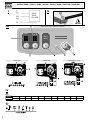 2
2
-
 3
3
-
 4
4
-
 5
5
-
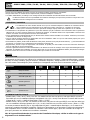 6
6
-
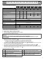 7
7
-
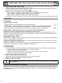 8
8
-
 9
9
-
 10
10
-
 11
11
-
 12
12
-
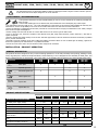 13
13
-
 14
14
-
 15
15
-
 16
16
-
 17
17
-
 18
18
-
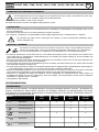 19
19
-
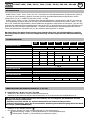 20
20
-
 21
21
-
 22
22
-
 23
23
-
 24
24
-
 25
25
-
 26
26
-
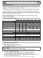 27
27
-
 28
28
-
 29
29
-
 30
30
-
 31
31
-
 32
32
-
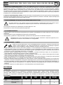 33
33
-
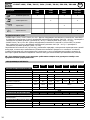 34
34
-
 35
35
-
 36
36
-
 37
37
-
 38
38
-
 39
39
-
 40
40
-
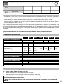 41
41
-
 42
42
-
 43
43
-
 44
44
-
 45
45
-
 46
46
-
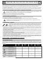 47
47
-
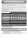 48
48
-
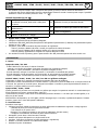 49
49
-
 50
50
-
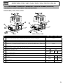 51
51
-
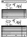 52
52
-
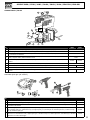 53
53
-
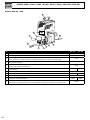 54
54
-
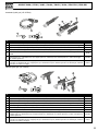 55
55
-
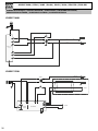 56
56
-
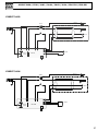 57
57
-
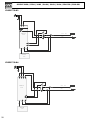 58
58
-
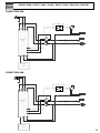 59
59
-
 60
60
-
 61
61
-
 62
62
-
 63
63
-
 64
64


GYS GYSPOT 3404 de handleiding
- Type
- de handleiding
- Deze handleiding is ook geschikt voor
in andere talen
- italiano: GYS GYSPOT 3404 Manuale del proprietario
- français: GYS GYSPOT 3404 Le manuel du propriétaire
- español: GYS GYSPOT 3404 El manual del propietario
- Deutsch: GYS GYSPOT 3404 Bedienungsanleitung
Gerelateerde artikelen
-
GYS GYSPOT EXPERT 400 de handleiding
-
GYS GYSPOT COMBI 230 E PRO de handleiding
-
-
-
GYS GYSPOT PTI GENIUS - 400 V de handleiding
-
-
GYS GYSPOT INVERTER PTI.G - 220 V de handleiding
-
-
GYS GYSPOT ARCPULL 350 de handleiding
-