
YAMAHA ELECTRONICS CORPORATION, USA
6660 ORANGETHORPE AVE., BUENA PARK, CALIF. 90620, U.S.A.
YAMAHA CANADA MUSIC LTD.
135 MILNER AVE., SCARBOROUGH, ONTARIO M1S 3R1, CANADA
YAMAHA ELECTRONIK EUROPA G.m.b.H.
SIEMENSSTR. 22-34, 25462 RELLINGEN BEI HAMBURG, GERMANY
YAMAHA ELECTRONIQUE FRANCE S.A.
RUE AMBROISE CROIZAT BP70 CROISSY-BEAUBOURG 77312 MARNE-LA-VALLEE CEDEX02, FRANCE
YAMAHA ELECTRONICS (UK) LTD.
YAMAHA HOUSE, 200 RICKMANSWORTH ROAD WATFORD, HERTS WD18 7GQ, ENGLAND
YAMAHA SCANDINAVIA A.B.
J A WETTERGRENS GATA 1, BOX 30053, 400 43 VÄSTRA FRÖLUNDA, SWEDEN
YAMAHA MUSIC AUSTRALIA PTY. LTD.
LEVEL 1, 99 QUEENSBRIDGE STREET, SOUTHBANK, VIC 3006, AUSTRALIA
©
2008 All rights reserved.
RX-V863
Printed in Malaysia WN24780
RX-V863
AV Receiver
Ampli-tuner audio-vidéo
OWNER’S MANUAL
MODE D’EMPLOI
BEDIENUNGSANLEITUNG
BRUKSANVISNING
GEBRUIKSAANWIJZING
ИНСТРУКЦИЯ ПО ЭКСПЛУАТАЦИИ
G
RX-V863_G-cv.mif Page 1 Thursday, January 17, 2008 5:05 PM
Black process 45.0° 240.0 LPI

CAUTION: READ THIS BEFORE OPERATING YOUR UNIT.
En
1 To assure the finest performance, please read this manual
carefully. Keep it in a safe place for future reference.
2 Install this sound system in a well ventilated, cool, dry, clean
place – away from direct sunlight, heat sources, vibration,
dust, moisture, and/or cold. Allow ventilation space of at least
30 cm on the top, 20 cm on the left and right, and 20 cm on
the back of this unit.
3 Locate this unit away from other electrical appliances, motors,
or transformers to avoid humming sounds.
4 Do not expose this unit to sudden temperature changes from
cold to hot, and do not locate this unit in an environment with
high humidity (i.e. a room with a humidifier) to prevent
condensation inside this unit, which may cause an electrical
shock, fire, damage to this unit, and/or personal injury.
5 Avoid installing this unit where foreign objects may fall onto
this unit and/or this unit may be exposed to liquid dripping or
splashing. On the top of this unit, do not place:
– other components, as they may cause damage and/or
discoloration on the surface of this unit.
– burning objects (i.e. candles), as they may cause fire,
damage to this unit, and/or personal injury.
– containers with liquid in them, as they may fall and liquid
may cause electrical shock to the user and/or damage to
this unit.
6 Do not cover this unit with a newspaper, tablecloth, curtain,
etc. in order not to obstruct heat radiation. If the temperature
inside this unit rises, it may cause fire, damage to this unit,
and/or personal injury.
7 Do not plug in this unit to a wall outlet until all connections
are complete.
8 Do not operate this unit upside-down. It may overheat,
possibly causing damage.
9 Do not use force on switches, knobs and/or cords.
10 When disconnecting the power cable from the wall outlet,
grasp the plug; do not pull the cable.
11 Do not clean this unit with chemical solvents; this might
damage the finish. Use a clean, dry cloth.
12 Only voltage specified on this unit must be used. Using this
unit with a higher voltage than specified is dangerous and may
cause fire, damage to this unit, and/or personal injury. Yamaha
will not be held responsible for any damage resulting from use
of this unit with a voltage other than specified.
13 To prevent damage by lightning, keep the power cord and
outdoor antennas disconnected from a wall outlet or the unit
during a lightning storm.
14 Do not attempt to modify or fix this unit. Contact qualified
Yamaha service personnel when any service is needed. The
cabinet should never be opened for any reasons.
15 When not planning to use this unit for long periods of time
(i.e. vacation), disconnect the AC power plug from the wall
outlet.
16 Install this unit near the AC outlet and where the AC power
plug can be reached easily.
17 Be sure to read the “Troubleshooting” section on common
operating errors before concluding that this unit is faulty.
18 Before moving this unit, press
L
SYSTEM OFF to set this
unit to the standby mode, and then disconnect the AC power
plug from the AC wall outlet.
19 VOLTAGE SELECTOR (Asia and General models only)
The VOLTAGE SELECTOR on the rear panel of this unit
must be set for your local main voltage BEFORE plugging
into the AC wall outlet. Voltages are:
Asia model ............................ 220/230–240 V AC, 50/60 Hz
General model ........ 110/120/220/230–240 V AC, 50/60 Hz
20 The batteries shall not be exposed to excessive heat such as
sunshine, fire or like.
21 Excessive sound pressure from earphones and headphones can
cause hearing loss.
■ For U.K. customers
If the socket outlets in the home are not suitable for the plug
supplied with this appliance, it should be cut off and an
appropriate 3 pin plug fitted. For details, refer to the
instructions described below.
The plug severed from the mains lead must be destroyed, as a
plug with bared flexible cord is hazardous if engaged in a live
socket outlet.
■ Special Instructions for U.K. Model
Caution: Read this before operating your unit.
WARNING
TO REDUCE THE RISK OF FIRE OR ELECTRIC
SHOCK, DO NOT EXPOSE THIS UNIT TO RAIN OR
MOISTURE.
As long as this unit is connected to the AC wall outlet, it is
not disconnected from the AC power source even if you
turn off this unit by
L
SYSTEM OFF. In this state, this
unit is designed to consume a very small quantity of
power.
Note
IMPORTANT
THE WIRES IN MAINS LEAD ARE COLOURED IN
ACCORDANCE WITH THE FOLLOWING CODE:
Blue: NEUTRAL
Brown: LIVE
As the colours of the wires in the mains lead of this apparatus
may not correspond with the coloured markings identifying
the terminals in your plug, proceed as follows:
The wire which is coloured BLUE must be connected to the
terminal which is marked with the letter N or coloured
BLACK. The wire which is coloured BROWN must be
connected to the terminal which is marked with the letter L or
coloured RED.
Making sure that neither core is connected to the earth
terminal of the three pin plug.
This symbol mark is according to the EU
directive 2002/96/EC.
This symbol mark means that electrical
and electronic equipment, at their end-of-
life, should be disposed of separately from
your household waste.
Please act according to your local rules
and do not dispose of your old products
with your normal household waste.

1 En
PREPARATIONINTRODUCTION
BASIC
OPERATION
ADVANCED
OPERATION
ADDITIONAL
INFORMATION
APPENDIX
English
Features ................................................................... 2
Supplied accessories .................................................. 2
Notice ....................................................................... 3
Getting started ........................................................ 4
Quick start guide .................................................... 5
Connections........................................................... 10
Optimizing the speaker setting
for your listening room (YPAO) ..................... 32
Using AUTO SETUP .............................................. 32
Selecting the SCENE templates........................... 37
Selecting the desired SCENE template
to the SCENE buttons.......................................... 37
Creating your original SCENE templates................ 40
Using the remote control for the SCENE feature .... 41
Playback ................................................................ 42
Basic procedure ....................................................... 42
Selecting the MULTI CH INPUT component......... 43
Selecting the front speaker set ................................. 43
Selecting audio input jacks (AUDIO SELECT)...... 44
Displaying the current status of this unit
on a video monitor............................................... 44
Using your headphones............................................ 45
Muting the audio output........................................... 45
Playing video sources in the background
of an audio source................................................ 45
Displaying the input source information ................. 46
Using the sleep timer ............................................... 47
Sound field programs.......................................... 48
Selecting sound field programs ............................... 48
Sound field program descriptions............................ 48
Enjoying unprocessed input sources
(Straight decoding mode) .................................... 51
Using audio features ............................................. 52
Adjusting the speaker level...................................... 52
Enjoying pure hi-fi sound ........................................ 52
Adjusting the tonal quality....................................... 52
FM/AM tuning ...................................................... 53
Overview.................................................................. 53
Basic tuning operations............................................ 53
Using station preset feature ..................................... 54
Radio Data System tuning
(Europe and Russia models only).................... 57
Selecting the Radio Data System program type
(PTY SEEK mode).............................................. 57
Using the enhanced other networks (EON)
data service .......................................................... 58
Displaying the Radio Data System information ...... 59
Using iPod™.......................................................... 60
Controlling iPod™................................................... 60
Using Bluetooth™ components ........................... 62
Pairing the Bluetooth™ adapter
and your Bluetooth™ component ....................... 62
Playback of the Bluetooth™ component................. 62
Recording .............................................................. 63
Advanced sound configurations...........................64
Changing sound field parameter settings................. 64
Selecting decoders ................................................... 70
Customizing this unit (MANUAL SETUP).........72
Using SET MENU................................................... 76
1 BASIC MENU...................................................... 77
2 VOLUME MENU ................................................ 81
3 SOUND MENU.................................................... 82
4 INPUT MENU...................................................... 85
5 OPTION MENU................................................... 88
Remote control features........................................92
Controlling this unit, a TV,
or other components ............................................ 92
Setting remote control codes ................................... 94
Programming codes from other remote controls ..... 96
Changing source names in the display window....... 97
Macro programming features .................................. 98
Clearing configurations ......................................... 101
Using multi-zone configuration..........................104
Connecting Zone 2................................................. 104
Controlling Zone 2................................................. 105
Advanced setup....................................................107
Using the advanced setup ...................................... 107
Troubleshooting...................................................111
Resetting the system............................................119
Glossary................................................................120
Sound field program information......................123
Specifications .......................................................124
Index.....................................................................126
(at the end of this manual)
Front panel................................................................i
Remote control ....................................................... ii
List of remote control codes ................................. iii
Contents
INTRODUCTION
PREPARATION
BASIC OPERATION
ADVANCED OPERATION
ADDITIONAL INFORMATION
APPENDIX
“
A
SPEAKERS” or “
5
DVD” (example) indicates the name
of the parts on the front panel or the remote control. Refer to
the attached sheet or the pages at the end of this manual for
the information about each position of the parts.

FEATURES
2 En
Built-in 7-channel power amplifier
◆ Minimum RMS output power
(20 Hz to 20 kHz, 0.06% THD, 8 Ω)
Front: 105 W + 105 W
Center: 105 W
Surround: 105 W + 105 W
Surround back: 105 W + 105 W
SCENE function
◆ Preset SCENE templates for various situations
◆ SCENE templates for customizing capability
◆ Controlling Yamaha SCENE control signal support
component (some models only) working with the SCENE
function
Sound field programs
◆ Proprietary Yamaha technology for the creation of sound
fields
◆ Compressed Music Enhancer mode
◆ Virtual CINEMA DSP
◆ SILENT CINEMA
Digital audio decoders
◆ Dolby TrueHD, Dolby Digital Plus decoder
◆ DTS-HD Master Audio, DTS-HD High Resolution Audio
decoder
◆ Dolby Digital/Dolby Digital EX decoder
◆ DTS/DTS-ES Matrix 6.1, Discrete 6.1, DTS 96/24 decoder
◆ Dolby Pro Logic/Dolby Pro Logic II/Dolby Pro Logic IIx
decoder
Radio tuners
◆ FM/AM tuning capability
◆ Radio Data System capability (Europe and Russia models
only)
HDMI™ (High-Definition Multimedia Interface)
◆ HDMI interface for standard, enhanced or
high-definition video as well as multi-channel digital audio
based on HDMI version 1.3a (HDMI is licensed by HDMI
Licensing LLC.)
– Automatic audio and video synchronization (lip sync)
information capability
– Deep Color video signal (30/36 bit) transmission capability
– “x.v.Color” video signal transmission capability
– High refresh rate and high resolution video signals
capability
– High definition digital audio format signals capability
◆ HDCP (High-bandwidth Digital Content Protection System)
licensed by Digital Content Protection, LLC.
◆ Analog video to HDMI digital video up-conversion
(composite video ↔ S-video ↔ component video → HDMI
digital video) capability for monitor out
◆ Analog video up-scaling from 480i (NTSC)/576i (PAL) or
480p/576p to 720p, 1080i or 1080p
DOCK terminal
◆ DOCK terminal to connect a Yamaha iPod universal dock
(such as YDS-10, sold separately) or Bluetooth adapter (such
as YBA-10, sold separately)
Other features
◆ YPAO (Yamaha Parametric Room Acoustic Optimizer) for
automatic speaker setup
◆ 192-kHz/24-bit D/A converter
◆ OSD (on-screen display) menus that allow you to optimize
this unit to suit your individual audiovisual system
◆ 5.1 or 7.1-channel additional input jacks for discrete multi-
channel input
◆ Component video input/output capability includes
(3 COMPONENT VIDEO INs and 1 MONITOR OUT)
◆ Digital video signal conversion (composite video ↔ S-video
↔ component video) capability for monitor out
◆ Pure Direct mode for pure hi-fi sound for all sources
◆ Adaptive dynamic range controlling capability
◆ Adaptive DSP effect level controlling capability
◆ iPod controlling capability
◆ Remote control with preset remote control codes, learning,
and macro capability
◆ Zone 2 custom installation facility
◆ Bi-amplification connection capability
◆ Sleep timer
Check that you received all of the following parts.
❏ Remote control
❏ Batteries (4) (AAA, R03, UM-4)
❏ Optimizer microphone
❏ AM loop antenna
❏ Indoor FM antenna
Features
Supplied accessories

Notice
3 En
INTRODUCTION
English
Manufactured under license from Dolby Laboratories.
“Dolby”, “Pro Logic”, and the double-D symbol are trademarks
of Dolby Laboratories.
Manufactured under license under U.S. Patent No’s:
5,451,942;5,956,674;5,974,380;5,978,762;6,226,616;6,487,535
& other U.S. and worldwide patents issued & pending. DTS is a
registered trademark and the DTS logos, Symbol, DTS-HD and
DTS-HD Master Audio are trademark of DTS, Inc. © 1996-2007
DTS, Inc. All Rights Reserved.
iPod™
“iPod” is a trademark of Apple Inc., registered in the U.S. and
other countries.
Bluetooth
™
Bluetooth is a registered trademark of the Bluetooth SIG and is
used by Yamaha in accordance with a license agreement.
“HDMI”, the “HDMI” logo and “High-Definition Multimedia
Interface” are trademarks or registered trademarks of HDMI
Licensing LLC.
x.v.Color™
“x.v.Color” is a trademark of Sony Corporation.
“SILENT CINEMA” is a trademark of Yamaha Corporation.
Notice
About this manual
• y indicates a tip for your operation.
• Some operations can be performed by using either the
buttons on the front panel or the ones on the remote
control. In case the button names differ between the front
panel and the remote control, the button name on the
remote control is given in parentheses.
• This manual is printed prior to production. Design and
specifications are subject to change in part as a result of
improvements, etc. In case of differences between the
manual and product, the product has priority.
•“
A
SPEAKERS” or “
5
DVD” (example) indicates the
name of the parts on the front panel or the remote control.
Refer to the attached sheet or the pages at the end of this
manual for the information about each position of the
parts.
•
The symbol “☞ ” with page number(s) indicates the
corresponding reference page(s).

GETTING STARTED
4 En
■ Installing batteries in the remote control
1 Press the part and slide the battery
compartment cover off.
2 Insert the four supplied batteries
(AAA, R03, UM-4) according to the polarity
markings (+ and –) on the inside of the
battery compartment.
3 Slide the cover back until it snaps into place.
• Change all of the batteries if you notice the following
conditions:
– the operation range of the remote control decreases.
– the transmit indicator (
2
) does not flash or its light becomes
dim.
• Do not use an old battery together with a new one.
• Do not use different types of batteries (such as alkaline and
manganese batteries) together. Read the packaging carefully as
these different types of batteries may have the same shape and
color.
• If the batteries have leaked, dispose of them immediately. Avoid
touching the leaked material or letting it come into contact with
clothing, etc. Clean the battery compartment thoroughly before
installing new batteries.
• Do not throw away batteries with general house waste; dispose
of them correctly in accordance with your local regulations.
• If the remote control is without batteries for more than 2
minutes, or if exhausted batteries remain in the remote control,
the contents of the memory may be cleared. When the memory
is cleared, insert new batteries, set up the remote control code
and program any acquired functions that may have been
cleared.
■ VOLTAGE SELECTOR
(Asia and General models only)
Getting started
Notes
1
3
2
Caution
The VOLTAGE SELECTOR on the rear panel of this
unit must be set for your local voltage BEFORE
plugging the power cable into the AC wall outlet.
Improper setting of the VOLTAGE SELECTOR may
cause damage to this unit and create a potential fire
hazard.
Rotate the VOLTAGE SELECTOR clockwise or
counterclockwise to the correct position using a
straight slot screwdriver.
Voltages are as follows:
Asia model ................... 220/230–240 V AC, 50/60 Hz
General model
..................... 110/120/220/230–240 V AC, 50/60 Hz
230-
240V
VOLTAGE
SELECTOR
Voltage indication

Quick start guide
5 En
INTRODUCTION
English
The following steps describe the easiest way to enjoy DVD movie playback in your home theater. See pages 11 to 15 for
details of the speaker placement.
Prepare the following items.
❏ Speakers
❏ Front speakers ...................................x 2
❏ Center speaker ..................................x 1
❏ Surround speakers ............................x 4
Select magnetically shielded speakers. The
minimum required speakers are two front speakers.
The priority of the requirement of other speakers is
as follows:
1. Two surround speakers
2. Center speaker
3. One (or two) surround back speaker(s)
❏ Active subwoofer ...................................x 1
Select an active subwoofer equipped with an RCA
input jack.
❏ Speaker cables .......................................x 7
❏ Subwoofer cable ....................................x 1
Select a monaural RCA cable.
❏ DVD player ..............................................x 1
Select DVD player equipped with coaxial digital
audio output jack and composite video output
jack.
❏ Video monitor .........................................x 1
Select a TV monitor, video monitor or projector
equipped with a composite video input jack.
❏ Video cable .............................................x 2
Select an RCA composite video cable.
❏ Digital coaxial audio cable ....................x 1
y
You can also connect two subwoofers to this unit. In this
case, prepare two active subwoofers and subwoofer cables.
Quick start guide
Front right
speaker
Subwoofer
Surround back
right speaker
Surround left
speaker
Front left
speaker
Surround back left
speaker
Surround right
speaker
Center
speaker
Video monitor
DVD player
Enjoy DVD playback!
Step 1: Set up your speakers
☞
P. 6
Step 2: Connect your DVD player
and other components
Step 3: Press SCENE 1 button
☞
P. 7
☞
P. 8
Preparation: Check the items

Quick start guide
6 En
Place your speakers in the room and connect them to this
unit.
1 Place your speakers and subwoofer in the
room.
2 Connect speaker cables to each speaker.
Be sure to connect the “+” (red) and “–” (black) properly.
Cables are colored or shaped differently, perhaps with a
stripe, groove or ridge. Connect the striped (grooved, etc.)
cable to the “+” (red) terminals of this unit and your speaker.
Connect the plain cable to the “–” (black) terminals.
3 Connect each speaker cable to the
corresponding speaker terminal of this unit.
Be sure to connect the left channel (L), right channel
(R), “+” (red) and “–” (black) properly.
Front speakers and center speaker
Surround and surround back speakers
4 Connect the subwoofer cable to the
SUBWOOFER PRE OUT 1 jack of this unit
and the input jack of the subwoofer.
y
You can also connect another subwoofer to the SUBWOOFER
PRE OUT 2 jack.
Step 1: Set up your speakers
AC OUTLETS
R
L
AUDIO MULTI CH INPUT PRE OUT DOCK VIDEO
COMPONENT VIDEO
HDMI
DIGITAL INPUT
ANTENNA
REMOTE
DIGITAL
OUTPUT
TRIGGER
OUT
SPEAKERS
DVDSUBWOOFERFRONTSB (8CH) ZONE 2
OUT
SUB
WOOFER
SUR. BACKSURROUND
SINGLE CENTERCENTERFRONT (8CH)
SURROUND
DVD
DTV/CBL
S VIDEO
VIDEO
DTV/CBL
DVR
DVRMONITOR OUT
VCR
OUTININ OUT
1 2
DVD
DVDCDDTV/CBL
OPTICAL COAXIAL
DVD
DVR
OUT
SURROUND BACK/BI-AMPSURROUND
SINGLE
CENTERFRONT A
AM
+12V
15mA MAX.
GND
FRONT B/ZONE B/
ZONE 2/PRESENCE
DTV/CBLDVD
MD/CD-R MD/CD-R
PHONO
GND
CD
MD/
CD-R
IN
(PLAY)
OUT
(REC)
DTV/CBL DVR VCR
OUTININ OUT
IN OUT
MONITOR
OUT
FM
UNBAL.
R
L
R
L
R
L
R
L
65
4
321
IN2 IN3IN1
EXTRA SP
Y
P
R
P
B
Y
P
R
P
B
A B
C
75Ω
Speaker terminals
PRE OUT SUBWOOFER 1 jack
12 3 4
4
1
Make sure that this unit and the subwoofer are
unplugged from the AC wall outlets.
2
Twist the exposed wires of the speaker cables
together to prevent short circuits.
3
Do not let the bare speaker wires touch each
other.
4
Do not let the bare speaker wires touch any
metal part of this unit.
To the front left
speaker
To the front right
speaker
To the center speaker
Loosen Insert Tighten
To the surround
right speaker
To the surround
back left speaker
To the surround
left speaker
To the surround
back right speaker
PRE OUT
DOCK
DVD
SUBWOOFER
SUR. BACK
R
ROUND
SINGLE
CENTER
S VI
D
VID
E
12
SUBWOOFER PRE
OUT 1 jack
Subwoofer cable
Input jack
AV receiverSubwoofer

Quick start guide
7 En
INTRODUCTION
English
1 Connect the digital coaxial audio cable to the
digital coaxial audio output jack of your DVD
player and the DVD DIGITAL INPUT COAXIAL
jack of this unit.
2 Connect the video cable to the composite
video output jack of your DVD player and
DVD VIDEO jack of this unit.
y
• When you connect a component that has only a SCART
jack, use an appropriate converter. The connection
between a converter and this unit depends on signals that
are available on the converter. For details, refer to the
instructions of your converter.
• This unit cannot transmit RGB signals.
3 Connect the video cable to the VIDEO
MONITOR OUT jack of this unit and the video
input jack of your video monitor.
4 Connect the power plug of this unit and other
components into the AC wall outlet.
y
This unit is equipped with AC OUTLET(S) for the power
supply of the other components (except Korea model). See
page 28 for details.
Step 2: Connect your DVD player
and other components
AC OUTLETS
R
L
AUDIO MULTI CH INPUT PRE OUT DOCK VIDEO
COMPONENT VIDEO
HDMI
DIGITAL INPUT
ANTENNA
REMOTE
DIGITAL
OUTPUT
TRIGGER
OUT
SPEAKERS
DVDSUBWOOFERFRONTSB (8CH) ZONE 2
OUT
SUB
WOOFER
SUR. BACKSURROUND
SINGLE CENTERCENTERFRONT (8CH)
SURROUND
DVD
DTV/CBL
S VIDEO
VIDEO
DTV/CBL
DVR
DVRMONITOR OUT
VCR
OUTININ OUT
12
DVD
DVDCDDTV/CBL
OPTICAL COAXIAL
DVD
DVR
OUT
SURROUND BACK/BI-AMPSURROUND
SINGLE
CENTERFRONT A
AM
+12V
15mA MAX.
GND
FRONT B/ZONE B/
ZONE 2/PRESENCE
DTV/CBLDVD
MD/CD-R MD/CD-R
PHONO
GND
CD
MD/
CD-R
IN
(PLAY)
OUT
(REC)
DTV/CBL DVR VCR
OUTININ OUT
IN OUT
MONITOR
OUT
FM
UNBAL.
R
L
R
L
R
L
R
L
65
4
321
IN2 IN3IN1
EXTRA SP
Y
P
R
P
B
Y
P
R
P
B
A B
C
75Ω
Make sure that this unit and the DVD
player are unplugged from the AC
wall outlets.
DVD DIGITAL INPUT COAXIAL jack DVD VIDEO jack
VIDEO MONITOR OUT jack
DVD
AUDIO
AUDIO
M
DIGITAL INPUT
SPEAKERS
SB (8C
H
FRONT (8C
H
DVD
DVD
CD
DTV/CBL
DVD
OPTICAL
COAXIAL
S
U
CENTER
FRONT A
FRONT B/ZONE B/
ZONE 2/PRESENCE
DVD
D/
D
-R
OUT
(REC)
DTV/CBL
DVR
VCR
O
U
T
IN
IN O
U
T
R
R
L
R
L
6
5
4
3
IN1
EXTRA SP
Digital coaxial
audio output
jack
Digital coaxial audio
cable
DVD DIGITAL
INPUT COAXIAL
jack
DVD player
AV receiver
DOCK
VIDEO
COMPONENT
V
DVD
DVD
DTV/CBL
S VIDEO
V
I
DEO
DVR
OUT
IN
OUT
P
R
Y
P
R
P
B
A
Composite
video output
jack
Video cable
DVD VIDEO jack
DVD player
AV receiver
■ For further connections
• Using the other kind of speaker combinations
☞ P. 11
• Connecting a video monitor via various ways of the
connection ☞ P. 20
• Connecting a DVD player via various ways of the
connection ☞ P. 21
• Connecting a DVD recorder or a digital video
recorder ☞ P. 22
• Connecting a set-top box ☞ P. 22
• Connecting a CD player, an MD recorder or a
turntable ☞ P. 23
• Connecting an external amplifier ☞ P. 24
• Connecting a DVD player via analog multi-channel
audio connection ☞ P. 25
• Connecting a Yamaha iPod universal dock or
Bluetooth adapter ☞ P. 25
• Using the REMOTE IN/OUT jacks ☞ P. 26
• Using the VIDEO AUX jacks on the front panel
☞ P. 26
• Connecting a FM/AM antenna ☞ P. 27
VIDEO
COMPONENT VIDEO
DVD
DTV/CBL
DVR
DVR
VCR
OUT
IN
IN
OUT
MONITOR
OUT
Y
P
R
P
B
Y
P
B
B
C
Video monitor
AV receiver
Video cable
VIDEO
MONITOR OUT
jack
Video input jack

Quick start guide
8 En
1 Turn on the video monitor and then set the
input source selector of the video monitor to
this unit.
2 Press
S
SCENE1 button.
This unit is turned on. “DVD Movie Viewing”
appears in the front panel display, and this unit
automatically optimize own status for the DVD
playback.
y
The indicator on the selected SCENE button lights up while
this unit is in the SCENE mode.
3 Rotate
J
VOLUME to adjust the volume.
When you change the input source or sound field program,
the SCENE mode is deactivated.
■ About SCENE function
Just by pressing one SCENE button, you can turn on this
unit and recall your favorite input source and sound field
program according to the SCENE template that has been
assigned to the SCENE button. The SCENE templates are
built combinations of input sources and sound field
programs.
y
If you connect a Yamaha product that has capability of the
SCENE control signals, this unit can automatically activate the
component and start playback. Refer to the instruction manual of
the DVD player for further information.
■ The default assigned SCENE templates
*1
You must connect a cable TV or a satellite tuner to this unit in
advance. See page 22 for details.
*2
You need to connect the supplied FM and AM antennas to this
unit in advance. See page 27 for details.
*3
You must tune into the desired radio station in advance. See
pages 53 to 56 for tuning information.
*4
To achieve the best possible reception, orient the connected
AM loop antenna, or adjust the position of the end of the
indoor FM antenna.
y
You can change the assigned SCENE template for the SCENE
buttons. See page 37 for details.
Step 3: Press SCENE 1 button
Check the type of the connected speakers.
If the speakers are 6 ohm speakers, set “SP IMP.” to
“6Ω MIN” before using this unit (see page 28). 4 ohm
speakers can be also used as the front speakers (see
page 107).
Note
Default
SCENE
button
The name of the SCENE template
and its description
SCENE
1
DVD Movie Viewing
– input source: DVD
– sound field program: Sci-Fi
For when you want to enjoy a movie from the
connected DVD player.
SCENE
2
Music Disc Listening
– input source: DVD
– sound field program: 2ch Stereo
For when you want to listen to a music disc from
the connected DVD player.
SCENE
3
TV Viewing
*1
– input source: DTV/CBL
– sound field program: Straight
For when you want to watch a TV program.
SCENE
4
Radio Listening
*2, *3, *4
– input source: TUNER
– sound field program: 7ch Enhancer
For when you want to listen to a music program
from the FM radio station.
Notes

Quick start guide
9 En
INTRODUCTION
English
■ After using this unit...
Press
K
MAIN ZONE ON/OFF to set this unit to
the standby mode.
This unit is set to the standby mode and consumes a small
amount of power in order to receive infrared signals from
the remote control. To turn on this unit from the standby
mode, press the desired
S
SCENE buttons
(or
4
SCENE) or
K
MAIN ZONE ON/OFF
(or
E
POWER). See page 29 for details.
What do you want to do with this
unit?
■ Customizing the SCENE templates
• Using various SCENE templates ☞ P. 37
• Creating your original SCENE templates
☞ P. 40
■ Using various input sources
• Basic controls of this unit ☞ P. 42
• Enjoying FM/AM radio programs ☞ P. 53
• Using your iPod with this unit ☞ P. 60
• Using the Bluetooth components ☞ P. 62
■ Using various sound features
• Using various sound field programs ☞ P. 48
• Using the pure direct mode for high
fidelity sound ☞ P. 52
• Customizing the sound field programs ☞ P. 64
■ Adjusting the parameters of this unit
• Automatically optimizing the speaker parameters
for your listening room
(AUTO SETUP) ☞ P. 32
• Manually adjusting various parameters of this unit
☞ P. 72
• Setting the remote control ☞ P. 92
• Adjusting the advanced parameters ☞ P. 107
■ Additional feature
• Automatically turning off this unit ☞ P. 47

CONNECTIONS
10 En
8
TRIGGER OUT jack
This is control expansion jack for custom installation.
Connections
Rear panel
AC OUTLETS
R
L
AUDIO MULTI CH INPUT PRE OUT DOCK VIDEO
COMPONENT VIDEO
HDMI
DIGITAL INPUT
ANTENNA
REMOTE
DIGITAL
OUTPUT
TRIGGER
OUT
SPEAKERS
DVDSUBWOOFERFRONTSB (8CH) ZONE 2
OUT
SUB
WOOFER
SUR. BACKSURROUND
SINGLE CENTERCENTERFRONT (6CH)
SURROUND
DVD
DTV/CBL
S VIDEO
VIDEO
DTV/CBL
DVR
DVRMONITOR OUT
VCR
OUTININ OUT
12
DVD
DVDCDDTV/CBL
OPTICAL COAXIAL
DVD
DVR
OUT
SURROUND BACK/BI-AMPSURROUND
SINGLE
CENTERFRONT A
AM
+12V
15mA MAX.
GND
FRONT B/ZONE B/
ZONE 2/PRESENCE
DTV/CBLDVD
MD/CD-R MD/CD-R
PHONO
GND
CD
MD/
CD-R
IN
(PLAY)
OUT
(REC)
DTV/CBL DVR VCR
OUTININ OUT
IN OUT
MONITOR
OUT
FM
UNBAL.
R
L
R
L
R
L
R
L
65
4
321
IN2 IN3IN1
EXTRA SP
Y
P
R
P
B
Y
P
R
P
B
A B
C
75Ω
78 9 0A B
123456
Name Page
1 AUDIO jacks
21
DIGITAL INPUT/OUTPUT jacks
17-23
2 MULTI CH INPUT jacks
25
3 ZONE2 OUT jacks
104
4 PRE OUT jacks
24
5 DOCK terminal
25
6 Video component jacks
(VIDEO and S VIDEO)
17-22
COMPONENT VIDEO jacks
17-22
7 ANTENNA terminals
27
8 REMOTE IN/OUT jacks
26
9 Speaker terminals
11-16
0 HDMI jacks
18
A VOLTAGE SELECTOR
(Asia and General models only)
4
B AC OUTLET(S)
28

11 En
Connections
PREPARATION
English
The speaker layout below shows the speaker setting we recommend. You can use it to enjoy the CINEMA DSP and
multi-channel audio sources.
■ 7.1-channel speaker layout
7.1-channel speaker layout is highly recommended for playback the sound of high definition audio formats (Dolby
TrueHD, DTS-HD Master Audio, etc.) as well as the conventional audio sources with sound field programs. See page 14
for connection information.
y
We recommend that you also add the presence speakers for the effect sounds of the CINEMA DSP sound field program. See page 13 for
details.
Front left and right speakers
The front speakers are used for the main source sound plus effect sounds. Place these speakers at an equal distance from the
ideal listening position. The distance of each speaker from each side of the video monitor should be the same.
Center speaker
The center speaker is for the center channel sounds (dialog, vocals, etc.). If for some reason it is not practical to use a
center speaker, you can do without it. Best results, however, are obtained with the full system.
Surround left and right speakers
The surround speakers are used for effect and surround sounds.
Surround back left and right speakers
The surround back speakers supplement the surround speakers and provide more realistic front-to-back transitions.
Subwoofer(s)
The use of a subwoofer with a built-in amplifier, such as the Yamaha Active Servo Processing Subwoofer System, is
effective not only for reinforcing bass frequencies from any or all channels, but also for reproducing the high fidelity
sound of the LFE (low-frequency effect) channel included in Dolby Digital and DTS sources. You can connect one or
two subwoofer(s) to this unit. When you use two subwoofers, you can enjoy deeper bass sound. The position of the
subwoofer is not so critical, because low bass sounds are not highly directional. But it is better to place the subwoofer
near the front speakers. Turn it slightly toward the center of the room to reduce wall reflections.
y
When you use two subwoofers, select the same type of the subwoofer as another and set these subwoofers as same sound characteristics.
Place each subwoofer at the same distance from the listening position. The signal output at the SUBWOOFER PRE OUT 2 jack is the
same as the one output at the SUBWOOFER PRE OUT 1 jack.
Placing speakers
FR
FL
SBR
SBL
SL
SR
C
SW
SW
60˚
30˚
80˚
FR
SBL
SBR
SL
SL
C
SR
SR
FL
Speaker indications
FL/FR: Front left/right
C: Center
SL/SR: Surround left/right
SBL/SBR: Surround back left/right
SW: Subwoofer
30 cm (12 in) or more

12 En
Connections
■ 6.1-channel speaker layout
See page 14 for connection information.
y
We recommend that you also add the presence speakers for the
effect sounds of the CINEMA DSP sound field program. See
page 13 for details.
Front left and right speakers
Center speaker
Surround left and right speakers
Subwoofer(s)
The functions and settings of each speaker are the same as
those for the 7.1-channel speaker layout (see page 11).
Surround back speaker
Connect a single surround speakers to the SURROUND
BACK SINGLE speaker terminal and place the single
surround back speaker behind the listening position. The
surround back left and right channel signals are mixed
down and output at the single surround back speaker when
you set “SUR.B L/R SP” to “SMLx1” or “LRGx1” (see
page 78).
■ 5.1-channel speaker layout
See page 14 for connection information.
y
We recommend that you also add the presence speakers for the
effect sounds of the CINEMA DSP sound field program. See
page 13 for details.
Front left and right speakers
Center speaker
Subwoofer(s)
The functions and settings of each speaker are the same as
those for the 7.1-channel speaker layout (see page 11).
Surround left and right speakers
Connect the surround speakers to the SURROUND
speaker terminals even if you place the surround speakers
behind the listening position. For the smooth and
unbroken sound field behind the listening position, place
the surround left and right speakers farther back compared
with the placement in the 7.1-channel speaker layout. The
surround back channel signals are directed to the surround
left and right speakers when “SUR.B L/R SP” is set to
“NONE” (see page 78).
FR
FL
SB
SL
SR
C
SW
SW
60˚
30˚
80˚
FR
SB
SL
SL
C
SR
SR
FL
Speaker indications
FL/FR: Front left/right
C: Center
SL/SR: Surround left/right
SB: Surround back
SW: Subwoofer
FR
FL
SL
SR
SW
SW
C
60˚
30˚
80˚
FR
SL
SL
C
SR
SR
FL
Speaker indications
FL/FR: Front left/right
C: Center
SL/SR: Surround left/right
SW: Subwoofer
For other speaker combinations
You can enjoy multi-channel sources with sound field programs by using a speaker combination other than the 7.1/
6.1/5.1-channel speaker combinations.
Use the automatic setup feature (see page 32) or set the “SPEAKER SET” parameters in “MANUAL SETUP” (see
page 77) to output the surround sounds at the connected speakers.

13 En
Connections
PREPARATION
English
■ Using presence speakers
The presence speakers supplement the sound from the front and surround back speakers with extra ambient effects
produced by the sound field programs (see page 48). You can adjust the vertical position of dialogues with using the
presence speakers (see page 65).
To use the presence speakers, connect the speakers to the EXTRA SP terminal (see page 14) and set “EXTRA SP
ASSIGN” to “PRESENCE” (see pages 33 and 77).
FR
PRPL
C
FL
0.5 to 1 m (1 to 3 ft)
1.8 m
(6 ft) or
higher
Speaker indications
FL: Front left
FR: Front right
C: Center
PL: Front presence left
PR: Front presence right
0.5 to 1 m (1 to 3 ft)
1.8 m
(6 ft) or
higher

14 En
Connections
Be sure to connect the left channel (L), right channel (R), “+” (red) and “–” (black) properly. If the connections are faulty,
this unit cannot reproduce the input sources accurately.
A speaker cord is actually a pair of insulated cables running side by side. Cables are colored or shaped differently, perhaps with a stripe,
groove or ridge. Connect the striped (grooved, etc.) cable to the “+” (red) terminals of this unit and your speaker. Connect the plain cable
to the “–” (black) terminals.
■ For the 7.1-channel speaker setting
Connecting speakers
Caution
• Before connecting the speakers, make sure that the AC power plug is disconnected from the AC wall outlet.
• Do not let the bare speaker wires touch each other or let them touch any metal part of this unit. This could damage
this unit and/or the speakers. If the speaker wires are short-circuited, “CHECK SP WIRES” appears in the front
panel display when you turn on this unit.
• Use the magnetically shielded speakers. If this type of speaker still creates interference with the monitor, place the
speakers away from the monitor.
• If you are to use 6 ohm speakers, be sure to set “SP IMP.” to “6Ω MIN” before using this unit (see page 28). 4 ohm
speakers can be also used as the front speakers. For details about the speaker impedance setting, see page 107.
Note
AC OUTLETS
R
L
AUDIO MULTI CH INPUT PRE OUT DOCK VIDEO
COMPONENT VIDEO
HDMI
DIGITAL INPUT
ANTENNA
REMOTE
DIGITAL
OUTPUT
TRIGGER
OUT
SPEAKERS
DVDSUBWOOFERFRONTSB (8CH) ZONE 2
OUT
SUB
WOOFER
SUR. BACKSURROUND
SINGLE CENTERCENTERFRONT (6CH)
SURROUND
DVD
DTV/CBL
S VIDEO
VIDEO
DTV/CBL
DVR
DVRMONITOR OUT
VCR
OUTININ OUT
12
DVD
DVDCDDTV/CBL
OPTICAL COAXIAL
DVD
DVR
OUT
SURROUND BACK/BI-AMPSURROUND
SINGLE
CENTERFRONT A
AM
+12V
15mA MAX.
GND
FRONT B/ZONE B/
ZONE 2/PRESENCE
DTV/CBLDVD
MD/CD-R MD/CD-R
PHONO
GND
CD
MD/
CD-R
IN
(PLAY)
OUT
(REC)
DTV/CBL DVR VCR
OUTININ OUT
IN OUT
MONITOR
OUT
FM
UNBAL.
R
L
R
L
R
L
R
L
65
4
321
IN2 IN3IN1
EXTRA SP
Y
P
R
P
B
Y
P
R
P
B
A B
C
75Ω
Front speakers
(FRONT A)
Surround speakers
Subwoofers
Right
Center speaker
Surround back speakers
Left
Left
Left
Right
Right
EXTRA SP terminals
Connect the alternative front speaker system (FRONT B), front speaker systems in another room
(ZONE B), presence speakers, or Zone 2 speakers. To select the function of the speakers connected
to the EXTRA SP terminals, set the “EXTRA SP ASSIGN” parameter in “SOUND MENU” (see
page 77).
y
You can also select the function of the speakers connected to the EXTRA SP terminals in “AUTO
SETUP” (see page 33).
(optional)

15 En
Connections
PREPARATION
English
■ For the 6.1-channel speaker setting
■ For the 5.1-channel speaker setting
Surround back speaker
AUDIO MULTI CH INPUT PRE OUT DOCK
HDMI
DIGITAL INPUT
E
R
SPEAKERS
SUBWOOFERFRONTSB (8CH) ZONE 2
OUT
SUB
WOOFER
SUR. BACKSURROUND
SINGLE CENTERCENTERFRONT (6CH)
SURROUND
12
DVD
DVDCDDTV/CBL
OPTICAL COAXIAL
DVD
DVR
OUT
SURROUND BACK/BI-AMPSURROUND
SINGLE
CENTERFRONT A
A
X.
FRONT B/ZONE B/
ZONE 2/PRESENCE
DTV/CBLDVD
D
/CD-R
MD/
CD-R
I
N
L
AY )
OUT
(REC)
DTV/CBL DVR VCR
OUTININ OUT
R
L
R
L
R
L
R
L
65
4
32
IN2 IN3IN1
EXTRA SP
Surround speakers
EXTRA SP terminals
(see page 14)
Left (SINGLE)
Center speaker
LeftRight
Front speakers
(FRONT A)
LeftRight
Subwoofers
(optional)
AUDIO MULTI CH INPUT PRE OUT DOCK
HDMI
DIGITAL INPUT
E
R
T
SPEAKERS
SUBWOOFERFRONTSB (8CH) ZONE 2
OUT
SUB
WOOFER
SUR. BACKSURROUND
SINGLE CENTERCENTERFRONT (6CH)
SURROUND
12
DVD
DVDCDDTV/CBL
OPTICAL COAXIAL
DVD
DVR
OUT
SURROUND BACK/BI-AMPSURROUND
SINGLE
CENTERFRONT A
A
X.
FRONT B/ZONE B/
ZONE 2/PRESENCE
DTV/CBLDVD
D
/CD-R
MD/
CD-R
IN
LAY)
OUT
(REC)
DTV/CBL DVR VCR
OUTININ OUT
R
L
R
L
R
L
R
L
65
4
32
IN2 IN3IN1
EXTRA SP
Surround speakers
EXTRA SP terminals
(see page 14)
Center speaker
LeftRight
Front speakers
(FRONT A)
LeftRight
Subwoofers
(optional)

16 En
Connections
■ Connecting the speaker cable
1 Remove approximately 10 mm (0.4 in) of
insulation from the end of each speaker
cable and then twist the exposed wires of the
cable together to prevent short circuits.
2 Loosen the knob.
3 Insert one bare wire into the hole on the side
of each terminal.
4 Tighten the knob to secure the wire.
■ Using bi-amplification connections
This unit allows you to make bi-amplification connections
to one speaker system. Check if your speakers support bi-
amplification.
To make the bi-amplification connections, use the FRONT
and SURROUND BACK/BI-AMP terminals as shown
below. To activate the bi-amplification connections, set
“BI-AMP” to “ON” in “ADVANCED SETUP” (see
page 110).
When you make the conventional connection, make sure that the
shorting bars are put into the terminals appropriately. Refer to the
instruction manuals of the speakers for details.
10 mm (0.4 in)
Red: positive (+)
Black: negative (–)
Caution
Remove the shorting bars or bridges of your speakers
to separate the LPF (low pass filter) and HPF (high
pass filter) crossovers.
Note
FRONT A
SURROUND BACK/
BI-AMP
SINGLE
L
R
L
R
This unit
Left
Right
Front speakers

17 En
Connections
PREPARATION
English
Connect one of the type of the audio jack(s) and/or video jack(s) that your input components are equipped with.
■ Audio jacks
This unit has three types of audio jacks. Connection
depends on the availability of audio jacks on your other
components.
AUDIO jacks
For conventional analog audio signals transmitted via left
and right analog audio cables. Connect red plugs to the
right jacks and white plugs to the left jacks.
DIGITAL COAXIAL jacks
For digital audio signals transmitted via coaxial digital
audio cables.
DIGITAL OPTICAL jacks
For digital audio signals transmitted via optical digital
audio cables.
You can use the digital jacks to input PCM, Dolby Digital and
DTS bitstreams. When you connect components to both the
COAXIAL and OPTICAL jacks, priority is given to the signals
input at the COAXIAL jack. Optical input jacks are compatible
with digital signals with up to 96 kHz of sampling frequency.
■ Video jacks
This unit has three types of video jacks. Connection
depends on the availability of input jacks on your video
monitor.
VIDEO jacks
For conventional composite video signals transmitted via
composite video cables.
S VIDEO jacks
For S-video signals, separated into the luminance (Y) and
chrominance (C) video signals transmitted on separate
wires of S-video cables.
COMPONENT VIDEO jacks
For component video signals, separated into the
luminance (Y) and chrominance (P
B, PR) video signals
transmitted on separate wires of component video cables.
y
This unit is equipped with the video conversion function. See
pages 19 and 88 for details.
Information on jacks and cable plugs
Note
COAXIAL
DIGITAL
AUDIO
OPTICAL
DIGITAL
R
L
C
O
R
L
Left and right
analog audio
cable plugs
Optical
digital
audio cable
plug
Coaxial
digital audio
cable plug
Audio jacks and cable plugs
(Red)(White) (Orange)
VIDEO S VIDEO
COMPONENT VIDEO
YR P B P
PB
Y
P
R
S
V
Composite
video cable
plug
S-video
cable plug
Component
video cable
plugs
Video jacks and cable plugs
(Yellow) (Green)(Blue)(Red)

18 En
Connections
■ HDMI signal compatibility
Audio signals
y
• If the input source component can decode the bitstream audio
signals of audio commentaries, you can play back the audio
sources with the audio commentaries mixed down by using the
following connections:
– multi-channel analog audio input (see page 25)
– DIGITAL INPUT OPTICAL (or COAXIAL)
• Refer to the supplied instruction manuals of the input source
component, and set the component appropriately.
• When CPPM copy-protected DVD-Audio is played back, video
and audio signals may not be output depending on the type of
the DVD player.
• This unit is not compatible with HDCP-incompatible HDMI or
DVI components.
• To decode audio bitstream signals on this unit, set the input
source component appropriately so that the component outputs
the bitstream audio signals directly (does not decode the
bitstream signals on the component). Refer to the supplied
instruction manuals for details.
• This unit is not compatible with the audio commentary features
(for example, the special audio contents downloaded via Internet)
of Blu-ray Disc or HD DVD. This unit does not play back the
audio commentaries of the Blu-ray Disc or HD DVD contents.
Video signals
This unit is compatible with the video signals of the
following resolutions:
Video signal format
– 480i/60 Hz
– 576i/50 Hz
– 480p/60 Hz
– 576p/50 Hz
– 720p/60 Hz, 50 Hz
– 1080i/60 Hz, 50 Hz
– 1080p/60 Hz, 50 Hz, 24 Hz
Default input assignment of HDMI input jacks
■ HDMI jack and cable plug
y
• We recommend that you use an HDMI cable shorter than 5
meters (16 feet) with the HDMI logo printed on it.
• Use a conversion cable (HDMI jack
↔ DVI-D jack) to connect
this unit to other DVI components.
• Do not disconnect or connect the cable or turn off the power of
the HDMI components connected to the HDMI OUT jack of
this unit while data is being transferred. Doing so may disrupt
playback or cause noise.
• If you turn off the power of the video monitor connected to the
HDMI OUT jack via a DVI connection, this unit may fail to
establish the connection to the component.
• The analog video signals input at the composite video, S-video
and component video jacks can be digitally up-converted to be
output at the HDMI OUT jack. Set “VIDEO CONV.” to “ON”
in “MANUAL SETUP” (see page 88) to activate this feature.
Information on HDMI™
Audio signal
types
Audio signal
formats
Compatible
media
2ch Linear
PCM
2ch, 32-192 kHz,
16/20/24 bit
CD, DVD-Video,
DVD-Audio, etc.
Multi-ch
Linear PCM
8ch, 32-192 kHz,
16/20/24 bit
DVD-Audio, Blu-
ray Disc, HD DVD,
etc.
DSD 2/5.1ch,
2.8224 MHz, 1 bit
SA-CD, etc.
Bitstream Dolby Digital,
DTS
DVD-Video, etc.
Bitstream (High
definition audio)
Dolby TrueHD,
Dolby Digital Plus,
DTS-HD Master
Audio, DTS-HD High
Resolution Audio,
DTS Express
Blu-ray Disc,
HD DVD, etc.
Notes
HDMI input jack Assigned input source
IN1 DVD
IN2 DTV/CBL
IN3 DVR
Notes
HDMI
HDMI cable plug

19 En
Connections
PREPARATION
English
■ Audio signal flow
• 2-channel as well as multi-channel PCM, Dolby Digital and
DTS signals input at one of the HDMI IN jacks can be output at
the HDMI OUT jack only when “S.AUDIO” is set to “OTHER”
(see page 91).
• Audio signals input at the HDMI IN jacks are not output at the
AUDIO output and DIGITAL OUTPUT jacks.
■ Video signal flow
• When the video signals are input at the HDMI, COMPONENT
VIDEO, S VIDEO, and VIDEO jacks, the priority order of the
input signals is as follows:
1. HDMI
2. COMPONENT VIDEO
3. S VIDEO
4. VIDEO
• Digital video signals input at one of the HDMI IN jacks cannot
be output from analog video output jacks.
• The analog component video signals with
480i (NTSC)/576i (PAL) of resolution are converted to the
S-video or composite video signals and output at the S VIDEO
MONITOR OUT and VIDEO MONITOR OUT jacks.
• The analog component video signals with 1080p of resolution
are only output at the COMPONENT VIDEO MONITOR OUT
jacks.
• Use the “HDMI RES.” parameter in “VIDEO SET” to
deinterlace and convert the resolution of the analog video
signals output at the HDMI OUT jack (see page 89).
Audio and video signal flow
Notes
DIGITAL AUDIO
(OPTICAL)
DIGITAL AUDIO
(COAXIAL)
HDMI
AUDIO
OutputInput
Analog output
Digital output
Notes
S VIDEO
VIDEO
COMPONENT
VIDEO
HDMI
Through
OutputInput
Video conversion ON (see page 88)

20 En
Connections
Connect your TV (or projector) to the HDMI OUT jack,
the COMPONENT VIDEO MONITOR OUT jacks, the
S VIDEO MONITOR OUT jack or the VIDEO
MONITOR OUT jack of this unit.
y
• You can choose to play back HDMI audio signals on this unit or
on another HDMI component connected to the HDMI OUT
jack of this unit. Use the “S.AUDIO” parameter in “OPTION
MENU” to select the component to play back HDMI audio
signals (see page 91).
• When you use the internal tuner of the TV as the input source,
connect the digital or analog audio output jacks of the TV and
digital or analog audio input jacks of this unit. Refer to
“Connecting a set-top box” on page 22 for connecting
information.
• If a video monitor is connected to this unit via a DVI
connection, you may not take full advantage of the HDMI
features.
• Some video monitors connected to this unit via a DVI
connection fail to recognize the HDMI audio/video signals
being input if they are in the standby mode. In this case, the
HDMI indicator flashes irregularly.
• If the connected video monitor is compatible with the automatic
audio and video synchronization feature (automatic lip sync
feature), this unit adjusts the audio and video timing
automatically (see page 84). Connect the video monitor to the
HDMI OUT jack of this unit to use the feature.
Connecting a TV monitor or projector
Make sure that this unit and other
components are unplugged from the
AC wall outlets.
Notes
AC OUTLETS
AUDIO MULTI CH INPUT PRE OUT DOCK VIDEO
COMPONENT VIDEO
HDMI
DIGITAL INPUT
SPEAKERS
DVDSUBWOOFERFRONTSB (8CH) ZONE 2
OUT
SUB
WOOFER
SUR. BACKSURROUND
SINGLE CENTERCENTERFRONT (6CH)
SURROUND
DVD
DTV/CBL
S VIDEO
VIDEO
DTV/CBL
DVR
DVRMONITOR OUT
VCR
OUTININ OUT
12
DVD
DVDCDDTV/CBL
OPTICAL COAXIAL
DVD
DVR
OUT
SINGLE
SURROUND BACK/BI-AMPSURROUNDCENTERFRONT A
FRONT B/ZONE B/
ZONE 2/PRESENCE
DTV/CBLDVD
D
/
-R
OUT
(REC)
DTV/CBL DVR VCR
OUTININ OUT
MONITOR
OUT
R
L
R
L
R
L
R
L
65
4
3
IN2 IN3IN1
EXTRA SP
Y
P
R
P
B
Y
P
R
P
B
A B
C
PRPB
V
S
Y
O
TV (or projector)
Video in
Component video in
S-video in
HDMI in
Optical out
indicates recommended connections
indicates alternative connections
(One for the video connection, and one for the
audio connection)

21 En
Connections
PREPARATION
English
• When “VIDEO CONV.” is set to “OFF” (see page 88), be sure
to make the same type of video connections as those made for
your TV (see page 20). For example, if you connected your TV
to the VIDEO MONITOR OUT jack of this unit, connect your
other components to the VIDEO jacks.
• When “VIDEO CONV.” is set to “ON” (see page 88), the
converted video signals are output only at the MONITOR OUT
jacks. To record a source, make the same type of video
connections between each component.
• To make a digital connection to a component other than the
default component assigned to each DIGITAL INPUT or
DIGITAL OUTPUT jack, select the corresponding setting for
“OPTICAL OUT”, “OPTICAL IN”, or “COAXIAL IN” in “I/O
ASSIGNMENT” (see page 85).
• If you connect your DVD player to both the DIGITAL INPUT
(OPTICAL) and the DIGITAL INPUT (COAXIAL) jacks,
priority is given to the signals input at the DIGITAL INPUT
(COAXIAL) jack.
■ Connecting a DVD player
Connecting other components
Notes
Make sure that this unit and other
components are unplugged from the
AC wall outlets.
SINGLE
AC OUTLETS
R
L
AUDIO MULTI CH INPUT PRE OUT DOCK VIDEO
COMPONENT VIDEO
HDMI
DIGITAL INPUT
ANTENNA
REMOTE
DIGITAL
OUTPUT
TRIGGER
OUT
SPEAKERS
DVDSUBWOOFERFRONTSB (8CH) ZONE 2
OUT
SUB
WOOFER
SUR. BACKSURROUND
SINGLE CENTERCENTERFRONT (6CH)
SURROUND
DVD
DTV/CBL
S VIDEO
VIDEO
DTV/CBL
DVR
DVRMONITOR OUT
VCR
OUTININ OUT
12
DVD
DVDCDDTV/CBL
OPTICAL COAXIAL
DVD
DVR
OUT
SURROUND BACK/BI-AMPSURROUNDCENTERFRONT A
AM
+12V
15mA MAX.
GND
FRONT B/ZONE B/
ZONE 2/PRESENCE
DTV/CBLDVD
MD/CD-R MD/CD-R
PHONO
GND
CD
MD/
CD-R
IN
(PLAY)
OUT
(REC)
DTV/CBL DVR VCR
OUTININ OUT
IN OUT
MONITOR
OUT
FM
UNBAL.
R
L
R
L
R
L
R
L
65
4
3
21
IN2 IN3IN1
EXTRA SP
Y
P
R
P
B
Y
P
R
P
B
A B
C
75Ω
RL
C
O
V
S
PR PB Y
DVD player
HDMI out
Component video out
S-video out
Video out
Optical out
Audio out
indicates recommended connections
indicates alternative connections
(One for the video connection, and one for the
audio connection)
Coaxial out

22 En
Connections
■ Connecting a DVD recorder, PVR or VCR
■ Connecting a set-top box
AC OUTLETS
R
L
AUDIO MULTI CH INPUT PRE OUT DOCK VIDEO
COMPONENT VIDEO
HDMI
DIGITAL INPUT
ANTENNA
DIGITAL
OUTPUT
SPEAKERS
DVDSUBWOOFERFRONTSB (8CH) ZONE 2
OUT
SUB
WOOFER
SUR. BACKSURROUND
SINGLE CENTERCENTERFRONT (6CH)
SURROUND
DVD
DTV/CBL
S VIDEO
VIDEO
DTV/CBL
DVR
DVRMONITOR OUT
VCR
OUTININ OUT
12
DVD
DVDCDDTV/CBL
OPTICAL COAXIAL
DVD
DVR
OUT
SURROUND BACK/BI-AMPSURROUNDCENTERFRONT A
FRONT B/ZONE B/
ZONE 2/PRESENCE
DTV/CBLDVD
MD/CD-R MD/CD-R
PHONO
GND
CD
MD/
CD-R
IN
(PLAY)
OUT
(REC)
DTV/CBL DVR VCR
OUTININ OUT
MONITOR
OUT
LLLL
65
4
321
IN2 IN3IN1
EXTRA SP
Y
P
R
P
B
Y
P
R
P
B
AB
C
V
S
S
V
S
S
V
V
Y PB PR
R
L
R
L
R LR L
S-video in
Video out
Audio in
Audio out
VCR
S-video out
S-video in
Video in
Video out
Audio out
Video in
Component video out
DVD recorder
or PVR
S-video out
HDMI out
Audio in
R
L
AUDIO MULTI CH INPUT PRE OUT DOCK VIDEO
COMPONENT VIDEO
HDMI
G
DVDSUBWOOFERFRONTSB (8CH) ZONE 2
OUT
SUB
WOOFER
SUR. BACKSURROUND
SINGLE CENTERCENTERFRONT (6CH)
SURROUND
DVD
DTV/CBL
S VIDEO
VIDEO
DTV/CBL
DVR VCR
OUTININ OUT
12
DVD
DVDCDDTV/CBL
OPTICAL COAXIAL
DVD
DVR
OUT
DTV/CBLDVD
MD/CD-R MD/CD-R
PHONO
GND
CD
MD/
CD-R
IN
(PLAY)
OUT
(REC)
DTV/CBL DVR VCR
OUTININ OUT
MONITOR
OUT
65
4
321
IN2 IN3IN1
Y
P
R
P
B
Y
P
R
P
B
A B
O
V
R L
S
Y PB PR
Satellite receiver, cable
TV receiver or HDTV
decoder
HDMI out
Component video out
Audio out
S-video out
Video out
Optical out
indicates recommended connections
indicates alternative connections
(One for the video connection, and one for the
audio connection)

23 En
Connections
PREPARATION
English
■ Connecting audio components
• To make a digital connection to a component other than the default component assigned to each the DIGITAL INPUT jack or the
DIGITAL OUTPUT jack, select the corresponding setting for “OPTICAL OUT”, “OPTICAL IN”, or “COAXIAL IN” in “I/O
ASSIGNMENT” (see page 85).
• Connect your turntable to the GND terminal of this unit to reduce noise in the signal. However, you may hear less noise without the
connection to the GND terminal for some turntables.
• The PHONO jacks are only compatible with a turntable with an MM or a high-output MC cartridge. To connect a turntable with a low-
output MC cartridge to the PHONO jacks, use an in-line boosting transformer or an MC-head amplifier.
• When you connect both the DIGITAL INPUT (OPTICAL) jack and the DIGITAL INPUT (COAXIAL) jack to an audio component,
the priority is given to the DIGITAL INPUT (COAXIAL) jack.
Notes
SINGLE
R
L
AUDIO MULTI CH INPUT PRE OU
T
HDMI
DIGITAL INPUT
ANTENNA
REMOTE
DIGITAL
OUTPUT
TRIGGER
OUT
SPEAKERS
FRONTSB (8CH) ZONE 2
OUT
SUB
WOOFER
S
U
SURROUND
S
CENTERFRONT (6CH)
SURROUND
DVD
DVDCDDTV/CBL
OPTICAL COAXIAL
DVD
DVR
OUT
SURROUND BACK/BI-AMPSURROUNDCENTERFRONT A
AM
+12V
15mA MAX.
GND
FRONT B/ZONE B/
ZONE 2/PRESENCE
DTV/CBLDVD
MD/CD-R MD/CD-R
PHONO
GND
CD
MD/
CD-R
IN
(PLAY)
OUT
(REC)
DTV/CBL DVR VCR
OUTININ OUT
IN OUT
75Ω
UNBAL.
R
L
R
L
R
L
R
L
65
4
321
IN2 IN3IN1
EXTRA SP
FM
RL
RL
C
O
RL RL
O
Turntable
CD recorder, MD
recorder or tape deck
Audio in
Optical in
Audio out
Optical out
Audio out
Coaxial
out
Audio
out
Ground
indicates recommended connections
indicates alternative connections
(One for the audio connection)
CD player

24 En
Connections
■ Connecting an external amplifier
This unit has more than enough power for any home use. However, if you want to add more power to the speaker output
or if you want to use another amplifier, connect an external amplifier to the PRE OUT jacks. Each PRE OUT jack outputs
the same channel signals as the corresponding SPEAKERS terminals.
• When you make connections to the PRE OUT jacks, do not make connections to the SPEAKERS terminals.
• The signals output at the FRONT PRE OUT jacks are affected by the TONE CONTROL settings (see page 52).
• Adjust the volume level of the subwoofer with the control on the subwoofer (see page 52).
• Some signals may not be output at the SUBWOOFER PRE OUT jacks depending on the settings for “SPEAKER SET” (see page 77).
1
FRONT PRE OUT jacks
Front channel output jacks.
2
SURROUND PRE OUT jacks
Surround channel output jacks.
3
SUR.BACK PRE OUT jacks
Surround back channel output jacks. When you only
connect one external amplifier for the surround back
channel, connect it to the SINGLE jack.
• When “BI-AMP” is set to “ON”, this unit outputs the front
channel audio signals at the SUR.BACK PRE OUT jacks.
• The audio signals output at the SUR.BACK PRE OUT jacks
differ depending on the “EXTRA SP ASSIGN” setting (see
pages 33 and 77).
4
SUBWOOFER PRE OUT jacks
Connect one or two subwoofers with a built-in amplifier.
The signal output at the SUBWOOFER PRE OUT 2 jack is the
same as the one output at the SUBWOOFER PRE OUT 1 jack.
5
CENTER PRE OUT jack
Center channel output jack.
Notes
Notes
Note
L
R
PRE OUT
SUBWOOFERFRONT
SUR. BACKSURROUND
SINGLE CENTER
12
1
2
3
4
5

25 En
Connections
PREPARATION
English
■ Connecting a multi-format player or an external decoder
This unit is equipped with 6 additional input jacks (left and right FRONT, CENTER, left and right SURROUND and
SUBWOOFER) for discrete multi-channel input from a multi-format player, external decoder, sound processor or pre-
amplifier.
If you set “INPUT CH” to “8CH” in “MULTI CH” (see page 87), you can use the input jacks assigned as “FRONT” in
“MULTI CH” (see page 87) together with the MULTI CH INPUT jacks to input 8-channel signals.
Connect the output jacks on your multi-format player or external decoder to the MULTI CH INPUT jacks. Be sure to
match the left and right outputs to the left and right input jacks for the front and surround channels.
• When you select the component connected to the MULTI CH INPUT jacks as the input source (see page 43), this unit automatically
turns off the digital sound field processor, and you cannot select sound field programs.
• This unit does not redirect signals input at the MULTI CH INPUT jacks to accommodate for missing speakers. We recommend that
you connect at least a 5.1-channel speaker system before using this feature.
*1
The analog audio input jacks assigned as “FRONT” in “MULTI CH” (see page 87).
■ Connecting a Yamaha iPod universal
dock or Bluetooth adapter
This unit is equipped with the DOCK terminal on the rear
panel that allows you to connect a Yamaha iPod universal
dock (such as YDS-10, sold separately) or Bluetooth
adapter (such as YBA-10 sold separately). Connect a
Yamaha iPod universal dock or Bluetooth adapter to the
DOCK terminal on the rear panel of this unit using its
dedicated cable.
y
Refer to “Using iPod™” on page 60 for playback of your iPod
and “Using Bluetooth™ components” on page 62 for playback of
your Bluetooth components.
Notes
L
R
MULTI CH INPUT
SB (8CH)
SUB
WOOFER
CENTERFRONT (6CH)
SURROUND
L R LR
Subwoofer
out
Multi-format player/External
decoder (5.1-channel output)
Center out
Surround out
Front out
L
R
MULTI CH INPUT
SB (8CH)
SUB
WOOFER
CENTERFRONT (6CH)
SURROUND
L
R
*1
L R LRL R
Multi-format player/External
decoder (7.1-channel output)
Front out
Subwoofer
out
Center out
Surround back out
Surround out
DOCK VIDEO
COMPONENT VIDEO
DVD
DVD
DTV/CBL
S VIDEO
VIDEO
DTV/CBL
DVR
DVRMONITOR OUT
VCR
OUTININ OUT
MONITOR
OUT
Y
P
R
P
B
Y
P
R
P
B
A B
C
Yamaha iPod universal dock
or Bluetooth adapter

26 En
Connections
■ Using REMOTE IN/OUT jacks
When the components are the Yamaha products and have
the capability of the transmission of the remote control
signals, connect the REMOTE IN jack and REMOTE
OUT jack to the remote control input and output jack with
the monaural analog mini cable as follows.
y
• If the components have the capability of the SCENE control
signals, this unit can automatically activate the corresponding
components and start the playback when you use one of the
SCENE buttons. Refer to the owner’s manuals for details about
the capability of the SCENE control signals of the components.
• If the component connected to the REMOTE OUT jack is not
the Yamaha product, set “SCENE IR” in the advanced setup
menu to “OFF” (see page 110).
Use the VIDEO AUX jacks on the front panel to connect a
game console or a video camera to this unit.
• The audio signals input at the DOCK terminal on the rear panel
take priority over the ones input at the VIDEO AUX jacks.
• To reproduce the source signals input at these jacks, select
“V-AUX” as the input source.
REMOTE TRIGGER
OUT
+12V
15mA MAX.
GND
IN OUT
FM
UNBAL.
75Ω
Yamaha component
(CD or DVD player,
etc.)
Remote
control in
Remote
control out
Infrared signal
receiver or Yamaha
component
Using the VIDEO AUX jacks on the
front panel
Caution
Be sure to turn down the volume of this unit and other
components before making connections.
Notes
VOLUME
SILENT CINEMA
PHONES
MAIN ZONE
TONE CONTROL STRAIGHT PURE DIRECT
SCENE
AUDIO SELECT OPTIMIZER MIC
EFFECT
PROGRAM INPUT
ON/OFF
SYSTEM OFF
PRESET/TUNINGBANDSPEAKERS MEMORY INFO
ZONE 2
ON/OFF
ZONE
CONTROLA/B/C/D/E
EDIT
SEARCH MODE
R
L
AUDIO OPTICAL
VIDEO AUX
VIDEOS VIDEO
1234
R
L
OPTICAL
AUDIO
S VIDEO
VIDEO
O
V
S
L
R
Game console or
video camera
Optical output
Video output
S-Video output
Audio output
indicates recommended connections
indicates alternative connections
(One for the video connection, and
one for the audio connection)

27 En
Connections
PREPARATION
English
Both FM and AM indoor antennas are supplied with this
unit. Connect each antenna correctly to the designated
terminals. In general, these antennas should provide
sufficient signal strength.
• The AM loop antenna should be placed away from this unit.
• A properly installed outdoor antenna provides clearer reception
than an indoor one. If you experience poor reception quality,
install an outdoor antenna. Consult the nearest authorized
Yamaha dealer or service center about outdoor antennas.
• The AM loop antenna should always be connected, even if an
outdoor AM antenna is connected to this unit.
Connecting the wire of the AM loop antenna
y
The wire of the AM loop antenna does not have any polarity
and you can connect either end of the wire to AM or GND
terminal.
Assembling the supplied AM loop antenna
Connecting the FM and AM
antennas
Notes
ANTENNA
REMOTE
DIGITAL
OUTPUT
TRIGGER
OUT
OPTIC
DV
AM
GND
FR
O
ZO
MD/CD-R MD/CD-R
FM
UNBAL.
R
321
75
Ω
Indoor FM
antenna
(supplied)
Ground (GND terminal)
For maximum safety and minimum interference, connect the
antenna GND terminal to a good earth ground. A good earth
ground is a metal stake driven into moist earth.
AM loop antenna
(supplied)
Outdoor AM antenna
Use a 5 to 10 m (16 to 33
ft) vinyl-covered wire
extended outdoors from a
window.
Open the lever
Insert
Close the lever

28 En
Connections
■ AC OUTLET(S) (SWITCHED)
Australia model ..................................................... 1 outlet
Korea model ...............................................................None
Other models .........................................................2 outlets
Use these outlet(s) to supply power to any connected
components. Connect the power cable of your other
components to these outlet(s). Power to these outlet(s) is
supplied when the main zone or Zone 2 is turned on. However,
power to these outlet(s) is cut off when the main zone and
Zone 2 are turned off or when
L
SYSTEM OFF
on the front
panel is pressed. For information on the maximum power or
the total power consumption of the components that can be
connected to these outlet(s), see “Specifications” on page 124.
The power to AC OUTLET(S) of this unit is not cut off while this
unit is charging connected iPod even when this unit is in the
standby mode. When this unit completes charging or the iPod is
disconnected, the power is cut off automatically when this unit is
in the standby mode.
1 Press
L
SYSTEM OFF on the front panel to
turn off this unit.
See page 29 for details.
2 Press and hold
M
TONE CONTROL and
then press
K
MAIN ZONE ON/OFF to turn
on this unit.
This unit turns on, and the advanced setup menu
appears in the front panel display.
3 Rotate the
N
PROGRAM selector to select
“SP IMP.”.
“SP IMP.” and the current speaker impedance setting
(“8Ω MIN”) appear in the front panel display.
4 Press
M
TONE CONTROL repeatedly to
select “6Ω MIN”.
5 Press
L
SYSTEM OFF to save the new
setting and turn off this unit.
The setting you made is reflected next time you turn on this
unit.
Connecting the power cable
Note
Memory back-up
The memory back-up circuit prevents the stored data
from being lost even if this unit is in the standby mode.
However, the stored data will be lost in case the power
cable is disconnected from the AC wall outlet or if the
power supply is cut off for more than one week.
AC OUTLETS
DVRMONITOR OUT
C
To the AC wall outlet
Setting the speaker impedance
Caution
If you are to use 6 ohm speakers, set “SP IMP.” to
“6Ω MIN” as follows BEFORE using this unit. 4 ohm
speakers can be also used as the front speakers.
Note
TONE CONTROL
ON/OFF
MAIN ZONE
While holding
down

29 En
Connections
PREPARATION
English
■ Turning on this unit
Press
K
MAIN ZONE ON/OFF (or
E
POWER) to
turn on this unit.
The main zone is turned on.
y
• When you turn on this unit, there will be delay for a few
seconds before this unit can reproduce sound.
• You can also turn on the main zone by pressing
S
SCENE (or
4
SCENE) buttons.
■ Set the main zone to the standby mode
Press
K
MAIN ZONE ON/OFF
(or
D
STANDBY
)
to set the main zone to the standby mode.
In the standby mode, this unit consumes a small amount of
power in order to receive infrared signals from the remote
control.
y
Press
L
SYSTEM OFF to set the main zone and Zone 2 (see
page 105) to the standby mode simultaneously.
Turning this unit on and off

30 En
Connections
1
HDMI indicator
Lights up when the signal of the selected input source is
input at the HDMI IN jacks (see page 18).
2
ADAPTIVE DRC indicator
Lights up when the adaptive dynamic range control
feature is turned on (see page 81).
3
DOCK indicator
• Lights up when you station your iPod in a Yamaha
iPod universal dock (such as YDS-10, sold separately)
connected to the DOCK terminal of this unit (see
page 25) and V-AUX is selected as the input source.
The DOCK indicator also lights up when this unit is
charging the battery of the stationed iPod in the
standby mode.
• Flashes while the connected Yamaha Bluetooth adapter
(such as YBA-10, sold separately) and the Bluetooth
component is in the paring or the Bluetooth adapter is
searching the Bluetooth component (see page 62).
• Light up while the Yamaha Bluetooth adapter is
connected to the Bluetooth component (see page 62).
4
ENHANCER indicator
Lights up when the Compressed Music Enhancer mode is
selected (see page 50).
5
Input source indicators
The corresponding cursor lights up to show the currently
selected input source.
6
YPAO indicator
Lights up when you run “AUTO SETUP” and when the
speaker settings set in “AUTO SETUP” are used without
any modifications (see page 32).
7
Tuner indicators
Lights up when this unit is in the FM or AM tuning mode
(see pages 53 to 56).
8
96/24 indicator
Lights up when a DTS 96/24 signal is input to this unit.
9
MUTE indicator and VOLUME level indicator
• The MUTE indicator flashes while the MUTE function
is on (see page 45).
• Indicates the current volume level.
0
Input signal indicators
Lights up when this unit is reproducing PCM (Pulse Code
Modulation) or DSD (Direct Stream Digital) digital audio
signals.
A
Decoder indicators
The respective indicator lights up when any of the
decoders of this unit function.
B
Sound field indicators
Light up to indicate the active sound fields (see page 48).
C
Headphone indicator
Lights up when headphones are connected (see page 45).
D
SP A B indicators
Light up according to the set of front speakers activated
(see page 43).
SP A: The FRONT A speakers are activated.
SP B: The FRONT B speakers are activated.
SP A B: The FRONT A and FRONT B speakers are
activated.
E
ZONE2 indicator
Lights up when Zone 2 is turned on (see page 105).
F
DSP indicators
The respective indicator lights up when any of the sound
field programs are selected (see page 48).
CINEMA DSP indicator
Lights up when you select a CINEMA DSP sound
field program (see page 48).
Front panel display
MUTE
VOL.
dB
DSD
PCM
96/24
VIRTUAL
AUTO
YPAO
MEMORY
TUNED
STEREO
EONCTRTPTYPSHOLDPTY
SLEEP
MULTI CH
VCR DVR
V-AUX
DTV/CBL
DVD CD
MD/CD-R
TUNER PHONO
MATRIX DISCRETE
MASTER AUDIO
HD
ES
ADAPTIVE DRC
DOCK ENHANCER
SILENT
CINEMA
ZONE 2
SP
A B
96
24
q
q
PL x
LFE
LL C R
SL SB SR
SBRSBL
TRUE HD
q
EX
q
DIGITAL PLUS
JHIGED FCA B0
12345 6789
Presence sound field
Listening position
Surround left
sound field
Surround right
sound field
Surround back sound field

31 En
Connections
PREPARATION
English
VIRTUAL indicator
Lights up when the Virtual CINEMA DSP mode is
active (see page 51).
SILENT CINEMA indicator
Lights up when headphones are connected and a
sound field program is selected (see page 51).
G
Multi-information display
Shows the name of the current sound field program and
other information when adjusting or changing settings.
H
SLEEP indicator
Lights up while the sleep timer is on (see page 47).
I
Radio Data System indicators
(Europe and Russia models only)
PTY HOLD
Lights up while this unit is in the PTY SEEK mode
(see page 57).
PS, PTY, RT and CT
Light up according to the available Radio Data System
information (see page 59).
EON
Lights up when the EON data service is available (see
page 58).
J
Input channel and speaker indicators
Input channel indicators
• Indicate the channel components of the current
digital input signal.
• Light up or flash according to the settings of the
speakers when this unit is in the automatic setup
procedure (see page 32) or in the “BASIC MENU”
in “MANUAL SETUP” (see page 79).
Presence speaker indicators
Light up or flash according to the setting of “EXTRA
SP ASSIGN” when this unit is in the automatic setup
procedure (see page 32) or in the “BASIC MENU” in
“MANUAL SETUP” (see page 77).
y
You can make settings for the presence and surround back
speakers automatically by running “AUTO SETUP” (see
page 32) or manually by adjusting settings for “SUR.B L/R
SP” (see page 78) in “SPEAKER SET”.
The remote control transmits a directional infrared ray.
Be sure to aim the remote control directly at the remote
control sensor on this unit during operation.
Infrared window (
1
)
Outputs infrared control signals. Aim this window at the
component you want to operate.
Transmit indicator (
2
)
Flashes while the remote control is sending infrared
signals.
Display window (
6
)
Shows the name of the selected input source that you can
control.
Operation mode selector (
F
)
The function of some buttons depends on the operation
mode selector position.
AMP
Operates the amplifier function of this unit.
SOURCE
Operates the component selected with an input
selector button (see page 93).
TV
Operates the TV assigned to either DTV/CBL or
PHONO (see page 92).
• Do not spill water or other liquids on the remote control.
• Do not drop the remote control.
• Do not leave or store the remote control in the following types
of conditions:
– places of high humidity, such as near a bath
– places of high temperatures, such as near a heater or stove
– places of extremely low temperatures
– dusty places
• To set the remote control codes for other components, see
page 94.
Input channel indicators
LFE
LL C R
SL SB SR
SBRSBL
LFE indicator
Presence speaker indicators
Using the remote control
Notes
30 30
Approximately 6 m (20 ft)
Remote control sensor

OPTIMIZING THE SPEAKER SETTING FOR YOUR LISTENING ROOM (YPAO)
32 En
This unit employs the YPAO (Yamaha Parametric Room Acoustic Optimizer) technology which lets you avoid
troublesome listening-based speaker setup and achieves highly accurate sound adjustments automatically. The supplied
optimizer microphone collects and this unit analyzes the sound your speakers produce in your actual listening
environment.
• Be advised that it is normal for loud test tones to be output
during the “AUTO SETUP” procedure.
• To achieve the best results, make sure the room is as quiet as
possible while the “AUTO SETUP” procedure is in progress. If
there is too much ambient noise, the results may not be
satisfactory.
y
• Initial settings are indicated in bold.
• You can run “AUTO SETUP” using the system menu that
appears in the OSD or in the front panel display. This manual
uses the OSD illustrations to explain the “AUTO SETUP”
procedure.
• Before performing operations, set the operation mode selector
on the remote control to
F
AMP.
• This unit uses the speakers connected to the FRONT A speaker
terminals as the front speakers for the adjustment.
1 Make sure of the following check points.
Before starting the automatic setup, check the following
check points.
❏ Speakers are connected appropriately.
❏ Headphones are disconnected from this unit.
❏ This unit and the video monitor are turned on.
❏ This unit is selected as the video input source of
the video monitor.
❏ The connected subwoofer is turned on and the
volume level is set to about half way (or slightly
less).
❏ The crossover frequency controls of the
connected subwoofer is set to the maximum.
❏ The room is sufficiently quiet.
y
If you connect two subwoofers to this unit, the volume level
of each subwoofer is set to slightly less.
2 Connect the supplied optimizer microphone
to the OPTIMIZER MIC jack on the front
panel.
“MIC ON View OSD menu” appears in the front
panel display.
The following menu screen appears on the video
monitor.
3 Place the optimizer microphone at your
normal listening position on a flat level
surface with the omni-directional
microphone heading upward.
y
It is recommended that you use a tripod (etc.) to affix the
optimizer microphone at the same height as your ears would
be when you are seated in your listening position. You can
use the attached screw of a tripod (etc.) to fix the optimizer
microphone to the tripod (etc.).
Optimizing the speaker setting for your listening room (YPAO)
Using AUTO SETUP
Notes
Note
VOLUME
MIN
MAX
MIN MAX
CROSSOVER
HIGH CUT
Controls of a subwoofer (example)
VIDEO AUX
OPTIMIZER MIC
S VIDEO
VIDEO AUDIO
OPTICAL
LR
Omni-directional
microphone
AUTOSETUP
ZONEBPRESENCE
. EXTRASPASSIGN
>ZONE2 FRONTB
[]/[]:Select
NONE
SETUP;;;;;;;AUTO
EQ;;;;;;;NATURAL
START
[]/[]:Up/Down
[
[
[
[
Optimizer microphone

33 En
Optimizing the speaker setting for your listening room (YPAO)
PREPARATION
English
4 Press
9
l / h to select the desired setting
for “EXTRA SP ASSIGN” and then press
9
n.
Extra speaker assignment
EXTRA SP ASSIGN
Selects the function of the speakers connected to the
EXTRA SP terminals.
Choices: FRONT B, ZONE2, ZONE B,
PRESENCE, NONE
• When you use the alternative front speaker
system (see page 43)
Select “FRONT B”.
• When you use the Zone 2 speakers (see
page 105)
Select “ZONE2” to set the function of the speakers
to the Zone 2 speakers. This unit drives the Zone 2
speakers by using the internal amplifier.
• When you want to use another front
speaker system in Zone B
Select “ZONE B”.
• When you use the presence speakers (see
page 13)
Select “PRESENCE” to set the function of the
speakers to the presence speakers.
• When you do not use the EXTRA SP
terminals
Select “NONE” to deactivate the EXTRA SP
terminals.
If you select “ON” in “BI-AMP” (see page 110), you cannot
select “PRESENCE” or “ZONE2” in “EXTRA SP ASSIGN”.
5 Press
9
l / h to select “SETUP” and then
press
9
n.
Choices: AUTO, RELOAD, UNDO, DEFAULT
• Select “AUTO” to automatically run the entire
“AUTO SETUP” procedure.
• Select “RELOAD” to reload the last “AUTO
SETUP” settings and override the previous
settings.
• Select “UNDO” to undo the last “AUTO SETUP”
settings and restore the previous settings.
• Select “DEFAULT” to reset the “AUTO SETUP”
parameters to the initial factory settings.
• “RELOAD” or “UNDO” is available only when you have
previously run “AUTO SETUP” and confirmed the results.
• “RELOAD” or “UNDO” is not available when you change
the setting of “BI-AMP” in the advanced setup (see
page 110) or “EXTRA SP ASSIGN” in “BASIC MENU”
(see page 77).
6 Press
9
l / h to select the desired setting of
“EQ”.
Parametric equalizer type EQ
Parametric equalizer adjusts the level of the specified
frequency bands. This unit automatically selects the
crucial frequency bands for the listening room and
adjusts the level of the selected frequency bands to
create a cohesive sound field in the room. You can
select the type of the parametric equalizer adjustment
from the following choices.
Choices: NATURAL, FLAT, FRONT
• Select “NATURAL” to average out the frequency
response of all speakers with higher frequencies
being all speakers to achieve more natural sound.
Recommended if the FLAT setting sounds a little
harsh.
• Select “FLAT” to average the frequency response
of all speakers. Recommended if all of your
speakers are of similar quality.
• Select “FRONT” to adjust the frequency response
of each speaker in accordance with the sound of
your front speakers. Recommended if your front
speakers are of much higher quality than your other
speakers.
Note
Notes

34 En
Optimizing the speaker setting for your listening room (YPAO)
7 Press
9
n to select “START” and then press
9
ENTER to start the setup procedure.
The following message appears in the OSD.
When this unit starts the automatic setup procedure,
loud test tones are output at the speakers.
For more accurate measurements, keep quiet and
move to the wall where speakers are not around. We
recommend that you leave the listening room during
the automatic setup procedure.
Once you perform the next operation, this unit starts
the automatic setup procedure.
8 Press
9
ENTER to start the automatic setup
procedure.
The following screen appears in the OSD and setup
procedure starts in 10 seconds.
Loud test tones are output from each speaker during
the auto setup procedure. Once all items are set, the
“RESULT” display appears in the OSD.
• During the automatic setup procedure, do not perform any
operation on this unit.
• We recommend that you get out of the room while this unit
is in the auto setup procedure. It takes approximately 3
minutes for this unit to complete the auto setup procedure.
y
Press
9
k to cancel the automatic setup procedure.
9 Make sure that the following screen appears
and then press
9
ENTER to display the
result screen.
The results displayed under “RESULT” are as
follows:
Number of speakers SP
Displays the number of speakers connected to this
unit in the following order:
Front/Back/Subwoofer
Speaker distance DIST
Displays the speaker distance from the listening
position in the following order:
Closest speaker distance/Farthest speaker distance
Speaker level LVL
Displays the speaker output level in the following
order:
Lowest speaker output level/Highest speaker output
level
• The signal output at the SUBWOOFER PRE OUT 2 jack
is the same as the one output at the SUBWOOFER PRE
OUT 1 jack. Therefore, even if you connect two
subwoofers, the number of the connected subwoofer is
indicated as “0.1”.
• If “E-10:INTERNAL ERROR” appears during the testing
procedure, restart from step 4.
• If you selected other than “AUTO” in step 5, no test tones
are output.
• If an error occurs during the “AUTO SETUP” procedure,
the setup procedure is canceled and an error screen
appears. For details, see “If an error screen appears” on
page 36.
• When this unit detects potential problems during the
“AUTO SETUP” procedure, “WARNING” and the
number of warning messages appears in the above of
“RESULT” (see page 36).
• Depending on the listening environment, “SWFR
PHASE:REV” appears during the automatic procedure
and “SUBWOOFER PHASE” in “SOUND MENU” (see
page 79) is automatically set to “REVERSE”.
Notes
NOTICE
output.
Loudtesttonesare
Pleasekeepquiet
orleavetheroom.
Press[ENTER]
AUTOSETUP
MeasurementStart
in 9seconds
[RETURN]:Cancel
Notes
AUTOSETUP
. RESULT
SP : 3/4/0.1
DIST: 4.50/5.30m
LVL : -9.0/+6.5dB
SET CANCEL
[ ]/[ ]:Up/Down
[ENTER]:Detail
>
AUTOSETUP
Measurement Complete
Press [ENTER]

35 En
Optimizing the speaker setting for your listening room (YPAO)
PREPARATION
English
10 Press
9
ENTER to display the setup results
in detail.
11 Press
9
l / h repeatedly to toggle between
the setup result displays.
Press
9
k / n to toggle between the parameters in a
results.
y
If you are not satisfied with the results or want to manually
adjust each parameter, use “MANUAL SETUP” (see
page 72).
• The distances displayed in the “DISTANCE” results may
be longer than the actual distance depending on the
characteristics of your subwoofer.
• In the “EQ” results, different values may be set for the
same frequency to provide finer adjustments.
12 Press
9
ENTER to return to the top
result display.
13 Make sure the pointer is pointing at “SET”
and “CANCEL” and then press
9
l / h to
select “SET” or “CANCEL”.
Choices: SET, CANCEL
• Select “SET” to confirm the “AUTO SETUP”
results.
• Select “CANCEL” to cancel the “AUTO SETUP”
results.
14 Press
9
ENTER to confirm your selection.
The following screen appears. Disconnect the
optimizer microphone from this unit to exit from
“SET MENU”. The optimizer microphone is
sensitive to heat. Keep it away from direct sunlight
and do not place it on top of this unit.
y
If you change speakers, speaker positions, or the layout of your
listening environment, run “AUTO SETUP” again to recalibrate
your system.
AUTOSETUP
. RESULT
SP : 3/4/0.1
DIST: 4.50/5.30m
LVL : -9.0/+6.5dB
SET CANCEL
[ ]/[ ]:Up/Down
[ENTER]:Detail
>
RESULT WIRING
FRONT L;;;;;;;OK
[ ]/[ ]:Select
[ENTER]:Return
[
[
Results of the speaker
connection and wiring
(WIRING)
Results of the speaker distance
from the listening position
(DISTANCE)
Results of the setting of each
speaker size
(SIZE)
Results of the parametric
equalizer of each speaker
(EQ)
Results of the speaker output level
(LEVEL)
Notes
AUTOSETUP
RESULT
SP : 3/4/0.1
DIST: 4.50/5.30m
LVL : -9.0/+6.5dB
. SET CANCEL
[ ]/[ ]:Up/Down
[ENTER]:Enter
>
AUTOSETUP
RESULT
SP : 3/4/0.1
DIST: 4.50/5.30m
LVL : -9.0/+6.5dB
. SET CANCEL
[ ]/[ ]:Up/Down
[ENTER]:Enter
>
AUTOSETUP
[MENU]:Exit
AUTOSETUPComplete
Disconnect Microphone
PRESS [ENTER]

36 En
Optimizing the speaker setting for your listening room (YPAO)
■ If an error screen appears
Press
9
k / n / l / h to select “RETRY” or
“EXIT” and then press
9
ENTER.
The following display is an example when “E-9:USER
CANCEL” appears in the OSD.
Choices: RETRY, EXIT
• Select “RETRY” to retry the “AUTO SETUP”
procedure.
• Select “EXIT” to exit from the “AUTO SETUP”
procedure.
y
If “E-5:NOISY” appears, “PROCEED” also appears in the
choices. When you select “PROCEED”, this unit continues the
measurements and settings, but the settings may not be optimal.
■ If “WARNING” appears
When this unit detects potential problems during the
“AUTO SETUP” procedure, “WARNING” appears in the
top result display. Check the warning messages to correct
your speaker settings.
Warnings differ from errors in that warnings do not cancel the
“AUTO SETUP” procedure.
1 Make sure the pointer is pointing at
“WARNING” and then press
9
ENTER to
display the detailed information about the
warning.
The number on the right of “WARNING” indicates
the number of warning messages.
2 Press
9
l / h repeatedly to toggle between
the warning displays.
y
• For details about each warning message, see the “AUTO
SETUP” section in “Troubleshooting” on page 117.
• When the corresponding warning message is not
applicable to a speaker, “––” is displayed instead.
• If “SWFR: TOO LOUD” or “SWFR: TOO LOW” appears
in the “W-3: LEVEL ERROR” display, adjust the volume
level of the subwoofer(s).
3 Press
9
ENTER to return to the top result
display.
ERROR
. E-9:USER CANCEL
Don't operate
any function
>RETRY EXIT
[ ]/[ ]:Select
[ENTER]:Enter
[
[
Note
AUTOSETUP
RESULT
. WARNING(3)
>SET CANCEL
[ ]/[ ]:Up/Down
[ENTER]:Detail
SP : 3/4/0.1
DIST: 4.50/5.30m
LVL : -9.0/+6.5dB
WARNING
W-1:OUTOFPHASE
Reverse Channel
FL --
CENTER
PL PR
SL SR
SBL SBR
[ ]/[ ]:Select
[ENTER]:Return
[
[

SELECTING THE SCENE TEMPLATES
37 En
BASIC
OPERATION
English
This unit is equipped with 17 preset SCENE templates for
various situations of using this unit. As the initial factory
setting, the following SCENE templates are assigned to
each SCENE button (see page 8):
SCENE 1: DVD Movie Viewing
SCENE 2: Music Disc Listening
SCENE 3: TV Viewing
SCENE 4: Radio Listening
If you want to use other SCENE templates, you can select
the desired SCENE templates from the SCENE template
library and assign the templates to the selected SCENE
buttons on the front panel and the remote control.
1 Press and hold the
S
SCENE (or
4
SCENE)
button for 3 seconds.
The indicator on the selected SCENE button on the
front panel starts to flash, and the name of the
currently assigned SCENE template appears in the
front panel display.
2 Rotate the
R
INPUT selector (or set the
operation mode selector to
F
AMP and then
press
9
l / h) to select the desired
template.
3 Press the
S
SCENE (or
4
SCENE) button
again to confirm the selection.
The selected SCENE template is assigned to the
SCENE button.
Once the desired SCENE templates are assigned to the
corresponding SCENE buttons, you need to set the input
source of the SCENE template on the remote control. See
page 41 for details.
Selecting the SCENE templates
Selecting the desired SCENE
template to the SCENE buttons
1
SCENE template library
(Image)
Select the desired SCENE
template
Assign the
SCENE
template to the
SCENE button
1
DVD MovieView
1
1
or
Remote control
Flashes
3 seconds
3 seconds
Front panel
1
Note
DVD Viewing
1
1
or
Remote control
Front panel

38 En
Selecting the SCENE templates
■ Which SCENE template would you like to select?
*
When iPod is connected to the Yamaha iPod universal dock or a Bluetooth component is connected to the Bluetooth adapter, this unit
plays back the audio sources input at the DOCK terminal.
y
You can create your original SCENE templates by editing the preset SCENE templates. See page 40 for details.
Note
1
2
3
4
Radio Listening
CD Hi-fi Listening
CD Listening
CD Music Listening
Dock Listening
DVD Live Viewing
DVD Movie Viewing
DVD Viewing
Disc Hi-fi Listening
Music Disc Listening
Disc Listening
DVR Viewing
TV Viewing
Action Game Playing
RPG Playing
DVD
V-AUX
*
PHONO
DTV/CBL
TUNER (FM/AM)
DOCK
*
CD
DVD
DVR
Video sources
(DVD video,
Recorded video)
TV programs
Video games
iPod or Bluetooth
component
Radio programs
Music discs (CD,
SA-CD or DVD-Audio)
SCENE templates
Which component do you
like for playback?
Vinyl records
Which source do you like to
play back?
Default
SCENE buttons
TV Sports Viewing
LP Record Listening

39 En
Selecting the SCENE templates
BASIC
OPERATION
English
■ Preset SCENE templates descriptions
The illustrations of the SCENE button in the following table indicate the assigned SCENE buttons in the default setting.
*
When the connected DVD player or CD player has the capability of the SCENE control signals and is connected to the REMOTE
OUT jack of this unit, this unit operates the DVD player or CD player worked with the SCENE features.
SCENE template Input source Playback mode Features
DVD Viewing
DVD
*
Straight
Select this SCENE template when you play back general
contents on the DVD player.
DVD Movie Viewing
DVD
*
MOVIE
Sci-Fi
Select this SCENE template when you play back movies on
your DVD player.
DVD Live Viewing
DVD
*
ENTERTAINMENT
Music Video
Select this SCENE template when you enjoy the music live
video on your DVD player.
DVR Viewing
DVR MOVIE
Drama
Select this SCENE template when you play back movies on
your digital video recorder.
Disc Hi-fi Listening
DVD
*
Pure Direct
Select this SCENE template when you enjoy the high fidelity
sound of the music discs on your DVD player.
Music Disc
Listening
DVD
*
STEREO
2ch Stereo
Select this SCENE template when you play back music discs
on your DVD player.
Disc Listening
DVD
*
STEREO
7ch Stereo
Select this SCENE template when you play back music
sources on your DVD player as the background music.
CD Hi-fi Listening
CD
*
Pure Direct
Select this SCENE template when you enjoy the high fidelity
sound of the music discs on your CD player.
CD Listening
CD
*
STEREO
7ch Stereo
Select this SCENE template when you play back music discs
on your CD player.
CD Music Listening
CD
*
STEREO
2ch Stereo
Select this SCENE template when you play back music source
on your CD player as the background music.
Radio Listening
TUNER MUSIC ENHANCER
7ch Enhancer
Select this SCENE template when you enjoy FM or AM radio
programs.
Dock Listening
V-AUX MUSIC ENHANCER
7ch Enhancer
Select this SCENE template when you play back music on
your iPod stationed in a Yamaha iPod universal dock or
Bluetooth component that is connected to the Bluetooth
adapter.
TV Viewing
DTV/CBL Straight
Select this SCENE template when you enjoy general
programs on your TV.
TV Sports Viewing
DTV/CBL ENTERTAINMENT
Sports
Select this SCENE template when you enjoy sports programs
on your TV.
Action Game
Playing
V-AUX ENTERTAINMENT
Action Game
Select this SCENE template when you play action games such
as car racing and FPS games.
RPG Playing
V-AUX ENTERTAINMENT
Roleplaying Game
Select this SCENE template when you play role-playing
games.
LP Record Listening
PHONO Pure Direct
Select this SCENE template when you play back vinyl records
on your turntable.
1
2
4
3

40 En
Selecting the SCENE templates
You can create your original SCENE templates for each
SCENE button. You can refer to the preset 17 SCENE
templates to create the original SCENE templates.
1 Turn on the video monitor connected to this
unit.
2 Press and hold the desired
4
SCENE button
for 3 seconds.
The SCENE template customizing screen appears on
the video monitor.
When the SCENE template you want to customize is not
assigned to any of the
4
SCENE buttons, press
9
l / h
repeatedly to recall the desired SCENE template on the
menu screen.
3 Press
9
k / n to select the desired parameter
of the SCENE template and then
9
l / h to
select the desired value of the selected
parameter.
You can adjust the following parameters for a SCENE
template:
• INPUT: The input source component.
• MODE: The active sound field programs,
“Straight” or “Pure Direct” mode.
4 Press the
4
SCENE button again to confirm
the edit.
y
An asterisk mark (*) appears by the name of the original SCENE
template.
• Once the desired SCENE templates are assigned to the
corresponding
4
SCENE buttons, you need to set the input
source of the SCENE template on the remote control. See
page 41 for details.
• You can create a customized SCENE template for each SCENE
button, and if you create another customized SCENE template,
this unit overwrites the old customized SCENE template with
the new one.
• The newly created template is only available for the assigned
SCENE button.
■ Rename the SCENE templates
Select the name of the SCENE template at step 3
of “Creating your original SCENE templates” and
then press
9
ENTER.
•Press
9
k / n to select the desired character.
•Press
9
l / h to place an “_” (underscore) under the
space or the desired character.
•Press
0
RETURN to cancel the new name.
•Press
9
ENTER to confirm the new name.
Creating your original SCENE
templates
Note
: DVD Viewing
: DVD
SCENE
INPUT
SCENE : DVD Viewing
1
SCENE template library
(Image)
Select the desired SCENE
template
Assign the SCENE
template to the
SCENE button
Create an original SCENE
template
[RETURN]:EXIT
[SCENE1]:SET
[ENTER]:Rename
MODE:Sci-Fi
INPUT: DVD
.pDVDMovieViewing[
SCENE1
[
Notes
[RETURN]:CANCEL
[ENTER]:SET
[p]/[[]:Position
[]/[]:Character
DVDMovieViewing
RENAME
SCENE1
p
[
-

41 En
Selecting the SCENE templates
BASIC
OPERATION
English
■ Controlling the input source
components in the SCENE mode
You can operate both this unit and the input source
component by using the remote control. You must set the
appropriate remote control code for each input source in
advance (see page 94).
1 Press the desired
4
SCENE button on the
remote control.
2 Press the desired buttons in the * area below
to control the input source component of the
selected SCENE template.
*
These buttons control the input source component. See page 93
for details of the function of each button.
■ Setting the input source of the
customized SCENE template on the
remote control
If you customize the input source of the selected SCENE
template, you must set the input source of the SCENE
template on the remote control to operate the input source
component correctly.
1 Press and hold the
4
SCENE button and the
desired input selector button (
5
).
The transmit indicator (
2
) flashes twice.
2 Keep holding down the buttons pressed in
step 2 until “OK” appears in the display
window (
6
) on the remote control.
If the setting of the input source is not successful, “NG”
appears in the display window (
6
). In this case, repeat the
setting procedure.
Using the remote control for the SCENE feature
Before performing the following operations, set the operation
mode selector on the remote control to
F
SOURCE.
Note
V
-
AUX/DOCK
–
+
+
––
+
ENTER
DISPLAY
AUDI O
MENU
TITLE
TV MUTE
TV INPUT
MUTE
4
3
2
ENT
+
10
0
9
5
1
AV
TV
1234
7
6
8
RETURN
ON
OFF
CLEAR
LEARN
RENAME
MACRO
REC
INFO EON MODE- PTY SEEK- START
VOLUME
STRAIGHT
PURE DIRECT
A/B/C/D/E
PRESET/CH
SET MENU
SRCH MODE
LEVEL
SLEEP
STEREO
MULTI CH IN
SUR. DECODE
PARAMETER
CLASSICAL
LIVE/CLUB
ENTERTAIN
ENHANCER
MOVIE
TV
SOURCE
AMP
SELECT
DVD
VCR
DVR
PHONO
DTV/CBL
CD
MD/CD-R
TUNER
POWER
POWER
SCENE
POWER
STANDBY
TV VOL TV CH
CBA
BAND
MEMORY
Set to
SOURCE
SCENE
buttons
*
Note

PLAYBACK
42 En
1 Turn on the video monitor connected to this
unit.
y
See page 46 to display the input source information on the
video monitor.
2 Rotate the
R
INPUT selector (or press one
of the input selector buttons (
5
)) to select
the desired input source.
The name of the currently selected input source
appears in the front panel display for a few seconds.
y
The corresponding input selector button on the remote
control for the currently selected input source lights up for
approximately 5 seconds after you press any buttons on the
remote control, showing which source component is
currently being operated.
3 Start playback on the selected source
component or select a broadcast station.
• Refer to the operating instructions for the source
component.
• See page 53 for details about FM/AM tuning
instructions.
• See page 60 for details about iPod operations.
• See page 62 for details about Bluetooth operations.
4
Rotate
J
VOLUME
(or press
G
VOLUME +/–
)
to adjust the volume to the desired output
level.
y
• See page 52 to adjust the level of each speaker.
• This does not affect the AUDIO OUT (REC) level.
• You can set the initial volume level and maximum volume
level (see page 81).
5 Rotate the
N
PROGRAM selector (or press
one of the sound field program selector
buttons
(O) repeatedly)
to select the desired
sound field program.
The name of the selected sound field program appears
in the front panel display. See page 48 for details
about sound field programs.
Sound field programs cannot be selected when the
component connected to the MULTI CH INPUT jacks is
selected as the input source (see page 43).
y
• Choose a sound field program based on your listening
preference, not merely on the name of the program.
• When you select an input source, this unit automatically
selects the last sound field program used with the
corresponding input source.
• To display information about the currently selected sound
field program in the OSD, see page 64 for details.
Playback
Caution
Extreme caution should be exercised when you play
back CDs encoded in DTS. If you play back a CD
encoded in DTS on a DTS-incompatible CD player,
you will only hear some unwanted noise that may
damage your speakers. Check whether your CD player
supports CDs encoded in DTS. Also, check the sound
output level of your CD player before you play back a
CD encoded in DTS.
y
To play DTS-encoded CDs when using a digital audio
connection, set “DECODER MODE” in “INPUT MENU” to
“DTS” before the playback (see page 86).
Before performing the following operations, set the operation
mode selector on the remote control to
F
AMP.
Basic procedure
MULTI CH
VCR DVR
V-AUX
DTV/CBL
DVD CD
MD/CD-R
TUNER PHONO
DVD
Currently selected input source
Available input sources
Note
Sci-Fi
Currently selected sound field program

43 En
Playback
BASIC
OPERATION
English
Use this feature to select the component connected to the
MULTI CH INPUT jacks (see page 25) as the input
source.
Rotate the
R
INPUT selector to select “MULTI
CH” (or press
P
MULTI CH IN).
“MULTI CH” appears in the front panel display.
y
Use “MULTI CH” menu in “INPUT MENU” to set the
parameters for MULTI CH INPUT (see page 87).
Sound field programs cannot be selected when the component
connected to the MULTI CH INPUT jacks is selected as the input
source.
Use this feature to turn the front speaker system (FRONT
A and/or FRONT B) on or off.
Press
A
SPEAKERS on the front panel
repeatedly to turn on or off the set of front
speakers connected to the FRONT A and/or
EXTRA SP speaker terminals.
The active front speaker set changes as follows.
• FRONT A and B or FRONT B setting is not available when
“EXTRA SP ASSIGN” is set to “PRESENCE”, “ZONE 2” or
“NONE” (see page 77).
• Turn off the volume level of this unit when you switch the front
speaker setting.
■ Using the Zone B feature
When you set “EXTRA SP ASSIGN” to “ZONE B” (see
page 77
), you can use the speakers connected to the
EXTRA SP speaker terminals in another room (Zone B).
Press
A
SPEAKERS on the front panel
repeatedly to turn on or off the Zone B speakers.
When you activate the Zone B speakers, all the speakers in
the main room are muted.
If you select the sound field program and activate the Zone B
speakers, Virtual CINEMA DSP activates automatically (see
page 51).
Before performing the following operations, set the operation
mode selector on the remote control to
F
AMP.
Selecting the MULTI CH INPUT
component
Note
Selecting the front speaker set
Notes
Note
FRONT A
FRONT B
FRONT A
and
FRONT B
OFF

44 En
Playback
This unit comes with a variety of input jacks. Use this
feature (audio input jack select) to switch between input
jacks when more than one input jack is assigned to the
same input source.
y
• We recommend that you set the audio input jack select to
“AUTO” in most cases.
• You can adjust the default audio input jack select of this unit by
using “AUDIO SELECT” in “OPTION MENU” (see page 90).
Press
Q
AUDIO SELECT (or
I
AUDIO)
repeatedly to select the desired audio input jack
select setting.
This feature is not available when no digital input jacks
(OPTICAL, COAXIAL and HDMI) are assigned. In addition,
HDMI is not available as an audio input jack select setting when
the HDMI IN jacks are not used. Use “I/O ASSIGNMENT” in
“INPUT MENU” to reassign the respective input jack (see
page 85).
You can display the operating information of this unit on a
video monitor.
1 Turn on the video monitor connected to this
unit.
2 Press
L
DISPLAY on the remote control.
The current status screen appears in the OSD.
y
• You can select the amount of time that the current status is
displayed in the OSD by using the “OSD-AMP” parameter
in “OPTION MENU” (see page 88).
• To turn off the status screen, press
L
DISPLAY again.
The OSD signal is not output at the DVR and VCR VIDEO
OUT jacks and will not be recorded.
Before performing the following operations, set the operation
mode selector on the remote control to
F
AMP.
Selecting audio input jacks
(AUDIO SELECT)
AUDIO SELECT Function
AUTO
Automatically selects input signals in the
following order:
(1) HDMI
(2) Digital signals
(3) Analog signals
HDMI
Selects only HDMI signals. When HDMI
signals are not input, no sound is output.
COAX/OPT
Automatically selects input signals in the
following order:
(1) Digital signals input at the COAXIAL
jack
(2) Digital signals input at the OPTICAL
jack
When no signals are input, no sound is
output.
ANALOG
Selects only analog signals. If no analog
signals are input, no sound is output.
Note
MULTI CH
VCR DVR
V-AUX
DTV/CBL
DVD CD
MD/CD-R
TUNER PHONO
A.SEL:AUTO
Currently selected audio input jack select setting
Available input sources
Displaying the current status of
this unit on a video monitor
Note
A.SEL:HDMI
INPUT:DVD
Sci-Fi
MOVIE
[DISPLAY]:STATUSOFF
STATUSVOL:-40.0dB

45 En
Playback
BASIC
OPERATION
English
Connect a pair of headphones with a stereo
analog audio cable plug to the PHONES jack on
the front panel.
y
When you select a sound field program, SILENT CINEMA mode
activates automatically (see page 51).
• When you connect headphones, no signals are output at the
speaker terminals.
• All Dolby Digital and DTS audio signals are mixed down to the
left and right headphone channels.
Press
G
MUTE on the remote control to mute the
audio output.
Press
G
MUTE again to resume the audio output.
y
• You can also rotate
J
VOLUME (or press
G
VOLUME +/–) to
resume the audio output.
• You can adjust the muting level by using the “MUTE TYPE”
parameter in “VOLUME MENU” (see page 81).
• The MUTE indicator flashes in the front panel display when the
audio output is muted and disappears from the front panel
display when the audio output is resumed.
You can combine a video image from a video source with
sound from an audio source. For example, you can enjoy
listening to classical music while viewing beautiful
scenery from the video source on the video monitor.
Press the input selector buttons (
5
) on the
remote control to select a video source and then
an audio source.
y
• You can also select “MULTI CH” as the audio source (see
page 43). Set the operation mode selector to
F
AMP and then
press
P
MULTI CH IN.
• Set the “BGV” parameter in the “MULTI CH” menu to the
desired setting to select the default background video input
source of the MULTI CH INPUT sources (see page 87).
Using your headphones
Notes
Muting the audio output
VOLUME
SILENT CINEMA
PHONES
MAIN ZONE
TONE CONTROL STRAIGHT PURE DIRECT
SCENE
AUDIO SELECT OPTIMIZER MIC
EFFECT
PROGRAM INPUT
ON/OFF
SYSTEM OFF
PRESET/TUNINGBANDSPEAKERS MEMORY INFO
ZONE 2
ON/OFF
ZONE
CONTROLA/B/C/D/E
EDIT
SEARCH MODE
R
L
AUDIO OPTICAL
VIDEO AUX
VIDEOS VIDEO
1234
Before performing the following operations, set the operation
mode selector on the remote control to
F
AMP.
Playing video sources in the
background of an audio source
V
-
AUX/DOCK
DVD
VCR
DVR
PHONO
DTV/CBL
MULTI CH IN
9
V
-
AUX/DOCK
DVD
VCR
DVR
PHONO
DTV/CBL
CD
MD/CD-R
TUNER
Audio sources
Video sources
Video sources
Audio sources

46 En
Playback
You can display the audio and video information of the
current input signal.
1 Set the operation mode selector to
F
AMP
and then press
H
SET MENU on the remote
control.
The top “SET MENU” display appears in the OSD.
2 Press
9
n repeatedly to select “SIGNAL
INFO” and then press
9
ENTER.
The audio information about the input source appears
in the OSD.
3 Press
9
l / h to toggle between the audio
and video information displays.
4 Press
H
SET MENU on the remote control
again to exit from “SET MENU”.
■ Audio information
“–––” appears when this unit cannot display the corresponding
information.
■ Video information
“–––” appears when this unit cannot display the corresponding
information.
HDMI error and message
Displaying the input source
information
Information Descriptions
FORMAT
Signal format. When this unit cannot detect a
digital signal, it automatically switches to
analog input.
SAMPLING
The number of samples per second taken from
a continuous signal to make a discrete signal.
CHANNEL
The number of source channels in the input
signal (front/surround/LFE). For example, a
multi-channel soundtrack with 3 front
channels, 2 surround channels and LFE, is
displayed as “3/2/0.1”.
BITRATE
The number of bits passing a given point per
second.
FLAG
Flag data encoded in DTS, Dolby Digital, or
PCM signals that cue this unit to automatically
switch decoders (“Surround EX”, etc.).
Note
SET MENU
.;AUTO SETUP
;MANUAL SETUP
.A;SIGNAL INFO
[ ]/[ ]:Up/Down
[ENTER]:Enter
p
p
Information Descriptions
HDMI SIGNAL
Type of the source video signals and
the video signals output at the HDMI
OUT jack of this unit.
HDMI RES.
Resolution of the input signal (analog
or HDMI) and the output signal
(HDMI). When input video signals are
composite video or S-video signals,
the input video signals are indicated as
“Composite” or “S-Video”.
ANALOG RES.
Resolution of the analog video signals
output at the COMPONENT VIDEO
MONITOR OUT jacks of this unit.
HDMI ERROR
(HDMI MESSAGE)
Error message for HDMI sources or
connected HDMI devices.
Note
Message Cause
DEVICE OVER
The number of the connected HDMI
components is over the limit.
HDCP ERROR
HDCP authentication failed.
Out of Res.
Out of resolution. The connected monitor is
not compatible with the resolution of the
input video signal.

47 En
Playback
BASIC
OPERATION
English
Use this feature to automatically set the main zone to the
standby mode after a certain amount of time. The sleep
timer is useful when you are going to sleep while this unit
is playing or recording a source. The sleep timer also
automatically turns off any external components
connected to the AC OUTLET(S) (see page 28).
Even if this unit is in the standby mode, this unit does not cut off
the power to AC OUTLET(S) while charging connected iPod (see
page 28).
Set the operation mode selector to
F
AMP and
then press
M
SLEEP repeatedly to set the
amount of time.
Each time you press
M
SLEEP, the front panel display
changes as shown below.
The SLEEP indicator flashes while you are switching the
amount of time for the sleep timer. Once the sleep timer is
set, the SLEEP indicator lights up in the front panel
display, and the display returns to the selected sound field
program.
■ Canceling the sleep timer
Press
M
SLEEP on the remote control repeatedly
until “SLEEP OFF” appears in the front panel
display.
The SLEEP indicator turns off, and “SLEEP OFF”
disappears from the front panel display after a few
seconds.
y
The sleep timer setting can also be canceled by pressing
D
STANDBY (or
K
MAIN ZONE ON/OFF) to set the main
zone to the standby mode.
Using the sleep timer
Note
SLEEP 120min SLEEP 90min
SLEEP 60minSLEEP 30minSLEEP OFF
SLEEP
SLEEP 120min.
Flashes
SLEEP
Straight
Lights up
SLEEP OFF
Disappears

SOUND FIELD PROGRAMS
48 En
This unit is equipped with a variety of precise digital decoders that allow you to enjoy multi-channel playback from
almost any stereo or multi-channel sound source. This unit is also equipped with a Yamaha digital sound field processing
(DSP) chip containing several sound field programs which you can use to enhance your playback experience.
Rotate the
N
PROGRAM selector (or set the
operation mode selector to
F
AMP and then
press one of the sound field program selector
buttons (
O
) repeatedly).
The name of the selected sound field program appears in
the front panel display and in the OSD.
• When you select an input source, this unit automatically selects
the last sound field program used with the corresponding input
source.
• Sound field programs cannot be selected when the component
connected to the MULTI CH INPUT jacks is selected as the
input source (see page 43).
• When you play back the Dolby TrueHD, Dolby Digital Plus,
DTS-HD Master Audio, or DTS-HD High Resolution Audio
sources, this unit does not activate any sound field program.
• When the sampling frequency of the input sources are higher
than 96 kHz, this unit does not apply any sound field programs.
y
Select a sound field program based on your listening preference, not merely on the name of the program, etc.
■ For audio music sources
y
For audio music sources, we also recommend that you use the Pure Direct mode (see page 52).
• The available sound field parameters differ depending on the settings of the speakers.
• “DIALG.LIFT” is available only when “EXTRA SP ASSIGN” in “SPEAKER SET” is set to “PRESENCE” (see page 77).
CLASSICAL
Sound field programs
Selecting sound field programs
Notes
Sound field program descriptions
Notes
Program Descriptions
Hall in Munich
This sound field simulates a concert hall with approximately 2500 seats in Munich, using stylish
wood for the interior finishing as normal standards for European concert halls. Fine, beautiful
reverberations spread richly, creating a calming atmosphere. The listener’s virtual seat is at the
center left of the arena.
Hall in Vienna
This is an approximately 1700-seated, middle-sized concert hall with a shoebox shape that is
traditional in Vienna. Pillars and ornate carvings create extremely complex reflections from all
around the audience, producing a very full, rich sound.
Chamber
This program creates a relatively wide space with a high ceiling like an audience hall in a palace. It
offers pleasant reverberations that are suitable for courtly music and chamber music.

49 En
Sound field programs
BASIC
OPERATION
English
LIVE/CLUB
■ For various sources
• The available sound field parameters and the created sound fields differ depending on the input sources and the settings of this unit.
• “DIALG.LIFT” is available only when “EXTRA SP ASSIGN” in “SPEAKER SET” is set to “PRESENCE” (see page 77).
ENTERTAINMENT
■ For movie sources
y
You can select the desired decoder used with following sound field program (except “Mono Movie”). See page 69 for details.
• The available sound field parameters and the created sound fields differ depending on the input sources and the settings of this unit.
• “DIALG.LIFT” is available only when “EXTRA SP ASSIGN” in “SPEAKER SET” is set to “PRESENCE” (see page 77).
MOVIE
Program Descriptions
Cellar Club
This program simulates a live house with a low ceiling and homey atmosphere. A realistic, live sound
field features powerful sound as if the listener is in a row in front of a small stage.
The Roxy Theatre
This is the sound field of a rock music live house in Los Angeles, with approximately 460 seats. The
listener’s virtual seat is at the center left of the hall.
The Bottom Line
This is the sound field at stage front in The Bottom Line, that was a famous New York jazz club once. The
floor can seat 300 people to the left and right in a sound field offering real and vibrant sound.
Notes
Program Descriptions
Sports
This program allows the listeners to enjoy stereo sport broadcasts and studio variety programs with
enriched live feeling. In sports broadcasts, the voices of the commentator and sportscaster are positioned
clearly at the center while the atmosphere of the stadium expands in an optimum space to offer the
listeners with a feeling of presence in the stadium.
Action Game
This sound field has been suitable for action games such as car racing and FPS games. It uses the
reflection data that limits the effects range per channel in order to offer a powerful playing environment
with a being-there feeling by enhancing various effects tones while maintaining a clear sense of
directions.
Roleplaying Game
This sound field has been suitable for role-playing and adventure games. It combines the sound field
effects for movies and the sound field designs for “Action Game” to represent the depth and 3D feeling of
the field during play, while offering movie-like surround effects in the movie scenes in the game.
Music Video
This sound field offers an image of a concert hall for live performance of pop, rock and jazz music. The
listener can indulge oneself in a hot live space thanks to the presence sound field that emphasizes the
vividness of vocals and solo play and the beat of rhythm instruments, and to the surround sound field that
reproduces the space of a big live hall.
Notes
Program Descriptions
Standard
This program creates a sound field emphasizing the surrounding feeling without disturbing the original
acoustic positioning of multi-channel audio such as Dolby Digital and DTS. It has been designed with the
concept of “an ideal movie theater”, in which the audience is surrounded by beautiful reverberations from
the left, right and rear.
Spectacle
This program represents the spectacular feeling of large-scale movie productions.
It reproduces a broad theater sound field matching the cinemascope and wider-screen movies with an
excellent dynamic range from very small to extremely large sound.
Sci-Fi
This program clearly reproduces the finely elaborated sound design of the latest science fiction and
special effects-featuring movies.
You can enjoy a variety of cinematographically created virtual spaces reproduced with clear separation
between dialog, sound effects and background music.

50 En
Sound field programs
The available parameters differ depending on the input sources and the settings of this unit.
STEREO
■ The Compressed Music Enhancer
MUSIC ENHANCER
■ Surround decode mode
SUR. DECODE
Adventure
This program is ideal for precisely reproducing the sound design of action and adventure movies.
The sound field restrains reverberations but puts emphasis on reproducing a powerful space expanded
widely to the left and right. The reproduced depth is also restrained relatively to ensure the separation
between audio channels and the clarity of the sound.
Drama
This sound field features stable reverberations that match a wide range of movie genres from serious
dramas to musicals and comedies. The reverberations are modest but offer an optimum 3D feeling,
reproducing effects tones and background music softly but cubically around clear words and center
positioning in a way that does not fatigue the listener even after long hours of viewing.
Mono Movie
This program is provided for reproducing monaural video sources such as a classic movie in an
atmosphere of a good old movie theater.
The program produces the optimum expansion and reverberation to the original audio to create a
comfortable space with a certain sound depth.
Note
Program Descriptions
2ch Stereo
Use this program to mix down multi-channel sources to 2 channels.
7ch Stereo
Use this program to output sound from all speakers. When you play back multi-channel sources, this unit
downmixes the source to 2 channels, and then outputs the sound from all speakers. This program creates
a larger sound field and is ideal for background music at parties, etc.
Program Descriptions
Straight Enhancer
Use this program to enhance the sound nearest to the original depth and width of the 2-channel or
multi-channel compression artifacts.
7ch Enhancer
Use this program to play back compression artifacts in 7-channel stereo.
Program Descriptions
Sur. Decoder
Select this program to playback sources with selected decoders. You can playback 2-channel sources on
multi-channels. See page 70 for details.
Program Descriptions

51 En
Sound field programs
BASIC
OPERATION
English
■ Using sound field programs without
surround speakers
(Virtual CINEMA DSP)
Virtual CINEMA DSP allows you to enjoy the CINEMA
DSP programs without surround speakers. It creates
virtual speakers to reproduce the natural sound field.
When you set “SUR. L/R SP”
to “NONE” (see page 78),
Virtual CINEMA DSP activates automatically whenever
you select a sound field program (see page 48).
Virtual CINEMA DSP will not activate even when “SUR. L/R
SP” is set to “NONE” (see page 78) in the following cases:
– when the component connected to the MULTI CH INPUT
jacks is selected as the input source (see page 43).
– when headphones are connected to the PHONES jack.
– when this unit is in the “7ch Stereo” mode.
■ Enjoying multi-channel sources and
sound field programs with headphones
(SILENT CINEMA)
SILENT CINEMA allows you to enjoy multi-channel
music or movie sound, including Dolby Digital and DTS
sources, through ordinary headphones. SILENT CINEMA
activates automatically whenever you connect headphones
to the PHONES jack while listening to sound field
programs (see page 48). When activated, the SILENT
CINEMA indicator lights up in the front panel display.
• SILENT CINEMA does not activate when the component
connected to the MULTI CH INPUT jacks is selected as the
input source (see page 43).
• SILENT CINEMA is not effective when the “Pure Direct” (see
page 52) or “2ch Stereo” mode (see page 50) is selected, or
when this unit is in the “Straight” mode (see page 51).
When this unit is in the “Straight” mode, 2-channel stereo
sources are output from only the front left and right
speakers. Multi-channel sources are decoded straight into
the appropriate channels without any additional effect
processing.
Press
O
STRAIGHT (or
K
STRAIGHT) to select
“Straight”.
■ Deactivating the “Straight” mode
Press
O
STRAIGHT (or
K
STRAIGHT) so that
“Straight” disappears from the front panel
display.
The sound effect is turned back on.
Note
Notes
Before performing the following operation, set the operation
mode selector on the remote control to
F
AMP.
Enjoying unprocessed input
sources (Straight decoding mode)

USING AUDIO FEATURES
52 En
You can adjust the output level of each speaker while
listening to a music source. This is also possible when
playing sources input at the MULTI CH INPUT jacks.
This operation will override the level adjustments made in
“AUTO SETUP” (see page 32) and “SP LEVEL” (see page 79).
1 Press
8
LEVEL on the remote control and
then
9
k / n repeatedly to select the speaker
you want to adjust.
y
• The available speaker channels differ depending on the
setting of the speakers.
• When the video monitor is turned on, the “LEVEL”
adjustment menu appears in the video monitor.
2 Press
9
l / h to adjust the speaker output
level.
• Press
9
h to increase the value.
• Press
9
l to decrease the value.
Control range: –10.0 dB to +10.0 dB
3 Press
8
LEVEL to turn off the speaker level
adjustment display.
Use the Pure Direct mode to enjoy the pure high fidelity
sound of the selected source. When the Pure Direct mode
is activated, this unit plays back the selected source with
the least circuitry.
Press
P
PURE DIRECT (or
J
PURE DIRECT)
to turn the Pure Direct mode on or off.
The
P
PURE DIRECT button on the front panel lights up
while this unit is in the Pure Direct mode. The front panel
display automatically dims.
• The following operations are not possible when this unit is in
the Pure Direct mode:
– switching the sound field program
– displaying the OSD
– adjusting the “SET MENU” parameters (except for level
settings)
– operating video functions (video conversion, etc.)
• The Pure Direct mode is automatically canceled whenever this
unit is turned off.
y
The front panel display turns on momentarily when an operation
is performed.
Use this feature to adjust the balance of bass and treble for
the front left and right speaker channels.
y
Speaker and headphone adjustments are stored independently.
1 Press
M
TONE CONTROL on the front
panel repeatedly to select the high-frequency
response (TREBLE) or the low-frequency
response (BASS).
2 Rotate the
N
PROGRAM selector to adjust
the high-frequency response (TREBLE) or
the low-frequency response (BASS).
Control range: –6 dB to +6 dB
• If you increase or decrease the high-frequency or the low-frequency
sound to an extreme level, the tonal quality of the surround
speakers may not match.
• TONE CONTROL is not effective when PURE DIRECT is
selected, or when MULTI CH INPUT is selected as the input
source.
Using audio features
Before performing the following operations, set the operation
mode selector on the remote control to
F
AMP.
Adjusting the speaker level
Note
Display Adjusted speaker
FRONT L
Front left speaker
FRONT R
Front right speaker
CENTER
Center speaker
SUR. L
Surround left speaker
SUR. R
Surround right speaker
SBL
Surround back left speaker
SBR
Surround back right speaker
SWFR
Subwoofer
PRNS L
Presence left speaker
PRNS R
Presence right speaker
Enjoying pure hi-fi sound
Notes
Adjusting the tonal quality
Notes

FM/AM TUNING
53 En
BASIC
OPERATION
English
You can use two tuning modes to tune into the desired FM/AM station:
Frequency tuning mode (AUTO TUNING/MANUAL TUNING)
You can search or specify the frequency of the desired FM/AM station automatically or manually (see “Basic tuning
operations” on this page).
Preset tuning mode (PRESET TUNING)
You can preset the desired FM/AM station in advance, and then recall the station by specifying the preset group and
number (see “Using station preset feature” on page 54).
Orient the connected FM and AM antennas for the best reception.
1 Rotate the
R
INPUT selector (or press
5
TUNER) to select “TUNER” as the input
source.
2 Press
C
BAND (or
8
BAND) to select the
reception band.
“FM” or “AM” appears in the front panel display.
3 Press
B
SEARCH MODE (or
H
SRCH
MODE) to select the desired tuning mode.
Automatic tuning mode (AUTO TUNING)
Use this feature when the signal from the station you
want to select is strong.
When this unit is in the automatic tuning mode,
“AUTO TUNING” appears in the front panel display
for a moment. The AUTO indicator appears in the
front panel display.
Manual tuning mode (MANUAL TUNING)
Use this feature if the signal from the station you
want to select is weak and you cannot tune by using
the automatic tuning. When this unit is in the manual
tuning mode, “MANUAL TUNING” appears in the
front panel display for a moment.
y
Manually tuning into an FM station automatically switches
the tuner to monaural reception to increase the signal
quality.
Preset tuning mode (PRESET TUNING)
Use this feature to recall the preset stations. When
this unit is in the preset tuning mode, “PRESET
TUNING” appears in the front panel display for a
moment. Frequency tuning is not possible. See
page 54 for details.
4 Press
E
PRESET/TUNING l / h (or
9
PRESET/CH k / n) repeatedly to tune into
the desired station.
•Press
E
h (or
9
k) to tune into a higher
frequency.
•Press
E
l (or
9
n) to tune into a lower frequency.
FM/AM tuning
Overview
Note
Basic tuning operations
Before performing the following operations, set the operation
mode selector on the remote control to
F
SOURCE and then
press
5
TUNER.
AUTO
AFM 89.10MHz
Lights up
No colon (:)
AFM 89.10MHz
No colon (:)

54 En
FM/AM tuning
y
• When this unit is tuned into a station, the TUNED indicator
lights up.
• Hold down the button to continue searching when this unit is in
the manual tuning mode.
• Press
G
INFO (or
B
INFO) repeatedly to toggle the frequency
information and sound field program information in the front
panel.
■ Direct frequency tuning
Use this feature tune into the desired station directly by
entering the frequency.
1 Press
8
BAND on the remote control
repeatedly to select the desired reception
band.
“FM” or “AM” appears in the front panel display.
2 Press
B
SEARCH MODE (or
H
SRCH
MODE) repeatedly to select “AUTO TUNING”
or “MANUAL TUNING”.
y
If a colon (:) appears in the front panel display, manual
tuning is not possible. Press
B
SEARCH MODE (or
H
SRCH MODE) to turn the colon (:) off.
3 Enter the frequency of the desired station by
pressing the numeric buttons (
A
).
Example: To tune into 103.75 MHz
y
If the entered frequency is out of the range of the FM/AM tuning,
“WRONG STATION!” appears in the front panel display and
then this unit automatically tunes into the last selected station.
Use this feature to store up to 40 stations FM/AM stations
(A1 to E8: 8 preset station numbers in each of the 5 preset
station groups). Preset the desired stations to this unit by
using the automatic or manual preset tuning features in
advance (see “Automatic station preset” and “Manual
station preset” on page 55).
1 Press
B
SEARCH MODE (or
H
SRCH
MODE) repeatedly to select “PRESET
TUNING”.
2 Press
E
PRESET/TUNING l / h (or
9
PRESET/CH k / n) to select the desired
preset station number (A1 to E8).
The preset station group and number appear in the
front panel display along with the station band and
frequency.
y
You can select the preset station group (A to E) by pressing
D
A/B/C/D/E (or
9
A/B/C/D/E l / h) repeatedly.
Before performing the following operations, set the operation
mode selector on the remote control to
F
SOURCE and then
press
5
TUNER.
AFM 89.10MHz
No colon (:)
1
0 3 7 5
Using station preset feature
Before performing the following operations, set the operation
mode selector on the remote control to
F
SOURCE and then
press
5
TUNER.
A1:FM 89.10MHz
Preset group and preset station number

55 En
FM/AM tuning
BASIC
OPERATION
English
■ Automatic station preset
You can use the automatic preset tuning feature to store up
to 40 FM stations with strong signals (A1 to E8: 8 preset
station numbers in each of the 5 preset station groups) in
order.
1 Rotate the
R
INPUT selector (or press
5
TUNER) to select “TUNER” as the input
source.
2 Press
C
BAND (or
8
BAND) to select “FM”
as the reception band.
“FM” appears in the front panel display.
3 Press and hold
F
MEMORY (or
0
MEMORY) for more than 3 seconds.
The preset station number as well as the MEMORY
and AUTO indicators flashes. After approximately 5
seconds, automatic presetting starts from the current
frequency and proceeds toward higher frequencies.
When automatic preset tuning is completed, the
MEMORY indicator disappears.
y
• You can specify the preset number from which this unit stores
FM stations. Press
D
A/B/C/D/E (or
9
A/B/C/D/E l / h)
and then
E
PRESET/TUNING l / h (or
9
PRESET/CH
k / n) repeatedly after you perform step 3 to select the preset
station number under which the first station will be stored.
• To cancel the automatic station preset, press
F
MEMORY (or
0
MEMORY) again.
• Any stored station data existing under a preset station number is
cleared when you store a new station under the same preset
station number.
• If the number of received stations does not reach 40 (E8),
automatic preset tuning automatically stops after searching for
all the available stations and copy the stored stations to the rest
preset station numbers.
• Only FM stations with sufficient signal strength are stored
automatically by automatic preset tuning. If the station you
want to store is weak in signal strength or an AM radio station,
tune into it manually and store it as described in “Manual
station preset” below.
• (Europe and Russia models only)
Only Radio Data System broadcasting station are stored
automatically by automatic preset tuning.
■ Manual station preset
Use this feature to store the FM or AM stations with weak
signals manually.
1 Tune into a station.
See page 53 for tuning instructions.
2 Press
F
MEMORY (or
0
MEMORY).
The MEMORY indicator flashes in the front panel
display for approximately 30 seconds.
y
To cancel the preset memory mode, press
F
MEMORY (or
0
MEMORY) again.
3 Press
E
PRESET/TUNING l / h (or
9
PRESET/CH k / n) repeatedly to select a
preset station group and number (A1 to E8)
while the MEMORY indicator is flashing.
•Press
E
h (or
9
k) to select a higher preset
station group and number.
•Press
E
l (or
9
n) to select a lower preset station
group and number.
y
You can select the preset station group (A to E) by pressing
D
A/B/C/D/E (or
9
A/B/C/D/E l / h) repeatedly.
4 Press
F
MEMORY (or
0
MEMORY) while
the MEMORY indicator is flashing.
The station band and frequency appear in the front
panel display with the preset station group and
number you have selected. The MEMORY indicator
disappears from the front panel display.
• Any stored station data existing under a preset station number is
cleared when you store a new station under the same preset
station number.
• The reception mode (stereo or monaural) is stored along with
the station frequency.
Notes
AUTO
MEMORY
A1:FM 89.10MHz
Flashes
Flash
Notes
MEMORY
Flashes
MEMORY
A1:FM 89.10MHz
The displayed station has been stored as A1.
Flashes

56 En
FM/AM tuning
■ Exchanging preset stations
You can exchange the assignments of two preset stations
with each other. The example below describes the
procedure to exchange preset station “E1” with “A5”.
1 Select preset station “E1” using
D
A/B/C/D/E
and
E
PRESET/TUNING l / h.
See “Using station preset feature” on page 54.
2 Press and hold
B
EDIT for more than 3
seconds.
“E1” and the MEMORY indicator flash in the front
panel display.
3
Select preset station “A5” using
D
A/B/C/D/E
and
E
PRESET/TUNING l / h.
“A5” and the MEMORY indicator flash in the front
panel display.
See “Using station preset feature” on page 54.
4 Press
B
EDIT again.
“EXCHANGE E1-A5” appears in the front panel
display and the assignments of the two preset stations
are exchanged.
Before performing the following operations, set the operation
mode selector on the remote control to
F
SOURCE and then
press
5
TUNER.
MEMORY
E1:FM 89.10MHz
Flashes
Flashes
MEMORY
A5:FM 89.10MHz
Flashes
Flashes

RADIO DATA SYSTEM TUNING (EUROPE AND RUSSIA MODELS ONLY)
57 En
BASIC
OPERATION
English
Radio Data System is a data transmission system used by FM stations in many countries. This unit can receive various
Radio Data System data such as PS (program service), PTY (program type), RT (radio text), CT (clock time), and EON
(enhanced other networks) when receiving Radio Data System broadcasting stations.
Use this feature to select the desired radio program by
program type from the all preset Radio Data System
broadcasting stations.
1 Press
8
BAND repeatedly to select “FM” as
the reception band.
2 Press
B
PTY SEEK MODE on the remote
control to set this unit to the PTY SEEK
mode.
The name of the program type or “NEWS” flashes in
the front panel display.
y
To cancel the PTY SEEK mode, press
B
PTY SEEK
MODE on the remote control again.
3 Press
9
PRESET/CH k / n on the remote
control to select the desired program type.
The name of the selected program type appears in the
front panel display.
Radio Data System tuning (Europe and Russia models only)
Selecting the Radio Data System
program type (PTY SEEK mode)
Before performing the following operations, set the operation
mode selector on the remote control to
F
SOURCE and then
press
5
TUNER.
Flashes
NEWS
Program type Descriptions
NEWS
News
AFFAIRS
Current affairs
INFO
General information
SPORT
Sports
EDUCATE
Education
DRAMA
Drama
CULTURE
Culture
SCIENCE
Science
VARIED
Light entertainment
POP M
Popular music
ROCK M
Rock music
M.O.R. M
Middle-of-the-road music
(easy-listening)
LIGHT M
Light classics
CLASSICS
Serious classics
OTHER M
Other music
Lights up
POP M

58 En
Radio Data System tuning (Europe and Russia models only)
4 Press
B
PTY SEEK START on the remote
control to start searching for all the available
Radio Data System preset stations.
The name of the selected program type flashes and
the PTY HOLD indicator lights up in the front panel
display.
y
To stop searching for stations, press
B
PTY SEEK START
on the remote control again.
• This unit stops searching for stations when a station
broadcasting the selected program type is found.
• If the station found is not the one you desire, press
B
PTY
SEEK START again to resume searching for another
station broadcasting the same program type.
Use this feature to receive the EON (enhanced other
networks) data service of the Radio Data System station
network. Once you select one of the 4 Radio Data System
program types (NEWS, AFFAIRS, INFO, or SPORT), this
unit automatically searches for all the available preset
stations that are scheduled to broadcast the EON data
service of the selected program type for a certain duration
of time. When the scheduled EON data service starts, this
unit automatically switches to the local station
broadcasting the EON data service and then switches back
to the national station once the EON data service ends.
• You can use this feature only when the EON data service is
available.
• The EON indicator lights up in the front panel display only
when the EON data service is being received from a Radio Data
System station.
1 Tune into the desired Radio Data System
broadcasting station.
2 Make sure the EON indicator is lit in the front
panel display.
If the EON indicator is not lit in the front panel
display, select another Radio Data System program so
that the EON indicator lights up.
3 Press
B
EON on the remote control
repeatedly to select one of the 4 Radio Data
System program types (NEWS, AFFAIRS,
INFO or SPORT).
The name of the selected program type appears in the
front panel display.
y
To cancel the EON feature, press
B
EON on the remote
control repeatedly until the name of the program type
disappears and “EON OFF” appears in the front panel
display.
Notes
POP M
PTY HOLD
Flashes Lights up
Using the enhanced other
networks (EON) data service
Notes
EON
NEWS
Lights up

59 En
Radio Data System tuning (Europe and Russia models only)
BASIC
OPERATION
English
Use this feature to display the 4 types of the Radio Data
System information: PS (program service), PTY (program
type), RT (radio text) and CT (clock time). The
corresponding indicators light up in the front panel display
(see page 31).
• You can select one of the Radio Data System display modes
only when the corresponding Radio Data System indicator
lights up in the front panel display. It may take a while for this
unit to receive all of the Radio Data System data from the
station.
• You can select only the available Radio Data System display
modes being offered by the station.
• If the signals being received are not strong enough, this unit
may not be able to utilize the Radio Data System data. In
particular, the RT mode requires a large amount of data and may
not be available even when the other Radio Data System display
modes are available.
• In case of poor reception conditions, press
H
SRCH MODE on
the remote control repeatedly to select “MANUAL TUNING”
(see page 53).
• If the signal strength is weakened by external interference while
this unit is receiving the Radio Data System data, the reception
may be cut off unexpectedly and “...WAIT” appears in the front
panel display.
• When the RT mode is selected, this unit can display the
program information by a maximum of 64 alphanumeric
characters, including the umlaut symbol. Unavailable characters
are displayed with the “_” (underscore).
• If the reception is cut off when the CT mode is selected, “CT
WAIT” appears in the front panel display.
1 Tune into the desired Radio Data System
broadcasting station.
• We recommend using the automatic preset tuning
to tune into the Radio Data System broadcasting
stations (see page 55).
• You can also use PTY SEEK mode to tune into the
desired Radio Data System broadcasting station
from the preset ones (see page 57).
2 Press
G
INFO (or
B
INFO) repeatedly to
select the desired Radio Data System display
mode.
Back to “PROGRAM SERVICE”
Displaying the Radio Data System
information
Notes
Before performing the following operations, set the operation
mode selector on the remote control to
F
SOURCE and then
press
5
TUNER.
PROGRAM SERVICE
Program service (PS). Select this mode to display the
currently received Radio Data System program.
PROGRAM TYPE
Program type (PTY). Select this mode to display the
type of the currently received Radio Data System
program.
RADIO TEXT
Radio text (RT). Select this mode to display the
information of the currently received Radio Data
System program.
CLOCK TIME
Clock time (CT). Select this mode to display the current
time.
FREQUENCY
Select this mode to display the frequency and preset
group and number.
DSP PROG. INFO
Select this mode to display the currently selected sound
field program.

USING IPOD™
60 En
Once you have stationed your iPod in a Yamaha iPod universal dock (such as YDS-10, sold separately) connected to the
DOCK terminal of this unit (see page 25), you can enjoy playback of your iPod using the supplied remote control. You
can also use the Compressed Music Enhancer mode of this unit to improve the sound quality of the compression artifacts
(such as the MP3 format) stored on your iPod (see page 50).
• Only iPod (Click and Wheel), iPod nano, and iPod mini are supported.
• Some features may not be compatible depending on the model or the software version of your iPod.
y
• For a complete list of status messages that appear in the front panel display and in the OSD, see the “iPod” section in
“Troubleshooting” on page 116.
• Once the connection between your iPod and this unit is complete, “iPod connected” appears in the front panel display and the DOCK
indicator lights up in the front panel display.
• Only the analog audio and video signals of your iPod are input at the DOCK terminal, and the analog audio signals can be output at the
analog AUDIO OUT (REC) jacks for recording.
• Your iPod battery is automatically charged when your iPod is stationed in a Yamaha iPod universal dock connected to the DOCK
terminal of this unit as long as this unit is turned on. You can also select whether this unit charges the battery of the stationed iPod or
not when this unit is in the standby mode by selecting the “STANDBY CHARGE” parameter in “INPUT MENU” (see page 86). The
DOCK indicator turns on while this unit charges the battery of the connected iPod when this unit is in the standby mode.
You can control your iPod when “V-AUX” is selected as the input source. The operations of your iPod can be done with
the aid of the OSD of this unit (menu browse mode) or without it (simple remote mode).
■ Remote control operation ■ Controlling iPod in the simple remote
mode
You can perform the basic operations of your iPod (play,
stop, skip, etc.) using the supplied remote control without
the aid of the OSD of this unit.
y
• You can view the photos or video clips stored on your iPod
(some models only).
• Operations can be also done with the controls on your iPod.
Using iPod™
Notes
Controlling iPod™
Before performing the following operations, set the operation
mode selector on the remote control to
F
SOURCE and then
press
5
V-AUX/DOCK.
Button Function
9 ENTER Subsequent menu
k Menu up
n Menu down
l Previous menu
h Subsequent menu
B ll Search backward (Press and hold)
hh
Search forward
(Press and hold)
a Skip forward
b Skip backward
s Stop
e Pause (Menu browse mode)
Play/Pause (Simple remote mode)
p Play (Menu browse mode)
Play/Pause (Simple remote mode)
H MENU Previous menu
L DISPLAY Display

61 En
Using iPod™
BASIC
OPERATION
English
■ Controlling iPod in the menu browse
mode
You can perform the advanced operations of your iPod
using the supplied remote control with the aid of the OSD
of this unit. You can browse the songs stored on your iPod
in the OSD. Further, you can change or adjust settings for
your iPod to suit your personal preferences.
y
• The name of the song being played also appears in the front
panel display according to the “FL SCROLL” parameter in
“OPTION MENU” (see page 88).
• You can select the amount of time the iPod menu and play
information is displayed in the OSD by using the
“OSD-SOURCE” in “OPTION MENU” (see page 88).
• Operations cannot be done with the controls on your iPod.
• There are some characters that cannot be displayed in the front
panel display or in the OSD of this unit. Those characters are
replaced with underscores “_”.
• The “Settings” parameters can be changed or adjusted only in
the OSD. Press
9
ENTER or
9
k / n repeatedly on the remote
control to toggle between the “Settings” parameter settings.
• You cannot browse the photos or video clips stored on your
iPod in the OSD. Use the simple remote mode to enjoy
watching the photos or video clips stored on your iPod.
1 Set the operation mode selector to
F
SOURCE and then press
L
DISPLAY on
the remote control.
The following display appears in the OSD.
2 Press
9
k / n / l / h to navigate the iPod
menu and then press
9
ENTER to begin
playback of the selected song.
Choices: Playlists (playlists), Artists (artists), Albums
(albums), Songs (songs), Genres (genres),
Composers (composers), Settings (settings)
• Playlists > Songs
• Artists > Albums > Songs
• Albums > Songs
• Songs
• Genres > Artists > Albums > Songs
• Composers > Albums > Songs
• Settings > Shuffle, Repeat
Shuffle Shuffle
Use this feature to set this unit to play songs or albums in
random order.
Choices: Off, Songs, Albums
• Select “Off” to deactivate this feature.
• Select “Songs” to set this unit to play songs in random
order.
• Select “Albums” to set this unit to play albums in
random order.
y
When “Shuffle” is set to a setting other than “Off”, “ ” appears
in the top right corner while songs or albums are being shuffled.
Repeat Repeat
Use this feature to set this unit to repeat one song or a
sequence of songs.
Choices: Off, One, All
• Select “Off” to deactivate this feature.
• Select “One” to set this unit to repeat one song.
• Select “All” to set this unit to repeat a sequence of
songs.
y
When “Repeat” is set to a setting other than “Off”, “ ” or “ ”
appears in the top right corner while one song or a sequence of
songs are being repeated.
■ The function of the play information
display
[1] Playback status
[2] Track number/total tracks
[3] Artist name
[4] Song title
[5] Progress bar
[6] Elapsed time
[7] Shuffle and repeat icons
[8] (playback), (pausing), (search
forward) and (search backward)
[9] Name of the album
[10] Remaining time
Notes
>
>
>
>
>
>
>
Playlists
Artists
Albums
Songs
Genres
Composers
Settings
iPod Top
1 All
iPod[Play]
1/9
FrankieZipper
Made-to-order
RoadtoIndia
||;;;;;;;;;;;;;;;;;;
0:51-7:44
All
[2]
[7]
[8]
[9]
[10]
[3]
[4]
[5]
[6]
[1]

USING BLUETOOTH™ COMPONENTS
62 En
You can connect a Yamaha Bluetooth adapter (such as YBA-10, sold separately) to the DOCK terminal of this unit and
enjoy the music contents stored in your Bluetooth component (such as a portable music player) without wiring between
this unit and the Bluetooth component. You need to perform “pairing” the connected Bluetooth adapter and your
Bluetooth component in advance.
Pairing must be performed when using a Bluetooth
component with the Bluetooth adapter connected to this
unit for the first time or if the pairing data has been
deleted. “Pairing” refers to the operation of registering a
Bluetooth component for Bluetooth communications.
y
• You only need the pairing operation for the first time that you
use the Bluetooth component with the Bluetooth adapter.
• Pairing requires operations on this unit and on the other
component with which Bluetooth communications are to be
established. If necessary, refer to the other component’s
operating instructions.
There are two pairing methods: pairing by using “START
PAIRING” in “SET MENU” and quick pairing.
■ Pairing by using “SET MENU”
Use this feature to perform pairing with the video monitor.
Select “START PAIRING” in “INPUT MENU”. See
page 87 for details.
■ Quick pairing
1 Rotate the
R
INPUT selector (or set the
operation mode selector to
F
SOURCE and
then press
5
V-AUX/DOCK) to select
“V-AUX” as the input source.
2 Turn on the Bluetooth component you want
to pair with.
3 Press and hold
C
BAND (or
8
BAND) for 3
seconds to start pairing.
Once the Bluetooth adapter starts pairing,
“Searching...” appears for a moment. While the
Bluetooth adapter is in the pairing mode, DOCK
indicator flashes in the front panel display.
y
To cancel the pairing, press
C
BAND (or
8
BAND) again.
If the Bluetooth adapter is not connected to the DOCK
terminal of this unit, “No BT adapter” appears in the front
panel display.
4 Check that the Bluetooth component detects
the Bluetooth adapter.
If the Bluetooth component detects the Bluetooth
adapter, “YBA-10 YAMAHA” (example) appears in
the Bluetooth device list.
5 Select the Bluetooth adapter in the Bluetooth
device list and then enter the pass key
“0000” on the Bluetooth component.
When the pairing procedure is successful,
“Completed” appears in the front panel display.
The Yamaha Bluetooth adapter can be paired with up to eight
Bluetooth components. When pairing is conducted successfully
with a ninth component and the pairing data is registered, the
pairing data for the least recently used other component is
cleared.
1 Rotate the
R
INPUT selector (or set the
operation mode selector to
F
SOURCE and
then press
5
V-AUX/DOCK) to select
“V-AUX” as the input source.
2 Start playback of your Bluetooth component.
When the connected Bluetooth adapter detects the
Bluetooth component, “BT connected” and the
DOCK indicator appears in the front panel display.
y
• When you press
9
ENTER on the remote control, the
connected Bluetooth adapter searches and connect to the last
connected Bluetooth component. If the Bluetooth adapter
cannot find the Bluetooth component, “Not found” appears in
the front panel display.
• To disconnect the Bluetooth adapter from the Bluetooth
component, press
0
RETURN.
Using Bluetooth™ components
Pairing the Bluetooth™ adapter
and your Bluetooth™ component
To ensure security, a time limit of 8 minutes is set for the
pairing operation. You are recommended to read and fully
understand all the instructions before starting.
Note
Note
Playback of the Bluetooth™
component

RECORDING
63 En
BASIC
OPERATION
English
Recording adjustments and other operations are performed from the recording components. Refer to the operating
instructions for those components.
• When this unit is set to the standby mode, you cannot record between other components connected to this unit.
• TONE CONTROL (see page 52) and VOLUME settings, the speaker level (see page 52) and the sound field programs (see page 48)
do not affect recorded material.
• The source connected to the MULTI CH INPUT jacks of this unit cannot be recorded.
• Digital signals input at the DIGITAL INPUT jacks are not output at the analog AUDIO OUT (REC) jacks for recording. Likewise,
analog signals input at the AUDIO IN jacks are not output at the DIGITAL OUTPUT jack. Therefore, if your source component is
connected to provide only digital or analog signals, you can only record digital or analog signals.
• A given input source is not output on the same AUDIO OUT (REC) channel.
• S-video and composite video signals pass independently through the video circuits of this unit. Therefore, when recording or dubbing
video signals input from a video source component that provides only an S-video or a composite video signal, you can only record an
S-video or a composite video signal on your VCR.
• The analog audio signals input at the DOCK terminal can be output at the analog AUDIO OUT (REC) jacks for recording.
• Check the copyright laws in your country to record from CDs, radio, etc. Recording of copyrighted material may infringe copyright
laws.
y
Do a test recording before you start an actual recording.
1 Turn on all the connected components.
2 Rotate the
R
INPUT selector (or press one
of the input selector buttons (
5
)) to select
the source component you want to record
from.
3 Start playback on the selected source
component or select a broadcast station.
4 Start recording on the recording component.
Recording
Caution
The DTS signal is a digital bitstream. Attempting to digitally record the DTS bitstream will result in noise being
recorded. Therefore, if you want to use this unit to record sources encoded in DTS, the following considerations and
adjustments need to be made. To play DTS-encoded DVDs and CDs (when using a digital audio connection) on your
DTS-compatible player, follow its operating instructions to make a setting so that the analog signal will be output
from the player.
Notes
If you play back a video source that uses scrambled or encoded signals to prevent it from being dubbed, the picture
itself may be disturbed due to those signals.

ADVANCED SOUND CONFIGURATIONS
64 En
You can enjoy good quality sound with the initial factory
settings. Although you do not have to change the initial
factory settings, you can change some of the parameters to
better suit the input source or your listening room.
You cannot change the sound field parameter values when
“MEMORY GUARD” in “OPTION MENU” is set to “ON” (see
page 90). If you want to change the sound field parameter values,
set “MEMORY GUARD” to “OFF”.
1 Turn on the video monitor connected to this
unit.
2 Set the operation mode selector to
F
AMP
and then press
R
PARAMETER on the
remote control.
The following screen is shown in the OSD.
3 Press one of the sound field program
selector buttons (
O
) repeatedly to select the
desired sound field program you want to
adjust.
4 Press
9
k / n to select the desired sound
field parameter and then
9
l / h to change
the selected sound field parameter value.
•Press
9
h to increase the value.
•Press
9
l to decrease the value.
y
• For details about the function and control range of each sound
field parameter, see page 66.
• When you set a sound field parameter to a value other than the
initial factory settings, an asterisk mark (*) appears by the
sound field parameter name in the OSD.
• Repeat steps 3 and 4 as necessary to change other sound field
program parameter settings.
• The available sound field parameters for some of the sound field
programs may be displayed on more than one page in the OSD.
In this case, press
9
k / n to scroll through pages.
• If you press and hold
9
l / h to change the sound field
parameter value, the initial factory settings are shown
momentarily in the front panel display.
• To initialize the parameters of the selected sound field program,
press
9
n repeatedly to select “INITIALIZE” and then press
9
h. Once the confirmation screen appears in the OSD, press
9
h to confirm or
9
l to cancel the initialization.
5 Press
R
PARAMETER to turn off the sound
field parameter screen.
Advanced sound configurations
Changing sound field parameter
settings
Note
Sound field program category
Sound field parameters Sound field parameter
values
[p]/[[]:
MOVIE 1/2
Sci-Fi
SUR.;;PLIIx Movie
DSP LEVEL;;;;;0dB
P.INIT.DLY;;;16ms
P.ROOM SIZE;;;1.0
S.INIT.DLY;;;16ms
S.ROOM SIZE;;;1.0
Select
.
Cursor
[[]:
MOVIE 2/2
Sci-Fi
SB INIT.DLY;;15ms
SB ROOM SIZE ;;1.0
DIALOG LIFT;;;;;0
INITIALIZE
Initialize
.

65 En
Advanced sound configurations
ADVANCED
OPERATION
English
■ Basic configuration of sound field
programs
Each sound field program has some parameters defining
the characteristics of the program. To customize the
selected sound field program, adjust “DSP LEVEL” and/
or “DIALG.LIFT” first, and then try other parameters.
y
To change sound field parameter settings, see page 64 for details.
Adjusting the effect sound level of the sound
field programs (DSP LEVEL)
Sound field programs add effect sounds (DSP effect
sounds) to the original source sound to create sound field
in the listening room. Use the “DSP LEVEL” parameter to
adjust the level of the effect sounds.
Adjust “DSP LEVEL” in the following cases:
Increase the value of “DSP LEVEL”
• The effect sound of the selected sound field
program is too weak.
• You cannot recognize any difference between the
sound field programs.
Decrease the value of “DSP LEVEL”
• The sound is vague.
• You feel that the additional sound effect is
excessive.
Control range: –6 dB to +3 dB
Adjusting the vertical dialogue position
(DIALG.LIFT)
Use this feature to adjust the vertical position of the
dialogues in movies. The ideal position of the dialogues is
at the center of the video monitor screen.
If the dialogues are heard at the lower position of the video
monitor screen, increase the value of “DIALG.LIFT”.
Choices: 0, 1, 2, 3, 4, 5
“0” (initial setting) is the lowest position, and “5” is the
highest position.
• “DIALG.LIFT” is only available only “EXTRA SP ASSIGN”
is set to “PRESENCE” (see page 72).
• You cannot move the dialogue position down from the initial
dialogue position.
The DSP effect
sound level is low.
The DSP effect sound
level is high.
Notes
The ideal
dialogue
position.
Move up to the ideal dialogue position.

66 En
Advanced sound configurations
■ Sound field parameters for the advanced configurations
Use the following sound field parameters to customize sound field programs in detail.
y
To change sound field parameter settings, see page 64 for details.
Sound field parameter Features
INIT.DLY
P.INIT.DLY
S.INIT.DLY
SB INI.DLY
Initial delay. Presence, surround, and surround back sound field initial delay. Changes the
apparent distance from the source sound by adjusting the delay between the direct sound and the
first reflection heard by the listener. The smaller the value, the closer the sound source seems to
the reflection face.
y
When you adjust the initial delay parameters, we also recommend that you adjust the
corresponding room size parameters likewise. This adjustment is especially effective for the
CINEMA DSP programs.
Control range: 1 to 99 ms (INIT.DLY and P.INIT.DLY)
1 to 49 ms (S.INIT.DLY and SB INI.DLY)
Source sound
Early
reflections
Time
Time
Time
Delay
Delay
Delay
Sound source
Reflection face
Level
Small value = 1 ms Large value = 99 ms
Level
Level

67 En
Advanced sound configurations
ADVANCED
OPERATION
English
ROOM SIZE
P.ROOM SIZE
S.ROOM SIZE
SB ROOM SIZE
Room size. Presence, surround, and surround back room size. Adjusts the apparent size of the
surround sound field. The larger the value, the larger the surround sound field becomes. As the
sound is repeatedly reflected around a room, the larger the hall is, the longer the time between
the original reflected sound and the subsequent reflections. By controlling the time between the
reflected sounds, you can change the apparent size of the virtual venue. Changing this parameter
from one to two doubles the apparent length of the room.
y
When you adjust the room size parameters, we also recommend that you adjust the
corresponding initial delay parameters likewise. This adjustment is especially effective for the
CINEMA DSP programs.
Control range: 0.1 to 2.0
LIVENESS
S.LIVENESS
SB LIVENESS
Liveness. Surround and surround back sound field liveness. Adjusts the reflectivity of the virtual
walls in the hall by changing the rate at which the early reflections decay. The early reflections of
a sound source decay much faster in a room with acoustically absorbent wall surfaces than in one
which has highly reflective surfaces. A room with acoustically absorbent surfaces is referred to
as “dead”, while a room with highly reflective surfaces is referred to as “live”. This parameter
lets you adjust the early reflection decay rate and thus the “liveness” of the room.
Control range: 0 to 10
Sound field parameter Features
Level
Level
Level
Time Time Time
Source sound
Early
reflections
Small value = 0.1
Large value = 2.0
Sound source
Source sound
Level
Level
Level
Dead
Live
Time
Time Time
Small reflected
sound
Large reflected
sound
Small value = 0 Large value = 10

68 En
Advanced sound configurations
REV.TIME
Reverberation time. Adjusts the amount of time taken for the dense, subsequent reverberation
sound to decay by 60 dB at 1 kHz. This changes the apparent size of the acoustic environment
over an extremely wide range. Set a longer reverberation time for “dead” sources and listening
room environments, and a shorter time for “live” sources and listening room environments.
Control range: 1.0 to 5.0 s
REV.DELAY
Reverberation delay. Adjusts the time difference between the beginning of the direct sound and
the beginning of the reverberation sound. The larger the value, the later the reverberation sound
begins. A later reverberation sound makes you feel as if you are in a larger acoustic environment.
Control range: 0 to 250 ms
REV.LEVEL
Reverberation level. Adjusts the volume of the reverberation sound. The larger the value, the
stronger the reverberation becomes.
Control range: 0 to 100%
Sound field parameter Features
Reverberation
ReverberationSource sound
REV.TIME
REV.TIME
REV.TIME
Sound source
Short
reverberation
Long
reverberation
Small value = 1.0 s Large value = 5.0 s
Early reflections
60 dB 60 dB 60 dB
(dB)
Level
Source sound
Reverberation
REV.TIME
REV.DELAY
Time
60 dB
(dB)
Source sound
Level
REV. LEVEL
Time

69 En
Advanced sound configurations
ADVANCED
OPERATION
English
■ Selecting decoders used with sound
field programs (SUR.)
Use this feature to select the desired decoder used with
MOVIE sound field programs (except “Mono Movie”).
See page 49 for details about MOVIE sound field
program.
Available decoders
DIRECT
(“2ch Stereo” only)
2-channel stereo direct. Bypasses the decoders and the DSP processors of this unit for pure hi-fi
stereo sound when playing 2-channel analog sources.
Choices: AUTO, OFF
y
• Select “AUTO” to bypass the decoders, the DSP processors and the tone control circuitry only
when “BASS” and “TREBLE” are set to 0 dB (see page 52).
• Select “OFF” not to bypass the decoders, the DSP processors and the tone control circuitry
when “BASS” and “TREBLE” are set to 0 dB.
• When multi-channel signals (Dolby Digital and DTS) are input, they are downmixed to 2
channels and output from the front left and right speakers.
• The low-frequency signals of the front left and right channels are redirected to the subwoofer
in the following cases:
– “LFE/BASS OUT” is set to “BOTH” (see page 77).
– “FRONT SP” is set to “SMALL” (see page 78) and “LFE/BASS OUT” is set to “SWFR”
(see page 77).
CT LEVEL
SL LEVEL
SR LEVEL
SB LEVEL
PL LEVEL
PR LEVEL
(“7ch Stereo” only)
7-channel stereo center, surround left, surround right, surround back, presence left and presence
right levels. Adjusts the volume level of each channel in the 7-channel stereo mode. The
available parameters differ depending on the setting of the speakers.
Control range: 0 to 100%
EFFECT LEVEL
(“Straight Enhancer” and
“7ch Enhancer” only)
Straight and 7-channel Compressed Music Enhancer effect level. The high-frequency signals of
some sources may be emphasized too much. In this case, set the effect level to “LOW”.
Choices: HIGH, LOW
• Select “HIGH” for a high effect level.
• Select “LOW” for a low effect level.
Sound field parameter Features
Decoder Functions
PLIIx Movie
PLII Movie
Dolby Pro Logic IIx (or Dolby Pro
Logic II) processing for movie
sources. The Pro Logic IIx decoder
is not available when “SUR.B L/R
SP” is set to “NONE” (see page 78).
Neo:6 Cinema
DTS processing for movie sources.

70 En
Advanced sound configurations
■ Selecting decoders for 2-channel
sources (surround decode mode)
Use this feature to play back sources with selected
decoders. You can play back 2-channel sources on multi-
channels.
Set the operation mode selector to
F
AMP and
then press
Q
SUR. DECODE repeatedly on the
remote control to select the desired surround
decoder.
You can select from the following modes depending on the
type of source you are playing and your personal
preference.
y
You can change the decoder parameter settings (see page 71). Set
the operation mode to
F
AMP and then press
R
PARAMETER
to display the decoder parameters in the OSD. Press
9
k / n
repeatedly to select the desired decoder parameter and then press
9
l / h repeatedly to change the value of the selected
parameter.
■ Decoder descriptions (SUR.)
y
When you select the surround decode mode for Dolby Digital, DTS or DTS 96/24 sources, this unit automatically selects “SURROUND
DECODE Dolby Digital”, “SURROUND DECODE DTS” or “SURROUND DECODE DTS 96/24” program.
Selecting decoders
Decoder Descriptions
Pro Logic
Dolby Pro Logic processing for any sources.
PLIIx Movie
PLII Movie
Dolby Pro Logic IIx (or Dolby Pro Logic II) processing for movie sources.
The Pro Logic IIx
decoder is not available when “SUR.B L/R SP” is set to “NONE” (
see page 78
).
PLIIx Music
PLII Music
Dolby Pro Logic IIx (or Dolby Pro Logic II) processing for music sources.
The Pro Logic IIx
decoder is not available when “SUR.B L/R SP” is set to “NONE” (
see page 78
).
PLIIx Game
PLII Game
Dolby Pro Logic IIx (or Dolby Pro Logic II) processing for game sources.
The Pro Logic IIx decoder
is not available when “SUR.B L/R SP” is set to “NONE” (
see page 78
).
Neo:6 Cinema
DTS processing for movie sources.
Neo:6 Music
DTS processing for music sources.

71 En
Advanced sound configurations
ADVANCED
OPERATION
English
Decoder parameter descriptions
Decoder parameter Features
PANORAMA
(“PLIIx Music” and “PLII
Music” only)
Pro Logic IIx Music and Pro Logic II Music panorama. Sends stereo signals to the surround speakers as
well as the front speakers for a wraparound effect.
Choices: OFF, ON
DIMENSION
(“PLIIx Music” and “PLII
Music” only)
Pro Logic IIx Music and Pro Logic II Music dimension. Adjusts the sound field either towards the front
or towards the rear.
Control range: –3 (towards the rear) to +3 (towards the front)
Initial setting: STD (standard)
CENTER WIDTH
(“PLIIx Music” and “PLII
Music” only)
Pro Logic IIx Music and Pro Logic II Music center width. Moves the center channel output completely
towards the center speaker or towards the front left and right speakers. A larger value moves the center
channel output towards the front left and right speakers.
Control range: 0 (center channel sound is output only from the center speaker) to
7 (center channel sound is output only from the front left and right speakers)
Initial setting: 3
C. IMAGE
(“Neo:6 Music” only)
DTS Neo:6 Music center image. Adjusts the front left and right channel output relative to the center
channel to make the center channel more or less dominant as necessary.
Control range: 0.0 (center channel sound is output only from the front left and right speakers) to
1.0 (center channel sound output only from the center speaker)
Initial setting: 0.3

CUSTOMIZING THIS UNIT (MANUAL SETUP)
72 En
You can use the following parameters in “SET MENU” to adjust a variety of system settings and customize the way this
unit operates. Change the initial settings (indicated in bold under each parameter) to reflect the needs of your listening
environment.
■ Auto setup AUTO SETUP
Use this feature to automatically adjust speaker and system parameters (see page 32).
■ Manual setup MANUAL SETUP
Use this feature to manually adjust speaker and system parameters.
Basic menu 1 BASIC MENU
Customizing this unit (MANUAL SETUP)
Menu Parameter Functions Page
A)SPEAKER SET
EXTRA SP ASSIGN
Selects the function of the speakers connected to the EXTRA SP
speaker terminal.
77
LFE/BASS OUT
Selects the speakers that output the LFE (low-frequency effect) and the
low-frequency signals.
77
FRONT SP
Selects the size of the front speakers. 78
CENTER SP
Selects the size of the center speaker. 78
SUR. L/R SP
Selects the size and number of the surround speakers. 78
SUR.B L/R SP
Selects the size and number of the surround back speakers. 78
CROSS OVER
Selects the crossover frequency of all the speakers set to “SML” (or
“SMALL”) in “SPEAKER SET” (see page 78).
79
SUBWOOFER PHASE
Switches the phase of your subwoofer if bass sounds are lacking or
unclear.
79
B)SP LEVEL
FR.L/FR.R/CNTR/
SUR.L/SUR.R/
SBL/SBR/SWFR/
PR.L/PR.R
Adjust the balance the speaker levels between the front left or
surround left speakers and each speaker selected in “SPEAKER SET”
(see page 77).
79
C)SP DISTANCE
UNIT
Selects the unit to adjust the speaker distance. 80
FRONT L/FRONT R/
CENTER/SUR. L/
SUR. R/SBL/SBR/
SWFR/PRNS L/
PRNS R
Adjust the distance of each speaker and the delay applied to the
respective channel.
80
D)TEST TONE
— Turns the test tone output on or off for the “SPEAKER SET”, “SP
LEVEL”, and “SP DISTANCE” settings.
80

73 En
Customizing this unit (MANUAL SETUP)
ADVANCED
OPERATION
English
Volume menu 2 VOLUME MENU
Sound menu 3 SOUND MENU
Parameter Functions Page
ADAPTIVE DRC
Selects whether this unit automatically adjusts the dynamic range in conjunction with the
volume level or not.
81
ADAPTIVE DSP LEVEL
Selects whether this unit adjusts the DSP effect level automatically in conjunction with the
volume level or not.
81
MUTE TYPE
Adjusts how much the mute function reduces the output volume (see page 45). 81
MAX VOL.
Sets the maximum volume level of the main zone. 81
INIT. VOL.
Sets the volume level of the main zone when the power of this unit is turned on. 81
Menu Parameter Functions Page
A)EQUALIZER
EQ TYPE SELECT
Selects the type of equalizer. 82
GEQ
Adjusts the tonal quality of the speakers when you set “EQ TYPE
SELECT” to “GEQ”.
82
TEST
Selects whether this unit outputs the test tone while making
adjustments of “GEQ” or not.
82
B)LFE LEVEL
SPEAKER
Adjusts the speaker LFE level. 83
HEADPHONE
Adjusts the headphone LFE level. 83
C)DYNAMIC
RANGE
SPEAKER
Adjusts the amount of the dynamic range compression of the speakers. 83
HEADPHONE
Adjusts the amount of the dynamic range compression of the
headphones.
83
D)LIPSYNC
HDMI AUTO
Selects whether this unit activates the automatic audio and video
synchronization function (automatic lip sync) or not.
84
AUTO
Makes fine adjustments of the audio delay when the automatic audio
and video synchronization function is active.
84
MANUAL
Adjustment the audio delay manually when the connected video
monitor is not compatible with the automatic audio and video
synchronization function or “HDMI AUTO” is set to “OFF”.
84
E)EXTD SUR.
— Use this feature to enjoy 6.1/7.1-channel playback for multi-channel
sources using the Dolby Pro Logic IIx, Dolby Digital EX, or DTS-ES
decoders by using the connected surround back speakers.
84

74 En
Customizing this unit (MANUAL SETUP)
Input menu 4 INPUT MENU
Some parameters described below may not be available for all input sources and some parameters are only available for specific input
sources.
Option menu 5 OPTION MENU
Note
Parameter Functions Page
I/O ASSIGNMENT
Assigns the input/output jacks according to the component to be used if the initial settings of
this unit do not correspond to your needs.
85
INPUT RENAME
Changes the name of the input source that appears in the OSD and in the front panel display. 86
VOL. TRIM
Adjusts the level of the signal input at each jack. 86
DECODER MODE
Switches the decoder activation mode. You can designate the reassigned digital input jacks for
DTS signals.
86
STANDBY CHARGE
Selects whether this unit charges the battery of the stationed iPod or not when this unit is in the
standby mode (see page 29).
86
START PAIRING
Pair the connected Yamaha Bluetooth adapter (such as YBA-10, sold separately) with a
Bluetooth component (see page 62).
87
BGV
Selects the video source played back in the background of the sources input at the MULTI CH
INPUT jacks.
87
INPUT CH
Selects the number of channels input from an external decoder. 87
FRONT
Selects the analog jacks at which the front channel signals from an external decoder are input
when you set “INPUT CH” to “8CH”.
87
Menu Parameter Functions Page
A)DISPLAY SET
DIMMER
Adjusts the brightness of the front panel display. 88
OSD SHIFT
Adjusts the vertical position of the OSD. 88
OSD-SOURCE
Sets the amount of time to display the iPod menu in the video monitor
after you perform a certain operation.
88
OSD-AMP
Sets the amount of time to display the status information screen after
you perform a certain operation.
88
FL SCROLL
Selects the mode to display the information of the iPod in the front
panel display.
88
B)VIDEO SET
VIDEO CONV.
Selects whether to convert the video signals input at the VIDEO,
S VIDEO, and COMPONENT VIDEO jacks.
88
HDMI RES.
Selects whether this unit activates the HDMI up-conversion of the
analog video signals input at the VIDEO, S VIDEO, and
COMPONENT VIDEO jacks so that the up-scaled video signals are
output at the HDMI OUT jack.
89
HDMI ASPECT
Adjusts the aspect ratio for analog video signals output at the HDMI
OUT jack.
89
C)MEMORY GUARD
— Prevents accidental changes to sound field program parameter values
and other system settings.
90

75 En
Customizing this unit (MANUAL SETUP)
ADVANCED
OPERATION
English
■ Signal information SIGNAL INFO
Use this feature to check audio and video signal information (see page 46).
D)INIT. CONFIG
AUDIO SELECT
Designates the default audio input jack select setting for the input
sources connected to the DIGITAL INPUT jacks when you turn on the
power of this unit.
90
DECODER MODE
Designates the default decoder mode for the input sources connected
to the DIGITAL INPUT jacks when you turn on the power of this unit.
90
EXTD SUR.
Designates the extended decoder mode for the input sources connected
to the DIGITAL INPUT jacks when you turn on the power of this unit.
90
E)HDMI SET
S.AUDIO
Selects whether to play back HDMI audio signals on this unit or on
another HDMI component connected to the HDMI OUT jack.
91
F)ZONE2 SET
MAX VOL.
Adjusts the maximum volume level in Zone 2. 91
INIT. VOL.
Sets the volume level of Zone 2 when you turn on the power of this
unit.
91
Menu Parameter Functions Page

76 En
Customizing this unit (MANUAL SETUP)
Use the remote control to access and adjust each
parameter.
y
• You can change the “SET MENU” parameters while this unit is
reproducing sound.
• If you press
R
PARAMETER during the “SET MENU”
operation, the “SET MENU” operation is canceled.
• Press
0
RETURN to return to the previous menu level.
1 Set the operation mode selector to
F
AMP
and then press
H
SET MENU to enter “SET
MENU”.
The top “SET MENU” display appears in the OSD.
2 Press
9
k / n to select “MANUAL SETUP”.
3 Press
9
ENTER to enter “MANUAL SETUP”.
The “MANUAL SETUP” display appears in the
OSD.
4 Press
9
k / n repeatedly and then press
9
ENTER to select and enter the desired
menu.
The following displays are examples where “SOUND
MENU” is selected.
5 Press
9
k / n repeatedly and then press
9
ENTER to select and enter the desired
submenu.
The following display is an example where “LFE
LEVEL” is selected.
6 Press
9
k / n to select the desired parameter
and then
9
l / h to change the parameter
settings.
•Press
9
h to increase the value.
•Press
9
l to decrease the value.
7 Press
H
SET MENU to exit from “SET
MENU”.
Using SET MENU
[]/[]:
[ENTER]:
[
p
SET MENU
;AUTO SETUP
;MANUAL SETUP
;SIGNAL INFO
Up/Down
Enter
.
[]/[]:
[ENTER]:
[
p
MANUAL SETUP
1 BASIC MENU
2 VOLUME MENU
3 SOUND MENU
4 INPUT MENU
5 OPTION MENU
Up/Down
Enter
.
[]/[]:
[ENTER]:
[
p
3 SOUND MENU
A)EQUALIZER
B)LFE LEVEL
C)DYNAMIC RANGE
D)LIPSYNC
E)EXTD SUR.
Up/Down
Enter
.
[]/[]:
[p]/[[]:
[
p
B)LFE LEVEL
SPEAKER;;;;;;0dB
HEADPHONE;;-20dB
Up/Down
Adjust
.

77 En
Customizing this unit (MANUAL SETUP)
ADVANCED
OPERATION
English
Use this feature to manually adjust the basic speaker
settings. Most of the “BASIC MENU” parameters are set
automatically when you run the automatic setup.
y
Set “TEST TONE” to “ON” to output the test tone for the
“SPEAKER SET”, “SP LEVEL” and “SP DISTANCE”.
■ Speaker settings A)SPEAKER SET
y
To select the desired parameter, press
9
k / n repeatedly.
Extra speaker assignment EXTRA SP ASSIGN
Selects the function of the speakers connected to the
EXTRA SP terminals.
• This parameter shares the value with the “EXTRA SP
ASSIGN” parameter in “AUTO SETUP” (see page 33).
• If you select “ON” in “BI-AMP” (see page 110), you cannot
select “PRESENCE” or “ZONE2” in “EXTRA SP ASSIGN”.
• After changing the “EXTRA SP ASSIGN” setting, carry out
“AUTO SETUP” again (see page 32).
LFE/bass out LFE/BASS OUT
Use this feature to select the speakers that output the LFE
(low-frequency effect) and the low-frequency signals.
LFE signals output
Low-frequency signals output
*1
Output(s) the low-frequency signals of the front
channels and other speakers set to “SMALL”.
*2
Always output the low-frequency signals of the front
channels.
*3
Output the low-frequency signals if the speakers are set
to “LARGE”.
*4
Outputs the low-frequency signals of the speakers set to
“SMALL” or “NONE”.
1 BASIC MENU
Choice Descriptions
ZONE2
Select this setting when you use the Zone 2
speakers (see page 105).
FRONT B
Select this setting when you use another front
speaker system in the main zone (see page 43).
ZONE B
Select this setting when you use another front
speaker system in another room (see page 43).
PRESENCE
Select this setting when you use the presence
speakers (see page 13).
NONE
Select this setting when you do not use the
EXTRA SP terminals.
Notes
[]/[]:
[ENTER]:
[
p
1 BASIC MENU
A)SPEAKER SET
B)SP LEVEL
C)SP DISTANCE
D)TEST TONE
Up/Down
Enter
.
X
X
X
X
X
X
X
X
X
XXXX[]/[]:Up/DownXXXXX
XXXX[p]/[[]:EnterXXXXXXX
X
[
p
A)SPEAKER SET
EXTRA SP ASSIGN
ZONE2 >FRONT B
ZONE B PRESENCE
NONE
ZONE2 SET
Not Available
Choice
Subwoofer(s) and speakers
Subwoofer(s)
Front
speakers
Other
speakers
BOTH
Output No output No output
SWFR
Output No output No output
FRONT
No output Output No output
Choice
Subwoofer(s) and speakers
Subwoofer(s)
Front
speakers
Other
speakers
BOTH
*1 *2 *3
SWFR
*4 *3 *3
FRONT
No output *1 *3
A)SPEAKER SET
LFE/BASS OUT
SWFR FRONT >BOTH

78 En
Customizing this unit (MANUAL SETUP)
Front speakers FRONT SP
When “LFE/BASS OUT” is set to “FRONT”, you can select only
“LARGE” in “FRONT SP”. If the value of “FRONT SP” is set to
other than “LARGE” in advance, this unit change the value to
“LARGE” automatically.
Center speaker CENTER SP
When the center speaker is large:
Select “LARGE” (large).
When the center speaker is small:
Select “SMALL” (small).
When you do not use the center speaker:
Select “NONE” (none). The center channel signals are
directed to the front left and right speakers.
Surround left/right speakers SUR. L/R SP
Surround back left/right speakers
SUR.B L/R SP
If the Dolby TrueHD audio signals are input and “SUR.B L/R
SP” is set to “NONE”, the left and right surround back channels
are not directed to the surround left and right speakers.
Measure for the speaker size
The woofer section of a speaker is
– 16 cm (6.5 in) or larger: large
– smaller than 16 cm (6.5 in): small
Choice Descriptions
LARGE
Select this setting when the front speakers are
large.
SMALL
Select this setting when the front speakers are
small.
Note
Choice Descriptions
LARGE
Select this setting when the center speaker is
large.
SMALL
Select this setting when the center speaker is
small.
NONE
Select this setting when you do not use the center
speaker. The center channel signals are directed
to the front left and right speakers.
A)SPEAKER SET
FRONT SP
SMALL >LARGE
A)SPEAKER SET
CENTER SP
NONE >SMALL LARGE
Choice Descriptions
LARGE
Select this setting when the surround speakers
are large.
SMALL
Select this setting when the surround speakers
are small.
NONE
Select this setting when you do not use the
surround speakers. This unit is set to the Virtual
CINEMA DSP mode (see page 51), and “SUR.B
L/R SP” is automatically set to “NONE”.
Choice Descriptions
LRGx1
Select this setting when the single surround back
speaker is large.
LRGx2
Select this setting when the surround back left
and right speakers are Large.
SMLx1
Select this setting when the single surround back
speaker is small.
SMLx2
Select this setting when the surround back left
and right speakers are small.
NONE
Select this setting when you do not use the
surround back speakers. The surround back
channel signals are directed to the surround left
and right speakers.
Note
A)SPEAKER SET
SUR. L/R SP
NONE >SMALL LARGE
A)SPEAKER SET
SUR.B L/R SP
SMLx1 >SMLx2 LRGx1

79 En
Customizing this unit (MANUAL SETUP)
ADVANCED
OPERATION
English
Bass cross over CROSS OVER
Use this feature to select the crossover frequency of all the
speakers set to “SML” (or “SMALL”) in “SPEAKER
SET” (see page 77). All frequencies below the selected
frequency will be sent to the subwoofer(s) or front
speakers depending on the setting of “LFE/BASS OUT”
in “SPEAKER SET” (see page 77).
Choices: 40Hz, 60Hz, 80Hz, 90Hz, 100Hz, 110Hz,
120Hz, 160Hz, 200Hz
y
If your subwoofer can adjust the output volume and the crossover
frequency, set the volume to about half way (or slightly less) and
set the crossover frequency to the maximum.
Subwoofer phase SUBWOOFER PHASE
Use this feature to switch the phase of your subwoofer if
bass sounds are lacking or unclear.
■ Speaker level B)SP LEVEL
Use this feature to manually balance the speaker levels
between the front left or surround left speakers and each
speaker selected in “SPEAKER SET” (see page 77).
Control range: –10.0 dB to +10.0 dB
Control step: 0.5 dB
Initial setting:
FR.L/FR.R/SWFR/PR.L/PR.R: 0 dB
CNTR/SUR.L/SUR.R/SBL/SBR: –1.0 dB
y
• If your subwoofer can adjust the output volume and the
crossover frequency, set the volume to about half way (or
slightly less) and set the crossover frequency to the maximum.
• Set “TEST TONE” to “ON” to output the test tone for the
“SPEAKER LEVEL” setting (see page 80).
• The available speaker channels differ depending on the setting
of the speakers.
• Instead of “SBL” and “SBR”, “SB” is displayed if “SUR. B L/R
SP” is set to either “SMLx1” or “LRGx1” (see page 78).
Choice Functions
NORMAL
(normal)
Does not change the phase of your subwoofer.
REVERSE
(reverse)
Sets the phase of your subwoofer to reverse.
A)SPEAKER SET
CROSS OVER
FREQ;;;;80Hz
A)SPEAKER SET
SUBWOOFER PHASE
>NORMAL REVERSE
SP LEVEL Adjusted speaker
FR.L
Front left speaker
FR.R
Front right speaker
CNTR
Center speaker
SUR.L
Surround left speaker
SUR.R
Surround right speaker
SBL
Surround back left speaker
SBR
Surround back right speaker
SWFR
Subwoofer
PR.L
Presence left speaker
PR.R
Presence right speaker
Notes
B)SP LEVEL 1/2
FR.L
FR.R
CNTR
SUR.L
SUR.R
.
B)SP LEVEL 2/2
SBL
SBR
SWFR
.

80 En
Customizing this unit (MANUAL SETUP)
■ Speaker distance C)SP DISTANCE
Use this feature to manually adjust the distance of each
speaker and the delay applied to the respective channel.
Ideally, each speaker should be the same distance from the
main listening position. However, this is not possible in
most home situations. Thus, a certain amount of delay
must be applied to the sound from each speaker so that all
sounds will arrive at the listening position at the same
time.
Unit for the speaker distance adjustment UNIT
Initial setting:
[U.S.A. and Canada models]: feet (ft)
[Other models]: meters (m)
Speaker distances
Control range: 0.30 to 24.00 m (1.0 to 80.0 ft)
Control step: 0.10 m (0.5 ft)
Initial setting:
FRONT L/FRONT R/SWFR/PRNS L/
PRNS R: 3.00 m (10.0 ft)
CENTER: 2.60 m (8.5 ft)
SUR. L/SUR. R/SBL/SBR: 2.40 m (8.0 ft)
• The available speaker channels differ depending on the setting
of the speakers.
• Instead of “SBL” and “SBR”, “SUR.B” is displayed if “SUR.B
L/R SP” is set to either “SMLx1” or “LRGx1” (see page 78).
■ Test tone D)TEST TONE
Turns the test tone output on or off for the “SPEAKER
SET”, “SP LEVEL”, and “SP DISTANCE” settings.
y
If you use a handheld sound pressure level meter, hold at arm’s
length and point upwards so that the meter is in the listening
position. With the meter set to the 70 dB scale and to C SLOW,
calibrate each speaker to 75 dB.
This function is automatically turned off if you exit from “BASIC
MENU”.
Choice Functions
meters (m)
Adjusts speaker distances in meters.
feet (ft)
Adjusts speaker distances in feet.
SP DISTANCE Adjusted speaker
FRONT L
Front left speaker
FRONT R
Front right speaker
CENTER
Center speaker
SUR. L
Surround left speaker
SUR. R
Surround right speaker
SBL
Surround back left speaker
SBR
Surround back right speaker
SWFR
Subwoofer
PRNS L
Presence left speaker
PRNS R
Presence right speaker
Notes
[]/[]:
[p]/[[]:
[
p
C)SP DISTANCE 2/2
SBL;;;;;;;;2.40m
SBR;;;;;;;;2.40m
SWFR;;;;;;;3.00m
PRNS L;;;;;3.00m
PRNS R;;;;;3.00m
Up/Down
Adjust
.
[]/[]:
[p]/[[]:
[
p
C)SP DISTANCE 1/2
UNIT;;;;;;meters
FRONT L;;;;3.00m
FRONT R;;;;3.00m
CENTER;;;;;2.60m
SUR. L;;;;;2.40m
SUR. R;;;;;2.40m
Up/Down
Select
.
Choice Functions
OFF
This unit does not output the test tone for the
“SPEAKER SET”, “SP LEVEL”, and “SP
DISTANCE” settings.
ON
This unit outputs the test tone for the
“SPEAKER SET”, “SP LEVEL”, and “SP
DISTANCE” settings.
Note
[p]/[[]:
[ENTER]:
D)TEST TONE
>OFF ON
Select
Return

81 En
Customizing this unit (MANUAL SETUP)
ADVANCED
OPERATION
English
Use this menu to manually adjust the various volume
settings.
Adaptive dynamic range control
ADAPTIVE DRC
Use this feature to adjust the dynamic range in
conjunction with the volume level. This feature is useful
when you are listening at lower volumes or at night. When
“ADAPTIVE DRC” is set to “AUTO”, this unit controls
the dynamic range as follows:
– If the VOLUME setting is low:
the dynamic range is narrow
–If the VOLUME setting is high:
the dynamic range is wide
y
• You can also adjust the dynamic range of the bitstream signal
sources by using “DYNAMIC RANGE” in “SOUND MENU”
(see page 83).
• This function is also useful for listening with your headphones.
The adaptive dynamic range control feature does not function
when this unit is in the Pure Direct mode (see page 52).
Adaptive DSP level ADAPTIVE DSP LEVEL
Use this feature to make fine adjustments of the DSP
effect level (see page 65) automatically in conjunction
with the volume level.
Even if you set “ADAPTIVE DSP LEVEL” to “AUTO”, this unit
does not change but the fine-tunes the specified value of “DSP
LEVEL” (see page 65).
Muting type MUTE TYPE
Use this feature to adjust how much the mute function
reduces the output volume (see page 45).
Maximum volume MAX VOL.
Use this feature to set the maximum volume level in the
main zone. This feature is useful to avoid the unexpected
loud sound by mistake. For example, the original volume
range is –80.0 dB to +16.5 dB. However, when “MAX
VOL.” is set to –5.0 dB, the volume range becomes
–80.0 dB to –5.0 dB.
Control range: –30.0 dB to +15.0 dB, +16.5 dB
Control step: 5.0 dB
• When this unit is in the auto setup procedure, the volume level
is automatically set to 0 dB regardless of the current “MAX
VOL.” setting.
• The “MAX VOL.” setting takes priority over the initial volume
setting. For example, if “INI.VOL.” is set to –20.0 dB and
“MAX VOL.” is set to –30.0 dB, the volume level is
automatically set to –30.0 dB when you turn on the power of
this unit next time.
• Use “MAX VOL.” in “ZONE SET” to set the initial volume
level in Zone 2.
Initial volume INIT. VOL.
Use this feature to set the volume level of the main zone
when the power of this unit is turned on.
Choices: OFF, MUTE, –80.0 dB to +16.5 dB
Control step: 0.5 dB
The “MAX VOL.” setting takes priority over the initial volume
setting.
2 VOLUME MENU
Choice Functions
AUTO
Adjusts the dynamic range automatically.
OFF
Does not adjust the dynamic range automatically.
Note
[]/[]:
[p]/[[]:
[
p
2 VOLUME MENU
ADAPTIVE DRC;;;;OFF
ADAPTIVE DSP
LEVEL;;;;OFF
MUTE TYPE;;;;;;FULL
MAX VOL.;;;;+16.5dB
INIT. VOL.;;;;;;OFF
Up/Down
Select
.
Input level
Output level
Output level
Input level
AUTO
OFF
AUTO
OFF
VOLUME: low VOLUME: high
Choice Functions
AUTO
Adjusts the DSP effect level in conjunction with
the volume level.
OFF
Does not adjust the DSP effect level
automatically.
Note
Choice Functions
FULL
Mutes all the audio output.
–20dB
Reduces the current volume by 20 dB.
Notes
Note

82 En
Customizing this unit (MANUAL SETUP)
Use this feature to adjust the audio parameters.
■ Equalizer A)EQUALIZER
Use this feature to select the parametric equalizer or the
graphic equalizer.
Equalizer type select EQ TYPE SELECT
Use this feature to select the type of equalizer.
y
Currently applied parametric equalizer type (see page 33) appears
under “AUTO PEQ”.
You can select “AUTO PEQ” only when you carry out “AUTO
SETUP” in advance (see page 32). In this case, “AUTO PEQ” is
automatically selected as the default setting.
Graphic equalizer GEQ
Use this feature to match the tonal quality of the center,
surround L/R and surround back L/R, and surround back
speakers with that of the front L/R speakers. You can
adjust 7 frequency bands (63 Hz, 160 Hz, 400 Hz, 1 kHz,
2.5 kHz, 6.3 kHz, 16 kHz).
Control range: –6.0 dB to +6.0 dB
Control step: 0.5 dB
y
Press
9
k / n to select a frequency band and
9
l / h to adjust
the selected frequency band.
The “GEQ” parameter can be adjusted only when “GEQ” is
selected in “EQ TYPE SELECT”.
Test tone TEST
Use this feature to make adjustments of “GEQ” while
listening to a test tone. To select “TEST”, press
9
k / n
repeatedly in the graphic equalizer screen.
3 SOUND MENU
Choice Functions
AUTO PEQ
Uses the parametric equalizer adjusted in
“AUTO SETUP” (see page 33).
GEQ
Adjusts the built-in 7-frequency band graphic
equalizer so that the tonal quality of the speakers
matches. Press
9
ENTER to display the graphic
equalizer screen.
OFF
Deactivates the equalizing feature.
Note
[]/[]:
[ENTER]:
[
p
3 SOUND MENU
A)EQUALIZER
B)LFE LEVEL
C)DYNAMIC RANGE
D)LIPSYNC
E)EXTD SUR.
Up/Down
Enter
.
[p]/[[]:
[ENTER]:
A)EQUALIZER
EQ TYPE SELECT
AUTO PEQ >GEQ OFF
[NATURAL]
Select
Enter
Note
Choice Functions
OFF
Does not output test tones and output the
currently selected source component.
ON
Outputs test tones from the selected speakers.
[]/[]:
[p]/[[]:
[
p
A)EQUALIZER 1/2
TEST >OFF ON
CHANNEL;;;;FRONT L
63Hz 0dB
160Hz 0dB
400Hz 0dB
1kHz 0dB
Up/Down
Select
.
[]/[]:
[p]/[[]:
[
p
A)EQUALIZER 2/2
TEST >OFF ON
CHANNEL;;;;FRONT L
2.5kHz 0dB
6.3kHz 0dB
16kHz 0dB
Up/Down
Adjust
.
[]/[]:
[p]/[[]:
[
p
A)EQUALIZER 1/2
TEST >OFF ON
CHANNEL;;;;FRONT L
63Hz 0dB
160Hz 0dB
400Hz 0dB
1kHz 0dB
Up/Down
Select
.

83 En
Customizing this unit (MANUAL SETUP)
ADVANCED
OPERATION
English
■ Low-frequency effect level
B)LFE LEVEL
Use this feature to adjust the output level of the LFE (low-
frequency effect) channel according to the capacity of
your subwoofer or headphones. The LFE channel carries
low-frequency special effects which are only added to
certain scenes. This setting is effective when the input
signal contains the LFE channel.
Control range: –20 to 0 dB
Control step: 1 dB
Speakers SPEAKER
Adjusts the speaker LFE level.
Headphones HEADPHONE
Adjusts the headphone LFE level.
Depending on the settings of “LFE/BASS OUT” (see page 77),
some signals may not be output at the SUBWOOFER PRE OUT
jack.
■ Dynamic range C)DYNAMIC RANGE
Use this feature to select the amount of dynamic range
compression to be applied to your speakers or
headphones. This setting is effective only when this unit is
decoding bitstream signals.
Speakers SPEAKER
Adjusts the dynamic range compression for the speakers.
Headphones HEADPHONE
Adjusts the dynamic range compression for the
headphones.
Note
[]/[]:
[p]/[[]:
[
p
B)LFE LEVEL
SPEAKER;;;;;;0dB
HEADPHONE;;;;0dB
Up/Down
Adjust
.
Choice Functions
MIN/AUTO
• MIN: Adjusts the dynamic range to narrow
when this unit is decoding bitstream signals
(except Dolby TrueHD).
• AUTO: Adjusts the dynamic range according
to the instruction of the input source signals
when this unit is decoding Dolby TrueHD
signals.
STD
Adjusts the dynamic range to medium. When
this unit is decoding Dolby TrueHD signals, the
dynamic range control is always active
regardless of the instruction of the input source
signals.
MAX
Preserves the greatest amount of dynamic range.
[]/[]:
[p]/[[]:
[
p
C)DYNAMIC RANGE
SPEAKER;;;;;;;;;MAX
HEADPHONE;;;;;;;MAX
Up/Down
Select
.

84 En
Customizing this unit (MANUAL SETUP)
■ Audio and video synchronization
(lip sync)
D)LIPSYNC
Use this feature to adjust the audio and video
synchronization.
HDMI automatic lip sync mode HDMI AUTO
If the connected video monitor is connected to the HDMI
OUT jack of this unit and compatible with the automatic
audio and video synchronization function (automatic lip
sync), this unit adjusts the audio and video
synchronization automatically. Use this feature to activate
or deactivate the automatic lip sync.
Choices: ON, OFF
If the connected video monitor is compatible
with the automatic lip sync:
Select “ON”. Use “AUTO” to make fine adjustments of
the audio and video synchronization.
If the video monitor is not compatible with the
automatic lip sync or you do not want to use
the automatic lip sync:
Select “OFF”. Use “MANUAL” to adjust the audio and
video synchronization.
Auto delay AUTO
Use this feature to make fine adjustments of the audio and
video synchronization when you set “HDMI AUTO” to
“ON”.
Control range: 0 to 240 ms
Control step: 1 ms
y
“offset” indicates the difference between the value of the audio
delay that this unit sets automatically and the value of the audio
delay that you set in “AUTO”. This unit stores the value of
“offset” and applies the value to other automatic lip sync
compatible video monitors.
Manual delay MANUAL
Use this feature to adjust the delay of the sound output
manually to synchronize audio with video images when
you set “HDMI AUTO” to “OFF”.
Control range: 0 to 240 ms
Control step: 1 ms
■ Extended surround E)EXTD SUR.
Use this feature to enjoy 6.1/7.1-channel playback for
multi-channel sources using the Dolby Pro Logic IIx,
Dolby Digital EX, or DTS-ES decoders by using the
connected surround back speakers.
[]/[]:
[p]/[[]:
[
p
D)LIPSYNC
HDMI AUTO;;;;;;OFF
AUTO;;;;;;;;;---ms
(offset;;;---ms)
MANUAL;;;;;;;;;0ms
Up/Down
Select
.
Choice Functions
AUTO
Activates the optimum decoder to play back
signals in 6.1/7.1 channels when this unit
recognizes a signal flag being input.
PLIIxMovie
Plays back Dolby Digital or DTS signals in 7.1
channels using the Pro Logic IIx movie decoder.
PLIIxMusic
Plays back Dolby Digital or DTS signals in 6.1/
7.1 channels using the Pro Logic IIx music
decoder.
EX/ES
Plays back Dolby Digital or DTS signals in 6.1/
7.1 channels using the Dolby Digital EX or DTS-
ES decoder.
OFF
Does not use any decoders to create 6.1/7.1
channels.
[p]/[[]:
[ENTER]:
E)EXTD SUR.
EXTD SUR.;;;;;;AUTO
Select
Return

85 En
Customizing this unit (MANUAL SETUP)
ADVANCED
OPERATION
English
Use this menu to adjust the parameters of each input
source.
Some parameters described above may not be available for all
input sources and some parameters are only available for specific
input sources.
Input/output assignment
I/O ASSIGNMENT
Use this feature to assign the input/output jacks according
to the component to be used if the initial settings of this
unit do not correspond to your needs. Change the
parameter to reassign the respective jacks and effectively
connect more components.
Once the input/output jacks are reassigned, you can select
the corresponding component by using the
R
INPUT
selector on the front panel (or the input selector buttons
(
5
) on the remote control).
y
• “NONE” appears in the OSD when any input source is not
assigned to the input/output jack.
• Set “OPTICAL OUT” to “(1)” for the digital recording
component that you connect to the DIGITAL OUTPUT jack.
• You cannot select a specific item more than once for the same
type of jack.
• An asterisk (*) appears to the right of the input/output jack
names that have been changed from their previous settings.
• The currently assigned input source for the selected input/
output jack appears in the OSD (“Current( DTV/CBL )” in the
display example above).
4 INPUT MENU
Input source Parameter
B)TUNER INPUT RENAME
VOL. TRIM
L)MULTI CH INPUT RENAME
VOL. TRIM
BGV
INPUT CH
FRONT
A)PHONO
C)CD
D)MD/CD-R
E)DVD
F)DTV/CBL
G)V-AUX
J)DVR
K)VCR
I/O ASSIGNMENT
INPUT RENAME
VOL. TRIM
DECODER MODE
H)DOCK INPUT RENAME
VOL. TRIM
STANDBY CHARGE
I)BLUETOOTH INPUT RENAME
VOL. TRIM
START PAIRING
Note
[]/[]:
[ENTER]:
[
p
4 INPUT MENU 1/2
A) PHONO
B) TUNER
C) CD
D) MD/CD-R
E) DVD
F) DTV/CBL
G) V-AUX
Up/Down
Enter
.
[]/[]:
[ENTER]:
[
p
4 INPUT MENU 2/2
H) DOCK
I) BLUETOOTH
J) DVR
K) VCR
L) MULTI CH
Up/Down
Enter
.
[p]/[[]:
[ENTER]:
J)DVR
COMPONENT IN;;;[B]
*
COAXIAL IN;;;;NONE
OPTICAL IN;;;;NONE
OPTICAL OUT;;;NONE
HDMI IN;;;;;;;;[3]
Current( DTV/CBL )
Select
Enter
.

86 En
Customizing this unit (MANUAL SETUP)
Input rename INPUT RENAME
Use this feature to change the name of the input source
that appears in the OSD and in the front panel display.
1 Press
9
l / h to place the “_” (underscore)
under the space or the character you want to
edit.
2 Press
9
k / n to select the character you
want to use and then press
9
l / h to move
to the next space.
• You can use up to 9 characters for each input.
•Press
9
n to change the character in the following order,
or press
9
k to go in the reverse order:
A to Z, 0 to 9, a to z, symbols (#, *, –, +, etc.), space.
3 Repeat steps 1 through 2 to rename each
input source.
4 Press
9
ENTER to complete.
Volume trim VOL. TRIM
Use this feature to adjust the level of the signal input at
each jack. This feature is useful if you want to balance the
level of each input source to avoid sudden changes in
volume when switching between input sources.
Control range: –6.0 dB to +6.0 dB
Control step: 0.5 dB
Initial setting: 0.0 dB
y
This parameter also affects the signals output at the audio ZONE
OUT jacks.
Decoder mode DECODER MODE
Use this feature to switch the decoder activation mode.
When you select “DTS” and digital audio signals are
input, this unit always activates the DTS decoder and only
plays back the DTS digital audio signals.
“DECODER MODE” is only available when the digital audio
input jacks (HDMI, OPTICAL, and/or COAXIAL) are assigned
to the selected input source.
Charge on standby STANDBY CHARGE
Use this feature to select whether this unit charges the
battery of the stationed iPod or not when this unit is in the
standby mode.
Notes
[p]/[[]:
[ ]/[ ]:
[ENTER]:
[RETURN]:
[
p
J)DVR
INPUT RENAME
DVR . DVR
Position
Character
Enter
Return
[]/[]:
[p]/[[]:
[
p
B)TUNER
INPUT RENAME
VOL. TRIM;;;;+6.0dB
Up/Down
Adjust
.
Choice Functions
AUTO
Automatically detects digital audio signal input
types and selects the appropriate decoder.
DTS
Activates the DTS decoder and plays back only
DTS digital audio signals when digital audio
signals are input.
Note
Choice Functions
AUTO
Charges the battery of the stationed iPod when
this unit is turned on and in the standby mode.
OFF
Charges the battery of the stationed iPod only
when this unit is turned on.
[]/[]:
[p]/[[]:
[
p
C)CD
I/O ASSIGNMENT
INPUT RENAME
VOL. TRIM;;;;;0.0dB
DECODER MODE;;;AUTO
Up/Down
Select
.

87 En
Customizing this unit (MANUAL SETUP)
ADVANCED
OPERATION
English
Start pairing START PAIRING
Use this feature to start pairing the connected Yamaha
Bluetooth adapter (such as YBA-10, sold separately) with
your Bluetooth component. For details about the pairing,
refer to “Pairing the Bluetooth™ adapter and your
Bluetooth™ component” on page 62.
1 Press
9
ENTER to start pairing.
The connected Bluetooth adapter starts searching
Bluetooth components. “Searching...” appears in the
video monitor.
2 Check that the Bluetooth component detects
the Bluetooth adapter.
If the Bluetooth component the Bluetooth adapter,
“YBA-10 YAMAHA” (example) appears in the
Bluetooth device list.
3 Select the Bluetooth adapter in the Bluetooth
device list and then enter the pass key
“0000” on the Bluetooth component.
Once this unit completes the pairing successfully,
“Pairing completed” appears.
y
To cancel the pairing, press
0
RETURN to exit from
“START PAIRING”.
4 Press
0
RETURN to exit from “START
PAIRING”.
• If the connected Bluetooth adapter cannot find any Bluetooth
components, “Not found” appears.
• If a Bluetooth adapter is not connected to this unit, “No
Bluetooth Adapter” appears.
Multi-channel input BGV BGV
Use this feature to select the video source played in the
background of the sources input at the MULTI CH INPUT
jacks.
Input channels INPUT CH
Use this setting to select the number of channels input
from an external decoder (see page 25).
Choices: 6CH, 8CH
If the connected component outputs discrete
6-channel audio signals.
Select “6CH”.
If the connected component outputs discrete
8-channel audio signals.
Select “8CH”. Also set “FRONT” (see below) to the
analog audio jacks at which the front left and right
channel signals output from the connected component
are input.
Front left and right channels input jack FRONT
If you selected “8CH” in “INPUT CH”, you can select the
analog audio jacks at which the front left and right channel
signals output from the connected external decoder is
input.
Choices: CD, MD/CD-R, DVD, DTV/CBL, DVR, VCR,
V-AUX
“FRONT” parameter appears only when you set “INPUT CH” to
“8CH”.
To ensure security, a time limit of 8 minutes is set for
the pairing operation. You are recommended to read
and fully understand all the instructions before starting.
Notes
[]/[]:
[ENTER]:
[
p
L)MULTI CH
INPUT RENAME
VOL. TRIM;;;;;0.0dB
BGV;;;;;;;;;;;;LAST
INPUT CH;;;;;;;;6CH
Up/Down
Select
.
Choice Functions
LAST
Automatically selects the last selected video
source as the background video source.
DVD, DTV/
CBL, DVR,
VCR, V-AUX
Selects the corresponding input source as the
background video source.
OFF
Does not play the video source in the
background.
Note
[]/[]:
[ENTER]:
[
p
L)MULTI CH
INPUT RENAME
VOL. TRIM;;;;;0.0dB
BGV;;;;;;;;;;;;LAST
INPUT CH;;;;;;;;6CH
Up/Down
Select
.
[]/[]:
[ENTER]:
[
p
L) MULTI CH
INPUT RENAME
VOL. TRIM;;;;;0.0dB
BGV;;;;;;;;;;;;LAST
INPUT CH;;;;;;;;8CH
FRONT;;;;;;;;;;;DVD
Up/Down
Select
.

88 En
Customizing this unit (MANUAL SETUP)
Use this menu to adjust the optional system parameters.
■ Display settings A)DISPLAY SET
Use “VIDEO” of “INIT” in “ADVANCED SETUP” to set “OSD
SHIFT” to the factory presets (see page 110).
Dimmer DIMMER
Use this feature to adjust the brightness of the front panel
display.
Control range: – 4 to 0
Control step: 1
• Press
9
l to make the front panel display dimmer.
• Press
9
h to make the front panel display brighter.
OSD shift OSD SHIFT
Use this feature to adjust the vertical position of the OSD.
Control range: –5 (downward) to +5 (upward)
Control step: 1
Initial setting: 0
• Press
9
l to lower the position of the OSD.
• Press
9
h to raise the position of the OSD.
Source feature OSD display time OSD-SOURCE
Use this feature to set the amount of time to display the
iPod menu in the OSD after you perform a certain
operation.
Amplifier function OSD display time OSD-AMP
Use this feature to set the amount of time to display the
status information screen after you perform a certain
operation.
Front panel display scroll FL SCROLL
Use this feature to set the mode to display the iPod menu
(such as song title or channel name) in the front panel
display.
■ Video settings B)VIDEO SET
Use “VIDEO” of “INIT” in “ADVANCED SETUP” to set the
parameters in “VIDEO SET” to the factory presets (see
page 110).
Video conversion VIDEO CONV.
Use this feature to set whether to convert the video signals
input at the VIDEO, S VIDEO, and COMPONENT
VIDEO jacks.
5 OPTION MENU
Note
Choice Functions
ON
Displays the OSD unceasingly during an
operation.
10S
Turns off the OSD 10 seconds after you perform
a certain operation.
30S
Turns off the OSD 30 seconds after you perform
a certain operation.
[]/[]:
[ENTER]:
[
p
5 OPTION MENU
A)DISPLAY SET
B)VIDEO SET
C)MEMORY GUARD
D)INIT. CONFIG
E)HDMI SET
F)ZONE2 SET
Up/Down
Enter
.
[]/[]:
[p]/[[]:
[
p
A)DISPLAY SET
DIMMER;;;;;;;;;;;;0
OSD SHIFT;;;;;;;;+5
OSD-SOURCE;;;;;;30S
OSD-AMP;;;;;;;;;30S
FL SCROLL;;;;;;CONT
Up/Down
Adjust
.
Choice Functions
ON
Displays the OSD unceasingly during an
operation.
10S
Turns off the OSD 10 seconds after you perform
a certain operation.
30S
Turns off the OSD 30 seconds after you perform
a certain operation.
Choice Functions
CONT
Continuous mode.
Select this to display the operation status in the
front panel display in a continuous manner.
ONCE
Scroll-once mode.
Select this to display the operation status in the
front panel display by the first 14 alphanumeric
characters after scrolling all characters once.
Note
Choice Functions
ON
Converts composite, S-video, and component
video signals interchangeably and up-converts
composite, S-video, and component video
signals to HDMI video signals.
OFF
Does not convert any signals.
[]/[]:
[p]/[[]:
[
p
B)VIDEO SET
VIDEO CONV.;;;;;;ON
HDMI RES.;;;;*THRGH
Up/Down
Select
.

89 En
Customizing this unit (MANUAL SETUP)
ADVANCED
OPERATION
English
• This unit does not convert 480 line video signals and 576 line
video signals interchangeably.
• The analog component video signals with 480i (NTSC)/576i
(PAL) of resolution are converted into the S-video or composite
video signals and output at the S VIDEO MONITOR OUT and
VIDEO MONITOR OUT jacks.
• The converted video signals are only output at the MONITOR
OUT jacks. When recording a video source, you must make the
same type of video connections between each component.
• When composite video or S-video signals from a VCR are
converted into component video signals, the picture quality may
suffer depending on your VCR.
• Unconventional signals input at the composite video or S-video
jacks cannot be converted or may be output abnormally. In such
cases, set “VIDEO CONV.” to “OFF”.
HDMI resolution HDMI RES.
Use this feature to activate or deactivate the HDMI up-
scaling of the analog video signals input at the VIDEO, S
VIDEO and COMPONENT VIDEO jacks so that the up-
scaled video signals are output at the HDMI OUT jack.
This unit up-scales the video signals as follows:
• 480i (NTSC)/576i (PAL) → 480p/576p, 1080i, 720p,
or 1080p
• 480p/576p → 1080i, 720p, or 1080p
• This unit does not up-scale the analog component video signals
with 720p or 1080i of resolution.
• The “HDMI RES.” parameter appears only when you set
“VIDEO CONV.” to “ON”.
• If you connect your video monitor via HDMI connection, this
unit automatically detects the available video signal resolution
of the video monitor, and an asterisk (*) appears on the left of
the available video signal resolution(s).
• If this unit cannot detect the available video signal resolution(s)
of the connected video monitor, set “MON. CHK” (see
page 110) to “SKIP” and then set “HDMI RES.” again.
• This unit does not convert between 480 line video signals and
576 line video signals.
HDMI aspect ratio HDMI ASPECT
Use this feature to select the adjustment of aspect ratio for
analog video signals output at the HDMI OUT jack.
• When “HDMI RES.” is set to “THROUGH”, you cannot make
any adjustments to “HDMI ASPECT”.
• If the aspect ratio of the input video source is other than 4:3, this
unit automatically ignores the setting of “HDMI ASPECT”.
• When “HDMI ASPECT” is set to “SMART”, the video images
of the edge of the video monitor are rather stretched.
• When the video signals are input at HDMI IN jacks or the
signals are input with 720p, 1080i or 1080p of resolution, the
setting of “HDMI ASPECT” does not affect the video signals
output at the HDMI OUT jack.
Notes
Choice Functions
THROUGH
Does not up-scale any analog video signals.
576p (or 480p),
1080i, 720p,
1080p
Up-scales analog video signals to 480p or 576p,
1080i, 720p, or 1080p of resolution.
Notes
[p]/[[]:
[ENTER]:
B)VIDEO SET
HDMI RESOLUTION
>*THROUGH * 576p
* 720p *1080i
*1080p
Select
Enter
Choice Functions
THRGH
Does not make any adjustments to the aspect
ratio for the HDMI video signal sources.
16:9
Displays video images with the aspect ratio of
4:3 on your video monitor with the aspect ratio
of 16:9. Black stripes appear on the right and left
sides as a result.
SMART
Fits video images with the aspect ratio of 4:3 to
your video monitor with the aspect ratio of 16:9.
Notes
[p]/[[]:
[ENTER]:
B)VIDEO SET
VIDEO CONV.;;;;;;ON
HDMI RES.;;;;*1080p
HDMI ASPECT;;;THRGH
Up/Down
Select
.

90 En
Customizing this unit (MANUAL SETUP)
■ Memory guard C)MEMORY GUARD
Use this feature to prevent accidental changes to sound
field program parameter and other system settings.
• You can change the following parameters even if “MEMORY
GUARD” is set to “ON”:
– “EXTD SUR.” in “SOUND MENU” (see page 84)
– “DECODER MODE” in “INPUT MENU” (see page 86)
– “MEMORY GUARD”
• When “MEMORY GUARD” is set to “ON”, “ ” appears at the
top right of the “SET MENU” screen.
• You can change the settings of “SUR.” in the sound field
program parameter screen (see page 69) even if “MEMORY
GUARD” is set to “ON”.
■ Initial configuration D)INIT. CONFIG
Use this feature to select the settings of the audio input
jack select, active decoders and extended surround when
you turn on this unit.
Audio select AUDIO SELECT
Use this feature to designate the default audio input jack
select setting (see page 44) for the input sources connected
to the DIGITAL INPUT jacks when you turn on the power
of this unit.
Decoder mode DECODER MODE
Use this feature to designate the default decoder mode
(see page 86) for the input sources connected to the
DIGITAL INPUT jacks when you turn on the power of
this unit.
Extended surround EXTD SUR.
Use this feature to designate the extended decoder mode
(see page 84) for the input sources connected to the
DIGITAL INPUT jacks when you turn on the power of
this unit.
Choice Functions
OFF
Turns off the “MEMORY GUARD” feature.
ON
Protects:
– sound field program parameters
– “AUTO SETUP” items
– all speaker levels
– “MANUAL SETUP” items
Notes
[p]/[[]:
[ENTER]:
C)MEMORY GUARD
>OFF ON
Select
Return
G
[p]/[[]:
[ENTER]:
D)INIT. CONFIG
AUDIO SELECT;;AUTO
DECODER MODE;;AUTO
EXTD SUR.;;;;;AUTO
Select
Return
.
Choice Functions
AUTO
Automatically detects the type of input signals
and selects the appropriate audio input jack
select setting.
LAST
Automatically selects the last input jack select
setting used for the connected input source.
Choice Functions
AUTO
Automatically detects the type of input signals
and select the appropriate decoder mode setting.
LAST
Automatically selects the last decoder mode
setting used for the connected input source.
Choice Functions
AUTO Automatically detects the digital audio input
signals and activates the appropriate decoder.
LAST Automatically selects the last decoder mode set
for “EXTD SUR.” in “SOUND MENU”.

91 En
Customizing this unit (MANUAL SETUP)
ADVANCED
OPERATION
English
■ HDMI set E)HDMI SET
Use this feature to select the component to play back
HDMI audio signals.
Support audio S.AUDIO
Use this feature to select whether to play back HDMI
audio signals on this unit or on another HDMI component
connected to the HDMI OUT jack on the rear panel of this
unit.
• This unit transmits audio and video signals input at the HDMI
input jacks to the HDMI out jack only when this unit is turned
on even if “S.AUDIO” is set to “OTHER”.
• Available audio/video signals depend on the specification of the
connected video monitor. Refer to the instruction manual of
each connected component.
■ Zone 2 settings F)ZONE2 SET
Zone 2 Maximum volume MAX VOL.
Use this feature to set the maximum volume level in the
Zone 2.
Control range: –30.0 dB to +15.0 dB, +16.5 dB
Control step: 5.0 dB
• The “MAX VOL.” setting takes priority over the “INI.VOL.”
setting. For example, when “INI.VOL.” is set to –20.0 dB and
then “MAX VOL.” is set to –30.0 dB, the volume level is
automatically set to –30.0 dB when you turn on the power of
this unit next time.
• The “MAX VOL.” setting does not affect the output level at the
“ZONE 2 OUT” jacks.
Zone 2 Initial volume INI.VOL.
Use this feature to set the volume level of Zone 2 when the
power of this unit is turned on.
Choices: OFF, MUTE, –80.0 dB to +16.5 dB
Control step: 0.5 dB
• The “MAX VOL.” setting takes priority over the “INI.VOL.”
setting.
• When you select “FRONT B”, “PRNS”, “Zone B”, or “NONE”
in “EXTRA SP ASSIGN” (see page 77), “Zone 2 SP Not
Assigned” appears in the OSD and the “ZONE2 SET”
parameter is not available.
• The “INI.VOL.” setting does not affect the output level at the
“ZONE 2 OUT” jacks.
Choice Functions
RX-V863
Plays back HDMI audio signals on this unit. The
HDMI audio signals input at the HDMI input
jacks of this unit are not output to the HDMI
component connected to the HDMI OUT jack on
the rear panel of this unit.
OTHER
Plays back HDMI audio signals on another
HDMI component connected to the HDMI OUT
jack.
Notes
[p]/[[]:
[ENTER]:
E)HDMI SET
S. AUDIO;;;;;RX-V863
Select
Return
Notes
Notes
[]/[]:
[p]/[[]:
[
p
F)ZONE2 SET
MAX VOL.;;;+16.5dB
INIT. VOL.;;;;;OFF
Up/Down
Adjust
.

REMOTE CONTROL FEATURES
92 En
In addition to controlling this unit, the remote control can also operate other audiovisual components made by Yamaha
and other manufacturers. To control your TV or other components, you must set up the appropriate remote control code
for each input source (see page 94).
■ Controlling this unit
Set the operation mode selector to
F
AMP to control this
unit.
*1
These buttons always control this unit regardless of the
operation mode selector position.
*2
These buttons control this unit only when the component
operation mode selector is set to
F
AMP.
*3
5
A, B, or C, is the optional component control area button.
You can control the desired component without changing the
input source of this unit.
■ Controlling a TV
Set the operation mode selector to
F
TV to control your
TV. To control your TV, you must set the appropriate
remote control code for
5DTV/CBL
or
5PHONO
(see
page 94). When you set the remote control codes for both
5DTV/CBL
and
5PHONO
, priority is given to the one
set for
5DTV/CBL
.
*1
These buttons always control your TV regardless of the
operation mode selector position.
*2
These buttons control your TV only when the operation mode
selector is set to
F
TV. For details, see the “TV” column on
page 93.
Remote control features
Controlling this unit, a TV, or other components
Notes
V
-
AUX/DOCK
–
+
+
––
+
ENTER
DISPLAY
AUDI O
MENU
TITLE
TV MUTE
TV INPUT
MUTE
4
3
2
ENT
+
10
0
9
5
1
AV
TV
1234
7
6
8
RETURN
ON
OFF
CLEAR
LEARN
RENAME
MACRO
REC
INFO EON MODE- PTY SEEK-START
VOLUME
STRAIGHT
PURE DIRECT
A/B/C/D/E
PRESET/CH
SET MENU
SRCH MODE
LEVEL
SLEEP
STEREO
MULTI CH IN
SUR. DECODE
PARAMETER
CLASSICAL
LIVE/CLUB
ENTERTAIN
ENHANCER
MOVIE
TV
SOURCE
AMP
SELECT
DVD
VCR
DVR
PHONO
DTV/CBL
CD
MD/CD-R
TUNER
POWER
POWER
SCENE
POWER
STANDBY
TV VOL TV CH
CBA
BAND
MEMORY
Set to AMP
*3
*1
*1
*1
*2
Notes
Remote control Digital TV/Cable TV
TV POWER Turns on or off the power.
TV VOL +/– Increases or decreases the volume
level.
TV CH +/– Changes the channel number.
TV MUTE Mutes the audio output.
TV INPUT Changes the input source.
V
-
AUX/DOCK
–
+
+
––
+
ENTER
DISPLAY
AUDIO
MENU
TITLE
TV MUTE
TV INPUT
MUTE
4
3
2
ENT
+
10
0
9
5
1
AV
TV
1234
7
6
8
RETURN
ON
OFF
CLEAR
LEARN
RENAME
MACRO
REC
INFO EON MODE- PTY SEEK- START
VOLUME
STRAIGHT
PURE DIRECT
A/B/C/D/E
PRESET/CH
SET MENU
SRCH MODE
LEVEL
SLEEP
STEREO
MULTI CH IN
SUR. DECODE
PARAMETER
CLASSICAL
LIVE/CLUB
ENTERTAIN
ENHANCER
MOVIE
TV
SOURCE
AMP
SELECT
DVD
VCR
DVR
PHONO
DTV/CBL
CD
MD/CD-R
TUNER
POWER
POWER
SCENE
POWER
STANDBY
TV VOL TV CH
CBA
BAND
MEMORY
Set to TV
*2
*2
*1
*1

93 En
Remote control features
ADVANCED
OPERATION
English
■ Controlling other components
Set the operation mode selector to
F
SOURCE to control
other components selected with the input selector buttons
(
5
). You must set the appropriate remote control code for
each input source in advance (see page 94). The following
table shows the function of each control button used to
control other components assigned to each input selector
button (
5
). Be advised that some buttons may not
correctly operate the selected component.
y
The remote control has 12 modes (control areas) to control
components so that the remote control can operate up to 12
different components.
*1
This button is operational only when the original remote control supplied with the component has a POWER button.
*2
These buttons operate your VCR or DVR when you set the appropriate remote control code for DVR (see page 94).
ENTER
DISPLAY
AUDIO
MENU
TITLE
4
3
2
ENT
+
10
0
9
5
1
7
6
8
RETURN
ON
OFF
CLEAR
LEARN
RENAME
MACRO
REC
INFO EON MODE- PTY SEEK- START
STRAIGHT
PURE DIRECT
A/B/C/D/E
PRESET/CH
SET MENU
SRCH MODE
LEVEL
SLEEP
STEREO
MULTI CH IN
SUR. DECODE
PARAMETER
CLASSICAL
LIVE/CLUB
ENTERTAIN
ENHANCER
MOVIE
BAND
MEMORY
V
-
AUX/DOCK
–
+
+
––
+
TV MUTE
TV INPUT
MUTE
AV
TV
1234
VOLUME
TV
SOURCE
AMP
SELECT
DVD
VCR
DVR
PHONO
DTV/CBL
CD
MD/CD-R
TUNER
POWER
POWER
SCENE
POWER
STANDBY
TV VOL TV CH
CBA
[1]
[2]
[3]
[4]
[5]
[6]
[7]
[8]
[9]
[10]
DVD player/
DVD recorder
VCR
Cable TV/
Satellite tuner
TV LD player CD player
MD recorder/
CD recorder
Tape deck Tuner
[1] AV P OWER
Power
*1
Power
*1
Power
*1
VCR power
*2
Power
*1
Power
*1
Power
*1
Power
*1
Power
*1
[2] TITLE Title Title Title Title Band
[3] ENTER Menu enter Menu select Menu select
PRESET/CH k Menu up Menu up Menu up
Preset up
(1 to 8)
PRESET/CH n Menu down Menu down Menu down
Preset down
(1 to 8)
A/B/C/D/E l Menu left Menu left Menu left
Preset down
(A to E)
A/B/C/D/E h Menu right Menu right Menu right Direction A/B
Preset up
(A to E)
[4] RETURN Return Return Return Return Memory
[5] 1-9, 0, +10
Numeric buttons Numeric buttons Numeric buttons Numeric buttons Numeric buttons Numeric buttons Numeric buttons
Preset stations (1 to
8) / Numeric
buttons
[6] MENU Menu Menu Menu Sound mode
[7] AUDIO Audio Audio
[8] DISPLAY Display Display Display Display Display Display
[9] ENT Enter Enter/recall Enter Enter
[10] ll
Search
backward
Search
backward
DVR search
backward
*2
DVR search
backward
*2
Search
backward
Search
backward
Search
backward
Search
backward
Information
hh Search forward Search forward
DVR search
forward
*2
DVR search
forward
*2
Search forward Search forward Search forward Search forward EON
b Skip backward
DVR skip
backward
*2
DVR skip
backward
*2
Chapter/Skip
backward
Skip backward Skip backward Direction back
Program type
seek mode
a Skip forward
DVR skip
forward
*2
DVR skip
forward
*2
Chapter/Skip
forward
Skip forward Skip forward
Direction
forward
Program type
seek mode
REC
Disc skip (player)
Rec (recorder)
Rec
DVR rec
*2
DVR rec
*2
Disc skip Rec Rec
s Stop Stop
DVR stop
*2
DVR stop
*2
Stop Stop Stop Stop
e Pause Pause
DVR pause
*2
DVR pause
*2
Pause Pause Pause Pause
p Play Play
DVR play
*2
DVR play
*2
Play Play Play Play
Notes

94 En
Remote control features
■ Selecting a component to be controlled
You can select a component to be controlled
independently of the input source selected with the input
selector buttons.
Press
6
SELECT k / n repeatedly to select the
desired component.
The name of the component to be controlled appears in the
display window (
6
) on the remote control.
■ Controlling optional components
(Option mode)
“OPTN” is an optional component control area that can be
programmed with remote control functions independently
from any input source. This area is useful for
programming commands that are to be used only as a part
of a macro function or for components that do not have a
valid remote control code.
To select the option mode, press
6
SELECT k
/
n
repeatedly until “OPTN” appears in the display
window (
6
) on the remote control.
You cannot set a remote control code for the optional area. See
page 96 to program buttons operated within this component
control area.
You can control other components by setting the
appropriate remote control codes. Codes can be set up for
each control area. For a complete list of available remote
control codes, refer to “List of remote control codes” at
the end of this manual.
The following table shows the default component
(Library: component category) and the remote control
code for each control area.
Remote control code default settings
You may not be able to operate your Yamaha component even if a
Yamaha remote control code is preset as listed above.
In this case, try setting another Yamaha remote control code.
1 Set the operation mode selector to
F
SOURCE and then press an input selector
button (
5
) to select the control area you
want to set up.
Note
SELECT
SELECT
Setting remote control codes
Control area
Component
category
Manufacturer
Default
code
TUNER TUNER Yamaha 2602
A TAPE Yamaha 2700
B LD Yamaha 2200
C TUNER Yamaha 2607
V-AU X/
DOCK
TUNER Yamaha 2606
DTV/CBL TV – –
CD CD Yamaha 2300
MD/CD-R CD-R Yamaha 2400
DVD DVD Yamaha 2100
DVR DVR Yamaha 2807
VCR VCR – –
PHONO TV – –
Note
V
-
AUX/DOCK
DVD
VCR
DVR
PHONO
DTV/CBL
CD
MD/CD-R
TUNER
CBA
TV
SOURCE
AMP

95 En
Remote control features
ADVANCED
OPERATION
English
2 Press and hold
C
LEARN for about 3
seconds using a ballpoint pen or similar
object.
The library name (e.g. L;DVD) and the name of the
selected control area (e.g. DVD) appear alternately in
the display window (
6
) on the remote control.
y
• You can set a remote control code of a different type of
component to an control area. Press
9
l / h repeatedly
to change the library (component category).
Library choices: L;DVD, L;DVR, L;LD, L;CD, L;CDR,
L;MD, L;TAP (tape), L;TUN (tuner),
L;AMP, L;TV, L;CAB (cable),
L;SAT (satellite), L;VCR
• If you want to setup for another control area, press the
input selector button, or press
6
SELECT k / n
repeatedly to select the control area.
• Be sure to press and hold
C
LEARN for at least 3
seconds, otherwise the learning process will start.
• If you do not complete each of the following steps within
30 seconds, the setting mode will be automatically
canceled. In this case, start over from step 2.
3 Press
9
ENTER.
The four-digit code set for the selected component
appears in the display window (
6
).
“0000” appears in the display window (
6
) if no code has
been set.
4 Press the numeric buttons (
A
) to enter the
four-digit remote control code for the
component you want to use.
For a complete list of available remote control codes,
refer to “List of remote control codes” at the end of
this manual.
5 Press
9
ENTER to set the number.
“OK” appears in the display window (
6
) on the
remote control if setting was successful.
“NG” appears in the display window (
6
) on the
remote control if the setting was unsuccessful. In this
case, start over from step 3.
y
If you continuously want to set up another code for another
component, press the input selector button (
5
), or
6
SELECT k / n repeatedly to select the component, then
repeat steps 2 through 5.
6 Press
C
LEARN again to exit from the setup
mode.
7 Press
B
p or
3
AV POWER to confirm
whether you can control your component
using the remote control.
y
If operation is not possible and the manufacturer of your
component has more than one code, try each of them until
you find the correct one.
• “ERROR” appears in the display window (
6
) on the remote
control if you press a button not indicated in the respective step,
or when you press more than one button simultaneously.
• The supplied remote control does not contain all possible codes
for commercially available audio and video components
(including Yamaha components). If operation is not possible
with any of the remote control codes, program the new remote
control function using the learn feature (see “Programming
codes from other remote controls” on page 96) or use the
remote control supplied with the component.
• Functions programmed using the learn feature take priority over
remote control code functions.
Notes
Note
LEARN
Notes
4
3
2
0
9
5
1
7
6
8
STEREO
MULTI CH IN
SUR. DECODE
PARAMETER
CLASSICAL
LIVE/CLUB
ENTERTAIN
ENHANCER
MOVIE
LEARN
AV
POWER
or

96 En
Remote control features
You can program remote control codes from other remote
controls. Use the learn feature if you want to program
functions not included in the basic operations covered by
the remote control codes, or an appropriate remote control
code is not available. You can program the function of
other remote control to the buttons in the highlighted areas
in the following illustration. The buttons can be
programmed independently for each control area.
The remote control transmits infrared rays. If the other remote
control also uses infrared rays, this remote control can learn most
of its functions. However, you may not be able to program some
special signals or extremely long transmissions. Refer to the
operating instructions for the other remote control.
1 Set the operation mode selector to
F
SOURCE and then press an input selector
button (
5
) to select a an control area.
Make sure that the operation mode selector is set to
F
SOURCE. When you set the operation mode selector to
F
AMP and program a remote control codes from other
remote controls, the programmed key cannot operate the
amplifier function of this unit.
2 Place this remote control about 5 to 10 cm
(2 to 4 in) apart from the other remote control
on a flat surface so that their infrared
transmitters are aimed at each other.
3 Press
C
LEARN using a ballpoint pen or
similar object.
“LEARN” and the name of the selected control area
(e.g. “DVD”) appear alternately in the display
window (
6
) on the remote control.
• Do not press and hold
C
LEARN. If you hold it down for
more than 3 seconds, the remote enters the remote control
code setting mode.
• If you do not complete each of the following steps within
30 seconds, the learning mode will be automatically
canceled. In this case, start over from step 3.
4 Press the button for which you want to
program the new function.
“LEARN” appears in the display window (
6
) on the
remote control.
Programming codes from other
remote controls
Note
Note
V
-
AUX/DOCK
–
+
+
––
+
TV MUTE
TV INPUT
MUTE
AV
TV
1234
VOLUME
TV
SOURCE
AMP
SELECT
DVD
VCR
DVR
PHONO
DTV/CBL
CD
MD/CD-R
TUNER
POWER
POWER
SCENE
POWER
STANDBY
TV VOL TV CH
CBA
ENTER
DISPLAY
AUDIO
MENU
TITLE
4
3
2
ENT
+
10
0
9
5
1
7
6
8
RETURN
ON
OFF
CLEAR
LEARN
RENAME
MACRO
REC
INFO EON MODE- PTY SEEK- START
STRAIGHT
PURE DIRECT
A/B/C/D/E
PRESET/CH
SET MENU
SRCH MODE
LEVEL
SLEEP
STEREO
MULTI CH IN
SUR. DECODE
PAR A ME TE R
CLASSICAL
LIVE/CLUB
ENTERTAIN
ENHANCER
MOVIE
BAND
MEMORY
Notes
V
-
AUX/DOCK
AV
TV
1234
SELECT
DVD
VCR
DVR
PHONO
DTV/CBL
CD
MD/CD-R
TUNER
POWER
POWER
SCENE
POWER
STANDBY
CBA
5 to 10 cm
Other remote control
LEARN

97 En
Remote control features
ADVANCED
OPERATION
English
5 Press and hold the button you want to
program on the other remote control until
“OK” appears in the display window (
6
) on
the remote control.
“NG” appears in the display window (
6
) on the
remote control if learning was unsuccessful. In this
case, start over from step 4.
y
• If you want to program another function, repeat steps 4
and 5.
• If you continuously want to program another function for
another component, press
6
SELECT k / n to select the
component, and then repeat steps 4 and 5.
6 Press
C
LEARN again to exit the learning
mode.
• “ERROR” appears in the display window (
6
) on the remote
control if you press a button not indicated in the respective step,
or when you press more than one button simultaneously.
• This remote control can learn approximately 200 functions.
However, depending on the signals learned, “FULL” may
appear in the display before you program 200 functions. In this
case, clear unnecessary programmed functions to make room
for further learning.
• Learning may not be possible in the following cases:
– when the batteries in the remote control for this unit or other
components are weak.
– when the distance between the two remote controls is too
great or too small.
– when the remote control infrared windows are not facing each
other at the appropriate angle.
– when the remote control is exposed to direct sunlight.
– when the function to be programmed is continuous or
uncommon.
You can change the name of the input source that appears
in the display window (
6
) on the remote control if you
want to use a different name than the factory preset. This
feature is useful when you have set an control area to
control a different component.
1 Set the operation mode selector to
F
AMP or
F
SOURCE and then press an input selector
button (
5
) to select the control area you
want to rename.
The name of the selected control area appears in the
display window (
6
).
2 Press
C
RENAME using a ballpoint pen or
similar object.
If you do not complete each of the following steps within 30
seconds, the renaming mode will be automatically canceled.
In this case, start over from step 2.
Notes
V
-
AUX/DOCK
AV
TV
1234
SELECT
DVD
VCR
DVR
PHONO
DTV/CBL
CD
MD/CD-R
TUNER
POWER
POWER
SCENE
POWER
STANDBY
CBA
Other remote control
LEARN
Changing source names in the
display window
Note
V
-
AUX/DOCK
DVD
VCR
DVR
PHONO
DTV/CBL
CD
MD/CD-R
TUNER
CBA
TV
SOURCE
AMP
TV
SOURCE
AMP
or
RENAME

98 En
Remote control features
3 Press
9
k / n to select and enter a character.
Pressing
9
n changes the character as follows:
A to Z, 1 to 9, 0, + (plus), – (hyphen), ; (semicolon),
/ (slash), and space.
Pressing
9
k changes the characters in reverse order.
4 Press
9
h to move the cursor to the next
position.
y
Press
9
l to move the cursor to the previous position.
5 Press
9
ENTER to set the new name.
“OK” appears in the display window (
6
) on the
remote control if renaming was successful.
“NG” appears in the display window (
6
) on the
remote control if renaming was unsuccessful. In this
case, start over from step 3.
y
If you continuously want to rename another control area,
press the input selector button (
5
), or press
6
SELECT k / n repeatedly to select the component, then
repeat steps 3 through 5.
6 Press
C
RENAME again to exit the renaming
mode.
“ERROR” appears in the display window (
6
) on the remote
control if you press a button not indicated in the respective step,
or when you press more than one button simultaneously.
The macro programming feature makes it possible to
perform a series of operations with the press of a single
button. For example, when you want to play a CD,
normally you would turn on the components, select the
CD input, and press the play button to start playback. The
macro programming feature lets you perform all of these
operations simply by pressing the CD macro button. The
buttons listed as macro buttons below are factory set with
macro programs. You can also program your own macros
(see page 100).
■ MACRO operations
1 Set the
C
MACRO ON/OFF selector to ON.
2 Press the desired macro button.
3 Set the
C
MACRO ON/OFF selector to OFF
when you finish to using the macro
programming operation.
• While the remote control is running a macro program, it does
not accept any other operation until it has completed running
the program (the transmission indicator stops flashing).
• Continue to aim the remote control at the component the macro
is operating until the macro operation is complete.
Note
ENTER
A/B/C/D/E
PRESET/CH
ENTER
A/B/C/D/E
PRESET/CH
RENAME
Macro programming features
Notes
V
-
AUX/DOCK
AV
TV
1234
DVD
VCR
DVR
PHONO
DTV/CBL
CD
MD/CD-R
TUNER
POWER
POWER
SCENE
POWER
STANDBY
CBA
ON
OFF
CLEAR
LEARN
RENAME
MACRO
REC
INFO EON MODE- PTY SEEK- START
Macro buttons
MACRO ON/OFF MACRO
ON
OFF
CLEAR
LEARN
MACRO
ON
OFF
CLEAR
LEARN
MACRO

99 En
Remote control features
ADVANCED
OPERATION
English
■ Default macro functions
*1
You can turn on some components (including Yamaha components) connected to this unit by connecting them to the AC OUTLETS
on the rear panel of this unit. Power control may not be synchronized with this unit depending on the component.
For details, refer to the operating instructions for the connected component.
*2
When the remote control code for your TV is set up for either
5DTV/CBL
or
5PHONO
(see page 94), you can turn on the power of
your TV without selecting an input source. The remote control code set up for
5DTV/CBL
takes priority over the one for
5PHONO
.
*3
When
5
TUNER is selected as the input source, this unit plays the last station received before the unit was set in the standby mode.
*4
Playback can be started for any Yamaha remote control-compatible CD player, CD recorder, DVD player, or DVD recorder. When
using macros to operate other components, you will need to program the play button on the control area of that component (see
page 96) or set a remote control code (see page 94).
Pressing
macro button
To automatically transmit these signals in order
First Second Third
—
—
—
—
—
—
—
—
—
(CD area) (*4)
(MD/CD-R area) (*4)
(DVD area) (*4)
(DVR area) (*4)
(VCR area) (*4)
—
STANDBY STANDBY
POWER
POWER
(*1)
TV
POWER
(*2)
TUNER
POWER
(*1)
TUNER
(*3)
A
A
B B
C C
V
-
AUX/DOC
K
V
-
AUX/DOC
K
DTV/CB
L
DTV/CB
L
CD CD
MD/CD-
R
MD/CD-
R
DVD DVD
DVR DVR
VCR VCRVCR
PHONO PHONO

100 En
Remote control features
■ Programming macro operations
You can program your own macro and use the macro
programming feature to transmit several remote control
commands in sequence at the press of a button. Be sure to
set up remote control codes or perform learning operations
before programming the macro.
• The default macro is not cleared when a new macro is
programmed for a button. The default macro can be used again
when the programmed macro is cleared.
• It is not possible to add a new signal (macro step) to the default
macro. Programming a macro changes all macro contents.
• We do not recommend programming continuous operations
such as volume control in a macro.
1 Set the operation mode selector to
F
AMP or
F
SOURCE and then press
C
MACRO using
a ballpoint pen or similar object.
“MCR ?” appears in the display window (
6
) on the
remote control.
If you do not complete each of the following steps within 30
seconds, the macro programming mode will be
automatically canceled. In this case, start over from step 1.
2 Press the macro button you want to use to
operate the macro.
The macro button name (e.g. “M;DVD”) and the
selected component name (e.g. “DVD”) appear
alternately in the display window (
6
) on the remote
control.
“AGAIN” appears in the display window (
6
) if you press a
button other than a macro button.
3 Press the buttons for the functions you want
to include in the macro operation in
sequence.
You can set up to 10 steps (10 functions). After you
have set 10 steps, “FULL” appears and the remote
control automatically exits the macro mode. The
following example is for programming the following
procedure:
Step 1 (“MCR 1”): Press POWER.
Step 2 (“MCR 2”): Press DVD.
Step 3 (“MCR 3”): Press AUDIO.
To change the selected control area, press
6
SELECT k / n
.
Pressing the input selector buttons will program a macro step,
whereas
6
SELECT k / n
only changes the selected control
area.
4 Press
C
MACRO again using a ballpoint pen
or similar object when the operation
sequence you want to program is complete.
“ERROR” appears in the display window (
6
) if you press
more than one button simultaneously.
Notes
Note
MACRO
TV
SOURCE
AMP
TV
SOURCE
AMP
or
V
-
AUX/DOCK
DVD
VCR
DVR
PHONO
DTV/CBL
CD
MD/CD-R
TUNER
POWER
STANDBY
CBA
Note
Note
Note
V
-
AUX/DOCK
AV
TV
1234
DVD
VCR
DVR
PHONO
DTV/CBL
CD
MD/CD-R
TUNER
POWER
POWER
SCENE
POWER
STANDBY
CBA
ENTER
DISPLAY
AUDIO
MENU
TITLE
RETURN
STRAIGHT
PURE DIRECT
A/B/C/D/E
PRESET/CH
SET MENU
SRCH MODE
LEVEL
BAND
MEMORY
2
3
1
Indicates the
number of macro
steps entered
Flashes alternately so you can
set the next step
MCR 2: DVD
MCR 1: POWER
MCR 3: AUDIO

101 En
Remote control features
ADVANCED
OPERATION
English
You can clear all changes made in each function set, such
as learned functions, macros, renamed control area names
and setup remote control ID.
■ Clearing function sets
1 Set the operation mode selector to
F
AMP or
F
SOURCE and then press
C
CLEAR by
using a ballpoint pen or similar object.
“CLEAR” appears in the display window (
6
).
If you do not complete each of the following steps within 30
seconds, the clearing mode will be automatically canceled.
In this case, start over from step 1.
2 Press
9
k / n to select the clear mode.
L;CD (etc.) (L; Name of an control area)
Clears all learned functions in the respective
control area. The name of a component is
shown after a semicolon (;). Press an input
selector button to select the control area.
L;AMP Clears all learned functions for controlling the
amplifier functions of this unit.
L;ALL Clears all learned functions.
M;ALL Clears all programmed macros.
RNAME Clears all renamed source names.
FCTRY Clears all remote functions and returns the
remote to the factory settings.
3 Press and hold
C
CLEAR again for about 3
seconds.
“WAIT” appears in the display window (
6
). If
clearing was successful, “C;OK” appears in the
display window (
6
) on the remote control.
y
Once you have cleared a learned function for a button, the button
reverts to the factory setting (or to the manufacturer setting, if you
have set remote control codes).
• “L;ALL” and “FCTRY” may take about 30 seconds to
complete.
• “C;NG” appears in the display window (
6
) if clearing was
unsuccessful. In this case start over from step 2.
• “ERROR” appears in the display window (
6
) if you press a
button not indicated in the respective step, or if you press more
than one button simultaneously.
Clearing configurations
Note
CLEAR
TV
SOURCE
AMP
TV
SOURCE
AMP
or
Notes
CLEAR

102 En
Remote control features
■ Clearing a learned function
You can clear the function learned for a certain button in
each control area.
1 Set the operation mode selector to
F
AMP or
F
SOURCE and then press an input selector
button (
5
) to select the control area
containing the function you want to clear.
The selected component name appears in the display
window (
6
).
2 Press
C
LEARN using a ballpoint pen or
similar object.
“LEARN” and the selected component name
(e.g. “DVD”) appear alternately in the display
window (
6
).
• Do not press and hold
C
LEARN. If you hold it down for
more than 3 seconds, the remote control enters the remote
control code setting mode.
• If you do not complete each of the following steps within
30 seconds, the learning mode will be automatically
canceled. In this case, start over from step 2.
3 Press and hold
C
CLEAR using a ballpoint
pen or similar object and then press the
button you want to clear for about 3 seconds.
“C;OK” appears in the display window (
6
) if
clearing was successful. Once “C;OK” appears in the
display window (
6
) on the remote control, release
the ballpoint pen or similar object used to press
C
CLEAR to exit the clearing mode. The remote
control returns to the learning mode.
y
• If you continuously want to clear another function, repeat
step 3.
• If you continuously want to clear another function for
another component, press
6
SELECT k / n to select the
control area, then repeat step 3.
• Once you clear a learned function, the button reverts to the
factory setting (or to the manufacturer setting if you have
set remote control codes).
4 Press
C
LEARN again to exit.
• “C;NG” appears in the display window (
6
) on the remote
control if clearing was unsuccessful. In this case, start over from
step 2.
• “ERROR” appears in the display window (
6
) on the remote
control if you press more than one button simultaneously.
Notes
V
-
AUX/DOCK
DVD
VCR
DVR
PHONO
DTV/CBL
CD
MD/CD-R
TUNER
CBA
TV
SOURCE
AMP
TV
SOURCE
AMP
or
LEARN
Notes
CLEAR
LEARN
RENAME
MODE- PTY SEEK-START

103 En
Remote control features
ADVANCED
OPERATION
English
■ Clearing a macro function
You can clear the function programmed for a certain
macro button.
1 Set the operation mode selector to
F
AMP or
F
SOURCE and then press
C
MACRO using
a ballpoint pen or similar object.
“MCR ?” appears in the display window (
6
) on the
remote control.
If you do not complete each of the following steps within 30
seconds, the macro programming mode will be
automatically canceled. In this case, start over from step 1.
2 Press and hold
C
CLEAR using a ballpoint
pen or similar object, then press the macro
button you want to clear for about 3 seconds.
“C;OK” appears in the display window (
6
) on the
remote control if clearing was successful.
y
• If you continuously want to clear another function, repeat
step 2.
• Once you clear a programmed function, the button reverts
to the factory setting (or to the manufacturer setting if you
have set remote control codes).
3 Press
C
MACRO again to exit the macro
programming mode.
• “C;NG” appears in the display window (
6
) on the remote
control if clearing was unsuccessful. In this case, start over from
step 2.
• “ERROR” appears in the display window (
6
) on the remote
control if you press more than one button simultaneously.
Note
MACRO
TV
SOURCE
AMP
TV
SOURCE
AMP
or
Notes
V
-
AUX/DOCK
DVD
VCR
DVR
PHONO
DTV/CBL
CD
MD/CD-R
ON
OFF
CLEAR
LEARN
RENAME
MACRO

USING MULTI-ZONE CONFIGURATION
104 En
This unit allows you to configure a multi-zone audio system. The Zone 2 feature allows you to set this unit to reproduce
separate input sources in the main zone and the second zone (Zone 2). You can control this unit from the second zone
using the supplied remote control.
You need the following additional equipment to use the multi-zone functions of this unit:
• An infrared signal receiver in the second zone.
• An infrared signal emitter in the main zone. This emitter transmits the infrared signals from the remote control via the
infrared signal receiver in the second zone to a CD player or a DVD player, etc. in the main zone.
• An amplifier and speakers in the second zone.
y
• Since there are many possible ways to connect and use this unit in a multi-zone configuration, we recommend that you consult with
your nearest authorized Yamaha dealer or service center about the Zone 2 connections that best meet your requirements.
• Some Yamaha models are able to connect directly to the REMOTE jacks of this unit. If you own these products, you may not need to
use an infrared signal emitter. Up to 6 Yamaha components can be connected as shown below.
■ Using the external amplifier
Connect the amplifier/receiver in the second zone and other components to this unit as follows.
To avoid unexpected noise, DO NOT USE the Zone 2 feature with CDs encoded in DTS.
Using multi-zone configuration
Only analog signals are sent to the second zone. Any source you want to listen to in the second zone must be
connected to the analog AUDIO IN jacks of this unit.
Connecting Zone 2
Note
OUTOUT
IN
REMOTE
IN
REMOTE
OUT
IN
REMOTE
REMOTE
This unit
Yamaha
component
Yamaha
component
Infrared signal
receiver
Infrared signal emitter
DVD player (etc.)
Amplifier
Remote control
Infrared signal receiver
Second zone
(Zone 2)
Main zone
This unit
From the ZONE 2 OUT jacks
From the REMOTE OUT jack
From the REMOTE IN jack

105 En
Using multi-zone configuration
ADVANCED
OPERATION
English
■ Using the internal amplifier of this unit
Connect the speakers in the second zone to the EXTRA SP speaker terminals and then set the “EXTRA SP ASSIGN” to
“ZONE2” (see page 77).
y
• You can use the speakers connected EXTRA SP speaker terminals as the front speaker system of another zone. Set “EXTRA SP
ASSIGN” to “ZONE B” (see page 77).
• When you use the internal amplifiers for the Zone 2 speakers, you can adjust the volume level and set the initial volume level and
maximum volume level of the Zone 2 speakers (see page 91).
You can select and control Zone 2 by using the control
buttons on the front panel or on the remote control. The
available operations are as follows:
• Selecting the input source of Zone 2.
• Tuning into FM or AM when “TUNER” is selected as
the input source of Zone 2 (see page 53).
• Enjoying music stored on your iPod stationed in a
Yamaha iPod universal dock (such as YDS-10 sold
separately) connected to the DOCK terminal of this
unit when “V-AUX” is selected as the input source
(see page 60).
You must complete each step while the ZONE2 indicator is
flashing in the front panel display. Otherwise, the Zone 2 mode is
automatically canceled and this unit returns to the normal
operation mode. In this case, repeat the Zone 2 selection
procedure.
■ Controlling Zone 2 with the front panel
Turning on Zone 2
Press
H
ZONE 2 ON/OFF to turn on Zone 2.
Activating the Zone 2 operation mode
Press
I
ZONE CONTROL to control Zone 2.
The ZONE2 indicator flashes in the front panel display for
approximately 10 seconds.
Important safety notice
The EXTRA SP speaker terminals of this Receiver should not be connected to a Passive Loudspeaker Selector Box or
more than one loudspeaker per channel.
Connection to a Passive Loudspeaker Selector Box or multiple speakers per channel could create an abnormally low
impedance load resulting in amplifier damage. See this owner’s manual for correct usage.
Compliance with minimum speaker impedance information for all channels must be maintained at all times. This
information is found on the back panel of your Receiver.
Controlling Zone 2
FRONT B/ZONE2/
PRESENCE
EXTRA SP
L
R
Second zone
(Zone 2)
This unit
Main zone
Note
ZONE2
Flashes

106 En
Using multi-zone configuration
Operating Zone 2
Rotate the
R
INPUT selector to select the
desired input source while the ZONE2 indicator
is flashing in the front panel display.
• Select “TUNER” as the input source to use the TUNER
features in Zone 2. For details about the TUNER
operations, see “FM/AM tuning” on page 53.
• Select “V-AUX” as the input source to use iPod
features or Bluetooth features in Zone 2. For details
about the iPod operations, see “Using iPod™” on
page 60 or “Using Bluetooth™ components” on
page 62.
Set Zone 2 to the standby mode
Press
H
ZONE 2 ON/OFF to set Zone 2 to the
standby mode.
y
Press
L
SYSTEM OFF to set the main zone and Zone 2 to the
standby mode simultaneously.
■ Controlling Zone 2 with the remote
control
Activating the Zone 2 operation mode
Set the operation mode selector to
F
AMP and
then press
6
SELECT k repeatedly to select the
Zone 2 operation mode.
“ZONE 2” is displayed in the display window (
6
) on the
remote control.
y
To deactivate the Zone 2 operation mode, press
6
SELECT
k
/
n
repeatedly to select other than “ZONE 2”.
Turning on or off Zone 2 using the remote control
E
POWER and
D
STANDBY on the remote control
work differently depending on the selected zone that
appears in the display window (
6
) on the remote control.
• When the main zone, Zone 2 mode is selected, you can
turn on the main zone or Zone 2 or set them to the
standby mode individually.
• When the all mode is selected, pressing
E
POWER
turns on the main zone and Zone 2 simultaneously and
pressing
D
STANDBY sets them to the standby mode
simultaneously.
• When the remote control is in the main zone mode, “MAIN”
appears for a few seconds when
E
POWER or
D
STANDBY
is pressed.
• “ALL” appears in the display window (
6
) on the remote
control only when
6
SELECT n is pressed.
Selecting the input source of Zone 2
Press one of the input selector buttons (
5
) to
select the input source of the selected zone.
If the remote control is used to select the input source, “2;
name of the selected input area” is displayed in the display
window (
6
) on the remote control when Zone 2 is
selected respectively.
The selected input source is shared across all zones.
Operate the following operations after activating the Zone 2
operation mode.
SELECT
TV
SOURCE
AMP
Control mode
Display window
(
6
)
POWER
and
STANDBY
Main zone
mode
Name of the selected
input area
Turns on the main
zone only or sets it to
the standby mode.
Zone 2 mode
“ZONE 2” or “2;name
of the selected input
area”
Turns on Zone 2 or
sets it to the standby
mode.
All mode
“ALL” E
POWER: turns on
the main zone and
Zone 2.
D
STANDBY: sets
the main zone and
Zone 2 to the standby
mode.
Notes
Note

ADVANCED SETUP
107 En
ADVANCED
OPERATION
English
This unit has additional menus that are displayed in the front panel display. The advanced setup menu offers additional
operations to adjust and customize the way this unit operates. Change the initial settings (indicated in bold under each
parameter) to reflect the needs of your listening environment.
• The settings you make are reflected next time you press
K
MAIN ZONE ON/OFF to turn on this unit (see page 29).
• Only
K
MAIN ZONE ON/OFF,
L
SYSTEM OFF,
M
TONE CONTROL and the
N
PROGRAM selector are effective while you
are using the advanced setup menu.
• No other operations can be made while you are using the advanced setup menu.
• The advanced setup menu is only available in the front panel display.
1 Press
L
SYSTEM OFF on the front panel to
set this unit to the standby mode.
2 Press and hold
M
TONE CONTROL and
then press
K
MAIN ZONE ON/OFF to turn
on this unit.
This unit turns on, and the advanced setup menu
appears in the front panel display.
3 Rotate the
N
PROGRAM selector to select
the parameter you want to adjust.
The name of the selected parameter appears in the
front panel display.
4 Press
M
TONE CONTROL repeatedly to
change the selected parameter setting.
5 Press
L
SYSTEM OFF to save the new
setting and set this unit to the standby mode.
y
The settings you made are reflected next time you turn on
this unit.
■ Speaker impedance SP IMP.
Use this feature to set the speaker impedance of this unit
so that it matches that of your speakers.
Choices: 8ΩMIN, 6ΩMIN
•Select “8ΩMIN” to set the speaker impedance to 8 Ω.
• Select “6ΩMIN” to set the speaker impedance to 6 Ω.
*
The Canada model cannot use two separate speaker systems
(A and B) simultaneously when “SP IMP.” is set to “8ΩMIN”.
Advanced setup
Notes
Using the advanced setup
TONE CONTROL
ON/OFF
MAIN ZONE
While holding
down
SPIMP.-8MIN
Currently selected
parameter setting
Currently selected
parameter
SP IMP. Speaker Impedance level
8ΩMIN
Front
If you use one set (A or B),
the impedance of each
speaker must be 8 Ω or
higher.
If you use two sets (A and
B), the impedance of each
speaker must be 16 Ω or
higher.
*
Center
The impedance of each
speaker must be 8 Ω or
higher.
Surround
Surround back
6ΩMIN
Front
If you use one set (A or B),
the impedance of each
speaker must be 4 Ω or
higher.
If you use two sets (A and
B), the impedance of each
speaker must be 8 Ω or
higher.
Center
The impedance of each
speaker must be 6 Ω or
higher.
Surround
Surround back

108 En
Advanced setup
■ Remote control AMP ID REMOTE AMP
Use this feature to set the AMP ID of this unit for remote
control recognition. This feature is useful when you
operate this unit and the other Yamaha receivers/
amplifiers in the same room separately.
Choices: ID1, ID2
• Select “ID1” when the remote control AMP ID code is
set to “2201”.
• Select “ID2” when the remote control AMP ID code is
set to “2202”.
Setting remote control AMP ID codes
You need to set the remote control AMP ID code for the
remote control.
1 Set the operation mode selector to
F
AMP or
F
SOURCE.
2 Press and hold
C
LEARN for about 3
seconds using a ballpoint pen or similar
object and then press
9
l / h repeatedly
until “L;AMP” appears in the display window
(
6
) on the remote control.
• Be sure to press and hold
C
LEARN for at least 3
seconds, otherwise the learning process will start.
• If you do not complete each of the following steps within
30 seconds, the setting mode will be automatically
canceled. In this case, start over from step 1.
3 Press
9
ENTER.
The four-digit code set for the selected input area
appears in the display window (
6
) on the remote
control.
4 Press the numeric buttons (
A
) to enter the
four-digit remote control code for the input
area you want to use.
Remote control AMP ID codes
Select one of the following codes to set the remote control
AMP ID code for the input area you want to use.
5 Press
9
ENTER to set the number.
“OK” appears in the display window (
6
) if setting
was successful.
“NG” appears in the display window (
6
) if the
setting was unsuccessful. In this case, start over from
step 1.
6 Press
C
LEARN again to exit from the setup
mode.
See page 107 for the operation of the advanced setup.
Notes
LEARN
ENTER
A/B/C/D/E
PRESET/CH
AMP ID code
(remote control
setting)
Function
Remote
control AMP
ID
2201
(initial setting)
To operate this unit using the
default code.
ID1
(initial setting)
2202 To operate this unit using an
alternative code.
ID2
4
3
2
0
9
5
1
7
6
8
STEREO
MULTI CH IN
SUR. DECODE
PARAMETER
CLASSICAL
LIVE/CLUB
ENTERTAIN
ENHANCER
MOVIE
LEARN

109 En
Advanced setup
ADVANCED
OPERATION
English
■ Remote control TUNER ID REMOTE TU
Use this feature to set the TUNER ID of this unit for
remote control recognition.
Choices: ID1, ID2
• Select “ID1” when the remote control TUNER ID code
is set to “2602”.
• Select “ID2” when the remote control TUNER ID code
is set to “2610”.
Setting remote control TUNER ID codes
You need to set the remote control TUNER ID library
code for the remote control.
1 Set the operation mode selector to
F
AMP or
F
SOURCE and then press
5
TUNER on
the remote control to select the tuner to
change the remote control ID.
2 Press and hold
C
LEARN for about 3
seconds using a ballpoint pen or similar
object and the
9
l / h repeatedly until
“L;TUN” and “TUNER” appear in the display
window (
6
) on the remote control.
• Be sure to press and hold
C
LEARN for at least 3
seconds, otherwise the learning process will start.
• If you do not complete each of the following steps within
30 seconds, the setting mode will be automatically
canceled. In this case, start over from step 1.
3 Press
9
ENTER.
The four-digit code set for the selected input area
appears in the display window (
6
) on the remote
control.
4 Press the numeric buttons (
A
) to enter the
four-digit remote control code for the input
area you want to use.
Remote control tuner ID codes
Select one of the following codes to set the remote control
tuner ID code for the input area you want to use.
5 Press
9
ENTER to set the number.
“OK” appears in the display window (
6
) if setting
was successful.
“NG” appears in the display window (
6
) if the
setting was unsuccessful. In this case, start over from
step 1.
6 Press
C
LEARN again to exit from the setup
mode.
See page 107 for the operation of the advanced setup.
Notes
LEARN
ENTER
A/B/C/D/E
PRESET/CH
Tuner ID code
(remote control
setting)
Function
Remote
control
tuner ID
2602
(initial setting)
To operate this unit using the
default code.
ID1
(initial setting)
2610 To operate this unit using an
alternative code.
ID2
4
3
2
0
9
5
1
7
6
8
STEREO
MULTI CH IN
SUR. DECODE
PARAMETER
CLASSICAL
LIVE/CLUB
ENTERTAIN
ENHANCER
MOVIE
LEARN

110 En
Advanced setup
■ Bi-amplifier setting BI-AMP
Use this feature to activate or deactivate the bi-amplifier
function (see page 16).
Choices: ON, OFF
• Select “ON” if you want to activate the bi-amplifier
function. “SUR.B L/R SP” is set to “NONE”
automatically, and this unit outputs the front channel
audio signals at the SURROUND BACK/BI-AMP
speaker terminals.
• Select “OFF” if you want to deactivate the bi-amplifier
function.
When “BI-AMP” is set to “ON”, you can only select “FRONT
B”, “ZONE B”, or “NONE” in “EXTRA SP ASSIGN” (see
page 77).
■ SCENE IR code setting SCENE IR
Use this feature to output the remote control signals at the
REMOTE OUT jack automatically when this unit is in the
SCENE mode.
Choices: ON, OFF
• Select “ON” when the component connected to the
REMOTE OUT jack is the Yamaha component and has
the capability of the SCENE control signals. This unit
automatically sends the remote control signals to the
component.
• Select “OFF” when the component connected to the
REMOTE OUT jack is not the Yamaha component and
does not have the capability of the SCENE control
signals.
If noises are output when you operate the SCENE function, set
“SCENE IR” to “OFF”.
■ Monitor check MON.CHK
Use this feature to activate or deactivate the monitor check
function of this unit. When this parameter is set to “YES”,
this unit receives the information of the available video
signal resolutions from the video monitor connected via
HDMI and you can only select the resolutions supported
by the video monitor in “HDMI RES.” (see page 89).
When “MON. CHK” is set to “SKIP”, you can select any
resolution in “HDMI RES.”.
Choices: YES, SKIP
■ Tuner frequency step TU
(Asia and General models only)
Use this feature to set the tuner frequency step according
to the frequency spacing in your area.
Choices: AM10/FM100, AM9/FM50
• Select “AM10/FM100” for North, Central and South
America.
• Select “AM9/FM50” for all other areas.
■ Parameter initialization INIT
Use this feature to reset the parameters of this unit to the
initial factory settings. You can select the category of
parameters to be initialized.
Choices: DSP PARAM, VIDEO, ALL, CANCEL
• Select “DSP PARAM” to initialize all the parameters
of the sound field programs (see page 64).
• Select “VIDEO” to initialize the parameters in
“VIDEO SET” (see page 88) and “OSD SHIFT” in
“DISPLAY SET” (see page 88).
• Select “ALL” to initialize all the parameters of this
unit.
• Select “CANCEL” to cancel the initialization
procedure.
Use “INITIALIZE” in the sound field program menu to initialize
the parameters of the desired program (see page 64).
See page 107 for the operation of the advanced setup.
Note
Note
Note

TROUBLESHOOTING
111 En
ADDITIONAL
INFORMATION
English
Refer to the table below when this unit does not function properly. If the problem you are experiencing is not listed below
or if the instruction below does not help, turn off this unit, disconnect the power cable, and contact the nearest authorized
Yamaha dealer or service center.
■ General
Troubleshooting
Problem Cause Remedy
See
page
This unit fails to turn
on or enters the
standby mode soon
after the power is
turned on.
The power cable is not connected or the
plug is not completely inserted.
Connect the power cable firmly. —
The speaker impedance setting is incorrect. Set the speaker impedance to match your speakers. 28
The protection circuitry has been activated. Make sure that all speaker wire connections on this
unit and on all speakers are secure and that the wires
for each connection do not touch anything other than
their respective connections.
14
This unit has been exposed to a strong
external electric shock (such as lightning or
strong static electricity).
Set this unit to the standby mode, disconnect the power
cable, plug it back in after 30 seconds and then use this
unit normally.
—
No sound. Incorrect input or output cable connections. Connect the cables properly. If the problem persists,
the cables may be defective.
20-26
The optimizer microphone is connected. Disconnect the optimizer microphone. 35
Audio input jack select is set to “HDMI”,
“COAX/OPT” or “ANALOG”.
Set Audio input jack select to “AUTO”. 44
Audio input jack select is set to
“ANALOG” while playing a source
encoded in Dolby Digital or DTS.
Set Audio input jack select to “AUTO” or
“COAX/OPT”.
44
No appropriate input source has been
selected.
Select an appropriate input source with the INPUT
selector on the front panel (or the input selector
buttons on the remote control).
42, 43
Speaker connections are not secure. Secure the connections. 14
The front speakers to be used have not been
selected properly.
Select the front speakers by pressing
A
SPEAKERS
on the front panel repeatedly.
43
The volume is turned down. Turn up the volume. —
The sound is muted.
Press
G
MUTE or
G
VOLUME +/– on the remote
control to resume audio output and then adjust the
volume.
45
Signals this unit cannot reproduce are
being input from a source component, such
as a CD-ROM.
Play a source whose signals can be reproduced by this
unit.
—
The HDMI components connected to this
unit do not support the HDCP copy
protection standards.
Connect HDMI components that support the HDCP
copy protection standards.
18
“S.AUDIO” is set to “OTHER” and
“HDMI” audio signals are not being played
back on this unit.
Set “S.AUDIO” to “RX-V863” in “MANUAL
SETUP”.
91
No picture. The output and input for the picture are
connected to different types of video jacks.
Set “VIDEO CONV.” to “ON” or connect your source
components in the same way as you connect your
video monitor to this unit.
88
Non-standard video signals are input.
The sound suddenly
goes off.
The protection circuitry has been activated
because of a short circuit, etc.
Check that the speaker impedance setting is correct. 28, 107
Check that the speaker wires are not touching each
other and then turn this unit back on.
—
The sleep timer has turned this unit off. Turn this unit on, and play the source again. —
The sound is muted.
Press
G
MUTE or
G
VOLUME +/– on the remote
control to resume audio output.
45
Sound is heard from
the speaker on one
side only.
Incorrect cable connections. Connect the cables properly. If the problem persists,
the cables may be defective.
14
Incorrect settings in “SP LEVEL”. Adjust the “SP LEVEL” settings. 79

112 En
Troubleshooting
Only the center
speaker outputs
substantial sound.
When playing a monaural source with a
sound field program, the source signal is
directed to the center channel, and the front
and surround speakers output effect
sounds.
No sound is heard
from the center
speaker.
“CENTER SP” in “SET MENU” is set to
“NONE”.
Set “CENTER SP” to “SMALL” or “LARGE”. 78
One of the sound field programs (except
for “7ch Stereo”) has been selected.
Try another sound field program. 48
No sound is heard
from the presence
speakers.
The sound field programs are turned off.
Press
O
STRAIGHT to turn them on.
51
You are using a source or program
combination that does not output sound
from all channels.
Try another sound field program. 42
“EXTRA SP ASSIGN” is set to a setting
other than “PRESENCE”.
Set “EXTRA SP ASSIGN” to “PRESENCE”. 77
No sound is heard
from the surround
speakers.
“SUR. L/R SP” in “SET MENU” is set to
“NONE”.
Set “SUR. L/R SP” to “SML” or “LRG”. 78
This unit is in the “Straight” mode and a
monaural source is being played back.
Press
O
STRAIGHT on the front panel so that
“Straight” disappears from the front panel display.
51
No sound is heard
from the surround
back speakers.
“SUR. L/R SP” in “SET MENU” is set to
“NONE” and “SUR.B L/R SP” is
automatically set to “NONE”.
Set “SUR. L/R SP” and “SUR.B L/R SP” to a setting
other than “NONE”.
78
“SUR.B L/R SP” in “SET MENU” is set to
“NONE”.
Set “SUR.B L/R SP” to a setting other than “NONE”. 78
Zone 2 speaker
settings are not
available in “SET
MENU”.
“EXTRA SP ASSIGN” is set to a setting
other than “ZONE2”.
Set “EXTRA SP ASSIGN” to “ZONE2”. 77
FRONT B speakers
cannot be activated.
“EXTRA SP ASSIGN” is set to a setting
other than “FRONT B”.
Set “EXTRA SP ASSIGN” to “FRONT B”. 77
No sound from the
center, surround or
surround back
speakers when the
FRONT B speakers are
activated.
“EXTRA SP ASSIGN” is set to
“ZONE B”.
Set “EXTRA SP ASSIGN” to “FRONT B”. 77
Presence speaker
settings are not
available in “SET
MENU”.
“EXTRA SP ASSIGN” is set to a setting
other than “PRESENCE”.
Set “EXTRA SP ASSIGN” to “PRESENCE”. 77
No sound is heard
from the subwoofer.
“LFE/BASS OUT” in “SET MENU” is set
to “FRONT” when a Dolby Digital or DTS
signal is being played.
Set “LFE/BASS OUT” to “SWFR” or “BOTH”. 77
“LFE/BASS OUT” in “SET MENU” is set
to “SWFR” or “FRONT” when a
2-channel source is being played.
Set “LFE/BASS OUT” to “BOTH”. 77
The source does not contain low-frequency
signals.
Dolby Digital or DTS
sources cannot be
played. (Dolby Digital
or DTS indicator in the
front panel display
does not light up.)
The connected component is not set to
output Dolby Digital or DTS digital
signals.
Make an appropriate setting following the operating
instructions for your component.
—
Audio input jack select is set to
“ANALOG”.
Set Audio input jack select to “AUTO”. 44
A humming sound is
heard.
Incorrect cable connections. Connect the audio cables firmly. If the problem
persists, the cables may be defective.
—
No connection from the turntable to the
GND terminal.
Connect the grounding cable of your turntable to the
GND terminal of this unit.
23
The volume level is
low while a record is
being played.
The record is being played on a turntable
with an MC cartridge.
Connect your turntable to this unit through an MC-
head amplifier.
23
Problem Cause Remedy
See
page

113 En
Troubleshooting
ADDITIONAL
INFORMATION
English
■ HDMI
The volume level
cannot be increased,
or the sound is
distorted.
The component connected to the AUDIO
OUT (REC) jacks of this unit is turned off.
Turn on the power of the component. —
The sound effects
cannot be recorded.
It is not possible to record the sound effects
with a recording component.
A source cannot be
recorded by a digital
recording component
connected to the
DIGITAL OUTPUT jack.
The source component is not connected to
the DIGITAL INPUT jacks of this unit.
Connect the source component to the DIGITAL
INPUT jacks.
21, 23
Some components cannot record Dolby
Digital or DTS sources.
A source cannot be
recorded by an analog
component connected
to the AUDIO OUT
(REC) jacks.
The source component is not connected to
the analog AUDIO IN jacks of this unit.
Connect the source component to the analog AUDIO
IN jacks.
23
The sound field
parameters and some
other settings of this
unit cannot be
changed.
“MEMORY GUARD” in “SET MENU” is
set to “ON”.
Set “MEMORY GUARD” to “OFF”. 90
This unit does not
operate properly.
The internal microcomputer has been
frozen by an external electric shock (such
as lightning or excessive static electricity)
or by a power supply with low voltage.
Disconnect the power cable from the AC wall outlet
and then plug it in again after about 30 seconds.
—
No sound is heard
from the connected
HDMI component.
The HDMI component does not accept the
multi-channel audio signals.
Convert the multi-channel audio signals to the
2-channel audio signals at the source component such
as a DVD player.
—
“CHECK SP WIRES”
appears in the front
panel display.
Speaker cables are short-circuited. Make sure all speaker cables are connected correctly. 14
There is noise
interference from
digital or radio
frequency equipment.
This unit is too close to the digital or high-
frequency equipment.
Move this unit further away from such equipment. —
The picture is
disturbed.
The video source uses scrambled or
encoded signals to prevent dubbing.
This unit suddenly
enters the standby
mode.
The internal temperature is too high and the
overheat protection circuitry has been
activated.
Wait about 1 hour for this unit to cool down and then
turn it back on.
—
Problem Cause Remedy
See
page
Problem Cause Remedy
See
page
No picture or sound.
The number of the connected HDMI
components is over the limit.
Reduce the number of the connected HDMI
components.
—
HDCP authentication failed. Check that the connected HDMI components support
the HDCP copy protection standards.
—

114 En
Troubleshooting
■ Tuner (FM/AM)
Problem Cause Remedy
See
page
FM
FM stereo reception is
noisy.
The characteristics of FM stereo
broadcasts may cause this problem
when the transmitter is too far away or
the antenna input is poor.
Check the antenna connections. 27
Try using a high-quality directional FM
antenna.
—
Use the manual tuning method. 53
There is distortion, and
clear reception cannot be
obtained even with a
good FM antenna.
There is multi-path interference. Adjust the antenna position to eliminate multi-
path interference.
—
The desired station
cannot be tuned into with
the automatic tuning
method.
The signal is too weak. Use a high-quality directional FM antenna. —
Use the manual tuning method. 53
Previously preset
stations can no longer be
tuned into.
This unit has been disconnected for a
long period.
Preset the stations again. 54
AM
The desired station
cannot be tuned into with
the automatic tuning
method.
The signal is weak or the antenna
connections are loose.
Tighten the AM loop antenna connections and
orient the antenna for the best reception.
—
Use the manual tuning method. 53
There are continuous
crackling and hissing
noises.
Noise can result from lightning,
fluorescent lamps, motors, thermostats
and other electrical equipment.
Use an outdoor antenna and a ground wire.
This will help somewhat, but it is difficult to
eliminate all noise.
—
There are buzzing and
whining noises.
A TV set is being used nearby. Move this unit away from the TV set. —

115 En
Troubleshooting
ADDITIONAL
INFORMATION
English
■ Remote control
Problem Cause Remedy
See
page
The remote control
does not work or
function properly.
Wrong distance or angle. The remote control will function within a maximum
range of 6 m and no more than 30 degrees off-axis
from the front panel.
31
Direct sunlight or lighting (from an
inverter type of fluorescent lamp, etc.) is
striking the remote control sensor of this
unit.
Reposition this unit. —
The batteries are weak. Replace all batteries. 4
The operation mode selector is set
incorrectly.
Set the operation mode selector correctly.
When operating this unit, set it to the
F
AMP
position. When operating the component selected by
the input selector button, set it to the
F
SOURCE
position. When operating the TV set in the
5
DTV/CBL or
5
PHONO area, set it to the
F
TV
position.
—
The remote control code was not correctly
set.
Set the remote control code correctly using
“List of remote control codes” at the end of this
manual.
94
Try setting another code of the same manufacturer
using “List of remote control codes” at the end of this
manual.
94
The library code of the remote control and
the remote control ID of this unit do not
match.
Match the remote control ID of this unit with the
corresponding remote control library code.
108, 109
Even if the remote control code is
correctly set, there are some models that
do not respond to the remote control.
Program the necessary functions independently into
the programmable buttons using the Learn feature.
96
The remote control
does not learn new
functions.
The batteries of this remote control and/or
the other remote control are too weak.
Replace the batteries. 4
The distance between the two remote
controls is too much or too little.
Place the remote controls at the proper distance. 96
The signal coding or modulation of the
other remote control is not compatible
with this remote control.
Learning is not possible. —
Memory capacity is full. Delete other unnecessary functions to make room for
the new functions.
102

116 En
Troubleshooting
■ iPod
In case of a transmission error without a status message appearing in the front panel and in the OSD, check the connection to your iPod
(see page 25).
■ Bluetooth
Note
Status message Cause Remedy
See
page
Loading...
This unit is in the middle of recognizing the
connection with your iPod.
This unit is in the middle of acquiring song
lists from your iPod.
Connect error
There is a problem with the signal path
from your iPod to this unit.
Turn off this unit and reconnect the Yamaha iPod
universal dock to the DOCK terminal of this unit.
25
Try resetting your iPod. —
Unknown iPod
The iPod being used is not supported by
this unit.
Only iPod (Click and Wheel), iPod nano, and iPod
mini are supported.
—
iPod connected
Your iPod is properly stationed in a
Yamaha iPod universal dock (such as YDS-
10, sold separately) connected to the
DOCK terminal of this unit, and the
connection between your iPod and this unit
is complete.
Disconnected
Your iPod was removed from a Yamaha
iPod universal dock (such as YDS-10 sold
separately) connected to the DOCK
terminal of this unit.
Station your iPod back in a Yamaha iPod universal
dock (such as YDS-10 sold separately) connected to
the DOCK terminal of this unit.
25
Unable to play
This unit cannot play back the songs
currently stored on your iPod.
Check that the songs currently stored on your iPod are
playable.
—
Store some other playable music files on your iPod. —
Status message Cause Remedy
See
page
Searching...
The Bluetooth adapter and the Bluetooth
component is in the middle of the pairing.
The Bluetooth adapter and the Bluetooth
component is in the middle of establishing
the connection.
Completed
The paring is completed.
Canceled
The paring is canceled.
BT connected
The connection between the Yamaha
Bluetooth adapter (such as YBA-10, sold
separately) and the Bluetooth component is
established.
Disconnected
The Bluetooth component is disconnected
from the Yamaha Bluetooth adapter (such
as YBA-10, sold separately).
No BT adapter
The Bluetooth adapter is not connected to
the DOCK terminal.
Connect the Yamaha Bluetooth adapter (such as YBA-
10, sold separately) to the DOCK terminal.
25
Not found
Yamaha Bluetooth adapter (such as YBA-
10, sold separately) could not find any
Bluetooth components.
Not Available
Another Bluetooth connection has already
been established.
Terminate the existing connection. 62

117 En
Troubleshooting
ADDITIONAL
INFORMATION
English
■ AUTO SETUP
Before AUTO SETUP
During AUTO SETUP
Error message Cause Remedy
See
page
Connect MIC!
Optimizer microphone is not connected. Connect the supplied optimizer microphone
to the OPTIMIZER MIC jack on the front
panel.
32
Unplug HP!
Headphones are connected. Unplug the headphones. —
Memory Guard!
The parameters of this unit are protected. Set “MEMORY GUARD” to “OFF”. 90
Error message Cause Remedy
See
page
E-1:NO FRONT SP
Front L/R channel signals are not detected. Check the front L/R speaker connections. 14
E-2:NO SUR SP
A surround channel signal is not detected. Check the surround speaker connections. 14
E-3:NO PRNS SP
A presence channel signal is not detected. Check the presence speaker connections. 14
E-4:SBR->SBL
Only a right surround back channel signal is
detected.
Connect the surround back speaker to the
LEFT SURROUND BACK SPEAKERS
terminal if you only have one surround back
speaker.
14
E-5:NOISY
Background noise is too loud. Try running “AUTO SETUP” in a quiet
environment.
—
Turn off noisy electric equipment like air
conditioners or move them away from the
optimizer microphone.
—
E-6:CHECK SUR.
Surround back speakers are connected,
though surround L/R speakers are not.
Connect surround speakers when you use
surround back speakers.
14
E-7:NO MIC
The optimizer microphone was unplugged
during the “AUTO SETUP” procedure.
Connect the supplied optimizer microphone
to the OPTIMIZER MIC jack on the front
panel.
32
E-8:NO SIGNAL
The optimizer microphone does not detect
test tones.
Check the microphone setting. 32
Check the speaker connections and
placement.
14
E-9:USER CANCEL
The “AUTO SETUP” procedure was
cancelled due to user activity.
Run “AUTO SETUP” again. 32
E-10:INTERNAL ERROR
An internal error occurred. Run “AUTO SETUP” again. 32

118 En
Troubleshooting
After AUTO SETUP
• If the “ERROR” or “WARNING” screens appears, check the cause of the problem, then run “AUTO SETUP” again.
• If a warning message “W-1”, “W-2”, or “W-3” appears, corrections are made, but they may not be optimal.
• If an error message “E-10” occurs repeatedly, contact a qualified Yamaha service center.
Warning message Cause Remedy
See
page
W-1:OUT OF PHASE
Speaker polarity is not correct. This message
may appear depending on the speakers even
when the speakers are connected correctly.
Check the speaker connections for proper
polarity (+ or –).
14
W-2:OVER 24m (80ft)
The distance between the speaker and the
listening position is over 24 m (80 ft).
Bring the speaker closer to the listening
position.
—
W-3:LEVEL ERROR
The difference of volume level among
speakers is excessive.
Readjust the speaker installation so that all
speakers are set in locations with similar
conditions.
—
Check the speaker connections. 14
Use speakers of similar quality. —
When “SWFR: TOO LOUD” or “SWFR:
TOO LOW” appears in the result screen, the
output volume of the subwoofer.
32
W-4:CHECK PRNS
“EXTRA SP ASSIGN” is set to
“PRESENCE”, though the presence channel
signals are not detected.
Check the presence speaker connections. 14
Set “EXTRA SP ASSIGN” to a setting other
than “PRESENCE”.
33
Notes

RESETTING THE SYSTEM
119 En
ADDITIONAL
INFORMATION
English
Use this feature to reset all the parameters of this unit to the initial factory settings.
• This procedure completely resets all the parameters of this unit including the “SET MENU” parameters.
• The initial factory settings are activated next time you turn on this unit.
y
To cancel the initialization procedure at any time without making any changes, press
L
SYSTEM OFF on the front panel.
1 Press
L
SYSTEM OFF on the front panel to
set this unit to the standby mode.
2 Press and hold
M
TONE CONTROL and
then press
K
MAIN ZONE ON/OFF to turn
on this unit.
This unit turns on, and the advanced setup menu
appears in the front panel display.
3 Rotate the
N
PROGRAM selector to select
“INIT”.
4 Press
M
TONE CONTROL repeatedly to
select “ALL”.
y
Select “CANCEL” to cancel the initialization procedure
without making any changes.
5 Press
L
SYSTEM OFF to confirm your
selection and set this unit to the standby
mode.
Resetting the system
Notes
TONE CONTROL
ON/OFF
MAIN ZONE
While holding
down

GLOSSARY
120 En
■ Audio and video synchronization
(lip sync)
Lip sync, an abbreviation for lip synchronization, is a technical
term that involves both a problem and a capability of maintaining
audio and video signals synchronized during post-production and
transmission. Whereas the audio and video latency requires
complex end-user adjustments, HDMI version 1.3 incorporates an
automatic audio and video syncing capability that allows devices
to perform this synchronization automatically and accurately
without user interaction.
■ Bi-amplification connection
A bi-amplification connection uses two amplifiers for a speaker.
One amplifier is connected to the woofer section of a loudspeaker
while the other is connected to the combined mid and tweeter
section. With this arrangement each amplifier operates over a
restricted frequency range. This restricted range presents each
amplifier with a much simpler job and each amplifier is less likely
to influence the sound in some way. The internal crossover of the
speaker consists of a LPF (low pass filter) and a HPF (high pass
filter). As its name implies, the LPF passes frequencies below a
cutoff and rejects frequencies above the cutoff frequency.
Likewise, the HPF passes frequencies above its cutoff.
■ Component video signal
With the component video signal system, the video signal is
separated into the Y signal for the luminance and the P
B and PR
signals for the chrominance. Color can be reproduced more
faithfully with this system because each of these signals is
independent. The component signal is also called the “color
difference signal” because the luminance signal is subtracted
from the color signal. A monitor with component input jacks is
required in order to output component signals.
■ Composite video signal
With the composite video signal system, the video signal is
composed of three basic elements of a video picture: color,
brightness and synchronization data. A composite video jack on a
video component transmits these three elements combined.
■ Deep Color
Deep Color refers to the use of various color depths in displays,
up from the 24-bit depths in previous versions of the HDMI
specification. This extra bit depth allows HDTVs and other
displays go from millions of colors to billions of colors and
eliminate on-screen color banding for smooth tonal transitions
and subtle gradations between colors. The increased contrast ratio
can represent many times more shades of gray between black and
white. Also Deep Color increases the number of available colors
within the boundaries defined by the RGB or YCbCr color space.
■ Dolby Digital
Dolby Digital is a digital surround sound system that gives you
completely independent multi-channel audio. With 3 front
channels (front L/R and center), and 2 surround stereo channels,
Dolby Digital provides 5 full-range audio channels. With an
additional channel especially for bass effects, called LFE (Low
Frequency Effect), the system has a total of 5.1-channels (LFE is
counted as 0.1 channel). By using 2-channel stereo for the
surround speakers, more accurate moving sound effects and
surround sound environment are possible than with Dolby
Surround. The wide dynamic range from maximum to minimum
volume reproduced by the 5 full-range channels and the precise
sound orientation generated using digital sound processing
provide listeners with unprecedented excitement and realism.
With this unit, any sound environment from monaural up to a 5.1-
channel configuration can be freely selected for your enjoyment.
■ Dolby Digital EX
Dolby Digital EX creates 6 full-bandwidth output channels from
5.1-channel sources. This is done using a matrix decoder that
derives 3 surround channels from the 2 in the original recording.
For the best results, Dolby Digital EX should be used with movie
sound tracks recorded with Dolby Digital Surround EX. With this
additional channel, you can experience more dynamic and
realistic moving sound especially with scenes with
“fly-over” and “fly-around” effects.
■ Dolby Digital Plus
Dolby Digital Plus is an advanced audio technology developed
for high-definition programming and media including HD
broadcasts, HD DVD, and Blu-ray Disc. Selected as a mandatory
audio standard for HD DVD and as an optional audio standard for
Blu-ray Disc, this technology delivers multichannel sound with
discrete channel output. Supporting bitrates up to 6.0 Mbps,
Dolby Digital Plus can carry up to 7.1 discreet audio channels
simultaneously. Supported by HDMI version 1.3 and designed for
the optical disc players and AV receivers/amplifiers of the future,
Dolby Digital Plus also remains fully compatible with the
existing multichannel audio systems that incorporate Dolby
Digital.
■ Dolby Pro Logic II
Dolby Pro Logic II is an improved technique used to decode vast
numbers of existing Dolby Surround sources. This new
technology enables a discrete 5-channel playback with 2 front left
and right channels, 1 center channel, and 2 surround left and right
channels instead of only 1 surround channel for conventional Pro
Logic technology. There are three modes available: “Music
mode” for music sources, “Movie mode” for movie sources and
“Game mode” for game sources.
■ Dolby Pro Logic IIx
Dolby Pro Logic IIx is a new technology enabling discrete multi-
channel playback from 2-channel or multi-channel sources. There
are three modes available: “Music mode” for music sources,
“Movie mode” for movie sources (for 2-channel sources only)
and “Game mode” for game sources.
Glossary

121 En
Glossary
ADDITIONAL
INFORMATION
English
■ Dolby Surround
Dolby Surround uses a 4-channel analog recording system to
reproduce realistic and dynamic sound effects: 2 front left and
right channels (stereo), a center channel for dialog (monaural),
and a surround channel for special sound effects (monaural). The
surround channel reproduces sound within a narrow frequency
range. Dolby Surround is widely used with nearly all video tapes
and laser discs, and in many TV and cable broadcasts as well. The
Dolby Pro Logic decoder built into this unit employs a digital
signal processing system that automatically stabilizes the volume
on each channel to enhance moving sound effects and
directionality.
■ Dolby TrueHD
Dolby TrueHD is an advanced lossless audio technology
developed for high-definition disc-based media including HD
DVD and Blu-ray Disc. Selected as a mandatory audio standard
for HD DVD and as an optional audio standard for Blu-ray Disc,
this technology delivers sound that is bit-for-bit identical to the
studio master, offering a high-definition home theater experience.
Supporting bitrates up to 18.0 Mbps, Dolby TrueHD can carry up
to 8 discrete channels of 24-bit/96 kHz audio simultaneously.
Supported by HDMI version 1.3 and designed for the optical disc
players and AV receivers/amplifiers of the future, Dolby TrueHD
also remains fully compatible with the existing multichannel
audio systems and retains the metadata capability of Dolby
Digital, allowing dialog normalization and dynamic range
control.
■ DSD
Direct Stream Digital (DSD) technology stores audio signals on
digital storage media, such as Super Audio CDs. Using DSD,
signals are stored as single bit values at a high-frequency
sampling rate of 2.8224 MHz, while noise shaping and
oversampling are used to reduce distortion, a common occurrence
with very high quantization of audio signals. Due to the high
sampling rate, better audio quality can be achieved than that
offered by the PCM format used for normal audio CDs.
■ DTS 96/24
DTS 96/24 offers an unprecedented level of audio quality for
multi-channel sound on DVD video, and is fully backward-
compatible with all DTS decoders. “96” refers to a 96 kHz
sampling rate compared to the typical 48 kHz sampling rate. “24”
refers to 24-bit word length. DTS 96/24 offers sound quality
transparent to the original 96/24 master, and 96/24 5.1-channel
sound with full-quality full-motion video for music programs and
motion picture soundtracks on DVD video.
■ DTS Digital Surround
DTS digital surround was developed to replace the analog
soundtracks of movies with a 6.1-channel digital sound track, and
is now rapidly gaining popularity in movie theaters around the
world. DTS, Inc. has developed a home theater system so that you
can enjoy the depth of sound and natural spatial representation of
DTS digital surround in your home. This system produces
practically distortion-free 6.1-channel sound (technically, front
left and right, center, surround left and right, and LFE 0.1
(subwoofer) channels for a total of 5.1 channels). This unit
incorporates a DTS-ES decoder that enables 6.1-channel
reproduction by adding the surround back channel to the existing
5.1-channel format.
■ DTS Express
DTS Express is an advanced audio technology for the optional
feature on Blu-ray Disc or HD DVD, which offers high-quality,
low bit rate audio optimized for network streaming, and Internet
applications. DTS Express is used for the Secondary Audio
feature of Blu-ray Disc or the Sub Audio feature of HD DVD.
These features deliver audio commentaries (for example, the
additional commentaries made by the director of a film) on
demand by the users via the Internet, etc. DTS Express signals are
mixed down with the main audio stream on the player
component, and the component sends the mixed audio stream to
the AV receivers/amplifiers via digital coaxial, digital optical, or
analog connections.
■ DTS-HD High Resolution Audio
DTS-HD High Resolution Audio is an high resolution audio
technology developed for high-definition disc-based media
including HD DVD and Blu-ray Disc. Selected as an optional
audio standard for both HD DVD and Blu-ray Disc, this
technology delivers sound that is virtually indistinguishable from
the original, offering a high-definition home theater experience.
Supporting bitrates up to 3.0 Mbps for HD DVD and 6.0 Mbps
for Blu-ray Disc, DTS-HD High Resolution Audio can carry up
to 7.1 discrete channels of 24-bit/96 kHz audio simultaneously.
Supported by HDMI version 1.3 and designed for the optical disc
players and AV receivers/amplifiers of the future, DTS-HD High
Resolution Audio also remains fully compatible with the existing
multichannel audio systems that incorporate DTS Digital
Surround.
■ DTS-HD Master Audio
DTS-HD Master Audio is an advanced lossless audio technology
developed for high-definition disc-based media including HD
DVD and Blu-ray Disc. Selected as a mandatory audio standard
for both HD DVD and Blu-ray Disc, this technology delivers
sound that is bit-for-bit identical to the studio master, offering a
high-definition home theater experience. Supporting bitrates up to
18.0 Mbps for HD DVD and up to 24.5 Mbps for Blu-ray Disc,
DTS-HD Master Audio can carry up to 7.1 discrete channels of
24-bit/96 kHz audio simultaneously. Supported by HDMI version
1.3 and designed for the optical disc players and AV receivers/
amplifiers of the future, DTS-HD Master Audio also remains
fully compatible with the existing multichannel audio systems
that incorporate DTS Digital Surround.
■ HDMI
HDMI (High-Definition Multimedia Interface) is the first
industry-supported, uncompressed, all-digital audio/video
interface. Providing an interface between any source (such as a
set-top box or AV receiver) and an audio/video monitor (such as a
digital television), HDMI supports standard, enhanced or high-
definition video as well as multi-channel digital audio using a
single cable. HDMI transmits all ATSC HDTV standards and
supports 8-channel digital audio, with bandwidth to spare to
accommodate future enhancements and requirements.
When used in combination with HDCP (High-bandwidth Digital
Content Protection), HDMI provides a secure audio/video
interface that meets the security requirements of content
providers and system operators. For further information on
HDMI, visit the HDMI website at
“http://www.hdmi.org/”.

122 En
Glossary
■ LFE 0.1 channel
This channel reproduces low-frequency signals. The frequency
range of this channel is from 20 Hz to 120 Hz. This channel is
counted as 0.1 because it only enforces a low-frequency range
compared to the full-range reproduced by the other 5/6 channels
in Dolby Digital or DTS 5.1/6.1-channel systems.
■ Neo:6
Neo:6 decodes the conventional 2-channel sources for 6- channel
playback by the specific decoder. It enables playback with the
full-range channels with higher separation just like digital
discrete signal playback. There are two modes available: “Music
mode” for music sources and “Cinema mode” for movie sources.
■ PCM (Linear PCM)
Linear PCM is a signal format under which an analog audio
signal is digitized, recorded and transmitted without using any
compression. This is used as a method of recording CDs and
DVD audio. The PCM system uses a technique for sampling the
size of the analog signal per very small unit of time. Standing for
“Pulse Code Modulation”, the analog signal is encoded as pulses
and then modulated for recording.
■ Sampling frequency and number of
quantized bits
When digitizing an analog audio signal, the number of times the
signal is sampled per second is called the sampling frequency,
while the degree of fineness when converting the sound level into
a numeric value is called the number of quantized bits. The range
of rates that can be played back is determined based on the
sampling rate, while the dynamic range representing the sound
level difference is determined by the number of quantized bits. In
principle, the higher the sampling frequency, the wider the range
of frequencies that can be played back, and the higher the number
of quantized bits, the more finely the sound level can be
reproduced.
■ S-video signal
With the S-video signal system, the video signal normally
transmitted using a pin cable is separated and transmitted as the Y
signal for the luminance and the C signal for the chrominance
through the S-video cable. Using the S VIDEO jack eliminates
video signal transmission loss and allows recording and playback
of even more beautiful images.
■ “x.v.Color”
A color space standard supported by HDMI version 1.3. It is a
more extensive color space than sRGB, and allows the expression
of colors that could not be expressed before. While remaining
compatible with the color gamut of sRGB standards, “x.v.Color”
expands the color space and can thus produce more vivid, natural
images. It is particularly effective for still pictures and computer
graphics.

SOUND FIELD PROGRAM INFORMATION
123 En
ADDITIONAL
INFORMATION
English
■ Elements of a sound field
What really creates the rich, full tones of a live instrument
are the multiple reflections from the walls of the room. In
addition to making the sound live, these reflections enable
us to tell where the player is situated as well as the size
and shape of the room in which we are sitting.
There are two distinct types of sound reflections that
combine to make up the sound field in addition to the
direct sound coming straight to our ears from the player’s
instrument.
Early reflections
Reflected sounds reach our ears extremely rapidly (50 ms
to 100 ms after the direct sound), after reflecting from one
surface only (for example, from a wall or the ceiling).
Early reflections actually add clarity to the direct sound.
Reverberations
These are caused by reflections from more than one
surface (for example, from the walls, and the ceiling) so
numerous that they merge together to form a continuous
sonic afterglow. They are non-directional and lessen the
clarity of the direct sound.
Direct sound, early reflections and subsequent
reverberations taken together help us to determine the
subjective size and shape of the room, and it is this
information that the digital sound field processor
reproduces in order to create sound fields.
If you could create the appropriate early reflections and
subsequent reverberations in your listening room, you
would be able to create your own listening environment.
The acoustics in your room could be changed to those of a
concert hall, a dance floor, or a room with virtually any
size at all. This ability to create sound fields at will is
exactly what Yamaha has done with the digital sound field
processor.
■ CINEMA DSP
Since the Dolby Surround and DTS systems were
originally designed for use in movie theaters, their effect
is best felt in a theater having many speakers designed for
acoustic effects. Since home conditions, such as room
size, wall material, number of speakers, and so on, can
differ so widely, it is inevitable that there are differences in
the sound heard. Based on a wealth of actually measured
data, Yamaha CINEMA DSP uses Yamaha original sound
field technology to combine Dolby Pro Logic, Dolby
Digital and DTS systems to provide the audiovisual
experience of a movie theater in the listening room of your
own home.
■ SILENT CINEMA
Yamaha has developed a natural, realistic sound effect
DSP algorithm for headphones. Parameters for
headphones have been set for each sound field so that
accurate representations of all the sound field programs
can be enjoyed on headphones.
■ Virtual CINEMA DSP
Yamaha has developed a Virtual CINEMA DSP algorithm
that allows you to enjoy DSP sound field surround effects
even without any surround speakers by using virtual
surround speakers. It is even possible to enjoy Virtual
CINEMA DSP using a minimal two-speaker system that
does not include a center speaker.
■ Compressed Music Enhancer
The Compressed Music Enhancer feature of this unit
enhances your listening experience by regenerating the
missing harmonics in a compression artifact. As a result,
flattened complexity due to the loss of high-frequency
fidelity as well as lack of bass due to the loss of low-
frequency bass is compensated, providing improved
performance of the overall sound system.
Sound field program information

SPECIFICATIONS
124 En
AUDIO SECTION
• Minimum RMS Output Power for Front, Center, Surround,
Surround back
20 Hz to 20 kHz, 0.06% THD, 8 Ω .................................... 105 W
• Dynamic Power (IHF)
Front L/R, 8/6/4/2 Ω ..................................... 140/175/205/250 W
• Maximum Useful Output Power (JEITA)
[Asia, General, China and Korea models]
1 kHz, 10% THD, 8 Ω
.......................................................................................... 145 W
• Maximum Output Power [Europe, Russia and Asia models]
Speaker impedance setting: 8 Ω, 1 kHz, 0.7% THD, 4 Ω
.......................................................................................... 155 W
• Dynamic Headroom [U.S.A. and Canada models]
8 Ω ..................................................................................... 1.25 dB
• IEC Output Power [Europe, Russia and Asia models]
Front L/R, 1 kHz, 0.06% THD, 8 Ω ................................... 115 W
• Damping Factor (IHF)
Front L/R, SPEAKERS A, 20 Hz to 20 kHz, 8 Ω
.................................................................................. 120 or more
• Input Sensitivity/Input Impedance
PHONO (MM) ........................................................ 3.5 mV/47 kΩ
CD, etc. ................................................................. 200 mV/47 kΩ
MULTI CH INPUT ............................................... 200 mV/47 kΩ
• Maximum Input Voltage
PHONO (MM)
1 kHz, 0.1% THD .............................................. 60 mV or more
CD, etc.
Effect On, 1 kHz, 0.5% THD ............................... 2.3 V or more
• Rated Output Voltage/Output Impedance
OUT (REC) .......................................................... 200 mV/1.2 kΩ
PRE OUT ................................................................. 1.0 V/1.2 kΩ
SUBWOOFER (2ch Stereo, FRONT SP: SMALL)
................................................................................ 1.0 V/1.2 kΩ
ZONE 2 OUT ....................................................... 200 mV/1.2 kΩ
• Headphone Jack Rated Output/Impedance
CD, etc. (1 kHz, 50 mV, 8 Ω) ................................ 150 mV/100 Ω
• Frequency Response
CD to Front L/R, 10 Hz to 100 kHz
...................................................................................... +0/–3 dB
• RIAA Equalization Deviation
PHONO (MM) ............................................................. 0 ± 0.5 dB
• Total Harmonic Distortion
PHONO (MM) to OUT (REC)
20 Hz to 20 kHz, 1 V ............................................ 0.02% or less
CD, etc. to Front L/R
2ch Stereo, 20 Hz to 20 kHz, 50 W, 8 Ω ............... 0.06% or less
• Signal to Noise Ratio (IHF-A Network)
PHONO (MM, 5 mV) to OUT (REC)
[Australia, Europe, Russia, Korea and Asia models]
.............................................................................. 81 dB or more
[Other models] ....................................................... 86 dB or more
CD, etc. (Effect Off, 250 mV) to Front L/R
............................................................................ 100 dB or more
• Residual Noise (IHF-A Network)
Front L/R ................................................................ 150 µV or less
• Channel Separation (1 kHz/10 kHz)
PHONO (shortened) to Front L/R ............... 60 dB/55 dB or more
CD, etc. (5.1 kΩ shortened) to Front L/R
................................................................... 60 dB/45 dB or more
• Volume Control ....................................... MUTE/–80 dB to 16.5 dB
• Tone Control (Front L/R)
BASS Boost/Cut ..................................................... ±10 dB/50 Hz
BASS Turnover Frequency ................................................. 350 Hz
TREBLE Boost/Cut .............................................. ±10 dB/20 kHz
TREBLE Turnover Frequency ........................................... 3.5 kHz
• Filter Characteristics (fc=40/60/80/90/100/110/120/160/200 Hz)
H.P.F.
(FRONT SP, CENTER SP, SUR. L/R SP, SUR.B L/R SP:
SMALL/SML) ............................................................ 12 dB/oct.
L.P.F. (Subwoofer) ......................................................... 24 dB/oct.
VIDEO SECTION
• Video Format (Gray Back)
[U.S.A., Canada, General and Korea models] ..................... NTSC
[Europe, Russia, Australia, Asia and China models]
.............................................................................................. PAL
• Video Format (Video Conversion) ................................. NTSC/PAL
• Signal Level
Composite ................................................................. 1 Vp-p/75 Ω
S-video ............................ 1 Vp-p/75 Ω (Y), 0.286 Vp-p/75 Ω (C)
Component ................... 1 Vp-p/75 Ω (Y), 0.7 Vp-p/75 Ω (PB/PR)
• Maximum Input Level (Video Conversion Off)
............................................................................... 1.5 Vp-p or more
• Signal to Noise Ratio
.................................................................................... 50 dB or more
• Frequency Response (MONITOR OUT)
Component (Video Conversion Off)
............................................................. 5 Hz to 100 MHz, –3 dB
FM SECTION
• Tuning Range
[U.S.A. and Canada models] .......................... 87.5 to 107.9 MHz
[Asia and General models] ....... 87.5/87.50 to 108.0/108.00 MHz
[Other models] ............................................ 87.50 to 108.00 MHz
• 50 dB Quieting Sensitivity (IHF)
1 kHz, 100% MOD., Mono .............................. 2.8 µV (20.2 dBf)
• Signal to Noise Ratio (IHF)
Mono/Stereo ............................................................. 73 dB/70 dB
• Harmonic Distortion (1 kHz)
Mono/Stereo ......................................................................... 0.5%
• Antenna Input (unbalanced) ..................................................... 75 Ω
AM SECTION
• Tuning Range
[U.S.A. and Canada models] .............................. 530 to 1710 kHz
[Asia and General models] ................. 530/531 to 1710/1611 kHz
[Other models] .................................................... 531 to 1611 kHz
Specifications

125 En
Specifications
ADDITIONAL
INFORMATION
English
GENERAL
• Power Supply
[U.S.A. and Canada models] ............................. AC 120 V, 60 Hz
[General model]
....................................... AC 110/120/220/230–240 V, 50/60 Hz
[Asia model]
..................................................... AC 220/230–240 V, 50/60 Hz
[China model] .................................................... AC 220 V, 50 Hz
[Korea model] .................................................... AC 220 V, 60 Hz
[Australia model] ............................................... AC 240 V, 50 Hz
[Europe and Russia models] .............................. AC 230 V, 50 Hz
• Power Consumption
[U.S.A. and Canada models] ................................. 400 W/500 VA
[Other models] .................................................................... 440 W
• Standby Power Consumption
[U.S.A. and Canada models] .................................... 0.8 W or less
[Other models] .......................................................... 0.1 W or less
• Maximum Power Consumption [General model only]
6ch, 10% THD .................................................................... 850 W
• AC Outlets
[U.S.A., Canada, and China models]
.......................................................... 2 (Total 100 W maximum)
[Asia, General, Europe and Russia models]
............................................................ 2 (Total 50 W maximum)
[Australia model] ......................................... 1 (100 W maximum)
• Dimensions (W x H x D) ................................ 435 x 171 x 393 mm
(17-1/8 x 6-3/4 x 15-1/2 in)
• Weight .............................................................. 11.9 kg (26 lbs 4 oz)
* Specifications are subject to change without notice.

INDEX
126 En
■ Numerics
1 BASIC MENU, Manual setup .......... 72
2 VOLUME MENU,
Manual setup ................................... 73
2ch STEREO,
Sound field program ........................ 50
3 SOUND MENU, Manual setup ........ 73
4 INPUT MENU, Manual setup .......... 74
5 OPTION MENU, Manual setup ....... 74
7ch Enhancer,
Sound field program ........................ 50
7ch STEREO,
Sound field program ........................ 50
96/24 indicator ..................................... 30
■ A
A)DISPLAY SET, Option menu ......... 88
A)EQUALIZER, Sound menu ............. 82
A)SPEAKER SET, Basic menu ........... 77
AC OUTLET(S) (SWITCHED) .......... 28
Action Game,
Sound field program ........................ 49
ADAPTIVE DRC indicator ................. 30
ADAPTIVE DRC, Volume menu ....... 81
ADAPTIVE DSP LEVEL,
Volume menu .................................. 81
Adaptive DSP level,
Volume menu .................................. 81
Adaptive dynamic range control,
Volume menu .................................. 81
Advanced setup .................................. 107
Advanced sound configurations ........... 64
Adventure, Sound field program ......... 50
AFFAIRS, Radio Data System
program type .................................... 57
AM antenna connection ....................... 27
AM tuning ............................................ 53
Amplifier function OSD display time,
Display settings ............................... 88
ANALOG RES.,
Video information ........................... 46
Audio and video synchronization,
Sound menu ..................................... 84
Audio cable plugs ................................ 17
Audio components connection ............. 23
Audio information ................................ 46
Audio input jacks selection .................. 44
AUDIO jacks ....................................... 17
Audio jacks .......................................... 17
AUDIO SELECT ................................. 44
AUDIO SELECT,
Initial configuration ......................... 90
Audio select,
Initial configuration ......................... 90
Audio signal flow ................................. 19
AUTO DELAY, Lip sync .................... 84
Auto delay, Lip sync ............................ 84
AUTO SETUP ............................... 32, 72
Auto setup ............................................ 72
AUTO SETUP, Troubleshooting ....... 117
AUTO TUNING, FM/AM tuning ........53
Automatic tuning mode,
FM/AM tuning .................................53
Available decoders with Sound field
programs ..........................................69
■ B
B)LFE LEVEL, Sound menu ...............83
B)SP LEVEL, Basic menu ...................79
BASIC MENU, Manual setup .............77
Basic menu, Manual setup ...................72
Bass cross over, Speaker settings .........79
BGV, Input menu .................................87
BI-AMP, Advanced setup ..................110
Bi-Amplifier, Advanced setup ...........110
BITRATE, Audio information .............46
Bluetooth adapter connection ...............25
Bluetooth component playback ............62
Bluetooth component use .....................62
Bluetooth, Troubleshooting ...............116
BT connected,
Bluetooth status message ...............116
■ C
C)DYNAMIC RANGE,
Sound menu .....................................83
C)MEMORY GUARD,
Option menu ....................................90
C)SP DISTANCE, Basic menu ............80
Cable plugs ...........................................17
Canceled,
Bluetooth status message ...............116
CD player connection ...........................23
CD recorder connection .......................23
Cellar Club,
Sound field program ........................49
CENTER PRE OUT jack
connection ........................................24
CENTER SP, Speaker settings .............78
Center speaker level,
Sound field parameter ......................69
Center speaker, Speaker settings ..........78
CENTER WIDTH,
Decoder parameter ...........................71
Chamber, Sound field program ............48
CHANNEL, Audio information ...........46
Charge on standby, Input menu ...........86
CHECK PRNS, Automatic setup
warning message ............................118
CHECK SP WIRES .............................14
CHECK SUR., Automatic setup
error message .................................117
CINEMA DSP indicator ......................30
CLASSICAL,
Sound field category ........................48
CLASSICS, Radio Data System
program type ....................................57
Clear settings, Remote control ...........101
CLEAR, Remote control ....................101
CLOCK TIME, Radio Data System
information ...................................... 59
Clock time, Radio Data System
information ...................................... 59
Completed,
Bluetooth status message .............. 116
COMPONENT VIDEO jacks ............. 17
Compressed Music Enhancer .............. 50
Connect error,
iPod status message ....................... 116
Connect MIC!, Automatic setup
error message ................................ 117
Connection,
AM antenna connection .................. 27
Connection, audio components ........... 23
Connection, Bluetooth adapter ............ 25
Connection, CD player ........................ 23
Connection, CD recorder ..................... 23
Connection,
CENTER PRE OUT jack ................ 24
Connection, DVD player ..................... 21
Connection, DVD recorder .................. 22
Connection, External amplifier ........... 24
Connection, external decoder .............. 25
Connection, FM antenna ..................... 27
Connection,
FRONT PRE OUT jacks ................. 24
Connection, iPod universal dock ......... 25
Connection, MD recorder .................... 23
Connection, Multi-format player ......... 25
Connection, Power cable ..................... 28
Connection, projector .......................... 20
Connection, PVR ................................. 22
Connection, set-top boxes ................... 22
Connection, speaker cable ................... 16
Connection, SUBWOOFER PRE OUT
jack .................................................. 24
Connection,
SUR.BACK PRE OUT jacks .......... 24
Connection, SURROUND PRE OUT
jacks ................................................. 24
Connection, Tape deck ........................ 23
Connection, Turntable ......................... 23
Connection, TV monitor ...................... 20
Connection, VCR ................................ 22
CROSS OVER, Speaker settings ........ 79
CT indicator ......................................... 31
CT LEVEL,
Sound field parameter ..................... 69
CT, Radio Data System
information ...................................... 59
CULTURE, Radio Data System
program type ................................... 57
Current status display .......................... 44
■ D
D)INIT. CONFIG, Option menu ......... 90
D)LIPSYNC, Sound menu .................. 84
D)TEST TONE, Basic menu ............... 80
Decoder descriptions ........................... 70
Index

Index
127 En
ADDITIONAL
INFORMATION
English
Decoder indicators ............................... 30
DECODER MODE,
Initial configuration ......................... 90
Decoder mode,
Initial configuration ......................... 90
DECODER MODE, Input menu ......... 86
Decoder mode, Input menu ..................86
Decoder selection ................................. 70
DEVICE OVER,
HDMI error message .......................46
DIALG.LIFT,
Sound field parameter ......................65
Dialogue lift,
Sound field parameter ......................65
DIGITAL COAXIAL jacks .................17
DIGITAL OPTICAL jacks ..................17
DIMENSION, Decoder parameter ....... 71
DIMMER, Display settings .................88
Dimmer, Display settings ....................88
Direct frequency tuning,
FM/AM tuning ................................. 54
DIRECT, Sound field parameter .........69
Disconnected,
Bluetooth status message ............... 116
Disconnected,
iPod status message .......................116
Display settings, Option menu ............. 88
DIST, Auto setup result .......................34
DOCK indicator ...................................30
DRAMA, Radio Data System
program type ....................................57
Drama, Sound field program ...............50
DSP effect level,
Sound field parameter ......................65
DSP indicators ..................................... 30
DSP LEVEL,
Sound field parameter ......................65
DSP PROG. INFO, Radio Data System
information ...................................... 59
DVD player connection ....................... 21
DVD recorder connection ....................22
Dynamic range, Sound menu ...............83
■ E
E)EXTD SUR., Sound menu ............... 84
E)HDMI SET, Option menu ................ 91
E-1:NO FRONT SP, Automatic setup
error message ................................. 117
E-10:INTERNAL ERROR, Automatic
setup error message ....................... 117
E-2:NO SUR SP, Automatic setup error
message ..........................................117
E-3:NO PRNS SP, Automatic setup error
message ..........................................117
E-4:SBR->SBL, Automatic setup error
message ..........................................117
E-5:NOISY, Automatic setup error
message ..........................................117
E-6:CHECK SUR., Automatic setup error
message ..........................................117
E-7:NO MIC, Automatic setup error
message ..........................................117
E-8:NO SIGNAL, Automatic setup error
message ..........................................117
E-9:USER CANCEL, Automatic setup
error message .................................117
EDUCATE, Radio Data System program
type ...................................................57
EFFECT LEVEL,
Sound field parameter ......................69
Enhanced other networks data service,
Radio Data System tuning ...............58
ENHANCER indicator .........................30
ENTERTAINMENT, Sound field
category ............................................49
EON data service, Radio Data System
tuning ...............................................58
EON indicator ......................................31
EQ TYPE SELECT, Equalizer ............82
EQ, Auto setup parameter ....................33
Equalizer type select, Equalizer ...........82
Equalizer, Sound menu ........................82
EXTD SUR., Initial configuration .......90
Extended surround,
Initial configuration .........................90
Extended surround, Sound menu .........84
External amplifier connection ..............24
External decoder connection ................25
EXTRA SP ASSIGN,
Auto setup parameter .......................33
EXTRA SP ASSIGN,
Speaker settings ...............................77
Extra speaker assignment,
Auto setup parameter .......................33
Extra speaker assignment,
Speaker settings ...............................77
■ F
F)ZONE2 SET, Option menu ..............91
FL SCROLL, Display settings .............88
FLAG, Audio information ...................46
FM antenna ...........................................27
FM antenna connection ........................27
FM tuning .............................................53
FORMAT, Audio information .............46
FREQUENCY, Radio Data System
information .......................................59
Frequency, Radio Data System
information .......................................59
Front panel display ...............................30
Front panel display scroll,
Display settings ................................88
FRONT PRE OUT jack
connection ........................................24
FRONT SP, Speaker settings ...............78
Front speaker set selection ...................43
Front speakers, Speaker settings ..........78
FRONT, Input menu ............................87
■ G
GEQ, Equalizer ....................................82
Graphic equalizer, Equalizer ................82
■ H
Hall in Munich,
Sound field program ........................48
Hall in Vienna,
Sound field program ........................48
HDCP ERROR,
HDMI Error message ...................... 46
HDMI .................................................. 18
HDMI aspect ratio ............................... 89
HDMI ASPECT,
Video settings .................................. 89
HDMI AUTO, Lip sync ...................... 84
HDMI auto, Lip sync ........................... 84
HDMI error and message .................... 46
HDMI ERROR,
Video information ........................... 46
HDMI indicator ................................... 30
HDMI RES., Video information ......... 46
HDMI RES., Video settings ................ 89
HDMI resolution,
Video settings .................................. 89
HDMI set, Option menu ...................... 91
HDMI SIGNAL,
Video information ........................... 46
HDMI, troubleshooting ..................... 113
HEADPHONE, Dynamic range .......... 83
HEADPHONE,
Low frequency effect level .............. 83
Headphones ......................................... 45
Headphones indicator .......................... 30
Headphones, Dynamic range ............... 83
Headphones,
Low frequency effect level .............. 83
■ I
I/O ASSIGNMENT, Input menu ......... 85
INFO, Radio Data System
program type ................................... 57
Infrared window .................................. 31
INI.VOL., Zone 2 settings ................... 91
INIT, Advanced setup ....................... 110
INIT.DLY, Sound field parameter ...... 66
INIT.VOL., Volume menu .................. 81
Initial configuration,
Option menu .................................... 90
Initial delay,
Sound field parameter ..................... 66
Initial volume, Volume menu .............. 81
INPUT CH, Input menu ...................... 87
Input channel and speaker
indicators ......................................... 31
Input channel indicators ...................... 31
INPUT MENU, Manual setup ............. 85
Input menu, Manual setup ................... 74
INPUT RENAME, Input menu ........... 86
Input rename, Input menu .................... 86
Input signal indicators ......................... 30
Input source indicators ........................ 30
Input source information display ......... 46
Input/output assignment,
Input menu ....................................... 85
INTERNAL ERROR, Automatic setup
error message ................................. 117
iPod connected,
iPod status message ....................... 116
iPod universal dock connection ........... 25
iPod use ............................................... 60
iPod, Trouble shooting ...................... 116

Index
128 En
■ J
Jacks ..................................................... 17
■ L
LEARN, Remote control, Learning,
Remote control settings ................... 96
LEVEL ERROR, Automatic setup
warning message ........................... 118
LFE/BASS OUT,
Speaker settings ............................... 77
LFE/Bass out, Speaker settings ........... 77
LIGHT M, Radio Data System
program type .................................... 57
Lip Sync, Sound menu ......................... 84
LIVE/CLUB,
Sound field category ............................ 49
LIVENESS,
Sound field parameter ..................... 67
Liveness, Sound field parameter .......... 67
Loading, iPod status message ............ 116
Low-frequency effect level,
Sound menu ..................................... 83
LVL, Auto setup result ........................ 34
■ M
M.O.R. M, Radio Data System program
type .................................................. 57
Macro programming, Remote control
settings ............................................. 98
MANUAL DELAY, Lip sync ............. 84
Manual delay, Lip sync ........................ 84
MANUAL SETUP ............................... 72
Manual setup ........................................ 72
Manual tuning mode,
FM/AM tuning ................................. 53
MANUAL TUNING,
FM/AM tuning ................................. 53
MAX VOL., Volume menu ................. 81
MAX VOL., Zone 2 settings ............... 91
Maximum volume ................................ 81
Maximum volume,
Volume menu .................................. 81
MCR ?, Remote control ..................... 100
MD recorder connection ...................... 23
Memory Guard!, Automatic setup
error message ................................. 117
Memory guard, Option menu ............... 90
MON.CHK, Advanced setup ............. 110
Monitor check, Advanced setup ........ 110
Mono Movie,
Sound field program ........................ 50
MOVIE, Sound field category ............. 49
MULTI CH INPUT
component selection ........................ 43
MULTI CH INPUT jacks .................... 25
Multi-channel input BGV,
Input menu ....................................... 87
Multi-channel input channels,
Input menu ....................................... 87
Multi-channel input front left and right
channel input jack,
Input menu ....................................... 87
Multi-channel source playback with
headphones ...................................... 51
Multi-format player connection ...........25
Multi-information display ....................31
MULTI-ZONE Configuration ............104
MUSIC ENHANCER,
Sound field category ........................50
Music Video,
Sound field program ........................49
MUTE ..................................................45
MUTE indicator ...................................30
MUTE TYPE, Volume menu ...............81
Muting ..................................................45
Muting type, Volume menu .................81
■ N
Neo:6 Cinema, Decoder type .........69, 70
Neo:6 Music, Decoder type .................70
NEWS, Radio Data System
program type ....................................57
No BT Adapter, Bluetooth
status message ................................116
NO FRONT SP, Automatic setup
error message .................................117
NO MIC, Automatic setup
error message .................................117
NO PRNS SP, Automatic setup error
message ..........................................117
NO SIGNAL, Automatic setup error
message ..........................................117
NO SUR SP, Automatic setup error
message ..........................................117
NOISY, Automatic setup
error message .................................117
Number of speakers,
Auto setup result ..............................34
■ O
Operation mode selector ......................31
OPTIMIZER MIC jack ........................32
Optimizing the speaker setting
for your listening room ....................32
OPTION MENU, Manual setup ...........88
Option menu, Manual setup .................74
OPTN, Remote control ........................94
OSD SHIFT, Display settings ..............88
OSD shift, Display settings ..................88
OSD-AMP, Display settings ................88
OSD-SOURCE, Display settings .........88
OTHER M, Radio Data System
program type ....................................57
OUT OF PHASE, Automatic setup
warning message ............................118
Out of Res., HDMI message ................46
OVER 24m (80ft), Automatic setup
warning message ............................118
■ P
P.INIT.DLY,
Sound field parameter ......................66
P.ROOM SIZE,
Sound field parameter ......................67
Pairing, Bluetooth operation ................62
PANORAMA, Decoder parameter ......71
Parameter initialization,
Advanced setup ..............................110
Parametric equalizer type, Auto setup
parameter ......................................... 33
PHONES jack ...................................... 45
PL LEVEL,
Sound field parameter ..................... 69
Playing video sources
in the background ............................ 45
PLII Game, Decoder type .................... 70
PLII Movie, Decoder type ............. 69, 70
PLII Music, Decoder type ................... 70
PLIIx Game, Decoder type .................. 70
PLIIx Movie, Decoder type ........... 69, 70
PLIIx Music, Decoder type ................. 70
POP M, Radio Data System
program type ................................... 57
Power cable connection ....................... 28
PR LEVEL, Sound field parameter ..... 69
Presence left speaker level, Sound field
parameter ......................................... 69
Presence right speaker level,
Sound field parameter ..................... 69
Presence sound field initial delay,
Sound field parameter ..................... 66
Presence sound field room size,
Sound field parameter ..................... 67
Presence speaker indicators ................. 31
Presence speaker using ........................ 13
Preset SCENE templates ..................... 39
PRESET TUNING .............................. 53
Preset tuning mode,
FM/AM tuning ................................ 53
Pro Logic, Decoder type ...................... 70
PROGRAM SERVICE, Radio Data
System information ......................... 59
Program service, Radio Data System
information ...................................... 59
PROGRAM TYPE, Radio Data System
information ...................................... 59
Program type, Radio Data System
information ...................................... 59
Projector connection ............................ 20
PS indicator ......................................... 31
PS, Radio Data System
information ...................................... 59
PTY HOLD indicator .......................... 31
PTY indicator ...................................... 31
PTY SEEK mode, Radio Data System
tuning ............................................... 57
PTY, Radio Data System
information ...................................... 59
Pure Direct ........................................... 52
Pure hi-fi sound ................................... 52
PVR connection ................................... 22
■ R
Radio Data System indicators ............. 31
Radio Data System tuning ................... 57
RADIO TEXT, Radio Data System
information ...................................... 59
Radio text, Radio Data System
information ...................................... 59
Rear panel ............................................ 10
REMOTE AMP,
Advanced setup ............................. 108

Index
129 En
ADDITIONAL
INFORMATION
English
Remote control AMP ID,
Advanced setup .............................. 108
Remote control code setting ................ 94
Remote control TUNER ID,
Advanced setup .............................. 109
Remote control,
Trouble shooting ............................ 115
REMOTE IN/OUT jacks ..................... 26
REMOTE TU, Advanced setup ......... 109
Rename, SCENE template ...................40
Repeat .................................................. 61
Repeat, iPod playback ..........................61
Resetting the system .......................... 119
REV.DELAY,
Sound field parameter ......................68
REV.LEVEL,
Sound field parameter ......................68
REV.TIME,
Sound field parameter ......................68
Reverberation delay, Sound field
parameter .........................................68
Reverberation level, Sound field
parameter .........................................68
Reverberation time,
Sound field parameter ......................68
ROCK M, Radio Data System
program type ....................................57
Roleplaying Game,
Sound field program ........................ 49
ROOM SIZE,
Sound field parameter ......................67
Room size,
Sound field parameter ......................67
RT indicator .........................................31
RT, Radio Data System
information ...................................... 59
■ S
S VIDEO jacks ..................................... 17
S.Audio, HDMI set .............................. 91
S.INIT.DLY,
Sound field parameter ......................66
S.LIVENESS,
Sound field parameter ......................67
S.ROOM SIZE,
Sound field parameter ......................67
SAMPLING,
Audio information ........................... 46
SB INI.DLY,
Sound field parameter ......................66
SB LEVEL,
Sound field parameter ......................69
SB LIVENESS,
Sound field parameter ......................67
SB ROOM SIZE,
Sound field parameter ......................67
SBR->SBL, Automatic setup
error message ................................. 117
SCENE 1 ................................................ 8
SCENE 2 ................................................ 8
SCENE 3 ................................................ 8
SCENE 4 ................................................ 8
SCENE IR code setting,
Advanced setup .............................. 110
SCENE IR, Advanced setup ..............110
SCENE template rename ......................40
SCIENCE, Radio Data System
program type ....................................57
Sci-Fi, Sound field program .................49
Selection, Audio input jacks ................44
Selection, Front speaker set ..................43
Selection, MULTI CH INPUT
component ........................................43
Selection, Radio Data System program
type ...................................................57
Selection, SCENE template .................37
SET MENU usage ................................76
Set-top box connection .........................22
Shuffle, iPod playback .........................61
SIGNAL INFO .....................................46
Signal information ................................75
SILENT CINEMA ...............................51
SILENT CINEMA indicator ................31
SL LEVEL,
Sound field parameter ......................69
SLEEP indicator ...................................31
Sleep timer ...........................................47
Sound field indicators ..........................30
Sound field parameter changing ...........64
Sound field program, Radio Data System
information .......................................59
Sound field programs ...........................48
Sound field programs
with headphones ...............................51
Sound field programs
without surround speakers ...............51
SOUND MENU, Manual setup ............82
Sound menu, Manual setup ..................73
Source feature OSD display time,
Display settings ................................88
source name setting, Remote control
settings .............................................97
SP A B indicators .................................30
SP IMP., Advanced setup ...................107
SP, Auto setup result ............................34
Speaker cable connection .....................16
Speaker distance,
Auto setup result ..............................34
Speaker distance, Basic menu ..............80
Speaker distances .................................80
Speaker impedance setting ...................28
Speaker impedance,
Advanced setup ..............................107
Speaker level adjustment ......................52
Speaker level, Auto setup result ...........34
Speaker level, Basic menu ...................79
Speaker settings, Basic menu ...............77
SPEAKER, Dynamic range .................83
SPEAKER,
Low frequency effect level ..............83
Speakers, Dynamic range .....................83
Speakers,
Low frequency effect level ..............83
Specifications .....................................124
Spectacle, Sound field program ...........49
SPORT, Radio Data System
program type ....................................57
Sports, Sound field program ................49
SR LEVEL,
Sound field parameter ..................... 69
Standard, Sound field program ............ 49
STANDBY CHARGE,
Input menu ....................................... 86
Standby mode, Main zone ................... 29
Standby mode, Zone 2 ....................... 106
START PAIRING, Input menu ........... 87
Start pairing, Input menu ..................... 87
STEREO, Sound field category ........... 50
Straight ................................................ 51
Straight Enhancer,
Sound field program ........................ 50
Straight mode ....................................... 51
SUBWOOFER PHASE,
Speaker settings ............................... 79
Subwoofer phase,
Speaker settings ............................... 79
SUBWOOFER PRE OUT jack
connection ....................................... 24
Supplied accessories .............................. 2
Support audio, HDMI set .................... 91
SUR. L/R SP, Speaker settings ............ 78
SUR.B L/R SP, Speaker settings ......... 78
SUR.BACK PRE OUT jack
connection ....................................... 24
Surround back left/right speakers,
Speaker settings ............................... 78
Surround back sound field initial delay,
Sound field parameter ..................... 66
Surround back sound field liveness,
Sound field parameter ..................... 67
Surround back sound field room size,
Sound field parameter ..................... 67
Surround back speaker level,
Sound field parameter ..................... 69
Surround decode mode ........................ 70
Surround left speaker level,
Sound field parameter ..................... 69
Surround left/right speakers,
Speaker settings ............................... 78
SURROUND PRE OUT jack
connection ....................................... 24
Surround right speaker level,
Sound field parameter ..................... 69
Surround sound field initial delay,
Sound field parameter ..................... 66
Surround sound field liveness,
Sound field parameter ..................... 67
Surround sound field room size,
Sound field parameter ..................... 67
SYSTEM OFF ..................................... 29
■ T
Tape deck connection .......................... 23
Test tone, Basic menu .......................... 80
Test tone, Equalizer ............................. 82
TEST, Equalizer .................................. 82
The Bottom Line,
Sound field program ........................ 49
The Roxy Theatre,
Sound field program ........................ 49
Tonal quality adjustment ..................... 52
Transmit indicator ............................... 31

Index
130 En
Troubleshooting ................................. 111
TU, Advanced setup .......................... 110
Tuner frequency step,
Advanced setup ............................. 110
Tuner indicators ................................... 30
Tuner, Trouble shooting .................... 114
Turning off ........................................... 29
Turning on ............................................ 29
Turntable connection ........................... 23
TV controlling by remote control ........ 92
TV monitor connection ........................ 20
■ U
Unable to play,
iPod status message ....................... 116
UNIT, Speaker distance ....................... 80
Unit, Speaker distance ......................... 80
Unknown iPod,
iPod status message ....................... 116
Unplug HP!, Automatic setup
error message ................................. 117
Unprocessed input sources ................... 51
USER CANCEL,
Automatic setup error message ..... 117
■ V
VARIED, Radio Data System
program type .................................... 57
VCR connection ................................... 22
VIDEO AUX jacks .............................. 26
VIDEO CONV., Video settings ........... 88
Video conversion,
Video settings .................................. 88
Video information ................................ 46
VIDEO jacks ........................................ 17
Video jacks .......................................... 17
VIDEO SET, Option menu .................. 88
Video settings, Option menu ............... 88
Video signal flow ................................. 19
Video sources in the background ......... 45
Virtual CINEMA DSP ......................... 51
VIRTUAL indicator ............................. 31
VOL. TRIM, Input menu ..................... 86
VOLTAGE SELECTOR ....................... 4
VOLUME level indicator .................... 30
VOLUME MENU,
Manual setup ................................... 81
Volume menu, Manual setup ............... 73
Volume Trim, Input menu ................... 86
■ W
W-1:OUT OF PHASE, Automatic setup
warning message ........................... 118
W-2:OVER 24m (80ft), Automatic setup
warning message ........................... 118
W-3:LEVEL ERROR, Automatic setup
warning message ........................... 118
W-4:CHECK PRNS, Automatic setup
warning message ........................... 118
■ Y
YPAO indicator ................................... 30
■ Z
Zone 2 ................................................ 104
Zone 2 Initial volume,
Zone 2 settings .................................91
Zone 2 Maximum volume,
Zone 2 settings .................................91
Zone 2 settings, Option menu ..............91
Zone B ..................................................43
ZONE2 indicator ..................................30
“
A
SPEAKERS” or “
5
DVD”
(example) indicates the name of
the parts on the front panel or the
remote control. Refer to the
attached sheet or the pages at the
end of this manual for the
information about each position of
the parts.

131 En
English
Limited Guarantee for European Economic Area (EEA) and Switzerland
Thank you for having chosen a Yamaha product. In the unlikely event that your Yamaha product needs guarantee service, please contact the dealer from
whom it was purchased. If you experience any difficulty, please contact Yamaha representative office in your country. You can find full details on our
website (http://www.yamaha-hifi.com/ or http://www.yamaha-uk.com/ for U.K. resident).
The product is guaranteed to be free from defects in workmanship or materials for a period of two years from the date of the original purchase. Yamaha
undertakes, subject to the conditions listed below, to have the faulty product or any part(s) repaired, or replaced at Yamaha’s discretion, without any charge
for parts or labour. Yamaha reserves the right to replace a product with that of a similar kind and/or value and condition, where a model has been
discontinued or is considered uneconomic to repair.
Conditions
1. The original invoice or sales receipt (showing date of purchase, product code and dealer’s name) MUST accompany the defective product, along with a
statement detailing the fault. In the absence of this clear proof of purchase, Yamaha reserves the right to refuse to provide free of charge service and the
product may be returned at the customer’s expense.
2. The product MUST have been purchased from an AUTHORISED Yamaha dealer within the European Economic Area (EEA) or Switzerland.
3. The product must not have been the subject of any modifications or alterations, unless authorised in writing by Yamaha.
4. The following are excluded from this guarantee:
a. Periodic maintenance and repair or replacement of parts due to normal wear and tear.
b. Damage resulting from:
(1) Repairs performed by the customer himself or by an unauthorised third party.
(2) Inadequate packaging or mishandling, when the product is in transit from the customer. Please note that it is the customer’s responsibility to
ensure the product is adequately packaged when returning the product for repair.
(3) Misuse, including but not limited to (a) failure to use the product for its normal purpose or in accordance with Yamaha’s instructions on the proper
use, maintenance and storage, and (b) installation or use of the product in a manner inconsistent with the technical or safety standards in force in
the country where it is used.
(4) Accidents, lightning, water, fire, improper ventilation, battery leakage or any cause beyond Yamaha’s control.
(5) Defects of the system into which this product is incorporated and/or incompatibility with third party products.
(6) Use of a product imported into the EEA and/or Switzerland, not by Yamaha, where that product does not conform to the technical or safety
standards of the country of use and/or to the standard specification of a product sold by Yamaha in the EEA and/or Switzerland.
(7) Non AV (Audio Visual) related products.
(Products subject to “Yamaha AV Guarantee Statement” are defined in our website at http://www.yamaha-hifi.com/ or
http://www.yamaha-uk.com/ for U.K. resident.)
5. Where the guarantee differs between the country of purchase and the country of use of the product, the guarantee of the country of use shall apply.
6. Yamaha may not be held responsible for any losses or damages, whether direct, consequential or otherwise, save for the repair or replacement of the
product.
7. Please backup any custom settings or data, as Yamaha may not be held responsible for any alteration or loss to such settings or data.
8. This guarantee does not affect the consumer’s statutory rights under applicable national laws in force or the consumer’s rights against the dealer arising
from their sales/purchase contract.

i
■ Front panel/Face avant/Frontblende/Frontpanelen/Voorpaneel/
Фронтальная панель
SILENT CINEMA
PHONES
TONE CONTROLSYSTEM OFF STRAIGHT PURE DIRECT
SCENE
AUDIO SELECT
EFFECT
PROGRAM INPUT
ON/OFF
MAIN ZONE
PRESET/TUNINGBANDSPEAKERS MEMORYA/B/C/D/E
ZONE 2
ON/OFF
ZONE
CONTROL
EDIT
SEARCH MODE
1234
OPTIMIZER MIC
R
L
AUDIO OPTICAL
VIDEO AUX
VIDEOS VIDEO
VOLU ME
INFO
AB CD E F G H I J
KL M NO PQ R S

ii
APPENDIX
■ Remote control/Boîtier de télécommande/Fernbedienung/Fjärrkontrollen/
Afstandsbediening/Пульт ДУ
V
-
AUX/DOCK
–
+
+
––
+
ENTER
DISPLAY
AUDIO
MENU
TITLE
TV MUTE
TV INPUT
MUTE
4
3
2
ENT
+
10
0
9
5
1
AV
TV
1234
7
6
8
RETURN
ON
OFF
CLEAR
LEARN
RENAME
MACRO
REC
INFO EON MODE- PTY SEEK- START
VOLUME
STRAIGHT
PURE DIRECT
A/B/C/D/E
PRESET/CH
SET MENU
SRCH MODE
LEVEL
SLEEP
STEREO
MULTI CH IN
MULTI CH IN
SUR. DECODE
PARAMETER
CLASSICAL
LIVE/CLUB
ENTERTAIN
ENHANCER
MOVIE
TV
SOURCE
AMP
SELECT
DVD
VCR
DVR
PHONO
DTV/CBL
CD
MD/CD-R
TUNER
POWER
POWER
SCENE
POWER
STANDBY
4
3
2
0
9
5
1
7
6
8
STEREO
SUR. DECODE
PARAMETER
CLASSICAL
LIVE/CLUB
ENTERTAIN
ENHANCER
MOVIE
TV VOL TV CH
CBA
BAND
MEMORY
1
2
3
4
RP
Q
O
N
M
L
K
J
I
H
G
F
E
D
C
B
A
0
9
8
7
6
5

iii
List of remote control codes
Liste des codes de commande
Liste der Fernbedienungscodes
Lista över fjärrstyrningskoder
Lijst met afstandsbedieningscodes
Список кодов дистанционного управления
CABLE
ABC 0030, 0035
AMERICAST 0926
BELL SOUTH 0926
BIRMINGHAM CABLE
COMMUNICATIONS
0303
BRITISH TELECOM
0030
CABLE & WIRELESS
1095
DAERYUNG 0035, 0504, 0904,
1904
DIRECTOR 0503
FILMNET 0470
GENERAL INSTRUMENT
0030, 0303, 0503,
0837,
GOLDSTAR 0171
HAMLIN 0036, 0300
JERROLD 0030, 0303, 0503,
0837
LG 0171
MNET 0470
MEMOREX 0027
MOTOROLA 0303, 0503, 0837,
1133
NTL 1095
NOOS 0844
ONO 1095
PVP STEREO VISUAL MATRIX
0030
PACE 0264, 1087, 1095
PANASONIC 0027, 0035, 0134
PARAGON 0027
PHILIPS 0332, 0344
PIONEER 0171, 0560, 0904,
1904
PULSAR 0027
QUASAR 0027
REGAL 0300, 0306
RUNCO 0027
SAGEM 0844
SAMSUNG 0027, 0171
SCIENTIFIC ATLANTA
0035, 0504, 0904,
1904
SONY 1033
STARCOM 0030
SUPERCABLE
0303
TS 0030
TELE+1 0470
TELEWEST 1095
TORX 0030
TOSHIBA 0027
TRANS PX 0303
UNITED CABLE
0030
ZENITH 0027, 0552, 0926
CD PLAYER
AIWA 0184
ARCAM 0184
AUDIO RESEARCH
0184
AUDIO TON 0184
AUDIOLAB 0184
AUDIOMECA 0184
CAIRN 0184
CALIFORNIA AUDIO LABS
0056
CARVER 0184, 0206
CYRUS 0184
DKK 0027
DMX ELECTRONICS
0184
DENON 0900
DYNAMIC BASS
0206
EMERSON 0332
FISHER 0206
GENEXXA 0059, 0332
GOODMANS 0332
GRUNDIG 0184
HARMAN/KARDON
0184, 0200
HITACHI 0059
JVC 0099
KENWOOD 0055, 0064
KRELL 0184
LXI 0332
LINN 0184
MCS 0056
MAGNAVOX 0184, 0332
MARANTZ 0056, 0184
MATSUI 0184
MEMOREX 0332
MERIDIAN 0184
MICROMEGA 0184
MIRO 0027
MISSION 0184
MYRYAD 0184
NAD 0027
NSM 0184
NAIM 0184
OPTIMUS 0027, 0059, 0064,
0206, 0332
PANASONIC 0056
PHILIPS 0184
PIONEER 0059, 0332
POLK AUDIO 0184
PROTON 0184
QED 0184
QUAD 0184
QUASAR 0056
RCA 0059, 0206, 0332
REALISTIC 0206
REVOX 0184
ROTEL 0184
SAE 0184
SANSUI 0184, 0332
SANYO 0206
SCOTT 0332
SEARS 0332
SHARP 0064
SIMAUDIO 0184
SONIC FRONTIERS
0184
SONY 0027
SYMPHONIC 0332
TAG MCLAREN
0184
TANDY 0059
TECHNICS 0056
THORENS 0184
THULE 0184
UNIVERSUM 0184
VICTOR 0099
WARDS 0184
YAMAHA 2300, 2301
CD RECORDER
KENWOOD 0653
MARANTZ 0653
PHILIPS 0653
YAMAHA 2400
DVD PLAYER
ACOUSTIC SOLUTIONS
0757
ALBA 0744
AMSTRAD 0740
APEX DIGITAL
0699, 0744, 0782,
0821, 0823, 0857,
1127
BLAUPINKT 0744
BLUE PARADE
0598
BUSH 0740
CENTREX 0699
CLATRONIC 0815
CYBERHOME
0741
DVD2000 0548
DAEWOO 0811, 0797
DANSAI 0797
DECCA 0797
DENON 0517
DIAMOND 0795
DIGITREX 0699
EMERSON 0618
ENTERPRISE 0618
FISHER 0697
GE 0549, 0744
GO VIDEO 0742
GOLDSTAR 0768
GRADIENTE 0678
GREENHILL 0744
GRUNDIG 0566
HITACHI 0600, 0691
HITEKER 0699
JVC 0585, 0650
KLH 0744
KENWOOD 0517, 0561
KOSS 0678
LG 0768
LIMIT 0795
MAGNAVOX 0530, 0702
MARANTZ 0566
MEMOREX 0858
MICO 0750
MICROSOFT 0549
MINTEK 0744
MITSUBISHI 0548
MUSTEK 0757
NESA 0744
ONKYO 0530
ORITRON 0678
PALSONIC 0699
PANASONIC 0517, 0659, 1389
PHILIPS 0530, 0566, 0673,
0881
PIONEER 0552, 0598, 0658,
0659
POLK AUDIO 0566
PROSCAN 0549
QWESTAR 0678
RCA 0549, 0598, 0744
ROTEL 0650
SM ELECTRONIC
0757
SAMSUNG 0600
SANYO 0697
SHARP 0657
SHERWOOD 0797
SHINSONIC 0560
SLIM ART 0811
SONY 0560, 0891
SYLVANIA 0702
TATUNG 0797
TEAC 0598, 0744
TECHNICS 0517
THETA DIGITAL
0598
THOMSON 0549
TOSHIBA 0530
URBAN CONCEPTS
0530
XBOX 0549
YAMAHA 0517, 0566, 0572,
2100
ZENITH 0530, 0618, 0768
ZEUS 0811
Blu-lay Disc player
PANASONIC 2800, 2801, 2802
SAMSUNG 2816
DVD RECORDER
PANASONIC 2800
YAMAHA 2807
HD DVD PLAYER
TOSHIBA 2103

iv
APPENDIX
LD PLAYER
CARVER 0091
DENON 0086
MARANTZ 0091
MITSUBISHI 0086
NAD 0086
NAGSMI 0086
OPTIMUS 0086
PHILIPS 0091
PIONEER 0086
SALORA 0091
SONY 0228
TELEFUNKEN
0086
YAMAHA 2200
MD RECORDER
KENWOOD 0708
ONKYO 0895
SHARP 0888
SONY 0517
YAMAHA 2500, 2501, 2502
RECEIVER (TUNER)
ADC 0558
AIWA 0185, 1116, 1415,
1432, 1668
ALCO 1417
ANAM 1636
APEX DIGITAL
1284
AUDIOLAB 1216
AUDIOTRONIC
1216
AUDIOVOX 1417
BOSE 1256
CAMBRIDGE SOUNDWORKS
1397
CAPETRONIC
0558
CARVER 1116, 1216
CENTREX 1284
DENON 1387
FERGUSON 0558
FINE ARTS 1216
GRUNDIG 1216
HARMAN/KARDON
0137, 1331
INTEGRA 0162, 1325
JBL 0137, 1333
JVC 0101, 0558, 1401,
1522
KLH 1417, 1439
KENWOOD 1054, 1340
MCS 0066
MAGNAVOX 0558, 1116, 1216,
1296,
MARANTZ 0066, 1116, 1216,
1316
MICROMEGA 1216
MUSICMAGIC
1116
MYRYAD 1216
NAD 0347
NORCENT 1416
ONKYO 0162, 0869, 1325
OPTIMUS 0558, 1050
PANASONIC 0066, 1315, 1545,
1790
PHILIPS 1116, 1216, 1293,
1295, 1296, 1310,
1316
PIONEER 0041, 0558, 1050,
1411
POLK AUDIO 1316
PROSCAN 1281
QUASAR 0066
RCA 0558, 1050, 1281,
1417, 1636,
SABA 0558
SANSUI 1116
SCHNEIDER 0558
SONY 0185, 1085, 1185,
1685, 1785
STEREOPHONICS
1050
SUNFIRE 1340
TEAC 1417
TECHNICS 0066, 1335, 1336,
1545
TELEFUNKEN
0558
THOMSON 1281
THORENS 1216
UHER 0558
VENTURER 1417
VICTOR 0101
WARDS 0041, 0185
YAMAHA 0203, 1203, 1358,
2601, 2608, 2609,
2611
(TUNER ID1) 2602
(TUNER ID2) 2610
(iPod) 2606
SATELLITE TUNER
@SAT 1327
ABSAT 0150
ALBA 0482
ALPHASTAR 0799
AMSTRAD 0874
ASTON 0169, 1156
ASTRO 0200
ATSAT 1327
AVALON 0423
BLAUPUNKT 0200
BRITISH SKY BROADCASTING
0874, 1202
CANAL DIGITAL
0880
CANAL SATELLITE
0880
CANAL+ 0880
CHAPARRAL 0243
CITYCOM 1203
CONNEXIONS
0423
CROSSDIGITAL
1136
CYRUS 0227
D-BOX 0750, 1154
DMT 1102
DNT 0227, 0423
DAERYUNG 0423
DAEWOO 1323
DIGENIUS 0326
DIRECTV 0274, 0419, 0593,
0666, 0751, 0776,
0846, 1103, 1136,
1169, 1776, 1883
DISH NETWORK SYSTEM
0802, 1032
DISHPRO 0802, 1032
DISTRATEL 0111
DREAM MULTIMEDIA
1264
ECHOSTAR 0194, 0423, 0637,
0802, 0880, 0898,
1032, 1113
ENGEL 1044
EXPRESSVU 0802
FTE 0890
FINLUX 0482
FRACARRO 0898
FUBA 0423
GE 0593
GOI 0802
GALAXIS 0890, 1138
GENERAL INSTRUMENT
0896
GOLD BOX 0880
GRUNDIG 0200, 0874
HTS 0802
HIRSCHMANN
0200, 0423
HITACHI 0482, 0846
HUGHES NETWORK SYSTEM
0776, 1169, 1776
HUMAX 0890, 1203
INVIDEO 0898
JVC 0802
KATHREIN 0150, 0200, 0227,
0276, 0685, 1248
KREISELMEYER
0200
LABGEAR 1323
LOGIX 1044
LORENZEN 0326
MAGNAVOX 0749, 0751
MANHATTAN
0482, 1044, 1110
MARANTZ 0227
MEDIASAT 0880
MEMOREX 0751
METRONIC 0111
MITSUBISHI 0776
MOTOROLA 0896
MYRYAD 0227
NEXT LEVEL 0896
NOKIA 0482, 0750, 0778,
1154, 1250, 1750
OCTALTV 1032
ORBITECH 1127
PACE 0482, 0874, 1202,
1350
PANASONIC 0274, 0728, 0874,
1347
PANDA 0482
PAYSAT 0751
PHILIPS 0160, 0227, 0482,
0749, 0751, 0776,
0880, 1103, 1169,
1776
PIONEER 0880
PROMAX 0482
PROSCAN 0419, 0593
RCA 0170, 0419, 0593,
0882
RFT 0227
RADIOSHACK
0896
RADIOLA 0227
RADIX 0423
SKY 0874, 0883, 1202
SM ELECTRONIC
1227
SABRE 0482
SAGEM 0847, 1141, 1280
SAMSUNG 1044, 1136, 1303,
1319
SAT CONTROL
1327
SATSTATION 1110
SCHWAIGER 1138
SEEMANN 0423
SIEMENS 0200
SONY 0666, 0874, 1666
STAR CHOICE
0896
STRONG 1327
TPS 0847, 1280
TANTEC 0482
TECHNISAT 1126, 1127
TELESTAR 1127
THOMSON 0482, 0880, 1073,
1318
TOPFIELD 1233
TOSHIBA 0776, 0817, 1776
ULTIMATETV
0419, 0666
UNIDEN 0749, 0751
UNIVERSUM 0200
VENTANA 0227
WISI 0200, 0423, 0482
XSAT 0150
ZEHNDER 1102
ZENITH 0883, 1883
TAPE DECK
AIWA 0056
CARVER 0056
GRUNDIG 0056
HARMAN/KARDON
0056
MAGNAVOX 0056
MARANTZ 0056
MYRYAD 0056
OPTIMUS 0054
PHILIPS 0056
PIONEER 0054
POLK AUDIO 0056
RCA 0054
REVOX 0056
SANSUI 0056
SONY 0270
THORENS 0056
WARDS 0054
YAMAHA 2700,2701
TV
AGB 0543
AOC 0036, 0057, 0087,
0119, 0120, 0135,
0205, 0207, 0478
ASA 0131
AWA 0036
ACURA 0036
ADDISON 0119, 0135, 0680
ADMIRAL 0120, 0190, 0490
ADVENT 0788
AIKO 0119
AKAI 0036, 0057, 0235,
0388, 0543, 0729,
0839
AKURA 0291
ALBA 0036, 0064, 0398,
0695
AMERICA ACTION 0207
AMPRO 0778

v
AMSTRAD 0036, 0064, 0198,
0398, 0439, 0460,
0543
ANAM 0036, 0207, 0277
ANAM NATIONAL
0277, 0677
ANITECH 0036
APEX DIGITAL
0775, 0792, 0794
AUDIOSONIC 0064, 0136
BANG & OLUFSEN
0592
BASIC 0036
BAUR 0064, 0388, 0539
BAYSONIC 0207
BEAUMARK 0205
BEKO 0397, 0513, 0741,
0742
BELL & HOWELL
0181
BEON 0064
BLAUPUNKT 0222
BLUE SKY 0695, 1064
BONDSTEC 0274
BRADFORD 0207
BRANDT 0136, 0362
BROKSONIC 0263, 0490
BUSH 0036, 0064, 0398,
0401, 0695, 1064
CCE 0064
CGE 0274
CTC 0274
CXC 0207
CANDLE 0057
CARNIVALE 0057
CARVER 0081, 0197
CASCADE 0036
CATHAY 0064
CELEBRITY 0027
CELERA 0792
CENTURION 0064
CHANGHONG
0792
CHING TAI 0036, 0119
CHUN YUN 0027, 0036, 0119,
0207
CHUNG HSIN 0080, 0135, 0207
CIMLINE 0036
CINERAL 0119, 0478
CITIZEN 0057, 0087, 0119
CLARION 0207
CLARIVOX 0064
CLATRONIC 0274, 0397
CONDOR 0347, 0397
CONRAC 0835
CONTEC 0036, 0207
CRAIG 0207
CROSLEY 0081
CROWN 0036, 0064, 0207,
0397, 0445
CURTIS MATHES
057, 0074, 0081,
0087, 0120, 0172,
0181, 0193, 0478,
0729, 1174, 1374
DAEWOO 0036, 0057, 0064,
0119, 0135, 0181,
0197, 0205, 0207,
0401, 0478, 0650,
0661, 1688
DANSAI 0064
DAYTON 0036
DE GRAAF 0235, 0575
DECCA 0064, 0543
DENON 0172
DIGATRON 0064
DIXI 0036, 0064
DUMONT 0044
DWIN 0747, 0801
ECE 0064
ELBE 0286
ELECTROBAND
0027
ELIN 0064, 0575
ELITE 0347
ELTA 0036
EMERSON 0181, 0205, 0207,
0263, 0388, 0490,
0650
ENVISION 0057,0840
EPSON 0860
ERRES 0064
ETHER 0036, 0057
ETRON 0036
EUROPHON 0543
FERGUSON 0064, 0100, 0136,
0265, 0314, 0362,
0587
FIDELITY 0388
FINLANDIA 0235, 0373
FINLUX 0064, 0131, 0132,
0373, 0543
FIRSTAR 0036, 0263
FIRSTLINE 0036, 0274, 0695
FISHER 0131, 0181, 0235,
0397
FLINT 0482
FORMENTI 0064, 0347
FORTRESS 0120
FRONTECH 0190, 0274, 0291
FUJITSU 0710, 0836
FUNAI 0207, 0198, 0291
FUTURETECH
0207
GE 0057, 0074, 0078,
0119, 0205, 0207,
0478, 0587, 1174,
1374, 1481
GEC 0064, 0543
GATEWAY 1782, 1783
GELOSO 0036
GENEXXA 0190
GIBRALTER 0044, 0057
GOLDSTAR 0057, 0064, 0136,
0181, 0205, 0404
GOODMANS 0064, 0398, 0401,
0661
GOREMJE 0397
GRADIENTE 0080, 0197
GRAETZ 0190, 0388
GRANADA 0064, 0235, 0366,
0543
GRANDIN 0637
GRUNDIG 0064, 0222, 0514,
0583, 0614
GRUNPY 0207
HCM 0036, 0439
HALLMARK 0205
HANKOOK 0057, 0205, 0207
HANSEATIC 0064, 0347, 0388,
0455, 0583
HANTAREX 0543
HARMAN/KARDON
0081
HARVARD 0207
HAVERMY 0120
HELLO KITTY
0478
HINARI 0036, 0064
HISAWA 0482
HITACHI 0036, 0057, 0119,
0132, 0136, 0172,
0190, 0205, 0252,
0383, 0508, 0575,
0605, 1172, 1283
HUA TUN 0036
HUANYU 0401
HYPSON 0064, 0291
ICE 0291, 0398
ITS 0398
ITT 0190, 0388, 0575
IMPERIAL 0274, 0397, 0445
INDIANA 0064
INFINITY 0081
INGELEN 0190
INNO HIT 0543
INNOVA 0064
INTEQ 0044
INTERFUNK 0064, 0190, 0274,
0388, 0539
INTERVISION
0064, 0291, 0404
JBL 0081
JCB 0027
JVC 0080, 0398, 0490,
0680, 0710
JEAN 0036, 0078, 0119,
0183, 0263
JENSEN 0788
KEC 0207
KTV 0057, 0207
KAISUI 0036
KAPSCH 0190
KARCHER 0637
KATHREIN 0583
KENDO 0064
KENWOOD 0057
KNEISSEL 0286, 0462
KOLIN 0080, 0135, 0207
KORPEL 0064
KOYODA 0036
L&S ELECTRONIC
0835
LG 0057, 0064, 0087,
0135, 0205, 0741
LXI 0074, 0081, 0181,
0183, 0205
LEYCO 0064, 0291
LIESENK & TTER
0064
LOEWE 0539
LUXOR 0383, 0388
M ELECTRONIC
0036, 0064, 0131,
0132, 0136, 0190,
0314, 0373, 0401,
0507
MGA 0057, 0177, 0205
MTC 0057, 0087, 0539
MAGNADYNE
0274, 0543
MAGNAFON 0543
MAGNAVOX 0057, 0081, 1281,
1481
MANESTH 0291, 0347
MARANTZ 0057, 0064, 0081,
0583
MARK 0064
MATSUI 0036, 0064, 0235,
0398, 0514, 0543
MATSUSHITA
0277, 0677
MEDIATOR 0064
MEDION 0695, 0835, 1064
MEGATRON 0172, 0205
MEMOREX 0036, 0177, 0181,
0205, 0277, 0490,
1064
METZ 0474
MICROMAXX
0835
MICROSTAR 0835
MIDLAND 0044, 0074, 0078
MINERVA 0514
MINOKA 0439
MITSUBISHI 0057, 0120, 0135,
0177, 0181, 0205,
0207, 0263, 0277,
0539, 0863, 1277
MIVAR 0318,0319, 0543,
0636
MOTOROLA 0120
MULTITECH 0036, 0207
MYRYAD 0583
NAD 0183, 0205, 0388,
0893
NEC 0036, 0057, 0078,
0181, 0183, 0197,
0205, 0482, 0524,
1731
NEI 0064
NTC 0119
NECKERMANN
0064, 0583
NETSAT 0064
NEWAVE 0036, 0119, 0120,
0205
NIKKAI 0064, 0291
NIKKO 0057, 0119, 0205
NOKIA 0388, 0500, 0507,
0575, 0658
NORCENT 0775, 0851
NORDMENDE
0136, 0314, 0587
OCEANIC 0190, 0388
ONWA 0207, 0460
OPTIMUS 0181, 0193, 0277,
0677
OPTONICA 0120
ORION 0064, 0263, 0347,
0490, 0543
OSAKI 0291, 0439
OTTO VERSAND
0064, 0347, 0539,
0583
PALLADIUM 0397, 0445
PANAMA 0291
PANASONIC 0064, 0078, 0081,
0190, 0277, 0677,
1437
PATHE CINEMA
0265, 0347
PAUSA 0036
PENNEY 0057, 0074, 0078,
0087, 0183, 0205,
1374
PERDIO 0347
PHILCO 0057, 0064, 0081,
0172, 0205, 0207,
0274, 0490, 1688
PHILIPS 0027, 0057, 0064,
0078, 0081, 0119,
0135, 0205, 0401,
0583, 0717, 1481
PHONOLA 0064
PILOT 0057
PIONEER 0136, 0190, 0193,
0314, 0706, 0787,
0893
PORTLAND 0119

vi
APPENDIX
PRANDONI-PRINCE
0543
PRIMA 0788
PRISM 0078
PROFEX 0036, 0388
PROSCAN 0074
PROTECH 0036, 0064, 0274,
0291, 0445, 0695
PROTON 0036, 0057, 0205
PULSAR 0044
QUASAR 0078, 0277, 0677
QUELLE 0064, 0131, 0388,
0539
R-LINE 0064
RCA 0027, 0057, 0074,
0117, 0119, 0205,
0706, 1074, 1174,
1274, 1374, 1474,
1481, 1574
RFT 0455
RADIOSHACK
0057, 0074, 0181,
0205, 0207
RADIOLA 0064
RADIOMARELLI
0543
REALISTIC 0057, 0181, 0205,
0207
REDIFFUSION
0388
REOC 0741
REVOX 0064
REX 0190, 0286, 0291
ROADSTAR 0036, 0291, 0445
RUNCO 0044, 0057, 0524,
0630
SBR 0064
SEG 0291, 0695
SEI 0543
SKY 0064
SSS 0207
SABA 0136, 0190, 0314,
0362
SACCS 0265
SAGEM 0637
SAISHO 0036, 0291, 0543
SALORA 0190, 0380, 0388,
0575
SAMBERS 0543
SAMPO 0036, 0057, 0119,
0120, 0181, 0198,
0205, 0677, 1782
SAMSUNG 0036, 0057, 0064,
0087, 0117, 0119,
0181, 0205, 0291,
0397, 0583, 0614,
0645, 0729, 0793,
0839, 0841
SANSEI 0478
SANSUI 0490
SANYO 0131, 0181, 0207,
0235, 0366, 0826
SCHAUB LORENZ
0388
SCHNEIDER 0064, 0274, 0398,
0695
SCOTCH 0205
SCOTT 0205, 0207, 0263
SEARS 0074, 0081, 0181,
0183, 0198, 0205
SELECO 0190, 0286
SEMIVOX 0207
SEMP 0183
SHARP 0057, 0120, 0677
SHEN YING 0036, 0119
SHENG CHIA 0036, 0120, 0263
SIAREM 0543
SIEMENS 0064, 0222
SINUDYNE 0543
SKANTIC 0383
SKYGIANT 0207
SKYWORTH 0064
SOLAVOX 0190
SONITRON 0235
SONOKO 0036, 0064
SONOLOR 0190, 0235
SONTEC 0064
SONY 0027, 0677, 0861,
1127, 1532, 1678
SOUNDESIGN
0205, 0207
SOUNDWAVE
0064, 0445
SOWA 0078, 0087, 0119,
0183, 0205
SQUAREVIEW
0198
STANDARD 0036
STARLITE 0207
STERN 0190, 0286
SUPREME 0027
SYLVANIA 0057, 0081, 0198
SYMPHONIC 0198, 0207
SYNCO 0027, 0087, 0119,
0120, 0205, 0478
SYSLINE 0064
T + A 0474
TCM 0835
TMK 0205
TNCI 0044
TVS 0490
TACICO 0036, 0119, 0205
TAI YI 0036
TANDY 0120, 0190
TASHIKO 0119, 0677
TATUNG 0036, 0064, 0078,
0081, 0087, 0181,
0183, 0543
TEAC 0036, 0064, 0291,
0439, 0445, 0482,
0695, 1064
TEC 0274
TECHNEMA 0347
TECHNICS 0078, 0277, 0677
TECHWOOD 0078
TECO 0036, 0078, 0119,
0120, 0205, 0291,
0680
TEKNIKA 0081, 0087, 0119,
0177, 0207
TELEFUNKEN
0136, 0289, 0362,
0652, 0729
TELEMEISTER
0347
TELETECH 0036
TENSAI 0347
TERA 0057
THOMSON 0136, 0314, 0587,
0652, 1474
THORN 0064, 0131, 0388,
0539
TOSHIBA 0087, 0181, 0183,
0535, 0645, 0677,
0859, 1283, 1383,
1683, 1731
TRIUMPH 0543
TUNTEX 0036, 0057, 0119
UHER 0347
UNIVERSUM 0064, 0131, 0132,
0291, 0373, 0397,
0519
VECTOR RESEARCH
0057
VESTEL 0064
VICTOR 0080, 0277, 0677,
0680
VIDEOSAT 0274
VIDIKRON 0081
VIDTECH 0205
VIEWSONIC 1782
VISION 0347
VOXSON 0190
WALTHAM 0383
WARDS 0057, 0081, 0205,
0893
WATSON 0064, 0347
WAYCON 0183
WHITE WESTINGHOUSE
0064, 0347, 0490,
0650
YAMAHA 0057, 0172, 0677,
0796, 0860,
2900 (projector),
2901 (projector),
2904 (projector)
YAPSHE 0277
YOKO 0064, 0291
ZENITH 0044, 0119, 0205,
0490
VCR
ASA 0064, 0108
ADMIRAL 0075
ADVENTURA 0027
AIKO 0305
AIWA 0027, 0064, 0334,
0375, 0379
AKAI 0068, 0342
AKIBA 0099
ALBA 0099, 0305, 0342,
0379
AMERICA ACTION
0305
AMERICAN HIGH
0062
AMSTRAD 0027
ANAM 0064, 0253, 0267,
0305, 0507
ANAM NATIONAL
0253, 1589
ANITECH 0099
ASHA 0267
ASUKA 0064
AUDIOVOX 0064, 0305
BAIRD 0027, 0068, 0131
BASIC LINE 0099, 0305
BEAUMARK 0267
BELL & HOWELL
0131
BLAUPUNKT 0253
BRANDT 0347
BRANDT ELECTRONIC
0068
BROKSONIC 0211, 0375, 1506
BUSH 0099, 0305, 0379
CCE 0099, 0305
CGE 0027
CALIX 0064
CANON 0062
CARVER 0108
CIMLINE 0099
CINERAL 0305
CITIZEN 0064, 0305, 1305
COLT 0099
COMBITECH 0379
CRAIG 0064, 0074, 0099,
0267
CROWN 0099, 0305
CURTIS MATHES
0062, 0068, 0087,
1062
CYBERNEX 0267
CYRUS 0108
DAEWOO 0072, 0131, 0305,
0669, 1305
DANSAI 0099
DE GRAAF 0069
DECCA 0027, 0108
DENON 0069
DUAL 0068
DUMONT 0027, 0108, 0131
DYNATECH 0027
ESC 0267, 0305
ELCATECH 0099
ELECTROHOME
0064
ELECTROPHONIC
0064
EMEREX 0059
EMERSON 0027, 0062, 0064,
0070, 0072, 0211,
0267, 0305, 1305,
1506
FERGUSON 0068, 0347
FIDELITY 0027
FINLANDIA 0108, 0131
FINLUX 0027, 0069, 0108,
0131
FIRSTLINE 0064, 0070, 0072,
0099
FISHER 0074, 0131
FUJI 0060, 0062
FUJITSU 0027, 0072
FUNAI 0027
GE 0062, 0087, 0267,
0834, 1062, 1087
GEC 0108
GARRARD 0027
GENERAL 0072
GO VIDEO 0459
GOLDHAND 0099
GOLDSTAR 0064, 0252, 0507,
1264
GOODMANS 0027, 0064, 0099,
0305
GRADIENTE 0027
GRAETZ 0068, 0131, 0267
GRANADA 0108, 0131
GRANDIN 0027, 0064, 0099
GRUNDIG 0099, 0108, 0253,
0374
HCM 0099
HI-Q 0074
HANSEATIC 0064
HARLEY DAVIDSON
0027
HARMAN/KARDON
0108
HARWOOD 0099
HINARI 0099, 0267, 0379
HITACHI 0027, 0064, 0068,
0069, 0267

YAMAHA ELECTRONICS CORPORATION, USA
6660 ORANGETHORPE AVE., BUENA PARK, CALIF. 90620, U.S.A.
YAMAHA CANADA MUSIC LTD.
135 MILNER AVE., SCARBOROUGH, ONTARIO M1S 3R1, CANADA
YAMAHA ELECTRONIK EUROPA G.m.b.H.
SIEMENSSTR. 22-34, 25462 RELLINGEN BEI HAMBURG, GERMANY
YAMAHA ELECTRONIQUE FRANCE S.A.
RUE AMBROISE CROIZAT BP70 CROISSY-BEAUBOURG 77312 MARNE-LA-VALLEE CEDEX02, FRANCE
YAMAHA ELECTRONICS (UK) LTD.
YAMAHA HOUSE, 200 RICKMANSWORTH ROAD WATFORD, HERTS WD18 7GQ, ENGLAND
YAMAHA SCANDINAVIA A.B.
J A WETTERGRENS GATA 1, BOX 30053, 400 43 VÄSTRA FRÖLUNDA, SWEDEN
YAMAHA MUSIC AUSTRALIA PTY. LTD.
LEVEL 1, 99 QUEENSBRIDGE STREET, SOUTHBANK, VIC 3006, AUSTRALIA
©
2008 All rights reserved.
RX-V863
Printed in Malaysia WN24780
RX-V863
AV Receiver
Ampli-tuner audio-vidéo
OWNER’S MANUAL
MODE D’EMPLOI
BEDIENUNGSANLEITUNG
BRUKSANVISNING
GEBRUIKSAANWIJZING
ИНСТРУКЦИЯ ПО ЭКСПЛУАТАЦИИ
G
RX-V863_G-cv.mif Page 1 Thursday, January 17, 2008 5:05 PM
Black process 45.0° 240.0 LPI

The circled numbers and alphabets correspond to those in the Owner’s Manual.
Les nombres et lettres dans un cercle correspondent à ceux du mode d’emploi.
Die umkreisten Zahlen und Buchstaben entsprechen denen in der Bedienungsanleitung.
Inringade nummer och bokstäver motsvarar de som anges i bruksanvisningen.
I manuali e le lettere dell’alfabeto corrispondono a quelli nel Manuale di istruzioni.
Los números y las letras en el interior de círculos se corresponden con aquellos del manual de instrucciones.
De omcirkelde cijfers en letters corresponderen met die in de Gebruiksaanwijzing.
Цифры и буквы в кружках относятся к цифрам и буквам в Инструкции по эксплуатации.
원 번호 및 원 알파벳은 사용 설명서 안의 표기와 일치합니다 .
■ Front panel/Face avant/Frontblende/Frontpanelen/Pannello anteriore/Panel delantero/Voorpaneel/
Фронтальная панель/ 전변 패널
RX-V863/RX-V663
KGEF
SILENT CINEMA
PHONES
TONE CONTROLSYSTEM OFF STRAIGHT PURE DIRECT
SCENE
AUDIO SELECT
EFFECT
PROGRAM INPUT
ON/OFF
MAIN ZONE
PRESET/TUNINGBANDSPEAKERS MEMORYA/B/C/D/E
ZONE 2
ON/OFF
ZONE
CONTROL
EDIT
SEARCH MODE
1234
OPTIMIZER MIC
R
L
AUDIO OPTICAL
VIDEO AUX
VIDEOS VIDEO
VOLUME
INFO
ABCD E FGHI J
KL M NO PQ R S
00_RX-V863-663_KGEF_cd.book Page 1 Thursday, January 17, 2008 6:17 PM
Black process 45.0° 240.0 LPI

■ Remote control/Boîtier de télécommande/Fernbedienung/Fjärrkontrollen/
Telecomando/Mando a distancia/Afstandsbediening/Пульт ДУ/ 리모콘
V
-
AUX/DOCK
–
+
+
––
+
ENTER
DISPLAY
AUDIO
MENU
TITLE
TV MUTE
TV INPUT
MUTE
4
3
2
ENT
+
10
0
9
5
1
AV
TV
1234
7
6
8
RETURN
ON
OFF
CLEAR
LEARN
RENAME
MACRO
REC
INFO EON MODE- PTY SEEK- START
VOLUME
STRAIGHT
PURE DIRECT
A/B/C/D/E
PRESET/CH
SET MENU
SRCH MODE
LEVEL
SLEEP
STEREO
MULTI CH IN
MULTI CH IN
SUR. DECODE
PARAMETER
CLASSICAL
LIVE/CLUB
ENTERTAIN
ENHANCER
MOVIE
TV
SOURCE
AMP
SELECT
DVD
VCR
DVR
PHONO
DTV/CBL
CD
MD/CD-R
TUNER
POWER
POWER
SCENE
POWER
STANDBY
4
3
2
0
9
5
1
7
6
8
STEREO
SUR. DECODE
PARAMETER
CLASSICAL
LIVE/CLUB
ENTERTAIN
ENHANCER
MOVIE
TV VOL TV CH
CBA
BAND
MEMORY
1
2
3
4
RP
Q
O
N
M
L
K
J
I
H
G
F
E
D
C
B
A
0
9
8
7
6
5
WN26070
Printed in Malaysia
00_RX-V863-663_KGEF_cd.book Page i Thursday, January 17, 2008 6:17 PM
Black process 45.0° 240.0 LPI
-
 1
1
-
 2
2
-
 3
3
-
 4
4
-
 5
5
-
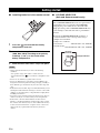 6
6
-
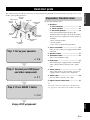 7
7
-
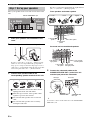 8
8
-
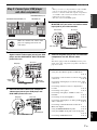 9
9
-
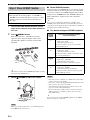 10
10
-
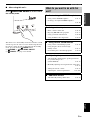 11
11
-
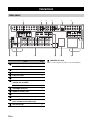 12
12
-
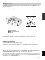 13
13
-
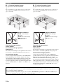 14
14
-
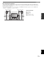 15
15
-
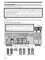 16
16
-
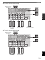 17
17
-
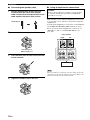 18
18
-
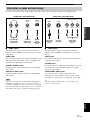 19
19
-
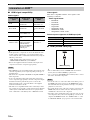 20
20
-
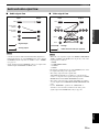 21
21
-
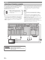 22
22
-
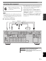 23
23
-
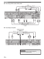 24
24
-
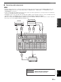 25
25
-
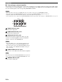 26
26
-
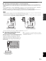 27
27
-
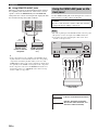 28
28
-
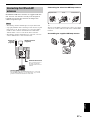 29
29
-
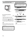 30
30
-
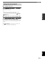 31
31
-
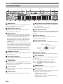 32
32
-
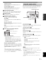 33
33
-
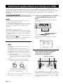 34
34
-
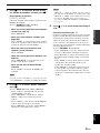 35
35
-
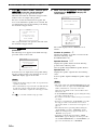 36
36
-
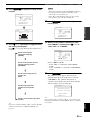 37
37
-
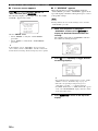 38
38
-
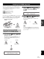 39
39
-
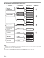 40
40
-
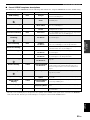 41
41
-
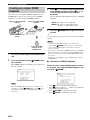 42
42
-
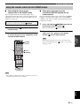 43
43
-
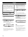 44
44
-
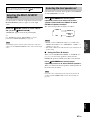 45
45
-
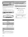 46
46
-
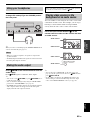 47
47
-
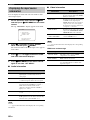 48
48
-
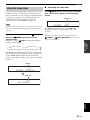 49
49
-
 50
50
-
 51
51
-
 52
52
-
 53
53
-
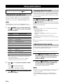 54
54
-
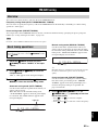 55
55
-
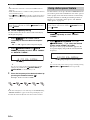 56
56
-
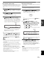 57
57
-
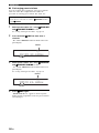 58
58
-
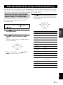 59
59
-
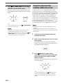 60
60
-
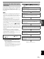 61
61
-
 62
62
-
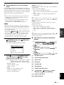 63
63
-
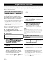 64
64
-
 65
65
-
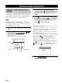 66
66
-
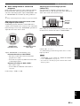 67
67
-
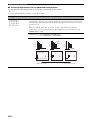 68
68
-
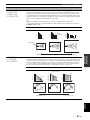 69
69
-
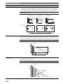 70
70
-
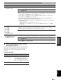 71
71
-
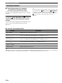 72
72
-
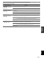 73
73
-
 74
74
-
 75
75
-
 76
76
-
 77
77
-
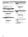 78
78
-
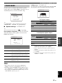 79
79
-
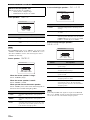 80
80
-
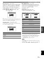 81
81
-
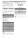 82
82
-
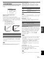 83
83
-
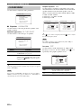 84
84
-
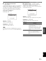 85
85
-
 86
86
-
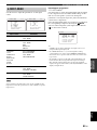 87
87
-
 88
88
-
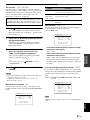 89
89
-
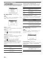 90
90
-
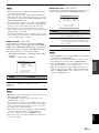 91
91
-
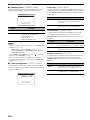 92
92
-
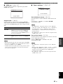 93
93
-
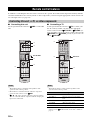 94
94
-
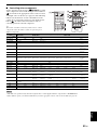 95
95
-
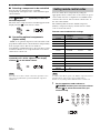 96
96
-
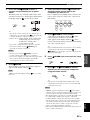 97
97
-
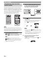 98
98
-
 99
99
-
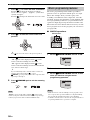 100
100
-
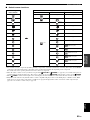 101
101
-
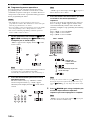 102
102
-
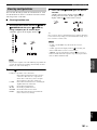 103
103
-
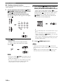 104
104
-
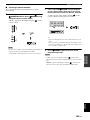 105
105
-
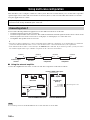 106
106
-
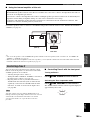 107
107
-
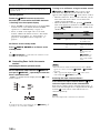 108
108
-
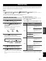 109
109
-
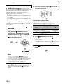 110
110
-
 111
111
-
 112
112
-
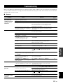 113
113
-
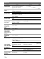 114
114
-
 115
115
-
 116
116
-
 117
117
-
 118
118
-
 119
119
-
 120
120
-
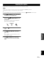 121
121
-
 122
122
-
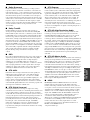 123
123
-
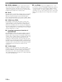 124
124
-
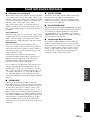 125
125
-
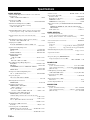 126
126
-
 127
127
-
 128
128
-
 129
129
-
 130
130
-
 131
131
-
 132
132
-
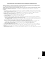 133
133
-
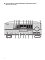 134
134
-
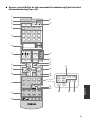 135
135
-
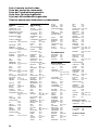 136
136
-
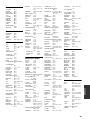 137
137
-
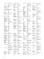 138
138
-
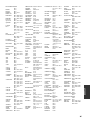 139
139
-
 140
140
-
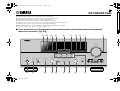 141
141
-
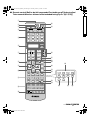 142
142


in andere talen
- English: Yamaha RX-V863 Owner's manual
- italiano: Yamaha RX-V863 Manuale del proprietario
Gerelateerde artikelen
-
Yamaha HTR-6160 de handleiding
-
Yamaha RX-V563 de handleiding
-
Yamaha RX-V657 de handleiding
-
-
-
Yamaha RX-V365 de handleiding
-
-
-
-
Yamaha RX-V863 de handleiding