EcoFlow Smart Home Panel Combo(13 relay modules) Handleiding
- Type
- Handleiding

Smart Home Panel Installation Manual
WARNING
The EcoFlow Smart Home Panel must be installed by a licensed electrician,
who should be familiar with all electrical codes, electrical wiring practices and
experience working with home electrical systems. Any accident, damage or
personal injury caused by incorrect installation is the sole responsibility of the
user.


CONTENTS
3. Product Details
2. Specifications
4. What's in the box
5. Installation SOP Checklist
1. Safety Instructions
3.1 External Features
3.2 Internal Features
3
4
1
2
6. Installation Steps
7. System Commissioning and App Setup
8. FAQ
6.1 Preparation
6.2 Installation
6.2.1 Installing the Relay Module
6.2.2 Mounting
6.2.3 Wiring
10
12
14
16
23
24
6
7

1
3
4
1
2
6.1 Preparation
6.2 Installation
6.2.1 Installing the Relay Module
6.2.2 Mounting
6.2.3 Wiring
10
12
14
16
23
24
6
7
1. Open all connected upstream circuit breakers and make sure the Grid Power Indicators are off.
2. Turn off DELTA Pro(s) from the SHP and ensure the DELTA Pro Power Indicators are off.
3. The alarm will sound if the SHP is energized while the front cover is open. Please ensure that the
unit is de-energized and the alarm has stopped
The SHP MUST be completely de-energized before being serviced
Complete the following to de-energize the SHP
1. The product must be installed by a licensed electrician and verified by local AHJ (Authority
Having Jurisdiction, i.e., your city, town, county or state).
2. The SHP defaults to grid mode when not powered. For safety, do not access or disconnect any
load circuits when there is an internal fault. Power down those loads and contact a licensed
electrician or EcoFlow technical support.
3. This product is not intended to be used as a service disconnect. To completely de-energize the
product, the user MUST open the upstream breakers as well as physically unplug all DELTA Pros.
Failure to do so may present a shock hazard.
4. DO NOT unplug relay modules while SHP is energized, because unplugging the relay module
while the SHP is energized may cause damage to the relay modules and SHP.
5. Smart Home Panel by itself does not provide an AFCI (Arc Fault Circuit Interrupter) function. AFCI
or GFCI protection may be available with an external AFCI accessory. Consult EcoFlow support
for AFCI or GFCI solutions.
6. All upstream breakers feeding SHP should be non-GFCI/AFCI. GFCI and AFCI protection should
be downstream of the SHP using GFCI/AFCI breakers or outlets. Follow NEC or local electrical
codes for AFCI or GFCI installation. An additional accessory panel to aid with installation of AFCI
circuits may be available from EcoFlow.
7. Do not use the product near a heat source, such as a fire or furnace. Do not place flammable
gases or liquids (e.g. Gasoline) near the device.
8. If there is a loud noise in the relay module, there may be a ground fault downstream of the SHP.
The user should clear the fault and replace the relay module before resetting the SHP for normal
use.
9. Do not use the SHP if the Short-Circuit Current Rating (SCCR) at the electrical service entrance is
above 10kA.
10. Do not install or operate the product outdoors or in damp/wet conditions.
11. Do not install or operate the product in extreme temperatures.
12. Do not use the product if it is damaged or appears to be damaged.
13. Do not connect the relay channels to circuit breakers higher than their current rating. Doing so
can result in damage to the relay modules.
14. The split-phase mode should be used for multi-wire circuits (MWBC, circuits sharing a balanced
neutral), and the circuits split across the two phases appropriately.
15. Adhere to all local and national safety regulations for installation and use.
16. If an overcurrent fault (breaker tripped) occurs, the corresponding relay module must be replaced
to ensure safe operation in the future.
17. This product is designed for residential use only.
18. Upstream circuit breakers protect the SHP only in grid mode. Only use circuit breakers with a fault
current interruption capability of 10kA or greater, 4ms or 5kA, 8ms.
19. The maximum total current for all input circuits under the grid mode is 160A.
1. Safety Instructions

2
2. Specifications
General Information
Weight
Dimensions
Mounting Type
Standard Connector
Type of Enclosure
Warranty Description
Maximum # of Circuits Controlled
Rated System Voltage
Max Total Input Current
Short Circuit Rating
Rated Relay Module Current
Rated Max DELTA Pro Input
DELTA Pro Charging Power
Max Connected Battery Energy
Operating Humidity (RH)
20 lbs (9 kg)
19.7x11.8x4.7 in (500x330x120 mm)
Wall Mount
EcoFlow Infinity Port
Type 1
5 Years
10
120V/240V
160A
10kA
30A, 20A, 15A
7200W Max (2x3600W)
6800W Max (2x3400W)(Max. charging time <3hrs)
21.6 kWh (6x3.6kWh)
5-85%
1. Multiple sources power this equipment.
2. Electrical equipment should be serviced by authorized personnel only.
3. This equipment is not intended to be used as a service disconnect breaker.
4. Upon losing power, this product automatically switches to the power station.
5. This equipment and downstream load can only be de-energized by opening all upstream
breakers and physically unplugging all DELTA Pros.
DANGER

3
1
2
3
4
5
6
7
The SHP can be set up to control a total of 10 load circuits, circuits 1, 3, 5, 7, 9 on the left and 2, 4, 6, 8,
10 on the right. There is a button allowing users to manually reset each circuit relay if there has been
an overcurrent event on the circuit. An indicator lamp on the button turns red if there is a fault in that
circuit.
A lightning bolt indicator for each load circuit is illuminated if that load circuit is energized through one
of the sources (grid or power station).
There are three energization indicators on the SHP, one for the grid, two for the DELTA Pros. If any of
these indicators are illuminated, SHP is energized from that source and, therefore, cannot be opened to
be serviced.
There are two infinity ports on the SHP, which can be either on the bottom of the SHP (default),
or relocated to the front. They connect DELTA Pros to the SHP through the Infinity Cable (one for
each DELTA Pro). Once plugged in, SHP and DELTA Pro will try to establish connection through
communication and SHP’s control circuitry may be powered via DC current from the DELTA pro. Press
the enable button located near the infinity port (labeled “AC 1” or “AC2” to make DELTA Pro ready for
output.
When the DELTA Pro load circuits are energized, an alarm will sound if the front panel cover is opened.
To de-energize the product, all upstream breakers must be opened and both DELTA Pros must be
unplugged.
1. Load Circuit Control Board
3.1 External Features
2. Grid Indicator and Infinity Port Indicator
3. Infinity Port and Enable Button
4. Panel Open Alarm System
3. Product Details

4
This button can be used to turn on the Bluetooth hotspot for 5 minutes for the user to connect.
This indicator is normally off if no fault is present inside the SHP. It will turn red if there is a fault in
the product. Users can go to the app for a fault diagnostic report. If there is an issue, please contact
customer support for assistance.
5. IOT Reset Button and Indicator
6. Error Indicator
The pause button will physically isolate the 10 load circuits and lock out both connected DELTA Pros.
A signal from the SHP will tell the DELTA Pros to stop outputting power. Please note that this does not
substitute for a service disconnect, nor does it substitute for the de-energization procedure required
before servicing.
This is the only “quick disconnect” that can be used to manually cut all power in an emergency.
AC in and Pro in still energize.
7. Power Station Pause/Resume Button
3.2 Internal Features
1
2
3
4
5
6
7
8
9
NOTE

5
1. Output Wire Connectors
2. Communication Ports connecting to the key panel
3. Relay Modules
These are the wire connectors for output hot wires going to the load.
The relay modules are available in different current ratings, 15A, 20A and 30A. These modules contain
two relays for each circuit as well as an overcurrent protection fuse. Each module can be individually
replaced without affecting other circuits. De-energize the SHP before replacing any module.
4. DELTA Pro Wire Connectors
5. Infinity Ports
6. Cooling Fan
7. Ground Bus Bar
8. Input Wire Connectors
9. Switching Connector for Single/Split Phase Operation
These are wire connectors for DELTA Pro. There is one hot wire and one neutral wire required for each
DELTA Pro. At least one neutral wire must be connected to the main panel even if no DELTA Pro is
used. This neutral is used as a return path for DELTA Pro to power your circuits.
Infinity ports can be installed either on the front or the bottom of the product. Users can choose to
switch the position of the Infinity ports. This can improve cable management in tight quarters.
The cooling fan is activated under extreme operating conditions to reduce the ambient temperature
inside of the unit.
This is the ground bus bar, which should be connected to the ground bus bar in the main electrical
panel. The panel casing is connected to this ground. NOTE: Please follow NEC and/or local code
requirements with regard to bonding neutral and ground. Bonding should be done at the first means of
disconnect, which is the service panel, NOT the SHP.
These are the wire connectors for hot wires coming from the circuit breakers in your main panel.
For split phase operation (North America and Japan ONLY), this connector should be removed
permanently from the product. Split-phase also requires additional setup in the EcoFlow app.

6
4. What’s in the Box
Smart Home Panel
Product User Manual Product Installation
Manual
Wall mounting brackets
A bag of accessoriesInfinity Cable and
Wires
The AWM wires can be removed from the harness plugs and replaced with an appropriate length
and type of cable.
NOTE

7
5. Installation SOP Checklist
No. Checklist Status
Before installation- Project information
1
Determine the installation location. The Smart Home Panel is rated to IP20,
therefore, it needs to be installed away from direct sunlight, rain, snow and
moisture.
2Determine the distance between the SHP and main electrical panel.
3
Determine if there is a split-phase or double pole load (240V/200V or
MWBC, USA and Japan only) that needs to be connected to the SHP. Channel
1, 3, 5, 7, 9 AC input should be connected on the same phase (phase a),
whereas Channel 2, 4, 6, 8, 10 AC input should be connected on the opposite
phase (phase b) when using the split-phase function. Mismatched phases will
result in an error condition and SHP will not function properly.
4Confirm the number of loads to be connected to SHP. You can connect up to
10 single pole load circuits, or up to 5 double pole load circuits.
5
Determine whether the upstream circuit breakers of the selected loads
require AFCI or GFCI protection. This can be accomplished with an on-site
inspection or photo or video of the panel from the end user.
6
Determine and gather required materials. SHP can support up to 1 1/2 “
conduit via five knockouts. Ensure that necessary adjustment factors (for
number of conductors) are accounted for and that wire ampacity is sized
appropriately. For longer runs it is recommended that you use separate
conduits for the input and output wires. USA ONLY - For AFCI and GFCI
breakers, an additional standard overcurrent trip breaker is required. For
circuits where AFCI protection is required, metal conduit or whip to the
SHP from the main panel is required to comply with NEC requirements. An
external AFCI enclosure (available from EcoFlow) to house AFCI breakers is
also required downstream of the SHP.
During installation - Circuit breaker and relay module
1The current rating of relay module must match the upstream circuit breaker.
Failure to do so may cause overcurrent protection to fail.
2The ampacity rating of wiring used should match the circuit current. Using an
undersized cable may cause overheating and even a fire.
3All upstream breakers should be non-GFCI/AFCI. Any AFCI/GFCI breakers
need to be moved downstream of the SHP using an optional accessory box.

8
During installation - Wiring
1
When using split phase, the Channel 1, 3, 5, 7, 9 AC input should be connected
with hot wires on the same phase, the Channel 2, 4, 6, 8, 10 AC input should be
connected with hot wires on another phase.
2For split phase operation, the Switching Connector should be removed
permanently from the SHP.
3When using single phase, each load circuit AC input should be connected to
the hot wire.
4
Install the relay modules in the corresponding places and secure by tightening
the screws. Failure to do so may cause the relay module to come loose, which
will produce an error and disconnection of the load channel, as well as risk
overheating and fire.
During installation - Check wiring
1With a multimeter in continuity setting, confirm that the hot wire in of each
SHP channel is not shorted to neutral.
2With a multimeter in continuity setting, confirm that the hot wire in of each
SHP channel is not shorted to ground.
Commissioning
1Make sure the power stations are enabled and that the stop button is off
(raised).
2Close the upstream breaker of DELTA Pro and energize the DELTA Pro AC
Input channel. The grid indicator (white) will turn on if there is no fault.
3Turn each branch circuit breaker back on one by one and check the indicator
status of each channel and power indicator. The indicators will stay white.
4
If you haven’t done so already, download the EcoFlow app from Google Play
or the App Store and create an EcoFlow account. Open the app on your
mobile device, log into the app and add the Smart Home Panel to your device
pool. For first time users, the app will lead through a commissioning process
to setup the SHP.
5Update the firmware of the Smart Home Panel to the latest version, then
check whether there are any errors reported on the app.
6
Follow the instructions in the app to conduct device wiring testing. If the
device wiring testing fails, correct the wiring following the prompts in the app
and re-run the wiring test.
7Turn on the DELTA Pro and update the firmware to the latest version.

9
No. Checklist Status
8
Connect the DELTA Pro and Smart Home Panel using the Infinity cable. For
split-phase, two DELTA Pros and two infinity cables are required. Turn on the
main power button of DELTA Pro, then press the On/Off button (AC button,
near the infinity port) on the SHP to enable each DELTA Pro.
9
Switch the power supply from grid to power station for each channel via
the app. Check whether the switchover is successful and there are no errors
reported on the app. Follow the instructions on the app to fix the errors if
any.
10
Set up the charging for DELTA Pro on the app (if AC grid charging is desired),
check whether the DELTA Pro is recharged successfully and there are no
errors reported on the app. Follow the instructions on the app to fix the
errors if any.

10
6. Installation Steps
6.1 Preparation
Tools and Items Needed for Installation:
Tools required:
1. Level
2. Phillips head screwdriver, Torx T20 screwdriver and 7mm socket screwdriver
3. Pliers
4. Wire cutters
5. Wire nuts
6. Drill
7. Conduit (e.g. 1,1/4 inch and 1 inch), Conduit whip
8. Wire harness
9. Tape measure
10. Multimeter
11. Voltage detector
12. Purchase a new double pole 30A circuit breaker or two single pole 30A circuit breakers. (NOTE:
these breakers may be required to be handle tied per code.)
WARNINGWARNING
Installation of this product involves high voltage. Please hire a licensed electrician to perform the
installation.
Circuit
1Refrigerator 700W running
2000W startup
200W
1400W
800W
700W
0W
1000W
0W
1000W
400W
500W
300W
1200W
700W
0W
0W
0W
0W
1000W
Kitchen Light
Kitchen Plug
Bedroom Plug
Bedroom Light
Bathroom Light
Living Room Light
Living Room Light
Furnace
Sump Pump
Plug
2
3 4
5 6
7 8
910
CircuitName NameWattage Wattage
Load Calculation Example
The total DELTA Pro wattage (3600W for single Pro or 7200W for two Pros) should be greater than
the total continuous running wattage of all backed up loads plus the largest start-up wattage.

11
Total Running Load
Largest Estimated Simultaneous Running Load (LESRL)
Largest Startup Wattage (LSW)
Minimum Backup Power Needed = LESRL + LSW
6900 W
2300 W
2000 W
4300 W (Two DELTA Pros)
Inductive loads such as air conditioners, clothes dryers or pumps have high Inrush current when
starting. This may trip the relay modules because of overload. Ensure the circuit is sized appropriately
for the intended load.
Once you have determined the load circuits that you want to back up, fill out the table below. The
numbering arrangement is the same as your SHP.
Circuit
11
1
1
2
2
2
2
3 4
5 6
7 8
910
Circuit
Original
Phase
Original
Phase
Name Name
1
1
2
2
1
1
1
2
2
2
1
1
2
2
NOTE

12
6.2 Installation
De-energize the system: When you are ready to start the installation work, turn off the main breaker
as well as each branch circuit breaker intended to be connected. Ensure that DELTA Pros are not
connected to the SHP as well.
The relay modules are shipped separately from the main unit. These modules include two switching
relays and a fuse. The fuse is for load circuit protection in the backup mode only and therefore
should match the current rating for the circuit breaker upstream of that load circuit. There are three
standard ratings for the modules, 15A, 20A and 30A. Users should install these modules at the position
corresponding to the load circuits that they plan to use it for according to the diagram below. The
diagram below shows the module position corresponding to the circuit number.
There are 10 module mounting spaces inside the SHP as shown below. 4 out of the 10 channels
(channel 1-4) have a maximum of 30A current rating, the rest have a maximum 20A current rating. No
load circuit larger than the maximum current rating for a channel should be connected. Once placed
into position, two screws are used to secure the module into place.
It's easier if the knockouts are removed before the SHP is installed on the wall.
NOTE
The actual continuous current rating for each relay module is 80% of module rating. For example,
for the 20A relay module, the continuous current rating is 20A × 0.8 = 16A.
6.2.1 Installing the Relay Module

13
1. (a) Open the panel cover using the T20
screwdriver.
(b) Slide out the screw cover on top.
(c) Release the four screws one by one.
Relay Module Position
Install Relay Module
aa
bb
cc
01
30A MAX
02
30A MAX
03
30A MAX
04
30A MAX
05
20A MAX
06
20A MAX
07
20A MAX
08
20A MAX
09
20A MAX
10
20A MAX
DELTA Pro DELTA Pro

14
2. (a) Plug in each relay module and seat firmly (it is
recommended to use the palm of your hand).
(b) Secure the relay module by tightening the two screws.
(c) Close the front panel, and secure the four screws.
(d) The Relay Module installation is complete.
(e) Repeat for all 10 relays. 10 relays must be installed even
if they are not all used
After you have placed the relay module inside and fastened the screws, attach both top and bottom
mounting brackets to the SHP as shown below.
6.2.2 Mounting
1
Position the SHP center to center to your main panel.
Please follow the local safe electrical clearance distance.

15
2
Attach the top mounting bracket along the top edge
of the mark on the wall. Make sure you also check the
length of the flexible conduit.
wall
3
Hang the SHP up on the wall bracket.
Secure the bottom mounting bracket to the wall. wall

16
Wiring inside the Smart Home Panel
All wires come labeled in the box, 12 input wires, labeled "1 in - 10 in" "Pro1 in, Pro2 in" connected to the
circuit breakers, 10 output wires, labeled "1 out - 10 out" connecting to the load hot wires, two neutral
wires connecting to the neutral bus bar in the main panel and ground wire connecting to the ground
bus bar in the main panel. Users should connect all input, output, neutral and grounds wire to their
designated connectors inside the SHP.
6.2.3 Wiring
Pro1,N1,N2,Pro2
Ground bar
Output connectors
Input connectors
NOTE
Two neutral wires and the ground wire must be connected to the main panel in order for the SHP to
operate correctly and safely.
The maximum current for circuits 1-4 is 30A. Maximum current for circuits 5-10 is 20A. The current
rating for each circuit should not be exceeded. Please plan the load circuits appropriately. If a non-
metallic conduit is used to connect between the main panel and SHP, an equipment grounding
conductor needs to be present inside each conduit. Additional ground wires can be connected
between the ground bar inside the main panel and the SHP.
You may use your own wires with the connectors instead of the included wire. Use a screwdriver to
remove the connectors, strip the wire and then insert and torque down

17
1. Run a cable from the grounding bus of the main electrical panel to the grounding bar in SHP. Install
two 30A single pole or one 30A double pole circuit breaker(s) to the main electrical panel and connect
Pro 1 and Pro 2 modules in SHP with a 10AWG cable to provide AC charging and overcurrent protection
for the Delta Pro(s).
Single-phase without GFCI or AFCI breakers
Below illustrates a typical single-phase 120V (100V in Japan) setup. SHP can be connected to the main
electrical panel to provide backup power to ten 120V load circuits. All input wires should be routed
through the bottom conduit into the SHP and output wires through the upper conduit. The whole
system is single point grounded at the main electrical panel.
6.2.3.1 Single Phase Setup (120V)
1. Turn off the main breaker as well as the 10 branch circuit breakers intended to be connected in the
main panel and use a voltage detector or voltmeter to make sure the system is fully de-energized.
2. Remove the front cover of the main panel. Keep in mind that the grid side of the main panel
(upstream of the main breaker) is still energized.
3. Remove the knockouts that you want to use on both the SHP and the main electrical panel.
4. Attach both top and bottom conduit to the SHP and main electrical panel.
5. Pull all wires (Input, output, neutral and ground) from the SHP to the main electrical panel.
6. Connect the two neutral wires and the ground wire to the neutral and ground bus respectively.
Cut them to the appropriate length before connecting.
7. Remove the hot wire from the circuit breaker. Connect each load hot wire to the corresponding
output wire from the SHP using wire nuts (for example, the output wire labeled “1 out” means it’s
the output for channel 1). Make sure it’s connected to the right number as planned.
8. Connect the input wire, with the same number (for example, if you used “1 out”, now you should
find the red wire labeled “1 in”), to the circuit breaker planned. Make sure you cut them to the
appropriate length before connecting.
9. Repeat step 7 & 8 for all 10 load circuits.
10. Each charging circuit for DELTA Pro needs to feed off a single 30A breaker from the main panel
to enable the fast charge function. If not available, 30A circuit breakers need to be purchased and
installed. The wires corresponding to the PRO charging wires are labeled “PRO1 in” and “PRO2 in”.
If the 30A breaker is not used, the correct current rating should be entered into the app later on to
prevent the circuit breaker tripping from charging current. It is recommended to handle tie both
charging breakers or use a double pole breaker. This makes de-energization of the SHP safer for
future servicing.
Wiring in the Electrical panel

18
2. Connect input wires from SHP to corresponding breakers of the main electrical panel and output
wires to the load port of the main electrical panel.
To Load
Utility Power
Ground Bus
Neutral Bus
Main
To Load
Two Ne w Beakers added
for Delt a Pr o Charging
11/4in Conduit
To Load
Utility Power
Ground Bus
Neutral Bus
Main
To Load
Two Ne w Beaker s adde d
for Delta Pro Chargin g

19
Single-phase with GFCI or AFCI breakers
1. Uninstall the upstream A/GFCI breaker of the main electrical panel and replace with normal breakers,
then install the A/GFCI breakers into the EcoFlow AFCI/GFCI Box (please refer to the manual of
EcoFlow AFCI/GFCI Box for details).
2. Follow steps below to wire up the product:
2.1. Connect the grounding wire from the ground bus of the main electrical panel to the EcoFlow AFCI/
GFCI Box.
2.2. Connect input wires from SHP to corresponding breakers of the main electrical panel.
2.3. Connect output wires from SHP to corresponding breakers of the EcoFlow AFCI/GFCI Box.
2.4. Connect A/GFCI breakers of the EcoFlow AFCI/GFCI Box back to the load port of the main
electrical panel.
Metallic conduit
Metallic conduit
To Load
Utility Power
Ground Bus
Neutral Bus
Main
To Load
Two Ne w Beaker s adde d
for Delta Pro Chargin g

20
Split-phase without GFCI or AFCI breakers
1. Remove the switching connector of SHP.
2. Connect L1 phase and L2 phase of the main electrical panel to corresponding outputs and inputs of
SHP (L1 phase to 1, 3, 5, 7, 9 of SHP; L2 phase to 2, 4, 6, 8, 10 of SHP).
L1 phase wiring
d
d
Smart Home Panel Main Electrical Panel
To Loa
Utility Power
Ground Bus
Neutral Bus
Main
To Loa
Two Ne w Beaker s added
for D elta Pr o Charging
1 in Conduit
11/4in Conduit
Split phase setup is different from the single-phase mode in that.
1. The switching connector needs to be unplugged from the SHP.
2. Two DELTA Pros need to be connected at the same time to support the split phase operation.
3. Circuits 1,3,5,7 and 9 are connected to the same phase in the SHP when phase split, and should be
connected to the same phase inside the main electrical panel. Circuits 2,4,6,8 and 10 should be
connected to the other phase.
6.2.3.2 Split Phase Setup (240V)

21
To Load
Utility Power
Ground Bus
Neutral Bus
Main
To Load
Two Ne w Beaker s adde d
for Delt a Pr o Charging
1 in Conduit
1 1/4in Conduit
Smart Home Panel
Split-phase with GFCI or AFCI breakers
Main Electrical Panel
1. Connect the grounding wire from the ground bus of main electrical panel to the grounding terminal
of EcoFlow AFCI/GFCI Box.
Main electrical panel
To Load
Utility Power
Ground Bus
Neutral Bus
Main
To Load
Two New Beaker s adde d
for Delt a Pro Charging
L2 phase wiring

22
2. Connect L1 phase and L2 phase of the main electrical panel to corresponding inputs of SHP. Output
wires of SHP are connected to corresponding hot wire terminals.
L1 phase wiring
L2 phase wiring
To Load
Utility Power
Ground Bus
Neutral Bus
Main
To Load
Two New B eaker s added
for Delt a Pro Charging
To Load
Utility Power
Ground Bus
Neutral Bus
Main
To Load
Two New Beaker s adde d
for Delt a Pro C harging
Metallic conduit
Metallic conduit
Wire nuts
Metallic conduit
Metallic conduit

23
After you have connected all wires accordingly, clean up all the wires and tie them using a wire
harness. Close the front panel and tighten the screws to secure the door. Label the circuit names
accordingly on the SHP.
1. Download the EcoFlow app from the App Store, Google Play Store or EcoFlow official site. Set
up the account and sign in.
2. Connect a DELTA Pro to the SHP without pressing the enable button.
3. Press the IOT button to enable Bluetooth connection. When the indicator light is flashing, it’s
ready to pair with the EcoFlow App.
4. Open the EcoFlow App and add the device from the “+” icon on the top right. Find the SHP and
click the icon to pair. After Bluetooth connection, you will be asked to choose the Wi-Fi and
enter Wi-Fi password to finish Internet connection.
5. For first time users, the app will lead through a commissioning process to setup the SHP. Simply
follow the steps to complete the process. Once you have finished the commissioning process on
the app, you are ready to energize the SHP.
6. After completing the device wiring test, press the enable button (near the infinity port) for the
connected DELTA Pro. The power indicator should turn green. Watch for any abnormal signs
and fault indication.
7. If there is no sign of fault, turn the main breaker back on and then turn each branch circuit
breaker back on one by one and watch for any fault indication.
WARNING
The SHP defaults to grid mode when without power, which means the load is automatically
connected to the grid power if no power is supplied to the SHP or it’s started for the first time.
Please make sure energization of load circuits do not endanger any person or incur any property
damage before closing the main breaker.
7. System Commissioning and App Setup
a. If the device wiring testing reports any errors, or if there are any errors, please resolve the issue
following the message shown on the App or contact our customer support from the Help Center
in the App. You can leave your SHP as long as there is no indication of electrical or other type of
sign for a fault. The default mode for SHP is grid power so it will not affect your use of power.
b. If there is no sign of error, congratulations! You are ready to go!
APP
Control and monitor EcoFlow portable power stations and the SHP remotely with the EcoFlow App.
Download at: https://download.ecoflow.com/app

24
8. FAQ
1. Can the SHP connect to a roof solar system, if yes, how?
For DC coupled solar panel system, currently, only solar panels with the correct output
parameters can be connected to the system. See the DELTA Pro manual for supported solar
panel specifications.
2. Does the SHP support split phase 240V output?
Yes, it does up to 30 amps, 7200W. This requires two DELTA pros and two infinity cables..
3. What's the maximum number of DELTA Pros and extra batteries that can be connected to the
SHP?
A maximum of 2 DELTA Pros and 4 extra batteries can be connected, with a total of 7200W output
power and 21.6kWh of energy.
4. Can multiple smart panels be used at the same time in one house?
Yes.
5. Can I manually switch between grid power and backup power?
Yes. Through the EcoFlow App.
6. How many circuits can SHP manage?
A maximum of 10 single phase circuits or 5 split phase circuits.
7. Is there any protection function in the SHP?
Yes. There is a relay based overcurrent and over-temperature protection system in both the grid
and backup mode. There is also a fuse for fault protection in the backup mode only.
8. Is there an AFCI function provided by the SHP?
No, an additional accessory needs to be purchased to house an AFCI breaker
Privacy Policy
By using EcoFlow Products, Applications, and Services, you consent to the EcoFlow Terms of Use and
Privacy Policy, which you can access via the "About" section of the "User" page on the EcoFlow App
or the official EcoFlow website at https://ecoflow.com/pages/terms-of-use and https://ecoflow.com/
pages/privacy-policy.


Smart Home Panel Installation Manual
WARNING
The EcoFlow Smart Home Panel must be installed by a licensed electrician,
who should be familiar with all electrical codes, electrical wiring practices and
experience working with home electrical systems. Any accident, damage or
personal injury caused by incorrect installation is the sole responsibility of the
user.


CONTENTS
3. Product Details
2. Specifications
4. What's in the box
5. Installation SOP Checklist
1. Safety Instructions
3.1 External Features
3.2 Internal Features
3
4
1
2
6. Installation Steps
7. System Commissioning and App Setup
8. FAQ
6.1 Preparation
6.2 Installation
6.2.1 Installing the Relay Module
6.2.2 Mounting
6.2.3 Wiring
9
11
13
15
19
20
6
7

1
3
4
1
2
6.1 Preparation
6.2 Installation
6.2.1 Installing the Relay Module
6.2.2 Mounting
6.2.3 Wiring
9
11
13
15
19
20
6
7
1. Open all connected upstream circuit breakers and make sure the Grid Power Indicators are off.
2. Turn off DELTA Pro(s) from the SHP and ensure the DELTA Pro Power Indicators are off.
3. The alarm will sound if the SHP is energized while the front cover is open. Please ensure that the
unit is de-energized and the alarm has stopped.
The SHP MUST be completely de-energized before being serviced
Complete the following to de-energize the SHP
1. The product must be installed by a licensed electrician.
2. The SHP defaults to grid mode when not powered. For safety, do not access or disconnect any
load circuits when there is an internal fault. Power down those loads and contact a licensed
electrician or EcoFlow technical support.
3. This product is not intended to be used as a service disconnect. To completely de-energize the
product, the user MUST open the upstream breakers as well as physically unplug all DELTA Pros.
Failure to do so may present a shock hazard.
4. DO NOT unplug relay modules while SHP is energized, because unplugging the relay module
while the SHP is energized may cause damage to the relay modules and SHP.
5. Smart Home Panel by itself does not provide an AFCI (Arc Fault Circuit Interrupter) function. AFCI
or GFCI protection may be available with an external AFCI accessory. Consult EcoFlow support
for AFCI or GFCI solutions.
6. All upstream breakers feeding SHP should be non-GFCI/AFCI. GFCI and AFCI protection should
be downstream of the SHP using GFCI/AFCI breakers or outlets. Follow local electrical codes for
AFCI or GFCI installation. An additional accessory panel to aid with installation of AFCI circuits
may be available from EcoFlow.
7. Do not use the product near a heat source, such as a fire or furnace. Do not place flammable
gases or liquids (e.g. Gasoline) near the device.
8. If there is a loud noise in the relay module, there may be a ground fault downstream of the SHP.
The user should clear the fault and replace the relay module before resetting the SHP for normal
use.
9. Do not use the SHP if the Short-Circuit Current Rating (SCCR) at the electrical service entrance is
above 10kA.
10. Do not install or operate the product outdoors or in damp/wet conditions.
11. Do not install or operate the product in extreme temperatures.
12. Do not use the product if it is damaged or appears to be damaged.
13. Do not connect the relay channels to circuit breakers higher than their current rating. Doing so
can result in damage to the relay modules.
14. Adhere to all local and national safety regulations for installation and use.
15. If an overcurrent fault (breaker tripped) occurs, the corresponding relay module must be replaced
to ensure safe operation in the future.
16. This product is designed for residential use only.
17. Upstream circuit breakers protect the SHP only in grid mode. Only use circuit breakers with a fault
current interruption capability of 10kA or greater, 4ms or 5kA, 8ms.
18. The maximum total current for all input circuits under the grid mode is 120A.
1. Safety Instructions

2
2. Specifications
General Information
Weight
Protective class
Dimensions
Mounting type
Standard connector
Ingress protection
Warranty description
Maximum # of circuits controlled
Rated system voltage
Max total input current
Short circuit rating
Rated relay module current
Rated Max. DELTA Pro input
DELTA Pro charging power
Max. connected battery energy
Operating and storage temperature range
Enclosure temperature
Touch current
20 lb (9 kg)
I
500×330×120 mm
Wall Mount
EcoFlow Infinity Port
IP20
5 Years
10
240V
120A
10kA
6A, 13A, 16A, 20A, 30A
7200W Max (2×3600W)
6800W Max (2×3400W)
21.6 kWh (6×3.6 kWh)
-20°C - 45°C
Less than 65°C
<3.5mA a.c. (Under single fault condition)
1. Multiple sources power this equipment.
2. Electrical equipment should be serviced by authorized personnel only.
3. This equipment is not intended to be used as a service disconnect breaker.
4. Upon losing power, this product automatically switches to the power station.
5. This equipment and downstream load can only be de-energized by opening all upstream
breakers and physically unplugging all DELTA Pros.
DANGER

3
1
2
3
4
5
6
7
The SHP can be set up to control a total of 10 load circuits, circuits 1, 3, 5, 7, 9 on the left and 2, 4, 6, 8,
10 on the right. There is a button allowing users to manually reset each circuit relay if there has been
an overcurrent event on the circuit. An indicator lamp on the button turns red if there is a fault in that
circuit.
A lightning bolt indicator for each load circuit is illuminated if that load circuit is energized through one
of the sources (grid or power station).
There are three energization indicators on the SHP, one for the grid, two for the DELTA Pros. If any of
these indicators are illuminated, SHP is energized from that source and, therefore, cannot be opened to
be serviced.
There are two infinity ports on the SHP, which can be either on the bottom of the SHP (default),
or relocated to the front. They connect DELTA Pros to the SHP through the Infinity Cable (one for
each DELTA Pro). Once plugged in, SHP and DELTA Pro will try to establish connection through
communication and SHP’s control circuitry may be powered via DC current from the DELTA pro. Press
the enable button located near the infinity port (labeled “AC 1” or “AC2” to make DELTA Pro ready for
output.
When the DELTA Pro load circuits are energized, an alarm will sound if the front panel cover is opened.
To de-energize the product, all upstream breakers must be opened and both DELTA Pros must be
unplugged.
1. Load Circuit Control Board
3.1 External Features
2. Grid Indicator and Infinity Port Indicator
3. Infinity Port and Enable Button
4. Panel Open Alarm System
3. Product Details

4
This button can be used to turn on the Bluetooth hotspot for 5 minutes for the user to connect.
This indicator is normally off if no fault is present inside the SHP. It will turn red if there is a fault in
the product. Users can go to the app for a fault diagnostic report. If there is an issue, please contact
customer support for assistance.
5. IOT Reset Button and Indicator
6. Error Indicator
The pause button will physically isolate the 10 load circuits and lock out both connected DELTA Pros.
A signal from the SHP will tell the DELTA Pros to stop outputting power. Please note that this does not
substitute for a service disconnect, nor does it substitute for the de-energization procedure required
before servicing.
This is the only “quick disconnect” that can be used to manually cut all power in an emergency.
AC in and Pro in still energize.
7. Power Station Pause/Resume Button
3.2 Internal Features
1
2
3
4
5
6
7
8
9
NOTE

5
1. Output Wire Connectors
2. Communication Ports connecting to the key panel
3. Relay Modules
These are the wire connectors for output hot wires going to the load.
The relay modules are available in different current ratings, 6A, 13A, 16A, 20A, and 30A. These
modules contain two relays for each circuit as well as an overcurrent protection fuse. Each module can
be individually replaced without affecting other circuits. De-energize the SHP before replacing any
module.
4. DELTA Pro Wire Connectors
5. Infinity Ports
6. Cooling Fan
7. Ground Bus Bar
8. Input Wire Connectors
9. Switching Connector
These are wire connectors for DELTA Pro. There is one hot wire and one neutral wire required for each
DELTA Pro. At least one neutral wire must be connected to the main panel even if no DELTA Pro is
used. This neutral is used as a return path for DELTA Pro to power your circuits.
Infinity ports can be installed either on the front or the bottom of the product. Users can choose to
switch the position of the Infinity ports. This can improve cable management in tight quarters.
The cooling fan is activated under extreme operating conditions to reduce the ambient temperature
inside of the unit.
This is the ground bus bar, which should be connected to the ground bus bar in the main electrical
panel. The panel casing is connected to this ground. NOTE: Please follow local code requirements with
regard to bonding neutral and ground. Bonding should be done at the first means of disconnect, which
is the service panel, NOT the SHP.
These are the wire connectors for hot wires coming from the circuit breakers in your main panel.
Please keep the connector plugged in its original place, otherwise, if it's unplugged, the power station
connected to Pro 1 will only provide energy to circuits 1, 3, 5, 7, and 9, whereas the power station
connected to Pro 2 will only provide energy to circuits 2, 4, 6, 8, 10.

6
4. What’s in the Box
Smart Home Panel
Product User Manual Product Installation
Manual
Wall mounting brackets
A bag of accessoriesInfinity Cable and
Wires
The AWM wires can be removed from the harness plugs and replaced with an appropriate length
and type of cable.
NOTE

7
5. Installation SOP Checklist
No. Checklist Status
Before installation- Project information
1
Determine the installation location. The Smart Home Panel is rated to IP20,
therefore, it needs to be installed away from direct sunlight, rain, snow and
moisture.
2Determine the distance between the SHP and main electrical panel.
3Confirm the number of loads to be connected to SHP. You can connect up to
10 single pole load circuits.
4
Determine whether the upstream circuit breakers of the selected loads
require AFCI or GFCI protection. This can be accomplished with an on-site
inspection or photo or video of the panel from the end user.
5
Determine and gather required materials. SHP can support up to 1 1/2 inch
conduit via five knockouts. Ensure that necessary adjustment factors (for
number of conductors) are accounted for and that wire ampacity is sized
appropriately. For longer runs it is recommended that you use separate
conduits for the input and output wires. For AFCI and GFCI breakers, an
additional standard overcurrent trip breaker is required. For circuits where
AFCI protection is required, metal conduit or whip to the SHP from the main
panel is required. An external AFCI enclosure (available from EcoFlow) to
house AFCI breakers is also required downstream of the SHP.
During installation - Circuit breaker and relay module
1The current rating of relay module must match the upstream circuit breaker.
Failure to do so may cause overcurrent protection to fail.
2The ampacity rating of wiring used should match the circuit current. Using an
undersized cable may cause overheating and even a fire.
3All upstream breakers should be non-GFCI/AFCI. Any AFCI/GFCI breakers
need to be moved downstream of the SHP using an optional accessory box.
During installation - Wiring
1Each load circuit AC input should be connected to the hot wire.
2
Install the relay modules in the corresponding places and secure by tightening
the screws. Failure to do so may cause the relay module to come loose, which
will produce an error and disconnection of the load channel, as well as risk
overheating and fire.

8
During installation - Check wiring
1With a multimeter in continuity setting, confirm that the hot wire in of each
SHP channel is not shorted to neutral.
2With a multimeter in continuity setting, confirm that the hot wire in of each
SHP channel is not shorted to ground.
Commissioning
1Make sure the power stations are enabled and that the stop button is off
(raised).
2Close the upstream breaker of DELTA Pro and energize the DELTA Pro AC
Input channel. The grid indicator (white) will turn on if there is no fault.
3Turn each branch circuit breaker back on one by one and check the indicator
status of each channel and power indicator. The indicators will stay white.
4
If you haven’t done so already, download the EcoFlow App from Google
Play or the App Store and create an EcoFlow account. Open the app on your
mobile device, log into the app and add the Smart Home Panel to your device
pool. For first time users, the app will lead through a commissioning process
to setup the SHP.
5Update the firmware of the Smart Home Panel to the latest version, then
check whether there are any errors reported on the app.
6
Follow the instructions in the app to conduct device wiring testing. If the
device wiring testing fails, correct the wiring following the prompts in the app
and re-run the wiring test.
7Turn on the DELTA Pro and update the firmware to the latest version.
8
Connect the DELTA Pro and Smart Home Panel using the Infinity cable. For
split-phase, two DELTA Pros and two infinity cables are required. Turn on the
main power button of DELTA Pro, then press the On/Off button (AC button,
near the infinity port) on the SHP to enable each DELTA Pro.
9
Switch the power supply from grid to power station for each channel via
the app. Check whether the switchover is successful and there are no errors
reported on the app. Follow the instructions on the app to fix the errors if
any.
10
Set up the charging for DELTA Pro on the app (if AC grid charging is desired),
check whether the DELTA Pro is recharged successfully and there are no
errors reported on the app. Follow the instructions on the app to fix the
errors if any.

9
6. Installation Steps
6.1 Preparation
Tools and Items Needed for Installation:
Tools required:
1. Level
2. Phillips head screwdriver, Torx T20 screwdriver and 7mm socket screwdriver
3. Pliers
4. Wire cutters
5. Wire nuts
6. Drill
7. Conduit (e.g. 1,1/4 inch and 1 inch), Conduit whip
8. Wire harness
9. Tape measure
10. Multimeter
11. Voltage detector
12. Purchase a new double pole 30A circuit breaker or two single pole 30A circuit breakers. (NOTE:
these breakers may be required to be handle tied per code.)
WARNINGWARNING
Installation of this product involves high voltage. Please hire a licensed electrician to perform the
installation.
Circuit
1Refrigerator 700W running
2000W startup
200W
1400W
800W
700W
0W
1000W
0W
1000W
400W
500W
300W
1200W
700W
0W
0W
0W
0W
1000W
Kitchen Light
Kitchen Plug
Bedroom Plug
Bedroom Light
Bathroom Light
Living Room Light
Living Room Light
Furnace
Sump Pump
Plug
2
3 4
5 6
7 8
910
CircuitName NameWattage Wattage
Load Calculation Example
The total DELTA Pro wattage (3600W for single Pro or 7200W for two Pros) should be greater than
the total continuous running wattage of all backed up loads plus the largest start-up wattage.

10
Total Running Load
Largest Estimated Simultaneous Running Load (LESRL)
Largest Startup Wattage (LSW)
Minimum Backup Power Needed = LESRL + LSW
6900 W
2300 W
2000 W
4300 W (Two DELTA Pros)
Inductive loads such as air conditioners, clothes dryers or pumps have high Inrush current when
starting. This may trip the relay modules because of overload. Ensure the circuit is sized appropriately
for the intended load.
Once you have determined the load circuits that you want to back up, fill out the table below. The
numbering arrangement is the same as your SHP.
Circuit
11
1
1
2
2
2
2
3 4
5 6
7 8
910
Circuit
Original
Phase
Original
Phase
Name Name
1
1
2
2
1
1
1
2
2
2
1
1
2
2
NOTE

11
6.2 Installation
De-energize the system: When you are ready to start the installation work, turn off the main breaker
as well as each branch circuit breaker intended to be connected. Ensure that DELTA Pros are not
connected to the SHP as well.
The relay modules are shipped separately from the main unit. These modules include two switching
relays and a fuse. The fuse is for load circuit protection in the backup mode only and therefore should
match the current rating for the circuit breaker upstream of that load circuit. There are three standard
ratings for the modules, 6A, 13A, 16A, 20A, 30A. Users should install these modules at the position
corresponding to the load circuits that they plan to use it for according to the diagram below. The
diagram below shows the module position corresponding to the circuit number.
There are 10 module mounting spaces inside the SHP as shown below. 4 out of the 10 channels (channel
1-4) have a maximum of 30A current rating, the rest have a maximum 20A current rating. No load
circuit larger than the maximum current rating for a channel should be connected. Once placed into
position, two screws are used to secure the module into place.
It's easier if the knockouts are removed before the SHP is installed on the wall.
NOTE
The actual continuous current rating for each relay module is 80% of module rating. For example,
for the 20A relay module, the continuous current rating is 20A × 0.8 = 16A.
6.2.1 Installing the Relay Module

12
1. (a) Open the panel cover using the T20
screwdriver.
(b) Slide out the screw cover on top.
(c) Release the four screws one by one.
Relay Module Position
Install Relay Module
aa
bb
cc
01
30A MAX
02
30A MAX
03
30A MAX
04
30A MAX
05
20A MAX
06
20A MAX
07
20A MAX
08
20A MAX
09
20A MAX
10
20A MAX
DELTA Pro DELTA Pro

13
2. (a) Plug in each relay module and seat firmly (it is
recommended to use the palm of your hand).
(b) Secure the relay module by tightening the two screws.
(c) Close the front panel, and secure the four screws.
(d) The Relay Module installation is complete.
(e) Repeat for all 10 relays. 10 relays must be installed even
if they are not all used
After you have placed the relay module inside and fastened the screws, attach both top and bottom
mounting brackets to the SHP as shown below.
6.2.2 Mounting
1
Position the SHP center to center to your main panel.
Please follow the local safe electrical clearance distance.

14
2
Attach the top mounting bracket along the top edge
of the mark on the wall. Make sure you also check the
length of the flexible conduit.
wall
3
Hang the SHP up on the wall bracket.
Secure the bottom mounting bracket to the wall. wall

15
Wiring inside the Smart Home Panel
All wires come labeled in the box, 12 input wires, labeled "1 in - 10 in" "Pro1 in, Pro2 in" connected to the
circuit breakers, 10 output wires, labeled "1 out - 10 out" connecting to the load hot wires, two neutral
wires connecting to the neutral bus bar in the main panel and ground wire connecting to the ground
bus bar in the main panel. Users should connect all input, output, neutral and grounds wire to their
designated connectors inside the SHP.
6.2.3 Wiring
Pro1,N1,N2,Pro2
Ground bar
Output connectors
Input connectors
NOTE
Two neutral wires and the ground wire must be connected to the main panel in order for the SHP to
operate correctly and safely.
The maximum current for circuits 1-4 is 30A. Maximum current for circuits 5-10 is 20A. The current
rating for each circuit should not be exceeded. Please plan the load circuits appropriately. If a non-
metallic conduit is used to connect between the main panel and SHP, an equipment grounding
conductor needs to be present inside each conduit. Additional ground wires can be connected
between the ground bar inside the main panel and the SHP.
You may use your own wires with the connectors instead of the included wire. Use a screwdriver to
remove the connectors, strip the wire and then insert and torque down

16
1. Run a cable from the grounding bus of the main electrical panel to the grounding bar in SHP. Install
two 30A single pole or one 30A double pole circuit breaker(s) to the main electrical panel and connect
Pro 1 and Pro 2 modules in SHP with a 10AWG cable to provide AC charging and overcurrent protection
for the Delta Pro(s).
Installation steps
1. Turn off the main breaker as well as the 10 branch circuit breakers intended to be connected in the
main panel and use a voltage detector or voltmeter to make sure the system is fully de-energized.
2. Remove the front cover of the main panel. Keep in mind that the grid side of the main panel
(upstream of the main breaker) is still energized.
3. Remove the knockouts that you want to use on both the SHP and the main electrical panel.
4. Attach both top and bottom conduit to the SHP and main electrical panel.
5. Pull all wires (Input, output, neutral and ground) from the SHP to the main electrical panel.
6. Connect the two neutral wires and the ground wire to the neutral and ground bus respectively.
Cut them to the appropriate length before connecting.
7. Remove the hot wire from the circuit breaker. Connect each load hot wire to the corresponding
output wire from the SHP using wire nuts (for example, the output wire labeled “1 out” means it’s
the output for channel 1). Make sure it’s connected to the right number as planned.
8. Connect the input wire, with the same number (for example, if you used “1 out”, now you should
find the red wire labeled “1 in”), to the circuit breaker planned. Make sure you cut them to the
appropriate length before connecting.
9. Repeat step 7 & 8 for all 10 load circuits.
10. Each charging circuit for DELTA Pro needs to feed off a single 30A breaker from the main panel
to enable the fast charge function. If not available, 30A circuit breakers need to be purchased and
installed. The wires corresponding to the PRO charging wires are labeled “PRO1 in” and “PRO2 in”.
If the 30A breaker is not used, the correct current rating should be entered into the app later on to
prevent the circuit breaker tripping from charging current. It is recommended to handle tie both
charging breakers or use a double pole breaker. This makes de-energization of the SHP safer for
future servicing.
Wiring in the Electrical panel

17
PE N
GRID
1 1 /4 in Conduit
PE N
GRID
1 1 /4 in Conduit

18
2. Connect input wires from SHP to corresponding breakers of the main electrical panel and output
wires to the load port of the main electrical panel.
PE N
GRID
1 1 /4 in Conduit
PE N
GRID
TO LOAD
1 1 /4 in Conduit

19
After you have connected all wires accordingly, clean up all the wires and tie them using a wire
harness. Close the front panel and tighten the screws to secure the door. Label the circuit names
accordingly on the SHP.
1. Download the EcoFlow app from the App Store, Google Play Store or EcoFlow official site. Set
up the account and sign in.
2. Connect a DELTA Pro to the SHP without pressing the enable button.
3. Press the IOT button to enable Bluetooth connection. When the indicator light is flashing, it’s
ready to pair with the EcoFlow App.
4. Open the EcoFlow App and add the device from the “+” icon on the top right. Find the SHP and
click the icon to pair. After Bluetooth connection, you will be asked to choose the Wi-Fi and
enter Wi-Fi password to finish Internet connection.
5. For first time users, the app will lead through a commissioning process to setup the SHP. Simply
follow the steps to complete the process. Once you have finished the commissioning process on
the app, you are ready to energize the SHP.
6. After completing the device wiring test, press the enable button (near the infinity port) for the
connected DELTA Pro. The power indicator should turn green. Watch for any abnormal signs
and fault indication.
7. If there is no sign of fault, turn the main breaker back on and then turn each branch circuit
breaker back on one by one and watch for any fault indication.
WARNING
The SHP defaults to grid mode when without power, which means the load is automatically
connected to the grid power if no power is supplied to the SHP or it’s started for the first time.
Please make sure energization of load circuits do not endanger any person or incur any property
damage before closing the main breaker.
7. System Commissioning and App Setup
a. If the device wiring testing reports any errors, or if there are any errors, please resolve the issue
following the message shown on the App or contact our customer support from the Help Center
in the App. You can leave your SHP as long as there is no indication of electrical or other type of
sign for a fault. The default mode for SHP is grid power so it will not affect your use of power.
b. If there is no sign of error, congratulations! You are ready to go!
APP
Control and monitor EcoFlow portable power stations and the SHP remotely with the EcoFlow App.
Download at: https://download.ecoflow.com/app

20
8. FAQ
1. Can the SHP connect to a roof solar system, if yes, how?
For DC coupled solar panel system, currently, only solar panels with the correct output parameters
can be connected to the system. See the DELTA Pro manual for supported solar panel
specifications.
2. What's the maximum number of DELTA Pros and extra batteries that can be connected to the
SHP?
A maximum of 2 DELTA Pros and 4 extra batteries can be connected, with a total of 7200W output
power and 21.6kWh of energy.
3. Can multiple smart panels be used at the same time in one house?
Yes.
4. Can I manually switch between grid power and backup power?
Yes. Through the EcoFlow App.
5. How many circuits can SHP manage?
A maximum of 10 single phase circuits.
6. Is there any protection function in the SHP?
Yes. There is a relay based overcurrent and over-temperature protection system in both the grid
and backup mode. There is also a fuse for fault protection in the backup mode only.
7. Is there an AFCI function provided by the SHP?
No, an additional accessory needs to be purchased to house an AFCI breaker
Privacy Policy
By using EcoFlow Products, Applications, and Services, you consent to the EcoFlow Terms of Use and
Privacy Policy, which you can access via the "About" section of the "User" page on the EcoFlow App
or the official EcoFlow website at https://ecoflow.com/pages/terms-of-use and https://ecoflow.com/
pages/privacy-policy.


Smart-Home-Modul Installationshandbuch
WARNUNG
Das EcoFlow Smart-Home-Modul (SHM) muss von einem zugelassenen
Elektriker installiert werden, der mit allen Elektrorichtlinien, den Verfahren zur
elektrischen Verkabelung und der Arbeit an Haus-Stromnetzen vertraut sein
sollte. Für Unfälle, Schäden oder Verletzungen, die durch eine falsche Installation
verursacht werden, ist allein der Benutzer verantwortlich.


INHALT
3. Produktdetails
2. Spezifikationen
4. Lieferumfang
5. Checkliste für das
Standardinstallationsverfahren
1. Sicherheitshinweise
3.1 Externe Elemente
3.2 Interne Elemente
3
4
1
2
6. Installationsschritte
7. Systeminbetriebnahme und App-Einrichtung
8. Häufig gestellte Fragen
6.1 Vorbereitung
6.2 Installation
6.2.1 Installation des Relaismoduls
6.2.2 Montage
6.2.3 Verkabelung
9
11
13
15
18
19
6
7

1
1. Schalten Sie alle vorgeschalteten Schutzschalter aus und vergewissern Sie sich, dass die
Netzstromanzeigen aus sind.
2. Trennen Sie die DELTA Pro(s) vom SHM und vergewissern Sie sich, dass die DELTA Pro-
Stromanzeigen ausgeschaltet sind.
3. Der Alarm ertönt, wenn das SHM unter Spannung gesetzt wird, während die vordere Abdeckung
geöffnet ist. Stellen Sie sicher, dass das Gerät stromlos ist und der Alarm gestoppt wurde.
Das SHM MUSS vor Wartungseingriffen vollständig stromlos geschaltet werden.
Führen Sie die folgenden Schritte aus, um das SHM stromlos zu schalten.
1. Das Produkt muss von einem zugelassenen Elektriker installiert werden.
2. Das SHM schaltet standardmäßig in den Netzmodus, wenn es keinen Strom erhält. Greifen Sie aus
Sicherheitsgründen nicht auf Lastkreise zu und trennen Sie diese nicht, wenn ein interner Fehler
vorliegt. Schalten Sie diese Verbraucher ab, und wenden Sie sich an einen zugelassenen Elektriker
oder den technischen Support von EcoFlow.
3. Dieses Produkt ist nicht als Trennvorrichtung von der Stromversorgung vorgesehen. Um das Produkt
vollständig stromlos zu machen, MUSS der Benutzer die vorgelagerten Schutzschalter öffnen und die
Stecker aller DELTA Pro-Einheiten trennen. Andernfalls besteht die Gefahr eines Stromschlags.
4. Ziehen Sie NICHT die Stecker der Relaismodule, während das SHM unter Spannung steht. Das Trennen
des Relaismoduls unter Spannung kann zu Schäden an den Relaismodulen und am SHM führen.
5. Das Smart-Home-Modul verfügt nicht über eine AFCI-Funktion (Fehlerlichtbogen-
Schutzeinrichtung). AFCI- oder GFCI-Schutz ist möglicherweise mit einem externen AFCI-Zubehör
erhältlich. Wenden Sie sich für AFCI- oder GFCI-Lösungen an den EcoFlow-Support.
6. Alle vorgeschalteten Leistungsschutzschalter, die das SHM speisen, sollten nicht mit GFCI-/
AFCI-Funktionen ausgestattet sein. Die GFCI- und AFCI-Schutzeinrichtungen sollten dem SHM
nachgeschaltet sein und GFCI-/AFCI-Schutzschalter oder -Ausgänge nutzen. Befolgen Sie die
örtlichen Elektrorichtlinien für die Installation von AFCI- oder GFCI-Schutzeinrichtungen. Bei
EcoFlow ist möglicherweise ein zusätzliches Zubehörmodul zur Unterstützung der Installation von
AFCI-Schaltungen erhältlich.
7. Verwenden Sie das Produkt nicht in der Nähe einer Wärmequelle, wie einem offenen Feuer oder einem
Ofen. Stellen Sie keine brennbaren Gase oder Flüssigkeiten (z.B. Benzin) in der Nähe des Geräts ab.
8. Wenn im Relaismodul ein lautes Geräusch zu hören ist, liegt möglicherweise ein Erdschluss hinter
dem SHM vor. Der Benutzer sollte den Fehler beheben und das Relaismodul austauschen, bevor er
das SHM für die übliche Verwendung zurücksetzt.
9. Verwenden Sie das SHM nicht, wenn die Kurzschlussfestigkeit (SCCR) an der elektrischen Zuleitung
über 10kA liegt.
10. Installieren oder betreiben Sie das Produkt nicht im Freien oder unter feuchten/nassen Bedingungen.
11. Installieren oder betreiben Sie das Produkt nicht bei extremen Temperaturen.
12. Verwenden Sie das Produkt nicht, wenn es beschädigt ist oder beschädigt zu sein scheint.
13. Schließen Sie die Relaiskanäle nicht an Leistungsschutzschalter mit einer höheren Nennstromstärke
an. Dies kann zu Schäden an den Relaismodulen führen.
14. Alle lokalen und nationalen Sicherheitsvorschriften für Installation und Verwendung müssen
eingehalten werden.
15. Nach einem Überstromfehler (Unterbrecher ausgelöst) muss das entsprechende Relaismodul
ausgetauscht werden, um einen weiteren sicheren Betrieb zu gewährleisten.
16. Dieses Produkt ist nur für den privaten Gebrauch bestimmt.
17. Vorgeschaltete Leistungsschalter schützen das SHM nur im Netzmodus. Verwenden Sie nur
Leistungsschalter mit einer Fehlerstromunterbrechungskapazität von 10kA oder höher, 4ms oder
5kA, 8ms.
18. Der maximale Gesamtstrom für alle Eingangsschaltkreise im Netzmodus beträgt 120A.
1. Sicherheitshinweise

2
2. Spezifikationen
Allgemeine Informationen
Gewicht
Schutzklasse
Abmessungen
Montageart
Standardanschluss
Schutzart
Angaben zur Garantie
Maximale Anzahl an gesteuerten Stromkreisen
Systemnennspannung
Max. Gesamteingangsstrom
Kurzschlussfestigkeit
Relaismodulnennstrom
Max. Eingangsnennwert für DELTA Pro
DELTA Pro-Ladeleistung
Max. Leistung der angeschlossenen Batterie
Betriebs- und Lagertemperaturbereich
Gehäusetemperatur
Berührungsstrom
9 kg (20lbs.)
I
500×330×120mm (19.7×13×120in)
Wandmontage
EcoFlow Infinity-Anschluss
IP20
5Jahre
10
230V
120A
10kA
6A, 13A, 16A, 20A, 30A
max. 7200W (2×3600W)
max. 6800W (2×3400W)
21,6kWh (6×3,6kWh)
-20°C bis 45°C
Unter 65°C
<3,5mA Wechselstrom (bei einem einzelnen Fehler)
1. Dieses Gerät kann aus unterschiedlichen Stromquellen gespeist werden.
2. Elektrische Geräte sollten nur von autorisiertem Personal gewartet werden.
3. Dieses Gerät ist nicht für die Verwendung als Trennschalter für die Stromversorgung vorgesehen.
4. Bei einem Stromausfall schaltet dieses Produkt automatisch zur Powerstation.
5. Dieses Gerät und die nachgeschaltete Last können nur stromlos geschaltet werden, indem alle
vorgeschalteten Leistungsschutzschalter geöffnet und die Stecker aller DELTA Pros getrennt
werden.
GEFAHR

3
1
2
3
4
5
6
7
Das SHM kann so eingerichtet werden, dass insgesamt 10Lastkreise, (Stromkreise 1, 3, 5, 7 und 9 links
und 2, 4, 6, 8 und 10 rechts) gesteuert werden können. Es gibt eine Taste, mit der Benutzer jedes Relais
manuell zurücksetzen können, wenn ein Überstrom im Stromkreis vorhanden ist. Eine Kontrollleuchte auf
der Taste leuchtet rot auf, wenn ein Fehler in diesem Stromkreis vorliegt.
Eine Blitzsymbol leuchtet für jeden Lastkreis auf, wenn dieser Lastkreis durch eine der Quellen
(Netzoder Powerstation) unter Spannung gesetzt wird.
Es gibt drei Stromversorgungsanzeigen am SHM, eine für das Netz, zwei für die DELTA Pro-Einheiten.
Wenn eine dieser Anzeigen leuchtet, bedeutet dies, dass das SHM von dieser Quelle mit Spannung
versorgt wird und daher nicht zu Wartungszwecken geöffnet werden kann.
Es gibt zwei Infinity-Anschlüsse am SHM, die entweder auf der Unterseite des SHM (Standard) oder
auf der Vorderseite angebracht sind. Sie verbinden DELTA Pros über das Infinity-Kabel (eines für
jede DELTA Pro) mit dem SHM. Nach dem Anschließen werden SHM und DELTA Pro versuchen, eine
Kommunikationsverbindung herzustellen, und die SHM-Steuerschaltung kann mit Gleichstrom von der
DELTA Pro versorgt werden. Drücken Sie die Aktivierungstaste in der Nähe des Infinity-Anschlusses
(mit„AC 1“ oder „AC 2“ beschriftet), um die Delta Pro für die Abgabe bereit zu machen.
Wenn die DELTAPro-Lastkreise aktiviert sind, ertönt ein Alarmton, wenn die Frontabdeckung geöffnet
wird. Um das Produkt stromlos zu schalten, müssen alle vorgeschalteten Leistungsschutzschalter
geöffnet und die DELTA Pro-Einheiten ausgesteckt werden.
1. Lastkreis-Steuerplatine
3.1 Externe Elemente
2. Netzstromanzeige und Infinity-Anzeige
3. Infinity-Anschluss und Freigabetaste
4. Alarmsystem bei geöffnetem Modul
3. Produktdetails

4
Mit dieser Taste kann der Bluetooth-Hotspot für fünf Minuten aktiviert werden, damit der Benutzer eine
Verbindung herstellen kann.
Diese Leuchte ist normalerweise aus, wenn im SHM kein Fehler vorliegt. Wenn ein Fehler am Produkt
vorliegt, leuchtet sie rot. Benutzer können die App aufrufen, um einen Fehlerdiagnosebericht zu erhalten.
Wenn ein Problem auftritt, wenden Sie sich bitte an den Kundendienst, um Unterstützung zu erhalten.
5. IOT-Reset-Taste und -Anzeige
6. Fehleranzeige
Mit der Pause-Taste werden die 10Lastkreise physisch isoliert und beide angeschlossenen DELTAPros
gesperrt. Ein Signal vom SHM teilt den DELTA Pro-Einheiten mit, dass keine Leistung mehr abgegeben
werden soll. Bitte beachten Sie, dass dies weder eine Trennung von der Stromversorgung noch den vor
der Wartung erforderlichen Abschaltvorgang ersetzt.
Dies ist die einzige „Schnelltrennung“, mit der im Notfall die gesamte Stromversorgung manuell
unterbrochen werden kann. Wechselstromeingang und DELTAPro stehen immer noch unter
Spannung.
7. Taste für Unterbrechung/Wiederaufnahme des Powerstation-Betriebs
3.2 Interne Elemente
1
2
3
4
5
6
7
8
9
HINWEIS

5
1. Ausgangskabelanschlüsse
2. Kommunikationsanschlüsse, die an das Tastenfeld angeschlossen
werden
3. Relaismodule
Dies sind die Kabelanschlüsse für die stromführenden Ausgangsleiter, die zur Last führen.
Die Relaismodule sind in verschiedenen Nennströmen (6A, 13A, 16A, 20A und 30A) erhältlich. Diese
Module enthalten zwei Relais für jeden Stromkreis sowie die Überstromschutzsicherung. Jedes Modul
kann einzeln ausgetauscht werden, ohne dass andere Stromkreise beeinträchtigt werden. Schalten Sie
das SHM stromlos, bevor Sie ein Modul austauschen.
4. DELTA Pro-Kabelanschlüsse
5. Infinity-Anschlüsse
6. Lüfter
7. Erdungsschiene
8. Eingangskabelanschlüsse
9. Schaltsteckverbinder
Dies sind die Kabelanschlüsse für DELTA Pro. Für den Betrieb jeder DELTA Pro sind ein stromführender
Leiter und ein Neutralleiter erforderlich. Es muss mindestens ein Neutralleiter am Hauptmodul
angeschlossen werden, auch wenn keine DELTA Pro verwendet wird. Dieser Neutralleiter wird als
Rückführung für DELTA Pro verwendet, um Ihren Stromkreis mit Strom zu versorgen.
Die Infinity-Anschlüsse können entweder an der Vorderseite oder an der Unterseite des Produkts
installiert werden. Der Benutzer kann die Position der Infinity-Anschlüsse ändern. Dadurch kann das
Kabelmanagement in engen Räumlichkeiten verbessert werden.
Der Lüfter wird unter extremen Betriebsbedingungen aktiviert, um die Temperatur im Gerät zu reduzieren.
Hierbei handelt es sich um die Erdungsschiene, die an die Erdungsschiene in der elektrischen
Hauptschalttafel angeschlossen werden sollte. Das Modulgehäuse ist mit dieser Erdung verbunden.
HINWEIS: Bitte beachten Sie die lokalen Vorschriften bezüglich der Verbindung des Neutralleiters und
der Erdung. Die Verbindung sollte an der ersten Trennstelle stattfinden, d. h. an der Verteilertafel und
NICHT am SHM.
Dies sind die Kabelanschlüsse für stromführende Leiter, die von den Leistungsschutzschaltern in Ihrem
Hauptmodul kommen.
Lassen Sie den Stecker an seinem ursprünglichen Platz eingesteckt. Wenn der Stecker nicht
angeschlossen ist, liefert die an Pro 1 angeschlossene Powerstation nur Strom für die Stromkreise 1, 3, 5,
7und 9. Die an Pro 2 angeschlossene Powerstation versorgt nur die Stromkreise 2, 4, 6, 8, 10 mit Energie.

6
4. Lieferumfang
Smart-Home-Modul
Benutzerhandbuch Installationshandbuch Wandhalterungen
ZubehörInfinity-Kabel
und-Leiter
Die AWM-Kabel können aus den Kabelbaumsteckern entfernt und durch ein Kabel mit geeigneter
Länge und geeignetem Typ ersetzt werden.
HINWEIS

7
5. Checkliste für das Standardinstallationsverfahren
Nr. Checkliste Status
Vor der Installation– Projektinformationen
1
Bestimmen Sie den Installationsort. Das Smart-Home-Modul ist für IP20
ausgelegt, daher darf es nicht direkt direkter Sonneneinstrahlung, Regen,
Schnee und Feuchtigkeit ausgesetzt werden.
2Ermitteln Sie den Abstand zwischen dem SHM und der elektrischen
Hauptschalttafel.
3Bestätigen Sie die Anzahl der Lasten, die an das SHM angeschlossen werden
sollen. Sie können bis zu zehn einpolige Lastkreise anschließen.
4
Stellen Sie fest, ob die vorgeschalteten Leistungsschutzschalter der ausgewählten
Lasten einen AFCI- oder GFCI-Schutz erfordern. Dies kann durch eine Inspektion
vor Ort oder ein Foto oder Video des Moduls vom Endbenutzer erreicht werden.
5
Ermitteln und sammeln Sie die erforderlichen Materialien. Mit dem SHM können
bis zu 1 1/2 Zoll (38,1mm) starke Kabelkanäle über fünf Vorprägungen verbunden
werden. Stellen Sie sicher, dass die erforderlichen Anpassungsfaktoren (für
die Zahl der Leiter) berücksichtigt werden und dass die Strombelastbarkeit
der Leiter entsprechend dimensioniert ist. Bei längeren Strecken wird
empfohlen, separate Kabelkanäle für die Eingangs- und Ausgangskabel zu
verwenden. Für AFCI- und GFCI-Schutzschalter ist ein zusätzlicher Standard-
Überstromschutzschalter erforderlich. Schaltkreise, bei denen ein AFCI-Schutz
erforderlich ist, benötigen einen Kabelkanal oder einen vorgefertigter Kabelkanal
aus Metall vom Hauptpanel zum SHM. Ein externes AFCI-Gehäuse (erhältlich von
EcoFlow) für AFCI-Schutzschalter muss dem SHM nachgeschaltet sein.
Während der Installation– Leistungsschutzschalter und Relaismodul
1Der Nennstrom des Relaismoduls sollte mit dem vorgeschalteten Leistungs-
schutzschalter übereinstimmen. Andernfalls kann der Überstromschutz versagen.
2
Der Nennstrom des verwendeten Kabels sollte mit der Nennstromstärke im
Stromkreis übereinstimmen. Die Verwendung eines zu kleinen Kabels kann zu
Überhitzung und sogar zu einem Brand führen.
3
Die vorgeschalteten Schutzschalter sollten nicht mit GFCI-/AFCI-Funktionen
ausgestattet sein. Alle AFCI/GFCI-Schutzschalter müssen mit einer optionalen
Zubehörbox dem SHM nachgeschaltet werden.
Während der Installation– Verkabelung
1Jeder AC-Eingang des Lastkreises muss an das stromführende Kabel
angeschlossen werden.
2
Schließen Sie die Relaismodule an den entsprechenden Stellen an und
befestigen Sie sie durch Anziehen der Schrauben. Andernfalls kann sich das
Relaismodul lösen, was zu einem Fehler und einer Trennung des Lastkanals
sowie zu Überhitzung und Feuer führen kann.

8
Während der Installation– Verkabelung überprüfen
1
Mit einem Multimeter, das für eine Durchgangsprüfung eingestellt ist, prüfen
Sie, dass das stromführende Kabel jedes SHM-Kanals nicht gegen den
Neutralleiter kurzgeschlossen ist.
2
Mit einem Multimeter, das für eine Durchgangsprüfung eingestellt ist, prüfen
Sie, dass das stromführende Kabel jedes SHM-Kanals nicht gegen die Erdung
kurzgeschlossen ist.
Inbetriebnahme
1Stellen Sie sicher, dass die Powerstations aktiviert sind und dass die Stopptaste
ausgeschaltet (angehoben) ist.
2
Schließen Sie den vorgeschalteten Leistungsschutzschalter der DELTAPro
und schalten Sie den Wechselstromeingangskanal der DELTA Pro ein. Die
Netzstromanzeige (weiß) leuchtet auf, wenn kein Fehler vorliegt.
3
Schalten Sie alle Leistungsschutzschalter der Stromkreis-Abzweige
nacheinander wieder ein und überprüfen Sie den Status der Anzeige für jeden
Kanal und jede Netzstromanzeige. Die Anzeigen bleiben weiß.
4
Wenn Sie dies noch nicht getan haben, laden Sie sich die EcoFlow-App von
Google Play oder dem App Store herunter und erstellen Sie ein EcoFlow-Konto.
Öffnen Sie die EcoFlow-App auf Ihrem mobilen Gerät, melden Sie sich in der App
an und fügen Sie das Smart-Home-Modul zu Ihren Geräten hinzu. Erstbenutzer
durchlaufen in der App einen Inbetriebnahmeprozess zur Einrichtung des SHM.
5Aktualisieren Sie die Firmware des Smart-Home-Moduls auf die neueste Version
und prüfen Sie dann, ob Fehler in der App gemeldet werden.
6
Befolgen Sie die Anweisungen in der App und testen Sie die Verkabelung des
Geräts. Wenn die Prüfung der Geräteverkabelung fehlschlägt, korrigieren Sie die
Verkabelung gemäß den Anweisungen in der App und führen Sie die Prüfung
der Geräteverkabelung erneut durch.
7Schalten Sie die DeltaPro ein und aktualisieren Sie die Firmware auf die
neueste Version.
8
Verbinden Sie die DeltaPro über das Infinity-Kabel mit dem Smart-Home-
Modul. Für den geteilten Modus sind zwei DELTA-Pros und zwei Infinity-
Kabel erforderlich. Schalten Sie den Hauptnetzschalter der DELTA Pro ein und
drücken Sie dann den Ein-/Ausschalter (AC-Schalter, in der Nähe des Infinity-
Anschlusses) am SHM, um jede DELTA Pro zu aktivieren.
9
Schalten Sie die Stromversorgung für alle Kanäle per App vom Netz auf die
Powerstation um. Überprüfen Sie, ob die Umstellung erfolgreich war und ob
Fehler in der App gemeldet werden. Befolgen Sie die Anweisungen in der App,
um eventuell vorhandene Fehler zu beheben.
10
Starten Sie den Ladevorgang der DELTAPro in der App (wenn eine AC-
Netzaufladung gewünscht wird), überprüfen Sie, ob die DELTAPro erfolgreich
aufgeladen wird und ob Fehler in der App gemeldet werden. Befolgen Sie die
Anweisungen in der App, um eventuell vorhandene Fehler zu beheben.

9
6. Installationsschritte
6.1 Vorbereitung
Für die Installation benötigte Werkzeuge und Ausrüstung:
Erforderliche Werkzeuge:
1. Wasserwaage
2. Kreuzschraubendreher, Torx T20-Schraubendreher und 7-mm-Innensechskantschraubendreher
3. Zange
4. Drahtschneider
5. Kabelverbinder
6. Bohrer
7. Kabelkanal (z.B. 1 1/4 Zoll (31,75mm) und 1 Zoll (25,4mm)), vorgefertigter Kabelkanal
8. Kabelstrang
9. Maßband
10. Multimeter
11. Spannungsprüfer
12. Kaufen Sie einen neuen zweipoligen 30-A-Leistungsschutzschalter oder zwei einpolige
30-A-Leistungsschutzschalter. (HINWEIS: Diese Trennschalter müssen möglicherweise gemäß den
Vorschriften miteinander verbunden werden.)
WARNUNG
Die Installation dieses Produkts erfolgt im Hochspannungsbereich. Bitte beauftragen Sie einen
zugelassenen Elektriker, um die Installation durchzuführen.
Strom-
kreis
1Kühlschrank 700W – Betrieb
2.000W – Anlaufen
200W
1400W
800W
700W
0W
1000W
0W
1000W
400W
500W
300W
1200W
700W
0W
0W
0W
0W
1000W
Küchenbe-
leuchtung
Küchen-
Steckdose
Schlafzimmer-
Steckdose
Schlafzimmer-
beleuchtung
Badezimmer-
beleuchtung
Wohnzimmer-
beleuchtung
Wohnzimmer-
beleuchtung
Heizofen
Stecker der
Sickergru-
benpumpe
2
3 4
5 6
7 8
9 10
Strom-
kreis
Bezeich-
nung BezeichnungWattleistung Wattleis-
tung
Beispiel für die Lastberechnung
Die Gesamt-Wattleistung der DELTA Pro (3.600W für eine Pro-Einheit oder 7.200W für zwei
Pro-Einheiten) sollte größer sein als die gesamte Dauerbetriebsleistung aller Verbraucher mit
Notstromversorgung plus die größte Anlaufleistung.

10
Gesamt-Betriebslast
Größte geschätzte simultane Betriebslast (GGSBL)
Größte Anlauf-Wattleistung (GAW)
Minimale erforderliche Notstromleistung = GGSBL + GAW
6900W
2300W
2000W
4.300W (zwei DELTA-Pro-Einheiten)
Induktive Lasten wie Klimaanlagen, Wäschetrockner oder Pumpen haben beim Starten einen hohen
Einschaltstrom. Dadurch können die Relaismodule aufgrund einer Überlast ausschaltet werden.
StellenSie sicher, dass der Stromkreis für die vorgesehene Last ausgelegt ist.
Nachdem Sie die Lastkreise ermittelt haben, die Sie mit Notstrom versorgen möchten, füllen Sie die
folgende Tabelle aus. Die Nummerierung entspricht der Ihres SHM.
Strom-
kreis
11
1
1
2
2
2
2
3 4
5 6
7 8
9 10
Strom-
kreis
Ursprüng-
liche
Phase
Ursprüng-
liche
Phase
Bezeichnung Bezeichnung
1
1
2
2
1
1
1
2
2
2
1
1
2
2
HINWEIS

11
6.2 Installation
Schalten Sie das System stromlos: Wenn Sie mit den Installationsarbeiten beginnen, schalten Sie den
Hauptschalter sowie die Leistungsschutzschalter aller Stromkreis-Abzweige aus, die angeschlossen
werden sollen. Stellen Sie sicher, dass die DELTA Pros nicht auch an das SHM angeschlossen sind.
Die Relaismodule werden getrennt von der Haupteinheit geliefert. Diese Module umfassen zwei
Schaltrelais und eine Sicherung. Die Sicherung dient nur zum Schutz des Lastkreises im Notstrom-
Modus und sollte daher dem Nennstrom des Leistungsschutzschalters vor diesem Lastkreis entsprechen.
Es gibt fünf standardmäßige Nennstromstärken für die Module: 6A, 13A, 16A, 20A, 30A. Der Benutzer
sollte diese Module an der Position installieren, die den Lastkreisen entspricht, für die er sie gemäß
der folgenden Abbildung verwenden möchten. Die folgende Abbildung zeigt die Modulposition
entsprechend der Stromkreisnummer.
Im Inneren des SHM befinden sich 10 Montageplätze für Module, wie unten gezeigt. 4 der 10 Kanäle
(Kanal 1–4) haben einen Nennstrom von maximal 30A, die restlichen Kanäle haben einen Nennstrom
von maximal 20A. Es sollte kein Lastkreis angeschlossen werden, der größer als der maximale
Nennstrom für einen Kanal ist. Nach dem Einsetzen wird das Modul mit zwei Schrauben befestigt.
Es ist einfacher, die Ausbrüche zu entfernen, bevor das SHM an der Wand installiert wird.
HINWEIS
Der tatsächliche Dauernennstrom für jedes Relaismodul beträgt 80% des Modulnennstroms. Für das
20-A-Relaismodul beträgt der Dauernennstrom beispielsweise 20A × 0,8 = 16A.
6.2.1 Installation des Relaismoduls

12
1. (a) Öffnen Sie die Modulabdeckung mit
dem T20-Schraubendreher.
(b) Schieben Sie die Schraubenabdeckung
oben heraus.
(c) Lösen Sie die vier Schrauben.
Position des Relaismoduls
Installation des Relaismoduls
aa
bb
cc
01
30A MAX
02
30A MAX
03
30A MAX
04
30A MAX
05
20A MAX
06
20A MAX
07
20A MAX
08
20A MAX
09
20A MAX
10
20A MAX
DELTA Pro DELTA Pro

13
2. (a) Schließen Sie jedes Relaismodul an, und bringen Sie es fest
an (es wird empfohlen, die Handfläche zu verwenden).
(b) Befestigen Sie das Relaismodul durch Anziehen der
beiden Schrauben.
(c) Schließen Sie die Frontverkleidung, und befestigen Sie
die vier Schrauben.
(d) Die Installation des Relaismoduls ist abgeschlossen.
(e) Wiederholen Sie dies für alle zehn Relais. Zehn Relais
müssen installiert werden, auch wenn sie nicht alle
verwendet werden.
Nachdem Sie das Relaismodul im Inneren angebracht und die Schrauben befestigt haben, bringen Sie
die obere und untere Montagehalterung wie unten dargestellt am SHM an.
6.2.2 Montage
1
Positionieren Sie das SHM in der Mitte zum Hauptmodul.
Bitte beachten Sie die örtlichen Sicherheitsabstände für
elektrische Geräte.

14
2
Befestigen Sie die obere Montagehalterung an der
oberen Kante der Markierung an der Wand. Überprüfen
Sie auch die Länge des flexiblen Kabelkanals.
Wand
3
Hängen Sie das SHM an der Wandhalterung auf.
Befestigen Sie die untere Montagehalterung an
der Wand.
Wand

15
Verkabelung im Smart-Home-Modul
Alle Kabel im Lieferumfang sind beschriftet: 12Eingangskabel mit der Bezeichnung „1 in - 10 in“ „Pro1 in,
Pro2 in“, die mit den Leistungsschutzschaltern verbunden sind, 10Ausgangskabel mit der Bezeichnung
„1 out - 10 out“, die mit den stromführenden Leitern der Last verbunden sind, zwei Neutralleiter, die mit
der Neutralleiter-Sammelschiene im Hauptmodul verbunden sind, und ein Erdungskabel, das mit der
Erdungsschiene im Hauptmodul verbunden ist. Der Benutzer muss alle Eingangs-, Ausgangs-, Neutral-
und Erdungskabel an die dafür vorgesehenen Anschlüsse im SHM anschließen.
6.2.3 Verkabelung
Pro1, N1, N2, Pro2
Erdungsschiene
Ausganganschlüsse
Eingangsanschlüsse
HINWEIS
Zwei Neutralleiter und das Erdungskabel müssen am Hauptmodul angeschlossen werden, damit das
SHM ordnungsgemäß und sicher funktioniert.
Die maximale Stromstärke für die Kanäle 1–4 beträgt 30A. Die maximale Stromstärke für die
Kanäle5–10 beträgt 20A. Der Nennstrom für jeden Kanal darf nicht überschritten werden. Bitte
planen Sie die Lastkreise entsprechend. Wenn ein nichtmetallischer Kabelkanal zur Verbindung
zwischen dem Hauptmodul und dem SHM verwendet wird, muss in jedem Kabelkanal ein
Erdungskabel vorhanden sein. Zwischen der Erdungsschiene im Hauptmodul und dem SHM können
zusätzliche Erdungskabel angeschlossen werden.
Sie können anstelle des mitgelieferten Kabels eigene Kabel für die Anschlüsse verwenden. Entfernen
Sie die Stecker mit einem Schraubendreher, entfernen Sie die Isolierung des Kabels, setzen Sie es ein
und ziehen Sie es fest.

16
1. Führen Sie ein Kabel von der Erdungsschiene der elektrischen Hauptschalttafel zur Erdungsschiene
des SHM. Installieren Sie zwei einpolige 30-A-Leistungsschalter oder einen zweipoligen
30-A-Leistungsschalter an der elektrischen Hauptschalttafel, und verbinden Sie die Pro 1- und Pro
2-Module im SHM mit einem 10-AWG-Kabel, um die Delta Pro(s) mit Wechselstrom zu laden und
Überstromschutz zu gewährleisten.
Installationsschritte
1. Schalten Sie den Hauptschalter sowie die 10 Leistungsschutzschalter der Stromkreis-Abzweige aus,
die am Hauptmodul angeschlossen werden sollen, und verwenden Sie einen Spannungsprüfer oder
Voltmeter, um sicherzustellen, dass das System vollständig stromlos ist.
2. Entfernen Sie die Frontabdeckung des Hauptmoduls. Beachten Sie, dass die Netzseite des (dem
Hauptschalter nachgeschalteten) Hauptmoduls noch unter Spannung steht.
3. Entfernen Sie die Ausbrüche, die Sie auf dem SHM und auf der elektrische Hauptschalttafel
verwenden möchten.
4. Befestigen Sie den oberen und den unteren Kabelkanal am SHM und an der elektrischen
Hauptschalttafel.
5. Ziehen Sie alle Kabel (Eingang, Ausgang, Neutral und Erdung) vom SHM zur elektrische
Hauptschalttafel.
6. Schließen Sie die beiden Neutralleiter und das Erdungskabel an der Neutralleiter- bzw.
Erdungsschiene an. Schneiden Sie sie vor dem Anschließen auf die entsprechende Länge zu.
7. Entfernen Sie den stromführenden Leiter vom Leistungsschutzschalter. Verbinden Sie jeden
stromführenden Lastleiter mit dem entsprechenden Ausgangsleiter vom SHM mithilfe von
Kabelverbindern (zum Beispiel ist der Ausgangsleiter mit der Bezeichnung „1out“ der Ausgang für
Kanal1). Stellen Sie sicher, dass jeder Leiter wie vorgesehen mit der richtigen Nummer verbunden ist.
8. Schließen Sie den Eingangsleiter mit der gleichen Nummer an den vorgesehenen
Leistungsschutzschalter an (wenn Sie z. B. „1out“ verwendet haben, müssen Sie jetzt den roten
Draht mit der Bezeichnung „1in“ verwenden). Stellen Sie sicher, dass Sie die Leiter vor dem
Anschließen auf die richtige Länge zuschneiden.
9. Wiederholen Sie die Schritte 7 und 8 für alle 10 Lastkreise.
10. Jeder Ladestromkreis für DELTA Pro muss einen einzelnen 30-A-Leistungsschutzschalter
vom Hauptmodul speisen, um die Schnellladefunktion zu aktivieren. Falls nicht verfügbar,
müssen 30-A-Leistungsschutzschalter beschafft und installiert werden. Die Leiter, die den
PRO-Ladekabeln entsprechen, sind mit „Pro1 in“ und „Pro2 in“ gekennzeichnet. Wenn kein
30-A-Leistungsschutzschalter verwendet wird, sollte die korrekte Nennstromstärke später in
die App eingegeben werden, um zu verhindern, dass der Leistungsschutzschalter durch den
Ladestrom ausgelöst wird. Es wird empfohlen, beide Ladeschutzschalter miteinander zu verbinden
oder einen zweipoligen Ladeschutzschalter zu verwenden. Dies macht die Stromlosschaltung des
SHM für zukünftige Wartungsarbeiten sicherer.
Verkabelung in der elektrischen Schalttafel
HINWEIS
1. Das Netz des SHM ist an den dreiphasigen Strom angeschlossen. Wenn das System auf
die Powerstation umgeschaltet wird, wird es einphasig. Wenn das Netz auf die Powerstation
umgeschaltet wird, kommt es nicht zu einem Kurzschluss.
2. Stellen Sie bei der Verkabelung die symmetrische Belastung über alle drei Phasen sicher.

17
2. Schließen Sie die Eingangskabel des SHM an die entsprechenden Leistungsschutzschalter der elektrischen
Hauptschalttafel und die Ausgangskabel an den Lastanschluss der elektrischen Hauptschalttafel an.
To Load
Utility Power
Ground Bus
Neutral Bus
Main
To Load
Two Ne w Beakers added
for Delt a Pr o Charging
To Load
Utility Power
Ground Bus
Neutral Bus
Main
To Load
Two Ne w Beaker s adde d
for Delta Pro Chargin g
Kabelkanal 1 1/4-Zoll
(31,75mm)
Zur LastZur Last
Zur LastZur Last
NetzstromNetzstrom
Haupt-
schalter
Haupt-
schalter
Neutralleiter-Sammelschiene
Neutralleiter-
Sammelschiene
Erdungsschiene
Erdungsschiene
Zwei neue Schutzschalter
für Delta Pro (Laden)
hinzugefügt
Zwei neue Schutzschalter
für Delta Pro (Laden)
hinzugefügt

18
Nachdem Sie alle Leiter entsprechend angeschlossen haben, bündeln Sie alle Leiter, und binden Sie sie
mit einem Kabelbinder zusammen. Schließen Sie die Frontabdeckung und befestigen Sie die Abdeckung
mit den Schrauben. Beschriften Sie die Stromkreisbezeichnungen entsprechend auf dem SHM.
1. Laden Sie die EcoFlow-App aus dem AppStore, dem GooglePlayStore oder von der offiziellen
EcoFlow-Website herunter. Richten Sie ein Konto ein und melden Sie sich an.
2. Schließen Sie eine DELTA Pro-Einheit an das SHM an, ohne die Freigabetaste zu drücken.
3. Drücken Sie die IOT-Taste, um die Bluetooth-Verbindung zu aktivieren. Wenn das Anzeigelicht
blinkt, kann sie mit der EcoFlow-App gekoppelt werden.
4. Öffnen Sie die EcoFlow-App und fügen Sie das Gerät über das „+“-Symbol oben rechts hinzu.
Suchen Sie das SHM und klicken Sie auf das Symbol, um die Kopplung zu beginnen. Nachdem eine
Bluetooth-Verbindung hergestellt wurde, werden Sie aufgefordert, ihr WLAN auszuwählen und das
WLAN-Passwort einzugeben, um die Verbindung mit dem Internet abzuschließen.
5. Erstbenutzer durchlaufen in der App einen Inbetriebnahmeprozess zur Einrichtung des SHM.
Befolgen Sie einfach die Schritte, um den Vorgang abzuschließen. Sobald Sie die Inbetriebnahme
der App abgeschlossen haben, können Sie das SHM mit Strom versorgen.
6. Drücken Sie nach Abschluss der Prüfung der Verkabelung die Freigabetaste (in der Nähe des
Infinity-Anschlusses) für die angeschlossene DELTA Pro. Die Stromanzeige sollte grün aufleuchten.
Achten Sie auf ungewöhnliche Anzeichen und Fehleranzeigen.
7. Wenn kein Fehler vorliegt, schalten Sie den Hauptschalter und dann die Leistungsschutzschalter
aller Stromkreis-Abzweige nacheinander wieder ein und achten Sie auf Fehleranzeigen.
WARNUNG
Das SHM schaltet standardmäßig in den Netzmodus, wenn es keinen Strom erhält. Das bedeutet,
dass die Last automatisch mit dem Netzstrom verbunden wird, wenn keine Stromversorgung
zum SHM erfolgt oder das Gerät zum ersten Mal gestartet wird. Vergewissern Sie sich vor dem
Einschalten des Hauptschalters, dass durch das Einschalten der Lastkreise keine Personen
gefährdet werden und keine Sachschäden entstehen.
7. Systeminbetriebnahme und App-Einrichtung
a. Wenn beim Testen der Geräteverkabelung Fehler auftreten oder sonstige Fehler entstehen,
beheben Sie das Problem bitte anhand der in der App angezeigten Meldung oder wenden Sie sich
an unseren Kundendienst im Hilfebereich in der App. Ihr SHM ist bereit für den Einsatz, solange
kein Hinweis auf elektrische oder andere Fehler vorhanden ist. Der Standardmodus für das SHM ist
Netzstrom, sodass sich dies nicht auf Ihre Stromnutzung auswirkt.
b. Wenn es keine Anzeichen für einen Fehler gibt, ist die Installation erfolgreich abgeschlossen!
DasGerät ist einsatzbereit!
APP
Steuern und überwachen Sie die tragbaren EcoFlow-Powerstations und das SHM per Fernzugriff mit der
EcoFlow-App. Laden Sie die App hier herunter: https://download.ecoflow.com/app

19
8. Häufig gestellte Fragen
1. Kann das SHM eine Verbindung zu einer Solaranlage auf dem Hausdach herstellen? Wenn ja, wie?
Bei einem DC-gekoppelten Solarmodulsystem können derzeit nur tragbare Solarmodule mit den
richtigen Ausgangsparametern an das System angeschlossen werden. Informationen zu den
unterstützten Spezifikationen für Solarmodule finden Sie im DELTA Pro-Handbuch.
2. Wie viele DELTAPro-Einheiten und zusätzliche Akkus können maximal an das SHM angeschlossen
werden?
Es können maximal 2DELTA Pro-Einheiten und 4Zusatzakkus mit einer Gesamtausgangsleistung von
7.200W und einer Energie von 21,6kWh angeschlossen werden.
3. Können mehrere Smart-Module gleichzeitig in einem Haus verwendet werden?
Ja.
4. Kann ich manuell zwischen Netz- und Notstromversorgung wechseln?
Ja. Mithilfe der EcoFlow App.
5. Wie viele Stromkreise kann das SHM verwalten?
Maximal 10 einphasige Stromkreise.
6. Gibt es eine Schutzfunktion im SHM?
Ja. Es gibt ein relaisgestütztes Überstromschutz- und Übertemperaturschutzsystem sowohl für
den Netz- als auch für den Notstrombetrieb. Zusätzlich gibt es eine Sicherung zum Fehlerschutz,
allerdings nur im Notstrombetrieb.
7. Gibt es eine AFCI-Funktion, die vom SHM bereitgestellt wird?
Nein, für einen AFCI-Schutzschalter muss ein zusätzliches Zubehörteil erworben werden.
Datenschutzerklärung
Durch die Nutzung von EcoFlow-Produkten, -Anwendungen und -Services stimmen Sie den
Nutzungsbedingungen und der Datenschutzrichtlinie von EcoFlow zu, auf die Sie über den Bereich
„Info“ der Seite „Benutzer“ in der EcoFlow-App oder auf der offiziellen EcoFlow-Website unter
https://ecoflow.com/pages/terms-of-use und https://ecoflow.com/pages/privacy-policy zugreifen
können.


Smart Home Panel Installatiehandleiding
WAARSCHUWING
Het EcoFlow Smart Home Panel moet worden geïnstalleerd door een erkende
elektricien. Deze moet bekend moet zijn met alle elektravoorschriften en
elektrische bedradingsmethoden, en moet ervaring hebben met het werken
aan elektrische systemen in woningen. Elk ongeval, schade of persoonlijk letsel
veroorzaakt door een onjuiste installatie is de volledige verantwoordelijkheid
van de gebruiker.


INHOUD
3. Productgegevens
2. Specificaties
4. Inhoud van de doos
5. Controlelijst standaardwerkwijzen installatie
1. Veiligheidsinstructies
3.1 Externe elementen
3.2 Interne elementen
3
4
1
2
6. Installatiestappen
7. Systeem in gebruik nemen en app instellen
8. Veelgestelde vragen
6.1 Voorbereiding
6.2 Installatie
6.2.1 De relaismodule installeren
6.2.2 Bevestiging
6.2.3 Bedrading
9
11
13
15
18
19
6
7

1
1. Open alle aangesloten upstream stroomonderbrekers en zorg ervoor dat de netstroomlampjes uit zijn.
2. Koppel de DELTA Pro('s) los van het SHP en zorg ervoor dat de DELTA Pro-stroomindicatoren
uitgeschakeld zijn.
3. Het alarm gaat af als het SHP onder spanning staat terwijl de voorklep is geopend. Zorg ervoor dat
de eenheid spanningsloos is en dat het alarm is gestopt
Het SHP MOET volledig spanningsloos worden gemaakt voordat er
onderhoudswerkzaamheden worden uitgevoerd
Voer het volgende uit om het SHP uit te schakelen
1. Het product moet geïnstalleerd worden door een erkende elektricien.
2. Het SHP wordt standaard ingesteld op de netmodus wanneer er geen stroom is. Uit
veiligheidsoverwegingen mag u geen belastingscircuits openen of loskoppelen wanneer er sprake
is van een interne storing. Schakel deze belastingscircuits uit en neem contact op met een erkende
elektricien of de technische ondersteuning van EcoFlow.
3. Dit product is niet bedoeld om te worden gebruikt als stroomonderbreker. Om het product volledig
spanningsloos te maken, MOET de gebruiker de upstream stroomonderbrekers openen en alle
DELTA Pro's fysiek loskoppelen. Als u dit niet doet, kan dit leiden tot schokgevaar.
4. Koppel relaismodules NIET los terwijl het SHP is ingeschakeld. Het loskoppelen van de
relaismodules terwijl het SHP is ingeschakeld, kan namelijk schade veroorzaken aan de
relaismodules en het SHP.
5. Dit Smart Home Panel biedt zelf geen vlamboogdetectiefunctie (AFCI). AFCI- of GFCI-
bescherming is mogelijk beschikbaar met behulp van een extern AFCI-accessoire. Raadpleeg de
EcoFlow-klantenservice voor AFCI- of GFCI-oplossingen.
6. Alle upstream onderbrekers die het SHP van stroom voorzien mogen geen aardlekbeveiliging/
vlamboogdetectie (GFCI/AFCI) hebben. De GFCI en AFCI moeten downstream van het SHP
worden geplaatst met behulp van GFCI-/AFCI-onderbrekers of -stopcontacten. Volg de plaatselijke
elektravoorschriften voor AFCI- of GFCI-installatie. Een extra accessoirepaneel ten behoeve van de
installatie van AFCI-circuits is verkrijgbaar bij EcoFlow.
7. Gebruik het product niet in de buurt van een warmtebron, zoals vuur of een verwarmingsoven.
Plaats geen brandbare gassen of vloeistoffen (bijv. benzine) in de buurt van het apparaat.
8. Als er een hard geluid in de relaismodule is, is er mogelijk een aardlekprobleem na het SHP. De
gebruiker moet het probleem verhelpen en de relaismodule vervangen voordat het SHP voor
normaal gebruik wordt gereset.
9. Gebruik het SHP niet als de kortsluitspanning (SCCR) bij de aansluiting van het elektriciteitsnet
hoger is dan 10 kA.
10. Installeer of gebruik het product niet buiten of in vochtige/natte omstandigheden.
11. Installeer of gebruik het product niet bij extreme temperaturen.
12. Gebruik het product niet als het beschadigd is of lijkt te zijn.
13. Sluit de relaiskanalen niet aan op stroomonderbrekers die hoger zijn dan hun nominale
stroomsterkte. Indien u dit toch doet, kunnen de relaismodules beschadigd raken.
14. Houd u aan alle plaatselijke en nationale veiligheidsvoorschriften voor installatie en gebruik.
15. Zodra er een overbelastingsfout (onderbreker uitgeschakeld) optreedt, moet de bijbehorende
relaismodule worden vervangen om een veilige werking in de toekomst te garanderen.
16. Dit product is uitsluitend ontworpen voor gebruik in woonhuizen.
17. Upstream stroomonderbrekers beschermen het SHP alleen in de netmodus. Gebruik alleen
stroomonderbrekers met een foutstroomonderbrekingscapaciteit van 10 kA of meer, 4 ms of
5kA,8 ms.
18. De maximale totale stroom voor alle ingangscircuits in de netmodus is 120 A.
1. Veiligheidsinstructies

2
2. Specificaties
Algemene info
Gewicht
Beschermingsklasse
Afmetingen
Bevestigingstype
Standaardconnector
Bescherming tegen binnendringen
Garantiebeschrijving
Maximaal aantal circuits beheerd
Nominale systeemspanning
Max. totale ingangsstroom
Kortsluitingswaarde
Nominale stroom relaismodule
Nominale max. DELTA Pro-invoer
DELTA Pro-laadvermogen
Max. aangesloten batterijvermogen
Bereik bedrijfs- en opslagtemperatuur
Temperatuur van behuizing
Contactstroom
9 kg
I
500×330×120 mm
Wandbevestiging
EcoFlow Infinity-poort
IP20
5 jaren
10
230 V
120 A
10 kA
6 A, 13 A, 16 A, 20 A, 30 A
7200 W max. (2×3600 W)
6800 W max. (2×3400 W)
21,6 kWh (6×3,6 kWh)
-20 °C - 45 °C
Minder dan 65 °C
<3,5 mA AC (Bij één storing)
1. Deze apparatuur wordt gevoed door meerdere bronnen.
2. Onderhoud aan elektrische apparatuur mag uitsluitend worden uitgevoerd door bevoegd
personeel.
3. Deze apparatuur is niet bedoeld om te worden gebruikt als stroomonderbreker.
4. Als de stroom uitvalt, schakelt dit product automatisch over op het laadstation.
5. Deze apparatuur en de downstream-belasting kunnen alleen spanningsloos worden gemaakt
door alle upstream-stroomonderbrekers te openen en alle DELTA Pro's fysiek te ontkoppelen.
GEVAAR

3
1
2
3
4
5
6
7
Het SHP kan worden ingesteld om in totaal 10 belastingscircuits te regelen, circuits 1, 3, 5, 7, 9 aan
de linkerkant en 2, 4, 6, 8, 10 aan de rechterkant. Met een knop kunnen gebruikers elk circuitrelais
handmatig resetten als er sprake is van overbelasting in het circuit. Het indicatielampje op de knop
wordt rood als er een storing in dat circuit optreedt.
Er gaat een bliksemschicht-indicator branden voor elk belastingscircuit als dat belastingcircuit van
stroom wordt voorzien via een van de bronnen (elektriciteitsnet of laadstation).
Er zijn drie energie-lampjes op het SHP, één voor het net en twee voor de DELTA Pro's. Als een van deze
indicatielampjes brandt, wordt het SHP door die bron van stroom voorzien, waardoor deze niet kan
worden geopend voor onderhoud.
Er zijn twee Infinity-poorten op het SHP, die zich ofwel aan de onderkant van het SHP (standaard)
bevinden, ofwel zijn verplaatst naar de voorzijde. Ze verbinden DELTA Pro's met het SHP via de
Infinity-kabel (één voor elke DELTA Pro). Zodra het SHP en de DELTA Pro zijn aangesloten, proberen
ze verbinding te maken via communicatie en kunnen de regelcircuits van het SHP van stroom worden
voorzien via DC-stroom vanuit de DELTA pro. Druk op de aan/uitknop bij de Infinity-poort (met het label
"AC 1" of "AC2") om DELTA Pro gereed te maken voor uitvoer.
Wanneer de belastingscircuits van de DELTA Pro onder spanning staan, gaat er een alarm af als de klep
van het voorpaneel wordt geopend. Om het product spanningsloos te maken, moeten alle upstream-
onderbrekers worden geopend en moeten beide DELTA Pro's worden losgekoppeld.
1. Printplaat belastingscircuit
3.1 Externe elementen
2. GRID (Netindicator) en Infinity-poortindicator
3. Infinity-poort en ON/OFF (aan/uitknop)
4. Alarmsysteem paneel open
3. Productgegevens

4
Met deze knop kan de Bluetooth-hotspot gedurende 5 minuten worden ingeschakeld, zodat de
gebruiker verbinding kan maken.
Dit indicatielampje is gewoonlijk uit als er geen storing in het SHP is. Het brandt rood als er sprake is
van een storing in het product. Gebruikers kunnen naar de app gaan voor een storingsdiagnoserapport.
Bijproblemen kunt u contact opnemen met de klantenservice voor hulp.
5. IOT RESET-knop en -indicator
6. ERROR (Foutindicator)
Met de pauzeknop worden de 10 belastingscircuits fysiek geïsoleerd en worden beide gekoppelde
DELTA Pro's uitgesloten. Een signaal vanaf het SHP geeft de DELTA Pro's opdracht om het
uitgangsvermogen te stoppen. Let op: dit is geen vervanging voor een stroomonderbreker en vervangt
ook niet de procedure voor het uitschakelen van de stroomtoevoer die vereist is voor het uitvoeren van
onderhoudswerkzaamheden.
Dit is de enige "snelle ontkoppelingsmanier" die kan worden gebruikt om in een noodgeval alle
stroom handmatig uit te schakelen. AC in en Pro in staan nog steeds onder spanning.
7. Knop PAUSE/RESUME (Pauze/Hervatten) van laadstation
3.2 Interne elementen
1
2
3
4
5
6
7
8
9
OPMERKING

5
1. Uitgangsdraadconnectoren
2. Communicatiepoorten die zijn aangesloten op het bedieningspaneel
3. Relaismodules
Dit zijn de draadconnectoren voor uitgangsfasedraden die naar de belasting gaan.
De relaismodules zijn verkrijgbaar in verschillende stroomsterktes, 6 A, 13 A, 16 A, 20 A en 30 A. Deze
modules bevatten twee relais voor elk circuit en een zekering voor overbelastingsbeveiliging. Elke
module kan afzonderlijk worden vervangen zonder andere circuits te beïnvloeden. Schakel het SHP uit
voordat u een module vervangt.
4. Draadconnectoren DELTA Pro
5. Infinity-poorten
6. Koelventilator
7. Aardrail
8. Ingangsdraadconnectoren
9. Stekker van de schakelaar
Dit zijn draadconnectoren voor de DELTA Pro. Voor elke DELTA Pro is één fasedraad en één nuldraad
vereist. Er moet minstens één nuldraad op het hoofdpaneel worden aangesloten, zelfs als er geen
DELTAPro wordt gebruikt. Deze nuldraad wordt gebruikt als retourpad voor DELTA Pro om uw circuits
van stroom te voorzien.
Infinity-poorten kunnen aan de voor- of onderkant van het product worden geïnstalleerd. Gebruikers
kunnen ervoor kiezen om de positie van de Infinity-poorten te veranderen. Dit kan zorgen voor beter
kabelbeheer in krappe ruimtes.
De koelventilator wordt onder extreme bedrijfsomstandigheden geactiveerd om de temperatuur aan de
binnenzijde van de eenheid te verlagen.
Dit is de aardrail, die moet worden aangesloten op de aardrail in het elektrische hoofdpaneel.
De behuizing van het paneel is op deze aarding aangesloten. OPMERKING: Houd u aan de lokale
voorschriften met betrekking tot het verbinden van de nuldraad en de aarding. Deze verbinding moet
worden uitgevoerd bij de eerste stroomonderbreker, namelijk het servicepaneel, NIET het SHP.
Dit zijn de draadconnectoren voor fasedraden die afkomstig zijn van de stroomonderbrekers in het
hoofdpaneel.
Laat de stekker aangesloten op de oorspronkelijke plaats. Als deze wordt losgekoppeld, levert het
laadstation dat is aangesloten op de Pro 1 namelijk alleen energie aan de circuits 1, 3, 5, 7 en 9, terwijl
het laadstation dat is aangesloten op de Pro 2 alleen energie levert aan de circuits 2, 4, 6, 8 en 10.

6
4. Inhoud van de doos
Smart Home Panel
Gebruikershandleiding
voor het product
Installatiehandleiding
voor het product
Wandmontagebeugels
Een zak met accessoiresInfinity-kabel
en-draden
De AWM-draden kunnen van de kabelboomstekkers worden verwijderd en worden vervangen door
een kabel van de juiste lengte en het juiste type.
OPMERKING

7
5. Controlelijst standaardwerkwijzen installatie
Nr. Controlelijst Status
Vóór de installatie - projectinformatie
1
Bepaal de installatielocatie. Het Smart Home Panel voldoet aan IP20 en moet
daarom uit de buurt van direct zonlicht, regen, sneeuw en vocht worden
geïnstalleerd.
2Bepaal de afstand tussen het SHP en het elektrische hoofdpaneel.
3Bevestig het aantal belastingen dat op het SHP moet worden aangesloten.
Ukunt maximaal 10 enkelpolige belastingscircuits aansluiten.
4
Bepaal of de upstream stroomonderbrekers van de geselecteerde belastingen
AFCI- of GFCI-beveiliging vereisen. Dit kan worden gedaan met een inspectie ter
plaatse of aan de hand van een foto of video van het paneel van de eindgebruiker.
5
Bepaal en verzamel de benodigde materialen. Het SHP ondersteunt een buis
van maximaal 1 1/2 inch (3,81 cm) via vijf uitsparingen. Houd rekening met
de noodzakelijke aanpassingsfactoren (voor het aantal geleiders) en zorg
dat de stroomsterkte van de draad correct is. Voor langere afstanden wordt
het aanbevolen om afzonderlijke leidingen te gebruiken voor de ingangs- en
uitgangsdraden. Voor AFCI- en GFCI-onderbrekers is een extra standaard
overbelastingsonderbreker vereist. Bij circuits waarvoor AFCI-bescherming
is vereist, is een metalen leiding of buis vanaf het hoofdpaneel naar het SHP
vereist. Een externe AFCI-behuizing (verkrijgbaar bij EcoFlow) voor AFCI-
onderbrekers is ook downstream van het SHP vereist.
Tijdens de installatie - stroomonderbreker en relaismodule
1
De stroomwaarde van de relaismodule moet overeenkomen met de upstream
stroomonderbreker. Als dit niet het geval is, kan de overbelastingsbeveiliging
defect raken.
2
De stroomsterkte van de gebruikte bedrading moet overeenkomen met de
stroomkring. Als u een te kleine kabel gebruikt, kan dit oververhitting en zelfs
brand veroorzaken.
3
Alle upstream onderbrekers mogen geen aardlekbeveiliging/vlamboogdetectie
(GFCI/AFCI) hebben. Alle AFCI/GFCI-onderbrekers moeten downstream van
het SHP worden geplaatst met behulp van een optionele accessoirebox.
Tijdens de installatie - bedrading
1Elke AC-ingang van het belastingscircuit moet worden aangesloten op de
fasedraad.
2
Installeer de relaismodules op de bijbehorende plaatsen en zet ze vast door
de schroeven vast te draaien. Als u dit niet doet, kan de relaismodule losraken,
waardoor er een fout optreedt en het laadkanaal wordt losgekoppeld. Er kan
dan oververhitting en brand optreden.

8
Tijdens de installatie - de bedrading controleren
1Meet met een multimeter in de continuïteitsstand of de fasedraad in elk SHP-
kanaal niet is kortgesloten naar nul.
2Meet met een multimeter in de continuïteitsstand of de fasedraad in elk SHP-
kanaal niet is kortgesloten naar de aarding.
Inbedrijfstelling
1Zorg ervoor dat de laadstations zijn ingeschakeld en dat de stopknop is
uitgeschakeld (omhoog).
2
Sluit de upstream onderbreker van de DELTA Pro en start de voeding van het
DELTA Pro AC-ingangskanaal. Het netlampje (wit) gaat branden als er geen
storing is.
3
Schakel één voor één de stroomonderbrekers van elke aftakking weer in en
controleer de status van het lampje van elk kanaal en de voedingsindicator.
Delampjes blijven wit.
4
Als u dit nog niet hebt gedaan, downloadt u de EcoFlow-app via Google
Play of de App Store en maakt u een EcoFlow-account aan. Open de app op
uw mobiele apparaat, meld u aan bij de app en voeg het Smart Home Panel
toe aan uw apparaatgroep. Gebruikers die de app voor het eerst gebruiken,
worden door een inbedrijfstellingsproces geleid om het SHP in te stellen.
5Werk de firmware van het Smart Home Panel bij naar de nieuwste versie en
controleer vervolgens of er fouten in de app worden gemeld.
6
Volg de instructies in de app om de bedrading van het apparaat te testen.
Als het testen van de bedrading van het apparaat mislukt, corrigeert u
de bedrading aan de hand van de aanwijzingen in de app en voert u de
bedradingstest opnieuw uit.
7Schakel de DELTA Pro in en werk de firmware bij naar de nieuwste versie.
8
Verbind de DELTA Pro met het Smart Home Panel met behulp van de Infinity-
kabel. Voor gesplitste fase zijn twee DELTA Pro's en twee Infinity-kabels nodig.
Schakel de hoofdschakelaar van de DELTA Pro in en druk vervolgens op de
aan/uit-knop (AC-knop, bij de Infinity-poort) op het SHP om elke DELTA Pro in
te schakelen.
9
Schakel via de app voor elk kanaal de stroomvoorziening over van het
elektriciteitsnet naar het laadstation. Controleer of de overschakeling is
geslaagd en of er geen fouten worden gemeld in de app. Volg de instructies in
de app om eventuele fouten te verhelpen.
10
Stel het opladen van DELTA Pro in op de app (als opladen via AC-stroom
gewenst is), controleer of de DELTA Pro is opgeladen en of er geen fouten
worden gemeld in de app. Volg de instructies in de app om eventuele fouten te
verhelpen.

9
6. Installatiestappen
6.1 Voorbereiding
Benodigde gereedschappen en items voor de installatie:
Benodigd gereedschap:
1. Waterpas
2. Kruiskopschroevendraaier, Torx-schroevendraaier T20 en 7 mm-dopschroevendraaier
3. Tang
4. Draadschaar
5. Lasdoppen
6. Boor
7. Buis (bijv. 1 1/4 inch (3,18 cm) en 1 inch (2,54 cm)), voorbedrade buis
8. Kabelbinder
9. Meetlint
10. Multimeter
11. Spanningsdetector
12. Koop een nieuwe tweepolige 30 A-stroomonderbreker of twee eenpolige 30 A-stroomonderbrekers.
(Opmerking: deze onderbrekers moeten mogelijk worden gekoppeld volgens de voorschriften.)
WAARSCHUWING
Bij de installatie van dit product krijgt u te maken met hoogspanning. Huur een gekwalificeerde
elektricien in om de installatie uit te voeren.
Circuit
1Koelkast 700 W in bedrijf
2000 W opstarten
200 W
1400 W
800 W
700 W
0 W
1000 W
0 W
1000 W
400 W
500 W
300 W
1200 W
700 W
0 W
0 W
0 W
0 W
1000 W
Keuken-
verlichting
Stopcontact
keuken
Stopcontact
slaapkamer
Slaapkamer-
verlichting
Badkamer-
verlichting
Woonkamer-
verlichting
Woonkamer-
verlichting
Oven
Stopcontact
dompelpomp
2
3 4
5 6
7 8
9 10
CircuitNaam NaamWattage Wattage
Voorbeeld van belastingsberekening
Het totale DELTA Pro-wattage (3600 W voor één Pro of 7200 W voor twee Pro's) moet groter zijn dan
het totale continue wattage van alle belastingen met back-up plus het grootste startwattage.

10
Totale bedrijfsbelasting
Grootste geschatte gelijktijdige bedrijfsbelasting (GGGBB)
Grootste startwattage (GSW)
Minimaal benodigde noodvoeding = GGGBB + GSW
6900 W
2300 W
2000 W
4300 W (twee DELTA Pro's)
Inductieve belastingen zoals airconditioners, wasdrogers of pompen hebben een hoge
inschakelstroom bij het starten. Hierdoor kunnen de relaismodules door overbelasting worden
uitgeschakeld. Zorg ervoor dat het circuit geschikt is voor de beoogde belasting.
Als u hebt vastgesteld voor welke belastingscircuits u back-up wilt, vult u de onderstaande tabel in.
Denummerindeling is hetzelfde als die van uw SHP.
Circuit
11
1
1
2
2
2
2
3 4
5 6
7 8
9 10
Circuit
Oorspron-
kelijke fase
Oorspron-
kelijke fase
Naam Naam
1
1
2
2
1
1
1
2
2
2
1
1
2
2
OPMERKING

11
6.2 Installatie
Maak het systeem spanningsloos: Wanneer u klaar bent om met de installatiewerkzaamheden te
beginnen, schakelt u de hoofdstroomonderbreker uit en de stroomonderbreker van elke aftakking die u
wilt aansluiten. Zorg ervoor dat de DELTA Pro's niet op het SHP zijn aangesloten.
De relaismodules worden afzonderlijk van het hoofdapparaat verzonden. Deze modules omvatten
twee schakelrelais en een zekering. De zekering is uitsluitend bedoeld voor de beveiliging van het
belastingscircuit in de noodmodus en moet daarom overeenkomen met de stroomwaarde van de
stroomonderbreker upstream van dat belastingscircuit. Er zijn drie standaardsterktes voor de modules:
6 A, 13 A, 16 A, 20 A, 30 A. Gebruikers moeten deze modules installeren op de positie die overeenkomt
met de belastingscircuits waarvoor ze deze willen gebruiken, volgens het onderstaande schema.
Hetonderstaande schema toont de positie van de module die overeenkomt met het circuitnummer.
Er zijn 10 montageplaatsen voor modules in het SHP, zoals hieronder weergegeven. 4 van de 10kanalen
(kanaal 1-4) hebben een maximale stroomwaarde van 30 A, de overige hebben een maximale
stroomwaarde van 20 A. Er mag geen belastingscircuit worden aangesloten dat groter is dan de
maximale stroomwaarde voor een kanaal. Als de module op zijn plaats is gezet, zet u de module vast
met twee schroeven.
Het is eenvoudiger als de uitsparingen worden verwijderd voordat het SHP aan de muur wordt bevestigd.
OPMERKING
De werkelijke continue stroomwaarde van elke relaismodule is 80% van de modulewaarde. Bij de
relaismodule van 20 A is de continue stroomwaarde bijvoorbeeld 20 A × 0,8 = 16 A.
6.2.1 De relaismodule installeren

12
1. (a) Open het paneeldeksel met de T20-
schroevendraaier.
(b) Schuif de schroefklep aan de
bovenkanteraf.
(c) Maak de vier schroeven één voor één los.
Positie van de relaismodule
De relaismodule installeren
aa
bb
cc
01
30A MAX
02
30A MAX
03
30A MAX
04
30A MAX
05
20A MAX
06
20A MAX
07
20A MAX
08
20A MAX
09
20A MAX
10
20A MAX
DELTA Pro DELTA Pro

13
2. (a) Sluit elke relaismodule aan en druk deze stevig aan (het
wordt aanbevolen om de palm van uw hand te gebruiken).
(b) Bevestig de relaismodule door de twee schroeven aan te
draaien.
(c) Sluit het voorpaneel en draai de vier schroeven vast.
(d) De installatie van de relaismodule is voltooid.
(e) Herhaal dit voor alle 10 relais. 10 relais moeten worden
geïnstalleerd, zelfs als ze niet allemaal worden gebruikt
Nadat u de relaismodule in het SHP hebt geplaatst en de schroeven hebt vastgedraaid, bevestigt u de
bovenste en onderste montagebeugels aan het SHP, zoals hieronder wordt weergegeven.
6.2.2 Bevestiging
1
Plaats het SHP in het midden naast het hoofdpaneel.
Houd u aan de lokale veilige afstand voor elektrische
apparatuur.

14
2
Bevestig de bovenste montagebeugel langs de
bovenrand van de markering op de muur. Controleer
ook de lengte van de flexibele buis.
muur
3
Hang het SHP aan de wandsteun.
Bevestig de onderste montagebeugel aan de muur. muur

15
Bedrading in het Smart Home Panel
Alle draden in de doos zijn gelabeld, 12 ingangsdraden, gelabeld '1 in - 10 in' 'Pro1 in, Pro2 in',
aangesloten op de stroomonderbrekers, 10 uitgangsdraden, gelabeld '1 out - 10 out', die aansluiten op
de fasedraden van de belasting, twee nuldraden die aansluiten op de aardnulrail in het hoofdpaneel en
de aarddraad die aansluit op de aardrail in het hoofdpaneel. Gebruikers moeten alle ingangs-, uitgangs-,
nul- en aarddraden aansluiten op de daarvoor bestemde connectoren in het SHP.
6.2.3 Bedrading
Pro1, N1, N2, Pro2
Aardrail
Uitgangsconnectoren
Ingangsconnectoren
OPMERKING
Twee nuldraden en de aarddraad moeten op het hoofdpaneel worden aangesloten om het SHP
correct en veilig te laten werken.
De maximale stroom voor circuit 1-4 is 30 A. De maximale stroom voor circuit 5-10 is 20 A. De
stroomwaarde van elk circuit mag niet worden overschreden. Plan de belastingscircuits op de juiste
manier. Als een niet-metalen buis wordt gebruikt voor de aansluiting tussen het hoofdpaneel en
het SHP, moet er in elke buis een aardgeleider aanwezig zijn. Er kunnen extra aarddraden worden
aangesloten tussen de aardrail in het hoofdpaneel en het SHP.
U kunt uw eigen draden gebruiken met de connectoren in plaats van de meegeleverde draad. Gebruik
een schroevendraaier om de connectoren te verwijderen, strip de draad, steek deze erin en zet hem vast

16
1. Leid een kabel van de aardrail van het elektrische hoofdpaneel naar de aardrail in het SHP.
Installeer twee enkelpolige of één tweepolige 30A-stroomonderbreker(s) op het elektrische
hoofdpaneel en sluit Pro 1- en Pro 2-modules aan op het SHP met een 10AWG-kabel voor AC-laden en
overbelastingsbeveiliging voor de Delta Pro('s).
Installatiestappen
1. Schakel de hoofdonderbreker uit en de 10 stroomonderbrekers van de aftakkingen die u in het
hoofdpaneel wilt aansluiten, en controleer met een spanningsdetector of voltmeter of het systeem
volledig spanningsloos is.
2. Verwijder de voorklep van het hoofdpaneel. Houd er rekening mee dat de netzijde van het
hoofdpaneel (upstream van de hoofdonderbreker) nog steeds onder spanning staat.
3. Verwijder de uitdrukbare uitsparingen die u wilt gebruiken op het SHP en het elektrische
hoofdpaneel.
4. Bevestig de bovenste en onderste buis aan het SHP en het elektrische hoofdpaneel.
5. Trek alle draden (ingang, uitgang, nul en aarding) van het SHP naar het elektrische hoofdpaneel.
6. Sluit de twee nuldraden en de aarddraad aan op respectievelijk de aardnulrail en de aardrail. Snijd
ze op de juiste lengte voordat u ze aansluit.
7. Verwijder de fasedraad uit de stroomonderbreker. Sluit elke belastingsfasedraad aan op de
bijbehorende uitgangsdraad van het SHP met een lasdop (de uitgangsdraad met het label '1
out' is bijvoorbeeld de uitgang voor kanaal 1). Zorg ervoor dat de draad op het juiste nummer is
aangesloten, zoals gepland.
8. Sluit de ingangsdraad met hetzelfde nummer (als u bijvoorbeeld '1 out' hebt gebruikt, moet u nu de
rode draad met '1 in' erop zoeken) op de geplande stroomonderbreker aan. Zorg ervoor dat u de
draden op de juiste lengte afsnijdt voordat u ze aansluit.
9. Herhaal stap 7 en 8 voor alle 10 belastingscircuits.
10. Elk laadcircuit voor DELTA Pro moet worden gevoed door één enkele 30 A-onderbreker van
het hoofdpaneel om de functie voor snel laden mogelijk te maken. Als u deze niet heeft, moet
u stroomonderbrekers van 30 A aanschaffen en installeren. De draden die overeenkomen met
de PRO-oplaaddraden zijn gelabeld met 'PRO1 in' en 'PRO2 in'. Als u de 30A-onderbreker niet
gebruikt, moet u de juiste stroomwaarde later in de app invoeren om te voorkomen dat de
stroomonderbreker doorslaat door de laadstroom. Het wordt aanbevolen beide laadonderbrekers
vast te zetten of een tweepolige schakelaar te gebruiken. Hierdoor wordt het veiliger om het SHP
spanningsloos te maken voor toekomstig onderhoud.
Bedrading in het elektrische paneel

17
2. Sluit de ingangsdraden van het SHP aan op de bijbehorende onderbrekers van het elektrische
hoofdpaneel en de uitgangsdraden op de belastingspoort van het elektrische hoofdpaneel.
To Load
Utility Power
Ground Bus
Neutral Bus
Main
To Load
Two Ne w Beakers added
for Delt a Pr o Charging
To Load
Utility Power
Ground Bus
Neutral Bus
Main
To Load
Two Ne w Beaker s adde d
for Delta Pro Chargin g
1 1/4 inch (3,18 cm) buis
LadenLaden
LadenLaden
NetstroomNetstroom
Hoofd
Hoofd
Aardnulrail
Aardnulrail
Aardrail
Aardrail
Twee nieuwe onderbrekers
toegevoegd voor opladen
Delta Pro
Twee nieuwe onderbrekers
toegevoegd voor opladen
Delta Pro

18
Nadat u alle draden dienovereenkomstig hebt aangesloten, ruimt u alle draden op en bindt u ze vast
met een kabelbinder. Sluit het voorpaneel en draai de schroeven vast om de deur vast te zetten. Label
de circuitnamen overeenkomstig op het SHP.
1. Download de EcoFlow-app uit de App Store, Google Play Store of op de officiële EcoFlow-website.
Stel het account in en meld u aan.
2. Sluit een DELTA Pro aan op het SHP zonder op de inschakelknop te drukken.
3. Druk op de IoT-knop om de Bluetooth-verbinding in te schakelen. Wanneer het indicatielampje
knippert, is het apparaat klaar om te worden gekoppeld met de EcoFlow-app.
4. Open de EcoFlow-app en voeg het apparaat toe via het pictogram '+' rechtsboven. Zoek het SHP
en klik op het pictogram om te koppelen. Na de verbinding via Bluetooth wordt u gevraagd om de
WiFi te kiezen en het WiFi-wachtwoord in te voeren om de instelling van de internetverbinding af
te ronden.
5. Gebruikers die de app voor het eerst gebruiken, worden door een inbedrijfstellingsproces geleid
om het SHP in te stellen. Volg gewoon de stappen om het proces te voltooien. Wanneer u het inbe-
drijfstellingsproces in de app hebt doorlopen, bent u klaar om de voeding van het SHP te activeren.
6. Nadat u de bedrading van het apparaat hebt getest, drukt u op de inschakelknop (bij de Infinity-
poort) voor de aangesloten DELTA Pro. De stroomindicator moet groen gaan branden. Let op
abnormale signalen en storingsmeldingen.
7. Als er geen tekenen van storing zijn, zet u de hoofdonderbreker weer aan en zet u vervolgens
één voor één de stroomonderbrekers van elke aftakking weer aan, terwijl u let op eventuele
storingsaanduidingen.
WAARSCHUWING
Het SHP wordt standaard ingesteld op de netmodus wanneer er geen stroom is. Dit betekent dat
de belasting automatisch wordt aangesloten op het elektriciteitsnet wanneer het SHP geen stroom
krijgt of wanneer het SHP voor de eerste keer wordt gestart. Zorg ervoor dat het inschakelen van
belastingscircuits geen personen in gevaar brengt of materiële schade veroorzaakt voordat u de
hoofdonderbreker sluit.
7. Systeem in gebruik nemen en app instellen
a. Als bij het testen van de bedrading van het apparaat een fout wordt gemeld of als er een fout is
opgetreden, lost u het probleem op door het bericht te volgen dat wordt weergegeven in de app,
of neemt u contact op met onze klantenservice via het Helpcentrum in de app. U kunt uw SHP
alleen laten zolang er geen aanwijzingen zijn voor elektrische of andere soorten storingen. De
standaardmodus voor het SHP is netstroom, dus dit heeft geen invloed op uw energiegebruik.
b. Als er geen tekenen van fouten zijn, gefeliciteerd! U kunt aan de slag!
APP
Bedien en bewaak draagbare EcoFlow-laadstations en het SHP op afstand met de EcoFlow-app.
Download de app op: https://download.ecoflow.com/app

19
8. Veelgestelde vragen
1. Kan het SHP worden aangesloten op een zonnepaneelsysteem op het dak, en zo ja, hoe?
Bij een DC-gekoppeld zonnepaneelsysteem kunnen momenteel alleen draagbare zonnepanelen met
de juiste uitvoerparameters op het systeem worden aangesloten. Zie de DELTA Pro-handleiding voor
specificaties van ondersteunde zonnepanelen.
2. Wat is het maximale aantal DELTA Pro's en extra batterijen dat kan worden aangesloten op het SHP?
Er kunnen maximaal 2 DELTA Pro's en 4 extra batterijen worden aangesloten, met een totaal
uitgangsvermogen van 7200 W en 21,6 kWh energie.
3. Kunnen meerdere smart panels tegelijkertijd in één huis worden gebruikt?
Ja.
4. Kan ik handmatig schakelen tussen net- en noodvoeding?
Ja. Via de EcoFlow-app.
5. Hoeveel circuits kan het SHP beheren?
Maximaal 10 enkelfasige circuits.
6. Is er een beveiligingsfunctie in het SHP?
Ja. Er is een op relais gebaseerd beveiligingssysteem voor overstroom en te hoge temperatuur in
zowel de net- als de noodmodus. Er is ook een zekering voor storingsbeveiliging in de noodmodus.
7. Heeft het SHP een AFCI-functie?
Nee, er moet een extra accessoire worden aangeschaft om een AFCI-onderbreker te kunnen plaatsen
Privacybeleid
Door gebruik te maken van producten, apps en services van EcoFlow, gaat u akkoord met de
gebruiksvoorwaarden en het privacybeleid van EcoFlow, dat u kunt openen via het gedeelte
'Info'vande pagina 'Gebruiker' in de EcoFlow-app of op de officiële EcoFlow-website via
https://ecoflow.com/pages/terms-of-use en https://ecoflow.com/ pages/privacy-policy.


Panneau Smart Home Manuel d'installation
AVERTISSEMENT
Le panneau SmartHome d'EcoFlow doit être installé par un électricien
professionnel, maîtrisant parfaitement tous les codes d'électricité, les normes
en matière de protection incendie, les pratiques de câblage électrique et la
manipulation de systèmes électriques domestiques. Seul l'utilisateur sera tenu
pour responsable en cas d'accident, de dommage ou de blessure corporelle
résultant d'une mauvaise installation.


TABLE DES MATIÈRES
3. Informations sur le produit
2. Spécifications
4. Contenu de la boîte
5. Liste de contrôle des PON d'installation
1. Instructions de sécurité
3.1 Caractéristiques externes
3.2 Caractéristiques internes
3
4
1
2
6. Étapes d'installation
7. Mise en service du système et
configuration de l'application
8. FAQ
6.1 Préparation
6.2 Installation
6.2.1 Installation du module de relais
6.2.2 Montage
6.2.3 Câblage
9
11
13
15
18
19
6
7

1
1. Ouvrez tous les disjoncteurs connectés en amont et assurez-vous que les voyants d'alimentation
réseau sont éteints.
2. Déconnectez les DELTA Pro du SHP et assurez-vous que les voyants d'alimentation des DELTA Pro
sont éteints.
3. L'alarme retentit si le SHP est alimenté alors que le capot avant est ouvert. Assurez-vous que
l'unité est hors tension et que l'alarme s'est arrêtée
Le SHP DOIT être complètement mis hors tension avant toute opération d'entretien.
Suivez les étapes suivantes pour mettre le SHP hors tension:
1. Le produit doit être installé par un électricien agréé.
2. Le SHP passe par défaut en mode réseau en l'absence d'alimentation électrique. Pour des raisons de
sécurité, n'accédez pas ou ne débranchez pas de circuits de charge en cas de défaut interne. Mettez
ces charges hors tension et contactez un électricien professionnel ou le support technique Ecoflow.
3. Cet appareil n'est pas destiné à être utilisé comme dispositif de sectionnement de branchement.
Pour mettre complètement l'appareil hors tension, l'utilisateur DOIT ouvrir les disjoncteurs en
amont et débrancher physiquement tous les DELTA Pro. Le non-respect de cette consigne peut
entraîner un risque d'électrocution.
4. NE débranchez PAS les modules de relais lorsque le SHP est sous tension, car le débranchement du
module de relais lorsque le SHP est sous tension peut endommager les modules de relais et le SHP.
5. Le panneau Smart Home en lui-même ne comporte pas de fonction DCAA (disjoncteur combiné
anti-arc). Une protection DCAA ou DDFT peut être disponible avec un accessoire DCAA externe.
Consultez le support Ecoflow pour les solutions DCAA ou DDFT.
6. Tous les disjoncteurs en amont alimentant le SHP ne doivent pas avoir de DDFT/DCAA. La protection
DDFT et DCAA doit être située en aval du SHP avec des prises ou des disjoncteurs DDFT/DCAA.
Suivez les codes électriques locaux pour l'installation DCAA ou DDFT. Un panneau d'accessoires
supplémentaire pour faciliter l'installation des circuits DCAA peut être disponible auprès d'Ecoflow.
7. N'utilisez pas l'appareil à proximité d'une source de chaleur, telle que du feu ou un générateur de
chaleur. Ne placez pas de gaz ou de liquides inflammables (par ex. de l'essence) à proximité de
l'appareil.
8. Si le module de relais émet un bruit fort, il se peut qu'il y ait un défaut à la masse en aval du SHP.
L'utilisateur doit corriger le défaut et remplacer le module de relais avant de réinitialiser le SHP
pour une utilisation normale.
9. N'utilisez pas le SHP si le courant de court-circuit nominal à l'entrée de votre dispositif électrique
est supérieur à 10kA.
10. N'installez pas et n'utilisez pas l'appareil à l'extérieur ou dans un environnement humide/mouillé.
11. N'installez pas et n'utilisez pas l'appareil à des températures extrêmes.
12. N'utilisez pas l'appareil s'il est endommagé ou semble l'être.
13. Ne connectez pas les canaux de relais à des disjoncteurs dont le courant nominal est supérieur à
celui des canaux. Cela pourrait endommager les modules de relais.
14. Respectez toutes les réglementations locales et nationales en matière de sécurité pour l'installation
et l'utilisation.
15. Lorsqu'un défaut de surintensité (disjoncteur déclenché) se produit, le module de relais
correspondant doit être remplacé pour garantir un fonctionnement sûr à l'avenir.
16. Cet appareil a été conçu pour un usage domestique uniquement.
17. Les disjoncteurs en amont protègent le SHP uniquement en mode réseau. Utilisez uniquement des
disjoncteurs dont la capacité de coupure en cas de courant par défaut est de 10kA, ou supérieure,
4ms ou 5kA, 8ms.
18. Le courant total maximal pour l'ensemble des circuits d'entrée en mode réseau est de 120A.
1. Instructions de sécurité

2
2. Spécifications
Informations générales
Poids
Classe de protection
Dimensions
Type de montage
Connecteur standard
Indice de protection
Description de la garantie
Nombre maximal de circuits contrôlés
Tension nominale du système
Courant d'entrée total max.
Tenue au court-circuit
Courant nominal du module de relais
Entrée nominale maximale du DELTAPro
Puissance de charge du DELTAPro
Énergie maximale de la batterie branchée
Plage de températures de fonctionnement
et de stockage
Température du boîtier
Courant de contact
9kg
I
500×330×120mm
Fixation murale
Port EcoFlow Infinity
IP20
5ans
10
220V/240V
120A
10kA
6A, 13A, 16A, 20A, 30A
7200W max. (2x3600W)
6800W max. (2x3400W)
21,6kWh (6x3,6kWh)
-20°C à 45°C
Moins de 65°C
<3,5mA CA (pour un seul défaut)
1. Plusieurs sources alimentent cet équipement.
2. L'entretien de l'équipement électrique doit être effectué uniquement par du personnel autorisé.
3. Cet équipement n'est pas destiné à être utilisé comme dispositif de sectionnement de
branchement.
4. En cas de coupure de courant, cet appareil repasse automatiquement sur la station électrique.
5. Cet équipement et la charge en aval ne peuvent être mis hors tension qu'en ouvrant tous les
disjoncteurs en amont et en débranchant physiquement tous les DELTA Pro.
DANGER

3
1
2
3
4
5
6
7
Le SHP peut être configuré de sorte à contrôler 10circuits de charge au total; les circuits 1, 3, 5, 7
et 9 à gauche et les circuits 2, 4, 6, 8 et 10 à droite. Un bouton permet aux utilisateurs de réinitialiser
manuellement chaque relais de circuit en cas de surintensité sur le circuit. Un indicateur sur le bouton
est également doté d'un voyant, qui devient rouge en cas de défaut au niveau de ce circuit.
Un indicateur éclair pour chaque circuit de charge s'allume si ce circuit de charge est alimenté par l'une
des sources (réseau ou station électrique).
Le SHP compte trois voyants de mise sous tension: un pour le réseau et deux pour les DELTAPro.
Sil'un de ces voyants est allumé, cela signifie que le SHP est alimenté par la source correspondante et
que par conséquent, il ne peut être ouvert pour l'entretien.
Le SHP compte deux ports Infinity, soit en bas du SHP (par défaut), soit transféré à l'avant. Ils connectent
les DELTA Pro au SHP via le câble Infinity (un pour chaque DELTA Pro). Une fois connectés, le SHP et
le DELTAPro essaient d'établir une connexion pour communiquer et les circuits de commande de SHP
peuvent être alimentés par le courant CC du DELTA Pro. Appuyez sur le bouton d'activation situé près du
port Infinity (étiqueté «AC 1» ou «AC 2» pour préparer le DELTA Pro à la sortie.
Lorsque les circuits de charge du DELTAPro sont sous tension, une alarme retentit si le panneau avant
est ouvert. Pour mettre l'appareil hors tension, tous les disjoncteurs en amont doivent être ouverts et les
deux DELTAPro doivent être débranchés.
1. Carte de commande du circuit de charge
3.1 Caractéristiques externes
2. Voyant du réseau et voyant du port Infinity
3. Port Infinity et bouton Enable (Activer)
4. Système d'alarme d'ouverture du panneau
3. Informations sur le produit

4
Ce bouton peut être utilisé pour activer le point d'accès Bluetooth pendant 5minutes afin que
l'utilisateur puisse se connecter.
En général, ce voyant est éteint si aucun défaut n'est détecté à l'intérieur du SHP. Il devient rouge en
cas de défaut sur l'appareil. Les utilisateurs peuvent accéder à l'application pour obtenir un rapport de
diagnostic de défaut. En cas de problème, veuillez contacter l'assistance clientèle pour obtenir de l'aide.
5. Bouton et voyant IOT Reset (Réinitialisation IdO)
6. Voyant d'erreur
Le bouton Pause isole physiquement les 10circuits de charge et verrouille les deux DELTAPro
connectés. Un signal de SHP indique alors aux DELTA Pro de couper la puissance de sortie. Veuillez
noter que cela ne remplace pas le dispositif de débranchement, ni la procédure de mise hors tension
requise avant l'entretien.
Il s'agit du seul «débranchement rapide» pouvant être utilisé pour couper manuellement toute
l'alimentation en cas d'urgence. Le courant CA et Pro sont toujours sous tension.
7. Bouton Pause/Resume (Pause/Reprise) de la station électrique
3.2 Caractéristiques internes
1
2
3
4
5
6
7
8
9
REMARQUE

5
1. Connecteurs de fils de sortie
2. Ports de communication connectés au tableau principal
3. Modules de relais
Il s'agit des connecteurs de fils de sortie chargés allant vers la charge.
Il existe différentes intensités nominales pour les modules de relais, 6A, 13A, 16A, 20A et 30A.
Ces modules contiennent deux relais pour chaque circuit, ainsi qu'un fusible de protection contre les
surintensités. Chaque module peut être remplacé individuellement sans affecter les autres circuits.
Mettez le SHP hors tension avant de remplacer un module.
4. Connecteurs de fils DELTAPro
5. Ports Infinity
6. Ventilateur de refroidissement
7. Barre omnibus de mise à la masse
8. Connecteurs de fils d'entrée
9. Connecteur de commutation
Il s'agit des connecteurs de fils pour le DELTAPro. Pour que chaque DELTAPro fonctionne, un fil chargé
et un fil neutre sont nécessaires. Au moins un fil neutre doit être branché au tableau principal, même
si aucun DELTAPro n'est utilisé. Ce neutre est utilisé comme chemin de retour pour que DELTA Pro
alimente vos circuits.
Les ports Infinity peuvent être installés à l'avant ou en bas du produit. Chaque utilisateur est à même de
changer la position des ports Infinity. Cela peut améliorer la gestion des câbles dans les espaces restreints.
Le ventilateur de refroidissement s'active en cas de conditions de fonctionnement extrêmes afin de
réduire la température ambiante à l'intérieur du boîtier.
Cette barre omnibus de mise à la masse doit être connectée à celle du tableau électrique principal.
La plaque du tableau est connectée à cette masse. REMARQUE: Veuillez respecter les exigences du
code local en ce qui concerne la liaison de mise à la terre et le neutre. La liaison doit être effectuée au
premier moyen de déconnexion, c'est-à-dire au panneau d'entretien, ET NON au SHP.
Il s'agit des connecteurs de fils chargés provenant des disjoncteurs dans votre panneau principal.
Veuillez garder le connecteur branché à son emplacement d'origine, sinon, si le connecteur est
débranché, la station électrique connectée au Pro 1 ne fournira de l'énergie qu'aux circuits 1, 3, 5, 7 et 9,
alors que la station électrique connectée à Pro 2 ne fournit de l'énergie qu'aux circuits 2, 4, 6, 8, 10.

6
4. Contenu de la boîte
Panneau Smart Home
Manuel d'utilisation
duproduit
Manuel d'installation
duproduit
Supports de fixation
murale
Sac d'accessoiresCâble Infinity et fils
Les fils AWM peuvent être retirés des prises de faisceau et remplacés par un câble de longueur et de
type appropriés.
REMARQUE

7
5. Liste de contrôle des PON d'installation
N° Liste de contrôle État
Avant l'installation - Informations générales
1
Déterminez l'emplacement d'installation. Le panneau Smart Home est classé
IP20. Il doit donc être installé à l'abri de la lumière directe du soleil, de la pluie,
de la neige et de l'humidité.
2Déterminez la distance entre le SHP et le tableau électrique principal.
3Confirmez le nombre de charges à connecter au SHP. Vous pouvez connecter
jusqu'à 10 circuits de charge unipolaires.
4
Déterminez si les disjoncteurs en amont des charges sélectionnées nécessitent
une protection DCAA ou DDFT. Pour ce faire, l'utilisateur final peut procéder à
une inspection sur site, à une photo ou à une vidéo du panneau.
5
Déterminez et rassemblez le matériel requis. SHP peut prendre en charge un
tube de 38,1mm via cinq alvéoles défonçables. Assurez-vous que les facteurs
de réglage nécessaires (pour le nombre de conducteurs) sont pris en compte
et que le courant admissible du câble est correctement dimensionné. Pour les
passages plus longs, il est recommandé d'utiliser des tubes séparés pour les
fils d'entrée et de sortie. Pour les disjoncteurs DDFT et DCAA, un disjoncteur
de déclenchement par surintensité standard supplémentaire est nécessaire.
Pour les circuits nécessitant une protection DDFT, un tube métallique ou un
fouet vers le SHP depuis le panneau principal est nécessaire. Un boîtier DDFT
externe (disponible auprès d'EcoFlow) pour héberger les disjoncteurs DDFT
est également nécessaire en aval du SHP.
Pendant l'installation - Disjoncteur et module de relais
1
L'intensité nominale du module de relais doit correspondre au disjoncteur
en amont. Le non-respect de cette consigne peut entraîner l'échec de la
protection contre les surintensités.
2
L'intensité nominale du câblage utilisé doit correspondre au courant du
circuit. L'utilisation d'un câble sous-dimensionné peut provoquer une
surchauffe, voire même un incendie.
3
Tous les disjoncteurs en amont ne doivent pas avoir de DDFT/DCAA. Tous
les disjoncteurs DDFT et DCAA doivent être déplacés en aval du SHP à l'aide
d'une boîte d'accessoires en option.
Pendant l'installation - Câblage
1Chaque entrée CA du circuit de charge doit être connectée au fil chargé.
2
Installez les modules de relais aux emplacements correspondants et fixez-
les en serrant les vis. Dans le cas contraire, le module de relais risque de se
desserrer, ce qui provoquera une erreur et une déconnexion du canal de
charge, ainsi qu'un risque de surchauffe et d'incendie.

8
Pendant l'installation - Vérification du câblage
1Réglez le multimètre sur le test de continuité et confirmez que le fil chargé de
chaque canal du SHP est court-circuité au neutre.
2Réglez le multimètre sur le test de continuité et confirmez que le fil chargé de
chaque canal du SHP est court-circuité à la masse.
Mise en service
1Assurez-vous que les stations électriques sont activées et que le bouton
d'arrêt est éteint (relevé).
2
Fermez le disjoncteur en amont du DELTAPro et mettez le canal d'entrée CA
du DELTA Pro sous tension. Le voyant du réseau (blanc) s'allume en l'absence
de défaut.
3
Remettez chaque disjoncteur de dérivation sous tension, un par un, puis
vérifiez l'état du voyant de chaque canal et du voyant d'alimentation.
Lesvoyants doivent rester blancs.
4
Si vous ne l'avez pas déjà fait, téléchargez l'application Ecoflow depuis
GooglePlay ou l'App Store et créez un compte Ecoflow. Ouvrez l'application
sur votre appareil mobile, connectez-vous à l'application et ajoutez le panneau
SmartHome à votre groupe d'appareils. Pour les nouveaux utilisateurs,
l'application propose une procédure de mise en service afin de configurer
leSHP.
5Mettez à jour le micrologiciel du panneau SmartHome avec la dernière
version disponible, puis vérifiez si l'application signale des erreurs.
6
Suivez les instructions de l'application et testez le câblage de l'appareil. En
cas d'échec du test du câblage de l'appareil, rectifiez le câblage en suivant les
instructions de l'application et ré-exécutez le test du câblage
7Allumez le DELTAPro et mettez à jour le micrologiciel avec la dernière version
disponible.
8
Connectez le DELTAPro et le panneau SmartHome à l'aide d'un câble
Infinity. Pour la phase fractionnée, deux DELTA Pro et deux câbles Infinity
sont nécessaires. Mettez sous tension le bouton d'alimentation principal de
DELTA Pro, puis appuyez sur le bouton marche/arrêt (bouton AC, près du port
Infinity) du SHP pour activer chaque DELTA Pro.
9
Via l'application, basculez l'alimentation entre le réseau et la station électrique
pour chaque canal. Vérifiez si la transition a réussi et si l'application ne
signale pas d'erreur. Suivez les instructions de l'application pour corriger les
éventuelles erreurs.
10
Configurez la charge du DELTAPro sur l'application (si le réseau CA
est désiré), vérifiez que le DELTAPro est correctement rechargé et que
l'application ne signale pas d'erreur. Suivez les instructions de l'application
pour corriger les éventuelles erreurs.

9
6. Étapes d'installation
6.1 Préparation
Outils et éléments nécessaires pour l'installation:
Outils requis:
1. Niveau
2. Tournevis cruciforme, tournevis Torx T20 et clé à douille 7mm
3. Pince
4. Pince coupante
5. Capuchons de connexion
6. Perceuse
7. Tubes (ex. 31,75mm et 25,40mm), gaines
8. Faisceau de câbles
9. Mètre ruban
10. Multimètre
11. Voltmètre
12. Un disjoncteur bipolaire 30A neuf ou deux disjoncteurs unipolaires 30A neufs. (REMARQUE:
ilpeut être nécessaire de manipuler ces disjoncteurs conformément au code.)
AVERTISSEMENT
L'installation de ce produit se fait sous haute tension. Faites appel à un électricien agréé pour
effectuer l'installation.
Circuit
1Réfrigérateur
700W en marche
2000W au
démarrage
200W
1400W
800W
700W
0W
1000W
0W
1000W
400W
500W
300W
1200W
700W
0W
0W
0W
0W
1000W
Éclairage
cuisine
Prise cuisine
Prise chambre
Éclairage
chambre
Éclairage
salle de bain
Éclairage salon
Éclairage salon
Four
Prise pompe
de vidange
2
3 4
5 6
7 8
9 10
CircuitNom NomPuissance Puissance
Exemple de calcul de charge
La puissance totale du DELTAPro (3600W pour un seul DELTAPro ou 7200W pour deux
DELTAPros) doit être supérieure à la puissance de fonctionnement continu totale de toutes les charges
de secours, plus la plus forte puissance de démarrage.

10
Charge de fonctionnement totale
Charge de fonctionnement simultanée estimée la plus
élevée (CFSEE)
Puissance de démarrage la plus élevée (PDE)
Alimentation de secours minimale requise = CFSEE + PDE
6900W
2300W
2000W
4300W (deux DELTAPros)
Les charges inductives telles que les climatiseurs, les sèche-linge ou les pompes ont un courant
d'appel élevé au démarrage. Cela peut déclencher les modules de relais en raison d'une surcharge.
Assurez-vous que le circuit est dimensionné de manière appropriée pour la charge prévue.
Une fois que vous avez déterminé les circuits de charge à utiliser comme circuits de secours, remplissez
le tableau ci-dessous. La numérotation doit être identique à celle de votre SHP.
Circuit
11
1
1
2
2
2
2
3 4
5 6
7 8
9 10
Circuit
Phase
d'origine
Phase
d'origine
Nom Nom
1
1
2
2
1
1
1
2
2
2
1
1
2
2
REMARQUE

11
6.2 Installation
Mettez le système hors tension. Avant de commencer l'installation, coupez le disjoncteur principal
ainsi que chaque disjoncteur de dérivation à connecter. Assurez-vous que les DELTA Pro ne sont pas
également connectés au SHP.
Les modules de relais sont envoyés séparément de l'unité principale. Ces modules comprennent deux
relais de commutation et un fusible. Le fusible sert uniquement à la protection du circuit de charge en
mode de secours et doit donc correspondre à l'intensité nominale du disjoncteur en amont de ce circuit
de charge. Il existe trois intensités nominales standard pour les modules, 6A, 13A, 16A, 20A et 30A.
Les utilisateurs doivent installer ces modules dans la position correspondant aux circuits de charge pour
lesquels ils prévoient de les utiliser, conformément au schéma ci-dessous. Le schéma suivant indique la
position du module correspondant au numéro de circuit.
Le SHP dispose de 10espaces de montage pour les modules, comme illustré ci-après. 4 des 10canaux
(canaux1 à 4) ont une intensité nominale maximale de 30A, tandis que les autres ont une intensité
nominale maximale de 20A. Aucun circuit de charge supérieur à l'intensité nominale maximale d'un
canal ne doit être connecté. Une fois le module en place, il est fixé à l'aide de deux vis.
Il est plus facile de retirer les alvéoles défonçables avant d'installer le SHP sur le mur.
REMARQUE
L'intensité nominale continue réelle de chaque module de relais équivaut à 80% de l'intensité
nominale du module. Par exemple, pour le module de relais 20A, l'intensité nominale continue
équivaut à 20Ax0,8=16A.
6.2.1 Installation du module de relais

12
1. (a) Ouvrez le couvercle du panneau à l'aide
du tournevis T20.
(b) Faites glisser le cache-vis sur le dessus.
(c) Desserrez les quatre vis une par une.
Position du module de relais
Installation du module de relais
aa
bb
cc
01
30A MAX
02
30A MAX
03
30A MAX
04
30A MAX
05
20A MAX
06
20A MAX
07
20A MAX
08
20A MAX
09
20A MAX
10
20A MAX
DELTA Pro DELTA Pro

13
2. (a) Branchez chaque module de relais et installez-les
fermement (il est recommandé d'utiliser la paume de
votre main).
(b) Fixez le module de relais en serrant les deux vis.
(c) Fermez le panneau avant et serrez les quatre vis.
(d) L'installation du module de relais est terminée.
(e) Répétez l'opération pour les 10 relais. 10 relais doivent
être installés même s'ils ne sont pas tous utilisés
Après avoir positionné le module de relais et serré les vis, fixez les supports de fixation supérieur et
inférieur au SHP comme indiqué ci-dessous.
6.2.2 Montage
1
Placez le centre du SHP au milieu du tableau principal.
Veuillez respecter la réglementation électrique locale en
matière de distance de sécurité.

14
2
Fixez le support de fixation supérieur le long du bord
supérieur du repère sur le mur. Veillez également à
vérifier la longueur du tube flexible.
mur
3
Accrochez le SHP sur le support mural.
Fixez le support de fixation inférieur au mur. mur

15
Câblage à l'intérieur du panneau SmartHome
Dans la boîte, tous les fils sont identifiés: 12fils d'entrée, étiquetés «1in à 10in» et «Pro1in, Pro2in» et
connectés aux disjoncteurs, 10fils de sortie, étiquetés «1out à 10out» et connectés aux fils de charge
chargés, deux fils neutres connectés à la barre omnibus neutre du tableau principal et un fil de masse
relié à la barre omnibus de masse du tableau principal. Les utilisateurs doivent brancher tous les fils
d'entrée, de sortie, neutres et de masse aux connecteurs dédiés situés à l'intérieur du SHP.
6.2.3 Câblage
Pro1, N1, N2, Pro2
Barre de mise à la masse
Connecteurs de sortie
Connecteurs d'entrée
REMARQUE
Les deux fils neutres et le fil de masse doivent être branchés au tableau principal pour que le SHP
puisse fonctionner correctement et en toute sécurité.
Le courant maximal pour les circuits1 à4 est de 30A. Le courant maximal pour les circuits5 à10 est
de 20A. L'intensité nominale de chaque circuit ne doit pas être dépassée. Organisez vos circuits de
charge de manière appropriée. Si un tube non métallique est utilisé pour la connexion entre le tableau
principal et le SHP, chaque tube doit être équipé d'un conducteur de mise à la terre. Des fils de masse
supplémentaires peuvent être branchés entre la barre de mise à la masse, située à l'intérieur du
tableau principal, et le SHP.
Vous pouvez utiliser vos propres fils avec les connecteurs au lieu du fil fourni. Utilisez un tournevis
pour retirer les connecteurs, dénuder le fil, puis insérez et serrez.

16
1. Faites passer un câble entre le bus de masse du tableau électrique principal et la barre de mise à la masse
dans le SHP. Installez soit deux disjoncteurs unipolaires 30A, soit un ou plusieurs disjoncteurs bipolaires
30A sur le panneau électrique principal et connectez les modules Pro1 et Pro2 dans le SHP avec un câble
10AWG pour fournir une charge CA et une protection contre les surintensités pour le(s) Delta Pro.
Étapes d'installation
1. Coupez le disjoncteur principal ainsi que les 10disjoncteurs de dérivation destinés à être connectés
au tableau principal, puis utilisez un voltmètre pour vous assurer que le système est entièrement
hors tension.
2. Retirez le capot avant du tableau principal. N'oubliez pas que la partie réseau du tableau principal
(en amont du disjoncteur principal) est toujours sous tension.
3. Retirez les alvéoles défonçables que vous souhaitez utiliser, sur le SHP et sur le tableau électrique
principal.
4. Fixez les tubes supérieur et inférieur au SHP et au tableau électrique principal.
5. Tirez tous les fils (entrée, sortie, neutre et masse), du SHP jusqu'au tableau électrique principal.
6. Branchez respectivement les deux fils neutres et le fil de masse au bus neutre et au bus de masse.
Coupez-les à la longueur appropriée avant de les raccorder.
7. Retirez le fil chargé du disjoncteur. Connectez chaque fil de charge chargé au fil de sortie
correspondant du SHP à l'aide de capuchons de connexion (par exemple, le fil de sortie étiqueté
«1out» correspond à la sortie du canal1). Assurez-vous que chaque fil est connecté au bon numéro.
8. Connectez le fil d'entrée, portant le même numéro (c'est-à-dire le fil rouge étiqueté «1in» si
vous avez précédemment utilisé «1out»), au disjoncteur approprié. Coupez les fils à la longueur
appropriée avant de les raccorder.
9. Répétez les étapes7 et8 pour les 10circuits de charge.
10. Chaque circuit de charge du DELTAPro doit alimenter un seul disjoncteur 30A du tableau principal
pour activer la fonction de charge rapide. S'il n'y en a pas, vous devrez acheter et installer des
disjoncteurs 30A. Les fils correspondant aux fils de charge du DELTAPro sont étiquetés «PRO1in»
et «PRO2in». Si le disjoncteur 30A n'est pas utilisé, l'intensité nominale appropriée doit être saisie
ultérieurement dans l'application pour éviter que le disjoncteur ne se coupe à partir du courant de
charge. Il est recommandé de manipuler les deux disjoncteurs de charge ou d'utiliser un disjoncteur
bipolaire. Cela rend la mise hors tension du SHP plus sûre pour les opérations d'entretien ultérieures.
Câblage dans le panneau électrique

17
2. Connectez les fils d'entrée du SHP aux disjoncteurs correspondants du tableau électrique principal,
puis les fils de sortie au port de charge du tableau électrique principal.
To Load
Utility Power
Ground Bus
Neutral Bus
Main
To Load
Two Ne w Beakers added
for Delt a Pr o Charging
To Load
Utility Power
Ground Bus
Neutral Bus
Main
To Load
Two Ne w Beaker s adde d
for Delta Pro Chargin g
Tube 11/4
Pour chargerPour charger
Pour chargerPour charger
Alimentation
électrique
Alimentation
électrique
Principal
Principal
Bus neutre
Bus neutre
Omnibus de mise à la masse
Omnibus de mise à la masse
Ajout de deux nouveaux
disjoncteurs pour la charge
Delta Pro
Ajout de deux nouveaux
disjoncteurs pour la charge
Delta Pro

18
Après avoir correctement branché tous les fils, nettoyez-les et attachez-les à l'aide d'un faisceau de câbles.
Fermez le panneau avant et serrez les vis pour fixer la porte. Notez les noms des circuits sur le SHP.
1. Téléchargez l'application EcoFlow depuis l'AppStore, GooglePlayStore ou le site officiel
d'EcoFlow. Configurez le compte et connectez-vous.
2. Connectez un DELTAPro au SHP sans appuyer sur le bouton d'activation.
3. Appuyez sur le bouton IOT pour activer la connexion Bluetooth. Dès que le voyant clignote,
leDELTAPro peut être associé à l'application EcoFlow.
4. Ouvrez l'application EcoFlow et ajoutez l'appareil en cliquant sur l'icône «+» en haut à droite.
Recherchez le SHP et cliquez sur l'icône pour les associer. Une fois la connexion Bluetooth établie, vous
devrez choisir un réseau Wi-Fi et saisir le mot de passe approprié pour activer la connexion Internet.
5. Pour les nouveaux utilisateurs, l'application propose une procédure de mise en service afin de
configurer le SHP. Il vous suffit de suivre les étapes pour terminer le processus. Une fois la mise en
service effectuée sur l'application, vous pourrez allumer le SHP.
6. Une fois le test de câblage de l'appareil terminé, appuyez sur le bouton d'activation (près du port
Infinity) du DELTA Pro connecté. Le voyant d'alimentation doit devenir vert. Recherchez tout signe
d'anomalie ou de défaut.
7. En l'absence de problème, réenclenchez le disjoncteur principal, puis chaque disjoncteur de
dérivation, un par un, tout en vérifiant qu'aucun défaut n'apparaît.
AVERTISSEMENT
Par défaut, le SHP est en mode réseau lorsqu'il n'est pas alimenté, ce qui signifie que la charge est
automatiquement connectée à l'alimentation réseau si le SHP n'est pas alimenté ou lors du premier
démarrage. Veuillez vous assurer que la mise sous tension des circuits de charge est sans danger
pour les personnes et ne présente aucun risque matériel avant de fermer le disjoncteur principal.
7. Mise en service du système et configuration
de l'application
a. Si le test du câblage de l'appareil indique une erreur, ou si toute autre erreur est détectée, résolvez
le problème grâce au message qui s'affiche sur l'application ou contactez notre assistance
clientèle depuis le centre d'aide de l'application. Vous n'avez plus rien à faire tant que votre SHP ne
rencontre pas de défaut électrique ou autre. Par défaut, le SHP est alimenté par le réseau, ce qui
n'affecte pas votre consommation électrique.
b. S'il n'y a aucun signe d'erreur, félicitations! Tout est en ordre!
Application
Contrôlez et surveillez à distance les stations électriques portables EcoFlow et le SHP grâce à
l'application EcoFlow. Pour la télécharger: https://download.ecoflow.com/app

19
8. FAQ
1. Le SHP peut-il se connecter à un système de panneaux solaires de toit? Si oui, comment?
Pour un système de panneaux solaires avec couplage à courant continu, actuellement, seuls les
panneaux solaires portables disposant des paramètres de sortie adéquats peuvent se connecter au
système. Consultez le manuel DELTAPro pour connaître les caractéristiques des panneaux solaires
pris en charge.
2. Combien de DELTAPro et de batteries supplémentaires maximum est-il possible de connecter
auSHP?
Au maximum, il est possible de connecter 2DELTAPro et 4batteries supplémentaires, pour une
puissance de sortie totale de 7200W et une énergie de 21,6kWh.
3. Est-il possible d'utiliser plusieurs panneaux intelligents en même temps dans une maison?
Oui.
4. Puis-je alterner manuellement entre l'alimentation réseau et l'alimentation de secours?
Oui. Par l'application EcoFlow.
5. Combien de circuits le SHP peut-il gérer?
Au maximum, il peut gérer 10circuits monophasés.
6. Le SHP est-il muni d'une fonction de protection?
Oui. En mode réseau et en mode d'alimentation de secours, il dispose d'un système de protection
contre les surchauffes et contre les surintensités par relais. Il comporte également un fusible pour la
protection contre les défauts, actif en mode d'alimentation de secours uniquement.
7. Le SHP possède-t-il une fonction DCAA?
Non. Vous devez acheter un accessoire supplémentaire pour ajouter un DCAA.
Politique de confidentialité
En utilisant les appareils, les applications et les services EcoFlow, vous acceptez les conditions
d'utilisation et la politique de confidentialité d'EcoFlow, que vous pouvez consulter via la section
«Àpropos» de la page «Utilisateur» de l'application EcoFlow ou sur le site officiel d'EcoFlow aux
adresses https://ecoflow.com/pages/terms-of-use et https://ecoflow.com/pages/privacy-policy.


Panel inteligente Smart Home Manual de instalación
ADVERTENCIA
El panel inteligente EcoFlow Smart Home debe instalarlo un electricista
autorizado, que deberá estar familiarizado con todos los códigos eléctricos
y con las prácticas de conexión de cableado eléctrico pertinentes, además
de contar con experiencia con sistemas eléctricos domésticos. Cualquier
accidente, daño o lesión personal causados por una instalación incorrecta son
responsabilidad exclusiva del usuario.


ÍNDICE
3. Datos del producto
2. Especificaciones
4. Contenido
5. Lista de comprobación de SOP de instalación
1. Instrucciones de seguridad
3.1 Características externas
3.2 Características internas
3
4
1
2
6. Pasos de instalación
7. Puesta en servicio del sistema y
configuración de la aplicación
8. Preguntas frecuentes
6.1 Preparación
6.2 Instalación
6.2.1 Instalación del módulo de relé
6.2.2 Montaje
6.2.3 Conexión del cableado
9
11
13
15
18
19
6
7

1
1. Abra todos los disyuntores anteriores conectados y asegúrese de que los indicadores de
alimentación de la red estén apagados.
2. Desactive las DELTA Pro desde el SHP y asegúrese de que los indicadores de alimentación de las
DELTA Pro están apagados.
3. La alarma sonará si el SHP recibe corriente mientras la cubierta delantera está abierta. Asegúrese
de que la unidad no reciba corriente y de que la alarma se haya detenido.
El SHP DEBE estar completamente desenergizado antes de proceder a su revisión
Realice lo siguiente para desenergizar el SHP:
1. La instalación del producto debe llevarla a cabo un electricista autorizado.
2. El SHP pasa por defecto al modo de red cuando no recibe alimentación. Por motivos de seguridad,
no acceda a ningún circuito de carga ni lo desconecte cuando se produzca alguna avería interna.
Desactive las cargas y póngase en contacto con un electricista certificado o con el servicio de
asistencia técnica de EcoFlow.
3. Este producto no está diseñado para utilizarse como una forma de desconexión del servicio. Para
eliminar toda la corriente del producto, el usuario DEBE abrir los disyuntores anteriores, así como
desenchufar físicamente todas las unidades DELTA Pro. De lo contrario, puede existir riesgo de
descarga eléctrica.
4. NO desconecte los módulos de relé mientras el SHP tenga corriente, pues esto podría dañar tanto
los módulos como el SHP.
5. El panel inteligente Smart Home por sí solo no dispone de la función AFCI (interruptor de circuito de
fallo de arco). La protección que ofrecen los sistemas AFCI o GFCI puede conseguirse con un accesorio
AFCI externo. Consulte al servicio de asistencia de EcoFlow para obtener soluciones de AFCI o GFCI.
6. Todos los disyuntores anteriores que suministran alimentación al SHP deben ser de un tipo distinto
de GFCI/AFCI. La protección de GFCI y AFCI debe situarse después del SHP mediante disyuntores
o salidas de GFCI/AFCI. Siga la normativa eléctrica en vigor de ámbito para la instalación de
protecciones AFCI o GFCI. EcoFlow puede proporcionar un panel accesorio adicional para facilitar
la instalación de circuitos AFCI.
7. No utilice el producto cerca de fuentes de calor, como un fuego o un horno. Evite exponer el
dispositivo a gases y líquidos inflamables (p. ej., la gasolina).
8. Si el módulo de relé emite un ruido fuerte, puede existir una avería de tierra posteriormente al SHP.
El usuario debe eliminar el fallo y sustituir el módulo de relé antes de restablecer el SHP para su
uso normal.
9. No utilice el SHP si la capacidad nominal de corriente de cortocircuito (SCCR) de la entrada del
suministro eléctrico es superior a 10kA.
10. No instale ni utilice el producto en exteriores ni en condiciones de humedad.
11. No instale ni utilice el producto a temperaturas extremas.
12. No utilice el producto si está dañado o parece estar dañado.
13. No conecte los canales de relé a disyuntores que superen su corriente nominal. De hacerlo, podría
dañar los módulos de relé.
14. Cumpla todas las normativas de seguridad locales y nacionales para su instalación y uso.
15. Si se produce alguna avería por sobrecorriente (el disyuntor se activa), debe sustituirse el módulo
de relé correspondiente para garantizar que el dispositivo pueda funcionar en las debidas
condiciones de seguridad de ahora en adelante.
16. Este producto está diseñado únicamente para uso residencial.
17. Los disyuntores anteriores protegen el SHP únicamente en el modo de red. Utilice únicamente
disyuntores con una capacidad de interrupción de corriente de fallo de 10kA o superior, 4ms
o5kA, 8ms.
18. La corriente total máxima para todos los circuitos de entrada en el modo de red es de 120A.
1. Instrucciones de seguridad

2
2. Especificaciones
Información general
Peso
Clase de protección
Dimensiones
Tipo de montaje
Conector estándar
Protección contra entrada de agua
Descripción de la garantía
N.º máximo de circuitos controlados
Tensión nominal del sistema
Corriente de entrada total máxima
Valores nominales de cortocircuito
Corriente nominal del módulo de relé
Entrada máxima nominal de la DELTA Pro
Potencia de carga de la DELTA Pro
Energía máxima de la batería conectada
Rango de temperaturas de funcionamiento y
almacenamiento
Temperatura de la carcasa
Corriente de contacto
9kg
I
500×330×120mm
Soporte de montaje en pared
Puerto EcoFlow Infinity
IP20
5años
10
230V
120A
10kA
6A, 13A, 16A, 20A, 30A
7200Wmáx. (2×3600W)
6800Wmáx. (2×3400W)
21,6kWh (6×3,6kWh)
Entre −20°C y 45°C
Menos de 65 °C
<3,5mA CA (en caso de avería única)
1. Este equipo recibe alimentación de diversas fuentes.
2. Los equipos eléctricos deben ser revisados únicamente por personal autorizado.
3. Este equipo no está diseñado para utilizarse como disyuntor de servicio.
4. Al quedarse sin alimentación, este producto pasa automáticamente a recibir suministro de la
estación de energía.
5. La corriente de este equipo y la carga posterior solo puede eliminarse abriendo todos los
disyuntores anteriores y desenchufando físicamente todas las DELTA Pro.
PELIGRO

3
1
2
3
4
5
6
7
El SHP se puede configurar para controlar un total de 10 circuitos de carga: los circuitos 1, 3, 5, 7 y
9de la izquierda y los 2, 4, 6, 8, 10 de la derecha. Hay un botón que permite a los usuarios restablecer
manualmente cada relé del circuito si se ha producido sobrecorriente en el circuito. Un indicador situado
en el botón se enciende en color rojo en caso de avería del circuito correspondiente.
Cada circuito de carga cuenta con un indicador en forma de rayo que se ilumina si el circuito recibe
corriente de alguna de las fuentes (la red o una estación de energía).
Hay tres indicadores de corriente en el SHP: uno para la red y dos para las DELTA Pro. Si alguno de estos
indicadores está encendido, significa que el SHP recibe corriente de esa fuente y, por lo tanto, no puede
abrirse para llevar a cabo trabajos de mantenimiento.
Hay dos puertos Infinity en el SHP, bien en la parte inferior del panel (de forma predeterminada),
bien desplazados a la parte delantera. Permiten conectar las DELTA Pro al SHP mediante cable
Infinity (uno por cada DELTA Pro). Una vez conectados, el SHP y la DELTA Pro tratarán de establecer
conexión mediante comunicación y el circuito de control del SHP puede obtener energía por medio
de la corriente continua del DELTA Pro. Pulse el botón de activación situado cerca del puerto Infinity
(marcado como "AC1" o "AC2") para preparar la DELTA Pro para funcionar.
Si hay corriente en los circuitos de carga de la DELTA Pro, se activará una alarma si se abre la cubierta
del panel delantero. Para eliminar la corriente del producto, se deben abrir todos los disyuntores
anteriores y desconectar ambas DELTA Pro.
1. Placa de control del circuito de carga
3.1 Características externas
2. Indicador Grid (Red) e indicador Infinity Port (Puerto Infinity)
3. Infinity Port (Puerto Infinity) y botón Enable (Activar)
4. Sistema de alarma de panel abierto
3. Datos del producto

4
Este botón se puede utilizar para activar el punto de acceso de Bluetooth durante 5minutos para que el
usuario pueda establecer la conexión.
Este indicador permanece apagado en condiciones normales si no hay ninguna avería en el SHP. Se
encenderá de color rojo si se produce alguna avería en el producto. Los usuarios pueden acceder a
la aplicación para obtener un informe de diagnóstico de fallos. Si hay algún problema, póngase en
contacto con el servicio de atención al cliente para obtener ayuda.
5. Botón e indicador IOT Reset (Restablecimiento de IOT)
6. Indicador Error
El botón de pausa permite aislar físicamente los 10circuitos de carga y bloquear las dos DELTA Pro
conectadas. Una señal del SHP indicará a las DELTA Pro que dejen de suministrar corriente. Tenga
en cuenta que esto no es una forma de desconexión de servicio ni sustituye el procedimiento de
eliminación de corriente necesario antes de realizar tareas de mantenimiento.
Esta es la única forma de "desconexión rápida" que puede utilizarse para cortar manualmente toda
la energía en caso de emergencia. Las entradas CA y la Pro aún tienen corriente.
7. Botón Pause/Resume (Pausa/reanudación) de la estación de energía
3.2 Características internas
1
2
3
4
5
6
7
8
9
NOTA

5
1. Conectores de salida con cable
2. Puertos de comunicación que se conectan al panel del teclado
3. Módulos de relé
Estos son los conectores con cable correspondientes a los cables de fase de salida dirigidos a la carga
eléctrica.
Los módulos de relé están disponibles con diferentes corrientes nominales: 6A, 13A, 16A, 20A y 30A.
Estos módulos constan de dos relés para cada circuito, además de un fusible de protección contra
sobrecorriente. Los módulos pueden sustituirse por separado sin que los demás circuitos se vean
afectados. Elimine la corriente del SHP antes de sustituir cualquier módulo.
4. Conectores de cable de DELTA Pro
5. Puertos Infinity
6. Ventilador de refrigeración
7. Barra colectora de tierra
8. Conectores de cables de entrada
9. Conector de conmutación
Se trata de conectores de cable para las unidades DELTA Pro. Se necesitan un cable de fase y un cable
neutro para cada DELTA Pro. Debe haber conectado como mínimo un cable de neutro al panel principal
aun cuando no se utilice ninguna DELTA Pro. Este neutro se utiliza como vía de retorno para que
DELTAPro suministre energía a sus circuitos.
Los puertos Infinity pueden colocarse en las partes delantera o inferior del producto. Los usuarios
pueden elegir cambiar de posición los puertos Infinity y de esta forma mejorar la disposición del
cableado en espacios reducidos.
El ventilador de refrigeración se activa en condiciones de funcionamiento extremas para reducir la
temperatura ambiente en el interior de la unidad.
Esta es la barra colectora de tierra, que debe conectarse a la barra colectora de tierra del panel
eléctrico principal. La carcasa del panel está conectada a esta toma de tierra. NOTA: Obedezca las
disposiciones del pertinente Código eléctrico nacional o las normativas locales en vigor en lo que
respecta a la conexión del neutro y la conexión a tierra. Esta conexión debe practicarse en el primer
punto de desconexión, que en este caso es el panel de mantenimiento y NO el SHP.
Estos son los conectores con cable correspondientes a los cables de fase procedentes de los
disyuntores de su panel principal.
Mantenga el conector conectado en la correspondiente ubicación original, ya que, si se desconecta,
laestación de energía conectada a Pro 1 solo suministrará energía a los circuitos 1, 3, 5, 7 y 9, y la
estación conectada a Pro 2, solo a los circuitos 2, 4, 6, 8 y 10.

6
4. Contenido de la caja
Panel inteligente Smart
Home
Manual del usuario del
producto
Manual de instalación del
producto
Soportes de montaje
enpared
Una bolsa de accesoriosCables e hilos Infinity
Los cables AWM pueden retirarse de los enchufes del mazo y sustituirse por un cable de la longitud
y el tipo adecuados.
NOTA

7
5. Lista de comprobación de SOP de instalación
N.º Lista de comprobación Estado
Antes de la instalación: información del proyecto
1
Decida la ubicación de instalación. El panel inteligente Smart Home cuenta
con una clasificación IP20, por lo que debe instalarse lejos de la luz solar
directa, la lluvia, la nieve y la humedad.
2Calcule la distancia entre el SHP y el panel eléctrico principal.
3Confirme el número de cargas que se van a conectar al SHP. Es posible
conectar hasta 10circuitos de carga monopolares.
4
Compruebe si los disyuntores anteriores de las cargas seleccionadas
requieren protección de tipo AFCI o GFCI. Para ello bastaría con una
inspección in situ o con una foto o vídeo del panel del usuario final.
5
Determine qué materiales va a necesitar y reúnalos. El SHP puede admitir un
conducto de hasta 1 1/2" a través de cinco piezas troquelables. Asegúrese
de que se tienen en cuenta los factores de ajuste necesarios para el número
de conductores y de que la ampacidad de los cables es la adecuada. Para
tramos más largos, se recomienda utilizar conductos independientes para
los cables de entrada y salida. Para los disyuntores AFCI y GFCI, se requiere
un disyuntor de sobrecorriente normal adicional. Para circuitos en los que se
requiere protección de tipo AFCI, es necesario instalar un conducto o una
manguera de protección de metal que vaya desde el panel principal hasta el
SHP. También se necesita una carcasa AFCI externa (disponible en EcoFlow)
para alojar los disyuntores AFCI posteriores del SHP.
Durante la instalación: disyuntor y módulo de relé
1
La corriente nominal del módulo de relé debe ser la misma que la del
disyuntor anterior. De lo contrario, la protección contra sobrecorriente podría
no funcionar correctamente.
2
La ampacidad del cableado utilizado debe coincidir con la corriente del
circuito. Usar un cable de tamaño inferior al correspondiente puede provocar
sobrecalentamientos e incluso un incendio.
3
Todos los disyuntores anteriores deben ser de un tipo distinto de GFCI/
AFCI. Todos los disyuntores de AFCI/GFCI deben trasladarse a una ubicación
posterior al SHP mediante una caja de accesorios opcional.
Durante la instalación: conexión del cableado
1Todas las entradas de CA del circuito de carga deben estar conectadas al
cable de fase.
2
Instale los módulos de relé en las ubicaciones correspondientes y apriete
los tornillos para fijarlos. De no hacerlo, el módulo de relé podría aflojarse,
lo que produciría un error y la desconexión del canal de carga, además del
consiguiente riesgo de sobrecalentamiento e incendio.

8
Durante la instalación: comprobación del cableado
1Con la ayuda de un multímetro en modo de continuidad, compruebe que el
cable de fase de cada canal del SHP no presenta cortocircuito al neutro.
2Con la ayuda de un multímetro en modo de continuidad, compruebe que el
cable de fase de los canales del SHP no presente cortocircuito a tierra.
Puesta en servicio
1Asegúrese de que las estaciones de energía están activadas y de que el botón
de parada está apagado (levantado).
2
Cierre el disyuntor anterior de la DELTA Pro y active la corriente del canal de
entrada de CA de la DELTA Pro. El indicador de la red (blanco) se enciende si
no hay ninguna avería.
3
Vuelva a activar todos los disyuntores de los ramales uno a uno y consulte el
estado del indicador de cada canal, además del indicador de alimentación.
Los indicadores permanecerán encendidos en color blanco.
4
Si aún no lo ha hecho, descargue la aplicación EcoFlow de Google Play o la
App Store y cree una cuenta EcoFlow. Abra la aplicación en su dispositivo
móvil, inicie sesión y agregue el panel inteligente Smart Home al grupo de
dispositivos. Para los usuarios nuevos, la aplicación llevará a cabo un proceso
de puesta en servicio para configurar el SHP.
5Actualice el firmware del panel inteligente Smart Home a la última versión y,
acontinuación, compruebe si se ha notificado algún error en la aplicación.
6
Siga las instrucciones de la aplicación para realizar comprobaciones de
cableado del dispositivo. Si no se supera la comprobación, rectifique
el cableado; para ello, siga las instrucciones de la aplicación y vuelva a
comprobar los cables.
7Encienda la DELTA Pro y actualice el firmware a la última versión.
8
Conecte la DELTA Pro y el panel inteligente Smart Home mediante el cable
Infinity. Para la fase dividida, se necesitan dos DELTA Pro y dos cables Infinity.
Encienda el botón de alimentación principal de la estación y, seguidamente,
pulse el botón de encendido/apagado (botón de CA, cerca del puerto Infinity)
del SHP para activar cada DELTA Pro.
9
Cambie la fuente de alimentación de la red eléctrica a la estación de energía
de cada canal mediante la aplicación. Compruebe que el cambio se haya
efectuado correctamente y que no haya errores en la aplicación. Siga las
instrucciones de la aplicación para solucionar errores si los hubiera.
10
Configure la carga de la DELTA Pro en la aplicación (si se desea carga de
CA mediante la red eléctrica). Compruebe si la estación se ha cargado
correctamente y si se ha notificado algún error en la aplicación. Siga las
instrucciones de la aplicación para solucionar errores si los hubiera.

9
6. Pasos de instalación
6.1 Preparación
Herramientas y elementos necesarios para la instalación:
Herramientas necesarias:
1. Nivel
2. Destornillador de estrella, destornillador Torx T20 y llave de vaso de 7mm
3. Alicates
4. Cortacables
5. Tuercas
6. Taladro
7. Conducto (p. ej. 1-1/4pulg. [3,175cm] y 1pulg. [2,54cm]), conducto de protección
8. Mazo de cables
9. Cinta métrica
10. Multímetro
11. Detector de tensión
12. Adquiera un disyuntor bipolar de 30A nuevo o dos disyuntores monopolares de 30A. (NOTA:
Esposible que sea necesario conectar estos disyuntores según la normativa).
ADVERTENCIA
Durante la instalación de este producto se producen altas tensiones. Solicite a un electricista
cualificado que realice la instalación.
Circuito
1Frigorífico
700 W corrientes
2000W de
arranque
200W
1400W
800W
700W
0W
1000W
0W
1000W
400W
500W
300W
1200W
700W
0W
0W
0W
0W
1000W
Luz de cocina
Enchufe
de cocina
Enchufe de
dormitorio
Luz de dormitorio
Luz de baño
Luz de sala
de estar
Luz de sala
de estar
Horno
Enchufe de
bomba de
sumidero
2
3 4
5 6
7 8
9 10
CircuitoNombre NombreIntensidad Intensidad
Ejemplo de cálculo de carga
La intensidad total de la DELTA Pro (3600W en caso de una única unidad Pro o 7200W en caso de
dos unidades Pro) debe ser superior a la intensidad de corriente continua total de todas las cargas con
reserva más la intensidad de arranque más alta.

10
Carga total en funcionamiento
Mayor carga de ejecución simultánea estimada (LESRL)
Mayor potencia inicial (LSW)
Potencia de reserva mínima necesaria = LESRL + LSW
6900W
2300W
2000W
4300 W (dos DELTA Pro)
Las cargas inductivas, como las de los aires acondicionados, las secadoras de ropa o las bombas,
producen una corriente de entrada elevada al ponerse en marcha. Esto puede hacer que los módulos
de relé se activen como consecuencia de una sobrecarga. Asegúrese de que el circuito tenga la
capacidad pertinente para la carga prevista.
Una vez que haya determinado los circuitos de carga para los que quiere disponer una reserva, rellene la
tabla que aparece a continuación. La numeración es la misma que la de su SHP.
Circuito
11
1
1
2
2
2
2
3 4
5 6
7 8
9 10
Circuito
Fase
original
Fase
original
Nombre Nombre
1
1
2
2
1
1
1
2
2
2
1
1
2
2
NOTA

11
6.2 Instalación
Elimine la corriente del sistema: Cuando esté listo para comenzar el trabajo de instalación, apague el
interruptor principal y todos los disyuntores de los ramales que quiera conectar. Asegúrese de que las
DELTA Pro no estén conectadas también al SHP.
Los módulos de relé se envían separados de la unidad principal. Estos módulos incorporan dos relés de
conmutación y un fusible. El fusible sirve únicamente para proteger el circuito de carga en el modo de
reserva y, por lo tanto, debe tener la misma corriente nominal que el disyuntor situado anteriormente a
dicho circuito de carga. Hay tres intensidades nominales normalizadas para los módulos: 6A, 13 A, 16A,
20A, 30A. Los usuarios deben instalar estos módulos en la posición correspondiente con respecto
a los circuitos de carga para los que se tenga previsto usarlos conforme al diagrama que aparece a
continuación. En el diagrama siguiente se indica la posición del módulo correspondiente al número de
circuito.
Hay 10 espacios de montaje de módulos en el SHP, como se indica a continuación. 4 de los 10 canales
(canales 1-4) tienen una corriente nominal máxima de 30 A; el resto tiene una corriente nominal máxima
de 20 A. No se debe conectar ningún circuito de carga superior a la corriente nominal máxima para un
canal. Una vez colocado en la posición correspondiente, se utilizan dos tornillos para fijar el módulo.
Resulta más fácil si se retiran las piezas troquelables antes de instalar el SHP en la pared.
NOTA
La corriente nominal continua real para cada módulo de relé es del 80% de la tensión nominal
delmódulo. Por ejemplo, en el módulo de relé de 20A, la corriente nominal continua es de
20A×0,8 = 16A.
6.2.1 Instalación del módulo de relé

12
1. (a) Abra la cubierta del panel con el
destornillador T20.
(b) Aparte la tapa de los tornillos situada
encima.
(c) Afloje los cuatro tornillos uno a uno.
Posición del módulo de relé
Instalación del módulo de relé
aa
bb
cc
01
30A MAX
02
30A MAX
03
30A MAX
04
30A MAX
05
20A MAX
06
20A MAX
07
20A MAX
08
20A MAX
09
20A MAX
10
20A MAX
DELTA Pro DELTA Pro

13
2. (a) Conecte cada módulo de relé y asiéntelo firmemente
en la posición correspondiente (es recomendable
utilizar la palma de la mano).
(b) Fije el módulo del relé apretando los dos tornillos.
(c) Cierre el panel delantero y fije los cuatro tornillos.
(d) Ha terminado la instalación del módulo de relé.
(e) Repita esta operación para los 10 relés, que tendrá que
instalar aunque no vayan a utilizarse.
Una vez que haya colocado el módulo de relé dentro y apretado los tornillos, fije los soportes de
montaje superior e inferior al SHP como se indica a continuación.
6.2.2 Montaje
1
Coloque el centro SHP en el centro del panel principal.
Obedezca la separación de seguridad eléctrica dispuesta
en la normativa en vigor.

14
2
Fije el soporte de montaje superior a lo largo del borde
superior de la marca de la pared. Asegúrese también
de medir la longitud del conducto flexible.
Pared
3
Cuelgue el SHP del soporte de pared.
Fije el soporte de montaje inferior a la pared. Pared

15
Cableado interno del panel inteligente Smart Home
Todos los cables están etiquetados en la caja: 12 cables de entrada con las etiquetas "1 in" a "10 in" (para
indicar el número consecutivo de cable de entrada ["in"]) y 2 cables "PRO 1 in" y "PRO 2 in" (de entrada
de Pro 1 y 2) conectados a los disyuntores; 10 cables de salida con las etiquetas "1 out" a "10 out" (para
indicar el número consecutivo de cable de salida ["out"]) que se conectan a los cables de fase de carga;
dos cables de neutro que se conectan a la barra colectora de neutro del panel principal, y un cable de
carga que se conecta a la barra colectora de tierra del panel principal. Los usuarios deben conectar
todos los cables de entrada, salida, neutro y tierra a sus conectores correspondientes del SHP.
6.2.3 Conexión del cableado
PRO1, N1, N2, Pro2
Barra de tierra
Conectores de salida
Conectores de entrada
NOTA
Es obligatorio que haya dos cables de neutro y un cable de tierra conectados al panel principal para
que el SHP pueda funcionar correctamente y en las debidas condiciones de seguridad.
La corriente máxima es de 30A para los circuitos 1-4 y de 20 A para los circuitos 5-10. No se deben
superar los valores nominales de corriente de cada circuito. Planifique los circuitos de carga como
corresponda. Si se utiliza un conducto no metálico para la conexión entre el panel principal y el SHP,
es necesario que haya un conductor de puesta a tierra en cada conducto. Es posible conectar otros
cables entre la barra de tierra interna del panel principal y el SHP.
Puede utilizar sus propios cables con los conectores en lugar del cable provisto. Utilice un
destornillador para retirar los conectores, pele el cable y, a continuación, introdúzcalo y apriételo

16
1. Pase un cable del bus de tierra del panel eléctrico principal a la barra de tierra del SHP. Monte dos
disyuntores monopolares 30A o uno bipolar 30A en el panel eléctrico principal y conecte los módulos
Pro 1 y Pro 2 del SHP con un cable de 10AWG para suministrar carga de CA y proporcionar protección
contra sobrecorriente para las DELTA Pro.
Pasos de instalación
1. Apague el disyuntor principal, así como los 10disyuntores de los ramales que se vayan a conectar
al panel principal y utilice un detector de tensión o un voltímetro para asegurarse de que no haya
ninguna corriente en el sistema.
2. Retire la cubierta delantera del panel principal. Tenga en cuenta que el lado de la red del panel
principal (antes del disyuntor principal) sigue recibiendo energía.
3. Extraiga las piezas troquelables que quiera usar tanto del SHP como del panel eléctrico principal.
4. Conecte los conductos superior e inferior al SHP y al panel eléctrico principal.
5. Lleve todos los cables (de entrada, de salida, neutro y tierra) del SHP al panel eléctrico principal.
6. Conecte los dos cables de neutro y el cable de tierra al bus del neutro y de tierra, respectivamente.
Córtelos a la longitud correspondiente antes de conectarlos.
7. Desconecte el cable de fase del disyuntor. Conecte todos los cables de fase de carga al cable
de carga correspondiente procedente del SHP mediante tuercas (por ejemplo, el cable de salida
con la etiqueta "1 out" indica que se trata del cable de salida del canal 1). Asegúrese de que está
conectado al número correspondiente conforme a la planificación.
8. Conecte el cable de entrada, con el mismo número (por ejemplo, si ha utilizado el "1 out" [de
salida], ahora debería localizar el cable rojo con la etiqueta "1 IN" [de entrada]), al disyuntor
previsto. Asegúrese de cortarlos a la longitud adecuada antes de conectarlos.
9. Repita los pasos 7 y 8 para los 10 circuitos de carga.
10. Cada circuito de carga de DELTA Pro debe suministrar alimentación a un único disyuntor de 30A
del panel principal para activar la función de carga rápida. Si no se dispone de ellos, es necesario
adquirir disyuntores de 30 A y montarlos. Los cables correspondientes a los cables de carga del
Pro están etiquetados con "PRO 1 in" y "PRO 2 in". Si no se utiliza el disyuntor de 30A, se debe
introducir la corriente nominal correcta en la aplicación más adelante para evitar que el disyuntor
se active como consecuencia de la corriente de carga. Se recomienda conectar los dos disyuntores
de carga o utilizar un disyuntor bipolar. De este modo, resulta más seguro eliminar la corriente del
SHP para la realización de tareas de mantenimiento futuras.
Conexión del cableado en el panel eléctrico

17
2. Conecte los cables de entrada del SHP a los disyuntores correspondientes del panel eléctrico
principal y los cables de salida al puerto de carga del panel eléctrico principal.
To Load
Utility Power
Ground Bus
Neutral Bus
Main
To Load
Two Ne w Beakers added
for Delt a Pr o Charging
To Load
Utility Power
Ground Bus
Neutral Bus
Main
To Load
Two Ne w Beaker s adde d
for Delta Pro Chargin g
Conducto de 1-1/4 pulg.
(3,175cm)
Para la cargaPara la carga
Para la cargaPara la carga
Suministro
eléctrico
Suministro
eléctrico
Principal
Principal
Bus de neutro
Bus de neutro
Bus de tierra
Bus de tierra
Se han añadido dos nuevos
disyuntores para la carga
de unidades DELTA Pro
Se han añadido dos nuevos
disyuntores para la carga
de unidades DELTA Pro

18
Después de conectar todos los cables según corresponda, limpie todos los cables y fíjelos con un mazo
de cables. Cierre el panel delantero y apriete los tornillos para fijar la puerta. Etiquete los nombres de
los circuitos según corresponda en el SHP.
1. Descargue la aplicación EcoFlow de la App Store, de Google Play o de la página oficial de
EcoFlow. Configure la cuenta e inicie sesión.
2. Conecte una DELTA Pro al SHP sin pulsar el botón de activación.
3. Pulse el botón IoT para activar la conexión de Bluetooth. Cuando el indicador luminoso parpadee,
estará listo para emparejarse con la aplicación EcoFlow.
4. Abra la aplicación EcoFlow y añada el dispositivo mediante el icono "+" de la parte superior
derecha. Busque el SHP y haga clic en el icono para emparejarlo. Después de conectar el
Bluetooth, se le pedirá que seleccione la red Wi-Fi e introduzca la contraseña del Wi-Fi para
terminar la conexión a Internet.
5. Para los usuarios nuevos, la aplicación llevará a cabo un proceso de puesta en servicio para
configurar el SHP. Limítese a seguir los pasos correspondientes para llevar a cabo el proceso. Una vez
que haya terminado el proceso de puesta en servicio en la aplicación, estará listo para activar el SHP.
6. Después de terminar la comprobación del cableado del dispositivo, pulse el botón de activación
(cerca del puerto Infinity) de la DELTA Pro conectada. El indicador de alimentación debe
iluminarse en verde. Compruebe si hay señales anómalas e indicaciones de avería.
7. Si no hay indicios de avería, vuelva a activar el disyuntor principal y, seguidamente, el disyuntor de
cada circuito de ramal uno a uno. Vaya observando si se produce cualquier indicio de avería.
ADVERTENCIA
El SHP pasa por defecto al modo de red cuando no recibe alimentación. Por consiguiente, la carga
se conecta automáticamente a la alimentación de la red si no se suministra alimentación al SHP
o si se arranca por primera vez. Asegúrese de que la presencia de corriente en los circuitos de
carga no ponga en peligro a ninguna persona ni suponga daño material alguno antes de cerrar el
disyuntor principal.
7. Puesta en servicio del sistema y configuración
de la aplicación
a. Si durante la comprobación del cableado del dispositivo se observa cualquier error o si se hubiera
producido algún error de algún otro tipo, rectifíquelos tras recibir el mensaje en la aplicación o
póngase en contacto con nuestro servicio de atención al cliente mediante el Centro de ayuda de la
aplicación. Puede dejar el SHP tal y como esté si no hubiera indicio alguno de avería eléctrica o de
cualquier otro tipo. El modo predeterminado para SHP es el de alimentación de red, por lo que el
consumo de energía no se verá afectado.
b. Si no hubiera ningún indicio de error, enhorabuena. Ya lo tiene todo listo para empezar.
APLICACIÓN
Controle y supervise de forma remota las estaciones de energía portátiles EcoFlow y el SHP mediante la
aplicación EcoFlow. Para descargar: https://download.ecoflow.com/app

19
8. Preguntas frecuentes
1. ¿Puede el SHP conectarse a un sistema solar de techo? En caso afirmativo, ¿cómo?
Con un sistema de paneles solares conectado a CC, al sistema solo es posible conectar paneles
solares portátiles con los parámetros de potencia correctos. Consulte el manual de la DELTA Pro
para conocer las especificaciones de paneles solares compatibles.
2. ¿Cuántas DELTA Pro y baterías adicionales pueden conectarse al SHP como máximo?
Se pueden conectar un máximo de 2DELTA Pro y 4baterías adicionales, con una potencia de salida
total de 7200W y una capacidad de 21,6kWh.
3. ¿Se pueden utilizar varios paneles inteligentes al mismo tiempo en un solo hogar?
Sí.
4. ¿Puedo alternar manualmente entre la red eléctrica y la energía de reserva?
Sí. Mediante la aplicación EcoFlow.
5. ¿Cuántos circuitos puede gestionar el SHP?
Un máximo de 10 circuitos monofásicos.
6. ¿Hay alguna función de protección en el SHP?
Sí. Cuenta con un sistema de protección contra sobrecorriente y sobrecalentamiento mediante relés
en el modo de red y de reserva. También dispone de un fusible para la protección contra averías
exclusivamente en el modo de reserva.
7. ¿El SHP cuenta con función de AFCI?
No, es necesario adquirir un accesorio adicional para alojar un disyuntor de AFCI.
Política de privacidad
Al utilizar los productos, las aplicaciones y los servicios de EcoFlow, acepta los Términos de uso
y laPolítica de privacidad de EcoFlow, a los que puede acceder en la sección "Acerca de" de la
página"Usuario" de la aplicación EcoFlow o en la página web oficial de EcoFlow, en los enlaces
https://ecoflow.com/pages/terms-of-use y https://ecoflow.com/pages/privacy-policy.


Pannello Smart Home Manuale di installazione
Il pannello Smart Home di EcoFlow deve venire installato da un elettricista
professionista che abbia familiarità con tutte le normative elettriche e le
procedure di cablaggio elettrico e che abbia esperienza nel lavorare con gli
impianti elettrici domestici. Eventuali incidenti, danni o lesioni personali causati
da un'installazione non corretta sono responsabilità esclusiva dell'utente.
AVVERTENZA


CONTENUTO
3. Dettagli sul prodotto
2. Specifiche
4. Contenuto della confezione
5. Elenco di controllo delle procedure
operative standard di installazione
1. Istruzioni per la sicurezza
3.1 Caratteristiche esterne
3.2 Caratteristiche interne
3
4
1
2
6. Procedura di installazione
7. Messa in servizio del sistema e
configurazione dell'app
8. Domande frequenti
6.1 Preparazione
6.2 Installazione
6.2.1 Installazione del modulo relè
6.2.2 Montaggio
6.2.3 Cablaggio
9
11
13
15
18
19
6
7

1
1. Aprire tutti gli interruttori automatici a monte collegati e assicurarsi che gli indicatori di
alimentazione della rete siano spenti.
2. Disattivare entrambi i DELTA Pro dall'SHP e verificare che gli indicatori di alimentazione dei
DELTAPro siano spenti.
3. Se l'SHP è eccitato mentre il coperchio anteriore è aperto, entra in funzione l'allarme. Assicurarsi
che l'unità sia diseccitata e che l'allarme si sia arrestato
L'SHP DEVE essere completamente diseccitato prima di essere sottoposto a
manutenzione
Per diseccitare l'SHP, procedere come segue
1. Il prodotto deve venire installato da un elettricista professionista.
2. Per impostazione predefinita, l'SHP passa alla modalità di rete quando non è alimentato. Per motivi
di sicurezza, non accedere o scollegare alcun circuito di carico in caso di guasto interno. Disattivare
i carichi interessati e contattare un elettricista professionista o il supporto tecnico EcoFlow.
3. Questo prodotto non deve essere utilizzato come sezionatore di servizio. Per diseccitare
completamente il prodotto, l'utente DEVE aprire gli interruttori automatici a monte e scollegare
fisicamente tutti i DELTA Pro. In caso contrario, potrebbero verificarsi scosse elettriche.
4. NON scollegare i moduli relè mentre l'SHP è eccitato, poiché si potrebbero danneggiare sia i
moduli relè che l'SHP.
5. Il pannello Smart Home di per sé non fornisce una funzione AFCI (Arc Fault Circuit Interrupter,
interruttore automatico per guasti da arco elettrico). La protezione AFCI o GFCI può essere disponibile
con un accessorio AFCI esterno. Consultare il supporto EcoFlow per le soluzioni AFCI o GFCI.
6. Tutti gli interruttori automatici a monte che alimentano l'SHP devono essere non GFCI/AFCI.
Laprotezione GFCI e AFCI deve essere a valle dell'SHP utilizzando interruttori automatici o prese
GFCI/AFCI. Attenersi alle normative elettriche locali per l'installazione di AFCI o GFCI. Un pannello
accessori aggiuntivo per facilitare l'installazione dei circuiti AFCI può essere disponibile presso
EcoFlow.
7. Non utilizzare il prodotto in prossimità di fonti di calore, ad esempio fuochi o forni. Non posizionare
gas o liquidi infiammabili (ad es. benzina) vicino al dispositivo.
8. Se si rileva un forte rumore nel modulo relè, potrebbe essere presente un guasto di massa a valle
dell'SHP. L'utente deve cancellare il guasto e sostituire il modulo relè prima di ripristinare l'SHP per
un utilizzo normale.
9. Non utilizzare l'SHP se la corrente nominale di cortocircuito (SCCR, Short-Circuit Current Rating)
all'ingresso del servizio elettrico è superiore a 10 kA.
10. Non installare o utilizzare il prodotto all'aperto o in ambienti umidi/bagnati.
11. Non installare o utilizzare il prodotto a temperature estreme.
12. Non utilizzare il prodotto se è danneggiato o sembra danneggiato.
13. Non collegare i canali dei relè a interruttori automatici con corrente superiore a quella nominale.
Incaso contrario, si potrebbero danneggiare i moduli relè.
14. Attenersi a tutte le norme di sicurezza locali e nazionali per l'installazione e l'utilizzo.
15. Se si verifica un guasto da sovracorrente (interruttore automatico attivato), il modulo relè
corrispondente deve essere sostituito per garantire un funzionamento sicuro in futuro.
16. Questo prodotto è stato progettato esclusivamente per uso residenziale.
17. Gli interruttori automatici a monte proteggono l'SHP solo in modalità di rete. Utilizzare solo
interruttori automatici con capacità di interruzione della corrente di guasto pari a 10 kA o
superiore, 4 ms o 5 kA, 8 ms.
18. La corrente totale massima per tutti i circuiti di ingresso in modalità di rete è 120 A.
1. Istruzioni per la sicurezza

2
2. Specifiche
Informazioni generali
Peso
Classe di protezione
Dimensioni
Tipo di montaggio
Connettore standard
Protezione ingresso
Descrizione della garanzia
Numero massimo di circuiti controllati
Tensione nominale del sistema
Corrente di ingresso totale massima
Valori nominali di cortocircuito
Corrente nominale del modulo relè
Ingresso nominale massimo DELTA Pro
Potenza di carica DELTA Pro
Energia massima della batteria collegata
Intervallo di temperatura di esercizio e di stoccaggio
Temperatura del contenitore
Corrente di contatto
9 kg
I
500×330×120 mm
Supporto a parete
Porta EcoFlow Infinity
IP20
5 anni
10
230 V
120 A
10 kA
6 A, 13 A, 16 A, 20 A, 30 A
7200 W max (2x3600 W)
6800 W max (2x3400 W)
21,6 kWh (6x3,6 kWh)
-20 °C - 45 °C
Inferiore a 65°C
< 3,5 mA c.a. (in condizione di guasto singolo)
1. Più fonti alimentano questa apparecchiatura.
2. La manutenzione delle apparecchiature elettriche deve essere eseguita esclusivamente da
personale autorizzato.
3. Questa apparecchiatura non deve essere utilizzata come sezionatore di servizio.
4. In caso di interruzione dell'alimentazione, il prodotto passa automaticamente alla power station.
5. Questa apparecchiatura e il carico a valle possono essere diseccitati solo aprendo tutti gli
interruttori automatici a monte e scollegando fisicamente tutti i DELTA Pro.
PERICOLO

3
1
2
3
4
5
6
7
L'SHP può essere impostato per controllare un totale di 10 circuiti di carico, i circuiti 1, 3, 5, 7, 9 si trovano
a sinistra e i circuiti 2, 4, 6, 8, 10 a destra. Un pulsante consente agli utenti di ripristinare manualmente
ciascun relè del circuito se si è verificato un evento di sovracorrente sul circuito. Una spia sul pulsante
diventa rossa in caso di guasto in tale circuito.
Un indicatore a forma di fulmine per ciascun circuito di carico si accende se il circuito di carico in
questione viene eccitato attraverso una delle sorgenti (rete o power station).
Sull'SHP sono presenti tre indicatori di eccitazione, uno per la rete e due per i DELTA Pro. Se uno di
questi indicatori è acceso, l'SHP viene eccitato dalla relativa sorgente e, pertanto, non può essere aperto
ai fini della manutenzione.
Sull'SHP sono presenti due porte Infinity, ubicate sulla parte inferiore dell'SHP (standard) o dislocate
sulla parte anteriore. Collegano i DELTA Pro all'SHP attraverso il cavo Infinity (uno per ogni DELTA Pro).
Una volta collegati, l'SHP e DELTA Pro tenteranno di stabilire la connessione tramite la comunicazione e
i circuiti di controllo dell'SHP potrebbero essere alimentati tramite corrente CC da DELTA Pro. Premere
il pulsante di attivazione situato vicino alla porta Infinity (con etichetta "AC1" o "AC2") per preparare
DELTA Pro per l'uscita.
Quando i circuiti di carico di DELTA Pro sono eccitati, se il coperchio del pannello anteriore viene aperto,
entra in funzione un allarme. Per diseccitare il prodotto, tutti gli interruttori automatici a monte devono
essere aperti ed entrambi i DELTA Pro devono essere scollegati.
1. Scheda di controllo del circuito di carico
3.1 Caratteristiche esterne
2. Indicatore di rete e indicatore della porta Infinity
3. Porta Infinity e pulsante di attivazione
4. Sistema di allarme per pannello aperto
3. Dettagli sul prodotto

4
Questo pulsante può essere utilizzato per attivare l'hotspot Bluetooth per 5 minuti per permettere
all'utente di connettersi.
Se non è presente alcun guasto all'interno dell'SHP, questo indicatore è spento. In caso di guasti al
prodotto, l'indicatore diventa rosso. Gli utenti possono accedere all'app per visualizzare un rapporto
diagnostico dei guasti. In caso di problemi, contattare l'assistenza clienti.
5. Pulsante e indicatore per ripristino IOT
6. Indicatore di errore
Il pulsante di pausa isolerà fisicamente i 10 circuiti di carico ed escluderà entrambi i DELTA Pro collegati.
Un segnale emesso dall'SHP indicherà ai DELTA Pro di interrompere la potenza di uscita. Si noti che
ciò non sostituisce il sezionatore di servizio, né la procedura di diseccitazione richiesta prima della
manutenzione.
Si tratta dell'unico "sezionatore rapido" che può essere utilizzato per interrompere manualmente
tutta l'alimentazione in caso di emergenza. L'ingresso CA e l'ingresso Pro sono ancora eccitati.
7. Pulsante di pausa/ripresa della power station
3.2 Caratteristiche interne
1
2
3
4
5
6
7
8
9
NOTA

5
1. Connettori dei fili di uscita
2. Porte di comunicazione collegate al pannello tasti
3. Moduli relè
Sono i connettori per i fili caldi di uscita diretti al carico.
I moduli relè sono disponibili con diverse correnti nominali, 6 A, 13 A, 16 A, 20 A e 30 A. Questi moduli
contengono due relè per ciascun circuito e un fusibile di protezione da sovracorrente. Ogni modulo
può essere sostituito singolarmente senza che ciò influisca sugli altri circuiti. Diseccitare l'SHP prima di
sostituire qualsiasi modulo.
4. Connettori fili di DELTA Pro
5. Porte Infinity
6. Ventola di raffreddamento
7. Barra di messa a terra
8. Connettori dei fili di ingresso
9. Connettore di commutazione
Sono i connettori per fili per DELTA Pro. Per ogni DELTA Pro sono necessari un filo caldo e un filo neutro.
Anche se DELTA Pro non è in uso, almeno un filo neutro deve essere collegato al pannello principale.
Questo neutro viene utilizzato come percorso di ritorno per DELTA Pro per alimentare i circuiti.
Le porte Infinity possono essere installate sulla parte anteriore o inferiore del prodotto. Gli utenti
possono scegliere se cambiare la posizione delle porte Infinity. Ciò può migliorare la gestione dei cavi in
spazi ristretti.
La ventola di raffreddamento viene attivata in condizioni di funzionamento estreme per ridurre la
temperatura ambiente all'interno dell'unità.
Barra di messa a terra, che deve essere collegata alla barra di messa a terra del quadro elettrico
principale. L'alloggiamento del pannello è collegato a questa messa a terra. NOTA: attenersi ai requisiti
le normative locali per quanto riguarda il collegamento del neutro e della messa a terra. Ilcollegamento
deve essere eseguito in corrispondenza del primo dispositivo di sezionamento, ovvero ilpannello di
servizio, NON l'SHP.
Connettori per i fili caldi provenienti dagli interruttori automatici del pannello principale.
Tenere il connettore inserito nella posizione originale; in caso contrario, se scollegato, la power station
collegata a Pro 1 fornirà energia solo ai circuiti 1, 3, 5, 7 e 9, mentre la power station collegata a Pro 2
fornirà energia solo ai circuiti 2, 4, 6, 8, 10.

6
4. Contenuto della confezione
Pannello Smart Home
Manuale utente del
prodotto
Manuale di installazione
del prodotto
Staffe per montaggio
aparete
Una borsa di accessoriCavo Infinity e fili
I fili AWM possono essere rimossi dalle spine del cablaggio e sostituiti con un cavo della lunghezza e
del tipo appropriati.
NOTA

7
5. Elenco di controllo delle procedure operative
standard di installazione
N. Elenco di controllo Stato
Prima dell'installazione - informazioni sul progetto
1
Determinare la posizione di installazione. Il pannello Smart Home è classificato
IP20, pertanto deve essere installato lontano dalla luce diretta del sole, dalla
pioggia, dalla neve e dall'umidità.
2Determinare la distanza tra l'SHP e il quadro elettrico principale.
3Verificare il numero di carichi da collegare all'SHP. È possibile collegare fino a
10circuiti di carico unipolari.
4
Determinare se gli interruttori automatici a monte dei carichi selezionati
richiedono la protezione AFCI o GFCI. Ciò è possibile tramite un'ispezione in
loco o una foto o un video del pannello da parte dell'utente finale.
5
Determinare e raccogliere i materiali necessari. L'SHP può supportare condotti
fino a 1 1/2 poll. (38,1 mm) tramite cinque fori di montaggio. Assicurarsi che
vengano presi in considerazione i fattori di regolazione necessari (per il numero
di conduttori) e che la portata del filo sia appropriata. Per esecuzioni più lunghe
si consiglia di utilizzare condotti separati per i fili di ingresso e di uscita. Per gli
interruttori AFCI e GFCI, è necessario un interruttore automatico per sovracorrente
standard aggiuntivo. Per i circuiti in cui è richiesta la protezione AFCI, è necessario
un condotto metallico o un condotto elettrico flessibile sull'SHP proveniente dal
pannello principale. A valle dell'SHP è necessario anche un contenitore AFCI
esterno (disponibile presso EcoFlow) per alloggiare gli interruttori AFCI.
Durante l'installazione - interruttore automatico e modulo relè
1
La corrente nominale del modulo relè deve corrispondere all'interruttore
automatico a monte. In caso contrario, la protezione da sovracorrente potrebbe
non funzionare.
2
La portata nominale del cablaggio utilizzato deve corrispondere alla corrente
del circuito. L'utilizzo di un cavo di dimensioni inferiori può causare un
surriscaldamento e persino incendi.
3
Tutti gli interruttori automatici a monte devono essere non GFCI/AFCI. Tutti gli
interruttori AFCI/GFCI devono essere spostati a valle dell'SHP utilizzando una
scatola accessori opzionale.
Durante l'installazione - cablaggio
1L'ingresso CA di ogni circuito di carico deve essere collegato al filo caldo.
2
Installare i moduli relè nei punti corrispondenti e fissarli serrando le viti.
Ilmancato rispetto di questa misura potrebbe causare l'allentamento del
modulo relè, con conseguente errore e scollegamento del canale di carico,
nonché il rischio di surriscaldamento e incendio.

8
Durante l'installazione - controllo del cablaggio
1Con un multimetro in continuità, verificare che l'ingresso del filo caldo di ciascun
canale SHP sia in cortocircuito al neutro.
2Con un multimetro in continuità, verificare che l'ingresso del filo caldo di ciascun
canale SHP sia in cortocircuito a terra.
Messa in funzione
1Assicurarsi che le power station siano attivate e che il pulsante di arresto sia
disattivato (sollevato).
2
Chiudere l'interruttore automatico a monte di DELTA Pro ed eccitare il canale di
ingresso CA di DELTA Pro. Se non ci sono guasti l'indicatore di rete (bianco) si
accende.
3
Riaccendere gli interruttori automatici di linea uno alla volta e controllare lo
stato dell'indicatore di ciascun canale e dell'indicatore di alimentazione. Gli
indicatori devono restare bianchi.
4
Se non lo si è ancora fatto, scaricare l'app EcoFlow da Google Play o dall'App
Store e creare un account EcoFlow. Aprire l'app sul dispositivo mobile, accedere
all'app e aggiungere il pannello Smart Home ai dispositivi. L'app guiderà i nuovi
utenti nel processo di messa in servizio per configurare l'SHP.
5Aggiornare il firmware del pannello Smart Home alla versione più recente,
quindi controllare se sono stati segnalati errori sull'app.
6
Seguire le istruzioni nell'app per eseguire il test del cablaggio del dispositivo.
Seil test del cablaggio del dispositivo non riesce, correggere il cablaggio
seguendo le istruzioni visualizzate nell'app ed eseguire nuovamente il test.
7Accendere DELTA Pro e aggiornare il firmware alla versione più recente.
8
Collegare DELTA Pro e il pannello Smart Home utilizzando il cavo Infinity.
Perla fase divisa, sono necessari due DELTA Pro e due cavi Infinity. Azionare il
pulsante di alimentazione principale di DELTA Pro, quindi premere il pulsante
di accensione/spegnimento (pulsante CA, vicino alla porta Infinity) sull'SHP per
attivare ciascun DELTA Pro.
9
Passare dall'alimentazione da rete elettrica alla power station per ciascun canale
tramite l'app. Verificare se il passaggio è riuscito e se sono stati segnalati errori
sull'app. Seguire le istruzioni sull'app per correggere eventuali errori.
10
Impostare la ricarica per DELTA Pro sull'app (se si desidera la ricarica tramite la
rete CA), controllare se DELTA Pro si ricarica correttamente e se ci sono errori
segnalati sull'app. Seguire le istruzioni sull'app per correggere eventuali errori.

9
6. Procedura di installazione
6.1 Preparazione
Utensili e articoli necessari per l'installazione:
Utensili richiesti:
1. Livella
2. Cacciavite a stella, cacciavite Torx T20 e cacciavite a bussola da 7 mm
3. Pinze
4. Pinza tagliafili
5. Cappucci di torsione e isolamento fili
6. Trapano
7. Condotto (ad es. 1 1/4 poll. e 1 poll. (31,7 mm e 25,4 mm)), condotto elettrico flessibile
8. Fascette
9. Metro a nastro
10. Multimetro
11. Rilevatore di tensione
12. Acquistare un nuovo interruttore automatico bipolare da 30 A o due interruttori automatici unipolari
da 30 A. (NOTA: potrebbe essere necessario fissare insieme questi interruttori in base al codice).
AVVERTENZA
L'installazione di questo prodotto comporta l'utilizzo di tensioni elevate. Affidare l'installazione a un
elettricista professionista.
Circuito
1Frigorifero
700 W durante
l'utilizzo
2000 W all'avvio
200 W
1400 W
800 W
700 W
0 W
1000 W
0 W
1000 W
400 W
500 W
300 W
1200 W
700 W
0 W
0 W
0 W
0 W
1000 W
Luce cucina
Spina cucina
Spina camera
da letto
Luce camera
da letto
Luce bagno
Luce soggiorno
Luce soggiorno
Forno
Spina pompa
per pozzetto
2
3 4
5 6
7 8
9 10
CircuitoNome Nome
Potenza
elettrica
Potenza
elettrica
Esempio di calcolo del carico
La potenza elettrica totale di DELTA Pro (3600 W per un solo Pro o 7200 W per due Pro) deve essere
superiore alla somma della potenza elettrica continua totale di tutti i carichi alimentati e della potenza
di avvio più elevata.

10
Carico di esercizio totale
Massimo carico di esercizio simultaneo stimato (LESRL)
Massima potenza elettrica di avvio (LSW)
Potenza di riserva minima necessaria = LESRL + LSW
6900 W
2300 W
2000 W
4300 W (due DELTA Pro)
I carichi induttivi come condizionatori d'aria, asciugatrici o pompe presentano un'elevata corrente di
picco all'avvio. Ciò potrebbe far scattare i moduli relè a causa di un sovraccarico. Assicurarsi che il
circuito sia di dimensioni adeguate al carico previsto.
Una volta individuati i circuiti di carico da alimentare, compilare la tabella riportata di seguito. La
disposizione della numerazione è identica a quella dell'SHP.
Circuito
11
1
1
2
2
2
2
3 4
5 6
7 8
9 10
Circuito
Fase
originale
Fase
originale
Nome Nome
1
1
2
2
1
1
1
2
2
2
1
1
2
2
NOTA

11
6.2 Installazione
Diseccitare il sistema: quando si è pronti per l'installazione, spegnere l'interruttore principale e tutti
gli interruttori automatici di linea da collegare. Assicurarsi che anche i DELTA Pro non siano collegati
all'SHP.
I moduli relè vengono spediti separatamente dall'unità principale. Questi moduli contengono due relè
di commutazione e un fusibile. Il fusibile serve per proteggere il circuito di carico in modalità di backup
e deve quindi corrispondere alla corrente nominale dell'interruttore automatico a monte di tale circuito
di carico. Sono disponibili tre valori nominali standard per i moduli, 6 A, 13 A, 16 A, 20 A, 30 A. Questi
moduli vanno installati in corrispondenza dei circuiti di carico per i quali si intende utilizzarli, secondo
lo schema riportato di seguito. Lo schema seguente mostra la posizione del modulo che corrisponde al
numero del circuito.
All'interno dell'SHP sono presenti 10 spazi per l'installazione dei moduli, come mostrato di seguito.
4 canali su 10 (canali 1-4) hanno una corrente nominale massima di 30 A, mentre gli altri hanno una
corrente nominale massima di 20 A. Non collegare nessun circuito di carico superiore alla corrente
nominale massima del canale. Una volta posizionato, il modulo viene fissato in posizione tramite due viti.
È più facile se i fori di montaggio vengono aperti prima che l'SHP venga installato sulla parete.
NOTA
La corrente nominale continua effettiva di ciascun modulo relè è pari all'80% della potenza
nominale del modulo. Ad esempio, per il modulo relè a 20 A, la corrente nominale continua è
20Ax 0,8 = 16 A.
6.2.1 Installazione del modulo relè

12
1. (a) Aprire il coperchio del pannello con il
cacciavite T20.
(b) Far scorrere il coperchio delle viti sulla
parte superiore.
(c) Allentare le quattro viti una alla volta.
Posizione del modulo relè
Installazione del modulo relè
aa
bb
cc
01
30A MAX
02
30A MAX
03
30A MAX
04
30A MAX
05
20A MAX
06
20A MAX
07
20A MAX
08
20A MAX
09
20A MAX
10
20A MAX
DELTA Pro DELTA Pro

13
2. (a) Collegare ciascun modulo relè e posizionarlo saldamente
(si consiglia di utilizzare il palmo della mano).
(b) Fissare il modulo relè serrando le due viti.
(c) Chiudere il pannello anteriore e serrare le quattro viti.
(d) L'installazione del modulo relè è completa.
(e) Ripetere per tutti i 10 relè. È necessario installare 10 relè
anche se non vengono tutti utilizzati
Dopo aver posizionato il modulo relè all'interno e aver fissato le viti, fissare la staffa di montaggio
superiore e inferiore all'SHP come mostrato di seguito.
6.2.2 Montaggio
1
Posizionare centro a centro l'SHP sul pannello principale.
Rispettare la distanza di sicurezza elettrica locale.

14
2
Fissare la staffa di montaggio superiore lungo il bordo
superiore del contrassegno sulla parete. Assicurarsi di
verificare la lunghezza del condotto flessibile.
muro
3
Appendere l'SHP sulla staffa a parete.
Fissare la staffa di montaggio inferiore alla parete. muro

15
Cablaggio all'interno del pannello Smart Home
I fili nella confezione sono etichettati: 12 fili di ingresso, etichettati come "1 in - 10 in", "Pro1 in, Pro2 in"
collegati agli interruttori automatici, 10 fili di uscita, etichettati come "1 out - 10 out" collegati ai fili caldi
del carico, due fili neutri collegati alla barra di collegamento neutra nel pannello principale e un filo di
messa a terra collegato alla barra di messa a terra nel pannello principale. Collegare tutti i fili di ingresso,
uscita, neutri e di messa a terra ai propri connettori all'interno dell'SHP.
6.2.3 Cablaggio
Pro1, N1, N2, Pro2
Barra di messa a terra
Connettori di uscita
Connettori di ingresso
NOTA
Affinché l'SHP funzioni correttamente e in sicurezza, è necessario collegare due fili neutri e il filo di
messa a terra al pannello principale.
La corrente massima per i circuiti da 1 a 4 è di 30 A. La corrente massima per i circuiti da 5 a 10 è di
20A. Non superare la corrente nominale di ciascun circuito. Pianificare i circuiti di carico in modo
appropriato. Se si utilizza un condotto non metallico per il collegamento tra il pannello principale e
l'SHP, è necessario che all'interno di ciascun condotto sia presente un conduttore di messa a terra
dell'apparecchiatura. È possibile collegare la barra di messa a terra all'interno del pannello principale
e l'SHP con ulteriori fili di messa a terra.
È possibile utilizzare i propri fili con i connettori al posto del filo incluso. Utilizzare un cacciavite per
rimuovere i connettori, spelare il filo, quindi inserire e serrare

16
1. Collegare un cavo dalla barra di messa a terra del quadro elettrico principale alla barra di messa a terra
dell'SHP. Installare due interruttori automatici unipolari da 30 A o un interruttore automatico bipolare da
30A sul quadro elettrico principale e collegare i moduli Pro 1 e Pro 2 nell'SHP con un cavo da 10 AWG
per fornire una ricarica CA e una protezione da sovracorrente per i Delta Pro.
Procedura di installazione
1. Spegnere l'interruttore principale e i 10 interruttori automatici di linea da collegare al pannello
principale e utilizzare un rilevatore di tensione o un voltmetro per assicurarsi che il sistema sia
completamente diseccitato.
2. Rimuovere il coperchio anteriore del pannello principale. Tenere presente che il lato rete del
pannello principale (a monte dell'interruttore principale) è ancora eccitato.
3. Aprire i fori di montaggio che si desidera utilizzare sia sull'SHP che sul quadro elettrico principale.
4. Collegare sia il condotto superiore che quello inferiore all'SHP e al quadro elettrico principale.
5. Tirare tutti i fili (di ingresso, di uscita, neutri e di messa a terra) dall'SHP al quadro elettrico principale.
6. Collegare i due fili neutri alla barra di collegamento neutra e il filo di messa a terra alla barra di
messa a terra. Tagliarli alla lunghezza appropriata prima di effettuare il collegamento.
7. Rimuovere il filo caldo dall'interruttore automatico. Collegare ciascun filo caldo del carico al filo di
uscita corrispondente dell'SHP utilizzando dei cappucci di torsione e isolamento (ad esempio, il filo
di uscita etichettato come "1 out" corrisponde all'uscita per il canale 1). Assicurarsi che sia collegato
al numero corretto.
8. Collegare il filo di ingresso con lo stesso numero (ad esempio, se si è utilizzato "1 out", utilizzare
ora il filo rosso etichettato "1 in"), all'interruttore automatico previsto. Accertarsi di tagliarli alla
lunghezza appropriata prima di effettuare il collegamento.
9. Ripetere i passi 7 e 8 per tutti i 10 circuiti di carico.
10. Per abilitare la funzione di ricarica rapida, ogni circuito di ricarica per DELTA Pro deve alimentare
un singolo interruttore da 30 A dal pannello principale. Se non disponibile, è necessario acquistare
e installare degli interruttori automatici da 30 A. I fili corrispondenti ai fili di ricarica PRO sono
etichettati come "PRO1 in" e "PRO2 in". Se l'interruttore da 30 A non viene utilizzato, la corrente
nominale corretta deve essere immessa nell'app in un secondo momento per evitare che
l'interruttore automatico scatti a causa della corrente di ricarica. Si consiglia di fissare insieme i due
interruttori di ricarica o di utilizzare un interruttore bipolare. Ciò rende la diseccitazione del sistema
SHP più sicura per gli interventi di manutenzione futuri.
Cablaggio nel quadro elettrico

17
2. Collegare i fili di ingresso dall'SHP agli interruttori del quadro elettrico principale corrispondenti e i fili
di uscita alla porta di carico del quadro elettrico principale.
To Load
Utility Power
Ground Bus
Neutral Bus
Main
To Load
Two Ne w Beakers added
for Delt a Pr o Charging
To Load
Utility Power
Ground Bus
Neutral Bus
Main
To Load
Two Ne w Beaker s adde d
for Delta Pro Chargin g
Condotto da 1 1/4 poll.
(31,7mm)
Al caricoAl carico
Al caricoAl carico
Alimentazione
di rete
Alimentazione
di rete
Principale
Principale
Barra di collegamento neutra
Barra di
collegamento neutra
Barra di messa a terra
Barra di messa a terra
Sono stati aggiunti due
nuovi interruttori per la
ricarica di Delta Pro
Sono stati aggiunti due
nuovi interruttori per la
ricarica di Delta Pro

18
Dopo aver collegato tutti i fili, sistemarli e legarli utilizzando una fascetta. Chiudere il pannello anteriore
e serrare le viti per fissare lo sportello. Etichettare i nomi dei circuiti sull'SHP.
1. Scaricare l'app EcoFlow dall'App Store, da Google Play Store o dal sito ufficiale di EcoFlow.
Impostare l'account e accedere.
2. Collegare un DELTA Pro all'SHP senza premere il pulsante di attivazione.
3. Premere il pulsante IOT per attivare la connessione Bluetooth. Quando la spia lampeggia si può
procedere all'associazione con l'app EcoFlow.
4. Aprire l'app EcoFlow e aggiungere il dispositivo tramite l'icona "+" in alto a destra. Individuare l'SHP
e fare clic sull'icona per eseguire l'associazione. Dopo aver stabilito la connessione Bluetooth, verrà
richiesto di scegliere la rete Wi-Fi e inserirne la password per stabilire la connessione a Internet.
5. L'app guiderà i nuovi utenti nel processo di messa in servizio per configurare l'SHP. È sufficiente
seguire la procedura per completare il processo. Una volta terminato il processo di messa in
funzione sull'app, è possibile eccitare l'SHP.
6. Dopo aver completato il test del cablaggio del dispositivo, premere il pulsante di attivazione
(vicino alla porta Infinity) sul DELTA Pro collegato. L'indicatore di alimentazione dovrebbe
diventare verde. Controllare che non vi siano segnali anomali e indicazioni di guasto.
7. Se non vi sono segnali di guasto, riaccendere l'interruttore principale, quindi riaccendere ciascun
interruttore automatico di linea uno alla volta e verificare che non ci siano indicazioni di guasto.
AVVERTENZA
Per impostazione predefinita, l'SHP passa alla modalità di rete quando non è alimentato, il che
significa che il carico viene collegato automaticamente all'alimentazione di rete se l'SHP non viene
alimentato o viene avviato per la prima volta. Prima di chiudere l'interruttore principale, assicurarsi
che l'eccitazione dei circuiti di carico non metta in pericolo le persone o causi danni alle proprietà.
7. Messa in servizio del sistema e
configurazione dell'app
a. Se il test del cablaggio del dispositivo segnala degli errori o se si verifica un errore, risolvere il
problema seguendo le istruzioni visualizzate sull'app o contattare l'assistenza clienti dal Centro
assistenza dell'app. Se non viene visualizzata alcuna indicazione di guasto elettrico o di altro tipo
è possibile lasciare l'SHP. La modalità predefinita per l'SHP è l'alimentazione di rete, pertanto non
influisce sull'uso dell'energia.
b. Se non c'è alcun segnale di errore, congratulazioni! È tutto pronto!
APP
Controllare e monitorare da remoto le power station portatili EcoFlow e l'SHP con l'app EcoFlow.
Scaricare all'indirizzo: https://download.ecoflow.com/app

19
8. Domande frequenti
1. L'SHP può essere collegato a un sistema solare da tetto, e come?
Al momento, con un sistema a pannelli solari in CC è possibile collegare al sistema solo i pannelli
solari portatili con i parametri di uscita corretti. Consultare il manuale di DELTA Pro per le specifiche
dei pannelli solari supportati.
2. Qual è il numero massimo di DELTA Pro e batterie supplementari che è possibile collegare all'SHP?
È possibile collegare un massimo di 2 DELTA Pro e 4 batterie supplementari, con una potenza in
uscita totale di 7200 W e una potenza di 21,6 kWh.
3. È possibile utilizzare più Smart Panel contemporaneamente in un'unica casa?
Sì.
4. È possibile passare manualmente dall'alimentazione di rete all'alimentazione di backup?
Sì. Tramite l'app EcoFlow.
5. Quanti circuiti può gestire l'SHP?
Un massimo di 10 circuiti monofase.
6. Nell'SHP è presente una funzione di protezione?
Sì. È presente un sistema di protezione da sovracorrente e sovratemperatura basato su relè sia nella
modalità di rete che nella modalità di backup. In modalità di backup è inoltre presente un fusibile per
la protezione dai guasti.
7. L'SHP fornisce una funzione AFCI?
No, è necessario acquistare un accessorio aggiuntivo per inserire un interruttore AFCI.
Informativa sulla privacy
Utilizzando i prodotti, le applicazioni e i servizi EcoFlow, l'utente acconsente ai Termini di utilizzo
e all'Informativa sulla privacy di EcoFlow, a cui può accedere dalla sezione "Informazioni su" della
pagina"Utente" dell'applicazione EcoFlow o dal sito Web EcoFlow ufficiale agli indirizzi:
https://ecoflow.com/pages/terms-of-use e https://ecoflow.com/ pages/privacy-policy.


Панель Smart Home Руководство по установке
ОСТОРОЖНО
Работы по установке панели EcoFlow Smart Home должны выполняться лицензированным
электриком, знакомым со всеми стандартами по электротехнике, правилами выполнения
электромонтажных работ и имеющим опыт работы с домашними электрическими
системами. Единоличную ответственность за несчастные случаи, повреждения или
травмы, вызванные неправильной установкой, несет пользователь.


СОДЕРЖАНИЕ
3. Описание устройства
2. Технические характеристики
4. Комплект поставки
5. Контрольный список по стандартной
процедуре установки
1. Техника безопасности
3.1 Внешние функции
3.2 Внутренние функции
3
4
1
2
6. Этапы установки
7. Ввод системы в эксплуатацию и настройка
приложения
8. Часто задаваемые вопросы
6.1 Подготовка
6.2 Установка
6.2.1 Установка модуля реле
6.2.2 Крепление
6.2.3 Электропроводка
9
11
13
15
18
19
6
7

1
1. Отключите все выключатели в сети на стороне источника питания и убедитесь, что индикаторы питания от
сети не горят.
2. Выключите устройства DELTA Pro от SHP и убедитесь, что индикаторы питания DELTA Pro не горят.
3. Если при открытии передней крышки SHP находится под напряжением, прозвучит сигнал тревоги.
Убедитесь, что устройство обесточено и сигнал тревоги прекратился.
Перед обслуживанием устройство SHP НЕОБХОДИМО полностью обесточить
Выполните следующие действия, чтобы отключить питание SHP
1. Установка устройства должна выполняться лицензированным электриком.
2. При отсутствии питания панель SHP по умолчанию переходит в сетевой режим. В целях безопасности
исключите доступ к цепям нагрузки или отсоедините их при наличии внутренней неисправности.
Отключите эти нагрузки от питания и обратитесь к лицензированному электрику или в службу технической
поддержки EcoFlow.
3. Данное устройство не предназначено для использования в качестве сервисного выключателя. Чтобы
полностью обесточить устройство, пользователь ДОЛЖЕН разомкнуть цепи выключателей со стороны
источника питания, а также физически отсоединить все разъемы оборудования DELTA Pro. Несоблюдение
этого требования может привести к поражению электрическим током.
4. ЗАПРЕЩЕНО отсоединять модули реле, когда на SHP подается питание, так как отсоединение модуля реле
при подаче питания на панели SHP может привести к повреждению модулей реле и панели.
5. Сама панель Smart Home не поддерживает функцию AFCI (прерыватель защиты от дуговых разрядов).
Защита AFCI или GFCI может быть доступна при использовании внешней принадлежности AFCI. Обратитесь
в службу поддержки EcoFlow по поводу решений AFCI или GFCI.
6. Со стороны источника питания запрещено использование автоматический выключателей GFCI/AFCI,
питающих панель SHP. Защита от замыкания на землю и от дуговых разрядов (GFCI и AFCI) должна
находиться со стороны нагрузки в виде прерывателей или разъемов GFCI/AFCI. При установке AFCI или GFCI
следуйте местным электротехническим правилам и нормам. Дополнительную панель принадлежностей,
упрощающую установку цепей AFCI, можно запросить в компании EcoFlow.
7. Не используйте устройство вблизи источников тепла, например, открытого огня или печи. Не размещайте
горючие газы или жидкости (например, бензин) рядом с устройством.
8. Если в модуле реле слышен громкий шум, это может быть связано с коротким замыканием устройства SHP
на землю. Пользователь должен удалить ошибку и заменить модуль реле, а затем выполнить перезагрузку
устройства SHP, чтобы возобновить нормальную работу.
9. Запрещается использование SHP, если номинальный ток короткого замыкания (SCCR) на вводе
электрической установки превышает 10 кА.
10. Запрещается устанавливать и эксплуатировать изделие на открытом воздухе или в условиях повышенной
влажности и сырости.
11. Запрещается устанавливать и эксплуатировать изделие при экстремальных температурах.
12. Запрещается использовать продукт, если он поврежден или выглядит поврежденным.
13. Запрещается подключать каналы реле к автоматическим выключателям при параметрах питания выше их
текущего номинала. Это может привести к повреждению модулей реле.
14. Соблюдайте все местные и государственные правила техники безопасности при установке и эксплуатации.
15. После перегрузки по току (срабатывания автомата) необходимо заменить соответствующий модуль реле,
чтобы обеспечить безопасную работу в будущем.
16. Данное устройство предназначено только для бытового использования.
17. Автоматические выключатели на стороне источника питания защищают SHP только в режиме питания от
сети. Используйте только автоматические выключатели с функцией прерывания тока короткого замыкания
10 кА или выше (4 мс) или 5 кА (8 мс).
18. Максимальный общий ток для всех входных цепей в режиме питания от сети составляет 120 А.
1. Техника безопасности

2
2. Технические характеристики
Общие сведения
Масса
Класс защиты
Размеры
Тип монтажа
Стандартный разъем
Защита от проникновения пыли и влаги
Описание гарантии
Максимальное количество управляемых цепей
Номинальное напряжение системы
Максимальный общий входной ток
Номинальный ток короткого замыкания
Номинальный ток модуля реле
Макс. номинальная мощность DELTA Pro
Мощность зарядки DELTA Pro
Макс. энергия подключенной батареи
Диапазон температуры эксплуатации и хранения
Температура корпуса
Ток прикосновения
9 кг (20 фунтов)
I
500×330×120 мм
Настенное крепление
Порт Infinity EcoFlow
IP20
5 года
10
220 В
120 А
10 кА
6 А, 13 А, 16 А, 20 А, 30 А
7200 Вт макс. (2×3600 Вт)
6800 Вт макс. (2×3400 Вт)
21,6 кВт ч (6x3,6 кВт ч)
-20 °C – +45 °C
Ниже 65 °C
< 3,5 мА перем. тока (в условиях единичного повреждения)
1. Для питания этого оборудования используется несколько источников.
2. Техническое обслуживание электрооборудования должно выполняться только уполномоченным
персоналом.
3. Данное оборудование не предназначено для использования в качестве сервисного выключателя.
4. При отключении питания устройство автоматически переключается на энергетическую станцию.
5. Данное устройство и нагрузка могут быть обесточены только путем размыкания цепей всех выключателей
со стороны источника питания и физического отключения разъемов всех устройств DELTA Pro.
ОПАСНО

3
1
2
3
4
5
6
7
Панель SHP может управлять в общей сложности 10 цепями нагрузки: цепями 1, 3, 5, 7, 9 слева и 2, 4, 6, 8,
10 справа. На панели имеется кнопка, которая позволяет вручную сбросить каждое реле цепи, если в цепи
имеется перегрузка по току. Индикаторная лампа на кнопке загорается красным при наличии неисправности в
соответствующей цепи.
Для каждой цепи нагрузки загорается индикатор с символом в виде молнии, если цепь нагрузки запитывается от
одного из источников (сеть или энергетическая станция).
На панели SHP имеется три индикатора питания: один для сети и два для устройств DELTA Pro. Если один из этих
индикаторов включен, на панель SHP подается питание от этого источника и панель невозможно открыть для
обслуживания.
На панели SHP имеются два порта Infinity, которые могут располагаться в нижней части SHP (по умолчанию) или
могут быть перемещены в переднюю часть. Они используются для подключения устройств DELTA Pro к панели
SHP с помощью кабеля Infinity (по одному на каждое устройство DELTA Pro). После подключения панель SHP и
устройство DELTA Pro устанавливают соединение путем обмена данными, и цепь управления SHP может получать
питание постоянного тока от DELTA Pro. Нажмите кнопку включения, расположенную рядом с портом Infinity
(обозначенным AC 1 или AC2), чтобы подготовить устройство DELTA Pro к подаче мощности.
Если цепи нагрузки DELTA Pro находятся под напряжением, при открытии крышки передней панели звучит
сигнал тревоги. Чтобы обесточить устройство, необходимо отключить все выключатели со стороны источника
питания и отсоединить оба устройства DELTA Pro.
1. Панель управления цепью нагрузки
3.1 Внешние функции
2. Индикатор питания от сети и индикатор порта Infinity
3. Порт Infinity и кнопка Enable (Включить)
4. Система сигнализации открытой панели
3. Описание устройства

4
Эту кнопку можно использовать для включения точки доступа Bluetooth на 5 минут, чтобы пользователь мог
установить соединение.
При отсутствии неисправностей в панели SHP этот индикатор не горит. При наличии неисправности устройства
он станет красным. Пользователи могут перейти в приложение, чтобы получить отчет о диагностике
неисправностей. При возникновении проблемы обратитесь за помощью в службу поддержки клиентов.
5. Кнопка IOT Reset (Сброс IOT) и индикатор
6. Индикатор ошибки
Кнопка паузы физически изолирует 10 цепей нагрузки и блокирует оба подключенных устройства DELTA
Pro. Сигнал от панели SHP сообщит Delta Pro о том, что необходимо прекратить подачу мощности. Обратите
внимание, что это не заменяет сервисный выключатель, а также не заменяет процедуру отключения питания,
которую необходимо выполнить перед обслуживанием.
Это единственное быстроразъемное соединение, которое можно использовать для ручного отключения
питания в аварийной ситуации. Вход переменного тока и модуля Pro все еще находятся под напряжением.
7. Кнопка паузы/возобновления работы энергетической станции
3.2 Внутренние функции
1
2
3
4
5
6
7
8
9
ПРИМЕЧАНИЕ

5
1. Разъемы для выходных проводов
2. Порты связи, подключенные к клавишной панели
3. Модули реле
Это разъемы для выходных фазных проводов, идущих к нагрузке.
Модули реле имеют различный номинальный ток: 6 А, 13 А, 16 А, 20 А 30 А. Эти модули содержат два реле для
каждой цепи, а также предохранитель для защиты от перегрузки по току. Каждый модуль можно заменять по
отдельности, не затрагивая другие цепи. Перед заменой модуля отключите питание панели SHP.
4. Разъемы для проводов DELTA Pro
5. Порты Infinity
6. Вентилятор охлаждения
7. Шина заземления
8. Разъемы для входных проводов
9. Разъем для переключения
Это разъемы для проводов DELTA Pro. Для каждого устройства DELTA Pro требуется один фазный провод и один
нейтральный провод. По меньшей мере один нейтральный провод должен быть подключен к главной панели,
даже если устройство DELTA Pro не используется. Этот нейтральный провод используется в качестве обратной
цепи DELTA Pro для питания ваших цепей.
Порты Infinity могут располагаться как в передней, так и в нижней части устройства. Пользователи могут выбрать
расположение портов Infinity. Это позволит оптимальным образом проложить кабели в ограниченном пространстве.
Вентилятор охлаждения включается в экстремальных условиях эксплуатации для снижения температуры внутри
устройства.
Это шина заземления, которая должна быть подключена к шине заземления на главной электрической панели.
Корпус панели соединен с этим заземлением. ПРИМЕЧАНИЕ. Соблюдайте требования Национальных стандартов
по электротехнике и/или местных стандартов по соединению перемычкой нейтрального провода и заземления.
Соединение необходимо выполнять на первом средстве отключения, то есть на сервисной панели, НЕ на панели SHP.
Это разъемы для фазных проводов, идущих от автоматических выключателей в вашей главной панели.
Оставьте разъем подключенным в исходном положении. Если он отсоединен, то энергетическая станция,
подключенная к Pro 1, будет подавать питание только на цепи 1, 3, 5, 7 и 9, а энергетическая станция,
подключенная к Pro 2, будет подавать питание только на цепи 2, 4, 6, 8, 10.

6
4. Комплект поставки
Панель Smart Home
Руководство
пользователя
Руководство по установке Кронштейны для
настенного монтажа
Пакет с
принадлежностями
Кабель и провода Infinity
Провода AWM можно отсоединить от разъемов жгута проводов и заменить на кабель соответствующей
длины и типа.
ПРИМЕЧАНИЕ

7
5. Контрольный список по стандартной процедуре
установки
№ Контрольный список Состояние
Перед установкой — информация о проекте
1
Определите место установки. Панель Smart Home имеет степень защиты IP20, поэтому
ее необходимо устанавливать в месте, защищенном от прямых солнечных лучей,
дождя, снега и влаги.
2Определите расстояние между панелью SHP и главной электрической панелью.
3Подтвердите количество нагрузок, которые необходимо подключить к панели SHP.
Можно подключить до 10 однополюсных цепей нагрузки.
4
Определите, требуется ли для автоматических выключателей выбранных нагрузок
со стороны источника питания защита от дуговых разрядов (AFCI) или защита от
замыкания на землю (GFCI). Это можно сделать с помощью осмотра на месте или по
фотографии или видео панели от конечного пользователя.
5
Определите и соберите необходимые материалы. Панель SHP может поддерживать
кабелепровод размером до 1 1/2 дюйма (3,81 см) с пятью выбивными отверстиями.
Убедитесь, что учтены необходимые поправочные коэффициенты (для количества
проводников) и что допустимая токовая нагрузка на кабель соответствует его
сечению. Для длинных ответвлений рекомендуется использовать отдельные
кабелепроводы для входных и выходных проводов. Для автоматических
выключателей AFCI и GFCI требуется дополнительный стандартный выключатель,
срабатывающий при перегрузке по току. Для цепей с защитой AFCI требуется
металлический кабелепровод или гибкий ввод к панели SHP от главной панели. После
панели SHP также необходимо установить внешний корпус AFCI (доступен в компании
EcoFlow) для установки автоматических выключателей AFCI.
Во время установки — автоматический выключатель и модуль реле
1
Номинальный ток модуля реле должен соответствовать току автоматического
выключателя со стороны источника питания. Несоблюдение этого требования может
привести к сбою защиты от перегрузки по току.
2
Допустимая токовая нагрузка используемого кабеля должна соответствовать
току цепи. Использование кабеля меньшего номинального тока может привести к
перегреву и даже пожару.
3
Со стороны источника питания запрещено использование переключателей GFCI/AFCI.
Любые автоматические выключатели AFCI/GFCI необходимо устанавливать после
панели SHP, используя дополнительный блок для принадлежностей.
Во время установки — электропроводка
1Вход переменного тока каждой цепи нагрузки должен быть подключен к фазному проводу.
2
Установите модули реле на соответствующих позициях и закрепите их винтами.
В противном случае модуль реле может отсоединиться, что приведет к ошибке и
отключению канала нагрузки, а также создаст риск перегрева и возгорания.

8
Во время установки — проверка электропроводки
1
С помощью мультиметра в режиме проверки целостности цепи проверьте фазный
провод каждого канала SHP на отсутствие короткого замыкания на нейтральный
провод.
2С помощью мультиметра в режиме проверки целостности цепи проверьте фазный
провод каждого канала SHP на отсутствие короткого замыкания на землю.
Ввод в эксплуатацию
1Убедитесь, что энергетические станции включены, а кнопка останова выключена
(поднята).
2
Замкните выключатель DELTA Pro со стороны источника питания и подайте питание
на входной канал переменного тока DELTA Pro. При отсутствии неисправностей
включится индикатор питания от сети (белый).
3
Поочередно включите автоматический выключатель каждой цепи и проверьте
состояние каждого индикатора канала и индикатора питания. Индикаторы должны
оставаться белыми.
4
Если вы еще не сделали этого, загрузите приложение EcoFlow из Google Play или
App Store и создайте учетную запись EcoFlow. Откройте приложение на своем
мобильном устройстве, войдите в приложение и добавьте панель Smart Home к
вашим устройствам. При первом запуске приложение выполнит процедуру ввода в
эксплуатацию для настройки панели SHP.
5Обновите микропрограммное обеспечение панели Smart Home до последней
версии, затем проверьте наличие сообщений об ошибках в приложении.
6
Следуя инструкциям в приложении, выполните проверку электропроводки
устройства. Если проверка электропроводки устройства не будет пройдена,
исправьте электропроводку в соответствии с подсказками в приложении и
перезапустите проверку электропроводки.
7Включите DELTA Pro и обновите микропрограммное обеспечение до последней
версии.
8
Подключите DELTA Pro к панели Smart Home с помощью кабеля Infinity. Для
функции разделения фаз требуются два устройства DELTA Pro и два кабеля Infinity.
Нажмите основную кнопку питания на DELTA Pro, затем нажмите кнопку включения/
выключения (кнопка включения переменного тока, рядом с портом Infinity) на
панели SHP, чтобы включить каждое из устройств DELTA Pro.
9
Переключите источник питания с сети на энергетическую станцию для каждого
канала через приложение. Проверьте, успешно ли выполнено переключение, и
убедитесь, что в приложении отсутствуют сообщения об ошибках. При наличии
ошибок следуйте инструкциям в приложении, чтобы устранить их.
10
Настройте зарядку DELTA Pro в приложении (если предпочтительна зарядка от
сети переменного тока), проверьте, успешно ли выполняется зарядка DELTA Pro,
и убедитесь, что сообщения об ошибках в приложении отсутствуют. При наличии
ошибок следуйте инструкциям в приложении, чтобы устранить их.

9
6. Этапы установки
6.1 Подготовка
Инструменты и принадлежности, необходимые для установки:
Необходимые инструменты:
1. Уровень
2. Крестовая отвертка, отвертка Torx T20 и торцевая отвертка 7 мм
3. Плоскогубцы
4. Кусачки
5. Соединительные зажимы
6. Перфоратор
7. Кабелепровод (например, 1 1/4 дюйма (3,175 см) и 1 дюйм (2,54 см)), гибкий ввод
8. Кабельная стяжка
9. Рулетка
10. Мультиметр
11. Индикатор напряжения
12. Приобретите новый двухполюсный автоматический выключатель на 30 А или два однополюсных
автоматических выключателя на 30 А. (ПРИМЕЧАНИЕ: согласно стандарту может потребоваться объединить
перемычкой рычаги этих автоматических выключателей.)
ОСТОРОЖНО
Установка данного устройства предусматривает работы с высоким напряжением. Для выполнения
монтажных работ необходимо привлечь лицензированного электрика.
Контур
1Холодильник 700 Вт (рабочая)
2000 Вт (пусковая)
200 Вт
1400 Вт
800 Вт
700 Вт
0 Вт
1000 Вт
0 Вт
1000 Вт
400 Вт
500 Вт
300 Вт
1200 Вт
700 Вт
0 Вт
0 Вт
0 Вт
0 Вт
1000 Вт
Освещение
кухни
Розетки
на кухне
Розетки в
спальне
Освещение
спальни
Освещение ванной
Освещение
гостиной
Освещение
гостиной
Печь
Розетка
водоотливного
насоса
2
3 4
5 6
7 8
9 10
Контур
Название НазваниеМощность Мощность
Пример расчета нагрузки
Общая мощность DELTA Pro (3600 Вт для одного Pro или 7200 Вт для двух Pro) должна превышать общую
номинальную рабочую мощность всех нагрузок, для которых обеспечивается резервное питание, в сумме с
наибольшей пусковой мощностью.

10
Общая рабочая нагрузка
Наибольшая расчетная одновременная рабочая нагрузка (LESRL)
Наибольшая пусковая мощность (LSW)
Минимальная необходимая резервная мощность = LESRL + LSW
6900 Вт
2300 Вт
2000 Вт
4300 Вт (два устройства DELTA Pro)
При включении индуктивных нагрузок, например кондиционеров воздуха, сушильных машин или насосов,
происходит бросок тока. Это может привести к срабатыванию модулей реле из-за перегрузки. Убедитесь,
что сечение цепи соответствует предполагаемой нагрузке.
После того как вы определите цепи нагрузки, для которых вы хотите обеспечить резервное питание, заполните
таблицу ниже. Порядок нумерации совпадает с вашей панелью SHP.
Контур
11
1
1
2
2
2
2
3 4
5 6
7 8
9 10
Контур
Исходная
фаза
Исходная
фаза
Название Название
1
1
2
2
1
1
1
2
2
2
1
1
2
2
ПРИМЕЧАНИЕ

11
6.2 Установка
Обесточьте систему. Когда вы будете готовы приступить к установке устройства, выключите главный
выключатель, а также автоматические выключатели всех цепей, которые вы планируете подключить.
Убедитесь, что устройства DELTA Pro также не подключены к панели SHP.
Модули реле поставляются отдельно от основного блока. Эти модули включают два переключающих реле и
один предохранитель. Предохранитель предназначен только для защиты цепи нагрузки в режиме питания от
резервного источника и поэтому должен соответствовать номинальному току автоматического выключателя
перед этой цепью нагрузки. Модули имеют стандартные значения номинального тока: 6 А, 13 А, 16 А, 20 А, 30 А.
Пользователи должны установить эти модули в позициях, соответствующих цепям нагрузки, для которых их
планируется использовать, в соответствии с приведенной ниже схемой. На схеме ниже показаны позиции
модулей, соответствующие номерам цепей.
Внутри панели SHP предусмотрено 10 монтажных мест для модулей, как показано ниже. Четыре из десяти
каналов (каналы 1–4) имеют максимальный номинальный ток 30 А, остальные — 20 А. К каналам запрещается
подключать цепи нагрузки, номинальный ток которых превышает максимальный номинальный ток канала.
После установки модуля необходимо закрепить его на месте двумя винтами.
Панель SHP будет проще установить на стену, если перед этим удалить заглушки с отверстий.
ПРИМЕЧАНИЕ
Фактический номинальный длительный ток каждого модуля реле составляет 80% от номинального тока
модуля. Например, для модуля реле на 20 А номинальный длительный ток составляет 20 А × 0,8 = 16 А.
6.2.1 Установка модуля реле

12
1. (a) Откройте крышку панели с помощью
отвертки T20.
(b) Сдвиньте крышку винта вверху.
(c) Поочередно открутите четыре винта.
Расположение модулей реле
Установка модуля реле
aa
bb
cc
01
30A MAX
02
30A MAX
03
30A MAX
04
30A MAX
05
20A MAX
06
20A MAX
07
20A MAX
08
20A MAX
09
20A MAX
10
20A MAX
DELTA Pro DELTA Pro

13
2. (a) Плотно вставьте каждый модуль реле (рекомендуется
использовать ладонь руки).
(b) Закрепите модуль реле, затянув два винта.
(c) Закройте переднюю панель и затяните четыре винта.
(d) Установка модуля реле завершена.
(e) Повторите для всех 10 реле. Необходимо установить 10 реле,
даже если не все реле используются.
После установки модуля реле и затяжки винтов прикрепите верхний и нижний монтажные кронштейны к
панели SHP, как показано ниже.
6.2.2 Крепление
1
Расположите панель SHP по центру вашей главной панели.
Соблюдайте безопасное расстояние до электрических
компонентов в соответствии с местными правилами.

14
2
Закрепите верхний монтажный кронштейн на стене по
верхнему краю метки. Не забудьте проверить длину гибкого
кабелепровода.
стена
3
Повесьте панель SHP на настенный кронштейн.
Закрепите нижний монтажный кронштейн на стене. стена

15
Электропроводка внутри панели Smart Home
Все провода поставляются в коробке и имеют маркировку: 12 входных проводов с маркировкой "1 in - 10 in",
"Pro1 in, Pro2 in", подключаемые к автоматическим выключателям; 10 выходных проводов с маркировкой
"1 out - 10 out", подключаемые к фазным проводам нагрузки; два нейтральных провода, подключаемых к
нейтральной шине на главной панели, и провод заземления, подключаемый к шине заземления на главной
панели. Пользователи должны подключить все входные, выходные, нейтральные и заземляющие провода к
соответствующим разъемам внутри панели SHP.
6.2.3 Электропроводка
Pro1, N1, N2, Pro2
Шина заземления
Выходные разъемы
Входные разъемы
ПРИМЕЧАНИЕ
Для правильной и безопасной работы панели SHP два нейтральных провода и провод заземления должны
быть подключены к главной панели.
Максимальный ток для цепей 1–4 составляет 30 А. Максимальный ток для цепей 5–10 составляет 20 А.
Не допускайте превышения номинального тока ни для одной из цепей. Для этого цепи нагрузки должны быть
спроектированы соответствующим образом. Если для соединения главной панели и панели SHP используется
неметаллический кабелепровод, в каждом кабелепроводе должен присутствовать провод заземления
оборудования. Дополнительные провода заземления могут быть смонтированы между шиной заземления
внутри главной панели и панели SHP.
Вы можете использовать свои провода с разъемами вместо входящего в комплект провода. С помощью
отвертки снимите разъемы, удалите изоляцию с провода, затем вставьте и затяните.

16
1. Проложите кабель от шины заземления главной электрической панели к шине заземления панели SHP.
Установите два однополюсных автоматических выключателя на 30 А или один двухполюсный автоматический
выключатель на 30 А на главную электрическую панель и подключите модули Pro 1 и Pro 2 панели SHP с помощью
кабеля 10AWG, чтобы обеспечить зарядку от источника переменного тока и защиту от перегрузки по току для
устройств Delta Pro.
Этапы установки
1. Выключите главный выключатель, а также 10 автоматических выключателей, которые должны быть
подключены к главной панели, и убедитесь, что система полностью обесточена, с помощью индикатора
напряжения или вольтметра.
2. Снимите переднюю крышку главной панели. Помните, что со стороны сети питания главная панель (перед
главным выключателем) все еще находится под напряжением.
3. Снимите заглушки с отверстий, которые вы хотите использовать, на панели SHP и главной электрической
панели.
4. Подсоедините верхний и нижний кабелепроводы к панели SHP и главной электрической панели.
5. Протяните все провода (входные, выходные, нейтральные и заземляющие) от панели SHP к главной
электрической панели.
6. Подсоедините два нейтральных провода и провод заземления к нейтральной шине и шине заземления
соответственно. Перед подсоединением обрежьте их до необходимой длины.
7. Отсоедините фазный провод от автоматического выключателя. Подключите фазный провод каждой
цепи нагрузки к соответствующему выходному проводу панели SHP с помощью соединительных зажимов
(например, выходной провод с маркировкой "1 out" означает, что это выход для канала 1). Убедитесь, что он
подключен к правильному номеру, как и планировалось.
8. Подключите входной провод с тем же номером (например, если вы использовали провод "1 out", теперь вам
следует найти красный провод с маркировкой "1 in") к соответствующему автоматическому выключателю.
Перед подсоединением обрежьте его до необходимой длины.
9. Повторите пункты 7 и 8 для всех 10 цепей нагрузки.
10. Чтобы обеспечить возможность быстрой зарядки, каждая цепь зарядки для устройства DELTA Pro должна
быть запитана от главной панели через один автоматический выключатель на 30 А. При отсутствии
автоматических выключателей на 30 А необходимо приобрести и установить их. Провода, соответствующие
проводам для зарядки PRO, имеют маркировку "PRO1 in" и "PRO2 in". Если автоматический выключатель на
30 А не используется, необходимо ввести правильный номинальный ток в приложении, чтобы предотвратить
срабатывание автоматического выключателя от тока зарядки. Рекомендуется объединить два автоматических
выключателя для зарядки или использовать двухполюсный автоматический выключатель. В результате можно
обеспечить более безопасное отключение питания панели SHP для обслуживания в будущем.
Электропроводка в электрической панели

17
2. Подключите входные провода панели SHP к соответствующим автоматическим выключателям главной
электрической панели, а выходные провода — к портам нагрузки главной электрической панели.
To Load
Utility Power
Ground Bus
Neutral Bus
Main
To Load
Two Ne w Beakers added
for Delt a Pr o Charging
To Load
Utility Power
Ground Bus
Neutral Bus
Main
To Load
Two Ne w Beaker s adde d
for Delta Pro Chargin g
Кабелепровод 1 1/4 дюйма
(3,175 см)
К нагрузкеК нагрузке
К нагрузкеК нагрузке
Питание
общего
назначения
Питание
общего
назначения
Главн.
Главн.
Нейтральная шина
Нейтральная шина
Шина заземления
Шина заземления
Два новых автоматических
выключателя добавлены
для зарядки Delta Pro
Два новых автоматических
выключателя добавлены
для зарядки Delta Pro

18
После того как все провода будут надлежащим образом подключены, очистите все провода и свяжите с помощью
кабельной стяжки. Закройте переднюю панель и затяните винты, чтобы зафиксировать дверцу. Отметьте
соответствующие названия цепей на панели SHP.
1. Загрузите приложение EcoFlow из App Store, Google Play Store или с официального сайта EcoFlow. Настройте
учетную запись и войдите в приложение.
2. Подключите DELTA Pro к панели SHP, не нажимая кнопку включения.
3. Нажмите кнопку IOT, чтобы активировать подключение по Bluetooth. Когда индикатор мигает, устройство
готово к сопряжению с приложением EcoFlow.
4. Откройте приложение EcoFlow и добавьте устройство с помощью значка "+" в правом верхнем углу. Найдите
панель SHP и нажмите на значок сопряжения. После подключения по Bluetooth вам будет предложено
выбрать Wi-Fi и ввести пароль Wi-Fi для завершения подключения к интернету.
5. При первом запуске приложение выполнит процедуру ввода в эксплуатацию для настройки панели
SHP. Для завершения процедуры просто следуйте инструкциям. После завершения процедуры ввода в
эксплуатацию в приложении панель SHP готова к включению.
6. После завершения проверки электропроводки устройства нажмите кнопку включения (рядом с портом
Infinity) для подключенного устройства DELTA Pro. Индикатор питания должен стать зеленым. Следите за
любыми признаками сбоев или неисправностей.
7. Если признаки неисправности отсутствуют, включите главный выключатель, а затем поочередно включите
автоматический выключатель каждой цепи и следите за признаками неисправностей.
ОСТОРОЖНО
Панель SHP по умолчанию переходит в режим питания от сети при отсутствии питания. Это значит, что
нагрузка автоматически подключается к сети питания, если на панель SHP не подается питание или она
запускается впервые. Перед включением главного выключателя убедитесь, что подача питания на цепи
нагрузки не представляет опасности для человека или имущества.
7. Ввод системы в эксплуатацию и настройка
приложения
a. В случае выявления ошибок при проверке электропроводки устройства или возникновения неисправности
устраните проблему, следуя инструкциям в приложении, или обратитесь в нашу службу поддержки через
Центр поддержки в приложении. Вы можете оставить свою панель SHP, если нет никаких признаков
электрических или иных неисправностей. Панель SHP по умолчанию работает в режиме питания от сети,
поэтому она не влияет на ваше энергопотребление.
b. Если признаки неисправности отсутствуют, поздравляем! Вы готовы к работе!
ПРИЛОЖЕНИЕ
Дистанционное управление и мониторинг портативных энергетических станций EcoFlow и панелей SHP с
помощью приложения EcoFlow. Загрузите с сайта: https://download.ecoflow.com/app

19
8. Часто задаваемые вопросы
1. Можно ли подключить панель SHP к солнечной системе на крыше? Если да, то как?
При использовании солнечной системы с подключением к постоянному току в настоящее время допускается
только соединение с портативными солнечными панелями с соответствующими выходными параметрами.
Поддерживаемые технические характеристики солнечных панелей см. в руководстве к DELTA Pro.
2. Какое максимальное количество устройств DELTA Pro и дополнительных аккумуляторов можно подключить
к панели SHP?
Можно подключить не более двух устройств DELTA Pro и четырех дополнительных аккумуляторов с общей
выходной мощностью 7200 Вт и емкостью 21,6 кВт ч.
3. Можно ли использовать сразу несколько интеллектуальных панелей в одном доме?
Да.
4. Можно ли вручную переключаться между сетью и резервным источником питания?
Да. Через приложение EcoFlow.
5. Сколько цепей может контролировать SHP?
Не более 10 однофазных цепей.
6. Предусмотрены ли в панели SHP функции защиты?
Да. В режиме питания от сети и от резервного источника действует система защиты от перегрузки по току
на основе реле и система защиты от перегрева. Также имеется предохранитель, который используется для
защиты от неисправностей только в режиме питания от резервного источника.
7. Предусмотрена ли в панели SHP защита от дуговых разрядов (AFCI)?
Нет, для установки автоматического выключателя AFCI необходимо приобрести дополнительное оборудование.
Политика конфиденциальности
Используя Продукты, Приложения и Сервисы EcoFlow, вы соглашаетесь с Условиями использования и
Политикой конфиденциальности EcoFlow, которые доступны в разделе «О нас» на странице «Пользователь» в
приложении EcoFlow или на официальном веб-сайте EcoFlow по адресу https://ecoflow.com/pages/terms-of-use и
https://ecoflow.com/ pages/privacy-policy.


-
 1
1
-
 2
2
-
 3
3
-
 4
4
-
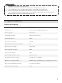 5
5
-
 6
6
-
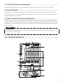 7
7
-
 8
8
-
 9
9
-
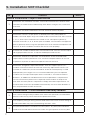 10
10
-
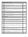 11
11
-
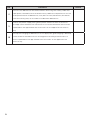 12
12
-
 13
13
-
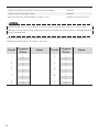 14
14
-
 15
15
-
 16
16
-
 17
17
-
 18
18
-
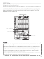 19
19
-
 20
20
-
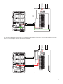 21
21
-
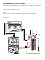 22
22
-
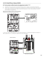 23
23
-
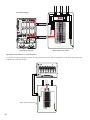 24
24
-
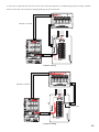 25
25
-
 26
26
-
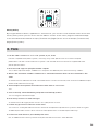 27
27
-
 28
28
-
 29
29
-
 30
30
-
 31
31
-
 32
32
-
 33
33
-
 34
34
-
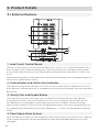 35
35
-
 36
36
-
 37
37
-
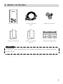 38
38
-
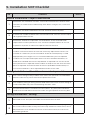 39
39
-
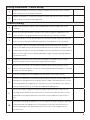 40
40
-
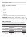 41
41
-
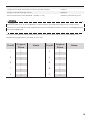 42
42
-
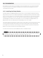 43
43
-
 44
44
-
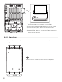 45
45
-
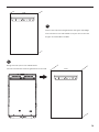 46
46
-
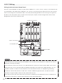 47
47
-
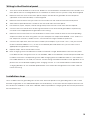 48
48
-
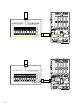 49
49
-
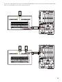 50
50
-
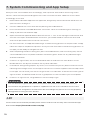 51
51
-
 52
52
-
 53
53
-
 54
54
-
 55
55
-
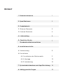 56
56
-
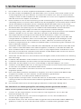 57
57
-
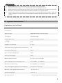 58
58
-
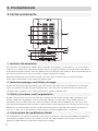 59
59
-
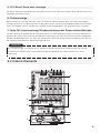 60
60
-
 61
61
-
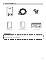 62
62
-
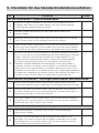 63
63
-
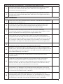 64
64
-
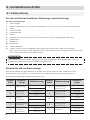 65
65
-
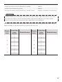 66
66
-
 67
67
-
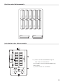 68
68
-
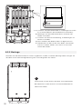 69
69
-
 70
70
-
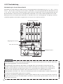 71
71
-
 72
72
-
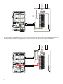 73
73
-
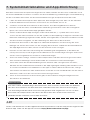 74
74
-
 75
75
-
 76
76
-
 77
77
-
 78
78
-
 79
79
-
 80
80
-
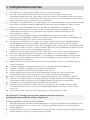 81
81
-
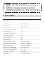 82
82
-
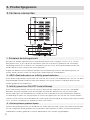 83
83
-
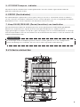 84
84
-
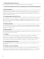 85
85
-
 86
86
-
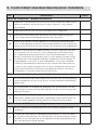 87
87
-
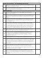 88
88
-
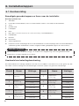 89
89
-
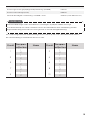 90
90
-
 91
91
-
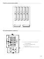 92
92
-
 93
93
-
 94
94
-
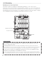 95
95
-
 96
96
-
 97
97
-
 98
98
-
 99
99
-
 100
100
-
 101
101
-
 102
102
-
 103
103
-
 104
104
-
 105
105
-
 106
106
-
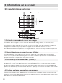 107
107
-
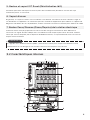 108
108
-
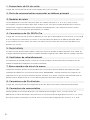 109
109
-
 110
110
-
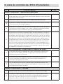 111
111
-
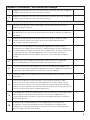 112
112
-
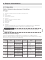 113
113
-
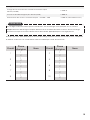 114
114
-
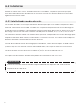 115
115
-
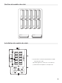 116
116
-
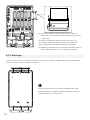 117
117
-
 118
118
-
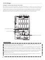 119
119
-
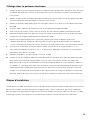 120
120
-
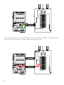 121
121
-
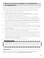 122
122
-
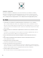 123
123
-
 124
124
-
 125
125
-
 126
126
-
 127
127
-
 128
128
-
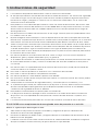 129
129
-
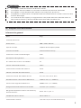 130
130
-
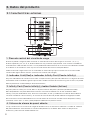 131
131
-
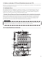 132
132
-
 133
133
-
 134
134
-
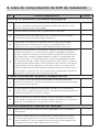 135
135
-
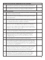 136
136
-
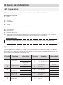 137
137
-
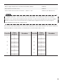 138
138
-
 139
139
-
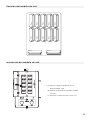 140
140
-
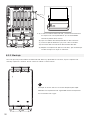 141
141
-
 142
142
-
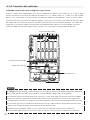 143
143
-
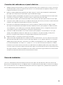 144
144
-
 145
145
-
 146
146
-
 147
147
-
 148
148
-
 149
149
-
 150
150
-
 151
151
-
 152
152
-
 153
153
-
 154
154
-
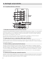 155
155
-
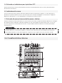 156
156
-
 157
157
-
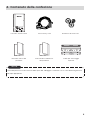 158
158
-
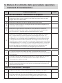 159
159
-
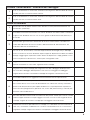 160
160
-
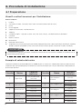 161
161
-
 162
162
-
 163
163
-
 164
164
-
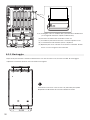 165
165
-
 166
166
-
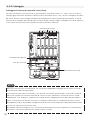 167
167
-
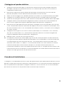 168
168
-
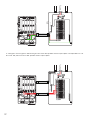 169
169
-
 170
170
-
 171
171
-
 172
172
-
 173
173
-
 174
174
-
 175
175
-
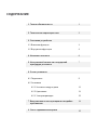 176
176
-
 177
177
-
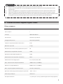 178
178
-
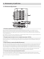 179
179
-
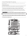 180
180
-
 181
181
-
 182
182
-
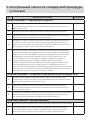 183
183
-
 184
184
-
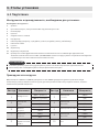 185
185
-
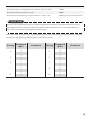 186
186
-
 187
187
-
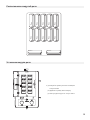 188
188
-
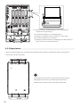 189
189
-
 190
190
-
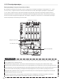 191
191
-
 192
192
-
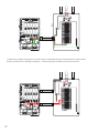 193
193
-
 194
194
-
 195
195
-
 196
196
-
 197
197


EcoFlow Smart Home Panel Combo(13 relay modules) Handleiding
- Type
- Handleiding
in andere talen
- English: EcoFlow Smart Home Panel Combo(13 relay modules) User manual
- italiano: EcoFlow Smart Home Panel Combo(13 relay modules) Manuale utente
- français: EcoFlow Smart Home Panel Combo(13 relay modules) Manuel utilisateur
- español: EcoFlow Smart Home Panel Combo(13 relay modules) Manual de usuario
- Deutsch: EcoFlow Smart Home Panel Combo(13 relay modules) Benutzerhandbuch
Gerelateerde papieren
-
EcoFlow MR500-BC Handleiding
-
-
EcoFlow DELTA Pro Handleiding
-
EcoFlow RIVER 2 Gebruikershandleiding
-
-
EcoFlow DELTA2000-EB-US Handleiding
-
-
EcoFlow 720Wh RIVER Pro Portable Power Station Handleiding
-
EcoFlow RIVER Gebruikershandleiding
-
Andere documenten
-
MSW MSW-POWER 700 de handleiding
-
Miller KE623992 de handleiding
-
-
-
-
-
Miller LK040031E de handleiding
-
Victron energy MultiPlus Compact 12/24V 2000VA 230V de handleiding
-
Miller KG117575 de handleiding
-
Samsung AR24KSWSAWKN Handleiding