
0DT866 • Rev. 10-05-2022
www.ditecdoor.com
L N
P5 P3 P4P1 P2
41 40 20 9 8 4 3 2 1 1 0 LAMP111 12 13
OFF
12345678
DL
23456 7
DL
M7
M5
M6
M3 M2
J4
15
S3 S4
S5 S2
+F -F U V W
SAFETY OPEN
M4A
BACK
M4
1 IN NC C NO
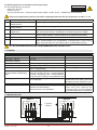
Handleiding voor installatie Schakelbord 52E
K22INV en K10INV motoren met eindschakelaars en microschakelaars
NL
Installation manual for 52E control panel
with K22INV and K10INV motors, with limit switches group
EN

- 2 -
0DT866 10-05-2022
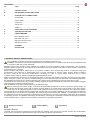
1. ALGEMENE WAARSCHUWINGEN M.B.T. DE VEILIGHEID
Deze installatiehandleiding is uitsluitend bedoeld voor vakkundig competent personeel.
De installatie, de elektrische aansluitingen en de afstellingen moeten uitgevoerd worden met inachtneming van Goed
Vakmanschap en de geldende voorschriften.
Lees de instructies aandacht voordat u begint met de installatie van het product. Een onjuiste installatie kan een bron van
gevaar vormen. De verpakkingsmaterialen (kunststof, polystyrol, enz.) mogen niet in het milieu worden achtergelaten en
moeten buiten bereik van kinderen worden gehouden aangezien deze een mogelijke bron van gevaar kunnen zijn.
Controleer, voor de installatie, of het product intact is. Installeer het product niet in een explosieve omgeving en atmosfeer:
aanwezigheid van gas of ontvlambare dampen vormen een groot gevaar voor de veiligheid. Voordat u de deur installeert,
alle structurele wijzigingen met betrekking tot een veilige doorgang en de bescherming of afscherming van alle gebieden
waar risico bestaat van beknelling, het afsnijden of meesleuren van ledematen en gevaar in het algemeen.
Controleer of de bestaande structuur voldoet aan de noodzakelijke vereisten voor stevigheid en stabiliteit. De
veiligheidsvoorzieningen (fotocellen, gevoelige randen, noodstop, enz.) moeten geïnstalleerd worden rekening houdend
met: de geldende voorschriften en richtlijnen, de criteria van Goed Vakmanschap, de installatie-omgeving, de werkingslogica
van het systeem en de krachten die ontwikkeld worden door gemotoriseerde deuren of hekken.
De veiligheidsvoorzieningen moeten eventuele gebieden van de deur beschermen waar risico op beknelling, het afsnijden of
afrukken van ledematen en gevaar in het algemeen bestaat. Bevestig de waarschuwingen die door de geldende voorschriften
voorzien zijn om de gevaarlijke zones aan te geven.
Bij elke installatie moet de indicatie van de identifcatiegegevens van de deur zichtbaar blijven.
Voordat de elektrische voeding wordt aangesloten moet u zich ervan verzekeren dat de gegevens op het plaatje overeenkomen
met die van het elektriciteitsnet. Zorg op het voedingsnet voor een omnipolaire schakelaar/scheidingsvoorziening met een
opening tussen de contacten van 3 mm of meer. Controleer of er bovenstrooms van de elektrische installatie een geschikte
dierentieelschakelaar en een beveiliging tegen overspanning. Sluit de deur aan op een eectieve aardingsinstallatie uitgevoerd
volgens de geldende veiligheidsvoorschriften. De fabrikant van de deur wijst elke aansprakelijkheid af als bestanddelen worden
geïnstalleerd die niet compatibel zijn wat veiligheid en goede werking betreft of als wijzigingen van eender welke aard worden
uitgevoerd zonder de specieke toesteming van de fabrikant zelf. Voor de eventuele reparatie of vervanging van onderdelen
mogen uitsluitend orginele Ditec vervangingsonderdelen gebruikt worden. De installateur moet alle informatie verschaen
met betrekking tot de automatische en handmatige werking en de noodbediening van de gemotoriseerde deur of hek, en de
gebruiker van het systeem de gebruiksaanwijzing geven.
INHOUDSOPGAVE VAN DE ONDERWERPEN
Hoofdst. Onderwerp ............................................................................................................................ Pag.
1. AANSLUITINGEN ...................................................................................................................... 3
2. REGELINGEN EN MELDINGEN .............................................................................................. 4
3. ELEKTRISCHE AANSLUITINGEN
Smart Reset .................................................................................................................................. 5
Sector Reset ................................................................................................................................ 6
Smart Plus .................................................................................................................................... 7
Sector Plus ................................................................................................................................... 8
Trac C ........................................................................................................................................ 9
4. INSTELLING EINDAANSLAG ................................................................................................ 10
5. PROBLEMEN OPSPOREN ...................................................................................................... 10
6. PROGRAMMEERMENU
6.1 Installatiemenu ...................................................................................................................... 11
6.2 Geavanceerd menu .............................................................................................................. 12
6.3 Menu opening met timer ....................................................................................................... 13
6.4 Bedieningsmenu ................................................................................................................... 14
7. ALARMEN ................................................................................................................................14
8. VERGRENDELING .................................................................................................................. 14
Alle rechten voorbehouden
Alle gegevens en specicaties werden met grote zorg opgesteld en gecontroleerd. De fabrikant is echter niet aansprakelijk voor
eventuele vergissingen, weglatingen of onvolledige gegevens te wijten aan technische redenen of redenen in verband met illustraties.
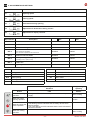
Optioneel accessoire Safety Confort
CSafety Top
T

- 3 - 0DT866 10-05-2022
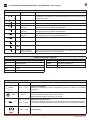
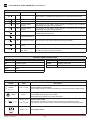
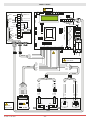
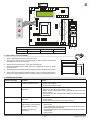
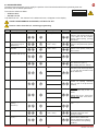
1. ELEKTRONISCH BEDIENINGSPANEEL 52E (INVERTER) - Aansluitingen
INGANGEN
Bediening Functie Beschrijving
1 2 N.G. STOP Als op het programmeermenu (pag.15 punt 16)
het contact 1-2 vrijgegeven is, hoort bij de opening van het contact ook de
STOP van de deur
1 3 N.O. Openen De sluiting van het contact activeert het openen.
1 4 N.O. Sluiting De sluiting van het contact activeert het sluiten.
41 40 N.G. Veiligheid bij
omkering
De opening van het veiligheidscontact veroorzaakt de omkering van de
beweging (heropening) tijdens de sluitingsfase.
1 8 N.G. Veiligheid bij
omkering
De opening van het veiligheidscontact veroorzaakt de omkering van de
beweging (heropening) tijdens de sluitingsfase.
1 20 N.O. Gedeeltelijke
opening
De sluiting van het contact activeert een gedeeltelijke opening waarvan de
duur ingesteld wordt met het geavanceerde menu.
1 11 N.G. Sluitstand De opening van het contact geeft de sluitstand aan.
1 13 N.G. Openingsstand De opening van het contact geeft de openingsstand aan.
1 12 N.G. Vertragingspositie De opening van het contact activeert de vertraging tijdens het openen.
1 9 N.O. Sluiting mogelijk
maken met SLEC
Bij deuren met SLEC zorgt het openen van het contact ervoor dat de deur
alleen met dodeman kan worden bediend.
UITGANGEN
Uitgang Waarde Beschrijving
1
0
+
-24 V = / 0,5 A
Voeding hulpstukken.
Uitgang voor voeding van externe hulpstukken, lampen voor staat van automaat
inbegrepen.
LAMP 230 V~
Knipperlicht (FML).
Niet-intermitterend signaal (jumper ON op FML).
Wordt geactiveerd tijdens het openen en sluiten.
-F +F
200 V = / 0,2 A
o
24 V = / 0,5 A
Elektrische rem van motor.
Automatisch ingesteld met de keuze van het deurmodel in het programmeermenu.
De uitgang is actief de gehele duur van de beweging zowel in opening als in sluiting.
U W V
M
3 ~
230 V~ / 6 A Driefasemotor.
M2 Veiligheid / Bedieningen
M3 Signaal positie
M4 Vergrendeling
M4A Terug
M5 Motor / Motorrem
J4 Remweerstand
OPEN Hulpkaart schakelbord
SAFETY Hulpkaart veiligheid
CONNETTORI BORDO QUADRO
52E NL

- 4 -
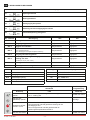
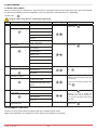
0DT866 10-05-2022
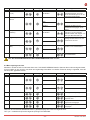
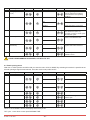
Trimmer Beschrijving
P1 Openingssnelheid
P2 Sluitingssnelheid
P3 Vertraging bij het openen
P4 Afstelling van de vertraging bij het sluiten
P5 Contrastaanpassing weergeven
0 s 30 s
0 s 10 s
0 MAX
0 MAX
0 MAX
Dip - schakelaar
Beschrijving OFF ON
DIP 1 Later gebruik – –
DIP 2 Toegang tot geavanceerd menu Uitgeschakeld. Vrijgegeven.
DIP 3 Vrijgave van trimmers Uitgeschakeld. Vrijgegeven.
DIP 4 Meter
TOT: Aantal bewegingen
SVC: Bewegingen niet uitgevoerd tijdens bediening
Uitgeschakeld. Vrijgegeven.
DIP 5 Toegang tot bedieningsmenu Uitgeschakeld. Vrijgegeven.
DIP 6
Inrichting voor weergave van gegevens i.v.m.
werking van deur
(F. bedrijf, S. bus, S. piek, S. bus)
Uitgeschakeld. Vrijgegeven.
DIP 7 Later gebruik – –
DIP 8 Menu cyclische werking Uitgeschakeld. Vrijgegeven.
LED Brandt
DL2 Sluitstand
DL3 Vertraging
DL6 Gedeeltelijke opening
DL7 Openingsstand
DL15 Automatische start
Drukknoppen Beschrijving
S2 GEBRUIKT VOOR PROGRAMMERING
S3 NIET GEBRUIKT
S4 NIET GEBRUIKT
S5 GEBRUIKT VOOR PROGRAMMERING
Werking
Standaard
Werking
Programmering
Drukknop LED Drukknop
Activeert het
openen.
- De brandende groene led geeft de aanwezigheid van de
24 V= voeding aan. Scrollen van menu
Activeert het
gedeeltelijk openen. Bevestigt
Schakelt de STOP-
functie in en uit.
- De brandende rode led geeft de activering van de STOP aan.
- De knipperende rode led geeft de activering van de
beveiligingen aan.
- De kort knipperende rode led geeft aan dat de
bedieningsdrempelwaarde bereikt is
Activeert het sluiten. Scrollen van menu
ON
2. REGELINGEN EN MELDINGEN
52E

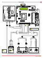
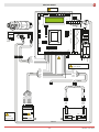
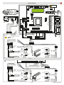
- 5 - 0DT866 10-05-2022
0 1 9
41 FC FA OUT
R1
1
ON
PWR SA
23 4
SLEC
K22
13
11
0
U
V
W
12
M
3 ~
140
B
A
C
P5 P3 P4P1 P2
41 40 20 9 8 4 3 2 1 1 0 LAMP111 12 13
ON
OFF 1 2 3 4 5 6 7 8
DL
23456 7
DL
M7
M4A
M5
M6
M3
BACK
M4
1 IN NC C NO
M2
J4
15
S3 S4
S5 S2
SAFETY OPEN
F2F1
230 V
50/60 Hz
GND
L N
4327
Rx
Tx
5FB
0 80 1 1
8132 8132
8265A
8265B
4328
+F -F U V W
7978
8457
7979
Rx
Tx
LAB4
0 10 1 8 1
8132 8132
7825A
SMART RESET
Blauw
Zwart
Bruin
Wit
T
Blauw
Bruin
Bruin
Blauw
Zwart
0 1 0 8 1
Zwart
Blauw
Blauw
Zwart
Oranje
Zwart
Blauw
Rood
Oranje
Wit
Bruin
Rood
Blauw
Geel
Groen
Roze
Wit
Bruin
Grijs
Roze
Wit
Groen
Grijs
Geel
Blauw
Bruin
Rood
1-9 Sluiten
om de deur te sluiten
Dip 1 OFF
Dip 2,3,4 ON
Dip 3 ON
T
0 1 0 1 8 1
Zwart
Blauw
Zwart
Blauw
Oranje
Rood
C
Wit
Zwart
Blauw
Eindaanslag
vertraging
Eindaanslag opening
Eindaanslag sluiting
Stop
Grijs
Wit
Rode
Rem
Geel/Groene
Bruin
Zwart
Bruin
NL

- 6 -
0DT866 10-05-2022
P5 P3 P4P1 P2
41 40 20 9 8 4 3 2 1 1 0 LAMP111 12 13
ON
OFF 1 2 3 4 5 6 7 8
DL
23456 7
DL
M7
M4A
M5
M6
M3
BACK
M4
1 IN NC C NO
M2
J4
15
S3 S4
S5 S2
SAFETY OPEN
F2F1
230 V
50/60 Hz
GND
L N
+F -F U V W
0 1 9
41 FC FA OUT
R1
1
ON
PWR SA
23 4
SLEC
A931C
8457
A933A
7825A
Rx
Tx
5FB
0 80 1 1
8132 8132
8265A
8265B
LS
LK
A
C
M
B
M LKLS
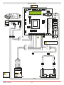
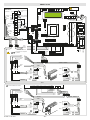
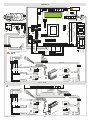
SECTOR RESET
Wit
Rood
Blauw
Zwart
Bruin
Oranje
Zwart
Blauw
Rood
Oranje
Wit
Bruin
Rood
Blauw
Geel
Groen
Roze
Wit
Bruin
Grijs
Roze
Wit
Groen
Grijs
Geel
Blauw
Bruin
Rood
T
Dip 1 OFF
Dip 2,3,4 ON C
1-9 Sluiten
om de deur te sluiten
Blauw
Bruin
Bruin
Blauw
Zwart
Zwart
Blauw
Blauw
Zwart
Oranje
Dip 3 ON

- 7 - 0DT866 10-05-2022
P5 P3 P4P1 P2
41 40 20 9 8 4 3 2 1 1 0 LAMP111 12 13
ON
OFF 1 2 3 4 5 6 7 8
DL
23456 7
DL
M7
M4A
M5
M6
M3
BACK
M4
1 IN NC C NO
M2
J4
15
S3 S4
S5 S2
SAFETY OPEN
F2F1
230 V
50/60 Hz
GND
L N
+F -F U V W
0 1 9
41 FC FA OUT
R1
1
ON
PWR SA
23 4
SLEC
A931C
8457
A933A
7825A
Rx
Tx
5FB
0 80 1 1
8132 8132
8265A
8265B
LS
LK
A
C
M
B
M LKLS
P5 P3 P4P1 P2
41 40 20 9 8 4 3 2 1 1 0 LAMP111 12 13
ON
OFF 1 2 3 4 5 6 7 8
DL
23456 7
DL
M7
M4A
M5
M6
M3
BACK
M4
1 IN NC C NO
M2
J4
15
S3 S4
S5 S2
SAFETY OPEN
F2F1
230 V
50/60 Hz
GND
L N
+F -F U V W
41 40 20 9 8 4 3 2 1 1 0 LAMP111 12 13
M3 M2
L N
SOFA1
POWER
IN1
OUT1
P2.0
2.0
1 11 4 N
I
7825A
0 1
0 1
0 1
A935C A935E - A935G
7796
7982
0 1
TX2
R
X1
R
X2
T
X1
0 1
0 1
0 1
A935C A935E - A935G
7796
7982
0 1
A934E/L
TX2
R
X1
R
X2
T
X1
A451L
7825A
7979
A934E/L
A451L
4327
K22 inv Y
13
11
0
U
V
W
12
M
3 ~
140
B
A
C
4328
7978
Bruin
Blauw
Zwart
Blauw
Oranje
Rode
Zwart
Blauw
Oranje
Rode
C
C
C
Zwart
Blauw
Rood
Oranje
Wit
Bruin
Rode
Oranje
Blauw
Zwart
Zwart
Blauw
Oranje
Rode
Zwart
Blauw
Blauw
Zwart
1
6
1
0
1
0
0
1
8
41
0
1
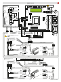
Standaardaansluiting met
voorbedrading
C
SMART PLUS
Dip 3 ON
Wit
Zwart
Blauw
Eindaanslag
vertraging
Eindaanslag opening
Eindaanslag sluiting
Stop
Grijs
Wit
Rode
Rem
Geel/Groene
Bruin
Zwart
Bruin
T
Bruin
Blauw
Zwart
Blauw
Oranje
Rode
Zwart
Blauw
Oranje
Rode
T
T
T
Blauw
Zwart
Bruin
Wit
Bruin
Wit
Oranje
Rode
Blauw
Zwart
Rode
Oranje
Blauw
Zwart
Zwart
Blauw
Oranje
Rode
Zwart
Blauw
Blauw
Zwart
1
6
1
0
1
0
0
1
SOF
SOF
0
1
Aansluiting uit te voeren door
de monteur
NL

- 8 -
0DT866 10-05-2022
P5 P3 P4P1 P2
41 40 20 9 8 4 3 2 1 1 0 LAMP111 12 13
ON
OFF 1 2 3 4 5 6 7 8
DL
23456 7
DL
M7
M4A
M5
M6
M3
BACK
M4
1 IN NC C NO
M2
J4
15
S3 S4
S5 S2
SAFETY OPEN
F2F1
230 V
50/60 Hz
GND
L N
+F -F U V W
41 40 20 9 8 4 3 2 1 1 0 LAMP111 12 13
M3 M2
L N
LS
LK
A
C
M
B
M LKLS
SOFA1
POWER
IN1
OUT1
P2.0
2.0
1 11 4 N
I
7825A
0 1
0 1
0 1
A935C A935E - A935G
7796
7982
0 1
TX2
R
X1
R
X2
T
X1
0 1
0 1
0 1
A935C A935E - A935G
7796
7982
0 1
A934E/L
TX2
R
X1
R
X2
T
X1
A451L
7825A
A933A
A934E/L
A451L
A931C
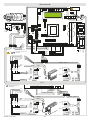
SECTOR PLUS
Dip 3 ON
T
Bruin
Blauw
Zwart
Blauw
Oranje
Rode
Zwart
Blauw
Oranje
Rode
T
T
T
Wit
Rood
Blauw
Zwart
Bruin
Oranje
Bruin
Wit
Oranje
Rode
Blauw
Zwart
Rode
Oranje
Blauw
Zwart
Zwart
Blauw
Oranje
Rode
Zwart
Blauw
Blauw
Zwart
1
8
1
0
1
0
0
1
SOF
SOF
0
1
Aansluiting uit te voeren door
de monteur
Bruin
Blauw
Zwart
Blauw
Oranje
Rode
Zwart
Blauw
Oranje
Rode
C
C
C
Zwart
Blauw
Rood
Oranje
Wit
Bruin
Rode
Oranje
Blauw
Zwart
Zwart
Blauw
Oranje
Rode
Zwart
Blauw
Blauw
Zwart
1
8
1
0
1
0
0
1
8
41
0
1
Standaardaansluiting met
voorbedrading
C

- 9 - 0DT866 10-05-2022
P5 P3 P4P1 P2
41 40 20 9 8 4 3 2 1 1 0 LAMP111 12 13
ON
OFF 1 2 3 4 5 6 7 8
DL
23456 7
DL
M7
M4A
M5
M6
M3
BACK
M4
1 IN NC C NO
M2
J4
15
S3 S4
S5 S2
SAFETY OPEN
F2F1
230 V
50/60 Hz
GND
L N
+F -F U V W
41 40 20 9 8 4 3 2 1 1 0 LAMP111 12 13
M3 M2
L N
LS
LK
A
C
M
B
M LKLS
SOFA1
POWER
IN1
OUT1
P2.0
2.0
1 11 4 N
I
7825A-C
0 1
0 1
0 1
A935L A935G / E
7982
0 1
TX2
R
X1
R
X2
T
X1
0 1
0 1
0 1
A935L A935G / E
7982
0 1
A934E/L
TX2
R
X1
R
X2
T
X1
A451L
7825A-C
A933A - 7823B
A934E/L
A451L
A931C - 7824B
TRAFFIC C
Dip 3 ON
T
Bruin
Blauw
Zwart
Blauw
Oranje
Rode
Zwart
Blauw
Oranje
Rode
T
T
T
Wit
Rood
Blauw
Zwart
Bruin
Oranje
Bruin
Wit
Oranje
Rode
Blauw
Zwart
Rode
Oranje
Blauw
Zwart
Zwart
Blauw
Oranje
Rode
Zwart
Blauw
Blauw
Zwart
1
8
1
0
1
0
0
1
SOF
SOF
0
1
Aansluiting uit te voeren door
de monteur
Bruin
Blauw
Zwart
Blauw
Oranje
Rode
Zwart
Blauw
Oranje
Rode
C
C
C
Zwart
Blauw
Rood
Oranje
Wit
Bruin
Rode
Oranje
Blauw
Zwart
Zwart
Blauw
Oranje
Rode
Zwart
Blauw
Blauw
Zwart
1
8
1
0
1
0
0
1
8
41
0
1
Standaardaansluiting met
voorbedrading
C
NL

- 10 -
0DT866 10-05-2022
P5 P3 P4P1 P2
41 40 20 9 8 4 3 2 1 1 0 LAMP111 12 13
ON
OFF 1 2 3 4 5 6 7 8
DL
23456 7
DL
M7
M4A
M5
M6
M3
BACK
M4
1 IN NC C NO
M2
J4
15
S3 S4
S5 S2
SAFETY OPEN
F2F1
230 V
50/60 Hz
GND
L N
+F -F U V W
ON
5. PROBLEMEN OPSPOREN
4. INSTELLING EINDAANSLAG
1. Kalibreer de vertragingsstappen op nul. (P3 - P4)
2. Kalibreer de eindaanslag (C) op de reductiemotor, zodanig dat de deur zich
sluit op ongeveer 200/300 mm van het sluitingspunt.
3. Kalibreer de eindaanslag voor opening (A), op het punt van opening.
4. Kalibreer de eindaanslag van de vertraging (B) zodanig dat deze in werking
treedt op ongeveer ¾ van de openingsslag.
5. Kalibreer de openingssnelheid met de (P1) en sluiting (P2).
6. Kalibreer de trimmers van de vertragingsstappen (P3) opening en (P4)
sluiting, zodanig dat een stilstand verkregen wordt in de eectieve standen
van deur geopend en deur gesloten.
Dip 3 ON
ZEKERINGEN
ID Waarden Afmetingen Circuit
F1 - F2 12A - 500V 10.3 x 38 Eenfaseleiding
C
B
A
B
C
300
A
¾
Meldingen op het display Probleem Controle
Stroomlimiet overschreden Vereiste motorkoppel groter
dan de beschikbare.
• Verlaag de openingssnelheid.
• Controleer de voeding.
• Controleer de voedingskabels.
Remweerstand
inschakelen
Spanning op BUS hoger dan
de drempelwaarde
• Sluit voor deuren met sectorreset de remweerstand aan en
zet het item in het geavanceerde menu op "JA".
• Zet het schakelbord uit, wacht 3 minuten en koppel de voeding
terug aan.
• Als de fout zich opnieuw voordoet, controleert u of de
spanning op de BUS lager ligt dan 360 V.
Spanning BUS Max. Spanning van BUS hoger
dan de drempelwaarde
• Zet het schakelbord uit, wacht 3 minuten en koppel de voeding
terug aan.
• Controleer de voedingsspanning van het schakelbord.
Wachten op Encoder Nieuwe paneelontsteking /
Vervangingskader al eerder
gepland en niet resetten
Absolute Encoder niet
aangesloten
Reset het paneel met behulp van de volgende instructies:
• DIP2 op ON
• Druk op STOP (hier komt de kaart in het "programmeermenu"
en toont de reeds geregistreerde gegevens)
• Blader door het menu naar het item "COMMAND MODE" en
stel de EINDSCHAKELAAR in
• DIP2 op OFF

- 11 - 0DT866 10-05-2022
6 PROGRAMMEERMENU
6.1 INSTALLATIEMENU
Wanneer het schakelbord wordt aangezet, geeft het toestel de meldingen DITEC en VERSIE FW van microprocessor en
kaart weer en opent automatisch het installatiemenu met de melding SEL TAAL.
Bevestigen met
STAP Keuzen 1ste niveau Keuzen 2de niveau Scrollen van menu Aantekeningen
1Sel. Taal
Bevestigen met:
Bevestigen met: ENGLISH
ITALIAN
FRANÇAIS
DEUTCH
ESPANOL - POLSKA
CESKY - MAGYAR
2Model deur
Bevestigen met:
Bevestigen met: SOFT RESET
SECTOR RESET
SMART PLUS
SECTOR PLUS
TRAFFIC C
SMART RESET
3Beheer posities
Bevestigen met:
Bevestigen met: ENCODER
EINDSCHAKELAAR
4IJking van posities
De deur wordt verplaatst naar de ge-
wenste positie in de modus met bedie-
ner en aan een lage snelheid.
Positie bevestigen met:
Bevestigen met: POSITIE SLUIT
GEDEELTELIJK
OPENINGSSTAND
POSITIE OPENT
5Modus commando
Bevestigen met:
Selecteer 1-9: de bediening zal
impulsief zijn als 1-9 is gesloten of met
bediener als 1-9 is geopend
Bevestigen met: IMPULS
MET BEDIENER
INPUT 1 - 9
6BEVESTIG GEGEVENS Bevestigen met:
PROGRAMMERING UITGEVOERD
De deur is nu geprogrammeerd en werkt aan de snelheidswaarden die standaard worden ingesteld.
Met de deur IN BEWEGING worden de waarden van de spanning en de stroom op de BUS op het display weergegeven.
Tijdens de programmering moeten alle kabels losgekoppeld worden die zijn aangesloten op PIN 3 - 4 - 20
NL

- 12 -
0DT866 10-05-2022
1 2 3 4 5 6 7 8
ON
6.2 GEAVANCEERD MENU
Het geavanceerde menu dient om de positie van de eindschakelaars, die eerder ingesteld werden, te wijzigen
en om de ingestelde defaultparameters te wijzigen.
Om het geavanceerde menu te openen:
- Zet de deur in STOP
- Zet DIP 2 op ON
Op het display wordt “IJK ENCODER”, het eerste trefwoord van het geavanceerde menu, weergegeven.
ZET NA DE BEËINDIGING VAN DE PROGRAMMERING DIP2 OP OFF
Tijdens de programmering moeten alle kabels losgekoppeld worden die zijn aangesloten op PIN 3 - 4 - 20
STAP Keuzen 1ste niveau Scrollen Bevestigen Keuzen 2de niveau Aantekeningen
1 IJking van Encoder
Positie sluit
De deur wordt verplaatst naar de
gewenste positie in de modus met
bediener en aan een lage snelheid.
U dient alle posities (sluiting,
gedeeltelijke opening, opening) in
te stellen.
2 Uitsluiting van fotocel
(stap enkel voor
deuren Reset)
Waarde wijzigen
(1 eenheid ≅ 3mm)
Als de waarde toeneemt, verhoogt
de positie van de by-pass van de
fotocel
3 Uitsluiting primaire
beveiliging
Waarde wijzigen
(1 eenheid ≅ 3mm)
Als de waarde toeneemt, verhoogt
de positie van de by-pass van de
primaire beveiliging
4 Automatische sluiting
(default JA met T= 5 s)
JA
NEE
5 Tijd voor automatische
sluiting
Variante tijd
Optie enkel ter beschikking als
onder punt 4) JA is gekozen.
Waarde van variabele van 0 tot
100 sec.
6 Modus commando
Impuls
Selecteer 1-9: de bediening zal
impulsief zijn als 1-9 is gesloten of
met bediener als 1-9 is geopend
Met bediener
INPUT 1 - 9
7 Beveiliging in opening
JA
Als JA ingesteld is, gaat de gesloten
deur die een openingscommando
ontvangt niet open als de fotocel in
bedrijf is.
NEE
8 Vergrendeling
GEEN
VERGRENDELING
SLUIS: deur 2 gaat open met ex-
terne bediening alleen als deur 1
gesloten is.
VERGRENDELING: deur 2 gaat
automatisch open na de sluiting
van deur 1
SLUIS
VERGRENDELING
9 Voorafgaande
knippering opening
(default nee)
JA
De voorafgaande knippering heeft
een vaste duur van
3 sec.
NEE
10 Vervroeging gradiënt
opening
WAARDE WIJZIGEN
(1 eenheid ≅ 3mm)
Als de waarde toeneemt, verhoogt
de vertragingsruimte in opening.
11 Openingssnelheid
in (Hz)
WAARDE
WIJZIGEN
Waarden instellen die groter zijn
dan de defaultwaarden moet
geëvalueerd worden in functie
van de deurafmetingen en van de
werkingsomstandigheden.

- 13 - 0DT866 10-05-2022
STAP Keuzen 1ste niveau Scrollen Bevestigen Keuzen 2de niveau Aantekeningen
12 Sluitsnelheid
in (Hz)
WAARDE
WIJZIGEN
Grotere waarden instellen moet
geëvalueerd worden in functie
van de deurafmetingen en van de
werkingsomstandigheden.
13 Activering Alarm
Service
JA
NEE
RESET? Reset van de telling van de
ontbrekende bewegingen tot de
service
14 Drempelwaarde
bediening
WAARDE
WIJZIGEN
Optie enkel ter beschikking als
onder punt 13) JA is gekozen.
Waarde instellen met stappen van
1000 cycli. Max 200.000 cycli
15 Vrijgave stop 1-2
JA
Als JA ingesteld is, hoort bij de
opening van het contact 1-2 ook
de STOP van de deur.
NEE
16 Remweerstand (default
NEE)
JA
Stel JA in wanneer de deur
voorzien is van remweerstand.
NEE
17 RESET PARAMETERS
BEVESTIG
Als u bevestigt, gaat u terug naar
het installatiemenu.
STAP Keuzen 1ste niveau Scrollen Bevestigen Keuzen 2de niveau Aantekeningen
1CYCL. WERKING
TIMER OFF
Timer niet actief
TIMER ON Timer actief
2TIJDSEENHEID
MIN.
Interval in minuten
SEC. Interval in seconden
3INTERVAL OPENING
1 …200
Instelling interval opening
4TIJDSDUUR PAUZE
1….200
Instelling tijdsduur pauze bij
geopende deur
5TOT
WAARDE
Weergave totaal aantal
uitgevoerde bewegingen
6RESET CYCLI
RESET?
Reset telling totaal aantal
bewegingen
ZET NA DE BEËINDIGING VAN DE PROGRAMMERING DIP2 OP OFF
6.3 Menu opening met timer
Met deur in STOP en DIP 8 in ON wordt het menu CYCLISCHE WERKING bereikt. Wanneer die modus wordt geactiveerd,
is het mogelijk om een opening met timer aan regelmatige intervallen in te stellen. Zodra de timing is ingesteld, moet de
DIP 8 op OFF geplaatst worden.
Wanneer de CYCLISCHE WERKING actief is, geeft de display elke 2 sec het volgende weer:
TOT cycli - ontbrekende tijd tot de volgende opening/TIJD OPENING
NL

- 14 -
0DT866 10-05-2022
7. ALARMEN
8. VERGRENDELING
MELDING SITUATIE AANTEKENINGEN
Ditec deur gesloten in afwachting van commando
Opening vbus iBUS deur in openingsbeweging
Deur open - tijd voor
automatische sluiting
deur open
Sluiting vbus iBUS deur in sluitingsbeweging
Input 40 gesloten; input 8 open inwerkingtreding fotocel Tijdens beweging deur
input 40 open; input 8 gesloten Inwerkingtreding primaire beveiliging
(SLEC / veiligheidsbalk)
Tijdens beweging deur
Thermische beveiliging of
microschakelaar ontgrendeling
open
Inwerkingtreding veiligheidsmicroschakelaar op
inrichting manuele opening / inwerkingtreding
thermische beveiliging motor / Eindschakelaars
voor opening (A) en sluiting (C) zijn gelijktijdig actief
Beveiliging open actief fotocel ingeschakeld bij gesloten deur en deur
die niet opengaat
Melding die enkel verschijnt als op het
geavanceerde menu (stap 7) de functie
"beveiliging opening" ingesteld is op JA.
Deur in stop stopbediening actief
Wachten op Encoder Nieuwe elektrische paneelontsteking / vervanging
elektrische paneelontsteking
Absolute Encoder niet aangesloten
Paneel al geprogrammeerd om te
werken met motor uitgerust met
absolute Encoder. Zie het gedeelte
over probleemoplossing om te resetten.
6.4 Bedieningsmenu (een wachtwoord wordt gevraagd)
Om het bedieningsmenu te openen:
- Zet de deur in STOP
- Zet DIP5 op ON
- Voer het wachtwoord in: sequentie drukknoppen OPEN - OPEN - SLUIT - GEDEELTELIJKE OPENING
1 2 3 4 5 6 7 8
ON
ZET NA DE BEËINDIGING VAN DE PROGRAMMERING DIP5 TERUG OP OFF
STAP Keuzen 1ste niveau Aantekeningen
1SP. REMMING MIN
Default 340Vdc
Limiet voor gedeeltelijke activering van de remweerstand
2SP. REMMNING MAX
Default 380Vdc
Limiet voor totale activering van de remweerstand
3LIMIET OVERSTROOM
Default 10A
Als de stroom op de BUS de ingestelde drempelwaarde overschrijdt, gaat de
deur open aan de helft van de snelheid om de stroomopname te verlagen.
4HELLING GRADIËNT OPENING Verandert de helling van de vertragingsgradiënt in opening. Default 15.
(Als de waarde toeneemt, wordt de ruimte van de gradiënt gereduceerd).
5STATUS ACCU Weergave % accu encoder van 0% tot 100%
6LIJST ALARMEN De laatste 50 alarmen worden weergegeven: Overstroom; busspanning buiten
limiet, inwerkingtreding van remweerstand, overtemperatuur inverter, storing
driver motor (encoder). Om af te sluiten drukt u op gedeeltelijke opening.
Tijdens de programmering moeten alle kabels losgekoppeld worden die zijn aangesloten op PIN 3 - 4 - 20
+24V
INPUT
1 IN NC C NO
QE 52E
QE 52E
+24V
INPUT
1 IN NC C NO
M4 M4
Logische
werking
DEUR 1 DEUR 2

- 15 - 0DT866 10-05-2022
1. GENERAL SAFETY PRECAUTIONS
This installation manual is intended for professionally competent personnel only.
Installation, electrical connections and adjustments must be performed in accordance with Good Working Methods and
in compliance with the current standards.
Read the instructions carefully before installing the product. Incorrect installation could be dangerous. The packaging
materials (plastic, polystyrene, etc.) should not be discarded in the environment or left within reach of children, as they are
a potential source of danger.
Before installing the product, make sure it is in perfect condition. Do not install the product in explosive areas and
atmospheres: the presence of inammable gas or fumes represents a serious safety hazard. Before installing
the door, make all the structural modifications necessary in order to create safety clearance and to guard
or isolate all the crushing, shearing, trapping and general danger areas.
Make sure the existing structure is up to standard in terms of strength and stability. The safety devices (photocells, safety
edges, emergency stops, etc.) must be installed taking into account current laws and directives, Good Working Methods,
the installation environment, the system operating logic and the forces developed by the motorised door or gate.
The safety devices must protect any crushing, shearing, trapping and general hazardous areas of the door. Display the signs
required by law to identify hazardous areas.
Each installation must clearly indicate the door identication data.
Before connecting the power supply, make sure the plate data correspond to those of the mains power supply. An
omnipolar disconnection switch with a contact opening distance of at least 3mm must be tted on the mains supply.
Check there is an adequate residual current circuit breaker and overcurrent cutout upstream of the electrical system.
Connect the door to an ecient earthing system that complies with current safety standards. The door manufacturer declines
all responsibility if components not compatible with safety and good functioning are installed, or modications of any kind
are made that have not been specically authorised by the manufacturer. Use only original Ditec spare parts when repairing
or replacing products. The installer must supply all information concerning the automatic, manual and emergency operation
of the motorised door or gate, and must provide the user with the operating instructions.
CONTENTS
Ch. Topic ..................................................................................................................................... Page
1. CONNECTIONS ....................................................................................................................... 16
2. ADJUSTMENTS AND SETTINGS .......................................................................................... 17
3. ELECTRICAL CONNECTIONS
Smart Reset ................................................................................................................................ 18
Sector Reset .............................................................................................................................. 19
Smart Plus .................................................................................................................................. 20
Sector Plus ................................................................................................................................. 21
Trac C ...................................................................................................................................... 22
4. LIMIT SWITCH ADJUSTMENT .............................................................................................. 23
5. TROUBLESHOOTING .............................................................................................................. 23
6. PROGRAMMING
6.1 Installation menu ................................................................................................................... 24
6.2 Advanced menu .................................................................................................................... 25
6.3 Timed opening menu ............................................................................................................ 26
6.4 Service menu ........................................................................................................................ 27
7. ALARMS ................................................................................................................................... 27
8. INTERLOCK ............................................................................................................................. 27
All rights reserved
The data given have been compiled and checked with the greatest care. We cannot, however, assume any responsibility
for any errors, omissions or approximations due to technical or graphical requirements.
Optional accessory Comfort Safety
CTop Safety
T
EN

- 16 -
0DT866 10-05-2022
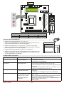
1. 52E CONTROL PANEL (INVERTER) - Connections
INPUTS
Command Function Description
1 2 NC STOP If on the programming menu (page 15 point 16)
With contact 1-2 enabled, the opening of the contact STOPS the door
1 3 NO Opening The closure of the contact activates the opening operation.
1 4 NO Closure The closure of the contact activates the closing operation.
41 40 NC Reversal safety
contact
The opening of the safety contact triggers a reversal of the movement
(reopening) during the closing operation.
1 8 NC Reversal safety
contact
The opening of the safety contact triggers a reversal of the movement
(reopening) during the closing operation.
1 20 NO Partial opening The closure of the contact activates a partial opening operation of the duration
set with the advanced menu.
1 11 NC Closing limit switch The opening of the contact stops the closing operation.
1 13 NC Opening limit switch The opening of the contact stops the opening operation.
1 12 NC Deceleration limit
switch
The opening of the contact activates deceleration during opening.
1 9 NO Closure enabling
with SLEC
In the case of doors with SLEC, the opening of the contact allows the door
to work only when someone is present.
OUTPUTS
Output Value Description
1
0
+
-24V = / 0.5A Power supply to accessories.
Power supply output for external accessories, including automation status lamps.
LAMP 230 V~
Flashing light (FLM).
Non-ashing signal (jumper ON on FML).
Activated during opening and closing operations.
-F +F
200V= / 0.2A
or
24V = / 0.5A
Electric motor brake.
Automatically set with the choice of door model in the programming menu.
The output is active for the duration of both the opening and closing operations.
U W V
M
3 ~
230V~ / 6A Three-phase motor.
M2 Safety device / Commands
M3 Position signal
M4 Interlock
M4A Back
M5 Motor / brake motor
J4 Brake resistance
OPEN Auxiliary panel card
SAFETY Auxiliary safety card
CONTROL PANEL CONNECTORS
52E

- 17 - 0DT866 10-05-2022
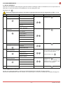
Trimmer Description
P1 Opening speed
P2 Closing speed
P3 Deceleration during opening
P4 Adjustment of deceleration during closure
P5 Adjustment of display contrast.
0 s 30 s
0 s 10 s
0 MAX
0 MAX
0 MAX
Dip-switches Description OFF ON
DIP 1 Future use – –
DIP 2 Access to advanced menu Disabled Enabled
DIP 3 Trimmer enabling Disabled Enabled
DIP 4 Counter
TOT: Number of operations
SVC: Number of operations left until service
Disabled Enabled
DIP 5 Access to service menu Disabled Enabled
DIP 6 Door operating data display
(F working, I Bus, I peak, V Bus) Disabled Enabled
DIP 7 Future use – –
DIP 8 Cyclic operation menu Disabled Enabled
LED On
DL2 Closing position
DL3 Deceleration
DL6 Partial opening
DL7 Opening position
DL15 Autostart
Buttons Description
S2 USED FOR PROGRAMMING
S3 NOT USED
S4 NOT USED
S5 USED FOR PROGRAMMING
Operating mode
Standard
Programming
Operating
Button LED Button
Starts the opening
operation.
- The green LED on indicates the presence of the 24 V= power
supply. Menu scrolling
Starts the partial
opening operation. Conrm
Starts and stops the
STOP operation.
- The red LED on indicates that the STOP has been activated.
- The ashing red LED indicates that the safety devices have
been activated.
- The quick ashing red LED indicates that the service threshold
has been reached
Starts the closing
operation. Menu scrolling
ON
2. ADJUSTMENTS AND SETTINGS
52E EN

- 18 -
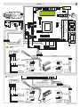
0DT866 10-05-2022
0 1 9
41 FC FA OUT
R1
1
ON
PWR SA
23 4
SLEC
K22
13
11
0
U
V
W
12
M
3 ~
140
B
A
C
P5 P3 P4P1 P2
41 40 20 9 8 4 3 2 1 1 0 LAMP111 12 13
ON
OFF 1 2 3 4 5 6 7 8
DL
23456 7
DL
M7
M4A
M5
M6
M3
BACK
M4
1 IN NC C NO
M2
J4
15
S3 S4
S5 S2
SAFETY OPEN
F2F1
230 V
50/60 Hz
GND
L N
4327
Rx
Tx
5FB
0 80 1 1
8132 8132
8265A
8265B
4328
+F -F U V W
7978
8457
7979
Rx
Tx
LAB4
0 10 1 8 1
8132 8132
7825A
SMART RESET
Blue
Black
Brown
White
T
Blue
Brown
Brown
Blue
Black
0 1 0 8 1
Black
Blue
Blue
Black
Orange
Black
Blue
Red
Orange
White
Brown
Red
Blue
Yellow
Green
Pink
White
Brown
Grey
Pink
White
Green
Grey
Yellow
blue
Brown
Red
White
Black
blue
Deceleration limit
switch
Opening limit switch
Closing limit switch
Stop
Brake
Brown
Grey
White
Red
Yellow/green
Brown
Black
1-9 Close to enable
door closure
Dip 1 OFF
Dip 2,3,4 ON
Dip 3 ON
T
0 1 0 1 8 1
Black
Blue
Black
Blue
Orange
Red
C

- 19 - 0DT866 10-05-2022
P5 P3 P4P1 P2
41 40 20 9 8 4 3 2 1 1 0 LAMP111 12 13
ON
OFF 1 2 3 4 5 6 7 8
DL
23456 7
DL
M7
M4A
M5
M6
M3
BACK
M4
1 IN NC C NO
M2
J4
15
S3 S4
S5 S2
SAFETY OPEN
F2F1
230 V
50/60 Hz
GND
L N
+F -F U V W
0 1 9
41 FC FA OUT
R1
1
ON
PWR SA
23 4
SLEC
A931C
8457
A933A
7825A
Rx
Tx
5FB
0 80 1 1
8132 8132
8265A
8265B
LS
LK
A
C
M
B
M LKLS
SECTOR RESET
White
Red
Blue
Black
Brown
Orange
Black
Blue
Red
Orange
White
Brown
Red
Blue
Yellow
Green
Pink
White
Brown
Grey
Pink
White
Green
Grey
Yellow
Blue
Brown
Red
T
Dip 1 OFF
Dip 2,3,4 ON C
1-9 Close to enable
door closure
Blue
Brown
Brown
Blue
Black
Black
Blue
Blue
Black
Orange
Dip 3 ON
EN

- 20 -
0DT866 10-05-2022
P5 P3 P4P1 P2
41 40 20 9 8 4 3 2 1 1 0 LAMP111 12 13
ON
OFF 1 2 3 4 5 6 7 8
DL
23456 7
DL
M7
M4A
M5
M6
M3
BACK
M4
1 IN NC C NO
M2
J4
15
S3 S4
S5 S2
SAFETY OPEN
F2F1
230 V
50/60 Hz
GND
L N
+F -F U V W
41 40 20 9 8 4 3 2 1 1 0 LAMP111 12 13
M3 M2
L N
SOFA1
POWER
IN1
OUT1
P2.0
2.0
1 11 4 N
I
7825A
0 1
0 1
0 1
A935C A935E - A935G
7796
7982
0 1
TX2
R
X1
R
X2
T
X1
0 1
0 1
0 1
A935C A935E - A935G
7796
7982
0 1
A934E/L
TX2
R
X1
R
X2
T
X1
A451L
7825A
7979
A934E/L
A451L
4327
K22 inv Y
13
11
0
U
V
W
12
M
3 ~
140
B
A
C
4328
7978
White
Black
Blue
Deceleration limit
switch
Opening limit switch
Closing limit switch
Stop
Grey
White
Red
Brake
Yellow/green
Brown
Black
Brown
Blue
Black
Blue
Orange
Red
Black
Blue
Orange
Red
Brown
Blue
Black
Blue
Orange
Red
Black
Blue
Orange
Red
T
T
T
C
C
C
Blue
Black
Brown
White
Brown
White
Orange
Red
Black
Blue
Red
Orange
White
Brown
Blue
Black
Red
Orange
Blue
Black
Black
Blue
Orange
Red
Black
Blue
Blue
Black
1
6
1
0
1
0
0
1
8
41
0
1
Red
Orange
blue
Black
Black
Blue
Orange
Red
Black
Blue
Blue
Black
1
6
1
0
1
0
0
1
SOF
SOF
0
1
TConnection to be completed
by installer
Brown
Pre-wired standard connection
C
SMART PLUS
Dip 3 ON

- 21 - 0DT866 10-05-2022
P5 P3 P4P1 P2
41 40 20 9 8 4 3 2 1 1 0 LAMP111 12 13
ON
OFF 1 2 3 4 5 6 7 8
DL
23456 7
DL
M7
M4A
M5
M6
M3
BACK
M4
1 IN NC C NO
M2
J4
15
S3 S4
S5 S2
SAFETY OPEN
F2F1
230 V
50/60 Hz
GND
L N
+F -F U V W
41 40 20 9 8 4 3 2 1 1 0 LAMP111 12 13
M3 M2
L N
LS
LK
A
C
M
B
M LKLS
SOFA1
POWER
IN1
OUT1
P2.0
2.0
1 11 4 N
I
7825A
0 1
0 1
0 1
A935C A935E - A935G
7796
7982
0 1
TX2
R
X1
R
X2
T
X1
0 1
0 1
0 1
A935C A935E - A935G
7796
7982
0 1
A934E/L
TX2
R
X1
R
X2
T
X1
A451L
7825A
A933A
A934E/L
A451L
A931C
Brown
Blue
Black
Blue
Orange
Red
Black
Blue
Orange
Red
Brown
Blue
Black
Blue
Orange
Red
Black
Blue
Orange
Red
T
T
T
C
C
C
White
Red
Blue
Black
Brown
Orange
Brown
White
Orange
Red
Black
Blue
Red
Orange
White
Brown
Blue
Black
Red
Orange
Blue
Black
Black
Blue
Orange
Red
Black
Blue
Blue
Black
1
8
1
0
1
0
0
1
8
41
0
1
Red
Orange
Blue
Black
Black
Blue
Orange
Red
Black
Blue
Blue
Black
1
8
1
0
1
0
0
1
SOF
SOF
0
1
TConnection to be completed
by installer
Pre-wired standard connection
C
SECTOR PLUS
Dip 3 ON
EN

- 22 -
0DT866 10-05-2022
P5 P3 P4P1 P2
41 40 20 9 8 4 3 2 1 1 0 LAMP111 12 13
ON
OFF 1 2 3 4 5 6 7 8
DL
23456 7
DL
M7
M4A
M5
M6
M3
BACK
M4
1 IN NC C NO
M2
J4
15
S3 S4
S5 S2
SAFETY OPEN
F2F1
230 V
50/60 Hz
GND
L N
+F -F U V W
41 40 20 9 8 4 3 2 1 1 0 LAMP111 12 13
M3 M2
L N
LS
LK
A
C
M
B
M LKLS
SOFA1
POWER
IN1
OUT1
P2.0
2.0
1 11 4 N
I
7825A-C
0 1
0 1
0 1
A935L A935G / E
7982
0 1
TX2
R
X1
R
X2
T
X1
0 1
0 1
0 1
A935L A935G / E
7982
0 1
A934E/L
TX2
R
X1
R
X2
T
X1
A451L
7825A-C
A933A - 7823B
A934E/L
A451L
A931C - 7824B
Brown
Blue
Black
Blue
Orange
Red
Black
Blue
Orange
Red
Brown
Blue
Black
Blue
Orange
Red
Black
Blue
Orange
Red
T
T
T
C
C
C
White
Red
Blue
Black
Brown
Orange
Brown
White
Orange
Red
Black
Blue
Red
Orange
White
Brown
Blue
Black
Red
Orange
Blue
Black
Black
Blue
Orange
Red
Black
Blue
Blue
Black
1
8
1
0
1
0
0
1
8
41
0
1
Red
Orange
Blue
Black
Black
Blue
Orange
Red
Black
Blue
Blue
Black
1
8
1
0
1
0
0
1
SOF
SOF
0
1
TConnection to be completed
by installer
Pre-wired standard connection
C
TRAFFIC C
Dip 3 ON

- 23 - 0DT866 10-05-2022
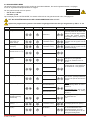
Display message Problem Check
Current limit exceeded Requested motor torque
exceeds available torque.
• Reduce opening speed.
• Check power supply.
• Check power supply wiring.
Insert brake resistance Voltage on BUS exceeds
threshold
• For Sector Reset doors, connect the brake resistance and set
the item on the advanced menu to "YES".
• Switch o the control panel, wait 3 minutes and reconnect the
power supply.
• If the error reoccurs, check that the voltage on the BUS is lower
than 360 V.
Max. BUS voltage BUS voltage exceeds
threshold
• Switch o the control panel, wait 3 minutes and reconnect the
power supply.
• Check the control panel power supply voltage.
Stand by Encoder Installation of a new control/
replacement control already
programmed previously
Absolute Encoder not
connected.
To reset the control panel follow the procedure:
• DIP2 in ON
• push STOP (the control panel goes in the “programmin menu”
showing the data already set)
• scroll the menù till the step “COMMAND MODE” and set LIMIT
SWITCHES
• DIP2 in OFF
FUSES
ID Value Size Circuit
F1 - F2 12A - 500V 10.3 x 38 Single phase line
P5 P3 P4P1 P2
41 40 20 9 8 4 3 2 1 1 0 LAMP111 12 13
ON
OFF 1 2 3 4 5 6 7 8
DL
23456 7
DL
M7
M4A
M5
M6
M3
BACK
M4
1 IN NC C NO
M2
J4
15
S3 S4
S5 S2
SAFETY OPEN
F2F1
230 V
50/60 Hz
GND
L N
+F -F U V W
ON
5. TROUBLESHOOTING
4. LIMIT SWITCH ADJUSTMENT
1. Set the deceleration ramps at zero (P3 - P4)
2. Set the limit switch (C) on the gearmotor so that the door stops about
200/300mm from its closure point.
3. Set the opening limit switch (A) at the opening point.
4. Set the deceleration limit switch (B) so it is triggered at about ¾ of the
opening stroke.
5. Set the opening and closure speeds using trimmers (P1) and (P2) respectively.
6. Set the trimmers of the deceleration ramps - (P3) for opening and (P4) for
closure - to ensure the door stops at its actual "open" and "closed" positions.
C
B
A
B
C
300
A
¾
Dip 3 ON EN

- 24 -
0DT866 10-05-2022
6. PROGRAMMING
STEP 1st level options 2nd level options Menu scrolling Notes
1Select language
Conrm with:
Conrm with: ENGLISH
ITALIAN
FRANÇAIS
DEUTCH
ESPANOL - POLSKA
CESKY - MAGYAR
2Door model
Conrm with:
Conrm with: SOFT RESET
SECTOR RESET
SMART PLUS
SECTOR PLUS
TRAFFIC C
SMART RESET
3Position control
Conrm the Limit Switch option
with:
Conrm with: LIMIT SWITCH
ENCODER
4Calibrating positions
The door will move to the required
position in operator present mode and
at low speed.
Conrm the Limit Switch position after
setting
Conrm with: CLOSED POSITION
PARTIAL POSITION
(indicates the deceleration start
position)
OPEN POSITION
5Command mode
Conrm with:
Selecting 1-9: if 1-9 is closed, the
command mode will be impulsive, if
1-9 is open the command mode will be
“dead man”
Conrm with: IMPULSIVE
MAN PRESENT
INPUT 1-9
6CONFIRM DATA Conrm with:
6.1 INSTALLATION MENU
When the control panel is switched on, after showing the messages DITEC and microprocessor and card FW VERSION,
the device automatically enters the installation menu and displays the message SELECT LANGUAGE.
PROGRAMMING COMPLETED
The door is now programmed and operating with the set default speed values.
With the door MOVING, the voltage and current values will be displayed on the BUS.
Conrm with
Remove cables from PIN 3, 4, 20 during programming

- 25 - 0DT866 10-05-2022
6.2 ADVANCED MENU
The advanced menu allows you to modify the position of the limit switches which have previously been set
and modify the set default parameters.
To access the Advanced Menu:
- STOP the door
- Set DIP 2 to ON
“LIM. SWITCH CAL.”, the rst item in the advanced menu, will appear on the display.
1 2 3 4 5 6 7 8
ON
ONCE PROGRAMMING HAS ENDED, SET DIP2 TO OFF
Remove cables from PIN 3, 4, 20 during programming
STEP 1st level options Scrolling Conrm 2nd level options Notes
1 Encoder Calibration
Closed position
The door will move to the desired
position in man present mode and
at low speed. All the positions
(closing, partial opening, opening)
must be set.
2 Photocell excluded
(step present only for
Reset doors)
Change value
(1 unit ≅ 3mm)
By increasing the value, the
position of the photocell by-pass is
raised
3 Primary safety device
excluded
Change value
(1 unit ≅ 3mm)
By increasing the value, the
position of the primary safety by-
pass is raised
4 Automatic closing
(default SI with T= 5 s)
YES
NO
5 Automatic closing time
Time variant
Option available only if YES has
been selected for point 4).
Value ranging from 0 to 100 sec.
6 Command mode
Impulsive
Selecting 1-9: if 1-9 is closed, the
command mode will be impulsive,
if 1-9 is open the command mode
will be “dead man”
Man present
INPUT 1-9
7 Opening safety device
YES
If set to YES, the closed door that
receives an opening command
does not open if the photocell is
activated.
NO
8 Interlock
NO INTERLOCK
AIRLOCK: door 2 opens with ex-
ternal command only if door 1 is
closed.
INTERLOCK: door 2 opens auto-
matically when door 1 has closed
AIRLOCK
INTERLOCK
9Pre-ashing when
opening
(default no)
YES
Pre-ashing has a set time of
3 sec.
NO
10 Opening ramp advance
CHANGE VALUE
(1 unit ≅ 3mm)
When the value increases, the
deceleration distance when
opening increases.
11 Opening speed
in (Hz)
CHANGE VALUE
The setting of values that are
higher than the default ones
must be assessed according to
door dimensions and operating
conditions.
EN

- 26 -
0DT866 10-05-2022
ONCE PROGRAMMING HAS ENDED, SET DIP2 TO OFF
STEP 1st level options Scrolling Conrm 2nd level options Notes
1CYCLIC MODE
TIMER OFF
Timer not active
TIMER ON Timer active
2TIME UNIT
MIN.
Timer by minuts
SEC. Timer by seconds
3OPENING TIME
1 …200
Set the regular time intervals
4AUTO CLOS.TIME
1….200
Set the time during which the door
remains open
5TOT
VALUE
Cycle counter
6RESET CYCLES
RESET?
Cycle counter reset
6.3 Timed opening menu
With door in STOP position and DIP 8 ON you enter the menu CYCLIC MODE. By activating this mode it is possible to set
a timed opening at regular time intervals. Once the mode is set put DIP 8 OFF.
When CYCLIC MODE is active, the display shows every 2 sec:
TOT cycle - count down to next open/OPENING TIME
STEP 1st level options Scrolling Conrm 2nd level options Notes
12 Closing speed
in (Hz)
CHANGE VALUE
The setting of higher values
must be assessed according to
door dimensions and operating
conditions.
13 Service Alarm
YES
NO
RESET? Restart the service count down
14 Service thresh
CHANGE VALUE
Option available only if YES has
been selected for point 13).
Set value to steps of 1000 cycles
Max 200,000 cycles
15 Enable stop 1-2
YES
If set to YES, opening of the
contact 1-2 STOPS the door.
NO
16 Brake resistance
(default NO)
YES
Set to YES when the door is
supplied with brake resistance.
NO
17 PARAMETER RESET
CONFIRM
Conrm to go back to the
installation menu.

- 27 - 0DT866 10-05-2022
MESSAGE SITUATION NOTES
Ditec door closed waiting for command
Opening of VBUS IBUS door opening
Door open - automatic closing time Door open
Closing of VBUS IBUS door closing
Input 40 closed; input 8 open intervention of photocell When door is moving
input 40 open; input 8 closed Primary safety device intervention
(SLEC / SAFETY EDGE)
When door is moving
Limit switches open Intervention of safety microswitch on manual
opening device / intervention of thermal
protection on motor / opening (A) and closure
(C) limit switches simultaneously active.
Opening safety device activated photocell engaged when door is closed
and door does not open
Message that only appears if the "safety
in open" function is set to YES on the
advanced menu (step 7).
Door stopped stop command activated
Stand by encoder New control panel power on / replacing
control panel power on
Absolute Encoder not connected.
Control panel already programmed to
work with motor having absolute encoder.
To reset see troubleshooting chapter.
7. ALARMS
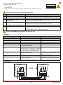
8. INTERLOCK
6.4 Service menu (password required)
To access the Service menu:
- STOP the door
- Set DIP5 to ON
- Enter the PW: button sequence OPEN- OPEN- CLOSE- PARTIAL OPENING
1 2 3 4 5 6 7 8
ON
ONCE PROGRAMMING HAS ENDED, SET DIP5 TO OFF
STEP 1st level options Notes
1 MIN BRAKING VOLT. Default 340Vdc Threshold for partial intervention of braking resistance
2MAX BRAKING VOLT. Default 380Vdc Threshold for total intervention of braking resistance
3OVERCURRENT LIMIT
Default 10A
If the current on the BUS exceeds the set threshold, the door opens at
half the speed to reduce absorption.
4RAMP SLOPE DURING OPENING Changes the slope of the deceleration ramp when opening. Default 15.
(If the value is increased, the ramp distance is reduced).
5BATTERY LEVEL Visualizes the encoder battery charge level from 0% to 100%
6 ALARM LIST The last 50 alarms are displayed: Overcurrent; bus voltage exceeds limit,
Intervention of brake resistance, inverter overtemperature, faulty motor
driver (encoder). To exit, press partial opening
Remove cables from PIN 3, 4, 20 during programming
+24V
INPUT
1 IN NC C NO
QE 52E
QE 52E
+24V
INPUT
1 IN NC C NO
M4 M4
Logical
operation
DOOR 1 DOOR 2
EN

0DT866NLEN 10-05-2022
-
 1
1
-
 2
2
-
 3
3
-
 4
4
-
 5
5
-
 6
6
-
 7
7
-
 8
8
-
 9
9
-
 10
10
-
 11
11
-
 12
12
-
 13
13
-
 14
14
-
 15
15
-
 16
16
-
 17
17
-
 18
18
-
 19
19
-
 20
20
-
 21
21
-
 22
22
-
 23
23
-
 24
24
-
 25
25
-
 26
26
-
 27
27
-
 28
28


