
Ditec Sector Reset
Installation manual, maintenance, use.
(Translation)
EN
Handleiding voor installatie, onderhoud, gebruik
(Vertaling)
NL
0DT848 • Rev. 01-12-2021
www.ditecdoor.com

- 2 -
0DT848 01-12-2021
INHOUDSOPGAVE VAN DE ONDERWERPEN
Hoofdst. Onderwerp ............................................................................................................................ Pag.
1. ALGEMENE WAARSCHUWINGEN M.B.T. DE VEILIGHEID ..................................................... 2
2. TECHNISCHE KENMERKEN .....................................................................................................3
3. MECHANISCHE INSTALLATIE
3.1 Controles doorgangsruimte ..................................................................................................... 4
3.2 Bevestiging van de verticale stijlen ......................................................................................... 4
3.3 Montage van de dwarsbalk ..................................................................................................... 4
3.4 Montage van de tegenwichten ................................................................................................ 4
3.5 Installatie fotocellen (indien voorzien) ..................................................................................... 4
3.6 Montage van de noodontgrendelhendel ................................................................................. 4
3.7 Installatie van de veiligheidsinrichting SLE (lineaire encoder) ................................................ 4
3.8 Plaatsing van het doek ............................................................................................................4
4. ELEKTRISCHE AANSLUITINGEN
4.1 Elektrisch schakelpaneel ........................................................................................................ 5
4.2 Aansluitingen elektrisch schakelpaneel / motor / beveiligingen .............................................. 5
4.3 Veiligheidsfotocellen ............................................................................................................... 5
5. ELEKTRONISCH BEDIENINGSPANEEL
5.1 49E - aansluitingen .................................................................................................................6
5.2 52E (inverter) - aansluitingen ................................................................................................ 10
6. PROGRAMMEERMENU
6.1 Installatiemenu ......................................................................................................................14
6.2 Geavanceerd menu ..............................................................................................................15
6.3 Menu opening met timer .......................................................................................................16
6.4 Bedieningsmenu ...................................................................................................................17
6.5 Meldingen op het display ...................................................................................................... 17
6.6 Vergrendeling ........................................................................................................................ 17
7. INSTELLINGEN EN START
7.1 Regeling van de veiligheidsinrichting SLE (lineaire encoder) ............................................... 18
8. OPSPOREN VAN STORINGEN ................................................................................................. 19
9. ONDERHOUDSSCHEMA .........................................................................................................20
Deze installatiehandleiding is uitsluitend bedoeld voor
vakkundig competent personeel.
De installatie, de elektrische aansluitingen en de
afstellingen moeten uitgevoerd worden met inachtneming van
Goed Vakmanschap en de geldende voorschriften.
Lees de instructies aandacht voordat u begint met de
installatie van het product. Een onjuiste installatie kan een
bron van gevaar vormen. De verpakkingsmaterialen (kunststof,
polystyrol, enz.) mogen niet in het milieu worden achtergelaten
en moeten buiten bereik van kinderen worden gehouden
aangezien deze een mogelijke bron van gevaar kunnen zijn.
Controleer, voor de installatie, of het product intact is.
Installeer het product niet in een explosieve omgeving en
atmosfeer: aanwezigheid van gas of ontvlambare dampen
vormen een groot gevaar voor de veiligheid. Voordat u de
deur installeert, alle structurele wijzigingen met betrekking tot
een veilige doorgang en de bescherming of afscherming van
alle gebieden waar risico bestaat van beknelling, het afsnijden
of meesleuren van ledematen en gevaar in het algemeen.
Controleer of de bestaande structuur voldoet aan de
noodzakelijke vereisten voor stevigheid en stabiliteit. De
veiligheidsvoorzieningen (fotocellen, gevoelige randen,
noodstop, enz.) moeten geïnstalleerd worden rekening
houdend met: de geldende voorschriften en richtlijnen, de
criteria van Goed Vakmanschap, de installatie-omgeving, de
werkingslogica van het systeem en de krachten die ontwikkeld
worden door gemotoriseerde deuren of hekken.
De veiligheidsvoorzieningen moeten eventuele gebieden van
de deur beschermen waar risico op beknelling, het afsnijden
of afrukken van ledematen en gevaar in het algemeen
bestaat. Bevestig de waarschuwingen die door de geldende
voorschriften voorzien zijn om de gevaarlijke zones aan te
geven.
Bij elke installatie moet de indicatie van de identifcatiegegevens
van de deur zichtbaar blijven.
Voordat de elektrische voeding wordt aangesloten
moet u zich ervan verzekeren dat de gegevens op het
plaatje overeenkomen met die van het elektriciteitsnet.
Zorg op het voedingsnet voor een omnipolaire schakelaar/
scheidingsvoorziening met een opening tussen de contacten
van 3 mm of meer. Controleer of er bovenstrooms van de
elektrische installatie een geschikte dierentieelschakelaar en
een beveiliging tegen overspanning. Sluit de deur aan op een
eectieve aardingsinstallatie uitgevoerd volgens de geldende
veiligheidsvoorschriften. De fabrikant van de deur wijst elke
aansprakelijkheid af als bestanddelen worden geïnstalleerd
die niet compatibel zijn wat veiligheid en goede werking betreft
of als wijzigingen van eender welke aard worden uitgevoerd
zonder de specieke toesteming van de fabrikant zelf. Voor
de eventuele reparatie of vervanging van onderdelen mogen
uitsluitend orginele Ditec vervangingsonderdelen gebruikt
worden. De installateur moet alle informatie verschaen met
betrekking tot de automatische en handmatige werking en
de noodbediening van de gemotoriseerde deur of hek, en
de gebruiker van het systeem de gebruiksaanwijzing geven.
Alle rechten voorbehouden
Alle gegevens en specicaties werden met grote zorg opgesteld en gecontroleerd. De fabrikant is echter niet aansprakelijk voor
eventuele vergissingen, weglatingen of onvolledige gegevens te wijten aan technische redenen of redenen in verband met illustraties.
1. ALGEMENE WAARSCHUWINGEN M.B.T. DE VEILIGHEID
Optioneel accessoire Safety Top T
T T
Safety Top
T

- 3 - 0DT848 01-12-2021
Ref. Beschrijving
1Bak
2Motor K10
3Aandrijfketting
4Oprolas
5Manuele ontgrendelgreep
6Geleider in polizene bovenste deel
7Geleider in polizene onderste deel
8Steun voor bevestiging van geleider
9SLE (lineaire encoder)
10 Steunveer van geleider
11 Bevestigingsschroef van geleider
12 Riem tegenwicht
Ref. Beschrijving
13 Modulair tegenwicht
14 Afdekplaat rechterstijl
15 Afdekplaat linkerstijl
16 Rechterstijl
17 Linkerstijl
18 Schakelbord
19 Fotocel 5FB
20 Doek in polyester
21 Raam in transparant PVC
22 Verticale versterkingsstroken
23 Onderste rand met zand als tegengewicht
2. TECHNISCHE KENMERKEN
ELEKTRONISCH BEDIENINGSPANEEL DRIEFASE (49E)
Voedingsspanning ................. 400 V driefase 50/60 Hz
Dimensionering lijn .................................................. 5 A
Voeding hulpbedieningselementen..................24V
Vermogen motor .............................................. 0,9 KW
Beschermingsgraad bedieningspaneel .............. IP 55
Bedrijfstemperatuur ................................... - 5 + 50 °C
ELEKTRONISCH PANEEL 52E (INVERTER)
Voedingsspanning ................. 230 V eenfase 50/60 Hz
Dimensionering lijn ................................................ 12 A
Voeding hulpbedieningselementen..................24V
Vermogen motor .............................................. 0,9 KW
Beschermingsgraad bedieningspaneel .............. IP 55
Bedrijfstemperatuur ................................... - 5 + 50 °C
Zorg voor geleiders met de juiste doorsnede: houd rekening met de vermelde stroomopname en met de lengte en de
ligging van de kabels.
18
5
15
21
23
2
1
14
16
4
3
12
13
17
19
6
9
7
10
8
11
22
20
NL

- 4 -
0DT848 01-12-2021
3. MECHANISCHE INSTALLATIE
Zie de tekeningen van de mechanische installatie op pagina 26 - 27 (uit te nemen blad in het midden)
3.1 Controles doorgangsruimte (g.1).
• Controleer of de afmetingen van de ruimte overeenkomen met de maten van de geleverde deur, rekening houdend met
eventuele noodzakelijke tolerantie indien de installatie binnen de spanwijdte plaats moet vinden.
• Controleer of er geen obstakels zijn die de montage van de structuur belemmeren.
• Verzeker u ervan dat de steunvlakken waterpas zijn en pas deze eventueel aan met behulp van geschikte wiggen.
• Controleer de stevigheid van de structuur van de doorgang: een stevige verankering met behulp van beugels of pluggen
moet gegarandeerd zijn. In geval van onvoldoende of twijfelachtige stevigheid moet er gezorgd worden voor een geschikte
zelfdragende metalen structuur.
3.2 Bevestiging van de verticale stijlen (g.2).
• Meet de totale lengte van de dwarsbalk (LT).
• Merk de exacte positie van de verticale stijlen op de vloer.
• Verwijder de afdekplaten van de verticale stijlen en bevestig de bases ervan op de merktekens met speciale pluggen
maat M8.
• Plaats de verticale stijlen loodrecht en bevestig ze op de gemerkte plekken (A) met externe beugels of (B) beugels voor
bevestiging binnenin de kolom. Maat van pluggen M8.
• Controleer of de montage rechthoekig is en meet daarvoor de diagonalen.
Maak geen boringen in de verticale rechterstijl ter hoogte van de zone waar het tegenwicht loopt (C).
3.3 Montage van de dwarsbalk
• Verwijder de bouten M8 die vooraf op de uiteinden van de dwarsbalk gemonteerd zijn.
• Hef de dwarsbalk voorzichtig met een heftruck of een ander hefmiddel, zorg ervoor dat hij tijdens het heen niet kan vallen
en bescherm het doek tegen eventuele schade (g.3).
• Leg de dwarsbalk op de verticale stijlen, breng de bevestigingsbouten terug in en haal ze aan (g.4).
• Bevestig de dwarsbalk op de laterale plaat.
• In geval van deuren met PL > 4000 om de dwarsbalk vast te maken in midden (om een onesthetische doorbuiging van
het bouwstaal te voorkomen).
3.4 Montage van de tegenwichten
• Wikkel de riem helemaal los, maar laat 1 omwikkeling als reserve op de opwikkeltrommel zitten, doe de riem over de leirol
lopen (g.5).
• Maak de riem vast met het daarvoor bedoelde plaatje (g.6). Regel de riemlengte zodanig dat de staaf met schroefdraad
ongeveer 200 mm van de grond blijft (als de deur helemaal open staat).
• Voer de jnregeling van de balans uit met de 4 onderste elementen van het tegenwicht.
3.5 Installatie fotocellen
• Sluit de fotocellen volgens de uitleg op (g.16).
3.6 Montage van de noodontgrendelhendel
• De noodontgrendelhendel dient gemonteerd te worden op de constructie of op de wand; op een hoogte van tenminste
1,8 m ten opzichte van de vloer (g.8).
• Maak bij montage op de constructie gebruik van de afmetingen op (g.9), plaats de aandrijfkabel in de gleuven en sluit
hem aan op de rem van de reductiemotor (g.10).
• Controleer of de inrichting correct werkt; als u de hendel bedient, moet het zeil kunnen worden opgetild.
3.7 Installatie van de veiligheidsinrichting SLE (lineaire encoder)
• De inrichting SLE dient bevestigd te worden op de leirail van de exibele deur aan de linkerzijde, volgens de uitleg op
(g.11) en aangesloten volgens de uitleg op Hoofdst 5.
3.8 Plaatsing van het doek
• Breng het bovenste deel van de geleiders (D) dichterbij door het aan de buitenkant met een hefboom op te tillen (g.12).
• Breng elk bevestigingselement van de doek (E) aan in zijn geleider; verwijder, om de werkzaamheid gemakkelijker uit te
voeren, de eerste schroef met buer (F).
• Rol het doek zodanig af dat de onderste rand zich op een halve meter onder de opening voor terugkeer van het doek
bevindt (g.13).

- 5 - 0DT848 01-12-2021
Zorg voor geleiders met de juiste doorsnede: houd rekening met de vermelde stroomopname en met de lengte en de
ligging van de kabels.
4. ELEKTRISCHE AANSLUITINGEN
4.1 Schakelbord
• Steek de kabels met de voorbedrade klemmenborden in de behuizing (g. 14); en sluit ze aan op de kaarten (volgens de
aanwijzingen in hfdstk. 5). Plaats de kabels in de kabelgoot en sluit de connectoren op de motor aan (g.15).
De aansluiting van de bedrading moet uitgevoerd worden wanneer de regeleenheid sinds minstens 30 sec.
niet onder spanning staat.
4.2 Aansluitingen schakelbord / motor / beveiligingen
• Op afbeelding 16 staan de schema's van de meegeleverde kabels en hun ligging in de deur; elke bekabeling wordt
geïdenticeerd met een speciale code op een zelfklevend etiket.
4.3 Veiligheidsfotocellen
• Voer de aansluitingen uit volgens de uitleg op (g. 16).
• Voer de aansluitingen in het schakelbord uit volgens de schema's in hfdstk. 5.
8265A
9055
8265B
A931C
A933A
9055
7825A
L 800 L 5000 / L6500
8132 ≤ PL4500
8132A > PL4500
M
FM
F
M
F
M
F
M
M
F
M
F
Tx Rx
FC
Tx Rx
SLEC
9040
9036
9055
9038
7825A
L 800
9037
L 5000 / L6500
8132 ≤ PL4500
8132A > PL4500
M
FM
F
M
F
M
F
M
M
F
M
F
EC
T
SLEC
16
400 V
230 V
Inverter
T
1514
400 V 230 V
Inverter
NL

- 6 -
0DT848 01-12-2021
17 14 12 11 0 0 0 1 1 2 3 4 6 8 9 20 41
17 14 12 11 0 0 0 1 1 2 3 4 6 8 9 20 41
INGANGEN
Commando Functie Beschrijving
1 2 N.O Automatische sluiting
De permanente sluiting van het contact maakt de automatische sluiting mogelijk.
1 3 N.O Opening Met DIP1=ON activeert de sluiting van het contact de openingsmanoeuvre.
Geleidelijk Met DIP1=OFF activeert de sluiting van het contact een manoeuvre van
opening of sluiting in volgorde: opent-stop-sluit-opent.
NB.: als de automatische sluiting geactiveerd is, is de stop niet permanent
maar duurt deze gedurende de tijd die is ingesteld door TC.
1 4 N.O Sluiting De sluiting van het contact activeert het sluitingsmanoeuvre.
1 6 N.C Veiligheidsomkering De opening van het veiligheidscontact veroorzaakt de omkering van de
beweging (heropening) tijdens de sluitingsfase.
41 8 N.C Veiligheidsomkering De opening van het veiligheidscontact veroorzaakt de omkering van de
beweging (heropening) tijdens de sluitingsfase.
1 9 N.C Stop
De opening van het veiligheidscontact veroorzaakt het stoppen van de beweging.
1 9 N.O Niet-puls commando De permanente opening van het veiligheidscontact maakt de werking van
een niet-puls commando mogelijk.
In deze omstandigheid werken de bedieningsknoppen openen (1-3/1-20) en
sluiten (1-4) alleen als ze ingedrukt gehouden worden, zodra ze losgelaten
worden stopt de automatische werking.
De eventueel aanwezige veiligheidsvoorzieningen, de bedieningsknop
geleidelijke en automatische sluiting zijn buiten werking gesteld.
1 20 N.O Gedeeltelijke
opening
De sluiting van het contact activeert een gedeeltelijk openingsmanoeuvre
gedurende de tijd die is ingesteld met behulp van de trimmer RP.
Als de automatische werking stopt, voert het commando gedeeltelijke opening
een manoeuvre uit die tegengesteld is aan die van voor het stoppen.
0 11 N.C Eindaanslag sluit De opening van het contact van de eindaanslag stopt de sluitingsbeweging.
0 12 N.C Eindaanslag opent De opening van het contact van de eindaanslag stopt de openingsbeweging.
0 17 N.O Eindaanslag fotocel By-pass fotocel
UITGANGEN
Uitgang Waarde Beschrijving
1 +
0 – 24 V = / 0,5 A
Voeding accessoires.
Uitgang voor voeding externe accessoires met inbegrip van de lampjes status
automatische werking.
0 14 24 V = / 50 W
(2 A)
Knipperlicht (FML).
Intermitterend signaal (jumper OFF op FML).
Wordt geactiveerd tijdens het openen en sluiten.
- LK + 24 V = / 0,5 A Uitgang is actief tijdens de beweging van de deur.
U W V
M
3 ~ 400 V~ / 4 A
Driefase motor.
NB.: als de rotatie van de motor niet overeenkomt met de juiste
bewegingsrichting, de fasen U - W omkeren
5.1 ELEKTRONISCH BEDIENINGSPANEEL 49E - AANSLUITINGEN
Werking met niet-pulscommando Werking met pulscommando
49E

- 7 - 0DT848 01-12-2021
L3 L2 L1
F
U
S
E
F4
U W V
- LK +
RP TC ON
ON
1 2 3 4 5 6
11 12 17 IN SA POWER
NIO
SO EO
PRG
COM
EL07L
00000000000
17 14 12 11 0 0 0 1 1 2 3 4 6 8 9 20 41
1
3
9
4
LDV
LDR
20
J7
M
A933A
EL07PW1
00000000000
M LKLS
A931C
LS
LK
A
C
B
9055
110
41 FC FA OUT
R1
1
ON
PWR SA
23 4
SLE
9016
Rx
Tx
5FB
0 60 1 1
8132 8132
8265A
8265B
7825A
RX TX
7825A
Bruin
Wit
Oranje
Blauw
Rood
Zwart
Wit
Rosé
Rood
Bruin
Blauw
Grijs
Geel
Groen
Rood
Wit
Bruin
Oranje
Zwart
Blauw
1-9 Sluit:
Werking met
pulscommando
49E TT
SO EO
Blauw
Bruin
Bruin
Blauw
Zwart
0 1 0 6 1
Zwart
Blauw
Blauw
Zwart
Oranje
Rood
Blauw
Geel
Groen
Roze
Wit
Bruin
Grijs
T
TT
L
T
T
Niet verbonden
Bruin
Wit
Blauw
Zwart
Rood
Oranje
Blauw
Zwart
Wit
Zwart
Bruin
Blauw
Grijs
E5BFSY10B
(TOPL)
E5BFSY24B
(TOPT)
NL

- 8 -
0DT848 01-12-2021
Trimmer Beschrijving
TC
Instelling automatische sluitingstijd. Van 0 tot 30 s.
NB.: na de activering van het stopcommando, bij het opnieuw sluiten van het contact 1-9, wordt de
automatische sluiting alleen in werking gesteld na een commando van volledige, gedeeltelijke of
geleidelijke opening.
RP Instelling motor gedeeltelijke opening. Van 0 tot 30 s.
0 s 30 s
0 s 30 s
1 2 3 4 5 6
ON
SIGNALEN EN INSTELLINGEN
Voor
Ditec Sector Reset
positioneer de
Dip-switch als volgt:
Dip-switch Beschrijving OFF ON
DIP 1 Werking commando 1-3. Geleidelijk. Opening.
DIP 2 Herstel automatische
sluitingstijd. Niet gebruiken. 100 %
DIP 3 Voorits vast op 3 s. Gedesactiveerd bij
opening.
Geactiveerd zowel bij
opening als sluiting.
DIP 4 Type toepassing. Niet gebruiken. Flexibele deur.
DIP 5 Dynamische rem bij
sluiting. Gedesactiveerd. Niet gebruiken.
DIP 6 Dubbele snelheid. Gedesactiveerd. Niet gebruiken.
Tijdelijke
verbindings-draden Beschrijving OFF ON
SO Werking
veiligheidsomkering
Als de automatische werking gestopt
is, als het contact 41-8 geopend is, kan
de handmatige openingsmanoeuvre
geactiveerd worden.
Als de automatische werking gestopt
is, als het contact 41-8 geopend is,
wordt willekeurig welk manoeuvre
verhinderd.
EO Elektrische rem. Niet gebruiken. Normaal.
Knop LED
Activeert het
openingsmanoeuvre. De brandende groene led geeft de aanwezigheid aan van voeding 24 V=.
Activeert het manoeuvre van
gedeeltelijke opening.
Stelt de functie STOP in en
buiten werking. De brandende rode led geeft de in werking stelling van STOP aan.
De knipperende rode led geeft de in werking stelling van de veiligheidsvoorzieningen aan.
Activeert het
sluitingsmanoeuvre.
ON
LED Brandt Knippert
POWER Aanwezigheid van voeding 24 V=. /
SA Geeft aan dat minstens een van de
veiligheidscontacten open is. ( 6 - 8 - 9 )
- Geeft de functie STOP aan die geactiveerd is door het
knoppenpaneel PT4 (indien aanwezig).
- Indien de voorziening SOFA1 wordt gebruikt, geeft dit
aan dat de veiligheidstest mislukt is (klem 41).
- Bij inschakeling knippert de LED waarmee het tellen
van de uitgevoerde manoeuvres wordt aangegeven:
elke snelle knippering = 10000 manoeuvres
elke langzame knippering = 100000 manoeuvres
IN
Gaat branden bij elk commando en bij elke wijziging
van dip-switch en tijdelijke verbindingsdraden.
/
11 Geeft aan dat het contact van de eindschakelaar
voor sluiting in bedrijf is 0-11 open is. /
12 Geeft aan dat het contact van de eindschakelaar
voor opening in bedrijf is 0-12 open is. /
17 Geeft aan dat het contact van de eindaanslag 0-17
geopend is. (By-pass fotocel) /
49E

- 9 - 0DT848 01-12-2021
ZEKERINGEN
ID Waarden Afmetingen Circuit
F1 - F2 - F3 8A - 500V 10.3 x 38 Driefasenleiding
F4 3.15A - 230V 5 x 20 Transformator
F5 3.15A - 230V 5 x 20 Dynamische rem
F6 0.630A - 230V 5 x 20 Rem
INSTELLING EINDAANSLAG
1. Stel de deur in werking, door op de bijbehorende knoppen te drukken, en
controleer of de deur in de juiste richting beweegt en keer, indien nodig,
de bewegingsrichting om door de volgorde van de fases te veranderen,
doe dat met de lijndraden die voor de hoofdschakelaar zitten.
2. Zet de deur in de sluitingsstand.
3 Draai, met behulp van een schroevendraaier, de nok “C” totdat de
bijbehorende microschakelaar inschakelt.
4 Doe hetzelfde voor de eindaanslag voor het openen: breng het doek in
de stand van geopende deur en stel de nok “A” af.
5 Doe hetzelfde voor de eindaanslag voor het openen: breng het doek op
300 mm van de grond wordt en stel de nok “B” af.
6 Controleer de kalibratie met de automatische werking eectief, ga, indien
nodig over tot een “jne” kalibratie.
F2F1 F3
L3 L2 L1
F
U
S
E
F4
U W V
- LK +
RP TC ON
ON
1 2 3 4 5 6
11 12 17 IN SA POWER
NIO
SO EO
PRG
COM
EL07L
00000000000
www.ditec.it
17 14 12 11 0 0 0 1 1 2 3 4 6 8 9 20 41
1
3
9
4
LDV
LDR
20
EL07PW1
00000000000
ON
C
A
C
B
A
B
300
NL
49E NL

- 10 -
0DT848 01-12-2021
5.2 ELEKTRONISCH BEDIENINGSPANEEL 52E (INVERTER) - Aansluitingen
INGANGEN
Bediening Functie Beschrijving
1 2 N.G. STOP Als op het programmeermenu (pag.15 punt 16)
het contact 1-2 vrijgegeven is, hoort bij de opening van het contact ook de
STOP van de deur
1 3 N.O. Openen De sluiting van het contact activeert het openen.
1 4 N.O. Sluiting De sluiting van het contact activeert het sluiten.
41 40 N.G. Veiligheid bij
omkering
De opening van het veiligheidscontact veroorzaakt de omkering van de
beweging (heropening) tijdens de sluitingsfase.
1 8 N.G. Veiligheid bij
omkering
De opening van het veiligheidscontact veroorzaakt de omkering van de
beweging (heropening) tijdens de sluitingsfase.
1 20 N.O. Gedeeltelijke
opening
De sluiting van het contact activeert een gedeeltelijke opening waarvan de
duur ingesteld wordt met het geavanceerde menu.
1 11 N.G. Sluitstand De opening van het contact geeft de sluitstand aan. (max. 50 mA)
1 13 N.G. Openingsstand De opening van het contact geeft de openingsstand aan. (max. 50 mA)
UITGANGEN
Uitgang Waarde Beschrijving
1
0
+
-24 V= / 0,5 A
Voeding hulpstukken.
Uitgang voor voeding van externe hulpstukken, lampen voor staat van auto-
maat inbegrepen.
LAMP 230 V~
Knipperlicht (FML).
Niet-intermitterend signaal (jumper ON op FML).
Wordt geactiveerd tijdens het openen en sluiten.
-F +F 24 V= / 0,5 A
Elektrische rem van motor.
De uitgang is actief de gehele duur van de beweging zowel in opening als in
sluiting.
U W V
M
3 ~ 230 V~ / 6 A Driefasemotor.
M2 Veiligheid / Bedieningen
M3 Signaal positie
M4 Vergrendeling
M4A Terug
M5 Motor / Motorrem
M6 Thermische beveiliging motor
M7 Absolute encoder
J4 Remweerstand
OPEN Hulpkaart schakelbord
VEILIGHEID Hulpkaart veiligheid
CONNECTOREN OP SCHAKELBORD
52E

- 11 - 0DT848 01-12-2021
LK
T °C
M
P5 P3 P4P1 P2
41 40 20 9 8 4 3 2 1 1 0 LAMP111 12 13
ON
OFF 1 2 3 4 5 6 7 8
DL
23456 7
DL
M7
M4A
M5
M6
M3
BACK
M4
1 IN NC C NO
M2
J4
15
S3 S4
S5 S2
SAFETY OPEN
F2F1
230 V
50/60 Hz
GND
L N
9036
+F -F U V W
9038
9040
M LK
EC
Rx
Tx
5FB
0 80 1 1
8132 8132
8265A
8265B
7825A
0 11
41 FC FA OUT
R1
1
ON
PWR SA
23 4
SLE
9055
9016
RX TX
7825A
52E
Wit
Geel
Groen
Bruin
Blauw
Zwart
Zwart
Blauw
Zwart
Blauw
Rood
Oranje
Wit
Bruin
Roze
Wit
Groen
Grijs
Geel
Blauw
Bruin
Rood
Het loskoppelen van de
bedrading van de absolute
encoder veroorzaakt de reset van
de posities van de eindschakelaars.
Blauw
Bruin
Bruin
Blauw
Zwart
0 1 0 8 1
Zwart
Blauw
Blauw
Zwart
Oranje
Rood
Blauw
Geel
Groen
Roze
Wit
Bruin
Grijs
T
TT
L
T
T
Niet verbonden
Bruin
Wit
Blauw
Zwart
Rood
Oranje
Blauw
Zwart
Wit
Zwart
Bruin
Blauw
Grijs
E5BFSY10B
(TOPL)
E5BFSY24B
(TOPT)
NL

- 12 -
0DT848 01-12-2021
Trimmer Beschrijving
P1 NIET GEBRUIKT
P2 NIET GEBRUIKT
P3 NIET GEBRUIKT
P4 NIET GEBRUIKT
P5 Regeling van displaycontrast.
0 s 30 s
0 s 10 s
0 MAX
0 MAX
0 MAX
Dip - schakelaar
Beschrijving OFF ON
DIP 1 Later gebruik – –
DIP 2 Toegang tot geavanceerd menu Uitgeschakeld. Vrijgegeven.
DIP 3 Vrijgave van trimmers Uitgeschakeld. Vrijgegeven.
DIP 4 Meter
TOT: Aantal bewegingen
SVC: Bewegingen niet uitgevoerd tijdens bediening
Uitgeschakeld. Vrijgegeven.
DIP 5 Toegang tot bedieningsmenu Uitgeschakeld. Vrijgegeven.
DIP 6
Inrichting voor weergave van gegevens i.v.m.
werking van deur
(F. bedrijf, S. bus, S. piek, S. bus)
Uitgeschakeld. Vrijgegeven.
DIP 7 Later gebruik – –
DIP 8 Menu cyclische werking Uitgeschakeld. Vrijgegeven.
LED Brandt
DL2 Sluitstand
DL3 Vertraging
DL6 Gedeeltelijke opening
DL7 Openingsstand
DL15 Automatische start
Drukknoppen Beschrijving
S2 GEBRUIKT VOOR PROGRAMMERING
S3 NIET GEBRUIKT
S4 NIET GEBRUIKT
S5 GEBRUIKT VOOR PROGRAMMERING
Werking
Standaard
Werking
Programmering
Drukknop LED Drukknop
Activeert het
openen.
- De brandende groene led geeft de aanwezigheid van de
24 V= voeding aan. Scrollen van menu
Activeert het
gedeeltelijk openen. Bevestigt
Schakelt de STOP-
functie in en uit.
- De brandende rode led geeft de activering van de STOP aan.
- De knipperende rode led geeft de activering van de
beveiligingen aan.
- De kort knipperende rode led geeft aan dat de
bedieningsdrempelwaarde bereikt is
Activeert het sluiten. Scrollen van menu
ON
REGELINGEN EN MELDINGEN
52E

- 13 - 0DT848 01-12-2021
ZEKERINGEN
ID Waarden Afmetingen Circuit
F1 - F2 12A - 500V 10.3 x 38 Eenfaseleiding
COMMANDO AANTEKENINGEN
Openingsstand op 170 mm van de dwarsbalk
Gedeeltelijke openingsstand van 200 mm van de vloer tot
de positie van de opening
Sluitstand op de vloer
REGELING VAN POSITIES
PROBLEMEN OPSPOREN
Meldingen op het display Probleem Controle
Stroomlimiet overschreden Vereiste motorkoppel groter
dan de beschikbare.
• Verlaag de openingssnelheid.
• Controleer de voeding.
• Controleer de voedingskabels.
Encoderbatterij Batterij van absolute encoder
is leeg of fout in aezen van
positie
• Zet het schakelbord uit, wacht 3 minuten en koppel
de voeding terug aan.
Probeer opnieuw als het probleem niet verholpen is.
• Als de melding encoderbatterij blijft aanstaan,
vervangt u de encoder.
Remweerstand inschakelen Spanning op BUS hoger dan
de drempelwaarde
• Zet het schakelbord uit, wacht 3 minuten en koppel
de voeding terug aan.
• Als de fout zich opnieuw voordoet, controleert u of
de spanning op de BUS lager ligt dan 360 V.
Spanning BUS Max. Spanning van BUS hoger dan
de drempelwaarde
• Zet het schakelbord uit, wacht 3 minuten en koppel
de voeding terug aan.
• Controleer de voedingsspanning van het schakelbord.
P5
P3 P4P1 P2
41 40 20 9 8 4 3 2 1 1 0 LAMP111 12 13
ON
OFF 1 2 3 4 5 6 7 8
DL
23456 7
DL
M7
M4A
M5
M6
M3
BACK
M4
1 IN NC C NO
M2
J4
15
S3 S4
S5 S2
SAFETY OPEN
F2F1
230 V
50/60 Hz
GND
L N
+F -F U V W
ON
52E NL

- 14 -
0DT848 01-12-2021
6 PROGRAMMEERMENU
6.1 INSTALLATIEMENU
Wanneer het schakelbord wordt aangezet, geeft het toestel de meldingen DITEC en VERSIE FW van microprocessor en
kaart weer en opent automatisch het installatiemenu met de melding SEL TAAL.
Bevestigen met
STAP Keuzen 1ste niveau Keuzen 2de niveau Scrollen van menu Aantekeningen
1Sel. Taal
Bevestigen met:
Bevestigen met: ENGLISH
ITALIAN
FRANÇAIS
DEUTCH
ESPANOL - POLSKA
CESKY - MAGYAR
2Model deur
Bevestigen met:
Bevestigen met: SOFT RESET
SECTOR RESET
SMART PLUS
SECTOR PLUS
TRAFFIC C
SMART RESET
3Beheer posities
Bevestigen met:
Bevestigen met: ENCODER
EINDSCHAKELAAR
4IJking van posities
De deur wordt verplaatst naar de ge-
wenste positie in de modus met bedie-
ner en aan een lage snelheid.
Positie bevestigen met:
Bevestigen met: POSITIE SLUIT
GEDEELTELIJK
OPENINGSSTAND
POSITIE OPENT
5Modus commando
Bevestigen met:
Selecteer 1-9: de bediening zal
impulsief zijn als 1-9 is gesloten of met
bediener als 1-9 is geopend
Bevestigen met: IMPULS
MET BEDIENER
INPUT 1 - 9
6BEVESTIG GEGEVENS Bevestigen met:
PROGRAMMERING UITGEVOERD
De deur is nu geprogrammeerd en werkt aan de snelheidswaarden die standaard worden ingesteld.
Met de deur IN BEWEGING worden de waarden van de spanning en de stroom op de BUS op het display weergegeven.
Tijdens de programmering moeten alle kabels losgekoppeld worden die zijn aangesloten op PIN 3 - 4 - 20

- 15 - 0DT848 01-12-2021
6.2 GEAVANCEERD MENU
Het geavanceerde menu dient om de positie van de eindschakelaars, die eerder ingesteld werden, te wijzigen
en om de ingestelde defaultparameters te wijzigen.
Om het geavanceerde menu te openen:
- Zet de deur in STOP
- Zet DIP 2 op ON
Op het display wordt “IJK ENCODER”, het eerste trefwoord van het geavanceerde menu, weergegeven.
1 2 3 4 5 6 7 8
ON
ZET NA DE BEËINDIGING VAN DE PROGRAMMERING DIP2 OP OFF
Tijdens de programmering moeten alle kabels losgekoppeld worden die zijn aangesloten op PIN 3 - 4 - 20
STAP Keuzen 1ste niveau Scrollen Bevestigen Keuzen 2de niveau Aantekeningen
1 IJking van Encoder
Positie sluit
De deur wordt verplaatst naar de
gewenste positie in de modus met
bediener en aan een lage snelheid.
U dient alle posities (sluiting,
gedeeltelijke opening, opening) in
te stellen.
2 Uitsluiting van fotocel
(stap enkel voor
deuren Reset)
Waarde wijzigen
(1 eenheid ≅ 3mm)
Als de waarde toeneemt, verhoogt
de positie van de by-pass van de
fotocel
3 Uitsluiting primaire
beveiliging
Waarde wijzigen
(1 eenheid ≅ 3mm)
Als de waarde toeneemt, verhoogt
de positie van de by-pass van de
primaire beveiliging
4 Automatische sluiting
(default JA met T= 5 s)
JA
NEE
5 Tijd voor automatische
sluiting
Variante tijd
Optie enkel ter beschikking als
onder punt 4) JA is gekozen.
Waarde van variabele van 0 tot
100 sec.
6 Modus commando
Impuls
Selecteer 1-9: de bediening zal
impulsief zijn als 1-9 is gesloten of
met bediener als 1-9 is geopend
Met bediener
INPUT 1 - 9
7 Beveiliging in opening
JA
Als JA ingesteld is, gaat de gesloten
deur die een openingscommando
ontvangt niet open als de fotocel in
bedrijf is.
NEE
8 Vergrendeling
GEEN
VERGRENDELING
SLUIS: deur 2 gaat open met ex-
terne bediening alleen als deur 1
gesloten is.
VERGRENDELING: deur 2 gaat
automatisch open na de sluiting
van deur 1
SLUIS
VERGRENDELING
9 Voorafgaande
knippering opening
(default nee)
JA
De voorafgaande knippering heeft
een vaste duur van
3 sec.
NEE
10 Vervroeging gradiënt
opening
WAARDE WIJZIGEN
(1 eenheid ≅ 3mm)
Als de waarde toeneemt, verhoogt
de vertragingsruimte in opening.
11 Openingssnelheid
in (Hz)
WAARDE
WIJZIGEN
Waarden instellen die groter zijn
dan de defaultwaarden moet
geëvalueerd worden in functie
van de deurafmetingen en van de
werkingsomstandigheden.
NL

- 16 -
0DT848 01-12-2021
STAP Keuzen 1ste niveau Scrollen Bevestigen Keuzen 2de niveau Aantekeningen
12 Sluitsnelheid
in (Hz)
WAARDE
WIJZIGEN
Grotere waarden instellen moet
geëvalueerd worden in functie
van de deurafmetingen en van de
werkingsomstandigheden.
13 Activering Alarm
Service
JA
NEE
RESET? Reset van de telling van de
ontbrekende bewegingen tot de
service
14 Drempelwaarde
bediening
WAARDE
WIJZIGEN
Optie enkel ter beschikking als
onder punt 14) JA is gekozen.
Waarde instellen met stappen van
1000 cycli. Max 200.000 cycli
15 Vrijgave stop 1-2
JA
Als JA ingesteld is, hoort bij de
opening van het contact 1-2 ook
de STOP van de deur.
NEE
16 Remweerstand (default
NEE)
JA
Stel JA in wanneer de deur
voorzien is van remweerstand.
NEE
17 RESET PARAMETERS
BEVESTIG
Als u bevestigt, gaat u terug naar
het installatiemenu.
STAP Keuzen 1ste niveau Scrollen Bevestigen Keuzen 2de niveau Aantekeningen
1 CYCL. WERKING
TIMER OFF
Timer niet actief
TIMER ON Timer actief
2 TIJDSEENHEID
MIN.
Interval in minuten
SEC. Interval in seconden
3 INTERVAL OPENING
1 …200
Instelling interval opening
4 TIJDSDUUR PAUZE
1….200
Instelling tijdsduur pauze bij
geopende deur
5TOT
WAARDE
Weergave totaal aantal
uitgevoerde bewegingen
6 RESET CYCLI
RESET?
Reset telling totaal aantal
bewegingen
ZET NA DE BEËINDIGING VAN DE PROGRAMMERING DIP2 OP OFF
6.3 Menu opening met timer
Met deur in STOP en DIP 8 in ON wordt het menu CYCLISCHE WERKING bereikt. Wanneer die modus wordt geactiveerd,
is het mogelijk om een opening met timer aan regelmatige intervallen in te stellen. Zodra de timing is ingesteld, moet de
DIP 8 op OFF geplaatst worden.
Wanneer de CYCLISCHE WERKING actief is, geeft de display elke 2 sec het volgende weer:
TOT cycli - ontbrekende tijd tot de volgende opening/TIJD OPENING

- 17 - 0DT848 01-12-2021
+24V
INPUT
1 IN NC C NO
QE 52E
QE 52E
+24V
INPUT
1 IN NC C NO
M4 M4
6.4 Bedieningsmenu (een wachtwoord wordt gevraagd)
Met het bedieningsmenu kunt u de drempelwaarden van de remweerstand en de drempelwaarde van de overstroom wijzigen
en van de anti-windfunctie op de inwerkingtreding van de encoder.
Om het bedieningsmenu te openen:
- Zet de deur in STOP
- Zet DIP5 op ON
- Voer het wachtwoord in: sequentie drukknoppen OPEN - OPEN - SLUIT - GEDEELTELIJKE OPENING
6.5 Meldingen op het display
6.6 Vergrendeling
1 2 3 4 5 6 7 8
ON
STAP Keuzen 1ste niveau Aantekeningen
1 SP. REMMING MIN
Default 340Vdc
Limiet voor gedeeltelijke activering van de remweerstand
2 SP. REMMNING MAX
Default 380Vdc
Limiet voor totale activering van de remweerstand
3 LIMIET OVERSTROOM
Default 10A
Als de stroom op de BUS de ingestelde drempelwaarde overschrijdt, gaat de
deur open aan de helft van de snelheid om de stroomopname te verlagen.
4 HELLING GRADIËNT OPENING Verandert de helling van de vertragingsgradiënt in opening. Default 15.
(Als de waarde toeneemt, wordt de ruimte van de gradiënt gereduceerd).
5STATUS ACCU Weergave % accu encoder van 0% tot 100%
6LIJST ALARMEN De laatste 50 alarmen worden weergegeven: Overstroom; busspanning buiten
limiet, inwerkingtreding van remweerstand, overtemperatuur inverter, storing
driver motor (encoder). Om af te sluiten drukt u op gedeeltelijke opening.
MELDING SITUATIE AANTEKENINGEN
Ditec deur gesloten in afwachting van commando
Opening vbus iBUS deur in openingsbeweging
Deur open - tijd voor automatische sluiting deur open
Sluiting vbus iBUS deur in sluitingsbeweging
Input 40 gesloten; input 8 open inwerkingtreding fotocel Tijdens beweging deur
input 40 open; input 8 gesloten inwerkingtreding encoder (SLE) Tijdens beweging deur
Thermische beveiliging of microschake-
laar ontgrendeling open
Inwerkingtreding veiligheidsmicroschakelaar
op inrichting manuele opening / inwerkingtre-
ding thermische beveiliging motor.
Beveiliging open actief fotocel ingeschakeld bij gesloten deur en
deur die niet opengaat
Melding die enkel verschijnt als op
het geavanceerde menu (stap 7) de
functie "beveiliging opening" inge-
steld is op JA.
Deur in stop stopbediening actief
ZET NA DE BEËINDIGING VAN DE PROGRAMMERING DIP5 TERUG OP OFF
Logische
werking
DEUR 1 DEUR 2
Durante la programmazione disconnettere tutti i cavi collegati con PIN 3 - 4 - 20
NL

- 18 -
0DT848 01-12-2021
7. INSTELLING
7.1 Regeling van de veiligheidsinrichting SLE (lineaire encoder)
Trimmer Beschrijving
R1 Regeling van de gevoeligheid voor
obstakels.
LED Acceso / Lampeggiante Uit
PWR Er is voeding Er is geen voeding
SA
• Initialisatie
• Inwerkingtreding door obstakel
• Test in uitvoering
• Test faalt / Alarm
Normale activiteit
geen obstakel.
MAX MIN
Dip -
schakelaar
Beschrijving
OFF ON
DIP 1
Type schakelbord
49E / 52E /
DIP 2
Waarneming obstakel
na eindschakelaar
sluiting FC
Uitgeschakeld
Vrijgegeven
(alleen elektro-
nische bedie-
ningspanelen
met INVERTER)
DIP 3
Gevoeligheidsschaal
HOOG
(deuren sluiten
snel)
LAAG
(deuren sluiten
langzaam)
DIP 4
Polariteit van eind-
schakelaar
0 = gemeen-
schappelijk
eindschakelaar
49E
1 = gemeen-
schappelijk
eindschakelaar
52E)
Voor 49E
positioneer de
DIP-schakelaars
als volgt:
Voor 52E
positioneer de
DIP-schakelaars
als volgt:
1 2 3 4
ON
1 2 3 4
ON

- 19 - 0DT848 01-12-2021
8. PROBLEMEN OPSPOREN
COMMANDO
PROBLEEM
CONTROLE
Om het even welk
commando in om het
even welke stand van
het doek
Het doek en de motor
worden niet verplaatst
• Voeding van stroomnet of zekeringen F1, F2, F3
• STOP geactiveerd (led “Stop” op knoppenbord blijft branden)
• Motor aangesloten op de verkeerde aansluitklemmen en/of
op uitvoering 400V DIP-schakelaar in verkeerde stand (zie
pag. 8)
• Op uitvoering 400V eindschakelaars voor opening (A) en
sluiting (C) zijn gelijktijdig actief (leds 11 en 12 branden)
• Motor met thermische beveiliging
• Veiligheidsmicroschakelaar van de handmatige manoeuvre
geactiveerd
• Een van de elektriciteitsinrichtingen is defect (elektronisch
bedieningspaneel, motor, aansluitkabel van motor)
De motor draait in
omgekeerde richting
• Verwissel de twee fasen van de stroomtoevoerleiding
Commando voor
opening bij gesloten
doek
De motor beweegt niet
• Bediening voor opening niet correct aangesloten of defect
(bedieningen 1 - 3)
• Op uitvoering 400V beveiliging geactiveerd (led van Stopknop
knippert en led SA blijft constant branden) bij gesloten brugje SO
• Eindschakelaar voor opening (A) actief ( led 12 brandt)
• Bediening voor sluiting altijd geactiveerd of kortgesloten
Commando voor
sluiting bij open doek
De motor beweegt niet
• Bediening voor opening niet correct aangesloten of defect
(bord bedieningen 1 - 4)
• Beveiliging geactiveerd (led van Stopknop knippert)
• Eindschakelaar voor sluiting (C) actief (led 11 brandt)
• Bediening voor opening altijd geactiveerd of kortgesloten
• Autotest van beveiligingen faalt (Stopled knopperbord staat uit
Activering van de
Stop tijdens een
manoeuvre
De motor stopt niet
• Stopcommando werkt niet of is niet juist aangesloten (led van
Stop op knoppenbord gaat niet branden)
De motor stopt met
vertraging
• Motorrem is versleten of defect
Activering van een
beveiliging tijdens de
sluiting
De beweging van de deur
wordt niet omgekeerd
• Veiligheidsinrichting is defect of is niet correct aangesloten
• Controleer de aardingsaanslutingen.
De beweging van de deur
wordt niet omgekeerd of
wordt alleen omgekeerd voor
een gedeelte van de slag
Voor uitvoering 400V
• Ingang 17 is gesloten (led 17 is gedoofd)
• Nok B is slecht geregeld (led 17 staat uit of gaat branden in
de verkeerde positie)
Automatische
sluiting is actief bij
open doek
De deur sluit niet automa-
tisch na de tijdspanne in-
gesteld met TC
• Vrijgave van de automatische sluiting is niet correct uitgevoerd
• Bediening voor opening altijd geactiveerd of kortgesloten
• Autotest van beveiligingen faalt
Tijdens een
manoeuvre
Het doek stopt niet bij de
eindschakelaar
Voor uitvoering 400V
• Contact van eindschakelaar is kortgesloten (led 11 of led 12 zijn
altijd gedoofd)
• Mechanisch defect van eindschakelaar (led 11 of led 12 zijn altijd
gedoofd)
• Slijtage of defect van rem (led 11 of led 12 branden)
Het doek stopt niet
regelmatig bij de
eindschakelaar
Voor uitvoering 400V
• Dip-schakelaar 5 op OFF
Alvorens werkzaamheden en werk binnenin de elektronische apparaten uit te voeren, dient u te
controleren of de stroomtoevoerleiding losgekoppeld is
De instructies die volgens zijn alleen bedoeld voor gekwaliceerd en bevoegd personeel. Specieke
wetten en bepalingen dienen altijd in acht genomen te worden, ook als dat niet uitdrukkelijk vermeld wordt.
Gebruik voor reparaties en vervangingen altijd en alleen originele reservedelen van Ditec.
GEVAAR
LET OP
NB: zie voor de specieke diagnose van het inverterbord 52E ook op pag. 13
NL

- 20 -
0DT848 01-12-2021
• Zet de bovenste delen van de geleiders (D) dicht bij elkaar, gebruik een hefboom aan de buitenkant.
• Breng elk bevestigingselement van de doek (E) aan in zijn geleider; verwijder, om de werkzaamheden gemakkelijker uit te voeren,
de eerste schroef met buer (F).
• Wikkel het doek zodanig af dat de onderste rand zich een halve meter onder de opening voor het inbrengen van het doek bevindt.
HET DOEK OPNIEUW INBRENGEN
E
D
F
9. ONDERHOUDSSCHEMA ELKE 6 MAANDEN
Er moeten regelmatig inspecties worden uitgevoerd, met inachtneming van de geldende landelijke voorschriften en van de
productdocumentatie, door gekwaliceerde en door Ditec opgeleide technici. De frequentie van de onderhoudswerkzaamheden
moet voldoen aan de geldende landelijke voorschriften en aan de productdocumentatie.
Veiligheidsinrichtingen
• Controleer of de inrichting SLE (lineaire encoder) correct werkt
• Controleer of de veiligheidsfotocellen correct werken
Zijgeleiders
• Controleer de slijtage van de zijgeleiders
Bevestiging / Montage
• Haal de schroeven aan die de verticale stijlen op de bovenste dwarsbalk vastmaken
• Controleer of de deur goed vastgemaakt is op de ruimte
Motoren
• Controleer de bevestiging van de motor aan de bijbehorende steunen
• Controleer de spanning van de aandrijfketting
• Controleer de werking van de eindaanslagen en de correcte uitlijning van de activeringsnokken.
• Controleer de slijtage van de remschijf, vervang deze indien nodig
• Controleer de correcte werking van de manuele remontgrendelinrichting (wanneer voorzien)
• Controleer de slijtage van de tegenwichtriem. Vervang indien nodig de riem
Oprolas van doek
• Controleer de bevestigingen van de lagersteunen
• Smeer de lagersteunen
9.1. Onderhoudsschema
In de volgende tabel zijn de aanbevolen intervals weergegeven, op basis van gebruiksmaanden, voor de vervanging van
de onderdelen tijdens het preventief onderhoud.
Beschrijving Code
Cycli / uur Zware
omgevings-
omstandigheden
(1)
<10
Low
Trac
<30
Medium
Trac
>30
High
Trac
Maanden Maanden Maanden
Groep eindschakelaar (als 400V) 6K10GF 36 24 12 12
Eindschakelaar (als 400V) 5M 48 36 24 24
Remschijf 21572 36 24 12 12
Geleider remschijf 21571 36 24 12 12
Bovenste geleider met lenzen 29198ASOL 48 36 24 24
Bovenste geleider 28106B 48 36 24 24
Onderste geleider 6BGBSC 48 36 24 24
Riem tegenwicht 6KTFCS 36 24 12 12
Veer compensatie geleider KSPRING 36 24 12 12
Lensgroep wide screen 6GLSLEC 36 24 12 12
(1) Vuile of stoge omgeving, bedrijfstemperatuur in de buurt van 0 °C of hoger dan 35 °C, druk van de wind binnen 20% van de voorziene
maximale limiet.

- 21 - 0DT848 01-12-2021
AANWIJZINGEN VOOR GEBRUIK EN ONDERHOUD
ALGEMENE WAARSCHUWINGEN M.B.T. DE VEILIGHEID
Deze handleiding maakt integraal en essentieel onderdeel uit van het product en moet overhandigd
worden aan de gebruiker van het product. Dit document moet bewaard worden en overhandigd
worden aan eventuele volgende gebruikers van het systeem. Het betreende automatische systeem
is een "deur met verticale beweging", is bestemd voor het gebruik waarvoor deze uitdrukkelijk is
ontworpen. Elk ander gebruik wordt als oneigenlijk en dus gevaarlijk beschouwd. Assa Abloy Entrance
Systems AB kan niet aansprakelijk gesteld worden voor schade veroorzaakt door oneigenlijk, foutief
of onredelijk gebruik. Het apparaat kan gebruikt worden door kinderen die 8 jaar of ouder zijn en
door personen met beperkte fysieke, zintuigelijke of mentale vermogens of zonder ervaring of de
noodzakelijke kennis, mits ze onder toezicht staan of aanwijzingen hebben gekregen over het veilige
gebruik en de gevaren van het apparaat. De reiniging en het onderhoud dat de gebruiker uitvoert
mag niet door kinderen zonder toezicht worden uitgevoerd.
VOORZORGSMAATREGELEN VOOR HET GEBRUIK
• Kom niet binnen de actieradius van de deur tijdens de beweging.
• In geval van een defect of slechte werking de hoofdschakelaar uitschakelen. De
onderhoudswerkzaamheden, instelling of reparatie mogen uitsluitend verricht worden door hiervoor
opgeleid en geautoriseerd personeel.
• Elk automatisch systeem is vergezeld van een “Handleiding voor installatie en onderhoud”, waarin
onder andere het periodieke onderhoudsschema is evrmeld, geadviseerd wordt om met name alle
veiligheidsvoorzieningen te controleren.
DRUKKNOPPEN
• Volledige opening: hiermee wordt de deur volledig geopend. De instelling van de slag vindt plaats
met behulp van een eindaanslagmicroschakelaar.
• Gedeeltelijke opening: opent de deur tot het punt dat op een tijdstip ingesteld is met de trimmer RP.
• STOP: leidt tot het onmiddellijke stoppen van de deur.
• Sluiting: hiermee wordt de deur volledig gesloten. De instelling van de slag vindt plaats met behulp
van een eindaanslagmicroschakelaar.
MANUELE ONTGRENDELHENDEL (voor heropening in geval van nood).
Let op: gebruik de manuele hendel alleen nadat u het toestel uitgezet heeft.
• Als de ontgrendelhendel losstaat, werkt de rem normaal.
• Als u aan de ontgrendelhendel trekt, wordt de rem ontgrendeld.
Ga als volgt te werk om het doek manueel te heen in geval van gebrek aan voeding of storingen:
• trek aan de ontgrendelhendel (zie g. 2) om de rem los te zetten;
• hef het doek tot in de stand deur open;
• laat de hendel los (zie g. 3) zodat de werking van de rem opnieuw geactiveerd wordt:
Laat de ontgrendelhendel los voordat de balk de volledige opening van de deur bereikt om
mogelijke schade te voorkomen.
LOSMAKEN EN ONVERHANDIGEN AAN DE GEBRUIKER
Installer:
Dynaco Europe n.v.
Waverstraat 21
B-9310 MOORSEL
TVA/BTW: BE 439,752,567 RCA/HRA 64232
Tel. (+32) 53 72 98 98
Fax (+32) 53 72 98 50
NL

- 22 -
0DT848 01-12-2021
Datum Cyclusteller Handtekening Datum Cyclusteller Handtekening
9. ONDERHOUDSSCHEMA ELKE 6 MAANDEN
Er moeten regelmatig inspecties worden uitgevoerd, met inachtneming van de geldende landelijke
voorschriften en van de productdocumentatie, door gekwaliceerde en door Ditec opgeleide technici.
De frequentie van de onderhoudswerkzaamheden moet voldoen aan de geldende landelijke voorschriften en
aan de productdocumentatie.
Veiligheidsinrichtingen
• Controleer of de inrichting SLE (lineaire encoder) correct werkt
• Controleer of de veiligheidsfotocellen correct werken
Zijgeleiders
• Controleer de slijtage van de zijgeleiders
Bevestiging / Montage
• Haal de schroeven aan die de verticale stijlen op de bovenste dwarsbalk vastmaken
• Controleer of de deur goed vastgemaakt is op de ruimte
Motoren
• Controleer de bevestiging van de motor aan de bijbehorende steunen
• Controleer de spanning van de aandrijfketting
• Controleer de werking van de eindaanslagen en de correcte uitlijning van de activeringsnokken.
• Controleer de slijtage van de remschijf, vervang deze indien nodig
• Controleer de correcte werking van de manuele remontgrendelinrichting (wanneer voorzien)
• Controleer de slijtage van de tegenwichtriem. Vervang indien nodig de riem
Oprolas van doek
• Controleer de bevestigingen van de lagersteunen
• Smeer de lagersteunen
9.1. Onderhoudsschema
In de volgende tabel zijn de aanbevolen intervals weergegeven, op basis van gebruiksmaanden, voor de
vervanging van de onderdelen tijdens het preventief onderhoud.
Beschrijving Code
Cycli / uur Zware
omgevings-
omstandighe-
den
(1)
<10
Low
Trac
<30
Medium
Trac
>30
High
Trac
Maanden Maanden Maanden
Groep eindschakelaar (als 400V) 6K10GF 36 24 12 12
Eindschakelaar (als 400V) 5M 48 36 24 24
Remschijf 21572 36 24 12 12
Geleider remschijf 21571 36 24 12 12
Bovenste geleider met lenzen 29198ASOL 48 36 24 24
Bovenste geleider 28106B 48 36 24 24
Onderste geleider 6BGBSC 48 36 24 24
Riem tegenwicht 6KTFCS 36 24 12 12
Veer compensatie geleider KSPRING 36 24 12 12
Lensgroep wide screen 6GLSLEC 36 24 12 12
(1) Vuile of stoge omgeving, bedrijfstemperatuur in de buurt van 0 °C of hoger dan 35 °C, druk van de wind
binnen 20% van de voorziene maximale limiet.

- 23 - 0DT848 01-12-2021
GEBRUIKSAANWIJZINGEN
Bedieningscategorie 5 (minimum 5 jaren van bedrijf met 600 cycli per dag)
Gebruik: ZEER INTENS (voor industriële en commerciële ingangen met zeer intens gebruik)
• De bedieningscategorie, de gebruikstijden en het aantal opeenvolgende cycli geven alleen een algemeen
idee. Ze werden op statistische wijze gemeten in gemiddelde gebruiksvoorwaarden en zijn niet zeker
voor elk afzonderlijk geval. Ze verwijzen naar de tijdspanne dat het product functioneert zonder dat
buitengewoon onderhoud nodig is.
• Elke automatische ingang heeft variabele elementen, onder andere: wrijving, uitbalancering en
omgevingsomstandigheden die zowel de duur als de kwaliteit van de werking van de automatische
ingang of delen ervan (onder andere de automatismen) fundamenteel kunnen wijzigen. De monteur is
verantwoordelijk voor het toepassen van de juiste veiligheidscoëciënten voor elke afzonderlijke installatie.
GELUIDSDRUK
geluidsdrukniveau LPa ≤ 70 dBa
VERKLARING VAN OVEREENKOMST
Wij:
Assa Abloy Entrance Systems AB
Lodjursgatan 10
SE-261 44 Landskrona
Zweden
verklaren onder eigen verantwoordelijkheid dat het apparaat met benaming/omschrijving:
SECTOR RESET Deur met sneloprolsysteem met tegengewicht
met prestatieniveaus zoals verklaard in de Verklaring van prestatie en op het productetiket, en met elektrische
motor zoals aangegeven in de bijgeleverde handleiding voor installatie, voldoet aan de volgende richtlijnen:
2006/42/EC Machinery Directive (MD)
2014/30/EU Electromagnetic Compatibility Directive (EMCD)
2011/65/EU On the restriction of the use of certain hazardous substances in electrical and
electronic equipment (RoSH)
Toegepaste geharmoniseerde Europese normen:
EN 13241-1 EN 61000-6-2 EN 61000-6-3 EN 60335-1 EN 60204-1
Andere toegepaste normen of technische specicaties:
EN 60335-2-103
De onderstaande aangemelde instantie (neem voor het volledige adres contact op met Assa Abloy Entrance
Systems AB) heeft een certicaat van typeonderzoek voor het apparaat waarvan sprake uitgereikt:
CSI Spa Reg. - N° 0497
Het productieproces garandeert de overeenstemming van het apparaat met het technisch dossier.
Het productieproces wordt volgens de regels gecontroleerd door derden.
LOSMAKEN EN ONVERHANDIGEN AAN DE GEBRUIKER
NL

- 24 -
0DT848 01-12-2021
6
A
B
C
1 m
1
1
3
2
5
4
STOP
INSTRUCTIES VOOR HERSTEL VAN DOEK MET NOODUITGANG

- 25 - 0DT848 01-12-2021
LIJST VAN BESTANDDELEN
Referentie Beschrijving Hoeveelheid
ALinkerstijl 1
BRechterstijl 1
COprolas 1
DTegenwicht 1
ESchakelbord 1
FDoos met hulpstukken 1
A
B
D
F
E
C
NL

TEKENINGEN VAN MECHANISCHE INSTALLATIE
min
900
1700
max
6000
5000
PL
PH
25
15
50
25
140
515
300
190
115
1800
HT
H
LT
L
PL 185
standard (Top)
R
200
PH 300200
400
475 1
≥ 1,8 m
8 10
Ø 4,5Ø 8 x 20
Ø 4,5
6
39
27
13
9
3 4
Ø 8 mm

MECHANICAL INSTALLATION DRAWINGS
B
LT
1/2H
H
X
Y
A
A
C
C C
2
57
X
~ 0,5 m
200
6
1312
D
F
E
11

- 28 -
0DT848 01-12-2021
PACKING LIST
Reference Description Quantity
ALeft column 1
BRight column 1
CTransom with rolled curtain 1
DCounterweight 1
EControl unit 1
FHardware box 1
EN
A
B
D
F
E
C

- 29 - 0DT848 01-12-2021
6
A
B
C
1 m
1
1
3
2
5
4
STOP
EMERGENCY EXIT – RESTORE CURTAIN INSTRUCTION EN

- 30 -
0DT848 01-12-2021
CONTENTS
Chap. Topic ..................................................................................................................................... Page
1. GENERAL SAFETY PRECAUTIONS ....................................................................................... 30
2. TECHNICAL CHARACTERISTICS ........................................................................................... 31
3. MECHANICAL INSTALLATION
3.1 Checking the opening ...........................................................................................................32
3.2 Fitting the uprights ................................................................................................................32
3.3 Assembling the crosspiece ................................................................................................... 32
3.4 Assembling the counterweights ............................................................................................ 32
3.5 Installing the photocells .........................................................................................................32
3.6 Assembling the emergency release lever ............................................................................. 32
3.7 Installation of the Safety Linear Encoder (SLE) .................................................................... 32
3.8 Positioning the curtain ...........................................................................................................32
4. ELECTRIC CONNECTIONS
4.1 Control panel .........................................................................................................................33
4.2 Connecting the control panel / automation ........................................................................... 33
4.3 Safety photocells ...................................................................................................................33
5. ELECTRONIC CONTROL PANEL
5.1 49E - connections .................................................................................................................34
5.2 52E (inverter) - connections ..................................................................................................38
6. PROGRAMMING MENU
6.1 Installation menu ...................................................................................................................42
6.2 Advanced menu .................................................................................................................... 43
6.3 Timed opening menu ............................................................................................................ 44
6.4 Service menu ........................................................................................................................ 45
6.5 Display messages .................................................................................................................45
6.6 Interlock ................................................................................................................................45
7. ADJUSTING AND STARTING
7.1 Adjustment of the Safety Linear Encoder (SLE) ................................................................... 46
8. TROUBLESHOOTING ..............................................................................................................47
9. MAINTENANCE ........................................................................................................................48
All right reserved
All data and specications have been drawn up and checked with the greatest care. The manufacturer cannot however take
any responsibility for eventual errors, ommisions or incomplete data due to technical or illustrative purposes.
1. GENERAL SAFETY PRECAUTIONS
This installation manual is intended for professionally
competent personnel only.
The installation, the electrical connections and the settings
must be completed in conformity with good workmanship
and with the laws in force.
Read the instructions carefully before beginning to install the
product. Incorrect installation may be a source of danger.
Packaging materials (plastics, polystyrene, etc) must not be
allowed to litter the environment and must be kept out of the
reach of children for whom they may be a source of danger.
Before beginning the installation check that the product is in
perfect condition.
Do not install the product in explosive areas and atmospheres:
the presence of ammable gas or fumes represents a serious
threat to safety.
Before installing the door, make all the structural modications
necessary in order to create safety clerance and to guard or
isolate all the compression, shearing, trapping and general
danger areas.
Check that the existing structure has the necessary strength
and stability.
The safety devices must protect against compression, shearing,
trapping and general danger areas of the motorized door.
Display the signs required by law to identify danger areas.
Each installation must bear a visible indication of the data
identifying the motorised door.
Before connecting to the mains check that the rating is
correct for the destination power requirements.
A multipolar isolation switch with minimum contact gaps
of 3 mm must be included in the mains supply.
Check that upstream of the electrical installation there is an
adequate dierential switch and a suitable circuit breaker.
Ensure that the motorised door has an earth terminal in
acwireance with the safety adjustements in force.
The manufacturer of the door declines all responsability in
cases where components which are incompatible with the
safe and correct operation of the product only original spare
parts must be used or whenever modications of any nature
are made that have not been specically authorised by the
manufacturer.
For repairs or replacements of products only Ditec original
spare parts must be used.
The tter must supply all information corcerning the automatic,
the manual and emergency operation of the motorised door or
gate, and must provide the user the device with the operating
instructions.
Optional accessory Safety Top T
T T
Safety Top
T

- 31 - 0DT848 01-12-2021
2. TECHNICAL CHARACTERISTICS
CONTROL PANEL TRIPHASE (49E)
Power supply voltage ............400 V triphase 50/60 Hz
Line sizing ............................................................... 5 A
Auxiliary control power voltage ........................24V
Motor rating .....................................................0,9 KW
Control board protection class ............................ IP 55
Operating temperature .............................. - 5 + 50 °C
CONTROL PANEL INVERTER (52E)
Power supply voltage ........ 230 V monofase 50/60 Hz
Line sizing ............................................................. 12 A
Auxiliary control power voltage ........................24V
Motor rating .....................................................0,9 KW
Control board protection class ............................ IP 55
Operating temperature .............................. - 5 + 50 °C
Ref. Description
1Transom
2Motor K10
3Transmission chain
4Rolling shaft
5Manual release lever
6Polyzene guide upper section
7Polyzene guide lower section
8Fixing plate of the guide
9Linear Encoder (SLE)
10 Supporting spring
11 Fixing screw
12 Belt counterweight
Ref. Description
13 Modular counterweight
14 Right column cover
15 Left column cover
16 Right column
17 Left column
18 Electronic board
19 Photocell 5FB
20 Polyester curtain
21 PVC transparent window
22 Vertical re reinforcing strips
23 Bottom edge with sand ballast
Correctly size the line conductor cross-section by referring to the indicated absorption and taking the length and
installation of the cables into account.
18
5
15
21
23
2
1
14
16
4
3
12
13
17
19
6
9
7
10
8
11
22
20
EN

- 32 -
0DT848 01-12-2021
3. MECHANICAL INSTALLATION
See the relevant drawings of the mechanical installation at page. 26 - 27 (central sheet to be removed).
3.1 Checking the opening (g.1).
• Check the dimensions of the opening, and their correspondence to the overall dimensions of the door supplied, taking into
consideration any necessary tolerances in the case of installation in an archway.
• Check that no existing structures obstruct the assembly of the door.
• Ensure the resting surfaces are level and, if necessary, adapt them using appropriate shims.
• Check the solidity of the opening: secure anchorage must be ensured by means of brackets or anchor plugs. In the case
of insucient or dubious solidity, it is necessary to create an adequate self-supporting metal structure.
3.2 Fitting the uprights (g.2).
• Measure the overall dimensions of the crosspiece (LT).
• Mark the exact position of the uprights on the oor.
• Remove the covers of the uprights and x the bases according to the marks using special M8 size plugs.
• Plumb the uprights and x them at the indicated points (A) with external brackets or (B) for xing from inside column. M8
size plugs.
• Check that the installation is perfectly perpendicular by measuring the diagonals.
Do not drill holes in the right-hand upright near the counterweight sliding area (C).
3.3 Assembling the crosspiece
• Remove the M8 bolts preassembled on the ends of the crosspiece.
• Carefully lift the crosspiece using a forklift truck or other lifting equipment. Make sure that it cannot fall while being lifted
and protect the door section from being damaged (g.3).
• Place the crosspiece on the uprights, reinsert the xing bolts and tighten them (g.4).
• Fix the crosspiece onto the side plate.
• For doors with PL > 4000 x the crosspiece on the centre (to avoid unsightly bending of the frame).
3.4 Assembling the counterweights
• Completely unroll the belt leaving 1 spare turn wound around the winding drum and passing the belt around the transmission
pulley (g.5).
• Fix the belt in place using the special plaque (g.6). Adjust the length of the belt so that the threaded bar remains
approximately 200 mm o the ground (when the door is wide open).
• Finely adjust the balance using the 4 lower counterweight elements.
3.5 Installing the photocells
• Connect the photocells as shown in (g.16).
3.6 Assembling the emergency release lever
• The emergency release lever must be assembled on the structure itself or on the wall at a minimum height of 1.8 m o
the ground (g.8).
• If it is assembled on the structure, use the measurements indicated in (g.9) and place the drive cable in the spaces and
connect it to the gearmotor brake (g.10).
• Check that the device is operating correctly; when the lever is operated, the door section should be free to rise.
3.7 Installation of the Safety Linear Encoder (SLE)
• The SLE must be xed to the sliding guide of the exible door on the left side as shown in (g.11) and connected as shown
at the paragraph 5.
3.8 Positioning the curtain
• Close the upper part of the plastic guides (D) by pushing on the outer side (g.12)
• Insert each tooth side edge (E) of the curtain in the relevant guide, if necessary to make easier the operation remove the
higher screw (F).
• Roll down the curtain so the bottom edge is 0.5m beneath the curtain inlet slot (g.13).

- 33 - 0DT848 01-12-2021
Correctly size the line conductor cross-section by referring to the indicated absorption and taking the length and
installation of the cables into account.
4. ELECTRICAL CONNECTIONS
4.1 Electrical panel
• Insert the cables with the pre-wired terminal boards in the housing (g. 14) and connect them to the boards (as shown in
chap. 5). Fit the cables in the conduit and connect the connectors on the motor (g.15).
Cabling connection on the board must be done with main power cut o, for at least 30 sec.
4.2 Electrical panel/motor/safety device connections
• Figure 16 shows the layout of the cables supplied and their position in the door; each cable is identied by a special code
on an adhesive label.
4.3 Safety photocells
• Make the electrical connections as shown in (g.16).
• Make the connections in the control panel as shown in the diagrams in chap. 5.
8265A
9055
8265B
A931C
A933A
9055
7825A
L 800 L 5000 / L6500
8132 ≤ PL4500
8132A > PL4500
M
FM
F
M
F
M
F
M
M
F
M
F
Tx Rx
FC
Tx Rx
SLEC
9040
9036
9055
9038
7825A
L 800
9037
L 5000 / L6500
8132 ≤ PL4500
8132A > PL4500
M
FM
F
M
F
M
F
M
M
F
M
F
EC
T
SLEC
16
400 V
230 V
Inverter
T
1514
400 V 230 V
Inverter
EN

- 34 -
0DT848 01-12-2021
17 14 12 11 0 0 0 1 1 2 3 4 6 8 9 20 41
17 14 12 11 0 0 0 1 1 2 3 4 6 8 9 20 41
INPUTS
Command Function Description
1 2 N.O Automatic closing Permanently closing the contact enables automatic closing.
1 3 N.O Opening With DIP1=ON the closure of the contact activates an opening operation.
Step-by-step With DIP1=OFF the closure of the contact activates an opening or closing
operation in the following sequence: open-stop-close-open.
Note: if automatic closing is enabled, the stop is not permanent but at a
time that is set by the TC.
1 4 N.O Closing The closing manoeuvre starts when the contact is closed.
1 6 N.C Reversal safety
device
Opening the safety contact triggers a reversal of the movement (reopening)
during a closing operation.
41 8 N.C Reversal safety
device
Opening the safety contact triggers a reversal of the movement (reopening)
during a closing operation.
1 9 N.C Stop Opening the safety contact stops the current operation.
1 9 N.O Non-pulse command Permanently opening the safety contact enables the operation by non-
pulse command.
In this state, the opening (1-3/1-20) and closing (1-4) controls function only
if held in the pressed position, and the automation stops when the controls
are released.
All safety switches, the step-by-step control and the automatic closing
function are disabled.
1 20 N.O Partial opening The closing of the contact activates a partial opening operation of the
duration set with the RP trimmer.
Once the automation stops, the partial opening control performs the
opposite operation to the one performed before stoppage.
0 11 N.C Closure limit switch The opening of the limit switch contact stops the closure operation.
0 12 N.C Opening limit switch The opening of the limit switch contact stops the opening operation.
0 17 N.O limit switch photocell By-pass photocell
OUTPUTS
Output Value Description
1 +
0 – 24 V = / 0,5 A
Accessories power supply.
Power supply output for external accessories, including automation status
lamp.
0 14 24 V = / 50 W
(2 A)
Lampeggiante (FML).
Flashing signal (jumper OFF on FML).
Activated during opening and closing operations.
- LK + 24 V = / 0,5 A Output activated during the door running.
U W V
M
3 ~ 400 V~ / 4 A
Three-phase motor.
Note: if the direction of rotation of the motor is incorrect for the desired direction
of movement, swap the U - W phases.
5.1 49E ELECTRONIC CONTROL PANEL - CONNECTIONS
Operation by non-pulse command Operation by pulse command
49E

- 35 - 0DT848 01-12-2021
L3 L2 L1
F
U
S
E
F4
U W V
- LK +
RP TC ON
ON
1 2 3 4 5 6
11 12 17 IN SA POWER
NIO
SO EO
PRG
COM
EL07L
00000000000
17 14 12 11 0 0 0 1 1 2 3 4 6 8 9 20 41
1
3
9
4
LDV
LDR
20
J7
M
A933A
EL07PW1
00000000000
M LKLS
A931C
LS
LK
A
C
B
9055
110
41 FC FA OUT
R1
1
ON
PWR SA
23 4
SLE
9016
Rx
Tx
5FB
0 60 1 1
8132 8132
8265A
8265B
7825A
RX TX
7825A
Brown
White
Orange
Blue
Red
Black
White
Pink
Red
Brown
Blue
Gray
Yellow
Green
Red
White
Brown
Orange
Black
Blue
1-9 To close:
Operation by pulse
command
49E
T
Red
Blue
Yellow
Green
Pink
White
Brown
Gray
TT
SO EO
Blue
Brown
Brown
Blue
Black
0 1 0 6 1
Black
Blue
Blue
Black
Orange
T
T
L
T
T
Free
Red
Orange
Blue
Black
White
Black
Brown
Blue
Grey
E5BFSY10B
(TOPL)
E5BFSY24B
(TOPT)
Brown
White
Blue
Black
EN

- 36 -
0DT848 01-12-2021
Trimmer Description
TC
Setting automatic closing time. From 0 to 30 s.
Note: after the activation of the stop command, once contact 1-9 has closed again, the
automatic closing is only activated after a total, partial or step-by-step opening command.
RP Motor partial opening adjustment. From 0 to 30 s.
Jumpers Description OFF ON
SO Reversal safety switch
function.
With the automation blocked, if the
contacts 41-8 are open, it is possible to
activate the opening operation.
With the automation blocked, if
the contacts 41-8 are open, any
operation is impossible.
EO Electric brake. Do not use Normal.
0 s 30 s
0 s 30 s
SIGNALS AND SETTING
Button LED
Starts the opening operation. The green LED on indicates the presence of the 24 V=power supply.
Starts the partial opening operation.
Starts and stops the STOP operation. the red LED on indicates that the STOP has been activated.
the ashing red LED indicates that the safety devices have been activated.
Starts the closing operation.
ON
Dip - switch Description OFF ON
DIP 1 Control 1-3 function. Step-by-Step Opening
DIP 2 Restore automatic closing
time. Do not use 100 %
DIP 3 Preashing set at 3 s. Disabled during
opening Enabled for both
opening and closing
DIP 4 Application type. Do not use Rapid door
DIP 5 Dynamic brake. Disabled Do not use
DIP 6 Double speed Disabled Do not use
LED On Flashing
POWER 24 V= power supply. /
SA Indicates that at least one of the safety
contacts is open. ( 6 - 8 - 9 )
- Indicates the STOP operation activated by pushbutton panel
PT4 (if present).
- If the AUTOTEST device is installed, this indicates a safety
test failure (terminal 41).
- On power on, the LED ashes to indicate the number of
operations performed:
each rapid ash = 10000 operations
each slow ash = 100000 operations
IN Activated at every command and
adjustment to the dip-switch and jumper. /
11 Indicates that the 0-11 limit switch
contact is open. /
12 Indicates that the 0-12 limit switch
contact is open. /
17 Indicates that the 0-17 limit switch
contact is open. (By-pass photocell) /
Ditec Sector Reset
Dip-switches
setting
1 2 3 4 5 6
ON
49E

- 37 - 0DT848 01-12-2021
F2F1 F3
L3 L2 L1
F
U
S
E
F4
U W V
- LK +
RP TC ON
ON
1 2 3 4 5 6
11 12 17 IN SA POWER
NIO
SO EO
PRG
COM
EL07L
00000000000
www.ditec.it
17 14 12 11 0 0 0 1 1 2 3 4 6 8 9 20 41
1
3
9
4
LDV
LDR
20
EL07PW1
00000000000
ON
ADJUSTMENT LIMIT SWITCH
1. Activate the door by pressing the appropriate buttons, and check it moves
in the correct direction and If necessary, reverse the movement direction
by modifying the phase sequence, adjusting the line wires upstream of
the main switch.
2. Carry the curtain in the closed position.
3. By means of a screwdriver, turn the “C” cam until the relative micro-switch
is triggered.
4. Carry out the same procedure for the opening limit switch: bring the
curtain to the open door position, and adjust cam “A”.
5. Carry out the same procedure for the opening limit switch: bring the
curtain at 300mm from the ground, and adjust cam “B”.
6. Activate the automation to check the calibration and, if necessary, make
a further adjustment.
C
A
C
B
A
B
300
FUSES
ID Value Dimension Circuit
F1 - F2 - F3 8A - 500V 10.3 x 38 Three phase line
F4 3.15A - 230V 5 x 20 Transformer
49E EN

- 38 -
0DT848 01-12-2021
5.2 52E CONTROL PANEL (INVERTER) - Connections
INPUTS
Command Function Description
1 2 NC STOP If on the programming menu (page 15 point 16)
Contact 1-2 enabled, opening of the contact STOPS the door
1 3 NO Opening The closure of the contact activates the opening operation.
1 4 NO Closure The closure of the contact activates the closing operation.
41 40 NC Reversal safety
contact
Opening the safety contact triggers a reversal of the movement (reopening)
during the closing operation.
1 8 NC Reversal safety
contact
Opening the safety contact triggers a reversal of the movement (reopening)
during the closing operation.
1 20 NO Partial opening Closing of the contact activates a partial opening operation of the duration set
with the advanced menu.
1 11 NC Closing position Opening of the contact indicates the closing position. (max. 50 mA)
1 13 NC Opening position Opening of the contact indicates the opening position. (max. 50 mA)
OUTPUTS
Output Value Description
1
0
+
-24 V = / 0. 5A
Power supply to accessories.
Power supply output for external accessories, including automation status
lamps.
LAMP 230 V~
Flashing light (FLM).
Non-ashing signal (jumper ON on FML).
Activated during opening and closing operations.
-F +F 24 V = / 0.5 A Motor electric brake.
The output is active for the duration of both the opening and closing operation.
U W V
M
3 ~ 230 V~ / 6 A Three-phase motor.
M2 Safety device / Commands
M3 Position signal
M4 Interlock
M4A Back
M5 Motor / brake motor
M6 Thermal motor
M7 Absolute encoder
J4 Brake resistance
OPEN Auxiliary panel card
SAFETY Auxiliary safety card
CONTROL PANEL CONNECTORS
52E

- 39 - 0DT848 01-12-2021
LK
T °C
M
P5 P3 P4P1 P2
41 40 20 9 8 4 3 2 1 1 0 LAMP111 12 13
ON
OFF 1 2 3 4 5 6 7 8
DL
23456 7
DL
M7
M4A
M5
M6
M3
BACK
M4
1 IN NC C NO
M2
J4
15
S3 S4
S5 S2
SAFETY OPEN
F2F1
230 V
50/60 Hz
GND
L N
9036
+F -F U V W
9038
9040
M LK
EC
Rx
Tx
5FB
0 80 1 1
8132 8132
8265A
8265B
7825A
0 11
41 FC FA OUT
R1
1
ON
PWR SA
23 4
SLE
9055
9016
RX TX
7825A
White
Yellow
Green
Brown
Blue
Black
Black
Blue
Black
Blue
Red
Orange
White
Brown
Pink
White
Green
Grey
Yellow
Blue
Brown
Red
When the absolute encoder wiring
is disconnected, the positions of
the limit switches are reset.
T
Red
Blue
Yellow
Green
Pink
White
Brown
Grey
Blue
Brown
Brown
Blue
Black
0 1 0 8 1
Black
Blue
Blue
Black
Orange
T
52E
T
L
T
T
Free
Red
Orange
Blue
Black
White
Black
Brown
Blue
Grey
E5BFSY10B
(TOPL)
E5BFSY24B
(TOPT)
Brown
White
Blue
Black
EN

- 40 -
0DT848 01-12-2021
Trimmer Description
P1 NOT USED
P2 NOT USED
P3 NOT USED
P4 NOT USED
P5 Adjustment of display contrast.
0 s 30 s
0 s 10 s
0 MAX
0 MAX
0 MAX
Dip-switches Description OFF ON
DIP 1 Future use – –
DIP 2 Access to advanced menu Disabled. Enabled
DIP 3 Trimmer enabling Disabled Enabled
DIP 4 Counter
TOT: Number of operations
SVC: Number of operations left until service
Disabled Enabled
DIP 5 Access to service menu Disabled Enabled
DIP 6 Door operating data display
(F working, I Bus, I peak, V Bus) Disabled Enabled
DIP 7 Future use – –
DIP 8 Cyclic operation menu Disabled Enabled
LED On
DL2 Closing position
DL3 Deceleration
DL6 Partial opening
DL7 Opening position
DL15 Autostart
Buttons Description
S2 USED FOR PROGRAMMING
S3 NOT USED
S4 NOT USED
S5 USED FOR PROGRAMMING
Standard
Operating
Programming
Operating
Button LED Button
Starts the opening
operation.
- The green LED on indicates the presence of the 24 V= power
supply. Menu scrolling
Starts the partial
opening operation. Conrm
Starts and stops the
STOP operation.
- The red LED on indicates that the STOP has been activated.
- The ashing red LED indicates that the safety devices have been activated.
- The quick ashing red LED indicates that the service threshold has been
reached
Starts the closing
operation. Menu scrolling
ON
ADJUSTMENTS AND SIGNALS
52E

- 41 - 0DT848 01-12-2021
FUSES
ID Value Size Circuit
F1 - F2 12A - 500V 10.3 x 38 Single phase line
COMMAND NOTES
Opening position at 170 mm from the crosspiece
Partial opening position From 200 mm, from oor to
opening position
Closing position on floor
POSITION ADJUSTMENT
TROUBLESHOOTING
Display message Problem Check
Current limit exceeded Requested motor torque
exceeds available torque.
• Reduce opening speed.
• Check power supply.
• Check power supply wiring.
Encoder battery Absolute encoder battery at or
position read error
• Switch o the control panel, wait 3 minutes and
reconnect the power supply.
If the problem is not resolved, try again.
• If the encoder battery message remains displayed,
replace the encoder.
Insert brake resistance Voltage on BUS exceeds
threshold
• Switch o the control panel, wait 3 minutes and
reconnect the power supply.
• If the error reoccurs, check that the voltage on the
BUS is lower than 360 V.
Max. BUS voltage BUS voltage exceeds threshold • Switch o the control panel, wait 3 minutes and
reconnect the power supply.
• Check the control panel power supply voltage.
P5
P3 P4P1 P2
41 40 20 9 8 4 3 2 1 1 0 LAMP111 12 13
ON
OFF 1 2 3 4 5 6 7 8
DL
23456 7
DL
M7
M4A
M5
M6
M3
BACK
M4
1 IN NC C NO
M2
J4
15
S3 S4
S5 S2
SAFETY OPEN
F2F1
230 V
50/60 Hz
GND
L N
+F -F U V W
ON
52E EN

- 42 -
0DT848 01-12-2021
6 PROGRAMMING MENU
STEP 1st level options 2nd level options Menu scrolling Notes
1Select language
Conrm with:
Conrm with: ENGLISH
ITALIAN
FRANÇAIS
DEUTCH
ESPANOL - POLSKA
CESKY - MAGYAR
2Door model
Conrm with:
Conrm with: SOFT RESET
SECTOR RESET
SMART PLUS
SECTOR PLUS
TRAFFIC C
SMART RESET
3Position control
Conrm with:
Conrm with: LIMIT SWITCH
ENCODER
4Calibrating positions
The door will move to the desired
position in man present mode and at
low speed.
Conrm position with:
Conrm with: CLOSED POSITION
PARTIAL OPEN POS.
OPEN POSITION
5Command mode
Conrm with:
Selecting 1-9: if 1-9 is closed, the
command mode will be impulsive, if
1-9 is open the command mode will be
“dead man”
Conrm with: IMPULSIVE
MAN PRESENT
INPUT 1-9
6CONFIRM DATA Conrm with:
6.1 Installation menu
When the control panel is switched on, after showing the messages DITEC and microprocessor and card FW VERSION,
the device automatically enters the installation menu and displays the message SELECT LANGUAGE.
PROGRAMMING COMPLETED
The door is now programmed and operating with the set default speed values.
With the door MOVING, the voltage and current values will be displayed on the BUS.
Conrm with
Remove cables from PIN 3, 4, 20 during programming

- 43 - 0DT848 01-12-2021
STEP 1st level options Scrolling Conrm 2nd level options Notes
1 Encoder Calibration
Closed position
The door will move to the desired
position in man present mode and
at low speed. All the positions
(closing, partial opening, opening)
must be set.
2 Photocell excluded
(step present only for
Reset doors)
Change value
(1 unit ≅ 3mm)
By increasing the value, the
position of the photocell by-pass is
raised
3 Primary safety device
excluded
Change value
(1 unit ≅ 3mm)
By increasing the value, the
position of the primary safety by-
pass is raised
4 Automatic closing
(default SI with T= 5 s)
YES
NO
5 Automatic closing time
Time variant
Option available only if YES has
been selected for point 4).
Value ranging from 0 to 100 sec.
6 Command mode
Impulsive
Selecting 1-9: if 1-9 is closed, the
command mode will be impulsive,
if 1-9 is open the command mode
will be “dead man”
Man present
INPUT 1-9
7 Opening safety device
YES
If set to YES, the closed door that
receives an opening command
does not open if the photocell is
activated.
NO
8 Interlock
NO INTERLOCK
AIRLOCK: door 2 opens with ex-
ternal command only if door 1 is
closed.
INTERLOCK: door 2 opens auto-
matically when door 1 has closed
AIRLOCK
INTERLOCK
9Pre-ashing when
opening
(default no)
YES
Pre-ashing has a set time of
3 sec.
NO
10 Opening ramp advance
CHANGE VALUE
(1 unit ≅ 3mm)
When the value increases, the
deceleration distance when
opening increases.
11 Opening speed
in (Hz)
CHANGE VALUE
The setting of values that are
higher than the default ones
must be assessed according to
door dimensions and operating
conditions.
6.2 Advanced menu
The advanced menu allows you to modify the position of the limit switches which have previously been set
and modify the set default parameters.
To access the Advanced Menu:
- STOP the door
- Set DIP 2 to ON
“ENCODER CALIB.”, the rst item in the advanced menu, will appear on the display. 1 2 3 4 5 6 7 8
ON
ONCE PROGRAMMING HAS ENDED, SET DIP2 TO OFF
Remove cables from PIN 3, 4, 20 during programming
EN

- 44 -
0DT848 01-12-2021
STEP 1st level options Scrolling Conrm 2nd level options Notes
12 Closing speed
in (Hz)
CHANGE VALUE
The setting of higher values
must be assessed according to
door dimensions and operating
conditions.
13 Enable service alarms
YES
NO
RESET? Restart the service count down
14 Service thresh
CHANGE VALUE
Option available only if YES has
been selected for point 14).
Set value to steps of 1000 cycles
Max 200,000 cycles
15 Enable stop 1-2
YES
If set to YES, opening of the
contact 1-2 STOPS the door.
NO
16 Brake resistance
(default NO)
YES
Set to YES when the door is
supplied with brake resistance.
NO
17 PARAMETER RESET
CONFIRM
Conrm to go back to the
installation menu.
STEP 1st level options Scrolling Conrm 2nd level options Notes
1 CYCLIC MODE
TIMER OFF
Timer not active
TIMER ON Timer active
2 TIME UNIT
MIN.
Timer by minuts
SEC. Timer by seconds
3OPENING TIME
1 …200
Set the regular time intervals
4 AUTO CLOS.TIME
1….200
Set the time during which the door
remains open
5TOT
VALUE
Cycle counter
6 RESET CYCLES
RESET?
Cycle counter reset
6.3 Timed opening menu
With door in STOP position and DIP 8 ON you enter the menu CYCLIC MODE. By activating this mode it is possible to set
a timed opening at regular time intervals. Once the mode is set put DIP 8 OFF.
When CYCLIC MODE is active, the display shows every 2 sec:
TOT cycle - count down to next open/OPENING TIME
ONCE PROGRAMMING HAS ENDED, SET DIP2 TO OFF

- 45 - 0DT848 01-12-2021
6.4 Service menu (password required)
The Service menu is used to modify the brake resistance thresholds, the overcurrent threshold
and the anti-wind function when the encoder intervenes.
To access the Service menu:
- STOP the door
- Set DIP5 to ON
- Enter the PW: button sequence OPEN- OPEN- CLOSE- PARTIAL OPENING
6.5 Display messages
6.6 Interlock
1 2 3 4 5 6 7 8
ON
STEP 1st level options Notes
1 MIN BRAKING VOLT.
Default 340Vdc
Threshold for partial intervention of braking resistance
2 MAX BRAKING VOLT.
Default 380Vdc
Threshold for total intervention of braking resistance
3 OVERCURRENT LIMIT
Default 10A
If the current on the BUS exceeds the set threshold, the door opens at half the
speed to reduce absorption.
4 RAMP SLOPE DURING
OPENING
Changes the slope of the deceleration ramp when opening. Default 15.
(If the value is increased, the ramp distance is reduced).
5 BATTERY LEVEL Visualizes the encoder battery charge level from 0% to 100%
6 ALARM LIST The last 50 alarms are displayed: Overcurrent; bus voltage exceeds limit,
Intervention of brake resistance, inverter overtemperature, faulty motor driver
(encoder). To exit, press partial opening
MESSAGE SITUATION NOTES
Ditec door closed waiting for command
Opening of VBUS IBUS door opening
Door open - automatic closing time Door open
Closing of VBUS IBUS door closing
Input 40 closed; input 8 open intervention of photocell When door is moving
input 40 open; input 8 closed intervention of encoder (SLE) When door is moving
Thermal or release micro open Intervention of safety micro on manual
opening device / intervention of motor
thermal switch.
Opening safety device activated photocell engaged when door is
closed and door does not open
Message that only appears if the
"opening safety" function is set to YES
on the advanced menu (step 7).
Door stopped stop command activated
ONCE PROGRAMMING HAS ENDED, SET DIP5 TO OFF
+24V
INPUT
1 IN NC C NO
QE 52E
QE 52E
+24V
INPUT
1 IN NC C NO
M4 M4
Logical
operation
DOOR 1 DOOR 2
Remove cables from PIN 3, 4, 20 during programming
EN

- 46 -
0DT848 01-12-2021
7. ADJUSTING AND STARTING
7.1 Adjustment of the Safety Linear Encoder (SLE)
Trimmer Description
R1 Obstacles sensitivity adjustment
LED On / Flashing O
PWR Power supply on Power supply o
SA
• Initialisation
• Intervention due to obstacle
• Test running
• Test failed / Alarm
Normal operating no
obstacle
MAX MIN
Dip-
switches
Description OFF ON
DIP 1 Control panel type 49E / 52E /
DIP 2
Obstacle detected
after FC closing
limit switch
Disabled
Enabled (only
control panels
with INVERTER)
DIP 3 Scale of sensitivity
HIGH
(doors close
quickly)
LOW
(doors close
slowly)
DIP 4 Limit switch
polarity
0 = Limit switch
common 49E
1 = Limit switch
common 52E)
For 49E
position
the dip-switches
as follows:
For 52E
position
the dip-switches
as follows:
1 2 3 4
ON
1 2 3 4
ON

- 47 - 0DT848 01-12-2021
8. TROUBLESHOOTING
COMMAND PROBLEM CHECK
Any command with the
curtain in any position
The curtain and the
motor do not move
• Mains power supply or fuses F1, F2, F3
•
STOP activated (“Stop” LED on push-button panel permanently on)
• Motor connected to wrong terminals and/or for 400V version
dip-switch in incorrect position (see page 8)
• For 400V version opening (A) and closing (C) limit switches
activated simultaneously (LEDs 11 e 12 on)
• Motor with thermal switch activated
• Manual operation safety micro activated
• One of the power devices faulty (control panel, motor, motor
connection cable)
The motor rotates in the
opposite direction
• Invert the position of the two phases of the power supply line
Opening command with
curtain closed
The motor does not
move
• Opening command not connected correctly or faulty
(commands 1 - 3)
• For 400V version safety device activated (Stop button LED
ashing and SA LED permanently ON) with SO jumper closed
• Opening limit switch(A) activated (LED 12 ON)
• Closing command always activated or short-circuited
Closing command with
curtain open
The motor does not
move
• Closing command not connected correctly or faulty
(commands 1 - 4)
• Safety device activated (Stop button LED ashing)
• Closing limit switch (C) activated (LED 11 ON)
• Opening command always activated or short-circuited
• Failed safety device autotest (Stop LED on push-button panel
OFF)
Stop activated during
an operation
The motor does not
stop
• Stop command not working or incorrectly connected (Stop
LED on push-button panel does not come on)
The motor stops late • Motor brake worn or faulty
Activation of a safety
device during closing
Door movement is not
reversed
• Safety device faulty or not connected correctly
• Check earth connections.
Door movement does
not reverse or reverses
only for part of the
stroke
For 400V version
• Input 17 closed (LED 17 OFF)
• Cam B incorrectly regulated (LED 17 OFF or comes on in an
incorrect position)
Automatic closure
activated with curtain
open
The door does not close
automatically after the
time set with TC
• Automatic closure not enabled correctly
• Opening command always activated or short-circuited
• Failed safety device autotest
During an operation The curtain does not
stop at the limit switch
For 400V version
• Limit switch contact is short-circuited (LED 11 or LED 12 always
OFF)
• Mechanical fault in the limit switch (LED 11 or LED 12 always OFF)
• Brake worn or faulty (LED 11 or LED 12 ON)
The curtain does not
stop correctly at the limit
switch
For 400V version
• Dip-switch 5 set to OFF
Before performing and operations and working on the electronic equipment make sure that the power
supply has been disconnected
The following instructions are for qualied and authorised personnel only. Specic laws and standards
must always be complied with even when not expressly indicated.
For repair work or replacements, use only original Ditec spare parts.
DANGER
WARNING
NB: for diagnostics specically for the inverter panel 52E, also see page 13
EN

- 48 -
0DT848 01-12-2021
REINSERT THE CURTAIN
• Close the upper part of the plastic guides (D) by pushing on the outer side.
• Insert each tooth side edge (E) of the curtain in the relevant guide, if necessary to make easier the operation remove the
higher screw (F).
• Roll down the curtain so the bottom edge is 0.5m beneath the curtain inlet slot.
9. MAINTENANCE TO BE CARRIED OUT EVERY 6 MONTHS
Regular inspections should be made according to national regulations and product documentation by a Ditec trained and
qualied technician. The number of service occasions should be in accordance with national requirements and with the product
documentation.
Safety Devices
• Check the correct operation of the safety device Linear Encoder (SLE)
• Check the correct operation of the safety photocells
Side guides
• Check the guides wearing and the relevant curtain sliding
Installation / Fitting
• Tighten the tting screws of the uprights with the crosspiece
• Check the anchoring of the door to the door frame
Motor
• Check the xing of the motor to the relevant support
• Check the tensioning of the transmission chain
• Check the limit switches functioning and the good alignment with the cams.
• Check the brake disc wearing. If necessary replace the disc
• Check the properly manual release lever brake functioning (when applicable)
• Check the wear and tear of the counterweight belt. Replace the belt if necessary.
Main Shaft
• Check the good bearing supports xing
• Lubricate the support of the bearings by suitable grease inlet
9.1 Maintenance Plan
The table below shows the recommended interval - in months - when to replace parts during preventive maintenance.
Part Part number
Cycles / hour Abusive
Environment
(1)
<10
Low Trac
<30
Medium Trac
>30
High Trac
Months Months Months
Limit switch group (if 400V) 6K10GF 36 24 12 12
Limit switch (if 400V) 5M 48 36 24 24
Brake disc 21572 36 24 12 12
Brake disc guide 21571 36 24 12 12
Upper guide with lens 29198ASOL 48 36 24 24
Upper guide 281068 48 36 24 24
Lower guide 6BGBSC 48 36 24 24
Belt counterweight 6KTFCS 36 24 12 12
Guide compensation spring KSPRING 36 24 12 12
Lens group wide screen 6GLSLEC 36 24 12 12
(1) Dirty or dusty environment, operating temperature near to 0°C or over 35°C, wind pressure within 20% of maximum limit.
E
D
F

- 49 - 0DT848 01-12-2021
USE INSTRUCTIONS
GENERAL SAFETY PRECAUTIONS
This user handbook is an integral and essential part of the product and must be delivered to the users.
Keep this document and pass it on to any future users.
This automation is a “vertical-roll door”; it must be used for the specic purpose for which it was
designed. Any other use is to be considered inappropriate and so dangerous. Assa Abloy Entrance
Systems AB declines all responsibility for damage caused by improper, incorrect or unreasonable use.
The device may be used by children over the age of 8 and by people with reduced physical, sensorial
or mental abilities, or lack of experience or knowledge, as long as they are properly supervised or
have been instructed in the safe use of the device and the relative hazards.
Cleaning and maintenance work must not be carried out by children unless they are supervised.
USE PRECAUTIONS
• Do not enter the door action area while the door is moving.
• In the event of a fault or malfunctioning, turn o the main switch. The operations of maintenance,
adjustment and repair must be carried out by skilled and authorised sta.
• Each automation has its own “Installation and Maintenance handbook”, reporting the periodical
maintenance plan. Please take care to check all the safety devices.
BUTTONS
• Full opening: the door opens completely. The stroke can be xed via the end stop microswitch.
• Partial opening: the door opens partially, to a point time-regulated by the RP trimmer.
• STOP: the door stops immediately.
• Closing: the door closes completely. The stroke can be xed via the end stop microswitch.
MANUAL RELEASE LEVER (for emergency reopening).
Warning: before using the manual lever, turn the equipment o, putting the main switch on “0”.
• When the lever is released, the brake is regularly working.
• Pulling the lever, the brake is unclamped.
To raise manually the panel, in case of power lacking or damage, act as follows:
• pull the release lever (g. 2), releasing the brake;
• raise the panel on open door position;
• leave the lever back (g. 3), in order to run the brake again.
Stop the opening of the panel before the safety edge hits the crosspiece.
DETACH AND DELIVER TO THE CUSTOMER
Installer:
Dynaco Europe n.v.
Waverstraat 21
B-9310 MOORSEL
TVA/BTW: BE 439,752,567 RCA/HRA 64232
Tel. (+32) 53 72 98 98
Fax (+32) 53 72 98 50
EN

- 50 -
0DT848 01-12-2021
Date Counter Signature Date Counter Signature
9. MAINTENANCE TO BE CARRIED OUT EVERY 6 MONTHS
Regular inspections should be made according to national regulations and product documentation by a Ditec trained
and qualied technician. The number of service occasions should be in accordance with national requirements
and with the product documentation.
Safety Devices
• Check the correct operation of the safety device Linear Encoder (SLE)
• Check the correct operation of the safety photocells
Side guides
• Check the guides wearing and the relevant curtain sliding
Installation / Fitting
• Tighten the tting screws of the uprights with the crosspiece
• Check the anchoring of the door to the door frame
Motor
• Check the xing of the motor to the relevant support
• Check the tensioning of the transmission chain
• Check the limit switches functioning and the good alignment with the cams.
• Check the brake disc wearing. If necessary replace the disc
• Check the properly manual release lever brake functioning (when applicable)
• Check the wear and tear of the counterweight belt. Replace the belt if necessary.
Main Shaft
• Check the good bearing supports xing
• Lubricate the support of the bearings by suitable grease inlet
9.1 Maintenance Plan
The table below shows the recommended interval - in months - when to replace parts during preventive maintenance.
Part Part number
Cycles / hour Abusive
Environment
(1)
<10
Low Trac
<30
Medium Trac
>30
High Trac
Months Months Months
Limit switch group (if 400V) 6K10GF 36 24 12 12
Limit switch (if 400V) 5M 48 36 24 24
Brake disc 21572 36 24 12 12
Brake disc guide 21571 36 24 12 12
Upper guide with lens 29198ASOL 48 36 24 24
Upper guide 281068 48 36 24 24
Lower guide 6BGBSC 48 36 24 24
Belt counterweight 6KTFCS 36 24 12 12
Guide compensation spring KSPRING 36 24 12 12
Lens group wide screen 6GLSLEC 36 24 12 12
(1) Dirty or dusty environment, operating temperature near to 0°C or over 35°C, wind pressure within 20% of
maximum limit.

- 51 - 0DT848 01-12-2021
APPLICATIONS
Use: 5 (minimum 5 years of working life with 600 cycles a day)
Applications: HEAVY DUTY (for industrial and commercial access with heavy duty use).
• Service class, running times, and the number of consecutive cycles are to be taken as merely indicative
having been statistically determined under average operating conditions, and cannot therefore be applied
to each individual case. Reference is to the period when the product functions without the need for any
extraordinary maintenance.
• Independent variables such as friction, balancing and environmental factors may substantially alter the
lifespan or performance characteristics of the automatic access or parts thereof (including the automatic
systems). It is the responsibility of the installer to adopt suitable safety measures for each single installation.
SOUND PRESSURE
sound pressure level LPa ≤ 70 dBa
DECLARATION OF CONFORMITY
We:
Assa Abloy Entrance Systems AB
Lodjursgatan 10
SE-261 44 Landskrona
Sweden
declare under our sole responsibility that the type of equipment with name / description:
SECTOR RESET Roll-up high speed door with counter weight
With performance levels as declared in the accompanying Declaration of Performance and the product
label, and electrical drive unit as identied in the log book provided with it, is in compliance with the following
directives:
2006/42/EC Machinery Directive (MD)
2014/30/EU Electromagnetic Compatibility Directive (EMCD)
2011/65/EU On the restriction of the use of certain hazardous substances in electrical and
electronic equipment (RoSH)
Harmonized European standards which have been applied:
EN 13241-1 EN 61000-6-2 EN 61000-6-3 EN 60335-1 EN 60204-1
Other standards or technical specications, which have been applied:
EN 60335-2-103
EC type examination or certicate issued by a notied or competent body (for full address, please contact
Assa Abloy Entrance Systems AB) concerning the equipment:
CSI Spa Reg. - N° 0497
The manufacturing process ensures the compliance of the equipment with the technical le.
The manufacturing process is regularly accessed by 3rd party.
DETACH AND DELIVER TO THE CUSTOMER
EN

0DT848NLEN - 01-12-2021
Ditec C/O Dynaco Europe n.v.
Waverstraat 21
B-9310 MOORSEL
TVA/BTW: BE 439,752,567 RCA/HRA 64232
© ASSA ABLOY
-
 1
1
-
 2
2
-
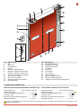 3
3
-
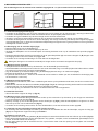 4
4
-
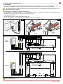 5
5
-
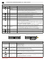 6
6
-
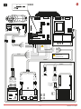 7
7
-
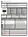 8
8
-
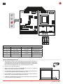 9
9
-
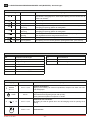 10
10
-
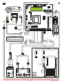 11
11
-
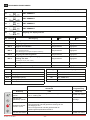 12
12
-
 13
13
-
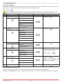 14
14
-
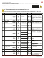 15
15
-
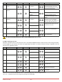 16
16
-
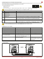 17
17
-
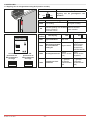 18
18
-
 19
19
-
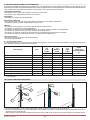 20
20
-
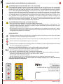 21
21
-
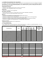 22
22
-
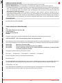 23
23
-
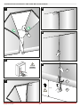 24
24
-
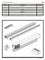 25
25
-
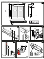 26
26
-
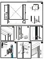 27
27
-
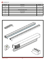 28
28
-
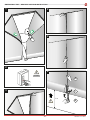 29
29
-
 30
30
-
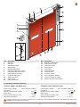 31
31
-
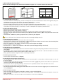 32
32
-
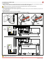 33
33
-
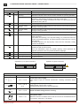 34
34
-
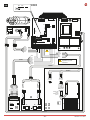 35
35
-
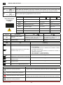 36
36
-
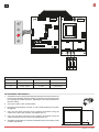 37
37
-
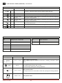 38
38
-
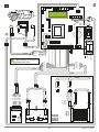 39
39
-
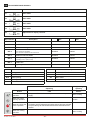 40
40
-
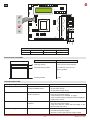 41
41
-
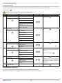 42
42
-
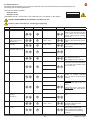 43
43
-
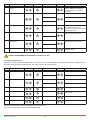 44
44
-
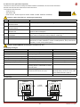 45
45
-
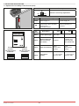 46
46
-
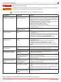 47
47
-
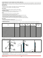 48
48
-
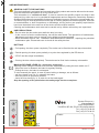 49
49
-
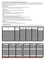 50
50
-
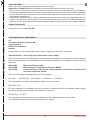 51
51
-
 52
52


