
.CeC&eC.CZ`<<`.HC
HTV`.HCC.CZ`<<`.HC
e`.<.Z`.HC`.CZ`<<`.HC
eZH.CZ`<<x.HC
.C.C&C.CZ`<<`.
+H+<.Z`eC&Zé%<+:H<<:`HV+.&+TV%HVBC%<`éT<`H<<`HVT`eV
T<`+e`TV%HVBCH<<``HVT.``H<`HVC.BC`HT<``H<<`HV
B`+HH&VCBC`
á ZH<ŝŌTVB.eBZ
á ZH<ŝŌTVB.eBq

ŝZH<ŝŌTVB.eB qqqĪZ`.<é<`VHCĪHB
.C+<`.CeC&
<<&B.C+.Cq.Z
.CeC&
1. Allgemeine Hinweise
Das Kapitel „Bedienung“ richtet sich an den Benutzer und den
Fachhandwerker.
Das Kapitel „Installation“ richtet sich an den Fachhandwerker.
Hinweis
Lesen Sie diese Anleitung sorgfältig durch und bewahren
Sie diese auf. Geben Sie die Anleitung im Falle einer
Weitergabe des Gerätes an den nachfolgenden Benutzer
weiter.
1.1 Sicherheitshinweise
1.1.1 Aufbau von Sicherheitshinweisen
SIGNALWORT Art der Gefahr
Hier stehen mögliche Folgen bei Nichtbeachtung des
Sicherheitshinweises.
f Hier stehen Maßnahmen zur Abwehr der Gefahr.
1.1.2 Symbole, Art der Gefahr
ZźăĒù ļŒ®¼ļ&¼Ï|äļ
!
Verletzung
Verbrennung oder Verbrühung
Brand
1.1.3 Signalworte
Z.&C<qHV` ¼®¼şŒşĉÖ
GEFAHR Hinweise, deren Nichtbeachtung schwere Verletzungen
oder Tod zur Folge haben.
WARNUNG Hinweise, deren Nichtbeachtung schwere Verletzungen
oder Tod zur Folge haben kann.
VORSICHT Hinweise, deren Nichtbeachtung zu mittelschweren oder
leichten Verletzungen führen kann.
1.2 Andere Markierungen in dieser Dokumentation
Hinweis
Hinweise werden durch horizontale Linien ober- und
unterhalb des Textes begrenzt. Allgemeine Hinweise
werden mit dem nebenstehenden Symbol gekenn-
zeichnet.
f Lesen Sie die Hinweistexte sorgfältig durch.
BEDIENUNG
1. Allgemeine Hinweise ________________________________________2
1.1 Sicherheitshinweise _____________________________________________ 2
1.2 Andere Markierungen in dieser Dokumentation __________ 2
1.3 Maßeinheiten _____________________________________________________ 3
1.4 Mitgeltende Dokumente ________________________________________ 3
2. Sicherheit _____________________________________________________3
2.1 Bestimmungsgemäße Verwendung _________________________ 3
2.2 Sicherheitshinweise _____________________________________________ 3
3. Gerätebeschreibung _________________________________________3
4. Bedienung ____________________________________________________3
5. Reinigung, Wartung, Pflege_________________________________3
5.1 Jährliche Überprüfung __________________________________________ 3
5.2 Selbstreinigung __________________________________________________ 3
5.3 Anlagendruck prüfen ___________________________________________ 3
6. Was tun wenn ...? ____________________________________________4
INSTALLATION
7. Sicherheit _____________________________________________________5
7.1 Vorschriften, Normen und Bestimmungen _________________ 5
7.2 Sicherheitshinweise _____________________________________________ 5
8. Gerätebeschreibung _________________________________________5
8.1 Lieferumfang _____________________________________________________ 5
9. Installation ____________________________________________________6
9.1 Vorbereitungen __________________________________________________ 6
9.2 Rohrinstallation __________________________________________________ 6
9.3 Entlüfter ___________________________________________________________ 6
9.4 Sicherheitsventil _________________________________________________ 6
9.5 Entleerungseinrichtung ________________________________________ 6
9.6 Installationsbeispiel _____________________________________________ 7
10. Montage _______________________________________________________8
10.1 Montageort _______________________________________________________ 8
10.2 Transport auf das Dach _________________________________________ 9
10.3 Befestigung des Kollektors ____________________________________ 9
10.4 Kollektoranschlüsse verbinden _______________________________ 9
10.5 Dachdurchführung______________________________________________ 10
10.6 Kollektorfühler __________________________________________________11
10.7 Blitzschutz _______________________________________________________ 11
10.8 Potenzialausgleich ______________________________________________11
10.9 Ausdehnungsgefäß _____________________________________________ 11
10.10 Spülen der Rohrleitungen_____________________________________ 11
10.11 Anschließen der Kollektoren _________________________________ 12
10.12 Befüllen der Solaranlage ______________________________________ 12
10.13 Druckprüfung ___________________________________________________ 13
10.14 Dichtheitsprüfung ______________________________________________13
10.15 Abschluss des Befüllvorgangs________________________________ 13
10.16 Wärmedämmung _______________________________________________ 14
11. Inbetriebnahme ____________________________________________ 14
12. Wartung _____________________________________________________ 14
13. Störungsbeseitigung _______________________________________ 15
14. Technische Daten ___________________________________________ 17
INBETRIEBNAHMEPROTOKOLL
KUNDENDIENST UND GARANTIE
UMWELT UND RECYCLING

.CeC&
Z.+V+.`
DEUTSCH
qqqĪZ`.<é<`VHCĪHB ZH<ŝŌTVB.eBŗ
ZźăĒù
Geräte- und Umweltschäden
Geräteentsorgung
f Dieses Symbol zeigt Ihnen, dass Sie etwas tun müssen.
Die erforderlichen Handlungen werden Schritt für Schritt
beschrieben.
1.3 Maßeinheiten
Hinweis
Wenn nicht anders angegeben, sind alle Maße in Milli-
meter.
1.4 Mitgeltende Dokumente
Beachten Sie die Betriebs- und Bedienungshinweise in den
Bedienungs- und Installationsanleitungen der Befestigungssets,
Regelungen, Kompaktinstallationen und Speicher.
2. Sicherheit
2.1 Bestimmungsgemäße Verwendung
Dieser Flachkollektor dient zur Erwärmung einer Wärmeträger-
flüssigkeit.
Eine andere oder darüber hinausgehende Benutzung gilt als nicht
bestimmungsgemäß. Zum bestimmungsgemäßen Gebrauch ge-
hört auch das Beachten dieser Anleitung.
2.2 Sicherheitshinweise
Alle Schritte bis nach der Erstinbetriebnahme dürfen nur von
einem Fachhandwerker durchgeführt werden.
Der Fachhandwerker ist bei der Installation und der Erstinbetrieb-
nahme verantwortlich für die Einhaltung der geltenden Vor-
schriften.
Betreiben Sie die Solaranlage nur komplett installiert und mit
allen Sicherheitseinrichtungen.
!
GEFAHR Verletzung
Sollten Kinder oder Personen mit eingeschränkten
physischen, sensorischen oder geistigen Fähigkeiten die
Anlage bedienen, so ist sicherzustellen, dass dies nur
unter Aufsicht oder nach entsprechender Einweisung
durch eine für deren Sicherheit zuständige Person ge-
schieht. Kinder sollten beaufsichtigt werden, um sicher-
zustellen, dass sie nicht mit dem Gerät spielen.
3. Gerätebeschreibung
Der Flachkollektor wandelt Licht in Wärme um.
Das Licht durchdringt die Glasabdeckung. Sie besteht aus vor-
gespanntem, hochtransparentem Einscheibensicherheitsglas.
Das Licht trifft auf den Absorber und wird dort in Wärme um-
gewandelt. Durch die hochselektive Beschichtung des Absorbers
und die Wärmedämmung auf der Absorberrückseite werden die
Wärmeverluste an die Umgebung auf ein Minimum reduziert.
Die vom Kollektor gewonnene Wärmeenergie wird von einer
zirkulierenden Wärmeträgerflüssigkeit mittels einer Pumpe zum
Warmwasserspeicher transportiert. Bei bestimmten Betriebs-
zuständen kann es im Inneren des Kollektors zum Beschlag mit
Kondenswasser kommen. Auftreten kann dies zum Beispiel bei
großem Speicher mit niedrigem Temperaturniveau gegenüber der
Umgebung oder bei hoher Luftfeuchtigkeit.
4. Bedienung
Die Solaranlage ist so ausgelegt, dass keine speziellen Bedien-
maßnahmen erforderlich sind, auch wenn über einen längeren
Zeitraum kein warmes Wasser entnommen wird, zum Beispiel
während des Urlaubs.
Geräte- und Umweltschäden
Die Wärmeträgerflüssigkeit darf bei Außerbetriebsetzung
der Anlage nicht abgelassen werden!
5. Reinigung, Wartung, Pflege
5.1 Jährliche Überprüfung
Lassen Sie die Solaranlage jährlich von einem Fachhandwerker
überprüfen
.
5.2 Selbstreinigung
Eine Reinigung des Kollektors ist aufgrund des Selbstreinigungs-
vermögens normalerweise nicht erforderlich. Sollte dennoch eine
starke Verschmutzung vorliegen, zum Beispiel mit Staub oder
Vogelkot, dann reinigen Sie den Kollektor mit klarem Wasser.
Geräte- und Umweltschäden
Achten Sie darauf, dass der Kollektor nicht durch starke
Sonneneinstrahlung aufgeheizt ist, wenn Sie den
Kollektor mit Wasser reinigen.
5.3 Anlagendruck prüfen
f Überprüfen Sie an der Solarstation regelmäßig das Mano-
meter des Wärmeträgerkreislaufes. Der Wert sollte bei kalter
Solaranlage (Kollektortemperatur unter 30°C) zwischen 0,35
und 0,4MPa liegen.
Verständigen Sie einen Fachhandwerker, wenn Sie Abweichungen
vom Sollwert feststellen.

.CeC&
qZ`eCqCCĪĪĪIJ
ÔZH<ŝŌTVB.eB qqqĪZ`.<é<`VHCĪHB
6. Was tun wenn ...?
Nachfolgend sind Maßnahmen zur Störungsbehebung be-
schrieben. Wenden Sie sich an einen Fachhandwerker, falls sich
das Problem mit diesen Hinweisen nicht beheben lässt.
ZŒĖļşĉÖ eļń|ä¼ ¼ä¼şĉÖ
Störung/Fehlermeldung am Regler Es liegt ein Fehler in der Anlage vor; der Fühler ist defekt
oder falsch angeschlossen.
Lesen Sie in der Bedienungs- und Installations-
anleitung des Reglers nach.
Druckschwankungen in der Anlage Tritt das Problem direkt nach der Inbetriebnahme auf, so
ist Luft im Solarkreis
Wenden Sie sich an einen Fachhandwerker.
Die Kollektoren sind beschlagen.
Bei der Lagerung ist Nässe eingedrungen.
Wenn die Anlage in Betrieb genommen wird, ver-
schwindet der Beschlag nach wenigen Wochen.
Die Feuchtigkeit entweicht durch die eingebauten
Lüftungsschlitze.
Die Pumpe läuft nicht, obwohl der Kollektor
wärmer als der Speicher ist (kein Motor-
geräusch, keine Vibration fühlbar)
Die Speicher- oder die Kollektor-Maximaltemperatur ist
überschritten. Die Kontrollleuchte oder die Anzeige am
Regler ist aktiviert.
Der Regler hat ordnungsgemäß abgeschaltet und geht
nach Unterschreitung der eingestellten Maximal-
temperaturen selbstständig wieder in Betrieb.
Die Stromzufuhr ist unterbrochen. Kontrollieren Sie die Sicherungen.
Andere Ursache Wenden Sie sich an einen Fachhandwerker.
Die Pumpe läuft, aber am Durchflussmesser
mit Abgleichventil ist kein Volumenstrom ab-
lesbar. Die Vor- und Rücklauftemperatur sind
gleich oder die Speichertemperatur steigt gar
nicht oder nur langsam an.
Wenden Sie sich an einen Fachhandwerker.
Die Pumpe läuft, aber am Durchflussmesser
mit Abgleichventil ist kein Volumenstrom ab-
lesbar.
Die Absperreinrichtung ist geschlossen Öffnen Sie die Absperreinrichtung.
Andere Ursache Wenden Sie sich an einen Fachhandwerker.
Die Pumpe springt vermeintlich spät an und
schaltet früh ab.
Wenden Sie sich an einen Fachhandwerker.
Die Pumpe läuft an und schaltet sich kurz
danach wieder aus. Dies wiederholt sich einige
Male, bis die Anlage durchläuft. Abends ist das
Gleiche zu beobachten.
Die Sonnenstrahlung reicht noch nicht aus, um das
gesamte Rohrnetz zu erwärmen.
Prüfen Sie mögliche Fehler nochmals bei stärkerer
Sonneneinstrahlung.
Andere Ursache Wenden Sie sich an einen Fachhandwerker.
Das Manometer zeigt einen Druckabfall an.
Kurze Zeit nach dem Befüllen der Anlage ist ein Druckver-
lust normal, da noch Luft aus der Anlage entweicht. Tritt
später nochmals ein Druckabfall auf, kann dies durch eine
Luftblase verursacht sein, die sich gelöst hat. Außerdem
schwankt der Druck im Normalbetrieb je nach Anlagen-
temperatur um 0,02–0,03 MPa. Geht der Druck kontinuier-
lich zurück, ist eine Stelle im Solarkreis undicht.
Wenden Sie sich an einen Fachhandwerker.
Die Pumpe verursacht Geräusche. Wenden Sie sich an einen Fachhandwerker.
Die Anlage verursacht Geräusche. In den
ersten Tagen nach der Befüllung ist dies
normal.Bei späterem Auftreten:
Wenden Sie sich an einen Fachhandwerker.
Der Speicher kühlt nachts aus. Nach Ab-
schalten der Pumpe herrschen in Vor- und
Rücklauf unterschiedliche Temperaturen. Die
Kollektortemperatur ist nachts höher als die
Außentemperatur.
Die Schwerkraftbremse schließt nicht.
Kontrollieren Sie die Stellung der Einstellschraube an
der Schwerkraftbremse.
Andere Ursache Wenden Sie sich an einen Fachhandwerker.
Die Nachheizung funktioniert nicht. Der
Kessel läuft kurze Zeit, geht aus und springt
wieder an. Dies wiederholt sich so oft, bis der
Speicher seine Solltemperatur erreicht hat
Wenden Sie sich an einen Fachhandwerker.
Der Speicher kühlt zu stark ab. Wenden Sie sich an einen Fachhandwerker.
Die Pumpe schaltet nicht ab.
Die Regelung ist nicht in Ordnung. Drehzahlgeregelte Pumpen schalten nicht sofort ab,
sondern erst nach Erreichen der kleinsten Drehzahl.
Andere Ursache Wenden Sie sich an einen Fachhandwerker.

DEUTSCH
qqqĪZ`.<é<`VHCĪHB ZH<ŝŌTVB.eBÑ
.CZ`<<`.HC
Z.+V+.`
.CZ`<<`.HC
7. Sicherheit
Die Installation, Inbetriebnahme sowie Wartung und Reparatur
dürfen nur von einem Fachhandwerker durchgeführt werden.
7.1 Vorschriften, Normen und Bestimmungen
Hinweis
Beachten Sie alle nationalen und regionalen Vorschriften
und Bestimmungen.
7.2 Sicherheitshinweise
!
WARNUNG Verletzung
Ein Solarkollektor erzeugt bei Sonnenlicht oder anderen
Lichtarten Wärme. Dies führt auch bei ungefüllten
Kollektoren zu einer starken Erhitzung der Kollektor-
anschlüsse. Es besteht Verbrennungsgefahr und der
Kollektor könnte Schaden nehmen. Decken Sie die
Kollektoren bis zur endgültigen Montage mit einem
lichtundurchlässigen Material ab. Wir empfehlen, den
Kollektor in der Verpackung zu lassen, bis er montiert
wird.
Geräte- und Umweltschäden
Lassen Sie den Kollektor nicht fallen. Lassen sie keine
Gegenstände auf den Kollektor fallen. Treten Sie nicht
auf den Kollektor.
Geräte- und Umweltschäden
Lassen Sie den Kollektor nicht ungesichert stehen. Sollte
der Kollektor umstürzen, kann das Glas brechen.
8. Gerätebeschreibung
Der Kollektor verfügt über einen Aluminium-Vollflächen-Absorber
mit einer hochselektiven Beschichtung. Die Anschlüsse sind seit-
lich herausgeführt. Die hydraulische Verbindung der Kollektoren
wird ohne Werkzeug mit einem Steckverbindungssystem her-
gestellt.
Eine prismierte Einscheiben-Sicherheitsglasabdeckung mit
Antireflex-Beschichtung schützt den Absorber. Der Betrieb des
Kollektors mit der fertig gemischten Wärmeträgerflüssigkeit (siehe
„Technische Daten“) sorgt für die notwendige Frostsicherheit. Das
Kollektorgehäuse besteht aus seewasserbeständigem Aluminium.
Der Kollektor „SOL 27 premium S“ wird verwendet für die Montage
mehrerer Kollektoren in senkrechter Ausrichtung nebeneinander
und sowie in waagerechter Ausrichtung übereinander.
Der Kollektor „SOL 27 premium W“ ist vorgesehen für die Montage
mehrerer Kollektoren in waagerechter Ausrichtung neben-
einander.
8.1 Lieferumfang
- Flachkollektor
- Reinigungstuch

ōZH<ŝŌTVB.eB qqqĪZ`.<é<`VHCĪHB
.CZ`<<`.HC
.CZ`<<`.HC
9. Installation
Die Installation, Inbetriebnahme sowie Wartung und Reparatur
dürfen nur von einem Fachhandwerker durchgeführt werden.
Beachten Sie die Unfallverhütungsvorschriften.
Hinweis
Aus hydraulischen Gründen dürfen nicht mehr als fünf
Kollektoren in Reihe geschaltet werden. Werden mehrere
Kollektorreihen montiert, müssen diese parallel ge-
schaltet werden
.
Hinweis
Werden mehr als 30 Kollektoren zu einer hydraulischen
Gruppe zusammengefasst, erlischt die Bauartzulassung.
Darüber hinausgehende Anlagen müssen einzeln ab-
genommen werden.
Hinweis
Gewerbliche Anlagen, deren unabsperrbarer Inhalt mehr
als 10Liter und nicht mehr als 50Liter beträgt, müssen
beim zuständigen Gewerbeaufsichtsamt angezeigt
werden.
Geräte- und Umweltschäden
Verwenden Sie bei der Befüllung der Solaranlage zum
Frost- und Korrosionsschutz ausschließlich die Wärme-
trägerflüssigkeit, die in der Tabelle „Technische Daten“
erwähnt wird.
9.1 Vorbereitungen
Die Rohrdurchführungen zum Inneren des Gebäudes sind bauseits
zu erstellen.
9.2 Rohrinstallation
Verwenden Sie bei der Installation der Vor- und Rücklaufleitungen
Kupferrohre, Edelstahlrohre oder Edelstahlwellschläuche. Bei
einer Anlage bis zu vier Kollektoren empfehlen wir als Rohrdurch-
messer Ø18x1,0.
Bei Pfannen- oder Ziegeldächern mit großer Dachneigung
empfehlen wir Lüftungspfannen als Dachdurchführungen.
Bei Flach- und Welldächern mit geringer Dachneigung empfehlen
wir, die Rohrleitung durch eine Außenwand zu führen.
Vermeiden Sie das Absägen von Rohrleitungen, damit keine Späne
in die Anlage geraten. Verwenden Sie zur spanlosen Rohrtrennung
einen Rohrabschneider.
9.2.1 Gelötete Leitungen
Gelötete Leitungen müssen hartgelötet werden. Verwenden Sie
Lote gemäß EN 1044: CP105 und CP203. Verwenden Sie diese Lote
ohne Flussmittel. Nur Rotguss- und Messingfittings sind mit Fluss-
mittel F-SH-1 nach EN1045 zu löten. Andere Lote beeinträchtigen
die Korrosionsbeständigkeit.
9.2.2 Andere Leitungen
Versehen Sie alle Leitungen, die mit Klemmringverschraubungen,
Pressfittingen und Wellrohrschläuchen erstellt werden, mit ge-
eigneten Dichtmitteln. Die Dichtungen sollten glykolbeständig und
bis 180°C temperaturfest sein.
Geräte- und Umweltschäden
Die Wärmedämmung darf erst nach erfolgter Dichtig-
keitsprüfung angebracht werden.
9.3 Entlüfter
Setzen Sie an den Hochpunkten der Anlage ein absperrbares
Handentlüftungsventil oder legen Sie eine Entlüftungsleitung
zu einem Handentlüftungsventil. In Kollektornähe installierte
automatische Schnellentlüfter sind mit einem Absperrventil vom
System zu trennen.
9.4 Sicherheitsventil
Geräte- und Umweltschäden
In der Rohrleitung zwischen den Kollektoren und dem
Sicherheitsventil dürfen keine Absperrorgane enthalten
sein.
Der Abfluss des Sicherheitsventils muss in einen Behälter münden,
der den Gesamtinhalt der Anlage aufnehmen kann. Hier genügt
bei kleineren Anlagen der entleerte Wärmeträgerkanister.
9.5 Entleerungseinrichtung
f Setzen Sie an der tiefsten Stelle der Solaranlage eine
Entleerungseinrichtung.

DEUTSCH
qqqĪZ`.<é<`VHCĪHB ZH<ŝŌTVB.eBŌ
.CZ`<<`.HC
.CZ`<<`.HC
9.6 Installationsbeispiel
Die Systemskizze zeigt die prinzipielle Ausführung einer Solar-
anlage.
III
26_05_01_0061
2k
10
4
1b
1b
2
5
6
3f
3
3
3
3
3
3
3
3
3
3
3
3
3
10
11
7
V
2a
28
16
2s
III Kollektor
V Heizung
1b Handentlüfter
2 Regelung
2a Außentemperaturfühler
2k Temperaturfühler in der Kollektortauchhülse
2s Speicherfühler Solaranlage
3f Umwälzpumpe für die Solaranlage
Warmwasserbereitung
4 Solarstation
5 Sicherheitsventil
6 Ausdehnungsgefäß
7 Speicher
10 Füll- und Entleerungshahn
11 Alternative Nacherwärmung (z.B. Wärmepumpe)
16 Sollwertfernversteller
28 Kaltwasser-Sicherheitsgruppe nach DIN 1988

ÄZH<ŝŌTVB.eB qqqĪZ`.<é<`VHCĪHB
.CZ`<<`.HC
BHC`&
10. Montage
!
WARNUNG Verletzung
Seien Sie Vorsicht beim Umgang mit scharfen Kanten.
Tragen Sie Schutzkleidung.
10.1 Montageort
!
GEFAHR Verletzung
Beachten Sie bei Arbeiten auf Dächern die Sicherheits-
vorschriften!
Lassen Sie alle Dacharbeiten von einem Fachhandwerker aus-
führen.
f Prüfen Sie den Zustand der Dachkonstruktion. Beachten Sie
die Statik. Stellen Sie gegebenenfalls eine Bauanfrage an die
zuständige Behörde.
10.1.1 Rand- und Eckbereiche
Die Dachränder, und hier insbesondere die Ecken, sind Bereiche
verstärkter Windbewegung und Wirbel. Daher sind Mindest-
abstände einzuhalten.
26_05_01_0237
:ù¼êĉ¼ļ¼|äé
Öļşĉ®ļêńńń¼êŒ¼ĵĶ
V|ĉ®éŎ÷¼ļ¼êäĵVĶ
A < 30 m A/8, aber 1 m ≤ R ≤ 2 m
A ≥ 30 m A/8
Die Breite des Rand-/Eckbereiches „R“ beträgt 1/8 der kleineren
Dachgrundrissseite (A), mindestens jedoch 1m.
Bei Wohngebäuden, Bürogebäuden und geschlossenen Hallen,
bei denen „A“ kleiner als 30m ist, darf die Breite des Rand-
bereiches auf 2m begrenzt werden.
Die Eckbereiche haben stets eine quadratische Grundfläche mit
der Seitenlänge A/8.
Dachdurchdringungen
26_05_01_0607
&ļĖÛ¼ļ¼|şŒ¼êùé
ń¼êŒ¼ĵĶ
V|ĉ®¼ļ¼êäĵĶ
0,5 m < b ≤ 2 m 1 m
b > 2 m b/2, aber 1 m ≤ D ≤ 2 m
Als Dachdurchdringungen gelten Bauteile, die an mindestens einer
Stelle mehr als 0,35m über die Oberkante des Dachwerkstoffes
hinausragen und die mindestens eine Seitenabmessung größer
als 0,5m aufweisen. Die Breite des zugehörigen Randbereiches
„D“ beträgt 1/2 der längeren Bauteilseite „b“, jedoch mindestens
1m. Der Randbereich darf auf 2m Breite begrenzt werden.
10.1.2 Regelschneelast für Deutschland
Beachten Sie bei der Aufstellung der Solarkollektoren den ge-
forderten Mindestaufstellwinkel. Dieser richtet sich nach der
Schneelastzone in der die Kollektoren aufgestellt werden. Aus-
kunft gibt Ihnen die Baubehörde. Es wird davon ausgegegangen,
dass der Schnee ungehindert vom Dach abrutschen kann.
+Ėä¼êĉă Zäĉ¼¼ù|ńŒſĒĉ¼
ţ¼ļCC Ĝ Ĝ| ŝ ŝ| ŗ
100 • • • • •
200 • • • • •
300 • • • • •
400 • • • • > 32°
500 • • • > 35° > 39°
600 • • > 37° > 41° > 44°
700 • • > 41° > 45° > 48°
800 • > 36° > 45° > 48° > 50°
900 > 35° > 40° > 48° > 50° > 52°
1000 > 39° > 43° > 49° > 52° > 53°
1100 > 42° > 46° > 51° > 53° > 54°
1200 > 44° > 48° > 53° > 54° > 55°
1300 > 47° > 49° > 54° > 55° > 56°
x Beliebiger Aufstellwinkel (siehe Kapitel „Technische Daten“)
* nach Angaben der zuständigen Baubehörde
Die Regelschneelast darf auch durch Schneesackbildung, Schnee-
verwehungen und Eisbildung nicht überschritten werden.
10.1.3 Einbauhöhe
Die Montagerahmen sind ausgelegt für eine maximale Einbauhöhe
von 20m bei einer Schneelast von 1,25kN/m². Dies entspricht
einer Regelschneelast von 1,2kN/m².

DEUTSCH
qqqĪZ`.<é<`VHCĪHB ZH<ŝŌTVB.eBĎ
.CZ`<<`.HC
BHC`&
10.2 Transport auf das Dach
Geräte- und Umweltschäden
Berühren Sie nicht die Glasscheibe des Kollektors.
Falls Verschmutzungen der Glasoberfläche auftreten, zum
Beispiel Fingerabdrücke, reinigen Sie die Kollektorober-
fläche unverzüglich mit dem beiliegenden Reinigungs-
tuch.
Sie können den Kollektor über eine Leiter auf das Dach ziehen.
Legen Sie dazu ein Seil um den Kollektorrahmen.
Befestigen Sie das Seil nicht an den Kollektoranschlüssen!
26_05_01_0443
1
1
2
2
1 Seil
2 Kollektor
26_05_01_0442
10.3 Befestigung des Kollektors
Montieren Sie den Kollektor gemäß der Installationsanleitung des
verwendeten Befestigungssystems.
Geräte- und Umweltschäden
Falls starke Sonneneinstrahlung vorliegt, sollten Sie
die Kollektoren vor der Inbetriebnahme mit licht-
undurchlässigem Material abdecken.
10.4 Kollektoranschlüsse verbinden
Steckverbindung
26_05_01_0609
1
2
3
2
3
3
3
3
3
3
3
3
3
3
1 Steckverbindung
2 Abstandhalter
3 Anschlussklammer
Geräte- und Umweltschäden
Der Abstandhalter darf erst abgenommen werden, nach-
dem die Kollektoren miteinander verbunden sind.
Wenn Sie den Abstandhalter vorher abnehmen, kann
dies beim Heranschieben des zweiten Kollektors zur Be-
schädigung der flexiblen Steckverbindung führen.
Hinweis
Die Steckverbindungen dürfen nicht eingefettet werden.
f Entfernen Sie die Abdeckung des Kollektoranschlusses.
f Stecken Sie die Steckverbindung in den Kollektoranschluss.
!
WARNUNG Verbrennung
Wenn Sie eine Steckverbindung herausziehen, die einige
Minuten in einem aufgeheizten Kollektor gesteckt haT,
kann das Metall erhitzt sein.
26_05_01_0622
f Schieben Sie den benachbarten Kollektor heran, sodass sich
dessen Kollektoranschluss auf die Steckverbindung schiebt.

ĜƃZH<ŝŌTVB.eB qqqĪZ`.<é<`VHCĪHB
.CZ`<<`.HC
BHC`&
1
26_05_01_0623
1 Abstandhalter
f Entfernen Sie den Abstandhalter.
26_05_01_0624
1
1
1 Anschlussklammer
f Montieren Sie die Anschlussklammern am Übergang
zwischen Kollektor und Steckverbindung.
26_05_01_0625
f Sichern Sie die Anschlussklammern, indem Sie die Ver-
riegelung einklappen.
f Dämmen Sie die Steckverbindung zwischen den Kollektoren
mit der beiliegenden Wärmedämmung.
10.5 Dachdurchführung
Die Dachdurchführungen sind ab Werk mit einer temperatur- und
UV-beständigen Wärmedämmung ausgestattet.
26_05_01_0610
1
2
3
1 Anschlussklammer
2 Dachdurchführung mit Fühlerleitung
3 Dachdurchführung
Hinweis
Die Steckverbindungen dürfen nicht eingefettet werden.
f Entfernen Sie die Abdeckung des Kollektoranschlusses.
26_05_01_0626
f Stecken Sie die Steckverbindung der „Dachdurchführung mit
Fühlerleitung“ in den Kollektoranschluss am Vorlaufende des
Kollektorfeldes.

DEUTSCH
qqqĪZ`.<é<`VHCĪHB ZH<ŝŌTVB.eBĜĜ
.CZ`<<`.HC
BHC`&
26_05_01_0627
f Montieren Sie die Anschlussklammer am Übergang zwischen
Kollektor und Steckverbindung.
26_05_01_0628
f Sichern Sie die Anschlussklammer, indem Sie die Ver-
riegelung einklappen.
f Montieren Sie entsprechend die Dachdurchführung am Rück-
laufende des Kollektorfeldes.
10.6 Kollektorfühler
Die korrekte Anbindung des Kollektorfühlers ist für die einwand-
freie Funktion der Solaranlage von entscheidender Bedeutung.
f Fixieren Sie die Fühlerleitung, zum Beispiel mit
Kabelbindern.
f Verbinden Sie die Fühlerleitung mit dem Solarregler.
10.7 Blitzschutz
Wenn das Gebäude bereits über eine Blitzschutzanlage verfügt,
müssen Kollektorgehäuse, Montagerahmen und Rohrleitungen in
die vorhandenen Blitzschutzmaßnahmen eingebunden werden.
10.7.1 Blitzschutz des Kollektorgehäuses
Binden Sie den Kollektor über Schraubvorrichtungen in die
Blitzschutz anlage ein. Verwenden Sie für jeden Kollektor zwei
Blechschrauben aus Edelstahl (Ø6,3mm).
f Bohren Sie Löcher vor (Ø5mm). Platzieren Sie die
Bohrungen an der unteren Stirnseite des Kollektors in dem
Bereich, der in der nachfolgenden Abbildung schraffiert
ist. Halten Sie beim Bohren der Löcher einen Abstand von
mindestens 100mm zur Ecke des Kollektorgehäuses.
26_05_01_0189
min. 100 mm
1
1 Bohrlöcher (Ø 5 mm)
10.7.2 Blitzschutz der Montagerahmen
f Verbinden Sie den Montagerahmen mittels Schraub- oder
Klemmverbindungen mit den Blitzschutzeinrichtungen.
10.7.3 Blitzschutz der Rohrleitung
f Schließen Sie die Rohrleitung in unmittelbarer Nähe des
Kollektors (über dem Dach) mit Rohrschellen an die Blitz-
schutzanlage an (Korrosionsgefahr beachten).
10.8 Potenzialausgleich
f Verbinden Sie die Rohrinstallation gemäß den geltenden
Vorschriften mit dem Potenzialausgleich.
Alle Rohrleitungen müssen auf kurzem Wege mit dem Gebäude-
Potenzialausgleich verbunden werden.
10.9 Ausdehnungsgefäß
f Stellen Sie das Druckausdehnungsgefäß auf einen Vordruck
von 0,3 MPa (3 bar) ein.
10.10 Spülen der Rohrleitungen
Spülen Sie vor dem Anschließen der Kollektoren das im Gebäude
installierte Rohrleitungssystem gründlich mit Wasser durch, damit
keine Fremdkörper in der Anlage verbleiben.

ĜŝZH<ŝŌTVB.eB qqqĪZ`.<é<`VHCĪHB
.CZ`<<`.HC
BHC`&
Hinweis
Spülen Sie die Anlage mit Trinkwasser und nicht mit
Wärmeträgerflüssigkeit.
Geräte- und Umweltschäden
Achten Sie darauf, dass kein Frost herrscht, wenn sie die
Anlage mit Wasser spülen.
Für das Spülen ist eine leistungsstarke Pumpe mit einem Betriebs-
druck von etwa 0,4 MPa (4 bar) zu verwenden.
Alternativ können Sie eine Bohrmaschinen-Pumpe verwenden.
26_05_01_0515
2
1
3
4
4
4
4
4
4
4
4
4
4
4
4
1 Solar-Kompaktinstallation
2 Wärmeträgerflüssigkeit
3 Filter
4 Füllpumpe
Mögliche Vorgehensweise:
f Schließen Sie den Wasserzulauf an den KFE-Hahn unterhalb
des Manometers an
f Schließen Sie den Wasserablauf an den KFE-Hahn unterhalb
des Volumenstrommessers an.
f Verbinden Sie den Solarvorlauf und den Solarrücklauf mit
einem Wasserschlauch. Sie ersetzen damit den Kollektor-
strang, der erst später eingebunden wird. Dadurch wird
verhindert, dass Verunreinigungen in die Kollektorrohre ein-
gespült werden.
f Schließen Sie das Einstellventil in der Solarstation, indem
Sie den Schlitz der Durchflusseinstellschraube (oberhalb der
Volumenstromanzeige) in die waagerechte Position drehen.
So ist gewährleistet, dass die gesamte Anlage durchströmt
wird.
f Setzen Sie die Schwerkraftbremse außer Funktion, indem Sie
den Kugelhahn in 45°-Stellung drehen.
f Schließen Sie die Absperrhähne vor den Entlüftern.
f Spülen Sie die Rohrleitungen mindestens 15 Minuten lang
durch.
f Öffnen Sie nach dem Spülvorgang das Einstellventil in der
Solarstation, indem Sie den Schlitz der Durchflusseinstell-
schraube (oberhalb der Volumenstromanzeige) in die senk-
rechte Position drehen.
f Entfernen Sie den Schlauch, der den Kollektorstrang ersetzt
hat und lassen Sie die Rohrleitungen leer laufen.
10.11 Anschließen der Kollektoren
Schließen Sie die zuvor montierten Dachdurchführungen an die
gespülte Rohrinstallation an.
10.12 Befüllen der Solaranlage
!
VORSICHT Verletzung
f Ziehen Sie vor dem Umgang mit dem Wärmeträger-
medium Schutzhandschuhe an.
f Tragen Sie eine Schutzbrille!
f Beachten Sie das am Ende dieser Anleitung ab-
gedruckte EG-Sicherheitsdatenblatt der Wärme-
trägerflüssigkeit.
Stellen Sie vor dem Befüllen des Wärmeträgerkreislaufs sicher,
dass die Rohrinstallation beendet ist, die Kollektoren an-
geschlossen sind und der Speicher gefüllt ist.
Für das Füllen ist eine leistungsstarke Pumpe mit einem Betriebs-
druck von etwa 0,4MPa (4bar) zu verwenden. Durch die hohe
Strömungsgeschwindigkeit wird die Luft optimal ausgetragen.
Verwenden Sie als Wärmeträger ausschließlich die in der Tabelle
„Technische Daten“ erwähnte Wärmeträgerflüssigkeit. Die Ge-
binde sind gebrauchsfertig vorgemischt und bedürfen keiner
weiteren Behandlung.
Geräte- und Umweltschäden
Beimengungen von Wasser oder anderen Wärmeträger-
medien sind nicht zulässig. Die notwendigen Eigen-
schaften und der Korrosionsschutz sind dann nicht ge-
währleistet.
Geräte- und Umweltschäden
Füllen Sie die Anlage nicht bei starker Sonnenein-
strahlung. Dies könnte zu Dampfschlägen im Kollektor
führen! Decken Sie die Kollektoren ab!
10.12.1 Vorbereitung
» Achten Sie darauf, dass die Kollektoren für die Druckprüfung
abgedeckt sind.
» Bauen Sie das Sicherheitsventil ab und verschließen Sie den
Anschluss.
10.12.2 Befüllen der Solaranlage
Öffnen Sie bei allen Füll- und Entleervorgängen die Entlüftungs-
ventile am höchsten Punkt der Anlage. Schließen Sie Absperr-
hähne vor den Entlüfter, sobald Wärmeträgerflüssigkeit austritt.
f Schließen Sie die Druckseite der Füllpumpe mit einem
Schlauch an den KFE-Hahn unterhalb des Manomenters an.
f Schließen Sie den Solarflüssigkeitsbehälter an der Saugseite
der Pumpe an.

DEUTSCH
qqqĪZ`.<é<`VHCĪHB ZH<ŝŌTVB.eBĜŗ
.CZ`<<`.HC
BHC`&
f Schließen Sie am unteren KFE-Hahn einen Ableitungs-
schlauch an, den Sie in den Solarflüssigkeitsbehälter münden
lassen.
f Schließen Sie das Einstellventil in der Solarstation, indem
Sie den Schlitz der Durchflusseinstellschraube (oberhalb der
Volumenstromanzeige) in die waagerechte Position drehen.
f Setzen Sie die Schwerkraftbremse außer Funktion, indem Sie
den Kugelhahn in 45°-Stellung drehen.
f Schalten Sie die Füllpumpe ein.
Setzen Sie die Befüllung solange fort, bis keine Luftblasen mehr
aus dem Ableitungsschlauch austreten.
f Schließen Sie den Entleerungs-Hahn und füllen Sie bis zu
einem Druck von etwa 0,35MPa (3,5bar).
26_05_01_0648
f Öffnen Sie die Entlüftungsventile am höchsten Punkt der
Anlage und schließen Sie sie wieder, sobald Wärmeträger-
flüssigkeit austritt.
10.13 Druckprüfung
f Schließen Sie die Absperrhähne vor den Entlüftern, damit es
hier nicht zu einem Druckabfall kommen kann.
f Bauen Sie, zum Beispiel mit einer hydraulischen Hebel-
pumpe, einen Druck von 0,78MPa (7,8bar) im System auf.
f Schließen Sie den KFE-Hahn an der Füllseite.
f Schließen Sie das Kappenventil, um den Druckabfall messen
zu können.
Der Druck darf nach 15Minuten nicht abgefallen sein!
Zum Montieren des Sicherheitsventils muss die Anlage wieder
entleert werden.
f Öffnen Sie die Entlüfter an der höchsten Stelle der Anlage.
Wenn
f Öffnen Sie das Einstellventil in der Solarstation, indem Sie
den Schlitz der Durchflusseinstellschraube, oberhalb der
Volumenstromanzeige, in die senkrechte Position drehen.
f Öffnen Sie zum Entleeren der Anlage die KFE-Hähne an der
Füllseite und an der Entleerungsseite.
f Lassen Sie die Anlage leerlaufen.
f Öffnen Sie das Kappenventil.
Geräte- und Umweltschäden
Montieren Sie nach erfolgter Druckprüfung das Sicher-
heitsventil.
10.14 Dichtheitsprüfung
Geräte- und Umweltschäden
Die Wärmedämmung darf erst nach erfolgter Dichtig-
keitsprüfung angebracht werden.
f Befüllen Sie die Anlage erneut.
f Bauen Sie mit der Füllpumpe einen Druck von 0,5MPa
(5bar) auf.
f Der Prüfdruck darf über zwei Stunden nicht abfallen.
f Druckschwankungen sind durch wechselnde Sonnenein-
strahlung auch bei abgedeckten Kollektoren möglich.
f Führen Sie eine Sichtprüfung an allen Verbindungsstellen der
Solaranlage durch.
10.15 Abschluss des Befüllvorgangs
f Senken Sie den Anlagendruck auf den erforderlichen Füll-
druck. Bei einer kalten Anlage beträgt der Mindestfülldruck
0,35 MPa (3,5 bar).
f Verschließen Sie die Füll- und Entleerungshähne mit den
mitgelieferten Verschlusskappen.
f Bringen Sie das Sicherheitsdatenblatt der Wärmeträger-
flüssigkeit an der Anlage an!
f Lassen Sie die Solaranlage über Nacht ruhen.
f Entlüften Sie die Anlage am nächsten Morgen vor
Beginn starker Sonneneinstrahlung erneut über die
Entlüftungsventile.
f Setzen Sie die Schwerkraftbremse in Funktion, indem Sie den
Kugelhahn in vertikale Position drehen.
Hinweis
Im normalen Betrieb sind die Absperrhähne vor den Ent-
lüftern in Kollektornähe immer geschlossen zu halten.
Geräte- und Umweltschäden
Der Abfluss des Sicherheitsventils muss in ein Auffang-
gefäß münden, das den Gesamtinhalt der Anlage auf-
nehmen kann. Bei kleineren Anlagen genügt der ent-
leerte Wärmeträgerkanister. Die verbrauchte Wärme-
trägerflüssigkeit ist einer geeigneten Entsorgung zuzu-
führen (Deponie oder Verbrennungsanlage).

ĜÔZH<ŝŌTVB.eB qqqĪZ`.<é<`VHCĪHB
.CZ`<<`.HC
.C`V.C+B
10.16 Wärmedämmung
Achten Sie darauf, dass die Anlage vor Ausführung der Wärme-
dämmung einer Druckprüfung unterzogen wurde und eine
Dichtigkeitskontrolle vorgenommen wurde.
Dämmen Sie alle Rohrleitungen. Das Dämmmaterial ist bauseits
zu stellen.
VĒäļêĉĉ¼ĉ®şļäă¼ńń¼ļ
ăă
ê÷¼®¼ļqļă¼®ăăşĉÖ
Ħ¼ſĒÖ¼ĉ|şÏ¼êĉ¼qļă¼ù¼êŒÏäêÖé
÷¼êŒŶĒĉƃ©ƃŗÑŨqŎĦă:ħ¼êÔƃŨ°ħ
bis 22 20
22 - 35 30
35 - 100 gleich dem Rohrinnendurchmesser
Rechnen Sie bei Dämmmaterialien mit anderen Wärmeleitfähig-
keiten die Dämmschichtdicke um.
Verwenden Sie zur Wärmedämmung der Außenrohrleitungen
temperatur- und UV-beständiges Dämmmaterial: Mineralwolle,
die mit Alu-Gitterfolie kaschiert ist, einen flexiblen EPDM-Schlauch
oder einen geschlossenporigen EPDM-Schlauch.
Bei der Mineralwolle empfiehlt sich eine feste Ummantelung aus
Aluminiumblech. Der EPDM-Schlauch kann mit einem UV-be-
ständigen Anstrich versehen werden.
f Versehen Sie die Kollektortauchhülse, die Verschraubungen
und die Dachdurchführung mit einer Wärmedämmung, die
fugendicht geschlossen, temperatur- und UV-beständig sein
muss.
f Schneiden Sie das Dämmmaterial gegebenenfalls seitlich ein
und verkleben Sie den Schlitz nach der Montage.
f Schützen Sie die Wärmedämmung vor Vogel- und
Marderverbiss.
11. Inbetriebnahme
f Ziehen Sie sämtliche Verschraubungen nach.
f Überprüfen Sie den Fülldruck der Anlage.
Hinweis
Der Mindest-Fülldruck beträgt bei einer kalten Anlage
(unter 30°C) 0,35MPa (3,5bar).
f Überprüfen Sie den Vordruck des Druckausdehnungsgefäßes.
Hinweis
Das Druckausdehnungsgefäß muss einen Vordruck von
0,3MPa (3bar) haben.
f Füllen Sie das „Inbetriebnahmeprotokoll“ aus.
f Stellen Sie die eingebaute Regelung auf Handbetrieb. Be-
achten Sie die Bedienungs- und Installtionsanleitung der in
der Anlage eingebauten Regelung.
f Überprüfen Sie, ob alle benötigten Relais der Solar-Regelung
angeschlossen sind.
f Stellen Sie die Regelung wieder auf Automatik-Betrieb.
Wenn die Einschaltbedingungen erfüllt sind, sollte die Anlage
automatisch in Betrieb gehen. Sollte dies nicht der Fall sein,
schauen Sie im Kapitel „Was tun wenn ...“ nach der möglichen
Störungsursache.
12. Wartung
Hinweis
Wir bieten Ihnen die Möglichkeit, einen Wartungsvertrag
abzuschließen.
f Überprüfen Sie die einwandfreie Funktion der Anlage ein-
schließlich Regelung, Sicherheitseinrichtungen und Speicher.
f Überprüfen Sie die der Witterung ausgesetzten Anlagenteile,
die Befestigungen und die Wärmedämmung, auf ordnungs-
gemäßen Zustand.
f Beseitigen Sie Verschmutzungen.
f Überprüfen Sie die Wärmeträgerflüssigkeit auf ph-Wert (> 7)
und Frostsicherheit (--30 °C). Tauschen Sie die Wärmeträger-
flüssigkeit gegebenenfalls aus oder füllen Sie über den Füll-
stutzen der Solarstation nach.
!
VORSICHT Verletzung
Ist bei Wartungs- oder Reparaturarbeiten das Ablassen
der Wärmeträgerflüssigkeit notwendig, muss dies von
einem Fachhandwerker durchgeführt werden.
Geräte- und Umweltschäden
Bevor Sie die Wärmeträgerflüssigkeit aus dem Kollektor
entfernen, muss der Kollektor vor Lichteinfall geschützt
werden. Decken Sie den Kollektor lichtundurchlässig ab.

DEUTSCH
qqqĪZ`.<é<`VHCĪHB ZH<ŝŌTVB.eBĜÑ
.CZ`<<`.HC
Z`MVeC&ZZ.`.&eC&
13. Störungsbeseitigung
Die nachfolgende Fehlertabelle enthält auch alle Inhalte der im Kapitel „Was tun wenn“ beschriebenen Maßnahmen zur Störungs-
beseitigung
ZŒĖļşĉÖ eļń|ä¼ ¼ä¼şĉÖ
Störung/Fehlermeldung am Regler Es liegt ein Fehler in der Anlage vor; der Fühler ist
defekt oder falsch angeschlossen.
Lesen Sie in der Bedienungs- und Installationsanleitung des
Reglers nach.
Druckschwankungen in der Anlage Tritt das Problem direkt nach der Inbetriebnahme
auf, so ist Luft im Solarkreis
Entlüften Sie die Anlage.
Die Kollektoren sind beschlagen.
Bei der Lagerung ist Nässe eingedrungen.
Wenn die Anlage in Betrieb genommen wird, verschwindet
der Beschlag nach wenigen Wochen. Die Feuchtigkeit ent-
weicht durch die eingebauten Lüftungsschlitze.
Die Pumpe läuft nicht, obwohl der Kollektor
wärmer als der Speicher ist (kein Motor-
geräusch, keine Vibration fühlbar)
Die Speicher- oder die Kollektor-Maximal-
temperatur ist überschritten. Die Kontrollleuchte
oder die Anzeige am Regler ist aktiviert.
Der Regler hat ordnungsgemäß abgeschaltet und geht nach
Unterschreitung der eingestellten Maximaltemperaturen
selbstständig wieder in Betrieb.
Die Stromzufuhr ist unterbrochen. Kontrollieren Sie die Leitungen und Sicherungen.
Die Temperaturdifferenz ist zu hoch eingestellt
(>15°C) oder der Regler schaltet nicht.
Überprüfen Sie den Regler.
Überprüfen Sie den Temperaturfühler.
Verringern Sie die Temperaturdifferenz.
Die Pumpenwelle blockiert.
Schalten Sie kurzfristig auf maximale Drehzahl um oder
öffnen Sie, wenn möglich, an der Pumpe die Entlüfter-
schraube. Führen Sie einen Schraubendreher in die Kerbe ein
und drehen Sie das Pumpenrad von Hand an.
Die Pumpe ist verschmutzt. Demontieren und reinigen Sie die Pumpe. Schließen Sie den
Durchflussmengenbegrenzer und den Pumpenkugelhahn.
Der Fühler ist defekt. Tauschen Sie den Fühler aus
Der Fühler ist falsch installiert. Prüfen Sie die Fühlerposition. Der Kollektorfühler muss voll-
ständig in der Fühlertauchhülse sitzen.
Die Pumpe läuft, aber am Durchflussmesser
mit Abgleichventil ist kein Volumenstrom ab-
lesbar. Die Vor- und Rücklauftemperatur sind
gleich oder die Speichertemperatur steigt gar
nicht oder nur langsam an.
Im Leitungssystem befindet sich Luft,
der Anlagendruck ist zu niedrig oder
die Anlage ist verschmutzt.
Kontrollieren Sie den Anlagendruck. Überprüfen Sie, ob das
Ausdehnungsgefäß groß genug gewählt wurde. Prüfen Sie
den Vordruck des Ausdehnungsgefäßes.
Betreiben Sie die Pumpe stoßweise (mit maximaler Leistung).
Öffnen Sie die Entlüfter an Kollektor, Pumpe und Solar-
speicher.
Spülen Sie die Anlage vorwärts und rückwärts. Reinigen
Sie Einbauten wie Durchflussmesser mit Abgleichventil und
Schmutzfänger.
Prüfen Sie die Leitungsführung. Durchläuft die Leitung eine
„Berg- und Talbahn“, zum Beispiel an Balkenvorsprüngen
oder der Umgehung von Wasserleitungen, so ändern sie die
Leitungsführung oder setzen sie einen zusätzlichen Entlüfter.
Beachten Sie, dass in Kollektornähe keine Automatikentlüfter
plaziert werden, die nicht mittels eines Kugelhahns vom
System getrennt sind.
Prüfen Sie den Automatik-Entlüfter auf Funktionsfähigkeit.
Schrauben Sie dazu die Schutzkappe ab und prüfen Sie
die Gängigkeit des Schwimmers mit einer stumpfen Nadel.
Tauschen Sie gegebenenfalls den Entlüfter aus.
Die Pumpe läuft, aber am Durchflussmesser
mit Abgleichventil ist kein Volumenstrom ab-
lesbar.
Der Durchflussmesser mit Abgleichventil ist ver-
klemmt.
Prüfen Sie die Funktion des Durchflussmessers mit Abgleich-
ventil. Auch bei korrekt eingestelltem Durchfluss kann, zum
Beispiel durch den festsitzenden Ring, die Anzeige im Schau-
glas blockiert sein. Schalten Sie die Pumpe im Handbetrieb
ein. Hier muss eine Bewegung des Stempels feststellbar sein.
Lösen Sie den Stempel durch leichtes Schlagen. Tauschen Sie
notfalls Durchflussmesser und Abgleichventil aus.
Die Absperreinrichtung ist geschlossen. Öffnen Sie die Absperreinrichtung.
Die Pumpe springt vermeintlich spät an und
schaltet früh aus.
Die Temperaturdifferenz zwischen Kollektor und
Speicher ist zu groß eingestellt.
Verkleinern Sie die Temperaturdifferenz an der Regelung.

ĜōZH<ŝŌTVB.eB qqqĪZ`.<é<`VHCĪHB
.CZ`<<`.HC
Z`MVeC&ZZ.`.&eC&
ZŒĖļşĉÖ eļń|ä¼ ¼ä¼şĉÖ
Die Pumpe läuft an und schaltet sich kurz
danach wieder aus. Dies wiederholt sich einige
Male, bis die Anlage durchläuft. Abends ist das
Gleiche zu beobachten.
Die Sonnenstrahlung reicht noch nicht aus, um das
gesamte Rohrnetz zu erwärmen.
Prüfen Sie mögliche Fehler nochmals bei stärkerer Sonnen-
einstrahlung.
Der Volumenstrom ist zu hoch (die Pumpe ist zu
hoch eingestellt).
Verringern Sie die Leistungsstufe der Pumpe.
Die Schalttemperaturdifferenz des Reglers ist zu
klein eingestellt.
Erhöhen Sie die Schalttemperaturdifferenz am Regler.
Das Rohrnetz ist nicht vollständig isoliert. Isolieren Sie die Rohrleitungen
Speicher- und Kollektorfühler sind vertauscht
angeschlossen. (Das Problem tritt nach Inbetrieb-
nahme auf).
Schließen Sie die Temperatursensoren an die richtigen
Sensorklemmen an (siehe Gebrauchs- und Montageanleitung
der Regelung).
Das Manometer zeigt einen Druckabfall an.
Kurze Zeit nach dem Befüllen der Anlage ist ein
Druckverlust normal, da noch Luft aus der Anlage
entweicht. Tritt später nochmals ein Druckabfall
auf, kann dies durch eine Luftblase verursacht sein,
die sich gelöst hat. Außerdem schwankt der Druck
im Normalbetrieb je nach Anlagentemperatur
um 0,02–0,03 MPa. Geht der Druck kontinuierlich
zurück, ist eine Stelle im Solarkreis undicht.
Ist der Automatikentlüfter abgesperrt?
Kontrollieren Sie die Verschraubungen, die Stopfbuchsen an
Absperrschiebern und die Gewindeanschlüsse. Kontrollieren
Sie die Lötstellen.
Prüfen Sie den Vordruck des Ausdehnungsgefäßes und die
Dichtigkeit der Membran.
Fluidverlust durch Öffnen des Sicherheits-ventils,
da Ausdehnungsgefäß zu gering dimensioniert
bzw. drucklos oder defekt ist. Kollektorschäden
(undicht) und Frostschäden durch zu geringen
Frostschutzgehalt.
Überprüfen Sie die Gefäßgröße. Überprüfen Sie den Frost-
schutzgehalts und den pH-Wert.
Die Pumpe verursacht Geräusche. Luft in der Pumpe Entlüften Sie die Pumpe.
Unzureichender Anlagendruck Erhöhen Sie den Anlagendruck.
Die Anlage verursacht Geräusche. In den
ersten Tagen nach der Befüllung ist dies
normal. Bei späterem Auftreten gibt es zwei
mögliche Ursachen:
Der Anlagendruck ist zu gering. Pumpe zieht Luft
über den Entlüfter an.
Überprüfen Sie, ob das Ausdehnungsgefäß groß genug ge-
wählt wurde. Prüfen Sie den Vordruck des Ausdehnungs-
gefäßes. Erhöhen Sie den Anlagendruck.
Die Pumpenleistung ist zu hoch eingestellt.
Schalten Sie auf eine niedrigere Drehzahl und kontrollieren
Sie den Volumenstrom am Durchflussmesser (mit Abgleich-
ventil).
Der Speicher kühlt nachts aus. Nach Ab-
schalten der Pumpe herrschen in Vor- und
Rücklauf unterschiedliche Temperaturen. Die
Kollektortemperatur ist nachts höher als die
Außentemperatur.
Die Schwerkraftbremse schließt nicht.
Kontrollieren Sie die Stellung der Einstellschraube. Prüfen
Sie die Schwerkraftbremse auf Dichtigkeit. Hat sich ein Span
verklemmt oder befinden sich Schmutzpartikel in der Dicht-
fläche?
Einrohrzirkulation bei kurzen Rohrnetzen mit
geringem Druckverlust.
Ändern Sie die Leitungsführung. Schließen Sie den Solar-
wärmetauscher nicht direkt an, sondern ziehen Sie die Zu-
leitungen erst u-förmig nach unten. Der Syphon unterstützt
die Schwerkraftbremse. Montieren Sie gegebenenfalls ein
Zwei-Wege-Ventil, das gleichzeitig mit der Pumpe geschaltet
wird.
Nachheizung funktioniert nicht. Der Kessel
läuft kurze Zeit, geht aus und springt wieder
an. Dies wiederholt sich so oft, bis der
Speicher seine Solltemperatur erreicht hat.
Es befindet sich Luft im Nachheizwärmetauscher. Entlüften Sie den Nachheizwärmetauscher.
Die Wärmetauscherfläche ist zu klein.
Vergleichen Sie die Angaben des Kesselherstellers und des
Speicherherstellers. Eventuell lässt sich das Problem durch
eine höhere Vorlauftemperatur am Kessel lösen.
Der Speicher kühlt zu stark ab.
Die Dämmung ist defekt oder unsachgemäß montiert.
Prüfen Sie, ob die Dämmung intakt ist. Dämmen Sie die
Speicheranschlüsse.
Falsche Einstellung des Reglers für die Nachheizung Prüfen Sie die Einstellung des Kesselreglers.
Die Warmwasser-Zirkulation läuft zu häufig und/
oder nachts.
Prüfen Sie die Schaltzeiten und den Intervallbetrieb.
Die Pumpe schaltet nicht ab.
Fühler defekt oder nicht korrekt positioniert. Prüfen Sie Fühlerposition, -montage und -kennlinien
Regelung nicht in Ordnung Hinweis: Drehzahlgeregelte Pumpen schalten nicht sofort ab,
sondern erst nach Erreichen der kleinsten Drehzahl.

DEUTSCH
qqqĪZ`.<é<`VHCĪHB ZH<ŝŌTVB.eBĜŌ
.CZ`<<`.HC
`+C.Z+`C
14. Technische Daten
ZH<ŝŌĤļ¼ăêşăZ ZH<ŝŌĤļ¼ăêşăq
230016 230017
Ausführung Aufdach Aufdach
Kollektorart Flachkollektor Flachkollektor
Bauform Senkrecht Waagerecht
Farbe Rahmen silber silber
Höhe mm 2171 1171
Breite mm 1171 2171
Tiefe mm 96 96
Rastermaß mm 1194x2171 2194x1171
Gewicht kg 40 40,5
Gehäusematerial Aluminium, seewasserbeständig Aluminium, seewasserbeständig
Glasabdeckung ESG ESG
Glasdicke mm 3,2 3,2
Dicke der Wärmedämmung mm 50 50
Werkstoff Wärmedämmung Mineralwolle, ausgasungsarm, WLG 040 Mineralwolle, ausgasungsarm, WLG 040
Kollektoranschluss 22 mm Steckverbindung 22 mm Steckverbindung
Stillstandstemperatur max. °C >210 >210
Min. Betriebsdruck MPa 0,35 0,35
Max. zulässiger Druck MPa 0,6 0,6
Druckverlust bei 300 l/h MPa 0,0035 0,0035
Prüfdruck MPa 1 1
Prüfmedium Wasser (werkseitig) Wasser (werkseitig)
Wärmeträgerflüssigkeit H-30 L/LS H-30 L/LS
Füllmenge Wärmeträger-Flüssigkeit l 1,5 1,83
Nennvolumenstrom l/h 50...300 50...300
Aufstellwinkel 20...85 20...85
Gesamtfläche m² 2,55 2,55
Aperturfläche m² 2,4 2,4
Geförderte Fläche m² 2,4 2,4
Absorber Aluminium, hoch selektive Miro-Therm-Beschichtung,
Verrohrung aus Kupfer, lasergeschweißt
Aluminium, hoch selektive Miro-Therm-Beschichtung,
Verrohrung aus Kupfer, lasergeschweißt
Konversionsfaktor η₀ >0,82 >0,82
Effektiver Wärmedurchgangskoeffizient a1 W/
(m²K)
3,46 3,46
Effektiver Wärmedurchgangskoeffizient a2 W/m²K² 0,0153 0,0153
Absorptionsgrad α % 95±2 95±2
Emissionsgrad ε % 5±1 5±1
Max. Leistungsvermögen je Kollektor W 2000 2000
Kollektorertrag kWh/
(m²a)
>525 >525
Hinweis
Das Leistungsvermögen eines Kollektors ist abhängig
von der Globalstrahlung, den Aufstellbedingungen, der
Warmeträgertemperatur und der Anlagencharakteristik.
Der Kollektorertrag beruht auf der Berechnung des
Jahresenergieertrages in einer Referenzanlage zur
Brauchwassererwarmung, in Anlehnung an die DIN EN
12975 bei festem Deckungsanteil von 40%, 200 l Tages-
verbrauch und Standort Würzburg.

ĜÄZH<ŝŌTVB.eB qqqĪZ`.<é<`VHCĪHB
.CZ`<<`.HC
`+C.Z+`C
!&$! #$"&""
!%$&'!
!%$&!%&&'$
,'&)#
.2+&1.0.*2-&86
*-5+&1.0.*2-&86
%3-2-&86*:*5'*
2)8675.**:*5'*
>++*270.(-**'?8)*
2)*5*20&,*
*675
*567*005
&'5./&7.3265
'%&'!%"&"$%
%*00)&(- :&&,*5*(-7
%*00)&(- 6*2/5*(-7
+&22*2)&(- :&&,*5*(-7
+&22*2)&(- 6*2/5*(-7
0&(-)&(- :&&,*5*(-7
0&(-)&(- 6*2/5*(-7
%&2) :&&,*5*(-7
%&2) 6*2/5*(-7
!(-.*+*5)&(- :&&,*5*(-7
!(-.*+*5)&(- 6*2/5*(-7
.'*56(-:&2<)&(- :&&,*5*(-7
.'*56(-:&2<)&(- 6*2/5*(-7
2)*5*327&,*&57
'%&!'!! ,+'!%$$"' !&&"!
300*/735*20&,*5.(-7.,.1*67*00*.2,*'&8782)64.*0+5*.,*
6.(-*57
;)5&80.6(-*86+A-582,<:.6(-*2)*2300*/735*282))*5
814*2'&8,5844**27645*(-*2)267&00&7.326'*.64.*0
3-5.267&00&7.321.7)*237*23)*53-2*0866
1.77*0-&57,*0@7*7
!.(-*5-*.769*27.0&82)270A+7*5*27645*(-*2))*6
267&00&7.326'*.64.*06.267&00.*57
58(/45A+82,1.7'*.&)85(-,*+A-57
%?51*75?,*5/5*.60&8+2851.7)*1%?51*75?,*51*).81
,*+A00782)*270A+7*7A00)58(/&
8++&2,,*+?=+A5)&6%?51*75?,*51*).81&1!.(-*5
-*.769*27.0.267&00.*57
'64*559*27.0*3++*282) A(/6(-0&,9*27.0&/7.9.*57327&,*
&2:*.682,814*2'&8,5844*
300*/735"*14*5&785+A-0*5&2935,*6*-*2*536.7.321327.*57
82)*0*/75.6(-&2,*6(-0366*2
'!
!4086
!4086
!4086
!4086
!*0*(7532.((31+357
!
5*1)+&'5./&7";4
0*/75.6(-*526(-0866)*5 *,*082,*27645*(-*2)!(-&07'.0)
327&,*&2:*.682,&86,*+A-57
!30&5 *,*082,2&(-327&,*82)*'5&8(-6&2:*.682,*.2
,*67*007
#1:?0<4814*53'*0&8+)85(-,*+A-57*5?86(-*%?51*
75&264357'*.!322*2*.2675&-082,
$ (%%$$%'
!30&564*.(-*51.7)*1%&66*50*.782,62*7<*27645*(-*2))*6
267&00&7.326'*.64.*0682))*2*27645*(-*2)*2$356(-5.+7*2
.267&00.*57
"*14*5&785+A-0*5.1!30&564*.(-*5*27645*(-*2))*6
267&00&7.326'*.64.*061327.*5782)*0*/75.6(-&2,*6(-0366*2
"&!*'%'!&*%'&*
814*2'&8,5844*&2935-&2)*2*37*2<.&086,0*.(-60*.782,
&2,*6(-0366*2
0.7<6(-87<932&(-4*5632&0&2,*6(-0366*2
57&781
#27*56(-5.+7267&00&7*85

DEUTSCH
qqqĪZ`.<é<`VHCĪHB ZH<ŝŌTVB.eBĜĎ
&VBCt
:eCC.CZ`eC&VC`.
&:77>00498,70490&>G<?92,904908?9=0<0<$<:/?6>0,?1><0>09
=>0309A4<39099,>H<74.384>%,>?9/',>C?<&04>0
%?109&40?9=,9
I849-049<?109,?=/08/0?>=.3090=>
90>C",B48,7I849-049<?109,?=":-471?9690>C09
:/0<=.3<04-09
&40?9=
&>40-077><:98-:
?9/09/409=>
H<=>09-0<20<&><,D0:7C849/09
",476?9/09/409=>=>40-0707><:9/0
,BI849,?=/08/0?>=.3090=>90>C
",B48,7I849-049<?109,?=":-471?9690>C09
*04>0<09=.3<41>09=49/,?1/0<70>C>09&04>0,?1201
H3<>
(9=0<09 ?9/09/409=>0<<04.309&40>0701:94=.3<?9/?8/40(3<
,?.3,9&,8=>,209?9/&:99>,209=:A40,9040<>,209 ?9/09
/409=>049=F>C00<1:7209AF3<09/?9=0<0<0=.3F1>=C04>09@:9
-4=(3<1<04>,2=-4=(3<7=&:9/0<=0<@4.0-40>09
A4< ?9/09/409=>049=F>C0-4=(3<H</40=09
&:9/0<=0<@4.0
=:A40 ?9/09/409=>049=F>C0,9&,8=&:99?9/040<>,209
A0</093G30<0$<04=0-0<0.390>
40=0,<,9>40-0/492?9209<02079C?=F>C74.30,<,9>40704=>?9209
@:9?9=20209H-0</089/6?9/09&40><0>0990-09/4020=0>C
74.3090AF3<704=>?92=,9=;<H.30/0= ?9/094020=0>C74.309
0AF3<704=>?92=,9=;<H.3020209H-0<
/09=:9=>4209)0<><,2=
;,<>90<9=49/94.3>-0<H3<>
40=0,<,9>40-0/492?9209207>099?<1H<=:7.300<F>0/40@:8
9/6?9/0949/0<?9/0=<0;?-7460?>=.37,9/,7=#0?20<F>0
0<A:<-09A0</0949,<,9>40@0<><,26:88>94.3>C?=>,9/0
=:A04>/0<9/6?9/004920-<,?.3>0=0<F>:/0<04990?0=0<F>
=0490<=04>=@:904908,9/0<099/6?9/09
0<A4<->
40,<,9>40704=>?92A4</0<-<,.3>A099,9?9=0<090<F>09049
0<=>077?92=?9/:/0<",>0<4,710370<4990<3,7-/0<,<,9>40
/,?0<,?1><4>>40,<,9>40?81,==>50/:.360490!04=>?92091H<
=:7.300<F>0,9/09090370<&.3F/09:/0<"F9207,?12<?9/
@:9)0<6,76?92.3084=.30<:/0<
0706><:.3084=.30<49A4<6?92
10370<3,1>0<?1=>077?92-CA9=>,77,>4:9=:A40?9=,.3208FD0<
49<02?740<?920/409?92:/0<?9=,.3208FD0<9,9=;<?.3
9,380-CA)0<A09/?92,?1><0>09-09=:,?=20=.37:==09=49/
!04=>?9209,?12<?9/8,92073,1>0<:/0<?9>0<7,==090<*,<>?92
*4>>0<?92=049H==09:/0<=:9=>4209#,>?<0<=.3049?9209
40,<,9>400<74=.3>A099,80<F>%0;,<,>?<09492<4110:/0<
-F9/0<?9209/?<.394.3>@:9?9=
,?>:<4=40<>0$0<=:909@:<
209:8809A?</09
40,<,9>40704=>?92?81,==>/40=:<21F7>420$<H1?92/0=0<F>0=
A:-04C?9F.3=>0<84>>07>A4</:-049,<,9>40,9=;<?.3-0=>03>
8,<,9>401,7709>=.304/09,77049A4<,?1A07.30<>/0<0370<
-03:-09A4</==>03>?9=1<040490%0;,<,>?</0=0<F>0=,?=
1H3<09C?7,==09:/0<
=07-=>,?=C?1H3<09>A,420,?=20A0.3=07>0
'0470A0</09?9=0<4209>?8
H</40,?0<?9/%04.3A04>0/0<,<,9>40H-0<903809A4<=F8>
74.30",>0<4,7?9/":9>,206:=>09
&:A04>/0< ?9/0A0209/0=,<,9>401,770=,?12<?9/20=0>C
74.30<0AF3<704=>?92=,9=;<H.3020209,9/0<0)0<><,2=;,<>90<
!04=>?92090<3,7>093,>09>1F77>0490!04=>?92=;4.3>@:9?9=
&:A04>
0490,<,9>40704=>?920<-<,.3>A4</H-0<903809A4<
60490,1>?921H</400=.3F/42?920490=0<F>0=/?<.340-
=>,370?0<?1<?3<:/0<F3974.30(<=,.309
E-0</40@:<=>0309/C?20=,2>09,<,9>40704=>?9209349,?=20309/
6,99/0<9/6?9/09,.3/40=0<,<,9>40604909=;<H.30A0209
84>>07-,<0<&.3F/09:/0<:720=.3F/09/40/?<.3/,=0<F>
@0<
?<=,.3>A0</0949=-0=:9/0<0,?1<=,>C,?D0<3,7-/0=0<F>0=
09>=>,9/090<&.3F/09207>09/8,.3090=0>C74.309=;<H.30
/0= ?9/09?9=20209H-0<:/0<20209H-0<<4>>09-704-09?9
-0<H3<>
H<48;<4@,>09,?=3,7>04920=0>C>00<F>0-0><F2>/40,<,9>40
/,?0<":9,>0
48H-<4209C?804=;407-040490849=,>C/0<
0<F>0490A0<-0,9/A0<6=:/0<9/?=><40-0><40-09-0><F2>
/40,<,9>40/,?0<":9,>0
40,<,9>40/,?0<-02499>1H<50/0=0<F>84>/0<E-0<2,-0/0=
0<F>0=,9/09 ?9/09/0</,=0<F>C?80<=>09",7049=0>C>
,<,9>40704=>?92091H3<0994.3>
C?0490<)0<7F920<?92/0<,<,9
>40/,?0<?<.3/400<-<,.3>0,<,9>40704=>?92A4</6049090?0
,<,9>40/,?0<49,9220=0>C>40=247>1H<,7700<-<,.3>09,
<,9>40704=>?920949=-0=:9/0<01H<0>A,4204920-,?>0<=,>C>0470
:/0<1H</40<=,>C74010<?920490=90?090<F>0=
,<,9>40,9=;<
H.30=49/@:<-7,?1/0<,<,9>40/,?0<4990<3,7-
@:9CA04*:.3099,.3/08/0<",92070<6,99>A?</0-04?9=
,9C?807/09,-048H==0992,-09C?80370<C?80<F>?9/
C?8+04>;?96>/0<0=>=>077?92208,.3>A0</097=,<,9>40
9,.3A04=4=>/40%0.39?92:/0<049=:9=>420</,>40<>0< ,?19,.3
A04=-04C?1H20903709
/40@:<209,99>0992,-09:/0<(9>0<
7,209-0=>03>6049,<,9>40,9=;<?.3
!
*4<=49/94.3>@0<;4.3>0>,<,9>40704=>?9209,?D0<3,7-/0<
?9/0=<0;?-7460?>=.37,9/C?0<-<4920904&>G<?92090490=
48?=7,9/04920=0>C>090<F>0=4=>/40=0=
2020-09091,77=,?1
01,3<?9/ :=>09/0= ?9/09,9/09 ?9/09/409=>490?>=.3
7,9/C?=09/0940%H.6=09/?920<1:72>0-091,77=,?101,3<?9/
:=>09/0= ?9/09>A,42020=0>C74.309=;<H.30/0= ?9/09
?9=20209H-0<:/0<20209H-0<<4>>09-704-09,?.349/40=08
,77?9-0<H3<>
H<,?D0<3,7-0?>=.37,9/=0<A:<-0900<F>0247>/40=0,<,9>40
94.3>=207>09/4050A047420920=0>C74.309):<=.3<41>09?9/20
20-09091,77=/40!4010<-0/492?9209/0<!F9/0<20=077=.3,1>-CA
/0=8;:<>0?<=
,# "#'% &$% $%)%!#!%!# '#
+ # (## %+* '!# %
&
%#*&#$$ %#&'!$)&
### %&#& $!$% !$ &$%&$!%!#
$%%(#( #!#!%!# $%#&
&# #$%& $! $%#&%! $!#%# %
#&$+%#,# &$(# &#& $
## % (%#
%&$%&$)&$ +
!$% ,# !

ŝƃZH<ŝŌTVB.eB qqqĪZ`.<é<`VHCĪHB
&VBCt
eBq<`eCVt<.C&
*'1&/#/:12+ #0!&:"'%1 #'&+#++(,**1& #+4'/#0
0,/%$:)1'%3#/-!(1'11#&#)$#+'#"'#*4#)1620!&<16#+2+"
< #/)00#+'#"'##/-!(2+%"#*!&&+"4#/( 64!&&+
"#)'/ #1#')'%#+2+0%#*#'+0**'1"#*/,8&+"#)2+""#*
!&&+"4#/(!&&+"#)'+#210!&)+"+#'+#*4'/(0*#+
<!(+&*#2+"+10,/%2+%0(,+6#-1$</"'#2*4#)10!&,+#+"#
2$/ #'12+%"#/#/-!(2+%#+
'#+10,/%2+%"'#0#0#/:1#0$:))12+1#/"0#0#16< #/
"0+3#/(#&/ /'+%#+"'#<!(+&*#2+""'#2*4#)13#/1/:%)'
!&#+10,/%2+%3,+)#(1/,2+")#(1/,+'(%#/:1#+)#(1/,2+"
)#(1/,+'(%#/:1#%#0#167)#(1/,'#0#0#/:1(;++#+'#
+"#+
(,**2+)#+**#)01#))#+ %# #+
+10,/%#+'#)1%#/:1#$!&2+"0!&%#/#!&1*&*#+"#0
/#'0)2$4'/10!&$12+" $))%#0#16#02+""#/"*'13#/ 2+"#
+#+/,"2(13#/+14,/12+%#/*;%)'!&#+4'/*'1#'+#*(,01#+
%<+01'%#+<!(+&*#0501#*"'#+10,/%2+%3,+)1%#/:1#+
/%#+'#2+0,"#/&/#+!&&+"4#/(#/!&&:+")#/
9 #/"0<!(+&*#0501#*4#/"#+&,&##!5!)'+%.2,1#+"#/
1#/')'#+#//#'!&12*#-,+'#+
2+""'#*4#)162#+1)0
1#+*'1)#'01#+4'/%#*#'+0*#'+#+4'!&1'%#+#'1/%62*
*4#)10!&216
#/#'10 #'"#/+14'!()2+%+#2#/#/:1#!&1#+4'/2$#'+#&,&#
#!5!)'+%$:&'%(#'1"#/1#/')'#+'#,/200#162+%$</#'+#
1#/')'#"#/3#/4#/12+%0'+""'##!5!)'+%5* ,)#2+""'#
3,+2+03,/%#+,**#+##++6#'!&+2+%+!&
2+"
"*'1"'#3#/0!&'#"#+#+2+0101,$$#%#
1/#++1%#0**#)14#/"#+(;++#+
+10,/%#+'#"'#0#0#/:1$!&2+"0!&%#/#!&1+!&"#+;/1)'!&
%#)1#+"#+,/0!&/'$1#+2+"#0#16#+

qqqĪZ`.<é<`VHCĪHB ZH<ŝŌTVB.eBŝĜ
ENGLISH
H C ` C ` Z H T V ` . H C
&CV<.C%HVB`.HC
1. General information
The chapter entitled "Operation" is intended for appliance users
and contractors.
The chapter entitled "Installation" is intended for contractors.
Note
Read these instructions carefully before using the
appliance and retain them for future reference.
Pass on the instructions to a new user if required.
1.1 Safety information
1.1.1 Structure of safety information
KEYWORD Type of risk
Here, possible consequences are listed that may result
from non-observation of the safety information.
f Steps to prevent the risk are listed.
1.1.2 Symbols, type of risk
ZźăĒù `źĤ¼ĒÏļêń÷
!
Injury
Burns or scalding
Fire
1.1.3 Keywords
:tqHV ¼ńļêĤŒêĒĉ
DANGER If this information is not observed, it will result in serious
injury or death.
WARNING If this information is not observed, it can result in serious
injury or death.
CAUTION If this information is not observed, it can lead to medium
or minor injury.
1.2 Other symbols in this documentation
Note
Notes are bordered by horizontal lines above and below
the text. General information is identified by the symbol
shown on the left.
f Read these texts carefully.
OPERATION ________________________________________________________ 21
1. General information _______________________________________ 21
1.1 Safety information ______________________________________________ 21
1.2 Other symbols in this documentation ______________________ 21
1.3 Units of measurement _________________________________________ 22
2. Safety ________________________________________________________ 22
2.1 Intended use _____________________________________________________ 22
2.2 Safety information ______________________________________________22
3. Equipment description ____________________________________ 22
4. Operation ___________________________________________________ 22
5. Cleaning, maintenance and care _________________________ 22
5.1 Annual inspection ______________________________________________ 22
5.2 Self-cleaning _____________________________________________________ 22
5.3 Checking the system pressure _______________________________22
6. What to do if ... ? ___________________________________________ 23
INSTALLATION _____________________________________________________ 24
7. Safety ________________________________________________________ 24
7.1 Instructions, standards and regulations ___________________ 24
7.2 Safety information ______________________________________________ 24
8. Equipment description ____________________________________ 24
8.1 Standard delivery _______________________________________________ 24
9. Installation __________________________________________________ 25
9.1 Preparations _____________________________________________________ 25
9.2 Pipework installation __________________________________________ 25
9.3 Air vent valve ____________________________________________________ 25
9.4 Safety valve ______________________________________________________ 25
9.5 Drain facility _____________________________________________________25
9.6 Sample installation _____________________________________________ 26
10. Installation __________________________________________________ 27
10.1 Installation location ____________________________________________ 27
10.2 Lifting onto the roof ____________________________________________28
10.3 Fixing the collector _____________________________________________ 28
10.4 Making the collector connections ___________________________28
10.5 Roof outlet _______________________________________________________ 29
10.6 Collector sensor _________________________________________________ 30
10.7 Lightning protection ___________________________________________30
10.8 Earthing system _________________________________________________ 30
10.9 Expansion vessel ________________________________________________30
10.10 Flushing the pipework _________________________________________30
10.11 Connecting the collectors _____________________________________ 31
10.12 Filling the solar thermal system _____________________________ 31
10.13 Pressure test ____________________________________________________ 32
10.14 Checking the system for leaks________________________________ 32
10.15 Completing the filling procedure ____________________________ 32
10.16 Thermal insulation _____________________________________________ 32
11. Commissioning ____________________________________________ 33
12. Maintenance ________________________________________________ 33
12.1 Maintenance _____________________________________________________ 33
13. Troubleshooting ____________________________________________ 34
14. Specification ________________________________________________ 36
GUARANTEE | ENVIRONMENT AND RECYCLING _________________ 36
START-UP PROTOCOL _____________________________________________ 37

HTV`.HC
Z%`t
ŝŝZH<ŝŌTVB.eB qqqĪZ`.<é<`VHCĪHB
ZźăĒù
Damage to the appliance and environment
Appliance disposal
Never cover the appliance
f This symbol indicates that you have to do something. The
action you need to take is described step by step.
1.3 Units of measurement
Note
All measurements are given in mm unless stated
otherwise.
1.3.1 Other relevant documents
Observe the operating notes contained in the operating and
installation instructions of the fixing sets, control units, compact
installations and cylinders.
2. Safety
2.1 Intended use
This flat-plate collector is designed to heat a heat transfer medium.
Any other use beyond that described shall be deemed inappropriate.
Observation of these instructions is also part of the correct use
of this appliance.
2.2 Safety information
All steps up to the commissioning of this appliance must only be
carried out by qualified contractors.
Contractors are responsible for adherence to all currently
applicable regulations during installation and commissioning.
Operate the solar thermal system only if it is fully installed and all
safety equipment is fitted.
!
DANGER Injury
Where children or persons with limited physical, sensory
or mental capabilities are to be allowed to control
this system, ensure that this will only happen under
supervision or after appropriate instructions by a person
responsible for their safety. Children should be supervised
to ensure that they never play with the equipment.
3. Equipment description
The flat-plate collector converts light into heat.
The light penetrates the glass cover. This is made from pre-stressed,
highly transparent single pane safety glass. The light strikes the
absorber and is converted there into heat. The highly selective
coating of the absorber and the thermal insulation on the back of
the absorber reduce heat losses to the ambience to a minimum.
A circulating heat transfer medium is pumped to the DHW cylinder,
thus transferring the energy generated by the collector in the
form of heat. Under certain operating conditions, the inside of
the collector may mist up with condensate. This can happen,
for example, with a large DHW cylinder with low temperature
compared to the environment or high atmospheric humidity.
4. Operation
The solar thermal system is designed so that no special measures
are required if no hot water is drawn, even for a prolonged period
(e.g. during a summer holiday).
Damage to the appliance and environment
The process medium must not be drained off when the
system is shut down.
5. Cleaning, maintenance and care
5.1 Annual inspection
Ask your heating contractor to check the solar thermal
system annually
.
5.2 Self-cleaning
Generally, solar collectors require no cleaning, as they are largely
self-cleaning. However, in case of severe contamination, e.g. dust
or avian excrement, clean the collector with fresh water.
Damage to the appliance and environment
If you want to clean the collector with water, ensure that
the collector has not already been heated up by strong
sunlight.
5.3 Checking the system pressure
f Regularly check the pressure of the heat transfer medium
at the pressure gauge of the solar module. With a cold solar
thermal system (collector temperature below 30 °C), the
pressure should be between 0.35 and 0.4 MPa.
Notify your heating contractor if you notice large deviations from
the set value.

HTV`.HC
q+``HH.%ĪĪĪIJ
qqqĪZ`.<é<`VHCĪHB ZH<ŝŌTVB.eBŝŗ
ENGLISH
6. What to do if ... ?
The following contains descriptions of what measures to take in
order to remedy faults. If you are still unable to fix the problem
using this information, please consult your heating contractor.
%|şùŒ |şń¼ V¼ă¼®ź
Fault/error message at the controller. There is a fault in the system; the sensor is faulty or
incorrectly connected.
Please refer to the controller operating and
installation instructions.
Pressure fluctuations in the system. If the problem occurs immediately after commissioning,
there is air in the solar circuit.
Please consult a qualified contractor.
The collectors are misted up.
Moisture has entered the collector during storage.
The internal mist will evaporate after a few weeks
in operation. The moisture will progressively escape
through the integral ventilation slots.
The pump does not run although the collector
is warmer than the cylinder (no noise from the
motor, no noticeable vibration).
The maximum cylinder or collector temperature is
exceeded. The control indicator or display on the
controller is activated.
The controller has shut down correctly and restarts
again automatically when the actual temperature
drops below their selected maximum temperature.
The power supply is interrupted. Check fuses/MCBs.
Other cause. Please consult a qualified contractor.
The pump is running, but no flow rate is
discernible at the flow meter with balancing
valve. The flow and return temperatures are
identical or the cylinder temperature does not
rise or rises only slowly.
Please consult a qualified contractor.
The pump is running, but no flow rate
is discernible at the flow meter with
balancing valve.
The shut-off valve is closed. Open the shut-off valve.
Other cause. Please consult a qualified contractor.
The pump appears to open late and switch
itself off early.
Please consult a qualified contractor.
The pump starts and switches itself off again
shortly afterwards. This repeats a few times
until the system runs correctly. The same
happens in the evening.
There is still too little insolation to heat up the
entire pipework.
Check for faults again when there is strong insolation.
Other cause. Please consult a qualified contractor.
The pressure gauge indicates a drop
in pressure.
A pressure drop shortly after the system is filled is
quite normal, as air is still escaping from the system. A
pressure drop later on can be caused by an air lock that
has shifted. In addition during normal operation, the
pressure fluctuates by 0.02-0.03 bar depending on the
system temperature. If the pressure drops continuously,
the system is leaking somewhere.
Please consult a qualified contractor.
The pump runs noisily. Please consult a qualified contractor.
The system runs noisily. This is normal in the
first few days after filling the system. If this
occurs later:
Please consult a qualified contractor.
The cylinder cools down over night. After
the pump has stopped, the flow and return
operate at different temperatures. At night the
collector temperature is higher than the out-
side temperature.
The gravity brake does not close.
Check the position of the adjusting screw on the
gravity brake.
Other cause. Please consult a qualified contractor.
Reheating does not work. The boiler runs for
a short while, stops and starts again. This
repeats frequently, until the cylinder has
reached its set temperature.
Please consult a qualified contractor.
The cylinder cools down excessively. Please consult a qualified contractor.
The pump does not switch off.
The control unit is faulty. The variable speed pump does not stop immediately
but only after it reaches its lowest speed.
Other cause. Please consult a qualified contractor.

ŝÔZH<ŝŌTVB.eB qqqĪZ`.<é<`VHCĪHB
.CZ`<<`.HC
Z%`t
7. Safety
Only qualified contractors should carry out installation,
commissioning, maintenance and repair.
7.1 Instructions, standards and regulations
Note
Observe all applicable national and regional regulations
and instructions.
7.2 Safety information
!
WARNING Injury
A solar collector generates heat when exposed to sunlight
or other types of light. This leads to collector connectors
getting very hot, even when they are not filled. There
is a risk of burns and the collector suffering damage.
Cover the collectors with opaque material until they are
fully installed. It is advisable to leave collectors in their
packaging until they are installed.
Damage to the appliance and environment
Be careful not to drop the collector. Be careful not to
drop any objects on the collector. Do not step onto the
collector.
Damage to the appliance and environment
Do not leave the collector unsecured. It the collector falls
down, the glass may break.
8. Equipment description
The collector is fitted with a full area aluminium absorber with
highly selective coating. The connections are routed out of the
side. The hydraulic connection between collectors is made without
any tools by means of a plug-in connector system.
A prismatic single pane safety glass cover with anti-reflex coating
protects the absorber. Operating the collector with the prepared
heat transfer medium (see "Specification") provides the essential
frost protection. The collector casing is made from seawater-
resistant aluminium.
The "SOL 27 premium S" collector is used both for the installation
of several collectors on end next to each other, and for installation
across above each other.
The "SOL 27 premium W" collector is designed for the installation
of several collectors across next each other.
8.1 Standard delivery
- Flat-plate collector
- Cleaning cloth

qqqĪZ`.<é<`VHCĪHB ZH<ŝŌTVB.eBŝÑ
ENGLISH
.CZ`<<`.HC
.CZ`<<`.HC
9. Installation
Only qualified contractors should carry out installation,
commissioning, maintenance and repair.
Observe the accident prevention instructions.
Note
For hydraulic reasons, never link up more than five
collectors in series. Where several rows of collectors are
fitted, they must be connected in parallel
.
Note
The type-testing is limited to single hydraulic assemblies
of no more than 30 individual collectors. An individual
inspection is required for larger systems.
Note
Commercial systems, the open content of which exceeds
10 litres and is not more than 50 litres, require notification
to the relevant local authority [in Germany - check local
regulations].
Damage to the appliance and environment
When filling the solar thermal system with frost and
corrosion protection, use only the heat transfer medium
which is mentioned in the table "Specification".
9.1 Preparations
Provide all pipe runs to the building interior on site.
9.2 Pipework installation
Use copper, stainless steel or corrugated stainless steel hoses when
installing the flow and return lines. With a system comprising up
to four collectors, we recommend a pipe diameter of Ø 18 x 1.0.
Ventilation tiles are recommended as roof outlets for tiled or
slate-covered roofs with more severe inclination.
For flat roofs and corrugated roofs with lesser pitches, routing the
pipes through an external wall is recommended.
Avoid sawing off pipes to prevent swarf entering the system. Use
a pipe cutter for swarf-free cutting.
9.2.1 Soldered lines
Soldered lines must be brazed. Use solder to DIN EN 1044: CP105
and CP203. Use this solder without flux. Only solder gunmetal
and brass fittings with flux F-SH-1 to EN 1045. Other flux has a
detrimental effect on corrosion resistance.
9.2.2 Alternative lines
Seal lines made with locking ring fittings, press fittings and
corrugated hoses by suitable means. Seals must be resistant to
glycol and temperatures up to 180 °C.
Damage to the appliance and environment
Apply the thermal insulation only following a successful
leak test.
9.3 Air vent valve
Install a lockable manual air vent valve at a high point of the system
or route a ventilation line to a manual air vent valve. Automatic
quick-acting air vent valves installed close to the collector must be
able to be isolated from the system with a shut-off valve.
9.4 Safety valve
Damage to the appliance and environment
There must not be any shut-off fittings between the
collectors and the safety valve.
The safety valve must discharge into a container that can hold the
entire content of the system. In case of smaller systems, the empty
heat transfer medium can is adequate.
9.5 Drain facility
f Install a drain valve at the lowest point of the solar thermal
system.

ŝōZH<ŝŌTVB.eB qqqĪZ`.<é<`VHCĪHB
.CZ`<<`.HC
.CZ`<<`.HC
9.6 Sample installation
The system diagram shows the design principle of a solar
thermal system.
III
26_05_01_0061
2k
10
4
1b
1b
2
5
6
3f
3
3
3
3
3
3
3
3
3
3
3
3
10
11
7
V
2a
28
16
2s
III Collector
V Central heating
1b Manual air vent valve
2 Control unit
2a Outside temperature sensor
2k Temperature sensor in the collector sensor well
2s Solar thermal system cylinder temperature sensor
3f Solar thermal system DHW heating circuit pump
4 Solar module
5 Safety valve
6 Expansion vessel
7 Cylinder
10 Fill & drain valve
11 Alternative heat source (heat pump for example)
16 Set temperature remote controller
28 Cold water safety assembly to DIN 1988

qqqĪZ`.<é<`VHCĪHB ZH<ŝŌTVB.eBŝŌ
ENGLISH
.CZ`<<`.HC
.CZ`<<`.HC
10. Installation
!
WARNING Injury
Take care when handling sharp edges. Wear suitable
safety equipment.
10.1 Installation location
!
DANGER Injury
When working on roofs, observe applicable
safety regulations.
Have all roof work carried out by a qualified contractor.
f Check the condition of the roof structure. Observe the static
calculation. If necessary, apply for planning permission with
the relevant authority.
10.1.1 Edge and corner areas
Roof edges, and here particularly the corners, are areas exposed to
strong winds and turbulence. Minimum clearances must therefore
be maintained.
26_05_01_0237
C|ļļĒŷ¼ļ
ļĒĒÏńꮼĴĴ
®Ö¼ŎĒļĉ¼ļ|ļ¼|ĴVĴ
A < 30 m A/8, but 1 m ≤ R ≤ 2 m
A ≥ 30 m A/8
The width of the edge/corner area "R" is 1/8 of the narrower
roof side (A), but should be at least 1 m.
In residential buildings, office buildings and closed halls where
"A" is shorter than 30 m, the width of the edge area may be lim-
ited to 2 m.
The corner areas always have a square area with a side length
A/8.
Roof outlets
26_05_01_0607
<ĒĉÖ¼ļĒăĤĒĉ¼ĉŒ
ńꮼĴĴ
®Ö¼|ļ¼|ĴĴ
0.5 m < b ≤ 2 m 1 m
b > 2 m b/2, but 1 m ≤ D ≤ 2 m
Roof outlets include components that protrude more than 0.35 m
above the upper edge of the roof material at one or more points,
and that have a side measurement of at least 0.5 m. The width of
the associated edge area "D" is 1/2 of the longer component side
"b", but at least 1 m. The edge area may be limited to 2 m in width.
10.1.2 Standard snow loads for Germany
When installing the solar collectors, observe the required
minimum angle of inclination. This is based on the snow load zone
in which the collectors are installed. Your local Planning Office will
provide the relevant information. When making this calculation it
is assumed that the snow can slide off the roof unimpeded.
+¼êÖäŒêĉă
ZĉĒŷùĒ|®ſĒĉ¼
Z< Ĝ Ĝ| ŝ ŝ| ŗ
100 • • • • •
200 • • • • •
300 • • • • •
400 • • • • > 32°
500 • • • > 35° > 39°
600 • • > 37° > 41° > 44°
700 • • > 41° > 45° > 48°
800 • > 36° > 45° > 48° > 50°
900 > 35° > 40° > 48° > 50° > 52°
1000 > 39° > 43° > 49° > 52° > 53°
1100 > 42° > 46° > 51° > 53° > 54°
1200 > 44° > 48° > 53° > 54° > 55°
1300 > 47° > 49° > 54° > 55° > 56°
x Any angle of inclination (see chapter "Specification")
* In accordance with the relevant Planning Office
The standard snow load must also never be exceeded through the
formation of snow traps, snow drifts and ice.
10.1.3 Installed height
The collector frames are designed for a maximum installed height
of 20 m and a snow load of 1.25 kN/m². This corresponds to a
standard snow load of 1.2 kN/m².

ŝÄZH<ŝŌTVB.eB qqqĪZ`.<é<`VHCĪHB
.CZ`<<`.HC
.CZ`<<`.HC
10.2 Lifting onto the roof
Damage to the appliance and the environment
Never touch the glass pane in the collector.
If the glass surface becomes dirty, e.g. with fingermarks,
clean the collector surface immediately with the cleaning
cloth provided.
You can pull the collector onto the roof over a ladder. To do this,
place a rope around the collector frame.
Never secure the rope to the collector connections.
26_05_01_0443
1
1
2
2
1 Rope
2 Collector
26_05_01_0442
10.3 Fixing the collector
Install the collector in accordance with the installation instructions
for the fixing system being used.
Damage to the appliance and the environment
If there is strong sunlight, the collectors should be
covered with opaque material before commissioning.
10.4 Making the collector connections
Plug-in connection
26_05_01_0609
1
2
3
2
2
2
2
3
3
3
3
3
3
3
3
3
3
1 Plug-in connection
2 Spacer
3 Connecting clip
Damage to the appliance and the environment
The spacer should not be removed until the collectors
have been linked to one another.
If the spacer is removed beforehand, the flexible plug-in
connection may be damaged when the second collector
is pushed into place.
Note
Never lubricate the plug-in connections.
f Remove the cover of the collector connection.
f Insert the plug-in connection into the collector connection.
!
WARNING Burns
When a plug-in connection is removed after being inside
a heated collector for several minutes, the metal may
be hot.
26_05_01_0622
f Push the adjacent collector into place in such a way that its
collector connection is pushed onto the plug-in connection.

qqqĪZ`.<é<`VHCĪHB ZH<ŝŌTVB.eBŝĎ
ENGLISH
.CZ`<<`.HC
.CZ`<<`.HC
1
26_05_01_0623
1 Spacer
f Remove the spacer.
26_05_01_0624
1
1
1 Connecting clip
f Fit the connecting clips at the junction between collector and
plug-in connection.
26_05_01_0625
f Secure the connecting clips by pushing down the locking tab.
f Lag the plug-in connection between the collectors using the
thermal insulation provided.
10.5 Roof outlet
The roof outlets are equipped with factory-fitted thermal insulation
that is resistant to temperature and UV.
26_05_01_0610
1
2
3
1 Connecting clip
2 Roof outlet with sensor lead
3 Roof outlet
Note
Never lubricate the plug-in connections.
f Remove the cover of the collector connection.
26_05_01_0626
f Insert the plug-in connection of the "roof outlet with sensor
lead" into the collector connection at the flow end of the
collector array.

ŗƃZH<ŝŌTVB.eB qqqĪZ`.<é<`VHCĪHB
.CZ`<<`.HC
.CZ`<<`.HC
26_05_01_0627
f Fit the connecting clip at the junction between collector and
plug-in connection.
26_05_01_0628
f Secure the connecting clip by pushing down the locking tab.
f Fit the roof outlet at the return end of the collector array in
the same way.
10.6 Collector sensor
The correct connection of the collector sensor is crucial to the
correct function of the solar thermal system.
f Secure the sensor lead, with cable ties for example.
f Connect the sensor lead to the solar controller.
10.7 Lightning protection
If the building already has a lightning protection system, the
collector casing, mounting frame and pipework must be connected
to the existing lightning protection scheme.
10.7.1 Collector casing lightning protection
Connect the collector to the lightning protection system using
screw fittings. Use two stainless steel self-tapping screws
(Ø 6.3 mm) per collector.
f Pre-drill the holes (Ø 5 mm). Position the drill holes on the
lower part of the front of the collector in the area which is
shaded in the following illustration. When drilling the holes,
maintain a distance of at least 100 mm from the corner of the
collector casing.
26_05_01_0082
min. 100 mm
1
1 Drill holes (Ø= 5 mm)
10.7.2 Mounting frame lightning protection
f Connect the mounting frame to the lightning protection
system using screw or clamp connections.
10.7.3 Pipework lightning protection
f Connect the pipework to the lightning protection system in
close proximity to the collector (above the roof) using pipe
clips.
10.8 Earthing system
f Earth the pipework in accordance with current regulations.
All pipes must be connected to the building earthing system via
a short connection.
10.9 Expansion vessel
f Set the expansion vessel to a pre-charge pressure of
0.3 MPa (3 bar).
10.10 Flushing the pipework
Before connecting the collectors, thoroughly flush the pipework
installed in the building with water so that no foreign matter
remains in the system.
Note
Flush the system with fresh water and not with heat
transfer medium.
Damage to the appliance and the environment
Avoid frost periods when you flush the system with water.

qqqĪZ`.<é<`VHCĪHB ZH<ŝŌTVB.eBŗĜ
ENGLISH
.CZ`<<`.HC
.CZ`<<`.HC
Use a powerful pump with an operating pressure of approximately
0.4 MPa (4 bar) for flushing.
Alternatively, you can also use a power drill pump.
26_05_01_0515
2
1
3
4
4
4
4
4
4
4
4
4
4
4
1 Solar compact installation
2 Heat transfer medium
3 Filter
4 Fill pump
Possible method:
f Connect the water supply to the fill & drain valve beneath the
pressure gauge
f Connect the water drain to the fill & drain valve beneath the
flow meter.
f Connect the solar flow and the solar return with a water
hose. This way, you replace the collector line which will not
be connected until later, and prevents contamination from
being drawn into the collector pipes.
f Close the adjusting valve in the solar module by turning the
slot on the flow rate adjusting screw (above the flow rate
display) to the horizontal position. This ensures that the
entire system is supplied.
f Disable the gravity brake by turning the fill & drain valve to a
45° position.
f Close the shut-off valves upstream of the air vent valves.
f Flush the pipes for at least 15 minutes.
f After flushing, open the adjusting valve in the solar module
by turning the slot on the flow rate adjusting screw (above
the flow rate display) to the vertical position.
f Remove the hose which replaced the collector line and allow
the pipes to fully drain.
10.11 Connecting the collectors
Connect the roof outlets connected earlier to the flushed pipework
installation.
10.12 Filling the solar thermal system
!
CAUTION Injury
f Put on protective gloves before handling the heat
transfer medium.
f Wear suitable safety goggles.
f Observe the EC's heat transfer medium safety
datasheet that is printed at the end of these
instructions.
Before filling the heat transfer medium circuit, ensure that the
pipework installation has been completed, the collectors are
connected and the cylinder has been filled.
A powerful pump with an operating pressure of approximately
0.4 MPa (4 bar) should be used for filling. Due to the high flow
velocity, the air will be fully expelled.
Use only the heat transfer medium mentioned in the table
"Specification". The bottles have been premixed and require no
further treatment.
Damage to the appliance and the environment
Never admix water or alternative heat transfer media.
Otherwise, the essential characteristics and corrosion
protection can no longer be guaranteed.
Damage to the appliance and the environment
Never fill the system during strong sunlight. This could
lead to steam hammer inside the collectors. Cover
the collectors.
10.12.1 Preparation
» Ensure that the collectors are covered for the pressure test.
» Remove the safety valve and close the connection.
10.12.2 Filling the solar thermal system
During all filling and draining procedures, open the air vent valve at
the highest point of the system. Close the shut-off valves upstream
of the air vents as soon as heat transfer medium is expelled.
f Using a hose, connect the pressure side of the fill pump to
the fill & drain valve beneath the pressure gauge.
f Connect the heat transfer medium container to the inlet side
of the pump.
f On the lower fill & drain valve, attach a drain hose and route
it into the heat transfer medium container.
f Close the adjusting valve in the solar module by turning the
slot on the flow rate adjusting screw (above the flow rate
display) to the horizontal position.
f Disable the gravity brake by turning the fill & drain valve to a
45° position.
f Switch the fill pump ON.
Continue the filling process until no more bubbles are expelled
from the drain hose.

ŗŝZH<ŝŌTVB.eB qqqĪZ`.<é<`VHCĪHB
.CZ`<<`.HC
.CZ`<<`.HC
f Close the drain valve and fill up to a pressure of
approximately 0.35 MPa (3.5 bar).
26_05_01_0648
f Open the air vent valves at the highest point of the system
and close them again as soon as heat transfer medium is
expelled.
10.13 Pressure test
f Close the shut-off valves upstream of the air vent valves to
eliminate a loss of pressure.
f Using a hydraulic lifting pump, for example, pressurise the
system to 0.78 MPa (7.8 bar) in the system.
f Close the fill & drain valve on the filling side.
f Close the cap valve in order to be able to measure the
pressure drop.
The pressure must not drop for 15 minutes.
The system must be drained again to assemble the safety valve.
f Open the air vent valve at the highest point of the system.
f Open the adjusting valve in the solar module by turning the
slot on the flow rate adjusting screw (above the flow rate
display) to the vertical position.
f To drain the system, open the fill & drain valves on the fill
and drain sides.
f Allow the system to fully drain.
f Open the cap valve.
Damage to the appliance and the environment
Following a pressure test, fit the safety valve.
10.14 Checking the system for leaks
Damage to the appliance and the environment
The thermal insulation may only be applied following a
successful leak test.
f Refill the system.
f Using the fill pump, build a pressure of 0.5 MPa (5 bar).
f The test pressure must not drop for a period of two hours.
f Pressure fluctuations are possible due to changing insolation
even when the collectors are covered.
f Carry out a visual inspection of all joints on the solar thermal
system.
10.15 Completing the filling procedure
f Reduce the system pressure to the required filling pressure.
The minimum filling pressure of a cold system is 0.35 MPa
(3.5 bar).
f Close both fill & drain valves with the caps supplied.
f Attach the heat transfer medium safety datasheet to the
system.
f Allow the solar thermal system to rest overnight.
f Before the onset of strong sunlight, vent the system once
more the following morning using the air vent valve.
f Enable the gravity brake by turning the fill & drain valve to a
vertical position.
Note
During normal operation, the shut-off valves upstream
of the air vent valves in close proximity to the collector
must always be kept closed.
Damage to the appliance and the environment
The safety valve drain must terminate in a container that
can hold the entire system contents. In case of smaller
systems, the empty heat transfer medium can is adequate.
Dispose of spent process medium by permissible means.
10.16 Thermal insulation
Ensure that the system undergoes a pressure test and a leak test
before applying thermal insulation.
Insulate all pipes. The insulation material is to be provided on site.
.ĉŒ¼ļĉ|ùĤêĤ¼®ê|ă¼Œ¼ļ
ăă
`äê÷ĉ¼ńńĒÏêĉńşù|ŒêĒĉĦļ¼ù|ŒêŶ¼ŒĒ|
Œä¼ļă|ùĒĉ®şŒêŶêŒźĒÏƃĪƃŗÑqŎĦă:ħ
|ŒÔƃ³C)
to 22 20
22 - 35 30
35 - 100 same as internal pipe diameter
For insulation material with a different thermal conductivity,
re-calculate the thickness of the insulation layer.
Use temperature and UV-resistant insulation material to provide
thermal insulation for the external pipes: Mineral wool which
is backed by aluminium mesh foil, a flexible EPDM hose or a
closed-pore EPDM hose.

qqqĪZ`.<é<`VHCĪHB ZH<ŝŌTVB.eBŗŗ
ENGLISH
.CZ`<<`.HC
HBB.ZZ.HC.C&
It is advisable to use a fixed armour made of aluminium sheet
around the mineral wool. The EPDM hose can be finished with
UV-resistant paint.
f Provide the collector sensor well and the roof outlet with
thermal insulation, which must be tightly sealed and must be
temperature and UV-resistant.
f If necessary, cut into the side of the insulation material and
seal the slit with adhesive tape after installation.
f Where required, protect the thermal insulation against bird
or rodent attack.
11. Commissioning
f Retighten all fittings.
f Check the system's filling pressure.
Note
The minimum filling pressure of a cold system (below
30 °C) is 0.35 MPa (3.5 bar).
f Check the pre-charge pressure of the expansion vessel.
Note
The expansion vessel must have a pre-charge pressure
of 0.3 MPa (3 bar).
f Complete the "Commissioning report".
f Set the integral control unit to manual. Please observe the
operating and installation instructions of the control unit
which is fitted into the system.
f Check whether all required relays of the solar control unit are
connected.
f Set the control unit back to automatic mode.
The system should then start automatically subject to all starting
conditions being met. If this is not the case, check in chapter
"What to do if ..." for a possible cause for this fault.
12. Maintenance
Note
We offer you the opportunity to take out a maintenance
contract.
12.1 Maintenance
f Check that the system, including the control unit, safety
equipment and cylinder, is functioning correctly.
f Check the parts of the system exposed to the weather,
mounting fixtures and thermal insulation to ensure that they
are in acceptable condition.
f Remove contaminants.
f Check the pH value (> 7) and frost protection level (-- 30 °C)
of the heat transfer medium. If necessary, replace the heat
transfer medium or top it up via the filler inlet in the solar
module.
!
CAUTION Injury
If the heat transfer medium needs to be drained to
carry out maintenance or repair work, this work must
be carried out by a qualified contractor.
Damage to the appliance and the environment
Before you remove the heat transfer medium from the
collector, the collector must be protected from daylight.
Cover the collector with an opaque material.

ŗÔZH<ŝŌTVB.eB qqqĪZ`.<é<`VHCĪHB
.CZ`<<`.HC
`VHe<Z+HH`.C&
13. Troubleshooting
The following table of faults also contains all troubleshooting measures included in the chapter "What to do if"
%|şùŒ |şń¼ V¼ă¼®ź
Fault/error message at the controller. There is a fault in the system; the sensor is faulty or
incorrectly connected.
Please refer to the controller operating and installation
instructions.
Pressure fluctuations in the system. If the problem occurs immediately after
commissioning, there is air in the solar circuit.
Vent the system.
The collectors are misted up.
Moisture has entered the collector during storage.
The internal mist will evaporate after a few weeks in
operation. The moisture will progressively escape through
the integral ventilation slots.
The pump does not run although the collector
is warmer than the cylinder (no noise from the
motor, no noticeable vibration).
The maximum cylinder or collector temperature is
exceeded. The control indicator or display on the
controller is activated.
The controller has shut down correctly and restarts again
automatically when the actual temperature drops below the
selected maximum temperature.
The power supply is interrupted. Check pipes and fuses/MCBs.
Excessive temperature differential (>15 °C) selected
or the controller does not work.
Check the controller.
Check the temperature sensor.
Reduce the temperature differential.
Pump shaft blocked.
Briefly switch to maximum speed or, if possible, open the
vent screw on the pump. Insert a screwdriver into the notch
and turn the pump wheel by hand.
The pump is contaminated. Dismantle and clean the pump. Close the flow limiter and the
pump ball valve.
The sensor is faulty. Replace the sensor.
The sensor is fitted incorrectly. Check the position of the sensor. The collector sensor must be
fully inserted into the collector sensor well.
The pump is running, but no flow rate is
discernible at the flow meter with balancing
valve. The flow and return temperatures are
identical or the cylinder temperature does not
rise or rises only slowly.
There is air in the pipework,
the system pressure is too low or
the system is contaminated.
Check the system pressure. Check whether the selected
expansion vessel is large enough. Check the pre-charge
pressure of the expansion vessel.
Operate the pump in intervals at maximum pump rate.
Open the air vent valves on the collector, pump and
solar cylinder.
Flush the system forwards and backwards. Clean fitted
components, such as the flow meter with the balancing valve
and the dirt trap.
Check the line routing. In case of "up and down" line routing,
e.g. at balcony protrusions or around water pipes, change
the line routing, if required or insert an additional air vent
valve. Ensure that no automatic air vent valves are positioned
close to the collector which cannot be disconnected from the
system using a fill & drain valve.
Check that the automatic air vent valve is operating correctly.
For this, undo the protective cap and check the float with a
blunt needle to ensure it moves easily. Replace the air vent
valve if required.
The pump is running, but no flow rate
is discernible at the flow meter with
balancing valve.
The flow meter with balancing valve is stuck.
Check the function of the flow meter with balancing valve.
A jammed ring, for example, can block the display in the
sight glass, even if the flow rate is correctly adjusted. Switch
the pump ON in manual mode. The pump piston movement
must be discernible. Release the piston by tapping it lightly.
Replace the flow meter and balancing valve if necessary.
The shut-off valve is closed. Open the shut-off valve.
The pump appears to open late and switch
itself off early.
Excessive temperature differential between
collector and cylinder.
Reduce the temperature differential at the control unit.

qqqĪZ`.<é<`VHCĪHB ZH<ŝŌTVB.eBŗÑ
ENGLISH
.CZ`<<`.HC
`VHe<Z+HH`.C&
%|şùŒ |şń¼ V¼ă¼®ź
The pump starts and switches itself off again
shortly afterwards. This repeats a few times
until the system runs correctly. The same
happens in the evening.
There is still too little insolation to heat up the
entire pipework.
Check for faults again when there is strong insolation.
The flow rate is too high (the pump is set too high). Reduce the output stage of the pump.
The switching temperature differential of the
controller is set too low.
Increase the switching temperature differential on
the controller.
The pipework is not fully insulated. Insulate all pipes.
The cylinder and collector sensors are
interchanged. (The problem occurs after
commissioning).
Connect the temperature sensors to the correct
sensor terminals (see the control unit installation and
operating instructions).
The pressure gauge indicates a drop in
pressure.
A pressure drop shortly after the system is filled
is quite normal, as air is still escaping from the
system. A pressure drop later on can be caused
by an air lock that has shifted. In addition during
normal operation, the pressure fluctuates by 0.02-
0.03 MPa depending on the system temperature.
If the pressure drops continuously, the system is
leaking somewhere.
Is the automatic air vent valve closed?
Check the threaded fittings, glands on shut-off valves and
threaded connections. Check the soldered joints.
Check the pre-charge pressure of the expension vessel and
ensure the diaphragm is not leaking.
Fluid loss as a result of opening the safety
valve, because the expansion vessel is not large
enough,or it is depressurised or faulty. Collector
damage (leaking) and frost damage through
insufficient frost protection.
Check the vessel size. Check the antifreeze level and the
pH value.
The pump runs noisily. Air in the pump. Vent the pump.
Inadequate system pressure. Increase the system pressure.
The system runs noisily. This is normal in
the first few days after filling. There are two
possible causes if this occurs later:
The system pressure is too low. The pump draws in
air via the air vent valve.
Check whether the selected expansion vessel is large enough.
Check the pre-charge pressure of the expansion vessel.
Increase the system pressure.
The pump rate is too high. Change to a lower pump rate and check the flow rate at the
flow meter with balancing valve.
The cylinder cools down over night. After
the pump has stopped, the flow and return
operate at different temperatures. At night the
collector temperature is higher than the out-
side temperature.
The gravity brake does not close.
Check the position of the adjusting screw. Check the gravity
brake for leaks. Has swarf become jammed or are there dirt
particles on the sealing surface?
Single pipe circulation for short pipework with low
pressure drop.
Change the line routing. Never connect the solar heat
exchanger directly but draw the supply lines first in a U
downwards. The siphon assists the gravity brake. If required,
install a two-way valve that is switched simultaneously with
the pump.
Reheating does not work. The boiler runs for
a short while, stops and starts again. This
repeats frequently, until the cylinder has
reached its set temperature.
There is air in the reheat indirect coil. Vent the reheat indirect coil.
The indirect coil surface area is too small.
Compare the details supplied by the boiler manufacturer
and those of the cylinder manufacturer. The problem may be
resolved by selecting a higher flow temperature at the boiler.
The cylinder cools down excessively.
The insulation is faulty or incorrectly fitted.
Check whether the insulation is intact. Insulate the cylinder
connections.
Incorrect setting of the control unit for reheating. Check the setting on the boiler control unit.
DHW circulation runs too frequently and/or at night. Check the switching times and the interval operation.
The pump does not switch off.
Sensor faulty or incorrectly positioned. Check the sensor position, installation and curves.
The control unit is faulty. Note: The variable speed pump does not stop immediately
but only after it reaches its lowest speed.

ŗōZH<ŝŌTVB.eB qqqĪZ`.<é<`VHCĪHB
.CZ`<<`.HC
ZT.%.`.HC
14. Specification
ZH<ŝŌĤļ¼ăêşăZ ZH<ŝŌĤļ¼ăêşăq
230016 230017
Version Rooftop Rooftop
Collector type Flat-plate collector Flat-plate collector
Type Vertical Horizontal
Frame colour silver silver
Height mm 2171 1171
Width mm 1171 2171
Depth mm 96 96
Modular dimension mm 1194x2171 2194x1171
Weight kg 40 40,5
Casing material Aluminium, salt water resistant Aluminium, salt water resistant
Glass cover ESG ESG
Glass thickness mm 3,2 3,2
Thermal insulation thickness mm 50 50
Thermal insulation material Mineral wool, low outgassing, WLG 040 Mineral wool, low outgassing, WLG 040
Collector connection 22 mm plug-in connector 22 mm plug-in connector
Max. idle temperature °C >210 >210
Min. operating pressure MPa 0,35 0,35
Max. permissible pressure MPa 0,6 0,6
Pressure drop at 300 l/h MPa 0,0035 0,0035
Test pressure MPa 1 1
Test medium Water (at the factory) Water (at the factory)
Heat transfer medium H-30 L/LS H-30 L/LS
Fill level, heat transfer medium l 1,5 1,83
Nominal volume flow l/h 50...300 50...300
Angle of inclination 20...85 20...85
Total area m² 2,55 2,55
Aperture area m² 2,4 2,4
Subsidised area m² 2,4 2,4
Absorber Aluminium, highly spec Miro-Therm coating,
copper pipes, laser welded
Aluminium, highly spec Miro-Therm coating,
copper pipes, laser welded
Conversion factor η₀ >0,82 >0,82
Effective heat transfer coefficient a1 W/(m²K) 3,46 3,46
Effective heat transfer coefficient a2 W/m²K² 0,0153 0,0153
Absorption level α % 95±2 95±2
Emission level ε % 5±1 5±1
Max. output per collector W 2000 2000
Collector yield kWh/(m² p.a.) >525 >525
Note
The output of a collector is subject to global radiation,
installation conditions, heat transfer medium temperature
and system characteristics. The collector yield is based
on a calculation of the annual energy yield in a reference
system for DHW heating, with reference to DIN EN 12975
with a fixed coverage of 40% and a daily consumption of
200 litres in the city of Würzburg.
!
!

qqqĪZ`.<é<`VHCĪHB ZH<ŝŌTVB.eBŗŌ
ENGLISH
.CZ`<<`.HC
)')*%%'$)$$!
*()$"'('((
!*"'('((
+%$* ! #
"-1+/)*%0-/<,286)
*%0-/<,286)
8/7-*%0-/<25#5%()&8-/(-1+
!8&/-'&8-/(-1+
27,)56
+%$%%! #
5()52
%7)2*0%18*%'785-1+
%18*%'785-1+2
+%$$!!)$'#()!!) $#
2558+%7)(522* ,25-=217%/
9)57-'%/
!%17-/)522* ,25-=217%/ 9)57-'%/
/%7522* ,25-=217%/ 9)57-'%/
$%// ,25-=217%/ 9)57-'%/
27,)57<3)2*-167%//%7-21
#()!!) $# #$'#)$)) !!)'$#
#()!!) $##()'*) $#(
5)7,)%7'2//)'7256&8-/7-17,)67%1(-17,)-5
3523)5326-7-21%1(6)'85)(*5))2*3/%<:-7,7,)723
%1(7,)&277206'5):6
%67,)-167%//%7-212*7,)3-3):25.&)7:))17,)
'2//)'7256%1(7,)" &))13)5*250)(-1%''25(%1')
:-7,7,)"7-)&)//7521-167%//%7-21);%03/)
%67,)3-3):25.&))1,%5(62/()5)(:-7,7,)62/()56
!25!:-7,2878;
%9)7,)6%*)7<9%/9)&%5%1(7,)9)17&))1-167%//)(
-1%''25(%1'):-7,7,)-167%//%7-21);%03/)
$%67,)35)6685)7)673)5*250)(:-7,25
"%7&%5
67,)'-5'8-72*7,),)%775%16*)50)(-80//)(%1(9)17)(
86-1+21/<7,)25",)%775%16*)50)(-80
%7&%5
6%'2//)'7-1+3%1*257,)25"
,)%775%16*)50)(-80-167%//)(%77,)6%*)7<9%/9)
5)7,)6,872**9%/9)623)1%1(-67,)1215)78519%/9)
%'7-9%7)(3803+5283%66)0&/<-16758'7-216
67,)'2//)'7257)03)5%785)6)162502817)(%77,)
63)'-)(326-7-21%1()/)'75-'%//<'211)'7)(
$#)'$!
" 3/86" 3/86
" 3/86" 3/86
"
"
" "
27,)5'21752/
%67,))/)'75-'%/:-5-1+&))13)5*250)(-1%''25(%1')
:-7,7,)"7-)&)//7521:-5-1+(-%+5%0
67,)62/%5'21752/6)7%''25(-1+727,)-167%//%7-21%1(
23)5%7-1+-16758'7-216
%67,)7)675812*7,)'-5'8/%7-213803
&))13)5*250)(
'* )
%67,)62/%56725%+)6<67)0&))1-167%//)(727,)
:%7)50%-16-1%''25(%1'):-7,7,)"7-)&)//7521
-167%//%7-21);%03/)%1(7,)%335235-%7)5)+8/%7-216
%67,)7)03)5%785)6)1625-17,)62/%56725%+)6<67)0
&))102817)(%1()/)'75-'%//<'211)'7)(-1%''25(%1')
:-7,7,)"7-)&)//7521-167%//%7-21);%03/)
$)#) !&*! () $## )# #'$)) $#
67,)3803+5283'211)'7)(727,));-67-1+
327)17-%/)48%/-6%7-21/-1)
$%67,)/-+,71-1+3527)'7-21)48-30)17'211)'7)(
&<%87,25-6)(6.-//)(3)56211)/
!/%')%7)
!/80&)566-+1%785)

ŗÄZH<ŝŌTVB.eB qqqĪZ`.<é<`VHCĪHB
`<ZB`. VZe`.<.Z`.HC
VBVUeZ&CV<Z
e`.<.Z`.HC
1. Remarques générales
Le chapitre Utilisation s'adresse aux utilisateurs et artisans pro-
fessionnels.
Le chapitre Installation s'adresse aux artisans professionnels.
Remarque
Veuillez lire attentivement cette notice et conservez-la.
En cas de cession de l'appareil, veuillez la transmettre
au nouvel utilisateur.
1.1 Consignes de sécurité
1.1.1 Structure des consignes de sécurité
MENTIONS D’AVERTISSEMENT, nature du danger
Sont indiqués ici les risques éventuellement encourus
en cas de non-respect de la consigne de sécurité.
f Sont indiquées ici les mesures permettant de
pallier au danger.
1.1.2 Symboles, nature du danger
ZźăĒù¼ C|Œşļ¼®ş®|ĉÖ¼ļ
!
Blessure
Brûlure
Incendie
1.1.3 Mentions d‘avertissement
BC`.HC
ĻpV`.ZZBC`
ZêÖĉêÏê|ŒêĒĉ
DANGER Caractérise des remarques dont le non-respect entraîne
de graves lésions, voire la mort.
AVERTISSEMENT Caractérise des remarques dont le non-respect peut
entraîner de graves lésions, voire la mort.
ATTENTION Caractérise des remarques dont le non-respect peut
entraîner des lésions légères ou moyennement graves.
1.2 Autres repérages utilisés dans cette documen-
tation
Remarque
Les remarques sont délimitées par des lignes horizontales
au-dessus et en dessous du texte. Le symbole ci-contre
caractérise des remarques générales.
f Lisez attentivement les textes de remarque.
UTILISATION _______________________________________________________ 39
1. Remarques générales _____________________________________ 39
1.1 Consignes de sécurité __________________________________________ 39
1.2 Autres repérages utilisés dans cette documentation ____ 39
1.3 Unités de mesure _______________________________________________40
2. Sécurité _____________________________________________________ 40
2.1 Utilisation conforme ___________________________________________40
2.2 Consignes de sécurité __________________________________________40
3. Description de l'appareil __________________________________ 40
4. Utilisation ___________________________________________________ 40
5. Nettoyage, maintenance et entretien ____________________ 40
5.1 Inspection annuelle ____________________________________________40
5.2 Autonettoyage ___________________________________________________40
5.3 Contrôle de la pression de l'installation ___________________ 40
6. Que faire si ...? _____________________________________________ 41
INSTALLATION _____________________________________________________ 42
7. Sécurité _____________________________________________________ 42
7.1 Prescriptions, normes et directives _________________________ 42
7.2 Consignes de sécurité __________________________________________ 42
8. Description de l'appareil __________________________________ 42
8.1 Fourniture ________________________________________________________ 42
9. Installation __________________________________________________ 43
9.1 Travaux préparatoires _________________________________________ 43
9.2 Installation de la tuyauterie __________________________________ 43
9.3 Purgeur ___________________________________________________________ 43
9.4 Vanne de sécurité _______________________________________________ 43
9.5 Dispositif de vidange ___________________________________________43
9.6 Exemple d'installation _________________________________________44
10. Montage _____________________________________________________ 45
10.1 Emplacement de montage ____________________________________ 45
10.2 Transport sur le toit ____________________________________________46
10.3 Fixation du capteur _____________________________________________46
10.4 Connexion des raccords du panneau _______________________46
10.5 Traversée de toit ________________________________________________ 47
10.6 Sonde de panneau solaire ____________________________________48
10.7 Paratonnerre ____________________________________________________48
10.8 Équipotentialité _________________________________________________48
10.9 Vase d'expansion _______________________________________________48
10.10 Rinçage des conduites de tuyauterie _______________________48
10.11 Raccordement des panneaux solaires ______________________ 49
10.12 Remplissage de l'installation solaire _______________________ 49
10.13 Essai de pression ______________________________________________ 50
10.14 Épreuve d'étanchéité ___________________________________________50
10.15 Fin du remplissage _____________________________________________ 50
10.16 Isolation thermique ____________________________________________ 51
11. Mise en service ____________________________________________ 51
12. Entretien ____________________________________________________ 51
12.1 Entretien __________________________________________________________ 51
13. Dépannage __________________________________________________ 52
14. Données techniques _______________________________________ 54
GA R AN TI E __________________________________________________________ 54
ENVIRONNEMENT ET RECYCLAGE ________________________________ 54
PROCÈS-VERBAL DE MISE EN SERVICE __________________________ 55

e`.<.Z`.HC
ZeV.`
FRANÇAIS
qqqĪZ`.<é<`VHCĪHB ZH<ŝŌTVB.eBŗĎ
ZźăĒù¼
Endommagements de l'appareil et pollution de
l'environnement
Recyclage de l'appareil
f Ce symbole vous indique que vous devez agir. Les actions né-
cessaires sont décrites étape par étape.
1.3 Unités de mesure
Remarque
Sauf indication contraire, toutes les cotes sont indiquées
en millimètres.
1.3.1 Documents applicables
Respectez les instructions de service et d'utilisation dans les no-
tices d'utilisation et d'installation des kits de fixation, des régula-
tions, des installations compactes et des ballons.
2. Sécurité
2.1 Utilisation conforme
Ce capteur plat sert au réchauffement d'un fluide caloporteur.
Tout emploi sortant de ce cadre est considéré comme non
conforme. Fait aussi partie d'une utilisation conforme le respect
de cette notice.
2.2 Consignes de sécurité
Un spécialiste doit effectuer toutes les étapes nécessaires
jusqu'après la première mise en service.
L'artisan professionnel est responsable du respect des prescrip-
tions applicables à l'installation et lors de la première mise en
service.
N'exploitez cette installation solaire que si elle est montée com-
plètement et dotée de tous les dispositifs de sécurité.
!
DANGER Blessure
À moins d’avoir été supervisées ou d’avoir reçu les ins-
tructions d’usage de la personne responsable de leur
sécurité, les personnes (y compris des enfants) aux capa-
cités physiques, sensorielles ou mentales réduites ne doi-
vent pas utiliser cette installation. Surveillez les enfants
pour vous assurer qu’ils ne jouent pas avec l’appareil.
3. Description de l'appareil
Le capteur plat transforme la lumière en chaleur.
La lumière traverse le recouvrement en verre. Celui-ci se compose
de verre trempé de sûreté à transparence élevée et précontraint.
La lumière pénètre dans l'absorbeur et s'y transforme en chaleur.
Les déperditions thermiques ambiantes sont réduites à un mini-
mum grâce au revêtement hautement sélectif de l'absorbeur et à
l'isolation thermique au dos de celui-ci.
L'énergie thermique captée par le capteur est transportée vers le
ballon de stockage d'eau chaude sanitaire par un fluide calopor-
teur mis en circulation par la pompe. Sous certaines conditions de
service, de la buée due à la condensation peut se former à l'inté-
rieur du capteur. Ceci peut se produire par exemple dans le cas
d'un grand ballon avec un niveau de température bas, par rapport
à l'environnement ou en présence d'une forte humidité de l'air.
4. Utilisation
L'installation solaire est conçue pour ne pas nécessiter de ma-
nipulations spéciales en cas de période prolongée au cours de
laquelle il n'y a pas de prise d'eau chaude, comme les vacances
par exemple.
Endommagements de l‘appareil et pollution de
l‘environnement
Le fluide caloporteur ne doit pas être vidangé en cas de
mise hors service de l’installation !
5. Nettoyage, maintenance et entre-
tien
5.1 Inspection annuelle
Faîtes contrôler l'installation solaire une fois par an par un artisan pro-
fessionnel.
5.2 Autonettoyage
Il est inutile normalement de nettoyer le capteur vu sa propriété
auto-nettoyante. Nettoyez toutefois le capteur à l'eau claire s'il
est fortement sali par la poussière ou les excréments d'oiseau.
Endommagements de l‘appareil et pollution de
l‘environnement
Veillez à ce que le capteur ne soit pas chauffé par un
rayonnement solaire trop fort lorsque vous le nettoyez
à l’eau.
5.3 Contrôle de la pression de l'installation
f Contrôlez régulièrement le manomètre du circuit de fluide
caloporteur sur la station solaire. La pression doit se situer
entre 0,35 et 0,4 MPa pour une installation solaire froide
(température de capteur inférieure à 30 °C).
Contactez un artisan professionnel si vous constatez des écarts
par rapport à la valeur de consigne.

e`.<.Z`.HC
Ue%.VZ.ĪĪĪIJ
ÔƃZH<ŝŌTVB.eB qqqĪZ`.<é<`VHCĪHB
6. Que faire si ...?
Vous trouverez ci-après des mesures pour pallier aux perturba-
tions. Si le problème ne peut être résolu en appliquant ces me-
sures, veuillez vous adresser à un artisan professionnel.
T¼ļŒşļ|ŒêĒĉ |şń¼ Ēăă¼ĉŒźļ¼ă½®ê¼ļ
Perturbation/erreur sur le régulateur. Il y a une erreur dans l'installation ; la sonde est défec-
tueuse ou mal raccordée.
Veuillez vous référer à la notice d'utilisation et d'instal-
lation du régulateur.
Variations de pression dans l'installation. Si ce problème survient directement après la mise en ser-
vice, il y a présence d'air dans le circuit solaire.
Adressez-vous à un artisan professionnel.
Les capteurs sont embués.
De l'humidité s'est infiltrée lors du stockage.
La buée disparaît au bout de quelques semaines
lorsque l'installation sera mise en service. L'humidité
s'évapore par les fentes d'aération pratiquées.
La pompe ne fonctionne pas alors que le cap-
teur est plus chaud que le ballon (pas de bruit
de moteur, pas de vibration).
La température maximale du ballon ou du capteur est dé-
passée. Le voyant de contrôle ou l'affichage du régulateur
est activé.
Le régulateur s'est mis en arrêt normalement et se remettra
en marche automatiquement dès que la température sera
redescendue sous le niveau maximal réglé.
L'arrivée de courant est interrompue. Contrôlez régulièrement les fusibles.
Autre cause. Adressez-vous à un artisan professionnel.
La pompe fonctionne mais pas de débit volu-
métrique lisible sur le débitmètre avec soupape
d'équilibrage. Les températures de départ et de
retour sont identiques ou la température du ballon
ne s'élève pas ou seulement lentement.
Adressez-vous à un artisan professionnel.
La pompe fonctionne mais pas de débit volu-
métrique lisible sur le débitmètre avec sou-
pape d'équilibrage.
Le dispositif de verrouillage est fermé. Ouvrez le dispositif de verrouillage.
Autre cause. Adressez-vous à un artisan professionnel.
La pompe se lance apparemment avec du re-
tard et s'arrête précocement.
Adressez-vous à un artisan professionnel.
La pompe se met en marche et s'arrête peu
après. Ceci se répète plusieurs fois jusqu'à ce
que le fluide circule dans toute l'installation. La
même chose est observée le soir.
Le rayonnement solaire ne suffit pas encore pour réchauf-
fer toutes les conduites de tuyauterie.
Contrôler les erreurs potentielles sous plus fort rayon-
nement solaire.
Autre cause. Adressez-vous à un artisan professionnel.
Le manomètre indique une chute de pression.
Une perte de pression est normale peu après le remplissage de
l'installation étant donné que de l'air s'échappe de celle-ci. Si
une chute de pression apparaît par la suite, cela peut être dû à
une bulle d'air qui s'est détachée. La pression varie d'ailleurs de
0,02-0,03 MPa en fonctionnement normal selon la température
de l'installation. Si la pression baisse continuellement, il y a
quelque part une fuite dans le circuit solaire.
Adressez-vous à un artisan professionnel.
La pompe fait du bruit. Adressez-vous à un artisan professionnel.
L'installation fait du bruit. Ceci est normal dans
les premiers jours après le remplissage. Si cela
survient plus tard :
Adressez-vous à un artisan professionnel.
Le ballon se refroidit la nuit. Des températures
différentes règnent après la mise en arrêt de la
pompe dans le départ et le retour. La tempé-
rature du capteur est plus élevée la nuit que la
température extérieure.
Le frein par gravité ne ferme pas.
Contrôlez la position de la vis de réglage sur le frein
par gravité.
Autre cause. Adressez-vous à un artisan professionnel.
Le chauffage complémentaire ne fonctionne
pas. La chaudière fonctionne peu de temps,
s'arrête et se remet en marche. Ceci se répète
tant que le ballon n'a pas atteint la tempéra-
ture de consigne.
Adressez-vous à un artisan professionnel.
Le ballon se refroidit trop. Adressez-vous à un artisan professionnel.
La pompe ne se coupe pas.
La régulation ne fonctionne pas correctement.
Remarque : les pompes à régulation de vitesse ne s'ar-
rêtent pas aussitôt mais après avoir atteint la vitesse la
plus faible.
Autre cause. Adressez-vous à un artisan professionnel.

FRANÇAIS
qqqĪZ`.<é<`VHCĪHB ZH<ŝŌTVB.eBÔĜ
.CZ`<<`.HC
ZeV.`
.CZ`<<`.HC
7. Sécurité
L'installation, la mise en service, la maintenance et les réparations
ne doivent être effectuées que par un artisan professionnel.
7.1 Prescriptions, normes et directives
Remarque
Prenez en compte toutes les prescriptions et les consignes
nationales et régionales.
7.2 Consignes de sécurité
!
AVERTISSEMENT Blessure
Un capteur solaire produit de la chaleur en présence de
lumière solaire ou d’autres types de lumière. Ceci en-
traîne également un fort échauffement des raccords de
capteur en cas de capteurs non remplis. Il y a un risque de
brûlure et le capteur pourrait être endommagé. Recou-
vrez donc les capteurs avec un matériau ne laissant pas
passer la lumière jusqu’à la fin du montage définitif. Nous
préconisons de ne pas sortir le capteur de son emballage
jusqu’à son montage.
Endommagements de l‘appareil et pollution de
l‘environnement
Ne laissez pas tomber le capteur. Ne laissez pas tomber
d’objet sur le capteur. Ne marchez pas sur le capteur.
Endommagements de l‘appareil et pollution de
l‘environnement
Ne laissez pas le capteur sans l’avoir sécurisé. Si le cap-
teur se renverse, le verre peut se briser.
8. Description de l'appareil
Le panneau solaire est équipé d’une surface absorbante intégrale
en aluminium, revêtue d’une couche hautement sélective. Les rac-
cordements sont disposés sur le côté. La connexion hydraulique
des panneaux solaires se fait sans outil à l‘aide d‘un système de
raccords à emboîter.
La surface absorbante est protégée par une vitre de sécurité sim-
ple à prismes et anti-reflet. Le fonctionnement du panneau solaire
avec le fluide caloporteur mélangé (voir Données techniques) as-
sure la protection nécessaire contre le gel. Le corps du panneau
solaire est en aluminium résistant à l‘eau de mer.
Le panneau solaire SOL 27 premium S est utilisé pour le montage
de plusieurs panneaux solaires à la verticale les uns à côté des
autres ou à l‘horizontale les uns au-dessus des autres.
Le panneau solaire SOL 27 premium W est prévu pour le montage
de plusieurs panneaux solaires à l‘horizontale les uns à côté des
autres.
8.1 Fourniture
- Panneau solaire plat
- Chiffon de nettoyage

ÔŝZH<ŝŌTVB.eB qqqĪZ`.<é<`VHCĪHB
.CZ`<<`.HC
.CZ`<<`.HC
9. Installation
L'installation, la mise en service, la maintenance et les réparations
ne doivent être effectuées que par un artisan professionnel.
Respectez les prescriptions en matière de prévention des acci-
dents.
Remarque
Pour des raisons d’hydraulique, il ne faut pas monter
plus de cinq capteurs en série. Si plusieurs rangées de
capteurs sont montées, il faut faire un montage du circuit
en parallèle.
Remarque
Le permis de construire perd sa validité si plus de 30
capteurs sont assemblés en un groupe hydraulique. Les
installations comptant un nombre supérieur de capteurs
doivent être réceptionnées séparément.
Remarque
Les installations industrielles dont la contenance ne pou-
vant être coupée dépasse les 10 litres sans excéder 50
litres doivent être déclarées au service d’inspection du
travail.
Endommagements de l‘appareil et pollution de
l‘environnement
Pour remplir l’installation solaire, n’utilisez que le fluide
caloporteur spécifié dans le tableau des données tech-
niques pour assurer la protection contre le gel et la cor-
rosion.
9.1 Travaux préparatoires
La réalisation des passages de conduites vers l'intérieur du bâti-
ment incombe au propriétaire.
9.2 Installation de la tuyauterie
Pour les tuyauteries de départ et de retour à installer, n'utili-
sez que des tubes en cuivre, en acier inoxydable ou des gaines
cannelées flexibles en acier inoxydable. Nous recommandons un
diamètre de tube Ø 18 x 1,0 pour une installation de quatre cap-
teurs maximum.
En présence de toits en tuiles ou en ardoises à forte inclinaison,
nous recommandons d'utiliser des chatières pour les traversées
de toit.
En présence de toits plats ou en tôles ondulées à faible inclinaison,
nous recommandons de faire passer la conduite au travers d'un
mur extérieur.
Évitez de scier les tuyauteries afin qu'aucun copeau ne pénètre
dans l'installation. Utilisez un coupe-tube qui ne formera pas de
copeaux à la coupure du tuyau.
9.2.1 Conduites soudées
Les conduites à souder doivent être réalisées au soudobrasage.
Utilisez des produits de soudage conformes à EN 1044 : CP105 et
CP203. Utilisez ces produits de soudage sans décapant de soudage.
Uniquement, les garnitures au laiton rouge et en laiton doivent
être soudées avec le décapant de soudage F-SH-1 selon EN 1045.
Tout autre produit de soudage exerce une influence sur la résis-
tance à la corrosion.
9.2.2 Autres conduites
Équipez toutes les conduites à réaliser avec des raccords à bague
de serrage, raccords de pression et gaines flexibles cannelées de
moyens d'étanchéité appropriés. Les joints doivent être résistants
au glycol et à des températures de 180 °C maximum.
Endommagements de l‘appareil et pollution de
l‘environnement
L’isolation thermique ne devra être posée qu’après avoir
effectué une épreuve d’étanchéité.
9.3 Purgeur
Montez aux points culminants de l'installation un purgeur manuel
avec arrêt ou posez une conduite d'échappement vers un purgeur
manuel. Les purgeurs rapides automatiques installés à proximité
du capteur doivent être séparés du système par une vanne d'arrêt.
9.4 Vanne de sécurité
Endommagements de l‘appareil et pollution de
l‘environnement
La conduite placée entre les capteurs et la vanne de
sécurité ne doit pas comporter d’organes d’obturation
d’obturation.
L'écoulement de la vanne de sécurité doit déboucher dans un bac
capable de recueillir tout le contenu de l'installation. Dans le cas
d'installations de moindre taille, le bidon vide à fluide caloporteur
suffit.
9.5 Dispositif de vidange
f Installez au point le plus bas de l'installation un dispositif de
vidange.

FRANÇAIS
qqqĪZ`.<é<`VHCĪHB ZH<ŝŌTVB.eBÔŗ
.CZ`<<`.HC
.CZ`<<`.HC
9.6 Exemple d'installation
Le schéma du système montre l'exécution de principe d'une ins-
tallation solaire.
III
26_05_01_0061
2k
10
4
1b
1b
2
5
6
3f
3
3
3
3
3
3
3
3
3
3
3
3
3
10
11
7
V
2a
28
16
2s
III Capteur
V Chauffage
1b Purgeur manuel
2 Régulation
2a Sonde thermométrique extérieure
2k Sonde thermométrique dans le doigt de gant du
capteur
2s Sonde de ballon de l'installation solaire
3f Circulateur de l'installation solaire, côté chauffage
4 Station solaire
5 Vanne de sécurité
6 Vase d'expansion
7 Ballon
10 Robinet de remplissage et de vidange
11 Chauffage complémentaire en alternative (pompe à
chaleur p. ex.)
16 Télécommande de consigne
28 Groupe de sécurité eau froide selon DIN 1988

ÔÔZH<ŝŌTVB.eB qqqĪZ`.<é<`VHCĪHB
.CZ`<<`.HC
BHC`&
10. Montage
!
AVERTISSEMENT Blessure
Procédez avec précaution quand vous manipulez des
arêtes vives.
Portez des vêtements de protection.
10.1 Emplacement de montage
!
DANGER Blessure
Respectez les consignes de sécurité pour tous les travaux
sur les toits !
Chargez un artisan professionnel de réaliser les travaux sur les
toits.
f Contrôlez l'état de la toiture. Respectez les prescriptions en
matière de statique des bâtiments. Déposez éventuellement
une demande de permis de construire auprès de l'adminis-
tration compétente.
10.1.1 Zones de bord et d‘angle
Les bords de toitures, et en particulier les angles, sont des end-
roits où les courants d‘air et tourbillons sont plus forts. Pour cette
raison, respectez les distances minimales.
26_05_01_0237
T¼ŒêŒĕŒ½®¼ĤļĒé
õ¼ŒêĒĉ®¼ŒĒêŒşļ¼
àŨŨá
xĒĉ¼ń®¼Ēļ®Ēş®Ĺ|ĉÖù¼àŨVŨá
A < 30 m A/8, mais 1 m ≤ R ≤ 2 m
A ≥ 30 m A/8
La largeur de la zone de bord ou d’angle «R» est 1/8 du plus
petit côté projection de toiture (A), mais au moins 1 m.
Sur les immeubles d’habitations, de bureaux et les grandes
salles fermées sur lesquels «A» est inférieur à 30 m, la largeur
de la zone de bord peut être limitée à 2 m.
Les zones d’angle ont toujours une surface carrée avec la lon-
gueur des côtés A/8.
Sorties de toit
26_05_01_0607
ĕŒ½ĤùşńùĒĉÖ®¼
ùĻ½ù½ă¼ĉŒàŨŨá
xĒĉ¼®¼Ēļ®àŨŨá
0,5 m < b ≤ 2 m 1 m
b > 2 m b/2, mais 1 m ≤ D ≤ 2 m
Sont considérés comme sortie de toit les éléments qui au moins
à un endroit dépassent de plus de 0,35 m au-dessus de l‘arête
supérieure du matériau de toiture et qui présentent au moins une
dimension de côté supérieure à 0,5 m. La largeur de la zone de
bord correspondante «D» mesure 1/2 du côté le plus long «b»
de l‘élément, mais au moins 1 m. La zone de bord peut être limitée
à une largeur de 2 m.
10.1.2 Charge de neige courante en Allemagne
Respectez lors de la mise en place des capteurs solaires l'angle
d'inclinaison minimum. Celui-ci s'oriente sur la zone définie pour
la charge de neige dans laquelle les capteurs sont installés. L'au-
torité en matière de construction vous renseignera. Il est supposé
que la neige tombe du toit sans être retenue.
ùŒêŒş®¼¼ĉă xĒĉ¼®¼ä|ļÖ¼¼ĉĉ¼êÖ¼
ĜĜ|ŝŝ|ŗ
100 • • • • •
200 • • • • •
300 • • • • •
400 • • • • > 32°
500 • • • > 35° > 39°
600 • • > 37° > 41° > 44°
700 • • > 41° > 45° > 48°
800 • > 36° > 45° > 48° > 50°
900 > 35° > 40° > 48° > 50° > 52°
1000 > 39° > 43° > 49° > 52° > 53°
1100 > 42° > 46° > 51° > 53° > 54°
1200 > 44° > 48° > 53° > 54° > 55°
1300 > 47° > 49° > 54° > 55° > 56°
x: Angle d'inclinaison au choix (voir chapitre Données techniques)
* Selon les prescriptions de l'administration compétente pour les constructions
La charge de neige normée ne doit pas non plus être dépassée par
formation de poches de neige, de congères et de glaces.
10.1.3 Hauteur d'installation
Les cadres de montage sont dimensionnés pour une hauteur de
montage max. de 20 m pour une charge en neige de 1,25 kN/m²,
ce qui correspond à une charge de neige normée de 1,2 kN/m².

FRANÇAIS
qqqĪZ`.<é<`VHCĪHB ZH<ŝŌTVB.eBÔÑ
.CZ`<<`.HC
BHC`&
10.2 Transport sur le toit
Endommagements de l'appareil et pollution de l'envi-
ronnement
Ne touchez pas la vitre en verre du panneau solaire.
Si la surface du verre s'encrasse, par exemple présence
de marques de doigts, nettoyez la surface du panneau
sans tarder avec le chiffon de nettoyage fourni.
Il est possible de tirer le capteur sur le toit le long d'une échelle.
Posez pour cela une corde tout autour du cadre du capteur.
Ne fixez pas la corde aux raccords du capteur !
26_05_01_0443
1
1
2
2
1 Corde
2 Capteur
26_05_01_0442
10.3 Fixation du capteur
Montez le capteur selon la notice d'installation du système de
fixation employé.
Endommagements de l'appareil et pollution de l'envi-
ronnement
En présence d’un fort rayonnement solaire, les capteurs
devraient être recouverts d’un matériau ne laissant pas
passer la lumière avant la mise en service.
10.4 Connexion des raccords du panneau
Connexion par raccords à emboîter
26_05_01_0609
1
2
3
2
3
3
3
3
3
3
3
3
3
3
3
3
1 Connexion par raccords à emboîter
2 Pièce d‘écartement
3 Bride de raccordement
Endommagements de l'appareil et pollution de l'envi-
ronnement
La pièce d'écartement ne peut être retirée que lorsque les
panneaux solaires sont reliés les uns aux autres.
Si vous retirez la pièce d'écartement avant, cela risque
d'endommager la connexion flexible par raccords à em-
boîter lorsque vous approchez le deuxième panneau
solaire.
Remarque
Les raccords à emboîter ne doivent pas être graissés.
f Retirez le capot du raccordement du panneau solaire
f Enfichez le raccord à emboîter dans le raccordement du pan-
neau solaire.
!
AVERTISSEMENT Brûlure
Si vous retirez un raccord que vous avez emboîté quel-
ques minutes sur un panneau solaire qui a chauffé, le
métal peut avoir chauffé.
26_05_01_0622
f Approchez en le poussant le panneau voisin pour que le rac-
cordement de ce panneau solaire coulisse dans le raccord à
emboîter.

ÔōZH<ŝŌTVB.eB qqqĪZ`.<é<`VHCĪHB
.CZ`<<`.HC
BHC`&
1
26_05_01_0623
1 Pièce d‘écartement
f Retirez la pièce d‘écartement.
26_05_01_0624
1
1
1 Bride de raccordement
f Montez les brides de raccordement au niveau de la jonction
entre le panneau et le raccord à emboîter.
26_05_01_0625
f Fixez bien les brides de raccordement en place en repliant le
verrouillage.
f Isolez la connexion par raccords à emboîter entre les pan-
neaux solaires à l‘aide de l‘isolant thermique fourni.
10.5 Traversée de toit
Les traversées de toit sont équipées en usine d‘un isolant ther-
mique résistant aux températures et aux UV.
26_05_01_0610
1
2
3
1 Bride de raccordement
2 Traversée de toit avec câble de sonde
3 Traversée de toit
Remarque
Les raccords à emboîter ne doivent pas être graissés.
f Retirez le capot du raccordement du panneau.
26_05_01_0626
f Enfichez le raccord à emboîter de la «traversée de toit avec
câble de sonde» dans le raccordement du panneau solaire
sur l‘extrémité avant du champ de panneaux solaires.

FRANÇAIS
qqqĪZ`.<é<`VHCĪHB ZH<ŝŌTVB.eBÔŌ
.CZ`<<`.HC
BHC`&
26_05_01_0627
f Montez les brides de raccordement au niveau de la jonction
entre le panneau et le raccord à emboîter.
26_05_01_0628
f Fixez bien les brides de raccordement en place en repliant le
verrouillage.
f Montez la traversée de toit de manière correspondante sur
l‘autre extrémité arrière du champ de panneaux solaires.
10.6 Sonde de panneau solaire
La connexion correcte de la sonde de panneau solaire est décisive
pour assurer un fonctionnement parfait de l‘installation solaire.
f Fixez le câble de sonde, par exemple à l‘aide de serre-câbles.
f Raccordez le câble de sonde au régulateur solaire.
10.7 Paratonnerre
Si une installation de protection contre la foudre est déjà dispo-
nible sur le bâtiment, le boîtier du capteur, le cadre de montage et
les conduites de tuyauterie doivent être connectés à ces dispositifs
de protection anti-foudre.
10.7.1 Protection anti-foudre du boîtier de capteur
Intégrez le capteur à l'installation de protection anti-foudre par
des dispositifs à vis. Utilisez pour chaque capteur deux vis Parker
Ø 6,3 mm en acier inoxydable.
f Percez des trous de Ø 5 mm. Placez les trous en bas de la
face avant du capteur dans la zone hachurée sur la figure ci-
après. Maintenez un écart de 100 mm au moins par rapport à
l'angle du boîtier de capteur pour percer les trous.
26_05_01_0082
min. 100 mm
1
1 Trous percés (Ø 5 mm)
10.7.2 Protection anti-foudre du cadre de montage
f Reliez le cadre de montage aux dispositifs de protection anti-
foudre par des connexions à vis ou de jonction par serrage.
10.7.3 Protection anti-foudre de la conduite
f Raccordez la conduite à proximité immédiate du capteur (sur
le toit) à l'installation de protection contre la foudre à l'aide
de colliers de serrage, tout en veillant au risque de corrosion.
10.8 Équipotentialité
f Reliez l'installation de tuyauterie au dispositif d'équipotentia-
lité conformément aux prescriptions en vigueur.
Toutes les conduites doivent être reliées au plus court au dispositif
d'équipotentialité du bâtiment.
10.9 Vase d'expansion
f Réglez le vase d'expansion sur une pression d'alimentation
de 0,3 MPa (3 bars).
10.10 Rinçage des conduites de tuyauterie
Avant de procéder au raccordement aux capteurs, rincez soigneu-
sement à l'eau le système de tuyauterie installé dans le bâtiment
afin qu'aucun corps étranger ne subsiste dans l'installation.

ÔÄZH<ŝŌTVB.eB qqqĪZ`.<é<`VHCĪHB
.CZ`<<`.HC
BHC`&
Remarque
Rincez l’installation avec de l’eau potable et non avec le
fluide caloporteur.
Endommagements de l‘appareil et pollution de l‘envi-
ronnement
Veillez à des conditions météorologiques sans gel lorsque
vous rincez l’installation à l’eau.
Utilisez une pompe performante avec une pression de service de
0,4 MPa (4 bars) environ pour le rinçage.
En alternative, vous pouvez utiliser une pompe entraînée avec
une perceuse.
26_05_01_0515
2
1
3
4
4
4
4
4
4
4
4
4
4
1 Installation compacte solaire
2 Fluide caloporteur
3 Filtre
4 Pompe de remplissage
Procédure possible :
f Raccordez l'arrivée d'eau au robinet KFE (robinet de contrôle,
remplissage et vidange) en aval du manomètre.
f Raccordez la sortie d'eau au robinet KFE en aval du
débitmètre.
f Raccordez le départ du système solaire et son retour à un
tuyau d'eau. Vous remplacez ainsi le tronçon de capteur qui
sera intégré ultérieurement. Ceci évite que des impuretés pé-
nètrent dans les tuyauteries du capteur lors du rinçage.
f Fermez la vanne de réglage de la station solaire en tournant
la fente de la vis de réglage du débit (en dessus de l'indica-
teur de débit) en position horizontale. Ceci garantit une cir-
culation dans l'ensemble de l'installation.
f Mettez le frein par gravité hors fonction en tournant le robi-
net à boisseau sphérique à 45°.
f Fermez les robinets d'arrêt en amont des purgeurs.
f Rincez les conduites pendant au moins 15 minutes.
f Ouvrez la vanne de réglage de la station solaire après le
rinçage en tournant la fente de la vis de réglage du débit (en
dessus de l'indicateur de débit) en position verticale.
f Retirez le tuyau qui avait remplacé le tronçon de capteur et
vidangez les conduites.
10.11 Raccordement des panneaux solaires
Raccordez d‘abord les traversées de toit montées auparavant sur
l‘installation de tuyaux rincée.
10.12 Remplissage de l'installation solaire
!
ATTENTION Blessure
f Mettez des gants de protection avant de manipuler
le fluide caloporteur.
f Portez des lunettes de protection !
f Tenez compte de la fiche de données de sécurité
CE du fluide caloporteur, imprimée à la fin de cette
notice.
Avant de remplir le circuit de fluide caloporteur, assurez-vous
que l'installation de tuyauterie est achevée, que les capteurs sont
raccordés et que le ballon est rempli.
Utilisez une pompe performante avec une pression de service de
0,4 MPa (4 bars) environ pour le remplissage. La grande vitesse
du flux chasse l'air de manière optimale.
N'utilisez que le fluide caloporteur spécifié dans le tableau des
données techniques. Les bidons sont prémélangés, prêts à l'utili-
sation et ne nécessitent aucun autre traitement.
Endommagements de l‘appareil et pollution de l‘envi-
ronnement
L’addition d’eau ou d’autres fluides caloporteurs n’est pas
autorisée. Les propriétés requises et la protection anti-
corrosion ne seraient plus assurées.
Endommagements de l‘appareil et pollution de l‘envi-
ronnement
Ne remplissez pas l’installation en cas de fort rayonne-
ment solaire. Ceci pourrait produire des coups de vapeur
dans le capteur ! Recouvrez les capteurs !
10.12.1 Travaux préparatoires
» Veillez à ce que les capteurs soient recouverts lors de l'essai
de pression.
» Démontez la vanne de sécurité et fermez le raccord.
10.12.2 Remplissage de l'installation solaire
Ouvrez les purgeurs au point le plus haut de l'installation pour
tous les travaux de remplissage ou de vidange. Fermez les robi-
nets d'arrêt en amont du purgeur dès que du fluide caloporteur
s'échappe.
f Raccordez le côté refoulement de la pompe de remplissage à
un tuyau sur le robinet KFE en aval du manomètre.
f Raccordez le récipient à fluide solaire du côté aspiration de
la pompe.

FRANÇAIS
qqqĪZ`.<é<`VHCĪHB ZH<ŝŌTVB.eBÔĎ
.CZ`<<`.HC
BHC`&
f Raccordez un tuyau de dérivation au robinet KFE que vous
laisserez arriver dans le récipient à fluide solaire.
f Fermez la vanne de réglage de la station solaire en tournant
la fente de la vis de réglage du débit (en dessus de l'indica-
teur de débit) en position horizontale.
f Mettez le frein par gravité hors fonction en tournant le robi-
net à boisseau sphérique à 45°.
f Mettez la pompe de remplissage en marche.
Remplissez l'installation jusqu'à ce qu'aucune bulle d'air ne
s'échappe plus du flexible de dérivation.
f Fermez le robinet de vidange et remplissez jusqu'à une pres-
sion de 0,35 MPa (3,5 bars) environ.
26_05_01_0648
f Ouvrez les purgeurs au point le plus élevé de l'installation
puis refermez-les dès que du fluide caloporteur s'échappe.
10.13 Essai de pression
f Fermez les robinets d'arrêt en amont des purgeurs pour évi-
ter une chute de pression.
f Faîtes monter la pression à 0,78 MPa (7,8 bars) dans le
système au moyen d'une pompe hydraulique à levier par
exemple.
f Connectez le robinet KFE du côté remplissage.
f Fermez la vanne de coupure afin de mesurer la chute de
pression.
La pression ne doit pas baisser après une période de 15 minutes !
L'installation doit être à nouveau vidée pour monter la vanne de
sécurité.
f Ouvrez le purgeur au point le plus haut de l'installation.
f Ouvrez la vanne de réglage de la station solaire en tournant
la fente de la vis de réglage du débit (en dessus de l'indica-
teur de débit) en position verticale.
f Ouvrez les robinets KFE pour vidanger l'installation du côté
remplissage et du côté vidange.
f Vidangez l'installation.
f Ouvrez la vanne de coupure.
Endommagements de l‘appareil et pollution de l‘envi-
ronnement
Montez la vanne de sécurité si l’essai de pression a été
positif.
10.14 Épreuve d'étanchéité
Endommagements de l‘appareil et pollution de l‘envi-
ronnement
L’isolation thermique ne devra être posée qu’après avoir
effectué une épreuve d’étanchéité.
f Remplissez l'installation à nouveau.
f Faîtes monter la pression à 0,5 MPa (5 bars) avec la pompe
de remplissage.
f La pression d'essai ne doit pas baisser pendant plus de deux
heures.
f Des variations de pression sont possibles en raison du
rayonnement solaire variable même si les capteurs sont
recouverts.
f Effectuez un contrôle visuel de tous les raccords de l'installa-
tion solaire.
10.15 Fin du remplissage
f Abaissez la pression de l'installation au niveau de la pression
de remplissage requis. La pression de remplissage minimale
est de 0,35 MPa (3,5 bars) pour une installation froide.
f Obturez les robinets de remplissage et de vidange à l'aide
des bouchons de fermeture fournis.
f Apposez la fiche de données de sécurité CE du fluide calo-
porteur sur l'installation !
f Laissez reposer l'installation solaire une nuit durant.
f Purgez à nouveau l'installation le matin suivant avant l'appa-
rition du rayonnement solaire au moyen des purgeurs.
f Mettez le frein par gravité en fonction en tournant le robinet
à boisseau sphérique en position verticale.
Remarque
En service normal, les robinets d’arrêt doivent toujours
être maintenus fermés en amont des purgeurs à proxi-
mité du capteur.

ÑƃZH<ŝŌTVB.eB qqqĪZ`.<é<`VHCĪHB
.CZ`<<`.HC
B.ZCZVp.
Endommagements de l‘appareil et pollution de l‘envi-
ronnement
L’écoulement de la vanne de sécurité doit déboucher dans
un bac capable de recueillir tout le contenu de l’instal-
lation. Pour les petites installations, le bidon de fluide
caloporteur vidé suffit. Le fluide caloporteur usagé doit
être éliminé de manière appropriée (décharge ou inci-
nérateur).
10.16 Isolation thermique
Avant d'exécuter l'isolation thermique, veillez à ce que l'instal-
lation ait été soumise à un essai de pression et à une épreuve
d'étanchéité.
Isolez toutes les tuyauteries. Le matériau d'isolation thermique
incombe au propriétaire.
ê|ăÃŒļ¼êĉŒ½ļê¼şļ®¼
Œşź|şăă
Ĥ|êńń¼şļ®¼ùĻêńĒù|ŒêĒĉ
Ħ|ń½¼ńşļù|Ēĉ®şŒêêùꌽŒä¼ļé
ăêış¼®¼ƃ©ƃŗÑqŎĦă:ħÔƃ°ħ
jusqu'à 22 20
22 - 35 30
35 - 100 égale au diamètre intérieur de tuyau
Recalculez les épaisseurs de couches isolantes en cas de matériaux
d'isolation avec d'autres indices de conductibilité thermique.
Pour l'isolation thermique des conduites extérieures, employez un
matériau isolant résistant à la température et aux ultraviolets : de
la laine minérale doublée d'un film en aluminium, un tuyau en
EPDM souple ou à cellules fermées.
Une enveloppe stable en tôle d'aluminium est recommandée dans
le cas de la laine minérale. Le tuyau en EPDM peut recevoir une
couche de peinture résistant aux ultraviolets.
f Isolez thermiquement le doigt de gant du capteur, les rac-
cords vissés et la traversée de toit. Cette isolation doit être
parfaitement étanche, résistante aux ultra-violets et à la
température.
f Taillez le matériau isolant éventuellement sur le côté et recol-
lez la fente après le montage.
f Protégez l'isolation thermique des oiseaux et des morsures
de martre.
11. Mise en service
f Resserrez toutes les connexions vissées.
f Vérifiez la pression de remplissage de l'installation.
Remarque
La pression de remplissage minimale est de 0,35 MPa
(3,5 bars) pour une installation froide (à moins de 30 °C).
f Vérifiez la pression d'alimentation du vase d'expansion.
Remarque
Le vase d’expansion doit avoir une pression d’alimenta-
tion de 0,3 MPa (3 bars).
f Remplissez le procès-verbal de mise en service.
f Réglez la régulation intégrée sur mode manuel. Prenez en
considération la notice d'utilisation et d'installation de la ré-
gulation intégrée à l'installation.
f Vérifiez si tous les relais requis par la régulation solaire sont
raccordés.
f Remettez la régulation sur le mode automatique.
Si les conditions d'enclenchement sont correctes, l'installation
devrait se mettre en service automatiquement. Si ce n'est pas le
cas, cherchez la cause éventuelle au chapitre « Que faire si ... ».
12. Entretien
Remarque
Nous vous proposons la possibilité de conclure un contrat
d’entretien.
12.1 Entretien
f Vérifiez le bon fonctionnement de l'installation y compris la
régulation, les dispositifs de sécurité et le ballon.
f Vérifiez le bon état des éléments de l'installations sujets aux
intempéries, les fixations et l'isolation thermique.
f Eliminez les saletés.
f Vérifiez la valeur pH (> 7) du fluide caloporteur ainsi que la
protection antigel (--30 °C). Remplacez le fluide caloporteur
éventuellement ou complétez le volume par l'orifice de rem-
plissage de la station solaire.
!
ATTENTION Blessure
Si des travaux de maintenance ou de réparation nécessi-
tent la vidange du fluide caloporteur, ces travaux doivent
être réalisés par un artisan professionnel.
Endommagements de l‘appareil et pollution de l‘envi-
ronnement
Il faut protéger le capteur de la lumière avant de vider le
capteur de son fluide caloporteur. Recouvrez le capteur
afin que la lumière ne pénètre pas !

FRANÇAIS
qqqĪZ`.<é<`VHCĪHB ZH<ŝŌTVB.eBÑĜ
.CZ`<<`.HC
TCC&
13. Dépannage
Le tableau d'erreurs suivant comprend également les mesures
décrites au chapitre Que faire si... concernant le dépannage.
T¼ļŒşļ|ŒêĒĉ |şń¼ Ēăă¼ĉŒźļ¼ă½®ê¼ļ
Perturbation/erreur sur le régulateur Il y a une erreur dans l'installation ; la sonde est
défectueuse ou mal raccordée.
Veuillez vous référer à la notice d'utilisation et d'installation
du régulateur.
Variations de pression dans l'installation.
Si ce problème survient directement après la mise
en service, il y a présence d'air dans le circuit so-
laire.
Purgez l'installation.
Les capteurs sont embués.
De l'humidité s'est infiltrée lors du stockage.
La buée disparaît au bout de quelques semaines lorsque
l'installation sera mise en service. L'humidité s'évapore par
les fentes d'aération pratiquées.
La pompe ne fonctionne pas alors que le cap-
teur est plus chaud que le ballon (pas de bruit
de moteur, pas de vibration).
La température maximale du ballon ou du capteur
est dépassée. Le voyant de contrôle ou l'affichage
du régulateur est activé.
Le régulateur s'est mis en arrêt normalement et se remettra
en marche automatiquement dès que la température sera
redescendue sous le niveau maximal réglé.
L'arrivée de courant est interrompue. Contrôlez les conducteurs et les fusibles.
La température différentielle est trop grande
(>15 °C) ou le régulateur ne commute pas.
Contrôlez le régulateur.
Contrôlez la sonde thermométrique.
Réduisez la température différentielle.
L'arbre de pompe est bloqué.
Commutez brièvement sur la vitesse maximale ou ouvrez, si
possible, la vis de purge sur la pompe. Introduisez un tour-
nevis dans l'encoche et tournez la turbine de la pompe à la
main.
La pompe est sale. Déposez et nettoyez la pompe. Fermez le limiteur de débit et
le robinet à boisseau sphérique de la pompe.
La sonde est défectueuse. Remplacez la sonde.
La sonde est mal installée. Contrôlez la position de la sonde. La sonde de capteur doit
être insérée entièrement dans le doigt de gant de la sonde.
La pompe fonctionne mais pas de débit vo-
lumétrique lisible sur le débitmètre avec
soupape d'équilibrage. Les températures de
départ et de retour sont identiques ou la tem-
pérature du ballon ne s'élève pas ou seulement
lentement.
De l’air se trouve dans le système de conduites,
la pression de l’installation est trop basse ou
l’installation est sale.
Contrôlez la pression de l'installation. Vérifiez si la taille du
vase d'expansion est suffisante. Vérifiez la pression d'alimen-
tation du vase d'expansion.
Faîtes fonctionner la pompe par à-coups (à puissance maxi-
male).
Ouvrez les purgeurs sur le capteur, la pompe et le ballon
solaire.
Rincez l'installation dans les deux sens (avant et arrière).
Nettoyez les éléments rapportés comme le débitmètre avec
soupape d'équilibrage et collecteur d'impuretés.
Contrôlez le cheminement de la conduite. Modifiez ce chemi-
nement en cas de « montées et descentes » au niveau d'en-
corbellement de balcon par ex. ou aux environs des conduites
d'eau ou installez un purgeur supplémentaire. Veillez à ne
pas placer de purgeur automatique à proximité du capteur
qui ne serait pas séparé du système par un robinet à bois-
seau sphérique.
Contrôlez la fonctionnalité du purgeur automatique. Dévissez
pour cela le capuchon et vérifiez la facilité de manœuvre du
flotteur avec une aiguille émoussée. Remplacez le purgeur si
besoin est.
La pompe fonctionne mais pas de débit volu-
métrique lisible sur le débitmètre avec sou-
pape d'équilibrage.
Le débitmètre avec soupape d'équilibrage est collé.
Contrôlez le bon fonctionnement du débitmètre avec soupape
d'équilibrage. L'indicateur dans le verre-regard peut être
bloqué, même en cas de débit réglé correctement, par la
bague coincée par exemple. Commutez la pompe sur le mode
manuel. Vous devez constater un mouvement du piston.
Déclenchez le piston en le frappant légèrement. Remplacez
éventuellement le débitmètre et la soupape d'équilibrage.
Le dispositif de verrouillage est fermé. Ouvrez le dispositif de verrouillage.
La pompe se lance apparemment avec du re-
tard et s'arrête précocement.
La température différentielle entre le capteur et le
ballon est trop grande.
Réduisez la température différentielle sur la régulation.

ÑŝZH<ŝŌTVB.eB qqqĪZ`.<é<`VHCĪHB
.CZ`<<`.HC
TCC&
T¼ļŒşļ|ŒêĒĉ |şń¼ Ēăă¼ĉŒźļ¼ă½®ê¼ļ
La pompe se met en marche et s'arrête peu
après. Ceci se répète plusieurs fois jusqu'à ce
que le fluide circule dans toute l'installation. La
même chose est observée le soir.
Le rayonnement solaire ne suffit pas encore pour
réchauffer toutes les conduites de tuyauterie.
Contrôlez les erreurs potentielles sous plus fort rayonnement
solaire.
Le débit volumétrique est trop élevé (le réglage de
la pompe est trop fort).
Réduisez le niveau de puissance de la pompe.
La température différentielle de commutation du
régulateur est trop faible.
Augmentez la température différentielle de commutation sur
le régulateur.
Le réseau de conduites n'est pas entièrement isolé. Isolez toutes les tuyauteries.
La sonde du ballon et celle du capteur ont été inver-
sées au raccordement (le problème apparaît après
la mise en service).
Raccordez les sondes thermométriques aux bornes de sonde
correctes (voir la notice d'utilisation et de montage du régu-
lateur).
Le manomètre indique une chute de pression.
Une perte de pression est normale peu après le
remplissage de l'installation étant donné que de
l'air s'échappe de celle-ci. Si une chute de pression
apparaît par la suite, cela peut être dû à une bulle
d'air qui s'est détachée. La pression varie d'ailleurs
de 0,02-0,03 MPa en fonctionnement normal selon
la température de l'installation. Si la pression
baisse continuellement, il y a quelque part une
fuite dans le circuit solaire.
Contrôlez les connexions vissées, les presse-étoupe sur les
vannes d'obturation et les raccords filetés. Contrôlez les
points de soudure.
Vérifiez la pression d’alimentation du vase d’expansion et
l’étanchéité de la membrane.
Perte de fluide en ouvrant la vanne de sécurité car
le dimensionnement du vase d'expansion est trop
faible ou le vase d'expansion est dépressurisé ou
défectueux. Détérioration du capteur (il fuit) et
dommages dus au gel en raison de la teneur trop
faible en produit antigel.
Contrôlez la taille du vase d'expansion. Contrôlez la teneur en
antigel et la valeur pH.
La pompe fait du bruit. Air dans la pompe Purgez la pompe.
Pression de l'installation insuffisante Augmentez la pression de l'installation.
L'installation fait du bruit. Ceci est normal dans
les premiers jours après le remplissage. Il y a
deux causes possibles si cela se produit ulté-
rieurement :
La pression de l'installation est trop faible. La
pompe aspire de l'air par le purgeur.
Vérifiez si la taille du vase d'expansion est suffisante. Vérifiez
la pression d'alimentation du vase d'expansion. Augmentez la
pression de l'installation.
La puissance de la pompe est trop forte. Commutez sur une vitesse plus faible et contrôlez le débit sur
le débitmètre avec soupape d'équilibrage.
Le ballon se refroidit la nuit. Des températures
différentes règnent après la mise en arrêt de la
pompe dans le départ et le retour. La tempé-
rature du capteur est plus élevée la nuit que la
température extérieure.
Le frein par gravité ne ferme pas.
Contrôlez la position de la vis de réglage. Contrôlez l'étan-
chéité du frein par gravité. Un copeau s'est-il coincé ou y a-t-
il des particules de poussière sur la surface d'étanchéité ?
Circulation à conduite unique pour réseaux courts
avec faible perte de pression.
Modifiez le cheminement de la conduite. Ne raccordez pas
directement l'échangeur de chaleur solaire mais tirez d'abord
les conduites vers le bas pour former un U. Le siphon assiste
le frein par gravité. Montez une vanne deux voies éventuelle-
ment qui se déclenchera simultanément avec la pompe.
Le chauffage complémentaire ne fonctionne
pas. La chaudière fonctionne peu de temps,
s'arrête et se remet en marche. Ceci se répète
tant que le ballon n'a pas atteint la tempéra-
ture de consigne.
Il y a de l'air dans l'échangeur de chaleur du chauf-
fage complémentaire.
Purgez l'échangeur de chaleur du chauffage complémentaire.
La surface d'échange de chaleur est trop petite.
Comparez les indications du fabricant de la chaudière et
celles du fabricant du ballon. Ce problème peut se résoudre
éventuellement par un réglage plus fort de la température de
départ sur la chaudière.
Le ballon se refroidit trop.
L'isolation est défectueuse ou mal montée.
Vérifiez si l'isolation est intacte. Isolez les raccords au ballon.
Mauvais réglage du régulateur pour le chauffage
complémentaire.
Contrôlez le réglage du régulateur de la chaudière.
La circulation d'eau chaude sanitaire fonctionne
trop souvent et/ou la nuit.
Contrôlez les temps de commutation et le fonctionnement par
intervalles.
La pompe ne se coupe pas.
La sonde est défectueuse ou mal positionnée. Contrôlez la position, le montage et les courbes de la sonde.
La régulation ne fonctionne pas correctement. Remarque : les pompes à régulation de vitesse ne s'arrêtent
pas aussitôt mais après avoir atteint la vitesse la plus faible.

ÑŗZH<ŝŌTVB.eB qqqĪZ`.<é<`VHCĪHB
.CZ`<<`.HC
HCCZ`+C.UeZ
14. Données techniques
ZH<ŝŌĤļ¼ăêşăZ ZH<ŝŌĤļ¼ăêşăq
230016 230017
Exécution Sur le toit Sur le toit
Type de capteur, type de collecteur Capteur solaire plat Capteur solaire plat
Forme vertical horizontal
Couleur du cadre argenté argenté
Hauteur mm 2171 1171
Largeur mm 1171 2171
Profondeur mm 96 96
Dimension modulaire mm 1194x2171 2194x1171
Poids kg 40 40,5
Matériau du boîtier, de l‘enveloppe, du corps Aluminium, résistant à l‘eau de mer Aluminium, résistant à l‘eau de mer
Vitre de recouvrement ESG ESG
Épaisseur du verre mm 3,2 3,2
Épaisseur de l‘isolation thermique mm 50 50
Matériau isolation thermique, isolant Laine minérale dégageant peu de gaz, WLG 040 Laine minérale dégageant peu de gaz, WLG 040
Raccord capteur raccords 22 mm raccords 22 mm
Température à l‘arrêt max. °C >210 >210
Pression de service min. MPa 0,35 0,35
Pression max. admissible MPa 0,6 0,6
Perte de pression à 300 l/h MPa 0,0035 0,0035
Pression d‘essai MPa 1 1
Fluide de contrôle eau (en usine) eau (en usine)
Fluide caloporteur H-30 L/LS H-30 L/LS
Quantité de fluide caloporteur l 1,5 1,83
Débit volumétrique nominal l/h 50...300 50...300
Angle d‘inclinaison 20...85 20...85
Surface totale m² 2,55 2,55
Surface d‘ouverture m² 2,4 2,4
Surface active m² 2,4 2,4
Absorbeur aluminium, revêtement Miro-Therm à sélectivi-
té élevée, tuyauterie en cuivre, soudé au laser
aluminium, revêtement Miro-Therm à sélectivi-
té élevée, tuyauterie en cuivre, soudé au laser
Facteur de conversion >0,82 >0,82
Coefficient de transmission de chaleur effectif a1 W/(m²K) 3,46 3,46
Coefficient de transmission de chaleur effectif a2 W/m²K² 0,0153 0,0153
Degré d‘absorption α % 95±2 95±2
Degré d‘émission ε % 5±1 5±1
Puissance max. / capteur W 2000 2000
Production du panneau solaire kWh/(m²a) >525 >525
Remarque
La performance d'un panneau solaire dépend du ray-
onnement total, des conditions de mise en place, de la
température de l'échangeur de chaleur et des caractéris-
tiques de l'installation. Le rendement du panneau solaire
est basé sur le calcul du rendement annuel en énergie
sur une installation de référence pour la production d'eau
chaude sanitaire, en conformité avec l'EN 12975 avec un
taux de couverture fixe de 40 %, 200 l de consommation
par jour et sur le site de Würzburg.
"!%##
#
#"###
!
!
"#
##
$#

FRANÇAIS
qqqĪZ`.<é<`VHCĪHB ZH<ŝŌTVB.eBÑÔ
.CZ`<<`.HC
HCCZ`+C.UeZ
&#.'*& !'"'&*
&'') "(
&'' "'( ()&
+$,(!"(
"&;.1143
&.843+&2.1.&1*
&'.9&9.4314(&1(422*7(.&1
4(&1.3):897.*1(422*7(.&1
A9.2*395:'1.(
:97*8C).(*8
+$$$&
@.)*39.(&9.43
@+&'7.(&39
@+&'7.(&9.43
!$ "((#")# ()&
%4.9*351&6:*843):1C*8 5&=8&,*
54797&.9
%4.9*39:.1*8 5&=8&,* 54797&.9
%4.951&9 5&=8&,* 54797&.9
:7 5&=8&,* 54797&.9
:97*9=5*)*2439&,*
#"(#"'!$ "((#"' #" '"'(&)(#"')( '(#"
(!#"(( (&#"
*8(411*(9*:7884392439C88:71*(-A88.8*3'433*548.9.43*9
84398C(:7.8C88&3857C8*3(*)*/*:
<C(:9.43)*1-=)7&:1.6:**397*1*8(411*(9*:78*91*,74:5*)*
5425*(43+472*B1*<*251*
389&11&9.43)*8(43):.9*8&;*('7&8:7*"4:"'7&8C
8&38)C(&5&39)*84:)&,*
$4:5&5*)*8E7*9C'&78*95:7,*:72439C8
(43+472C2*39B1*<*251*).389&11&9.43
%*89)*57*88.437C&1.8C&;*(>B'&78
.7(:.9)*:.)*(&145479*:77*251.:3.6:*2*39&;*(
1*:.)*(&145479*:7>*95:7,C
57*88.43)*7*251.88&,*'&78
&()*7C(*59.43)::.)*(&145479*:7>
.389&11C&:3.;*&:)*1&84:5&5*)*8E7*9C
#4'.3*98)&77D94:;*798*9(1&5*9&39.7*94:7&(9.;C
.3897:(9.438)*2439&,*,74:5*)*5425*
$43)*)*9*25C7&9:7*):(411*(9*:72439C*B1&
548.9.4357C;:**97&((47)C*C1*(97.6:*2*39
-) (#"
$!51:8
$!
$!51:8
$!$
$!*1*(9743.((42+479
"74):.9)&:97*+&'7.(&39
#&((47)*2*39C1*(97.6:*)*1&7C,:1&9.43*<C(:9C8*143
1*8(-C2&)*(A'1&,**91*8.3897:(9.438)*2439&,*
&7C,:1&9.43841&.7*7C,1C*8*1431*8.3897:(9.438
):9.1.8&9.43*9)*2439&,*
%*89)*+43(9.43)*1&5425*B(.7(:1&9.43*<C(:9C
'7:.9897&3854799-*72.6:*84:87&=433*2*39841&.7*
&)())
&1143)*894(0&,*841&.7*&;*(8437C8*&:)*(43):.9*8
)*1*&:2439C(43+472C2*39B1*<*251*).389&11&9.43
*9&:<7C,1*2*39&9.4387*85*(9.;*8 5&7*<*9(
$43)*)*9*25C7&9:7*)&381*'&1143)*894(0&,*
841&.7*2439C(43+472C2*39B1*<*251*).389&11&9.43
*97&((47)CC1*(97.6:*2*39
%)$#("( (-($&#((#"#"(& #)&
74:5*)*5425*7&((47)CB1&1.,3*
)C6:.549*39.&1.9C*<.89&39*
"749*(9.43(4397*1&+4:)7*2439C5&7:385C(.&1.89*
?1*??
$.,3&9:7*)*1.389&11&9*:7

qqqĪZ`.<é<`VHCĪHB ZH<ŝŌTVB.eBÑÑ
ITALIANO
. C . e ` . < . x x H
ppV`Cx&CV<.
e`.<.xxH
1. Avvertenze generali
Il capitolo Uso si rivolge all'utilizzatore finale e al tecnico
specializzato.
Il capitolo Installazione è diretto al tecnico.
Avvertenza
Leggere attentamente queste istruzioni e conservarle per
riferimento futuro. Nel caso di cessione dell'apparecchio
consegnate le istruzioni al nuovo utilizzatore.
1.1 Avvisi di sicurezza
1.1.1 Struttura degli avvisi di sicurezza
TERMINE SEGNALAZIONE Tipo di pericolo
Qui sono indicate le conseguenze possibili in caso di
mancata osservanza dell'avviso di sicurezza.
f Qui si trovano le misure da adottare per evitare
i pericoli.
1.1.2 Simboli, tipo di pericolo
ZêăĒùĒ `êĤĒ®êĤ¼ļêĒùĒ
!
Ferita
Ustione o scottatura
Incendio
1.1.3 Termini di segnalazione
`VB.C
Z&C<x.HC
ZêÖĉêÏê|ŒĒ
PERICOLO Avvertenze che, se non osservate, possono causare ferite
gravi o addirittura letali.
AVVERTENZA Avvertenze che, se non osservate, possono causare ferite
gravi o addirittura letali.
CAUTELA Avvertenze che, se non osservate, possono causare ferite
medio-gravi o lievi.
1.2 Altre segnalazioni utilizzate in questo
documento
Avvertenza
Le avvertenze sono delimitate da linee orizzontali al di
sopra e al di sotto del testo. Le avvertenze generali sono
contrassegnate dal simbolo inserito a fianco.
f Leggere con attenzione i testi delle avvertenze.
UTILIZZO ___________________________________________________________ 57
1. Avvertenze generali _______________________________________ 57
1.1 Avvisi di sicurezza ______________________________________________ 57
1.2 Altre segnalazioni utilizzate in questo documento ______ 57
1.3 Unità di misura __________________________________________________ 58
2. Sicurezza ____________________________________________________ 58
2.1 Utilizzo in conformità alle normative _______________________ 58
2.2 Avvisi di sicurezza ______________________________________________ 58
3. Descrizione dell'apparecchiatura _________________________ 58
4. Uso ___________________________________________________________ 58
5. Pulizia, manutenzione, cura ______________________________ 58
5.1 Controllo annuale _______________________________________________ 58
5.2 Auto pulizia ______________________________________________________58
5.3 Verificare la pressione dell'impianto _______________________58
6. Cosa fare quando... ? ______________________________________ 59
INSTALLAZIONE____________________________________________________ 60
7. Sicurezza ____________________________________________________ 60
7.1 Disposizioni, norme e direttive ______________________________ 60
7.2 Avvisi di sicurezza ______________________________________________ 60
8. Descrizione dell'apparecchio ______________________________ 6 0
8.1 Fornitura _________________________________________________________60
9. Installazione ________________________________________________ 61
9.1 Fasi di preparazione ___________________________________________ 61
9.2 Installazione di tubazioni _____________________________________ 61
9.3 Ventilatore _______________________________________________________ 61
9.4 Valvola di sicurezza ____________________________________________ 61
9.5 Attrezzatura di spurgo _________________________________________ 61
9.6 Esempio di installazione ______________________________________ 62
10. Montaggio __________________________________________________ 63
10.1 Luogo di montaggio ____________________________________________ 63
10.2 Trasporto sul tetto _____________________________________________64
10.3 Fissaggio del collettore ________________________________________64
10.4 Collegamento dei raccordi del collettore __________________64
10.5 Canalina passante nel tetto ___________________________________ 65
10.6 Sensore collettore ______________________________________________ 66
10.7 Protezione anti-fulmine ______________________________________66
10.8 Collegamento equipotenziale ________________________________66
10.9 Vaso di espansione _____________________________________________ 66
10.10 Lavaggio delle tubazioni ______________________________________66
10.11 Allacciamento dei collettori ___________________________________ 67
10.12 Riempimento dell'impianto solare __________________________ 67
10.13 Verifica pressione ______________________________________________ 68
10.14 Controllo di tenuta ______________________________________________ 68
10.15 Fine della procedura di riempimento ______________________68
10.16 Isolamento termico _____________________________________________ 69
11. Messa in funzione _________________________________________ 69
12. Manutenzione ______________________________________________ 69
12.1 Manutenzione ___________________________________________________ 69
13. Eliminazione dei problemi ________________________________ 70
14. Dati tecnici __________________________________________________ 72
GARANZIA _________________________________________________________ 73
AMBIENTE E RECICLAGEM ________________________________________ 73
PROTOCOLLO DI MESSA IN FUNZIONE ___________________________ 73

e`.<.xxH
Z.eVxx
ÑōZH<ŝŌTVB.eB qqqĪZ`.<é<`VHCĪHB
ZêăĒùĒ
Danni all'apparecchio e all'ambiente
Smaltimento dell'apparecchio
f Questo simbolo indica che si deve intervenire. Le operazioni
necessarie vengono descritte punto per punto.
1.3 Unità di misura
Avvertenza
Quando non specificato altrimenti, tutte le dimensioni
sono fornite in millimetri.
1.3.1 Documenti validi
Osservare le indicazioni di uso e manutenzione nelle istruzioni
d'uso e installazione dei corredi di fissaggio, pannelli di comando,
installazioni compatte e accumulatore.
2. Sicurezza
2.1 Utilizzo in conformità alle normative
Questo collettore piatto serve per il riscaldamento di un liquido
termovettore.
Un utilizzo diverso o che oltrepassi quanto specificato non è
conforme. Nell'uso conforme rientra anche il completo rispetto
di queste istruzioni.
2.2 Avvisi di sicurezza
Tutti i passi necessari fino alla prima messa in funzione possono
essere eseguite solo da un tecnico specializzato.
L'installatore specializzato riconosciuto è responsabile per
l'osservanza delle normative in vigore durante l'installazione e
primo uso dell'apparecchio.
Usare l'impianto solare solo dopo che lo stesso sia stato installato
completo dei dispositivi di sicurezza.
!
PERICOLO Ferita
Nel caso in cui l‘impianto dovesse essere azionato da
bambini o persone con limiti fisici, sensoriali o psichici,
è necessario assicurarsi che ciò avvenga solo dopo che
adeguata istruzione sia avvenuta a cura di una persona
responsabile è per loro sicurezza. I bambini non devono
essere lasciati senza supervisione, per essere sicuri che
non giochino con l‘apparecchio.
3. Descrizione dell'apparecchiatura
Il collettore piano è un convertitore di luce in calore.
la luce attraversa la copertura di vetro. Il pannello è in vetro di
sicurezza monostrato, polarizzato, ad elevata trasparenza. La
luce colpisce l'assorbitore e viene convertita in calore. Grazie al
rivestimento altamente selettivo dell'assorbitore e il rivestimento
termico sul retro dell'assorbitore le perdite termiche nell'ambiente
sono ridotte al minimo.
L'energia termica prodotta dal collettore viene trasportata nel
liquido del termovettore tramite una pompa all'accumulatore
d'acqua calda. In alcune condizioni particolari di esercizio si
può formare all'interno del collettore una patina con l'acqua
di condensa. Questo si può verificare ad esempio nel caso di
accumulatori di grandi dimensioni con un livello di temperatura
basso rispetto all'ambiente circostanze oppure nel caso di umidità
dell'aria molto elevata.
4. Uso
L'impianto solare è disposto in modo tale che non sono necessarie
condizioni di manutenzione particolare, anche nel caso in cui non
venga prelevata acqua calda per un periodo di tempo prolungato,
ad esempio durante le vacanze.
Danni all‘apparecchio e all‘ambiente
Il liquido del termovettore non può essere scaricato
dall‘impianto durante il periodo di inattività!
5. Pulizia, manutenzione, cura
5.1 Controllo annuale
Annualmente far controllare l'impianto solare da un tecnico
specializzato
.
5.2 Auto pulizia
Normalmente non è richiesta la pulizia del collettore che viene
soddisfatta dalla capacità autopulente dello stesso. Ciò nonostante,
nel caso fosse presente sporco e elevato, ad esempio polvere o
deiezione di uccelli, allora pulire il collettore con l'acqua pulita.
Danni all‘apparecchio e all‘ambiente
Fare attenzione che il collettore non venga riscaldato da
raggi solari molto forti durante la pulizia con acqua.
5.3 Verificare la pressione dell'impianto
f Verificare regolarmente sulla stazione di controllo solare
il manometro del circuito del termo vettore. Nel caso di un
impianto solare freddo (temperatura del collettore inferiore a
30 °C) il valore deve essere tra 0,35 e 0,4 MPa.
Quando vengono rilevati scostamenti dal valore di riferimento
informare immediatamente un tecnico specializzato.

e`.<.xxH
HZ%VUeCHĪĪĪIJ
qqqĪZ`.<é<`VHCĪHB ZH<ŝŌTVB.eBÑŌ
ITALIANO
6. Cosa fare quando... ?
Di seguito vengono riportate le misure da intraprendere per
risolvere i problemi. Rivolgersi ad un tecnico specializzato nel caso
in cui il problema non venga risolto seguendo questi suggerimenti.
&ş|ńŒĒ |şń| ùêăêĉ|ſêĒĉ¼
Guasto/Avviso di errore sul dispositivo di
regolazione.
È presente un errore dell'impianto; il sensore è difettoso
oppure è stato allacciato in modo errato.
Documentarsi nelle istruzioni di uso e l'installazione
del regolatore.
Variazioni di pressione nell'impianto. Se il problema si presenta direttamente dopo la messa in
funzione, è presente aria nel circuito solare.
Rivolgersi ad un tecnico specializzato.
Una patina ricopre i collettori.
Durante un suo raggio è penetrata umidità.
Quando l'impianto viene messo in funzione, la patina che
lo riveste scompare dopo un poche settimane. L'umidità
viene eliminata attraverso le feritoie di ventilazione.
La pompa non funziona nonostante il
correttore sia più caldo dell'accumulatore (non
si sente il rumore del motore o vibrazioni).
È stata superata la temperatura massima del collettore o
dell'accumulatore. La spia di controllo oppure l'indicatore
del regolatore è attivata.
Il dispositivo di regolazione si è disinserito
correttamente e si riattiva automaticamente dopo essere
sceso al di sotto delle temperature massime impostate.
L'alimentazione di corrente è stata interrotta. Controllare i fusibili.
Altre cause. Rivolgersi ad un tecnico specializzato.
La pompa funziona ma il misuratore di
flusso con la valvola di sicurezza non riporta
alcuna portata volumetrica. La temperatura
di mandata e quella di ritorno sono identiche
oppure la temperatura dell'accumulatore non
aumenta o lo fa lentamente.
Rivolgersi ad un tecnico specializzato.
La pompa funziona ma il misuratore di flusso
con la valvola di sicurezza non riporta alcuna
portata volumetrica.
Il dispositivo di chiusura e chiuso. Aprire il dispositivo di chiusura.
Altre cause. Rivolgersi ad un tecnico specializzato.
La pompa si mette in moto con presunto
ritardo e cessa presto di funzionare.
Rivolgersi ad un tecnico specializzato.
La pompa si mette in moto e si disinserisce
nuovamente poco dopo. L'evento si ripete
alcune volte finché l'impianto riprende a
funzionare con continuità. Di sera si assiste
allo stesso evento.
L'irradiazione solare non è ancora sufficiente per
riscaldare l'intera rete di tubazioni.
Verificare ancora una volta possibili errori in presenza
di irradiazione solare forte.
Altre cause.
Rivolgersi ad un tecnico specializzato.
Il manometro indica un calo di pressione.
Una perdita di pressione poco dopo aver riempito
l'impianto è normale, in quanto l'aria fuoriesce ancora
dall'impianto. Se la perdita di pressione si verifica ancora
successivamente, la causa può essere una bolla d'aria
che si è dissolta più tardi. In modalità di funzionamento
normale, inoltre, la pressione oscilla di 02–0,03 MPa in base
alla temperatura dell'impianto. Se la pressione continua a
calare, un punto del circuito solare non è stagno.
Rivolgersi ad un tecnico specializzato.
La pompa genera rumore. Rivolgersi ad un tecnico specializzato.
L'impianto genera rumore Questa condizione è
normale nei primi giorni dopo il riempimento.
Nel caso si verifichi nei giorni successivi:
Rivolgersi ad un tecnico specializzato.
Durante la notte l'accumulatore si raffredda.
Successivamente lo spegnimento della pompa
sono presenti sul circuito di andata e di ritorno
temperature diverse. La temperatura collettore
di notte è più alta della temperatura esterna.
Il freno a gravità non si chiude.
Controllare la posizione della vite di regolazione del
freno a gravità.
Altre cause Rivolgersi ad un tecnico specializzato.
Il riscaldamento supplementare non funziona.
La caldaia gira per un tempo breve, si spegne
e si avvia nuovamente. Ciò si ripete finché
l'accumulatore non raggiunge la temperatura
effettiva.
Rivolgersi ad un tecnico specializzato.
L'accumulatore si raffredda troppo. Rivolgersi ad un tecnico specializzato.
La pompa non si spegne.
La regolazione non è in ordine. le pompe regolate dai giri motore non si spengono
subito ma solo dopo aver raggiunto il regime minimo.
Altre cause. Rivolgersi ad un tecnico specializzato.

ÑÄZH<ŝŌTVB.eB qqqĪZ`.<é<`VHCĪHB
.CZ`<<x.HC
Z.eVxx
.CZ`<<x.HC
7. Sicurezza
L'installazione, messa in funzione come pure la manutenzione e la
riparazione possono essere solo eseguite da tecnici specializzati.
7.1 Disposizioni, norme e direttive
Avvertenza
Osservare tutte le normative e disposizioni nazionali e
regionali.
7.2 Avvisi di sicurezza
!
AVVERTENZA Ferita
Un collettore solare produce calore dalla luce solare o
da altri tipi di luce. Ciò comporta un forte riscaldamento
degli attacchi dei collettori anche se vuoti. Esiste il
pericolo di combustione e il collettore potrebbe esserne
danneggiato. Coprire i collettori con materiale a tenuta
di luce fino a quando il montaggio non sarà completato.
Si consiglia di lasciare il collettore nell‘imballo originale
fino al momento dell‘installazione.
Danni all‘apparecchio e all‘ambiente
Non lasciar cadere il collettore. Non lasciar cadere alcun
oggetto sul collettore. Non calpestare il collettore.
Danni all‘apparecchio e all‘ambiente
Non lasciare il collettore senza averlo fissato. In caso di
ribaltamento del collettore, il vetro potrebbe rompersi.
8. Descrizione dell'apparecchio
Il collettore dispone di un assorbitore a piena superficie di
alluminio con rivestimento altamente selettivo. I raccordi sono
portati fuori lateralmente. Il collegamento idraulico dei collettori
viene realizzato con un sistema a spina senza necessità di utilizzare
attrezzi.
L‘assorbitore è protetto da un coperchio di vetro di sicurezza
monostrato prismatico antiriflesso. L‘esercizio del collettore
completo di liquido termovettore premiscelato (vedere
„Dati tecnici“) garantisce la sicurezza antigelo necessaria.
L‘alloggiamento del collettore è di alluminio resistente alla
salsedine.
Il collettore „SOL 27 premium S“ viene utilizzato per il montaggio di
più collettori in installazione verticale affiancati e in installazione
orizzontale sovrapposti.
Il collettore „SOL 27 premium W“ è previsto per il montaggio di
più collettori in installazione orizzontale affiancati.
8.1 Fornitura
- Collettore piatto
- Panno di pulizia

qqqĪZ`.<é<`VHCĪHB ZH<ŝŌTVB.eBÑĎ
ITALIANO
.CZ`<<x.HC
.CZ`<<x.HC
9. Installazione
L'installazione, messa in funzione come pure la manutenzione e la
riparazione possono essere solo eseguite da tecnici specializzati.
Osservare le disposizioni in materia di prevenzione degli incidenti.
Avvertenza
Per motivi idraulici, non è possibile collegare in serie
più di 5 collettori. Nel caso vengono montate più file di
collettori, queste devono essere collegate in parallelo
.
Avvertenza
Se a un gruppo idraulico fanno capo oltre 30 collettori, il
permesso di costruzione non ha più validità. Gli impianti
superiori a tale configurazione devono essere approvati
singolarmente.
Avvertenza
Gli impianti commerciali il cui contenuto non bloccabile
risulti oltre i 10 litri e non superi i 50 litri, devono essere
notificati all‘Ispettorato del lavoro competente.
Danni all‘apparecchio e all‘ambiente
Utilizzare per il riempimento dell‘impianto solare per la
protezione dalla corrosione e antigelo il liquido termo
vettore, riportato nella tabella “Dati tecnici”.
9.1 Fasi di preparazione
Le tracce per le tubazioni di entrata nell'edificio sono di competenza
dell'impresa costruttrice.
9.2 Installazione di tubazioni
Utilizzare per l'installazione delle tubature di andata e di ritorno
tubi di rame, tubi di acciaio inossidabile oppure tubi ondulati di
acciaio inossidabile. In un impianto composto di fino a quattro
collettori si consiglia di utilizzare dubbi con un diametro di
Ø 18 x 1,0.
Con i tetti a coppi o di laterizi tetti con una pendenza tetto elevata
si consiglia di utilizzare come passaggi tetto coppi di ventilazione.
Con i tetti piatti oppure o ondulati con una pendenza di tetto
minima si consiglia di far passare l'approvazione attraverso una
parete esterna.
Evitare di segare i tubi per evitare che i trucioli penetrino
nell'impianto. Utilizzare per tagliare i dubbi senza formazione di
trucioli un taglia tubi.
9.2.1 Tubazioni saldate
saldatura forte. Utilizzare queste leghe per saldature in conformità
a EN 1044: CP105 e CP203. Usare queste leghe per saldature senza
preparato fondente. Solo i raccordi in bronzo e ottone devono
essere saldati flusso F-SH-1 A norma EN 1045. Altri tipi di saldatura
possono influire negativamente sulla resistenza alla corrosione.
9.2.2 Altre tubazioni
Le tubazioni collegate con raccordi a vite dotati di anello di
serraggio, raccordi pressfitting e tubi corrugati devono essere
provviste di guarnizioni appropriate. Le guarnizioni devono essere
resistenti al glicole e alle temperature fino a 180 °C.
Danni all‘apparecchio e all‘ambiente
La coibentazione deve essere montata solo dopo avere
eseguito con successo la verifica di tenuta.
9.3 Ventilatore
Montare nei conti alti dell'impianto una valvola manuale di sfiato
bloccabile, pure aggiungere un tubo di sfiato su una valvola di
sfiato manuale. I disaeratori rapidi automatici installati nelle
vicinanze del collettore devono essere separati dall'impianto da
una valvola di bloccaggio.
9.4 Valvola di sicurezza
Danni all‘apparecchio e all‘ambiente
Nella tubazione tra i collettori e la valvola di sicurezza
non devono essere presenti elementi di blocco.
Lo scarico della valvola di sicurezza deve defluire in un contenitore
capace di raccogliere l'intero contenuto dell' impianto. Negli
impianti minori è sufficiente la tanica del termovettore svuotata.
9.5 Attrezzatura di spurgo
f Collocare un'attrezzatura di spurgo nel punto più basso
dell'impianto solare.

ōƃZH<ŝŌTVB.eB qqqĪZ`.<é<`VHCĪHB
.CZ`<<x.HC
.CZ`<<x.HC
9.6 Esempio di installazione
Lo schema del sistema mostra l'esecuzione di massima di un
impianto solare.
III
26_05_01_0061
2k
10
4
1b
1b
2
5
6
3f
3
3
3
3
3
3
3
3
3
3
3
3
10
11
7
V
2a
28
16
2s
III Collettore
V Riscaldamento
1b Sfiatatoio manuale
2 Regolatore
2a Sensore esterno della temperatura
2k Sensore temperatura nella guaina a immersione del
collettore
2s Sensore accumulatore impianto solare
3f Pompa di circolazione impianto solare produzione acqua
calda
4 Stazione solare
5 Valvola di sicurezza
6 Vaso di espansione
7 Accumulatore
10 Rubinetto di riempimento e scarico
11 Riscaldamento aggiuntivo alternativo (ad esempio pompa di
calore)
16 Regolatore telecomando valore di riferimento
28 Gruppo di sicurezza acqua fredda DIN 1988

qqqĪZ`.<é<`VHCĪHB ZH<ŝŌTVB.eBōĜ
ITALIANO
.CZ`<<x.HC
BHC`&&.H
10. Montaggio
!
AVVERTENZA Ferita
Procedere con cautela data la presenza di spigoli vivi.
Indossare indumenti protettivi.
10.1 Luogo di montaggio
!
PERICOLO Ferita
Quando si lavora sui diritti osservare sempre le norme
di sicurezza!
Far eseguire i lavori sul tetto solo da tecnici specializzati.
f Verificare lo stato della struttura del tetto. Fare attenzione
alla statica. Eventualmente presentare una domanda di
concessione edilizia alle autorità competenti.
10.1.1 Bordi e angoli
I bordi del tetto, e nel caso particolare gli angoli, sono zone
maggiormente soggette all‘effetto dei venti e delle perturbazioni.
Per questo motivo occorre rispettare sempre le distanze minime.
26_05_01_0237
Tê|ĉŒ|®¼ùŒ¼ŒŒĒ©
ù|ŒĒăêĉĒļ¼ĴĴ
xĒĉ|Ēļ®ê¼|ĉÖĒùêĴVĴ
A < 30 m A/8, ma 1 m ≤ R ≤ 2 m
A ≥ 30 m A/8
La larghezza della zona bordi e angoli “R” è pari a 1/8 del lato
minore della pianta del tetto (A), comunque almeno pari a 1 m.
In edifici residenziali, ad uso ufficio e in capannoni chiusi, in cui
“A” è inferiore a 30 m, la larghezza della zona bordo può essere
limitata a 2 m.
Le zone degli angoli hanno sempre una superficie quadrata con
lunghezza dei lati A/8.
Passaggi a tetto
26_05_01_0607
<|ŒĒă|ÖÖêĒļ¼
ĒăĤĒĉ¼ĉŒ¼
Ĥ|ńń|ĉŒ¼ĴĴ
xĒĉ|Ēļ®ĒĴĴ
0,5 m < b ≤ 2 m 1 m
b > 2 m b/2, ma 1 m ≤ D ≤ 2 m
Per passaggi a tetto si intendono componenti che almeno su un
lato sporgono per più di 0,35 m oltre il bordo superiore del tetto
lavorato, e i cui lati sono superiori almeno a 0,5 m. La larghezza
della rispettiva zona bordo „D“ è pari a 1/2 del lato più lungo
dell‘elemento „b“, comunque almeno 1 m. La zona bordo può
essere limitata ad una larghezza di 2 m.
10.1.2 Carico normale da neve in Germania
Nel montaggio dei collettori solari a fare attenzione agli angoli di
inclinazione minimi richiesti. Questo si basa sulla zona di carico
da neve nella quale vengono installati collettori. Informazioni sono
disponibili presso le autorità edilizie. Il montaggio deve garantire
che la neve possa scivolare senza ostacoli dal tetto.
ùŒ¼ſſ|êĉă
xĒĉ||ļêĒ®|ĉ¼Ŷ¼
ńĒĤļ|CC
ĜĜ|ŝŝ|ŗ
100 • • • • •
200 • • • • •
300 • • • • •
400 • • • • > 32°
500 • • • > 35° > 39°
600 • • > 37° > 41° > 44°
700 • • > 41° > 45° > 48°
800 • > 36° > 45° > 48° > 50°
900 > 35° > 40° > 48° > 50° > 52°
1000 > 39° > 43° > 49° > 52° > 53°
1100 > 42° > 46° > 51° > 53° > 54°
1200 > 44° > 48° > 53° > 54° > 55°
1300 > 47° > 49° > 54° > 55° > 56°
x Angolo di montaggio preferito (vedere il capitolo “Dati tecnici”)
* Secondo le indicazioni delle autorità competenti
Concorrono a formare il carico normale da neve anche sacche
di neve, raffiche di neve e formazioni di ghiaccio: tenerne conto
affinché il carico consentito dall'impianto non venga superato.

ōŝZH<ŝŌTVB.eB qqqĪZ`.<é<`VHCĪHB
.CZ`<<x.HC
BHC`&&.H
10.1.3 Altezza dell'installazione
Di terra e di montaggio sono disposti per un'altezza massima di
montaggio di 20 m nel caso di carico da neve di 1,25 kN/m². Questo
corrisponde a una regola di carico da neve di 1,2 KN/m².
10.2 Trasporto sul tetto
Danni all‘apparecchio e all‘ambiente
Non toccare la lastra di vetro del collettore.
Se si riscontrano imbrattamenti sulla superficie di vetro,
ad esempio impronte di dita, pulire immediatamente la
superficie del collettore con il panno di pulizia fornito in
dotazione.
Il collettore può essere tirata sul tetto tramite una scala. Per fare
questa operazione legale la cornice del collettore con una fune.
Non fissare la fune agli attacchi del collettore!
26_05_01_0443
1
1
2
2
1 Fune
2 Collettore
26_05_01_0442
10.3 Fissaggio del collettore
Montare il collettore come indicato dall'istruzione di installazione
del sistema di fissaggio adottato.
Danni all‘apparecchio e all‘ambiente
Nel caso sia presente un‘irradiazione solare molto forte,
prima della messa in funzione i collettori devono essere
coperti con materiale che non lasci passare la luce.
10.4 Collegamento dei raccordi del collettore
Connettore
26_05_01_0609
1
2
3
2
3
3
3
3
3
3
3
3
3
3
1 Connettore
2 Distanziale
3 Morsetto per raccordo
Danni all'apparecchio e ambiente
Rimuovere il distanziale solo dopo aver collegato tra loro
i collettori.
Se lo si rimuove in anticipo, il trascinamento del secondo
collettore può causare danni al connettore flessibile.
Avvertenza
Non ingrassare i connettori.
f Rimuovere la copertura del raccordo del collettore.
f Inserire il connettore nel raccordo del collettore.
!
AVVERTENZA Ustioni
Quando si sfila un connettore che è rimasto per alcuni
minuti in un collettore riscaldato, il metallo può risultare
molto caldo.
26_05_01_0622
f Avvicinare il collettore successivo in modo che il suo raccordo
si inserisca sopra il connettore.

qqqĪZ`.<é<`VHCĪHB ZH<ŝŌTVB.eBōŗ
ITALIANO
.CZ`<<x.HC
BHC`&&.H
1
26_05_01_0623
1 Distanziale
f Rimuovere il distanziale.
26_05_01_0624
1
1
1 Morsetto per raccordo
f Montare i morsetti per raccordi sul passaggio tra collettore e
connettore.
26_05_01_0625
f Assicurare i morsetti facendo scattare il meccanismo di
bloccaggio.
f Isolare i connettori tra i collettori con la coibentazione
termica fornita in dotazione.
10.5 Canalina passante nel tetto
Le canaline passanti nel tetto sono rivestite in fabbrica con una
coibentazione resistente alla temperatura e ai raggi ultravioletti.
26_05_01_0610
1
2
3
1 Morsetto per raccordo
2 Canalina di passaggio per tetto con cavo sensore
3 Canalina passante nel tetto
Avvertenza
Non ingrassare i connettori.
f Rimuovere la copertura del raccordo del collettore.
26_05_01_0626
f Infilare il connettore della „canalina passante nel tetto
con cavo sensore“ nel raccordo sull‘estremità mandata del
campo del collettore.

ōÔZH<ŝŌTVB.eB qqqĪZ`.<é<`VHCĪHB
.CZ`<<x.HC
BHC`&&.H
26_05_01_0627
f Montare i morsetti per raccordi sul passaggio tra collettore e
connettore.
26_05_01_0628
f Assicurare i morsetti facendo scattare il meccanismo di
bloccaggio.
f Eseguire l‘analogo montaggio sull‘altra estremità, lato
ritorno del campo del collettore.
10.6 Sensore collettore
La connessione corretta del sensore del collettore è di importanza
fondamentale per il funzionamento senza problemi dell‘impianto
solare.
f Fissare il cavo del sensore, ad esempio con fascette per cavi.
f Collegare il cavo del sensore al regolatore solare.
10.7 Protezione anti-fulmine
Se l'edificio dispone già di un parafulmine la scatola del collettore,
i telai di montaggio e le tubazioni devono essere connessi ai
dispositivi di protezione da fulmini già presenti.
10.7.1 Protezione da fulmini della scatola del collettore
Connettere il collettore tramite i dispositivi a vite presenti
nell'impianto parafulmine. Utilizzare per ciascun collettore 2 viti
autofilettanti Ø 6,3 mm in acciaio inox.
f Praticare i fori (Ø 5 mm). Posizione i fori sul lato frontale del
correttore nella zona tratteggiata nella figura. mantenere
quando si praticano i fori una distanza di almeno 00 mm
dall'angolo della scatola del connettore.
26_05_01_0082
min. 100 mm
1
1 Fori (Ø 5 mm)
10.7.2 Protezione dai fulmini del telaio di montaggio
f Collegare il telaio di montaggio tramite accordi aviti o giunti
ai dispositivi anti fulmine.
10.7.3 Protezione antifulmine delle tubature
f Connettere la tubazione vicino del collettore (sopra il tetto)
con fascette per tubi all'impianto anti fulmine (attenzione al
pericolo di corrosione).
10.8 Collegamento equipotenziale
f Collegare i tubi secondo le direttive vigenti con il
collegamento e equipotenziale.
Tutte le tubazioni devono essere collegate per via breve con il
collegamento equipotenziale dell'edificio.
10.9 Vaso di espansione
f Impostare il serbatoio per la compensazione della pressione
su una pressione iniziale di 0,3 MPa (3 bar).
10.10 Lavaggio delle tubazioni
Prima di allacciare i collettori lavare a fondo l'impianto di tubi
installato nell'edificio per impedire che rimangano nell'impianto
corpi estranei.

qqqĪZ`.<é<`VHCĪHB ZH<ŝŌTVB.eBōÑ
ITALIANO
.CZ`<<x.HC
BHC`&&.H
Avvertenza
Lavare l‘impianto con acqua pulita e non con liquido
termo vettore.
Danni all‘apparecchio e all‘ambiente
Fare attenzione che non vi sia pericolo di gelo quando si
lava impianto con acqua.
Utilizzare per il lavaggio dell'impianto una pompa potente con
una pressione di lavoro di circa 0,4 MPa (4 bar).
In alternativa è possibile usare una pompa da trapano.
26_05_01_0515
2
1
3
4
4
4
4
4
4
4
4
4
4
1 Installazione solare compatta
2 Liquido del termovettore
3 Filtro
4 Pompa di riempimento
Possibile procedura:
f Dell'acqua tramite il rubinetto KFE che si trova sotto il
manometro.
f Dell'acqua tramite il rubinetto KFE che si trova sotto il
misuratore di portata.
f Collegare la mandata solare e il ritorno solare con un tubo di
gomma. In questo modo si sostituisce la linea del collettore
che verrà connessa soltanto successivamente. Con questa
procedura si impedisce che sporcizia presente nei tubi del
collettore vengano trascinati con il lavaggio.
f Chiudere la valvola di regolazione presente sulla stazione
solare portando in posizione orizzontale il taglio della vite di
regolazione della portata (sopra l'indicatore della portata)
In questo modo viene garantito che l'intero impianto venga
coinvolto nel lavaggio.
f Disattivare il freno di gravità portando il rubinetto a sfera in
posizione 45°.
f Chiudere i rubinetti di chiusura di fronte ai disaeratori.
f Eseguire il lavaggio dei tubi per almeno 15 minuti.
f Una volta concluso il lavaggio aprire la valvola di regolazione
presente sulla stazione solare portando in posizione verticale
il taglio della vite di regolazione della portata (sopra
l'indicatore della portata).
f Rimuovere il tubo utilizzato per sostituire la linea del
collettore e lasciare svuotare le tubazioni.
10.11 Allacciamento dei collettori
Allacciare le canaline passanti nel tetto precedentemente montate
alle tubazioni installate e lavate.
10.12 Riempimento dell'impianto solare
!
CAUTELA Ferita
f Prima di lavorare con il liquido termo vettore
indossare guanti di protezione.
f Indossare occhiali protettivi.
f Consultare il foglio con i dati di sicurezza CE relativo
al liquido termo vettore riportato in fondo a queste
istruzioni.
Verificare prima di riempire il circuito di liquido termovettore,
che l'installazione dei tubi si è terminata, i collettori allacciati e
l'accumulatore riempito.
Utilizzare per il riempimento dell'impianto una pompa potente
con una pressione di lavoro di circa 0,4 MPa (4 bar). L'aria viene
espulsa in modo ottimale grazie alla velocità di flusso elevata.
Utilizzare come liquido termo vettore esclusivamente liquido che
non vettore riportato nella tabella “Dati tecnici”. Il contenuto
è premescolato e pronto per l'uso e non necessita di ulteriori
trattamenti.
Danni all‘apparecchio e all‘ambiente
Non è permesso di miscelare con acqua o altro liquido
termovettore. In questo caso le qualità necessarie e la
protezione da corrosione non sono garantite.
Danni all‘apparecchio e all‘ambiente
Non riempire l‘impianto in caso di irradiazione solare
molto forte. Potrebbero verificarsi esplosioni di vapore
nel collettore. Coprire i collettori!
10.12.1 Preparazione
» Assicurarsi che i fornitori siano coperti per la prova di pressione.
» Rimuovere la valvola di sicurezza e di chiudere il raccordo.
10.12.2 Riempimento dell'impianto solare
Aprire, in tutte le procedure di riempimento è svuotamento, la
valvola di sfiato posta sul punto più alto dell'impianto. Chiudere
i rubinetti di chiusura prima degli disaeratori appena comincia
fuoriuscire liquido termovettore
f Allacciare il lato pressione della pompa di riempimento
con un tubo flessibile al rubinetto KFE che si trova sotto il
manometro.
f allacciare il contenitore e il liquido solare sul lato aspirazione
della pompa.

ōōZH<ŝŌTVB.eB qqqĪZ`.<é<`VHCĪHB
.CZ`<<x.HC
BHC`&&.H
f Allacciare alla rubinetto KFE inferiore un tubo flessibile di
scarico al quale abboccare il contenitore del liquido solare.
f Chiudere la valvola di regolazione presente sulla stazione
solare portando in posizione orizzontale il taglio della vite di
regolazione della portata (sopra l'indicatore della portata)
f Disattivare il freno di gravità portando il rubinetto a sfera in
posizione 45°.
f Accendere la pompa di riempimento.
Procedere con il riempimento finché dal tubo di scarico non vi
sarà più fuoriuscita di bolle d'aria.
f Chiudere il rubinetto di svuotamento e riempire fino ad una
pressione di circa 0,35 MPa (3,5 bar).
26_05_01_0648
f Aprire le valvole di spurgo dell'aria nel punto più alto
dell'impianto e richiuderle appena vi è fuoriuscita di liquido
termovettore.
10.13 Verifica pressione
f Il rubinetto di chiusura prima degli disaeratori predica che si
possa verificare un calo di pressione.
f Creare, ad esempio una pompa a leva idraulica, una
pressione di 0,78 MPa (7,8 bar) nell'impianto.
f Chiudere il rubinetto KFE su un lato riempimento.
f Chiudere la valvola con il cappuccio per misurare il calo della
pressione.
Dopo 15 min la pressione non deve essere calata!
Per montare la valvola di sicurezza è necessario che l'impianto sia
stato nuovamente svuotato.
f Aprire il disaeratore nel punto più alto dell'impianto.
f Aprire la valvola di regolazione presente sulla stazione
solare portando in posizione verticale il taglio della vite di
regolazione della portata sopra l'indicatore della portata.
f Per svuotare l'impianto ad aprire il rubinetto KFE sul lato di
movimento e sull'atto svuotamento.
f Lasciar svuotare l'impianto.
f Aprire la valvola con cappuccio.
Danni all‘apparecchio e all‘ambiente
Terminato con successo il test di pressione montare la
valvola di sicurezza.
10.14 Controllo di tenuta
Danni all‘apparecchio e all‘ambiente
La coibentazione deve essere montata solo dopo avere
eseguito con successo la verifica di tenuta.
f Riempire nuovamente l'impianto.
f Creare con la pompa di riempimento una pressione di
0,5 MPa (5 bar).
f La pressione di prova non può scendere per 2 h.
f Oscillazioni della pressione sono possibili a causa del
cambiamento di irradiazione solare anche quando i collettori
sono coperti.
f Controllare visivamente i punti di collegamento dell'impianto
solare.
10.15 Fine della procedura di riempimento
f Abbassare la pressione dell'impianto alla pressione
necessaria di riempimento. Nel caso di un impianto freddo la
pressione di riempimento minima e di 0,35 MPa (3,5 bar).
f Chiudere i rubinetti di riempimento e svuotamento con i
tappi di chiusura in dotazione.
f Attaccare il foglio dati di sicurezza del liquido termovettore
sull'impianto!
f Lasciar riposare per una notte l'impianto solare.
f Il mattino successivo spurgare l'impianto dell'aria
nuovamente dalle valvole di disaerazione prima che inizi di
radiazione solare forte.
f Mettere in funzione il freno di gravità portando il rubinetto a
sfera in posizione verticale.
Avvertenza
Durante l‘esercizio normale i rubinetti di chiusura prima
dei disaeratori vicino ai collettori devono essere tenuti
sempre chiusi.
Danni all‘apparecchio e all‘ambiente
Lo scarico della valvola di sicurezza deve defluire in una
vaschetta di raccolta in grado di ricevere l‘intero contenuto
dell‘impianto. Negli impianti minori è sufficiente la tanica
del termovettore svuotata.

qqqĪZ`.<é<`VHCĪHB ZH<ŝŌTVB.eBōŌ
ITALIANO
.CZ`<<x.HC
BZZ.C%eCx.HC
10.16 Isolamento termico
Assicurarsi di sottoporre l'impianto prima di montare la
coibentazione ad una prova di pressione e un controllo della
tenuta.
Coibentare tutte le tubazioni. Il materiale da utilizzare per la
coibentazione deve essere affrontato in loco.
ê|ă¼ŒļĒêĉŒ¼ļĉĒŒşê
ăă
ZĤ¼ńńĒļ¼®¼ùùĻêńĒù|ă¼ĉŒĒŒ¼ļăêĒ
ĦļêϼļêŒĒ|şĉŶ|ùĒļ¼®êĒĉ®şêêùêŒ
Œ¼ļăê|®êƃ©ƃŗÑqŎĦă:ħ|Ôƃ³ħ
fino a 22 20
22 - 35 30
35 - 100 Uguale al diametro interno del tubo
Se si utilizzano materiali isolanti con altri valori di conducibilità
termica, calcolare gli spessori dello strato isolante.
Per il rivestimento termico delle tubazioni esterne impiegare
materiale isolante resistente a temperatura e ai raggi UVA: Lana
minerale, rivestita con maglia di alluminio, tubo flessibile in EPDM
o un tubo poroso chiuso EPDM.
Per la lana minerale si consiglia un solido rivestimento in lamiera
di alluminio. Il tubo flessibile in EPDM può essere provvisto di una
protezione resistente ai raggi UVA.
f La sonda a immersione del collettore, i raccordi a vite e la
canalina passante nel tetto devono essere provvisti di un
isolante completamente stagno e resistente a temperatura e
ai raggi UVA.
f Tagliare eventualmente materiale isolante sul lato e chiudere
con colla il taglio dopo il montaggio.
f Proteggere il rivestimento termico da morsi di roditori e
beccate di volatili.
11. Messa in funzione
f Serrare nuovamente tutti raccordi a vite.
f Verificare la pressione di riempimento dell'impianto.
Avvertenza
La pressione di riempimento minima a impianto freddo
(sotto i 30 °C) deve essere 0,35 MPa (3,5 bar).
f Verificare la pressione iniziale del serbatoio per la
compensazione della pressione.
Avvertenza
Il serbatoio per la compensazione della pressione deve
avere una pressione iniziale 0,3 MPa (3 bar).
f Combinare il “registro messa in funzione chiuse le virgolette.
f Impostare il regolatore integrato sull'esercizio manuale.
Osservare le istruzioni per l'installazione e l'uso della
regolatore integrato negli impianti.
f Verificare che tutti i relè necessari della regolatore solare
siano allacciati.
f Reimpostare il regolatore sull'esercizio automatico.
Quando le condizioni di attivazione sono soddisfatte l'impianto
dovrebbe rientrare automaticamente in esercizio. In caso
contrario, ricercare la possibile causa del malfunzionamento nel
capitolo “Cosa fare se ...”
12. Manutenzione
Avvertenza
Vi offriamo l‘opportunità di stipulare un contratto di
manutenzione.
12.1 Manutenzione
f Verificare il funzionamento ineccepibile dell'impianto inclusi
il regolatore, dispositivi di sicurezza e accumulatore.
f Verificare che i componenti di un impianto esposti agli agenti
atmosferici, i fissaggi e la coibentazione siano in perfette
condizioni.
f Eliminare la sporcizia.
f Verificare il valore di pH (>7) del liquido termo vettore e
sicurezza antigelo (--30 °C). Sostituire il liquido termo vettore
oppure per rabboccare dalle bocche di riempimento della
stazione sola.
!
CAUTELA Ferita
Nel caso sia necessario nel corso degli interventi di
riparazione o manutenzione lo scaricamento di liquido
termo vettore, è necessario che quest‘operazione sia
eseguita da un tecnico specializzato..
Danni all‘apparecchio e all‘ambiente
Brilla di rimuovere il liquido termo vettore dal collettore,
il collettore deve essere protetto dall‘incidenza della luce.
Coprire il collettore in modo che non passi la luce.

ōÄZH<ŝŌTVB.eB qqqĪZ`.<é<`VHCĪHB
.CZ`<<x.HC
<.B.Cx.HC.TVH<B.
13. Eliminazione dei problemi
La seguente tabella degli errori contiene anche la descrizione di procedure per l'eliminazione dei guasti argomenti del capitolo “Cosa
fare se”.
&ş|ńŒĒ |şń| ùêăêĉ|ſêĒĉ¼
Guasto/Avviso di errore sul dispositivo di
regolazione.
È presente un errore dell'impianto; il sensore è
difettoso oppure è stato allacciato in modo errato.
Documentarsi nelle istruzioni di uso e l'installazione del
regolatore.
Variazioni di pressione nell'impianto.
Se il problema si presenta direttamente dopo la
messa in funzione, è presente aria nel circuito solare.
Disaerare l'impianto.
Una patina ricopre i collettori.
Durante un suo raggio è penetrata umidità.
Quando l'impianto viene messo in funzione, la patina che lo
riveste scompare dopo un poche settimane. L'umidità viene
eliminata attraverso le feritoie di ventilazione.
La pompa non funziona nonostante il
correttore sia più caldo dell'accumulatore (non
si sente il rumore del motore o vibrazioni).
È stata superata la temperatura massima del
collettore o dell'accumulatore. La spia di controllo
oppure l'indicatore del regolatore è attivata.
Il dispositivo di regolazione si è disinserito correttamente e si
riattiva automaticamente dopo essere sceso al di sotto delle
temperature massime impostate.
L'alimentazione di corrente è stata interrotta. Controllare le linee e i fusibili.
Il differenziale di temperatura è stato impostato troppo
alta (> 15 °C) oppure il regolatore non si aziona.
Verificare il regolatore.Verificare il sensore della
temperatura.Ridurre il differenziale di temperatura.
L'alberino della pompa e blocca.
Azione brevemente al massimo dei giri oppure aprire, se
possibile, la vite di spurgo della pompa. Inserire un cacciavite
nella e girare manualmente il rotore della pompa.
La pompa è sporca. Smontare e pulire la pompa. Chiudere il limitatore di portata
e il rubinetto a sfera della pompa.
Il sensore è difettoso. Sostituire il sensore.
Il sensore è stato installato male.
Verificare la posizione del sensore. Il sensore del collettore
deve essere inserito completamente nella sonda a
immersione.
La pompa funziona ma il misuratore di
flusso con la valvola di sicurezza non riporta
alcuna portata volumetrica. La temperatura
di mandata e quella di ritorno sono identiche
oppure la temperatura dell'accumulatore non
aumenta o lo fa lentamente.
Aria è presente nelle condutture, la pressione
dell'impianto è troppo bassa oppure l'impianto
sporco.
Controllare la pressione dell'impianto. Verificare che il
serbatoio di compensazione della pressione sia stato
selezionato di dimensioni sufficienti. Verificare la pressione
iniziale del vaso di espansione.
Azionaria scatti la pompa (alla massima potenza).
Aprire i disaeratori nel collettore, pompa e accumulatore
solare.
Lavare l'impianto in avanti e indietro. Pulire gli elementi
integrati come misuratore di portata con valvola di
compensazione e raccoglitore di sporcizia.
Verificare il posizionamento delle linee. Se le linee passano
un “circuito di monti e valli”, ad esempio sporgenze delle
travi o aggiramento di tubazioni d'acqua, allora modificare
il passaggio delle condutture oppure inserire un disaeratore
supplementare. Assicurarsi che le vicinanze del collettore
siano stati posizionati disaeratori automatici, che non siano
stati separati dal sistema tramite un rubinetto.
Verificare la funzionalità dei disaeratori automatici. Svitare
il coperchio di protezione e verificare la sacralità del
galleggiante con un ago spuntato. Se necessario sostituire il
disaeratore.
La pompa funziona ma il misuratore di flusso
con la valvola di sicurezza non riporta alcuna
portata volumetrica.
Il misuratore di portata con valvola di
compensazione è bloccato.
Verificare la funzionalità del misuratore di portata con
valvola di compensazione. Anche se il flusso è impostato
correttamente, l'indicatore nel vetro spia potrebbe essere
bloccato, per es. dall'anello inceppato. Attivare l'esercizio
manuale della pompa. Deve essere visibile un movimento
del punzone. Allentare il punzone con dei leggeri colpi.
Se necessario sostituire misuratore di portata e valvola di
compensazione.
Il dispositivo di chiusura e chiuso. Aprire il dispositivo di chiusura.
La pompa si mette in moto con presunto
ritardo e cessa presto di funzionare.
È stata impostata una differenza di temperatura
eccessiva tra collettore e accumulatore.
Ridurre la differenza di temperatura sul dispositivo di
regolazione.

qqqĪZ`.<é<`VHCĪHB ZH<ŝŌTVB.eBōĎ
ITALIANO
.CZ`<<x.HC
<.B.Cx.HC.TVH<B.
&ş|ńŒĒ |şń| ùêăêĉ|ſêĒĉ¼
La pompa si mette in moto e si disinserisce
nuovamente poco dopo. L'evento si ripete
alcune volte finché l'impianto riprende a
funzionare con continuità. Di sera si assiste
allo stesso evento.
L'irradiazione solare non è ancora sufficiente per
riscaldare l'intera rete di tubazioni.
Verificare ancora una volta possibili errori in presenza di
irradiazione solare forte.
La portata in volume troppo alto (la pompa è
impostata troppo alta).
Ridurre il livello di potenza della pompa.
La differenza della temperatura d'esercizio del
dispositivo di regolazione impostata è troppo
bassa.
Aumentare il differenziale della temperatura di attivazione
sul regolatore.
La rete di tubazioni non è completamente isolata. Isolare le tubazioni.
L'accumulatore e il sensore di collettore sono
stati scambiati nell'allacciamento. (Il problema si
presenta dopo la messa in funzione).
Collegare correttamente i sensori di temperatura ai morsetti
del sensore (consultare le istruzioni di montaggio e utilizzo
del dispositivo di regolazione).
Il manometro indica un calo di pressione.
Una perdita di pressione poco dopo aver riempito
l'impianto è normale, in quanto l'aria fuoriesce
ancora dall'impianto. Se la perdita di pressione
si verifica ancora successivamente, la causa può
essere una bolla d'aria che si è dissolta più tardi.
In modalità di funzionamento normale, inoltre,
la pressione oscilla di 02–0,03 MPa in base alla
temperatura dell'impianto. Se la pressione continua
a calare, un punto del circuito solare non è stagno.
Il disaeratori automatico e bloccato?Controllare i raccordi,
premistoppa, paratoie e raccordo a vite. Controllare i punti
di saldatura.Verificare la pressione iniziale del vaso di
compensazione e la tenuta della membrana.
Perdita di fluido per apertura della valvola
di sicurezza a causa del vaso di espansione
dimensionato troppo piccolo o senza pressione o
difettoso. Danni al collettore (non stagno) e danni
causati da un quantitativo insufficiente di antigelo.
Verificare le dimensioni del vaso. Verificare il contenuto del
liquido antigelo e il valore pH.
La pompa genera rumore. Presenza di aria nella pompa. Disaerare la pompa.
Pressione insufficiente nell'impianto. Aumentare la pressione dell'impianto.
L'impianto genera rumore Condizione normale
se si verifica nei primi giorni successivi al
riempimento dell'impianto. Se si verifica più
tardi due sono le cause possibili:
La pressione dell'impianto è insufficiente. La
pompa manda aria al ventilatore.
Verificare che il serbatoio di compensazione della pressione
sia stato selezionato di dimensioni sufficienti. Verificare la
pressione iniziale del vaso di espansione.
È stata impostata una potenza eccessiva della
pompa.
Ridurre il regime di giri e controllare la portata volumetrica
sul misuratore di flusso con valvola di sicurezza.
Durante la notte l'accumulatore si raffredda.
Successivamente lo spegnimento della pompa
sono presenti sul circuito di andata e di ritorno
temperature diverse. La temperatura collettore
di notte è più alta della temperatura esterna.
Il freno a gravità non si chiude.
Controllare la posizione della vite di regolazione. Verificare la
tenuta stagna del freno di gravità. Si è bloccata una scaglia
oppure ci sono particelle di sporco sulla superficie della
guarnizione di?
La circolazione monotubo in piccole reti di tubazioni
presenta una minima perdita di pressione.
Modificare il posizionamento delle linee. Non collegare
immediatamente lo scambiatore di calore solare ma tirare
verso il basso i condotti a forma di U. Il sifone sostiene il
freno di gravità. Eventualmente montare una valvola a due
vie che viene attivata contemporaneamente con la pompa.
Il riscaldamento supplementare non funziona.
La caldaia gira per un tempo breve, si spegne
e si avvia nuovamente. Ciò si ripete finché
l'accumulatore non raggiunge la temperatura
effettiva.
Nello scambiatore di calore supplementare è
presente aria.
Spurgare l'aria dello scambiatore di calore supplementare.
La superficie di scambio calore è insufficiente.
Confrontare i dati del costruttore della caldaia con quelli
del costruttore dell'accumulatore. Il problema si può
eventualmente risolto impostando un valore più alto di
temperatura di mandata della caldaia.
L'accumulatore si raffredda troppo.
La coibentazione è difettosa o montata in modo non
a regola d'arte.
Verificare se la coibentazione è intatta. Coibentare gli allacci
dell'accumulatore.
Impostazione errata del regolatore per il
riscaldamento supplementare
Verificare l'impostazione del regolatore della caldaia.
La circolazione dell'acqua calda è troppo frequente
e/o avviene durante la notte.
Verificare i tempi di inserimento e intervalli.
La pompa non si spegne.
Sensore difettoso o posizionato in modo non
corretto.
Verificare la posizione, montaggio e caratteristiche del
sensore.
La regolazione non è in ordine.
Avvertenza: Le pompe regolate dai giri motore non si
spengono subito ma solo dopo aver raggiunto il regime
minimo.

ŌƃZH<ŝŌTVB.eB qqqĪZ`.<é<`VHCĪHB
.CZ`<<x.HC
`.`C..
14. Dati tecnici
ZH<ŝŌĤļ¼ăêşăZ ZH<ŝŌĤļ¼ăêşăq
230016 230017
Esecuzione Su tetto Su tetto
Tipo di collettore Collettore piatto Collettore piatto
Forma di costruzione verticale orizzontale
Colore cornice argento argento
Altezza mm 2171 1171
Larghezza mm 1171 2171
Profondità mm 96 96
Dimensione modulare mm 1194x2171 2194x1171
Peso kg 40 40,5
Materiale rivestimento Alluminio, resistente all’acqua marina Alluminio, resistente all’acqua marina
Copertura di vetro ESG ESG
Spessore vetro mm 3,2 3,2
Spessore materiale dell’isolamento termico mm 50 50
Materiale dell’isolamento termico Lana di roccia, senza degassamento, WLG 040 Lana di roccia, senza degassamento, WLG 040
Allaccio salamoia 22 mm innesto a spina 22 mm innesto a spina
Temperatura di stagnazione max. °C >210 >210
Pressione di esercizio minima MPa 0,35 0,35
Pressione massima ammissibile MPa 0,6 0,6
Perdita di pressione a 300 l/h MPa 0,0035 0,0035
Pressione di prova MPa 1 1
Elemento utilizzato per il collaudo Acqua (impostazione di fabbrica) Acqua (impostazione di fabbrica)
Liquido del termovettore H-30 L/LS H-30 L/LS
Quantità complessive liquido termovettore l 1,5 1,83
Flusso di volume nominale l/h 50...300 50...300
Angolo di installazione 20...85 20...85
Superficie complessiva m² 2,55 2,55
Superficie di apertura m² 2,4 2,4
Superficie richiesta m² 2,4 2,4
Assorbitore Alluminio, rivestimento miro termico altamente
sensibile, tubazione di rame, saldata con il laser
Alluminio, rivestimento miro termico altamente
sensibile, tubazione di rame, saldata con il laser
Fattore di conversione η₀ >0,82 >0,82
Coefficiente di passaggio calore effettivo a1 W/(m²K) 3,46 3,46
Coefficiente di passaggio calore effettivo a2 W/m²K² 0,0153 0,0153
Grado di assorbimento α % 95±2 95±2
Grado emissioni ε % 5±1 5±1
Max. Capacità per collettore W 2000 2000
Resa collettore kWh/(m²a) >525 >525
Avvertenza
Il rendimento di un collettore dipende dall'irraggiamento
globale, dalle condizioni di installazione, dalla
temperatura del termovettore e dalla curva caratteristica
dell'impianto. La resa del collettore è basata sul calcolo
della resa annuale di energia di un impianto di riferimento
per la produzione di acqua calda, attenendosi a EN 12975
con una quota di copertura fissa del 40%, 200 litri uso
quotidiano e luogo Würzburg.
!
!

qqqĪZ`.<é<`VHCĪHB ZH<ŝŌTVB.eBŌĜ
ITALIANO
.CZ`<<x.HC
TVH`HH<<H.BZZ.C%eCx.HC
!#""$%
!%%#
!%%"##!
%,5$8,0/(6/,)$.,-,$3(
$4$1-63,)$.,-,$3(
%,5$8,0/(,55$&0..(3&,$-(
/'6453,$55,7,5:&0..(3&,$-(
',&,16%%-,&,
-53,,.1,$/5,
3',03',/(
3',130'68,0/(
3',)$%%3,&$8,0/(
"%###!
"(5500/'6-$50 03,880/5$-(
"(5500/'6-$50 7(35,&$-(
"(550$&011, 03,880/5$-(
"(550$&011, 7(35,&$-(
"(5501,$550 03,880/5$-(
"(5501,$550 7(35,&$-(
$3(5( 03,880/5$-(
$3(5( 7(35,&$-(
-5305,10',.0/5$**,0
%#""#!$#%
0--(5503,.0/5$5,46--$45365563$,/104,8,0/(&033(55$(
44$5,4(/8$*,0&0
4(&68,0/('(*-,$--$&&,$.(/5,,'3$6-,&,53$,&0--(5503,(,-
*3611010.1(&033,410/'(/5,$*-,(4(.1,',,/45$--$8,0/(
/45$--$8,0/(56%$8,0/,&0/1,0.%$563$ 0
%3$4$504(/8$130'05506,'0
#$-70-$',4,&63(88$ $(7(/5,-$503(,/45$--$5(
&033,410/'(/5,$*-,(4(.1,',,/45$--$8,0/(
4(*6,5$-$7(3,&$13(44,0/(&0/$ $
,3&6,50'(--,26,'05(3.07(5503(3,(.1,50(7(/5,-$5040-0
&0/-,26,'05(3.07(5503(13(44,0/(',3,(.1,.(/50
; $
#$4&$',3$&&0-5$1(3130'05505(3.07(5503(
,/45$--$5$46--$7$-70-$',4,&63(88$
#$-70-('9$33(450$1(35((7$-70-$',/0/3,503/0$55,7$5$
,45368,0/,1(3,-.0/5$**,0'(-*3611010.1$
!(/403(5(.1(3$563$&0--(5503(.0/5$50/(--$104,8,0/(
13(7,45$(13077,450',$--$&&,$.(/50(-(553,&0
#!
!1-64
!1-64
!1-64
!1-64
!(-(&530/,&&0.)035
!
30'0550453$/,(305,10
--$&&,$.(/50(-(553,&0'(-3(*0-$503((4(*6,50,/%$4($--(
,45368,0/,',.0/5$**,0(4&+(.,&,3&6,5$-,&033,410/'(/5,
,4104,5,70',3(*0-$8,0/(40-$3(,/45$--$50,/%$4($
,45368,0/,',.0/5$**,0(3(*0-$50
0.1$',&,3&0-$8,0/((4(*6,50)6/8,0/$.(/50',1307$
36.03,53$410350&$-03(&0/,33$',$8,0/(40-$3(
!$# $
&&6.6-$503(40-$3(&0/3(5(',$-,.(/5$8,0/($&26$
,/45$--$5$,/&0/)03.,5:$--9(4(.1,0',,/45$--$8,0/(($--$
3(-$5,7$/03.$5,7$7,*(/5(
!(/403(5(.1(3$563$/(--9$&&6.6-$503(40-$3(.0/5$50
($--$&&,$50(-(553,&$.(/5(&0.(,/',&$50'$--9(4(.1,0',
,/45$--$8,0/(
# $#%!#%#$
3611010.1($--$&&,$50$-&0/'65503((26,105(/8,$-(
',410/,%,-(
305(8,0/($/5,)6-.,/((4(*6,5$'$1(340/$-(41(&,$-,88$50
$--(*$5$
60*0'$5$
,3.$'(--9,/45$--$503(

ŌŝZH<ŝŌTVB.eB qqqĪZ`.<é<`VHCĪHB
.C+He.C.C&
<&BCCq.8x.C&C
.C.C&
1. Algemene aanwijzingen
Het hoofdstuk Bediening is bedoeld voor de gebruiker en voor
de vakman.
Het hoofdstuk Installatie is bedoeld voor de vakman.
Instructie
Lees deze handleiding zorgvuldig door en bewaar deze.
Als het toestel wordt doorgegeven aan derden, dient u
ook de handleiding mee te geven.
1.1 Veiligheidsaanwijzingen
1.1.1 Structuur veiligheidsaanwijzingen
TREFWOORD soort gevaar
Hier staan mogelijke gevolgen, wanneer de
veiligheidsaanwijzing wordt genegeerd.
f Hier staan maatregelen om het gevaar af te
wenden.
1.1.2 Symbolen, soort gevaar
ZźăĒĒù ZĒĒļŒÖ¼Ŷ||ļ
!
Letsel
Verbranden of verschroeien
Brand
1.1.3 Trefwoorden
`V%qHHV ¼Œ¼÷¼ĉêń
GEVAAR Aanwijzingen die leiden tot zwaar letsel of overlijden,
wanneer deze niet in acht worden genomen.
WAARSCHUWING Aanwijzingen die kunnen leiden tot zwaar letsel of
overlijden, wanneer deze niet in acht worden genomen.
OPGELET Aanwijzingen die kunnen leiden tot middelmatig zwaar of
licht letsel, wanneer deze niet in acht worden genomen.
BEDIENING _________________________________________________________ 74
1. Algemene aanwijzingen ___________________________________ 74
1.1 Veiligheidsaanwijzingen ______________________________________ 74
1.2 Andere aandachtspunten in deze documentatie _________ 75
1.3 Meeteenheden __________________________________________________ 75
2. Veiligheid ___________________________________________________ 75
2.1 Voorgeschreven gebruik ______________________________________ 75
2.2 Veiligheidsaanwijzingen ______________________________________ 75
3. Toestelbeschrijving ________________________________________ 75
4. Bediening ___________________________________________________ 75
5. Reiniging, onderhoud, verzorging _______________________ 75
5.1 Jaarlijkse controle ______________________________________________ 75
5.2 Zelfreiniging _____________________________________________________ 75
5.3 Installatiedruk controleren ___________________________________75
6. Wat moet u doen als...? ___________________________________ 76
INSTALLATIE _______________________________________________________ 77
7. Veiligheid ___________________________________________________ 77
7.1 Voorschriften, normen en bepalingen______________________77
7.2 Veiligheidsaanwijzingen ______________________________________77
8. Toestelbeschrijving ________________________________________ 77
8.1 Leveringstoebehoren___________________________________________77
9. Installatie ___________________________________________________ 78
9.1 Voorbereidingen ________________________________________________ 78
9.2 Buisinstallatie ___________________________________________________ 78
9.3 Ontluchters _______________________________________________________ 78
9.4 Veiligheidsklep __________________________________________________ 78
9.5 Leegmaakinrichting ____________________________________________ 78
9.6 Installatievoorbeeld ____________________________________________ 79
10. Montage _____________________________________________________ 80
10.1 Montageplaats __________________________________________________ 80
10.2 Transport naar het dak ________________________________________ 81
10.3 Bevestiging van de collector __________________________________ 81
10.4 Collectoraansluitingen verbinden ___________________________ 81
10.5 Dakdoorvoer _____________________________________________________ 82
10.6 Collectorsensor __________________________________________________ 83
10.7 Bliksembeveiliging ____________________________________________ 83
10.8 Potentiaalcompensatie ________________________________________ 83
10.9 Expansievat ______________________________________________________83
10.10 Buizen spoelen __________________________________________________ 83
10.11 De collectoren aansluiten _____________________________________84
10.12 Vullen van de zonne-installatie. _____________________________84
10.13 Drukcontrole ____________________________________________________ 85
10.14 Dichtheidscontrole ______________________________________________ 85
10.15 Afsluiten van het vulproces ___________________________________ 85
10.16 Isolatie ____________________________________________________________ 85
11. Ingebruikname ____________________________________________ 86
12. Onderhoud __________________________________________________ 86
12.1 Onderhoud _______________________________________________________86
13. Storingen verhelpen _______________________________________ 87
14. Technische gegevens_______________________________________ 89
GA R AN TI E __________________________________________________________ 89
MILIEU EN RECYCLING ____________________________________________ 89
INBEDRIJFSTELLINGSPROTOCOL __________________________________ 90

.C.C&
p.<.&+.
qqqĪZ`.<é<`VHCĪHB ZH<ŝŌTVB.eBŌŗ
NEDERLANDS
1.2 Andere aandachtspunten in deze documentatie
Instructie
Aanwijzingen worden door horizontale lijnen boven en
onder de tekst begrensd. Algemene aanwijzingen worden
aangeduid met het symbool dat hiernaast staat.
f Lees de aanwijzingsteksten grondig door.
ZźăĒĒù
Apparatuur- en milieuschade
Het toestel afdanken
f Dit symbool geeft aan dat u iets moet doen. De vereiste
handelingen worden stapsgewijs beschreven.
1.3 Meeteenheden
Instructie
Tenzij anders wordt vermeld, worden alle maten in
millimeter aangegeven.
1.3.1 Geldende documenten
Hou rekening met de gebruiks- en bedieningsaanwijzingen in de
bedienings- en installatiehandleidingen van de bevestigingssets,
regelingen, compacte installaties en boilers.
2. Veiligheid
2.1 Voorgeschreven gebruik
Deze platte collector dient om een warmtedragervloeistof op
te warmen.
Elk ander gebruik geldt niet als gebruik conform de voorschriften.
Het voorgeschreven gebruik betekent ook de naleving van deze
handleiding.
2.2 Veiligheidsaanwijzingen
Alle handelingen tot na de eerste ingebruikname mogen alleen
worden uitgevoerd door een vakman.
De vakman is tijdens de installatie en de eerste ingebruikname
verantwoordelijk voor het naleven van de geldende voorschriften.
Gebruik de zonne-installatie uitsluitend als ze volledig en met alle
veiligheidsinrichtingen is geïnstalleerd.
!
GEVAAR Letsel
Als kinderen of personen met beperkte fysieke,
zintuiglijke of geestelijke vermogens het toestel moeten
bedienen, moet ervoor worden gezorgd dat dit alleen
gebeurt onder toezicht of na degelijke instructies door
de persoon die voor hun veiligheid verantwoordelijk is.
Houd altijd toezicht op kinderen en zorg ervoor dat ze
nooit met het toestel spelen.
3. Toestelbeschrijving
De platte collector zet licht om in warmte.
Het licht dringt door de glasafdekking. Deze afdekking bestaat
uit een enkelvoudig, zeer transparant en voorgespannen
veiligheidsglas. Het licht valt op de absorbeerder en wordt
daar omgezet in warmte. Dankzij de zeer selectieve coating
van de absorbeerder en de isolatie aan de achterzijde van de
absorbeerder blijft het warmteverlies naar de omgeving tot een
minimum beperkt.
De door de collector verkregen warmte-energie wordt door een
circulerende warmtedragervloeistof met behulp van een pomp
naar de boiler getransporteerd. In bepaalde omstandigheden kan
er zich condenswater afzetten op de binnenzijde van de collector.
Dit is bijv. het geval bij een grote boiler met laag temperatuurniveau
t.o.v. de omgeving of bij hoge luchtvochtigheid.
4. Bediening
De zonne-installatie is zo opgevat, dat geen speciale
bedieningsingrepen vereist zijn, ook als gedurende lange tijd geen
warm water wordt afgenomen, bijvoorbeeld tijdens de vakantie.
Apparatuur- en milieuschade
De warmtedragervloeistof mag niet worden afgelaten als
de installatie buiten dienst wordt gesteld!
5. Reiniging, onderhoud, verzorging
5.1 Jaarlijkse controle
Laat de zonne-installatie jaarlijks controleren door een vakman.
5.2 Zelfreiniging
Dankzij het zelfreinigend vermogen van de collector hoeft hij
in normale omstandigheden niet te worden gereinigd. Als de
collector toch sterk vervuild is, bijv. met stof of uitwerpselen van
vogels, kunt u de collector reinigen met zuiver water.
Apparatuur- en milieuschade
Zorg ervoor dat de collector niet opgewarmd is door
sterke zonnestralen wanneer u hem met water reinigt.
5.3 Installatiedruk controleren
f Controleer regelmatig de manometer van het
warmtedragercircuit op het zonnestation. De waarde moet
tussen 0,35 en 0,4 MPa liggen als de zonne-installatie koud
staat (collectortemperatuur onder 30 °C).
Verwittig uw vakman als u een afwijking t.o.v. de normale waarde
vaststelt.

.C.C&
q`BH`eHC<ZĪĪĪIJ
ŌÔZH<ŝŌTVB.eB qqqĪZ`.<é<`VHCĪHB
6. Wat moet u doen als...?
Hierna worden maatregelen beschreven om storingen te
verhelpen. Neem contact op met uw vakman als u het probleem
met deze instructies niet kunt verhelpen.
ZŒĒļêĉÖ HĒļſ||÷ HĤùĒńńêĉÖ
Storing/foutmelding op de regelaar. Er zit een fout in de installatie; de voeler is defect of
verkeerd aangesloten.
Raadpleeg de bedienings- en installatiehandleiding
van de regelaar.
Drukschommelingen in de installatie. Als dit probleem zich direct na de ingebruikname
voordoet, zit er lucht in het zonnecircuit.
Verwittig uw vakman.
De collectoren zijn beslagen.
Tijdens de bewaring is er vocht in de collector
binnengedrongen.
Als de installatie in gebruik wordt genomen, verdwijnt
de aanslag na enkele weken. Het vocht ontsnapt via de
ingebouwde ventilatiesleuven.
De pomp draait niet, hoewel de collector
warmer is dan de boiler (geen motorgeluid,
geen trilling merkbaar).
De maximale boiler- of collectortemperatuur is
overschreden. Het controlelampje of de indicator op de
regelaar is geactiveerd.
De regelaar is op de normale wijze uitgeschakeld en
gaat automatisch weer in werking wanneer de waarde
onder de ingestelde maximumtemperatuur daalt.
De stroomtoevoer is onderbroken. Controleer de zekeringen.
Andere oorzaak. Verwittig uw vakman.
De pomp draait, maar op de debietmeter met
compensatieventiel kan geen debiet worden
afgelezen. De aanvoer- en retourtemperatuur
zijn gelijk of de boilertemperatuur stijgt
helemaal niet of slechts langzaam.
Verwittig uw vakman.
De pomp draait, maar op de debietmeter met
compensatieventiel kan geen debiet worden
afgelezen.
De blokkeerinrichting is gesloten. Open de blokkeerinrichting.
Andere oorzaak. Verwittig uw vakman.
De pomp slaat vermeend laat aan en schakelt
vroeg uit.
Verwittig uw vakman.
De pomp slaat aan en schakelt kort daarna
weer uit. Dit proces wordt enkele keren
herhaald tot de installatie doorloopt. 's
Avonds wordt hetzelfde vastgesteld.
De zonnestralen volstaan nog niet om het volledige
buisnet te verwarmen.
Controleer nogmaals op eventuele fouten als de
zonnestraling sterk genoeg is.
Andere oorzaak. Verwittig uw vakman.
De manometer toont een drukdaling.
Korte tijd na het vullen van de installatie is een
drukverlies normaal, omdat er nog lucht uit de
installatie ontsnapt. Als er zich later nogmaals een
drukdaling voordoet, kan dit worden veroorzaakt door
een luchtbel die losgekomen is. Bovendien schommelt
de druk bij normale werking afhankelijk van de
installatietemperatuur met 0,02–0,03 MPa. Als de druk
continu daalt, zit er een lek in het zonnecircuit.
Verwittig uw vakman.
De pomp maakt lawaai. Verwittig uw vakman.
De installatie maakt lawaai. Tijdens de eerste
dagen na het vullen is dit normaal. Als het
fenomeen zich later voordoet:
Verwittig uw vakman.
De boiler koelt 's nacht af. Na het uitschakelen
van de pomp zijn de temperaturen in de
aanvoer en de retour verschillend. De
collectortemperatuur is 's nachts hoger dan de
buitentemperatuur.
De zwaartekrachtrem sluit niet.
Controleer de stand van de instelschroef op de
zwaartekrachtrem.
Andere oorzaak Verwittig uw vakman.
De naverwarming werkt niet. De ketel draait
gedurende korte tijd, gaat uit en slaat weer
aan. Dit proces blijft zich herhalen tot de boiler
zijn ingestelde temperatuur heeft bereikt.
Verwittig uw vakman.
De boiler koelt te sterk af. Verwittig uw vakman.
De pomp schakelt niet uit.
De regeling is niet in orde.
Toerentalgeregelde pompen schakelen niet
onmiddellijk uit, maar pas nadat het kleinste toerental
werd bereikt.
Andere oorzaak Verwittig uw vakman.

qqqĪZ`.<é<`VHCĪHB ZH<ŝŌTVB.eBŌÑ
NEDERLANDS
.CZ`<<`.
p.<.&+.
.CZ`<<`.
7. Veiligheid
De installatie, de ingebruikname, het onderhoud en de reparatie
mogen alleen worden uitgevoerd door een vakman.
7.1 Voorschriften, normen en bepalingen
Instructie
Neem alle nationale en regionale voorschriften en
bepalingen in acht.
7.2 Veiligheidsaanwijzingen
!
WAARSCHUWING Letsel
Een zonnecollector produceert warmte bij zonlicht
of andere soorten licht. Ook als een collector niet
gevuld is, veroorzaakt dit een sterke verhitting van
de collectoraansluitingen. Er bestaat gevaar voor
verbranding en de collector kan beschadigd raken.
Dek de collectoren tot aan de definitieve montage
af met lichtondoorlaatbaar materiaal. Het is aan te
bevelen de collector in zijn verpakking te laten tot hij
wordt gemonteerd.
Apparatuur- en milieuschade
Laat de collector niet vallen. Laat geen voorwerpen op de
collector vallen. Stap niet op de collector.
Apparatuur- en milieuschade
Laat de collector niet onbeveiligd staan. Als de collector
valt, kan het glas breken.
8. Toestelbeschrijving
De collector beschikt over een aluminium absorbeerder over
het volledige oppervlak met een zeer selectieve coating. De
aansluitingen komen aan de zijkant naar buiten. De hydraulische
verbinding tussen de collectoren wordt zonder gereedschap
gerealiseerd door middel van een stekkerverbinding.
De absorbeerder wordt beschermd door een afdekking van
gehard veiligheidsglas met prisma met antireflectie coating.
De werking van de collector met de kant-en-klaar gemengde
warmtedragervloeistof (zie "Technische gegevens") zorgt voor
de nodige vorstbescherming. De collectorbehuizing bestaat uit
zeewaterbestendig aluminium.
De collector "SOL 27 premium S" wordt gebruikt voor de montage
van verschillende collectoren in een verticale opstelling naast
elkaar, evenals in een horizontale uitlijning boven elkaar.
De collector "SOL 27 premium W" is voorzien voor de montage van
verschillende collectoren in een horizontale uitlijning naast elkaar.
8.1 Leveringstoebehoren
- Platte collector
- Reinigingsdoek

ŌōZH<ŝŌTVB.eB qqqĪZ`.<é<`VHCĪHB
.CZ`<<`.
.CZ`<<`.
9. Installatie
De installatie, de ingebruikname, het onderhoud en de reparatie
mogen alleen worden uitgevoerd door een vakman.
Hou rekening met de omgevalpreventievoorschriften.
Instructie
Om hydraulische redenen mogen niet meer dan vijf
collectoren in serie worden geschakeld. Als meerdere
collectorreeksen worden gemonteerd, moeten ze parallel
worden geschakeld
.
Instructie
Als meer dan 30 collectoren worden samengevoegd tot
een hydraulische groep, vervalt de modelvergunning.
Grotere installaties moeten individueel worden aanvaard.
Instructie
Commerciële installaties waarvan de niet-vergrendelbare
inhoud meer dan 10 liter en niet meer dan 50 liter
bedraagt, moeten worden aangegeven bij de bevoegde
instanties.
Apparatuur- en milieuschade
Gebruik voor het vullen van de zonne-installatie
uitsluitend de warmtedragervloeistof die vermeld is in
de tabel "Technische gegevens", teneinde de bescherming
tegen vorst en corrosie te verzekeren.
9.1 Voorbereidingen
De buisdoorvoeren naar het inwendige van het gebouw moeten
door derden worden gerealiseerd.
9.2 Buisinstallatie
Gebruik voor de installatie van de aanvoer- en retourleidingen
koperbuizen, buizen uit roestvrij staal of gegolfde slangen
uit roestvrij staal. Bij een installatie tot vier collectoren is een
buisdiameter Ø 18 x 1,0 aan te bevelen.
Bij pannendaken met grote dakneiging zijn ventilatiepannen als
dakdoorvoer aan te bevelen.
Bij platte en gegolfde daken met geringe dakneiging is het aan te
bevelen de buis door een buitenmuur te installeren.
Vermijd dat u buizen moet afzagen, zodat er geen spanen in de
installatie terechtkomen. Om buizen zonder spanen te snijden,
dient u een pijpsnijder te gebruiken.
9.2.1 Gesoldeerde leidingen
Gesoldeerde leidingen moeten hard worden gesoldeerd. Gebruik
soldeer overeenkomstig EN 1044: CP105 en CP203. Gebruik
deze soldeermiddelen zonder vloeimiddel. Enkel roodkoper-
en messingfittingen moeten met vloeimiddel F-SH-1 volgens
EN 1045 worden gesoldeerd. Andere soorten soldeer zouden de
corrosieweerstand negatief beïnvloeden.
9.2.2 Andere leidingen
Voorzie alle leidingen die worden gerealiseerd met
klemringschroefkoppelingen, persfittingen en gegolfde slangen,
van geschikte dichtingsmiddelen. De dichtingen moeten bestand
zijn tegen glycol en tegen temperaturen tot 180 °C.
Apparatuur- en milieuschade
De isolatie mag pas worden aangebracht als de
dichtheidscontrole uitgevoerd is.
9.3 Ontluchters
Plaats op de hoge punten van de installatie een afsluitbare
manuele ontluchtingskraan of plaats een ontluchtingsleiding
naar een manuele ontluchtingskraan. In de buurt van de collector
geïnstalleerde automatische snelontluchters moeten met een
afsluitklep van het systeem worden gescheiden.
9.4 Veiligheidsklep
Apparatuur- en milieuschade
In de buis tussen de collectoren en de veiligheidsklep
mogen geen afsluitorganen zitten.
De afvoer van de veiligheidsklep moet uitmonden in een tank die
de volledige inhoud van de installatie kan opnemen. Bij kleine
installaties volstaat hiervoor de leeggemaakte warmtedragerbus.
9.5 Leegmaakinrichting
f Plaats een leegmaakinrichting op het diepste punt van de
zonne-installatie.

qqqĪZ`.<é<`VHCĪHB ZH<ŝŌTVB.eBŌŌ
NEDERLANDS
.CZ`<<`.
.CZ`<<`.
9.6 Installatievoorbeeld
De systeemschets toont de principiële uitvoering van een
zonne-installatie.
III
26_05_01_0061
2k
10
4
1b
1b
2
5
6
3f
3
3
3
3
3
3
3
3
3
3
3
3
3
3
3
10
11
7
V
2a
28
16
2s
III Collector
V Verwarming
1b Handontluchter
2 Regeling
2a Buitentemperatuurvoeler
2k Temperatuurvoeler in de collectordompelhuls
2s Boilervoeler zonne-installatie
3f Circulatiepomp voor de zonne-installatie
warmwaterbereiding
4 Zonnestation
5 Veiligheidsklep
6 Expansievat
7 Boiler
10 Vul- en aftapkraan
11 Alternatieve naverwarming (bijvoorbeeld
warmtepomp)
16 Afstandsinstelling nominale waarde
28 Koudwater-veiligheidsgroep volgens DIN 1988

ŌÄZH<ŝŌTVB.eB qqqĪZ`.<é<`VHCĪHB
.CZ`<<`.
BHC`&
10. Montage
!
WAARSCHUWING letsel
Wees voorzichtig wanneer u scherpe randen hanteert.
Draag veiligheidskleding.
10.1 Montageplaats
!
GEVAAR letsel
Let op de veiligheidsvoorschriften wanneer u op een dak
werkt!
Laat alle dakwerken uitvoeren door een vakman.
f Controleer de toestand van de dakconstructie. Hou rekening
met de statica. Dien indien nodig een bouwaanvraag in bij
de bevoegde diensten.
10.1.1 Rand- en hoekzones
Aan de dakranden en dan met name op de hoeken, waait het
krachtiger en hebt u ook te maken met wervelingen. Om die reden
dienen de minimumafstanden te worden aangehouden.
26_05_01_0237
:|ĉŒŶ|ĉ®¼
÷ù¼êĉ¼ļ¼
®|÷Ŷù|÷ſêõ®¼ĴĴ
V|ĉ®éŎäĒ¼÷ſĒĉ¼ĴVĴ
A < 30 m A/8, echter 1 m ≤ R ≤ 2 m
A ≥ 30 m A/8
De breedte van het rand-/hoekzone "R" is 1/8 van de kleinere
dakvlakzijde (A), echter ten minste 1
m.
Bij woningen, kantoren en gesloten hallen, wanneer "A" kleiner
is dan 30
m, kan de breedte van de randzone worden beperkt tot
2
m.
De hoeken hebben telkens een vierkant grondvlak met een
lengte van de zijde A/8.
Dakdoorvoeren
26_05_01_0607
<|ĉÖ¼ļ¼ſêõ®¼
¼ù¼ă¼ĉŒĴĴ
V|ĉ®ſĒĉ¼ĴĴ
0,5 m < b ≤ 2 m 1 m
b > 2 m b/2, echter 1 m ≤ D ≤ 2 m
Met dakdoorvoeren worden elementen bedoeld die op minstens één
plaats meer dan 0,35
m boven de bovenkant van het dakmateriaal
uitsteken en die ten minste een afmeting aan een zijde hebben die
groter is dan 0,5
m. De breedte van het bijbehorende randgebied
"D" is 1/2 van de langste zijde "b" van het element, minstens echter
1
m. Het is toegestaan de randzone te beperken tot 2 m.
10.1.2 Voorgeschreven sneeuwbelasting voor Duitsland
Hou bij de opstelling van de zonnecollectoren rekening met
de vereiste minimale opstelhoek. Deze is afhankelijk van de
sneeuwbelastingszone waarin de collectoren worden opgesteld.
Meer informatie hieromtrent vindt u bij de bevoegde instanties.
Er wordt ervan uitgegaan dat de sneeuw ongehinderd van het
dak kan glijden.
+ĒĒÖŒ¼êĉă Zĉ¼¼şŷ¼ù|ńŒêĉÖńſĒĉ¼
ĒŶ¼ĉCC Ĝ Ĝ| ŝ ŝ| ŗ
100 • • • • •
200 • • • • •
300 • • • • •
400 • • • • > 32°
500 • • • > 35° > 39°
600 • • > 37° > 41° > 44°
700 • • > 41° > 45° > 48°
800 • > 36° > 45° > 48° > 50°
900 > 35° > 40° > 48° > 50° > 52°
1000 > 39° > 43° > 49° > 52° > 53°
1100 > 42° > 46° > 51° > 53° > 54°
1200 > 44° > 48° > 53° > 54° > 55°
1300 > 47° > 49° > 54° > 55° > 56°
x Willekeurige opstelhoek (zie hoofdstuk "Technische gegevens")
* Volgens informatie van de bevoegde overheidsinstanties
De voorgeschreven sneeuwbelasting mag ook door de vorming
van sneeuwzakken, opgewaaide sneeuw en ijsvorming niet
worden overschreden.

qqqĪZ`.<é<`VHCĪHB ZH<ŝŌTVB.eBŌĎ
NEDERLANDS
.CZ`<<`.
BHC`&
10.1.3 Inbouwhoogte
De montageframes zijn voorzien voor een maximale inbouwhoogte
van 20 m bij een sneeuwbelasting van 1,25 kN/m². Dit komt overeen
met een voorgeschreven sneeuwbelasting van 1,2 kN/m².
10.2 Transport naar het dak
Apparatuur- en milieuschade
Raak de glasplaat van de collector niet aan.
Indien het glazen oppervlak vervuild raakt, bijvoorbeeld
door vingerafdrukken, dient het collectoroppervlak
onmiddellijk met de bijgevoegde reinigingsdoek te
worden schoongemaakt.
U kunt de collector via een ladder op het dak trekken. Plaats
daartoe een koord rond het collectorframe.
Bevestig het koord niet aan de collectoraansluitingen!
26_05_01_0443
1
1
2
2
1 Koord
2 Collector
26_05_01_0442
10.3 Bevestiging van de collector
Monteer de collector zoals beschreven in de montagevoorschriften
van het gebruikte bevestigingssysteem.
Apparatuur- en milieuschade
Bij sterke zonnestraling moeten de collectoren voor de
ingebruikname worden afgedekt met lichtondoorlaatbaar
materiaal.
10.4 Collectoraansluitingen verbinden
Stekkerverbinding
26_05_01_0609
1
2
3
2
3
3
3
3
3
3
3
3
3
3
1 Stekkerverbinding
2 Afstandhouder
3 Aansluitklemmen
Apparatuur- en milieuschade
Het is pas toegestaan de afstandhouder te verwijderen
nadat de collectoren met elkaar zijn verbonden.
Wanneer de afstandhouder van tevoren wordt verwijderd,
kan de flexibele stekkerverbinding worden beschadigd
wanneer de tweede collector wordt aangeschoven.
Instructie
Het is niet toegestaan de stekkerverbindingen te smeren.
f Verwijder de afdekking van de collectoraansluiting.
f Steek de stekkerverbinding in de collectoraansluiting.
!
WAARSCHUWING verbranding
Wanneer de stekkerverbinding eruit wordt getrokken
nadat deze een paar minuten in een verwarmde collector
was gestoken, is het metaal mogelijk verhit.
26_05_01_0622
f Schuif de nabijgelegen collector aan, zodat de
collectoraansluiting van deze op de stekkerverbinding
schuift.

ÄƃZH<ŝŌTVB.eB qqqĪZ`.<é<`VHCĪHB
.CZ`<<`.
BHC`&
1
26_05_01_0623
1 Afstandhouder
f Verwijder de afstandhouder.
26_05_01_0624
1
1
1 Aansluitklemmen
f Monteer de aansluitklemmen op de overgang tussen de
collector en de stekkerverbinding.
26_05_01_0625
f Borg de aansluitklemmen door de vergrendeling in te
klappen.
f Isoleer de stekkerverbinding tussen de collectoren met het
meegeleverde isolatiemateriaal.
10.5 Dakdoorvoer
De dakdoorvoeren zijn in de fabriek uitgerust met een temperatuur-
en UV-bestendige isolatie.
26_05_01_0610
1
2
3
1 Aansluitklem
2 Dakdoorvoer met sensorleiding
3 Dakdoorvoer
Instructie
Het is niet toegestaan de stekkerverbindingen te smeren.
f Verwijder de afdekking van de collectoraansluiting.
26_05_01_0626
f Steek de stekkerverbinding in de "Dakdoorvoer met
sensorleiding" in de collectoraansluiting aan de aanvoerzijde
van het collectorveld.

qqqĪZ`.<é<`VHCĪHB ZH<ŝŌTVB.eBÄĜ
NEDERLANDS
.CZ`<<`.
BHC`&
26_05_01_0627
f Monteer de aansluitklemmen op de overgang tussen de
collector en de stekkerverbinding.
26_05_01_0628
f Borg de aansluitklemmen door de vergrendeling in te
klappen.
f Monteer de dakdoorvoer naar behoren aan de retourzijde
van het collectorveld.
10.6 Collectorsensor
De juiste koppeling van de collectorsensor is voor een onberispelijke
werking van de zonne-installatie van doorslaggevende betekenis.
f Borg de sensorkabel, bijvoorbeeld met kabelbinders.
f Sluit de sensorleiding aan op de regelaar van de
zonne-installatie.
10.7 Bliksembeveiliging
Als het gebouw reeds over een bliksembeveiligingssysteem
beschikt, moeten de collectorbehuizing, het montageframe en de
buizen worden geïntegreerd in de bestaande bliksembeveiliging.
10.7.1 Bliksembeveiliging van de collectorbehuizing
Integreer de collector via schroefinrichtingen in de
bliksembeveiliging. Gebruik voor elke collector twee
plaatschroeven van roestvrij staal (Ø 6,3 mm).
f Boor de gaten (Ø 5 mm). Plaats de boorgaten op de onderste
kopse zijde van de collector op de plaats die in de volgende
afbeelding gearceerd is. Hou tijdens het boren van de gaten
een afstand van minstens 100 mm ten opzichte van de hoek
van de collectorbehuizing aan.
26_05_01_0082
min. 100 mm
1
1 Boorgaten (Ø 5 mm)
10.7.2 Bliksembeveiliging van het montageframe
f Verbind het montageframe met behulp van schroef- of
klemverbindingen met de bliksembeveiligingsinrichtingen.
10.7.3 Bliksembeveiliging van de buis
f Sluit de buis in de onmiddellijk omgeving van de collector
(boven het dak) met behulp van buisklemmen aan op de
bliksembeveiliging (let op het corrosiegevaar).
10.8 Potentiaalcompensatie
f Verbind de buisinstallatie overeenkomstig de geldende
voorschriften met de potentiaalcompensatie.
Alle buizen moeten zo kort mogelijk worden verbonden met de
potentiaalcompensatie van het gebouw.
10.9 Expansievat
f Stel het drukexpansievat in op een voordruk van 0,3 MPa
(3 bar).
10.10 Buizen spoelen
Voor u de collectoren aansluit, dient u het in het gebouw
geïnstalleerde buissysteem grondig met water te spoelen, zodat
er geen vreemde voorwerpen in de installatie achterblijven.

ÄŝZH<ŝŌTVB.eB qqqĪZ`.<é<`VHCĪHB
.CZ`<<`.
BHC`&
Instructie
Spoel de installatie met drinkwater en niet met
warmtedragervloeistof.
Apparatuur- en milieuschade
Let op dat er geen vorst is als de installatie met water
wordt gespoeld.
Om te spoelen dient u een krachtige pomp met een werkdruk van
ongeveer 0,4 MPa (4 bar) te gebruiken.
Als alternatief kunt u ook een boormachinepomp gebruiken.
26_05_01_0515
2
1
3
4
4
4
4
4
4
4
4
4
4
4
4
1 Compacte zonne-installatie
2 Warmtedragervloeistof
3 Filter
4 Vulpomp
Mogelijke werkwijze:
f Sluit de watertoevoer aan op de KFE-kraan onder de
manometer.
f Sluit de waterafvoer aan op de KFE-kraan onder de
debietmeter.
f Verbind de zonneaanvoer en de zonneretour met behulp
van een waterslang. Deze vervangt de collectorbuis, die pas
later wordt aangesloten. Op die manier wordt vermeden dat
er tijdens het spoelen verontreinigingen in de collectorbuis
binnendringen.
f Sluit het instelventiel in het zonnestation door de sleuf van
de debietinstelschroef (boven de debietindicator) naar de
horizontale positie te draaien. Op die manier is verzekerd dat
de volledige installatie wordt doorstroomd.
f Zet de zwaartekrachtrem buiten dienst door de kogelkraan
naar de 45°-stand te draaien.
f Sluit de afsluitkranen voor de ontluchters.
f Spoel de buizen gedurende minstens 15 minuten.
f Na het spoelen opent u het instelventiel in het zonnestation
door de sleuf van de debietinstelschroef (boven de
debietindicator) naar de verticale positie te draaien.
f Verwijder de slang die u ter vervanging van de
collectorleiding heeft gebruikt, en laat de buizen leeglopen.
10.11 De collectoren aansluiten
Sluit de vooraf gemonteerde dakdoorvoeren aan op de gespoelde
buiswerkinstallatie.
10.12 Vullen van de zonne-installatie.
!
OPGELET letsel
f Voor u met warmtedragermedium omgaat, dient u
beschermhandschoenen te dragen.
f Draag een veiligheidsbril!
f Hou rekening met het op het einde van deze
handleiding afgedrukte EG-veiligheidsgegevensblad
van de warmtedragervloeistof.
Voor u het warmtedragercircuit vult, dient u na te gaan of de
buisinstallatie voltooid is, de collectoren aangesloten zijn en de
boiler gevuld is.
Voor het vullen heeft u een krachtige pomp met een werkdruk
van ongeveer 0,4 MPa (4 bar) nodig. Door de hoge stroomsnelheid
wordt de lucht optimaal uitgeduwd.
Gebruik als warmtedrager uitsluitend de warmtedragervloeistof
die vermeld is in de tabel "Technische gegevens". De vaten
zijn gebruiksklaar voorgemengd en vergen geen bijkomende
behandeling.
Apparatuur- en milieuschade
U mag geen water of ander warmtedragermedia
bijmengen. De vereiste eigenschappen en de
corrosiewering zouden dan niet verzekerd zijn.
Apparatuur- en milieuschade
Vul de installatie niet wanneer er sterke zonnestraling
is. Dit zou tot stoomslagen in de collector kunnen leiden!
Dek de collectoren af!
10.12.1 Voorbereiding
» Let erop dat de collectoren afgedekt zijn wanneer u de
drukcontrole uitvoert.
» Demonteer de veiligheidsklep en sluit de aansluiting af.
10.12.2 Vullen van de zonne-installatie.
Bij alle vul- en leegmaakbewerkingen dient u de
ontluchtingsventielen op het hoogste punt van de installatie te
openen. Sluit de afsluitkranen voor de ontluchters van zodra er
warmtedragervloeistof naar buiten komt.
f Sluit de drukzijde van de vulpomp met een slang aan op de
KFE-kraan onder de manometer.
f Sluit het zonnevloeistofreservoir aan op de zuigzijde van de
pomp.
f Sluit op de onderste KFE-kraan een afvoerslang aan, die u
laat uitmonden in het zonnevloeistofreservoir.

qqqĪZ`.<é<`VHCĪHB ZH<ŝŌTVB.eBÄŗ
NEDERLANDS
.CZ`<<`.
BHC`&
f Sluit het instelventiel in het zonnestation door de sleuf van
de debietinstelschroef (boven de debietindicator) naar de
horizontale positie te draaien.
f Zet de zwaartekrachtrem buiten dienst door de kogelkraan
naar de 45°-stand te draaien.
f Schakel de vulpomp in.
Blijf verder vullen tot er geen luchtbellen meer uit de afvoerslang
komen.
f Sluit de aftapkraan en vul tot een druk van ongeveer
0,35 MPa (3,5 bar).
f Open de ontluchtingsventielen op het hoogste punt
van de installatie en sluit ze opnieuw van zodra er
warmtedragervloeistof naar buiten komt.
10.13 Drukcontrole
f Sluit de afsluitkranen voor de ontluchters, zodat er geen
drukdaling kan optreden.
f Breng, bijvoorbeeld met een hydraulische opvoerpomp, een
druk van 0,78 MPa (7,8 bar) in het systeem tot stand.
f Sluit de KFE-kraan aan op de vulzijde.
f Sluit het kapventiel om de drukdaling te kunnen meten.
De druk mag na 15 minuten niet gedaald zijn!
Om de veiligheidsklep te monteren, moet de installatie weer
worden leeggemaakt.
f Open de ontluchters op het hoogste punt in de installatie.
f Open het instelventiel van het zonnestation door de sleuf van
de debietinstelschroef, boven de debietindicator, naar de
verticale positie te draaien.
f Om de installatie leeg te maken, opent u de KFE-kranen aan
de vulzijde en aan de aftapzijde.
f Laat de installatie leeglopen.
f Open het kapventiel.
Apparatuur- en milieuschade
Monteer de veiligheidsklep als de drukcontrole uitgevoerd
is.
10.14 Dichtheidscontrole
Apparatuur- en milieuschade
De isolatie mag pas worden aangebracht als de
dichtheidscontrole uitgevoerd is.
f Vul de installatie opnieuw.
f Breng met de vulpomp een druk van 0,5 MPa (5 bar) tot
stand.
f De testdruk mag gedurende twee uur niet dalen.
f Ook als de collectoren afgedekt zijn, zijn drukschommelingen
door wisselende zonnestraling mogelijk.
f Voer een visuele controle uit op alle verbindingspunten van
de zonne-installatie.
10.15 Afsluiten van het vulproces
f Verlaag de installatiedruk naar de vereiste vuldruk. Als de
installatie koud staat, bdraagt de minimale vuldruk 0,35 MPa
(3,5 bar).
f Sluit de vul- en aftapkranen af met de bijgeleverde
afsluitkappen.
f Breng het veiligheidsgegevensblad van de
warmtedragervloeistof aan op de installatie!
f Laat de zonne-installatie 's nachts rusten.
f De volgende morgen, voor het begin van de sterke
zonnestraling, ontlucht u de installatie opnieuw aan de
ontluchtingsventielen.
f Zet de zwaartekrachtrem buiten dienst door de kogelkraan
naar de verticale positie te draaien.
Instructie
Tijdens normale werking moeten de afsluitkranen voor
de ontluchters in de omgeving van de collector altijd
gesloten worden gehouden.
Apparatuur- en milieuschade
De afvoer van de veiligheidsklep moet uitmonden in een
opvangbak die de volledige inhoud van de installatie
kan opnemen. Bij kleine installaties volstaat hiervoor
de leeggemaakte warmtedragerbus. De verbruikte
warmtedragervloeistof moet op de voorgeschreven manier
worden weggedaan (stort of verbrandingsinstallatie).
10.16 Isolatie
Ga na of de installatie aan een drukcontrole werd onderworpen
en een dichtheidscontrole werd uitgevoerd voor de isolatie wordt
aangebracht.
Isoleer alle buizen. Het isolatiemateriaal moet ter plaatse worden
voorzien.
êĉĉ¼ĉ®ê|ă¼Œ¼ļşêń
Ħăăħ
ê÷Œ¼êńĒù|Œê¼
ĦÖ¼ù®ŒŶĒĒļ¼¼ĉŷ|ļăŒ¼Ö¼ù¼ê®¼ĉ®
Ŷ¼ļăĒÖ¼ĉŶ|ĉƃ©ƃŗÑqŎĦă:ħêõÔƃ°)
tot 22 20
22 - 35 30
35 - 100 dezelfde als de binnendiameter van de buis
Bij isolatiematerialen met een ander warmtegeleidend vermogen
dient u de dikte van de isolatielaag om te rekenen.
Gebruik voor de isolatie van de buitenbuizen temperatuur- en UV-
bestendig isolatiemateriaal: minerale wol die voorzien is van een
aluminium roosterfolie, een flexibele EPDM-slang of een EPDM-
slang met gesloten poriën.
Bij de minerale wol is een vaste ommanteling uit aluminiumplaat
aan te bevelen. De EPDM-slang kan worden voorzien van een UV-
bestendige verflaag.
f Voorzie de collectordompelhuls, de schroefkoppelingen en
de dakdoorvoer van een isolatie die voegdicht gesloten,
temperatuur- en UV-bestendig moet zijn.
f Snij het isolatiemateriaal eventueel aan de zijkant in en kleef
de sleuf dicht na de montage.

ÄÔZH<ŝŌTVB.eB qqqĪZ`.<é<`VHCĪHB
.CZ`<<`.
.C&Ve.:CB
f Bescherm de isolatie tegen stukbijten door vogels en
marters.
11. Ingebruikname
f Draai alle schroefkoppelingen vast.
f Controleer de vuldruk van de installatie.
Instructie
Bij koude installatie (onder 30 °C) bedraagt de minimale
vuldruk 0,35 MPa (3,5 bar).
f Controleer de voordruk van het drukexpansievat.
Instructie
Het drukexpansievat moet een voordruk van 0,3 MPa
(3 bar) hebben.
f Vul het "Inbedrijfstellingsprotocol" in.
f Stel de ingebouwde regeling in op manuele werking. Hou
rekening met de bedienings- en installatiehandleiding van de
in de installatie ingebouwde regeling.
f Controleer of alle vereiste relais van de zonneregeling
aangesloten zijn.
f Schakel de regeling weer naar automatische werking.
Als aan de inschakelvoorwaarden voldaan is, moet de installatie
automatisch in werking gaan. Als dit niet het geval is, controleert
u in het hoofdstuk "Wat moet u doen als..." wat de mogelijke
oorzaak van de storing is.
12. Onderhoud
Instructie
U kunt bij ons een onderhoudscontract afsluiten.
12.1 Onderhoud
f Controleer de goede werking van de installatie, inclusief
regeling, veiligheidsinrichtingen en boiler.
f Controleer of de onderdelen van de installatie die blootstaan
aan de weersomstandigheden, de bevestigingen en de
isolatie in goede staat verkeren.
f Verwijder vuil.
f Controleer de pH-waarde (>7) en de vorstbescherming
(--30 °C) van de warmtedragervloeistof. Vervang de
warmtedragervloeistof eventueel of vul bij via de
vulopeningen van het zonnestation.
!
OPGELET letsel
Als de warmtedragervloeistof tijdens onderhouds- of
reparatiewerken moet worden afgelaten, moet dit door
een vakman gebeuren.
Apparatuur- en milieuschade
Voor u de warmtedragervloeistof uit de collector
verwijdert, moet de collector worden beschermd tegen
lichtinval. Dek de collector lichtondoorlaatbaar af.

qqqĪZ`.<é<`VHCĪHB ZH<ŝŌTVB.eBÄÑ
NEDERLANDS
.CZ`<<`.&VC`.B.<.eCVt<.C&
Z`HV.C&CpV+<TC
13. Storingen verhelpen
In de volgende fouttabel vindt u ook alle informatie van de in het hoofdstuk "Wat moet u doen als" beschreven maatregelen om storingen
te verhelpen.
ZŒĒļêĉÖ HĒļſ||÷ HĤùĒńńêĉÖ
Storing/foutmelding op de regelaar. Er zit een fout in de installatie; de voeler is defect of
verkeerd aangesloten.
Raadpleeg de bedienings- en installatiehandleiding van de
regelaar.
Drukschommelingen in de installatie. Als dit probleem zich direct na de ingebruikname
voordoet, zit er lucht in het zonnecircuit.
Ontlucht de installatie.
De collectoren zijn beslagen.
Tijdens de bewaring is er vocht in de collector
binnengedrongen.
Als de installatie in gebruik wordt genomen, verdwijnt
de aanslag na enkele weken. Het vocht ontsnapt via de
ingebouwde ventilatiesleuven.
De pomp draait niet, hoewel de collector
warmer is dan de boiler (geen motorgeluid,
geen trilling merkbaar).
De maximale boiler- of collectortemperatuur is
overschreden. Het controlelampje of de indicator op
de regelaar is geactiveerd.
De regelaar is op de normale wijze uitgeschakeld en gaat
automatisch weer in werking wanneer de waarde onder de
ingestelde maximumtemperatuur daalt.
De stroomtoevoer is onderbroken. Controleer de leidingen en de zekeringen.
Het temperatuurverschil is te hoog ingesteld
(> 15 °C) of de regelaar schakelt niet.
Controleer de regelaar.
Controleer de temperatuurvoeler.
Verminder het temperatuurverschil.
De pompas blokkeert.
Schakel kortstondig naar maximaal toerental of open indien
mogelijk de ontluchtingsschroef op de pomp. Plaats een
schroevendraaier in de inkeping en draai het pompwiel met
de hand aan.
De pomp is vuil. Demonteer en reinig de pomp. Sluit de
doorstroomvolumebegrenzer en de pompkogelkraan aan.
De voeler is defect. Vervang de voeler.
De voeler is verkeerd geïnstalleerd. Controleer de positie van de voeler. De collectorvoeler moet
volledig in de voelerdompelhuls zitten.
De pomp draait, maar op de debietmeter met
compensatieventiel kan geen debiet worden
afgelezen. De aanvoer- en retourtemperatuur
zijn gelijk of de boilertemperatuur stijgt
helemaal niet of slechts langzaam.
Er zit lucht in het leidingsysteem,
de installatiedruk is te laag of
de installatie is vuil.
Controleer de installatiedruk. Ga na of het expansievat
groot genoeg werd gekozen. Controleer de voordruk van het
expansievat.
Laat de pomp met schokken werken (bij maximaal
vermogen).
Open de ontluchters op de collector, de pomp en de
zonneboiler.
Spoel de installatie vooruit en achteruit. Reinig de
ingebouwde onderdelen zoals debietmeter met
compensatieventiel en vuilvanger.
Controleer de plaatsing van de kabel. Als de kabel een "berg-
en dalbaan" doorloopt, bijvoorbeeld waar balken uitsteken
of om waterleidingen te overbruggen, dient u de plaatsing
van de kabel te wijzigen of een bijkomende ontluchter aan te
brengen. Zorg ervoor dat er in de omgeving van de collector
geen automatische ontluchters worden opgesteld die niet
door middel van een kogelkraan van het systeem gescheiden
zijn.
Ga na of de automatische ontluchter correct werkt. Schroef
daartoe de beschermkap af en controleer met een stompe
naald of de vlotter goed werkt. Vervang de ontluchter indien
nodig.
De pomp draait, maar op de debietmeter met
compensatieventiel kan geen debiet worden
afgelezen.
De debietmeter met compensatieventiel zit
vastgeklemd.
Controleer de goede werking van de debietmeter met
compensatieventiel. Ook bij correct ingesteld debiet kan de
indicator in het kijkglas geblokkeerd zijn, bijvoorbeeld omdat
de ring vastzit. Schakel de pomp naar manuele werking. Hier
moet een beweging van de stempel merkbaar zijn. Maak de
stempel los door lichtjes te slaan. Vervang indien nodig de
debietmeter en het compensatieventiel.
De blokkeerinrichting is gesloten. Open de blokkeerinrichting.
De pomp slaat vermeend laat aan en schakelt
vroeg uit.
Het temperatuurverschil tussen collector en boiler
is te groot ingesteld.
Verklein het temperatuurverschil op de regeling.

ÄōZH<ŝŌTVB.eB qqqĪZ`.<é<`VHCĪHB
.CZ`<<`.
Z`HV.C&CpV+<TC
ZŒĒļêĉÖ HĒļſ||÷ HĤùĒńńêĉÖ
De pomp slaat aan en schakelt kort daarna
weer uit. Dit proces wordt enkele keren
herhaald tot de installatie doorloopt. 's Avonds
wordt hetzelfde vastgesteld.
De zonnestralen volstaan nog niet om het volledige
buisnet te verwarmen.
Controleer nogmaals op eventuele fouten als de
zonnestraling sterk genoeg is.
Het debiet is te hoog (de pomp is te hoog
ingesteld).
Verminder de vermogenstrap van de pomp.
Het schakeltemperatuurverschil van de regelaar is
te klein ingesteld.
Verhoog het schakeltemperatuurverschil op de regelaar.
Het buisnet is niet volledig geïsoleerd. Isoleer de buizen.
De boiler- en collectorvoeler werden omgewisseld
tijdens de aansluiting. (Het probleem doet zich voor
na de ingebruikname.)
Sluit de temperatuursensoren aan op de juiste sensor-
klemmen (zie gebruiks- en montagehandleiding van de
regeling).
De manometer toont een drukdaling.
Korte tijd na het vullen van de installatie is een
drukverlies normaal, omdat er nog lucht uit de
installatie ontsnapt. Als er zich later nogmaals een
drukdaling voordoet, kan dit worden veroorzaakt
door een luchtbel die losgekomen is. Bovendien
schommelt de druk bij normale werking afhankelijk
van de installatietemperatuur met 0,02–0,03 MPa.
Als de druk continu daalt, zit er een lek in het
zonnecircuit.
Is de automatische ontluchter vergrendeld?
Controleer de schroefkoppelingen, de pakkingbussen op
de afsluiters en de draadaansluitingen. Controleer de
soldeerpunten.
Controleer de voordruk van het expansievat en de dichtheid
van het membraan.
Fluïdverlies door openen van de veiligheidsklep,
omdat het expansievat te klein werd
gedimensioneerd, of drukloos of defect is.
Collectorschade (niet dicht) en vorstschade door te
klein vorstbeschermingsgehalte.
Controleer de grootte van het expansievat. Controleer het
vorstbeschermingsgehalte en de pH-waarde.
De pomp maakt lawaai. Lucht in de pomp. Ontlucht de pomp.
Onvoldoende installatiedruk. Verhoog de installatiedruk.
De installatie maakt lawaai. Dit is normaal
tijdens de eerste dagen na het vullen. Als
dit lawaai zich later voordoet, zijn er twee
mogelijke oorzaken:
De installatiedruk is te klein. De pomp trekt lucht
aan via de ontluchter.
Ga na of het expansievat groot genoeg werd gekozen.
Controleer de voordruk van het expansievat. Verhoog de
installatiedruk.
Het pompvermogen is te hoog ingesteld. Schakel naar een lager toerental en controleer het debiet op
de debietmeter met compensatieventiel.
De boiler koelt 's nacht af. Na het uitschakelen
van de pomp zijn de temperaturen in de
aanvoer en de retour verschillend. De
collectortemperatuur is 's nachts hoger dan de
buitentemperatuur.
De zwaartekrachtrem sluit niet.
Controleer de stand van de instelschroef. Controleer de
zwaartekrachtrem op dichtheid. Zit een spaan vastgeklemd of
zitten er vuildeeltjes in het dichtingsvlak?
Eénbuiscirculatie bij korte buisnetten met gering
drukverlies.
Wijzig de plaatsing van de kabel. Sluit de
zonnewarmtewisselaar niet direct aan, maar trek de
toevoerleidingen eerst U-vormig omlaag. De sifon
ondersteunt de zwaartekrachtrem. Monteer eventueel
een twee-weg-ventiel dat tegelijk met de pomp wordt
geschakeld.
De naverwarming werkt niet. De ketel draait
gedurende korte tijd, gaat uit en slaat weer
aan. Dit proces blijft zich herhalen tot de boiler
zijn ingestelde temperatuur heeft bereikt.
Er zit lucht in de naverwarming-warmtewisselaar. Ontlucht de naverwarming-warmtewisselaar.
Het warmtewisselaaroppervlak is te klein.
Vergelijk de informatie van de ketelfabrikant en van de
boilerfabrikant. Het probleem kan eventueel worden opgelost
door een hogere aanvoertemperatuur op de ketel.
De boiler koelt te sterk af.
De isolatie is defect of verkeerd gemonteerd.
Controleer of de isolatie in orde is. Isoleer de
boileraansluitingen.
Verkeerde instelling van de regelaar voor de
naverwarming.
Controleer de instelling van de ketelregelaar.
De warmwater-circulatie werkt te vaak en/of 's
nachts.
Controleer de schakeltijden en de intervalwerking.
De pomp schakelt niet uit.
Voeler defect of niet correct gepositioneerd. Controleer de positie, de montage en de karakteristieken van
de voeler.
Regeling niet in orde.
Opmerking: Toerentalgeregelde pompen schakelen niet
onmiddellijk uit, maar pas nadat het kleinste toerental werd
bereikt.

qqqĪZ`.<é<`VHCĪHB ZH<ŝŌTVB.eBÄŌ
NEDERLANDS
.CZ`<<`.
`+C.Z+&&pCZ
14. Technische gegevens
ZH<ŝŌĤļ¼ăêşăZ ZH<ŝŌĤļ¼ăêşăq
230016 230017
Uitvoering Dakopbouw Dakopbouw
Collectortype Plattecollector Plattecollector
Uitvoering Verticaal Horizontaal
Kleur frame Zilver Zilver
Hoogte mm 2171 1171
Breedte mm 1171 2171
Diepte mm 96 96
Rastermaat mm 1194x2171 2194x1171
Gewicht kg 40 40,5
Behuizingsmateriaal Aluminium, bestand tegen zeewater Aluminium, bestand tegen zeewater
Glasafdekking IJGW IJGW
Glasdikte mm 3,2 3,2
Dikte van isolatie mm 50 50
Materiaal isolatie Minerale wol, uitgassingsarm, WLG 040 Minerale wol, uitgassingsarm, WLG 040
Collectoraansluiting 22 mm stekkerverbinding 22 mm stekkerverbinding
Stilstandtemperatuur max. °C >210 >210
Min. werkdruk MPa 0,35 0,35
Max. toegelaten druk MPa 0,6 0,6
Drukverlies bij 300 l/h MPa 0,0035 0,0035
Testdruk MPa 1 1
Proefmedium Water (in de fabriek) Water (in de fabriek)
Warmtemediumvloeistof H-30 L/LS H-30 L/LS
Vulvolume warmtedragervloeistof l 1,5 1,83
Nominale volumestroom l/h 50...300 50...300
Opstelhoek 20...85 20...85
Totaal oppervlak m² 2,55 2,55
Apertuurvlak m² 2,4 2,4
Vereist oppervlak m² 2,4 2,4
Absorbeerder Aluminium, zeer selectieve Miro-Therm-coating,
buizenwerk uit koper, lasergelast
Aluminium, zeer selectieve Miro-Therm-coating,
buizenwerk uit koper, lasergelast
Conversiefactor η₀ >0,82 >0,82
Effectieve warmtedoorgangscoëfficiënt a1 W/(m²K) 3,46 3,46
Effectieve warmtedoorgangscoëfficiënt a2 W/m²K² 0,0153 0,0153
Absorptiegraad α % 95±2 95±2
Emissiegraad ε % 5±1 5±1
Max. verwarmingsvermogen per collector W 2000 2000
Collectoropbrengst kWh/(m²a) >525 >525
Instructie
Het prestatievermogen van een collector is afhankelijk van
de globale straling, de opstelvoorwaarden, de temperatuur
van de warmtedrager en de installatiekarakteristiek. De
collectoropbrengst is gebaseerd op de berekening van de
jaarlijkse energieopbrengst in een referentie-installatie
voor het verwarmen van tapwater, in overeenstemming
met DIN EN 12975 bij een vast dekkingsaandeel van 40%,
200 l dagelijks verbruik en met vestigingsplaats Würz-
burg.

ÄÄZH<ŝŌTVB.eB qqqĪZ`.<é<`VHCĪHB
.CZ`<<`.
.CV.8%Z`<<.C&ZTVH`HH<
#$%$!# %
#$%
#$$%%&#
&(%)!
(1*(=,16:21,1*
((5*(=,16:21,1*
"221+8,6+$1'(/6=$$.
1'8675,(+$1'(/6=$$.
3(1%$$5*(%28:
1'(5(,167$//$7,(
5'(515
$%5,.$1715
$%5,&$*(15
!$% % #
2/)3/$7(1'$. +25,=217$$/
2/)3/$7(1'$. 9(57,&$$/
$11(1'$. +25,=217$$/
$11(1'$. 9(57,&$$/
/$7'$. +25,=217$$/
/$7'$. 9(57,&$$/
"$1' +25,=217$$/
"$1' 9(57,&$$/
1'(5(622570217$*(
!$%' #(# # * &%%
2//(&725(1:25'(1,1'(-8,67(5,&+7,1*,1+(7)5$0(
*(0217((5'(1=21'(563(/,1**(%25*'
<'5$8/,6&+(8,792(5,1*7866(1'(&2//(&725(1(1'(
320302'8/(*(6&+,('7&21)250+(7,167$//$7,(9225%((/'
8,=(1,167$//$7,(0(7'(62/'((50,''(/(1(1
=21'(59/2(,0,''(/+$5'*(62/'((5'
!(,/,*+(,'6./(3$(1217/8&+7(5=,-1*(>167$//((5'
&21)250+(7,167$//$7,(9225%((/'
58.7(670(7%,-$,68,7*(92(5'
"$507('5$*(5&,5&8,7,6$//((10(7:$507('5$*(50(',80
*(98/'(1217/8&+798/'58.$
39$1*%$.9225+(7:$507('5$*(50(',80,6$$1'(
9(,/,*+(,'6./(3*(0217((5'
)6/8,7./(33(1=,-1*(23(1'(17(58*6/$*./(3,6*($&7,9((5'
0217$*(+$1'/(,',1*320302'8/(
2//(&7257(03(5$78856(1625,623'(*(3/$1'(326,7,(
*(0217((5'(1$$1*(6/27(123'((/(.75,&,7(,7
3/86
3/86
3/86
3/86
(/(&7521,&&20)257
;7(51)$%5,&$$77<3(
/(.75,6&+($$16/8,7,1*9$1'(5(*(/,1*,6&21)250+(7
6&+$.(/6&+(0$'(0217$*(+$1'/(,',1*8,7*(92(5'
#211((1(5*,(5(*(/,1*,6&21)2500217$*((1
*(%58,.(56+$1'/(,',1*,1*(67(/'
(67:(5.,1*9$1'(&,5&8/$7,(3203,68,7*(92(5'*(/8,'(1
:$507(75$163257%,-=211(675$/,1*
#(%##&%
#211(%2,/(5,623+(7:$7(5/(,',1*1(7:(5.$$1*(6/27(1&21)250
+(7,167$//$7,(9225%((/'(1'(%(75())(1'(92256&+5,)7(1
(03(5$78856(1625,1'(=211(%2,/(5,6&21)250+(7
,167$//$7,(9225%((/'*(0217((5'(123'((/(.75,&,7(,7
$$1*(6/27(1
"&! %%'#$'
20302'8/(,623%(6&+,.%$5((48,327(17,$$/9(5%,1',1*
$$1*(6/27(1
/,.6(0%(9(,/,*,1*,6'2259$..81',*3(5621((/$$1*(6/27(1
/$$76'$780
$1'7(.(1,1*,167$//$7(85

e`Z+
qqqĪZ`.<é<`VHCĪHB ZH<ŝŌZ.Ä Ď
C+C&
Z.+V+.`Z`C<``+éŗƃ<
7<)2523(*6LFKHUKHLWVGDWHQEODWW hEHUDUEHLWHWDP 'UXFNGDWXP
3URGXNW7<)2&25
£
+/)HUWLJPLVFKXQJ9RO.lOWHVFKXW]&%ODWWYRQ
0DQDKPHQEHLXQEHDEVLFKWLJWHU)UHLVHW]XQJ
3HUVRQHQEH]RJHQH .HLQHEHVRQGHUHQ0DQDKPHQHUIRUGHUOLFK
0DQDKPHQ
8PZHOWVFKXW]PD 'DV3URGXNWGDUIQLFKWRKQH9RUEHKDQGOXQJELRORJLVFKH
QDKPHQ .OlUDQODJHLQ*HZlVVHUJHODQJHQ
9HUIDKUHQ]XU5HLQL )UJURH0HQJHQ3URGXNWDESXPSHQ.OHLQH0HQJHQPLWJH
JXQJ$XIQDKPH HLJQHWHPIOVVLJNHLWVELQGHQGHQ0DWHULDODXIQHKPHQ$QVFKOLHV
VHQGYRUVFKULIWVPlLJHQWVRUJHQ6SULW]HUPLWYLHO:DVVHUIRUW
VSOHQEHLJU|HUHQ0HQJHQGLHLQGLH'UDLQDJHRGHU*HZlV
VHUODXIHQN|QQWHQ]XVWlQGLJH:DVVHUEHK|UGHLQIRUPLHUHQ
+DQGKDEXQJXQG/DJHUXQJ
+DQGKDEXQJ .HLQHEHVRQGHUHQ0DQDKPHQHUIRUGHUOLFK
%UDQGXQG([SORVLRQVVFKXW].HLQHEHVRQGHUHQ0DQDKPHQHUIRUGHUOLFK
/DJHUXQJ %HKlOWHUGLFKWJHVFKORVVHQDQHLQHPWURFNHQHQ2UWDXIEHZDK
UHQ9HU]LQNWH%HKlOWHUVLQG]XU/DJHUXQJQLFKW]XYHUZHQGHQ
([SRVLWLRQVEHJUHQ]XQJXQGSHUV|QOLFKH6FKXW]DXVUVWXQJHQ
3HUV|QOLFKH6FKXW]DXVUVWXQJ
$WHPVFKXW] $WHPVFKXW]EHL)UHLVHW]XQJYRQ'lPSIHQ$HURVROHQ
+DQGVFKXW] &KHPLNDOLHQEHVWlQGLJH6FKXW]KDQGVFKXKH(1
(PSIRKOHQ1LWULONDXWVFKXN1%56FKXW]LQGH[
:HJHQJURHU7\SHQYLHOIDOWVLQGGLH*HEUDXFKV
DQZHLVXQJHQGHU+HUVWHOOHU]XEHDFKWHQ
$XJHQVFKXW] 6FKXW]EULOOHPLW6HLWHQVFKXW]*HVWHOOEULOOH(1
$OOJHPHLQH6FKXW]XQG 'LHEHLP8PJDQJPLW&KHPLNDOLHQEOLFKHQ9RUVLFKWVPD
+\JLHQHPDQDKPHQ QDKPHQVLQG]XEHDFKWHQ
3K\VLNDOLVFKHXQGFKHPLVFKH(LJHQVFKDIWHQ
)RUPIOVVLJ
)DUEH EODX
*HUXFK JHUXFKORV
.lOWHVFKXW] FD&
(UVWDUUXQJVWHPSHUDWXU FD& ',1
6LHGHWHPSHUDWXU !& $670'
)ODPPSXQNW QLFKWDQZHQGEDU ',1
8QWHUH([SORVLRQVJUHQ]H 9RO 3URS\OHQJO\NRO
2EHUH([SORVLRQVJUHQ]H 9RO 3URS\OHQJO\NRO
=QGWHPSHUDWXU QLFKWDQZHQGEDU ',1
'DPSIGUXFNEHL& FDPEDU
'LFKWHEHL& FDJFP
',1
:DVVHUO|VOLFKNHLW YROONRPPHQO|VOLFK
/|VOLFKNHLWTXDOLWDWLY/|VHPLWWHOSRODUH/|VHPLWWHOO|VOLFK
S+:HUWEHL& $670'
9LVNRVLWlWEHL& FDPP
V',1
6WRII=XEHUHLWXQJVXQG)LUPHQEH]HLFKQXQJ
+DQGHOVQDPH 7<)2&25
£
+/)HUWLJPLVFKXQJ9RO.lOWHVFKXW]&
Ň 9HUZHQGXQJ :lUPHWUlJHUIOVVLJNHLWIUWKHUPLVFKH6RODUDQODJHQ
)LUPD 7<)2523&KHPLH*PE+$QWRQ5pH:HJ'+DPEXUJ
7HO)D[HPDLOLQIR#W\IRGH
1RWIDOODXVNXQIW
0|JOLFKH*HIDKUHQ
%HVRQGHUH*HIDKUHQKLQZHLVHIU0HQVFKXQG8PZHOW.HLQHEHVRQGHUHQ*HIDKUHQEHNDQQW
=XVDPPHQVHW]XQJ$QJDEHQ]X%HVWDQGWHLOHQ
&KHPLVFKH&KDUDNWHULVLHUXQJ
,QKLELHUWHYROLJHZlULJH3URS\OHQJO\NRO/|VXQJ&$61U
(UVWH+LOIH0DQDKPHQ
$OOJHPHLQH+LQZHLVH 9HUXQUHLQLJWH.OHLGXQJHQWIHUQHQ
1DFK(LQDWPHQ %HL%HVFKZHUGHQQDFK(LQDWPHQYRQ'DPSI$HURVRO
)ULVFKOXIW$U]WKLOIH
1DFK+DXWNRQWDNW 0LW:DVVHUXQG6HLIHDEZDVFKHQ
1DFK$XJHQNRQWDNW 0LQGHVWHQV0LQXWHQEHLJHVSUHL]WHQ/LGHUQXQWHUIOLHV
VHQGHQ:DVVHUJUQGOLFKDXVVSOHQ
1DFK9HUVFKOXFNHQ 0XQGDXVVSOHQXQGUHLFKOLFK:DVVHUQDFKWULQNHQ
+LQZHLVHIUGHQ$U]W 6\PSWRPDWLVFKH%HKDQGOXQJ'HNRQWDPLQDWLRQ9LWDO
IXQNWLRQHQNHLQVSH]LILVFKHV$QWLGRWEHNDQQW
0DQDKPHQ]XU%UDQGEHNlPSIXQJ
*HHLJQHWH/|VFKPLWWHO 'DV3URGXNWLVWQLFKWEUHQQEDU=XP/|VFKHQYRQ8PJH
EXQJVEUlQGHQVLQG6SUKZDVVHU7URFNHQO|VFKPLWWHODO
NRKROEHVWlQGLJHU6FKDXPVRZLH.RKOHQGLR[LG&2
JHHLJQHW
%HVRQGHUH*HIlKUGXQJHQ *HVXQGKHLWVFKlGOLFKH'lPSIH(QWZLFNOXQJYRQ5DXFK
1HEHO'LHJHQDQQWHQ6WRIIH6WRIIJUXSSHQN|QQHQEHL
HLQHP%UDQGIUHLJHVHW]WZHUGHQ
%HVRQGHUH6FKXW]DXVUVWXQJ8POXIWXQDEKlQJLJHV$WHPVFKXW]JHUlWWUDJHQ
:HLWHUH$QJDEHQ 'LH*HIlKUGXQJKlQJWYRQGHQYHUEUHQQHQGHQ6WRIIHQXQG
GHQ%UDQGEHGLQJXQJHQDE.RQWDPLQLHUWHV/|VFKZDVVHU
PXHQWVSUHFKHQGGHQ|UWOLFKHQEHK|UGOLFKHQ9RUVFKULIWHQ
HQWVRUJWZHUGHQ
(*6,&+(5+(,76'$7(1%/$77
JHP(*>5($&+@
hEHUDUEHLWHWDP 'UXFNGDWXP %ODWWYRQ

ĎƃZH<ŝŌZ. qqqĪZ`.<é<`VHCĪHB
C+C&
Z.+V+.`Z`C<``+éŗƃ<
7<)2523(*6LFKHUKHLWVGDWHQEODWW hEHUDUEHLWHWDP 'UXFNGDWXP
3URGXNW7<)2&25
£
+/)HUWLJPLVFKXQJ9RO.lOWHVFKXW]&%ODWWYRQ
6WDELOLWlWXQG5HDNWLYLWlW
=XYHUPHLGHQGH6WRIIH 6WDUNH2[LGDWLRQVPLWWHO
*HIlKUOLFKH5HDNWLRQHQ .HLQHJHIlKUOLFKHQ5HDNWLRQHQZHQQGLH9RUVFKULIWHQ
+LQZHLVHIU/DJHUXQJXQG8PJDQJEHDFKWHWZHUGHQ
*HIlKUOLFKH=HUVHW]XQJV .HLQHJHIlKUOLFKHQ=HUVHW]XQJVSURGXNWHZHQQGLH9RUVFKULI
SURGXNWH WHQ+LQZHLVHIU/DJHUXQJXQG8PJDQJEHDFKWHWZHUGHQ
$QJDEHQ]XU7R[LNRORJLH
/'RUDO5DWWH!PJNJ
3ULPlUH+DXWUHL]XQJ.DQLQFKHQQLFKWUHL]HQG2(&'5LFKWOLQLH
3ULPlUH6FKOHLPKDXWUHL]XQJHQ.DQLQFKHQQLFKWUHL]HQG2(&'5LFKWOLQLH
=XVlW]OLFKH+LQZHLVH 'DV3URGXNWZXUGHQLFKWJHSUIW'LH$XVVDJHLVWYRQGHQ
(LQ]HONRPSRQHQWHQDEJHOHLWHW
8PZHOWVSH]LILVFKH$QJDEHQ
gNRWR[L]LWlW )LVFKWR[L]LWlW2QFRUK\QFKXVP\NLVV/&K!PJO
$TXDWLVFKH,QYHUWHEUDWHQ(&K!PJO
:DVVHUSIODQ]HQ(&K!PJO
0LNURRUJDQLVPHQ:LUNXQJDXI%HOHEWVFKODPP'(9/
!PJO%HLVDFKJHPlHU(LQOHLWXQJJHULQJHU.RQ]HQ
WUDWLRQHQLQDGDSWLHUWHELRORJLVFKH.OlUDQODJHQVLQG6W|UXQ
JHQGHU$EEDXDNWLYLWlWYRQ%HOHEWVFKODPPQLFKW]XHUZDUWHQ
%HXUWHLOXQJDTXDWLVFKH 'DV3URGXNWZXUGHQLFKWJHSUIW'LH$XVVDJHLVWYRQGHQ
7R[L]LWlW (LQ]HONRPSRQHQWHQDEJHOHLWHW
3HUVLVWHQ]XQG$EEDXEDUNHLW $QJDEHQ]XU(OLPLQDWLRQ
9HUVXFKVPHWKRGH2(&'$QHXH9HUVLRQ
$QDO\VHQPHWKRGH'2&$EQDKPH
(OLPLQDWLRQVJUDG!G
%HZHUWXQJOHLFKWELRORJLVFKDEEDXEDU
=XVlW]OLFKH+LQZHLVH 6RQVWLJH|NRWR[LNRORJLVFKH+LQZHLVH3URGXNWQLFKWRKQH
9RUEHKDQGOXQJLQ*HZlVVHUJHODQJHQODVVHQ
+LQZHLVH]XU(QWVRUJXQJ
'DV3URGXNWPXXQWHU%HDFKWXQJGHU|UWOLFKHQ9RUVFKULIWHQ]%HLQHUJHHLJQHWHQ'HSRQLH
RGHUHLQHUJHHLJQHWHQ9HUEUHQQXQJVDQODJH]XJHIKUWZHUGHQ%HL0HQJHQOPLWGHU
|UWOLFKHQ6WDGWUHLQLJXQJE]ZPLWGHP8PZHOWPRELOLQ9HUELQGXQJVHW]HQ
8QJHUHLQLJWH 1LFKWNRQWDPLQLHUWH9HUSDFNXQJHQN|QQHQZLHGHUYHUZHQ
9HUSDFNXQJHQ GHWZHUGHQ1LFKWUHLQLJXQJVIlKLJH9HUSDFNXQJHQVLQGZLH
GHU6WRII]XHQWVRUJHQ
$QJDEHQ]XP7UDQVSRUW
.HLQ*HIDKUJXWLP6LQQHGHU7UDQVSRUWYRUVFKULIWHQ
$'55,'$'15,0'***96HH,&$2,$7$
7<)2523(*6LFKHUKHLWVGDWHQEODWW hEHUDUEHLWHWDP 'UXFNGDWXP
3URGXNW7<)2&25
£
+/)HUWLJPLVFKXQJ9RO.lOWHVFKXW]& %ODWWYRQ
5HFKWVYRUVFKULIWHQ
9RUVFKULIWHQGHU(XURSlLVFKHQ8QLRQ.HQQ]HLFKQXQJ1DWLRQDOH9RUVFKULIWHQ
1LFKWNHQQ]HLFKQXQJVSIOLFKWLJ
6RQVWLJH9RUVFKULIWHQ :DVVHUJHIlKUGXQJVNODVVH:*.VFKZDFKZDVVHU
JHIlKUGHQG'HXWVFKODQG9Z9Z6YRP
6RQVWLJH$QJDEHQ
$OOH$QJDEHQGLHVLFKLP9HUJOHLFK]XUYRUDQJHJDQJHQHQ$XVJDEHLQ$XVVDJHXQGRGHU
:RUWODXWJHlQGHUWKDEHQVLQGGXUFKHLQHQVHQNUHFKWHQ6WULFKDPOLQNHQ5DQGGHUEHWUHI
IHQGHQ3DVVDJHJHNHQQ]HLFKQHWbOWHUH$XVJDEHQYHUOLHUHQGDPLWLKUH*OWLJNHLW
'DV6LFKHUKHLWVGDWHQEODWWLVWGD]XEHVWLPPWGLHEHLP8PJDQJPLWFKHPLVFKHQ6WRIIHQXQG
=XEHUHLWXQJHQZHVHQWOLFKHQSK\VLNDOLVFKHQVLFKHUKHLWVWHFKQLVFKHQWR[LNRORJLVFKHQX|NR
ORJLVFKHQ'DWHQ]XYHUPLWWHOQVRZLH(PSIHKOXQJHQIUGHQVLFKHUHQ8PJDQJE]Z/DJH
UXQJ+DQGKDEXQJXQG7UDQVSRUW]XJHEHQ(LQH+DIWXQJIU6FKlGHQLP=XVDPPHQKDQJ
PLWGHU9HUZHQGXQJGLHVHU,QIRUPDWLRQRGHUGHP*HEUDXFKGHU$QZHQGXQJ$QSDVVXQJ
RGHU9HUDUEHLWXQJGHUKLHULQEHVFKULHEHQHQ3URGXNWHLVWDXVJHVFKORVVHQ'LHVJLOWQLFKW
VRZHLWZLUXQVHUHJHVHW]OLFKHQ9HUWUHWHURGHU(UIOOXQJVJHKLOIHQEHL9RUVDW]RGHUJUREHU
)DKUOlVVLJNHLW]ZLQJHQGKDIWHQ'LH+DIWXQJIUPLWWHOEDUH6FKlGHQLVWDXVJHVFKORVVHQ
'LHVH$QJDEHQVLQGQDFKEHVWHP:LVVHQXQG*HZLVVHQDQJHIHUWLJWXQGHQWVSUHFKHQXQ
VHUHPDNWXHOOHQ.HQQWQLVVWDQG6LHHQWKDOWHQNHLQH=XVLFKHUXQJYRQ3URGXNWHLJHQVFKDIWHQ
'DWHQEODWWDXVVWHOOHQGHU%HUHLFK$EW$77HO

qqqĪZ`.<é<`VHCĪHB ZH<ŝŌZ.Ď Ĝ
C&<.Z+
CCs
Z%`t`Z+`+éŗƃ<
7<)2523((&6DIHW\'DWD6KHHW 'DWH5HYLVHG 3ULQWLQJGDWH
3URGXFW7<)2&25
+/UHDG\WRXVHYROIURVWSURWHFWLRQ& 3DJHRI
$FFLGHQWDOUHOHDVHPHDVXUHV
3HUVRQDOSUHFDXWLRQV 1RVSHFLILFPHDVXUHVQHFHVVDU\
(QYLURQPHQWDOSUHFDXWLRQV 'RQRWGLVFKDUJHLQWRQDWXUDOZDWHUVZLWKRXWSUHWUHDWPHQW
ELRORJLFDOWUHDWPHQWSODQW
0HWKRGVIRUFOHDQLQJ )RUODUJHDPRXQWVSXPSRIISURGXFW)RUUHVLGXHVELQGWKH
XSWDNLQJXS OLTXLGE\XVLQJDVXLWDEOHDEVRUEHQWPDWHULDODQGGLVSRVHRI
LQDFFRUGDQFHZLWKWKHUHJXODWLRQV:DVKDZD\VSLOOVWKR
URXJKO\ZLWKODUJHTXDQWLWLHVRIZDWHU,QFDVHRIUHOHDVHRI
ODUJHUTXDQWLWLHVZKLFKPLJKWIORZLQWRWKHGUDLQLQJV\VWHP
RUZDWHUVFRQWDFWDSSURSULDWHDXWKRULWLHV
+DQGOLQJDQGVWRUDJH
+DQGOLQJ 1RVSHFLILFPHDVXUHVQHFHVVDU\
3URWHFWLRQDJDLQVW 1RVSHFLILFPHDVXUHVQHFHVVDU\
ILUHDQGH[SORVLRQ
6WRUDJH &RQWDLQHUVVKRXOGEHVWRUHGWLJKWO\VHDOHGLQDGU\SODFH
6WRUDJHLQJDOYDQL]HGFRQWDLQHUVLVQRWUHFRPPHQGHG
([SRVXUHFRQWUROVDQGSHUVRQDOSURWHFWLRQ
3HUVRQDOSURWHFWLYHHTXLSPHQW
5HVSLUDWRU\3URWHFWLRQ 5HVSLUDWRU\SURWHFWLRQLQFDVHRIUHOHDVHRIIXPHVIRJ
+DQGSURWHFWLRQ &KHPLFDOUHVLVWDQWSURWHFWLYHJORYHV(15HFRPPHQGHG
QLWULOHUXEEHUSURWHFWLYHLQGH[0DQXIDFWXUHUVGLUHFWLRQVIRU
XVHVKRXOGEHREVHUYHGEHFDXVHRIJUHDWGLYHUVLW\RIW\SHV
(\HSURWHFWLRQ 6DIHW\JODVVHVZLWKVLGHVKLHOGVIUDPHJRJJOHV(1
*HQHUDOVDIHW\DQG 7KHXVXDOSUHFDXWLRQVIRUWKHKDQGOLQJRIFKHPLFDOVPXVW
K\JLHQHPHDVXUHV EHREVHUYHG
3K\VLFDODQGFKHPLFDOSURSHUWLHV
)RUP OLTXLG
&RORXU EOXH
2GRXU RGRXUOHVV
)URVWSURWHFWLRQ DSSUR[&
6ROLGLILFDWLRQWHPSHUDWXUHDSSUR[& ',1
%RLOLQJWHPSHUWDWXUH !& $670'
)ODVKSRLQW QRWDSSOLFDEOH ',1
/RZHUH[SORVLRQOLPLW YRO 3URS\OHQHJO\FRO
8SSHUH[SORVLRQOLPLW YRO 3URS\OHQHJO\FRO
,JQLWLRQWHPSHUDWXUH QRWDSSOLFDEOH ',1
9DSRXUSUHVVXUHDW& DSSUR[PEDU
'HQVLW\DW& DSSUR[JFP
',1
6ROXELOLW\LQZDWHU XQOLPLWHG
6ROXELOLW\TXDOLWDWLYHVROYHQWV VROXEOHLQSRODUVROYHQWV
S+YDOXH& $670'
9LVFRVLW\NLQHPDWLF& DSSUR[PP
V ',1
6XEVWDQFHSUHSDUDWLRQDQGFRPSDQ\QDPH
7UDGHQDPH 7<)2&25
+/UHDG\WRXVHYROIURVWSURWHFWLRQ&
Ň 8VH +HDW7UDQVIHU)OXLGIRU7KHUPDO6RODU6\VWHPV
&RPSDQ\ 7<)2523&KHPLH*PE+$QWRQ5pH:HJ'+DPEXUJ
7HO)D[HPDLOLQIR#W\IRGH
(PHUJHQF\LQIRUPDWLRQ7HO
+D]DUGLGHQWLILFDWLRQ
3DUWLFXODUKD]DUGVWRKXPDQVDQGWKHHQYLURQPHQW1RSDUWLFXODUKD]DUGVNQRZQ
&RPSRVLWLRQLQIRUPDWLRQRQLQJUHGLHQWV
&KHPLFDOQDWXUH
3URSDQHGLROZLWKFRUURVLRQLQKLELWRUVDTXHRXVVROXWLRQYRO&$61R
)LUVWDLGPHDVXUHV
*HQHUDODGYLFH 5HPRYHFRQWDPLQDWHGFORWKLQJ
,ILQKDOHG ,IGLIILFXOWLHVRFFXUDIWHUYDSRXUDHURVROKDVEHHQLQKDOHG
UHPRYHWRIUHVKDLUDQGVHHNPHGLFDODWWHQWLRQ
2QVNLQFRQWDFW :DVKWKRURXJKO\ZLWKVRDSDQGZDWHU
2QFRQWDFWZLWKH\HV :DVKDIIHFWHGH\HVIRUDWOHDVWPLQXWHVXQGHUUXQQLQJ
ZDWHUZLWKH\HOLGVKHOGRSHQ
2QLQJHVWLRQ 5LQVHPRXWKDQGWKHQGULQNSOHQW\RIZDWHU
1RWHWRSK\VLFLDQ 6\PSWRPDWLFWUHDWPHQWGHFRQWDPLQDWLRQYLWDOIXQFWLRQV
QRNQRZQVSHFLILFDQWLGRWH
)LUHILJKWLQJPHDVXUHV
6XLWDEOHH[WLQJXLVKLQJPHGLD 7KHSURGXFWLVQRQIODPPDEOH:DWHUVSUD\DOFRKROUHVLVWDQW
IRDPGU\H[WLQJXLVKHUVDQGFDUERQGLR[LGH&2
DUHVXLWDEOH
IRUH[WLQJXLVKLQJHQYLURQPHQWDOILUH
6SHFLILFKD]DUGV (YROXWLRQRIIXPHVIRJ7KHVXEVWDQFHVJURXSVRIVXEVWDQFHV
PHQWLRQHGFDQEHUHOHDVHGLQFDVHRIILUH
6SHFLDOSURWHFWLYH ,QFDVHRIILUHZHDUDVHOIFRQWDLQHGEUHDWKLQJDSSDUDWXV
HTXLSPHQW
)XUWKHULQIRUPDWLRQ 7KHGHJUHHRIULVNLVJRYHUQHGE\WKHEXUQLQJVXEVWDQFH
DQGWKHILUHFRQGLWLRQV&RQWDPLQDWHGH[WLQJXLVKLQJZDWHU
PXVWEHGLVSRVHGRILQDFFRUGDQFHZLWKRIILFLDOUHJXODWLRQV
((&6$)(7<'$7$6+((7
DFF(*>5($&+@
'DWH5HYLVHG 3ULQWLQJGDWH 3DJHRI

ĎŝZH<ŝŌZ. qqqĪZ`.<é<`VHCĪHB
CCs
Z%`t`Z+`+éŗƃ<
7<)2523((&6DIHW\'DWD6KHHW 'DWH5HYLVHG 3ULQWLQJGDWH
3URGXFW7<)2&25
+/UHDG\WRXVHYROIURVWSURWHFWLRQ& 3DJHRI
6WDELOLW\DQGUHDFWLYLW\
6XEVWDQFHVWRDYRLG 3RZHUIXOR[LGL]LQJDJHQWV
+D]DUGRXVUHDFWLRQV 1RKD]DUGRXVUHDFWLRQVLIVWRUHGDQGKDQGOHGDVSUHVFULEHG
+D]DUGRXVGHFRPSRVLWLRQ 1RKD]DUGRXVGHFRPSRVLWLRQSURGXFWVLIVWRUHGDQGKDQGOHG
SURGXFWV DVSUHVFULEHG
7R[LFRORJLFDOGDWD
/'RUDOUDW!PJNJ
3ULPDU\VNLQLUULWDWLRQUDEELWQRQLUULWDQW2(&'*XLGHOLQH
3ULPDU\LUULWDWLRQRIWKHPXFRXVPHPEUDQHUDEELWQRQLUULWDQW2(&'*XLGHOLQH
$GGLWLRQDO,QIRUPDWLRQ 7KHSURGXFWKDVQRWEHHQWHVWHG7KHVWDWHPHQWKDVEHHQ
GHULYHGIURPWKHSURSHUWLHVRIWKHLQGLYLGXDOFRPSRQHQWV
(FRORJLFDOGDWD
(FRWR[LFLW\ 7R[LFLW\WRILVK2QFRUK\QFKXVP\NLVV/&K!PJO
$TXDWLFLQYHUWHEUDWHV(&KPJO
$TXDWLFSODQWV(&K!PJO
0LFURRUJDQLVPVHIIHFWRQDFWLYDWHGVOXGJH'(9/
!PJO,QKLELWLRQRIGHJUDGDWLRQDFWLYLW\LQDFWLYDWHG
VOXGJHLVQRWWREHDQWLFLSDWHGGXULQJFRUUHFWLQWURGXFWLRQ
RIORZFRQFHQWUDWLRQV
$VVHVVPHQWRI 7KHSURGXFWKDVQRWEHHQWHVWHG7KHVWDWHPHQWKDVEHHQ
DTXDWLF WR[LFLW\ GHULYHGIURPWKHSURSHUWLHVRIWKHLQGLYLGXDOFRPSRQHQWV
3HUVLVWHQFHDQG (OLPLQDWLRQLQIRUPDWLRQ
GHJUDGDELOLW\ 7HVWPHWKRG2(&'$QHZYHUVLRQ
0HWKRGRIDQDO\VLV'2&UHGXFWLRQ
'HJUHHRIHOLPLQDWLRQ!
(YDOXDWLRQ5HDGLO\ELRGHJUDGDEOH
$GGLWLRQDO,QIRUPDWLRQ 2WKHUHFRWR[LFRORJLFDODGYLFH'RQRWUHOHDVHLQWR
QDWXUDOZDWHUVZLWKRXWSUHWUHDWPHQW
'LVSRVDOFRQVLGHUDWLRQV
7KHSURGXFWPXVWEHGXPSHGRULQFLQHUDWHGLQDFFRUGDQFHZLWKORFDOUHJXODWLRQV
&RQWDPLQDWHG 8QFRQWDPLQDWHGSDFNVFDQEHUHXVHG3DFNVWKDWFDQQRW
SDFNDJLQJ EHFOHDQHGVKRXOGEHGLVSRVHGRILQWKHVDPHPDQQHUDV
WKHFRQWHQWV
7UDQVSRUWLQIRUPDWLRQ
1RWFODVVLILHGDVKD]DUGRXVXQGHUWUDQVSRUWUHJXODWLRQV
$'55,'$'15,0'***96HH,&$2,$7$
7<)2523((&6DIHW\'DWD6KHHW 'DWH5HYLVHG 3ULQWLQJGDWH
3URGXFW7<)2&25
+/UHDG\WRXVHYROIURVWSURWHFWLRQ& 3DJHRI
5HJXODWRU\LQIRUPDWLRQ
5HJXODWLRQVRIWKH(XURSHDQ8QLRQ/DEHOOLQJ1DWLRQDOOHJLVODWLRQ5HJXODWLRQV
1RWVXEMHFWWRODEHOOLQJ
2WKHU5HJXODWLRQV 1RQH
)XUWKHU,QIRUPDWLRQ
9HUWLFDOOLQHVLQWKHOHIWKDQGPDUJLQLQGLFDWHDQDPHQGPHQWIURPWKHSUHYLRXVYHUVLRQ
7KLVVDIHW\GDWDVKHHWLVLQWHQGHGWRSURYLGHLQIRUPDWLRQDQGUHFRPPHQGDWLRQVDVWRKRZ
WRKDQGOHFKHPLFDOVXEVWDQFHVDQGSUHSDUDWLRQVLQDFFRUGDQFHZLWKWKHHVVHQWLDOUHTXLUH
PHQWVRIVDIHW\SUHFDXWLRQVDQGSK\VLFDOWR[LFRORJLFDODQGHFRORJLFDOGDWDKRZWRKDQGOH
VWRUHXVHDQGWUDQVSRUWWKHPVDIHO\
1ROLDELOLW\IRUGDPDJHRFFXUHGLQFRQQHFWLRQZLWKWKHXVHRIWKLVLQIRUPDWLRQRUZLWKWKHXVH
DSSOLFDWLRQDGDSWLRQRUSURFHVVLQJRIWKHSURGXFWVKHUHGHVFULEHGZLOOEHDFFHSWHG$QH[
FHSWLRQZLOOEHPDGHLQWKHFDVHWKDWRXUOHJDOUHSUHVHQWDWLYHVVKRXOGFRPHWREHKHOGUH
VSRQVLEOHDQGOLDEOHE\UHDVRQRILQWHQWRUJURVVQHJOLJHQFH1ROLDELOLW\ZLOOEHDFFHSWHGIRU
GDPDJHLQGLUHFWO\LQFXUHG
:H SURYLGH WKLVLQIRUPDWLRQDQG GDWD DFFRUGLQJ WRRXU SUHVHQW OHYHORINQRZOHGJH DQG H[SH
ULHQFH1RDVVXUDQFHVFRQFHUQLQJWKHFKDUDUDFWHULVWLFVRIRXUSURGXFWDUHKHUHE\IXUQLVKHG
'HSDUWPHQWZKLFKLVVXHGWKHGDWDVKHHW'HSW$77HO

qqqĪZ`.<é<`VHCĪHB ZH<ŝŌZ.Ď ŗ
%VC.Z
CCs
%.+HCCZZeV.`+éŗƃ<
7<)2523&(()LFKHGHGRQQpHVGHVHFXULWp'DWHPLVHjMRXUOH'DWHG¶LPSUHVVLRQ
3URGXLW 7<)2&25
+/SUrWjOµHPSORLYROSURWHFWLRQDQWLJHO& 3DJHGH
0HVXUHVjSUHQGUHHQFDVGHGLVSHUVLRQDFFLGHQWHO
0HVXUHVLQGLYLGXHOOHVGHSUpYHQWLRQ3DVGHPHVXUHVSDUWLFXOLqUHVQpFHVVDLUHV
0HVXUHVGHSURWHFWLRQGH /HSURGXLWQHGRLWSDVSpQpWUHUGDQVOHVHDX[VDQVWUDLWHPHQW
O¶HQYLURQQHPHQW SUpDODEOHVWDWLRQG¶HSXUDWLRQELRORJLTXH
3URFpGpVGHQHWWR\DJH 3RXUGHJUDQGHVTXDQWLWpV3RPSHUOHSURGXLW5HVLGXV5D
UDPDVVDJH PDVVHUDYHFGHVDEVRUEDQWVDSSURSULpV/HSURGXLWUpFXSpUp
GRLWrWUHpOLPLQpFRQIRUPpPHQWjODUpJOHPHQWDWLRQHQYLJXHXU
-HWHUTXDQWLWpVSHWLWHVjO¶pJRXWDYHFEHDXFRXSG¶HDX(QFDV
GHJUDQGHVTXDQWLWpVTXLSHXYHQWFRXOHUGDQVODFDQDOLVDWLRQ
HWOHVHDX[LQIRUPHUOHVDXWRULWpVFRPSpWHQWHV
0DQLSXODWLRQHWVWRFNDJH
0DQLSXODWLRQ 3DVGHPHVXUHVSDUWLFXOLqUHVQpFHVVDLUHV
0HVXUHVGHSURWHFWLRQFRQWUHO¶LQFHQGLHHWO¶H[SORVLRQ3DVGHPHVXUHVSDUWLFXOLqUHVQpFHVVDLUHV
6WRFNDJH &RQVHUYHUOHVUpFLSLHQWVKHUPpWLTXHPHQWIHUPpVGDQVXQ
HQGURLWVHF/HVWRFNDJHHQUpFLSLHQWVJDOYDQLVpVQ¶HVWSDV
UHFRPPDQGp
&RQWU{OHGHO¶H[SRVLWLRQSURWHFWLRQLQGLYLGXHOOH
(TXLSHPHQWGHSURWHFWLRQLQGLYLGXHOOH
3URWHFWLRQUHVSLUDWRLUH (QFDVGHGpJDJHPHQWGHIXPpHVEURXLOODUG
3URWHFWLRQGHVPDLQV *DQWVUpVLVWDQWDX[SURGXLWVFKLPLTXHV(15HFRPPDQ
GpFDRXWFKRXFQLWULOHLQGLFHGHSURWHFWLRQ&RPSWHWHQXGH
ODGLYHUVLWpGHVW\SHVLO\DOLHXGHUHVSHFWHUOHPRGHG¶HPSORL
GHVSURGXFWHXUV
3URWHFWLRQGHV\HX[ /XQHWWHVGHVpFXULWpDYHFSURWHFWLRQODWpUDOHV
OXQHWWHVjPRQWXUH(1
0HVXUHVJpQpUDOHVGH 5HVSHFWHUOHVPHVXUHVGHSUXGHQFHKDELWXHOOHPHQWDSSOLFDEOHV
SURWHFWLRQHWG¶K\JLqQH ORUVGHODPLVHHQRHXYUHGHVSURGXLWVFKLPLTXHV
3URSULpWpVSK\VLTXHVHWFKLPLTXHV
(WDWSK\VLTXH /LTXLGH
&RXOHXU %OHX
2GHXU ,QRGRUH
3URWHFWLRQFRQWUHOHIURLG(QY&
7HPSpUDWXUHGHVROLGLILFDWLRQ (QY& ',1
3RLQWGRPDLQHG¶HEXOOLWLRQ !& $670'
3RLQWG¶pFODLU 1µHVWSDVLQIODPPDEOH ',1
/LPLWHG¶H[SORVLRQLQIpULHXUH YROXPH SURS\OqQHJO\FRO
/LPLWHG¶H[SORVLRQVXSpULHXUH YROXPH SURS\OqQHJO\FRO
7HPSG¶DXWRLQIODPPDWLRQ 1µHVWSDVDSSOLFDEOH
3UHVVLRQGHYDSHXU& (QYPEDU
'HQVLWp& (QYJFP
',1
6ROXELOLWpGDQVO¶HDX ,OOLPLWp
6ROXELOLWpTXDOLWDWLYHVROYDQWV 6ROXEOHGDQVOHVVROYDQWVSRODLUHV
9DOHXUS+& $670'
9LVFRVLWp& (QYPP
V ',1
,GHQWLILFDWLRQGHODVXEVWDQFHSUpSDUDWLRQHWGHODVRFLHWp
1RPGXSURGXLW 7<)2&25
+/ SUrWjOµHPSORL YROSURWHFWLRQ DQWLJHO &
Ň 8WLOLVDWLRQ &DORSRUWHXUSRXULQVWDOODWLRQVVRODLUHVWKHUPLTXHV
6RFLHWp 7<)2523&KHPLH*PE+$QWRQ5pH:HJ'+DPEXUJ
7pO)D[HPDLOLQIR#W\IRGH
5HQVHLJQHPHQWVHQFDVG¶XUJHQFH7pO
,GHQWLILFDWLRQGHVGDQJHUV
'DQJHUVSDUWLFXOLHUVSRXUOKRPPHHWOHQYLURQQHPHQW3DVGHGDQJHUVSDUWLFXOLHUVFRQQXV
&RPSRVLWLRQLQIRUPDWLRQVXUOHVFRPSRVDQWV
&DUDFWpULVDWLRQFKLPLTXH
SURS\OqQHJO\FRODYHFLQKLELWHXUVGHFRUURVLRQVROXWLRQDTXHXVHYRO1
R
&$6
3UHPLHUVVHFRXUV
,QGLFDWLRQVJpQpUDOHV 5HWLUHUOHVYrWHPHQWVVRXLOOpV
$SUqVLQKDODWLRQ (QFDVGHPDODLVHDSUqVLQKDODWLRQGHYDSHXUVDpURVROV
$LUIUDLVVHFRXUVPpGLFDO
$SUqVFRQWDFWDYHFODSHDX /DYHUjIRQGDYHFGHO¶HDXHWGXVDYRQ
$SUqVFRQWDFWDYHFOHV\HX[ /DYHUjIRQGjO¶HDXFRXUDQWHSHQGDQWPLQXWHV
HQPDLQWHQDQWOHVSDXSLqUHVpFDUWpHV
$SUqVLQJHVWLRQ 6HULQFHULPPpGLDWHPHQWODERXFKHERLUHGHO¶HDXDERQGDPPHQW
,QGLFDWLRQVSRXUOHPpGHFLQ 7UDLWHPHQWV\PSW{PDWLTXHGpFRQWDPLQDWLRQIRQFWLRQV
YLWDOHVDXFXQDQWLGRWVSpFLILTXHFRQQX
0HVXUHVGHOXWWHFRQWUHO¶LQFHQGLH
0R\HQVG¶H[WLQFWLRQ /HSURGXLWQ¶HVWSDVFRPEXVWLEOH&RPEDWWUHOHVIR\HUV
UHFRPPDQGpV G¶HQWRXUDJHSDUGHOµHDXSXOYHULVpHH[WLQFWHXUjVHF
PRXVVHUpVLVWDQWDX[DOFRROVGLR[\GHGHFDUERQH
5LVTXHVSDUWLFXOLHUV 9DSHXUVQRFLYHV'pJDJHPHQWGHIXPpHVEURXLOODUG
/HVVXEVWDQFHVHWOHVJURXSHVGHVXEVWDQFHVFLWpV
SHXYHQWrWUHOLEpUpVORUVG¶XQLQFHQGLH
(TXLSHPHQWSDUWLFXOLHU (QFDVG¶LQFHQGLHSRUWHUXQDSSDUHLOUHVSLUDWRLUHDXWRQRPH
GHSURWHFWLRQ
$XWUHVLQIRUPDWLRQV /HGDQJHUGpSHQGGHVSURGXLWVHWGHVFRQGLWLRQVGHFRP
EXVWLRQ/¶HDXG¶H[WLQFWLRQFRQWDPLQpHGRLWrWUHpOLPLQpH
FRQIRUPpPHQWDX[UpJOHPHQWDWLRQVRIILFLHOOHVORFDOHV
&((),&+('('211e(6'(6e&85,7e
VHORQ&(>5($&+@
'DWHPLVHjMRXUOH 'DWHG¶LPSUHVVLRQ 3DJHGH

ĎÔZH<ŝŌZ. qqqĪZ`.<é<`VHCĪHB
CCs
%.+HCCZZeV.`+éŗƃ<
7<)2523&(()LFKHGHGRQQpHVGHVHFXULWp'DWHPLVHjMRXUOH'DWHG¶LPSUHVVLRQ
3URGXLW7<)2&25
+/SUrWjOµHPSORLYROSURWHFWLRQDQWLJHO& 3DJHGH
6WDELOLWpHWUHDFWLYLWp
3URGXLWVjpYLWHU 2[\GDQWVSXLVVDQWV
5pDFWLRQVGDQJHUHXVHV3DVGHVUpDFWLRQVGDQJHUHXVHVVLOHVSUHVFULSWLRQVLQGLFDWLRQV
SRXUOHVWRFNDJHHWODPDQLSXODWLRQVRQWUHVSHFWpHV
3URGXLWVGHGpFRPSRVLWLRQ 3DVGHVSURGXLWVGHGpFRPSRVLWLRQGDQJHUHX[VLOHVSUHVFULS
GDQJHUHX[ WLRQVLQGLFDWLRQVSRXUOHVWRFNDJHHWODPDQLSXODWLRQVRQW
UHVSHFWpHV
,QIRUPDWLRQVWR[LFRORJLTXHV
'/SDUYRLHRUDOHUDW!PJNJ
,UULWDWLRQSULPDLUHFXWDQpHODSLQQRQLUULWDQW/LJQHGLUHFWULFHGHO¶2&'(
,UULWDWLRQSULPDLUHGHPXTXHXVHODSLQQRQLUULWDQW/LJQHGLUHFWULFHGHO¶2&'(
,QGLFDWLRQVFRPSOpPHQWDLUHV /HSURGXLWQ¶DSDVpWpWHVWp/µLQGLFDWLRQHVWGpGXLWHGHV
SURSULpWpVGHVGLIIpUHQWVFRQVWLWXDQWV
,QIRUPDWLRQVpFRORJLTXHV
(FRWR[LFLWp 7R[LFLWpYLVjYLVGHVSRLVVRQV2QFRU0\NLVV&/K!PJO
,QYHUWpEUpVDTXDWLTXHV&(K!PJO
3ODQWHVDTXDWLTXHV&(K!PJO
0LFURRUJDQLVPHV(IIHWVXUODERXHDFWLYpH'(9/!PJO
/¶LQWURGXFWLRQDSSURSULpHGHIDLEOHVFRQFHQWUDWLRQVHQVWDWLRQ
G¶pSXUDWLRQELRORJLTXHDGDSWpHQHSHUWXEHSDVOHF\FOHG¶DF
WLRQELRORJLTXHGHVERXHVDFWLYpHV
(YDOXDWLRQGHODWR[LFLWp /HSURGXLWQ¶DSDVpWpWHVWp/¶LQGLFDWLRQHVWGHGXLWHGHVSUR
DTXDWLTXH SULpWpVGHVGLIIpUHQWVFRQVWLWXDQWV
3HUVLVWDQFHHWGpJUD 'RQQpHVVXUO¶pOLPLQDWLRQ
GDELOLWp 0pWKRGHG¶HVVDL$GHOµ2&'(QRXYHOOHYHUVLRQ
0pWKRGHG¶DQDO\VHUpGXFWLRQGX&2'
7DX[G¶pOLPLQDWLRQ!
(YDOXDWLRQ6¶pOLPLQHELHQSDUELRGpJUDGDWLRQ
,QGLFDWLRQVFRPSOp $XWUHVLQIRUPDWLRQVVXUO¶pFRWR[LFLWp1HSDVODLVVHUSpQpWUHUOH
PHQWDLUHV SURGXLWGDQVOHVHDX[VDQVWUDLWHPHQWSUpDODEOH
&RQVLGpUDWLRQVUHODWLYHVjO¶pOLPLQDWLRQ
eOLPLQDWLRQ /HSURGXLWGRLWrWUHRULHQWpYHUVXQHGpFKDUJHDJUppHRX
LQFLQpUpGDQVXQFHQWUHDJUppWRXWHQUHVSHFWDQWOHVSUHV
FULSWLRQVUpJOHPHQWDLUHVORFDOHV
(PEDOODJHQRQQHWWR\p /HVHPEDOODJHVQRQFRQWDPLQpVSHXYHQWrWUHUpXWLOLVpV
/HVHPEDOODJHVTXLQHSHXYHQWrWUHQHWWR\pVVRQWj
pOLPLQHUFRPPHOHSURGXLWTX¶LOVRQWFRQWHQX
,QIRUPDWLRQVUHODWLYHVDXWUDQVSRUW
3URGXLWQRQGDQJHUHX[DXVHQVGHVUpJOHPHQWDWLRQVGHWUDQVSRUW
$'55,'$'15,0'***96HH2$&,,$7$
7<)2523&(()LFKHGHGRQQpHVGHVHFXULWp'DWHPLVHjMRXUOH'DWHG¶LPSUHVVLRQ
3URGXLW7<)2&25
+/SUrWjOµHPSORLYROSURWHFWLRQDQWLJHO& 3DJHGH
,QIRUPDWLRQVUpJOHPHQWDLUHV
5pJOHPHQWDWLRQVGHO¶8QLRQHXURSpHQQHeWLTXHWDJH3UHVFULSWLRQVQDWLRQDOHV
eWLTXHWDJHQRQREOLJDWRLUH
$XWUHVSUHVFULSWLRQV 1pDQWV
$XWUHVLQIRUPDWLRQV
/HVWUDLWVYHUWLFDX[VXUOHERUGJDXFKHVHLQGLTXHQWOHVPRGLILFDWLRQVSDUUDSSRUWj
ODYHUVLRQSUpFpGHQWH
/HVGRQQpHVFRQWHQXHVGDQVFHWWHILFKHGHGRQQpHVGHVpFXULWpUHSRVHQWVXUQRWUHH[SpULHQFH
HWQRVFRQQDLVVDQFHVDFWXHOOHVHOOHVGpFULYHQWOHSURGXLWTXDQWDX[H[LJHQFHVHQPDWLpUHGH
VHFXULWp/HVGRQQpHVQHSHXYHQWHQDXFXQFDVrWUHFRQVLGHUpHVFRPPHGHVVSpFLILFDWLRQV
GXSURGXLW1LOHVVSpFLILFDWLRQVGXSURGXLWQLOHVGRPDLQHVG¶DSSOLFDWLRQGXSURGXLWQHSHXYHQW
rWUHGpGXLWVGHVGRQQpHVILJXUDQWGDQVFHWWHILFKHGHGRQQpHVGHVpFXULWp,OLQFRPEHj
O¶DTXHUHXUGHQRVSURGXLWVGHV¶DVVXUHUTXHWRXVOHVGURLWVG¶H[FOXVLYLWpHWWRXWHVOHVORLV
H[LVWDQWHVVRQWREVHUYpV
6HUYLFHFKDUJpGHVUHQVHLJQHPHQWV'HSW$77pO

e`Z+
qqqĪZ`.<é<`VHCĪHB ZH<ŝŌZ.Ď Ñ
CH`.xCCH`ZCH`ZTTeC`.CH`.`.Z

%#$"
'(!!(&$#3A;0
43@27<53@'B@I+3:A
(3:I/F
7<4=AB7303:3:B@=</B
EEEAB7303:3:B@=</B
%
'(!!(&$#'>@:%D0/
JB=4D3:2I@==B785//@23<
(3:I/F
7<4=AB7303:3:B@=<03
EEEAB
7303:3:B@=<03
)!%
'(!!(&$#A>=:A@=
M8V;I%@/6/'B=2V:9G
(3:I/F
7<4=AB7303:3:B@=<1H
EEEAB7303:3:B@=<1H
"
%((#&$!'
"/<2/:::RI"7223:4/@B
(3:I/F
7<4=>3BB7</@=:729
EEE>3BB7</@=:729
<A7<TT@7B
=7;7AB=$::7<23@AA=<$G
3A9CA9/BCI"N<BAN:N
(3:I/F
7<4=AB7303:3:B@=<47
EEEAB7303:3:B@=<47
"
'(!!(&$#''
@C323A'3::73@A
%I"3BHR23F
(3:I/F
7<4=AB7303:3:B@=<4@
EEEAB7303:3:B@=<4@
"$"$
'(!!(&$#) !B2
)<7B'B/27C;=C@BI'B/27C;&=/2
@=;0=@=C56I+7@@/:I&%
(3:I/F
7<4=AB7303:3:B@=<1=C9
EEEAB7303:3:B@=<1=C9
%"(
'(!!(&$# 4B
%/1A7@B/;3HWCIC2/>3AB
(3:
I/F
7<4=AB7303:3:B@=<6C
EEEAB7303:3:B@=<6C
!
#76=<'B7303:=!B2
0/@/0C7:27<5I/;/;/BAC16=
"7</B=9CI(=9G=
(3:I/F
7<4=<76=<AB7303:1=8>
$"#
'(!!(&$##323@:/<2*
/D7=BB3<E35
.A3@B=53<0=A16
(3:
I/F
AB7303:AB7303:3:B@=<<:
EEEAB7303:3:B@=<<:
'(!!(&$#A>H==
C:<AB/:/B=@SEI+/@AH/E/
(3:I/F
AB7303:AB7303:3:B@=<1=;>:
EEEAB7303:3:B@=<1=;>:
%##
'(!!(&$#!!&)''
)@H6C;A9/G/AB@33BI"=A1=E
(3:
I/F
7<4=AB7303:3:B@=<@C
EEEAB7303:3:B@=<@C
&
((&"(=6@73D/13D=2GA@=
:/D</I%=>@/2
(3:I/F
7<4=AB7303:3:B@=<A9
EEEAB7303:3:B@=<A9
'
'(#&,
*/A/5/B/<I(T@30=2/
'/:3A
(3:
I7<4=AB7303:3:B@=<A3
(316<7?C3'3@D713
(3:I7<4=63/B316A3
EEEAB7303:3:B@=<A3
'$)"
'(!!(&$#
#3BH70=23<AB@1I%@/BB3:<
(3:I/F
7<4=AB7303:3:B@=<16
EEEAB7303:3:B@=<16
'(!!(&$#A7/!B2
"==
(/;0=: :=<579
;>C@/<5>/<IGCBB6/G/
(3:I/F
7<4=AB7303:3:B@=</A7/1=;
EEEAB7303:3:B@=</A7/1=;
$$$# "
'(!!(&$#<1
+3AB'B@33BI+3AB/B473:2"
(3:I/F
7<4=AB7303:3:B@=<CA/1=;
EEEAB7303:3:B@=<CA/1=;
%$#
'(!!(&$#
;0=
@'B7303:'B@/K3I=:H;7<23<
(3:I/F
7<4=AB7303:3:B@=<23
EEEAB7303:3:B@=<23
"% (3:I/FI7<4=13<B3@AB7303:3:B@=<23
%#$ (3:I/FI9C<23<273<ABAB7303:3:B@=<23
"#$)$&"%
(3:I/FI3@A/BHB37:3AB7303:3:B@=<23
"$"#)$"(3:I/F
X;7<037<@C43</CA23;23CBA163<3AB<3BH
"/F7;/:X;7<037<@C43</CA"=07:4C<9<3BH3<
@@BC;C<2B316<7A163L<23@C<53<D=@036/:B3<I'C0831BB=3@@=@A/<2B316<71/:16/<53AI'=CA@RA3@D3
2.3@@3C@A3B23;=27471/B7=<AB316<7?C3AI$<23@D==@036=C2D/<D3@57AA7<53<3<B316<7A163E78H757<53<
I'/:D=3@@=@=;=27471/17S
<BR1<71/I&NBBB7::;7AAB/5=16B39<7A9/N<2@7<5/@4T@036O::AIF13>B=3@@=
=C/:B3@/QP=BR1<71/I-/AB@H3Y=<3H;7/<GB316<71H<373E3<BC/:<30Z2GI$;G:G/B316<719RH;[<G8A=C
DG6@/H3<GI
;CAH/97DM:B=HB/BMA=9RABRD32RA398=5MB43<<B/@B8C9IȼɨɡɦɨԒɧɨɫɬɶɧɟɬɨɱɧɨɫɬɟɣɢ
ɬɟɯɧɢɱɟɫɤɢɯɢɡɦɟɧɟɧɢɣɧɟɢɫɤɥɸɱɚɟɬɫɹI6G0G/B316<719RH;3<GAUDG6@/23<R 'B/<2
A 290781-35852-8559
.%,-&-
-
 1
1
-
 2
2
-
 3
3
-
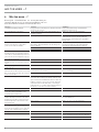 4
4
-
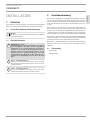 5
5
-
 6
6
-
 7
7
-
 8
8
-
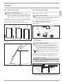 9
9
-
 10
10
-
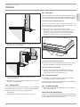 11
11
-
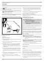 12
12
-
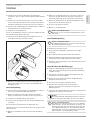 13
13
-
 14
14
-
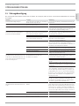 15
15
-
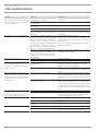 16
16
-
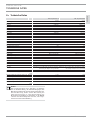 17
17
-
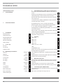 18
18
-
 19
19
-
 20
20
-
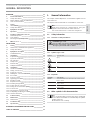 21
21
-
 22
22
-
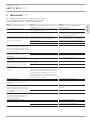 23
23
-
 24
24
-
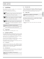 25
25
-
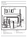 26
26
-
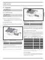 27
27
-
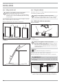 28
28
-
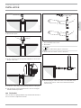 29
29
-
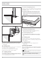 30
30
-
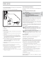 31
31
-
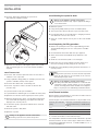 32
32
-
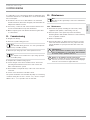 33
33
-
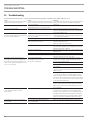 34
34
-
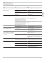 35
35
-
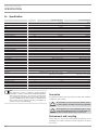 36
36
-
 37
37
-
 38
38
-
 39
39
-
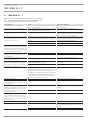 40
40
-
 41
41
-
 42
42
-
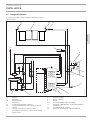 43
43
-
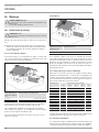 44
44
-
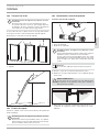 45
45
-
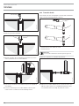 46
46
-
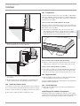 47
47
-
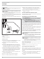 48
48
-
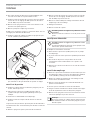 49
49
-
 50
50
-
 51
51
-
 52
52
-
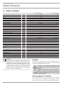 53
53
-
 54
54
-
 55
55
-
 56
56
-
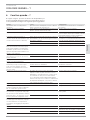 57
57
-
 58
58
-
 59
59
-
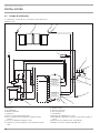 60
60
-
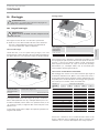 61
61
-
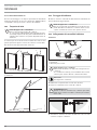 62
62
-
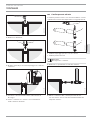 63
63
-
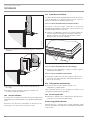 64
64
-
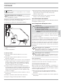 65
65
-
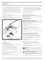 66
66
-
 67
67
-
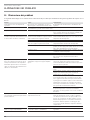 68
68
-
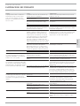 69
69
-
 70
70
-
 71
71
-
 72
72
-
 73
73
-
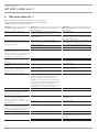 74
74
-
 75
75
-
 76
76
-
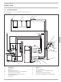 77
77
-
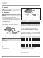 78
78
-
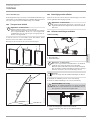 79
79
-
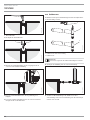 80
80
-
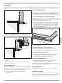 81
81
-
 82
82
-
 83
83
-
 84
84
-
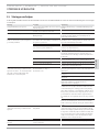 85
85
-
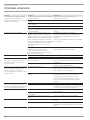 86
86
-
 87
87
-
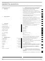 88
88
-
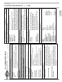 89
89
-
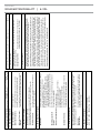 90
90
-
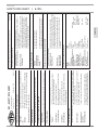 91
91
-
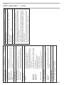 92
92
-
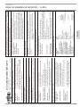 93
93
-
 94
94
-
 95
95
-
 96
96


STIEBEL ELTRON SOL 27 PREMIUM S Operation and Installation
- Type
- Operation and Installation
- Deze handleiding is ook geschikt voor
in andere talen
- italiano: STIEBEL ELTRON SOL 27 PREMIUM S
- français: STIEBEL ELTRON SOL 27 PREMIUM S
- Deutsch: STIEBEL ELTRON SOL 27 PREMIUM S
Gerelateerde artikelen
-
STIEBEL ELTRON SOL 27 basic Operation Instruction
-
-
-
-
-
-
Andere documenten
-
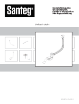 Santeg 62555 Installatie gids
-
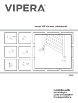 Vipera 28909 Installatie gids
-
Interline 57100030 Handleiding
-
Dometic TENT211 Installatie gids
-
Danfoss DWH Installatie gids
-
 Dantherm HCC 2 Handleiding
-
WAGNER HAWAII Handleiding
-
Daikin ECOLLECTRMV Operating Lnstructions
-
Wolf SEM-2 300 Assembly Instructions Manual
-
Honeywell E121 de handleiding


