
D301411 Issue 0 July 2021
Page 1 of 20
INSTALLATION INSTRUCTION – INSTRUCTION D’INSTALLATION
INSTALLATIE-INSTRUCTIE - MONTAGEVORSCHRIFT
PIVOTING WALL BRACKETS - CONSOLES DE SUSPENSION PIVOTANTES
DRAAIBARE WANDCONSOLES - WANDKONSOLE FÜR I-TRÄGER
For/pour/voor/für
PHOTON
Unit Heaters / Aeortherme a Gaz / Gasgestookte Luchtver /
Gas-Warmlufterzeuger
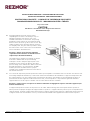
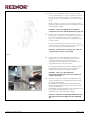
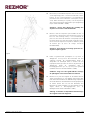
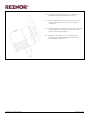
EN Pivoting wall brackets may be used for either
suspending the air heater or mounting on top. For
adequate mounting of the heater, refer to the
installation instructions for the heater. The pivoting
wall bracket offers solutions in cases where the fixed
brackets cannot be used e.g. due to lack of room. They
enable mounting of the unit either directly on wall or
an I-shaped profile. They also make it possible to install
the heater in the corner of the room to be heated and
turn it towards the desired direction.
Attention : always ensure that the minimum
required clearance distances around the unit are
respected (see Installation Manual).
The wall bracket is suitable for mounting on I-beams
from 140 to 180mm wide. A special fastening
technique is used to clamp the support plate of the
wall bracket to the I-beam. The Photon unit can be
placed or hung on the wall brackets. Where a flue runs
through the bracket to an outer wall, the gas WLE
must be placed on the wall bracket. For proper
installation, the installation instructions for the Photon
unit must be observed.
FR
Les consoles de suspension pivotants peuvent être utilisés pour suspendre le réchauffeur d'air ou le monter sur le dessus. Pour
un montage adéquat du réchauffeur, se référer aux instructions d'installation du réchauffeur. Le support mural pivotant offre
des solutions dans les cas où les supports fixes ne peuvent pas être utilisés, par exemple en raison du manque de place. Ils
permettent de monter l'appareil soit directement sur le mur, soit sur un profilé en I. Ils permettent également d'installer
l'appareil dans un coin de la pièce à chauffer et de le tourner dans la direction souhaitée.
Attention : veillez toujours à respecter les distances minimales de dégagement requises autour de l'appareil (voir
manuel d'installation).
Le support mural peut être monté sur des poutres en I de 140 à 180 mm de large. Une technique de fixation spéciale est
utilisée pour fixer la plaque de support du support mural à la poutre en I. L'appareil Photon peut être posé ou suspendu sur les
supports muraux. Lorsqu'un conduit d'évacuation traverse le support jusqu'à un mur extérieur, le WLE à gaz doit être placé sur
le support mural. Pour une installation correcte, les instructions d'installation de l'appareil Photon doivent être respectées.

D301411 Issue 0 July 2021
Page 2 of 20
NL
Om de luchtverhitter op te hangen of aan de bovenkant te monteren, kunnen draaibare muurbeugels worden gebruikt.
Raadpleeg voor de juiste montage van de verwarmer de montagehandleiding van de verwarmer. De draaibare muurbeugels
bieden oplossingen in gevallen waar de vaste beugels niet kunnen worden gebruikt, b.v. door ruimtegebrek. Zij maken de
montage van het toestel rechtstreeks op de muur of op een I-vormig profiel mogelijk. Ze maken het ook mogelijk om de
verwarmer in de hoek van de te verwarmen ruimte te installeren en hem in de gewenste richting te draaien.
Let op : zorg er altijd voor dat de minimaal vereiste vrije afstanden rondom het toestel in acht worden genomen
(zie Installatiehandleiding).
De muurbeugel is geschikt voor montage op I-balken van 140 tot 180 mm breed. Door middel van een speciale
bevestigingstechniek wordt de steunplaat van de muurbeugel aan de I-balk geklemd. De Photon unit kan op de muurbeugels
worden geplaatst of opgehangen. Daar waar een rookkanaal door de beugel naar een buitenmuur loopt, dient de gas WLE op
de muurbeugel geplaatst te worden. Voor een juiste installatie moeten de installatievoorschriften van de Photon-unit in acht
worden genomen.
DE Schwenkbare Wandhalterungen können entweder zur Aufhängung des Lufterhitzers oder zur Aufbaumontage verwendet
werden. Für die adäquate Montage des Lufterhitzers lesen Sie bitte die Montageanleitung des Lufterhitzers. Die schwenkbaren
Wandhalterungen bieten Lösungen für Fälle, in denen die festen Halterungen z. B. aus Platzmangel nicht verwendet werden
können. Sie ermöglichen die Montage des Geräts entweder direkt an der Wand oder an einem I-förmigen Profil. Sie
ermöglichen es auch, das Gerät in der Ecke des zu beheizenden Raumes zu installieren und in die gewünschte Richtung zu
drehen.
Achtung: Achten Sie immer darauf, dass die erforderlichen Mindestabstände um das Gerät herum eingehalten
werden (siehe Installationsanleitung).
Die Wandhalterung ist für die Montage an I-Trägern von 140 bis 180 mm Breite geeignet. Mit einer speziellen
Befestigungstechnik wird die Trägerplatte des Wandhalters an den I-Träger geklemmt. Das Photon-Gerät kann auf die
Wandhalterungen gestellt oder gehängt werden. Wenn ein Abgasrohr durch die Konsole zu einer Außenwand führt, muss die
Gas-WLE auf die Wandkonsole gestellt werden. Für eine ordnungsgemäße Installation muss die Installationsanleitung für das
Photon-Gerät beachtet werden.

D301411 Issue 0 July 2021
Page 3 of 20
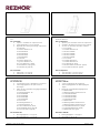
TYPE / TYP A PHOTON 10 and 20
TYPE / TYP B Photon 25 - 100
EN
The pivoting wall bracket set comprises two separate
kits:-
FR
L'ensemble de supports muraux pivotants est composé de
deux kits distincts:-
Kit 1 Contains
Kit 1 Comprend
• 3 parts to assemble the suspension arm
• 2 fastening plates to fix on support
• Bag with the following fastening components
6 x nut M10
3 x washer diameter 10
8 x bolt M10x20
6 x bolt M10x30
6 x bolt M12x60
1 x bolt M16x45
6 x nut M12
4 x washer diameter 6
1 x grower diamater 16
4 x screw diameter 4, 8x50
8 x bolt M8x16 (only Type B)
8 x nut M8 (only Type B)
• 3 pièces pour assembler le bras de suspension
• 2 plaques de fixation pour fixer sur le support
• Sac avec les éléments de fixation suivants
6 x écrou M10
3 x rondelle diamètre 10
8 x boulon M10x20
6 x boulon M10x30
6 x boulon M12x60
1 x boulon M16x45
6 x écrou M12
4 x rondelle diamètre 6
1 x rondelle diamètre 16
4 x vis diamètre 4, 8x50
8 x boulon M8x16 (seulement Type B)
8 x écrou M8 (seulement Type B)
Kit 2 Contains
Kit 2 Comprend
•
Fixing plate 1 for Type A
•
Fixing Plate 2 for Type B
•
Tôle de fixation 1 pour le type A
•
Tôle de fixation 2 pour le type B
NL
De draaibare muurbeugelset bestaat uit twee
afzonderlijke kits:-
DE
Das schwenkbare Wandhalterungsset besteht aus zwei
separaten Kits:-
Kit 1 bestaat uit
Bausatz 1 Enthält
• 3 onderdelen om de ophangarm te monteren
• 2 bevestigingsplaten om op de steun te
bevestigen
• Zakje met de volgende bevestigingsonderdelen
6 x moer M10
3 x sluitring diameter 10
8 x bout M10x20
6 x bout M10x30
6 x bout M12x60
1 x bout M16x45
6 x moer M12
4 x sluitring diameter 6
1 x sluitring diameter 16
4 x schroef diameter 4, 8x50
8 x bout M8x16 (alleen Type B)
8 x moer M8 (alleen Type B)
• 3 Teile zur Montage des Tragarmes
• 2 Befestigungsplatten zur Befestigung am
Träger
• Beutel mit folgenden Befestigungsteilen
6 x Mutter M10
3 x Unterlegscheibe Durchmesser 10
8 x Schraube M10x20
6 x Schraube M10x30
6 x Schraube M12x60
1 x Schraube M16x45
6 x Mutter M12
4 x Unterlegscheibe Durchmesser 6
1 x Unterlegscheibe Durchmesser 16
4 x Schraube Durchmesser 4, 8x50
8 x Schraube M8x16 (nur Typ B)
8 x Mutter M8 (nur Typ B)
Kit 2 bestaat uit
Bausatz 2 Enthält
•
Bevestigingsplaat 1 voor type A
• Bevestigingsplaat 2 voor type B
•
Befestigungsplatte 1 für Typ A
• Fixierplatte 2 für Typ B

D301411 Issue 0 July 2021
Page 4 of 20
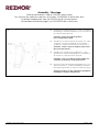
Assembly – Montage
Pivoting wall brackets used to SUSPEND the air heater
Des consoles de suspension rotatives utilisés pour SUSPENDRE le réchauffeur d'air
Draaibare wandconsoles voor het ZUIGEN van de luchtverwarmer
Schwenkbare Wandhalterungen zum SUSPENDEN des Lufterhitzers
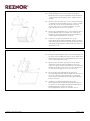
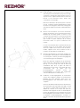
Fig 1
EN
Assemble the 3 wall bracket parts (1, 2 & 3) – use 6 bolts
M10x30 (B), 6 nuts M10 and washers (C). Ensure that bolts
have been properly tightened.
Attention : make sure smallest lip (D) of
part 3 is upwards mounted.
FR
Assembler les 3 éléments du bras de suspension (1, 2 & 3)
en utilisant : 6 boulons M10x30 (B), 6 écrous M10 &
rondelles (C). Vérifier que les boulons soient bien serrés.
Attention : veiller à ce que le membre le plus étroit
(D) soit monté en haut.
NL
Assembleer de 3 wandconsole-onderdelen (1, 2 & 3) –
gebruik hiertoe 6 bouten M10x30 (B), 6 moeren M10 en
de rondsels (C). Span alle bouten stevig vast.
Aandacht : zorg ervoor dat het smalste lid (D) van
onderdeel 3 naar boven wordt gemonteerd.
DE
Montieren Sie die 3 Bestandteile der Wandkonsole (1, 2 &
3) Dazu brauchen Sie : 6x Bolzen M10x30 (B), 6x Mutter
M10 & unterlegscheiben (C). Ziehen Sie alle Bolzen gut an.
Achtung : beachten Sie dass schmallest Stück (D)von
Bestandteil 3 aufwärts wird montiert.

D301411 Issue 0 July 2021
Page 5 of 20
Fig 2a
EN
Mount the pre-assembled suspension arm on the wall or
on the supporting profile – ensure horizontal arm is at the
bottom. In case of wall mounting it is recommended to
provide the back of the wall with a counter-plate (not part
of kit).
When mounting on a profile, lock the suspension arm on
the profile using 2 fixing profiles (pos 4) (tightening torque
6 bolts M12x60 =73Nm).
Attention : ensure that during the assembly the
suspension arm cannot slide downwards (see fig. 2b).
FR
Monter le bras de suspension pré-assemblé sur mur ou
profil porteur – Vérifier que le bras horizontal se trouve en
bas. Lors d’un montage mural, il est recommandé de
prévoir le côté arrière du mur d’une contreplaque (ne fait
pas partie du kit).
En cas d’un montage sur profil porteur, serrer le bras de
suspension au profil en utilisant 2 profils de fixation (pos 4)
(force de serrage 6 boulons M12x60=73Nm).
Attention : éviter durant le montage que le bras de
suspension puisse glisser (voir fig. 2b).
Fig 2b
NL
Plaats voorgemonteerde ophangarm nu op muur of
draagprofiel en zorg ervoor dat horizontale arm zich
onderaan bevindt. Bij muurbevestiging wordt er
aangeraden om achterzijde muur te voorzien van een
tegenplaat (maakt geen deel uit van kit).
Bij montage op draagprofiel wordt de ophangarm mbv 2
bevestigingsprofielen (pos 4) op het profiel geklemd
(aandraai-moment 6 bouten M12x60 = 73Nm).
Aandacht : zorg ervoor dat gedurende
de montage de ophangarm niet naar beneden kan
schuiven (zie fig 2b).
DE
Montieren Sie jetzt den Tragarm an der Wand oder am
Träger. Vergewissern Sie sich daβ den horizontalen Arm
nach unten wird installiert.
Bei Wandmontage empfehlen wir um die Rückseite der
Wand mit einem Gegenprofil aus zu statten (macht kein
Teil aus des Bausatzes).
Bei Montage am Träger klemmen Sie den Tragarm fest am
Träger mittels 2 Befestigungsprofile (Pos. 4)
(Anzugsmoment 6 Bolzen M12x60 = 73Nm).
Achtung : verhindern Sie daβ während der Montage
der Tragarm nicht kann abgleiten (sehe Abbildung
2b).

D301411 Issue 0 July 2021
Page 6 of 20
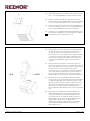
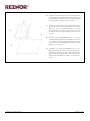
Fig 3a
Type/Typ A - Photon 10-20
EN
Install fixing plate (pos 5) on top panel using 4 bolts
M10x20. Ensure head of bolt M16x45 and grower (B) are
clamped between plate and top panel. Tighten all bolts
securely.
FR Monter la tôle de fixation (pos 5) sur le panneau supérieur
en utilisant 4 boulons M10x20. Veiller à ce que la rondelle
Grower (B) et la tête du boulon M16x45 soient bien
serrées entre la tôle et le panneau supérieur. Il est très
important de bien serrer tous les boulons.
NL
Monteer bevestigingsplaat (pos 5) op bovenpaneel mbv 4
bouten M10x20. Zorg ervoor dat de kop van de bout
M16x45 en de veerring (B) tussen plaat en bovenpaneel
worden geklemd. Draai bouten stevig aan.
DE Installieren Sie die Befestigunsplatte (Pos. 5) am
Deckenblech mittels 4 Bolzen M10x20. Achten Sie darauf
daβ Federring (B) und Bolzenkopf M16x45 geklemmt sind
zwischen Befestigungsplatte und Deckenblech. Ziehen Sie
alle Bolzen fest an.
Fig 3b
Type/Typ B – Photon 25-100
EN
Install the small fixing plate (A) on the large fixing plate (B)
by means of 8 bolts M8x16 & nuts (C). Ensure head of bolt
M16x45 and grower (D) are clamped between the 2 fixing
plates. Tighten all bolts securely.
FR
Monter la tôle de fixation la plus petite (A) sur la plus
grande (B) en utilisant 8 boulons M8x16 & écrous (C).
Veiller à ce que la rondelle Grower (D) et la tête du boulon
M16x45 soient bien serrées entre les 2 tôles de fixation. Il
est très important de bien serrer tous les boulons.
NL
Monteer kleine bevestigingsplaat (A) op de grote
bevestigingsplaat (B) mbv 8 bouten M8x16 en moeren (C).
Zorg ervoor dat kop van bout M16x45 en veerring (D)
tussen beide bevestigingsplaten worden geklemd. Draai
bouten stevig aan.
DE
Installieren Sie die Befestigunsplatte (A) an der
Befestigunsplatte (B) mittels 8 Bolzen M8x16 & Muttern
(C). Achten Sie darauf daβ Federring (D) und Bolzenkopf
M16x45 geklemmt sind zwischen beiden
Befestigungsplatten. Ziehen Sie alle Bolzen fest an.

D301411 Issue 0 July 2021
Page 7 of 20
Fig 3c
Type/Typ A & B
EN
Then install fixing plates assembly on the top panel of the
unit – use 4 bolts M10x20 (A). Tighten all bolts securely.
FR Ensuite, installer l’ensemble des tôles de fixation sur le
panneau supérieur de l’appareil. Utiliser 4 boulons M10x20
(A). Il est très important de bien serrer tous les boulons.
NL
Monteer vervolgens het geheel van de bevestigingsplaten
op het bovenpaneel van het toestel – maak hierbij gebruik
van 4 bouten M10x20 (A). Draai bouten stevig aan.
DE
Installieren Sie der Aufbau beiden Befestigungsplatten am
Deckenblech des Apparates. Hierfür brauchen Sie 4 Bolzen
M10x20 (A). Ziehen Sie alle Bolzen fest an.
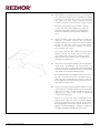
Fig 4
Type/Typ A & B
EN
Finally, fix the unit to the suspension arm. Bring nut M16
through the large hole located in the horizontal section
of the suspension arm until fixing plate touches the
horizontal section of the suspension arm. Tighten nut M16
securely but ensure that unit remains rotatable. Put the
heater in the required position and install on suspension
arm using 4 bolts M10x20. Tighten bolts & nut M16
securely.
FR
Monter finalement l’appareil sur le bras de suspension.
Mettre l’écrou M16 à travers le trou localisé dans la section
horizontale du bras de suspension jusqu’à ce que la tôle de
fixation touche la section horizontale du bras de
suspension. Serrer l’écrou M16 en vérifiant que l’appareil
reste rotatif. Mettre l’appareil dans la position désirée et
fixer le au bras de suspension par moyen de 4 boulons
M10x20. Après, serrer boulons et écrou M16 solidement.
NL
Bevestig nu toestel aan ophangarm. Breng moer M16
doorheen groot gat in horizontaal deel van de ophangarm
totdat bevestigingsplaat het horizontale gedeelte van de
ophangarm raakt. Draai moer M16 aan maar zorg ervoor
dat toestel kan gedraaid worden Breng het toestel in de
gewenste positie en bevestig aan ophangarm mbv 4
bouten M10x20. Draai daarna bouten en moer M16 stevig
aan.
DE
Befestigen Sie jetzt Apparat am Tragarm. Bringen Sie
Mutter M16 durch das Loch lokalisiert in horizontalen
Sektion des Tragarmes bis die Befestigungsplatte die
horizontale Sektion des Tragarmes berührt. Ziehen Sie
Mutter M16 an doch achten Sie darauf daβ Installation
drehbar bleibt. Bringen Sie den apparat in der
gewünschten Position und befestigen Sie an Tragarm
mittels 4 Bolzen M10x20. Ziehen Sie alle Bolzen &
Mutter M16 fest an.

D301411 Issue 0 July 2021
Page 8 of 20
Assembly – Montage
Pivoting wall brackets used to MOUNT the unit on top
Des consoles de suspension pivotantes utilisées pour MONTER l'appareil sur le dessus
Draaibare wandconsoles voor de MOUNT van de unit bovenop
Schwenkbare Wandhalterungen für die MONTAGE des Geräts an der Oberseite
Fig 5
EN
Assemble the 3 wall bracket parts (1, 2 & 3) – use : 6 bolts
M10x30 (B), 6 nuts M10 and washers (C). Ensure that
bolts have been properly tightened.
Attention : Make sure smallest lip (D) of part 3 is
upwards mounted.
FR Assembler les 3 éléments du bras de suspension (1, 2 & 3)
en
utilisant : 6 boulons M10x30 (B), 6 écrous M10 &
rondelles (C). Vérifier que les boulons soient bien serrés.
Attention : Veiller à ce que le membre le plus étroit (D)
soit monté en haut.
NL Assembleer de 3 wandconsole-onderdelen (1, 2 & 3) –
gebruik hiertoe 6 bouten M10x30 (B), 6 moeren M10 en
de rondsels (C). Span alle bouten stevig vast.
Aandacht : Zorg ervoor dat het smalste lid (D) van
onderdeel 3 naar boven wordt gemonteerd.
DE
Montieren Sie die 3 Bestandteile der Wandkonsole (1, 2 &
3) Dazu brauchen Sie : 6x Bolzen M10x30 (B), 6x Mutter
M10 & unterlegscheiben (C). Ziehen Sie alle Bolzen gut an.
Achtung : beachten Sie dass schmallest Stück (D)von
Bestandteil 3 aufwärts wird montiert.

D301411 Issue 0 July 2021
Page 9 of 20
Fig 6a
EN
Mount the pre-assembled suspension arm on the wall or
on the supporting profile – ensure horizontal arm is at the
bottom. In case of wall mounting it is recommended to
provide the back of the wall with a counter-plate (no part
of kit). When mounting on a profile, lock the suspension
arm on the profile using 2 fixing profiles (pos 4) (tightening
torque 6 bolts M12x60 = 73Nm).
Attention :
Ensure that during the assembly the
suspension arm cannot slide downwards.
FR
Monter le bras de suspension pré-assemblé sur mur ou
profil porteur – Vérifier que le bras horizontal se trouve en
bas. Lors d’un montage mural, il est
recommandé de
prévoir le côté arrière du mur d’une contreplaque (ne fait
pas partie du kit). En cas d’un montage sur profil porteur,
serrer le bras de suspension au profil en utilisant 2 profils
de fixation (pos 4) (force de serrage 6 boulons
M12x60=73Nm).
Attention : Eviter durant le montage que le bras de
suspension puisse glisser.
Fig 6b
NL
Plaats voorgemonteerde ophangarm nu op muur of
draagprofiel en zorg ervoor dat horizontale arm zich
onderaan bevindt. Bij muurbevestiging wordt er
aangeraden om achterzijde muur te voorzien van een
tegenplaat (maakt geen deel uit van kit). Bij montage op
draagprofiel wordt de ophangarm mbv 2
bevestigingsprofielen (pos 4) op het profiel geklemd
(aandraai-moment 6 bouten M12x60 is 73Nm).
Aandacht : Zorg ervoor dat gedurende de montage
de ophangarm niet naar beneden kan schuiven.
DE Montieren Sie jetzt den Tragarm an der Wand oder am
Träger. Vergewissern Sie sich daβ den horizontalen Arm
nach unten wird installiert. Bei Wandmontage empfehlen
wir um die Rückseite der Wand mit einem Gegenprofil aus
zu statten (macht kein Teil aus des
Bausatzes). Bei
Montage am Träger klemmen Sie den Tragarm fest am
Träger mittels 2 Bef
estigungsprofile (Pos. 4)
(Anzugsmoment 6 Bolzen M12x60 = 73Nm).
Achtung : Verhindern Sie daβ während der Montage
der Tragarm nicht kann abgleiten.

D301411 Issue 0 July 2021
Page 10 of 20
Fig 7a
Type / Typ A – Photon 10-20
EN
Install fixing plate on horizontal section of suspension
arm. Bring hereto bolt M16x45 (A) & grower through
central hole of fixing plate and horizontal section of
suspension arm – tighten nut M16 until it touches the
bottom of the horizontal section. Ensure that
construction is still rotatable.
Drill 4 holes dia 3mm in the bottom panel of the unit
(see fig. 13 and 14). Ensure that drilled holes match
the holes in the fixing plate. Install unit on fixing plate
& fix with the supplied screws dia, 4.8x50 and washer
dia. 6
FR
Monter la tôle de fixation sur la section horizontale
du bras de suspension. Pour cela il faut mettre boulon
M16x45 (A) & rondelle grower à travers le trou
central de la tôle de fixation et section horizontale du
bras de suspension. Serrer l’écrou M16 jusqu’à ce
qu’il touche la partie inférieure de la section
horizontale. Veiller à ce que la construction reste
rotative.
Forer 4 trous dia 3mm dans le panneau inférieur de
l’appareil (voir fig. 13 et 14). Vérifier que la position
des trous s’adapte aux trous de la tôle de fixation.
Installer l’appareil sur la tôle de fixation et fixer à
l’aide des vis dia 4,8x50 et rondelle dia 6.
NL
Plaats bevestigingsplaat op horizontale gedeelte van
de ophangarm – breng hiertoe de bout M16x45 (A)
en veerring door centrale gat van bevestigingsplaat
en horizontale ligger van ophangarm.
Draai moer M16 aan onderkant van de horizontale
ligger totdat deze onderkant horizontale ligger raakt
(zie fig. 13 en 14). Zorg ervoor dat de tafel nog
verdraaibaar blijft. Boor 4 gaten dia 3mm in
onderpaneel van het toestel – zorg hierbij dat positie
overeenstemt met de gaten van het
bevestigingspaneel. Monteer toestel op
bevestigingsplaat en bevestig met bijgeleverde
schroeven dia 4,8x50 en rondsels dia 6.
DE
Installieren Sie Befestigungsplatte an horizontalen
Sektion des Tragarmes. Bringen Sie hierzu Bolzen
M16x45 (A) und Federring durch Loch von
Befestigungsplatte und horizontalen Sektion des
Tragarms.
Ziehen Sie die Mutter M16 an bis diese die Unterseite
der horizontalen Sektion berührt (siehe Abb. 13 und
14). Achten Sie darauf daβ die Konstruktion noch
drhebar ist. Bohren Sie 4 Löcher dia 3mm im
Bodenblech des Apparats. Achten Sie darauf daβ die
Position der gebohrten Löcker und die Löcker in der
Befestigungsplatte miteinander stimmen. Montieren
Sie Apparat an Befestigungsplatte - brauchen Sie
dazu die Schrauben dia 4,8x50 und Unterlegscheiben
dia 6.

D301411 Issue 0 July 2021
Page 11 of 20
Fig 7b
Type / Typ B – Photon 25-100
EN
Install the small fixing plate (A) on the large fixing plate
(B) by means of 8 bolts M8x16 & nuts (C). Ensure head
of bolt M16x45 and grower (D) are clamped between
the 2 fixing plates. Tighten all bolts securely.
FR
Monter la tôle de fixation la plus petite (A) sur la plus
grande (B) en utilisant 8 boulons M8x16 & écrous (C).
Veiller à ce que la rondelle Grower (D) et la tête du
boulon M16x45 soient bien serrées entre les 2 tôles
de fixation. Il est très important de bien serrer tous les
boulons.
NL
Monteer kleine bevestigingsplaat (A) op de grote
bevestigingsplaat (B) mbv 8 bouten M8x16 en moeren
(C). Zorg ervoor dat kop van bout M16x45 en veerring
(D) tussen beide bevestigingsplaten worden geklemd.
Draai bouten stevig aan.
DE
Installieren Sie die Befestigunsplatte (A) an der
Befestigunsplatte (B) mittels 8 Bolzen M8x16 &
Muttern (C). Achten Sie darauf daβ Federring (D)
und Bolzenkopf M16x45 geklemmt sind zwischen
beiden Befestigungsplatten. Ziehen Sie alle Bolzen
fest an.

D301411 Issue 0 July 2021
Page 12 of 20
Fig 7c
Type/Typ A & B
EN
Fix the whole to the horizontal section of the suspension
arm – bring the threaded end of bolt M16x45 through the
central hole in the horizontal section of the suspension
arm. Tighten nut M16 securely
(underside horizontal
section) securely but ensure that whole remains rotatable.
Drill 4 holes dia 3mm in the bottom panel of the unit
(see fig. 14). Ensure that drilled holes match the
holes in the fixing plate. Install unit on fixing plate &
fix with the supplied screws dia, 4.8x50 and washer
dia. 6
FR
Monter l’ensemble sur la section horizontale du bras de
suspension en mettant l’embout fileté du boulon
M16x45 à travers le trou central de la section horizontale
du bras de suspension. Serrer l’écrou M16 (partie
inférieure section horizontale) solidement en vérifiant
que l’ensemble reste rotatif.
Forer 4 trous dia 3mm dans le panneau inférieur de
l’appareil (voir fig. 14). Vérifier que la position des
trous s’adapte aux trous de la tôle de fixation. Installer
l’appareil sur la tôle de fixation et fixer à l’aide des vis
dia 4,8x50 et rondelle dia 6.
NL Plaats geheel op horizontale gedeelte van de ophangarm –
breng hiertoe
draaduiteinde van bout M16x45 door
centrale gat in de horizontale ligger van de ophangarm.
Draai moer M16 aan (onderkant van de horizontale ligger)
maar waak erover dat geheel draaibaar blijft.
Boor 4 gaten dia 3mm in onderpaneel van het toestel (zie
fig. 14) – zorg hierbij dat positie overeenstemt met de
gaten van het bevestigingspaneel. Monteer toestel op
bevestigingsplaat en bevestig met bijgeleverde schroeven
dia 4,8x50 en rondsels dia 6.
DE
Stellen Sie das Ganze auf dem Tragarm. Bringen Sie hierzu
Fadenende Bolzen M16x45 durch Lock der horizontalen
Sektion des Tragarms. . Ziehen Sie Mutter M16 fest an
(Unterseite hor. Sektion) doch achten Sie darauf daβ
Installation drehbar bleibt.
Bohren Sie 4 Löcher dia 3mm im Bodenblech des
Apparats (siehe Abb. 14). Achten Sie darauf daβ die
Position der gebohrten Löcker und die Löcker in der
Befestigungsplatte miteinander stimmen. Montieren Sie
Apparat an Befestigungsplatte - brauchen Sie dazu die
Schrauben dia 4,8x50 und Unterlegscheiben dia 6.

D301411 Issue 0 July 2021
Page 13 of 20
Fig 8
Type/Typ A & B
EN Put heater in the required position – fix the 4 bolts
M10x20 (A) Tighten bolts & nut M16 securely.
FR
Mettre l’appareil dans la position désirée & fixer les 4
boulons M10x20 (A). Serrer boulons et écrou M16
solidement.
NL
Verdraai toestel tot de gewenste positie en bevestig de 4
bouten M10x20 (A) om tafel vast te klemmen. Draai
bouten en moer M16 stevig aan.
DE
Bringen Sie den apparat in der gewünschten &
befestigen Sie die 4 Bolzen M10x20. Ziehen Sie alle
Bolzen & Mutter M16 fest an.

D301411 Issue 0 July 2021
Page 14 of 20
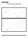
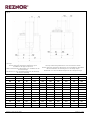
Dimensions – Afmetingen - Geräteabmessungen
Pivoting wall bracket - Console de suspension pivotante
Draaibare wandconsole -
Drehbare Wandkonsole
Photon 10 - 20
Side view - Vue de côté - Zijaanzicht – Seitenansicht
Fig 9
Front view – Vue de face – Vooraanzicht – Vorderansicht
Fig 10

D301411 Issue 0 July 2021
Page 15 of 20
Dimensions – Afmetingen - Geräteabmessungen
Pivoting wall bracket - Console de suspension pivotante
Draaibare wandconsole -
Drehbare Wandkonsole
Photon 25 - 100
Side view - Vue de côté - Zijaanzicht – Seitenansicht
Fig 11
Front view – Vue de face – Vooraanzicht – Vorderansicht
Fig 12

D301411 Issue 0 July 2021
Page 16 of 20
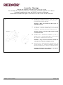
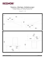
Dimensions – Afmetingen - Geräteabmessungen
Pivoting wall bracket with unit - Console de suspension pivotante avec l’appareil
Draaibare wandconsole met toestel - Drehbare Wandkonsole mit dem Gerät
Side view - Vue de côté - Zijaanzicht – Seitenansicht
Fig 13
Model
A
A1
C1
C2
E
F
K
Photon 10
413
215
584.5
388
350
450.5
380
Photon 20
413
215
584.5
388
350
450.5
660
Photon 25
623
265
611.5
468.5
600
463
520
Photon 35
623
265
611.5
468.5
600
463
520
Photon 45
623
265
611.5
468.5
600
463
520
Photon 55
623
265
611.5
468.5
600
463
733
Photon 65
623
265
611.5
468.5
600
463
733
Photon 70
623
265
611.5
468.5
600
463
800
Photon 100
623
265
611.5
468.5
600
463
1080
Photon 120
Not suitable for Photon 120

D301411 Issue 0 July 2021
Page 17 of 20
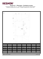
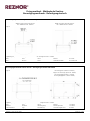
Top view - Vue de dessus - Bovenaanzicht – Draufsicht
Fig 14
EN Top view showing dimensions for top bracket install
FR Vue de dessus montrant les dimensions pour
l'installation du support supérieur
NL Bovenaanzicht met afmetingen voor installatie van de
bovenste beugel
DE Ansicht von oben mit Abmessungen für die Montage
der oberen Halterung
EN Top view showing dimensions for bottom bracket install
FR Vue de dessus montrant les dimensions pour l'installation du pédalier
NL Bovenaanzicht met afmetingen voor montage trapas
DE Ansicht von oben mit Abmessungen für die Tretlagermontage
Photon
10
20
25
35
45
55
65
70
100
B1
333
333
434
434
434
434
434
434
434
B2
80
80
189
189
189
189
189
189
189
B3
14
14
32
32
32
32
32
32
32
B4
333
333
338
338
338
338
338
338
338
B5
80
80
285
285
285
285
285
285
285
J
700
700
970
970
970
970
970
970
1010
J1
347
347
466
466
466
466
466
466
466
J2
353
353
504
504
504
504
504
504
544
J3
94
94
370
370
370
370
370
370
370
J4
259
259
600
600
600
600
600
600
600
Y1
167
167
304
304
304
304
304
304
301
Y2
76
76
63
63
63
63
63
63
47
Y3
76
76
400
400
400
400
400
400
397

D301411 Issue 0 July 2021
Page 18 of 20
Fixing method – Méthode de fixation
Bevestigingsmethode - Befestigungstechnik
With I-shaped profile – Avec profilé en I – Met I-profiel – Mit I-Profil
Width / Largeur / Breedte / Breite
min. 100mm & max. 180mm
Width / Largeur / Breedte / Breite
min. 100mm & max. 180mm
Fig 15
Tightening torque – Force de serrage – Aandraaimoment – Anzugsmoment = 73 Nm
Nut
Ecru
More
Mutter
6 x M12
Bolt
Boulon
Bout
Gewindeschraube
6 x M12 x 60
Fixing method hrough the wall – Méthode de fixation à travers le mur
Bevestigingsmethode doorheen de muur – Befestigungstecnik durch die Wand
Fig 16
Mounting plate (thickness 10mm)
Support de montage (épaisseur 10mm)
Bevestigingsplaat (dikte = 10mm)
Befestigungsplatte ( Stärke 10mm)
Tightening torque – Force de serrage – Aandraaimoment – Anzugsmoment = 73 Nm
Nut
Ecru
Moer
Mutter
12 x M12
Washer
Rondelle
Onderlegring
Unterlegscheibe
12 x M12
Threaded Rod
Tige
Draadstang
Verankerungsbolzen
6 x M12

D301411 Issue 0 July 2021
Page 19 of 20
NOTES

NORTEK GLOBAL HVAC (UK) LTD
Fens Pool Avenue
Brierley Hill
West Midlands DY5 1QA
United Kingdom
Tel +44 (0)1384 489700
Fax +44 (0)1384 489707
reznorsales@nortek.com
www.reznor.eu
Current full Part No.
Installation Instruction Pivoting Wall Brackets
EN/FR/NL/DE July 2021 D301411 Issue 0
Nortek Global HVAC is a registered trademark of Nortek Global HVAC Limited. Because of the continuous product innovation,
Nortek Global HVAC reserves the right to change product specification without due notice.
-
 1
1
-
 2
2
-
 3
3
-
 4
4
-
 5
5
-
 6
6
-
 7
7
-
 8
8
-
 9
9
-
 10
10
-
 11
11
-
 12
12
-
 13
13
-
 14
14
-
 15
15
-
 16
16
-
 17
17
-
 18
18
-
 19
19
-
 20
20


in andere talen
- English: Reznor UH28-R User manual
- français: Reznor UH28-R Manuel utilisateur
- Deutsch: Reznor UH28-R Benutzerhandbuch


