
VIDEO2
PHONES
SILENT
VIDEO L AUDIO OPTICALR
STANDBY/ON
MEMORY
AUTO/MAN'L
A/B/C/D/E
PRESET/BAND PRESET/TUNING
STEREO
DSP
INPUT
VOLUME
+
–
INPUT MODE
HOME THEATER SOUND SYSTEM
AVX-S80
AVX-S80: AVR-S80 + NX-S80S + NX-S80C + SW-S80
OWNER’S MANUAL
U B
101_S80_H14(UB) 02.5.27, 9:03 PM3

CAUTION
• Explanation of Graphical Symbols
The lightning flash with arrowhead symbol, within
an equilateral triangle, is intended to alert you to the
presence of uninsulated “dangerous voltage” within
the product’s enclosure that may be of sufficient
magnitude to constitute a risk of electric shock to
persons.
The exclamation point within an equilateral triangle
is intended to alert you to the presence of important
operating and maintenance (servicing) instructions in
the literature accompanying the appliance.
WARNING
TO REDUCE THE RISK OF FIRE OR ELECTRIC SHOCK,
DO NOT EXPOSE THIS UNIT TO RAIN OR MOISTURE.
CAUTION
RISK OF ELECTRIC SHOCK
DO NOT OPEN
CAUTION: TO REDUCE THE RISK OF
ELECTRIC SHOCK, DO NOT REMOVE
COVER (OR BACK). NO USER-SERVICEABLE
PARTS INSIDE. REFER SERVICING TO QUALIFIED
SERVICE PERSONNEL.
IMPORTANT SAFETY INSTRUCTIONS
1 Read Instructions – All the safety and operating instructions
should be read before the product is operated.
2 Retain Instructions – The safety and operating instructions
should be retained for future reference.
3 Heed Warnings – All warnings on the product and in the
operating instructions should be adhered to.
4 Follow Instructions – All operating and use instructions
should be followed.
5 Cleaning – Unplug this product from the wall outlet before
cleaning. Do not use liquid cleaners or aerosol cleaners.
Use a damp cloth for cleaning.
6 Attachments – Do not use attachments not recommended
by the product manufacturer as they may cause hazards.
7 Water and Moisture – Do not use this product near water –
for example, near a bath tub, wash bowl, kitchen sink, or
laundry tub; in a wet basement; or near a swimming pool;
and the like.
8 Accessories – Do not place this product on an unstable cart,
stand, tripod, bracket, or table. The product may fall,
causing serious injury to a child or adult, and serious
damage to the product. Use only with a cart, stand, tripod,
bracket, or table recommended by the manufacturer, or sold
with the product. Any mounting of the product should
follow the manufacturer’s instructions, and should use a
mounting accessory recommended by the manufacturer.
9 A product and cart combination should be
moved with care. Quick stops, excessive
force, and uneven surfaces may cause the
product and cart combination to overturn.
10 Ventilation – Slots and openings in the cabinet are provided
for ventilation and to ensure reliable operation of the
product and to protect it from overheating, and these
openings must not be blocked or covered. The openings
should never be blocked by placing the product on a bed,
sofa, rug, or other similar surface. This product should not
be placed in a built-in installation such as a bookcase or
rack unless proper ventilation is provided or the
manufacturer’s instructions have been adhered to.
11 Power Sources – This product should be operated only from
the type of power source indicated on the marking label. If
you are not sure of the type of power supply to your home,
consult your product dealer or local power company. For
products intended to operate from battery power, or other
sources, refer to the operating instructions.
12 Grounding or Polarization – This product may be equipped
with a polarized alternating current line plug (a plug having
one blade wider than the other). This plug will fit into the
power outlet only one way. This is a safety feature. If you
are unable to insert the plug fully into the outlet, try
reversing the plug. If the plug should still fail to fit, contact
your electrician to replace your obsolete outlet. Do not
defeat the safety purpose of the polarized plug.
13 Power-Cord Protection – Power-supply cords should be
routed so that they are not likely to be walked on or pinched
by items placed upon or against them, paying particular
attention to cords at plugs, convenience receptacles, and the
point where they exit from the product.
14 Lightning – For added protection for this product during a
lightning storm, or when it is left unattended and unused for
long periods of time, unplug it from the wall outlet and
disconnect the antenna or cable system. This will prevent
damage to the product due to lightning and power-line
surges.
15 Power Lines – An outside antenna system should not be
located in the vicinity of overhead power lines or other
electric light or power circuits, or where it can fall into such
power lines or circuits. When installing an outside antenna
system, extreme care should be taken to keep from touching
such power lines or circuits as contact with them might be
fatal.
16 Overloading – Do not overload wall outlets, extension
cords, or integral convenience receptacles as this can result
in a risk of fire or electric shock.
17 Object and Liquid Entry – Never push objects of any kind
into this product through openings as they may touch
dangerous voltage points or short-out parts that could result
in a fire or electric shock. Never spill liquid of any kind on
the product.
18 Servicing – Do not attempt to service this product yourself
as opening or removing covers may expose you to
dangerous voltage or other hazards. Refer all servicing to
qualified service personnel.
19 Damage Requiring Service – Unplug this product from the
wall outlet and refer servicing to qualified service personnel
under the following conditions:
a) When the power-supply cord or plug is damaged,
b) If liquid has been spilled, or objects have fallen into
the product,
c) If the product has been exposed to rain or water,
102_S80_Cau(UB) (5.1)b 02.5.27, 9:04 PM2

CAUTION
d) If the product does not operate normally by following
the operating instructions. Adjust only those controls
that are covered by the operating instructions as an
improper adjustment of other controls may result in
damage and will often require extensive work by a
qualified technician to restore the product to its normal
operation,
e) If the product has been dropped or damaged in any
way, and
f) When the product exhibits a distinct change in
performance - this indicates a need for service.
20 Replacement Parts – When replacement parts are required,
be sure the service technician has used replacement parts
specified by the manufacturer or have the same
characteristics as the original part. Unauthorized
substitutions may result in fire, electric shock, or other
hazards.
21 Safety Check – Upon completion of any service or repairs
to this product, ask the service technician to perform safety
checks to determine that the product is in proper operating
condition.
22 Wall or Ceiling Mounting – The unit should be mounted to
a wall or ceiling only as recommended by the manufacturer.
23 Heat – The product should be situated away from heat
sources such as radiators, heat registers, stoves, or other
products (including amplifiers) that produce heat.
24 Outdoor Antenna Grounding – If an outside antenna or
cable system is connected to the product, be sure the
antenna or cable system is grounded so as to provide some
protection against voltage surges and built-up static charges.
Article 810 of the National Electrical Code, ANSI/NFPA
70, provides information with regard to proper grounding of
the mast and supporting structure, grounding of the lead-in
wire to an antenna discharge unit, size of grounding
conductors, location of antenna discharge unit, connection
to grounding electrodes, and requirements for the
grounding electrode.
EXAMPLE OF ANTENNA GROUNDING
MAST
GROUND
CLAMP
ANTENNA
LEAD IN
WIRE
ANTENNA
DISCHARGE UNIT
(NEC SECTION 810–20)
GROUNDING CONDUCTORS
(NEC SECTION 810–21)
GROUND CLAMPS
POWER SERVICE GROUNDING
ELECTRODE SYSTEM
(NEC ART 250. PART H)
ELECTRIC
SERVICE
EQUIPMENT
NEC – NATIONAL ELECTRICAL CODE
1. IMPORTANT NOTICE : DO NOT MODIFY THIS
UNIT!
This product, when installed as indicated in the
instructions contained in this manual, meets FCC
requirements. Modifications not expressly approved
by Yamaha may void your authority, granted by the
FCC, to use the product.
2. IMPORTANT : When connecting this product to
accessories and/or another product use only high
quality shielded cables. Cable/s supplied with this
product MUST be used. Follow all installation
instructions. Failure to follow instructions could void
your FCC authorization to use this product in the USA.
3. NOTE : This product has been tested and found to
comply with the requirements listed in FCC
Regulations, Part 15 for Class “B” digital devices.
Compliance with these requirements provides a
reasonable level of assurance that your use of this
product in a residential environment will not result in
harmful interference with other electronic devices.
This equipment generates/uses radio frequencies and,
if not installed and used according to the instructions
found in the users manual, may cause interference
harmful to the operation of other electronic devices.
Compliance with FCC regulations does not guarantee
that interference will not occur in all installations. If
this product is found to be the source of interference,
which can be determined by turning the unit “OFF” and
“ON”, please try to eliminate the problem by using one
of the following measures:
Relocate either this product or the device that is being
affected by the interference.
Utilize power outlets that are on different branch (circuit
breaker or fuse) circuits or install AC line filter/s.
In the case of radio or TV interference, relocate/reorient
the antenna. If the antenna lead-in is 300 ohm ribbon
lead, change the lead-in to coaxial type cable.
If these corrective measures do not produce satisfactory
results, please contact the local retailer authorized to
distribute this type of product. If you can not locate the
appropriate retailer, please contact Yamaha Electronics
Corp., U.S.A. 6660 Orangethorpe Ave, Buena Park, CA
90620.
The above statements apply ONLY to those products
distributed by Yamaha Corporation of America or its
subsidiaries.
FCC INFORMATION (for US customers)
Note to CATV system installer:
This reminder is provided to call the CATV system installer’s
attention to Article 820-40 of the NEC that provides
guidelines for proper grounding and, in particular, specifies
that the cable ground shall be connected to the grounding
system of the building, as close to the point of cable entry as
practical.
102_S80_Cau(UB) (5.1)b 02.5.27, 9:04 PM3

CAUTION
1 To assure the finest performance, please read this manual
carefully. Keep it in a safe place for future reference.
2 Install this sound system in a well ventilated, cool, dry, clean
place with at least 5 cm on the top, 5 cm on the left and right,
and 5 cm at the back of AVR-S80, and 20 cm on the top, 10 cm
on the left and right, and 10 cm at the back of SW-S80 — away
from direct sunlight, heat sources, vibration, dust, moisture, and/
or cold.
3 Locate this system away from other electrical appliances,
motors, or transformers to avoid humming sounds. To prevent
fire or electrical shock, do not place this system where it may get
exposed to dripping or splashing, and never put any objects filled
with liquids, such as vases, on the top of the system.
4 Do not expose this system to sudden temperature changes from
cold to hot, and do not locate this system in a environment with
high humidity (i.e. a room with a humidifier) to prevent
condensation inside this system, which may cause an electrical
shock, fire, damage to this system, and/or personal injury.
5 Avoid installing this system in a place where foreign objects and
liquid might fall. It might cause a fire, damage to this system
and/or personal injury. Do not place the following objects on this
system:
– Other components, as they may cause damage and/or
discoloration on the surface of this system.
– Burning objects (i.e. candles), as they may cause fire, damage
to this system, and/or personal injury.
– Containers with liquid in them, as they may cause electrical
shock to the user and/or damage to this system.
6 Do not cover this system with a newspaper, tablecloth, curtain,
etc. in order not to obstruct heat radiation. If the temperature
inside this system rises, it may cause fire, damage to this system,
and/or personal injury.
7 Do not plug in this system to a wall outlet until all connections
are complete.
8 Do not operate this system upside-down. It may overheat,
possibly causing damage.
9 Do not use force on switches, knobs and/or cords.
10 When disconnecting the power cord from the wall outlet, grasp
the plug; do not pull the cord.
11 Do not clean this system with chemical solvents; this might
damage the finish. Use a clean, dry cloth.
12 Only voltage specified on this system must be used. Using this
system with a higher voltage than specified is dangerous and
may cause fire, damage to this system, and/or personal injury.
YAMAHA will not be held responsible for any damage resulting
from use of this system with a voltage other than specified.
13 To prevent damage by lightning, disconnect the power cord from
the wall outlet during an electrical storm.
14 Take care of this system so that no foreign objects and/or liquid
drops inside this system.
15 Do not attempt to modify or fix this system. Contact qualified
YAMAHA service personnel when any service is needed. The
cabinet should never be opened for any reasons.
16 When µanning to use this system for long periods of time (i.e.
vacation), disconnect the AC power plug from the wall outlet.
17
Be sure to read the “TROUBLESHOOTING” section on common
operating errors before concluding that this system is faulty.
18 Before moving this system, press STANDBY/ON to set this
system in the standby mode, and disconnect the AC power plug
from the wall outlet.
CAUTION: READ THIS BEFORE OPERATING YOUR SYSTEM.
This system is not disconnected from the AC power source as long
as it is connected to the wall outlet, even if this system itself is
turned off. This state is called the standby mode. In this state, this
system is designed to consume a very small quantity of power.
IMPORTANT
Please record the serial number of this system in the space below.
MODEL:
Serial No.:
The serial number is located on the bottom of AVR-S80 and the
rear of SW-S80.
Retain this Owner’s Manual in a safe place for future reference.
YAMAHA and the Electronic Industries Association’s Consumer
Electronics Group want you to get the most out of your equipment by
playing it at a safe level. One that lets the sound come through loud
and clear without annoying blaring or distortion – and, most
importantly, without affecting your sensitive hearing.
Since hearing damage from loud sounds is often
undetectable until it is too late, YAMAHA and the
Electronic Industries Association’s Consumer
Electronics Group recommend you to avoid prolonged
exposure from excessive volume levels.
We Want You Listening For A Lifetime
■ For U.K. customers
If the socket outlets in the home are not suitable for the plug supplied
with this appliance, it should be cut off and an appropriate 3 pin plug
fitted. For details, refer to the instructions described below.
Note
• The plug severed from the mains lead must be destroyed, as a plug
with bared flexible cord is hazardous if engaged in a live socket
outlet.
■ Special Instructions for U.K. Model
IMPORTANT
THE WIRES IN MAINS LEAD ARE COLOURED IN
ACCORDANCE WITH THE FOLLOWING CODE:
Blue: NEUTRAL
Brown: LIVE
As the colours of the wires in the mains lead of this apparatus
may not correspond with the coloured markings identifying the
terminals in your plug, proceed as follows:
The wire which is coloured BLUE must be connected to the
terminal which is marked with the letter N or coloured BLACK.
The wire which is coloured BROWN must be connected to the
terminal which is marked with the letter L or coloured RED.
Making sure that neither core is connected to the earth terminal of
the three pin plug.
The name plate is located on the bottom of AVR-S80.
FREQUENCY STEP switch
(China, Korean and General models only)
Because the interstation frequency spacing
differs in different areas, set the
FREQUENCY STEP switch (locating at the
rear of AVR-S80) according to the frequency
spacing in your area.
North, Central and South America: 100 kHz/10 kHz
Other area: 50 kHz/9 kHz
Before setting this switch, disconnect the AC power plug of this
system from the AC outlet.
FREQUENCY STEP
50
K
Hz
100
K
Hz
FM
9
K
Hz
10
K
Hz
AM
102_S80_Cau(UB) (5.30)a 02.5.30, 1:15 PM4

1
English
CONTENTS
INTRODUCTION
INTRODUCTION ............................................................... 2
FEATURES .......................................................................... 2
CHECKING THE ACCESSORIES ................................... 3
INSTALLING BATTERIES IN THE REMOTE
CONTROL ........................................................................... 3
CONTROLS AND FUNCTIONS ....................................... 4
Front panel ......................................................................... 4
Remote control .................................................................. 5
Front panel display ............................................................ 7
PREPARATION
PREPARATION STEPS ..................................................... 8
SPEAKER SETUP ............................................................... 9
Speaker placement ............................................................. 9
Installing the speakers ..................................................... 10
CONNECTIONS ................................................................ 12
Connecting TV and audio/video components ................. 12
Connecting the antennas .................................................. 14
Connecting the speakers .................................................. 15
Connecting to an external amplifier ................................ 17
Connecting the AC power cord ........................................ 17
Turning on the power....................................................... 17
ADJUSTING SPEAKER OUTPUT LEVELS ................ 18
Using the test tone ........................................................... 18
USING BASIC FUNCTIONS
BASIC PLAYBACK .......................................................... 19
Basic operations............................................................... 19
Selecting a sound field program ...................................... 21
RECORDING .................................................................... 26
TUNING
TUNING ............................................................................. 27
Automatic and manual tuning ......................................... 27
Presetting stations ............................................................ 28
Exchanging preset stations .............................................. 29
Tuning in to a preset station ............................................ 29
RECEIVING RDS STATIONS
(U.K. and Europe models only) ......................................... 30
Description of RDS data .................................................. 30
Changing the RDS mode ................................................. 31
PTY SEEK function ........................................................ 31
REMOTE CONTROL FEATURES
OPERATING OTHER COMPONENTS USING THE
REMOTE CONTROL ....................................................... 32
Setting the manufacturer code ......................................... 32
Other component controlling functions ........................... 33
ADJUSTMENTS
SET MENU ......................................................................... 35
List of SET MENU items ................................................ 35
Adjusting the items on the SET MENU .......................... 35
1 SPEAKER SET (speaker mode settings) .................... 36
2 LFE LEVEL ................................................................ 37
3 SP DLY TIME (speaker delay time) ........................... 38
4 D. RANGE (dynamic range) ....................................... 38
5 L/R BALANCE (balance of the front left and right
speakers) ...................................................................... 38
6 HP TONE CTRL (headphone tone control) ................ 38
7 INPUT MODE (initial input mode) ............................ 39
8 DISPLAY SET (brightness of front panel display) ..... 39
9 SP/PRE OUT (output source settings) ........................ 39
ADJUSTING THE LEVEL OF THE EFFECT
SPEAKERS ........................................................................ 40
CHANGING THE PARAMETER SETTINGS FOR DSP
PROGRAMS ...................................................................... 41
Adjusting the delay time .................................................. 41
Adjusting the parameter settings for PRO LOGIC II
Music ............................................................................... 42
APPENDIX
TROUBLESHOOTING .................................................... 43
GLOSSARY ....................................................................... 46
SPECIFICATIONS ............................................................ 47
E2-S80-1-7(6.29)b 02.6.29, 4:31 AM1

2
FEATURES
The AVX-S80 is the Home Theater Sound System that delivers a powerful and realistic sound experience like that found
in a movie theater just by combining the system with the TV.
The newest DSP programs will enhance the power and realism of various sources, from movies to concerts, and
sporting events. Also, the SILENT CINEMA DSP program allows you to enjoy the sound field even through the
headphones.
Since the AVX-S80 consists of an AV receiver, a center speaker, front speakers, rear speakers and a subwoofer, you can
enjoy stronger bass and surround effects as well as a good balance throughout the speakers. Moreover, the One-touch
connection of the speaker connectors designed exclusively for this system allows you to easily connect the speakers.
◆ Dolby Pro Logic/Dolby Pro Logic II decoder
◆ Dolby Digital/Dolby Digital + Matrix 6.1
decoder
◆ DTS/DTS + Matrix 6.1 decoder
◆ CINEMA DSP: Combination of YAMAHA DSP
technology and Dolby Pro Logic, Dolby Digital
or DTS
◆ Virtual CINEMA DSP
◆ SILENT CINEMA DSP
◆ Built-in 5.1-channel power amplifier
◆ Sophisticated FM/AM tuner
◆ Multi-function remote control which can also be
used for other AV components of certain
manufacturers
■ About this manual
• y indicates a tip for your operation.
• Some operations can be performed by using the buttons
on either the main unit or the remote control. In this
case, the operations performed by using the remote
control are described in this manual.
• This manual is printed prior to production. Design and
specifications are subject to change in part for the
reason of the improvement in operativity ability, and
others. In this case, the product has priority.
• Some of the illustrations and names of the package
contents etc. written in this manual may differ from the
actual products and the names written on the package
etc.
Manufactured under license from Dolby Laboratories.
“Dolby”, “Pro Logic”, and the double-D symbol are
trademarks of Dolby Laboratories.
“DTS” and “DTS Digital Surround” are registered
trademarks of Digital Theater Systems, Inc.
INTRODUCTION
Thank you for purchasing this YAMAHA product. We
hope it will give you many years of trouble-free
enjoyment. For the best performance, read this manual
carefully. It will guide you in operating your YAMAHA
product.
This product is a home theater sound system consisting of
the components shown on the table at right.
Please check the all components are contained without
fail by referring to the table.
Model name
Category No. of pcs.
AVR-S80 AV receiver 1
NX-S80S Speaker (for front/rear) 4
NX-S80C Center speaker 1
SW-S80 Subwoofer 1
E2-S80-1-7(6.29)b 02.6.29, 4:31 AM2

3
INTRODUCTION
English
CHECKING THE ACCESSORIES
Check your package to make sure it contains the following items.
AVR-S80
Remote control Batteries (x2)
(AA, R06, UM-3)
AM loop antenna
Indoor FM antenna
(U.S.A., Canada,
China, Korean and
General models)
(Europe, U.K. and
Australia models)
NX-SW80 (NX-S80S x4, NX-S80C, SW-S80)
Fasteners (2 sets)
for the center
speaker
Speaker cables
(for the rear speakers: 15m (x2),
for the front/center speaker:
5m (x3))
System control cable
(5m x 1)
INSTALLING BATTERIES IN THE REMOTE CONTROL
Insert the batteries in the correct direction by aligning the
+ and – marks on the batteries with the polarity markings
(+ and –) inside the battery compartment.
1 Press the part and slide off the battery
compartment cover.
2 Insert the two batteries (AA, R06, UM-3 type)
with + and – oriented properly.
3 Slide the cover back on so that it snaps into
place.
1
3
2
■ Notes on batteries
• Change all of the batteries if you notice a decrease in
the operating range of the remote control.
• Do not use old batteries together with new ones.
• Do not use different types of batteries (such as alkaline
and manganese batteries) together. Read the packaging
carefully as these different types of batteries may have
the same shape and color.
• If the batteries have leaked, dispose of them
immediately. Avoid touching the leaked material or
letting it come into contact with clothing, etc. Clean the
battery compartment thoroughly before installing new
batteries.
Preserving the manufacturer code
Replace batteries early before they become unusable.
The manufacturer code set by the user will be
preserved for about two minutes when batteries run
out or when they are removed. Note that the
manufacturer code setting may be lost if more than
two minutes elapses. Also, if you press any button on
the remote control accidentally while replacing
batteries, the manufacturer code setting will be lost.
Non-skid pads
(2 sets: 16 pieces)
Screws
(4 pieces)
Optical cable Video pin cable Connection guide
Mounting
brackets
(4 pieces)
AV X - S 8 0
CONNECTION GUIDE
*1 : Insert the plug with its mark facing up.
Connecting to a TV (monitor), DVD player, video camera
and video game player
Printed in Malaysia V969790
FRONT REAR CENTER
DIGITAL AUDIO IN
DVD/CD
OPTICAL OPTICAL
VIDEO 1
AM ANTFM ANT GND
SYSTEM
CONNECTOR
6CH PREOUT
VCR OUT
MONITOR
OUT
VIDEO 1 IN
VIDEO VIDEO
VCR IN
DVD/CD IN
TO SW–S80
R L
R
L
R L
MARK
75Ω UNBAL.
SUBWOOFER
S VIDEO
VIDEO OUT
VIDEO
AUDIO OUT
SUBWOOFER
MIXED 2CH
COMPONENT
VIDEO
P
B
P
R
Y
L
R
PCM/ DIGITAL
DTS
DIGITAL
AUDIO OUT
OPTICAL
AC IN
~
VIDEO INPUT
VIDEO
OUTPUT
Video pin cable
(included)
Optical cable
(included)
OPTICAL
OUTPUT
VIDEO
OUTPUT
VIDEO
INPUT
Video pin cable (not included)
+– +– +–
+–
–+
REAR
CENTERFRONT FRONT
(GREEN)
(WHITE)
(BLUE)
(SURROUND)
SPEAKER IMPEDANCE : 6ΩMIN.
(GRAY)
(RED)
R L
L
R
SPEAKERS
MARK
SYSTEM
CONNECTOR
TO AVR-S80
System control cable (included)
Speaker cable (included)
Speaker cable (included)
Speaker
cable
(included)
Speaker
cable
(included)
Speaker
cable
(included)
FRONT R
REAR R
REAR L
CENTER
FRONT L
(WHITE)(RED)(BLUE)(GRAY)
(GREEN)
DVD player TV (monitor)
Subwoofer (SW-S80) Rear speaker (R)
(NX-S80S)
Front speaker (R)
(NX-S80S)
Front speaker (L)
(NX-S80S)
Rear speaker (L)
(NX-S80S)
Center speaker
(NX-S80C)
AV receiver (AVR-S80) Rear panel (U.S.A. model)
*1
*1
Video game player
Video camera
AV receiver (AVR-S80) Front panel
VIDEO
OUTPUT
OPTICAL
VIDEO2
PHONES
SILENT
VIDEO L AUDIO OPTICALR
STANDBY/ON
MEMORY
AUTO/MAN'L
AUDIO
OUTPUT
VIDEO
OUTPUT
L
R
Connect either
to AVR-S80.
Optical cable (not included)
Video pin cable (not included)
Video pin cable
(not included)
Audio pin cable (not included)
E2-S80-1-7(6.29)b 02.6.29, 4:31 AM3

4
CONTROLS AND FUNCTIONS
Front panel
VIDEO2
PHONES
SILENT
VIDEO L AUDIO OPTICALR
STANDBY/ON
MEMORY
AUTO/MAN'L
A/B/C/D/E
PRESET/BAND PRESET/TUNING
STEREO
DSP
INPUT
VOLUME
+
–
INPUT MODE
12 3 45
8
9 0 e r tq w6 7
1 STANDBY/ON
Turns this system on, or set it to the standby mode. When
you turn this system on, you will hear a click and there
will be a 4 to 5-second delay before this system can
reproduce sound.
Standby mode
In this mode, this system will consume a small amount
of power in order to receive infrared-signals from the
remote control.
2 Remote control sensor
Receives signals from the remote control.
3 Front panel display
Shows information about the operational status of this
system.
4 STEREO
Switches between normal stereo and DSP effect
reproduction. When STEREO is selected, 2-channel
signals are directed to the front left and right speakers
without effect sounds.
5 VOLUME +/–
Controls the output level of all audio channels.
This does not affect the output level at the VCR OUT
jacks.
6 PHONES (
SILENT)
Allows you enjoy DSP effect for private listening with
headphones. When you connect headphones, no signals
are output to the speakers.
7 VIDEO 2 jacks
These jacks are for connecting a video component such as
a camcorder or video game player. To select the
component connected to these jacks, select “VIDEO2”
with the INPUT button.
8 MEMORY
Stores the current station in the memory.
9 AUTO/MAN’L
Switches the tuning mode between automatic and manual.
0 A/B/C/D/E
Selects preset station groups A to E.
q PRESET/BAND
Switches the reception band between FM and AM and
also the mode between the tuning mode and the preset
mode.
w d PRESET/TUNING u
Selects preset station numbers 1 to 8 or the tuning
frequency.
e DSP
Selects the DSP program. This button is disabled when
the stereo mode is selected by the STEREO button.
r INPUT
Selects the input source you want to listen to or watch.
t INPUT MODE
Sets the priority for the types of input signals (AUTO,
DTS, ANALOG) to receive when one component is
connected to both digital and analog input jacks.
E2-S80-1-7(6.29)b 02.6.29, 4:31 AM4

5
CONTROLS AND FUNCTIONS
INTRODUCTION
English
Remote control
This section explains the function of each button on the
remote control when you operate this system as an
amplifier. Make sure that the AMP mode is selected
before starting operation.
Refer to “OPERATING OTHER COMPONENTS
USING THE REMOTE CONTROL” on pages 32–34 for
the details about the remote control functions for
controlling other components connected to this system.
y
• The buttons on the remote control whose names are written in
purple are operation buttons when you operate this system in
the AMP mode.
AUDIO
POWER
TV MODE
POWER
TUNER
VCR
VIDEO 2
VIDEO 1
CD
ENTERTAINMENT
ROCKJAZZHALL
4321
MOVIE 2MOVIE 1
MONO MOVIE
SPORTS
8765
STEREO
MATRIX 6.1
SELECT
/DTS
CANCEL
1009
CODE SET
TV AV
SLEEP
INPUT
VOLCH
MUTE
SUBTITLE
REC
TOP MENU
MENU
LEVEL
SET MENU
TEST
B.BOOST
ON SCREEN
RETURN
ABCDE
MUTE
VOL
PRESET
PRESET
ENTER
CH CH
DVD
AMP
1
3
4
5
7
y
t
r
e
w
q
0
9
8
2
6
(U.S.A. model)
1 Infrared window
Outputs infrared control signals. Aim this window at the
component you want to operate.
2 Basic operation buttons
Used to operate the components selected with input
selector buttons.
3 CODE SET
Used when setting up the manufacturer code.
4 DSP program buttons
Select DSP programs for the AMP position. For some
programs, pressing a button repeatedly selects its
subprograms.
5 LEVEL
Selects the effect speaker channel to be adjusted.
6 Cursor buttons (j, i, u, d)
Select SET MENU items and change the settings on the
SETUP menu etc.
7 TEST
Outputs the test tone to adjust the speaker levels.
8 SLEEP
Sets the sleep timer.
9 POWER (
)
Turns this system on, or set it to the standby mode.
0 Input selector buttons
Select the input source and set the remote control to
operate the selected source component. Sets the remote
control to the AMP mode for controlling this system.
q AMP
Switches the functions of the remote control buttons to
the functions for controlling this system. The DSP
program buttons, B.BOOST, etc. are made available by
pressing this button.
w STEREO
Switches between normal stereo and DSP effect
reproduction. When STEREO is selected, 2-channel
signals are directed to the front left and right speakers
without effect sounds.
e MUTE
Mutes the sound. Press again to restore the audio output
to the previous volume level.
r SET MENU
Selects the SET MENU mode.
t VOL +/–
Increases or decreases the volume level.
y B. BOOST
Turns BASS BOOST function on or off.
E2-S80-1-7(6.29)b 02.6.29, 4:31 AM5

6
CONTROLS AND FUNCTIONS
■ Using the remote control
+
–
30° 30°
Approximately 6 m (20 feet)
Handling the remote control
• Do not spill water or other liquids on the remote
control.
• Do not drop the remote control.
• Do not leave or store the remote control in the
following types of conditions:
– high humidity or temperature such as near a heater,
stove or bath;
– dusty places; or
– in places subject to extremely low temperatures.
E2-S80-1-7(6.29)b 02.6.29, 4:31 AM6

7
CONTROLS AND FUNCTIONS
INTRODUCTION
English
Front panel display
88888888888888
MATRIX
VIRTUAL
SILENT
MOVIE THTR DTS
DOLBY DIGITALPRO LOGIC
12
ENTERTAINMENT
DVD/CD VIDEO 1VIDEO 2 VCR
TUNER
STEREO
AUTO
TUNED
PS PTY RT CT
PTY HOLD
MEMORY
SLEEP
MUTE
dB
ms
SP
PRE
B. BOOST
DIGITAL
PRO LOGIC
/
DSP
PCM
L
LFE
C R
RL RC RR
12345
6
7890
o
iuytewq
r
1 Decoder indicators
Lights up when the t, g,
PRO LOGIC
/
or
MATRIX are activated.
2 VIRTUAL indicator
Lights up in the Virtual CINEMA DSP mode.
3 Headphones indicator
Lights up when headphones are connected.
4 SP/PRE indicator
The indicator of the item selected in “9 SP/PRE OUT” on
the SET MENU lights up. (But it does not light up when
headphones are connected.)
5 SILENT indicator
Lights up when headphones are connected while the
digital sound field processor is on.
6 Input source indicator
Shows the current input source with a cursor.
7 STEREO indicator
Lights up when this system is receiving a strong signal for
an FM stereo broadcast while the “AUTO” indicator is lit.
8 AUTO indicator
Shows that this system is in the automatic tuning mode.
9 TUNED indicator
Lights up when this system is tuned to a station.
0 MEMORY indicator
Flashes to show a station can be stored.
q DSP indicator
Lights up when you select DSP programs.
w v indicator
Lights up when this system is reproducing PCM (pulse
code modulation) digital audio signals.
e B. BOOST indicator
Lights up when BASS BOOST is ON. (But it does not
light up when headphones are connected.)
r DSP program indicators
The name of the selected DSP program lights up when
the ENTERTAINMENT, MOVIE THEATER 1, MOVIE
THEATER 2 or V/DTS SURROUND DSP program is
selected.
t Multi-information display
Shows the current DSP program name and other
information when adjusting or changing settings.
y SLEEP indicator
Lights up while the sleep timer is on.
u MUTE indicator
Flashes while the MUTE function is on.
i Input channel indicator
Indicates the channel components of input signals being
received.
o RDS indicator (U.K. and Europe models only)
The name(s) of the RDS data offered by the currently
received RDS station light(s) up.
PTY HOLD indicator lights up while searching for
stations in the PTY SEEK mode.
E2-S80-1-7(6.29)b 02.6.29, 4:32 AM7

8
PREPARATION STEPS
In order to enjoy sound and video images with this sound
system, follow the procedures as described below. See
each page for details.
Installing batteries in the remote control (P.3)
Speaker setup (P.9)
• Speaker placement (P.9)
• Installing the speakers (P.10)
Connections (P.12 – 17)
• Connecting TV and audio/video components (P.12)
• Connecting the antennas (P.14)
• Connecting the speakers (P.15)
• Connecting the AC power cord (P.17)
• Turning on the power (P.17)
Adjusting speaker output levels (P.18)
Before connecting components
• Do not connect this system or other components to the
mains power until all connections between the
components have been completed.
• Be sure all connections are made correctly, that is to
say, L (left) to L, R (right) to R, “+” to “+” and “–” to
“–”. Some components require different connection
methods and have different jack names. Refer to the
operation instructions for each component to be
connected to this system.
• Insert the plugs properly. The speakers may not output
any sound or may output noise if they are not inserted
properly.
• The name of jack corresponds to input selector.
• The VOLTAGE SELECTOR on the rear panel of AVR-
S80 and SW-S80 must be set for your local main
voltage BEFORE plugging into the AC main supply.
Voltages are 110-120V/220-240V AC, 50/60 Hz.
(China, Korean and General models only)
After connecting components
• Check them again to make sure they are correct.
110 – 120V 220 – 240V
VOLTAGE
SELECTOR
VOLTAGE SELECTOR
AVR-S80 (General model)
II0V–I20V
220V–240V
VO LTAGE
SELECTOR
SW-S80 (General model)
E3-S80-8-18(6.29)a 02.6.29, 4:32 AM8

9
PREPARATION
English
SPEAKER SETUP
This system has been designed to provide the best sound-
field quality with a 5-speaker system, using front left and
right speakers, rear left and right speakers and a center
speaker.
The front speakers are used for the main source sound
plus effect sounds. The rear speakers are used for effect
and surround sounds. The center speaker is for the center
sounds (dialog, vocals, etc.).
Notes
• If you do not use any of effect speakers (rear and/or center),
change the settings of SPEAKER SET items at the SET MENU
(p.36) to designate the signals to other terminals you connect
speakers to.
• If you use speakers (with different tonal qualities) instead of
the included speakers, the tone of a moving human voice and
other types of sound may not shift smoothly. We recommend
that you use speakers from the same manufacturer or speakers
with the same tonal quality.
Speaker placement
Refer to the following diagram when you place the
speakers.
Front speakers
Place the front left and right speakers an equal distance
from the ideal listening position. The distance between
each speaker and each side of the video monitor should
also be the same.
Center speaker
Align the front face of the center speaker with the front
face of your video monitor. Place the speaker as close to
the monitor as possible (such as directly over or under the
monitor) and centrally between the front speakers.
Rear speakers
Place these speakers behind your listening position,
facing slightly inwards, nearly 1.8 m (6 feet) above the
floor.
Subwoofer
The position of the subwoofer is not so critical, because
low bass sounds are not highly directional. But it is better
to place the subwoofer near the front speakers. Turn it
slightly toward the center of the room to reduce wall
reflections.
Note
• Although the speaker system in this system is magnetically
shielded, it may still affect the color on the television monitor
when using this system near the television. Adjust the relative
positions of this system and the television if this happens.
Center speaker Front speaker (R)
Rear speaker (R)
Front speaker (L)
Subwoofer
Rear speaker (L)
1.8 m (6 feet)
E3-S80-8-18(6.29)a 02.6.29, 4:32 AM9

10
SPEAKER SETUP
Installing the speakers
■ Placing the center speaker
Place the speaker on TV whose top is flat or on the floor
under the TV or inside the TV rack so that it is stabilized.
When placing the speaker on top of the TV, to prevent the
speaker from falling down, put the provided fasteners at
two points on the bottom of the speaker and the top of the
TV.
Cautions
• Do not place the speaker on top of the TV whose area is
smaller than the bottom area of the speaker. If placed, the
speaker may drop out causing an injury to you.
• Do not place the speaker on top of the TV with an inclination.
• Do not touch the adhesive surface after peeling off the seal as
this will weaken its adhesive strength.
• Thoroughly wipe clean the surface where the fastener is to be
applied. Note that adhesive strength is weakened if the surface
is dirty, oily or wet and that this may cause the center speaker
to drop.
■ Placing the front and rear
speakers
When placing the front and rear speakers on a flat
surface, attach the included non-skid pads to the corners
on the bottom of the speakers as shown below. This
prevents the speakers from sliding around.
Peel off the
seal
Fastener
■ Mounting the front and rear
speakers on a wall
When mounting the speakers on a wall, use the holes on
the speakers’ back panels.
1 Fasten screws into a firm wall or wall
support as shown in the figure.
2 Hang the holes on the protruding screws.
Make sure that the screws are securely caught by the
narrow parts of the holes.
Warning
• Each speaker weighs 0.9 kg (11 lbs. 16 oz.). Do not mount
them on thin plywood or a wall with soft surface material. If
mounted, the screws may come out of the flimsy surface and
the speakers may fall. This damages the speakers or causes
personal injury.
• Do not install the speakers to a wall with nails, adhesives, or
any other unstable hardware. Long-term use and vibrations
may cause them to fall.
• To avoid accidents resulting from tripping over loose speaker
cables, fix them to the wall.
• Select a proper position on the wall to mount the speaker so
that no one will injure his/her head or face.
Non-skid pad
Wall/ wall
support
Tapping screw
(Available at the
hardware store)
Min.
20 mm
Diam. 3.5 to 4 mm
10 mm
70 mm
70 mm
70 mm
E3-S80-8-18(6.29)a 02.6.29, 4:32 AM10

11
SPEAKER SETUP
PREPARATION
English
■ If you want to mount a speaker
on a commercially available
speaker stand
The provided mounting bracket with 1 pair of screw holes
(at an interval of 60 mm) can be used to mount the
speaker on a speaker stand.
* Those screw holes can be used with M4 screws only.
1 Attach the bracket to the bottom of the
speaker by using the provided screw so that
the convex part of the bracket fits in the
grooved part on the bottom of the speaker
as shown below.
2 Mount the speaker on the speaker stand by
using the screw holes on the bracket.
Note
The mounting bracket is provided for each speaker.
Using the Yamaha Speaker Stand SPS-80
(option)
By using the Yamaha Speaker Stand SPS-80, speakers
can be placed on the floor. (Two stands make a set.)
* The SPS-80 is not available in some areas.
60 mm
Mounting
bracket
Screw
SPS-80
E3-S80-8-18(6.29)a 02.6.29, 4:32 AM11

12
Anti-dust cap
Remove the cap covering the OPTICAL jack when
connecting an optical cable to an OPTICAL jack on the
rear panel of this system. Safely store the cap and always
re-insert it in the terminal when the terminal is not in use.
(This cap prevents the entrance of dust.)
■ Type of video jacks
1 VIDEO jack
Inputs/outputs conventional composite video signal.
Note
• If you connect this system to a video monitor through a video
cassette recorder, the picture may not be played back properly
due to the copyright protection technology incorporated in this
system.
CONNECTIONS
Connecting TV and audio/video
components
■ Types of audio jacks
1 OPTICAL (digital) jack
Connects an optical cable and provides the better quality
sound than analog audio jacks.
The cable can be inserted directly into the OPTICAL jack
on the front panel.
For the OPTICAL jacks on the rear panel, first remove
the anti-dust cap from a jack, and then connect the cable
to the jack.
2 Analog audio jacks
Connect the audio pin cable of an audio/video cable.
y
• You can use the digital jacks to input PCM, Dolby Digital and
DTS bitstreams.
• All digital input jacks are acceptable for 96-kHz or lower
sampling digital signals.
• By connecting to the digital jacks, you can enjoy listening to
the multi-channel sound track of a DVD source with sound
field effects.
Notes
• The OPTICAL jacks on this system conform to the EIA
standard. If you use an optical cable that does not conform to
this standard, this system may not function properly.
• Once you have connected a recording component to this
system, keep its power turned on while using this system. If the
power is off, this system may distort the sound from other
components.
VIDEO2
PHONES
SILENT
VIDEO L AUDIO OPTICALR
STANDBY/ON
MEMORY
AUTO/MAN'L
DIGITAL AUDIO IN
DVD/CD
OPTICAL OPTICAL
VIDEO 1
AM ANTFM ANT GND
VCR OUTVIDEO 1 IN
VIDEO VIDEO
VCR IN
DVD/CD IN
R
LR L
75Ω UNBAL.
1
2 1
2 2
Anti-dust cap
VIDEO2
PHONES
SILENT
VIDEO L AUDIO OPTICALR
STANDBY/ON
MEMORY
AUTO/MAN'L
DIGITAL AUDIO IN
DVD/CD
OPTICAL OPTICAL
VIDEO 1
AM ANTFM ANT GND
VCR OUTVIDEO 1 IN
VIDEO VIDEO
VCR IN
DVD/CD IN
R
LR L
75Ω UNBAL.
1
1 1
Front panel
Rear panel (U.S.A. model)
Front panel
Rear panel (U.S.A. model)
E3-S80-8-18(6.29)a 02.6.29, 4:32 AM12

13
CONNECTIONS
PREPARATION
English
The connection example shown below is just an example. Connect in accordance with the components you have.
■ The connection example
Use the following included or commercially available connection cables.
For Audio component
Optical cable
For AV component
Audio/Video cable
For Video Component
Video pin cable
FRONT REAR CENTER
110
DIGITAL AUDIO IN
DVD/CD
OPTICAL OPTICAL
VIDEO 1
AM ANTFM ANT GND
SYSTEM
CONNECTOR
6CH PREOUT
VCR OUT
MONITOR
OUT
VIDEO 1 IN
VIDEO VIDEO
VCR IN
DVD/CD IN
TO SW–S80
R L
R
L
R L
MARK
75Ω UNBAL.
SUBWOOFER
VIDEO2
PHONES
SILENT
VIDEO L AUDIO OPTICALR
STANDBY/ON
MEMORY
AUTO/MAN'L
INPUT
VIDEO
AUDIO
L
R
OUTPUT
VIDEO
AUDIO
L
R
INPUT
VIDEO
OUTPUT
OPTICAL
AUDIO
L
VIDEO
R
PCM/ DIGITAL
DTS
S VIDEO
VIDEO OUT
VIDEO
AUDIO OUT
DIGITAL
AUDIO OUT
OPTICAL
SUBWOOFER
MIXED 2CH
COMPONENT
VIDEO
PB
PR
Y
L
R
OUTPUT
OPTICAL
AUDIO
L
VIDEO
R
OUTPUT
Video monitor
Audio/Video
cable
VCR
Audio/Video cable
Optical cable
DVD player
Optical cable
Audio/Video cable
TV/digital TV/cable TV
Rear panel
(U.S.A. model)
Front panel
Audio/Video cable
Optical cable
Audio/Video
cable
Video pin cable
Video camera, video game player, etc.
E3-S80-8-18(6.29)a 02.6.29, 4:32 AM13

14
CONNECTIONS
Connecting the antennas
Both AM and FM indoor antennas are included with this
system. In general, these antennas should provide
sufficient signal strength.
Connect each antenna correctly to the designated
terminals.
■ Connecting indoor FM antenna
Connect the included indoor FM antenna to the FM ANT
terminal.
DIGITAL AUDIO IN
DVD/CD
OPTICAL O
V
AM ANTFM ANT GND
75Ω UNBAL.
Ground (GND terminal)
In some cases, you can reduce
interference by connecting the
antenna GND terminal to a good
earth ground. A good earth ground
is a metal stake driven into moist
earth.
Indoor FM antenna
(included)
AM loop antenna
(included)
■ Connecting the AM loop antenna
1 Set up the AM loop antenna, then connect it.
2 Press and hold the tab to insert the AM loop
antenna lead wires into the AM ANT and
GND terminals.
3 Release the tab. (The tab will return to its
original position when you release your
finger.)
Once connected, pull the wires gently to check that
they are connected securely.
4 Orient the AM loop antenna for the best
reception.
y
• A properly installed outdoor antenna provides clearer reception
than an indoor one. If you experience poor reception quality, an
outdoor antenna may improve the quality. Consult the nearest
authorized YAMAHA dealer or service center about the
outdoor antennas.
Notes
• The AM loop antenna should be placed away from this system.
• The AM loop antenna should always be connected, even if an
outdoor AM antenna is connected to this system.
Bare wire
Tab
(U.S.A. model)
E3-S80-8-18(6.29)a 02.6.29, 4:32 AM14

15
CONNECTIONS
PREPARATION
English
Connecting the speakers
Connect the included speakers to the AV receiver (AVR-S80) using the included speaker cables and system control cable
as shown below.
FRONT REAR CENTER
DIGITAL AUDIO IN
DVD/CD
OPTICAL OPTICAL
VIDEO 1
AM ANTFM ANT GND
6CH PREOUT
VCR OUT
MONITOR
OUT
VIDEO 1 IN
VIDEO VIDEO
VCR IN
DVD/CD IN
R
L
R
L
R L
75Ω UNBAL.
SUBWOOFER
SYSTEM
CONNECTOR
TO SW–S80
MARK
SYSTEM
CONNECTOR
TO AVR-S80
FRONT R
FRONT L
CENTER
REAR L
REAR R
*1
*1
AV receiver
(AVR-S80)
As this terminal is used for testing at the
factory, do not connect any equipment to this
terminal.
*1: Insert the plug with its mark facing up.
System control cable
Front speaker (R)
(NX-S80S)
Front speaker (L)
(NX-S80S)
(RED) (WHITE)
Speaker cable (RED)
Speaker cable (WHITE)
Speaker cable (GREEN)
Speaker cable (BLUE)
Speaker cable (GRAY)
Center speaker
(NX-S80C)
(GREEN)
(GRAY) (BLUE)
Subwoofer (SW-S80)
Rear speaker (R)
(NX-S80S)
Rear speaker (L)
(NX-S80S)
(Also applicable to the
center speaker)
(U.S.A. model)
E3-S80-8-18(6.29)a 02.6.29, 4:32 AM15

16
CONNECTIONS
y
• The connector of the included speaker cable and the terminal of
the subwoofer are classified by color. Connect a connector to
the terminal of the same color.
• The label of the speaker is attached to each speaker cable.
Connect the speakers in accordance with the labels.
• Connect the color tube of the speaker cable to the plus (+) side
of each speaker. If the polarity of the speaker connections is
incorrect, the sound will be unnatural and lack bass.
• A cover is attached to the end of the speaker cable. Connect the
speakers after removing the cover.
• Make sure that the plugs of the system control cable and the
connectors of the speaker cables are inserted correctly before
inserting them.
Notes
• Do not let the bare speaker wires touch each other or any metal
part of this system. This could damage this system and/or the
speakers.
• Do not insert the plug or connector forcibly. Doing so may
damage the plug, connector or terminal.
• Do not scratch, forcibly bend, or pull the system control or
speaker cable as this may damage the cable, causing loss of
audio output, and may possibly result in a fire or electric shock.
Take particular care in making sure that the cable is not
squashed by a rack or caster.
• Before disconnecting or connecting the system control cable,
disconnect the power supply cord of the subwoofer and AV
receiver.
(RED)
(RED)
Color tube
(RED)
Color tube
(BLUE)
(BLUE)
Connector
(BLUE)
The back of the
Subwoofer
Connector
■ Using commercially available
speakers and speaker cables
You can use commercially available speaker cables and
speakers except for a subwoofer. If you use them, note the
following.
• Use the speaker whose impedance is 6Ω or higher.
When using the speaker whose impedance is lower than
6Ω, the protection circuit may start working or this
system may be damaged.
• Use magnetically shielded speakers. If this type of
speakers still creates the interference with the monitor,
place the speakers away from the monitor.
• Use the speaker cable that is as thick as the included
cable. Too thick cables cannot be used.
Exchanging the speaker cables
1 Remove approximately 15 mm (9/16”) of
insulation from each of the speaker cables.
Twist the exposed wires of the cable together to
prevent short circuits.
2 Open the tab.
3 Pull the inserted bare wire of the speaker
cable from the connector and insert the bare
wire of the commercially available speaker
cable.
4 Return the tab to secure the wire.
2
3
1
4
15 mm
Tab
E3-S80-8-18(6.29)a 02.6.29, 4:32 AM16

17
CONNECTIONS
PREPARATION
English
Connecting to an external
amplifier
If you want to increase the power output to the speakers,
or want to use another amplifier, connect an external
amplifier to the 6CH PREOUT jacks as follows.
Note
• When you have connected this system to an external amplifier,
select PRE or BOTH in “9 SP/PRE OUT” on the SET MENU.
(See page 39.)
1 FRONT jacks
Front channel line output jacks.
2 REAR jacks
Rear channel line output jacks.
3 CENTER jack
Center channel line output jack.
4 SUBWOOFER jack
Low bass signals distributed from the front, center and/or
rear channels are directed to this jack if they are assigned
to this jack. (The cut-off frequency of this jack is 90 Hz.)
The LFE (low-frequency effect) signals generated when
Dolby Digital or DTS is decoded are also directed if they
are assigned to this jack.
y
• The adjustments made in the following settings have an effect
on the signals output from the 6CH PREOUT jacks.
– BASS BOOST settings
– Speaker settings
– DSP programs
FRONT CENTER
6CH PREOUT
REAR
SUBWOOFER
1
2
3
4
Connecting the AC power cord
Plug in this system to the wall outlet.
■ Memory back-up
The memory back-up circuit prevents the stored data from
being lost when the power cord is disconnected from the
AC outlet, or the power supply is temporarily cut due to
power failure. However, if the system is turned off for
more than one week, the stored setting will be cleared. If
so, set the setting again.
• Volume level
• Input source
• Speaker output level (center, rear L/R and subwoofer)
• Sleep timer
• Parameter
• Delay time
• Set menu
• Preset station
Turning on the power
When all connections are complete, turn on the power of
this system.
1 Press STANDBY/ON (POWER ( ) on the
remote control) to turn on the power of this
system.
2 Turn on the video monitor connected to this
system.
Note
• When you use only some of the included 6 speakers or when
using commercially available speakers, adjust speaker mode
settings soon after turning the power on. See “1 SPEAKER
SET (speaker mode settings)” on page 36 for details.
VIDEO2
PHONES
SILENT
VIDEO L AUDIO OPTICALR
STANDBY/ON
MEMORY
AUTO/MAN'L
STANDBY/ON
AUDIO
POWER
TV MODE
POWER
TUNER
VCR
VIDEO 2
VIDEO 1
CD
ENTERTAINMENT
ROCKJAZZHALL
4321
CODE SET
TV AV
SLEEP
INPUT
VOLCH
MUTE
SUBTITLE
REC
DVD
AMP
POWER ( )
E3-S80-8-18(6.29)a 02.6.29, 4:32 AM17

18
ADJUSTING SPEAKER OUTPUT LEVELS
This section explains how to adjust speaker output levels
using the test tone generator. When this adjustment is
complete, the output level heard at the listening position
should be the same from each speaker. This is important
for best performance of the digital sound field processor,
and the various decoders (Dolby Digital, Dolby Pro
Logic, Dolby Pro Logic II and DTS).
Note
• Since this system cannot enter the test mode while headphones
are connected to this system, be sure to unplug the headphones
from the PHONES (
SILENT) jack when using the test tone.
Using the test tone
Use the test tone to balance the output levels of the
speakers.
Note
• The adjustment of each speaker output level should be made at
your listening position using the remote control.
1 Press AMP.
2 Press TEST to output the test tone.
3 Press VOL +/– to adjust the volume of this
system so you can hear the test tone.
The test tone is heard (in order) from the LEFT
(front left speaker), CENTER (center speaker),
RIGHT (front right speaker), R SUR. (rear right
speaker), L SUR. (rear left speaker), and the
SUBWOOFER (subwoofer). The tone is produced
for about 2 seconds from each speaker.
ENTERTAINMENT
ROCKJAZZHALL
4321
MOVIE 2MOVIE 1
MONO MOVIE
SPORTS
8765
STEREO
MATRIX 6.1
SELECT
/DTS
CANCEL
1009
CODE SET
TOP MENU
MENU
LEVEL
SET MENU
TEST
B.BOOST
ON SCREEN
RETURN
ABCDE
MUTE
VOL
PRESET
PRESET
ENTER
CH CH
DVD
AMP
AMP
VOL + / —
TEST
j, i
(U.S.A. model)
4 Adjust the level of the effect speakers using
j/i so that it matches the level of the front
speakers.
While adjusting, the test tone is heard from the
selected speaker. After j or i is released, the test
tone begins travelling to another speaker again.
Note
• To adjust the level of the front speakers, use VOL +/– on
the remote control.
5 When adjustment is complete, press TEST to
stop the test tone.
y
• It is not necessary to readjust the speaker levels once they are
set (as long as you do not change the speakers). You can enjoy
listening to or watching the input source at the desired volume
simply by pressing VOL +/– on the remote control.
• If the output level of the effect speakers (center, rear left, and
rear right) cannot be increased enough to match the level of the
front speakers, set “1E F. Level” on SET MENU to –10 dB (see
page 37). This setting decreases the front speaker output level
to about one-third of the normal level. After you have set “1E F.
Level” on the SET MENU to –10 dB, adjust the levels for the
center and rear speakers again.
Notes
• If “1A CENTER” on the SET MENU is set to NON, the level
of the center speaker cannot be adjusted. The test tone skips the
center speaker.
• If “1C REAR LR” on the SET MENU is set to NON, the
output level of the rear left and right speakers cannot be
adjusted in step 4. The test tone will be circulated skipping the
rear right and left speakers.
• If “1D BASS” on the SET MENU is set to FRONT, the test
tone will be circulated skipping the subwoofer.
L SUR. R SUR.
CENTER
RIGHT
LEFT
SUBWOOFER
E3-S80-8-18(6.29)a 02.6.29, 4:32 AM18

19
USING BASIC FUNCTIONS
English
BASIC PLAYBACK
Basic operations
You can play the software loaded on the audio and video
components connected to this system.
Indication on the front panel display (example):
1 Press POWER ( ) to turn on the power.
2 Turn on the AV component connected to this
system.
3 Press INPUT on the front panel repeatedly
(one of the input selector buttons on the
remote control) to select the input source.
The selected input source name and input mode
appear on the front panel display for a few seconds.
4 Start playback or select a broadcast station
on the source component.
Refer to the operation instructions for the
component.
AUDIO
POWER
TV MODE
POWER
TUNER
VCR
VIDEO 2
VIDEO 1
CD
ENTERTAINMENT
ROCKJAZZHALL
4321
MOVIE 2MOVIE 1
MONO MOVIE
SPORTS
8765
STEREO
MATRIX 6.1
SELECT
/DTS
CANCEL
1009
CODE SET
TV AV
SLEEP
INPUT
VOLCH
MUTE
SUBTITLE
REC
TOP MENU
MENU
LEVEL
SET MENU
TEST
B.BOOST
ON SCREEN
RETURN
ABCDE
MUTE
VOL
PRESET
PRESET
ENTER
CH CH
DVD
AMP
POWER ( )
MUTE
B.BOOST
SLEEP
VOL + / –
Input selector
buttons
DSP program
buttons
VIDEO 1 AUTO
VIDEO 1
SP
Selected input source Input mode
5 Adjust the volume to the desired level.
The volume level is displayed digitally.
Example: –70 dB
Control range: VOLUME MUTE (minimum) to
0 dB (maximum)
Note
• If you have connected a recording component to the VCR OUT
jacks, and you notice distortion or low volume during playback
of other components, try turning the recording component on.
■ Enhancing the bass tones
First press AMP, then press B. BOOST.
•“Bass Boost ON” appears in the display.
• This function enhances the bass tones of the
subwoofer by increasing the level of the low-range
frequencies.
• To cancel B. BOOST mode, press B. BOOST
again.
y
• The B. BOOST mode does not function when the headphones
are connected.
Note
• If a thudding noise is heard from the subwoofer when this
function is turned on, lower the subwoofer level. Otherwise, the
subwoofer may be damaged due to an excessive input level of
low-bass signal.
■ To mute the sound
Press MUTE on the remote control.
To resume the audio output, press MUTE again.
y
• You can also cancel mute by pressing VOL +/–, etc.
• During muting, the “MUTE” indicator flashes on the front
panel display.
(U.S.A. model)
E4-S80-19-26(6.29)b 02.6.29, 4:33 AM19

20
BASIC PLAYBACK
■ When you have finished using
this system
Press STANDBY/ON on the front panel (POWER ( )
on the remote control) to set this system in the standby
mode.
■ Setting the sleep timer
Use this feature to automatically set this system in the
standby mode after the amount of time you have set. The
sleep timer is useful when you are going to sleep while
this system is playing or recording a source.
y
• By connecting a commercially available timer to this system,
you can also set a wake-up timer. Refer to the operation
instructions of the timer.
(While playing a source)
Press SLEEP repeatedly to set the amount of
time.
Each time you press SLEEP, the front panel display
changes as shown below.
The “SLEEP” indicator lights up on the front panel
display soon after the sleep timer has been set.
The display then returns to the previous indication.
Canceling the sleep timer
Press SLEEP repeatedly until “SLEEP OFF”
appears on the front panel display.
After a few seconds, “SLEEP OFF” disappears, the
“SLEEP” indicator goes off and the display returns
to the previous indication.
y
• The sleep timer setting can also be canceled by setting this
system in the standby mode by using POWER (
) on the
remote control (or STANDBY/ON on the front panel) or by
disconnecting the AC power cord from the AC outlet.
■ Input modes and indications
This system comes with a variety of input jacks. You can
select the type of input signals you desire.
Press INPUT MODE (the input selector button that you
have pressed to select the input source on the remote
control) repeatedly until the desired input mode is shown
on the front panel display.
• AUTO: In this mode, the input signal is selected
automatically as follows:
1)Digital signal
2)Analog signal
• DTS: In this mode, only the digital input signal
encoded with DTS is selected.
• ANALOG: In this mode, only the analog input signal is
selected.
y
• When AUTO is selected, this system automatically determines
the type of signal. If this system detects a Dolby Digital or
DTS signal, the decoder automatically switches to the
appropriate setting.
• Each time you turn on the power of this system, the input mode
is set according to “7 INPUT MODE” setting on the SET
MENU (see page 39 for details).
Notes
• When playing a disc encoded with Dolby Digital or DTS on
some LD players, the sound output may be delayed for a
moment when playback resumes after a search because the
digital signal is selected again.
• When playing a LD source that has not been digitally recorded,
the sound may not be output for some LD players. In this case,
set the input mode to ANALOG.
About playing DTS-CD/LDs
• If you use a player with a digital volume level
controller, set the level to maximum when playing a
source.
• If you play a source encoded with a DTS signal and set
the input mode to ANALOG, this system may
reproduce the noise of an unprocessed DTS signal. In
this case, connect the source to a digital (optical) input
jack and set the input mode to AUTO or DTS.
• If you switch the input mode to ANALOG while
playing a source encoded with a DTS signal, this
system reproduces no sound.
• If you play a source encoded with a DTS signal with
the input mode set to AUTO;
– This system automatically switches to the DTS-
decoding mode (The “t” indicator lights up) after
having detected the DTS signal. When playback of
the DTS source is completed, the “t” indicator
may flash. While this indicator is flashing, only DTS
source can be played. If you want to play a normal
PCM source soon, set the input mode back to AUTO.
– When the input mode is set to AUTO and a search or
skip operation is performed during playback of a
DTS source, the “t” indicator may flash. If this
status continues for longer than 30 seconds, this
system will automatically switch from “DTS-
decoding” mode to PCM digital signal input mode.
The “t” indicator will turn off.
E4-S80-19-26(6.29)b 02.6.29, 4:33 AM20

21
BASIC PLAYBACK
English
USING BASIC FUNCTIONS
Selecting a sound field program
This system’s built-in DSP (Digital Sound field Processor) can simulate various acoustic environments, including a
concert hall and movie theater, with its 9 sound field programs. For the best results, choose a program appropriate for
the selected audio source.
1 Press AMP.
2 Press one of the DSP program buttons on
the remote control to select the desired
program.
3 After selecting the desired program, press
the same button repeatedly to select the
desired sub-program if available.
y
• You can also select DSP program by pressing DSP on the front
panel.
DSP is not available when “STEREO” is illuminated on the
display. To use DSP, press STEREO to turn “STEREO” off.
• Select the DSP program that you feel sounds best regardless of
the name and description given for it below.
Indication on the front panel display (example):
Program name
Sub-program name
■ Feature of DSP programs
No.
1
2
3
4
Program
CONCERT HALL
JAZZ CLUB
ROCK CONCERT
ENTERTAINMENT/
Disco
ENTERTAINMENT/
5ch Stereo
Features
A large round concert hall with a rich surround effect. Pronounced reflections from all directions
emphasize the extension of sounds. The sound field has a great deal of presence, and your
virtual seat is near the center, close to the stage.
This is the sound field at stage front in “The Bottom Line”, a famous New York jazz club, that
seats up to 300 people. Its wide left to right seating arrangement offers a real and vibrant sound.
The ideal program for lively, dynamic rock music. The data for this program was recorded at
LA’s “hottest” rock club. The listener’s virtual seat is at the center-left of the hall.
This program recreates the acoustic environment of a lively disco in the heart of a big city. The
sound is dense and highly concentrated. It is also characterized by a high-energy, “immediate”
sound.
Using this program increases the listening position range. This is a sound field suitable for
background music at parties, etc.
Hi-Fi DSP (for music sources)
ENTERTAINMENT
ROCKJAZZHALL
4321
MOVIE 2MOVIE 1
MONO MOVIE
SPORTS
8765
STEREO
MATRIX 6.1
SELECT
/DTS
CANCEL
1009
CODE SET
TOP MENU
MENU
LEVEL
SET MENU
TEST
B.BOOST
ON SCREEN
RETURN
ABCDE
MUTE
VOL
PRESET
PRESET
ENTER
CH CH
DVD
AMP
AMP
STEREO
MATRIX6.1
d
SELECT
/DTS
DSP program
buttons
(U.S.A. model)
70mm Spectacle
MOVIE THTR
1
DVD/CD
SP
E4-S80-19-26(6.29)b 02.6.29, 4:33 AM21

22
BASIC PLAYBACK
No.
4
5
6
7
8
9
9
Program
ENTERTAINMENT/
Game
ENTERTAINMENT/
Concert Video
TV SPORTS
MONO MOVIE
MOVIE THEATER 1/
Spectacle
MOVIE THEATER 1/
Sci-Fi
MOVIE THEATER 2/
Adventure
MOVIE THEATER 2/
General
q/DTS/Enhanced
q/DTS/Normal
Features
This program adds a deep and spatial feeling to video game sounds.
This program produces an enthusiastic atmosphere and lets you feel as if you are at an actual
jazz or rock concert.
With this program, you can enjoy watching various TV programs such as news, variety shows,
music programs or sports programs. In a stereo broadcast of a sports game, the commentator is
oriented at the center position, and the shouts and the atmosphere in the stadium spread on the
surround side, while their spread to the rear is properly restrained.
This program is provided for reproducing monaural video sources (such as old movies). The
program produces the optimum reverberation to create sound depth by using only the presence
sound field.
This program creates the extremely wide sound field of a 70-mm movie theater. It precisely
reproduces the source sound in detail, making both the video and the sound field incredibly real.
This is ideal for any kind of video source encoded with Dolby Surround, Dolby Digital or DTS
(especially large-scale movie productions).
This program clearly reproduces dialog and sound effects in the latest sound form of science
fiction films, thus creating a broad and expansive cinematic space amid the silence. You can
enjoy science fiction films in a virtual-space sound field that includes Dolby Surround, Dolby
Digital and DTS-encoded software employing the most advanced techniques.
This program is ideal for precisely reproducing the sound design of the newest 70-mm and
multichannel soundtrack films. The sound field is made to be similar to that of the newest movie
theaters, so the reverberations of the sound field itself are restrained as much as possible.
This program is for reproducing sounds from 70-mm and multichannel soundtrack films, and is
characterized by a soft and extensive sound field. The presence sound field is relatively narrow.
It spatially spreads all around and toward the screen, restraining the echo effect of conversations
without losing clarity.
This program ideally simulates the multi-surround speaker systems of the 35-mm film theaters.
Dolby Pro Logic and Dolby Pro Logic II decoding, Dolby Digital decoding or DTS decoding
and digital sound field processing create precise effects without altering the original sound
orientation.
The surround effects produced by this sound field wrap around the viewer naturally from the
back to the left and right, and toward the screen.
The built-in decoder precisely reproduces sounds and sound effects from sources. The highly
efficient decoding process improves crosstalk and channel separation and makes sound
positioning smoother and more precise.
In this program, no DSP effect is applied.
CINEMA-DSP
(for video sources)
CINEMA-DSP
(for cinema sources)
STRAIGHT
DECODE
y
• When you set this system in the standby mode, the current source and DSP program are memorized and are automatically selected
when you turn on the power again.
• When you select an input source, this system automatically selects the last DSP program used with that source.
• The “
” indicator does not light up when selecting program No. 9 except in Enhanced mode.
• The acoustics of your listening room affect the DSP program. It is recommended to use a room with fewer sound reflections to
maximize the effect created by the program.
Notes
• There are 9 programs with sub-programs available with this system. However, the selection depends on the input signal format and
not all sub-programs can be used with all input signal formats.
• When a monaural source is being played with PRO LOGIC/Normal or PRO LOGIC/Enhanced, or PRO LOGIC II Movie, sound will
be hardly heard from the front speakers and the rear speakers. Sound can only be heard from the center speaker. (If “1A CENTER”
on the SET MENU is set to NON, the center channel sound is output from the front speakers.)
E4-S80-19-26(6.29)b 02.6.29, 4:33 AM22

23
BASIC PLAYBACK
English
USING BASIC FUNCTIONS
■ Table of Program Names for Each Input Format
This system automatically chooses the appropriate decoder and DSP sound field pattern according to the input signal
format.
MOVIE
THEATER 1
MOVIE
THEATER 2
DOLBY
DIGITAL
DTS DIGITAL
SUR
PRO LOGIC
PRO LOGIC II
2 channel
ANALOG, PCM,
DOLBY DIGITAL, DTS
70 mm Spectacle
70 mm Sci-Fi
70 mm Adventure
70 mm General
—
—
—
—
Normal
Enhanced
Movie
Music
DOLBY DIGITAL
DGTL Spectacle
DGTL Sci-Fi
DGTL Adventure
DGTL General
Normal
Enhanced
—
—
—
—
—
—
DTS
DTS Spectacle
DTS Sci-Fi
DTS Adventure
DTS General
—
—
Normal
Enhanced
—
—
—
—
DTS
+ Matrix 6.1
Spectacle 6.1
Sci-Fi 6.1
Adventure 6.1
General 6.1
—
—
Matrix 6.1
Enhanced 6.1
—
—
—
—
6.1 channel *
Input
Program
DOLBY DIGITAL
+ Matrix 6.1
Spectacle 6.1
Sci-Fi 6.1
Adventure 6.1
General 6.1
Matrix 6.1
Enhanced 6.1
—
—
—
—
—
—
No.
7
8
9
5.1 channel
* Only when the Matrix 6.1 decoder is ON.
y
• If Dolby Digital Surround EX software or DTS ES software is played when AUTO is selected by pressing the MATRIX 6.1 button on
the remote control, the Dolby Digital + Matrix 6.1 or DTS + Matrix 6.1 decoder usually turns on and the corresponding DSP
program is selected.
• MATRIX 6.1 on the remote control can be used to play Dolby Digital or DTS 5.1 channel sources with the virtual rear center
speaker. In this case the program name changes to the corresponding name for 6.1 channel.
• When playing a 6.1 channel source with MATRIX 6.1 on the remote control turned off, the program name changes to the
corresponding name for 5.1 channel.
E4-S80-19-26(6.29)b 02.6.29, 4:33 AM23

24
BASIC PLAYBACK
■ Selecting PRO LOGIC II
You can enjoy the 2-channel sources decoded into five
discrete channels by selecting PRO LOGIC II in program
No. 9.
(While playing a 2-channel source)
1 Press AMP.
2 Press q/DTS.
The previously selected sub program appears on the
front panel display.
3 Press SELECT repeatedly to select the
decoder, PRO LOGIC II.
4 After selecting on the decoder (PRO LOGIC
II), select the mode appropriate for the
source by pressing q/DTS.
The selection switches as follows;
PRO LOGIC II Movie ↔ PRO LOGIC II Music
y
• You can select PRO LOGIC, PRO LOGIC II Movie, and PRO
LOGIC II Music by pressing DSP on the front panel
repeatedly.
Note
• Playback using DOLBY PRO LOGIC II decoders is possible
only for 2-channel signals.
■ Playing Dolby Digital Surround
EX or DTS ES software
While playing a 5.1-channel source, press MATRIX 6.1
to turn on the Dolby Digital + Matrix 6.1 or DTS +
Matrix 6.1 decoder.
The rear center channel is created from rear left and right
channels, and output from virtual rear center speaker.
While playing a 5.1-channel source, the display changes
AUTO ^ Matrix6.1 ^ OFF each time the MATRIX 6.1
button is pressed.
• AUTO: This mode automatically switches Dolby
Digital + Matrix 6.1 and DTS + Matrix 6.1
depending on the signal. Virtual rear center
speaker does not work for 5.1 channel
sources.
• Matrix6.1: This setting produces 6-channel playback
of the input source using the Matrix 6.1
decoder. The virtual rear center speaker can
be used when playing a 5.1-channel source.
• OFF: Virtual rear center speaker does not work in
this setting.
y
• When the Matrix 6.1 decoder is functioning, the “MATRIX”
indicator lights up on the front panel display.
Notes
• Some Dolby Digital Surround EX or DTS ES software may not
contain the signal that is necessary for this system to switch to
the Matrix 6.1 decoding mode. To turn on the Matrix 6.1
decoder when playing such a source, press Matrix6.1.
• Playing a 6.1-channel source is not possible even if
MATRIX6.1 is pressed in the following cases:
– when “1C REAR LR” in the SET MENU is set to NON;
– when the sound effect is turned off;
– when headphones are connected;
– when a Dolby Digital KARAOKE source is being played;
– when 5ch Stereo is selected.
• The setting becomes AUTO once this system turns into standby
mode.
■ Virtual CINEMA DSP
With Virtual CINEMA DSP, you can enjoy all DSP
programs without rear speakers. It creates virtual speakers
to reproduce a natural sound field.
You can listen to Virtual CINEMA DSP by setting “1C
REAR LR” in the SET MENU to NON. Sound field
processing changes to Virtual CINEMA DSP
automatically.
y
• When Virtual CINEMA DSP is functioning, the “VIRTUAL”
indicator lights up on the front panel display.
Note
• This system is not set in the Virtual CINEMA DSP mode even
if “1C REAR LR” is set to NON in the following cases:
– when the 5ch Stereo, DOLBY DIGITAL Normal, Pro Logic
Normal, Pro Logic II, or DTS Normal program is selected;
– when the sound effect is turned off;
– when 96-kHz sampling digital signals are input to this
system;
– when using the test tone; or
– when connecting the headphones.
E4-S80-19-26(6.29)b 02.6.29, 4:33 AM24

25
BASIC PLAYBACK
English
USING BASIC FUNCTIONS
■ SILENT CINEMA DSP
You can enjoy a powerful sound field similar to what you
could expert from actual speakers with SILENT
CINEMA DSP. You can listen to SILENT CINEMA DSP
by connecting your headphones to the PHONES (
SILENT) jack while the digital sound field processor is
on. Enjoy all the DSP program using the headphones. The
“SILENT” indicator lights up on the front panel display.
(When sound effects are off, you listen to the source with
normal stereo reproduction.)
y
• When SILENT CINEMA DSP is functioning, the “SILENT”
indicator lights up on the front panel display.
Notes
• This feature is not available when 96-kHz sampling digital
signals are input to this system.
• The sound of LFE channel will be mixed and output from the
headphone.
■ Normal Stereo Reproduction
Press STEREO to turn off the sound effect for normal
stereo reproduction.
Press STEREO again to turn the sound effect back on.
Notes
• If you turn off the sound effects, no sound is output from the
center or rear speakers.
• The volume may be greatly reduced when you turn off the
sound effects or if you set “4 D. RANGE” on the SET MENU
to MIN. In this case turn on the sound effect.
• The sound of LFE channel will be directed to the front left and
right or the subwoofer (or both) channels depending on the
setting of “1D BASS” on the SET MENU.
• If you turn off the sound effects while a Dolby Digital or DTS
signal is being output, the dynamic range of the signal is
automatically compressed and the sounds of the center and rear
speaker channels are mixed and output from the front speakers.
■ Displaying the information about
input signal
During stereo reproduction, you can display information such as
the type, format and sampling frequency of the signal input from
the components connected to this system.
(While playing a stereo source)
1 Press AMP.
2 Press d to display the information about the
input signal.
y
• Format:
The type of an input signal. When digital input is not known,
the mode is set to the analog mode.
• fs:
The sampling frequency of an input signal when a digital signal
is input. If the frequency is not known, “unknown” appears on
the front panel display.
• Audio Channels:
The number of audio channels included in an input signal when
a Dolby Digital or DTS signal is input.
• Rate (bit rate):
The amount of data contained in an input signal per second
when a Dolby Digital or DTS signal is input. If the bit rate is
not known, “unknown” appears on the front panel display.
• Flg (flag):
An identification signal contained in an input signal when a
Dolby Digital or DTS signal is input. If the flag is not detected,
“None” appears on the front panel display.
■ About 96-kHz sampling digital
signals
The digital input jacks of this system can handle 96-kHz
sampling digital signals. Note the following when 96-kHz
sampling digital signal is input to this system:
– DSP programs cannot be selected.
– Sound will be output as 2-channel stereo from only the
front left and right speakers. (There may be sound
output from the subwoofer depending on the
SPEAKER SET settings on the SET MENU.)
Therefore, the level of the effect speakers cannot be
adjusted while listening to such a source.
Input signal
Analog signal
PCM signal
Dolby Digital signal
DTS signal
Other digital signals
Display
Analog
PCM
Dolby Digital
DTS
Unknwn Digital
(Unknown Digital)
E4-S80-19-26(6.29)b 02.6.29, 4:33 AM25

26
RECORDING
Recording adjustments and other operations are
performed from the recording components. Refer to the
operation instructions for these components.
1 Turn on the power of this system and all
connected component.
2 Select the source component you want to
record from.
The procedure for selecting an input source is the
same as the one described in “BASIC PLAYBACK”
on page 19.
3 Start playback (or select a broadcast station)
on the source component.
4 Start recording on the recording component.
Notes
• Do a test recording before you start an actual recording.
• When this system is set in the standby mode, you cannot record
between the components connected to this system.
• The setting of BASS BOOST, VOLUME, “5 L/R BALANCE”
on the SET MENU and DSP programs does not effect the
recorded material.
• The signal input from VCR IN is not output to VCR OUT.
• Check the copyright laws in your country to record from
records, CDs, radio, etc. Recording of copyrighted material
may infringe copyright laws.
• It is not possible to record the sound effect created by this
system’s DSP processing.
If you playback a video source that uses scrambled or
encoded signals to prevent it from being dubbed, the
picture itself may be disturbed due to those signals.
■ Timer playback/recording
This system can perform playback or recording with an
external timer (not supplied). Refer to the operating
instructions for the component and the timer to be used.
Notes
• Stored data, such as input source, will be reflected when
playback or recording with the timer.
• If you do not want any sound output when recording with a
timer, turn the volume down.
E4-S80-19-26(6.29)b 02.6.29, 4:33 AM26

27
English
TUNING
TUNING
C1:AM 630 kHz
TUNER
SP
Indication on the front panel (example)
Preset station
number
Reception band
Station frequencyColon
*1
Preset station
group
*1
The colon (:) lights up in the preset mode and goes off in the tuning
mode.
Automatic and manual tuning
There are 2 ways to tune; automatic and manual.
Automatic tuning is effective when station signals are
strong and there is no interference.
■ Automatic tuning
1 Press INPUT (TUNER on the remote control)
to select TUNER as the input source.
2 Press PRESET/BAND to select the reception
band. (“FM” or “AM”)
Each time PRESET/BAND is pressed, the mode
changes as follows:
FM (Tuning mode) ^ AM (Tuning mode) ^ (Preset
mode) ^ FM (Tuning mode) ^ ...
y
• Make sure that the colon (:) turns off when the mode switches
to the tuning mode.
3 Press AUTO/MAN’L so that the “AUTO”
indicator lights up on the front panel display.
4 Press d PRESET/TUNING u once to begin
automatic tuning.
Press u to tune in to a higher frequency, or press d
to tune in to a lower frequency.
y
• Use the manual tuning method if the tuning search does not
stop at the desired station because the signal is weak.
• When tuned in to a station, the “TUNED” indicator lights up
and the frequency of the received station is shown on the front
panel display.
MEMORY
AUTO/MAN'L
A/B/C/D/E
PRESET/BAND PRESET/TUNING
STEREO
DSP
INPUT
VOLUME
+
–
INPUT MODE
PRESET/BAND
AUTO/MAN'L
INPUT
d
PRESET/TUNING
u
■ Manual tuning
If the signal from the station you want to select is weak,
you must tune in to it manually.
1 Select TUNER and the reception band
following steps 1 and 2 described in
“Automatic tuning” at left.
2 Press AUTO/MAN’L so that the “AUTO”
indicator goes off from the front panel
display.
3 Press d PRESET/TUNING u to tune in to the
desired station manually.
Hold down the button to continue the tuning search.
y
• Manually tuning in to an FM station will automatically change
the reception mode to monaural to increase the signal quality.
E5-S80-27-29(5.1)b 02.6.29, 4:33 AM27

TUNING
28
Presetting stations
■ Automatically presetting stations
(for FM stations)
This function enables this system to automatically tune in
to FM stations with strong signals, and to store up to 40
(8 stations x 5 groups) of those stations in order. This
feature enables you to easily tune in to any preset station
by selecting the preset station number.
1 Press PRESET/BAND to select the FM band.
2 Press AUTO/MAN’L so that the “AUTO”
indicator lights up on the front panel display.
3 Press and hold MEMORY for more than
3 seconds.
The preset number and the “MEMORY” and
“AUTO” indicators flash. Then, after about
5 seconds, automatic preset tuning begins from the
frequency currently displayed toward the higher
frequencies.
When automatic preset tuning is completed, the front
panel display shows the frequency of the last preset
station.
y
• When a station data is stored under a preset number, the
frequency and reception band are also stored.
• You can manually replace a preset station with another FM or
AM station by simply following the procedure in the section
“Exchanging preset stations” on page 29.
• If the number of the received stations does not reach E8,
automatic preset tuning has automatically stopped after
searching all stations.
Notes
• Any stored station data existing under a preset number is
cleared when you store a new station under that preset number.
• Only FM stations with sufficient signal strength are stored
automatically by automatic preset tuning. If the station you
want to store is weak in signal strength, tune in to it manually
in the monaural mode, and store it by following the procedure
in “Manually presetting stations”.
You can also store AM stations manually.
Automatic preset tuning options
You can select the preset group and number from which
this system will store FM stations and/or begin tuning
toward lower or higher frequencies.
1 Follow steps 1 and 2 described in
“Automatically presetting stations (for FM
stations)” on the left.
(After keeping MEMORY pressed for more than 3
seconds)
2 Press A/B/C/D/E and d PRESET/TUNING u
to select the preset number under which the
first station will be stored.
Automatic preset tuning will stop when stations have
all been stored up to E8.
3 Press PRESET/BAND to turn off the colon (:)
and then press d PRESET/TUNING u.
When pressing d, automatic preset tuning begins
from the frequency currently displayed toward the
lower frequencies, and when pressing u, it begins
toward the higher ones.
■ Manually presetting stations
You can also store up to 40 stations (8 stations x 5
groups) manually.
You can also store AM stations manually.
1 Tune in to a station.
See page 27 for tuning instructions.
When tuned in to a station, the front panel display
shows the frequency of received station.
2 Press MEMORY.
The “MEMORY” indicator flashes for about
5 seconds.
3 Press A/B/C/D/E repeatedly to select a preset
station group (A to E) while the “MEMORY”
indicator is flashing.
The group letter appears and make sure that the
colon (:) appears on the front panel display.
4 Press d PRESET/TUNING u to select a
preset station number (1 to 8) while the
“MEMORY” indicator is flashing.
Press u to select a higher preset station number.
Press d to select a lower preset station number.
MEMORY
AUTO/MAN'L
A/B/C/D/E
PRESET/BAND PRESET/TUNING
STEREO
DSP
INPUT
VOLUME
+
–
INPUT MODE
PRESET/BANDMEMORY
AUTO/MAN'L A/B/C/D/E
d
PRESET/TUNING
u
E5-S80-27-29(5.1)b 02.6.29, 4:33 AM28

TUNING
29
TUNING
English
5 Press MEMORY on the front panel while the
“MEMORY” indicator is flashing.
The station band and frequency appear on the front
panel display with the preset group and number you
have selected.
6 Repeat steps 1 to 5 to store other stations.
Notes
• Any stored station data existing under a preset number is
cleared when you store a new station under that preset number.
• The reception mode (stereo or monaural) is stored along with
the station frequency.
MEMORY
AUTO/MAN'L
A/B/C/D/E
PRESET/BAND PRESET/TUNING
STEREO
DSP
INPUT
VOLUME
+
–
INPUT MODE
PRESET/BAND
A/B/C/D/E
d
PRESET/TUNING
u
Exchanging preset stations
You can exchange the assignment of two preset stations.
The example below describes the procedure for
exchanging preset station “E1” with “A5”.
1 Tune in to preset station “E1” by using the
A/B/C/D/E and d PRESET/TUNING u.
See “Tuning in to a preset station” at right.
2 Press and hold PRESET/BAND for more than
3 seconds.
“E1” appears and the “MEMORY” indicator flashes
on the front panel display.
3 Tune in to preset station “A5” by using the
A/B/C/D/E and d PRESET/TUNING u.
“A5” appears and the “MEMORY” indicator flashes
on the front panel display.
4 Press PRESET/BAND again.
“EDIT E1-A5” appears on the front panel display,
and then the preset stations are exchanged.
AUDIO
TV MODE
TUNER
VCR
VIDEO 2
VIDEO 1
CD
ENTERTAINMENT
ROCKJAZZHALL
4321
MOVIE 2MOVIE 1
MONO MOVIE
SPORTS
8765
STEREO
MATRIX 6.1
SELECT
/DTS
CANCEL
1009
CODE SET
INPUT
VOLCH
MUTE
SUBTITLE
REC
TOP MENU
MENU
LEVEL
SET MENU
TEST
B.BOOST
ON SCREEN
RETURN
ABCDE
MUTE
VOL
PRESET
PRESET
ENTER
CH CH
DVD
AMP
ABCDE
TUNER
PRESET u
,d
Tuning in to a preset station
You can tune any desired station simply by selecting the
preset station number under which it was stored.
1 Press TUNER.
2 Press ABCDE (A/B/C/D/E on the front panel)
to select the preset station group.
The preset group letter appears on the front panel
display and changes each time you press ABCDE.
3 Press PRESET u / d (d PRESET/TUNING u
on the front panel) to select a preset station
number (1 to 8).
The preset group and number appear on the front
panel display along with the station band and
frequency, and the “TUNED” indicator lights up.
(U.S.A. model)
E5-S80-27-29(5.1)b 02.6.29, 4:33 AM29

30
RECEIVING RDS STATIONS (U.K. and Europe models only)
RDS (Radio Data System) is a data transmission system
by FM stations in many countries.
RDS data contains various information such as PS
(Program Service name), PTY (Program Type), RT
(Radio Text), CT (Clock Time), etc. The RDS function is
carried out among the network stations.
FREQ/RDS
When an RDS station is received, press this button to
change the display mode among the PS mode, PTY mode,
RT mode, CT mode (if the station offers those RDS data
service) and/or frequency display mode in turn.
PTY SEEK MODE
Press this button to set the system in the PTY SEEK
mode.
PTY SEEK START
Press this button to begin searching for a station after the
desired program type has been selected in the PTY SEEK
mode.
ENTERTAINMENT
ROCKJAZZHALL
4321
MOVIE 2MOVIE 1
MONO MOVIE
SPORTS
8765
STEREO
MATRIX 6.1
SELECT
/DTS
CANCEL
1009
CODE SET
TOP MENU
MENU
LEVEL
SET MENU
TEST
B.BOOST
ON SCREEN
RETURN
ABCDE
MUTE
VOL
PRESET
PRESET
ENTER
CH CH
AMP
PTY SEEK STARTMODE
FREQ/
RDS
PRESET
u, d
PTY SEEK
START
FREQ/
RDS
PTY SEEK
MODE
(U.K. and Europe models)
Description of RDS data
This system can receive, PS, PTY, RT and CT data when
receiving RDS broadcasting stations.
■ PS (Program Service name)
mode:
The name of the RDS station being received is displayed.
■ PTY (Program Type) mode:
There are 15 program types to classify RDS stations.
■ RT (Radio Text) mode:
Information about the program (such as the title of the
song, name of the singer, etc.) on the RDS station being
received is displayed by a maximum of 64 alphanumeric
characters, including the umlaut symbol. If other
characters are used for RT data, they are displayed with
under-bars.
■ CT (Clock Time) mode:
The current time is displayed and updated every minute.
If the data are accidentally cut off, “CT WAIT” may
appear.
NEWS
AFFAIRS
INFO
SPORT
EDUCATE
DRAMA
CULTURE
SCIENCE
VARIED
POP M
ROCK M
M.O.R. M
LIGHT M
CLASSICS
OTHER M
News
Current affairs
General information
Sports
Education
Drama
Culture
Science
Light entertainment
Pops
Rock
Middle-of-the-road music
(easy-listening)
Light classics
Serious classics
Other music
E6-S80-30-31(5.30)a 02.6.29, 4:34 AM30

31
English
RECEIVING RDS STATIONS (U.K. and Europe models only)
TUNING
Changing the RDS mode
The four modes are available in this system for displaying
RDS data. When an RDS station is being received, PS,
PTY, RT and/or CT mode indicators that correspond to
the RDS data services offered by the station light up on
the front panel display. Press FREQ/RDS repeatedly to
change the display mode among the RDS data offered by
the transmitting station in the order shown below.
Notes
• When an RDS station is being received, do not press
FREQ/RDS until one or more RDS mode indicators light up on
the front panel display. If you press the button before the
indicators light up on the front panel display, the mode cannot
be changed. This is because this system has not yet received all
of the RDS data on the station.
• RDS data not offered by the station cannot be selected.
• The RDS data service cannot be utilized by this system if the
received signal is not strong enough. In particular, the RT mode
requires a large amount of data to be received, so it is possible
that the RT mode may not be displayed even if other RDS
modes (PS, PTY, etc.) are displayed.
• RDS data cannot sometimes be received under poor reception
conditions. If so, press AUTO/MAN’L so that the “AUTO”
indicator goes off from the front panel display. Although the
reception mode is changed to monaural by this operation, when
you change the display to RDS mode, RDS data may be
displayed.
• If the signal strength is weakened by external interference
during the reception of an RDS station, the RDS data service
may be cut off suddenly and “...WAIT” will appear on the front
panel display.
PTY SEEK function
If you select the desired program type, this system
automatically searches all preset RDS stations that are
broadcasting a program of the required type.
1 Press PTY SEEK MODE to set this system in
the PTY SEEK mode.
The program type of the station being received or
“NEWS” flashes on the front panel display.
2 Press PRESET u/d (d PRESET/TUNING u
on the front panel) to select the desired
program type.
The selected program type appears on the front panel
display.
3 Press PTY SEEK START to begin searching
all preset RDS stations.
The selected program type flashes and the “PTY
HOLD” indicator lights up on the front panel display
while searching for stations.
• If a station that is broadcasting a program of the
required type is found, this system stops at that
station.
• If the called station is not the desired one, press
PTY SEEK START again. This system begins
searching for another station that is broadcasting a
program of the same type.
■ To cancel the steps 1 or 2
Press PTY SEEK MODE twice.
PS mode
PTY mode
RT mode
CT mode
RDS mode
OFF
E6-S80-30-31(5.30)a 02.6.29, 4:34 AM31

32
OPERATING OTHER COMPONENTS USING THE REMOTE CONTROL
Setting the manufacturer code (remote control signal
assigned to each manufacturer) for your TV, VCR or
DVD player on the remote control allows you to operate
not only the AVX-S80 but also your TV, VCR or DVD
player using the remote control.
Note
• Depending on the model, certain components from other
manufacturers cannot be controlled, or only limited functions
can be controlled, even though the proper manufacturer code
has been set. If you encounter this problem, please use the
remote control supplied with the component.
Setting the manufacturer code
Manufacturer codes can be set for TV, VCR and DVD/CD
buttons only.
Note
• TV manufacturer codes can be set for the TV button only.
However, any of the manufacturer codes can be set for the VCR
and DVD/CD buttons.
1 While pressing CODE SET, press the input
selector button (TV, VCR, DVD/CD) for which
the manufacturer code is to be set.
Only one manufacturer code can be set for each input
selector button.
Note
• Keep pressing CODE SET between step 1 and 2.
• Refer to “LIST OF MANUFACTURER’S
CODES” at the end of this manual.
2 Keeping CODE SET pressed, enter the 1-
digit device code and the 2-digit
manufacturer code for the component to be
controlled using the numeric buttons.
You can release CODE SET after entering the code.
y
• The manufacturer code 99 has been set for the remote control
selector buttons (TV, VCR and DVD/CD) at the factory.
3 Press POWER (TV or AV) and check that the
component to be controlled turns on and off
(standby).
Precautions when performing the setting
You can operate the component using the TV, VCR or
DVD player operation buttons on the remote control once
the manufacturer code is set properly. If unsuccessful,
perform the procedure from step 1 again. Pay attention to
the following points when you perform the procedure.
• Check that the correct remote control selector button
has been selected when setting the manufacturer code.
• If more than one code is given for a manufacturer, try
entering each code in the order given.
• Remove and replace the remote control’s batteries
(complete this step within 2 minutes) and then perform
the procedure. While replacing the batteries, be sure not
to press any button on the remote control. Doing so
may erase the manufacturer code which has been set
for other remote control selector buttons.
To reset the manufacturer code to the
factory-set code
Follow steps 1 to 2 for the procedure “Setting the
manufacturer code”, and enter the device code for the
component and “99” while pressing CODE SET in step 2.
(It is not necessary to follow step 3.)
AUDIO
POWER
TV MODE
POWER
TUNER
VCR
VIDEO 2
VIDEO 1
CD
ENTERTAINMENT
ROCKJAZZHALL
4321
MOVIE 2MOVIE 1
MONO MOVIE
SPORTS
8765
STEREO
MATRIX 6.1
SELECT
/DTS
CANCEL
1009
CODE SET
TV AV
SLEEP
INPUT
VOLCH
MUTE
SUBTITLE
REC
TOP MENU
MENU
LEVEL
SET MENU
TEST
B.BOOST
ON SCREEN
RETURN
ABCDE
MUTE
VOL
PRESET
PRESET
ENTER
CH CH
DVD
AMP
CODE SET
TV
AV
DVD/CD
VCR
Numeric buttons
(U.S.A. model)
E7-S80-32-34(5.8)a 02.6.29, 4:34 AM32

33
REMOTE CONTROL FEATURES
English
OPERATING OTHER COMPONENTS USING THE REMOTE CONTROL
By pressing an input selector button (TV, VCR, DVD/CD) for which the manufacturer code is set, the functions of the
remote control buttons change for controlling the corresponding component as follows.
Controlling a TV
Controlling a VCR
1 TV (POWER)
Turns the TV on, or set it to the standby mode.
2 INPUT (TV MODE)
Changes the TV’s input.
3 CH +/– (TV MODE)
Changes the channel.
4 MUTE (TV MODE)
Mutes the sound.
5 VOL +/– (TV MODE)
Press to increase/decrease the volume level.
Other component controlling functions
1 AV (POWER)
Turns the VCR on, or set it to the standby mode.
2 d
Temporarily stops playback.
3 REC
Starts recording.
4 w
Starts playback.
5 e
Makes playback fast backward.
6 a
Stops playback.
7 r
Makes playback fast forward.
8 CH +/–
Changes the channel.
*
1
This button functions only when the original remote control
of the component has POWER button.
*
2
Only when pressing this button twice in quick succession
within one second, the button functions.
AUDIO
POWER
TV MODE
POWER
TUNER
VCR
VIDEO 2
VIDEO 1
CD
ENTERTAINMENT
ROCKJAZZHALL
4321
MOVIE 2MOVIE 1
MONO MOVIE
SPORTS
8765
STEREO
MATRIX 6.1
SELECT
/DTS
CANCEL
1009
CODE SET
TV AV
SLEEP
INPUT
VOLCH
MUTE
SUBTITLE
REC
TOP MENU
MENU
LEVEL
SET MENU
TEST
B.BOOST
ON SCREEN
RETURN
ABCDE
MUTE
VOL
PRESET
PRESET
ENTER
CH CH
DVD
AMP
1
2
6
4
3
5
*1
*2
7
8
AUDIO
POWER
TV MODE
POWER
TUNER
VCR
VIDEO 2
VIDEO 1
CD
ENTERTAINMENT
ROCKJAZZHALL
4321
MOVIE 2MOVIE 1
MONO MOVIE
SPORTS
8765
STEREO
MATRIX 6.1
SELECT
/DTS
CANCEL
1009
CODE SET
TV AV
SLEEP
INPUT
VOLCH
MUTE
SUBTITLE
REC
TOP MENU
MENU
LEVEL
SET MENU
TEST
B.BOOST
ON SCREEN
RETURN
ABCDE
MUTE
VOL
PRESET
PRESET
ENTER
CH CH
DVD
AMP
2
4
3
5
1
(U.S.A. model)
(U.S.A. model)
E7-S80-32-34(5.8)a 02.6.29, 4:34 AM33

34
OPERATING OTHER COMPONENTS USING THE REMOTE CONTROL
y
• The buttons on the remote control whose names are
written in green are operation buttons for a DVD
player.
AUDIO
POWER
TV MODE
POWER
TUNER
VCR
VIDEO 2
VIDEO 1
CD
ENTERTAINMENT
ROCKJAZZHALL
4321
MOVIE 2MOVIE 1
MONO MOVIE
SPORTS
8765
STEREO
MATRIX 6.1
SELECT
/DTS
CANCEL
1009
CODE SET
TV AV
SLEEP
INPUT
VOLCH
MUTE
SUBTITLE
REC
TOP MENU
MENU
LEVEL
SET MENU
TEST
B.BOOST
ON SCREEN
RETURN
ABCDE
MUTE
VOL
PRESET
PRESET
ENTER
CH CH
DVD
AMP
1
3
5
6
2
*1
r
e
q
w
4
7
8
0
9
1 AV (POWER)
Press to turn on the DVD player or set it to the standby
mode.
2 SUBTITLE
Press to select a subtitle language.
3 d
Press to pause.
4 t y
Press to skip forward or backward.
5 w
Press to start playback.
6 a
Press to stop playback.
7 Numeric buttons/CANCEL
Press to enter numbers./Press to cancel a specific mode or
a setting.
8 TOP MENU
Press to display a DVD’s disc menu screen.
9 u, d, j, i/ENTER
Use to select and determine an item on menu screen, etc.
0 ON SCREEN
Press to turn the on-screen icons on and off on the video
monitor.
q AUDIO
Press to switch the audio track language to others
recorded on the disc.
w e, r
Press to play back a disc fast forward or backward.
e MENU
Press to call up menu screen contained in the disc.
r RETURN
Press to go back to the previous screen when operating in
the menu screen.
(U.S.A. model)
Controlling a DVD player
*
1
This button functions only when the original remote control
of the component has POWER button.
y
• If the manufacturer code of TV has been set for the TV button,
the TV (POWER) and TV MODE buttons can also operate
your TV even if any input selector button is pressed.
E7-S80-32-34(5.8)a 02.6.29, 4:34 AM34

35
English
ADJUSTMENTS
Adjusting the items on the SET
MENU
Adjustment should be made with the remote control.
Note
• Some items require extra steps.
1 Press AMP.
2 Press SET MENU to enter the SET MENU.
3 Press d/u repeatedly to select the item you
want to adjust (1 to 9).
y
• Pressing u cancels the SET MENU mode when the item 1 is
shown on the display. (The same result is gained by pressing d
when the item 9 is selected.)
4 Press j / i once to enter the setup mode of
the selected item.
The last setting you adjusted appears on the front
panel display.
Depending on the item, press d/u to select a sub
item.
5 Press j / i repeatedly to change the setting
of the item.
6 Press u/d repeatedly until the menu
disappears or simply press one of the DSP
program buttons to exit SET MENU.
SET MENU
The SET MENU consists of 9 items including the speaker
mode setting. Choose the appropriate item and adjust or
select the values as necessary.
y
• You can adjust the items on the SET MENU while playing a
source.
List of SET MENU items
Items Initial settings
1 SPEAKER SET
A CENTER SML (small)
B FRONT SMALL
C REAR LR SML (small)
D BASS SWFR
E F. Level Nrm (Normal)
2 LFE LEVEL
SP LFE 0 dB
HP LFE 0 dB
3 SP DLY TIME 0 ms
4 D. RANGE
SP D.R MAX
HP D.R MAX
5 L/R BALANCE 0 dB for L/R
6 HP TONE CTRL
HP BASS 0 dB
HP TRBL 0 dB
7 INPUT MODE AUTO
8 DISPLAY SET 0
9 SP/PRE OUT BOTH
In the descriptions for each item from the following page,
the default setting is indicated in bold.
ENTERTAINMENT
ROCKJAZZHALL
4321
MOVIE 2MOVIE 1
MONO MOVIE
SPORTS
8765
STEREO
MATRIX 6.1
SELECT
/DTS
CANCEL
1009
CODE SET
TOP MENU
MENU
LEVEL
SET MENU
TEST
B.BOOST
ON SCREEN
RETURN
ABCDE
MUTE
VOL
PRESET
PRESET
ENTER
CH CH
DVD
AMP
j , i
AMP
SET MENU
u , d
DSP program
buttons
(U.S.A. model)
E8-S80-35-42(5.29)a 02.6.29, 4:34 AM35

SET MENU
36
1 SPEAKER SET (speaker mode
settings)
Use this feature to select suitable output modes for your
speaker configuration.
If you do not use one or any of the included speakers, or
if you use other speakers instead of the included speakers,
set the following.
Note
• When 96-kHz sampling digital signals are input to this system,
some items are not affected.
■ 1A CENTER (center speaker
mode)
By adding a center speaker to your speaker configuration,
this system can provide better dialog localization for
several listeners and superior synchronization of sound
and images.
Choices: LRG (large), SML (small), NON (none)
LRG
Select this if you have a large center speaker. The entire
range of the center channel signal is directed to the center
speaker.
SML
Select this if you have a small center speaker. The low-
frequency signals (90 Hz and below) of the center
channel are directed to the speakers selected with “1D
BASS”.
NON
Select this if you do not have a center speaker. All of the
center channel signals are directed to the front left and
right speakers.
■ 1B FRONT (front speaker mode)
Choices: LARGE, SMALL
LARGE
Select this if you have large front speakers. The entire
range of the front left and right channel signal is directed
to the front left and right speakers.
SMALL
Select this if you have small front speakers. The low-
frequency signals (90 Hz and below) of the front channel
are directed to the speakers selected with “1D BASS”.
Note
• When you select FRONT for “1D BASS”, the low-frequency
signals (90 Hz and below) of the front channel are directed to
the front speakers even if you select SMALL for the front
speaker mode.
■ 1C REAR LR (rear speaker mode)
Choices: LRG (large), SML (small), NON (none)
LRG
Select this if you have large rear left and right speakers or
if a rear subwoofer is connected to the rear speakers. The
entire range of the rear channel signal is directed to the
rear left and right speakers.
SML
Select this if you have small rear left and right speakers.
The low-frequency signals (90 Hz and below) of the rear
channel are directed to the speakers selected with “1D
BASS”.
NON
Select this if you do not have rear speakers.
y
• This system is set in the Virtual CINEMA DSP mode when you
select NON for “1C REAR LR”.
E8-S80-35-42(5.29)a 02.6.29, 4:34 AM36

SET MENU
37
English
ADJUSTMENTS
■ 1D BASS (LFE/bass out mode)
LFE signals carry low-frequency effects when this system
decodes a Dolby Digital or DTS signal. Low-frequency
signals are defined as 90 Hz and below. The Low-
frequency signals can be directed to both front left and
right speakers, and the subwoofer (subwoofer can be used
for both stereo reproduction and the DSP program).
Choices: SWFR (subwoofer), FRONT, BOTH
SWFR
Select this if you use a subwoofer. The LFE signals are
directed to the subwoofer.
FRONT
Select this if you do not use a subwoofer. The LFE signals
are directed to the front speakers.
BOTH
The LFE signals are directed to the subwoofer. Low-
frequency signals designated to the front channels in
accordance with other speaker mode settings are directed
to both front speakers and a subwoofer.
■ 1E F. Level (front level mode)
Change this setting if you cannot match the output level
of the center and rear (L/R) speakers with that of the front
speakers because of unusually high-efficiency
performance from the front speakers.
Choices: Nrm (Normal), –10 dB
Nrm
Select this if you can match the output level of the center
and rear speakers with that of the front speakers when
using the test tone.
–10 dB
Select this if you cannot match the output level of the
effect speakers with that of the front speakers when using
the test tone.
2 LFE LEVEL
Use this feature to adjust the output level of the LFE
(low-frequency effect) channel when playing back a
Dolby Digital or DTS signal. Adjust the LFE level
according to the capacity of your subwoofer or
headphones.
Control range:
SPEAKER
(SP LFE) ............. –20 to 0 dB
HEADPHONE
(HP LFE)............. –20 to 0 dB
Initial setting: 0 dB
1 Press d/u to select the item to be adjusted.
2 Press j to adjust the LFE level.
E8-S80-35-42(5.29)a 02.6.29, 4:34 AM37

SET MENU
38
L
C
C
R
RL
RR
3 SP DLY TIME (speaker delay
time)
Use this feature to adjust the delay of the center channel
sounds. This feature works when there is sound output
from the center speaker, with a source like Dolby Digital
or DTS, etc. Ideally, the center speaker should be the
same distance from the main listening position as the left
and right speakers.
However, in most home situations, the center speaker is
placed in line with the front speakers. By delaying the
sound from the center speaker, the apparent distance from
the center speaker to the main listening position can be
adjusted to make it seem the same as the distance
between the front left and right speaker to the listening
position. Adjusting the delay time for the center speaker
is especially important for giving depth to the dialogue.
Control range:
CENTER ............. 0 to 5 ms
Initial setting:
CENTER ............. 0 ms
Press j / i to increase or decrease the delay
of the center channel sounds.
y
• Increasing the delay by 1 ms simulates moving the speakers
about 30 cm (one foot) farther away from the listening position.
Center speaker image
4 D. RANGE (dynamic range)
Use this feature to adjust the dynamic range. This setting
is effective only when this system is decoding Dolby
Digital signals.
The dynamic range can be adjusted for speaker listening
and headphone listening independently.
Choices: MAX, STD (standard), MIN (minimum)
MAX
Select the “MAX” for feature films.
STD
Select the “STD” for general use.
MIN
Select the “MIN” for listening to sources at low volume
levels.
1 Press d/u to select “SP D.R” (for speaker
listening) or “HP D.R” (for headphone
listening).
2 Press j / i to adjust the dynamic range.
Note
• Some types of the Dolby Digital software do not support
“MIN” for the dynamic range. If “MIN” is selected to play this
type of software, the volume may be extremely lowered fall
greatly, sharply. If this happens, select “MAX” or “STD”.
5 L/R BALANCE (balance of the
front left and right speakers)
Use this feature to adjust the balance of the output level
from the front left and right speakers.
Control range: 20 steps each for L/R
Initial setting: 0 dB for L/R
Press i to decrease the output level for the
front left speaker. Press j for the front right
speaker.
6 HP TONE CTRL (headphone tone
control)
Use this feature to adjust the level of the bass and treble
when you use your headphones.
Control range (dB):
BASS................... –6 to +3
TRBL (treble) ..... –6 to +3
Initial setting:
BASS................... 0 dB
TRBL .................. 0 dB
Press i to increase the level of the bass and treble, and
press j to decrease the level.
E8-S80-35-42(5.29)a 02.6.29, 4:34 AM38

SET MENU
39
English
ADJUSTMENTS
7 INPUT MODE (initial input
mode)
Use this feature to designate the input mode for sources
connected to the digital (optical) input jacks when you
turn on this system.
Choices: AUTO, LAST
AUTO
Select this to allow this system to automatically detect the
type of input signal and select the appropriate input mode.
LAST
Select this to set this system to automatically select the
last input mode used for the respective source.
8 DISPLAY SET (brightness of
front panel display)
■ DIMMER
Use this feature to adjust the brightness of the front panel
display.
Control range: –4 to 0
Initial setting: 0
Press i to increase or j to decrease the
brightness.
9 SP/PRE OUT (output source
settings)
Choices: BOTH, SP, PRE
BOTH
Select this to direct signals to both the speakers connected
to the subwoofer (SW-S80) and the 6CH PREOUT jacks.
SP
Select this to direct signals to the speakers connected to
the subwoofer (SW-S80). (No sound is output from 6CH
PREOUT jacks.)
PRE
Select this to direct signals to 6CH PREOUT jacks or if
you connect your external amplifier to 6CH PREOUT
jacks on this system. (No sound is output from the
speakers connected to the subwoofer (SW-S80).)
E8-S80-35-42(5.29)a 02.6.29, 4:34 AM39

40
You can adjust the output level of each effect speaker
(center, rear left and right, and subwoofer) while listening
to a source.
(While playing a source)
1 Press AMP.
2 Press LEVEL repeatedly to select the
speaker(s) you want to adjust.
Each time you press LEVEL, the selected speaker
changes and appears on the front panel display as
follows: center, rear right, rear left and subwoofer.
CENTER (Center speaker) ^ R SUR. (Rear right
speaker) ^ L SUR.(Rear left speaker) ^ SWFR
(Subwoofer) ^ CENTER (Center speaker)...
y
• Once you press LEVEL, you can also select the speaker(s) to
be adjusted by pressing d / u.
3 Press j / i to adjust the speaker output level.
• The control range for the center or rear left and
right speakers is from +10 dB to –10 dB.
• The control range for the subwoofer is from
+10 dB to –10 dB.
Notes
• When the speaker output modes for “1A CENTER” and “1C
REAR LR” are set to NON, and “1D BASS” to FRONT, the
output level of those speakers cannot be adjusted because there
is no sound coming from these speakers.
• When you adjust the output level with LEVEL, the settings you
made with the test tone will be changed.
• We recommend adjusting the speakers by following the steps
described in “Using the test tone” on page 18.
ADJUSTING THE LEVEL OF THE EFFECT SPEAKERS
■ For 5ch Stereo
You can adjust the volume level for each channel in 5-
channel Stereo mode.
Control range: 0 to 100%
Initial Setting: 100%
• CT level (Center level)
• RL level (Rear left level)
• RR level (Rear right level)
(While playing a source)
1 Press AMP.
2 Press “4” button to select 5ch Stereo.
3 Press u / d repeatedly to select the
speaker(s) you want to adjust.
4 Press j / i to adjust the speaker output level.
Notes
• During the 5ch Stereo mode, the output level adjusted with the
test tone or LEVEL is replaced with the level adjusted in the
5-channel stereo mode.
• When the speaker output modes for “1A CENTER” and “1C
REAR LR” are set to NON, the output level of those speakers
cannot be adjusted because there is no sound coming from
these speakers.
ENTERTAINMENT
ROCKJAZZHALL
4321
MOVIE 2MOVIE 1
MONO MOVIE
SPORTS
8765
STEREO
MATRIX 6.1
SELECT
/DTS
CANCEL
1009
CODE SET
TOP MENU
MENU
LEVEL
SET MENU
TEST
B.BOOST
ON SCREEN
RETURN
ABCDE
MUTE
VOL
PRESET
PRESET
ENTER
CH CH
DVD
AMP
AMP
j
,
i
u
,
d
LEVEL
ENTERTAINMENT
ROCKJAZZHALL
4321
MOVIE 2MOVIE 1
MONO MOVIE
SPORTS
8765
STEREO
MATRIX 6.1
SELECT
/DTS
CANCEL
1009
CODE SET
TOP MENU
MENU
LEVEL
SET MENU
TEST
B.BOOST
ON SCREEN
RETURN
ABCDE
MUTE
VOL
PRESET
PRESET
ENTER
CH CH
DVD
AMP
AMP
4
j
, i
u
, d
(U.S.A. model)
(U.S.A. model)
E8-S80-35-42(5.29)a 02.6.29, 4:34 AM40

41
English
ADJUSTMENTS
Adjusting the delay time
You can adjust the time difference between the beginning
of the sound from the front speakers and the beginning of
the sound effect from the rear speakers. The larger the
value, the later the sound effect is generated. The delay
time can be individually adjusted to all DSP programs.
(While playing a source)
1 Press AMP.
2 Select a DSP program you want to adjust the
delay time.
3 Press u / d so that “DELAY” appears on the
front panel display.
4 Press j / i to adjust the delay time.
Notes
• Adding too much delay will cause an unnatural effect with
some sources.
• The sound is momentarily interrupted while adjusting the delay
time.
(U.S.A. model)
CHANGING THE PARAMETER SETTINGS FOR DSP PROGRAMS
The following table shows factory-set delay time.
1
2
3
4
5
6
7
8
9
Program
CONCERT HALL
JAZZ CLUB
ROCK CONCERT
DISCO
GAME
CONCERT VIDEO
TV SPORTS
MONO MOVIE
70 mm SPECTACLE
DGTL SPECTACLE
DTS SPECTACLE
Spectacle 6.1
70 mm SCI-FI
Sci-Fi 6.1
DGTL SCI-FI
DTS SCI-FI
70 mm ADVENTURE
DGTL ADVENTURE
DTS ADVENTURE
Adventure 6.1
70 mm GENERAL
DGTL GENERAL
DTS GENERAL
General 6.1
PRO LOGIC/NORMAL
DOLBY DIGITAL/NORMAL
DTS DIGITAL SUR./NORMAL
Matrix 6.1
PRO LOGIC/ENHANCED
DOLBY DIGITAL/ENHANCED
DTS DIGITAL SUR./ENHANCED
Enhanced 6.1
PRO LOGIC II Movie
PRO LOGIC II Music
Preset value (ms)
45
30
15
26
36
21
10
69
23
15
15
15
20
15
15
15
20
15
15
15
20
15
15
15
15
5
5
5
20
5
5
5
15
5
ENTERTAINMENT
ROCKJAZZHALL
4321
MOVIE 2MOVIE 1
MONO MOVIE
SPORTS
8765
STEREO
MATRIX 6.1
SELECT
/DTS
CANCEL
1009
CODE SET
TOP MENU
MENU
LEVEL
SET MENU
TEST
B.BOOST
ON SCREEN
RETURN
ABCDE
MUTE
VOL
PRESET
PRESET
ENTER
CH CH
DVD
AMP
AMP
j
,
i
u
,
d
DSP program
buttons
E8-S80-35-42(5.29)a 02.6.29, 4:34 AM41

CHANGING THE PARAMETER SETTINGS FOR DSP PROGRAMS
42
Adjusting the parameter settings for PRO LOGIC II Music
■ Changing parameter settings
You can adjust the values of PRO LOGIC II Music
parameters so the sound fields are recreated accurately in
your listening room.
1 Press AMP.
2 Select PRO LOGIC II Music.
Refer to “Selecting PRO LOGIC II” on page 24 for
details.
3 Press u / d to select the parameter.
4 Press j / i to change the parameter value.
5 Repeat steps 3 and 4 above as necessary to
change other parameters.
■ PRO LOGIC II Music parameter
descriptions
PANORAMA
Function: Turning the function on extends the front
stereo image to include the surround
speakers for wraparound effect.
Choices: OFF/ON, initial setting is OFF.
DIMENSION
Function: Gradually adjusts the soundfield either
towards the front or towards the rear.
Control range: –3 (towards the rear) to +3 (towards the
front), initial setting is STD (standard).
CT WIDTH (Center width)
Function: Adjusts the center image from the center
and front speakers to varying degrees. The
larger the value, adjusts the center image
towards the front left and right speakers.
Control range: 0 (center channel sound is output only
from center speaker) to 7 (center channel
sound is output only from front left and
right speakers), initial setting is 3.
(U.S.A. model)
ENTERTAINMENT
ROCKJAZZHALL
4321
MOVIE 2MOVIE 1
MONO MOVIE
SPORTS
8765
STEREO
MATRIX 6.1
SELECT
/DTS
CANCEL
1009
CODE SET
TOP MENU
MENU
LEVEL
SET MENU
TEST
B.BOOST
ON SCREEN
RETURN
ABCDE
MUTE
VOL
PRESET
PRESET
ENTER
CH CH
DVD
AMP
AMP
9
, 0
j
, i
u
, d
E8-S80-35-42(5.29)a 02.6.29, 4:34 AM42

43
APPENDIX
English
TROUBLESHOOTING
Refer to the chart below when this system does not function properly. If the problem you are having is not listed below
or if the instruction below does not help, set this system to the standby mode, disconnect the power cord, and contact the
nearest authorized YAMAHA dealer or service center.
■ General
Problem
This system fails to
turn on when
STANDBY/ON (or
POWER ( ) is
pressed, or enters in
the standby mode
soon after the power
has been turned on.
No sound.
The sound suddenly
goes off.
Only the speaker on
one side can be
heard.
Sound can be heard
only from the front
speakers.
Cause
The power cord is not connected or the plug
is not completely inserted.
This system has been exposed to a strong
external electric shock (such as lightning and
strong static electricity).
Incorrect input or output cable connections.
An appropriate input source has not been
selected.
The speaker connections are not secure.
The volume is turned down.
The sound is muted.
The source that this system cannot reproduce,
such as a CD-ROM, is being played.
The sleep timer has functioned.
Incorrect cable connections.
The sound effect is off.
A Dolby Surround, Dolby Digital or DTS
decoding DSP program is being used with
material not encoded with Dolby Surround,
Dolby Digital or DTS.
A 96-kHz sampling digital signal is being
input to this system.
Remedy
Firmly connect the power cord.
Set this system in the standby mode, disconnect
the power cord, plug it back in after 30 seconds,
then start operating.
Connect the cables properly. If the problem
persists, the cables may be defective.
Select an appropriate input source with the
input selector buttons.
Secure the connections.
Turn up the volume.
Press MUTE or any operation buttons of this
system to cancel a mute and adjust the volume.
Play a source whose signals this system can
reproduce.
Turn on the power, and play the source again.
Connect the cables properly. If the problem
persists, the cables may be defective.
Press STEREO to turn it on.
Select another DSP program.
When a 96-kHz sampling digital signal is being
input to this system, sound is output from the
front speakers only.
Refer
to page
—
—
12 – 17
19
15 – 16
19
19
—
20
15 – 16
25
21 – 22
25
E9-S80-43-47E(5.30)a 02.6.29, 4:34 AM43

TROUBLESHOOTING
44
Problem
No sound from the
center speaker.
No sound from the
rear speakers.
No sound from the
subwoofer.
Poor bass
reproduction.
A “humming” sound
can be heard.
The volume level
cannot be increased,
or the sound is
distorted.
The sound effect
cannot be recorded.
This system does
not operate properly.
There is noise
interference from
digital or high-
frequency equipment,
or this system.
Cause
The output level of the center speaker is set to
minimum.
“1A CENTER” on the SET MENU is set to
NON.
One of the Hi-Fi DSP programs (1 to 4) has
been selected (except for 5ch Stereo).
The source encoded with a Dolby Digital or
DTS signal does not have a center channel
signal.
The output level of the rear speakers is set to
minimum.
A monaural source is being played with
program 9.
“1D BASS” on the SET MENU is set to
FRONT when a Dolby Digital or DTS signal
is being played.
“1D BASS” on the SET MENU is set to
SWFR or FRONT when a 2-channel source is
being played.
The source does not contain low bass signals
(90 Hz and below).
The speaker mode settings (front, center, or
rear) on the SET MENU do not match your
speaker configuration.
Incorrect cable connections to the analog
audio jacks.
The component connected to the output (VCR
OUT) jacks of this system is turned off.
It is not possible to record the sound effect by
a recording component.
The internal microcomputer has been frozen
by an external electric shock (such as
lightning or excessive static electricity) or by
a power supply with low voltage.
This system is too close to the digital or high-
frequency equipment.
Remedy
Raise the level of the center speaker.
Select the appropriate mode for your center
speaker.
Select another DSP program.
Raise the output level of the rear speakers.
Select another DSP program.
Select SWFR or BOTH.
Select BOTH.
Select the appropriate position for each speaker
based on the size of the speakers in your
configuration.
Firmly connect the audio plugs to the analog
audio jacks. If the problem persists, the cables
may be defective.
Turn on the power to the component.
Disconnect the AC power cord from the outlet
and then plug it in again after about 30 seconds.
Move this system further away from such
equipment.
Refer
to page
40
36
21 – 22
—
40
21 – 22
37
37
—
36 – 37
12 – 13
—
—
—
—
E9-S80-43-47E(5.30)a 02.6.29, 4:34 AM44

TROUBLESHOOTING
45
English
APPENDIX
■ Tuner
Previously preset
stations cannot be
tuned in.
FM stereo reception is
noisy.
There is distortion, and
clear reception cannot
be obtained even with a
good FM antenna.
The desired station
cannot be tuned in with
the automatic tuning
method.
The desired station
cannot be tuned in with
the automatic tuning
method.
There are continuous
crackling and hissing
noises.
There are buzzing and
whining noises
(especially in the
evening).
Problem
FM/
AM
FM
AM
Cause
The preset stations are cleared.
The characteristics of FM stereo
broadcasts may cause this problem
when the transmitter is too far away or
the antenna input is poor.
There is multipath interference.
The station is too weak.
The signal is weak or the antenna
connections are loose.
Noises result from lightning,
fluorescent lamps, motors, thermostats
and other electrical equipment.
A TV set is being used nearby.
Remedy
Pre-set the stations once again.
Check the antenna connections.
Try using a high-quality directional FM
antenna.
Use the manual tuning method.
Adjust the antenna position to eliminate
multipath interference.
Use a high-quality directional FM antenna.
Use the manual tuning method.
Tighten the AM loop antenna connections
and orient it for best reception.
Use the manual tuning method.
Use an outdoor antenna and a ground wire.
This will help somewhat, but it is difficult to
eliminate all noise.
Move this system away from the TV.
Refer
to page
28
14
27
14
14
27
14
27
14
—
■ Remote control
Problem
The remote control
does not work nor
function properly.
Cause
Wrong distance or angle.
Direct sunlight or lighting (from an
inverter type of fluorescent lamp, etc.) is
striking the remote control sensor of this
system.
The batteries are weak.
The manufacture code is not correctly
set.
Even if the manufacturer code is
correctly set, there are some models that
do not respond to the remote control.
The functions of the remote control are
not switched to the functions for
controlling this system.
The component you want to control with
the remote control is not selected.
Remedy
The remote control will function within a
maximum range of 6 m (20 feet) and no more
than 30 degrees off-axis from the front panel.
Reposition this system.
Replace all batteries with new ones.
Set the code correctly.
Try setting another code of the same
manufacturer.
Operate the component using its remote
control.
First press the AMP button on the remote
control, then try to control this system by using
the remote control.
Select the component you want to control by
pressing the corresponding input selector
button.
Refer
to page
6
—
3
32
32
—
—
—
E9-S80-43-47E(5.30)a 02.6.29, 4:35 AM45

46
GLOSSARY
Bitstream
This is the digital form of multiple channel audio data
(eg., 5.1 channel) before it is decoded into its various
channels.
CINEMA DSP
Since the Dolby Surround and DTS systems were
originally designed for use in movie theaters, their effect
is best felt in a theater having many speakers and
designed for acoustic effects. Since home conditions,
such as room size, wall material, number of speakers, and
so on, can differ so widely, it’s inevitable that there are
differences in the sound heard as well. Based on a wealth
of actually measured data, YAMAHA CINEMA DSP uses
YAMAHA original sound field technology to combine
Dolby Pro Logic, Dolby Digital and DTS systems to
provide the visual and audio experience of movie theater
in the listening room of your own home.
Decoder
A decoder restores the coded signals on DVDs to normal.
This is called decoding.
Dolby Digital
This is a method of coding digital signals developed by
Dolby Laboratories. Apart from stereo (2-channel) audio,
these signals can also be 5.1-channel audio. A large
amount of audio information can be recorded on one disc
using this method.
Dolby Pro Logic
A surround system where a 4-channel audio track is
recorded as 2 channels and then is restored to 4 channels
for play. The surround channel is monaural and can
reproduce up to 7 kHz.
Dolby Pro Logic II
Dolby Pro Logic II is an improved technique used to
decode vast numbers of existing Dolby Surround
software. This new technology enables a discrete 5-
channel playback with 2 front channels, 1 center channel,
and 2 rear channels (instead of only 1 rear channel for
conventional Pro Logic technology). A music mode is
also available for 2-channel sources in addition to the
movie mode.
DTS (Digital Theater Systems)
This surround system is used in many movie theaters
around the world. There is good separation between the
channels, so realistic sound effects are possible.
Dynamic range
Dynamic range is the difference between the lowest level
of sound that can be heard above the noise of the
equipment and the highest level of sound before distortion
occurs.
LFE 0.1 channel
This channel is for the reproduction of low bass signals.
The frequency range for this channel is 20 Hz to 120 Hz.
This channel is counted as 0.1 because it only enforces a
low frequency range compared to the full-range
reproduced by the other 5 channels in a Dolby Digital or
DTS 5.1 channel systems.
Linear PCM (pulse code modulation)
PCM is the usual digital method used for music CDs.
DVDs have a greater volume so they use linear PCM,
which has a higher sampling rate. Compressed PCM
signals are called packed PCM (PPCM).
Matrix 6.1
The system incorporates Matrix 6.1 decoder for Dolby
Digital and DTS multi-channel software that enables 6.1-
channel reproduction by adding the rear center channel to
existing 5.1-channel format. (The rear center channel is
created from rear left and right channels, and outputted
from virtual rear center speaker.) With this additional
channel, you can experience more dynamic and realistic
moving sound especially with scenes with “fly-over” and
“fly-around” effects.
Sampling frequency and number of
quantized bits
When digitizing an analog audio signal, the number of
times the signal is sampled per second is called the
sampling frequency, while the degree of fineness when
converting the sound level into a numeric value is called
the number of quantized bits.
SILENT CINEMA
YAMAHA has developed a natural, realistic sound effect
DSP algorithm for headphones.
Parameters for headphones have been set for each sound
field so that accurate representations of all the sound field
programs can be enjoyed using headphones.
Virtual CINEMA DSP
YAMAHA has developed a virtual CINEMA DSP
algorithm that allows you to enjoy DSP sound field
surround effects even without center or rear speakers by
using virtual rear speakers.
E9-S80-43-47E(5.30)a 02.6.29, 4:35 AM46

47
APPENDIX
English
SPECIFICATIONS
AUDIO SECTION
• Minimum RMS Output Power
[U.S.A. and Canada models]
FRONT L/R, CENTER, REAR L/R
20 Hz to 20 kHz, 0.9% THD, 6 Ω .................................. 25 W
• Output Power
FRONT L/R, CENTER, REAR L/R
1 kHz, 0.9% THD, 6 Ω ....................................................... 33 W
SUBWOOFER
100 Hz, 0.9% THD, 5 Ω ........................................................ 40 W
• Maximum Power (EIAJ)
FRONT L/R, CENTER, REAR L/R (1 kHz, 10% THD, 6 Ω)
............................................................................................ 40 W
SUBWOOFER (100 Hz, 10% THD, 5 Ω)
............................................................................................ 50 W
• Total Harmonic Distortion
FRONT L/R (20 W, 1 kHz) ................................................ 0.05 %
• Signal to Noise Ratio (IHF-A Network, shorted) .................... 95 dB
• Input Sensitivity
DVD/CD, VCR, VIDEO 1, VIDEO 2 .................... 200 mV/47 kΩ
• Output Level (when 200 mV is input.)
6CH PRE OUT (FRONT L/R, CENTER, REAR L/R)... max. 1 V
6CH PRE OUT (SUBWOOFER) ................................... max. 4 V
VCR OUT ............................................................. 200 mV/1.2 kΩ
Headphones ............................................................ 165 mV/100 Ω
VIDEO SECTION
• Video Signal Level ........................................................ 1 Vp-p/75 Ω
• Signal to Noise Ratio ............................................................... 50 dB
TUNER SECTION
• FM Tuning Range
[U.S.A. and Canada models] ............................87.5 to 107.9 MHz
[Other models] ........................... 87.5/87.50 to 108.0/108.00 MHz
• AM Tuning Range
[U.S.A. and Canada models] ............................... 530 to 1710 kHz
[U.K., Europe and Australia models] .................. 531 to 1611 kHz
[China, Korean and General models] .. 530/531 to 1710/1611 kHz
SPEAKER SECTION
• Front and Rear Speakers
Model Name ................................................................... NX-S80S
Type ............................................................... Acoustic suspension
Speakers.................................... 5 cm (2 inch) full range cone x 2,
magnetic shielding
Impedance ................................................................................ 6 Ω
• Center Speaker
Model Name ................................................................... NX-S80C
Type ............................................................... Acoustic suspension
Speakers.................................... 5 cm (2 inch) full range cone x 2,
magnetic shielding
Impedance ................................................................................ 6 Ω
• Subwoofer
Model Name ......................................................................SW-S80
Type ........ Advanced YAMAHA Active Servo Technology system
Speaker ............ 16 cm (6-1/2 inch) woofer, magnetically shielded
Impedance ................................................................................ 5 Ω
GENERAL
• Power Supply
[U.S.A. and Canada models] ............................... AC 120 V/60 Hz
[Australia model] ................................................. AC 240 V/50 Hz
[U.K. and Europe models] ................................... AC 230 V/50 Hz
[China, Korean and General models]
.............................................. AC 110–120/220–240 V, 50/60Hz
• Power Consumption
AVR-S80 ............................................................................... 20 W
SW-S80 ................................................................................ 160 W
• Standby Power Consumption
AVR-S80
[China, Korean and General models] ................................... 0.5 W
[Other models] ...................................................................... 0.4 W
• Dimensions (W x H x D)
AVR-S80 ......................................................... 435 x 67 x 265 mm
(17-1/8” x 2-5/8” x 10-7/16”)
SW-S80 .......................................................... 200 x 395 x 416 mm
(7-7/8” x 15-9/16” x 16-3/8”)
NX-S80C ......................................................... 300 x 72 x 110 mm
(11-13/16” x 2-13/16” x 4-5/16”)
NX-S80S ......................................................... 72 x 164 x 111 mm
(2-13/16” x 6-7/16” x 4-3/8”)
• Weight
AVR-S80 ............................................................................... 4.0kg
(8 lbs 13 oz)
SW-S80 ................................................................................ 11.2kg
(24 lbs 10 oz)
NX-S80C ............................................................................... 1.1kg
(2 lbs 7 oz)
NX-S80S ............................................................................... 0.9kg
(2 lbs)
• Usable temperature range .............................................. 5°C to 35°C
• Usable humidity range
.......................... 5% to 90% (There should be no condensation.)
E9-S80-43-47E(5.30)a 02.6.29, 4:35 AM47

LIST OF MANUFACTURER’S CODES
TV
(Device Code: 2)
Yamaha 99 92
Admiral 92 93
Aiwa 94 76 83
Akai 95 96
Alba 96
AOC 97
Bell&Howell 92
Bestar 98
Blaupunkt 29 22
Blue sky 98
Brandt 23
Brocsonic 97
Bush 96
Clatronic 98
Craig 24
Croslex 25
Curtis Mathis 97 26
Daewoo 97 98 24 27 28
Daytron 39
Dual 98
Emerson 97 24 39 32
Ferguson 23 65 66
First line 98
Funai 77 78
Fisher 95 33
Fraba 98
GE 93 97 34 35 36
Goodmans 96 98 23
Grundig 29 38 49
Hitachi 97 39 42 43
ICE 96
Irradio 96
Itt/Nokia 44 45
JC Penny 93 97 34 37
JVC 96 46 47
Kendo 98
KTV 97 39
LG (Goldstar) 97 98 39 37
Loewe 98 48
LXI 93 97 25 26 33
Magnavox 97 25 39
Matsui 95
Mitsubishi 99 97 59
NEC 97 52 82
Nokia 44 45
Nokia Oceanic 45
Nordmende 65 66
Onwa 96
Panasonic 34 35 36 53
Philco 97 25 39
Philips 25
Pioneer 26 35 54 55 68
Portland 97 56
Quasar 34 35
Radio Shack 99 93 97
RCA 93 97 34 56 57 58
SABA 23 69 65 66
Samsung 97 39 48 62 75
Sanyo 95 33 79 72 73 74
Schneider 96
Scott 97
Sharp 92 39 32
Siemens 29
Signature 92
Sony 63
Sylvania 97 25
Telefunken 69 64 65 66
Thomson 23 66
Toshiba 92 26 67
Videch 97 42
Wards 97 39 32
VCR
(Device Code: 3)
Yamaha 99 92 93 94
Admiral 95
Aiwa 96 97 98 29
Akai 22 23 24
Audio Dynamic 92 94
Bell&Howell 93
Blaupunkt 25 26
Brocsonic 27
Bush 22
Canon 25 28
CGM 96 32
Citizen 96
Craig 96
Curtis Mathis 97 28 33
Daewoo 28 34 35
DBX 92 94
Dimensia 33
Emerson 27 34
Fisher 93 36
Funai 97
GE 28 33
Goodmans 34 37
Grundig 32 38
Hitachi 25 33 49 42 43
Instant Replay 25 28
Itt/Nokia 93
JC Penny 92 93 94 28 33 49
JVC 92 94 44 45 46 47
Kendo 96
Kenwood 92 94 96
LG (Goldstar) 96 88
Loewe 96 37
Luxor 95
LXI 93 96 97 36 49
Magnavox 25 26 28
Marantz 92 94
Marta 96
Matsui 96
Memorex 28 36
Minolta 33 49
Mitsubishi 99 44 48 59 52 53
Multitech 97 48 54
NEC 92 94 44 83
Nokia 93 95
Nokia Oceanic 95
Okano 23
Olympic 25 28
Orion 27
Panasonic 25 28 39 55 78 84 85
Pentax 33 49
Philco 25 28
Philips 25 26 28 37 56 57
Phonola 37
MANUFACTURER CODE(UB) 02.5.27, 9:05 PM2

Pioneer 25
Quasar 25 28
RCA/PROSCAN 25 26 28 33 35 49 58 69
Realistic 93 97 28 36 59 62
Samsung 54 58 63 64 65 66
Sansui 94
Sanyo 93 36 67
Schneider 37
Scott 99 35 36 48 59 52 54 58
Seleco 22
Sharp 95 62 82
Siemens 93
Signature 2000 95 97
Sony 68 79 72 73 74 75
Sylvania 97 25 26 28
Symphonic 97
Tandberg 34
Tashiro 96
Tatung 92 94
Teac 92 94 97
Technics 25 28
Telefunken 76 77
Thorn 93 96
Toshiba 35 69 89
Universum 96 27 76
W.WHouse 96
Wards 95 96 36 62
DVD
(Device Code: 4)
Yamaha 99 22 23
DENON 99 24
Funai 25
HITACHI 26
JVC 27
KENWOOD 28
Mitsubishi 29
Onkyo 32 33 34
Panasonic 99 35
Philips 23
Pioneer 36 37 38
RCA 39
Samsung 42
Sharp 43
Sony 44
Toshiba 34
MANUFACTURER CODE(UB) 02.5.27, 9:05 PM3

YAMAHA ELECTRONICS CORPORATION, USA 6660 ORANGETHORPE AVE., BUENA PARK, CALIF. 90620, U.S.A.
YAMAHA CANADA MUSIC LTD. 135 MILNER AVE., SCARBOROUGH, ONTARIO M1S 3R1, CANADA
YAMAHA ELECTRONIK EUROPA G.m.b.H. SIEMENSSTR. 22-34, 25462 RELLINGEN BEI HAMBURG, F.R. OF GERMANY
YAMAHA ELECTRONIQUE FRANCE S.A. RUE AMBROISE CROIZAT BP70 CROISSY-BEAUBOURG 77312 MARNE-LA-VALLEE CEDEX02, FRANCE
YAMAHA ELECTRONICS (UK) LTD. YAMAHA HOUSE, 200 RICKMANSWORTH ROAD WATFORD, HERTS WD1 7JS, ENGLAND
YAMAHA SCANDINAVIA A.B. J A WETTERGRENS GATA 1, BOX 30053, 400 43 VÄSTRA FRÖLUNDA, SWEDEN
YAMAHA MUSIC AUSTRALIA PTY, LTD. 17-33 MARKET ST., SOUTH MELBOURNE, 3205 VIC., AUSTRALIA
Printed in Malaysia
V940570
101_S80_H14(UB) 02.5.27, 9:03 PM2

AV X - S 8 0
CONNECTION GUIDE
*1 : Insert the plug with its mark facing up.
Connecting to a TV (monitor), DVD player, video camera
and video game player
Printed in Malaysia V969790
FRONT REAR CENTER
DIGITAL AUDIO IN
DVD/CD
OPTICAL OPTICAL
VIDEO 1
AM ANTFM ANT GND
SYSTEM
CONNECTOR
6CH PREOUT
VCR OUT
MONITOR
OUT
VIDEO 1 IN
VIDEO VIDEO
VCR IN
DVD/CD IN
TO SW–S80
R L
R
L
R L
MARK
75Ω UNBAL.
SUBWOOFER
S VIDEO
VIDEO OUT
VIDEO
AUDIO OUT
SUBWOOFER
MIXED 2CH
COMPONENT
VIDEO
P
B
P
R
Y
L
R
PCM/ DIGITAL
DTS
DIGITAL
AUDIO OUT
OPTICAL
AC IN
~
VIDEO INPUT
VIDEO
OUTPUT
Video pin cable
(included)
Optical cable
(included)
OPTICAL
OUTPUT
VIDEO
OUTPUT
VIDEO
INPUT
Video pin cable (not included)
+– +– +–
+–
MARK
REAR
CENTERFRONT FRONT
(GREEN)
(WHITE)
(BLUE)
(SURROUND)
DO NOT CONNECT THIS UNIT TO
SPEAKERS OTHER THAN NX-S100C
AND NX-S100S.
(GRAY)
(RED)
R L
L
R
SYSTEM
CONNECTOR
TO DVR-S100
SPEAKERS
–+
System connector cable (included)
Speaker cable (included)
Speaker cable (included)
Speaker
cable
(included)
Speaker
cable
(included)
Speaker
cable
(included)
FRONT R
REAR R
REAR L
CENTER
FRONT L
(WHITE)(RED)(BLUE)(GRAY)
(GREEN)
DVD player TV (monitor)
Subwoofer (SW-S80) Rear speaker (R)
(NX-S80S)
Front speaker (R)
(NX-S80S)
Front speaker (L)
(NX-S80S)
Rear speaker (L)
(NX-S80S)
Center speaker
(NX-S80C)
AV receiver (AVR-S80) Rear panel (U.S.A. model)
*1
*1
Video game player
Video camera
AV receiver (AVR-S80) Front panel
VIDEO
OUTPUT
OPTICAL
VIDEO2
PHONES
SILENT
VIDEO L AUDIO OPTICALR
STANDBY/ON
MEMORY
AUTO/MAN'L
AUDIO
OUTPUT
VIDEO
OUTPUT
L
R
Connect either
to AVR-S80.
Optical cable (not included)
Video pin cable (not included)
Video pin cable
(not included)
Audio pin cable (not included)
Documenttranscriptie
UB HOME THEATER SOUND SYSTEM AVX-S80 VOLUME + STANDBY/ON STEREO SILENT DSP INPUT INPUT MODE VIDEO2 – MEMORY PHONES VIDEO L AUDIO R AUTO/MAN'L A/B/C/D/E PRESET/BAND PRESET/TUNING OPTICAL AVX-S80: AVR-S80 + NX-S80S + NX-S80C + SW-S80 OWNER’S MANUAL 101_S80_H14(UB) 3 02.5.27, 9:03 PM IMPORTANT SAFETY INSTRUCTIONS 10 CAUTION RISK OF ELECTRIC SHOCK DO NOT OPEN CAUTION: TO REDUCE THE RISK OF ELECTRIC SHOCK, DO NOT REMOVE COVER (OR BACK). NO USER-SERVICEABLE PARTS INSIDE. REFER SERVICING TO QUALIFIED SERVICE PERSONNEL. 11 • Explanation of Graphical Symbols The lightning flash with arrowhead symbol, within an equilateral triangle, is intended to alert you to the presence of uninsulated “dangerous voltage” within the product’s enclosure that may be of sufficient magnitude to constitute a risk of electric shock to persons. The exclamation point within an equilateral triangle is intended to alert you to the presence of important operating and maintenance (servicing) instructions in the literature accompanying the appliance. WARNING TO REDUCE THE RISK OF FIRE OR ELECTRIC SHOCK, DO NOT EXPOSE THIS UNIT TO RAIN OR MOISTURE. 1 2 3 4 5 6 7 8 9 Read Instructions – All the safety and operating instructions should be read before the product is operated. Retain Instructions – The safety and operating instructions should be retained for future reference. Heed Warnings – All warnings on the product and in the operating instructions should be adhered to. Follow Instructions – All operating and use instructions should be followed. Cleaning – Unplug this product from the wall outlet before cleaning. Do not use liquid cleaners or aerosol cleaners. Use a damp cloth for cleaning. Attachments – Do not use attachments not recommended by the product manufacturer as they may cause hazards. Water and Moisture – Do not use this product near water – for example, near a bath tub, wash bowl, kitchen sink, or laundry tub; in a wet basement; or near a swimming pool; and the like. Accessories – Do not place this product on an unstable cart, stand, tripod, bracket, or table. The product may fall, causing serious injury to a child or adult, and serious damage to the product. Use only with a cart, stand, tripod, bracket, or table recommended by the manufacturer, or sold with the product. Any mounting of the product should follow the manufacturer’s instructions, and should use a mounting accessory recommended by the manufacturer. A product and cart combination should be moved with care. Quick stops, excessive force, and uneven surfaces may cause the product and cart combination to overturn. 12 13 14 15 16 17 18 19 Ventilation – Slots and openings in the cabinet are provided for ventilation and to ensure reliable operation of the product and to protect it from overheating, and these openings must not be blocked or covered. The openings should never be blocked by placing the product on a bed, sofa, rug, or other similar surface. This product should not be placed in a built-in installation such as a bookcase or rack unless proper ventilation is provided or the manufacturer’s instructions have been adhered to. Power Sources – This product should be operated only from the type of power source indicated on the marking label. If you are not sure of the type of power supply to your home, consult your product dealer or local power company. For products intended to operate from battery power, or other sources, refer to the operating instructions. Grounding or Polarization – This product may be equipped with a polarized alternating current line plug (a plug having one blade wider than the other). This plug will fit into the power outlet only one way. This is a safety feature. If you are unable to insert the plug fully into the outlet, try reversing the plug. If the plug should still fail to fit, contact your electrician to replace your obsolete outlet. Do not defeat the safety purpose of the polarized plug. Power-Cord Protection – Power-supply cords should be routed so that they are not likely to be walked on or pinched by items placed upon or against them, paying particular attention to cords at plugs, convenience receptacles, and the point where they exit from the product. Lightning – For added protection for this product during a lightning storm, or when it is left unattended and unused for long periods of time, unplug it from the wall outlet and disconnect the antenna or cable system. This will prevent damage to the product due to lightning and power-line surges. Power Lines – An outside antenna system should not be located in the vicinity of overhead power lines or other electric light or power circuits, or where it can fall into such power lines or circuits. When installing an outside antenna system, extreme care should be taken to keep from touching such power lines or circuits as contact with them might be fatal. Overloading – Do not overload wall outlets, extension cords, or integral convenience receptacles as this can result in a risk of fire or electric shock. Object and Liquid Entry – Never push objects of any kind into this product through openings as they may touch dangerous voltage points or short-out parts that could result in a fire or electric shock. Never spill liquid of any kind on the product. Servicing – Do not attempt to service this product yourself as opening or removing covers may expose you to dangerous voltage or other hazards. Refer all servicing to qualified service personnel. Damage Requiring Service – Unplug this product from the wall outlet and refer servicing to qualified service personnel under the following conditions: a) When the power-supply cord or plug is damaged, b) If liquid has been spilled, or objects have fallen into the product, c) If the product has been exposed to rain or water, CAUTION 102_S80_Cau(UB) (5.1)b 2 02.5.27, 9:04 PM d) 20 21 22 23 If the product does not operate normally by following the operating instructions. Adjust only those controls that are covered by the operating instructions as an improper adjustment of other controls may result in damage and will often require extensive work by a qualified technician to restore the product to its normal operation, e) If the product has been dropped or damaged in any way, and f) When the product exhibits a distinct change in performance - this indicates a need for service. Replacement Parts – When replacement parts are required, be sure the service technician has used replacement parts specified by the manufacturer or have the same characteristics as the original part. Unauthorized substitutions may result in fire, electric shock, or other hazards. Safety Check – Upon completion of any service or repairs to this product, ask the service technician to perform safety checks to determine that the product is in proper operating condition. Wall or Ceiling Mounting – The unit should be mounted to a wall or ceiling only as recommended by the manufacturer. Heat – The product should be situated away from heat sources such as radiators, heat registers, stoves, or other products (including amplifiers) that produce heat. Note to CATV system installer: This reminder is provided to call the CATV system installer’s attention to Article 820-40 of the NEC that provides guidelines for proper grounding and, in particular, specifies that the cable ground shall be connected to the grounding system of the building, as close to the point of cable entry as practical. 24 Outdoor Antenna Grounding – If an outside antenna or cable system is connected to the product, be sure the antenna or cable system is grounded so as to provide some protection against voltage surges and built-up static charges. Article 810 of the National Electrical Code, ANSI/NFPA 70, provides information with regard to proper grounding of the mast and supporting structure, grounding of the lead-in wire to an antenna discharge unit, size of grounding conductors, location of antenna discharge unit, connection to grounding electrodes, and requirements for the grounding electrode. EXAMPLE OF ANTENNA GROUNDING MAST ANTENNA LEAD IN WIRE GROUND CLAMP ANTENNA DISCHARGE UNIT (NEC SECTION 810–20) ELECTRIC SERVICE EQUIPMENT GROUNDING CONDUCTORS (NEC SECTION 810–21) GROUND CLAMPS POWER SERVICE GROUNDING ELECTRODE SYSTEM (NEC ART 250. PART H) NEC – NATIONAL ELECTRICAL CODE FCC INFORMATION (for US customers) 1. 2. 3. IMPORTANT NOTICE : DO NOT MODIFY THIS UNIT! This product, when installed as indicated in the instructions contained in this manual, meets FCC requirements. Modifications not expressly approved by Yamaha may void your authority, granted by the FCC, to use the product. IMPORTANT : When connecting this product to accessories and/or another product use only high quality shielded cables. Cable/s supplied with this product MUST be used. Follow all installation instructions. Failure to follow instructions could void your FCC authorization to use this product in the USA. NOTE : This product has been tested and found to comply with the requirements listed in FCC Regulations, Part 15 for Class “B” digital devices. Compliance with these requirements provides a reasonable level of assurance that your use of this product in a residential environment will not result in harmful interference with other electronic devices. This equipment generates/uses radio frequencies and, if not installed and used according to the instructions found in the users manual, may cause interference harmful to the operation of other electronic devices. Compliance with FCC regulations does not guarantee that interference will not occur in all installations. If this product is found to be the source of interference, which can be determined by turning the unit “OFF” and “ON”, please try to eliminate the problem by using one of the following measures: Relocate either this product or the device that is being affected by the interference. Utilize power outlets that are on different branch (circuit breaker or fuse) circuits or install AC line filter/s. In the case of radio or TV interference, relocate/reorient the antenna. If the antenna lead-in is 300 ohm ribbon lead, change the lead-in to coaxial type cable. If these corrective measures do not produce satisfactory results, please contact the local retailer authorized to distribute this type of product. If you can not locate the appropriate retailer, please contact Yamaha Electronics Corp., U.S.A. 6660 Orangethorpe Ave, Buena Park, CA 90620. The above statements apply ONLY to those products distributed by Yamaha Corporation of America or its subsidiaries. CAUTION 102_S80_Cau(UB) (5.1)b 3 02.5.27, 9:04 PM CAUTION: READ THIS BEFORE OPERATING YOUR SYSTEM. 1 2 3 4 5 6 7 8 9 10 11 12 13 14 15 16 17 18 To assure the finest performance, please read this manual carefully. Keep it in a safe place for future reference. Install this sound system in a well ventilated, cool, dry, clean place with at least 5 cm on the top, 5 cm on the left and right, and 5 cm at the back of AVR-S80, and 20 cm on the top, 10 cm on the left and right, and 10 cm at the back of SW-S80 — away from direct sunlight, heat sources, vibration, dust, moisture, and/ or cold. Locate this system away from other electrical appliances, motors, or transformers to avoid humming sounds. To prevent fire or electrical shock, do not place this system where it may get exposed to dripping or splashing, and never put any objects filled with liquids, such as vases, on the top of the system. Do not expose this system to sudden temperature changes from cold to hot, and do not locate this system in a environment with high humidity (i.e. a room with a humidifier) to prevent condensation inside this system, which may cause an electrical shock, fire, damage to this system, and/or personal injury. Avoid installing this system in a place where foreign objects and liquid might fall. It might cause a fire, damage to this system and/or personal injury. Do not place the following objects on this system: – Other components, as they may cause damage and/or discoloration on the surface of this system. – Burning objects (i.e. candles), as they may cause fire, damage to this system, and/or personal injury. – Containers with liquid in them, as they may cause electrical shock to the user and/or damage to this system. Do not cover this system with a newspaper, tablecloth, curtain, etc. in order not to obstruct heat radiation. If the temperature inside this system rises, it may cause fire, damage to this system, and/or personal injury. Do not plug in this system to a wall outlet until all connections are complete. Do not operate this system upside-down. It may overheat, possibly causing damage. Do not use force on switches, knobs and/or cords. When disconnecting the power cord from the wall outlet, grasp the plug; do not pull the cord. Do not clean this system with chemical solvents; this might damage the finish. Use a clean, dry cloth. Only voltage specified on this system must be used. Using this system with a higher voltage than specified is dangerous and may cause fire, damage to this system, and/or personal injury. YAMAHA will not be held responsible for any damage resulting from use of this system with a voltage other than specified. To prevent damage by lightning, disconnect the power cord from the wall outlet during an electrical storm. Take care of this system so that no foreign objects and/or liquid drops inside this system. Do not attempt to modify or fix this system. Contact qualified YAMAHA service personnel when any service is needed. The cabinet should never be opened for any reasons. When µanning to use this system for long periods of time (i.e. vacation), disconnect the AC power plug from the wall outlet. Be sure to read the “TROUBLESHOOTING” section on common operating errors before concluding that this system is faulty. Before moving this system, press STANDBY/ON to set this system in the standby mode, and disconnect the AC power plug from the wall outlet. This system is not disconnected from the AC power source as long as it is connected to the wall outlet, even if this system itself is turned off. This state is called the standby mode. In this state, this system is designed to consume a very small quantity of power. IMPORTANT Please record the serial number of this system in the space below. MODEL: Serial No.: The serial number is located on the bottom of AVR-S80 and the rear of SW-S80. Retain this Owner’s Manual in a safe place for future reference. ■ For U.K. customers If the socket outlets in the home are not suitable for the plug supplied with this appliance, it should be cut off and an appropriate 3 pin plug fitted. For details, refer to the instructions described below. Note • The plug severed from the mains lead must be destroyed, as a plug with bared flexible cord is hazardous if engaged in a live socket outlet. ■ Special Instructions for U.K. Model IMPORTANT THE WIRES IN MAINS LEAD ARE COLOURED IN ACCORDANCE WITH THE FOLLOWING CODE: Blue: NEUTRAL Brown: LIVE As the colours of the wires in the mains lead of this apparatus may not correspond with the coloured markings identifying the terminals in your plug, proceed as follows: The wire which is coloured BLUE must be connected to the terminal which is marked with the letter N or coloured BLACK. The wire which is coloured BROWN must be connected to the terminal which is marked with the letter L or coloured RED. Making sure that neither core is connected to the earth terminal of the three pin plug. The name plate is located on the bottom of AVR-S80. FREQUENCY STEP switch (China, Korean and General models only) Because the interstation frequency spacing differs in different areas, set the FREQUENCY STEP switch (locating at the rear of AVR-S80) according to the frequency spacing in your area. North, Central and South America: 100 kHz/10 kHz Other area: 50 kHz/9 kHz Before setting this switch, disconnect the AC power plug of this system from the AC outlet. 50 K Hz 9 K Hz FM AM 100 K Hz 10 K Hz FREQUENCY STEP We Want You Listening For A Lifetime YAMAHA and the Electronic Industries Association’s Consumer Electronics Group want you to get the most out of your equipment by playing it at a safe level. One that lets the sound come through loud and clear without annoying blaring or distortion – and, most importantly, without affecting your sensitive hearing. Since hearing damage from loud sounds is often undetectable until it is too late, YAMAHA and the Electronic Industries Association’s Consumer Electronics Group recommend you to avoid prolonged exposure from excessive volume levels. CAUTION 102_S80_Cau(UB) (5.30)a 4 02.5.30, 1:15 PM CONTENTS INTRODUCTION REMOTE CONTROL FEATURES INTRODUCTION ............................................................... 2 FEATURES .......................................................................... 2 CHECKING THE ACCESSORIES ................................... 3 INSTALLING BATTERIES IN THE REMOTE CONTROL ........................................................................... 3 CONTROLS AND FUNCTIONS ....................................... 4 Front panel ......................................................................... 4 Remote control .................................................................. 5 Front panel display ............................................................ 7 OPERATING OTHER COMPONENTS USING THE REMOTE CONTROL ....................................................... 32 Setting the manufacturer code ......................................... 32 Other component controlling functions ........................... 33 PREPARATION PREPARATION STEPS ..................................................... 8 SPEAKER SETUP ............................................................... 9 Speaker placement ............................................................. 9 Installing the speakers ..................................................... 10 CONNECTIONS ................................................................ 12 Connecting TV and audio/video components ................. 12 Connecting the antennas .................................................. 14 Connecting the speakers .................................................. 15 Connecting to an external amplifier ................................ 17 Connecting the AC power cord ........................................ 17 Turning on the power ....................................................... 17 ADJUSTING SPEAKER OUTPUT LEVELS ................ 18 Using the test tone ........................................................... 18 USING BASIC FUNCTIONS BASIC PLAYBACK .......................................................... 19 Basic operations ............................................................... 19 Selecting a sound field program ...................................... 21 RECORDING .................................................................... 26 ADJUSTMENTS SET MENU ......................................................................... 35 List of SET MENU items ................................................ 35 Adjusting the items on the SET MENU .......................... 35 1 SPEAKER SET (speaker mode settings) .................... 36 2 LFE LEVEL ................................................................ 37 3 SP DLY TIME (speaker delay time) ........................... 38 4 D. RANGE (dynamic range) ....................................... 38 5 L/R BALANCE (balance of the front left and right speakers) ...................................................................... 38 6 HP TONE CTRL (headphone tone control) ................ 38 7 INPUT MODE (initial input mode) ............................ 39 8 DISPLAY SET (brightness of front panel display) ..... 39 9 SP/PRE OUT (output source settings) ........................ 39 ADJUSTING THE LEVEL OF THE EFFECT SPEAKERS ........................................................................ 40 CHANGING THE PARAMETER SETTINGS FOR DSP PROGRAMS ...................................................................... 41 Adjusting the delay time .................................................. 41 Adjusting the parameter settings for PRO LOGIC II Music ............................................................................... 42 APPENDIX TROUBLESHOOTING .................................................... 43 GLOSSARY ....................................................................... 46 SPECIFICATIONS ............................................................ 47 TUNING TUNING ............................................................................. 27 Automatic and manual tuning ......................................... 27 Presetting stations ............................................................ 28 Exchanging preset stations .............................................. 29 Tuning in to a preset station ............................................ 29 RECEIVING RDS STATIONS (U.K. and Europe models only) ......................................... 30 Description of RDS data .................................................. 30 Changing the RDS mode ................................................. 31 PTY SEEK function ........................................................ 31 English 1 E2-S80-1-7(6.29)b 1 02.6.29, 4:31 AM INTRODUCTION Thank you for purchasing this YAMAHA product. We hope it will give you many years of trouble-free enjoyment. For the best performance, read this manual carefully. It will guide you in operating your YAMAHA product. This product is a home theater sound system consisting of the components shown on the table at right. Please check the all components are contained without fail by referring to the table. Model name Category No. of pcs. AVR-S80 AV receiver 1 NX-S80S Speaker (for front/rear) 4 NX-S80C Center speaker 1 SW-S80 Subwoofer 1 FEATURES The AVX-S80 is the Home Theater Sound System that delivers a powerful and realistic sound experience like that found in a movie theater just by combining the system with the TV. The newest DSP programs will enhance the power and realism of various sources, from movies to concerts, and sporting events. Also, the SILENT CINEMA DSP program allows you to enjoy the sound field even through the headphones. Since the AVX-S80 consists of an AV receiver, a center speaker, front speakers, rear speakers and a subwoofer, you can enjoy stronger bass and surround effects as well as a good balance throughout the speakers. Moreover, the One-touch connection of the speaker connectors designed exclusively for this system allows you to easily connect the speakers. ◆ Dolby Pro Logic/Dolby Pro Logic II decoder ◆ Dolby Digital/Dolby Digital + Matrix 6.1 decoder ◆ DTS/DTS + Matrix 6.1 decoder ◆ CINEMA DSP: Combination of YAMAHA DSP technology and Dolby Pro Logic, Dolby Digital or DTS ◆ Virtual CINEMA DSP ◆ SILENT CINEMA DSP ◆ Built-in 5.1-channel power amplifier ◆ Sophisticated FM/AM tuner ◆ Multi-function remote control which can also be used for other AV components of certain manufacturers ■ About this manual • y indicates a tip for your operation. • Some operations can be performed by using the buttons on either the main unit or the remote control. In this case, the operations performed by using the remote control are described in this manual. • This manual is printed prior to production. Design and specifications are subject to change in part for the reason of the improvement in operativity ability, and others. In this case, the product has priority. • Some of the illustrations and names of the package contents etc. written in this manual may differ from the actual products and the names written on the package etc. Manufactured under license from Dolby Laboratories. “Dolby”, “Pro Logic”, and the double-D symbol are trademarks of Dolby Laboratories. “DTS” and “DTS Digital Surround” are registered trademarks of Digital Theater Systems, Inc. 2 E2-S80-1-7(6.29)b 2 02.6.29, 4:31 AM CHECKING THE ACCESSORIES INTRODUCTION Check your package to make sure it contains the following items. NX-SW80 (NX-S80S x4, NX-S80C, SW-S80) AVR-S80 Remote control Batteries (x2) (AA, R06, UM-3) Indoor FM antenna (U.S.A., Canada, China, Korean and General models) AM loop antenna Fasteners (2 sets) for the center speaker Non-skid pads (2 sets: 16 pieces) Screws (4 pieces) Mounting brackets (4 pieces) (Europe, U.K. and Australia models) Speaker cables (for the rear speakers: 15m (x2), for the front/center speaker: 5m (x3)) System control cable (5m x 1) Optical cable Video pin cable Connection guide Connecting to a TV (monitor), DVD player, video camera and video game player AVX - S 8 0 DVD player CONNECTION GUIDE TV (monitor) VIDEO INPUT L PCM/ DTS PB DIGITAL Y S VIDEO MIXED 2CH OPTICAL R PR COMPONENT VIDEO SUBWOOFER DIGITAL AUDIO OUT *1 : Insert the plug with its AUDIO OUT AC IN VIDEO ~ VIDEO OUT VIDEO OUTPUT OPTICAL OUTPUT mark facing up. Video pin cable (not included) Video pin cable (included) Optical cable (included) AV receiver (AVR-S80) Front panel VIDEO INPUT VIDEO OUTPUT AV receiver (AVR-S80) Rear panel (U.S.A. model) STANDBY/ON 75Ω UNBAL. VIDEO 1 IN SILENT MONITOR OUT VCR OUT SYSTEM CONNECTOR MARK FM ANT MEMORY REAR CENTER GND VIDEO L AUDIO R L AM ANT AUTO/MAN'L OPTICAL PHONES FRONT VIDEO2 OPTICAL R OPTICAL DVD/CD VIDEO 1 DVD/CD IN R DIGITAL AUDIO IN L VCR IN VIDEO R L 6CH PREOUT TO SW–S80 VIDEO SUBWOOFER Video pin cable (not included) System control cable (included) Speaker cable (included) VIDEO OUTPUT L AUDIO OUTPUT Speaker cable (included) SPEAKERS FRONT *1 CENTER FRONT R MARK L (RED) (WHITE) (GREEN) R (GRAY) SYSTEM CONNECTOR TO AVR-S80 REAR (SURROUND) REAR L Speaker cable (included) REAR R Speaker cable (included) (GRAY) CENTER Speaker cable (included) L (BLUE) SPEAKER IMPEDANCE : 6ΩMIN. Video camera FRONT L Optical cable (not included) Audio pin cable (not included) R VIDEO OUTPUT FRONT R Video pin cable (not included) *1 Connect either to AVR-S80. (BLUE) (RED) (WHITE) (GREEN) – + – + – + – + OPTICAL – Video game player Subwoofer (SW-S80) Rear speaker (R) (NX-S80S) Rear speaker (L) (NX-S80S) + Center speaker (NX-S80C) Front speaker (R) Front speaker (L) (NX-S80S) (NX-S80S) Printed in Malaysia V969790 INSTALLING BATTERIES IN THE REMOTE CONTROL Insert the batteries in the correct direction by aligning the + and – marks on the batteries with the polarity markings (+ and –) inside the battery compartment. 2 1 3 Press the part and slide off the battery compartment cover. 2 Insert the two batteries (AA, R06, UM-3 type) with + and – oriented properly. 3 Slide the cover back on so that it snaps into place. • Change all of the batteries if you notice a decrease in the operating range of the remote control. • Do not use old batteries together with new ones. • Do not use different types of batteries (such as alkaline and manganese batteries) together. Read the packaging carefully as these different types of batteries may have the same shape and color. • If the batteries have leaked, dispose of them immediately. Avoid touching the leaked material or letting it come into contact with clothing, etc. Clean the battery compartment thoroughly before installing new batteries. Preserving the manufacturer code Replace batteries early before they become unusable. The manufacturer code set by the user will be preserved for about two minutes when batteries run out or when they are removed. Note that the manufacturer code setting may be lost if more than two minutes elapses. Also, if you press any button on the remote control accidentally while replacing batteries, the manufacturer code setting will be lost. English 1 ■ Notes on batteries 3 E2-S80-1-7(6.29)b 3 02.6.29, 4:31 AM CONTROLS AND FUNCTIONS Front panel 1 2 3 4 5 VOLUME + STANDBY/ON STEREO SILENT DSP INPUT INPUT MODE VIDEO2 – MEMORY PHONES 6 VIDEO L AUDIO R AUTO/MAN'L A/B/C/D/E PRESET/BAND PRESET/TUNING OPTICAL 8 9 7 1 STANDBY/ON Turns this system on, or set it to the standby mode. When you turn this system on, you will hear a click and there will be a 4 to 5-second delay before this system can reproduce sound. Standby mode In this mode, this system will consume a small amount of power in order to receive infrared-signals from the remote control. 2 Remote control sensor Receives signals from the remote control. 3 Front panel display Shows information about the operational status of this system. 4 STEREO Switches between normal stereo and DSP effect reproduction. When STEREO is selected, 2-channel signals are directed to the front left and right speakers without effect sounds. 5 VOLUME +/– Controls the output level of all audio channels. This does not affect the output level at the VCR OUT jacks. 6 PHONES ( SILENT) Allows you enjoy DSP effect for private listening with headphones. When you connect headphones, no signals are output to the speakers. 0 q w 4 r t 7 VIDEO 2 jacks These jacks are for connecting a video component such as a camcorder or video game player. To select the component connected to these jacks, select “VIDEO2” with the INPUT button. 8 MEMORY Stores the current station in the memory. 9 AUTO/MAN’L Switches the tuning mode between automatic and manual. 0 A/B/C/D/E Selects preset station groups A to E. q PRESET/BAND Switches the reception band between FM and AM and also the mode between the tuning mode and the preset mode. w d PRESET/TUNING u Selects preset station numbers 1 to 8 or the tuning frequency. e DSP Selects the DSP program. This button is disabled when the stereo mode is selected by the STEREO button. r INPUT Selects the input source you want to listen to or watch. t INPUT MODE Sets the priority for the types of input signals (AUTO, DTS, ANALOG) to receive when one component is connected to both digital and analog input jacks. 4 E2-S80-1-7(6.29)b e 02.6.29, 4:31 AM CONTROLS AND FUNCTIONS Remote control Refer to “OPERATING OTHER COMPONENTS USING THE REMOTE CONTROL” on pages 32–34 for the details about the remote control functions for controlling other components connected to this system. 3 CODE SET Used when setting up the manufacturer code. INTRODUCTION This section explains the function of each button on the remote control when you operate this system as an amplifier. Make sure that the AMP mode is selected before starting operation. 4 DSP program buttons Select DSP programs for the AMP position. For some programs, pressing a button repeatedly selects its subprograms. 5 LEVEL Selects the effect speaker channel to be adjusted. y • The buttons on the remote control whose names are written in purple are operation buttons when you operate this system in the AMP mode. 7 TEST Outputs the test tone to adjust the speaker levels. 1 8 POWER TV POWER AV SLEEP 9 TV MODE INPUT TUNER CH 8 SLEEP Sets the sleep timer. 9 POWER ( ) Turns this system on, or set it to the standby mode. VOL VCR MUTE 2 6 Cursor buttons (j, i, u, d) Select SET MENU items and change the settings on the SETUP menu etc. SUBTITLE AUDIO REC VIDEO 2 VIDEO 1 0 0 Input selector buttons Select the input source and set the remote control to operate the selected source component. Sets the remote control to the AMP mode for controlling this system. CD DVD 3 CODE SET HALL 4 JAZZ 1 2 3 4 MONO MOVIE MOVIE 1 MOVIE 2 6 7 8 5 SELECT MATRIX 6.1 STEREO 9 6 7 0 TOP MENU LEVEL 10 MENU SET MENU PRESET CH CANCEL MUTE ABCDE ENTER q ENTERTAINMENT SPORTS /DTS 5 AMP ROCK w e r CH t PRESET TEST ON SCREEN B.BOOST RETURN VOL y q AMP Switches the functions of the remote control buttons to the functions for controlling this system. The DSP program buttons, B.BOOST, etc. are made available by pressing this button. w STEREO Switches between normal stereo and DSP effect reproduction. When STEREO is selected, 2-channel signals are directed to the front left and right speakers without effect sounds. e MUTE Mutes the sound. Press again to restore the audio output to the previous volume level. r SET MENU Selects the SET MENU mode. (U.S.A. model) 1 Infrared window Outputs infrared control signals. Aim this window at the component you want to operate. t VOL +/– Increases or decreases the volume level. y B. BOOST Turns BASS BOOST function on or off. English 2 Basic operation buttons Used to operate the components selected with input selector buttons. 5 E2-S80-1-7(6.29)b 5 02.6.29, 4:31 AM CONTROLS AND FUNCTIONS ■ Using the remote control + – Approximately 6 m (20 feet) 30° 30° Handling the remote control • Do not spill water or other liquids on the remote control. • Do not drop the remote control. • Do not leave or store the remote control in the following types of conditions: – high humidity or temperature such as near a heater, stove or bath; – dusty places; or – in places subject to extremely low temperatures. 6 E2-S80-1-7(6.29)b 6 02.6.29, 4:31 AM CONTROLS AND FUNCTIONS Front panel display MATRIX DIGITAL PRO LOGIC/ DSP PCM q w 2 34 VIRTUAL B. BOOST SP PRE 5 7 6 8 INTRODUCTION 1 9 0o SILENT DVD/CD VIDEO 1VIDEO 2 VCR TUNER STEREO AUTO TUNED PS PTY RT CT MOVIE THTR 12ENTERTAINMENT DTSDOLBY DIGITALPRO LOGIC PTY HOLD MEMORY L C R SLEEP dB ms MUTE LFE RL RC RR 88888888888888 e t r 1 Decoder indicators Lights up when the t, g, MATRIX are activated. PRO LOGIC/ or 2 VIRTUAL indicator Lights up in the Virtual CINEMA DSP mode. 3 Headphones indicator Lights up when headphones are connected. 4 SP/PRE indicator The indicator of the item selected in “9 SP/PRE OUT” on the SET MENU lights up. (But it does not light up when headphones are connected.) 5 SILENT indicator Lights up when headphones are connected while the digital sound field processor is on. 6 Input source indicator Shows the current input source with a cursor. 7 STEREO indicator Lights up when this system is receiving a strong signal for an FM stereo broadcast while the “AUTO” indicator is lit. 8 AUTO indicator Shows that this system is in the automatic tuning mode. 9 TUNED indicator Lights up when this system is tuned to a station. 0 MEMORY indicator Flashes to show a station can be stored. yu i q DSP indicator Lights up when you select DSP programs. w v indicator Lights up when this system is reproducing PCM (pulse code modulation) digital audio signals. e B. BOOST indicator Lights up when BASS BOOST is ON. (But it does not light up when headphones are connected.) r DSP program indicators The name of the selected DSP program lights up when the ENTERTAINMENT, MOVIE THEATER 1, MOVIE THEATER 2 or V/DTS SURROUND DSP program is selected. t Multi-information display Shows the current DSP program name and other information when adjusting or changing settings. y SLEEP indicator Lights up while the sleep timer is on. u MUTE indicator Flashes while the MUTE function is on. i Input channel indicator Indicates the channel components of input signals being received. o RDS indicator (U.K. and Europe models only) The name(s) of the RDS data offered by the currently received RDS station light(s) up. PTY HOLD indicator lights up while searching for stations in the PTY SEEK mode. English 7 E2-S80-1-7(6.29)b 7 02.6.29, 4:32 AM PREPARATION STEPS In order to enjoy sound and video images with this sound system, follow the procedures as described below. See each page for details. Installing batteries in the remote control (P.3) Speaker setup (P.9) • Speaker placement (P.9) • Installing the speakers (P.10) Connections (P.12 – 17) • Connecting TV and audio/video components (P.12) • Connecting the antennas (P.14) • Connecting the speakers (P.15) • Connecting the AC power cord (P.17) • Turning on the power (P.17) Adjusting speaker output levels (P.18) Before connecting components • Do not connect this system or other components to the mains power until all connections between the components have been completed. • Be sure all connections are made correctly, that is to say, L (left) to L, R (right) to R, “+” to “+” and “–” to “–”. Some components require different connection methods and have different jack names. Refer to the operation instructions for each component to be connected to this system. • Insert the plugs properly. The speakers may not output any sound or may output noise if they are not inserted properly. • The name of jack corresponds to input selector. • The VOLTAGE SELECTOR on the rear panel of AVRS80 and SW-S80 must be set for your local main voltage BEFORE plugging into the AC main supply. Voltages are 110-120V/220-240V AC, 50/60 Hz. (China, Korean and General models only) AVR-S80 (General model) VOLTAGE SELECTOR 110 – 120V 220 – 240V VOLTAGE SELECTOR SW-S80 (General model) 220V–240V II0V–I20V VOLTAGE SELECTOR After connecting components • Check them again to make sure they are correct. 8 E3-S80-8-18(6.29)a 8 02.6.29, 4:32 AM SPEAKER SETUP Speaker placement Refer to the following diagram when you place the speakers. The front speakers are used for the main source sound plus effect sounds. The rear speakers are used for effect and surround sounds. The center speaker is for the center sounds (dialog, vocals, etc.). Center speaker PREPARATION This system has been designed to provide the best soundfield quality with a 5-speaker system, using front left and right speakers, rear left and right speakers and a center speaker. Front speaker (R) Subwoofer Rear speaker (R) Notes • If you do not use any of effect speakers (rear and/or center), change the settings of SPEAKER SET items at the SET MENU (p.36) to designate the signals to other terminals you connect speakers to. • If you use speakers (with different tonal qualities) instead of the included speakers, the tone of a moving human voice and other types of sound may not shift smoothly. We recommend that you use speakers from the same manufacturer or speakers with the same tonal quality. 1.8 m (6 feet) Front speaker (L) Rear speaker (L) Front speakers Place the front left and right speakers an equal distance from the ideal listening position. The distance between each speaker and each side of the video monitor should also be the same. Center speaker Align the front face of the center speaker with the front face of your video monitor. Place the speaker as close to the monitor as possible (such as directly over or under the monitor) and centrally between the front speakers. Rear speakers Place these speakers behind your listening position, facing slightly inwards, nearly 1.8 m (6 feet) above the floor. Subwoofer The position of the subwoofer is not so critical, because low bass sounds are not highly directional. But it is better to place the subwoofer near the front speakers. Turn it slightly toward the center of the room to reduce wall reflections. Note • Although the speaker system in this system is magnetically shielded, it may still affect the color on the television monitor when using this system near the television. Adjust the relative positions of this system and the television if this happens. English 9 E3-S80-8-18(6.29)a 9 02.6.29, 4:32 AM SPEAKER SETUP Installing the speakers ■ Placing the center speaker When mounting the speakers on a wall, use the holes on the speakers’ back panels. 1 Fasten screws into a firm wall or wall support as shown in the figure. Tapping screw (Available at the hardware store) Diam. 3.5 to 4 mm Wall/ wall support Place the speaker on TV whose top is flat or on the floor under the TV or inside the TV rack so that it is stabilized. When placing the speaker on top of the TV, to prevent the speaker from falling down, put the provided fasteners at two points on the bottom of the speaker and the top of the TV. ■ Mounting the front and rear speakers on a wall 70 mm 70 mm 10 mm Fastener Min. 20 mm Peel off the seal 2 Hang the holes on the protruding screws. Make sure that the screws are securely caught by the narrow parts of the holes. Cautions • Do not place the speaker on top of the TV whose area is smaller than the bottom area of the speaker. If placed, the speaker may drop out causing an injury to you. • Do not place the speaker on top of the TV with an inclination. • Do not touch the adhesive surface after peeling off the seal as this will weaken its adhesive strength. • Thoroughly wipe clean the surface where the fastener is to be applied. Note that adhesive strength is weakened if the surface is dirty, oily or wet and that this may cause the center speaker to drop. ■ Placing the front and rear speakers When placing the front and rear speakers on a flat surface, attach the included non-skid pads to the corners on the bottom of the speakers as shown below. This prevents the speakers from sliding around. 70 mm Warning • Each speaker weighs 0.9 kg (11 lbs. 16 oz.). Do not mount them on thin plywood or a wall with soft surface material. If mounted, the screws may come out of the flimsy surface and the speakers may fall. This damages the speakers or causes personal injury. • Do not install the speakers to a wall with nails, adhesives, or any other unstable hardware. Long-term use and vibrations may cause them to fall. • To avoid accidents resulting from tripping over loose speaker cables, fix them to the wall. • Select a proper position on the wall to mount the speaker so that no one will injure his/her head or face. Non-skid pad 10 E3-S80-8-18(6.29)a 10 02.6.29, 4:32 AM SPEAKER SETUP Using the Yamaha Speaker Stand SPS-80 (option) By using the Yamaha Speaker Stand SPS-80, speakers can be placed on the floor. (Two stands make a set.) ■ If you want to mount a speaker on a commercially available speaker stand SPS-80 PREPARATION The provided mounting bracket with 1 pair of screw holes (at an interval of 60 mm) can be used to mount the speaker on a speaker stand. * Those screw holes can be used with M4 screws only. 60 mm 1 Attach the bracket to the bottom of the speaker by using the provided screw so that the convex part of the bracket fits in the grooved part on the bottom of the speaker as shown below. * The SPS-80 is not available in some areas. Mounting bracket Screw 2 Mount the speaker on the speaker stand by using the screw holes on the bracket. Note The mounting bracket is provided for each speaker. English 11 E3-S80-8-18(6.29)a 11 02.6.29, 4:32 AM CONNECTIONS Anti-dust cap Remove the cap covering the OPTICAL jack when connecting an optical cable to an OPTICAL jack on the rear panel of this system. Safely store the cap and always re-insert it in the terminal when the terminal is not in use. (This cap prevents the entrance of dust.) Connecting TV and audio/video components ■ Types of audio jacks Rear panel (U.S.A. model) 75Ω UNBAL. VIDEO 1 IN FM ANT GND VCR OUT AM ANT OPTICAL OPTICAL DVD/CD VIDEO 1 DVD/CD IN R DIGITAL AUDIO IN L VCR IN VIDEO L R VIDEO Anti-dust cap 1 2 2 Front panel ■ Type of video jacks STANDBY/ON SILENT Rear panel (U.S.A. model) VIDEO2 75Ω UNBAL. MEMORY PHONES VIDEO L AUDIO R AUTO/MAN'L VIDEO 1 IN OPTICAL FM ANT GND OPTICAL 2 OPTICAL DVD/CD 1 VCR OUT AM ANT VIDEO 1 DVD/CD IN R DIGITAL AUDIO IN 1 OPTICAL (digital) jack Connects an optical cable and provides the better quality sound than analog audio jacks. The cable can be inserted directly into the OPTICAL jack on the front panel. For the OPTICAL jacks on the rear panel, first remove the anti-dust cap from a jack, and then connect the cable to the jack. L VCR IN VIDEO R L 1 VIDEO 1 Front panel STANDBY/ON SILENT VIDEO2 MEMORY PHONES 2 Analog audio jacks Connect the audio pin cable of an audio/video cable. VIDEO L AUDIO R AUTO/MAN'L OPTICAL 1 y • You can use the digital jacks to input PCM, Dolby Digital and DTS bitstreams. • All digital input jacks are acceptable for 96-kHz or lower sampling digital signals. • By connecting to the digital jacks, you can enjoy listening to the multi-channel sound track of a DVD source with sound field effects. Notes 1 VIDEO jack Inputs/outputs conventional composite video signal. Note • If you connect this system to a video monitor through a video cassette recorder, the picture may not be played back properly due to the copyright protection technology incorporated in this system. • The OPTICAL jacks on this system conform to the EIA standard. If you use an optical cable that does not conform to this standard, this system may not function properly. • Once you have connected a recording component to this system, keep its power turned on while using this system. If the power is off, this system may distort the sound from other components. 12 E3-S80-8-18(6.29)a 12 02.6.29, 4:32 AM CONNECTIONS ■ The connection example Use the following included or commercially available connection cables. For Video Component For Audio component Video pin cable Optical cable PREPARATION For AV component Audio/Video cable The connection example shown below is just an example. Connect in accordance with the components you have. INPUT Video pin cable VIDEO OUTPUT INPUT VIDEO VIDEO AUDIO AUDIO L L R R VCR Audio/Video cable Video monitor Audio/Video cable 75Ω UNBAL. VIDEO 1 IN MONITOR OUT VCR OUT SYSTEM CONNECTOR MARK FM ANT GND FRONT REAR CENTER L AM ANT 110 OPTICAL OPTICAL DVD/CD VIDEO 1 R DVD/CD IN DIGITAL AUDIO IN R L VCR IN VIDEO R L 6CH PREOUT TO SW–S80 VIDEO SUBWOOFER Rear panel (U.S.A. model) Audio/Video cable OUTPUT Optical cable OUTPUT OPTICAL L PCM/ DTS Optical cable DIGITAL DIGITAL AUDIO OUT Audio/Video cable AUDIO PB Y S VIDEO MIXED 2CH OPTICAL R VIDEO SUBWOOFER AUDIO OUT PR COMPONENT VIDEO VIDEO VIDEO OUT L R DVD player TV/digital TV/cable TV Front panel OUTPUT OPTICAL Optical cable STANDBY/ON SILENT VIDEO2 VIDEO MEMORY PHONES VIDEO L AUDIO R AUTO/MAN'L OPTICAL English AUDIO L Audio/Video cable R Video camera, video game player, etc. 13 E3-S80-8-18(6.29)a 13 02.6.29, 4:32 AM CONNECTIONS Connecting the antennas Both AM and FM indoor antennas are included with this system. In general, these antennas should provide sufficient signal strength. Connect each antenna correctly to the designated terminals. ■ Connecting the AM loop antenna 1 Set up the AM loop antenna, then connect it. 2 Press and hold the tab to insert the AM loop antenna lead wires into the AM ANT and GND terminals. ■ Connecting indoor FM antenna Connect the included indoor FM antenna to the FM ANT terminal. Indoor FM antenna (included) AM loop antenna (included) Bare wire Tab 3 Release the tab. (The tab will return to its original position when you release your finger.) Once connected, pull the wires gently to check that they are connected securely. 4 Orient the AM loop antenna for the best reception. 75Ω UNBAL. (U.S.A. model) FM ANT GND AM ANT OPTICAL O V DVD/CD DIGITAL AUDIO IN Ground (GND terminal) In some cases, you can reduce interference by connecting the antenna GND terminal to a good earth ground. A good earth ground is a metal stake driven into moist earth. y • A properly installed outdoor antenna provides clearer reception than an indoor one. If you experience poor reception quality, an outdoor antenna may improve the quality. Consult the nearest authorized YAMAHA dealer or service center about the outdoor antennas. Notes • The AM loop antenna should be placed away from this system. • The AM loop antenna should always be connected, even if an outdoor AM antenna is connected to this system. 14 E3-S80-8-18(6.29)a 14 02.6.29, 4:32 AM CONNECTIONS Connecting the speakers Connect the included speakers to the AV receiver (AVR-S80) using the included speaker cables and system control cable as shown below. As this terminal is used for testing at the factory, do not connect any equipment to this terminal. 75Ω UNBAL. VIDEO 1 IN MONITOR OUT VCR OUT SYSTEM CONNECTOR MARK FM ANT GND FRONT REAR PREPARATION AV receiver (AVR-S80) CENTER L AM ANT OPTICAL OPTICAL DVD/CD R VIDEO 1 DVD/CD IN DIGITAL AUDIO IN R L VCR IN VIDEO (U.S.A. model) R L TO SW–S80 VIDEO 6CH PREOUT SUBWOOFER *1 Front speaker (R) (NX-S80S) *1: Insert the plug with its Front speaker (L) (NX-S80S) mark facing up. (RED) (WHITE) System control cable Speaker cable (RED) FRONT R *1 Speaker cable (WHITE) FRONT L (GREEN) Speaker cable (GREEN) CENTER Center speaker (NX-S80C) SYSTEM CONNECTOR TO AVR-S80 Speaker cable (BLUE) REAR L Speaker cable (GRAY) REAR R (GRAY) (BLUE) Subwoofer (SW-S80) (Also applicable to the center speaker) Rear speaker (R) (NX-S80S) Rear speaker (L) (NX-S80S) English 15 E3-S80-8-18(6.29)a 15 02.6.29, 4:32 AM CONNECTIONS ■ Using commercially available speakers and speaker cables The back of the Subwoofer (RED) (RED) Connector Color tube (RED) (BLUE) Connector Color tube (BLUE) (BLUE) You can use commercially available speaker cables and speakers except for a subwoofer. If you use them, note the following. • Use the speaker whose impedance is 6Ω or higher. When using the speaker whose impedance is lower than 6Ω, the protection circuit may start working or this system may be damaged. • Use magnetically shielded speakers. If this type of speakers still creates the interference with the monitor, place the speakers away from the monitor. • Use the speaker cable that is as thick as the included cable. Too thick cables cannot be used. Exchanging the speaker cables 2 Tab y • The connector of the included speaker cable and the terminal of the subwoofer are classified by color. Connect a connector to the terminal of the same color. • The label of the speaker is attached to each speaker cable. Connect the speakers in accordance with the labels. • Connect the color tube of the speaker cable to the plus (+) side of each speaker. If the polarity of the speaker connections is incorrect, the sound will be unnatural and lack bass. • A cover is attached to the end of the speaker cable. Connect the speakers after removing the cover. • Make sure that the plugs of the system control cable and the connectors of the speaker cables are inserted correctly before inserting them. 3 1 15 mm 4 Notes • Do not let the bare speaker wires touch each other or any metal part of this system. This could damage this system and/or the speakers. • Do not insert the plug or connector forcibly. Doing so may damage the plug, connector or terminal. • Do not scratch, forcibly bend, or pull the system control or speaker cable as this may damage the cable, causing loss of audio output, and may possibly result in a fire or electric shock. Take particular care in making sure that the cable is not squashed by a rack or caster. • Before disconnecting or connecting the system control cable, disconnect the power supply cord of the subwoofer and AV receiver. 1 Remove approximately 15 mm (9/16”) of insulation from each of the speaker cables. Twist the exposed wires of the cable together to prevent short circuits. 2 3 Open the tab. 4 Return the tab to secure the wire. Pull the inserted bare wire of the speaker cable from the connector and insert the bare wire of the commercially available speaker cable. 16 E3-S80-8-18(6.29)a 16 02.6.29, 4:32 AM CONNECTIONS Connecting to an external amplifier Note • When you have connected this system to an external amplifier, select PRE or BOTH in “9 SP/PRE OUT” on the SET MENU. (See page 39.) 1 FRONT jacks Front channel line output jacks. 2 REAR jacks Rear channel line output jacks. 3 CENTER jack Center channel line output jack. 4 SUBWOOFER jack Low bass signals distributed from the front, center and/or rear channels are directed to this jack if they are assigned to this jack. (The cut-off frequency of this jack is 90 Hz.) The LFE (low-frequency effect) signals generated when Dolby Digital or DTS is decoded are also directed if they are assigned to this jack. Plug in this system to the wall outlet. ■ Memory back-up The memory back-up circuit prevents the stored data from being lost when the power cord is disconnected from the AC outlet, or the power supply is temporarily cut due to power failure. However, if the system is turned off for more than one week, the stored setting will be cleared. If so, set the setting again. • Volume level • Input source • Speaker output level (center, rear L/R and subwoofer) • Sleep timer • Parameter • Delay time • Set menu • Preset station PREPARATION If you want to increase the power output to the speakers, or want to use another amplifier, connect an external amplifier to the 6CH PREOUT jacks as follows. Connecting the AC power cord Turning on the power When all connections are complete, turn on the power of this system. STANDBY/ON 1 2 STANDBY/ON FRONT REAR CENTER SILENT VIDEO2 3 MEMORY PHONES VIDEO L AUDIO R AUTO/MAN'L OPTICAL 4 6CH PREOUT SUBWOOFER POWER POWER TV y AV SLEEP POWER ( ) TV MODE INPUT • The adjustments made in the following settings have an effect on the signals output from the 6CH PREOUT jacks. – BASS BOOST settings – Speaker settings – DSP programs CH TUNER VOL VCR MUTE SUBTITLE AUDIO REC VIDEO 2 VIDEO 1 CD DVD CODE SET AMP HALL JAZZ ROCK ENTERTAINMENT 1 2 3 4 1 Press STANDBY/ON (POWER ( ) on the remote control) to turn on the power of this system. 2 Turn on the video monitor connected to this system. Note • When you use only some of the included 6 speakers or when using commercially available speakers, adjust speaker mode settings soon after turning the power on. See “1 SPEAKER SET (speaker mode settings)” on page 36 for details. English 17 E3-S80-8-18(6.29)a 17 02.6.29, 4:32 AM ADJUSTING SPEAKER OUTPUT LEVELS This section explains how to adjust speaker output levels using the test tone generator. When this adjustment is complete, the output level heard at the listening position should be the same from each speaker. This is important for best performance of the digital sound field processor, and the various decoders (Dolby Digital, Dolby Pro Logic, Dolby Pro Logic II and DTS). LEFT SUBWOOFER RIGHT CENTER Note • Since this system cannot enter the test mode while headphones are connected to this system, be sure to unplug the headphones from the PHONES ( SILENT) jack when using the test tone. L SUR. Using the test tone 4 Use the test tone to balance the output levels of the speakers. Note • The adjustment of each speaker output level should be made at your listening position using the remote control. HALL JAZZ AMP ROCK 2 3 4 MONO MOVIE MOVIE 1 MOVIE 2 5 6 /DTS 7 0 TOP MENU LEVEL 10 MENU SET MENU PRESET CH 5 8 CANCEL ENTER TEST ON SCREEN y VOL + / — B.BOOST RETURN VOL (U.S.A. model) 1 2 3 When adjustment is complete, press TEST to stop the test tone. MUTE ABCDE CH PRESET TEST AMP SELECT MATRIX 6.1 STEREO 9 j, i • To adjust the level of the front speakers, use VOL +/– on the remote control. ENTERTAINMENT 1 SPORTS Adjust the level of the effect speakers using j/ i so that it matches the level of the front speakers. While adjusting, the test tone is heard from the selected speaker. After j or i is released, the test tone begins travelling to another speaker again. Note DVD CODE SET Press AMP. Press TEST to output the test tone. Press VOL +/– to adjust the volume of this system so you can hear the test tone. The test tone is heard (in order) from the LEFT (front left speaker), CENTER (center speaker), RIGHT (front right speaker), R SUR. (rear right speaker), L SUR. (rear left speaker), and the SUBWOOFER (subwoofer). The tone is produced for about 2 seconds from each speaker. • It is not necessary to readjust the speaker levels once they are set (as long as you do not change the speakers). You can enjoy listening to or watching the input source at the desired volume simply by pressing VOL +/– on the remote control. • If the output level of the effect speakers (center, rear left, and rear right) cannot be increased enough to match the level of the front speakers, set “1E F. Level” on SET MENU to –10 dB (see page 37). This setting decreases the front speaker output level to about one-third of the normal level. After you have set “1E F. Level” on the SET MENU to –10 dB, adjust the levels for the center and rear speakers again. Notes • If “1A CENTER” on the SET MENU is set to NON, the level of the center speaker cannot be adjusted. The test tone skips the center speaker. • If “1C REAR LR” on the SET MENU is set to NON, the output level of the rear left and right speakers cannot be adjusted in step 4. The test tone will be circulated skipping the rear right and left speakers. • If “1D BASS” on the SET MENU is set to FRONT, the test tone will be circulated skipping the subwoofer. 18 E3-S80-8-18(6.29)a 18 R SUR. 02.6.29, 4:32 AM BASIC PLAYBACK 5 Basic operations You can play the software loaded on the audio and video components connected to this system. POWER POWER AV SLEEP POWER ( ) TV MODE INPUT TUNER CH VOL VCR MUTE SUBTITLE AUDIO REC VIDEO 2 VIDEO 1 Input selector buttons CD Note • If you have connected a recording component to the VCR OUT jacks, and you notice distortion or low volume during playback of other components, try turning the recording component on. ■ Enhancing the bass tones DVD CODE SET DSP program buttons JAZZ ROCK ENTERTAINMENT 1 2 3 4 SPORTS MONO MOVIE MOVIE 1 MOVIE 2 5 6 /DTS 7 SELECT 9 10 CANCEL MENU SET MENU PRESET CH 8 MATRIX 6.1 STEREO 0 TOP MENU LEVEL First press AMP, then press B. BOOST. • “Bass Boost ON” appears in the display. • This function enhances the bass tones of the subwoofer by increasing the level of the low-range frequencies. • To cancel B. BOOST mode, press B. BOOST again. AMP HALL MUTE ABCDE ENTER MUTE CH VOL + / – USING BASIC FUNCTIONS TV SLEEP Adjust the volume to the desired level. The volume level is displayed digitally. Example: –70 dB Control range: VOLUME MUTE (minimum) to 0 dB (maximum) PRESET TEST ON SCREEN B.BOOST B.BOOST RETURN VOL (U.S.A. model) y • The B. BOOST mode does not function when the headphones are connected. Note Indication on the front panel display (example): SP VIDEO 1 VIDEO 1 AUTO Selected input source Input mode 1 2 Press POWER ( 3 Press INPUT on the front panel repeatedly (one of the input selector buttons on the remote control) to select the input source. The selected input source name and input mode appear on the front panel display for a few seconds. 4 Start playback or select a broadcast station on the source component. Refer to the operation instructions for the component. • If a thudding noise is heard from the subwoofer when this function is turned on, lower the subwoofer level. Otherwise, the subwoofer may be damaged due to an excessive input level of low-bass signal. ■ To mute the sound Press MUTE on the remote control. To resume the audio output, press MUTE again. ) to turn on the power. Turn on the AV component connected to this system. y • You can also cancel mute by pressing VOL +/–, etc. • During muting, the “MUTE” indicator flashes on the front panel display. English 19 E4-S80-19-26(6.29)b 19 02.6.29, 4:33 AM BASIC PLAYBACK ■ When you have finished using this system Press STANDBY/ON on the front panel (POWER ( ) on the remote control) to set this system in the standby mode. ■ Setting the sleep timer Use this feature to automatically set this system in the standby mode after the amount of time you have set. The sleep timer is useful when you are going to sleep while this system is playing or recording a source. y • When AUTO is selected, this system automatically determines the type of signal. If this system detects a Dolby Digital or DTS signal, the decoder automatically switches to the appropriate setting. • Each time you turn on the power of this system, the input mode is set according to “7 INPUT MODE” setting on the SET MENU (see page 39 for details). Notes • By connecting a commercially available timer to this system, you can also set a wake-up timer. Refer to the operation instructions of the timer. • When playing a disc encoded with Dolby Digital or DTS on some LD players, the sound output may be delayed for a moment when playback resumes after a search because the digital signal is selected again. • When playing a LD source that has not been digitally recorded, the sound may not be output for some LD players. In this case, set the input mode to ANALOG. (While playing a source) About playing DTS-CD/LDs y Press SLEEP repeatedly to set the amount of time. Each time you press SLEEP, the front panel display changes as shown below. The “SLEEP” indicator lights up on the front panel display soon after the sleep timer has been set. The display then returns to the previous indication. Canceling the sleep timer Press SLEEP repeatedly until “SLEEP OFF” appears on the front panel display. After a few seconds, “SLEEP OFF” disappears, the “SLEEP” indicator goes off and the display returns to the previous indication. y • The sleep timer setting can also be canceled by setting this system in the standby mode by using POWER ( ) on the remote control (or STANDBY/ON on the front panel) or by disconnecting the AC power cord from the AC outlet. ■ Input modes and indications This system comes with a variety of input jacks. You can select the type of input signals you desire. • If you use a player with a digital volume level controller, set the level to maximum when playing a source. • If you play a source encoded with a DTS signal and set the input mode to ANALOG, this system may reproduce the noise of an unprocessed DTS signal. In this case, connect the source to a digital (optical) input jack and set the input mode to AUTO or DTS. • If you switch the input mode to ANALOG while playing a source encoded with a DTS signal, this system reproduces no sound. • If you play a source encoded with a DTS signal with the input mode set to AUTO; – This system automatically switches to the DTSdecoding mode (The “t” indicator lights up) after having detected the DTS signal. When playback of the DTS source is completed, the “t” indicator may flash. While this indicator is flashing, only DTS source can be played. If you want to play a normal PCM source soon, set the input mode back to AUTO. – When the input mode is set to AUTO and a search or skip operation is performed during playback of a DTS source, the “t” indicator may flash. If this status continues for longer than 30 seconds, this system will automatically switch from “DTSdecoding” mode to PCM digital signal input mode. The “t” indicator will turn off. Press INPUT MODE (the input selector button that you have pressed to select the input source on the remote control) repeatedly until the desired input mode is shown on the front panel display. • AUTO: In this mode, the input signal is selected automatically as follows: 1) Digital signal 2) Analog signal • DTS: In this mode, only the digital input signal encoded with DTS is selected. • ANALOG: In this mode, only the analog input signal is selected. 20 E4-S80-19-26(6.29)b 20 02.6.29, 4:33 AM BASIC PLAYBACK Selecting a sound field program This system’s built-in DSP (Digital Sound field Processor) can simulate various acoustic environments, including a concert hall and movie theater, with its 9 sound field programs. For the best results, choose a program appropriate for the selected audio source. DVD CODE SET HALL JAZZ ROCK ENTERTAINMENT 1 2 3 4 SPORTS MONO MOVIE MOVIE 1 MOVIE 2 6 7 8 5 /DTS DSP program buttons 1 2 Press AMP. 3 After selecting the desired program, press the same button repeatedly to select the desired sub-program if available. SELECT MATRIX 6.1 STEREO 9 0 TOP MENU LEVEL 10 MENU SET MENU PRESET CH AMP MUTE ABCDE ENTER d CANCEL STEREO MATRIX6.1 CH PRESET TEST ON SCREEN B.BOOST RETURN VOL Press one of the DSP program buttons on the remote control to select the desired program. y (U.S.A. model) Indication on the front panel display (example): Program name SP • You can also select DSP program by pressing DSP on the front panel. DSP is not available when “STEREO” is illuminated on the display. To use DSP, press STEREO to turn “STEREO” off. • Select the DSP program that you feel sounds best regardless of the name and description given for it below. USING BASIC FUNCTIONS /DTS SELECT AMP DVD/CD MOVIE THTR 1 70mm Spectacle Sub-program name ■ Feature of DSP programs Hi-Fi DSP (for music sources) No. Features Program 1 CONCERT HALL A large round concert hall with a rich surround effect. Pronounced reflections from all directions emphasize the extension of sounds. The sound field has a great deal of presence, and your virtual seat is near the center, close to the stage. 2 JAZZ CLUB This is the sound field at stage front in “The Bottom Line”, a famous New York jazz club, that seats up to 300 people. Its wide left to right seating arrangement offers a real and vibrant sound. 3 ROCK CONCERT The ideal program for lively, dynamic rock music. The data for this program was recorded at LA’s “hottest” rock club. The listener’s virtual seat is at the center-left of the hall. 4 ENTERTAINMENT/ Disco This program recreates the acoustic environment of a lively disco in the heart of a big city. The sound is dense and highly concentrated. It is also characterized by a high-energy, “immediate” sound. ENTERTAINMENT/ 5ch Stereo Using this program increases the listening position range. This is a sound field suitable for background music at parties, etc. English 21 E4-S80-19-26(6.29)b 21 02.6.29, 4:33 AM BASIC PLAYBACK No. STRAIGHT DECODE CINEMA-DSP (for cinema sources) CINEMA-DSP (for video sources) 4 Program Features ENTERTAINMENT/ Game This program adds a deep and spatial feeling to video game sounds. ENTERTAINMENT/ Concert Video This program produces an enthusiastic atmosphere and lets you feel as if you are at an actual jazz or rock concert. 5 TV SPORTS With this program, you can enjoy watching various TV programs such as news, variety shows, music programs or sports programs. In a stereo broadcast of a sports game, the commentator is oriented at the center position, and the shouts and the atmosphere in the stadium spread on the surround side, while their spread to the rear is properly restrained. 6 MONO MOVIE This program is provided for reproducing monaural video sources (such as old movies). The program produces the optimum reverberation to create sound depth by using only the presence sound field. 7 MOVIE THEATER 1/ Spectacle This program creates the extremely wide sound field of a 70-mm movie theater. It precisely reproduces the source sound in detail, making both the video and the sound field incredibly real. This is ideal for any kind of video source encoded with Dolby Surround, Dolby Digital or DTS (especially large-scale movie productions). MOVIE THEATER 1/ Sci-Fi This program clearly reproduces dialog and sound effects in the latest sound form of science fiction films, thus creating a broad and expansive cinematic space amid the silence. You can enjoy science fiction films in a virtual-space sound field that includes Dolby Surround, Dolby Digital and DTS-encoded software employing the most advanced techniques. MOVIE THEATER 2/ Adventure This program is ideal for precisely reproducing the sound design of the newest 70-mm and multichannel soundtrack films. The sound field is made to be similar to that of the newest movie theaters, so the reverberations of the sound field itself are restrained as much as possible. MOVIE THEATER 2/ General This program is for reproducing sounds from 70-mm and multichannel soundtrack films, and is characterized by a soft and extensive sound field. The presence sound field is relatively narrow. It spatially spreads all around and toward the screen, restraining the echo effect of conversations without losing clarity. 9 q/DTS/Enhanced This program ideally simulates the multi-surround speaker systems of the 35-mm film theaters. Dolby Pro Logic and Dolby Pro Logic II decoding, Dolby Digital decoding or DTS decoding and digital sound field processing create precise effects without altering the original sound orientation. The surround effects produced by this sound field wrap around the viewer naturally from the back to the left and right, and toward the screen. 9 q/DTS/Normal The built-in decoder precisely reproduces sounds and sound effects from sources. The highly efficient decoding process improves crosstalk and channel separation and makes sound positioning smoother and more precise. In this program, no DSP effect is applied. 8 y • When you set this system in the standby mode, the current source and DSP program are memorized and are automatically selected when you turn on the power again. • When you select an input source, this system automatically selects the last DSP program used with that source. • The “ ” indicator does not light up when selecting program No. 9 except in Enhanced mode. • The acoustics of your listening room affect the DSP program. It is recommended to use a room with fewer sound reflections to maximize the effect created by the program. Notes • There are 9 programs with sub-programs available with this system. However, the selection depends on the input signal format and not all sub-programs can be used with all input signal formats. • When a monaural source is being played with PRO LOGIC/Normal or PRO LOGIC/Enhanced, or PRO LOGIC II Movie, sound will be hardly heard from the front speakers and the rear speakers. Sound can only be heard from the center speaker. (If “1A CENTER” on the SET MENU is set to NON, the center channel sound is output from the front speakers.) 22 E4-S80-19-26(6.29)b 22 02.6.29, 4:33 AM BASIC PLAYBACK ■ Table of Program Names for Each Input Format This system automatically chooses the appropriate decoder and DSP sound field pattern according to the input signal format. Input No. 8 9 MOVIE THEATER 1 5.1 channel 6.1 channel * ANALOG, PCM, DOLBY DIGITAL, DTS DOLBY DIGITAL DTS DOLBY DIGITAL + Matrix 6.1 DTS + Matrix 6.1 70 mm Spectacle DGTL Spectacle DTS Spectacle Spectacle 6.1 Spectacle 6.1 70 mm Sci-Fi DGTL Sci-Fi DTS Sci-Fi Sci-Fi 6.1 Sci-Fi 6.1 70 mm Adventure DGTL Adventure DTS Adventure Adventure 6.1 Adventure 6.1 70 mm General DGTL General DTS General General 6.1 General 6.1 — Normal — Matrix 6.1 — — Enhanced — Enhanced 6.1 — — — Normal — Matrix 6.1 — — Enhanced — Enhanced 6.1 Normal — — — — Enhanced — — — — Movie — — — — Music — — — — MOVIE THEATER 2 USING BASIC FUNCTIONS 7 Program 2 channel DOLBY DIGITAL DTS DIGITAL SUR PRO LOGIC PRO LOGIC II * Only when the Matrix 6.1 decoder is ON. y • If Dolby Digital Surround EX software or DTS ES software is played when AUTO is selected by pressing the MATRIX 6.1 button on the remote control, the Dolby Digital + Matrix 6.1 or DTS + Matrix 6.1 decoder usually turns on and the corresponding DSP program is selected. • MATRIX 6.1 on the remote control can be used to play Dolby Digital or DTS 5.1 channel sources with the virtual rear center speaker. In this case the program name changes to the corresponding name for 6.1 channel. • When playing a 6.1 channel source with MATRIX 6.1 on the remote control turned off, the program name changes to the corresponding name for 5.1 channel. English 23 E4-S80-19-26(6.29)b 23 02.6.29, 4:33 AM BASIC PLAYBACK ■ Selecting PRO LOGIC II You can enjoy the 2-channel sources decoded into five discrete channels by selecting PRO LOGIC II in program No. 9. (While playing a 2-channel source) 1 2 Press AMP. 3 Press SELECT repeatedly to select the decoder, PRO LOGIC II. 4 After selecting on the decoder (PRO LOGIC II), select the mode appropriate for the source by pressing q/DTS. The selection switches as follows; PRO LOGIC II Movie ↔ PRO LOGIC II Music Press q/DTS. The previously selected sub program appears on the front panel display. y • You can select PRO LOGIC, PRO LOGIC II Movie, and PRO LOGIC II Music by pressing DSP on the front panel repeatedly. Note Notes • Some Dolby Digital Surround EX or DTS ES software may not contain the signal that is necessary for this system to switch to the Matrix 6.1 decoding mode. To turn on the Matrix 6.1 decoder when playing such a source, press Matrix6.1. • Playing a 6.1-channel source is not possible even if MATRIX6.1 is pressed in the following cases: – when “1C REAR LR” in the SET MENU is set to NON; – when the sound effect is turned off; – when headphones are connected; – when a Dolby Digital KARAOKE source is being played; – when 5ch Stereo is selected. • The setting becomes AUTO once this system turns into standby mode. ■ Virtual CINEMA DSP With Virtual CINEMA DSP, you can enjoy all DSP programs without rear speakers. It creates virtual speakers to reproduce a natural sound field. You can listen to Virtual CINEMA DSP by setting “1C REAR LR” in the SET MENU to NON. Sound field processing changes to Virtual CINEMA DSP automatically. y • Playback using DOLBY PRO LOGIC II decoders is possible only for 2-channel signals. ■ Playing Dolby Digital Surround EX or DTS ES software While playing a 5.1-channel source, press MATRIX 6.1 to turn on the Dolby Digital + Matrix 6.1 or DTS + Matrix 6.1 decoder. The rear center channel is created from rear left and right channels, and output from virtual rear center speaker. While playing a 5.1-channel source, the display changes AUTO ^ Matrix6.1 ^ OFF each time the MATRIX 6.1 button is pressed. • When Virtual CINEMA DSP is functioning, the “VIRTUAL” indicator lights up on the front panel display. Note • This system is not set in the Virtual CINEMA DSP mode even if “1C REAR LR” is set to NON in the following cases: – when the 5ch Stereo, DOLBY DIGITAL Normal, Pro Logic Normal, Pro Logic II, or DTS Normal program is selected; – when the sound effect is turned off; – when 96-kHz sampling digital signals are input to this system; – when using the test tone; or – when connecting the headphones. • AUTO: This mode automatically switches Dolby Digital + Matrix 6.1 and DTS + Matrix 6.1 depending on the signal. Virtual rear center speaker does not work for 5.1 channel sources. • Matrix6.1: This setting produces 6-channel playback of the input source using the Matrix 6.1 decoder. The virtual rear center speaker can be used when playing a 5.1-channel source. • OFF: Virtual rear center speaker does not work in this setting. y • When the Matrix 6.1 decoder is functioning, the “MATRIX” indicator lights up on the front panel display. 24 E4-S80-19-26(6.29)b 24 02.6.29, 4:33 AM BASIC PLAYBACK ■ SILENT CINEMA DSP • Format: The type of an input signal. When digital input is not known, the mode is set to the analog mode. Input signal Analog signal Analog PCM signal PCM Dolby Digital signal DTS signal Dolby Digital DTS Other digital signals y Display • When SILENT CINEMA DSP is functioning, the “SILENT” indicator lights up on the front panel display. Unknwn Digital (Unknown Digital) fs: The sampling frequency of an input signal when a digital signal is input. If the frequency is not known, “unknown” appears on the front panel display. • Audio Channels: The number of audio channels included in an input signal when a Dolby Digital or DTS signal is input. • Rate (bit rate): The amount of data contained in an input signal per second when a Dolby Digital or DTS signal is input. If the bit rate is not known, “unknown” appears on the front panel display. • Flg (flag): An identification signal contained in an input signal when a Dolby Digital or DTS signal is input. If the flag is not detected, “None” appears on the front panel display. • Notes • This feature is not available when 96-kHz sampling digital signals are input to this system. • The sound of LFE channel will be mixed and output from the headphone. ■ Normal Stereo Reproduction Press STEREO to turn off the sound effect for normal stereo reproduction. Press STEREO again to turn the sound effect back on. Notes • If you turn off the sound effects, no sound is output from the center or rear speakers. • The volume may be greatly reduced when you turn off the sound effects or if you set “4 D. RANGE” on the SET MENU to MIN. In this case turn on the sound effect. • The sound of LFE channel will be directed to the front left and right or the subwoofer (or both) channels depending on the setting of “1D BASS” on the SET MENU. • If you turn off the sound effects while a Dolby Digital or DTS signal is being output, the dynamic range of the signal is automatically compressed and the sounds of the center and rear speaker channels are mixed and output from the front speakers. ■ Displaying the information about input signal During stereo reproduction, you can display information such as the type, format and sampling frequency of the signal input from the components connected to this system. USING BASIC FUNCTIONS You can enjoy a powerful sound field similar to what you could expert from actual speakers with SILENT CINEMA DSP. You can listen to SILENT CINEMA DSP by connecting your headphones to the PHONES ( SILENT) jack while the digital sound field processor is on. Enjoy all the DSP program using the headphones. The “SILENT” indicator lights up on the front panel display. (When sound effects are off, you listen to the source with normal stereo reproduction.) y ■ About 96-kHz sampling digital signals The digital input jacks of this system can handle 96-kHz sampling digital signals. Note the following when 96-kHz sampling digital signal is input to this system: – DSP programs cannot be selected. – Sound will be output as 2-channel stereo from only the front left and right speakers. (There may be sound output from the subwoofer depending on the SPEAKER SET settings on the SET MENU.) Therefore, the level of the effect speakers cannot be adjusted while listening to such a source. (While playing a stereo source) 1 2 Press AMP. Press d to display the information about the input signal. English 25 E4-S80-19-26(6.29)b 25 02.6.29, 4:33 AM RECORDING Recording adjustments and other operations are performed from the recording components. Refer to the operation instructions for these components. 1 Turn on the power of this system and all connected component. 2 Select the source component you want to record from. The procedure for selecting an input source is the same as the one described in “BASIC PLAYBACK” on page 19. 3 Start playback (or select a broadcast station) on the source component. 4 Start recording on the recording component. ■ Timer playback/recording This system can perform playback or recording with an external timer (not supplied). Refer to the operating instructions for the component and the timer to be used. Notes • Stored data, such as input source, will be reflected when playback or recording with the timer. • If you do not want any sound output when recording with a timer, turn the volume down. Notes • Do a test recording before you start an actual recording. • When this system is set in the standby mode, you cannot record between the components connected to this system. • The setting of BASS BOOST, VOLUME, “5 L/R BALANCE” on the SET MENU and DSP programs does not effect the recorded material. • The signal input from VCR IN is not output to VCR OUT. • Check the copyright laws in your country to record from records, CDs, radio, etc. Recording of copyrighted material may infringe copyright laws. • It is not possible to record the sound effect created by this system’s DSP processing. If you playback a video source that uses scrambled or encoded signals to prevent it from being dubbed, the picture itself may be disturbed due to those signals. 26 E4-S80-19-26(6.29)b 26 02.6.29, 4:33 AM TUNING ■ Manual tuning Indication on the front panel (example) Preset station number Reception band If the signal from the station you want to select is weak, you must tune in to it manually. TUNER SP C1:AM Preset station group Select TUNER and the reception band following steps 1 and 2 described in “Automatic tuning” at left. 2 Press AUTO/MAN’L so that the “AUTO” indicator goes off from the front panel display. 3 Press d PRESET/TUNING u to tune in to the desired station manually. Hold down the button to continue the tuning search. 630 kHz Colon*1 Station frequency *1 The colon (:) lights up in the preset mode and goes off in the tuning mode. Automatic and manual tuning There are 2 ways to tune; automatic and manual. Automatic tuning is effective when station signals are strong and there is no interference. TUNING 1 y • Manually tuning in to an FM station will automatically change the reception mode to monaural to increase the signal quality. PRESET/BAND VOLUME + STEREO DSP INPUT INPUT MODE – MEMORY AUTO/MAN'L AUTO/MAN'L A/B/C/D/E PRESET/BAND PRESET/TUNING d PRESET/TUNING u INPUT ■ Automatic tuning 1 Press INPUT (TUNER on the remote control) to select TUNER as the input source. 2 Press PRESET/BAND to select the reception band. (“FM” or “AM”) Each time PRESET/BAND is pressed, the mode changes as follows: FM (Tuning mode) ^ AM (Tuning mode) ^ (Preset mode) ^ FM (Tuning mode) ^ ... y • Make sure that the colon (:) turns off when the mode switches to the tuning mode. 3 Press AUTO/MAN’L so that the “AUTO” indicator lights up on the front panel display. 4 Press d PRESET/TUNING u once to begin automatic tuning. Press u to tune in to a higher frequency, or press d to tune in to a lower frequency. y English • Use the manual tuning method if the tuning search does not stop at the desired station because the signal is weak. • When tuned in to a station, the “TUNED” indicator lights up and the frequency of the received station is shown on the front panel display. 27 E5-S80-27-29(5.1)b 27 02.6.29, 4:33 AM TUNING Automatic preset tuning options You can select the preset group and number from which this system will store FM stations and/or begin tuning toward lower or higher frequencies. Presetting stations MEMORY PRESET/BAND 1 VOLUME + STEREO DSP INPUT INPUT MODE Follow steps 1 and 2 described in “Automatically presetting stations (for FM stations)” on the left. – MEMORY AUTO/MAN'L A/B/C/D/E PRESET/BAND PRESET/TUNING (After keeping MEMORY pressed for more than 3 seconds) AUTO/MAN'L A/B/C/D/E d PRESET/TUNING u 2 Press A/B/C/D/E and d PRESET/TUNING u to select the preset number under which the first station will be stored. Automatic preset tuning will stop when stations have all been stored up to E8. 3 Press PRESET/BAND to turn off the colon (:) and then press d PRESET/TUNING u. When pressing d, automatic preset tuning begins from the frequency currently displayed toward the lower frequencies, and when pressing u, it begins toward the higher ones. ■ Automatically presetting stations (for FM stations) This function enables this system to automatically tune in to FM stations with strong signals, and to store up to 40 (8 stations x 5 groups) of those stations in order. This feature enables you to easily tune in to any preset station by selecting the preset station number. 1 2 Press PRESET/BAND to select the FM band. 3 Press and hold MEMORY for more than 3 seconds. The preset number and the “MEMORY” and “AUTO” indicators flash. Then, after about 5 seconds, automatic preset tuning begins from the frequency currently displayed toward the higher frequencies. When automatic preset tuning is completed, the front panel display shows the frequency of the last preset station. Press AUTO/MAN’L so that the “AUTO” indicator lights up on the front panel display. y • When a station data is stored under a preset number, the frequency and reception band are also stored. • You can manually replace a preset station with another FM or AM station by simply following the procedure in the section “Exchanging preset stations” on page 29. • If the number of the received stations does not reach E8, automatic preset tuning has automatically stopped after searching all stations. Notes • Any stored station data existing under a preset number is cleared when you store a new station under that preset number. • Only FM stations with sufficient signal strength are stored automatically by automatic preset tuning. If the station you want to store is weak in signal strength, tune in to it manually in the monaural mode, and store it by following the procedure in “Manually presetting stations”. You can also store AM stations manually. ■ Manually presetting stations You can also store up to 40 stations (8 stations x 5 groups) manually. You can also store AM stations manually. 1 Tune in to a station. See page 27 for tuning instructions. When tuned in to a station, the front panel display shows the frequency of received station. 2 Press MEMORY. The “MEMORY” indicator flashes for about 5 seconds. 3 Press A/B/C/D/E repeatedly to select a preset station group (A to E) while the “MEMORY” indicator is flashing. The group letter appears and make sure that the colon (:) appears on the front panel display. 4 Press d PRESET/TUNING u to select a preset station number (1 to 8) while the “MEMORY” indicator is flashing. Press u to select a higher preset station number. Press d to select a lower preset station number. 28 E5-S80-27-29(5.1)b 28 02.6.29, 4:33 AM TUNING 5 Press MEMORY on the front panel while the “MEMORY” indicator is flashing. The station band and frequency appear on the front panel display with the preset group and number you have selected. Tuning in to a preset station You can tune any desired station simply by selecting the preset station number under which it was stored. TV MODE 6 Repeat steps 1 to 5 to store other stations. INPUT TUNER CH VOL Notes SUBTITLE AUDIO REC • Any stored station data existing under a preset number is cleared when you store a new station under that preset number. • The reception mode (stereo or monaural) is stored along with the station frequency. TUNER VCR MUTE VIDEO 2 VIDEO 1 CD DVD CODE SET HALL JAZZ ROCK 3 4 MOVIE 1 MOVIE 2 5 6 7 0 TOP MENU LEVEL 10 MENU SET MENU PRESET CH 8 SELECT MATRIX 6.1 STEREO CANCEL MUTE ABCDE ENTER CH ABCDE PRESET u ,d TUNING 2 MONO MOVIE 9 You can exchange the assignment of two preset stations. The example below describes the procedure for exchanging preset station “E1” with “A5”. ENTERTAINMENT 1 SPORTS /DTS Exchanging preset stations AMP PRESET TEST ON SCREEN B.BOOST RETURN VOL PRESET/BAND (U.S.A. model) VOLUME + STEREO DSP INPUT INPUT MODE – MEMORY AUTO/MAN'L A/B/C/D/E A/B/C/D/E PRESET/BAND PRESET/TUNING 1 2 Press TUNER. 3 Press PRESET u / d (d PRESET/TUNING u on the front panel) to select a preset station number (1 to 8). The preset group and number appear on the front panel display along with the station band and frequency, and the “TUNED” indicator lights up. d PRESET/TUNING u 1 Tune in to preset station “E1” by using the A/B/C/D/E and d PRESET/TUNING u. See “Tuning in to a preset station” at right. 2 Press and hold PRESET/BAND for more than 3 seconds. “E1” appears and the “MEMORY” indicator flashes on the front panel display. 3 Tune in to preset station “A5” by using the A/B/C/D/E and d PRESET/TUNING u. “A5” appears and the “MEMORY” indicator flashes on the front panel display. 4 Press PRESET/BAND again. “EDIT E1-A5” appears on the front panel display, and then the preset stations are exchanged. Press ABCDE (A/B/C/D/E on the front panel) to select the preset station group. The preset group letter appears on the front panel display and changes each time you press ABCDE. English 29 E5-S80-27-29(5.1)b 29 02.6.29, 4:33 AM RECEIVING RDS STATIONS (U.K. and Europe models only) RDS (Radio Data System) is a data transmission system by FM stations in many countries. RDS data contains various information such as PS (Program Service name), PTY (Program Type), RT (Radio Text), CT (Clock Time), etc. The RDS function is carried out among the network stations. CODE SET JAZZ ROCK 1 2 3 4 SPORTS MONO MOVIE MOVIE 1 MOVIE 2 5 6 7 8 /DTS 0 TOP MENU LEVEL 10 MENU SET MENU PRESET FREQ/ RDS CH ENTERTAINMENT ENTER MODE ■ PS (Program Service name) mode: CANCEL ■ PTY (Program Type) mode: MUTE There are 15 program types to classify RDS stations. ABCDE PRESET u, d CH PRESET PTY SEEK MODE This system can receive, PS, PTY, RT and CT data when receiving RDS broadcasting stations. The name of the RDS station being received is displayed. SELECT MATRIX 6.1 STEREO 9 FREQ/ RDS AMP HALL Description of RDS data TEST B.BOOST ON SCREEN RETURN PTY SEEK START VOL PTY SEEK START (U.K. and Europe models) FREQ/RDS When an RDS station is received, press this button to change the display mode among the PS mode, PTY mode, RT mode, CT mode (if the station offers those RDS data service) and/or frequency display mode in turn. PTY SEEK MODE Press this button to set the system in the PTY SEEK mode. PTY SEEK START Press this button to begin searching for a station after the desired program type has been selected in the PTY SEEK mode. NEWS News AFFAIRS Current affairs INFO General information SPORT Sports EDUCATE Education DRAMA Drama CULTURE Culture SCIENCE Science VARIED Light entertainment POP M Pops ROCK M Rock M.O.R. M Middle-of-the-road music (easy-listening) LIGHT M Light classics CLASSICS Serious classics OTHER M Other music ■ RT (Radio Text) mode: Information about the program (such as the title of the song, name of the singer, etc.) on the RDS station being received is displayed by a maximum of 64 alphanumeric characters, including the umlaut symbol. If other characters are used for RT data, they are displayed with under-bars. ■ CT (Clock Time) mode: The current time is displayed and updated every minute. If the data are accidentally cut off, “CT WAIT” may appear. 30 E6-S80-30-31(5.30)a 30 02.6.29, 4:34 AM RECEIVING RDS STATIONS (U.K. and Europe models only) Changing the RDS mode The four modes are available in this system for displaying RDS data. When an RDS station is being received, PS, PTY, RT and/or CT mode indicators that correspond to the RDS data services offered by the station light up on the front panel display. Press FREQ/RDS repeatedly to change the display mode among the RDS data offered by the transmitting station in the order shown below. PS mode PTY SEEK function If you select the desired program type, this system automatically searches all preset RDS stations that are broadcasting a program of the required type. Press PTY SEEK MODE to set this system in the PTY SEEK mode. The program type of the station being received or “NEWS” flashes on the front panel display. 2 Press PRESET u/ d (d PRESET/TUNING u on the front panel) to select the desired program type. The selected program type appears on the front panel display. 3 Press PTY SEEK START to begin searching all preset RDS stations. The selected program type flashes and the “PTY HOLD” indicator lights up on the front panel display while searching for stations. • If a station that is broadcasting a program of the required type is found, this system stops at that station. • If the called station is not the desired one, press PTY SEEK START again. This system begins searching for another station that is broadcasting a program of the same type. PTY mode RT mode CT mode RDS mode OFF Notes • When an RDS station is being received, do not press FREQ/RDS until one or more RDS mode indicators light up on the front panel display. If you press the button before the indicators light up on the front panel display, the mode cannot be changed. This is because this system has not yet received all of the RDS data on the station. • RDS data not offered by the station cannot be selected. • The RDS data service cannot be utilized by this system if the received signal is not strong enough. In particular, the RT mode requires a large amount of data to be received, so it is possible that the RT mode may not be displayed even if other RDS modes (PS, PTY, etc.) are displayed. • RDS data cannot sometimes be received under poor reception conditions. If so, press AUTO/MAN’L so that the “AUTO” indicator goes off from the front panel display. Although the reception mode is changed to monaural by this operation, when you change the display to RDS mode, RDS data may be displayed. • If the signal strength is weakened by external interference during the reception of an RDS station, the RDS data service may be cut off suddenly and “...WAIT” will appear on the front panel display. TUNING 1 ■ To cancel the steps 1 or 2 Press PTY SEEK MODE twice. English 31 E6-S80-30-31(5.30)a 31 02.6.29, 4:34 AM OPERATING OTHER COMPONENTS USING THE REMOTE CONTROL Setting the manufacturer code (remote control signal assigned to each manufacturer) for your TV, VCR or DVD player on the remote control allows you to operate not only the AVX-S80 but also your TV, VCR or DVD player using the remote control. Note 2 Keeping CODE SET pressed, enter the 1digit device code and the 2-digit manufacturer code for the component to be controlled using the numeric buttons. You can release CODE SET after entering the code. y • Depending on the model, certain components from other manufacturers cannot be controlled, or only limited functions can be controlled, even though the proper manufacturer code has been set. If you encounter this problem, please use the remote control supplied with the component. Setting the manufacturer code Manufacturer codes can be set for TV, VCR and DVD/CD buttons only. Note • TV manufacturer codes can be set for the TV button only. However, any of the manufacturer codes can be set for the VCR and DVD/CD buttons. POWER TV TV POWER AV AV SLEEP TV MODE INPUT TUNER CH VOL VCR MUTE SUBTITLE AUDIO REC VCR VIDEO 2 VIDEO 1 CD DVD CODE SET CODE SET HALL JAZZ ROCK ENTERTAINMENT 1 2 3 4 SPORTS MONO MOVIE MOVIE 1 MOVIE 2 6 7 8 5 /DTS Numeric buttons SELECT MATRIX 6.1 STEREO 9 0 TOP MENU LEVEL 10 MENU SET MENU PRESET CH DVD/CD AMP CANCEL MUTE ABCDE ENTER CH • The manufacturer code 99 has been set for the remote control selector buttons (TV, VCR and DVD/CD) at the factory. 3 Press POWER (TV or AV) and check that the component to be controlled turns on and off (standby). Precautions when performing the setting You can operate the component using the TV, VCR or DVD player operation buttons on the remote control once the manufacturer code is set properly. If unsuccessful, perform the procedure from step 1 again. Pay attention to the following points when you perform the procedure. • Check that the correct remote control selector button has been selected when setting the manufacturer code. • If more than one code is given for a manufacturer, try entering each code in the order given. • Remove and replace the remote control’s batteries (complete this step within 2 minutes) and then perform the procedure. While replacing the batteries, be sure not to press any button on the remote control. Doing so may erase the manufacturer code which has been set for other remote control selector buttons. To reset the manufacturer code to the factory-set code Follow steps 1 to 2 for the procedure “Setting the manufacturer code”, and enter the device code for the component and “99” while pressing CODE SET in step 2. (It is not necessary to follow step 3.) PRESET TEST ON SCREEN B.BOOST RETURN VOL (U.S.A. model) 1 While pressing CODE SET, press the input selector button (TV, VCR, DVD/CD) for which the manufacturer code is to be set. Only one manufacturer code can be set for each input selector button. Note • Keep pressing CODE SET between step 1 and 2. • Refer to “LIST OF MANUFACTURER’S CODES” at the end of this manual. 32 E7-S80-32-34(5.8)a 32 02.6.29, 4:34 AM OPERATING OTHER COMPONENTS USING THE REMOTE CONTROL Other component controlling functions By pressing an input selector button (TV, VCR, DVD/CD) for which the manufacturer code is set, the functions of the remote control buttons change for controlling the corresponding component as follows. Controlling a TV 1 TV (POWER) Turns the TV on, or set it to the standby mode. POWER 1 2 3 4 TV POWER AV 2 INPUT (TV MODE) Changes the TV’s input. SLEEP TV MODE INPUT TUNER CH 5 VOL VCR MUTE SUBTITLE AUDIO REC 3 CH +/– (TV MODE) Changes the channel. VIDEO 2 CD DVD CODE SET JAZZ ROCK ENTERTAINMENT 1 2 3 4 SPORTS MONO MOVIE MOVIE 1 MOVIE 2 6 7 8 5 /DTS 5 VOL +/– (TV MODE) Press to increase/decrease the volume level. AMP HALL REMOTE CONTROL FEATURES 4 MUTE (TV MODE) Mutes the sound. VIDEO 1 SELECT MATRIX 6.1 STEREO 9 0 TOP MENU LEVEL 10 MUTE PRESET CH CANCEL MENU SET MENU ABCDE CH ENTER PRESET TEST ON SCREEN B.BOOST RETURN VOL (U.S.A. model) Controlling a VCR *1 1 POWER POWER TV 1 AV (POWER) Turns the VCR on, or set it to the standby mode. AV SLEEP 2 d Temporarily stops playback. TV MODE INPUT TUNER CH 2 *2 3 VOL 3 REC Starts recording. VCR MUTE SUBTITLE AUDIO REC VIDEO 2 VIDEO 1 4 5 6 CD DVD CODE SET JAZZ ROCK 1 2 3 4 SPORTS MONO MOVIE MOVIE 1 MOVIE 2 5 6 7 0 TOP MENU LEVEL 10 MENU SET MENU PRESET CH 5 e Makes playback fast backward. ENTERTAINMENT 8 6 a Stops playback. SELECT MATRIX 6.1 STEREO 9 CANCEL MUTE ABCDE ENTER CH 8 PRESET TEST ON SCREEN 4 w Starts playback. AMP HALL /DTS 7 B.BOOST RETURN VOL 7 r Makes playback fast forward. 8 CH +/– Changes the channel. of the component has POWER button. *2 Only when pressing this button twice in quick succession within one second, the button functions. 33 E7-S80-32-34(5.8)a 33 02.6.29, 4:34 AM English *1 This button functions only when the original remote control (U.S.A. model) OPERATING OTHER COMPONENTS USING THE REMOTE CONTROL Controlling a DVD player y • The buttons on the remote control whose names are written in green are operation buttons for a DVD player. *1 1 POWER TV 2 SUBTITLE Press to select a subtitle language. 3 d Press to pause. POWER AV 1 AV (POWER) Press to turn on the DVD player or set it to the standby mode. SLEEP TV MODE INPUT VOL VCR MUTE 2 3 4 5 4 ty Press to skip forward or backward. TUNER CH SUBTITLE AUDIO REC VIDEO 2 q VIDEO 1 CD w DVD 6 CODE SET 7 JAZZ ROCK ENTERTAINMENT 1 2 3 4 SPORTS MONO MOVIE MOVIE 1 MOVIE 2 5 6 7 8 0 0 TOP MENU LEVEL 10 CH CANCEL e MENU SET MENU PRESET 9 u, d, j, i/ENTER Use to select and determine an item on menu screen, etc. CH PRESET TEST ON SCREEN 8 TOP MENU Press to display a DVD’s disc menu screen. MUTE ABCDE ENTER 6 a Press to stop playback. 7 Numeric buttons/CANCEL Press to enter numbers./Press to cancel a specific mode or a setting. SELECT MATRIX 6.1 STEREO 9 9 AMP HALL /DTS 8 5 w Press to start playback. B.BOOST RETURN (U.S.A. model) VOL r 0 ON SCREEN Press to turn the on-screen icons on and off on the video monitor. q AUDIO Press to switch the audio track language to others recorded on the disc. w e, r Press to play back a disc fast forward or backward. e MENU Press to call up menu screen contained in the disc. r RETURN Press to go back to the previous screen when operating in the menu screen. *1 This button functions only when the original remote control of the component has POWER button. y • If the manufacturer code of TV has been set for the TV button, the TV (POWER) and TV MODE buttons can also operate your TV even if any input selector button is pressed. 34 E7-S80-32-34(5.8)a 34 02.6.29, 4:34 AM SET MENU The SET MENU consists of 9 items including the speaker mode setting. Choose the appropriate item and adjust or select the values as necessary. Adjusting the items on the SET MENU y • You can adjust the items on the SET MENU while playing a source. Adjustment should be made with the remote control. DVD CODE SET HALL List of SET MENU items JAZZ 3 4 MOVIE 1 MOVIE 2 5 6 TOP MENU LEVEL u,d SPEAKER SET A CENTER B FRONT C REAR LR D BASS E F. Level SML (small) SMALL SML (small) SWFR Nrm (Normal) LFE LEVEL SP LFE HP LFE 0 dB 0 dB 3 SP DLY TIME 0 ms 4 D. RANGE SP D.R HP D.R MAX MAX 5 L/R BALANCE 0 dB for L/R 6 HP TONE CTRL HP BASS HP TRBL 0 dB 0 dB 7 INPUT MODE AUTO 8 DISPLAY SET 0 9 SP/PRE OUT BOTH 8 MENU SET MENU DSP program buttons CANCEL MUTE SET MENU ABCDE ENTER CH PRESET In the descriptions for each item from the following page, the default setting is indicated in bold. TEST ON SCREEN B.BOOST RETURN VOL j,i ADJUSTMENTS 2 10 PRESET CH 1 7 SELECT MATRIX 6.1 STEREO 0 AMP ENTERTAINMENT 2 MONO MOVIE /DTS Initial settings ROCK 1 SPORTS 9 Items AMP (U.S.A. model) Note • Some items require extra steps. 1 2 3 Press AMP. Press SET MENU to enter the SET MENU. Press d/u repeatedly to select the item you want to adjust (1 to 9). y • Pressing u cancels the SET MENU mode when the item 1 is shown on the display. (The same result is gained by pressing d when the item 9 is selected.) 4 Press j / i once to enter the setup mode of the selected item. The last setting you adjusted appears on the front panel display. Depending on the item, press d/u to select a sub item. 5 Press j / i repeatedly to change the setting of the item. 6 Press u/d repeatedly until the menu disappears or simply press one of the DSP program buttons to exit SET MENU. English 35 E8-S80-35-42(5.29)a 35 02.6.29, 4:34 AM SET MENU 1 SPEAKER SET (speaker mode settings) Use this feature to select suitable output modes for your speaker configuration. If you do not use one or any of the included speakers, or if you use other speakers instead of the included speakers, set the following. Note • When 96-kHz sampling digital signals are input to this system, some items are not affected. ■ 1A CENTER (center speaker mode) By adding a center speaker to your speaker configuration, this system can provide better dialog localization for several listeners and superior synchronization of sound and images. Choices: LRG (large), SML (small), NON (none) LRG Select this if you have a large center speaker. The entire range of the center channel signal is directed to the center speaker. SML Select this if you have a small center speaker. The lowfrequency signals (90 Hz and below) of the center channel are directed to the speakers selected with “1D BASS”. NON Select this if you do not have a center speaker. All of the center channel signals are directed to the front left and right speakers. ■ 1B FRONT (front speaker mode) Choices: LARGE, SMALL LARGE Select this if you have large front speakers. The entire range of the front left and right channel signal is directed to the front left and right speakers. SMALL Select this if you have small front speakers. The lowfrequency signals (90 Hz and below) of the front channel are directed to the speakers selected with “1D BASS”. Note • When you select FRONT for “1D BASS”, the low-frequency signals (90 Hz and below) of the front channel are directed to the front speakers even if you select SMALL for the front speaker mode. ■ 1C REAR LR (rear speaker mode) Choices: LRG (large), SML (small), NON (none) LRG Select this if you have large rear left and right speakers or if a rear subwoofer is connected to the rear speakers. The entire range of the rear channel signal is directed to the rear left and right speakers. SML Select this if you have small rear left and right speakers. The low-frequency signals (90 Hz and below) of the rear channel are directed to the speakers selected with “1D BASS”. NON Select this if you do not have rear speakers. y • This system is set in the Virtual CINEMA DSP mode when you select NON for “1C REAR LR”. 36 E8-S80-35-42(5.29)a 36 02.6.29, 4:34 AM SET MENU ■ 1D BASS (LFE/bass out mode) LFE signals carry low-frequency effects when this system decodes a Dolby Digital or DTS signal. Low-frequency signals are defined as 90 Hz and below. The Lowfrequency signals can be directed to both front left and right speakers, and the subwoofer (subwoofer can be used for both stereo reproduction and the DSP program). Choices: SWFR (subwoofer), FRONT, BOTH SWFR Select this if you use a subwoofer. The LFE signals are directed to the subwoofer. FRONT Select this if you do not use a subwoofer. The LFE signals are directed to the front speakers. Use this feature to adjust the output level of the LFE (low-frequency effect) channel when playing back a Dolby Digital or DTS signal. Adjust the LFE level according to the capacity of your subwoofer or headphones. Control range: SPEAKER (SP LFE) ............. –20 to 0 dB HEADPHONE (HP LFE) ............. –20 to 0 dB Initial setting: 0 dB 1 2 Press d/u to select the item to be adjusted. Press j to adjust the LFE level. ADJUSTMENTS BOTH The LFE signals are directed to the subwoofer. Lowfrequency signals designated to the front channels in accordance with other speaker mode settings are directed to both front speakers and a subwoofer. 2 LFE LEVEL ■ 1E F. Level (front level mode) Change this setting if you cannot match the output level of the center and rear (L/R) speakers with that of the front speakers because of unusually high-efficiency performance from the front speakers. Choices: Nrm (Normal), –10 dB Nrm Select this if you can match the output level of the center and rear speakers with that of the front speakers when using the test tone. –10 dB Select this if you cannot match the output level of the effect speakers with that of the front speakers when using the test tone. English 37 E8-S80-35-42(5.29)a 37 02.6.29, 4:34 AM SET MENU 3 SP DLY TIME (speaker delay time) Use this feature to adjust the delay of the center channel sounds. This feature works when there is sound output from the center speaker, with a source like Dolby Digital or DTS, etc. Ideally, the center speaker should be the same distance from the main listening position as the left and right speakers. However, in most home situations, the center speaker is placed in line with the front speakers. By delaying the sound from the center speaker, the apparent distance from the center speaker to the main listening position can be adjusted to make it seem the same as the distance between the front left and right speaker to the listening position. Adjusting the delay time for the center speaker is especially important for giving depth to the dialogue. Control range: CENTER ............. 0 to 5 ms Initial setting: CENTER ............. 0 ms Press j / i to increase or decrease the delay of the center channel sounds. Center speaker image C L C R 4 D. RANGE (dynamic range) Use this feature to adjust the dynamic range. This setting is effective only when this system is decoding Dolby Digital signals. The dynamic range can be adjusted for speaker listening and headphone listening independently. Choices: MAX, STD (standard), MIN (minimum) MAX Select the “MAX” for feature films. STD Select the “STD” for general use. MIN Select the “MIN” for listening to sources at low volume levels. 1 Press d/u to select “SP D.R” (for speaker listening) or “HP D.R” (for headphone listening). 2 Press j / i to adjust the dynamic range. Note • Some types of the Dolby Digital software do not support “MIN” for the dynamic range. If “MIN” is selected to play this type of software, the volume may be extremely lowered fall greatly, sharply. If this happens, select “MAX” or “STD”. 5 L/R BALANCE (balance of the front left and right speakers) Use this feature to adjust the balance of the output level from the front left and right speakers. RR RL Control range: 20 steps each for L/R Initial setting: 0 dB for L/R Press i to decrease the output level for the front left speaker. Press j for the front right speaker. y • Increasing the delay by 1 ms simulates moving the speakers about 30 cm (one foot) farther away from the listening position. 6 HP TONE CTRL (headphone tone control) Use this feature to adjust the level of the bass and treble when you use your headphones. Control range (dB): BASS ................... –6 to +3 TRBL (treble) ..... –6 to +3 Initial setting: BASS ................... 0 dB TRBL .................. 0 dB Press i to increase the level of the bass and treble, and press j to decrease the level. 38 E8-S80-35-42(5.29)a 38 02.6.29, 4:34 AM SET MENU 7 INPUT MODE (initial input mode) Use this feature to designate the input mode for sources connected to the digital (optical) input jacks when you turn on this system. Choices: AUTO, LAST AUTO Select this to allow this system to automatically detect the type of input signal and select the appropriate input mode. LAST Select this to set this system to automatically select the last input mode used for the respective source. ADJUSTMENTS 8 DISPLAY SET (brightness of front panel display) ■ DIMMER Use this feature to adjust the brightness of the front panel display. Control range: –4 to 0 Initial setting: 0 Press i to increase or j to decrease the brightness. 9 SP/PRE OUT (output source settings) Choices: BOTH, SP, PRE BOTH Select this to direct signals to both the speakers connected to the subwoofer (SW-S80) and the 6CH PREOUT jacks. SP Select this to direct signals to the speakers connected to the subwoofer (SW-S80). (No sound is output from 6CH PREOUT jacks.) PRE Select this to direct signals to 6CH PREOUT jacks or if you connect your external amplifier to 6CH PREOUT jacks on this system. (No sound is output from the speakers connected to the subwoofer (SW-S80).) English 39 E8-S80-35-42(5.29)a 39 02.6.29, 4:34 AM ADJUSTING THE LEVEL OF THE EFFECT SPEAKERS You can adjust the output level of each effect speaker (center, rear left and right, and subwoofer) while listening to a source. ■ For 5ch Stereo You can adjust the volume level for each channel in 5channel Stereo mode. DVD CODE SET HALL JAZZ ROCK ENTERTAINMENT 1 2 3 4 SPORTS MONO MOVIE MOVIE 1 MOVIE 2 6 7 5 /DTS AMP 8 SELECT MATRIX 6.1 STEREO 9 LEVEL AMP 0 TOP MENU LEVEL 10 MENU SET MENU PRESET CANCEL MUTE ABCDE u,d Control range: 0 to 100% Initial Setting: 100% • CT level (Center level) • RL level (Rear left level) • RR level (Rear right level) DVD CH ENTER CH CODE SET PRESET TEST ON SCREEN HALL B.BOOST RETURN VOL j,i AMP JAZZ ROCK 2 3 4 MONO MOVIE MOVIE 1 MOVIE 2 5 6 /DTS 7 0 TOP MENU LEVEL 10 MENU SET MENU PRESET (While playing a source) 1 2 ENTER MUTE CH PRESET TEST ON SCREEN B.BOOST RETURN VOL j, i Press AMP. Press LEVEL repeatedly to select the speaker(s) you want to adjust. Each time you press LEVEL, the selected speaker changes and appears on the front panel display as follows: center, rear right, rear left and subwoofer. CENTER (Center speaker) ^ R SUR. (Rear right speaker) ^ L SUR.(Rear left speaker) ^ SWFR (Subwoofer) ^ CENTER (Center speaker)... y • Once you press LEVEL, you can also select the speaker(s) to be adjusted by pressing d / u. 3 8 CANCEL ABCDE u, d CH Press j / i to adjust the speaker output level. • The control range for the center or rear left and right speakers is from +10 dB to –10 dB. • The control range for the subwoofer is from +10 dB to –10 dB. Notes (U.S.A. model) (While playing a source) 1 2 3 Press AMP. 4 Press j / i to adjust the speaker output level. Press “4” button to select 5ch Stereo. Press u / d repeatedly to select the speaker(s) you want to adjust. Notes • During the 5ch Stereo mode, the output level adjusted with the test tone or LEVEL is replaced with the level adjusted in the 5-channel stereo mode. • When the speaker output modes for “1A CENTER” and “1C REAR LR” are set to NON, the output level of those speakers cannot be adjusted because there is no sound coming from these speakers. • When the speaker output modes for “1A CENTER” and “1C REAR LR” are set to NON, and “1D BASS” to FRONT, the output level of those speakers cannot be adjusted because there is no sound coming from these speakers. • When you adjust the output level with LEVEL, the settings you made with the test tone will be changed. • We recommend adjusting the speakers by following the steps described in “Using the test tone” on page 18. 40 E8-S80-35-42(5.29)a AMP 4 SELECT MATRIX 6.1 STEREO 9 (U.S.A. model) ENTERTAINMENT 1 SPORTS 40 02.6.29, 4:34 AM CHANGING THE PARAMETER SETTINGS FOR DSP PROGRAMS The following table shows factory-set delay time. Adjusting the delay time Program You can adjust the time difference between the beginning of the sound from the front speakers and the beginning of the sound effect from the rear speakers. The larger the value, the later the sound effect is generated. The delay time can be individually adjusted to all DSP programs. Preset value (ms) 1 CONCERT HALL 45 2 JAZZ CLUB 30 3 ROCK CONCERT 15 4 DISCO 26 GAME 36 DVD CODE SET AMP HALL JAZZ ROCK ENTERTAINMENT 1 2 3 4 SPORTS MONO MOVIE MOVIE 1 MOVIE 2 5 6 7 8 /DTS CONCERT VIDEO 21 5 TV SPORTS 10 6 MONO MOVIE 69 7 70 mm SPECTACLE 23 DGTL SPECTACLE 15 DTS SPECTACLE 15 Spectacle 6.1 15 70 mm SCI-FI 20 Sci-Fi 6.1 15 DGTL SCI-FI 15 DTS SCI-FI 15 70 mm ADVENTURE 20 DGTL ADVENTURE 15 DTS ADVENTURE 15 Adventure 6.1 15 70 mm GENERAL 20 DGTL GENERAL 15 DTS GENERAL 15 General 6.1 15 PRO LOGIC/NORMAL 15 DOLBY DIGITAL/NORMAL 5 DTS DIGITAL SUR./NORMAL 5 SELECT MATRIX 6.1 STEREO 9 0 TOP MENU LEVEL 10 MENU SET MENU CANCEL MUTE PRESET ABCDE u, d CH AMP DSP program buttons ENTER CH PRESET B.BOOST RETURN VOL j, i (U.S.A. model) (While playing a source) 1 2 3 4 8 Press AMP. Select a DSP program you want to adjust the delay time. Press u / d so that “DELAY” appears on the front panel display. Press j / i to adjust the delay time. Notes • Adding too much delay will cause an unnatural effect with some sources. • The sound is momentarily interrupted while adjusting the delay time. 9 Matrix 6.1 5 PRO LOGIC/ENHANCED 20 DOLBY DIGITAL/ENHANCED 5 DTS DIGITAL SUR./ENHANCED 5 Enhanced 6.1 5 PRO LOGIC II Movie 15 PRO LOGIC II Music 5 ADJUSTMENTS TEST ON SCREEN English 41 E8-S80-35-42(5.29)a 41 02.6.29, 4:34 AM CHANGING THE PARAMETER SETTINGS FOR DSP PROGRAMS Adjusting the parameter settings for PRO LOGIC II Music ■ Changing parameter settings You can adjust the values of PRO LOGIC II Music parameters so the sound fields are recreated accurately in your listening room. HALL JAZZ ROCK 2 3 4 MONO MOVIE MOVIE 1 MOVIE 2 5 6 AMP 7 Choices: 8 SELECT MATRIX 6.1 STEREO 9 0 TOP MENU LEVEL 10 MENU SET MENU PRESET CANCEL DIMENSION MUTE Function: ABCDE u,d CH Turning the function on extends the front stereo image to include the surround speakers for wraparound effect. OFF/ON, initial setting is OFF. ENTERTAINMENT 1 SPORTS /DTS 9,0 AMP PANORAMA Function: DVD CODE SET ■ PRO LOGIC II Music parameter descriptions ENTER CH PRESET TEST ON SCREEN B.BOOST RETURN VOL j,i Gradually adjusts the soundfield either towards the front or towards the rear. Control range: –3 (towards the rear) to +3 (towards the front), initial setting is STD (standard). CT WIDTH (Center width) Function: (U.S.A. model) 1 2 Press AMP. 3 4 5 Press u / d to select the parameter. Select PRO LOGIC II Music. Refer to “Selecting PRO LOGIC II” on page 24 for details. Adjusts the center image from the center and front speakers to varying degrees. The larger the value, adjusts the center image towards the front left and right speakers. Control range: 0 (center channel sound is output only from center speaker) to 7 (center channel sound is output only from front left and right speakers), initial setting is 3. Press j / i to change the parameter value. Repeat steps 3 and 4 above as necessary to change other parameters. 42 E8-S80-35-42(5.29)a 42 02.6.29, 4:34 AM TROUBLESHOOTING Refer to the chart below when this system does not function properly. If the problem you are having is not listed below or if the instruction below does not help, set this system to the standby mode, disconnect the power cord, and contact the nearest authorized YAMAHA dealer or service center. ■ General Problem Cause Remedy Refer to page The power cord is not connected or the plug is not completely inserted. Firmly connect the power cord. — This system has been exposed to a strong external electric shock (such as lightning and strong static electricity). Set this system in the standby mode, disconnect the power cord, plug it back in after 30 seconds, then start operating. — No sound. Incorrect input or output cable connections. Connect the cables properly. If the problem persists, the cables may be defective. 12 – 17 An appropriate input source has not been selected. Select an appropriate input source with the input selector buttons. 19 The speaker connections are not secure. Secure the connections. The volume is turned down. Turn up the volume. 19 The sound is muted. Press MUTE or any operation buttons of this system to cancel a mute and adjust the volume. 19 The source that this system cannot reproduce, such as a CD-ROM, is being played. Play a source whose signals this system can reproduce. — The sound suddenly goes off. The sleep timer has functioned. Turn on the power, and play the source again. 20 Only the speaker on one side can be heard. Incorrect cable connections. Connect the cables properly. If the problem persists, the cables may be defective. Sound can be heard only from the front speakers. The sound effect is off. Press STEREO to turn it on. 25 A Dolby Surround, Dolby Digital or DTS decoding DSP program is being used with material not encoded with Dolby Surround, Dolby Digital or DTS. Select another DSP program. 21 – 22 A 96-kHz sampling digital signal is being input to this system. When a 96-kHz sampling digital signal is being input to this system, sound is output from the front speakers only. 15 – 16 APPENDIX This system fails to turn on when STANDBY/ON (or POWER ( ) is pressed, or enters in the standby mode soon after the power has been turned on. 15 – 16 25 English 43 E9-S80-43-47E(5.30)a 43 02.6.29, 4:34 AM TROUBLESHOOTING Problem No sound from the center speaker. Cause Remedy The output level of the center speaker is set to minimum. Raise the level of the center speaker. 40 “1A CENTER” on the SET MENU is set to NON. Select the appropriate mode for your center speaker. 36 One of the Hi-Fi DSP programs (1 to 4) has been selected (except for 5ch Stereo). Select another DSP program. The source encoded with a Dolby Digital or DTS signal does not have a center channel signal. No sound from the rear speakers. No sound from the subwoofer. Refer to page 21 – 22 — The output level of the rear speakers is set to minimum. Raise the output level of the rear speakers. A monaural source is being played with program 9. Select another DSP program. “1D BASS” on the SET MENU is set to FRONT when a Dolby Digital or DTS signal is being played. Select SWFR or BOTH. 37 “1D BASS” on the SET MENU is set to SWFR or FRONT when a 2-channel source is being played. Select BOTH. 37 The source does not contain low bass signals (90 Hz and below). 40 21 – 22 — Poor bass reproduction. The speaker mode settings (front, center, or rear) on the SET MENU do not match your speaker configuration. Select the appropriate position for each speaker based on the size of the speakers in your configuration. 36 – 37 A “humming” sound can be heard. Incorrect cable connections to the analog audio jacks. Firmly connect the audio plugs to the analog audio jacks. If the problem persists, the cables may be defective. 12 – 13 The volume level cannot be increased, or the sound is distorted. The component connected to the output (VCR OUT) jacks of this system is turned off. Turn on the power to the component. The sound effect cannot be recorded. It is not possible to record the sound effect by a recording component. This system does not operate properly. The internal microcomputer has been frozen by an external electric shock (such as lightning or excessive static electricity) or by a power supply with low voltage. Disconnect the AC power cord from the outlet and then plug it in again after about 30 seconds. — There is noise interference from digital or highfrequency equipment, or this system. This system is too close to the digital or highfrequency equipment. Move this system further away from such equipment. — — 44 E9-S80-43-47E(5.30)a 44 — 02.6.29, 4:34 AM TROUBLESHOOTING ■ Tuner Problem FM/ AM FM Remedy Refer to page Previously preset stations cannot be tuned in. The preset stations are cleared. Pre-set the stations once again. 28 FM stereo reception is noisy. The characteristics of FM stereo broadcasts may cause this problem when the transmitter is too far away or the antenna input is poor. Check the antenna connections. Try using a high-quality directional FM antenna. 14 Use the manual tuning method. 27 There is distortion, and clear reception cannot be obtained even with a good FM antenna. There is multipath interference. Adjust the antenna position to eliminate multipath interference. 14 The desired station cannot be tuned in with the automatic tuning method. The station is too weak. Use a high-quality directional FM antenna. 14 Use the manual tuning method. 27 The desired station cannot be tuned in with the automatic tuning method. The signal is weak or the antenna connections are loose. Tighten the AM loop antenna connections and orient it for best reception. 14 Use the manual tuning method. 27 There are continuous crackling and hissing noises. Noises result from lightning, fluorescent lamps, motors, thermostats and other electrical equipment. Use an outdoor antenna and a ground wire. This will help somewhat, but it is difficult to eliminate all noise. 14 There are buzzing and whining noises (especially in the evening). A TV set is being used nearby. Move this system away from the TV. — APPENDIX AM Cause ■ Remote control Problem The remote control does not work nor function properly. Cause Remedy Refer to page Wrong distance or angle. The remote control will function within a maximum range of 6 m (20 feet) and no more than 30 degrees off-axis from the front panel. 6 Direct sunlight or lighting (from an inverter type of fluorescent lamp, etc.) is striking the remote control sensor of this system. Reposition this system. — The batteries are weak. Replace all batteries with new ones. 3 The manufacture code is not correctly set. Set the code correctly. 32 Try setting another code of the same manufacturer. 32 Even if the manufacturer code is correctly set, there are some models that do not respond to the remote control. Operate the component using its remote control. — The functions of the remote control are not switched to the functions for controlling this system. First press the AMP button on the remote control, then try to control this system by using the remote control. — The component you want to control with the remote control is not selected. Select the component you want to control by pressing the corresponding input selector button. — English 45 E9-S80-43-47E(5.30)a 45 02.6.29, 4:35 AM GLOSSARY Bitstream LFE 0.1 channel This is the digital form of multiple channel audio data (eg., 5.1 channel) before it is decoded into its various channels. This channel is for the reproduction of low bass signals. The frequency range for this channel is 20 Hz to 120 Hz. This channel is counted as 0.1 because it only enforces a low frequency range compared to the full-range reproduced by the other 5 channels in a Dolby Digital or DTS 5.1 channel systems. CINEMA DSP Since the Dolby Surround and DTS systems were originally designed for use in movie theaters, their effect is best felt in a theater having many speakers and designed for acoustic effects. Since home conditions, such as room size, wall material, number of speakers, and so on, can differ so widely, it’s inevitable that there are differences in the sound heard as well. Based on a wealth of actually measured data, YAMAHA CINEMA DSP uses YAMAHA original sound field technology to combine Dolby Pro Logic, Dolby Digital and DTS systems to provide the visual and audio experience of movie theater in the listening room of your own home. Decoder A decoder restores the coded signals on DVDs to normal. This is called decoding. Dolby Digital This is a method of coding digital signals developed by Dolby Laboratories. Apart from stereo (2-channel) audio, these signals can also be 5.1-channel audio. A large amount of audio information can be recorded on one disc using this method. Dolby Pro Logic A surround system where a 4-channel audio track is recorded as 2 channels and then is restored to 4 channels for play. The surround channel is monaural and can reproduce up to 7 kHz. Dolby Pro Logic II Dolby Pro Logic II is an improved technique used to decode vast numbers of existing Dolby Surround software. This new technology enables a discrete 5channel playback with 2 front channels, 1 center channel, and 2 rear channels (instead of only 1 rear channel for conventional Pro Logic technology). A music mode is also available for 2-channel sources in addition to the movie mode. Linear PCM (pulse code modulation) PCM is the usual digital method used for music CDs. DVDs have a greater volume so they use linear PCM, which has a higher sampling rate. Compressed PCM signals are called packed PCM (PPCM). Matrix 6.1 The system incorporates Matrix 6.1 decoder for Dolby Digital and DTS multi-channel software that enables 6.1channel reproduction by adding the rear center channel to existing 5.1-channel format. (The rear center channel is created from rear left and right channels, and outputted from virtual rear center speaker.) With this additional channel, you can experience more dynamic and realistic moving sound especially with scenes with “fly-over” and “fly-around” effects. Sampling frequency and number of quantized bits When digitizing an analog audio signal, the number of times the signal is sampled per second is called the sampling frequency, while the degree of fineness when converting the sound level into a numeric value is called the number of quantized bits. SILENT CINEMA YAMAHA has developed a natural, realistic sound effect DSP algorithm for headphones. Parameters for headphones have been set for each sound field so that accurate representations of all the sound field programs can be enjoyed using headphones. Virtual CINEMA DSP YAMAHA has developed a virtual CINEMA DSP algorithm that allows you to enjoy DSP sound field surround effects even without center or rear speakers by using virtual rear speakers. DTS (Digital Theater Systems) This surround system is used in many movie theaters around the world. There is good separation between the channels, so realistic sound effects are possible. Dynamic range Dynamic range is the difference between the lowest level of sound that can be heard above the noise of the equipment and the highest level of sound before distortion occurs. 46 E9-S80-43-47E(5.30)a 46 02.6.29, 4:35 AM SPECIFICATIONS AUDIO SECTION SPEAKER SECTION • Minimum RMS Output Power [U.S.A. and Canada models] FRONT L/R, CENTER, REAR L/R 20 Hz to 20 kHz, 0.9% THD, 6 Ω .................................. 25 W • Front and Rear Speakers Model Name ................................................................... NX-S80S Type ............................................................... Acoustic suspension Speakers .................................... 5 cm (2 inch) full range cone x 2, magnetic shielding Impedance ................................................................................ 6 Ω • Output Power FRONT L/R, CENTER, REAR L/R 1 kHz, 0.9% THD, 6 Ω ....................................................... 33 W SUBWOOFER 100 Hz, 0.9% THD, 5 Ω ........................................................ 40 W • Maximum Power (EIAJ) FRONT L/R, CENTER, REAR L/R (1 kHz, 10% THD, 6 Ω) ............................................................................................ 40 W SUBWOOFER (100 Hz, 10% THD, 5 Ω) ............................................................................................ 50 W • Total Harmonic Distortion FRONT L/R (20 W, 1 kHz) ................................................ 0.05 % • Signal to Noise Ratio (IHF-A Network, shorted) .................... 95 dB • Input Sensitivity DVD/CD, VCR, VIDEO 1, VIDEO 2 .................... 200 mV/47 kΩ VIDEO SECTION • Video Signal Level ........................................................ 1 Vp-p/75 Ω • Signal to Noise Ratio ............................................................... 50 dB TUNER SECTION • FM Tuning Range [U.S.A. and Canada models] ............................ 87.5 to 107.9 MHz [Other models] ........................... 87.5/87.50 to 108.0/108.00 MHz • AM Tuning Range [U.S.A. and Canada models] ............................... 530 to 1710 kHz [U.K., Europe and Australia models] .................. 531 to 1611 kHz [China, Korean and General models] .. 530/531 to 1710/1611 kHz • Subwoofer Model Name ...................................................................... SW-S80 Type ........ Advanced YAMAHA Active Servo Technology system Speaker ............ 16 cm (6-1/2 inch) woofer, magnetically shielded Impedance ................................................................................ 5 Ω GENERAL • Power Supply [U.S.A. and Canada models] ............................... AC 120 V/60 Hz [Australia model] ................................................. AC 240 V/50 Hz [U.K. and Europe models] ................................... AC 230 V/50 Hz [China, Korean and General models] .............................................. AC 110–120/220–240 V, 50/60Hz • Power Consumption AVR-S80 ............................................................................... 20 W SW-S80 ................................................................................ 160 W APPENDIX • Output Level (when 200 mV is input.) 6CH PRE OUT (FRONT L/R, CENTER, REAR L/R) ... max. 1 V 6CH PRE OUT (SUBWOOFER) ................................... max. 4 V VCR OUT ............................................................. 200 mV/1.2 kΩ Headphones ............................................................ 165 mV/100 Ω • Center Speaker Model Name ................................................................... NX-S80C Type ............................................................... Acoustic suspension Speakers .................................... 5 cm (2 inch) full range cone x 2, magnetic shielding Impedance ................................................................................ 6 Ω • Standby Power Consumption AVR-S80 [China, Korean and General models] ................................... 0.5 W [Other models] ...................................................................... 0.4 W • Dimensions (W x H x D) AVR-S80 ......................................................... 435 x 67 x 265 mm (17-1/8” x 2-5/8” x 10-7/16”) SW-S80 .......................................................... 200 x 395 x 416 mm (7-7/8” x 15-9/16” x 16-3/8”) NX-S80C ......................................................... 300 x 72 x 110 mm (11-13/16” x 2-13/16” x 4-5/16”) NX-S80S ......................................................... 72 x 164 x 111 mm (2-13/16” x 6-7/16” x 4-3/8”) • Weight AVR-S80 ............................................................................... 4.0kg (8 lbs 13 oz) SW-S80 ................................................................................ 11.2kg (24 lbs 10 oz) NX-S80C ............................................................................... 1.1kg (2 lbs 7 oz) NX-S80S ............................................................................... 0.9kg (2 lbs) • Usable temperature range .............................................. 5°C to 35°C • Usable humidity range .......................... 5% to 90% (There should be no condensation.) English 47 E9-S80-43-47E(5.30)a 47 02.6.29, 4:35 AM LIST OF MANUFACTURER’S CODES 92 93 76 83 96 Signature Sony Sylvania Telefunken Thomson Toshiba Videch Wards 22 VCR (Device Code: 3) TV (Device Code: 2) Yamaha Admiral Aiwa Akai Alba AOC Bell&Howell Bestar Blaupunkt Blue sky Brandt Brocsonic Bush Clatronic Craig Croslex Curtis Mathis Daewoo Daytron Dual Emerson Ferguson First line Funai Fisher Fraba GE Goodmans Grundig Hitachi ICE Irradio Itt/Nokia JC Penny JVC Kendo KTV LG (Goldstar) Loewe LXI Magnavox Matsui Mitsubishi NEC Nokia Nokia Oceanic Nordmende Onwa Panasonic Philco Philips Pioneer Portland Quasar Radio Shack RCA SABA Samsung Sanyo Schneider Scott Sharp Siemens MANUFACTURER CODE(UB) 99 92 94 95 96 97 92 98 29 98 23 97 96 98 24 25 97 97 39 98 97 23 98 77 95 98 93 96 29 97 96 96 44 93 96 98 97 97 98 93 97 95 99 97 44 45 65 96 34 97 25 26 97 34 99 93 23 97 95 96 97 92 29 26 98 24 27 28 24 39 32 65 66 78 33 97 98 38 39 34 35 36 23 49 42 43 45 97 34 37 46 47 39 98 39 37 48 97 25 26 33 25 39 97 59 52 82 45 66 35 36 53 25 39 35 56 35 93 97 69 39 33 54 55 68 97 34 65 48 79 39 32 2 56 57 58 66 62 75 72 73 74 Yamaha Admiral Aiwa Akai Audio Dynamic Bell&Howell Blaupunkt Brocsonic Bush Canon CGM Citizen Craig Curtis Mathis Daewoo DBX Dimensia Emerson Fisher Funai GE Goodmans Grundig Hitachi Instant Replay Itt/Nokia JC Penny JVC Kendo Kenwood LG (Goldstar) Loewe Luxor LXI Magnavox Marantz Marta Matsui Memorex Minolta Mitsubishi Multitech NEC Nokia Nokia Oceanic Okano Olympic Orion Panasonic Pentax Philco Philips Phonola 92 63 97 69 23 92 97 97 99 95 96 22 92 93 25 27 22 25 96 96 96 97 28 92 33 27 93 97 28 34 32 25 25 93 92 92 96 92 96 96 95 93 25 92 96 96 28 33 99 97 92 93 95 23 25 27 25 33 25 25 37 25 64 65 66 66 26 67 42 39 32 92 93 94 97 98 29 23 24 94 26 28 32 28 33 34 35 94 34 36 33 37 38 33 49 42 43 28 93 94 28 33 49 94 44 45 46 47 94 96 88 37 96 97 36 49 26 28 94 36 49 44 48 59 52 53 48 54 94 44 83 95 28 28 39 55 78 84 85 49 28 26 28 37 56 57 02.5.27, 9:05 PM Pioneer Quasar RCA/PROSCAN Realistic Samsung Sansui Sanyo Schneider Scott Seleco Sharp Siemens Signature 2000 Sony Sylvania Symphonic Tandberg Tashiro Tatung Teac Technics Telefunken Thorn Toshiba Universum W.WHouse Wards 25 25 25 93 54 94 93 37 99 22 95 93 95 68 97 97 34 96 92 92 25 76 93 35 96 96 95 28 26 28 33 35 49 58 69 97 28 36 59 62 58 63 64 65 66 36 67 35 36 48 59 52 54 58 62 82 97 79 72 73 74 75 25 26 28 94 94 97 28 77 96 69 89 27 76 96 36 62 DVD (Device Code: 4) Yamaha DENON Funai HITACHI JVC KENWOOD Mitsubishi Onkyo Panasonic Philips Pioneer RCA Samsung Sharp Sony Toshiba MANUFACTURER CODE(UB) 99 99 25 26 27 28 29 32 99 23 36 39 42 43 44 34 22 23 24 33 34 35 37 38 3 02.5.27, 9:05 PM YAMAHA YAMAHA YAMAHA YAMAHA YAMAHA YAMAHA YAMAHA 101_S80_H14(UB) ELECTRONICS CORPORATION, USA 6660 ORANGETHORPE AVE., BUENA PARK, CALIF. 90620, U.S.A. CANADA MUSIC LTD. 135 MILNER AVE., SCARBOROUGH, ONTARIO M1S 3R1, CANADA ELECTRONIK EUROPA G.m.b.H. SIEMENSSTR. 22-34, 25462 RELLINGEN BEI HAMBURG, F.R. OF GERMANY ELECTRONIQUE FRANCE S.A. RUE AMBROISE CROIZAT BP70 CROISSY-BEAUBOURG 77312 MARNE-LA-VALLEE CEDEX02, FRANCE ELECTRONICS (UK) LTD. YAMAHA HOUSE, 200 RICKMANSWORTH ROAD WATFORD, HERTS WD1 7JS, ENGLAND SCANDINAVIA A.B. J A WETTERGRENS GATA 1, BOX 30053, 400 43 VÄSTRA FRÖLUNDA, SWEDEN MUSIC AUSTRALIA PTY, LTD. 17-33 MARKET ST., SOUTH MELBOURNE, 3205 VIC., AUSTRALIA 2 02.5.27, 9:03 PM Printed in Malaysia V940570 Connecting to a TV (monitor), DVD player, video camera and video game player AVX - S 8 0 DVD player CONNECTION GUIDE TV (monitor) VIDEO INPUT L PCM/ DTS Y S VIDEO MIXED 2CH OPTICAL R PR COMPONENT VIDEO SUBWOOFER DIGITAL AUDIO OUT *1 : Insert the plug with its PB DIGITAL AUDIO OUT ~ VIDEO OUT OPTICAL OUTPUT mark facing up. AC IN VIDEO VIDEO OUTPUT Video pin cable (not included) Video pin cable (included) Optical cable (included) AV receiver (AVR-S80) Front panel VIDEO OUTPUT VIDEO INPUT AV receiver (AVR-S80) Rear panel (U.S.A. model) STANDBY/ON 75Ω UNBAL. VIDEO 1 IN SILENT MONITOR OUT VCR OUT SYSTEM CONNECTOR MARK FM ANT MEMORY PHONES FRONT REAR CENTER VIDEO2 VIDEO L AUDIO R GND L AM ANT AUTO/MAN'L OPTICAL OPTICAL DVD/CD VIDEO 1 R OPTICAL DVD/CD IN R DIGITAL AUDIO IN L VCR IN VIDEO R L 6CH PREOUT TO SW–S80 VIDEO SUBWOOFER Video pin cable (not included) System connector cable (included) Speaker cable (included) VIDEO OUTPUT L AUDIO OUTPUT Speaker cable (included) SPEAKERS FRONT *1 CENTER FRONT R MARK L (RED) (WHITE) (GREEN) R (GRAY) SYSTEM CONNECTOR TO DVR-S100 REAR (SURROUND) REAR L REAR R Speaker cable (included) Speaker cable (included) VIDEO OUTPUT Speaker cable (included) L (BLUE) DO NOT CONNECT THIS UNIT TO SPEAKERS OTHER THAN NX-S100C AND NX-S100S. Video camera (GRAY) FRONT L R FRONT R Video pin cable (not included) Connect either to AVR-S80. Audio pin cable (not included) CENTER Optical cable (not included) *1 (BLUE) (RED) (WHITE) (GREEN) – + – + – + – + OPTICAL – Video game player Printed in Malaysia V969790 Subwoofer (SW-S80) Rear speaker (R) (NX-S80S) Rear speaker (L) (NX-S80S) + Center speaker (NX-S80C) Front speaker (R) Front speaker (L) (NX-S80S) (NX-S80S)-
 1
1
-
 2
2
-
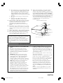 3
3
-
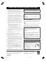 4
4
-
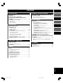 5
5
-
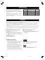 6
6
-
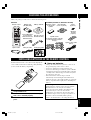 7
7
-
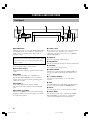 8
8
-
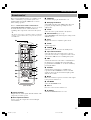 9
9
-
 10
10
-
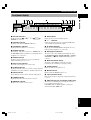 11
11
-
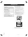 12
12
-
 13
13
-
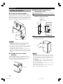 14
14
-
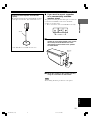 15
15
-
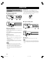 16
16
-
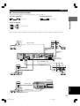 17
17
-
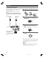 18
18
-
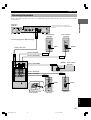 19
19
-
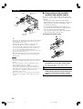 20
20
-
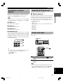 21
21
-
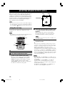 22
22
-
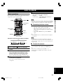 23
23
-
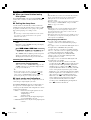 24
24
-
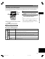 25
25
-
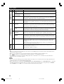 26
26
-
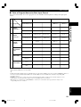 27
27
-
 28
28
-
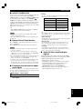 29
29
-
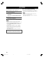 30
30
-
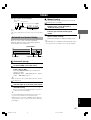 31
31
-
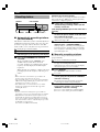 32
32
-
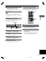 33
33
-
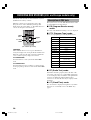 34
34
-
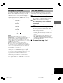 35
35
-
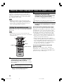 36
36
-
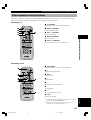 37
37
-
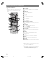 38
38
-
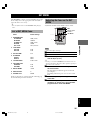 39
39
-
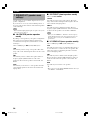 40
40
-
 41
41
-
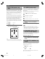 42
42
-
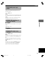 43
43
-
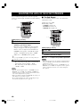 44
44
-
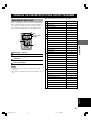 45
45
-
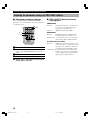 46
46
-
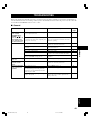 47
47
-
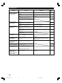 48
48
-
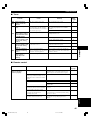 49
49
-
 50
50
-
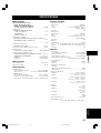 51
51
-
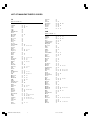 52
52
-
 53
53
-
 54
54
-
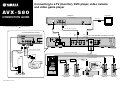 55
55


Yamaha AVX-S80 Handleiding
- Categorie
- Synthesizer
- Type
- Handleiding
in andere talen
- English: Yamaha AVX-S80 User manual
- italiano: Yamaha AVX-S80 Manuale utente
- русский: Yamaha AVX-S80 Руководство пользователя
- français: Yamaha AVX-S80 Manuel utilisateur
- español: Yamaha AVX-S80 Manual de usuario
- Deutsch: Yamaha AVX-S80 Benutzerhandbuch
- português: Yamaha AVX-S80 Manual do usuário
- dansk: Yamaha AVX-S80 Brugermanual
- suomi: Yamaha AVX-S80 Ohjekirja
- čeština: Yamaha AVX-S80 Uživatelský manuál
- svenska: Yamaha AVX-S80 Användarmanual
- Türkçe: Yamaha AVX-S80 Kullanım kılavuzu
- polski: Yamaha AVX-S80 Instrukcja obsługi
- română: Yamaha AVX-S80 Manual de utilizare