
119DS56
MANUALE D’INSTALLAZIONE
F500 / F510
AUTOMAZIONE ESTERNA PER CANCELLI A BATTENTE

Pag.
2
- Codice manuale:
119DS56IT
119DS56IT ver.
5
5 01/2015 © CAME S.p.A. - I dati e le informazioni indicate in questo manuale sono da ritenersi suscettibili di modifica in qualsiasi momento e senza obbligo di preavviso da parte di CAME S.p.A.
ITALIANO
Premessa
• Il prodotto deve essere destinato solo all’uso per il quale è stato espressa-
mente studiato. Ogni altro uso è da considerarsi pericoloso. CAME S.p.A. non
è responsabile per eventuali danni causati da usi impropri, erronei ed irragio-
nevoli • Conservare queste avvertenze assieme ai manuali di installazione e
d’uso dei componenti l’impianto di automazione.
Prima dell’installazione
(verifi ca dell’esistente: nel caso di valutazione negativa, non procedere prima
di aver ottemperato agli obblighi di messa in sicurezza)
• Controllare che la parte da automatizzare sia in buono stato meccanico,
che sia bilanciata e in asse, e che si apra e si chiuda correttamente. Verifi care
che siano presenti adeguati fermi meccanici • Se l’automazione deve esse-
re installata a un’altezza inferiore ai 2,5 m dal pavimento o da altro livello
di accesso, verifi care la necessità di eventuali protezioni e/o avvertimenti •
Qualora vi siano aperture pedonali ricavate nelle ante da automatizzare, ci
deve essere un sistema di blocco della loro apertura durante il movimento
• Assicurarsi che l’apertura dell’anta automatizzata non causi situazioni di
intrappolamento con le parti fi sse circostanti • Non montare l’automazione
rovesciata o su elementi che potrebbero piegarsi. Se necessario, aggiungere
adeguati rinforzi ai punti di fi ssaggio • Non installare su ante non in piano
• Controllare che eventuali dispositivi di irrigazione non possano bagnare
l’automazione dal basso verso l’alto • Verifi care che il range di temperatura
indicato sull’automazione sia adatto al luogo di installazione • Seguire tutte
le istruzioni poiché un’errata installazione può causare gravi lesioni • Per la
sicurezza delle persone è importante seguire queste istruzioni. Conservare
queste istruzioni.
Installazione
• Segnalare e delimitare adeguatamente tutto il cantiere per evitare incauti
accessi all’area di lavoro ai non addetti, specialmente minori e bambini •
Fare attenzione nel maneggiare automazioni con peso superiore ai 20 kg.
Nel caso, premunirsi di strumenti per la movimentazione in sicurezza • Tutti i
comandi di apertura (pulsanti, selettori a chiave, lettori magnetici, etc.) devo-
no essere installati ad almeno 1,85 m dal perimetro dell’area di manovra del
cancello, oppure dove non possano essere raggiunti dall’esterno attraverso
il cancello. Inoltre i comandi diretti (a pulsante, a sfi oramento, etc.) devono
essere installati a un’altezza minima di 1,5 m e non devono essere accessibili
al pubblico • Tutti i comandi in modalità azione mantenuta, devono essere
posti in luoghi dai quali siano visibili le ante in movimento e le relative aree
di transito o manovra • Applicare, ove mancasse, un’etichetta permanente
che indichi la posizione del dispositivo di sblocco • Prima della consegna
all’utente, verifi care la conformità dell’impianto alla norma EN 12453 (prove
d’impatto), assicurarsi che l’automazione sia stata regolata adeguatamente
e che i dispositivi di sicurezza, protezione e lo sblocco manuale funzionino
correttamente • Applicare ove necessario e in posizione chiaramente visibile
i Simboli di Avvertimento (es. targa cancello)
Istruzioni e raccomandazioni particolari per gli utenti
• Tenere libere da ingombri e pulite le aree di manovra del cancello. Control-
lare che non vi sia vegetazione nel raggio d’azione delle fotocellule e che non
vi siano ostacoli sul raggio d’azione dell’automazione • Non permettere ai
bambini di giocare con i dispositivi di comando fi ssi, o di sostare nell’area di
manovra del cancello. Tenete fuori dalla loro portata i dispositivi di comando
a distanza (trasmettitori) o qualsiasi altro dispositivo di comando, per evitare
che l’automazione possa essere azionata involontariamente • L’apparecchio
può essere utilizzato da bambini di età non inferiore a 8 anni e da persone
con ridotte capacità fi siche, sensoriali o mentali, o prive di esperienza o della
necessaria conoscenza, purché sotto sorveglianza oppure dopo che le stes-
se abbiano ricevuto istruzioni relative all’uso sicuro dell’apparecchio e alla
comprensione dei pericoli ad esso inerenti. I bambini non devono giocare con
l’apparecchio. La pulizia e la manutenzione destinata ad essere e ettuata
dall’utilizzatore non deve essere e ettuata da bambini senza sorveglianza
• Controllare frequentemente l’impianto, per verifi care eventuali anomalie e
segni di usura o danni alle strutture mobili, ai componenti dell’automazione,
a tutti i punti e dispositivi di fi ssaggio, ai cavi e alle connessioni accessibili.
Tenere lubrifi cati e puliti i punti di snodo (cerniere) e di attrito (guide di scorri-
mento) • Eseguire i controlli funzionali a fotocellule e bordi sensibili ogni sei
mesi. Per controllare che le fotocellule funzionino, passare un oggetto davanti
durante la chiusura; se l’automazione inverte il senso di marcia o si blocca, le
fotocellule funzionano correttamente. Questa è l’unica operazione di manu-
tenzione che va fatta con l’automazione in tensione. Assicurare una costante
pulizia dei vetrini delle fotocellule (utilizzare un panno leggermente inumidito
con acqua; non utilizzare solventi o altri prodotti chimici che potrebbero ro-
vinare i dispositivi) • Nel caso si rendano necessarie riparazioni o modifi che
alle regolazioni dell’impianto, sbloccare l’automazione e non utilizzarla fi no
al ripristino delle condizioni di sicurezza • Togliere l’alimentazione elettrica
prima di sbloccare l’automazione per aperture manuali e prima di una qual-
siasi altra operazione, per evitare possibili situazioni di pericolo. Consultare
le istruzioni • Se il cavo di alimentazione è danneggiato, esso deve essere
sostituito dal costruttore o dal suo servizio di assistenza tecnica o comunque
da una persona con qualifi ca similare, in modo da prevenire ogni rischio •
È fatto DIVIETO all’utente di eseguire OPERAZIONI NON ESPRESSAMENTE A
LUI RICHIESTE E INDICATE nei manuali. Per le riparazioni, le modifi che alle
regolazioni e per le manutenzioni straordinarie, RIVOLGERSI ALL’ASSISTENZA
TECNICA • Annotare l’esecuzione delle verifi che sul registro delle manuten-
zioni periodiche.
Ulteriori e raccomandazioni particolari per tutti
• Evitare di operare in prossimità delle cerniere o degli organi meccanici
in movimento • Non entrare nel raggio di azione dell’automazione in mo-
vimento • Non opporsi al moto dell’automazione poiché potrebbe causare
situazioni di pericolo • Fare sempre e comunque particolare attenzione ai
punti pericolosi che dovranno essere segnalati da appositi pittogrammi e/o
strisce giallo-nere • Durante l’utilizzo di un selettore o di un comando in mo-
dalità azione mantenuta, controllare continuamente che non ci siano persone
nel raggio d’azione delle parti in movimento, fi no al rilascio del comando • Il
cancello può muoversi in ogni momento senza preavviso • Togliere sempre
l’alimentazione elettrica durante le operazioni di pulizia o di manutenzione.
ATTENZIONE!
importanti istruzioni per la sicurezza delle persone:
LEGGERE ATTENTAMENTE!
Pericolo di schiacciamento mani
Pericolo parti in tensione
Divieto di transito durante la manovra
Pericolo di schiacciamento piedi

#
#
#
#
Pag.
3
- Codice manuale:
119DS56IT
119DS56IT ver.
5
5 01/2015 © CAME S.p.A. - I dati e le informazioni indicate in questo manuale sono da ritenersi suscettibili di modifica in qualsiasi momento e senza obbligo di preavviso da parte di CAME S.p.A.
ITALIANO
Alimentazione quadro: 230 A.C. 50/60Hz
Alimentazione motore: 24V D.C.
Assorbimento max.: 2A
Potenza: 48W
Coppia massima: 100 Nm
Tempo di apertura (90°): 13”
Rapporto di riduzione: 1/531
Intermittenza di lavoro: servizio intensivo
Grado di protezione: IP54
Peso: 5 kg
Temperatura d’esercizio:
4.1 Motoriduttore
Questo prodotto è progettato e costruito dalla CAME S.p.A. in conformità alle vigenti norme di sicurezza.
Il motoriduttore è di tipo reversibile ed è costituito da un estruso in alluminio al cui interno si trova il motoriduttore con sistema di
riduzione epicicloidale.
4 Descrizione
2.1 Destinazione d’uso
1 Legenda simboli
Questo simbolo segnala parti da leggere con attenzione.
Questo simbolo segnala parti riguardanti alla sicurezza.
Questo simbolo segnala le note da comunicare all’utente.
2 Destinazione e limiti d’impiego
Il motoriduttore F500 - F510 è destinato per automatizzare cancelli battenti di tipo residenziale e condominiale anche per servizio
intensivo.
3 Riferimenti normativi
2.2 Condizioni d’impiego
4.2 Dati tecnici
CAME S.p.A. è una azienda certificata per il sistema di gestione della qualità aziendale ISO 9001 e di gestione ambientale ISO 14001.
Il prodotto in oggetto è conforme alle seguenti normative: vedi dichiarazione di conformità.
Alimentazione quadro: 230 A.C. 50/60Hz
Alimentazione motore: 24V D.C.
Assorbimento max.: 2A
Potenza: 48W
Coppia massima: 100 Nm
Tempo di apertura (90°): 9”
Rapporto di riduzione: 1/531
Intermittenza di lavoro: servizio intensivo
Grado di protezione: IP54
Peso: 6,5 kg
Temperatura d’esercizio:
Motoriduttore F500 Motoriduttore F510
Larghezza anta (m) 0,8 1,2 1,6
Peso anta (kg) 150 125 100
Nei cancelli a battente è sempre consigliata l’installazione di una elettroserratura, allo scopo di assicurare un’affidabile chiusura.

1
5
4
3
F500
F510
2
1
5
4
3
2
F500 F510
85
80
360
230
90°
100
90°
6
6
7
Pag.
4
- Codice manuale:
119DS56IT
119DS56IT ver.
5
5 01/2015 © CAME S.p.A. - I dati e le informazioni indicate in questo manuale sono da ritenersi suscettibili di modifica in qualsiasi momento e senza obbligo di preavviso da parte di CAME S.p.A.
ITALIANO
4.3 Descrizione delle parti
4.4 Dimensioni
1) Corpo centrale motoriduttore
2) Calotta superiore
3) Calotta inferiore
4) Braccio snodato
5) Staffa di fi ssaggio braccio
6) Staffa di fi ssaggio motoriduttore
Misure in mm
1) Corpo centrale motoriduttore
2) Calotta superiore
3) Calotta inferiore
4) Braccio
5) Pattino di scorrimento
6) Guida di scorrimento
7) Staffa di fi ssaggio motoriduttore

F500
F510
A= 100 mm max
A= 40 mm min B= 210 mm
B= 235 mm
A
B= 350 mm
C
C min
C min= 0 mm B= 210 mm
C max= 150 mm B= 235 mm
C max
Pag.
5
- Codice manuale:
119DS56IT
119DS56IT ver.
5
5 01/2015 © CAME S.p.A. - I dati e le informazioni indicate in questo manuale sono da ritenersi suscettibili di modifica in qualsiasi momento e senza obbligo di preavviso da parte di CAME S.p.A.
ITALIANO
5 Installazione
Prima di procedere all’installazione dell’automatismo è necessario:
• Prevedere adeguato dispositivo di disconnesione onnipolare, con distanza maggiore di 3 mm tra i contatti, a sezionamento
dell’alimentazione;
• Predisporre adeguate tubazioni e canaline per il passaggio dei cavi elettrici garantendone la protezione contro il danneggiamento
meccanico;
• Verificare che le eventuali connessioni interne al contenitore (eseguite per la continuità del circuito di protezione) siano
provviste di isolamento supplementare rispetto ad altre parti conduttrici interne;
• Verificare che la struttura del cancello sia adeguatamente robusta, le cerniere siano efficienti e che non vi siano attriti tra parti fisse
e mobili;
• Verificare la presenza di una battuta d’arresto meccanico in apertura e in chiusura.
L’installazione deve essere effettuata da personale qualificato ed esperto e nel pieno rispetto delle normative vigenti.
5.1 Verifiche preliminari
corsa=115
corsa=350
i = 230 mm max
con apertura a 90°
Disassamento minimo
Disassamento massimo
LARGHEZZA ANTA PESO ANTA
m. Kg.
0,80 150
1,20 125
1,60 100
AC
40÷100 0÷150

67
1
48
9
RG58
3
TX
RX
2
5
4
10
Pag.
6
- Codice manuale:
119DS56IT
119DS56IT ver.
5
5 01/2015 © CAME S.p.A. - I dati e le informazioni indicate in questo manuale sono da ritenersi suscettibili di modifica in qualsiasi momento e senza obbligo di preavviso da parte di CAME S.p.A.
ITALIANO
Assicurarsi di avere tutti gli strumenti e il materiale necessario per effettuare l’installazione nella massima sicurezza e secondo le
normative vigenti. In figura alcuni esempi di attrezzatura per l’installatore.
N.B. Qualora i cavi abbiano lunghezza diversa rispetto a quanto previsto in tabella, si determini la sezione dei cavi sulla base
dell’effettivo assorbimento dei dispositivi collegati e secondo le prescrizioni indicate dalla normativa CEI EN 60204-1.
Per i collegamenti che prevedano più carichi sulla stessa linea (sequenziali), il dimensionamento a tabella deve essere riconsiderato
sulla base degli assorbimenti e delle distanze effettivi. Per i collegamenti di prodotti non contemplati in questo manuale fa fede la
documentazione allegata ai prodotti stessi.
5.3 Tipo cavi e spessori minimi
Collegamento Tipo cavo Lunghezza cavo
1 < 10 m
Lunghezza cavo
10 < 20 m
Lunghezza cavo
20 < 30 m
Alimentazione quadro 230V
FROR CEI
20-22
CEI EN
50267-2-1
3G x 1,5 mm23G x 2,5 mm23G x 4 mm2
Alimentazione motore 24V 3G x 1,5 mm23G x 1,5 mm23G x 2,5 mm2
Lampeggiatore 2 x 0,5 mm22 x 1 mm22 x 1,5 mm2
Trasmettitori fotocellule 2 x 0,5 mm22 x 0.5 mm22 x 0,5 mm2
Ricevitori fotocellule 4 x 0,5 mm24 x 0,5 mm24 x 0,5 mm2
Alimentazione accessori 2 x 0,5 mm22 x 0,5 mm22 x 1 mm2
Dispositivi di comando e di sicurezza 2 x 0,5 mm22 x 0,5 mm22 x 0,5 mm2
Antenna RG58 max. 10 m
5.2 Attrezzi e materiali
1) Gruppo motoriduttore
2) Quadro comando
3) Ricevitore radio
4) Fotocellule
5) Selettore esterno a chiave
6) Lampeggiatore
7) Antenna
8) Elettroserratura
9) Trasmettitore
10) Battuta d’arresto meccanico
5.4 Impianto tipo

24
F500
F510
56
12
20
80
5 x ø 8,5
56
400
20
3 x M6
50 50150150
15
24
12
56 1212 20
80
5 x ø 8,5
56
17,5
50
80
2 x ø 6,5
Pag.
7
- Codice manuale:
119DS56IT
119DS56IT ver.
5
5 01/2015 © CAME S.p.A. - I dati e le informazioni indicate in questo manuale sono da ritenersi suscettibili di modifica in qualsiasi momento e senza obbligo di preavviso da parte di CAME S.p.A.
ITALIANO
Predisporre i tubi corrugati necessari per i collegamenti provenienti dal pozzetto di derivazione.
N.B. il numero di tubi dipende dal tipo di impianto e dagli accessori previsti.
Le seguenti illustrazioni sono solo esempi, in quanto lo spazio per il fissaggio dell’automazione e degli accessori varia a seconda
degli ingombri. Spetta quindi all’installatore scegliere la soluzione più adatta.
5.5 Installazione dell’automazione
Pozzetto di derivazione collegamenti
1) Tracciare gli assi e gli ingombri dell’insieme, quindi fi ssare la staffa di fi ssaggio del motoriduttore al muro o al pilastro e, per il
motoriduttore F500, il supporto di ancoraggio al cancello.

F500
F510
ø 3,5 x 9,5
Pag.
8
- Codice manuale:
119DS56IT
119DS56IT ver.
5
5 01/2015 © CAME S.p.A. - I dati e le informazioni indicate in questo manuale sono da ritenersi suscettibili di modifica in qualsiasi momento e senza obbligo di preavviso da parte di CAME S.p.A.
ITALIANO
3) Togliere la calotta inferiore dal motoriduttore.
2b) Fissare la guida di scorrimento all’anta e inserire il braccio.
2a) Assemblare il braccio snodato unendo i due semibracci con l’apposita bulloneria, lubrifi cando i perni di rotazione.
4) Fissare il motoriduttore alla fl angia mediante le quattro viti
in dotazione. Fissare la calotta superiore.

B
A
ø 3,9 x 13
F500
F510 D
C
C
E
E
Pag.
9
- Codice manuale:
119DS56IT
119DS56IT ver.
5
5 01/2015 © CAME S.p.A. - I dati e le informazioni indicate in questo manuale sono da ritenersi suscettibili di modifica in qualsiasi momento e senza obbligo di preavviso da parte di CAME S.p.A.
ITALIANO
5a) - Assemblare il braccio snodato (A) alla boccola intermedia solidale all’albero del motoriduttore;
- fi ssare la staffa sul cancello con l’apposita bulloneria;
- eseguire il collegamento elettrico, dare tensione al motoriduttore in chiusura e fi ssare il braccio tramite il grano M6 (B);
- fi ssare la calotta inferiore.
5b) - Assemblare il braccio diritto (D) alla boccola intermedia solidale all’albero del motoriduttore;
- eseguire il collegamento elettrico, dare tensione al motoriduttore in chiusura e fissare il braccio tramite i grani M8 (C) e M4 (E);
- fissare la calotta inferiore.

OR
- . - . %
M1 M2
FLEX FLEX
FLEX
.%-
Pag.
10
10 - Codice manuale:
119DS56IT
119DS56IT ver.
5
5 01/2015 © CAME S.p.A. - I dati e le informazioni indicate in questo manuale sono da ritenersi suscettibili di modifica in qualsiasi momento e senza obbligo di preavviso da parte di CAME S.p.A.
ITALIANO
6) Completare l’installazione fi ssando il coperchio superiore con il suo relativo OR.
Collegamento elettrico al quadro comando ZL150N
6 Collegamenti elettrici
Rosso
Rosso
Verde
Verde
Motoriduttore a 24V (D.C.) ad
azione ritardata in chiusura
Motoriduttore a 24V (D.C.) ad
azione ritardata in apertura
Motoriduttore a 24V (D.C.)
Per il montaggio a destra invertire
i cavi di collegamento:
(M-Rosso, N-Verde)
Rosso
Verde
Collegamento elettrico al quadro comando ZL160N

Pag.
11
11 - Codice manuale:
119DS56IT
119DS56IT ver.
5
5 01/2015 © CAME S.p.A. - I dati e le informazioni indicate in questo manuale sono da ritenersi suscettibili di modifica in qualsiasi momento e senza obbligo di preavviso da parte di CAME S.p.A.
ITALIANO
9.3 Manutenzione
Data Annotazioni Firma
Manutenzione periodica
Prima di qualsiasi operazione di manutenzione, togliere la tensione, per evitare possibili situazioni di pericolo causate da accidentali movimen-
tazioni del dispositivo.
9.4 Manutenzione straordinaria
Registro manutenzione straordinaria
Timbro installatore Nome operatore
Data intervento
Firma tecnico
Firma committente
Intervento effettuato ____________________________________________________________________________________
__________________________________________________________________________________________________
__________________________________________________________________________________________________
La seguente tabella serve per registrare gli interventi di manutenzione straordinaria, di riparazione e di miglioramento eseguiti da ditte
esterne specializzate.
Gli interventi di manutenzione straordinaria devono essere effettuati da tecnici specializzati.

www. came.com
www. came.com
IT • Per ogni ulteriore informazione su azienda, prodotti e assistenza nella vostra lingua:
EN • For any further information on company, products and assistance in your language:
FR • Pour toute autre information sur la société, les produits et l’assistance dans votre langue :
DE • Weitere Infos über Unternehmen, Produkte und Kundendienst bei:
ES • Para cualquier información sobre la empresa, los productos y asistencia en su idioma:
NL • Voor meer informatie over het bedrijf, de producten en hulp in uw eigen taal:
PT • Para toda e qualquer informação acerca da empresa, de produtos e assistência técnica, em sua língua:
PL • Wszystkie inne informacje dotyczące fi rmy, produktów oraz usług i pomocy technicznej w Waszym języku znajdują się na stronie:
RU •
Для получения дополнительной информации о компании, продукции и сервисной поддержке на вашем языке:
HU • A vállalatra, termékeire és a műszaki szervizre vonatkozó minden további információért az Ön nyelvén:
HR • Za sve dodatne informacije o poduzeću, proizvodima i tehničkoj podršci:
UK • Для отримання будь-якої іншої інформації про компанію, продукцію та технічну підтримку:
Pag.
12
12 - Codice manuale:
119DS56IT
119DS56IT ver.
5
5 01/2015 © CAME S.p.A. - I dati e le informazioni indicate in questo manuale sono da ritenersi suscettibili di modifica in qualsiasi momento e senza obbligo di preavviso da parte di CAME S.p.A.
ITALIANO
CAME S.p.A. implementa all’interno dei propri stabilimenti un Sistema di Gestione Ambientale certificato e conforme alla norma
UNI EN ISO 14001 a garanzia del rispetto e della tutela dell’ambiente.
Vi chiediamo di continuare l’opera di tutela dell’ambiente, che CAME considera uno dei fondamenti di sviluppo delle proprie strategie
operative e di mercato, semplicemente osservando brevi indicazioni in materia di smaltimento:
SMALTIMENTO DELL’IMBALLO
I componenti dell’imballo (cartone, plastiche ecc.) sono assimilabili ai rifiuti solidi urbani e possono essere smaltiti senza alcuna
difficoltà, semplicemente effettuando la raccolta differenziata per il riciclaggio.
Prima di procedere è sempre opportuno verificare le normative specifiche vigenti nel luogo d’installazione.
NON DISPERDERE NELL’AMBIENTE!
SMALTIMENTO DEL PRODOTTO
I nostri prodotti sono realizzati con materiali diversi. La maggior parte di essi (alluminio, plastica, ferro, cavi elettrici) è assimilabile ai
rifiuti solidi e urbani. Possono essere riciclati attraverso la raccolta e lo smaltimento differenziato nei centri autorizzati.
Altri componenti (schede elettroniche, batterie dei radiocomandi etc.) possono invece contenere sostanze inquinanti.
Vanno quindi rimossi e consegnati a ditte autorizzate al recupero e allo smaltimento degli stessi.
Prima di procedere è sempre opportuno verificare le normative specifiche vigenti nel luogo di smaltimento.
NON DISPERDERE NELL’AMBIENTE!
9 Dismissione e smaltimento
MALFUNZIONAMENTI POSSIBILI CAUSE VERIFICHE E RIMEDI
Il cancello non apre e
non chiude
• Manca alimentazione
• Il trasmettitore ha la batteria scarica
• Il trasmettitore è rotto
• Pulsante di stop è inceppato o rotto
• Pulsante di apertura/chiusura o selettore a chiave sono inceppati
• Verificare la presenza di rete
• Sostituire le pile
• Rivolgersi all’assistenza
• Rivolgersi all’assistenza
• Rivolgersi all’assistenza
Il cancello apre ma
non chiude
• Le fotocellule sono sollecitate • Verificare pulizia e corretto
funzionamento delle fotocellule
• Rivolgersi all’assistenza
Non funziona il
lampeggiatore
• Lampadina bruciata • Rivolgersi all’assistenza
8.2 Risoluzione dei problemi
Timbro installatore Nome operatore
Data intervento
Firma tecnico
Firma committente
Intervento effettuato ____________________________________________________________________________________
__________________________________________________________________________________________________
__________________________________________________________________________________________________
Dichiarazione - CAME S.p.A. dichiara che questo prodotto è conforme ai requisiti essenziali e alle altre disposizioni pertinenti stabilite dalla
direttiva 2006/42/CE, 2014/30/UE.
Su richiesta è disponibile la copia conforme all'originale della dichiarazione di conformità.
DICHIARAZIONE DI CONFORMITÀ

INSTALLATION MANUAL
F500 / F510
AUTOMATION FOR SWING GATES
English EN
119DS56EN

Pag.
2
- Manual code:
119DS56EN
119DS56EN ver.
5
5 01/2015 © CAME S.p.A. - The data and information reported in this installation manual are susceptible to change at any time and without obligation on CAME S.p.A. to notify users.
ENGLISH
Premise
• Employ this product only for the use for which it was expressly made. Any
other use is dangerous. CAME S.p.A. is not liable for any damage caused by
improper, wrongful and unreasonable use • Keep these warnings together
with the installation and operation manuals that come with the operator.
Before installing
(checking what's there: if your evaluation is negative, do not proceed before
having complied with all safety requirements)
• Check that the automated parts are in good mechanical order, that the
operator is level and aligned, and that it opens and closes properly. Make
sure you have suitable mechanical stops • If the operator is to be installed at
a height of over 2.5 m from the ground or other access level, make sure you
have any necessary protections and/or warnings in place • If any pedestrian
openings are fi tted into the operator, there must also be a a system to block
their opening while they are moving • Make sure that the opening automated
door or gate cannot entrap people against the fi xed parts of the operator •
Do not install the operator upside down or onto elements that could yield and
bend. If necessary, add suitable reinforcements to the anchoring points • Do
not install door or gate leaves on tilted surfaces • Make sure any sprinkler
systems cannot wet the operator from the ground up • Make sure the tempe-
rature range shown on the product literature is suitable to the climate where
it will be installed • Follow all instructions as improper installation may result
in serious bodily injury • It is important to follow these instructions for the
safety of people. Keep these instructions.
Installing
• Suitably section o and demarcate the entire installation site to prevent
unauthorized persons from entering the area, especially minors and children
• Be careful when handling operators that weigh over 20 kg. If need be, use
proper safety hoisting equipment • All opening commands (that is, buttons,
key switches, magnetic readers, and so on) must be installed at least 1.85
m from the perimeter of the gate's working area, or where they cannot be
reached from outside the gate. Also, any direct commands (buttons, touch
panels, and so on) must be installed at least 1.5 m from the ground and must
not be reachable by unauthorized persons • All maintained action comman-
ds, must be fi tted in places from which the moving gate leaves and transit
and driving areas are visible • Apply, if missing, a permanent sign showing
the position of the release device • Before delivering to the users, make sure
the system is EN 12453 standard compliant (regarding impact forces), and
also make sure the system has been properly adjusted and that any safety,
protection and manual release devices are working properly • Apply Warning
Signs (such as the gate's plate) where necessary and in a visible place
Special user-instructions and recommendations
• Keep gate operation areas clean and free of any obstructions. Make sure
that the photocells are free of any overgrown vegetation and that the opera-
tor's area of operation is free of any obstructions • Do not allow children to
play with fi xed commands, or to loiter in the gate's maneuvering area. Keep
any remote control transmitters or any other command device away from
children, to prevent the operator from being accidentally activated. • The
apparatus may be used by children of eight years and above and by physi-
cally, mentally and sensorially challenged people, or even ones without any
experience, provided this happens under close supervision or once they have
been properly instructed to use the apparatus safely and about the potential
hazards involved. Children must not play with the apparatus. Cleaning and
maintenance by users must not be done by children, unless properly super-
vised • Frequently check the system for any malfunctions or signs of wear
and tear or damage to the moving structures, to the component parts, all
anchoring points, including cables and any accessible connections. Keep any
hinges, moving joints and slide rails properly lubricated • Perform functional
checks on the photocells and sensitive safety edges, every six months. To
check whether the photocells are working, wave an object in front of them
while the gate is closing; if the operator inverts its direction of travel or sud-
denly stops, the photocells are working properly. This is the only maintenance
operation to do with the power on. Constantly clean the photocells' glass co-
vers using a slightly water-moistened cloth; do not use any solvents or other
chemical products that may ruin the devices • If repairs or modifi cations are
required to the system, release the operator and do not use it until safety
conditions have been restored • Cut o the power supply before releasing
the operator for manual openings and before any other operation, to prevent
potentially hazardous situations. Read the instructions • If the power supply
cable is damaged, it must be replaced by the manufacturer or authorized
technical assistance service, or in any case, by similarly qualifi ed persons,
to prevent any risk • It is FORBIDDEN for users to perform any OPERATIONS
THAT ARE NOT EXPRESSLY REQUIRED OF THEM AND WHICH ARE NOT LISTED
in the manuals. For any repairs, modifi cations and adjustments and for ex-
traordinary maintenance, CALL TECHNICAL ASSISTANCE • Log the job and
checks into the periodic maintenance log.
Additional special recommendations for everyone
• Keep away from hinges and mechanical moving parts • Do not enter the
operator's area of operation when it is moving • Do not counter the opera-
tor's movement as this could result in dangerous situations • Always pay
special attention to any dangerous points, which have to be labeled with
specifi c pictograms and/or black and yellow stripes • While using a selector
switch or a command in maintained actions, keep checking that there are no
persons within the operating range of any moving parts, until the command
is released • The gate may move at any time and without warning • Always
cut o the power supply before performing any maintenance or cleaning.
Danger of hand crushing
Danger! High voltage.
No transiting while maneuvering
WARNING!
important safety instructions for people:
READ CAREFULLY!
Danger of foot crushing

#
#
#
#
Pag.
3
- Manual code:
119DS56EN
119DS56EN ver.
5
5 01/2015 © CAME S.p.A. - The data and information reported in this installation manual are susceptible to change at any time and without obligation on CAME S.p.A. to notify users.
ENGLISH
Control board power supply: 230 A.C. 50/60Hz
Motor power supply: 24V D.C.
Max draw.: 2A
Power: 48W
Maximum torque: 100 Nm
Opening time (90°): 13”
Gear ratio: 1/531
Duty Cycle: Intensive use
Protection Rating: IP54
Weight: 5 kg
Operating temperature:
4.1 Gearmotor
This product is engineered and manufactured by CAME S.p.A. and complies with current safety regulations.
The gearmotor is reversible and made from drawn aluminium., with an epicyclical reduction.
4 Description
2.1 Intended use
1 Legend of symbols
This symbol tells you to read the section with particular care.
This symbol tells you that the sections concern safety issues.
This symbol tells you what to say to the end-users.
2 Intended use and restrictions
The ATI F500 - F510 gearmotor is specifi cally engineered to automate residential and condominium swing gates, even under
intensive use.
3 Reference Standards
2.2 Restrictions
4.2 Technical features
The company: CAME S.p.A. is ISO 9001 quality certified; is has also obtained the ISO 14001 environmental safeguarding certification.
Came engineers and manufactures all of its products in Italy.
This product complies with the following standards: see declaration of compliance.
Length of gate leaf (m) 0,8 1,2 1,6
Weight of gate leaf (kg) 150 125 100
Control board power supply: 230 A.C. 50/60Hz
Motor power supply: 24V D.C.
Max draw.: 2A
Power: 48W
Maximum torque: 100 Nm
Opening time (90°): 9”
Gear ratio: 1/531
Duty Cycle: Intensive use
Protection Rating: IP54
Weight: 6,5 kg
Operating temperature:
F500 Gearmotor F510 Gearmotor
We suggest you always fit an electrolock onto swing gates for a more reliable closure.

1
5
4
3
F500
F510
2
1
5
4
3
2
F500 F510
85
80
360
230
90°
100
90°
6
6
7
Pag.
4
- Manual code:
119DS56EN
119DS56EN ver.
5
5 01/2015 © CAME S.p.A. - The data and information reported in this installation manual are susceptible to change at any time and without obligation on CAME S.p.A. to notify users.
ENGLISH
4.3 Description of parts
4.4 Dimensions
Measurements in mm
1) Gearmotor central body
2) Upper casing
3) Lower casing
4) Articulated arm
5) Arm fi xing bracket
6) Gearmotor fi xing bracket
1) Gearmotor central body
2) Upper casing
3) Lower casing
4) Arm
5) Slide block
6) Runner
7) Gearmotor fi xing bracket

F500
F510
A= 100 mm max
A= 40 mm min B= 210 mm
B= 235 mm
A
B= 350 mm
C
C min
C min= 0 mm B= 210 mm
C max= 150 mm B= 235 mm
C max
Pag.
5
- Manual code:
119DS56EN
119DS56EN ver.
5
5 01/2015 © CAME S.p.A. - The data and information reported in this installation manual are susceptible to change at any time and without obligation on CAME S.p.A. to notify users.
ENGLISH
5 Installation
Before installing, do the following:
• Make sure you have suitable tubing and conduits for the electrical cables to pass through and be protected against mechanical
damage;
• Fit tubing to drain away any water leaks which may cause oxidation;
•Make sure that any connections inside the case (that provide continuance to the protective circuit) be fitted with extra insulation
as compared to the other conductive parts inside;
• Make sure the structure of the gate is sturdy, the hinges work and that the is no friction between moving and non-moving parts;
• Make sure there is a mechanical stop for opening and closing.
Installation must be carried out by expert qualified personnel and in full compliance with current regulations.
5.1 Preliminary checks
i = 230 mm max
with 90° opening angle
GATE WING WIDTH GATE WING WEIGHT
m. Kg.
0,80 150
1,20 125
1,60 100
AC
40÷100 0÷150
travel=115
travel=350
Excentration minimum
Excentration maximum

67
1
48
9
RG58
3
TX
RX
2
5
4
10
Pag.
6
- Manual code:
119DS56EN
119DS56EN ver.
5
5 01/2015 © CAME S.p.A. - The data and information reported in this installation manual are susceptible to change at any time and without obligation on CAME S.p.A. to notify users.
ENGLISH
Make sure you have all the tools and materials you will need for the installation at hand to work in total safety and compliance with the
current standards and regulations. The following figure illustrates the minimum equipment needed by the installer.
N.B.: If the cable length differs from that specified in the table, then you must determine the proper cable diameter in the basis of the
actual power draw by the connected devices and depending on the standards specified in CEI EN 60204-1.
For connections that require several, sequential loads, the sizes given on the table must be re-evaluated based on actual power draw
and distances.
When connecting products that are not specified in this manual, please follow the documentation provided with said products.
5.3 Cable list and minimum thickness
Connections Type of cable Type of cable Length of cable
10 < 20 m
Length of cable
20 < 30 m
Control panel power supply 230V
FROR CEI
20-22
CEI EN
50267-2-1
3G x 1,5 mm23G x 2,5 mm23G x 4 mm2
Motor power supply 24V 3G x 1,5 mm23G x 1,5 mm23G x 2,5 mm2
Flashing light 2 x 0,5 mm22 x 1 mm22 x 1,5 mm2
Photocell transmitters 2 x 0,5 mm22 x 0.5 mm22 x 0,5 mm2
Photocell receivers 4 x 0,5 mm24 x 0,5 mm24 x 0,5 mm2
Accessories power supply 2 x 0,5 mm22 x 0,5 mm22 x 1 mm2
Control and safety devices 2 x 0,5 mm22 x 0,5 mm22 x 0,5 mm2
Antenna RG58 max. 10 m
5.2 Tools and materials
1) Gear motor unit
2) Control panel
3) Radio receiver
4) Photocells
5) Protruding key-operated selector switch
6) Flasher
7) Antenna
8) Electric lock
9) Transmitter
10) Mechanical gate stop
5.4 Standard installation

24
F500
F510
56
12
20
80
5 x ø 8,5
56
400
20
3 x M6
50 50150150
15
24
12
56 1212 20
80
5 x ø 8,5
56
17,5
50
80
2 x ø 6,5
Pag.
7
- Manual code:
119DS56EN
119DS56EN ver.
5
5 01/2015 © CAME S.p.A. - The data and information reported in this installation manual are susceptible to change at any time and without obligation on CAME S.p.A. to notify users.
ENGLISH
Lay the corrugated tubing needed for the connections deriving from the junction box.
N.B. the number of tubes depends on the type of system and accessories employed.
The following illustrations are only examples, given that the space available for anchoring the operator and accessories may vary
from gate to gate. It is up to the installer, thus, to choose the most suitable solution.
5.5 Installing the operator
Electric cable junction box
1) Trace the centre lines and external dimensions of the entire assembly in accordance with the diagrams on pages 2 and 3.
Next, mount the fl ange for the gear motor on the wall or pillar, and mount the anchor block for gear motor F500 on the gate.

F500
F510
ø 3,5 x 9,5
Pag.
8
- Manual code:
119DS56EN
119DS56EN ver.
5
5 01/2015 © CAME S.p.A. - The data and information reported in this installation manual are susceptible to change at any time and without obligation on CAME S.p.A. to notify users.
ENGLISH
3) Remove the cover at the bottom of the gear motor.
2b) Secure the runner to the wing and insert the straight arm.
2a) Use the hardware provided with the unit to join the two halves of the articulated arm together.
4) sing the four screws provided with the unit, install the gear
motor on the fl ange. Fix the upper cap.

B
A
ø 3,9 x 13
F500
F510 D
C
C
E
E
Pag.
9
- Manual code:
119DS56EN
119DS56EN ver.
5
5 01/2015 © CAME S.p.A. - The data and information reported in this installation manual are susceptible to change at any time and without obligation on CAME S.p.A. to notify users.
ENGLISH
5a) - Assemble the articulated arm (A) onto the intermediate bush which is all in one with the ratiomotor shaft;
- using the hardware provided with the unit, install the bracket on the gate;
- make the electrical connection, supply voltage to the ratio-motor during closure and secure the arm with the M6 (B) grub screw;
- fi x the lower cap.
5b) - Assemble the articulated arm (D) onto the intermediate bush which is all in one with the ratiomotor shaft;
- make the electrical connection, supply voltage to the ratio-motor during closure and secure the arm with the M6 (C) grub screws;
- fix the lower cap.

OR
- . - . %
M1 M2
FLEX FLEX
FLEX
.%-
Pag.
10
10 - Manual code:
119DS56EN
119DS56EN ver.
5
5 01/2015 © CAME S.p.A. - The data and information reported in this installation manual are susceptible to change at any time and without obligation on CAME S.p.A. to notify users.
ENGLISH
6) Complete instal-lation by mounting the upper cover with its OR gasket.
6 Electrical connections
Red
Red
Green
Green
24 V D.C. gearmotor featuring
delayed action on closing
24 V D.C. gearmotor featuring
delayed action on opening
24 V D.C. gearmotor
Red
Green
Electric connections to the ZL150N control panel
Electric connections to the ZL160N control panel
For mounting on the right side,
invert the connection leads:
(M-red, N-green)

Pag.
11
11 - Manual code:
119DS56EN
119DS56EN ver.
5
5 01/2015 © CAME S.p.A. - The data and information reported in this installation manual are susceptible to change at any time and without obligation on CAME S.p.A. to notify users.
ENGLISH
9.3 Maintenance
Date Notes Signature
Periodic maintenance
Before doing any maintenance, cut off the power supply, to prevent any hazardous situations caused by accidentally activating the operator.
Periodic maintenance log kept by users (every six months)
9.4 Extraordinary maintenance
Extraordinary maintenance log
Installer's stamp Product name
Date of job
Technician's signature
Customer's signature
Job carried out ______________________________________________________________________________________
_________________________________________________________________________________________________
_________________________________________________________________________________________________
The following table is for logging any extraordinary maintenance jobs, repairs and improvements performed by specialized contractors.
Any extraordinary maintenance jobs must be done only by specialized technicians.

www. came.com
www. came.com
IT • Per ogni ulteriore informazione su azienda, prodotti e assistenza nella vostra lingua:
EN • For any further information on company, products and assistance in your language:
FR • Pour toute autre information sur la société, les produits et l’assistance dans votre langue :
DE • Weitere Infos über Unternehmen, Produkte und Kundendienst bei:
ES • Para cualquier información sobre la empresa, los productos y asistencia en su idioma:
NL • Voor meer informatie over het bedrijf, de producten en hulp in uw eigen taal:
PT • Para toda e qualquer informação acerca da empresa, de produtos e assistência técnica, em sua língua:
PL • Wszystkie inne informacje dotyczące fi rmy, produktów oraz usług i pomocy technicznej w Waszym języku znajdują się na stronie:
RU •
Для получения дополнительной информации о компании, продукции и сервисной поддержке на вашем языке:
HU • A vállalatra, termékeire és a műszaki szervizre vonatkozó minden további információért az Ön nyelvén:
HR • Za sve dodatne informacije o poduzeću, proizvodima i tehničkoj podršci:
UK • Для отримання будь-якої іншої інформації про компанію, продукцію та технічну підтримку:
Pag.
12
12 - Manual code:
119DS56EN
119DS56EN ver.
5
5 01/2015 © CAME S.p.A. - The data and information reported in this installation manual are susceptible to change at any time and without obligation on CAME S.p.A. to notify users.
ENGLISH
CAME S.p.A. employs a UNI EN ISO 14001 certified and compliant environmental protection system at its plants, to ensure that
environmental safeguarding.
We ask you to keep protecting the environment, as CAME deems it to be one of the fundamental points of its market operations
strategies, by simply following these brief guidelines when disposing.
DISPOSING THE PACKING MATERIALS
The packing components (cardboard, plastic, etc.) are solid urban waste and may be disposed of without any particular difficulty, by
simply separating them so that they can be recycled.
Before actions it is always advisable to check the pertinent legislation where installation will take place.
DO NOT DISPOSE OF IN NATURE!
DISPOSING OF THE PRODUCT
Our products are made using different types of materials. The majority of them (aluminium, plastic, iron, electric cables) can be
considered to be solid urban waste. They may be recycled at authorised firms.
Other components (electrical circuit board, remote control batteries etc.) may contain hazardous waste.
They must, thus, be removed and turned in to licensed firms for their disposal.
Before acting always check the local laws on the matter.
DO NOT DISPOSE OF IN NATURE!
9 Phasing out and disposal
MALFUNCTIONS POSSIBLE CAUSES CHECK AND REMEDIES
The gate will not open
nor close
• There is no power
• The transmitter’s batteries are run down
• The transmitter is broken
• The stop button is either stuck or broken
• The opening/closing button or the selector switch are stuck
• Check that the power is up
• Replace batteries
• Call assistance
• Call assistance
• Call assistance
The gate opens but
will not close
• The photocells are engaged • Check that photocells are clean
and in good working order
• Call assistance
The Flashing light
does not work
• The bulb is burnt • Call assistance
8.2 Trouble shooting
Installer's stamp Product name
Date of job
Technician's signature
Customer's signature
Job carried out ______________________________________________________________________________________
_________________________________________________________________________________________________
_________________________________________________________________________________________________
Declaration CAME S.p.A. declares that this device conforms to the essential, pertinent requirements provided by directives 2006/42/CE,
2014/30/UE.
An original copy of the declaration of conformity is available on request.
DECLARATION OF CONFORMITY

MANUEL POUR L’INSTALLATION
F500 / F510
AUTOMATISME POUR PORTAILS BATTANTS
Français FR
119DS56FR

Pag.
2
- Code manuel:
119DS56FR
119DS56FR ver.
5
5 01/2015 © CAME S.p.A. - Les données et les indications fournies dans ce manuel d’installation peuvent subir des modifications à tout moment sans avis préalable de la part de CAME S.p.A.
FRANÇAIS
Avant-propos
• Ce produit ne devra être destiné qu'à l'utilisation pour laquelle il a été
expressément conçu. Toute autre utilisation est à considérer comme dange-
reuse. La société CAME S.p.A. décline toute responsabilité en cas d'éventuels
dommages provoqués par des utilisations impropres, incorrectes et dérai-
sonnables • Conserver ces instructions avec les manuels d'installation et
d'utilisation des composants du système d'automatisation.
Avant l'installation
(contrôle du matériel existant : en cas d'évaluation négative, ne procéder à
l'installation qu'après avoir e ectué la mise en sécurité conforme)
• S'assurer que la partie à automatiser est en bon état mécanique, qu'elle est
équilibrée et alignée, et qu'elle s'ouvre et se ferme correctement. S'assurer
en outre de la présence de butées mécaniques appropriées • En cas d'ins-
tallation de l'automatisme à une hauteur inférieure à 2,5 m par rapport au
sol ou par rapport à un autre niveau d'accès, évaluer la nécessité d'éventuels
dispositifs de protection et/ou d'avertissement • En cas d'ouvertures pié-
tonnières dans les vantaux à automatiser, prévoir un système de blocage de
leur ouverture durant le mouvement • S'assurer que l'ouverture du vantail
automatisé ne provoque aucun coincement avec les parties fi xes présentes
tout autour • Ne pas installer l'automatisme dans le sens inverse ou sur
des éléments qui pourraient se plier. Si nécessaire, renforcer les points de
fi xation • Ne pas installer l'automatisme sur des vantaux non positionnés sur
une surface plane • S'assurer que les éventuels dispositifs d'arrosage ne
peuvent pas mouiller l'automatisme de bas en haut • S'assurer que la tem-
pérature du lieu d'installation correspond à celle indiquée sur l'automatisme
• Suivre toutes les instructions étant donné qu'une installation incorrecte
peut provoquer de graves lésions • Il est important, pour la sécurité des
personnes, de suivre ces instructions. Conserver ces instructions.
Installation
• Signaler et délimiter correctement le chantier afi n d'éviter tout accès im-
prudent à la zone de travail de la part de personnes non autorisées, notam-
ment des mineurs et des enfants • Manipuler les automatismes de plus de
20 kg avec une extrême prudence. Prévoir, si nécessaire, des instruments
adéquats pour une manutention en toute sécurité • Toutes les commandes
d'ouverture (boutons, sélecteurs à clé, lecteurs magnétiques, etc.) doivent
être installées à au moins 1,85 m du périmètre de la zone d'actionnement du
portail, ou bien en des points inaccessibles de l'extérieur à travers le portail.
Les commandes directes (à bouton, à e eurement, etc.) doivent en outre
être installées à une hauteur minimum de 1,5 m et être inaccessibles au
public • Toutes les commandes en modalité « action maintenue » doivent être
positionnées dans des endroits permettant de visualiser les vantaux en mou-
vement ainsi que les zones correspondantes de passage ou d'actionnement
• Appliquer une étiquette permanente indiquant la position du dispositif de
déblocage • Avant de livrer l'installation à l'utilisateur, en contrôler la confor-
mité à la norme EN 12453 (essais d'impact), s'assurer que l'automatisme a
bien été réglé comme il faut et que les dispositifs de sécurité, de protection
et de déblocage manuel fonctionnent correctement • Les Symboles d'Aver-
tissement (ex. : plaquette portail) doivent être appliqués dans des endroits
spécifi ques et bien en vue.
Instructions et recommandations particulières pour les utilisateurs
• Dégager et nettoyer les zones d'actionnement du portail. S'assurer de
l'absence de toute végétation dans le rayon d'action des photocellules et de
tout obstacle dans celui de l'automatisme • Ne pas permettre aux enfants
de jouer avec les dispositifs de commande fi xes ou de stationner dans la
zone de manœuvre du portail. Conserver hors de leur portée les dispositifs
de commande à distance (émetteurs), ou tout autre dispositif de commande,
afi n d'éviter l'actionnement involontaire de l'automatisme. • L’appareil peut
être utilisé par des enfants âgés d'au moins 8 ans et par des personnes
aux capacités physiques, sensorielles ou mentales réduites, ou par des
personnes dotées d'une expérience et d'une connaissance insu santes, à
condition qu'elles soient surveillées ou qu'elles aient reçu des instructions
sur l'utilisation en toute sécurité de l'appareil et sur la compréhension des
dangers y étant liés. Les enfants ne doivent pas jouer avec l'appareil. Le net-
toyage et l'entretien que doit e ectuer l'utilisateur ne doivent pas être confi és
à des enfants laissés sans surveillance • Contrôler souvent l'installation afi n
de s'assurer de l'absence d'anomalies et de signes d'usure ou de dommages
sur les structures mobiles, les composants de l'automatisme, tous les points
et dispositifs de fi xation, les câbles et les connexions accessibles. Les points
d'articulation (charnières) et de frottement (glissières) doivent toujours être
lubrifi és et propres • Contrôler le bon fonctionnement des photocellules et
des bords sensibles tous les six mois. Pour s'assurer du bon fonctionne-
ment des photocellules, y passer devant un objet durant la fermeture ; si
l'automatisme inverse le sens de la marche ou qu'il se bloque, les photocel-
lules fonctionnent correctement. Il s'agit de l'unique opération d'entretien à
e ectuer avec l'automatisme sous tension. Assurer un nettoyage constant
des verres des photocellules (utiliser un chi on légèrement humidifi é d'eau
; ne pas utiliser de solvants ni d'autres produits chimiques qui pourraient
endommager les dispositifs) • En cas de réparations ou de modifi cations
nécessaires des réglages de l'installation, débloquer l'automatisme et ne
l'utiliser qu'après le rétablissement des conditions de sécurité • Couper le
courant électrique avant de débloquer l'automatisme pour des ouvertures
manuelles et avant toute autre opération afi n d'éviter les situations de dan-
ger potentielles. Consulter les instructions • Si le câble d'alimentation est
endommagé, son remplacement doit être e ectué par le fabricant, ou par son
service d'assistance technique, ou par une personne ayant son même niveau
de qualifi cation afi n de prévenir tout risque • Il est INTERDIT à l'utilisateur
d'exécuter des OPÉRATIONS QUI NE LUI AURAIENT PAS ÉTÉ EXPRESSÉMENT
DEMANDÉES ET QUI NE SERAIENT PAS INDIQUÉES dans les manuels. Pour
les réparations, les modifi cations des réglages et pour les entretiens curatifs,
S'ADRESSER À L'ASSISTANCE TECHNIQUE • Noter l'exécution des contrôles
sur le registre des entretiens périodiques.
Instructions et recommandations particulières pour tous
• Éviter d'intervenir à proximité des charnières ou des organes mécaniques
en mouvement • Ne pas pénétrer dans le rayon d'action de l'automatisme
lorsque ce dernier est en mouvement • Ne pas s'opposer au mouvement
de l'automatisme afi n d'éviter toute situation dangereuse • Faire toujours
très attention aux points dangereux qui devront être signalés par des picto-
grammes et/ou des bandes jaunes et noires spécifi ques • Durant l'utilisation
d'un sélecteur ou d'une commande en modalité « action maintenue », tou-
jours s'assurer de l'absence de toute personne dans le rayon d'action des
parties en mouvement jusqu'au relâchement de la commande • L'action-
nement de l'automatisme peut avoir lieu à tout moment et sans préavis •
Toujours couper le courant électrique durant les opérations de nettoyage ou
d'entretien
Danger d'écrasement des mains
Danger parties sous tension
Passage interdit durant la manœuvre
ATTENTION !
Instructions importantes pour la sécurité des personnes :
À LIRE ATTENTIVEMENT !
Danger d'écrasement des pieds

#
#
#
#
Pag.
3
- Code manuel:
119DS56FR
119DS56FR ver.
5
5 01/2015 © CAME S.p.A. - Les données et les indications fournies dans ce manuel d’installation peuvent subir des modifications à tout moment sans avis préalable de la part de CAME S.p.A.
FRANÇAIS
Alimentation armoire: 230 A.C. 50/60Hz
Alimentation moteur: 24V D.C.
Absorption max.: 2A
Puissance: 48W
Coppia massima: 100 Nm
Temps d’ouverture (90°) : 13”
Rapport de réduction: 1/531
Intermittence travail : service intensif
Degré de protection: IP54
Poids: 5 kg
Température de fonctionnement:
4.1 Motoréducteur
Le produit a été conçu et fabriqué par CAME S.p.A. conformément aux normes de sécurité en vigueur.
Le motoréducteur est de type irréversible et sa structure est en aluminium extrudé à l’intérieur duquel se trouve le motoréducteur avec
réducteur épicloidale.
4 Description
2.1 Usage prévu
1 Légende des symboles
Ce symbole signale les parties à lire attentivement.
Ce symbole signale les parties concernant la sécurité.
Ce symbole signale les indications à communiquer à l’usager.
2 Destinations et conditions d’emploi
Le motoréducteur F500 - F510 est prévu pour automatiser les portails battants des habitations et des copropriétés même pour
passages fréquents.
3 Normes de référence
2.2 Mode d’emploi
4.2 Informations techniques
CAME S.p.A. est une entreprise certifiée par le Système de Contrôle Qualité des Entreprises ISO 9001 et de Gestion de l’Environnement
ISO 14001. Les produits Came sont entièrement conçus et fabriqués en Italie.
Le produit en objet est conforme aux normes suivantes : voir déclaration de conformité.
Longueur porte (m) 0,8 1,2 1,6
Poids porte (kg) 150 125 100
Motoréducteur F500 Motoréducteur F510
Alimentation armoire: 230 A.C. 50/60Hz
Alimentation moteur: 24V D.C.
Absorption max.: 2A
Puissance: 48W
Coppia massima: 100 Nm
Temps d’ouverture (90°) : 9”
Rapport de réduction: 1/531
Intermittence travail : service intensif
Degré de protection: IP54
Poids: 6,5 kg
Température de fonctionnement:
Il convient toujours d’appliquer une serrure de verrouillage électrique sur les portails battants afin d’assurer une fermeture fiable.

1
5
4
3
F500
F510
2
1
5
4
3
2
F500 F510
85
80
360
230
90°
100
90°
6
6
7
Pag.
4
- Code manuel:
119DS56FR
119DS56FR ver.
5
5 01/2015 © CAME S.p.A. - Les données et les indications fournies dans ce manuel d’installation peuvent subir des modifications à tout moment sans avis préalable de la part de CAME S.p.A.
FRANÇAIS
4.3 Description des parties
4.4 Dimensions
Mesures en mm
1) Corps central motoréducteur
2) Calotte supérieure
3) Calotte inférieure
4) Bras articulé
5) Bride de fi xation bras
6) Bride de fi xation motoréducteur
1) Corps central motoréducteur
2) Calotte supérieure
3) Calotte inférieure
4) Bras
5) Patin de guidage
6) Glissière de guidage
7) Bride de fi xation motoréducteur

F500
F510
A= 100 mm max
A= 40 mm min B= 210 mm
B= 235 mm
A
B= 350 mm
C
C min
C min= 0 mm B= 210 mm
C max= 150 mm B= 235 mm
C max
Pag.
5
- Code manuel:
119DS56FR
119DS56FR ver.
5
5 01/2015 © CAME S.p.A. - Les données et les indications fournies dans ce manuel d’installation peuvent subir des modifications à tout moment sans avis préalable de la part de CAME S.p.A.
FRANÇAIS
5 Installation
Avant de procéder au montage, il est nécessaire de:
• Prévoir un disjoncteur omnipolaire approprié, avec plus de 3 mm. de distance entre les contacts pour sélectionner l’alimentation.
• Prévoir un tuyau pour le drainage afin d’éviter les stagnations qui pourraient provoquer des oxydations;
•Contrôler que les connexions éventuelles à l’intérieur du conteneur (réalisées pour continuer le circuit de protection) sont
équipées d’une isolation supplémentaire par rapport aux autres parties conductrices présentes à l’intérieur;
• Vérifier que le châssis du portail est robuste, les charnières en état de marche et qu’il n’y a pas de frottement entre les partie sfixes
et les parties mobiles;
• Vérifier la présence d’une butée d’arrêt mécanique en ouverture et une en fermeture.
Le montage doit être effectué par du personnel qualifié et expérimenté et dans le respect des normes en vigueur.
5.1 Contrôles préliminaires
course=115
course=350
i = 230 mm max
avec ouverture à 90°
Minimum misalignment
Maximum misalignment
LARGEUR VANTAIL POIDS VANTAIL
m. Kg.
0,80 150
1,20 125
1,60 100
AC
40÷100 0÷150

67
1
48
9
RG58
3
TX
RX
2
5
4
10
Pag.
6
- Code manuel:
119DS56FR
119DS56FR ver.
5
5 01/2015 © CAME S.p.A. - Les données et les indications fournies dans ce manuel d’installation peuvent subir des modifications à tout moment sans avis préalable de la part de CAME S.p.A.
FRANÇAIS
Assurez-vous d’avoir tous les outils et le matériel nécessaire pour effectuer le montage de l’automatisme en toute sécurité et
conformément aux normes en vigueur. Sur la planche, quelques exemples de matériel pour l’installateur.
N.B. Au cas où les câbles auraient une longueur différente de celle prévue dans le tableau, on détermine la section des câbles sur la
base de l’absorption effective des dispositifs branchés en suivant les prescriptions indiquées dans la normative CEI EN 60204-1.
Pour les branchements qui prévoient plusieurs charges sur la même ligne (séquentiels), il faut revoir les dimensions indiquées sur le
tableau sur la base des absorptions et des distances effectives. Pour les branchements de produits qui ne sont pas présents sur ce
manuel la documentation de référence est celle qui est fournie avec lesdits produits.
5.3 Types de câbles et épaisseurs minimales
Branchements Type de
câble
Longueur câble
1 < 10 m
Longueur câble
10 < 20 m
Longueur câble
20 < 30 m
Alimentation armoire 230V
FROR CEI
20-22
CEI EN
50267-2-1
3G x 1,5 mm23G x 2,5 mm23G x 4 mm2
Alimentation moteur 24V 3G x 1,5 mm23G x 1,5 mm23G x 2,5 mm2
Clignotant 2 x 0,5 mm22 x 1 mm22 x 1,5 mm2
Émetteurs photocellules 2 x 0,5 mm22 x 0.5 mm22 x 0,5 mm2
Récepteurs photocellules 4 x 0,5 mm24 x 0,5 mm24 x 0,5 mm2
Alimentation accessoires 2 x 0,5 mm22 x 0,5 mm22 x 1 mm2
Dispositifs de commande et de sécurité 2 x 0,5 mm22 x 0,5 mm22 x 0,5 mm2
Antenne RG58 max. 10 m
5.2 Outils et matériel
1) Groupe motoréducteur
2) Armoire de commande
3) Récepteur radio
4) Photocellule
5) Sélecteur externe a clé
6) Clignotant
7) Antenne
8) Serrure électrique
9) Emetteur
10) Butée d’arrêt mécanique
5.4 Installation Type

24
F500
F510
56
12
20
80
5 x ø 8,5
56
400
20
3 x M6
50 50150150
15
24
12
56 1212 20
80
5 x ø 8,5
56
17,5
50
80
2 x ø 6,5
Pag.
7
- Code manuel:
119DS56FR
119DS56FR ver.
5
5 01/2015 © CAME S.p.A. - Les données et les indications fournies dans ce manuel d’installation peuvent subir des modifications à tout moment sans avis préalable de la part de CAME S.p.A.
FRANÇAIS
Prévoyez les tubes ondulés nécessaires pour les connexions en provenance de la boîte de dérivation des connexions.
N.B. le nombre de tubes dépend de l’installation et des accessoires prévus.
Les dessins présentés ne sont que des exemples étant donné que l’espace disponible pour le fixage de l’automatisme et de ses
accessoires dépend des encombrements. C’est l’installateur qui devra choisir la solution la plus appropriée.
5.5 Installation de l’automatisme
Boîte de dérivation pour connexions
1) Tracer les axes et les encombres de l’ensemble en se référant aux schémas de page 2 et 3, puis fi xer la bride du motoréducteur au
mur ou au pilier. Pour le motoréducteur F500, fi xer le support de fi xation au portail.

F500
F510
ø 3,5 x 9,5
Pag.
8
- Code manuel:
119DS56FR
119DS56FR ver.
5
5 01/2015 © CAME S.p.A. - Les données et les indications fournies dans ce manuel d’installation peuvent subir des modifications à tout moment sans avis préalable de la part de CAME S.p.A.
FRANÇAIS
3) Enlever les carter inférieur du motoré-ductéur.
2b) Fixer le rail de guidage au vantail et monter le bras droit.
2a) Assembler le bras articulé en reliant les deux demibras avec la boulonnerie prèvue à cet effet.
4) Fixer le motoréducteur à la bride à l’aide des quatre vis
fournies. Fixer la calotte su pé rieu re.

B
A
ø 3,9 x 13
F500
F510 D
C
C
E
E
Pag.
9
- Code manuel:
119DS56FR
119DS56FR ver.
5
5 01/2015 © CAME S.p.A. - Les données et les indications fournies dans ce manuel d’installation peuvent subir des modifications à tout moment sans avis préalable de la part de CAME S.p.A.
FRANÇAIS
5a) - Assembler le bras articulé (A) à la douille intermédiaire solidaire de l’arbre du motoréducteur;
- Fixer l’étrier sur le portail avec la boulon-nerie prévue à cet effet ;
- Effectuer le bran che ment électrique, don ner de la tension au motoréducteur en fer me tu re et fi xer le bras à l’aide du boulon
sans tête M6 (B);
- Fixer la calotte in fé rieu re.
5b) - Assembler le bras articulé (D) à la douille intermédiaire solidaire de l’arbre du motoréducteur;
- Effectuer le bran che ment électrique, don ner de la tension au motoréducteur en fer me tu re et fi xer le bras à l’aide des boulons
sans tête M6 (C);
- Fixer la calotte in fé rieu re.

OR
- . - . %
M1 M2
FLEX FLEX
FLEX
.%-
Pag.
10
10 - Code manuel:
119DS56FR
119DS56FR ver.
5
5 01/2015 © CAME S.p.A. - Les données et les indications fournies dans ce manuel d’installation peuvent subir des modifications à tout moment sans avis préalable de la part de CAME S.p.A.
FRANÇAIS
6) Terminer l’instal-lation en fi xant le cou-vercle supérieur avec le joint torique correspon-dant.
6 Connexions électriques
Rouge
Rouge
Vert
Vert
Motoréducteur en 24 V D.C. à
action retardée en fermeture
Motoréducteur en 24 V D.C. à
action retardée en ouverture
Motoréducteur en 24 V D.C
Rouge
Vert
Raccordement électrique à l’armoire de commande ZL150N
Pour le montage à droite, invertissez
les câbles de raccordement :
(M-Rouge, N-Vert)
Raccordement électrique à l’armoire de commande ZL160N

Pag.
11
11 - Code manuel:
119DS56FR
119DS56FR ver.
5
5 01/2015 © CAME S.p.A. - Les données et les indications fournies dans ce manuel d’installation peuvent subir des modifications à tout moment sans avis préalable de la part de CAME S.p.A.
FRANÇAIS
9.3 Entretien
Date Remarques Signature
Registre entretien périodique tenu par l'utilisateur (semestriel)
Entretien périodique
Avant toute autre opération d'entretien, il est conseillé de mettre hors tension pour éviter toute situation de danger provoquée par des dépla-
cements accidentels du dispositif.
9.4 Entretien curatif
Registre entretien curatif
Timbre installateur Nom opérateur
Date intervention
Signature technicien
Signature client
Intervention effectuée __________________________________________________________________________________
__________________________________________________________________________________________________
_________________________________________________________________________________________________
Le tableau suivant permet d'enregistrer les interventions d'entretien curatif, de réparation et d'amélioration effectuées par des sociétés
externes spécialisées.
Les interventions d'entretien curatif doivent être effectuées par des techniciens qualifiés.

www. came.com
www. came.com
IT • Per ogni ulteriore informazione su azienda, prodotti e assistenza nella vostra lingua:
EN • For any further information on company, products and assistance in your language:
FR • Pour toute autre information sur la société, les produits et l’assistance dans votre langue :
DE • Weitere Infos über Unternehmen, Produkte und Kundendienst bei:
ES • Para cualquier información sobre la empresa, los productos y asistencia en su idioma:
NL • Voor meer informatie over het bedrijf, de producten en hulp in uw eigen taal:
PT • Para toda e qualquer informação acerca da empresa, de produtos e assistência técnica, em sua língua:
PL • Wszystkie inne informacje dotyczące fi rmy, produktów oraz usług i pomocy technicznej w Waszym języku znajdują się na stronie:
RU •
Для получения дополнительной информации о компании, продукции и сервисной поддержке на вашем языке:
HU • A vállalatra, termékeire és a műszaki szervizre vonatkozó minden további információért az Ön nyelvén:
HR • Za sve dodatne informacije o poduzeću, proizvodima i tehničkoj podršci:
UK • Для отримання будь-якої іншої інформації про компанію, продукцію та технічну підтримку:
Pag.
12
12 - Code manuel:
119DS56FR
119DS56FR ver.
5
5 01/2015 © CAME S.p.A. - Les données et les indications fournies dans ce manuel d’installation peuvent subir des modifications à tout moment sans avis préalable de la part de CAME S.p.A.
FRANÇAIS
CAME S.p.A. dispose au sein de son établissement d’un Système de Gestion de l’Environnement certifié et conforme à la norme
UNI EN ISO 14001 pour garantir le respect et la sauvegarde de l’environnement.
L’usager est prié de continuer cet effort de sauvegarde de l’environnement que Came considère comme un des facteurs de développe-
ment de ses stratégies de fabrication et commerciales, en suivant ces brèves indications concernant le recyclage:
ÉLIMINATION DE L’EMBALLAGE
Les éléments de l’emballage (carton, plastique etc.) sont tous des produits assimilables aux déchets solides urbains. Ils peuvent donc être
éliminés sans aucun problème, tout simplement en les triant pour pouvoir les recycler.
Avant de procéder, il est nécessaire de s’informer sur la réglementation en vigueur en la matière dans le pays où le dispositif est monté.
NE PAS JETER N’IMPORTE OÙ !
ÉLIMINATION DU DISPOSITIF
Nos produits sont constitués de différents matériaux. La plupart d’entre eux (aluminium, plastique, fer, câbles électriques) sont assimi-
lables aux déchets solides urbains. Ils peuvent donc être recyclés en les triant et en les portant dans un des centres spécialisés pour le
ramassage des déchets.
Par contre, les autres composants (cartes électroniques, batteries des radiocommandes etc.) peuvent contenir des substances polluan-
tes.
Il faut donc les confier aux sociétés chargées du traitement et de l’élimination des déchets.
Avant de procéder, il est nécessaire de s’informer sur la réglementation en vigueur en la matière dans le pays où le dispositif est monté.
NE PAS JETER N’IMPORTE OÙ !
9 Démolition et élimination
MAUVAIS
FONCTIONNEMENT
CAUSES POSSIBLES CONTRÔLES ET SOLUTIONS
Le portail ne s’ouvre
pas et il ne se ferme
pas.
• Il n’y a pas d’alimentation.
• La batterie de l’émetteur est déchargée.
• L’émetteur est cassé.
• Le bouton-poussoir de stop est coincé ou cassé.
• Le bouton d’ouverture/fermeture ou le sélecteur à clé sont
coincés.
• Vérifiez la présence de réseau.
• Changez les piles.
• Adressez-vous au service après-vente
• Adressez-vous au service après-vente.
• Adressez-vous au service après-vente.
Le portail s’ouvre,
mais il ne se ferme
pas.
• Les photocellules sont sollicitées. • Contrôlez si les photocellules sont
propres et en état de marche.
• Adressez-vous au service après-vente.
Le clignotant ne
marche pas.
• La lampe est brûlée. • Adressez-vous au service après-vente.
8.2 Résolution des problèmes
Timbre installateur Nom opérateur
Date intervention
Signature technicien
Signature client
Intervention effectuée __________________________________________________________________________________
__________________________________________________________________________________________________
_________________________________________________________________________________________________
Déclaration - CAME S.p.A. déclare que ce produit est conforme aux exigences essentielles et aux
dispositions pertinentes établies par les directives 2006/42/CE, 2014/30/UE.
La copie conforme à l'original de la déclaration de conformité est disponible sur demande.
DÉCLARATION DE CONFORMITÉ

INSTALLATIONSANLEITUNG
F500 / F510
DREHTORANTRIEB
Deutsch DE
119DS56DE

Seite
2
- Handbuch-Code:
119DS56DE
119DS56DE ver.
5
5 01/2015 © CAME S.p.A. - Sämtliche in der Installationsanleitung aufgeführten Daten und Informationen können jederzeit und ohne Vorankündigung von CAME S.p.A. verändert werden.
DEUTSCH
Vorwort
• Das Gerät ist ausschließlich für den Zweck zu verwenden, für den es
entwickelt wurde. Andere Verwendungszwecke sind gefährlich. Die CAME
S.p.A. haftet nicht für durch ungeeignete, unsachgemäße bzw. fehlerhafte
Verwendung verursachte Schäden • Diese Hinweise zusammen mit den
Gebrauchs- und Montageanleitungen der, in die Anlage eingebauten Geräte,
aufbewahren.
Vor der Montage
(Überprüfung der vorhandenen Anlage: bei negativer Bewertung vor der
Montage zunächst dafür sorgen, dass die Anlage sicher ist)
• Überprüfen, dass das zu automatisierende Teil in gutem mechanischem Zu-
stand, dass es ausbalanciert und waagerecht ist und dass es sich problemlos
ö net und schließt. Überprüfen, dass geeignete mechanische Toranschläge
vorhanden sind • Sollte der Antrieb in weniger als 2,5 m Höhe vom Boden
bzw. von einer anderen Zugangsebene montiert werden, überprüfen ob ge-
gebenenfalls Schutzanlagen bzw. Warnschilder anzubringen sind • Sollten
die zu automatisierenden Torfl ügel über Fußgängertüren verfügen, muss ein
System vorhanden sein, das deren Ö nung während des Torlaufs verhindert
• Darauf achten, dass der sich ö nende Torfl ügel keine Quetschgefahr mit
dem umliegenden Mauerwerk zur Folge hat • Antrieb nicht verkehrt herum
oder auf Teile, die sich verbiegen könnten, montieren. Wenn nötig, die Befe-
stigungspunkte in geeigneter Weise verstärken • Nicht auf nicht eben lie-
genden Toren montieren • Überprüfen, dass vorhandene Bewässerungsan-
lagen den Antrieb nicht von unten befeuchten können. • Überprüfen, dass
der auf dem Typenschild des Antriebs angegebene Temperaturbereich für
den Montageort geeignet ist. • Sämtliche Montageanweisungen befolgen,
eine fehlerhafte Montage kann schwere Schäden verursachen • Um die Si-
cherheit der Personen zu gewährleisten, müssen diese Anweisungen befolgt
werden. Diese Anleitung aufbewahren.
Montage
• Baustelle in angemessener Weise kennzeichnen und abgrenzen, um
den Zutritt Unbefugter, im Besonderen von Minderjährigen und Kindern, zu
verhindern • Bei der Handhabung von über 20 kg schweren Antrieben ist
besondere Vorsicht gegeben. In diesem Fall, benötigt man geeignete Geräte,
um den Antrieb sicher bewegen zu können • Alle Aufl aufbefehlsgeber (Ta-
ster, Schlüsseltaster, Magnetkartenleser usw.) müssen in mindestens 1,85 m
Entfernung vom Aktionsbereich der Tür bzw. so montiert werden, dass man
sie nicht von außen erreichen kann. Zudem müssen sämtliche Befehlsgeber
(Taster, Annäherungstaster usw.) in mindestens 1,5 m Höhe so montiert wer-
den, dass sie nicht von Unbefugten betätigt werden können • Alle Befehlsge-
ber mit "Totmannbedienung" müssen so montiert werden, dass die sich
bewegenden Torfl ügel und der gesamte Durchgangs- und Fahrbereich gut
überblickbar sind • Wenn nicht vorhanden, einen die Entriegelungseinheit
anzeigenden, permanenten Aufkleber anbringen • Vor der Übergabe an den
Benutzer überprüfen, dass die Anlage den Richtlinien EN 12453 und EN12445
(Schließkräfte) entspricht und sicher stellen, dass der Antrieb in angemesse-
ner Weise eingestellt und dass die Sicherheits-- und Schutzeinrichtungen
sowie die manuelle Entriegelungseinheit gut funktionieren • Wenn nötig gut
sichtbare Warnschilder (z.B. Torwarnschild) anbringen.
Anleitungen und besondere Hinweise für den Verwender
• Dafür sorgen, dass der Torbereich sauber und Hindernisfrei ist. Den
Funktionsbereich der Lichtschranken von Pfl anzenwuchs sowie den
Aktionsbereich des Antriebs von Hindernissen frei halten • Kinder dürfen
nicht mit den festen Befehlsgebern spielen bzw. sie dürfen sich nicht im
Torbereich aufhalten. Fernbedienungsgeräte (Handsender) und alle sonsti-
gen Befehlsgeber außerhalb der Reichweite von Kindern halten, um den
ungewollten Betrieb der Anlage zu vermeiden. • Das Gerät kann von Kin-
dern, die älter als 8 Jahre sind und von Personen mit beschränkten physi-
schen, sensorischen oder geistigen Fähigkeiten bzw., die nicht über die
nötige Erfahrung und Kenntnisse verfügen, verwendet werden, sofern sie
dabei beaufsichtigt werden bzw. mit dem Betrieb des Geräts und den davon
ausgehenden möglichen Gefahren vertraut gemacht wurden. Kinder dürfen
nicht mit dem Gerät spielen. Vom Benutzer vorzunehmende Reinigungs- und
Wartungsmaßnahmen dürfen nicht von nicht beaufsichtigten Kindern vor-
genommen werden • Die Anlage regelmäßig überprüfen, um etwaige Fehl-
funktionen oder Verschleißerscheinungen bzw. Schäden an den beweglichen
Teilen, an den Antriebskomponenten sowie an allen Befestigungspunkten-
und Einrichtungen und an den zugänglichen Kabeln und Anschlüssen festzu-
stellen. Sämtliche Gelenke (Scharniere) und Reibungsstellen (Laufschienen)
schmieren und sauber halten • Alle sechs Monate die Funktionstüchtigkeit
der Lichtschranken und der Sicherheitsleisten überprüfen. Um die Funktion-
stüchtigkeit der Lichtschranken zu kontrollieren, während des Zulaufs einen
Gegenstand davor bewegen; wenn der Antrieb reversiert oder stehen bleibt,
funktionieren die Lichtschranken in korrekter Weise. Dies ist die einzige War-
tungsmaßnahme, die bei mit Strom versorgter Anlage durchgeführt wird. Die
Lichtschranken regelmäßig säubern (dafür ein mit Wasser befeuchtetes Tuch
verwenden; keine Lösungsmittel oder Chemikalien verwenden, da diese die
Geräte beschädigen könnten) • Sollten Reparaturen oder Einstellungsän-
derungen erforderlich sein, den Antrieb entriegeln und bis zur erneuten Si-
cherung nicht verwenden • Vor der Entriegelung der Anlage zur manuellen
Ö nung die Stromversorgung unterbrechen, um mögliche Gefahrsituationen
zu vermeiden. Anleitungen durchlesen. • Sollte das Netzkabel beschädigt
sein, zur Vermeidung von durch Strom verursachten Unfällen dafür sorgen,
dass es vom Hersteller, seinem technischen Kundendienst bzw. von einem
Fachmann ersetzt wird • NICHT AUSDRÜCKLICH AUFGEFÜHRTE TÄTIGKEITEN
sind dem Verwender UNTERSAGT. Für Reparaturen, Einstellungsänderun-
gen und außerplanmäßige Wartungsmaßnahmen WENDEN SIE SICH BITTE
AN DEN WARTUNGSDIENST • Das Ergebnis der Anlagenprüfungen im War-
tungsregister notieren.
Weitere Anweisungen und Empfehlungen für alle
• Tätigkeiten in der Nähe der Scharniere bzw. der sich bewegenden mecha-
nischen Teile vermeiden • Während des Betriebs den Aktionsbereich der sich
bewegenden Anlage vermeiden • Nicht gegen die Antriebskraft einwirken,
da dadurch Gefahrsituationen entstehen können • In den Gefahrzonen, die
durch entsprechende Piktogramme bzw. schwarz-gelbe Färbung zu kenn-
zeichnen sind, besondere Vorsicht walten lassen • Während der Betätigung
eines Tasters bzw. eines Befehlsgerätes im „Totmannbetrieb“ ständig kon-
trollieren, dass sich bis zum Schluss niemand im Aktionsradius der Anlage
befi ndet • Das Tor kann sich jederzeit ohne Vorwarnung in Bewegung setzen
• Während der Reinigung und Wartung immer die Stromzufuhr unterbrechen.
Quetschgefahr Hände
Gefahr durch unter Strom stehende Teile
Durchgang während des Betriebs der Anlage verboten
ACHTUNG!
Wichtige Sicherheitshinweise:
BITTE AUFMERKSAM DURCHLESEN!
Quetschgefahr Füße

#
#
#
#
Seite
3
- Handbuch-Code:
119DS56DE
119DS56DE ver.
5
5 01/2015 © CAME S.p.A. - Sämtliche in der Installationsanleitung aufgeführten Daten und Informationen können jederzeit und ohne Vorankündigung von CAME S.p.A. verändert werden.
DEUTSCH
Anschluss Motorsteuerung: 230 A.C. 50/60Hz
Anschluss Motor: 24V D.C.
Max. Absorption.: 2A
Leistung: 48W
Höchst drehmoment: 100 Nm
Laufzeit (90°): 13”
Übersetzungsverhältnis: 1/531
ED: Intensiv
Schutzart: IP54
Gewicht: 5 kg
Temperaturbereich:
4.1 Getriebemotor
Dieses Produkt wurde von der CAME S.p.A. gemäß den geltenden Sicherheitsvorschriften entwickelt und produziert.
Die Antriebseinheit ist selbst hemmend und besteht aus extrudiertem Aluminium mit einem Umlaufgetriebe befi ndet.
4 Beschreibung
2.1 Gebrauchsbestimmung
1 Zeichenerklärung
Dieses Zeichen steht vor den Teilen des Handbuchs, die aufmerksam zu lesen sind.
Dieses Zeichen steht vor den Teilen des Handbuchs, welche die Sicherheit betreffen.
Dieses Zeichen steht vor den Anmerkungen für den Benutzer.
2 Verwendungszweck und Verwendungsbedingungen
Der Antrieb F500 - F510 dient dem automatischen Antrieb von Drehtoren im privaten Bereich auch bei intensivem Betrieb.
3 Bezugsnormen
2.2 Verwendungsbedingungen
4.2 Technische Daten
CAME automatische Antriebe verfügt über die Zertifizierung ISO 9001 Qualitätsmanagement und ISO 14001 Umweltmanagement.
Came entwickelt und produziert ausschließlich in Italien.
Für das besagte Produkt wurden die nachstehenden Bezugsnormen berücksichtigt: siehe Konformitätserklärung.
Getriebemotor F500 Getriebemotor F510
Torflügelweite (m) 0,8 1,2 1,6
Torflügelgewich (kg) 150 125 100
Anschluss Motorsteuerung: 230 A.C. 50/60Hz
Anschluss Motor: 24V D.C.
Max. Absorption.: 2A
Leistung: 48W
Höchst drehmoment: 100 Nm
Laufzeit (90°): 9”
Übersetzungsverhältnis: 1/531
ED: Intensiv
Schutzart: IP54
Gewicht: 6,5 kg
Temperaturbereich:
Bei Drehtoren empfehlen wir immer die Montage eines Elektroschlosses, um zu gewährleisten, dass das Tor sich gut schließt.

1
5
4
3
F500
F510
2
1
5
4
3
2
F500 F510
85
80
360
230
90°
100
90°
6
6
7
Seite
4
- Handbuch-Code:
119DS56DE
119DS56DE ver.
5
5 01/2015 © CAME S.p.A. - Sämtliche in der Installationsanleitung aufgeführten Daten und Informationen können jederzeit und ohne Vorankündigung von CAME S.p.A. verändert werden.
DEUTSCH
4.3 Beschreibung der Einzelteile
4.4 Bemaßung
In mm
1) Zentralkörper des Antriebs
2) oberer Deckel
3) unterer Deckel
4) Gelenkarm
5) Haltebügel Arm
6) Haltebügel Antrieb
1) Zentralkörper des Antriebs
2) oberer Deckel
3) unterer Deckel
4) Antriebsarm
5) Gleitklotz
6) Gleitschiene
7) Haltebügel Antrieb

F500
F510
A= 100 mm max
A= 40 mm min B= 210 mm
B= 235 mm
A
B= 350 mm
C
C min
C min= 0 mm B= 210 mm
C max= 150 mm B= 235 mm
C max
Seite
5
- Handbuch-Code:
119DS56DE
119DS56DE ver.
5
5 01/2015 © CAME S.p.A. - Sämtliche in der Installationsanleitung aufgeführten Daten und Informationen können jederzeit und ohne Vorankündigung von CAME S.p.A. verändert werden.
DEUTSCH
5 Installation
Vor der Installation sind folgende Kontrollen vorzunehmen:
• Einen geeigneten ganzpoligen Trennschalter mit einem Höchstabstand zwischen den Kontakten von mehr als 3 mm zur Unter
brechung der Stromversorgung vorsehen.
• Geeignete Kabelkanäle und -schläuche vorsehen, um die elektrischen Kabel vor Schäden zu schützen.
• Überprüfen, dass etwaige Kabelverbindungen im Inneren des Fundamentkastens (für die Kontinuität des Sicherheitsnetzes) im
Vergleich zu den anderen inneren Verbindungen über eine zusätzliche Isolierung verfügen.
• Überprüfen, dass die Torstruktur robust ist, die Scharniere gut funktionieren und kein Reibwiderstand zwischen bewegl. und
unbewegl. Teilen besteht.
• Überprüfen, ob ein mechanischer Torblock bei Torauf- und –zulauf vorhanden ist.
Die Installation muss von qualifiziertem und fachkundigem Personal gemäß den geltenden Vorschriften durchgeführt werden.
5.1 Vorherige Überprüfungen
lauf=115
lauf=350
i = 230 mm max
mit 90°-Öffnungwinkel
Min. Fluchtabweichung
Max. Fluchtabweichung
TORFLÜGELBREITE TORFLÜGELGEWICHT
m. Kg.
0,80 150
1,20 125
1,60 100
AC
40÷100 0÷150

67
1
48
9
RG58
3
TX
RX
2
5
4
10
Seite
6
- Handbuch-Code:
119DS56DE
119DS56DE ver.
5
5 01/2015 © CAME S.p.A. - Sämtliche in der Installationsanleitung aufgeführten Daten und Informationen können jederzeit und ohne Vorankündigung von CAME S.p.A. verändert werden.
DEUTSCH
Sich davon überzeugen, dass alle Werkzeuge und das notwendige Material zur Durchführung der Installation gemäß den geltenden
Sicherheitsvorschriften vorhanden sind. In der nachstehenden Abbildung wird die Mindestausrüstung für den Installateur dargestellt.
N.B. Die Auswahl des Kabeldurchmessers von Kabeln mit einer anderen Länge als die in der Tabelle angeführten, muss laut den
Angaben der Rechtsvorschrift CEI EN 60204-1 auf der Grundlage der effektiven Leistungsaufnahme der angeschlossenen Vorrichtungen
erfolgen.
Für Anschlüsse, die mehrere Belastungen auf der gleichen Leitung (sequential) vorsehen, muss die Bemessung laut Tabelle auf der
Grundlage der Leistungsaufnahmen und effektiven Entfernungen nochmals berechnet werden. Für den Anschluss von in diesem
Handbuch nicht berücksichtigten Produkten gelten die dem jeweiligen Produkt beigefügten Gebrauchsanweisungen.
5.3 Kabelmindeststärken und typen
Anschlüsse Tipo cavo Lunghezza cavo
1 < 10 m
Lunghezza cavo
10 < 20 m
Lunghezza cavo
20 < 30 m
Stromversorgung 230V
FROR CEI
20-22
CEI EN
50267-2-1
3G x 1,5 mm23G x 2,5 mm23G x 4 mm2
Stromversorgung des Motors 24V 3G x 1,5 mm23G x 1,5 mm23G x 2,5 mm2
Warnleuchte 2 x 0,5 mm22 x 1 mm22 x 1,5 mm2
Empfänger-Optikkopf 2 x 0,5 mm22 x 0.5 mm22 x 0,5 mm2
Sender-Optikkopf 4 x 0,5 mm24 x 0,5 mm24 x 0,5 mm2
Stromversorgung Zubehör 2 x 0,5 mm22 x 0,5 mm22 x 1 mm2
Befehls- und Sicherheitstaster 2 x 0,5 mm22 x 0,5 mm22 x 0,5 mm2
Antenne RG58 max. 10 m
5.2 Arbeitsgeräte und Material
1) Antriebsmotor
2) Steuergerät
3) Funkempfänger
4) Photozellen
5) Außenmontage-Schlüsselschalter
6) Blinkleuchte
7) Antenne
8) Elektroschloß
9) Funksender
10) Mechanischer Torblock
5.4 Standardanlage

24
F500
F510
56
12
20
80
5 x ø 8,5
56
400
20
3 x M6
50 50150150
15
24
12
56 1212 20
80
5 x ø 8,5
56
17,5
50
80
2 x ø 6,5
Seite
7
- Handbuch-Code:
119DS56DE
119DS56DE ver.
5
5 01/2015 © CAME S.p.A. - Sämtliche in der Installationsanleitung aufgeführten Daten und Informationen können jederzeit und ohne Vorankündigung von CAME S.p.A. verändert werden.
DEUTSCH
Die für die vom Kabelschacht kommenden Kabel benötigten gewellten Schläuche auslegen.
N.B. Die Anzahl der Schläuche hängt vom Anlagentyp und der Anzahl der vorgesehenen Zubehörteilen ab.
Bei den folgenden Figuren handelt es sich nur um Beispiele, da der für die Anbringung von Antrieb und Zubehör benötigte Raum
von der Größe abhängt. Es ist Sache des Installateurs, die geeigneteste Lösung zu finden.
5.5 Installation des Antriebes
Kabelschacht Verbindungen
1) Die Achsen und Außenabmessungen der Antriebseinheit unter Berücksichtigung der schematischen Dar-stellungen auf Seite 2 und
3 aufreißen und dann den Getriebe-motor-Flansch an der Wand oder am Pfosten befestigen und, bei Verwedung des Getrie-bemotor
F500, die entsprechende Befesti-gungsvorrichtung am Tor anbringen.

F500
F510
ø 3,5 x 9,5
Seite
8
- Handbuch-Code:
119DS56DE
119DS56DE ver.
5
5 01/2015 © CAME S.p.A. - Sämtliche in der Installationsanleitung aufgeführten Daten und Informationen können jederzeit und ohne Vorankündigung von CAME S.p.A. verändert werden.
DEUTSCH
3) Die untere Getriebe-motor-Schutzabdeckung entfernen.
2b) Die Laufschiene am Türfl ügel befestigen und den geraden Arm einführen.
2a) Die beiden GelenKarmhälften mit den mitgelieferten Schrauben zusammenfügen.
4) Den Getriebemotor mit den vier zum Lieferumfang
gehörenden Schrauben am Flansch befestigen. Die obere
Gehäuse-hälfte Befestigen.

B
A
ø 3,9 x 13
F500
F510 D
C
C
E
E
Seite
9
- Handbuch-Code:
119DS56DE
119DS56DE ver.
5
5 01/2015 © CAME S.p.A. - Sämtliche in der Installationsanleitung aufgeführten Daten und Informationen können jederzeit und ohne Vorankündigung von CAME S.p.A. verändert werden.
DEUTSCH
5a) - Den Gelenkarm (A) an der mittleren Buchse anbringen, die fest mit der Welle vom Getriebemotor verbun-den ist;
- den Bügel mit den ents-prechenden Schrauben am Tor befestigen;
- den Strom an schluß durch füh ren, den Strom am Ge trie be mo tor beim Schlie ßen ein schal ten und den Arm mit dem Zap fen M6 (B)
be fe sti gen;
- die untere Gehäuse-hälfte Befestigen.
5b) - Den Gelenkarm (D) an der mittleren Buchse anbringen, die fest mit der Welle vom Getriebemotor verbun-den ist;
- den Strom an schluß durch füh ren, den Strom am Ge trie be mo tor beim Schlie ßen ein schal ten und den Arm mit dem Zap fen M6
(C) be fe sti gen;
- die untere Gehäuse-hälfte Befestigen.

OR
- . - . %
M1 M2
FLEX FLEX
FLEX
.%-
Seite
10
10 - Handbuch-Code:
119DS56DE
119DS56DE ver.
5
5 01/2015 © CAME S.p.A. - Sämtliche in der Installationsanleitung aufgeführten Daten und Informationen können jederzeit und ohne Vorankündigung von CAME S.p.A. verändert werden.
DEUTSCH
6) Die Installation beenden und die obere Abdeckung mit entsprechender Rund-gummidichtung befe-stigen.
6 Elektrische Anschlüsse
Rot
Rot
Grün
Grün
24V D.C. getriebemotor mit
Flügelverzögerung im Zulauf
24V D.C. getriebemotor mit
Flügelverzögerung im Aufl auf
24V D.C. getriebemotor
Rot
Grün
Elektrischer Anschluss an die Schalttafel ZL150N
Bei Montage rechts die
Anschlusskabel invertieren:
(M-rot; N-grün)
Elektrischer Anschluss an die Schalttafel ZL160N

Seite
11
11 - Handbuch-Code:
119DS56DE
119DS56DE ver.
5
5 01/2015 © CAME S.p.A. - Sämtliche in der Installationsanleitung aufgeführten Daten und Informationen können jederzeit und ohne Vorankündigung von CAME S.p.A. verändert werden.
DEUTSCH
9.3 Wartung
Datum Anmerkungen Unterschrift
Register für regelmäßige Wartungsmaßnahmen vom Benutzer durchzuführen (alle 6 Monate)
Regelmäßige Wartung
Vor jeder Wartungsmaßnahme Stromzufuhr unterbrechen, um Gefahr durch unbeabsichtigte Bewegung des Geräts zu vermeiden.
9.4 Außerplanmäßige Wartung
Register für außerplanmäßige Wartungsmaßnahmen
Stempel Installateur Name des Fachmanns
Tag des Eingriffs
Unterschrift des Fachmanns
Unterschrift des Auftraggebers
Durchgeführter Eingriff __________________________________________________________________________________
__________________________________________________________________________________________________
__________________________________________________________________________________________________
Die folgende Tabelle dient der Eintragung von außerplanmäßigen Wartungsmaßnahmen, Reparationen und Verbesserungen, die von Fachfir-
men durchgeführt wurden.
Außerplanmäßige Wartungsmaßnahmen müssen von Fachleuten durchgeführt werden.

www. came.com
www. came.com
IT • Per ogni ulteriore informazione su azienda, prodotti e assistenza nella vostra lingua:
EN • For any further information on company, products and assistance in your language:
FR • Pour toute autre information sur la société, les produits et l’assistance dans votre langue :
DE • Weitere Infos über Unternehmen, Produkte und Kundendienst bei:
ES • Para cualquier información sobre la empresa, los productos y asistencia en su idioma:
NL • Voor meer informatie over het bedrijf, de producten en hulp in uw eigen taal:
PT • Para toda e qualquer informação acerca da empresa, de produtos e assistência técnica, em sua língua:
PL • Wszystkie inne informacje dotyczące fi rmy, produktów oraz usług i pomocy technicznej w Waszym języku znajdują się na stronie:
RU •
Для получения дополнительной информации о компании, продукции и сервисной поддержке на вашем языке:
HU • A vállalatra, termékeire és a műszaki szervizre vonatkozó minden további információért az Ön nyelvén:
HR • Za sve dodatne informacije o poduzeću, proizvodima i tehničkoj podršci:
UK • Для отримання будь-якої іншої інформації про компанію, продукцію та технічну підтримку:
Seite
12
12 - Handbuch-Code:
119DS56DE
119DS56DE ver.
5
5 01/2015 © CAME S.p.A. - Sämtliche in der Installationsanleitung aufgeführten Daten und Informationen können jederzeit und ohne Vorankündigung von CAME S.p.A. verändert werden.
DEUTSCH
CAME S.p.A. folgt im Betrieb dem Umweltmanagement gemäß UNI EN ISO 14001 zum Schutz der Umwelt.Wir bitten
Sie, diese Umweltschutzarbeit, die für CAME eine Grundlage der Fertigungs- und Marktstrategien sind, durch Beachtung der
Entsorgungsangaben weiterzuführen:
ENTSORGUNG DER VERPACKUNG
Die Bestandteile der Verpackung (Karton, Plastik usw.) können getrennt gesammelt mit dem normalen Hausmüll entsorgt werden.
Vor der Entsorgung, ist es empfehlenswert sich über die am Installationsort geltenden Vorschriften zu informieren.
NICHT IN DIE UMWELT GELANGEN LASSEN!
ENTSORGUNG DES PRODUKTES
Unsere Produkte bestehen aus verschiedenen Materialien. Der größte Teil davon (Aluminium, Plastik, Eisen, Stromkabel) kann mit dem
Hausmüll entsorgt werden.Sie können durch getrennte Sammlung in zugelassenen Fachbetrieben recycelt werden.
Andere Bestandteile (elektronische Steckkarten, Batterien der Funkgeräte usw.) können Schadstoffe enthalten.
Sie müssen dementsprechend entfernt und in zugelassenen Fachbetrieben entsorgt werden.
Vor der Entsorgung, ist es empfehlenswert sich über die am Installationsort geltenden Vorschriften zu informieren.
NICHT IN DIE UMWELT GELANGEN LASSEN!
9 Abbruch und Entsorgung
STÖRUNGEN MÖGLICHE URSACHEN KONTROLLEN UND
MÄNGELBESEITIGUNG
Tor öffnet und
schließt nicht
• Keine Stromversorgung
• Sender – Batterie leer
• Sender kaputt
• Stopp-Taster verklemmt oder kaputt
• Auf/Zu-Taster bzw. Schlüsseltaster verklemmt
• Strom kontrollieren
• Batterien ersetzen
• Techniker rufen
• Techniker rufen
• Techniker rufen
Tor öffnet aber
schließt nicht
• Lichtschranken belastet • Überprüfen, ob die
Lichtschranken sauber sind und
korrekt funktionieren
• Techniker rufen
Blinkleuchte
funktioniert nicht
• Glühbirne kaputt • Techniker rufen
8.2 Problemlösung
Stempel Installateur Name des Fachmanns
Tag des Eingriffs
Unterschrift des Fachmanns
Unterschrift des Auftraggebers
Durchgeführter Eingriff _________________________________________________________________________________
__________________________________________________________________________________________________
_________________________________________________________________________________________________
Herstellererklärung - CAME S.p.A. bestätigt, dass dieses Produkt den grundlegenden Anforderungen und entsprechenden Bestimmungen
der Richtlinien 2006/42/EG, 2014/30/UE entspricht.
Auf Anfrage ist eine dem Original entsprechende Kopie der Konformitätserklärung erhältlich.
KONFORMITÄTSERKLÄRUNG

MANUAL DE INSTALACIÓN
F500 / F510
AUTOMATIZACIÓN PARA CANCELAS BATIENTES
Español ES
119DS56ES

Pag.
2
- Codigo manual:
119DS56ES
119DS56ES ver.
5
5 01/2015 © CAME S.p.A. - Los datos y las informaciones indicadas en este manual de instalación podrían modificarse en cualquier momento y sin obligación de aviso previo por parte de la firma CAME S.p.A.
ESPAÑOL
Consideración preliminar
• Este producto deberá destinarse solo al uso para el cual ha sido expresa-
mente diseñado. Cualquier uso diferente se debe considerar peligroso. CAME
S.p.A. no puede ser considerada responsable de eventuales daños debidos a
usos impropios, erróneos e irrazonables • Estas advertencias se tienen que
guardar junto con los manuales de instalación y de uso de los componentes
del sistema de automatización.
Antes de la instalación
(Comprobación del riesgo existente: en caso de evaluación negativa no pro-
seguir antes de haber cumplido con las obligaciones de puesta en condicio-
nes de seguridad)
• Comprobar que la parte que se va a automatizar esté en buenas condicio-
nes mecánicas, equilibrada y alineada y que se abra y cierre correctamente.
Cerciorarse que existan adecuados topes mecánicos • Si la automatización
se tuviera que instalar a una altura por debajo de 2,5 m con respecto al pa-
vimento u otro nivel de acceso, verifi car si es necesario utilizar protecciones
y/o advertencias • En caso de aberturas peatonales presentes en las hojas
que se van a automatizar, debe existir un sistema de bloqueo de la apertura
durante el movimiento • Cerciorarse que la apertura de la hoja automatizada
no pueda causar situaciones de atrapamiento con las partes fi jas circundan-
tes • No montar la automatización al revés ni sobre elementos que pudiesen
plegarse. Si fuese necesario, añadir unos refuerzos adecuados en los puntos
de fi jación • No instalar en hojas que no estén horizontales • Comprobar que
eventuales dispositivos de riego no puedan mojar la automatización desde
abajo hacia arriba • Comprobar que el rango de temperatura indicado en la
automatización sea adecuado para el lugar donde se efectúa la instalación
• Ajustarse a todas las instrucciones ya que una instalación errónea puede
causar lesiones graves • Para la seguridad de las personas es importante
ajustarse a estas instrucciones. Guardar estas instrucciones.
Instalación
• Indicar y delimitar adecuadamente toda la obra para evitar accesos de
personas no autorizadas al área de trabajo, en particular de menores y ni-
ños • Prestar atención al manejar las automatizaciones que pesen más de
20 kg. En tal caso es necesario utilizar herramientas para efectuar los des-
plazamientos en condiciones de seguridad • Todos los mandos de apertura
(pulsadores, selectores de llave, lectores magnéticos, etc.) deben instalarse a
1,85 m como mínimo del perímetro del área de maniobra de la puerta o bien
donde no se pueda llegar a ellos desde afuera a través de la puerta. Además,
los mandos directos (de pulsador , de membrana, etc.) deben instalarse a
una altura mínima de 1,5 m y el público no tiene que poder acceder a ellos
• Todos los mandos en la modalidad de “acción mantenida”, se tienen que
situar en lugares desde los cuales se vean perfectamente las hojas en movi-
miento y las pertinentes áreas de tránsito y maniobra • Si faltara, poner una
etiqueta que indique la posición del dispositivo de desbloqueo • Antes de la
entrega al usuario, comprobar que la instalación sea conforme a la norma EN
12453 (pruebas de impacto), cerciorarse de que la automatización haya sido
regulada adecuadamente y que los dispositivos de seguridad y de protección
y que el desbloqueo manual funcionen correctamente • Cuando sea necesa-
rio, poner en una posición bien visible los Símbolos de Advertencia (por ej.:
señales de peligro).
Instrucciones y recomendaciones especiales para los usuarios
• Mantener limpias y despejadas las zonas de maniobra de la puerta. Com-
probar que no haya plantas en el radio de acción de las fotocélulas y que no
haya obstáculos en el radio de acción de la automatización • No permitir
que los niños jueguen con los dispositivos de mando fi jos ni que se queden
dentro de la zona de maniobra de la puerta. Mantener fuera de su alcance
los dispositivos de mando a distancia (emisores) o cualquier otro dispositivo
de mando, en vistas de evitar que se pueda accionar involuntariamente la
automatización. • No está previsto que el aparato sea utilizado por personas
(incluidos los niños) con reducidas capacidades físicas, sensoriales o men-
tales o bien que no tengan sufi ciente experiencia o conocimientos, salvo que
dichas personas hayan podido benefi ciarse, a través de una persona respon-
sable de su seguridad, de una vigilancia o de instrucciones acerca de cómo
se utiliza el aparato. Los niños no tienen que jugar con el aparato. La limpieza
y el mantenimiento que atañen al usuario no tienen que ser efectuados por
niños no vigilados • Inspeccionar a menudo el sistema para ver si presenta
eventuales anomalías, signos de desgaste o daños en estructuras móviles,
componentes de la automatización, todos los puntos y dispositivos de fi ja-
ción, los cables y las conexiones accesibles. Mantener lubricados y limpios
los puntos de articulación (goznes) y de rozamiento (guías de deslizamiento)
• Comprobar cada seis meses el funcionamiento de fotocélulas y bandas de
goma sensibles. Para comprobar que las fotocélulas funcionen, pasar un ob-
jeto delante de ellas durante el cierre; si la automatización invierte el sentido
de marcha o se bloquea, las fotocélulas funcionan correctamente. Esta es la
única operación de mantenimiento que se efectuará con la automatización
alimentada eléctricamente. Cerciorarse que los cristales de las fotocélulas
estén limpios (utilizar un paño ligeramente humedecido con agua; no utili-
zar solventes ni otros productos químicos que puedan estropear los dispo-
sitivos) • Si fuese necesario efectuar reparaciones o modifi caciones de las
regulaciones del sistema, desbloquear la automatización y no utilizarla hasta
que se restablezcan las condiciones de seguridad • Cortar la alimentación
eléctrica antes de desbloquear la automatización para efectuar aperturas
manuales o cualquier otra operación, esto en vistas de evitar eventuales si-
tuaciones de peligro. Consúltense las instrucciones • Si el cable de alimenta-
ción está estropeado se tiene que sustituir y esto puede hacerlo el fabricante
o su servicio técnico o de todas maneras una persona con una cualifi cación
similar, en vistas de prever cualquier riesgo • Se PROHÍBE al usuario efectuar
OPERACIONES NO EXPRESAMENTE ENCOMENDADAS A ÉL E INDICADAS en
los manuales. Para las reparaciones, las modifi caciones de las regulaciones y
para las operaciones de mantenimiento extraordinario, DIRIGIRSE A LA ASIS-
TENCIA TÉCNICA • Apuntar la ejecución de las verifi caciones en el registro
del mantenimiento periódico.
Ulteriores instrucciones y recomendaciones especiales para todos
• No efectuar operaciones cerca de bisagras ni de órganos mecánicos en
movimiento • No entrar en el radio de acción de la automatización mientras
está en movimiento • No oponerse al movimiento de la automatización ya
que se podrían crear situaciones de peligro • Prestar siempre mucha aten-
ción a los puntos peligrosos que tendrán que estar señalados mediante los
correspondientes pictogramas y/o bandas amarillas-negras • Al utilizar un
selector o un mando en la modalidad de "acción mantenida", cabe compro-
bar continuamente que no haya personas en el radio de acción de la partes
en movimiento hasta que se suelte el mando • La puerta puede moverse en
cualquier momento sin previo aviso • Cortar siempre la alimentación eléctri-
ca durante las operaciones de limpieza o de mantenimiento
Peligro de aplastamiento de las manos
Peligro por partes bajo tensión
Prohibido transitar durante la maniobra
¡ATENCIÓN!
Instrucciones importantes para la seguridad de las personas:
¡LEER DETENIDAMENTE!
Peligro de aplastamiento de los pies

#
#
#
#
Pag.
3
- Codigo manual:
119DS56ES
119DS56ES ver.
5
5 01/2015 © CAME S.p.A. - Los datos y las informaciones indicadas en este manual de instalación podrían modificarse en cualquier momento y sin obligación de aviso previo por parte de la firma CAME S.p.A.
ESPAÑOL
Alimentación cuadro: 230 A.C. 50/60Hz
Alimentación motor: 24V D.C.
Absorción máx.: 2A
Potencia: 48W
Pareja motor maxima: 100 Nm
Tiempo de apertura (90°): 13”
Relación de transmisión: 1/531
Intermitencia trabajo: servicio intensivo
Grado de protección: IP54
Peso: 5 kg
Temperatura de funcionamiento:
4.1 Motorreductor
Este producto ha sido diseñado y fabricado por CAME S.p.A. y responde a las normas de seguridad vigentes.
El motorreductor es de tipo reversible y está constituido por extracción de aluminio en cuyo interior se encuentra el motorreductor con
sistema de reducción epicicloidal.
4 Descripción
2.1 Uso previsto
1 Leyenda de los símbolos
Este símbolo indica las partes que deben leerse detenidamente.
Este símbolo indica las partes que se refieren a la seguridad.
Este símbolo indica las informaciones destinadas al usuario final.
2 Uso previsto y condiciones de utilización
El motorreductor F500 - F510 se utiliza para la automatización de cancelas batientes de tipo residencial o para instalaciones
comunitarias aun para uso intensivo.
3 Normativas de referencia
2.2 Condiciones de utilización
4.2 Datos técnicos
CAME S.p.A. es una empresa que cuenta con sistema de gestión de la calidad certificado en ISO 9001 y de gestión ambiental
certificado en ISO 14001. CAME proyecta y produce íntegramente en Italia sus productos.
Para el producto en cuestión se han tomado como referencia las siguientes normativas: véase declaración de conformidad.
Motorreductor F500 Motorreductor F510
Alimentación cuadro: 230 A.C. 50/60Hz
Alimentación motor: 24V D.C.
Absorción máx.: 2A
Potencia: 48W
Pareja motor maxima: 100 Nm
Tiempo de apertura (90°): 9”
Relación de transmisión: 1/531
Intermitencia trabajo: servicio intensivo
Grado de protección: IP54
Peso: 6,5 kg
Temperatura de funcionamiento:
Longitud hoja (m) 0,8 1,2 1,6
Peso hoja (kg) 150 125 100
En las cancelas batientes siempre se aconseja instalar una electrocerradura en vistas de asegurar un cierre fiable.

1
5
4
3
F500
F510
2
1
5
4
3
2
F500 F510
85
80
360
230
90°
100
90°
6
6
7
Pag.
4
- Codigo manual:
119DS56ES
119DS56ES ver.
5
5 01/2015 © CAME S.p.A. - Los datos y las informaciones indicadas en este manual de instalación podrían modificarse en cualquier momento y sin obligación de aviso previo por parte de la firma CAME S.p.A.
ESPAÑOL
4.3 Descripción de las piezas
4.4 Medidas
Dimensiones en mm
1) Cuerpo central motorreductor
2) Funda superior
3 - Funda inferior
4) Brazo articulado
5) Brida de fi jación brazo
6) Brida de fi jación motorreductor
1) Cuerpo central motorreductor
2) Funda superior
3) Funda inferior
4) Brazo
5) Patín de deslizamiento
6 Guías de deslizamiento
7) Brida de fi jación motorreductor

F500
F510
A= 100 mm max
A= 40 mm min B= 210 mm
B= 235 mm
A
B= 350 mm
C
C min
C min= 0 mm B= 210 mm
C max= 150 mm B= 235 mm
C max
Pag.
5
- Codigo manual:
119DS56ES
119DS56ES ver.
5
5 01/2015 © CAME S.p.A. - Los datos y las informaciones indicadas en este manual de instalación podrían modificarse en cualquier momento y sin obligación de aviso previo por parte de la firma CAME S.p.A.
ESPAÑOL
5 Instalación
Antes de instalar la automatización es necesario:
• Colocar un adecuado dispositivo de desconexión omnipolar con una distancia mayor de 3 mm entre los contactos, con
seccionamiento de la alimentación ;
• Colocar tubos y canaletas adecuados para el pasaje de los cables eléctricos garantizando de esta manera la protección contra los
eventuales daños mecánicos.
•Verificar que las eventuales conexiones internas del contenedor (efectuadas para la continuidad del circuito de protección)
cuenten con aislamiento suplementario respecto a las demás partes conductoras internas.
• Verificar que la estructura de la cancela sea robusta, que las bisagras funcionen correctamente y que no exista rozamiento entre
las partes fijas y móviles.
• Verificar que exista un tope de parada mecánico en fase de apertura y de cierre.
La instalación debe ser efectuada por parte de personal cualificado y experto y respetando las normativas vigentes.
5.1 Controles preliminares
carrera=115
carrera=350
i = 230 mm max
con apertura a 90°
Desalineado mínimo
Desalineado máximo
ANCHO PUERTA PESO PUERTA
m. Kg.
0,80 150
1,20 125
1,60 100
AC
40÷100 0÷150

67
1
48
9
RG58
3
TX
RX
2
5
4
10
Pag.
6
- Codigo manual:
119DS56ES
119DS56ES ver.
5
5 01/2015 © CAME S.p.A. - Los datos y las informaciones indicadas en este manual de instalación podrían modificarse en cualquier momento y sin obligación de aviso previo por parte de la firma CAME S.p.A.
ESPAÑOL
Tenga a disposición todas las herramientas y el material necesario para efectuar la instalación de manera segura, respetando las
normativas vigentes. En la figura se indican algunos ejemplos de las herramientas que necesita el instalador.
Nota: la evaluación de la sección de los cables con una longitud distinta de los datos indicados en la tabla, debe considerarse en
función de las absorciones efectivas de los dispositivos conectados, según las prescripciones indicadas por la normativa CEI EN 60204-
1.
Para las conexiones que prevean varias cargas en la misma línea (secuenciales), el dimensionamiento en la tabla debe reconsiderarse
en función de las absorciones y distancias efectivas.
En caso de conexión de productos no contemplados en este manual tomar como referencia la documentación que acompaña dichos
productos.
5.3 Tipo de cables y espesores mínimos
Conexiones Tipo cable Longitud cable
1 < 10 m
Longitud cable
10 < 20 m
Longitud cable
20 < 30 m
Alimentación cuadro 230V
FROR CEI
20-22
CEI EN
50267-2-1
3G x 1,5 mm23G x 2,5 mm23G x 4 mm2
Alimentación motor 24V 3G x 1,5 mm23G x 1,5 mm23G x 2,5 mm2
Lámpara intermitente 2 x 0,5 mm22 x 1 mm22 x 1,5 mm2
Emisores fotocélulas 2 x 0,5 mm22 x 0.5 mm22 x 0,5 mm2
Riceptores fotocélulas 4 x 0,5 mm24 x 0,5 mm24 x 0,5 mm2
Alimentación accesorios 2 x 0,5 mm22 x 0,5 mm22 x 1 mm2
Dispositivos de mando y seguridad 2 x 0,5 mm22 x 0,5 mm22 x 0,5 mm2
Antena RG58 max. 10 m
5.2 Herramientas y materiales
1) Conjunto motorreductores
2) Cuadro de mando
3) Radioreceptor
4) Fotocélules
5) Selector exterior mediante llave
6) Lámpara
7) Antena
8) Cerradura eléctrica
9) Trasmisor
10) Tope de parada mecánico
5.4 Instalación tipo

24
F500
F510
56
12
20
80
5 x ø 8,5
56
400
20
3 x M6
50 50150150
15
24
12
56 1212 20
80
5 x ø 8,5
56
17,5
50
80
2 x ø 6,5
Pag.
7
- Codigo manual:
119DS56ES
119DS56ES ver.
5
5 01/2015 © CAME S.p.A. - Los datos y las informaciones indicadas en este manual de instalación podrían modificarse en cualquier momento y sin obligación de aviso previo por parte de la firma CAME S.p.A.
ESPAÑOL
Disponer los tubos corrugados necesarios para las conexiones que provienen de la boca de paso.
Nota: el número de tubos depende del tipo de instalación y de los accesorios previstos.
Las siguientes ilustraciones son sólo ejemplos, ya que el espacio para la fijación de la automatización varía de acuerdo a las
dimensiones máximas ocupadas. El instalador deberá elegir la solución más adecuada.
5.5 Instalación de la automatización
Boca de paso de las conexiones
1) Trazar los ejes y las dimensiones del conjunto tenendo en cuenta los esquemas de pág. 2 y 3,po ste rior men te fi jar la brida del
motorreductor a la pared o al pilar y, para el motorreductor F500, el soporte de enclje a la puerta.

F500
F510
ø 3,5 x 9,5
Pag.
8
- Codigo manual:
119DS56ES
119DS56ES ver.
5
5 01/2015 © CAME S.p.A. - Los datos y las informaciones indicadas en este manual de instalación podrían modificarse en cualquier momento y sin obligación de aviso previo por parte de la firma CAME S.p.A.
ESPAÑOL
3) Desplazar el casquete inferior de la puerta.
2b) Fije la guía de deslizamiento a la hoja e introduzca el brazo recto.
2a) Ensamblar el brazo articulado uniendo los semibrazos con los pernos correspondientes.
4) Fijar el motor-reductor a la brida me dian te los quatro
tornillos suministrados. Fije la tapa superior.

B
A
ø 3,9 x 13
F500
F510 D
C
C
E
E
Pag.
9
- Codigo manual:
119DS56ES
119DS56ES ver.
5
5 01/2015 © CAME S.p.A. - Los datos y las informaciones indicadas en este manual de instalación podrían modificarse en cualquier momento y sin obligación de aviso previo por parte de la firma CAME S.p.A.
ESPAÑOL
5a) - Ensamble el brazo articulado (A) al casquillo intermedio integrado con el árbol del motorreductor;
- fi jar el estribo a la puerta con los tornil-los correspondientes;
- haga la conexión eléc tri ca, ponga bajo ten sión el motorreductor durante el cierre y fi je el brazo con el pa sa dor M6 (B);
- fi je la tapa inferior.
5b) - Ensamble el brazo articulado (D) al casquillo intermedio integrado con el árbol del motorreductor;
- haga la conexión eléc tri ca, ponga bajo ten sión el motorreductor durante el cierre y fije el brazo con las pasadores M6 (C);
- fije la tapa inferior.

OR
- . - . %
M1 M2
FLEX FLEX
FLEX
.%-
Pag.
10
10 - Codigo manual:
119DS56ES
119DS56ES ver.
5
5 01/2015 © CAME S.p.A. - Los datos y las informaciones indicadas en este manual de instalación podrían modificarse en cualquier momento y sin obligación de aviso previo por parte de la firma CAME S.p.A.
ESPAÑOL
6) Completar la instalación fi jando la tapa superior con el corre-spondiente OR.
6 Conexiones eléctricas
Rojo
Rojo
Verde
Verde
Motorreductor de 24V D.C. de
acción retardada en cierre
Motorreductor de 24V D.C. de
acción retardada en apertura
Motorreductor de 24V D.C.
Rojo
Verde
Conexión eléctrica al cuadro de mando ZL150N
Para el montaje a la derecha
invertir los cables de conexión:
(M-Rojo, N-Verde)
Conexión eléctrica al cuadro de mando ZL160N

Pag.
11
11 - Codigo manual:
119DS56ES
119DS56ES ver.
5
5 01/2015 © CAME S.p.A. - Los datos y las informaciones indicadas en este manual de instalación podrían modificarse en cualquier momento y sin obligación de aviso previo por parte de la firma CAME S.p.A.
ESPAÑOL
9.3 Mantenimiento
Fecha Anotaciones Firma
Registro del mantenimiento periódico a cargo del usuario (semestral)
Mantenimiento periódico
Antes de efectuar cualquier operación de mantenimiento, cortar la corriente eléctrica para evitar eventuales situaciones de peligro causadas
por movimientos accidentales del dispositivo.
9.4 Mantenimiento extraordinario
Registro de mantenimiento extraordinario
Timbre instalador Nombre operador
Fecha operación
Firma técnico
Firma usuario
Operación efectuada ___________________________________________________________________________________
__________________________________________________________________________________________________
__________________________________________________________________________________________________
Timbre instalador Nombre operador
Fecha operación
Firma técnico
Firma usuario
Operación efectuada ___________________________________________________________________________________
__________________________________________________________________________________________________
_________________________________________________________________________________________________
El siguiente cuadro sirve para apuntar las operaciones de mantenimiento extraordinario, de reparación y de mejora efectuadas por empresas
externas especializadas.
Las operaciones de mantenimiento extraordinario deben ser efectuadas por parte de técnicos especializados.

www. came.com
www. came.com
IT • Per ogni ulteriore informazione su azienda, prodotti e assistenza nella vostra lingua:
EN • For any further information on company, products and assistance in your language:
FR • Pour toute autre information sur la société, les produits et l’assistance dans votre langue :
DE • Weitere Infos über Unternehmen, Produkte und Kundendienst bei:
ES • Para cualquier información sobre la empresa, los productos y asistencia en su idioma:
NL • Voor meer informatie over het bedrijf, de producten en hulp in uw eigen taal:
PT • Para toda e qualquer informação acerca da empresa, de produtos e assistência técnica, em sua língua:
PL • Wszystkie inne informacje dotyczące fi rmy, produktów oraz usług i pomocy technicznej w Waszym języku znajdują się na stronie:
RU •
Для получения дополнительной информации о компании, продукции и сервисной поддержке на вашем языке:
HU • A vállalatra, termékeire és a műszaki szervizre vonatkozó minden további információért az Ön nyelvén:
HR • Za sve dodatne informacije o poduzeću, proizvodima i tehničkoj podršci:
UK • Для отримання будь-якої іншої інформації про компанію, продукцію та технічну підтримку:
Pag.
12
12 - Codigo manual:
119DS56ES
119DS56ES ver.
5
5 01/2015 © CAME S.p.A. - Los datos y las informaciones indicadas en este manual de instalación podrían modificarse en cualquier momento y sin obligación de aviso previo por parte de la firma CAME S.p.A.
ESPAÑOL
CAME S.p.A. implementa en sus establecimientos un Sistema de Gestión Ambiental
certificado y de conformidad con la norma UNI EN ISO 14001 garantizando el respeto y la tutela del medio ambiente.
Invitamos a Ud. a continuar el compromiso por la tutela del ambiente que CAME considera uno de los fundamentos de desarrollo de
sus estrategias operativas y de mercado, respetando simplemente breves indicaciones en materia de eliminación:
ELIMINACIÓN DEL EMBALAJE
Los componentes del embalaje (cartón, plásticos etc.) son asimilables a los residuos sólidos urbanos y pueden eliminarse fácilmente
efectuando simplemente la recolección diferenciada para su ulterior reciclaje.
Antes de efectuar la eliminación verifique las normativas específicas vigentes en el lugar donde se realizará la instalación.
¡NO DISPERSAR LOS RESIDUOS EN EL MEDIO AMBIENTE!
DEMOLICIÓN DEL PRODUCTO
Nuestros productos han sido realizados con diferentes materiales. La mayor parte de éstos (aluminio, plástico, hierro, cables eléctricos)
son asimilables a los residuos sólidos y urbanos. Pueden reciclarse mediante la recolección y la eliminación diferenciada en los centros
autorizados.
Otros componentes tales como tarjetas electrónicas, baterías de los radiomandos etc, podrían contener en cambio, sustancias
contaminantes.
Por lo tanto se deben extraer y entregar a empresas autorizadas para su recuperación y eliminación.
Antes de efectuar la eliminación verifique las normativas específicas vigentes en el lugar donde se realizará la eliminación.
¡NO DISPERSAR EN EL MEDIO AMBIENTE!
9 Demolición y eliminación
MAL
FUNCIONAMIENTO
CAUSAS POSIBLES VERIFICACIONES Y SOLUCIONES
La cancela no se abre
ni se cierra
• Falta alimentación
• El emisor tiene la batería descargada
• El emisor está roto
• El pulsador de stop está atascado o roto
• El pulsador de apertura/cierre o el selector de llave están atascados
• Verificar la presencia de red
• Cambiar las pilas
• Contactar la asistencia
• Contactar la asistencia
• Contactar la asistencia
La cancela se abre
pero no se cierra
• Las fotocélulas están estimuladas • Cerciorarse que las fotocélulas
estén limpias y que funcionen
correctamente
• Rivolgersi all’assistenza
No funciona la
lampara
• Bombilla quemada • Contactar la asistencia
8.2 Resolución de los inconvenientes
Timbre instalador Nombre operador
Fecha operación
Firma técnico
Firma usuario
Operación efectuada ___________________________________________________________________________________
__________________________________________________________________________________________________
__________________________________________________________________________________________________
Declaración - CAME S.p.A. declara que este producto cumple con los requisitos esenciales y con las demás
disposiciones pertinentes establecidas por las directivas 2006/42/CE, 2014/30/UE. A
petición está disponible la copia conforme al original de la declaración de conformidad.
DECLARACIÓN DE CONFORMIDAD

HANDLEIDING VOOR DE INSTALLATIE
F500 / F510
AUTOMATISERING VOOR DRAAIHEKKEN
Nederlands NL
119DS56NL

Pag.
2
- Handleiding nummer:
119DS56NL
119DS56NL ver.
5
5 01/2015 © CAME S.p.A. - De gegevens en informatie in deze handleiding voor de installatie zijn op elk ogenblik vatbaar voor wijziging zonder verplichting tot waarschuwing vooraf door CAME S.p.A.
NEDERLANDS
Voorwoord
• Dit product mag alleen worden gebruikt voor de doeleinden waarvoor
het expliciet is bestemd. Elk ander gebruik moet als gevaarlijk worden be-
schouwd. CAME S.p.A. is niet verantwoordelijk voor eventuele schade die
is veroorzaakt door oneigenlijk, verkeerd of onverstandig gebruik • Bewaar
deze voorschriften samen met de gebruiksaanwijzing en de instructies voor
de installatie van de componenten van de automatisering.
Voordat u installeert
(controleer de bestaande situatie: als deze niet in orde is, zorg dan eerst
dat aan de veiligheidsverplichtingen is voldaan voordat u met de installa-
tiewerkzaamheden begint)
• Controleer of de afsluiting die u automatiseert mechanisch in goede staat
verkeert, of ze recht en in evenwicht staat en goed opent en sluit. Controleer
of er geschikte mechanische stoppen zijn • Als de automatisering lager dan
2,5 m van de vloer of een ander toegangsvlak moet worden geïnstalleerd,
controleer dan of eventuele beveiligingen en/of waarschuwingen nodig zijn
• Als er voetgangerstoegangen in de geautomatiseerde vleugels zijn, moet
er een systeem zijn dat deze toegang blokkeert tijdens de bewegingen van
de vleugels • Controleer of de geautomatiseerde vleugel geen beknelling
kan veroorzaken met de vaste delen rondom • Monteer de automatisering
niet omgekeerd of op elementen die door kunnen buigen. Voeg, indien nodig,
versterkingen toe aan de bevestigingspunten • Installeer de automatisering
niet op onvlakke vleugels • Controleer of eventuele sproeisystemen de auto-
matisering niet van onder naar boven nat kunnen maken • Controleer of de
installatieplek geschikt is voor het temperatuurbereik dat staat aangegeven
op de automatisering • Volg alle instructies; een onjuiste installatie kan ern-
stig letsel veroorzaken • Voor de veiligheid van personen is het belangrijk om
deze instructies in acht te nemen. Bewaar deze instructies.
Installatie
• Markeer en omhein voldoende de hele werkplek zodat er geen toegang
mogelijk is voor onbevoegden, in het bijzonder kinderen en minderjarigen
• Let goed op als u automatiseringen moet verplaatsen die meer dan 20
kg wegen. Zorg, indien nodig, voor geschikte vervoermiddelen • Alle bedie-
ningen om de vleugel te openen (knoppen, sleutelschakelaars, magnetische
lezers, enz.) moeten op minstens 1,85 m van de bewegingsruimte van het
hek worden geplaatst, of op een plaats waar ze niet van buitenaf via het
hek kunnen worden bereikt. Directe bedieningen (knoppen, proximitysyste-
men, enz.) moeten op een minimale hoogte van 1,5 m en buiten bereik van
onbevoegden worden gemonteerd • Alle hold-to-run-bedieningen moeten op
plaatsen zitten van waaruit de bewegende vleugels en de bijbehorende do-
organgs- en bewegingsruimten goed zichtbaar zijn • Breng waar nodig een
sticker aan die de plaats van de ontgrendelingsinrichting aangeeft • Contro-
leer, alvorens het systeem aan de klant te overhandigen, of het aan de norm
EN 12453 (sluitkrachtmetingen) voldoet, of de automatisering goed afgesteld
is en alle beveiligingen en beschermingen en de handmatige ontgrendeling
goed werken • Breng waar nodig en op goed zichtbare plaatsen de waar-
schuwingssymbolen aan (bijv. de identifi catieplaat van het hek)
Belangrijke instructies en waarschuwingen voor de gebruiker
• Houd de bewegingsruimte van het hek schoon en vrij. Controleer of de ru-
imte waarin de fotocellen werken vrij is van vegetatie en er niets de bewegin-
gen van de automatisering hindert • Laat kinderen niet met de vaste bedie-
ningen spelen en houd ze buiten de bewegingsruimte van het hek. Houd de
afstandsbedieningen (zenders) en andere soorten bedieningen buiten bereik
van kinderen om te voorkomen dat de automatisering per ongeluk in werking
wordt gesteld. • Het apparaat mag worden gebruikt door kinderen ouder dan
8 jaar en door personen met fysieke, zintuiglijke of mentale beperkingen of
die onvoldoende kennis en/of ervaring ermee hebben, mits dit onder toe-
zicht gebeurt of mits zij instructies hebben gekregen met betrekking tot het
veilige gebruik van het apparaat en ze in staat zijn de bijbehorende gevaren
te begrijpen. Laat kinderen niet met het apparaat spelen. De reiniging en
het onderhoud waar de gebruiker zorg voor moet dragen, mogen niet door
kinderen zonder toezicht worden uitgevoerd • Controleer regelmatig het sy-
steem om eventuele problemen, slijtage of schade aan bewegende delen,
componenten van de automatisering, bevestigingspunten en -mechanismen,
kabels of toegankelijke aansluitingen op te sporen. Houd alle scharnieren en
wrijvingspunten (rails) schoon en gesmeerd • Controleer elke zes maanden
of de fotocellen en veiligheidsranden goed werken. Om de werking van de
fotocellen te checken, laat u tijdens de sluiting een object ervoorlangs passe-
ren. Als de automatisering van draairichting verandert of wordt geblokkeerd,
betekent dit dat de fotocellen goed werken. Dit is het enige onderhoud dat
met de stroom van de automatisering ingeschakeld moet worden uitgevoerd.
Zorg ervoor dat de glaasjes van de fotocellen regelmatig worden gereinigd
(gebruik hiervoor een met water bevochtigde doek; gebruik geen oplosmid-
delen of chemische producten die de inrichtingen kunnen beschadigen) • Als
er reparaties of aanpassingen aan het systeem moeten worden uitgevoerd,
ontgrendel dan de automatisering en gebruik deze niet tot het systeem weer
volledig veilig is gemaakt • Schakel de stroom uit alvorens u de automati-
sering ontgrendelt en handmatig opent en sluit, om gevaarlijke situaties te
voorkomen. Raadpleeg de instructies • Als de voedingskabel beschadigd is,
moet deze vervangen worden door de fabrikant of door de technische service
of in ieder geval door iemand met een soortgelijke bevoegdheid, om gevaar
te voorkomen • De gebruiker mag GEEN HANDELINGEN UITVOEREN DIE NIET
EXPLICIET VOOR HEM ZIJN VOORGESCHREVEN EN VERMELD in de handlei-
dingen. Voor reparaties, andere instellingen en bijzonder onderhoud ROEPT U
DE HULP IN VAN DE TECHNISCHE SERVICE • Noteer de periodieke controles
in het onderhoudsregister.
Belangrijke instructies en waarschuwingen voor iedereen
• Werk niet in de buurt van de scharnieren en de bewegende mechanische
delen • Kom niet binnen de bewegingsruimte van de automatisering als
deze beweegt • Probeer de beweging van de automatisering niet tegen te
werken, dit kan gevaarlijk zijn • Let altijd en hoe dan ook op voor de ge-
vaarlijke punten die aangegeven moeten worden met geschikte symbolen
en/of geel-zwarte strepen • Controleer tijdens het gebruik van een hold-to-
run-bediening voortdurend, tot u de knop loslaat, of er geen mensen binnen
de bewegingsruimte van de bewegende delen komen • Het hek kan op elk
moment onverwacht in beweging komen • Schakel voor reinigings- en on-
derhoudswerkzaamheden altijd de stroom uit
Gevaar voor verbrijzeling handen
Gevaar voor delen onder spanning
Verboden toegang tijdens beweging
OPGELET!
belangrijke voorschriften voor de veiligheid van personen:
AANDACHTIG LEZEN!
Gevaar voor verbrijzeling voeten

#
#
#
#
Pag.
3
- Handleiding nummer:
119DS56NL
119DS56NL ver.
5
5 01/2015 © CAME S.p.A. - De gegevens en informatie in deze handleiding voor de installatie zijn op elk ogenblik vatbaar voor wijziging zonder verplichting tot waarschuwing vooraf door CAME S.p.A.
NEDERLANDS
Voeding van de stuurprint: 230 A.C. 50/60Hz
Voeding van de motor: 24V D.C.
Maximaal verbruik.: 2A
Vermogen: 48W
Max koppel: 100 Nm
Openingstijd (90°): 13”
Overbrengingsverhouding: 1/531
Arbeidstussentijd: intensief gebruik
Beschermingsgraad: IP54
Gewicht: 5 kg
Omgevingstemperatuur:
4.1 Motor
Dit product werd ontworpen en geproduceerd door CAME S.p.A. volgens alle geldende veiligheidsvoorschriften en -normen.
De motor met reductie is omkeerbaar en zit in gietaluminium behuizing samen met een planeetoverbrengingswerk.
4 Beschrijving
2.1 Bedoeld gebruiko
1 Legenda van de symbolen
Dit symbool staat bij tekst die aandachtig dient te worden gelezen.
Dit symbool hoort bij veiligheidsinstructies.
Dit symbool signaleert informatie die u aan de gebruiker van het product moet verstrekken.
2 Bedoeld gebruik en toepassingsvoorwaarden
De aandrijving F500 - F510 is bedoeld voor automatisering van vleugelhekken voor woningen of fl atgebouwen, ook voor intensief
gebruik.
3 Normen waarnaar wordt verwezen
2.2 Toepassingslimieten
4.2 Technische gegevens
CAME S.p.A. is houder van het ISO-certificaat voor het beheer van bedrijfskwaliteit 9001 en milieubeheer 14001. Came ontwerpt en
produceert uitsluitend in Italië.
Het onderhavige product voldoet aan de volgende normen: zie de Verklaring van overeenstemming.
Vleugellengte (m) 0,8 1,2 1,6
Vleugelgewicht (kg) 150 125 100
Motor F500 Motor F510
Voeding van de stuurprint: 230 A.C. 50/60Hz
Voeding van de motor: 24V D.C.
Maximaal verbruik.: 2A
Vermogen: 48W
Max koppel: 100 Nm
Openingstijd (90°): 9”
Overbrengingsverhouding: 1/531
Arbeidstussentijd: intensief gebruik
Beschermingsgraad: IP54
Gewicht: 6,5 kg
Omgevingstemperatuur:
Bij draaihekken wordt altijd aanbevolen een elektrisch slot te installeren, teneinde een betrouwbare sluiting te garanderen.

1
5
4
3
F500
F510
2
1
5
4
3
2
F500 F510
85
80
360
230
90°
100
90°
6
6
7
Pag.
4
- Handleiding nummer:
119DS56NL
119DS56NL ver.
5
5 01/2015 © CAME S.p.A. - De gegevens en informatie in deze handleiding voor de installatie zijn op elk ogenblik vatbaar voor wijziging zonder verplichting tot waarschuwing vooraf door CAME S.p.A.
NEDERLANDS
4.3 Beschrijving van de delen
4.4 Afmetingen
Maten in mm
1) Hoofdgedeelte van de motor
2) Bovenste bedekking
3) Onderste bedekking
4) Scharnierarm
5) Bevestigingsbeugel voor arm
6) Bevestigingsbeugel voor motor
met reductie
1) Hoofdgedeelte van de motor
2) Bovenste bedekking
3) Onderste bedekking
4) Arm
5) Loopblok
6) Geleider
7) Bevestigingsbeugel voor motor
met reductie

F500
F510
A= 100 mm max
A= 40 mm min B= 210 mm
B= 235 mm
A
B= 350 mm
C
C min
C min= 0 mm B= 210 mm
C max= 150 mm B= 235 mm
C max
Pag.
5
- Handleiding nummer:
119DS56NL
119DS56NL ver.
5
5 01/2015 © CAME S.p.A. - De gegevens en informatie in deze handleiding voor de installatie zijn op elk ogenblik vatbaar voor wijziging zonder verplichting tot waarschuwing vooraf door CAME S.p.A.
NEDERLANDS
5 Installatie
Voordat u de automatisering installeert, dient u de volgende punten te controleren:
• Zorg voor een meerpolige uitschakelaar met een afstand tussen de contacten van meer dan 3 mm om de stroom uit te schakelen
• Zorg voor buizen en goten voor de elektrische kabels en let erop dat deze nergens kunnen worden beschadigd door andere
mechanismen;
• Controleer of de eventuele aansluitingen in de kast zelf (voor een doorlopend beveiligingscircuit) extra geïsoleerd zijn t.o.v.
andere interne geleidende delen;
• Controleer of het hek sterk genoeg is, de scharnieren goed werken en of er nergens wrijving is tussen vaste en bewegende delen;
• Controleer of er mechanische eindaanslag zijn, zowel voor de geopende als de gesloten vleugel.
Laat de installatie over aan deskundige en erkende technici die hun werkzaamheden volgens de geldende normen uitvoeren
5.1 Controles vooraf
loop=115
loop=350
i = 230 mm max
Bij een 90° opening
Minimum afwijking
Maximum afwijking

67
1
48
9
RG58
3
TX
RX
2
5
4
10
Pag.
6
- Handleiding nummer:
119DS56NL
119DS56NL ver.
5
5 01/2015 © CAME S.p.A. - De gegevens en informatie in deze handleiding voor de installatie zijn op elk ogenblik vatbaar voor wijziging zonder verplichting tot waarschuwing vooraf door CAME S.p.A.
NEDERLANDS
Zorg voor alle instrumenten en materialen die u nodig hebt voor een veilige installatie volgens alle geldende voorschriften en normen.
Op de afbeelding ziet u enkele voorbeelden van gereedschap dat u nodig hebt voor de installatie.
Opm. Als de kabels een andere lengte hebben dan de voorgeschreven lengtes in de tabel, bepaalt u de dikte ervan aan de hand van het
effectieve opgenomen vermogen van de aangesloten uitrustingen en volgens de voorschriften van de norm CEI EN 60204-1.
Voor serie geschakelde belastingen op dezelfde lijn dient u de afmetingen van de kabel te bepalen aan de hand van de opgenomen
stroom en de effectieve afstanden.
Voor aansluiting van producten die niet in deze handleiding in aanmerking zijn genomen, geldt de documentatie die bij deze producten
zelf hoort.
5.3 Kabels, minimum afmetingen
Verbinding Kabeltype Kabellengte
1 < 10 m
Kabellengte
10 < 20 m
Kabellengte
20 < 30 m
Aansluitstroom voor de bedieningen 230V
FROR CEI
20-22
CEI EN
50267-2-1
3G x 1,5 mm23G x 2,5 mm23G x 4 mm2
Motorstroom 24V 3G x 1,5 mm23G x 1,5 mm23G x 2,5 mm2
Knipperlicht 2 x 0,5 mm22 x 1 mm22 x 1,5 mm2
Fotocellenzenders 2 x 0,5 mm22 x 0.5 mm22 x 0,5 mm2
Fotocellenontvangers 4 x 0,5 mm24 x 0,5 mm24 x 0,5 mm2
Aansluitstroom accessoires 2 x 0,5 mm22 x 0,5 mm22 x 1 mm2
Bedieningen en beveiligingen 2 x 0,5 mm22 x 0,5 mm22 x 0,5 mm2
Antenne RG58 max. 10 m
5.2 Gereedschap en materialen
1) Aandrijving
2) Bedieningspaneel
3) Signaalontvanger
4) Fotocellen
5) Externe vergrendelde schakelaar
6) Knipperlicht
7) Antenne
8) Elektrisch slot
9) Radiosignaalzender
10) Mechanische eindaanslag
5.4 Standaard installatie

24
F500
F510
56
12
20
80
5 x ø 8,5
56
400
20
3 x M6
50 50150150
15
24
12
56 1212 20
80
5 x ø 8,5
56
17,5
50
80
2 x ø 6,5
Pag.
7
- Handleiding nummer:
119DS56NL
119DS56NL ver.
5
5 01/2015 © CAME S.p.A. - De gegevens en informatie in deze handleiding voor de installatie zijn op elk ogenblik vatbaar voor wijziging zonder verplichting tot waarschuwing vooraf door CAME S.p.A.
NEDERLANDS
Zorg voor de nodige ribbelbuizen voor de verbindingen die uit de verdeelput komen.
Opm. Het aantal buizen hangt af van de installatie en de accessoires.
De volgende afbeeldingen vormen slechts een voorbeeld omdat de ruimte voor het monteren van de automatisering en de
accessoires kan wijzigen naar gelang van de beschikbare ruimte. De technicus die het systeem installeert, zal dus de meest
geschikte oplossing moeten kiezen.
5.5 De automatisering installeren
Verdeeldoos voor de aansluitingen
1) Duid de assen en de omtrek van het geheel aan en bevestig de beugel voor de motor tegen de muur of de paal. Bevestig voor de
motor F500 het support voor de motor op het hek.

F500
F510
ø 3,5 x 9,5
Pag.
8
- Handleiding nummer:
119DS56NL
119DS56NL ver.
5
5 01/2015 © CAME S.p.A. - De gegevens en informatie in deze handleiding voor de installatie zijn op elk ogenblik vatbaar voor wijziging zonder verplichting tot waarschuwing vooraf door CAME S.p.A.
NEDERLANDS
3) Haal de onderste bedekking van de motor af.
2b) Bevestig de geleider op de vleugel en monteer de arm.
2a) Zet de scharnierarm in elkaar (twee armhelften) met de bouten en smeer de spillen.
4) Zet de motor op de fl ens vast met de vier meegeleverde
schroeven. Zet de bovenste bedekking vast.

B
A
ø 3,9 x 13
F500
F510 D
C
C
E
E
Pag.
9
- Handleiding nummer:
119DS56NL
119DS56NL ver.
5
5 01/2015 © CAME S.p.A. - De gegevens en informatie in deze handleiding voor de installatie zijn op elk ogenblik vatbaar voor wijziging zonder verplichting tot waarschuwing vooraf door CAME S.p.A.
NEDERLANDS
5a) - Zet de scharnierarm (A) op de middelste bus die op één lijn zit met de motor.
- Bevestig de beugel op het hek met de bijbehorende schroeven;
- Maak de elektrische aansluiting; en zet de stroom naar de motor aan met gesloten hek. Zet dan de arm vast met de stift M6 (B);
- Zet de onderste bedekking erop vast.
5b) - Zet de rechte arm (D) op de middelste bus die op één lijn zit met de motor;
- Maak de elektrische aansluiting en zet de stroom naar de motor aan met gesloten hek. Zet dan de arm vast met de stiften M8
(C) en M4 (E);
- Zet de onderste bedekking erop vast.

OR
- . - . %
M1 M2
FLEX FLEX
FLEX
.%-
Pag.
10
10 - Handleiding nummer:
119DS56NL
119DS56NL ver.
5
5 01/2015 © CAME S.p.A. - De gegevens en informatie in deze handleiding voor de installatie zijn op elk ogenblik vatbaar voor wijziging zonder verplichting tot waarschuwing vooraf door CAME S.p.A.
NEDERLANDS
6 Elektrische aansluitingen
Rood
Rood
Groen
Groen
24 V D.C. Aandrijving met
vertraging tijdens sluiten
24 V D.C. Aandrijving met
vertraging tijdens openen
24 V D.C. Aandrijving
Rood
Groen
6) Eindig de installatie met de bovenste bedekking die u bevestigt met zijn O-ring.
Elektrische aansluiting op de stuurkast ZL150N
Voor een montage aan de
rechterkant, keert u de draden om:
(M-Rood, N-Groen)
Elektrische aansluiting op de stuurkast ZL160N

Pag.
11
11 - Handleiding nummer:
119DS56NL
119DS56NL ver.
5
5 01/2015 © CAME S.p.A. - De gegevens en informatie in deze handleiding voor de installatie zijn op elk ogenblik vatbaar voor wijziging zonder verplichting tot waarschuwing vooraf door CAME S.p.A.
NEDERLANDS
9.3 Onderhoud
Datum Opmerkingen Handtekening
Register voor routine-onderhoud in te vullen door de gebruiker (halfjaarlijks)
Routine-onderhoud
Voordat er onderhoudswerkzaamheden worden uitgevoerd moet de stroom worden uitgeschakeld om gevaarlijke situaties te voorkomen door
onverwachte bewegingen van de installatie.
9.4 Eenmalig onderhoud
Register voor eenmalig onderhoud
Stempel van de installateur Naam van de monteur
Datum onderhoud
Handtekening monteur
Handtekening opdrachtgever
Uitgevoerd onderhoud __________________________________________________________________________________
__________________________________________________________________________________________________
_________________________________________________________________________________________________
In de volgende tabel kunt u bijzondere onderhoudswerkzaamheden noteren, reparaties of verbeteringen die door externe gespecialiseerde
bedrijven zijn uitgevoerd.
Bijzonder onderhoud moet worden overgelaten aan gespecialiseerde monteurs.

www. came.com
www. came.com
IT • Per ogni ulteriore informazione su azienda, prodotti e assistenza nella vostra lingua:
EN • For any further information on company, products and assistance in your language:
FR • Pour toute autre information sur la société, les produits et l’assistance dans votre langue :
DE • Weitere Infos über Unternehmen, Produkte und Kundendienst bei:
ES • Para cualquier información sobre la empresa, los productos y asistencia en su idioma:
NL • Voor meer informatie over het bedrijf, de producten en hulp in uw eigen taal:
PT • Para toda e qualquer informação acerca da empresa, de produtos e assistência técnica, em sua língua:
PL • Wszystkie inne informacje dotyczące fi rmy, produktów oraz usług i pomocy technicznej w Waszym języku znajdują się na stronie:
RU •
Для получения дополнительной информации о компании, продукции и сервисной поддержке на вашем языке:
HU • A vállalatra, termékeire és a műszaki szervizre vonatkozó minden további információért az Ön nyelvén:
HR • Za sve dodatne informacije o poduzeću, proizvodima i tehničkoj podršci:
UK • Для отримання будь-якої іншої інформації про компанію, продукцію та технічну підтримку:
Pag.
12
12 - Handleiding nummer:
119DS56NL
119DS56NL ver.
5
5 01/2015 © CAME S.p.A. - De gegevens en informatie in deze handleiding voor de installatie zijn op elk ogenblik vatbaar voor wijziging zonder verplichting tot waarschuwing vooraf door CAME S.p.A.
NEDERLANDS
CAME S.p.A. past in het bedrijf een milieubeheersysteem toe met certificaat UNI EN ISO 14001 ter garantie van een werkwijze
die het milieu respecteert.
Wij verzoeken u om dit eveneens te doen. CAME is van mening dat milieubehoud een van de steunpilaren is waarop onze bedrijfs- en
marktpolitiek rusten door simpelweg enkele eenvoudige afvalvoorschriften na te leven:
DE VERPAKKING VERWIJDEREN
De verpakkingsmaterialen zoals karton, plastic enz. Kunnen gewoon bij het huishoudelijke afval worden gerekend en zonder problemen
worden gescheiden voor de recyclage ervan.
Controleer voordat u dit doet altijd eerst de voorschriften die gelden op de plaats van installatie.
VERVUIL HET MILIEU NIET MET AFVAL!
HET PRODUC SLOPEN
Onze producten zijn gemaakt van verschillende materialen. De meeste daarvan zoals aluminium, plastic, ijzer en elektrische draden,
kunnen worden ingedeeld bij het gewone huishoudelijke niet organisch afval. U kunt deze materialen recyclen door ze te scheiden en
naar erkende afvalophaalcentra te brengen.
Andere componenten (zoals elektronische printkaarten, batterijen enz.) kunnen echter vervuilen.
U dient deze te overhandigen aan bedrijven met een vergunning voor het ophalen en verwerken van deze materialen.
Controleer voordat u dit doet altijd eerst de voorschriften die gelden op de plaats waar u het product sloopt.
VERVUIL HET MILIEU NIET MET AFVAL!
9 Buiten gebruik stellen en slopen
8.2 Problemen oplossen
PROBLEMEN MOGELIJKE OORZAKEN CONTROLE EN OPLOSSING
Het hek opent en
sluit niet
• Er is geen stroom
• De batterij van de zender is leeg
• De zender is stuk
• De stopknop zit vast of is stuk
• De knop om te openen/sluiten of de schakelaar met sleutel
zitten vast
• Controleer de netstroom
• Vervang de batterijen
• Raadpleeg de technische service
• Raadpleeg de technische service
• Raadpleeg de technische service
Het hek gaat open
maar sluit niet
• De fotocellen worden door iets in werking gezet • Controleer of de fotocellen schoon zijn
en goed werken
• Raadpleeg de technische service
Het knipperlicht
werkt niet
• Lampje verbrand • Raadpleeg de technische service
Stempel van de installateur Naam van de monteur
Datum onderhoud
Handtekening monteur
Handtekening opdrachtgever
Uitgevoerd onderhoud __________________________________________________________________________________
__________________________________________________________________________________________________
_________________________________________________________________________________________________
Verklaring - CAME S.p.A. verklaart hierbij dat dit product voldoet aan de essentiële vereisten en andere
ter zake doende voorschriften van de richtlijnen 2006/42/EG, 2014/30/UE.
Op verzoek is een kopie van de verklaring van overeenstemming verkrijgbaar.
VERKLARING VAN OVEREENSTEMMING
-
 1
1
-
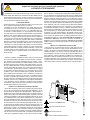 2
2
-
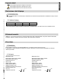 3
3
-
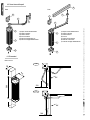 4
4
-
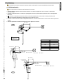 5
5
-
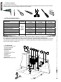 6
6
-
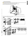 7
7
-
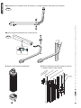 8
8
-
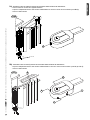 9
9
-
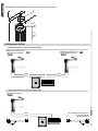 10
10
-
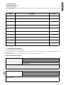 11
11
-
 12
12
-
 13
13
-
 14
14
-
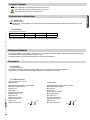 15
15
-
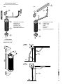 16
16
-
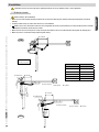 17
17
-
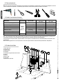 18
18
-
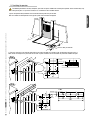 19
19
-
 20
20
-
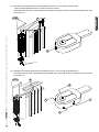 21
21
-
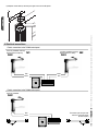 22
22
-
 23
23
-
 24
24
-
 25
25
-
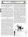 26
26
-
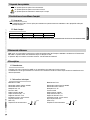 27
27
-
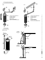 28
28
-
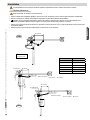 29
29
-
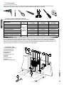 30
30
-
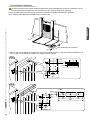 31
31
-
 32
32
-
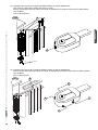 33
33
-
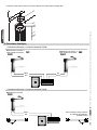 34
34
-
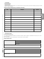 35
35
-
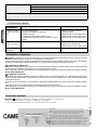 36
36
-
 37
37
-
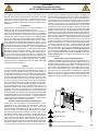 38
38
-
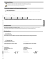 39
39
-
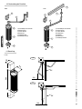 40
40
-
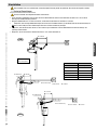 41
41
-
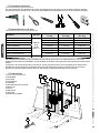 42
42
-
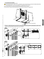 43
43
-
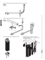 44
44
-
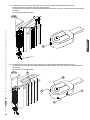 45
45
-
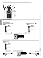 46
46
-
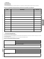 47
47
-
 48
48
-
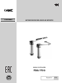 49
49
-
 50
50
-
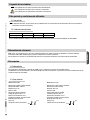 51
51
-
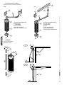 52
52
-
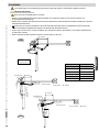 53
53
-
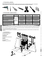 54
54
-
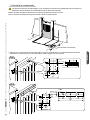 55
55
-
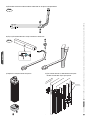 56
56
-
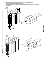 57
57
-
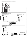 58
58
-
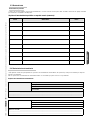 59
59
-
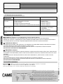 60
60
-
 61
61
-
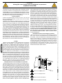 62
62
-
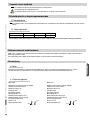 63
63
-
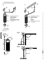 64
64
-
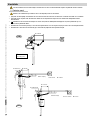 65
65
-
 66
66
-
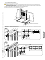 67
67
-
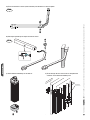 68
68
-
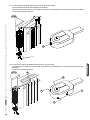 69
69
-
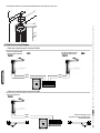 70
70
-
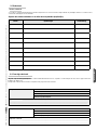 71
71
-
 72
72


in andere talen
- italiano: CAME Flex Guida d'installazione
- français: CAME Flex Guide d'installation
- Deutsch: CAME Flex Installationsanleitung
Gerelateerde papieren
-
CAME PS EASY Installatie gids
-
CAME 3199ZL90, 3199ZL90110 Spare Parts Manual
-
-
-
-
-
-
-
-