
ALIMENTATORE SUPPLEMENTARE
ADDITIONAL POWER SUPPLY UNIT
ALIMENTADOR ADICIONAL
ALIMENTATION SUPPLÉMENTAIRE
EXTRA VOEDINGSEENHEID
ZSP100
Alimentatore per Sistemi rivelazione incendio
Conforme Norma EN 54-4:1997+A1:2002+ A2:2006:2
Certificato di conformità CNBOP No.1438/CPD/0163
Certificate di approvazione CNBOP No. 2039/2014
Certificato di approvazione VdS No. G 511007

Attenzione
Prima dell'utilizzo leggere attentamente questo manuale.
Non toccare gli elementi interni del dispositivo.
Proteggere il dispositivo dall’ introduzione al suo interno di qualsiasi oggetto o liquido.
Non coprire i fori di ventilazione - pericolo di danneggiamento del dispositivo.
Assicurarsi che vi sia uno spazio libero di almeno10 cm ai lati del dispositivo per consentire la corretta ventilazione.
E 'vietato tenere il dispositivo con le batterie montate e collegate.
Il dispositivo deve essere alimentato dalla rete elettrica di servizio con un terminale di protezione a terra.
Il dispositivo può interferire con il funzionamento dei dispositivi radio o TV.
CARATTERISTICHE GENERALI
Gli alimentatori ZSP100 sono progettati per l’alimentazione di impianti di sicurezza antincendio a 24V, in conformità ai requisiti
delle norme EN 54-4 + A1 + A2 e EN 12101-10.
L’alimentazione di riserva è data da 2 batterie al piombo-acido VRLA da 12V.
Questi alimentatori sono progettati per il montaggio a parete.
CARATTERISTICHE TECNICHE
ALIMENTATORE USCITA IN
CORRENTE MAX.
CORRENTE DI
CARICA
BATTERIE DIMENSIONI
ZSP100-2.5A-18 2,5 A 1.0 A 7…20Ah
395x356x96mm
ZSP100-5.5A-18 5,5 A 1.0 A 7…20Ah
395x356x96mm
Fig.1. Vista frontale e laterale dell’alimentatore.
Gli alimentatori, nella parte superiore e sul lato sinistro, predispongono di fori pre-tranciati per il montaggio di passacavi,
dispongono anche di un ritaglio rettangolare sul retro per il passaggio dei cavi elettrici. Prima di installare gli alimentatori, si prega
di scegliere il percorso dei cavi, rimuovere la chiusura dei fori appropriati (rompendoli) e montare il numero corretto di passacavi
nei punti più adatti, in base alla tipologia di installazione.
CARATTERISTICHE ELETTRICHE
Alimentazione principale 230V +10% -15%
Tensione in uscita nominale 27.1V
Range tensione in uscita 20.0…28.0V
Assorbimento corrente batterie Max 35 mA
Massima resistenza circuito batterie *1 250mΩ
Numero batterie alloggiabili 2
Numero uscite protette da fusibile 2
Temperatura di funzionamento -25…+55°C
Grado di protezione EN 60529:1991+A1:2000 IP44
Classe di funzionamento EN 12101-10:2005
A
Classe ambientale EN 12101-10:2005
1
Classe ambientale VdS 2593
III
Classe sicurezza elettrica EN 60950-1:2006+A1:2010
I
*1 Il valore garantito della resistenza del circuito della batteria per attivare una segnalazione di guasto.

MONTAGGIO
Installare in un luogo senza insolazione diretta;
Assicurarsi di effettuare i collegamenti SENZA tensione elettrica principale (230V) e batterie;
Rispettare la polarità delle batterie;
Collegare l’alimentazione 230V e la messa a terra;
Verificare tutte le connessioni prima di alimentare il dispositivo.
Descrizione degli elementi dell’alimentatore
N°
Descrizione
Etichetta
1 Alimentazione 230V 50Hz L - N - Terra
2 Terminali batteria Battery
3 Sonda di temperatura
4 Connettore 1 Out 1
5 Connettore 2 Out 2
6 Uscita guasto generale Gen FLT
7 Uscita guasto alimentazione Mains FLT
8 Ingresso guasto esterno Ext FLT
9 LED verde Rete
10 LED giallo Batterie
11 Indicazione diodi Z201
12 Connettore tamper Z204 jumper
13 Ingresso indicazione esterna J201
I relè di uscita guasto (Gen FLT e Mains FLT), dispongono di contatti NC e NO.
L’ingresso per un guasto esterno deve essere chiuso per ottenere la segnalazione di guasto LED giallo acceso e lo scambio
del relè uscita Guasto Generale.
Se si vuole utilizzare il tamper apertura portella, collegare un contatto NC sul connettore Z204, in
caso contrario lasciare il jumper chiuso (default).
B201 FUSIBILE circuito di rete (ritardato T)
B101, B102 FUSIBILI circuiti di uscita (fast-blow F)
B103 FUSIBILE circuito della batteria (fast-blow F)
ACCENSIONE
Se tutte le connessioni sono effettuate correttamente, le indicazioni di stato devono essere quelle indicate nella tabella
sottostante, colonna 1.
Prima di utilizzare l'alimentatore, per favore, eseguire ulteriori due prove.
1. Prova di alimentazione di backup (batterie tampone):
Togliere l'alimentazione principale, l'alimentatore deve passare in modalità di funzionamento a batteria, verificare
la tensione in uscita sui faston della batteria.
Se viene tolto il fusibile di rete B201, la condizione può essere rilevata solo dopo 10 minuti.
Il relè GEN FLT interviene con un ritardo di 5 secondi.
2. Prova di presenza della batteria:
Quando l'alimentazione è quella della rete 230V, interrompere il circuito della batteria scollegando uno dei 2 poli
collegati ad essa. Questa condizione verrà rilevata al prossimo test, che può richiedere fino a 10 minuti.

FUNZIONAMENTO
1 NORMALE Test Batteria
Test
alimentazione
Stato LED sportello
frontale
230VAC LED verde Acceso Lampeggiante Acceso
ALLARM LED giallo Spento Acceso Acceso
Stato LED sulla scheda
RETE LED verde Acceso Spento Acceso
BATTERIA LED giallo Spento Spento Lampeggiante *
Stato RELE’
MAINS FLT Guasto alimentazione Attivato A riposo Attivato
GEN FLT Guasto generale Attivato A riposo A riposo
*) Se la batteria è scollegata per più di 30 min., Il diodo BAT sarà acceso fisso.
Verificare durante le prove se l'indicazione di guasto GEN FLT è stata trasmessa correttamente.
Attenzione non collegare il polo negativo della batteria (B) al polo negativo OUT1 OUT2 (-).
Con l'alimentazione di rete presente, la tensione della batteria è superiore a 21.6V.
L’ Indicazione di Warning (brevi lampeggi del LED ALLARME) viene visualizzata con tensioni intermedie.
Nella modalità di funzionamento a batteria, quando non c’è l'alimentazione primaria (230V) e il valore scende sotto i 21V, il
LVDD (Low Voltage Disconnect Device) scollega la batteria per evitare di danneggiarla.
Indicazione LED (portella frontale alimentatore):
230V LED Verde
0 Spento Assenza di rete, batteria scollegata
1 Acceso Rete presente, alimentatore / caricabatteria operativi
0/1 Lampeggiante Funzionamento a batteria:
alimentazione difettosa caricatore * 1)
Allarme LED giallo
0 Spento Funzionante ok
1Acceso Funzionamento a batteria:
alimentazione difettosa
-
Nessuna batteria, o la tensione di batteria collegata è inferiore a 10 V -
-
Resistenza del fusibile del circuito della batteria troppo alta (> 250mΩ)
-
Fusibile uscita bruciato
-
Tensione della batteria al di sotto di 22V con l'alimentazione di rete presente * 1)
0/1 lampeggio veloce
Allarme esterno o allarme interno (tamper)
0/1 lampeggio
lento
batteria riconosciuta (U> 10V), ma la tensione è troppo bassa (U <21.6V)
* 1) Lo stato può verificarsi quando l'alimentazione di rete è rientrata e quando la batteria inizia la ricarica.
Indicazione LED sulla scheda d’alimentazione:
0 Spento Assenza alimentazione di rete
1 Acceso Alimentazione di rete presente, alimentatore / caricabatteria funzionanti
0/1 lampeggio veloce Alimentazione di rete presente, alimentatore / caricabatterie difettoso * 1)
0 Spento Batteria funzionante
1 o 0/1 lampeggio lento Resistenza del circuito della batteria> 250mΩ (compresa la mancanza di batteria o fusibile
bruciato batteria * 1)
* 1) Il controllo dei valori di resistenza del circuito della batteria, compresa la disconnessione della batteria e del fusibile, è
eseguito ogni 10 minuti. Dopo aver rilevato l’anomalia tre volte, il LED BAT si accende fisso e, contemporaneamente,
l'indicazione relè guasto generale GEN FLT viene attivata.
Indicazione Relè (0 - relè diseccitato, 1 - relè eccitato)
Mains FLT Guasto alimentazione
0 Spento Mancanza alimentazione principale 230V
1 Acceso Rete elettrica presente, alimentatore / caricabatteria funzionanti
GEN FLT Guasto generale
0 Spento Allarme LED è acceso lampeggiante * 1), * 2)
1 Acceso Tutto ok
* 1) Guasto alimentazione / caricatore
* 2) Dopo un guasto rete elettrica e dopo il suo rientro, l'indicazione viene attivata con un ritardo di 5s.

Power supply unit for fire detection systems
Conforms to Standard EN 54-4:1997+A1:2002+ A2:2006:2
CNBOP certificate of conformity No.1438/CPD/0163
CNBOP certificate of approval No. 2039/2014
VdS Certificate of approval No. G 511007
Caution
Read this manual carefully before use.
Do not touch the internal elements of the device.
Make sure no objects or liquids can reach the inside of the device.
Do not cover the ventilation holes; doing so may cause the device to become damaged.
Make sure there is a free space of at least 10 cm either side of the device, to allow proper ventilation.
Do not hold the device with the batteries fitted and connected.
The device must be powered from the mains electricity supply with an earthed protection terminal.
The device may interfere with the operation of radio or TV devices.
GENERAL FEATURES
ZSP100 power supply units are designed to power 24 V fire detection safety systems, in compliance with the requirements
specified in standards EN 54-4 + A1 + A2 and EN 12101-10.
Backup power is provided by 2 x 12 V VRLA lead-acid batteries.
These power supply units are designed for wall mounting.
TECHNICAL CHARACTERISTICS
POWER SUPPLY
UNIT
MAX. CURRENT
OUTPUT
LOAD CURRENT BATTERIES DIMENSIONS
ZSP100-2.5 A-18 2.5 A 1.0 A 7…20 Ah 395x356x96 mm
ZSP100-5.5 A-18 5.5 A 1.0 A 7…20 Ah 395x356x96 mm
Fig.1. Front and side view of the power supply unit.
The power supply units have pre-cut holes at the top and on the left-hand side for fitting cable routing plugs; they also have a
rectangular cut-out on the back for the routing of electrical cables. Before installing the power supply units, please choose a cable
route, remove the middle of the relevant cut-outs (by breaking them) and fit the correct number of cable routing plugs at the most
suitable points, depending on the type of installation you have chosen.
ELECTRICAL SPECIFICATIONS
Main power supply 230 V +10% -15%
Rated voltage output 27.1 V
Output voltage range 20.0…28.0 V
Battery current absorption Max. 35 mA
Battery circuit maximum resistance *1 250 mΩ
Number of batteries housed 2
Number of outlets protected by fuse 2
Operating temperature -25…+55°C
Protection rating EN 60529:1991+A1:2000 IP44
Operating class EN 12101-10:2005
A
Environmental class EN 12101-10:2005
1
Environmental class VdS 2593
III
Electrical safety class EN 60950-1:2006+A1:2010
I
*1 The battery circuit resistor value guaranteed to trigger a fault indication.

MOUNTING
Install in a site which does not experience direct sunlight;
Make sure you carry out the connection procedure WITHOUT the mains voltage (230 V) and batteries connected;
Observe the polarity of the batteries;
Connect the 230 V power supply and earth connection;
Check all the connections before powering up the device.
Description of the power supply unit elements
No.
Description
Label
1 Power supply 230 V 50 Hz L - N - Earth
2 Battery terminals Battery
3 Temperature sensor
4 Connector 1 Out 1
5 Connector 2 Out 2
6 General fault output Gen FLT
7 Power supply fault output Mains FLT
8 External fault input Ext FLT
9 Green LED Mains
10 Yellow LED Batteries
11 Diode indication Z201
12 Tamper connector Z204 jumper
13 External indication input J201
The fault output relays (Gen FLT and Mains FLT) have NC and NO contacts.
The external fault input must be closed to obtain the steadily lit yellow LED fault indication and the switching of the General
Fault output relay.
If you want to use the door opening tamper, connect an NC contact on connector Z204; otherwise
leave the jumper closed (default).
B201 mains circuit (delayed T) FUSE
B101, B102 output circuits (fast-blow F) FUSES
B103 battery circuit (fast-blow F) FUSE
ACTIVATION
If all the connections have been performed correctly, the status indications should be those listed in the table below, column 1.
Before using the power supply unit, please carry out a further two tests.
1. Backup power supply test (backup battery):
Cut off the main power supply; the power supply unit should switch to battery operation mode. Check the output
voltage on the battery fastons.
If the B201 mains fuse is removed, the condition can only be detected after 10 minutes.
The GEN FLT relay intervenes with a delay of 5 seconds.
2. Battery presence test:
When the power is supplied from the 230 V mains, break the battery circuit by disconnecting one of the 2 poles
connected to it. This condition will be detected the next time a test is carried out, which may take up to 10 minutes.

OPERATION
1 NORMAL Battery test
Power supply
test
Front cover LED status
230 VAC Green LED On Flashing On
ALARM Yellow LED Off On On
Board LED status
MAINS Green LED On Off On
BATTERY Yellow LED Off Off Flashing *
RELAY status
MAINS FLT Power supply fault Activated In standby Activated
GEN FLT General fault Activated In standby In standby
*) If the battery is disconnected for over 30 minutes, the BAT diode will remain lit steadily.
Check whether the GEN FLT fault indication has been transmitted correctly during the tests.
Caution do not connect the negative pole of the battery (B) to the negative pole OUT1 OUT2 (-).
When mains power is being supplied, the battery voltage is over 21.6 V.
The Warning indication (brief flashes of the ALARM LED) is displayed with intermediate voltages.
In battery operating mode, when there is no primary (230 V) power supply and the value drops below 21 V, the LVDD (Low
Voltage Disconnect Device) disconnects the battery to avoid damaging it.
LED indication (power supply unit front door):
230 V Green LED
0 Off No mains, battery disconnected
1 On Mains power supply present, power supply unit / battery charger operative
0/1 Flashing Battery operation:
charger power supply faulty *1)
Alarm Yellow LED
0 Off Working ok
1 On
Battery operation:
faulty power supply
-
No battery, or the voltage of the battery connected is under 10 V -
-
Battery circuit fuse resistance too high (> 250 mΩ)
-
Output fuse blown
-
Battery voltage under 22 V with mains power supply present *1)
0/1 fast flashing
External alarm or internal alarm (tamper)
0/1 slow
flashing
battery recognised (U> 10 V), but the voltage is too low (U <21.6 V)
*1) The status may emerge when the mains power supply has been restored and when the battery begins recharging.
LED indication on the power supply board:
0 Off No mains power supply
1 On Mains power supply present, power supply unit / battery charger operative
0/1 fast flashing Mains power supply present, power supply unit / battery charger faulty *1)
0 Off Battery working
1 or 0/1 slow flashing Battery circuit resistance > 250 mΩ (including no battery or blown battery fuse *1)
*1) The battery circuit resistance values are checked, including battery and fuse disconnection, every 10 minutes. After the
fault has been detected three times, the BAT LED lights up steadily and the GEN FLT relay indication is activated at the same
time.
Relay indication (0 - relay de-energised, 1 - relay energised)
Mains FLT Power supply fault
0 Off No 230 V main power supply
1 On Electricity mains present, power supply unit / battery charger working
GEN FLT General fault
0 Off Alarm LED flashing *1), *2)
1 On All ok
*1) Power supply / charger fault
*2) After an electricity mains supply fault and after the power has been restored, the indication is activated with a delay of 5s.

Alimentation pour systèmes de détection des incendies
Conforme à la norme EN 54-4:1997+A1:2002+ A2:2006:2
Certificat de conformité CNBOP n° 1438/CPD/0163
Certificat d’homologation CNBOP n° 2039/2014
Certificat d’homologation VdS n° G 511007
Attention
Lire attentivement ce manuel avant d’utiliser le dispositif.
Ne pas toucher les éléments qui se trouvent à l’intérieur du dispositif.
Protéger le dispositif pour éviter la pénétration d’objets ou de liquide.
Ne pas couvrir les fentes d’aération - risque d’endommager le dispositif.
Laisser au moins 10 cm de chaque côté du dispositif pour assurer une bonne ventilation.
Il est interdit de laisser les batteries montées et branchées sur le dispositif.
Brancher le dispositif sur secteur disposant d’une mise à la terre.
Le dispositif peut compromettre le fonctionnement des dispositifs radio ou des téléviseurs.
CARACTÉRISTIQUES GÉNÉRALES
Les alimentations ZSP100 ont été conçues pour alimenter des systèmes de sécurité incendie à 24V, conformément aux
conditions dictées par les normes EN 54-4 + A1 + A2 et EN 12101-10.
L’alimentation de secours est assurée par 2 batteries au plomb (accumulateur acide) VRLA de 12V.
Ces alimentations sont conçues pour être installées en saillie.
CARACTÉRISTIQUES TECHNIQUES
ALIMENTATION COURANT MAXI DE
SORTIE
COURANT DE
CHARGE
BATTERIES DIMENSIONS
ZSP100-2.5A-18 2,5 A 1.0 A 7…20 Ah 395x356x96mm
ZSP100-5.5A-18 5,5 A 1.0 A 7…20 Ah 395x356x96mm
Fig.1. Vue avant et latérale de l’alimentation.
Les alimentations présentent des orifices prédécoupés pour le montage de serre-câbles sur le dessus et sur la gauche, et d’une
ouverture rectangulaire à l’arrière pour le passage des câbles électriques. Avant d’installer les alimentations, étudier le parcours
des câbles, ouvrir les orifices utiles (en cassant leur protection) et monter le nombre correct de serre-câbles sur les points
appropriés, en fonction du type d’installation.
CARACTÉRISTIQUES ÉLECTRIQUES
Alimentation principale 230 V +10% -15%
Tension de sortie nominale 27,1V
Plage de tension de sortie 20,0…28,0V
Absorption courant des batteries 35 mA maxi
Résistance maximale du circuit des batteries *1 250 mΩ
Nbre de batteries pouvant être installées 2
Nbre de sorties protégées par un fusible 2
Température de fonctionnement -25…+55 °C
Indice de protection EN 60529:1991+A1:2000 IP44
Classe de fonctionnement EN 12101-10:2005
A
Classe environnementale EN 12101-10:2005
1
Classe environnementale VdS 2593
III
Classe de sécurité électrique EN 60950-1:2006+A1:2010
I
*1 Valeur garantie de la résistance du circuit de la batterie pour déclencher la signalisation d’une anomalie.

MONTAGE
Installer le dispositif à l’abri du rayonnement solaire direct ;
S’assurer d’effectuer les connexions SANS tension électrique principale (230 V) ni batteries ;
Respecter la polarité des batteries ;
Brancher l’alimentation 230 V et la mise à la terre ;
Vérifier toutes les connexions avant de mettre le dispositif sous tension.
Description des composants de l’alimentation
N°
Description
Étiquette
1 Alimentation 230 V 50 Hz L - N - Terre
2 Cosses de la batterie Batterie
3 Sonde de température
4 Connecteur 1 Out 1
5 Connecteur 2 Out 2
6 Sortie panne générale Gen FLT
7 Sortie panne alimentation Mains FLT
8 Entrée panne extérieure Ext FLT
9 led verte Réseau
10 led jaune Batteries
11 Indication diodes Z201
12 Connecteur autoprotection Z204 cavalier
13 Entrée indication extérieure J201
Les relais de sortie panne (Gen FLT et Mains FLT) disposent de contacts NF et NO.
L’entrée pour une panne extérieure doit être fermée pour obtenir la signalisation de panne, led jaune allumée, et l’échange
du relais de sortie Panne Générale.
Pour utiliser l’autoprotection d’ouverture du volet, brancher un contact NF sur le connecteur Z204.
Dans le cas contraire, laisser le cavalier fermé (par défaut).
Indication des fusibles:
B201 secteur (retardé T)
B101, B102 circuits de sortie (fast-blow F)
B103 circuit de la batterie (fast-blow F)
ALLUMAGE
Si toutes les connexions sont réalisées correctement, les indications d’état doivent correspondre à celles du tableau ci-dessous,
colonne 1.
Effectuer deux tests supplémentaires avant d’utiliser l’alimentation.
1. Test d’alimentation de secours (batterie de secours):
Couper l'alimentation principale. L’alimentation doit passer en mode de fonctionnement sur batterie. Vérifier la
tension de sortie sur les fastons de la batterie.
En ôtant le fusible de réseau B201, la condition ne sera détectée qu’au bout de 10 minutes.
Le relais GEN FLT intervient avec un retard de 5 secondes.
2. Test de présence de la batterie :
Lorsque l'alimentation est celle du réseau 230 V, interrompre le circuit de la batterie en débranchant l’un de ses 2
pôles. Cette condition sera détectée au prochain test, qui peut durer 10 minutes.

FONCTIONNEMENT
1 NORMAL Test batterie
Test
alimentation
État led volet avant
230 Vca led verte Allumée Clignotante Allumée
ALLARM led jaune Éteinte Allumée Allumée
État led sur la carte
RÉSEAU led verte Allumée Éteinte Allumée
BATTERIE led jaune Éteinte Éteinte Clignotante *
État RELAIS
MAINS FLT Panne alimentation Activée Au repos Activée
GEN FLT Panne générale Activée Au repos Au repos
*) Si la batterie reste débranchée plus de 30 min., la diode BAT restera allumée.
Durant les tests, vérifier si l'indication de panne GEN FLT a été transmise correctement.
Attention, ne pas relier le pôle négatif de la batterie (B) au pôle négatif OUT1 OUT2 (-).
En présence de tension, la tension de la batterie est supérieure à 21,6 V.
L’indication de Warning (led d’ALARME clignotant rapidement) s’affiche en cas de tensions intermédiaires.
En mode de fonctionnement sur batterie, en l’absence de l’alimentation principale (230 V), si la valeur descend au-dessous de
21 V, le LVDD (Low Voltage Disconnect Device) déconnecte la batterie pour éviter de l’endommager.
Indication led (volet avant alimentation) :
230 V led verte
0 Éteinte Absence de tension, batterie déconnectée
1 Allumée Présence de tension, alimentation / chargeurs de batterie en service
0/1 Clignotante Fonctionnement sur batterie :
alimentation défectueuse du chargeur * 1)
Alarme led jaune
0 Éteinte Fonctionnement ok
1 Allumée Fonctionnement sur batterie :
alimentation défectueuse
-
Aucune batterie, ou la tension de la batterie connectée est inférieure à 10 V -
-
Résistance du fusible du circuit de la batterie trop élevée (> 250 mΩ)
-
Fusible de sortie grillé
-
Tension de la batterie inférieure à 22 V en présence de tension * 1)
0/1 clignotement
rapide
Alarme extérieure ou alarme intérieure (autoprotection)
0/1 clignotement
lent
batterie détectée (U > 10 V) mais la tension est trop basse (U < 21,6 V)
* 1) Possibilité de vérifier l’état lorsque la tension retourne sur sa valeur normale et lorsque la batterie commence à se
recharger.
Indication led sur la carte d’alimentation :
0 Éteinte Absence de tension
1 Allumée Présence de tension, alimentation / chargeurs de batterie en service
0/1 clignotement rapide Présence de tension, alimentation / chargeur de batterie défectueux * 1)
0 Éteinte Batterie en service
1 ou 0/1 clignotement
lent
Résistance du circuit de la batterie > 250 mΩ (comprenant l’absence de batterie ou
fusible de batterie grillé * 1)
* 1) Le contrôle des valeurs de résistance du circuit de la batterie, avec déconnexion de la batterie et du fusible, a lieu toutes
les 10 minutes. Après avoir détecté l’anomalie trois fois, la led BAT reste allumée et l’indication relais de panne générale se
déclenche simultanément.
Indication Relais (0 - relais désexcité, 1 - relais excité)
Mains FLT Panne alimentation
0 Éteinte Absence d’alimentation principale 230 V
1 Allumée Présence de tension, alimentation / chargeurs de batterie en service
GEN FLT Panne générale
0 Éteinte Led d’Alarme clignotante * 1), * 2)
1 Allumée Tout ok
* 1) Panne alimentation / chargeur
* 2) Après une panne de secteur et la remise sous tension, l'indication se déclenche avec un retard de 5 secondes.

Alimentador para sistemas de detección de incendios
Conforme con la norma EN 54-4:1997+A1:2002+ A2:2006:2
Certificado de conformidad CNBOP Núm. 1438/CPD/0163
Certificado de aprobación CNBOP Núm. 2039/2014
Certificado de aprobación VdS Núm. G 511007
Atención
Leer atentamente este manual antes de usar el dispositivo.
No tocar los elementos internos del dispositivo.
Proteger el dispositivo contra la penetración en su interior de cualquier objeto o líquido.
No cubrir los orificios de ventilación - Peligro de dañar el dispositivo.
Asegurarse de que alrededor del dispositivo quede un espacio libre de al menos 10 cm para permitir una correcta ventilación.
Se prohíbe cargar y transportar el dispositivo con las baterías montadas y conectadas.
El dispositivo se tiene que alimentar mediante la red eléctrica de servicio con un terminal de tierra de protección.
El dispositivo puede interferir en el funcionamiento de radios o televisores.
CARACTERÍSTICAS GENERALES
Los alimentadores o fuentes de alimentación ZSP100 se han diseñado para alimentar sistemas de detección de incendios a 24
V, en conformidad con los requisitos de las normas EN 54-4 + A1 + A2 y EN 12101-10.
Dos baterías de plomo-ácido VRLA de 12 V proporcionan la alimentación de reserva.
Los alimentadores se han diseñado para montarse en la pared.
CARACTERÍSTICAS TÉCNICAS
ALIMENTADOR SALIDA EN
CORRIENTE MÁX.
CORRIENTE DE
CARGA
BATERÍAS DIMENSIONES
ZSP100-2.5 A-18 2,5 A 1,0 A 7…20 Ah 395x356x96 mm
ZSP100-5.5 A-18 5,5 A 1,0 A 7…20 Ah 395x356x96 mm
Fig. 1. Vista frontal y lateral del alimentador.
En la parte superior y en el lado izquierdo de los alimentadores hay unos orificios troquelados para montar los pasacables;
además, en la parte trasera hay un orificio rectangular para pasar los cables eléctricos. Antes de instalar los alimentadores, se
debe seleccionar el recorrido de los cables, abrir los orificios adecuados (rompiendo su cierre) y montar el número correcto de
pasacables en los puntos más indicados teniendo en cuenta el tipo de instalación.
CARACTERÍSTICAS ELÉCTRICAS
Alimentación principal 230 V +10 % -15 %
Tensión de salida nominal 27,1 V
Intervalo de tensión en salida 20,0…28,0 V
Consumo de corriente de las baterías Máx. 35 mA
Máxima resistencia del circuito de baterías *1 250 mΩ
Número de baterías que se pueden alojar 2
Número de salidas protegidas por fusibles 2
Temperatura de funcionamiento -25…+55 °C
Grado de protección EN 60529:1991+A1:2000 IP44
Clase de funcionamiento EN 12101-10:2005
A
Clase ambiental EN 12101-10:2005
1
Clase ambiental VdS 2593
III
Clase de seguridad eléctrica EN 60950-1:2006+A1:2010
I
*1 Valor garantizado de la resistencia del circuito de la batería para activar una señalización de avería.

MONTAJE
Instalar el dispositivo en un lugar que no esté expuesto a la luz solar directa.
Asegurarse de efectuar las conexiones SIN tensión eléctrica principal (230 V) ni baterías.
Respetar la polaridad de las baterías.
Conectar la alimentación de 230 V y la toma de tierra.
Antes de alimentar el dispositivo, controlar que todas las conexiones sean correctas.
Descripción de los elementos del alimentador
N°
Descripción
Etiqueta
1 Alimentación de 230 V y 50 Hz L - N - Tierra
2 Terminales para conectar las baterías Battery
3 Sonda de temperatura
4 Conector 1 Out 1
5 Conector 2 Out 2
6 Salida avería general Gen FLT
7 Salida avería alimentación Mains FLT
8 Entrada avería externa Ext FLT
9 Led verde Red
10 Led amarillo Baterías
11 Indicación diodos Z201
12 Conector tamper Z204 jumper
13 Entrada indicación externa J201
Los relés de salida para avería (Gen FLT y Mains FLT) disponen de contactos normalmente cerrados y normalmente abiertos.
La entrada para una avería externa tiene que cerrarse para obtener la señalización de avería mediante el encendido del led
amarillo y el intercambio del relé de salida de avería general.
Si se desea utilizar el tamper de apertura de la tapa, conectar un contacto normalmente cerrado al
conector Z204; en caso contrario, dejar el puente cerrado (por defecto).
Indicación de los fusibles:
B201 Circuito de red (acción lenta T)
B101, B102 Circuitos de salida (acción rápida F)
B103 Circuito de la batería (acción rápida F)
ENCENDIDO
Si todas las conexiones se han efectuado correctamente, las indicaciones de estado tienen que ser las descritas en la columna
1 Normal de la tabla siguiente.
Antes de utilizar el alimentador, hay que efectuar otras dos pruebas.
1. Prueba de alimentación de reserva (baterías tampón):
Quitar la alimentación principal: el alimentador debe pasar al modo de funcionamiento con batería; comprobar la
tensión de salida en los conectores faston de la batería.
Si se quita el fusible de red B201, la condición solo se puede detectar transcurridos 10 minutos.
El relé GEN FLT interviene con un retardo de 5 segundos.
2. Prueba de presencia de la batería:
Cuando la alimentación es la de la red de 230 V, interrumpir el circuito de la batería desconectando uno de los
dos cables conectados a ella. Esta condición se detectará durante la siguiente prueba, que puede requerir hasta
10 minutos.

FUNCIONAMIENTO
1 NORMAL Prueba batería
Prueba
alimentación
Estado del led en la tapa frontal
230 Vca Led verde Encendido Parpadeante Encendido
ALARMA Led amarillo Apagado Encendido Encendido
Estado del led en la tarjeta
RED Led verde Encendido Apagado Encendido
BATERÍA Led amarillo Apagado Apagado Parpadeante *
Estado del RELÉ
MAINS FLT Avería de alimentación Activado En reposo Activado
GEN FLT Avería general Activado En reposo En reposo
*) Si la batería se mantiene desconectada durante más de 30 min, el diodo BAT estará encendido en modo fijo.
Controlar que, durante las pruebas, la indicación de avería GEN FLT se transmita correctamente.
Atención: no conectar el polo negativo de la batería (B) al polo negativo OUT1 OUT2 (-).
Con la alimentación de red presente, la tensión de la batería es superior a 21,6 V.
La indicación de aviso (breves parpadeos del led ALARMA) se visualiza con tensiones intermedias.
En el modo de funcionamiento con batería, cuando no hay alimentación principal (230 V), si el valor desciende por debajo de
21 V, el LVDD (Low Voltage Disconnect Device) desconecta la batería para evitar que se dañe.
Indicación del led en la tapa frontal del alimentador:
230 V Led verde
0 Apagado No hay alimentación de red, batería desconectada
1 Encendido Red presente, alimentador / cargador de baterías funcionando
0/1 Parpadeante Funcionamiento con batería:
alimentación defectuosa del cargador * 1)
Alarma Led amarillo
0 Apagado Funcionamiento correcto
1 Encendido Funcionamiento con batería:
alimentación defectuosa
-
Ninguna batería o la tensión de la batería conectada es inferior a 10 V -
-
Resistencia del fusible del circuito de la batería demasiado alta (> 250 mΩ)
-
Fusible de la salida fundido
-
Tensión de la batería por debajo de 22 V con alimentación de red presente * 1)
0/1 Parpadeo rápido
Alarma externa o alarma interna (tamper)
0/1 Parpadeo
lento
Batería reconocida (U > 10 V), pero la tensión es demasiado baja (U < 21,6 V)
* 1) Este estado se puede presentar cuando la alimentación de red ha vuelto y la batería empieza la recarga.
Indicación del led en la tarjeta de alimentación:
0 Apagado No hay alimentación de red
1 Encendido Alimentación de red presente, alimentador / cargador de baterías funcionando
0/1 Parpadeo rápido Alimentación de red presente, alimentador / cargador de baterías defectuoso * 1)
0 Apagado Batería funcionando
1 o 0/1 Parpadeo lento
Resistencia del circuito de la batería > 250 mΩ (incluida la falta de batería o fusible
fundido de la batería * 1)
* 1) Los valores de resistencia del circuito de la batería, incluida la desconexión de la batería y del fusible, se controlan cada
10 minutos. Tras detectar la anomalía tres veces, el led BAT se enciende fijo y, al mismo tiempo, se activa la indicación del
relé de avería general GEN FLT.
Indicación del relé (0 - relé desexcitado, 1 - relé excitado)
Mains FLT Avería de alimentación
0 Apagado Falta alimentación principal de 230 V
1 Encendido Red eléctrica presente, alimentador / cargador de baterías funcionando
GEN FLT Avería general
0 Apagado Led alarma encendido parpadeante * 1), * 2)
1 Encendido Todo correcto
* 1) Avería alimentación / cargador
* 2) Tras una avería de red eléctrica, una vez vuelve la corriente, la indicación se activa con un retardo de 5s.

Voedingseenheid voor branddetectiesystemen
Voldoet aan de norm EN 54-4:1997+A1:2002+ A2:2006:2
Conformiteitsverklaring CNBOP Nr.1438/CPD/0163
Goedkeuringscertificaten CNBOP Nr. 2039/2014
Goedkeuringscertificaat VdS Nr. G 511007
Let op
Voor gebruik deze handleiding zorgvuldig doorlezen.
De interne onderdelen van het apparaat niet aanraken.
Het apparaat beschermen tegen indringing van voorwerpen of vloeistoffen.
De ventilatieopeningen niet bedekken - gevaar voor beschadiging van het apparaat.
Zorg ervoor dat er een vrije ruimte van minimaal 10 cm aan weerszijden van het apparaat aanwezig is om te zorgen voor een
goede ventilatie.
Het is niet toegestaan het apparaat met geplaatste en aangesloten batterijen te bewaren.
Het apparaat moet worden gevoed door het stroomnet met een aardingsklem.
Het apparaat kan interfereren met de werking van radio- en tv-toestellen.
ALGEMENE EIGENSCHAPPEN
De voedingseenheden ZSP100 zijn ontworpen voor de voeding van 24V brandbeveiligingssystemen conform de eisen van de
norm EN 54-4 + A1 + A2 en EN 12101-10.
De reservevoeding is voorzien van 2 VRLA lood-zuurbatterijen van 12V.
Deze voedingseenheden zijn geschikt voor wandmontage.
TECHNISCHE EIGENSCHAPPEN
VOEDINGSEENHEID MAX.
UITGANGSSPANNING
LAADSTROOM BATTERIJEN AFMETINGEN
ZSP100-2.5A-18 2,5 A 1,0 A 7…20Ah 395x356x96mm
ZSP100-5.5A-18 5,5 A 1,0 A 7…20Ah 395x356x96mm
Fig.1. Front- en zijaanzicht van de voedingseenheid.
De voedingseenheden zijn aan de bovenzijde en de linkerzijde voorzien van voorgeboorde gaten voor de montage van de
kabelgeleiders en beschikken ook over een rechthoekige uitsnijding aan de achterkant voor de doorvoer van de elektrische kabels.
Alvorens de voedingseenheid te installeren, moet het kabeltraject worden bepaald, moet de afsluiting van de betreffende gaten
worden verwijderd (door ze te breken) en moet het juiste aantal kabelgeleiders op de meeste geschikte plaatsen worden
aangebracht, afhankelijk van het type installatie.
ELEKTRISCHE EIGENSCHAPPEN
Hoofdvoeding 230V +10% -15%
Nominale uitgangsspanning 27,1V
Bereik uitgangsspanning 20.0…28.0V
Stroomverbruik batterijen Max 35 mA
Maximale weerstand batterijcircuit *1 250mΩ
Aantal plaatsbare batterijen 2
Aantal gezekerde uitgangen 2
Bedrijfstemperatuur -25…+55°C
Beschermingsgraad EN 60529:1991+A1:2000 IP44
Werkingsklasse EN 12101-10:2005
A
Omgevingsklasse EN 12101-10:2005
1
Omgevingsklasse VdS 2593
III
Elektrische veiligheidsklasse EN 60950-1:2006+A1:2010
I
*1 De gegarandeerde weerstandswaarde van het batterijcircuit om een storingssignaal te activeren.

MONTAGE
Installeren op een plaats die beschermd is tegen direct zonlicht;
Voer de aansluitingen uit ZONDER elektrische hoofdspanning (230V) en batterijen;
Neem de polariteit van de batterijen in acht;
Sluit de 230V voeding en de aarding aan;
Controleer alle aansluitingen alvorens de stroom van het apparaat in te schakelen.
Omschrijving van de onderdelen van de voedingseenheid
Nr.
Beschrijving
Label
1 Voeding 230V 50Hz L - N - Aarde
2 Batterijklemmen Battery
3 Temperatuursensor
4 Connector 1 Out 1
5 Connector 2 Out 2
6 Algemene storingsuitgang Gen FLT
7 Storingsuitgang voeding Mains FLT
8 Externe storingsingang Ext FLT
9 Groene led Netstroom
10 Gele led: Batterijen
11 Indicatie diodes Z201
12 Tamper connector Z204 jumper
13 Externe signaleringsingang J201
De relais van de storingsuitgang (Gen FLT en Mains FLT), zijn voorzien van NC en NO-contacten.
De externe storingsingang moet gesloten zijn om het storingssignaal te ontvangen waarbij de gele led brandt en de
wisseling van het relais Algemene storingsuitgang
Als u de tamper opening frontpaneel wilt gebruiken, sluit dan een NC-contact aan op de connector
Z204. Zo niet, laat de jumper dan gesloten (default).
Indicatie zekeringen:
B201 netstroomcircuit (vertraagde T)
B101, B102 uitgangscircuits (fast-blow F)
B103 batterijcircuit (fast-blow F)
INSCHAKELING
Als de aansluitingen allemaal correct zijn uitgevoerd, moeten de statusindicaties overeenkomen met hetgeen is aangegeven in
de onderstaande tabel, kolom 1.
Alvorens de voedingseenheid te gebruiken, gelieve nog twee tests uit te voeren.
1. Test back-upvoeding (back-upbatterij):
Sluit de hoofdvoeding af, de voedingseenheid moet naar de werkingsmodus op batterij gaan. Controleer de
uitgangsspanning op de fastonaansluitingen van de batterij.
Als de zekering B201 van de netstroom wordt verwijderd, kan de conditie pas na 10 minuten worden afgelezen.
Het relais GEN FLT treedt in werking met een vertraging van 5 seconden.
2. Aanwezigheidstest batterij:
Als de voeding de 230V netvoeding is, moet het circuit van de batterij worden onderbroken door één van de 2
aangesloten polen los te koppelen. Deze conditie wordt afgelezen bij de volgende test, dit kan maar liefst 10
minuten duren.

HANDELING
1 NORMAAL Batterijtest
Voedingstest
Led
-
status frontpaneel
230VAC Groene led Aan Knipperend Aan
ALARM Gele led: Uit Aan Aan
Status-led op de kaart
NETSTROOM Groene led Aan Uit Aan
BATTERIJ Gele led: Uit Uit Knipperend *
Relaisstatus
MAINS FLT Storing voeding Geactiveerd Stand-by Geactiveerd
GEN FLT Algemene storing Geactiveerd Stand-by Stand-by
*) Als de batterij langer dan 30 min. is losgekoppeld, zal de diode BAT blijven branden.
Controleer tijdens de tests of de storingsindicatie GEN FLT correct is verzonden.
Let op de negatieve pool van de batterij (B) niet aansluiten op de negatieve pool OUT1 OUT2 (-).
Als er netvoeding aanwezig is, zal de batterijspanning hoger zijn dan 21.6V.
De indicatie Warning (de ALARM-LED knippert kort) zal worden weergegeven met gemiddelde spanningen.
In de werkingsmodus met batterij, als de hoofdvoeding (230V) ontbreekt, daalt de waarde tot onder de 21V, de LVDD (Low
Voltage Disconnect Device) koppelt de batterij los om beschadiging van het apparaat te voorkomen.
Led-indicatie (frontpaneel voedingseenheid):
230V Groene led
0 Uit Geen netstroom, batterij losgekoppeld
1 Aan Netstroom aanwezig, voedingseenheid / batterijoplader werkt
0/1 Knippert Werking op batterij:
defecte voeding lader * 1)
Alarm Gele led:
0 Uit Werking ok
1Aan Werking op batterij:
defecte voeding
-
Geen batterij, of de spanning van de aangesloten batterij is lager dan 10 V -
-
De zekeringsweerstand van het circuit van de batterij is te hoog (> 250mΩ)
-
Uitgangszekering verbrand
-
Batterijspanning lager dan 22V terwijl de netvoeding aanwezig is * 1)
0/1 snel knipperend
Extern alarm of intern alarm (tamper)
0/1 knippert
langzaam
batterij herkend (U> 10V), maar de spanning is te laag (U <21.6V)
* 1) De status kan optreden als de netvoeding is teruggekeerd en de batterij begint te laden.
Led-indicatie op de voedingskaart:
0 Uit Geen netvoeding
1 Aan Netvoeding aanwezig, voedingseenheid / batterijoplader werkt
0/1 knippert snel Netvoeding aanwezig, voedingseenheid / batterijoplader defect * 1)
0 Uit Batterij werkt
1 of 0/1 langzaam
knipperend
Weerstand van het batterijcircuit> 250mΩ (inclusief het ontbreken van de batterij of
verbrande zekering batterij * 1)
* 1) De controle van de weerstandswaarden van het batterijcircuit, inclusief de loskoppeling van de batterij en de zekering,
wordt elke 10 minuten uitgevoerd. Nadat de storing drie maal is afgelezen, zal de de led BAT gaan branden en wordt
tegelijkertijd de relais-indicatie algemene storing GEN FLT geactiveerd.
Relais-indicatie (0 - relais gedeactiveerd, 1 - relais geactiveerd)
Mains FLT Storing voeding
0 Uit Geen 230V hoofdvoeding
1 Aan Netvoeding aanwezig, voedingseenheid / batterijoplader werkt
GEN FLT Algemene storing
0 Uit Led-alarm knippert * 1), * 2)
1 Aan Alles ok
* 1) Storing voeding / lader
* 2) Na een stroomstoring en het terugkeren van de netvoeding, wordt de indicatie geactiveerd met een vertraging van 5s.

Comelit Group Spa – Via Don Arrigoni 5
24020 Rovetta S. Lorenzo (Italy)
Tel. +39 (0) 346 750011
Fax +39 (0) 346 71436
www.comelitgroup.com
Documenttranscriptie
ALIMENTATORE SUPPLEMENTARE ADDITIONAL POWER SUPPLY UNIT ALIMENTADOR ADICIONAL ALIMENTATION SUPPLÉMENTAIRE EXTRA VOEDINGSEENHEID ZSP100 Alimentatore per Sistemi rivelazione incendio Conforme Norma EN 54-4:1997+A1:2002+ A2:2006:2 Certificato di conformità CNBOP No.1438/CPD/0163 Certificate di approvazione CNBOP No. 2039/2014 Certificato di approvazione VdS No. G 511007 Attenzione Prima dell'utilizzo leggere attentamente questo manuale. Non toccare gli elementi interni del dispositivo. Proteggere il dispositivo dall’ introduzione al suo interno di qualsiasi oggetto o liquido. Non coprire i fori di ventilazione - pericolo di danneggiamento del dispositivo. Assicurarsi che vi sia uno spazio libero di almeno10 cm ai lati del dispositivo per consentire la corretta ventilazione. E 'vietato tenere il dispositivo con le batterie montate e collegate. Il dispositivo deve essere alimentato dalla rete elettrica di servizio con un terminale di protezione a terra. Il dispositivo può interferire con il funzionamento dei dispositivi radio o TV. CARATTERISTICHE GENERALI Gli alimentatori ZSP100 sono progettati per l’alimentazione di impianti di sicurezza antincendio a 24V, in conformità ai requisiti delle norme EN 54-4 + A1 + A2 e EN 12101-10. L’alimentazione di riserva è data da 2 batterie al piombo-acido VRLA da 12V. Questi alimentatori sono progettati per il montaggio a parete. CARATTERISTICHE TECNICHE ALIMENTATORE USCITA IN CORRENTE MAX. CORRENTE DI CARICA BATTERIE DIMENSIONI ZSP100-2.5A-18 ZSP100-5.5A-18 2,5 A 5,5 A 1.0 A 1.0 A 7…20Ah 7…20Ah 395x356x96mm 395x356x96mm Fig.1. Vista frontale e laterale dell’alimentatore. Gli alimentatori, nella parte superiore e sul lato sinistro, predispongono di fori pre-tranciati per il montaggio di passacavi, dispongono anche di un ritaglio rettangolare sul retro per il passaggio dei cavi elettrici. Prima di installare gli alimentatori, si prega di scegliere il percorso dei cavi, rimuovere la chiusura dei fori appropriati (rompendoli) e montare il numero corretto di passacavi nei punti più adatti, in base alla tipologia di installazione. CARATTERISTICHE ELETTRICHE Alimentazione principale 230V +10% -15% Tensione in uscita nominale 27.1V Range tensione in uscita 20.0…28.0V Assorbimento corrente batterie Max 35 mA Massima resistenza circuito batterie *1 250mΩ Numero batterie alloggiabili 2 Numero uscite protette da fusibile 2 Temperatura di funzionamento -25…+55°C Grado di protezione EN 60529:1991+A1:2000 IP44 A Classe di funzionamento EN 12101-10:2005 1 Classe ambientale EN 12101-10:2005 III Classe ambientale VdS 2593 I Classe sicurezza elettrica EN 60950-1:2006+A1:2010 *1 Il valore garantito della resistenza del circuito della batteria per attivare una segnalazione di guasto. MONTAGGIO Installare in un luogo senza insolazione diretta; Assicurarsi di effettuare i collegamenti SENZA tensione elettrica principale (230V) e batterie; Rispettare la polarità delle batterie; Collegare l’alimentazione 230V e la messa a terra; Verificare tutte le connessioni prima di alimentare il dispositivo. Descrizione degli elementi dell’alimentatore N° 1 2 3 4 5 6 7 8 9 10 11 12 13 Descrizione Alimentazione 230V 50Hz Terminali batteria Sonda di temperatura Connettore 1 Connettore 2 Uscita guasto generale Uscita guasto alimentazione Ingresso guasto esterno LED verde LED giallo Indicazione diodi Connettore tamper Ingresso indicazione esterna Etichetta L - N - Terra Battery Out 1 Out 2 Gen FLT Mains FLT Ext FLT Rete Batterie Z201 Z204 jumper J201 I relè di uscita guasto (Gen FLT e Mains FLT), dispongono di contatti NC e NO. L’ingresso per un guasto esterno deve essere chiuso per ottenere la segnalazione di guasto LED giallo acceso e lo scambio del relè uscita Guasto Generale. Se si vuole utilizzare il tamper apertura portella, collegare un contatto NC sul connettore Z204, in caso contrario lasciare il jumper chiuso (default). B201 B101, B102 B103 FUSIBILE circuito di rete (ritardato T) FUSIBILI circuiti di uscita (fast-blow F) FUSIBILE circuito della batteria (fast-blow F) ACCENSIONE Se tutte le connessioni sono effettuate correttamente, le indicazioni di stato devono essere quelle indicate nella tabella sottostante, colonna 1. Prima di utilizzare l'alimentatore, per favore, eseguire ulteriori due prove. 1. 2. Prova di alimentazione di backup (batterie tampone): Togliere l'alimentazione principale, l'alimentatore deve passare in modalità di funzionamento a batteria, verificare la tensione in uscita sui faston della batteria. Se viene tolto il fusibile di rete B201, la condizione può essere rilevata solo dopo 10 minuti. Il relè GEN FLT interviene con un ritardo di 5 secondi. Prova di presenza della batteria: Quando l'alimentazione è quella della rete 230V, interrompere il circuito della batteria scollegando uno dei 2 poli collegati ad essa. Questa condizione verrà rilevata al prossimo test, che può richiedere fino a 10 minuti. FUNZIONAMENTO Stato LED sportello frontale 230VAC LED verde ALLARM LED giallo Stato LED sulla scheda RETE LED verde BATTERIA LED giallo Stato RELE’ MAINS FLT Guasto alimentazione GEN FLT Guasto generale 1 NORMALE Test Batteria Test alimentazione Acceso Spento Lampeggiante Acceso Acceso Acceso Acceso Spento Spento Spento Acceso Lampeggiante * Attivato Attivato A riposo A riposo Attivato A riposo *) Se la batteria è scollegata per più di 30 min., Il diodo BAT sarà acceso fisso. Verificare durante le prove se l'indicazione di guasto GEN FLT è stata trasmessa correttamente. Attenzione non collegare il polo negativo della batteria (B) al polo negativo OUT1 OUT2 (-). Con l'alimentazione di rete presente, la tensione della batteria è superiore a 21.6V. L’ Indicazione di Warning (brevi lampeggi del LED ALLARME) viene visualizzata con tensioni intermedie. Nella modalità di funzionamento a batteria, quando non c’è l'alimentazione primaria (230V) e il valore scende sotto i 21V, il LVDD (Low Voltage Disconnect Device) scollega la batteria per evitare di danneggiarla. Indicazione LED (portella frontale alimentatore): 230V 0 Spento 1 Acceso 0/1 Lampeggiante Allarme 0 Spento 1Acceso 0/1 lampeggio veloce 0/1 lampeggio lento LED Verde Assenza di rete, batteria scollegata Rete presente, alimentatore / caricabatteria operativi Funzionamento a batteria: alimentazione difettosa caricatore * 1) LED giallo Funzionante ok Funzionamento a batteria: alimentazione difettosa - Nessuna batteria, o la tensione di batteria collegata è inferiore a 10 V - Resistenza del fusibile del circuito della batteria troppo alta (> 250mΩ) - Fusibile uscita bruciato - Tensione della batteria al di sotto di 22V con l'alimentazione di rete presente * 1) Allarme esterno o allarme interno (tamper) batteria riconosciuta (U> 10V), ma la tensione è troppo bassa (U <21.6V) * 1) Lo stato può verificarsi quando l'alimentazione di rete è rientrata e quando la batteria inizia la ricarica. Indicazione LED sulla scheda d’alimentazione: 0 Spento 1 Acceso 0/1 lampeggio veloce 0 Spento 1 o 0/1 lampeggio lento Assenza alimentazione di rete Alimentazione di rete presente, alimentatore / caricabatteria funzionanti Alimentazione di rete presente, alimentatore / caricabatterie difettoso * 1) Batteria funzionante Resistenza del circuito della batteria> 250mΩ (compresa la mancanza di batteria o fusibile bruciato batteria * 1) * 1) Il controllo dei valori di resistenza del circuito della batteria, compresa la disconnessione della batteria e del fusibile, è eseguito ogni 10 minuti. Dopo aver rilevato l’anomalia tre volte, il LED BAT si accende fisso e, contemporaneamente, l'indicazione relè guasto generale GEN FLT viene attivata. Indicazione Relè (0 - relè diseccitato, 1 - relè eccitato) Mains FLT 0 Spento 1 Acceso GEN FLT 0 Spento 1 Acceso Guasto alimentazione Mancanza alimentazione principale 230V Rete elettrica presente, alimentatore / caricabatteria funzionanti Guasto generale Allarme LED è acceso lampeggiante * 1), * 2) Tutto ok * 1) Guasto alimentazione / caricatore * 2) Dopo un guasto rete elettrica e dopo il suo rientro, l'indicazione viene attivata con un ritardo di 5s. Power supply unit for fire detection systems Conforms to Standard EN 54-4:1997+A1:2002+ A2:2006:2 CNBOP certificate of conformity No.1438/CPD/0163 CNBOP certificate of approval No. 2039/2014 VdS Certificate of approval No. G 511007 Caution Read this manual carefully before use. Do not touch the internal elements of the device. Make sure no objects or liquids can reach the inside of the device. Do not cover the ventilation holes; doing so may cause the device to become damaged. Make sure there is a free space of at least 10 cm either side of the device, to allow proper ventilation. Do not hold the device with the batteries fitted and connected. The device must be powered from the mains electricity supply with an earthed protection terminal. The device may interfere with the operation of radio or TV devices. GENERAL FEATURES ZSP100 power supply units are designed to power 24 V fire detection safety systems, in compliance with the requirements specified in standards EN 54-4 + A1 + A2 and EN 12101-10. Backup power is provided by 2 x 12 V VRLA lead-acid batteries. These power supply units are designed for wall mounting. TECHNICAL CHARACTERISTICS POWER SUPPLY UNIT MAX. CURRENT OUTPUT LOAD CURRENT BATTERIES DIMENSIONS ZSP100-2.5 A-18 ZSP100-5.5 A-18 2.5 A 5.5 A 1.0 A 1.0 A 7…20 Ah 7…20 Ah 395x356x96 mm 395x356x96 mm Fig.1. Front and side view of the power supply unit. The power supply units have pre-cut holes at the top and on the left-hand side for fitting cable routing plugs; they also have a rectangular cut-out on the back for the routing of electrical cables. Before installing the power supply units, please choose a cable route, remove the middle of the relevant cut-outs (by breaking them) and fit the correct number of cable routing plugs at the most suitable points, depending on the type of installation you have chosen. ELECTRICAL SPECIFICATIONS Main power supply 230 V +10% -15% Rated voltage output 27.1 V Output voltage range 20.0…28.0 V Battery current absorption Max. 35 mA Battery circuit maximum resistance *1 250 mΩ Number of batteries housed 2 Number of outlets protected by fuse 2 Operating temperature -25…+55°C Protection rating EN 60529:1991+A1:2000 IP44 A Operating class EN 12101-10:2005 1 Environmental class EN 12101-10:2005 III Environmental class VdS 2593 I Electrical safety class EN 60950-1:2006+A1:2010 *1 The battery circuit resistor value guaranteed to trigger a fault indication. MOUNTING Install in a site which does not experience direct sunlight; Make sure you carry out the connection procedure WITHOUT the mains voltage (230 V) and batteries connected; Observe the polarity of the batteries; Connect the 230 V power supply and earth connection; Check all the connections before powering up the device. Description of the power supply unit elements No. 1 2 3 4 5 6 7 8 9 10 11 12 13 Description Power supply 230 V 50 Hz Battery terminals Temperature sensor Connector 1 Connector 2 General fault output Power supply fault output External fault input Green LED Yellow LED Diode indication Tamper connector External indication input Label L - N - Earth Battery Out 1 Out 2 Gen FLT Mains FLT Ext FLT Mains Batteries Z201 Z204 jumper J201 The fault output relays (Gen FLT and Mains FLT) have NC and NO contacts. The external fault input must be closed to obtain the steadily lit yellow LED fault indication and the switching of the General Fault output relay. If you want to use the door opening tamper, connect an NC contact on connector Z204; otherwise leave the jumper closed (default). B201 B101, B102 B103 mains circuit (delayed T) FUSE output circuits (fast-blow F) FUSES battery circuit (fast-blow F) FUSE ACTIVATION If all the connections have been performed correctly, the status indications should be those listed in the table below, column 1. Before using the power supply unit, please carry out a further two tests. 1. 2. Backup power supply test (backup battery): Cut off the main power supply; the power supply unit should switch to battery operation mode. Check the output voltage on the battery fastons. If the B201 mains fuse is removed, the condition can only be detected after 10 minutes. The GEN FLT relay intervenes with a delay of 5 seconds. Battery presence test: When the power is supplied from the 230 V mains, break the battery circuit by disconnecting one of the 2 poles connected to it. This condition will be detected the next time a test is carried out, which may take up to 10 minutes. Front cover LED status 230 VAC ALARM Board LED status MAINS BATTERY RELAY status MAINS FLT GEN FLT OPERATION 1 NORMAL Battery test Power supply test Green LED Yellow LED On Off Flashing On On On Green LED Yellow LED On Off Off Off On Flashing * Power supply fault General fault Activated Activated In standby In standby Activated In standby *) If the battery is disconnected for over 30 minutes, the BAT diode will remain lit steadily. Check whether the GEN FLT fault indication has been transmitted correctly during the tests. Caution do not connect the negative pole of the battery (B) to the negative pole OUT1 OUT2 (-). When mains power is being supplied, the battery voltage is over 21.6 V. The Warning indication (brief flashes of the ALARM LED) is displayed with intermediate voltages. In battery operating mode, when there is no primary (230 V) power supply and the value drops below 21 V, the LVDD (Low Voltage Disconnect Device) disconnects the battery to avoid damaging it. LED indication (power supply unit front door): 230 V 0 Off 1 On 0/1 Flashing Green LED No mains, battery disconnected Mains power supply present, power supply unit / battery charger operative Battery operation: charger power supply faulty *1) Yellow LED Working ok Battery operation: faulty power supply - No battery, or the voltage of the battery connected is under 10 V - Battery circuit fuse resistance too high (> 250 mΩ) - Output fuse blown - Battery voltage under 22 V with mains power supply present *1) External alarm or internal alarm (tamper) Alarm 0 Off 1 On 0/1 fast flashing 0/1 slow flashing battery recognised (U> 10 V), but the voltage is too low (U <21.6 V) *1) The status may emerge when the mains power supply has been restored and when the battery begins recharging. LED indication on the power supply board: 0 Off 1 On 0/1 fast flashing 0 Off 1 or 0/1 slow flashing No mains power supply Mains power supply present, power supply unit / battery charger operative Mains power supply present, power supply unit / battery charger faulty *1) Battery working Battery circuit resistance > 250 mΩ (including no battery or blown battery fuse *1) *1) The battery circuit resistance values are checked, including battery and fuse disconnection, every 10 minutes. After the fault has been detected three times, the BAT LED lights up steadily and the GEN FLT relay indication is activated at the same time. Relay indication (0 - relay de-energised, 1 - relay energised) Mains FLT 0 Off 1 On GEN FLT 0 Off 1 On Power supply fault No 230 V main power supply Electricity mains present, power supply unit / battery charger working General fault Alarm LED flashing *1), *2) All ok *1) Power supply / charger fault *2) After an electricity mains supply fault and after the power has been restored, the indication is activated with a delay of 5s. Alimentation pour systèmes de détection des incendies Conforme à la norme EN 54-4:1997+A1:2002+ A2:2006:2 Certificat de conformité CNBOP n° 1438/CPD/0163 Certificat d’homologation CNBOP n° 2039/2014 Certificat d’homologation VdS n° G 511007 Attention Lire attentivement ce manuel avant d’utiliser le dispositif. Ne pas toucher les éléments qui se trouvent à l’intérieur du dispositif. Protéger le dispositif pour éviter la pénétration d’objets ou de liquide. Ne pas couvrir les fentes d’aération - risque d’endommager le dispositif. Laisser au moins 10 cm de chaque côté du dispositif pour assurer une bonne ventilation. Il est interdit de laisser les batteries montées et branchées sur le dispositif. Brancher le dispositif sur secteur disposant d’une mise à la terre. Le dispositif peut compromettre le fonctionnement des dispositifs radio ou des téléviseurs. CARACTÉRISTIQUES GÉNÉRALES Les alimentations ZSP100 ont été conçues pour alimenter des systèmes de sécurité incendie à 24V, conformément aux conditions dictées par les normes EN 54-4 + A1 + A2 et EN 12101-10. L’alimentation de secours est assurée par 2 batteries au plomb (accumulateur acide) VRLA de 12V. Ces alimentations sont conçues pour être installées en saillie. CARACTÉRISTIQUES TECHNIQUES ALIMENTATION COURANT MAXI DE SORTIE COURANT DE CHARGE BATTERIES DIMENSIONS ZSP100-2.5A-18 ZSP100-5.5A-18 2,5 A 5,5 A 1.0 A 1.0 A 7…20 Ah 7…20 Ah 395x356x96mm 395x356x96mm Fig.1. Vue avant et latérale de l’alimentation. Les alimentations présentent des orifices prédécoupés pour le montage de serre-câbles sur le dessus et sur la gauche, et d’une ouverture rectangulaire à l’arrière pour le passage des câbles électriques. Avant d’installer les alimentations, étudier le parcours des câbles, ouvrir les orifices utiles (en cassant leur protection) et monter le nombre correct de serre-câbles sur les points appropriés, en fonction du type d’installation. CARACTÉRISTIQUES ÉLECTRIQUES Alimentation principale 230 V +10% -15% Tension de sortie nominale 27,1V Plage de tension de sortie 20,0…28,0V Absorption courant des batteries 35 mA maxi Résistance maximale du circuit des batteries *1 250 mΩ Nbre de batteries pouvant être installées 2 Nbre de sorties protégées par un fusible 2 Température de fonctionnement -25…+55 °C Indice de protection EN 60529:1991+A1:2000 IP44 A Classe de fonctionnement EN 12101-10:2005 1 Classe environnementale EN 12101-10:2005 III Classe environnementale VdS 2593 I Classe de sécurité électrique EN 60950-1:2006+A1:2010 *1 Valeur garantie de la résistance du circuit de la batterie pour déclencher la signalisation d’une anomalie. MONTAGE Installer le dispositif à l’abri du rayonnement solaire direct ; S’assurer d’effectuer les connexions SANS tension électrique principale (230 V) ni batteries ; Respecter la polarité des batteries ; Brancher l’alimentation 230 V et la mise à la terre ; Vérifier toutes les connexions avant de mettre le dispositif sous tension. Description des composants de l’alimentation N° 1 2 3 4 5 6 7 8 9 10 11 12 13 Description Alimentation 230 V 50 Hz Cosses de la batterie Sonde de température Connecteur 1 Connecteur 2 Sortie panne générale Sortie panne alimentation Entrée panne extérieure led verte led jaune Indication diodes Connecteur autoprotection Entrée indication extérieure Étiquette L - N - Terre Batterie Out 1 Out 2 Gen FLT Mains FLT Ext FLT Réseau Batteries Z201 Z204 cavalier J201 Les relais de sortie panne (Gen FLT et Mains FLT) disposent de contacts NF et NO. L’entrée pour une panne extérieure doit être fermée pour obtenir la signalisation de panne, led jaune allumée, et l’échange du relais de sortie Panne Générale. Pour utiliser l’autoprotection d’ouverture du volet, brancher un contact NF sur le connecteur Z204. Dans le cas contraire, laisser le cavalier fermé (par défaut). Indication des fusibles: B201 secteur (retardé T) B101, B102 circuits de sortie (fast-blow F) B103 circuit de la batterie (fast-blow F) ALLUMAGE Si toutes les connexions sont réalisées correctement, les indications d’état doivent correspondre à celles du tableau ci-dessous, colonne 1. Effectuer deux tests supplémentaires avant d’utiliser l’alimentation. 1. 2. Test d’alimentation de secours (batterie de secours): Couper l'alimentation principale. L’alimentation doit passer en mode de fonctionnement sur batterie. Vérifier la tension de sortie sur les fastons de la batterie. En ôtant le fusible de réseau B201, la condition ne sera détectée qu’au bout de 10 minutes. Le relais GEN FLT intervient avec un retard de 5 secondes. Test de présence de la batterie : Lorsque l'alimentation est celle du réseau 230 V, interrompre le circuit de la batterie en débranchant l’un de ses 2 pôles. Cette condition sera détectée au prochain test, qui peut durer 10 minutes. État led volet avant 230 Vca ALLARM État led sur la carte RÉSEAU BATTERIE État RELAIS MAINS FLT GEN FLT FONCTIONNEMENT 1 NORMAL Test batterie Test alimentation led verte led jaune Allumée Éteinte Clignotante Allumée Allumée Allumée led verte led jaune Allumée Éteinte Éteinte Éteinte Allumée Clignotante * Panne alimentation Panne générale Activée Activée Au repos Au repos Activée Au repos *) Si la batterie reste débranchée plus de 30 min., la diode BAT restera allumée. Durant les tests, vérifier si l'indication de panne GEN FLT a été transmise correctement. Attention, ne pas relier le pôle négatif de la batterie (B) au pôle négatif OUT1 OUT2 (-). En présence de tension, la tension de la batterie est supérieure à 21,6 V. L’indication de Warning (led d’ALARME clignotant rapidement) s’affiche en cas de tensions intermédiaires. En mode de fonctionnement sur batterie, en l’absence de l’alimentation principale (230 V), si la valeur descend au-dessous de 21 V, le LVDD (Low Voltage Disconnect Device) déconnecte la batterie pour éviter de l’endommager. Indication led (volet avant alimentation) : 230 V 0 Éteinte 1 Allumée 0/1 Clignotante Alarme 0 Éteinte 1 Allumée 0/1 clignotement rapide 0/1 clignotement lent led verte Absence de tension, batterie déconnectée Présence de tension, alimentation / chargeurs de batterie en service Fonctionnement sur batterie : alimentation défectueuse du chargeur * 1) led jaune Fonctionnement ok Fonctionnement sur batterie : alimentation défectueuse - Aucune batterie, ou la tension de la batterie connectée est inférieure à 10 V - Résistance du fusible du circuit de la batterie trop élevée (> 250 mΩ) - Fusible de sortie grillé - Tension de la batterie inférieure à 22 V en présence de tension * 1) Alarme extérieure ou alarme intérieure (autoprotection) batterie détectée (U > 10 V) mais la tension est trop basse (U < 21,6 V) * 1) Possibilité de vérifier l’état lorsque la tension retourne sur sa valeur normale et lorsque la batterie commence à se recharger. Indication led sur la carte d’alimentation : 0 Éteinte 1 Allumée 0/1 clignotement rapide 0 Éteinte 1 ou 0/1 clignotement lent Absence de tension Présence de tension, alimentation / chargeurs de batterie en service Présence de tension, alimentation / chargeur de batterie défectueux * 1) Batterie en service Résistance du circuit de la batterie > 250 mΩ (comprenant l’absence de batterie ou fusible de batterie grillé * 1) * 1) Le contrôle des valeurs de résistance du circuit de la batterie, avec déconnexion de la batterie et du fusible, a lieu toutes les 10 minutes. Après avoir détecté l’anomalie trois fois, la led BAT reste allumée et l’indication relais de panne générale se déclenche simultanément. Indication Relais (0 - relais désexcité, 1 - relais excité) Mains FLT 0 Éteinte 1 Allumée GEN FLT 0 Éteinte 1 Allumée Panne alimentation Absence d’alimentation principale 230 V Présence de tension, alimentation / chargeurs de batterie en service Panne générale Led d’Alarme clignotante * 1), * 2) Tout ok * 1) Panne alimentation / chargeur * 2) Après une panne de secteur et la remise sous tension, l'indication se déclenche avec un retard de 5 secondes. Alimentador para sistemas de detección de incendios Conforme con la norma EN 54-4:1997+A1:2002+ A2:2006:2 Certificado de conformidad CNBOP Núm. 1438/CPD/0163 Certificado de aprobación CNBOP Núm. 2039/2014 Certificado de aprobación VdS Núm. G 511007 Atención Leer atentamente este manual antes de usar el dispositivo. No tocar los elementos internos del dispositivo. Proteger el dispositivo contra la penetración en su interior de cualquier objeto o líquido. No cubrir los orificios de ventilación - Peligro de dañar el dispositivo. Asegurarse de que alrededor del dispositivo quede un espacio libre de al menos 10 cm para permitir una correcta ventilación. Se prohíbe cargar y transportar el dispositivo con las baterías montadas y conectadas. El dispositivo se tiene que alimentar mediante la red eléctrica de servicio con un terminal de tierra de protección. El dispositivo puede interferir en el funcionamiento de radios o televisores. CARACTERÍSTICAS GENERALES Los alimentadores o fuentes de alimentación ZSP100 se han diseñado para alimentar sistemas de detección de incendios a 24 V, en conformidad con los requisitos de las normas EN 54-4 + A1 + A2 y EN 12101-10. Dos baterías de plomo-ácido VRLA de 12 V proporcionan la alimentación de reserva. Los alimentadores se han diseñado para montarse en la pared. CARACTERÍSTICAS TÉCNICAS ALIMENTADOR SALIDA EN CORRIENTE MÁX. CORRIENTE DE CARGA BATERÍAS DIMENSIONES ZSP100-2.5 A-18 ZSP100-5.5 A-18 2,5 A 5,5 A 1,0 A 1,0 A 7…20 Ah 7…20 Ah 395x356x96 mm 395x356x96 mm Fig. 1. Vista frontal y lateral del alimentador. En la parte superior y en el lado izquierdo de los alimentadores hay unos orificios troquelados para montar los pasacables; además, en la parte trasera hay un orificio rectangular para pasar los cables eléctricos. Antes de instalar los alimentadores, se debe seleccionar el recorrido de los cables, abrir los orificios adecuados (rompiendo su cierre) y montar el número correcto de pasacables en los puntos más indicados teniendo en cuenta el tipo de instalación. CARACTERÍSTICAS ELÉCTRICAS Alimentación principal 230 V +10 % -15 % Tensión de salida nominal 27,1 V Intervalo de tensión en salida 20,0…28,0 V Consumo de corriente de las baterías Máx. 35 mA Máxima resistencia del circuito de baterías *1 250 mΩ Número de baterías que se pueden alojar 2 Número de salidas protegidas por fusibles 2 Temperatura de funcionamiento -25…+55 °C Grado de protección EN 60529:1991+A1:2000 IP44 A Clase de funcionamiento EN 12101-10:2005 1 Clase ambiental EN 12101-10:2005 III Clase ambiental VdS 2593 I Clase de seguridad eléctrica EN 60950-1:2006+A1:2010 *1 Valor garantizado de la resistencia del circuito de la batería para activar una señalización de avería. MONTAJE Instalar el dispositivo en un lugar que no esté expuesto a la luz solar directa. Asegurarse de efectuar las conexiones SIN tensión eléctrica principal (230 V) ni baterías. Respetar la polaridad de las baterías. Conectar la alimentación de 230 V y la toma de tierra. Antes de alimentar el dispositivo, controlar que todas las conexiones sean correctas. Descripción de los elementos del alimentador N° 1 2 3 4 5 6 7 8 9 10 11 12 13 Descripción Alimentación de 230 V y 50 Hz Terminales para conectar las baterías Sonda de temperatura Conector 1 Conector 2 Salida avería general Salida avería alimentación Entrada avería externa Led verde Led amarillo Indicación diodos Conector tamper Entrada indicación externa Etiqueta L - N - Tierra Battery Out 1 Out 2 Gen FLT Mains FLT Ext FLT Red Baterías Z201 Z204 jumper J201 Los relés de salida para avería (Gen FLT y Mains FLT) disponen de contactos normalmente cerrados y normalmente abiertos. La entrada para una avería externa tiene que cerrarse para obtener la señalización de avería mediante el encendido del led amarillo y el intercambio del relé de salida de avería general. Si se desea utilizar el tamper de apertura de la tapa, conectar un contacto normalmente cerrado al conector Z204; en caso contrario, dejar el puente cerrado (por defecto). Indicación de los fusibles: B201 Circuito de red (acción lenta T) B101, B102 Circuitos de salida (acción rápida F) B103 Circuito de la batería (acción rápida F) ENCENDIDO Si todas las conexiones se han efectuado correctamente, las indicaciones de estado tienen que ser las descritas en la columna 1 Normal de la tabla siguiente. Antes de utilizar el alimentador, hay que efectuar otras dos pruebas. 1. 2. Prueba de alimentación de reserva (baterías tampón): Quitar la alimentación principal: el alimentador debe pasar al modo de funcionamiento con batería; comprobar la tensión de salida en los conectores faston de la batería. Si se quita el fusible de red B201, la condición solo se puede detectar transcurridos 10 minutos. El relé GEN FLT interviene con un retardo de 5 segundos. Prueba de presencia de la batería: Cuando la alimentación es la de la red de 230 V, interrumpir el circuito de la batería desconectando uno de los dos cables conectados a ella. Esta condición se detectará durante la siguiente prueba, que puede requerir hasta 10 minutos. FUNCIONAMIENTO Estado del led en la tapa frontal 230 Vca Led verde ALARMA Led amarillo Estado del led en la tarjeta RED Led verde BATERÍA Led amarillo Estado del RELÉ MAINS FLT Avería de alimentación GEN FLT Avería general 1 NORMAL Prueba batería Prueba alimentación Encendido Apagado Parpadeante Encendido Encendido Encendido Encendido Apagado Apagado Apagado Encendido Parpadeante * Activado Activado En reposo En reposo Activado En reposo *) Si la batería se mantiene desconectada durante más de 30 min, el diodo BAT estará encendido en modo fijo. Controlar que, durante las pruebas, la indicación de avería GEN FLT se transmita correctamente. Atención: no conectar el polo negativo de la batería (B) al polo negativo OUT1 OUT2 (-). Con la alimentación de red presente, la tensión de la batería es superior a 21,6 V. La indicación de aviso (breves parpadeos del led ALARMA) se visualiza con tensiones intermedias. En el modo de funcionamiento con batería, cuando no hay alimentación principal (230 V), si el valor desciende por debajo de 21 V, el LVDD (Low Voltage Disconnect Device) desconecta la batería para evitar que se dañe. Indicación del led en la tapa frontal del alimentador: 230 V 0 Apagado 1 Encendido 0/1 Parpadeante Alarma 0 Apagado 1 Encendido 0/1 Parpadeo rápido 0/1 Parpadeo lento Led verde No hay alimentación de red, batería desconectada Red presente, alimentador / cargador de baterías funcionando Funcionamiento con batería: alimentación defectuosa del cargador * 1) Led amarillo Funcionamiento correcto Funcionamiento con batería: alimentación defectuosa - Ninguna batería o la tensión de la batería conectada es inferior a 10 V - Resistencia del fusible del circuito de la batería demasiado alta (> 250 mΩ) - Fusible de la salida fundido - Tensión de la batería por debajo de 22 V con alimentación de red presente * 1) Alarma externa o alarma interna (tamper) Batería reconocida (U > 10 V), pero la tensión es demasiado baja (U < 21,6 V) * 1) Este estado se puede presentar cuando la alimentación de red ha vuelto y la batería empieza la recarga. Indicación del led en la tarjeta de alimentación: 0 Apagado 1 Encendido 0/1 Parpadeo rápido 0 Apagado 1 o 0/1 Parpadeo lento No hay alimentación de red Alimentación de red presente, alimentador / cargador de baterías funcionando Alimentación de red presente, alimentador / cargador de baterías defectuoso * 1) Batería funcionando Resistencia del circuito de la batería > 250 mΩ (incluida la falta de batería o fusible fundido de la batería * 1) * 1) Los valores de resistencia del circuito de la batería, incluida la desconexión de la batería y del fusible, se controlan cada 10 minutos. Tras detectar la anomalía tres veces, el led BAT se enciende fijo y, al mismo tiempo, se activa la indicación del relé de avería general GEN FLT. Indicación del relé (0 - relé desexcitado, 1 - relé excitado) Mains FLT 0 Apagado 1 Encendido GEN FLT 0 Apagado 1 Encendido Avería de alimentación Falta alimentación principal de 230 V Red eléctrica presente, alimentador / cargador de baterías funcionando Avería general Led alarma encendido parpadeante * 1), * 2) Todo correcto * 1) Avería alimentación / cargador * 2) Tras una avería de red eléctrica, una vez vuelve la corriente, la indicación se activa con un retardo de 5s. Voedingseenheid voor branddetectiesystemen Voldoet aan de norm EN 54-4:1997+A1:2002+ A2:2006:2 Conformiteitsverklaring CNBOP Nr.1438/CPD/0163 Goedkeuringscertificaten CNBOP Nr. 2039/2014 Goedkeuringscertificaat VdS Nr. G 511007 Let op Voor gebruik deze handleiding zorgvuldig doorlezen. De interne onderdelen van het apparaat niet aanraken. Het apparaat beschermen tegen indringing van voorwerpen of vloeistoffen. De ventilatieopeningen niet bedekken - gevaar voor beschadiging van het apparaat. Zorg ervoor dat er een vrije ruimte van minimaal 10 cm aan weerszijden van het apparaat aanwezig is om te zorgen voor een goede ventilatie. Het is niet toegestaan het apparaat met geplaatste en aangesloten batterijen te bewaren. Het apparaat moet worden gevoed door het stroomnet met een aardingsklem. Het apparaat kan interfereren met de werking van radio- en tv-toestellen. ALGEMENE EIGENSCHAPPEN De voedingseenheden ZSP100 zijn ontworpen voor de voeding van 24V brandbeveiligingssystemen conform de eisen van de norm EN 54-4 + A1 + A2 en EN 12101-10. De reservevoeding is voorzien van 2 VRLA lood-zuurbatterijen van 12V. Deze voedingseenheden zijn geschikt voor wandmontage. TECHNISCHE EIGENSCHAPPEN VOEDINGSEENHEID MAX. UITGANGSSPANNING LAADSTROOM BATTERIJEN AFMETINGEN ZSP100-2.5A-18 ZSP100-5.5A-18 2,5 A 5,5 A 1,0 A 1,0 A 7…20Ah 7…20Ah 395x356x96mm 395x356x96mm Fig.1. Front- en zijaanzicht van de voedingseenheid. De voedingseenheden zijn aan de bovenzijde en de linkerzijde voorzien van voorgeboorde gaten voor de montage van de kabelgeleiders en beschikken ook over een rechthoekige uitsnijding aan de achterkant voor de doorvoer van de elektrische kabels. Alvorens de voedingseenheid te installeren, moet het kabeltraject worden bepaald, moet de afsluiting van de betreffende gaten worden verwijderd (door ze te breken) en moet het juiste aantal kabelgeleiders op de meeste geschikte plaatsen worden aangebracht, afhankelijk van het type installatie. ELEKTRISCHE EIGENSCHAPPEN Hoofdvoeding 230V +10% -15% Nominale uitgangsspanning 27,1V Bereik uitgangsspanning 20.0…28.0V Stroomverbruik batterijen Max 35 mA Maximale weerstand batterijcircuit *1 250mΩ Aantal plaatsbare batterijen 2 Aantal gezekerde uitgangen 2 Bedrijfstemperatuur -25…+55°C Beschermingsgraad EN 60529:1991+A1:2000 IP44 A Werkingsklasse EN 12101-10:2005 1 Omgevingsklasse EN 12101-10:2005 III Omgevingsklasse VdS 2593 I Elektrische veiligheidsklasse EN 60950-1:2006+A1:2010 *1 De gegarandeerde weerstandswaarde van het batterijcircuit om een storingssignaal te activeren. MONTAGE Installeren op een plaats die beschermd is tegen direct zonlicht; Voer de aansluitingen uit ZONDER elektrische hoofdspanning (230V) en batterijen; Neem de polariteit van de batterijen in acht; Sluit de 230V voeding en de aarding aan; Controleer alle aansluitingen alvorens de stroom van het apparaat in te schakelen. Omschrijving van de onderdelen van de voedingseenheid Nr. 1 2 3 4 5 6 7 8 9 10 11 12 13 Beschrijving Voeding 230V 50Hz Batterijklemmen Temperatuursensor Connector 1 Connector 2 Algemene storingsuitgang Storingsuitgang voeding Externe storingsingang Groene led Gele led: Indicatie diodes Tamper connector Externe signaleringsingang Label L - N - Aarde Battery Out 1 Out 2 Gen FLT Mains FLT Ext FLT Netstroom Batterijen Z201 Z204 jumper J201 De relais van de storingsuitgang (Gen FLT en Mains FLT), zijn voorzien van NC en NO-contacten. De externe storingsingang moet gesloten zijn om het storingssignaal te ontvangen waarbij de gele led brandt en de wisseling van het relais Algemene storingsuitgang Als u de tamper opening frontpaneel wilt gebruiken, sluit dan een NC-contact aan op de connector Z204. Zo niet, laat de jumper dan gesloten (default). Indicatie zekeringen: B201 netstroomcircuit (vertraagde T) B101, B102 uitgangscircuits (fast-blow F) B103 batterijcircuit (fast-blow F) INSCHAKELING Als de aansluitingen allemaal correct zijn uitgevoerd, moeten de statusindicaties overeenkomen met hetgeen is aangegeven in de onderstaande tabel, kolom 1. Alvorens de voedingseenheid te gebruiken, gelieve nog twee tests uit te voeren. 1. 2. Test back-upvoeding (back-upbatterij): Sluit de hoofdvoeding af, de voedingseenheid moet naar de werkingsmodus op batterij gaan. Controleer de uitgangsspanning op de fastonaansluitingen van de batterij. Als de zekering B201 van de netstroom wordt verwijderd, kan de conditie pas na 10 minuten worden afgelezen. Het relais GEN FLT treedt in werking met een vertraging van 5 seconden. Aanwezigheidstest batterij: Als de voeding de 230V netvoeding is, moet het circuit van de batterij worden onderbroken door één van de 2 aangesloten polen los te koppelen. Deze conditie wordt afgelezen bij de volgende test, dit kan maar liefst 10 minuten duren. Led-status frontpaneel 230VAC ALARM Status-led op de kaart NETSTROOM BATTERIJ Relaisstatus MAINS FLT GEN FLT HANDELING 1 NORMAAL Batterijtest Voedingstest Groene led Gele led: Aan Uit Knipperend Aan Aan Aan Groene led Gele led: Aan Uit Uit Uit Aan Knipperend * Storing voeding Algemene storing Geactiveerd Geactiveerd Stand-by Stand-by Geactiveerd Stand-by *) Als de batterij langer dan 30 min. is losgekoppeld, zal de diode BAT blijven branden. Controleer tijdens de tests of de storingsindicatie GEN FLT correct is verzonden. Let op de negatieve pool van de batterij (B) niet aansluiten op de negatieve pool OUT1 OUT2 (-). Als er netvoeding aanwezig is, zal de batterijspanning hoger zijn dan 21.6V. De indicatie Warning (de ALARM-LED knippert kort) zal worden weergegeven met gemiddelde spanningen. In de werkingsmodus met batterij, als de hoofdvoeding (230V) ontbreekt, daalt de waarde tot onder de 21V, de LVDD (Low Voltage Disconnect Device) koppelt de batterij los om beschadiging van het apparaat te voorkomen. Led-indicatie (frontpaneel voedingseenheid): 230V 0 Uit 1 Aan 0/1 Knippert Alarm 0 Uit 1Aan 0/1 snel knipperend 0/1 knippert langzaam Groene led Geen netstroom, batterij losgekoppeld Netstroom aanwezig, voedingseenheid / batterijoplader werkt Werking op batterij: defecte voeding lader * 1) Gele led: Werking ok Werking op batterij: defecte voeding - Geen batterij, of de spanning van de aangesloten batterij is lager dan 10 V - De zekeringsweerstand van het circuit van de batterij is te hoog (> 250mΩ) - Uitgangszekering verbrand - Batterijspanning lager dan 22V terwijl de netvoeding aanwezig is * 1) Extern alarm of intern alarm (tamper) batterij herkend (U> 10V), maar de spanning is te laag (U <21.6V) * 1) De status kan optreden als de netvoeding is teruggekeerd en de batterij begint te laden. Led-indicatie op de voedingskaart: 0 Uit 1 Aan 0/1 knippert snel 0 Uit 1 of 0/1 langzaam knipperend Geen netvoeding Netvoeding aanwezig, voedingseenheid / batterijoplader werkt Netvoeding aanwezig, voedingseenheid / batterijoplader defect * 1) Batterij werkt Weerstand van het batterijcircuit> 250mΩ (inclusief het ontbreken van de batterij of verbrande zekering batterij * 1) * 1) De controle van de weerstandswaarden van het batterijcircuit, inclusief de loskoppeling van de batterij en de zekering, wordt elke 10 minuten uitgevoerd. Nadat de storing drie maal is afgelezen, zal de de led BAT gaan branden en wordt tegelijkertijd de relais-indicatie algemene storing GEN FLT geactiveerd. Relais-indicatie (0 - relais gedeactiveerd, 1 - relais geactiveerd) Mains FLT 0 Uit 1 Aan GEN FLT 0 Uit 1 Aan Storing voeding Geen 230V hoofdvoeding Netvoeding aanwezig, voedingseenheid / batterijoplader werkt Algemene storing Led-alarm knippert * 1), * 2) Alles ok * 1) Storing voeding / lader * 2) Na een stroomstoring en het terugkeren van de netvoeding, wordt de indicatie geactiveerd met een vertraging van 5s. Comelit Group Spa – Via Don Arrigoni 5 24020 Rovetta S. Lorenzo (Italy) Tel. +39 (0) 346 750011 Fax +39 (0) 346 71436 www.comelitgroup.com-
 1
1
-
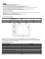 2
2
-
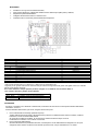 3
3
-
 4
4
-
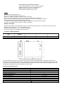 5
5
-
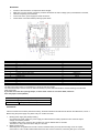 6
6
-
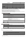 7
7
-
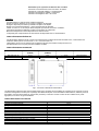 8
8
-
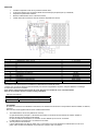 9
9
-
 10
10
-
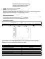 11
11
-
 12
12
-
 13
13
-
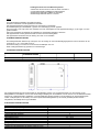 14
14
-
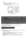 15
15
-
 16
16
-
 17
17


Comelit ZSP100-2.5 A-18 Handleiding
- Type
- Handleiding
- Deze handleiding is ook geschikt voor
in andere talen
- English: Comelit ZSP100-2.5 A-18 User manual
- italiano: Comelit ZSP100-2.5 A-18 Manuale utente
- français: Comelit ZSP100-2.5 A-18 Manuel utilisateur
- español: Comelit ZSP100-2.5 A-18 Manual de usuario
Andere documenten
-
Eaton SPS-24V-4A5/BNS Installatie gids
-
ABB ACS55-01N-02A2-2 Handleiding
-
BORETTI B101 de handleiding
-
Victron energy Skylla-i de handleiding
-
Zibro SC3225 de handleiding
-
Abus TVAC35600 Handleiding
-
Dometic SMP301-01, SMP301-02, SMP301-03, SMP301-04, SMP301-05, SMP301-07, SMP301-10 Handleiding
-
Yamaha Card Filer Handleiding
-
Yamaha S30 Handleiding