Marantec Command 802 de handleiding
- Categorie
- Beveiligingsdeurcontrollers
- Type
- de handleiding

Deutsch Urheberrechtlich geschützt.
Nachdruck, auch auszugsweise, nur mit unserer Genehmigung.
Änderungen, die dem technischen Fortschritt dienen, vorbehalten.
English Copyright.
No part of this manual may be reproduced without our prior consent.
Subject to changes which are in the interest of technical improvements.
Français Protégé par droits d’auteur
Reproduction, même partielle, seulement après autorisation de notre part.
Sous réserve de modifications servant au progrès technique.
Nederlands Auteursrechtelijk beschermd.
Nadruk, ook gedeeltelijk, uitsluitend met onze toestemming.
Wijzigingen met het oog op de technische vooruitgang voorbehouden.
Español Propiedad intelectual.
Reimpresión, aunque se trate sólo de extractos, sólo con nuestro permiso.
Sujeto a modificaciones en función del progreso técnico.
Italiano Tutti i diritti riservati.
Riproduzione, anche parziale, solo previa nostra autorizzazione.
La ditta si riserva la facoltà di apportare modifiche in base al progresso tecnologico.
Stand: 10.2007
#83004
1 - D/GB/F/NL/E/I 360275 - M - 0.5 - 1007
83004
Command 802
Zugangssteuerung
Access control
Commande d'accès
Toegangsbesturing
Control de acceso
Sistema di controllo accessi
FULL-SERVICE
ANTRIEBSSYSTEME
FÜR GARAGENTORE
ANTRIEBSSYSTEME
FÜR SEKTIONALTORE
ANTRIEBSSYSTEME
FÜR SCHIEBETORE
ANTRIEBSSYSTEME
FÜR DREHTORE
ANTRIEBSSYSTEME
FÜR ROLLTORE
PARKSCHRANKEN
SYSTEME
ELEKTRONISCHE
STEUERUNGEN
PRODUKT-SERVICE
ZUBEHÖR
Handbuch für Einbau und Bedienung
Manual for installation and operation
Manuel de l’utilisateur : Montage et service
Montage- en bedieningshandleiding
Manual para el montaje y el manejo
Manuale di montaggio e d’uso
ACCESSORIES
PRODUCT SERVICE
ELECTRONIC
CONTROL UNITS
PARK BARRIER
SYSTEMS
OPERATOR SYSTEMS
FOR ROLLER SHUTTERS
OPERATOR SYSTEMS
FOR HINGED GATES
OPERATOR SYSTEMS
FOR SLIDING GATES
OPERATOR SYSTEMS
FOR SECTIONAL DOORS
OPERATOR SYSTEMS
FOR GARAGE DOORS
FULL-SERVICE
D
GB
FNLEI

2 Handbuch für Einbau und Bedienung, Command 802 D (#83004)
2. Inhaltsverzeichnis
Vorsicht!
Gefahr von
Personenschäden!
Hier folgen wichtige Sicherheits -
hinweise, die zur Vermeidung von
Personen schäden unbedingt
beachtet werden müssen!
Achtung!
Gefahr von Sachschäden!
Hier folgen wichtige Sicherheits-
hinweise, die zur Vermeidung von
Sachschäden unbedingt beachtet
werden müssen!
Hinweis / Tipp
Kontrolle
Verweis
i
Hinweise
1. Symbolerklärung . . . . . . . . . . . .2
2. Inhaltsverzeichnis . . . . . . . . . . . .2
3. Allgemeine
Sicherheitshinweise . . . . . . . . . .3
4. Produktübersicht . . . . . . . . . . . .5
4.1 Lieferumfang . . . . . . . . . . . . . .5
4.2 Leistungsmerkmale . . . . . . . . .5
4.4 Zugangskontrollen . . . . . . . . . .6
4.3 Benutzerrechte . . . . . . . . . . . .6
5. Montage . . . . . . . . . . . . . . . . . . .7
5.1 Steuerung montieren . . . . . . . .7
5.2 Anschluss . . . . . . . . . . . . . . . .7
6. Programmierung . . . . . . . . . . . .11
6.1 Übersicht LED Anzeige . . . . . .11
6.2 Inbetriebnahme . . . . . . . . . . .11
6.3 Karten hinzufügen . . . . . . . . .12
6.4 Benutzerkarten löschen . . . . .13
7. Bedienung . . . . . . . . . . . . . . . . .14
7.1 Tür öffnen . . . . . . . . . . . . . . .14
7.2 Reset . . . . . . . . . . . . . . . . . . .14
8. Anhang . . . . . . . . . . . . . . . . . . .15
8.1 Technische Daten
Command 802 . . . . . . . . . . .15
8.2 Nummernliste . . . . . . . . . . . .16
8.3 Herstellererklärung . . . . . . . . .17
8.4 EG-Konformitätserklärung . . .17
1. Symbolerklärung

Handbuch für Einbau und Bedienung, Command 802 D (#83004) 3
3. Allgemeine Sicherheitshinweise
Zielgruppe
Dieses Produkt darf nur von qualifiziertem und geschultem Fachpersonal montiert, angeschlossen und in
Betrieb genommen werden!
Qualifiziertes und geschultes Fachpersonal im Sinne dieser Beschreibung sind Personen
- mit Kenntnis der allgemeinen und speziellen Sicherheits- und Unfallverhütungsvorschriften,
- mit Kenntnis der einschlägigen elektro technischen Vorschriften,
- mit Ausbildung in Gebrauch und Pflege angemessener Sicherheitsausrüstung,
- mit ausreichender Unterweisung und Beaufsichtigung durch Elektrofachkräfte,
- mit der Fähigkeit, Gefahren zu erkennen, die durch Elektrizität verursacht werden können,
- mit Kenntnis in der Anwendung der EN 12635 (Anforderungen an Installation und Nutzung).
Gewährleistung
Für eine Gewährleistung in Bezug auf Funktion und Sicherheit müssen die Hinweise in dieser Anleitung
beachtet werden.
Bei Missachtung der Warnhinweise können Körperverletzungen und Sachschäden auftreten.
Für Schäden, die durch Nichtbeachtung der Hinweise eintreten, haftet der Hersteller nicht.
Um Einbaufehler und Schäden am Gerät zu vermeiden, ist unbedingt nach den Montage an weisungen der
Einbauanleitung vorzugehen. Das Produkt darf erst nach Kenntnisnahme der zugehörigen Einbau- und
Bedienungs anleitung betrieben werden.
Die Einbau- und Bedienungsanleitung ist dem Betreiber der Toranlage zu übergeben und aufzubewahren.
Sie beinhaltet wichtige Hinweise für Bedienung, Prüfung und Wartung.
Das Produkt wird gemäß den in der Hersteller- und Konformitäts erklärung aufgeführten Richtlinien und
Normen gefertigt. Das Produkt hat das Werk in sicherheitstechnisch einwandfreiem Zustand verlassen.
Kraftbetätigte Fenster, Türen und Tore müssen vor der ersten Inbetrieb nahme und nach Bedarf, jedoch
jährlich mindestens einmal von einem Sachkundigen geprüft werden (mit schriftlichem Nachweis).
Bestimmungsgemäße Verwendung
Die Zugangssteuerung überwacht das Öffnen und Schließen von Sicherheitsbereichen.
Neben den Hinweisen in dieser Anleitung sind die allgemein gültigen Sicherheits- und Unfall vor-
schriften zu beachten! Es gelten unsere Verkaufs- und Lieferbedingungen.
Bitte unbedingt lesen!

4 Handbuch für Einbau und Bedienung, Command 802 D (#83004)
3. Allgemeine Sicherheitshinweise
Hinweise zum Einbau
• Stellen Sie sicher, dass sich die anzuschließenden Anlagen (Türen etc.) mechanisch in einem einwand-
freien Zustand befinden.
• Vor Verkabelungsarbeiten trennen Sie das System unbedingt von der Stromversorgung.
Stellen Sie sicher, dass während der Verkabelungsarbeiten die Stromversorgung unterbrochen bleibt.
• Beachten Sie die örtlichen Schutzbestimmungen.
• Verlegen Sie die Netz- und Steuerleitungen unbedingt getrennt. Die Betriebsspannung beträgt
24 V AC/DC.
Hinweise zur Reinigung
Auf keinen Fall dürfen zur Reinigung eingesetzt werden: direkter Wasserstrahl, Hochdruckreiniger, Säuren
oder Laugen.
Bitte unbedingt lesen!
Manuale di montaggio e d’uso, Command 802 I (#83004) 97
8. Appendice
8.3 Dichiarazione del produttore 8.4 Dichiarazione di conformità CE
Con la presente dichiariamo che il prodotto
indicato in seguito corrisponde - in base al tipo di
concezione e di costruzione, e nella versione da noi
immessa nel mercato - ai requisiti fondamentali in
materia di sicurezza e salute della direttiva CE
sulla compatibilità elettromagnetica, della
direttiva sulle macchine e della direttiva sulla
tensione bassa.
Se vengono apportate modifiche da noi non
consentite al prodotto, questa dichiarazione è da
considerarsi invalida.
Prodotto: Command 802
Disposizioni CE in materia:
Direttiva CE sulla compatibilità elettromagnetica
(89/336/EWG),
Direttiva sulle macchine
(98/37/EWG)
e direttiva sulla tensione bassa
(73/23/EWG und 93/68/EWG).
Norme armonizzate applicate, in particolare:
EN 292-1 / EN 61000-6-2 / EN 61000-6-3 /
EN 55014 / EN 61000-3-2 / EN 61000-3-3 /
EN 60335-1 / EN 60335-2-95 / EN 12445 /
EN 12453 / EN 300220-1 / EN 301489-3 /
ETS 300683
08.02.2006 ppa. J. Hörmann
Marantec Antriebs- und Steuerungstechnik
GmbH & Co. KG
Remser Brook 11 · 33428 Marienfeld · Germany
Fon +49 (5247) 705-0
Con la presente dichiariamo che il prodotto
indicato in seguito corrisponde - in base al tipo di
concezione e di costruzione, e nella versione da noi
immessa nel mercato - ai requisiti fondamentali in
materia di sicurezza e salute della direttiva CE
sulla compatibilità elettromagnetica, della
direttiva sulle macchine e della direttiva sulla
tensione bassa.
Se vengono apportate modifiche da noi non
consentite al prodotto, questa dichiarazione è da
considerarsi invalida.
Produkt:
Disposizioni CE in materia:
Direttiva CE sulla compatibilità elettromagnetica
(89/336/EWG),
Direttiva sulle macchine
(98/37/EWG)
e direttiva sulla tensione bassa
(73/23/EWG und 93/68/EWG).
Norme armonizzate applicate, in particolare:
EN 292-1 / EN 61000-6-2 / EN 61000-6-3 /
EN 55014 / EN 61000-3-2 / EN 61000-3-3 /
EN 60335-1 / EN 60335-2-95 / EN 12445 /
EN 12453 / EN 300220-1 / EN 301489-3 /
ETS 300683
Data / Firma

96 Manuale di montaggio e d’uso, Command 802 I (#83004)
8. Appendice
8.2 Lista promemoria
Numero Nome
0001*
0002*
0003
0004
0005
0006
0007
0008
0009
0010
0011
0012
0013
0014
0015
0016
0017
0018
0019
0020
0021
Numero Nome
0022
0023
0024
0025
0026
0027
0028
0029
0030
* Tessera master
Handbuch für Einbau und Bedienung, Command 802 D (#83004) 5
4.1 Lieferumfang 4.2 Leistungsmerkmale
1 Zugangssteuerung / Kartenlesegerät
2 Schraubenset
3 Transponder-Code-Karte
Die Zugangssteuerung hat folgende
Leistungsmerkmale:
- Zugangsüberwachung für eine Tür
- 30 Karten einlesbar
(2 Master und 28 Benutzer)
- Benutzerrechte löschen (nur bei vorhandener
Benutzerkarte)
1
2
4. Produktübersicht
4.1 / 1
3

6 Handbuch für Einbau und Bedienung, Command 802 D (#83004)
4.3 Benutzerrechte
Die Karten werden in zwei Kartentypen
unterschieden.
Je nach Kartentyp stehen dem Anwender
unterschiedliche Benutzerrechte zu.
Masterkarte
- Rechte für das Öffnen von Türen
- Rechte für Änderungen am System
Benutzerkarte
- Rechte für das Öffnen von Türen
4.4 Zugangskontrollen
Zugangsüberwachung für eine Tür
Die Steuerung kontrolliert einen Eingang.
4. Produktübersicht
4.4 / 1
Hinweis:
Der Ausgang erfolgt über einen
Taster (RTE) bzw. eine Türklinke.
Manuale di montaggio e d’uso, Command 802 I (#83004) 95
8. Appendice
8.1 Dati tecnici Command 802
Tensione d’alimentazione:
24 V AC/DC
Assorbimento medio:
30 mA
Carico massimo del relais:
24 V / 2,5 A
Per carichi superiori occorre utilizzare un relais
aggiuntivo.
Display:
LED a tre colori
Bip
Portata del lettore:
Tessere ISO: 70 mm
Portachiavi: 50 mm
Numero max utenti:
30 utenti
Dimensioni della scatola da fissare alla porta:
circa 75 mm x 39 mm x 15 mm (LxPxH)
Tipo di protezione:
IP 54 (chiuso)
Temperature ammesse:
da -10°C fino a +60°C

94 Manuale di montaggio e d’uso, Command 802 I (#83004)
7.1 Aprire la porta
• Tenere la tessera davanti al lettore.
Viene autorizzato l’accesso all’area protetta ed è
possibile aprire la porta.
7.2 Reset
• Agire sull’interruttore collegato ai morsetti per il
pulsante (RTE) tenendolo premuto fino a che il
reset è terminato.
Consiglio:
Dopo un reset vengono disabilitate
tutte le tessere master e utenti.
7.1 / 1
Consiglio:
Se non è presente nessun interruttore
occorre realizzare un ponte tra i
morsetti per il pulsante (RTE)
(cavi bianco e verde).
Il ponte deve essere nuovamente
rimosso dopo avere effettuato il reset!
• Interrompere brevemente e ripristinare l’alimen-
tazione alla centralina per due volte di seguito.
Display
Il LED lampeggia in verde e arancione:
modalità relais di apertura/chiusura
Il LED lampeggia in rosso:
modalità invio impulso singolo
Dopo il reset occorre abilitare una tessera master.
7. Uso
Handbuch für Einbau und Bedienung, Command 802 D (#83004) 7
5.1 Steuerung montieren 5.2 Anschluss
5. Montage
• Verschrauben Sie die Steuerung an einem
festen Untergrund.
5.2.1 Steuerungsübersicht
A
5.1 / 1
5.2.1 / 1
B
Position Bezeichnung
A Statusanzeige (LED)
B Kartenlesefläche
5.2.2 Verkabelung
Hinweis:
Die maximal zulässige Länge für
das Kabel der Zugangssteuerung
beträgt 50 Meter. Das Kabel muss
abgeschirmt sein.
• Führen Sie alle Verkabelungen an der Zugangs-
steuerung durch.

8 Handbuch für Einbau und Bedienung, Command 802 D (#83004)
A1
24 V
DC
A2 A3
A4
12 V DC
GND
RTE
RTE
COM
N/O
N/C
*
Beispiel Türöffner (Impuls)
Bezeichnung Art / Funktion
A1 Zugangssteuerung / Lesegerät
12 V DC rot
GND schwarz
RTE weiß
RTE grün
COM blau
N/0 gelb
N/C violett
* braun (ohne Belegung)
A2 Ausgangstaster
A3 Türöffner
A4 MOV
5. Montage
5.2.2 / 1
Achtung!
Um einen Flashback zu vermeiden,
muss bei einer Induktiven Last (z. B.
Türöffner) ein MOV (Metaloxid
Varistor = spannungsabhängiger
Widerstand) eingesetzt werden.
Manuale di montaggio e d’uso, Command 802 I (#83004) 93
6. Programmazione
Abilitare ulteriori tessere utenti
6.4 Disabilitare tessere utenti
Occorre avere a disposizione la tessera utente, per
poterla disabilitare dalla centralina.
Consiglio:
Se si tiene la tessera utente per due
volte davanti alla centralina, la
tessera utente viene nuovamente
disabilitata dalla centralina.
• Tenere la tessera master per 7 secondi davanti
alla centralina.
Il LED è acceso in arancione.
La centralina manda 2 brevi bip consecutivi.
La centralina si trova nella modalità di
programmazione.
• Tenere la tessera utente da disabilitare davanti
alla centralina.
Il LED si accende per 1 secondo in rosso.
La centralina manda 1 bip prolungato.
Se si vogliono disabilitare ulteriori tessere utenti
nella centralina:
• Tenere davanti alla centralina una dopo l’altra le
tessere utenti desiderate.
• Tenere la tessera master davanti alla centralina,
per uscire dalla modalità di programmazione.
• Tenere la tessera master per 7 secondi davanti
alla centralina.
Il LED è acceso in arancione.
La centralina manda 2 brevi bip consecutivi.
La centralina si trova nella modalità di
programmazione.
• Tenere una nuova tessera utente davanti alla
centralina.
Il LED si accende brevemente in verde.
La centralina manda 1 breve bip.
Se si vogliono abilitare ulteriori tessere utenti nella
centralina:
• Tenere davanti alla centralina una dopo l’altra le
tessere utenti desiderate.
• Tenere la tessera master davanti alla centralina,
per uscire dalla modalità di programmazione.
Consiglio:
- Le tessere master possono essere
disabilitate solo tramite reset.
- Le tessere utenti devono essere
tenute davanti alla centralina solo
una volta, alla seconda volta infatti
verrebbero riabilitate.

92 Manuale di montaggio e d’uso, Command 802 I (#83004)
Abilitare una seconda tessera master
• Tenere la tessera master per 7 secondi davanti
alla centralina.
Il LED è acceso in arancione.
La centralina manda 2 brevi bip consecutivi.
La centralina si trova nella modalità di
programmazione.
• Tenere una nuova tessera utente davanti alla
centralina.
La tessera utente viene abilitata dalla centralina
come seconda tessera master.
• Tenere la prima tessera master davanti alla
centralina, per uscire dalla modalità di
programmazione.
6. Programmazione
6.3 Abilitazione di ulteriori tessere
Definire la tessera master
Prima di abilitare la prima tessera master occorre
scegliere la modalità di funzionamento (invio im-
pulso singolo oppure relais di apertura/chiusura).
Le prime due tessere utenti vengono abilitate
nella centralina come tessere master.
Il LED lampeggia in rosso:
modalità invio impulso singolo
Il LED lampeggia in verde e arancione:
modalità relais di apertura/chiusura
• Tenere una tessera utente davanti alla centralina.
Il LED è acceso in rosso.
Consiglio:
Se non viene inserito alcun comando
per 20 secondi, la centralina esce
automaticamente dalla modalità di
programmazione e torna alla
modalità di funzionamento.
Handbuch für Einbau und Bedienung, Command 802 D (#83004) 9
5. Montage
A1
24 V
DC
A2
A5
12 V DC
GND
RTE
RTE
COM
N/O
N/C
*
Beispiel Magnetschloss (Impuls)
5.2.2 / 2
Bezeichnung Art / Funktion
A1 Zugangssteuerung / Lesegerät
12 V DC rot
GND schwarz
RTE weiß
RTE grün
COM blau
N/0 gelb
N/C violett
* braun (ohne Belegung)
A2 Ausgangstaster
A5 Magnetschloss

10 Handbuch für Einbau und Bedienung, Command 802 D (#83004)
5. Montage
A1
24 V
DC
12 V DC
GND
RTE
RTE
COM
N/O
N/C
*
Beispiel Sperr-Relais Modus
(Schalterfunktion)
5.2.2 / 3
Bezeichnung Art / Funktion
A1 Zugangssteuerung / Lesegerät
12 V DC rot
GND schwarz
RTE weiß
RTE grün
COM blau
N/0 gelb
N/C violett
* braun (ohne Belegung)
*
* Die Brücke an den RTE-Anschlüssen wird für die
Inbetriebnahme benötigt. Nach der Inbetrieb-
nahme muss die Brücke entfernt werden.
Manuale di montaggio e d’uso, Command 802 I (#83004) 91
6.1 Panoramica del display a LED
Modalità di messa in funzione
Il LED lampeggia in rosso:
la centralina è pronta per leggere la tessera
master (modalità invio impulso singolo)
Il LED lampeggia in arancione e verde:
la centralina è pronta per leggere la tessera
master (modalità relais di apertura/chiusura)
Modalità di programmazione
Il LED è acceso in arancione:
la centralina è pronta per abilitare o
disabilitare tessere utenti
Il LED è acceso in verde:
la tessera utente è stata abilitata
Il LED è acceso in rosso:
la tessera utente è stata disabilitata
Modalità di funzionamento a invio di un
impulso singolo
Il LED è acceso in rosso:
sistema pronto al funzionamento
Il LED è acceso in verde:
la centralina viene attivata da una tessera
utente abilitata (bip breve)
Il LED è acceso in rosso:
la centralina rileva una tessera non abilitata
(bip prolungato)
Modalità di funzionamento a relais di
apertura/chiusura
Il LED è acceso in rosso:
sistema pronto al funzionamento
Il LED lampeggia in rosso e verde:
la centralina viene attivata da una tessera
utente abilitata (bip breve)
Il LED è acceso in rosso oppure verde:
la centralina rileva una tessera non abilitata
(bip prolungato)
6.2 Messa in funzione
La centralina può funzionare in modalità invio
impulso singolo oppure relais di apertura/chiusura.
Modalità invio impulso singolo (impulso)
Il contatto relais viene eccitato per 2 secondi e
ritorna poi nella sua posizione iniziale.
Modalità relais di apertura/chiusura
(interruttore)
Il contatto relais cambia come un interruttore tra
aperto e chiuso.
Modifica del tipo di funzionamento
• Collegare la centralina del controllo accessi
all’alimentazione di rete.
• Agire sul dispositivo apriporta collegato ai
morsetti per il pulsante (RTE).
Attenzione!
Per evitare che possa bruciarsi la
bobina dell’apriporta, la modalità
relais di apertura/chiusura non può
essere utilizzata in presenza di un
dispositivo apriporta.
Consiglio:
Se non è presente nessun dispositivo
apriporta può essere rimosso il ponte
collegato ai morsetti per il pulsante
(RTE) (cavi bianco e verde).
Display
Il LED lampeggia in rosso:
modalità invio impulso singolo
Il LED lampeggia in verde e arancione:
modalità relais di apertura/chiusura
Ripetendo la procedura viene modificata
l’impostazione della modalità di funzionamento.
Una volta definita la modalità di funzionamento,
occorre abilitare una tessera master.
6. Programmazione

90 Manuale di montaggio e d’uso, Command 802 I (#83004)
5. Montaggio
A1
24 V
DC
12 V DC
GND
RTE
RTE
COM
N/O
N/C
*
Esempio di funzionamento:
Modalità relais di apertura/chiusura
(interruttore)
5.2.2 / 3
Descrizione Tipo / Funzionamento
A1 centralina / lettore
12 V DC rosso
GND nero
pulsante
(RTE)
bianco
pulsante
(RTE)
verde
COM blu
N/0 giallo
N/C viola
* marrone (non utilizzato)
*
* Il ponte sui morsetti per il pulsante (RTE) è
necessario per la messa in funzione del sistema.
Dopo la messa in funzione ed il collaudo, il
ponte deve essere rimosso.
Handbuch für Einbau und Bedienung, Command 802 D (#83004) 11
6.1 Übersicht LED Anzeige
Inbetriebnahmemodus
LED blinkt rot:
Zugangssteuerung bereit zum Einlesen der
Masterkarte (Stromstoß-Modus)
LED blinkt orange und grün:
Zugangssteuerung bereit zum Einlesen der
Masterkarte (Sperr-Relais-Modus)
Programmiermodus
LED leuchtet orange:
Steuerung bereit zum Hinzufügen oder
löschen von Benutzerkarten
LED leuchtet grün:
Benutzerkarte wurde hinzugefügt
LED leuchtet rot:
Benutzerkarte wurde gelöscht
Betrieb - Stromstoß-Modus
LED leuchtet rot:
Betriebsbereit
LED leuchtet grün:
Zugangssteuerung wird von einer gültigen
Benutzerkarte aktiviert (kurzer Summton)
LED leuchtet rot:
Ungültige Karte vor Zugangssteuerung
gehalten (langer Summton)
Betrieb - Sperr-Relais-Modus
LED leuchtet rot:
Betriebsbereit
LED blinkt rot und grün:
Zugangssteuerung wird von einer gültigen
Benutzerkarte aktiviert (kurzer Summton)
LED leuchtet rot oder grün:
Ungültige Karte vor Zugangssteuerung
gehalten (langer Summton)
6.2 Inbetriebnahme
Die Zugangssteuerung kann im Stromstoß-Modus
oder im Sperr-Relais-Modus betrieben werden.
Stromstoß-Modus (Impuls)
Der Relaiskontakt wird 2 Sekunden geschaltet
und geht dann wieder in die Ausgangsstellung
zurück.
Sperr-Relais-Modus (Schalterfunktion)
Der Relaiskontakt wechselt wie ein Schalter
zwischen offen und geschlossen.
Betriebsart wechseln
• Schließen Sie die Zugangssteuerung an die
Stromversorgung an.
• Drücken Sie den an RTE angeschlossenen
Türöffner.
Achtung!
Um ein Durchbrennen der Türöffner-
spule zu verhindern, darf der Sperr-
Relais-Modus nicht mit einem
Türöffner verwendet werden.
Hinweis:
Wenn kein Türöffner montiert ist,
können die RTE Anschlüsse (weiße
und grüne Ader) kurzgeschlossen
werden (Brücke).
Anzeige
LED blinkt rot:
Stromstoß-Modus
LED blinkt grün und orange:
Sperr-Relais-Modus
Durch wiederholen des Vorgangs wechselt der
Modus in die andere Betriebsart.
Nach dem Festlegen der Betriebsart muss eine
Masterkarte eingelesen werden.
6. Programmierung

12 Handbuch für Einbau und Bedienung, Command 802 D (#83004)
Masterkarte hinzufügen
• Halten Sie die Masterkarte 7 Sekunden vor die
Zugangssteuerung.
Die LED leuchtet orange.
Die Zugangssteuerung piept 2x kurz.
Die Zugangssteuerung befindet sich im Program-
miermodus.
• Halten Sie eine neue Benutzerkarte vor die
Zugangssteuerung.
Die Benutzerkarte wird von der Zugangssteue-
rung als Masterkarte gespeichert.
• Halten Sie die erste Masterkarte vor die
Zugangssteuerung, um den Programmiermodus
zu verlassen.
6. Programmierung
6.3 Karten hinzufügen
Masterkarte festlegen
Bevor die erste Masterkarte eingelesen werden
kann, muss der Betriebsmodus (Stromstoß-Modus
oder Sperr-Relais-Modus) gewählt werden.
Die ersten zwei Benutzerkarten werden von der
Zugangssteuerung als Masterkarten gespeichert.
LED blinkt rot:
Stromstoß-Modus
LED blinkt grün und orange:
Sperr-Relais-Modus
• Halten Sie eine Benutzerkarte vor die
Zugangssteuerung.
Die LED leuchtet rot.
Hinweis:
Wenn keine Eingabe erfolgt, wechselt
die Zugangssteuerung automatisch
nach 30 Sekunden vom Program-
miermodus in den Betriebsmodus.
Manuale di montaggio e d’uso, Command 802 I (#83004) 89
5. Montaggio
A1
24 V
DC
A2
A5
12 V DC
GND
RTE
RTE
COM
N/O
N/C
*
Esempio di funzionamento:
Serratura magnetica (impulso)
5.2.2 / 2
Descrizione Tipo / Funzionamento
A1 centralina / lettore
12 V DC rosso
GND nero
pulsante
(RTE)
bianco
pulsante
(RTE)
verde
COM blu
N/0 giallo
N/C viola
* marrone (non utilizzato)
A2 pulsante di uscita
A5 serratura magnetica

88 Manuale di montaggio e d’uso, Command 802 I (#83004)
A1
24 V
DC
A2 A3
A4
12 V DC
GND
RTE
RTE
COM
N/O
N/C
*
Esempio di funzionamento:
Apriporta (impulso)
Descrizione Tipo / Funzionamento
A1 centralina / lettore
12 V DC rosso
GND terra nero
pulsante
(RTE)
bianco
pulsante
(RTE)
verde
COM blu
N/0 giallo
N/C viola
* marrone (non utilizzato)
A2 pulsante di uscita
A3 apriporta
A4 resistenza (MOV)
5. Montaggio
5.2.2 / 1
Attenzione!
Per proteggere l’elettronica dalla
tensione generata da un eventuale
carico induttivo (ad esempio un
dispositivo apriporta), occorre
utilizzare una resistenza
(MOV = MetalOxidVaristor).
Handbuch für Einbau und Bedienung, Command 802 D (#83004) 13
6. Programmierung
Benutzerkarten hinzufügen
6.4 Benutzerkarten löschen
Die Benutzerkarte muss vorliegen, um einen
Benutzer aus der Zugangssteuerung zu löschen.
Hinweis:
Wenn die Benutzerkarte zweimal vor
die Zugangssteuerung gehalten wird,
wird die Benutzerkarte wieder aus
der Zugangssteuerung gelöscht.
• Halten Sie die Masterkarte 7 Sekunden vor die
Zugangssteuerung.
Die LED leuchtet orange.
Die Zugangssteuerung piept 2x kurz.
Die Zugangssteuerung befindet sich im Program-
miermodus.
• Halten Sie die zu löschende Benutzerkarte vor
die Zugangssteuerung.
Die LED leuchtet 1x rot.
Die Zugangssteuerung piept 1x lang.
Wenn weitere Benutzerkarten aus der Zugangs-
steuerung gelöscht werden sollen:
• Halten Sie nacheinander weitere Benutzerkarten
vor die Zugangssteuerung.
• Halten Sie die Masterkarte vor die Zugangs-
steuerung, um den Programmiermodus zu
verlassen.
• Halten Sie die Masterkarte 7 Sekunden vor die
Zugangssteuerung.
Die LED leuchtet orange.
Die Zugangssteuerung piept 2x kurz.
Die Zugangssteuerung befindet sich im Program-
miermodus.
• Halten Sie eine neue Benutzerkarte vor die
Zugangssteuerung.
Die LED leuchtet 1x grün.
Die Zugangssteuerung piept 1x kurz.
Wenn weitere Benutzerkarten in der Zugangs-
steuerung gespeichert werden sollen:
• Halten Sie nacheinander weitere Benutzerkarten
vor die Zugangssteuerung.
• Halten Sie die Masterkarte vor die Zugangs-
steuerung, um den Programmiermodus zu ver-
lassen.
Hinweis:
- Masterkarten können nur durch
Reset gelöscht werden.
- Benutzerkarten dürfen zum Lö-
schen nur einmal vor die Zugangs-
steuerung gehalten werden, da sie
beim zweiten Mal wieder eingespei-
chert werden.

14 Handbuch für Einbau und Bedienung, Command 802 D (#83004)
7.1 Tür öffnen
• Halten Sie die Karte vor das Lesegerät.
Der Zugangsbereich wird freigegeben und die Tür
kann geöffnet werden.
7.2 Reset
• Drücken Sie den an RTE angeschlossenen
Taster und halten Sie ihn gedrückt, bis der Reset
beendet ist.
Hinweis:
Nach einem Reset werden alle
Master- und Benutzerkarten gelöscht.
7.1 / 1
Hinweis:
Wenn kein Taster montiert ist,
können die RTE Anschlüsse (weiße
und grüne Ader) kurzgeschlossen
werden (Brücke).
Die Brücke muss nach dem Reset
wieder entfernt werden!
• Schalten Sie die Zugangssteuerung in kurzen
Abständen zweimal an und wieder aus (Strom-
zufuhr unterbrechen).
Anzeige
LED blinkt grün und orange:
Sperr-Relais- Modus
LED blinkt rot:
Stromstoß-Modus
Nach dem Reset muss eine Masterkarte eingelesen
werden.
7. Bedienung
Manuale di montaggio e d’uso, Command 802 I (#83004) 87
5.1 Installazione della centralina 5.2 Collegamento
5. Montaggio
• Fissare con le apposite viti la centralina ad una
base solida.
5.2.1 Panoramica della centralina
A
5.1 / 1
5.2.1 / 1
B
Legenda Descrizione
A Display di stato (tramite LED)
B Superficie di lettura della tessera
5.2.2 Cablaggio
Consiglio:
Il cavo di collegamento del sistema di
controllo accessi può essere lungo
max 50 metri. Il cavo deve essere
sempre schermato.
• Effettuare il cablaggio alla centralina.

86 Manuale di montaggio e d’uso, Command 802 I (#83004)
Le tessere sono di due diversi tipi.
A seconda del tipo di tessera, l’utente è
autorizzato a diversi tipi di accesso.
Tessera master:
- autorizzazione all’apertura della porta
- autorizzazione alla modifica del sistema
Tessera utente:
- autorizzazione all’apertura della porta
4.4 Controllo accessi
Controllo accessi per una porta
La centralina gestisce l’accesso ad una singola
porta.
4. Panoramica del prodotto
4.4 / 1
Consiglio:
Per uscire occorre utilizzare un
pulsante (RTE) oppure la maniglia
della porta.
4.3 Autorizzazioni di accesso
degli utenti
Handbuch für Einbau und Bedienung, Command 802 D (#83004) 15
8. Anhang
8.1 Technische Daten
Command 802
Versorgungsspannung:
24 V AC/DC
Durchschnittlicher Stromverbrauch:
30 mA
Relais Leistung:
24 V / 2,5 A
Bei größeren Leistungen ist ein zusätzliches Relais
notwendig.
Anzeige:
Dreifarbige LED
Summer
Leserreichweite:
ISO Karten: 70 mm
Anhänger: 50 mm
Anzahl der Benutzer:
30 Benutzer
Abmessungen:
ca. 75 mm x 39 mm x 15 mm (LxBxH)
Schutzart:
IP 54 (geschlossen)
Umgebungstemperatur:
-10°C bis +60°C

16 Handbuch für Einbau und Bedienung, Command 802 D (#83004)
8. Anhang
8.2 Nummernliste
Nummer Name
0001*
0002*
0003
0004
0005
0006
0007
0008
0009
0010
0011
0012
0013
0014
0015
0016
0017
0018
0019
0020
0021
Nummer Name
0022
0023
0024
0025
0026
0027
0028
0029
0030
* Masterkarte
Manuale di montaggio e d’uso, Command 802 I (#83004) 85
4.1 Dotazione 4.2 Caratteristiche tecniche
1 Centralina di controllo accessi /
lettore di tessere
2 Set di viti di fissaggio
3 Tessera con transponder
Il sistema di controllo accessi ha le seguenti
caratteristiche tecniche:
- controlla gli accessi per una porta
- abbinabile a max 30 tessere (2 master e
28 utenti)
- possono essere disabilitati singoli utenti
(utilizzando la relativa tessera)
1
2
4. Panoramica del prodotto
4.1 / 1
3

84 Manuale di montaggio e d’uso, Command 802 I (#83004)
3. Avvisi generali per la sicurezza
Istruzioni per il montaggio
• Assicurarsi che i sistemi di chiusura da collegare (porte etc.) siano perfettamente funzionanti dal punto di
vista meccanico.
• Prima di effettuare il cablaggio interrompere l’alimentazione elettrica.
Assicurarsi che il dispositivo rimanga separato dall'alimentazione elettrica per tutta la durata dei lavori di
cablaggio.
• Osservare le norme di sicurezza locali.
• Installare sempre separatamente i cavi dell'alimentazione ed i cavi di collegamento all’elettronica.
L’alimentazione di funzionamento è di 24 V AC/DC.
Avvertenze per la pulizia
Per la pulizia, non usare in nessun caso: getti d’acqua diretti, pulitori ad alta pressione, acidi o soluzioni
alcaline.
Leggere attentamente queste informazioni!
Handbuch für Einbau und Bedienung, Command 802 D (#83004) 17
8. Anhang
8.3 Herstellererklärung 8.4 EG-Konformitätserklärung
Hiermit erklären wir, dass das nachfolgend bezeich-
nete Produkt aufgrund seiner Konzipierung und
Bauart sowie in der von uns in Verkehr gebrachten
Ausführung den einschlägigen grundlegenden
Sicherheits- und Gesundheitsanforderungen der
EG-Richtlinie Elektromagnetische Ver träg lichkeit,
der Maschinen-Richtlinie und der Nieder spannungs-
richtlinie entspricht.
Bei einer nicht mit uns abgestimmten Änderung
der Produkte verliert diese Erklärung ihre Gültigkeit.
Produkt: Command 802
Einschlägige EG-Richtlinien:
EG-Richtlinie Elektromagnetische Verträglichkeit
(89/336/EWG),
Maschinen-Richtlinie
(98/37/EWG)
und Niederspannungsrichtlinie
(73/23/EWG und 93/68/EWG).
Angewandte harmonisierte Normen,
insbesondere:
EN 292-1 / EN 61000-6-2 / EN 61000-6-3 /
EN 55014 / EN 61000-3-2 / EN 61000-3-3 /
EN 60335-1 / EN 60335-2-95 / EN 12445 /
EN 12453 / EN 300220-1 / EN 301489-3 /
ETS 300683
08.02.2006 ppa. J. Hörmann
Marantec Antriebs- und Steuerungstechnik
GmbH & Co. KG
Remser Brook 11 · 33428 Marienfeld · Germany
Fon +49 (5247) 705-0
Hiermit erklären wir, dass das nachfolgend bezeich-
nete Produkt aufgrund seiner Konzipierung und
Bauart sowie in der von uns in Verkehr gebrachten
Ausführung den einschlägigen grundlegenden
Sicherheits- und Gesundheitsanforderungen der
EG-Richtlinie Elektromagnetische Ver träg lichkeit,
der Maschinen-Richtlinie und der Nieder spannungs-
richtlinie entspricht.
Bei einer nicht mit uns abgestimmten Änderung
der Produkte verliert diese Erklärung ihre Gültigkeit.
Produkt:
Einschlägige EG-Richtlinien:
EG-Richtlinie Elektromagnetische Verträglichkeit
(89/336/EWG),
Maschinen-Richtlinie
(98/37/EWG)
und Niederspannungsrichtlinie
(73/23/EWG und 93/68/EWG).
Angewandte harmonisierte Normen,
insbesondere:
EN 292-1 / EN 61000-6-2 / EN 61000-6-3 /
EN 55014 / EN 61000-3-2 / EN 61000-3-3 /
EN 60335-1 / EN 60335-2-95 / EN 12445 /
EN 12453 / EN 300220-1 / EN 301489-3 /
ETS 300683
Datum / Unterschrift

18 Manual for installation and operation, Command 802 GB (#83004)
2. Table of contents
Caution!
Danger of personal injury!
The following safety advice must be
observed at all times so as to avoid
personal injury!
Attention!
Danger of material damage!
The following safety advice must be
observed at all times so as to avoid
material damage!
Advice / Tip
Check
Reference
i
Advice
1. Meaning of symbols . . . . . . . . .18
2. Table of contents . . . . . . . . . . .18
3. General safety advice . . . . . . . .19
4. Product overview . . . . . . . . . . .21
4.1 Scope of delivery . . . . . . . . . .21
4.2 Performance Features . . . . . .21
4.3 User rights . . . . . . . . . . . . . . .22
4.4 Access controls . . . . . . . . . . .22
5. Installation . . . . . . . . . . . . . . . .23
5.1 Mounting a control unit . . . . .23
5.2 Connection . . . . . . . . . . . . . .23
6. Programming . . . . . . . . . . . . . .27
6.1 Overview of the LED display . .27
6.2. Initial Operation . . . . . . . . . . .27
6.3 Adding cards . . . . . . . . . . . . .28
6.4 Deleting a user card . . . . . . . .29
7. Operation . . . . . . . . . . . . . . . . .30
7.1 Open the door . . . . . . . . . . . .30
7.2 Resetting . . . . . . . . . . . . . . . .30
8. Attachment . . . . . . . . . . . . . . . .31
8.1 Technical data for
Command 802 . . . . . . . . . . .31
8.2 List of numbers . . . . . . . . . . .32
8.3 Manufacturer’s Declaration . .33
8.4 EC Declaration of Conformity 33
1. Meaning of symbols
Manuale di montaggio e d’uso, Command 802 I (#83004) 83
3. Avvisi generali per la sicurezza
Target lettori
Questa automazione deve essere installata e messa infunzione esclusivamente da personale specializzato e
qualificato.
Per personale specializzato e qualificato si intendono persone
- con conoscenza delle norme generali e speciali di sicurezza e antinfortunistiche,
- con conoscenza delle corrette norme elettrotecniche,
- con istruzione professionale nel campo dell‘uso e della manutenzione di un’adeguata attrezzatura di
sicurezza,
- istruiti e sorvegliati adeguatamente da esperti elettrotecnici,
- in grado di riconoscere i pericoli potenzialmente causati dall’elettricità,
- con le conoscenze necessarie per la corretta applicazione della norma EN 12635
(requisiti di installazione e utilizzazione).
Garanzia
Per usufruire della garanzia relativa al funzionamento e alla sicurezza dell’automazione, è indispensabile il
rispetto delle disposizioni contenute in queste istruzioni. La mancata osservanza di queste avvertenze può
provocare danni alle persone ed alle cose. Il produttore non risponde dei danni provocati dalla mancata
osservanza delle istruzioni.
Per evitare errori e danni durante l’installazione, occorre attenersi sempre alle istruzioni di montaggio.
Prima della messa in funzione del prodotto è indispensabile la lettura delle istruzioni d'uso e di montaggio.
Le istruzioni d’uso e di montaggio devono essere consegnate all’utilizzatore dell’impianto. Infatti contengono
istruzioni importanti per le operazioni successive di uso, controllo e manutenzione.
Il prodotto è fabbricato secondo le direttive e norme indicate nella dichiarazione di conformità del produttore.
Il prodotto è uscito dalla fabbrica in stato perfetto dal punto di vista tecnico e della sicurezza.
Finestre, cancelli e porte automatizzate devono essere controllati da parte di un esperto (con documentazione
scritta) prima della loro prima messa in servizio e anche almeno una volta l’anno, a seconda delle necessità!
Uso convenzionale del dispositivo
Il sistema di controllo accessi gestisce l’apertura e la chiusura di aree protette.
Oltre alle disposizioni contenute in queste istruzioni, devono essere osservate anche le norme
di sicurezza e antinfortunistiche di validità generale! Si applicano le nostre condizioni di vendita
e di fornitura.
Leggere attentamente queste informazioni!

82 Manuale di montaggio e d’uso, Command 802 I (#83004)
2. Indice
Avvertenza!
Pericolo di danni alle
persone!
Dopo questo simbolo seguono
avvisi importanti per la sicurezza
che devono essere assolutamente
rispettati per evitare danni alle
persone!
Attenzione!
Pericolo di danni materiali!
Dopo questo simbolo seguono
avvisi importanti per la sicurezza
che devono essere assolutamente
rispettati per evitare danni materiali!
Consiglio
Controllo
Rinvio
i
Avvisi
1. Spiegazione dei simboli . . . . . .82
2. Indice . . . . . . . . . . . . . . . . . . . . .82
3. Avvisi generali per la sicurezza 83
4. Panoramica del prodotto . . . . .85
4.1 Dotazione . . . . . . . . . . . . . . .85
4.2 Caratteristiche tecniche . . . . .85
4.3 Autorizzazioni di accesso
degli utenti . . . . . . . . . . . . . .86
4.4 Controllo accessi . . . . . . . . . .86
5. Montaggio . . . . . . . . . . . . . . . .87
5.1 Installazione della centralina . .87
5.2 Collegamento . . . . . . . . . . . .87
6. Programmazione . . . . . . . . . . .91
6.1 Panoramica del display a LED .91
6.2 Messa in funzione . . . . . . . . .91
6.3 Abilitazione di ulteriori
tessere . . . . . . . . . . . . . . . . . .92
6.4 Disabilitare tessere utenti . . . .93
7. Uso . . . . . . . . . . . . . . . . . . . . . . .94
7.1 Aprire la porta . . . . . . . . . . . .94
7.2 Reset . . . . . . . . . . . . . . . . . . .94
8. Appendice . . . . . . . . . . . . . . . . .95
8.1 Dati tecnici Command 802 . .95
8.2 Lista promemoria . . . . . . . . . .96
8.3 Dichiarazione del produttore .97
8.4 Dichiarazione di
conformità CE . . . . . . . . . . . .97
1. Spiegazione dei simboli
Manual for installation and operation, Command 802 GB (#83004) 19
3. General safety advice
Target group
This product may only be installed, connected and put into operation by qualified and trained
professionals!
Qualified and trained specialist personnel are persons
- who have knowledge of the general and special safety regulations,
- who have knowledge of the relevant electro-technical regulations,
- with training in the use and maintenance of suitable safety equipment,
- who are sufficiently trained and supervised by qualified electricians,
- who are able to recognise the particular hazards involved when working with electricity,
- with knowledge regarding applications of the EN 12635 standard (installation and usage requirements).
Warranty
For an operations and safety warranty, the advice in this instruction manual has to be observed.
Disregarding these warnings may lead to personal injury or material damage.
If this advice is disregarded, the manufacturer will not be liable for damages that might occur.
To avoid installation errors and damage to the device, it is imperative that the installation instructions are
followed. The system may only be used after thoroughly reading the respective mounting and installation
instructions.
The installation and operating instructions are to be given to the door system user, who must keep them
safe. They contain important advice for operation, checks and maintenance.
This item is produced according to the directives and standards mentioned in the Manufacturer's
Declaration and in the Declaration of Conformity.
The product has left the factory in perfect condition with regard to safety.
Power-operated windows, doors and gates must be checked by an expert (and this must be documented)
before they are put into operation and thereafter as required, but at least once a year.
Correct use
The access control system monitors the opening and closing of security areas.
Beside the advice in these instructions, please observe the general safety and accident prevention
regulations! Our sales and supply terms and conditions are effective.
Please read carefully!

20 Manual for installation and operation, Command 802 GB (#83004)
3. General safety advice
Information on installing
• Ensure that the devices to be connected (doors etc.) are in a mechanically faultless state.
• Before commencing cabling works it is very important to disconnect the system from the electricity supply.
Ensure that the electricity supply remains disconnected throughout the cabling works.
• Adhere to the local protection regulations.
• Lay the electricity supply cables and control cables; these MUST be laid separately.
The operating voltage is 24 V AC/DC.
Information on cleaning
Never use water jets, high pressure cleaners, acids or bases for cleaning.
Please read carefully!
Manual para el montaje y el manejo, Command 802 E (#83004) 81
8. Apéndice
8.3 Declaración del fabricante 8.4 Declaración de conformidad CE
Por la presente declaramos que el producto
especificado a continuación, tanto en su diseño y
modo de construcción como en el modelo lanzado
por nosotros al mercado, cumple con los requeri-
mientos básicos pertinentes de seguridad y de
salud de las directiva comunitaria de compatibilidad
electromagnética, de la directiva de máquinas y de
la directiva de baja tensión.
Esta declaración pierde su validez en caso de que
se lleven a cabo modificaciones de los productos
que no hayan sido acordadas con nosotros.
Producto: Command 802
Directivas CE pertinentes:
Directiva CE de compatibilidad electromagnética
(89/336/EWG),
Directiva de máquinas
(98/37/EWG)
Directiva de baja tensión
(73/23/EWG und 93/68/EWG).
Normas armonizadas aplicadas, especialmente:
EN 292-1 / EN 61000-6-2 / EN 61000-6-3 /
EN 55014 / EN 61000-3-2 / EN 61000-3-3 /
EN 60335-1 / EN 60335-2-95 / EN 12445 /
EN 12453 / EN 300220-1 / EN 301489-3 /
ETS 300683
08.02.2006 ppa. J. Hörmann
Marantec Antriebs- und Steuerungstechnik
GmbH & Co. KG
Remser Brook 11 · 33428 Marienfeld · Germany
Fon +49 (5247) 705-0
Por la presente declaramos que el producto
especificado a continuación, tanto en su diseño y
modo de construcción como en el modelo lanzado
por nosotros al mercado, cumple con los requeri-
mientos básicos pertinentes de seguridad y de
salud de las directiva comunitaria de compatibilidad
electromagnética, de la directiva de máquinas y de
la directiva de baja tensión.
Esta declaración pierde su validez en caso de que
se lleven a cabo modificaciones de los productos
que no hayan sido acordadas con nosotros.
Producto:
Directivas CE pertinentes:
Directiva CE de compatibilidad electromagnética
(89/336/EWG),
Directiva de máquinas
(98/37/EWG)
Directiva de baja tensión
(73/23/EWG und 93/68/EWG).
Normas armonizadas aplicadas, especialmente:
EN 292-1 / EN 61000-6-2 / EN 61000-6-3 /
EN 55014 / EN 61000-3-2 / EN 61000-3-3 /
EN 60335-1 / EN 60335-2-95 / EN 12445 /
EN 12453 / EN 300220-1 / EN 301489-3 /
ETS 300683
Fecha / Firma

80 Manual para el montaje y el manejo, Command 802 E (#83004)
8. Apéndice
8.2 Lista de números
Número Nombre
0001*
0002*
0003
0004
0005
0006
0007
0008
0009
0010
0011
0012
0013
0014
0015
0016
0017
0018
0019
0020
0021
Número Nombre
0022
0023
0024
0025
0026
0027
0028
0029
0030
* Tarjeta master
Manual for installation and operation, Command 802 GB (#83004) 21
4.1 Scope of delivery 4.2 Performance Features
1 Access control / card reader
2 Screw set
3 Transponder code card
The access control system has the following
performance features:
- Access monitoring for a door
- 30 readable cards (2 master and 28 user cards)
- User rights can be deleted (only if the user card
is to hand)
1
2
4. Product overview
4.1 / 1
3

22 Manual for installation and operation, Command 802 GB (#83004)
There are two different types of card.
The user has different user rights depending on
the type of card.
Master card
- Rights for opening doors
- Rights for making alterations to the system
User card
- Rights for opening doors
4.4 Access controls
Access monitoring of one door
The access control system controls an entrance.
4. Product overview
4.4 / 1
Advice:
A button (RTE) is pressed or a door
handle is turned to exit through the
door.
4.3 User rights
Manual para el montaje y el manejo, Command 802 E (#83004) 79
8. Apéndice
8.1 Datos técnicos
Command 802
Tensión de alimentación:
24 V AC/DC
Consumo medio de corriente:
30 mA
Potencia del relé:
24 V / 2,5 A
En caso de potencias mayores es necesario un
relé adicional.
Indicación:
LED tricolor
Zumbador
Alcance del lector:
Tarjetas ISO: 70 mm
Colgadores: 50 mm
Número de usuarios:
30 usuarios
Dimensiones:
Aprox. 75 mm x 39 mm x 15 mm
(long x anch x alt)
Tipo de protección:
IP 54 (cerrado)
Temperatura ambiente:
-10°C a +60°C

78 Manual para el montaje y el manejo, Command 802 E (#83004)
7.1 Abrir puerta
• Sostenga la tarjeta delante del lector.
Se libera la zona de acceso y es posible abrir la
puerta.
7.2 Reset
• Accione el pulsador conectado a RTE y
manténgalo pulsado hasta que haya concluido
el reset.
Indicación:
Después de un reset se borran todas
las tarjetas master y de usuario.
7.1 / 1
Indicación:
Si no hay montado ningún pulsador,
es posible cortocircuitar las conexiones
RTE (conductores blanco y verde)
puente).
¡Hay que retirar de nuevo el puente
después del reset!
• Conecte y desconecte el control de acceso dos
veces a intervalos breves (interrumpir la
alimentación de corriente).
Indicación
LED parpadea verde y naranja:
Modo de relé de bloqueo
LED parpadea rojo:
Modo de golpe de corriente
Después del reset hay que leer una tarjeta master.
7. Manejo
Manual for installation and operation, Command 802 GB (#83004) 23
5.1 Mounting a control unit 5.2 Connection
5. Installation
• Screw the control unit to a sturdy surface.
5.2.1 Overview of the controls
A
5.1 / 1
5.2.1 / 1
B
Position Designation
A Status display (LED)
B Card reading surface
5.2.2 Cabling
Advice:
The maximum permissible length of
the cable for the access controls is
50 metres. The cable must be
shielded.
• Carry out all the cabling and connection works
for the access control unit.

24 Manual for installation and operation, Command 802 GB (#83004)
A1
24 V
DC
A2 A3
A4
12 V DC
GND
RTE
RTE
COM
N/O
N/C
*
Example: door opener (impulse)
Designation Type / function
A1 Access controls / reader
12 V DC red
GND black
RTE white
RTE green
COM blue
N/0 yellow
N/C violet
* brown (not used)
A2 Exit button
A3 Door opener
A4 MOV
5. Installation
5.2.2 / 1
Attention!
To avoid a flashback, an MOV (metal
oxide varistor = voltage-dependent
resistor) must be used for inductive
loads (e.g. door openers).
Manual para el montaje y el manejo, Command 802 E (#83004) 77
6. Programación
Añadir tarjeta de usuario
6.4 Borrar tarjetas de usuario
Para borrar un usuario del control de acceso hay
que dispone de la tarjeta correspondiente.
Indicación:
Si la tarjeta de usuario es sostenida
dos veces delante del control de
acceso, la tarjeta de usuario es
borrada entonces del mismo.
• Mantenga la tarjeta master 7 segundos delante
del control de acceso.
El LED ilumina naranja.
El control de acceso hace beep brevemente dos
veces.
El control de acceso se encuentra en el modo de
programación.
• Sostenga delante del control de acceso la tarjeta
de usuario que desea borrar.
El LED se ilumina rojo una vez.
El control de acceso hace un beep largo una vez.
Si desea borrar más tarjetas del control de acceso:
• Sostenga más tarjetas sucesivamente delante
del control de acceso.
• Sostenga la tarjeta master delante del control
de acceso para abandonar el modo de
programación.
• Mantenga la tarjeta master 7 segundos delante
del control de acceso.
El LED ilumina naranja.
El control de acceso hace beep brevemente dos
veces.
El control de acceso se encuentra en el modo de
programación.
• Sostenga una nueva tarjeta de usuario delante
del control de acceso.
El LED se ilumina una vez verde.
El control de acceso hace beep brevemente una
vez.
Si se desea registrar más tarjetas en el control de
acceso:
• Sostenga más tarjetas sucesivamente delante
del control de acceso.
• Sostenga la tarjeta master delante del
control de acceso para abandonar el modo
de programación.
Indicación:
- Las tarjetas master pueden borrarse
sólo por medio de reset.
- Para borrarlas, las tarjetas de usuario
hay que sostenerlas sólo una vez
delante del control de acceso, ya
que la segunda vez son registradas
de nuevo.

76 Manual para el montaje y el manejo, Command 802 E (#83004)
Añadir tarjeta master
• Mantenga la tarjeta master 7 segundos delante
del control de acceso.
El LED ilumina naranja.
El control de acceso hace beep brevemente dos
veces.
El control de acceso se encuentra en el modo de
programación.
• Sostenga una nueva tarjeta de usuario delante
del control de acceso.
La tarjeta de usuario es registrada como tarjeta
master por el control de acceso.
• Sostenga la primera tarjeta master delante del
control de acceso para abandonar el modo de
programación.
6. Programación
6.3 Añadir tarjeta de usuario
Determinar tarjeta master
Antes de que sea posible leer la primera tarjeta
master, hay que seleccionar el modo de operación
(modo de golpe de corriente o modo de relé de
bloqueo).
Las primeras dos tarjetas de usuario son registradas
por el control de acceso como tarjetas master.
LED parpadea rojo:
Modo de golpe de corriente
LED parpadea verde y naranja:
Modo de relé de bloqueo
• Sostenga la tarjeta de usuario delante del control
de acceso.
El LED se ilumina rojo.
Indicación:
Si no tiene lugar ninguna entrada,
después de 30 segundos el control de
acceso cambia automáticamente del
modo de programación al modo de
operación.
Manual for installation and operation, Command 802 GB (#83004) 25
5. Installation
A1
24 V
DC
A2
A5
12 V DC
GND
RTE
RTE
COM
N/O
N/C
*
Example: magnetic lock (impulse)
5.2.2 / 2
Designation Type / function
A1 Access controls / reader
12 V DC red
GND black
RTE white
RTE green
COM blue
N/0 yellow
N/C violet
* brown (not used)
A2 Exit button
A5 Magnetic lock

26 Manual for installation and operation, Command 802 GB (#83004)
5. Installation
A1
24 V
DC
12 V DC
GND
RTE
RTE
COM
N/O
N/C
*
Example: blocking relay mode
(switch function)
5.2.2 / 3
Designation Type / function
A1 Access controls / reader
12 V DC red
GND black
RTE white
RTE green
COM blue
N/0 yellow
N/C violet
* brown (not used)
*
* The jumper at the RTE terminals is required for
initial operation. After initial operation, the
jumper must be removed.
Manual para el montaje y el manejo, Command 802 E (#83004) 75
6.1 Sinopsis de la indicación LED
Modo de puesta en funcionamiento
LED parpadea rojo:
Control de acceso dispuesto para la lectura
de la tarjeta master (modo de golpe de
corriente)
LED parpadea naranja y verde:
Control de acceso dispuesto para la lectura
de la tarjeta master (modo de relé de
bloqueo)
Modo de programación
LED se ilumina naranja:
Control preparado para añadir o borrar
tarjetas de usuario
El LED se ilumina verde:
Tarjeta de usuario añadida
El LED se ilumina rojo:
Tarjeta de usuario borrada
Operación - Modo de golpe de corriente
El LED se ilumina rojo:
Dispuesto para el servicio
El LED se ilumina verde:
El control de acceso está siendo activado
por una tarjeta de usuario válida (señal
acústica breve)
El LED se ilumina rojo:
Se ha colocado una tarjeta inválida delante
del control de acceso (señal acústica larga)
Operación - Modo de relé de bloqueo
El LED se ilumina rojo:
Dispuesto para el servicio
LED parpadea rojo y verde:
El control de acceso está siendo activado
por una tarjeta de usuario válida (breve
señal acústica)
LED se ilumina rojo o verde:
Se ha colocado una tarjeta inválida delante
del control de acceso (señal acústica larga)
6.2 Puesta en funcionamiento
El control de acceso puede operarse en el modo
de golpe de corriente o en el modo de relé de
bloqueo.
Modo de golpe de corriente (impulso)
El contacto de relé se conmuta durante
2 segundos, y retorna seguidamente a la posición
de partida.
Modo de relé de bloqueo
(función de interruptor)
El contacto de relé cambia entre abierto y cerrado
como un interruptor.
Cambio del modo de operación
• Conecte el control de acceso al suministro de
corriente.
• Pulse el abridor de puerta conectado a RTE.
¡Atención!
Para evitar que se queme la bobina
del abridor de puerta, no se debe
emplear el modo de relé de bloqueo
con un abridor de puerta.
Indicación:
Si no hay montado ningún abridor de
puerta, es posible cortocircuitar las
conexiones RTE (conductores blanco
y verde) (puente).
Indicación
LED parpadea rojo:
Modo de golpe de corriente
LED parpadea verde y naranja:
Modo de relé de bloqueo
El modo cambia al otro modo de operación si se
repite el procedimiento.
Después de haber determinado el modo de
operación hay que leer una tarjeta master.
6. Programación

74 Manual para el montaje y el manejo, Command 802 E (#83004)
5. Montaje
A1
24 V
DC
12 V DC
GND
RTE
RTE
COM
N/O
N/C
*
Ejemplo modo de relé de bloqueo
(Función de interruptor)
5.2.2 / 3
Denominación
Tipo / Función
A1 Control de acceso / lector
12 V DC rojo
GND negro
RTE blanco
RTE verde
COM azul
N/0 amarillo
N/C violeta
* marrón (sin asignar)
*
* El puente de las conexiones RTE se requiere
para la puesta en funcionamiento. Después de
la puesta en funcionamiento hay que retirar el
puente.
Manual for installation and operation, Command 802 GB (#83004) 27
6.1 Overview of the LED display
Initial operation mode
LED flashes red:
Access control system is ready to read the
master card (surge mode)
LED flashes orange and green:
Access control system is ready to read the
master card (blocking relay mode)
Programming mode
LED lights up orange:
Control system is ready to add or delete
user cards
LED lights up green:
User card has been added
LED lights up red:
User card has been deleted
Operating, surge mode
LED lights up red:
Ready for operation
LED lights up green:
Access control system is being activated by
a valid user card (short buzzing sound)
LED lights up red:
Invalid card presented to access control
system (long buzzing sound)
Operating, blocking relay mode
LED lights up red:
Ready for operation
LED flashes red and green:
Access control system is being activated by
a valid user card (short buzzing sound)
LED lights up red or green:
Invalid card presented to access control
system (long buzzing sound)
6.2. Initial Operation
The access control system can be operated in
surge mode or in blocking relay mode.
Surge mode (impulse)
The relay contact is closed for 2 seconds and then
returns to the initial setting.
Blocking relay mode (switch function)
The relay contact switches between open and clo-
sed like a switch.
Change operating mode
• Connect the access control system to the power
supply.
• Press the door opener that is connected to RTE.
Attention!
To prevent the door opener coil from
burning out, the blocking relay mode
may not be used with a door opener.
Advice:
If no door opener has been installed,
the RTE terminals (white and green
leads) can be shorted (jumper).
Display
LED flashes red:
Surge mode
LED flashes green and orange:
Blocking relay mode
Repeating the procedure causes the system to
switch to the other operating mode.
After setting the operating mode, a master card
must be read in.
6. Programming

28 Manual for installation and operation, Command 802 GB (#83004)
Adding a master card
• Hold the master card up to the access control
unit for 7 seconds.
The LED lights up orange.
The access control system gives 2 short beeps.
The access control system is in programming
mode.
• Hold a new user card up to the access control
unit.
The user card is saved as a master card.
• Hold the first master card up to the access
control unit in order to exit programming mode.
6. Programming
6.3 Adding cards
Designating cards as master cards
Before the first master card can be read in, the
operating mode (surge mode or blocking relay
mode) must be selected.
The first two user cards are saved as master cards
by the access control system.
LED flashes red
Surge mode
LED flashes green and orange:
Blocking relay mode
• Hold a user card up to the access control unit.
The LED lights up red.
Advice:
If no input is made, the access control
system switches automatically from
programming mode to operating
mode after 30 seconds.
Manual para el montaje y el manejo, Command 802 E (#83004) 73
5. Montaje
A1
24 V
DC
A2
A5
12 V DC
GND
RTE
RTE
COM
N/O
N/C
*
Ejemplo cerradura electromagnética (impulso)
5.2.2 / 2
Denominación
Tipo / Función
A1 Control de acceso / lector
12 V DC rojo
GND negro
RTE blanco
RTE verde
COM azul
N/0 amarillo
N/C violeta
* marrón (sin asignar)
A2 Pulsador de salida
A5 Cerradura electromagnética

72 Manual para el montaje y el manejo, Command 802 E (#83004)
A1
24 V
DC
A2 A3
A4
12 V DC
GND
RTE
RTE
COM
N/O
N/C
*
Ejemplo abridor de puerta (impulso)
Denominación
Tipo / Función
A1 Control de acceso / lector
12 V DC rojo
GND negro
RTE blanco
RTE verde
COM azul
N/0 amarillo
N/C violeta
* marrón (sin asignar)
A2 Pulsador de salida
A3 Abridor de puerta
A4 MOV
5. Montaje
5.2.2 / 1
¡Atención!
Para evitar un flashback, con una
carga inductiva (p.ej. abridor de
puerta) hay que emplear un MOV
(varistor de óxido metálico = resistencia
independiente de la tensión).
Manual for installation and operation, Command 802 GB (#83004) 29
6. Programming
Adding a user card
6.4 Deleting a user card
The user card must be to hand in order to delete
a user from the access control system.
Advice:
If the user card is held up to the
access control unit twice, the user
card is deleted from the access
control system.
• Hold the master card up to the access control
unit for 7 seconds.
The LED lights up orange.
The access control system gives two short beeps.
The access control system is in programming
mode.
• Hold the user card that needs to be deleted up
to the access control unit.
The LED lights up red once.
The access control system gives one long beep.
If further user cards need to be deleted from the
access control system:
• Hold the other user cards up to the access
control unit one after the other.
• Hold the master card up to the access control
unit in order to exit programming mode.
• Hold the master card up to the access control
unit for 7 seconds.
The LED lights up orange.
The access control system gives two short beeps.
The access control system is in programming
mode.
• Hold a new user card up to the access control
unit.
The LED lights up green once.
The access control system gives one short beep.
If further user cards need to be saved in the access
control system:
• Hold more cards up to the access control unit
one after the other.
• Hold the master card up to the access control
unit in order to exit programming mode.
Advice:
- Master cards can only be deleted by
resetting the system.
- User cards should only be held up
to the access control unit once to
delete them, since they would be
saved again if held up a second
time.

30 Manual for installation and operation, Command 802 GB (#83004)
7.1 Open the door
• Hold the card up to the reader.
Access to the access area is approved and the
door can be opened.
7.2 Resetting
• Press the button that is connected to the RTE
and hold it pressed until the reset is complete.
Advice:
After a reset all the master and user
cards are deleted.
7.1 / 1
Advice:
If no button is installed, the RTE
connections (the white and the green
lead) can be short-circuited (jumper).
The jumper must be removed again
after resetting!
• Switch the access control system on and off
twice in quick succession (interrupt the power
supply).
Display
LED flashes green and orange:
Blocking relay mode
LED flashes red:
Surge mode
After the reset, a master card must be read in.
7. Operation
Manual para el montaje y el manejo, Command 802 E (#83004) 71
5.1 Montaje de un control 5.2 Conexión
5. Montaje
• Atornille el control sobre una base firme.
5.2.1 Sinopsis del control
A
5.1 / 1
5.2.1 / 1
B
Posición Denominación
A Indicación de estado (LED)
B Superficie de lectura de tarjeta
5.2.2 Cableado
Indicación:
La longitud máxima del cable del
control de acceso es de 50 metros.
El cable tiene que estar blindado.
• Lleve a cabo todos los cableados en el control
de acceso.

70 Manual para el montaje y el manejo, Command 802 E (#83004)
Se distinguen dos tipos diferentes de tarjetas.
Dependiendo del tipo de tarjeta, el usuario
disfruta también de diferentes derechos.
Tarjeta master
- Derechos para abrir puertas
- Derechos para realizar cambios en el sistema
Tarjeta de usuario
- Derechos para abrir puertas
4.4 Controles de acceso
Supervisión de acceso para una puerta
El control vigila una entrada.
4. Sinopsis del producto
4.4 / 1
Indicación:
La salida tiene lugar por medio de un
pulsador (RTE) o de un picaporte.
4.3 Derechos de usuario
Manual for installation and operation, Command 802 GB (#83004) 31
8. Attachment
8.1 Technical data
for Command 802
Supply voltage:
24 V AC/DC
Average energy consumption
30 mA
Relay output:
24 V / 2.5 A
An additional relay is required for greater outputs.
Display:
Three-coloured LED
Buzzer
Range of card reader:
ISO cards: 70 mm
Tags: 50 mm
Number of users:
30 users
Dimensions:
approx. 75 mm x 39 mm x 15 mm (LxWxH)
Protection category:
IP 54 (closed)
Ambient temperature:
-10°C to +60°C

32 Manual for installation and operation, Command 802 GB (#83004)
8. Attachment
8.2 List of numbers
Number Name
0001*
0002*
0003
0004
0005
0006
0007
0008
0009
0010
0011
0012
0013
0014
0015
0016
0017
0018
0019
0020
0021
Number Name
0022
0023
0024
0025
0026
0027
0028
0029
0030
* Master card
Manual para el montaje y el manejo, Command 802 E (#83004) 69
4.1 Volumen de suministro 4.2 Características
1 Control de acceso / lector de tarjeta
2 Juego de tornillos
3 Tarjeta transpondedora de código
El control de acceso tiene las siguientes
características:
- Supervisión de acceso para una puerta
- Pueden leerse 30 tarjetas (2 master y 28 usuarios)
- Eliminación de derechos de usuarios (sólo con
tarjeta de usuario disponible)
1
2
4. Sinopsis del producto
4.1 / 1
3

68 Manual para el montaje y el manejo, Command 802 E (#83004)
3. Indicaciones generales de seguridad
Indicaciones para el montaje
• Asegúrese de que las instalaciones que se van a conectar (puertas etc.) se encuentran en un estado
mecánicamente perfecto.
• Antes de realizar trabajos de cableado, es estrictamente necesario cortar el suministro eléctrico del sistema.
Asegúrese de que la corriente se mantiene cortada mientras que se llevan a cabo los trabajos de
cableado.
• Observe las normativas locales de protección.
• ¡Es estrictamente necesario tender por separado las líneas de red y de control! La tensión de control es
La tensión de servicio es de 24 V AC/DC.
Indicaciones para la limpieza
Para la limpieza no se debe emplear en ningún caso: chorro de agua directo, equipo de limpieza a alta
presión, ácidos o lejías.
¡Por favor, lea lo siguiente en cualquier caso!
Manual for installation and operation, Command 802 GB (#83004) 33
8. Attachment
8.3 Manufacturer’s Declaration 8.4 EC Declaration of Conformity
We hereby declare that the product sold by us
and mentioned below corresponds in its design,
construction and version to the relevant and basic
health and safety requirements of the following
EC regulations: EMC Directive, Machinery Directive
and Low Voltage Directive.
Product changes made without our consent will
render this Declaration void.
Product: Command 802
Relevant EC Regulations:
EC EMC Directive (89/336/EWG),
Machinery Directive
(98/37/EWG)
Low Voltage Directive
(73/23/EWG and 93/68/EWG).
Applied harmonised standards, in particular:
EN 292-1 / EN 61000-6-2 / EN 61000-6-3 /
EN 55014 / EN 61000-3-2 / EN 61000-3-3 /
EN 60335-1 / EN 60335-2-95 / EN 12445 /
EN 12453 / EN 300220-1 / EN 301489-3 /
ETS 300683
08.02.2006 ppa. J. Hörmann
Marantec Antriebs- und Steuerungstechnik
GmbH & Co. KG
Remser Brook 11 · 33428 Marienfeld · Germany
Fon +49 (5247) 705-0
We hereby declare that the product sold by us
and mentioned below corresponds in its design,
construction and version to the relevant and basic
health and safety requirements of the following
EC regulations: EMC Directive, Machinery Directive
and Low Voltage Directive.
Product changes made without our consent will
render this Declaration void.
Product:
Relevant EC Regulations:
EC EMC Directive (89/336/EWG),
Machinery Directive
(98/37/EWG)
Low Voltage Directive
(73/23/EWG and 93/68/EWG).
Applied harmonised standards, in particular:
EN 292-1 / EN 61000-6-2 / EN 61000-6-3 /
EN 55014 / EN 61000-3-2 / EN 61000-3-3 /
EN 60335-1 / EN 60335-2-95 / EN 12445 /
EN 12453 / EN 300220-1 / EN 301489-3 /
ETS 300683
Date / Signature

34 Manuel de l’utilisateur : Montage et service, Command 802 F (#83004)
2. Table des matières
Prudence !
Risque de dommages
corporels !
Vous trouverez ici d’importantes
consignes de sécurité à observer
scrupuleusement pour éviter des
dommages corporels !
Attention !
Risque de dommages
matériels !
Vous trouverez ici d’importantes
consignes de sécurité à respecter
scrupuleusement pour éviter des
dommages matériels !
Remarque / Conseil
Contrôle
Référence
i
Remarques
1. Explication des symboles . . . . .34
2. Table des matières . . . . . . . . . .34
3. Consignes générales
de sécurité . . . . . . . . . . . . . . . . .35
4. Vue d’ensemble du produit . . .37
4.1 Fournitures . . . . . . . . . . . . . .37
4.2 Caractéristiques . . . . . . . . . . .37
4.3 Droits d'utilisateur . . . . . . . . .38
4.4 Contrôles d'accès . . . . . . . . . .38
5. Montage . . . . . . . . . . . . . . . . . .39
5.1 Monter la commande . . . . . .39
5.2 Branchement . . . . . . . . . . . . .39
6. Programmation . . . . . . . . . . . . .43
6.1 Présentation de l'indication
à diodes lumineuses (DEL) . . .43
6.2 Mise en service . . . . . . . . . . .43
6.3 Ajouter des cartes . . . . . . . . .44
6.4 Supprimer des cartes
d'utilisateur . . . . . . . . . . . . . .45
7. Fonctionnement . . . . . . . . . . . .46
7.1 Ouvrir la porte . . . . . . . . . . . .46
7.2 Retour à l'état initial . . . . . . . .46
8. Annexe . . . . . . . . . . . . . . . . . . .47
8.1 Caractéristiques techniques
Command 802 . . . . . . . . . . .47
8.2 Liste de numéros . . . . . . . . . .48
8.3 Déclaration de conformité
constructeur . . . . . . . . . . . . .49
8.4 Certificat de conformité CE . .49
1. Explication des symboles
Manual para el montaje y el manejo, Command 802 E (#83004) 67
3. Indicaciones generales de seguridad
Grupo de destino
¡Este automatismo tiene que ser montado, conectado y puesto en funcionamiento exclusivamente por
especialistas cualificados e instruidos!
Especialistas cualificados e instruidos, en el sentido de estas instrucciones, son personas
- con conocimiento de las prescripciones generales y especiales de seguridad y de prevención de
accidentes,
- con conocimiento de las prescripciones electrotécnicas pertinentes,
- con formación en el uso y el cuidado de los equipamientos adecuados de seguridad,
- con una instrucción y dirección suficiente por parte de electricistas profesionales,
- con la capacidad de reconocer los peligros que pueden ser causados por la electricidad,
- con conocimientos de la aplicación práctica de EN 12635 (Requerimientos a la instalación y al empleo).
Garantía
Para que sea efectiva la garantía relativa al funcionamiento y a la seguridad, es necesario que se observen
las indicaciones de estas instrucciones. En caso de no observancia de las indicaciones de advertencia
pueden producirse lesiones corporales y daños materiales. El fabricante no se hace responsable de los
daños que se produzcan como consecuencia de la no observancia de las indicaciones.
Con objeto de evitar errores de montaje y daños en el aparato es estrictamente necesario proceder
conforme a las indicaciones de las instrucciones de montaje. Sólo se debe poner en funcionamiento el
producto después de haber leído las instrucciones de montaje y de manejo correspondientes.
Las instrucciones de montaje y de manejo se le tienen que entregar al usuario de la instalación de la
puerta, el cual ha de guardarlas debidamente. Ellas contienen importantes indicaciones para el manejo,
el control y el mantenimiento.
El producto se fabrica en conformidad con las directivas y normas aducidas en la declaración del fabricante
y en la declaración de conformidad. El producto ha salido de la fábrica en un estado impecable en lo que
respecta a la técnica de seguridad.
Es necesario que un perito inspeccione puertas, portones y ventanas accionadas mediante motor antes de
la primera puesta en funcionamiento y siempre que ello sea preciso, pero como mínimo una vez al año
(con certificación escrita).
Utilización reglamentaria
El control de acceso supervisa la apertura y el cierre de zonas de seguridad.
¡Además de las indicaciones contenidas en estas instrucciones, hay que observar también las
prescripciones generales vigentes para la seguridad y para la prevención de accidentes! Rigen
nuestras condiciones de venta y de suministro.
¡Por favor, lea lo siguiente en cualquier caso!

66 Manual para el montaje y el manejo, Command 802 E (#83004)
2. Índice
¡Precaución!
¡Peligro de daños a
personas!
Aquí aparecen indicaciones
importantes de seguridad que
tienen que ser observadas de modo
estrictamente necesario con objeto
de evitar daños personales.
¡Atención!
¡Peligro de daños
materiales!
Aquí aparecen indicaciones
importantes de seguridad que tienen
que ser observadas de modo
estrictamente necesario con objeto
de evitar daños materiales.
Indicación / Consejo
Controles
Referencia
i
Indicaciones
1. Explicación de los símbolos . . .66
2. Índice . . . . . . . . . . . . . . . . . . . . .66
3. Indicaciones generales
de seguridad . . . . . . . . . . . . . . .67
4. Sinopsis del producto . . . . . . . .69
4.1 Volumen de suministro . . . . .69
4.2 Características . . . . . . . . . . . .69
4.3 Derechos de usuario . . . . . . .70
4.4 Controles de acceso . . . . . . . .70
5. Montaje . . . . . . . . . . . . . . . . . . .71
5.1 Montaje de un control . . . . . .71
5.2 Conexión . . . . . . . . . . . . . . . .71
6. Programación . . . . . . . . . . . . . .75
6.1 Sinopsis de la indicación LED .75
6.2 Puesta en funcionamiento . . .75
6.3 Añadir tarjeta de usuario . . . .76
6.4 Borrar tarjetas de usuario . . . .77
7. Manejo . . . . . . . . . . . . . . . . . . .78
7.1 Abrir puerta . . . . . . . . . . . . . .78
7.2 Reset . . . . . . . . . . . . . . . . . . .78
8. Apéndice . . . . . . . . . . . . . . . . . .79
8.1 Datos técnicos
Command 802 . . . . . . . . . . .79
8.2 Lista de números . . . . . . . . . .80
8.3 Declaración del fabricante . . .81
8.4 Declaración de
conformidad CE . . . . . . . . . . .81
1.
Explicación de los símbolos
Manuel de l’utilisateur : Montage et service, Command 802 F (#83004) 35
3. Consignes générales de sécurité
Groupe-cible
Cet opérateur doit être monté, raccordé et mis en service exclusivement par un personnel qualifié et
instruit qui :
- dispose de connaissance relatives aux dangers liés aux interventions sur des installations électriques.
- dispose de connaissances sur les règles se rapportant à l’électrotechnique,
- dispose d’une formation aux premiers secours et à l’utilisation d’équipements de sécurité,
- est suffisamment instruits et encadrés par des électriciens qualifiés,
- a la capacité de reconnaître les dangers liés à l’électricité,
- dispose de connaissances dans l’application de la norme EN 12635 (exigences concernant l’installation et
l’utilisation).
Garantie
La garantie concernant la fonctionnalité et la sécurité d’utilisation entrera en vigueur si les consignes
contenues dans ces instructions ont été respectées. La non-observation des présentes consignes peut
conduire à des blessures corporelles et des dégâts matériels. Le fabricant ne sera pas responsable des
dommages imputables à un non-respect des consignes.
Afin d'éviter toute erreur pouvant occasionner un endommagement de l’appareil, il convient de suivre
impérativement les indications de la notice de montage. Le produit pourra seulement être mis en service
après avoir pris connaissance de la notice de montage et d’entretien correspondante.
Les instructions de montage et de service sont à remettre à l’utilisateur de l’installation et à conserver.
Elles contiennent d’importantes informations concernant l’utilisation, les vérifications et la maintenance.
Le produit est fabriqué conformément aux normes et directives citées dans la déclaration de conformité
constructeur et le certificat de conformité. Le produit a quitté l’usine dans un état de sécurité technique
sans défauts.
Avant la première mise en service, les fenêtres, portes et portails motorisés doivent être vérifiés par un
spécialiste et entretenus au moins une fois par an et selon les besoins (avec justificatif écrit).
Application conforme
La commande d'accès surveille l'ouverture et la fermeture des zones de sécurité.
En plus des consignes contenues dans ces instructions, il faut respecter les règlements généraux
sur la sécurité et sur la prévention des accidents ! Nos conditions générales de vente et de livraison
entrent en vigueur.
A lire absolument !

36 Manuel de l’utilisateur : Montage et service, Command 802 F (#83004)
3. Consignes générales de sécurité
Consignes concernant le montage
• Vérifiez l'état mécanique irréprochable des installations à brancher (Portes etc.).
• Avant les travaux de câblage, il est indispensable de débrancher le système.
Pendant les travaux, l'alimentation électrique doit impérativement restée coupée.
• Respectez les normes locales en vigueur.
• Pour éviter tout phénomène d'induction, il est impératif de séparer dans deux gaines différentes les
câbles d'alimentation 230 V des câbles d'asservissement basse tension pour raccordement d'appareils
périphériques tels que contacteurs ou cellules etc.. La tension de service est de 24 V AC/DC.
Consignes concernant l'entretien de l'opérateur
A proscrire : un jet d’eau direct, un nettoyeur haute pression, des acides ou une eau savonneuse.
A lire absolument !
Montage- en bedieningshandleiding, Command 802 NL (#83004) 65
8. Bijlage
8.3 Fabrikantenverklaring 8.4 EG-Conformiteitsverklaring
Hierbij verklaren wij dat het hierna beschreven
product op basis van zijn ontwerp en model alsook
in de door ons in omloop gebrachte uitvoering
voldoet aan de geldende fundamentele veiligheids-
en gezondheidseisen van de EG-richtlijn inzake
elektromagnetische compatibiliteit, de machine-
richtlijn en de laagspanningsrichtlijn.
Bij een niet met ons afgesproken wijziging van de
producten verliest deze verklaring haar geldigheid.
Product: Command 802
Geldende EG-richtlijnen:
EG-richtlijn elektromagnetische compatibiliteit
(89/336/EWG),
machinerichtlijn
(98/37/EWG)
en laagspanningsrichtlijn
(73/23/EWG en 93/68/EWG).
Toegepaste geharmoniseerde normen, in het
bijzonder:
EN 292-1 / EN 61000-6-2 / EN 61000-6-3 /
EN 55014 / EN 61000-3-2 / EN 61000-3-3 /
EN 60335-1 / EN 60335-2-95 / EN 12445 /
EN 12453 / EN 300220-1 / EN 301489-3 /
ETS 300683
08.02.2006 ppa. J. Hörmann
Marantec Antriebs- und Steuerungstechnik
GmbH & Co. KG
Remser Brook 11 · 33428 Marienfeld · Germany
Fon +49 (5247) 705-0
Hierbij verklaren wij dat het hierna beschreven
product op basis van zijn ontwerp en model alsook
in de door ons in omloop gebrachte uitvoering
voldoet aan de geldende fundamentele veiligheids-
en gezondheidseisen van de EG-richtlijn inzake
elektromagnetische compatibiliteit, de machine-
richtlijn en de laagspanningsrichtlijn.
Bij een niet met ons afgesproken wijziging van de
producten verliest deze verklaring haar geldigheid.
Product:
Geldende EG-richtlijnen:
EG-richtlijn elektromagnetische compatibiliteit
(89/336/EWG),
machinerichtlijn
(98/37/EWG)
en laagspanningsrichtlijn
(73/23/EWG en 93/68/EWG).
Toegepaste geharmoniseerde normen, in het
bijzonder:
EN 292-1 / EN 61000-6-2 / EN 61000-6-3 /
EN 55014 / EN 61000-3-2 / EN 61000-3-3 /
EN 60335-1 / EN 60335-2-95 / EN 12445 /
EN 12453 / EN 300220-1 / EN 301489-3 /
ETS 300683
Datum / handtekening

64 Montage- en bedieningshandleiding, Command 802 NL (#83004)
8. Bijlage
8.2 Nummerlijst
Nummer Naam
0001*
0002*
0003
0004
0005
0006
0007
0008
0009
0010
0011
0012
0013
0014
0015
0016
0017
0018
0019
0020
0021
Nummer Naam
0022
0023
0024
0025
0026
0027
0028
0029
0030
* masterkaart
Manuel de l’utilisateur : Montage et service, Command 802 F (#83004) 37
4.1 Fournitures 4.2 Caractéristiques
1 Commande d'accès / Lecteur de cartes
2 Sachet de visserie
3 Carte à code de transpondeur
La commande d'accès a les caractéristiques
suivantes :
- Contrôle d'accès pour une porte
- 30 cartes lisibles (2 maîtres et 28 utilisateurs)
- Effacer les droits d'utilisateur (uniquement en
présence d'une carte d'utilisateur)
1
2
4. Vue d’ensemble du produit
4.1 / 1
3

38 Manuel de l’utilisateur : Montage et service, Command 802 F (#83004)
Il existe deux types de cartes.
Selon le type de carte, l'utilisateur a des droits
différents.
Carte maître
- Droits d'ouverture de portes
- Droits de modifications du système
Carte d'utilisateur
- Droits d'ouverture de portes
4.4 Contrôles d'accès
Contrôle d'accès pour une porte
La commande contrôle une entrée.
4. Vue d’ensemble du produit
4.4 / 1
Remarque :
La sortie se fait par l'intermédiaire
d'un contacteur (RTE) ou d'une
poignée de porte.
4.3 Droits d'utilisateur
Montage- en bedieningshandleiding, Command 802 NL (#83004) 63
8. Bijlage
8.1 Technische gegevens
Command 802
Voedingsspanning:
24 V AC/DC
Gemiddeld stroomverbruik:
30 mA
Relais vermogen:
24 V / 2,5 A
Bij grotere vermogens is een extra relais vereist.
Weergave:
Driekleurige LED
Zoemer
Leesreikwijdte:
ISO-kaarten: 70 mm
Hangers: 50 mm
Aantal gebruikers:
30 gebruikers
Afmetingen deurbladbehuizing:
ca. 75 mm x 39 mm x 15 mm (lxbxh)
Beschermingsklasse:
IP 54 (gesloten)
Omgevingstemperatuur:
-10°C t/m +60°C

62 Montage- en bedieningshandleiding, Command 802 NL (#83004)
7.1 Deur openen
• Houd de kaart voor het leesapparaat.
Het toegangsgedeelte wordt vrijgegeven en de
deur kan worden geopend.
7.2 Reset
• Druk op de knop die op RTE is aangesloten en
houd deze knop ingedrukt totdat de reset is
voltooid.
Opmerking:
Na een reset worden alle master- en
gebruikerskaarten verwijderd.
7.1 / 1
Opmerking:
Als er geen knop is gemonteerd, dan
kunnen de RTE-aansluitingen (witte
en groene ader) worden kortgesloten
(brug).
De brug moet na de reset weer
worden verwijderd!
• Schakel de toegangsbesturing kort achterelkaar
twee keer in en weer uit (voeding onderbreken).
Weergave
LED knippert oranje en groen:
schakelaarmodus
LED knippert rood:
impulsmodus
Na de reset moet er een masterkaart worden
ingelezen.
7. Bediening
Manuel de l’utilisateur : Montage et service, Command 802 F (#83004) 39
5.1 Monter la commande 5.2 Branchement
5. Montage
• Vissez la commande sur un support solide.
5.2.1 Aperçu de la commande
A
5.1 / 1
5.2.1 / 1
B
Position Désignation
A Affichage d’état (DEL)
B Surface de lecture de carte
5.2.2 Câblage
Remarque :
La longueur maximale autorisée pour
le câble de la commande d'accès est
de 50 mètres. Le câble doit être blindé.
• Faites passer tous les câbles à travers la
commande d'accès.

40 Manuel de l’utilisateur : Montage et service, Command 802 F (#83004)
A1
24 V
DC
A2 A3
A4
12 V DC
GND
RTE
RTE
COM
N/O
N/C
*
Exemple d'ouvre-porte (impulsion)
Désignation Type / Fonction
A1 Commande d'accès / Lecteur
12 V DC rouge
GND noir
RTE blanc
RTE vert
COM bleu
N/0 jaune
N/C violet
* marron (sans attribution)
A2 Contacteur de sortie
A3 Ouvre-porte
A4 MOV
5. Montage
5.2.2 / 1
Attention !
Pour éviter un Flashback, il faut utiliser
un MOV (Metaloxid Varistor =
résistance dépendant de la tension
(varistance)) lors d'une charge
inductive (un ouvre-porte par exemple).
Montage- en bedieningshandleiding, Command 802 NL (#83004) 61
6. Programmering
Gebruikerskaarten toevoegen
6.4 Gebruikerskaarten verwijderen
De gebruikerskaart moet beschikbaar zijn om een
gebruiker uit de toegangsbesturing te kunnen
verwijderen.
Opmerking:
Als de gebruikerskaart twee keer
voor de toegangsbesturing wordt
gehouden, dan wordt de gebruikers-
kaart weer uit het geheugen van de
toegangsbesturing verwijderd.
• Houd de masterkaart 7 seconden voor de
toegangsbesturing.
De LED brandt oranje.
De toegangsbesturing piept twee keer kort.
De toegangsbesturing bevindt zich in de
programmeermodus.
• Houd de te verwijderen gebruikerskaart voor de
toegangsbesturing.
De LED brandt één keer rood.
De toegangsbesturing piept één keer lang.
Als er meer gebruikerskaarten uit de toegangsbe-
sturing moeten worden verwijderd:
• Houd achtereenvolgens de resterende
gebruikerskaarten voor de toegangsbesturing.
• Houd de masterkaart voor de toegangsbesturing
om de programmeermodus te verlaten.
• Houd de masterkaart 7 seconden voor de
toegangsbesturing.
De LED brandt oranje.
De toegangsbesturing piept twee keer kort.
De toegangsbesturing bevindt zich in de
programmeermodus.
• Houd een nieuwe gebruikerskaart voor de
toegangsbesturing.
De LED brandt één keer groen.
De toegangsbesturing piept één keer kort.
Als er meer gebruikerskaarten in de toegangsbe-
sturing moeten worden opgeslagen:
• Houd achtereenvolgens de resterende
gebruikerskaarten voor de toegangsbesturing.
• Houd de masterkaart voor de toegangsbesturing
om de programmeermodus te verlaten.
Opmerking:
- Masterkaarten kunnen worden
verwijderd door een reset.
- Gebruikerskaarten mogen slechts
één keer voor de toegangsbesturing
worden gehouden om ze te v
erwijderen. Bij de tweede keer
worden ze nl. weer opgeslagen.

60 Montage- en bedieningshandleiding, Command 802 NL (#83004)
Masterkaart toevoegen
• Houd de masterkaart 7 seconden voor de
toegangsbesturing.
De LED brandt oranje.
De toegangsbesturing piept twee keer kort.
De toegangsbesturing bevindt zich in de
programmeermodus.
• Houd een nieuwe gebruikerskaart voor de
toegangsbesturing.
De gebruikerskaart wordt door de toegangsbe-
sturing als masterkaart opgeslagen.
• Houd de eerste masterkaart voor de toegangs-
besturing om de programmeermodus te verlaten.
6. Programmering
6.3 Kaarten toevoegen
Masterkaart vastleggen
Voordat de eerste masterkaart kan worden
ingelezen, moet de bedrijfsmodus (impulsmodus
of schakelaarmodus) worden geselecteerd.
De eerste twee gebruikerskaarten worden door
de toegangsbesturing als masterkaart opgeslagen.
LED knippert rood:
impulsmodus
LED knippert oranje en groen:
schakelaarmodus
• Houd een gebruikerskaart voor de
toegangsbesturing.
De LED brandt rood.
Opmerking:
Als er geen invoer plaatsvindt,
schakelt de toegangsbesturing na
30 seconden automatisch over van
de programmeermodus naar de
bedrijfsmodus.
Manuel de l’utilisateur : Montage et service, Command 802 F (#83004) 41
5. Montage
A1
24 V
DC
A2
A5
12 V DC
GND
RTE
RTE
COM
N/O
N/C
*
Exemple verrou magnétique (impulsion)
5.2.2 / 2
Désignation Type / Fonction
A1 Commande d'accès / Lecteur
12 V DC rouge
GND noir
RTE blanc
RTE vert
COM bleu
N/0 jaune
N/C violet
* marron (sans attribution)
A2 Contacteur de sortie
A5 Verrou magnétique

42 Manuel de l’utilisateur : Montage et service, Command 802 F (#83004)
5. Montage
A1
24 V
DC
12 V DC
GND
RTE
RTE
COM
N/O
N/C
*
Exemple mode relais de blocage
(Fonction de commutateur)
5.2.2 / 3
Désignation Type / Fonction
A1 Commande d'accès / Lecteur
12 V DC rouge
GND noir
RTE blanc
RTE vert
COM bleu
N/0 jaune
N/C violet
* marron (sans attribution)
*
* Le pont des branchements RTE sera nécessaire
pour la mise en service. Après la mise en service,
il faut enlever le pont.
Montage- en bedieningshandleiding, Command 802 NL (#83004) 59
6.1 Overzicht LED-weergave
Inbedrijfstellingsmodus
LED knippert rood:
toegangsbesturing gereed om masterkaart
in te lezen (impulsmodus)
LED knippert oranje en groen:
toegangsbesturing gereed om masterkaart
in te lezen (schakelaarmodus)
Programmeermodus
LED brandt oranje:
besturing gereed om gebruikerskaarten toe
te voegen of te verwijderen.
LED brandt groen:
gebruikerskaart toegevoegd
LED brandt rood:
gebruikerskaart verwijderd
Bedrijf - impulsmodus
LED brandt rood:
gebruiksklaar
LED brandt groen:
toegangsbesturing wordt door een geldige
gebruikerskaart geactiveerd
(korte zoemtoon).
LED brandt rood:
er wordt een ongeldige kaart voor de
toegangsbesturing gehouden
(lange zoemtoon).
Bedrijf - schakelaarmodus
LED brandt rood:
gebruiksklaar
LED knippert rood en groen:
toegangsbesturing wordt door een geldige
gebruikerskaart geactiveerd
(korte zoemtoon).
LED brandt rood of groen:
er wordt een ongeldige kaart voor de
toegangsbesturing gehouden
(lange zoemtoon).
6.2 Inbedrijfstelling
De toegangsbesturing kan in de impulsmodus of
in de schakelaarmodus worden gebruikt.
Impulsmodus
Het relaiscontact wordt 2 seconden geactiveerd
en schakelt dan weer terug in de uitgangspositie.
Schakelaarmodus (schakelaarfunctie)
Het relaiscontact schakelt als een schakelaar
tussen open en gesloten.
Modus veranderen
• Sluit de toegangsbesturing aan op de voeding.
• Druk op de aan de RTE aangesloten deuropener.
Attentie!
Om te voorkomen dat de deurope-
nerspoel doorbrandt mag de schake-
laarmodus niet worden gebruikt in
combinatie met een deuropener.
Opmerking:
Als er geen deuropener is gemonteerd,
dan kunnen de RTE-aansluitingen
(witte en groene ader) worden door-
verbinding (brug).
Weergave
LED knippert rood:
impulsmodus
LED knippert oranje en groen:
schakelaarmodus
Door het herhalen van de procedure verandert de
modus.
Na het vastleggen van de modus moet er een
masterkaart worden ingelezen.
6. Programmering

58 Montage- en bedieningshandleiding, Command 802 NL (#83004)
5. Montage
A1
24 V
DC
12 V DC
GND
RTE
RTE
COM
N/O
N/C
*
Voorbeeld schakelaarmodus
(schakelaarfunctie)
5.2.2 / 3
Omschrijving Type / functie
A1 Toegangsbesturing / leesapparaat
12 V DV rood
massa zwart
RTE wit
RTE groen
COM blauw
N/0 geel
N/C paars
* bruin (vrij)
*
* De brug aan de RTE-aansluitingen is nodig voor
de inbedrijfstelling. Na de inbedrijfstelling moet
de brug worden verwijderd.
Manuel de l’utilisateur : Montage et service, Command 802 F (#83004) 43
6.1 Présentation de l'indication à
diodes lumineuses (DEL)
Mode de mise en service
DEL clignote en rouge:
Commande d'accès prête à lire la carte
maître (mode à pointes de surtension)
DEL clignote en orange et en vert :
Commande d'accès prête à lire la carte
maître (mode à relais de blocage)
Mode de programmation
DEL s'allume en orange:
Commande prête à recevoir ou à effacer
des cartes d'utilisateur
DEL s'allume en vert :
Une carte d'utilisateur a été ajoutée
DEL s'allume en rouge :
Une carte d'utilisateur a été supprimée
Service - mode à pointes de surtension
DEL s'allume en rouge :
en ordre de marche
DEL s'allume en vert :
La commande d'accès sera activée par une
carte d'utilisateur valable (signal sonore bref)
DEL s'allume en rouge :
Maintien d'une carte non valable devant la
commande d'accès (signal sonore long)
Service - mode à relais de blocage
DEL s'allume en rouge :
en ordre de marche
DEL clignote en rouge et en vert :
La commande d'accès sera activée par une
carte d'utilisateur valable (signal sonore bref)
DEL s'allume en rouge ou en vert :
Maintien d'une carte non valable devant la
commande d'accès (signal sonore long)
6.2 Mise en service
La commande d'accès peut servir en mode à
pointes de surtension ou en mode à relais de
blocage.
Mode à pointes de surtension (impulsion)
Le contact relais sera commuté 2 secondes puis
retournera dans sa position d'origine.
Mode à relais de blocage
(fonction commutateur)
Le contact relais passe d'ouvert à fermé, comme
un commutateur.
Changer le mode de fonctionnement
• Branchez la commande d'accès à l'alimentation
électrique.
• Appuyez sur l'ouvre-porte branché à RTE.
Attention !
Pour éviter de griller la bobine de
l'ouvre-porte, il est interdit d'appliquer
le mode à relais de blocage avec un
ouvre-porte.
Remarque :
Si aucun ouvre-porte n'est installé,
les raccords RTE (fil blanc et vert)
peuvent être court-circuités (pont).
Indication
DEL clignote en rouge :
Mode à pointes de surtension
DEL clignote en vert et en orange :
Mode à relais de blocage
En répétant le procédé, le mode passe dans
l'autre type de service.
Après avoir déterminé le mode de service, une
carte maître devra être lue.
6. Programmation

44 Manuel de l’utilisateur : Montage et service, Command 802 F (#83004)
Ajouter une carte maître
• Maintenez la carte maître pendant 7 s devant la
commande d'accès.
La DEL s'allume en orange.
La commande d'accès émet 2 x une tonalité
courte.
La commande d'accès se trouve en mode de
programmation.
• Maintenez une nouvelle carte d'utilisateur
devant la commande d'accès.
La carte d'utilisateur sera mémorisée en tant que
carte maître par la commande d'accès.
• Maintenez la première carte maître devant la
commande d'accès pour quitter le mode de
programmation.
6. Programmation
6.3 Ajouter des cartes
Déterminer la carte maître
Avant que la première carte maître puisse être
lue, il faut sélectionner le mode de service (mode
à pointes de surtension ou mode à relais de
blocage).
Les deux premières cartes d'utilisateur seront
mémorisées par la commande d'accès en tant
que cartes maîtres.
DEL clignote rouge:
Mode à pointes de surtension
DEL clignote en vert et en orange :
Mode à relais de blocage
• Maintenez une carte d'utilisateur devant la
commande d'accès.
La DEL s'allume en rouge.
Remarque :
S'il n'y a pas d'entrée, la commande
d'accès passera automatiquement
après 30 secondes du mode de
programmation au mode de service.
Montage- en bedieningshandleiding, Command 802 NL (#83004) 57
5. Montage
A1
24 V
DC
A2
A5
12 V DC
GND
RTE
RTE
COM
N/O
N/C
*
Voorbeeld magneetslot (impuls)
5.2.2 / 2
Omschrijving Type / functie
A1 Toegangsbesturing / leesapparaat
12 V DC rood
massa zwart
RTE wit
RTE groen
COM blauw
N/0 geel
N/C paars
* bruin (vrij)
A2 uitgangsknop
A5 magneetslot

56 Montage- en bedieningshandleiding, Command 802 NL (#83004)
A1
24 V
DC
A2 A3
A4
12 V DC
GND
RTE
RTE
COM
N/O
N/C
*
Voorbeeld deuropener (impuls)
Omschrijving Type / functie
A1 Toegangsbesturing / leesapparaat
12 V DC rood
massa zwart
RTE wit
RTE groen
COM blauw
N/0 geel
N/C paars
* bruin (vrij)
A2 uitgangsknop
A3 deuropener
A4 MOV
5. Montage
5.2.2 / 1
Attentie!
Om een terugslag te voorkomen
moet er voor een inductieve last
(bijv. deuropener) een MOV
(metaaloxidevaristor =
spanningsafhankelijke weerstand)
worden gebruikt.
Manuel de l’utilisateur : Montage et service, Command 802 F (#83004) 45
6. Programmation
Ajouter des cartes d'utilisateur
6.4 Supprimer des cartes
d'utilisateur
Pour supprimer un utilisateur de la commande
d'accès, il faut être en possession de la carte
d'utilisateur.
Remarque :
Si la carte d'utilisateur est maintenue
deux fois devant la commande
d'accès, elle sera effacée de la
commande d'accès.
• Maintenez la carte maître pendant 7 s devant la
commande d'accès.
La DEL s'allume en orange.
La commande d'accès émet 2 x une tonalité
courte.
La commande d'accès se trouve en mode de
programmation.
• Maintenez la carte d'utilisateur à supprimer
devant la commande d'accès.
La DEL s'allume 1 x en rouge.
La commande d'accès émet 1 x une tonalité
longue.
Si d'autres cartes d'utilisateurs doivent être
supprimées de la commande d'accès :
• Maintenez, l'une après l'autre, les cartes
d'utilisateur devant la commande d'accès.
• Maintenez la carte maître devant la commande
d'accès pour quitter le mode de programmation.
• Maintenez la carte maître pendant 7 s devant la
commande d'accès.
La DEL s'allume en orange.
La commande d'accès émet 2 x une tonalité
courte.
La commande d'accès se trouve en mode de
programmation.
• Maintenez une nouvelle carte d'utilisateur
devant la commande d'accès.
La DEL s'allume une fois en vert.
La commande d'accès émet 1 x une tonalité
courte.
Si d'autres cartes d'utilisateurs doivent être
mémorisées dans la commande d'accès :
• Maintenez, l'une après l'autre, les autres cartes
d'utilisateur devant la commande d'accès.
• Maintenez la carte maître devant la commande
d'accès pour quitter le mode de programmation.
Remarque :
- Les cartes maître peuvent uniquement
être supprimées par un retour à l'état
initial.
- Pour les supprimer, il est impératif
de maintenir une seule fois les
cartes d'utilisateur devant la
commande d'accès ; une deuxième
fois les remettrait en mémoire.

46 Manuel de l’utilisateur : Montage et service, Command 802 F (#83004)
7.1 Ouvrir la porte
• Maintenez la carte devant le lecteur.
La zone d'accès sera débloquée et la porte pourra
être ouverte.
7.2 Retour à l'état initial
• Appuyer sur le contacteur branché à RTE puis
maintenez l'appui jusqu'à ce que le retour à
l'état initial soit terminé.
Remarque :
Après un retour à l'état initial,
toutes les cartes maîtres et les cartes
d'utilisateur seront supprimées.
7.1 / 1
Remarque :
Si aucun contacteur n'est installé, les
raccords RTE (fil blanc et vert)
peuvent être court-circuités (pont).
Après le retour à l'état initial, il faut
enlever le pont !
• Mettez en marche puis hors marche la commande
d'accès, deux fois à bref intervalle (interrompre
l'alimentation électrique).
Indication
DEL clignote en vert et en orange :
Mode à relais de blocage
DEL clignote en rouge :
Mode à pointes de surtension
Après le retour à l'état initial, une carte maître
devra être lue.
7. Fonctionnement
Montage- en bedieningshandleiding, Command 802 NL (#83004) 55
5.1 Besturing monteren 5.2 Aansluiting
5. Montage
• Schroef de besturing vast op een stevige
ondergrond.
5.2.1 Overzicht besturing
A
5.1 / 1
5.2.1 / 1
B
Positie Omschrijving
A Statusweergave (LED)
B Kaartenleesoppervlak
5.2.2 Bekabeling
Opmerking:
De maximaal toegestane lengte van
de kabel van de toegangsbesturing
bedraagt 50 meter. De kabel moet
zijn afgeschermd.
• Sluit alle bekabeling bij de toegangsbesturing
aan.

54 Montage- en bedieningshandleiding, Command 802 NL (#83004)
Er zijn twee verschillende typen kaarten.
Afhankelijk van het type kaart, beschikt de
gebruiker over verschillende gebruikersrechten.
Masterkaart
- rechten m.b.t. het openen van deuren
- rechten m.b.t. uitvoeren van wijzigingen in het
systeem
Gebruikerskaart
- rechten m.b.t. het openen van deuren
4.4 Toegangscontroles
Toegangsbewaking voor één deur
De besturing controleert een ingang.
4. Productoverzicht
4.4 / 1
Opmerking:
Voor het naar buiten gaan wordt een
knop (RTE - request to exit =
hulpingang / aansluiting voor
uitgangsknop) of een deurklink
gebruikt.
4.3 Gebruikersrechten
Manuel de l’utilisateur : Montage et service, Command 802 F (#83004) 47
8. Annexe
8.1 Caractéristiques techniques
Command 802
Tension d'alimentation :
24 V AC/DC
Consommation moyenne en électricité :
30 mA
Relais puissance :
24 V / 2,5 A
En présence de puissances plus importantes, un
relais supplémentaire est nécessaire.
Affichage :
DEL tricolore
Vibreur sonore
Portée du lecteur :
Cartes ISO : 70 mm
Pendentif : 50 mm
Nombre d'utilisateurs :
30 utilisateurs
Dimensions:
75 mm x 39 mm x 15 mm (LxLxH) env.
Protection :
IP 54 (fermé)
Température ambiante :
-10°C à +60°C

48 Manuel de l’utilisateur : Montage et service, Command 802 F (#83004)
8. Annexe
8.2 Liste de numéros
Numéro Désignation
0001*
0002*
0003
0004
0005
0006
0007
0008
0009
0010
0011
0012
0013
0014
0015
0016
0017
0018
0019
0020
0021
Numéro Désignation
0022
0023
0024
0025
0026
0027
0028
0029
0030
* Carte maître
Montage- en bedieningshandleiding, Command 802 NL (#83004) 53
4.1 Inhoud van de levering 4.2 Prestatiekenmerken
1 toegangsbesturing / kaartenleesapparaat
2 schroevenset
3 transpondercodekaart
De toegangsbesturing heeft de volgende
prestatiekenmerken:
- toegangsbewaking voor één deur
- 30 kaarten inleesbaar (2 master en
28 gebruikers)
- gebruikersrechten verwijderen (alleen bij
beschikbare gebruikerskaart)
1
2
4. Productoverzicht
4.1 / 1
3

52 Montage- en bedieningshandleiding, Command 802 NL (#83004)
3. Algemene veiligheidsinstructies
Aanwijzingen voor de montage
• Controleer of de installaties (deuren etc.) die moeten worden aangesloten, in mechanisch opzicht geen
gebreken vertonen.
• Zorg dat het systeem voor bekabelingswerkzaamheden van de voedingsbron is gescheiden.
Verzeker u ervan dat tijdens het installeren van de bekabeling de netspanning onderbroken blijft.
• Neem de plaatselijke veiligheidsbepalingen in acht.
• Installeer de net- en besturingskabels gescheiden. De bedrijfsspanning bedraagt 24 V AC/DC.
Aanwijzingen voor de reiniging
Voor reiniging mag in geen geval worden gebruikt:
Een directe waterstraal, een hogedrukreiniger, zuren en logen.
Lees het onderstaande grondig door!
Manuel de l’utilisateur : Montage et service, Command 802 F (#83004) 49
8. Annexe
8.3 Déclaration de
conformité constructeur
8.4 Certificat de conformité CE
Par la présente, nous déclarons que le produit
ci-après répond, de par sa conception et sa
construction ainsi que de par le modèle que nous
avons mis sur le marché, aux exigences de sécurité
et d’hygiène de la CE, à la compatibilité électro-
magnétique, aux directives sur les machines et sur
les basses tensions.
En cas de modification du produit effectuée sans
notre accord, cette déclaration perd sa validité.
Produit : Command 802
Directives CE correspondantes :
Directive CE sur la compatibilité électromagnétique
(89/336/EWG),
Directives sur les machines
(98/37/EWG)
et directives sur les basses tensions
(73/23/EWG und 93/68/EWG).
Normes harmonisées appliquées, en particulier :
EN 292-1 / EN 61000-6-2 / EN 61000-6-3 /
EN 55014 / EN 61000-3-2 / EN 61000-3-3 /
EN 60335-1 / EN 60335-2-95 / EN 12445 /
EN 12453 / EN 300220-1 / EN 301489-3 /
ETS 300683
08.02.2006 ppa. J. Hörmann
Marantec Antriebs- und Steuerungstechnik
GmbH & Co. KG
Remser Brook 11 · 33428 Marienfeld · Germany
Fon +49 (5247) 705-0
Par la présente, nous déclarons que le produit
ci-après répond, de par sa conception et sa
construction ainsi que de par le modèle que nous
avons mis sur le marché, aux exigences de sécurité
et d’hygiène de la CE, à la compatibilité électro-
magnétique, aux directives sur les machines et sur
les basses tensions.
En cas de modification du produit effectuée sans
notre accord, cette déclaration perd sa validité.
Produit :
Directives CE correspondantes :
Directive CE sur la compatibilité électromagnétique
(89/336/EWG),
Directives sur les machines
(98/37/EWG)
et directives sur les basses tensions
(73/23/EWG und 93/68/EWG).
Normes harmonisées appliquées, en particulier :
EN 292-1 / EN 61000-6-2 / EN 61000-6-3 /
EN 55014 / EN 61000-3-2 / EN 61000-3-3 /
EN 60335-1 / EN 60335-2-95 / EN 12445 /
EN 12453 / EN 300220-1 / EN 301489-3 /
ETS 300683
Date / signature

50 Montage- en bedieningshandleiding, Command 802 NL (#83004)
2. Inhoudsopgave
Voorzichtig!
Gevaar voor lichamelijk
letsel!
Hier volgen belangrijke
veiligheidsinstructies die absoluut in
acht moeten worden genomen ter
voorkoming van lichamelijk letsel!
Attentie!
Gevaar voor materiële
schade!
Hier volgen belangrijke
veiligheidsinstructies die absoluut in
acht moeten worden genomen ter
voorkoming van materiële schade!
Opmerking / Tip
Controle
Informatie
i
Aanwijzingen
1. Verklaring van de symbolen . .50
2. Inhoudsopgave . . . . . . . . . . . . .50
3. Algemene
veiligheidsinstructies . . . . . . . .51
4. Productoverzicht . . . . . . . . . . . .53
4.1 Inhoud van de levering . . . . . .53
4.2 Prestatiekenmerken . . . . . . . .53
4.3 Gebruikersrechten . . . . . . . . .54
4.4 Toegangscontroles . . . . . . . . .54
5. Montage . . . . . . . . . . . . . . . . . .55
5.1 Besturing monteren . . . . . . . .55
5.2 Aansluiting . . . . . . . . . . . . . .55
6. Programmering . . . . . . . . . . . . .59
6.1 Overzicht LED-weergave . . . .59
6.2 Inbedrijfstelling . . . . . . . . . . .59
6.3 Kaarten toevoegen . . . . . . . .60
6.4 Gebruikerskaarten
verwijderen . . . . . . . . . . . . . .61
7. Bediening . . . . . . . . . . . . . . . . .62
7.1 Deur openen . . . . . . . . . . . . .62
7.2 Reset . . . . . . . . . . . . . . . . . . .62
8. Bijlage . . . . . . . . . . . . . . . . . . . .63
8.1 Technische gegevens
Command 802 . . . . . . . . . . .63
8.2 Nummerlijst . . . . . . . . . . . . . .64
8.3 Fabrikantenverklaring . . . . . . .65
8.4 EG-Conformiteitsverklaring . .65
1.
Verklaring van de symbolen
Montage- en bedieningshandleiding, Command 802 NL (#83004) 51
3. Algemene veiligheidsinstructies
Doelgroep
Dit aandrijfsysteem mag uitsluitend door gekwalificeerd en geschoold personeel worden gemonteerd,
aangesloten en in bedrijf worden gesteld!
Gekwalificeerd en geschoold personeel overeenkomstig deze beschrijving zijn personen:
- met kennis van de algemene en speciale veiligheidsvoorschriften en voorschriften voor de preventie
van ongevallen,
- met kennis van de geldende elektrotechnische voorschriften,
- met een opleiding in gebruik en onderhoud van de toegepaste veiligheidsuitrusting,
- met voldoende scholing en onder toezicht staan bij gespecialiseerde elektrotechnici,
- met het vermogen om gevaren te herkennen die door elektriciteit kunnen worden veroorzaakt,
- met kennis over de toepassing van de norm EN 12635 (eisen inzake installatie en gebruik).
Garantie
Voor een garantie met betrekking tot de werking en veiligheid moeten de aanwijzingen in deze
handleiding in acht worden genomen. Bij niet-inachtneming van de waarschuwingen kan lichamelijk
letsel en materiële schade optreden. Voor beschadigingen die ontstaan door niet-inachtneming van de
aanwijzingen aanvaardt de fabrikant geen aansprakelijkheid.
Volg de montageaanwijzingen in de montage- en bedieningshandleiding op om montagefouten of
beschadiging van het apparaat te voorkomen. Het product mag pas na kennisneming van de bijbehorende
montage- en bedieningshandleiding worden gebruikt.
De montage- en bedieningshandleiding moet aan de gebruiker van de deurinstallatie worden overhandigd
en dient te worden bewaard. Deze bevat belangrijke aanwijzingen voor bediening, controle en onderhoud.
Het product wordt vervaardigd overeenkomstig de richtlijnen en normen die vermeld zijn in de
fabrikantenverklaring en de conformiteitsverklaring. Het product heeft de fabriek in veiligheidstechnisch
foutloze toestand verlaten.
Mechanisch aangedreven ramen, deuren en hekken moeten voor de eerste inbedrijfstelling en wanneer
nodig, maar minstens één keer per jaar, door een deskundige worden gecontroleerd (met schriftelijk bewijs).
Eigenlijk gebruik
De toegangsbesturing bewaakt het openen en sluiten van veiligheidsbereiken.
Naast de aanwijzingen in deze handleiding moeten de algemeen geldende
veiligheidsvoorschriften en de voorschriften voor de preventie van ongevallen in acht worden
genomen! Onze algemene leverings- en betalingsvoorwaarde zijn van toepassing.
Lees het onderstaande grondig door!
Documenttranscriptie
Command 802 Copyright. No part of this manual may be reproduced without our prior consent. Subject to changes which are in the interest of technical improvements. Français Protégé par droits d’auteur Reproduction, même partielle, seulement après autorisation de notre part. Sous réserve de modifications servant au progrès technique. Nederlands Auteursrechtelijk beschermd. Nadruk, ook gedeeltelijk, uitsluitend met onze toestemming. Wijzigingen met het oog op de technische vooruitgang voorbehouden. Español Propiedad intelectual. Reimpresión, aunque se trate sólo de extractos, sólo con nuestro permiso. Sujeto a modificaciones en función del progreso técnico. OPERATOR SYSTEMS ANTRIEBSSYSTEME FOR DOORS FÜR GARAGE GARAGENTORE OPERATOR SYSTEMS ANTRIEBSSYSTEME FOR DOORS FÜRSECTIONAL SEKTIONALTORE Tutti i diritti riservati. Riproduzione, anche parziale, solo previa nostra autorizzazione. La ditta si riserva la facoltà di apportare modifiche in base al progresso tecnologico. OPERATOR SYSTEMS ANTRIEBSSYSTEME FOR GATES FÜRSLIDING SCHIEBETORE E Italiano FULL-SERVICE GB English F Urheberrechtlich geschützt. Nachdruck, auch auszugsweise, nur mit unserer Genehmigung. Änderungen, die dem technischen Fortschritt dienen, vorbehalten. NL Deutsch D Zugangssteuerung Access control Commande d'accès Toegangsbesturing Control de acceso Sistema di controllo accessi I OPERATOR SYSTEMS ANTRIEBSSYSTEME FOR HINGED GATES FÜR DREHTORE 83004 Stand: 10.2007 #83004 1 - D/GB/F/NL/E/I 360275 - M - 0.5 - 1007 OPERATOR SYSTEMS ANTRIEBSSYSTEME FORFÜR ROLLER SHUTTERS ROLLTORE PARK BARRIER PARKSCHRANKEN SYSTEMS SYSTEME ELECTRONIC ELEKTRONISCHE CONTROL UNITS STEUERUNGEN PRODUCT SERVICE PRODUKT-SERVICE ACCESSORIES ZUBEHÖR Handbuch für Einbau und Bedienung Manual for installation and operation Manuel de l’utilisateur : Montage et service Montage- en bedieningshandleiding Manual para el montaje y el manejo Manuale di montaggio e d’uso 1. Symbolerklärung Hinweise Vorsicht! Gefahr von Personenschäden! Hier folgen wichtige Sicherheitshinweise, die zur Vermeidung von Personenschäden unbedingt beachtet werden müssen! Achtung! Gefahr von Sachschäden! Hier folgen wichtige Sicherheitshinweise, die zur Vermeidung von Sachschäden unbedingt beachtet werden müssen! 2. Inhaltsverzeichnis 1. Symbolerklärung . . . . . . . . . . . .2 2. Inhaltsverzeichnis . . . . . . . . . . . .2 3. Allgemeine Sicherheitshinweise . . . . . . . . . .3 4. Produktübersicht . . . . . . . . . . . .5 4.1 4.2 4.4 4.3 5. 7. 8. Verweis Tür öffnen . . . . . . . . . . . . . . .14 Reset . . . . . . . . . . . . . . . . . . .14 Anhang . . . . . . . . . . . . . . . . . . .15 8.1 8.2 8.3 8.4 2 Übersicht LED Anzeige . . . . . .11 Inbetriebnahme . . . . . . . . . . .11 Karten hinzufügen . . . . . . . . .12 Benutzerkarten löschen . . . . .13 Bedienung . . . . . . . . . . . . . . . . .14 7.1 7.2 Kontrolle Steuerung montieren . . . . . . . .7 Anschluss . . . . . . . . . . . . . . . .7 Programmierung . . . . . . . . . . . .11 6.1 6.2 6.3 6.4 Hinweis / Tipp i Montage . . . . . . . . . . . . . . . . . . .7 5.1 5.2 6. Lieferumfang . . . . . . . . . . . . . .5 Leistungsmerkmale . . . . . . . . .5 Zugangskontrollen . . . . . . . . . .6 Benutzerrechte . . . . . . . . . . . .6 Technische Daten Command 802 . . . . . . . . . . .15 Nummernliste . . . . . . . . . . . .16 Herstellererklärung . . . . . . . . .17 EG-Konformitätserklärung . . .17 Handbuch für Einbau und Bedienung, Command 802 D (#83004) 3. Allgemeine Sicherheitshinweise Bitte unbedingt lesen! Zielgruppe Dieses Produkt darf nur von qualifiziertem und geschultem Fachpersonal montiert, angeschlossen und in Betrieb genommen werden! Qualifiziertes und geschultes Fachpersonal im Sinne dieser Beschreibung sind Personen - mit Kenntnis der allgemeinen und speziellen Sicherheits- und Unfallverhütungsvorschriften, - mit Kenntnis der einschlägigen elektrotechnischen Vorschriften, - mit Ausbildung in Gebrauch und Pflege angemessener Sicherheitsausrüstung, - mit ausreichender Unterweisung und Beaufsichtigung durch Elektrofachkräfte, - mit der Fähigkeit, Gefahren zu erkennen, die durch Elektrizität verursacht werden können, - mit Kenntnis in der Anwendung der EN 12635 (Anforderungen an Installation und Nutzung). Gewährleistung Für eine Gewährleistung in Bezug auf Funktion und Sicherheit müssen die Hinweise in dieser Anleitung beachtet werden. Bei Missachtung der Warnhinweise können Körperverletzungen und Sachschäden auftreten. Für Schäden, die durch Nichtbeachtung der Hinweise eintreten, haftet der Hersteller nicht. Um Einbaufehler und Schäden am Gerät zu vermeiden, ist unbedingt nach den Montageanweisungen der Einbauanleitung vorzugehen. Das Produkt darf erst nach Kenntnisnahme der zugehörigen Einbau- und Bedienungsanleitung betrieben werden. Die Einbau- und Bedienungsanleitung ist dem Betreiber der Toranlage zu übergeben und aufzubewahren. Sie beinhaltet wichtige Hinweise für Bedienung, Prüfung und Wartung. Das Produkt wird gemäß den in der Hersteller- und Konformitätserklärung aufgeführten Richtlinien und Normen gefertigt. Das Produkt hat das Werk in sicherheitstechnisch einwandfreiem Zustand verlassen. Kraftbetätigte Fenster, Türen und Tore müssen vor der ersten Inbetriebnahme und nach Bedarf, jedoch jährlich mindestens einmal von einem Sachkundigen geprüft werden (mit schriftlichem Nachweis). Bestimmungsgemäße Verwendung Die Zugangssteuerung überwacht das Öffnen und Schließen von Sicherheitsbereichen. Neben den Hinweisen in dieser Anleitung sind die allgemein gültigen Sicherheits- und Unfallvorschriften zu beachten! Es gelten unsere Verkaufs- und Lieferbedingungen. Handbuch für Einbau und Bedienung, Command 802 D (#83004) 3 3. Allgemeine Sicherheitshinweise 8. Appendice 8.3 Dichiarazione del produttore 8.4 Dichiarazione di conformità CE Bitte unbedingt lesen! Hinweise zum Einbau • Stellen Sie sicher, dass sich die anzuschließenden Anlagen (Türen etc.) mechanisch in einem einwandfreien Zustand befinden. • Vor Verkabelungsarbeiten trennen Sie das System unbedingt von der Stromversorgung. Stellen Sie sicher, dass während der Verkabelungsarbeiten die Stromversorgung unterbrochen bleibt. • Beachten Sie die örtlichen Schutzbestimmungen. • Verlegen Sie die Netz- und Steuerleitungen unbedingt getrennt. Die Betriebsspannung beträgt 24 V AC/DC. Hinweise zur Reinigung Auf keinen Fall dürfen zur Reinigung eingesetzt werden: direkter Wasserstrahl, Hochdruckreiniger, Säuren oder Laugen. Con la presente dichiariamo che il prodotto indicato in seguito corrisponde - in base al tipo di concezione e di costruzione, e nella versione da noi immessa nel mercato - ai requisiti fondamentali in materia di sicurezza e salute della direttiva CE sulla compatibilità elettromagnetica, della direttiva sulle macchine e della direttiva sulla tensione bassa. Se vengono apportate modifiche da noi non consentite al prodotto, questa dichiarazione è da considerarsi invalida. Con la presente dichiariamo che il prodotto indicato in seguito corrisponde - in base al tipo di concezione e di costruzione, e nella versione da noi immessa nel mercato - ai requisiti fondamentali in materia di sicurezza e salute della direttiva CE sulla compatibilità elettromagnetica, della direttiva sulle macchine e della direttiva sulla tensione bassa. Se vengono apportate modifiche da noi non consentite al prodotto, questa dichiarazione è da considerarsi invalida. Prodotto: Command 802 Produkt: Disposizioni CE in materia: Direttiva CE sulla compatibilità elettromagnetica (89/336/EWG), Direttiva sulle macchine (98/37/EWG) e direttiva sulla tensione bassa (73/23/EWG und 93/68/EWG). Disposizioni CE in materia: Direttiva CE sulla compatibilità elettromagnetica (89/336/EWG), Direttiva sulle macchine (98/37/EWG) e direttiva sulla tensione bassa (73/23/EWG und 93/68/EWG). Norme armonizzate applicate, in particolare: EN 292-1 / EN 61000-6-2 / EN 61000-6-3 / EN 55014 / EN 61000-3-2 / EN 61000-3-3 / EN 60335-1 / EN 60335-2-95 / EN 12445 / EN 12453 / EN 300220-1 / EN 301489-3 / ETS 300683 Norme armonizzate applicate, in particolare: EN 292-1 / EN 61000-6-2 / EN 61000-6-3 / EN 55014 / EN 61000-3-2 / EN 61000-3-3 / EN 60335-1 / EN 60335-2-95 / EN 12445 / EN 12453 / EN 300220-1 / EN 301489-3 / ETS 300683 08.02.2006 Data / Firma ppa. J. Hörmann Marantec Antriebs- und Steuerungstechnik GmbH & Co. KG Remser Brook 11 · 33428 Marienfeld · Germany Fon +49 (5247) 705-0 4 Handbuch für Einbau und Bedienung, Command 802 D (#83004) Manuale di montaggio e d’uso, Command 802 I (#83004) 97 8. Appendice 4. Produktübersicht 8.2 Lista promemoria 4.1 Lieferumfang Numero Nome Numero 0001* 0022 0002* 0023 0003 0024 0004 0025 0005 0026 0006 0027 0007 0028 0008 0029 0009 0030 0010 4.2 Die Zugangssteuerung hat folgende Leistungsmerkmale: - Zugangsüberwachung für eine Tür - 30 Karten einlesbar (2 Master und 28 Benutzer) - Benutzerrechte löschen (nur bei vorhandener Benutzerkarte) 4.1 / 1 Nome Leistungsmerkmale 1 2 3 * Tessera master 1 2 3 Zugangssteuerung / Kartenlesegerät Schraubenset Transponder-Code-Karte Manuale di montaggio e d’uso, Command 802 I (#83004) Handbuch für Einbau und Bedienung, Command 802 D (#83004) 0011 0012 0013 0014 0015 0016 0017 0018 0019 0020 0021 96 5 4. Produktübersicht 4.3 Benutzerrechte Die Karten werden in zwei Kartentypen unterschieden. Je nach Kartentyp stehen dem Anwender unterschiedliche Benutzerrechte zu. 4.4 Zugangskontrollen Zugangsüberwachung für eine Tür 8. Appendice 8.1 Dati tecnici Command 802 Tensione d’alimentazione: 24 V AC/DC 4.4 / 1 Assorbimento medio: 30 mA Masterkarte - Rechte für das Öffnen von Türen - Rechte für Änderungen am System Carico massimo del relais: 24 V / 2,5 A Per carichi superiori occorre utilizzare un relais aggiuntivo. Benutzerkarte - Rechte für das Öffnen von Türen Display: LED a tre colori Bip Portata del lettore: Tessere ISO: 70 mm Portachiavi: 50 mm Die Steuerung kontrolliert einen Eingang. Hinweis: Der Ausgang erfolgt über einen Taster (RTE) bzw. eine Türklinke. Numero max utenti: 30 utenti Dimensioni della scatola da fissare alla porta: circa 75 mm x 39 mm x 15 mm (LxPxH) Tipo di protezione: IP 54 (chiuso) Temperature ammesse: da -10°C fino a +60°C 6 Handbuch für Einbau und Bedienung, Command 802 D (#83004) Manuale di montaggio e d’uso, Command 802 I (#83004) 95 7. Uso 7.1 Aprire la porta 7.1 / 1 7.2 Reset Consiglio: 5. Montage 5.1 Steuerung montieren 5.2 Anschluss 5.2.1 Steuerungsübersicht 5.1 / 1 5.2.1 / 1 Dopo un reset vengono disabilitate tutte le tessere master e utenti. A • Agire sull’interruttore collegato ai morsetti per il pulsante (RTE) tenendolo premuto fino a che il reset è terminato. B Consiglio: • Tenere la tessera davanti al lettore. Viene autorizzato l’accesso all’area protetta ed è possibile aprire la porta. Se non è presente nessun interruttore occorre realizzare un ponte tra i morsetti per il pulsante (RTE) (cavi bianco e verde). Il ponte deve essere nuovamente rimosso dopo avere effettuato il reset! • Verschrauben Sie die Steuerung an einem festen Untergrund. • Interrompere brevemente e ripristinare l’alimentazione alla centralina per due volte di seguito. Display Il LED lampeggia in verde e arancione: modalità relais di apertura/chiusura Il LED lampeggia in rosso: modalità invio impulso singolo Position Bezeichnung A Statusanzeige (LED) B Kartenlesefläche 5.2.2 Dopo il reset occorre abilitare una tessera master. Verkabelung Hinweis: Die maximal zulässige Länge für das Kabel der Zugangssteuerung beträgt 50 Meter. Das Kabel muss abgeschirmt sein. • Führen Sie alle Verkabelungen an der Zugangssteuerung durch. 94 Manuale di montaggio e d’uso, Command 802 I (#83004) Handbuch für Einbau und Bedienung, Command 802 D (#83004) 7 5. Montage 6. Programmazione 6.4 Beispiel Türöffner (Impuls) Achtung! Um einen Flashback zu vermeiden, muss bei einer Induktiven Last (z. B. Türöffner) ein MOV (Metaloxid Varistor = spannungsabhängiger Widerstand) eingesetzt werden. 5.2.2 / 1 A1 A2 24 V DC A4 8 * N/C N/O COM RTE RTE GND 12 V DC Bezeichnung A3 Abilitare ulteriori tessere utenti Zugangssteuerung / Lesegerät 12 V DC rot GND schwarz RTE weiß RTE grün COM blau N/0 gelb N/C violett * braun (ohne Belegung) A2 Ausgangstaster A3 Türöffner A4 MOV Occorre avere a disposizione la tessera utente, per poterla disabilitare dalla centralina. Consiglio: Se si tiene la tessera utente per due volte davanti alla centralina, la tessera utente viene nuovamente disabilitata dalla centralina. Art / Funktion A1 Disabilitare tessere utenti • Tenere la tessera master per 7 secondi davanti alla centralina. Consiglio: - Le tessere master possono essere disabilitate solo tramite reset. - Le tessere utenti devono essere tenute davanti alla centralina solo una volta, alla seconda volta infatti verrebbero riabilitate. Il LED è acceso in arancione. La centralina manda 2 brevi bip consecutivi. • Tenere la tessera master per 7 secondi davanti alla centralina. La centralina si trova nella modalità di programmazione. Il LED è acceso in arancione. La centralina manda 2 brevi bip consecutivi. • Tenere una nuova tessera utente davanti alla centralina. La centralina si trova nella modalità di programmazione. Il LED si accende brevemente in verde. La centralina manda 1 breve bip. • Tenere la tessera utente da disabilitare davanti alla centralina. Se si vogliono abilitare ulteriori tessere utenti nella centralina: Il LED si accende per 1 secondo in rosso. La centralina manda 1 bip prolungato. • Tenere davanti alla centralina una dopo l’altra le tessere utenti desiderate. Se si vogliono disabilitare ulteriori tessere utenti nella centralina: • Tenere la tessera master davanti alla centralina, per uscire dalla modalità di programmazione. • Tenere davanti alla centralina una dopo l’altra le tessere utenti desiderate. • Tenere la tessera master davanti alla centralina, per uscire dalla modalità di programmazione. Handbuch für Einbau und Bedienung, Command 802 D (#83004) Manuale di montaggio e d’uso, Command 802 I (#83004) 93 Beispiel Magnetschloss (Impuls) Bezeichnung 5.2.2 / 2 Il LED è acceso in arancione. La centralina manda 2 brevi bip consecutivi. A1 La centralina si trova nella modalità di programmazione. La tessera utente viene abilitata dalla centralina come seconda tessera master. Il LED lampeggia in rosso: modalità invio impulso singolo Il LED lampeggia in verde e arancione: modalità relais di apertura/chiusura • Tenere la prima tessera master davanti alla centralina, per uscire dalla modalità di programmazione. * Le prime due tessere utenti vengono abilitate nella centralina come tessere master. N/C • Tenere una nuova tessera utente davanti alla centralina. N/O Definire la tessera master Prima di abilitare la prima tessera master occorre scegliere la modalità di funzionamento (invio impulso singolo oppure relais di apertura/chiusura). Abilitare una seconda tessera master • Tenere la tessera master per 7 secondi davanti alla centralina. COM Consiglio: Se non viene inserito alcun comando per 20 secondi, la centralina esce automaticamente dalla modalità di programmazione e torna alla modalità di funzionamento. RTE Abilitazione di ulteriori tessere Montage RTE 6.3 5. GND Programmazione 12 V DC 6. Art / Funktion A1 Zugangssteuerung / Lesegerät 12 V DC rot GND schwarz RTE weiß RTE grün COM blau N/0 gelb N/C violett * braun (ohne Belegung) A2 Ausgangstaster A5 Magnetschloss • Tenere una tessera utente davanti alla centralina. Il LED è acceso in rosso. 24 V DC 92 Manuale di montaggio e d’uso, Command 802 I (#83004) A2 A5 Handbuch für Einbau und Bedienung, Command 802 D (#83004) 9 5. Montage Beispiel Sperr-Relais Modus (Schalterfunktion) Bezeichnung Art / Funktion A1 Zugangssteuerung / Lesegerät 12 V DC rot GND schwarz RTE weiß 5.2.2 / 3 * N/C N/O COM RTE RTE GND 12 V DC A1 RTE grün COM blau N/0 gelb N/C violett * braun (ohne Belegung) * Die Brücke an den RTE-Anschlüssen wird für die Inbetriebnahme benötigt. Nach der Inbetriebnahme muss die Brücke entfernt werden. * 6. Programmazione 6.1 Panoramica del display a LED Modalità di messa in funzione Il LED lampeggia in rosso: la centralina è pronta per leggere la tessera master (modalità invio impulso singolo) Il LED lampeggia in arancione e verde: la centralina è pronta per leggere la tessera master (modalità relais di apertura/chiusura) Modalità di programmazione Il LED è acceso in arancione: la centralina è pronta per abilitare o disabilitare tessere utenti Il LED è acceso in verde: la tessera utente è stata abilitata Il LED è acceso in rosso: la tessera utente è stata disabilitata Modalità di funzionamento a invio di un impulso singolo Il LED è acceso in rosso: sistema pronto al funzionamento Il LED è acceso in verde: la centralina viene attivata da una tessera utente abilitata (bip breve) Il LED è acceso in rosso: la centralina rileva una tessera non abilitata (bip prolungato) Modalità di funzionamento a relais di apertura/chiusura Il LED è acceso in rosso: sistema pronto al funzionamento Il LED lampeggia in rosso e verde: la centralina viene attivata da una tessera utente abilitata (bip breve) Il LED è acceso in rosso oppure verde: la centralina rileva una tessera non abilitata (bip prolungato) 24 V DC 6.2 Messa in funzione Attenzione! Per evitare che possa bruciarsi la bobina dell’apriporta, la modalità relais di apertura/chiusura non può essere utilizzata in presenza di un dispositivo apriporta. La centralina può funzionare in modalità invio impulso singolo oppure relais di apertura/chiusura. Modalità invio impulso singolo (impulso) Il contatto relais viene eccitato per 2 secondi e ritorna poi nella sua posizione iniziale. Modalità relais di apertura/chiusura (interruttore) Il contatto relais cambia come un interruttore tra aperto e chiuso. Modifica del tipo di funzionamento • Collegare la centralina del controllo accessi all’alimentazione di rete. • Agire sul dispositivo apriporta collegato ai morsetti per il pulsante (RTE). Consiglio: Se non è presente nessun dispositivo apriporta può essere rimosso il ponte collegato ai morsetti per il pulsante (RTE) (cavi bianco e verde). Display Il LED lampeggia in rosso: modalità invio impulso singolo Il LED lampeggia in verde e arancione: modalità relais di apertura/chiusura Ripetendo la procedura viene modificata l’impostazione della modalità di funzionamento. Una volta definita la modalità di funzionamento, occorre abilitare una tessera master. 10 Handbuch für Einbau und Bedienung, Command 802 D (#83004) Manuale di montaggio e d’uso, Command 802 I (#83004) 91 5. Montaggio Esempio di funzionamento: Modalità relais di apertura/chiusura (interruttore) Descrizione 5.2.2 / 3 * N/C N/O COM RTE RTE GND 12 V DC A1 centralina / lettore 12 V DC rosso GND nero pulsante (RTE) pulsante (RTE) A1 Tipo / Funzionamento 6. Programmierung 6.1 Übersicht LED Anzeige Inbetriebnahmemodus LED blinkt rot: Zugangssteuerung bereit zum Einlesen der Masterkarte (Stromstoß-Modus) LED blinkt orange und grün: Zugangssteuerung bereit zum Einlesen der Masterkarte (Sperr-Relais-Modus) bianco verde COM blu N/0 giallo N/C viola * marrone (non utilizzato) * Il ponte sui morsetti per il pulsante (RTE) è necessario per la messa in funzione del sistema. Dopo la messa in funzione ed il collaudo, il ponte deve essere rimosso. * Programmiermodus LED leuchtet orange: Steuerung bereit zum Hinzufügen oder löschen von Benutzerkarten LED leuchtet grün: Benutzerkarte wurde hinzugefügt LED leuchtet rot: Benutzerkarte wurde gelöscht Betrieb - Stromstoß-Modus LED leuchtet rot: Betriebsbereit LED leuchtet grün: Zugangssteuerung wird von einer gültigen Benutzerkarte aktiviert (kurzer Summton) LED leuchtet rot: Ungültige Karte vor Zugangssteuerung gehalten (langer Summton) Betrieb - Sperr-Relais-Modus LED leuchtet rot: Betriebsbereit LED blinkt rot und grün: Zugangssteuerung wird von einer gültigen Benutzerkarte aktiviert (kurzer Summton) LED leuchtet rot oder grün: Ungültige Karte vor Zugangssteuerung gehalten (langer Summton) 24 V DC 6.2 Inbetriebnahme Achtung! Um ein Durchbrennen der Türöffnerspule zu verhindern, darf der SperrRelais-Modus nicht mit einem Türöffner verwendet werden. Die Zugangssteuerung kann im Stromstoß-Modus oder im Sperr-Relais-Modus betrieben werden. Stromstoß-Modus (Impuls) Der Relaiskontakt wird 2 Sekunden geschaltet und geht dann wieder in die Ausgangsstellung zurück. Sperr-Relais-Modus (Schalterfunktion) Der Relaiskontakt wechselt wie ein Schalter zwischen offen und geschlossen. Betriebsart wechseln • Schließen Sie die Zugangssteuerung an die Stromversorgung an. • Drücken Sie den an RTE angeschlossenen Türöffner. Hinweis: Wenn kein Türöffner montiert ist, können die RTE Anschlüsse (weiße und grüne Ader) kurzgeschlossen werden (Brücke). Anzeige LED blinkt rot: Stromstoß-Modus LED blinkt grün und orange: Sperr-Relais-Modus Durch wiederholen des Vorgangs wechselt der Modus in die andere Betriebsart. Nach dem Festlegen der Betriebsart muss eine Masterkarte eingelesen werden. 90 Manuale di montaggio e d’uso, Command 802 I (#83004) Handbuch für Einbau und Bedienung, Command 802 D (#83004) 11 Masterkarte hinzufügen • Halten Sie die Masterkarte 7 Sekunden vor die Zugangssteuerung. Hinweis: Wenn keine Eingabe erfolgt, wechselt die Zugangssteuerung automatisch nach 30 Sekunden vom Programmiermodus in den Betriebsmodus. Die LED leuchtet orange. Die Zugangssteuerung piept 2x kurz. Die Zugangssteuerung befindet sich im Programmiermodus. Tipo / Funzionamento A1 centralina / lettore 12 V DC rosso GND nero pulsante (RTE) pulsante (RTE) A1 • Halten Sie die erste Masterkarte vor die Zugangssteuerung, um den Programmiermodus zu verlassen. bianco verde COM blu N/0 giallo N/C viola * marrone (non utilizzato) A2 pulsante di uscita A5 serratura magnetica * N/C Die Benutzerkarte wird von der Zugangssteuerung als Masterkarte gespeichert. N/O • Halten Sie eine neue Benutzerkarte vor die Zugangssteuerung. COM LED blinkt rot: Stromstoß-Modus LED blinkt grün und orange: Sperr-Relais-Modus Descrizione 5.2.2 / 2 Masterkarte festlegen Bevor die erste Masterkarte eingelesen werden kann, muss der Betriebsmodus (Stromstoß-Modus oder Sperr-Relais-Modus) gewählt werden. Die ersten zwei Benutzerkarten werden von der Zugangssteuerung als Masterkarten gespeichert. Esempio di funzionamento: Serratura magnetica (impulso) RTE Karten hinzufügen Montaggio RTE 6.3 5. GND Programmierung 12 V DC 6. • Halten Sie eine Benutzerkarte vor die Zugangssteuerung. Die LED leuchtet rot. 24 V DC 12 Handbuch für Einbau und Bedienung, Command 802 D (#83004) A2 A5 Manuale di montaggio e d’uso, Command 802 I (#83004) 89 5. Montaggio 6. Programmierung 6.4 Esempio di funzionamento: Apriporta (impulso) Attenzione! Per proteggere l’elettronica dalla tensione generata da un eventuale carico induttivo (ad esempio un dispositivo apriporta), occorre utilizzare una resistenza (MOV = MetalOxidVaristor). 5.2.2 / 1 Benutzerkarten hinzufügen Die Benutzerkarte muss vorliegen, um einen Benutzer aus der Zugangssteuerung zu löschen. Hinweis: Hinweis: Wenn die Benutzerkarte zweimal vor die Zugangssteuerung gehalten wird, wird die Benutzerkarte wieder aus der Zugangssteuerung gelöscht. - Masterkarten können nur durch Reset gelöscht werden. - Benutzerkarten dürfen zum Löschen nur einmal vor die Zugangssteuerung gehalten werden, da sie beim zweiten Mal wieder eingespeichert werden. * N/C N/O Tipo / Funzionamento A1 centralina / lettore 12 V DC rosso GND terra nero pulsante (RTE) pulsante (RTE) A2 24 V DC A4 88 COM RTE RTE GND 12 V DC A1 Descrizione A3 • Halten Sie die Masterkarte 7 Sekunden vor die Zugangssteuerung. Die LED leuchtet orange. Die Zugangssteuerung piept 2x kurz. Die Zugangssteuerung befindet sich im Programmiermodus. bianco verde COM blu N/0 giallo N/C viola * marrone (non utilizzato) A2 pulsante di uscita A3 apriporta A4 resistenza (MOV) Benutzerkarten löschen • Halten Sie eine neue Benutzerkarte vor die Zugangssteuerung. Die LED leuchtet 1x grün. Die Zugangssteuerung piept 1x kurz. Wenn weitere Benutzerkarten in der Zugangssteuerung gespeichert werden sollen: • Halten Sie nacheinander weitere Benutzerkarten vor die Zugangssteuerung. • Halten Sie die Masterkarte vor die Zugangssteuerung, um den Programmiermodus zu verlassen. • Halten Sie die Masterkarte 7 Sekunden vor die Zugangssteuerung. Die LED leuchtet orange. Die Zugangssteuerung piept 2x kurz. Die Zugangssteuerung befindet sich im Programmiermodus. • Halten Sie die zu löschende Benutzerkarte vor die Zugangssteuerung. Die LED leuchtet 1x rot. Die Zugangssteuerung piept 1x lang. Wenn weitere Benutzerkarten aus der Zugangssteuerung gelöscht werden sollen: • Halten Sie nacheinander weitere Benutzerkarten vor die Zugangssteuerung. • Halten Sie die Masterkarte vor die Zugangssteuerung, um den Programmiermodus zu verlassen. Manuale di montaggio e d’uso, Command 802 I (#83004) Handbuch für Einbau und Bedienung, Command 802 D (#83004) 13 7. Bedienung 7.1 Tür öffnen 7.2 Reset Hinweis: 7.1 / 1 5. Montaggio 5.1 Installazione della centralina 5.1 / 1 5.2 Collegamento 5.2.1 Panoramica della centralina 5.2.1 / 1 Nach einem Reset werden alle Master- und Benutzerkarten gelöscht. A • Drücken Sie den an RTE angeschlossenen Taster und halten Sie ihn gedrückt, bis der Reset beendet ist. B Hinweis: • Halten Sie die Karte vor das Lesegerät. Der Zugangsbereich wird freigegeben und die Tür kann geöffnet werden. Wenn kein Taster montiert ist, können die RTE Anschlüsse (weiße und grüne Ader) kurzgeschlossen werden (Brücke). Die Brücke muss nach dem Reset wieder entfernt werden! • Fissare con le apposite viti la centralina ad una base solida. • Schalten Sie die Zugangssteuerung in kurzen Abständen zweimal an und wieder aus (Stromzufuhr unterbrechen). Anzeige LED blinkt grün und orange: Sperr-Relais- Modus LED blinkt rot: Stromstoß-Modus Legenda Descrizione A Display di stato (tramite LED) B Superficie di lettura della tessera 5.2.2 Cablaggio Consiglio: Nach dem Reset muss eine Masterkarte eingelesen werden. Il cavo di collegamento del sistema di controllo accessi può essere lungo max 50 metri. Il cavo deve essere sempre schermato. • Effettuare il cablaggio alla centralina. 14 Handbuch für Einbau und Bedienung, Command 802 D (#83004) Manuale di montaggio e d’uso, Command 802 I (#83004) 87 4. Panoramica del prodotto 4.3 Autorizzazioni di accesso degli utenti Le tessere sono di due diversi tipi. A seconda del tipo di tessera, l’utente è autorizzato a diversi tipi di accesso. 4.4 Controllo accessi Controllo accessi per una porta 8. Anhang 8.1 Technische Daten Command 802 Versorgungsspannung: 24 V AC/DC 4.4 / 1 Durchschnittlicher Stromverbrauch: 30 mA Tessera master: - autorizzazione all’apertura della porta - autorizzazione alla modifica del sistema Relais Leistung: 24 V / 2,5 A Bei größeren Leistungen ist ein zusätzliches Relais notwendig. Tessera utente: - autorizzazione all’apertura della porta Anzeige: Dreifarbige LED Summer Leserreichweite: ISO Karten: 70 mm Anhänger: 50 mm La centralina gestisce l’accesso ad una singola porta. Consiglio: Per uscire occorre utilizzare un pulsante (RTE) oppure la maniglia della porta. Anzahl der Benutzer: 30 Benutzer Abmessungen: ca. 75 mm x 39 mm x 15 mm (LxBxH) Schutzart: IP 54 (geschlossen) Umgebungstemperatur: -10°C bis +60°C 86 Manuale di montaggio e d’uso, Command 802 I (#83004) Handbuch für Einbau und Bedienung, Command 802 D (#83004) 15 8. Anhang 4. Panoramica del prodotto 8.2 Nummernliste 4.1 Dotazione Nummer Name Nummer 0001* 0022 0002* 0023 0003 0024 0004 0025 0005 0026 0006 0027 0007 0028 0008 0029 0009 0030 0010 * Masterkarte Caratteristiche tecniche Il sistema di controllo accessi ha le seguenti caratteristiche tecniche: - controlla gli accessi per una porta - abbinabile a max 30 tessere (2 master e 28 utenti) - possono essere disabilitati singoli utenti (utilizzando la relativa tessera) 4.1 / 1 Name 0011 4.2 1 2 3 1 2 3 Centralina di controllo accessi / lettore di tessere Set di viti di fissaggio Tessera con transponder 0012 0013 0014 0015 0016 0017 0018 0019 0020 0021 16 Handbuch für Einbau und Bedienung, Command 802 D (#83004) Manuale di montaggio e d’uso, Command 802 I (#83004) 85 3. Avvisi generali per la sicurezza 8. Anhang 8.3 Herstellererklärung 8.4 EG-Konformitätserklärung Leggere attentamente queste informazioni! Istruzioni per il montaggio • Assicurarsi che i sistemi di chiusura da collegare (porte etc.) siano perfettamente funzionanti dal punto di vista meccanico. • Prima di effettuare il cablaggio interrompere l’alimentazione elettrica. Assicurarsi che il dispositivo rimanga separato dall'alimentazione elettrica per tutta la durata dei lavori di cablaggio. • Osservare le norme di sicurezza locali. • Installare sempre separatamente i cavi dell'alimentazione ed i cavi di collegamento all’elettronica. L’alimentazione di funzionamento è di 24 V AC/DC. Avvertenze per la pulizia Per la pulizia, non usare in nessun caso: getti d’acqua diretti, pulitori ad alta pressione, acidi o soluzioni alcaline. Hiermit erklären wir, dass das nachfolgend bezeichnete Produkt aufgrund seiner Konzipierung und Bauart sowie in der von uns in Verkehr gebrachten Ausführung den einschlägigen grundlegenden Sicherheits- und Gesundheitsanforderungen der EG-Richtlinie Elektromagnetische Verträglichkeit, der Maschinen-Richtlinie und der Niederspannungsrichtlinie entspricht. Bei einer nicht mit uns abgestimmten Änderung der Produkte verliert diese Erklärung ihre Gültigkeit. Hiermit erklären wir, dass das nachfolgend bezeichnete Produkt aufgrund seiner Konzipierung und Bauart sowie in der von uns in Verkehr gebrachten Ausführung den einschlägigen grundlegenden Sicherheits- und Gesundheitsanforderungen der EG-Richtlinie Elektromagnetische Verträglichkeit, der Maschinen-Richtlinie und der Niederspannungsrichtlinie entspricht. Bei einer nicht mit uns abgestimmten Änderung der Produkte verliert diese Erklärung ihre Gültigkeit. Produkt: Command 802 Produkt: Einschlägige EG-Richtlinien: EG-Richtlinie Elektromagnetische Verträglichkeit (89/336/EWG), Maschinen-Richtlinie (98/37/EWG) und Niederspannungsrichtlinie (73/23/EWG und 93/68/EWG). Einschlägige EG-Richtlinien: EG-Richtlinie Elektromagnetische Verträglichkeit (89/336/EWG), Maschinen-Richtlinie (98/37/EWG) und Niederspannungsrichtlinie (73/23/EWG und 93/68/EWG). Angewandte harmonisierte Normen, insbesondere: EN 292-1 / EN 61000-6-2 / EN 61000-6-3 / EN 55014 / EN 61000-3-2 / EN 61000-3-3 / EN 60335-1 / EN 60335-2-95 / EN 12445 / EN 12453 / EN 300220-1 / EN 301489-3 / ETS 300683 Angewandte harmonisierte Normen, insbesondere: EN 292-1 / EN 61000-6-2 / EN 61000-6-3 / EN 55014 / EN 61000-3-2 / EN 61000-3-3 / EN 60335-1 / EN 60335-2-95 / EN 12445 / EN 12453 / EN 300220-1 / EN 301489-3 / ETS 300683 08.02.2006 Datum / Unterschrift ppa. J. Hörmann Marantec Antriebs- und Steuerungstechnik GmbH & Co. KG Remser Brook 11 · 33428 Marienfeld · Germany Fon +49 (5247) 705-0 84 Manuale di montaggio e d’uso, Command 802 I (#83004) Handbuch für Einbau und Bedienung, Command 802 D (#83004) 17 1. Meaning of symbols 2. Table of contents 3. Avvisi generali per la sicurezza Leggere attentamente queste informazioni! Advice Caution! Danger of personal injury! The following safety advice must be observed at all times so as to avoid personal injury! Attention! Danger of material damage! The following safety advice must be observed at all times so as to avoid material damage! 1. Meaning of symbols . . . . . . . . .18 2. Table of contents . . . . . . . . . . .18 3. General safety advice . . . . . . . .19 4. Product overview . . . . . . . . . . .21 4.1 4.2 4.3 4.4 5. 7. Reference 8. Overview of the LED display . .27 Initial Operation . . . . . . . . . . .27 Adding cards . . . . . . . . . . . . .28 Deleting a user card . . . . . . . .29 Operation . . . . . . . . . . . . . . . . .30 7.1 7.2 i Mounting a control unit . . . . .23 Connection . . . . . . . . . . . . . .23 Programming . . . . . . . . . . . . . .27 6.1 6.2. 6.3 6.4 Advice / Tip Check Installation . . . . . . . . . . . . . . . .23 5.1 5.2 6. Scope of delivery . . . . . . . . . .21 Performance Features . . . . . .21 User rights . . . . . . . . . . . . . . .22 Access controls . . . . . . . . . . .22 Open the door . . . . . . . . . . . .30 Resetting . . . . . . . . . . . . . . . .30 Attachment . . . . . . . . . . . . . . . .31 8.1 8.2 8.3 8.4 Technical data for Command 802 . . . . . . . . . . .31 List of numbers . . . . . . . . . . .32 Manufacturer’s Declaration . .33 EC Declaration of Conformity 33 Target lettori Questa automazione deve essere installata e messa infunzione esclusivamente da personale specializzato e qualificato. Per personale specializzato e qualificato si intendono persone - con conoscenza delle norme generali e speciali di sicurezza e antinfortunistiche, - con conoscenza delle corrette norme elettrotecniche, - con istruzione professionale nel campo dell‘uso e della manutenzione di un’adeguata attrezzatura di sicurezza, - istruiti e sorvegliati adeguatamente da esperti elettrotecnici, - in grado di riconoscere i pericoli potenzialmente causati dall’elettricità, - con le conoscenze necessarie per la corretta applicazione della norma EN 12635 (requisiti di installazione e utilizzazione). Garanzia Per usufruire della garanzia relativa al funzionamento e alla sicurezza dell’automazione, è indispensabile il rispetto delle disposizioni contenute in queste istruzioni. La mancata osservanza di queste avvertenze può provocare danni alle persone ed alle cose. Il produttore non risponde dei danni provocati dalla mancata osservanza delle istruzioni. Per evitare errori e danni durante l’installazione, occorre attenersi sempre alle istruzioni di montaggio. Prima della messa in funzione del prodotto è indispensabile la lettura delle istruzioni d'uso e di montaggio. Le istruzioni d’uso e di montaggio devono essere consegnate all’utilizzatore dell’impianto. Infatti contengono istruzioni importanti per le operazioni successive di uso, controllo e manutenzione. Il prodotto è fabbricato secondo le direttive e norme indicate nella dichiarazione di conformità del produttore. Il prodotto è uscito dalla fabbrica in stato perfetto dal punto di vista tecnico e della sicurezza. Finestre, cancelli e porte automatizzate devono essere controllati da parte di un esperto (con documentazione scritta) prima della loro prima messa in servizio e anche almeno una volta l’anno, a seconda delle necessità! Uso convenzionale del dispositivo Il sistema di controllo accessi gestisce l’apertura e la chiusura di aree protette. Oltre alle disposizioni contenute in queste istruzioni, devono essere osservate anche le norme di sicurezza e antinfortunistiche di validità generale! Si applicano le nostre condizioni di vendita e di fornitura. 18 Manual for installation and operation, Command 802 GB (#83004) Manuale di montaggio e d’uso, Command 802 I (#83004) 83 1. Spiegazione dei simboli 2. Indice 3. General safety advice Please read carefully! Avvisi Avvertenza! Pericolo di danni alle persone! Dopo questo simbolo seguono avvisi importanti per la sicurezza che devono essere assolutamente rispettati per evitare danni alle persone! 1. Spiegazione dei simboli . . . . . .82 2. Indice . . . . . . . . . . . . . . . . . . . . .82 3. Avvisi generali per la sicurezza 83 4. Panoramica del prodotto . . . . .85 4.1 4.2 4.3 4.4 Attenzione! Pericolo di danni materiali! Dopo questo simbolo seguono avvisi importanti per la sicurezza che devono essere assolutamente rispettati per evitare danni materiali! 5. Montaggio . . . . . . . . . . . . . . . .87 5.1 5.2 6. Consiglio 6.4 8. i Rinvio Panoramica del display a LED .91 Messa in funzione . . . . . . . . .91 Abilitazione di ulteriori tessere . . . . . . . . . . . . . . . . . .92 Disabilitare tessere utenti . . . .93 Warranty For an operations and safety warranty, the advice in this instruction manual has to be observed. Disregarding these warnings may lead to personal injury or material damage. If this advice is disregarded, the manufacturer will not be liable for damages that might occur. To avoid installation errors and damage to the device, it is imperative that the installation instructions are followed. The system may only be used after thoroughly reading the respective mounting and installation instructions. The installation and operating instructions are to be given to the door system user, who must keep them safe. They contain important advice for operation, checks and maintenance. Uso . . . . . . . . . . . . . . . . . . . . . . .94 7.1 7.2 Controllo Installazione della centralina . .87 Collegamento . . . . . . . . . . . .87 Programmazione . . . . . . . . . . .91 6.1 6.2 6.3 7. Dotazione . . . . . . . . . . . . . . .85 Caratteristiche tecniche . . . . .85 Autorizzazioni di accesso degli utenti . . . . . . . . . . . . . .86 Controllo accessi . . . . . . . . . .86 Target group This product may only be installed, connected and put into operation by qualified and trained professionals! Qualified and trained specialist personnel are persons - who have knowledge of the general and special safety regulations, - who have knowledge of the relevant electro-technical regulations, - with training in the use and maintenance of suitable safety equipment, - who are sufficiently trained and supervised by qualified electricians, - who are able to recognise the particular hazards involved when working with electricity, - with knowledge regarding applications of the EN 12635 standard (installation and usage requirements). Aprire la porta . . . . . . . . . . . .94 Reset . . . . . . . . . . . . . . . . . . .94 Appendice . . . . . . . . . . . . . . . . .95 8.1 8.2 8.3 8.4 Dati tecnici Command 802 . .95 Lista promemoria . . . . . . . . . .96 Dichiarazione del produttore .97 Dichiarazione di conformità CE . . . . . . . . . . . .97 This item is produced according to the directives and standards mentioned in the Manufacturer's Declaration and in the Declaration of Conformity. The product has left the factory in perfect condition with regard to safety. Power-operated windows, doors and gates must be checked by an expert (and this must be documented) before they are put into operation and thereafter as required, but at least once a year. Correct use The access control system monitors the opening and closing of security areas. Beside the advice in these instructions, please observe the general safety and accident prevention regulations! Our sales and supply terms and conditions are effective. 82 Manuale di montaggio e d’uso, Command 802 I (#83004) Manual for installation and operation, Command 802 GB (#83004) 19 3. General safety advice 8. Apéndice 8.3 Declaración del fabricante 8.4 Declaración de conformidad CE Please read carefully! Information on installing • Ensure that the devices to be connected (doors etc.) are in a mechanically faultless state. • Before commencing cabling works it is very important to disconnect the system from the electricity supply. Ensure that the electricity supply remains disconnected throughout the cabling works. • Adhere to the local protection regulations. • Lay the electricity supply cables and control cables; these MUST be laid separately. The operating voltage is 24 V AC/DC. Information on cleaning Never use water jets, high pressure cleaners, acids or bases for cleaning. Por la presente declaramos que el producto especificado a continuación, tanto en su diseño y modo de construcción como en el modelo lanzado por nosotros al mercado, cumple con los requerimientos básicos pertinentes de seguridad y de salud de las directiva comunitaria de compatibilidad electromagnética, de la directiva de máquinas y de la directiva de baja tensión. Esta declaración pierde su validez en caso de que se lleven a cabo modificaciones de los productos que no hayan sido acordadas con nosotros. Por la presente declaramos que el producto especificado a continuación, tanto en su diseño y modo de construcción como en el modelo lanzado por nosotros al mercado, cumple con los requerimientos básicos pertinentes de seguridad y de salud de las directiva comunitaria de compatibilidad electromagnética, de la directiva de máquinas y de la directiva de baja tensión. Esta declaración pierde su validez en caso de que se lleven a cabo modificaciones de los productos que no hayan sido acordadas con nosotros. Producto: Command 802 Producto: Directivas CE pertinentes: Directiva CE de compatibilidad electromagnética (89/336/EWG), Directiva de máquinas (98/37/EWG) Directiva de baja tensión (73/23/EWG und 93/68/EWG). Directivas CE pertinentes: Directiva CE de compatibilidad electromagnética (89/336/EWG), Directiva de máquinas (98/37/EWG) Directiva de baja tensión (73/23/EWG und 93/68/EWG). Normas armonizadas aplicadas, especialmente: EN 292-1 / EN 61000-6-2 / EN 61000-6-3 / EN 55014 / EN 61000-3-2 / EN 61000-3-3 / EN 60335-1 / EN 60335-2-95 / EN 12445 / EN 12453 / EN 300220-1 / EN 301489-3 / ETS 300683 Normas armonizadas aplicadas, especialmente: EN 292-1 / EN 61000-6-2 / EN 61000-6-3 / EN 55014 / EN 61000-3-2 / EN 61000-3-3 / EN 60335-1 / EN 60335-2-95 / EN 12445 / EN 12453 / EN 300220-1 / EN 301489-3 / ETS 300683 08.02.2006 Fecha / Firma ppa. J. Hörmann Marantec Antriebs- und Steuerungstechnik GmbH & Co. KG Remser Brook 11 · 33428 Marienfeld · Germany Fon +49 (5247) 705-0 20 Manual for installation and operation, Command 802 GB (#83004) Manual para el montaje y el manejo, Command 802 E (#83004) 81 8. Apéndice 4. Product overview 8.2 Lista de números 4.1 Scope of delivery Número Nombre Número 0001* 0022 0002* 0023 0003 0024 0004 0025 0005 0026 0006 0027 0007 0028 0008 0029 0009 0030 0010 Performance Features The access control system has the following performance features: - Access monitoring for a door - 30 readable cards (2 master and 28 user cards) - User rights can be deleted (only if the user card is to hand) 4.1 / 1 Nombre * Tarjeta master 4.2 1 2 3 1 2 3 Access control / card reader Screw set Transponder code card 0011 0012 0013 0014 0015 0016 0017 0018 0019 0020 0021 80 Manual para el montaje y el manejo, Command 802 E (#83004) Manual for installation and operation, Command 802 GB (#83004) 21 4. Product overview 4.3 User rights There are two different types of card. The user has different user rights depending on the type of card. 4.4 Access controls Access monitoring of one door 8. Apéndice 8.1 Datos técnicos Command 802 Tensión de alimentación: 24 V AC/DC 4.4 / 1 Consumo medio de corriente: 30 mA Master card - Rights for opening doors - Rights for making alterations to the system Potencia del relé: 24 V / 2,5 A En caso de potencias mayores es necesario un relé adicional. User card - Rights for opening doors Indicación: LED tricolor Zumbador Alcance del lector: Tarjetas ISO: 70 mm Colgadores: 50 mm The access control system controls an entrance. Advice: A button (RTE) is pressed or a door handle is turned to exit through the door. Número de usuarios: 30 usuarios Dimensiones: Aprox. 75 mm x 39 mm x 15 mm (long x anch x alt) Tipo de protección: IP 54 (cerrado) Temperatura ambiente: -10°C a +60°C 22 Manual for installation and operation, Command 802 GB (#83004) Manual para el montaje y el manejo, Command 802 E (#83004) 79 7. Manejo 7.1 Abrir puerta 7.1 / 1 7.2 Reset Indicación: 5. Installation 5.1 Mounting a control unit 5.1 / 1 5.2 Connection 5.2.1 Overview of the controls 5.2.1 / 1 Después de un reset se borran todas las tarjetas master y de usuario. A • Accione el pulsador conectado a RTE y manténgalo pulsado hasta que haya concluido el reset. B Indicación: • Sostenga la tarjeta delante del lector. Se libera la zona de acceso y es posible abrir la puerta. Si no hay montado ningún pulsador, es posible cortocircuitar las conexiones RTE (conductores blanco y verde) puente). ¡Hay que retirar de nuevo el puente después del reset! • Conecte y desconecte el control de acceso dos veces a intervalos breves (interrumpir la alimentación de corriente). Indicación LED parpadea verde y naranja: Modo de relé de bloqueo LED parpadea rojo: Modo de golpe de corriente • Screw the control unit to a sturdy surface. Position Designation A Status display (LED) B Card reading surface 5.2.2 Cabling Advice: Después del reset hay que leer una tarjeta master. The maximum permissible length of the cable for the access controls is 50 metres. The cable must be shielded. • Carry out all the cabling and connection works for the access control unit. 78 Manual para el montaje y el manejo, Command 802 E (#83004) Manual for installation and operation, Command 802 GB (#83004) 23 5. Installation 6. Programación 6.4 Example: door opener (impulse) Attention! To avoid a flashback, an MOV (metal oxide varistor = voltage-dependent resistor) must be used for inductive loads (e.g. door openers). 5.2.2 / 1 A2 24 V DC A1 Access controls / reader 12 V DC red GND black RTE white RTE green COM blue N/0 yellow N/C violet * brown (not used) A2 Exit button A3 A3 Door opener A4 MOV 24 • Mantenga la tarjeta master 7 segundos delante del control de acceso. El LED ilumina naranja. El control de acceso hace beep brevemente dos veces. El control de acceso se encuentra en el modo de programación. • Sostenga una nueva tarjeta de usuario delante del control de acceso. Manual for installation and operation, Command 802 GB (#83004) Indicación: - Las tarjetas master pueden borrarse sólo por medio de reset. - Para borrarlas, las tarjetas de usuario hay que sostenerlas sólo una vez delante del control de acceso, ya que la segunda vez son registradas de nuevo. • Mantenga la tarjeta master 7 segundos delante del control de acceso. El LED ilumina naranja. El control de acceso hace beep brevemente dos veces. El control de acceso se encuentra en el modo de programación. El LED se ilumina una vez verde. El control de acceso hace beep brevemente una vez. • Sostenga delante del control de acceso la tarjeta de usuario que desea borrar. Si se desea registrar más tarjetas en el control de acceso: El LED se ilumina rojo una vez. El control de acceso hace un beep largo una vez. • Sostenga más tarjetas sucesivamente delante del control de acceso. Si desea borrar más tarjetas del control de acceso: • Sostenga la tarjeta master delante del control de acceso para abandonar el modo de programación. A4 Para borrar un usuario del control de acceso hay que dispone de la tarjeta correspondiente. Indicación: Si la tarjeta de usuario es sostenida dos veces delante del control de acceso, la tarjeta de usuario es borrada entonces del mismo. Type / function * N/C Designation N/O COM RTE RTE GND 12 V DC A1 Añadir tarjeta de usuario Borrar tarjetas de usuario Manual para el montaje y el manejo, Command 802 E (#83004) • Sostenga más tarjetas sucesivamente delante del control de acceso. • Sostenga la tarjeta master delante del control de acceso para abandonar el modo de programación. 77 Añadir tarjeta master • Mantenga la tarjeta master 7 segundos delante del control de acceso. Example: magnetic lock (impulse) Designation 5.2.2 / 2 El LED ilumina naranja. El control de acceso hace beep brevemente dos veces. La tarjeta de usuario es registrada como tarjeta master por el control de acceso. LED parpadea rojo: Modo de golpe de corriente LED parpadea verde y naranja: Modo de relé de bloqueo • Sostenga la primera tarjeta master delante del control de acceso para abandonar el modo de programación. * Las primeras dos tarjetas de usuario son registradas por el control de acceso como tarjetas master. • Sostenga una nueva tarjeta de usuario delante del control de acceso. N/C El control de acceso se encuentra en el modo de programación. N/O Determinar tarjeta master Antes de que sea posible leer la primera tarjeta master, hay que seleccionar el modo de operación (modo de golpe de corriente o modo de relé de bloqueo). A1 COM Indicación: Si no tiene lugar ninguna entrada, después de 30 segundos el control de acceso cambia automáticamente del modo de programación al modo de operación. RTE Añadir tarjeta de usuario Installation RTE 6.3 5. GND Programación 12 V DC 6. • Sostenga la tarjeta de usuario delante del control de acceso. Type / function A1 Access controls / reader 12 V DC red GND black RTE white RTE green COM blue N/0 yellow N/C violet * brown (not used) A2 Exit button A5 Magnetic lock El LED se ilumina rojo. 24 V DC 76 Manual para el montaje y el manejo, Command 802 E (#83004) A2 A5 Manual for installation and operation, Command 802 GB (#83004) 25 5. Installation Example: blocking relay mode (switch function) Designation Type / function A1 Access controls / reader 12 V DC red GND black RTE white RTE green COM blue N/0 yellow N/C violet * brown (not used) 5.2.2 / 3 * N/C N/O COM RTE RTE GND 12 V DC A1 * The jumper at the RTE terminals is required for initial operation. After initial operation, the jumper must be removed. * 24 V DC 6. Programación 6.1 Sinopsis de la indicación LED Modo de puesta en funcionamiento LED parpadea rojo: Control de acceso dispuesto para la lectura de la tarjeta master (modo de golpe de corriente) LED parpadea naranja y verde: Control de acceso dispuesto para la lectura de la tarjeta master (modo de relé de bloqueo) Modo de programación LED se ilumina naranja: Control preparado para añadir o borrar tarjetas de usuario El LED se ilumina verde: Tarjeta de usuario añadida El LED se ilumina rojo: Tarjeta de usuario borrada Operación - Modo de golpe de corriente El LED se ilumina rojo: Dispuesto para el servicio El LED se ilumina verde: El control de acceso está siendo activado por una tarjeta de usuario válida (señal acústica breve) El LED se ilumina rojo: Se ha colocado una tarjeta inválida delante del control de acceso (señal acústica larga) Operación - Modo de relé de bloqueo El LED se ilumina rojo: Dispuesto para el servicio LED parpadea rojo y verde: El control de acceso está siendo activado por una tarjeta de usuario válida (breve señal acústica) LED se ilumina rojo o verde: Se ha colocado una tarjeta inválida delante del control de acceso (señal acústica larga) 6.2 Puesta en funcionamiento ¡Atención! Para evitar que se queme la bobina del abridor de puerta, no se debe emplear el modo de relé de bloqueo con un abridor de puerta. El control de acceso puede operarse en el modo de golpe de corriente o en el modo de relé de bloqueo. Modo de golpe de corriente (impulso) El contacto de relé se conmuta durante 2 segundos, y retorna seguidamente a la posición de partida. Modo de relé de bloqueo (función de interruptor) El contacto de relé cambia entre abierto y cerrado como un interruptor. Cambio del modo de operación • Conecte el control de acceso al suministro de corriente. • Pulse el abridor de puerta conectado a RTE. Indicación: Si no hay montado ningún abridor de puerta, es posible cortocircuitar las conexiones RTE (conductores blanco y verde) (puente). Indicación LED parpadea rojo: Modo de golpe de corriente LED parpadea verde y naranja: Modo de relé de bloqueo El modo cambia al otro modo de operación si se repite el procedimiento. Después de haber determinado el modo de operación hay que leer una tarjeta master. 26 Manual for installation and operation, Command 802 GB (#83004) Manual para el montaje y el manejo, Command 802 E (#83004) 75 5. Montaje Ejemplo modo de relé de bloqueo (Función de interruptor) Denominación Tipo / Función A1 Control de acceso / lector 12 V DC rojo GND negro RTE blanco RTE verde COM azul N/0 amarillo N/C violeta * marrón (sin asignar) 5.2.2 / 3 * * N/C N/O COM RTE RTE GND 12 V DC A1 * El puente de las conexiones RTE se requiere para la puesta en funcionamiento. Después de la puesta en funcionamiento hay que retirar el puente. 6. Programming 6.1 Overview of the LED display Initial operation mode LED flashes red: Access control system is ready to read the master card (surge mode) LED flashes orange and green: Access control system is ready to read the master card (blocking relay mode) Programming mode LED lights up orange: Control system is ready to add or delete user cards LED lights up green: User card has been added LED lights up red: User card has been deleted Operating, surge mode LED lights up red: Ready for operation LED lights up green: Access control system is being activated by a valid user card (short buzzing sound) LED lights up red: Invalid card presented to access control system (long buzzing sound) Operating, blocking relay mode LED lights up red: Ready for operation LED flashes red and green: Access control system is being activated by a valid user card (short buzzing sound) LED lights up red or green: Invalid card presented to access control system (long buzzing sound) 24 V DC 6.2. Initial Operation Attention! To prevent the door opener coil from burning out, the blocking relay mode may not be used with a door opener. The access control system can be operated in surge mode or in blocking relay mode. Surge mode (impulse) The relay contact is closed for 2 seconds and then returns to the initial setting. Blocking relay mode (switch function) The relay contact switches between open and closed like a switch. Change operating mode • Connect the access control system to the power supply. • Press the door opener that is connected to RTE. Advice: If no door opener has been installed, the RTE terminals (white and green leads) can be shorted (jumper). Display LED flashes red: Surge mode LED flashes green and orange: Blocking relay mode Repeating the procedure causes the system to switch to the other operating mode. After setting the operating mode, a master card must be read in. 74 Manual para el montaje y el manejo, Command 802 E (#83004) Manual for installation and operation, Command 802 GB (#83004) 27 6. Programming 6.3 Adding cards 5. Advice: Adding a master card • Hold the master card up to the access control unit for 7 seconds. Montaje Ejemplo cerradura electromagnética (impulso) Denominación Tipo / Función A1 Control de acceso / lector 12 V DC rojo GND negro RTE blanco RTE verde COM azul N/0 amarillo N/C violeta * marrón (sin asignar) • Hold a user card up to the access control unit. A2 Pulsador de salida The LED lights up red. A5 Cerradura electromagnética If no input is made, the access control system switches automatically from programming mode to operating mode after 30 seconds. Designating cards as master cards Before the first master card can be read in, the operating mode (surge mode or blocking relay mode) must be selected. The LED lights up orange. The access control system gives 2 short beeps. A1 The access control system is in programming mode. 24 V DC 28 Manual for installation and operation, Command 802 GB (#83004) A2 * N/C N/O COM RTE RTE • Hold the first master card up to the access control unit in order to exit programming mode. GND The user card is saved as a master card. 12 V DC • Hold a new user card up to the access control unit. The first two user cards are saved as master cards by the access control system. LED flashes red Surge mode LED flashes green and orange: Blocking relay mode 5.2.2 / 2 A5 Manual para el montaje y el manejo, Command 802 E (#83004) 73 5. Montaje 6. Programming 6.4 Ejemplo abridor de puerta (impulso) ¡Atención! Para evitar un flashback, con una carga inductiva (p.ej. abridor de puerta) hay que emplear un MOV (varistor de óxido metálico = resistencia independiente de la tensión). 5.2.2 / 1 A2 24 V DC A4 * N/C N/O COM RTE RTE GND 12 V DC A1 A3 Denominación Tipo / Función A1 Control de acceso / lector 12 V DC rojo GND negro RTE blanco RTE verde COM azul N/0 amarillo N/C violeta * marrón (sin asignar) A2 Pulsador de salida A3 Abridor de puerta A4 MOV Adding a user card Deleting a user card The user card must be to hand in order to delete a user from the access control system. Advice: Advice: If the user card is held up to the access control unit twice, the user card is deleted from the access control system. - Master cards can only be deleted by resetting the system. - User cards should only be held up to the access control unit once to delete them, since they would be saved again if held up a second time. • Hold the master card up to the access control unit for 7 seconds. The LED lights up orange. The access control system gives two short beeps. The access control system is in programming mode. • Hold a new user card up to the access control unit. The LED lights up green once. The access control system gives one short beep. If further user cards need to be saved in the access control system: • Hold more cards up to the access control unit one after the other. • Hold the master card up to the access control unit in order to exit programming mode. • Hold the master card up to the access control unit for 7 seconds. The LED lights up orange. The access control system gives two short beeps. The access control system is in programming mode. • Hold the user card that needs to be deleted up to the access control unit. The LED lights up red once. The access control system gives one long beep. If further user cards need to be deleted from the access control system: • Hold the other user cards up to the access control unit one after the other. • Hold the master card up to the access control unit in order to exit programming mode. 72 Manual para el montaje y el manejo, Command 802 E (#83004) Manual for installation and operation, Command 802 GB (#83004) 29 7. Operation 7.1 Open the door 7.1 / 1 7.2 Resetting Advice: 5. Montaje 5.1 Montaje de un control 5.1 / 1 5.2 Conexión 5.2.1 Sinopsis del control 5.2.1 / 1 After a reset all the master and user cards are deleted. A • Press the button that is connected to the RTE and hold it pressed until the reset is complete. B Advice: • Hold the card up to the reader. Access to the access area is approved and the door can be opened. If no button is installed, the RTE connections (the white and the green lead) can be short-circuited (jumper). The jumper must be removed again after resetting! • Atornille el control sobre una base firme. • Switch the access control system on and off twice in quick succession (interrupt the power supply). Display LED flashes green and orange: Blocking relay mode LED flashes red: Surge mode Posición Denominación A Indicación de estado (LED) B Superficie de lectura de tarjeta 5.2.2 After the reset, a master card must be read in. Cableado Indicación: La longitud máxima del cable del control de acceso es de 50 metros. El cable tiene que estar blindado. • Lleve a cabo todos los cableados en el control de acceso. 30 Manual for installation and operation, Command 802 GB (#83004) Manual para el montaje y el manejo, Command 802 E (#83004) 71 4. Sinopsis del producto 4.3 Derechos de usuario Se distinguen dos tipos diferentes de tarjetas. Dependiendo del tipo de tarjeta, el usuario disfruta también de diferentes derechos. 4.4 Controles de acceso Supervisión de acceso para una puerta 8. Attachment 8.1 Technical data for Command 802 Supply voltage: 24 V AC/DC 4.4 / 1 Average energy consumption 30 mA Tarjeta master - Derechos para abrir puertas - Derechos para realizar cambios en el sistema Relay output: 24 V / 2.5 A An additional relay is required for greater outputs. Tarjeta de usuario - Derechos para abrir puertas Display: Three-coloured LED Buzzer Range of card reader: ISO cards: 70 mm Tags: 50 mm El control vigila una entrada. Indicación: La salida tiene lugar por medio de un pulsador (RTE) o de un picaporte. Number of users: 30 users Dimensions: approx. 75 mm x 39 mm x 15 mm (LxWxH) Protection category: IP 54 (closed) Ambient temperature: -10°C to +60°C 70 Manual para el montaje y el manejo, Command 802 E (#83004) Manual for installation and operation, Command 802 GB (#83004) 31 8. Attachment 4. Sinopsis del producto 8.2 List of numbers 4.1 Volumen de suministro Number Name Number 0001* 0022 0002* 0023 0003 0024 0004 0025 0005 0026 0006 0027 0007 0028 0008 0029 0009 0030 0010 * Master card Características El control de acceso tiene las siguientes características: - Supervisión de acceso para una puerta - Pueden leerse 30 tarjetas (2 master y 28 usuarios) - Eliminación de derechos de usuarios (sólo con tarjeta de usuario disponible) 4.1 / 1 Name 4.2 1 2 3 1 2 3 Control de acceso / lector de tarjeta Juego de tornillos Tarjeta transpondedora de código 0011 0012 0013 0014 0015 0016 0017 0018 0019 0020 0021 32 Manual for installation and operation, Command 802 GB (#83004) Manual para el montaje y el manejo, Command 802 E (#83004) 69 3. Indicaciones generales de seguridad 8. Attachment 8.3 Manufacturer’s Declaration 8.4 EC Declaration of Conformity ¡Por favor, lea lo siguiente en cualquier caso! Indicaciones para el montaje • Asegúrese de que las instalaciones que se van a conectar (puertas etc.) se encuentran en un estado mecánicamente perfecto. • Antes de realizar trabajos de cableado, es estrictamente necesario cortar el suministro eléctrico del sistema. Asegúrese de que la corriente se mantiene cortada mientras que se llevan a cabo los trabajos de cableado. • Observe las normativas locales de protección. • ¡Es estrictamente necesario tender por separado las líneas de red y de control! La tensión de control es La tensión de servicio es de 24 V AC/DC. Indicaciones para la limpieza Para la limpieza no se debe emplear en ningún caso: chorro de agua directo, equipo de limpieza a alta presión, ácidos o lejías. We hereby declare that the product sold by us and mentioned below corresponds in its design, construction and version to the relevant and basic health and safety requirements of the following EC regulations: EMC Directive, Machinery Directive and Low Voltage Directive. Product changes made without our consent will render this Declaration void. We hereby declare that the product sold by us and mentioned below corresponds in its design, construction and version to the relevant and basic health and safety requirements of the following EC regulations: EMC Directive, Machinery Directive and Low Voltage Directive. Product changes made without our consent will render this Declaration void. Product: Command 802 Product: Relevant EC Regulations: EC EMC Directive (89/336/EWG), Machinery Directive (98/37/EWG) Low Voltage Directive (73/23/EWG and 93/68/EWG). Relevant EC Regulations: EC EMC Directive (89/336/EWG), Machinery Directive (98/37/EWG) Low Voltage Directive (73/23/EWG and 93/68/EWG). Applied harmonised standards, in particular: EN 292-1 / EN 61000-6-2 / EN 61000-6-3 / EN 55014 / EN 61000-3-2 / EN 61000-3-3 / EN 60335-1 / EN 60335-2-95 / EN 12445 / EN 12453 / EN 300220-1 / EN 301489-3 / ETS 300683 Applied harmonised standards, in particular: EN 292-1 / EN 61000-6-2 / EN 61000-6-3 / EN 55014 / EN 61000-3-2 / EN 61000-3-3 / EN 60335-1 / EN 60335-2-95 / EN 12445 / EN 12453 / EN 300220-1 / EN 301489-3 / ETS 300683 08.02.2006 Date / Signature ppa. J. Hörmann Marantec Antriebs- und Steuerungstechnik GmbH & Co. KG Remser Brook 11 · 33428 Marienfeld · Germany Fon +49 (5247) 705-0 68 Manual para el montaje y el manejo, Command 802 E (#83004) Manual for installation and operation, Command 802 GB (#83004) 33 1. Explication des symboles 2. Table des matières 3. Indicaciones generales de seguridad ¡Por favor, lea lo siguiente en cualquier caso! Remarques Prudence ! Risque de dommages corporels ! Vous trouverez ici d’importantes consignes de sécurité à observer scrupuleusement pour éviter des dommages corporels ! Attention ! Risque de dommages matériels ! Vous trouverez ici d’importantes consignes de sécurité à respecter scrupuleusement pour éviter des dommages matériels ! 1. Explication des symboles . . . . .34 2. Table des matières . . . . . . . . . .34 3. Consignes générales de sécurité . . . . . . . . . . . . . . . . .35 4. Vue d’ensemble du produit . . .37 4.1 4.2 4.3 4.4 5. 6.2 6.3 6.4 i Référence 7. Présentation de l'indication à diodes lumineuses (DEL) . . .43 Mise en service . . . . . . . . . . .43 Ajouter des cartes . . . . . . . . .44 Supprimer des cartes d'utilisateur . . . . . . . . . . . . . .45 Fonctionnement . . . . . . . . . . . .46 7.1 7.2 8. Monter la commande . . . . . .39 Branchement . . . . . . . . . . . . .39 Programmation . . . . . . . . . . . . .43 6.1 Remarque / Conseil Contrôle Montage . . . . . . . . . . . . . . . . . .39 5.1 5.2 6. Fournitures . . . . . . . . . . . . . .37 Caractéristiques . . . . . . . . . . .37 Droits d'utilisateur . . . . . . . . .38 Contrôles d'accès . . . . . . . . . .38 Ouvrir la porte . . . . . . . . . . . .46 Retour à l'état initial . . . . . . . .46 Annexe . . . . . . . . . . . . . . . . . . .47 8.1 8.2 8.3 8.4 Caractéristiques techniques Command 802 . . . . . . . . . . .47 Liste de numéros . . . . . . . . . .48 Déclaration de conformité constructeur . . . . . . . . . . . . .49 Certificat de conformité CE . .49 Grupo de destino ¡Este automatismo tiene que ser montado, conectado y puesto en funcionamiento exclusivamente por especialistas cualificados e instruidos! Especialistas cualificados e instruidos, en el sentido de estas instrucciones, son personas - con conocimiento de las prescripciones generales y especiales de seguridad y de prevención de accidentes, - con conocimiento de las prescripciones electrotécnicas pertinentes, - con formación en el uso y el cuidado de los equipamientos adecuados de seguridad, - con una instrucción y dirección suficiente por parte de electricistas profesionales, - con la capacidad de reconocer los peligros que pueden ser causados por la electricidad, - con conocimientos de la aplicación práctica de EN 12635 (Requerimientos a la instalación y al empleo). Garantía Para que sea efectiva la garantía relativa al funcionamiento y a la seguridad, es necesario que se observen las indicaciones de estas instrucciones. En caso de no observancia de las indicaciones de advertencia pueden producirse lesiones corporales y daños materiales. El fabricante no se hace responsable de los daños que se produzcan como consecuencia de la no observancia de las indicaciones. Con objeto de evitar errores de montaje y daños en el aparato es estrictamente necesario proceder conforme a las indicaciones de las instrucciones de montaje. Sólo se debe poner en funcionamiento el producto después de haber leído las instrucciones de montaje y de manejo correspondientes. Las instrucciones de montaje y de manejo se le tienen que entregar al usuario de la instalación de la puerta, el cual ha de guardarlas debidamente. Ellas contienen importantes indicaciones para el manejo, el control y el mantenimiento. El producto se fabrica en conformidad con las directivas y normas aducidas en la declaración del fabricante y en la declaración de conformidad. El producto ha salido de la fábrica en un estado impecable en lo que respecta a la técnica de seguridad. Es necesario que un perito inspeccione puertas, portones y ventanas accionadas mediante motor antes de la primera puesta en funcionamiento y siempre que ello sea preciso, pero como mínimo una vez al año (con certificación escrita). Utilización reglamentaria El control de acceso supervisa la apertura y el cierre de zonas de seguridad. ¡Además de las indicaciones contenidas en estas instrucciones, hay que observar también las prescripciones generales vigentes para la seguridad y para la prevención de accidentes! Rigen nuestras condiciones de venta y de suministro. 34 Manuel de l’utilisateur : Montage et service, Command 802 F (#83004) Manual para el montaje y el manejo, Command 802 E (#83004) 67 1. Explicación de los símbolos 2. Índice 3. Consignes générales de sécurité A lire absolument ! Indicaciones ¡Precaución! ¡Peligro de daños a personas! Aquí aparecen indicaciones importantes de seguridad que tienen que ser observadas de modo estrictamente necesario con objeto de evitar daños personales. Explicación de los símbolos . . .66 2. Índice . . . . . . . . . . . . . . . . . . . . .66 3. Indicaciones generales de seguridad . . . . . . . . . . . . . . .67 4. Sinopsis del producto . . . . . . . .69 4.1 4.2 4.3 4.4 ¡Atención! ¡Peligro de daños materiales! 5. Aquí aparecen indicaciones importantes de seguridad que tienen que ser observadas de modo estrictamente necesario con objeto de evitar daños materiales. 6. Indicación / Consejo Controles i 1. Referencia Montaje . . . . . . . . . . . . . . . . . . .71 5.1 5.2 Sinopsis de la indicación LED .75 Puesta en funcionamiento . . .75 Añadir tarjeta de usuario . . . .76 Borrar tarjetas de usuario . . . .77 Manejo . . . . . . . . . . . . . . . . . . .78 7.1 7.2 8. Montaje de un control . . . . . .71 Conexión . . . . . . . . . . . . . . . .71 Programación . . . . . . . . . . . . . .75 6.1 6.2 6.3 6.4 7. Volumen de suministro . . . . .69 Características . . . . . . . . . . . .69 Derechos de usuario . . . . . . .70 Controles de acceso . . . . . . . .70 Abrir puerta . . . . . . . . . . . . . .78 Reset . . . . . . . . . . . . . . . . . . .78 Apéndice . . . . . . . . . . . . . . . . . .79 8.1 8.2 8.3 8.4 Datos técnicos Command 802 . . . . . . . . . . .79 Lista de números . . . . . . . . . .80 Declaración del fabricante . . .81 Declaración de conformidad CE . . . . . . . . . . .81 Groupe-cible Cet opérateur doit être monté, raccordé et mis en service exclusivement par un personnel qualifié et instruit qui : - dispose de connaissance relatives aux dangers liés aux interventions sur des installations électriques. - dispose de connaissances sur les règles se rapportant à l’électrotechnique, - dispose d’une formation aux premiers secours et à l’utilisation d’équipements de sécurité, - est suffisamment instruits et encadrés par des électriciens qualifiés, - a la capacité de reconnaître les dangers liés à l’électricité, - dispose de connaissances dans l’application de la norme EN 12635 (exigences concernant l’installation et l’utilisation). Garantie La garantie concernant la fonctionnalité et la sécurité d’utilisation entrera en vigueur si les consignes contenues dans ces instructions ont été respectées. La non-observation des présentes consignes peut conduire à des blessures corporelles et des dégâts matériels. Le fabricant ne sera pas responsable des dommages imputables à un non-respect des consignes. Afin d'éviter toute erreur pouvant occasionner un endommagement de l’appareil, il convient de suivre impérativement les indications de la notice de montage. Le produit pourra seulement être mis en service après avoir pris connaissance de la notice de montage et d’entretien correspondante. Les instructions de montage et de service sont à remettre à l’utilisateur de l’installation et à conserver. Elles contiennent d’importantes informations concernant l’utilisation, les vérifications et la maintenance. Le produit est fabriqué conformément aux normes et directives citées dans la déclaration de conformité constructeur et le certificat de conformité. Le produit a quitté l’usine dans un état de sécurité technique sans défauts. Avant la première mise en service, les fenêtres, portes et portails motorisés doivent être vérifiés par un spécialiste et entretenus au moins une fois par an et selon les besoins (avec justificatif écrit). Application conforme La commande d'accès surveille l'ouverture et la fermeture des zones de sécurité. En plus des consignes contenues dans ces instructions, il faut respecter les règlements généraux sur la sécurité et sur la prévention des accidents ! Nos conditions générales de vente et de livraison entrent en vigueur. 66 Manual para el montaje y el manejo, Command 802 E (#83004) Manuel de l’utilisateur : Montage et service, Command 802 F (#83004) 35 3. Consignes générales de sécurité 8. Bijlage 8.3 Fabrikantenverklaring 8.4 EG-Conformiteitsverklaring A lire absolument ! Consignes concernant le montage • Vérifiez l'état mécanique irréprochable des installations à brancher (Portes etc.). • Avant les travaux de câblage, il est indispensable de débrancher le système. Pendant les travaux, l'alimentation électrique doit impérativement restée coupée. • Respectez les normes locales en vigueur. • Pour éviter tout phénomène d'induction, il est impératif de séparer dans deux gaines différentes les câbles d'alimentation 230 V des câbles d'asservissement basse tension pour raccordement d'appareils périphériques tels que contacteurs ou cellules etc.. La tension de service est de 24 V AC/DC. Consignes concernant l'entretien de l'opérateur A proscrire : un jet d’eau direct, un nettoyeur haute pression, des acides ou une eau savonneuse. Hierbij verklaren wij dat het hierna beschreven product op basis van zijn ontwerp en model alsook in de door ons in omloop gebrachte uitvoering voldoet aan de geldende fundamentele veiligheidsen gezondheidseisen van de EG-richtlijn inzake elektromagnetische compatibiliteit, de machinerichtlijn en de laagspanningsrichtlijn. Bij een niet met ons afgesproken wijziging van de producten verliest deze verklaring haar geldigheid. Hierbij verklaren wij dat het hierna beschreven product op basis van zijn ontwerp en model alsook in de door ons in omloop gebrachte uitvoering voldoet aan de geldende fundamentele veiligheidsen gezondheidseisen van de EG-richtlijn inzake elektromagnetische compatibiliteit, de machinerichtlijn en de laagspanningsrichtlijn. Bij een niet met ons afgesproken wijziging van de producten verliest deze verklaring haar geldigheid. Product: Command 802 Product: Geldende EG-richtlijnen: EG-richtlijn elektromagnetische compatibiliteit (89/336/EWG), machinerichtlijn (98/37/EWG) en laagspanningsrichtlijn (73/23/EWG en 93/68/EWG). Geldende EG-richtlijnen: EG-richtlijn elektromagnetische compatibiliteit (89/336/EWG), machinerichtlijn (98/37/EWG) en laagspanningsrichtlijn (73/23/EWG en 93/68/EWG). Toegepaste geharmoniseerde normen, in het bijzonder: EN 292-1 / EN 61000-6-2 / EN 61000-6-3 / EN 55014 / EN 61000-3-2 / EN 61000-3-3 / EN 60335-1 / EN 60335-2-95 / EN 12445 / EN 12453 / EN 300220-1 / EN 301489-3 / ETS 300683 Toegepaste geharmoniseerde normen, in het bijzonder: EN 292-1 / EN 61000-6-2 / EN 61000-6-3 / EN 55014 / EN 61000-3-2 / EN 61000-3-3 / EN 60335-1 / EN 60335-2-95 / EN 12445 / EN 12453 / EN 300220-1 / EN 301489-3 / ETS 300683 08.02.2006 Datum / handtekening ppa. J. Hörmann Marantec Antriebs- und Steuerungstechnik GmbH & Co. KG Remser Brook 11 · 33428 Marienfeld · Germany Fon +49 (5247) 705-0 36 Manuel de l’utilisateur : Montage et service, Command 802 F (#83004) Montage- en bedieningshandleiding, Command 802 NL (#83004) 65 8. Bijlage 4. Vue d’ensemble du produit 8.2 Nummerlijst 4.1 Fournitures Nummer Naam Nummer 0001* 0022 0002* 0023 0003 0024 0004 0025 0005 0026 0006 0027 0007 0028 0008 0029 0009 0030 0010 Caractéristiques La commande d'accès a les caractéristiques suivantes : - Contrôle d'accès pour une porte - 30 cartes lisibles (2 maîtres et 28 utilisateurs) - Effacer les droits d'utilisateur (uniquement en présence d'une carte d'utilisateur) 4.1 / 1 Naam * masterkaart 4.2 1 2 3 1 2 3 Commande d'accès / Lecteur de cartes Sachet de visserie Carte à code de transpondeur 0011 0012 0013 0014 0015 0016 0017 0018 0019 0020 0021 64 Montage- en bedieningshandleiding, Command 802 NL (#83004) Manuel de l’utilisateur : Montage et service, Command 802 F (#83004) 37 4. Vue d’ensemble du produit 4.3 Droits d'utilisateur 4.4 Il existe deux types de cartes. Selon le type de carte, l'utilisateur a des droits différents. Contrôles d'accès Contrôle d'accès pour une porte 8. Bijlage 8.1 Technische gegevens Command 802 Voedingsspanning: 24 V AC/DC 4.4 / 1 Gemiddeld stroomverbruik: 30 mA Carte maître - Droits d'ouverture de portes - Droits de modifications du système Relais vermogen: 24 V / 2,5 A Bij grotere vermogens is een extra relais vereist. Carte d'utilisateur - Droits d'ouverture de portes Weergave: Driekleurige LED Zoemer Leesreikwijdte: ISO-kaarten: 70 mm Hangers: 50 mm La commande contrôle une entrée. Remarque : La sortie se fait par l'intermédiaire d'un contacteur (RTE) ou d'une poignée de porte. Aantal gebruikers: 30 gebruikers Afmetingen deurbladbehuizing: ca. 75 mm x 39 mm x 15 mm (lxbxh) Beschermingsklasse: IP 54 (gesloten) Omgevingstemperatuur: -10°C t/m +60°C 38 Manuel de l’utilisateur : Montage et service, Command 802 F (#83004) Montage- en bedieningshandleiding, Command 802 NL (#83004) 63 7. Bediening 7.1 Deur openen 7.1 / 1 7.2 Reset Opmerking: 5. Montage 5.1 Monter la commande 5.1 / 1 5.2 Branchement 5.2.1 Aperçu de la commande 5.2.1 / 1 Na een reset worden alle master- en gebruikerskaarten verwijderd. A • Druk op de knop die op RTE is aangesloten en houd deze knop ingedrukt totdat de reset is voltooid. B Opmerking: • Houd de kaart voor het leesapparaat. Het toegangsgedeelte wordt vrijgegeven en de deur kan worden geopend. Als er geen knop is gemonteerd, dan kunnen de RTE-aansluitingen (witte en groene ader) worden kortgesloten (brug). De brug moet na de reset weer worden verwijderd! • Schakel de toegangsbesturing kort achterelkaar twee keer in en weer uit (voeding onderbreken). Weergave LED knippert oranje en groen: schakelaarmodus LED knippert rood: impulsmodus • Vissez la commande sur un support solide. Position Désignation A Affichage d’état (DEL) B Surface de lecture de carte 5.2.2 Na de reset moet er een masterkaart worden ingelezen. Câblage Remarque : La longueur maximale autorisée pour le câble de la commande d'accès est de 50 mètres. Le câble doit être blindé. • Faites passer tous les câbles à travers la commande d'accès. 62 Montage- en bedieningshandleiding, Command 802 NL (#83004) Manuel de l’utilisateur : Montage et service, Command 802 F (#83004) 39 5. Montage 6. Programmering 6.4 Exemple d'ouvre-porte (impulsion) Attention ! Pour éviter un Flashback, il faut utiliser un MOV (Metaloxid Varistor = résistance dépendant de la tension (varistance)) lors d'une charge inductive (un ouvre-porte par exemple). 5.2.2 / 1 A1 A2 24 V DC A4 * N/C N/O COM RTE RTE GND 12 V DC Désignation A3 Gebruikerskaarten toevoegen Opmerking: De gebruikerskaart moet beschikbaar zijn om een gebruiker uit de toegangsbesturing te kunnen verwijderen. Als de gebruikerskaart twee keer voor de toegangsbesturing wordt gehouden, dan wordt de gebruikerskaart weer uit het geheugen van de toegangsbesturing verwijderd. Opmerking: - Masterkaarten kunnen worden verwijderd door een reset. - Gebruikerskaarten mogen slechts één keer voor de toegangsbesturing worden gehouden om ze te v erwijderen. Bij de tweede keer worden ze nl. weer opgeslagen. Type / Fonction A1 Commande d'accès / Lecteur 12 V DC rouge GND noir RTE blanc RTE vert COM bleu N/0 jaune N/C violet * marron (sans attribution) A2 Contacteur de sortie A3 Ouvre-porte A4 MOV • Houd de masterkaart 7 seconden voor de toegangsbesturing. De LED brandt oranje. De toegangsbesturing piept twee keer kort. De toegangsbesturing bevindt zich in de programmeermodus. • Houd een nieuwe gebruikerskaart voor de toegangsbesturing. De LED brandt één keer groen. De toegangsbesturing piept één keer kort. Als er meer gebruikerskaarten in de toegangsbesturing moeten worden opgeslagen: • Houd achtereenvolgens de resterende gebruikerskaarten voor de toegangsbesturing. • Houd de masterkaart voor de toegangsbesturing om de programmeermodus te verlaten. Gebruikerskaarten verwijderen • Houd de masterkaart 7 seconden voor de toegangsbesturing. De LED brandt oranje. De toegangsbesturing piept twee keer kort. De toegangsbesturing bevindt zich in de programmeermodus. • Houd de te verwijderen gebruikerskaart voor de toegangsbesturing. De LED brandt één keer rood. De toegangsbesturing piept één keer lang. Als er meer gebruikerskaarten uit de toegangsbesturing moeten worden verwijderd: • Houd achtereenvolgens de resterende gebruikerskaarten voor de toegangsbesturing. • Houd de masterkaart voor de toegangsbesturing om de programmeermodus te verlaten. 40 Manuel de l’utilisateur : Montage et service, Command 802 F (#83004) Montage- en bedieningshandleiding, Command 802 NL (#83004) 61 Masterkaart toevoegen • Houd de masterkaart 7 seconden voor de toegangsbesturing. Opmerking: Als er geen invoer plaatsvindt, schakelt de toegangsbesturing na 30 seconden automatisch over van de programmeermodus naar de bedrijfsmodus. Exemple verrou magnétique (impulsion) Désignation 5.2.2 / 2 De LED brandt oranje. De toegangsbesturing piept twee keer kort. A1 De toegangsbesturing bevindt zich in de programmeermodus. Masterkaart vastleggen Voordat de eerste masterkaart kan worden ingelezen, moet de bedrijfsmodus (impulsmodus of schakelaarmodus) worden geselecteerd. • Houd de eerste masterkaart voor de toegangsbesturing om de programmeermodus te verlaten. * LED knippert rood: impulsmodus LED knippert oranje en groen: schakelaarmodus N/C De gebruikerskaart wordt door de toegangsbesturing als masterkaart opgeslagen. N/O De eerste twee gebruikerskaarten worden door de toegangsbesturing als masterkaart opgeslagen. COM • Houd een nieuwe gebruikerskaart voor de toegangsbesturing. RTE Kaarten toevoegen Montage RTE 6.3 5. GND Programmering 12 V DC 6. • Houd een gebruikerskaart voor de toegangsbesturing. Type / Fonction A1 Commande d'accès / Lecteur 12 V DC rouge GND noir RTE blanc RTE vert COM bleu N/0 jaune N/C violet * marron (sans attribution) A2 Contacteur de sortie A5 Verrou magnétique De LED brandt rood. 24 V DC 60 Montage- en bedieningshandleiding, Command 802 NL (#83004) A2 A5 Manuel de l’utilisateur : Montage et service, Command 802 F (#83004) 41 5. Montage Exemple mode relais de blocage (Fonction de commutateur) Désignation Type / Fonction A1 Commande d'accès / Lecteur 12 V DC rouge GND noir RTE blanc RTE vert COM bleu N/0 jaune N/C violet * marron (sans attribution) 5.2.2 / 3 * N/C N/O COM RTE RTE GND 12 V DC A1 * Le pont des branchements RTE sera nécessaire pour la mise en service. Après la mise en service, il faut enlever le pont. * 24 V DC 42 Manuel de l’utilisateur : Montage et service, Command 802 F (#83004) 6. Programmering 6.1 Overzicht LED-weergave 6.2 Inbedrijfstellingsmodus LED knippert rood: toegangsbesturing gereed om masterkaart in te lezen (impulsmodus) LED knippert oranje en groen: toegangsbesturing gereed om masterkaart in te lezen (schakelaarmodus) Programmeermodus LED brandt oranje: besturing gereed om gebruikerskaarten toe te voegen of te verwijderen. LED brandt groen: gebruikerskaart toegevoegd LED brandt rood: gebruikerskaart verwijderd Inbedrijfstelling Attentie! Om te voorkomen dat de deuropenerspoel doorbrandt mag de schakelaarmodus niet worden gebruikt in combinatie met een deuropener. De toegangsbesturing kan in de impulsmodus of in de schakelaarmodus worden gebruikt. Impulsmodus Het relaiscontact wordt 2 seconden geactiveerd en schakelt dan weer terug in de uitgangspositie. Schakelaarmodus (schakelaarfunctie) Het relaiscontact schakelt als een schakelaar tussen open en gesloten. Bedrijf - impulsmodus LED brandt rood: gebruiksklaar LED brandt groen: toegangsbesturing wordt door een geldige gebruikerskaart geactiveerd (korte zoemtoon). LED brandt rood: er wordt een ongeldige kaart voor de toegangsbesturing gehouden (lange zoemtoon). Modus veranderen • Sluit de toegangsbesturing aan op de voeding. Bedrijf - schakelaarmodus LED brandt rood: gebruiksklaar LED knippert rood en groen: toegangsbesturing wordt door een geldige gebruikerskaart geactiveerd (korte zoemtoon). LED brandt rood of groen: er wordt een ongeldige kaart voor de toegangsbesturing gehouden (lange zoemtoon). Weergave LED knippert rood: impulsmodus LED knippert oranje en groen: schakelaarmodus • Druk op de aan de RTE aangesloten deuropener. Opmerking: Als er geen deuropener is gemonteerd, dan kunnen de RTE-aansluitingen (witte en groene ader) worden doorverbinding (brug). Door het herhalen van de procedure verandert de modus. Na het vastleggen van de modus moet er een masterkaart worden ingelezen. Montage- en bedieningshandleiding, Command 802 NL (#83004) 59 5. Montage Voorbeeld schakelaarmodus (schakelaarfunctie) Omschrijving Type / functie A1 Toegangsbesturing / leesapparaat 12 V DV rood massa zwart RTE wit RTE groen COM blauw N/0 geel N/C paars * bruin (vrij) 5.2.2 / 3 * N/C N/O COM RTE RTE GND 12 V DC A1 * De brug aan de RTE-aansluitingen is nodig voor de inbedrijfstelling. Na de inbedrijfstelling moet de brug worden verwijderd. * 6. Programmation 6.1 Présentation de l'indication à diodes lumineuses (DEL) Mode de mise en service DEL clignote en rouge: Commande d'accès prête à lire la carte maître (mode à pointes de surtension) DEL clignote en orange et en vert : Commande d'accès prête à lire la carte maître (mode à relais de blocage) Mode de programmation DEL s'allume en orange: Commande prête à recevoir ou à effacer des cartes d'utilisateur DEL s'allume en vert : Une carte d'utilisateur a été ajoutée DEL s'allume en rouge : Une carte d'utilisateur a été supprimée Service - mode à pointes de surtension DEL s'allume en rouge : en ordre de marche DEL s'allume en vert : La commande d'accès sera activée par une carte d'utilisateur valable (signal sonore bref) DEL s'allume en rouge : Maintien d'une carte non valable devant la commande d'accès (signal sonore long) Service - mode à relais de blocage DEL s'allume en rouge : en ordre de marche DEL clignote en rouge et en vert : La commande d'accès sera activée par une carte d'utilisateur valable (signal sonore bref) DEL s'allume en rouge ou en vert : Maintien d'une carte non valable devant la commande d'accès (signal sonore long) 24 V DC 6.2 Mise en service Attention ! Pour éviter de griller la bobine de l'ouvre-porte, il est interdit d'appliquer le mode à relais de blocage avec un ouvre-porte. La commande d'accès peut servir en mode à pointes de surtension ou en mode à relais de blocage. Mode à pointes de surtension (impulsion) Le contact relais sera commuté 2 secondes puis retournera dans sa position d'origine. Mode à relais de blocage (fonction commutateur) Le contact relais passe d'ouvert à fermé, comme un commutateur. Changer le mode de fonctionnement • Branchez la commande d'accès à l'alimentation électrique. • Appuyez sur l'ouvre-porte branché à RTE. Remarque : Si aucun ouvre-porte n'est installé, les raccords RTE (fil blanc et vert) peuvent être court-circuités (pont). Indication DEL clignote en rouge : Mode à pointes de surtension DEL clignote en vert et en orange : Mode à relais de blocage En répétant le procédé, le mode passe dans l'autre type de service. Après avoir déterminé le mode de service, une carte maître devra être lue. 58 Montage- en bedieningshandleiding, Command 802 NL (#83004) Manuel de l’utilisateur : Montage et service, Command 802 F (#83004) 43 DEL clignote rouge: Mode à pointes de surtension DEL clignote en vert et en orange : Mode à relais de blocage Omschrijving 5.2.2 / 2 La DEL s'allume en orange. La commande d'accès émet 2 x une tonalité courte. La commande d'accès se trouve en mode de programmation. • Maintenez une nouvelle carte d'utilisateur devant la commande d'accès. La carte d'utilisateur sera mémorisée en tant que carte maître par la commande d'accès. * A1 N/C Les deux premières cartes d'utilisateur seront mémorisées par la commande d'accès en tant que cartes maîtres. Voorbeeld magneetslot (impuls) N/O Déterminer la carte maître Avant que la première carte maître puisse être lue, il faut sélectionner le mode de service (mode à pointes de surtension ou mode à relais de blocage). Ajouter une carte maître • Maintenez la carte maître pendant 7 s devant la commande d'accès. COM Remarque : S'il n'y a pas d'entrée, la commande d'accès passera automatiquement après 30 secondes du mode de programmation au mode de service. RTE Ajouter des cartes Montage RTE 6.3 5. GND Programmation 12 V DC 6. • Maintenez la première carte maître devant la commande d'accès pour quitter le mode de programmation. • Maintenez une carte d'utilisateur devant la commande d'accès. Type / functie A1 Toegangsbesturing / leesapparaat 12 V DC rood massa zwart RTE wit RTE groen COM blauw N/0 geel N/C paars * bruin (vrij) A2 uitgangsknop A5 magneetslot La DEL s'allume en rouge. 24 V DC 44 Manuel de l’utilisateur : Montage et service, Command 802 F (#83004) A2 A5 Montage- en bedieningshandleiding, Command 802 NL (#83004) 57 5. Montage 6. Programmation 6.4 Voorbeeld deuropener (impuls) Attentie! Om een terugslag te voorkomen moet er voor een inductieve last (bijv. deuropener) een MOV (metaaloxidevaristor = spanningsafhankelijke weerstand) worden gebruikt. 5.2.2 / 1 A1 A2 24 V DC A4 Type / functie A1 Toegangsbesturing / leesapparaat 12 V DC rood massa zwart * N/C N/O COM RTE RTE GND 12 V DC Omschrijving A3 RTE wit RTE groen COM blauw N/0 geel N/C paars * bruin (vrij) A2 uitgangsknop A3 deuropener A4 MOV Ajouter des cartes d'utilisateur Remarque : Pour supprimer un utilisateur de la commande d'accès, il faut être en possession de la carte d'utilisateur. Si la carte d'utilisateur est maintenue deux fois devant la commande d'accès, elle sera effacée de la commande d'accès. Remarque : - Les cartes maître peuvent uniquement être supprimées par un retour à l'état initial. - Pour les supprimer, il est impératif de maintenir une seule fois les cartes d'utilisateur devant la commande d'accès ; une deuxième fois les remettrait en mémoire. • Maintenez la carte maître pendant 7 s devant la commande d'accès. La DEL s'allume en orange. La commande d'accès émet 2 x une tonalité courte. La commande d'accès se trouve en mode de programmation. • Maintenez une nouvelle carte d'utilisateur devant la commande d'accès. La DEL s'allume une fois en vert. La commande d'accès émet 1 x une tonalité courte. Si d'autres cartes d'utilisateurs doivent être mémorisées dans la commande d'accès : Supprimer des cartes d'utilisateur • Maintenez la carte maître pendant 7 s devant la commande d'accès. La DEL s'allume en orange. La commande d'accès émet 2 x une tonalité courte. La commande d'accès se trouve en mode de programmation. • Maintenez la carte d'utilisateur à supprimer devant la commande d'accès. • Maintenez, l'une après l'autre, les autres cartes d'utilisateur devant la commande d'accès. La DEL s'allume 1 x en rouge. La commande d'accès émet 1 x une tonalité longue. • Maintenez la carte maître devant la commande d'accès pour quitter le mode de programmation. Si d'autres cartes d'utilisateurs doivent être supprimées de la commande d'accès : • Maintenez, l'une après l'autre, les cartes d'utilisateur devant la commande d'accès. • Maintenez la carte maître devant la commande d'accès pour quitter le mode de programmation. 56 Montage- en bedieningshandleiding, Command 802 NL (#83004) Manuel de l’utilisateur : Montage et service, Command 802 F (#83004) 45 7. Fonctionnement 7.1 Ouvrir la porte 7.2 Retour à l'état initial Remarque : 7.1 / 1 5. Montage 5.1 Besturing monteren 5.2 Aansluiting 5.2.1 Overzicht besturing 5.1 / 1 5.2.1 / 1 Après un retour à l'état initial, toutes les cartes maîtres et les cartes d'utilisateur seront supprimées. A • Appuyer sur le contacteur branché à RTE puis maintenez l'appui jusqu'à ce que le retour à l'état initial soit terminé. B Remarque : • Maintenez la carte devant le lecteur. La zone d'accès sera débloquée et la porte pourra être ouverte. Si aucun contacteur n'est installé, les raccords RTE (fil blanc et vert) peuvent être court-circuités (pont). Après le retour à l'état initial, il faut enlever le pont ! • Schroef de besturing vast op een stevige ondergrond. • Mettez en marche puis hors marche la commande d'accès, deux fois à bref intervalle (interrompre l'alimentation électrique). Indication DEL clignote en vert et en orange : Mode à relais de blocage DEL clignote en rouge : Mode à pointes de surtension Positie Omschrijving A Statusweergave (LED) B Kaartenleesoppervlak 5.2.2 Bekabeling Opmerking: Après le retour à l'état initial, une carte maître devra être lue. De maximaal toegestane lengte van de kabel van de toegangsbesturing bedraagt 50 meter. De kabel moet zijn afgeschermd. • Sluit alle bekabeling bij de toegangsbesturing aan. 46 Manuel de l’utilisateur : Montage et service, Command 802 F (#83004) Montage- en bedieningshandleiding, Command 802 NL (#83004) 55 4. Productoverzicht 4.3 Gebruikersrechten Er zijn twee verschillende typen kaarten. Afhankelijk van het type kaart, beschikt de gebruiker over verschillende gebruikersrechten. 4.4 Toegangscontroles Toegangsbewaking voor één deur 8. Annexe 8.1 Caractéristiques techniques Command 802 Tension d'alimentation : 24 V AC/DC 4.4 / 1 Consommation moyenne en électricité : 30 mA Masterkaart - rechten m.b.t. het openen van deuren - rechten m.b.t. uitvoeren van wijzigingen in het systeem Relais puissance : 24 V / 2,5 A En présence de puissances plus importantes, un relais supplémentaire est nécessaire. Gebruikerskaart - rechten m.b.t. het openen van deuren Affichage : DEL tricolore Vibreur sonore Portée du lecteur : Cartes ISO : 70 mm Pendentif : 50 mm De besturing controleert een ingang. Opmerking: Voor het naar buiten gaan wordt een knop (RTE - request to exit = hulpingang / aansluiting voor uitgangsknop) of een deurklink gebruikt. Nombre d'utilisateurs : 30 utilisateurs Dimensions: 75 mm x 39 mm x 15 mm (LxLxH) env. Protection : IP 54 (fermé) Température ambiante : -10°C à +60°C 54 Montage- en bedieningshandleiding, Command 802 NL (#83004) Manuel de l’utilisateur : Montage et service, Command 802 F (#83004) 47 8. Annexe 4. Productoverzicht 8.2 Liste de numéros 4.1 Inhoud van de levering Numéro Désignation Numéro 0001* 0022 0002* 0023 0003 0024 0004 0025 0005 0026 0006 0027 0007 0028 0008 0029 0009 0030 0010 * Carte maître Prestatiekenmerken De toegangsbesturing heeft de volgende prestatiekenmerken: - toegangsbewaking voor één deur - 30 kaarten inleesbaar (2 master en 28 gebruikers) - gebruikersrechten verwijderen (alleen bij beschikbare gebruikerskaart) 4.1 / 1 Désignation 4.2 1 2 3 1 2 3 toegangsbesturing / kaartenleesapparaat schroevenset transpondercodekaart 0011 0012 0013 0014 0015 0016 0017 0018 0019 0020 0021 48 Manuel de l’utilisateur : Montage et service, Command 802 F (#83004) Montage- en bedieningshandleiding, Command 802 NL (#83004) 53 3. Algemene veiligheidsinstructies 8. Annexe 8.3 Déclaration de conformité constructeur 8.4 Certificat de conformité CE Lees het onderstaande grondig door! Aanwijzingen voor de montage • Controleer of de installaties (deuren etc.) die moeten worden aangesloten, in mechanisch opzicht geen gebreken vertonen. • Zorg dat het systeem voor bekabelingswerkzaamheden van de voedingsbron is gescheiden. Verzeker u ervan dat tijdens het installeren van de bekabeling de netspanning onderbroken blijft. • Neem de plaatselijke veiligheidsbepalingen in acht. • Installeer de net- en besturingskabels gescheiden. De bedrijfsspanning bedraagt 24 V AC/DC. Aanwijzingen voor de reiniging Voor reiniging mag in geen geval worden gebruikt: Een directe waterstraal, een hogedrukreiniger, zuren en logen. Par la présente, nous déclarons que le produit ci-après répond, de par sa conception et sa construction ainsi que de par le modèle que nous avons mis sur le marché, aux exigences de sécurité et d’hygiène de la CE, à la compatibilité électromagnétique, aux directives sur les machines et sur les basses tensions. En cas de modification du produit effectuée sans notre accord, cette déclaration perd sa validité. Par la présente, nous déclarons que le produit ci-après répond, de par sa conception et sa construction ainsi que de par le modèle que nous avons mis sur le marché, aux exigences de sécurité et d’hygiène de la CE, à la compatibilité électromagnétique, aux directives sur les machines et sur les basses tensions. En cas de modification du produit effectuée sans notre accord, cette déclaration perd sa validité. Produit : Command 802 Produit : Directives CE correspondantes : Directive CE sur la compatibilité électromagnétique (89/336/EWG), Directives sur les machines (98/37/EWG) et directives sur les basses tensions (73/23/EWG und 93/68/EWG). Directives CE correspondantes : Directive CE sur la compatibilité électromagnétique (89/336/EWG), Directives sur les machines (98/37/EWG) et directives sur les basses tensions (73/23/EWG und 93/68/EWG). Normes harmonisées appliquées, en particulier : EN 292-1 / EN 61000-6-2 / EN 61000-6-3 / EN 55014 / EN 61000-3-2 / EN 61000-3-3 / EN 60335-1 / EN 60335-2-95 / EN 12445 / EN 12453 / EN 300220-1 / EN 301489-3 / ETS 300683 Normes harmonisées appliquées, en particulier : EN 292-1 / EN 61000-6-2 / EN 61000-6-3 / EN 55014 / EN 61000-3-2 / EN 61000-3-3 / EN 60335-1 / EN 60335-2-95 / EN 12445 / EN 12453 / EN 300220-1 / EN 301489-3 / ETS 300683 08.02.2006 Date / signature ppa. J. Hörmann Marantec Antriebs- und Steuerungstechnik GmbH & Co. KG Remser Brook 11 · 33428 Marienfeld · Germany Fon +49 (5247) 705-0 52 Montage- en bedieningshandleiding, Command 802 NL (#83004) Manuel de l’utilisateur : Montage et service, Command 802 F (#83004) 49 1. Verklaring van de symbolen 2. Inhoudsopgave 3. Algemene veiligheidsinstructies Lees het onderstaande grondig door! Aanwijzingen Voorzichtig! Gevaar voor lichamelijk letsel! Hier volgen belangrijke veiligheidsinstructies die absoluut in acht moeten worden genomen ter voorkoming van lichamelijk letsel! Attentie! Gevaar voor materiële schade! Hier volgen belangrijke veiligheidsinstructies die absoluut in acht moeten worden genomen ter voorkoming van materiële schade! 1. Verklaring van de symbolen . .50 2. Inhoudsopgave . . . . . . . . . . . . .50 3. Algemene veiligheidsinstructies . . . . . . . .51 4. Productoverzicht . . . . . . . . . . . .53 4.1 4.2 4.3 4.4 5. Opmerking / Tip 7. 8. Informatie Programmering . . . . . . . . . . . . .59 Garantie Voor een garantie met betrekking tot de werking en veiligheid moeten de aanwijzingen in deze handleiding in acht worden genomen. Bij niet-inachtneming van de waarschuwingen kan lichamelijk letsel en materiële schade optreden. Voor beschadigingen die ontstaan door niet-inachtneming van de aanwijzingen aanvaardt de fabrikant geen aansprakelijkheid. 6.1 6.2 6.3 6.4 Overzicht LED-weergave . . . .59 Inbedrijfstelling . . . . . . . . . . .59 Kaarten toevoegen . . . . . . . .60 Gebruikerskaarten verwijderen . . . . . . . . . . . . . .61 Volg de montageaanwijzingen in de montage- en bedieningshandleiding op om montagefouten of beschadiging van het apparaat te voorkomen. Het product mag pas na kennisneming van de bijbehorende montage- en bedieningshandleiding worden gebruikt. Bediening . . . . . . . . . . . . . . . . .62 De montage- en bedieningshandleiding moet aan de gebruiker van de deurinstallatie worden overhandigd en dient te worden bewaard. Deze bevat belangrijke aanwijzingen voor bediening, controle en onderhoud. 7.1 7.2 Controle i Montage . . . . . . . . . . . . . . . . . .55 5.1 5.2 6. Inhoud van de levering . . . . . .53 Prestatiekenmerken . . . . . . . .53 Gebruikersrechten . . . . . . . . .54 Toegangscontroles . . . . . . . . .54 Doelgroep Dit aandrijfsysteem mag uitsluitend door gekwalificeerd en geschoold personeel worden gemonteerd, aangesloten en in bedrijf worden gesteld! Gekwalificeerd en geschoold personeel overeenkomstig deze beschrijving zijn personen: - met kennis van de algemene en speciale veiligheidsvoorschriften en voorschriften voor de preventie van ongevallen, - met kennis van de geldende elektrotechnische voorschriften, - met een opleiding in gebruik en onderhoud van de toegepaste veiligheidsuitrusting, - met voldoende scholing en onder toezicht staan bij gespecialiseerde elektrotechnici, - met het vermogen om gevaren te herkennen die door elektriciteit kunnen worden veroorzaakt, - met kennis over de toepassing van de norm EN 12635 (eisen inzake installatie en gebruik). Besturing monteren . . . . . . . .55 Aansluiting . . . . . . . . . . . . . .55 Deur openen . . . . . . . . . . . . .62 Reset . . . . . . . . . . . . . . . . . . .62 Bijlage . . . . . . . . . . . . . . . . . . . .63 8.1 8.2 8.3 8.4 Technische gegevens Command 802 . . . . . . . . . . .63 Nummerlijst . . . . . . . . . . . . . .64 Fabrikantenverklaring . . . . . . .65 EG-Conformiteitsverklaring . .65 Het product wordt vervaardigd overeenkomstig de richtlijnen en normen die vermeld zijn in de fabrikantenverklaring en de conformiteitsverklaring. Het product heeft de fabriek in veiligheidstechnisch foutloze toestand verlaten. Mechanisch aangedreven ramen, deuren en hekken moeten voor de eerste inbedrijfstelling en wanneer nodig, maar minstens één keer per jaar, door een deskundige worden gecontroleerd (met schriftelijk bewijs). Eigenlijk gebruik De toegangsbesturing bewaakt het openen en sluiten van veiligheidsbereiken. Naast de aanwijzingen in deze handleiding moeten de algemeen geldende veiligheidsvoorschriften en de voorschriften voor de preventie van ongevallen in acht worden genomen! Onze algemene leverings- en betalingsvoorwaarde zijn van toepassing. 50 Montage- en bedieningshandleiding, Command 802 NL (#83004) Montage- en bedieningshandleiding, Command 802 NL (#83004) 51-
 1
1
-
 2
2
-
 3
3
-
 4
4
-
 5
5
-
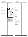 6
6
-
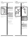 7
7
-
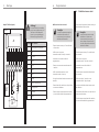 8
8
-
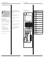 9
9
-
 10
10
-
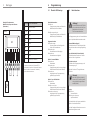 11
11
-
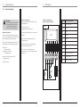 12
12
-
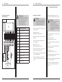 13
13
-
 14
14
-
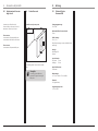 15
15
-
 16
16
-
 17
17
-
 18
18
-
 19
19
-
 20
20
-
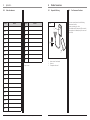 21
21
-
 22
22
-
 23
23
-
 24
24
-
 25
25
-
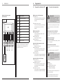 26
26
-
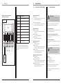 27
27
-
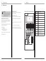 28
28
-
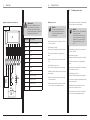 29
29
-
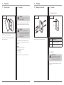 30
30
-
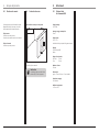 31
31
-
 32
32
-
 33
33
-
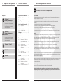 34
34
-
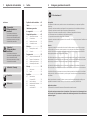 35
35
-
 36
36
-
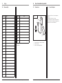 37
37
-
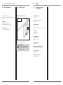 38
38
-
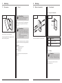 39
39
-
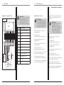 40
40
-
 41
41
-
 42
42
-
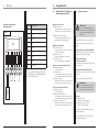 43
43
-
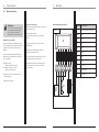 44
44
-
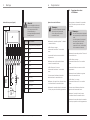 45
45
-
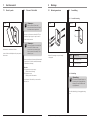 46
46
-
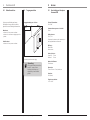 47
47
-
 48
48
-
 49
49
-
 50
50


Marantec Command 802 de handleiding
- Categorie
- Beveiligingsdeurcontrollers
- Type
- de handleiding
in andere talen
Gerelateerde papieren
Andere documenten
-
Velleman WSHA179 Handleiding
-
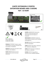 Intratone 12-0109 Installatie gids
-
Renkforce LESER de handleiding
-
Aritech ATS1190 de handleiding
-
-
Renkforce Transponder access control de handleiding
-
Chamberlain HC400ML de handleiding
-
-
Comelit SKB Technical Manual
-
Nice Automation MORX de handleiding
