
040108.03
NEDERLANDS
ENGLISH
DEUTSCH
FRANÇAIS
ESPAÑOL
ITALIANO
Copyright © 2022 VETUS Schiedam Holland
Installatiehandleiding
Inspectiedeksel voor
vastebrandstoftanks
Installation manual
Inspection lid for rigid fuel tanks
Installationshandbuch
Inspektionsdeckel für starre
Kraftstotanks
Manuel d’ installation
Couvercle d’inspection pour
réservoirs de carburant rigides
Manual de instalación
Tapa de inspección para depósitos de
combustible rígidos
Manuale d’installazione
Coperchio di ispezione per serbatoi di
carburante rigidi
Inspection lid for rigid fuel tanks
Installation manual
ILT120B / ILT120X

2 040108.03 Inspection lid ILT120B/X
1 Inleiding
Deze handleiding geldt voor het inspectiedeksel
voor vaste tanks. De tank mag van kunststof, poly-
ester of metaal zijn gemaakt en moet een minimale
wanddikte hebben van 0,8 mm.
ILT120B geschikt voor (tot 10% bio) diesel. ILT120X
geschikt voor benzine of (>10% bio) diesel tanks.
Let op!
Raadpleeg de bijbehorende handleiding voor
het aansluiten van de tank.
2 Installatie
2.1 Aanbrengen van het montagegat
voor het inspectiedeksel
• Plaats het inspectiedeksel in de bovenzijde van
de tank. Indien een VETUS tank wordt gebruikt
plaats dan het inspectiedeksel bij voorkeur zo
dat de plug P wordt verwijderd bij het aanbren-
gen van het gat.
• Breng het gat in de tank aan en werk het gat
braambrij af. Pas bij voorkeur een gatzaag
(ø 159 mm) toe.
• Reinig de binnenzijde van de tanks alvorens het
inspectiedeksel te monteren.
2.2 Toe te passen afdichtrubber
Bepaal de wanddikte van de tank en pas het aange-
geven afdichtrubber toe.
2.3 Montage inspectiedeksel
Flens (1)
• Plaats de ens (1) in het gat van de tank.
• Draai de 4 schroeven (2) ieder één (-1-) omwen-
teling vast (rechtsom) en test of de ens nog
eenvoudig met de hand te verdraaien is. Her-
haal dit tot de ens niet meer te verdraaien is.
• Nu moeten alle schroeven vier (-4-) omwente-
lingen aangedraaid worden. Doe dit door, na
elkaar, iedere schroef één (-1-) omwenteling
aan te draaien. Herhaal deze handeling drie (-3-)
keer.
Massa-aansluiting (3)
• De schroef (3) is bestemd om de ens aan massa
te kunnen aansluiten.
Deksel (4)
• Schroef het deksel op de ens.
Let op
Controleer de dichtheid van alle
verbindingen alvorens de tank te vullen
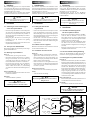
ø 159 (6 1/4”)
MIN. 160
(6 1/4”)
P
T = 0.8 - 4 mm
(1/32”- 5/32”)
T = 4 - 10 mm
(5/32”- 3/8”)
T
16 mm (5/8”)
22 mm (7/8”)
2.1 2.2
1 Introduction
This manual is applicable to the installation of the
inspection lid for rigid tanks. The tank may be made
from plastic, GRP or metal and should have a mini-
mum wall thickness of 0.8 mm.
ILT120B suitable for (up to 10% bio) diesel. ILT120X
suitable for petrol or (>10% bio) diesel tanks.
Note!
Consult the manual supplied with the tank for
instructions on how to connect it.
2 Installation
2.1 Cutting the hole for the
inspection lid
• Position the inspection lid on the top face of the
tank. If a VETUS tank is used, then it should be
tted with plug P on the top and the inspection
lid should preferably be located so that plug P is
removed when the hole is cut.
• Cut the hole in the tank and remove all burrs.
Preferably use a holesaw (159 mm, 6 1/4” diam.).
• Clean the inside of the tanks before tting the
inspection lid.
2.2 Rubber seal to be applied
Determine the thickness of the wall of the tank and
use the indicated rubber seal.
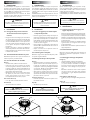
2.3 Installation of connector lid
Flange (1)
• Position the ange (1) into the hole of the tank.
• Tighten each of the 4 screws (2) one (-1-) revo-
lution (clockwise) and check if the ange can
be rotated easily by hand. Repeat this until the
ange can’t be rotated anymore.
• Now all screws have to be tightened four (-4-)
turns. Do this by, one after the other, tightening
each screw one (-1-) revolution. Repeat this ac-
tion three (-3-) times.
Ground connection (3)
• Use the screw to connect the ange to ground.
Lid (4)
• Screw the lid onto the ange.
Note!
Check the tightness of all connections before
lling the tank.
1 Einleitung
Diese Anleitung gilt für den Inspektionsdeckel für
starre tanks. Der Treibstotank kann aus Kunst-
so, GRP oder Metall sein und sollte eine minimale
Wanddicke von 0,8 mm aufweisen.
ILT120B Geeignet für (bis zu 10% Bio-)Diesel.
ILT120X Geeignet für Benzin- oder (>10% Bio-) Die-
selkraftstotanks.
AchtuNg!
Konsultieren Sie das Handbuch das mit dem
Tank geliefert wurde für Anweisungen zu den
Verbindungen.
2 Installation
2.1 Herstellen des Montagelochs
für den Inspektionsdeckel
• Bringen Sie den Inspektionsdeckel an der Ober-
seite des Tanks an. Handelt es sich um einen
Vetus-Tank, bringen Sie den Inspektionsdeckel
vorzugsweise so an, dass das Angussteil P beim
Herstellen des Lochs entfernt wird.
• Stellen Sie das Loch an der betreenden Stelle
des Tanks so her, dass es frei von Riefen ist. Ver-
wenden Sie dazu vorzugsweise eine Lochsäge (ø
159 mm).
• Reinigen Sie den Tank von innen, bevor Sie den
Inspektionsdeckel montieren.
2.2 Zu verwendender Dichtgummiring
Stellen Sie die Wanddicke des Tanks fest und ver-
wenden Sie den angegebenen Dichtgummiring.
2.3 Montage des Inspektionsdeckels
Flansch (1)
• Montieren Sie den Flansch (1) in das Loch am Tank.
• Ziehen Sie die 4 Schrauben (2) jeweils um eine (-1-)
Umdrehung fest (rechts herum) und testen Sie, ob
der Flansch noch einfach mit der Hand verdreht
werden kann. Wiederholen Sie diesen Vorgang,
bis der Flansch nicht mehr verdreht werden kann.
• Jetzt müssen alle Schrauben vier (-4-) Umdre-
hungen angezogen werden. Tun Sie dies, eine
nach der anderen, indem Sie jede Schraube eine
(-1-) Umdrehung anziehen. Wiederholen Sie die-
sen Prozess drei (-3-) Mal.
Masse-Anschluss (3)
• Die Schraube (3) hat den Zweck, den Flansch an
ein Massekabel anschließen zu können.
Deckel (4)
• Schrauben Sie den Deckel auf den Flansch.
AchtuNg!
Prüfen Sie die Dichtheit aller Verbindungen
vor dem auüllen der Treibstotanks.
ENGLISH
NEDERLANDS DEUTSCH

040108.03 3
Inspection lid ILT120B/X
52
1
3
4
2.3
1 Introduction
Le mode d’emploi se rapporte au couvercle d’ins-
pection pour réservoirs rigides. Le réservoir peut
être fait en plastique, en plastique renforcé de bre
de verre (GRP) ou en métal et doit avoir une épais-
seur minimale de paroi de 0,8 mm.
ILT120B Convient pour les réservoirs de diesel
(jusqu’à 10% bio). ILT120X Convient aux réservoirs
d’essence ou de diesel (> 10% bio).
RemARque !
Consulter le manuel fourni avec le réservoir de
carbunant pour obtenir des instructions sur la
manière de le connecter.
2 Installation
2.1 Perçage du trou pour le couvercle
du connecteur et les trous pour le
raccord
• Perçage du trou de montage pour le bouchon
de contrôle. Placez le bouchon de contrôle dans
la partie supérieure du réservoir. Si vous utilisez
un réservoir VETUS, faites en sorte que le bou-
chon de contrôle soit placé de manière à ce que
le trou puisse être percé à l’emplacement du
bouchon P.
• Percez le trou dans le réservoir et ébarbez-le.
Utilisez de préférence une mèche de ø159 mm.
• Nettoyez l’intérieur du réservoir avant de poser
le bouchon de contrôle.
2.2 Joint d’étanchéité à mettre en place
Déterminer l’épaisseur de la paroi du réservoir et
mettre en place le joint d’étanchéité.
2.3 Pose du bouchon de contrôle
Bride (1)
• Placez la bride (1) dans le trou du réservoir.
• Fixez les 4 vis (2) en les tournant (-1-) chacune
une fois (de gauche à droite) et contrôlez s’il est
toujours possible de tourner manuellement la
bride. Répétez l’opération jusqu’à ce qu’il ne soit
plus possible de tourner la bride.
• Maintenant, toutes les vis doivent être serrées
de quatre (-4-) tours. Pour ce faire, l’un après
l’autre, serrez chaque vis par une (-1-) révolu-
tion. Répétez cette action trois (-3-) fois.
Raccord à la masse (3)
• La vis (3) sert à raccorder la bride à la masse.
Bouchon (4)
• Vissez le bouchon sur la bride.
RemARque !
Vérier l’étanchéité de toutes les connexions
avant le remplissage du réservoir.
1 Introduction
Este manual es aplicable a la tapa de inspección
para depósitos rígidos. El tanque puede estar he-
cho de plástico, GRP (plástico reforzado con vídrio)
ó metal y debe tener un grosor mínimo de pared
de 0,8 mm.
ILT120B Adecuado para tanques (hasta un 10% de
bio) diesel. ILT120X Adecuado para tanques de ga-
solina o (> 10% bio) diésel.
NotA!
Consulte el manual entregado con el tanque
de carburante para ver las instrucciones de
cómo conectarlo.
2 Instalación
2.1 Cortar el agujero para el montaje de
la tapa de inspección
• Cortar el agujero para el montaje de la tapa de
inspección. Coloque la tapa de inspección en la
parte superior del depósito. Si se utiliza un de-
pósito VETUS, coloque preferentemente la tapa
de inspección de tal manera que el conector P
se retire al cortar el agujero.
• Corte el agujero en el depósito y retire todas las
rebabas. Utilice preferentemente una sierra de
corona (ø 159 mm).
• Limpie el interior de los depósitos antes de
montar la tapa de inspección.
2.2 Junta de goma a emplear
Determine el grosor de la pared del depósito y utili-
ce la junta de goma indicada.
2.3 Montaje de la tapa de inspección
Brida (1)
• Coloque la brida (1) en el agujero del depósito.
• Apriete cada uno de los 4 tornillos (2) una (-1-
) vuelta (en el sentido de las agujas del reloj) y
compruebe si la brida se puede girar fácilmente
con la mano. Repita este procedimiento hasta
que la brida no se pueda girar más.
• Ahora todos los tornillos tienen que ser apreta-
dos cuatro (-4-) vueltas. Haga esto, uno tras otro,
apretando cada tornillo una (-1-) revolución. Re-
pita esta acción tres (-3-) veces.
Conexión de masa (3)
• El tornillo (3) tiene como función poder conec-
tar la brida a la masa.
Tapa (4)
• Atornille la tapa en la brida.
NotA!
Compruebe el apriete de todas las
conexiones antes de llenar el tanque.
1 Introduzione
Queste istruzioni valgono per coperchio di ispe-
zione per serbatoi rigidi. Il serbatoio può essere in
plastica, GRP o metallo e deve avere uno spessore
minimo di parete di 0,8 mm.
ILT120B Adatto per serbatoi diesel (no al 10% bio).
ILT120X Adatto per serbatoi benzina o diesel (>10%
bio).
NotA!
Consultare il manuale fornito con il serbatoio
per carburante per le istruzioni di collegamento.
2 Installazione
2.1 Praticare il foro di montaggio per il
tappo d’ispezione
• Praticare il foro di montaggio per il tappo d’ispe-
zione. Posizionate il tappo d’ispezione sulla par-
te superiore del serbatoio. Se usate un serbatoio
VETUS, si consiglia di posizionare il tappo d’ispe-
zione in modo tale che il tappo P venga rimosso
praticando il foro.
• Praticate il foto nel serbatoio e rinitelo limando
ogni sbavatura. Si consiglia di usare una sega
per fori (ø159mm).
• Pulite l’interno del serbatoio prima di montare il
tappo d’ispezione.
2.2 Guarnizione da applicare
Misurate lo spessore della parete del serbatoio ed
applicate la guarnizione appropriata, secondo le
indicazioni.
2.3 Montaggio del tappo d’ispezione
Flangia (1)
• Inserite la angia (1) nel foro del serbatoio.
• Avvitate le 4 viti (2) girandole ognuna di un giro
(-1-) (verso destra) e controllate se la angia si
può ancora serrare con la mano. Ripetete questa
azione no a che la angia non si può più ser-
rare.
• Ora tutte le viti devono essere serrate a quattro
(-4-) giri. A tal ne, una dopo l’altra, stringere
ogni vite di un (-1-) giro. Ripetere questa azione
tre (-3-) volte.
Collegamento della massa (3).
• La vite (3) serve per collegare la angia alla mas-
sa.
Tappo (4).
• Avvitate il tappo alla angia.
NotA!
Vericare il serraggio di tutti i collegamenti
prima di riempire il serbatoio.
ESPAÑOL
FRANÇAIS ITALIANO

4
1
32
5
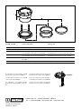
ILT120B ILT120X Service onderdelen Service parts
pos. qty part benaming description
1 1 ILTSET1 Set afdichtrubbers ILT120B Set of rubber seals ILT120B
2 1 ILTVITL Afdichtrubber, hoogte 16 mm,
voor wanddikte 0,8 tot 4 mm voor ILT120B/X
Rubber seal, height 16 mm,
for wall thickness 0.8 up to 4 mm for ILT120B/X
3 1 ILTVITH Afdichtrubber, hoogte 22 mm,
voor wanddikte 4 tot 10 mm voor ILT120B/X
Rubber seal, height 22 mm,
for wall thickness 4 up to 10 mm for ILT120B/X
4 1 ILTSET2 Deksel incl. pakking voor inspectiedeksel voor
ILT120B/X
Cover incl. gasket for inspection lid for ILT120B/X
5 1 ILTCON18 Pakking Gasket
Printed in the Netherlands
040108.03 2022-12
De blindplaat van inspectiedeksel ILT120B
kan worden vervangen door ILTCONF38.
The blind plate of inspection cover ILT120B
can be replaced by ILTCONF38.
Die Blindplatte des Inspektionsdeckels
ILT120B kann durch ILTCONF38 ersetzt wer-
den.
La plaque aveugle du couvercle d’inspection
ILT120B peut être remplacée par ILTCONF38.
La placa de cobertura de la tapa de inspecci-
ón ILT120B puede sustituirse por ILTCONF38.
La piastra cieca del coperchio di ispezionee
ILT120B può essere sostituita da ILTCONF38.
ILTCONF38
Fokkerstraat 571 - 3125 BD Schiedam - Holland
Tel.: +31 (0)88 4884700 - [email protected] - www.vetus.com
-
 1
1
-
 2
2
-
 3
3
-
 4
4


in andere talen
- italiano: Vetus ILT120B Manuale utente
- français: Vetus ILT120B Manuel utilisateur
- español: Vetus ILT120B Manual de usuario
- Deutsch: Vetus ILT120B Benutzerhandbuch
Gerelateerde papieren
-
Vetus ILTCONF38 Installatie gids
-
-
Vetus ILTCONW Installatie gids
-
-
-
-
-
-