
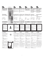
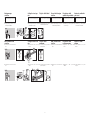
- 1 -
D
5.1.3.4 Edition 07.04
03250141 09.07 Fx/ivd 1.000
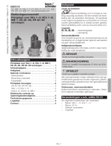
Gas-Magnetventil VS
Luft-Magnetventil VL
Betriebsanleitung
● Bitte lesen und aufbewahren
Zeichenerklärung
●, 1, 2, 3... = Tätigkeit
➔ = Hinweis
Solenoid valve for gas
VS
Solenoid valve for air
VL
Operating instructions
● Please read and keep in a safe
place
Explanation of symbols
●, 1, 2, 3 ... = Action
➔ = Instruction
GB F
Electrovanne pour gaz
VS
Electrovanne pour air
VL
Instructions de service
● A lire attentivement et à con-
server
Légendes
●, 1, 2, 3... = action
➔ = remarque
Gasmagneetklep VS
Luchtmagneetklep VL
Bedieningsvoorschrift
● Lezen en goed bewaren a.u.b.
Legenda
●, 1, 2, 3,... = werkzaamheden
➔ = aanwijzing
NL I
Valvola elettromagneti-
ca per gas VS
Valvola elettromagneti-
ca per aria VL
Istruzioni d’uso
● Si prega di leggere e conser-
vare
Spiegazione dei simboli
●, 1, 2, 3... = Operazione
➔ = Avvertenza
E
Válvula electromagné-
tica para gas VS
Válvula electromagné-
tica para aire VL
Instrucciones de utili-
zación
● Se ruega que las lean y con-
serven
Explicación de símbolos
●, 1, 2, 3... = Actividad
➔ = Indicación
Konformitäts-
bescheinigung
Wir erklären als Hersteller, dass das
Produkt VS, gekennzeichnet mit der
Produkt-ID-Nr. CE-0085AQ0005, die
grundlegenden Anforderungen fol-
gender Richtlinien erfüllt:
– 90/396/EWG in Verbindung mit
EN 161,
– 98/37/EG,
– 73/23/EWG in Verbindung mit den
einschlägigen Normen,
– 89/336/EWG in Verbindung mit
EN 55014.
Das entsprechend bezeichnete Pro-
dukt stimmt überein mit dem bei der
zugelassenen Stelle 0085 geprüften
Baumuster.
Eine umfassende Qualitätssicherung
ist gewährleistet durch ein zertifi -
ziertes Qualitätsmanagementsystem
nach DIN EN ISO 9001 gemäß
Anhang II Absatz 3 der Richtlinie
90/396/EWG.
G. Kromschröder AG, Osnabrück
VS
CE-0085AQ0005
D-49018 Osnabrück, Germany
WARNUNG! Unsachgemäßer Ein-
bau, Einstellung, Verän de rung,
Be die nung oder War tung kann
Ver letzungen oder Sachschäden
verursachen.
Anleitung vor dem Gebrauch lesen.
Dieses Gerät muss nach den gelten-
den Vorschriften installiert werden.
Certifi caat van over-
eenstemming
Wij verklaren als fabrikant dat het pro-
duct VS, gemerkt met het product-
identifi catienummer CE-0085AQ0005,
aan de fundamentele voorschriften
van de volgende richtlijnen voldoet:
– 90/396/EEG in combinatie met
EN 161,
– 98/37/EG,
– 73/23/EEG in combinatie met de
toepasselijke normen,
– 89/336/EEG in combinatie met
EN 55014.
Het overeenkomstig geïdentifi ceerde
product komt overeen met het door
de aangewezen instantie 0085 ge-
controleerde type.
Een uitgebreide kwaliteitsborging
wordt gegarandeerd door een gecer-
tifi ceerd kwaliteitsborgingssysteem
conform DIN EN ISO 9001 overeen-
komstig bijlage II, lid 3 van de richtlijn
90/396/EEG.
G. Kromschröder AG, Osnabrück
Dichiarazione di
conformità
Dichiariamo in qualità di costruttori
che il prodotto VS, contrassegnato
con il numero di identifi cazione
CE-0085AQ0005, risponde ai requi-
siti essenziali posti dalle seguenti di-
rettive:
– 90/396/CEE in unione con
EN 161,
– 98/37/CE,
– 73/23/CEE in unione con le nor-
me pertinenti,
– 89/336/CEE in unione con
EN 55014.
Il prodotto con tale contrassegno
corrisponde al tipo esaminato dall’or-
ganismo notifi cato 0085.
La totale sicurezza della qualità è ga-
rantita da un sistema certifi cato di
management della qualità ai sensi
della DIN EN ISO 9001, in base al-
l’appendice II, comma 3 della diretti-
va 90/396/CEE.
G. Kromschröder AG, Osnabrück
Certifi cado de
conformidad
Nosotros, el fabricante, declaramos que
el producto VS, marcado con el nº de iden-
tifi cación de producto CE-0085AQ0005,
cumple con los requisitos básicos de las
siguientes Directivas:
– 90/396/CEE en relación con EN 161,
– 98/37/CE,
– 73/23/CEE en relación con las nor-
mas pertinentes,
– 89/336/CEE en relación con
EN 55014.
El producto denominado de la forma arri-
ba mencionada es conforme con el mo-
delo de construcción ensayado por el
respectivo Organismo Notifi cado 0085.
El exhaustivo control de calidad está ga-
rantizado por un sistema de gestión de
calidad, certifi cado conforme a la norma
DIN EN ISO 9001 según el Anexo II,
Párrafo 3 de la Directiva 90/396/CEE.
G. Kromschröder AG, Osnabrück
Certifi cate of
conformity
We, the manufacturer, hereby declare
that the product VS, marked with
product ID No. CE-0085AQ0005,
complies with the essential require-
ments of the following Directives:
– 90/396/EEC in conjunction with
EN 161,
– 98/37/EC,
– 73/23/EEC in conjunction with the
relevant standards,
– 89/336/EEC in conjunction with
EN 55014.
The relevant product corresponds to
the type tested by the notifi ed body
0085.
Comprehensive quality assurance is
guaranteed by a certifi ed Quality Sys-
tem pursuant to DIN EN ISO 9001
according to annex II, paragraph 3
of Directive 90/396/EEC.
G. Kromschröder AG, Osnabrück
Attestation de
conformité
En tant que fabricant, nous décla-
rons que le produit VS, identifi é par le
numéro de produit CE-0085AQ0005,
répond aux exigences essentielles
des directives suivantes :
– 90/396/CEE en association avec
la EN 161,
– 98/37/CE,
– 73/23/CEE en association avec
les normes pertinentes,
– 89/336/CEE en association avec
la EN 55014.
Le produit désigné en conséquence
est conforme au type éprouvé à l’or-
ganisme notifi é 0085.
Une assurance de la qualité com plète
est garantie par un système qualité
certifi é selon DIN EN ISO 9001, con-
formément à l’annexe II, paragraphe
3, de la directive 90/396/CEE.
G. Kromschröder AG, Osnabrück
WARNING! Incorrect installation,
adjustment, modifi cation, operation
or maintenance may cause injury
or material damage.
Read the instructions before use.
This unit must be installed in ac-
cordance with the regulations in
force.
ATTENTION ! Un montage, un
réglage, une modi fi cation, une utilisa-
tion ou un entretien in adaptés ris-
quent d’engendrer des dom mages
matériels ou corporels.
Lire les instructions avant utilisation.
Cet appareil doit être installé en res-
pectant les règlements en vigueur.
WAARSCHUWING! Ondeskundi-
ge inbouw, instelling, wijziging,
bediening of onder houds werk zaam-
heden kunnen per soonlijk letsel of
materiële schade veroor zaken.
Aanwijzingen voor het gebruik lezen.
Dit apparaat moet overeenkomstig
de geldende regels worden
geïnstalleerd.
ATTENZIONE! Se montaggio, re-
go lazione, modifi ca, utilizzo o manu-
tenzione non vengono ese guiti
correttamente, possono veri fi carsi
infortuni o danni.
Si prega di leggere le istruzioni
prima di utilizzare il prodotto che
dovrà venire installato in base alle
normative vigenti.
¡ADVERTENCIA! La instalación,
ajuste, modifi cación, manejo o man-
tenimiento incorrecto puede oca-
sionar daños personales o mate-
riales.
Leer las instrucciones antes de
usar. Este dispositivo debe ser
instalado observando las normati-
vas en vigor.
Alle in dieser Betriebsanleitung
aufgeführten Tätigkeiten dürfen
nur von autorisiertem Fach per-
sonal ausgeführt werden!
All the work set out in these
operating instructions may only
be completed by authorised
trained personnel!
Toutes les actions mentionnées
dans les présentes instructions
de service doivent être exécutées
par des spécialistes formés et
autorisés uniquement !
Alle in deze bedrijfshandleiding
vermelde werkzaamheden mo-
gen alleen door technici worden
uitgevoerd!
Tutte le operazioni indicate nelle
presenti istruzioni d’uso devono
essere eseguite soltanto dal pre-
posto esperto autorizzato.
¡Todas las actividades indicadas
en estas Instrucciones de utiliza-
ción, sólo deben realizarse por
una persona formada y autorizada!
TR CZ PL RUS H
DK S N P GR
➔
www.kromschroeder.de

- 2 -
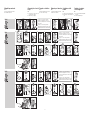
VS
Gas-Magnetventil zum Sichern, Re-
geln und Steuern von Luft oder
Gas an Luft- oder Gasver brauchs-
einrichtungen.
VL
Luft-Magnetventil zum Sichern, Re-
geln und Steuern von Luft an Luft-
ver brauchseinrichtungen.
Prüfen
VS
➔ Gas-Magnetventil für Erdgas,
Stadtgas, Flüssiggas oder Luft.
VL
➔ Luft-Magnetventil für Kaltluft.
VS, VL
➔ Netzspannung, elektrische Leistung,
Umgebungstemperatur, Schutzart
und Einbaulage – siehe Typen-
schild.
➔ VS..N
Ausführung ohne Dämpfung.
Schnell öffnend: ca. 0,5 s.
Schnell schließend: < 1 s.
➔ VS..L
Ausführung mit Dämpfung.
Langsam öffnend: ca. 10 s.
Schnell schließend: < 1 s.
➔ VL..R
Ausführung mit Dämpfung.
Langsam öffnend: ca. 3 s.
Langsam schließend: ca. 3 s.
➔ VS 1
Der Eingangsdruck pe kann am
Mess-Stutzen abgegriffen wer-
den.
➔ VS 2, VS 3
Der Eingangsdruck pe sowie der
Ausgangsdruck pa können an
den Mess-Stutzen abgegriffen
werden.
➔ Luft-Volumenstrom bei Druckver-
lust Δp = 1 mbar.
➔ Der Magnetkörper wird beim Be-
trieb warm – je nach Umgebungs-
temperatur und Spannung bis zu
90 °C.
VS, VL V
' [m3/h]
∆
p
= 1 mba
r
VS 115, VL 115
VS 125, VL 125
VS 232, VL 232
VS 240, VL 240
VS 350, VL 350
3,8
9,0
16,0
23,0
42,0
+90 °C
p
e
pa
p
e
Achtung!
VL..R, die Dämpfung nicht verdre-
hen.
VS
Gasmagneetklep voor het beveiligen,
regelen en besturen van gas of lucht
aan gas- of luchttoestellen.
VL
Luchtmagneetklep voor het beveili-
gen, regelen en besturen van lucht
aan luchttoestellen.
Controleren
VS
➔ Gasmagneetklep voor aardgas,
stadsgas, LPG of lucht.
VL
➔ Luchtmagneetklep voor koude
lucht.
VS, VL
➔ Netspanning, elektrisch vermo-
gen, omgevingstemperatuur, be-
schermingsklasse en inbouwposi-
tie – zie typeplaatje.
➔ VS..N
Uitvoering voor aardgas zonder
demping.
Snel openend: ca. 0,5 s.
Snel sluitend: < 1 s.
➔ VS..L
Uitvoering voor aardgas met dem-
ping.
Langzaam openend: ca. 10 s.
Snel sluitend: < 1 s.
➔ VL..R
Uitvoering voor lucht met dem-
ping.
Attentie!
VL..R, de demper niet verdraaien.
Langzaam openend: ca. 3 s.
Langzaam sluitend: ca. 3 s.
➔ VS 1
De inlaatdruk pe kan met behulp van
de meetnippel worden gemeten.
➔ VS 2, VS 3
De inlaatdruk pe alsmede de uitlaat-
druk pa kunnen met behulp van de
meetnippel worden gemeten.
➔ Luchtvolumestroom bij drukver-
lies Δp = 1 mbar.
➔ De magneetspoel wordt tijdens
bedrijf warm – afhankelijk van de
omgevingstemperatuur en span-
ning tot 90 °C.
VS
Valvola elettromagnetica per gas per
regolare, controllare e garantire la si-
curezza di aria e gas degli apparec-
chi per utenze aria e gas.
VL
Valvola elettromagnetica per aria per
regolare, controllare e garantire la si-
curezza dell’aria degli apparecchi per
utenze aria.
Controllo
VS
➔ Valvola elettromagnetica per gas,
metano, gas di città, gas liquido o
aria.
VL
➔ Valvola elettromagnetica per aria
fredda.
VS, VL
➔ Per tensione di rete, potenza elet-
trica, temperatura ambiente, tipo
di protezione e posizione di mon-
taggio si rimanda alla targhetta
dati.
➔ VS..N
Esecuzione senza smorzatore.
Ad apertura rapida: circa 0,5 s.
A chiusura rapida: < 1 s.
➔ VS..L
Esecuzione con smorzatore.
Ad apertura lenta: circa 10 s.
A chiusura rapida: < 1 s.
➔ VL..R
Esecuzione con smorzatore.
Attenzione!
VL..R, non invertire lo smorzatore.
Ad apertura lenta: circa 3 s.
A chiusura lenta: circa 3 s.
➔ VS 1
La pressione di entrata pe può es-
sere misurata sulla presa di misura.
➔ VS 2, VS 3
La pressione di entrata pe nonché
la pressione di uscita pa possono
essere misurate sulle prese di mi-
sura.
➔ Regolare la portata dell’aria per
una perdita di carico Δp = 1 mbar.
➔ Durante il funzionamento la bobi-
na può scaldarsi fi no a 90 °C a se-
conda della temperatura ambien-
te e della tensione.
VS
Válvula electromagnética para gas, para
la seguridad, regulación y control del aire
o de gas en dispositivos de consumo de
aire o de gas.
VL
Válvula electromagnética para aire, para
la seguridad, regulación y control del aire
en dispositivos de consumo de aire.
Comprobar
VS
➔ Válvula electromagnética para gas na-
tural, gas ciudad, GLP o aire.
VL
➔ Válvula electromagnética para aire
frío.
VS, VL
➔ Para la tensión de red, conexión eléc-
trica, temperatura ambiente, clase de
protección y posición de montaje –
véase placa de características.
➔ VS..N
Ejecución sin amortiguación.
Apertura rápida: aprox. 0,5 s.
Cierre rápido: < 1 s.
➔ VS..L
Ejecución con amortiguación.
Apertura lenta: aprox. 10 s.
Cierre rápido: < 1 s.
➔ VL..R
Ejecución con amortiguación.
¡Atención!
VL..R, no forzar el amortiguador.
Apertura lenta: aprox. 3 s.
Cierre lento: aprox. 3 s.
➔ VS 1
La presión de entrada pe se puede
medir en la toma de presión.
➔ VS 2, VS 3
La presión de entrada pe, así como la
presión de salida pa se pueden medir
en las tomas de presión.
➔ Caudal de aire con pérdida de carga
Δp = 1 mbar.
➔ El actuador electromagnético se
calienta durante el funcionamiento,
según sea la temperatura ambiente y
la tensión, casi hasta los 90°C.
VS
Solenoid valve for gas for safeguard-
ing, regulating and controlling air or
gas on various appliances.
VL
Solenoid valve for air for safeguard-
ing, regulating and controlling air on
air appliances.
Testing
VS
➔ Solenoid valve for gas for natural
gas, town gas, LPG or air.
VL
➔ Solenoid valve for cold air.
VS, VL
➔ Mains voltage, electrical power
rating, ambient temperature, en-
closure and fi tting position – see
type label.
➔ VS..N
Version without damping.
Quick opening: approx. 0.5 s.
Quick closing: < 1 s.
➔ VS..L
Version with damping.
Slow opening: approx. 10 s.
Quick closing: < 1 s.
➔ VL..R
Version with damping.
Caution!
VL..R; do not twist damping unit.
Slow opening: approx. 3 s.
Slow closing: approx. 3 s.
➔ VS 1
The inlet pressure pe can be meas-
ured at the pressure test point.
➔ VS 2, VS 3
The inlet pressure pe and the out-
let pressure pa can be measured
at the pressure test points.
➔ Air fl ow rate with pressure loss
Δp = 1 mbar.
➔ The solenoid body heats up dur-
ing operation – up to 90°C de-
pending on ambient temperature
and voltage.
VS
Electrovanne pour gaz assurant la sé-
curité, la régulation et la commande
de l’air ou du gaz sur des équipements
consommant de l’air ou du gaz.
VL
Electrovanne pour air assurant la sé-
curité, la régulation et la commande
de l’air sur des équipements con-
sommant de l’air.
Vérifi er
VS
➔ Electrovanne pour gaz naturel,
gaz de ville, GPL ou air.
VL
➔ Electrovanne pour air froid.
VS, VL
➔ Tension du secteur, puissance
électrique, température ambiante,
indice de protection et position
de montage – voir la plaque signa-
létique.
➔ VS..N
Modèle sans amortisseur.
A ouverture rapide : env. 0,5 s
A fermeture rapide : < 1 s
➔ VS..L
Modèle avec amortisseur.
A ouverture lente : env. 10 s
A fermeture rapide : < 1 s
➔ VL..R
Modèle avec amortisseur.
A ouverture lente : env. 3 s
A fermeture lente : env. 3 s
➔ VS 1
La pression d’entrée pe peut être
mesurée au niveau du raccord de
mesure.
➔ VS 2, VS 3
La pression d’entrée pe ainsi que
la pression de sortie pa peuvent
être mesurées au niveau du rac-
cord de mesure.
➔ Débit d’air en cas de perte de
charge Δp = 1 mbar.
➔ Pendant le fonctionnement, la bo-
bine chauffe – elle peut atteindre
90°C selon la température am-
biante et la tension.
Attention !
VL..R, ne pas tourner l’amortisseur.

- 3 -
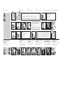
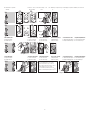
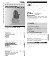
Einbauen
➔ Einbaulage senkrecht oder waa-
gerecht, nicht über Kopf.
➔ Das Gehäuse darf kein Mauer-
werk berühren. Mindestabstand
20 mm.
➔ Dichtmaterial und Späne dürfen
nicht in das Ventilgehäuse gelan-
gen.
➔ Vor jede Anlage einen Filter oder
Schmutzfänger einbauen.
➔ Passenden Schraubenschlüssel
verwenden.
Verdrahten
1 Anlage spannungsfrei schalten.
2 Gaszufuhr absperren.
▼
VS
D-49018 Osnabrück, Germany
U:
P:
VS, VL 1 2 3 6745
VS..L, VL..R
VS..N 7
-
N
39 10
5
Pg 11: ø 8-12 mm
Pg 13,5: ø 10-14 mm
11
5 6
Pg 11: ø 8-12 mm
Pg 13,5: ø 10-14 mm
LV1
+
-
N
8
LV1
+
4
3
68
7
4 9
Inbouwen
➔ Inbouwpositie verticaal of horizon-
taal, niet onderste boven.
➔ Het huis mag geen muur aanra-
ken. Minimale afstand 20 mm.
➔ Afdichtingsmateriaal en spanen
mogen niet in het klephuis terecht-
komen.
➔ Voor elke installatie een fi lter of
zeef inbouwen.
➔ Bijpassende sleutel gebruiken.
Bedraden
1 Installatie spanningsvrij maken.
2 Gastoevoer afsluiten.
▼
Montaggio
➔ Posizione di montaggio verticale
o orizzontale, non capovolta.
➔ La valvola non deve toccare la mu-
ratura. Distanza minima 20 mm.
➔ Il materiale sigillante ed i trucioli
non devono entrare nella valvola.
➔ A monte di ogni impianto installa-
re un fi ltro.
➔ Utilizzare la chiave adatta.
Cablaggio
1 Togliere la tensione dall’impianto.
2 Interrompere l’alimentazione del
gas.
▼
Montaje
➔ Posición de montaje vertical u hori-
zontal, no con el actuador en posi-
ción invertida.
➔ El cuerpo no debe tener ningún con-
tacto con las paredes. Distancia míni-
ma 20 mm.
➔ Evitar la entrada de material sellante y
de viruta en el cuerpo de la válvula.
➔ Montar aguas arriba de cada instala-
ción un fi ltro o un recogedor de sucie-
dad.
➔ Emplear las herramientas apropiadas.
Cableado
1 Desconectar la instalación dejándola
sin tensión.
2 Cortar el suministro de gas.
▼
Installation
➔ Fitting position vertical or horizon-
tal, not upside down.
➔ The housing may not be in con-
tact with masonry. Minimum clear-
ance 20 mm.
➔ Sealing material and swarf must
not be allowed to enter the hous-
ing.
➔ Fit a fi lter or dirt trap upstream of
each system.
➔ Use an appropriate spanner.
Wiring
1 Disconnect the system from the
electrical power supply.
2 Shut off the gas supply.
▼
Montage
➔ Position de montage verticale ou
horizontale, pas à l’envers.
➔ Le boîtier ne doit toucher aucun
mur. Distance minimale de
20 mm.
➔ Le matériau d’étanchéité et les
copeaux ne doivent pas pénétrer
dans le corps de la vanne.
➔ En amont de chaque installation,
monter un fi ltre ou un purgeur.
➔ Utiliser les clés appropriées.
Câblage
1 Mettre l’installation hors tension.
2 Fermer l’arrivée de gaz.
▼

- 4 -
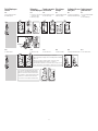
Dichtheit prüfen
1 Magnetventil schließen.
2 Ausgang mit Steckscheibe schlie-
ßen.
9 Steckscheibe entfernen.
Meldeschalter verdrahten
1 Anlage spannungsfrei schalten.
2 Gaszufuhr absperren.
VS..S, VS..G,
VL..S, VL..G
V..S
60–250 V: ≤ 2 A,
50/60 Hz
V..G
24 V: ≤ 40 mA
457
1
32
6
2 A
Pg 11: ø 8-12 mm
3
1
2
3 8
VS, VL
0
6 7
348
0
5
0
N2
≤ 1,5 x pe max
N2
≤ 1,5 x pe max
VS..6, VL..6
110–230V~: 1= N, 2= L1
24 V=: 1= +, 2= –
75 1= N
2 = L1
863 4
Controle op lekkage
1 Magneetklep sluiten.
2 Uitgang met steekschijf sluiten.
9 Steekschijf verwijderen.
Eindschakelaar
bedraden
1 Installatie spanningsvrij maken.
2 Gastoevoer afsluiten.
Controllo della tenuta
1 Chiudere la valvola elettromagnetica.
2 Chiudere l’uscita con un tappo a
innesto.
9 Togliere il tappo a innesto.
Cablaggio fi ne corsa
1 Togliere la tensione dall’impianto.
2 Interrompere l’alimentazione del
gas.
Comprobar la
estanqueidad
1 Cerrar la válvula electromagnética.
2 Cerrar la salida.
9 Abrir la salida.
Cablear el indicador
de posición
1 Desconectar la instalación dejándola
sin tensión.
2 Cortar el suministro de gas.
Tightness test
1 Close the solenoid valve.
2 Close the outlet with blanking
plate.
9 Remove blanking plate.
Wiring the position
indicator
1 Disconnect the system from the
electrical power supply.
2 Shut off the gas supply.
Vérifi er l’étanchéité
1 Fermer l’électrovanne.
2 Fermer la sortie avec une plaque
d’obturation.
9 Retirer la plaque d’obturation.
Câblage de l’indicateur
de position
1 Mettre l’installation hors tension.
2 Fermer l’arrivée de gaz.
Magnetventil öffnen.
Open the solenoid valve.
Ouvrir l’électrovanne.
Magneetklep openen.
Aprire la valvola elettromagnetica.
Abrir la válvula electromagnética.

- 5 -
Startgasmenge
einstellen
VS..L
➔ Startgasmenge mit max. 3 Um-
drehungen einstellbar.
Max. Volumenstrom
einstellen
➔ Volumenstrom von unten einstell-
bar.
➔ Volumenstrom von oben einstell-
bar.
VS..D 1 3
+-
V
2V+V-
0
~1 mm
VS..D 1 32
0
V+V-
123
VS..L
V Start
+
+
V
+
V
~1 mm
Achtung!
VL..R, die Dämpfung nicht verdre-
hen.
Hoeveelheid startgas
instellen
Attentie!
VL..R, de demper niet verdraaien.
VS..L
➔ Hoeveelheid startgas is met max.
3 omwentelingen instelbaar.
Max. volumestroom
instellen
➔ Volumestroom van beneden instel-
baar.
➔ Volumestroom van boven instel-
baar.
Regolazione della
quantità di gas iniziale
Attenzione!
VL..R, non invertire lo smorzatore.
VS..L
➔ Quantità di gas iniziale regolabile
con max. 3 giri.
Regolazione della
portata massima
➔ Regolazione della portata dal
basso.
➔ Regolazione della portata
dall’alto.
Ajustar la cantidad de
gas inicial
¡Atención!
VL..R, no forzar el amortiguador.
VS..L
➔ Cantidad de gas inicial ajustable
con 3 vueltas como máximo.
Ajustar el caudal
máximo
➔ Caudal ajustable en la parte
inferior.
-
➔ Caudal ajustable en la parte
superior.
Setting the start gas
rate
Caution!
VL..R; do not twist damping unit.
VS..L
➔ The start gas rate can be set with
a maximum of 3 turns.
Setting the max. fl ow
rate
➔ The fl ow rate can be set from
below.
➔ The fl ow rate can be set from
above.
Régler le débit initial
VS..L
➔ Le débit initial peut être réglé en
tournant d’au plus 3 tours.
Régler le débit
maximum
➔ Le débit peut être réglé dans la
partie inférieure.
➔ Le débit peut être réglé dans la
partie supérieure.
Attention !
VL..R, ne pas tourner l’amortisseur.

- 6 -
Magnetkörper wechseln
VS
1 Anlage spannungsfrei schalten.
2 Gaszufuhr absperren.
VS..L
max. 3 x 360°
VS..N 43 965
-
N
7
LV1
+
17
+
+
V
34 765
1918
N2
≤ 1,5 x pe max
14 15 161312
VS..D
13
V-V+
+- V
3 4
12 16
15
65 7
14 17
18
N2
≤ 1,5 x pe max
19
98
98
-
N
10 11
8
LV1
+
-
N
10 11
LV1
+
Magneetspoel wisselen
VS
1 Installatie spanningsvrij maken.
2 Gastoevoer afsluiten.
Sostituzione della
bobina
VS
1 Togliere la tensione dall’impianto.
2 Interrompere l’alimentazione del
gas.
O-Ring ca. 10 mm hoch schieben.
Slide the O-ring approx. 10 mm up.
Pousser le joint torique de 10 mm environ
vers le haut.
O-ring ca. 10 mm omhoog duwen.
Spingere l’O-ring verso l’alto per circa 10 mm.
Desplazar la junta tórica unos 10 mm hacia arriba.
Cambiar el actuador
electromagnético
VS
1 Desconectar la instalación dejándola
sin tensión.
2 Cortar el suministro de gas.
O-Ring ca. 10 mm hoch schieben.
Slide the O-ring approx. 10 mm up.
Pousser le joint torique de 10 mm environ
vers le haut.
O-ring ca. 10 mm omhoog duwen.
Spingere l’O-ring verso l’alto per circa 10 mm.
Desplazar la junta tórica unos 10 mm hacia arriba.
Changing the solenoid
body
VS
1 Disconnect the system from the
electrical power supply.
2 Shut off the gas supply.
Remplacer la bobine
VS
1 Mettre l’installation hors tension.
2 Fermer l’arrivée de gaz.
O-Ring ca. 10 mm hoch schieben.
Slide the O-ring approx. 10 mm up.
Pousser le joint torique de 10 mm environ
vers le haut.
O-ring ca. 10 mm omhoog duwen.
Spingere l’O-ring verso l’alto per circa 10 mm.
Desplazar la junta tórica unos 10 mm hacia arriba
.

- 7 -
VL
1 Luftzufuhr absperren.
Gleichrichterplatine
wechseln
1 Anlage spannungsfrei schalten.
2 Gaszufuhr absperren.
VS, VL 4 5
LV1
(+)
N
(-)
6 7 8 9
LV1
(+)
N
(-)
3
-
N
10
LV1
+
11
VL..R 45
3
1918
7 9
17
810 11
15
14
6
16
2
1
1
2
2
-
N
12
LV1
+
13
VL
1 Luchttoevoer afsluiten.
Print van de gelijkrichter
wisselen
1 Installatie spanningsvrij maken.
2 Gastoevoer afsluiten.
VL
1 Interrompere l’alimentazione dell’aria.
Sostituzione della sche-
da del raddrizzatore
1 Togliere la tensione dall’impianto.
2 Interrompere l’alimentazione del
gas.
VL..R ausschalten.
Switch off the VL..R.
Mettre la VL..R hors tension.
VL..R uitschakelen.
Disattivare VL..R.
Desconectar la VL..R.
VL..R ausschalten. Die Dämpfung wird nach unten gezogen.
Switch off the VL..R. The damping unit is pulled downwards.
Mettre la VL..R hors tension. L’amortisseur est tiré vers le bas.
VL..R uitschakelen. De demper wordt naar beneden getrokken.
Disattivare VL..R. Lo smorzatore viene tirato verso il basso.
Desconectar la VL..R. El amortiguador se desliza hacia abajo.
VL
1 Cortar el suministro de aire.
Cambiar el circuito
rectifi cador
1 Desconectar la instalación dejándola
sin tensión.
2 Cortar el suministro de gas.
VL
1 Shut off the air supply.
Changing the rectifi er
board
1 Disconnect the system from the
electrical power supply.
2 Shut off the gas supply.
VL..R einschalten.
Switch on the VL..R.
Mettre la VL..R sous tension.
VL..R inschakelen.
Attivare VL..R.
Conectar la VL..R.
VL
1 Fermer l’arrivée d’air.
Remplacer la platine à
redresseur
1 Mettre l’installation hors tension.
2 Fermer l’arrivée de gaz.
VL..R elektrisch einschalten. Die Dämpfung springt ca. 1 cm nach oben.
Switch on the electrical power supply to the VL..R. The damping unit moves abruptly up
approx. 1 cm.
Mettre la VL..R sous tension. L’amortisseur saute de 1 cm environ vers le haut.
VL..R elektrisch inschakelen. De demper springt ca. 1 cm naar boven.
Attivare l’alimentazione elettrica di VL..R. Lo smorzatore scatta verso l’alto per circa 1 cm.
Conectar eléctricamente la VL..R. El amortiguador se desplaza aprox. 1 cm hacia arriba.
O-Ring ca. 10 mm hoch schieben.
Slide the O-ring approx. 10 cm up.
Pousser le joint torique de 10 mm environ
vers le haut.
O-ring ca. 10 mm omhoog duwen.
Spingere l’O-ring verso l’alto per circa 10 mm.
Desplazar la junta tórica unos 10 mm hacia arriba.

- 8 -
Defekte Dämpfung aus-
tauschen
VS..L
1 Anlage spannungsfrei schalten.
2 Gaszufuhr absperren.
VL..R
1 Luftzufuhr absperren.
4
7
5 6
VL..R 2
1
1
2
32
9
8
max. 3 x 360°
7+
VS..L
10
6 8
+
V
3 4 5
9
N2
≤ 1,5 x pe max
Defecte demper
vervangen
VS..L
1 Installatie spanningsvrij maken.
2 Gastoevoer afsluiten.
VL..R
1 Luchttoevoer afsluiten.
Sostituzione dello smor-
zatore guasto
VS..L
1 Togliere la tensione dall’impianto.
2 Interrompere l’alimentazione del gas.
VL..R
1 Interrompere l’alimentazione dell’aria.
Cambio de un amorti-
guador defectuoso
VS..L
1 Desconectar la instalación dejándola
sin tensión.
2 Cortar el suministro de gas.
VL..R
1 Cortar el suministro del aire.
Exchanging a
defective damping unit
VS..L
1 Disconnect the system from the
electrical power supply.
2 Shut off the gas supply.
VL..R
1 Shut off the air supply.
Remplacer un amortis-
seur défectueux
VS..L
1 Mettre l’installation hors tension.
2 Fermer l’arrivée de gaz.
VS..R
1 Fermer l’arrivée d’air.
VL..R elektrisch einschalten. Die Dämpfung springt ca. 1 cm nach oben.
Switch on the electrical power supply to the VL..R. The damping unit moves abruptly up
approx. 1 cm.
Mettre la VL..R sous tension. L’amortisseur saute de 1 cm environ vers le haut.
VL..R elektrisch inschakelen. De demper springt ca. 1 cm naar boven.
Attivare l’alimentazione elettrica di VL..R. Lo smorzatore scatta verso l’alto per circa 1 cm.
Conectar eléctricamente la VL..R. El amortiguador se desplaza aprox. 1 cm hacia arriba.
VL..R ausschalten. Die Dämpfung wird nach unten gezogen.
Switch off the VL..R. The damping unit is pulled downwards.
Mettre la VL..R hors tension. L’amortisseur est tiré vers le bas.
VL..R uitschakelen. De demper wordt naar beneden getrokken.
Disattivare VL..R. Lo smorzatore viene tirato verso il basso.
Desconectar la VL..R. El amortiguador se desliza hacia abajo.

- 9 -
Wartung
➔ 1 x im Jahr,
bei Biogas 2 x im Jahr.
VS
1 Anlage spannungsfrei schalten.
2 Gaszufuhr absperren.
VL
1 Luftzufuhr absperren.
VS, VL
▼
VS, VL 984 5 6 7
VL..R 3a 3b
3d 3f3e 3g
3c
2
1
32
VS..L
VS..N
VS..D
3
3 3c3b 3d 3e3a
3d
3a 3c3b 3e
3a3 3b
Onderhoud
➔ 1 x per jaar,
bij biogas 2 x per jaar
VS
1 Installatie spanningsvrij maken.
2 Gastoevoer afsluiten.
VL
1 Luchttoevoer afsluiten.
VS, VL
▼
Manutenzione
➔ 1 volta all’anno,
per il biogas 2 volte all’anno.
VS
1 Togliere la tensione dall’impianto.
2 Interrompere l’alimentazione del
gas.
VL
1 Interrompere l’alimentazione dell’aria.
VS, VL
▼
VL..R ausschalten.
Switch off the VL..R.
Mettre la VL..R hors tension.
VL..R uitschakelen.
Disattivare VL..R.
Desconectar la VL..R.
Mantenimiento
➔ 1 vez al año,
con biogás 2 veces al año.
VS
1 Desconectar la instalación dejándola
sin tensión.
2 Cortar el suministro de gas.
VL
1 Cortar el suministro de aire.
VS, VL
▼
Maintenance
➔ Once per year,
twice per year in the case of bio-
logically produced methane.
VS
1 Disconnect the system from the
electrical power supply.
2 Shut off the gas supply.
VL
1 Shut off the air supply.
VS, VL
▼
Maintenance
➔ 1 fois par an,
pour biogaz 2 fois par an.
VS
1 Mettre l’installation hors tension.
2 Fermer l’arrivée de gaz.
VL
1 Fermer l’arrivée d’air.
VS, VL
▼
VL..R elektrisch einschalten. Die Dämpfung springt ca. 1 cm nach oben.
Switch on the electrical power supply to the VL..R. The damping unit moves abruptly up
approx. 1 cm.
Mettre la VL..R sous tension. L’amortisseur saute de 1 cm environ vers le haut.
VL..R elektrisch inschakelen. De demper springt ca. 1 cm naar boven.
Attivare l’alimentazione elettrica di VL..R. Lo smorzatore scatta verso l’alto per circa 1 cm.
Conectar eléctricamente la VL..R. El amortiguador se desplaza aprox. 1 cm hacia arriba.

- 10 -
10 Zusammenbau in umgekehrter
Reihenfolge.
Äußere Dichtheit prüfen
1 Magnetventil schließen.
2 Gaszufuhr absperren.
Innere Dichtheit prüfen
1 Magnetventil schließen.
2 Gaszufuhr absperren.
VS, VL
0
4
3
N2
0
0
6
5
N2
≤ 1,5 x pe max
0
ca. 6 mbar
VS, VL 3456
N2
≤ 1,5 x pe max
VS..L
VS..D
max. 3 x 360°
12
V-V+
+- V
13
+
+
V
11 12
13
11
1514
1514
N2
≤ 1,5 x pe max
N2
≤ 1,5 x pe max
10 Montage in omgekeerde volgor-
de.
Externe controle op lekkage
1 Magneetklep sluiten.
2 Gastoevoer afsluiten.
Interne controle op lekkage
1 Magneetklep sluiten.
2 Gastoevoer afsluiten.
10 Assemblaggio in sequenza inver-
sa.
Controllo della tenuta esterna
1 Chiudere la valvola elettromagnetica.
2 Interrompere l’alimentazione del gas.
Controllo della tenuta interna
1 Chiudere la valvola elettromagnetica.
2 Interrompere l’alimentazione del gas.
10 Montaje en sucesión inversa.
Comprobar la estanqueidad externa
1 Cerrar la válvula electromagnética.
2 Cortar el suministro de gas.
Comprobar la estanqueidad interna
1 Cerrar la válvula electromagnética.
2 Cortar el suministro de gas.
10 Follow the reverse procedure
when reassembling.
Checking for external leakage
1 Close the solenoid valve.
2 Shut off the gas supply.
Checking for internal leakage
1 Close the solenoid valve.
2 Shut off the gas supply.
10 Assemblage dans l’ordre
in verse.
Vérifi er l’étanchéité externe
1 Fermer l’électrovanne.
2 Fermer l’arrivée de gaz.
Vérifi er l’étanchéité interne
1 Fermer l’électrovanne.
2 Fermer l’arrivée de gaz.
Nach 60 s den Prüfdruck auf ≤≤ 1,5 x pe max. erhöhen.
Increase the test pressure to ≤ 1.5 x pe max. after 60 s.
Après 60 s, augmenter la pression d’essai à ≤ 1,5 x pe max..
Na 60 s de testdruk op ≤ 1,5 x pe max. verhogen.
Dopo 60 s aumentare la pressione di prova a ≤ 1,5 x pe max..
Después de 60 s, aumentar la presión de prueba a ≤ 1,5 x pe máx..

- 11 -
Ersatzteile
▼
1
1
1
2
2
3
4
5
6
7
8
VS 115..N, VS 115..L
220/240 V
120 V
24 V
220/120 V
24 V
74951912
74971069
74951925
74912142
74912143
35443961
03109290
03109292
59601390
04185150
74952012
1
1
1
2
2
3
4
5
6
7
8
VS 125..N, VS 125..L
220/240 V
120 V
24 V
220/120 V
24 V
74951913
74971070
74951926
74912142
74912143
35443962
03109290
03109292
59601390
04185150
74952014
1
1
1
2
2
3
4
5
6
7
8
VS 232..N, VS 232..L
220/240 V
120 V
24 V
220/120 V
24 V
74951914
74971071
74951927
74912142
74912143
35443963
03109290
03109292
03109463
04185150
74952015
1
1
1
2
2
3
4
5
6
7
8
VS 240..N, VS 240..L
220/240 V
120 V
24 V
220/120 V
24 V
74960020
74971061
74960021
74913606
74913607
35440783
59601390
59600730
03109463
04185174
74952271
1
1
1
2
2
3
4
5
6
7
8
VS 350..N, VS 350..L
220/240 V
120 V
24 V
220/120 V
24 V
74952296
74971062
74952589
74913606
74913607
35440784
59601390
59600730
03109382
04185174
74952271
VS
4
1
5
6
3
8
7
2
Reserveonderdelen
▼
Pezzi di ricambio
▼
Piezas de recambio
▼
Spare parts
▼
Pièces de rechange
▼

- 12 -
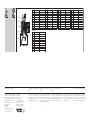
1
1
1
2
2
3
4
5
6
7
8
VL 115..R
220/240 V
120 V
24 V
220/120 V
24 V
74951912
74971069
74951925
74912142
74912143
35443961
03109290
03109292
59601390
04185150
74952731
1
1
1
2
2
3
4
5
6
7
8
VL 125..R
220/240 V
120 V
24 V
220/120 V
24 V
74951913
74971070
74951926
74912142
74912143
35443962
03109290
03109292
59601390
04185150
74952731
1
1
1
2
2
3
4
5
6
7
8
VL 232..R
220/240 V
120 V
24 V
220/120 V
24 V
74951914
74971071
74951927
74912142
74912143
35443963
03109290
03109292
03109463
04185150
74952731
1
1
1
2
2
3
4
5
6
7
8
VL 240..R
220/240 V
120 V
24 V
220/120 V
24 V
74960020
74971061
74960021
74913606
74913607
35440783
59601390
59600730
03109463
04185174
74952546
1
1
1
2
2
3
4
5
6
7
8
VL 350..R
220/240 V
120 V
24 V
220/120 V
24 V
74952296
74971062
74952589
74913606
74913607
35440784
59601390
59600730
59600550
04185174
74952546
VL
4
1
5
6
3
8
7
2
Salvo modifi che tecniche per migliorie.
Per problemi tecnici rivolgersi alla
fi liale/rappresentanza competente.
L’indirizzo è disponibile su Internet
o può essere richiesto alla Elster
GmbH, Osnabrück.
Technische Änderungen, die dem
Fortschritt dienen, vorbehalten.
Bei technischen Fragen wenden Sie
sich bitte an die für Sie zuständige
Nieder lassung/Vertretung. Die Adres-
se erfahren Sie im Internet oder bei
der Elster GmbH, Osnabrück
Zentrale Kundendienst-Einsatz-
Leitung weltweit:
Elster GmbH,
Osnabrück
Tel. +49 (0) 5 41/12 14-3 65
Tel. +49 (0) 5 41/12 14-4 99
Fax +49 (0) 5 41/12 14-5 47
Elster GmbH
Postfach 28 09
D-49018 Osnabrück
Strotheweg 1
D-49504 Lotte (Büren)
Tel. +49 (0)5 41/12 14-0
Fax +49 (0)5 41/12 14-3 70
info@kromschroeder.com
www.kromschroeder.de
We reserve the right to make techni-
cal modifi cations in the interests of
progress.
If you have any technical ques-
tions please contact your local
branch offi ce/agent. The address-
es are available on the Internet or
from Elster GmbH, Osnabrück.
Sous réserve de modifi cations
techniques visant à améliorer nos
pro duits.
Pour toute assistance technique,
vous pouvez également contacter
votre agence/représentation la plus
proche dont l’adresse est disponi-
ble sur Internet ou auprès de la so-
ciété Elster GmbH, Osnabrück.
Technische wijzigingen ter verbete-
ring van onze producten voorbe-
houden.
Voor technische vragen wendt u zich
a.u.b. tot de plaatselijke vestiging/
vertegenwoordiging. Het adres is op
het internet te vinden of u wendt zich
tot Elster GmbH in Osnabrück.
Se reserva el derecho a realizar modi-
fi caciones técnicas sin previo aviso.
Puede recibir soporte técnico en la
sucursal/representación que a Ud. le
corresponda. La dirección la puede
obtener en Internet o a través de la
empresa Elster GmbH, Osnabrück.
-
 1
1
-
 2
2
-
 3
3
-
 4
4
-
 5
5
-
 6
6
-
 7
7
-
 8
8
-
 9
9
-
 10
10
-
 11
11
-
 12
12


in andere talen
- italiano: Kromschroder VS, VL Istruzioni per l'uso
- français: Kromschroder VS, VL Mode d'emploi
- español: Kromschroder VS, VL Instrucciones de operación
- Deutsch: Kromschroder VS, VL Bedienungsanleitung
Gerelateerde papieren
-
 Kromschroder VS..Z, VP Handleiding
-
 Kromschroder VR Handleiding
-
 Kromschroder VG..Z Handleiding
-
 Kromschroder VG 10/15 Handleiding
-
 Kromschroder VG, VR, VAS, MB 7 Demper vervangen of uitbreiden Handleiding
-
 Kromschroder DU Handleiding
-
 Kromschroder VAS 6-9, VCS 6-9, MB 7 Magneetspoel verwisselen Handleiding
-
 Kromschroder CG 35, CG 45 Handleiding
-
 Kromschroder VAx, VCx, MB 7, VG, VR Printplaat vervangen Handleiding
-
 Kromschroder BICR Handleiding


