
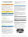
®
Fusion
™
SG-VREGLED and MS-VREG12 Installation Instructions ...................................................2
Instructions d'installation des appareils Fusion
™
SG-VREGLED et MS-VREG12 .............................4
Fusion
™
SG-VREGLED e MS-VREG12 Istruzioni di installazione .................................................... 6
Fusion
™
SG-VREGLED und MS-VREG12 – Installationsanweisungen ............................................ 8
Instrucciones de instalación de Fusion
™
SG-VREGLED y MS-VREG12 ........................................ 11
Fusion
™
Instruções de Instalação do SG-VREGLED e MS-VREG12 ............................................. 13
Fusion
™
SG-VREGLED en MS-VREG12 installatie-instructies ....................................................... 15
Garmin
®
, the Garmin logo, and the Fusion
™
logo are trademarks of Garmin Ltd. or its subsidiaries, registered in the USA and other countries. Fusion is a trademark of Garmin Ltd. or its subsidiaries. These
trademarks may not be used without the express permission of Garmin.
May 2015 190-01845-92_0APrinted in Taiwan

Fusion
™
SG-VREGLED and MS-
VREG12 Installation Instructions
Important Safety Information
WARNING
Failure to follow these warnings and cautions could result in
personal injury, damage to the vessel, or poor product
performance.
See the Important Safety and Product Information guide in the
product box for product warnings and other important
information.
This device must be installed according to these instructions.
Disconnect the vessel's power supply before beginning to install
this product.
Before applying power to this product, make sure it has been
correctly grounded, following the instructions in the guide.
CAUTION
Always wear safety goggles, ear protection, and a dust mask
when drilling, cutting, or sanding.
NOTICE
When drilling or cutting, always check what is on the opposite
side of the surface.
You must read all installation instructions before beginning the
installation. If you experience difficulty during the installation,
contact Fusion
™
Product Support.
What's in the Box
• 1 voltage regulator
• 1 removable terminal block connector
• 2 mounting screws
About the Voltage Regulator
Depending on the model, this device either converts the voltage
from your boat battery to a steady 12 Vdc (MS-VREG12), or it
regulates the voltage from your battery to power the LEDs on
compatible Fusion speakers (SG-VREGLED). The SG-
VREGLED model also allows you to set the LEDs to dim with
the boat lights and to select the color of the LEDs.
Mounting Location Considerations
NOTICE
If you are mounting the bracket on fiberglass with screws, it is
recommended to use a countersink bit to drill a clearance
counterbore through only the top gel-coat layer. This will help to
avoid any cracking in the gel-coat layer when the screws are
tightened.
Stainless-steel screws may bind when screwed into fiberglass
and overtightened. Garmin
®
recommends applying an anti-seize
lubricant to the screws before installing them.
When selecting a mounting location for the device, observe
these considerations.
• Due to the water rating, this device must be mounted and the
wiring connections must be made in a non-submerged
location, and it should not be exposed to spray or wash
down.
• The device should be mounted with the terminal block facing
downward, to avoid water entering the device through the
connector port.
• The best location for the device is near the battery, in a
protected area.
Connection Considerations
NOTICE
The 12 Vdc wiring from the battery to the regulator must run
through a fuse near the power supply using a 5 A fuse (not
included). You must connect the red power (+) wire to the fuse.
The red power (+) wire should also connect to an isolator switch
or circuit breaker to turn the regulator on and off. If the regulator
is used as an accessory with a stereo, you can use the same
isolator or circuit breaker that controls the power supply to the
stereo. This allows the regulator and the stereo to turn on and
off at the same time.
Wire Extensions
To ensure proper functionality of the voltage regulator, you
should use the wire gauge recommended for the wire function.
NOTE: The wire sizes provided in the following tables are valid
for a maximum length of 6 m (20 ft.). If a longer extension is
needed, contact Fusion Product Support for assistance.
SG-VREGLED
Wire Function Minimum Gauge
The power and ground wires from the boat battery. 18 AWG (0.8 mm
2
)
The LED power cables to each speaker. 20 AWG (0.5 mm
2
)
The REMOTE ON input wire and the DIM INPUT
wire.
22 AWG (0.3 mm
2
)
MS-VREG12
Wire Function Minimum Gauge
All power and ground wires from the boat battery,
and all wires to the regulated device.
18 AWG (0.8 mm
2
)
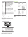
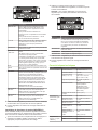
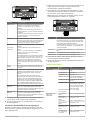
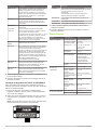
Installing the SG-VREGLED Voltage Regulator
Before you permanently install the voltage regulator, you should
select a mounting location, make wiring connections, and test
the wiring connections.
1
After you have selected a mounting location for the regulator,
route the appropriate cables to the mounting location.
2
Use a flat-blade screwdriver to connect the detachable
connector on the regulator, based on the diagram and table.
TIP: You can disconnect the connector from the regulator to
access the binding posts more easily.
Item Description
REMOTE ON You can connect to the stereo "Amplifier On"
output to turn the regulator on and off with your
stereo.
You can connect to an isolator switch for
manually-switched operation.
You can connect to + 12V IN for permanent
operation.
+ 12V IN The positive wire from the boat battery.
This wire must be connected through a 5 A fuse
(not included) near the power supply.
GROUND IN The negative or ground wire from the boat
battery.
2 Installation Instructions

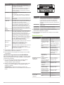
Item Description
+ LED OUT
- LED OUT
Provides power to the LEDs on a speaker.
The red (+) and black (-) LED wires must be
connected to the correct ports.
The regulator has two groups of + and - ports to
which the LED wires may connect. You can
connect up to five Fusion Signature Sports
model speakers or subwoofers per group, for a
total of 10 on one regulator.
BLUE
WHITE
This control switches the LED color on the
speakers between blue and white.
DIM INPUT This control switches between two preset LED
brightness levels. It can be connected to the
boat lighting circuit.
When connected to the boat lighting circuit, the
LEDs on the speakers dim when the boat lights
are turned on. You can adjust the LED
brightness level using the BRIGHTNESS DIM
ON and BRIGHTNESS DIM OFF controls.
Use of these controls is optional.
BRIGHTNESS
DIM OFF
This control adjusts the LED brightness when
the boat lighting circuit is off or the DIM INPUT is
not connected to the lighting circuit.
BRIGHTNESS
DIM ON
This control adjusts the LED brightness when
the boat lighting circuit is on and the DIM INPUT
is connected to the lighting circuit.
3
Test the regulator by powering on the boat and observing the
LEDs on the speakers.
4
Secure the regulator to the mounting surface using the
supplied screws.
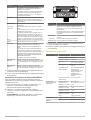
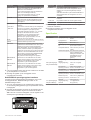
Installing the MS-VREG12 Voltage Regulator
Before you permanently install the voltage regulator, you should
select a mounting location, make wiring connections, and test
the wiring connections.
1
After you have selected a mounting location for the regulator
and installed the fuse, route the appropriate cables to the
mounting location.
2
Use a flat-blade screwdriver to connect the detachable
connector on the regulator, based on the diagram and table.
TIP: You can disconnect the connector from the regulator to
access the binding posts more easily.
Item Description
+ 12V IN The positive wire from the boat battery.
This wire must be connected through a 5 A fuse
(not included) near the power supply.
You should connect this wire to an isolator switch
or circuit breaker to turn the regulator on and off.
GROUND IN The negative or ground wire from the boat battery.
+ 12V OUT The positive wire to the regulated device.
GROUND OUT The negative wire to the regulated device.
3
Test the regulator by turning on the boat and observing the
regulated device.
4
Secure the regulator to the mounting surface using the
supplied screws.
Specifications
Model Specification Value
All models Voltage input From 10.8 to 16 Vdc
Input current 3 A max.
Output current 1.5 A max.
Size (L × W × H) 110 × 62.4 × 23.5 mm
(4.33 × 2.46 × .93 in.)
Temperature range From 0 to 50°C (from 32
to 122°F)
Water rating IEC 60529 IPX2
(Withstands incidental
exposure to dripping
water when installed with
the terminal block
pointing downward.)
Compass-safe
distance
20 cm (7.87 in.)
LED Voltage
Regulator (SG-
VREGLED)
Voltage output From 5 to 15 Vdc
Dim input on, voltage
and current
From 4 to 24 Vdc, less
than 1 mA
Dim input off, voltage
and current
From 0 to 3 Vdc, less
than 1 mA
Remote input on,
voltage and current
From 4 to 24 Vdc, less
than 1 mA
Remote input off,
voltage and current
From 0 to 3 Vdc, less
than 1 mA
Weight 100 g (3.53 oz.)
12V Voltage
Regulator (MS-
VREG12)
Voltage output 12 Vdc
Weight 80 g (2.82 oz.)
Installation Instructions 3

Instructions d'installation des
appareils Fusion
™
SG-VREGLED et
MS-VREG12
Informations importantes relatives à la
sécurité
AVERTISSEMENT
Le non-respect de ces avertissements et de ces mises en garde
est susceptible de provoquer des blessures, d'endommager le
bateau ou de dégrader les performances du produit.
Consultez le guide Informations importantes sur le produit et la
sécurité inclus dans l'emballage du produit pour prendre
connaissance des avertissements et autres informations
importantes sur le produit.
Cet appareil doit être installé conformément à ces instructions.
Déconnectez l'alimentation du bateau avant de commencer à
installer ce produit.
Avant d'alimenter ce produit en électricité, vérifiez que la mise à
la terre est correcte et qu'elle respecte les instructions de ce
guide.
ATTENTION
Portez toujours des lunettes de protection, un équipement
antibruit et un masque anti-poussière lorsque vous percez,
coupez ou poncez.
AVIS
Lorsque vous percez ou coupez, commencez toujours par
vérifier la nature de la face opposée de l'élément.
Lisez toutes les instructions d'installation avant de commencer
l'installation. Si vous rencontrez des difficultés durant
l'installation, contactez le service d'assistance produit de Fusion.
Contenu de l'emballage
• 1 régulateur de tension
• 1 connecteur pour répartiteur amovible
• 2 vis de fixation
A propos du régulateur de tension
Selon le modèle, cet appareil convertit la tension de la batterie
de votre bateau en courant stable de 12 V c.c. (MS-VREG12),
ou il régule la tension de votre batterie pour alimenter les
voyants DEL situés sur des haut-parleurs compatibles
Fusion(SG-VREGLED). Le modèle SG-VREGLED vous permet
également de configurer la baisse de luminosité des voyants
LED au moment où les phares du bateau s'allument et de
choisir la couleur des voyants DEL.
Remarques relatives à l'emplacement de
montage
AVIS
Si vous montez le support de montage sur de la fibre de verre
avec des vis, nous vous recommandons d'utiliser un foret de
fraisage pour percer un trou à fond plat à travers le revêtement
de la couche supérieure. De cette manière, vous ne risquez pas
de fissurer le revêtement au moment du serrage des vis.
Les vis en acier inoxydable risquent de se gripper lorsqu'elles
sont vissées dans la fibre de verre et qu'elles sont serrées outre
mesure. Garmin conseille d'appliquer un lubrifiant antigrippant
sur chaque vis avant installation.
Lorsque vous choisissez un emplacement de montage pour
l'appareil, tenez compte des considérations suivantes.
• En raison de l'indice de résistance à l'eau, cet appareil doit
être installé et les connexions de câbles doivent être faites
dans un emplacement non immergé, non exposé aux
projections d'eau.
• L'appareil doit être monté en plaçant le répartiteur tête en bas
de façon à éviter que de l'eau ne pénètre dans l'appareil à
travers le port du connecteur.
• Dans l'idéal, l'appareil doit être installé à proximité de la
batterie, dans une zone protégée.
Considérations relatives à la connexion
AVIS
Le câblage de 12 V c.c. entre la batterie et le régulateur doit être
connecté par le biais d'un fusible de 5 A à proximité de
l'alimentation (non inclus). Vous devez connecter le câble
d'alimentation rouge (+) au fusible.
Le câble d'alimentation rouge (+) doit aussi être raccordé à un
sectionneur ou un disjoncteur pour activer et désactiver le
régulateur. Si le régulateur est utilisé comme un accessoire
avec une chaîne stéréo, vous pouvez utiliser le même
sectionneur ou disjoncteur qui contrôle l'alimentation de la
stéréo. Cela permet au régulateur et à la stéréo de s'activer et
se désactiver en même temps.
Extensions de câble
Pour garantir le bon fonctionnement du régulateur de tension,
vous devez utiliser le calibre de fil recommandé pour la fonction
du câble.
REMARQUE : les calibres de câble fournis dans les tableaux
suivants sont valables pour une longueur maximale de 6 m
(20 pi). Si une rallonge est nécessaire, contactez Fusion
Product Support pour obtenir de l'aide.
SG-VREGLED
Fonction du fil Calibre minimum
Câble d'alimentation ou câble de la masse de la
batterie provenant du bateau.
0,8 mm
2
(18 AWG)
Câbles d'alimentation DEL vers chaque haut-
parleur.
0,5 mm
2
(20 AWG)
Câble d'entrée REMOTE ON et câble DIM INPUT. 0,3 mm
2
(22 AWG)
MS-VREG12
Fonction du fil Calibre minimum
Ensemble des câbles d'alimentation et de masse
provenant de la batterie du bateau, et ensemble
des câbles vers l'appareil régulé.
0,8 mm
2
(18 AWG)
Installation du régulateur de tension SG-VREGLED
Avant d'installer de façon permanente le régulateur de tension,
vous devez sélectionner un emplacement de montage, effectuer
des connexions de câbles et tester leur fonctionnement.
1
Après avoir sélectionné un emplacement de montage pour le
régulateur, acheminez les câbles appropriés jusqu'à
l'emplacement de montage.
2
Utilisez un tournevis à lame plate pour connecter le
connecteur amovible sur le régulateur, en tenant compte du
schéma et des tableaux.
ASTUCE : vous pouvez débrancher le connecteur du
régulateur pour accéder plus facilement aux bornes de
raccordement.
4 Instructions d'installation

Elément Description
REMOTE ON Vous pouvez brancher le câble sur la sortie
stéréo « Mise sous tension de l'ampli » pour
activer et désactiver le régulateur avec votre
chaîne stéréo.
Vous pouvez brancher le câble sur un
sectionneur pour une opération de commutation
manuelle.
Vous pouvez brancher le câble sur + 12V IN
pour un fonctionnement permanent.
+ 12V IN Câble positif provenant de la batterie du bateau.
Ce câble doit être connecté par le biais d'un
fusible de 5 A (non inclus) à proximité de
l'alimentation.
GROUND IN Câble négatif ou câble de la masse provenant de
la batterie du bateau.
+ LED OUT
- LED OUT
Fournit l'alimentation aux voyants DEL d'un haut-
parleur.
Les câbles rouge (+) et noir (-) doivent être
raccordés aux ports appropriés.
Le régulateur possède deux groupes de ports +
et - sur lesquels les câbles pour voyants DEL
peuvent être connectés. Vous pouvez connecter
jusqu'à cinq haut-parleurs ou caissons de basse
Fusion Signature Sports par groupe, pour un
total de 10 sur un seul régulateur.
BLUE
WHITE
Ce bouton permet de basculer entre le bleu et le
blanc pour la couleur du voyant DEL situé sur les
haut-parleurs.
DIM INPUT Ce bouton permet de basculer entre deux
niveaux de luminosité DEL préréglés. Il peut être
connecté au circuit d'éclairage du bateau.
Lorsque le régulateur est connecté au circuit
d'éclairage du bateau, les voyants DEL situés
sur les haut-parleurs baissent en luminosité dès
que les phares du bateau sont allumés. Vous
pouvez régler la luminosité du voyant DEL en
utilisant les boutons BRIGHTNESS DIM ON et
BRIGHTNESS DIM OFF.
L'utilisation de ces boutons est facultative.
BRIGHTNESS
DIM OFF
Ce bouton permet de régler la luminosité du
voyant DEL lorsque le circuit d'éclairage du
bateau est éteint ou que DIM INPUT n'est pas
connecté au circuit d'éclairage.
BRIGHTNESS
DIM ON
Ce bouton permet de régler la luminosité du
voyant DEL lorsque le circuit d'éclairage du
bateau est allumé ou que DIM INPUT est
connecté au circuit d'éclairage.
3
Faites un test du régulateur par mise sous tension du bateau
et observation des voyants DEL sur les haut-parleurs.
4
Fixez le régulateur à la surface de montage à l'aide des vis
fournies.
Installation du régulateur de tension MS-VREG12
Avant d'installer de façon permanente le régulateur de tension,
vous devez sélectionner un emplacement de montage, effectuer
des connexions de câbles et tester leur fonctionnement.
1
Après avoir sélectionné un emplacement de montage pour le
régulateur et installé le fusible, acheminez les câbles
appropriés jusqu'à l'emplacement de montage.
2
Utilisez un tournevis à lame plate pour connecter le
connecteur amovible sur le régulateur, en tenant compte du
schéma et des tableaux.
ASTUCE : vous pouvez débrancher le connecteur du
régulateur pour accéder plus facilement aux bornes de
raccordement.
Elément Description
+ 12V IN Câble positif provenant de la batterie du bateau.
Ce câble doit être connecté par le biais d'un fusible
de 5 A (non inclus) à proximité de l'alimentation.
Vous devez connecter ce câble à un sectionneur
ou un disjoncteur pour activer et désactiver le
régulateur.
GROUND IN Câble négatif ou câble de la masse provenant de la
batterie du bateau.
+ 12V OUT Câble positif vers l'appareil régulé.
GROUND OUT Câble négatif vers l'appareil régulé.
3
Faites un test du régulateur par mise sous tension du bateau
et observation de l'appareil régulé.
4
Fixez le régulateur à la surface de montage à l'aide des vis
fournies.
Caractéristiques techniques
Modèle Caractéristique Valeur
Tous les modèles Tension d'entrée De 10,8 à 16 V c.c.
Courant en entrée 3 A max.
Courant de sortie 1,5 A max.
Taille (L × P × H) 110 × 62,4 × 23,5 mm
(4,33 × 2,46 × 0,93’’)
Plage de températures De 0 à 50 °C (de 32 à
122 °F)
Résistance à l'eau IEC 60529 IPX2 (résiste
à une exposition
accidentelle à des
éclaboussures lorsqu'il
est installé répartiteur
tête en bas.)
Distance de sécurité du
compas
20 cm (7,87’’)
Régulateur de
tension DEL (SG-
VREGLED)
Tension de sortie De 5 à 15 V c.c.
DIM INPUT activé,
tension et courant
De 4 à 24 Vdc, inférieur
à 1 mA
DIM INPUT désactivé,
tension et courant
De 0 à 3 Vdc, inférieur à
1 mA
REMOTE INPUT
activé, tension et
courant
De 4 à 24 Vdc, inférieur
à 1 mA
REMOTE INPUT
désactivé, tension et
courant
De 0 à 3 Vdc, inférieur à
1 mA
Poids 100 g (3,53 oz)
Régulateur de
tension 12 V (MS-
VREG12)
Tension de sortie 12 V c.c.
Poids 80 g (2,82 oz)
Instructions d'installation 5

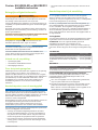
Fusion
™
SG-VREGLED e MS-VREG12
Istruzioni di installazione
Informazioni importanti sulla sicurezza
ATTENZIONE
La mancata osservanza delle seguenti avvertenze e avvisi
potrebbe causare lesioni personali, danni all'imbarcazione o
scarse prestazioni del prodotto.
Per avvisi sul prodotto e altre informazioni importanti, consultare
la guida Informazioni importanti sulla sicurezza e sul prodotto
inclusa nella confezione.
Questo dispositivo deve essere installato attenendosi alle
seguenti istruzioni.
Scollegare l'alimentazione dell'imbarcazione prima di installare il
prodotto.
Prima di fornire alimentazione al prodotto, accertarsi che la
messa a terra sia stata effettuata in modo corretto, seguendo le
istruzioni fornite in questa guida.
AVVISO
Durante le operazioni di foratura, taglio o carteggiatura,
indossare degli occhiali protettivi, una maschera antipolvere e
un'adeguata protezione per l'udito.
AVVERTENZA
Prima di effettuare fori o tagli verificare l'eventuale presenza di
oggetti nel lato opposto della superficie da tagliare.
Leggere tutte le istruzioni di installazione prima di iniziare
l'installazione. In caso di difficoltà durante l'installazione,
contattare il servizio di assistenza ai prodotti di Fusion.
Contenuto della confezione
• 1 regolatore di tensione
• 1 connettore della morsettiera rimovibile
• 2 viti di montaggio
Info sul regolatore di tensione
A seconda del modello, questo dispositivo converte la tensione
della batteria dell'imbarcazione su un valore fisso di 12 V cc
(MS-VREG12), oppure regola la tensione della batteria per
alimentare i LED sugli altoparlanti Fusion compatibili (SG-
VREGLED). Il modello SG-VREGLED consente anche di
impostare i LED affinché la luminosità si riduca con le luci
dell'imbarcazione e di selezionare il colore dei LED.
Note sulla posizione di installazione
AVVERTENZA
Se si sta installando la staffa su fibra di vetro con delle viti, si
consiglia di utilizzare una punta fresatrice per praticare una
svasatura attraverso lo strato di resina. In questo modo è
possibile evitare crepe prodotte dal serraggio delle viti nello
strato di resina.
Le viti in acciaio inossidabile possono bloccarsi se vengono
avvitate e serrate più del necessario all'interno della fibra di
vetro. Garmin raccomanda di applicare alle viti un lubrificante
antigrippaggio prima dell'installazione.
Selezionare la posizione di installazione del dispositivo tenendo
presente quanto segue.
• Data la classificazione di impermeabilità, il dispositivo e i
collegamenti cablati devono essere installati in una posizione
non sommersa e non soggetta a spruzzi d'acqua.
• Il dispositivo deve essere installato con la morsettiera rivolta
in avanti, per evitare che l'acqua penetri nel dispositivo
attraverso la porta del connettore.
• La posizione migliore per il dispositivo è vicino alla batteria, in
una posizione protetta.
Informazioni sul collegamento
AVVERTENZA
I cavi da 12 V cc dalla batteria al regolatore devono passare
attraverso un fusibile da 5 A (non incluso) vicino alla presa di
alimentazione. Collegare il cavo di alimentazione rosso (+) al
fusibile.
Il cavo di alimentazione rosso (+) deve inoltre essere collegato a
un interruttore/sezionatore per consentire l'accensione e lo
spegnimento del regolatore. Se il regolatore viene utilizzato
come accessorio con uno stereo, è possibile utilizzare lo stesso
sezionatore o interruttore automatico che controlla
l'alimentazione dello stereo. Ciò consente di accendere e
spegnere contemporaneamente il regolatore e lo stereo.
Prolunghe dei cavi
Per garantire il corretto funzionamento del regolatore di
tensione, utilizzare la sezione cavi consigliata.
NOTA: le dimensioni dei cavi fornite nelle seguenti tabelle sono
valide per una lunghezza massima di 6 m (20 piedi). Per
prolungarli ulteriormente, contattare l'assistenza ai prodotti
Fusion.
SG-VREGLED
Funzione cavo Sezione minima
I cavi di alimentazione e di terra dalla batteria
dell'imbarcazione.
18 AWG (0,8 mm
2
)
I cavi di alimentazione LED su ciascun altopar-
lante.
20 AWG (0,5 mm
2
)
Il cavo in ingresso REMOTE ON e il cavo DIM
INPUT.
22 AWG (0,3 mm
2
)
MS-VREG12
Funzione cavo Sezione minima
Tutti i cavi di alimentazione e di terra dalla batteria
dell'imbarcazione e tutti i cavi sul dispositivo
regolato.
18 AWG
(0,8 mm
2
)
Installazione del regolatore di tensione SG-VREGLED
Prima di installare definitivamente il regolatore di tensione,
selezionare una posizione di montaggio, effettuare e verificare i
collegamenti dei cavi.
1
Dopo aver selezionato una posizione di montaggio per il
regolatore, passare i cavi appropriati nella posizione di
montaggio.
2
Utilizzare un cacciavite a lama piatta per collegare il
connettore rimovibile sul regolatore, in base al diagramma e
alla tabella.
SUGGERIMENTO: è possibile scollegare il connettore dal
regolatore per accedere più facilmente ai morsetti.
6 Istruzioni di installazione

Elemento Descrizione
REMOTE ON È possibile collegare allo stereo l'uscita
"Amplifier On" per accendere e spegnere il
regolatore con lo stereo.
È possibile collegare un interruttore/sezionatore
per eseguire manualmente tale operazione.
È possibile collegare un cavo + 12V IN per il
funzionamento costante.
+ 12V IN Il cavo positivo dalla batteria dall'imbarcazione.
Questo cavo deve essere collegato tramite un
fusibile da 5 A (non incluso) vicino alla presa di
alimentazione.
GROUND IN Il cavo negativo o di terra dalla batteria dell'im-
barcazione.
+ LED OUT
- LED OUT
Fornisce alimentazione ai LED su un altopar-
lante.
I cavi dei LED rosso (+) e nero (-) devono essere
collegati alle porte corrette.
Il regolatore è dotato di due gruppi di porte + e -
alle quali possono collegarsi i cavi dei LED. È
possibile collegare fino a cinque altoparlanti o
subwoofer modello Fusion Signature Sports per
gruppo, per un totale di 10 a un solo regolatore.
BLUE
WHITE
Questo controllo consente di impostare il colore
dei LED da blu e bianco e viceversa.
DIM INPUT Questo controllo consente di impostare uno dei
due livelli predefiniti di luminosità LED. Può
essere collegato al circuito luci dell'imbarca-
zione.
Se collegati al circuito luci dell'imbarcazione, i
LED sugli altoparlanti riducono la luminosità
quando si accendono le luci dell'imbarcazione. È
possibile regolare il livello di luminosità LED
utilizzando i controlli BRIGHTNESS DIM ON e
BRIGHTNESS DIM OFF.
L'utilizzo di tali controlli è opzionale.
BRIGHTNESS
DIM OFF
Questo controllo regola la luminosità LED
quando il circuito luci dell'imbarcazione è spento
o il cavo DIM INPUT non è collegato al circuito
luci.
BRIGHTNESS
DIM ON
Questo controllo regola la luminosità LED
quando il circuito luci dell'imbarcazione è acceso
e il cavo DIM INPUT è collegato al circuito luci.
3
Testare il regolatore accendendo le luci dell'imbarcazione e
osservando i LED sugli altoparlanti.
4
Fissare il regolatore alla superficie di montaggio utilizzando le
viti in dotazione.
Installazione del regolatore di tensione MS-VREG12
Prima di installare definitivamente il regolatore di tensione,
selezionare una posizione di montaggio, effettuare e verificare i
collegamenti dei cavi.
1
Dopo aver selezionato una posizione di montaggio per il
regolatore e aver installato il fusibile, passare i cavi
appropriati nella posizione di montaggio.
2
Utilizzare un cacciavite a lama piatta per collegare il
connettore rimovibile sul regolatore, in base al diagramma e
alla tabella.
SUGGERIMENTO: è possibile scollegare il connettore dal
regolatore per accedere più facilmente ai morsetti.
Elemento Descrizione
+ 12V IN Il cavo positivo dalla batteria dall'imbarcazione.
Questo cavo deve essere collegato tramite un
fusibile da 5 A (non incluso) vicino alla presa di
alimentazione.
Collegare questo cavo a un interruttore/sezionatore
per consentire l'accensione e lo spegnimento del
regolatore.
GROUND IN Il cavo negativo o di terra dalla batteria dell'imbar-
cazione.
+ 12V OUT Il cavo positivo sul dispositivo regolato.
GROUND OUT Il cavo negativo sul dispositivo regolato.
3
Testare il regolatore accendendo le luci dell'imbarcazione e
osservando il dispositivo regolato.
4
Fissare il regolatore alla superficie di montaggio utilizzando le
viti in dotazione.
Caratteristiche tecniche
Modello Specifiche Valore
Tutti i modelli Tensione in ingresso Da 10,8 a 16 Vcc
Corrente in entrata 3 A max
Corrente in uscita 1,5 A max
Dimensioni (L × L ×
A)
110 × 62,4 × 23,5 mm
(4,33 × 2,46 × ,93 poll.)
Temperatura Da 0 a 50 °C (da 32 a
122 °F)
Classificazione di
impermeabilità
IEC 60529 IPX2 (resiste
all'esposizione
accidentale alle gocce
d'acqua quando è
installato con la
morsettiera rivolta in
avanti).
Distanza di sicurezza
dalla bussola
20 cm (7,87 poll.)
Regolatore di
tensione LED (SG-
VREGLED)
Tensione in uscita Da 5 a 15 V cc
Ingresso Dim on,
tensione e corrente
Da 4 a 24 V cc, meno di
1 mA
Ingresso Dim off,
tensione e corrente
Da 0 a 3 V cc, meno di
1 mA
Ingresso Remote on,
tensione e corrente
Da 4 a 24 V cc, meno di
1 mA
Ingresso Remote off,
tensione e corrente
Da 0 a 3 V cc, meno di
1 mA
Peso 100 g (3,53 once)
Regolatore di
tensione da 12V (MS-
VREG12)
Tensione in uscita 12 V cc
Peso 80 g (2,82 once)
Istruzioni di installazione 7

Fusion
™
SG-VREGLED und MS-
VREG12 – Installationsanweisungen
Wichtige Sicherheitsinformationen
WARNUNG
Wenn Sie die Warnungen und Vorsichtshinweise nicht
beachten, könnte es zu Personenschäden, Schäden am Schiff
oder zu einer schlechten Leistung des Produkts kommen.
Lesen Sie alle Produktwarnungen und sonstigen wichtigen
Informationen der Anleitung "Wichtige Sicherheits- und
Produktinformationen", die dem Produkt beiliegt.
Das Gerät muss gemäß diesen Anweisungen installiert werden.
Beginnen Sie erst mit der Installation dieses Produkts, wenn Sie
die Stromversorgung des Boots getrennt haben.
Bevor Sie das Produkt mit Strom versorgen, stellen Sie sicher,
dass es ordnungsgemäß geerdet ist. Folgen Sie dazu den
Anweisungen in der Anleitung.
ACHTUNG
Tragen Sie beim Bohren, Schneiden und Schleifen immer
Schutzbrille, Gehörschutz und eine Staubschutzmaske.
HINWEIS
Prüfen Sie beim Bohren oder Schneiden stets die andere Seite
der zu bearbeitenden Fläche.
Lesen Sie die gesamten Installationsanweisungen, bevor Sie mit
der Installation beginnen. Sollten bei der Installation Probleme
auftreten, wenden Sie sich an den Support von Fusion.
Lieferumfang
• 1 Spannungsregler
• 1 abnehmbarer Anschlussblockstecker
• 2 Befestigungsschrauben
Informationen zum Spannungsregler
Je nach Modell wandelt dieses Gerät entweder die Spannung
von der Bootsbatterie in 12-V-Gleichspannung um (MS-
VREG12) oder regelt die Spannung von der Batterie, um die
LEDs an kompatiblen Fusion Lautsprechern zu betreiben (SG-
VREGLED). Das Modell SG-VREGLED bietet außerdem die
Möglichkeit, die LEDs zusammen mit der Schiffsbeleuchtung zu
dimmen und die Farbe der LEDs auszuwählen.
Hinweise zur Auswahl des Montageorts
HINWEIS
Wenn Sie die Halterung in Glasfasermaterial einlassen und
festschrauben, wird die Verwendung eines Senkkopfbohrers
empfohlen, um die Ansenkung nur durch die oberste Gelcoat-
Schicht zu bohren. Dadurch wird Rissen in der obersten
Gelschicht beim Anziehen der Schrauben vorgebeugt.
Schrauben aus Edelstahl können sich leicht festklemmen, wenn
sie in Glasfasermaterial zu stark angezogen werden. Garmin
empfiehlt, vor der Installation Fettpaste auf die Schrauben
aufzutragen.
Beachten Sie bei der Auswahl eines Montageorts für das Gerät
folgende Hinweise.
• Angesichts der Wasserdichtigkeitseinstufung müssen die
Montage des Geräts und die Verkabelung an einem Ort
erfolgen, der sich nicht unter Wasser befindet. Außerdem
darf der Ort keinem Spritzwasser oder abfließendem Wasser
ausgesetzt sein.
• Das Gerät sollte so montiert werden, dass der
Anschlussblock nach unten zeigt, damit Wasser nicht durch
den Anschluss in das Gerät eindringt.
• Der beste Montageort für das Gerät ist ein geschützter
Bereich in der Nähe der Batterie.
Hinweise zum Verbinden des Geräts
HINWEIS
Die 12-V-Gleichspannungskabelverbindungen von der Batterie
zum Spannungsregler müssen durch eine 5-Ampere-Sicherung
(nicht im Lieferumfang enthalten) in der Nähe der
Stromversorgung geschützt werden. Sie müssen die rote
Stromleitung (+) mit der Sicherung verbinden.
Die rote Stromleitung (+) sollte außerdem mit einem
Trennschalter oder Unterbrecher verbunden werden, um den
Regler ein- und auszuschalten. Wenn der Regler als Zubehör
mit einem Radio genutzt wird, können Sie denselben
Trennschalter oder Unterbrecher verwenden, der die
Stromversorgung zum Radio regelt. Auf diese Weise können der
Regler und das Radio gleichzeitig ein- und ausgeschaltet
werden.
Verlängerungen der Leitungen
Damit der Spannungsregler ordnungsgemäß funktioniert, sollten
Sie den für die Funktion der Leitung empfohlenen
Leitungsquerschnitt verwenden.
HINWEIS: Die in den folgenden Tabellen angegebenen
Leitungsstärken gelten für eine maximale Länge von 6 m
(20 Fuß). Falls diese Verlängerung nicht ausreicht, wenden Sie
sich an den Produktsupport von Fusion, um Unterstützung zu
erhalten.
SG-VREGLED
Funktion der Leitung Mindestleitungsquer-
schnitt
Die Strom- und Masseleitungen von der
Bootsbatterie.
0,8 mm
2
(AWG 18)
Die LED-Stromleitungen zu den einzelnen
Lautsprechern.
0,5 mm
2
(AWG 20)
Die Eingangsleitung REMOTE ON und die
Leitung DIM INPUT.
0,3 mm
2
(AWG 22)
MS-VREG12
Funktion der Leitung Mindestleitungsquer-
schnitt
Alle Strom- und Masseleitungen von der
Bootsbatterie und alle Leitungen zum
geregelten Gerät.
0,8 mm
2
(AWG 18)
Installieren des SG-VREGLED Spannungsreglers
Montieren Sie den Spannungsregler erst dauerhaft, wenn Sie
einen Montageort gewählt, die Verkabelung vorgenommen und
diese getestet haben.
1
Wählen Sie einen Montageort für den Spannungsregler, und
verlegen Sie dann die entsprechenden Kabel dorthin.
2
Verwenden Sie einen Flachkopfschraubendreher, um den
abnehmbaren Stecker am Regler zu verbinden. Orientieren
Sie sich dabei an den Plänen und Tabellen.
TIPP: Sie können den Stecker vom Regler trennen, um die
Verbindungsklemmen einfacher zu erreichen.
8 Installationsanweisungen

Element Beschreibung
REMOTE ON Sie können eine Verbindung mit dem Ausgang
„Amplifier On“ herstellen, um den Regler
zusammen mit dem Radio ein- und auszu-
schalten.
Sie können eine Verbindung mit einem Trenn-
schalter herstellen, um eine manuelle Schaltung
zu erzielen.
Sie können eine Verbindung mit dem Anschluss
+ 12V IN herstellen, um einen dauerhaften
Betrieb zu erzielen.
+ 12V IN Die positive Leitung von der Bootsbatterie.
Die Leitung muss über eine 5-Ampere-Sicherung
(nicht im Lieferumfang enthalten) in der Nähe
der Stromversorgung verbunden werden.
GROUND IN Die negative oder Masseleitung von der Boots-
batterie.
+ LED OUT
- LED OUT
Versorgt die LEDs eines Lautsprechers mit
Strom.
Die rote (+) und die schwarze (-) LED-Leitung
müssen mit den richtigen Anschlüssen
verbunden werden.
Am Regler befinden sich zwei Gruppen positiver
(+) und negativer (-) Anschlüsse, mit denen die
LED-Leitungen verbunden werden können. Sie
können bis zu fünf Lautsprecher des Fusion
Signature Sports Modells bzw. Subwoofer pro
Gruppe verbinden, also insgesamt 10 an einem
Regler.
BLUE
WHITE
Diese Steuerung kontrolliert die LED-Farbe an
den Lautsprechern und wechselt zwischen blau
und weiß.
DIM INPUT Diese Steuerung wechselt zwischen zwei vorein-
gestellten LED-Helligkeitsstufen. Sie kann mit
dem Lichtstromkreis des Schiffs verbunden
werden.
Bei Anschluss an den Lichtstromkreis des
Schiffs werden die LEDs an den Lautsprechern
gedimmt, wenn die Schiffsbeleuchtung einge-
schaltet wird. Sie können die LED-Helligkeits-
stufe mit den Steuerungen BRIGHTNESS DIM
ON und BRIGHTNESS DIM OFF anpassen.
Die Verwendung dieser Steuerungen ist optional.
BRIGHTNESS
DIM OFF
Diese Steuerung passt die LED-Helligkeit an,
wenn der Lichtstromkreis des Schiffs ausge-
schaltet ist oder die Leitung DIM INPUT nicht mit
dem Lichtstromkreis verbunden ist.
BRIGHTNESS
DIM ON
Diese Steuerung passt die LED-Helligkeit an,
wenn der Lichtstromkreis des Schiffs einge-
schaltet ist und die Leitung DIM INPUT mit dem
Lichtstromkreis verbunden ist.
3
Testen Sie den Regler, indem Sie den Bootsmotor starten
und die LEDs an den Lautsprechern beobachten.
4
Sichern Sie den Regler mit den mitgelieferten Schrauben an
der Montagefläche.
Installieren des MS-VREG12 Spannungsreglers
Montieren Sie den Spannungsregler erst dauerhaft, wenn Sie
einen Montageort gewählt, die Verkabelung vorgenommen und
diese getestet haben.
1
Wählen Sie einen Montageort für den Spannungsregler, und
setzen Sie die Sicherung ein. Verlegen Sie dann die
entsprechenden Kabel zum Montageort.
2
Verwenden Sie einen Flachkopfschraubendreher, um den
abnehmbaren Stecker am Regler zu verbinden. Orientieren
Sie sich dabei an den Plänen und Tabellen.
TIPP: Sie können den Stecker vom Regler trennen, um die
Verbindungsklemmen einfacher zu erreichen.
Element Beschreibung
+ 12V IN Die positive Leitung von der Bootsbatterie.
Die Leitung muss über eine 5-Ampere-Sicherung
(nicht im Lieferumfang enthalten) in der Nähe der
Stromversorgung verbunden werden.
Sie sollten diese Leitung mit einem Trennschalter
oder Unterbrecher verbinden, um den Regler ein-
und auszuschalten.
GROUND IN Die negative oder Masseleitung von der Bootsbat-
terie.
+ 12V OUT Die positive Leitung zum geregelten Gerät.
GROUND OUT Die negative Leitung zum geregelten Gerät.
3
Testen Sie den Regler, indem Sie den Bootsmotor starten
und das geregelte Gerät beobachten.
4
Sichern Sie den Regler mit den mitgelieferten Schrauben an
der Montagefläche.
Technische Daten
Modell Angabe Wert
Alle Modelle Eingangsspannung 10,8 bis 16 V Gleichspan-
nung
Eingangsstrom Maximal 3 A
Ausgangsstrom Maximal 1,5 A
Größe (L × B × H) 110 × 62,4 × 23,5 mm
(4,33 × 2,46 × 0,93 Zoll)
Temperaturbereich 0 °C bis 50 °C (32 °F bis
122 °F)
Wasserdichtigkeit IEC 60529 IPX2 (bietet
Schutz gegen Tropfwasser,
wenn der Anschlussblock
so montiert wurde, dass er
nach unten zeigt)
Sicherheitsabstand
zum Kompass
20 cm (7,87 Zoll)
LED-Spannungs-
regler (SG-
VREGLED)
Ausgangsspan-
nung
5 bis 15 V Gleichspannung
Dimmer ein,
Spannung und
Strom
4 bis 24 V Gleichspannung,
weniger als 1 mA
Dimmer aus,
Spannung und
Strom
0 bis 3 V Gleichspannung,
weniger als 1 mA
Fernbedienung ein,
Spannung und
Strom
4 bis 24 V Gleichspannung,
weniger als 1 mA
Fernbedienung
aus, Spannung
und Strom
0 bis 3 V Gleichspannung,
weniger als 1 mA
Installationsanweisungen 9

Modell Angabe Wert
Gewicht 100 g (3,53 Unzen)
12-V-Spannungs-
regler (MS-VREG12)
Ausgangsspan-
nung
12 V Gleichspannung
Gewicht 80 g (2,82 Unzen)
10 Installationsanweisungen

Instrucciones de instalación de
Fusion
™
SG-VREGLED y MS-VREG12
Información importante sobre seguridad
AVISO
El incumplimiento de las advertencias y precauciones que se
indican puede derivar en daños personales o en la
embarcación, así como en un rendimiento deficiente del
producto.
Consulta la guía Información importante sobre el producto y tu
seguridad que se incluye en la caja del producto y en la que
encontrarás advertencias e información importante sobre el
producto.
El dispositivo debe instalarse de acuerdo con estas
instrucciones.
Desconecta el suministro de alimentación de la embarcación
antes de iniciar la instalación del producto.
Antes de suministrar alimentación al producto, asegúrate de que
está conectado a tierra correctamente de acuerdo con las
instrucciones indicadas en la guía.
ADVERTENCIA
Utiliza siempre gafas de seguridad, un protector de oídos y una
máscara antipolvo cuando vayas a realizar orificios, cortes o
lijados.
NOTIFICACIÓN
Al realizar orificios o cortes, comprueba siempre lo que hay al
otro lado de la superficie.
Debes leer todas las instrucciones de instalación antes de
proceder a la misma. Si tienes dificultades con la instalación,
ponte en contacto con el departamento de asistencia de Fusion.
Contenido de la caja
• 1 regulador de tensión
• 1 conector de bloque de terminal extraíble
• 2 tornillos de montaje
Acerca del regulador de tensión
Según el modelo, este dispositivo convierte el voltaje de la
batería de la embarcación a una alimentación estable de 12 V
de CC (MS-VREG12), o regula la tensión de la batería para
alimentar los LED de los altavoces Fusion compatibles (SG-
VREGLED). El modelo SG-VREGLED permite también atenuar
los LED con las luces de la embarcación y seleccionar el color
de los LED.
Especificaciones sobre la ubicación de
montaje
NOTIFICACIÓN
Si montas el soporte en fibra de vidrio con tornillos, se
recomienda utilizar una broca avellanadora para realizar un
avellanado que solamente atraviese la capa superior de gelcoat.
Así evitarás que se agriete la capa de gelcoat cuando se
ajusten los tornillos.
Los tornillos de acero inoxidable pueden atascarse cuando se
fijan a una superficie de fibra de vidrio si se aprietan en exceso.
Garmin recomienda la aplicación de un lubricante antiagarre a
los tornillos antes de su instalación.
Ten en cuenta las siguientes especificaciones cuando vayas a
seleccionar la ubicación de montaje del dispositivo.
• Siguiendo la clasificación de resistencia al agua, este
dispositivo ha de montarse y las conexiones de cableado
deben hacerse en una ubicación no sumergida y no debería
exponerse a inmersión o salpicaduras.
• El dispositivo ha de montarse con el bloque de terminal hacia
abajo para evitar la entrada de agua por el puerto del
conector.
• La mejor ubicación para el dispositivo es junto a la batería en
una zona protegida.
Especificaciones sobre la conexión
NOTIFICACIÓN
El cableado de 12 V de CC desde la batería al regulador debe
pasar por un fusible junto a la fuente de alimentación utilizando
un fusible de 5 A (no incluido). Debes conectar el cable de
alimentación (+) rojo al fusible.
El cable de alimentación (+) rojo también debe conectarse a un
interruptor de aislamiento o disyuntor para activar o desactivar
el regulador. Si el regulador se utiliza como accesorio con un
estéreo, se puede utilizar el mismo interruptor de aislamiento o
disyuntor que controla la fuente de alimentación del estéreo.
Esto permite activar y desactivar el regulador y el estéreo al
mismo tiempo.
Cable de extensión
Para garantizar el funcionamiento adecuado del regulador de
tensión, debería utilizar el calibre del cableado recomendado
para la función del cable.
NOTA: los tamaños de cables proporcionados en las tablas
siguientes son válidos para una longitud máxima de 6 m (20 ft.).
Si se necesita una extensión mayor, contacta con el
departamento de asistencia de Fusion para obtener ayuda.
SG-VREGLED
Función del cable Calibre mínimo
Cables de alimentación y tierra de la batería de la
embarcación.
18 AWG (0,8 mm
2
)
Cables de alimentación de LED de cada altavoz. 20 AWG (0,5 mm
2
)
Cable de entrada de REMOTE ON y cable de DIM
INPUT.
22 AWG (0,3 mm
2
)
MS-VREG12
Función del cable Calibre mínimo
Todos los cables de alimentación y tierra desde la
batería de la embarcación y todos los cables hacia
el dispositivo regulado.
18 AWG
(0,8 mm
2
)
Instalación del regulador de tensión SG-VREGLED
Antes de instalar definitivamente el regulador de tensión, debes
seleccionar la ubicación de montaje y realizar y comprobar las
conexiones de cableado.
1
Una vez seleccionada la ubicación de montaje para el
regulador, dirige los cables correspondientes a dicha
ubicación.
2
Utiliza un destornillador para tornillos de cabeza plana para
conectar el conector extraíble en el regulador según el
diagrama y la tabla.
SUGERENCIA: puedes desconectar el conector del
regulador para acceder con más facilidad a los terminales de
unión.
Instrucciones de instalación 11

Elemento Descripción
REMOTE ON Puedes conectar a la salida "Amplificador
encendido" del estéreo para activar y desactivar
el regulador con el estéreo.
Puedes conectar un interruptor de aislamiento
para accionar manualmente el interruptor.
Puedes conectar a + 12V IN para su funciona-
miento permanente.
+ 12V IN Cable positivo desde la batería de la
embarcación.
Este cable debe conectarse con un fusible de
5 A (no incluido) junto a la fuente de alimenta-
ción.
GROUND IN Cable negativo o de tierra desde la batería de la
embarcación.
+ LED OUT
- LED OUT
Suministra energía a los LED de un altavoz.
Los cables rojo (+) y negro (-) de los LED deben
conectarse a los terminales correctos.
El regulador tiene dos grupos de terminales + y -
a los que deben conectarse los cables de los
LED. Puedes conectar hasta 5 altavoces o
subwoofers del modelo Signature Sports Fusion
por grupo, para un total de 10 en un regulador.
BLUE
WHITE
Este control cambia el color de los LED en un
altavoz entre azul y blanco.
DIM INPUT Este control cambia entre dos niveles de brillo
de los LED predefinidos. Puede conectarse al
circuito de iluminación de la embarcación.
Cuando se conecta al circuito de iluminación de
la embarcación, los LED de los altavoces se
atenúan cuando se encienden las luces de la
embarcación. Puedes ajustar el nivel de brillo de
los LED mediante los controles BRIGHTNESS
DIM ON y BRIGHTNESS DIM OFF.
El uso de estos controles es opcional.
BRIGHTNESS
DIM OFF
Este control ajusta el brillo de los LED cuando se
apaga el circuito de iluminación de la
embarcación o si la DIM INPUT no está
conectada al circuito de iluminación.
BRIGHTNESS
DIM ON
Este control ajusta el brillo de los LED cuando se
enciende el circuito de iluminación de la
embarcación o si la DIM INPUT está conectada
al circuito de iluminación.
3
Comprueba el regulador encendiendo la embarcación y
observando los LED de los altavoces.
4
Fija el regulador a la superficie de montaje con los tornillos
suministrados.
Instalación del regulador de tensión MS-VREG12
Antes de instalar definitivamente el regulador de tensión, debes
seleccionar la ubicación de montaje y realizar y comprobar las
conexiones de cableado.
1
Una vez seleccionada la ubicación de montaje para el
regulador e instalado el fusible, dirige los cables
correspondientes a dicha ubicación.
2
Utiliza un destornillador para tornillos de cabeza plana para
conectar el conector extraíble en el regulador según el
diagrama y la tabla.
SUGERENCIA: puedes desconectar el conector del
regulador para acceder con más facilidad a los terminales de
unión.
Elemento Descripción
+ 12V IN Cable positivo desde la batería de la embarcación.
Este cable debe conectarse con un fusible de 5 A
(no incluido) junto a la fuente de alimentación.
Debes conectar este cable a un interruptor de
aislamiento o disyuntor para activar y desactivar el
regulador.
GROUND IN Cable negativo o de tierra desde la batería de la
embarcación.
+ 12V OUT El cable positivo al dispositivo regulado.
GROUND OUT El cable negativo al dispositivo regulado.
3
Comprueba el regulador encendiendo la embarcación y
observando el dispositivo regulado.
4
Fija el regulador a la superficie de montaje con los tornillos
suministrados.
Especificaciones
Modelo Especificación Valor
Todos los modelos Entrada de tensión De 10,8 a 16 V de CC
Toma de corriente 3 A máx.
Corriente de salida 1,5 A máx.
Tamaño (Pr. × An. ×
Al.)
110 × 62,4 × 23,5 mm
(4,33 × 2,46 × 0,93 in.)
Rango de tempera-
turas
De 0 °C a 50 °C (de
32 °F a 122 °F)
Clasificación de
resistencia al agua
IEC 60529 IPX2
(Soporta exposición
accidental a salpica-
duras de agua cuando
está instalado con el
bloque de terminal
hacia abajo).
Distancia de
seguridad de la
brújula
20 cm (7,87 in)
Regulador de tensión
de LED (SG-
-VREGLED)
Salida de tensión De 5 a 15 V de CC
Entrada de
atenuación activada,
tensión y corriente
De 4 a 24 V de CC,
menos de 1 mA
Entrada de
atenuación
desactivada, tensión y
corriente
De 0 a 3 V de CC,
menos de 1 mA
Entrada de control
remoto activada,
tensión y corriente
De 4 a 24 V de CC,
menos de 1 mA
Entrada de control
remoto desactivada,
tensión y corriente
De 0 a 3 V de CC,
menos de 1 mA
Peso 100 g (3,53 oz.)
Regulador de tensión
de 12 V (MS-
-VREG12)
Salida de tensión 12 V de CC
Peso 80 g (2,82 oz.)
12 Instrucciones de instalación

Fusion
™
Instruções de Instalação do
SG-VREGLED e MS-VREG12
Informações importantes sobre segurança
ATENÇÃO
Caso os avisos e precauções não sejam seguidos, poderão
ocorrer lesões corporais, danos à embarcação ou desempenho
inadequado do produto.
Consulte o guia Informações importantes sobre segurança e
sobre o produto na caixa do produto para obter mais detalhes
sobre avisos e outras informações importantes.
Este dispositivo deve ser instalado de acordo com essas
instruções.
Desconecte a fonte de alimentação da embarcação antes de
instalar o produto.
Antes de aplicar energia ao produto, certifique-se de ter sido
aterrado corretamente conforme as instruções no guia.
CUIDADO
Sempre use óculos de segurança, protetores auriculares e uma
máscara contra pó ao perfurar, cortar ou lixar.
AVISO
Ao fazer perfurações ou cortes, sempre verifique o que está no
lado oposto da superfície.
Leia todas as instruções antes de iniciar a instalação. Se
enfrentar dificuldades durante a instalação, entre em contato
com o Fusion Suporte ao Produto.
Conteúdo da caixa
• 1 regulador de tensão
• 1 conector de bloco de terminal removível
• 2 parafusos de instalação
Sobre o Regulador de Tensão
Dependendo do modelo, esse dispositivo converte a tensão da
bateria da embarcação para 12 Vdc estáveis (MS-VREG12) ou
regula a tensão da sua bateria para alimentar os LEDs em alto-
falantes compatíveis Fusion (SG-VREGLED). O modelo SG-
VREGLED também permite definir os LEDs para serem
reduzidos com as luzes da embarcação e selecionar a cor dos
LEDs.
Considerações sobre os locais de
montagem
AVISO
Se você estiver montando o suporte em fibra de vidro com
parafusos, é recomendável usar um rebaixamento de
espaçamento apenas através da camada de Gel-Coat superior.
Isso ajudará a evitar rachaduras nessa camada quando os
parafusos forem apertados.
Os parafusos de aço inoxidável poderão emperrar quando
apertados em fibra de vidro e apertados em excesso.A Garmin
recomenda aplicar um lubrificante antigrimpagem de aço
inoxidável nos parafusos antes de instalá-los.
Ao selecionar um local de montagem do dispositivo, observe as
seguintes considerações.
• Em razão da classificação de impermeabilidade, esse
dispositivo deve ser montado e as fiações devem ser feitas
em um local não submerso, não devendo ser exposto a
respingos ou mergulhos em água.
• O dispositivo deve ser montado com o bloco do terminal
voltado para baixo para evitar entrada de água no dispositivo
através da porta do conector.
• O melhor local para o dispositivo é próximo à bateria, em
área protegida.
Considerações sobre conexão
AVISO
A fiação de 12 Vdc entre a bateria e o regulador deve se
estender através de um fusível próximo à fonte de alimentação
utilizando um fusível 5 A (não incluso). Você deve conectar o fio
de alimentação vermelho (+) ao fusível.
O fio de alimentação vermelho (+) também deve ser conectado
a um interruptor isolador ou disjuntor para ligar e desligar o
regulador. Se o regulador for utilizado como acessório com uma
caixa de som, será possível utilizar o mesmo isolador ou
disjuntor que controla a alimentação da caixa de som. Isso
permite ligar e desligar o regulador e a caixa de som ao mesmo
tempo.
Extensão de Fiação
Para garantir a funcionalidade apropriada do regulador de
tensão, utilize o calibre recomendado para a função de fiação.
OBSERVAÇÃO: os tamanhos de fio fornecidos na seguinte
tabela são válidos para um comprimento máximo de 6 m
(20 pés). Se uma extensão maior for necessária, contate Fusion
o Suporte ao Produto para obter assistência.
SG-VREGLED
Função do fio Calibre mínimo
Fios de alimentação e aterramento da bateria da
embarcação.
18 AWG (0,8 mm
2
)
Os cabos de energia de LED de cada alto-falante. 20 AWG (0,5 mm
2
)
O fio de entrada REMOTE ON e o fio DIM INPUT. 22 AWG (0,3 mm
2
)
MS-VREG12
Função do fio Calibre mínimo
Todos os cabos de alimentação e os condutores de
massa da bateria da embarcação e todos os cabos
até o dispositivo regulado.
18 AWG
(0,8 mm
2
)
Instalação do Regulador de Tensão do SG-VREGLED
Antes de instalar permanentemente o regulador de tensão,
selecione um local de montagem, faça as conexões da fiação e
teste as conexões da fiação.
1
Depois de selecionar um local de montagem para o
regulador, passe os cabos apropriados até o local de
montagem.
2
Utilize uma chave de fenda plana para conectar o conector
removível sobre o regulador, com base no diagrama e na
tabela.
DICA: é possível desconectar o conector do regulador para
acessar as hastes de conexão mais facilmente.
Instruções de instalação 13

Item Descrição
REMOTE ON É possível fazer conexão com a saída "Amplifi-
cador ativado" da caixa de som para ligar e
desligar o regulador com sua caixa de som.
É possível fazer conexão com um interruptor
isolador para operação alternada manualmente.
É possível fazer conexão com + 12V IN para
operação permanente.
+ 12V IN O fio positivo da bateria da embarcação.
Esse fio deve ser conectado através de um
fusível 5 A (não incluído) próximo da fonte de
alimentação.
GROUND IN O fio negativo ou de aterramento da bateria da
embarcação.
+ LED OUT
- LED OUT
Fornece energia aos LEDs do alto-falante.
Os fios de LED vermelho (+) e preto (-) devem
ser conectados às portas corretas.
O regulador tem dois grupos de portas + e - para
conexão dos fios de LED. É possível conectar
até cinco alto-falantes e cinco subwoofers
Fusion da série esportiva da marca por grupo,
para um total de 10 em um regulador.
BLUE
WHITE
Esse controle alterna a cor do LED nos alto-
-falantes entre azul e branco.
DIM INPUT Esse controle alterna entre dois níveis predefi-
nidos de brilho de LED. Pode ser conectado ao
circuito de iluminação da embarcação.
Quando conectados ao circuito de iluminação da
embarcação, os LEDs dos alto-falantes são
reduzidos quando as luzes da embarcação são
acesas. É possível ajustar o nível de brilho do
LED utilizando os controles BRIGHTNESS DIM
ON e BRIGHTNESS DIM OFF.
O uso desses controles é opcional.
BRIGHTNESS
DIM OFF
Esse controle ajusta o brilho do LED quando o
circuito de iluminação da embarcação está
desligado ou quando a DIM INPUT não está
conectada ao circuito de iluminação.
BRIGHTNESS
DIM ON
Esse controle ajusta o brilho do LED quando o
circuito de iluminação da embarcação está
ligado e quando a DIM INPUT está conectada
ao circuito de iluminação.
3
Teste o regulador ligando a embarcação e observando os
LEDs nos alto-falantes.
4
Prenda o dispositivo à superfície de montagem usando os
parafusos incluídos.
Instalação do Regulador de Tensão do MS-VREG12
Antes de instalar permanentemente o regulador de tensão,
selecione um local de montagem, faça as conexões da fiação e
teste as conexões da fiação.
1
Depois de selecionar um local de montagem para o
regulador e instalar o fusível, passe os cabos apropriados
até o local de montagem.
2
Utilize uma chave de fenda plana para conectar o conector
removível sobre o regulador, com base no diagrama e na
tabela.
DICA: é possível desconectar o conector do regulador para
acessar as hastes de conexão mais facilmente.
Item Descrição
+ 12V IN O fio positivo da bateria da embarcação.
Esse fio deve ser conectado através de um fusível
5 A (não incluído) próximo da fonte de
alimentação.
Conecte esse fio a um interruptor isolador ou
disjuntor para ligar e desligar o regulador.
GROUND IN O fio negativo ou de aterramento da bateria da
embarcação.
+ 12V OUT O fio positivo até o dispositivo regulado.
GROUND OUT O fio negativo até o dispositivo regulado.
3
Teste o regulador ligando a embarcação e observando o
dispositivo regulado.
4
Prenda o dispositivo à superfície de montagem usando os
parafusos incluídos.
Especificações
Modelo Especificação Valor
Todos os modelos Entrada de tensão De 10,8 a 16 VCC
Corrente de entrada 3 A max.
Corrente de saída 1,5 A max.
Tamanho (C × L × A) 110 × 62,4 × 23,5 mm
(4,33 × 2,46 ×
0,93 pol.)
Intervalo de
temperatura
De -0 a 50 °C (de 32 a
122 °F)
Classificação de
impermeabilidade
IEC 60529 IPX2
(resistente à exposição
acidental à água
quando instalado com o
bloco de terminal
voltado para baixo.)
Distância segura da
bússola
20 cm (7,87 pol.)
Regulador de Tensão
de LED (SG-
-VREGLED)
Saída de tensão De 5 a 15 Vdc
Entrada ofuscada
ativada, tensão e
corrente
De 4 a 24 Vdc, menos
de 1 mA
Entrada ofuscada
desativada, tensão e
corrente
De 0 a 3 Vdc, menos
de 1 mA
Entrada remota
ativada, tensão e
corrente
De 4 a 24 Vdc, menos
de 1 mA
Entrada remota
desativada, tensão e
corrente
De 0 a 3 Vdc, menos
de 1 mA
Peso 100 g (3,53 oz.)
Regulador de Tensão
de 12V (MS-VREG12)
Saída de tensão 12 Vdc
Peso 80 g (2,82 oz.)
14 Instruções de instalação

Fusion
™
SG-VREGLED en MS-VREG12
installatie-instructies
Belangrijke veiligheidsinformatie
WAARSCHUWING
Geen gevolg geven aan deze waarschuwingen en
aanbevelingen kan resulteren in persoonlijk letsel, schade aan
het vaartuig of slecht functioneren van het product.
Lees de gids Belangrijke veiligheids- en productinformatie in de
verpakking voor productwaarschuwingen en andere belangrijke
informatie.
Dit toestel moet worden geïnstalleerd volgens deze instructies.
Ontkoppel de stroomvoorziening van het vaartuig, voordat u dit
product gaat installeren.
Controleer, voordat u dit product inschakelt, aan de hand van de
instructies in de handleiding of het goed is geaard.
LET OP
Draag altijd een veiligheidsbril, oorbeschermers en een
stofmasker tijdens het boren, zagen en schuren.
KENNISGEVING
Controleer voordat u gaat boren of zagen wat zich aan de
andere kant van het oppervlak bevindt.
Lees alle installatie-instructies alvorens de installatie uit te
voeren. Neem contact op met Fusion Product Support als u
problemen ondervindt tijdens het installeren.
Inhoud van de verpakking
• 1 spanningsregelaar
• 1 uitneembare aansluitblokconnector
• 2 bevestigingsschroeven
Over de spanningsregelaar
Afhankelijk van het model, dient deze regelaar om de spanning
van uw bootaccu om te zetten in een constante 12 V
gelijkstroom (MS-VREG12) of om de stroomtoevoer te regelen
van uw accu naar de LED's op compatibele Fusion luidsprekers
(SG-VREGLED). Het SG-VREGLED model biedt u ook de
mogelijkheid om in te stellen dat de LED's tegelijk met de
bootverlichting dimmen en om de kleur van de LED's te
selecteren.
Aandachtspunten voor de montageplek
KENNISGEVING
Als u de beugel met schroeven bevestigt op glasvezel, kunt u
het beste bij het boren met een kleine verzinkboor alleen in de
bovenste gellaag een kleine verdieping aanbrengen. U voorkomt
hiermee dat er scheuren in de gellaag ontstaan als de
schroeven worden aangedraaid.
Roestvrijstalen schroeven kunnen zich gaan binden wanneer ze
in het glasvezel worden geschroefd en te strak worden
aangedraaid. Garmin raadt het aanbrengen van zuurvrij
smeermiddel op schroeven aan voordat u deze installeert.
Houd rekening met de volgende aandachtspunten bij het kiezen
van een montageplek voor het toestel.
• Vanwege de waterbestendigheidsgraad dient dit toestel,
evenals de kabelaansluitingen, te worden geïnstalleerd op
een plek die niet onder water raakt en mag het toestel niet
worden blootgesteld aan opspattend water of spoelwater.
• Het toestel moet worden gemonteerd met het aansluitblok
omlaag gericht, zodat geen water kan binnendringen via de
connectorpoort.
• De beste locatie is een beschermde plek in de buurt van de
accu.
Aandachtspunten bij de aansluiting
KENNISGEVING
De 12 V gelijkstroomkabels van de accu naar de regelaar
dienen in de buurt van de voeding te zijn voorzien van een
zekering van 5 A (niet meegeleverd). De rode (+) voedingsdraad
moet worden aangesloten op de zekering.
De rode (+) voedingsdraad moet ook worden aangesloten op
een isolatieschakelaar of stroomonderbreker om de regelaar in
en uit te schakelen. Als de regelaar wordt gebruikt als
accessoire bij een stereo, kunt u dezelfde isolatieschakelaar of
stroomonderbreker gebruiken die de stroomtoevoer naar de
stereo regelt. Regelaar en stereo kunnen dan tegelijk worden in-
en uitgeschakeld.
Verlengkabels
Voor een juiste werking van de spanningsregelaar dient u draad
te gebruiken met de voor deze functie aanbevolen doorsnede.
OPMERKING: De in de volgende tabellen genoemde
draaddiktes zijn geschikt voor verlenging tot een
maximumlengte van 6 m (20 ft.). Neem voor advies contact op
met Fusion Product Support, als een langere verlengkabel nodig
is.
SG-VREGLED
Draadfunctie Minimumdikte
De voedings- en aarddraden vanaf de bootaccu. 0,8 mm
2
(18 AWG)
De LED-voedingskabels naar elke luidspreker. 0,5 mm
2
(20 AWG)
De REMOTE ON invoerdraad en de DIM INPUT
draad.
0,3 mm
2
(22 AWG)
MS-VREG12
Draadfunctie Minimumdikte
Alle voedings- en aarddraden vanaf de bootaccu
en alle draden naar het te regelen toestel.
0,8 mm
2
(18 AWG)
De SG-VREGLED spanningsregelaar installeren
Voordat u de spanningsregelaar kunt installeren, moet u een
montageplek kiezen, kabelaansluitingen maken en de
kabelaansluitingen testen.
1
Als u een montageplek voor de regelaar hebt geselecteerd,
legt u de juiste kabels naar de montageplek.
2
Bevestig de uitneembare connector op de regelaar met een
platte schroevendraaier volgens het schema en de tabel.
TIP: U kunt de connector loskoppelen van de regelaar om de
aansluitpunten gemakkelijker te bereiken.
Installatie-instructies 15

Onderdeel Beschrijving
REMOTE ON U kunt verbinding maken met de "Amplifier On"
uitgang op de stereo om de regelaar met uw
stereo in en uit te schakelen.
U kunt verbinding maken met een isolatiescha-
kelaar voor handmatige bediening.
U kunt verbinding maken met de + 12V IN
ingang voor permanente inschakeling.
+ 12V IN De positieve draad vanaf de bootaccu.
Deze draad moet worden aangesloten via een
zekering van 5 A (niet meegeleverd) nabij de
voedingsbron.
GROUND IN De negatieve draad of aarddraad vanaf de
bootaccu.
+ LED OUT
- LED OUT
Levert stroom naar de LED's op een luidspreker.
De rode (+) en zwarte (-) LED-draden moeten
worden aangesloten op de juiste poorten.
De regelaar heeft twee groepen + en - poorten
waarop de LED-draden kunnen worden
aangesloten. U kunt maximaal vijf Fusion
Signature Sports model luidsprekers of
subwoofers per groep aansluiten, voor een
maximum van 10 per regelaar.
BLUE
WHITE
Hiermee kunt u de kleur van de LED's op de luid-
sprekers instellen op blauw of wit.
DIM INPUT Hiermee kunt u schakelen tussen twee vooraf
ingestelde LED-helderheidsniveaus. Kan op het
verlichting van de boot worden aangesloten.
Indien aangesloten op het verlichtingscircuit van
de boot, worden de LED's op de luidsprekers
gedimd als de verlichting van de boot wordt inge-
schakeld. U kunt het helderheidsniveau van de
LED's regelen met de knoppen BRIGHTNESS
DIM ON en BRIGHTNESS DIM OFF.
Het gebruik van deze knoppen is optioneel.
BRIGHTNESS
DIM OFF
Hiermee kunt u de helderheid van de LED's
regelen als de verlichting van de boot is uitge-
schakeld of de DIM INPUT ingang niet is
aangesloten op het verlichtingscircuit.
BRIGHTNESS
DIM ON
Hiermee kunt u de helderheid van de LED's
regelen als de verlichting van de boot is inge-
schakeld en de DIM INPUT ingang is
aangesloten op het verlichtingscircuit.
3
U kunt de regelaar testen door de boot te starten en de LED's
op de luidsprekers te controleren.
4
Bevestig de regelaar op de montageplek met de
meegeleverde schroeven.
De MS-VREG12 spanningsregelaar installeren
Voordat u de spanningsregelaar kunt installeren, moet u een
montageplek kiezen, kabelaansluitingen maken en de
kabelaansluitingen testen.
1
Als u een montageplek voor de regelaar hebt geselecteerd
en de zekering hebt geplaatst, legt u de juiste kabels naar de
montageplek.
2
Bevestig de uitneembare connector op de regelaar met een
platte schroevendraaier volgens het schema en de tabel.
TIP: U kunt de connector loskoppelen van de regelaar om de
aansluitpunten gemakkelijker te bereiken.
Onderdeel Beschrijving
+ 12V IN De positieve draad vanaf de bootaccu.
Deze draad moet worden aangesloten via een
zekering van 5 A (niet meegeleverd) nabij de
voeding.
Sluit deze draad aan op een isolatieschakelaar of
stroomonderbreker om de regelaar in en uit te
schakelen.
GROUND IN De negatieve draad of aarddraad vanaf de
bootaccu.
+ 12V OUT De positieve draad naar het te regelen toestel.
GROUND OUT De negatieve draad naar het te regelen toestel.
3
Test de regelaar door de boot te starten en het te regelen
toestel te controleren.
4
Bevestig de regelaar op de montageplek met de
meegeleverde schroeven.
Specificaties
Model Specificatie Waarde
Alle modellen Ingangsspanning Van 10,8 tot 16 V gelijk-
stroom
Ingangsstroom Maximaal 3 A
Uitgangsstroom Maximaal 1,5 A
Afmetingen (L × B ×
H)
110 x 62,4 x 23,5 mm
(4,33 x 2,46 x 0,93 in.)
Temperatuurbereik Van 0 tot 50°C (van 32 tot
122°F)
Waterbestendigheid IEC 60529 IPX2 (bestand
tegen incidentele bloot-
stelling aan lekwater, mits
geïnstalleerd met het
aansluitblok omlaag
gericht.)
Kompasveilige
afstand
20 cm (7,87 in.)
LED spanningsrege-
laar (SG-VREGLED)
Uitgangsspanning Van 5 tot 15 V gelijk-
stroom
Dim input on,
spanning en stroom
Van 4 tot 24 V gelijk-
stroom, minder dan 1 mA
Dim input off,
spanning en stroom
Van 0 tot 3 V gelijkstroom,
minder dan 1 mA
Remote input on,
spanning en stroom
Van 4 tot 24 V gelijk-
stroom, minder dan 1 mA
Remote input off,
spanning en stroom
Van 0 tot 3 V gelijkstroom,
minder dan 1 mA
Gewicht 100 g (3,53 oz.)
12 V spanningsrege-
laar (MS-VREG12)
Uitgangsspanning 12 V gelijkstroom
Gewicht 80 g (2,82 oz.)
© 2015 Garmin Ltd. or its subsidiaries www.garmin.com/support
-
 1
1
-
 2
2
-
 3
3
-
 4
4
-
 5
5
-
 6
6
-
 7
7
-
 8
8
-
 9
9
-
 10
10
-
 11
11
-
 12
12
-
 13
13
-
 14
14
-
 15
15
-
 16
16


in andere talen
- italiano: Fusion SG-VREGLED Manuale utente
- français: Fusion SG-VREGLED Manuel utilisateur
- español: Fusion SG-VREGLED Manual de usuario
- Deutsch: Fusion SG-VREGLED Benutzerhandbuch
- português: Fusion SG-VREGLED Manual do usuário
Gerelateerde papieren
-
Fusion SG-UPKITCLASSIC Installatie gids
-
Fusion XS-SL10SPGW Installatie gids
-
-
Fusion EL-F651B Installatie gids
-
Fusion XS-F65CWB Installatie gids
-
Fusion SG-FT88SPWC Installatie gids
-
Fusion SG-DA61500 Handleiding
-
Fusion SG-DA82000 Handleiding
-
Fusion MS-RGBRC de handleiding
-