
SC
IT UK FR NL
SC230E (AS05880-AS05885)
Apparecchiatura elettronica
SCHEMA ELETTRICO E COLLEGAMENTI
Electronic control unit
ELECTRICAL DIAGRAM AND CONNECTIONS
Appareil électronique
SCHEMA ELECTRIQUE ET BRANCHEMENTS
Elektronische besturing
GEBRUIKSAANWIJZING VOOR DE INSTALLATIE

SC230E
2
1
SCHEMA ELETTRICO / ELECTRICAL CONNECTIONS
ENCODER
14 15 16 17 18 19
M4
24Vac
24Vac 3W MAX
COM
SPIA
+12Vcc
SENSORE FINECORSA CHIUDE
CLOSE LIMIT MAGNET SENSOR
SENSORE FINECORSA APRE
OPEN LIMIT MAGNET SENSOR
ENERGY
SAVING
M
MOT-COM
MOT-1
MOT-2
230Vac
40W MAX
PHASE
NEUTRAL
LAMP
LAMP
STOP/SAF. (NC/8K2)
PHOTO (NC)
COM
SAFETY (NC/8K2)
START (NO)
PED (NO)
230Vac
1 2
3
4
5 6
7
8 9
10
M2
M3
M1
M4
EXTERNAL
CAPACITOR
PAUSEFORCE
SLOW SENS.
ON
OFF
1 2
3
4
5 6
7
8 9
10
DIP1DIP2
ON
OFF
STOP
SAF
PHOTO
START
PED FCA FCC
F3
F0.5A
F1
F0.5A
F2
F5A
CN4
CN3
CN5
CN2
LEARN LED
RX
SW3
SW4
14 15 16 17 18 19
START
PED
3 4 5 6 7
8 9 10 11 12 13
1 2
STOP LED
SAF LED
PHOTO LED
START LED
PED LED
FCA LED
FCC LED
SC230E
3
4
COLLEGAMENTO MOTORE / MOTOR CONNECTION
COLLEGAMENTO ALIMENTAZIONE / POWER SUPPLY CONNECTION
COLLEGAMENTO DI TERRA / EARTH CONNECTION
2
3
1 2
M1
PHASE
NEUTRAL
230Vac
PHASE
NEUTRAL
INTERRUTTORE DIFFERENZIALE
RESIDUAL-CURRENT DEVICE
INTERRUTTORE MAGNETOTERMICO
OVERCURRENT CIRCUIT BREAKER
CN3
CN2
3
4
5 6
7
M2
CAVO BLU / BLUE CABLE
CAVO NERO / BLACK CABLE
CAVO MARRONE / BROWN CABLE
3 4 5 6 7
M2
CAVO BLU / BLUE CABLE
CAVO NERO / BLACK CABLE
CAVO MARRONE / BROWN CABLE
AUTOAPPRENDIMENTO DEL VERSO DI MOVIMENTO
POSIZIONARE CORRETTAMENTE I FINECORSA
SELF-LEARNING OF THE MOVEMENT DIRECTION
PLACE THE LIMIT MAGNETS CORRECTLY

SC230E
2
1
SCHEMA ELETTRICO / ELECTRICAL CONNECTIONS
ENCODER
14 15 16 17 18 19
M4
24Vac
24Vac 3W MAX
COM
SPIA
+12Vcc
SENSORE FINECORSA CHIUDE
CLOSE LIMIT MAGNET SENSOR
SENSORE FINECORSA APRE
OPEN LIMIT MAGNET SENSOR
ENERGY
SAVING
M
MOT-COM
MOT-1
MOT-2
230Vac
40W MAX
PHASE
NEUTRAL
LAMP
LAMP
STOP/SAF. (NC/8K2)
PHOTO (NC)
COM
SAFETY (NC/8K2)
START (NO)
PED (NO)
230Vac
1 2
3
4
5 6
7
8 9
10
M2
M3
M1
M4
EXTERNAL
CAPACITOR
PAUSEFORCE
SLOW SENS.
ON
OFF
1 2
3
4
5 6
7
8 9
10
DIP1DIP2
ON
OFF
STOP
SAF
PHOTO
START
PED FCA FCC
F3
F0.5A
F1
F0.5A
F2
F5A
CN4
CN3
CN5
CN2
LEARN LED
RX
SW3
SW4
14 15 16 17 18 19
START
PED
3 4 5 6 7
8 9 10 11 12 13
1 2
STOP LED
SAF LED
PHOTO LED
START LED
PED LED
FCA LED
FCC LED
SC230E
3
4
COLLEGAMENTO MOTORE / MOTOR CONNECTION
COLLEGAMENTO ALIMENTAZIONE / POWER SUPPLY CONNECTION
COLLEGAMENTO DI TERRA / EARTH CONNECTION
2
3
1 2
M1
PHASE
NEUTRAL
230Vac
PHASE
NEUTRAL
INTERRUTTORE DIFFERENZIALE
RESIDUAL-CURRENT DEVICE
INTERRUTTORE MAGNETOTERMICO
OVERCURRENT CIRCUIT BREAKER
CN3
CN2
3
4
5 6
7
M2
CAVO BLU / BLUE CABLE
CAVO NERO / BLACK CABLE
CAVO MARRONE / BROWN CABLE
3 4 5 6 7
M2
CAVO BLU / BLUE CABLE
CAVO NERO / BLACK CABLE
CAVO MARRONE / BROWN CABLE
AUTOAPPRENDIMENTO DEL VERSO DI MOVIMENTO
POSIZIONARE CORRETTAMENTE I FINECORSA
SELF-LEARNING OF THE MOVEMENT DIRECTION
PLACE THE LIMIT MAGNETS CORRECTLY

4
COLLEGAMENTO CONDENSATORE / CAPACITOR CONNECTION
6
INSTALLAZIONE FINECORSA / LIMIT MAGNETS INSTALLATION
5
SC230E
STOP
OPENING
APERTURA
CLOSING
CHIUSURA
STOP
3 4 5 6 7
8 9 10 11 12 13
1 2
EXTERNAL
CAPACITOR
CN4
CN3
CN5
230Vac
CN2
M2
M3
M1
3 4 5 6 7
8 9 10 11 12 13
14 15 16 17 18 19
1 2
EXTERNAL
CAPACITOR
CN4
CN3
CN5
230Vac
CN2
M2
M3
M1
M4
CAPACITOR
CONDENSATORE
!
5
COLLEGAMENTO LAMPEGGIANTE / FLASHING LIGHT CONNECTION
COLLEGAMENTO DISPOSITIVI DI COMANDO / CONTROL DEVICES CONNECTION
COLLEGAMENTO FOTOCELLULE / PHOTOCELLS CONNECTION
COLLEGAMENTO FOTOCELLULE CON TEST / PHOTOCELLS CONNECTION WITH TEST
8
9
10
11
SC230E
LAMP
LAMP
230 Vac 40W max
DIP1_3
Ref
3 4 5 6 7
M2
on
off
3s
on
off
3s
on
off
on
off
ON
3
OFF
ON
3
OFF
8 9 10 11 12 13
M3
COM
START (NO)
PED (NO)
2
3
RXTX
M1
1 2
3
4
M2
1
2
3
RXTX
M1
1 2
3
4
M2
1
14 15 16 17 18 19
M4
24Vac
COM
M3
8 9 10 11 12 13
PHOTO (NC)
DCF180
2
3
RXTX
M1
1 2
3
4
M2
1
2
3
RXTX
M1
1 2
3
4
M2
1
14 15 16 17 18 19
M4
24Vac
COM
M3
8 9 10 11 12 13
PHOTO (NC)
ENERGY
SAVING
DCF180
CONSULTARE IL MANUALE
DELLE FOTOCELLULE
PER MAGGIORI DETTAGLI
REFER TO THE PHOTOCELLS
MANUAL FOR DETAILED
CONNECTION DIAGRAMS
CONSULTARE IL MANUALE
DELLE FOTOCELLULE
PER MAGGIORI DETTAGLI
REFER TO THE PHOTOCELLS
MANUAL FOR DETAILED
CONNECTION DIAGRAMS

4
COLLEGAMENTO CONDENSATORE / CAPACITOR CONNECTION
6
INSTALLAZIONE FINECORSA / LIMIT MAGNETS INSTALLATION
5
SC230E
STOP
OPENING
APERTURA
CLOSING
CHIUSURA
STOP
3 4 5 6 7
8 9 10 11 12 13
1 2
EXTERNAL
CAPACITOR
CN4
CN3
CN5
230Vac
CN2
M2
M3
M1
3 4 5 6 7
8 9 10 11 12 13
14 15 16 17 18 19
1 2
EXTERNAL
CAPACITOR
CN4
CN3
CN5
230Vac
CN2
M2
M3
M1
M4
CAPACITOR
CONDENSATORE
!
5
COLLEGAMENTO LAMPEGGIANTE / FLASHING LIGHT CONNECTION
COLLEGAMENTO DISPOSITIVI DI COMANDO / CONTROL DEVICES CONNECTION
COLLEGAMENTO FOTOCELLULE / PHOTOCELLS CONNECTION
COLLEGAMENTO FOTOCELLULE CON TEST / PHOTOCELLS CONNECTION WITH TEST
8
9
10
11
SC230E
LAMP
LAMP
230 Vac 40W max
DIP1_3
Ref
3 4 5 6 7
M2
on
off
3s
on
off
3s
on
off
on
off
ON
3
OFF
ON
3
OFF
8 9 10 11 12 13
M3
COM
START (NO)
PED (NO)
2
3
RXTX
M1
1 2
3
4
M2
1
2
3
RXTX
M1
1 2
3
4
M2
1
14 15 16 17 18 19
M4
24Vac
COM
M3
8 9 10 11 12 13
PHOTO (NC)
DCF180
2
3
RXTX
M1
1 2
3
4
M2
1
2
3
RXTX
M1
1 2
3
4
M2
1
14 15 16 17 18 19
M4
24Vac
COM
M3
8 9 10 11 12 13
PHOTO (NC)
ENERGY
SAVING
DCF180
CONSULTARE IL MANUALE
DELLE FOTOCELLULE
PER MAGGIORI DETTAGLI
REFER TO THE PHOTOCELLS
MANUAL FOR DETAILED
CONNECTION DIAGRAMS
CONSULTARE IL MANUALE
DELLE FOTOCELLULE
PER MAGGIORI DETTAGLI
REFER TO THE PHOTOCELLS
MANUAL FOR DETAILED
CONNECTION DIAGRAMS

6
SC230E
14 15 16 17 18 19
M4
24Vac
COM
M3
8 9 10 11 12 13
PHOTO (NC)
COLLEGAMENTO FOTOCELLULE / PHOTOCELLS CONNECTION
COLLEGAMENTO FOTOCELLULE CON TEST / PHOTOCELLS CONNECTION WITH TEST
COLLEGAMENTO “DISPOSITIVO DI SICUREZZA” NC / NC “SAFETY DEVICE” CONNECTION
COLLEGAMENTO “DISPOSITIVO DI SICUREZZA” 8K2 / 8K2 “SAFETY DEVICE” CONNECTION
1 3 42
TX
1 3 4 52
RX
1 3 42
TX
1 3 4 52
RX
1 3 42
TX
1 3 4 52
RX
1 3 42
TX
1 3 4 52
RX
14 15 16 17 18 19
M4
24Vac
COM
M3
8 9 10 11 12 13
PHOTO (NC)
ENERGY
SAVING
8K2
8K2
NC
NC
NC
M3
8 9 10 11 12 13
COM
SAFETY
M3
8 9 10 11 12 13
COM
SAFETY
SW3 =
SW3 =
DGF100-200
DGF100-200
12
13
14
15
CONSULTARE IL MANUALE
DELLE FOTOCELLULE
PER MAGGIORI DETTAGLI
REFER TO THE PHOTOCELLS
MANUAL FOR DETAILED
CONNECTION DIAGRAMS
CONSULTARE IL MANUALE
DELLE FOTOCELLULE
PER MAGGIORI DETTAGLI
REFER TO THE PHOTOCELLS
MANUAL FOR DETAILED
CONNECTION DIAGRAMS
7
COLLEGAMENTO “DISPOSITIVO DI SICUREZZA” NC ATTIVO SOLO IN APERTURA
CONNECTION OF NC “SAFETY DEVICE” ACTIVE ONLY DURING OPEN
COLLEGAMENTO “DISPOSITIVO DI SICUREZZA” 8K2 ATTIVO SOLO IN APERTURA
CONNECTION OF 8K2 “SAFETY DEVICE” ACTIVE ONLY DURING OPEN
16
17
SC230E
COLLEGAMENTO STOP / STOP CONNECTION
18
NC
NC
NC
M3
8 9 10 11 12 13
STOP/SAFETY
COM
ON
10
OFF
DIP1_10 = ON
SW4 =
8K2
8K2
M3
8 9 10 11 12 13
STOP/SAFETY
COM
ON
10
OFF
DIP1_10 = ON
SW4 =
M3
8 9 10 11 12 13
STOP/SAFETY
COM
ON
10
OFF
DIP1_10 = OFF
SW4 =
NC

8
19
20
21
COLLEGAMENTO SPIA DI SEGNALAZIONE / WARNING LIGHT CONNECTION
COLLEGAMENTO ELETTROSERRATURA / ELECTRICAL LOCK CONNECTION
COLLEGAMENTO ENCODER / ENCODER CONNECTION
SC230E
14 15 16 17 18 19
M4
COM
SPIA
24Vac 3W MAX
ON
8
OFF
DIP2_8 = OFF
on
off
on
off
on
off
ON
8
OFF
DIP2_8 = ON
14 15 16 17 18 19
M4
COM
SPIA
24Vac
BLU - BLUE
MARRONE - BROWN
NERO - BLACK
ENCODER
14 15 16 17 18 19
M4
COM
+12Vcc
ON
3
OFF
DIP2_3 = ON
9
22
23
IMPOSTAZIONE DI DEFAULT DIP1 / DIP1 DEFAULT SETTINGS
IMPOSTAZIONE DI DEFAULT DIP2 / DIP2 DEFAULT SETTINGS
SC230E
ON
1 2
3
4
5 6
7
8
DIP1
9
10
OFF
ON
1 2
3
4
5 6
7
8
DIP2
9
10
OFF
PRELAMPEGGIO DISABILITATO / PRE-FLASHING DISABLED
ENERGY SAVING - TEST SICUREZZE DISABILITATO
ENERGY SAVING - SAFETY DEVICES TEST DISABLED
FOTOCELLULA IN APERTURA DISABILITATA
PHOTOCELL DURING OPENING DISABLED
CHIUSURA AUTOMATICA DISABILITATA
AUTOMATIC CLOSING DISABLED
RALLENTAMENTI DISABILITATI / DECELERATION DISABLED
RICHIUSURA RAPIDA DISABILITATA / FAST CLOSING DISABLED
ANTISCHIACCIAMENTO ANTI CRUSHING DISABILITATO / DISABLED
MORSETTO 12 COME STOP / TERMINAL 12 AS STOP
MORSETTO 12 COME COSTA ATTIVA SOLO IN APRE
TERMINAL 12 AS SAFETY EDGE ACTIVE ONLY IN OPEN
ANTISCHIACCIAMENTO ABILITATO / ANTI CRUSHING ENABLED
RICHIUSURA RAPIDA ABILITATA / FAST CLOSING ENABLED
RALLENTAMENTI ABILITATI / DECELERATION ENABLED
CHIUSURA AUTOMATICA ABILITATA / AUTOMATIC CLOSING ENABLED
FOTOCELLULA IN APERTURA ABILITATA
PHOTOCELL DURING OPENING ENABLED
ENERGY SAVING - TEST SICUREZZE ABILITATO
ENERGY SAVING - SAFETY DEVICES TEST ENABLED
PRELAMPEGGIO ABILITATO / PRE-FLASHING ENABLED
LOGICA DI FUNZIONAMENTO / WORKING LOGIC
OFF-OFF = PASSO-PASSO CON STOP / STEP BY STEP WITH STOP
ON-OFF = PASSO-PASSO / STEP BY STEP
OFF-ON = CONDOMINIALE / AUTOMATIC
ON-ON = UOMO PRESENTE / DEAD MAN
ADDITIONAL ATTEMPTS AFTER SECURITY DEVICES INTERVENTION ENABLED
TENTATIVI MULTIPLI DOPO INTERVENTO SICUREZZE ABILITATO TENTATIVI MULTIPLI DOPO INTERVENTO SICUREZZE DISABILITATO
ADDITIONAL ATTEMPTS AFTER SECURITY DEVICES INTERVENTION DISABLED
FRENATURA ELETTRONICA ABILITATA
ELECTRONIC BRAKE ENABLED
FRENATURA ELETTRONICA DISABILITATA
ELECTRONIC BRAKE DISABLED
120cm RALLENTAMENTO / 120CM SLOW DOWNS 60cm RALLENTAMENTO / 60CM SLOW DOWNS
MODALITA’ APPRENDIMENTO CORSA / TRAVEL LEARN MODE MODALITA’ FUNZIONAMENTO NORMALE / NORMAL FUNCTIONING
FUNZIONAMENTO A TEMPO / TIME FUNCTIONING ENABLEDFUNZIONAMENTO A ENCODER ENCODER FUNCTIONING / ENABLED
SOFT START ATTIVO / SOFT START ENABLED SOFT START DISATTIVO / SOFT START DISABLED
INUTILIZZATO / UNUSED INUTILIZZATO / UNUSED
MORSETTO 17 COME COMANDO ELETTROSERRATURA, VEDI FIG.
TERMINAL 17 AS ELECTRIC LOCK SIGNAL, SEE FIG.
MORSETTO 17 COME SPIA / TERMINAL 17 AS WARNING LIGHT
MORSETTO 11 COME COSTA ATTIVA IN APRE E CHIUDE
TERMINAL 11 AS SAFETY EDGE ACTIVE DURING CLOSE AND OPEN
MORSETTO 8 COME COMANDO «PAUSA»
TEMINAL 8 AS «PAUSE» COMMAND
MORSETTO 8 COME COMANDO PEDONALE
TERMINAL 8 AS PEDESTRIAN COMMAND
MORSETTO 11 COME COSTA ATTIVA SOLO IN CHIUSURA
TERMINAL 11 AS SAFETY EDGE ONLY ACTIVE DURING CLOSE

8
19
20
21
COLLEGAMENTO SPIA DI SEGNALAZIONE / WARNING LIGHT CONNECTION
COLLEGAMENTO ELETTROSERRATURA / ELECTRICAL LOCK CONNECTION
COLLEGAMENTO ENCODER / ENCODER CONNECTION
SC230E
14 15 16 17 18 19
M4
COM
SPIA
24Vac 3W MAX
ON
8
OFF
DIP2_8 = OFF
on
off
on
off
on
off
ON
8
OFF
DIP2_8 = ON
14 15 16 17 18 19
M4
COM
SPIA
24Vac
BLU - BLUE
MARRONE - BROWN
NERO - BLACK
ENCODER
14 15 16 17 18 19
M4
COM
+12Vcc
ON
3
OFF
DIP2_3 = ON
9
22
23
IMPOSTAZIONE DI DEFAULT DIP1 / DIP1 DEFAULT SETTINGS
IMPOSTAZIONE DI DEFAULT DIP2 / DIP2 DEFAULT SETTINGS
SC230E
ON
1 2
3
4
5 6
7
8
DIP1
9
10
OFF
ON
1 2
3
4
5 6
7
8
DIP2
9
10
OFF
PRELAMPEGGIO DISABILITATO / PRE-FLASHING DISABLED
ENERGY SAVING - TEST SICUREZZE DISABILITATO
ENERGY SAVING - SAFETY DEVICES TEST DISABLED
FOTOCELLULA IN APERTURA DISABILITATA
PHOTOCELL DURING OPENING DISABLED
CHIUSURA AUTOMATICA DISABILITATA
AUTOMATIC CLOSING DISABLED
RALLENTAMENTI DISABILITATI / DECELERATION DISABLED
RICHIUSURA RAPIDA DISABILITATA / FAST CLOSING DISABLED
ANTISCHIACCIAMENTO ANTI CRUSHING DISABILITATO / DISABLED
MORSETTO 12 COME STOP / TERMINAL 12 AS STOP
MORSETTO 12 COME COSTA ATTIVA SOLO IN APRE
TERMINAL 12 AS SAFETY EDGE ACTIVE ONLY IN OPEN
ANTISCHIACCIAMENTO ABILITATO / ANTI CRUSHING ENABLED
RICHIUSURA RAPIDA ABILITATA / FAST CLOSING ENABLED
RALLENTAMENTI ABILITATI / DECELERATION ENABLED
CHIUSURA AUTOMATICA ABILITATA / AUTOMATIC CLOSING ENABLED
FOTOCELLULA IN APERTURA ABILITATA
PHOTOCELL DURING OPENING ENABLED
ENERGY SAVING - TEST SICUREZZE ABILITATO
ENERGY SAVING - SAFETY DEVICES TEST ENABLED
PRELAMPEGGIO ABILITATO / PRE-FLASHING ENABLED
LOGICA DI FUNZIONAMENTO / WORKING LOGIC
OFF-OFF = PASSO-PASSO CON STOP / STEP BY STEP WITH STOP
ON-OFF = PASSO-PASSO / STEP BY STEP
OFF-ON = CONDOMINIALE / AUTOMATIC
ON-ON = UOMO PRESENTE / DEAD MAN
ADDITIONAL ATTEMPTS AFTER SECURITY DEVICES INTERVENTION ENABLED
TENTATIVI MULTIPLI DOPO INTERVENTO SICUREZZE ABILITATO TENTATIVI MULTIPLI DOPO INTERVENTO SICUREZZE DISABILITATO
ADDITIONAL ATTEMPTS AFTER SECURITY DEVICES INTERVENTION DISABLED
FRENATURA ELETTRONICA ABILITATA
ELECTRONIC BRAKE ENABLED
FRENATURA ELETTRONICA DISABILITATA
ELECTRONIC BRAKE DISABLED
120cm RALLENTAMENTO / 120CM SLOW DOWNS 60cm RALLENTAMENTO / 60CM SLOW DOWNS
MODALITA’ APPRENDIMENTO CORSA / TRAVEL LEARN MODE MODALITA’ FUNZIONAMENTO NORMALE / NORMAL FUNCTIONING
FUNZIONAMENTO A TEMPO / TIME FUNCTIONING ENABLEDFUNZIONAMENTO A ENCODER ENCODER FUNCTIONING / ENABLED
SOFT START ATTIVO / SOFT START ENABLED SOFT START DISATTIVO / SOFT START DISABLED
INUTILIZZATO / UNUSED INUTILIZZATO / UNUSED
MORSETTO 17 COME COMANDO ELETTROSERRATURA, VEDI FIG.
TERMINAL 17 AS ELECTRIC LOCK SIGNAL, SEE FIG.
MORSETTO 17 COME SPIA / TERMINAL 17 AS WARNING LIGHT
MORSETTO 11 COME COSTA ATTIVA IN APRE E CHIUDE
TERMINAL 11 AS SAFETY EDGE ACTIVE DURING CLOSE AND OPEN
MORSETTO 8 COME COMANDO «PAUSA»
TEMINAL 8 AS «PAUSE» COMMAND
MORSETTO 8 COME COMANDO PEDONALE
TERMINAL 8 AS PEDESTRIAN COMMAND
MORSETTO 11 COME COSTA ATTIVA SOLO IN CHIUSURA
TERMINAL 11 AS SAFETY EDGE ONLY ACTIVE DURING CLOSE

10
.
.
TRIMMER “FORCE”
TRIMMER “SLOW”
24
25
SC230E
MOVEMENT SPEED : - THRUST FORCE: 10 100% %-100%
VELOCITA’ ANTA : 100% - FORZA DI SPINTA : 10%-100%
{
{
FORZA IN APERTURA-CHIUSURA / FORCE DURING OPEN-CLOSE
FORZA IN APERTURA / FORCE DURING OPEN
{
FORZA IN CHIUSURA / FORCE DURING CLOSE
ON
7
OFF
DIP1_7 = ON
RALLENTAMENTI ATTIVI
SLOW DOWNS ENABLED
ON
7
OFF
DIP1_7 = OFF
RALLENTAMENTI DISATTIVATI
SLOW DOWNS DISABLED
MOVEMENT SPEED : - THRUST FORCE: 50% 25%
VELOCITA’ ANTA : 50% - FORZA DI SPINTA : 25%
MOVEMENT SPEED : - THRUST FORCE: 10 100% %-100%
VELOCITA’ ANTA : 100% - FORZA DI SPINTA : 10%-100%
{
{
RALLENTAMENTO IN CHIUSURA
DECELERATION FOR CLOSE MOVEMENT
60-120cm 60-120cm
RALLENTAMENTO IN APERTURA
DECELERATION FOR OPEN MOVEMENT
ON
7
OFF
DIP1_7 = ON
RALLENTAMENTI ATTIVI
SLOW DOWNS ENABLED
11
.
.
TRIMMER “SENS”
TRIMMER “PAUSE”
26
27
SC230E
HIGH SENSITIVITY
ALTA SENSIBILITA’
SENSIBILITA’ INTERVENTO SENSORE ANTISCHIACCIAMENTO
INTERVENTION SENSITIVITY OF ANTICRUSHING SENSOR
MEDIUM SENSITIVITY
MEDIA SENSIBILITA’
LOW SENSITIVITY
BASSA SENSIBILITA’
PAUSE 2 SECONDS
PAUSA 2 SECONDI
PAUSE 220 SECONDS
TEMPO PAUSA 220 SECONDI

12
1 - CARATTERISTICHE TECNICHE
IT
SC230E
Ÿ
Ÿ
Ÿ
Ÿ
Ÿ
Ÿ
Ÿ
Ÿ
Ÿ
Ÿ
Ÿ
Ÿ
Ÿ
Ÿ
Ÿ
Led rossi di segnalazione dei contatti N.C. (photo, safety, fcc, fca, stop/safety).
Led verdi di segnalazione dei contatti N.O. (start e ped).
Led blu per le segnalazioni.
Pulsanti START e PED a bordo scheda.
Funzionamento a tempo con finecorsa o ad encoder con finecorsa.
Apprendimento della corsa totale tramite procedura dedicata.
Apertura pedonale regolabile tramite procedura dedicata.
Rallentamento in apertura e chiusura regolabile ed escludibile.
Funzione soft start abilitabile.
Arresto ed inversione del moto per 1 s dopo l'intervento dei dispositivi di sicurezza. Al successivo impulso di Start il
moto riparte nel senso di liberazione dell'ostacolo.
Funzione anti schiacciamento tramite encoder, sia in funzionamento normale che in modalità rallentata.
Test sicurezze effettuato prima del movimento di apertura e chiusura.
Morsetto ENERGY SAVING. I dispositivi alimentati da questo morsetto saranno alimentati solo durante il ciclo di
funzionamento.Il collegamento a questa alimentazione permetterà il TEST dei dispositivi prima del moto.
1 ingresso per dispositivo di sicurezza selezionabile NC o 8K2.
1 ingresso selezionabile come dispositivo di sicurezza o STOP, selezionabile NC o 8K2.
2 - CARATTERISTICHE TECNICHE / FUNZIONI
SC230E / AS05880-AS05885
230 Vac monofase 50/60 Hz
1
230 Vac
230 Vac 40W max
24 Vac 3W max
Ad innesto
-20°C +60°C
25m
24 Vac 8W max
Apparecchiatura elettronica per l’automazione di un
cancello scorrevole con motore a 230Vac
Apparecchiatura
Alimentazione
N° motori
Alimentazione motore
Lampeggiante
Lampada spia
Ricevitore radio
Temperatura di utilizzo
Lunghezza anta max
Alimentazione accessori
Tipo
AVVERTENZE: Questo prodotto è stato collaudato in GI.BI.DI. verificando la perfetta corrispondenza delle caratteristiche alle direttive vigenti.
GI.BI.DI. S.r.l. si riserva la facoltà di modificare i dati tecnici senza avviso, in funzione dell’evoluzione del prodotto.
SMALTIMENTO: GI.BI.DI. consiglia di riciclare i componenti in plastica e di smaltire in appositi centri abilitati i componenti elettronici
evitando di contaminare l'ambiente con sostanze inquinanti.
LEGGERE ATTENTAMENTE QUESTO MANUALE PRIMA DI PROCEDERE ALL’INSTALLAZIONE.
Grazie per avere scelto GIBIDI.
13
ATTENZIONE: IMPORTANTI ISTRUZIONI DI SICUREZZA.
E' importante per la sicurezza delle persone seguire queste istruzioni.
Conservare il presente libretto di istruzioni.
3 - AVVERTENZE PER L’INSTALLAZIONE
IT
SC230E
4 - AVVERTENZE PER L’UTENTE
• In caso di guasto o anomalie di funzionamento staccare l’alimentazione a monte dell’apparecchiatura e
chiamare l’assistenza tecnica.
• Verificare periodicamente il funzionamento delle sicurezze.
• Le eventuali riparazioni devono essere eseguite da personale specializzato usando materiali originali e
certificati.
• Il prodotto non deve essere usato da bambini o persone con ridotte capacità fisiche, sensoriali o mentali,
oppure mancanti di esperienza e conoscenza, a meno che non siano stati correttamente istruiti.
• Non accedere alla scheda per regolazioni e/o manutenzioni.
• Prima di procedere con l’installazione bisogna predisporre a monte dell’impianto un interruttore magneto
termico e differenziale con portata massima 10A. L’interruttore deve garantire una separazione omnipolare dei
contatti, con distanza di apertura di almeno 3 mm.
• Per evitare possibili interferenze, differenziare e tenere sempre separati i cavi di potenza (sezione minima
1,5mm²) dai cavi di segnale (sezione minima 0,5mm²).
• Eseguire i collegamenti facendo riferimento alle tabelle seguenti e alla serigrafia sulla scheda. Fare molta
attenzione a collegare in serie tutti i dispositivi che vanno collegati allo stesso ingresso N.C. (normalmente
chiuso) e in parallelo tutti i dispositivi che condividono lo stesso ingresso N.O. (normalmente aperto).
• Una errata installazione o un uso errato del prodotto può compromettere la sicurezza dell’impianto.
• Tutti i materiali presenti nell’imballo non devono essere lasciati alla portata dei bambini in quanto potenziali
fonti di pericolo.
• Il costruttore declina ogni responsabilità ai fini del corretto funzionamento dell'automazione nel caso non
vengano utilizzati i componenti e gli accessori di propria produzione e idonei per l'applicazione prevista.
• Al termine dell’istallazione verificare sempre con attenzione il corretto funzionamento dell’impianto e dei
dispositivi utilizzati.
• Questo manuale d’istruzioni si rivolge a persone abilitate all’installazione di “apparecchi sotto tensione” pertanto
si richiede una buona conoscenza della tecnica, esercitata come professione e nel rispetto delle norme vigenti.
• La manutenzione deve essere eseguita da personale qualificato.
• Prima di eseguire qualsiasi operazione di pulizia o di manutenzione, scollegare l’apparecchiatura dalle rete di
alimentazione elettrica.
• L’apparecchiatura qui descritta deve essere utilizzata solo all’uso per il quale è stata concepita.
• Verificare lo scopo dell'utilizzo finale e assicurarsi di prendere tutte le sicurezze necessarie.
• L’utilizzo dei prodotti e la loro destinazione ad usi diversi da quelli previsti, non è stata sperimentata dal
costruttore, pertanto i lavori eseguiti sono sotto la completa responsabilità dell’installatore.
• Segnalare l’automazione con targhe di avvertenza che devono essere visibili.
• Avvisare l’utente che bambini o animali non devono giocare o sostare nei pressi del cancello.
• Proteggere adeguatamente i punti di pericolo (per esempio mediante l’uso di una costa sensibile).

14
5 - COLLEGAMENTI ELETTRICI: MORSETTIERE
IT
SC230E
Ingresso DISPOSITIVI DI SICUREZZA .
Se non utilizzato ponticellare con morsetto n°13 e aprire il jumper SW3.
Vedi anche funzionamento jumper SW3 e funzionamento del DIP2_6.
Descrizione
M1
M2
M3
Morsetto
Alimentazione 230 Vac
1
Posizione Segnale
PHASE
Alimentazione 230 Vac
2
NEUTR
Uscita lampeggiatore 230Vac 40W.
Lampeggio lento in apertura, spento in pausa, lampeggio veloce in chiusura.
Ingresso FOTOCELLULA (N.C.), vedi funzionamento DIP1_5.
Se non utilizzato ponticellare con morsetto n°13
3
8
5
10
LAMP
PED
PHOTO
Ingresso START (N.O.). Vedi DIP1_1 e DIP1_2.
Collegamento fase 1 motore (cavo nero)
Collegamento fase 2 motore (cavo marrone)
Ingresso DISPOSITIVI DI SICUREZZA / STOP selezionabile col DIP1_10.
Vedi descrizione DIP1_10.
Se non utilizzato ponticellare con morsetto n°13 e aprire il jumper SW4.
COMUNE INGRESSI-USCITE
4
9
6
11
7
12
13
START
MOT1
SAFETY
MOT2
COM
Comune motore (cavo blu)
MOT-COM
SAFETY
/
STOP
Ingresso PED (N.O.). Vedi DIP2_7 .
M4
14
16
19
COM
IMP
15
17
18
24Vac
SPIA
+12Vdc
Alimentazione 24Vac accessori esterni (fotocellule, radio, etc) 8W Max
Alimentazione 24Vac per dispositivi di sicurezza esterni sottoposti a test, 8W Max .
Alimentazione 24Vac per dispositivi esterni sottoposti a ENERGY SAVING.
Vedi funzionamento DIP1_4.
Ingresso encoder (cavo nero)
Alimentazione encoder (cavo marrone)
Uscita SPIA 24Vac 3W max.
Lampeggio lento in apertura, accesa fissa in pausa, lampeggio veloce in chiusura.
ENERGY
SAVING
COMUNE INGRESSI-USCITE, COMUNE ENCODER.
6 - COLLEGAMENTI ELETTRICI: FASTON
Faston
CN2 CN3
CN4 CN5
Descrizione
Collegamento terra
Collegamento condensatore motore
15
7 - FUSIBILI DI PROTEZIONE
8 - LED DI SEGNALAZIONE
IT
SC230E
Protegge le uscite di alimentazione ACCESSORI e DISPOSITIVI di SICUREZZA
500 mA
RAPIDO
Protegge l’apparecchiatura all’ingresso alimentazione 230 Vac
5 A
500 mA
RAPIDO
RAPIDO
F1
F2
F3
Descrizione
Posizione Valore Tipo
Protegge la scheda elettronica
Sempre acceso. Si spegne quando viene raggiunto il FINECORSA DI CHIUSURA.
Sempre acceso. Si spegne quando viene raggiunto il FINECORSA DI APERTURA.
Sempre acceso. Si spegne quando viene intercettata la fotocellula interrompendone il
raggio.
Si accende quando viene attivato il comando di START e si spegne al rilascio.
Si accende quando viene attivato il comando di PEDONALE e si spegne al rilascio.
Sempre acceso. Si spegne in seguito all’intervento dell’ingresso STOP/COSTA.
Descrizione
Sempre acceso. Si spegne in seguito all’intervento dell’ingresso COSTA.
ROSSO
FCC
ROSSO
FCA
ROSSO
PHOTO
VERDE
START
VERDE
PED
STOP
Segnale
Colore
ROSSO
SAF
ROSSO
Errore ENCODER ( assenza o intervento anti schiacciamento).
0,5s ON - 0,5s OFF
0,5s ON - 2s OFF
X4
Apprendimento abortito. E’ avvenuto un intervento di foto-stop-costa-
start-ped-finecorsa durante le manovre di apprendimento.
Apprendimento eseguito correttamente.
Riposizionare in OFF il DIP2_10.
La centrale è in fase di pre apprendimento in seguito all’attivazione del
DIP2_10.
BLU
LEARN
SEMPRE ON
0,5s ON 0,5 OFF
Apprendimento corsa necessario.
CONTINUO
0,3s ON - 0,3s OFF
0,3s ON - 0,3s OFF
0,3s ON - 1s OFF
CONTINUO
3s ON-1s OFF
CONTINUO

14
5 - COLLEGAMENTI ELETTRICI: MORSETTIERE
IT
SC230E
Ingresso DISPOSITIVI DI SICUREZZA .
Se non utilizzato ponticellare con morsetto n°13 e aprire il jumper SW3.
Vedi anche funzionamento jumper SW3 e funzionamento del DIP2_6.
Descrizione
M1
M2
M3
Morsetto
Alimentazione 230 Vac
1
Posizione Segnale
PHASE
Alimentazione 230 Vac
2
NEUTR
Uscita lampeggiatore 230Vac 40W.
Lampeggio lento in apertura, spento in pausa, lampeggio veloce in chiusura.
Ingresso FOTOCELLULA (N.C.), vedi funzionamento DIP1_5.
Se non utilizzato ponticellare con morsetto n°13
3
8
5
10
LAMP
PED
PHOTO
Ingresso START (N.O.). Vedi DIP1_1 e DIP1_2.
Collegamento fase 1 motore (cavo nero)
Collegamento fase 2 motore (cavo marrone)
Ingresso DISPOSITIVI DI SICUREZZA / STOP selezionabile col DIP1_10.
Vedi descrizione DIP1_10.
Se non utilizzato ponticellare con morsetto n°13 e aprire il jumper SW4.
COMUNE INGRESSI-USCITE
4
9
6
11
7
12
13
START
MOT1
SAFETY
MOT2
COM
Comune motore (cavo blu)
MOT-COM
SAFETY
/
STOP
Ingresso PED (N.O.). Vedi DIP2_7 .
M4
14
16
19
COM
IMP
15
17
18
24Vac
SPIA
+12Vdc
Alimentazione 24Vac accessori esterni (fotocellule, radio, etc) 8W Max
Alimentazione 24Vac per dispositivi di sicurezza esterni sottoposti a test, 8W Max .
Alimentazione 24Vac per dispositivi esterni sottoposti a ENERGY SAVING.
Vedi funzionamento DIP1_4.
Ingresso encoder (cavo nero)
Alimentazione encoder (cavo marrone)
Uscita SPIA 24Vac 3W max.
Lampeggio lento in apertura, accesa fissa in pausa, lampeggio veloce in chiusura.
ENERGY
SAVING
COMUNE INGRESSI-USCITE, COMUNE ENCODER.
6 - COLLEGAMENTI ELETTRICI: FASTON
Faston
CN2 CN3
CN4 CN5
Descrizione
Collegamento terra
Collegamento condensatore motore
15
7 - FUSIBILI DI PROTEZIONE
8 - LED DI SEGNALAZIONE
IT
SC230E
Protegge le uscite di alimentazione ACCESSORI e DISPOSITIVI di SICUREZZA
500 mA
RAPIDO
Protegge l’apparecchiatura all’ingresso alimentazione 230 Vac
5 A
500 mA
RAPIDO
RAPIDO
F1
F2
F3
Descrizione
Posizione Valore Tipo
Protegge la scheda elettronica
Sempre acceso. Si spegne quando viene raggiunto il FINECORSA DI CHIUSURA.
Sempre acceso. Si spegne quando viene raggiunto il FINECORSA DI APERTURA.
Sempre acceso. Si spegne quando viene intercettata la fotocellula interrompendone il
raggio.
Si accende quando viene attivato il comando di START e si spegne al rilascio.
Si accende quando viene attivato il comando di PEDONALE e si spegne al rilascio.
Sempre acceso. Si spegne in seguito all’intervento dell’ingresso STOP/COSTA.
Descrizione
Sempre acceso. Si spegne in seguito all’intervento dell’ingresso COSTA.
ROSSO
FCC
ROSSO
FCA
ROSSO
PHOTO
VERDE
START
VERDE
PED
STOP
Segnale
Colore
ROSSO
SAF
ROSSO
Errore ENCODER ( assenza o intervento anti schiacciamento).
0,5s ON - 0,5s OFF
0,5s ON - 2s OFF
X4
Apprendimento abortito. E’ avvenuto un intervento di foto-stop-costa-
start-ped-finecorsa durante le manovre di apprendimento.
Apprendimento eseguito correttamente.
Riposizionare in OFF il DIP2_10.
La centrale è in fase di pre apprendimento in seguito all’attivazione del
DIP2_10.
BLU
LEARN
SEMPRE ON
0,5s ON 0,5 OFF
Apprendimento corsa necessario.
CONTINUO
0,3s ON - 0,3s OFF
0,3s ON - 0,3s OFF
0,3s ON - 1s OFF
CONTINUO
3s ON-1s OFF
CONTINUO

16
IT
SC230E
9 - JUMPER SW3-SW4
Le impostazioni di DEFAULT sono evidenziate con lo sfondo della casella in grigio
Descrizione
JUMPER StatoFunzione
SW3
FUNZIONAMENTO
MORSETTO 11
Al morsetto 11 (SAFETY) sono collegati dispositivi di tipo N.C.
Al morsetto 11 (SAFETY) sono collegati dispositivi di tipo resistivo 8,2 KOhm (8K2).
SW4
FUNZIONAMENTO
MORSETTO 12
Al morsetto 12 (STOP/SAFETY) sono collegati dispositivi di tipo N.C.
Al morsetto 12 (STOP/SAFETY) sono collegati dispositivi di tipo resistivo 8,2
KOhm (8K2).
Descrizione
DIP 1
DIP 2
DIP
OFF
OFF
Stato
Funzione
PASSO – PASSO
CON STOP
10 - DIP SWITCHES DIP1
Le impostazioni vengono memorizzate durante la fase di riposo (cancello chiuso).
OFF
ON
AUTOMATICA
ON
OFF
PASSO – PASSO
Se mantenuto premuto pulsante Start: APRE
Se mantenuto premuto pulsante Pedonale: CHIUDE
Gli ingressi SAFETY, PHOTO, i rallentamenti e l’anti schiacciamentonon saranno
attivi.
STOP (DIP1_10=OFF) sarà attivo.
Non gestibile col radiocomando.
ON
ON
UOMO PRESENTE
Funzionamento in risposta al comando di START :
Ÿ Cancello chiuso APRE
→
Ÿ Durante l’apertura STOP
→
Ÿ Cancello aperto CHIUDE
→
Ÿ Durante la chiusura STOP
→
Ÿ Dopo uno STOP inverte il moto
→
Funzionamento in risposta al comando di START :
Ÿ Cancello chiuso APRE
→
Ÿ Durante l’apertura CHIUDE
→
Ÿ Cancello aperto CHIUDE
→
Ÿ Durante la chiusura APRE
→
Funzionamento in risposta al comando di START :
Ÿ Cancello chiuso APRE
→
Ÿ Durante l’apertura ININFLUENTE
→
Ÿ Cancello aperto Ricarica il tempo di chiusura automatica se la richiusura
→
automatica è abilitata altrimenti chiude.
Ÿ Durante la chiusura APRE
→
COMANDO SOSTENUTO: il cancello APRE e resta aperto fino a che il contatto
rimane chiuso.
Le impostazioni di DEFAULT sono evidenziate con lo sfondo della casella in grigio
17
IT
SC230E
10 - DIP SWITCHES DIP1
DIP 3
Abilita il prelampeggio di 3 secondi prima dell’attivazione del motore in apertura e
chiusura.
ON
PRELAMPEGGIO
DIP 8
Riduce il tempo di pausa a 2 s dopo l’intervento delle fotocellule.
Disabilita la funzione di richiusura rapida
ON
OFF
RICHIUSURA RAPIDA
Descrizione
DIP StatoFunzione
Disabilita la funzione rallentamento.
DIP 7
Abilita il rallentamento sia in apertura che in chiusura.
La velocità di rallentamento è regolata dal trimmer TR3 SLOW.
La distanza di rallentamento è regolabile col DIP2_4.
ON
RALLENTAMENTO
OFF
DIP 6
Abilita la chiusura automatica dopo il tempo di pausa regolabile tramite il trimmer
TR1 PAUSE da 2 a 220 s.
Disabilita la chiusura automatica.
ON
OFF
RICHIUSURA
AUTOMATICA
DIP 5
Quando viene intercettata la fotocellula, sia in apertura che in chiusura, viene
bloccato il moto del cancello fintanto che la fotocellula stessa non viene liberata.
Successivamente si ha sempre una fase di apertura.
ON
FOTOCELLULA IN
APERTURA
OFF
Fotocellula attiva solo durante la chiusura, quando viene intercettata il cancello apre.
DIP 4
Abilita il TEST dei dispositivi collegati ai morsetti (10)-(11)-(12): Se i dispositivi
saranno perfettamente funzionanti il ciclo potrà iniziare, in caso contrario alcuni
lampeggi prolungati indicheranno l’anomalia.
ŸMorsetto (10 - “PHOTO”): alimentare i trasmettitori delle fotocellule tramite il
morsetto (16) ed i ricevitori tramite il morsetto (15 - ” 24Vac”). Ad inizio manovra verrà
tolta corrente ai trasmettitori per 1 secondo e poi ridata per verificarne il corretto
funzionamento.
ŸMorsetto (11 - “SAFETY”) e (12 se DIP1_10=ON ) : Viene verificato il valore resistivo
8K2Ω.
Abilita ENERGY SAVING: Sarà presente tensione sul morsetto (16) solo durante la
manovra. A riposo i led saranno spenti.
ON
Disabilita il test dei dispositivi di sicurezza.
Disabilita ENERGY SAVING
OFF
TEST SICUREZZE
ENERGY SAVING
DIP 9
Abilita il funzionamento del sensore giri motore. In seguito ad una riduzione del
numero di giri del motore (ad es. ostacolo) il sensore interviene bloccando il moto
ed invertendone la direzione per 1 s al fine di liberare l’ostacolo. Al successivo
impulso di Start il moto riparte nel senso di liberazione dell’ostacolo.
ATTIVABILE SOLO SE E’ PRESENTE L’ENCODER.
ON
ANTI
SCHIACCIAMENTO
Disabilita l’antischiacciamento.
OFF
Disabilita il prelampeggio.
OFF

18
SC230E
IT
DIP 10
Morsetto 12 (SAFETY-STOP) funziona come COSTA ATTIVA SOLO DURANTE
L’APERTURA.
In seguito all’intervento del dispositivo di sicurezza, la centrale blocca il moto, lo
inverte per 1 secondo e resta in attesa di comandi.
ON
OFF
FUNZIONE
MORSETTO 12
Morsetto 12 funziona come STOP.
L’attivazione del dispositivo STOP comporta uno STOP immediato dell’automazione.
Descrizione
DIP StatoFunzione
10 - DIP SWITCHES DIP1
11 - DIP SWITCHES DIP2
Le impostazioni vengono memorizzate durante la fase di riposo (cancello chiuso).
Le impostazioni di DEFAULT sono evidenziate con lo sfondo della casella in grigio
DIP 2
Frenatura elettronica disabilitata.
ON
OFF
Descrizione
DIP
Stato
Funzione
DIP 1
Abilita la funzione tentativi in seguito all’intervento delle sicurezze.
Dopo l'intervento del dispositivo di sicurezza SAFETY o SAFETY-STOP (DIP 1_10 =
ON) o del SENSORE GIRI MOTORE e trascorsi 10 secondi, l'automazione tenterà,
per un massimo di 3 volte, di riprende il moto nella direzione che era stata interrotta.
In seguito a un ulteriore intervento del dispositivo di sicurezza l'automazione si blocca
in attesa di comandi.
ON
TENTATIVI DOPO
INTERVENTO
SICUREZZE
OFF
Disabilita la funzione.
ATTENZIONE!
Una diversa programmazione della funzione rispetto alla configurazione preimpostata
dal costruttore, pur consentendo, se effettuata in modo corretto, la riduzione dei casi di
arresto dell'impianto in posizione intermedia (a titolo esemplificativo e non esaustivo,
per la presenza di attriti, vento e/o ostacoli sulla corsa dell'elemento mobile),
determina, in ogni caso, un abbassamento del livello di sicurezza dell'impianto stesso
e un conseguente pericolo per l'incolumità delle persone.
Frenatura elettronica abilitata.
Attivare questa funzione quando il cancello mostra una eccessiva inerzia o supera i
finecorsa di fine movimento.
FRENATURA
ELETTRONICA
DIP 3
ON
OFF
Funzionamento con encoder, l’encoder deve essere sul motore presente e collegato
alla centrale.
FUNZIONAMENTO
CON ENCODER
O A TEMPO
Funzionamento a tempo.
19
SC230E
IT
11 - DIP SWITCHES DIP2
DIP 4
ON
OFF
La manovra rallentata inizia 120cm prima della totale apertura/chiusura.
DISTANZA
DI RALLENTAMENTO
La manovra rallentata inizia 60cm prima della totale apertura/chiusura.
DIP 5
ON
OFF
Soft start ATTIVO.
SOFT START
Soft start DISABILITATO.
DIP 6
Morsetto 11 (SAFETY) funziona come COSTA ATTIVA IN APERTURA E
CHIUSURA.
In seguito all’intervento del dispositivo di sicurezza, la centrale blocca il moto, lo
inverte per 1 secondo e resta in attesa di comandi.
ON
OFF
FUNZIONE
MORSETTO 11
(SAFETY)
Morsetto 11 (SAFETY) funziona come COSTA ATTIVA SOLO IN CHIUSURA.
In seguito all’intervento del dispositivo di sicurezza, la centrale blocca il moto, lo
inverte per 1 secondo e resta in attesa di comandi.
DIP 7
Morsetto 8 (PED) funziona come comando PAUSA (N.O.)
Funzionamento in risposta al comando di PAUSA:
Cancello chiuso: ININFLUENTE
Durante l’apertura: Ferma il moto e inizia timer chiusura automatica (se la chiusura
automaitica è disabilitata ININFLUENTE).
Cancello aperto: ININFLUENTE
Durante la chiusura: ININFLUENTE
La PAUSA si comporta come la PAUSA da apertura totale.
ON
OFF
FUNZIONE
MORSETTO 8 (PED)
Morsetto 8 (PED) funziona come comando PEDONALE (N.O.)
La manovra pedonale viene eseguita in seguito alla chiusura di questo contatto o
tramite il relè 2 delle riceventi bicanale ad innesto.
Funzionamento in risposta al comando di PEDONALE:
Cancello chiuso: APRE per il tempo memorizzato
Durante l’apertura: ININFLUENTE
Cancello aperto: Ricarica il tempo della chiusura automatica se attiva, altrimenti CHIUDE.
Durante la chiusura: APRE parziale
Interazione con fotocellula durante la chiusura : APRE parziale.
Interazione PED->START: APRE tutto/CHIUDE/STOP secondo la logica impostata
per lo START.
interazione START->PED: durante apertura ininfluente, durante chiusura riapre, in
pausa richiude se chiusura automatica è disabilitata.
COMANDO SOSTENUTO: il cancello APRE parziale e resta aperto fino a che il
contatto rimane chiuso.
Descrizione
DIP StatoFunzione

20
SC230E
IT
DIP 10
APPRENDIMENTO CORSA ATTIVO.ON
APPRENDIMENTO
CORSA
FUNZIONAMENTO STANDARD.OFF
INUTILIZZATO
Morsetto 17 (SPIA) funziona come Uscita SPIA 24Vac 3W max.
Lampeggio lento in apertura, accesa fissa in pausa, lampeggio veloce in chiusura.
Morsetto 17 (SPIA) funziona come Uscita ELETTROSERRATURA 24Vac 3W max.
Non è possibile alimentare l’elettroserratura direttamente dal morsetto 17, è
necessario utilizzare un relè ed un trasformatore esterno.
DIP 9
ON
OFF
DIP 8
ON
OFF
FUNZIONE
MORSETTO 17 (SPIA)
INUTILIZZATO
Descrizione
DIP StatoFunzione
12 - APPRENDIMENTO CORSA
Avvertenze preliminari:
• Durante il movimento di apprendimento corsa, qualsiasi interazione con comandi o dispositivi di sicurezza
causa il termine della procedura.
• Il ciclo di memorizzazione del tempo PEDONALE non completato con successo, DISABILITA l’apertura
PEDONALE.
• L’apprendimento del pedonale non è possibile senza avere prima eseguito l’apprendimento corsa totale.
• Verificare il corretto posizionamento dei finecorsa magnetici, con il DIP1_4 in OFF, movimentare il cancello a
mano e verificare il corretto spegnimento dei led FCC-FCA.
• Verificare il DIP2_3, OFF (funzionamento a tempo) oppure ON (funzionamento a encoder).
Procedura di apprendimento corsa totale:
• Sbloccare l’operatore e posizionare il cancello tra i due finecorsa FCC-FCA, LED FCC-FCA accesi.
• Posizionare DIP2_10 in OFF.
• Posizionare DIP2_10 in ON .
• Il led LEARN si accende fisso.
• Premere START per iniziare il ciclo di apprendimento .
• Il cancello chiuderà fino a raggiungere il finecorsa FCC.
• Il cancello aprirà fino a raggiungere il finecorsa FCA .
• Il cancello chiuderà fino a raggiungere il finecorsa FCC.
• Il led LEARN lampeggerà ad indicare la corretta memorizzazione.
• Posizionare il DIP2_10 in OFF.
11 - DIP SWITCHES DIP2
21
SC230E
IT
12 - APPRENDIMENTO CORSA
Procedura apprendimento corsa pedonale:
• Sbloccare l’operatore e posizionare il cancello tra i due finecorsa FCC-FCA, LED FCC-FCA accesi.
• Posizionare DIP2_10 in OFF.
• Posizionare DIP2_10 in ON .
• Il led LEARN si accende fisso.
• Premere PED per iniziare il ciclo di apprendimento.
• Il cancello chiuderà fino a raggiungere il finecorsa FCC.
• Il cancello aprirà fino a una pressione ulteriore del tasto PED. In assenza di una pressione del tasto PED,
l’apprendimento terminerà raggiunto il 70% dell’apertura totale.
• Il cancello chiuderà fino a raggiungere il finecorsa FCC.
• Il led LEARN lampeggerà ad indicare la corretta memorizzazione.
• Posizionare il DIP2_10 in OFF .
SENS
Regola la sensibilità d’intervento del sensore giri motore .
Ruotando il trimmer in senso orario diminuisce la sensibilità.
13 - REGOLAZIONE TRIMMER
Trimmer
PAUSE
FORCE
SLOW
Descrizione
Regola il TEMPO di PAUSA da 2 a 220 secondi. Il valore aumenta ruotando in senso orario il trimmer.
Regola il livello della FORZA/VELOCITA’ motore durante il periodo di movimento non rallentato.
ATTENZIONE: Con regolazione del trimmer inferiori al 20% ed in funzione delle
caratteristiche del’impianto è possibile che il cancello si fermi prima di completare la corsa.
Regolare opportunamente il trimmer evitando regolazioni troppo basse.
ATTENZIONE: Con regolazione del trimmer inferiori al 20% ed in funzione delle
caratteristiche del’impianto è possibile che il cancello si fermi prima di completare la corsa.
Regolare opportunamente il trimmer evitando regolazioni troppo basse.
Regola il livello della FORZA/VELOCITA’ motore durante il periodo di movimento rallentato.
Regolazione diverse dal minimo causano solo una diminuzione della forza di spinta ma non un
rallentamento visibile.
Default

22
SC230E
IT
DESRCIZIONE MENU ( A )
• Verificare i collegamenti elettrici: un collegamento errato può risultare dannoso sia per l'apparecchiatura che per
l'operatore.
• Verificare la corretta posizione dei finecorsa.
• Prevedere sempre i fermi meccanici in apertura e chiusura.
• Verificare il corretto funzionamento delle fotocellule e dei dispositivi di sicurezza.
• Verificare che i motori siano bloccati e pronti per il funzionamento in posizione di CANCELLO A META CORSA.
• Rimuovere eventuali ostacoli nel raggio d'azione del cancello.
• Verificare che la direzione del moto del cancello sia corretta:
• togliere alimentazione alla centrale.
• alimentare la centrale.
• dare un comando di START.
• verificare che il cancello stia aprendo, in caso contrario verificare il corretto posizionamento dei finecorsa
e ripetere la procedura di apprendimento corsa.
• Verificare il corretto funzionamento dell'automazione.
14 - VERIFICHE FINALI
DESRCIZIONE MENU ( A )
15 - RIEPILOGO SEGNALAZIONI DA LAMPEGGIATORE
Dispositivo Segnalazione Effetto
Foto intercettata a riposo in presenza di comando di
START ( DIP1_5 = ON )
5 lampeggi veloci
Al rilascio apre
Costa intercettata prima del moto
3 lampeggi lenti
Porta bloccata
Test foto fallito
4 lampeggi lenti
Porta bloccata
Test costa 8K2 fallito ( morsetto 11) 2 lampeggi lenti
Porta bloccata
Test costa 8K2 fallito (morsetto 12)
1 lampeggio lento
Porta bloccata
Errore Encoder
4 serie di 2 lampeggi veloci
Porta bloccata
23
SC230E
IT
Dichiarazione di conformità CE
Il fabbricante:
GI.BI.DI.
Via Abetone Brennero, 177/B,
46025 Poggio Rusco (MN) - ITALY
dichiara che i prodotti:
APPARECCHIATURA ELETTRONICA SC230E
sono conformi alle seguenti Direttive CEE:
•
e che sono state applicate le seguenti norme armonizzate:
•
•
Data 21/01/2019
S.r.l.
Direttiva LVD 2006/95/CE e successive modifiche;
• Direttiva EMC 2004/108/CE e successive modifiche;
EN60335-1,
EN61000-6-1, EN61000-6-3
Il Rappresentante Legale
Michele Prandi

24
UK
SC230E
1 - TECHNICAL CHARACTERISTICS
2 - TECHNICAL CHARACTERISTICS / FUNCTIONS
SC230E / AS05880-AS05885
230 Vac single-phase 50/60 Hz
1
230 Vac
230 Vac 40W max
24 Vac 3W max
Plug-in
-20°C +60°C
25m
24 Vac 8W max
Electronic control unit for the automation of a
sliding gate with 230Vac motor
Control unit
Power supply
No. of motors
Motor power supply
Flashing light
Warning light
Radio receiver
Operating temperature
Max. length of the leaf
Accessories power supply
Type
WARNING: This product has been tested by GI.BI.DI. checking the perfect correspondence of its characteristics to the current directive.
GI.BI.DI. S.r.l. reserves the right to modify the technical data without prior notice, depending on the product development.
DISPOSAL: GI.BI.DI. advises recycling the plastic components and disposing of them at special authorised centres for electronic components,
protecting the environment form polluting substances.
READ CAREFULLY THIS MANUAL BEFORE PROCEEDING WITH THE INSTALLATION.
Thank you for choosing GIBIDI.
Ÿ
Ÿ
Ÿ
Ÿ
Ÿ
Ÿ
Ÿ
Ÿ
Ÿ
Ÿ
Ÿ
Ÿ
Ÿ
Ÿ
Ÿ
Red warning led of N.C. contacts (photo, safety, closing limit switch,opening limit switch, stop/safety).
Green warning led of N.O. contacts (start and ped).
Blue led for signalling.
START and PED buttons on board.
Time operation with limit switch or encoder with limit switch.
Learning of the complete stroke by proper procedure.
Adjustable pedestrian opening by proper procedure.
Adjustable and excludable deceleration in opening and closing.
Soft start function can be activated.
Motion stop and inversion for 1 s after the intervention of safety devices. At next Start pulse the motion restarts in
the 'obstacle freeing direction.
Anti-crushing function by encoder, both in standard operation and in slowed mode.
Safety test made before the movement in opening and closing.
ENERGY SAVING terminal. The devices powered by this terminal will not be powered only during the operation
cycle. The connection to this power supply will allow the devices TEST before the motion.
1 input for safety device can be selected NC or 8K2.
1 input can be selected as safety device or STOP, NC or 8K2.
25
UK
SC230E
CAUTION: IMPORTANT SAFETY INSTRUCTIONS.
It is important to follow these instructions for your safety.
Keep this instruction manual.
• In the event of an operating fault or failure, cut the power upstream of the control unit and call the technical
service.
• Periodically check the functioning of the safety devices.
• Any repairs must be carried out by specialised personnel using original and certified materials.
• The product is not to be used by children or people with reduced physical, sensory or mental capabilities, or
lack of experience and knowledge, unless they have been instructed.
• Do not touch the card for adjustments and/or maintenance.
• Before proceeding with the installation, it is necessary to fit a magnetohtermal and differential switch of 10A
max. upstream of the system. The switch must guarantee an omnipolar separation of the contacts with an
opening distance of at least 3 mm.
• To prevent possible interferences, differentiate and always keep the power cables (min. cross-section 1,5mm²)
separate from the signal cables (min. cross-section 0,5mm²).
• Make the connections referring to the following tables and to the attached screen-print. Be extremely careful to
connect in series all the devices that are connected to the same N.C. (normally closed) input and in parallel all
the devices that share the same N.O. (normally open) input.
• An incorrect installation or an improper use of the product may compromise the safety of the system.
• Keep all the materials contained in the packaging away from children, since they pose a potential risk.
• The manufacturer declines any responsibility for improper functioning of the automated device if the original
components and accessories suitable for the specific application are not used.
• After the installation, always carefully check the proper functioning of the system and the devices used.
• This instruction manual addresses persons qualified for installation of “live equipment”. Therefore good technical
knowledge and professional practice, in compliance with the regulations in force, are required.
• Maintenance must be carried out by qualified personnel.
• Before carrying out any cleaning or maintenance operation, disconnect the control unit from the mains.
• This control unit may only be used for the purpose for which it was designed.
• Check the aim of the final use and make sure that all safety measures are taken.
• The use of the products for purposes different from the intended use has not been tested by the manufacturer,
therefore any work is carried out on full responsibility of the installer.
• Mark the automated device with visible warning plates.
• Warn the user that children or animals must not play or stand around near the gate.
• Appropriately protect the danger points (for example using a sensitive frame).
3 - INSTALLATION WARNINGS
4 - WARNINGS FOR THE USER

26
SC230E
UK
5 - ELECTRICAL CONNECTIONS: TERMINAL BOARDS
SAFETY DEVICES input .
If not used, make a jumper with terminal no. 13 and open jumper SW3.
See also jumper SW3 and DIP2_6 operation.
Description
M1
M2
M3
Terminal
230 Vac power supply
1
Position Signal
PHASE
230 Vac power supply
2
NEUTR
Flashing light output 230Vac 40W.
Slow flashing in opening, turned off in pause, fast flashing in closing.
PHOTOCELL (N.C.) input, see DIP1_5 operation.
If not used, make a jumper with terminal no. 13
3
8
5
10
LAMP
PED
PHOTO
START (N.O.) input. See DIP1_1 and DIP1_2.
Motor phase 1 connection (black cable)
Motor phase 2 connection (brown cable)
SAFETY DEVICES / STOP input, selectable by DIP1_10.
See description DIP1_10.
If not used, make a jumper with terminal no. 13 and open jumper SW4.
INPUTS-OUTPUTS COMMON
4
9
6
11
7
12
13
START
MOT1
SAFETY
MOT2
COM
Motor common (blue cable)
MOT-COM
SAFETY
/
STOP
PED (N.O.) input. See DIP2_7 .
M4
14
16
19
COM
IMP
15
17
18
24Vac
SPIA
+12Vdc
24Vac power supply for external accessories (photocells, radio, etc) 8W Max
24Vac power supply for external safety devices tested,8W Max .
24Vac power supply for external devices tested to ENERGY SAVING.
See DIP1_4 operation.
Encoder input (black cable)
Encoder power supply (brown cable)
WARNING LIGHT 24Vac 3W max. output
Slow flashing in opening, turned on fixed in pause, fast f lashing in closing.
ENERGY
SAVING
INPUTS-OUTPUTS COMMON, ENCODER COMMON.
6 - ELECTRICAL CONNECTIONS: FASTON
Faston
CN2 CN3
CN4 CN5
Description
Ground connection
Motor capacitor connection
27
SC230E
UK
7 - PROTECTION FUSES
8 - SIGNALLING LED
Protects the ACCESSORIES and SAFETY DEVICES power supply outputs
500 mA
FAST
Protects the control unit at 230 Vac power supply input
5 A
500 mA
FAST
FAST
F1
F2
F3
Description
Position Value Type
Protects the electronic card
Always on. It turns off when the CLOSING LIMIT SWITCH is reached.
Always on. It turns off when the OPENING LIMIT SWITCH is reached.
Always on. It turns off when the photocell is intercepted, interrumping its ray.
It turns on when START command is activated and off when you release it.
It turns on when PEDESTRIAN command is activated and off when you release it.
Always on. It turns off after the intervention of STOP/EDGE input.
Description
Always on. It turns off after the intervention of EDGE input.
RED
FCC
RED
FCA
RED
PHOTO
GREEN
START
GREEN
PED
STOP
Signal
Colour
RED
SAF
RED
ENCODER error ( absence or anti-crushing intervention).
0,5s ON - 0,5s OFF
0,5s ON - 2s OFF
X4
Failed learning. There has been an intervention of photo-stop-edge-
start-ped-limit switch during learning manoeuvres.
Learning correctly made.
Position again in OFF the DIP2_10.
The control unit is in pre-learning phase after DIP2_10 activation.
BLUE
LEARN
ALWAYS ON
0,5s ON 0,5 OFF
Stroke learning necessary.
CONTINUOUS
0,3s ON - 0,3s OFF
0,3s ON - 0,3s OFF
0,3s ON - 1s OFF
CONTINUOUS
3s ON-1s OFF
CONTINUOUS

28
SC230E
UK
9 - JUMPER SW3-SW4
The DEFAULT settings are coloured in grey
Descrizione
JUMPER StatusFunction
SW3
TERMINAL 11
OPERATION
N.C. devices are connected to terminal 11 (SAFETY)
Resistive devices 8,2 KOhm (8K2) are connected to terminal 11 (SAFETY)
SW4
TERMINAL 12
OPERATION
N.C. devices are connected to terminal 12 (STOP/SAFETY).
Resistive devices 8,2 KOhm (8K2) are connected to terminal 12 (STOP/SAFETY).
Description
DIP 1
DIP 2
DIP
OFF
OFF
Status
Function
STEP - BY - STEP
WITH STOP
10 - DIP SWITCHES DIP1
The settings are stored during the rest phase (gate closed).
OFF
ON
AUTOMATIC
ON
OFF
STEP - BY - STEP
If Start button is held down: OPENS
If Pedestrian button is held down: CLOSES
SAFETY, PHOTO inputs, deceleration and anti-crushing will not be active.
STOP (DIP1_10=OFF) will be enabled.
Not manageable with radio control.
ON
ON
DEAD MAN
Operation in reply to a START command:
Ÿ Gate closed OPENS
→
Ÿ During opening STOPS
→
Ÿ Gate open CLOSES
→
Ÿ During closing STOPS
→
Ÿ After a STOP inverts the motion
→
Operation in reply to a START command:
Ÿ Gate closed OPENS
→
Ÿ During opening CLOSES
→
Ÿ Gate open CLOSES
→
Ÿ During closing OPENS
→
Operation in reply to a START command:
Ÿ Gate closed OPENS
→
Ÿ During opening IRRELEVANT
→
Ÿ Gate open Recharges the automatic closing time if the automatic
→
reclosing is enabled, otherwise closes.
Ÿ During closing OPENS
→
COMMAND SUPPORTED: the gate OPENS and stays opened as long as the
contact stays closed.
The DEFAULT settings are coloured in grey
29
SC230E
UK
10 - DIP SWITCHES DIP1
DIP 3
Enables the pre-flashing of 3 s before the activation of the motor in opening and
closing.
ON
PRE-FLASHING
DIP 8
Reduces the pause time to 2 s after the intervention of the photocells.
Disables the fast closing function.
ON
OFF
FAST RECLOSING
Description
DIP StatusFunction
Disables the deceleration function.
DIP 7
Enables the deceleration both in opening and closing.
The deceleration speed is adjusted by trimmer TR3 SLOW.
The deceleration distance is adjustable with DIP2_4.
ON
DECELERATION
OFF
DIP 6
Enables the automatic closing after the pause time adjustable by the trimmer
TR1 PAUSE from 2 to 220 s.
Disables the automatic closing.
ON
OFF
AUTOMATIC
RECLOSING
DIP 5
When the photocell is intercepted, in opening and closing, the gate motion is locked
until the photocell is freed.
Subsequently there is always an opening phase.
ON
PHOTOCELL IN
OPENING
OFF
Photocell enabled only during closing, when it is intercepted the gate opens.
DIP 4
Enables the TEST of the devices connected to the terminals (10)-(11)-(12): if the
devices are working properly, the cycle can start, otherwise some prolonged flashing
will indicate the anomaly.
• Terminal (10 - “PHOTO”): power the photocells’ transmitters by the terminal (16) and
the receivers by the terminal (15 - ” 24Vac”). At the beginning of the manoeuvre, the
current will be cut to the transmitters for 1 s and then restored to check its right
operation.
• Terminal (11 - “SAFETY”) and (12 if DIP1_10=ON ) : the resistive value 8K2Ω is
checked.
Enables ENERGY SAVING: There will be some tension on terminal (16) only during
the manoeuvre. At rest the led will be off.
ON
Disables the safety devices test.
Disables ENERGY SAVING
OFF
ENERGY SAVING
SAFETY DEVICES
TEST
DIP 9
Enables the operation of motor rpm sensor. After a reduction of the number of motor
revolutions (e.g. obstacle), the sensor intervenes locking the motion and inverting the
direction for 1 s in order to free the obstacle. At next Start pulse, the motion restarts in
the obstacle freeing direction.
IT CAN BE ENABLED ONLY IF THERE IS THE ENCODER.
ON
ANTI
CRUSHING
Disables the anti-crushing.
OFF
Disables the pre-flashing.
OFF

30
SC230E
UK
DIP 10
Terminal 12 (SAFETY-STOP) works as SAFETY EDGE ENABLED ONLY DURING
OPENING.
After the intervention of the safety device, the control unit stops the motion,
inverts it for 1 s and waits for a command.
ON
OFF
TERMINAL 12
FUNCTION
Terminal 12 works as STOP.
The activation of STOP device causes an immediate STOP of the automation.
Description
DIP StatusFunction
10 - DIP SWITCHES DIP1
11 - DIP SWITCHES DIP2
The settings are stored during rest phase (gate closed).
The DEFAULT settings are coloured in grey
DIP 2
Electronic brake disabled.
ON
OFF
Description
DIP
Status
Function
DIP 1
Enables the function attempts after the intervention of the safety devices.
After the intervention of the safety devices SAFETY or SAFETY-STOP (DIP 1_10 =
ON) or of the MOTOR RPM SENSOR and, after 10 s, the automation will try, for 3
times max, to restart the motion in the direction that has been interrupted.
After another intervention of the safety device, the automation stops waiting for a
command.
ON
ATTEMPTS AFTER
SAFETY DEVICES
INTERVENTION
OFF
Disables the function.
WARNING!
A programming of the function different from the configuration pre-set by the
manufacturer, although it allows, if correctly done, the reduction of the cases of stop of
the system in intermediate position (as a simply example, for the presence of frictions,
wind and/or obstacles on the way of the movable element), causes, in any case, a
reduction of the safety level of the same system and a consequent danger for people
safety.
Electronic brake enabled.
Activate this function when the gate shows excessive inertia or its movement
exceeds the limit switches.
ELECTRONIC
BRAKE
DIP 3
ON
OFF
Encoder operation, the encoder must be on the present motor and connected to the
control unit.
ENCODER
OR TIMED
OPERATION
Timed operation.
31
SC230E
UK
11 - DIP SWITCHES DIP2
DIP 4
ON
OFF
The decelerated manoeuvre starts 120cm before the total opening/closing.
DECELERATION
DISTANCE
The decelerated manoeuvre starts 60cm before the total opening/closing.
DIP 5
ON
OFF
Soft start ENABLED.
SOFT START
Soft start DISABLED.
DIP 6
Terminal 11 (SAFETY) works as SAFETY EDGE ACTIVE IN OPENING AND
CLOSING.
After the intervention of the safety device, the control unit locks the motion, inverts it
for 1 s and waits for a command.
ON
OFF
TERMINAL 11
(SAFETY)
FUNCTION
Terminal 11 (SAFETY) works as SAFETY EDGE ACTIVE ONLY IN CLOSING.
After the intervention of the safety device, the control unit locks the motion, inverts
it for 1 s and waits for a command.
DIP 7
Terminal 8 (PED) works as PAUSE command (N.O.)
Operation in reply to a PAUSE command:
Gate open: IRRELEVANT
During opening: Stops the motion and starts automatic closing timer (if the
automaitic closing is disabled IRRELEVANT).
Gate open: IRRELEVANT
During closing: IRRELEVANT
The PAUSE acts as the PAUSE from total opening.
ON
OFF
TERMINAL 8 (PED)
FUNCTION
Terminal 8 (PED) works as PEDESTRIAN command (N.O.)
The pedestrian manoeuvre is made after the closure of this contact by relays 2 of
plug-in 2CH receivers.
Operation in reply to the PEDESTRIAN command:
Gate closed: OPENS for the time stored
During opening: IRRELEVANT
Gate open: Recharge the time of the automatic closing if enabled, otherwise
it CLOSES.
During closing: partially OPENS
Interaction with photocell during closing :partially OPENS.
Interaction PED->START: OPENS all/CLOSES/STOP following the logic set for
START.
interaction START->PED: during openingirrelevant, during closing opens again, in
pause closes again if automatic closing is disabled.
COMMAND SUPPORTED: the gate partially OPENS and stays open as long as
the contact stays closed.
Description
DIP StatusFunction

32
SC230E
UK
DIP 10
STROKE LEARNING ENABLED.ON
STROKE
LEARNING
STANDARD OPERATION.OFF
NOT USED
Terminal 17 (WARNING LIGHT) works as Output WARNING LIGHT 24Vac 3W max.
Slow blinking in opening, fixed on in pause, fast blinking in closing.
Terminal 17 (WARNING LIGHT) works as Output ELECTRIC LOCK 24Vac 3W max.
It is not possible to power the electric lock directly from terminal 17, it is necessary to
use a relay and an external transformer.
DIP 9
ON
OFF
DIP 8
ON
OFF
TERMINAL 17
(WARNING LIGHT)
FUNCTION
NOT USED
Description
DIP StatusFunction
12 - TRAVEL LEARNING
11 - DIP SWITCHES DIP2
Preliminary warnings:
• During the stroke learning movement, any interaction with commands or safety devices causes the end of the
procedure.
• The storage cycle of PEDESTRIAN time not succesfully completed DISABLES the PEDESTRIAN opening.
• The pedestrian learning is not possible without having made before the total stroke learning.
• Chek the correct positioning of magnetical limit switches, with DIP1_4 in OFF, move the gate manually and
check the correct switch-off of FCC-FCA led.
• Check DIP2_3, OFF (timed operation) or ON ( encoder operation).
Procedure for total travel learning:
• Unlock the operator and position the gate between the two limit switches FCC-FCA, LED FCC-FCA on.
Position DIP2_10 in OFF.
Position DIP2_10 in ON .
LEARN led turns on fixed.
Push START to start the learning cycle.
The gate will close up to FCC limit switch.
The gate will open up to FCA limit switch.
The gate will close up to FCC limit switch.
LEARN led will blink to indicate the correct storage.
Position DIP2_10 in OFF.
•
•
•
•
•
•
•
•
•
33
SC230E
UK
Procedure for pedestrian travel learning
• Unlock the operator and position the gate between the two limit switches FCC-FCA, LED FCC-FCA on.
• Position DIP2_10 in OFF.
• Position DIP2_10 in ON .
• LEARN led turns on fixed
to start the learning cycle
• The gate will close up to FCC limit switch.
• The gate will close up to FCC limit switch
• LEARN led will blink to indicate the correct storage.
• Position DIP2_10 in OFF.
:
.
• Push PED .
.
• The gate will open as long as you push again the button PED. If you do not push the button PED, the learning will
finish once reached the 70% of the total opening.
.
12 - TRAVEL LEARNING
SENS
Adjusts the intervention sensitivity of the motor rpm sensor.
Turning the trimmer clockwise, the sensitivity decreases.
13 - TRIMMER ADJUSTMENT
Trimmer
PAUSE
FORCE
SLOW
Description
Adjusts the PAUSE TIME from 2 to 220 s.The value is increased by turning the trimmer clockwise.
Adjusts the motor FORCE/SPEED level during the not decelrated movement period.
WARNING: If the trimmer adjustment is less than 20% and, according to the characteristics of
the system, it is possible that the gate stops before finishing its stroke.
Adjust appropriately the trimmer avoiding too low adjustments.
WARNING: If the trimmer adjustment is less than 20% and, according to the characteristics of
the system, it is possible that the gate stops before finishing its stroke.
Adjust appropriately the trimmer avoiding too low adjustments.
Adjusts the motor FORCE/SPEED level during the not decelerated movement.
Adjustments different from the minimum cause only a reduction of the thrust force, but not a visible
deceleration.
Default

34
SC230E
UK
• Check the electrical connections: an improper connection may be harmful to both the control unit and the
operator.
• Check the correct position of the limit switches.
• Always preset the mechanical stops in opening and closing.
• Check the correct operation of photocells and safety devices.
• Check that the motors are blocked and ready to work in GATE HALFWAY position.
• Remove any possible obstacle in the operating area of the gate.
• Check that the direction of gate motion is correct:
• take off the power supply from the control unit.
• power the control unit.
• give a START command.
• check that the gate is opening, otherwise check the correct position of the limit switches and repeat the
stroke learning procedure.
• Check the correct operation of the automation.
DESRCIZIONE MENU ( A )
14 - FINAL CHECKS
DESRCIZIONE MENU ( A )
15 - FLASHLIGHT SIGNALLING SUMMARY
Device Signalling Effect
Photo intercepted at rest in presence of START
command ( DIP1_5 = ON )
5 fast flashing
When released, it opens
Edge intercepted before the motion
3 slow flashing
Door blocked
Photo test failed
4 slow flashing
Door blocked
Edge 8K2 test failed (terminal 11) 2 slow flashing
Door blocked
Edge 8K2 test failed (terminal 12)
1 slow flashing
Door blocked
Encoder error
4 series of 2 fast flashing
Door blocked
35
SC230E
CE Declaration of conformity
The manufacturer:
GI.BI.DI.
Via Abetone Brennero, 177/B,
46025 Poggio Rusco (MN) - ITALY
declares that the products:
ELECTRONIC CONTROL UNIT SC230E
are in conformity with the following CEE Directives:
•
EMC Directive 2004/108/CE and subsequent amendments;
and that the following harmonised standards have been applied:
•
•
Date 21/01/2019
S.r.l.
Directive and subsequent amendments;LVD 2006/95/CE
•
EN60335-1,
EN61000-6-2, EN61000-6-3
The legal Representative
Michele Prandi
UK

36
SC230E
FR
1 - CARACTERISTIQUES TECHNIQUES
Ÿ
Ÿ
Ÿ
Ÿ
Ÿ
Ÿ
Ÿ
Ÿ
Ÿ
Ÿ
Ÿ
Ÿ
Ÿ
Ÿ
Ÿ
Led rossi di segnalazione dei contatti N.C. (photo, safety, fcc, fca, stop/safety).
Led verdi di segnalazione dei contatti N.O. (start e ped).
Led blu per le segnalazioni.
Pulsanti START e PED a bordo scheda.
Funzionamento a tempo con finecorsa o ad encoder con finecorsa.
Apprendimento della corsa totale tramite procedura dedicata.
Apertura pedonale regolabile tramite procedura dedicata.
Rallentamento in apertura e chiusura regolabile ed escludibile.
Funzione soft start abilitabile.
Arresto ed inversione del moto per 1 s dopo l'intervento dei dispositivi di sicurezza. Al successivo impulso di Start il
moto riparte nel senso di liberazione dell'ostacolo.
Funzione anti schiacciamento tramite encoder, sia in funzionamento normale che in modalità rallentata.
Test sicurezze effettuato prima del movimento di apertura e chiusura.
Morsetto ENERGY SAVING. I dispositivi alimentati da questo morsetto saranno alimentati solo durante il ciclo di
funzionamento.Il collegamento a questa alimentazione permetterà il TEST dei dispositivi prima del moto.
1 ingresso per dispositivo di sicurezza selezionabile NC o 8K2.
1 ingresso selezionabile come dispositivo di sicurezza o STOP, selezionabile NC o 8K2.
2 - CARACTERISTIQUES TECHNIQUES / FONCTIONS
SC230E / AS05880-AS05885
230 Vac monophasé 50/60 Hz
1
230 Vac
230 Vac 40W max
24 Vac 3W max
A enclenchement
-20°C +60°C
25m
24 Vac 8W max
Appareil électronique pour l’automation d’un
portail coulissant avec moteur de 230Vac
Appareil
Alimentation
N° moteurs
Alimentation moteur
Clignoteur
Lampe témoin
Récepteur radio
Température de service
Longueur max porte
Alimentation accessoires
Type
AVERTISSEMENTS: Ce produit a été ensayé par GI.BI.DI. en vérifiant la parfaite correspondence de ses caractéristiques aux règles en vigueur.
GI.BI.DI. S.r.l. se réserve le droit de modifier les données techniques sans aucun préavis, en fonction de l’évolution du produit.
ECOULEMENT: GI.BI.DI. conseille de recycler les composants en plastique et d’écouler dans spéciaux centres habiliés les composants
électroniques, évitant de contaminer le milieu avec substances polluantes.
LIRE AVEC ATTENTION CETTE NOTICE AVANT DE PROCEDER A L’INSTALLATION.
Merci pour avoir choisi GIBIDI.
37
SC230E
FR
ATTENTION: IMPORTANTES INSTRUCTIONS DE SECURITE.
C’est important pour la sécurité des personnes suivre ces instructions-ci.
Conserver cette notice d’instructions.
3 - AVERTISSEMENTS POUR L’INSTALLATION
4 - AVERTISSEMENTS POUR L’UTILISATEUR
• En cas de pannes ou d’anomalies de fonctionnement, couper l’alimentation en amont de la centrale et appeler
l’assistance technique.
• Contrôler périodiquement le fonctionnement des sécurités.
• Les éventuelles réparations doivent être exécutées par un personnel spécialisé qui utilise des matériels
d’origine et certifiés.
• Le produit ne doit pas être utilisé par enfants ou personnes avec réduites capacités physiques, sensoriales ou
mentales, ou sans expérience et connaissance, à moins qu’elles n’aient pas été correctement instruites.
• Ne pas accéder à la carte pour régulations et/ou maintenances.
• Avant d’éffectuer la mise en place, il faut prévoir en amont de l’installation un interrupteur magnétique
thermique et différentiel ayant une capacité maxi de 10A. L’interrupteur doit assurer une séparation
omnipolaire des contacts, avec une distance d’ouverture d’au moins 3 mm.
• Pour éviter de possibles interférences, différencier et maintenir toujours séparés les câbles de puissance
(section mini 1,5mm²) des câbles de signal (section mini 0,5mm²).
• Effectuer les connexions en se réferant aux tableaux suivants et à la sérigraphie jointe. Faire particulièrement
attention à raccorder en série tous les dispositifs qui doivent être connectés à la même entrée N.C. (normalement
fermé) et en parallèle tous les dispositifs qui partagent la même entrée N.O. (normalement ouvert).
• Une mauvaise installation ou utilisation du produit peut compromettre la sécurité de l’installation.
• Tous les matériels présents dans l’emballage ne doivent pas être laissés à la portée des enfants, car ils
peuvent être dangereux.
• Le constructeur décline toute responsabilité quant au bon fonctionnement de l'automation, en cas d’utilisation
de composants et accessoires n’étant pas de sa production et inappropriés à l’utilisation prévue.
• Après la mise en place, contrôler toujours avec attention le bon fonctionnement de l’installation et des
dispositifs utilisés.
• Cette notice d’instructions s’adresse aux personnes autorisées à la mise en place d’“appareil sous tension”, donc
il faut avoir une bonne connaissance de la tecnique, exercée comme profession et conformément aux
réglementations en vigueur.
• La maintenance doit être effectuée par un personnel qualifié.
• Avant d’effectuer toute opération de nettoyage ou maintenance, débrancher la centrale des réseaux
d’alimentation électrique.
• La centrale ici décrite doit être utilisée uniquement pour l’emploi pour le quel elle a été conçu.
• Vérifier le bût de l'utilisation finale et s’assurer de prendre toutes les sécurités nécessaires.
• L’utilisation des produits et leur destination à des usages différents de ceux prévus n’a pas été expérimentée
par le constructeur, donc les travaux exécutés sont sous l’entière responsabilité de l’installateur.
• Signaler l’automation à l’aide de plaques de mise en garde, qui doivent être visibles.
• Aviser l’usager qu’enfants ou animaux ne doivent pas jouer ou stationner près du portail.
• Protéger d’une manière adéquate les points de danger (par example utilisant un bord sensible).

38
SC230E
FR
5 - BRANCHEMENTS ELECTRIQUES: BORNIERS
Entrée DISPOSITIFS DE SECURITE .
Si pas utilisé,faire un pont avec borne n°13 et ouvrir le jumper SW3.
Voir même fonctionnement jumper SW3 et fonctionnement du DIP2_6.
Description
M1
M2
M3
Borne
Alimentation 230 Vac
1
Position Signal
PHASE
Alimentation 230 Vac
2
NEUTR
Sortie clignoteur 230Vac 40W.
Clignotement lent en ouverture, éteint en pause, clignotement rapide en fermeture.
Entrée PHOTOCELLULE (N.C.), voir fonctionnement DIP1_5.
Si pas utilisé ,faire un pont avec borne n°13
3
8
5
10
LAMP
PED
PHOTO
Entrée START (N.O.). Voir DIP1_1 et DIP1_2.
Branchement phase 1 moteur (câble noir)
Branchement phase 2 moteur (câble marron)
Entrée DISPOSITIFS DE SECURITE / STOP sélectionnable avec DIP1_10.
Voir description DIP1_10.
Si pas utilisé, faire un pont avec borne n°13 et ouvrir le jumper SW4.
COMMUN ENTREES-SORTIES
4
9
6
11
7
12
13
START
MOT1
SAFETY
MOT2
COM
Commun moteur (câble bleu)
MOT-COM
SAFETY
/
STOP
Entrée PED (N.O.). Voir DIP2_7 .
M4
14
16
19
COM
IMP
15
17
18
24Vac
SPIA
+12Vdc
Alimentation 24Vac accessoires extérieurs (photocellules, radio, etc) 8W Max
Alimentation 24Vac pour dispositifs de sécurité extérieurs soumis à test, 8W Max .
Alimentation 24Vac pour dispositifs extérieurs soumis à ENERGY SAVING.
Voir fonctionnement DIP1_4.
Entrée encoder (câble noir)
Alimentation encoder (câble marron)
Sortie LAMPE TEMOIN 24Vac 3W maxi.
Clignotement lent en ouverture, allumée fixe en pause, clignotement rapide en fermeture.
ENERGY
SAVING
COMMUN ENTREES-SORTIES, COMMUN ENCODER.
6 - BRANCHEMENTS ELECTRIQUES: FASTON
Faston
CN2 CN3
CN4 CN5
Description
Branchement à la terre
Branchement condensateur moteur
39
SC230E
FR
7 - FUSIBLES DE PROTECTION
8 - LED DE SIGNALISATION
Protège les sorties d’alimentation ACCESSOIRES et DISPOSITIFS de SECURITE
500 mA
RAPIDE
Protège la centrale à l’entrée alimentation 230 Vac
5 A
500 mA
RAPIDE
RAPIDE
F1
F2
F3
Description
Position Valeur Type
Protège la carte électronique
Toujours allumé. S’éteint quand on arrive au FIN DE COURSE DE FERMETURE.
Toujours allumé. S’éteint quand on arrive au FIN DE COURSE D’OUVERTURE.
Toujours allumé. S’éteint quand la photocellule est interceptée et son rayon s’interrompe.
S’allume quand on active la commande START et s’éteint quand on la relâche.
S’allume quand on active la commande PIETON et s’éteint quand on la relâche.
Toujours allumé. S’éteint après l’intervention de l’entrée STOP/BORD SENSIBLE.
Description
Toujours allumé. S’éteint après l’intervention de l’entrée BORD SENSIBLE.
ROUGE
FCC
ROUGE
FCA
ROUGE
PHOTO
VERT
START
VERT
PED
STOP
Signal
Coleur
ROUGE
SAF
ROUGE
Erreur ENCODER ( absence ou intervention anti-écrasement).
0,5s ON - 0,5s OFF
0,5s ON - 2s OFF
X4
Apprentissage pas réussi. Il y a eu un intervention de photo-stop-bord
sensible-start-ped-fin de course pendant les manoeuvres
d’apprentissage.
Apprentissage fait correctement.
Positionner de nouveau en OFF le DIP2_10.
La centrale est en phase de pré-apprentissage après l’activation du
DIP2_10.
BLEU
LEARN
TOUJOURS ON
0,5s ON 0,5 OFF
Apprentissage course nécessaire.
CONTINU
0,3s ON - 0,3s OFF
0,3s ON - 0,3s OFF
0,3s ON - 1s OFF
CONTINU
3s ON-1s OFF
CONTINU

40
SC230E
FR
9 - JUMPER SW3-SW4
Les réglages de DEFAULT sont indiquées en gris
Description
JUMPER EtatFonction
SW3
FONCTIONNEMENT
BORNE 11
Dispositifs de type N.C. sont connectés au borne 11(SAFETY)
Dispositifs de type résistif 8,2 KOhm (8K2) sont connectés au borne 11(SAFETY)
SW4
FONCTIONNEMENT
BORNE 12
Dispositifs de type N.C. sont connectés au borne 12 (STOP/SAFETY)
Dispositifs de type résistif 8,2 KOhm (8K2) sont connectés au borne 12
(STOP/SAFETY)
Description
DIP 1
DIP 2
DIP
OFF
OFF
Etat
Fonction
PAS – PAS
AVEC STOP
10 - DIP SWITCHES DIP1
Les réglages sont mémorisées pendant la phase de repos (portail fermé).
OFF
ON
AUTOMATIQUE
ON
OFF
PAS – PAS
Si on tient appuyé sur la touche Start: OUVRE
Si on tient appuyé sur la touche Piéton: FERME
Les entrées SAFETY, PHOTO, les ralentissements et l’anti-écrasement ne seront
pas actifs.
STOP (DIP1_10=OFF) sera actif.
Pas gérable par le radiocommande.
ON
ON
HOMME PRESENT
Fonctionnement en réponse à la commande de START :
Ÿ Portail fermé FERME
→
Ÿ Pendant l’ouverture STOP
→
Ÿ Portail ouvert FERME
→
Ÿ Pendant la fermeture STOP
→
Ÿ Après un STOP inverse le mouvement
→
Fonctionnement en réponse à la commande de START :
Ÿ Portail fermé OUVRE
→
Ÿ Pendant l’ouverture FERME
→
Ÿ Portail ouvert FERME
→
Ÿ Pendant la fermeture OUVRE
→
Fonctionnement en réponse à la commande de START :
Ÿ Portail fermé OUVRE
→
Ÿ Pendant l’ouverture PAS INFLUENT
→
Ÿ Portail ouvert Recharge le temps de fermeture automatique si la
→
nouvelle fermeture automatique est habilitée, au contraire ferme.
Ÿ Pendant la fermeture OUVRE
→
COMMANDE SOUTENUE: le portail OUVRE et reste ouvert jusqu’à quand le
contact reste fermé.
Les réglages de DEFAULT sont indiquées en gris
41
SC230E
FR
10 - DIP SWITCHES DIP1
DIP 3
Active le pré-clignotement de 3 s avant l’activation du moteur en ouverture et
fermeture.
ON
PRE-
CLIGNOTEMENT
DIP 8
Réduit le temps de pause à 2 s après l’intervention des photocellules.
Désactive la fonction de refermeture rapide
ON
OFF
REFERMETURE
RAPIDE
Description
DIP EtatFonction
Désactive la fonction ralentissement.
DIP 7
Active le ralentissement tant en ouverture qu’en fermeture.
La vitesse de ralentissement est reglée par le trimmer TR3 SLOW.
La distance de ralentissement est réglable avec le DIP2_4.
ON
RALENTISSEMENT
OFF
DIP 6
Active la fermeture automatique après le temps de pause réglable par le trimmer
TR1 PAUSE de 2 à 220 s.
Désactive la fermeture automatique.
ON
OFF
REFERMETURE
AUTOMATIQUE
DIP 5
Quand la photocellule est interceptée, tant en ouverture qu’en fermeture, le
mouvement du portail est bloqué jusqu’à quand la même photocellule n’est pas
libérée. Successivement on a toujours une phase d’ouverture.
ON
PHOTOCELLULE
EN OUVERTURE
OFF
Photocellule active seulement pendant la fermeture, quand elle est interceptée le
portail ouvre.
DIP 4
Active le TEST des dispositfis connectés aux bornes (10)-(11)-(12): Si les dispositifs
seront parfaitement fonctionnant le cycle pourra commencer, en cas contraire
quelque clignotement prolongé indiquera l’anomalie.
• Borne (10 - “PHOTO”): alimenter les émetteurs des photocellules par la borne (16)
et les récepteurs par la borne (15 - ” 24Vac”). Au début de la manoeuvre la courant
sera coupée aux émetteurs par 1 s et puis donnée de nouveau pour en vérifier le
correct fonctionnement.
• Borne (11 - “SAFETY”) et (12 si DIP1_10=ON ) : La valeur résistive 8K2Ω est
vérifiée.
Active ENERGY SAVING: Il y aura de la tension sur la borne (16) seulement pendant
la manoeuvre. Au repos les led seront éteints.
ON
Désactive le test des dispositifs de sécurité.
Désactive ENERGY SAVING
OFF
TEST SECURITES
ENERGY SAVING
DIP 9
Active le fonctionnement du senseur tours moteur. Après une réduction du
nombre de tours du moteur (par ex. obstacle), le senseur intervient en bloquant le
mouvement et inversant la direction par 1 s à fin de libérer l’obstacle. A la successive
impulsion de Start, le mouvement répart dans le sens de libération de l’obstacle.
ACTIVABLE SEULEMENT SI L’ENCODER EST PRESENT.
ON
ANTI
ECRASEMENT
Désactive l’anti-écrasement.
OFF
Désactive le pré-clignotement.
OFF

42
SC230E
FR
DIP 10
Borne 12 (SAFETY-STOP) fonctionne comme BORD SENSIBLE ACTIVE
SEULEMENT PENDANT L’OUVERTURE.
Après l’intervention du dispositif de sécurité, la centrale bloque le mouvement,
l’inverse par 1 s et reste dans l’attente de commandes.
ON
OFF
FONCTION
BORNE 12
Borne 12 fonctionne comme STOP.
L’activation du dispositif STOP cause un STOP immédiat de l’automation.
Description
DIP EtatFonction
10 - DIP SWITCHES DIP1
11 - DIP SWITCHES DIP2
Les réglages sont mémorisées pendant la phase de repos (portail fermé).
Les réglages de DEFAULT sont indiquées en gris
DIP 2
Electrofrein désactivé.
ON
OFF
Description
DIP
Etat
Fonction
DIP 1
Active la fonction tentatives après l’intervention des sécurités.
Après l'intervention du dispositif de sécurité SAFETY ou SAFETY-STOP (DIP 1_10 =
ON) ou du SENSEUR TOURS MOTEUR et passés 10 s, l'automation essaiera, pour
3 fois maxi, reprendre le mouvement dans la direction qui avait été interrompue.
Après autre intervention du dispositif de sécurité, l'automation se bloque dans l’attente
de commandes.
ON
TENTATIVES APRES
INTERVENTION
SECURITES
OFF
Désactive la fonction.
ATTENTION!
Une différente programmation de la fonction par rapport à la configuration pré-affichée
par le constructeur, bien qu’elle permette, si effectuée d’une façon correcte, la
réduction des cas d’arrêt de l'installation en position intérmediaire (à titre
exemplificateur et pas exhaustif, pour la présence de frictions, vent et/ou obstacles sur
la course de l'élement mobile), détermine, en tous les cas, une baisse du niveau de
sécurité de la même installation et un conséquent danger pour l'intégrité des
personnes.
Electrofrein activée.
Activer cette fonction quand le portail a une inertie excessive ou son mouvement
excède les fins de course.
ELECTROFREIN
DIP 3
ON
OFF
Fonctionnement avec encoder, l’encoder doit être sur le moteur et connecté à la
centrale.
FONCTIONNEMENT
AVEC ENCODER
OU A TEMPS
Fonctionnement à temps.
43
SC230E
FR
11 - DIP SWITCHES DIP2
DIP 4
ON
OFF
La manoeuvre ralentie commence 120cm avant l’ouverture/fermeture complète.
DISTANCE DE
RALENTISSEMENT
La manoeuvre ralentie commence 60cm avant l’ouverture/fermeture complète.
DIP 5
ON
OFF
Soft start ACTIF
SOFT START
Soft start DESACTIVE.
DIP 6
Borne 11 (SAFETY) fonctionne comme BORD SENSIBLE ACTIVE EN
OUVERTURE ET FERMETURE.
Après l’intervention du dispositif de sécurité, la centrale bloque le mouvement,
l’inverse par 1 s et reste dans l’attente de commandes.
ON
OFF
FONCTION
BORNE 11
(SAFETY)
Borne 11 (SAFETY) fonctionne comme BORD SENSIBLE ACTIVE SEULEMENT
EN FERMETURE.
Après l’intervention du dispositif de sécurité, la centrale bloque le mouvement,
l’inverse par 1 s et reste dans l’attente de commandes.
DIP 7
Borne 8 (PED) fonctionne comme commande de PAUSE (N.O.)
Fonctionnement en réponse à la commande de PAUSE:
Portail fermé: PAS INFLUENT
Pendant l’ouverture: Arrêt le mouvement et commence le timer fermeture
automatique (si la fermeture automaitique est désactivée PAS
INFLUENT).
Portail ouvert: PAS INFLUENT
Pendante la fermeture: PAS INFLUENT
La PAUSE se comporte comme la PAUSE de l'ouverture totale.
ON
OFF
FONCTION
BORNE 8 (PED)
Borne 8 (PED) fonctionne comme commande de PIETON (N.O.)
La manoeuvre piéton est faite après la fermeture de ce contact-ci ou par le relais 2
des récepteurs à 2 canaux à enclenchement.
Fonctionnement en réponse à la commande de PIETON:
Portail fermé: OUVRE par le temps mémorisé
Pendant l’ouverture: PAS INFLUENT
Portail ouvert: Recharge le temps de la fermeture automatique si activé, au
contraire FERME.
Pendant la fermeture: OUVRE partiellement
Interaction avec photocellule pendant la fermeture : OUVRE partiellement.
Interaction PED->START: OUVRE tout/FERME/STOP selon la logique poosée pour
le START.
interaction START->PED: pendant l’ouverture pas influent, pendant la fermeture
ouvre de nouveau, en pause ferme de nouveau si la
fermeture automatique est désactivée.
COMMANDE SOUTENUE: le portail OUVRE partiellement et reste ouvert jusqu’à
quand le contact reste fermé.
Description
DIP EtatFonction

44
SC230E
FR
DIP 10
APPRENTISSAGE COURSE ACTIFON
APPRENTISSAGE
COURSE
FONCTIONNEMENT STANDARDOFF
PAS UTILISE
Borne 17 (LAMPE TEMOIN) fonctionne comme Sortie LAMPE TEMOIN 24Vac 3W
maxi.
Clignotement lent en ouverture, allumée fixe en pause, clignotement rapide en
fermeture.
Borne 17 (LAMPE TEMOIN) fonctionne comme Sortie ELECTROSERRURE 24Vac
3W max.
Il n’est pas possible d’alimenter l’électroserrure directement du borne 17, il est
nécessaire utilser un relais et un transformateur extérieure.
DIP 9
ON
OFF
DIP 8
ON
OFF
FONCTION
BORNE 17
(LAMPE TEMOIN)
PAS UTILISE
Description
DIP EtatFonction
12 - APPRENTISSAGE COURSE
Avertissements préliminaires:
• Pendant le mouvement d’apprentissage course, quelle que soit interaction avec commandes ou dispositfs de
sécurité cause la fin de la procédure.
• Le cycle de mémorisation du temps PIETON pas completé avec succès DESACTIVE l’ouverture PIETON.
• L’apprentissage du piéton n’est pas possible sans avoir fait l’apprentissage course totale avant.
• Vérifier le correct positionnement des fins de course magnétiques, avec DIP1_4 en OFF, mouvoir le portail
manuellement et vérifier la corrècte coupure des led FCC-FCA.
• Vérifier le DIP2_3, OFF (fonctionnement à temps) ou ON (fonctionnement à encoder).
Procédure d’apprentissage course totale:
• Débloquer l’opérateur et positionner le portail entre les deux fins de course FCC-FCA, LED FCC-FCA allumés.
• Positionner DIP2_10 en OFF.
• Positionner DIP2_10 en ON .
• Le led LEARN s’ allume fixe.
• Appuyer sur START pour commencer le cycle d’ apprentissage .
• Le portail fermera jusqu’à quand il arrive au fin de course FCC.
• Le portail ouvrira jusqu’à quand il arrive au fin de course FCA .
• Le portail fermera jusqu’à quand il arrive au fin de course FCC.
• Le led LEARN clignotera pour indiquer la correcte mémorisation.
• Positionner le DIP2_10 en OFF.
11 - DIP SWITCHES DIP2
45
SC230E
FR
12 - APPRENTISSAGE COURSE
Procédure d’apprentissage course piéton:
• Débloquer l’opérateur et positionner le portail entre les deux fins de course FCC-FCA, LED FCC-FCA allumés.
• Positionner DIP2_10 en OFF.
• Positionner DIP2_10 en ON .
• Le led LEARN s’ allume fixe.
• Appuyer sur PED pour commencer le cycle d’ apprentissage .
• Le portail fermera jusqu’à quand il arrive au fin de course FCC.
• Le portail ouvrira jusqu’à autre pression de la touche PED. En absence d’une pression de la touche PED,
l’apprentissage terminera une fois arrivé au 70% de l’ouverture totale.
• Le portail fermera jusqu’à quand il arrive au fin de course FCC.
• Le led LEARN clignotera pour indiquer la correcte mémorisation.
• Positionner le DIP2_10 en OFF .
SENS
Règle la sensibilité d’intervention du senseur tours moteur.
Tournant le trimmer dans le sens horairie, la sensibilité baisse.
13 - REGLAGE TRIMMER
Trimmer
PAUSE
FORCE
SLOW
Description
Règle le TEMPS de PAUSE de 2 à 220 s. La valeur augmente en tournant le trimmer dans le sens
horaire.
Règle le niveau de la FORCE/VITESSE moteur pendant la période de mouvement pas ralenti.
ATTENTION: Avec réglages du trimmer inférieures au 20% et en fonction des
caractéristiques de l’installation, c’est possible que le portail s’arrêt avant de compléter la
course. Régler opportunement le trimmer évitant des réglages trop bas.
ATTENTION: Avec réglages du trimmer inférieures au 20% et en fonction des
caractéristiques de l’installation, c’est possible que le portail s’arrêt avant de compléter la
course. Régler opportunement le trimmer évitant des réglages trop bas.
Règle le niveau de la FORCE/VITESSE moteur pendant la période de mouvement ralenti..
Réglages différents du minimum causent seulement une diminution de la force de poussée, mais pas
un ralentissement visible.
Default

46
SC230E
FR
• Contrôler les enclenchements électriques: un mauvais branchement peut être nuisible tant pour la centrale que
pour l'opérateur.
• Contrôler la correcte position des fins de course.
• Prévoir toujours les arrêts mécaniques en ouverture et fermeture.
• Contrôler le correct fonctionnement des photocellules et des dispositifs de sécuité.
• Contrôler que les moteurs soient bloqués et prêts pour le fonctionnement en position de PORTAIL A LA MOITIE
DE LA COURSE.
• Eliminer d’éventuels obstacles dans le rayon d'action du portail.
• Contrôler que la direction du mouvement du portail soit correcte:
• couper alimentation à la centrale.
• alimenter la centrale.
• donner une commande de START.
• contrôler que le portail soit en train d’ouvrir, en cas contraire vérifier le correct positionnement des fins
de course et répéter la procédure d’apprentissage course.
• Contrôler le correct fonctionnement de l'automation.
DESRCIZIONE MENU ( A )
14 - VERIFICATIONS FINALES
DESRCIZIONE MENU ( A )
15 - RECAPITULATION SIGNALISATIONS DE CLIGNOTEUR
Dispositif Signalisation Effet
Photo interceptée au repos en présence de commande
de START ( DIP1_5 = ON )
5 clignotements rapides
Au relâchement ouvre
Bord sensible intercepté avant le mouvement
3 clignotements lents
Porte bloquée
Test photo pas réussi
4 lclignotements lents
Porte bloquée
Test bord sensible 8K2 pas réussi (borne 11) 2 clignotements lents
Porte bloquée
Test bord sensible 8K2 pas réussi (borne 12)
1 clignotement lent
Porte bloquée
Erreur Encoder
4 séries de 2 clignotements rapides
Porte bloquée
47
SC230E
FR
Déclaration de conformité CE
Le constructeur :
GI.BI.DI.
Via Abetone Brennero, 177/B,
46025 Poggio Rusco (MN) - ITALY
déclare que les produits ci-dessous :
APPAREIL ELECTRONIQUE SC230E
sont conformes aux Directives CEE suivantes :
•
et que les normes harmonisées suivantes ont été appliquées :
•
•
Date 21/01/2019
S.r.l.
Directive LVD 2006/95/CE et modifications successives ;
• Directive EMC 2004/108/CE et modifications successives ;
EN60335-1,
EN61000-6-2, EN61000-6-3
Le Représentant légal
Michele Prandi

48
SC230E
49
SC230E
NL
1 - TECHNISCHE EIGENSCHAPPEN
2 - TECHNISCHE EIGENSCHAPPEN / FUNCTIES
WAARSCHUWING: Dit product werd gekeurd bij GI.BI.DI. voor de naleving of de kenmerken van het product perfect overeenkomen met de geldige richtlijnen. GI.BI.DI.
behoudt zich het recht voor de technische gegevens te wijzigen zonder waarschuwing vooraf, als dat nodig is voor evolutie van het product.
VERWERKING: GI.BI.DI. adviseert om de kunststof componenten te recycleren en de elektronische componenten af te voeren naar erkende
inzamelpunten, om te voorkomen dat het milieu verontreinigd wordt door vervuilende stoffen.
LEES DEZE GEBRUIKSAANWIJZING HEEL AANDACHTIG ALVORENS DE INSTALLATIE AAN TE VATTEN.
Bedankt om te kiezen voor GIBIDI.
SC230E / AS05880-AS05885
230 Vac monofasig 50/60 Hz
1
230 Vac
230 Vac 40W max
24 Vac 3W max
Inplugbaar
-20°C +60°C
25 m
24 Vac 8W max
Elektronische besturing voor de automatisatie
van een 230 Vac motor voor schuifhekken.
Apparatuur
Voeding
Aantal motoren
Voeding motor
Knipperlicht
Controlelampje
Ontvanger
Werkingstemperatuur
Max. vleugelbreedte
Voeding toebehoren
Type
• Rode signaliseringsled van de N.C. contacten (fotocel, veiligheid, eindschakelaar sluiting, eindschakelaar
opening, stop/veiligheid).
• Groene signaliseringsled van de N.O. contacten (START en PED).
• Blauwe led voor de signalering.
• START en PED knoppen op de besturingseenheid.
• Werkingstijd met eindschakelaar of encoder met eindschakelaar.
• Aanleren van de volledige beweging door de juiste procedure.
• Instelbare opening voor de voetgangersdoorgang door de juiste procedure.
• Instelbare en uitsluitbare vertraging bij opening en sluiting.
• Soft start functie kan geactiveerd worden.
• Bewegingsstop en omkering voor 1 seconde na de tussenkomst van de veiligheidsvoorzieningen. Bij het volgende
START commando herstart de beweging in dezelfde richting dat het obstakel is vrijgemaakt.
• Functie tegen inklemming door encoder zowel tijdens de standaard werking als in vertraagde modus.
• Veiligheidstest wordt uitgevoerd vóór de open- en sluitbeweging start.
• Klem ENERGIEBESPARING. De voorzieningen gevoed door deze klem zullen enkel gevoed worden tijdens de
werkingscyclus. De aansluiting op deze voedingsspanning maakt de TEST van de voorzieningen mogelijk voordat
de beweging start.
• 1 ingang voor veiligheidsvoorziening instelbaar als NC of 8K2.
• 1 ingang instelbaar als veiligheidsvoorziening of STOP, NC of 8K2.
NL
LET OP: BELANGRIJKE VEILIGHEIDSVOORZIENINGEN
Het is belangrijk voor de veiligheid van de personen dat deze aanwijzingen gevolgd worden.
Bewaar deze instructie handleiding.
3 - AANWIJZINGEN VOOR DE INSTALLATIE
4 - AANWIJZINGEN VOOR DE GEBRUIKER
• In geval van defecten of storingen dient u de elektrische voeding vóór de apparatuur af te koppelen en de hulp
van de technische dienst in te roepen.
• Controleer regelmatig de correcte werking van de beveiligingen.
• Eventuele reparaties moeten uitgevoerd worden door gespecialiseerd personeel dat gebruik maakt van
originele en gecertificeerde reserveonderdelen.
• Het product mag niet gebruikt worden door kinderen of personen met verminderde lichamelijke, zintuiglijke of
geestelijke capaciteiten, of zonder ervaring en kennis, of ze moeten op correcte wijze onderricht zijn.
• Kom niet aan de besturing voor afstelling en/of onderhoud.
• Alvorens met de installatie te beginnen, is het belangrijk, dat een thermomagnetische schakelaar of een differentieel-
schakelaar met een maximale stroomsterkte van 10A stroomopwaarts van de installatie geplaatst wordt. De
schakelaar moet een omnipolaire onderbreking van de contacten waarborgen, met een openingsafstand van
minstens 3 mm.
• Differentieer en houd de vermogenkabels (met minimumdoorsnede van 1,5 mm²) altijd gescheiden van de
signaalkabels (minimumdoorsnede van 0,5 mm²).
• Voer de verschillende aansluitingen uit en raadpleeg hiervoor de volgende tabellen en de bijgevoegde
afbeelding van de besturing. Let er in het bijzonder op dat alle voorzieningen die met dezelfde N.C. (normaal
gesloten) ingang verbonden worden in serie en dat alle voorzieningen die dezelfde N.O. (normaal open)
ingang delen, in parallel worden aangesloten.
• Een verkeerde installatie of een verkeerd gebruik van het product kan de veiligheid van het systeem in gevaar brengen.
• Alle verpakkingsmaterialen moeten vanwege het mogelijke gevaar buiten het bereik van kinderen worden
gehouden.
• De fabrikant wijst elke verantwoordelijkheid af voor een niet correcte werking van de automatisatie indien er
geen originele onderdelen en accessoires worden gebruikt die geschikt zijn voor de voorziene toepassing.
• Na de installatie moet u steeds grondig controleren of zowel het systeem als de gebruikte voorzieningen
correct werken.
• Deze handleiding richt zich tot personen die bevoegd zijn om “apparaten onder spanning” te installeren, en
vandaar dat een goede kennis van de techniek verreist is. De installatie moet uitgevoerd worden door
vakmensen die de geldende voorschriften in acht nemen.
• Het onderhoud moet uitgevoerd worden door gekwalificeerd personeel.
• Alvorens reiniging- of onderhoudswerkzaamheden uit te voeren, moet de apparatuur van het elektriciteitsnet
worden afgekoppeld.
• De hier beschreven apparatuur mag alleen gebruikt worden voor het gebruik waarvoor het ontworpen is.
• Controleer het gebruiksdoel en zorg ervoor dat alle benodigde voorzorgen worden genomen.
• Het gebruik van de producten en hun bestemming voor andere dan de voorziene gebruiksdoeleinden is niet
door de fabrikant uitgetest, en dus vallen de uitgevoerde werkzaamheden volledig onder de
verantwoordelijkheid van de installateur.
• Duid de automatisatie aan met behulp van duidelijke zichtbare waarschuwingsborden.
• Waarschuw de gebruiker dat kinderen en huisdieren zich niet in de buurt van de poort mogen ophouden.
• Bescherm op een geschikte manier de gevaarpunten (bijvoorbeeld met behulp van veiligheidslijsten).

50
SC230E
51
SC230E
NL
5 - ELEKTRISCHE AANSLUITINGEN: KLEMMENBORDEN
Ingang VEILIGHEIDSVOORZIENINGEN.
Indien niet gebruikt, maak een brug met klem nr. 13 en open jumper SW3.
Zie ook jumper SW3 en de werking van dip DIP2_6.
Beschrijving
M1
M2
M3
Klem
Voeding 230 Vac
1
Positie Signaal
PHASE
Voeding 230 Vac
2
NEUTR
Uitgang knipperlicht 230 Vac 40W.
Knippert langzaam tijdens opening, gaat uit tijdens pauze, knippert snel tijdens sluiting.
Ingang FOTOCEL (N.C.), zie werking DIP1_5.
Indien niet gebruikt, maak een brug met klem nr. 13.
3
8
5
10
LAMP
PED
PHOTO
Ingang START (N.O.). Zie DIP1_1 en DIP1_2.
Aansluiting motor 1 (zwarte kabel)
Aansluiting motor 2 (bruine kabel)
Ingang VEILIGHEIDSVOORZIENINGEN/STOP selecteerbaar door DIP1_10.
Zie beschrijving DIP1_10.
Indien niet gebruikt, maak een brug met klem nr. 13 en open jumper SW4.
GEMEENSCHAPPELIJKE INGANGEN-UITGANGEN
4
9
6
11
7
12
13
START
MOT1
SAFETY
MOT2
COM
Gemeenschappelijke motor (blauwe kabel)
MOT-COM
SAFETY
/
STOP
Ingang PED (N.O.). Zie DIP2_7.
M4
14
16
19
COM
IMP
15
17
18
24Vac
SPIA
(CONTROLE-
LAMPJE)
+12Vdc
Voeding 24 Vac externe toebehoren (fotocellen, ontvanger, enz.) 8W Max
Voeding 24 Vac voor externe veiligheidsvoorzieningen met test, 8W max.
Voeding 24 Vac voor externe voorzieningen met ENERGIEBESPARING met test.
Zie werking DIPDIP1_4.
Ingang encoder (zwarte kabel)
Voeding encoder (bruine kabel)
Uitgang CONTROLELAMP 24 Vac 3W max.
Knippert langzaam tijdens opening, blijft branden tijdens de pauze, knippert snel
tijdens sl.u iting.
ENERGY
SAVING
GEMEENSCHAPPELIJKE INGANGEN-UITGANGEN, GEMEENSCHAPPELIJKE
ENCODER.
6 - ELEKTRISCHE AANSLUITINGEN: FASTON
Faston
CN2 CN3
CN4 CN5
Beschrijving
Aansluiting aardingsdraad
Aansluiting motor condensator
7 - ZEKERINGEN
8 - SIGNALISERINGSLEDS
500 mA
FAST
5 A
500 mA
FAST
FAST
F1
F2
F3
Positie Waarde Type
Brandt altijd. Gaat uit wanneer de EINDSCHAKELAAR SLUITEN wordt bereikt.
Brandt altijd. Gaat uit wanneer de EINDSCHAKELAAR OPENEN wordt bereikt.
Brandt altijd. Gaat uit wanneer de fotocel onderbroken wordt, onderbreking van de straal.
Gaat aan wanneer het START commando is geactiveerd en gaat uit wanneer het wordt
vrijgegeven.
Gaat aan wanneer de VOETGANGERSDOORGANG commando is geactiveerd en gaat
uit wanneer het wordt vrijgegeven.
Brandt altijd. Gaat uit na de tussenkomst van de ingang STOP/STRIP.
Brandt altijd. Gaat uit na de tussenkomst van de STRIP ingang.
ROOD
FCC
ROOD
FCA
ROOD
PHOTO
GROEN
START
GROEN
PED
STOP
Signaal
Kleur
ROOD
SAF
ROOD
0,5s ON - 0,5s OFF
0,5s ON - 2s OFF
X4
BLAUW
LEARN
ALTIJD AAN
0,5s ON 0,5 OFF
CONTINU
0,3s ON - 0,3s OFF
0,3s ON - 0,3s OFF
0,3s ON - 1s OFF
CONTINU
3s ON-1s OFF
CONTINU
NL
Beschermt de uitgang voedingsspanning TOEBEHOREN en
VEILIGHEIDSVOORZIENINGEN
Beschermt de besturing bij ingang 230 Vac voedingsspanning
Beschrijving
Beschermt de besturing
Beschrijving
Fout ENCODER (afwezigheid of tussenkomst inklemming).
Aanleren mislukt. Er is een interventie geweest van de fotocel-stop-
veiligheidslijst-voetgangersdoorgang-eindschakelaar tijdens het
aanleren van de beweging.
Aanleren correct uitgevoerd.
Plaats DIP2_10 terug op OFF.
De besturing is in de toestand voor het aanleren na de activering van
DIP2_10.
Aanleren van de beweging noodzakelijk.

52
SC230E
53
SC230E
NL
9 - JUMPER SW3-SW4
De DEFAULT instellingen zijn aangegeven door de grijze achtergrond van het vakje
Beschrijving
JUMPER StatusFunctie
SW3
WERKING
KLEM 11
N.C. voorzieningen zijn aangesloten op klem 11 (SAFETY).
Resistieve voorzieningen 8,2 KOhm (8K2) zijn aangesloten op klem 11 (SAFETY).
SW4
WERKING
KLEM 12
N.C. voorzieningen zijn aangesloten op klem 12 (STOP/SAFETY).
Resistieve voorzieningen 8,2 KOhm (8K2) zijn aangesloten op klem 12
(STOP/SAFETY).
Beschrijving
DIP 1
DIP 2
DIP
OFF
OFF
Status
Functie
STAP-NA-STAP
MET STOP
10 - DIP SWITCH DIP1
De instellingen worden opgeslagen tijdens de rust toestand van de motor (tijdens gesloten poort).
OFF
ON
CONDOMINIUM
ON
OFF
STAP-NA-STAP
Als de START knop wordt ingedrukt: OPENT
Als de VOETGANGERSDOORGANG knop wordt ingedrukt: SLUIT
De VEILIGHEIDSLIJST, FOTOCEL ingangen, vertragingen en klembeveiliging zijn
niet geactiveerd.
STOP (DIP1_10=OFF) is in werking.
Kan niet bediend worden met de afstandsbediening.
ON
ON
DODEMANS-
LOGICA
Werking na een START commando :
Ÿ OPENT
→
Ÿ Tijdens de opening STOPT
→
Ÿ Open poort SLUIT
→
Ÿ Tijdens de sluiting STOPT
→
Ÿ Na een STOP keert de beweging om
→
Gesloten poort
Werking na een START commando
Ÿ OPENT
→
Ÿ Tijdens de opening SLUIT
→
Ÿ Open poort SLUIT
→
Ÿ Tijdens de sluiting OPENT
→
:
Gesloten poort
Werking na een START commando
Ÿ OPENT
→
Ÿ Tijdens de opening NIET VAN TOEPASSING
→
Ÿ Poort open Herlaadt de automatische sluiting indien de automatische
→
sluiting is geactiveerd, indien niet, sluit de poort.
Ÿ Tijdens de sluiting OPENT
→
COMMANDO CONTINU GESLOTEN: de poort OPENT en blijft open zolang het
contact gesloten blijft.
:
Gesloten poort
De standaard instellingen worden hieronder gemarkeerd met een grijze arcering.
NL
10 - DIP SWITCH DIP1
DIP 3
Schakelt het voorknipperen van 3 seconden in alvorens de motor in opening en
sluiting in te schakelen.
ON
VOORKNIPPEREN
DIP 8
Vermindert de pauzetijd tot 2 seconden na de interventie van de fotocellen.
Deactiveert de functie snel sluiten.
ON
OFF
SNEL OPNIEUW
SLUITEN
Beschrijving
DIP StatusFunctie
Deactiveert de vertragingsfunctie.
DIP 7
Activeert de vertragingsfunctie zowel bij opening als sluiting.
De vertragingssnelheid kan met potentiometer TR3 SLOW ingesteld worden.
De vertragingsafstand kan met DIP2_4 ingesteld worden.
ON
VERTRAGING
OFF
DIP 6
Activeert de automatische sluiting na de pauzetijd die met de potentiometer
TR1 PAUSE van 2 tot 220 sec. kan ingesteld worden.
Deactiveert de automatische sluiting.
ON
OFF
AUTOMATISCH
OPNIEUW SLUITEN
DIP 5
Wanneer de fotocel tijdens opening of sluiting onderbroken wordt, wordt de
beweging van de poort geblokkeerd tot na vrijmaking van de fotocellen.
Na de onderbreking herstart de beweging altijd met opening.
ON
FOTOCEL
TIJDENS OPENING
OFF
Fotocel enkel ingeschakeld tijdens de sluiting, wanneer de fotocel onderbroken wordt
gaat de poort terug open.
DIP 4
Activeert de TEST van de veiligheidsvoorzieningen die aangesloten zijn op de
klemmen (10-11-12): indien de voorzieningen perfect werken, kan de cyclus starten,
bij langdurig knipperen wijst dit op een storing.
• Klem (10-"PHOTO"): voed de zender van de fotocellen door klem (16) en de
ontvanger door klem (15-"24 Vac"). Aan het begin van de beweging zal de
voedingsspanning naar de zenders toe worden afgebroken voor 1 seconde en wordt
vervolgens hersteld om de juiste werking te controleren.
• Klem (11-“SAFETY”) en (12 als DIP1_10=ON) : de 8K2Ω waarde is gecontroleerd.
Activeert de ENERGIEBESPARING: er zal enkel spanning aanwezig zijn op de klem
(16) tijdens de beweging. In rust toestand blijven de leds uit.
ON
Deactiveert de test veiligheidsvoorzieningen.
Deactiveert de ENERGIEBESPARING.
OFF
ENERGIEBESPARING
TEST
VEILIGHEIDS-
VOORZIENINGEN
DIP 9
Activeert de sensor motoromwentelingen. Na een verlaging van het aantal
motoromwentelingen (bijv. obstakel), blokkeert de beweging van de poort en keert
de beweging om voor 2 seconden om het obstakel vrij te maken. Bij een volgend
START commando, herstart de beweging in de richting van het vrijmaken van het
obstakel.
KAN ENKEL INGESCHAKELD WORDEN ALS ER EEN ENCODER IS.
ON
KLEMBEVEILIGING
Deactiveert de klembeveiliging.
OFF
Schakelt het voorknipperen uit.
OFF

54
SC230E
55
SC230E
NL
DIP 10
Klem 12 (SAFETY-STOP) werkt als VEILIGHEIDSLIJST ENKEL ACTIEF TIJDENS
DE OPENING.
Na de tussenkomst van de veiligheidsvoorzieningen stopt de besturing de
beweging, keert de beweging om voor 1 seconde en wacht op een commando.
ON
OFF
FUNCTIE
KLEM 12
Klem 12 werkt als STOP.
De activering van de STOP voorziening veroorzaakt een onmiddellijke STOP van
de automatisatie.
Beschrijving
DIP StatusFunctie
10 - DIP SWITCH DIP1
11 - DIP SWITCH DIP2
De instellingen worden opgeslagen tijdens de rust toestand van de motor (tijdens gesloten poort).
De standaard instellingen worden hieronder gemarkeerd met een grijze arcering.
DIP 2
Deactiveert de elektronische rem.
ON
OFF
Beschrijving
DIP
Status
Functie
DIP 1
Activeert de functie “pogingen na de interventie van de veiligheidsvoorzieningen”.
Na tussenkomst van de veiligheidsvoorzieningen SAFETY of SAFETY-STOP (DIP
10 = ON) of de SENSOR MOTOROMWENTELINGEN, zal na 10 seconden de
automatisatie tot max. 3 maal toe proberen om de beweging te herstarten in
richting dat het werd gestopt.
Na een bijkomende interventie van de veiligheidsvoorzieningen zal de
automatisatie stoppen en wachten op een commando.
ON
POGING NA DE
INTERVENTIE
VAN DE
VEILIGHEIDS-
VOORZIENINGEN
OFF
Deactiveert de functie.
OPGELET!
Een
correct uitgevoerd zal een vermindering geven van het aantal stopplaatsen van het
systeem in een tussenstand als gevolg van aanwezige wrijvingen, wind en/of
obstakels tijdens de beweging maar eveneens een verlaging van het
veiligheidsniveau van hetzelfde systeem en een bijkomend gevaar voor
personenveiligheid.
instelling van deze functie verschillend van de instelling van de fabrikant indien
Activeert de elektronische rem.
Activeer deze functie bij een overmatige inertie van de poort of wanneer de poort
zijn eindschakelaars voorbij loopt.
ELEKTRONISCHE
REM
DIP 3
ON
OFF
Werking met encoder, de encoder moet aanwezig zijn op de motor en verbonden
zijn met de besturing.
ENCODER OF
WERKINGSTIJD
Werkingstijd.
NL
11 - DIP SWITCH DIP2
DIP 4
ON
OFF
De vertraagde beweging begint 120 cm vóór de totale opening/sluiting.
VERTRAGINGS-
AFSTAND
De vertraagde beweging begint 60 cm vóór de totale opening/sluiting.
DIP 5
ON
OFF
Soft start geactiveerd.
SOFT START
Soft start gedeactiveerd.
DIP 6
Klem 11 (SAFETY) werkt als VEILIGHEIDSLIJST ACTIEF TIJDENS OPENING EN
SLUITING.
Na de tussenkomst van de veiligheidsvoorziening vergrendelt de besturing de
beweging, keert de beweging om voor 1 seconde en wacht op een commando.
ON
OFF
KLEM 11
(VEILIGHEID)
FUNCTIE
Klem 11 (SAFETY) werkt als VEILIGHEIDSLIJST ENKEL ACTIEF BIJ SLUITING.
Na de tussenkomst van de veiligheidsvoorziening vergrendelt de besturing de
beweging, keert de beweging om voor 1 seconde en wacht op een commando.
DIP 7
Ingang VOETGANGERSDOORGANG (N.O)
Werking na een VOETGANGERSDOORGANG commando:
Gesloten poort: NIET VAN TOEPASSING
Tijdens de opening: Stopt de beweging en start de timer van de automatische
sluiting (NIET VAN TOEPASSING als de automatische sluiting is gedeactiveerd).
Open poort: NIET VAN TOEPASSING
Tijdens de sluiting: NIET VAN TOEPASSING
De PAUZE handelt zoals de PAUZEvoor een totale opening.
ON
OFF
KLEM 8 (PED)
FUNCTIE
Ingang VOETGANGERSDOORGANG (N.O.)
De voetgangersdoorgang beweging wordt gemaakt na de sluiting van dit contact
of door relais 2 van de 2-kanaals inplug ontvanger.
Werking na een VOETGANGERSDOORGANG commando:
Gesloten poort: OPENT voor de opgeslagen tijd
Tijdens de opening: NIET VAN TOEPASSING
Open poort: indien geactiveerd herlaadt de tijd voor automatische sluiting, indien
niet sluit de poort.
Tijdens de sluiting: OPENT gedeeltelijk
Wisselwerking met fotocel tijdens sluiting: OPENT gedeeltelijk.
Wisselwerking PED-> START: OPENT alles /SLUIT/STOPT volgens de logica die
is ingesteld voor START.
Wisselwerking START-> PED: tijdens de opening niet van toepassing, opent
opnieuw tijdens de sluiting, sluit in pauze indien de
automatische sluiting is gedeactiveerd.
COMMANDO CONTINU GESLOTEN: de poort OPENT gedeeltelijk en blijft open
zolang het contact gesloten blijft.
Beschrijving
DIP StatusFunctie

56
SC230E
57
SC230E
NL
DIP 10
AANLEREN VAN DE BEWEGING GEACTIVEERD.ON
AANLEREN VAN
DE BEWEGING
STANDAARD WERKING.OFF
NIET GEBRUIKT
Klem 17 (CONTROLELAMP) werkt als uitgang CONTROLELAMP 24 Vac 3W max.
Langzaam knipperen bij opening, continu aan in pauze, snel knipperen bij sluiting.
Klem 17 (CONTROLELAMP) werkt als uitgang ELEKTRISCH SLOT 24 Vac 3W
max. Het is niet mogelijk om het elektrische slot direct vanaf klem 17 te voeden,
men moet verplicht een relais en een externe transformator gebruiken.
DIP 9
ON
OFF
DIP 8
ON
OFF
KLEM 17
(CONTROLELAMP)
FUNCTIE
NIET GEBRUIKT
Beschrijving
DIP StatusFunctie
12 - AANLEREN VAN DE VOLLEDIGE BEWEGING
Voorlopige waarschuwingen:
• Tijdens het aanleren van de beweging zal elke interactie met commando's of veiligheidsvoorzieningen het
einde van de procedure veroorzaken.
• Indien de opslagcyclus van de VOETGANGERS tijd niet succesvol is voltooid dan wordt de VOETGANGER
opening uitgeschakeld.
• Het aanleren van de voetgangersdoorgang is niet mogelijk vooraleer men het aanleren van de volledige
beweging heeft uitgevoerd.
• Controleer de correcte plaatsing van de magnetische eindschakelaars met DIP1_4 op OFF, beweeg de poort
manueel en controleer de correcte uitschakeling van de FCC-FCA leds.
• Controleer DIP2_3, OFF (werkingstijd) ofwel ON (werking met encoder).
Procedure voor het aanleren van de volledige beweging:
• Ontgrendel de motor en plaats de poort tussen de twee eindschakelaars FCC-FCA, LED FCC-FCA.
• Plaats DIP2_10 op OFF.
• Plaats DIP2_10 op ON.
• De led LEARN gaat branden.
• Druk op START op de cyclus aanleren te beginnen.
• De poort sluit tot aan de eindschakelaar FCC
• De poort opent tot aan de eindschakelaar FCA.
• De poort sluit tot aan de eindschakelaar FCC.
• De led LEARN zal knipperen om aan te geven dat alles correct is opgeslagen in het geheugen.
• Plaats DIP2_10 op OFF
11 - DIP SWITCH DIP2
NL
SENS
Regelt de interventie gevoeligheid van de sensor motoromwentelingen.
Uurwijzerzin draaien verlaagt de gevoeligheid.
13 - AFSTELLING POTENTIOMETERS
Potentiometer
PAUSE
FORCE
SLOW
Beschrijving
Uurwijzerzin draaien verhoogt de PAUZETIJD van 2 tot 220 seconden.
Uurwijzerzin draaien verhoogt de KRACHT/SNELHEID van de motor tijdens de niet
vertraagde beweging.
OPGELET: Indien de potentiometer op minder dan 20 % wordt ingesteld en volgens de
kenmerken van het systeem, bestaat de mogelijkheid dat de poort stopt voor de
eindschakelaar. De potentiometer moet op de juiste manier afgesteld worden en te lage
instellingen dienen vermeden te worden.
OPGELET: Indien de potentiometer op minder dan 20% wordt ingesteld en volgens
de kenmerken van het systeem, bestaat de mogelijkheid dat de poort stopt voor de
eindschakelaar. De potentiometer moet op de juiste manier afgesteld worden en te lage
instellingen dienen vermeden te worden.
Uurwijzerzin draaien verhoogt de KRACHT/SNELHEID van de motor tijdens de vertraagde
beweging. Aanpassingen verschillend van het minimum kunnen een vermindering van de
duwkracht veroorzaken, maar geen zichtbare vertragingen.
Standaard
Procedure voor het aanleren van voetgangersdoorgang beweging:
• Ontgrendel de motor en plaats de poort tussen de twee eindschakelaars FCC-FCA, LED FCC-FCA.
• Plaats DIP2_10 op OFF.
• Plaats DIP2_10 op ON.
• De led LEARN gaat branden.
• Druk op PED om de aanleer cyclus te starten.
• De poort sluit tot aan de eindschakelaar FCC.
• De poort opent tot er opnieuw op de PED knop gedrukt wordt. Indien er niet op de PED knop gedrukt wordt, zal het
aanleren stoppen wanneer 70% van de volledige opening bereikt is.
• De poort sluit tot aan de eindschakelaar FCC.
• De led LEARN zal knipperen om aan te geven dat alles correct is opgeslagen in het geheugen.
• Plaats DIP2_10 op OFF .

58
SC230E
59
SC230E
NL
DESRCIZIONE MENU ( A )
14 - EINDCONTROLES
• Controleer de elektrische aansluitingen: een foutieve aansluiting kan zowel schadelijk voor de besturing zijn
als voor de bediener.
• Controleer de correcte positie van de eindschakelaars.
• Voorzie altijd mechanische aanslagen in de OPEN en GESLOTEN toestand.
• Controleer de werking van de fotocellen en van de veiligheidsvoorzieningen.
• Controleer dat de motor geblokkeerd is en klaar voor werking is in de toestand POORT HALF GEOPEND.
• Verwijder eventuele obstakels in het werkingsbereik van de poort.
• Controleer of de bewegingsrichting van de poort correct is:
• verwijder de voedingsspanning van de besturing.
• breng de besturing opnieuw onder spanning.
• geef dan een START commando.
• controleer dat de poort opent, controleer anders de correcte plaatsing van de eindschakelaars en
herhaal de procedure voor het aanleren van de beweging.
• Controleer de juiste werking van de automatisatie.
DESRCIZIONE MENU ( A )
15 - OVERZICHT SIGNALERINGEN KNIPPERLICHT
Storing Signalering Effect
Fotocel onderbroken in rust toestand en START
commando aanwezig ( DIP1_5 = ON )
5 snelle knippersignalen
Veiligheidslijst onderbroken voor de beweging
3 langzame knippersignalen
Test fotocellen mislukt
4 langzame knippersignalen
Test veiligheidslijst 8K2 mislukt (klem 11) 2 langzame knippersignalen
Test veiligheidslijst 8K2 mislukt (klem 12)
1 langzaam knippersignaal
Fout Encoder
4 reeksen van 2 snelle knippersignalen
Opent bij vrijgave
Poort geblokkeerd
Poort geblokkeerd
Poort geblokkeerd
Poort geblokkeerd
Poort geblokkeerd
NL
EG-conformiteitsverklaring
De fabrikant :
GI.BI.DI.
Via Abetone Brennero, 177/B,
46025 Poggio Rusco (MN) - ITALY
verklaart dat de producten:
ELEKTRONISCHE BESTURING SC230E
conform zijn met de volgende :CEE-richtlijnen
•
en dat de volgende geharmoniseerde normen toegepast werden:
•
•
Datum 21/01/2019
S.r.l.
Richtlijn LVD 2006/95/CE en daaropvolgende wijzigingen;
• Richtlijn EMC 2004/108/CE en daaropvolgende wijzigingen;
EN60335-1,
EN61000-6-2, EN61000-6-3
De Wettelijke Vertegenwoordiger
Michele Prandi

GI.BI.DI. S.r.l.
Via Abetone Brennero, 177/B
46025 Poggio Rusco (MN) - ITALY
Tel. +39.0386.52.20.11
Fax +39.0386.52.20.31
E-mail: [email protected]
Numero Verde: 800.290156
w w w . g i b i d i . c o m
Cod. AIC0041 - 01/2019 - Rev. 00
-
 1
1
-
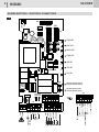 2
2
-
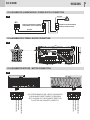 3
3
-
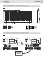 4
4
-
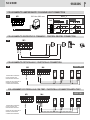 5
5
-
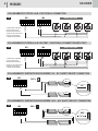 6
6
-
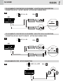 7
7
-
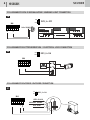 8
8
-
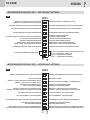 9
9
-
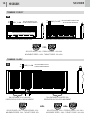 10
10
-
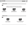 11
11
-
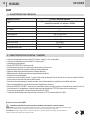 12
12
-
 13
13
-
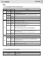 14
14
-
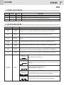 15
15
-
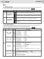 16
16
-
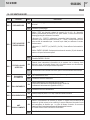 17
17
-
 18
18
-
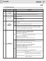 19
19
-
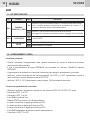 20
20
-
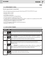 21
21
-
 22
22
-
 23
23
-
 24
24
-
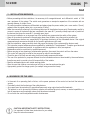 25
25
-
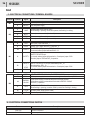 26
26
-
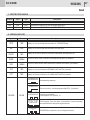 27
27
-
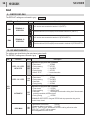 28
28
-
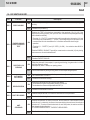 29
29
-
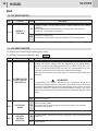 30
30
-
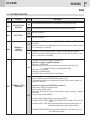 31
31
-
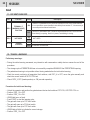 32
32
-
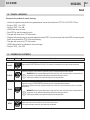 33
33
-
 34
34
-
 35
35
-
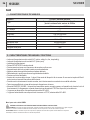 36
36
-
 37
37
-
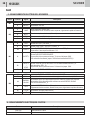 38
38
-
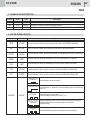 39
39
-
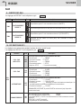 40
40
-
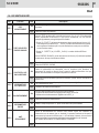 41
41
-
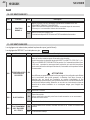 42
42
-
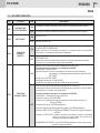 43
43
-
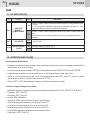 44
44
-
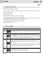 45
45
-
 46
46
-
 47
47
-
 48
48
-
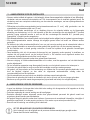 49
49
-
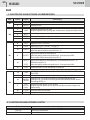 50
50
-
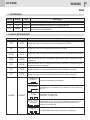 51
51
-
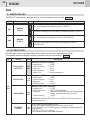 52
52
-
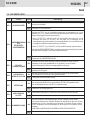 53
53
-
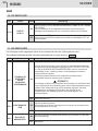 54
54
-
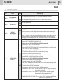 55
55
-
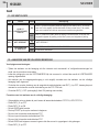 56
56
-
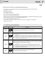 57
57
-
 58
58
-
 59
59
-
 60
60


in andere talen
- English: GiBiDi SC230E Owner's manual
- italiano: GiBiDi SC230E Manuale del proprietario
- français: GiBiDi SC230E Le manuel du propriétaire
Gerelateerde papieren

Andere documenten
-
Nice Automation Mindy A500 de handleiding
-
 Key Automation 580ISCT-101 Handleiding
-
Telcoma T201 de handleiding
-
Genius BRAIN03 BRAIN04 Handleiding
-
-
-
-
 Roger Technology B70/1DCHP Handleiding
-
Genius SPRINT 03 04 Handleiding
-

