
73515_V20_30/01/2020
FR
EN
DE
ES
RU
NL
IT
02-11 / 72-80
12-21 / 72-80
22-31 / 72-80
32-41 / 72-80
42-51 / 72-80
52-61 / 72-80
62-71 / 72-80
TIG 168 DC HF
TIG 200 DC HF FV
MADE IN FRANCE
www.gys.fr

2
TIG 168 DC HF/ TIG 200 DC HF FV
MADE IN FRANCE
AVERTISSEMENTS - RÈGLES DE SÉCURITÉ
CONSIGNE GÉNÉRALE
Ces instructions doivent être lues et bien comprises avant toute opération.
Toute modication ou maintenance non indiquée dans le manuel ne doit pas être entreprise.
Tout dommage corporel ou matériel dû à une utilisation non-conforme aux instructions de ce manuel ne pourra être
retenu à la charge du fabricant.
En cas de problème ou d’incertitude, consulter une personne qualiée pour manier correctement l’installation.
ENVIRONNEMENT
Ce matériel doit être utilisé uniquement pour faire des opérations de soudage dans les limites indiquées par la plaque
signalétique et/ou le manuel. Il faut respecter les directives relatives à la sécurité. En cas d’utilisation inadéquate ou
dangereuse, le fabricant ne pourra être tenu responsable.
L’installation doit être utilisée dans un local sans poussière, ni acide, ni gaz inammable ou autres substances corrosives
de même pour son stockage. S’assurer d’une circulation d’air lors de l’utilisation.
Plages de température :
Utilisation entre -10 et +40°C (+14 et +104°F).
Stockage entre -20 et +55°C (-4 et 131°F).
Humidité de l’air :
Inférieur ou égal à 50% à 40°C (104°F).
Inférieur ou égal à 90% à 20°C (68°F).
Altitude :
Jusqu’à 1000 m au-dessus du niveau de la mer (3280 pieds).
PROTECTIONS INDIVIDUELLE ET DES AUTRES
Le soudage à l’arc peut être dangereux et causer des blessures graves voire mortelles.
Le soudage expose les individus à une source dangereuse de chaleur, de rayonnement lumineux de l’arc, de champs
électromagnétiques (attention au porteur de pacemaker), de risque d’électrocution, de bruit et d’émanations gazeuses.
Pour bien se protéger et protéger les autres, respecter les instructions de sécurité suivantes :
An de se protéger de brûlures et rayonnements, porter des vêtements sans revers, isolants, secs, ignifugés et en
bon état, qui couvrent l’ensemble du corps.
Utiliser des gants qui garantissent l’isolation électrique et thermique.
Utiliser une protection de soudage et/ou une cagoule de soudage d’un niveau de protection sufsant (variable selon
les applications). Protéger les yeux lors des opérations de nettoyage. Les lentilles de contact sont particulièrement
proscrites.
Il est parfois nécessaire de délimiter les zones par des rideaux ignifugés pour protéger la zone de soudage des rayons
de l’arc, des projections et des déchets incandescents.
Informer les personnes dans la zone de soudage de ne pas xer les rayons de l’arc ni les pièces en fusion et de porter
les vêtements adéquats pour se protéger.
Utiliser un casque contre le bruit si le procédé de soudage atteint un niveau de bruit supérieur à la limite autorisée
(de même pour toute personne étant dans la zone de soudage).
Tenir à distance des parties mobiles (ventilateur) les mains, cheveux, vêtements.
Ne jamais enlever les protections carter du groupe froid lorsque la source de courant de soudage est sous tension,
le fabricant ne pourrait être tenu pour responsable en cas d’accident.
Les pièces qui viennent d’être soudées sont chaudes et peuvent provoquer des brûlures lors de leur manipulation.
Lors d’intervention d’entretien sur la torche ou le porte-électrode, il faut s’assurer que celui-ci soit sufsamment froid
en attendant au moins 10 minutes avant toute intervention. Le groupe froid doit être allumé lors de l’utilisation d’une
torche refroidie eau an d’être sûr que le liquide ne puisse pas causer de brûlures.
Il est important de sécuriser la zone de travail avant de la quitter an de protéger les personnes et les biens.
FR

3
TIG 168 DC HF/ TIG 200 DC HF FV
MADE IN FRANCE
FUMÉES DE SOUDAGE ET GAZ
Les fumées, gaz et poussières émis par le soudage sont dangereux pour la santé. Il faut prévoir une
ventilation sufsante, un apport d’air est parfois nécessaire. Un masque à air frais peut être une solution
en cas d’aération insufsante.
Vérier que l’aspiration est efcace en la contrôlant par rapport aux normes de sécurité.
Attention le soudage dans des milieux de petites dimensions nécessite une surveillance à distance de sécurité. Par
ailleurs le soudage de certains matériaux contenant du plomb, cadmium, zinc ou mercure voire du béryllium peuvent
être particulièrement nocifs, dégraisser également les pièces avant de les souder.
Les bouteilles doivent être entreposées dans des locaux ouverts ou bien aérés. Elles doivent être en position verticale
et maintenues à un support ou sur un chariot.
Le soudage doit être proscrit à proximité de graisse ou de peinture.
RISQUES DE FEU ET D’EXPLOSION
Protéger entièrement la zone de soudage, les matières inammables doivent être éloignées d’au moins
11 mètres.
Un équipement anti-feu doit être présent à proximité des opérations de soudage.
Attention aux projections de matières chaudes ou d’étincelles et même à travers des ssures, elles peuvent être source
d’incendie ou d’explosion.
Éloigner les personnes, les objets inammables et les containers sous pressions à une distance de sécurité sufsante.
Le soudage dans des containers ou des tubes fermés est à proscrire et dans le cas où ils sont ouverts il faut les vider de
toute matière inammable ou explosive (huile, carburant, résidus de gaz …).
Les opérations de meulage ne doivent pas être dirigées vers la source de courant de soudage ou vers des matières
inammables.
BOUTEILLES DE GAZ
Le gaz sortant des bouteilles peut être source de suffocation en cas de concentration dans l’espace
de soudage (bien ventiler).
Le transport doit être fait en toute sécurité : bouteilles fermées et la source de courant de soudage
éteinte. Elles doivent être entreposées verticalement et maintenues par un support pour limiter le
risque de chute.
Fermer la bouteille entre deux utilisations. Attention aux variations de température et aux expositions
au soleil.
La bouteille ne doit pas être en contact avec une amme, un arc électrique, une torche, une pince de
masse ou toutes autres sources de chaleur ou d’incandescence.
Veiller à la tenir éloignée des circuits électriques et de soudage et donc ne jamais souder une bouteille
sous pression.
Attention lors de l’ouverture du robinet de la bouteille, il faut éloigner la tête la robinetterie et s’assurer
que le gaz utilisé est approprié au procédé de soudage.
SÉCURITÉ ÉLECTRIQUE
Le réseau électrique utilisé doit impérativement avoir une mise à la terre. Utiliser la taille de fusible
recommandée sur le tableau signalétique.
Une décharge électrique peut être une source d’accident grave direct ou indirect, voire mortel.
Ne jamais toucher les parties sous tension à l’intérieur comme à l’extérieur de la source de courant sous-tension
(Torches, pinces, câbles, électrodes) car celles-ci sont branchées au circuit de soudage.
Avant d’ouvrir la source de courant de soudage, il faut la déconnecter du réseau et attendre 2 minutes. an que
l’ensemble des condensateurs soit déchargé.
Ne pas toucher en même temps la torche ou le porte-électrode et la pince de masse.
Veiller à changer les câbles, torches si ces derniers sont endommagés, par des personnes qualiées et habilitées.
Dimensionner la section des câbles en fonction de l’application. Toujours utiliser des vêtements secs et en bon état pour
s’isoler du circuit de soudage. Porter des chaussures isolantes, quel que soit le milieu de travail.
FR

4
TIG 168 DC HF/ TIG 200 DC HF FV
MADE IN FRANCE
CLASSIFICATION CEM DU MATÉRIEL
Ce matériel de Classe A n’est pas prévu pour être utilisé dans un site résidentiel où le courant électrique
est fourni par le réseau public d’alimentation basse tension. Il peut y avoir des difcultés potentielles
pour assurer la compatibilité électromagnétique dans ces sites, à cause des perturbations conduites,
aussi bien que rayonnées à fréquence radioélectrique.
TIG 168
Ce matériel est conforme à l’EN 61000-3-11 si l’impédance du réseau au point de raccordement avec
l’installation électrique est inférieure à l’impédance maximale admissible du réseau Zmax = 0.115
Ohms.
Ce matériel n’est pas conforme à la CEI 61000-3-12 et est destiné à être raccordé à des réseaux basse
tension privés connectés au réseau public d’alimentation seulement au niveau moyenne et haute
tension. S’il est connecté à un réseau public d’alimentation basse tension, il est de la responsabilité
de l’installateur ou de l’utilisateur du matériel de s’assurer, en consultant l’opérateur du réseau de
distribution, que le matériel peut être connecté.
TIG200
Ce matériel est conforme à l’EN 61000-3-11 si l’impédance du réseau au point de raccordement avec
l’installation électrique est inférieure à l’impédance maximale admissible du réseau Zmax = 0.085
Ohms.
Ce matériel est conforme à la CEI 61000-3-12.
ÉMISSIONS ÉLECTROMAGNÉTIQUES
Le courant électrique passant à travers n’importe quel conducteur produit des champs électriques et
magnétiques (EMF) localisés. Le courant de soudage produit un champ électromagnétique autour du
circuit de soudage et du matériel de soudage.
Les champs électromagnétiques EMF peuvent perturber certains implants médicaux, par exemple les stimulateurs
cardiaques. Des mesures de protection doivent être prises pour les personnes portant des implants médicaux. Par
exemple, restrictions d’accès pour les passants ou une évaluation de risque individuelle pour les soudeurs.
Tous les soudeurs devraient utiliser les procédures suivantes an de minimiser l’exposition aux champs électromagnétiques
provenant du circuit de soudage:
• positionner les câbles de soudage ensemble – les xer les avec une attache, si possible;
• se positionner (torse et tête) aussi loin que possible du circuit de soudage;
• ne jamais enrouler les câbles de soudage autour du corps;
• ne pas positionner le corps entre les câbles de soudage. Tenir les deux câbles de soudage sur le même côté du corps;
• raccorder le câble de retour à la pièce mise en œuvre aussi proche que possible à la zone à souder;
• ne pas travailler à côté de la source de courant de soudage, ne pas s’assoir dessus ou ne pas s’y adosser ;
• ne pas souder lors du transport de la source de courant de soudage ou le dévidoir.
Les porteurs de stimulateurs cardiaques doivent consulter un médecin avant d’utiliser ce matériel.
L’exposition aux champs électromagnétiques lors du soudage peut avoir d’autres effets sur la santé
que l’on ne connaît pas encore.
RECOMMANDATIONS POUR ÉVALUER LA ZONE ET L’INSTALLATION DE SOUDAGE
Généralités
L’utilisateur est responsable de l’installation et de l’utilisation du matériel de soudage à l’arc suivant les instructions du
fabricant. Si des perturbations électromagnétiques sont détectées, il doit être de la responsabilité de l’utilisateur du
matériel de soudage à l’arc de résoudre la situation avec l’assistance technique du fabricant. Dans certains cas, cette
action corrective peut être aussi simple qu’une mise à la terre du circuit de soudage. Dans d’autres cas, il peut être
nécessaire de construire un écran électromagnétique autour de la source de courant de soudage et de la pièce entière
avec montage de ltres d’entrée. Dans tous les cas, les perturbations électromagnétiques doivent être réduites jusqu’à
ce qu’elles ne soient plus gênantes.
Evaluation de la zone de soudage
Avant d’installer un matériel de soudage à l’arc, l’utilisateur doit évaluer les problèmes électromagnétiques potentiels
dans la zone environnante. Ce qui suit doit être pris en compte:
a) la présence au-dessus, au-dessous et à côté du matériel de soudage à l’arc d’autres câbles d’alimentation, de
commande, de signalisation et de téléphone;
FR

5
TIG 168 DC HF/ TIG 200 DC HF FV
MADE IN FRANCE
b) des récepteurs et transmetteurs de radio et télévision;
c) des ordinateurs et autres matériels de commande;
d) du matériel critique de sécurité, par exemple, protection de matériel industriel;
e) la santé des personnes voisines, par exemple, emploi de stimulateurs cardiaques ou d’appareils contre la surdité;
f) du matériel utilisé pour l’étalonnage ou la mesure;
g) l’immunité des autres matériels présents dans l’environnement.
L’utilisateur doit s’assurer que les autres matériels utilisés dans l’environnement sont compatibles. Cela peut exiger des
mesures de protection supplémentaires;
h) l’heure du jour où le soudage ou d’autres activités sont à exécuter.
La dimension de la zone environnante à prendre en compte dépend de la structure du bâtiment et des autres activités
qui s’y déroulent. La zone environnante peut s’étendre au-delà des limites des installations.
Evaluation de l’installation de soudage
Outre l’évaluation de la zone, l’évaluation des installations de soudage à l’arc peut servir à déterminer et résoudre les cas
de perturbations. Il convient que l’évaluation des émissions comprenne des mesures in situ comme cela est spécié à
l’Article 10 de la CISPR 11:2009. Les mesures in situ peuvent également permettre de conrmer l’efcacité des mesures
d’atténuation.
RECOMMANDATION SUR LES MÉTHODES DE RÉDUCTION DES ÉMISSIONS ÉLECTROMAGNÉTIQUES
a. Réseau public d’alimentation: Il convient de raccorder le matériel de soudage à l’arc au réseau public d’alimentation
selon les recommandations du fabricant. Si des interférences se produisent, il peut être nécessaire de prendre des
mesures de prévention supplémentaires telles que le ltrage du réseau public d’alimentation. Il convient d’envisager
de blinder le câble d’alimentation dans un conduit métallique ou équivalent d’un matériel de soudage à l’arc installé à
demeure. Il convient d’assurer la continuité électrique du blindage sur toute sa longueur. Il convient de raccorder le
blindage à la source de courant de soudage pour assurer un bon contact électrique entre le conduit et l’enveloppe de
la source de courant de soudage.
b. Maintenance du matériel de soudage à l’arc : Il convient que le matériel de soudage à l’arc soit soumis à
l’entretien de routine suivant les recommandations du fabricant. Il convient que tous les accès, portes de service et
capots soient fermés et correctement verrouillés lorsque le matériel de soudage à l’arc est en service. Il convient que
le matériel de soudage à l’arc ne soit modié en aucune façon, hormis les modications et réglages mentionnés dans
les instructions du fabricant. Il convient, en particulier, que l’éclateur d’arc des dispositifs d’amorçage et de stabilisation
d’arc soit réglé et entretenu suivant les recommandations du fabricant.
c. Câbles de soudage : Il convient que les câbles soient aussi courts que possible, placés l’un près de l’autre à
proximité du sol ou sur le sol.
d. Liaison équipotentielle : Il convient d’envisager la liaison de tous les objets métalliques de la zone environnante.
Toutefois, des objets métalliques reliés à la pièce à souder accroissent le risque pour l’opérateur de chocs électriques
s’il touche à la fois ces éléments métalliques et l’électrode. Il convient d’isoler l’opérateur de tels objets métalliques.
e. Mise à la terre de la pièce à souder : Lorsque la pièce à souder n’est pas reliée à la terre pour la sécurité
électrique ou en raison de ses dimensions et de son emplacement, ce qui est le cas, par exemple, des coques de navire
ou des charpentes métalliques de bâtiments, une connexion raccordant la pièce à la terre peut, dans certains cas et
non systématiquement, réduire les émissions. Il convient de veiller à éviter la mise à la terre des pièces qui pourrait
accroître les risques de blessure pour les utilisateurs ou endommager d’autres matériels électriques. Si nécessaire, il
convient que le raccordement de la pièce à souder à la terre soit fait directement, mais dans certains pays n’autorisant
pas cette connexion directe, il convient que la connexion soit faite avec un condensateur approprié choisi en fonction
des réglementations nationales.
f. Protection et blindage : La protection et le blindage sélectifs d’autres câbles et matériels dans la zone environnante
peuvent limiter les problèmes de perturbation. La protection de toute la zone de soudage peut être envisagée pour des
applications spéciales.
TRANSPORT ET TRANSIT DE LA SOURCE DE COURANT DE SOUDAGE
La source de courant de soudage est équipée d’une poignée supérieure permettant le portage à la
main. Attention à ne pas sous-évaluer son poids. La poignée n’est pas considérée comme un moyen
d’élingage.
Ne pas utiliser les câbles ou torche pour déplacer la source de courant de soudage. Elle doit être dépla-
cée en position verticale.
Ne pas faire transiter la source de courant au-dessus de personnes ou d’objets.
Ne jamais soulever une bouteille de gaz et la source de courant en même temps. Leurs normes de
transport sont distinctes.
FR

6
TIG 168 DC HF/ TIG 200 DC HF FV
MADE IN FRANCE
INSTALLATION DU MATÉRIEL
• Mettre la source de courant de soudage sur un sol dont l’inclinaison maximum est de 10°.
• Prévoir une zone sufsante pour aérer la source de courant de soudage et accéder aux commandes.
• Ne pas utiliser dans un environnement comportant des poussières métalliques conductrices.
• La source de courant de soudage doit être à l’abri de la pluie battante et ne pas être exposée aux rayons du soleil.
• Le matériel est de degré de protection IP21, signiant :
- une protection contre l’accès aux parties dangereuses des corps solides de diam >12.5 mm et,
- une protection contre les chutes verticales de gouttes d’eau
Les câbles d’alimentation, de rallonge et de soudage doivent être totalement déroulés an d’éviter toute surchauffe.
Le fabricant n’assume aucune responsabilité concernant les dommages provoqués à des personnes et
objets dus à une utilisation incorrecte et dangereuse de ce matériel.
ENTRETIEN / CONSEILS
• L’entretien ne doit être effectué que par une personne qualiée. Un entretien annuel est conseillé.
• Couper l’alimentation en débranchant la prise, et attendre deux minutes avant de travailler sur le matériel. A
l’intérieur, les tensions et intensités sont élevées et dangereuses.
• Régulièrement, enlever le capot et dépoussiérer à la soufette. En proter pour faire vérier la tenue des
connexions électriques avec un outil isolé par un personnel qualié.
• Contrôler régulièrement l’état du cordon d’alimentation. Si le câble d’alimentation est endommagé, il doit être
remplacé par le fabricant, son service après-vente ou une personne de qualication similaire, an d’éviter tout
danger.
• Laisser les ouïes de la source de courant de soudage libres pour l’entrée et la sortie d’air.
• Ne pas utiliser cette source de courant de soudage pour dégeler des canalisations, recharger des batteries/
accumulateurs ou démarrer des moteurs.
INSTALLATION – FONCTIONNEMENT PRODUIT
DESCRIPTION DES MATÉRIELS
Le TIG 168/200 est un poste de soudure Inverter, portable, monophasé, ventilé, pour soudage à l’électrode réfractaire
(TIG) en courant continu (DC). Le soudage TIG DC requiert une protection gazeuse (Argon). En mode MMA, il permet
de souder tout type d’électrode : rutile, basique, inox et fonte. Ils fonctionnent sur une alimentation électrique, mono-
phasée 230V pour le TIG 168, monophasée comprise entre 85V et 265V pour le TIG 200. Ils sont protégés pour le
fonctionnement sur groupes électrogènes. Le TIG 200 peut être équipé d’une commande à distance manuelle ou pédale.
ALIMENTATION-MISE EN MARCHE
• Ce matériel est livre avec une prise 16 A de type CEE7/7 et ne doit être utilisé que sur une installation électrique
monophasée 230 V (50 - 60 Hz) à trois ls avec un neutre relié à la terre.
Le courant effectif absorbé (I1eff) est indiqué sur l’appareil, pour les conditions d’utilisation maximales. Vérier que
l’alimentation et ses protections (fusible et/ou disjoncteur) sont compatibles avec le courant nécessaire en utilisation.
Dans certains pays, il peut être nécessaire. de changer la prise pour permettre une utilisation aux conditions maximales.
L’utilisateur doit s’assurer de l’accessibilité de la prise.
• La mise en marche s’effectue par une pression sur la touche « »
• L’appareil se met en protection si la tension d’alimentation est supérieure à 265 V (l’afcheur indique ). Le fonc-
tionnement normal reprend dès que la tension d’alimentation revient dans sa plage nominale.
BRANCHEMENT SUR GROUPE ÉLECTROGÈNE
Ce matériel peut fonctionner avec des groupes électrogènes à condition que la puissance auxiliaire réponde aux exi-
gences suivantes :
- La tension doit être alternative, réglée comme spéciée et de tension crête inférieure à 400 V,
- La fréquence doit être comprise entre 50 et 60 Hz.
Il est impératif de vérier ces conditions, car de nombreux groupes électrogènes produisent des pics de haute tension
pouvant endommager le matériel.
FR

7
TIG 168 DC HF/ TIG 200 DC HF FV
MADE IN FRANCE
FR
SOUDAGE À L’ÉLECTRODE ENROBÉE (MODE MMA) INTERFACE EN PAGE 74
Branchement et conseils
• Brancher les câbles porte-électrode et pince de masse dans les connecteurs de raccordement.
• Respecter les polarités et intensités de soudage indiquées sur les boîtes d’électrodes
• Enlever l’électrode du porte-électrode lorsque le poste n’est pas utilisé
Aides au soudage intégrés
Votre appareil est muni de 3 fonctionnalités spéciques aux Inverters :
Le Hot Start procure une surintensité réglable en début de soudage
L’Arc Force délivre une surintensité qui évite le collage lorsque l’électrode rentre dans le bain.
L’Anti-Sticking vous permet de décoller facilement votre électrode sans la faire rougir en cas de collage.
Sélection du procédé et réglage intensité
1- Sélectionner le mode MMA 2- Sélectionner le courant désiré grâce au potentiomètre
Nb. : pour le TIG 200, l’intensité de soudage varie selon la tension de votre alimentation électrique :
- en 110 V, l’intensité peut être réglée de 10 à 120A
- en 230V, l’intensité peut être réglée de 10 à 200A
Hot start ajustable
Le Hot Start est réglable de 0 à 60 % :
- dans la limite de 160A pour le TIG 168.
- dans la limite de 200A en 230V, 120A en 110V pour le TIG 200.
1- Cliquer et maintenir appuyé.
2- Sélectionner le Hot Start souhaité.
Nb. : l’inscription «HI» indique que le Hot Start est au maximum.
Arc Force ajustable (sur TIG 200 uniquement)
L’Arc Force est réglable de 0 à 100 % (dans la limite de 200A en 230V ou 120A en 110V pour le TIG 200).
1- Cliquer et maintenir appuyé
2- Sélectionner l’Arc Force souhaité.
SOUDAGE A L’ÉLECTRODE TUNGSTENE SOUS GAZ INERTE (MODE TIG) INTERFACE EN PAGE 74
Choix du type d’amorçage
1- Sélectionner votre amorçage LIFT ou HF
TIG LIFT: Amorçage par contact (pour les milieux sensibles aux perturbations HF)
1- Toucher l’électrode sur la pièce à souder
2- Appuyer sur la gâchette
3- Relever l’électrode.
TIG HF: amorçage haute fréquence sans contact
Comportement Gâchette
Torches compatibles
TIG 168 • •
TIG 200 • • •
Nb. : Les TIG 200 détectent automatiquement la torche qui leur est connectée.

8
TIG 168 DC HF/ TIG 200 DC HF FV
MADE IN FRANCE
FR
Mode 2T
1- Appui et maintien gâchette: Prégaz, montée en courant, soudage
2- Relâchement gâchette: évanouissement, post gaz.
Nb. : pour les torches double bouton et double boutons potentio-
mètre => bouton « haut/courant chaud » et potentiomètre actifs,
bouton « bas/courant froid » inactive.
Mode 4T
1- Appui gâchette : Pré-GAZ, suivi de l’amorçage. Pour faciliter le posi-
tionnement de l’électrode, un courant faible de 10A est fourni, agissant
comme un faisceau lumineux. ( = Adjust Ideal Position).
2- Relâchement gâchette : montée du courant jusqu’à la consigne af-
chée, soudage
3- Appui gâchette : évanouissement jusqu’à 10A (pour une bonne ferme-
ture du cratère)
4- Relâchement gâchette : arrêt du courant puis post gaz.
Nb. : pour les torches double bouton et double boutons potentiomètre => bouton « haut/courant chaud
» et potentiomètre actifs, bouton « bas/courant froid » inactif.
Mode 4T Log
Ce mode fonctionne comme le mode 4T mais lorsque vous êtes en phase de soudure une impulsion brève sur la gâ-
chette permet de passer à un courant froid préalablement réglé (20% à 70% du courant chaud de soudage).
1- Appui gâchette : Pré-GAZ, suivi de l’amorçage. Pour faciliter le position-
nement de l’électrode, un courant faible de 10A est fourni, agissant comme
un faisceau lumineux. ( = Adjust Ideal Position).
2- Relâchement gâchette : montée du courant jusqu’au courant «chaud»
de soudage (consigne afchée)
impulsion brève : passage au courant froid (% I).
impulsion brève : retour au courant «chaud».
3- Appui gâchette : évanouissement jusqu’à 10A (pour une bonne ferme-
ture du cratère).
4- Relâchement gâchette : arrêt du courant puis post gaz.
Nb. : Pour les torches double boutons et double boutons+potentiomètre => bouton « haut/courant
chaud » et « bas/ courant froid » + potentiomètre actifs.
Pour ce mode il peut être pratique d’utiliser l’option torche double bouton ou double boutons + potentiomètre. Le bou-
ton « haut » garde la même fonctionnalité que la torche simple bouton ou à lamelle. Le bouton « bas » permet, lorsqu’il
est maintenu appuyé, de basculer sur le courant froid. Le potentiomètre de la torche, lorsqu’il est présent permet de
régler le courant de soudage (chaud et froid) de 50% à 100% de la valeur afchée.
Options de soudage
Pulsé (Pulse)
Non disponible en 4T LOG
Les impulsions (pulse) correspondent aux augmentations et aux baisses alternées du courant (courant chaud, courant
froid). Le mode pulse permet d’assembler les pièces tout en limitant l’élévation en température.
En mode pulsé, vous pouvez régler :
- le courant froid (20% à 70% du courant de soudage)
- la fréquence de soudage (de 0.2 Hz à 20Hz).
Nb: la durée du temps chaud et la durée du temps froid sont identiques
Easy Pulse
Mode pulsé simplié. Vous réglez juste le courant moyen autour duquel la pulsation va se former.
L’Easy pulse détermine la fréquence et le courant de soudage chaud et froid.
Spot
Ce mode n’est accessible qu’en TIG HF 2T.
Il permet de préparer les pièces en faisant du pointage.
Une fois celles-ci maintenues, vous pouvez passer en soudage TIG an de réaliser le cordon dans sa totalité.

9
TIG 168 DC HF/ TIG 200 DC HF FV
MADE IN FRANCE
FR
Réglage des paramètres
Pré Gaz (0 à 2 sec.)
Le prégaz permet, avant amorçage, de purger la torche et la zone proche du début de cordon de sou-
dage. Il améliore aussi la régularité de l’amorçage.
Conseil :Plus la torche est longue et plus il faudra augmenter cette durée. (0,15 s/m de torche)
Montée du courant (Up Slope) (0 à 5 sec.)
Temps nécessaire pour évoluer du courant minimal au courant de soudage.
Réglage du courant de soudage
La valeur du courant de soudage dépend de l’épaisseur, de la nature du métal ainsi que de la conguration
de soudage.
Conseil : Prendre pour base 30A / mm et ajuster en fonction de la pièce à souder,
Réglage de la fréquence de pulsation (de 0,2 à 20Hz)
La fréquence de pulsation est le nombre de cycles (1/2cycle courant chaud 1/2 cycle courant froid) effec-
tués par seconde.
Réglage du courant froid (intensité basse) (de 20% à 70% du courant chaud)
Il s’agit du pourcentage du courant chaud, plus le courant froid est bas moins la pièce s’echauffera pen-
dant le soudage.
Réglage de l’évanouisseur (Down slope) (0 à 10 sec)
Temps nécessaire pour évoluer du courant de soudage jusqu’au courant minimum. Evite les ssures et les
cratères de n de soudure.
Réglage du Post GAZ (3 à 20 sec)
Ce paramètre dénit le temps durant lequel le gaz continue à s’écouler après extinction de l’arc. Il permet
de protéger la pièce ainsi que l’électrode contre les oxydations.
Conseil : Augmenter la durée si la soudure à l’air sombre.
(Pour base : 25A=4sec. - 50A=8sec - 75A=9sec - 100A=10sec - 125A=11sec- 150A=13sec- 200A=15sec)
Nb. : A tout moment vous pouvez vérier vos réglages en appuyant simplement sur le bouton du para-
mètre, sans tourner la molette.
Fonctions disponibles par procédé de soudage
En fonction des modes, certains boutons sont inactifs, cf tableau ci-dessous:
Amorçage Gachette Processus TIG
HF TIG Lift 2T 4T 4T log
Pre-gaz Post-gaz
TIG Normal • • • • • • • • (I)
•
uniquement
en 4T Log
• •
TIG Pulse • • • • • • • (I) • • • •
TIG Easy Pulse • • • • • • • (I
moyen
) • •
SPOT • • • • •
Mémorisation et rappel des mémoires
Vous disposez de 5 mémoires pour stocker et rappeler vos paramètres TIG. En plus de ces mémoires, TIG 168/200
mémorise vos derniers réglages activés et les réactive à chaque redémarrage du poste.
Mémorisation
1- Appuyer sur le bouton
2- «In» pendant 1 seconde.
Tant que l’afchage indique «In» l’action peut être annulée.
3- Au delà d’une seconde l’afcheur indique un numéro de programme (P1 à P5),
tout en maintenant le bouton appuyé tourner la molette pour denir l’emplace-
ment mémoire adéquat, lâcher le bouton vos paramètres sont mémorisés.

10
TIG 168 DC HF/ TIG 200 DC HF FV
MADE IN FRANCE
FR
Rappel d’une conguration
Procéder de la même façon mais en appuyant sur
Retour réglage usine
1- Presser 3 secondes sur le bouton reset.
2- L’afcheur afche Ini
Toutes les sauvegardes sont supprimées (les paramètres usine sont restaurés sur
les 5 programmes+ paramètre de démarrage).
Combinaisons conseillées / affutage électrode
Courant (A)
Ø Electrode (mm)
= Ø l
(métal d’apport)
Ø Buse
(mm)
Débit
(Argon l/mn)
0,5-5 10-130 1,6 9,8 6-7
4-6,5 130-200 2,4 11 7-8
> 6.5 > 200A 3,2 12,7 8-9
Pour un fonctionnement optimal vous devez utiliser une électrode affûtée de la manière suivante :
L = 3 x d pour un courant faible.
L = d pour un courant fort.
L
d
Connecteur de commande gâchette
Le connecteur de commande gâchette est conçu de la manière suivante :
3
1
4
5
2
1 3
2
4
5
TIG 200
1- Commun BP + Potentio.
2- Bouton courant froid
3- Bouton de soudage torche
4- Curseur / potentiomètre
5- +5V potentiomètre 10 KΩ
TIG 168
1- Commun
2- Bouton courant froid
3- Bouton de soudage torche
COMMANDE A DISTANCE (TIG 200 UNIQUEMENT)
La commande à distance fonctionne en mode TIG et en MMA.
Connectique
Les TIG 200 sont équipés d’une prise femelle pour commande à distance. La prise mâle spécique 7 points (option
ref.045699) permet d’y raccorder votre commande à distance manuelle (RC) ou à pédale (PEd).
Pour le câblage suivre le schéma ci-dessous.
D : Contact du switch
C : Masse
B : Curseur
A : + 5V
Nb : la valeur du potentiomètre doit être de 10 KΩ
ref. 045699

11
TIG 168 DC HF/ TIG 200 DC HF FV
MADE IN FRANCE
FR
Branchement
1- Allumer le poste
2- Brancher la pédale ou la télécommande sur la face avant de l’appareil.
3- L’afcheur clignote en afchant « No » (Rien),
4- Sélectionner votre type de commande en tournant la molette de réglage d’intensité :
No (Rien) « RC » (Remote Control/commande à distance) PEd (Pédale)
5- Après 2 secondes d’inactivité de la molette, l’afcheur se ge sur la valeur puis réafche l’intensité de soudage
Nb. : En cas d’erreur, débrancher votre commande à distance, le poste vous indique que plus rien n’est
connecté : « No ». Puis rebrancher votre commande et refaites la sélection.
Remarque : Ce choix sera demandé à chaque mise en route.
Fonctionnement
Commande à Distance.manuelle (option ref.045675)
La commande à distance manuelle permet de faire varier le courant de l’intensité mini (DC : 10A / MMA : 10) à l’intensité
dénie par l’utilisateur (afcheur).
Dans cette conguration, tous les modes et fonctionnalités du poste sont accessibles et paramétrables.
Pédale (option ref.045682) :
Dans tous les modes sauf en mode « Spot », la commande à pédale permet de faire varier le courant de l’intensité mini
(DC : 10A / MMA : 10A) à l’intensité dénie par l’utilisateur (afcheur).
En TIG le poste fonctionne uniquement en soudage 2 temps (mode 2T). De plus, la montée et l’évanouissement du
courant ne sont plus gérés par le poste (fonctions inactives) mais par l’utilisateur via la pédale.
En mode spot, la commande à pédale remplace la gâchette de la torche (la position de la pédale n’a pas d’effet sur le
courant)
ANOMALIE, CAUSE, REMÈDE
Anomalies Causes Remèdes
L’appareil ne délivre pas de courant et
le voyant jaune de défaut thermique est
allumé (6).
La protection thermique du poste
s’est enclenchée.
Attendre la n de la période de
refroidissement, environ 2 min. Le
voyant (6) s’éteint.
L’afcheur est allumé mais l’appareil ne
délivre pas de courant.
Le câble de pince de masse ou
porte électrode n’est pas connecté
au poste.
Vérier les branchements.
Lors de la mise en route, l’afcheur
indique .
La tension n’est pas
dans la fourchette
230 V +/- 15% pour le TIG 168,
ou 85-265V pour le TIG 200.
Vérier votre installation électrique
ou votre groupe électrogène
Arc instable
Défaut provenant de l'électrode en
tungstène
Utiliser une électrode en tungstène
correctement préparée
Utiliser une électrode en tungstène
correctement préparée
Débit de gaz trop important Réduire le débit de gaz
L’électrode en tungstène s’oxyde et se
ternit en n de soudage
Zone de soudage.
Protéger la zone de soudage
contre les courants d'air.
Défaut provenant du Post gaz.
Augmenter la durée du post gaz.
Contrôler et serrer tous les rac-
cords de gaz.
L'électrode fond Erreur de polarité
Vérier que la pince de masse est
bien reliée au +
« PH » s’afche à l’écran Problème de détection des phases
Vérier que toutes les phases sont
présentes. Le défaut se réinitialise
en redémarrant le produit

12
TIG 168 DC HF/ TIG 200 DC HF FV
MADE IN FRANCE
EN
WARNING - SAFETY RULES
GENERAL INSTRUCTIONS
Read and understand the following safety recommendations before using or servicing the unit.
Any change or servicing that is not specied in the instruction manual must not be undertaken.
The manufacturer is not liable for any injury or damage caused due to non-compliance with the instructions featured
in this manual .
In the event of problems or uncertainties, please consult a qualied person to handle the installation properly.
ENVIRONMENT
This equipment must only be used for welding operations in accordance with the limits indicated on the descriptive panel
and/or in the user manual. The operator must respect the safety precautions that apply to this type of welding. In case
of inedaquate or unsafe use, the manufacturer cannot be held liable for damage or injury.
This equipment must be used and stored in a place protected from dust, acid or any other corrosive agent. Operate the
machine in an open, or well-ventilated area.
Operating temperature:
Use between -10 and +40°C (+14 and +104°F).
Store between -20 and +55°C (-4 and 131°F).
Air humidity:
Lower or equal to 50% at 40°C (104°F).
Lower or equal to 90% at 20°C (68°F).
Altitude:
Up to 1000 meters above sea level (3280 feet).
INDIVIDUAL PROTECTIONS AND OTHERS
Arc welding can be dangerous and can cause serious and even fatal injuries.
Welding exposes the user to dangerous heat, arc rays, electromagnetic elds, noise, gas fumes, and electrical shocks.
People wearing pacemakers are advised to consult with their doctor before using this device.
To protect oneself as well as the other, ensure the following safety precautions are taken:
In order to protect you from burns and radiations, wear clothing without cuffs. These clothes must be
insulated, dry, reproof and in good condition, and cover the whole body.
Wear protective gloves which guarantee electrical and thermal insulation.
Use sufcient welding protective gear for the whole body: hood, gloves, jacket, trousers... (varies depen-
ding on the application/operation). Protect the eyes during cleaning operations. Do not operate whilst
wearing contact lenses.
It may be necessary to install reproof welding curtains to protect the area against arc rays, weld spatters
and sparks.
Inform the people around the working area to never look at the arc nor the molten metal, and to wear
protective clothes.
Ensure ear protection is worn by the operator if the work exceeds the authorised noise limit (the same
applies to any person in the welding area).
Stay away from moving parts (e.g. engine, fan...) with hands, hair, clothes etc...
Never remove the safety covers from the cooling unit when the machine is plugged in - The manufac-
turer is not responsible for any accident or injury that happens as a result of not following these safety
precautions.

13
TIG 168 DC HF/ TIG 200 DC HF FV
MADE IN FRANCE
EN
The pieces that have just been welded are hot and may cause burns when manipulated. During mainte-
nance work on the torch or the electrode holder, you should make sure it’s cold enough and wait at least
10 minutes before any intervention. The cooling unit must be on when using a water cooled torch in order
to ensure that the liquid does not cause any burns.
ALWAYS ensure the working area is left as safe and secure as possible to prevent damage or accidents.
WELDING FUMES AND GAS
The fumes, gases and dust produced during welding are hazardous. It is mandatory to ensure adequate
ventilation and/or extraction to keep fumes and gases away from the work area. An air fed helmet is
recommended in cases of insufcient air supply in the workplace.
Check that the air intake is in compliance with safety standards.
Care must be taken when welding in small areas, and the operator will need supervision from a safe distance. Welding
certain pieces of metal containing lead, cadmium, zinc, mercury or beryllium can be extremely toxic. The user will also
need to degrease the workpiece before welding.
Gas cylinders must be stored in an open or ventilated area. The cylinders must be in a vertical position secured to a
support or trolley.
Do not weld in areas where grease or paint are stored.
FIRE AND EXPLOSIONS RISKS
Protect the entire welding area. Compressed gas containers and other inammable material must be
moved to a minimum safe distance of 11 meters.
A re extinguisher must be readily available.
Be careful of spatter and sparks, even through cracks. It can be the source of a re or an explosion.
Keep people, ammable objects and containers under pressure at a safe distance.
Welding of sealed containers or closed pipes should not be undertaken, and if opened, the operator must remove any
inammable or explosive materials (oil, petrol, gas...).
Grinding operations should not be directed towards the device itself, the power supply or any ammable materials.
GAS BOTTLE
Gas leaking from the cylinder can lead to suffocation if present in high concentrations around the work
area.
Transport must be done safely: Cylinders closed and product off. Always keep cylinders in an upright
position securely chained to a xed support or trolley.
Close the bottle after any welding operation. Be wary of temperature changes or exposure to sunlight.
Cylinders should be located away from areas where they may be struck or subjected to physical damage.
Always keep gas bottles at a safe distance from arc welding or cutting operations, and any source of
heat, sparks or ames.
Be careful when opening the valve on the gas bottle, it is necessary to remove the tip of the valve and
make sure the gas meets your welding requirements.
ELECTRIC SAFETY
The machine must be connected to an earthed electrical supply. Use the recommended fuse size.
An electrical discharge can directly or indirectly cause serious or deadly accidents .
Do not touch any live part of the machine (inside or outside) when it is plugged in (Torches, earth cable, cables,
electrodes) because they are connected to the welding circuit.
Before opening the device, it is imperative to disconnect it from the mains and wait 2 minutes, so that all the capacitors
are discharged.
Do not touch the torch or electrode holder and earth clamp at the same time.
Damaged cables and torches must be changed by a qualied and skilled professional. Make sure that the cable cross
section is adequate with the usage (extensions and welding cables). Always wear dry clothes in good condition, in order
to be insulated from the electrical circuit. Wear insulating shoes, regardless of the environment in which you work in.

14
TIG 168 DC HF/ TIG 200 DC HF FV
MADE IN FRANCE
EN
EMC CLASSIFICATION
These Class A devices are not intended to be used on a residential site where the electric current is
supplied by the public network, with a low voltage power supply. There may be potential difculties in
ensuring electromagnetic compatibility on these sites, because of the interferences, as well as radio
frequencies.
TIG 168
This equipment complies with IEC 61000-3-11 if the power supply network’s impedance at the
electrical installation’s connection point is inferior to the network’s maximum admissible impendance
Zmax = 0.115 Ohms.
This equipment does not comply with IEC 61000-3-12 and is intended to be connected to private
low-voltage systems interfacing with the public supply only at the medium- or high-voltage level. On
a public low-voltage power grid, it is the responsibility of the installer or user of the device to ensure,
by checking with the operator of the distribution network, which device can be connected.
TIG200
This equipment complies with IEC 61000-3-11 if the power supply network’s impedance at the
electrical installation’s connection point is inferior to the network’s maximum admissible impendance
Zmax = 0.085 Ohms.
This equipment complies with the IEC 61000-3-12 standard.
ELECTROMAGNETIC INTERFERENCES
The electric currents owing through a conductor cause electrical and magnetic elds (EMF). The
welding current generates an EMF eld around the welding circuit and the welding equipment.
The EMF elds may disrupt some medical implants, such as pacemakers. Protection measures should be taken for
people wearing medical implants. For example, access restrictions for passers-by or an individual risk evaluation for the
welders.
All welders should take the following precautions in order to minimise exposure to the electromagnetic elds (EMF)
generated by the welding circuit::
• position the welding cables together – if possible, attach them;
• keep your head and torso as far as possible from the welding circuit;
• never enroll the cables around your body;
• never position your body between the welding cables. Hold both welding cables on the same side of your body;
• connect the earth clamp as close as possible to the area being welded;
• do not work too close to, do not lean and do not sit on the welding machine
• do not weld when you’re carrying the welding machine or its wire feeder.
People wearing pacemakers are advised to consult their doctor before using this device.
Exposure to electromagnetic elds while welding may have other health effects which are not yet
known.
RECOMMENDATIONS TO ASSESS THE WELDING AREA AND WELDING INSTALLATION
Overview
The user is responsible for installing and using the arc welding equipment in accordance with the manufacturer’s
instructions. If electromagnetic disturbances are detected, it is the responsibility of the user of the arc welding equipment
to resolve the situation with the manufacturer’s technical assistance. In some cases, this remedial action may be as
simple as earthing the welding circuit. In other cases, it may be necessary to construct an electromagnetic shield around
the welding power source and around the entire piece by tting input lters. In all cases, electromagnetic interferences
must be reduced until they are no longer bothersome.

15
TIG 168 DC HF/ TIG 200 DC HF FV
MADE IN FRANCE
EN
Welding area assessment
Before installing the machine, the user must evaluate the possible electromagnetic problems that may arise in the area
where the installation is planned.
. In particular, it should consider the following:
a) the presence of other power cables (power supply cables, telephone cables, command cable, etc...)above, below and
on the sides of the arc welding machine.
b) television transmitters and receivers ;
c) computers and other hardware;
d) critical safety equipment such as industrial machine protections;
e) the health and safety of the people in the area such as people with pacemakers or hearing aids;
f) calibration and measuring equipment
g)The isolation of the equipment from other machinery.
The user will have to make sure that the devices and equipments that are in the same room are compatible with each
other. This may require extra precautions;
h) make sure of the exact hour when the welding and/or other operations will take place.
The surface of the area to be considered around the device depends on the the building’s structure and other activities
that take place there. The area taken in consideration can be larger than the limits determined by the companies.
Welding area assessment
Besides the welding area, the assessment of the arc welding systems intallation itself can be used to identify and resolve
cases of disturbances. The assessment of emissions must include in situ measurements as specied in Article 10 of
CISPR 11: 2009. In situ measurements can also be used to conrm the effectiveness of mitigation measures.
RECOMMENDATION ON METHODS OF ELECTROMAGNETIC EMISSIONS REDUCTION
a. National power grid: The arc welding machine must be connected to the national power grid in accordance with
the manufacturer’s recommendation. If interferences occur, it may be necessary to take additional preventive measures
such as the ltering of the power suplly network. Consideration should be given to shielding the power supply cable in a
metal conduit. It is necessary to ensure the shielding’s electrical continuity along the cable’s entire length. The shielding
should be connected to the welding current’s source to ensure good electrical contact between the conduct and the
casing of the welding current source.
b. Maintenance of the arc welding equipment: The arc welding machine should be be submitted to a routine
maintenance check according to the manufacturer’s recommendations. All accesses, service doors and covers should be
closed and properly locked when the arc welding equipment is on.. The arc welding equipment must not be modied
in any way, except for the changes and settings outlined in the manufacturer’s instructions. The spark gap of the arc
start and arc stabilization devices must be adjusted and maintained according to the manufacturer’s recommendations.
c. Welding cables: Cables must be as short as possible, close to each other and close to the ground, if not on the
ground.
d. Electrical bonding : consideration shoud be given to bonding all metal objects in the surrounding area. However,
metal objects connected to the workpiece increase the riskof electric shock if the operator touches both these metal
elements and the electrode. It is necessary to insulate the operator from such metal objects.
e. Earthing of the welded part : When the part is not earthed - due to electrical safety reasons or because of its size
and its location (which is the case with ship hulls or metallic building structures), the earthing of the part can, in some
cases but not systematically, reduce emissions It is preferable to avoid the earthing of parts that could increase the risk
of injury to the users or damage other electrical equipment. If necessary, it is appropriate that the earthing of the part
is done directly, but in some countries that do not allow such a direct connection, it is appropriate that the connection
is made with a capacitor selected according to national regulations.
f. Protection and plating : The selective protection and plating of other cables and devices in the area can reduce
perturbation issues. The protection of the entire welding area can be considered for specic situations.
TRANSPORT AND TRANSIT OF THE WELDING MACHINE
The machine is tted with handle to facilitate transportation. Be careful not to underestimate the
machine’s weight. The handle cannot be used for slinging.
Do not use the cables or torch to move the machine. The welding equipment must be moved in an
upright position.
Do not place/carry the unit over people or objects.
Never lift the machine while there is a gas cylinder on the support shelf. A clear path is available when
moving the item.

16
TIG 168 DC HF/ TIG 200 DC HF FV
MADE IN FRANCE
EN
EQUIPMENT INSTALLATION
• Put the machine on the oor (maximum incline of 10°.)
• Ensure the work area has sufcient ventillation for welding, and that there is easy access to the control panel.
• The machine must not be used in an area with conductive metal dusts.
• The machine must be placed in a sheltered area away from rain or direct sunlight.
• The machine protection level is IP21, which means :
- Protection against acess to dangerous parts from solid bodies of a ≥12.5mm diameter and,
- Protection against vertically falling drops.
The power cables, extensions and welding cables must be fully uncoiled to prevent overheating
The manufacturer does not incur any responsability regarding damages to both objects and persons
that result from an incorrect and/or dangerous use of the machine.
MAINTENANCE / RECOMMENDATIONS
• Maintenance should only be carried out by a qualied person. Annual maintenance is recommended.
• Ensure the machine is unplugged from the mains, and wait for two minutes before carrying out main-
tenance work. DANGER High Voltage and Currents inside the machine.
• Remove the casing 2 or 3 times a year to remove any excess dust. Take this opportunity to have the
electrical connections checked by a qualied person, with an insulated tool.
• Regularly check the condition of the power supply cable. If the power cable is damaged, it must be
replaced by the manufacturer, its after sales service or an equally qualied person.
• Ensure the ventilation holes of the device are not blocked to allow adequate air circulation.
• Do not use this equipment to thaw pipes, to charge batteries, or to start any engine.
INSTALLATION – PRODUCT OPERATION
DESCRIPTION
The TIG 168/200 are portable, single phase ventilated Inverter welding units to be used with non-consumable elec-
trodes (TIG) in direct current (DC). TIG DC welding requires a gaseous protection (Argon). In MMA mode, it allows you
to weld with any kind of electrode : rutile, basic, stainless steel or cast iron. The TIG 168 work with a single phase 230V
input. The TIG 200 works on a single phase input between 85V to 265V. They are all protected for a use on electric
generators. The TIG 200 can be equipped with a remote control or foot pedal (This option is supplied separately).
POWER SUPPLY – STARTING UP
• This machine is tted with a 16A socket type CEE7/7 which must be connected to a single-phase 230V (50 - 60 Hz)
power supply tted with three wires and one earthed neutral.
The absorbed effective current (I1eff) is displayed on the machine, for optimal use. Check that the power supply and
its protection (fuse and/or circuit breaker) are compatible with the current needed by the machine. In some countries,
it may be necessary to change the plug to allow the use at maximum settings.
• To start the machine up, press the Standby Button « »
• NB: If the screen displays . this indicates that the device has entered protection mode. This will occur if the
power supply voltage is excessively high (over 265V). If the machine switches on in protection mode, unplug the device
and plug it into a socket delivering the correct voltage.
CONNECTION ON A GENERATOR
The machine can work with generators as long as the auxiliary power matches these requirements :
- The voltage must be AC, always set as specied, and the peak voltage below 400V,
- The frequency must be between 50 and 60 Hz.
It is imperative to check these requirements as several generators generate high voltage peaks that can damage these
machines.
MMA WELDING (ELECTRODE)
Getting Started
• Connect the electrode holder and earth clamp to the corresponding sockets.
• Ensure that the welding polarities and intensities indicated on the electrode packaging are observed.
• Remove the electrode from the electrode holder when the machine is not in use.
Welding Features:
Your device is equipped with 3 specic functions :
Hot Start gives an adjustable overcurrent at the beginning of the welding.
Arc Force delivers an overcurrent which avoids sticking when the electrode enters the weld pool.
Anti-Sticking allows easy removal of the electrode in case of sticking.

17
TIG 168 DC HF/ TIG 200 DC HF FV
MADE IN FRANCE
EN
Selection of process and current setting
1- Select MMA mode 2- Select the desired current using the potentiometer
Nb. : The TIG 200, the welding current will vary depending on the power supply voltage used:
- on 110V, the current can be set from 10 to 120A.
- on 230V, the current can be set from 10 to 200A.
Adjustable* Hot Start
The 168 up to 160 A. The TIG 200 has a limit of 200 A on 230V, and 120 A on 110V.
1- Press and hold the “Hot Start” button.
2- Select the wanted Hot Start.
Nb. : the display «HI» indicates that the Hot Start is at the maximum setting.
Adjustable Arc Force (TIG 200)
The Arc Force is adjustable between 0 and 100% (within the limit of 200A on 230V, 120A on 110V for the TIG 200).
1- Press and hold the “Arc Force” button
2- Select the required setting
TIG WELDING
Select Start Function
1- Select LIFT or HF function.
TIG LIFT: Contact start (for the environments sensitive to HF disturbances)
1- Touch the work-piece with the electrode
2- Press the trigger on the torch
3- Lift the electrode.
HF TIG : high frequency start without contact
Trigger behaviour
Compatible Torches
TIG 168 • •
TIG 200 • • •
Nb. : The TIG 200 automatically detects the type of torch that is connected. (Suitable for various kinds of
TIG torches: trigger, single command, dual command, dual potentiometer)
2T mode
1- Press and hold the trigger : pre-gas, up slope, welding
2- Release trigger : down slope, post-gas
Nb. : For dual control torches and dual potentiometer com-
mand “up / warm current” and potentiometer active, command
«low / cold current» inactive

18
TIG 168 DC HF/ TIG 200 DC HF FV
MADE IN FRANCE
EN
4T mode
1- Press trigger : pre-gas, followed by start. In order to make position-
ning the electrode easier, a low 10 Amp current is supplied, acting like a
light beam. (=Adjust to Ideal Position)
2- Release trigger : up slope until the displayed instruction, welding
3- Press trigger : down slope until 10A (for a good closure of the crater)
4- Release trigger : stops the current, post-gas.
Nb. : For dual control torches and dual potentiometer command “up / warm current” and potentiome-
ter active, command «low / cold current» inactive
4T Log mode
This mode is the same as the 4T mode but when in welding phase, a short impulse on the trigger allows a shift to a
previously set cold current (20% at 70% of hot welding current).
1- Press trigger : pre-gas, followed by start. In order to make position-
ning the electrode easier, a low 10 Amp current is supplied, acting like a
light beam. (=Adjust to Ideal Position)
2- Release trigger : up slope to displayed instruction, welding
short impulse : shift to cold current (%I)
short impulse : back to the «hot» current.
3- Press trigger : down slope to low current (for good closure of the cra-
ter)
4- Release trigger : stops the current, post-gas.
Nb. : For dual control torches and dual potentiometer command “up / warm current” and command»
low / cold current « + active potentiometer.
For this mode it may be convenient to use the dual torch option or dual command + potentiometer. The «up» command
keeps the same function as the simple torch command or slip. The «down» command can, when pressed, switch to the
cold current. The potentiometer of the torch, where available, allows control of the welding current (warm and cold)
from 50% to 100% of the value displayed.
Welding options
Pulse
Nb. : Not available in 4T Log.
The pulses correspond to alternative increases and decreases of current (hot current, cold current). The Pulse mode is
used to weld pieces whilst minimising the increase in temperature.
Pulse Mode Settings :
- Cold current (20% at 70% of welding current)
- Welding frequency (from 0.2 to 20Hz)
Nb. : hot and cold current times are the same.
Easy Pulse
Simplied pulse mode. You only set the medium current around which the pulsation will oscillate.
Easy mode determines the welding frequency and hot/cold current.
Spot
This mode is only available in TIG HF 2T.
This function allows spot-welding of work-piece to x it in place before completing the full weld in TIG mode.
Parameters setting
Pre-gas (0 to 2 sec.)
The pre-gas provides protection for the area where the welding pool will be formed. It also improves
stability when the welding arc is created.
Advice : the longer the torch lead, the longer the time needed (0.15s/Meter of lead)
Up slope (0 to 5 sec.)
Time needed to go from minimum current to welding current.

19
TIG 168 DC HF/ TIG 200 DC HF FV
MADE IN FRANCE
EN
Welding current setting
The value of the welding current needed depends on the thickness and the type of metal, as well as on the
welding conguration.
Advice : Take 30A/mm as a default setting for DC or 40A/mm for AC and adjust according to the piece to
weld.
Pulse frequency setting (from 0.2 to 20Hz)
The pulse frequency is the number of cycles (½ cycle of hot current, ½ cycle of cold current) made in
a second.
Cold current setting (low intensity) (from 20 to 70% of hot current)
Selected as a percentage of hot current : the colder the current, the cooler the welding piece will stay
during the welding process.
Post-gas setting (3 to 20 sec)
Time needed to shift from welding current to minimum current. Avoids cracks and craters at the end of wel-
ding.
Post-gas setting (3 to 20 sec)
This parameter determines the length of time in which gas is released after the arc has stopped. It pro-
tects the weld pool and the electrode against oxidization whilst the metal is cooling after welding.
Advice : Increase the time if the welding appears dark.
(For default setting : 25A=4sec. – 50A=8sec. – 75A=9sec. – 100A=10sec. – 125A=11sec. – 150A=13sec. - 200A=15sec).
Nb. : You can check your settings at any time by pressing the parameter button, without turning the
wheel.
Functions available according to welding mode
According to welding mode selected, some buttons will not work, please see table below :
Starting Trigger TIG process
HF TIG Lift 2T 4T 4T log
Pre-gas Post-gas
Normal TIG • • • • • • • • (I)
•
only in
4T Log
• •
Pulse TIG • • • • • • • (I) • • • •
Easy Pulse TIG • • • • • • • (I
average
) • •
SPOT • • • • •
Memory settings: saving and recall
There are 5 memory slots to save and recall TIG parameters. As well as these, the 168/200 stores the last used settings,
and activates them when the machine is restarted.
Input
1- Press the button and hold for 1 second until «In» is displayed.
As long as the display indicates «In», the action can be cancelled.
2- After one second, the display indicates a program number (P1 to P5), kee-
ping the button pressed, turn the wheel to select the desired memory location.
Release the button to store the parameters.
Recall a set-up
Proceed as above by pressing the button
Reset factory parameters
1- Press the reset button for 3 seconds.
2- The display indicates «Ini».
All saved memory settings have been deleted (the factory parameters are set on
all 5 programs + start parameters).

20
TIG 168 DC HF/ TIG 200 DC HF FV
MADE IN FRANCE
EN
Recommended combinations / Electrode grinding
Current (A)
Ø Electrode (mm)
= Ø wire (ller metal)
Ø Nozzle (mm)
Flow rate
(Argon L/mn)
0,5-5 10-130 1,6 9,8 6-7
4-6,5 130-200 2,4 11 7-8
> 6.5 > 200A 3,2 12,7 8-9
To optimise the welding process, it is recommended to grind the electrode prior to welding as described in the diagram
below :
L = 3 x d for a low current
L = d for a high current.
L
d
Trigger command connector
The trigger command socket is laid out in the following way:
3
1
4
5
2
1 3
2
4
5
TIG 200
1- Switch GND + Potentiometer
2- Cold current button
3- Welding torch button
4- Cursor / potentiometer
5- +5V potentiometer 10 KΩ
TIG 168
1- Switch GND
2- Cold current button
3- Welding torch button
REMOTE CONTROL (TIG 200 ONLY)
The remote control operates in TIG and MMA mode.
Connector technology
The TIG 200 is equipped with a female socket for a remote control. The specic 7 point male plug (GYS product
ref.045699) enables connection to a manual remote control (RC) or foot pedal (PEd).
For the cabling lay out, see the diagram below.
D : Switch contact
C : Earth
B : Cursor
A : + 5V
Nb : The Potentiometer value must be 10 KΩ
ref. 045699
Connecting remote/pedal
1- Power up the machine
2- Plug the pedal/remote control to the connecting socket on the machine.
3- The screen will ash and display « No » (Nothing),
4- Select the type of control by turning the intensity adjustment knob:
« No » (Nothing) / « RC » (Remote Control) / « PEd » (Pedal)
5- Turn the knob until the desired selecton is reached, and after 2 seconds the display will freeze on the chosen selec-
tion.
Nb. : In case of error, unplug the remote control, ( « No » will be displayed) and re-start the connection
process.
Remark: You will be asked to specify the remote connected each time the machine is powered up.

21
TIG 168 DC HF/ TIG 200 DC HF FV
MADE IN FRANCE
EN
Functions
Manual remote control: (GYS product ref.045675)
The remote control enables the variation of current from minimum intensity (DC : 10A / MMA : 10A) to an intensity
dened by the user.
In this conguration, all modes and functions of the machine are accessible and can be set.
Pedal (GYS product ref.045682):
In all modes excluding « Spot » mode, the pedal control enables variation of the current from the minimum intensity
(DC : 10A / MMA : 10) to an intensity denied by the user.
In TIG mode, the machine will only operate in two-stage welding (2T mode). The upslope and downslope are not auto-
matic, and are controlled by the User with the foot pedal.
In « Spot » mode, the pedal control replaces the torch trigger (the pedal position has no effect on the current).
TROUBLESHOOTING
Symptom Causes Remedies
The device does not deliver any current
and the yellow thermal default light is
on.
Thermal protection is on.
Wait for the end of the cooling
period, approx. 2mn. The light
turns off.
The display is on but the device does not
deliver any current.
The earth clamp or electrode
holder is not properly connected to
the unit.
Check the connections
When starting up, the display indicates
.
The voltage is not within range
TIG 168 = 230V +/- 15%.
TIG 200 = 85V - 265V
Check the electrical installation.
Unstable arc
Failure of the tungsten electrode
Ensure the correct size of Elec-
trode is being used.
Use a well prepared tungsten
electrode
Gas ow is too high
With weak currents, increase the
frequency
The tungsten electrode oxidizes and tar-
nishes the end of the weld.
Unprotected welding zone
Protect welding zone against air
ow (Post-gas) whilst cooling.
Fault from post-gas
Increase post-gas duration
Check and tighten all gas connec-
tions
The electrode melts Polarity error
Check that the earth clamp is pro-
perly connected to +ve
"PH" is displayed on screen Phase detection problem
Check that all phases are connec-
ted. Reset the machine to reset
the fault.

22
TIG 168 DC HF/ TIG 200 DC HF FV
MADE IN FRANCE
DE
SICHERHEITSANWEISUNGEN
ALLGEMEIN
Die Missachtung dieser Anweisungen und Hinweise kann zu schweren Personen- und Sachschäden
führen.
Nehmen Sie keine Wartungarbeiten oder Veränderungen am Gerät vor, die nicht explizit in der Anlei-
tung gennant werden.
Der Hersteller haftet nicht für Verletzungen oder Schäden, die durch unsachgemäße Handhabung dieses Gerätes ens-
tanden sind.
Bei Problemen oder Fragen zum korrekten Gebrauch dieses Gerätes, wenden Sie sich bitte an entsprechend quali-
ziertes und geschultes Fachpersonal.
UMGEBUNG
Dieses Gerät darf ausschließlich für Schweißarbeiten für die auf dem Siebdruck-Aufdruck bzw. dieser Anleitung ange-
gebenen Materialanforderungen (Material, Materialstärke, usw) verwendet werden. Es wurde allein für die sachgemäße
Anwendung in Übereinstimmung mit konventionellen Handelspraktiken und Sicherheitsvorschriften konzipiert. Der Hers-
teller ist nicht für Schäden bei fehlerhaften oder gefährlichen Verwendung nicht verantwortlich.
Verwenden Sie das Gerät nicht in Räumen, in denen sich in der Luft metallische Staubpartikel benden, die Elektrizität
leiten können. Achten Sie sowohl beim Betrieb als auch bei der Lagerung des Gerätes auf eine Umgebung, die frei von
Säuren, Gasen und anderen ätzenden Substanzen ist. Achten Sie auf eine gute Belüftung und ausreichenden Schutz
bzw. Ausstattung der Räumlichkeiten.
Betriebstemperatur:
zwischen -10 und +40°C (+14 und +104°F).
Lagertemperatur zwischen -20 und +55°C (-4 und 131°F).
Luftfeuchtigkeit:
Niedriger oder gleich 50% bis 40°C (104°F).
Niedriger oder gleich 90% bis 20°C (68°F).
Das Gerät ist bis in einer Höhe von 1000m über NN (3280 Fuß) einsetzbar.
SICHERHEITSHINWEISE
Lichtbogenschweißen kann gefährlich sein und zu schweren - unter Umständen auch tödlichen - Verletzungen führen.
Beim Lichtbogen ist der Anwender einer Vielzahl potentieller Risiken ausgesetzt: gefährliche Hitzequelle, Lichtbogens-
trahlung, elektromagnetische Störungen (Personen mit Herzschnittmacher oder Hörgerät sollten sich vor Arbeiten in der
Nähe der Maschinen von einem Arzt beraten lassen), elektrische Schläge, Schweißlärm und -rauch.
Schützen Sie daher sich selbst und andere. Beachten Sie unbedingt die folgenden Sicherheitshinweise:
Die Strahlung des Lichtbogens kann zu schweren Augenschäden und Hautverbrennungen führen. Die
Haut muss durch geeignete, trockene Schutzbekleidung (Schweißerhandschuhe, Lederschürze, Si-
cherheitsschuhe) geschützt werden.
Tragen Sie bitte elektrisch- und wärmeisolierende Schutzhandschuhe.
Tragen Sie bitte Schweißschutzkleidung und einen Schweißschutzhelm mit einer ausreichenden
Schutzstufe (je nach Schweißart und -strom). Schützen Sie Ihre Augen bei Reinigungsarbeiten. Kontakt-
linsen sind ausdrücklich verboten!
Schirmen Sie den Schweißbereich bei enstprechenden Umgebungsbedingungen durch Schweißvorhänge
ab, um Dritte vor Lichtbogenstrahlung, Schweißspritzern, usw. zu schützen.
In der Nähe des Lichtbogens bendliche Personen müssen ebenfalls auf Gefahren hingewiesen werden
und mit den nötigen Schutz ausgerüstet werden.
Bei Gebrauch des Schweißgerätes ensteht sehr großer Lärm, der auf Dauer das Gehör schädigt. Tragen
Sie daher im Dauereinsatz ausreichend Gehörschutz und schützen Sie in der Nähe arbeitende Personen.
Achten Sie auf einen ausreichenden Abstand mit ungeschützten Hände, Haaren und Kleidungstücken
zum Lüfter.
Entfernen Sie unter keinen Umständen das Gerätegehäuse, wenn dieses am Stromnetz angeschlossen
ist. Der Hersteller haftet nicht für Verletzungen oder Schäden, die durch unsachgemäße Handhabung
dieses Gerätes bzw. Nichteinhaltung der Sicherheitshinweise entstanden sind.

23
TIG 168 DC HF/ TIG 200 DC HF FV
MADE IN FRANCE
DE
ACHTUNG! Das Werkstück ist nach dem Schweißen sehr heiß! Seien Sie daher im Umgang mit dem
Werkstück vorsichtig, um Verbrennungen zu vermeiden. Achten Sie vor Instandhaltung / Reinigung eines
wassergekühlten Brenners darauf, dass Kühlaggregat nach Schweißende ca. 10min weiterlaufen zu las-
sen, damit die Kühlüssigkeit entsprechend abkühlt und Verbrennungen vermieden werden.
Der Arbeitsbereich muss zum Schutz von Personen und Geräten vor dem Verlassen gesichert werden.
SCHWEISSRAUCH/-GAS
Beim Schweißen entstehen Rauchgase bzw. toxische Dämpfe, die zu Sauerstoffmangel in der Atemluft
führen können. Sorgen Sie daher immer für ausreichend Frischluft, technische Belüftung (oder ein
zugelassenes Atmungsgerät).
Verwenden Sie die Schweßanlagen nur in gut belüfteten Hallen, im Freien oder in geschlossenen Räu-
men mit einer den aktuellen Sicherheitsstandards entsprechender Absaugung.
Achtung! Bei Schweißarbeiten in kleinen Räumen müssen Sicherheitsabstände besonders beachtet werden. Beim
Schweißen von Blei, auch in Form von Überzügen, verzinkten Teilen, Kadmium, «kadmierte Schrauben», Beryllium
(meist als Legierungsbestandteil, z.B. Beryllium-Kupfer) und andere Metalle entstehen giftige Dämpfe. Erhöhte Vorsicht
gilt beim Schweißen von Behältern. Entleeren und reinigen Sie diese zuvor. Um die Bildung von Giftgasen zu vermeiden
bzw. zu verhindern, muss der Schweißbereich des Werkstückes von Lösungs- und Entfettungsmitteln gereinigt werden.
Die zum Schweißen benötigten Gasaschen müssen in gut belüfteter, gesicherter Umgebung aufbewahrt werden. Lagern
Sie sie ausschließlich in vertikaler Position und sichern Sie sie z.B. mithilfe eines entsprechenden Gasaschenfahrwagens
gegen Umkippen. Informationen zum richtigen Umgang mit Gasaschen erhalten Sie von Ihrem Gaselieferanten.
Schweißarbeiten in unmittelbarer Nähe von Fett und Farben sind grundsätzlich verboten!
BRAND- UND EXPLOSIONSGEFAHR
Sorgen Sie für ausreichenden Schutz des Schweißbereiches. Der Sicherheitsabstand für Gasaschen
(brennbare Gase) und andere brennbare Materialien beträgt mindestens 11 Meter.
Brandschutzausrüstung muss am Schweißbplatz vorhanden sein.
Beachten Sie die beim Schweißen entstehende heiße Schlacke, Spritzer und Funken. Sie sind eine potentielle
Entstehungsquelle für Feuer oder Explosionen.
Behalten Sie einen Sicherheitsabstand zu Personen, entammbaren Gegenständen und Druckbehältern.
Schweißen Sie keine Behälter, die brennbare Materialien enthalten (auch keine Reste davon) -> Gefahr entammbarer
Gase). Bei geöffneten Behältern müssen vorhandene Reste entammbarer oder explosiver Stoffe entfernt werden.
Arbeiten Sie bei Schleifarbeiten immer in entgegengesetzer Richtung zu diesem Gerät und entammbaren Materialen.
GASDRUCKAUSRÜSTUNG
Austretendes Gas kann in hoher Konzentration zum Erstickungstod führen. Sorgen Sie daher immer für
eine gut belüftete Arbeits- und Lagerumgebung.
Achten Sie darauf, dass die Gasaschen beim Transport verschlossen sind und das Schweißgerät
ausgeschaltet ist. Lagern Sie die Gasaschen ausschließlich in vertikaler Position und sichern Sie sie z.B.
mithilfe eines entsprechenden Gasaschenfahrwagens gegen Umkippen.
Verschließen Sie die Flaschen nach jedem Schweißvorgang. Schützen Sie sie vor direkter
Sonneneinstrahlung, offenem Feuer und starken Temperaturschwankungen (z.B. sehr tiefen
Temperaturen).
Positionieren Sie die Gasaschen stets mit ausreichendem Abstand zu Schweiß- und Schleifarbeiten
bzw. jeder Hitze-, Funken- und Flammenquelle.
Halten Sie mit den Gasaschen Abstand zu Hochspannung und Schweißarbeiten. Das Schweißen einer
Druckglasasche ist untersagt.
Bei Erstöffnung des Gasventils muss der Plastikverschluss/Garantiesiegel von der Flasche entfernt
werden. Verwenden Sie ausschließlich Gas, das für die Schweißarbeit mit den von Ihnen ausgewählten
Materialen geeignet ist.
ELEKTRISCHE SICHERHEIT
Das Schweißgerät darf ausschließlich an einer geerdeten Netzversorgung betrieben werden. Verwenden
Sie nur die empfohlenen Sicherungen.
Das Berühren stromführender Teile kann tödliche elektrische Schläge, schwere Verbrennungen bis zum
Tod verursachen.
Berühren Sie daher UNTER KEINEN UMSTÄNDEN Teile des Geräteinneren oder das geöffnete Gehäuse, wenn das Gerät
im Betrieb ist.

24
TIG 168 DC HF/ TIG 200 DC HF FV
MADE IN FRANCE
DE
Trennen Sie das Gerät IMMER vom Stromnetz und warten Sie zwei weitere Minuten BEVOR Sie das Gerät öffnen, damit
sich die Spannung der Kondensatoren entladen kann.
Berühren Sie niemals gleichzeitig Brenner und Masseklemme!
Der Austausch von beschädigten Kabeln oder Brennern darf nur von qualiziertem und geschultem Fachpersonal
vorgenommen werden. Tragen Sie beim Schweißen immer trockene, unbeschädigte Kleidung. Tragen Sie unabhängig
von den Umgebungsbedingungen immer isolierendes Schuhwerk.
CEM-KLASSE DES GERÄTES
ACHTUNG! Dieses Gerät wird als Klasse A Gerät eingestuft. Es ist nicht für den Einsatz in Wohngebie-
ten bestimmt, in denen die lokale Energieversorgung über das öffentliche Niederspannungsnetz gere-
gelt wird. In diesem Umfeld ist es auf Grund von Hochfrequenz-Störungen und Strahlungen schwierig
die elektromagnetische Verträglichkeit zu gewährleisten.
TIG 168
Dieses Gerät ist dann mit der Norm EN 61000-3-11 konform, wenn die Netzimpedanz an der
Übergabestelle zum Versorgungsnetz niedriger als die maximale zulässige Netzimpedanz Zmax =
0.115 Ohm ist.
ACHTUNG! Dieses Gerät ist nicht mit der Norm IEC 61000-3-12 konform. Es ist dafür bestimmt, an
private Niederspannungsnetze angeschloßen zu werden, die an öffentliche Stromnetze mit mittlerer
und hoher Spannung angeschlossen. Bei Betrieb am öffentlichen Niederspannungsnetz, muss der
Betreiber des Geräts sich beim Versorgungsnetzbetreiber informieren, ob das Gerät für den Betrieb
geeignet ist.
TIG200
Dieses Gerät ist dann mit der Norm EN 61000-3-11 konform, wenn die Netzimpedanz an der
Übergabestelle zum Versorgungsnetz niedriger als die maximale zulässige Netzimpedanz Zmax =
0.085 Ohm ist.
Das Gerät entspricht der Norm IEC 61000-3-12.
ELEKTROMAGNETISCHE FELDER UND STÖRUNGEN
Der durch Leiter ießende elektrische Strom erzeugt lokale elektrische und magnetische Felder (EMF).
Beim Betrieb von Lichtbogenschweißanlagen kann es zu elektromagnetischen Störungen kommen.
Durch den Betrieb dieses Gerätes können elektromedizinische, informationstechnische und andere Geräte in ihrer
Funktionsweise beeinträchtigt werden. Personen, die Herzschrittmacher oder Hörgeräte tragen, sollten sich vor Arbeiten
in der Nähe der Maschine, von einem Arzt beraten lassen. Zum Beispiel Zugangseinschränkungen für Passanten oder
individuelle Risikobewertung für Schweißer.
Alle Schweißer sollten gemäß dem folgenden Verfahren die Exposition zu elektromagnetischen Feldern aus
Lichtbogenschweißgeräten minimieren :
• Elektrodenhalter und Massekabel bündeln, wenn möglich machen Sie sie mit Klebeband fest;
• Achten Sie darauf, dass ihren Oberkörper und Kopf sich so weit wie möglich von der Schweißarbeit entfernt benden;
• Achten Sie darauf, dass sich die Kabel, der Brenner oder die Masseklemme nicht um Ihren Körper wickeln;
• Stehen Sie niemals zwischen Masse- und Brennerkabel. Die Kabel sollten stets auf einer Seite liegen;
• Verbinden Sie die Massezange mit dem Werkstück möglichst nahe der Schweißzone;
• Arbeiten Sie nicht unmittelbar neben der Schweißstromquelle;
• Während des Transportes der Stromquelle oder des Drahtvorschubkoffer nicht schweißen.
Personen, die Herzschrittmacher oder Hörgeräte tragen, sollten sich vor Arbeiten in der Nähe der
Maschine, von einem Arzt beraten lassen.
Durch den Betrieb dieses Gerätes können elektromedizinische, informationstechnische und andere
Geräte in Ihrer Funktionsweise beeinträchtigt werden.
HINWEIS ZUR PRÜFUNG DES SCHWEISSPLATZES UND DER SCHWEISSANLAGE
Allgemein
Der Anwender ist für den korrekten Gebrauch des Schweißgerätes und des Zubehörs gemäß der Herstellerangaben
verantwortlich. Die Beseitigung bzw. Minimierung auftretender elektromagnetischer Störungen liegt in der Verantwortung

25
TIG 168 DC HF/ TIG 200 DC HF FV
MADE IN FRANCE
DE
des Anwenders, ggf. mit Hilfe des Herstellers. Die korrekte Erdung des Schweißplatzes inklusive aller Geräte hilft in
vielen Fällen. In einigen Fällen kann eine elektromagnetische Abschirmung des Schweißstroms erforderlich sein. Eine
Reduzierung der elektromagntische Störungen auf ein niedriges Niveau ist auf jeden Fall erforderlich.
Prüfung des Schweißplatzes
Das Umfeld sollte vor der Einrichtung der Lichtbogenschweißeinrichtung auf potenzielle elektromagnetische Probleme
geprüfen werden. Zur Bewertung potentieller elektromagnetischer Probleme in der Umgebung muss folgendes berück-
sichtigt werden:
a) Netz-, Steuer-, Signal-, und Telekommunikationsleitungen;
b) Radio- und Fernsehgeräte;
c) Computer und andere Steuereinrichtungen;
d) Sicherheitseinrichtungen, zum Beispiel, Industriematerialschutz;
e) die Gesundheit benachbarter Personen, insbesondere wenn diese Herzschrittmacher oder Hörgeräte tragen;
f) Kalibrier- und Messeinrichtungen;
g) die Störfestigkeit anderer Einrichtungen in der Umgebung.
Der Anwender muss prüfen, ob andere Werkstoffe in der Umgebung benutzt werden können. Weitere Schutzmaßnah-
men können dadurch erforderlich sein;
h) die Tageszeit, zu der die Schweißarbeiten ausgeführt werden müssen.
Die Größe der zu beachtenden Umgebung ist von der Struktur des Gebäudes und der anderen dort stattndenden Akti-
vitäten abhängig. Die Umgebung kann sich auch außerhalb der Grenzen der Schweißanlagen erstrecken.
Prüfung des Schweißgerätes
Neben der Überprüfung des Schweißplatzes kann eine Überprüfung des Schweißgerätes weitere Probleme lösen.
Die Prüfung sollte gemäß Art. 10 der IEC/CISPR 11:2009 durchgeführt werden. In-situ Messungen können auch die
Wirksamkeit der Minderungsmaßnahmen bestätigen.
HINWEIS ÜBER DIE METHODEN ZUR REDUZIERUNG ELEKTROMAGNETISCHER FELDE
a. Öffentliche Stromversorgung: Es wird empfohlen das Lichtbogenschweißgerät gemäß der Hinweise des Herstellers
an die öffentliche Versorgung anzuschließen. Falls Interferenzen auftreten, können weitere Maßnahmen erforderlich sein
(z.B. Netzlter). Eine Abschirmung der Versorgungskabel durch ein Metallrohr kann erforderlich sein. Kabeltrommeln
sollten vollständig abgerollt werden. Abschirmung von anderen Einrichtungen in der Umgebung oder der gesamten
Schweißeinrichtung können erforderlich sein.
b. Wartung des Gerätes und des Zubehörs: Es wird empfohlen das Lichtbogenschweißgerät gemäß der Hinweise
des Herstellers an die öffentliche Versorgung anzuschließen. Alle Zugänge, Betriebstüren und Deckel müssen
geschlossen und korrekt verriegelt sein, wenn das Gerät in Betrieb ist. Das Schweißgerät und das Zubehör sollten in
keiner Weise geändert werden mit Ausnahme der in den Anweisungen des Geräteherstellers erwähnten Änderungen
und Einstellungen. Für die Einstellung und Wartung der Lichtbogenzünd- und stabilisierungseinrichtungen müssen die
Anweisungen des Geräteherstellers besonders zu beachten.
c. Schweißkabel: Schweißkabel sollten so kurz wie möglich und eng zusammen am Boden verlaufen.
d. Potenzialausgleich: Alle metallischen Teile des Schweißplatzes sollten des Schweißplatzes sollten in den
Potentialausgleich einbezogen werden. Es besteht trotzdem die Gefahr eines elektrischen Schlages, wenn Elektrode und
Metallteile gleichzeitig berührt werden. Der Anwender muss sich von metallischen Bestückungen isolieren.
e. Erdung des Werkstücks: Die Erdung des Werkstücks kann in bestimmte Fällen die Störung reduzieren. Die Erdung
von Werkstücken, die Verletzungsrisiken für Anwender oder Beschädigung anderer elektrischen Materialen erhöhen
können, sollte vermieden werden. Die Erdung kann direkt oder über einen Kondensator erfolgen. Der Kondensator muss
gemäß der nationalen Normen gewählt werden.
f. Schutz und Trennung: Eine Abschirmung von anderen Einrichtungen in der Umgebung oder der gesamten
Schweißeinrichtung kann die Störungen reduzieren. Die Abschirmung der ganen Schweißzone kann für Spezialanwendungen
in Betracht gezogen werden.
TRANSPORT UND TRANSIT DER SCHWEISSSTROMQUELLE
Unterschätzen Sie nicht das Eigengewicht des Gerätes! Da das Gerät über keine weitere Transportein-
richtung verfügt, liegt es Ihrer eigenen Verantwortung dafür Sorge zu tragen, dass Transport und Bewe-
gung des Gerätes sicher verlaufen (Achten Sie darauf das Gerät nicht zu kippen).
Ziehen Sie niemals an Brenner oder Kabeln, um das Gerät zu bewegen. Das Gerät darf ausschließlich in
vertikaler Position transportiert werden.
Das Gerät darf nicht über Personen oder Objekte hinweg gehoben werden.
Halten Sie sich unbedingt an die unterschiedlichen Transportrichtlinien für Schweißgeräte und Gas-
aschen. Diese haben verschiedene Beförderungsnormen.

26
TIG 168 DC HF/ TIG 200 DC HF FV
MADE IN FRANCE
DE
AUFSTELLUNG
• Stellen Sie das Gerät ausschließlich auf festen und sicheren Untergrund, mit einem Neigungswinkel nicht größer als
10°.
• Achten Sie auf eine gute Belüftung und ausreichend Schutz bzw. Ausstattung der Räumlichkeiten. Der Netzstecker
muss zu jeder Zeit frei zugänglich sein.
• Verwenden Sie das Gerät nicht in einer elektromagnetisch sensiblen Umgebung.
• Schützen Sie das Gerät vor Regen und direkter Sonneneinstrahlung.
• Das Gerät ist IP21 konform, d. h:
- das Gerät schützt die eingebauten Teile vor Berührungen und mittelgroße Fremdkörpern mit einem Durchmesser
>12,5 mm,
- Schutzgitter gegen senkrecht fallendes Tropfwasser
Die Versorgungs-, Verlängerungs- und Schweißkabel müssen komplett abgerollt werden, um ein Überhitzungsrisiko zu
verhindern.
Der Hersteller GYS haftet nicht für Verletzungen oder Schäden, die durch unsachgemäße Handhabung
dieses Gerätes entstanden sind.
WARTUNG / HINWEISE
• Alle Wartungsarbeiten müssen von qualiziertem und geschultem Fachpersonal durchgeführt werden. Eine
jährliche Wartung/Überprüfung ist empfohlen.
• Ziehen Sie den Netzstecker, bevor Sie Arbeiten an dem Gerät vornehmen. Warten Sie bis der Lüfter nicht
mehr läuft. Die Spannungen und Ströme in dem Gerät sind hoch und gefährlich.
• Nehmen Sie regelmäßig (mindenstens 2 bis 3 Mal im Jahr) das Gehäuse ab und reinigen Sie das Innere
des Gerätes mit Pressluft. Lassen Sie regelmäßig Prüfungen des GYS Gerätes auf seine elektrische Betriebssi-
cherheit von qualiziertem Techniker durchführen.
• Prüfen Sie regelmäßig den Zustand der Netzzuleitung. Wenn diese beschädigt ist, muss sie durch den Hers-
teller, seinen Reparaturservice oder eine qualizierte Person ausgetauscht werden, um Gefahren zu vermeiden.
• Lüftungsschlitze nicht bedecken.
• Diese Stromquelle darf nicht zum Auftauen von gefrorenen Wasserleitungen, zur Batterieauadung und zum
Starten von Motoren benutzt werden.
MONTAGE UND FUNKTION
BESCHREIBUNG
Der TIG 168/200 ist ein tragbarer, einphasiger, luftgekühlter WIG- Schweißinverter zum Gleichstromschweißen. Beim
WIG- Schweißen wird Argon als Schutzgas verwendet. Beim E-Hand-Schweißen (MMA) können Rutil-, Edelstahl-, Stahl-
und basische Elektroden verwendet werden.
Die TIG 168 ist für 230V einphasigen Netzanschluss konzipiert. Die TIG 200 ist mit FV Technologie ausgestattet. Net-
zanschluss zwischen 85 und 265V (50-60Hz). Diese Geräte sind generatortauglich und gegen Überspannung geschützt.
Die TIG 200 Geräte können mit einem Hand- oder Fussfernregler ausgestattet werden.
GERÄTEBESCHREIBUNG
• Die Geräte besitzen einen Schutzkontaktsstecker (Schukostecker) (EEC7/7) und müssen an eine einphasige, geerdete
230V/16A (50-60Hz) Schutzkontaktsteckdose angeschlossen werden.
Die Stromaufnahme (I1eff) bei maximaler Leistung ist auf dem Typenschild der Maschine angegeben. Bitte prüfen
Sie, ob die Stromversorgung und die Absicherung mit dem Strom, den Sie benötigen, übereinstimmen. In Ländern mit
abweichender Netzversorgungswerten kann ein Tausch des Netzsteckers erforderlich sein, um die maximale Leistung
abrufen zu können.
• Zum Starten drücken Sie die ( ).
• Steigt die Netzspannung über 265 V bei einphasigen Geräten, schaltet sich das Gerät selbständig aus Überhitzungss-
chutz ( angezeigt).
Wieder unter den maximalen Spannungswert, geht das Gerät automatisch in Betriebsbereitschaft.
BETRIEB AN EINEM GENERATOR
Diese Maschine kann an Generatoren mit geregelter Ausgangsspannung betrieben werden, solange:
- der Generator die 400V mit der nötigen Leistung abgeben kann.
- die Frequenz zwischen 50 und 60Hz liegt.
Diese Bedingungen müssen eingehalten werden. Alte Generatoren mit hohen Spitzenspannungen können die Maschine
beschädigen und sind nicht erlaubt.

27
TIG 168 DC HF/ TIG 200 DC HF FV
MADE IN FRANCE
DE
ELEKTRODEN-SCHWEISSEN (MMA)
Anschluss und Hinweise
• Schließen Sie die Kabel für Elektrodenhalter und Erdklemme an die entsprechenden Anschlussbuchsen an.
• Beachten Sie die Schweißpolaritäten und angegebenen Stärken auf den Elektrodenpackungen.
• Entfernen Sie die Elektrode aus dem Elektrodenhalter, wenn das Schweißgerät nicht in Gebrauch ist.
Integrierte Schweißhilfen
Das Gerät ist mit drei spezischen Funktionen zur Verbesserung der Schweißeigenschaften ausgerüstet:
Hot Start: Einstellbarer erhöhter Strom beim Zünden der Elektrode.
Arc Force: Erhöht kurzzeitig den Schweißstrom. Ein mögliches Festbrennen (Sticking) der Elektrode am
Werkstück während des Eintauchens ins Schweißbad wird verhindert.
Anti-Sticking: Schaltet den Schweißstrom ab. Ein mögliches Ausglühen der Elektrode während des oben genannten,
möglichen Festbrennens wird vermieden.
Auswahl der Zündungsart und Schweißstromeinstellung
1- Elektrodenschweißmodus MMA auswählen 2- Am Potentiometer den gewünschten Strom einstellen
Hinweis: Für TIG 200 variiert der Schweißstrom je nach Netzstromspannung:
- im 110V Modus kann die Spannung zwischen 10 und 120A eingestellt werden
- im 230V Modus kann die Spannung zwischen 10 und 200A eingestellt werden
Hot Start einstellbar
Der Hot Start am 168 ist von 0 bis 60% bzw. bis max. 160A einstellbar.
Der Hot Start am TIG 200 ist von 0 bis 60% bzw. bis max. 200A (im 230V) oder 120A (im 110V) einstellbar.
1- drücken und gedrückt halten,
2- gewünschten Hot Start Strom wählen.
Wenn auf dem Display “HI” erscheint, ist der maximale Hot Start Strom erreicht.
Arc Force einstellbar (Nur für TIG 200)
Die Funktion Arc Force ist von 0 bis 100% bis max. 200A (im 230V einstellbar)
1- drücken und gedrückt halten,
2- gewünschten Arc Force wählen.
WIG SCHWEISSEN
Auswahl für den Start
1- Zwischen Kontaktzündung (LIFT) oder HF Start auswählen.
WIG Lift : Kontakt Start (wenn man mögliche HF-Störungen vermutet)
1- Das Werkstück mit der Elektrode berühren
2- Taster drücken
3- Brenner hochheben.
HF WIG: Die Hochfrequenz wird mit Drücken des Brennertaster aktiv. Berühren des Werkstücks mit der Elektrode ist
nicht nötig.
Brennertaster
Kompatible Brenner
TIG 168 • •
TIG 200 • • •
Hinweis: TIG 200 erkennt automatisch die Fackel, die mit ihnen verbunden ist.

28
TIG 168 DC HF/ TIG 200 DC HF FV
MADE IN FRANCE
DE
2Takt-Modus
1- Brennertaster drücken und gedrückt halten: Gasvorströmung ->
Stromanstieg -> Schweißen
2- Brennertaster loslassen: Stromabsenkung -> Gasnachströmung.
Sonderbrenner: Start/Stopp Taste => Stromreglung über Bren-
nerpoti aktiv Zweitstrom (%- Schweißstrom) Taster inaktiv.
4Takt Modus
1- Brennertaster drücken: Gasvorströmzeit beim Starten. Um die Positio-
nierung der Elektrode zu erleichtern, wird ein Strom von 10A initiert, der
wie ein Richtstrahl funktioniert. (= Adjust Ideal Position)
2- Brennertaster loslassen: Stromanstieg bis festgelegter Wert in der
Anzeige erscheint -> Schweißstart.
3- Brennertaster drücken: Stromabsenkung auf 10A (für einen sauberen
Abschluss der Schweißnaht ohne Kraterbildung).
4- Brennertaster loslassen: Stoppt den Strom und die Gasnachströmung.
Sonderbrenner: Start/Stopp Taste => Stromreglung über Brennerpoti aktiv Zweitstrom (%- Schweißs-
trom) Taster inaktiv.
4Takt Log Modus
Dieser Modus hat die gleiche Funktion wie der 4Takt-Modus, mit dem Unterschied, dass ein kurzes Drücken des unteren
Brennerwippschalters ein Umschalten auf einen vorher eingestellten, zweiten, niedrigeren Schweißstrom (20% bis 70
% des Schweißstroms) zur Folge hat.
1- oberen Brennerwippschalter drücken: Gasvorströmung beim Starten.
Um die Positionierung der Elektrode zu erleichtern, wird ein Strom von 10A
initiert, der wie ein Richtstrahl funktioniert. (= Adjust Ideal Position).
3- oberen Brennerwippschalter loslassen: Erhöhung des Stromes auf einen
eingestellten Schweißstrom (Wert wird im Display angezeigt)
kurzes Antippen: Wechsel zum zweiten Schweißstrom (%I)
kurzes Antippen: zurück zum ersten Schweißstrom (beliebig wiederholbar)
4- unteren Brennerwippschalter drücken: Stromabsenkung auf 10A (für
einen sauberen Abschluss der Schweißnaht ohne Kraterbildung)
5- unteren Brennerwippschalter loslassen: Stoppt Strom und Gasnachströ-
mung
Sonderbrenner: Start/Stopp Taste => Stromreglung über Brennerpoti aktiv
Zweitstrom (%- Schweißstrom) Taster aktiv.
In diesem Modus kann es nützlich sein, Brenner mit zwei Tasten Funktion und zweifachen Stromreglung einzusetzen.
Die Start/Stopp Taste behält dieselbe Funktion wie bei 2Takt und 4Takt Brennertaste. Die Zweitstrom Taste ermöglicht,
wenn sie gedrückt ist, das Wechseln auf Absenkstrom (%I nur im 4Takt Log Betrieb). Mit dem Strompoti ändert man
den Absenkstrom zwischen 50% und 100% des eingestellten Schweißstroms.
Schweißoptionen
Pulse
Nicht verfügbar im 4Takt Log Modus.
Beim Puls-Modus wechselt der Schweißstrom zwischen einem hohen und einem niedrigen, einstellbaren Wert. Beim
Verschweißen der Werkstoffe im Puls-Modus wird der Temperaturanstieg begrenzt.
Folgende Einstellungen sind im Puls-Modus möglich:
- Zweitstrom (20% bis 70% des Schweißstroms)
- Schweißfrequenz (von 0.2 bis 20Hz)
Hinweis: Schweißstrom und Zweitstromzeiten sind gleich.
Easy Pulse
Vereinfachter Puls-Modus. Den mittleren Strom einstellen, um den der Puls oszilliert (pendelt).
Die Funktion Easy Pulse regelt die Schweißfrequenz sowie den Schweiß- und Zweitstrom.
Punktschweißen-Spot
Diese Option ist nur im Zweitaktmodus möglich.
Mit dieser Funktion können Werkstücke geheftet werden, um sie zum Schweißen vorzubereiten.

29
TIG 168 DC HF/ TIG 200 DC HF FV
MADE IN FRANCE
DE
Parametereinstellung
Gasvorströmung (0 bis 2 sec.)
Die Funktion Gasvorströmung erlaubt vor dem Schweißen ein “Freibrennen” (Reinigen) des Brenners und
des Werkstücks am Beginn der Schweißnaht. Die Festigkeit am Beginn der Schweißnaht wird ebenfalls
verbessert.
Hinweis: Je länger das Schlauchpaket ist, desto länger sollte auch die einstellbare Zeit sein (0,15 s / Meter Schlauch)
Stromanstieg (0 bis 5 sec.)
Benötigte Zeit vom Start des Stroms bis zum Erreichen des Schweißstroms.
Einstellung des Schweißstroms
Der Wert des Schweißstroms ist von der Dicke und Art des Materials als auch von der Schweißeinstellung
abhängig.
Beachten Sie: Verwenden Sie 30A/mm als Richtwert und passen Sie diesen Wert dem Werkstück an.
Pulsfrequenz Einstellung (von 0.2 bis 20Hz)
Die Pulsfrequenz bezeichnet die Anzahl der Wechsel zwischen Schweißstrom und Zweitstrom (½ Zyklus
Schweißstrom, ½ Zyklus Zweitstrom) pro Sekunde.
Zweitstrom Einstellung (von 20 bis 70% des Schweißstroms)
Die Prozentzahl des Zweitstroms gibt folgendes an: je niedriger der Prozentwert ist, desto weniger erhitzt
sich das Werkstück während des Schweißens.
Stromabsenkung Einstellung (0 bis 10 sec)
Benötigte Zeit zum Absenken des Schweißstroms auf den niedrigsten Stromwert. Vermeidet Kraterbildung und
Risse am Ende der Schweißnaht.
Gasnachströmzeit Einstellung (3 bis 20 sec)
Diese Funktion legt die Nachströmzeit des Gases fest, nachdem der Lichtbogen abgeschaltet wurde. Sie
schützt Werkstück und Elektrode vor einer möglichen Oxidation.
Beachten Sie: Erhöhen Sie die Zeit, wenn die Schweißnaht dunkel aussieht. (Basiswerte : 25A=4sec. – 50A=8sec. –
75A=9sec. – 100A=10sec. – 125A=11sec. – 150A=13sec. - 200A=15sec.
N.B. : Sie können jederzeit die Einstellung überprüfen, indem Sie auf den Parameterknopf drücken, ohne
ihn zu drehen
.
Verfügbare Funktionen bei verschiedenen Schweißmodi
Unter verschiedenen Modi sind einige Funktionen nicht verfügbar. Bitte beachten Sie daher die folgende Tabelle:
Start Brennertaster WIG Modus
HF
WIG
Lift
2T 4T 4T log
Gasvor-
ström-zeit
Gasnach-
strömzeit
WIG Modus • • • • • • • • (I)
•
nur in 4T log
• •
Pulse TIG • • • • • • • (I) • • • •
Easy Pulse TIG • • • • • • • (I
Durchschnitt
) • •
SPOT • • • • •
Speicherung und Abruf der Schweißprogramme
Es gibt 5 Speicherplätze, um WIG Parameter zu speichern und abzurufen. Die zuletzt eingestellten Parameter stehen
beim Wiedereinschalten des 168 automatisch zur Verfügung.
Speicherung
1- Drücken Sie auf den folgenden Knopf
2- «In» erscheint für eine Sekunde.
So lange «In» auf dem Display angezeigt wird, kann der Vorgang abgebrochen
werden.
3- Nach einer Sekunde erscheint auf dem Display eine Programmnummer von P1
bis P5. Halten Sie den Knopf gedrückt und stellen Sie am Einstellrad den gewün-
schten Programmspeicherplatz ein.

30
TIG 168 DC HF/ TIG 200 DC HF FV
MADE IN FRANCE
DE
Programmabruf
1- Drücken Sie auf den folgenden Knopf
2- Halten Sie den Knopf gedrückt und stellen Sie am Einstellrad die gewünschte, abzurufende Programmnummer ein.
Wiedererstellung der Werkeinstellungen
1- Drücken Sie für 3 Sekunden den Einschaltknopf.
2- «Ini» erscheint auf dem Display.
Alle Speicherplätze werden gelöscht.
Empfohlene Schweißeinstellungen/ Elektrode schleifen
Strom (A)
Ø Elektrode (mm)
= Ø Zusatzdraht
Ø Düse (mm)
Gasströmung
(Argon L/mn)
0,5-5 10-130 1,6 9,8 6-7
4-6,5 130-200 2,4 11 7-8
> 6.5 > 200A 3,2 12,7 8-9
Um einen optimalen Schweißverlauf zu gewährleisten, nutzen Sie nur Elektroden, welche nach folgendem Vorbild ges-
chliffen wurden:
L = 3 x d für niedrigen Schweißstrom
L = d für hohen Schweißstrom
L
d
Brennertasteranschluss
Der Brennertasteranschluss sieht wie folgt aus:
3
1
4
5
2
1 3
2
4
5
TIG 200
1- GND- Brennertaste + Potentiometer
2- Zweitstrom Taste
3- Brennertaste
4- Potentiometerschleifer
5- +5V Potentiometer. Potiwert 10 KΩ
TIG 168
1- GND- Brennertaste
2- Zweitstrom Taste
3- Brennertaste
ANSCHLUSS FÜR FUSSFERNSTEUERUNG (NUR FÜR TIG 200)
Die Fernregelung funktioniert im WIG- und im E-Hand-Modus.
Die TIG 200 verfügen über einen Anschluss für eine Fussfernregelung. Der passende 7-polige Stecker (Zubehör Art.-Nr.
045699) ermöglicht Ihnen den Anschluss einer Fernbedienung (RC) oder Fußfernregelung (PED). Verkabelung siehe
Zeichnung:
D : Start/Stop Kontakt
C : Masse
B : Regelung
A : + 5V
NB : Der Wert des Poti muss 10 KΩ sein
ref. 045699

31
TIG 168 DC HF/ TIG 200 DC HF FV
MADE IN FRANCE
DE
Verbindung
1- Gerät anschalten
2- Fussfernreglung oder Handfernbedienung an das Gerät anschliessen
3- Die digitale Anzeige zeigt « NO » an
4- Mit dem Stromsregler wählen Sie den Typ der Fernsteuerung aus:
No « RC » (Handfernbedienung / Remote Control) PEd (Fussfernsteuerung)
5- Nach 2 Sekunden blinkt die digitale Anzeige nicht mehr. Die Stromstärke in Ampere wird angezeigt.
Im Falle eines Fehlers die Fernsteuerung trennen. Mit „No“ zeigt das Gerät an, dass nichts angeschlossen ist.
Bemerkung : Diese Anzeige erscheint bei jedem Neustart
Fernsteuerungsbetrieb
Hand Fernbedienung (Zubehör Art.-Nr. 045675)
Die Fernbedienung ermöglicht die Fernsteuerung des Schweißstroms ab der minimalen Stromstärke (DC : 10 A / MMA
: 10A) bis zu der durch den Anwender eingestellten maximalen Stromstärke. In dieser Einstellung sind alle Modi und
Funktionen des Gerätes verfügbar und können reguliert werden.
Fussfernregler (Zubehör Art.-Nr. 045682) :
In diesem Modus können per Fernsteuerung alle Funktionen ( außer bei « SPOT » die Stärke des Schweißstroms)
eingestellt werden. Dies gilt ab (DC : 10A / MMA : 10A) bis zur maxi malen durch den Anwender eingestellten und
angezeigten Stromstärke.
Im WIG-Modus arbeitet das Gerät nur in 2 Takt-Modus. Zudem werden Stromanstieg und Stromabsenkung nicht mehr
durch das Gerät reguliert, sondern durch den Fussfernregler. Im « SPOT » Modus ersetzt die Fussfernsteuerung den
Taster des Brenners (die Position der Fussfernsteuerung beinusst nicht den Schweissstrom).
STÖRUNGEN / GRÜNDE / LÖSUNGEN
Störungen Gründe Lösungen
Das Gerät liefert keinen Schweißstrom
und die gelbe Überhitzungslampe leuchtet
.
Der Überhitzungsschutz wurde
ausgelöst.
Warten Sie ca. 2mn, bis der Küh-
lvorgang abgeschlossen ist. Das
Licht erlischt danach .
Die Anzeige ist an, das Gerät liefert jedoch
keinen Schweißstrom.
Masseklemme oder Elektrodenhal-
ter- Kabel sind nicht korrekt mit
dem Gerät verbunden.
Überprüfen Sie die Anschlüsse.
Elektrodenhalter- Kabel sind nicht korrekt
mit dem Gerät verbunden.
Überprüfen Sie die Anschlüsse. Überprüfen Sie die Netzspannung.
Unstabiler Lichtbogen.
Schlechte Wolfram-Elektrode.
Benutzen Sie eine Wolfram-
Elektrode von angemessener
Länge.
Benutzen Sie eine sauber anges-
chliffene Elektrode.
Zu hohe Gasströmung. Reduzieren Sie den Gasstrom.
Die Wolfram-Elektrode oxidiert und ver-
färbt sich am Ende des Schweißvorgangs
dunkel.
Schweißumgebung.
Schützen Sie die Schweißumge-
bung vor Wind oder Luftzug.
Zu geringe Nachströmzeit.
Erhöhen Sie die Nachströmzeit.
Kontrollieren Sie die Gasverbindun-
gen.
Die Elektrode glüht Polarität Fehler
Überprüfen Sie, ob Massekabel
wirklich an + Buchse angeschlos-
sen ist.
Das Display zeigt 'PH' an Phasenerkennungfehler
Bitte prüfen Sie ob alle Phasen
angeschlossen sind. Starten Sie die
Maschine neu, um diese zurückzu-
setzen.

32
TIG 168 DC HF/ TIG 200 DC HF FV
MADE IN FRANCE
ES
ADVERTENCIAS - NORMAS DE SEGURIDAD
CONSIGNA GENERAL
Estas instrucciones se deben leer y comprender antes de toda operación.
Toda modicación o mantenimiento no indicado en el manual no se debe llevar a cabo.
Todo daño físico o material debido a un uso no conforme con las instrucciones de este manual no podrá atribuírsele al
fabricante.
En caso de problema o de incertidumbre, consulte con una persona cualicada para manejar correctamente el aparato.
ENTORNO
Este material se debe utilizar solamente para realizar operaciones de soldadura dentro de los límites indicados en el
aparato y el manual. Se deben respetar las instrucciones relativas a la seguridad. En caso de uso inadecuado o peligroso,
el fabricante no podrá considerarse responsable.
La instalación se debe hacer en un local sin polvo, ni ácido, ni gas inamable u otras sustancias corrosivas incluso donde
se almacene el producto. Hay que asegurarse de que haya una buena circulación de aire cuando se esté utilizando.
Zona de temperatura :
Uso entre -10 y +40°C (+14 y +104°F).
Almacenado entre -20 y +55°C (-4 y 131°F).
Humedad del aire :
Inferior o igual a 50% a 40°C (104°F).
Inferior o igual a 90% a 20°C (68°F).
Altitud:
Hasta 1000 m por encima del nivel del mar (3280 pies).
PROTECCIÓN INDIVIDUAL Y DE LOS DEMÁS
La soldadura al arco puede ser peligrosa y causar lesiones graves e incluso mortales.
La soldadura expone a los individuos a una fuente peligrosa de calor, de radiación lumínica del arco, de campos elec-
tromagnéticos (atención a los que lleven marcapasos), de riesgo de electrocución, de ruido y de emisiones gaseosas.
Para protegerse correctamente y proteger a los demás, siga las instrucciones de seguridad siguientes:
Para protegerse de quemaduras y de radiaciones, lleve ropas sin solapas, aislantes, secos, ignífugos y en
buen estado que cubran todo el cuerpo.
Utilice guantes que aseguren el aislamiento eléctrico y térmico.
Utilice una protección de soldadura y/o una capucha de soldadura de un nivel de protección suciente
(variable según aplicaciones). Protéjase los ojos durante operaciones de limpieza. Las lentillas de contacto
están particularmente prohibidas.
A veces es necesario delimitar las zonas mediante cortinas ignífugas para proteger la zona de soldadura
de los rayos del arco, proyecciones y de residuos incandescentes.
Informe a las personas en la zona de soldadura de que no miren los rayos del arco ni las piezas en fusión
y que lleven ropas adecuadas para protegerse.
Utilice un casco contra el ruido si el proceso de soldadura alcanza un nivel de ruido superior al límite
autorizado (así como cualquier otra persona que estuviera en la zona de soldadura).
Las manos, el cabello y la ropa deben estar a distancia de las partes móviles (ventilador).
No quite nunca el cárter del grupo de refrigeración del aparato estando bajo tensión, el fabricante no
podrá ser considerado responsable en caso de accidente.
Las piezas soldadas están caliente y pueden provocar quemaduras durante su manipulación. Cuando se
hace un mantenimiento de la antorcha o portaelectrodos, se debe asegurar que esta esté lo suciente-
mente fría y espere al menos 10 minutos antes de toda intervención. El grupo de refrigeración se debe
encender cuando se utilice una antorcha refrigerada por líquido para que el líquido no pueda causar
quemaduras.
Es importante asegurar la zona de trabajo antes de dejarla para proteger las personas y los bienes mate-
riales.

33
TIG 168 DC HF/ TIG 200 DC HF FV
MADE IN FRANCE
ES
HUMOS DE SOLDADURA Y GAS
El humo, el gas y el polvo que se emite durante la soldadura son peligrosos para la salud. Hay que
prever una ventilación suciente y en ocasiones puede ser necesario un aporte de aire. Una máscara de
aire puede ser una solución en caso de aireación insuciente.
Compruebe que la aspiración es ecaz controlándola conforme a las normas de seguridad.
Atención, la soldadura en los lugares de pequeñas dimensiones requiere una vigilancia a distancia de seguridad. La
soldadura de algunos materiales que contengan plomo, cadmio, zinc, mercurio o berilio pueden ser particularmente
nocivos. Desengrase las piezas antes de soldarlas.
Las botellas se deben colocar en locales abiertos o bien aireados. Se deben colocar en posición vertical y sujetadas con
un soporte o sobre un carro.
La soldadura no se debe efectuar cerca de grasa o de pintura.
RIESGOS DE FUEGO Y DE EXPLOSIÓN
Proteja completamente la zona de soldadura, los materiales inamables deben alejarse al menos 11
metros.
Cerca de la zona de operaciones de soldadura debe haber un anti-incendios.
Atención a las proyecciones de materiales calientes o chispas incluso a través de las suras. Pueden generar un incendio
o una explosión.
Aleje las personas, objetos inamables y contenedores a presión a una distancia de seguridad suciente.
La soldadura en contenedores o tubos cerrados está prohibida y en caso de que estén abiertos se les debe vaciar de
cualquier material inamable o explosivo (aceite, carburante, residuos de gas...).
Las operaciones de pulido no se deben dirigir hacia la fuente de energía de soldadura o hacia materiales inamables.
BOTELLAS DE GAS
El gas que sale de las botella puede ser una fuente de sofocamiento en caso de concentración en el
espacio de soldadura (comprobar bien).
El transporte de este se debe hacer con toda seguridad: botellas cerradas y el aparato apagado. Se
deben colocar verticalmente y sujetadas con un soporte para limitar el riesgo de caída.
Cierre la botella entre dos usos. Atención a las variaciones de temperatura y a las exposiciones al sol.
La botella no debe entrar en contacto con una llama, un arco eléctrico, una antorcha, una pinza de masa
o cualquier otra fuente de calor o de incandescencia.
Manténgalas alejadas de los circuitos eléctricos y del circuito de soldadura y no efectúe nunca una sol-
dadura sobre una botella a presión.
Cuidado al abrir la válvula de una botella, hay que alejar la cabeza de la válvula y asegurarse de que el
gas utilizado es el apropiado para el proceso de soldadura.
SEGURIDAD ELÉCTRICA
La red eléctrica utilizada de tener imperativamente una conexión a tierra. Utilice el tamaño de fusible
recomendado sobre la tabla de indicaciones.
Una descarga eléctrica puede ser una fuente de accidente grave directo o indirecto, incluso mortal.
No toque nunca las partes bajo tensión tanto en el interior como en el exterior del generador de corriente cuando este
está encendido (antorchas, pinzas, cables, electrodos) ya que están conectadas al circuito de soldadura.
Antes de abrir el aparato, es necesario desconectarlo de la red eléctrica y esperar dos minutos, para que el conjunto de
los condensadores se descarguen.
No toque al mismo tiempo la antorcha o el portaelectrodos y la pinza de masa.
Cambie los cables y antorcha si estos están dañados, acudiendo a una persona cualicada. Dimensione la sección de
los cables de forma adecuada a la aplicación. Utilizar siempre ropas secas y en buen estado para aislarse del circuito de
soldadura. Lleve zapatos aislantes, sin importar el lugar donde trabaje.
CLASIFICACIÓN CEM DEL MATERIAL
Este aparato de Clase A no está previstos para ser utilizado en un lugar residencial donde la corriente
eléctrica está suministrada por la red eléctrica pública de baja tensión. En estos lugares puede
encontrar dicultades a nivel de potencia para asegurar una compatibilidad electromagnética, debido
a las interferencias propagadas por conducción y por radiación con frecuencia radioeléctrica.

34
TIG 168 DC HF/ TIG 200 DC HF FV
MADE IN FRANCE
ES
TIG 168
Este aparato se ajusta a la normativa EN61000-3-11 si la impedancia de la red eléctrica cuando se
conecte a la red eléctrica es inferior a la impedancia máxima permitida por la red (Zmax = 0.115
Ohms).
Este material no se ajusta a la norma CEI 61000-3-12 y está destinado a ser usado en redes de
baja tensión privadas conectadas a la red pública de alimentación de media y alta tensión. En una
red eléctrica pública de baja tensión, es responsabilidad del instalador o del usuario del material
asegurarse, si fuera necesario consultando al distribuidor, de que el aparato se puede conectar.
TIG200
Este aparato se ajusta a la normativa EN61000-3-11 si la impedancia de la red eléctrica cuando se
conecte a la red eléctrica es inferior a la impedancia máxima permitida por la red (Zmax = 0.085
Ohms).
Este material es conforme a la norma CEI 61000-3-12.
EMISIONES ELECTROMAGNÉTICAS
La corriente eléctrica causa campos electromagnéticos (EMF) localizados al pasar por cualquier
conductor. La corriente de soldadura produce un campo electromagnético alrededor del circuito de
soldadura y del material de soldadura.
Los campos electromagnéticos EMF pueden alterar algunos implantes médicos, como los estimuladores cardíacos. Se
deben tomar medidas de protección para personas con implantes médicos. Por ejemplo, restricciones de acceso para
las visitas o una evaluación de riesgo individual para los soldadores.
Todos los soldadores deberían utilizar los procedimiento siguientes para minimizar la exposición a los campos
electromagnéticos que provienen del circuito de soldadura:
• Coloque los cables de soldadura juntos - fíjelos con una brida si es posible;
• Coloque su torso y su cabeza lo más lejos posible del circuito de soldadura;
• No enrolle nunca los cables de soldadura alrededor de su cuerpo;
• No coloque su cuerpo entre los cables de soldadura. Mantenga los dos cables de soldadura sobre el mismo lado de
su cuerpo;
• conecte el cable a la pieza lo más cerca posible de zona a soldar;
• no trabaje junto al generador, no se siente sobre este, ni se coloque muy cerca de este.
• no suelde cuando transporte el generador de soldadura o la devanadera.
Las personas con marcapasos deben consultar un médico antes de utilizar este aparato.
La exposición a los campos electromagnéticos durante la soldadura puede tener otros efectos sobre la
salud que se desconocen hasta ahora.
RECOMENDACIONES PARA EVALUAR LA ZONA Y LA INSTALACIÓN DE SOLDADURA
Generalidades
El usuario se responsabiliza de instalar y usar el aparato siguiendo las instrucciones del fabricante. Si se detectan
alteraciones electromagnéticas, el usuario debe resolver la situación siguiendo las recomendaciones del manual de
usuario o consultando el servicio técnico del fabricante. En algunos casos, esta acción correctiva puede ser tan simple
como una conexión a tierra del circuito de soldadura. En otros casos, puede ser necesario construir una pantalla
electromagnética alrededor de la fuente de corriente de soldadura y de la pieza entera con ltros de entrada. En
cualquier caso, las perturbaciones electromagnéticas deben reducirse hasta que no sean nocivas.
Evaluación de la zona de soldadura
Antes de instalar el aparato de soldadura al arco, el usuario deberá evaluar los problemas electromagnéticos potenciales
que podría haber en la zona donde se va a instalar. Lo que se debe tener en cuenta:
a) la presencia, encima, abajo y en los laterales del material de soldadura al arco de otros cables de red eléctrica,
control, de señalización y de teléfono;
b) receptores y transmisores de radio y televisión;
c) ordenadores y otros materiales de control;
d) material crítico, por ejemplo, protección de material industrial;
e) la salud de personas cercanas, por ejemplo, que lleven estimuladores cardíacos o aparatos de audición;
f) material utilizado para el calibrado o la medición;

35
TIG 168 DC HF/ TIG 200 DC HF FV
MADE IN FRANCE
ES
g) la inmunidad de los otros materiales presentes en el entorno.
El usuario deberá asegurarse de que los aparatos del local sean compatibles entre ellos. Ello puede requerir medidas de
protección complementarias;
h) la hora del día en el que la soldadura u otras actividades se ejecutan.
La dimensión de la zona conjunta a tomar en cuenta depende de la estructura del edicio y de las otras actividades que
se lleven a cabo en el lugar. La zona se puede extender más allá de los límites de las instalaciones.
Evaluación de la instalación de soldadura
Además de la evaluación de la zona, la evaluación de las instalaciones de soldadura al arco puede servir para determinar
y resolver los problemas de alteraciones. Conviene que la evaluación de las emisiones incluya las medidas hechas en
el lugar como especicado en el Artículo 10 de la CISPR 11:2009. Las medidas hechas en el lugar pueden permitir al
mismo tiempo conrmar la ecacia de las medidas de mitigación.
RECOMENDACIONES SOBRE LOS MÉTODOS DE REDUCCIÓN DE EMISIONES ELECTROMAGNÉTICAS.
a. Red eléctrica pública: conviene conectar el equipo de soldadura a la red eléctrica pública según las recomendaciones
del fabricante. Si se produjeran interferencias, podría ser necesario tomar medidas de prevención suplementarias como
el ltrado de la red pública de alimentación eléctrica. Se recomienda apantallar el cable de red eléctrica en un conducto
metálico o equivalente para material de soldadura instalado de forma ja. Conviene asegurar la continuidad eléctrica
del apantallado sobre toda la longitud. Se recomienda conectar el cable apantallado al generador de soldadura para
asegurar un buen contacto eléctrico entre el conducto y la fuente de soldadura.
b. Mantenimiento del material de soldadura al arco: conviene que el material de soldadura al arco esté sometido
a un mantenimiento regular según las recomendaciones del fabricante. Los accesos, aperturas y carcasas metálicas
estén correctamente cerradas cuando se utilice el material de soldadura al arco. El material de soldadura al arco no
se debe modicar de ningún modo, salvo modicaciones y ajustes mencionados en el manual de instrucciones del
fabricante. Se recomienda, en particular, que los dispositivos de cebado y de estabilización de arco se ajusten y se les
haga un mantenimiento siguiendo las recomendaciones del fabricante.
c. Cables de soldadura: Conviene que los cables sean lo más cortos posible, colocados cerca y a proximidad del suelo
sobre este.
d. Conexión equipotencial: Se recomienda comprobar los objetos metálicos de la zona de alrededor que pudieran
crear un paso de corriente. En cualquier caso, los objetos metálicos junto a la pieza que se va a soldar incrementan el
riesgo del operador a sufrir descargas eléctricas si toca estos elementos metálicos y el hilo a la vez. Conviene aislar al
operador de esta clase de objetos metálicos.
e. Conexión a tierra de la pieza a soldar: Cuando la pieza a soldar no está conectada a tierra para la seguridad
eléctrica o debido a su dimensiones y lugar, como es el caso, por ejemplo de carcasas metálicas de barcos o en la
carpintería metálica de edicios, una conexión a tierra de la pieza puede reducir en algunos casos las emisiones. Conviene
evitar la conexión a tierra de piezas que podrían incrementar el riesgo de heridas para los usuarios o dañar otros
materiales eléctricos. Si fuese necesario, conviene que la conexión a tierra de la pieza a soldar se haga directamente,
pero en algunos países no se autoriza este conexión directa, por lo que conviene que la conexión se haga con un
condensador apropiado seleccionado en función de la normativa nacional.
f. Protección y blindaje: La protección y el blindaje selectivo de otros cables y materiales de la zona puede limitar
los problemas de alteraciones. La protección de toda la zona de soldadura puedes ser necesaria para aplicaciones
especiales.
TRANSPORTE Y TRÁNSITO DE LA FUENTE DE CORRIENTE DE SOLDADURA
El aparato está equipado de mango en la parte superior que permiten transportarlo con la mano. No
se debe subestimar su peso. El mango no se debe considerar un modo para realizar la suspensión del
producto.
No utilice los cables o la antorcha para desplazar el aparato. Se debe desplazar en posición vertical.
No transporte el generador de corriente por encima de otras personas u objetos.
No eleve una botella de gas y el generador al mismo tiempo. Sus normas de transporte son distintas.

36
TIG 168 DC HF/ TIG 200 DC HF FV
MADE IN FRANCE
ES
INSTALACIÓN DEL MATERIAL
• La fuente de corriente de soldadura se debe colocar sobre una supercie cuya inclinación máxima sea 10°.
• Coloque la máquina en una zona lo sucientemente amplia para airearla y acceder a los comandos.
• No utilice en un entorno con polvos metálicos conductores.
• La máquina debe ser protegida de la lluvia y no se debe exponer a los rayos del sol.
• El material tiene un grado de protección IP21, lo cual signica:
- una protección contra el acceso a las partes peligrosas con objetos sólidos con un diámetro superior a 12.5mm.
- una protección contra gotas de agua verticales.
Los cables de alimentación, de prolongación y de soldadura deben estar completamente desenrollados para evitar
cualquier sobrecalentamiento.
El fabricante no asume ninguna responsabilidad respecto a daños provocados a personas y objetos
debido a un uso incorrecto y peligroso de este aparato.
MANTENIMIENTO / CONSEJOS
• El mantenimiento sólo debe realizarlo un personal cualicado. Se aconseja efectuar un mantenimiento anual.
• Corte el suministro eléctrico, luego desconecte el enchufe y espere 2 minutos antes de trabajar sobre el apa-
rato. En su interior, la tensión y la intensidad son elevadas y peligrosas.
• De forma regular, quite el capó y desempolve con un soplador de aire. Aproveche la ocasión para pedir a
un personal cualicado que compruebe que las conexiones eléctricas estén bien en sitio con una herramienta
aislada.
• Compruebe regularmente el estado del cable de alimentación. Si el cable de alimentación está dañado, debe
ser sustituido por el fabricante, su servicio post-venta o una persona con cualicación similar, para evitar cual-
quier peligro.
• Deje los oricios del equipo libres para la entrada y la salida de aire.
• Zo utilice este generador de corriente para deshelar cañerías, recargar baterías/acumuladores o arrancar
motores.
INSTALACIÓN - FUNCIONAMIENTO DEL PRODUCTO
DESCRIPCIÓN DE LOS MATERIALES
El TIG 168/200 es un aparato de soldadura Inverter, portátil, monofásico y ventilado para la soldadura al electrodo
refractario (TIG) en corriente continua (DC). La soldadura TIG DC necesita una protección gaseosa (argón). En modo
MMA, permite soldar toto tipo de electrodo : rutilo, básico, acero inoxidable y hierro colado. El TIG 200 puede ser dota-
do de un mando a distancia manual o a pedal. Funciona con una red eléctrica monofásica 230V para el TIG 168, mono-
fásica incluida entre 85V y 265V para el TIG 200. Están protegidos para el funcionamiento con grupos electrógenos.
RED ELÉCTRICA - PUESTA EN MARCHA
• Este material incluye una clavija de 16 A de tipo CEE7/7 y se debe conectar a una instalación eléctrica monofásica de
230V (50-60 Hz) de tres hilos con el neutro conectado a tierra.
La corriente efectiva absorbida (I1eff) está señalada sobre el equipo para condiciones de uso máximas. Compruebe que
el suministro eléctrico y sus protecciones (fusible y/o disyuntor) sean compatibles con la corriente necesaria durante
su uso. En ciertos países puede ser necesario cambiar la toma de corriente para permitir condiciones de uso máximas.
El usuario debe asegurarse de la accesibilidad del enchufe.
• La puesta en marcha se efectúa mediante la presión de la tecla « »
• El aparato se pone en protección si la tensión de la red eléctrica es superior a 265 V en equipos monofásicos (la pan-
talla indica )
El funcionamiento normal se reinicia en cuanto la tensión de red vuelve a las tensiones admitidas.
CONEXIÓN SOBRE GRUPO ELECTRÓGENO
Este material puede funcionar con grupos electrógenos siempre y cuando la potencia auxiliar responda a las exigencias
siguientes:
- La tensión debe ser alterna, ajustada como se especica y la tensión pico inferior a 400V.
- La frecuencia debe estar entre 50 y 60 Hz.
Es imperativo comprobar estas condiciones, ya que muchos grupos electrógenos producen picos de alta tensión que
pueden dañar los aparatos.

37
TIG 168 DC HF/ TIG 200 DC HF FV
MADE IN FRANCE
SOLDADURA AL ELECTRODO CUBIERTO (MODO MMA)
Conexiones y Consejos
• Enchufar los cables porta-electrodo y pinza de masa en los conectadores de enlace,
• Respetar las polaridades e intensidades de soldadura indicadas sobre las cajas de electrodos,
• Sacar el electrodo del porta-electrodo cuando el aparato no es utilizado.
Los aparatos poseen 3 funcionalidades especícas de los inverters :
- El Hot Start procura una sobreintensidad al inicio de la soldadura.
- El Arc Force libera una sobreintensidad que impide que el electrodo se pegue cuando entre en el baño de fusión.
- El Anti-Sticking permite despegar fácilmente su electrodo sin que tenga que calentarlo en caso de que se pegue.
Ayudas a la soldadura integradas
1- Selección del modo MMA 2- Selección de la corriente deseada gracias al potentiometro
Nb. : para el TIG 200 : la intensidad de soldadura varia según la tensión de su alimentación eléctrica :
- en 110V, la intensidad puede ajustarse de 10 a 120A
- en 230V, la intensidad puede ajustarse de 10 a 200A
Hot start ajustable*
El Hot Start del TIG 168 es ajustable de 0 a 60 % en la límite de 160 A.
El Hot Start del TIG 200 es ajustable de 0 a 60 % en la límite de 200 A en 230 V y 120 A en 110 V.
1- Clicar y mantener pulsado,
2- Seleccionar el Hot Start deseado,
Nb. : la inscripción «HI» indica que el Hot Start está a su máximo.
Arc Force ajustable (unicamente en el TIG 200)
El Arc Force es ajustable de de 0 a 100 %( TIG 200 en el límite de 200A en 230V y 120A en 110V).
1- Hacer clic y mantener pulsado
2- Elegir el Arc Force deseado.
SOLDADURA TIG
Elección del tipo de arranque
1- Seleccionar su arranque LIFT o HF
TIG LIFT: Arranque por contacto (para los medios sensibles a las perturbaciones HF)
1- Tocar la pieza que soldar con el electrodo,
2- Pulsar el gatillo,
3- Levantar el electrodo.
TIG HF: arranque alta frecuencia sin contacto
Comportamiento gatillo
Antorchas compatibles
TIG 168 • •
TIG 200 • • •
Nb. : Los TIG 200 detectan automáticamente la antorcha que está conectada.
ES

38
TIG 168 DC HF/ TIG 200 DC HF FV
MADE IN FRANCE
Modo 2T
1- Pulsar y mantener el gatillo : Pregas, subida en corriente, soldadura,
2- Aojar el gatillo : desvanecimiento, post-gas.
Nb. : Para las antorchas de doble mando y de doble mando po-
tenciómetro => mando « alto/corriente caliente » y potenció-
metros activos, mando « bajo/corriente fría » inactivo.
Modo 4T
1- Pulsar el gatillo : Pre-gas, seguido del arranque. Para facilitar el
posicionamiento del electrodo, una corriente baja de 10A está producida,
actuando tal un haz luminoso. (=Adjust Ideal Position)
2- Aojar el gatillo : subida en corriente hasta la consigna jada, solda-
dura,
3- Pulsar el gatillo : desvanecimiento hasta 10A (para un buen cierre del
cráter),
4- Aojar el gatillo : parada del corriente y post-gas.
Nb. : Para las antorchas de doble mando y de doble mando potenciómetro => mando « alto/corriente
caliente » y potenciómetros activos, mando « bajo/corriente fría » inactivo.
Modo 4T Log
Este modo funciona como el modo 4T pero cuando usted está en fase de soldaura, una pulsación breve sobre el gatillo
permite pasar a una corriente fría previamente regulada (20% a 70% de la corriente caliente de soldadura).
1- Pulsar el gatillo : Pre-gas, seguido del arranque. Para facilitar el posicio-
namiento del electrodo, una corriente baja de 10A está producida, actuan-
do tal un haz luminoso. (=Adjust Ideal Position)
2- Aojar el gatillo : subida de la corriente hasta la corriente «caliente» de
soldadura (consigna jada),
Pulsación breve : paso a la corriente fría(% I),
Pulsación breve : retorno a la corriente «caliente»,
3- Pulsación gatillo : desvanecimiento hasta 10A (para un buen cierre del
cráter),
4- Aojar el gatillo : parada de la corriente y post-gas.
Nb. : Para las antorchas doble mando y doble mando potenciómetro => mandos « alto/corriente caliente
» y « bajo/ corriente fría » + potenciómetro activos.
Para este modo, puede ser practico utilizar la opción antorcha doble mando o doble mando + potenciómetro. El mando
« alto » guarda la misma funcionalidad que la antorcha simplemente mando o con pulsador. El mando “bajo” permite,
cuando queda apretado, volver a la corriente fría. El potenciómetro de la antorcha, cuando es presente permite ajustar
la corriente de soldadura (caliente y fría) de 50% a 100% del valor anunciado.
Opciones de soldadura
Pulsado (Pulse)
No disponible en 4T LOG
Las impulsiones (pulse) corresponden a las aumentaciones y bajadas alternas de la corriente (corriente caliente, cor-
riente fría). El modo pulse permite juntar piezas limitando la elevación de temperatura.
En modo pulsado, puede regular :
- la corriente fría (20% a 70% de la corriente de soldadura),
- la frecuencia de soldadura (de 0.2 Hz a 20Hz).
Nb: la duración de tiempo caliente y la duración del tiempo frío son las mismas.
Easy Pulse
Mode pulsado simplicado. Usted sólo tiene que regular la corriente media alrededor de la cual la pulsación va a for-
marse.
El Easy pulse determina la frecuencia y la corriente de soldadura caliente y fría.
Spot
Este modo sólo es accesible en TIG HF 2T.
Permite preparar las piezas haciendo puntos de soldadura.
Una vez estas piezas mantenidas, puede pasar en soldadura TIG para realizar el cordón en su totalidad.
ES

39
TIG 168 DC HF/ TIG 200 DC HF FV
MADE IN FRANCE
Reglajes de los parametros
Pre-gas (0 a 2 sec.)
El pre-gas permite, antes el arranque, purgar la antorcha y la zona cerca del principio del cordón de
soldadura. También mejora la regularidad del arranque.
Consejo : cuanto más largo la antorcha, más habrá que aumentar esta duración (0,15s/m de antorcha)
Subida de la corriente (Up Slope) (0 a 5 sec.)
Tiempo necesito para pasar de la corriente minimal a la corriente de soldadura.
Reglaje de la corriente de soldadura
el valor de la corriente de soldadura depende del espesor, del tipo de metal y de la conguración de solda-
dura.
Consejo : tomar como base 30A/mm y ajustar en función de la pieza que soldar.
Reglaje de la frecuencia de pulsación (de 0,2 a 20Hz)
La frecuencia de pulsación es el nombre de ciclos (1/2 ciclo corriente caliente, ½ ciclo corriente fría) por
segundo.
Reglaje de la corriente fría (intensidad baja) (de 20% a 70% de la corriente caliente)
Es el porcentaje de corriente caliente. Cuanto más la corriente fría está baja, menos la pieza va a calen-
tar durante la soldadura.
Reglaje del desvanecimiento (Down slope) (0 a 10 sec)
Tiempo necesito para pasar de la corriente de soldadura hasta la corriente mínima. Evita las suras y los cra-
teres de n de soldadura.
Reglaje del post-gas (3 a 20 sec)
Este parametro dene el tiempo durante lo cual el gas sigue uyendo después la extinción del arco. Per-
mite proteger la pieza y el electrodo contra las oxidaciones.
Consejo : aumentar la duración si la soldadura parece oscura.
(Para base : 25A=4sec. - 50A=8sec - 75A=9sec - 100A=10sec - 125A=11sec- 150A=13sec - 200A=15sec)
Nb. : A todo momento, puede vericar sus reglajes simple pulsando el botón del parametro, sin girar la
rueda.
Funciones disponibles para cada uno proceso de soldadura
En función de los modos, algunos botones son inactivos, ver la tabla más abajo :
Arranque Gatillo Proceso TIG
HF TIG Lift 2T 4T 4T log
Pre-gas Post-gas
TIG Normal • • • • • • • • (I)
•
(únicamente
en 4T log)
• •
TIG Pulse • • • • • • • (I) • • • •
TIG Easy Pulse • • • • • • • (I
medio
) • •
SPOT • • • • •
Fijación y llamada de las memorias
Disponer de 5 memorias para salvaguardar y llamar sus parametros TIG. Además de estas memorias, 168 mermoriza
sus últimos reglajes activados y activalos de nuevo a cada uno reanudación del aparato.
Memorización
1- Pulsar el botón .
2- «In» durante 1 segundo,
Mientras la pantalla indica «In», la acción puede ser anulada,
3- Después 1 segundo, la pantalla indica un número de programa (P1 a P5).
Manteniendo el botón pulsado, girar la rueda para denir la memoria necesita y
aojar el botón : sus parametros son memorizados.
ES

40
TIG 168 DC HF/ TIG 200 DC HF FV
MADE IN FRANCE
LLamada de una conguración
Proceder de la misma manera pero pulsando el botón .
LLamada del reglaje de fábrica
1- Pulsar 3 segundos el botón RESET,
2- La pantalla indica InI.
Todas las salvaguardas son suprimidas (los parametros de fábricas son vueltos
sobre los 5 programas + parametro de arranque).
Combinaciones aconsejadas / aladura del electrodo
Corriente (A)
Ø Electrodo (mm)
= Ø alambre (me-
tal de aportación)
Ø Boquilla
(mm)
Caudal
(Argon l/min)
0,5-5 10-130 1,6 9,8 6-7
4-6,5 130-200 2,4 11 7-8
> 6.5 > 200A 3,2 12,7 8-9
Para un funcionamiento optimal, debe utilizar un electrodo aladurado de la manera siguiente :
L = 3 x d para una corriente oja,
L = d para una corriente fuerte.
L
d
Conectador de mando gatillo
El conectador de mando gatillo es concebido de la manera siguiente :
3
1
4
5
2
1 3
2
4
5
TIG 200
1- común botón pulsador + potenciómetro
2- Botón corriente fría
3- Botón de soldadura antorcha
4- Cursor / potenciómetro
5- +5V potenciómetro 10 KΩ
TIG 168
1- Común
2- Botón corriente fría
3- Botón de soldadura antorcha
MANDO A DISTANCIA ( TIG 200 UNICAMENTE)
El mando a distancia funciona en modo TIG y en MMA.
Sistemas de conexión
Los TIG 200 llevan una toma hembra para el mando a distancia. La toma macho especíca 7 puntos (opción ref.045699)
permite conectar su mando a distancia manual (RC) o a pedal (PEd).
Para el cableado, seguir el esquema abajo descrito.
D : Contacto del switch
C : Masa
B : Cursor
A : + 5V
Nb : el valor del potenciómetro debe ser de 10 KΩ
ref. 045699
ES

41
TIG 168 DC HF/ TIG 200 DC HF FV
MADE IN FRANCE
Conexión
1- Encender el aparato
2- Conectar el pedal o el mando a distancia en la cara frontal del aparato.
3- El visualizador parpadea enseñando « No » (Nada),
4- Seleccionar su tipo de mando girando el conmutador de ajuste de intensidad:
No (Nada) « RC » (Remote Control/mando a distancia) PEd (Pedal)
5- Después de 2 segundos de reposo del conmutador, el visualizador marca el valor y luego la intensidad de soldadura
Nb. : En cas de error, desconectar su mando a distancia, el aparato indica que ahora nada está conectado:
« No ». Después, conectar de nuevo el mando y rehacer la selección.
Comentario: Esta elección tendrá que repetirse cada vez que se enchufará el aparato.
Funcionamiento
Mando a distancia manual. (opción ref.045675):
El mando a distancia permite hacer variar la corriente de una intensidad mínima (DC: 5A / AC: 10 / MMA: 10) a una
intensidad denida por el usuario (pantalla).
En esta conguración, todos los modos y funcionalidades del aparato son accesibles y parametrizables.
Pedal (opción ref.045682):
En cualquier modo, excepto en el modo « Spot », el pedal de mando permite hacer variar la corriente de una intensidad
mínima (DC: 5A / AC: 10 / MMA: 10) a una intensidad denida por el usuario (pantalla).
En TIG, el aparato sólo funciona en soldadura 2 tiempos (modo 2T). Además, la subida y el desvanecimiento de la cor-
riente no son administrados por el aparato (funciones inactivas) sino por el usuario por medio del pedal.
En modo spot, el pedal de mando remplaza el gatillo de la antorcha (la posición del pedal no tiene efecto en la corriente)
AVERIAS / CAUSAS / REMEDIOS
Averías Causas Remedios
El aparato no libera ninguna corriente y
el indicador luminoso amarillo de defecto
térmico se encende.
La protección térmica del aparato
se ha puesta en marcha.
Esperar la n de refrigeración,
aproximadamente 2min. El indica-
dor se apaga.
La pantalla está encendida pero el aparato
no libera ninguna corriente.
El cable de pinza de masa o porta-
electrodo no está conectado al
aparato.
Vericar las conexiones.
Durante la puesta en marcha, la pantalla
indica
La tensión no está entre 230 V +/-
15% para el TIG 168, 85-265 V
para el TIG 200.
Hacer vericar la instalación eléc-
trica.
Arco inestable.
Defecto proveniendo del electrodo
tungsteno.
Utilizar un electrodo tungsteno de
dimensión apropiada.
Utilizar un electrodo tungsteno
correctamente preparado.
Caudal de gas demasiado impor-
tante.
Reducir el caudal de gas.
El electrodo tungsteno se oxida y se
empaña en n de soldadura.
Zona de soldadura.
Proteger la zona de soldadura
contra las corrientes de aire.
Defecto proveniendo del post-gas.
Aumentar la duración del post-gas.
Controlar y apretar todos los
conectadores de gas.
El electrodo funde Error de polaridad
Comprobar que la pinza de masa
está bien conectada al +
la pantalla indica 'PH'
problema de detección de las
fases.
Comprobar que todas las fases son
presentes. Se reinicializa el defecto
al reactivar el producto
ES

42
TIG 168 DC HF/ TIG 200 DC HF FV
MADE IN FRANCE
ПРЕДОСТЕРЕЖЕНИЯ - ПРАВИЛА БЕЗОПАСНОСТИ
ОБЩИЕ УКАЗАНИЯ
Эти указания должны быть прочтены и поняты до начала сварочных работ.
Изменения и ремонт, не указанные в этой инструкции, не должны быть предприняты.
Производитель не несет ответственности за травмы и материальные повреждения связанные с несоответствующим
данной инструкции использованием аппарата.
В случае проблемы или сомнений, обратитесь к квалифицированному специалисту для правильного использования
установки.
ОКРУЖАЮЩАЯ СРЕДА
Это оборудование должно быть использовано исключительно для сварочных работ, ограничиваясь указаниями заводской
таблички и/или инструкции. Необходимо соблюдать директивы по мерам безопасности. В случае неадекватного или
опасного использования производитель не несет ответственности.
Аппарат должен быть установлен в помещении без пыли, кислоты, возгораемых газов, или других коррозийных
веществ. Такие же условия должны быть соблюдены для его хранения. Убедитесь в присутствии вентиляции при
использовании аппарата.
Температурные пределы:
Использование: от -10 до +40°C (от +14 до +104°F).
Хранение: от -20 до +55°C (от -4 до 131°F).
Влажность воздуха:
50% или ниже при 40°C (104°F).
90% или ниже при 20°C (68°F).
Высота над уровнем моря:
До 1000м высоты над уровнем моря (3280 футов).
ИНДИВИДУАЛЬНАЯ ЗАЩИТА И ЗАЩИТА ОКРУЖЕНИЯ
Дуговая сварка может быть опасной и вызвать тяжелые и даже смертельные ранения.
Сварочные работы подвергают пользователя воздействию опасного источника тепла, светового излучения дуги,
электромагнитных полей (особое внимание лицам, имеющим электрокардиостимулятор), сильному шуму, выделениям
газа, а также могут стать причиной поражения электрическим током.
Что бы правильно защитить себя и защитить окружающих, соблюдайте следующие правила безопасности:
Чтобы защитить себя от ожогов и облучения при работе с аппаратом, надевайте сухую рабочую
защитную одежду (в хорошем состоянии) из огнеупорной ткани, без отворотов, которая покрывает
полностью все тело.
Работайте в защитных рукавицах, обеспечивающие электро- и термоизоляцию.
Используйте средства защиты для сварки и/или шлем для сварки соответствующего уровня защиты
(в зависимости от использования). Защитите глаза при операциях очистки. Ношение контактных линз
воспрещается.
В некоторых случаях необходимо окружить зону огнеупорными шторами, чтобы защитить зону сварки
от лучей, брызг и накаленного шлака.
Предупредите окружающих не смотреть на дугу и обрабатываемые детали и надевать защитную
рабочую одежду.
Носите наушники против шума, если сварочный процесс достигает звукового уровня выше дозволенного
(это же относится ко всем лицам, находящимся в зоне сварки).
Держите руки, волосы, одежду подальше от подвижных частей (двигатель, вентилятор…).
Никогда не снимайте защитный корпус с системы охлаждения, когда источник под напряжением.
Производитель не несет ответственности в случае несчастного случая.
Только что сваренные детали горячи и могут вызвать ожоги при контакте с ними. Во время
техобслуживания горелки или электрододержателя убедитесь, что они достаточно охладились и
подождите как минимум 10 минут перед началом работ. При использовании горелки с жидкостным
охлаждением система охлаждения должна быть включена, чтобы не обжечься жидкостью.
Очень важно обезопасить рабочую зону перед тем, как ее покинуть, чтобы защитить людей и имущество.
RU

43
TIG 168 DC HF/ TIG 200 DC HF FV
MADE IN FRANCE
СВАРОЧНЫЕ ДЫМ И ГАЗ
Выделяемые при сварке дым, газ и пыль опасны для здоровья. Вентиляция должна быть достаточной,
и может потребоваться дополнительная подача воздуха. При недостаточной вентиляции можно
воспользоваться маской сварщика-респиратором.
Проверьте, чтобы всасывание воздуха было эффективным в соответствии с нормами безопасности.
Будьте внимательны: сварка в небольших помещениях требует наблюдения на безопасном расстоянии. Кроме того,
сварка некоторых металлов, содержащих свинец, кадмий, цинк, ртуть или даже бериллий, может быть чрезвычайно
вредной. Следует очистить от жира детали перед сваркой.
Газовые баллоны должны быть складированы в открытых или хорошо проветриваемых помещениях. Они должны быть
в вертикальном положении и закреплены на стойке или тележке.
Ни в коем случае не варить вблизи жира или краски.
РИСК ПОЖАРА И ВЗРЫВА
Полностью защитите зону сварки. Возгораемые материалы должны быть удалены как минимум на 11
метров.
Противопожарное оборудование должно находиться вблизи проведения сварочных работ.
Удалите людей, возгораемые предметы и все емкости под давлением на безопасное расстояние.
Ни в коем случае не варите в контейнерах или закрытых трубах. В случае, если они открыты, то перед сваркой их
нужно освободить от всех взрывчатых или возгораемых веществ (масло, топливо, остаточные газы …).
Шлифовальные работы не должны быть направлены в сторону аппарата или в сторону возгораемых материалов.
ГАЗОВЫЕ БАЛЛОНЫ
Газом, выходящим из газовых баллонов, можно задохнуться в случае его концентрации в помещении
сварки (хорошо проветривайте).
Транспортировка должна быть безопасной : при закрытых газовых баллонов и выключенном источнике.
Баллоны должны быть в вертикальном положении и закреплены на подставке, чтобы ограничить риск
падения.
Закрывайте баллон в перерыве между двумя использованиями. Будьте внимательны к изменению
температуры и пребыванию на солнце.
Баллон не должен соприкасаться с пламенем, электрической дугой, горелкой, зажимом массы или с
любым другим источником тепла или свечения.
Держите его подальше от электрических и сварочных цепей и, следовательно, никогда не варите
баллон под давлением.
Будьте внимательны: при открытии вентиля баллона уберите голову от вентиля и убедитесь, что
используемый газ соответствует методу сварки.
ЭЛЕКТРИЧЕСКАЯ БЕЗОПАСНОСТЬ
Используемая электрическая сеть должна обязательно быть заземленной. Соблюдайте калибр
предохранителя указанный на аппарате.
Электрический разряд может вызвать прямые или косвенные ранения, и даже смерть.
Никогда не дотрагивайтесь до частей под напряжением как внутри, так и снаружи источника, когда он под напряжением
(горелки, зажимы, кабели, электроды), т.к. они подключены к сварочной цепи.
Перед тем, как открыть источник, его нужно отключить от сети и подождать 2 минуты для того, чтобы все конденсаторы
разрядились.
Никогда не дотрагивайтесь одновременно до горелки или электрододержателя и до зажима массы.
Если кабели, горелки повреждены, попросите квалифицированных и уполномоченных специалистов их
заменить. Размеры сечения кабелей должны соответствовать применению. Всегда носите сухую одежду в
хорошем состоянии для изоляции от сварочной цепи. Носите изолирующую обувь независимо от той среды, где
вы работаете.
КЛАССИФИКАЦИЯ ЭЛЕКТРОМАГНИТНОЙ СОВМЕСТИМОСТИ
Это оборудование класса A не подходит для использования в жилых кварталах, где электрический ток
подается общественной системой питания низкого напряжения. В таких кварталах могут возникнуть
трудности обеспечения электромагнитную совместимость из-за кондуктивных и индуктивных помех
на радиочастоте.
RU

44
TIG 168 DC HF/ TIG 200 DC HF FV
MADE IN FRANCE
TIG 168
Это оборудование соответствует норме EN 61000-3-11, если полное сопротивление сети в
месте подключения к электрической установке меньше, чем максимально допустимое полное
сопротивление сети Zmax = 0.115 Oм.
Этот аппарат не соответствует директиве CEI 61000-3-12 и предназначен для работы от
частных электросетей, подведенных к общественным электросетям только среднего и высокого
напряжения. Специалист, установивший аппарат, или пользователь, должны убедиться,
обратившись при надобности к организации, отвечающей за эксплуатацию системы питания, в
том, что он может к ней подключиться.
TIG200
Это оборудование соответствует норме EN 61000-3-11, если полное сопротивление сети в
месте подключения к электрической установке меньше, чем максимально допустимое полное
сопротивление сети Zmax = 0.085 Oм.
Это оборудование соответствует норме CEI 61000-3-12.
ЭЛЕКТРОМАГНИТНЫЕ ИЗЛУЧЕНИЯ
Электрический ток, проходящий через любой проводник, вызывает локализованные электромагнитные
поля (EMF). Сварочный ток вызывает электромагнитное поле вокруг сварочной цепи и сварочного
оборудования.
Электромагнитные поля EMF могут создать помехи для некоторых медицинских имплантатов, например
электрокардиостимуляторов. Меры безопасности должны быть приняты для людей, носящих медицинские имплантаты.
Например, ограничение доступа для прохожих или оценка индивидуального риска для сварщика.
Чтобы свести к минимуму воздействие электромагнитных полей сварочных цепей, сварщики должны следовать
следующим указаниям:
• сварочные кабели должны находиться вместе; если возможно соедините их хомутом;
• ваше туловище и голова должны находиться как можно дальше от сварочной цепи;
• не обматывайте сварочные кабели вокруг вашего тела;
• ваше тело не должно быть расположено между сварочными кабелями. Оба сварочных кабеля должны быть
расположены по одну сторону от вашего тела;
• закрепите кабель заземления на свариваемой детали как можно ближе с зоне сварки;
• не работаете рядом, не сидите и не облокачивайтесь на источник сварочного тока;
• не варите, когда вы переносите источник сварочного тока или устройство подачи проволоки.
Лица, использующие электрокардиостимуляторы, должны проконсультироваться у врача перед
работой с данным оборудованием.
Воздействие электромагнитного поля в процессе сварки может иметь и другие, еще не известные
науке, последствия для здоровья.
РЕКОМЕНДАЦИИ ДЛЯ ОЦЕНКИ СРЕДЫ ДЛЯ СВАРОЧНОЙ УСТАНОВКИ
Общие положения
Пользователь отвечает за установку и использование установки ручной дуговой сварки, следуя указаниям
производителя. При обнаружении электромагнитных излучений пользователь аппарата ручной дуговой сварки должен
разрешить проблему с помощью технической поддержки производителя. В некоторых случаях это корректирующее
действие может быть достаточно простым, например заземление сварочной цепи. В других случаях возможно
потребуется создание электромагнитного экрана вокруг источника сварочного тока и всей свариваемой детали путем
монтирования входных фильтров. В любом случае электромагнитные излучения должны быть уменьшены так, чтобы
они больше не создавали помех.
Оценка зоны сварки
Перед установкой оборудования дуговой сварки пользователь должен оценить возможные электромагнитные
проблемы, которые могу возникнуть в окружающей среде. Следующие моменты должны быть приняты во внимание:
а) наличие над, под или рядом с оборудованием для дуговой сварки, других кабелей питания, управления, сигнализации
и телефона;
b) приемники и передатчики радио и телевидения;
c) компьютеров и других устройств управления;
d) оборудование для безопасности, например, защита промышленного оборудования;
e) здоровье находящихся по-близости людей, например, использующих кардиостимуляторы и устройства от глухоты;
f) инструмент, используемый для калибровки или измерения;
RU

45
TIG 168 DC HF/ TIG 200 DC HF FV
MADE IN FRANCE
g) помехоустойчивость другого оборудования, находящегося поблизости.
Пользователь должен убедиться в том, что все аппараты в помещении совместимы друг с другом. Это может потребовать
соблюдения дополнительных мер защиты:
h) определенное время дня, когда сварка или другие работы можно будет выполнить.
Размеры окружающей среды, которые надо учитывать, зависят от конструкции здания и других работ, которые в нем
проводятся. Рассматриваемая зона может простираться за пределы размещения установки.
Оценка сварочной установки
Помимо оценки зоны, оценка аппаратов ручной дуговой сварки может помочь определить и решить случаи
электромагнитных помех. Оценка излучений должна учитывать измерения в условиях эксплуатации, как это указано
в Статье 10 CISPR 11:2009. Измерения в условиях эксплуатации могут также позволить подтвердить эффективность
мер по смягчению воздействия.
РЕКОМЕНДАЦИИ ПО МЕТОДИКЕ СНИЖЕНИЯ ЭЛЕКТРОМАГНИТНОГО ИЗЛУЧЕНИЯ
a. Общественная система питания: аппарат ручной дуговой сварки нужно подключить к общественной сети
питания, следуя рекомендациям производителя. В случае возникновения помех возможно будет необходимо принять
дополнительные предупредительные меры, такие как фильтрация общественной системы питания. Возможно
защитить шнур питания аппарата с помощью экранизирующей оплётки, либо похожим приспособлением (в случае
если аппарат ручной дуговой сварки постоянно находится на определенном рабочем месте). Необходимо обеспечить
электрическую непрерывность экранизирующей оплётки по всей длине. Необходимо подсоединить экранизирующую
оплётку к источнику сварочного тока для обеспечения хорошего электрического контакта между шнуром и корпусом
источника сварочного тока.
b. Техобслуживание аппарата ручной дуговой сварки: аппарат ручной дуговой сварки нужно необходимо
периодически обслуживать согласно рекомендациям производителя. Необходимо, чтобы все доступы, люки и
откидывающиеся части корпуса были закрыты и правильно закреплены, когда аппарат ручной дуговой сварки готов
к работе или находится в рабочем состоянии. Необходимо, чтобы аппарат ручной дуговой сварки не был переделан
каким бы то ни было образом, за исключением настроек, указанных в руководстве производителя. В частности, следует
отрегулировать и обслуживать искровой промежуток дуги устройств поджига и стабилизации дуги в соответствии с
рекомендациями производителя.
c. Сварочные кабели : кабели должны быть как можно короче и помещены друг рядом с другом вблизи от пола или на полу.
d. Эквипотенциальные соединения: необходимо обеспечить соединение всех металлических предметов
окружающей зоны. Тем не менее, металлические предметы, соединенные со свариваемой деталью, увеличивают
риск для пользователя удара электрическим током, если он одновременно коснется этих металлических предметов и
электрода. Оператор должен быть изолирован он таких металлических предметов.
e. Заземление свариваемой детали: В случае, если свариваемая деталь не заземлена по соображениям
электрической безопасности или в силу своих размеров и своего расположения, как, например, в случае корпуса
судна или металлоконструкции промышленного объекта, то соединение детали с землей, может в некоторых случаях,
но не систематически, сократить выбросы. Необходимо избегать заземление деталей, которые могли бы увеличить
для пользователей риски ранений или же повредить другие электроустановки. При надобности, следует напрямую
подсоединить деталь к земле, но в некоторых странах, которые не разрешают прямое подсоединение, его нужно
сделать с помощью подходящего конденсатора, выбранного в зависимости от национального законодательства.
f. Защита и экранизирующая оплётка: выборочная защита и экранизирующая оплётка других кабелей и
оборудования, находящихся в близлежащем рабочем участке, поможет ограничить проблемы, связанные с помехами.
Защита всей сварочной зоны может рассматриваться в некоторых особых случаях.
ТТРАНСПОРТИРОВКА И ТРАНЗИТ ИСТОЧНИКА СВАРОЧНОГО ТОКА
Источника сварочного тока оснащен ручками для транспортировки, позволяющими переносить
аппарат. Будьте внимательны: не недооценивайте вес аппарата. Рукоятка не может быть использована
для строповки.
Не пользуйтесь кабелями или горелкой для переноса источника сварочного тока. Его можно переносить
только в вертикальном положении.
Не переносить источник тока над людьми или предметами.
Никогда не поднимайте газовый баллон и источник тока одновременно. Их транспортные нормы различаются.
УСТАНОВКА АППАРАТА
• Поставьте источник сварочного тока на пол, максимальный наклон которого 10°.
• Предусмотрите достаточно большое пространство для хорошего проветривания источника сварочного тока и
доступа к управлению.
• Не использовать в среде содержащей металлическую пыль-проводник.
• Источник сварочного тока должен быть укрыт от проливного дождя и не стоять на солнце.
RU

46
TIG 168 DC HF/ TIG 200 DC HF FV
MADE IN FRANCE
• Оборудование имеет защиту IP21, что означает:
- Защиту от попадания в опасные зоны твердых тел диаметром >12,5мм и,
- Защиту от вертикальных капель воды.
Шнур питания, удлинитель и сварочный кабель должны полностью размотаны во избежание перегрева.
Производитель не несет ответственности относительно ущерба, нанесенного лицам или предметам,
из-за неправильного и опасного использования этого оборудования.
ОБСЛУЖИВАНИЕ / СОВЕТЫ
• Техническое обслуживание должно производиться только квалифицированным специалистом. Советуется
проводить ежегодное техобслуживание.
• Отключите питание, выдернув вилку из розетки, и дождитесь остановки вентилятора перед тем, как
приступить к техобслуживанию. Внутри аппарата высокие и опасные напряжение и ток.
• Регулярно открывайте аппарат и продувайте его, чтобы очистить от пыли. Необходимо также проверять
все электрические соединения с помощью изолированного инструмента. Проверка должна осуществляться
квалифицированным специалистом.
• Регулярно проверяйте состояние провода питания. Если шнур питания поврежден, он должен быть заменен
производителем, его сервисной службой или квалифицированным специалистом во избежание опасности.
• Оставляйте отверстия источника сварочного тока свободными для прохождения воздуха.
• Не использовать данный аппарат для разморозки труб, зарядки батарей/аккумуляторов или запуска
двигателей.
УСТАНОВКА И ПРИНЦИП ДЕЙСТВИЯ
ОПИСАНИЕ АППАРАТОВ
TIG 168/200 - это Инвертерный сварочный аппарат, переносной, однофазный, с вентилятором для сварки
тугоплавким электродом (TIG) при постоянном токе (DC). Сварка TIG DC должна происходить в среде газа (Аргон).
В режиме MMA он позволяет варить все типы электродов : рутиловые, обычные, из нержавейки и чугуна. Модель
200 имеет интегрированную систему водного охлаждения. Аппараты TIG 200 могут быть оснащены педальным
или ручным дистанционным управлением. Аппараты работают от электрической сети: однофазной на 230В для
TIG 168 и однофазной от 85 до 265В для TIG 200. Аппараты защищены для работы от электрогенераторов.
ПИТАНИЕ - ВКЛЮЧЕНИЕ
• Данное оборудование поставляется с вилкой 16 A типа CEE7/7 и должны быть подсоединены к электрической
установке на 3 провода, 230 В (50 - 60 Гц), с заземленной нейтралью.
Эффективное значение потребляемого тока (I1eff) для использования при максимальных условиях указано на
аппарате. Проверьте что питание и его защиты (плавкий предохранитель и/или прерыватель) совместимы с
током, необходимым для работы аппарата. В некоторых странах возможно понадобится поменять вилку для
использования при максимальных условиях. Пользователю следует убедиться что штепсельная розетка доступна.
• Запуск производится нажатием на кнопку « »
• Если аппарат однофазный, то в нем срабатывает защита, если напряжение питания выше 265В (на дисплее
появляется )
Аппарат снова начинает нормально функционировать, как только напряжение питания возвращается в свой
номинальный диапазон.
ПОДКЛЮЧЕНИЕ К ЭЛЕКТРОГЕНЕРАТОРУ
Эти аппараты могут работать от электрогенераторов при условии, что вспомогательная мощность отвечает
следующим требованиям :
- Напряжение должно быть переменным, настроенным согласно указаниям и пиковое напряжение ниже 400 В,
- Частота должна быть 50 - 60 Гц.
Очень важно проверить эти условия, тк многие электрогенераторы выдают пики напряжения, которые могут
повредить аппараты.
СВАРКА ЭЛЕКТРОДОМ С ПОКРЫТИЕМ (РЕЖИМ MMA)
Подключение и советы
• Подключить кабели держателя электрода и зажима массы к коннекторам.
• Необходимо соблюсти полярность и сварочный ток, указанные на коробках с электродами.
• Когда аппарат не используется, то надо снять электрод с держателя.
RU

47
TIG 168 DC HF/ TIG 200 DC HF FV
MADE IN FRANCE
Вспомогательные сварочные функции
Ваш аппарат имеет 3 свойственные для Инверторов функции:
Le Hot Start дает высокий регулируемый сварочный ток в начале сварки
L’Arc Force дает высокий ток для устранения залипания электрода в сварной ванне
L’Anti-Sticking позволяет легко отлепить электрод не нагревая его до красноты в случае залипания
Выбор режима и регулировка сварочного тока
1- Выбирете режим MMA 2- Выбирете нужный вам ток используя потенциометр
Примечение для TIG 200 : интенсивность сварки изменяется в соответствии с напряжением вашей
электрической установки:
- при 110В, интенсивность может регулироваться от 10 до 120A
- при 230В, интенсивность может регулироваться от 10 до 200A
Регулируемый* Hot start
Hot Start аппарата TIG 168 регулируется от 0 до 60 % в пределах 160 A
Hot Start аппарата TIG 200 регулируется от 0 до 60 % в пределах 200 A при 230В и 120A при 110В
1- Нажать и так держать
2- Выбрать нужный Hot Start
Nb. : надпись «HI» означает, что Hot Start на максимуме
Настройка Arc Force (ТОЛЬКО ДЛЯ TIG 200)
Arc Force регулируется от 0 до 100 % (Tig 200 в пределах 200 A при 230В и 120A при 110В).
1- Нажать и удерживать
2- Выбрать желаемый Arc Force
СВАРКА TIG
Выбор способа розжига
1- Выбирете рожзиг LIFT или HF
TIG LIFT: Розжиг контактом (для среды чувствительным к помехам HF)
1- Коснитесь электродом свариваемой детали
2- Нажмите на курок
3- Приподнимите электрод
TIG HF: безконтактный розжиг при высокой частоте
Работа курка
TIG 168 • •
TIG 200 • • •
Аппараты TIG 200 определяют автоматически подключенную к ним горелку.
RU

48
TIG 168 DC HF/ TIG 200 DC HF FV
MADE IN FRANCE
2-х тактный
1- Нажать и держать курок: подача газа, увеличение тока, сварка
2- Отпустить курок: снижение тока, продувка газа
Примечание: для горелок с двойным управлением и с двойным
управлением и потенциометром => режим «высокий/ток
горячий» и включенный потенциометр, режим «низкий/
холодный ток» отключен.
4-х тактный
1- Нажать на курок: подача газа, начало рожзига. Для упрощения
позиционирования электрода подается слабый ток 10А который
действует как световой пучок (= Ajust Ideal Position)
2- Отпустить курок: увеличение тока до указанного уровня, сварка
3- Нажать на курок : снижение тока до 10A (чтобы хорошо заварить
кратер)
4- Отпустить курок : прекращение подачи тока, затем продувка газа.
Примечание: для горелок с двойным управлением и с двойным управлением и потенциометром
=> режим «высокий/ток горячий» и включенный потенциометр, режим «низкий/холодный ток»
отключен.
4-х тактный Log
Этот режим работает как и 4-ч тактный, но при сварке короткое нажатие на курок позволяет пропустить
предварительно отрегулированный слабый (от 20% до 70% высокого сварочного тока).
1- Нажать на курок : Подача газа, затем розжиг. Для упрощения
позиционирования электрода подается слабый ток 10А который
действует как световой пучок (= Ajust Ideal Position)
2- Отпустить курок : увеличение до сильного сварочного тока (уровень указан)
короткое нажатие : переход к слабому току (% I).
короткое нажатие: возвращение к сильному току.
3- Нажать на курок : снижение тока до 10A (чтобы хорошо заварить кратер).
4- Отпустить курок : прекращение подачи тока, продувка газа.
Примечание: для горелок с двойным управлением и с двойным
управлением и потенциометром => режим «высокий/ток горячий» и «низкий/холодный ток» +
включенный потенциометр.
Для этого режима мы советум использовать горелку с двойным управлением или с двойным управлением и
потенциометром. Режим «высокий» сохраняет теже функции, что и и горелка с простым управлением или с
курком-пластиной. Режим «низкий» позволяет, в случае если он включен, переключиться на холодный ток.
Потенциометр горелки, при его наличии, позволяет отрегулировать сварочый ток (горячий и холодный) от 50%
до 100% от указанного значения.
Варианты сварки
Импульсный (Pulse)
Функция отсутствует в 4-тактном режиме LOG
Импульсы (pulse) соответствуют переменным увеличениям и снижениям тока (сильный ток, слабый ток).
Импульсный режим позволяет соединять детали, ограничивая увеличение температуры.
В импульсном режиме вы можете регулировать :
- слабый ток (от 20% до 70% сварочного тока)
- частоту сварки (от 0.2 Гц до 20Гц).
Nb. : продолжительность сильного и слабого тока одинаковы
Easy Pulse
Упрощенный импульсный режим. Вы можете отрегулировать только средний ток, вокруг которого будут
происходить импульсы.
Easy pulse определяет частоту и сильный и слабый сварочный ток.
Spot
Этот режим доступен только при работе в 2-тактном режиме TIG HF.
Он позволяет прихватить детали.
Как только они прихвачены, вы можете перейти в режим TIG и сварить шов полностью.
RU

49
TIG 168 DC HF/ TIG 200 DC HF FV
MADE IN FRANCE
Регулировка параметров
Подача газа (от 0 до 2 сек.)
Подача газа перед розжигом позволяет продуть горелку и близлежащую к началу сварного шва
зону. Это также улучшает равномерность розжига.
Наш совет : чем длиннее горелка, тем дольше должна быть подача (0,15 s/м горелки)
Увеличение тока (Up Slope) (от 0 до 5 сек.)
Время необходимое для того, чтобы перейти от минимального тока к сварочному току.
Регулировка сварочного тока
Значение сварочного тока зависит от толщины, типа металла, а также от заданных параметров
сварки.
Наш совет : Взять за основу 30A/мм и настроить в зависимости от свариваемой детали
Регулировка частоты импульсов (от 0,2 до 20Гц)
Частота импульсов - это количество циклов (1/2 цикла сильный ток 1/2 цикла слабый ток) за
секунду.
Регулировка слабого тока (низкий сварочный ток) (от 20% до 70% сильного тока)
Это процент сильного тока, чем ниже слабый ток, тем меньше будет нагреваться деталь во время
сварки.
Регулировка снижения тока (Down slope) (от 0 до 10 сек)
Время необходимое для снижения сварочного тока до минимального тока. Позволяет избежать трещин
и кратеров в конце сварки.
Регулировка Продувки газа (от 3 до 20 сек)
Этот параметр определяет время, в течение которого газ продолжает подаваться после затухания
дуги. Таким образом деталь и электрод защищены от окисления.
Наш совет : Увеличить это время если у шва темный цвет.
(За основу : 25A=4сек. - 50A=8сек - 75A=9сек - 100A=10сек - 125A=11сек- 150A=13сек – 200А=15сек)
Nb: В любой момент вы можете проверить регулировку нажатием на кнопку параметров, не
поворачивая тумблер.
Функции, доступные в зависимости от способа сварки
В зависимости от режимов некоторые кнопки не действуют, см таблицу ниже:
Розжиг Куроковой режим Процесс TIG
HF TIG Lift 2T 4T 4T log
Подача
газа
Продувка
газа
TIG Normal • • • • • • • • (I)
•
(только в
режиме
4T log)
• •
TIG Pulse • • • • • • • (I) • • • •
TIG Easy Pulse • • • • • • • (I
средний
) • •
SPOT • • • • •
Ввод в память и вызов информации
У вас имеется 5 ячеек памяти для ввода в память и вызова ваших параметров TIG. Помимо этих ячеек, TIG 168
запоминает ваши последние используемые регулировки и реактивирует их при каждом новом включении аппарата.
Ввод в память
1- Нажмите на кнопку
2- «In» в течение 1 секунды.
Пока на экране указано «In» операцию можно аннулировать.
3- стя секунду на экранчике указывается номер программы (от P1 до P5).
Дерда кнопку нажатой, поверните тумблер, чтобы найти подходящую
ячейку памяти, затем отпустите кнопку. Ваши параметры введены в память.
RU

50
TIG 168 DC HF/ TIG 200 DC HF FV
MADE IN FRANCE
Вызов данных
Действовать таким же образом, но нажимая на
Вернуться к заводским натстройкам
1- ать в течение 3 секунд на кнопку «reset».
2- экране появляется «Ini»
Все введенные вами данные стираются (заводские параметры
восстанавливаются по 5 программам + параметры включения)
Советуемые комбинации / затачивание электрода
Ток (A)
Ø Электрод (мм)
= Ø проволока
(присад. металл)
Ø Сопло
(мм)
Подача газа
(Аргон л/мин)
0,5-5 10-130 1,6 9,8 6-7
4-6,5 130-200 2,4 11 7-8
> 6.5 > 200A 3,2 12,7 8-9
Для оптимального функционирования вы должны использовать заточенный электрод следующим образом:
L = 3 x d для слабого тока.
L = d для сильного тока.
L
d
Коннектор для куркового управления
Коннектор для куркового управления
работает следующим образом :
3
1
4
5
2
1 3
2
4
5
TIG 200
1- общий Пусковой Кнопки + Потенциометр
2- кнопка холодного тока
3- кнопка сварки горелкой
4- Курсор / потенциометр
5- +5В потенциометр 10 KΩ
TIG 168
1- общий
2- кнопка холодного тока
3- кнопка сварки горелкой
ДИСТАНЦИОННОЕ УПРАВЛЕНИЕ (ТОЛЬКО ДЛЯ TIG 200)
Дистанционное управление работает в режимах TIG и MMA.
ТЕХНИКА ЭЛЕКТРИЧЕСКИХ ПОДСОЕДИНЕНИЙ
Аппараты TIG 200 оснащены разъёмами гнездового типа для дистанционного управления. Специфический
штепсель с 7 штырями (опция арт.045699) позволяет подключить ручное дистанционное управление (RC) или
ножное (PEd). Для монтажа следуйте следующей схеме:
D : Контакт переключателя
C : Масса
B : Скользящий контакт (движок)
A : + 5В
Nb: величина на потенциометре должна быть
10KΩ
ref. 045699
RU

51
TIG 168 DC HF/ TIG 200 DC HF FV
MADE IN FRANCE
Подключение
1- Включите аппарат
2- Подключите педаль или дистанционное управление к передней панели аппарата.
3- На табло мигает « No » (Ничего),
4- Выберите свой тип управления, поворачивая рукоятку регулировки силы тока :
No (Ничего) « RC » (Ручное управление) PEd (Педаль)
5- через 2 секунды неподвижности рукоятки, на табло фиксируется выбранный тип управления и затем
сновапоявляется величина сварочного тока
Nb : если вы ошиблись, отключите дистанционное управление, аппарат покажет, что больше ничего
не подключено: « No ». Затем, подключите заново дистанционное управление и выберите нужный
тип управления.
Примечание: Этот выбор надо будет делать при каждом включении аппарата.
Функционирование
Ручное дистанционное управление (опция арт.045675)
Дистанционное управление позволяет изменять мощность сварочного тока от минимальных значений (DC : 5A /
AC : 10 / MMA : 10A) до тока, выбранного пользователем (табло).
В этой конфигурации, все режимы и функции остаются доступными и регулируемыми.
Педаль (опция арт.045682) :
Во всех режимах кроме « Spot », управление педалью позволяет изменять мощность сварочного тока от
минимальных значений (DC : 5A / AC : 10A / MMA : 10A) до тока, выбранного пользователем (табло).
В режиме TIG аппарат работает только в 2х-тактном режиме (режим 2T). К тому же увеличение и затухание тока
не регулируются аппаратом (недействующие функции), а пользователем с помощью педали.
В режиме spot управление педалью заменяет гашетку горелки (положение педали не влияет на ток).
ДЕФЕКТЫ / ПРИЧИНЫ / УСТРАНЕНИЕ
Дефекты Причины Устранение
Аппарат не выдает тока, и горит желтая
лампочка температурного дефекта.
Включилась температурная за-
щита аппарата.
Подождать, когда закончиться
время охлаждения, примерно 2
мин. Лампочка
Экран горит, но аппарат не выдает
тока.
Кабель зажима массы или
держателя электрода не
подключён к аппарату.
Проверить подключения.
Во время включения экран пока-
зывает
Напряжение вне предела 230 В
+/- 15% для TIG 168, и 85 В –
265В для TIG 200.
Проверить электрическую про-
водку.
Нестабильная дуга.
Дефект вольфрамового
электрода
Использовать вольфрамовый
электрод подходящего размера
Использовать правильно
подгото-вленный вольфрамовый
электрод
Слишком сильная подача газа Снизить подачу газа
Вольфрамовый электрод окисляется и
тускнеет в конце сварки.
Зона сварки.
Защитить зону сварки от
сквозняков.
Дефект продувки газа в конце
сварки.
Увеличить длительность
продувки газа
Проверить и завинтить все
соединения газового баллона
Электрод плавится Ошибка полярности
Проверьте, что зажим массы
подключен к +
«PH» появляется на дисплее Проблема определения фазы
Проверьте присутствие всех фаз.
Затем перезапустите аппарат
для перепроверки.
RU

52
TIG 168 DC HF/ TIG 200 DC HF FV
MADE IN FRANCE
WAARSCHUWING - VEILIGHEIDSINSTRUCTIES
ALGEMENE INSTRUCTIES
Voor het in gebruik nemen van het product moeten deze instructies gelezen en goed begrepen wor-
den.
Voer geen wijzigingen of onderhoud uit die niet in de handleiding vermeld staan.
Geen enkel lichamelijk letsel of schade, veroorzaakt door het niet naleven van de instructies in deze handleiding, kan
verhaald worden op de fabrikant van het apparaat.
Raadpleeg, in geval van problemen of onzekerheid over het gebruik, een bevoegd persoon om het apparaat correct te
installeren.
OMGEVING
Dit apparaat mag enkel gebruikt worden om te lassen, en uitsluitend volgens de in de handleiding en/of op het typeplaa-
tje vermelde instructies. De veiligheidsvoorschriften moeten gerespecteerd worden. In geval van onjuist of gevaarlijk
gebruik kan de fabrikant niet aansprakelijk worden gesteld.
De installatie mag alleen worden gebruikt en bewaard in een stof- en zuurvrije ruimte, en in afwezigheid van ontvlam-
baar gas of andere corrosieve substanties. Zorg voor voldoende luchtstroom tijdens het gebruik.
Gebruikstemperatuur :
Gebruik tussen -10 en +40°C (+14 en +104°F).
Opslag tussen -20 en +55°C (-4 en 131°F).
Luchtvochtigheid :
Lager of gelijk aan 50% bij 40°C (104°F).
Lager of gelijk aan 90% bij 20°C (68°F).
Hoogte :
Tot 1000 m boven de zeespiegel (3280 voet).
PERSOONLIJKE BESCHERMING EN BESCHERMING VAN ANDEREN
Booglassen kan gevaarlijk zijn en ernstige en zelfs dodelijke verwondingen veroorzaken.
Tijdens het lassen worden de individuen blootgesteld aan een gevaarlijke warmtebron, aan de lichtstraling van de las-
boog, aan elektro-magnetische velden (waarschuwing voor dragers van een pacemaker), aan elektrocutie gevaar, aan
lawaai en aan uitstoting van gassen.
Bescherm uzelf en bescherm anderen, respecteer de volgende veiligheidsinstructies :
Draag, om uzelf te beschermen tegen brandwonden en straling, droge, goed isolerende kleding zonder
omslagen, brandwerend en in goede staat, die het gehele lichaam bedekt.
Draag handschoenen die de elektrische en thermische isolatie garanderen.
Draag een lasbescherming en/of een lashelm die voldoende bescherming biedt (afhankelijk van de lastoe-
passing). Bescherm uw ogen tijdens schoonmaakwerkzaamheden. Contactlenzen zijn speciek verboden.
Soms is het nodig om het lasgebied met brandwerende gordijnen af te schermen tegen stralingen, projec-
tie en wegspattende gloeiende deeltjes.
Informeer de personen in het lasgebied om niet naar de boog of naar gesmolten stukken te staren, en om
aangepaste kleding te dragen die voldoende bescherming biedt.
Gebruik een bescherming tegen lawaai als het lassen een hoger geluidsniveau bereikt dan de toegestane
norm (dit geldt tevens voor alle personen die zich in de las-zone bevinden).
Houd uw handen, haar en kleding op voldoende afstand van bewegende delen (ventilator).
Verwijder nooit de behuizing van het koelelement wanneer de las-installatie aan een elektrische voedings-
bron is aangesloten en onder spanning staat. De fabrikant kan in dit geval niet verantwoordelijk worden
gehouden in geval van een ongeluk.
De elementen die net gelast zijn zijn heet en kunnen brandwonden veroorzaken bij het aanraken. Zorg
ervoor dat, tijdens onderhoudswerkzaamheden aan de toorts of de elektrode-houder, deze voldoende afge-
koeld zijn en wacht ten minste 10 minuten alvorens met de werkzaamheden te beginnen. De koelgroep
moet in werking zijn tijdens het gebruik van een watergekoelde toorts, om te voorkomen dat de vloeistof
brandwonden veroorzaakt.
NL

53
TIG 168 DC HF/ TIG 200 DC HF FV
MADE IN FRANCE
LASDAMPEN EN GAS
Dampen, gassen en stof uitgestoten tijdens het lassen zijn gevaarlijk voor de gezondheid. Zorg voor
voldoende ventilatie, soms is toevoer van verse lucht tijdens het lassen noodzakelijk. Een lashelm met
verse luchtaanvoer kan een oplossing zijn als er onvoldoende ventilatie is.
Controleer of de zuigkracht voldoende is, en verieer of deze aan de gerelateerde veiligheidsnormen
voldoet.
Waarschuwing: bij het lassen in kleine ruimtes moet de veiligheid op afstand gecontroleerd worden. Bovendien kan het
lassen van materialen die bepaalde stoffen zoals lood, cadmium, zink, kwik of beryllium bevatten bijzonder schadelijk
zijn. Ontvet de te lassen materialen voor aanvang van de laswerkzaamheden.
De gasessen moeten worden opgeslagen in een open of goed geventileerde ruimte. Ze moeten in verticale positie
gehouden worden, in een houder of op een trolley.
Het lassen in de buurt van vet of verf is verboden.
BRAND- EN EXPLOSIEGEVAAR
Scherm het lasgebied volledig af, brandbare stoffen moeten minimaal op 11 meter afstand geplaatst
worden.
Een brandblusinstallatie moet aanwezig zijn in de buurt van laswerkzaamheden.
Pas op voor projectie van hete onderdelen of vonken, zelfs door kieren heen. Ze kunnen brand of explosies veroorzaken.
Houd personen, ontvlambare voorwerpen en containers onder druk op veilige en voldoende afstand.
Het lassen in containers of gesloten buizen moet worden verboden, en als ze open zijn dan moeten ze ontdaan worden
van ieder ontvlambaar of explosief product (olie, brandstof, gas residuen....).
Slijpwerkzaamheden mogen niet worden gericht naar de lasapparaat, of in de richting van brandbare materialen.
GASFLESSEN
Het gas dat uit de gasessen komt kan, in geval van hoge concentratie in de lasruimte, verstikking
veroorzaken (goed ventileren).
Vervoer moet veilig gebeuren: de essen goed afgesloten en het lasapparaat uitgeschakeld. Deze moeten
verticaal bewaard worden en door een ondersteuning rechtop gehouden worden, om te voorkomen dat
ze omvallen.
Sluit de es na ieder gebruik. Let op temperatuurveranderingen en blootstelling aan zonlicht.
De es mag niet in contact komen met een vlam, een elektrische boog, een toorts, een aardingsklem of
een andere warmtebron of gloeiend voorwerp.
Uit de buurt houden van elektrische leidingen en lasinstallaties, en nooit een es onder druk lassen.
Wees voorzichtig bij het openen van het ventiel van de es, houd uw hoofd ver verwijderd van het
ventiel en controleer of het gas geschikt is om mee te lassen.
ELEKTRISCHE VEILIGHEID
Het elektrische netwerk dat gebruikt wordt moet altijd geaard zijn. Gebruik het op de veiligheidstabel
aanbevolen type zekering.
Een elektrische schok kan, direct of indirect, ernstige en zelfs dodelijke ongelukken veroorzaken.
Raak nooit delen aan de binnen- of buitenkant van de machine aan (toortsen, klemmen, kabels, elektrodes) die onder
spanning staan. Deze delen zijn aangesloten op het lascircuit.
Koppel, voor het openen van het lasapparaat, dit los van het stroom-netwerk en wacht 2 minuten totdat alle condensatoren
ontladen zijn.
Raak nooit tegelijkertijd de toorts of de elektrodehouder en de massaklem aan.
Zorg ervoor dat, als de kabels of toortsen beschadigd zijn, deze vervangen worden door gekwaliceerde en bevoegde
personen. Gebruik alleen kabels met de geschikte doorsnede. Draag altijd droge, in goede staat verkerende kleren om
uzelf van het lascircuit te isoleren. Draag isolerend schoeisel, waar u ook werkt.
EMC CLASSIFICATIE VAN HET MATERIAAL
Dit Klasse A materiaal is niet geschikt voor gebruik in een woonomgeving waar de stroom wordt
geleverd door een openbare laagspanningsnet. Het is mogelijk dat er problemen ontstaan met de
elektromagnetische compatibiliteit in deze omgevingen, vanwege storingen of radiofrequente straling.
NL

54
TIG 168 DC HF/ TIG 200 DC HF FV
MADE IN FRANCE
TIG 168
Dit materiaal voldoet aan de norm EN 61000-3-11 als de impedantie van het netwerk op het
aansluitpunt met de elektrische installatie lager is dan de maximaal toegestane impedantie van het
netwerk Zmax = 0.115 Ohms.
Dit materiaal is niet conform aan de CEI 61000-3-12 norm en is bedoeld om aangesloten te worden
op private laagspanningsnetwerken, aangesloten op een openbaar netwerk met uitsluitend midden of
hoogspanning. Als het apparaat aangesloten wordt op een openbaar laagspanningsnetwerk is het de
verantwoordelijkheid van de installateur of de gebruiker van het apparaat om de stroomleverancier te
contacteren en zich ervan te verzekeren dat het apparaat daadwerkelijk op het netwerk aangesloten
kan worden.
TIG200
Dit materiaal voldoet aan de norm EN 61000-3-11 als de impedantie van het netwerk op het
aansluitpunt met de elektrische installatie lager is dan de maximaal toegestane impedantie van het
netwerk Zmax = 0.085 Ohms.
Dit materiaal voldoet aan de CEI 61000-3-12 norm.
ELEKTROMAGNETISCHE EMISSIES
Elektrische stroom die door een geleider gaat veroorzaakt elektrische en magnetische velden. De lass-
troom wekt een elektromagnetisch veld op rondom de laszone en het lasmateriaal.
De elektromagnetische velden, EMF, kunnen de werking van bepaalde medische apparaten, zoals pacemakers, verstoren.
Veiligheidsmaatregelen moeten in acht worden genomen voor mensen met medische implantaten. Bijvoorbeeld :
toegangsbeperking voor voorbijgangers of een individuele risico-evaluatie voor de lassers.
Alle lassers zouden de volgende procedures moeten opvolgen, om een blootstelling aan elektromagnetische straling
veroorzaakt door het lassen zo beperkt mogelijk te houden :
• plaats de laskabels dicht bij elkaar – bind ze indien mogelijk aan elkaar;
• houd uw hoofd en uw romp zo ver mogelijk van het lascircuit af;
• wikkel nooit de kabels om uw lichaam;
• zorg ervoor dat u zich niet tussen de laskabels bevindt. Houd de twee laskabels aan dezelfde kant van uw lichaam;
• bevestig de geaarde kabel zo dicht als mogelijk is bij de lasplek;
• voer geen werkzaamheden uit dichtbij de laszone, ga niet zitten op of leun niet tegen het lasapparaat;
• niet lassen wanneer u het lasapparaat of het draadaanvoersysteem draagt.
Personen met een pacemaker moeten een arts raadplegen voor gebruik van het apparaat.
De blootstelling aan elektromagnetische straling tijdens het lassen kan gevolgen voor de gezondheid
hebben die nog niet bekend zijn.
AANBEVELINGEN OM DE LASWERKPLEK EN DE INSTALLATIE TE EVALUEREN
Algemene aanbevelingen
De gebruiker is verantwoordelijk voor het installeren en het gebruik van het booglasmateriaal volgens de instructies
van de fabrikant. Als elektromagnetische storingen worden geconstateerd, is het de verantwoordelijkheid van de
gebruiker van het booglasmateriaal om het probleem op te lossen, met hulp van de technische dienst van de fabrikant.
In sommige gevallen kan de oplossing liggen in een eenvoudige aarding van het lascircuit. In andere gevallen kan het
nodig zijn om met behulp van lters een elektromagnetisch schild rondom de stroomvoorziening en om het vertrek te
creëren. In ieder geval moeten de storingen veroorzaakt door elektromagnetische stralingen beperkt worden tot een
aanvaardbaar niveau.
Evaluatie van de las-zone
Voor het installeren van een booglas-installatie moet de gebruiker de mogelijke elektro-magnetische problemen in de
omgeving evalueren. Daarbij moeten de volgende gegevens in acht genomen worden :
a) de aanwezigheid boven, onder, of naast het booglasmateriaal van andere voedingskabels, van besturingskabels,
signaleringskabels of telefoonkabels;
b) ontvangers en zenders voor radio en televisie;
c) computers en ander besturingsapparatuur;
d) essentieel veiligheidsmateriaal, zoals bijvoorbeeld bescherming van industriële apparatuur;
NL

55
TIG 168 DC HF/ TIG 200 DC HF FV
MADE IN FRANCE
e) de gezondheid van personen in de omgeving, bijvoorbeeld bij gebruik van pacemakers of gehoorapparaten;
f) materiaal dat gebruikt wordt bij het kalibreren of meten;
g) de immuniteit van overig aanwezig materiaal.
De gebruiker moet zich ervan verzekeren dat alle apparatuur in de werkruimte compatibel is. Dit kan aanvullende
veiligheidsmaatregelen vereisen;
h) het tijdstip waarop het lassen of andere activiteiten kunnen plaatsvinden.
De afmeting van het omliggende gebied dat in acht genomen moet worden hangt af van de structuur van het gebouw
en van de overige activiteiten die er plaatsvinden. Het omliggende gebied kan groter zijn dan de begrenzing van de
installatie.
Evaluatie van de lasinstallatie
Naast een evaluatie van de laszone kan een evaluatie van de booglasinstallaties elementen aanreiken om storingen vast
te stellen en op te lossen. Bij het evalueren van de emissies moeten de werkelijke resultaten worden bekeken, zoals die
zijn gemeten in de reële situatie, zoals gestipuleerd in Artikel 10 van de CISPR 11:2009. De metingen in de specieke
situatie, op een specieke plek, kunnen tevens helpen de efciëntie van de maatregelen te bevestigen.
AANBEVELINGEN BETREFFENDE METHODES OM ELEKTROMAGNETISCHE EMISSIES TE REDUCEREN
a. Openbare spanningsnet : het lasmateriaal moet aangesloten worden op het openbare net volgens de aanbevelingen
van de fabrikant. Als er storingen plaatsvinden kan het nodig zijn om extra voorzorgsmaatregelen te nemen, zoals het
lteren van het openbare stroomnetwerk. Er kan overwogen worden om de voedingskabel van de lasinstallatie af
te schermen in een metalen omhulsel of een equivalent daarvan. Het is wenselijk de elektrische continuïteit van het
omhulsel te verzekeren over de hele lengte. De bescherming moet aangekoppeld worden aan de lasstroomvoeding, om
er zeker van te zijn dat er een goed elektrisch contact is tussen de geleider en het omhulsel van de lasstroomvoeding.
b. nderhoud van het booglasapparaat : onderhoud regelmatig het booglasmateriaal, en volg daarbij de aanbevelingen
van de fabrikant op. Alle toegangen, service ingangen en kleppen moeten gesloten en correct vergrendeld zijn wanneer
het booglasmateriaal in werking is. Het booglasmateriaal mag op geen enkele wijze veranderd worden, met uitzondering
van veranderingen en instellingen zoals genoemd in de handleiding van de fabrikant. Let u er in het bijzonder op dat het
vonkenhiaat van de toorts correct afgesteld is en goed onderhouden wordt, volgens de aanbevelingen van de fabrikant.
c. Laskabels : De kabels moeten zo kort mogelijk zijn, en dichtbij elkaar en vlakbij of, indien mogelijk, op de grond
gelegd worden
d. Aarding : Het is wenselijk om alle metalen objecten in en om de werkomgeving te aarden. Waarschuwing :
de metalen objecten verbonden aan het te lassen voorwerp vergroten het risico op elektrische schokken voor de
gebruiker, wanneer hij tegelijkertijd deze objecten en de elektrode aanraakt. Het wordt aangeraden de gebruiker van
deze voorwerpen te isoleren.
e. Aarding van het te lassen voorwerp : wanneer het te lassen voorwerp niet geaard is, vanwege elektrische
veiligheid of vanwege de afmetingen en de locatie, zoals bijvoorbeeld het geval kan zijn bij scheepsrompen of metalen
structuren van gebouwen, kan een verbinding tussen het voorwerp en de aarde, in sommige gevallen maar niet altijd,
de emissies verkleinen. Vermijd het aarden van voorwerpen, wanneer daarmee het risico op verwondingen van de
gebruikers of op beschadigingen van ander elektrisch materiaal vergroot wordt. Indien nodig, is het wenselijk dat het
aarden van het te lassen voorwerp rechtstreeks plaatsvindt, maar in sommige landen waar deze directe aarding niet
toegestaan is is het aan te raden te aarden met een daarvoor geschikte condensator, die voldoet aan de reglementen
in het betreffende land.
f. Beveiliging en afscherming : Selectieve afscherming en bescherming van andere kabels en materiaal in de
omgeving kan problemen verminderen. De beveiliging van de gehele laszone kan worden overwogen voor speciale
toepassingen.
TRANSPORT EN VERVOER VAN DE LASSTROOMVOEDING
De lasstroomvoeding is uitgerust met één of meerdere handvatten waarmee het apparaat met de hand
gedragen kan worden. Let op : onderschat het gewicht niet. De handvatten mogen niet gebruikt worden
om het apparaat aan omhoog te hijsen.
Gebruik de kabels of de toorts niet om het apparaat te verplaatsen. Het apparaat moet in verticale
positie verplaatst worden.
Til nooit het apparaat boven personen of voorwerpen.
Til nooit een gases en het materiaal tegelijk op. De vervoersnormen zijn verschillend.
NL

56
TIG 168 DC HF/ TIG 200 DC HF FV
MADE IN FRANCE
INSTALLATIE VAN HET APPARAAT
• Plaats de voeding op een ondergrond met een helling van minder dan 10°.
• Zorg voor voldoende ruimte om de machine te ventileren en om toegang te hebben tot het controle board.
• Niet geschikt voor gebruik in een ruimte waar stroomgeleidend metaalstof aanwezig is.
• Plaats het lasapparaat niet in de stromende regen, en stel het niet bloot aan zonlicht.
• Het apparaat heeft een beveiligingsgraad IP21, wat betekent dat :
- het beveiligd is tegen toegang in gevaarlijke delen van solide voorwerpen waarvan de diameter >12.5 mm en,
- dat het beveiligd is tegen verticaal vallende waterdruppels
De voedingskabels, verlengsnoeren en lassnoeren moeten helemaal afgerold worden, om oververhitting te voorkomen.
De fabrikant kan niet verantwoordelijk gesteld worden voor lichamelijk letsel of schade aan voorwerpen
veroorzaakt door niet correct of gevaarlijk gebruik van dit materiaal.
ONDERHOUD/ADVIES
• Het onderhoud kan alleen door gekwaliceerd personeel uitgevoerd worden. Een jaarlijkse onderhoudsbeurt
wordt aangeraden.
• Haal de stekker uit het stopcontact om de elektriciteitsvoorziening te onderbreken, en wacht twee minuten
alvorens werkzaamheden op het apparaat te verrichten. De spanning en de stroomsterkte binnen het toestel
zijn hoog en gevaarlijk.
• De kap regelmatig afnemen en met een blazer stofvrij maken. Maak van deze gelegenheid gebruik om met
behulp van geïsoleerd gereedschap ook de elektrische verbindingen te laten controleren door gekwaliceerd
personeel.
• Controleer regelmatig de staat van het elektrische snoer. Als dit snoer beschadigd is, moet het door de fabri-
kant, zijn reparatie dienst of een gekwaliceerde technicus worden vervangen, om ieder gevaar te vermijden.
• Laat de ventilatieopening vrij zodat de lucht gemakkelijk kan circuleren.
• De voeding is niet geschikt voor het ontdooien van leidingen, het opladen van batterijen/accu’s of het ops-
tarten van motoren.
INSTALLEREN - GEBRUIK VAN HET PRODUCT
BESCHRIJVING VAN HET MATERIAAL
De TIG 168/200 zijn draagbaar, enkele fase, geventileerde Inverter lasseneenheden om te gebruiken met nonconsu-
mable elektroden (TIG) in gelijkstroom (DC). Bij TIG DC lassen wordt altijd een beschermgas gebruikt (Argon). In het
MMA mode, het stelt u in staat te lassen met elk soort elektrode: rutiel, basis, roestvrij staal of gietijzer. De TIG 168,
werken met een enkel fase 230V input. De TIG 200 werkt op een enkele fase ingang tussen de 85V en 265V. Ze zijn
allemaal beveiligd voor gebruik op een elektrische generatoren. De TIG 200 kan worden uitgerust met een afstandsbe-
diening of voetpedaal.
STROOMVOORZIENING - OPSTARTEN
• Dit materiaal wordt geleverd met een 16A elektrische aansluiting type CEE7/7 en moet worden aangesloten op een
230V (50 - 60 Hz) enkelfase elektrische installatie, met drie kabels met geaarde stekker.
Het werkelijke stroomverbruik (l1eff) bij optimaal gebruik staat aangegeven op het apparaat. Controleer of de
stroomvoorziening en zijn beveiligingen (netzekering en/of hoofdschakelaar) compatibel zijn met de elektrische stroom
die nodig is voor gebruik. In sommige landen kan het nodig zijn om de elektrische aansluiting aan te passen om het
toestel optimaal te kunnen gebruiken.
De aansluiting van het toestel moet toegankelijk zijn.
• Het apparaat wordt in werking gesteld door de knop « » in te drukken.
• Het apparaat schakelt de beveiliging in als de voedingsspanning hoger is dan 265 V voor de enkelfase apparaten
(display geeft aan)
Het apparaat gaat weer normaal functioneren zodra de voedingsspanning tot het normale niveau is gedaald.
AANSLUITEN OP EEN GENERATOR
Deze apparaten zijn geschikt voor gebruik met een generator, op voorwaarde dat de hulpstroom aan de volgende eisen
voldoet :
- De spanning moet wisselspanning zijn, afgesteld zoals gespeciceerd, en met een topspanning die lager is dan 400 V,
- De frequentie moet tussen 50 en 60 Hz liggen.
Het is belangrijk om deze omstandigheden te controleren, omdat veel generators hoge spanningspieken produceren die
het materiaal kunnen beschadigen.
NL

57
TIG 168 DC HF/ TIG 200 DC HF FV
MADE IN FRANCE
LASSEN MET BEKLEDE ELEKTRODE (MMA)
Aansluiten en advies
• Sluit de elektrode houder en de massa klem aan de desbetreffende aansluiting.
• Respecteer de polariteit en de lasstroom aangegeven op de elektrode verpakking
• Verwijder de elektrode van de elektrode houder als machine niet in gebruik is.
Geïntegreerde las hulp
Uw toestel is uitgerust met 3 specieke functies van Inverters:
Hot Startheeft een instelbaar* overstroom aan het begin van het lassen.
Arc Force levert een overstroom die vermijdt plakken wanneer de elektrode het smeltbad komt.
Anti Stickingmaakt een eenvoudige verwijdering van de elektrode in het geval van plakken.
Selectie van proces en de huidige instelling
1- Selecteer de MMA modus 2- Selecteer de gewenste stroom met behulp van de potentiometer
Nb. : Voor de TIG 200, zal de lasstroom variëren, afhankelijk van het gebruikte vermogen van de voe-
dingsspanning:
- Op 110 V, kan de stroom worden ingesteld van 10 tot 120A.
- Op 230 V, kan de stroom worden ingesteld van 10 tot 200A.
Instelbaar Hot Start
De Hot Start is instelbaar (tussen 0 en 60%) binnen de grenzen van 160A voor de TIG 168.
binnen de grenzen van 200A op 230V en 120A op 110V voor TIG 200.
1 - Houd de «Hot Start» knop aan.
2 - Selecteer de gewenste Hot Start.
Nb. :Op het display «HI» geeft aan dat de Hot Start is bij de maximale instelling.
Instelbare Arc Force (allen voor de TIG 200)
De Arc Force is instelbaar tussen 0 en 100% (binnen de grenzen van de 200A op 230V, 120A op 110Vvoor de TIG 200).
1- Houd de knop aan
2- Selecteer de gewenste Arc Force.
TIG LASSEN
Selecteer Start-functie
1- Selecteer LIFT of HF functie
TIG LIFT: Contact start (voor de omgevingen die gevoelig zijn voor storingen HF)
1 - Druk op het werkstuk met de elektrode
2 - Druk op de trigger op de toorts
3 - Til de elektrode op
.
TIG HF: hoogfrequent start zonder contact
Trigger gedrag
Compatibele toortsen
TIG 168 • •
TIG 200 • • •
Nb. : Les TIG 200 détectent automatiquement la torche qui leur est connectée.
NL

58
TIG 168 DC HF/ TIG 200 DC HF FV
MADE IN FRANCE
2T modus
1- Houd de trigger: pre-gas, up slope, lassen
2- Laat de trekker los: down slope, post-gas
Nb. : Voor dubbele controle toorts en dubbele potentiometer com-
mando => commando « hoog/warm stroom » en potentiometer
actief, commando « laag / koude stroom » inactieve
4T modus
1 - Druk op trekker: pre-gas, gevolgd door de start. Om positionering
van de elektrode te vergemakkelijken,wordt een lage stroom van 10A
verschaft, als een lichtbundel. (= Stel ideale positie)
2 - Laat de trekker los: stijgen van de lasstroom tot aan de aangegeven
instructie, lassen
3 - Druk op trekker: down slope tot 10A (voor een goede afsluiting van
de krater)
4- Laat de trekker los: down slope, post-gas
Nb. : Voor dubbele controle toorts en dubbele potentiometer commando => commando « hoog/warm
stroom » en potentiometer actief, commando « laag / koude stroom » inactieve
4T Log Modus
Deze modus is dezelfde als de 4T modus, maar wanneer in het lassen fase; met een korte impuls op de trekker kunt u
verschuiven naar een eerder ingestelde koude stroom (20% tegen 70% van hot lasstroom).
1 - Druk op trekker: pre-gas, gevolgd door de start.Om positionering van
de elektrode te vergemakkelijken,wordt een lage stroom van 10A ver-
schaft, als een lichtbundel. (= Stel ideale positie)
2 - Laat de trekker los: opstijgen van de lasstroom tot bereiken van
«warme» lasstroom (weergegeven setpoint)
korte impuls: verschuiving naar koude stroom (% I).
korte impuls: terug naar de «warme» stroom.
3 - Druk op trekker: dalen naar 10A (voor een goede afsluiting van het
krater)
4- Laat de trekker los: down slope, post-gas
Nb. : Voor dubbele controle toorts en dubbele potentiometer commando => commando « hoog/warm
stroom » en « laag / koude stroom » + potentiometer actief.
Voor deze modus kan het handig zijn om de dubbele toorts optie of dubbele commando + potentiometre te gebruiken.
Het «up» commando houdt dezelfde functionaliteit als de eenvoudige toorts met commando of slip. Wanneer ingedrukt,
kunt u met de «down» commando» schakelen naar de koude stroom. De potentiometer van de toorts, indien beschik-
baar, kan controle van de lasstroom (warm en koud) van 50% naar 100% van de weergegeven waarde regelen.
Las opties
Puls
Niet beschikbaar in 4T LOG
De pulsen komen overeen met andere stijgingen en dalingen van de huidige stroom (warme stroom, koud stroom). De
Puls modus wordt gebruikt om de las stukken bijeenvoegen, met de beperkte temperatuur stijging.
Puls Modus Instellingen:
- koude stroom (van 20% tot 70% van de lasstroom)
- lassen frequentie (van 0,2 tot 20 Hz).
Nb: de duur van de warme en de koude stroom zijn identiek
Eenvoudig Puls
Vereenvoudigd puls modus. U dient alleen het medium lasstroom in te stellen en de pulsatie zal rondom oscilleren.
Easy-modus bepaalt de las-frequentie en warm / koud stroom.
Spot (punt)
Deze modus is alleen beschikbaar in TIG HF 2T.
Hiermee kunt u het werkstuk voorbereiden met het puntlassen.
Met deze instellingen, kunt u overschakelen naar TIG lassen om de lasrups in zijn geheel af te maken.
NL

59
TIG 168 DC HF/ TIG 200 DC HF FV
MADE IN FRANCE
Parameters instelling
Pre-gas(0 tot 2 sec.)
De pre-gas biedt bescherming voor het gebied waar de lasrups wordt gevormd. Het verbetert ook de
stabiliteit van de lasboog.
Advies: hoe langer de toorts, hoe langer de tijd die nodig is (0.15s/m van toorts)
Up slop (0 tot 5 sec.)
De tijd die nodig is om van de minimale naar de gewenste lasstroom te gaan.
Lasstroom instelling
De waarde van de benodigde lasstroom is afhankelijk van de dikte en het type van metaal, evenals op het
lassen conguratie.
Advies: Neem 30A/mm als een standaardinstelling en aan te passen aan het te lassen stuk.
Pulse frequentie-instelling(van 0,2 tot 20 Hz)
De pulsfrequentie is het aantal cycli (½ cyclus van de huidige warme, ½ cyclus van koude stroom) in
een seconde
Koude lasstroom instelling (lage intensiteit)(van 20% tot 70% van warme lasstroom)
Dit is het percentage van de warme stroom, hoe lager de koude stroom hoe minder het werkstuk wordt
verwarmd tijdens het lassen.
Down-slope instelling(van 0 tot 10 sec)
De tijd die nodig is om van de gebruikte naar de minimale lasstroom te gaan. Vermijdt de schuren en de kra-
tervormig aan het einde van het lasproces.
Post-gas instelling (van 3 tot 20 sec)
Deze parameter denieert de tijd waarin het gas blijft stromen het uitsterven van de lasboog. Het be-
schermt het werkstuk en de elektrode tegen oxidatie.
Tip: Verhoog de tijd als het werkstuk somber wordt.
(Als basis: 25A=4sec. - 50A=8sec - 75A=9sec - 100A=10sec - 125A=11sec- 150A=13sec- 200A=15sec)
Nb.: Op elk moment kunt u uw instellingen controleren door simpelweg de instelling knop te drukken
zonder de draaiknop te draaien.
Functies die beschikbaar zijn per lasproces
Afhankelijk van de modus zijn sommige knoppen inactief, zie onderstaande tabel:
Start Trekker TIG proces
HF TIG Lift 2T 4T 4T log
Pre-gas Post-gas
TIG Normal • • • • • • • • (I)
•
(alleen
in 4T Log)
• •
TIG Pulse • • • • • • • (I) • • • •
TIG Easy Pulse • • • • • • • (I
gemiddeld
) • •
SPOT • • • • •
Opslaan en oproepen van gebruikte instellingen
Er zijn 5 programma voor opslaan en oproepen van uw TIG parameters. In aanvulling op deze programma, TIG
168/200slaat uw laatste geactiveerde instellingen op en heractiveert ze met elk opstarten van uw toestel.
Memoriseren
1- Druk op de selectieknop
2- «In» gedurende 1 seconde.
Zolang het display «In» aanheeft kan de handeling worden geannuleerd
3- Na een seconde, heeft het display een programma nummer aan (P1 tot P5);
terwijl u de knop ingedrukt houdt draai aan het wiel om de juiste geheugen loca-
tie te deniëren; laat de knop los en uw instellingen worden opgeslagen
NL

60
TIG 168 DC HF/ TIG 200 DC HF FV
MADE IN FRANCE
Oproepen van een conguratie
Voer dezelfde handeling terwijl u de knop ingedrukt houdt op
Retour fabriek Instellingen
1- Druk gedurende 3 seconden de knop reset.
2- Het display heeft Ini aan
Alle back-ups worden verwijderd (de fabrieksinstellingen worden toegepast op 5
programma’s en bij de opstarten parameters).
Geadviseerde combinaties / elektrode slijpen
Lasstroom (A)
Ø Elektrode (mm)
= Ø draad (lastoe-
voegmateriaal)
Ø Buis
(mm)
Gasstoom
(Argon l/mn)
0,5-5 10-130 1,6 9,8 6-7
4-6,5 130-200 2,4 11 7-8
> 6.5 > 200A 3,2 12,7 8-9
Voor optimaal gebruik slijp de elektroden als volgt:
L = 3 x d bij zwakstroom
L = d bij sterkstroom
L
d
Toorts controle connector
Toorts controle connector is opgebouwd als volgt:
3
1
4
5
2
1 3
2
4
5
TIG 200
1- GND schakelaar
+ Potentio.
2- Knop koude stroom
3- Knop toorts lassen
4- Cursor / potentiometer
5- +5V potentiometer 10 KΩ
TIG 168
1- GND schakelaar
2- Knop koude stroom
3- Knop toorts lassen
AFSTANDSBEDIENING (TIG 200 ALLEEN)
De afstandsbediening werkt in TIG en MMA modus.
Connectiviteit
TIG 200 zijn uitgerust met een aansluiting voor afstandsbediening. Met de specieke 7 punten stekker (045699 als
optie) kunt u uw handmatige afstandsbediening (RC) of pedaal (PED) aansluiten.
Voor de bedrading volg onderstaande schema.
D : SwitchContact
C : Massa
B : Cursor
A : + 5V
Nb: de potentiometer waarde moet 10 K zijnΩ
ref. 045699
NL

61
TIG 168 DC HF/ TIG 200 DC HF FV
MADE IN FRANCE
Aansluiting
1- Schakel het toestel aan
2- Sluit het pedaal of op de afstandsbediening op de voorkant van het toestel.
3- Het display knippert en heeft «No» aan (niks)
4- Selecteer uw commando type door het draaien van de intensiteit instelling
Nee (Niks) «RC» (Afstandsbediening) PEd (Pedaal)
5- Na 2 seconden van inactiviteit van de knop, bevriest het scherm op de waarde en keert terug naar de lasstroom
NB: In geval van een fout, koppel uw afstandsbediening los, het toestel heeft aan dat niks aangesloten
is: « No ». Sluit daarna de afstandsbediening en herhaal de selectie.
Opmerking: Deze keuze zal worden gevraagd bij elk opstarten.
Werking
Handmatige afstandsbediening (045675 als optie)
De handmatige afstandsbediening wordt gebruikt om te wisselen van de minimale stroom (DC: 10A / MMA: 10) tot de
gewenste stroom (display).
In deze conguratie, alle modi en functies zijn toegankelijk en aanpasbaar.
Pedaal (045682 als optie) :
In alle modi behalve « Spot «, kan de handmatige afstandsbediening worden gebruikt om te wisselen van de minimale
stroom (DC:10A / MMA: 10A) tot de gewenste stroom (display).
In de TIG modus werkt het toestel alleen in 2-takt (2T-modus). Daarna worden de up- en down sloop niet meer door
het toestel beheerd (inactieve functies), maar door de gebruiker via het pedaal.
In de spot modus, vervangt de voetschakelaar de toorts trekker (de positie van het pedaal heeft geen effect op de
stroom)
AFWIJKINGEN, OORZAKEN, OPLOSSINGEN
Afwijkingen Oorzaken Oplossingen
Lasapparaat levert geen stroom en geel
lampje van de thermische defect brandt.
De thermische beveiliging slaat
aan.
Wachten ongeveer 2 min tot het
lasapparaat afgekoeld is. Lampje
gaat uit.
Display staat aan maar het lasapparaat
levert geen stroom.
De massakabel of elektrodehouder
is niet goed aangesloten.
Controleer aansluiting.
Bij opstarten, wordt volgende aangegeven
De netspanning is niet gerespec-
teerd
Vérier votre installation électrique
ou votre groupe électrogène
Instabiel lasboog
Defect komt vanuit de wolfraame-
lektrode
Gebruik een goede maat van de
wolfraamelektrode
Gebruik een goed voorbereide
wolfraamelektrode
Te sterke gasstroom Reduceer de gasstroom
De wolfraamelektrode oxideert en bezoe-
delt aan het einde van het lasproces
Laszones Bescherm de laszone van de tocht
Defect komt vanuit de Post gas.
Verhoog de Post gas tijd
Controleer en draai de gas aans-
luitingen aan
Elektrode smelt Verkeerde polariteit aansluiting
Controleer of de massakabel
aangesloten is aan de positieve
pool (+).
Display heeft « PH » aan Probleem van de fasen detectie
Controleer of alle fasen beschik-
baar zijn. De fout wordt gereset
door het product opnieuw op te
starten
NL

62
TIG 168 DC HF/ TIG 200 DC HF FV
MADE IN FRANCE
AVVERTENZE - AVVERTENZE DI SICUREZZA
ISTRUZIONI GENERALI
Queste istruzioni devono essere lette e comprese prima dell’uso.
Ogni modica o manutenzione non indicata nel manuale non deve essere effettuata.
Ogni danno sico o materiale dovuto ad un uso non conforme alle istruzioni presenti in questo manuale non potrà essere
considerata a carico del fabbricante.
In caso di problema o incertezza, consultare una persona qualicata per manipolare correttamente l’installazione.
AMBIENTE
Questo materiale deve essere usato soltanto per eseguire operazioni di saldatura entro i limiti indicati sulla targhetta
indicativa e/o sul manuale. Bisogna rispettare le direttive relative alla sicurezza. In caso di uso inadeguato o pericoloso,
il fabbricante non potrà essere ritenuto responsabile.
Il dispositivo deve essere usato in un locale senza polvere, né accido, né gas inammabili o altre sostanze corrosive, e
lo stesso vale per il suo stoccaggio. Assicurarsi della circolazione dell’aria durante l’utilizzo.
Intervallo di temperatura :
Utilizzo tra -10 e +40°C (+14 e +104°F).
Stoccaggio fra -20 e +55°C (-4 e 131°F).
Umidità de l’aria:
Inferiore o uguale a 50% a 40°C (104°F).
Inferiore o uguale a 90% a 20°C (68°F).
Altitudine :
Fino a 1000 m al di sopra del livello del mare (3280 piedi).
PROTEZIONI INDIVIDUALI E DEI TERZI
La saldatura ad arco può essere pericolosa e causare ferite gravi o mortali.
La saldatura espone gli individui ad una fonte pericolosa di caldo , di radiazione luminosa dell’arco, di campi elettroma-
gnetici (attenzione ai portatori di pacemaker), di rischio di elettrocuzione, di rumore e di emanazioni gassose.
Per protteggersi bene e proteggere gli altri, rispettare le istruzioni di sicurezza che seguono:
Per proteggersi ne di brucciature per proteggere da ustioni e radiazioni, indossare indumenti senza pol-
sini, isolamento, asciutto, ignifugo e in buone condizioni, che coprono tutto il corpo.
Usare guanti che garantiscono l’isolamento elettrico e termico.
Utilizzare una protezione di saldatura e/o un casco d«per saldatura i livello di protezione sufcente (caria-
bile a seconda delle applicazioni). Proteggere gli occhi durante le operazioni di pulizia. Le lenti a contatto
sono particolarmente sconsigliate.
Potrebbe essere necessario limitare le aree con delle tende ignifughe per proteggere la zona di saldatura
dai raggi dell’arco, dalle proiezioni e dalle scorie incandescenti.
Informare le persone della zona di saldatura di non ssare le radiazioni d’arco nemmeno i pezzi in fusione
e di portare vestiti adeguati per proteggersi.
Utilizzare un casco contro il rumore se le procedure di saldatura arrivani ad un livello sonoro superiore al
limite autorizzati (fare lo stesso per tutte le persone presenti sulla zona di saldatura).
Mantenere a distanza delle parti mobili (ventilatore) le mani, i capelli, i vestiti.
Non togliere mai le protezioni carter dall’unità di refrigerazione quando la fonte di corrente di saldatura è
collegata alla presa di corrente, il fabbricante non potrà essere ritenuto responsabile in caso d’incidente.
I pezzi appena saldati sono caldi e possono causare ustioni durante la manipolazione. QUando s’inter-
viene sulla torcia o sul porta-elettrodo, bisogna assicurarsi che questi siano sufcientemente freddi e
aspettare almeno 10 minuti prima di qualsiasi intervento. L’unità di refrigerazione deve essere accesa
prima dell’uso di una torcia a raffreddamento liquido per assicurarsi che il liquido non causi ustioni.
È importate rendere sicura la zona di lavoro prima di uscire per proteggere le persone e gli oggetti.
IT

63
TIG 168 DC HF/ TIG 200 DC HF FV
MADE IN FRANCE
FUMI DI SALDATURA E GAS
I fumi, gas e polveri emesse dalla saldatura sono pericolosi per la salute. È necessario prevedere una
ventilazione sufciente e a volte è necessario un apporto d’aria. Una maschera ad aria fresca potrebbe
essere una soluzione in caso di aerazione insufciente.
Vericare che l’aspirazione sia efcace controllandola in relazione alle norme di sicurezza.
Attenzione, la saldatura in ambienti di piccola dimensione ha bisogno di una sorveglianza a distanza di sicurezza. Inoltre
il taglio di certi materiali contenenti piombo, cadmio, zinco, mercurio o berillio può essere particolarmente nocivo; pulire
e sgrassare le parti prima di tagliarle.
Le bombole devono essere messe in locali aperti ed aerati. Devono essere in posizione verticale e mantenute ad un
supporto o carrello.
La saldatura è proibita se in vicinanza a grasso o vernici.
PERICOLI DI INCENDIO ED ESPLOSIONI
Proteggere completamente la zona di saldatura, i materiali inammabili devono essere allontanati di
almeno 11 metri.
Un’attrezzatura antincendio deve essere presente in prossimità delle operazioni di saldatura.
Attenzione alle proiezioni di materia calda o di scintille anche attraverso le fessure, queste possono essere causa di
incendio o di esplosione.
Allontanare le persone, gli oggetti inammabili e i container sotto pressione ad una distanza di sicurezza sufciente.
La saldatura nei container o tubature chiuse è proibita e se essi non aperti devono prima essere svuotati di ogni
materiale inammabile o esplosivo (olio, carburante, residui di gas...).
Le operazioni di molatura non devono essere dirette verso la fonte di corrente di saldatura o verso dei materiali
inammabili.
BOMBOLE DI GAS
Il gas uscendo dalle bombole potrebbe essere fonte di soffocazione in caso di concentrazioni in spazi di
saldatura (ventilare correttamente).
Il trasporto deve essere fatto in sicurezza: bombole chiuse e dispositivo spento. Devono essere messi
verticalmente e mantenuto da un supporto per limitare il rischio di cadute.
Chiudere la bombola negli intervalli d’uso. Attenzione alle variazioni di temperatura e alle esposizioni al
sole.
La bombola non deve essere in contatto con le amme, arco elettrico, torce, morsetti di terra o ogni
altre fonte di calore o d’incandescenza.
Tenerla lontano dai circuiti elettrici e di saldatura e mai saldare una bombola sotto pressione.
Attenzione durante l’apertura della valvola di una bombola, bisogna allontanare la testa dai raccordi e
assicurarsi che il gas usato sia appropriato al procedimento di saldatura.
SICUREZZA ELETTRICA
La rete elettrica usata deve imperativamente avere una messa a terra. Usare la taglia del fusibile
consigliato sulla tabella segnaletica.
Una scarica elettrica potrebbe essere fonte di un incidente grave diretto, indiretto, o anche mortale.
Mai toccare le parti sotto tensione all’interno e all’esterno del dispositivo quando quest’ultimo *e collegato alla presa di
corrente (torce, morsetti, cavi, elettrodi), poiché esse sono collegate al circuito di saldatura.
Prima di aprire la fonte di corrente di saldatura, bisogna disconneterla dalla rete e attendere 2 minuti afnché l’insieme
dei condensatori sia scaricato.
Non toccare allo stesso momento la torcia e il morsetto di massa.
Cambiare i cavi e le torce se questi ultimi sono dannegiati. Chiedere ausilio a persone abilitate e qualicate. Dimensionare
la sezione dei cavi a seconda dell’applicazione. Sempre usare vestiti secchi e in buono stato per isolarsi dal circuito di
saldatura. Portare scape isolanti, indifferentemente dell’ambiente di lavoro.
CLASSIFICAZIONE CEM DEL MATERIALE
Questo materiale di Classe A non è fatto per essere usato in una zona residenziale dove la corrente
elettrica è fornita dal sistema pubblico di alimentazione di basa tensione. Potrebbero esserci difcoltà
potenziali per assicurare la compatibilità elettromagnetica in questi siti, a causa delle perturbazioni
condotte o irradiate.
IT

64
TIG 168 DC HF/ TIG 200 DC HF FV
MADE IN FRANCE
TIG 168
Questo materiale è conforme alla EN 61000-3-11 se l’impedenza della rete al punto di collegamento
con l’installazione elettrica è inferiore all’impedenza massima ammissibile dalla rete Zmax = 0.115
Ohms.
Questo materiale non è conforme alla CEI 61000-3-12 ed è destinato ad essere collegato alle reti
private di bassa tensione collegate a loro volta alla rete pubblica di alimentazione soltanto a livello
di media e alta tensione. Se è collegato al sistema pubblico di alimentazione di bassa tensione, è di
responsabilità dell’installatore o dell’utilizzatore del materiale di assicurarsi, consultando l’operatore
della rete pubblica di distribuzione, che il materiale possa essere collegato ad esso.
TIG 200
Questo materiale è conforme alla EN 61000-3-11 se l’impedenza della rete al punto di collegamento
con l’installazione elettrica è inferiore all’impedenza massima ammissibile dalla rete Zmax = 0.085
Ohms.
Questo dispositivo è conforme alla CEI 61000-3-12.
EMISSIONI ELETTROMAGNETICHE
La corrente elettrica passando attraverso a qualunque conduttore prodotto dai campi elettrici e magne-
tici (EMF) localizzati. La corrente di saldatura produce un campo elettromagnetico attorno al circuito di
saldatura e al dispositivo di saldatura.
I campi elettromagnetici EMF possono disturbare alcuni impianti medici, per esempio i pacemaker. Devono essere
attuate delle misure di protezione per le persone che portano impianti medici. Ad esempio, restrizioni d’accesso per i
passanti oppure una valutazione di rischio individuale per i saldatori.
Tutti i saldaturi dovrebbero utilizzare le procedure di accesso che seguono per minimizzare l’esposizione ai campi
elettromagnetici provenienti dai circuiti di saldatura:
• posizionare i cavi di saldatura insieme – ssarli con una fascetta, se possibile;
• posizionarsi (busto e testa) il più lontano possibile dal circuito di saldatura;
• non avvolgere mai i cavi di saldatura attorno al vostro corpo;
• non posizionare il vostro corpo tra i cavi si saldatura Mantenere entrambi i cavi di saldatura sullo stesso lato del corpo;
• collegare il cavo di ritorno al pezzo da lavorare il più vicino possibile alla zona da saldare;
• non lavorare a anco, né sedersi sopra, o addossarsi alla fonte di corrente di saldatura;
• non saldare durante il trasporto della fonte di corrente di saldatura o trainalo.
I portatori di pacemaker devono consultare un medico prima di usare questo materiale.
L’esposizione ai campi elettromagnetici durante la saldatura potrebbe avere altri effetti sulla salute che
non sono ancora conosciuti.
CONSIGLI PER VALUTARE LA ZONA E L’INSTALLAZIONE DI SALDATURA
Generalità
L’utente è responsabile dell’installazione e dell’uso del materiale di saldatura all’arco secondo le istruzioni del fabbricante.
Se delle perturbazioni elettromagnetiche sono rivelate, è responsabilità dell’utente del dispositivo di saldatura all’arco
di risolvere la situazione con l’assistenza tecnica del fabbricante. In certi casi, questa azione correttiva potrebbe essere
molto semplice come ad esempio la messa a terra di un circuito di saldatura. In altri casi, potrebbe essere necessario
costruire uno schermo elettromagnetico intorno alla fonte di corrente di saldatura e del pezzo completo con montaggio
di ltri d’entrata. In ogni caso, le perturbazioni elettromagnetiche devono essere ridotte no a che esse non siano più
fastidiose.
Valutazione della zona di saldatura
Prima di installare un dispositivo di saldatura all’arco, l’utente deve valutare i potenziali problemi elettromagnetici nella
zona circostante. Bisogna tenere conto di ciò che segue:
a) la presenza sopra, sotto e accanto al dispositivo di saldatura all’arco di altri cavi di alimentazione, di comando, di
segnalazione e telefonici;
b) di ricettori e trasmettitori radio e televisione;
c) di computer e altri dispositivi di comando;
d) di dispositivi critici di sicurezza, per esempio, protezione di dispositivi industriali;
e) la salute delle persone vicine, per esempio, l’azione di pacemaker o di apparecchi uditivi;
IT

65
TIG 168 DC HF/ TIG 200 DC HF FV
MADE IN FRANCE
f) di dispositivi utilizzati per la calibratura o la misurazione;
g) l’immunità degli altri dispositivi presenti nell’ambiente.
L’utente deve assicurarsi che gli altri dispositivi usati nell’ambiente siano compatibili. Questo potrebbe richiedere delle
misure di protezione supplementari;
h) l’orario della giornata in cui la saldatura o delle altre attività devono essere eseguite.
La dimensione della zona circostante da prendere in considerazione dipende dalla struttura degli edici e dalle altre
attività svolte sul posto. La zona circostante può stendersi oltre i limiti delle installazioni.
Valutazione della zona di saldatura
Oltre alla valutazione della zona, la valutazione delle installazioni di saldatura all’arco possono servire a determinare e
risolvere i casi di interferenze. Conviene che la valutazione delle emissioni comprenda misure in situ come specicato
all’articolo 10 della CISPR 11:2009. Le misure in situ possono anche permettere di confermare l’efcacia delle misure di
attenuazione.
CONSIGLI SUI METODI DI RIDUZIONE DELLE EMISSIONI ELETTROMAGNETICHE
a. Rete pubblica di alimentazione: conviene collegare il materiale di saldatura all’arco a una rete pubblica di ali-
mentazione secondo le raccomandazioni del fabbricante. Se ci sono interferenze, potrebbe essere necessario prendere
misure di prevenzione supplementari, come il ltraggio della rete pubblica di rifornimento [elettrico]. Converrebbe pren-
dere in considerazione il rinforzo del cavo della presa elettrica passandolo in un condotto metallico o equivalente di un
materiale di saldatura all’arco ssati stabilmente. Converrebbe anche assicurarsi della continuità elettrica del blindaggio
su tutta la lunghezza. Conviene collegare il blindaggio alla fonte di corrente di saldatura per assicurare il buon contatto
elettrico fra il condotto e l’involucro della fonte di corrente di saldatura.
b. Manutenzione del materiale di saldatura all’arco: è opportuno che il materiale di saldatura all’arco sia som-
messo alla manutenzione seguendo le raccomandazioni del fabbricante. È opportuno che ogni accesso, porte di servizio
e coperchi siano chiusi e correttamente bloccati quando il materiale di saldatura all’arco è in funzione. È opportuno che
il materiale di saldatura all’arco non sia modicato in alcun modo, tranne le modiche e regolazioni menzionati sulle
istruzioni del fabbricante. È opportuno, in particolar modo, che lo spinterometro dell’arco dei dispositivi di avviamento e
di stabilizzazione siano regolati e mantenuti secondo le raccomandazioni del fabbricante.
c. Cavi di saldatura: è opportuno che i cavi siano i più corti possibili, piazzati l’uno dopo l’altro in prossimità del suolo
o sul suolo.
d. Collegamento equipotenziale: converrebbe considerare il collegamento di tutti gli oggetti metallici della zona cir-
costante. Tuttavia, oggetti metallici collegati al pezzo da saldare potrebbero accrescere il rischio per l’operatore di scosse
elettriche se costui tocca contemporaneamente questi oggetti metallici e l’elettrodo. È opportuno isolare l’operatore di
tali oggetti metallici.
e. Messa a terra del pezzo da saldare: quando il pezzo da saldare non è collegato a terra per sicurezza elettrica
o a causa delle dimensioni e del posto dove si trova, come, ad esempio, gli sca delle navi o le strutture metalliche di
edici, una connessione collegando il pezzo alla terra può, in certi casi e non sistematicamente, ridurre le emissioni. È
opportuno vegliare alla messa a terra dei pezzi che potrebbero accrescere i rischi di ferire gli utenti o danneggiare altri
materiali elettrici. Se necessario, è opportuno che collegamento fra il pezzo da saldare la terra sia fatto direttamente, ma
in certi paesi che non autorizzano questo collegamento diretto, si consiglia che la connessione sia fatta con un conden-
satore appropriato scelto in funzione delle regole nazionali
f. Protezione e blindaggio: La protezione e il blindaggio selettivi di altri cavi e materiali nella zona circostante pos-
sono limitare i problemi di perturbazioni. La protezione di tutta la zona di saldatura può essere considerata per delle
applicazioni speciali.
TRASPORTO E TRANSITO DELLA FONTE DI CORRENTE DI SALDATURA
La fonte di corrente di saldatura è fornita con una impugnatura superiore permettendo il trasporto
manuale. Attenzione a non sottovalutare il peso. La impugnatura non è considerata come un modo di
imbragatura.
Non usare i cavi o la torcia per spostare la fonte di corrente di saldatura. Deve essere messa in posizione
verticale.
Non far passare la fonte di corrente di saldatura sopra a persone o oggetti.
Mai sollevare una bombola di gas e la fonte di corrente di saldatura nello stesso momento. Loro norme
di trasporto sono distinte.
INSTALLAZIONE DEL MATERIALE
• Mettere la fonte di corrente di saldatura su un suolo inclinato al massimo di 10°.
• Prevedere una zona sufciente per aerare il dispositivo di corrente di saldatura e accedere ai comandi.
• Non usare in un ambiente con polveri metalliche conduttrici.
• La fonte di corrente di saldatura deve essere al riparo della pioggia e non deve essere esposto ai raggi del sole.
IT

66
TIG 168 DC HF/ TIG 200 DC HF FV
MADE IN FRANCE
• Il materiale è di grado di protezione IP21, che signica:
- aree pericolose protette per impedire l’accesso di materiale solido di diam >12.5 mm e,
- protezione contro le cadute verticali di gocce d’acqua
I cavi di alimentazione, di prolunga e di saldatura devono essere totalmente srotolati, per evitare il surriscaldamento.
Il fabbricante non assume nessuna responsabilità circa i danni provocati a persone e oggetti dovuti ad
un uso incorretto e pericoloso di questo dispositivo..
MANUTENZIONE / CONSIGLI
• La manutenzione deve essere effettuata da una persona qualicata. È consigliata una manutenzione
annuale.
• Interrompere l’alimentazione staccando la presa, e attendere due minuti prima di lavorare sul dispo-
sitivo. All’interno, le tensioni e intensità sono elevate e pericolose.
• Regolarmente, togliere il coperchio e spolverare all’aiuto del sofatore. Cogliere l’occasione per far
vericare le connessioni elettriche con un utensile isolato da persone qualicate.
• Controllare periodicamente lo stato del cavo di alimentazione. Se il cavo di alimentazione è danneg-
giato, esso deve essere sostituito dal fabbricante, dal suo servizio post-vendita o da persone di quali-
che simili per evitare pericoli.
• Lasciare le uscite d’aria della fonte di corrente del dispositivo libere per l’entrata e l’uscita d’aria.
• Non usare questa fonte di corrente di saldatura per scongelare tubature, ricaricare batterie/accumu-
latori né per avviare motori.
INSTALLAZIONE - FUNZIONAMENTO DEL PRODOTTO
DESCRIZIONE DEI MATERIALI
TIG 168/200 sono Inverter venitilati, portatili, fase singola, progettati per essere usati con elettrodi TIG con corrente
continua (DC). La saldatura TIG a corrente continua richiede l’uso del gas (Argon). Nel modo MMA, permette la saldatura
con qualsiasi elettrodo : rutile, basico, acciaio inossidabile o ghisa. TIG 168 funziona con corrente da 230V fase singola.
TIG 200 funziona con corrente tra 85V e 265V fase singola. Presentano tutti la protezione per l’uso con i generatori. TIG
200 può essere dotato con controllo a distanza o comando a pedale (optional forniti separatamente).
ALIMENTAZIONE - ACCENSIONE
• Questi dispositivi sono forniti con una presa a 16 A di tipo EN 60309-1 e devono essere collegati ad un impianto elet-
trico monofase 230V (50-60 Hz) a tre li con il neutro collegato a terra.
La corrente effettiva assorbita (I1eff) è indicata sul dispositivo, per delle condizioni d’uso ottimali. Vericare che l’ali-
mentazione e le protezioni (fusibili e/o disgiuntore) siano compattibili con la corrente necessaria per l’uso. In certi paesi,
potrebbe essere necessario cambiare la presa per permettere l’uso del dispositivo in condizioni ottimali.
L’utente deve assicurarsi dell’accessibilità della presa.
• L’accensione si effettua con una pressione sul tasto « »
• Il dispositivo si mette in protezione se la tensione d’alimentazione è superiore a 460V per i dispositivi monofase (lo
schermo indica )
Il funzionamento normale riprende quando la tensione d’alimentazione ritorna al valore nominale.
COLLEGAMENTO SU MOTOGENERATORE
Questo dispositivo può funzionare con motogeneratori a condizione che la potenza ausiliaria risponda ai seguenti requisiti:
- La tensione deve essere alternata, regolata come specicato e con tensione di picco inferiore a 650 V
- La frequenza deve essere compresa tra 50 e 60 Hz.
È obbligatorio vericare queste condizioni, perché molti generatori producono dei picchi di alta tensione che possono
danneggiare il dispositivo.
SALDATURA MMA (ELETTRODO)
Preparazione
• Connettere il porta-elettrodo e la massa alle rispettive prese.
• Osservare le polarità indicate sulla confezione degli elettrodi.
• Rimuovere l’elettrodo dal porta-elettrodo quando la macchina non è in uso.
Caratteristiche della saldatura. La macchina è dotata di 3 funzioni speciche :
Hot Start permette di regolare la corrente all’inizio della saldatura
Arc Force permette di applicare una corrente che evita che l’elettrodo si incolli quando comincia la saldatura
Anti-Sticking permette una semplice rimozione dell’elettrodo nel caso in cui rimanga incollato
IT

67
TIG 168 DC HF/ TIG 200 DC HF FV
MADE IN FRANCE
Selezione del processo e impostazione della corrente
1- Selezionare il modo MMA 2- Selezionare la corrente utilizzando l’apposita manopola.
Nb. : Per TIG 200, la corrente di saldatura varia in base al voltaggio della rete di alimentazione:
- se 110V, la corrente può essere impostata su un valore da 10 a 120A.
- se 230V, la corrente può essere impostata su un valore 10 a 200A.
Hot Start Regolabile*
Il 168 arriva no a 160 A. TIG 200 ha il limite dei 200 A con 230V, e 120 A con 110V.
1- Premere e rilasciare il tasto “Hot Start”.
2- Selezioanare il valore dell’Hot Start desiderato.
Nb. : La scritta «HI» indica che la funzione Hot Start è stata impostata al valore massimo.
Forza Arco regolabile (Solo su TIG 200)
La Forza Arco è regolabile da 0 a 100% ( entro il limite dei 200A con 230V, 120A con 110V per il TIG 200) .
1- Premere e rilasciare il tasto “Arc Force”
2- Selezionare l’impostazione desiderata
SALDATURA TIG
Selezionare la funzione Start
1- Selezionare la funzione LIFT o HF.
TIG LIFT: Innesco con contatto (per gli ambienti sensibili alle interferenze HF)
1- Toccare la parte da lavorare con l’elettrodo
2- Premere il grilletto sulla torcia
3- Sollevare l’elettrodo
HF TIG : Innesco ad alta frequenza senza contatto
Uso del grilletto
Torce compatibili
TIG 168 • •
TIG 200 • • •
Nb. : TIG 200 riconosce automaticamente il tipo di torcia connessa. (Adatta per vari tipi di torce TIG: con
grilletto, a commando singolo, doppio, doppio potenziometro)
Modo 2T
1- Premere e rilasciare il grilletto : pre-gas, caricamento corrente, salda-
tura
2- Rilasciare il grilletto: il valore della corrente scende, post-gas
Nb. : Per le torcie a doppio controllo e doppio potenziometro
comando “up / corrente calda” e potenziometro attivo, comando
“low / corrente fredda», potenziometro inattivo.
IT

68
TIG 168 DC HF/ TIG 200 DC HF FV
MADE IN FRANCE
Mode 4T
1- Premere il grilletto : pre-gas, seguita dall’innesco. Per fare in modo
che l’elettrodo si posizioni più facilmente, viene fornita una corrente
bassa da 10 Amp simile ad un lampo. (=Regolare per trovare la posi-
zione ideale)
2- Rilasciare il grilleto : caricamento corrente no al valore indicato,
saldatura
3- Premere il grilletto : il valore della corrente scende no a 10A (per
una buona chiusura del cratere)
4- Rilasciare il grilletto : la corrente si ferma, post-gas.
Nb. : Per le torcie a doppio controllo e doppio potenziometro
comando “up / corrente calda” e potenziometro attivo, comando “low / corrente fredda», potenziometro
inattivo.
Modo 4T Log
E’ lo stesso del 4T, ma quando in saldatura, un breve impulsoe sul grilletto permette di tornare ad un valore di corrente
fredda precedentemente impostato (20% a 70% di corrente di saldatura calda).
1- Premere il grilletto : pre-gas, seguita dall’innesco. Per fare in modo che
l’elettrodo si posizioni più facilmente, viene fornita un corrente bassa da 10
Amp simile ad un lampo. (=Regolare per trovare la posizione ideale)
2- Rilasciare il grilletto: caricamento corrente no al valore indicato, sal-
datura
Breve impulso:passa alla corrente fredda(%I)
Breve impulso:torna alla corrente “calda”
3- Premere il grilletto: il valore della corrente scende (per una buona chiu-
sura del cratere)
11- Rilasciare il grilletto: la corrente si ferma, post gas
Nb. : Per le torcie a doppio controllo e doppio potenziometro comando “up / corrente calda” e poten-
ziometro attivo.
Per questo modo potrebbe convenire l’opzione torcia doppio comando o torcia doppio comando + potenziometro. Il
comando “up» ha la stessa funzione del comando sulla torcia base. Il comando «down», se premuto, può far passare
alla corrente fredda. Il potenziometro della torcia, dove disponibile, permette di controllare la corrente di saldatura
(fredda o calda) da 50% a 100%.
Opzioni di saldatura
Pulse
NB : Non disponibile nel modo 4T Log.
Gli impulsi corrispondono agli aumenti o diminuzioni della corrente (calda, fredda). Il modo Pulse è usato per saldare
pezzi limitando l’aumento della temperatura.
Impostazioni possibili nel modo Pulse :
- Corrente fredda (20% a 70% della corrente di saldatura)
- Frequenza della saldatura (da 0.2 a 20Hz)
Nb. : La durata della corrente calda è la stessa della durata della corrente fredda.
Easy Pulse
Modo pulse semplicato. Si imposta solo il valore medio della corrente intorno a cui oscilleranno le pulsazioni.
Il modo Easy determina la frequenza di saldatura e la corrente calda/fredda.
Spot
Questo modo è disponibile solo sulla TIG HF 2T.
Questa funzione permette la saldatura spot del pezzo da saldare per ssarlo nella sede dove verrà completamente sal-
dato con la funzione TIG.
Impostazione dei parametri
Pre-gas (0 a 2 sec.)
Il pre-gas garantisce protezione all’area dove si formerà il cratere di saldatura. Migliora la stabilità nel
momento in cui si innesca l’arco.
Consiglio: più la torcia è lunga e più tempo bisognerà impegare (0.15s/metri di torcia)
IT

69
TIG 168 DC HF/ TIG 200 DC HF FV
MADE IN FRANCE
Up slope (0 a 5 sec.)
Tempo necessario per raggiungere il valore massimo della corrente di saldatura
Impostazione della corrente di saldatura
Il valore della corrente di saldatura necessaria dipende dallo spessore e dal tipo di metallo ed anche dalla
congurazione della saldatura.
Consiglio : Impostare 30A/mm per la corrente alternata o 40A/mm per la corrente continua e regolare in
base al pezzo da saldare.
Impostazione della frequenza degli impulsi (da 0.2 a 20Hz)
La frequenza degli impulsi è il numero dei cicli (½ ciclo di corrente calda, ½ ciclo di corrente fredda)
fatti in un secondo.
Impostazione del valore della corrente fredda (bassa intensità) (da 20 a 70% della corrente calda)
Selezionata come percentuale della corrente calda: più il valore della corrente fredda è basso, e meno il
pezzo si riscalderà durante la saldatura.
Impostazione della diminuzione della corrente (0 a 10 sec)
Tenpo necessario per passare dalla corrente di saldatura al valore minimo della corrente. Evita spaccature alla
ne della saldatura
Impostazione del Post-gas (3 a 20 sec)
Questo parametro determina la durata della fase in cui il gas viene rilasciato dopo che l’arco si è fermato.
Portegge il cratere di saldatura e l’elettrodo contro l’ossidazione nel momento in cui il metallo si raffredda
dopo la sadatura.
Consiglio : Aumentare la durata se la saldatura appare scura.
(Impostazioni da default: 25A=4sec. – 50A=8sec. – 75A=9sec. – 100A=10sec. – 125A=11sec. – 150A=13sec. -
200A=15sec).
Nb. : In ogni momento è possibile controllare le impostazioni premendo il tasto parametri, senza girare
la manopola.
Funzioni disponibili in base al modo di saldatura
In base al modo scelto, alcuni tasti non funzioneranno, far riferimento alla tabella sotto:
Starting Trigger TIG process
HF TIG Lift 2T 4T 4T log
Pre-gas Post-gas
TIG Normal • • • • • • • • (I)
•
only in 4T
Log
• •
TIG Pulse • • • • • • • (I) • • • •
TIG Easy Pulse • • • • • • • (I
media
) • •
SPOT • • • • •
Funzioni della memoria: salvataggio e richiamo dei dati salvati
Ci sono 5 memorie per salvare e richiamare i parametri TIG. 168/200 memorizzano le ultime impostazioni usate che
rimangono anche selezionate quando la macchina viene accessa.
Memorizzazione
1- Premere il tasto ed attendere 1 secondo no a che il display mostra «In».
Si può tornare indietro no a quando nel display è indicato “In”.
2- Dopo un secondo, il display mostra un numero di programma (da P1 a P5).
Mantenendo il tasto premuto, girare la manopola per selezionare il programma di
memorizzazione desiderato. Lasciare il tasto per memorizzare i parametri.
IT

70
TIG 168 DC HF/ TIG 200 DC HF FV
MADE IN FRANCE
Richiamare una memorizzazione
Procedere come sopra premendo
Ritornare ai parametri impostati da fabbrica
1- Premere il tasto reset per 3 secondi.
2- Il display indica «In».
Tutti i salvataggi sono stati cancellati (in tutti e 5 i programmi di memorizzazione
ci sono i parametri impostati da fabbrica + i parametri di avvio)
Combinazioni consigliate / Molatura elettrodi
Current (A)
Ø Elettrodo (mm)
= Ø lo
Ø Ugello (mm)
Flusso dell’aria
(Argon L/mn)
0,5-5 10-130 1,6 9,8 6-7
4-6,5 130-200 2,4 11 7-8
> 6.5 > 200A 3,2 12,7 8-9
Per ottimizzare il prcesso di saldatura, si consiglia di molare l’elettrodo prima di saldare come descritto sotto:
L = 3 x d per la corrente bassa
L = d per la corrente alta
L
d
Connettore torcia con grilletto
Il connettore è composto nel modo sotto descritto:
3
1
4
5
2
1 3
2
4
5
TIG 200
1- Interruttore GND + Potenziometro
2- Tasto corrente fredda
3- Tasto saldatura
4- Cursore / potenziometro
5- potenziometro +5V 10 KΩ
TIG 168
1- Interruttore GND
2- Tasto corrente fredda
3- Tasto saldatura
COMANDO A DISTANZA (SOLO PER TIG 200)
Il comando a distanza funziona sia nel modo TIG che nel modo MMA.
Connessione
TIG 200 sono dotati di una presa femmina per il commando a distanza. La spina maschio a 7 spinotti (codice GYS
045699) permette la connessione per il comando manuale a distanza (RC) o per il comando a pedale (PEd).
Per la cablatura, vedere schema sotto:
D : Interruttore di contatto
C : Terra
B : Cursore
A : + 5V
Nb : Il valore del potenziometro deve essere 10 KΩ
ref. 045699
IT

71
TIG 168 DC HF/ TIG 200 DC HF FV
MADE IN FRANCE
Connessione comando a distanza / pedale
1- Accendere la macchina
2- Connettere l’apposita spina alla macchina.
3- Il display lampeggia e mostra la scritta « No » (« Niente »),
4- Selezionare il tipo di comando girando la manopola che regola l’intensità:
« No » (« Niente ») / « RC » (Comando a distanza) / « PEd » (Comando a pedale)
5- Girare la manopola no a che si arriva all’impostazione desiderata, dopo 2 secondi il display memorizzerà la scelta
fatta.
Nb. : In caso di errore, staccare la spina del controllo a distanza, ( comparirà la scritta « No ») e ricon-
netterla.
Attenzione: Verrà chiesto di specicare il tipo di connessione ogni volta che la macchina viene accesa.
Funzionamento
Comando manale a distanza: (codice GYS 045675)
Il comando a distanza permette la variazione della corrente da un’intensità minima (DC : 10A / MMA : 10A) ad un livello
di intensità denito dall’utente.
Con questa funzione, si può accedere a tutti i modi e a tutte le funzioni della macchina.
Comando a pedale (codice GYS 045682):
In tutti i modi, tranne nel modo « Spot », il commando a pedale pemette di variare l’intensità minima (DC : 10A / MMA
: 10A) no ad un livello di intensità denito dall’utente.
Nel modo TIG, la macchina funzionerà nel modo 2T. La salita e la discesa della corrente non sono automatiche e sono
controllate dall’utente tramite il comando a pedale.
Nel modo « Spot », il commando a pedale sostituisce la torcia (la posizione del pedale non ha effetto sulla corrente).
RISOLUZIONE DEI PROBLEMI
Problema Causa Rimedio
La macchina non fornisce corrente e la
spia gialla della protezione termica è
accesa.
E’ attiva la protezione termica.
Attendere la ne del ciclo di raf-
freddamento, circa 2mn. La spia
si spegne.
Il display è acceso ma la macchina non
fornisce corrente.
La massa o il porta-elettrodo non
sono connessi correttamente alla
saldatrice.
Controllare le connessioni.
All’accensione, il display indica .
Il voltaggio non rientra nella giusta
gamma
TIG 168 = 230V +/- 15%.
TIG 200 = 85V - 265V
Controllare la rete elettrica.
Arco non stabile
Problema con l’elettrodo al
tungsteno
Assicurarsi di usare un elettrodo
della giusta misura.
Usare un elettrodo al tungsteno
preparato nella maniera giusta.
Flusso gas troppo elevato
Con corrente bassa, aumentare la
frequenza
L’elettrodo al tungsteno si ossida e si
annerisce alla ne della saldatura.
La zona di saldatura non è protetta
Proteggere la zona di saldatura
contro i ussi d’aria (Post-gas)
durante il raffreddamento.
Errore derivante dalla fase post-
gas
Aumentare la durata della fase
post-gas
Controllare e stringere tutte le
connessioni del gas.
L’elettrodo si scioglie Errore nella polarità
Controllare che la massa sia colle-
gata al polo +
Lo schermo mostra "PH" Problema con le fasi
Controllare che tutte le fasi siano
connesse. Resettare la macchina
per resettare il messaggio di
errore.
IT

72
TIG 168 DC HF/ TIG 200 DC HF FV
MADE IN FRANCE
PIÈCES DE RECHANGE / SPARE PARTS / ERSATZTEILE / PIEZAS DE REPUESTO / ЗАПАСНЫЕ
ЧАСТИ / RESERVE ONDERDELEN / PEZZI DI RICAMBIO
DÉSIGNATION
168 200
1
Cordon secteur - Power supply cord - Netzzuleitung - Cordón de alimentación - Сетевой шнур - Cavo
corrente
21487 21480
2
Carte électronique Principale - Main Electronic Board - Hauptplatine - Tarjeta electrónica principal -
Основная электронная плата - Carta elettronica principale
97124C 97101C
3
Bouton potentionmètre - Potentiometer Button - Potentiometerknopf - Botón potentiometro - Кнопка
потенциометра - Tasto potenziometro
73011 73011
4
Bouton codeur incrémental - Encoder Button – Einstelldrehknopf - Botón de incrementación - Кнопка
дифференциального шифратора - Tasto codicatore incrementale
73016 73016
5
Connecteur gachette - Trigger connector – Brennerbuchse - Conectador gatillo - Коннектор курка -
Connettore grilletto
51126 51127
6
Douilles - Connectors – Schweißkabelbuchse T50 - Conectadores - Коннекторы - Boccole
51461 51461
7
Ventilateur - Fan - Ventilator - Ventilador - Вентилятор – Ventilatore 92 x 92
51032 51021
8
Grille ventilateur - Fan frame – Ventilatorgrill - Rejilla ventilador - Решетка вентилятора - Griglia
ventilatore
51011 51010
9
Carte d’afchage - Display board - Anzeigefeld - Pantallia - Дисплей - Scheda video
97174C 97102C
10
Clavier - Keyboard - Tastenfeld - Teclado - Кнопочное устройство - Tastiera
51935 51935
1
2
9
7
8
3
4
10
5
6

73
TIG 168 DC HF/ TIG 200 DC HF FV
MADE IN FRANCE
SCHÉMA ÉLECTRIQUE / CIRCUIT DIAGRAM /SCHALTPLAN/ DIAGRAMA ELECTRICO
/ЭЛЕКТРИЧЕСКАЯ СХЕМА / ELEKTRISCHE SCHEMA / SCEMA ELETTRICO
TIG 168
TIG 200

74
TIG 168 DC HF/ TIG 200 DC HF FV
MADE IN FRANCE
INTERFACE / INTERFACE / SCHNITTSTELLE / INTERFAZ / ИНТЕРФЕЙС / INTERFACE / INTERFACCIA
MEMORY
MADE IN FRANCE
1
Bouton de mise en marche/ veille / Standby button / Standby
Taste / Botón de espera / Кнопка включить/выключить /
Pulsante avviamento / standby
11
Bouton de réglage du temps de Post-GAZ TIG / TIG – Post-gas time
setting button / WIG – Gasnachströmung- Einstelltaste / Botón de
reglaje del tiempo de Post-GAZ TIG / Кнопка регулировки времени
продувки газа TIG / Tasto di regolazione del dopo-gas TIG
2
Afcheur + indicateur d’unités / Display + unit indicators /
Digitale Anzeige / Pantalla + indicador de unidades / Дисплей
+ индикатор единиц / Schermo + indicatore di unità
12
Bouton de choix du procédé de soudage / Welding mode choice but-
ton / Wahltaste für Schweißmodus / Botón de elección del proceso
de soldadura / Кнопка выбора способа сварки / Tasto di scelta del
procedimento di saldatura
3
Bouton de sauvegarde des paramètres TIG / TIG parame-
ters save button / WIG Parameter Speichertaste / Botón de
salvaguarda de los parametros TIG / Кнопка сохранения
параметров TIG / Tasto di salvaguardia parametri TIG
13
Bouton de choix du comportement de la gâchette TIG / TIG trigger
behaviour choice button / WIG Taktwahltaste / Botón de elección
del comportamiento del gatillo TIG / Кнопка выбора куркового
регулирования TIG / Tasto di scelta del comportamento del grilletto
TIG
4
Bouton de rappel des paramètres TIG / TIG parameters recall
button / WIG Parameter Abruftaste / Botón de llamada de los
parametros TIG / Кнопка напоминания параметров TIG /
Tasto di richiamo dei parametri TIG
14
Molette multifonctions de réglage des paramètres / Parameters set-
ting multifunction knob / Parameterwahl-Drehknopf / Rueda multi-
funcional de reglaje de los parametros / Многофункциональный
тумблер для регулировки параметров / Rotella multifunzioni di
regolazione dei parametri
5
Voyant de defaut thermique / Thermal default light / Ther-
mische Warnleuchte / Indicador luminoso de defecto térmico
/ Лампочка термического дефекта / Spia di difetto termico
15
Bouton de choix des options de soudage TIG / TIG welding options
choice button / WIG Schweißwahltaste / Botón de elección de las
opciones de soldadura TIG / Кнопка выбора вариантов сварки TIG
/ Tasto di scelta delle opzioni di saldatura TIG
6
Bouton de réglage du Pré-GAZ TIG / TIG - Pre-gas setting but-
ton / WIG – Gasvorströmung- Einstelltaste / Botón de reglaje
del Pre-gas TIG / Кнопка регулировки подачи газа TIG /
Tasto di regolazione del pre-gas TIG
16
• Connecteur de raccordement:
TIG : Connecteur de puissance
MMA: porte-électrode ou pince de masse
• Connecting socket :
TIG : power connection
MMA : electrode holder or earth clamp
• “-“Anschlussbuchse:
WIG: Brenner
MMA: Elektrodenhalter oder Masseklemme
• Conectador de enlace :
TIG : conectador de potencia
MMA : porta-electrodo o pinza de masa
• Коннектор:
TIG : Коннектор мощности
MMA: для держателя электрода или зажима массы.
• Connettore di collegamento:
TIG : Connettore di potenza
MMA: porta-elettrodo o morsetto di massa
1
2 3 4
5
6
7
8
9
10
11
12 13 14 15
16
17
18
19
20

75
TIG 168 DC HF/ TIG 200 DC HF FV
MADE IN FRANCE
7
Bouton de réglage du temps de monté du courant-TIG / TIG –
Current increasing time setting button / WIG – Stromanstieg-
Einstelltaste / Botón de reglaje del tiempo de subida de la
corriente - TIG / Кнопка регулировки времени увеличения
тока TIG / Tasto del tempo di salita della corrente-TIG
17
• Connecteur de raccordement:
TIG : Pince de masse torche
MMA: porte-électrode ou pince de masse
• Connecting socket :
TIG : torch earth clamp
MMA : electrode holder or earth clamp
• “+”Anschlussbuchse:
WIG : Brennermasseklemme
MMA: Elektrodenhalter oder Masseklemme
• Conectador de enlace:
TIG : Pinza de masa antorcha
MMA : porta-electrodo o pinza de masa.
• Коннектор:
TIG : для зажима массы горелки
MMA: для держателя электрода или • зажима массы
Connettore di collegamento:
TIG : Morsetto di massa torcia
MMA: porta-elettrodo o morsetto di massa
8
Bouton de réglage de la fréquence-TIG pulse / Pulse TIG –
Frequency setting button / Puls WIG – Frequenz Einstelltaste
/ Botón de reglaje de la frecuencia - TIG pulse / Кнопка
регулировки частоты TIG pulse / Tasto di regolazione della
frequenza-TIG pulse
18
TIG : connecteur gâchette torche / TIG : torch trigger socket / WIG
: Brenneranschlussbuchse / TIG : conectador gatillo antorcha / TIG :
коннектор курка горелки / TIG: connettore grilletto torcia
9
Bouton de réglage du courant froid TIG/ Hotstart MMA /
Cold current TIG / Hot Start MMA setting button / Zweiter
Schweißstrom / Hot Start MMA Einstelltaste / Botón de reglaje
de la corriente fría TIG/ Hotstart MMA / Кнопка регулировки
слабого тока TIG/ Hotstart MMA / Tasto di regolazione della
corrente fredda TIG/ Hotstart MMA
19
Raccord gaz / Gas connection Gasanschluss / Conectador gas /
Подключение газа / Connessione gas
10
Potentiomètre de réglage du temps évanouisseur TIG / TIG
– Down slope time setting potentiometer / WIG – Stromab-
senkung Einstellpotentiometer / Potentiometro de reglaje del
tiempo de desvanecimiento TIG / Потенциометр регулировки
времени снижения тока TIG / Potenziometro di regolazione
del tempo dell’evanescenza TIG
20
Connecteur commande à distance (TIG 200) / Remote control
connector (TIG 200) / Fernsteuerunganschluss (TIG 200) / Conec-
tor mando a distancia (TIG 200) / Коннектор дистанционного
управления (TIG 200) / Connessione telecomando (TIG 200)
GARANTIE
La garantie couvre tous défauts ou vices de fabrication pendant 2 ans, à compter de la date d’achat (pièces et main
d’oeuvre).
La garantie ne couvre pas :
• Toutes autres avaries dues au transport.
• L’usure normale des pièces (Ex. : câbles, pinces, etc.).
• Les incidents dus à un mauvais usage (erreur d’alimentation, chute, démontage).
• Les pannes liées à l’environnement (pollution, rouille, poussière).
En cas de panne, retourner l’appareil à votre distributeur, en y joignant :
- un justicatif d’achat daté (ticket de sortie de caisse, facture….)
- une note explicative de la panne.
WARRANTY
The warranty covers faulty workmanship for 2 years from the date of purchase (parts and labour).
The warranty does not cover:
• Transit damage.
• Normal wear of parts (eg. : cables, clamps, etc..).
• Damages due to misuse (power supply error, dropping of equipment, disassembling).
• Environment related failures (pollution, rust, dust).
In case of failure, return the unit to your distributor together with:
- The proof of purchase (receipt etc ...)
- A description of the fault reported

76
TIG 168 DC HF/ TIG 200 DC HF FV
MADE IN FRANCE
HERSTELLERGARANTIE
Die Garantieleistung des Herstellers erfolgt ausschließlich bei Fabrikations- oder Materialfehlern, die binnen 24 Monate
nach Kauf angezeigt werden (nachweis Kaufbeleg). Nach Anerkenntnis des Garantieanspruchs durch den Hersteller bzw.
seines Beauftragten erfolgen eine für den Käufer kostenlose Reparatur und ein kostenloser Ersatz von Ersatzteilen. Die
Garantiezeitraum bleibt aufgrund erfolgter Garantieleistungen unverändert.
Ausschluss:
Die Garantieleistung erfolgt nicht bei Defekten, die durch unsachgemäßen Gebruach, Sturz oder harte Stöße sowie
durch nicht autorisierte Reparaturen oder durch Transportschäden, die infolge des Einsendens zur Reparatur, hervor-
gerufen worden sind. Keine Garantie wird für Verschleißteile (z. B. Kabel, Klemmen, Vorsatzscheiben usw.) sowie bei
Gebruachsspuren übernommen.
Das betreffende Gerät bitte immer mit Kaufbeleg und kurzer Fehlerbeschreibung ausschließlich über den Fachhandel
einschicken. Die Reparatur erfolgt erst nach Erhalt einer schriftlichen Akzeptanz (unterschrift) des zuvor Kostenvoran-
schlags durch den Besteller. Im Fall einer Garantieleistung trägt der Hersteller ausschließlich die Kosten für den Rückver-
sand an den Fachhändler.
GARANTÍA
La garantía cubre todos los defectos o vicios de fabricación durante 2 años, a partir de la fecha de compra (piezas y
mano de obra)
La garantía no cubre:
• Todas las otras averías resultando del transporte
• El desgaste normal de las piezas (cables, pinzas…)
• Los incidentes resultando de un mal uso (error de alimentación, caída, desmontaje)
• Los fallos relacionados con el entorno (polución, oxidación, polvo…)
En caso de fallo, regresen la maquina a su distribuidor, adjuntando:
• Un justicativo de compra con fecha (recibo, factura…)
• Una nota explicativa del fallo
ГАРАНТИЯ
Гарантия распространяется на любой заводской дефект или брак в течение 2х лет с даты покупки изделия
(запчасти и рабочая сила).
Гарантия не распространяется на:
• Любые поломки, вызванные транспортировкой.
• Нормальный износ деталей (Например : кабели, зажимы и т.д.).
• Случаи неправильного использования (ошибка питания, падение, разборка).
• Случаи выхода из строя из-за окружающей среды (загрязнение воздуха, коррозия, пыль).
При выходе из строя, обратитесь в пункт покупки аппарата с предъявлением следующих документов:
- документ, подтверждающий покупку (с датой): кассовый чек, инвойс....
- описание поломки.
GARANTIE
De garantie dekt alle gebreken en fabricagefouten gedurende twee jaar vanaf de aankoopdatum (onderdelen en arbeids-
loon).
De garantie dekt niet :
• Alle overige schade als gevolg van vervoer.
• De gebruikelijke slijtage van onderdelen (Bijvoorbeeld : kabels, klemmen, enz.).
• Incidenten als gevolg van verkeerd gebruik (verkeerde elektrische voeding, vallen, ontmanteling).
• Gebreken ten gevolge van de gebruiksomgeving (vervuiling, roest, stof).
In geval van storing moet het apparaat teruggestuurd worden naar uw distributeur, samen met:
- Een gedateerd aankoopbewijs (betaalbewijs, factuur ...).
- Een beschrijving van de storing.
GARANZIA
La garanzia copre qualsiasi difetto di fabbricazione per 2 anni, a partire dalla data d’acquisto (pezzi e mano d’opera).
La garanzia non copre:
• Danni dovuti al trasporto.
• La normale usura dei pezzi (Es. : cavi, morsetti, ecc.).
• Gli incidenti causati da uso improprio (errore di alimentazione, cadute, smontaggio).
• I guasti legati all’ambiente (inquinamento, ruggine, polvere).
In caso di guasto, rinviare il dispositivo al distributore, allegando:
- la prova d’acquisto con data (scontrino, fattura...)
- una nota esplicativa del guasto

77
TIG 168 DC HF/ TIG 200 DC HF FV
MADE IN FRANCE
.
SPÉCIFICATIONS TECHNIQUES / TECHNICAL SPECIFICATIONS / TECHNISCHE DATEN /
ESPECIFICACIONES TÉCNICAS / ТЕХНИЧЕСКИЕ СПЕЦИФИКАЦИИ / TECHNISCHE GEGEVENS /
SPECIFICHE TECNICHE
168 DC HF 200 DC HF FV
Primaire / Primary / Primär / Primario / Первичка / Primaire / Primario
Tension d’alimentation / Power supply voltage / Stromversorgung / Tensión de red eléctrica /
Напряжение питания / Voedingsspanning / Tensione di alimentazione
230 V +/- 15%
110 V +/- 15 %
230 V +/- 15%
Fréquence secteur / Mains frequency / Netzfrequenz / Frecuencia / Частота сети / Frequentie sector /
Frequenza settore
50 / 60 Hz 50 / 60 Hz
Fusible disjoncteur / Fuse / Sicherung / Fusible disyuntor / Fusible disyuntor / Плавкий
предохранитель прерывателя / Zekering hoofdschakelaar / Fusibile disgiuntore
16 A
110 V : 32 A
230 V : 13 A
Secondaire / Secondary / Sekundär / Secundario / Вторичка / Secondair / Secondario
MMA TIG MMA TIG
Tension à vide / No load voltage / Leerlaufspannung / Tensión al vacío / Напряжение холостого хода
/ Nullastspanning / Tensione a vuoto
82 V 76 V
Courant de sortie nominal (I
2
) / Normal current output (I
2
) / nominaler Ausgangsstrom (I
2
) / Corriente
de salida nominal (I2) / Номинальный выходной ток (I2) / Nominale uitgangsstroom (I2) / Corrente
di uscita nominale (I2)
10
160 A
110 V : 10
120 A
230 V : 10
200 A
110 V : 5
180 A
230 V : 5
200 A
Tension de sortie conventionnelle (U
2
) / Conventional voltage output (U
2
) / entsprechende Arbeitsspan-
nung (U
2
) / Tensión de salida convencional (U2) / Условное выходные напряжения (U2) / Conventio-
nele uitgangsspanning (U2) / Tensione di uscita convenzionale (U2)
20.4
26.4 V 10.4
16.4 V
110 V : 20.4
24.8 V
230 V : 20.4
28 V
110 V : 10.2
17.2 V
230 V : 10.2
18 V
Facteur de marche à 40°C (10 min)*
Norme EN60974-1.
Duty cycle at 40°C (10 min)*
Standard EN60974-1.
Einschaltdauer @ 40°C (10 min)*
EN60974-1 -Norm.
Ciclo de trabajo a 40°C (10 min)*
Norma EN60974-1
ПВ% при 40°C (10 мин)*
Норма EN60974-1.
Inschakelduur bij 40°C (10 min)*
Norm EN60974-1.
Ciclo di lavoro a 40°C (10 min)*
Norma EN60974-1.
Imax 15 % 21 %
110 V : 30 %
230 V : 20 %
110 V : 26 %
230 V : 30 %
60% 80 A 100 A
110 V : 90 A
230 V : 125 A
110 V : 115 A
230 V : 140 A
100% 70 A 90 A
110 V : 80 A
230 V : 110 A
110 V : 100 A
230 V : 125 A
Température de fonctionnement / Functionning temperature / Betriebstemperatur / Temperatura de funciona-
miento / Рабочая температура / Gebruikstemperatuur / Temperatura di funzionamento
-10 °C
+40 °C -10 °C
+40 °C
Température de stockage / Storage temperature / Lagerungstemperatur / Temperatura de almacenaje /
Температура хранения / Bewaartemperatuur / Temperatura di stoccaggio
-25 °C
+55 °C -25 °C
+55 °C
Degré de protection / Protection level / Schutzgrad / Grado de protección / Степень защиты / Beschermings-
klasse / Grado di protezione
IP21 IP21
Dimensions (Lxlxh) / Dimensions (Lxlxh) / Abmessung (LxBxH) / Dimensiones (Lxlxh) / Размеры (ДхШхВ) /
Afmetingen (Lxlxh) / Dimensioni (Lxlxh)
37 x 30 x 14 cm 42 x 31 x 15 cm
Poids / Weight / Gewicht / Peso / Вес / Gewicht / Peso 9 kg 12 kg
*Les facteurs de marche sont réalisés selon la norme EN60974-1 à 40°C et sur un cycle de 10 min.
Lors d’utilisation intensive (> au facteur de marche) la protection thermique peut s’enclenchée, dans ce cas, l’arc s’éteint et le témoin
s’allume.
Laissez le matériel alimenté pour permettre son refroidissement jusqu’à annulation de la protection.
La source de courant de soudage décrit une caractéristique de sortie tombante.
*The duty cycles are measured according to standard EN60974-1 à 40°C and on a 10 min cycle.
While under intensive use (> to duty cycle) the thermal protection can turn on, in that case, the arc swictes off and the indicator
witches on.
Keep the machine’s power supply on to enable cooling until thermal protection cancellation.
The welding power source describes an external drooping characteristic.
*Einschaltdauer gemäß EN60974-1 (10 Minuten - 40°C).
Bei sehr intensivem Gebrauch (>Einschaltdauer) kann der Thermoschutz ausgelöst werden. In diesem Fall wird der Lichtbogen abgeschaltet und die entsprechende
Warnung erscheint
auf der Anzeige. Das Gerät zum Abkühlen nicht ausschalten und laufen lassen bis das Gerät wieder bereit ist.
Das Gerät entspricht in seiner Charakteristik einer Spannungsquelle mit fallender Kennlinie.
*Los ciclos de trabajo están realizados en acuerdo con la norma EN60974-1 a 40ºC y sobre un ciclo de diez minutos.
Durante un uso intensivo (superior al ciclo de trabajo), se puede activar la protección térmica. En este caso, el arco se apaga y el indicador
se enciende.
Deje el aparato conectado para permitir que se enfríe hasta que se anule la protección.
La fuente de corriente de soldadura posee una salida de tipo corriente constante.
*ПВ% указаны по норме EN60974-1 при 40°C и для 10-минутного цикла.
При интенсивном использовании (> ПВ%) может включиться тепловая защита. В этом случае дуга погаснет и загорится индикатор
.
Оставьте аппарат подключенным к питанию, чтобы он остыл до полной отмены защиты.
Источник сварочного тока описывает падающую внешнюю характеристику.
*De inschakelduur is gemeten volgens de norm EN60974-1 bij een temperatuur van 40°C en bij een cyclus van 10 minuten.
Bij intensief gebruik (superieur aan de inschakelduur) kan de thermische beveiliging zich in werking stellen. In dat geval gaat de boog uit en gaat het beveiligingslampje
gaat branden.
Laat het apparaat aan de netspanning staan om het te laten afkoelen, totdat de beveiliging afslaat.
Het beschreven lasapparaat heeft een output karakteristiek van «constante at» type.
*I cicli di lavoro sono realizzati secondo la norma EN60974-1 a 40°C e su un ciclo di 10 min.
Durante l’uso intensivo (> al ciclo di lavoro) la protezione termica può attivarsi, in questo caso, l’arco si spegne e la spia
si illumina.
Lasciate il dispositivo collegato per permettere il suo raffreddamento no all’annullamento della protezione.
La fonte di corrente di saldatura presenta una caratteristica di uscita spiovente.
1

78
TIG 168 DC HF/ TIG 200 DC HF FV
MADE IN FRANCE
ICÔNES / SYMBOLS / ZEICHENERKLÄRUNG / SÍMBOLOS / СИМВОЛЫ / PICTOGRAMMEN / ICONA
- Attention ! Lire le manuel d’instruction avant utilisation.
- Caution ! Read the user manual.
- Achtung! Lesen Sie die Betriebsanleitung.
- Cuidado, leer las instrucciones de utilización.
- Внимание ! Читайте инструкцию по использованию.
- Let op! Lees voorzichtig de gebruiksaanwijzing.
- Attenzione! Leggere il manuale d’istruzioni prima dell’uso.
- Source de courant de technologie onduleur délivrant un courant continu.
- Undulating current source delivering direct curent.
- Tecnología actual inversor fuente de entregar una corriente continua.
- Invertergleichstromquelle (DC)
- Источник тока с технологией преобразователя, выдающий постоянный ток.
- Stroomvoorziening met inverter technologie, continue stroom.
- Fonte di corrente con tecnologia inverter che rilascia una corrente continua.
- Soudage à l’électrode enrobée (MMA – Manual Metal Arc)
- MMA welding (Manual Metal Arc)
- Schweißen mit umhüllter Elektrode (E-Handschweißen)
- Soldadura con electrodos refractarios (TIG – Tungsten Inert Gas)
- Сварка электродом с обмазкой (MMA – Manual Metal Arc)
- Booglassen met beklede elektrode (MMA – Manual Metal Arc)
- Saldatura ad elettrodo rivestito (MMA – Manual Metal Arc)
- Soudage TIG (Tungsten Inert Gaz)
- TIG welding (Tungsten Inert Gaz)
- TIG- (WIG-)Schweißen (Tungsten (Wolfram) Inert Gas)
- Soldadura TIG (Tungsten Inert Gaz)
- Сварка TIG (Tungsten Inert Gaz)
- TIG lassen (Tungsten Inert Gaz)
- Saldatura TIG (Tungsten Inert Gaz)
- Convient au soudage dans un environnement avec risque accru de choc électrique. La source de courant elle-même ne doit toutefois pas être placée dans de tels
locaux.
- Suitable for welding in an environment with an increased risk of electric shock. Such a current source must not however be placed in the welding room or in the
surroundings.
- Geeignet für Schweißarbeiten im Bereich mit erhöhten elektrischen Risiken. Trotzdem sollte die Schweißquelle nicht unbedingt in solchen Bereichen betrieben werden.
- Adecuado para la soldadura en un entorno que comprende riesgos de choque eléctrico. No obstante, la fuente de corriente no debe estar situada dentro de estas
zonas.
- Подходит для сварки в среде с повышенным риском удара током. В этом случае источник тока не должен находиться в том же самом помещении.
- Geschikt voor het lassen in een ruimte met verhoogd risico op elektrische schokken. De voedingsbron zelf moet echter niet in dergelijke ruimte worden geplaatst.
- È consigliato per la saldatura in un ambiente con grandi rischi di scosse elettriche. La fonte di corrente non deve essere localizzata in tale posto.
- Courant de soudage continu - Direct welding current - Gleichschweißstrom - Corriente continua - Постоянный сварочный ток. - DC lasstroom - Corrente di saldatura
continua.
U0
- Tension assignée à vide - Open circuit voltage - Leerlaufspannung - Tensión asignada en vacío - Номинальное напряжение холостого хода - Nullastspanning - Ten-
sione nominale a vuoto
X(40°C)
- Facteur de marche selon la norme EN60974-1 (10 minutes – 40°C).
- Duty cycle according to standard EN 60974-1 (10 minutes – 40°C).
- Einschaltdauer: 10 min - 40°C, richlinienkonform EN60974-1
- Factor de funcionamiento según la norma EN60974-1 (10 minutos - 40 ° C).
- ПВ% согласно норме EN 60974-1 (10 минут – 40°C).
- Inschakelduur volgens de norm EN60974-1 (10 minuten – 40°C).
- Ciclo di lavoro conforme alla norma EN60974-1 (10 minuti – 40°C).
I2
I2: courant de soudage conventionnnel correspondant / I2: corresponding conventional welding current / I2: entsprechender Schweißstrom / I2 : Corrientes correspon-
dientes / I2: соответствующий номинальный сварочный ток. / I2 : overeenkomstige conventionele lasstroom / I2: corrente di saldatura convenzionale corris-
pondente.
A
Ampères - Amps - Ampere - Amperio - Ампер - Ampère - Amper
U2
U2: Tensions conventionnelles en charges correspondantes / U2: Conventional voltage in corresponding loads / U2 : Tensiones convencionales en carga / U2:
entsprechende Arbeitsspannung / U2: Номинальные напряжения при соответствующих нагрузках. / U2 : conventionele spanning in corresponderende belasting /
U2: Tensioni convenzionali in cariche corrispondenti.
V
Volt - Volt - Volt - Voltios - Вольт - Volt - Volt
Hz
Hertz - Hertz - Hertz - Hertz - Герц - Hertz - Hertz
UP
Tension de crête assignée - Rated Peak Voltage - Spitzennennspannung - pico de tensión nominal - пик номинального напряжения - piek nominale spanning - picco di
tensione nominale.
- Alimentation électrique monophasée 50 ou 60Hz.
- Single phase power supply 50 or 60 Hz.
- Einphasige Netzversorgung mit 50 oder 60Hz.
- Alimentación eléctrica monofásica 50 o 60Hz.
- Однофазное электропитание 50 или 60Гц.
- Enkelfase elektrische voeding 50Hz of 60Hz.
- Alimentazione elettrica monofase 50 o 60Hz.
U1
- Tension assignée d’alimentation - Rated power supply voltage - Netzspannung - Tensión de la red - Номинальное напряжение питания. - Netspanning - Tensione
nominale di alimentazione.
I1max
- Courant d’alimentation assigné maximal (valeur efcace).
- Maximum rated power supply current (effective value).
- Maximaler Versorgungsstrom (Effektiwert)
- Corriente maxima de alimentacion de la red
- Максимальный сетевой ток (эффективное значение).
- Maximale nominale voedingstroom (effectieve waarde)
- Corrente di alimentazione nominale massima (valore effettivo).
I1eff
- Courant d’alimentation effectif maximal - Maximum effective rated power supply current - Maximaler tatsächlicher Versorgungsstrom - Corriente de alimentación efec-
tiva maxima - Максимальный эффективный сетевой ток. - Maximale effectieve voedingstroom - Corrente di alimentazione massima effettiva.
- Matériel conforme aux directives européennes. La déclaration UE de conformité est disponible sur notre site.
- Device(s) compliant with European directives. The certicate of compliance is available on our website.
- Die Geräte entsprechen die europäischen Richtlinien. Die Konformitätserklärung nden Sie auf unsere Webseite.
- El aparato está conforme a las normas europeas. La declaración de conformidad está disponible en nuestra página Web.
- Aparato (s) conforme (s) a las directivas europeas. La declaración de conformidad está disponible en nuestra página Web.
- Het apparaat is in overeenstemming met met de Europese richtlijnen. De conformiteitsverklaring is te vinden op onze internetsite.
- Dispositivo(i) conforme(i) alle direttive europee. La dichiarazione di conformità è disponibile sul nostro sito internet.

79
TIG 168 DC HF/ TIG 200 DC HF FV
MADE IN FRANCE
Matériel conforme aux normes Marocaines. La déclaration Cم (CMIM) de conformité est disponible sur notre site (voir à la page de couverture).
- Equipment in conformity with Moroccan standards. The declaration Cم (CMIM) of conformity is available on our website (see cover page). - Das
Gerät entspricht die marokkanischen Standards. Die Konformitätserklärung Cم (CMIM) ist auf unserer Webseite verfügbar (siehe Titelseite). -
Equipamiento conforme a las normas marroquíes. La declaración de conformidad Cم (CMIM) está disponible en nuestra página web (ver página
de portada). - Товар соответствует нормам Марокко. Декларация Cم (CMIM) доступна для скачивания на нашем сайте (см на титульной
странице). - Dit materiaal voldoet aan de Marokkaanse normen. De verklaring Cم (CMIM) van overeenstemming is beschikbaar op onze internet
site (vermeld op de omslag). - Materiale conforme alle normative marocchine. La dichiarazione Cم (CMIM) di conformità è disponibile sul nostro
sito (vedi scheda del prodotto)
IEC 60974-1
IEC 60974 - 10
Class A
- La source de courant de soudage est conforme aux normes EN60974-1/-10 et de classe A.
- This welding machine is compliant with standard EN60974-1/-10 of class A.
- Die Schweißstromquelle entspricht der Norm EN60974-1/-10, Klasse A-Gerät.
- El aparato es conforme a las normas EN60974-1/-10 y de clase A.
- Источник сварочного тока отвечает нормам EN60974-1/-10 и относится к классу A.
- De lasstroomvoorziening is conform aan de EN60974-1/-10 en klasse A norm.
- La fonte di corrente di saldatura è conforme alle norme EN60974-1/-10 e di classe A.
IEC 60974-3
- La source de courant de soudage est conforme à la norme EN60974-3.
- This welding machine is compliant with standard EN60974-3.
- Die Schweißstromquelle entspricht der Norm EN60974-3.
- El aparato es conforme a la norma EN60974-3.
- Источник сварочного тока отвечает нормам EN60974-3.
- De lasstroomvoorziening is conform aan de EN60974-3.
- La fonte di corrente di saldatura è conforme alle norme EN60974-3.
- Ce matériel fait l’objet d’une collecte sélective selon la directive européenne 2012/19/UE. Ne pas jeter dans une poubelle domestique !
- This hardware is subject to waste collection according to the European directives 2002/96/UE. Do not throw out in a domestic bin !
- Für die Entsorgung Ihres Gerätes gelten besondere Bestimmungen (sondermüll) gemäß europäische Bestimmung 2012/19/EU. Es darf nicht mit dem Hausmüll
entsorgt werden.
- Este material sujeto a la recogida por separado de acuerdo con la Directiva de la UE 2012/19 / UE. No tire en un cubo de basura doméstica!
- Это оборудование подлежит переработке согласно директиве Евросоюза 2012/19/UE. Не выбрасывать в общий мусоросборник!
- Afzonderlijke inzameling vereist volgens de Europese richtlijn 2012/19/UE. Gooi het apparaat niet bij het huishoudelijk afval !
- Questo dispositivo è oggetto di raccolta differenziata secondo la direttiva europea 2012/19/UE. Non gettare nei riuti domestici !
- Produit dont le fabricant participe à la valorisation des emballages en cotisant à un système global de tri, collecte sélective et recyclage des déchets d’emballages
ménagers
- The product’s manufacturer contributes to the recycling of its packaging by contributing to a global recycling system.
- Für die Entsorgung Ihres Gerätes gelten besondere Bestimmungen (Elektroschrott).
- Producto sobre el cual el fabricante participa mediante una valorización de los embalajes cotizando a un sistema global de separación, recogida selectiva y reciclado de
los deshechos de embalajes domésticos.
- Аппарат, производитель которого участвует в глобальной программе переработки упаковки, выборочной утилизации и переработке бытовых отходов.
- De fabrikant van dit product neemt deel aan het hergebruik en recyclen van de verpakking, door middel van een contributie aan een globaal sorteer en recycle
systeem van huishoudelijk verpakkingsafval.
- Prodotto con cui il fabbricante partecipa alla valorizzazione degli imballaggi in collaborazione con un sistema globale di smistamento, raccolta differenziata e riciclaggio
degli scarti d’imballaggio.
- Produit recyclable qui relève d’une consigne de tri
- This product should be recycled appropriately
- Produkt muss getrennt ensorgt werden. Werfen Sie das Gerät nicht in den Hausmüll.
- Producto reciclable que requiere una separación determinada.
- Этот аппарат подлежит утилизации
- Product recyclebaar, niet bij het huishoudelijk afval gooien
- Prodotto riciclabile che assume un ordine di smistamento
- Marque de conformité EAC (Communauté économique Eurasienne).
- EAC Conformity marking (Eurasian Economic Community).
- EAC-Konformitätszeichen (Eurasische Wirtschaftsgemeinschaft)
- Marca de conformidad EAC (Comunidad económica euroasiática)
- Знак соответствия EAC (Евразийское экономическое сообщество).
- EAC (Euraziatische Economische Gemeenschap) merkteken van overeenstemming
- Marchio di conformità EAC (Comunità economica Eurasiatica).
- Information sur la température (protection thermique).
- Temperature information (thermal protection).
- Information zur Temperatur (Thermoschutz)
- Información de la temperatura (protección térmica)
- Информация по температуре (термозащита).
- Informatie over de temperatuur (thermische beveiliging).
- Informazioni sulla temperatura (protezione termica).
- Entrée de gaz
- Gas inlet
- Gaseinlass
- Entrada de gas
- газа на входе
- Gasinlaat
- Ingresso gas
- Sortie de gaz
- Gas outlet
- Gasaustritt
- Salida de gas
- выпуск газа
- Gasuitlaat
- Uscita del gas
- Le dispositif de déconnexion de sécurité est constitué par la prise secteur en coordination avec l’installation électrique domestique. L’utilisateur doit s’assurer de
l’accessibilité de la prise.
- The mains disconnection mean is the mains plug in combination with the house installation. Accessibility of the plug must be guaranteed by user.
- Die Stromunterbrechung erfolgt durch Trennen des Netzsteckers vom häuslichen Stromnetz. Der Gerätanwender sollte den freien Zugang zum Netzstecker immer
gewährleisten
- El dispositivo de desconección de seguridad se constituye de la toma de la red electrica en coordinación con la instalación eléctrica doméstica. El usuario debe asegu-
rarse de la accesibilidad del enchufe.
- Система отключения безопасности включается через сетевую штепсельную розетку соответствующую домашней электрической установке. Пользователь
должен убедиться, что розетка доступна.
- De veiligheidsontkoppeling van het apparaat bestaat uit de stekker en de elektrische installatie. De gebruiker moet zich ervan verzekeren dat het stopcontact goed
toegankelijk is.
- Il dispositivo di scollegamento di sicurezza è costituito dalla presa elettrica in coordinazione con l’installazione elettrica
domestica. L’utente deve assicurarsi dell’accessibilità della presa.

80
MADE IN FRANCE
SAS GYS
1, rue de la Croix des Landes
CS 54159
53941 SAINT-BERTHEVIN
Cedex France
-
 1
1
-
 2
2
-
 3
3
-
 4
4
-
 5
5
-
 6
6
-
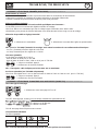 7
7
-
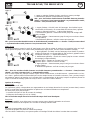 8
8
-
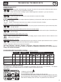 9
9
-
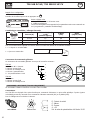 10
10
-
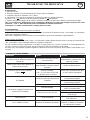 11
11
-
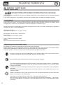 12
12
-
 13
13
-
 14
14
-
 15
15
-
 16
16
-
 17
17
-
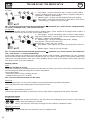 18
18
-
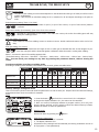 19
19
-
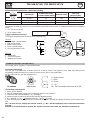 20
20
-
 21
21
-
 22
22
-
 23
23
-
 24
24
-
 25
25
-
 26
26
-
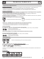 27
27
-
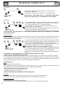 28
28
-
 29
29
-
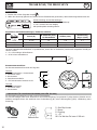 30
30
-
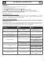 31
31
-
 32
32
-
 33
33
-
 34
34
-
 35
35
-
 36
36
-
 37
37
-
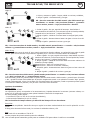 38
38
-
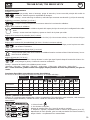 39
39
-
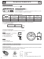 40
40
-
 41
41
-
 42
42
-
 43
43
-
 44
44
-
 45
45
-
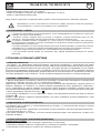 46
46
-
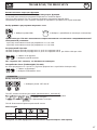 47
47
-
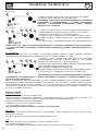 48
48
-
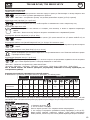 49
49
-
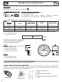 50
50
-
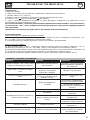 51
51
-
 52
52
-
 53
53
-
 54
54
-
 55
55
-
 56
56
-
 57
57
-
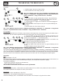 58
58
-
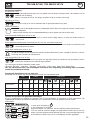 59
59
-
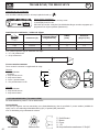 60
60
-
 61
61
-
 62
62
-
 63
63
-
 64
64
-
 65
65
-
 66
66
-
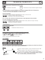 67
67
-
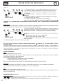 68
68
-
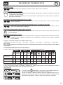 69
69
-
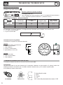 70
70
-
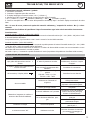 71
71
-
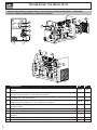 72
72
-
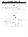 73
73
-
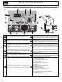 74
74
-
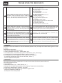 75
75
-
 76
76
-
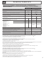 77
77
-
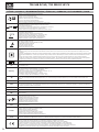 78
78
-
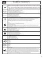 79
79
-
 80
80


in andere talen
- italiano: GYS TIG 168 DC Manuale del proprietario
- français: GYS TIG 168 DC Le manuel du propriétaire
- español: GYS TIG 168 DC El manual del propietario
- Deutsch: GYS TIG 168 DC Bedienungsanleitung
Gerelateerde papieren
-
GYS TITANIUM 400 AC/DC TRI de handleiding
-
GYS PROTIG 200 DC HF de handleiding
-
GYS EXATIG HF GENERATOR - FOR EXAGON/GENIUS 400 de handleiding
-
GYS ORBITIG 200A POWER SOURCE de handleiding
-
GYS TIG 220 DC HF FV (machine only) de handleiding
-
-
-
-
GYS TIG 220 AC/DC de handleiding
-