
Digital Sound Projector
Owner’s Manual
Read the supplied booklet “Quick Reference Guide” before using the unit.
English
EN

En 2
CONTENTS
FEATURES 4
What you can do with this unit . . . . . . . . . . . . . . . . . . . . . . . . . . . . . . . . . . . . 4
Supplied accessories . . . . . . . . . . . . . . . . . . . . . . . . . . . . . . . . . . . . . . . . . . . . . 6
Preparing remote control . . . . . . . . . . . . . . . . . . . . . . . . . . . . . . . . . . . . . . . . . . . . . . . . . . . . . . . . . . . . . . . . . . . . . . . . . . 7
Controls and functions . . . . . . . . . . . . . . . . . . . . . . . . . . . . . . . . . . . . . . . . . . . 8
PREPARATIONS 12
General setup procedure . . . . . . . . . . . . . . . . . . . . . . . . . . . . . . . . . . . . . . . . 12
a Installation . . . . . . . . . . . . . . . . . . . . . . . . . . . . . . . . . . . . . . . . . . . . . . . . . . 13
b Connecting a TV . . . . . . . . . . . . . . . . . . . . . . . . . . . . . . . . . . . . . . . . . . . . . . 24
c Connecting playback devices . . . . . . . . . . . . . . . . . . . . . . . . . . . . . . . . . 25
d Connecting to a network . . . . . . . . . . . . . . . . . . . . . . . . . . . . . . . . . . . . . . 27
Wired network connections . . . . . . . . . . . . . . . . . . . . . . . . . . . . . . . . . . . . . . . . . . . . . . . . . . . . . . . . . . . . . . . . . . . . . . . 27
e Connecting the power cable . . . . . . . . . . . . . . . . . . . . . . . . . . . . . . . . . . 28
Connecting the subwoofer . . . . . . . . . . . . . . . . . . . . . . . . . . . . . . . . . . . . . . . . . . . . . . . . . . . . . . . . . . . . . . . . . . . . . . . . 29
f Initial settings . . . . . . . . . . . . . . . . . . . . . . . . . . . . . . . . . . . . . . . . . . . . . . . 30
Displaying the menu screen on the TV . . . . . . . . . . . . . . . . . . . . . . . . . . . . . . . . . . . . . . . . . . . . . . . . . . . . . . . . . . . . . 30
Selecting a language for menu display . . . . . . . . . . . . . . . . . . . . . . . . . . . . . . . . . . . . . . . . . . . . . . . . . . . . . . . . . . . . . 31
Auto setup for appropriate surround effects (IntelliBeam) . . . . . . . . . . . . . . . . . . . . . . . . . . . . . . . . . . . . . . . . . . 32
Operating the unit by TV’s remote control (HDMI control) . . . . . . . . . . . . . . . . . . . . . . . . . . . . . . . . . . . . . . . . . . 37
PLAYBACK 39
Basic operation for playback . . . . . . . . . . . . . . . . . . . . . . . . . . . . . . . . . . . . 39
Enjoying sound based on your preference . . . . . . . . . . . . . . . . . . . . . . . . 40
Playback with surround sound . . . . . . . . . . . . . . . . . . . . . . . . . . . . . . . . . . . . . . . . . . . . . . . . . . . . . . . . . . . . . . . . . . . . . 40
Enjoying three-dimensional surround sound (CINEMA DSP) . . . . . . . . . . . . . . . . . . . . . . . . . . . . . . . . . . . . . . . . 41
2-channel playback (stereo playback mode) . . . . . . . . . . . . . . . . . . . . . . . . . . . . . . . . . . . . . . . . . . . . . . . . . . . . . . . . 42
Delivering sound to a specified location (target playback mode) . . . . . . . . . . . . . . . . . . . . . . . . . . . . . . . . . . . .42
Playing back digitally compressed formats (such as MP3, etc.) with enriched sound
(Compressed Music Enhancer) . . . . . . . . . . . . . . . . . . . . . . . . . . . . . . . . . . . . . . . . . . . . . . . . . . . . . . . . . . . . . . . . . . . . .43
Clear playback of human voices (CLEAR VOICE) . . . . . . . . . . . . . . . . . . . . . . . . . . . . . . . . . . . . . . . . . . . . . . . . . . . . .43
Adjusting volume for each channel . . . . . . . . . . . . . . . . . . . . . . . . . . . . . . . . . . . . . . . . . . . . . . . . . . . . . . . . . . . . . . . . 43
Adjusting tones . . . . . . . . . . . . . . . . . . . . . . . . . . . . . . . . . . . . . . . . . . . . . . . . . . . . . . . . . . . . . . . . . . . . . . . . . . . . . . . . . . . 44
Using useful features . . . . . . . . . . . . . . . . . . . . . . . . . . . . . . . . . . . . . . . . . . . 45
Saving energy with the Eco function . . . . . . . . . . . . . . . . . . . . . . . . . . . . . . . . . . . . . . . . . . . . . . . . . . . . . . . . . . . . . . .45
Switching information displayed in the front panel display . . . . . . . . . . . . . . . . . . . . . . . . . . . . . . . . . . . . . . . . . 45
Saving this unit’s settings to system memory . . . . . . . . . . . . . . . . . . . . . . . . . . . . . . . . . . . . . . . . . . . . . . . . . . . . . . . 46
Wireless playback of audio via Bluetooth connection . . . . . . . . . . . . . 47
Listening to music from a Bluetooth device (Receiving) . . . . . . . . . . . . . . . . . . . . . . . . . . . . . . . . . . . . . . . . . . . . . 48
Listening to audio through Bluetooth speakers or headphones (transmitting) . . . . . . . . . . . . . . . . . . . . . . . 49

En 3
NETWORKS 50
Network functions and the MusicCast CONTROLLER app . . . . . . . . . . 50
Connecting with the MusicCast CONTROLLER app
(registering the unit as a MusicCast-enabled device) . . . . . . . . . . . . . . . . . . . . . . . . . . . . . . . . . . . . . . . . . . . . . . . 50
Using connection methods other than the MusicCast CONTROLLER app (wireless network) . . . . . . . . . 53
Connecting a mobile device to the unit directly (Wireless Direct) . . . . . . . . . . . . . . . . . . . . . . . . . . . . . . . . . . . 60
Playing back music stored on media servers (PCs/NAS) . . . . . . . . . . . . 62
Media sharing setup . . . . . . . . . . . . . . . . . . . . . . . . . . . . . . . . . . . . . . . . . . . . . . . . . . . . . . . . . . . . . . . . . . . . . . . . . . . . . . 62
Playing music files . . . . . . . . . . . . . . . . . . . . . . . . . . . . . . . . . . . . . . . . . . . . . . . . . . . . . . . . . . . . . . . . . . . . . . . . . . . . . . . . 63
Listening to Internet radio . . . . . . . . . . . . . . . . . . . . . . . . . . . . . . . . . . . . . . . 64
Playback of Internet radio . . . . . . . . . . . . . . . . . . . . . . . . . . . . . . . . . . . . . . . . . . . . . . . . . . . . . . . . . . . . . . . . . . . . . . . . . 64
Registering favorite Internet radio stations . . . . . . . . . . . . . . . . . . . . . . . . . . . . . . . . . . . . . . . . . . . . . . . . . . . . . . . . . 64
Playing back music with AirPlay . . . . . . . . . . . . . . . . . . . . . . . . . . . . . . . . . 66
Playback of iTunes/iPod music contents . . . . . . . . . . . . . . . . . . . . . . . . . . . . . . . . . . . . . . . . . . . . . . . . . . . . . . . . . . . 66
Playing back music stored on mobile devices . . . . . . . . . . . . . . . . . . . . . 68
Using a mobile device to play songs . . . . . . . . . . . . . . . . . . . . . . . . . . . . . . . . . . . . . . . . . . . . . . . . . . . . . . . . . . . . . . . 68
SETTINGS 69
Setup menu . . . . . . . . . . . . . . . . . . . . . . . . . . . . . . . . . . . . . . . . . . . . . . . . . . . . 69
Setting the setup menu . . . . . . . . . . . . . . . . . . . . . . . . . . . . . . . . . . . . . . . . . . . . . . . . . . . . . . . . . . . . . . . . . . . . . . . . . . . 69
Setup menu list . . . . . . . . . . . . . . . . . . . . . . . . . . . . . . . . . . . . . . . . . . . . . . . . . . . . . . . . . . . . . . . . . . . . . . . . . . . . . . . . . . . 70
Beam . . . . . . . . . . . . . . . . . . . . . . . . . . . . . . . . . . . . . . . . . . . . . . . . . . . . . . . . . . . . . . . . . . . . . . . . . . . . . . . . . . . . . . . . . . . . . 72
Sound . . . . . . . . . . . . . . . . . . . . . . . . . . . . . . . . . . . . . . . . . . . . . . . . . . . . . . . . . . . . . . . . . . . . . . . . . . . . . . . . . . . . . . . . . . . . 77
HDMI . . . . . . . . . . . . . . . . . . . . . . . . . . . . . . . . . . . . . . . . . . . . . . . . . . . . . . . . . . . . . . . . . . . . . . . . . . . . . . . . . . . . . . . . . . . . . 80
Bluetooth . . . . . . . . . . . . . . . . . . . . . . . . . . . . . . . . . . . . . . . . . . . . . . . . . . . . . . . . . . . . . . . . . . . . . . . . . . . . . . . . . . . . . . . . . 81
Network . . . . . . . . . . . . . . . . . . . . . . . . . . . . . . . . . . . . . . . . . . . . . . . . . . . . . . . . . . . . . . . . . . . . . . . . . . . . . . . . . . . . . . . . . . 82
Function . . . . . . . . . . . . . . . . . . . . . . . . . . . . . . . . . . . . . . . . . . . . . . . . . . . . . . . . . . . . . . . . . . . . . . . . . . . . . . . . . . . . . . . . . . 85
Information . . . . . . . . . . . . . . . . . . . . . . . . . . . . . . . . . . . . . . . . . . . . . . . . . . . . . . . . . . . . . . . . . . . . . . . . . . . . . . . . . . . . . . . 86
Settings each input source (Option menu) . . . . . . . . . . . . . . . . . . . . . . . . 87
Setting the option menu . . . . . . . . . . . . . . . . . . . . . . . . . . . . . . . . . . . . . . . . . . . . . . . . . . . . . . . . . . . . . . . . . . . . . . . . . . 87
Option menu list . . . . . . . . . . . . . . . . . . . . . . . . . . . . . . . . . . . . . . . . . . . . . . . . . . . . . . . . . . . . . . . . . . . . . . . . . . . . . . . . . . 88
Advanced setup . . . . . . . . . . . . . . . . . . . . . . . . . . . . . . . . . . . . . . . . . . . . . . . . 89
Setting the advanced setup . . . . . . . . . . . . . . . . . . . . . . . . . . . . . . . . . . . . . . . . . . . . . . . . . . . . . . . . . . . . . . . . . . . . . . . 89
Advanced setup list . . . . . . . . . . . . . . . . . . . . . . . . . . . . . . . . . . . . . . . . . . . . . . . . . . . . . . . . . . . . . . . . . . . . . . . . . . . . . . . 90
Updating the unit’s firmware . . . . . . . . . . . . . . . . . . . . . . . . . . . . . . . . . . . . 92
Using “Network Update” in the setup menu to update firmware . . . . . . . . . . . . . . . . . . . . . . . . . . . . . . . . . . . . 92
Updating firmware with connection of a USB flash drive . . . . . . . . . . . . . . . . . . . . . . . . . . . . . . . . . . . . . . . . . . . . 93
APPENDIX 94
Troubleshooting . . . . . . . . . . . . . . . . . . . . . . . . . . . . . . . . . . . . . . . . . . . . . . . . 94
General . . . . . . . . . . . . . . . . . . . . . . . . . . . . . . . . . . . . . . . . . . . . . . . . . . . . . . . . . . . . . . . . . . . . . . . . . . . . . . . . . . . . . . . . . . . 94
Bluetooth . . . . . . . . . . . . . . . . . . . . . . . . . . . . . . . . . . . . . . . . . . . . . . . . . . . . . . . . . . . . . . . . . . . . . . . . . . . . . . . . . . . . . . . . .98
Remote control . . . . . . . . . . . . . . . . . . . . . . . . . . . . . . . . . . . . . . . . . . . . . . . . . . . . . . . . . . . . . . . . . . . . . . . . . . . . . . . . . . .99
Network . . . . . . . . . . . . . . . . . . . . . . . . . . . . . . . . . . . . . . . . . . . . . . . . . . . . . . . . . . . . . . . . . . . . . . . . . . . . . . . . . . . . . . . . .100
Messages in the front panel display . . . . . . . . . . . . . . . . . . . . . . . . . . . . . 102
When surround effect is not enough . . . . . . . . . . . . . . . . . . . . . . . . . . . . 103
Installing and adjusting the sound reflection board YRB-100 . . . . . . . . . . . . . . . . . . . . . . . . . . . . . . . . . . . . . . .103
Pairing the center unit and subwoofer . . . . . . . . . . . . . . . . . . . . . . . . . . 105
Basic knowledge of surround sound . . . . . . . . . . . . . . . . . . . . . . . . . . . . 106
What is Surround Sound? . . . . . . . . . . . . . . . . . . . . . . . . . . . . . . . . . . . . . . . . . . . . . . . . . . . . . . . . . . . . . . . . . . . . . . . . .106
What is a Digital Sound Projector? . . . . . . . . . . . . . . . . . . . . . . . . . . . . . . . . . . . . . . . . . . . . . . . . . . . . . . . . . . . . . . . .106
Yamaha’s audio technologies . . . . . . . . . . . . . . . . . . . . . . . . . . . . . . . . . . . . . . . . . . . . . . . . . . . . . . . . . . . . . . . . . . . . .106
Glossary . . . . . . . . . . . . . . . . . . . . . . . . . . . . . . . . . . . . . . . . . . . . . . . . . . . . . . 107
Audio/video information . . . . . . . . . . . . . . . . . . . . . . . . . . . . . . . . . . . . . . . . . . . . . . . . . . . . . . . . . . . . . . . . . . . . . . . . .107
Network information . . . . . . . . . . . . . . . . . . . . . . . . . . . . . . . . . . . . . . . . . . . . . . . . . . . . . . . . . . . . . . . . . . . . . . . . . . . . .108
Specifications . . . . . . . . . . . . . . . . . . . . . . . . . . . . . . . . . . . . . . . . . . . . . . . . . 109
Index . . . . . . . . . . . . . . . . . . . . . . . . . . . . . . . . . . . . . . . . . . . . . . . . . . . . . . . . . 112

FEATURES ➤ What you can do with this unit En 4
FEATURES
What you can do with this unit
Audio
Audio
Control
Audio
Network contents
Mobile
devices
Control
Audio
Audio
Bluetooth
headphones
Mobile
devices
MusicCast devices
HDMI
Control
BD/DVD player
This unit’s
remote control
Audio/
Video*
Audio Audio/
Video*
HDMI
Control
TV remote control
TV
Center unit (the unit)
Wireless subwoofer
(the unit)
* Supports 4K video and HDCP version 2.2
Sound beams are reflected off walls using unique real surround
sound formats and techniques, allowing listeners to enjoy their
preferred acoustic environment.
• Automatically and quickly adjusts surround
sound effects for the listening room setup
(IntelliBeam)
. p. 32
• Reproducing stereo or multichannel sounds with
the sound fields like actual movie theaters and
concert halls (CINEMA DSP)
. p. 41
• Enjoying compressed music with enhanced
sound (Compressed Music Enhancer)
. p. 43
• Delivering sound to a specified location (Target
playback mode)
. p. 42
Sequential operation of a TV, this unit, and
BD/DVD player (HDMI Control)
. p. 37
Listen to audio input to the
unit with Bluetooth
headphones or speakers
. p. 49
Plays back audio content
from Bluetooth
®
devices
. p. 48
Share music
via your home
network
. p. 5
Dedicated apps
for mobile
devices
. p. 5
Wide variety of supported content
• Media server (PC/NAS)
. p. 62
• Internet radio
. p. 64
•AirPlay
. p. 66
• Music stored on mobile
devices
. p. 68

FEATURES ➤ What you can do with this unit En 5
Unrestricted playback of music over a network
using MusicCast CONTROLLER
The free dedicated app for mobile devices, MusicCast CONTROLLER, allows you to
listen to music stored on mobile devices such smartphones, or on servers, or to listen to
Internet radio stations and many kinds of major streaming services.
This app also allows you to distribute content to other MusicCast-enabled devices for
synchronized playback.
The MusicCast CONTROLLER app can also be used to perform such tasks as
selecting the input source and adjusting volume.
See the “MusicCast Setup Guide”, or visit the Yamaha website for details.
Search for “MusicCast CONTROLLER” on the App Store or Google Play.
Bluetooth
functions
You can receive and play audio from a Bluetooth device, such as a mobile device over
a wireless connection. You can also transmit audio input to the unit to a Bluetooth
headphones.
• In this manual, iOS and Android mobile devices are collectively referred to as “mobile devices”. The specific
type of mobile device is noted in explanations as needed.
About this manual
• In this manual, operations that can be performed using either the front panel keys or the remote control
are explained using the remote control.
• indicates supplementary explanations for better use.
• indicates precautions for use of the unit and its feature limitations.

FEATURES ➤ Supplied accessories En 6
Before using the unit, make sure you have received all of the following items.
The YSP-2700
Supplied accessories
* The China model comes with a coaxial digital audio cable rather than an optical digital audio cable.
• The supplied optical digital audio cable may not be needed depending upon connections.
Supplied accessories for SPM-K20
Supplied accessories
Center unit (YSP-CU2700) Wireless subwoofer (NS-WSW121)
Remote control Batteries (AAA, R03, UM-4) (x2) Optical digital audio cable* (1.5 m (4.9 ft))
IntelliBeam microphone (6 m (19.7 ft)) Cardboard microphone stand Stands (x2)
• Owner’s Manual CD-ROM • Quick Reference Guide • MusicCast Setup Guide
Spacers (x2) Pads (x3) Screws (M4, 22 mm) (x2) Mounting template

FEATURES ➤ Supplied accessories En 7
Preparing remote control
Before installing batteries or using the remote control, be sure to read battery and remote control precautions in “Quick Reference Guide” (separate booklet).
Installing the batteries
Battery × 2 (supplied)
(AAA, R03, UM-4)
Press down on the arrow
and slide the cover in the
direction in which it
points.
Slide the cover back to close it.
Operation range
Within 6 m (20 ft)

FEATURES ➤ Controls and functions En 8
1 Front panel display
Displays the unit’s settings, such as the name of an audio
input source or surround mode (p. 45). The setting values
are also displayed.
2 z indicator
Lights to show the system condition.
Glows green: Power on
Glows red: Power off (when the HDMI control or network
standby is activated)
Turns off: Power off
3 (Wi-Fi) indicator
Shows the status of wireless network connection (p. 27).
4 (Bluetooth) indicator
Shows the status of Bluetooth connection (p. 47, 49).
5 Remote control sensor
Receives infrared signals from the remote control (p. 10).
6 CONNECT key
Use to connect the unit to a network using the MusicCast
CONTROLLER app (p. 50).
7 INPUT key
Select an audio input source.
8 MUTE key
Mute the sound (p. 39).
9 VOLUME (+/-) keys
Adjust the volume of the unit (p. 39).
0 z key
Turn on/off the unit.
• When the unit is turned off, this unit consumes a small amount of
power in order to search for HDMI signals or to receive signals from
a network device.
• The front panel display turns on for about 3 seconds only when the
unit is operated.
• “Dimmer” can adjust the brightness of the front panel display and
indicators in the setup menu (p. 85).
Controls and functions
Center unit (front, top)
CONNECT INPUT MUTE VOL
-
VOL
+ z
51234
678 9 0

FEATURES ➤ Controls and functions En 9
1 INTELLIBEAM MIC jack
For connecting the supplied IntelliBeam microphone (p. 33).
2 SYSTEM CONNECTOR jack
For connecting to the supplied subwoofer using a wired
connection (p. 29).
3 SUBWOOFER OUT jack
For connecting to the supplied subwoofer using a wired
connection (p. 29).
4 AUX1 input jacks
For connecting to a playback device equipped with the
analog audio output jacks (p. 26).
5 AUX2 input jack
For connecting to a playback device equipped with a coaxial
digital audio output jack (p. 25).
6 TV input jack
For connecting to a TV equipped with an optical digital audio
output jack (p. 24).
7 NETWORK jack
For connecting to a network with a network cable (p. 27).
8 HDMI OUT (ARC) jack
For connecting to an HDMI-compatible TV and outputting
video/audio signals (p. 24).
9 HDMI IN 1–3 jacks
For connecting an HDMI-compatible playback device such
as a BD/DVD player, a satellite and cable TV tuner, and a
game console (p. 25).
0 UPDATE ONLY jack
Use to update this unit’s firmware (p. 92).
A Antenna
Raise the antenna after the unit is installed (p. 23).
B Power cable
For connecting to an AC wall outlet (p. 28).
Center unit (rear)
SYSTEM
CONNECTOR
INTELLIBEAM
MIC
R AUX1 L
AUX2
TV
NETWORK
OUT (ARC)
UPDATE ONLY
SUBWOOFER
OUT
IN 1
HDMI
IN 2 IN 3
SYSTEM
CONNECTOR
INTELLIBEAM
MIC
R AUX1 L
AUX2
TV
NETWORK
OUT (ARC)
UPDATE ONLY
SUBWOOFER
OUT
IN 1
HDMI
IN 2 IN 3
12 435678 09
AB

FEATURES ➤ Controls and functions En 10
1 ECO key
Turn the Eco function on or off (p. 45).
2 Input selector keys
Select an audio input source to be played back (p. 39).
•NET key: Select an audio input via a network (p. 50).
Each time the key is pressed, the input source is selected
as follows:
SERVER NET RADIO AirPlay Streaming music
service (if available) MusicCast Link SERVER …
• HDMI 1–3 keys: For devices connected to the HDMI 1–
3 jacks (p. 39)
TV key: For a device connected to the TV input jack
(p. 39)
AUX 1 and 2 keys: For devices connected to the AUX 1
and 2 input jacks (p. 39)
• key: For a Bluetooth device (p. 48)
3 SYSTEM MEMORY keys
Save IntelliBeam measurements, speaker volume, and other
settings (p. 46).
4 SUB (+/-) key
Adjust the volume of the subwoofer (p. 39).
5 SETUP ( ) key
Display the setup menu (p. 69).
6 S/T/W/X keys, ENTER key
Change the setting (p. 69).
7 RETURN ( ) key
Return to the previous menu screen.
8 CINEMA DSP program keys
When playback is in surround playback mode, select the
CINEMA DSP programs (p. 41).
9 SURROUND key
Switch to surround playback mode (p. 41).
0 STEREO key
Switch to stereo playback mode (p. 42).
A TAR G E T key
Switch to target playback mode (p. 42).
B z key
Turn on/off the unit (p. 39).
C NET RADIO (1–3) keys
Register and play streaming services such as Internet radio
stations via the unit (p. 64).
D ENHANCER key
Turn Compressed Music Enhancer to on or off (p. 43).
E CLEAR VOICE key
Turn the CLEAR VOICE function on or off (p. 43).
F CH LEVEL key
Adjust the volume balance during playback (p. 43).
G VOL (+/-) key
Adjust the volume of the unit (p. 39).
H MUTE ( ) key
Mute the sound (p. 39).
I OPTION ( ) key
Display the option menu for each input source (p. 87).
J INFO ( ) key
Switch the information display on the front panel (p. 45).
Remote control
1
d
e
f
g
h
i
j
2
3
4
5
6
7
8
9
a
0
c
b
Infrared signal transmitter

FEATURES ➤ Controls and functions En 11
1 Power cable
For connecting to an AC wall outlet (p. 28).
2 SUBWOOFER PAIRING button
Used to pair the center unit with the subwoofer manually (p. 105). Use a pin or other pointed
object to press this key.
3 STATUS indicator
Shows subwoofer’s connection status (p. 29).
Glows green: Power on
Glows red: Power off
4 SYSTEM CONNECTOR jack
For connecting to the center unit using a wired connection (p. 29).
5 INPUT jack
For connecting to the center unit using a wired connection (p. 29).
Subwoofer (rear)
SYSTEM
CONNECTOR
SUBWOOFER
PAIR ING
INPUTSTATUS
SYSTEM
CONNECTOR
SUBWOOFER
PAIRING
INPUTSTATUS
23 45
1

PREPARATIONS ➤ General setup procedure En 12
PREPARATIONS
This completes all the preparations. Enjoy playing movies, music and other content with the unit!
• See “NETWORKS” (p. 50) for information regarding network connection and audio playback via a network.
General setup procedure
1 Installation (p. 13)
Position the unit to achieve the optimal surround sound effects.
2 Connecting a TV (p. 24)
Connect a TV to the unit.
3 Connecting playback devices (p. 25)
Connect video devices (such as BD/DVD players) to the unit.
4 Connecting to a network (p. 27)
Use a network cable to connect the unit to a router in preparation for wired network connection.
Information regarding connection to a wireless network is also provided.
5 Connecting the power cable (p. 28)
After all the connections are complete, plug in the power cable.
6 Initial settings (p. 30)
Perform initial setup, such as adjusting surround sound effects, before attempting playback.

PREPARATIONS ➤ a Installation En 13
This unit reflects sound beams off of walls to create the surround sound effect. The position of this unit in relation to the listening position and walls is important to achieving the
desired surround sound effects. Refer to pages 13 to 17 when installing the unit. When installing this unit on a rack behind which there is limited space, for example, it may be easier
to connect external devices to this unit first. This will depend upon the installation location. See pages 24 to 27 for information regarding the connection of external devices.
❑ Connecting the center unit and subwoofer via a wireless connection
The center unit and subwoofer communicate wirelessly. Subwoofer performance may be affected if the subwoofer is placed on a metal rack, or if there is a metal plate between the
subwoofer and the center unit. Use a wired connection to connect the subwoofer to the center unit if sounds are interrupted due to the installation condition (p. 29).
a Installation
Caution
• Be sure to install the center unit on a large, stable stand where it does not fall subject to vibrations, such as from an earthquake, and where it is out of the reach of children.
Notes
• The subwoofer speaker is not magnetically shielded. Do not install hard disk drives or similar devices near the subwoofer.
• Do not stack the center unit and subwoofer directly on top of other playback devices, or vice versa. Heat and vibrations may result in damage or malfunction.
Recommended place for installation
Center unit
* If the center unit will be installed on a TV stand, attach
the center unit stands to increase its height. Position the
center unit so that it does not obstruct the TV’s remote
control sensor or signal transmitter for 3D glasses.
Subwoofer
• Install the unit in the center of the left and right walls.
• If the antenna is raised (p. 23), position the center unit so that
the antenna does not obstruct the TV screen.
• Attach the stands if the center unit does not sit high enough
(p. 18)*.
• The center unit can be mounted on a wall using the optional
Wall Mount Bracket SPM-K20 (p. 19).
• The listening position (such as sofa, etc.) should be
located at the front of the unit.
• The distance between the listening position and the
unit should be more than 1.8 m (6 ft).
• To achieve desired surround sound effects, be
sure that obstacles such as furniture may not
obstruct the path of sound beams (p. 14).
• To prevent sound reflecting off of walls, angle
the subwoofer slightly toward the center of the
room.
• When installing the subwoofer on a rack, be
sure the rack is strong enough to support the
subwoofer and that it leaves sufficient space
for heat discharge.
1 2 3 4 5 6

PREPARATIONS ➤ a Installation En 14
This unit outputs sound beam as shown in the illustrations below. Install this unit where
there are no obstacles such as furniture obstructing the path of sound beams.
Otherwise, the desired surround sound effects may not be achieved.
If the unit is installed so that it is parallel to a wall, install it as close to the exact center of
the wall as possible.
If the unit is installed in a corner of a room, position it at a 40–50° angle to the adjacent
walls.
Parallel installation
Install this unit as close to the exact center of the wall as possible.
• If the unit cannot be installed evenly between the left and right walls, sound beams can be adjusted to
achieve natural surround sound effects (p. 17).
Ideal installation condition
Install this unit as close to the exact front of your normal listening position as possible.
The distance between listening position and the unit should be more than 1.8 m (6 ft).
Example of installing the unit
Objects, such as furniture
Parallel installation
40° to 50°
Objects, such as
furniture
Corner installation
Sound beam output varies depending upon the surround setting (p. 40) and the channel
output setting (p. 75). The illustration above shows the path of sound beams when
surround playback is enabled and “Front” in the Channel Out setting is set to “Beam”.
The illustrations above show the path of sound beams when surround playback is
enabled (p. 40) and “Front” in the Channel Out setting is set to “Stereo” (p. 75).
More
than
1.8 m
(6 ft)
More than 1.8 m
(6 ft)
1 2 3 4 5 6

PREPARATIONS ➤ a Installation En 15
Installing in a non-square room
Install this unit so that the sound beams can be reflected off the walls.
• If this unit cannot be repositioned, or the listening position cannot be changed, the optional YRB-100 sound
reflection board may be installed for a better surround sound experience (p. 103).
Irregularly shaped rooms with solid walls on all sides
Irregularly shaped rooms that are open to a hallway on one side
1 2 3 4 5 6

PREPARATIONS ➤ a Installation En 16
Example of installing the unit in a living room
• The legs on a table are not considered obstacles as sound beams normally pass
through them. A cupboard installed facing the wall reflects sounds.
• As the heavy curtains absorb sounds, the sound features of the listening room is
different from the case with the curtain opened and the case with the curtain closed.
Using saving settings function enables to save the best settings for each case of
listening room (p. 46).
This unit creates surround sound by reflecting projected sound beams off the walls of
your listening room. The surround sound effects produced by this unit may not be
sufficient when this unit is installed in the following locations.
• Rooms with walls inadequate for reflecting sound beams
• Rooms with acoustically absorbent walls
• Rooms with measurements outside the following range:
W (3 to 7 m (10 to 23 ft)) × H (2 to 3.5 m (7 to 11.5 ft)) × D (3 to 7 m (10 to 23 ft))
• Rooms where objects such as furniture are likely to obstruct the path of sound beams
• Rooms with less than 1.8 m (6 ft) from the listening position to this unit
• Rooms where the listening position is close to the walls
• Rooms where the listening position is not in front of this unit
The My Surround function creates rich surround sound effects in rooms with less than
optimal surround sound conditions. See “Channel Out” (p. 75) for more information.
Objects, such as
furniture
Unrecommended listening environments
Enjoying surround effects regardless of conditions (My
Surround)
1 2 3 4 5 6

PREPARATIONS ➤ a Installation En 17
This unit’s AUTO SETUP (p. 32) can be used to automatically adjust sound beams to achieve the optimal surround playback environment according to the listening room setup. In
addition to using AUTO SETUP, sound beams can be adjusted manually to achieve surround sound effects best suited to the listening room setup when the unit is installed as
described below.
Installing the unit near a corner of the room
When installing the unit near a corner of the room as shown in the illustration below,
front channel sound may seem to come from an unnatural direction if beam settings are
configured using AUTO SETUP.
Should this occur, adjust the left and right front channels using “Image Location” (p. 74)
in the setup menu to achieve more natural sound.
Installing the unit in an irregularly shaped room
When the unit is installed in a room that is not rectangular, sound beams may not be
properly reflected off the walls as shown in the illustration below.
Should this occur, perform AUTO SETUP, and then adjust the angle of beam from the
channel from which sound is not properly heard using “Horizontal Angle” (p. 72) in the
setup menu to achieve even distribution of sound.
Adjusting sound beams to achieve optimal surround sound effects
Left front channel adjusted
When left front channel sound is
unnatural
1 2 3 4 5 6

PREPARATIONS ➤ a Installation En 18
If the center unit does not sit high enough, attach the stands supplied with the unit to
the center unit to increase the height at which it sits.
1
Remove the seal from the stand.
2
Align the protrusions on the stand with, and insert them into, the
holes on the rear panel.
Install the left and right stands.
❑ Removing the stands
Pull the stands straight out.
Installing the stands
Seal
Protrusion
Hole
Press firmly.
1 2 3 4 5 6

PREPARATIONS ➤ a Installation En 19
If your TV is mounted on a wall, the optional Wall Mount Bracket SPM-K20 can be used
to mount this unit on the wall under the TV.
See “Dimensions” (p. 22) for this unit and SPM-K20 dimensions.
• Be sure to read “SAFETY INSTRUCTIONS” in the Installation Manual supplied with the SPM-K20 before
mounting it.
• The template and screws supplied with the SPM-K20 are not used with this unit.
• SPM-K20 may not be available in some countries or regions.
• Space between this unit and the wall is limited. Therefore, use of a flexible HDMI cable, or right-angle
connector, (neither supplied) is strongly recommended.
❑ Mounting the SPM-K20
Be sure that there is enough space on the wall to mount the wall mount bracket and this
unit. Follow the instructions below to mount both.
1
Attach the three supplied pads to the wall mount bracket as shown in
the illustration.
Mounting the center unit on a wall
YSP-CU2700
SPM-K20
20.2 mm
37.4 mm
Flexible HDMI cable or
right-angle connector
Follow instructions provided from this page through page 22.
1 2 3 4 5 6

PREPARATIONS ➤ a Installation En 20
2
Attach the template supplied with this unit to the wall and use a thumbtack or pin to mark the position where screws will be inserted in the wall.
3
Mount the wall mount bracket on the wall.
Template
Attach the template to the wall so that the center of
the template is aligned with the center of the TV.
The wall mount bracket is designed to be offset
slightly to the right of the center of this unit.
Once screw position has been
marked, remove the template.
Screw self-tapping screws (not supplied) partway
into the wall where marked using the template.
Mount the wall mount bracket on these
screws, and then tighten the screws.
Screw self-tapping screws, at least six including the
two previously used, into as many holes around the
outer edges of the wall mount bracket as possible to
ensure sufficient strength.
1 2 3 4 5 6

PREPARATIONS ➤ a Installation En 21
• Be sure that screws are inserted in a sturdy portion of the wall or pillar. Do not mount the bracket on a wall
made of materials such as mortar or veneer, which may chip or peel. If screws fall out, the wall mount
bracket will also fall, resulting in damage or injury.
4
Attach the spacer supplied with this unit to the bottom of this unit
using the screws also supplied with this unit.
Do not tighten the screws until this unit has been mounted on the wall mount
bracket.
5
Connect commercial cables to this unit.
6
Mount this unit on the wall.
Insert the screws on this unit into the mounting holes on the left and right sides
of the wall mount bracket, and then slide this unit to the left.
• When mounting or removing it, hold this unit firmly with both hands. If this unit falls, damage or injury
could occur.
25 mm or more
Beam, etc.
25 mm or more
Beam, etc.
Drywall
Screw
Spacer
Flexible HDMI cable or
right-angle connector
1 2 3 4 5 6

PREPARATIONS ➤ a Installation En 22
7
Tighten screws.
Tighten the screws used to attach the spacer to this unit in step 4.
❑ Dimensions
163.2
125
37.4
20.2
YSP-CU2700
SPM-K20
(mm)
457
70.2
500
298.5
277
944
YSP-CU2700 SPM-K20
(1.4 kg)
5
13.5
188.5
167
33.5
54
50
125
27.5
20.2
143
163.2
78.7
(mm)
(mm)
1 2 3 4 5 6

PREPARATIONS ➤ a Installation En 23
Raise the antenna on the rear panel of the unit when connecting a wireless router
(access point) to use a network.
• Do not apply excessive force on the antenna. Doing so may damage it.
• Be sure to check the direction in which the antenna moves, and angle it in the proper direction.
• Do not remove the antenna.
• For details on the wireless connection, refer to p. 27.
Raising the antenna
Hold the base of the
antenna while raising it
to its upright position.
1 2 3 4 5 6

PREPARATIONS ➤ b Connecting a TV En 24
Connect a TV to the unit so that video input to the unit can be output to the TV. You can also enjoy playback of TV audio on the unit.
• Use a 19-pin HDMI cable with the HDMI logo printed on it. A cable with a maximum length of 5 m (16 ft) is recommended to prevent degradation of signal quality.
• For playback of 3D and 4K video content, use a high-speed HDMI cable.
• This unit supports HDCP version 2.2, a copy protection technology. For playback of 4K video, connect the unit to the HDMI input jack (one compatible with HDCP 2.2) on an HDCP 2.2-compliant TV.
• To play 4K (4:4:4) video content, set “4K MODE” in advanced setup to “MODE 1” (p. 90).
Connect the TV to the unit with an HDMI cable (not supplied).
When connecting a TV that supports Audio Return Channel (ARC), enable the HDMI
control function (p. 80).
• Use an ARC-compatible HDMI cable.
Connect the TV to the unit with an HDMI cable (not supplied) and an optical digital
audio cable.
• If the TV has no optical jack
Connect the audio output jack on the TV to the AUX1 (analog) input jacks or AUX2 (coaxial digital) input
jack on the unit, and set “TV Input” in the setup menu to “Analog [AUX 1]” or “Coaxial [AUX 2]” accordingly
(p. 80). TV audio can be played through the unit by pressing the TV key on the remote control.
b Connecting a TV
TVs that support Audio Return Channel (ARC)
What is Audio Return Channel (ARC)?
In order for the unit to play audio from a TV, the TV must usually be connected to the unit via an audio
cable as well as an HDMI cable. If, however, the TV supports Audio Return Channel (ARC), TV audio
signals can be input to the unit via the HDMI cable that outputs video signals from the unit to the TV.
SYSTEM
CONNECTOR
INTELLIBEAM
MIC
R AUX1 L
AUX2
TV
NETWORK
OUT (ARC)
UPDATE ONLY
SUBWOOFER
OUT
IN 1
HDMI
IN 2 IN 3
HDMI
(ARC)
OUT (ARC)
HDMI HDMI
The unit (rear)
HDMI OUT (ARC) jack
ARC-compatible HDMI input
TV
TVs that do not support Audio Return Channel (ARC)
SYSTEM
CONNECTOR
INTELLIBEAM
MIC
R AUX1 L
AUX2
TV
NETWORK
OUT (ARC)
UPDATE ONLY
SUBWOOFER
OUT
IN 1
HDMI
IN 2 IN 3
HDMI
OUT (ARC)
OPTICAL
TV
HDMI HDMI
OO
The unit (rear)
HDMI OUT (ARC) jack HDMI input
TV input jack
Audio output
(optical digital)
TV
1. Remove the cap 2. Check the direction of
the plug
1 2 3 4 5 6

PREPARATIONS ➤ c Connecting playback devices En 25
Connect video devices such as BD/DVD players, set-top boxes (STBs) and game consoles to the unit. Depending on the video/audio output jacks available on your video device,
choose one of the following connections. We recommend using an HDMI connection if the video device has an HDMI output jack.
Connect a video device to the unit with an HDMI cable (not supplied).
• This unit supports HDCP version 2.2, a copy protection technology.
The audio/video played on the video device will be output though the unit by switching
input to HDMI 1–3 using the HDMI 1–3 key on the remote control.
• Once the HDMI control function has been activated (p. 37), video and audio content from playback devices
can be output from the TV even when this unit is off (HDMI signal pass-through).
• Use a 19-pin HDMI cable with the HDMI logo printed on it. A cable with a maximum length of 5 m (16 ft) is
recommended to prevent degradation of signal quality.
• For playback of 3D and 4K video content, use a high-speed HDMI cable.
• When audio from the video device cannot be output via the HDMI jack, use an optical digital audio cable to
connect the video device to the unit via the optical digital output jack on the video device and the TV jack on
the unit. If the video device is connected to the unit in this way, change “Audio Assign” to “Optical” in option
menu (p. 88).
Connect a video device to this unit via a coaxial digital cable. Next, connect the video
device’s video output to the TV’s video input.
The audio played on the video device will be output though the unit by switching input
to AUX2 using the AUX 2 key on the remote control.
c Connecting playback devices
HDMI connection
SYSTEM
CONNECTOR
INTELLIBEAM
MIC
R AUX1 L
AUX2
TV
NETWORK
OUT (ARC)
UPDATE ONLY
SUBWOOFER
OUT
IN 1
HDMI
IN 2 IN 3
HDMI
IN 1 IN 2
HDMI
IN 3
HDMI
HDMI
The unit (rear)
HDMI IN 1–3 jacks
HDMI output
Video device
Coaxial connection
SYSTEM
CONNECTOR
INTELLIBEAM
MIC
R AUX1 L
AUX2
TV
NETWORK
OUT (ARC)
UPDATE ONLY
SUBWOOFER
OUT
IN 1
HDMI
IN 2 IN 3
COAXIAL
AUX2
CC
The unit (rear)
AUX2 (coaxial
digital) input jack
Audio output
(coaxial digital)
Video device
TV
To video
output jack
To video
input jack
1 2 3 4 5 6

PREPARATIONS ➤ c Connecting playback devices En 26
Connect a video device to this unit via a stereo cable (not supplied). Next, connect the
video device’s video output to the TV’s video input.
The audio played on the video device will be output though the unit by switching input
to AUX1 using the AUX 1 key on the remote control.
Analog connection
SYSTEM
CONNECTOR
INTELLIBEAM
MIC
R AUX1 L
AUX2
TV
NETWORK
OUT (ARC)
UPDATE ONLY
SUBWOOFER
OUT
IN 1
HDMI
IN 2 IN 3
AUDIO
R
L
R AUX1 L
L
R
L
R
The unit (rear)
AUX1 (analog)
input jacks
Audio output
(analog)
Video device
TV
To video
output jack
To video
input jack
1 2 3 4 5 6

PREPARATIONS ➤ d Connecting to a network En 27
Wired network connections
To use a wired network connection, connect the unit to a router via an STP network
cable (category 5 or higher straight cable; not supplied).
• If the unit is already connected to a wireless network and you would like to switch to a wired connection,
change “Network” in the setup menu to “Wired”.
d Connecting to a network
SYSTEM
CONNECTOR
INTELLIBEAM
MIC
R AUX1 L
AUX2
TV
NETWORK
OUT (ARC)
UPDATE ONLY
SUBWOOFER
OUT
IN 1
HDMI
IN 2 IN 3
NETWORK
LAN
WAN
The unit (rear)
Internet
Network Attached Storage
(NAS)
PC
Modem
Mobile device
Router
Network cable
Wireless network
To connect to a network, be sure that the unit is plugged into an AC wall outlet, and
then connect the unit to a wireless router (access point).
Refer to the following for instructions on connecting to a wireless router (access
point).
• Using the MusicCast CONTROLLER app (p. 50)
• Using connection methods other than the MusicCast CONTROLLER app (p. 53 to
59)
The indicator on the front panel glows when the unit is
connected to a wireless network.
• You cannot use the wireless network connection simultaneously with the
wired network connection or Wireless Direct (p. 60).
• If the unit and the wireless router (access point) are too far apart, the unit may not connect to a wireless
router (access point). In such case, place them close to each other.
• If the unit will not be connected to a wireless router (access point), Wireless Direct (p. 60) can be used
to connect the unit directly to a mobile device to control the unit using the MusicCast CONTROLLER
app installed on that mobile device.
The unit
Internet
Modem
Mobile device
Wireless router
(access point)
Glows (green)
1 2 3 4 5 6

PREPARATIONS ➤ e Connecting the power cable En 28
After all the connections are complete, plug in the power cable of the center unit and
the subwoofer.
e Connecting the power cable
SYSTEM
CONNECTOR
SUBWOOFER
PAIRING
INPUTSTATUS
Center unit
To an AC wall outlet
To an AC wall outlet
Subwoofer
1 2 3 4 5 6

PREPARATIONS ➤ e Connecting the power cable En 29
Connecting the subwoofer
Plug the subwoofer’s power cable into a wall outlet. When the center unit is turned on,
the center unit and subwoofer are automatically connected via wireless connection.
Once the connection has been successfully established, the STATUS indicator on the
subwoofer glows as shown in the illustration below, and the unit is ready for play back.
• If the STATUS indicator does not glow properly the first time the unit is turned on, pair the center unit and
subwoofer manually. See “Pairing the center unit and subwoofer” (p. 105).
STATUS
STATUS indicator
Glows green
If there is no sound coming from the subwoofer, or if sound is intermittent, due to the influence of
radio waves from other devices, connecting the center unit and subwoofer via cables will solve
the problem. Connect the center unit and subwoofer via an RCA mono cable and a 3.5 mm
monaural mini plug cable. A 3.5 mm monaural mini plug cable is required to turn the center unit
and subwoofer on and off at the same time.
To connect the center unit and subwoofer using a wired connection, set “Bass Out” of
“Subwoofer” in the setup menu to “Wired” (p. 76).
When the center unit is turned on, the subwoofer turns on and its STATUS indicator glows green.
• Be sure the center unit is turned off before connecting the subwoofer.
• The subwoofer supplied with the unit can only be connected.
SYSTEM
CONNECTOR
INTELLIBEAM
MIC
R AUX1 L
AUX2
TV
NETWORK
OUT (ARC)
UPDATE ONLY
SUBWOOFER
OUT
IN 1
HDMI
IN 2 IN 3
SYSTEM
CONNECTOR
SUBWOOFER
PAIRING
INPUTSTATUS
SYSTEM
CONNECTOR
SUBWOOFER
OUT
INPUT
SYSTEM
CONNECTOR
RCA mono cable
3.5 mm monaural mini plug cable
1 2 3 4 5 6

PREPARATIONS ➤ f Initial settings En 30
Displaying the menu screen on the TV
Visual operation of this unit is
possible by displaying its menu
screen on the TV.
Turn on the unit and the TV, and
then use the input button on the
TV’s remote control to switch input
so that video input from this unit is
displayed.
When this unit and the TV are
connected as shown below,
select “HDMI 1” using the TV’s
remote control.
The menu display
The menu is displayed on the TV screen when the SETUP ( ) key
or OPTION ( ) key is pressed. When the TV is receiving HDMI
signals, the menu is superimposed over video content. Press the
SETUP ( ) key or OPTION ( ) key a second time to cancel menu
display.
• The setup menu (p. 69) can only be displayed on a TV screen. It cannot be shown
in the front panel display.
f Initial settings
TV remote control (example)
Switch
input
sources
SYSTEM
CONNECTOR
INTELLIBEAM
MIC
R AUX1 L
AUX2
TV
NETWORK
OUT (ARC)
SUBWOOFER
OUT
IN 1
HDMI
IN 2
OUT (ARC)
HDMI INPUT
123
HDMI
HDMI
TV
The unit (rear)
1 2 3 4 5 6
SETUP ( )
OPTION ( )
z

PREPARATIONS ➤ f Initial settings En 31
Selecting a language for menu display
1
Turn the unit and TV on.
2
Switch the TV’s input to display video input from this unit (p. 30).
3
Press and hold the SETUP ( ) key until the “OSD Language” menu
appears on the TV.
When the menu is not displayed
• Confirm the following cases.
– The HDMI input jack of your TV and the HDMI OUT (ARC) jack of the unit are connected.
– The input of your TV is set to “HDMI 1” (example).
4
Use the S/T key to select the desired language and press the
ENTER key.
Settings
, ENGLISH (default), DEUTSCH, FRANÇAIS, ESPAÑOL, ITALIANO, NEDERLANDS,
РУССКИЙ, SVENSKA, TÜRK
5
Press the SETUP ( ) key to exit the setup menu.
Initial screen display
When the unit is turned on for the first time after purchase, the screen below will be
displayed. (“ViewScreen” is shown in the front panel display.)
Follow the on-screen instructions to use an iOS device (iPhone, etc.) to connect the
unit to a wireless network.
Connecting the unit to a wireless network is simpler when the MusicCast
CONTROLLER app installed on your mobile device is used. Press the RETURN ( )
key to cancel this screen, and then refer to p. 50.
• This screen will not be displayed if the unit is connected to a router via its NETWORK jack (wired
connection).
• Be aware that if the IntelliBeam microphone is connected while the screen shown above is displayed
(p. 32), setup will be canceled, and the screen will switch to the auto measurement screen.
1 2 3 4 5 6

PREPARATIONS ➤ f Initial settings En 32
Auto setup for appropriate surround effects (IntelliBeam)
First use the “IntelliBeam” function to adjust each channel so that this unit provides the
optimal viewing and listening environment.
• The AUTO SETUP procedure may not be run successfully if this unit is installed in one of the rooms
described in “Unrecommended listening environments” (p. 16). The My Surround function can be used to
enjoy rich surround sound in these types of rooms as well. See “Channel Out” (p. 75) for more information.
• Do not connect the IntelliBeam microphone to an extension cable as doing so may result in an inaccurate
sound optimization.
1
Assemble the supplied cardboard microphone stand, and then
position the IntelliBeam microphone.
2
Position the supplied cardboard microphone stand and IntelliBeam
microphone at your listening position.
• Position the IntelliBeam microphone at the same height as your ears would be when you are seated.
• Position the IntelliBeam microphone so that it is parallel with the floor.
• A camera tripod or stool may also be used instead of the supplied cardboard microphone stand.
Make sure that there are no obstacles between the IntelliBeam microphone and the
walls in your listening room as these objects obstruct the path of sound beams.
However, any objects that are in contact with the walls will be regarded as a protruding
part of the walls.
Installing the IntelliBeam microphone
12
3
5
4
Remove
Fit in
Run through
Place horizontally
Fit in
IntelliBeam microphone
Upper limit
Within 1 m (3.3 ft)
Center height of
this unit
Cardboard
microphone stand
Within 1 m (3.3 ft)
Listening position
Lower limit
1.8 m (6 ft) or more
Center line
IntelliBeam microphone
Cardboard microphone stand
1 2 3 4 5 6

PREPARATIONS ➤ f Initial settings En 33
• Test tones output during measurement are loud. Perform AUTO SETUP when no children are around and
there is no possibility of their entering the listening room, as their hearing may be impaired.
• If there are curtains in your listening room, we recommend following the procedure below.
1. Open the curtains to improve sound reflection.
2. Run “Beam optimize only” (p. 35).
3. Close the curtains.
4. Run “Sound optimize only” (p. 35).
• Make sure that your listening room is as quiet as possible. For accurate measurement, turn off air
conditioner or other devices that make noises.
1
Turn the unit and your TV on.
2
Switch TV input to the input jack (HDMI 1, etc.) to which this unit is
connected (p. 30).
3
Connect the IntelliBeam microphone to the INTELLIBEAM MIC jack
on the rear panel of the unit.
The screen below is displayed after connecting IntelliBeam microphone to the
unit.
“AUTO SETUP” in the “IntelliBeam” menu can automatically adjust the
following two settings.
“Beam optimize only” or “Sound optimize only” can be measured separately in
the setup menu (p. 35).
• Follow the instructions below and then leave the room. If you remain in the room, you may obstruct
the beam, or the microphone may pickup any sounds you make, possibly resulting in improper
measurement.
Using AUTO SETUP (IntelliBeam)
INTELLIBEAM
MIC
IntelliBeam microphone
Cardboard microphone stand
Beam optimize
only
This feature optimizes the beam angle so that the parameter best
matches your listening environment.
Sound optimize
only
This feature optimizes sound quality for each channel by measuring
the acoustic characteristics of the listening environment.
1 2 3 4 5 6

PREPARATIONS ➤ f Initial settings En 34
4
Press the ENTER key to start the AUTO SETUP
procedure and then leave the room within 10
seconds.
If the AUTO SETUP procedure is complete, this unit rings
the chimes.
• The AUTO SETUP procedure takes about 3 minutes.
• To cancel the AUTO SETUP procedure after it is started, or if you do not
want to apply the results, press the RETURN ( ) key.
• If an error occurs, an error buzzer sounds and an error message is
displayed. For details on error messages, see “If an error message is
displayed” (p. 36).
5
Press the ENTER key.
The measurement results are applied and saved in the unit.
• You can save several measurement results by pressing
the SYSTEM MEMORY 1, 2, or 3 key.
When the SYSTEM MEMORY 1 key is pressed, “M1
Saving” is displayed, and settings are saved.
• If ambient noise is picked up after measurement begins,
an error message is displayed in the “AUTO SETUP
COMPLETE” screen prompting you to begin
measurement again. Press the ENTER key to exit the
error message screen, and begin measurement again.
• See page 46 for more information on the system memory function.
6
Remove the IntelliBeam microphone.
The “AUTO SETUP COMPLETE” screen closes.
The IntelliBeam microphone is sensitive to heat, so should
not be placed anywhere where it could be exposed to direct
sunlight or high temperatures (such as on top of AV
equipment).
The screen
changes
automatically as
measurement
progresses.
INTELLIBEAM
MIC
1 2 3 4 5 6
ENTER
SYSTEM
MEMORY
RETURN ( )

PREPARATIONS ➤ f Initial settings En 35
❑ AUTO SETUP via the setup menu
“Beam optimize only” or “Sound optimize only” can be measured
separately in the setup menu.
1
Place the IntelliBeam microphone at your normal
listening position, and press the SETUP ( ) key.
See “Installing the IntelliBeam microphone” (p. 32) for
instructions on positioning the IntelliBeam microphone.
2
Press the S/T key to select “Beam” and then press
the ENTER key.
3
Press the S/T key to select “IntelliBeam” and then
press the ENTER key.
4
Press the S/T key to select one of the items below
and then press the ENTER key.
Settings
5
Connect the IntelliBeam microphone to this unit
after “AUTO SETUP (PREPARATION & CHECK)”
screen is displayed.
For details on connecting IntelliBeam microphone, refer to
“Using AUTO SETUP (IntelliBeam)” (p. 33).
6
Follow steps 4, 5, and 6 under “Using AUTO SETUP
(IntelliBeam)” to configure settings, and then
remove the microphone.
• When the AUTO SETUP procedure is performed from the setup menu, the menu
selection screen of the setup menu appears. Press the SETUP ( ) key to exit
the setup menu.
Beam+Sound optimize
Select this optimization feature if you make
settings for the first time. This menu takes
about 3 minutes.
Beam optimize only
Use to optimize the beam angle so that the
parameter best matches your listening
environment. This menu takes about 1
minute.
Sound optimize only
Use to optimize the beam delay, volume,
and quality so that the parameters best
match your listening environment. This
menu takes about 2 minutes.
You must optimize the beam angle with
“Beam optimize only” before starting
“Sound optimize only”. Select this
optimization feature in the following cases:
• If you have opened or closed the curtains
in your listening room before using this
unit
• If you have manually set the beam angle
with “Beam optimize only”.
1 2 3 4 5 6
//
ENTER
SETUP ( )

PREPARATIONS ➤ f Initial settings En 36
❑ If an error message is displayed
If an error message is displayed on the TV screen, see “Error messages” below to determine the cause and resolve the problem. Follow the instructions displayed on the TV screen
to begin measurement again.
Error messages
Error message Cause Remedy
ERROR E-1 Please test in quieter environment. There is too much noise in your listening room.
Turn off devices, such as an air condition, that make noise, or
move the unit away from such devices.
You may want to choose certain hours during the day when
there is not much noise coming from outside.
ERROR E-2 No MIC detected. Please check MIC connection and re-try. The IntelliBeam microphone is disconnected.
Connect the IntelliBeam microphone to the INTELLIBEAM
MIC jack on the front of this unit and begin measurement
again.
ERROR E-3 Unexpected control is detected. Please re-try. Some other operations were performed on this unit.
Begin measurement again. Do not perform any other
operations with this unit during measurement.
ERROR E-4
Please check MIC position. MIC should be set in front of
Sound Projector. Please re-try.
The IntelliBeam microphone is not placed in front of this unit.
Position the IntelliBeam microphone in front of this unit and
begin measurement again.
ERROR E-5
Please check MIC position. MIC should be set above 1.8m/
6.0ft and re-try.
The IntelliBeam microphone is not placed in the right distance
from this unit.
Position the IntelliBeam microphone at a distance of more
than 1.8 m (6 ft) from this unit and begin measurement again.
ERROR E-6
Volume level is lower than expected. Please check MIC
position/connection and re-try.
The IntelliBeam microphone cannot collect the sound
produced by this unit.
Position the IntelliBeam microphone properly, check the
connection, and then begin measurement again.
ERROR E-7 Unexpected error happened. Please turn off and re-try. An internal system error occurred.
Press the z key to turn off this unit, then run AUTO SETUP
procedure again after turning this unit on.
ERROR E-9 Please check the connection with subwoofer. The subwoofer is not connected properly.
• Be sure that the subwoofer is connected (p. 29).
• According to the subwoofer connection method (wired/
wireless), select “Subwoofer” from “Beam” and set “Bass
Out” in the setup menu, and then begin measurement
again.
1 2 3 4 5 6

PREPARATIONS ➤ f Initial settings En 37
Operating the unit by TV’s remote control (HDMI control)
The HDMI control function (link function) coordinates operation of a TV and the unit so
that the unit can be operated using the TV’s remote control.
When a TV is connected to the unit with an HDMI cable, the TV’s remote control can be
used to perform the following operations.
Coordinated functions via the TV remote control
• If, after several attempts, you are unable to operate the unit with your TV’s remote control, change the
HDMI control setting for the unit, the TV, and any playback devices (p. 38).
In addition to the functions in the left column, the unit’s menus displayed on the TV can
be operated with some TV.
• Even if your TV supports the HDMI control function, some functions may not be available. For details, refer
to documentation supplied with your TV.
• We suggest using devices (TV, BD/DVD player, etc.) from the same manufacturer.
What is the HDMI control function?
Remote control of TV (Example)
1. Turn on/off
Both the TV and this unit turn on/off at the same time.
3. Switch the audio output device
(TV or this unit (amplifier))
4. Adjust volume
This unit's volume can be adjusted when the TV’s audio output is set
to this unit (amplifier).
2. Switch input sources
• The unit’s input source switches accordingly when the TV’s input
source is switched.
Examples
– When a TV program is selected on the TV, the unit’s audio input
source is switched to the HDMI OUT (ARC) jack using the ARC
function or TV input jack.
– When a BD/DVD player is connected to the HDMI IN 1 jack on the
unit, the unit’s input source switches to HDMI 1 when the BD/DVD
player is selected with the TV’s remote control.
• The input source can be switched while the unit is off.
1 2 3 4 5 6

PREPARATIONS ➤ f Initial settings En 38
If you are unable to operate the unit with your TV’s remote control,
configure the HDMI control function as follows.
1
Turn on the unit, TV, and playback devices.
2
Enable the HDMI control function on the unit, TV,
and playback devices such as BD/DVD players that
support this function.
For this unit, confirm that “HDMI Control” is set to “On”
(default setting) (p. 80).
Enable the HDMI control function on the TV and playback
devices. Refer to documentation supplied with the TV or
playback devices for details.
3
Turn off the main power of the TV and then turn off
the unit and playback devices.
4
Turn on the unit and playback devices and then turn
on the TV.
5
Switch TV input to the input jack (HDMI 1, etc.) to
which this unit is connected.
6
Select HDMI 1–3 as an input source and confirm that
the video of the playback device is displayed on the
TV.
When the playback device is connected to the HDMI IN 1
jack, press the HDMI1 key.
7
Check that the unit is properly coordinated with the
TV by turning off the TV or adjusting the TV volume
with the TV remote control.
When changing connected devices, or the jacks via which devices
are connected, reconfigure settings as follows.
1
Disable the HDMI control function of the TV and BD/
DVD player, turn off all connected devices, and
change the connections.
2
Perform steps 1 to 7 of “Changing the HDMI control
function”.
Changing the HDMI control function
HDMI1
Input source name
If devices are not coordinated
Confirm the settings are properly configured as described
below.
– “HDMI Control” (p. 80) is set to “On” in the setup menu.
– The HDMI control function is enabled on the TV.
Examples of TV settings
• From the setup menu on your TV, select “Link setting”
“HDMI control setting”, then set a setting such as “HDMI
control function” to “ON”.
• Set audio output to any option other than TV.
• Contact the manufacturer of your television for TV settings.
If devices fail to coordinate even after the settings described
above have been applied correctly:
– Turn off this unit and the TV, and then turn them back on again.
– Disconnect the power cable of the unit and external devices
connected to the unit via HDMI cable. Plug them in again after
about 30 seconds.
– If devices fail to coordinate after TV, AUX1, or AUX2 is input,
repeat steps 5 and 6 under “Changing the HDMI control
function”.
Changing the connection method and
connected devices
HDMI 1
z
1 2 3 4 5 6

PLAYBACK ➤ Basic operation for playback En 39
PLAYBACK
1
Press the z key to turn on this unit.
It may take a few seconds for sound to play from the center
unit and subwoofer after the unit is turned on.
2
Turn on devices (TV, BD/DVD player, game console,
etc.) connected to this unit.
3
Select a device by pressing the input selector key or
NET key corresponding to the connection of
external devices.
Press the HDMI1 key to play audio/video content from a
BD/DVD player connected via the HDMI IN1 jack.
For playback from a Bluetooth device, refer to p. 47. For
audio playback via a network, refer to p. 62 to 68.
• You can also select an input source with the MusicCast CONTROLLER app
installed on your mobile device (p. 50).
4
Play back a device selected in step 3.
5
Press the VOL (+/-) key to adjust the volume. Press
the SUB (+/-) key to adjust the volume of the
subwoofer.
• When audio is output from both TV speaker and this unit,
mute the TV sound.
• When sound input to HDMI IN jack is output from the TV,
the volume level does not change even if you press the
VOL (+/-) key or the MUTE ( ) key.
• To mute the sound, press the MUTE ( ) key. “MUTE
ON” is shown in the front panel display. To resume the
volume, press the MUTE ( ) key again or press VOL (+/
-) key. When the MUTE ( ) key is pressed, “MUTE OFF”
is shown in the front panel display.
• The subwoofer volume can be adjusted separately from the whole volume.
• Lowering the subwoofer volume is recommended at night.
• You can also adjust the volume with the MusicCast CONTROLLER app
installed on your mobile device (p. 50).
6
Select surround playback, stereo playback, or target
playback mode, and configure sound setting
according to your preferences (p. 40).
Basic operation for playback
HDMI1
Input source name
MUTE ( )
VOL (+/
-
)
SUB (+/
-
)
z
Input selector
keys

PLAYBACK ➤ Enjoying sound based on your preference En 40
This unit supports the following capabilities to enjoy sound based
on your preference.
• Surround playback mode (p. 40)
• CINEMA DSP (p. 41)
• Stereo playback mode (p. 42)
• Target playback mode (p. 42)
• Compressed Music Enhancer (p. 43)
• CLEAR VOICE (p. 43)
• Volume adjustment for each channel (p. 43)
Playback with surround sound
5-channel sound beams create a sound field for surround sound
playback.
1
Press the SURROUND key to switch to surround
mode.
“SURROUND” is shown in the front panel display.
• Configuring Channel Out settings (p. 75) in the setup menu allows for more
precise configuration of beam settings in accordance with the audio source and
listening room setup.
Enjoying sound based on your preference
Sound beams
Channels created from the front and rear sound
beams (p. 75)
SURROUND
SURROUND

PLAYBACK ➤ Enjoying sound based on your preference En 41
Enjoying three-dimensional surround sound (CINEMA DSP)
Select the desired CINEMA DSP program according to the audio
source and your preferences. Yamaha’s exclusive sound field
reproduction technology (CINEMA DSP) easily reproduces realistic
sound fields comparable to those found in movie theaters and
concert halls, allowing users to enjoy a natural and
three-dimensional listening environment.
1
Press the CINEMA DSP (MOVIE, MUSIC, or
ENTERTAINMENT) key repeatedly to select the
desired program.
The CINEMA DSP program name appears in the front
panel display.
• The CINEMA DSP programs are not available in the following conditions.
– In stereo playback mode (p. 42) or target playback mode (p. 42)
– Audio signals with sampling frequency of higher than 48 kHz are being played.
– My Surround function is used (p. 76).
• This unit memorizes a program assigned to each input source. When you select
another input, the unit automatically recalls the last program for the selected input.
MOVIE (use the MOVIE key to select)
MUSIC (use the MUSIC key to select)
ENTERTAINMENT (use the ENTERTAINMENT key to select)
Playback without using CINEMA DSP (press the OFF key)
CINEMA DSP options
Sci-Fi
This program clearly reproduces dialogs and special
sound effects of the latest science fiction films and lets
you feel a broad and expansive cinematic space.
Adventure
This program reproduces the thrilling environment of the
latest action films and lets you feel the dynamic and
excitement of fast-moving scenes.
Spectacle
This program reproduces the wide and grand
environment and lets you have added impressions on
spectacular scenes with strong visual impacts.
Music Video
This program produces a vibrant environment and lets
you feel as if you are at an actual jazz or rock concert.
Concert
This program creates a rich surround effect of a large
round concert hall with a great deal of presence,
emphasizing the extension of sounds, and lets you feel as
if you are seated close to the center of the stage.
Jazz Club
This program recreates the acoustic environment of “The
Bottom Line”, a famous jazz club in New York once and
lets you feel as if you are seated right in front of the stage.
Sports
This program reproduces the energetic environment of
live sports broadcasting, converging a commentator’s
voice on the center and broadening the overall
atmosphere of the stadium, and lets you feel as if you are
seated at an actual stadium or a ball park.
Talk Show
This program reproduces excitement of live talk shows. It
enhances the ambience of gaiety while keeping the
conversations at a comfortable volume.
Drama
This program stables reverberations that match a wide
range of movie genres from serious dramas to musicals
and comedies, and offers an optimum 3D feeling,
reproducing effects tones and background music softly
but cubically around clear words.
Game
This program is suitable for role-playing and adventure
games. It utilizes the sound field effects for movies to
represent the depth and spatial feeling of the field during
play, while offering movie-like surround effects in the
movie scenes in the game.
DSP Off
CINEMA DSP is not used and audio content is played in
surround mode.
CINEMA DSP

PLAYBACK ➤ Enjoying sound based on your preference En 42
2-channel playback (stereo playback mode)
2-channel stereo playback using the right front and left front
channels is enabled. When multi-channel audio signals are input,
they are down-mixed to 2 channels.
1
Press the STEREO key to switch to stereo playback
mode.
Delivering sound to a specified location
(target playback mode)
Target playback mode outputs sound beams from a single channel
for optimal listening from a specific position.
Refer to the illustrations below.
Play an input source, and adjust the beam angle.
1
Press the TARGET key.
2
Use the W/X key to adjust beam angle.
The angle to the left increases by 2 degrees each time the
W key is pressed; the angle to the right increases by 2
degrees each time the X key is pressed.
A maximum angle of 90 degrees in either direction is
possible.
Disabling target playback mode
Press the SURROUND key or STEREO key to turn target playback
mode off.
• The CINEMA DSP programs are not enabled in target playback mode.
• Bass output is controlled to prevent sounds from spreading in other directions.
For listening at low volumes, such as at night
For clear sound at a distance
TARGET L16
Beam angle adjusted 16 degrees to the left
SURROUND
STEREO
TARGET
/

PLAYBACK ➤ Enjoying sound based on your preference En 43
Playing back digitally compressed formats
(such as MP3, etc.) with enriched sound
(Compressed Music Enhancer)
Play back digitally compressed formats such as MP3, with
emphasis on bass and treble for extended dynamic sounds.
1
Press the ENHANCER key to turn on the
Compressed Music Enhancer function.
Press the key again to turn off the function.
• Compressed Music Enhancer is disabled when digital audio signal with a
sampling rate greater than 48 kHz is input.
• By default, this function is set to “ON” when the input source is Bluetooth. It is set
to “OFF” with any other input source.
• This unit memorizes the “ON” or “OFF” setting assigned to each input source.
When you select another input, the unit automatically recalls the last setting for the
selected input.
Clear playback of human voices
(CLEAR VOICE)
Human voices, such as lines in movies and TV shows, or news and
sports commentary, are played back very clearly.
1
Press the CLEAR VOICE key to turn on the CLEAR
VOICE function.
Press the key again to turn off the function.
Adjusting volume for each channel
Adjust the volume of playback for each channel (audio in each
direction) so that sounds are evenly distributed in their respective
directions.
• Refer to “Channel Level” (p. 77) when adjusting the volume of each channel with
the test sound.
1
Hold down the CH LEVEL key for more than 3
seconds.
2
Press the CH LEVEL key to select the channel.
FL: Front left
FR: Front right
C: Center
SL: Surround left
SR: Surround right
SUB: Subwoofer
• Adjusting the channel level is not available in target playback mode.
• SUB (subwoofer) volume can only be adjusted in stereo playback mode
(p. 42).
• Volume for the following channels can be adjusted when “My Surround” is
set to “On” (p. 76).
C: Center
SL/SR: Surround (left/right)
SUB: Subwoofer
3
Press the S/T key to adjust the volume.
Adjustable range: -20 to +20
Examples of volume balance adjustment
• If you have problems hearing words: Select C (center) to increase the level.
When the sound is not like surround sound: Select SL (surround left) or SR
(surround right) to increase the level.
• The volume of the subwoofer can also be adjusted by using the SUB (+/-) key.
FL FR
SUB
C
SL SR
/
CLEAR VOICE
ENHANCER
CH LEVEL
SUB (
+/
-
)

PLAYBACK ➤ Enjoying sound based on your preference En 44
Adjusting tones
Use the option menu to adjust the level at which high (treble) and
low (bass) tones are output while listening to sound.
Tones can be set for each of the following input sources.
HDMI 1–3, TV, AUX 1–2, Bluetooth, NET
• The option menu is displayed on, and operated from, the TV screen or front panel
display. This section uses illustrations of the front panel display as examples.
1
Press the OPTION ( ) key.
2
Press the S/T key to select “TREBLE” or “BASS”,
and press the ENTER key.
3
Press the S/T key to adjust the output level.
The adjustable range is -12 to +12 (default: 0).
4
Press the W key.
5
Repeat steps 2 and 3 to adjust the output level for
treble and bass.
6
Press the OPTION ( ) key to exit the option menu.
TREBLE
0
//
ENTER
OPTION ( )

PLAYBACK ➤ Using useful features En 45
Saving energy with the Eco function
Using the Eco function to reduce the amount of power consumed
by this unit.
When this function is enabled, the brightness of the front panel
display is minimized and the maximum volume is reduced.
1
Press the ECO key.
“ECO ON” is displayed and the front panel display turns off.
The brightness of STATUS indicator is minimized.
Disabling the Eco function
Press the ECO key.
“ECO OFF” is displayed in the front panel display.
• Disable this function for louder playback.
• When this function is enabled, “Dimmer” in the setup menu (p. 85) and “MAX
VOLUME” in the advanced setup menu (p. 89) cannot be configured.
Switching information displayed in the
front panel display
Information regarding the input source, surround sound, and
subwoofer is displayed.
1
Press the INFO ( ) key.
Display changes as follows each time the INFO ( ) key is
pressed. The information varies according to the input
source.
• Display in playback mode (Beam)
– SURROUND: Playback in surround mode (p. 40)
– MY SUR.: Playback using the My Surround function (p. 76)
– STEREO: Stereo playback (p. 42)
– TARGET: Playback in target playback mode (p. 42)
• Subwoofer status display (SUB Status)
– Wireless: The center unit is connected to the subwoofer via a wireless
connection (p. 29).
– None: No subwoofer is connected to the unit.
– Wired: When “Bass Out” in the setup menu is set to “Wired” (p. 76).
Using useful features
ECO ON
Input: Name of the input source
(“BLUETOOTH”, or the name of the connected
device, is displayed with Bluetooth input.)
T
Beam: Playback mode
T
Decoder: Current decoder (p. 78)
T
Cinema DSP: CINEMA DSP program (p. 41)
T
SUB Status: Subwoofer status
T
INFO ( )
ECO

PLAYBACK ➤ Using useful features En 46
Saving this unit’s settings to system memory
Three sets of settings can be saved to this unit’s memory, enabling
quick loading of settings optimized for specific listeners or
environmental changes as needed. Refer to the examples below to
save IntelliBeam measurement results and settings such as
surround setting to system memory, or to load a pre-defined
settings.
Example 1 Saving the IntelliBeam measurements for different
environments to system memory
If materials that absorb sound, such as curtains, obstruct sound
beams, the effectiveness of those beams decreases. Measure with
the curtains open and again with them closed. Save both sets of
settings to SYSTEM MEMORY 1 and 2, and load the appropriate
settings as needed.
Example 2 Saving frequently used settings to system memory
SYSTEM MEMORY 1: Surround setting
SYSTEM MEMORY 2: A target playback mode setting that
projects sound beams toward the kitchen
SYSTEM MEMORY 3: A target playback mode setting that
projects sound beams toward the living
room
Example 3 Saving preferred listener settings to system
memory
SYSTEM MEMORY 1: Settings configured for Dad
SYSTEM MEMORY 2: Settings configured for Mom
SYSTEM MEMORY 3: Settings configured for parties
The following settings can be saved to system memory.
• IntelliBeam measurement results (p. 33)
See page 35 for instructions on saving measurement results for
IntelliBeam.
(When “Horizontal Angle”, “Beam Travel Length”, “Focal Length”,
“Image Location”, and “Channel Level” are configured in the
setup menu (p. 69), these settings are applied to IntelliBeam’s
AUTO SETUP measurements.)
• Surround playback (p. 40), stereo playback (p. 42), or target
playback mode (p. 42)
(The Channel Out settings (p. 75) can also be saved for surround
playback mode.)
• Surround: CINEMA DSP (p. 41)
• Tone control (p. 44)
• Subwoofer settings (p. 76)
1
Hold down the SYSTEM MEMORY 1, 2, or 3 key until
“M1 Save?”, “M2 Save?”, or “M3 Save?”,
corresponding to the button pressed, is displayed.
2
Press the same SYSTEM MEMORY key again.
When the SYSTEM MEMORY 1 key is pressed, “M1
Saving” is displayed, and settings are saved.
• If system settings are already stored in the selected memory number, this
unit overwrites the old settings.
• The memory function cannot be set when “MEMORY PROTECT” is set to
“ON” in the advanced setup menu (p. 89).
1
Press the SYSTEM MEMORY 1, 2, or 3 key
corresponding to settings to be loaded.
If the SYSTEM MEMORY 1 key is pressed, “M1 Load?” will
be displayed.
2
Press the same SYSTEM MEMORY key again.
When the SYSTEM MEMORY 1 key is pressed, “M1
Loading” is displayed, and settings are loaded.
Saving settings to system memory
Loading settings
SYSTEM
MEMORY

PLAYBACK ➤ Wireless playback of audio via Bluetooth connection En 47
The unit can be used to receive and play audio from a Bluetooth device, and to transmit
audio for playback on a Bluetooth device.
See documentation supplied with your Bluetooth device for more information.
❑ Receiving audio from a Bluetooth device
Audio from a Bluetooth device, such as a mobile device or a digital music player, can
be played over a wireless connection.
❑ Transmitting audio to a Bluetooth device
Use Bluetooth wireless headphones and the like to listen to audio.
• Audio cannot be received by the unit from mobile devices and the like, and transmitted to speakers or
headphones at the same time.
• “Bluetooth” in the setup menu must be set to “On” (default; p. 81) to use Bluetooth functions.
•A Bluetooth device that has been assigned a passkey (PIN) other than “0000” cannot be connected to the
unit.
• Be sure that the Bluetooth device is no farther than 10 m (33 ft) from the unit when connecting the two.
• Refer to “Bluetooth” (p. 98) in “Troubleshooting” if a Bluetooth connection cannot be established.
• Adjust the Bluetooth device’s volume as needed.
Wireless playback of audio via Bluetooth connection
Bluetooth device (such
as a mobile device)
The unit
The unit
Bluetooth speakers/
headphones

PLAYBACK ➤ Wireless playback of audio via Bluetooth connection En 48
Listening to music from a
Bluetooth
device (Receiving)
1
Press the key on the remote control.
Bluetooth is selected as an input source, and
“BLUETOOTH” is shown in the front panel display.
• If a Bluetooth device has been connected before, the unit will connect to the
last connected device when the key is pressed. Terminate this
connection to connect a new device.
2
Turn on the Bluetooth function on the Bluetooth
device.
The operation varies depending on the device. Refer to
documentation supplied with the device.
3
Select “YSP-2700”* in the Bluetooth device list on
the device.
* If the unit is registered as a MusicCast-enabled device (p. 50), the
room name (network name) is displayed.
If a passkey (PIN) is required, enter the number “0000”.
The indicator in the front panel display flashes while the
unit and Bluetooth device are being connected, and glows
steadily when the connection is established.
“Connect” is shown in the front panel display.
The indicator or a completion message is displayed on
the Bluetooth device.
4
Play back a song on the Bluetooth device.
• With some Bluetooth devices, this unit must be specified as the destination for
audio output.
• Setting “Network Standby” in the setup menu to “On” allows the unit to be turned
on and off with Bluetooth device operations (p. 84).
Perform one of the following operations to terminate Bluetooth
connection.
The indicator on the unit’s front panel turns off when the
connection is terminated.
• Turn off the Bluetooth function on the Bluetooth device.
• Press the key for more than 3 seconds.
• Switch the unit's input source to any input source other than
Bluetooth.
• Turn off the unit.
• When Bluetooth connection is terminated, “Disconnect” is shown in the front panel
display.
BLUETOOTH
YSP-2700
PIN 0 0 0 0
123
456
7 8 9
0
Flashes while processing a
connection
Glows when the connection
is established
Terminating Bluetooth connection

PLAYBACK ➤ Wireless playback of audio via Bluetooth connection En 49
Listening to audio through
Bluetooth
speakers or headphones (transmitting)
• Music input using AirPlay cannot be output to Bluetooth devices.
• The MusicCast CONTROLLER app installed on your mobile device (p. 50) can
also be used to transmit audio to a Bluetooth device.
1
Turn on the Bluetooth device.
2
Select the input source (other than Bluetooth) with
the input selector keys.
3
Press the SETUP ( ) key.
The setup menu is displayed on the TV screen.
4
Use the S/T keys to select “Bluetooth”, and then
press the ENTER key.
5
Use the S/T keys to select “Transmission”, and
then press the ENTER key.
6
Use the S/T keys to select “On”, and then press
the ENTER key.
7
Use the S/T keys to select “Device Search”, and
then press the ENTER key.
8
Use the S/T keys to select a Bluetooth device, and
then press the ENTER key.
The indicator in the front panel display flashes while the
unit and Bluetooth device are being connected, and glows
steadily when the connection is established.
“Completed” is shown in the front panel display.
9
Play an audio source, and enjoy music via the
Bluetooth device.
• “Not found” is displayed on the screen with step 8 if the unit was unable to find a
device to which to connect.
• “No Device Name” replaces the device name on the screen with step 8 if the unit
is unable to recognize the name of the device.
• Audio will also be output from the unit.
Perform one of the following operations to terminate Bluetooth
connection.
The indicator on the unit’s front panel turns off when the
connection is terminated.
•Terminate Bluetooth connection from the Bluetooth device, or
turn off the Bluetooth device.
• Set “Transmission” in the setup menu to “Off”.
• Turn off the unit.
Terminating Bluetooth connection
Flashes while
processing a
connection
Glows when the
connection is
established
/
ENTER
SETUP ( )
Input selector
keys

NETWORKS ➤ Network functions and the MusicCast CONTROLLER app En 50
NETWORKS
A network connection allows you to listen to Internet radio stations or music streaming
services, and to use AirPlay to play music files, or to play music files stored on your
computer (media server) via this unit.
Most playback requires the “MusicCast CONTROLLER” app for mobile devices. Install
and use the MusicCast CONTROLLER app on your mobile device to play music files.
• To use network function, the unit, your PC and mobile device must be connected to the same router. Make
sure whether the network parameters (such as the IP address) are properly assigned to the unit in
“Information” (p. 82) in the setup menu.
• When using a multiple SSID router, access to the unit might be restricted depending on the SSID to
connect. Connect the unit and mobile device to the same SSID.
• Some security software installed on your computer, or network device settings (such as a firewall), may
block the unit’s access to your computer or Internet radio stations. Should this occur, change security
software and/or network device settings.
• A network connection cannot be established if the MAC address filter on your router is enabled. Check your
router’s settings.
• To configure your router’s subnet mask manually, apply the same subnet used by this unit to all devices.
• Use of a broadband connection is recommended when using Internet services.
• If your router supports DHCP, network settings for the unit need not be configured. Network parameters
(such as the IP address) will be assigned automatically. If your router does not support DHCP, or if you
prefer to configure network parameters manually, you must configure network settings yourself (p. 83).
• You can verify that network parameters (such as the IP address) have been properly assigned to the unit by
selecting “Information” (p. 82) from the setup menu.
Connecting with the MusicCast CONTROLLER app
(registering the unit as a MusicCast-enabled device)
Install the MusicCast CONTROLLER app on your mobile device to connect the unit to a
network and register it as a MusicCast-enabled device.
• Confirm that your mobile device is connected to your home router before beginning.
• This section uses MusicCast CONTROLLER app screens displayed in English on an iPhone as examples.
• MusicCast CONTROLLER app screens and menu labels are subject to change without prior notice.
1
Install the MusicCast CONTROLLER app on your mobile device, and
open the app.
Search for “MusicCast CONTROLLER” on the App Store or Google Play.
Network functions and the MusicCast CONTROLLER app

NETWORKS ➤ Network functions and the MusicCast CONTROLLER app En 51
2
Tap “Setup”.
3
Turn on the unit, and then tap “Next”.
4
Hold down the CONNECT key on the unit until “CONNECT” is
displayed on the front panel display, and tap “Next”.
• When a screen like that below is displayed, follow the on-screen instructions to configure network
settings.
• When a screen like that at left below is displayed, select the network to which the unit will be
connected and enter the router’s password.
The router’s password is often noted on the router itself. Refer to documentation supplied with the
router for details.
1. Use the Home button on your mobile device to return to the
Home screen.
2. Select “Wi-Fi” from “Settings”.
3. Select “MusicCastSetup” from “CHOOSE A NETWORK...”.
4. Use the Home button to return to the MusicCast
CONTROLLER app.

NETWORKS ➤ Network functions and the MusicCast CONTROLLER app En 52
5
To register the unit as a MusicCast-enabled device, configure the
following items.
• Location name (“home”, “John’s house”, etc.)
• Name and photo of the room where the unit is installed
The location name, and the name and photo of the room where the unit is
installed can be changed later.
Network connection with the MusicCast CONTROLLER app is now complete, and the
unit has been registered as a MusicCast-enabled device.
• If a different MusicCast-enabled device is already registered with the MusicCast CONTROLLER app, tap
(Setup) in the room selection screen, and then select “Add New Device” to add the unit to the app.
Tap

NETWORKS ➤ Network functions and the MusicCast CONTROLLER app En 53
Using connection methods other than the MusicCast CONTROLLER app (wireless network)
Use the setup menu on the unit to connect to a wireless network
without using the MusicCast CONTROLLER app.
• Sharing the iOS device setting (p. 53)
• Using the WPS push button configuration (p. 54)
• Searching for a wireless router (access point) (p. 55)
• Setting up the wireless connection manually (p. 57)
• Using the WPS PIN code (p. 59)
• Once the unit has been connected to a wireless network using any of the methods
described above, network settings will change when connection to a wireless
network is established with the MusicCast CONTROLLER app.
• AirPlay is the only network function that can be used without the MusicCast
CONTROLLER app.
You can easily setup a wireless connection by applying the
connection settings on iOS devices (such as an
iPhone).
Before proceeding, confirm that your iOS device is connected to a
wireless router (access point).
• You need iOS device with iOS 7 or later.
• The connection settings on iOS devices cannot be applied to the unit to establish
a wireless connection if your wireless router (access point) uses WEP encryption.
See “Searching for a wireless router (access point)” (p. 55) to establish a
connection.
1
Press the z key to turn on this unit.
2
Turn on the TV and switch the TV input to display
video from the unit (HDMI OUT jack; p. 30).
3
Press the SETUP ( ) key.
The setup menu is displayed on the TV screen.
4
Use the S/T keys to select “Network”, and press
the ENTER key.
5
Use the S/T keys to select “Network Connection”,
and press the ENTER key.
6
Use the S/T keys to select “Wireless (Wi-Fi)”, and
press the ENTER key.
7
Use the S/T keys to select “Share Wi-Fi Settings
(iOS)”, and press the ENTER key.
Sharing the iOS device setting
/
ENTER
SETUP ( )
z

NETWORKS ➤ Network functions and the MusicCast CONTROLLER app En 54
8
When the following screen is displayed, press the
ENTER key.
• The settings to be deleted (initialized) will be displayed. If you do not want to
delete these settings, press the RETURN ( ) key to terminate the
connection.
9
When the following screen is displayed, press the
ENTER key.
10
Display the Wi-Fi setup screen on the iOS device
and select the unit from “SETUP A NEW AIRPLAY
SPEAKER...”.
Follow the on-screen instructions displayed on the iOS
device.
A wireless connection can be established by pressing WPS button
on the wireless router (access point).
1
Press the z key to turn on this unit.
2
Turn on the TV and switch the TV input to display
video from the unit (HDMI OUT jack; p. 30).
3
Press the SETUP ( ) key.
The setup menu is displayed on the TV screen.
4
Use the S/T keys to select “Network”, and then
press the ENTER key.
5
Use the S/T keys to select “Network Connection”,
and then press the ENTER key.
6
Use the S/T keys to select “Wireless (Wi-Fi)”, and
then press the ENTER key.
Using the WPS push button configuration
/
ENTER
SETUP ( )
RETURN ( )
z

NETWORKS ➤ Network functions and the MusicCast CONTROLLER app En 55
7
Use the S/T keys to select “WPS Button”, and then
press the ENTER key.
8
Push the WPS button on the wireless router (access
point).
When a connection has been established, “Completed” will
be displayed on the TV screen.
If “Not connected” is displayed, press the ENTER key to
repeat the procedure beginning with step 6, or see the
information below to try another connection method.
• The WPS button cannot be used to establish a wireless connection if your
wireless router (access point) uses WEP encryption, or if the router’s MAC
address filter is enabled. See “Searching for a wireless router (access
point)” (p. 55) to establish a connection.
• The WPS button cannot be used to establish a wireless connection if your
wireless router (access point) is configured so that it does not broadcast its
SSID. See “Setting up the wireless connection manually” (p. 57) to establish
a connection.
9
Press the SETUP ( ) key to exit the setup menu.
Find and connect to a nearby wireless router (access point).
1
Press the z key to turn on this unit.
2
Turn on the TV and switch the TV input to display
video from the unit (HDMI OUT jack; p. 30).
3
Press the SETUP ( ) key.
The setup menu is displayed on the TV screen.
4
Use the S/T keys to select “Network”, and then
press the ENTER key.
5
Use the S/T keys to select “Network Connection”,
and then press the ENTER key.
6
Use the S/T keys to select “Wireless (Wi-Fi)”, and
then press the ENTER key.
About WPS
WPS (Wi-Fi Protected Setup) is a standard established by the
Wi-Fi Alliance, which allows easy establishment of a wireless
home network.
Searching for a wireless router (access
point)
/
ENTER
SETUP ( )
z

NETWORKS ➤ Network functions and the MusicCast CONTROLLER app En 56
7
Use the S/T keys to select “Access Point Scan”,
and then press the ENTER key.
The list of available access points appears on the TV
screen.
8
Use the S/T keys to select the desired access point
and press the ENTER key.
The wireless connection setting screen appears on the TV.
9
Press the ENTER key.
10
Use the W/X/S/T and ENTER keys to enter the
security key.
Once the security key been entered, select “OK”, and then
press the ENTER key. The screen will return to that
displayed in step 8.
11
Use the S/T keys to select “Connect” and press the
ENTER key to start the connection process.
When a connection has been established, “Completed” will
be displayed on the TV screen.
If “Not connected” is displayed, press the ENTER key to
repeat the procedure beginning with step 6, or see the
information below to try another connection method.
• “Access Point Scan” cannot be used to establish a wireless connection if
your wireless router (access point) is configured so that it does not
broadcast its SSID. See “Setting up the wireless connection manually”
(p. 57) to establish a connection.
12
Press the SETUP ( ) key to exit the setup menu.
[]/[]: Move the cursor left and right.
[Space]: Enter a space.
[BKSP]: Delete the character to the left of the selected one.
[DELETE]: Delete the selected character.
[CLEAR]: Delete all characters entered.
[CANCEL]: Cancel character entry, and return to the previous screen.
///
ENTER
SETUP ( )

NETWORKS ➤ Network functions and the MusicCast CONTROLLER app En 57
Setup the SSID (network name), encryption method and security
key for your network manually.
1
Press the z key to turn on this unit.
2
Turn on the TV and switch the TV input to display
video from the unit (HDMI OUT jack; p. 30).
3
Press the SETUP ( ) key.
The setup menu is displayed on the TV screen.
4
Use the S/T keys to select “Network”, and then
press the ENTER key.
5
Use the S/T keys to select “Network Connection”,
and then press the ENTER key.
6
Use the S/T keys to select “Wireless (Wi-Fi)”, and
then press the ENTER key.
7
Use the S/T keys to select “Manual Setting”, and
then press the ENTER key.
8
Use the S/T keys to select “SSID”.
Setting up the wireless connection
manually
///
ENTER
SETUP ( )
z

NETWORKS ➤ Network functions and the MusicCast CONTROLLER app En 58
9
Use the W/X/S/T keys and the ENTER key to enter
the SSID of the access point.
Once the security key been entered, select “OK”, and then
press the ENTER key. The screen will return to that
displayed in step 8.
10
Use the S/T keys to select “Security” and the W/X
keys to select the encryption method.
Settings
None, WEP, WPA2-PSK (AES), Mixed Mode
• As communications are not encrypted when “None” is selected, selecting
this option poses the risk that third parties may access the unit without your
permission.
11
Use the S/T keys to select “Security Key” and
press the ENTER key.
• If you select “None” in step 10, this item is not available.
12
Use the W/X/S/T and ENTER keys to enter the
security key.
If you select “WEP” in step 10, enter either 5 or 13
character string, or 10 or 26 hexadecimal (base 16) keys.
If you select the method other than “WEP”, enter either 8 to
63 character string, or 64 hexadecimal (base 16) keys.
• Hexadecimal (base 16) keys use combinations of the numbers 0 through 9
and the letters a through f. Letters are not case sensitive.
Once the security key been entered, select “OK”, and then
press the ENTER key. The screen will return to that
displayed in step 8.
13
Use the S/T keys to select “Connect” and press the
ENTER key to start the connection process.
When a connection has been established, “Completed” will
be displayed on the TV screen.
If “Not connected” is displayed, press the ENTER key to
repeat the procedure beginning with step 6.
14
Press the SETUP ( ) key to exit the setup menu.
[]/[]: Move the cursor left and right.
[Space]: Enter a space.
[BKSP]: Delete the character to the left of the selected one.
[DELETE]: Delete the selected character.
[CLEAR]: Delete all characters entered.
[CANCEL]: Cancel character entry, and return to the previous screen.
[]/[]: Move the cursor left and right.
[Space]: Enter a space.
[BKSP]: Delete the character to the left of the selected one.
[DELETE]: Delete the selected character.
[CLEAR]: Delete all characters entered.
[CANCEL]: Cancel character entry, and return to the previous screen.
///
ENTER
SETUP ( )

NETWORKS ➤ Network functions and the MusicCast CONTROLLER app En 59
Register the unit’s PIN code with your wireless router (access point)
to establish a connection. This procedure applies if your wireless
router (access point) supports the WPS PIN feature.
1
Press the z key to turn on this unit.
2
Turn on the TV and switch the TV input to display
video from the unit (HDMI OUT jack; p. 30).
3
Press the SETUP ( ) key.
The setup menu is displayed on the TV screen.
4
Use the S/T keys to select “Network”, and then
press the ENTER key.
5
Use the S/T keys to select “Network Connection”,
and then press the ENTER key.
6
Use the S/T keys to select “Wireless (Wi-Fi)”, and
then press the ENTER key.
7
Use the S/T keys to select “PIN Code”, and then
press the ENTER key.
The list of available access points appears on the TV
screen.
8
Use the S/T keys to select the desired access point
and press the ENTER key.
The PIN code of the unit appears on the TV screen.
9
Enter the unit’s PIN code into the wireless router
(access point).
For details on settings, refer to documentation supplied with
the wireless router (access point).
10
Press the ENTER key to start the connection
process.
When a connection has been established, “Completed” will
be displayed on the TV screen.
If “Not connected” is displayed, press the ENTER key to
repeat the procedure beginning with step 6, or see the
information below to try another connection method.
• The PIN code cannot be used to establish a wireless connection if your
wireless router (access point) uses WEP encryption, or if the router’s MAC
address filter is enabled. See “Searching for a wireless router (access
point)” (p. 55) to establish a connection.
11
Press the SETUP ( ) key to exit the setup menu.
Using the WPS PIN code
///
ENTER
SETUP ( )
z

NETWORKS ➤ Network functions and the MusicCast CONTROLLER app En 60
Connecting a mobile device to the unit directly (Wireless Direct)
Connect a mobile device directly to the unit without using a wireless
router (access point).
Wireless Direct supports the following.
– Operation of the unit using a mobile device to which the
dedicated MusicCast CONTROLLER app has been installed.
– Use of AirPlay to play music files stored on an iOS device.
• You cannot use Wireless Direct simultaneously with the wired network connection
(p. 27) or the wireless network connection (p. 27).
• When Wireless Direct is enabled, the mobile device and the unit cannot connect to
the Internet. Therefore, you cannot use any kind of Internet service such as
Internet radio.
1
Press the z key to turn on this unit.
2
Turn on the TV and switch the TV input to display
video from the unit (HDMI OUT jack; p. 30).
3
Press the SETUP ( ) key.
The setup menu is displayed on the TV screen.
4
Use the S/T keys to select “Network”, and then
press the ENTER key.
5
Use the S/T keys to select “Network Connection”,
and then press the ENTER key.
6
Use the S/T keys to select “Wireless Direct”, and
then press the ENTER key.
7
Use the S/T keys to select “Security” and the W/X
keys to select the encryption method.
Settings
None, WPA2-PSK (AES)
In most cases, “WPA2-PSK (AES)” should be selected. If
your mobile device does not support “WPA2-PSK (AES)”,
select “None”.
• As communications are not encrypted when “None” is selected, selecting
this option poses the risk that third parties may access the unit without your
permission.
8
Use the S/T keys to select “Security Key” and
press the ENTER key.
• If you select “None” in step 7, this item is not available.
The unit
Mobile device
///
ENTER
SETUP ( )
z

NETWORKS ➤ Network functions and the MusicCast CONTROLLER app En 61
9
Use the W/X/S/T and ENTER keys to enter the
security key.
Enter either 8 to 63 character string, or 64 hexadecimal
(base 16) keys.
• Hexadecimal (base 16) keys use combinations of the numbers 0 through 9
and the letters a through f. Letters are not case sensitive.
Once the security key been entered, select “OK”, and then
press the ENTER key. The screen below will be displayed.
• Before proceeding to the next step, record the following information. These
information will be needed to configure the Wi-Fi setting of a mobile device.
– SSID displayed on the TV screen
– Security key you have just entered
10
Use the S/T keys to select “Save” and press the
ENTER key to save the setting.
This completes the settings and “Set the mobile device.”
will be displayed on the TV screen. The unit functions as an
access point.
Next, configure the Wi-Fi settings of a mobile device.
11
Configure the Wi-Fi settings of a mobile device.
For details on settings of your mobile device, refer to
documentation supplied with the mobile device.
a Enable the Wi-Fi function on the mobile device.
b Select the SSID displayed in step 9 from the list of available
access points.
c When you are prompted for a password, enter the security key
displayed in step 9.
12
Press the SETUP ( ) key to exit the setup menu.
[]/[]: Moves the cursor left and right.
[Space]: Enter a space.
[BKSP]: Delete the character to the left of the selected one.
[DELETE]: Delete the selected character.
[CLEAR]: Delete all characters entered.
[CANCEL]: Cancel character entry, and return to the previous screen.
///
ENTER
SETUP ( )

NETWORKS ➤ Playing back music stored on media servers (PCs/NAS) En 62
You can play back music files stored on your PC or DLNA-compatible NAS via the unit.
• The audio may be interrupted while using the wireless network connection. In this case, use the wired
network connection.
❑ Supported File formats
* Linear PCM format only
• To play back FLAC files stored on a PC or NAS, you need to install server software that supports sharing of
FLAC files via DLNA on your PC or use a NAS that supports FLAC files.
• Digital Rights Management (DRM) contents cannot be played back.
Media sharing setup
To play back music files stored on your PC or DLNA-compatible NAS, first you need to
configure the media sharing setting on each music server.
This unit supports Windows Media Player 11 or later. This section explains Windows
Media Player 12 setup as an example.
• Operation may vary depending upon your PC or settings. Refer to documentation provided by your PC’s
manufacturer or Windows Media Player Help for details.
1
Start Windows Media Player 12 on your PC.
2
Select “Stream”, then “Turn on media streaming”.
3
Click “Turn on media streaming”.
4
Select “Allowed” from the drop-down list next to the unit’s model
name.
5
Click “OK” to exit.
Refer to documentation supplied with the device or software and configure the media
sharing settings.
Playing back music stored on media servers (PCs/NAS)
File
Sampling frequency
(kHz)
The number of
channels
Gapless playback
WAV* 32 to 192 2 ✓
MP3 8 to 48 2 —
WMA 8 to 48 2 —
MPEG-4 AAC 8 to 48 2 —
FLAC 32 to 192 2 ✓
ALAC 32 to 96 2 ✓
AIFF 32 to 192 2 ✓
For a PC with Windows Media Player installed
For a PC or a NAS with other DLNA server software
installed

NETWORKS ➤ Playing back music stored on media servers (PCs/NAS) En 63
Playing music files
Use the MusicCast CONTROLLER app installed on your mobile device to play music
files.
• Register the unit as a MusicCast-enabled device (p. 50) before playing music files.
1
Use the MusicCast CONTROLLER app to select the unit’s room
(Room1, etc.).
2
Tap (Server).
3
Follow the on-screen instructions to select a song.

NETWORKS ➤ Listening to Internet radio En 64
You can listen to Internet radio stations from all over the world.
• You may not be able to receive some Internet radio stations.
• The unit uses the vTuner Internet radio station database service. This service may be discontinued without notice.
Playback of Internet radio
Use the MusicCast CONTROLLER app installed on your mobile
device to select an Internet radio station.
• Register the unit as a MusicCast-enabled device (p. 50) before listening to
Internet radio.
1
Use the MusicCast CONTROLLER app to select the
unit’s room (Room1, etc.).
2
Tap (Net Radio).
3
Select a station from “Locations”, “Genres”, etc.
Registering favorite Internet radio stations
Internet radio stations can be assigned to the NET RADIO keys on
the remote control, or they can also be bookmarked with the
MusicCast CONTROLLER app.
1
Select the desired Internet radio station.
2
Press and hold one of the NET RADIO 1, 2, or 3 key
for at least 3 seconds.
❑ Tuning into assigned Internet radio stations
1
Press the NET RADIO 1, 2, or 3 key to which the
desired Internet radio station has been assigned.
“NET RADIO” is shown in the front panel display, and
streaming begins.
• When an Internet radio station is assigned to the NET RADIO 1, 2, or 3 key on the
remote control, the same station is also registered with No. 1, 2, or 3 in the
MusicCast CONTROLLER app’s “Favorites”. When an Internet radio station is
registered with No. 1, 2, or 3 in “Favorites” with the MusicCast CONTROLLER
app, the same station is also assigned to the NET RADIO 1, 2, or 3 key on the
remote control.
Listening to Internet radio
Assigning a station to a NET RADIO key
NET RADIO
1−3

NETWORKS ➤ Listening to Internet radio En 65
1
Select the desired Internet radio station.
2
Tap in the playback screen, and then tap “Add Bookmark”.
• You can use the Web browser on your PC to access the vTuner website (http://yradio.vtuner.com/)
and edit bookmarks.
• When the vTuner website is accessed, a dialog in which the unit’s vTuner ID can be entered is
displayed. Confirm the unit’s vTuner ID from “Network” of “Information” in the setup menu beforehand
(p. 82)
❑ Tuning into registered Internet radio stations
1
Tap “Bookmarks”, and then tap “My_Favorites” to select the desired
Internet radio station.
Using the MusicCast CONTROLLER app to bookmark a
station
ABC123
Tap

NETWORKS ➤ Playing back music with AirPlay En 66
The AirPlay function allows you to play back iTunes or iPod music on the unit via
network.
• This section describes “iPod touch”, “iPhone” and “iPad” as the “iPod”. “iPod” refers to “iPod touch”,
“iPhone” and “iPad”, unless otherwise specified.
• If no router is available, you can connect your iPod to the unit directly via a wireless connection for playback
(Wireless Direct). For instructions on connecting with Wireless Direct, refer to p. 60.
• AirPlay works with iPhone, iPad, and iPod touch with iOS 4.3.3 or later, Mac with OS X Mountain Lion or
later, and Mac and PC with iTunes 10.2.2 or later.
Playback of iTunes/iPod music contents
Follow the procedure below to play back iTunes/iPod music contents on the unit.
1
Turn on the unit, and start iTunes on the PC or display the playback
screen on the iPod.
If the iTunes/iPod recognizes the unit, the AirPlay icon ( ) appears.
• If the icon does not appear, check whether the unit and PC/iPod are connected to the router properly.
2
On the iTunes/iPod, click (tap) the AirPlay icon and select the unit as
the audio output device.
Playing back music with AirPlay
The unit
iTunes
iPod
Router
(wired or
wireless)
(wired or
wireless)
iTunes (example)
iPod (example)
iTunes (example) iPod (example)
The unit

NETWORKS ➤ Playing back music with AirPlay En 67
3
Select a song and start playback.
To operate playback, use the Music app on the iPod or iTunes on the PC.
“AirPlay” is shown in the front panel display, and playback begins.
• You can turn on the unit automatically when starting playback on iTunes or iPod by setting “Network
Standby” (p. 84) in the setup menu to “On”.
• You can adjust the unit’s volume from the iTunes/iPod during playback.
Caution
• When you use iTunes/iPod controls to adjust volume, the volume may be unexpectedly loud. This could
result in damage to the unit or speakers. If the volume suddenly increases during playback, stop
playback on the iTunes/iPod immediately.

NETWORKS ➤ Playing back music stored on mobile devices En 68
Use this function to play music stored on your mobile device over a network.
Using a mobile device to play songs
Use the MusicCast CONTROLLER app installed on your mobile device to operate
playback.
• Register the unit as a MusicCast-enabled device (p. 50) before playing music files.
1
Use the MusicCast CONTROLLER app to select the unit’s room
(Room1, etc.).
2
Tap .
3
Select a song from “Playlists”, “Artists”, etc.
Playing back music stored on mobile devices
The unit
Mobile device
Router
(wired or wireless)
Caution
• When you use mobile device controls to adjust volume, the volume may be unexpectedly loud. This
could result in damage to the unit or speakers. If the volume suddenly increases during playback, stop
playback on the mobile device immediately.

SETTINGS ➤ Setup menu En 69
SETTINGS
A variety of settings for this unit can be specified and adjusted from the setup menu. Among the options available are the sound beam output
method for optimal surround sound effects, channel volume control, and HDMI settings.
The setup menu is displayed on, and operated from, the TV screen (it cannot be displayed in the front panel display). See “Displaying the
menu screen on the TV” (p. 30) for instructions on displaying the setup menu on the TV.
Setting the setup menu
1
Press the SETUP ( ) key.
• Hold down the SETUP ( ) key to display “OSD Language” directly on the
screen (p. 31, 85).
• If an update for the unit’s firmware is available, an envelope icon ( ) will be
displayed in the setup menu (p. 92).
2
Press the S/T key to select a menu and then press
the ENTER key or X key.
Repeat these steps to display the desired menu.
Press the W key or RETURN ( ) key to return to the
previous menu.
3
Press the S/T key to change the setting value of
each menu.
4
Press the SETUP ( ) key again to exit the setup
menu.
Setup menu
///
ENTER
SETUP ( )
RETURN ( )

SETTINGS ➤ Setup menu En 70
Setup menu list
Menu Settings Function Page
Beam
IntelliBeam
Beam+Sound optimize Optimizes the sound beam and sound settings automatically. 35
Beam optimize only Optimizes the sound beam settings automatically. 35
Sound optimize only Optimizes the sound settings automatically. 35
Horizontal Angle Front L, Front R, Center, Surround L, Surround R Adjust horizontal sound beam angle. 72
Beam Travel Length Front L, Front R, Center, Surround L, Surround R Adjust sound beam travel length. 72
Focal Length Front L, Front R, Center, Surround L, Surround R Adjust sound beam focal length. 73
Image Location Adjustment, Left, Right Adjusts the sound position of the front right and left channels. 74
Channel Out
Front Specify the output method for the front channels. 75
Surround Back Specify whether or not there are surround back channels. 75
My Surround Enable/disable the My Surround function. 76
Subwoofer
Bass Out
Specify whether the subwoofer will be connected via a wired or wireless
connection.
76
Distance Specify the distance from the subwoofer to the listening position. 76
Pairing Manually pair the center unit with the subwoofer. 76
Sound
Channel Level
Front L, Front R, Center, Surround L, Surround R,
Height L, Height R, Subwoofer
Adjusts the volume of each channel. 77
Adaptive DRC Choose whether or not dynamic range is adjusted based on this unit’s volume level. 77
Dynamic Range Specify dynamic range. 78
Matrix Decoder Specify a surround decoder. 78
DPLx Parameter Center Width, Panorama, Dimension Specify Dolby Pro Logic IIx Music parameters. 79
Audio Delay (LINK) Audio Sync, Lip Sync
Specify audio output timing when distributing sound from the unit to other
MusicCast-enabled devices.
79
HDMI
HDMI Control Turn HDMI control on or off. 80
HDMI Audio Out Choose whether HDMI audio input is played via this unit or the TV. 80
TV Input
Select the input jack for TV audio from TV (optical digital) input jack, AUX1 (analog)
input jacks, and AUX2 (coaxial digital) input jack.
80

SETTINGS ➤ Setup menu En 71
Bluetooth
Bluetooth Enable/disable the Bluetooth functions. 81
Transmission
Turn the function that transmits audio to a Bluetooth device, such as Bluetooth
speakers, on or off.
81
Device Search
Search for the Bluetooth device, such as Bluetooth speakers, to which audio will be
transmitted.
81
MAC Address Display the MAC address for the Bluetooth connection. 81
Network
Information Display the unit’s network information. 82
Network Connection Select the network connection method. 82
IP Address
DHCP, IP Address, Subnet Mask, Default
Gateway, DNS Server (P), DNS Server (S)
Configure the network parameters (such as IP address). 83
MAC Address Filter Filter, MAC Address 1–10 Set the MAC address filter to limit access to the unit from other network devices. 83
Network Standby Enable/disable the function that turns on the unit from other network devices. 84
Network Update Perform Update Update the firmware via the network. 84
Function
Dimmer Adjust the brightness of the front panel display and indicators. 85
OSD Language Changes the language used for menus displayed on the TV screen. 85
Distance Unit Specify units used for length and distance in menus. 85
Information
Audio Display audio input signal information. 86
Video Display video input signal information. 86
System Display this unit’s firmware version. 86
Menu Settings Function Page

SETTINGS ➤ Setup menu En 72
Beam
When “AUTO SETUP” in the “IntelliBeam” menu (p. 33) is used, recommended beam settings are automatically applied by this unit. However, “Horizontal Angle”, “Beam Travel
Length”, “Focal Length” (except “Center”), and “Image Location” settings can later be fine-tuned.
The output method for each channel can also be specified in “Beam” menu.
• When manually adjusting sound beams for the front channels, set “Front” for “Channel Out” to “Beam” or “Mix”. Adjustment is not possible if “Front” is set to “Stereo”.
Adjust the horizontal angle of sound beams for each channel using test tones.
Adjust toward L (left) to move the direction of the output to the left and adjust toward R
(right) to move it to the right.
Settings
Front L, Front R, Center, Surround L, Surround R
Adjustable range
L90° to R90°
Specify the distance that sound beams travel for each channel. The distance starts at
this unit, ends at the listening position, and includes refraction off a wall. The audio
delay is adjusted and sound from each channel arrives at the listening position
simultaneously.
Settings
Front L, Front R, Center, Surround L, Surround R
Adjustable range
0.3 m to 24.0 m (1.0 ft to 80.0 ft)
• Configure this setting only when you have adjusted “Horizontal Angle”.
Horizontal Angle
Setup Menu
➜
Beam
➜
Horizontal Angle
Beam angle
Angle to
left
Angle to
right
Left
W key:
Increase angle.
X key:
Decrease angle.
Right
X key:
Increase angle.
W key:
Decrease angle.
Beam Travel Length
Setup Menu
➜
Beam
➜
Beam Travel Length
The length of each
arrow indicates the
beam travel length.

SETTINGS ➤ Setup menu En 73
Expand the optimal listening area (sweet spot).
The illustration below shows how output from all channels is once concentrated in a
focal point and then expanded from that point. Apply negative (-) values to broaden the
sweet spot, or positive (+) values to narrow the sweet spot.
Settings
Front L, Front R, Surround L, Surround R
Adjustable range
-1.0 m to +13.0 m (-3.5 ft to +43.5 ft)
Setting
Center
Adjustable range
-1.0 m to +13.0 m (default: -0.5 m) (-3.5 ft to +43.5 ft (default: -1.5 ft))
We recommend using the default setting (-0.5 m or -1.5 ft) for “Center”.
• “AUTO SETUP” (p. 33) automatically enables a range for optimal listening (sweet spot) that is broader than
the width of this unit.
Focal Length
Setup Menu
➜
Beam
➜
Focal Length
Focal
length
Focal
point
Sweet
spot
0
Example
Center channel
With negative focal
lengths
Left front channel
With positive focal
lengths

SETTINGS ➤ Setup menu En 74
If sound from the left and right channels is unnatural, first adjust the volume of each
channel (p. 43, 77).
If this does not resolve the problem, adjust left- and right-channel image location.
Use to adjust the direction from which the front left and right channel sound is heard so
that each sound can be heard closer to the center channel.
❑ Adjustment
Settings
❑ Left
The higher the percentage, the louder the output from the center channel.
Once “Adjustment” has been set to “On”, this setting can be selected.
Adjustable range
0% (default) to 95%
❑ Right
The higher the percentage, the louder the output from the center channel.
Once “Adjustment” has been set to “On”, this setting can be selected.
Adjustable range
0% (default) to 95%
Image Location
Setup Menu
➜
Beam
➜
Image Location
Off (default) No adjustments are made.
On Choose “Left” or “Right” to adjust the direction from which sound is heard.
Sound from the left front
channel is unnatural
With the left front channel
adjusted
Sound from the right front
channel is unnatural
With the right front channel
adjusted

SETTINGS ➤ Setup menu En 75
Specify the output method for each channel.
❑ Front
Specify whether sound beams or normal sounds are output from the front channels.
Settings
• This setting is not available when “My Surround” is selected.
❑ Surround Back
Specify whether or not surround back channels are present.
Settings
Channel Out
Setup Menu
➜
Beam
➜
Channel Out
Beam
Sound beams are output from the left front, right front, and center channels.
This setting is effective for creating sound fields greater than the dimensions of
the actual listening room for playback of movies and the like.
Stereo
No sound beams are output from the left front, right front, and center channels.
Front channel audio comes from the direction of the screen. Therefore, this
setting is effective for enjoying music content such as live music videos.
Mix
Sound beams are output from the left front, right front, and center channels.
Other channels are mixed into the left front and right front channels. This setting
is effective when the listening position is close to the rear wall, or when several
people have gathered to watch a movie.
Sound output with “Beam” Sound output with “Stereo” Sound output with “Mix”
None
Sounds are played back without using surround back channels. Left and right
surround channel audio is played back using sound beams that come from
behind the listening position.
Yes
Sounds are played back using surround back channels. Left and right surround
back channel audio is played back using sound beams that come from behind
the listening position. Left and right surround channel audio is output using both
sound beams that come from the front channels and from behind the listening
position. This allows sounds to be heard from the sides of the listening position
as well.
Auto (default)
Automatically select whether or not surround back channels are used based on
the number of channels used for playback of the selected input source.
FL FR
SL SR
SL SR
SBL SBR
C
FL FR
C
None Yes
FL: Front L
FR: Front R
C: Center
SL: Surround L
SR: Surround R
SBL: Surround back L
SBR: Surround back R

SETTINGS ➤ Setup menu En 76
❑ My Surround
Specify whether or not “My Surround” is enabled to reproduce a sense of surround
sound even in a room not suitable for surround sound playback using sound beams.
Settings
• To use “My Surround”, establish the listening position directly in front of the unit for a greater sense of
surround sound.
• When “My Surround” is set to “On”, CINEMA DSP is disabled.
Apply or adjust subwoofer settings, such as the connection method and the
subwoofer’s distance from the listening position.
❑ Bass Out
Specify how the subwoofer is connected.
Settings
❑ Distance
Specify the distance from the subwoofer to the listening position.
Adjustable range
0.3 m (1.0 ft) to 15.0 m (50.0 ft) (default: 2.5 m (8.5 ft))
❑ Pairing
Manually pair the center unit with the subwoofer.
After “Pairing” is selected, press the SUBWOOFER PAIRING button on the subwoofer
for three seconds. For details, refer to “Pairing the center unit and subwoofer” (p. 105).
• “Pairing” can be selected when “Bass Out” is set to “Wireless”.
Off (default) My Surround is disabled.
On
“My Surround” is enabled. Enjoy playing audio with a good sense of surround
sound even in an environment where surround sound playback using sound
beams does not provide sufficient surround sound effects.
Press the SURROUND key on the remote control for playback using the My
Surround function.
Subwoofer
Setup Menu
➜
Beam
➜
Subwoofer
Wireless
(default)
Select to connect the center unit and subwoofer wirelessly.
Wired
Select to connect the center unit and subwoofer via the subwoofer cable (RCA
mono cable) and system control cable (3.5 mm monaural mini plug cable).

SETTINGS ➤ Setup menu En 77
Sound
Adjust the volume of each channel to balance output levels. Use test sounds output
from each channel to adjust volume for optimal balance.
Settings
Front L, Front R, Center, Surround L, Surround R, Subwoofer
Adjustable range
-20 to +20
• When “My Surround” of “Channel Out” is set to “On” the following items can be configured (p. 76).
–Center
– Surround L/R
– Subwoofer
Adjust this unit’s volume and dynamic range for optimal balance. When “On” is
selected, dynamic range is adjusted as follows for optimal listening at low volumes,
such as might be used at night.
When the volume level is low:
Narrow the dynamic range. Loud sound is played back softer, and soft sound which is
hard to be listened to is played back louder.
When the volume level is high:
Widen the dynamic range. For both soft and loud sounds, source sound is played back
without adjusting volume.
Settings
• When set to “On”, “Dynamic Range” is automatically set to “Max”.
Channel Level
Setup Menu
➜
Sound
➜
Channel Level
Adaptive DRC
Setup Menu
➜
Sound
➜
Adaptive DRC
Off The dynamic range is not adjusted automatically.
On (default) Adjust the dynamic range automatically.
On
Output level
Output level
Off
Off
Input level Input level
Volume: low Volume: high
On

SETTINGS ➤ Setup menu En 78
Adjust this unit’s dynamic range (difference between maximum and minimum volumes).
Settings
• “Adaptive DRC” is automatically set to “Off” when the settings other than “Max” is selected.
Set the surround decoder.
When this unit plays back 2-channel or 5.1-channel sources in the surround mode,
surround decoder enables them playback for 7.1-channel. You can enjoy a variety of
surround sound effects by switching the decoder.
To enable a surround decoder, press the CINEMA DSP key to select “DSP Off”.
Settings
* The Dolby Pro Logic IIx surround decoder is used when 7.1-channel audio is output in
accordance with the selected “Channel Out” setting (p. 75).
• Decoders are disabled when stereo playback mode (p. 42), My Surround (p. 76), or target playback mode
(p. 42) is enabled.
• Dolby Pro Logic IIx Music parameters (Center Width, Panorama, and Dimension) can be adjusted from the
setup menu (p. 79).
❑ About the surround decoder for playback of 5.1-channel sources
When “Surround Back” of “Channel Out” (p. 75) is set to “Yes” or “Auto”, this unit
decodes 5.1-channel sources and then playback them in up to 7.1-channel surround.
One of the following decoders is automatically selected depending on the input
signals.
Dynamic Range
Setup Menu
➜
Sound
➜
Dynamic Range
Min/Auto
Min: Sets dynamic range at a level that supports comfortable listening at low
volumes.
Auto: Sets dynamic range in accordance with information received from input
signal.
Standard The dynamic range recommended for regular home use.
Max (default) Outputs sound without adjusting the dynamic range of the input signals.
Matrix Decoder
Setup Menu
➜
Sound
➜
Matrix Decoder
DPL Movie*
(default)
Use the Dolby Pro Logic II decoder suitable for movies.
DPL Music* Use the Dolby Pro Logic II decoder suitable for music.
DPL Game* Use the Dolby Pro Logic II decoder suitable for games.
Neo:6 Cinema Use the DTS Neo: 6 decoder suitable for movies.
Neo:6 Music Use the DTS Neo: 6 decoder suitable for music.
Input signal (5.1 ch) Decoder
PCM, Dolby Digital, Dolby Digital EX, Dolby TrueHD, Dolby
Digital Plus
Dolby Pro Logic IIx Movie
Dolby Pro Logic IIx Music
DTS, DTS-ES matrix, DTS-96/24, DTS-HD Master Audio, DTS-HD
High Resolution Audio, DTS Express
DTS-ES matrix
DTS-ES discrete DTS-ES discrete

SETTINGS ➤ Setup menu En 79
Adjust Dolby Pro Logic IIx Music surround decoder parameters.
• This setting can be configured only when “Matrix Decoder” (p. 78) is set to “DPL Music”.
❑ Center Width
The greater the value, the broader the sound to the left and right. Smaller values restrict
sound to the center.
Adjustable range
0 to 7 (default: 3)
❑ Panorama
When this is set to “On”, sounds from the front left and right channels are routed to the
left and right for a surround, panoramic effect.
Settings
Off (default), On
❑ Dimension
This setting adjusts the difference in levels between the front and surround channels.
The greater the value, the higher the volume from the front channel. The smaller the
value, the higher the volume from the surround channels.
Adjustable range
-3 to +3 (default: 0)
Specify whether or not the unit’s sound output timing is synchronized with other
MusicCast-enabled devices when sound is distributed from this unit to other
MusicCast-enabled devices.
• This setting can only be configured when “Link Control” is set to “Standard (default)” or “Speed Boost” with
the MusicCast CONTROLLER app.
Settings
DPLx Parameter
Setup Menu
➜
Sound
➜
DPLx Parameter
Audio Delay (LINK)
Setup Menu
➜
Sound
➜
Audio Delay (LINK)
Audio Sync
(default)
Output timing is synchronized with other MusicCast-enabled devices (to which
sound from this unit is distributed).
Lip Sync
Output timing is adjusted in accordance with the “Audio Delay” setting in the
option menu (p. 88). Select this option if you notice a deviation in timing
between audio and video playing on a TV or BD/DVD player.

SETTINGS ➤ Setup menu En 80
HDMI
Use to configure the settings related to HDMI signals and the HDMI control function.
Turn HDMI control (p. 37) on or off.
Settings
• Set the HDMI control function to “On” when a TV that supports audio return channel (ARC) is used (p. 24),
or when using the HDMI signal pass-through function (p. 25).
This setting can be configured only when “HDMI Control” is set to “Off”.
Use to select a device to play back HDMI audio signals.
Settings
• When “HDMI Control” is set to “On”, select the audio output device based on the settings configured for the
TV connected to this unit.
• HDMI video signals input to one of the HDMI IN jacks of this unit are always output from the HDMI OUT
(ARC) jack of this unit.
If your TV is not ARC compatible (or if the ARC feature has been disabled), TV audio is
input via the TV (optical digital) input jack (default). This unit’s input source can be
changed to the AUX2 (coaxial digital) input jack or AUX1 (analog) input jacks.
Settings
Optical [TV] (default), Analog [AUX1], Coaxial [AUX2]
• If this unit’s input source is switched to “Coaxial [AUX2]”:
Audio is input from the device (TV) connected to the AUX2 (coaxial digital) input jack on this unit when the
TV key is pressed. Audio is input from the device connected to the TV (optical digital) input jack on this unit
when the AUX2 key is pressed.
• If this unit’s input source is switched to “Analog [AUX1]”:
Audio is input from the device (TV) connected to the AUX1 (analog) input jacks on this unit when the TV key
is pressed. Audio is input from the device connected to the TV (optical digital) input jack on this unit when
the AUX1 key is pressed.
HDMI Control
Setup Menu
➜
HDMI
➜
HDMI Control
Off
Disable the control function. The standby power consumption of this unit
decreases.
On (default) Enable the control function.
HDMI Audio Out
Setup Menu
➜
HDMI
➜
HDMI Audio Out
AMP (default) Play HDMI audio input signal from the unit.
TV
Play HDMI audio input signal from the TV connected to the HDMI OUT (ARC)
jack on the unit.
TV Input
Setup Menu
➜
HDMI
➜
TV Input

SETTINGS ➤ Setup menu En 81
Bluetooth
Configures the Bluetooth settings.
Enables/disables the Bluetooth function.
Settings
Transmit audio from the unit to Bluetooth speakers or headphones.
Settings
Select the Bluetooth speakers or headphones to which audio will be transmitted, and
connect the unit to the speakers or headphones wirelessly.
Display the MAC address for the Bluetooth connection.
Bluetooth
Setup Menu
➜
Bluetooth
➜
Bluetooth
Off Disable the Bluetooth function.
On (default) Enable the Bluetooth function.
Transmission
Setup Menu
➜
Bluetooth
➜
Transmission
Off (default) Audio can not be transmitted.
On
Audio input to the unit can be transmitted to Bluetooth speakers or
headphones.
Device Search
Setup Menu
➜
Bluetooth
➜
Device Search
MAC Address
Setup Menu
➜
Bluetooth
➜
MAC Address

SETTINGS ➤ Setup menu En 82
Network
Configures the network settings.
Display the network information on the unit.
• The options displayed vary according to the type of network connection (Wired/Wireless (Wi-Fi)/Wireless
Direct).
Select the network connection method.
Settings
Information
Setup Menu
➜
Network
➜
Information
Status The connection status of the NETWORK jack
Connection Connection method
MC Network The connection status of MusicCast Network
SSID The access point to which the unit is connected
Security The encryption method for your network
MAC Address MAC address (Ethernet/Wi-Fi)
IP Address IP address
Subnet Mask Subnet mask
Default Gateway The IP address of the default gateway
DNS Server (P) The IP address of the primary DNS server
DNS Server (S) The IP address of the secondary DNS server
vTuner ID The ID of the Internet radio (vTuner)
Network Connection
Setup Menu
➜
Network
➜
Network Connection
Wired
Select this option when connecting the unit to a network with a network
cable (not supplied).
Wireless (Wi-Fi)
Select this option when connecting the unit to a network via the wireless
router (access point).
Wireless Direct Select this option when connecting a mobile device to the unit directly.

SETTINGS ➤ Setup menu En 83
Configure the network parameters (such as IP address).
❑ DHCP
Select whether to use a DHCP server.
Settings
Manual network settings
1
Set “DHCP” to “Off”.
2
Use the S/T keys to select a parameter type.
3
Use the W/X keys to move the edit position and the S/T keys to
select a value.
4
Press the ENTER key.
The MAC address filter limits network devices that can be used to operate the unit.
When operating the unit via an app on a mobile device, specify the MAC address of the
device.
• Operation of the AirPlay function (p. 66) or DLNA-compatible device (p. 62) is not limited by this setting.
❑ Filter
Enable/disable the MAC address filter.
Settings
❑ MAC Address 1–10
Specify the MAC addresses (up to 10) of the network devices that will operate the unit
when “Filter” is set to “On”.
1
Use the S/T keys to select an MAC address number (1 to 10).
2
Use the W/X keys to move the edit position and the S/T keys to
select a value.
3
Press the ENTER key.
IP Address
Setup Menu
➜
Network
➜
IP Address
Off
The DHCP server is not used. Configure the network parameters
manually. For details, see “Manual network settings”.
On (default)
The DHCP server is used to automatically obtain the unit’s network
parameters (such as IP address).
IP Address Specify an IP address.
Subnet Mask Specify a subnet mask.
Default Gateway Specify the IP address of the default gateway.
DNS Server (P) Specify the IP address of the primary DNS server.
DNS Server (S) Specify the IP address of the secondary DNS server.
MAC Address Filter
Setup Menu
➜
Network
➜
MAC Address Filter
Off (default) Disable the MAC address filter.
On
Enable the MAC address filter. In “MAC Address 1–10”, specify the MAC
addresses of the network devices that will operate the unit.

SETTINGS ➤ Setup menu En 84
Turn the function that controls the unit’s power (Network Standby) when a mobile device
or Bluetooth device is operated on or off.
Settings
• The unit consumes more power when “Network Standby” is set to “On” than when it is set to “Off”.
Update the firmware via the network.
Perform Update
This option is available after firmware has been updated. For details, see “Updating the
unit’s firmware” (p. 92).
Network Standby
Setup Menu
➜
Network
➜
Network Standby
Off Disable the network standby function.
On (default)
Enable the network
standby function.
• When the unit is turned off, it will turn on with the
following playback operations.
– Play back with AirPlay
– Music files stored on a DLNA-compliant network
attached storage (NAS) unit are played
• The unit can also be turned on and off using the
MusicCast CONTROLLER app installed on your mobile
device.
When a Bluetooth device is connected to this unit while it is
off, this unit turns on.
Network Update
Setup Menu
➜
Network
➜
Network Update

SETTINGS ➤ Setup menu En 85
Function
Adjust the brightness of the front panel display and indicators. The smaller the value,
the dimmer the display and indicators.
Settings
-2 (darkest) to 0 (brightest) (default)
• When the z indicator glows red, the display is at maximum brightness regardless of this setting.
• When the Eco function is activated, this function cannot be configured (p. 45).
Use to select the language used for menus displayed on the TV screen.
Settings
• Hold down the SETUP ( ) key to display “OSD Language” directly on the TV screen.
• The settings may be changed automatically when using the TV which supports the HDMI control function.
• Display language can only be selected for menus displayed on the TV screen. Information in the front panel
display is displayed in English.
Use to change the display unit of measurement.
Settings
Meters (default setting other than U.S.A. and Canada models), Feet (default setting for U.S.A. and
Canada models)
• If the unit used with measurement displays is changed from “Meters” to “Feet”, or vice versa, configure
settings again to reflect the change in unit. The change will not be reflected with current settings.
Dimmer
Setup Menu
➜
Function
➜
Dimmer
OSD Language
Setup Menu
➜
Function
➜
OSD Language
Menus are displayed in Japanese.
ENGLISH
(default)
Menus are displayed in English.
DEUTSCH Menus are displayed in German.
FRANÇAIS Menus are displayed in French.
ESPAÑOL Menus are displayed in Spanish.
ITALIANO Menus are displayed in Italian.
NEDERLANDS Menus are displayed in Dutch.
РУССКИЙ Menus are displayed in Russian.
SVENSKA Menus are displayed in Swedish.
TÜRK
Menus are displayed in Turkish.
Distance Unit
Setup Menu
➜
Function
➜
Distance Unit

SETTINGS ➤ Setup menu En 86
Information
Display information for the audio and video signal input to this unit.
The following information on the current audio input signal is displayed.
• The audio bit rate may not be displayed for some input signals.
The following information on the current video input signal is displayed.
Display the version of firmware currently installed on this unit.
Audio
Setup Menu
➜
Information
➜
Audio
Format Digital audio format
Number of channels
The number of channels contained within the input signal—front/
surround/low field effects (LFE).
Example: “3/2/0.1” means signal contains 3 front channels, 2 surround
channels, and LFE.
If the signal contains channels other than front, surround, and LFE, the
total number of channels may be displayed. Example: “5.1ch”
Sampling frequency The sampling frequency of the digital input signal
Bit rate The per-second bit rate of the input signal
Video
Setup Menu
➜
Information
➜
Video
Type HDMI or DVI
Resolution Video signal resolution
System
Setup Menu
➜
Information
➜
System

SETTINGS ➤ Settings each input source (Option menu) En 87
Configure the functions related to the input source currently playing back content.
The option menu is displayed on, and operated from, the TV screen. See “Displaying the menu screen on the TV” (p. 30) for instructions on
displaying the option menu on the TV.
Setting the option menu
1
Press the input selector key for the input source to
be configured.
2
Press the OPTION ( ) key.
3
Select the items by pressing the S/T key, then
press the ENTER key or X key.
4
Change setting value by pressing the S/T key.
5
Press the OPTION ( ) key to exit the option menu.
• The configurable items vary depending on the input source selected.
Settings each input source (Option menu)
///
ENTER
OPTION ( )
Input selector
keys

SETTINGS ➤ Settings each input source (Option menu) En 88
Option menu list
Adjust the output level of high (treble) and low (bass) tones.
Adjustable range
-12 to +12 (default: 0)
Adjust the input level for each jack to compensate for variations in volume.
Adjustable range
-12 to +12 (default: 0)
TV images sometimes lag behind the sound. You can use this function to delay the
sound output to synchronize it with the video image.
• Audio delay can only be adjusted when “Audio Delay (LINK)” (p. 79) is set to “Lip Sync”.
Adjustable range
HDMI1– 3: AUTO (default), 0 ms to 500 ms, 5 ms increments
TV, AUX1– 2: 0 ms (default) to 500 ms, 5 ms increments
When “AUTO” is selected, output timing is automatically adjusted. This setting is only
available when the TV connected via HDMI cable supports the audio delay automatic
adjustment feature.
When HDMI1– 3 is the selected input source, sound can be input from the TV (optical
digital) input jack rather than the HDMI IN jack.
Use this function to listen to sound from a different playback device while watching
video of the BD/DVD player.
Settings
HDMI (default), OPTICAL
Menu Description Input
Treble
Adjust the output level of high (treble)
tones.
HDMI1– 3, TV, AUX1– 2, Bluetooth,
NET (such as an internet radio
station)
Bass
Adjust the output level of low (bass)
tones.
HDMI1– 3, TV, AUX1– 2, Bluetooth,
NET (such as an internet radio
station)
Volume Trim
Adjust the input level for each jack to
compensate for variations in volume.
HDMI1– 3, TV, AUX1– 2, Bluetooth,
NET (such as an internet radio
station)
Audio Delay
Adjust deviations in timing between
audio and video playback.
HDMI1– 3, TV, AUX1– 2
Audio Assign
When an HDMI device is selected as
the input source, audio from a different
input source is assigned to HDMI
audio.
HDMI1– 3
Adjusting tones (Treble, Bass)
Adjusting input level of each jack (Volume Trim)
Audio delay control (Audio Delay)
Assigning HDMI audio to a different input jack
(Audio Assign)

SETTINGS ➤ Advanced setup En 89
The advanced setup enables more precise configuring of this unit’s function. For example, maximum volume can be specified and the INPUT
key on the top panel can be disabled.
Setting the advanced setup
1
Press the z key to turn off this unit.
2
While holding down the INPUT key on the top panel,
press the z key on the remote control to turn on the
power.
“ADVANCED” appears in the front panel display.
• The advanced setup menu is not displayed on the TV screen.
3
Release the INPUT key on the top panel.
4
Use the S/T key to display the desired menu in the
front panel display and then press the X key or
ENTER
key.
• To return to the previous menu, press the W or RETURN ( ) key.
5
Use the S/T key to change setting.
6
Press the z key to turn off this unit.
The new setting is reflected when you turn on the unit by
pressing the z key.
Advanced setup
INPUT
ADVANCED
///
ENTER
RETURN ( )
z

SETTINGS ➤ Advanced setup En 90
Advanced setup list
1)
When “MODE 1” is selected, use a high-speed HDMI cable that supports 18 Gbps.
Menu Settings/Adjustable range Description
TURN ON VOLUME OFF (Not set) (default), 1 to 70
Set the initial volume level when the power of this unit is turned on.
When set to “OFF”, volume level is the same as when this unit is turned off.
MAX VOLUME 1 to 99, MAX (Maximum) (default) Set the maximum volume level so that this unit will not output sound beyond the limited volume level.
INPUT LOCK
ON (INPUT key operation is disabled)
OFF (INPUT key operation is enabled) (default)
Select whether or not to enable the INPUT key on the unit.
PANEL LOCK
ON (Key operation on the unit is disabled)
OFF (Key operation on the unit is enabled) (default)
Select whether or not to enable key operations on the unit (except the advanced setup operations).
IR INPUT POWER
ON (Enables power-on)
OFF (Disables power-on) (default)
Select whether or not to automatically turn on this unit by pressing an input selector key on the remote
control when the unit is turned off.
AC ON STANDBY
ON (Enters standby mode) (default)
OFF (Restores the state before power was lost)
Set this unit’s power to off when the AC power is recovered after the power to this unit was lost temporally
(disconnect the AC power plug from the wall outlet, power outage, etc.).
MEMORY PROTECT
ON (Protect is performed)
OFF (Protect is not performed) (default)
Protect settings stored in system memory, and Internet radio stations registered with the unit.
YRB FL
YES (The reflection board is used)
NO (The reflection board is not used) (default)
Use the YRB-100 sound reflection board for the front left channel. Refer to page 103 for details of YRB-100.
YRB FR
YES (The reflection board is used)
NO (The reflection board is not used) (default)
Use the YRB-100 sound reflection board for the front right channel. Refer to page 103 for details of
YRB-100.
YRB SL
YES (The reflection board is used)
NO (The reflection board is not used) (default)
Use the YRB-100 sound reflection board for the surround left channel. Refer to page 103 for details of
YRB-100.
YRB SR
YES (The reflection board is used)
NO (The reflection board is not used) (default)
Use the YRB-100 sound reflection board for the surround right channel. Refer to page 103 for details of
YRB-100.
AUTO POWER STANDBY
ON (This unit turns off automatically) (default setting for U.K. and
Europe models)
OFF (This unit does not turn off automatically) (default setting
other than U.K. and Europe models)
When set to “ON”, this unit turns off automatically in any of the following situations:
• Audio is coming from the selected input source, but no operations have been performed for 8 hours or
more.
• HDMI1– 3, Bluetooth or NET is selected as the input source, but no audio has been input to the unit or no
operations have been performed with the unit for more than 20 minutes.
NOTICE OF NEW FW
ON (Notify) (default)
OFF (Do not notify)
Notifications will not be displayed on the TV screen when updates for the unit’s firmware are provided via
the network.
4K MODE
MODE 1
1)
Inputs/outputs 4K (60 Hz/50 Hz) signals in 4:4:4, 4:2:2 or 4:2:0 format.
Depending on the connected device or HDMI cables, video may not be displayed correctly. In this case,
select “MODE 2”.
MODE 2 (default) Inputs/outputs 4K (60 Hz/50 Hz) signals in 4:2:0 format.

SETTINGS ➤ Advanced setup En 91
2)
Initializing this unit also initializes measurement results with IntelliBeam and settings stored in system memory. Perform “AUTO SETUP” from the “IntelliBeam” menu again (p. 32).
Menu Settings/Adjustable range Description
FW UPDATE
01.02 (The firmware version is displayed)
Start OK? (Firmware is updated)
Confirm firmware version/update firmware.
INITIALIZE
2)
INFO (Initialize all settings not related to the network)
NET INFO (Initialize network related settings)*
CANCEL (Do not initialize) (default)
Reset the parameters of this unit to the factory presets. When the unit freezed, the problem may solve by
restoring to their default values.
* The following configurations will be restored if “INFO” is selected.
• Network Standby (p. 84)
• Bluetooth (p. 47)

SETTINGS ➤ Updating the unit’s firmware En 92
New firmware that provides additional features or product
improvements will be released as needed. If the unit is connected
to the Internet, you can download the firmware via the network and
update it.
The unit’s firmware can be updated as follows.
• Update firmware from “Network Update” in the setup menu.
• Update firmware by connecting a USB flash drive to which the
unit’s firmware update has been saved (p. 93).
• Update firmware using the dedicated MusicCast CONTROLLER
app installed on a mobile device. Follow MusicCast
CONTROLLER guides to operate the app and update the
firmware.
Using “Network Update” in the setup menu
to update firmware
When the unit is turned on for the first time after a new version of the
unit’s firmware has been released, a message indicating that a
firmware update is available will be displayed on the TV screen.
• To update the firmware later, press the RETURN ( ) key when the “Network
Update” screen is displayed on the TV screen.
1
Press the SETUP ( ) key.
2
Use the S/T keys to select “Network”, and then
press the ENTER key.
3
Use the S/T keys to select “Network Update”, and
then press the ENTER key.
Updating the unit’s firmware
Notes
• Do not operate the unit or disconnect the power cable or network cable during
firmware update. Firmware update takes about 20 minutes or more (depending
on your Internet connection speed).
• If the Internet connection speed is slow, or the unit is connected to the wireless
network, network update may not be possible depending on the condition of
the network connection. In this case, update the firmware using the USB flash
drive (p. 93).
• To perform the following procedure, your TV must be connected to the unit via
HDMI.
• For details on update, visit the Yamaha website.
Network Update
New firmware available.
You can start the update from
the “Setup Menu” .
It takes about 20 min. to
update firmware.
[SETUP] : Setup Menu
[RETURN] : Cancel
/
ENTER
SETUP ( )
RETURN ( )

SETTINGS ➤ Updating the unit’s firmware En 93
4
Press the ENTER key.
The TV screen goes black and firmware update begins.
Update progress is displayed on the front panel display while firmware is
updated.
5
When “Success!” is shown in the front panel display, press the z
key on the unit’s top panel.
The firmware update is complete.
• If the firmware update fails, use the z key to turn the unit off and then on again, and repeat the procedure
from step 1 again.
• If “XXXXSumError” is displayed, a problem with communications over the network has occurred. Check
communications status, use the z key to turn the unit off and then on again, and then repeat the procedure
from step 1 again.
Updating firmware with connection of a USB flash drive
Download the latest firmware version from the Yamaha website to a USB flash drive,
which can then be used to update the unit’s firmware.
See information provided when updating firmware for details.
1
Save this unit’s firmware to a USB flash drive.
2
Turn off the unit.
3
Connect the USB flash drive to the UPDATE ONLY jack on the unit’s
rear panel.
4
Select “FW UPDATE” in the advanced setup menu, and press the
ENTER key.
5
Use S/T key to select “Start OK?”, and press the ENTER key.
The firmware update begin.
Update progress is displayed on the front panel display while firmware is
updated.
6
When “Success!” is shown in the front panel display, press the z
key on the unit’s top panel.
The firmware update is complete.
• If the firmware update fails, use the z key to turn the unit off and then on again, and repeat the procedure
from step 1 again. If the firmware update fails again, confirm the USB flash drive is correctly connected to
the UPDATE ONLY jack.
• If any of the following messages are displayed, a problem has occurred during the update.
– “Not found”:
The USB flash drive does not contain the firmware data. Use a PC to properly save the firmware data to
the USB flash drive again.
– “XXXXSumError”:
There is a problem with the data stored on the USB flash drive. Use a PC to confirm data on the USB
flash drive.
FW Update
Success!
The update progress is displayed.
FW Update
Success!
The update progress is displayed.

APPENDIX ➤ Troubleshooting En 94
APPENDIX
Refer to the chart below when this unit does not function properly. If the problem you are experiencing is not listed below or if the instruction below does not help, turn off the unit,
disconnect the AC power supply cable, and contact the nearest authorized Yamaha dealer or service center.
General
Troubleshooting
Problem Cause Remedy See page
This unit does not operate
properly.
The internal microcomputer has been frozen by an external electric shock
(such as lightning or excessive static electricity) or by a power supply with
low voltage.
Disconnect the AC power supply cable from the outlet and plug it again in
after 30 seconds. –
This unit fails to turn on when the
z key is pressed, or the unit is
turned off soon after the power
has been turned on.
The AC power supply cable is not firmly connected to the AC wall outlet. Connect the AC power supply cable firmly to the AC wall outlet. 28
The internal microcomputer has been frozen by an external electric shock
(such as lightning or excessive static electricity) or by a power supply with
low voltage.
Disconnect the AC power supply cable from the outlet and plug it again in
after 30 seconds. –
“PANEL LOCK” is set to “ON”. Set to “OFF”. 89
This unit is suddenly turned off. The internal temperature becomes too high and the overheat protection
circuitry has been activated.
Wait for about 1 hour for this unit to cool down, turn it back on after
confirming an adequate amount of ventilation space and not to cover this
unit with a cloth.
–
When the Auto Power Standby function is enabled, this unit turns off
automatically in any of the following situations:
– Audio is coming from the selected input source, but no operations have
been performed for 8 hours or more.
– HDMI1–3, Bluetooth or NET is selected as the input source, but no audio
has been input to the unit or no operations have been performed with the
unit for more than 20 minutes.
Turn on the power of the unit and play back the source again. If the Auto
Power Standby function is not used, set “AUTO POWER STANDBY” to
“OFF”.
90

APPENDIX ➤ Troubleshooting En 95
No sound or sound is too low. Incorrect input or output cable connections. Connect the cable properly. 25
No appropriate input source has been selected. Select an appropriate input source with the input selector keys. 39
The volume is turned down. Turn up the volume. 39
The sound is muted.
Press the MUTE ( ) or VOL (+/-) key to resume audio output and adjust
the volume level.
39
There is input signal cannot be played back by this unit. Play a source whose signals can be reproduced by this unit. Change the
system settings of the source device.
110
“HDMI Audio Out” is set to “TV”. Set to “AMP”. 80
“HDMI Control” is set to “Off”. When connecting ARC (Audio Return Channel) supported TV and this unit
using an HDMI cable only, set “HDMI Control” to “On”.
80
To use this unit with “HDMI Control” set to “Off”, connect the TV’s audio
output jack to this unit’s TV (optical digital) input jack via the optical digital
audio cable.
24
Sound from an HDMI control-enabled TV is set for output from the TV’s
built-in speakers.
Use the TV’s HDMI settings to set audio output to any option other than the
TV’s built-in speakers.
–
No sound is coming from the subwoofer. Refer to the “No sound is coming from the subwoofer.” and “The volume of
the subwoofer is low.” problems.
96
Sound is intermittent. Audio output methods for surround playback were switched. Sound may be intermittent if the CINEMA DSP program is changed. –
No sound or too small sound from
a specific channel.
The output level of the channel is muted. Raise the output level of the channel. 43, 77
The beam setting is inappropriate. Adjust the beam setting. 32, 72
The source is played in stereo playback mode. Switch to surround playback mode. 40, 42
Surround sound effects are
insubstantial.
When connecting this unit with playback device and TV digitally, the output
setting of the playback device and TV is not valid.
Refer to documentation supplied with your device and check the setting.
–
The playback device is set for constant output from 2 channels (PCM, etc.). Change the playback device’s audio output setting. –
The listening room is not a regular shape, or the unit or listening position is
not at the center of the right and left wall of the listening room.
Relocate the unit or listening position.
14
There is no wall in the path of the sound beam. Place the sound reflection board in the path of the sound beam. 103
When “My Surround” is set to “On”, listening position is not in front of the
unit.
Listen in front of this unit.
76
Problem Cause Remedy See page

APPENDIX ➤ Troubleshooting En 96
No sound is
coming from
the subwoofer.
Wired/Wireless The AC power supply cable of the subwoofer is not firmly connected to the
AC wall outlet.
Connect the AC power supply cable firmly to the AC wall outlet.
–
Wired/Wireless The volume of the subwoofer is low. Increase the volume of the subwoofer with the SUB + key on the remote
control.
39
Wired/Wireless The subwoofer’s built-in protective circuit was activated.
(The STATUS indicator on the subwoofer glows orange.)
Disconnect the power cable, and contact your nearest Yamaha dealer or
service center to request repair.
–
Wired “Bass Out” of “Subwoofer” is set to “Wireless”. Set it to “Wired”. 76
Wired The system control cable (3.5 mm monaural mini plug cable) and
subwoofer cable (RCA mono cable) are not connected firmly.
Connect the cables firmly.
29
Wireless Conditions for wireless communications are not good, and the center unit
and the subwoofer are not connected.
(The STATUS indicator on the subwoofer flashes green, or glows red.)
Move the subwoofer closer to the center unit.
If the problem persists, move the subwoofer to a location where its STATUS
indicator steadily glows green.
–
If there are obstacles such as metal furniture obstructing communications
between the center unit and the subwoofer, rearrange the furniture or
reposition the subwoofer.
–
If there are devices such as microwave ovens or wireless network devices
that emit electromagnetic waves, move the center unit and the subwoofer
away from these devices.
–
Use cables to connect the subwoofer to the center unit. 29
Wireless The center unit is not paired with the subwoofer.
(The STATUS indicator on the subwoofer flashes or grows red.)
Move the subwoofer closer to the center unit to improve conditions for
wireless communications, and pair the two.
If the indicator on the subwoofer does not glow green steadily after pairing,
the unit may be malfunctioning. Disconnect the power cable and contact
your nearest Yamaha dealer or service center to request repairs.
76
Wireless “Bass Out” of “Subwoofer” is set to “Wired”. Set to “Wireless”. 76
The volume of
the subwoofer
is low.
Wired/Wireless The volume of the subwoofer is low. Increase the volume of the subwoofer with the SUB + key on the remote
control.
39
Wired/Wireless Content from an input source with a limited support for low tones is playing. Play content from an input source with broader support for low tones to see
if volume is still low.
–
Wired/Wireless The unit is in target playback mode. Switch to surround playback mode or stereo playback mode. 40, 42
Wired/Wireless Move or reposition the subwoofer.
13
Wired/Wireless A subwoofer other than that supplied with this unit is connected. This unit supports the supplied subwoofer NS-WSW121 only. –
Problem Cause Remedy See page

APPENDIX ➤ Troubleshooting En 97
Sound from
the subwoofer
is intermittent.
Wired Cables used to connect the subwoofer to the center unit are not connected
firmly.
Connect the cables firmly.
29
Wireless Wireless communication conditions are not good, and the center unit and
the subwoofer are not connected steadily.
Move the subwoofer closer to the center unit.
If the problem persists, move the subwoofer to a location where its STATUS
indicator steadily glows green.
–
If there are obstacles such as metal furniture obstructing communication
between the center unit and the subwoofer, rearrange the furniture and the
subwoofer.
–
If there are devices such as microwave ovens or wireless network devices
that emit electromagnetic waves, move the center unit and the subwoofer
away from these devices.
–
The image is not displayed on TV
screen.
The HDMI cable is not securely connected. Connect the HDMI cable properly. 24, 25
4K MODE is not properly configured. Select MODE 1 or MODE 2 in accordance with the 4K signal format. 90
Menu screen of this unit is not
displayed.
The input switch of TV is not set correctly. Set the TV’s input source to this unit.
30
A digital or high-frequency
equipment produces noises.
The unit may be placed close to digital equipment or high-frequency
equipment.
Move the equipment away from the unit.
–
The HDMI control function does
not work properly.
“HDMI Control” is set to “Off”. Set “HDMI Control” to “On”. 80
The HDMI control function is disabled on your TV. Refer to documentation supplied with your TV and check the setting. –
The number of the connected HDMI devices exceeds the limit. Disconnect some of the HDMI devices. –
Amplifiers (AV amplifiers, sound bars, etc.) other than the unit are
connected to the TV or a playback device with an HDMI cable.
Connect only this unit to the TV or a playback device for use as an amplifier.
–
When the unit is turned off, video
and/or audio from a playback
device are not output to the TV.
“HDMI Control” is set to “Off”. Set “HDMI Control” to “On”.
25
Sound beams for the front
channels cannot be adjusted
manually.
“Front” of “Channel Out” is set to “Stereo”. Set to “Beam” or “Mix”.
75
Audio delay control function is
not effective even “Audio Delay”
is set to “AUTO”.
The TV does not support the audio delay auto adjustment feature. Adjust timing of sound output manually from “Audio Delay” in the option
menu. 88
“Disable” appears in the front
panel display after key operation.
The key is unable to function in the current status of the unit.
–
Problem Cause Remedy See page

APPENDIX ➤ Troubleshooting En 98
Bluetooth
Problem Cause Remedy See page
Receiving Unable to
connect the unit
to a Bluetooth
device.
“Bluetooth” is set to “Off”. Set it to “On”. 81
Bluetooth is not selected as the input source. Select Bluetooth as the input source. 48
Another Bluetooth device is connected. Terminate the current Bluetooth connection, and connect to the device from
which audio should be received.
47, 48
A Bluetooth adaptor, etc. that you want to connect to the unit has a
password other than “0000”.
Use a Bluetooth adaptor, etc. whose password is “0000”.
47
The device does not support A2DP. Connect to a Bluetooth audio device that supports A2DP. 109
The unit and device are too far apart. Position the Bluetooth device so that it is less than 10 m (33 ft) from this unit
and connect the device to this unit.
47, 48
There is a device (microwave oven, wireless LAN, etc.) outputs signals in
the 2.4 GHz frequency band nearby.
Move this unit away from the device that is emitting radio frequency signals.
–
No sound is
heard or the
sound is
intermittent via
the unit.
The device is not set to send Bluetooth audio signals to the unit. Check that the Bluetooth function of the device is set properly. –
Playback on the device has not been performed. Perform playback on the device. –
The device’s volume is set to minimum. Turn up the volume level on the device. –
The unit and device are too far apart. Move the Bluetooth device so that it is less than 10 m (33 ft) from this unit. 47, 48
There is a device (microwave oven, wireless LAN, etc.) outputs signals in
the 2.4 GHz frequency band nearby.
Move this unit away from the device that is emitting radio frequency signal.
–
The Bluetooth connection of the unit with the device is disconnected. Perform Bluetooth connection operations again. 48

APPENDIX ➤ Troubleshooting En 99
Remote control
Transmitting Cannot make the
unit connected
to the Bluetooth
device.
“Bluetooth” is set to “Off”. Set it to “On”. 81
“Transmission” is set to “Off”. Set it to “On”. 81
Another Bluetooth device is connected. Terminate the current Bluetooth connection, and connect to the device to
which audio should be transmitted.
47, 49
The device does not support A2DP. Connect to a Bluetooth audio device that supports A2DP. 109
The unit and device are too far apart. Position the Bluetooth device so that it is less than 10 m (33 ft) from this unit
and connect the device to this unit.
47, 49
There is a device (microwave oven, wireless LAN, etc.) outputs signals in
the 2.4 GHz frequency band nearby.
Move this unit away from the device that is emitting radio frequency signals.
–
No sound is
heard or the
sound is
intermittent via
the Bluetooth
device.
The device is not set to receive Bluetooth audio signals from the unit. Check that the Bluetooth function of the device is set properly. –
The device’s volume is set to minimum. Turn up the volume level on the device. –
The sound to be transmitted is not playing. Play audio on the device selected with the input selector key. 49
The unit and device are too far apart. Move the Bluetooth device so that it is less than 10 m (33 ft) from this unit. 47, 49
There is a device (microwave oven, wireless LAN, etc.) outputs signals in
the 2.4 GHz frequency band nearby.
Move this unit away from the device that is emitting radio frequency signals.
–
The Bluetooth connection of the unit with the device is disconnected. Perform Bluetooth connection operations again. 49
Attempted to establish a connection during playback with AirPlay. Playback with AirPlay cannot be transmitted. Terminate AirPlay playback
and try again to establish a connection.
49, 66
Problem Cause Remedy See page
The remote control does not work
and/or function properly.
The wrong distance or angle. The remote control functions within a maximum range of 6 m (20 ft) and no
more than 30 degrees off-axis from the front panel.
7
Direct sunlight or lighting (from an inverter type of fluorescent lamp, etc.) is
striking the remote control sensor of this unit.
Reposition this unit.
–
The batteries are weak. Replace all batteries. 7
Problem Cause Remedy See page

APPENDIX ➤ Troubleshooting En 100
Network
Problem Cause Remedy See page
The network feature does not
function.
The network parameters (IP address) have not been obtained properly. Enable the DHCP server function on your router and set “DHCP” in the
setup menu to “On” on the unit. If you want to configure the network
parameters manually, check that you are using an IP address which is not
used by other network devices in your network.
83
“Not connected” is displayed with
“Wireless (Wi-Fi)” configuration;
unable to connect to wireless
router (access point).
The wireless router’s MAC address filter is enabled. A connection cannot be established if the wireless router’s MAC address
filter is enabled. Check wireless router (access point) settings and try a
different connection method.
83
“Not connected” is displayed with
“Wireless (Wi-Fi)” configuration
using the WPS function (“WPS
Button” and “PIN Code”) and
“Access Point Scan”; unable to
connect to wireless router
(access point).
The wireless router (access point) does not broadcast its SSID. A connection cannot be established if the wireless router (access point) is
configured so that it does not broadcast its SSID. Check wireless router
(access point) settings and try a different connection method.
54, 59
“Not connected” is displayed with
“Wireless (Wi-Fi)” configuration
using the WPS function (“WPS
Button” and “PIN Code”); unable
to connect to wireless router
(access point).
The wireless router (access point) uses WEP encryption. A connection cannot be established using the WPS function. Try a different
connection method.
54, 59
Playback stops unexpectedly and
files cannot be played
continuously.
The folder contains some files that cannot be played via the unit. Delete or move files (including video or hidden files) that cannot be played
via the unit from the folder. –
The unit does not detect the PC. The media sharing setting is not correct. Configure the sharing setting and select the unit as a device to which music
contents are shared.
62
Some security software installed on your PC is blocking the access of the
unit to your PC.
Check the settings of security software installed on your PC.
–
The unit and PC are not in the same network. Check the network connections of the unit and PC, and then connect the
unit and the PC to the same network.
–
The MAC address filter is enabled on the unit. In “MAC Address Filter” in the setup menu, disable the MAC address filter
or specify the MAC address of your PC to allow it to access to the unit.
83
The files in the PC cannot be
viewed or played back.
The files are not supported by the unit or the media server. Use the file format supported by both the unit and the media server.
62

APPENDIX ➤ Troubleshooting En 101
The Internet radio cannot be
played.
The selected Internet radio station is currently not available. There may be a network problem at the radio station, or the service may
have been stopped. Try the station later or select another station.
–
The selected Internet radio station is currently broadcasting silence. Some Internet radio stations broadcast silence at certain of times of the day.
Try the station later or select another station.
–
Access to the network is restricted by the firewall settings of your network
devices (such as the router).
Check the firewall settings of your network devices. The Internet radio can
be played only when it passes through the port designated by each radio
station. The port number varies depending on the radio station.
–
The dedicated apps for
mobile device does not detect
the unit.
The MAC address filter is enabled on the unit. In “MAC Address Filter” in the setup menu, disable the MAC address filter
or specify the MAC address of your mobile device to allow it to access to
the unit.
83
The unit and mobile device are not in the same network. Check the network connections and your router settings, and then connect
the unit and mobile device to the same network.
–
Firmware update via the
network (Network Update)
fails.
It may not be possible depending on the condition of the network. Update the firmware via the network (Network Update) again or use a USB
flash drive.
92
The iPod does not recognize
the unit when using AirPlay.
The unit and iPod/mobile device are connected to different SSIDs on the
same access point.
Check the network connections for the unit and your mobile device, and
connect them to the same SSID.
–
The app installed on a mobile
device does not recognize the
unit.
The unit cannot connect to
the Internet via a wireless
router (access point).
The wireless router (access point) is turned off. Turn on the wireless router (access point). –
The unit and the wireless router (access point) are too far apart. Place the unit and the wireless router (access point) closer to each other. –
There is an obstacle between the unit and the wireless router (access
point).
Move the unit and the wireless router (access point) in a location where
there are no obstacles between them.
–
Wireless network is not
found.
There is a device (microwave oven, wireless LAN, etc.) outputs signals in
the 2.4 GHz frequency band nearby.
Move this unit away from the device that is emitting radio frequency signals.
–
Access to the network is restricted by the firewall settings of the wireless
router (access point).
Check the firewall setting of the wireless router (access point).
–
Problem Cause Remedy See page

APPENDIX ➤ Messages in the front panel display En 102
Messages in the front panel display
Message Description See page
ViewScreen This unit’s setup menu is displayed on the TV screen. Use the TV screen to configure settings. 69
Key Locked The keys on the unit are locked. Use the remote control. 89
Sleep XXmin The Auto Power Standby function will turn this unit off in XX minutes. 89
Protected SYSTEM MEMORY 1–3 and NET RADIO 1–3 are protected. 89
Disable Key operation is disabled. This message is displayed in the following situations.
• When the Bluetooth function is disabled, Bluetooth cannot be selected as the input source.
• When using target playback mode, the channel level cannot be adjusted.
• When using My Surround, CINEMA DSP programs are not available.
• When audio signals with a sampling frequency higher than 48 kHz are being played, CINEMA DSP programs are not available.
• When audio signals with a sampling frequency higher than 48 kHz are being played, Compressed Music Enhancer is not available.
48
42
76
41
43

APPENDIX ➤ When surround effect is not enough En 103
The unit achieves its surround sound effects by projecting sound beams which reflect
off walls. The sound beams are not reflected toward to the listening position caused by
furniture, etc., in the path of sound beams, or the room shape. In this case, the sound
may become unbalanced.
If the sound beams are not reflected toward to the listening position (figure 2), you can
adjust for this by installing the optional sound reflection board YRB-100.
• YRB-100 may not be available in some countries or regions.
Installing and adjusting the sound reflection board
YRB-100
1
Decide the position of the sound reflection board.
Install the sound reflection board as shown in the picture.
• Always hold the pole when moving the sound reflection board.
• Use “Channel Level” in the setup menu (p. 77) to determine the precise direction from which sounds
are difficult to hear.
When surround effect is not enough
Figure 1. Ideal condition Figure 2. Surround right beam is not
being reflected because there
is no wall.
Surround right is quieter than surround
(left), or surround right is in front of its
proper location.
Figure 3. With a sound reflection board
installed
The sound beam for surround right is
reflected correctly, and correct surround
sound effect is achieved.
Front side
Approx. 1.5 to 3 m (5 to 10 ft)
YRB-100
Front side
Install the panel front side of the
listening position, and outside of
the surround side panel.
Listening position
Surround side
Install the panel back side of the listening
position, and inside of the front side panel.
Surround side
Approx. 1 to 2.5 m (3 to 8 ft)
Recommended position for installation

APPENDIX ➤ When surround effect is not enough En 104
2
Use advanced setup (p. 89) to configure the sound reflection board.
Set “YRB FL” (FL), “YRB FR” (FR), “YRB SL” (SL), and “YRB SR” (SR) to
“YES” depending upon the position of the sound reflection board to be
installed.
Color bars are displayed across the entire TV screen. This makes it easier to
recognize whether the TV screen is reflected in the panel when determining
the proper angle of the panel in step 4, to the left or right.
3
Adjust the height.
Adjust the height of the sound reflection board panel based on the position of
the unit and the sound reflection board, as well as the listening position.
See the YRB-100 Owner’s Manual for more information.
4
Adjust the angle of the panel left or right.
Adjust the angle of the panel so that sound beams are reflected toward the
listening position.
Turn on the TV and dim the lights in the room. If you see the TV screen (color
bar display) reflected in the panel from your listening position, the angle of the
panel is properly adjusted.
See the YRB-100 Owner’s Manual for more information.
5
Press the z key to turn this unit off. Press it a second time to turn
this unit on again.
6
Plug the IntelliBeam microphone into this unit and then perform
“AUTO SETUP” (Beam+Sound optimize) from the “IntelliBeam”
menu (p. 33).
Be sure that the channels (FL, FR, SL, and SR) configured for the sound
reflection board are displayed for “YRB” on the SHOW RESULT screen.
An asterisk (*) is displayed with a channel exhibiting poor sound beam
reflection.
Should this occur, follow the instructions below to re-adjust the panel.
a Adjust the height and angle of the sound reflection board panel in accordance with
installation conditions.
b Use “Channel Level” in the setup menu (p. 77) to confirm that the test sound is
successfully reflected.
For greater precision, perform “AUTO SETUP” in the “IntelliBeam” menu, and then
confirm that the asterisk (*) is no longer displayed with the channel.
If the asterisk (*) continues to be displayed, or if there is still no test sound
reflected from the direction of the sound reflection board, follow directions in
the YRB-100 Owner’s Manual to adjust sound beams manually.
Indicates poor reflection

APPENDIX ➤ Pairing the center unit and subwoofer En 105
• Be sure that “Bass Out” of “Subwoofer” in the setup menu is set to “Wireless” (p. 76).
Pairing is the process of establishing a wireless connection between the center unit and subwoofer.
When the center unit is turned on for the first time, the center unit and subwoofer are usually paired automatically. If a problem occurs (e.g.,
the STATUS indicator on the subwoofer does not glow green), follow the instructions below to pair the center unit and subwoofer manually.
1
Turn on the center unit.
2
Press the SETUP ( ) key.
3
Use the S/T keys to select “Beam”, and then press
the ENTER key.
4
Use the S/T keys to select “Subwoofer”, and then
press the ENTER key.
5
Use the S/T keys to select “Pairing”, and then
press the ENTER key.
6
Use an object with a fine point, such as a pin, to
hold down the SUBWOOFER PAIRING button on the
subwoofer for more than 3 seconds.
The subwoofer’s STATUS indicator will rapidly blink green.
Once pairing has been completed and the link between the
center unit and subwoofer has been re-established, the
STATUS indicator will glow green. “Completed” appears on
the TV screen.
• If “Not connected” is displayed on the TV screen or the subwoofer’s STATUS
indicator does not glow green after 30 seconds have passed, repeat the
procedure from step 2. If the problem persists, refer to “No sound is coming from
the subwoofer.” in “Troubleshooting” (p. 96).
Pairing the center unit and subwoofer
SYSTEM
CONNECTOR
SUBWOOFER
PAIRING
INPUTSTATUS
SUBWOOFER
PAIRING
STATUS
Rear panel of the subwoofer
/
ENTER
SETUP ( )

APPENDIX ➤ Basic knowledge of surround sound En 106
What is Surround Sound?
Surround sound offers the sense of being surrounded by sounds, an
experience common in concert halls and movie theaters. This can be
achieved by surrounding the audience with numerous speakers from
which sound is output uniformly in all directions. This “surround
sound” technology immerses the listener in sound with speakers
positioned not only in front of the listener, but also behind and to the
sides of the listener, making him or her feel as if they are actually in
the situation.
For precise directional control and quality of sound reproduction,
sounds must be split into separate audio channels for output to each
speaker. Surround sound systems for regular home use (7.1-channel
speaker systems) produce surround sound using seven speakers
and a subwoofer, as shown below:
A highly realistic sound field can be created with multiple speakers
installed around the listening position as shown in the illustration
above. However, this can be difficult to do in a living room. The unit
utilizes “digital sound projector” technology, enabling it alone to
provide a realistic and engaging surround sound experience.
What is a Digital Sound Projector?
A digital sound projector provides optimal control over the delay time
for each of the compact speakers installed in orderly rows, and
drives the amplifier for each of these speakers, synthesizing audio
signals output from each speaker as highly focused sounds (sound
beams).
These focused sounds possess wave-like characteristics. When they
hit a hard wall, they are reflected off the wall. A digital sound
projector outputs sound beams from five channels, including front
(left/right), center, and surround (left/right) channels, by reflecting
these beams off the walls so that sounds reach the listener from the
appropriate direction. It features a technology that enables true
surround sound without requiring the installation of speakers behind
or to the sides of the listener.
By combining sound beams coming from the front (left/right) and
back (left/right), it can also create two new audio channels for
surround sound playback using 7 channels. With this configuration,
the new audio channels output sounds from surround sound
channels, while sound beams coming from behind the listening
position (left/right) output sounds from surround back channels.
Yamaha’s audio technologies
This unit features many more functions based on Yamaha’s superior
audio technologies.
This technology enhances and extends bass and treble, which tend
to be weak in digitally compressed formats such as MP3 used with
portable digital audio players and computers. This makes
compressed audio sound more musically dynamic.
This technology enables precise digital recreation of actual acoustic
environments found in well-known concert halls and movie theaters.
This is achieved using Yamaha’s exclusive sound field programs,
which are based on data measured in various sound fields, and with
which the amplitude, depth, and volume of sounds have been
adjusted.
Basic knowledge of surround sound
Typical 7.1 channel speaker system
Front speakers
Subwoofer
Surround speakers
Center
speaker
Surround back speakers
Digital amplifier
Speaker
Sound beams are emitted
in the target direction
Compressed Music Enhancer
CINEMA DSP
The sound image of the system

APPENDIX ➤ Glossary En 107
Audio/video information
Sampling Frequency and Bit Depth
These are values that represent the amount of information used to convert analog signals to digital signals.
They may be expressed as 48kHz/24bit, for example.
• Sampling Frequency
This defines the number of samples per second (sampling a finite set of discrete values in an analog
signal). The higher the sampling rate, the broader the range of frequencies that can be played back.
• Bit Depth
This defines the amplitude value of sounds when quantifying analog signals as finite values. The higher
the bit depth, the deeper sounds are reproduced.
Deep Color
This is a video technology supported by the HDMI standard. It processes RGB or YCbCr signals at bit
depths of 10, 12, or 16 bits per color, whereas conventional formats utilize only 8-bit processing, enabling
reproduction of more colors. Its gamut is comprised of a billion or more colors, while the gamuts of
conventional formats are comprised of only millions of colors or less. This broader gamut results in more
precise reproduction of colors and greater detail in darker portions.
Dolby Digital
This is a compressed audio format for 5.1 channels. It was developed by Dolby Laboratories, and is widely
used with DVD discs.
Dolby Digital EX
This technology enables 6.1-channel playback for sources encoded in the Dolby Digital EX format. It takes
the Dolby Digital 5.1-channel setup one step further with an additional back surround channel.
Dolby Digital Plus
This is a compressed audio format for 7.1 channels developed by Dolby Laboratories. It is fully compatible
with Dolby Digital and is available for playback on Dolby Digital-enabled audio systems. It is widely used
with Blu-ray Discs.
Dolby Pro Logic II
This technology converts audio signal recorded in 2 channels to 5-channel signal. There are three modes
available: “Music mode” for stereo music sources, “Movie mode” for movie sources, and “Game mode” for
game sources.
Dolby Pro Logic IIx
This technology converts not only audio recorded in 2 channels, but also audio signal recorded in multiple
channels to discrete 7-channel sound. There are three modes available: “Music mode” for music sources,
“Movie mode” for movie sources and “Game mode” for game sources.
Dolby TrueHD
This advanced lossless audio technology was developed by Dolby Laboratories for high-definition
disc-based media to deliver sounds that are identical, bit for bit, to studio masters for a great home theater
experience. It delivers up to 8 discrete channels of 24-bit/96-kHz (up to 6 discrete channels of 24-bit/192
kHz) audio simultaneously, and is widely used with Blu-ray Discs.
DTS Digital Surround
This is a compressed audio format for 5.1 channels developed by DTS. It is widely used with DVD discs.
DTS Express
This is a compressed audio format for 5.1 channels. It provides a higher compression ratio than the DTS
Digital Surround audio format, and was developed specifically for network streaming and Blu-ray Disc
secondary audio.
DTS-HD High Resolution Audio
This is a compressed audio format for 24-bit/96-kHz superior sound quality with 7.1 channels developed by
DTS. It is fully compatible with DTS Digital Surround, and is widely used with Blu-ray Discs.
DTS-HD Master Audio
This advanced lossless audio technology was developed by DTS for high-definition disc-based media to
deliver sounds identical, bit for bit, to studio masters for a great home theater experience. It delivers up to 8
discrete channels at 24-bit/96 kHz (up to 6 discrete channels at 24-bit/192 kHz) audio simultaneously, and is
widely used with Blu-ray Discs.
DTS Neo:6
This technology enables discrete 6-channel playback from 2-channel sources. There are two modes
available: “Music mode” for music sources and “Cinema mode” for movie sources. It provides a channel
split effect similar to sources recorded as discrete surround sound.
HDMI
High-Definition Multimedia Interface (HDMI) is a digital audio/video interface that has become an industry
standard around the world. It is capable of transmitting both digital video and audio signals intact via a
single cable. It is also compliant with the High-bandwidth Digital Content Protection (HDCP) standard. See
http://www.hdmi.org for more information.
Pulse Code Modulation (PCM)
This technology records analog audio signals in digital form, converts analog audio signals to digital audio
signals, and transmits analog audio signals in digital form. It is the underlying technology for all digital audio
signal systems, and is widely used with CDs, Blu-ray Discs, and many other types of media as a
uncompressed audio format known as Linear PCM.
x.v.Color
This is a color space supported by HDMI. It has become an international standard for video and offers a
broader gamut than does the sRGB standard for expression of colors never before possible. It expands the
color space while ensuring compatibility with the sRGB standard for more natural and vivid images.
Glossary

APPENDIX ➤ Glossary En 108
Network information
SSID
SSID (Service Set Identifier) is a name that identifies a particular wireless LAN access point.
Wi-Fi
Wi-Fi is a technology that allows an electronic device to exchange data or connect to the Internet wirelessly
using radio waves. Wi-Fi offers the advantage of eliminating the complexity of making connections with
network cables by using wireless connection. Only products that complete Wi-Fi Alliance interoperability
tests can carry the “Wi-Fi Certified” trademark.
WPS
WPS (Wi-Fi Protected Setup) is a standard established by the Wi-Fi Alliance, which allows easy
establishment of a wireless home network.

APPENDIX ➤ Specifications En 109
YSP-CU2700
Amplifier section
• Rated Output Power
Tweeter (1 kHz, 1% THD, 4 Ω) ...................................... 27.2 W
• Maximum Effective Output Power
Tweeter (1 kHz, 10% THD, 4 Ω) ....................................... 32 W
Speaker section
• Speaker Type...Acoustic Suspension/Magnetic Shielding type
• Driver
Tweeter ......................................... 2.8 cm (1-1/8 in) Cone × 16
• Impedance ..........................................................................4 Ω
• Frequency Response ....................................500 Hz to 22 kHz
Input jacks
•Audio Input
Optical .............................................................................1 (TV)
Coaxial........................................................................ 1 (AUX2)
Analog .................................................................1 pair (AUX1)
• HDMI Input .................................................. 3 (HDMI IN 1 to 3)
Output jacks
• HDMI output (ARC).................................................................1
• Subwoofer output....................................................................1
Other jacks
• INTELLIBEAM MIC ..................................................................1
• SYSTEM CONNECTOR ...........................................................1
• NETWORK ...............................................................................1
• UPDATE ONLY.........................................................................1
Network
• Ethernet standard: 100BASE-T/10BASE-T
• Compatible with DLNA ver. 1.5
• Supported codecs
WAV (PCM format only) /AIFF/FLAC: up to 192 kHz
ALAC: up to 96 kHz
MP3/WMA/MPEG-4 AAC: up to 48 kHz
• AirPlay supported
• Internet Radio
Wireless LAN (Wi-Fi)
• Wireless LAN Standards ................................IEEE802.11b/g/n
• Radio Frequency Band ................................................2.4 GHz
• WPS (Wi-Fi Protected Setup)
...........................................Push-Button-Method, PIN Method
• Security Type..................WEP, WPA2-PSK (AES), Mixed Mode
Wireless LAN (Wireless Direct)
• Direct connection with mobile devices
Bluetooth
• Bluetooth version Ver. 2.1 +EDR
• Radio Frequency Band ................................................2.4 GHz
• Supported protocols
Receiving: A2DP, AVRCP
Transmitting: A2DP
• Supported codecs
Receiving: SBC, MPEG-4 AAC
Transmitting: SBC
• Wireless output..............................................Bluetooth Class 2
• Range (line-of-sight)..................................Approx. 10 m (33 ft)
• Supported content protection method.......SCMS-T (receiving)
General
• Power Supply
[U.S.A. and Canada models]..........................AC 120 V, 60 Hz
[Taiwan model]................................... AC 110–120 V, 50/60 Hz
[China model] ................................................. AC 220 V, 50 Hz
[Other models]................................... AC 220–240 V, 50/60 Hz
• Power Consumption..........................................................24 W
• Standby Power Consumption
HDMI Control Off, Network Standby Off .......................... 0.3 W
HDMI Control On, Network Standby Off .......................... 0.8 W
HDMI Control Off, Network Standby On
(Wired/Wi-Fi/Wireless Direct/Bluetooth) ......... 1.8/1.8/1.9/1.7 W
HDMI Control On, Network Standby On .........................2.3 W
• Dimensions (W × H × D)
Antenna raised.................................944 x 91 (110)* x 154 mm
(37-1/8 x 3-5/8 (4-3/8)* x 6 in)
Antenna lowered................................944 x 51 (70)* x 154 mm
(37-1/8 x 2 (2-3/4)* x 6 in)
* Values in parentheses are heights with the stands attached.
• Weight ...............................................................4.0 kg (8.8 lbs)
Specifications

APPENDIX ➤ Specifications En 110
NS-WSW121
• Driver ....................................14 cm (5-1/2 in) cone woofer × 1
non-magnetic shielding type
• INPUT jack...............................................................................1
• SYSTEM CONNECTOR jack....................................................1
• Output power........................... 75 W (100 Hz, 6 Ω, 10% T.H.D)
• Dynamic power............................................................... 130 W
• Frequency response...........................................40 Hz–500 Hz
•Wireless
Radio Frequency Band................................................ 2.4 GHz
Transmission Range ............ 10 m (33 ft) (without interference)
• Power supply
[U.S.A. and Canada models] ......................... AC 120 V, 60 Hz
[Taiwan model] ........................................AC 110–120 V, 60 Hz
[Australia model] ........................................... AC 240 V, 50 Hz
[U.K. and Europe models].............................. AC 230 V, 50 Hz
[China model]................................................. AC 220 V, 50 Hz
[Korea model]................................................. AC 220 V, 60 Hz
[Asia model] ...................................... AC 220–240 V, 50/60 Hz
• Power consumption.......................................................... 75 W
• Standby Power Consumption
Wireless ........................................................................... 1.5 W
Wired ............................................................................... 1.5 W
• Dimensions (W x H x D)...........................295 × 297 × 307 mm
(11-5/8 × 11-3/4 × 12-1/8 in)
• Weight................................................................ 9.1 kg (20 lbs)
YSP-CU2700 + NS-WSW121
• Frequency Response ........................40 Hz to 22 kHz (-10 dB)
• Crossover frequency ..................................................... 500 Hz
The contents of this manual apply to the latest
specifications as of the publishing date. To obtain the
latest manual, access the Yamaha website then
download the manual file.
HDMI signal
• Audio signals
• Refer to documentation supplied with the playback device, and set
the device appropriately.
• When CPPM copy-protected DVD-Audio is played back, video and
audio signals may not be output depending on the type of the DVD
player.
• This unit is not compatible with HDCP-incompatible HDMI or DVI
devices. Refer to documentation supplied with the HDMI or DVI
device for HDCP compatibility.
• To decode audio bitstream signals on this unit, set the input source
device appropriately so that the device outputs the bitstream audio
signals directly (does not decode the bitstream signals on the
device). Refer to documentation supplied with the device for details.
• Video signals
This unit is compatible with the following video signals.
• Deep Color
• x.v.Color
• 3D video signal
• High Dynamic Range (HDR) video
This unit is compatible with the following resolutions.
• The resolution of transmitted video signal varies according to
specifications of the TV connected to this unit.
Digital audio signal
• Optical/coaxial
• HDMI (ARC)
Audio signal
types
Audio signal
formats
Compatible media
2ch Linear PCM
2ch, 32–192 kHz,
16/20/24 bit
CD, DVD-Video,
DVD-Audio, etc.
Multi-ch Linear
PCM
8ch, 32–192 kHz,
16/20/24 bit
DVD-Audio,
Blu-ray disc, HD
DVD, etc.
Bitstream
(SD Audio)
Dolby Digital, DTS DVD-Video, etc.
Bitstream
(HD Audio)
Dolby TrueHD,
Dolby Digital Plus,
DTS-HD Master
Audio, DTS-HD
High Resolution
Audio, DTS
Express
Blu-ray disc, HD
DVD
•VGA
• 480i/60 Hz
• 480p/60 Hz
• 576i/50 Hz
• 576p/50 Hz
• 720p/60 Hz, 50 Hz
• 1080i/60 Hz, 50 Hz
• 1080p/60 Hz, 50 Hz, 30 Hz, 25 Hz,
24 Hz
• 4K (4:4:4, 4:2:2, 4:2:0)/60 Hz,
50 Hz, 30 Hz, 25 Hz, 24 Hz
Audio signal
types
Audio signal
formats
Compatible media
2ch Linear PCM
2ch, 32–96 kHz,
16/20/24 bit
CD, DVD-Video,
DVD-Audio, etc.
Bitstream
Dolby Digital,
Dolby Digital EX,
DTS, DTS-ES
DVD-Video, etc.
Audio signal
types
Audio signal
formats
Compatible media
2ch Linear PCM
2ch, 32–192 kHz,
16/20/24 bit
TV
Bitstream
Dolby Digital Plus,
Dolby Digital, DTS
TV

APPENDIX ➤ Specifications En 111
MusicCast is a trademark or registered trademark of Yamaha
Corporation.
The “ ” logo and “Cinema DSP” are registered
trademarks of Yamaha Corporation.
The “ ” logo and “IntelliBeam” are trademarks of Yamaha
Corporation.
Manufactured under license from Dolby Laboratories.
Dolby, Dolby Audio, Pro Logic, and the double-D symbol are
trademarks of Dolby Laboratories.
For DTS patents, see http://patents.dts.com. Manufactured under
license from DTS Licensing Limited. DTS, DTS-HD, the Symbol, &
DTS and the Symbol together are registered trademarks of DTS, Inc.
© DTS, Inc. All Rights Reserved.
The terms HDMI, the HDMI Logo, and High-Definition Multimedia
Interface are trademarks or registered trademarks of HDMI Licensing
LLC in the United States and other countries.
“x.v.Color” and “x.v.Color” logo are trademarks of Sony Corporation.
DLNA™ and DLNA CERTIFIED™ are trademarks or registered
trademarks of Digital Living Network Alliance. All rights reserved.
Unauthorized use is strictly prohibited.
The Wi-Fi CERTIFIED Logo is a certification mark of Wi-Fi Alliance.
The Wi-Fi Protected Setup Identifier Mark is a certification mark of
Wi-Fi Alliance.
Wi-Fi, Wi-Fi Alliance, Wi-Fi CERTIFIED, Wi-Fi Protected Setup, WPA
and WPA2 are trademark or registered trademark of Wi-Fi Alliance.
The Bluetooth
®
word mark and logos are registered trademarks
owned by Bluetooth SIG, Inc. and any use of such marks by Yamaha
Corporation is under license.
“Made for iPod,” “Made for iPhone,” and “Made for iPad” mean that
an electronic accessory has been designed to connect specifically
to iPod, iPhone, or iPad, respectively, and has been certified by the
developer to meet Apple performance standards. Apple is not
responsible for the operation of this device or its compliance with
safety and regulatory standards. Please note that the use of this
accessory with iPod, iPhone, or iPad may affect wireless
performance.
Supports iOS 7 or later for setup using Wireless Accessory
Configuration.
iTunes, AirPlay, iPad, iPhone, iPod, iPod nano, iPod touch, and Safari
are trademarks of Apple Inc., registered in the U.S. and other
countries.
AppStore
App Store is a service mark of Apple Inc.
Android/Google Play
Android and Google Play are trademarks of Google Inc.
Blu-ray
“Blu-ray Disc™”, “Blu-ray™”, and the logos are trademarks of the
Blue-ray Disc Association.
Explanations regarding GPL
This product utilizes GPL/LGPL open-source software in some
sections. You have the right to obtain, duplicate, modify, and
redistribute this open-source code only. For information on GPL/
LGPL open source software, how to obtain it, and the GPL/LGPL
license, refer to the Yamaha Corporation website
(http://download.yamaha.com/sourcecodes/musiccast/).
Bluetooth protocol stack (Blue SDK)
Copyright 1999-2014 OpenSynergy GmbH
All rights reserved. All unpublished rights reserved.
Google Noto Fonts
This product uses the following fonts.
Copyright © June 2015, Google
(https://www.google.com/get/noto/#sans-lgc), with Reserved Font
Name Noto Sans Version 1.004.
Copyright © June 2015, Google
(https://www.google.com/get/noto/help/cjk/), with Reserved Font
Name Noto Sans CJK Version 1.004.
This Font Software is licensed under the SIL Open Font License,
Version1.1.
This license is available with a FAQ at: http://scripts.sil.org/OFL
Windows
Windows is a registered trademark of Microsoft Corporation in the
United States and other countries.
Internet Explorer, Windows Media Audio and Windows Media Player
are either registered trademarks or trademarks of Microsoft
Corporation in the United States and/or other countries.

APPENDIX ➤ Index En 112
Numerics
2-channel playback 42
3D video 24
4K MODE 90
4K video 24
5.1ch 78
7.1ch 78
A
Access point scan 55
Adaptive DRC 77
ADVANCED 89
Advanced setup menu 89
AirPlay 66
Antenna 23
Audio Assign 88
Audio Delay 88
Audio Return Channel (ARC) 24
Audio signal information 86
AUTO POWER STANDBY 90
Auto setup (IntelliBeam) 32
B
Bass 44, 88
Beam optimize only 35
Beam Travel Length 72
Beam+Sound optimize 35
Bluetooth 47
Bluetooth (receiving audio) 48
Bluetooth (transmitting audio) 49
Bluetooth settings 81
Brightness adjustment (front panel display and
indicators) 85
C
Channel level 43
Channel Out 75
Channel output level adjustment (test sound) 77
CINEMA DSP 106
CLEAR VOICE 43
Compressed Music Enhancer 43
D
Deep Color 107
Default gateway 82, 83
DHCP 50, 83
Digital Sound Projector 106
Dimmer 85
Distance Unit 85
DLNA 62
DNS server (P) 82, 83
DNS server (S) 82, 83
Dolby Digital 78, 107
Dolby Digital EX 107
Dolby Digital Plus 78, 107
Dolby PLIIx PARAMETER 78, 79
Dolby Pro Logic II 107
Dolby Pro Logic IIx 107
Dolby Pro Logic IIx Music 79
Dolby TrueHD 107
DTS Digital Surround 107
DTS Express 107
DTS Neo:6 107
DTS-HD High Resolution Audio 107
DTS-HD Master Audio 107
Dynamic Range 78
E
Eco function 45
Encryption method 55, 58, 59, 60
Entertainment 41
Error buzzer 34
Error message 36
F
Firmware of this unit 86, 91
Firmware update 84, 92
Front panel (center unit) 8
H
HDCP version 2.2 24
HDMI 107
HDMI audio assignment 88
HDMI Audio Out 80
HDMI cable 24, 25
HDMI control 37, 80
I
Installing the unit 13
IntelliBeam 32
INTELLIBEAM MIC jack 9
IntelliBeam microphone 32
Internet radio 64
IP address 82, 83
iPod music (AirPlay) 66
iTunes music (AirPlay) 66
L
Language (OSD) 31
Language for menu display 85
M
MAC address 82
Index

APPENDIX ➤ Index En 113
MAC address filter 50, 83
Manual setting (wireless connection) 57
Matrix Decoder 78
Media sharing setup 62
Menu screen 30
Mobile device music 68
Movie 41
MP3 43
Music 41
MusicCast CONTROLLER app 5, 50
N
Network information 82
Network standby 84
O
Option menu 87
OSD Language 85
Output timing adjustment (image and sound) 88
P
Pairing 76, 105
Power cable 9, 11, 28
Pulse Code Modulation (PCM) 107
R
Rear panel (center unit) 9
Rear panel (subwoofer) 11
Reflection board 103
Remote control 7, 10
Remote control sensor 8
S
Sampling frequency 41, 86
Security 82
Security key 58, 60
Security software 50
Setup menu 69
Sharing Wi-Fi settings (iOS device) 31, 53
Sound optimize only 35
Sound output timing (MusicCast-enabled devices) 79
Sound reflection board 103
SSID 55, 56, 82, 108
Stands 18
Stereo playback 42
Subnet mask 50, 82
Subwoofer connections 29, 105
Subwoofer settings 76
Subwoofer volume 39
Surround sound 40
System memory 46
T
Target playback mode 42
Test sound 77
Tone adjustment 44, 88
Top panel (center unit) 8
Treble 44, 88
TV 30, 37
TV audio input 80
U
USB flash drive (firmware update) 93
V
Video signal information 86
Volume 39
Volume Trim 88
vTuner 64
vTuner ID 82
W
Wall Mount Bracket 19
Wi-Fi 108
Wired network 27
Wireless connection (center unit and subwoofer) 29
Wireless Direct 60
Wireless network 27
WPS 108
WPS PIN code 59
X
x.v.Color 107

Published 01/2019 KS-B0
Manual Development Group
© 2016 Yamaha Corporation
YH905A0/EN
Yamaha Global Site
http://www.yamaha.com/
Yamaha Downloads
http://download.yamaha.com/
-
 1
1
-
 2
2
-
 3
3
-
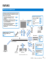 4
4
-
 5
5
-
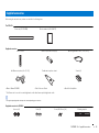 6
6
-
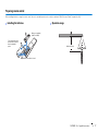 7
7
-
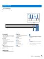 8
8
-
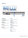 9
9
-
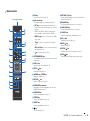 10
10
-
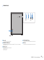 11
11
-
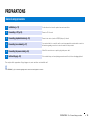 12
12
-
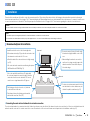 13
13
-
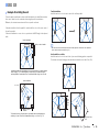 14
14
-
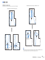 15
15
-
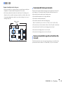 16
16
-
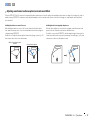 17
17
-
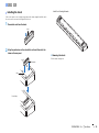 18
18
-
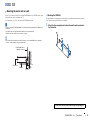 19
19
-
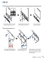 20
20
-
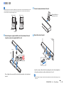 21
21
-
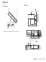 22
22
-
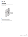 23
23
-
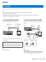 24
24
-
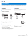 25
25
-
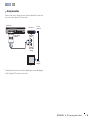 26
26
-
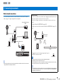 27
27
-
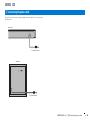 28
28
-
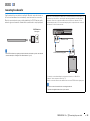 29
29
-
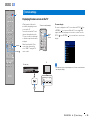 30
30
-
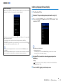 31
31
-
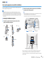 32
32
-
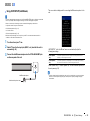 33
33
-
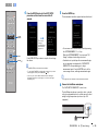 34
34
-
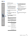 35
35
-
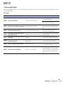 36
36
-
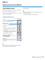 37
37
-
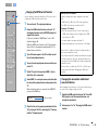 38
38
-
 39
39
-
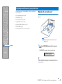 40
40
-
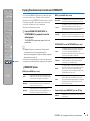 41
41
-
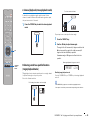 42
42
-
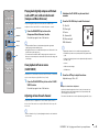 43
43
-
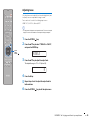 44
44
-
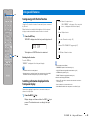 45
45
-
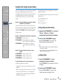 46
46
-
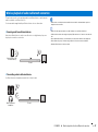 47
47
-
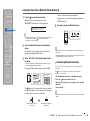 48
48
-
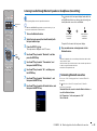 49
49
-
 50
50
-
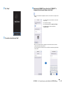 51
51
-
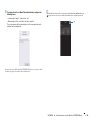 52
52
-
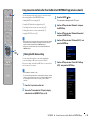 53
53
-
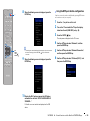 54
54
-
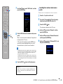 55
55
-
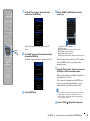 56
56
-
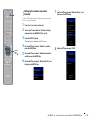 57
57
-
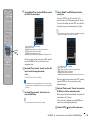 58
58
-
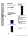 59
59
-
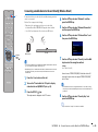 60
60
-
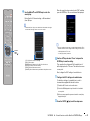 61
61
-
 62
62
-
 63
63
-
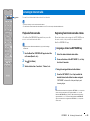 64
64
-
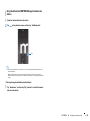 65
65
-
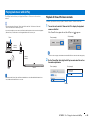 66
66
-
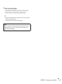 67
67
-
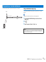 68
68
-
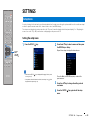 69
69
-
 70
70
-
 71
71
-
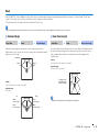 72
72
-
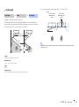 73
73
-
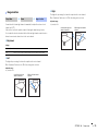 74
74
-
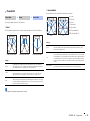 75
75
-
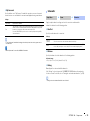 76
76
-
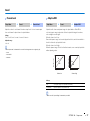 77
77
-
 78
78
-
 79
79
-
 80
80
-
 81
81
-
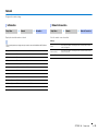 82
82
-
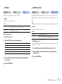 83
83
-
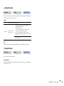 84
84
-
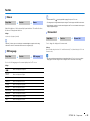 85
85
-
 86
86
-
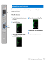 87
87
-
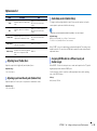 88
88
-
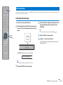 89
89
-
 90
90
-
 91
91
-
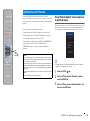 92
92
-
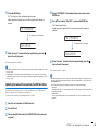 93
93
-
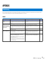 94
94
-
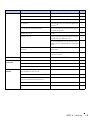 95
95
-
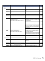 96
96
-
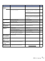 97
97
-
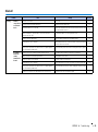 98
98
-
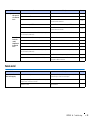 99
99
-
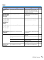 100
100
-
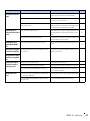 101
101
-
 102
102
-
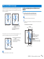 103
103
-
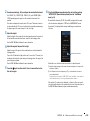 104
104
-
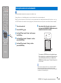 105
105
-
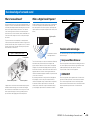 106
106
-
 107
107
-
 108
108
-
 109
109
-
 110
110
-
 111
111
-
 112
112
-
 113
113
-
 114
114


in andere talen
- English: Yamaha YSP-2700 Owner's manual
- italiano: Yamaha YSP-2700 Manuale del proprietario
- русский: Yamaha YSP-2700 Инструкция по применению
- français: Yamaha YSP-2700 Le manuel du propriétaire
- español: Yamaha YSP-2700 El manual del propietario
- Deutsch: Yamaha YSP-2700 Bedienungsanleitung
- dansk: Yamaha YSP-2700 Brugervejledning
- suomi: Yamaha YSP-2700 Omistajan opas
- svenska: Yamaha YSP-2700 Bruksanvisning
- Türkçe: Yamaha YSP-2700 El kitabı
Gerelateerde papieren
-
Yamaha YMS-4080 de handleiding
-
-
-
-
-
-
Yamaha WXC-50 de handleiding
-
Yamaha YSP-2700 Handleiding
-
Yamaha SRT-1500 de handleiding
-
Andere documenten
-
Sony HT-ST3 Gebruikershandleiding
-
Lenco LPJ-500BU de handleiding
-
-
Pioneer SBX-300 Handleiding
-
-
Philips NEOPIX EASY 2+ Handleiding
-
Bowers & Wilkins Panorama 2 Handleiding
-
Panasonic SCHTB01EG Handleiding
-
Motorola PMMN4095 series Handleiding
-
Denon AVC-A1XV Handleiding