protech Malibu Handleiding
- Categorie
- Speelgoed met afstandsbediening
- Type
- Handleiding

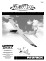
Malibu - 1
INSTRUCTION MANUEL • GEBRUIKSAANWIJZING • PLAN DE MONTAGE • ANLEITUNG
T0361
WARNING ! This R/C kit and the model
you will build is not a toy.
LET OP ! Deze bouwdoos van een
radiobestuurd vliegtuig is geen
speelgoed.
ATTENTION ! Ce kit d’avion R/C n’est
pas un jouet.
ACHTUNG ! Dieser Bausatz von
ferngesteurte model
ist kein Spielzeug.
version: 26/04/2002 • T0361
765 g.
32,95 dm
2
1000 mm
1720 mm

2 - Malibu
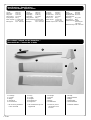
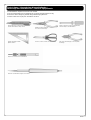
Specifications / Specificaties /
Technische daten / Spécifications
1. Fuselage
2. Cockpit
3. Wings
4. Vertical fin
5. Horizontal fin
+ all necessary hardware
is also included
1. Romp
2. Cockpit
3. Vleugels
4. Richtingsroer
5. Hoogteroer
+ alle toebehoren zijn ook
bijgeleverd
1. Fuselage
2. Verrière
3. Ailes
4. Dérive
5. Stabilisateur
+ toutes les pièces
nécessaires sont
incluses
1. Rumpf
2. Kabinenhaube
3. Flügel
4. Seitenruder
5. Höhenleitwerk
+ inklusive Zubehör
1
2
5
6
3
4
Kit content / Inhoud van de bouwdoos /
Bausatzinhalt / Contenu de la boîte
Length: 1000 mm
Wing span: 1720 mm
Wing area: 32,95 dm
2
Wing loading: 24,2 g/dm
2
Flying weight: 800 g
Radio required: 2 ch radio with
2 x std servos
Batterypack: 4,8V - 600 mAh
Lengte: 1000 mm
Spanwijdte: 1720 mm
Vleugelopp.: 32,95 dm
2
Vleugelbel.: 24,2 g/dm
2
Vlieg gewicht: 800 g
Radio besturing:2 kanaals radio
met 2 st servo’s
Batterijen: 4,8V - 600 mAh
Longueur: 1000 mm
Envergure: 1720 mm
Surface alaire: 32,95 dm
2
Charge alaire: 24,2 g/dm
2
Poids en vol: 800 g
Radio requise: 2 voies avec
2 servos std
Batterie requise:4,8V - 600 mAh
Länge: 1000 mm
Spannweite: 1720 mm
Tragflügelinhalt: 32,95 dm
2
Gesamtflachen-
belastung: 24,2 g/dm
2
Fluggewicht: 800 g
Funkfernsteuerung:
2 Kanal
Steuerung mit
2 std servo
Batterie benötigt
:4,8V - 600 mAh

Malibu - 3
Important Safety Notes.
Be sure to read right through the instructions covering assembly and operation of your model before you attempt to operate it for the first time. You alone are
responsible for the safe operation of your radio-controlled model. Young people should only be permitted to build and fly these models under the instruction and
supervision of an adult who is aware of the hazards involved in this activity.
Use only matching polarised connectors. All cables, connectors and the battery if home-assembled must be insulated to prevent short circuits. Never attempt to
combine different types of plug and socket - e.g. tin-plated and gold-plated types - as such combinations are bound to be unreliable.
NC batteries are capable of holding and releasing enormous amounts of energy, and as such represent a constant hazard of explosion and fire.
We have no control over the way you build and operate your RC model aircraft, and for this reason we are obliged to deny all liability for accidents. All we can do is
point out the hazards and make sure you are aware of them.
If you need help, please enlist the aid of an experienced modeller, a model club or enrol at a model flying training school, Model shops and the specialist model
press are also good sources of information. The best course is always to join a club and fly at the approved model flying site.
Rubber bands deteriorate with age and become brittle. Replace them from time to time to maintain the safety and reliability of your model. Stretch all rubber bands
before use to check that they are still strong enough for their purpose.
Motors should only be run in the open air! The powerful suction of the propeller and the volume of air which it accelerates can easily lead to accidents in enclosed
spaces (e.g. pictures falling down, curtains sucked into the propeller). The model must be held securely by an assistant at all times.
Keep well clear of the rotational plane of propellers - don't stand in line with it or in front of it. You never know when some part may come loose and fly off at high
speed, hitting you or anybody else in the vicinity. Never touch the revolving propeller with any object.
There must be no chance of any object getting in the way of the propeller and preventing it rotating.
Take care with loose clothing such as scarves, loose shirts etc. Flapping cloth can easily be sucked into the area of the propeller and then get tangled in it.
If you start your motor when the model is standing on loose or sandy ground, the propeller will suck up sand and dust and hurl it around. and it could easily get in
your eyes. Wear protective goggles at such times.
Every time you intend to operate your model check carefully that it and everything attached to it (e.g. propeller, gearbox,RC components etc.) are in good condition
and undamaged. If you find a fault do not fly the model until you have corrected it.
Satisfy yourself that your frequency is vacant before you switch on. Radio interference caused by unknown sources can occur at any time without warning. If this
should happen, your model will be uncontrollable and completely unpredictable. Never leave your radio control system unguarded, as other people might pick it up
and try to use it.
Check that nothing is in the way of the propeller before you switch on the electric motor. Never attempt to stop the spinning propeller.Electric motors with a propeller
attached should only be run when installed securely.
lf you are to fly your model safely and avoid problems it is essential that you are aware of its position and attitude throughout each flight - so don't let it fly too far
away! lf you detect a control problem or interference during a flight,immediately land the model to prevent a potential accident Note that the transmitter throttle stick
must be set to the OFF (motor stopped) position before you switch on the power system. To avoid the electric motor starting unexpectedly, switch on the transmitter
first. then the receiving system. Use the reverse sequence when switching off: receiver first, then the transmitter. Check that the control surfaces move in the correct
"sense" when you operate the sticks.
Please don't misunderstand the purpose of these notes. We only want to make you aware of the many dangers and hazards which can arise if you lack knowledge
and experience, or work carelessly or irresponsibly. If you take reasonable care model flying is a highly creative, instructive, enjoyable and relaxing pastime.
Belangrijke Veiligheidsinstructies
Lees de instructies betreffende montage en werking van je model vooraleer u het de eerste maal in gebruik neemt. U alleen bent verantwoordelijk voor de veilige
werking van uw radiobestuurd model. Kinderen zijn enkel toegestaan om deze modellen te bouwen en te vliegen onder het toeziend oog van een volwassene, die
zich bewust is van de gevaren die dit met zich meebrengt.
Gebruik enkel passende gepolariseerde verbindingsstukken. Alle kabels, verbindingsstukken en de batterij, indien deze zelf samengesteld is, moeten geïsoleerd
worden om kortsluiting te voorkomen. Poog nooit verschillende types van pluggen en contacten te kombineren (vb.tin-en goudcontacten), daar zulke combinaties
onbetrouwbaar zijn.
NC-batterijen zijn geschikt om enorme hoeveelheden energie vast te houden en vrij te geven. Zodoende vertegenwoordigt een batterij een constant risico op
explosie en brandgevaar.
Wij hebben geen controle over de manier waarop u het RC-vliegtuig bouwt en gebruikt. Daarom zijn wij verplicht om alle aansprakelijkheid voor ongevallen van de
hand te wijzen. Het enige dat in onze mogelijkheden ligt is u te waarschuwen voor de risico’s.
Als u hulp nodig heeft, roep dan de bijstand van een ervaren modelbouwer of een modelbouwclub in, of schrijf u in bij een modelvliegclub. Modelshops en de
gespecialiseerde pers zijn eveneens een geschikte bron van informatie. De beste les is echter zich aan te sluiten bij een club en te vliegen op de goedgekeurde
vliegplaatsen.
Rubber elastieken verslijten met het gebruiken en worden broos. Vervang ze tijdig, zodoende stelt u de veiligheid en de betrouwbaarheid van uw model veilig. Span
alle rubber elastieken op vooraleer u ze gebruikt om te controleren of ze nog sterk genoeg zijn.
Motoren mogen enkel buiten in openlucht lopen! De sterke zuigkracht van de propeller en de luchtverplaatsing die deze veroorzaakt, kan in kleine ruimten makkelijk
een ongeval tot gevolg hebben (vb. schilderijen die naar beneden vallen, een gordijn dat in de propeller gezogen wordt). Het model moet steeds stevig worden
vastgehouden door een helper.
Houdt de rotatiebaan van een propeller vrij, sta er nooit voor of in de lijn van de propeller. Er kan steeds een deel loskomen en met hoge snelheid wegvliegen, zodat
het uzelf of iemand anders in de omgeving kan verwonden. Raak de ronddraaiende propeller nooit met enig voorwerp aan. Vermijdt steeds dat welk voorwerp ook
het draaien van de propeller verhindert.
Pas op met losse kleding zoals sjaals, losse shirts, … Losse kleding kan makkelijk in de propeller gezogen worden.
Als u de motor start terwijl deze op losse of zanderige grond staat, zal de propeller het zand opzuigen en rondslingeren zodat het in je ogen kan komen. Draag dus
steeds een veiligheidsbril op zo’n momenten.
Controleer, elke keer als u een model wil gebruiken, zorgvuldig of het model en alles wat erbij hoort (vb. propeller, aandrijving, RC-onderdelen, …) in goede staat en
onbeschadigd is. Als u een fout bemerkt, vlieg dan niet met het model tot u de fout hebt opgelost.
Verzeker uzelf ervan dat de frequentie vrij is vooraleer u de zender aanzet. Radiostoringen veroorzaakt door vreemde bronnen kunnen op elk moment en zonder
waarschuwing voorkomen. Als dit gebeurt is je model oncontroleerbaar en volledig onvoorspelbaar. Laat uw radiobesturing nooit onbewaakt achter, andere mensen
zouden kunnen proberen het te gebruiken.
Controleer of er niets in de baan van de propeller is vooraleer u de electromotor aanzet. Probeer nooit de draaiende propeller te stoppen. Electromotoren verbonden
met een propeller mogen enkel lopen als deze veilig geïnstalleerd is.
Als u uw model veilig wil vliegen en u wil problemen vermijden, dan is het essentieel dat u zich bewust bent van zijn positite en hoogte tijdens iedere vlucht. Laat het
dus niet te ver weg vliegen ! Als u een controleprobleem of storingen ontdekt gedurende een vlucht, landt dan onmiddellijk om een mogelijk ongeval te voorkomen.
Bemerk dat de zenderstick voor de motorfunctie in de off-stand moet staan vooraleer u het systeem aanzet. Om te voorkomen dat de electromotor onverwacht start,
zet eerst de zender aan, later pas de ontvanger. Gebruik de omgekeerde volgorde bij het afzetten : eerst de ontvanger, dan de zender. Controleer of de roeren in de
juiste richting bewegen als u de sticks gebruikt.
Heb begrip voor het doel van deze opmerkingen. Wij willen u enkel opmerkzaam maken voor de vele gevaren en risico’s die zich kunnen voordoen als u kennis en
ervaring mist, nonchalant of onverantwoordelijk te werk gaat.
Als u redelijk zorg draagt, is modelvliegen een zeer creatieve, leerrijke, plezierige en ontspannende vrijetijdsbesteding.
Pagina laadt ...

Malibu - 5
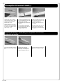
Sharp hobby knife / Scherp hobby mes /
Couteau de modeliste / Hobby messer
Needle nose pliers / Bek tang /
Pince à becs / Beisszange
Philips screw driver / Philips schroevendraaier /
Tournevis Philips / Schraubendreher
Triangle / Driehoeks meetlat /
Equerre / Winkel
Scissors / Schaar / Ciseaux / Schere Wire cutter / Draad stripper / Pince coupante /
Kneifzange
Drill / Boor / Perceuse à main / Handbohrer
To assamble this airplane some tools are needed.
Voor het samenstellen van het vliegtuig zijn er enkele gereedschappen nodig.
Zum bauen dieses Flugzeug werden einige Werkzeuge gebraucht .
Certains outils sont requis pour assembler cet avion.
Tools & items / Gereedschap & benodigdheden /
Werkzeuge und erforderliches / Outils et équipements
Solder iron / Soldeerbout /Lötgerät / Fer à souder

6 - Malibu
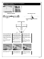
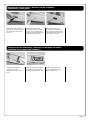
Wing assembling / Monteren van de vleugels /
Assemblage des ailes / Montieren von die Flugel
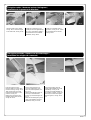
Glue the spar into one off the
wing panels with epoxy. When
dry join the two wing panels
together with epoxy.
Attention: Make sure you glue
both sides of the wing together
to guaranty the stiffness of the
wing, see fig. 1-2-3.
Lijm de vleugelverbinding in één
van de vleugelhelften. Als de lijm
gehard is lijm je de twee
vleugelhelften tegen elkaar met
epoxylijm.
Let op: Verlijm de binnenzijde
van de vleugels tegen elkaar om
de nodige stevigheid te
verkrijgen, zie fig. 1-2-3.
Collez la clé d’aile dans une des
deux demi-ailes. Quand la colle
est sèche assemblez la
deuxième demi-aile avec de la
colle epoxy.
Attention: Mettez de la colle sur
les deux faces des demi-ailes
pour obtenir la meilleure rigidité,
voir fig. 1-2-3.
Preparing the fuselage / Voorbereiding voor het plaatsen van de roeren /
Préparation du fuselage /
Cut out the excessif covering at
the back of the fuselage, see fig.
4-5.
Verwijder het overtollige
bespanfolie op de plaats waar
het hoogte- en richtingsroer
worden bevestigd, zie fig. 4-5.
Enlevez l’exédant de l’entoilage
à l’arrière du fuselage, voir fig.
4-5.
fig. 1 fig. 3fig. 2
fig. 4 fig. 5

Malibu - 7
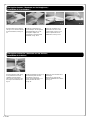
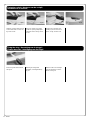
Mounting the horizontal fin / Monteren van hoogteroer /
Assemblage du stabilisateur /
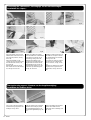
Draw a line in the middle of the
horizontal rudder. Mark 2 lines
on each side of the centerline at
12mm. This will help you to
aligne the stabilisator with the
fuselage, see fig. 6-7. Glue the
stabilisator carefully horizontal
on the fuselage.
Take care: Keep the tailplane
parallel with the wings and
fuselage.
Trek een loodlijn in het midden
van het horizontale staartvlak.
Breng op 12mm van de loodlijn
aan beide zijden een markering
aan. Deze markering dient voor
het gemakkelijk uitlijnen van het
staartvlak op de romp, zie fig. 6-
7. Verlijm vervolgens het
horizontale vlak in de romp met
epoxy.
Opgelet! Zorg ervoor dat dit
mooi haaks en horizontaal staat
t.o.v. de vleugel en de romp.
Tracez une ligne au centre du
stabilisateur. Faites un repère à
12mm de chaque côté de la
ligne. Ce repère vous aidera à
aligner le stabilisateur sur le
fuselage, voir fig. 6-7. Collez le
stabilisateur horizontalement sur
le fuselage.
Attention: Veillez à ce que le
stabilisateur soit bien horizon-
tale par rapport au fuselage et
parallèle à l’aile.
fig. 6 fig. 7
fig. 8 fig. 9 fig. 10
Glue the elevators together with
epoxy, see fig. 8-9-10.
Verlijm het verbindingsstuk aan
de beide hoogteroeren met
epoxy zoals afgebeeld op fig. 8-
9-10.
Assemblez les deux parties de
la profondeur avec la barre de
liaison, utilisez de la colle epoxy,
voir fig. 8-9-10.

8 - Malibu
Placing the vertical fin / Monteren van het kielvlak /
Installation de la dérive /
Glue the vertical fin with epoxy
in the preformed slot of the
stabilizer and the fuselage.
Take care the vertical fin is in a
90° angle to the stabilizer, see
fig. 15.
Verlijm het kielvlak met epoxy op
de voorziene plaats van het
hoogteroer en de romp.
Let op dat het kielvlak 90° t.o.v.
het horizontale vlak staat,
zie fig. 15.
Insérez et collez la dérive dans
le fuselage.
Respectez un angle de 90°
entre le stabilisateur et la dérive,
voir fig. 15.
fig. 15
Placing the elevator / Monteren van het hoogteroer /
Installation de la profondeur /
Glue the hinges in the elevator,
see fig. 11-12. Glue the elevator
in the horizontal fin, see fig. 13-
14.
Verlijm de scharnieren met
secondenlijm in het hoogteroer
zoals afgebeeld in fig. 11-12.
Vervolgens verlijmt u de
scharnieren in het horizontale
staartvlak, zie fig. 13-14.
Collez les charnières sur la
profondeur avec de la colle
cyanoacrylate, voir fig. 11-12.
Collez la profondeur sur le
stabilisateur, voir fig. 13-14.
??
fig. 11 fig. 13fig. 12 fig. 14

Malibu - 9
Fixing the rudder / Monteren van het richtingsroer /
Installation de la gouverne de direction /
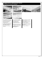
Glue the hinges in the rudder,
see fig. 16-17. Glue the hinges
in the vertical fin, see fig. 18-19.
Verlijm de scharnieren in het
richtingsroer zoals afgebeeld op
fig. 16-17. Vervolgens verlijmt u
de scharnieren in het vertikale
staartvlak, zie fig. 18-19.
Collez les charnières dans la
gouverne, voir fig. 16-17. Collez
les charnières dans la dèrive,
voir fig. 18-19.
Placing the pushrods / Plaatsen van de stuurstangen /
Installation des tringles de commande /
Push the pushrods in the
foreseen gliders en press them
true the covering, see fig. 20-21.
Take-out the rods and solder
both treaded bushings on the
pushrod, see fig. 22.
Replace the pushrods in the
fuselage starting from the tail,
see fig. 23-24-25.
Duw de stuurstangen in de
voorziene geleiders en druk
deze door het bespanfolie, zie
fig. 20-21.
Haal de stuurstangen terug uit
de romp en soldeer beide
bussen op de stuurstangen, zie
fig. 22.
Plaats de stuurstang terug in de
romp te verstrekken vanaf het
staartstuk, zie fig. 23-24-25.
Glissez les tringles dans les
gaines déjà installées et percez
l’entoillage, voir fig. 20-21.
Soudez les douilles filletées sur
les tringles en métal, voir fig. 22.
Glissez par l’arrière les tringles
dans les gaines, voir fig. 23-24-
25.
fig. 16 fig. 17 fig. 18 fig. 19
fig. 20 fig. 21 fig. 22 fig. 23
fig. 24 fig. 25

10 - Malibu
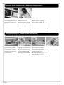
Cut a hole on the pre-set place
and fix the wing supports in the
fuselage, see fig. 36-37.
Snij een gaatje op de voorziene
plaatsen in de romp en plaats
de vleugelbevestigingen in de
romp zoals afgebeeld op fig. 36-
37.
Percez l’entoilage aux endroits
prévus et insérez les deux
bâtonnets dans le fuselage, voir
fig. 36-37.
fig. 32 fig. 33 fig. 34 fig. 35
fig. 36 fig. 37
Connecting the controlhorns / Bevestigings van de roeraansluitingen /
Installation des chapes /
Place the rubber rings over the
kwiklink and screw it as far as it
gets onto the pushrod, see fig.
26-27-28.
Attach the kwiklink on the
control horn and mount the horn
with the included screws, see
fig. 29-30-31.
Repeat these staps to mount
the control horns on the vertical
fin, see fig. 32-33-34-35.
Plaats een rubberen ringetje
over de kwiklink en schroef deze
vervolgens ver genoeg op de
stuurstang, zie fig. 26-27-28.
Bevestig de kwiklink op de
roerhorn en bevestig deze met
bijgeleverde schroeven en het
fixeerplaatje, zie fig. 29-30-31.
Herhaal deze stappen voor het
monteren op het richtingsroer,
zie fig. 32-33-34-35.
Installez le petit caoutchouc de
sécurité sur la chape et vissez-
la complètement sur la douille,
voir fig. 26-27-28.
Connectez la chape au guignol
et vissez-le sur la dérive avec
les vis fournies, voir fig. 29-30-
31.
Répetez les étapes pour monter
le guignol sur la gouverne de
profondeur, voir fig. 32-33-34-
35.
??
fig. 15fig. 26 fig. 27 fig. 28 fig. 29
fig. 30 fig. 31
Placing the wing support / Plaatsen van de vleugelbevestiging /
Installation des fixations d’aile /

Malibu - 11
Fixing the towhook / Monteren van de sleephaak /
Installation du crochet de treuillage /
Make a little hole in the center
of the fuselage, 55 mm behind
the front rib, see fig. 38. Glue
with epoxy the wooden
reinforcement in the
fuselage,see fig. 39. Drill a hole
(2,5mm) in the fuselage, from
the outside in, and mount the
hook, see fig. 40-41-42.
Reinforce the nut with epoxy,
see fig. 43.
Prik een gaatje in het midden
van de romp, 55 mm achter de
voorste spant, zie fig. 38.
Lijm het plaatje met 2-
componenten-lijm aan de
binnenzijde van de romp, zie fig.
39.
Boor het gaatje groter langs de
onderzijde (2,5 mm) en monteer
de sleephaak, zie fig. 40-41-42.
Verstevig de moer met
epoxy, zie fig. 43.
Faites un petit trou au centre du
fuselage, à 55mm du premier
couple, voir fig. 38.
Collez la plaque de renfort dans
le fuselage, voir fig. 39.
Percez par l’extérieur un trou de
2,5mm et vissez le crochet, voir
fig. 40-41-42.
Renforcez la fixation avec de la
colle epoxy, voir fig. 43.
fig. 38 fig. 39 fig. 40 fig. 41
fig. 42 fig. 43

12 - Malibu
Placing the servos / Monteren van de hoogte-en richtingsroerservo /
Installation des servos /
Mount the servos like shown on
fig. 44 and drill a hole of 1,5mm.
Screw the servos in place, see
fig. 44-45.
Plaats de servo’s op de
voorziene plaatsen. Boor een
gaatje van 1,5 mm en schroef
de servo’s vast, zie fig. 44-45.
Installez les servos. Percez des
trous de 1,5mm aux endroits
des vis. Vissez, voir fig. 44-45.
Placing the steeringrods / Plaatsen van de roeraansturing /
Installation des tringles de commande /
Place both rudders in neutral
position and bend a 90° angle
to connect the servoarm.
Cut off the excessif thread and
mount the servo arms as shown
in fig. 46-47-48-49.
Placez la dérive et le stabilisa-
teur en position neutre et pliez
la tringle à 90°, introduisez-la
dans le palonnier du servo.
Coupez la partie en trop.
Montez les palonniers sur les
servos, voir fig. 46-47-48-49.
fig. 44 fig. 45
fig. 46 fig. 47 fig. 48 fig. 49
Zet beide roeren neutraal en
plooi een hoek van 90° op de
plaats van de servoaansturing.
Knip de overtollige draad af.
Monteer de servoarm zoals
afgebeeld in fig. 46-47-48-49.

Malibu - 13
Mounting the receiver-switch / Monteren van de schakelaar /
Installation de l’intérrupteur /
Draw the size of the switch on
the fuselage. Cut-out and mount
the switch and screw, see fig.
50-51-52.
Teken het formaat van de
schakelaar op de romp. Maak
een gat voor de schakelaar en
schroef deze op zijn plaats zoals
afgebeeld op fig. 50-51-52.
Tracez les dimensions de
l’interrupteur sur le fuselage.
Percez un trou pour le passage
de l’intérrupteur et vissez-le en
place, voir fig. 50-51-52.
Install the receiver and battery / Monteren van ontvanger en batterij /
Installation du récepteur et de la batterie /
Install the receiver (min. 2-
channels) and a 4,8V
batterypack as shown on fig.
53-54.
Plaats een ontvanger (minimum
2 kanaals) en een 4,8V batterij
zoals afgebeeld op fig. 53 - 54.
Installez le récepteur (min. 2
voies) et la batterie comme
illustré, voir fig. 53-54.
??
fig. 53 fig. 54
fig. 50 fig. 51 fig. 52

14 - Malibu
Fixing the cockpit / Monteren van de cockpit /
Installation de la verrière /
Hold the cockpit in place and fix
on both sides with a screw, see
fig. 55-56-57-58.
Houd de cockpit op de juiste
positie en vijs langs bijde zijde
een klein schroef. zie fig. 55-56 -
57-58
Positionnez la verrière sur le
fuselage, percez et vissez en
place, voir fig. 55-56-57-58.
Fixing the wing / Bevestiging van de vleugel /
Fixation des ailes / Befestigung von die Flügel
Fix the wing with rubber bands,
see fig. 59.
Bevestig de vleugel met
elastieken, zoals afgebeeld op
fig. 59.
Attachez l’aile sur le fuselage
avec des élastiques comme
illustré, voir fig. 59.
fig. 55 fig. 56
fig. 59
fig. 57 fig. 58

Malibu - 15
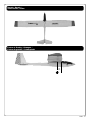
Decals / Decals /
Autocollants / Dekor
Centre of Gravity / Uitwegen /
Centre de gravité / Schwerpunkt
70
mm

16 - Malibu
© Copyright PROTECH
• Your kit is warranted against defects
in material and workmanship.
• This warranty does not apply to any
component parts, which have been
improperly installed, handled,
abused, damaged, modified and
used.
• De kit heeft een garantie voor
materiaalfouten en fabrieksfouten.
• Deze garantie geldt niet voor
onderdelen die niet goed zijn
geïnstalleerd, behandeld, mishandeld,
beschadigd, aangepast en gebruikt.
• Votre kit est garanti contre les défauts
de matériaux et de main d’œuvre.
• Cette garantie ne s’applique pas aux
composants qui ont été incorrecte-
ment montés, manipulés, modifiés et
utilisés ou qui ont été endommagés.
• Ihr Installationssatz wird gegen
Defekte im Material und in der
Kunstfertigkeit gewährleistet.
•
Diese Garantie trifft nicht auf
irgendwelche Bestandteile zu, die
unsachgemäß installiert worden,
angefaßt worden, mißbraucht worden,
beschädigt worden, geändert worden
und benutzt worden sind.
Limited warranty / Beperkte garantie /
Limitation de garantie / Begrenzte garantie
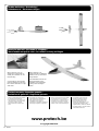
Rudder deflection / Roeruitslag /
Débattements / Ruderausschlägen
Ready for take off / Uw model is vliegklaar /
Votre modèle est prêt à voler / Ihr modell ist fertig zu fliegen
When necessary you can
straight the covering with an
sealing iron. Attention: do not
twist the wing.
Si nécessaire le recouvrement
peut être amélioré à l’aide d’un
fer à entoiler. Attention à ne pas
vriller l’aile.
Indien nodig kan u de
bespanning met een strijkbout
bijtrekken. Let op: niet met de
vleugel draaien.
Wenn erforderlich können Sie
die Bespannfolien mit ein
Bügeleisen nach bearbeiten.
Achtung: Nicht mit Flugel
drehen.
17 mm
12 mm
26 mm
26 mm
www.protech.be
Documenttranscriptie
T0361 INSTRUCTION MANUEL • GEBRUIKSAANWIJZING • PLAN DE MONTAGE • ANLEITUNG 765 g. 17 20 WARNING ! This R/C kit and the model you will build is not a toy. LET OP ! Deze bouwdoos van een radiobestuurd vliegtuig is geen speelgoed. mm m 0m 100 32,95 dm2 ATTENTION ! Ce kit d’avion R/C n’est pas un jouet. ACHTUNG ! Dieser Bausatz von ferngesteurte model ist kein Spielzeug. version: 26/04/2002 • T0361 Malibu -1 Specifications / Specificaties / Technische daten / Spécifications Length: Wing span: Wing area: Wing loading: Flying weight: Radio required: Batterypack: 1000 mm 1720 mm 32,95 dm2 24,2 g/dm2 800 g 2 ch radio with 2 x std servos 4,8V - 600 mAh Lengte: 1000 mm Spanwijdte: 1720 mm Vleugelopp.: 32,95 dm2 Vleugelbel.: 24,2 g/dm2 Vlieg gewicht: 800 g Radio besturing: 2 kanaals radio met 2 st servo’s Batterijen: 4,8V - 600 mAh Longueur: Envergure: Surface alaire: Charge alaire: Poids en vol: Radio requise: 1000 mm 1720 mm 32,95 dm2 24,2 g/dm2 800 g 2 voies avec 2 servos std Batterie requise: 4,8V - 600 mAh Länge: 1000 mm Spannweite: 1720 mm Tragflügelinhalt: 32,95 dm2 Gesamtflachenbelastung: 24,2 g/dm2 Fluggewicht: 800 g Funkfernsteuerung: 2 Kanal Steuerung mit 2 std servo Batterie benötigt: 4,8V - 600 mAh Kit content / Inhoud van de bouwdoos / Bausatzinhalt / Contenu de la boîte 1 2 4 3 5 6 1. Fuselage 2. Cockpit 3. Wings 4. Vertical fin 5. Horizontal fin 1. Romp 2. Cockpit 3. Vleugels 4. Richtingsroer 5. Hoogteroer 1. Fuselage 2. Verrière 3. Ailes 4. Dérive 5. Stabilisateur 1. Rumpf 2. Kabinenhaube 3. Flügel 4. Seitenruder 5. Höhenleitwerk + all necessary hardware is also included + alle toebehoren zijn ook bijgeleverd + toutes les pièces nécessaires sont incluses + inklusive Zubehör 2 - Malibu Important Safety Notes. Be sure to read right through the instructions covering assembly and operation of your model before you attempt to operate it for the first time. You alone are responsible for the safe operation of your radio-controlled model. Young people should only be permitted to build and fly these models under the instruction and supervision of an adult who is aware of the hazards involved in this activity. Use only matching polarised connectors. All cables, connectors and the battery if home-assembled must be insulated to prevent short circuits. Never attempt to combine different types of plug and socket - e.g. tin-plated and gold-plated types - as such combinations are bound to be unreliable. NC batteries are capable of holding and releasing enormous amounts of energy, and as such represent a constant hazard of explosion and fire. We have no control over the way you build and operate your RC model aircraft, and for this reason we are obliged to deny all liability for accidents. All we can do is point out the hazards and make sure you are aware of them. If you need help, please enlist the aid of an experienced modeller, a model club or enrol at a model flying training school, Model shops and the specialist model press are also good sources of information. The best course is always to join a club and fly at the approved model flying site. Rubber bands deteriorate with age and become brittle. Replace them from time to time to maintain the safety and reliability of your model. Stretch all rubber bands before use to check that they are still strong enough for their purpose. Motors should only be run in the open air! The powerful suction of the propeller and the volume of air which it accelerates can easily lead to accidents in enclosed spaces (e.g. pictures falling down, curtains sucked into the propeller). The model must be held securely by an assistant at all times. Keep well clear of the rotational plane of propellers - don't stand in line with it or in front of it. You never know when some part may come loose and fly off at high speed, hitting you or anybody else in the vicinity. Never touch the revolving propeller with any object. There must be no chance of any object getting in the way of the propeller and preventing it rotating. Take care with loose clothing such as scarves, loose shirts etc. Flapping cloth can easily be sucked into the area of the propeller and then get tangled in it. If you start your motor when the model is standing on loose or sandy ground, the propeller will suck up sand and dust and hurl it around. and it could easily get in your eyes. Wear protective goggles at such times. Every time you intend to operate your model check carefully that it and everything attached to it (e.g. propeller, gearbox,RC components etc.) are in good condition and undamaged. If you find a fault do not fly the model until you have corrected it. Satisfy yourself that your frequency is vacant before you switch on. Radio interference caused by unknown sources can occur at any time without warning. If this should happen, your model will be uncontrollable and completely unpredictable. Never leave your radio control system unguarded, as other people might pick it up and try to use it. Check that nothing is in the way of the propeller before you switch on the electric motor. Never attempt to stop the spinning propeller.Electric motors with a propeller attached should only be run when installed securely. lf you are to fly your model safely and avoid problems it is essential that you are aware of its position and attitude throughout each flight - so don't let it fly too far away! lf you detect a control problem or interference during a flight,immediately land the model to prevent a potential accident Note that the transmitter throttle stick must be set to the OFF (motor stopped) position before you switch on the power system. To avoid the electric motor starting unexpectedly, switch on the transmitter first. then the receiving system. Use the reverse sequence when switching off: receiver first, then the transmitter. Check that the control surfaces move in the correct "sense" when you operate the sticks. Please don't misunderstand the purpose of these notes. We only want to make you aware of the many dangers and hazards which can arise if you lack knowledge and experience, or work carelessly or irresponsibly. If you take reasonable care model flying is a highly creative, instructive, enjoyable and relaxing pastime. Belangrijke Veiligheidsinstructies Lees de instructies betreffende montage en werking van je model vooraleer u het de eerste maal in gebruik neemt. U alleen bent verantwoordelijk voor de veilige werking van uw radiobestuurd model. Kinderen zijn enkel toegestaan om deze modellen te bouwen en te vliegen onder het toeziend oog van een volwassene, die zich bewust is van de gevaren die dit met zich meebrengt. Gebruik enkel passende gepolariseerde verbindingsstukken. Alle kabels, verbindingsstukken en de batterij, indien deze zelf samengesteld is, moeten geïsoleerd worden om kortsluiting te voorkomen. Poog nooit verschillende types van pluggen en contacten te kombineren (vb.tin-en goudcontacten), daar zulke combinaties onbetrouwbaar zijn. NC-batterijen zijn geschikt om enorme hoeveelheden energie vast te houden en vrij te geven. Zodoende vertegenwoordigt een batterij een constant risico op explosie en brandgevaar. Wij hebben geen controle over de manier waarop u het RC-vliegtuig bouwt en gebruikt. Daarom zijn wij verplicht om alle aansprakelijkheid voor ongevallen van de hand te wijzen. Het enige dat in onze mogelijkheden ligt is u te waarschuwen voor de risico’s. Als u hulp nodig heeft, roep dan de bijstand van een ervaren modelbouwer of een modelbouwclub in, of schrijf u in bij een modelvliegclub. Modelshops en de gespecialiseerde pers zijn eveneens een geschikte bron van informatie. De beste les is echter zich aan te sluiten bij een club en te vliegen op de goedgekeurde vliegplaatsen. Rubber elastieken verslijten met het gebruiken en worden broos. Vervang ze tijdig, zodoende stelt u de veiligheid en de betrouwbaarheid van uw model veilig. Span alle rubber elastieken op vooraleer u ze gebruikt om te controleren of ze nog sterk genoeg zijn. Motoren mogen enkel buiten in openlucht lopen! De sterke zuigkracht van de propeller en de luchtverplaatsing die deze veroorzaakt, kan in kleine ruimten makkelijk een ongeval tot gevolg hebben (vb. schilderijen die naar beneden vallen, een gordijn dat in de propeller gezogen wordt). Het model moet steeds stevig worden vastgehouden door een helper. Houdt de rotatiebaan van een propeller vrij, sta er nooit voor of in de lijn van de propeller. Er kan steeds een deel loskomen en met hoge snelheid wegvliegen, zodat het uzelf of iemand anders in de omgeving kan verwonden. Raak de ronddraaiende propeller nooit met enig voorwerp aan. Vermijdt steeds dat welk voorwerp ook het draaien van de propeller verhindert. Pas op met losse kleding zoals sjaals, losse shirts, … Losse kleding kan makkelijk in de propeller gezogen worden. Als u de motor start terwijl deze op losse of zanderige grond staat, zal de propeller het zand opzuigen en rondslingeren zodat het in je ogen kan komen. Draag dus steeds een veiligheidsbril op zo’n momenten. Controleer, elke keer als u een model wil gebruiken, zorgvuldig of het model en alles wat erbij hoort (vb. propeller, aandrijving, RC-onderdelen, …) in goede staat en onbeschadigd is. Als u een fout bemerkt, vlieg dan niet met het model tot u de fout hebt opgelost. Verzeker uzelf ervan dat de frequentie vrij is vooraleer u de zender aanzet. Radiostoringen veroorzaakt door vreemde bronnen kunnen op elk moment en zonder waarschuwing voorkomen. Als dit gebeurt is je model oncontroleerbaar en volledig onvoorspelbaar. Laat uw radiobesturing nooit onbewaakt achter, andere mensen zouden kunnen proberen het te gebruiken. Controleer of er niets in de baan van de propeller is vooraleer u de electromotor aanzet. Probeer nooit de draaiende propeller te stoppen. Electromotoren verbonden met een propeller mogen enkel lopen als deze veilig geïnstalleerd is. Als u uw model veilig wil vliegen en u wil problemen vermijden, dan is het essentieel dat u zich bewust bent van zijn positite en hoogte tijdens iedere vlucht. Laat het dus niet te ver weg vliegen ! Als u een controleprobleem of storingen ontdekt gedurende een vlucht, landt dan onmiddellijk om een mogelijk ongeval te voorkomen. Bemerk dat de zenderstick voor de motorfunctie in de off-stand moet staan vooraleer u het systeem aanzet. Om te voorkomen dat de electromotor onverwacht start, zet eerst de zender aan, later pas de ontvanger. Gebruik de omgekeerde volgorde bij het afzetten : eerst de ontvanger, dan de zender. Controleer of de roeren in de juiste richting bewegen als u de sticks gebruikt. Heb begrip voor het doel van deze opmerkingen. Wij willen u enkel opmerkzaam maken voor de vele gevaren en risico’s die zich kunnen voordoen als u kennis en ervaring mist, nonchalant of onverantwoordelijk te werk gaat. Als u redelijk zorg draagt, is modelvliegen een zeer creatieve, leerrijke, plezierige en ontspannende vrijetijdsbesteding. Malibu - 3 Tools & items / Gereedschap & benodigdheden / Werkzeuge und erforderliches / Outils et équipements To assamble this airplane some tools are needed. Voor het samenstellen van het vliegtuig zijn er enkele gereedschappen nodig. Zum bauen dieses Flugzeug werden einige Werkzeuge gebraucht . Certains outils sont requis pour assembler cet avion. Sharp hobby knife / Scherp hobby mes / Couteau de modeliste / Hobby messer Triangle / Driehoeks meetlat / Equerre / Winkel Needle nose pliers / Bek tang / Pince à becs / Beisszange Scissors / Schaar / Ciseaux / Schere Philips screw driver / Philips schroevendraaier / Tournevis Philips / Schraubendreher Wire cutter / Draad stripper / Pince coupante / Kneifzange Drill / Boor / Perceuse à main / Handbohrer Solder iron / Soldeerbout /Lötgerät / Fer à souder Malibu - 5 Wing assembling / Monteren van de vleugels / Assemblage des ailes / Montieren von die Flugel fig. 1 Glue the spar into one off the wing panels with epoxy. When dry join the two wing panels together with epoxy. Attention: Make sure you glue both sides of the wing together to guaranty the stiffness of the wing, see fig. 1-2-3. fig. 2 fig. 3 Lijm de vleugelverbinding in één van de vleugelhelften. Als de lijm gehard is lijm je de twee vleugelhelften tegen elkaar met epoxylijm. Collez la clé d’aile dans une des deux demi-ailes. Quand la colle est sèche assemblez la deuxième demi-aile avec de la colle epoxy. Let op: Verlijm de binnenzijde van de vleugels tegen elkaar om de nodige stevigheid te verkrijgen, zie fig. 1-2-3. Attention: Mettez de la colle sur les deux faces des demi-ailes pour obtenir la meilleure rigidité, voir fig. 1-2-3. Preparing the fuselage / Voorbereiding voor het plaatsen van de roeren / Préparation du fuselage / fig. 4 Cut out the excessif covering at the back of the fuselage, see fig. 4-5. 6 - Malibu fig. 5 Verwijder het overtollige bespanfolie op de plaats waar het hoogte- en richtingsroer worden bevestigd, zie fig. 4-5. Enlevez l’exédant de l’entoilage à l’arrière du fuselage, voir fig. 4-5. Mounting the horizontal fin / Monteren van hoogteroer / Assemblage du stabilisateur / fig. 6 Draw a line in the middle of the horizontal rudder. Mark 2 lines on each side of the centerline at 12mm. This will help you to aligne the stabilisator with the fuselage, see fig. 6-7. Glue the stabilisator carefully horizontal on the fuselage. Take care: Keep the tailplane parallel with the wings and fuselage. fig. 8 Glue the elevators together with epoxy, see fig. 8-9-10. fig. 7 Trek een loodlijn in het midden van het horizontale staartvlak. Breng op 12mm van de loodlijn aan beide zijden een markering aan. Deze markering dient voor het gemakkelijk uitlijnen van het staartvlak op de romp, zie fig. 67. Verlijm vervolgens het horizontale vlak in de romp met epoxy. Opgelet! Zorg ervoor dat dit mooi haaks en horizontaal staat t.o.v. de vleugel en de romp. fig. 9 Verlijm het verbindingsstuk aan de beide hoogteroeren met epoxy zoals afgebeeld op fig. 89-10. Tracez une ligne au centre du stabilisateur. Faites un repère à 12mm de chaque côté de la ligne. Ce repère vous aidera à aligner le stabilisateur sur le fuselage, voir fig. 6-7. Collez le stabilisateur horizontalement sur le fuselage. Attention: Veillez à ce que le stabilisateur soit bien horizontale par rapport au fuselage et parallèle à l’aile. fig. 10 Assemblez les deux parties de la profondeur avec la barre de liaison, utilisez de la colle epoxy, voir fig. 8-9-10. Malibu - 7 Placing the elevator / Monteren van het hoogteroer / Installation de la profondeur / fig. 11 Glue the hinges in the elevator, see fig. 11-12. Glue the elevator in the horizontal fin, see fig. 1314. fig. 12 Verlijm de scharnieren met secondenlijm in het hoogteroer zoals afgebeeld in fig. 11-12. Vervolgens verlijmt u de scharnieren in het horizontale staartvlak, zie fig. 13-14. fig. 13 Collez les charnières sur la profondeur avec de la colle cyanoacrylate, voir fig. 11-12. Collez la profondeur sur le stabilisateur, voir fig. 13-14. Placing the vertical fin / Monteren van het kielvlak / Installation de la dérive / fig. 15 Glue the vertical fin with epoxy in the preformed slot of the stabilizer and the fuselage. Take care the vertical fin is in a 90° angle to the stabilizer, see fig. 15. 8 - Malibu Verlijm het kielvlak met epoxy op de voorziene plaats van het hoogteroer en de romp. Let op dat het kielvlak 90° t.o.v. het horizontale vlak staat, zie fig. 15. Insérez et collez la dérive dans le fuselage. Respectez un angle de 90° entre le stabilisateur et la dérive, voir fig. 15. fig. 14 ?? Fixing the rudder / Monteren van het richtingsroer / Installation de la gouverne de direction / fig. 16 Glue the hinges in the rudder, see fig. 16-17. Glue the hinges in the vertical fin, see fig. 18-19. fig. 17 Verlijm de scharnieren in het richtingsroer zoals afgebeeld op fig. 16-17. Vervolgens verlijmt u de scharnieren in het vertikale staartvlak, zie fig. 18-19. fig. 18 fig. 19 Collez les charnières dans la gouverne, voir fig. 16-17. Collez les charnières dans la dèrive, voir fig. 18-19. Placing the pushrods / Plaatsen van de stuurstangen / Installation des tringles de commande / fig. 20 fig. 21 fig. 24 fig. 25 Push the pushrods in the foreseen gliders en press them true the covering, see fig. 20-21. Take-out the rods and solder both treaded bushings on the pushrod, see fig. 22. Replace the pushrods in the fuselage starting from the tail, see fig. 23-24-25. Duw de stuurstangen in de voorziene geleiders en druk deze door het bespanfolie, zie fig. 20-21. Haal de stuurstangen terug uit de romp en soldeer beide bussen op de stuurstangen, zie fig. 22. Plaats de stuurstang terug in de romp te verstrekken vanaf het staartstuk, zie fig. 23-24-25. fig. 22 fig. 23 Glissez les tringles dans les gaines déjà installées et percez l’entoillage, voir fig. 20-21. Soudez les douilles filletées sur les tringles en métal, voir fig. 22. Glissez par l’arrière les tringles dans les gaines, voir fig. 23-2425. Malibu - 9 Connecting the controlhorns / Bevestigings van de roeraansluitingen / Installation des chapes / fig.fig. 15 26 fig. 27 fig. 30 fig. 31 fig. 32 Place the rubber rings over the kwiklink and screw it as far as it gets onto the pushrod, see fig. 26-27-28. Attach the kwiklink on the control horn and mount the horn with the included screws, see fig. 29-30-31. Repeat these staps to mount the control horns on the vertical fin, see fig. 32-33-34-35. fig. 33 Plaats een rubberen ringetje over de kwiklink en schroef deze vervolgens ver genoeg op de stuurstang, zie fig. 26-27-28. Bevestig de kwiklink op de roerhorn en bevestig deze met bijgeleverde schroeven en het fixeerplaatje, zie fig. 29-30-31. Herhaal deze stappen voor het monteren op het richtingsroer, zie fig. 32-33-34-35. fig. 28 fig. 29 fig. 34 fig. 35 Installez le petit caoutchouc de sécurité sur la chape et vissezla complètement sur la douille, voir fig. 26-27-28. Connectez la chape au guignol et vissez-le sur la dérive avec les vis fournies, voir fig. 29-3031. Répetez les étapes pour monter le guignol sur la gouverne de profondeur, voir fig. 32-33-3435. Placing the wing support / Plaatsen van de vleugelbevestiging / Installation des fixations d’aile / fig. 36 fig. 37 Cut a hole on the pre-set place and fix the wing supports in the fuselage, see fig. 36-37. Snij een gaatje op de voorziene plaatsen in de romp en plaats de vleugelbevestigingen in de romp zoals afgebeeld op fig. 3637. 10 - Malibu Percez l’entoilage aux endroits prévus et insérez les deux bâtonnets dans le fuselage, voir fig. 36-37. ?? Fixing the towhook / Monteren van de sleephaak / Installation du crochet de treuillage / fig. 38 fig. 39 fig. 42 fig. 43 Make a little hole in the center of the fuselage, 55 mm behind the front rib, see fig. 38. Glue with epoxy the wooden reinforcement in the fuselage,see fig. 39. Drill a hole (2,5mm) in the fuselage, from the outside in, and mount the hook, see fig. 40-41-42. Reinforce the nut with epoxy, see fig. 43. Prik een gaatje in het midden van de romp, 55 mm achter de voorste spant, zie fig. 38. Lijm het plaatje met 2componenten-lijm aan de binnenzijde van de romp, zie fig. 39. Boor het gaatje groter langs de onderzijde (2,5 mm) en monteer de sleephaak, zie fig. 40-41-42. Verstevig de moer met epoxy, zie fig. 43. fig. 40 fig. 41 Faites un petit trou au centre du fuselage, à 55mm du premier couple, voir fig. 38. Collez la plaque de renfort dans le fuselage, voir fig. 39. Percez par l’extérieur un trou de 2,5mm et vissez le crochet, voir fig. 40-41-42. Renforcez la fixation avec de la colle epoxy, voir fig. 43. Malibu - 11 Placing the servos / Monteren van de hoogte-en richtingsroerservo / Installation des servos / fig. 44 Mount the servos like shown on fig. 44 and drill a hole of 1,5mm. Screw the servos in place, see fig. 44-45. fig. 45 Plaats de servo’s op de voorziene plaatsen. Boor een gaatje van 1,5 mm en schroef de servo’s vast, zie fig. 44-45. Installez les servos. Percez des trous de 1,5mm aux endroits des vis. Vissez, voir fig. 44-45. Placing the steeringrods / Plaatsen van de roeraansturing / Installation des tringles de commande / fig. 46 Place both rudders in neutral position and bend a 90° angle to connect the servoarm. Cut off the excessif thread and mount the servo arms as shown in fig. 46-47-48-49. 12 - Malibu fig. 47 Zet beide roeren neutraal en plooi een hoek van 90° op de plaats van de servoaansturing. Knip de overtollige draad af. Monteer de servoarm zoals afgebeeld in fig. 46-47-48-49. fig. 48 Placez la dérive et le stabilisateur en position neutre et pliez la tringle à 90°, introduisez-la dans le palonnier du servo. Coupez la partie en trop. Montez les palonniers sur les servos, voir fig. 46-47-48-49. fig. 49 Mounting the receiver-switch / Monteren van de schakelaar / Installation de l’intérrupteur / fig. 50 Draw the size of the switch on the fuselage. Cut-out and mount the switch and screw, see fig. 50-51-52. fig. 51 Teken het formaat van de schakelaar op de romp. Maak een gat voor de schakelaar en schroef deze op zijn plaats zoals afgebeeld op fig. 50-51-52. fig. 52 Tracez les dimensions de l’interrupteur sur le fuselage. Percez un trou pour le passage de l’intérrupteur et vissez-le en place, voir fig. 50-51-52. Install the receiver and battery / Monteren van ontvanger en batterij / Installation du récepteur et de la batterie / fig. 53 Install the receiver (min. 2channels) and a 4,8V batterypack as shown on fig. 53-54. fig. 54 Plaats een ontvanger (minimum 2 kanaals) en een 4,8V batterij zoals afgebeeld op fig. 53 - 54. Installez le récepteur (min. 2 voies) et la batterie comme illustré, voir fig. 53-54. ?? Malibu - 13 Fixing the cockpit / Monteren van de cockpit / Installation de la verrière / fig. 55 Hold the cockpit in place and fix on both sides with a screw, see fig. 55-56-57-58. fig. 56 Houd de cockpit op de juiste positie en vijs langs bijde zijde een klein schroef. zie fig. 55-56 57-58 fig. 57 Positionnez la verrière sur le fuselage, percez et vissez en place, voir fig. 55-56-57-58. Fixing the wing / Bevestiging van de vleugel / Fixation des ailes / Befestigung von die Flügel fig. 59 Fix the wing with rubber bands, see fig. 59. 14 - Malibu Bevestig de vleugel met elastieken, zoals afgebeeld op fig. 59. Attachez l’aile sur le fuselage avec des élastiques comme illustré, voir fig. 59. fig. 58 Decals / Decals / Autocollants / Dekor Centre of Gravity / Uitwegen / Centre de gravité / Schwerpunkt 70 mm Malibu - 15 Rudder deflection / Roeruitslag / Débattements / Ruderausschlägen 26 mm 17 mm 26 mm 12 mm Ready for take off / Uw model is vliegklaar / Votre modèle est prêt à voler / Ihr modell ist fertig zu fliegen When necessary you can straight the covering with an sealing iron. Attention: do not twist the wing. Indien nodig kan u de bespanning met een strijkbout bijtrekken. Let op: niet met de vleugel draaien. Si nécessaire le recouvrement peut être amélioré à l’aide d’un fer à entoiler. Attention à ne pas vriller l’aile. Wenn erforderlich können Sie die Bespannfolien mit ein Bügeleisen nach bearbeiten. Achtung: Nicht mit Flugel drehen. Limited warranty / Beperkte garantie / Limitation de garantie / Begrenzte garantie • Your kit is warranted against defects in material and workmanship. • This warranty does not apply to any component parts, which have been improperly installed, handled, abused, damaged, modified and used. • De kit heeft een garantie voor materiaalfouten en fabrieksfouten. • Deze garantie geldt niet voor onderdelen die niet goed zijn geïnstalleerd, behandeld, mishandeld, beschadigd, aangepast en gebruikt. • Votre kit est garanti contre les défauts de matériaux et de main d’œuvre. • Cette garantie ne s’applique pas aux composants qui ont été incorrectement montés, manipulés, modifiés et utilisés ou qui ont été endommagés. www.protech.be © Copyright PROTECH 16 - Malibu • Ihr Installationssatz wird gegen Defekte im Material und in der Kunstfertigkeit gewährleistet. • Diese Garantie trifft nicht auf irgendwelche Bestandteile zu, die unsachgemäß installiert worden, angefaßt worden, mißbraucht worden, beschädigt worden, geändert worden und benutzt worden sind.-
 1
1
-
 2
2
-
 3
3
-
 4
4
-
 5
5
-
 6
6
-
 7
7
-
 8
8
-
 9
9
-
 10
10
-
 11
11
-
 12
12
-
 13
13
-
 14
14
-
 15
15
-
 16
16


protech Malibu Handleiding
- Categorie
- Speelgoed met afstandsbediening
- Type
- Handleiding
in andere talen
- English: protech Malibu User manual
- français: protech Malibu Manuel utilisateur
- Deutsch: protech Malibu Benutzerhandbuch
Gerelateerde artikelen
-
protech GILES G-202 Handleiding
-
-
-
-
-
-
-
-
-