
AM-4 module Code: 10800124
Installation - Instelling
excellence in hot water
660Y0700 rev: 05/03/2008
English
On the AM4-module, the following features are available: 1) an alarm relay (free 230 V contact), 2) an analogic input (0 ->10V) to control the
boiler on temperature or capacity, taking into account the limiting parameters in the MCBA and 3) two logic inputs to set the fan on min/max
speed. They communicate with the MCBA. See below and refer to the MCBA manual § 7.2.5, 7.2.6 and 7.2.7 for detailled information.
The module must be mounted by an authorized installer, in accordance with the applicable regulations.
Before starting the installation, disconnect the electric power supply.
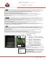
Attach the box on the electrical panel (holes are pre-punched) inside the boiler jacket, using two screws (see picture below).
Connect the box (X7) to the MCBA (X7 or X8) by means of the flat cable (included).
Connect the X1 and/or X2 terminal blocks according to the required signals (see schema) with flexible wires, with the appropriate gage
depending of the current.
Secure the wires on the jackets to avoid any force on the terminals. Close de boiler and proceed with the functional checks.
Nederlands
De AM-4 module bevat 1) een potentiaalvrij alarm relais, 2) een analoog input signaal (0 --> 10V), om de ketel op temperatuur of vermogen te
besturen, rekening houdend met de limietwaarden, die geprogrammeerd zijn in de MCBA en 3) twee logische input signalen om de
ventilator op max/min snelheid te besturen. Ze communiceren met de MCBA. Aansluitingsinformatie is hieronder vermeld, zie ook het technisch
boekje van de MCBA § 7.2.5, 7.2.6 en 7.2.7 voor meer informatie.
De module dient door een erkende installateur geplaatdt worden, overeenkomstig de geldende normen. Het is belangrijk voor elke interventie
de stroomvoorziening te onderbreken.
Plaatst de module op het elektrisch paneel (twee gaten zijn hiervoor geponst) met twee schroeven, zie foto hieronder.
De module (X7) verbinden met de MCBA (X7 of X8) met het lintkabel (meegeleverd).
De connectoren X1 en X2 aansluiten volgens de gewenste signalen (zie schema hieronder) met soepele kabel, de sectie moet overeenkomen
met de gebruikte stroom. De kabels vastmaken op de ommanteling om geen kracht op de aansluiting van de relais uit te voeren.
De voormantel terugplaatsen en de werkingstesten uitvoeren.
Français
Le module AM-4 contient 1) un relais permettant la signalisation à distance du brûleur en arrêt de sécurité, 2) une entrée analogique (0 → 10V)
pour régler la chaudière en température ou puissace, tenant compte des valeurs limites paramétrées dans le MCBA et 3) deux entrées
logiques pour régler le ventilateur à vitesse max. ou min. Ils communiquent avec le MCBA. Consulter le manuel du MCBA § 7.2.5, 7.2.6 et 7.2.7
pour de plus amples explications.
Le module doit être placé par un installateur agréé et en conformité avec les normes en vigueur. Avant installation, couper l'alimentation
électrique de la chaudière.
Fixer le boîtier sur le tableau électrique (trous généralement prévus) à l'intérieur de la chaudière à l'aide de deux vis.
Raccorder le boîtier (X7) au MCBA (X7 ou X8) à l'aide du câble plat (inclus dans le kit).
Raccorder les borniers X1 et X2 selon les signaux souhaités (voir schéma) à l'aide de fils souples à dimensionner en fonction du courant
requis. Attacher les fils pour éviter toute force sur les connexions. Refermer la chaudière, et effectuer la vérification du fonctionnement.
X1: Contact for remote alarm status
Alarmcontact
Contact d'alarme
X2: 1-2 Analog input 0 → 10V (0-100°C or min/max RPM)
Analoog input 0 → 10V (0-100°C of min/max RPM)
Entrée analogique 0 → 10V (0-100°C ou min/max RPM)
X2: 3-4 Logic input "+": fan driven to high speed
Logisch input "+": ventilator tot hoge toerental
Entrée logique "+": ventilateur à vitesse haute
X2: 5-6 Logic input "-": fan driven to low speed
Logisch input "-": ventilator tot lage toerental
Entrée logique "-": ventilateur à vitesse basse
Technical data – Technische gegevens –
Caractéristiques techniques
A
mbient temperature - Omgevings temperatuur - Température
d'ambiance: 0...60°C
X1 Contacts rating – Contacten waarden X1 - Valeurs des contacts
X1: max. 1 A (rms) 230V (-15/+10%) 50 Hz
EN- If inductive loads are connected, take precautions against
peak voltages (RC-circuit)
NL- In geval van inductieve lasten, neem maatregelen tegen
spanningspieken (RC-kring).
FR- Si des charges inductives sont connectées, il faut les
protéger contre des tensions de pointe (circuit RC).
X2-1: + 0,5 --> 10V
X2-2: 0 V
X2-3: 0 / 5V
X2-4: 0 V
X2-5: 0 / 5V
X2-6: 0 V
X7
X1
X2-
1 2 3 4 5 6
Dipswitches
not used
Niet gebruikt
Pas utilisés
▼▼
Documenttranscriptie
AM-4 module Code: 10800124 Installation - Instelling excellence in hot water English On the AM4-module, the following features are available: 1) an alarm relay (free 230 V contact), 2) an analogic input (0 ->10V) to control the boiler on temperature or capacity, taking into account the limiting parameters in the MCBA and 3) two logic inputs to set the fan on min/max speed. They communicate with the MCBA. See below and refer to the MCBA manual § 7.2.5, 7.2.6 and 7.2.7 for detailled information. The module must be mounted by an authorized installer, in accordance with the applicable regulations. Before starting the installation, disconnect the electric power supply. Attach the box on the electrical panel (holes are pre-punched) inside the boiler jacket, using two screws (see picture below). Connect the box (X7) to the MCBA (X7 or X8) by means of the flat cable (included). Connect the X1 and/or X2 terminal blocks according to the required signals (see schema) with flexible wires, with the appropriate gage depending of the current. Secure the wires on the jackets to avoid any force on the terminals. Close de boiler and proceed with the functional checks. Nederlands De AM-4 module bevat 1) een potentiaalvrij alarm relais, 2) een analoog input signaal (0 --> 10V), om de ketel op temperatuur of vermogen te besturen, rekening houdend met de limietwaarden, die geprogrammeerd zijn in de MCBA en 3) twee logische input signalen om de ventilator op max/min snelheid te besturen. Ze communiceren met de MCBA. Aansluitingsinformatie is hieronder vermeld, zie ook het technisch boekje van de MCBA § 7.2.5, 7.2.6 en 7.2.7 voor meer informatie. De module dient door een erkende installateur geplaatdt worden, overeenkomstig de geldende normen. Het is belangrijk voor elke interventie de stroomvoorziening te onderbreken. Plaatst de module op het elektrisch paneel (twee gaten zijn hiervoor geponst) met twee schroeven, zie foto hieronder. De module (X7) verbinden met de MCBA (X7 of X8) met het lintkabel (meegeleverd). De connectoren X1 en X2 aansluiten volgens de gewenste signalen (zie schema hieronder) met soepele kabel, de sectie moet overeenkomen met de gebruikte stroom. De kabels vastmaken op de ommanteling om geen kracht op de aansluiting van de relais uit te voeren. De voormantel terugplaatsen en de werkingstesten uitvoeren. Français Le module AM-4 contient 1) un relais permettant la signalisation à distance du brûleur en arrêt de sécurité, 2) une entrée analogique (0 → 10V) pour régler la chaudière en température ou puissace, tenant compte des valeurs limites paramétrées dans le MCBA et 3) deux entrées logiques pour régler le ventilateur à vitesse max. ou min. Ils communiquent avec le MCBA. Consulter le manuel du MCBA § 7.2.5, 7.2.6 et 7.2.7 pour de plus amples explications. Le module doit être placé par un installateur agréé et en conformité avec les normes en vigueur. Avant installation, couper l'alimentation électrique de la chaudière. Fixer le boîtier sur le tableau électrique (trous généralement prévus) à l'intérieur de la chaudière à l'aide de deux vis. Raccorder le boîtier (X7) au MCBA (X7 ou X8) à l'aide du câble plat (inclus dans le kit). Raccorder les borniers X1 et X2 selon les signaux souhaités (voir schéma) à l'aide de fils souples à dimensionner en fonction du courant requis. Attacher les fils pour éviter toute force sur les connexions. Refermer la chaudière, et effectuer la vérification du fonctionnement. X7 Dipswitches not used Niet gebruikt Pas utilisés ▼▼ X2- 123456 X1 X2-1: + 0,5 --> 10V X2-2: 0 V X2-3: 0 / 5V X2-4: 0 V X2-5: 0 / 5V X2-6: 0 V X1: Contact for remote alarm status Alarmcontact Contact d'alarme X2: 1-2 Analog input 0 → 10V (0-100°C or min/max RPM) Analoog input 0 → 10V (0-100°C of min/max RPM) Entrée analogique 0 → 10V (0-100°C ou min/max RPM) X2: 3-4 Logic input "+": fan driven to high speed Logisch input "+": ventilator tot hoge toerental Entrée logique "+": ventilateur à vitesse haute X2: 5-6 Logic input "-": fan driven to low speed Logisch input "-": ventilator tot lage toerental Entrée logique "-": ventilateur à vitesse basse Technical data – Technische gegevens – Caractéristiques techniques Ambient temperature - Omgevings temperatuur - Température d'ambiance: 0...60°C X1 Contacts rating – Contacten waarden X1 - Valeurs des contacts X1: max. 1 A (rms) 230V (-15/+10%) 50 Hz EN- If inductive loads are connected, take precautions against peak voltages (RC-circuit) NL- In geval van inductieve lasten, neem maatregelen tegen spanningspieken (RC-kring). FR- Si des charges inductives sont connectées, il faut les protéger contre des tensions de pointe (circuit RC). 660Y0700rev: 05/03/2008-
 1
1

in andere talen
- English: ACV AM-4 module Owner's manual
- français: ACV AM-4 module Le manuel du propriétaire
Gerelateerde papieren
Andere documenten
-
RADSON VR28R de handleiding
-
 BrainQ RSC/2 de handleiding
-
Danfoss Expansion Card Installatie gids
-
elco R600 Handleiding
-
-
Astralpool PRO ELYO INVERBOOST NN 71681 User And Service Manual
-
Grundfos UPE Series 2000 Installation And Operating Instructions Manual
-
Mark Interface+ Technical Manual
