
YAMAHA ELECTRONICS CORPORATION, USA 6660 ORANGETHORPE AVE., BUENA PARK, CALIF. 90620, U.S.A.
YAMAHA CANADA MUSIC LTD. 135 MILNER AVE., SCARBOROUGH, ONTARIO M1S 3R1, CANADA
YAMAHA ELECTRONIK EUROPA G.m.b.H. SIEMENSSTR. 22-34, 25462 RELLINGEN BEI HAMBURG, F.R. OF GERMANY
YAMAHA ELECTRONIQUE FRANCE S.A. RUE AMBROISE CROIZAT BP70 CROISSY-BEAUBOURG 77312 MARNE-LA-VALLEE CEDEX02, FRANCE
YAMAHA ELECTRONICS (UK) LTD. YAMAHA HOUSE, 200 RICKMANSWORTH ROAD WATFORD, HERTS WD1 7JS, ENGLAND
YAMAHA SCANDINAVIA A.B. J A WETTERGRENS GATA 1, BOX 30053, 400 43 VÄSTRA FRÖLUNDA, SWEDEN
YAMAHA MUSIC AUSTRALIA PTY, LTD. 17-33 MARKET ST., SOUTH MELBOURNE, 3205 VIC., AUSTRALIA
Printed in Malaysia ID V723000
OWNER’S MANUAL
MODE D’EMPLOI
BEDIENUNGSANLEITUNG
BRUKSANVISNING
MANUALE DI ISTRUZIONI
MANUAL DE INSTRUCCIONES
GEBRUIKSAANWIJZING
RX-V420RDS
Natural Sound AV Receiver
Ampli-tuner audio-vidéo
RX-V420RDS
G B
00RX-V420RDS-cv(ML) 2/12/1, 3:19 PM1

CAUTION
CAUTION: READ THIS BEFORE OPERATING YOUR UNIT.
1 To assure the finest performance, please read this
manual carefully. Keep it in a safe place for future
reference.
2 Install this unit in a well ventilated, cool, dry, clean
place with at least 30 cm on the top, 20 cm on the
right and left, and 10 cm at the back of this unit for
ventilation space — away from direct sunlight, heat
sources, vibration, dust, moisture, and/or cold.
3 Locate this unit away from other electrical
appliances, motors, or transformers to avoid
humming sounds. To prevent fire or electrical shock,
do not place this unit where it may get exposed to
rain, water, and/or any type of liquid.
4 Do not expose this unit to sudden temperature
changes from cold to hot, and do not locate this unit
in a environment with high humidity (i.e. a room with
a humidifier) to prevent condensation inside this unit,
which may cause an electrical shock, fire, damage to
this unit, and/or personal injury.
5 On the top of this unit, do not place:
– Other components, as they may cause damage
and/or discoloration on the surface of this unit.
– Burning objects (i.e. candles), as they may cause
fire, damage to this unit, and/or personal injury.
– Containers with liquid in them, as they may cause
electrical shock to the user and/or damage to this
unit.
6 Do not cover this unit with a newspaper, tablecloth,
curtain, etc. in order not to obstruct heat radiation. If
the temperature inside this unit rises, it may cause
fire, damage to this unit, and/or personal injury.
7 Do not plug in this unit to a wall outlet until all
connections are complete.
8 Do not operate this unit upside-down. It may
overheat, possibly causing damage.
9 Do not use force on switches, knobs and/or cords.
10 When disconnecting the power cord from the wall
outlet, grasp the plug; do not pull the cord.
11 Do not clean this unit with chemical solvents; this
might damage the finish. Use a clean, dry cloth.
12 Only voltage specified on this unit must be used.
Using this unit with a higher voltage than specified is
dangerous and may cause fire, damage to this unit,
and/or personal injury. YAMAHA will not be held
responsible for any damage resulting from use of this
unit with a voltage other than specified.
13 To prevent damage by lightning, disconnect the
power cord from the wall outlet during an electrical
storm.
14 Take care of this unit so that no foreign objects and/
or liquid drops inside this unit.
15 Do not attempt to modify or fix this unit. Contact
qualified YAMAHA service personnel when any
service is needed. The cabinet should never be
opened for any reasons.
16 When not planning to use this unit for long periods of
time (i.e. vacation), disconnect the AC power plug
from the wall outlet.
17 Be sure to read the “TROUBLESHOOTING” section
on common operating errors before concluding that
this unit is faulty.
18 Before moving this unit, press STANDBY/ON to set
this unit in the standby mode, and disconnect the AC
power plug from the wall outlet.
This unit is not disconnected from the AC power source
as long as it is connected to the wall outlet, even if this
unit itself is turned off. This state is called the standby
mode. In this state, this unit is designed to consume a
very small quantity of power.
■ For U.K. customers
If the socket outlets in the home are not suitable for the plug
supplied with this appliance, it should be cut off and an
appropriate 3 pin plug fitted. For details, refer to the
instructions described below.
Note
• The plug severed from the mains lead must be destroyed, as a
plug with bared flexible cord is hazardous if engaged in a live
socket outlet.
■ Special Instructions for U.K. Model
IMPORTANT
THE WIRES IN MAINS LEAD ARE COLOURED IN
ACCORDANCE WITH THE FOLLOWING CODE:
Blue: NEUTRAL
Brown: LIVE
As the colours of the wires in the mains lead of this
apparatus may not correspond with the coloured
markings identifying the terminals in your plug, proceed
as follows:
The wire which is coloured BLUE must be connected to
the terminal which is marked with the letter N or
coloured BLACK. The wire which is coloured BROWN
must be connected to the terminal which is marked with
the letter L or coloured RED.
Making sure that neither core is connected to the earth
terminal of the three pin plug.
0101V420RDS_caution_EN 2/12/1, 1:34 PM2

11
English
BASIC OPERATION
ADVANCED OPERA
TION
APPENDIX
INTRODUCTION
PREPARATION
INTRODUCTION
CONTENTS
INTRODUCTION
FEATURES .......................................................... 2
GETTING STARTED ......................................... 3
Checking the Package Contents ............................. 3
Battery Installation in the Remote Control ............ 3
Battery Replacement .............................................. 3
CONTROLS AND FUNCTIONS ....................... 4
Front Panel ............................................................. 4
Remote Control ...................................................... 6
Using the Remote Control ...................................... 7
Display ................................................................... 8
Rear Panel .............................................................. 9
PREPARATION
SPEAKER SETUP ............................................ 10
Speakers to Be Used ............................................ 10
Speaker Placement ............................................... 10
CONNECTIONS ............................................... 11
Before Connecting Components ........................... 11
Connecting Audio Components ........................... 12
Connecting an External Decoder ......................... 12
Connecting Video Components ............................ 14
Connecting Speakers ............................................ 16
IMPEDANCE SELECTOR Switch ..................... 18
Connecting the Power Supply Cords ................... 18
ADJUSTING THE SPEAKER BALANCE .... 19
Before You Start Adjusting .................................. 19
Using the Test Tone .............................................. 19
BASIC OPERATION
PLAYING A SOURCE ...................................... 21
Input Modes and Indications ................................ 23
Selecting a DSP Program ..................................... 24
Canceling the Sound Effect (turning off the effect
speakers) ........................................................... 25
TUNING ............................................................. 26
Connecting the Antennas ..................................... 26
Automatic Tuning ................................................ 27
Manual Tuning ..................................................... 27
Automatic Preset Tuning
(for RDS stations only) .................................... 28
Manual Preset Tuning .......................................... 29
To Recall a Preset Station .................................... 29
Exchanging Preset Stations .................................. 30
RECEIVING RDS STATIONS ........................ 31
Description of RDS Data ..................................... 31
Changing the RDS Mode ..................................... 31
PTY SEEK Function ............................................ 32
EON Function ...................................................... 33
RECORDING A SOURCE ............................... 34
ADVANCED OPERATION
SET MENU ......................................................... 35
Adjusting the Items on the SET MENU .............. 35
1 SPEAKER SET (speaker mode settings) .......... 36
2 HP TONE CTRL (headphone tone control) ...... 37
3 I/O ASSIGN ...................................................... 38
4 INPUT MODE (initial input mode) .................. 38
5 DOLBY D. SET (Dolby Digital set) ................. 38
6 DTS SET (DTS LFE level) ............................... 39
7 SP DLY TIME (center delay) ............................ 39
8 DIPSLAY SET .................................................. 39
9 MEM. GUARD (memory guard) ...................... 39
DELAY TIME AND SPEAKER OUTPUT
LEVELS .......................................................... 40
Delay Time ........................................................... 40
Sound Output Level of the Center, Right Rear
and Left Rear Speakers, and Subwoofer .......... 40
Adjusting Method ................................................ 41
SLEEP TIMER .................................................. 42
Setting the SLEEP Timer ..................................... 42
Canceling the SLEEP Timer ................................ 42
SOUND FIELD PROGRAM ............................ 43
Hi-Fi DSP Programs ............................................ 43
CINEMA DSP Programs ...................................... 43
APPENDIX
TROUBLESHOOTING .................................... 46
SPECIFICATIONS ............................................ 50
GLOSSARY ....................................................... 51
INDEX ................................................................ 53
0102V420RDS01-09_EN 2/12/1, 1:34 PM1

2
Manufactured under license from Dolby Laboratories.
“Dolby”, “AC-3”, “Pro Logic” and the double-D symbol are
trademarks of Dolby Laboratories.
Confidential Unpublished Works. ©1992-1997 Dolby Laboratories,
Inc. All rights reserved.
Manufactured under license from Digital Theater Systems, Inc. US
Pat. No. 5,451,942 and other world-wide patents issued and
pending. “DTS” and “DTS Digital Surround” are trademarks of
Digital Theater Systems, Inc. Copyright 1996 Digital Theater
Systems, Inc. All Rights Reserved.
• y indicates a tip for your operation.
• Some operations can be performed by using either the buttons on the main unit or on the remote control. In cases when
the button names differ between the main unit and the remote control, the button name on the remote control is given in
parentheses in this manual.
5-Channel Power Amplification
◆ Minimum RMS Output
(0.06% THD, 20 Hz – 20 kHz)
Main: 65 W + 65 W (8 Ω)
Center: 65 W (8 Ω)
Rear: 65 W + 65 W (8 Ω)
Multi-mode Digital Sound Field
Processing
◆ DTS Decoder
◆ Dolby Pro Logic Decoder
◆ Dolby Digital Decoder
◆ Hi-Fi DSP
◆ CINEMA DSP: Combination of YAMAHA DSP
Technology and Dolby Digital, Dolby Pro Logic or
DTS
◆ Virtual CINEMA DSP
◆ SILENT CINEMA
Sophisticated FM/AM Tuner
◆ 40-Station Random Access Preset Tuning
◆ Automatic Preset Tuning
◆ Preset Station Shifting Capability (Preset Editing)
◆ Multi-Functions for RDS Broadcast Reception
Other Features
◆ “SET MENU” which Provides You with 9 Items
for Optimizing This Unit for Your Audio/Video
System
◆ Test Tone Generator for Easier Speaker Balance
Adjustment
◆ 6-Channel External Decoder Input for Other Future
Formats
◆ Video Signal Input and Output Capability
◆ Optical and Coaxial Digital Signal Input Jacks
◆ SLEEP Timer
◆ Remote Control Capability
FEATURES
0102V420RDS01-09_EN 2/12/1, 1:34 PM2

3
English
BASIC OPERATION
ADVANCED OPERA
TION
APPENDIX
INTRODUCTION
PREPARATION
GETTING STARTED
Checking the Package Contents
Check that the following items are included in your package.
Remote control Batteries (AA, R06, UM-3 type) AM loop antenna
Indoor FM antenna
75-ohm/300-ohm antenna adapter
(U.K. model only)
Battery Installation in the Remote
Control
1 Turn the remote control over and slide the
battery compartment cover in the direction of
the arrow.
2 Insert the batteries (AA, R06 or UM-3 type)
according to the polarity markings on the
inside of the battery compartment.
3 Close the battery compartment cover.
Battery Replacement
If the remote control operates only when it is close to the
unit, the batteries are weak. Replace all the batteries with
new ones.
Notes
• Use only AA, R06 or UM-3 batteries for replacement.
• Be sure the battery polarity is correct. (See the illustration inside
the battery compartment.)
• Remove the batteries if the remote control will not be used for an
extended period of time.
• If the batteries have leaked, dispose of them immediately. Avoid
touching the leaked material or letting it come into contact with
clothing, etc. Clean the battery compartment thoroughly before
installing new batteries.
Connection guide
2
1
3
0102V420RDS01-09_EN 2/12/1, 1:34 PM3

4
SURROUND
DIGITAL
SILENT VIDEO AUX
PHONES VIDEO L AUDIO R
6CH INPUTINPUT MODE
INPUT
VOLUME
RDS MODE/FREQ
EON
PTY SEEK
MODE START
TUNING
MODE
PRESET
/TUNING
FM/AM
MEMORY
EDIT
BASS BALANCE SPEAKERS
PROGRAM
PRESET/TUNINGEFFECT A/B/C/D/E
AB
OFF
ON
STANDBY
/ON
DIGITAL
– +
LR
TREBLE
– +
MAN'L/AUTO FM AUTO/MAN'L MONO
6
1
2
3
7
9
0
8
q w
e
r
t
ds
p
fa g
u
o
i
y
5
4
6 EON
Press this button to select the desired program type (NEWS,
INFO, AFFAIRS, SPORT) when you want to tune in to a
radio program of that type automatically.
7 PTY SEEK START
Press this button to begin searching for a station after the
desired program type has been selected in the PTY SEEK
mode.
8 INPUT MODE
Press this button to select the input mode among AUTO,
DTS and ANALOG for the sources that send two or more
types of signals to this unit.
9 VOLUME
Turn this control to turn up or down the volume.
0 6CH INPUT
Press this button to select the source connected to the 6CH
INPUT jacks. The source selected by pressing 6CH INPUT
takes priority over the source selected with INPUT l / h
(or the input selector buttons on the remote control).
CONTROLS AND FUNCTIONS
Front Panel
1 STANDBY/ON
Press this switch to turn on the power of this unit or to set
this unit in the standby mode. Before turning the power on,
set the volume at the minimum level.
Standby mode
In this mode, this unit consumes a very small quantity of
power to receive infrared-signals from the remote
control.
2 Remote control sensor
This receives signals from the remote control.
3 Display
This shows various information.
4 PTY SEEK MODE
Press this button to set the unit in the PTY SEEK mode.
5 RDS MODE/FREQ
When an RDS station is received, press this button to
change the display mode among the PS mode, PTY mode,
RT mode, CT mode (if the station offers those RDS data
services) and/or frequency display mode in turn.
0102V420RDS01-09_EN 2/12/1, 1:34 PM4

5
English
BASIC OPERATION
ADVANCED OPERA
TION
APPENDIX
INTRODUCTION
PREPARATION
q BASS
Turn this control clockwise to increase or counterclockwise
to decrease the low-frequency response.
w TREBLE
Turn this control clockwise to increase or counterclockwise
to decrease the high-frequency response.
Note
• If you increase or decrease the high-frequency or the low-
frequency sound to an extreme level, the tonal quality from the
center and rear speakers may not match that of the left and right
main speakers.
e BALANCE
This control is only effective for the sound from the main
speakers.
Turn the control to adjust the balance of the output volume
from the right and left main speakers to compensate for
sound imbalance caused by the speaker location or listening
room conditions.
r SPEAKERS A/B
Set A or B (or both A and B) to the ON position for the main
speaker system (connected to this unit) that you want to use.
Set the button(s) to the OFF position for the main speaker
system that you don’t want to use.
t PROGRAM l / h
Press l or h to select a DSP program when the effect
speakers (center and rear) are turned on. The name of the
selected program appears on the display.
y EFFECT
Press this button to turn on or off the effect speakers (center
and rear). If you turn them off, all Dolby Digital and DTS
audio signals except for the LFE channel are directed to the
right and left main speakers. In that case, the output levels
of the right and left speakers may not match.
u PHONES jack
Connect the headphones to the PHONES jack so that this
unit outputs audio signals for private listening.
When listening with headphones privately, set both
SPEAKERS A/B to the OFF position.
i VIDEO AUX jacks
Connect an auxiliary audio or video input source such as a
game console to these jacks. To reproduce source signals
from these jacks, select V-AUX as the input source.
o PRESET/TUNING l / h
When “ z ” appears on the display:
This button is used to select a preset station number (1 to 8).
Press l to select a lower and h to select a higher preset
station number.
When “ z ” goes off from the display:
This button is used for tuning. Press l to tune in to lower
frequencies, and h to tune in to higher frequencies.
When this unit is in the PTY SEEK mode, press this button
to select a program type.
p A/B/C/D/E
Press this button to select one of 5 preset station groups (A
to E).
a PRESET/TUNING (EDIT)
Press this button to turn on or off “ z ” on the display and
switch the function between for storing a broadcasting
station (preset tuning) and for tuning. This button is also
used to exchange the assignment of two preset stations with
each other.
s MEMORY (MAN’L/AUTO FM)
Press this button to store the broadcasting stations. Hold
down this button for more than 3 seconds to begin
automatic preset tuning (for FM stations only).
d TUNING MODE (AUTO/MAN’L MONO)
Press this button to switch the tuning mode between
automatic and manual. To use the automatic tuning method,
press this button so that the “AUTO” indicator lights up on
the display. To use the manual tuning method, press this
button so that the “AUTO” indicator goes off.
f FM/AM
Press this button to switch the reception band between FM
and AM.
g INPUT l / h
Press these buttons to select the input source (DVD, AUX,
MD/CD-R, TUNER, CD, V-AUX, VCR, D-TV/CBL) that
you want to listen to or watch. The name of the selected
input source appears on the display.
CONTROLS AND FUNCTIONS
0102V420RDS01-09_EN 2/12/1, 1:34 PM5

6
Remote Control
■ Controlling this unit
1 POWER
Each time you press this button, the unit switches between
the power on and standby mode.
2 TIME/LEVEL
Press this button to select the item in the TIME/LEVEL
mode.
3 –/+
These buttons adjust the settings of the SET MENU and
TIME/LEVEL mode.
4 TEST
Press this button to output the test tone for each speaker.
5 A/B/C/D/E, PRESET –/+
These buttons are used to select a preset station.
A/B/C/D/E: To select one of a group (A to E) of preset
stations
PRESET –/+: To select a preset station number (1 to 8)
6 SLEEP
Press this button to set the SLEEP timer.
7 VOLUME
These buttons are used to adjust the volume level.
: To turn up the volume
: To turn down the volume
8 SET MENU
Press this button to select the items in the SET MENU.
9 DSP PRG+, PRG–
Press these buttons to select a DSP program.
0 EFFECT
Press this button to turn on or off the effect speakers (center
and rear).
q Input selector buttons
These buttons select the input source.
CD: To play a CD
TUNER: To listen to an FM (RDS) or AM
broadcast
MD/CD-R(TAPE): To play an MD or CD recorder (or
tape deck)
DVD: To play a DVD
D-TV/CBL: To watch a TV/digital TV or cable TV
VCR: To play a video cassette
AUX: To use another audio component
V-AUX: To use another audio/video
component
w 6CH INPUT
Press this button to play a source connected to the 6CH
INPUT jacks.
CONTROLS AND FUNCTIONS
1
2
4
3
9
8
0
!
@
q
w
5
6
7
The provided remote control is designed to control all most
commonly used functions of this unit. If a YAMAHA tape
deck or CD player designed for remote control
compatibility is connected to this unit, this remote control
can also control various functions of that component.
0102V420RDS01-09_EN 2/12/1, 1:34 PM6

7
English
BASIC OPERATION
ADVANCED OPERA
TION
APPENDIX
INTRODUCTION
PREPARATION
Using the Remote Control
■ Controlling a YAMAHA tape deck or
CD player
Identify the remote control buttons with your component’s
buttons. If these buttons are identical, their functions will be
the same. Refer to the instructions for each button function
supplied with your component.
! Tape deck buttons
These buttons are used for controlling a tape deck.
• DECK A/B, DIR A and DIR B are only available for a
double cassette tape deck.
• For a single cassette tape deck with an automatic reverse
function, press DIR A to reverse the direction of tape
running.
@ CD player buttons
These buttons are used for controlling a CD player.
• DISC SKIP is only available for a CD player with a CD
changer.
CONTROLS AND FUNCTIONS
The remote control transmits a directional infrared beam. Be
sure to aim the remote control directly at the infrared sensor
during operation. When the sensor is covered or there is a
large object between the remote control and the sensor, the
sensor cannot receive signals. The sensor may not be able to
receive signals properly when it is exposed to direct sunlight
or a strong artificial light (such as a fluorescent or strobe
light). In this case, change the direction of the light or
reposition the unit to avoid direct lighting.
Notes
• Handle the remote control with care.
• Do not spill water, tea or other liquids on the remote control.
• Do not drop the remote control.
• Do not leave or store the remote control in the following
conditions:
– high humidity or temperature such as near a heater, stove or
bath;
– dusty places; or
– extremely low temperature.
Remote control
sensor
Within approximately 6 m
(20 feet)
0102V420RDS01-09_EN 2/12/1, 1:34 PM7

8
Display
ENHANCED
PS PTY RT CT
MEMORY SLEEP
PCM
DSP
DIGITAL
PRO LOGIC
A
SP
B
VIRTUAL
DOLBY DTS
DIGITAL
PRO LOGIC
DISCO 5CH STEREO
MONO TV SPORTS
MOVIE THEATER 1 2
ENTERTAINMENT
GAME
CONCERT HALL
JAZZ CLUB PTY HOLD
NEWSINFOROCK CONCERT
BASS EXT.
AUTO
EON
STEREO
AFFAIRS SPORT
TUNED
dB
ms
KZ
H
1
2
3
4
5
6 7
8
9
0
q
w
r
e
t
u
y
1 t indicator
The “t” indicator lights up when the built-in DTS
decoder is turned on.
2 VIRTUAL indicator
This lights up when using Virtual CINEMA DSP.
3 g and o indicators
“ g ” lights up when the built-in Dolby Digital
decoder is on and the signals of the selected source are
encoded with Dolby Digital. “ o ” lights up when
the built-in Dolby Pro Logic decoder is on.
4 DSP program indicators
This indicates the name of the selected DSP program.
5 PTY HOLD indicator
This lights up while searching for stations in the PTY SEEK
mode.
6 RDS mode indicators
The name(s) of the RDS data offered by the currently
received RDS station light(s) up. Illumination of the red
indicator next to the RDS data name shows that the
corresponding RDS mode is now selected.
7 EON indicator
This lights up when an RDS station that offers the EON data
service is being received.
8 AUTO indicator
This lights up when the unit is in the automatic tuning
mode.
9 STEREO indicator
This lights up when an FM stereo broadcast with sufficient
signal strength is being received.
0 x indicator
“ x ” lights up when the built-in digital sound
field processor is on.
q v indicator
This lights up when this unit is reproducing PCM (pulse
code modulation) digital audio signals.
w Headphones indicator
This lights up when headphones are connected.
e Multi-information display
This display shows various information: for example the
name of the selected input source and the various settings
during adjustment with the SET MENU. The current station
frequency and band (FM or AM) also appear when the tuner
is selected as the input source.
r MEMORY indicator
This flashes for about 5 seconds after pressing MEMORY.
During this period, the displayed station can be stored in the
memory.
t Program type name indicators
The name of the selected program type lights up when the
“EON” indicator lights up.
y TUNED indicator
This lights up when this unit tunes in to a station.
u SLEEP indicator
This lights up while the built-in SLEEP timer is on.
CONTROLS AND FUNCTIONS
0102V420RDS01-09_EN 2/12/1, 1:34 PM8

9
English
BASIC OPERATION
ADVANCED OPERA
TION
APPENDIX
INTRODUCTION
PREPARATION
Rear Panel
1 DIGITAL INPUT jacks
2 6CH INPUT jacks
See pages 12 and 13 for connection information.
3 Antenna input terminals
See page 26 for connection information.
4 Video component jacks
See pages 14 and 15 for connection information.
5 Speaker terminals
See pages 16 and 17 for connection information.
6 AC power cord
Connect to a power outlet.
CONTROLS AND FUNCTIONS
As this terminal is used
for an examination in the
factory, do not connect
any equipment to this
terminal.
(Europe model)
7 AC OUTLET(S)
Use these outlets to supply power to your other audio/video
components (see page 18).
8 Audio component jacks
See pages 12 and 13 for connection information.
9 SUBWOOFER jack
See page 17 for connection information.
0 IMPEDANCE SELECTOR switch
Use this switch to match the amplifier output to your
speaker impedance. Set this unit in the standby mode before
you change the setting of this switch (see page 18).
1
2 3
4 5 6
7
9 0
8
SWITCHED
100W MAX. TOTAL
AC OUTLETS
IMPEDANCE SELECTOR
SET BEFORE POWER ON
MAIN A OR B: 4
MIN. /SPEAKER
A
+
B: 8
MIN. /SPEAKER
CENTER
: 6
MIN. /SPEAKER
REAR
: 6
MIN. /SPEAKER
SPEAKERS
MAIN
+ –
R L
A
– +
B
CENTER REAR
(SURROUND)
R
L
+
–
VIDEO
MONITOR OUT
DVD
DVD
DVD
D-TV/CBL
D-TV/CBL
D-TV/CBL
IN
VCR 1
OUT
VIDEO SIGNAL
AUDIO SIGNAL
SUB
WOOFER
OUTPUT
IN
VCR 1
OUT
OUT(REC)
IN(PLAY)
CD
AUX
MD/CD-R
OPTICAL
COAXIAL
AM ANT GND
FM ANT
75
UNBAL.
TUNER
MAIN
CENTER
SUB WOOFER
SURROUND
DIGITAL
INPUT
6CH INPUT
CD
MAIN A OR B: 8
MIN. /SPEAKER
A
+
B:
16
MIN. /SPEAKER
CENTER
: 8
MIN. /SPEAKER
REAR
: 8
MIN. /SPEAKER
R
L
R
L
MAINS
R
L
0102V420RDS01-09_EN 2/12/1, 1:34 PM9

10
SPEAKER SETUP
Speakers to Be Used
This unit is designed to provide the best sound-field quality
with a 5-speaker system, using main speakers, rear speakers
and a center speaker. If you use different brands of speakers
(with different tonal qualities) in your system, the tone of a
moving human voice and other types of sound may not shift
smoothly. We recommend that you use speakers from the
same manufacture to ensure even tonal quality.
The main speakers are used for the main source sound plus
the effect sounds. They will probably be the speakers from
your present stereo system. The rear speakers are used for
the effect and surround sounds, and the center speaker is for
the center sounds (dialog, vocals, etc.). If for some reason it
is not practical to use a center speaker, you can do without
it. Best results, however, are obtained with the full system.
The main speakers should be high-performance models and
have enough power-handling capacity to accept the
maximum output of your audio system. The other speakers
do not have to be equal to the main speakers. For precise
sound localization, however, it is ideal to use high-
performance models that can reproduce sounds over the full
range for the center speaker and the rear speakers.
■ Use of a subwoofer expands your
sound field
It is also possible to further expand your system with the
addition of a subwoofer. The use of a subwoofer is effective
not only for reinforcing bass frequencies from any or all
channels, but also for reproducing the LFE (low frequency
effect) channel with high fidelity when playing back a
source encoded with Dolby Digital or DTS. The YAMAHA
Active Servo Processing Subwoofer System is ideal for
natural and lively bass reproduction.
Speaker Placement
Refer to the following diagram when you place the
speakers.
Main speaker (R)
Center speaker
Main
speaker (L)
Subwoofer
Rear speaker (L)
Rear speaker (R)
1.8 m
■ Main speakers
Place the right and left main speakers an equal distance
from the ideal listening position. The distance of each
speaker from each side of the TV monitor should be the
same.
■ Rear speakers
Place these speakers behind your listening position, facing
slightly inwards, nearly 1.8 m (approx. 6 feet) above the
floor.
■ Center speaker
Align the front face of the center speaker with the front face
of your TV monitor. Place the speaker as close to the
monitor as possible, such as directly over or under the
monitor and centrally between the main speakers.
Note
• If the center speaker is not used, the sound will be heard from the
right and left main speakers. In that case, “CENTER SP” in the
SET MENU is set to the NON position.
■ Subwoofer
The position of the subwoofer is not so critical, because low
bass sounds are not highly directional. But it is better to
place the subwoofer near the main speakers. Turn it slightly
toward the center of the room to reduce the wall reflections.
CAUTION
Please use magnetically shielded speakers.
Sometimes a video monitor may be adversely affected
even when magnetically shielded speakers are used.
Separate the speakers from the monitor if this happens.
PREPARATION
0103V420RDS10-20_EN 2/12/1, 1:34 PM10

11
English
BASIC OPERATION
ADVANCED OPERA
TION
APPENDIX
INTRODUCTION
PREPARATION
CONNECTIONS
Before Connecting Components
CAUTION
Never connect this unit and other components to mains power until all connections between components have been
completed.
Be sure all connections are made correctly, that is to say L (left) to L, R (right) to R, “+” to “+” and “–” to “–”. Some
components require different connection methods and have different jack names. Refer to the instructions for each
component to be connected to this unit.
When you connect other YAMAHA audio components (such as a tape deck, MD recorder and CD player or changer), connect
it to the jacks with the same number labels as !, #, $ etc.
Use RCA-type pin plug cables for connecting audio/video components with the exception described later.
The input and output jacks for pin plugs can be distinguished as follows:
Yellow video signals (composite)
White analog audio signals for the left channel
Red analog audio signals for the right channel
coaxial digital signals
After completing all connections, check them again to make sure they are correct.
V V
C C
L
R
L
R
0103V420RDS10-20_EN 2/12/1, 1:34 PM11

12
■ Connecting an MD recorder, CD
recorder or tape deck
Connect the analog input/output jack of your recording
component to the AUDIO jacks.
Note
• When you connect a recording component to this unit, keep its
power on while using this unit. If the power is off, this unit may
distort the sound from other components.
Connecting an External Decoder
This unit is equipped with 6 additional input jacks (left and
right MAIN, CENTER, left and right SURROUND and
SUBWOOFER) for discrete multi-channel input from an
external decoder, sound processor or pre-amplifier.
Connect the output jacks on your external decoder to the
6CH INPUT jacks. Be sure to match the left and right
outputs to the left and right input jacks for the main and
surround channels.
Notes
• When you select 6CH INPUT as the input source, this unit
automatically turns off the digital sound field processor, and you
cannot listen to DSP programs.
• When you select 6CH INPUT as the input source, changing items
of “1 SPEAKER SET” in the SET MENU is not affected (except
“MAIN LVL”).
CONNECTIONS
Connecting Audio Components
■ Connecting to digital jacks
This unit has digital jacks for direct transmission of digital
signals through either coaxial or fiber optic cables. You can
use the digital jacks to input PCM, Dolby Digital and DTS
bitstreams. When you connect components to both the
COAXIAL and OPTICAL jacks, priority is given to the
input signals from the COAXIAL jack.
y
• You can designate the input for each digital jack according to
your component by using “3 I/O ASSIGN” in the SET MENU.
Notes
• When making connections between the digital signal jacks, you
should connect the components to the same-named analog audio
signal jacks of this unit, because a digital signal cannot be
recorded by a recording component connected to this unit.
• All digital signal input jacks are applicable to sampling
frequencies of 32 kHz, 44.1 kHz and 48 kHz.
About the dust protection cap
Pull out the cap from the optical jack before
you connect the fiber optic cable. Do not
discard the cap. When you are not using the
optical jack, be sure to put the cap back in
place. This cap protects the jack from dust.
Note
• The OPTICAL jacks on this unit conform to the EIA standard. If
you use a fiber optic cable that does not conform to this standard,
this unit may not function properly.
■ Connecting a CD player
y
• The COAXIAL jack is available for a CD player which has
coaxial digital output jack.
• When you connect a CD player to both the analog and digital
jacks, priority is given to the input signals from the digital jack.
0103V420RDS10-20_EN 2/12/1, 1:34 PM12

13
English
BASIC OPERATION
ADVANCED OPERA
TION
APPENDIX
INTRODUCTION
PREPARATION
VIDEO
MONITOR OUT
DVD
DVD
DVD
D-TV/CBL
D-TV/CBL
D-TV/CBL
IN
VCR 1
OUT
VIDEO SIGNAL
AUDIO SIGNAL
IN
VCR 1
OUT
OUT(REC)
IN(PLAY)
CD
AUX
MD/CD-R
OPTICAL
COAXIAL
AM ANT GND
FM ANT
75
UNBAL.
TUNER
MAIN
CENTER
SUB WOOFER
SURROUND
DIGITAL
INPUT
6CH INPUT
CD
R
L
R
L
R
L
L R
L R
L
R
C
L
R
L
R
OUTPUT
COAXIAL
OUTPUT
SUBWOOFER
OUTPUT
CENTER
OUTPUT
MAIN
OUTPUT
SURROUND
OUTPUT
INPUT OUTPUTOUTPUT
L R
L
R
C
MD recorder or
CD recorder
CD player
External decoder
(Europe model)
indicates signal direction
indicates left analog cables
indicates right analog cables
indicates coaxial cables
CONNECTIONS
Audio component
0103V420RDS10-20_EN 2/12/1, 1:34 PM13

14
Connecting Video Components
■ Audio signal jacks
Be sure to connect the right channel (R), left channel (L), input (IN) and output (OUT) properly.
■ Video signal jacks
Be sure to connect the input (IN) and output (OUT) properly.
■ TV monitor with a 21-pin connector
Make a connection as shown on page 15 with a commercially available SCART-plug connector cable.
■ VIDEO AUX jacks (on the front panel)
These jacks are used to connect any video input source such
as a game console to this unit.
AUDIO OUT R
AUDIO OUT L
VIDEO OUT
V
L
R
VIDEO AUX
VIDEO L AUDIO R
CONNECTIONS
Game console
0103V420RDS10-20_EN 2/12/1, 1:34 PM14

15
English
BASIC OPERATION
ADVANCED OPERA
TION
APPENDIX
INTRODUCTION
PREPARATION
VIDEO
MONITOR OUT
DVD
DVD
DVD
D-TV/CBL
D-TV/CBL
D-TV/CBL
IN
VCR 1
OUT
VIDEO SIGNAL
AUDIO SIGNAL
SUB
WOOFER
OUTPUT
IN
VCR 1
OUT
OUT(REC)
IN(PLAY)
CD
AUX
MD/CD-R
OPTICAL
COAXIAL
AM ANT GND
FM ANT
75
UNBAL.
TUNER
MAIN
CENTER
SUB WOOFER
SURROUND
DIGITAL
INPUT
6CH INPUT
CD
R
L
R
L
R
L
V
V
L
R
L
R
L
R
OPTICAL
OUTPUT
VIDEO
OUTPUT
AUDIO OUTPUTAUDIO OUTPUT VIDEO INPUT
VIDEO
OUTPUT
AUDIO
INPUT
V
O
O
OPTICAL
OUTPUT
L
R
AUDIO
OUTPUT
VIDEO
OUTPUT
V
V
V
R
L
VIDEO
INPUT
L
R
V
O
DVD player
Video monitor
SCART-plug
No connection
TV/digital TV or
cable TV/satellite
tuner
VCR
indicates signal direction
indicates left analog cables
indicates right analog cables
indicates optical cables
indicates video cables
When using an LD player
Connect the LD player output to the DVD jack.
If the LD player has an OPTICAL digital output jack, connect it to this unit’s OPTICAL DVD jack. If it has analog jacks,
connect it to the analog DVD jacks. If it has an “RF OUTPUT jack” to output a Dolby Digital RF signal (AC-3), use a
commercially available RF demodulator and connect it to the OPTICAL DVD jack.
If connecting a DVD player and an LD player, connect the LD player to the digital input jack (ex. D-TV/CBL) or the analog
input jack (D-TV/CBL or VCR 1). For details on connections and operations, refer to the operation instructions for the LD
player.
Note that this unit’s remote control can be used to operate the LD player by setting the corresponding manufacturer code for
the DVD/LD mode.
CONNECTIONS
(Europe model)
0103V420RDS10-20_EN 2/12/1, 1:34 PM15

16
Connecting Speakers
Be sure to connect the right channel (R), left channel (L), “+” (red) and “–” (black) properly. If the connections are faulty, no
sound will be heard from the speakers, and if the polarity of the speaker connections is incorrect, the sound will be unnatural
and lack bass.
CAUTION
• Use speakers with the specified impedance shown on the rear panel of this unit.
• Do not let the bare speaker wires touch each other and do not let them touch any metal part of this unit. This could
damage the unit and/or speakers.
■ Speaker cables
1 Remove approx. 10 mm (3/8”) of insulation
from each of the speaker cables.
2 Twist the exposed wires of the cable together
to prevent short circuits.
■ Connecting to the MAIN SPEAKERS terminals
1 Unscrew the knob.
2 Insert one bare wire into the hole in the side of
each terminal.
3 Tighten the knob to secure the wire.
■ Connecting to the REAR and CENTER SPEAKERS terminals
1 Open the tab.
2 Insert one bare wire into the hole of each
terminal.
3 Return the tab to secure the wire.
12
10 mm (3/8”)
2
1
3
Red: positive (+)
Black: negative (–)
Red: positive (+)
Black: negative (–)
■ Main speaker terminals
One or two speaker systems can be connected to these terminals. If you use only one speaker system, connect it to either of
the SPEAKERS A or B terminals.
■ Rear speaker terminals
A rear speaker system can be connected to these terminals.
■ Center speaker terminals
A center speaker can be connected to these terminals.
CONNECTIONS
2
1
3
0103V420RDS10-20_EN 2/12/1, 1:34 PM16

17
English
BASIC OPERATION
ADVANCED OPERA
TION
APPENDIX
INTRODUCTION
PREPARATION
■ Subwoofer connection
When using a subwoofer with built-in amplifier, including
the YAMAHA Active Servo Processing Subwoofer System,
connect the input jack of the subwoofer system to this jack.
Low bass signals distributed from the main, center and/or
rear channels are directed to this jack. (The cut-off
frequency of this jack is 90 Hz.) The LFE (low-frequency
effect) signals generated when Dolby Digital or DTS is
decoded are also directed if they are assigned to this jack.
Notes
• Adjust the subwoofer volume according to the operation
instructions for the subwoofer. (Fine adjustment is possible using
this unit’s output level control of the effect speakers.)
• Depending on the settings of “1 SPEAKER SET”, “LFE LEVEL
(5 DOLBY D. SET)” and “6 DTS SET” in the SET MENU, some
signals may not be output from the SUBWOOFER jack.
SWITCHED
100W MAX. TOTAL
AC OUTLETS
IMPEDANCE SELECTOR
SET BEFORE POWER ON
MAIN A OR B: 4
MIN. /SPEAKER
A
+
B: 8
MIN. /SPEAKER
CENTER
: 6
MIN. /SPEAKER
REAR
: 6
MIN. /SPEAKER
SPEAKERS
MAIN
+
–
R L
A
–
+
B
CENTER REAR
(SURROUND)
R
L
+
–
SUB
WOOFER
OUTPUT
MAIN A OR B: 8
MIN. /SPEAKER
A
+
B:
16
MIN. /SPEAKER
CENTER
: 8
MIN. /SPEAKER
REAR
: 8
MIN. /SPEAKER
MAINS
Main speakers A
Right
Left
Main speakers B
Right Left
(Europe model)
Center speaker Rear speakers
Right Left
Subwoofer
system
CONNECTIONS
0103V420RDS10-20_EN 2/12/1, 1:34 PM17

18
IMPEDANCE SELECTOR Switch
WARNING
Do not change the IMPEDANCE SELECTOR switch setting while the power to this unit is on, otherwise the unit may be
damaged.
If this unit fails to turn on when STANDBY/ON (or POWER) is pressed, the IMPEDANCE SELECTOR switch may not
be fully slid either position. If so, slide the switch to either position fully when this unit is in the standby mode.
Select the right or left position according to the impedance of speakers in your system. Be sure to move this switch only
when this unit is in the standby mode.
SWITCHED
100W MAX. TOTAL
AC OUTLETS
IMPEDANCE SELECTOR
SET BEFORE POWER ON
MAIN A OR B: 4
MIN. /SPEAKER
A
+
B: 8
MIN. /SPEAKER
CENTER
: 6
MIN. /SPEAKER
REAR
: 6
MIN. /SPEAKER
MAIN A OR B: 8
MIN. /SPEAKER
A
+
B:
16
MIN. /SPEAKER
CENTER
: 8
MIN. /SPEAKER
REAR
: 8
MIN. /SPEAKER
MAINS
Switch
position
Speaker
Impedance level
Left
Main
If you use one set of main speakers, the impedance of
each speaker must be 4 Ω or higher.
If you use two sets of main speakers, the impedance of
each speaker must be 8 Ω or higher.
Center The impedance must be 6 Ω or higher.
Rear The impedance of each speaker must be 6 Ω or higher.
Right
Main
If you use one set of main speakers, the impedance of
each speaker must be 8 Ω or higher.
If you use two sets of main speakers, the impedance of
each speaker must be 16 Ω or higher.
Center The impedance must be 8 Ω or higher.
Rear The impedance of each speaker must be 8 Ω or higher.
Connecting the Power Supply Cords
After completing all connections, connect the AC power cord to an AC power outlet. Disconnect the AC power cord if you
will not use this unit for a long period of time.
■ AC OUTLETS (SWITCHED)
Europe model .................................................... 2 OUTLETS
U.K. model .......................................................... 1 OUTLET
Use these outlets to connect the power cords only from your
audio/video components to this unit. The power to the AC
OUTLET(S) is controlled by this unit’s STANDBY/ON (or
POWER). These outlets will supply power to any connected
component whenever this unit is turned on. The maximum
power (total power consumption of components) that can be
connected to the AC OUTLET(S) is 100 W.
(Europe model)
IMPEDANCE
SELECTOR
CONNECTIONS
SWITCHED
100W MAX. TOTAL
AC OUTLETS
IMPEDANCE SELECTOR
SET BEFORE POWER ON
MAIN A OR B: 4
MIN. /SPEAKER
A
+
B: 8
MIN. /SPEAKER
CENTER
: 6
MIN. /SPEAKER
REAR
: 6
MIN. /SPEAKER
MAIN A OR B: 8
MIN. /SPEAKER
A
+
B:
16
MIN. /SPEAKER
CENTER
: 8
MIN. /SPEAKER
REAR
: 8
MIN. /SPEAKER
MAINS
(Europe model)
To AC outlet
SWITCHED
0103V420RDS10-20_EN 2/12/1, 1:34 PM18

19
English
BASIC OPERATION
ADVANCED OPERA
TION
APPENDIX
INTRODUCTION
PREPARATION
ADJUSTING THE SPEAKER BALANCE
Using the Test Tone
The adjustment of each speaker sound output level should
be performed at your listening position with the remote
control.
1 Press TEST.
“TEST LEFT” appears on the display.
2 Turn up the volume.
You will hear a test tone (like pink noise) from each
speaker for about two seconds in following order: left
main speaker, center speaker, right main speaker, right
rear speaker and left rear speaker. The display changes
as shown below.
Notes
• If the test tone cannot be heard, turn down the volume, set the unit
in the standby mode and check the speaker connections.
• If the test tone cannot be heard from the center speaker, check the
setting of “CENTER SP” in the SET MENU.
This procedure lets you adjust the sound output level
balance between the main, center and rear speakers by using
the built-in test tone generator. When this adjustment is
performed, the sound output level heard at the listening
position will be the same from each speaker. This is
important for the best performance of the digital sound field
processor, the Dolby Pro Logic decoder, Dolby Digital
decoder and DTS decoder.
Note
• Since this unit cannot enter the test mode while headphones are
connected to this unit, be sure to unplug the headphones from the
PHONES jack when using the test tone.
Before You Start Adjusting
1 Set the volume at the
minimum level.
2 Turn the power on.
3 Press SPEAKERS A or B
to select the main
speakers to be used.
If you use two main speaker
systems, press both A and B.
4 Set BASS, TREBLE and BALANCE to the
center position.
SILENT
PHONES VIDEO L AUDIO R
6CH INPUTINPUT MODE
INPUT
VOLUME
RDS MODE/FREQ
EON
PTY SEEK
MODE START
TUNING
MODE
PRESET
/TUNING
FM/AM
MEMORY
EDIT
BASS BALANCE SPEAKERS
PROGRAM
PRESET/TUNINGEFFECT A/B/C/D/E
AB
OFF
ON
DIGITAL
–
+
LR
TREBLE
–
+
MAN'L/AUTO FM AUTO/MAN'L MONO
SURROUND
DIGITAL
STANDBY
/ON
VIDEO AUX
12
4
3
VOLUME
STANDBY
/ON
SPEAKERS
AB
OFF
ON
BASS BALANCE
–
+
LR
TREBLE
–
+
4
1,5
2
TEST
LEFT
TEST
RIGHT
TEST L SUR. TEST R SUR.
TEST CENTER
0103V420RDS10-20_EN 2/12/1, 1:34 PM19

20
3 Adjust BALANCE on the
front panel so that the
sound output level of the
right main speaker and the
left main speaker is the
same.
4 Press –/+ repeatedly to
adjust the output level of
the speaker currently
outputting the test tone so
that it becomes almost the
same as that of the main
speakers.
While adjusting, the test tone is heard from the selected
speaker.
5 When the adjustment is complete, press TEST.
Test tone stops.
Notes
• If “CENTER SP” in the SET MENU is set to the NON position,
the sound output level of the center speaker cannot be adjusted in
step 4. The center channel sound is automatically output from the
right and left main speakers.
• For details on adjusting the subwoofer speaker, refer to “DELAY
TIME AND SPEAKER OUTPUT LEVELS” on page 40.
• After adjusting with the test tone, it is possible to adjust the
speaker level to taste while listening to the playback of an actual
source. Refer to “DELAY TIME AND SPEAKER OUTPUT
LEVELS” on page 40.
y
• Once you have completed the adjustments, you can only adjust
the overall volume level of your audio system by using VOLUME
(or VOLUME ( / )).
• If there is insufficient sound output from the center and rear
speakers, you may decrease the main speaker output level by
setting “MAIN LVL” in the SET MENU to “–10 dB”.
Front panel
BALANCE
LR
ADJUSTING THE SPEAKER BALANCE
0103V420RDS10-20_EN 2/12/1, 1:35 PM20

21
English
BASIC OPERATION
ADVANCED OPERA
TION
APPENDIX
INTRODUCTION
PREPARATION
PLAYING A SOURCE
SILENT
PHONES VIDEO L AUDIO R
6CH INPUTINPUT MODE
INPUT
VOLUME
RDS MODE/FREQ
EON
PTY SEEK
MODE START
TUNING
MODE
PRESET
/TUNING
FM/AM
MEMORY
EDIT
BASS BALANCE SPEAKERS
PROGRAM
PRESET/TUNINGEFFECT A/B/C/D/E
AB
OFFON
STANDBY
/ON
DIGITAL
– +
LR
TREBLE
– +
MAN'L/AUTO FM AUTO/MAN'L MONO
SURROUND
DIGITAL
VIDEO AUX
1,6
2
6
3
4
7
2
7
4
6
4 Select the desired input source with INPUT
l / h (or the input selector buttons). (Turn on
the video monitor for video sources.)
The name of the selected input source appears on the
display.
To select a source connected to the 6CH INPUT
jacks
Press 6CH INPUT so that “6CH INPUT” appears on the
display.
Notes
• An audio source can not be played if “6CH INPUT” appears.
Press 6CH INPUT to turn off “6CH INPUT”.
• If you select and play a video source when “6CH INPUT”
appears, the playback result will be a video image from the video
source and the sound from the audio source selected by using
“6CH INPUT”.
y
• The current input mode is also shown. Refer to “Input Modes and
Indications” on page 23 for details.
SPEAKERS
AB
OFF
ON
Front panel
VOLUME
Front panel
Remote control
6CH INPUT
Front panel
Input source
BASIC OPERATION
STANDBY
/ON
Front panel Remote control
or
or
or
Remote control
INPUT
Front panel
1 Set the volume at the
minimum level.
2 Turn the power on.
3 Press SPEAKERS A or B
to select the main
speakers to be used.
If you use two main speaker
systems, press both A and B.
0104V420RDS21-25_EN 2/12/1, 1:35 PM21

22
5 Play the source.
Refer to the instructions for the source component (and
“TUNING” for details).
6 Adjust the volume to the desired output level.
If desired, adjust BASS, TREBLE, BALANCE, etc.
These controls are only effective for the sound from the
main speakers.
• BASS controls the low-frequency response.
• TREBLE controls the high-frequency response.
• BALANCE adjusts the balance of the output volume
from the right and left main speakers.
7 Use the digital sound field processor.
Refer to “Selecting a DSP Program”.
PLAYING A SOURCE
PROGRAM
Front panel
Remote control
or
VOLUME
Front panel
Remote control
or
BASS BALANCE
–
+
LR
TREBLE
–
+
Front panel
■ When you have finished using this
unit
Press STANDBY/ON (or POWER) to set this
unit in the standby mode.
■ BGV (background video) function
The BGV function allows you to combine a video image
from a video source with a sound from an audio source.
(For example, you can listen to classical music while you
are watching a video.) This function can only be controlled
with the remote control.
Play a video source, and then select an audio source with
the input selector buttons on the remote control. The BGV
function does not work if you select the audio source with
INPUT l / h on the front panel.
0104V420RDS21-25_EN 2/12/1, 1:35 PM22

23
English
BASIC OPERATION
ADVANCED OPERA
TION
APPENDIX
INTRODUCTION
PREPARATION
■ Notes on playing a source
encoded with a DTS signal
• If the digital output data of the player has been processed
in any way, you may not be able to perform DTS
decoding even if you make a digital connection between
this unit and the player.
• If you play a source encoded with a DTS signal and set
the input mode to ANALOG, this unit reproduces the
noise of an unprocessed DTS signal. When you want to
play a DTS source, be sure to connect the source to a
digital input jack and set the input mode to AUTO or
DTS.
• If you switch the input mode to ANALOG while playing
a source encoded with a DTS signal, this unit reproduces
no sound.
• The following phenomena may occur if the input mode
is set to AUTO when playing back a source encoded with
DTS:
– If you continue to play a source encoded with a DTS
signal, this unit automatically switches to the “DTS-
decoding” mode to prevent noise from being generated
during subsequent operation. (The “t” indicator
lights up on the display.) The “t” indicator may flash
immediately after playback of a source encoded with a
DTS signal has finished. Only a source encoded with a
DTS signal can be played back while this indicator is
flashing. (The indicator will flash for less than a minute.)
If you want to play a normal PCM source soon, set the
input mode back to AUTO.
– The “t” indicator may flash when a search or skip
operation is performed. If this status continues for a
certain length of time, the unit will automatically switch
from the “DTS-decoding” mode to PCM digital signal
input mode and the “t” indicator will go out.
Input Modes and Indications
This unit comes with various input jacks. If your component
is connected to more than one type of input jack, you can set
the priority of the input signal.
Press INPUT MODE (or the input selector
button that you have pressed to select the
input source on the remote control) repeatedly
until the desired input mode is shown on the
display.
PLAYING A SOURCE
AUTO: In this mode, the input signal is
automatically selected in the following
order:
1) Dolby Digital or DTS signal
2) Digital (PCM) signal
3) Analog signal
DTS: In this mode, only the digital input
signal encoded with DTS is selected
even if another signal is input at the
same time.
ANALOG (ANLG): In this mode, only the analog input
signal is selected even if a digital
signal is input at the same time.
Notes
• If digital signals are input from both the COAXIAL and
OPTICAL jacks, the digital signal from the COAXIAL jack is
selected.
• When AUTO is selected, this unit automatically determines the
type of signal. If this unit detects a Dolby Digital or DTS signal,
the decoder automatically switches to the appropriate setting and
reproduces 5.1 channel source.
• The sound output may be interrupted for some LD players and
DVD players in the following situation:
When the input mode has been set to AUTO and a search is
performed while playing the source encoded with a Dolby Digital
or DTS signal, the sound may delay for a moment when playback
is resumed.
• Depending on the LD player, playback may not be made when
playing an LD that is not digitally recorded with the input mode
set to AUTO. If this happens, set the input mode to ANALOG.
Front panel
or
Remote control
Input mode
INPUT MODE
0104V420RDS21-25_EN 2/12/1, 1:35 PM23

24
Selecting a DSP Program
You can enhance your listening experience by selecting a
DSP program. Refer to “SOUND FIELD PROGRAM” for
details about each program.
y
• Make sure that the sound effect is turned on (see page 25).
Press PROGRAM l or h (or DSP PRG+ or
PRG–) repeatedly to select the desired
program.
The name of the selected program appears for a
moment and the selected DSP program indicator lights
up on the display.
PROGRAM
PLAYING A SOURCE
Notes
• Choose a DSP program based on your listening preference, and
not on the name of the program. The acoustics of your listening
room affect the DSP program. Minimize the sound reflections in
your room to maximize the effect created by the program.
• When you select an input source, this unit automatically selects
the last DSP program used with that source.
• When you set this unit in the standby mode, the current source
and DSP program are memorized and are automatically selected
when you turn on the power again.
• If a Dolby Digital or DTS signal is input when the input mode is
set to AUTO, the DSP program automatically switches to the
appropriate decoding program.
• When a monaural source is being played with PRO LOGIC/
NORMAL or PRO LOGIC/ENHANCED, no sound will be heard
from the main speakers and the rear speakers. Sound can only be
heard from the center speaker. However, if “CENTER SP” in the
SET MENU is set to NON, the center channel sound is output
from the main speakers.
• When a source connected to the 6CH INPUT jacks of this unit is
selected, the digital sound field processor cannot be used.
SILENT
PHONES VIDEO L AUDIO R
6CH INPUTINPUT MODE
INPUT
VOLUME
RDS MODE/FREQ
EON
PTY SEEK
MODE START
TUNING
MODE
PRESET
/TUNING
FM/AM
MEMORY
EDIT
BASS BALANCE SPEAKERS
PROGRAM
PRESET/TUNINGEFFECT A/B/C/D/E
AB
OFF
ON
STANDBY
/ON
DIGITAL
– +
LR
TREBLE
– +
MAN'L/AUTO FM AUTO/MAN'L MONO
SURROUND
DIGITAL
VIDEO AUX
PROGRAM /
DSP
DIGITAL
MOVIE THEATER 1
BASS EXT.
DSP
PRG+,PRG–
Front panel
or
Remote control
DSP program name
y
• If desired, adjust the delay time and the sound output level of each
speaker. (Refer to “DELAY TIME AND SPEAKER OUTPUT
LEVELS” on page 40 for details.)
0104V420RDS21-25_EN 2/12/1, 1:35 PM24

25
English
BASIC OPERATION
ADVANCED OPERA
TION
APPENDIX
INTRODUCTION
PREPARATION
■ Virtual CINEMA DSP and SILENT
CINEMA
Virtual CINEMA DSP
Virtual CINEMA DSP allows you to enjoy the sound field
effects of the DSP program without rear speakers. Using
YAMAHA original technology, natural surround
reproduction is possible through the generation of a virtual
speaker.
The sound field processing is changed to the Virtual
CINEMA DSP mode by setting “REAR LR SP” on the SET
MENU to NON. Virtual CINEMA DSP is performed by
using the main speakers.
Note
• This unit is not set in the Virtual CINEMA DSP mode even if
“REAR LR SP” is set to NON in the following cases:
– when the 5CH STEREO, PRO LOGIC/NORMAL, DOLBY
DIGITAL/NORMAL or DTS/NORMAL program is selected;
– when the sound effect is turned off;
– when 6CH INPUT is selected as the input source;
– when the Dolby Digital KARAOKE source is played;
– when using the test tone; or
– when connecting the headphones (you will hear SILENT
CINEMA).
SILENT CINEMA
SILENT CINEMA allows you to enjoy the realistic feel of
the DSP program while using headphones. This feature
delivers powerful surround reproduction just as if listening
through the speakers.
You can listen to SILENT CINEMA by connecting your
headphones to the PHONES jack while the effect speakers
are on.
EFFECT
Front panel
PLAYING A SOURCE
or
Canceling the Sound Effect (turning
off the effect speakers)
Press EFFECT to cancel the sound effect and
monitor only the main sound.
Press EFFECT again to turn the sound effect back on.
Notes
• If the sound effect is canceled when Dolby Digital or DTS is
decoding, the sounds of the center and rear channels are mixed
and output from the main speakers.
• If you turn off the sound effect when Dolby Digital or DTS is
decoding, it may happen that the sound is output faintly or not
output normally, depending on the source. In that case, turn back
on the sound effect.
Remote control
0104V420RDS21-25_EN 2/12/1, 1:35 PM25

26
TUNING
Connecting the Antennas
Both AM and FM indoor antennas are included with this unit. In general, these antennas should provide sufficient signal
strength.
Connect each antenna correctly to the designated terminals.
Indoor FM
antenna
(included)
AM ANT GND
FM ANT
75
UNBAL.
TUNER
5
4
Antenna stand
Connecting a coaxial cable to the included
75-ohm/300-ohm antenna adapter (U.K. model
only)
11 (7/16)
8 (5/16)
6 (1/14)
1
2
3
54
Cover
Unit: mm
(inch)
Lead wire
Clamp with
pliers.
Clamp
with
pliers.
Insert the wire
into the slot.
Open the cover of the
included 75-ohm/300-ohm
antenna adapter.
Cut the external sleeve of
the 75-ohm coaxial cable
and prepare it for
connection.
Cut the lead wire and
remove it.
Insert the cable wire into the
slot, and clamp it with
pliers.
Snap the cover into
place.
AM loop
antenna
(included)
Ground (GND terminal)
For maximum safety and
minimum interference, connect
the antenna GND terminal to a
good earth ground. A good earth
ground is a metal stake driven
into moist earth.
■ Connecting the indoor FM antenna
Connect the included indoor FM antenna to the FM ANT
75Ω UNBAL. terminal.
Note
• Do not connect an outdoor FM antenna and the indoor FM
antenna at the same time.
■ Connecting the AM loop antenna
1 Press and hold the tab to unlock the terminal
hole.
2 Insert the AM loop antenna lead wires into the
AM ANT and GND terminals.
3 Release the tab to lock the lead wires.
Lightly pull the lead wires to confirm a good
connection.
4 Attach the loop antenna to the antenna stand.
5 Orient the AM loop antenna so that the best
reception is obtained.
y
• The AM loop antenna can be removed from the stand and
attached to a wall, etc.
Notes
• The AM loop antenna should be placed away from this unit.
• The AM loop antenna should always be connected, even if an
outdoor AM antenna is connected to this unit.
A properly installed outdoor antenna provides clearer
reception than an indoor one. If you experience poor
reception quality, an outdoor antenna may improve the
quality. Consult the nearest authorized YAMAHA dealer
or service center about the outdoor antennas.
1
2
3
(Europe model)
0105V420RDS26-30_EN 2/12/1, 1:35 PM26

27
English
BASIC OPERATION
ADVANCED OPERA
TION
APPENDIX
INTRODUCTION
PREPARATION
TUNING
Automatic Tuning
Automatic tuning is effective when station signals are
strong and there is no interference.
1 Use INPUT l / h to select
TUNER as the input
source.
2 Press FM/AM to select the reception band (FM
or AM).
“FM” or “AM” appears on the display.
3 Press TUNING MODE (AUTO/MAN’L MONO) so
that the “AUTO” indicator lights up on the
display.
If “ z ” appears on the display next to the band
indication, press PRESET/TUNING (EDIT) to turn it
off.
4 Press PRESET/TUNING l once to tune in to a
lower frequency and h once to tune in to a
higher frequency.
Press the button again if the tuning search does not stop
at the desired station.
y
• Use the manual tuning method if the tuning search does not stop
at the desired station (because the signal from the station is weak).
• When tuned in to a station, the “TUNED” indicator lights up and
the frequency of the received station is shown on the display. If an
RDS station that offers the PS data service is being received, the
station name is shown instead of the frequency on the display.
SILENT
PHONES VIDEO L AUDIO R
6CH INPUTINPUT MODE
INPUT
VOLUME
RDS MODE/FREQ
EON
PTY SEEK
MODE START
TUNING
MODE
PRESET
/TUNING
FM/AM
MEMORY
EDIT
BASS BALANCE SPEAKERS
PROGRAM
PRESET/TUNINGEFFECT A/B/C/D/E
AB
OFF
ON
STANDBY
/ON
DIGITAL
– +
LR
TREBLE
– +
MAN'L/AUTO FM AUTO/MAN'L MONO
SURROUND
DIGITAL
VIDEO AUX
3
2
1
4
INPUT
PRESET/TUNING
PRESET/TUNING
INPUT
TUNING
MODE
AUTO/MAN'L MONO
TUNING
MODE
AUTO/MAN'L MONO
PRESET
/TUNING
EDIT
PRESET
/TUNING
EDIT
FM/AM
FM/AM
Manual Tuning
If the signal from the station you want to select is weak, you
must tune in to it manually.
1 Use INPUT l / h to select
TUNER as input source.
2 Press FM/AM to select the reception band (FM
or AM).
“FM” or “AM” appears on the display.
3 Press TUNING MODE (AUTO/MAN’L MONO) so
that the “AUTO” indicator goes off.
If “ z ” appears on the display next to the band
indication, press PRESET/TUNING (EDIT) to turn it
off.
4 Press PRESET/TUNING l or h to tune in to
the desired station.
To continue the tuning search, hold down the button.
Note
• If you tune in manually to an FM station, it will be automatically
received in monaural mode to increase the signal quality.
or
Lights up
Turn “ z ” off
or
Goes off
Turn “ z ” off
0105V420RDS26-30_EN 2/12/1, 1:35 PM27

28
TUNING
Automatic Preset Tuning (for RDS
stations only)
You can make use of the automatic preset tuning function
for RDS stations only. This function enables the unit to
automatically tune in with strong signals and to sequentially
store up to 40 RDS stations (5 groups x 8 stations).
1 Press FM/AM to select the FM band.
2 Press TUNING MODE (AUTO/MAN’L MONO) so
that the “AUTO” indicator lights up on the
display.
3 Hold down MEMORY (MAN’L/AUTO FM) for
about 3 seconds.
The preset number, the “MEMORY” and “AUTO”
indicators flash. After about 5 seconds, automatic
preset tuning begins from the frequency currently
displayed toward the higher frequencies.
Received stations are sequentially stored as A1, A2 ...
A8. If more than 8 stations have been tuned, they are
stored as preset station numbers in other groups (B, C,
D and E) in that order.
■ Automatic preset tuning options
You can select the preset number from which the unit will
store RDS stations and/or begin tuning toward lower
frequencies. Before automatic preset tuning begins (after
pressing MEMORY in step 3),
1. Press A/B/C/D/E and PRESET/TUNING l or h to
select the preset number with which the first station will
be stored. The automatic preset tuning will stop when
stations have all been stored up to E8.
2. Press PRESET/TUNING (EDIT) to turn “ z ” off and
then press PRESET/TUNING l to begin tuning toward
lower frequencies.
■ When automatic preset tuning is
completed
The display shows the frequency of the last preset station.
Check the contents and the number of preset stations by
following the procedure in the section “To Recall a Preset
Station” on page 29.
Notes
• A new setting can be stored in place of the former one.
• The reception mode is stored along with the station frequency.
• You can manually replace a preset station with another FM or AM
station by simply using the manual preset tuning method.
• Automatic preset tuning will be performed for all RDS network
stations until all have been stored up to E8. Even if the number of
received stations is not enough to be stored up to E8, automatic
preset tuning is automatically ended after searching for all
stations.
• Only RDS stations with sufficient signal strength are stored by
automatic preset tuning. If the station you want to store is weak in
signal strength, tune in to it manually in monaural mode and store
it by using the manual preset tuning method. (There may be a
case that this unit cannot receive a station which could be
received by using the automatic tuning method. This is because
this unit receives a large amount of PI (Program Identification)
data along with the station.)
Memory back-up
The memory back-up circuit prevents the stored data
from being lost when this unit is set in the standby mode.
If, however, the power cord is disconnected from the AC
power outlet or the power is cut for more than one week,
the memory will be erased. If so, store the stations again
by using preset tuning methods.
Lights up
SILENT
PHONES VIDEO L AUDIO R
6CH INPUTINPUT MODE
INPUT
VOLUME
RDS MODE/FREQ
EON
PTY SEEK
MODE START
TUNING
MODE
PRESET
/TUNING
FM/AM
MEMORY
EDIT
BASS BALANCE SPEAKERS
PROGRAM
PRESET/TUNINGEFFECT A/B/C/D/E
AB
OFF
ON
STANDBY
/ON
DIGITAL
– +
LR
TREBLE
– +
MAN'L/AUTO FM AUTO/MAN'L MONO
SURROUND
DIGITAL
VIDEO AUX
213
FM/AM
TUNING
MODE
AUTO/MAN'L MONO
MEMORY
MAN'L/AUTO FM
MEMORY
BASS EXT.
AUTO
Flashes
0105V420RDS26-30_EN 2/12/1, 1:35 PM28

29
English
BASIC OPERATION
ADVANCED OPERA
TION
APPENDIX
INTRODUCTION
PREPARATION
TUNING
Manual Preset Tuning
You can also store up to 40 stations (5 groups x 8 stations)
manually.
1 Tune in to the desired station.
Refer to “Automatic/Manual Tuning” for the tuning
procedure.
2 Press MEMORY (MAN’L/AUTO FM).
The “MEMORY” indicator flashes for about 5 seconds.
3 Press A/B/C/D/E repeatedly to select the
desired group (A to E) of preset stations
before the “MEMORY” indicator goes off.
Make sure that “ z ” appears on the display. The
selected group appears on the display.
4 Press PRESET/TUNING l or h to select a
preset station number (1 to 8) with which you
want to store the station before the “MEMORY”
indicator goes off.
Press l to select a lower preset
station number and h to select
a higher preset station number.
5 Press MEMORY (MAN’L/AUTO FM) before the
“MEMORY” indicator goes off.
The displayed station has been stored as the preset
group and number you have selected, and the reception
band and frequency appear and the “TUNED” indicator
lights up on the display.
6 Repeat steps 1 to 5 to store other stations.
Notes
• A new setting can be stored in place of the former one.
• The reception mode is stored along with the station frequency.
To Recall a Preset Station
You can recall any desired station simply by selecting the
preset station number with which it was stored.
You can also recall a preset station with the remote control.
1 Press A/B/C/D/E to select the required group
of preset stations.
Make sure that “ z ” appears on the display.
2 Press PRESET/TUNING l or h (or PRESET
–/+) to select a preset station number (1 to 8).
The preset group and number appear on the display
along with the reception band, frequency, and the
“TUNED” indicator lights up.
PRESET/TUNING
SILENT
PHONES VIDEO L AUDIO R
6CH INPUTINPUT MODE
INPUT
VOLUME
RDS MODE/FREQ
EON
PTY SEEK
MODE START
TUNING
MODE
PRESET
/TUNING
FM/AM
MEMORY
EDIT
BASS BALANCE SPEAKERS
PROGRAM
PRESET/TUNINGEFFECT A/B/C/D/E
AB
OFF
ON
STANDBY
/ON
DIGITAL
– +
LR
TREBLE
– +
MAN'L/AUTO FM AUTO/MAN'L MONO
SURROUND
DIGITAL
VIDEO AUX
1
2
12
MEMORY
MAN'L/AUTO FM
A/B/C/D/E
SILENT
PHONES VIDEO L AUDIO R
6CH INPUTINPUT MODE
INPUT
VOLUME
RDS MODE/FREQ
EON
PTY SEEK
MODE START
TUNING
MODE
PRESET
/TUNING
FM/AM
MEMORY
EDIT
BASS BALANCE SPEAKERS
PROGRAM
PRESET/TUNINGEFFECT A/B/C/D/E
AB
OFF
ON
STANDBY
/ON
DIGITAL
– +
LR
TREBLE
– +
MAN'L/AUTO FM AUTO/MAN'L MONO
SURROUND
DIGITAL
VIDEO AUX
3
2,5
4
MEMORY
MAN'L/AUTO FM
AUTO
STEREO
TUNED
Flashes
A/B/C/D/E
Front panel
or
Remote control
or
AUTO
STEREO
TUNED
PRESET/TUNING
Front panel Remote control
0105V420RDS26-30_EN 2/12/1, 1:35 PM29

30
TUNING
Exchanging Preset Stations
You can exchange the assignment of two preset stations
with each other.
Example: Exchange preset station “E1” with “A5”
1 Recall preset station “E1”.
Refer to the procedure in the section “To Recall a
Preset Station” on page 29.
2 Hold down (PRESET/
TUNING) EDIT for about
3 second.
“E1” and the “MEMORY”
indicator flash.
3 Recall preset station “A5” by using the buttons
on the front panel.
“A5” and the “MEMORY” indicator flash.
4 Press (PRESET/TUNING)
EDIT again.
The display shows the
exchange of stations has been
completed.
SILENT
PHONES VIDEO L AUDIO R
6CH INPUTINPUT MODE
INPUT
VOLUME
RDS MODE/FREQ
EON
PTY SEEK
MODE START
TUNING
MODE
PRESET
/TUNING
FM/AM
MEMORY
EDIT
BASS BALANCE SPEAKERS
PROGRAM
PRESET/TUNINGEFFECT A/B/C/D/E
AB
OFF
ON
STANDBY
/ON
DIGITAL
– +
LR
TREBLE
– +
MAN'L/AUTO FM AUTO/MAN'L MONO
SURROUND
DIGITAL
VIDEO AUX
2,4
PRESET
/TUNING
EDIT
PRESET
/TUNING
EDIT
MEMORY
BASS EXT.
MEMORY
BASS EXT.
MEMORY
Flashes
Flashes
0105V420RDS26-30_EN 2/12/1, 1:35 PM30

31
English
BASIC OPERATION
ADVANCED OPERA
TION
APPENDIX
INTRODUCTION
PREPARATION
RECEIVING RDS STATIONS
Radio Data System (RDS) is a data transmission system by
FM stations in many countries. Stations using this system
transmit an inaudible stream of data in addition to the
normal radio signal.
RDS data contains various information such as PI (Program
Identification), PS (Program Service name), PTY (Program
Type), RT (Radio Text), CT (Clock Time), EON (Enhanced
Other Networks), etc. The RDS function is carried out
among the network stations.
Description of RDS Data
This unit can receive PI, PS, PTY, RT, CT, and EON data
when receiving RDS broadcasting stations.
■ PS (Program Service name) mode:
The name of the RDS station being received is displayed.
■ PTY (Program Type) mode:
The program type on the RDS station being received is
displayed. There are 15 program types to classify RDS
stations. You can make this unit search for a station which is
broadcasting a program of the desired type. Refer to “PTY
SEEK Function” for details.
■ RT (Radio Text) mode:
Information about the program (such as the title of the song,
name of the singer, etc.) on the RDS station being received
is displayed by a maximum of 64 alphanumeric characters,
including the umlaut symbol. If other characters are used for
RT data, they are displayed with under-bars.
■ CT (Clock Time) mode:
The current time is displayed and updated every minute. If
the data are accidentally cut off, “CT WAIT” may appear.
■ EON (Enhanced Other Networks):
Refer to “EON Function” on page 33.
Changing the RDS Mode
The four modes are available in this unit for displaying RDS
data. When an RDS station is being received, PS, PTY, RT
and/or CT that correspond to the RDS data services offered
by the station light up on the display. Press RDS MODE/
FREQ repeatedly to change the display mode among the
RDS data offered by the transmitting station in the order
shown below. Illumination of the red indicator next to the
RDS mode indicator shows that the corresponding RDS
mode is now selected.
Notes
• When an RDS station is being received, do not press RDS
MODE/FREQ until one or more RDS mode indicators light up on
the display. If you press the button before the indicators light up
on the display, the mode cannot be changed. This is because the
unit has not yet received all of the RDS data on the station.
• RDS data not offered by the station cannot be selected.
• The RDS data service cannot be utilized by this unit if the
received signal is not strong enough. In particular, the RT mode
requires a large amount of data to be received, so it is possible
that the RT mode may not be displayed even if other RDS modes
(PS, PTY, etc.) are displayed.
• RDS data cannot sometimes be received under poor reception
conditions. If so, press TUNING MODE so that the “AUTO”
indicator goes off from the display. Although the reception mode
is changed to monaural by this operation, when you change the
display to RDS mode, RDS data may be displayed.
• If the signal strength is weakened by external interference during
the reception of an RDS station, the RDS data service may be cut
off suddenly and “...WAIT” will appear on the display.
RDS MODE/FREQ
PS mode
PTY mode
RT mode
CT mode
Frequency
display mode
0106V420RDS31-34_EN 2/12/1, 1:35 PM31

32
PTY SEEK Function
If you select the desired program type, the unit
automatically searches all preset RDS stations that are
broadcasting a program of the required type.
1 Press PTY SEEK MODE to set the unit in the
PTY SEEK mode.
The program type of the station being received or
“NEWS” flashes on the display.
2 Press PRESET/TUNING l or h to select the
desired program type.
The selected program type flashes on the display.
3 Press PTY SEEK START to begin searching all
preset RDS stations.
The selected program type flashes and the “PTY
HOLD” indicator lights up on the display while
searching for stations.
• If a station that is broadcasting a program of the
required type is found, the unit stops at that station.
• If the called station is not the desired one, press PTY
SEEK START again. The unit begins searching for
another station that is broadcasting a program of the
same type.
RECEIVING RDS STATIONS
■ To cancel this function
Press PTY SEEK MODE twice.
■ Program types in the PTY mode
There are 15 program types to classify RDS stations.
NEWS News
AFFAIRS Current affairs
INFO General information
SPORT Sports
EDUCATE Education
DRAMA Drama
CULTURE Culture
SCIENCE Science
VARIED Light entertainment
POP M Pops
ROCK M Rock
M.O.R. M Middle-of-the-road music (easy-listening)
LIGHT M Light classics
CLASSICS Serious classics
OTHER M Other music
PTY SEEK
MODE START
Flashes
PRESET/TUNING
The selected program type flashes.
Light up
PTY SEEK
MODE START
PS PTY RT CT
PTY HOLD
BASS EXT.
AUTO
SILENT
PHONES VIDEO L AUDIO R
6CH INPUTINPUT MODE
INPUT
VOLUME
RDS MODE/FREQ
EON
PTY SEEK
MODE START
TUNING
MODE
PRESET
/TUNING
FM/AM
MEMORY
EDIT
BASS BALANCE SPEAKERS
PROGRAM
PRESET/TUNINGEFFECT A/B/C/D/E
AB
OFF
ON
STANDBY
/ON
DIGITAL
–
+
LR
TREBLE
–
+
MAN'L/AUTO FM AUTO/MAN'L MONO
SURROUND
DIGITAL
VIDEO AUX
31
2
Flashes
0106V420RDS31-34_EN 2/12/1, 1:35 PM32

33
English
BASIC OPERATION
ADVANCED OPERA
TION
APPENDIX
INTRODUCTION
PREPARATION
EON Function
This function uses the EON data service on the RDS station
network. If you simply select the desired program type
(NEWS, INFO, AFFAIRS or SPORT), the unit
automatically searches for all preset RDS stations that are
scheduled to broadcast a program of the required type and
switches from the station being currently received to the
new station when the broadcasts starts.
Note
• This function can only be used when an RDS station that offers
the EON data service is being received. When such a station is
being received, the “EON” indicator lights up on the display.
1 Make sure that the “EON” indicator lights up
on the display.
If the “EON” indicator does not light up, tune in to
another RDS station so that the “EON” indicator lights
up.
PS PTY RT CT
AB
BASS EXT.
AUTO
EON
STEREO
TUNED
SILENT
PHONES VIDEO L AUDIO R
6CH INPUTINPUT MODE
INPUT
VOLUME
RDS MODE/FREQ
EON
PTY SEEK
MODE START
TUNING
MODE
PRESET
/TUNING
FM/AM
MEMORY
EDIT
BASS BALANCE SPEAKERS
PROGRAM
PRESET/TUNINGEFFECT A/B/C/D/E
AB
OFF
ON
STANDBY
/ON
DIGITAL
– +
LR
TREBLE
– +
MAN'L/AUTO FM AUTO/MAN'L MONO
SURROUND
DIGITAL
VIDEO AUX
2
2 Press EON repeatedly to select the desired
program type (NEWS, INFO, AFFAIRS or
SPORT).
The selected program type name indicator lights up on
the display.
• If a preset RDS station of the selected program type
starts broadcasting, the unit will automatically switch
from the program being currently received to that
program. The program type name indicator flashes.
• When broadcasting of the required program ends, the
previously received station (or another program on
the same station) is recalled.
■ To cancel this function
Press EON repeatedly until no program type name lights up
on the display.
RECEIVING RDS STATIONS
EON
PS PTY RT CT
AB
NEWS
BASS EXT.
AUTO
EON
STEREO
TUNED
Lights up
PS PTY RT CT
NEWS
BASS EXT.
AUTO
EON
STEREO
TUNED
Flashes
PS PTY RT CT
AB
BASS EXT.
AUTO
EON
STEREO
TUNED
Lights up
0106V420RDS31-34_EN 2/12/1, 1:35 PM33

34
RECORDING A SOURCE
SILENT
PHONES VIDEO L AUDIO R
6CH INPUTINPUT MODE
INPUT
VOLUME
RDS MODE/FREQ
EON
PTY SEEK
MODE START
TUNING
MODE
PRESET
/TUNING
FM/AM
MEMORY
EDIT
BASS BALANCE SPEAKERS
PROGRAM
PRESET/TUNINGEFFECT A/B/C/D/E
AB
OFF
ON
STANDBY
/ON
DIGITAL
–
+
LR
TREBLE
–
+
MAN'L/AUTO FM AUTO/MAN'L MONO
SURROUND
DIGITAL
2
VIDEO AUX
1,4
Recording adjustments and other operations are performed
from the recording component. Refer to the instructions for
these components.
1 Set the volume at the
minimum level.
2 Select the source you want to record.
3 Begin recording by the recording component
connected to this unit.
4 Play the source and then turn up the volume to
confirm the input source.
Notes
• Do a test recording before you start an actual recording.
• When this unit is set in the standby mode, you cannot record
between other components connected to this unit.
• The DSP program and the setting of VOLUME, BASS, TREBLE
and BALANCE have no effect on the material being recorded.
• A source connected to the 6CH INPUT jacks of this unit cannot
be recorded.
• A given input source is not output on the same REC OUT
channel. (For example, the signal input from VCR 1 IN is not
output on VCR 1 OUT.)
• Check the copyright laws in your country to record from records,
CDs, radio, etc. Recording of copyrighted material may infringe
copyright laws.
If you play back a video source that uses scrambled or
encoded signals to prevent it from being dubbed, the
picture itself may be disturbed due to those signals.
4
2
Remote control
INPUT
Front panel
or
VOLUME
Front panel
VOLUME
Front panel
or
Remote control
0106V420RDS31-34_EN 2/12/1, 1:36 PM34

35
English
BASIC OPERATION
ADVANCED OPERA
TION
APPENDIX
INTRODUCTION
PREPARATION
SET MENU
The SET MENU consists of 9 items including the speaker
mode setting. Use the SET MENU to enjoy the optimum
audio/video playback for your system.
y
• You can adjust the items on the SET MENU while playing a
source.
1 SPEAKER SET
CENTER SP
MAIN SP
REAR LR SP
BASS OUT
MAIN LVL
2 HP TONE CTRL
3 I/O ASSIGN
4 INPUT MODE
5 DOLBY D. SET
LFE LEVEL
D-RANGE
6 DTS SET
7 SP DLY TIME
8 DISPLAY SET
9 MEM. GUARD
Adjusting the Items on the SET
MENU
Adjustment should be made with the remote control.
Note
• Some items require extra steps to change to the desired setting.
ADVANCED OPERATION
1 Press SET MENU to enter the SET MENU.
2 Press PRG– (or PRG+) repeatedly to select the
item (1 to 9) you want to adjust.
y
• By pressing SET MENU repeatedly, you can select items in the
same order as when pressing PRG–.
3 Press – or + once to enter the setup mode of
the selected item.
The last setting you adjusted appears on the display.
Depending on the item, press PRG– (or PRG+) to
select a sub item.
2,5
3,4
1
0107V420RDS35-42_EN 2/12/1, 1:36 PM35

36
■ CENTER SP (center speaker mode)
By adding a center speaker to your speaker configuration,
the unit can provide good dialog localization for many
listeners and superior synchronization of sound and images.
Choices: LRG (large), SML (small), NON (none)
Initial setting: LRG
LRG
Select this if you have a large center speaker. The entire
range of the center channel signal is directed to the center
speaker.
SML
Select this if you have a small center speaker. The low-
frequency signals (90 Hz and below) of the center channel
are directed to the speakers selected with “BASS OUT”.
NON
Select this if you do not have a center speaker. All of the
center channel signals are directed to the left and right main
speakers.
■ MAIN SP (main speaker mode)
Choices: LARGE, SMALL
Initial setting: LARGE
LARGE
Select this if you have large main speakers. The entire range
of the left and right main channel signal is directed to the
left and right main speakers.
SMALL
Select this if you have small main speakers. The low-
frequency signals (90 Hz and below) of the main channel
are directed to the speakers selected with “BASS OUT”.
Note
• When you select MAIN for “BASS OUT”, the low-frequency
signals (90 Hz and below) of the main channel are directed to the
main speakers even if you select SMALL for the main speaker
mode.
SET MENU
4 Press – or + repeatedly to change the setting
of the item.
5 Press PRG– (or PRG+)
repeatedly until the input
source name appears to
exit from the SET MENU.
Memory back-up
The memory back-up circuit prevents the stored data
from being lost even if this unit is set in the standby
mode, the power cord is disconnected from the AC
outlet, or the power supply is temporarily cut due to
power failure. However, if the power is cut for more than
one week, the settings of the SET MENU you adjusted
will return to the factory settings. If so, adjust the items
again.
1 SPEAKER SET (speaker mode
settings)
Use this feature to select suitable output modes for your
speaker configuration.
Note
• When 6CH INPUT is selected as the input source, level
adjustments in items of “1 SPEAKER SET” are not affected
(except “MAIN LVL”).
0107V420RDS35-42_EN 2/12/1, 1:36 PM36

37
English
BASIC OPERATION
ADVANCED OPERA
TION
APPENDIX
INTRODUCTION
PREPARATION
■ REAR LR SP (rear speaker mode)
Choices: LRG (large), SML (small), NON (none)
Initial setting: LRG
LRG
Select this if you have large left and right rear speakers or if
a rear subwoofer is connected to the rear speakers. The
entire range of the rear channel signal is directed to the left
and right rear speakers.
SML
Select this if you have small left and right rear speakers. The
low-frequency signals (90 Hz and below) of the rear
channel are directed to the speakers selected with “BASS
OUT”.
NON
Select this if you do not have rear speakers.
y
• This unit is set in the Virtual CINEMA DSP mode by selecting
NON for “REAR LR SP”.
■ BASS OUT (bass out mode)
LFE signals carry low-frequency effects when this unit
decodes a Dolby Digital or DTS signal. Low-frequency
signals are defined as 90 Hz and below.
Choices: SWFR (subwoofer), MAIN, BOTH
Initial setting: BOTH
SWFR
Select this if you use a subwoofer. The LFE signals are
directed to the subwoofer.
MAIN
Select this if you do not use a subwoofer. The LFE signals
are directed to the main speakers.
BOTH
Select this if you use a subwoofer and you want to mix the
main channel low-frequency signals with the LFE signals.
Notes
• When playing a 2-channel source (CD, MD, tape, video cassette
etc.), select BOTH position to direct low bass signals (below
90 Hz) to the SUBWOOFER jack.
• When you select SMALL (SML) for items “CENTER SP”,
“MAIN SP” and “REAR LR SP”, the low-frequency signals
(90 Hz and below) from those channels are added to the LFE and
output to the subwoofer.
■ MAIN LVL (main level mode)
Change this setting if you cannot match the output level of
the center and rear speakers with the main speakers because
of the unusually high-efficiency performance of the main
speakers.
Choices: NORM (normal), –10 dB
Initial setting: NORM
NORM (normal)
Normally select this setting.
–10 dB
Select this if you cannot match the output level of your
effect speakers with that of your main speakers when using
the test tone. This setting decreases the main speaker output
level to about one-third of the normal level.
2 HP TONE CTRL (headphone tone
control)
Use this feature to adjust the level of the bass and treble
when you use your headphones.
Control range (dB): –6 to +3
Initial setting: 0 dB for both BASS and TRBL (treble)
SET MENU
dB
dB
0107V420RDS35-42_EN 2/12/1, 1:36 PM37

38
3 I/O ASSIGN
It is possible to assign jacks according to the component to
be used if this unit’s DIGITAL INPUT jack settings
(component names for jacks) differ from that component.
This makes it possible to change the jack assignment and
effectively connect more component.
Once you assign, you can select that component with
INPUT l / h (or the input selector buttons).
■ 3A (1) and (2) (for the OPTICAL
INPUT jacks)
Initial settings: (1) DVD
(2) D-TV/CBL
■ 3B (3) (for the COAXIAL INPUT
jack)
Initial setting: (3) CD
Note
• You cannot select an item more than once for the same type of
jack.
4 INPUT MODE (initial input mode)
Use this feature to designate the input mode when turning
on the power of this unit with the source component
connected to more than one type of input jacks.
Choices: AUTO, LAST
Initial setting: AUTO
AUTO
Select this to allow this unit to automatically detect the type
of input signal and select the appropriate input mode.
LAST
Select this to set this unit to automatically select the last
input mode used for that source.
5 DOLBY D. SET (Dolby Digital set)
This setting is effective only when this unit decodes Dolby
Digital signals.
■ LFE LEVEL
Use this feature to adjust the output level of the LFE (low-
frequency effect) channel when playing back a Dolby
Digital signal. The LFE signal carries the low-frequency
special effect sound which is only added to certain scenes.
Control value (dB): –20 to 0
Initial setting: 0 dB
Notes
• Adjust the LFE level according to the capacity of your subwoofer.
• Normally, around –6 dB to –8 dB is most suitable for listening at
home.
■ D-RANGE (dynamic range)
Use this feature to adjust the dynamic range (the difference
between the maximum level and the minimum level of
sounds).
Choices: MAX, STD (standard), MIN
Initial setting: MAX
• Select MAX for feature films.
• Select STD for general use.
• Select MIN for listening to sources at an extremely low
volume level.
SET MENU
dB
Note
• When you select MIN, the sound output may be faint because
some Dolby Digital signals are not compatible with the
minimum-level dynamic range. In this case, select MAX or STD.
Input level
Input level
L-LEVEL BST
H-LEVEL CUT
0.0
0.0
1.0
1.0
MAX
Dialog
level
Input level
Output level
STD
Dialog
level
Output level
MIN
Dialog
level
Output level
0107V420RDS35-42_EN 2/12/1, 1:36 PM38

39
English
BASIC OPERATION
ADVANCED OPERA
TION
APPENDIX
INTRODUCTION
PREPARATION
SET MENU
dB
L
C
C
R
RL
RR
Center speaker image
ms
6 DTS SET (DTS LFE level)
This setting is effective only when this unit decodes DTS
signals.
Use this feature to adjust the output level of the LFE (low-
frequency effect) channel when playing back a DTS signal.
The LFE signal carries the low-frequency special effect
sound which is only added to certain scenes.
Control range (dB): –10 to +10
Initial setting: 0 dB
Note
• Adjust the LFE level according to the capacity of your subwoofer.
7 SP DLY TIME (center delay)
Use this feature to adjust the delay of the center channel
sound. This feature works when this unit decodes a Dolby
Digital or DTS signal. Ideally, the center speaker should be
the same distance from the listening position as the left and
right main speakers. However, in most home situations, the
center speaker is placed in line with the main speakers. By
delaying the sound from the center speaker, the apparent
distance from the center speaker to the listening position can
be adjusted to make it seem the same as the distance
between the left and right main speakers to the listening
position. Adjusting the delay time for the center speaker is
especially important for giving depth to the dialog.
Control range (ms): 0 to 5
Initial setting: 0 ms
y
• Increasing the delay by 1 ms simulates moving the speaker about
30 cm (one foot) farther away from the actual position of the
center speaker.
8 DISPLAY SET
■ DIMMER
You can adjust the brightness of the display.
Control range : –4 to 0
Initial setting: 0
9 MEM. GUARD (memory guard)
Use this feature to prevent accidental changes to the setting
of the SET MENU and other settings on this unit.
Choices: ON, OFF
Initial setting: OFF
Select ON to protect the following features:
• All SET MENU items
• Center, rear speakers and subwoofer levels
• Delay time adjusted by using TIME/LEVEL
Notes
• When “9 MEM. GUARD” is set to ON, you cannot use the test
tone.
• When “9 MEM. GUARD” is set to ON, you cannot select any
other SET MENU items.
0107V420RDS35-42_EN 2/12/1, 1:36 PM39

40
DELAY TIME AND SPEAKER OUTPUT LEVELS
When using the digital sound field processor with the
Dolby Pro Logic decoder, Dolby Digital decoder or DTS
decoder, you can adjust the delay time between the main
sound and sound effect, and each speaker’s output level as
you wish.
Delay Time
You can adjust the time difference between the beginning
of the sound from the main speakers and the beginning of
the sound effect from the rear speakers. The larger the
value, the later the sound effect is generated. The delay
time can be individually adjusted to all DSP programs.
Notes
• Adding too much delay will cause an unnatural effect with some
sources.
• The sound is momentarily interrupted while adjusting the delay
time.
Program Preset value (ms)
1. CONCERT HALL 45
2. JAZZ CLUB 30
3. ROCK CONCERT 15
4. DISCO 26
5CH STEREO 2
GAME 36
5. TV SPORTS 10
6. MONO MOVIE 69
7. 70 mm SPECTACLE 23
DGTL SPECTACLE 13
DTS SPECTACLE 13
70 mm SCI-FI 20
DGTL SCI-FI 16
DTS SCI-FI 16
8. 70 mm ADVENTURE 20
DGTL ADVENTURE 15
DTS ADVENTURE 15
70 mm GENERAL 20
DGTL GENERAL 15
DTS GENERAL 15
9. PRO LOGIC/NORMAL 20
DOLBY DIGITAL/NORMAL 5
DTS DIGITAL SUR./NORMAL 5
PRO LOGIC/ENHANCED 20
DOLBY DIGITAL/ENHANCED 5
DTS DIGITAL SUR./ENHANCED 5
Sound Output Level of the Center,
Right Rear and Left Rear Speakers,
and Subwoofer
If desired, you can adjust the sound output level of each
speaker even if it has already been adjusted in
“ADJUSTING THE SPEAKER BALANCE” procedure.
Notes
• If “CENTER SP” in the SET MENU is set to the NON position,
the sound output level of the center speaker cannot be adjusted.
This is because the center channel sound is automatically output
from the right and left main speakers.
• Once the sound output level has been adjusted, the level will be
the same for all DSP programs.
Speaker Preset value (dB)
Center 0
Right rear 0
Left rear 0
Subwoofer 0
0107V420RDS35-42_EN 2/12/1, 1:36 PM40

41
English
BASIC OPERATION
ADVANCED OPERA
TION
APPENDIX
INTRODUCTION
PREPARATION
DELAY TIME AND SPEAKER OUTPUT LEVELS
2
1
Adjusting Method
Adjustments should be performed with the remote control
while watching the information on the display.
1 Press TIME/LEVEL repeatedly to select the
item you want to adjust.
Each time you press TIME/LEVEL, the selected item
changes and appears on the display as below.
Note
• Depending on the setting of the SET MENU, you may not be able
to select all these items.
2 Press – or + to adjust the
delay time or speaker
output levels.
3 Repeat steps 1 and 2 to adjust the settings of
any other item.
DELAY
CENTER
R SUR.
L SUR.
SWFR
Delay time
Center speaker output level
Right rear speaker output level
Left rear speaker output level
Subwoofer output level
Notes
• If “CENTER SP” or “REAR LR SP” is set to NON, or “BASS
OUT”is set to MAIN, the output level of that speaker cannot be
adjusted.
• When you adjust the output level with TIME/LEVEL, the settings
you made with the test tone will be changed.
• To adjust speakers other than the subwoofer, the adjusting
procedure using test tones on page 19 is recommended.
Memory back-up
The memory back-up circuit prevents the stored data
from being lost when this unit is set in the standby mode.
If, however, the power cord is disconnected from the AC
power outlet or the power is cut for more than one week,
the latest values for the delay time and the center/rear/
subwoofer output levels that were set will automatically
return to the preset values. If so, adjust the delay time
and output levels again.
0107V420RDS35-42_EN 2/12/1, 1:36 PM41

42
SLEEP TIMER
The SLEEP timer can be used to automatically set this unit
in the standby mode. This timer is useful when you are
going to sleep while enjoying a broadcast or other desired
input source. The SLEEP timer can only be set with the
remote control.
Note
• The SLEEP timer is effective for the components connected to the
AC OUTLET(S) on the rear panel of this unit.
Setting the SLEEP Timer
1 Play a source you want to enjoy when you are
going to sleep.
2 Press SLEEP repeatedly to
select the desired SLEEP
time.
Each time you press SLEEP, the
SLEEP time will change as
below:
\
3 The “SLEEP” indicator soon lights up on the
display after the SLEEP timer has been set.
The display returns to the previous indication.
Canceling the SLEEP Timer
Press SLEEP repeatedly until “SLEEP OFF”
appears on the display.
It will soon disappear and the “SLEEP” indicator will
go off.
Note
• The SLEEP timer can also be canceled by setting the unit in the
standby mode by using POWER on the remote control (or
STANDBY/ON), or by disconnecting the AC power cord from
the AC power outlet.
SLEEP
STEREO
TUNED
Lights up
120 90 60 30
The SLEEP timer is off
(SLEEP OFF).
(This is the state before
SLEEP is pressed.)
SLEEP
BASS EXT.
Flashes
0107V420RDS35-42_EN 2/12/1, 1:36 PM42

43
English
BASIC OPERATION
ADVANCED OPERA
TION
APPENDIX
INTRODUCTION PREPARATION
2 JAZZ CLUB —
SOUND FIELD PROGRAM
A digital sound field processor (DSP) based on the latest YAMAHA technology is built into this unit. It is possible to play
back various sound fields for the source you are listening to.
Note
• Regardless of the program name and characteristics listed in the table below, select the sound field program that sounds best to you.
Hi-Fi DSP Programs
■ For audio sources: Nos. 1 to 4
No. Program (group) Sub-program Features
1 CONCERT HALL —
Using this program increases the listening position range. This is a sound field
suitable for background music at parties.
Note
• Reverberations (sound effects) for realizing the sound field and unprocessed stereo from the left and right main speakers is output. The
sound is not output from the center speaker. (The sound is output when one of these programs is selected while playing a source encoded
with a Dolby Digital or DTS signal. If 5CH STEREO is selected, the sound is output from all speakers regardless of the input source.)
This is the sound field at stage front in “The Bottom Line”, a famous New York jazz
club. The floor can seat 300 people to the left and right in a sound field offering a
real and vibrant sound.
A large round concert hall with a rich surround effect. Pronounced reflections from
all directions emphasize the extension of sounds. The sound field has a great deal of
presence, and your virtual seat is near the center, close to the stage.
3 ROCK CONCERT —
The ideal program for lively, dynamic rock music. The data for this program was
recorded at LA’s “hottest” rock club. The listener’s virtual seat is at the center-left of
the hall.
4 ENTERTAINMENT DISCO
This program recreates the acoustic environment of a lively disco in the heart of a big
city. The sound is dense and highly concentrated. It is also characterized by a high-
energy, “immediate” sound.
5CH STEREO
CINEMA DSP Programs
■ For audio-video sources: Nos. 4 to 6
No. Program (group) Sub-program Features
4 ENTERTAINMENT GAME
This program adds a deep and spatial feeling to video game sounds.
5 TV SPORTS — Although the presence sound field is relatively narrow, the surround sound field
employs the sound environment of a large concert hall. With this program, you can
enjoy watching various TV programs such as news, variety shows, music programs
or sports programs. In a stereo broadcast of a sports game, the commentator is
oriented at the center position, and the shouts and the atmosphere in the stadium
spread on the surround side, while their spread to the rear is properly restrained.
This program is provided for reproducing monaural video sources (such as old
movies). The program produces the optimum reverberation to create sound depth by
using only the presence sound field.
6 MONO MOVIE —
0108V420RDS43-45_EN 2/12/1, 1:36 PM43

44
8 MOVIE THEATER 2 ADVENTURE 70 mm
ADVENTURE
This program is ideal for precisely reproducing the
sound design of the newest 70-mm and
multichannel soundtrack films. The sound field is
made to be similar to that of the newest movie
theaters, so the reverberations of the sound field
itself are restrained as much as possible.
GENERAL 70 mm GENERAL This program is for reproducing sounds from
70-mm and multichannel soundtrack films, and is
characterized by a soft and extensive sound field.
The presence sound field is relatively narrow. It
spatially spreads all around and toward the screen,
restraining the echo effect of conversations without
losing clarity. For the surround sound field, the
harmony of music or chorus sounds beautifully in a
wide space at the rear of the sound field.
DOLBY DIGITAL/
NORMAL
DTS DIGITAL
SUR./
ENHANCED
Analog, PCM,
Dolby Digital
in 2-channel
DGTL
ADVENTURE
Dolby Digital
(5.1-channel)
DTS ADVENTURE DTS
Analog, PCM,
Dolby Digital
in 2-channel
DGTL GENRAL Dolby Digital
(5.1-channel)
DTS GENERAL DTS
9 q/DTS
SURROUND
NORMAL PRO LOGIC/
NORMAL
Analog, PCM,
Dolby Digital
in 2-channel
Dolby Digital
(5.1-channel)
DTS DIGITAL
SUR./NORMAL
DTS
The built-in decoder precisely reproduces sounds
and sound effects from sources.
The highly efficient decoding process improves
crosstalk and channel separation, and makes sound
positioning smoother and more precise.
In this program, the digital sound field processor is
not turned on.
ENHANCED PRO LOGIC/
ENHANCED
Analog, PCM,
Dolby Digital
in 2-channel
DOLBY DIGITAL/
ENHANCED
Dolby Digital
(5.1-channel)
DTS
This program ideally simulates the multi-surround
speaker systems of the 35-mm film theaters. Dolby
Pro Logic decoding, Dolby Digital decoding or
DTS decoding and digital sound field processing
create precise effects without altering the original
sound orientation.
The surround effects produced by this sound field
wrap around the viewer naturally from the back to
the left and right, and toward the screen.
■ For movie programs: Nos. 7 to 9
No. Program (group) Sub-program Input source Features
7 MOVIE THEATER 1 SPECTACLE 70 mm
SPECTACLE
This program creates the extremely wide sound
field of a 70-mm movie theater. It precisely
reproduces the source sound in detail, making both
the video and the sound field incredibly real. This is
ideal for any kind of video source encoded with
Dolby Surround, Dolby Digital or DTS (especially
large-scale movie productions).
SOUND FIELD PROGRAM
Analog, PCM,
Dolby Digital
in 2-channel
DGTL
SPECTACLE
Dolby Digital
(5.1-channel)
DTS SPECTACLE DTS
SCI-FI 70 mm SCI-FI Analog, PCM,
Dolby Digital
in 2-channel
This program clearly reproduces dialog and sound
effects in the latest sound form of science fiction
films, thus creating a broad and expansive
cinematic space amid the silence. You can enjoy
science fiction films in a virtual-space sound field
that includes Dolby Surround, Dolby Digital and
DTS-encoded software employing the most
advanced techniques.
DGTL SCI-FI Dolby Digital
(5.1-channel)
DTS SCI-FI DTS
Notes
• The “ x ” indicator does not light up when selecting the sub-program “NORMAL” of the q/DTS SURROUND program.
• If “CENTER SP” in the SET MENU is set to NON, no sound is output from the center speaker.
• The effect sound is output from the main speakers when a monaural source is played with CINEMA DSP program groups 4 (GAME) and 5
to 8.
0108V420RDS43-45_EN 2/12/1, 1:36 PM44

45
English
BASIC OPERATION
ADVANCED OPERA
TION
APPENDIX
INTRODUCTION PREPARATION
SOUND FIELD PROGRAM
Presence DSP
sound field
Surround DSP
sound field
■ MOVIE THEATER 1 and 2
Most commercially available movie software has 4-channel (left, center, right and surround) sound information encoded by
Dolby Surround matrix processing and stored on the left and right tracks. These signals are processed by the Dolby Pro Logic
decoder. The MOVIE THEATER programs are designed to recreate the spaciousness and delicate nuances of sound that tend
to be lost in the encoding and decoding processes.
The 6-channel soundtracks found on 70-mm film produce precise sound field localization and rich, deep sound without using
matrix processing. This unit’s MOVIE THEATER 70 mm programs provide the same quality of sound and sound localization
that 6-channel soundtracks do.
When the input source is analog, PCM or encoded with Dolby Digital in 2-channel
These programs express an immense sound field and a large
surround effect. They also give depth to the sound from the
main speakers to recreate the realistic sound of a Dolby Stereo
theater.
70 mm SPECTACLE
70 mm SCI-FI
70 mm ADVENTURE
70 mm GENERAL
The built-in Dolby Digital or DTS decoder brings the professional-quality sound designed for movie theaters into your home.
With the unit’s MOVIE THEATER programs, you can recreate a dynamic sound that gives you the feeling of being at a
public theater in your listening room by using Dolby Digital or DTS technology.
When the input source is encoded with Dolby Digital (5.1-channel) or DTS (Tri-Field CINEMA DSP)
These programs use YAMAHA’s tri-field DSP processing on
each of the Dolby Digital or DTS signals for the front, left
surround and right surround channels. This processing enables
this unit to reproduce the immense sound field and surround
expression of a Dolby Digital- or DTS-equipped movie theater
without sacrificing the clear separation of all channels.
DGTL SPECTACLE
DTS SPECTACLE
DGTL SCI-FI
DTS SCI-FI
DGTL ADVENTURE
DTS ADVENTURE
DGTL GENERAL
DTS GENERAL
Presence DSP
sound field
Right surround DSP
sound field
Left surround DSP
sound field
y
• If a Dolby Digital signal or DTS signal is input when the input mode is set to AUTO, the DSP program will be automatically switched to
the Dolby Digital playback sound field or DTS playback sound field.
0108V420RDS43-45_EN 2/12/1, 1:36 PM45

46
TROUBLESHOOTING
Refer to the chart below when the unit does not function properly. If the problem you are experiencing is not listed below or
if the instruction below does not help, set this unit in the standby mode, disconnect the power cord and contact the nearest
authorized YAMAHA dealer or service center.
■ General
Problem Cause Remedy
APPENDIX
Refer to
page
The unit fails to turn on
when STANDBY/ON (or
POWER) is pressed, or
enters in the standby
mode soon after the
power has been turned
on.
The power cord is not connected or the plug is
not completely inserted.
Firmly connect the power cord.
The IMPEDANCE SELECTOR switch on the
rear panel is not fully set to the left or right
position.
Set the switch fully to the left or right position
when the unit is in the standby mode.
The protection circuit has been activated.
Make sure all speaker wire connections on this
unit and on all speakers are secure and that the
wire for each connection does not touch
anything other than its respective connection.
No sound and/or no
picture.
Incorrect input or output cable connections. Connect the cables properly. If the problem
persists, the cables may be defective.
An appropriate input source has not been
selected.
Select an appropriate input source with INPUT
l / h or 6CH INPUT (or the input selector
buttons).
The speaker connections are not secure. Secure the connections.
The main speakers to be used have not been
selected properly.
Select the main speakers with SPEAKERS A
and/or B.
The volume is turned down. Turn up the volume.
The sound suddenly
goes off.
The protection circuit has been activated
because of a short circuit, etc.
Check the IMPEDANCE SELECTOR switch is
set to the appropriate position and then turn the
unit back on.
18
18
16, 17
12 – 15
21
16, 17
21
22
—
18
16, 17
42
12 – 17
Digital signals other than PCM audio, Dolby
Digital or DTS signal which this unit cannot
reproduce are being input to this unit by playing
a CD-ROM, etc.
Play a source whose signals this unit can
reproduce.
Check the speaker wires are not touching each
other and then turn the unit back on.
The sleep timer has functioned.
Turn on the power, and play the source again.
Only the speaker on one
side can be heard.
Incorrect cable connections.
Connect the cables properly. If the problem
persists, the cables may be defective.
0109V420RDS46-53_EN 2/12/1, 1:36 PM46

47
English
BASIC OPERATION
ADVANCED OPERA
TION
APPENDIX
INTRODUCTION
PREPARATION
Problem Cause Remedy
Refer to
page
TROUBLESHOOTING
No sound from the effect
speakers.
The sound effect is off.
Press EFFECT to turn it on.
A Dolby Surround, Dolby Digital or DTS
decoding DSP program is being used with
material not encoded with Dolby Surround,
Dolby Digital or DTS.
Select another DSP program.
No sound from the
center speaker.
The output level of the center speaker is set to
minimum.
Raise the level of the center speaker.
“CENTER SP” in the SET MENU is set to
NON.
Select the appropriate mode for your center
speaker.
One of the Hi-Fi DSP programs (1 to 4) has been
selected.
Select another DSP program.
The source encoded with a Dolby Digital or
DTS signal does not have a center channel
signal.
No sound from the rear
speakers.
The output level of the rear speakers is set to
minimum.
Raise the output level of the rear speakers.
A monaural source is being played with the
program 9.
Select another DSP program.
No sound from the
subwoofer.
“BASS OUT” in the SET MENU is set to
MAIN when a Dolby Digital or DTS signal is
being played.
Select SWFR or BOTH.
“BASS OUT” in the SET MENU is set to
SWFR or MAIN when a 2-channel source is
being played.
Select BOTH.
The source does not contain low bass signals
(90 Hz and below).
Poor bass reproduction.
“BASS OUT” in the SET MENU is set to
SWFR or BOTH and your system does not
include a subwoofer.
Select MAIN.
The output mode for each speaker (main, center
or rear) in the SET MENU does not match your
speaker configuration.
Select the appropriate output mode for each
speaker based on the size of the speakers in
your configuration.
A “humming” sound can
be heard.
Incorrect cable connections.
Firmly connect the audio plugs. If the problem
persists, the cables may be defective.
25
43, 44
40
36
43, 44
—
40
43, 44
37
37
—
37
36, 37
12 – 15
0109V420RDS46-53_EN 2/12/1, 1:36 PM47

48
TROUBLESHOOTING
12
12 – 15
The volume level cannot
be increased, or the
sound is distorted.
The component connected to the REC OUT
jacks of this unit is turned off.
Turn on the power to the component.
The effect and surround
sounds cannot be
recorded.
It is not possible to record the effect and
surround sounds by a recording component.
A source cannot be
recorded.
A source component is only connected to the
digital input jacks of this unit.
Connect the source component to the analog
input jacks of this unit.
The settings of the SET
MENU and some other
settings on this unit
cannot be changed.
“9 MEM. GUARD” in the SET MENU is set
to ON.
Select OFF.
This unit does not
operate properly.
The internal microcomputer has been frozen by
an external electric shock (such as lightning or
excessive static electricity) or by a power
supply with low voltage.
Disconnect the AC power cord from the outlet
and then plug it in again after about 30 seconds.
The sound is degraded
when listening with
headphones connected
to a tape deck or CD
player that is connected
to this unit.
This unit is in the standby mode.
Turn on the power of the unit.
—
—
—
Refer to
page
Problem Cause Remedy
34
39
There is noise
interference from digital
or high-frequency
equipment, or the unit.
The unit is too close to the digital or high-
frequency equipment.
Move the unit further away from such
equipment.
0109V420RDS46-53_EN 2/12/1, 1:36 PM48

49
English
BASIC OPERATION
ADVANCED OPERA
TION
APPENDIX
INTRODUCTION
PREPARATION
TROUBLESHOOTING
FM
AM
27
26
27
26
28
26
■ Tuner
Problem
FM stereo reception
is noisy.
The characteristics of FM stereo broadcasts
may cause this problem when the transmitter is
too far away or the antenna input is poor.
Check the antenna connections.
Try using a high-quality directional FM
antenna.
There is distortion,
and clear reception
cannot be obtained
even with a good FM
antenna.
There is multipath interference. Adjust the antenna position to eliminate
multipath interference.
The desired station
cannot be tuned in
with the automatic
tuning method.
The station is too weak.
Use the manual tuning method.
Previously preset
stations can no
longer be tuned in.
The unit has been disconnected for a long
period.
Re-store the stations.
The desired station
cannot be tuned in
with the automatic
tuning method.
The signal is weak or the antenna connections
are loose.
Tighten the AM loop antenna connections and
orient it for best reception.
There are continuous
crackling and hissing
noises.
There are buzzing and
whining noises
(especially in the
evening).
Cause
Remedy
Refer to
page
Use an outdoor antenna and a ground wire. This
will help somewhat, but it is difficult to
eliminate all noise.
Noises result from lightning, fluorescent lamps,
motors, thermostats and other electrical
equipment.
A TV set is being used nearby.
Move this unit away from the TV.
The batteries are weak.
26
Problem Cause Remedy
Refer to
page
The remote control does
not work nor function
properly.
Wrong distance or angle. The remote control will function within a
maximum range of 6 m (20 feet) and no more
than 30 degrees off-axis from the front panel.
Direct sunlight or lighting (from an inverter type
of fluorescent lamp, etc.) is striking the remote
control sensor of this unit.
Reposition the unit.
Replace all batteries with new ones.
■ Remote control
7
7
3
After this unit has been exposed to a strong external electric shock (such as lightning and strong static electricity) or if you
mishandle the operation of this unit, it may not function properly. In these cases, set this unit in the standby mode, disconnect
the power cord, plug it back in after 30 seconds, and start operating.
Use the manual tuning method.
Use a high-quality directional FM antenna.
Use the manual tuning method. 27
26
—
0109V420RDS46-53_EN 2/12/1, 1:36 PM49

50
SPECIFICATIONS
AUDIO SECTION
• Minimum RMS Output Power for Main, Center, Rear
20 Hz to 20 kHz, 0.06% THD, 8 ohms ...................................... 65 W
• Maximum Power
1 kHz, 0.7% THD, 8 ohms ......................................................... 75 W
• DIN Standard Output Power
[Europe model only]
1 kHz, 0.7% THD, 4 ohms ......................................................... 95 W
• IEC Output Power
[Europe model only]
1 kHz, 0.06% THD, 8 ohms ....................................................... 67 W
• Damping Factor
20 Hz to 20 kHz, 8 ohms ................................................... 60 or more
• Frequency Response
CD, etc. to Main L/R (1 kHz, 150 mV, 8 ohms)
................................................................ 20 Hz to 20 kHz, ±0.5 dB
• Total Harmonic Distortion
CD, etc. to Main L/R (Effect Off, 20 Hz to 20 kHz, 30 W, 8 ohms)
.................................................................................. 0.025% or less
• Signal to Noise Ratio (IHF-A Network)
CD, etc. to Main L/R (Effect Off, 250 mV, shorted)
................................................................................ 100 dB or more
• Residual Noise (IHF-A Network)
Main L/R ..................................................................... 150 µV or less
• Channel Separation
CD, etc. to Main L/R (1 kHz) .................................................... 60 dB
(10 kHz) .................................................. 45 dB
• Tone Control (Main L/R)
BASS Boost/Cut ........................................................... ±10 dB/50 Hz
TREBLE Boost/Cut .................................................... ±10 dB/20 kHz
• Phones Output .......................................................... 470 mV/390 ohms
• Input Sensitivity
CD, etc ................................................................... 150 mV/47 kohms
6CH INPUT ........................................................... 150 mV/47 kohms
• Maximum Input Signal
CD, etc. (1 kHz, 0.5% THD) ........................................ 2.2 V or more
• Output Level
REC OUT ............................................................. 150 mV/1.2 kohms
SUBWOOFER ......................................................... 4.0 V/1.2 kohms
VIDEO SECTION
• Video Signal Type .......................................................................... PAL
• Composite Video Signal Level .................................... 1 Vp-p/75 ohms
• Signal to Noise Ratio ...................................................... 50 dB or more
• Frequency Response (MONITOR OUT)
Composite ...................................................... 5 Hz to 10 MHz, –3 dB
FM SECTION
• Tuning Range ...................................................... 87.50 to 108.00 MHz
• Alternate Channel Selectivity (±400 kHz) ................................... 70 dB
• Signal to Noise Ratio (IHF)
Mono/Stereo ................................................................... 76 dB/70 dB
• Harmonic Distortion (1 kHz)
Mono/Stereo ...................................................................... 0.2%/0.3%
• Stereo Separation (1 kHz) ............................................................ 48 dB
• Frequency Response ............................ 20 Hz to 15 kHz, +0.5, –2.0 dB
AM SECTION
• Tuning Range .............................................................. 531 to 1611 kHz
• Usable Sensitivity .................................................................. 300 µV/m
GENERAL
• Power Supply ............................................................. AC 230 V/50 Hz
• Power Consumption .................................................................... 210 W
Standby Mode ......................................................................... 0.96 W
• AC Outlets (Total 100 W maximum)
[Europe model] ......................................................... 2 (SWITCHED)
[U.K. model] ............................................................ 1 (SWITCHED)
• Dimension (W x H x D) ....................................... 435 x 151 x 390 mm
• Weight ......................................................................................... 9.5 kg
• Accessories ................................................................... Remote Control
........................................................................................... Batteries
............................................................................. AM loop antenna
.......................................................................... Indoor FM antenna
..................... 75-ohm/300-ohm antenna adapter (U.K. model only)
............................................................................ Connection Guide
* Specifications are subject to change without notice.
0109V420RDS46-53_EN 2/12/1, 1:36 PM50

51
English
BASIC OPERATION
ADVANCED OPERA
TION
APPENDIX
INTRODUCTION
PREPARATION
GLOSSARY
■ Dolby Surround
Dolby Surround uses a four analog channel recording
system to reproduce realistic and dynamic sound effects:
two left and right main channels (stereo), a center channel
for dialog (monaural), and a rear channel for special sound
effects (monaural). The rear channel reproduces sound
within a narrow frequency range.
Dolby Surround is widely used with nearly all video tapes
and laser discs, and in many TV and cable broadcasts as
well. The Dolby Pro Logic decoder built into this unit
employs a digital signal processing system that
automatically stabilizes the volume on each channel to
enhance moving sound effects and directionality.
■ Dolby Digital
Dolby Digital is a digital surround sound system that gives
you completely independent multi-channel audio. With
three front channels (left, center and right), and two rear
stereo channels, Dolby Digital provides five full-range
audio channels. With an additional channel especially for
bass effects, called LFE (low frequency effect), the system
has a total of 5.1 channels (LFE is counted as 0.1 channel).
Using two-channel stereo for the rear speakers, more
accurate moving sound effects and surround sound
environment are possible than with Dolby Surround. The
wide dynamic range (from maximum to minimum volume)
reproduced by the five full-range channels and the precise
sound orientation generated using digital sound processing
provide listeners with previously unheard of excitement and
realism.
With this unit, any sound environment from monaural up to
a 5.1-channel configuration can be freely selected for your
enjoyment.
■ DTS (Digital Theater Systems)
Digital Surround
DTS digital surround was developed to replace the analog
soundtracks of movies with a six-channel digital sound
track, and is now rapidly gaining popularity in movie
theaters around the world. Digital Theater Systems Inc. has
developed a home theater system so that you can enjoy the
depth of sound and natural spatial representation of DTS
digital surround in your home. This system is practically
distortion-free, clear 6-channel sound (technically, a left,
right and center channels, two rear channels, plus an LFE
0.1 channel as a subwoofer, for a total of 5.1 channels).
■ LFE 0.1 channel
This channel is for the reproduction of low bass signals. The
frequency range for this channel is 20 Hz to 120 Hz. This
channel is counted as 0.1 because it only enforces a low
frequency range compared to the full-range reproduced by
the other 5 channels in a Dolby Digital or DTS 5.1 channel
systems.
■ CINEMA DSP
DIGITAL
Since the Dolby Surround and DTS systems were originally
designed for use in movie theaters, their effect is best felt in
a theater having many speakers and designed for acoustic
effects. Since home conditions, such as room size, wall
material, number of speakers, and so on, can differ so
widely, it’s inevitable that there are differences in the sound
heard as well. Based on a wealth of actually measured data,
YAMAHA CINEMA DSP uses YAMAHA original sound
field technology to combine Dolby Pro Logic, Dolby Digital
and DTS systems to provide the visual and audio experience
of movie theater in the listening room of your own home.
■ SILENT CINEMA
YAMAHA has developed a natural, realistic sound effect
DSP algorithm for headphones.
Parameters for headphones have been set for each sound
field so that accurate representations of all the sound field
programs can be enjoyed on headphones.
■ Virtual CINEMA DSP
YAMAHA has developed a virtual CINEMA DSP algorithm
that allows you to enjoy DSP sound field surround effects
even without any rear speakers by using virtual rear
speakers.
It is even possible to enjoy virtual CINEMA DSP in a
minimum two-speaker system that does not include a center
speaker.
0109V420RDS46-53_EN 2/12/1, 1:36 PM51

52
■ PCM (Linear PCM)
Linear PCM is a signal format under which an analog audio
signal is digitized, recorded and transmitted without using
any compression. This is used as a method of recording CDs
and DVD audio. The PCM system uses a technique for
sampling the size of the analog signal per very small unit of
time. Standing for “pulse code modulation”, the analog
signal is encoded as pulses and then modulated for
recording.
■ Sampling frequency and number of
quantized bits
When digitizing an analog audio signal, the number of times
the signal is sampled per second is called the sampling
frequency, while the degree of fineness when converting the
sound level into a numeric value is called the number of
quantized bits.
The range of rates that can be played back is determined
based on the sampling rate, while the dynamic range
representing the sound level difference is determined by the
number of quantized bits. In principle, the higher the
sampling frequency, the wider the range of frequencies that
can be played back, and the higher the number of quantized
bits, the more finely the sound level can be reproduced.
■ I/O ASSIGN (SET MENU)
Although component is normally connected according to
jack names shown on the rear panel, this unit includes a
function that assigns jacks according to the component
being connected. If the component being used differs from
the component name shown for this unit’s digital input
jacks, it is possible to assign jacks according to the
component being connected. This makes it possible to
change the jack assignment and effectively connect more
component.
GLOSSARY
0109V420RDS46-53_EN 2/12/1, 1:36 PM52

53
English
BASIC OPERATION
ADVANCED OPERA
TION
APPENDIX
INTRODUCTION
PREPARATION
INDEX
A
AC outlets ...................................................................................... 18
Antennas ........................................................................................ 26
B
BALANCE .................................................................................... 22
BGV function ................................................................................ 22
C
CINEMA DSP ......................................................................... 43, 51
Connections
Antennas ................................................................................. 26
Audio components (MD recorder, CD recorder and
CD player) .............................................................................. 12
External decoder ..................................................................... 12
Power supply cords ................................................................ 18
Speakers ................................................................................. 16
Video components (DVD player, VCR and
TV/digital TV or cable TV/satellite tuner) ............................. 14
D
Delay time ..................................................................................... 40
Display ............................................................................................. 8
DISPLAY SET (SET MENU)
DIMMER ............................................................................... 39
DOLBY D. SET (SET MENU)
D-RANGE .............................................................................. 38
LFE LEVEL ........................................................................... 38
Dolby Digital ................................................................................. 51
Dolby Surround (Dolby Pro Logic) ............................................... 51
DSP program
CINEMA DSP program .......................................................... 43
Hi-Fi DSP program ................................................................. 43
DTS ............................................................................................... 51
DTS SET (SET MENU) ................................................................ 38
Dust protection cap ........................................................................ 12
E
External decoder ............................................................................ 12
F
Front panel ....................................................................................... 4
H
HP TONE CTRL (SET MENU) .................................................... 37
I
IMPEDANCE SELECTOR switch ............................................... 18
INPUT MODE (SET MENU) ....................................................... 38
Input modes ................................................................................... 23
I/O ASSIGN (SET MENU) ..................................................... 37, 52
L
LFE .................................................................................... 38, 39, 51
M
Memory back-up ............................................................... 28, 36, 41
MEM. GUARD (SET MENU) ...................................................... 39
Muting ........................................................................................... 22
P
Package contents ............................................................................. 3
PCM ............................................................................................... 52
Playing ........................................................................................... 21
Power supply cords ....................................................................... 18
Preset stations
Exchanging preset station ....................................................... 30
Tuning in to a preset station ................................................... 29
Presetting tuning
Automatic preset tuning ......................................................... 28
Manual preset tuning .............................................................. 29
R
RDS stations
EON function ......................................................................... 33
PTY SEEK function ............................................................... 32
RDS mode .............................................................................. 31
Rear panel ........................................................................................ 9
Recording ...................................................................................... 34
Remote control
Basic operation ......................................................................... 6
Batteries .................................................................................... 3
Operation range ........................................................................ 7
S
Sampling frequency ....................................................................... 52
SET MENU ................................................................................... 35
SILENT CINEMA ................................................................... 25, 51
Sleep timer ..................................................................................... 42
SP DLY TIME (SET MENU) ........................................................ 39
Speaker
Output balance (test tone) ...................................................... 19
Output levels (TIME/LEVEL mode) ...................................... 40
Placement ............................................................................... 10
SPEAKER SET (SET MENU)
BASS OUT ............................................................................. 37
CENTER SP ........................................................................... 36
MAIN LVL ............................................................................. 37
MAIN SP ................................................................................ 36
REAR LR SP .......................................................................... 36
Subwoofer ..................................................................................... 17
T
Test tone ........................................................................................ 19
Tuning
Automatic tuning .................................................................... 27
Manual tuning ........................................................................ 27
V
Virtual CINEMA DSP ............................................................. 25, 51
0109V420RDS46-53_EN 2/12/1, 1:36 PM53

YAMAHA ELECTRONICS CORPORATION, USA 6660 ORANGETHORPE AVE., BUENA PARK, CALIF. 90620, U.S.A.
YAMAHA CANADA MUSIC LTD. 135 MILNER AVE., SCARBOROUGH, ONTARIO M1S 3R1, CANADA
YAMAHA ELECTRONIK EUROPA G.m.b.H. SIEMENSSTR. 22-34, 25462 RELLINGEN BEI HAMBURG, F.R. OF GERMANY
YAMAHA ELECTRONIQUE FRANCE S.A. RUE AMBROISE CROIZAT BP70 CROISSY-BEAUBOURG 77312 MARNE-LA-VALLEE CEDEX02, FRANCE
YAMAHA ELECTRONICS (UK) LTD. YAMAHA HOUSE, 200 RICKMANSWORTH ROAD WATFORD, HERTS WD1 7JS, ENGLAND
YAMAHA SCANDINAVIA A.B. J A WETTERGRENS GATA 1, BOX 30053, 400 43 VÄSTRA FRÖLUNDA, SWEDEN
YAMAHA MUSIC AUSTRALIA PTY, LTD. 17-33 MARKET ST., SOUTH MELBOURNE, 3205 VIC., AUSTRALIA
Printed in Malaysia ID V723000
OWNER’S MANUAL
MODE D’EMPLOI
BEDIENUNGSANLEITUNG
BRUKSANVISNING
MANUALE DI ISTRUZIONI
MANUAL DE INSTRUCCIONES
GEBRUIKSAANWIJZING
RX-V420RDS
Natural Sound AV Receiver
Ampli-tuner audio-vidéo
RX-V420RDS
G B
00RX-V420RDS-cv(ML) 2/12/1, 3:19 PM1

*
SPEAKERS
MAIN
+
—
R L
A
—
+
B
CENTER REAR
(SURROUND)
R
L
+
—
S VIDEO
VIDEO
MONITOR OUT
DVD
DVD
DVD
D-TV/CBL
D-TV/CBL
D-TV/CBL
IN
VCR 1
OUT
VIDEO SIGNAL
AUDIO SIGNAL
SUB
WOOFER
OUTPUT
IN
VCR 1
OUT
OUT(REC)
IN(PLAY)
CD
AUX
MD/CD-R
MD/CD-R
MD/CD-R
DIGITAL
OUTPUT
OPTICAL
OPTICAL
COAXIAL
AM ANT GND
FM ANT
75
UNBAL.
TUNER
MAIN
CENTER
SUB WOOFER
SURROUND
DIGITAL
INPUT
6CH INPUT
CD
R
L
R
L
R
L
LR
AUDIO OUT S VIDEO
OUT
VIDEO
OUT
OPTICAL
V
V
AUDIO
OUT
S VIDEO IN
VIDEO IN
S VIDEO
OUT
VIDEO
OUT
OPTICAL
OUT
RLRL
DVD player
Main speakers A Main speakers B
RL
Rear speakers
Video signal
Optical signal
Signal flow
Center speaker
Subwoofer
system
Video Monitor
Connection Guide (when listening to a digital 5.1-channel source)
L
R
V
Analog signal
(U.S.A. model)
S Video signal
L R
S
S
O
O
S
*
RX-V520/RX-V520RDS
HTR-5450/HTR-5450RDS only
*
V728210 RX-V520/RX-V420 (ML)
-
 1
1
-
 2
2
-
 3
3
-
 4
4
-
 5
5
-
 6
6
-
 7
7
-
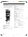 8
8
-
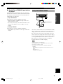 9
9
-
 10
10
-
 11
11
-
 12
12
-
 13
13
-
 14
14
-
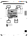 15
15
-
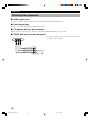 16
16
-
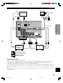 17
17
-
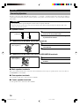 18
18
-
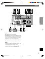 19
19
-
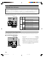 20
20
-
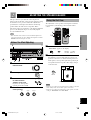 21
21
-
 22
22
-
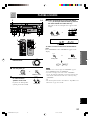 23
23
-
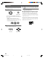 24
24
-
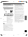 25
25
-
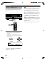 26
26
-
 27
27
-
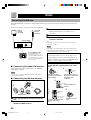 28
28
-
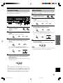 29
29
-
 30
30
-
 31
31
-
 32
32
-
 33
33
-
 34
34
-
 35
35
-
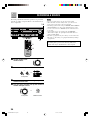 36
36
-
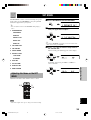 37
37
-
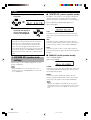 38
38
-
 39
39
-
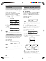 40
40
-
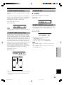 41
41
-
 42
42
-
 43
43
-
 44
44
-
 45
45
-
 46
46
-
 47
47
-
 48
48
-
 49
49
-
 50
50
-
 51
51
-
 52
52
-
 53
53
-
 54
54
-
 55
55
-
 56
56
-
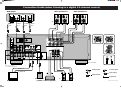 57
57


in andere talen
- English: Yamaha RX-V420RDS User manual
- italiano: Yamaha RX-V420RDS Manuale utente
- русский: Yamaha RX-V420RDS Руководство пользователя
- français: Yamaha RX-V420RDS Manuel utilisateur
- español: Yamaha RX-V420RDS Manual de usuario
- Deutsch: Yamaha RX-V420RDS Benutzerhandbuch
- português: Yamaha RX-V420RDS Manual do usuário
- dansk: Yamaha RX-V420RDS Brugermanual
- suomi: Yamaha RX-V420RDS Ohjekirja
- čeština: Yamaha RX-V420RDS Uživatelský manuál
- Türkçe: Yamaha RX-V420RDS Kullanım kılavuzu
- polski: Yamaha RX-V420RDS Instrukcja obsługi
- română: Yamaha RX-V420RDS Manual de utilizare
Gerelateerde papieren
-
Yamaha dvx s 100 de handleiding
-
-
Yamaha RX-V520RDS Handleiding
-
-
-
-
-
-
-