Pagina wordt geladen...

Inleiding
Om de benodigde elektrische verbindingen eenvoudig en
overzichtelijk te kunnen uitvoeren wordt een verbindingsdoos
meegeleverd.
De ventielen, de bedieningspanelen en de voedingsspanning
worden in de verbindingsdoos op elkaar aangesloten.
Installatie
De verbindingsdoos is geschikt voor zowel 12 als 24 Volt
boordspanning.
Plaats de doorverbinder, in de verbindingsdoos,
in de positie overeenkomend met de boordspan-
ning, resp. 12 of 24 Volt. Zie pag. 6 en 8.
Let er op dat de boordspanning overeenkomt
met de op de spoelen vermelde spanning.
Monteer de verbindingsdoos zo dicht mogelijk bij de olietank.
Tijdens bedrijf geven de LED’s op de printplaat aan welke
spoelen bekrachtigd worden. Dit kan als hulp dienen bij de
inbedrijfstelling.
Toe te passen kabels
Stuurstroomkabel: type CC,
- van de verbindingsdoos naar elke spoel apart van een ven-
tiel: 2 x 1 mm
2
- van de verbindingsdoos naar standaard boegschroef bedie-
ningspaneel (BPSSE, BPJSE, BPJDSE): 4 x 1 mm
2
(‘1-step
load-sensing’)
- van de verbindingsdoos naar vijf standen pookschakelaar
(BPJ5, BPJ5D, BPJSTH5 (2x)): 7 x 1 mm
2
(‘2-step load-
sensing’)
Voedingskabel: type CC, 2 x 1,5 mm
2
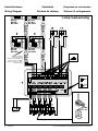
Aansluitingen
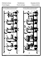
Afhankelijk van welk type load-sensing-ventiel is toegepast, te
weten ‘1-step load-sensing’ of ‘2-step load-sensing’, dient de
installatie te worden aangesloten volgens het desbetreffende
aansluitschema.
Voor aansluitschema’s, zie pagina 6 en 8.
Het is niet noodzakelijk alle aansluitmogelijkheden van de ver-
bindingsdoos te benutten.
Tip!
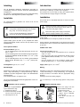
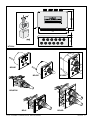
Aansluiten van de ventielen
Demonteer de apparaatstekkers
op de ventielen als volgt:
1 Verwijder de schroef
2 Druk met een stomp voorwerp
van circa ø 5 mm in het gat
3 Het blokje komt nu los
2 120103.04
vetus® POWER HYDRAULICS Electrical installation
NEDERLANDS
Introduction
In order to ensure the necessary wiring can be carried out with
the minimum of difficulty, a junction box is supplied.
This junction box can be used for wiring the solenoid valves,
control panels and supply voltage to each other.
Installation
The junction box is compatible with both 12 and 24 volt ship’s
power supply.
Position the jumper in the junction box to corres-
pond with the on-board power supply, either 12
or 24 Volts. See pages 6 and 8.
Ensure the ship’s power supply corresponds
with the voltage indicated on the solenoids.
The junction box is compatible with both 12 and 24 volt ship’s
power supply.
Fit the junction box as closely as possible to the oil tank.
During operation, the LED displays on the printed circuit board
indicate which coils are powered. This will assist the powering
up process.
Cables to be used
Control current cable: type CC,
- from the junction box to each separate coil of a solenoid
valve: 2 x 1 mm
2
- from the junction box to the standard bow thruster control
panel (BPSSE, BPJSE, BPJDSE): 4 x 1 mm
2
(‘1-step load-
sensing’)
- from the junction box to the 5-positions joystick (BPJ5,
BPJ5D, BPJSTH5 (2x)): 7 x 1 mm
2
(‘2-step load-sensing’)
Supply cable: type CC, 2x 1.5 mm
2
Wiring
Depending on the type of load-sensing solenoid valve used, ie.
‘1-step load-sensing’ of ‘2-step load-sensing’, the equipment
should be wired in accordance with the appropriate wiring
diagram.
See pages 6 and 8 for wiring diagram.
It is not necessary to use all the wiring options of the junction
box.
Tip!
Wiring the solenoid valves
Remove the plugs from the
solenoid valves as follows:
1 Remove the screw.
2 Push a blunt object of
approx. 5mm in diameter
into the hole.
3 The block will then be
released.
ENGLISH
1 2 3
Pagina wordt geladen...
Pagina wordt geladen...
Pagina wordt geladen...
Pagina wordt geladen...

120103.04 7
vetus® POWER HYDRAULICS Electrical installation
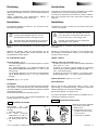
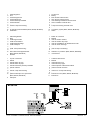
1 verbindingsdoos
2 accu
3 ventiel boegschroef
4 ventiel hekschroef
5 ventiel maststrijk installatie
6 ventiel ankerlier
7 ventiel ‘1-step load-sensing’
8 -
9 standaard boegschroef bedieningspaneel (BPSSE,
BPJSE, BPJDSE)
10 -
11 schakelaar
1 junction box
2 battery
3 bow thruster solenoid valve
4 stern thruster solenoid valve
5 mast lowering installation solenoid valve
6 anchor windlass solenoid valve
7 1-step load-sensing solenoid valve
8 -
9 standard bow thruster control panel (BPSSE, BPJSE,
BPJDSE)
10 -
11 switch
1 Verbindungskasten
2 Akku
3 Ventil Bugschraube
4 Ventil Heckschraube
5 Ventil Mastsenkanlage
6 Ventil Ankerspill
7 Ventil ‘1-step load-sensing’
8 -
9 Standard-Schaltbrett Bugschraube (BPSSE, BPJSE,
BPJDSE)
10 -
11 Schalter
1 boîtier de connexion
2 batterie
3 valve de l’hélice d’étrave
4 valve de l’hélice de poupe
5 valve de l’installation de rabattement du mât
6 valve du treuil d’ancrage
7 valve ‘1-step load-sensing’-
8 -
9 tableau de commande d’hélice d’étrave standard
(BPSSE, BPJSE, BPJDSE)
10 -
11 commutateur
1 caja de conexiones
2 batería
3 válvula hélice de proa
4 válvula hélice de popa
5 válvula instalación para bajar mástiles
6 válvula molinete
7 válvula ‘1-step load-sensing’
8 -
9 panel de control de hélice de proa estándar (BPSSE,
BPJSE, BPJDSE)
10 -
11 interruptor
1 scatola di derivazione
2 batteria
3 valvola elica di prua
4 valvola elica di poppa
5 valvola impianto sollevamento albero
6 valvola verricello d’ancora
7 valvola con ‘1-step load-sensing’
8 -
9 pannello di comando standard elica di prua (BPSSE,
BPJSE, BPJDSE)
10 -
11 interruttore
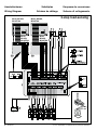
Kleurcode bedrading:
1 Blauw
2 Rood (+)
3 Zwart (-)
4 Wit
Wiring colour code:
1 Blue
2 Red (+)
3 Black (-)
4 White
Farbkode für die Bedrahtung:
1 Blau
2 Rot (+)
3 Schwarz (-)
4 Weiß
Code de couleur des câbles:
1 Bleu
2 Rouge (+)
3 Noir (-)
4 Blanc
Código de color de los cables:
1 Azul
2 Rojo (+)
3 Negro (-)
4 Blanco
Codice colori cavi:
1 Blu
2 Rosso (+)
3 Nero (-)
4 Bianco
Pagina wordt geladen...

120103.04 9
vetus® POWER HYDRAULICS Electrical installation
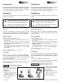
BPJSTH5
1 verbindingsdoos
2 accu
3 ventiel boegschroef
4 ventiel hekschroef
5 ventiel maststrijk installatie
6 ventiel ankerlier
7 -
8 ventiel ‘2-step load-sensing’
9 -
10 vijf standen pookschakelaar (BPJ5, BPJ5D, BPJSTH5)
11 schakelaar
1 junction box
2 battery
3 bow thruster solenoid valve
4 stern thruster solenoid valve
5 mast lowering installation solenoid valve
6 anchor windlass solenoid valve
7 -
8 2-step load-sensing solenoid valve
9 -
10 5-positions joystick (BPJ5, BPJ5D, BPJSTH5)
11 switch
1 Verbindungskasten
2 Akku
3 Ventil Bugschraube
4 Ventil Heckschraube
5 Ventil Mastsenkanlage
6 Ventil Ankerspill
7 -
8 Ventil ‘2-step load-sensing’
9 -
10 fünf Positionen Knüppelschalter
(BPJ5, BPJ5D, BPJSTH5)
11 Schalter
1 boîtier de connexion
2 batterie
3 valve de l’hélice d’étrave
4 valve de l’hélice de poupe
5 valve de l’installation de rabattement du mât
6 valve du treuil d’ancrage
7 -
8 valve ‘2-step load-sensing’
9 -
10 sélecteur à 5 positions (BPJ5, BPJ5D, BPJSTH5)
11 commutateur
1 caja de conexiones
2 batería
3 válvula hélice de proa
4 válvula hélice de popa
5 válvula instalación para bajar mástiles
6 válvula molinete
7 -
8 válvula ‘2-step load-sensing’
9 -
10 palanca interruptor de 5 posiciones
(BPJ5, BPJ5D, BPJSTH5)
11 interruptor
1 scatola di derivazione
2 batteria
3 valvola elica di prua
4 valvola elica di poppa
5 valvola impianto sollevamento albero
6 valvola verricello d’ancora
7 -
8 valvola con ‘2-step load-sensing’
9 -
10 interruttore a leva (BPJ5, BPJ5D, BPJSTH5)
11 interruttore
Pagina wordt geladen...

120103.04 11
vetus® POWER HYDRAULICS Electrical installation
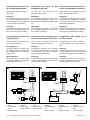
Aansluiten van het ventiel voor
het slingerdempingsysteem
Afhankelijk wat gewenst wordt kan
dit als volgt:
Schema A
De electrische voeding voor het ven-
tiel van het slingerdempingsysteem
wordt verzorgt vanuit de aansluitkast
voor de vermogens hydraulica.
Schema B
De electrische voeding voor het ven-
tiel van het roldempingsysteem wordt
verzorgt door een aparte voeding.
Connecting the valve for the roll
damping system
This can be done as follows depend-
ing on what is required:
Wiring diagram A
The power supply to the valve of the
roll damping system is supplied from
the connection box for the hydraulic
power system.
Wiring diagram B
The power supply to the valve of the
roll damping system is supplied from
a separate power source.
Anschließen des Ventils für das
Rolldämpfungssystem
Je nach dem, was gewünscht wird,
geschieht dies wie folgt:
Abbildung A
Die elektrische Versorgung für das Ventil
des Rolldämpfungssystems erfolgt vom
Anschluss kasten für die Hydraulikleistungen
aus.
Abbildung B
Die elektrische Versorgung für das Ventil
des Rolldämpfungssystems erfolgt über
eine separate Versorgung.
Raccordement de la soupape pour le
système d’amortissement du roulis
Selon ce que l’on souhaite, ce raccorde-
ment peut être effectué comme suit :
Schéma A
L’alimentation électrique de la soupape
du système d’amortissement du roulis est
assurée depuis la boîte de raccordement
pour la puissance hydraulique.
Schéma B
L’alimentation électrique de la soupape du
système d’amortissement est assurée par
une alimentation séparée.
Conexión de la válvula para el siste-
ma de amortiguamiento de balance
Dependiendo de lo que desea se puede
hacer de la siguiente manera:
Diagrama A
La alimentación eléctrica para la válvula
del sistema de amortiguamiento de balan-
ce, proviene de la caja de conexiones para
la hidráulica de potencia.
Diagrama B
La alimentación eléctrica para la válvula del
sistema de amortiguamiento de balance,
proviene de otra alimentación separada.
Collegamento della valvola per il
sistema antirollio
Il collegamento può essere effettuato in
uno dei seguenti modi, seconda neces-
sità:
Schema A
L’alimentazione elettrica per la valvola del
sistema antirollio può essere presa dalla
scatola dei terminali del sistema idraulico.
Schema B
L’alimentazione elettrica per la valvola del
sistema antirollio può essere fornita da un
sistema di alimentazione a parte.
1
2 3 4
+ –
1 2
+
–
3
+
–
CON11
1 2 3 4
+ –
T P
24 V
12
+
–
1
2
3
+
–
CON11
A B
1 Accu
2 Hoofdschake-
laar
3 Ventiel HT1024
1 Battery
2 Main switch
3 Valve HT1024
1 Akku
2 Hauptschalter
3 Ventil HT1024
1 Batterie
2 Interrupteur princi-
pal
3 Valve HT1024
1 Batería
2 Interruptor princi-
pal
3 Válvula HT1024
1 Batteria
2 Interruttore princi-
pale
3 Valvola HT1024

Printed in the Netherlands
120103.04 2015-09
RECON CTPANEL
Afstandsbedieningen voor maststrijkinstallatie /
ankerlier
Remote control for mast lowering installation /
anchor windlass
Fernbedienungen für Mastsenkanlage /
Ankerwinde
Commandes à distance pour l’installation de
rabattement du mât / guindeau
Mandos a distancia para instalación para bajar
mástiles / molinete
Comando a distanza per impianto di sollevamen-
to albero / verricello d’ancora
vetus b.v.
FOKKERSTRAAT 571 - 3125 BD SCHIEDAM - HOLLAND - TEL.: +31 10 4377700
TELEFAX: +31 10 4372673 - 4621286 - E-MAIL: [email protected] - INTERNET: http://www.vetus.com
Documenttranscriptie
NEDERLANDS ENGLISH Inleiding Introduction Om de benodigde elektrische verbindingen eenvoudig en overzichtelijk te kunnen uitvoeren wordt een verbindingsdoos meegeleverd. De ventielen, de bedieningspanelen en de voedingsspanning worden in de verbindingsdoos op elkaar aangesloten. In order to ensure the necessary wiring can be carried out with the minimum of difficulty, a junction box is supplied. This junction box can be used for wiring the solenoid valves, control panels and supply voltage to each other. Installation Installatie De verbindingsdoos is geschikt voor zowel 12 als 24 Volt boordspanning. The junction box is compatible with both 12 and 24 volt ship’s power supply. Position the jumper in the junction box to correspond with the on-board power supply, either 12 or 24 Volts. See pages 6 and 8. Plaats de doorverbinder, in de verbindingsdoos, in de positie overeenkomend met de boordspanning, resp. 12 of 24 Volt. Zie pag. 6 en 8. Ensure the ship’s power supply corresponds with the voltage indicated on the solenoids. Let er op dat de boordspanning overeenkomt met de op de spoelen vermelde spanning. Monteer de verbindingsdoos zo dicht mogelijk bij de olietank. Tijdens bedrijf geven de LED’s op de printplaat aan welke spoelen bekrachtigd worden. Dit kan als hulp dienen bij de inbedrijfstelling. Toe te passen kabels The junction box is compatible with both 12 and 24 volt ship’s power supply. Fit the junction box as closely as possible to the oil tank. During operation, the LED displays on the printed circuit board indicate which coils are powered. This will assist the powering up process. Cables to be used Stuurstroomkabel: type CC, - van de verbindingsdoos naar elke spoel apart van een ventiel: 2 x 1 mm2 - van de verbindingsdoos naar standaard boegschroef bedieningspaneel (BPSSE, BPJSE, BPJDSE): 4 x 1 mm2 (‘1-step load-sensing’) - van de verbindingsdoos naar vijf standen pookschakelaar (BPJ5, BPJ5D, BPJSTH5 (2x)): 7 x 1 mm2 (‘2-step loadsensing’) Control current cable: type CC, - from the junction box to each separate coil of a solenoid valve: 2 x 1 mm2 - from the junction box to the standard bow thruster control panel (BPSSE, BPJSE, BPJDSE): 4 x 1 mm2 (‘1-step loadsensing’) - from the junction box to the 5-positions joystick (BPJ5, BPJ5D, BPJSTH5 (2x)): 7 x 1 mm2 (‘2-step load-sensing’) Voedingskabel: type CC, 2 x 1,5 mm2 Supply cable: type CC, 2x 1.5 mm2 Aansluitingen Wiring Afhankelijk van welk type load-sensing-ventiel is toegepast, te weten ‘1-step load-sensing’ of ‘2-step load-sensing’, dient de installatie te worden aangesloten volgens het desbetreffende aansluitschema. Voor aansluitschema’s, zie pagina 6 en 8. Depending on the type of load-sensing solenoid valve used, ie. ‘1-step load-sensing’ of ‘2-step load-sensing’, the equipment should be wired in accordance with the appropriate wiring diagram. See pages 6 and 8 for wiring diagram. Het is niet noodzakelijk alle aansluitmogelijkheden van de verbindingsdoos te benutten. It is not necessary to use all the wiring options of the junction box. Tip! Aansluiten van de ventielen Demonteer de apparaatstekkers op de ventielen als volgt: 1 Verwijder de schroef 2 Druk met een stomp voorwerp van circa ø 5 mm in het gat 3 Het blokje komt nu los 2 120103.04 1 Tip! Wiring the solenoid valves 2 3 Remove the plugs from the solenoid valves as follows: 1 Remove the screw. 2 Push a blunt object of approx. 5mm in diameter into the hole. 3 The block will then be released. vetus® POWER HYDRAULICS Electrical installation 1 2 3 4 5 6 7 8 9 10 11 1 2 3 4 5 6 7 8 9 10 11 1 2 3 4 5 6 7 8 9 10 11 verbindingsdoos accu ventiel boegschroef ventiel hekschroef ventiel maststrijk installatie ventiel ankerlier ventiel ‘1-step load-sensing’ standaard boegschroef bedieningspaneel (BPSSE, BPJSE, BPJDSE) schakelaar Verbindungskasten Akku Ventil Bugschraube Ventil Heckschraube Ventil Mastsenkanlage Ventil Ankerspill Ventil ‘1-step load-sensing’ Standard-Schaltbrett Bugschraube (BPSSE, BPJSE, BPJDSE) Schalter caja de conexiones batería válvula hélice de proa válvula hélice de popa válvula instalación para bajar mástiles válvula molinete válvula ‘1-step load-sensing’ panel de control de hélice de proa estándar (BPSSE, BPJSE, BPJDSE) interruptor 1 2 3 4 5 6 7 8 9 10 11 1 2 3 4 5 6 7 8 9 10 11 1 2 3 4 5 6 7 8 9 10 11 junction box battery bow thruster solenoid valve stern thruster solenoid valve mast lowering installation solenoid valve anchor windlass solenoid valve 1-step load-sensing solenoid valve standard bow thruster control panel (BPSSE, BPJSE, BPJDSE) switch boîtier de connexion batterie valve de l’hélice d’étrave valve de l’hélice de poupe valve de l’installation de rabattement du mât valve du treuil d’ancrage valve ‘1-step load-sensing’‑ tableau de commande d’hélice d’étrave standard (BPSSE, BPJSE, BPJDSE) commutateur scatola di derivazione batteria valvola elica di prua valvola elica di poppa valvola impianto sollevamento albero valvola verricello d’ancora valvola con ‘1-step load-sensing’ pannello di comando standard elica di prua (BPSSE, BPJSE, BPJDSE) interruttore Kleurcode bedrading: 1 Blauw 2 Rood (+) 3 Zwart (-) 4 Wit Farbkode für die Bedrahtung: 1 Blau 2 Rot (+) 3 Schwarz (-) 4 Weiß Código de color de los cables: 1 Azul 2 Rojo (+) 3 Negro (-) 4 Blanco Wiring colour code: 1 Blue 2 Red (+) 3 Black (-) 4 White Code de couleur des câbles: 1 Bleu 2 Rouge (+) 3 Noir (-) 4 Blanc Codice colori cavi: 1 Blu 2 Rosso (+) 3 Nero (-) 4 Bianco vetus® POWER HYDRAULICS Electrical installation 120103.04 7 1 2 3 4 5 6 7 8 9 10 11 verbindingsdoos accu ventiel boegschroef ventiel hekschroef ventiel maststrijk installatie ventiel ankerlier ventiel ‘2-step load-sensing’ vijf standen pookschakelaar (BPJ5, BPJ5D, BPJSTH5) schakelaar 1 2 3 4 5 6 7 8 9 10 11 junction box battery bow thruster solenoid valve stern thruster solenoid valve mast lowering installation solenoid valve anchor windlass solenoid valve 2-step load-sensing solenoid valve 5-positions joystick (BPJ5, BPJ5D, BPJSTH5) switch 1 2 3 4 5 6 7 8 9 10 11 Verbindungskasten Akku Ventil Bugschraube Ventil Heckschraube Ventil Mastsenkanlage Ventil Ankerspill Ventil ‘2-step load-sensing’ fünf Positionen Knüppelschalter (BPJ5, BPJ5D, BPJSTH5) Schalter 1 2 3 4 5 6 7 8 9 10 11 boîtier de connexion batterie valve de l’hélice d’étrave valve de l’hélice de poupe valve de l’installation de rabattement du mât valve du treuil d’ancrage valve ‘2-step load-sensing’ sélecteur à 5 positions (BPJ5, BPJ5D, BPJSTH5) commutateur 1 2 3 4 5 6 7 8 9 10 11 caja de conexiones batería válvula hélice de proa válvula hélice de popa válvula instalación para bajar mástiles válvula molinete válvula ‘2-step load-sensing’ palanca interruptor de 5 posiciones (BPJ5, BPJ5D, BPJSTH5) interruptor 1 2 3 4 5 6 7 8 9 10 11 scatola di derivazione batteria valvola elica di prua valvola elica di poppa valvola impianto sollevamento albero valvola verricello d’ancora valvola con ‘2-step load-sensing’ interruttore a leva (BPJ5, BPJ5D, BPJSTH5) interruttore BPJSTH5 vetus® POWER HYDRAULICS Electrical installation 120103.04 9 Aansluiten van het ventiel voor het slingerdempingsysteem Anschließen des Ventils für das Rolldämpfungssystem Conexión de la válvula para el sistema de amortiguamiento de balance Afhankelijk wat gewenst wordt kan dit als volgt: Je nach dem, was gewünscht wird, geschieht dies wie folgt: Dependiendo de lo que desea se puede hacer de la siguiente manera: Schema A De electrische voeding voor het ventiel van het slingerdempingsysteem wordt verzorgt vanuit de aansluitkast voor de vermogens hydraulica. Abbildung A Die elektrische Versorgung für das Ventil des Rolldämpfungssystems erfolgt vom Anschlusskasten für die Hydraulikleistungen aus. Diagrama A La alimentación eléctrica para la válvula del sistema de amortiguamiento de balance, proviene de la caja de conexiones para la hidráulica de potencia. Schema B De electrische voeding voor het ventiel van het roldempingsysteem wordt verzorgt door een aparte voeding. Abbildung B Die elektrische Versorgung für das Ventil des Rolldämpfungssystems erfolgt über eine separate Versorgung. Diagrama B La alimentación eléctrica para la válvula del sistema de amortiguamiento de balance, proviene de otra alimentación separada. Connecting the valve for the roll damping system Raccordement de la soupape pour le système d’amortissement du roulis Collegamento della valvola per il sistema antirollio This can be done as follows depending on what is required: Selon ce que l’on souhaite, ce raccordement peut être effectué comme suit : Il collegamento può essere effettuato in uno dei seguenti modi, seconda necessità: Wiring diagram A The power supply to the valve of the roll damping system is supplied from the connection box for the hydraulic power system. Schéma A L’alimentation électrique de la soupape du système d’amortissement du roulis est assurée depuis la boîte de raccordement pour la puissance hydraulique. Schema A L’alimentazione elettrica per la valvola del sistema antirollio può essere presa dalla scatola dei terminali del sistema idraulico. Wiring diagram B The power supply to the valve of the roll damping system is supplied from a separate power source. Schéma B L’alimentation électrique de la soupape du système d’amortissement est assurée par une alimentation séparée. Schema B L’alimentazione elettrica per la valvola del sistema antirollio può essere fornita da un sistema di alimentazione a parte. – B + 1 2 3 4 2 1 2 3 4 CON11 1 CON11 2 – + – 1 3 2 1 1 Battery 2 Main switch 3 Valve HT1024 + P + – T 3 1 Accu 2 Hoofdschake laar 3 Ventiel HT1024 – – + + A 1 Akku 2 Hauptschalter 3 Ventil HT1024 vetus® POWER HYDRAULICS Electrical installation 24 V 1 Batterie 2 Interrupteur principal 3 Valve HT1024 1 Batería 2 Interruptor principal 3 Válvula HT1024 1 Batteria 2 Interruttore principale 3 Valvola HT1024 120103.04 11 Afstandsbedieningen voor maststrijkinstallatie / ankerlier Remote control for mast lowering installation / anchor windlass Fernbedienungen für Mastsenkanlage / Ankerwinde RECON vetus b. v. Commandes à distance pour l’installation de rabattement du mât / guindeau Mandos a distancia para instalación para bajar mástiles / molinete Comando a distanza per impianto di sollevamento albero / verricello d’ancora CTPANEL FOKKERSTRAAT 571 - 3125 BD SCHIEDAM - HOLLAND - TEL.: +31 10 4377700 TELEFAX: +31 10 4372673 - 4621286 - E-MAIL: [email protected] - INTERNET: http://www.vetus.com Printed in the Netherlands 120103.04 2015-09-
 1
1
-
 2
2
-
 3
3
-
 4
4
-
 5
5
-
 6
6
-
 7
7
-
 8
8
-
 9
9
-
 10
10
-
 11
11
-
 12
12


in andere talen
Gerelateerde papieren
-
Vetus HT1024 Installatie gids
-
-
-
-
-
-
-
-
-