
RICAMBI ORIGINALI
ORIGINAL SPARE PARTS
PIECES DE RECHANGE ORIGINALES
ORIGINALERSATZTEILE
REPUESTOS ORIGINALES
ORIGINEEL ONDERDEEL
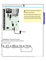
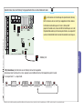
SCHEDA ELETTRONICA
CONTROL BOARD
CARTE ELECTRONIQUE
STEUER PLATINE
TARJETA ELECTRONICA
ELEKTRONISCHE PRINTKAART
Nederlands NL
Español ES
Deutch DE
Français FR
English EN
Italiano IT
ZL39
Spareparts

10 11 E1 E6 RX TX 1 2 3 3P 5 7 2 CX CY
A B GND A B S1 GND 24V 0 THERMAL
L N L1T L2T M N FC FA F + E -
A

ITALIANO
Pag.
3
- Codice manuale:
319LR37
319LR37 ver.
1.0
1.0 03/2012 © CAME cancelli automatici s.p.a.
I dati e le informazioni indicate in questo manuale sono da ritenersi suscettibili di modifica in qualsiasi momento e senza obbligo di preavviso da parte di CAME cancelli automatici s.p.a.
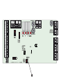
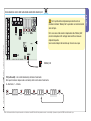
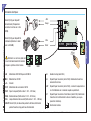
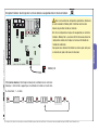
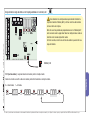
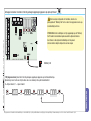
Collegamenti elettrici
IT
L-N Alimentazione 230 AC frequenza 50/60 Hz
M-N
Motore 24V DC
+ E -
Encoder
10-11
Alimentazione accessori 24V AC
10-E1
Cupola lampeggiante (Portata contatto: 24 V - 32 W max.).
10-E6
Cordone luminoso (Portata contatto: 24 V - 32 W max.).
10-5
Lampada spia barriera aperta (Portata contatto: 24 V - 3 W max.)
2-CX..CY Contatto (N.C.) di riapertura durante la chiusura, attesa ostacolo,
chiusura immediata o chiusura immediata con attesa ostacolo
1-2
Pulsante di stop (contatto N.C.)
2-3
Dispositivo per l’apertura (contatto N.O.). Comando di sola apertura
dell’asta.
2-3P
Dispositivo per l’apertura (contatto N.O.), da collegare solo in caso di
impianti con collegamento in abbinato o bussola.
2-7
Dispositivo per l’apertura e chiusura (contatto N.O.). Comando di
apertura e chiusura dell’asta in modalità “passo-passo” (apre-
chiude).
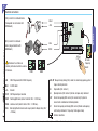
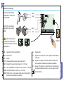
Collegamento antenna
10 11 E1 E6 RX TX 1 2 3 3P 5 7 2 CX CY
A B GND A B S1 GND
CAME
ACCESS CONTROL
Rosso
Nero
Bianco
Blu
Contatto (N.O.) per dispositivo di
comando (Transponder o lettore
tessere con scheda R700).
Contatto (N.O.) per dispositivo
di comando (Selettore a tastiera
con scheda R800).
CANCELLI AUTOMATICI
R700
CANCELLI AUTOMATICI
R800
AF
Attenzione! Le schede e la
memory roll vanno inserite in assenza
di tenzione.
Scheda AF
R700 R800

ITALIANO
I dati e le informazioni indicate in questo manuale sono da ritenersi suscettibili di modifica in qualsiasi momento e senza obbligo di preavviso da parte di CAME cancelli automatici s.p.a.
Pag.
4
- Codice manuale:
319LR37
319LR37 ver.
1.0
1.0 03/2012 © CAME cancelli automatici s.p.a.
N.O.
N.C.
C.
+ - + -
FUSIBILE 200m A
TX 2
TX 2
10 2 T X C
-
+ -
NC
+ -
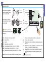
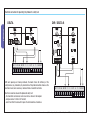
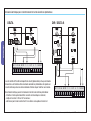
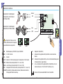
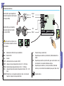
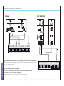
DELTA DIR / DELTA S
A ogni comando di apertura o di chiusura, la scheda verifi ca l’e cienza dei dispositivi
di sicurezza (fotocellule). Un’eventuale anomalia delle fotocellule viene segnalata sulla
scheda elettronica, e annulla qualsiasi comando dal trasmettitore radio o dal pulsante.
Collegamento elettrico per il funzionamento del test di sicurezza delle fotocellule:
- il trasmettitore e il ricevitore, devono essere collegati come da disegno;
- confi gurare il contatto 2-CX o 2-CY o entrambi;
- selezionare dalla funzione F 5 su quali ingressi attivare il test.
Collegamento elettronico per il funzionamento del test di sicurezza delle fotocellule
10 11 E1 E6 RX TX 1 2 3 3P 5 7 2 CX CY
10 11 E1 E6 RX TX 1 2 3 3P 5 7 2 CX CY

ITALIANO
Pag.
5
- Codice manuale:
319LR37
319LR37 ver.
1.0
1.0 03/2012 © CAME cancelli automatici s.p.a.
I dati e le informazioni indicate in questo manuale sono da ritenersi suscettibili di modifica in qualsiasi momento e senza obbligo di preavviso da parte di CAME cancelli automatici s.p.a.
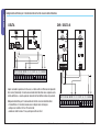
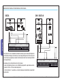
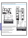
Per il ripristino delle confi gurazioni precedenti inserire la
schedina di memoria “Memory Roll” e procedere con la lettura dei dati
come da fi gura.
N.B.: se non sono state salvate le impostazioni nella “Memory Roll”,
occorrerà reimpostare tutti i settaggi come descritto nel manuale
originale del quadro.
Se necessario rivolgersi all’assistenza per riceverne una copia.
Carica memoria: carica i dati nella scheda salvati dalla memory roll A
10 11 E1 E6 RX TX 1 2 3 3P 5 7 2 CX CY
A B GND A B S1 GND 2
4
F i 0
F i5 i
ENTER > > ENTER
>...>
F 51 (Lettura dati) : carica i dati della memory roll nella scheda madre.
Nota: questa funzione compare solo se la memory roll è inserita sulla scheda madre.
0 = Disattivata; 1 = Attivata.
Memory roll

ITALIANO
I dati e le informazioni indicate in questo manuale sono da ritenersi suscettibili di modifica in qualsiasi momento e senza obbligo di preavviso da parte di CAME cancelli automatici s.p.a.
Pag.
6
- Codice manuale:
319LR37
319LR37 ver.
1.0
1.0 03/2012 © CAME cancelli automatici s.p.a.
Dismissione e smaltimento
I nostri prodotti sono realizzati con materiali diversi. La maggior parte di essi (alluminio, plastica, ferro, cavi elettrici) è assimilabile ai rifi uti solidi e urbani.
Possono essere riciclati attraverso la raccolta e lo smaltimento di erenziato nei centri autorizzati.
Altri componenti (schede elettroniche, batterie dei transmettitori etc.) possono invece contenere sostanze inquinanti.
Vanno quindi rimossi e consegnati a ditte autorizzate al recupero e allo smaltimento degli stessi.

The data and information reported in this installation manual are susceptible to change at any time and without obligation on CAME cancelli automatici s.p.a. to notify users.
Pag.
7
- Manual code:
319LR37
319LR37 ver.
1.0
1.0 03/2012 © CAME cancelli automatici s.p.a.
ENGLISH
ENEN
Electrical connections
L-N
230 V AC powered, 50 / 60 Hz frequency
M-N
24 V DC motor
+ E -
Encoder
10-11
24V AC powering accessories
10-E1
Flashing-light dome (contact rated for: 24 V - 32 W max.).
10-E6
Luminous cord (contact rated at: 24 V - 32 W max.).
10-5
Warning light when barrier-arm is open(contact voltage rating: 24 V
-3 W max.)
2-CX..CY Re-open during closing (N.C.) socket, re-close during opening, partial
stop or stand-by obstacle
1-2
Stop button (N.C. contact.)
2-3
Opening device (N.O. contact.). Barrier-arm open-only command
2-3P
Device for opening (N.O. contact), to connect only if system is
connected in combined or interlocking mode.
2-7
Device for opening and closing (N.O. contact). Barrier-arm opening
and closing command in “step-step” mode (open-close)
Antenna connection
10 11 E1 E6 RX TX 1 2 3 3P 5 7 2 CX CY
A B GND A B S1 GND
CAME
ACCESS CONTROL
Red
Black
White
Blue
CANCELLI AUTOMATICI
R700
CANCELLI AUTOMATICI
R800
AF
Attenzione! Le schede e la
memory roll vanno inserite in assenza
di tenzione.
AF radio
frequency
board
R700 R800
(N.O.) contact. for command device
(Transponder or card reader with
R700 board).
(N.O.) contact. for command
device (keypad selector with
R800 board).

The data and information reported in this installation manual are susceptible to change at any time and without obligation on CAME cancelli automatici s.p.a. to notify users.
Pag.
8
- Manual code:
319LR37
319LR37 ver.
1.0
1.0 03/2012 © CAME cancelli automatici s.p.a.
ENGLISH
Electrical connection for operating the photocell’s safety test
N.O.
N.C.
C.
+ - + -
FUSIBILE 200m A
TX 2
TX 2
10 2 T X C
-
+ -
NC
+ -
DELTA DIR / DELTA S
10 11 E1 E6 RX TX 1 2 3 3P 5 7 2 CX CY
10 11 E1 E6 RX TX 1 2 3 3P 5 7 2 CX CY
With each opening and closing command, the board checks the e ciency of the
safety devices (i.e. photocells). Any malfunction of the photocells will be shown on the
electronic board, and cancels any command from a transmitter or button.
Electrical connection to work the photocells safety test:
- the transmitter and receiver, must connected as shown in the diagram:
- confi gure contact 2-CX or 2-CY or both;
- select from the F5 feature which inputs the test should be activated on.

The data and information reported in this installation manual are susceptible to change at any time and without obligation on CAME cancelli automatici s.p.a. to notify users.
Pag.
9
- Manual code:
319LR37
319LR37 ver.
1.0
1.0 03/2012 © CAME cancelli automatici s.p.a.
ENGLISH
Restore backup: to load the data saved on the memory roll onto card A
To reset the previous confi gurations insert the “Memory Roll”
and read the data as shown in the fi gure.
Note: If you have saved the settings in the “Memory Roll”, you will
have to reset all the settings as explained in the panel’s original
manual. You can request a copy from you local assistance provider.
10 11 E1 E6 RX TX 1 2 3 3P 5 7 2 CX CY
A B GND A B S1 GND 2
4
F i 0
F i5 i
ENTER > > ENTER
>...>
Memory roll
F 51 (Data reading) : loads roll memory data onto the mother board.
Note: this feature appears only if the roll memory is plugged into the mother board.
0 = Deactivated; 1= Activated.

The data and information reported in this installation manual are susceptible to change at any time and without obligation on CAME cancelli automatici s.p.a. to notify users.
Pag.
10
10 - Manual code:
319LR37
319LR37 ver.
1.0
1.0 03/2012 © CAME cancelli automatici s.p.a.
ENGLISH
Disposal
This product, including the packaging, is made up of several types of materials that can be recycled.
Investigate the recycling or disposal systems of the product, complying with prevailing local legislation.
Some electronic components may contain polluting substances. Do not litter.

Pag.
11
11 - Code manuel:
319LR37
319LR37 ver.
1.0
1.0 03/2012 © CAME cancelli automatici s.p.a.
Les données et les indications fournies dans ce manuel d’installation peuvent subir des modifications à tout moment sans avis préalable de la part de CAME cancelli automatici s.p.a.
FRANÇAIS
FR
Connexions électriques
L-N
Alimentation 230 V CA fréquence 50/60 Hz
M-N Motoréducteur
24V DC
+ E -
Encoder
10-11
Alimentation des accessoires 24V AC
10-E1
Voyant à coupole (Portée contact : 24 V - 32 W max.)
10-E6
Cordon lumineux (Portée contact : 24 V - 32 W max.).
10-5
Lampe témoin barrière ouverte (Portée contact : 24 V - 3 W max.)
2-CX..CY Contact (N.C.) de réouverture pendant la fermeture, réfermeture
pendant l’ouverture, stop partiel ou attente obstacle
1-2 Boutons de stop (contact N.C.)
2-3
Dispositif pour l’ouverture (contact N.O.). Commande d’ouverture
seulement de la lisse.
2-3P
Dispositif pour l’ouverture (contact N.O.), à connecter uniquement en
cas d’installations avec connexion couplée ou pivotement.
2-7
Dispositif pour l’ouverture et la fermeture (contact N.O.). Commande
d’ouverture et de fermeture de la lisse en modalité « pas-à-pas »
(ouverture-fermeture).
Branchement antenne
10 11 E1 E6 RX TX 1 2 3 3P 5 7 2 CX CY
A B GND A B S1 GND
CAME
ACCESS CONTROL
Rouge
Noir
Blanc
Bleu
Contact (N.O.) pour dispositif
de commande (Transpondeur
ou lecteur de cartes avec carte
R700).
Contact (N.O.) pour dispositif de
commande (Sélecteur à clavier
avec carte R800).
CANCELLI AUTOMATICI
R700
CANCELLI AUTOMATICI
R800
R800R700
AF
Attention ! Les cartes en général et
la carte mémoire doivent être insérées
lorsque le système est hors tension.

Les données et les indications fournies dans ce manuel d’installation peuvent subir des modifications à tout moment sans avis préalable de la part de CAME cancelli automatici s.p.a.
Pag.
12
12 - Code manuel:
319LR37
319LR37 ver.
1.0
1.0 03/2012 © CAME cancelli automatici s.p.a.
FRANÇAIS
Connexion électronique pour le fonctionnement du test de sécurité des photocellules
N.O.
N.C.
C.
+ - + -
FUSIBILE 200m A
TX 2
TX 2
10 2 T X C
-
+ -
NC
+ -
DELTA DIR / DELTA S
La carte contrôle l'e cacité des dispositifs de sécurité (photocellules) à chaque commande
d'ouverture ou de fermeture. Toute éventuelle anomalie des photocellules est signalée sur
la carte électronique et annule toute commande e ectuée depuis l'émetteur ou le bouton.
Branchement électrique pour le fonctionnement du test de sécurité des photocellules :
- l'émetteur et le récepteur doivent être connectés comme indiqué sur le dessin ;
- confi gurer le contact 2-CX ou 2-CY ou les deux ;
- sélectionner par le biais de la fonction F 5 les entrées sur lesquelles activer le test.
10 11 E1 E6 RX TX 1 2 3 3P 5 7 2 CX CY
10 11 E1 E6 RX TX 1 2 3 3P 5 7 2 CX CY

Pag.
13
13 - Code manuel:
319LR37
319LR37 ver.
1.0
1.0 03/2012 © CAME cancelli automatici s.p.a.
Les données et les indications fournies dans ce manuel d’installation peuvent subir des modifications à tout moment sans avis préalable de la part de CAME cancelli automatici s.p.a.
FRANÇAIS
Pour la restauration des configurations précédentes, introduisez
la carte de mémoire “Memory Roll” et effectuez la lecture des
données en procédant comme sur le dessin.
N.B.: Si les configurations n’ont pas été sauvegardées sur la liste de
mémoire « Memory Roll », vous devez afficher de nouveau toutes les
configurations comme il est indiqué sur le manuel d’utilisation de
l’armoire de commande.
Vous pouvez vous adresser directement au service après-vente pour
en recevoir une copie si elle vous est nécessaire.
Chargement mémoire: elle charge dans la carte les données sauvegardées dans la liste de la mémoire A
10 11 E1 E6 RX TX 1 2 3 3P 5 7 2 CX CY
A B GND A B S1 GND 2
4
F i 0
F i5 i
ENTER > > ENTER
>...>
Memory roll
F 51 (Lecture données) : télécharge les données de la mémoire dans la carte mère.
Remarque : cette fonction n'apparaît que si la mémoire est insérée sur la carte mère.
0 = Désactivée ; 1 = Activée.

Les données et les indications fournies dans ce manuel d’installation peuvent subir des modifications à tout moment sans avis préalable de la part de CAME cancelli automatici s.p.a.
Pag.
14
14 - Code manuel:
319LR37
319LR37 ver.
1.0
1.0 03/2012 © CAME cancelli automatici s.p.a.
FRANÇAIS
Recyclage et élimination
Cet appareil, y compris l’emballage, est constitué de plusieurs types de matériaux pouvant être recyclés.
S’informer sur les systèmes de recyclage ou d’élimination de l’appareil en se conformant aux lois locales en vigueur.
Certains composants électroniques pourraient contenir des substances polluantes, ne pas les jeter n’importe où.

Seite
15
15 - Handbuch-Code:
319LR37
319LR37 ver.
1.0
1.0 03/2012 © CAME cancelli automatici s.p.a.
Sämtliche in der Installationsanleitung aufgeführten Daten und Informationen können jederzeit und ohne Vorankündigung von CAME cancelli automatici s.p.a verändert werden.
DEUTSCH
DE
Elektrische Anschlüsse
L-N
Betriebsspannung 230 V AC, Frequenz 50/60 Hz.
M-N
24 V DC - Antrieb
+ E -
Encoder
10-11
Klemmen für Stromversorgung der Zusatzgeräte: 24 V AC normal
10-E1
Blinkleuchte (Leistung Kontakt: 24 V - max. 32 W).
10-E6
Leuchtstrang (Leistung Kontakt: 24 V- max. 32 W.).
10-5
Anzeigeleuchte Schranke o en (Leistung Kontakt: 24 V - max. 3 W)
2-CX..CY Kontakt (N.C.) Wiederaufl auf bei Zulauf, Wiederzulauf bei Aufl auf,
Teilstopp oder Hinderniserwartung
1-2 Stopptaster (Kontakt N.C.)
2-3
Aufl aufvorrichtung (Kontakt N.O.). Befi ehlt nur den Aufl auf des
Baums.
2-3P
Aufl aufvorrichtung (Kontakt N.O.), wird nur bei Parallelschaltung oder
Schleusenfunktion angeschlossen.
2-7
Auf- und Zulaufvorrichtung (Kontakt N.O.). Befi ehlt den Auf- und
Zulauf des Baums im “Schritt-Schritt”-Betrieb (auf-zu).
Antenne mit Antennenkabel RG58 für den Funkbetrieb.
10 11 E1 E6 RX TX 1 2 3 3P 5 7 2 CX CY
A B GND A B S1 GND
CAME
ACCESS CONTROL
Rot
Schwarz
Weiß
Blau
Kontakt (N.O.) für Befehlsgeber
(Transponder- oder Kartenleser
mit Platine R700).
Kontakt (N.O.) für Befehlsgeber
(Codeschloss mit Platine R800).
CANCELLI AUTOMATICI
R700
CANCELLI AUTOMATICI
R800
R800R700
AF
Achtung! Die Platinen und die
Memory Roll werden bei herausgezo-
genem Netzstecker aufgesteckt.
AF-Steckmodul

Sämtliche in der Installationsanleitung aufgeführten Daten und Informationen können jederzeit und ohne Vorankündigung von CAME cancelli automatici s.p.a verändert werden.
Seite
16
16 - Handbuch-Code:
319LR37
319LR37 ver.
1.0
1.0 03/2012 © CAME cancelli automatici s.p.a.
DEUTSCH
Elektronischer Anschluss für Selbsttest der Lichtschranken
N.O.
N.C.
C.
+ - + -
FUSIBILE 200m A
TX 2
TX 2
10 2 T X C
-
+ -
NC
+ -
DELTA DIR / DELTA S
Nach jedem Auf- bzw. Zulaufbefehl kontrolliert die Steuerung die Funktionstüchtigkeit der
Sicherheitseinrichtungen (Lichtschranken). Eine etwaige Störung der Lichtschranken wird
auf der Steuerung angezeigt und jeder über Handsender oder Taster übertragene Befehl
wird ausgeschlossen.
Verkabelung für den Sicherheitstest der Lichtschranken:
- Sender und Empfänger müssen, wie in der Abbildung dargestellt, angeschlossen werden;
- Kontakt 2-CX bzw. 2-CY bzw. beide konfi gurieren;
- Über die Funktion F 5 auswählen, auf welchen Eingängen die Selbsttests eingeschaltet
werden sollen.
10 11 E1 E6 RX TX 1 2 3 3P 5 7 2 CX CY
10 11 E1 E6 RX TX 1 2 3 3P 5 7 2 CX CY

Seite
17
17 - Handbuch-Code:
319LR37
319LR37 ver.
1.0
1.0 03/2012 © CAME cancelli automatici s.p.a.
Sämtliche in der Installationsanleitung aufgeführten Daten und Informationen können jederzeit und ohne Vorankündigung von CAME cancelli automatici s.p.a verändert werden.
DEUTSCH
Zum Rücksetzen der Einstellungen die Speicherkarte „Memory
Roll” einstecken und wie in der Figur angegeben die Daten ablesen.
N.B.: Sollten die Einstellungen nicht in der „Memory Roll“
gespeichert worden sein, müssen sämtliche Einstellungen, wie in der
Originalbetriebsanleitung der Steuerung beschrieben, neu eingestellt
werden. Im Bedarfsfall fordern Sie beim Kundendienst eine Kopie an.
Speicher laden: die in der Memory Roll gespeicherten Daten auf die Steckkarte laden A
10 11 E1 E6 RX TX 1 2 3 3P 5 7 2 CX CY
A B GND A B S1 GND 2
4
F i 0
F i5 i
ENTER > > ENTER
>...>
Memory roll
F 51 (Daten Ablesen) : lädt die Daten von der Memory Roll auf die Hauptplatine
Anmerkung: diese Funktion wird nur dann angezeigt, wenn die Memory Roll auf die Hauptplatine gesteckt wurde.
0 = Ausgeschaltet; 1 = eingeschaltet.

Sämtliche in der Installationsanleitung aufgeführten Daten und Informationen können jederzeit und ohne Vorankündigung von CAME cancelli automatici s.p.a verändert werden.
Seite
18
18 - Handbuch-Code:
319LR37
319LR37 ver.
1.0
1.0 03/2012 © CAME cancelli automatici s.p.a.
DEUTSCH
Entsorgung
Dieses Produkt einschließlich Verpackungen besteht aus verschiedenen wiederverwertbaren Materialien.
Informieren Sie sich unter Berücksichtigung der örtlich geltenden Rechtsvorschriften über die Recycling- und Entsorgungssysteme des Produkts.
Einige elektronische Bauteile könnte verschmutzende Substanzen enthalten - nicht in der Umwelt zerstreuen.

Pag.
19
19 - Codigo manual:
319LR37
319LR37 ver.
1.0
1.0 03/2012 © CAME cancelli automatici s.p.a.
Los datos y las informaciones indicadas en este manual de instalación podrían modificarse en cualquier momento y sin obligación de aviso previo por parte de la firma CAME cancelli automatici s.p.a.
ESPAÑOL
ES
Conexiones eléctricas
L-N
Alimentación 230 V AC, frecuencia 50/60 Hz
M-N
Motor 24V DC
+ E -
Encoder
10-11
alimentación de los accesorios 24V AC
10-E1
Lámpara de cúpula (Capacidad contacto: 24 V - 32 W máx.).
10-E6
Cordón luminoso (Capacidad contacto: 24 V - 32 W máx.).
10-5
Lámpada testigo barrera abierta (Capacidad contacto: 24 V - 3 W
máx.)
2-CX..CY
Contacto (n.c.) de reapertura durante el cierre, cierre durante
l’apertura, stop parcial o espera obstáculo
1-2
Pulsador de stop (contacto N.C.).
2-3
Dispositivo para la abertura (contacto N.A.). Mando sólo abertura
mástil.
2-3P
Dispositivo para abertura (contacto N.A.), para conectar sólo en caso
de instalación con conexión combinada o brújula.
2-7
Dispositivo para la abertura y cierre (contacto N.A.). Mando de
abertura y cierre del mástil en modalidad “paso-paso” (abre-cierra)
Conexión antena
10 11 E1 E6 RX TX 1 2 3 3P 5 7 2 CX CY
A B GND A B S1 GND
CAME
ACCESS CONTROL
Rojo
Negro
Blanco
Azul
CANCELLI AUTOMATICI
R700
CANCELLI AUTOMATICI
R800
AF
¡Precaución! Las tarjetas y me-
mory roll deben introducirse cuando
falta tensión.
Tarjeta AF
R700 R800
Contacto (N.A.) para dispositivo de
mando (Transponder o lector tarjetas
con tarjeta R700).
Contacto (N.A.) para dispositivo
de mando (Selector de teclado
con tarjeta R700).

Los datos y las informaciones indicadas en este manual de instalación podrían modificarse en cualquier momento y sin obligación de aviso previo por parte de la firma CAME cancelli automatici s.p.a.
Pag.
20
20 - Codigo manual:
319LR37
319LR37 ver.
1.0
1.0 03/2012 © CAME cancelli automatici s.p.a.
ESPAÑOL
Conexión eléctrica para el funcionamiento del test de seguridad de las fotocélulas
N.O.
N.C.
C.
+ - + -
FUSIBILE 200m A
TX 2
TX 2
10 2 T X C
-
+ -
NC
+ -
DELTA DIR / DELTA S
Con cada mando de apertura o de cierre, la tarjeta verifi ca la efi ciencia de los dispositivos
de seguridad (fotocélulas). La posible anomalía de las fotocélulas es señalada en la tarjeta
electrónica y anula todos los mandos del emisor radio o del pulsador.
Conexión eléctrica para el funcionamiento del test de seguridad de las fotocélulas:
- el emisor y el receptor deben conectarse como se indica en el dibujo;
- confi gurar el contacto 2-CX o 2-CY o ambos;
- seleccionar desde la función F 5 en cuáles entradas activar el test.
10 11 E1 E6 RX TX 1 2 3 3P 5 7 2 CX CY
10 11 E1 E6 RX TX 1 2 3 3P 5 7 2 CX CY

Pag.
21
21 - Codigo manual:
319LR37
319LR37 ver.
1.0
1.0 03/2012 © CAME cancelli automatici s.p.a.
Los datos y las informaciones indicadas en este manual de instalación podrían modificarse en cualquier momento y sin obligación de aviso previo por parte de la firma CAME cancelli automatici s.p.a.
ESPAÑOL
Para restablecer las confi guraciones precedentes introducir la
tarjeta de memoria “Memory Roll” y efectuar la lectura de los datos
como se indica en la fi gura.
Nota: Si no se han grabado las programaciones en la “Memory Roll”,
será necesario volver a programar todas las confi guraciones como se
describe en el manual original del cuadro.
Si Ud. lo necesita, contacte a la ofi cina de asistencia para recibir una
copia del mismo.
Carga memoria: carga los datos en la tarjeta guardados en la memory roll A
10 11 E1 E6 RX TX 1 2 3 3P 5 7 2 CX CY
A B GND A B S1 GND 2
4
F i 0
F i5 i
ENTER > > ENTER
>...>
Memory roll
F 51 (Lectura datos) : carga los datos de la memory roll en la tarjeta madre.
Nota: esta función se verifica sólo si la memory roll está introducida en la tarjeta madre..
0 = Desactivada; 1 = Activada.

Los datos y las informaciones indicadas en este manual de instalación podrían modificarse en cualquier momento y sin obligación de aviso previo por parte de la firma CAME cancelli automatici s.p.a.
Pag.
22
22 - Codigo manual:
319LR37
319LR37 ver.
1.0
1.0 03/2012 © CAME cancelli automatici s.p.a.
ESPAÑOL
Este producto, incluido el embalaje, está hecho con diferentes tipos de materiales que pueden reciclarse.
Infórmese sobre los sistemas de reciclaje o eliminación del producto, respetando las normas locales vigentes.
Algunos componentes electrónicos podrían contener substancias contaminantes; no los abandone en el medio ambiente.
Desguase

Pag.
23
23 - Handleiding nummer:
319LR37
319LR37 ver.
1.0
1.0 03/2012 © CAME cancelli automatici s.p.a.
De gegevens en informatie in deze handleiding voor de installatie zijn op elk ogenblik vatbaar voor wijziging zonder verplichting tot waarschuwing vooraf door Came Cancelli Automatici S.p.A.
NEDERLANDS
NL
Elektrische aansluitingen
L-N
Voeding 230 V AC, frequentie 50/60 Hz
M-N
Motor 24V DC
+ E -
Encoder
10-11
Stroomaansluitklemmen voor de uitrustingen 24V AC
10-E1
Knipperlicht in koepel (contactvermogen: 24 V - 32 W max.)
10-5
Lamp “slagboom open” (vermogen van het contact: 24 V - 3 W max.)
10-E6
Lichtsnoer (Vermogen van contact: 24 V - 32 W max.)
2-CX..CY
Contact (N.C.) voor weer openen tijdens sluiten, hersluiting tijdens
de opening, stop halverwege, stop obstakel
1-2
Stopknop (N.C.).
2-3
Apparaat om te openen (N.O.-contact.). Apparaat dat de slagboom
alleen opent
2-3P
Apparaat om te openen (contact N.O.),alleen aan te sluiten voor
samenwerkende of afwisselend samenwerkende slagbomen.
2-7
Apparaat om te openen en te sluiten (N.O.-contact.). Bediening om
de slagboom stapsgewijs te openen en te sluiten (openen-sluiten)
Antenneaansluiting
10 11 E1 E6 RX TX 1 2 3 3P 5 7 2 CX CY
A B GND A B S1 GND
CAME
ACCESS CONTROL
Rood
Zwart
Wit
Blauw
CANCELLI AUTOMATICI
R700
CANCELLI AUTOMATICI
R800
AF
Opgelet! De printkaarten en
de memory roll moeten worden
gemonteerd zonder dat de spanning
ingeschakeld is. R700 R800
Contact (N.O.) voor bediening
(Transponder of card-lezer met
printkaart R700).
Contact (N.O.) voor bediening
(Toetsenbordje met printkaart
R800).
AF-
printkaart

De gegevens en informatie in deze handleiding voor de installatie zijn op elk ogenblik vatbaar voor wijziging zonder verplichting tot waarschuwing vooraf door Came Cancelli Automatici S.p.A.
Pag.
24
24 - Handleiding nummer:
319LR37
319LR37 ver.
1.0
1.0 03/2012 © CAME cancelli automatici s.p.a.
NEDERLANDS
Elektrische aansluiting voor de fotocellentest
N.O.
N.C.
C.
+ - + -
FUSIBILE 200m A
TX 2
TX 2
10 2 T X C
-
+ -
NC
+ -
DELTA DIR / DELTA S
Bij elk bevel controleert de printkaart of de beveiligingen (fotocellen) werken. Een eventueel
defect van de fotocellen wordt gesignaleerd op de prentkaart zodat elk bevel van de zender
of de knop wordt geannuleerd.
Elektrische aansluiting voor de fotocellentest
- de zender en de ontvanger moeten worden aangesloten zoals op de tekening;
- Het contact 1-CX of 2-CY of beiden confi gureren
- selecteer in de functie F 5 welke ingangen moeten worden getest.
10 11 E1 E6 RX TX 1 2 3 3P 5 7 2 CX CY
10 11 E1 E6 RX TX 1 2 3 3P 5 7 2 CX CY

Pag.
25
25 - Handleiding nummer:
319LR37
319LR37 ver.
1.0
1.0 03/2012 © CAME cancelli automatici s.p.a.
De gegevens en informatie in deze handleiding voor de installatie zijn op elk ogenblik vatbaar voor wijziging zonder verplichting tot waarschuwing vooraf door Came Cancelli Automatici S.p.A.
NEDERLANDS
Om de vorige confi guraties te herstellen, steekt u de
geheugenkaart “Memory Roll” erin en leest u de gegevens zoals u op
de afbeelding kunt zien.
OPMERKING: Als de instellingen niet zijn opgeslagen op de “Memory
Roll” moeten deze allemaal opnieuw worden uitgevoerd zoals is
beschreven in de originele handleiding van het paneel.
Verzoek indien nodig de hulpservice om een kopie.
Geheugen aanvullen: slaat de in het roll-geheugen opgeslagen gegevens op op de printkaart A
10 11 E1 E6 RX TX 1 2 3 3P 5 7 2 CX CY
A B GND A B S1 GND 2
4
F i 0
F i5 i
ENTER > > ENTER
>...>
Memory roll
F 51 (Gegevens lezen): slaat de in het roll-geheugen opgeslagen gegevens op het moederbord op.
Opmerking: deze functie verschijnt alleen als er een memory roll op het moederbord zit.
0 = Uitgeschakeld; 1 = Ingeschakeld

De gegevens en informatie in deze handleiding voor de installatie zijn op elk ogenblik vatbaar voor wijziging zonder verplichting tot waarschuwing vooraf door Came Cancelli Automatici S.p.A.
Pag.
26
26 - Handleiding nummer:
319LR37
319LR37 ver.
1.0
1.0 03/2012 © CAME cancelli automatici s.p.a.
NEDERLANDS
Afvalverwerking
Dit product, inclusief de verpakking, werd vervaardigd uit verschillende materialen die gerecycleerd kunnen worden.
Informeer in uw land over de recyclagemethoden of afvalverwerking van het product en volg de plaatselijke normen die van kracht zijn.
Elektronische onderdelen kunnen vervuilende sto en bevatten: laat ze niet in het milieu achter.


319LR37
319LR37 ver.
1.0
1.0 03/2012 © CAME cancelli automatici s.p.a.
www.came.com www.came.it
09_2011
CAME
CAME
France
France
S.a.
S.a. FRANCE
7, Rue Des Haras - Z.i. Des Hautes Patures
92737
Nanterre Cedex -
Nanterre Cedex - (+33) 0 825 825 874 - (+33) 1 46 13 05 00
GERMANY
CAME Gmbh Seefeld
CAME Gmbh Seefeld
Akazienstrasse, 9
16356
Seefeld
Seefeld - (+49) 33 3988390 - (+49) 33 39883985
CAME Automatismes S.a.
CAME Automatismes S.a. FRANCE
3, Rue Odette Jasse
13015
Marseille -
Marseille - (+33) 0 825 825 874 - (+33) 4 91 60 69 05
U.A.E.
CAME Gulf Fze
CAME Gulf Fze
Offi ce No: S10122a2o210 - P.O. Box 262853
Jebel Ali Free Zone -
Dubai -
Dubai - (+971) 4 8860046 - (+971) 4 8860048
CAME Automatismos S.a.
CAME Automatismos S.a. SPAIN
C/juan De Mariana, N. 17-local
28045
Madrid -
Madrid - (+34) 91 52 85 009 - (+34) 91 46 85 442
RUSSIA
CAME Rus - Umc Rus Llc
CAME Rus - Umc Rus Llc
Ul. Otradnaya D. 2b, Str. 2, offi ce 219
127273,
Moscow
Moscow -
(+7) 495 739 00 69
-
(+7) 495 739 00 69 (ext. 226)
CAME United Kingdom Ltd.
CAME United Kingdom Ltd. GREAT BRITAIN
Unit 3 Orchard Business Park - Town Street, Sandiacre
Nottingham
Nottingham - Ng10 5bp - (+44) 115 9210430 - (+44) 115 9210431
PORTUGAL
CAME Portugal - Ucj Portugal Unipessoal Lda
CAME Portugal - Ucj Portugal Unipessoal Lda
Rua Liebig, nº 23
2830-141
Barreiro
Barreiro - (+351) 21 207 39 67 - (+351) 21 207 39 65
CAME Group Benelux S.a.
CAME Group Benelux S.a. BELGIUM
Zoning Ouest 7
7860
Lessines -
Lessines - (+32) 68 333014 - (+32) 68 338019
INDIA
CAME India - Automation Solutions Pvt. Ltd
CAME India - Automation Solutions Pvt. Ltd
A - 10, Green Park
110016 -
New Delhi
New Delhi - (+91) 11 64640255/256 - (+91) 2678 3510
CAME Americas Automation Llc
CAME Americas Automation Llc U.S.A
11345 NW 122nd St.
Medley
Medley, FL 33178 - (+1) 305 433 3307 - (+1) 305 396 3331
ASIA
CAME Asia Pacific
CAME Asia Pacific
60 Alexandra Terrace #09-09 - Block C, The ComTech
118 502
Singapore
Singapore - (+65) 6275 0249 - (+65) 6274 8426
CAME Gmbh
CAME Gmbh GERMANY
Kornwestheimer Str. 37
70825
Korntal -
Korntal - (+49) 71 5037830 - (+49) 71 50378383
CAME
CAME
Cancelli Automatici S.p.a.
Cancelli Automatici S.p.a. ITALY
Via Martiri Della Libertà, 15 - 31030
Dosson Di Casier
Dosson Di Casier (Tv)
(+39) 0422 4940 - (+39) 0422 4941
Informazioni Commerciali 800 848095
ITALY
CAME Sud s.r.l.
CAME Sud s.r.l.
Via F. Imparato, 198 - Centro Mercato 2, Lotto A/7 - 80146
Napoli
Napoli
(+39) 081 7524455 - (+39) 081 7529190
CAME Service Italia S.r.l.
CAME Service Italia S.r.l. ITALY
Via Della Pace, 28 - 31030
Dosson Di Casier
Dosson Di Casier (Tv)
(+39) 0422 383532 - (+39) 0422 490044
Assistenza Tecnica 800 295830
Assistenza Tecnica 800 295830
ITALY
CAME Global Utilities s.r.l.
CAME Global Utilities s.r.l.
Via E. Fermi, 31 - 20060
Gessate
Gessate (Mi)
(+39) 02 95380366 - (+39) 02 95380224
-
 1
1
-
 2
2
-
 3
3
-
 4
4
-
 5
5
-
 6
6
-
 7
7
-
 8
8
-
 9
9
-
 10
10
-
 11
11
-
 12
12
-
 13
13
-
 14
14
-
 15
15
-
 16
16
-
 17
17
-
 18
18
-
 19
19
-
 20
20
-
 21
21
-
 22
22
-
 23
23
-
 24
24
-
 25
25
-
 26
26
-
 27
27
-
 28
28


in andere talen
- italiano: CAME GARD 4
- français: CAME GARD 4
- español: CAME GARD 4
- Deutsch: CAME GARD 4
Gerelateerde papieren
-
CAME Z24-Z230 Spare Parts Manual
-
CAME FAST 230V Installatie gids
-
CAME FAST 24V Installatie gids
-
-
-
CAME GARD 4 Installatie gids
-
-
-
-