Beisler 1265-5 Operating Instructions Manual
- Type
- Operating Instructions Manual

1265/5
Single-head se wing unit for serging and
overlocking for trou sers with knee li ning
Operating Instructions
Installations Instructions
Service Instructions
Frohn rad stra ße 10, D-63768 Hös bach
Telefon Ser vice +49 (0) 60 21/ 50 19 40 Telefax +49 (0) 60 21/ 54 00 61 E-mail: Vertrieb@beis ler-gmbh.de
1
2
3
Aus ga be / Edi ti on: 01/2007 Prin ted in Fe de ral Re pub lic of Ger ma ny Tei le-Nr.:/Part-No.:

Foreword
This instruction manual is intended to help the user to become familiar
with the machine and take advantage of its application possibilities in
accordance with the recommendations.
The instruction manual contains important information on how to
operate the machine securely, properly and economically. Observation
of the instructions eliminates danger, reduces costs for repair and
down-times, and increases the reliability and life of the machine.
The instruction manual is intended to complement existing national
accident prevention and environment protection regulations.
The instruction manual must always be available at the
machine/sewing unit.
The instruction manual must be read and applied by any person that is
authorized to work on the machine/sewing unit. This means:
– Operation, including equipping, troubleshooting during the work
cycle, removing of fabric waste,
– Service (maintenance, inspection, repair and/or
– Transport.
The user also has to assure that only authorized personnel work on
the machine.
The user is obliged to check the machine at least once per shift for
apparent damages and to immediatly report any changes (including
the performance in service), which impair the safety.
The user company must ensure that the machine is only operated in
perfect working order.
Never remove or disable any safety devices.
If safety devices need to be removed for equipping, repairing or
maintaining, the safety devices must be
remounted directly after completion of the maintenance and repair
work.
Unauthorized modification of the machine rules out liability of the
manufacturer for damage resulting from this.
Observe all safety and danger recommendations on the machine/unit!
The yellow-and-black striped surfaces designate permanend danger
areas, eg danger of squashing, cutting, shearing or collision.
Besides the recommendations in this instruction manual also observe
the general safety and accident prevention regulations!

General safety instructions
The non-observance of the following safety instructions can cause
bodily injuries or damages to the machine.
1. The machine must only be commissioned in full knowledge of the
instruction book and operated by persons with appropriate
training.
2. Before putting into service also read the safety rules and
instructions of the motor supplier.
3. The machine must be used only for the purpose intended. Use of
the machine without the safety devices is not permitted. Observe
all the relevant safety regulations.
4. When gauge parts are exchanged (e.g. needle, presser foot,
needle plate, feed dog and bobbin) when threading, when the
workplace is left, and during service work, the machine must be
disconnected from the mains by switching off the master switch or
disconnecting the mains plug.
5. Daily servicing work must be carried out only by appropriately
trained persons.
6. Repairs, conversion and special maintenance work must only be
carried out by technicians or persons with appropriate training.
7. For service or repair work on pneumatic systems, disconnect the
machine from the compressed air supply system (max. 7-10 bar).
Before disconnecting, reduce the pressure of the maintenance
unit.
Exceptions to this are only adjustments and functions checks
made by appropriately trained technicians.
8. Work on the electrical equipment must be carried out only by
electricians or appropriately trained persons.
9. Work on parts and systems under electric current is not permitted,
except as specified in regulations DIN VDE 0105.
10. Conversion or changes to the machine must be authorized by us
and made only in adherence to all safety regulations.
11. For repairs, only replacement parts approved by us must be used.
12. Commissioning of the sewing head is prohibited until such time
as the entire sewing unit is found to comply with EC directives.
It is absolutely necessary to respect
the safety instructions marked by these signs.
Danger of bodily injuries !
Please note also the general safety instructions.

Index Page:
Preface and generalsafetyinstru c tions
Part1: O perating instru c tions cl.1265/5
1. D escription ofproduct.......................................... 3
1.1 D escription ofproperuse ......................................... 3
1.2Briefdescription............................................... 3
1.3 Technicaldata................................................ 4
2. O ptionalequipm ent(see annex) .................................... 5
3. Sw itc h ing on -Sw itc h ing off-Program stop ............................ 6
3.1Switchingon ................................................. 6
3.2Switching off................................................. 6
3.3 Program stop ................................................ 7
3.4Restartafterprogram stop ........................................ 7
4. O peration ofthe sew ing m achine head ............................... 8
4.1 G eneralnotes
......................................................... 8
4.2 R ecom m ended threads .......................................... 9
4.3 R em oving /P utting on the fabricsliding sheet............................. 10
5. O peration ofthe sew ing unit...................................... 11
5.1 Footsw itch m achine sequence ...................................... 11
5.2 Feeding the trousers parts and starting the sew ing operation ................... 11
5.3Adjusting the edge guide ......................................... 13
5.4Adjusting the blow ing airforthe nozzles inthe tabletop ...................... 14
5.5Stackers ................................................... 15
5.5.1Standard stacker.............................................. 15
5.5.2 Throw -overstacker............................................ 16
5.5.3Alternating stacker ............................................ 17
5.6Fusing station (optional).......................................... 18
5.6.1Inserting adhesive tape .......................................... 18
5.6.2Switching the fusing station on and off................................. 18
5.6.3Fusing ofknee lining and fronttrousers................................. 19
5.6.4Clening the stamp.............................................. 20
5.7 Feeding the trousersparts and starting the sew ing operation in conjunction w iththe fusing station 21
6. O peration ofthe control......................................... 23
6.1 O peratorterm inal.............................................. 23
6.2Userinterface ................................................ 24
6.2.1 M enu stru c ture ofthe sew ing and settingprograms......................... 24
6.3Mainscreen ................................................. 26
1

Index Page:
6.4 Seam programs ............................................... 27
6.4.1Factory-setprogram s........................................... 27
6.4.2Selecting the seam program ....................................... 28
6.4.3 M anualsew ing,contro lled viafootpedal ............................... 28
6.4.4 C hanging the program functions .................................... 29
6.4.4.1Quick adjustm entofthe m ain param eters viathe inputfields .................. 29
6.4.4.2 A ccess tothe w hole param eterlistofa seam function ...................... 30
6.4.4.3Switching a seam orm achine function on and off ......................... 30
6.4.4.4 Seam -specific param eters inthe access level1 .......................... 31
6.4.4.5 Seam -specific param eters inthe access level2 .......................... 40
6.5 Seam sequences .............................................. 43
6.6 Preseams................................................... 45
6.7 Seam starting mode ............................................ 46
6.8Activating the sew ing m otor........................................ 46
6.9 R esetting the dailypiece counter .................................... 46
6.10 Input/O utputtest.............................................. 47
6.11 Program m ing m enus ............................................ 49
6.11.1 G eneralnotes ............................................... 49
6.11.2Allocatingafre e s torage location.................................... 49
6.11.3F1=INIT Param eter ........................................... 49
6.11.4 F2 = Mem oryCard............................................. 51
6.11.5F3=Diagnostics.............................................. 53
6.11.6 F5 = Additionalprogram s ........................................ 54
7. M aintenance ................................................ 56
7.1Cleaning and checking........................................... 56
7.2Oillubrication ................................................ 58

1
1. D escription ofproduct
1.1 D escription ofproperuse
The 1265/5isasewing unitw hich can properlybeusedforsew ing
lightto m edium -w eightm aterial.S uch m aterialis,as a rule,m ade of
textilefibres.These m aterials are used inthe garm entindustry.
In generalonlydrymaterialm ustbe sew n on this m achine.The
materialm ustnotcontain any hard objects.
The seam is generally m ade w ithcorethread,polyesterfibre
orcotton threads.
The dim ensions forneedle and hook threads can be taken fro m the
tablein chapter 4.2.
Before using any otherthreads itis necessary toestimatethe
consequentialdangers and totake the respective safety m easures,if
required.
Thissewing unitm ustonlybeinstalled and operated in dry and
well-keptroom s.Ifthe sew ing unitisusedinotherroom s,w hich are
notdry and w ell-kept,furtherm easures to be agreed upon m ay
becom e necessary (see E N 60204-31 :1999).
W e,as m anufacturerofindustrialsew ing m achines,assum e thatat
leastsem i-skilled operating personnelw illbe w orking on ourproducts
so thatallusualoperations and,w here applicable,theirrisks are
presum ed to be know n.
1.2Briefdescription
The Beisler1265/5isasingle-head sew ing unitforserging oftrousers
partswith and w ithoutknee lining.The overlocking ofthe seatand fly
bow as w ellas ofthe trousers hem can be integrated.
Optionally you can w ork w ithorwithouta hotfusing station (lining on
top /lining below ).
Allsew ing unitcom ponents are m ounted on a stand w elded ofsquare
steeltubes and contro lled by a m icroprocessor system .
The sewing unitis operated viaacontrolpanel.H ere itis possibleto
callup various controlprogram s,to define new program s and to check
allinputs and outputsform aintenance and repairpurposes.
M achine head
–
Pegasus two-orthree-thread overlock m achine
EXT 5204-02 w ithtop feed
–
Separatestep m otorcontro l fortop feed and differentialfeed,for
setting the desire d lining fullness,also forstre tch fabrics
–
Microprocessorcontro l,freely program m able
–
Sewing drive E fka D C 1500
–
Autom aticfullness distribution atthe side seam and crotch seam ,
program m able
–
Height-adjustable edge guide fordifferentm aterialthicknesses
–
Autom atic contourguide,contro lled viastep m otor
–
Ejectorviastep m otorforprecise chain separating and positioning
the trousers before stacking
3

–
Step m otorcontro l w ith auxiliary feed forw ide and difficult
materials
–
Processing ofknee lining w ithoutfusing device forcut-to-size knee
lining
–
Optionalfusing unit
–
Lightbarrierforrecognizing the seam beginning and seam end for
autom aticsewing startand stop
–
Verticalcutterw ithsuction foroverlocking and serging in one
operation
–
C hain separating device w ithsuction,program m able
–
Adjustableblow ing nozzles inthe tabletop forsupporting the
materialfeed
–
Height-adjustablestand,infinitelyvariablefrom 850 m m to
1200 m m
–
Integrated stacking device
1.3 Technicaldata
Machine head: Pegasus EXT 5204-02
Stitch type: 504/505
N um berofneedles: 1
N eedle system : B27
N eedlesize: N m 80 toNm110
Threads: see table chapter4.2
Speed: 7000 r/m inwithoutlining
6500 r/minwithlining
Speed upon
delivery: 6500 r/m in
Stitch length:m in. 1.0mm
max. 5.0mm
Seam w idth: 6 m m
Material:Lightto m edium -w eightm aterial
O perating pressure: 6 bar
Airconsum ption: 20 N L perw orking cycle
Rated voltage: 1 x 230 V 50/60 H z
Rated load: 0.9kVA
Dim ensions: 1500 x 900 x 1400 m m (L x W x H )
Working height: 850...1200 m m
(uppertabletop edge)
Weight: 120 kg
4

1
5
Noise value: LC = 81dB (A )
W orkstation-specificemission value according toDIN 45635-48-B-1
Stitch length: 3 m m
Seam length: 1160 m m
Speed: 7000 r/min
MaterialG 1 D IN 23328: 1 layer
M easuring pointaccording
toDIN 4895 part1 X = 600 m m Y = 350 m m Z = 600 m m
X-axis=atrightangles tothe feeding direction
Y-axis=mainfeeding dire c tion
Z-axis = height
2. O ptionalequipm ent
See annex.

3. Sw itching on -Sw itching off-P rogram stop
3.1Switching on
–
Switch on m ainswitch1(turn inclockw ise dire c tion).
The contro l loads the m achine program .
The startscreen appears inthe display ofthe controlpaneland
show s the follow ing m essage:
WAITING FOR RESET
–
Unlock the program stop key 2 atthe controlpanel.
3.2Switching off
–
Press program stop key 2 atthe controlpaneluntilitlocks.
–
Switch offm ainswitch1(turn counte r-c lockw ise).
6
21

3.3 Program stop
Foran im m ediatestop in case ofoperating errors,needle breakage
etc.the safety system ofthe 1265/5provides the follow ing m easures:
–
Press program stop sw itch2atthe controlpanel.
The running operations are stopped im m ediately.
–
Turn m ainswitch 1 counte r-c lockw ise.
The sewing unitdrops outim m ediately;
allm ovem entsofthe sew ing unitstop im m ediately.
3.4 R estartafterprogram stop
Caution:R isk ofinjury!
Switch the m ainswitch off.
Clearthe faultonlywiththe sew ing unitsw itched off.
Onlyrestartthe sew ing unitafterthe faulthas been cleared.
–
Switch on m ainswitch1(turn inclockw ise dire c tion).
–
Unlock the program stop sw itch.
The contro l loads the m achine program .
The m ain screen appears inthe display ofthe controlpanel.
The sewing unitis ready foroperation again.
7
1
21
2

4. O peration ofthe sew ing m achine head
4.1 G eneralnotes
The operation ofthe sew ing m achine head (needleinsertion,threading
ofneedlethread and hook thread etc.)is described inthe separately
attached Pegasus operating instru c tions.
The instru c tion m anualisincluded inthe accessories ofthe sew ing
unit.
A tte n tion:Risk ofinjury!
Please read the operating instru c tions ofthe sew ing m achine head
carefully and observe allsafetyinstru c tions.
8

4.2 R ecom m ended threads
N eedle system : B27
R ecom m ended
needlesize: N m 80 forvery thinmaterial
Nm 90forthinmaterial
N m 100 form edium -w eightm aterial
High sew ing security and good sew ability are achieved w iththe
follow ing core threads:
–
Tw o-ply polyesterendless polyestercore-spun
(e .g.E picPoly-P oly,R asantx,Saba C ,...)
–
Tw o-ply polyesterendless cotton core-spun
(e .g.Frikka,K oban,R asant,...)
Ifthese threads are notavailable,the polyesterfibre orcotton threads
listed inthe table can also be sew n.
Often two-plycorethreads are offered by the thread m anufacturers
withthe sam e designation as three-ply polyesterfibre threads
(3cyl.-spun).This causes uncertaintywith regard totwisting and thread
thickness.
W hen in doubt,unravelthe thread and check w hetheritistwisted 2-or
3-ply.
The labelno.120 on the thread reelofa core thread corresponds e.g.
tothe thread size N m 80/2(seetablevalues in brackets).
In case ofm onofilam entthreads you can use needlethreads and hook
threads ofthe sam e thickness.The bestresults are achieved w ithsoft
and elasticthreads (software)ofthe thread thickness 130 D enier.
R ecom m ended thread thicknesses:
N eedlesize C o re th re a d C o re th re a d
Nm
N eedlethread H ook thread N eedlethread H ook thread
Polyester Polyester Polyester C otton
endless core-spun endless core-spun
LabelN o. LabelN o. LabelN o. LabelN o.
80
90 120 (N m 80/2) 120 (N m 80/2) 120 (N m 80/2) 120 (N m 80/2)
100 100 (N m 65/2) 100 (N m 65/2) 100 (N m 65/2) 100 (N m 65/2)
N eedlesize P o lyester fibre thread Cotton thread
N m (3cyl.-spun)
N eedlethread H ook thread N eedlethread H ook thread
80 N m 120/3 N m 120/3Ne
B
60/3-80/3Ne
B
60/3-80/3
90 N m 80/3-120/3 N m 80/3-120/3Ne
B
50/3-70/3Ne
B
50/3-70/3
100 N m 70/3-100/3 N m 70/3-100/3Ne
B
40/3-60/3Ne
B
40/3-60/3
1
9

4.3Removing /Putting on the fabricsliding sheet
The fabricsliding sheet2 is heldinthe gap ofthe tabletop by the
m agnets1.
The edge guide3isfastened on the fabricsliding sheet.
Rem oving the fabricsliding sheet
–
Carefully rem ove the fabricsliding sheet2 fro m the m agnetsin
upw ard dire c tion.
–
Rem ove the fabricsliding sheet2 sidew ards.
The low ersection ofthe sew ing m achine head is accessible now .
P u tting on the fabricsliding sheet
–
Push the fabricsliding sheet2 intothe gap ofthe tabletop and
insertitin dow nw ard dire c tion.
10
23 1
23

5. O peration ofthe sew ing unit
5.1 Footsw itch m achine sequence
Insomesewing program s the footsw itch serves forstarting various
functions.
The footsw itch is equipped w ithtw o contacts.
O ne contactislocated inthe reararea and isreleased by stepping
back.
The otherone islocated inthe frontarea and isreleased by
m echanicalload.
5.2 Feeding the trousers partsandstarting the sew ing operation
The overlock unit1265/5 w orks sem i-autom atically.
The operatorofthe sew ing unithas to proceed as follow s:
l callup the desired seam program
l feed the m aterialaccurately
l supervise the sew ing process
l re m o v e the finished partsfro m the stacker
Feeding the trousers partand starting the sew ing operation
1) Selectthe seam program atthe controlpanel(see chapter6.4.2).
2) Place the trousers part1 on the tabletop3fro m the rightand
position itprecisely underneaththe contourguide 2.
ATTENTION!
As soon as the trousers partis pushed underneaththe lightbarrier4,
the sew ing operation starts autom atically and the contourguide 2
low ers.
11
1
32 1
42

3) The trousers partis sew n.
4) The puller5 low ers,too,and supportsthe feeding ofthe trousers
part.
5) As soon as the m aterialhas passed the lightbarrier,the seam is
finished and the ejector6 low ers.
6) The contourguide 2 and the puller5 m ove upw ards.
7) The ejector6 transportsthe m aterialoutofthe sew ing area.
8) The stacker clam p 8 m oves tothe front.
9) The ejector6 m oves upw ards again.
10) The trousers partisstacked.
11) A ctuatefootsw itch7forrem oving the w orkpieces.
Note
In ordertofacilitatethe m aterialfeed inthe area ofthe sew ing head
the tableblow ing and the ejector6 can be engaged atthe seam
beginning.
(see chapter5.4)
12
652
87

5.3Adjusting the edge guide
The height-adjustable edge guide ensures a precise positioning ofthe
trousers partinfrontofthe sew ing head.The heightofthe edge guide
canbeadjusted depending on the thickness ofthe m aterialtobe
processed.
The draw roll4 guarantees a precise m aterialfeed underthe sew ing
foot.
Adjusting the heightofthe edge guide
–
Draw the dial1 inthe dire c tion ofarrow .
–
Setthe dial1 to one ofthe fourlock-in positions.
Position1=minim um height
Position4=maxim um height
Fine adjustm entofthe heightofthe edge guide
–
Turn the dial2 correspondingly.
S e tting the contactpressure ofthe roller 4
–
Turn the dial3 inclockw ise dire c tion.
The conta c t p re s s u re o f the rolleris reduced.
–
Turn the dial3 counte r-c lockw ise.
The conta c t p re s s u re o f the rollerisincreased.
13
1
43
1
2

5.4Adjusting the blow ing airforthe nozzles inthe tabletop
The blastnozzles 1 inthe tabletop supportthe precise stacking ofthe
workpieces.
–
Setthe intensityofthe airblastw iththe dial2 atthe controlpanel.
Turn dialtothe right = increased intensityofairblast
Turn dialtothe left = reduced intensityofairblast
14
2
1

5.5Stackers
5.5.1Standard stacker
Onthe standard stacker the finished w orkpieces are bundled.
As soon as the balance pointofthe trousers parthas been pushed
beyond the tabletop edge 2 by the ejector1,the shield4ofthe stacker
extends and presses the trousers partagainstthe frontbundle bar5.
The blow ing device1ofthe stacker blow s the trousers parton the
stackerover the tw o bundle bars 5 and 6.
The stacker isactivated by a controlpulse.The pneum aticfunctions
canbetaken fro m the pneum aticwiring diagram .
Caution:R isk ofinjury!
D o notreach intothe w orking area ofthe standard stacker during the
stacking operation.
M anualstacking
–
Press key F7 atthe controlpanel.
Astacking process is c a rried out.
15
1
F7
65 4 32 1

5.5.2 Throw -overstacker
The finished w orkpieces are stackedonthe throw -overstacker 2.
The stacked and clam ped w orkpieces can be rem oved by actuating the
footsw itch 1.
The stacker isactivated by a controlpulse.The pneum aticfunctions
canbetaken fro m the pneum aticwiring diagram .
Caution:R isk ofinjury!
D o notreach intothe w orking area ofthe throw -overstackerduring the
stacking operation.
M anualstacking
–
Press key F7 atthe controlpanel.
Astacking process is c a rried out.
Rem oving stacked parts
–
Actuatefootsw itch 1 and keep itactuated.
–
Rem ove the stacked parts.
16
F7
21

5.5.3Alternating stacker
Onthe alternating stacker the rightand leftfinished w orkpieces are
stacked separately.
Forthis purpose the table7ofthe stacker is m oved from one side to
the otherafterevery sew ing operation.
As soon as the balance pointofthe trousers parthas been pushed
beyond the tabletop edge 1 by the ejector5,the shield2ofthe stacker
extends and presses the trousers partagainstthe frontbundle bar3.
The ejector6 and the blow ing device atthe shield 2 position the
trousers partaccuratelyoverthe tw o bundle bars 3 and 4.
The stacker isactivated by a controlpulse.The pneum aticfunctions
canbetaken fro m the pneum aticwiring diagram .
Caution:R isk ofinjury!
D o notreach intothe w orking area ofthe alternating stackerduring the
stacking operation.
M anualstacking
–
Press key F7 atthe controlpanel.
Astacking process is c a rried out.
17
1
7
6543 2 1
F7

5.6 Fusing station (optional)
5.6.1Inserting adhesive tape
–
Rem ove the rightsupporting disk by pulling the handle1strongly.
–
Inserta new rollofadhesive tape 2.
The fullrollm ustrotate counte r-c lockw ise w hen unw inding.
–
Push the rightsupporting disk w ith handle1onthe shaftagain until
itcatches.
–
Guide the adhesive tape through guide 3.
–
O pen flap 4 upw ards.
–
Separatethe adhesive tape2fro m th e c a rrierm aterial5.
–
Guide the adhesive tape 2 underthe flap 4 and draw itunderthe
clam p 7.
–
Guide th e c a rrierm aterial5 dow nw ards behind the transportroller6.
–
Close flap 4.
5.6.2Switching the fusing station on and off
–
The yellow signallamp1“Power”lightsupafterthe m ainswitch
has been sw itched on.
–
Press the toggleswitch2in position “O N ”.
Note
As long as the signallam p 3 “H eat”flashes,the low erstam p is being
heated up and has notyetreached the necessary tem perature.
18
76 542
432 1

5.6.3 Fusing ofknee lining and fronttrousers
Caution:R isk ofburn!
D o nottouch the area around the fusing station.
The low erstam p is very hot.
Sew ing startofthe hem
To avoidadisplacem entofthe knee lining during the sew ing process a
glue dotfusing the lining atthe correctposition has tobesetwiththe
fusing station.
–
Position knee lining 3 underclam p 2.
–
Press clam p key 1.
The clamp2low ers and clam ps the knee lining.
The fusing tape5is pushed forw ard simultaneously and the
net-like fusing tape8is separated fro m the release paper.
–
Position trousers part7 and align itas perthe lining.
–
Press the fusing key 4.
The upperstam p 6 m oves dow nw ards,the low erheated stam p
m oves upw ards so thattrousers partand lining are pressed w ith
the fusing tape lying in betw een.
Afterthe presetfusing timethe upperstam p 6 and the clamp2are
lifted autom atically and the low erstam p islow ered.
Lining and trousers partare fused now and can be positioned for
overlocking.
19
1
76 5 4
321
85

5.6.4Cleaning the stam p
Caution:R isk ofburn!
Clean the stam p only w hen itiscold.
–
Actuatethe toggleswitch 1.
The low erstam p 2 m oves upw ards.
–
Clean the stam p.
–
Actuatethe toggleswitch 1 again.
The low erstam p 2 m oves dow nw ards.
20
1
2

5.7 Feeding the trousers partsandstarting the sew ing operation in conjunction w ith
the fusing station
The overlock unit1265/5 w orks sem i-autom atically.
The operatorofthe sew ing unithas to proceed as follow s:
l
callup the seam program “Lining below ,sew ing startatthe
waistband”
l fuse upperfabric and knee lining atthe fusing station
l feed the w orkpiece accurately
l supervise the sew ing process
l re m o v e the finished partsfro m the stacker
l change the program and callup the seam program “Lining below ,
sew ing startatthe hem ”
l feed the w orkpiece accurately
l supervise the sew ing process
l re m o v e the finished partsfro m the stacker
Feeding the trousers partand starting the sew ing process
1) S electthe seam program atthe controlpanel(see chapter6.4.2).
2) P lace the trousers part1 fro m the righton the tabletop 2 and
stra ightunderthe contourguide 3.
ATTENTION!
As soon as the trousers partis pushed underthe lightbarrier4,the
sew ing process starts autom atically and the contourguide3low ers.
1
21
43 1 21

3) The trousers partis sew n.D uring the sew ing process the puller5
low ers and supportsthe m aterialfeed.
4) As soon as the w orkpiece has passed the lightbarrier,the seam is
finished and bothejectors 6 low er.
5) The contourguide 3 m oves upw ards.
6) The ejector6 transportsthe m aterialoutofthe sew ing area.
7) The stacker clam p 8 m oves tothe front.
8) The ejector6 m oves upw ards again.
9) The trousers partisstacked.
10) A ctuatefootsw itch7forrem oving the w orkpieces.
Note
In ordertofacilitatethe m aterialfeed inthe area ofthe sew ing head
the tableblow ing and the ejector6 can be engaged atthe seam
beginning.(see chapter5.4)
22
653
87

6. O peration ofthe contro l
6.1Operatorterm inal
The operatorterm inalisthe display and inputm edium ofthe m achine
contro l.Inthe operatorterm inalthe m icroprocessorforthe contro l o f
the sew ing unitand the storage m edia (EPROM )for securing the
program contro l a re installed.
Key
Slot Program stop
MemoryCard
Num ericpad
Display
A rro w k e y s
Function keys
Toolbar
Key Function
Callup access level2 ofthe userm enu
Switch on m anualsew ing
Selectseam param eters /m achine functions
Selectm achine param eters
fre e
Selectseam param eters /m achine functions
Activatestacking process
Switch on threading m ode
Enterkey
Selectprogram m ing m ode
Callup m em ory (program s M 10 -20)
Directprogram selection/Inputofnum ericalvalues
1
23

6.2 U serinterface
6.2.1Menustru c ture ofthe sew ing and setting program s
mainswitch
Switch on
Startscreen W aiting forreset
key program stop
Unlock
Main screen
A ccess level1
see page 23
A ccess level2
F1 = G lobalparam eters
F2 = S eam sequences
F3 = P aram eters forpreseam s
F4 = M anualsew ing start/Autom aticsewing start
F5 = M achine running atlow speed
F6 = fre e
F7 = Dailypiece counter
F8 = Inputs/O utputs m achine contro l
Program m ing m enus
see nextpage
24

Program m ing m enus
F1 = INIT param eters
F1 = EPRO M globalparam eters
F2 = EPRO M seam param eters
F3 = C opy seam num ber
F4 = Delete seam
F2 = M em ory card
F1 = C urrentseam -> C ard
F2 = C ard -> C urrentseam
F3 = M achin e m e m o ry -> C a rd
F4 = C ard -> M achinememory
F5 = M em ory card form at
F3 = Diagnostics
F1 = Service test
F1 = M em ory test
F1 = EEPRO M 2K
F2 = EEPRO M 8K
F3 = RAM 8K
F4 = I/O m odulelong-term test
F5 =
F6 = Furthertests
F1 = R S232 test
F2 = I/O adaptertest
F3 = com m unication test
F4 = Sewing head test
F1 = Sewing m otoractivation
F2 = Sewing m otorand puller
F3 = Ejector
F4 = Top feed
F5 = Differential
F6 = Reference value transm itter
F4 = Service code
F5 = A dditionalprogram s
F2 = S ystem update
F1 = E prom -> C ard
F2 = C ard -> Eprom
F3=Text->Card
F4=Card->Texts
F 5 = R S 2 3 2 -> C a rd
F3 = Language selection
F4 = Piece counter
25
1

6.3Main screen
–
Switch on m ainswitch1(turn inclockw ise dire c tion).
The contro l loads the m achine program .
The startscreen appears inthe display ofthe controlpaneland
show s the follow ing m essage:
WAITING FOR RESET
–
Press the program stop key 2 atthe controlpaneland unlock
again.
The m ain screen appears w iththe follow ing display:
1 = Seam pattern ofthe currentseam inthe program
2= Designation ofthe program
A program can consistofseveralseam s
3 = Seam num berofthe program
4= Starting m ode ofthe sew ing unit(m anual/vialightbarrier)
5 = Sym bols ofseam functions (active)
6= Dailypiece counter
7 = Sym bolofa seam function (inactive)
Note:
Black-shadow ed sym bols,e.g.5 = active function
Sym bolswhich are notblack-shadow ed,e.g.7 = inactive function
26
76 5
123 4

6.4 Seam program s
Inthe program controlm em ory up to 20 program s (M 01 -M 20)can be
program m ed.U p to8seamswiththe corresponding seam num bercan
be assigned to every program .
The seam s differby the controlparam eters assigned during the
program m ing process as w ellas by the contro l functions engaged.
6.4.1 Factory-setprogram s
The sewing unitisprovided w ithten program s preprogram m ed by the
m anufacturer.
Progr.No Seam N o. Sequence
M01 4 Hind trousers:crotch seam -sew ing startat
the w aistband
M02 5 Hind trousers:side seam -sew ing startat
the w aistband
M 03 6 /7 Fronttrousers:crotch and side seam
alternatelylining on top -sew ing startatthe
waistband
M 04 5 /4 Fronttrousers:side and crotch seam
alternatelylining below -sew ing startatthe
waistband
M 05 4 /5 Fronttrousers:crotch and side seam
alternatelylining below -sew ing startatthe
waistband (P rogram forsew ing unitswith
fusing station and photocell15)
M 06 5 /4 Fronttrousers:side and crotch seam alternately
lining below -sew ing startatthe hem
(P rogram forsew ing unitswithfusing station
and photocell15)
M 07 7 /5 Fronttrousers:side seam w ith pocketbag
lining on top and below alternately(with
m ovablestop)
M 08 4 /6 Fronttrousers:crotch seam ,lining below and
on top alternately
M09 1 Follow -up sew ing
M 10 134135 Program w ith preseam s
M11-20 fre e
Preseam s
Waistband seam s,fly seam s and hem seam s can be overlocked
separately.
The features ofthe preseam s are setinanownparameterlist.These
settings becom e onlyeffective if“preseam s”are activated inthe seam
program .
C rotch and side seam s
Crotch and side seam s can eitherbe overlocked inindividualseparate
sew ing operations orprocessed as com bined sew ing operation w ith
seam alteration.
The preprogram m ed seam s are activated atthe controlpanelby rapid
access.
Identicalstitc h p a tte rn
Ifitis require d thatthe crotch seam and the side seam have an equal
stitch pattern,the knee lining has alwaystobefed inthe sam e position
(a lw ays below ).
The trousers partisfirstpositioned atthe w aistband and then atthe
hem (only possiblewithfusing station).
1
27

6.4.2Selecting the program
1)Selecting the program via the num ericpad
The program s M 01 -M 09 are selected indirectaccess.
–
Enterthe num berofthe desired program viathe num eric pad,e.g.
program M 04
–
Press key “4”.
The program s M 10 -M 20 are selected viathe m em ory.
–
Press key “M ”.
–
Selectthe num berofthe program ,e.g.15
–
Press key “1”and then key “5”.
2)Selectthe seam num ber ofa seam indirectaccess
(in case ofseam sequences)
–
Movethe cursorw iththe keys “ï“or“ð “tothe desired seam
num ber2.
6.4.3 M anualsew ing,contro lled viafootpedal
The function “m anualsew ing”serves fortesting the sew ing head and
the sew ing equipm entas w ellas forim provem entoffaultysewing.
“M anualsew ing"can be called up indirectaccess.
1)Sw itc h ing the function on
–
Press key “F2”.
The display show s the sym bolfor“m anualseam ”.
–
C ontro l the sew ing speed by stepping on the pedal(ifavailable).
2)Sw itc h ing the function off
–
Press key “F2”once again.
The m ain screen appears inthe display.
28
2
1

6.4.4Altering the function ofthe seam program s
The param eters ofa program can be altered inthree steps:
1) Q uick adjustm entofthe m ain param eters viathe inputfields.
2) A ccess tothe entire p a ra m e terlist.
3) S w itching a seam orm achine function on oroff.
6.4.4.1Quick adjustm entofthe m ain param eters viathe inputfields
The follow ing functions ofa seam program can be altered as tothe
values orsw itched on oroffcom pletely:
Top feed
Increasing orreducing the value
Differentialfeed
Increasing orreducing the value
Puller
Param eter14,speed
Ejector
Param eter30,ejecting line
Pullerspeed,P aram eter20
low speed atthe hip bow
Black-shadow ed sym bols,e.g.1 = function active.
Sym bolswhich are notblack-shadow ed,e.g.2 = function inactive.
Alte ring values
–
Press key “F3”or“F6”,untilthe inputfieldallocated tothe icon is
black-shadow ed.
–
Increase orreduce the param eters dire c tlywiththe keys “ï“or“ð “.
–
Press key “P ”.
The new value istaken over.
29
1
2
1

6.4.4.2 A ccess tothe entire p a ra m e terlistofa seam function
–
Press key “F3”or“F6”,untilthe inputfieldallocated tothe icon is
black-shadow ed.
–
Press key “E N T”.
The param eterlistbelonging tothe seam is opened.
–
Scrolltothe desired param eterw iththe keys “ñ “or“ò”.
–
Alterthe value w iththe keys “ï“or“ð “.
or
–
Enterthe two-orthree-digitvalue viathe num eric pad.
–
Press key “P ”.
The altered param etervalue istaken over.
6.4.4.3Switching a m achine function on oroff
–
Press key “F3”or“F6”,untilthe inputfieldallocated tothe icon is
black-shadow ed.
–
Press key “E N T”.
The param eterlistbelonging tothe seam is opened.
–
Press key “F8”.
The function isactivated ordeactivated respectively.
–
Press key “P ”.
The new value istaken over.
30

6.4.4.4 Seam -specific param eters in access level1
Top and diffe re n tialfeed
In ordertoachieveacorrectfullness distribution the feeding features
ofthe differentialfeed and the top feed have to be adapted tothe knee
lining m aterial.
This adaptation is necessary ifthe lining is processed w ithfullness.
Top feed
Inthe program a correction ofthe fullness distribution can be m ade by
m eans ofthe top feed quick adjustm ent.
Forthis purpose itis possibletoalterthe position ofthe top feed-dog
as tothe m ainfeed-dog.
This adjustm entbecom es onlyeffective forthe seam line w hich has
been activated fora fullness distribution.
R ange ofvalues:-59 to+59
Diffe re n tialfeed
The position ofthe differentialfeed-dog as tothe m ainfeed-dog is
altered.
This adjustm entbecom es onlyeffective forthe seam line w hich has
been activated fora fullness distribution.
R ange ofvalues:-59 to+59
Subdivision ofthe seam in seam sections
Inthe sew ing area the trousers partis subdivided into seam sections.
l Seam A w iththe basicsetting S 1 -S4 w ith each 15,30,45 and
60 cm .
S5 isthe rem aining lengthofthe trousers w ith 255 cm
l Seam B w iththe basicsetting S 5 -S 2 w ith each 10,20,30 and
40 cm .
S1 isthe rem aining section fro m the photocell15 tothe knee lining
(norm ally2-7cm).
Thissection has tobedeterm ined by trialforevery w orkpiece.
l
The knee lining C reaches overfourofthe five sections.
Forevery ofthese seam sections the lengthofthe seam line can be
varied and the corresponding fullness (quantity) can be presetviathe
contro l.
1
31

Alte ra tion offullness
–
Press key “F3”,untilthe cursorpointsonthe program .
–
Press key “E N T”.
The param eterlistbelonging tothe seam is opened.
W hen opening the m enu the inputfield2ofthe param eter“basic
setting”isblack-shadow ed and can be altered.
The individualsections and the basicvalue 3 (quantity:orcm :resp.)
canbeselected w iththe keys “ñ“or“ò “. Ifthey are black-shadow ed,
theycanbealtered w iththe keys “ï“or“ð “orthe num eric pad.
Ifthe sym bol4 isblack-shadow ed w iththe key “F8”,the five seam
sections (quantity:and cm :)are active.
Ifthe sym bol4 is deactivated w iththe key “F8”(notblack-shadow ed),
the value setinsymbol3isactive over the w hole seam .
Seam sections
The seam sections 1 to 5 can be actived ordeactivated respectively.
Ifa seam section isactive (black-shadow ed),the value altered inthe
main m enu
e.g. + 10 istaken overinthisactivated seam section only.
Exam ple:
Q uantity:50 + + 10 = quantity 60.
Ifa seam section isinactive (notblack-shadow ed),the value altered in
the m ain m enu
+10is nottaken overinthis seam section.
Onlythe value setin quantity:(e.g.50)isactive.
32
1234

Low speed
You can choose betw een “M ax.speed”and “R educed speed”.
IfatLOW SPEED:a black barhas been chosen in a seam section,the
sew ing speed is reduced inthissection.
Ifthe barishidden,M ax.speed isactive.
Exam ple
The firstseam section1isinactive,the fourrem aining sections 2 are
active (sections 2 -5 are black-shadow ed and m arked as active).
Functions
–
Activate ordeactive an individualsection by the function key “F3”-
“F7”underneath.
–
Function LO W SPEED fordifferentialfeed
or
function PRESSURE fortop feed
-Activatethe respective section1to5atthe num ericpad
with key “F1”and the corresponding num ber.
Exam ple:Press “F1”+ “2”
–
Alterthe seam schem e w ith key “F2”(onlyincaseofdifferential
feed).
C hange betw een sew ing startatthe hem and sew ing startatthe
waistband.
33
1
1234

Exam ples forsubdivisions ofseam sections
1)Side seam ,sew ing startatthe w aistband
Start
Sewing dire c tion
2) C rotch seam ,sew ing startatthe w aistband/fly
Sewing dire c tion
3) S ide seam ,sew ing startatthe hem .
Feeding position w hen using the optionalfusing station
Photocell15
Sewing dire c tion
34

4) C rotch seam ,sew ing startatthe hem .
Feeding position w hen using the optionalfusing station
Photocell15
Start
Sewing dire c tion
Alte ra tion offullness
Forthe fullness the value ranges can be setas follow s (separatelyfor
differentialfeed and top feed):
1) B asicsetting offullness ifthe function
Top Feed isswitched on.
2) Fullness (quantity)foran individualsection tobesetseparately.
The individualsection has tobeactivated so thatthe setting
becom es effective.
3) The lengthofanindividualsection w here a fullness istobedistributed.
4) The function SEW AT LO W SPEED (differentialfeed only)
5) The function SLIGHT FOOTPRESSURE (top feed only)
35
1

Pullerspeed
The photocellidentifies the deviation ofthe fabric contourfro m the
idealcontourand regulates the speed ofthe puller,ifrequired.
l
Ifthe trousers partsareshifted aside fro m the stop during the feed,
the speed istoo high.
l
Ifthe trousers partscurlupatthe stop,the speed istoo low .
The basic speed ofthe pullercanbealtered viathe inputfield.
Param eterPuller
14 PULLER SPEED
Main param eter/B asicsetting ofthe speed forthe m ain seam .
15 H IG HER PULLER SPEED
Increasing the speed steps w ithblocked photocell16,ifthe w orkpiece
curlsupatthe stop.
16 LOW ER PULLER SPEED
R educing the speed steps w ith unblocked photocell16,ifthe
workpiece isshifted aside fro m the stop.
17 SEAM SECTION UNTIL PULLER DO W N
The seam section untilthe pullerlow ers afterthe sew ing start.
18SEAM SECTION W ITH PU LLER DO W N
The lengthofthe seam section during w hich the pullerislow ered.
19SEAM SECTIO N PU LLER LIFTING
The lengthofthe seam section during w hich the pullerislifted to
re lease the fabric.
33UNTIL AUXILIARY RO LLER DO W N
The seam section afterthe sew ing startafterw hich the contourroller
low ers
Startatthe w aistband = photocell13
Startatthe hem = photocell15
34DURATION AUXILIARY R O LLER DO W N
The lengthofthe seam section underthe guidance ofthe low ered
contourroller.
36

Ejector
The param eteralters the lengthofthe seam section overw hich the
ejectortransportsthe trousers parton the w orktablefro m the sew ing
head tothe stacker.
Body Textfett=
Param eterejector
25SEAM SECTION UNTIL RO LLER DO W N
The seam section afterthe sew ing startuntilthe ejectorlow ers;
only require d forheavy-w eightm aterial
26SEAM SECTION W ITH RO LLER DO W N
The lengthofthe seam section overw hich the ejectorislow ered atthe
sew ing start.
27UNTIL RO LLER STO P/KETTUP
The seam section overw hich the ejectortransportstostop the m aterial
and to separatethe chain.
28DURATIO N O F RO LLER STO P/KETTUP
The timethe ejectorstops forseparating the chain.
30EJECTOR TRANSPORT LENG TH
Main param eter/B asicsetting ofthe ejectortransportlength untilthe
workpiece is delivered tothe stacker.
31UNTIL STACKER START
The tim e untilthe stacker startsafterthe ejectorhas lifted.
(F ixthe w orkpiece untilthe stackerhas taken itoversafely)
32STACKER M ODE
Setting ofthe differentstacking operations (stackertypes)
00 = Function sw itched off
01 = Sw itch function on
02 = fre e
03 = alternating stacker
10 C LO S ING THE FEED
Function ofthe feeding unit(pullerand ejector)
00 = the feeding unitalwaysrem ains initslow erposition
01 -99 = the feeding unitlow ers afterthe seam section w hich has
been sethere
Note -Pneum aticstop
The sewing unitcan optionally be equipped w ith a pneum aticstop.
Withthis equipm enta pocketbag can be placed betw een trousers part
and lining and overlocked.The seam section up tothe pocketend is
sew n m anually;the rem aining seam section issewnfully autom atically.
The seam course sew n m anuallyis determ ined by param eter10 ofthe
seam function C LO SING THE FEED.
Atthe end ofthis seam section the feeding unitlow ers,the pneum atic
stop m oves tothe sew ing footand the seam contro l istaken overby
the contourguide.
37
1

Low puller speed atthe hip bow
The param eteralters the basicvalue ofthe pullerspeed w hen sew ing
offthe hip bow .
The pullerspeed can be adapted tothe shape ofthe hip bow .
(in conjunction w ith photocell15).
Param eterLow puller speed atthe hip bow
20LO W SPEED AT HIPBOW
Main param eter/B asicsetting ofthe pullerspeed forthe hip bow.
21LO W SPEED UP TO HIPBOW
The seam section sew n w iththe pullerspeed ofthe m ain seam until
the speed is reduced atthe hip bow.(R eference point= photocell15)
22DURATION OF LO W SPEED AT HIPBOW
The seam section sew n atlow speed inthe hip bow.
35 UP TO FLY BLO W ING
The lengthofthe seam section afterunblocked photocell13,untilthe
flyisblow n.
36DURATION OFFLY BLOW ING
Duration ofthe blow ing operation.
11UNTIL BLADE SW IVELS O UT
Transportlengthfro m the photocell13or15untilthe blade sw ivels out.
44 SW IVELLIN G TH E PU LLER
Thisfunction is only require d forthe crotch seam .
01 = Function on
00 = Function off
45 PULLER AFTER HIPBOW
The section the pullerrem ains low ered afterDURATION OFLOW
SPEED AT HIP B O W (param eter22).
Pullerspeed as setin param eter14.
Flyroller
37UNTIL FLY R O LLER DO W N
R equire d forpreseam 3 fora betterguidance ofthe fly bow.
38DURATION OFFLY ROLLER DOW N
The timeforw hich the flyrollerislow ered.
38

Selection ofm achin e p a ra m e te rs
The sewing behaviourofthe sew ing unitis determ ined by the settings.
01SEW ING AT LOW SPEED
R educed sew ing speed during the sew ing start(softstart).
02SEW ING AT HIG H SPEED
Mainsewing speed.
03SEW ING START AT LO W SPEED
Section ofdecelerated sew ing start(softstart).
05SEAM SECTION UNTILCONTOUR GUIDE DOW N
S eam section sew n fro m the sew ing startuntilthe contourguide is
low ered.
06UNTIL TABLE BLOW ING ON
S eam section sew n fro m the sew ing startuntilthe blow ing nozzles of
the w orktable are provided w ith com pressed air.
07DURATION OF TABLE BLOW ING
The section overw hichaworkpiece is additionallytransported by
com pressed air.
09REDUCED SPEED
R educed speed ofthe sew ing head sw itched on w iththe function
SEW ING AT LOW SPEED fordifficultseam sectio n s (S 1 - S 5 ).
Reference point= lightbarrierF13 orF15).
39
1

6.4.4.5 Seam -specific param eters inthe access level2
Globalparam eters
Globalparam eters are values contro lling the basicfunctions ofthe
sew ing unit.
Note
Ifglobalparam eters are altered,the alteration w illinfluence allseam
program s stored.
Alte ra tion ofglobalparam eters
The globalparam eters ofthe sew ing unitare optimally setand
coordinated by the m anufacturer.
Byinappropriatealteration ofthe values the w orking quality can be
affected;atw orstm achine com ponents can be dam aged.
–
Press key “F1”.
You gettothe userlevel2.
–
Press key “F1”.
The param eterlistis opened.
–
Scrolltothe desired param eterw iththe keys “ñ “or“ò”.
–
Press key “E N T”.
–
Alterthe value w iththe keys “ï“or“ð “.
or
–
Enterthe two-orthree-digitvalue atthe num eric pad.
–
Press key “E N T”.
The altered param etervalue istaken over.
–
Press key “P ”.
You quitthe m enu and return tothe access level2.
–
Press key “P ”.
You return tothe access level1.
01 FZ B EG INNING OF DOW N TIME
Tim e delay betw een feeding operation (lightbarrierrecognizes
“b locked”)and sew ing start
02FZ BLOCKED -> FOOT DOW N
The tim e untilthe sew ing footislow ered and the sew ing operation
starts
(s e tting depends on the m aterial).
03THREAD LIFTING SEAM BEG INNING
N um berofstitches w ithreleased needlethread before itistensioned
again.
04DURATION OF KETTUP AT THE BEGINNING
Lengthofthe kettup function atthe seam beginning incm.
Incaseofthree-thread heads a longersuction process is necessary.
Switch offto save energy.
05SEAM SECTION TO BE RESTITCHED
S eam section w here follow -up stitches are sew n ifthe w orkpiece is
m anually rem oved fro m the sew ing equipm entw hilesewing (e.g.in
orderto separatethe chain).
40

06DURATION OF KETTUP AT THE SEAM END
Duration ofthe kettup function atthe seam end.
Switch offto save energy.
07THREAD LIFTING AT THE SEAM END
The num berofstitches untilthe needlethread isreleased atthe seam
end.
08FZ BLOCKING TIMEATTHEEND
Tim e delay forfeeding a new w orkpiece (blocking timeafterlight
b a rrierunblocked).
09PHOTOCELL15ON/OFF
Switching status ofphotocellF15 onlyavailablewith optionalfusing
station.
01 = Function on
00 = Function off
Ifno lightbarrieris m ounted,an errorm essage appears.
10 STACKER -> EJECTOR DOW N
The timethe ejectorislow ered and fixes the w orkpiece untilitistaken
overby the stacker.
11CONTOUR SCANNING TIME
R esponse timeforaltering the pullerspeed (photocell16)
12THREAD MONITOR SENSITIVITY
Setting ofthe thread m onitor
00 = Function off
01 = H igh sensitivity
99 = Low sensitivity
(the setting depends on the sew ing thread used)
13EFKA POSITION UP
N eedle position dow n atthe sew ing start,needle position up w hen
threading.
41
1

14 STITCH LEN G TH
Synchronisation ofthe low ering position ofthe pullerand the stitch
lengthofthe sew ing unit.
ATTENTION !
Astitch lengthalteration has an effecton allseam sections.
–
Setthe stitch lengthatthe handw heel2 ofthe m achine head
(e .g.step 6 corresponds toastitch length ofapprox.3.2mm)
–
Markthe desire d low ering position M ofpuller1onthe w orkpiece.
–
Setting ofparam eter14 as tothe low ering position ofthe puller
(range oftolerance 2 cm )
Ifthe pullerlow ers too early(PosA)=the setvalue istoo high
Ifthe pullerlow ers too late(Pos.B)=the setvalue istoo low
15TOP FEED M AX POS:
Maximum fullness.
Securityvalue.
The value m ustnotbe altered.
16 D IFFERENTIAL MAX POS:
Maximum fullness.
Securityvalue.
The value m ustnotbe altered.
20M AX SPEED
Safeguard ofthe m aximum sewing speed
29 C-HEAD OFF/ON MODE
Refers tothe fusing station.
00 = Fusing station off
01 = Fusing station on
37CLAM P CLOSED
Timestam p fusing station
42

6.5 Seam sequences
In a program individualseam s can be deactivated orthe seam
sequence can be altered respectively.
A deactivated seam is notdeleted,butcan be called up and activated
again atany time.
Thisfunction becom es onlyeffective inthe currentprogram .
Determ ining the seam sequence
–
Selectprogram .
Exam ple:M 01
–
Press key “F1”.
You gettothe userlevel2.
–
Press key “F2”.
–
Enterthe num berofthe firstseam viathe num eric pad.
–
Place the cursoron the nextposition w iththe key “ð “.
–
Enterthe num berofthe second seam .
Adding a seam betw een tw o positions
–
Place the cursoron the seam num berinfrontofw hich a new seam
isto be added w iththe keys “ï“or“ð “.
Forexam ple on seam num ber4
–
Press key “E N T”.
Afree position1is added betw een the seam num bers already
available.
–
Enterthe num berofthe new seam .
–
Press key “P ”.
The seam sequence istaken over.
43
1
1
1

Deleting a seam from a seam sequence
–
Selectprogram .
Exam ple:M 01
–
Press key “F1”.
You gettothe userlevel2.
–
Press key “F2”.
–
Place the cursoron the seam num bertobedeleted fro m the seam
sequence w iththe keys “ï“or“ð “.
–
Press key “0”.
The seam is deleted.
–
Press key “P ”.
The seam sequence istaken over.
44
1

6.6 Preseam s
Withthe sew ing unit1265/5also the preseam s (w aistband seam 1,
crotch seam 2 and hem seam 3)can be sew n.
Calling up the param eter listfor preseam s
–
Press key “F1”.
You gettothe userlevel2.
–
Press key “F3”.
1.PRESEAM SPEED
Sewing speed
PRESEAM TOP FEED
Basicsetting offullness
PRESEAM DIFFERENTIAL
Basicsetting offullness
PRESEAM W ITH RO LLER
Lengthin cm untilthe auxiliary rollerlow ers,m ax.99 cm
2.PRESEAM SPEED
Sewing speed
PRESEAM TOP FEED
Basicsetting offullness
PRESEAM DIFFERENTIAL
Basicsetting offullness
PRESEAM W ITH RO LLER
Lengthin cm untilthe auxiliary rollerlow ers,m ax.99 cm
3.PRESEAM SPEED
Sewing speed
PRESEAM TOP FEED
Basicsetting offullness
PRESEAM DIFFERENTIAL
Basicsetting offullness
LINKED W ITH SEAM NUMBER
The third preseam can be linked w ithamain seam
in orderto access the seam param eters ofsam e.
Note
The linked m ain seam m ustnotbe used anyw here else inthe program .
45
1

6.7 Seam starting m ode
Tw o starting m odes ofthe sew ing sequence are available:
Startby photocell(autom atic sequence)
Startby footpedal
Alte ring the starting m ode
–
Press key “F1”.
You gettothe userlevel2.
–
Press key “F4”.
Pedalstartforseam off
Pedalstartforseam on
6.8Activating the sew ing m otor
Fortesting the m achine head the sew ing m otorcanbeactivated.
–
Press key “F1”.
You gettothe userlevel2.
–
Press key “F5”and keep itpressed.
The sewing m otorruns as long as the key “F5”is pressed.
6.9 R esetting the dailypiece counter
–
Press key “F1”.
You gettothe userlevel2.
–
Press key “F7”.
The dailypiece counteris resetto“0".
46

6.10 Input-O utputtest
Viathe input-output-testititpossibletoselectthe inputs and outputsof
the sew ing unitcontro l fortrouble shooting and forchecking individual
machine steps.
The outputs(Out)are called up and tested separately. T h e
corresponding inputs(Inp)are indicated w iththe active output.
Activated inputs /outputs are m arked by highlighted identification
num bers.
Inputtest
The inputsaretested dire c tly.
Exam ple:Photocell13
–
Pushapiece ofpaper1 betw een photocell13 and supportsheet.
InputN o.13 isblack-shadow ed.
O utputtest
–
Press key “F1”.
You gettothe userlevel2.
–
Press key “F8”.
–
Selectthe colum n ofnum bers w iththe keys “ñ “or“ò”.
–
Selectthe identification num berw iththe keys “ï“or“ð “.
–
Press key “E N T”.
The identification num berisblack-shadow ed and the outputis
activated.
–
Press key “E N T”once again.
The outputis deactivated.
Inputelem ents
Signal InputN o.
S02 02 GND bridge on photocell15,ifw ithout
hem recognition “FZ 15”
S04 04 Push-button lining clam p
S05 05 Push-button fusing start
S09 09 Thread m onitor
S13 13 Photocellprogram start
S15 15 Photocellhem recognition
S16 16 Photocellcontourcontro l
47
1
1

O utputelem ents
Valve O utputNo.
Y01 01 Sewing foot lifting
Y02 02 C ontourguide blow ing on
Y03 03 C ontourguide up/dow n
Y04 04 Flyblow ing on
Y05 05 Puller dow n/up
Y06 06 Ejector dow n/up
Y07 07 Swivelling the puller on
Y08 08 Feeding unit up/dow n
Y09 09 Swivelling the blade on
Y10 10 Tension lifting on
Y11 11 Auxiliary roller dow n/up
Y12 12 Sewing foot:high pressure on
Y13 13 Flyroller(optional) dow n/up
Y14 14 Fusing stam p dow n/up
Y15 15 Lining clam p dow n/up
Y16 16 M ovable guide backw ards/forw ards
Y26 26 M ove stacker (optional)on
Y27 27 Stacker start im pulse
Y30 30 Tableblow ing on
Y31 31 Kettup suction on
Y32 32 Dirt s u c tion on
48

6.11 Program m ing m enus
6.11.1 G eneralnotes
The program m ing m enus allow the generation ofprogram s and the
corresponding seam s.
Inprincipalitis possibleto generate a com plete new program .An
easierw ay is:
l to copy a program provided by the m anufacturertoafre e s torage
location inthe m em ory and to adaptittothe conditions ofyour
production.
l to copy an already m odified program toafre e s torage location inthe
memoryandtofurtheradaptit.
In orderto generate a new program the follow ing steps are required:
1) A llocateafre e s torage location
2) A dd seam s orcopy existing seam s
to a program
3) C onfigurate seam s (adaptthem tothe production)
Scrolling dow n the program m ing levels
W hen the program m ing m enus are called up,the m enu dealtw ithlast
isalwaysindicated.
The num berpreceding the functions show s w hich program m ing level
has been called up.
In ordertocallupacertainfunction you have to scrolldow n the
program m ing m enus and service m enus.
Calling up a program m ing m enu
–
Press key “P ”.
Scrolling dow n a program m ing m enu
–
Press key “ï“.
6.11.2Allocating a fre e s torage location
The storage locations M 01 -M 10 have been provided w ith program s by
the m anufacturer.The storage locations M 11 -M 20 are free.
–
Press key “M ”.
–
Enterthe two-digitnum berviathe num eric pad.
6.11.3F1=INIT Param eter
Functions inthe m enu InitP aram eter:
l F1 = EPRO M globalparam eter
l
F2 = EPRO M seam param eter
l
F3 = copy seam num ber
l
F4 = delete seam
1
49

F3 = Copying the seam num ber (program num ber)
ATTENTION!
The currentprogram is o v e rw ritten.
–
Press key “P ”.
The program m ing leveliscalled up.
–
Press key “F1”.
The function INIT PARAM ETER iscalled up.
–
Press key “F3”.
The function COPYING OF SEAM NUM BER iscalled up.
–
Enterthe num berofthe program tobecopied viathe num eric pad.
–
Press key “E N T”.
C onfirm the copying.
The display indicates*O K PLEASE W AIT!*. T h isisahintthatthe
copying is bein g c a rried out.
Finallythe display ofthe program show s the program num berw ith
the seam s.
F4 = Deleting a seam program
A program consists ofseveralseam s.
The contentsofthese seam s,the seam param eters,can be deleted
com pletely.
The currentprogram cannotbe deleted.
–
Press key “P ”.
The program m ing leveliscalled up.
–
Press key “F1”.
The function INIT PARAM ETER iscalled up.
–
Press key “F4”.
The function DELETE SEAM iscalled up.
–
Enterthe num berofthe seam tobedeleted w ith one ofthe keys
“1 ” to“9”.
–
Press key “P ”.
Startthe deleting procedure.
The display indicates a checkback
“ARE YOU SURE ?*
–
Press key “E N T”.
The new setting isstored and you return tothe selection m enu.
The display indicates*O K PLEASE W AIT!*. T h isisahintthatthe
deleting procedure is bein g c a rried out.
50

1
6.11.4 F2 = M em ory card
l
F1 = C urrentseam -> C ard
l
F2 = C ard -> C urrentseam
l
F3 = M achin e m e m o ry -> C a rd
l
F4 = C ard -> M achinememory
l
F5 = M em ory card form at
F1 = C urrentseam -> C ard (storing the dataonthememorycard)
The m em ory function optionallyallow s the securing ofonly one
selected program orthe securing ofallprogram s.
–
Push th e m e m o ry c a rd intothe slotofthe operating term inal.
–
Press key “P ”
.The program m ing m enus are called up.
–
Press key “F2”
.The functionMEMORY CARD iscalled up.
Securing a selected program
–
Press key “F1”.
The function C urrentseam -> C ard iscalled up.
oder
Securing allprogram s
–
Press key “F3”.
The function MACHINE MEMORY ->Cardiscalled up.
–
Press key “E N T”.
The checkback is confirm ed.
The display indicates*O K PLEASE W AIT!*. T h isisahintthatthe
datatransferis bein g c a rried out.
51

F2 = C ard -> C urrentseam (data transferfrom the m em ory card to the control)
Data secured on the m em ory card can optionallybetransfe rre d tothe
contro l a s individualprogram oras com plete data poolofallprogram s.
Note
Ifthe com plete data poolofallprogram s istransfe rre d tothe contro l,
alldata are overw ritten,even seam s w hich had been altered inthe
m eantime.
Therefore alterations ofseam s shouldalwaysbe im m ediatelystored
as individualdataprotection on thememorycard.
–
Push th e m e m o ry c a rd intothe slotofthe operating term inal.
–
Press key “P ”.
The program m ing m enus are called up.
–
Press key “F2”.
The functionMEMORYCARD iscalled up.
Transfer the selected program to the control
–
Press key “F2”.
Transferthe selected program indicated on the display.
The function CARD -> CURRENT SEAM iscalled up.
or
Transfer allprogram s to the control
–
Press key “F4”.
Transferthe com plete data poolofallprogram s.
The function CARD -> M ACHINE MEMORY iscalled up.
–
Press key “E N T”.
The checkback is confirm ed.
The display indicates*O K PLEASE W AIT!*Thisisahintthatthe
datatransferis bein g c a rried out.
F5 = M em ory C ard Form at
Ifadditionalm em ory cards (optionallyavailable)are used fordata
back-up,the storage m edium has tobeform atted before being used
forthe firs t time.
–
Push th e m e m o ry c a rd intothe slotofthe operating term inal.
–
Press key “P ”.
The program m ing m enus are called up.
–
Press key “F2”.
The functionMEMORYCARD iscalled up.
–
Press key “F5”.
The function MEM ORY CARD FORM AT iscalled up.
The display indicates the checkback *AR E YO U S U R E ?*
–
Press key “E N T”.
The checkback is confirm ed.
The display indicates*O K PLEASE W AIT!*. T h isisahintthatthe
form atting is bein g c a rried out.
52

6.11.5F3=Diagnostics
The m enu D IAGNO STICS includes service functions fortesting sew ing
units,aggregates as w ellas the initiators foractivating the aggregates.
F1 = Service test
F1 = M em ory test
F1 = EEPRO M 2K
F2 = EEPRO M 8K
F3 = RAM 8K
F4 = I/O M odulelong-term test
F5 = I/O Analog output
F6 = Furthertests
F1 = R S232 Test
F2 = I/O Adaptertest
F3 = C om m unication test
F4 = Sewing head test
F1 = Activating the sew ing m otor
F2 = Sewing m otorand puller
F3 = Ejector
F4 = Top feed
F5 = Differential
F6 = Reference value transm itter
–
Press key “P ”.
The program m ing leveliscalled up.
–
Press key “F3”.
The function D IAGNO STICS iscalled up.
–
Callup the testfunctions.
Note
These service functions should only b e c a rried outunderthe guidance
ofthe B eislerservice departm entorin cooperation w ith experienced
service personnel.
A tte n tion:R isk ofbreakage!
During the testsindividualm achine aggregates orm achine sequences
are started.Ifcom ponents have been disassem bled com pletelyor
partiallyorifthey are notoperational,m achine com ponents m ay be
dam aged.
Makeatestonly w hen the m achine is ready foroperation.
F1 = Service test/F1 = M em ory test
ATTENTION !
Alldatainthememories are deleted.
F1 = EEPRO M 2K
F2 = EEPRO M 8K
F3 = RAM 8K
1
53

F1 = Service test/F4 = I/O MODULE LONG-TERM TEST
A tte n tion:Risk ofinjury!
Alloutputs are autom aticallyswitched one afterthe other.
F4 = Sew ing head test/F1 = A C TIVATING THE SEW ING MOTOR
The currentspeed iscomparedwiththe idealspeed ofthe sew ing
motor.
–
Enterthe speed atthe num eric pad.
–
Press key “E N T”.
The m otorstarts,the currentspeed is m easured and indicated.
–
The m easured speed can be com pared w iththe testspeed.
–
Press key “P ”.
The testisfinished.
F4 = Sew ing head test/F2 = S EW ING MOTOR AND PULLER
Testofthe step m otors.
F4 = Sew ing head test/F3 = E JEC TO R
Testofthe ejecting section.
F4 = Sew ing head test/F4 = Top feed
Testofthe top feed function
F4 = Sew ing head test/F5 = D iffe re n tial
Testofthe differentialfeed function
F4 = Sew ing head test/F6 = R eference value transm itte r
Testofthe reference value transm itter
6.11.6 F5 = Additionalprogram s
F2 = System update
A system update can be carried out.
–
Press key “P ”.
The program m ing m enus are called up.
–
Press key “F5”.
The function ADDITIO NAL PROG RAM S iscalled up.
–
Press key “F2”.
The function “system update”iscalled up.
–
Selectthe requested function.
F1 = E prom -> C ard
F2 = C ard -> Eprom
F3=Text->Card
F4=Card->Texts
F 5 = R S 2 3 2 -> C a rd
54

F3 = Language selection
The language ofthe m enu navigation and ofthe hintsindicated inthe
displaycanbealtered.
–
Press key “P ”.
The program m ing m enus are called up.
–
Press key “F5”.
The function ADDITIO NAL PROG RAM S iscalled up.
–
Press key “F3”.
The function LANG UAGE SELECTION iscalled up.
–
Selectthe requested language.
F4 = Piece counter
The totalquantityofworkpieces sew n w iththe sew ing unitis registered
by m eans ofa counting function.This counting function cannotbe
re s e t to zero.
–
Press key “P ”.
The program m ing m enus are called up.
–
Press key “F5”.
The function ADDITIO NAL PROG RAM S iscalled up.
–
Press key “F4”.
The function P IECE COUNTER iscalled up.
–
R ead the m eter.
55
1

7. M aintenance
7.1Cleaning and checking
Caution:R isk ofinjury !
Switch the m ainswitch off.
The m aintenance ofthe sew ing unitm ustonly b e c a rried outw iththe
machine sw itched off.
Maintenance w ork has to be done afterthe intervalsindicated inthe
tables atthe latest(see colum n “O perating hours”).
The processing offluffymaterialm ay require shorterm aintenance
intervals.
Aclean sew ing unitprotectsfro m d isturbances.
Maintenance w ork Explanation O perating
to be done hours
M achine head
-R em ove sew ing dustand thread
re m a inders.
(e .g.w ith com pressed airpistol)
Clean the entire area 1 ofthe thread guides
underthe fabricsliding sheet
8
Suction device
Em pty container2 ofthe suction device
-Turnthe bottom partofthe containerto
the left
and rem ove it
-Emptythe container
-Screwthe bottom parton againin
clockw ise dire c tion
8
56
2
1

Maintenance w ork Explanation O perating
to be done hours
Pneum aticsystem
- C heck the w aterlevelinthe
pressure regulator3
-Clean the filterinsert4
R
-Makeleak testofthe system
The waterlevelm ustnotrise up tothe filter
insert4.
- Letthe w aterrun outofthe w aterseparator
underpressure afterpressing the drain
plug 5.
The filterinsert4 separates dirtand condensed
water.
- Separatethe sew ing unitfro m the
com pressed airnet.
-Pushindrainplug 5.
The pneum atic system ofthe
sew ing unithas tobepressureless.
-Screwthe w aterseparator6 off
- R em ove filterinsert4.
Washthe dirtyfiltertray and the filterinsert
with benzine (no solvent!)
and blow them clean.
- R eassem blethe w aterseparator
and connectthe m aintenance unit.
40
500
500
1
57
6543

7.2Oillubrication
Caution:R isk ofinjury !
Oilm ay cause skin eruption.
Avoidalongercontactw iththe skin.
W ash yourselfthoroughlyaftera contact.
ATTENTION !
The handling and disposalofm ineraloilsis subjecttolegal
regulations.
Deliver used oiltoanauthorized collecting station.
Protectyourenvironm ent.
Be carefulnottospillany oil.
Oilthe head ofthe sew ing unitexclusivelywithlubricating oilDA-10 or
an equivalentoilw iththe follow ing specification:
–
Viscosity at40° C : 10 m m ²/s
–
Ignition point: 150° C
D A -10 can be boughtatthe sales pointsofDÜRKOPP ADLER AG
underthe follow ing parts num bers:
C ontainer250 m l: 9047 000011
C ontainer1 litre: 9047 000012
C ontainer2 litres: 9047 000013
C ontainer5 litres: 9047 000014
Maintenance w ork Explanation O perating
to be done hours
Lubrication
C heck the oillevelatthe sew ing m achine
head regularly(inspection glass 1).
Please take furtherdetailsfro m the enclosed
operating instru c tions ofthe sew ing m achine
head.
8
58
1

In dex Page:
Part 2: As sem bly in stru c tions cl. 1265/5
1. Sco pe of de li very............................................... 3
2. G e ne ra l no tes ................................................. 3
3. In stal ling th e se wing unit.......................................... 4
3.1 Trans port pro tec tions ............................................. 4
3.2Set ting the wor king height.......................................... 5
3.3 M oun ting the thre ad reel hol der....................................... 6
3.4Alig ning the con tro l pa nel........................................... 6
3.5 M oun ting and alig ning the sta cker ..................................... 7
3.5.1 M oun ting the throw -over sta cker .................................... 7
3.5.2 M oun ting the al ter na ting sta cker .................................... 8
3.6 M oun ting the tray ............................................... 10
4. Elec tri cal con nec ti on ............................................ 11
4.1 C he cking the no mi nal vol ta ge ........................................ 11
4.2Ma king the mains con nec ti on ........................................ 11
5. Pneu ma tic con nec ti on ........................................... 12
6. Put ting into ope ra ti on............................................ 13
6.1Se wing test................................................... 13
1
2

1
4
7
6
3
2
5
8
10
9
11

2
1. Sco pe of de li very
The scope of delivery is dependent on your order.
The sew ing unit consists of:
–
1Sewing machine head (a s per order)
–
2 Thread reel holder
–
3 C ontro l with contro l panel
–
4Material tra y
–
5clam p for knee lining (optional)
–
6Fusing station for knee lining (optional)
–
7 Foot sw itch
–
8Stand and table top
–
9Suction device with suction container
–
10 Stacker (a s per order)
–
11 E jector
–
C om pressed air maintenance unit with com pressed air
pistol
2. G e ne ra l
ATTENTION !
The sew ing unit must only be installed by tra ined specialist staff.
Any work on the electrical equipm ent of the sew ing unit must
only be c a rried out by electricians or correspondingly instru c ted
persons.
The mains plug must be pulled out.
The enclosed operating instru c tions of the drive motor m anufacturer
have to be observed.
3

3. In stal ling the se wing unit
3.1Trans port pro tec tions
Before installing the sew ing unit all transport protections have to be
rem oved.
Transport protections at th e sew ing unit
–
Rem ove the protective foils 1.
–
Rem ove the security tapes fro m the thread reel holder, the
machine table etc.
–
Rem ove the machine head fastenings 2 (2 x)
Transport protections at th e th ro w -o v e r stacker
–
Rem ove the security tape 4 fro m the stacker.
–
Rem ove the security tape 3 and put the foot pedal dow n.
4
1
3
4
2

S a fe ty protections at th e alte rn a ting stacker
–
Rem ove the security tapes fro m the stacker.
3.2Set ting the wor king height
The working height is adjustable betw een 850 and 1200 mm
(m easured up to the top edge of the table top).
–
Loosen screw s 1 and 2 on all four spars.
–
Set the desired working height with the help of suitable auxiliary
m eans.
In order to avoid jamming lift the table top equally on both sides.
–
Retighten screw s 1 and 2 on all four spars.
5
2
1
2

6
3.3 M oun ting the thre ad reel hol der
–
Insert the thread reel holder 1 in re tainer 2.
–
Tighten the thread reel holder 1 with the screw 3.
3.4 M oun ting the con tro l pa nel
The contro l panel 2 has been rem oved for transportation and the
tube 3 has been low ered.
–
Loosen screw s 4.
–
Pull the tube 3 right to the top.
–
Retighten screw s 4.
–
Screw the contro l panel 1 on the tube.
–
Push plug 2 into the contro l panel and secure with the two screw s.
2 1 3 1
4 3 2 1

3.5 M oun ting and alig ning the sta cker
3.5.1 M oun ting the throw -over sta cker
–
Approach the stacker with the holder 4 to the sew ing unit.
–
Screw the holder 4 on the sew ing unit with two screw s 5.
–
Align the stacker in such a way that the sm oother 6 is in parallel
position to the edge of the table top 7.
–
Tighten screw s 5.
–
Screw earth wire 2 on the stacker.
–
Attach the com pressed air lines 1 and 3 to the distributor.
7
2
5 4 3 2 1 7 6

3.5.2 M oun ting the al ter na ting sta cker
–
Approach the stacker 1 with the holder 2 to the sew ing unit.
–
Screw the holder 2 on the sew ing unit with two screw s 5.
–
Align the stacker in such a way that the shield 3 is in parallel
position to the edge of the table top 4.
–
Tighten screw s 5.
Pneum atic connections fo r th e shield 3
–
Push the com pressed air line 7 on the com pressed air distributor 8
of shield 3.
–
Push com pressed air lines (32) on cylinder (32)
Push black cable 9 on valve 8.
Push blue cable 10 on valve 11.
8
4 3 2 1 2 5
3 8 7
11 10 (32) 9 8

Pneum atic connections fo r th e ta b le
–
Guide the com pressed air lines 2 through the spar 2.
–
Lay the blue cable to the right and secure with clam p 1.
–
Lay the black cable to the left and secure with clam p 4.
–
Push the black cable 5 (35) on valve 6.
–
Push the blue cable 8 (35) on valve 7.
9
2
4 3 2 1
6 5
8 7

3.6 M oun ting the tra y
The trays 2 and 3 have been rem oved for transportation.
–
Loosen screw s 4 and 5.
–
Push the spars 1 right to the top.
–
Retighten screw s 4 and 5.
–
Put the trays 2 and 3 on the spars 1 and draw them to the
corresponding working height.
–
Tighten screw s 6.
10
3 2 1 5 1 4
2 6 3

4. Elec tri cal con nec ti on
ATTENTION !
Any work on the electrical equipm ent of the sew ing unit must only be
c a rried out by electricians or correspondingly instru c ted persons.
The mains plug must be pulled out.
4.1Che cking the no mi nal vol ta ge
ATTENTION !
The nom inal voltage indicated on the type plate of the sew ing machine
contro l and the mains voltage must correspond.
Nom inal voltage = 190 - 240 V, 50/60 Hz
4.2Ma king the mains con nec ti on
–
C onnect the mains plug.
11
2

5. Pneu ma tic con nec ti on
For the operation of the pneum atic com ponents the sew ing unit has to
be provided with anhydrous com pressed air.
ATTENTION!
For a trouble-free function of the pneum atic contro l processes the
com pressed air net has to be ra ted as follow s:
Even in the moment of maximum air consum ption the minimum
operating pressure must not drop below 6 bar.
In case of a too high air pressure decrease:
–
Increase the com pressor output.
–
Increase the diam eter of the com pressed air supply line.
Connecting th e com pressed air maintenance unit
–
C onnect the connecting hose 3 to the com pressed air net.
S e tting th e operating pressure
–
The operating pressure am ounts to 6 bar.
It can be read off at the m anom eter 1.
–
For setting the operating pressure pull up and turn the ro tary
handle 2.
- Turn in clockw ise dire c tion = increase the pressure
- Turn counte r-c lockw ise = reduce the pressure
ATTENTION !
No oil-bearing com pressed air must be fed fro m the com pressed air
net.
Behind the filter cleaned com pressed air is withdraw n as blow ing air
for cleaning machine parts and for blow ing workpieces out.
Oil particles contained in the blow ing air lead to malfunction and stains
on the workpieces.
12
3 2 1

6. Put ting into ope ra ti on
6.1Se wing test
After com pletion of the installation work a sew ing test should be m ade.
–
Plug in the mains plug.
Caution: Risk of injury!
Switch the main sw itch off.
Thread needle and hook thread only with the sew ing unit sw itched off.
–
Thread needle and hook thread
(see operating instru c tions of the sew ing machine head).
–
Switch the main sw itch on.
The contro l is initialized.
–
Select the sew ing program .
–
For feeding and operating see part 1:
O perating instru c tions 1265/5
2
13

Note:
14

Index Page:
Part3: Service instru c tions class 1265/5
1. Generalnotes ................................................ 3
2. B riefinstructions forthe sew ing head ................................ 4
2.1Adjusting the needle barheight ...................................... 4
2.2Adjusting the hook .............................................. 5
2.2.1Distance betw een overlock hook and needle ............................. 5
2.2.2Distance betw een the upperoverlock hook and the needle..................... 7
2.3Adjusting the needleprotection ...................................... 9
2.3.1Hind needleprotection........................................... 9
2.3.2 Frontneedleprotection .......................................... 10
2.4Adjusting the feed-dog............................................ 11
2.4.1 Feed-dog inclination ............................................ 11
2.4.2 Feed-dog height............................................... 12
2.4.3 Synchronous run ofdifferentialfeed dog and m ainfeed-dog .................... 13
2.5Adjusting the sew ing footlift........................................ 14
2.5.2Sewing footheight ............................................. 14
2.5.2Sewing footinclination........................................... 15
2.5.3Sewing footpressure (slightpressure)................................. 16
2.5.4Sewing footpressure (high pressure).................................. 16
2.6Setting the top feed ............................................. 17
2.6.1 G eneralnotes ................................................ 17
2.6.2Topfeed dog -Zero point......................................... 17
2.6.3Topfeed-dog -Position .......................................... 18
2.6.4Topfeed-dog -Stitch regulatorlever................................... 19
2.6.5Topfeed-dog -Stroke ........................................... 20
2.6.6Spring tension ofthe U -shaped spring ................................. 21
2.6.7Topfeed-dog -H eight ........................................... 22
2.6.8Lifting lever.................................................. 23
2.6.9Adjustm entofthe stopper......................................... 24
2.6.10 Synchronous run -Top feed -Adjustm entofthe reference position ofthe top feed-dog .... 25
2.7 U pperand low erknife ............................................ 26
2.7.1 C hanging and adjusting the upperknife ................................ 26
2.7.2 C hanging and adjusting the low erknife................................. 27
3. A djusting the sew ing unit......................................... 28
3.1Adjusting the lightbarriers ......................................... 28
3.2Adjusting the contourguide......................................... 30
3.3Adjusting the stop guide forthe edge trim mer.............................. 32
3.3.1 Pneum aticstop (optional)......................................... 32
3.4Pullerand ejector............................................... 33
3.4.1 C hanging the toothed beltofthe step m otor.............................. 33
3.4.2 C hanging the toothed beltofthe puller................................. 34
3.4.3 C hanging the toothed beltofthe ejector ................................ 35
1
3

Index Page:
3.5Directsew ing drive ............................................. 36
3.5.1Setting the reference............................................ 36
4. M aintenance ................................................. 37
2

1. G eneralnotes
The service instru c tions on hand describe the adjustm entofthe
single-head overlock unit1265/5.
The m anualconsistsof:
·
Briefinstru c tions forthe sew ing head
·
Service instru c tions forthe sew ing unit
ATTENTION !
The briefinstru c tions are a sum m ary ofthe detailed operating
instru c tions ofthe sew ing head.In any case these operating
instru c tions have tobecarefully read and allregulations have tobe
observed.The B eislercom pany does notguarantee the accuracy of
the follow ing specifications.
ATTENTION !
The operations described inthe service instru c tions m ustonlybe
executed by qualified stafforcorrespondinglyinstru c ted persons
respectively!
Caution:R isk ofinjury !
In case ofrepair,alteration orm aintenance w ork sw itch the m ain
sw itch off.
C arry outadjusting operations and functionaltestsofthe running
machine only underobservation ofallsafety m easures and w ithutmost
caution.
The instru c tion m anualon hand describes the adjustm entofthe
sew ing unitin an appropriate sequence.
Please observe inthis connection thatvarious setting positions are
interdependent.
Therefore itis absolutely necessary todothe adjustm entfollow ing the
described order.
Forallsetting operations ofpartsinvolved inthe stitch form ation a new
needlewithoutdam age has tobeinserted.
3
3

2. B riefinstru c tions forthe sew ing head
2.1Adjusting the needlebarheight
Caution:R isk ofinjury!
Switch the m ainswitch off.
C heck and adjustthe heightofthe needle baronlywiththe sew ing unit
sw itched off.
Standard and checking
Inthe top dead centre o f the needle barthe distance betw een the
needle point4 and the throatplate should am ountto 10.4 -10.6mm.
–
Movethe needle barinitstop dead centre .
–
C heck w hetherthe distance betw een needle point4 and throat
plate 5 am ountsto 10.4 -10.6mm.
C orrection
–
U nscrew screw s 1 and rem ove cover2.
–
Movethe needle barinitstop dead centre .
–
Swivelthe sew ing footout.
–
Loosen screw 3 untilthe needle barcan justbe pushed.
–
Shiftthe needle barinsuchawaythatthe distance betw een
needle point4 and throatplate 5 am ountsto 10.4 -10.6mm.
–
Tighten screw 3.
–
Screw cover2 on again.
4
3
1
2
4
5

2.2Adjusting the hook
2.2.1Distance betw een overlock hook and needle
Caution:R isk ofinjury!
Switch the m ainswitch off.
C heck and adjustthe hook onlywiththe sew ing unitsw itched off.
C ross-line adjustm ent
Standard and checking
Inthe leftreverse pointofthe overlock hook 1 the distance betw een
the m iddleofthe needle and the hook tip should am ountto3.7-
3.9mm.
–
Movethe overlock hook initsleftreverse pointby handw heel.
–
C heck w hetherthe distance betw een the m iddleofthe needle and
the hook tip am ountsto3.7-3.9mm.
C orrection
–
U nscrew the throatplate,the frontfeed-dog as w ellas the front
and hind needleprotection.
–
Movethe overlock hook initsleftreverse pointby handw heel.
–
Loosen screw 2 and take care thatthe hook abutsonstop 3.
–
Tighten screw 2 again.
–
Loosen screw 4 untilthe hook support5 can justbe turned.
–
Turn the hook supportinsuchawaythatthe distance betw een the
middleofthe needle and the hook tip am ountsto3.7-3.9mm.
Note
D o notyettighten screw 4.
5
3
3,7-3,9mm
1
4
1
2
3
5

Adjustm entin sew ing direction
Standard and checking
The distance betw een hook tip 7 and needle 8 should am ountto
0.0-0.05mm.
–
Turn handw heelindire c tion ofrotation untilthe hook tipis exactly
atthe levelofthe m iddleofthe needle.
–
Adjustthe hook support5 w iththe screw 6 insuchawaythatthe
distance betw een hook supportand needle am ountsto0.0-0.05
mm.
–
C heck the cross-line adjustm entonce again and readjust,if
necessary.
–
Tighten screw 4.
6
4
7
8
0-0,05 m m
6
5

2.2.2Distance betw een the upperoverlock hook and the needle
Caution:R isk ofinjury!
Switch the m ainswitch off.
C heck and adjustthe hook onlywiththe sew ing unitsw itched off.
C ross-line adjustm ent
Standard and checking
Inthe leftreverse pointofthe upperhook 9 the distance betw een the
middleofthe needle and the hook tip 8 should am ountto4.4-4.7mm.
–
U nscrew thread guides 1 and 3 as w ellas cover2.
–
Movethe hook 9 initsleftreverse pointby handw heel.
–
Loosen screw 5.
–
Turn lever4 insuchawaythatthere isadistance of4.4-4.7mm
betw een hook tip 8 and the m iddleofthe needle.
Take care thatthe bar7 inthe bearing6is notrough-running.
–
Tighten screw 5.
7
3
3
7
2
1
6
4
5
9
4,4-4,7mm
8

Adjustm entin sew ing direction
Standard and checking
W hen the righthook crosses the lefthook,the distance “A”should
am ountto0.5 m m and the distance “B”to0.1mm.
C orrection
–
Turn handw heelindire c tion ofrotation untilthe righthook crosses
the lefthook.
–
Loosen screw 2.
–
Turn and shiftthe righthook insuchawaythatthe distance “A”
am ountsto0.5 m m and the distance “B”to0.1mm.
–
Tighten screw 2.
–
C heck alladjustm ents once again and readjust,ifnecessary.
–
R em ountthread guides 1 and 2 as w ellas cover3.
–
Adjustthread guides according to chapter“thread regulation ofthe
overlock hooks”.
Note
The rightoverlock hook is dependenton the needlesize.
U se hook N o.28 forneedles N m 60 -80 and hook N o.22 forneedles
N m 80 -100.
8
1
2
2
3
1

2.3Adjusting the needleprotection
2.3.1Hind needleprotection
Caution:R isk ofinjury!
Switch the m ainswitch off.
C heck and adjustthe needleprotection onlywiththe sew ing unit
sw itched off.
Standard and checking
W hen the tipofthe lefthook 3 isatthe levelofthe m iddleofthe
needle,the hind needleprotection 1 should abuton the needle.
–
Turn handw heelindire c tion ofrotation untilthe hook tipisatthe
levelofthe m iddleofthe needle.
–
C heck w hetherthe needleprotection abutsonthe needle.
C orrection ofthe m obileversion
–
Turn handw heelindire c tion ofrotation untilthe hook tipisatthe
levelofthe m iddleofthe needle.
–
Loosen screw 2.
–
Shiftthe needleprotection1insuchawaythatitabutsonthe
needle.
–
Tighten screw 2.
C orrection ofthe statio n a ry v e rs ion
–
Turn handw heelindire c tion ofrotation untilthe hook tipisatthe
levelofthe m iddleofthe needle.
–
Loosen screw s 4.
–
Shiftthe needleprotection3insuchawaythatitabutsonthe
needle.
–
Tighten screw s 4.
9
3
2
1
3
1
4
3
4

2.3.2 Frontneedleprotection
Caution:R isk ofinjury!
Switch the m ainswitch off.
C heck and adjustthe needleprotection onlywiththe sew ing unit
sw itched off.
Standard and checking
W hen the tipofthe lefthook isatthe levelofthe m iddleofthe needle,
the distance betw een the frontneedleprotection 1 and the needle
should am ountto0.1-0.2mm.
–
Turn handw heelindire c tion ofrotation untilthe needleisinits
low erdead centre .
–
C heck the position ofthe frontneedleprotection.
C orrection
–
Turn handw heelindire c tion ofrotation untilthe needleisinits
low erdead centre .
–
Loosen screw 2.
–
Shiftthe needleprotection1insuchawaythatthere isadistance
of0.1-0.2 m m betw een needleprotection and needle.
–
Tighten screw 2.
10
1
4
2
1

2.4Adjusting the feed-dog
2.4.1 Feed-dog inclination
Caution:R isk ofinjury!
Switch the m ainswitch off.
C heck and adjustthe feed-dog inclination onlywiththe sew ing unit
sw itched off.
Standard and checking
Intheirhighestposition the feed-dogs shouldbehorizontal.
–
Turn handw heelindire c tion ofrotation untilthe feed-dogs are in
theirhighestposition.
–
C heck the position ofthe feed-dogs.
C orrection
–
Turn handw heelindire c tion ofrotation untilthe feed-dogs are in
theirhighestposition.
–
Loosen screw 1.
–
Turn screw 2.
Feed-dogs are horizontal
Feed-dogs are inclined backw ards
Feed-dogs are inclined forw ards
–
Tighten screw 1.
11
3
1
21
2

2.4.2 Feed-dog height
Caution:R isk ofinjury!
Switch the m ainswitch off.
C heck and adjustthe feed-dog heightonlywiththe sew ing unit
sw itched off.
Standard and checking
W hen the feed-dogs are intheirhighestposition,the teethofthe m ain
feed-dog 4 shouldbe0.8 m m above the top edge ofthe throatplate,
the teethofthe differentialfeed-dog 5 0.9to1.0 m m and the teethof
the auxiliary feed-dog 6 0.6to0.7mm.
–
Turn the handw heelindire c tion ofrotation untilthe feed-dogs are
intheirhighestposition.
–
C heck the position ofthe feed-dogs tothe throatplate.
C orrection
–
U nscrew the throatplate.
–
Loosen screw s 1,2 and3alittle.
–
Putthe throatplate on again.
–
Setthe heightofthe feed-dogs.
–
Rem ove the throatplate.
–
Tighten screw s 1,2 and 3.
–
Putthe throatplate on again and tighten.
12
3
1
6
3
2
3
4
5

2.4.3 Synchronous run ofdifferentialfeed-dog and m ainfeed-dog
Standard
The zero position ofthe step m otors is determ ined by the reference
disk 3.Itcovers the proximityswitch2whenreferencing.
C orrection
–
Setthe value 50 forthe basic position ofthe differentialfeed inthe
program .
–
Actuatethe resetsw itch.
–
Movethe bottom feed tothe frontreversalpointby turning the
handw heel.
–
M easure the distance fro m the frontedge ofthe frontfeed-dog to
the hind edge ofthe hind feed-dog.
–
Movethe bottom feed tothe rearreversalpointby turning the
handw heel.
–
M easure the distance again.
The difference betw een the frontand hind distance m ustnot
exceed 0 m m to+0.02 m m atthe rearreversalpoint.
Shouldthe difference exceed + 0.02mm,this m eans thatthe feed
stre tches the m aterial.
The adjustm entofthe differentialfeed has to be changed to“plus”.
Afteropening the clam ping screw 1 the reference disk 3 has tobe
turned dow nw ards (tow ards the proximityswitch)and fixed again
by the clam ping screw 1.
Shouldthe difference be below 0mm,this m eans thatthe feed
distributes fullness.Thus the adjustm entofthe differentialfeed has
to be changed to“minus”.
Afteropening the clam ping screw 1 the reference disk 3 has tobe
turned upw ards (aw ay fro m the proximityswitch)and fixed againby
the clam ping screw 1.
–
M easure the distance again.
–
R epeatthe setting,ifrequired.
13
3
321

2.5Adjusting the sew ing foot
2.5.1Sewing footheight
Caution:R isk ofinjury!
Switch the m ainswitch off.
C heck and adjustthe sew ing footliftonlywiththe sew ing unitsw itched
off.
Standard
W hen the pistonrod7isextended,the lever6 should abuton screw 5
and the clearance underthe sew ing footshould am ountto4mm.
C orrection
–
Loosen counternut4 and screw the screw 5 dow n com pletely.
–
Swivelthe sew ing footin.
–
Turn handw heelindire c tion ofrotation untilthe teethofthe
feed-dog are underneaththe top edge ofthe throatplate.
–
Loosen screw 2 and press ring 1 backw ards untilitnearly reaches
the stop.There m ustbe a slightclearance so thatthe footsafely
re s tsonthe throatplate.
–
Tighten screw 2 inthis position.
Take care thatring 1 and lever3 have no axialbacklash.
–
Press lever6 dow n untilthere isadistance ofapprox.4 m m
betw een sew ing footand throatplate.
–
Letscrew 5 abuton lever6 inthis position and fixitby a locknut.
14
765 4 321

2.5.2Sewing footinclination
Caution:R isk ofinjury!
Switch the m ainswitch off.
C heck and adjustthe sew ing footonlywiththe sew ing unitsw itched
off.
Standard and checking
Sew ing footinclination (cross-line)
Itshouldbepossibleto pulla 0.025 m m thick brass foil2 from under
the rightpartofsew ing foot1 w ithaslightclam ping effect.
Onthe leftside3the brass foilm ustbe clam ped.
–
Place the brass foilunderthe sew ing foot.
–
Movethe feed-dogs in position “dow n”.
–
C heck the sew ing footposition w iththe brass foil2.
C orrection
–
Loosen screw 7 atthe sew ing foot.
–
Adjustthe sew ing footinclination.
–
Tighten screw 7.
Sew ing footinclination (in sew ing direction)
Screw 4 shouldliftthe sew ing footatthe frontinsuchawaythatthe
brass foilcan be pushed 5 to6mm infrontofthe needle.
Screw 6 m ustabuton the sew ing footinthis position.
–
Place the brass foilunderthe sew ing foot.
–
Movethe feed-dogs in position “dow n”.
–
C heck the sew ing footposition w iththe brass foil5.
C orrection
–
Turn screw 4 correspondingly.
–
Letscrew 6 abuton the sew ing foot.
Note
Afterthe adjustm entthe sew ing footinclination has tobechecked
once again.
15
3
2
4
5
1
3
6
7

2.5.3Sewing footpressure (slightpressure)
Standard and checking
The sewing footpressure ofthe spring (slightpressure)m ustbe as
high as to guarantee a constantstitch lengthoverthe w hole seam
course w hen sew ing w ithouttop feed.
–
Sew a testseam .
–
C heck the stitch lengthofthe w hole seam course.
C orrection
–
Turn the setting w heel1 correspondingly.
Inclockw ise dire c tion = highersew ing footpressure
C ounte r-c lockw ise = low ersew ing footpressure
2.5.4Sewing footpressure (high pressure)
The high sew ing footpressure issetviasetting w heel2 and can be
read offatthe m anom eter3.
–
Turn the setting w heel2 correspondingly.
Inclockw ise dire c tion = highersew ing footpressure
C ounte r-c lockw ise = low ersew ing footpressure
16
1
2
3

2.6Setting the top feed
2.6.1 G eneralnotes
The top feed drive isindependentofthe bottom feed and does not
change autom atically w hen the stitch lengthis changed.
Therefore the stitch length has tobedeterm ined before the top feed
canbeset.
The average value foroverlock unitsis2.8 m m perstitch resulting in
3.5stitches percm .
2.6.2Topfeed-dog -Zero point
Caution:R isk ofinjury!
Switch the m ainswitch off.
C heck and adjustthe top feed onlywiththe sew ing unitsw itched off.
Standard and checking
The zero pointshouldbeatthe rearreversalpoint2 ofthe top
feed-dog 1.
W hen the needle(coming fro m the top)is 5 m m above the throatplate
top,the top feed-dog 1 should notm ove w hen shifting the stitch
regulator3.
–
Turn the handw heeluntilthe needleis 5 m m above the throatplate
top.
–
Movethe stitch regulatorleverand check w hetherthe top feed
does notm ove.
C orrection
–
Loosen screw 4.
–
Turn block 5 on the shaftcorrespondingly.
–
Tighten screw 4.
–
Movethe stitch regulatorlever3 and check w hetherthe top
feed-dog 1 does notm ove.
17
3
3
4
1
2
5
1

2.6.3Topfeed-dog -Position
Caution:R isk ofinjury!
Switch the m ainswitch off.
C heck and adjustthe top feed onlywiththe sew ing unitsw itched off.
Standard and checking
Even withthe largeststitch lengththe top feed-dog 1 m ustnothitthe
throatplatecut-out2 ofthe sew ing footatthe rearreversalpoint.
–
Turn the handw heeland check w hetherthe top feed-dog 1 hitsthe
throatplatecut-out2.
C orrection
–
Movethe top feed-dog inits rearreversalpointby handw heel.
–
Loosen screw 3.
–
Shiftthe feed-dog insuchawaythatthere isadistance of1 m m
betw een the hind edge ofthe feed-dog and the throatplatecut-out.
–
Tighten screw 3.
18
1
2
3
1

2.6.4Topfeed-dog -Stitch regulatorlever
Notch 12
Caution:R isk ofinjury!
Switch the m ainswitch off.
C heck and adjustthe top feed onlywiththe sew ing unitsw itched off.
Standard and checking
W hen the stitch regulatorlever1 is positioned on the notch 12 after
re m o v ing the limitand sw ivelling outthe sew ing foot,the top edge of
casing 2 and the corner3 ofthe slotted leverm ustbe atthe sam e
level.
–
Turn the handw heeland check the position ofthe slotted lever3.
19
3
1
2
3

2.6.5Topfeed-dog -Stro k e
Caution:R isk ofinjury!
Switch the m ainswitch off.
C heck and adjustthe top feed onlywiththe sew ing unitsw itched off.
Standard and checking
The stro k e o f the top feed-dog is dependenton the thickness ofthe
materialtobeprocessed.
To reduce the running noise the low estpossiblestroke shouldbeset.
The lever1 shouldbefixed atthe extrem e position ofthe slotted
lever2.
C orrection
–
Loosen screw atlever1.
–
Swivelthe leveruntilitabutsonthe frontofthe slotted lever2.
–
Retighten screw 1.
20
2
1

2.6.6Spring tension ofthe U-shaped spring
Caution:R isk ofinjury!
Switch the m ainswitch off.
C heck and adjustthe top feed onlywiththe sew ing unitsw itched off.
Standard and checking
The spring tensioncanbesetindividuallyoronafixed value.
C orrection w ith a fixed value
–
Loosen counternut2.
–
Turn screw 1 insuchawaythatthere isadistance of4 m m
betw een the low eredge ofthe screw head and the counternut.
–
Tighten counternut2.
Individualcorrection
–
R em ove pressure spring 3.
–
M easure the spring tension w ithaspring balance.
–
Loosen counternut2.
–
Turn screw 1 correspondingly.
–
Tighten counternut2.
–
M ountpressure spring 3 again.
21
3
2
1
1
3

2.6.7Topfeed-dog -Height
Caution:R isk ofinjury!
Switch the m ainswitch off.
C heck and adjustthe top feed onlywiththe sew ing unitsw itched off.
Standard and checking
Basic position
The feed-dog 1 shouldbefastened inthe upperthird o f the slotted hole
atthe feed-dog support4.
Inthis position the feed-dog bends dow n insewing dire c tion.
Height
W hen the needleis m oved dow nw ard untilittakes overthe hook
thread,a 0.025 m m thick brass foil2 placed underthe top feed-dog 1
should notbe clam ped by the top feed-dog.
2-thread
C orrection ofbasic position
–
Loosen screw 3.
–
Pullthe feed-dog dow nw ards.
–
Tighten screw 3.
C orrection ofheight
–
Clam p the brass foil2 (0.025 m m )underthe top feed-dog.
–
Turn the handw heeluntilthe needleis behind the back ofthe hook
(s e e ill.on the leftfor2-and 3-thread m achine heads).
–
Loosen screw 3.
–
Adjustthe feed-dog insuchawaythatthe brass foilisnolonger
clam ped.
–
Tighten screw 3.
3-thread
22
1
4
3
2
1
4

2.6.8Lifting lever
Caution:R isk ofinjury!
Switch the m ainswitch off.
C heck and adjustthe top feed onlywiththe sew ing unitsw itched off.
Standard and checking
Inthe low estposition ofthe top feed-dog there shouldbeadistance of
0.5 m m betw een the top edge ofthe lifting lever4 and the low eredge
ofthe feed-dog support3.
–
S crew outscrew s 2 and rem ove cover 1.
–
Turn the handw heeluntilthe top feed-dog isinitslow estposition.
–
C heck w hetherthere isadistance of0.5 m m betw een the top edge
ofthe lifting lever4 and the low eredge ofthe feed-dog support3.
C orrection
–
Loosen screw 5.
–
Turn the lifting lever4.
–
Tighten screw 5.
–
M ountcover1 and tighten w ith screw s 2.
23
3
1
3
2
4
5

2.6.9Adjustm entofthe stopper
Caution:R isk ofinjury!
Switch the m ainswitch off.
C heck and adjustthe top feed onlywiththe sew ing unitsw itched off.
Standard and checking
W hen the needle point(com ing from below )is 5 m m above the throat
plate,turn the stopper1 dow nw ards untilthe top feed-dog starts
moving upw ards.
–
Movethe needleinitslow erreversalpointby handw heeland then
upw ards again untilitis 5 m m above the throatplate.
–
C heck w hetherthe top feed startsmoving upw ards now.
C orrection
–
Movethe needleinitslow erreversalpointby handw heeland then
upw ards again untilitis 5 m m above the throatplate.
–
Loosen counternut2.
–
Turn the stopper1 dow nw ards untilthe top feed-dog startsmoving
upw ards.
–
Tighten counternut2.
24
1
1
2

2.6.10 Synchronous run -Top feed -A djustm entofthe reference position ofthe top feed-dog
Standard
The zero position ofthe top feed-dog step m otoris determ ined by the
re ference disk 2 w hich covers the proximityswitch w hen referencing.
C orrection
–
Setthe value 50 forthe basic position ofthe top feed inthe
program .
–
Actuatethe resetsw itch.
Now the feed ofthe top and the bottom feed-dog should be equal
during a m achine revolution.
–
In orderto check thissetting carefullyatestseam w ithtw o equally
long m aterialplies is sew n.
W hen the seam isfinished the fabric shouldbepreciselyflush at
the beginning and atthe end.
Ifthe upperm aterialplyistoo short,the feed ofthe top feed-dog is
moreintensive than thatofthe bottom feed-dog.
The feed ofthe top feed-dog has to be reduced.
–
Afteropening the clam ping nut1 the reference disk 2 has tobe
turned dow nw ards (aw ay fro m the proximityswitch)and fixed again
by the clam ping nut1.
Ifthe upperm aterialplyislongerthan the low erone,the feed ofthe
top feed-dog isinsufficient.
The feed ofthe top feed-dog has tobeincreased.
–
Afteropening the clam ping nutthe reference disk has tobeturned
dow nw ards and fixed againbythe clam ping nut.
25
3
21

2.7 Upperand low erknife
2.7.1 Changing and adjusting the upperknife
Caution:R isk ofinjury!
Switch the m ainswitch off.
Exchange and adjustthe upperknife onlywiththe sew ing unit
sw itched off.
Standard
Inthe low estposition ofthe upperknifethe frontedge ofthe blade
shouldbe0.5to1.0 m m underneaththe top edge ofthe throatplate.
C orrection
–
Rem ove the fabricsliding sheet.
–
Swivelthe sew ing footout.
–
Turn the handw heeluntilthe needles are intheirtop reversalpoint
and sw ivelthe sew ing footout.
–
Screw offscrew 1.
–
Rem ove the knife holder2 w iththe knife.
–
Loosen screw 3 and rem ove the knife.
–
Inserta new,sharp knife and tighten w ith screw 3.
–
Insertknife holder2 and tighten slightlywith screw 1.
–
Turn the handw heeluntilthe knifeisinitslow estposition.
–
Shiftthe knifeinsuchawaythatitslightly abutsonthe low erknife
and the frontedge ofthe blade is approx.0.5to1.0mm
underneaththe top edge ofthe throatplate.
26
321

2.7.2 Changing and adjusting the low er knife
Caution:R isk ofinjury!
Switch the m ainswitch off.
Exchange and adjustthe low erknife onlywiththe sew ing unit
sw itched off.
Standard
The blade ofthe low erknife has tobeflush w iththe top edge ofthe
throatplate.
C orrection
–
Rem ove the fabricsliding sheet.
–
Swivelthe sew ing footout.
–
Loosen screw 4.
–
Draw the holderofthe low erknife3tothe leftas faras itw illgo
and tighten screw 4 slightly.
–
Loosen screw 2 and rem ove the oldknife.
–
Inserta new,sharp knifein guide1insuchawaythatthe blade is
flush w iththe top edge ofthe throatplate.
–
Tighten screw 2.
–
Turn the handw heeluntilthe upperknifeisinitshighestposition.
–
Loosen screw 4 and letthe holderofthe low erknife3spring
againstthe upperknife.
–
Tighten screw 4.
27
3
43 21

3. A djusting the sew ing unit
3.1Adjusting the lightbarriers
Caution:R isk ofinjury!
The adjustm entofthe lightbarriers is done w iththe sew ing unit
sw itched on.
C arry outadjustm entand function testw ithutm ostcaution.
Lightbarrier F13,sew ing startatthe w aistband
C ontro l o f the auxiliary rollercontourguide 1,contro l o f the fullness
distribution,sw ivelling the sw ivelblad
Lightbarrier F15,sew ing startatthe hem
C ontro l o f the auxiliary rollercontourguide 1,contro l o f the hip bow,
contro l o f the fullness distribution,sw ivelling the sw ivelblade
Lightbarrier F16,
contourcontro l
Aligning the lightbarrier F13
The lightbarrierF13 has tobealigned tothe area 2 ofthe m achine
head.
–
Loosen screw s 4 and 5.
–
Align the lightbarriersupport3 correspondingly.
–
Tighten screw s 4 and 5.
28
54321F13

Aligning the lightbarrier F16
The lightbarrierF16 has tobealigned insuchawaythatitisinline
withthe edge ofthe contourguide (m aterialstop).
–
Loosen screw s 6 and 7.
–
Align the lightbarriersupport5 correspondingly.
–
Tighten screw s 6 and 7.
Aligning the lightbarrier F15
The lightbarrierF15 has tobealigned insuchawaythatthere isa
distance ofapprox.770 m m betw een the needle and the lightbarrier
(basic adjustm ent).
Ifthe knee lining has excess length,the lightbarrierhas tobeshifted
tothe right.
–
Loosen screw 9.
–
Align the lightbarriersupportcorrespondingly (approx.770 m m to
the needle).
–
Tighten screw 9.
Adjusting the lightbarrier intensity
–
Turn the sensitivity potentiom eter10 atthe frontabove the
light-e m itting diode 11 tothe leftstop (m inim um sensitivity).
–
Turn the potentiom eterinclockw ise dire c tion untilthe light-e m itting
diode 11 sw itches on.
–
Fora safelightbarrierfunction turn the potentiom eteronce again
inclockw ise dire c tion (one revolution).
Ifthe light-e m itting diode does notshine,the lightbarriershouldbe
cleaned,resetorexchanged.
29
3
765 F16
9F158
11 10

3.2Adjusting the contourguide
Caution:R isk ofinjury!
Switch the m ainswitch off.
Adjustthe contourguide onlywiththe sew ing unitsw itched off.
1.Q uick adjustm entofheight
The rough setting ofthe m aterialthickness is setand read offatthe
setting w heel2.4 steps are available.
Step1=0.8mm
Step2=1.6mm
Step3=2.4mm
Step4=3.2mm
–
Setthe desire d m a terialthickness atthe setting w heel2.
2.Fine adjustm entofheight
The presetting viathe quick adjustm entofheight2 is readjusted by the
fine adjustm entofheight1.
Standard
The sliding plate3ofthe contourguide shouldbelow ered as m uch as
possible.The fabric shouldslide underneaththe sliding plate as easily
as possible.
–
Push the fabric underthe sliding plate.
–
Actuate outputY3 tolow erthe sliding plate.
–
Turn the setting screw 1 counte r-c lockw ise untilthe sliding plate
re s tsonthe fabric.
–
C heck w hetherthe fabricis easy-gliding.Forthis purpose guide
the fabric underneaththe sliding plate.
30
1
2
3

3.Contactpressure ofthe auxiliary roller
The conta c t p re s s u re o f the auxiliary roller6 is decisive forthe
constantfabric guide along the stop 7.
The contactpressure has tobeindividually setaccording tothe
materialtobeprocessed.
–
Feed the m aterialand startthe sew ing operation.
Ifthe m aterialisshifted aside fro m the stop 7 during the feed,the
conta c t p re s s u re istoo low.
Ifthe m aterialcurlsupatthe stop 7,the conta c t p re s s u re istoo high.
Increasing the contactpressure
–
Turn the setting screw 4 counte r-c lockw ise.
Reducing the contactpressure
–
Turn the setting screw 4 inclockw ise dire c tion.
Note
T h e p re s s u re o f the blow ing device 5 should notbe altered.
31
3
4
5
7
6

3.3Adjusting the stop guide forthe edge trimmer
3.3.1 Pneum aticstop (optional)
Caution:R isk ofinjury!
Switch the m ainswitch off.
Adjustthe stop onlywiththe sew ing unitsw itched off.
C orrection ofheightposition
–
Loosen screw 7.
–
Putstop3onthroatplate9.
–
Tighten screw 7.
C orrection ofthe lateraldistance to the sew ing foot1
The distance A tothe stop 3 should am ountto approx.0.2-0.3mm.
–
Loosen counternut8.
–
Turn knurl4 correspondingly.
–
Tighten counternut8.
C orrection ofthe edge trim m er2 as to the sew ing foot
The distance B betw een the sew ing footand the edge trim m ershould
be approx.0.5 m m .The edge trimmerhastobealigned
correspondingly.
–
Shiftthe upperand low erknifelaterally.
C orrection ofthe speed ofthe forw ard and backw ard feeding
motion
The speed ofthe forw ard and backw ard feeding m otion isaltered at
the throttles 5 and 6.
–
Setthe speed ofthe forw ard feeding m otion w iththrottle6.
–
Setthe speed ofthe backw ard feeding m otion w iththrottle5.
32
938 7 6 5 4
1
2
3

3.4Pullerand ejector
3.4.1 Changing the toothed beltofthe step m otor
Caution:R isk ofinjury!
Switch the m ainswitch off.
C hange the toothed beltonlywiththe sew ing unitsw itched off.
–
Low erthe feeding unitontothe tabletop m anually.
–
Switch the sew ing unitoff.
–
Screw offcoverplate1.
–
Screw outthe screw 2.
–
Loosen screw 4 and sw ivelcylinder3 tothe rear.
–
Loosen screw 6 and release the tension ofthe toothed belt5.
–
Rem ove the toothed beltfirs t fro m the drive roll7 and then fro m the
feed rollerofthe puller.
–
Fitthe new toothed beltin reverse order.
–
Tension toothed belt5 and tighten screw 6.
Ifthe tension is c o rre c t,itm ustbe possibleto bend the toothed
belt5 inthe m iddle by approx.5 m m w ith sensible counter
pressure.
–
Swivelthe cylinder3 tothe frontagain and screw iton the puller
with screw 2.
–
Tighten screw 4.
–
Screw coverplate 1 on again.
33
3
4321
765

3.4.2 Changing the toothed beltofthe puller
Caution:R isk ofinjury!
Switch the m ainswitch off.
C hange the toothed beltonlywiththe sew ing unitsw itched off.
–
Screw offsheet1.
–
Low erthe feeding unitontothe tabletop m anually.
–
Switch the sew ing unitoff.
–
Loosen screw 4.
–
Push block 2 upw ards and release the tension ofthe toothed belt3.
–
Rem ove the toothed belt3 tothe front.
–
Puton the new toothed belt.
–
Pullblock 2 dow n fortensioning and tighten screw 4.
Ifthe tension is c o rre c t,itm ustbe possibleto bend the toothed
belt3 inthe m iddle by approx.10 m m w ith sensible counter
pressure.
–
M ountsheet1 again.
34
43 21

3.4.3 Changing the toothed beltofthe ejector
Caution:R isk ofinjury!
Switch the m ainswitch off.
C hange the toothed beltonlywiththe sew ing unitsw itched off.
–
Low erthe feeding unitontothe tabletop m anually.
–
Switch the sew ing unitoff.
–
Screw the screw 3 outofthe cylinder2.
–
Loosen screw 4 and release the tension ofthe toothed belt5.
–
Rem ove the toothed beltfirs t fro m the drive rolland then fro m the
feed roller6 ofthe ejector.
–
Fitthe new toothed beltin reverse order.
–
Tension toothed belt5 and tighten screw 4.
Ifthe tension is c o rre c t,itm ustbe possibleto bend the toothed
belt5 inthe m iddle by approx.10 m m w ith sensible counter
pressure.
–
Swivelthe cylinder2 tothe frontagain and screw iton the ejector
with screw 3.
35
3
321
654

3.5Directsew ing drive
3.5.1Setting the reference
Caution:R isk ofinjury!
Switch the m ainswitch off.
C heck and adjustthe hook onlywiththe sew ing unitsw itched off.
Standard
W hen the needleisinthe position “7 m m afterthe bottom dead
centre”,the drive belthas to be puton insuchawaythatthe feather
key 2 inthe m otorshaftpointstothe m arking1inthe m otorcasing.
C orrection
–
Rem ove the toothed belt.
–
Movethe needle barinthe position “7 m m afterthe bottom dead
centre”by handw heel.
–
Turn the m otorshaftinsuchawaythatthe featherkey 2 inthe
motorshaftpointstothe m arking1inthe m otorcasing.
–
Putthe toothed belton again.
36
1

4. M aintenance
Caution:R isk ofinjury !
Switch the m ainswitch off.
The m aintenance ofthe sew ing unitm ustonly be done w iththe
machine sw itched off.
The daily orw eeklymaintenance w ork (cleaning and oiling)tobe
c a rried outby the operators ofthe sew ing unitis described inthe
operating instru c tions (chapter8).Thisislisted inthe follow ing table
forthe sake ofcom pleteness only.
Maintenance w ork to be carried out O perating hours
8 40 160 500
M achine head
- R em ove sew ing dustand thread rem ainders X
- C heck the oillevel X
-Firs t o ilchange X
- Subsequentoilchange every 2 years
Controlbox
- R em ove sew ing dustand thread rem ainders X
- Keep the fan grillclean X
Suction device
-Emptythe container X
-Clean the zone underthe fabricsliding sheetfro m s e w ing dustand
thread rem ainders X
Pneum aticsystem
- C heck the w aterlevelinthe pressure regulator X
-Clean the filterinsertinthe m aintenance unitX
-Makeleak testofthe system
37
3

Note:
38
-
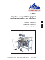 1
1
-
 2
2
-
 3
3
-
 4
4
-
 5
5
-
 6
6
-
 7
7
-
 8
8
-
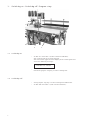 9
9
-
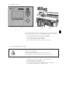 10
10
-
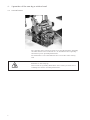 11
11
-
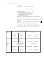 12
12
-
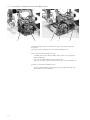 13
13
-
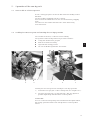 14
14
-
 15
15
-
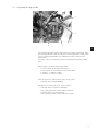 16
16
-
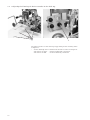 17
17
-
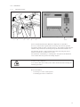 18
18
-
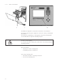 19
19
-
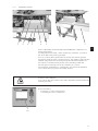 20
20
-
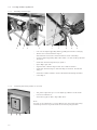 21
21
-
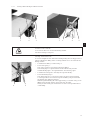 22
22
-
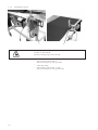 23
23
-
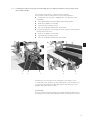 24
24
-
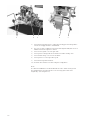 25
25
-
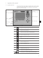 26
26
-
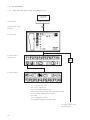 27
27
-
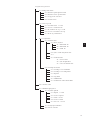 28
28
-
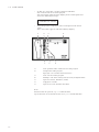 29
29
-
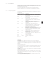 30
30
-
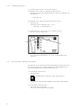 31
31
-
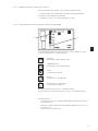 32
32
-
 33
33
-
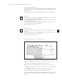 34
34
-
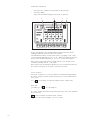 35
35
-
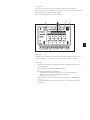 36
36
-
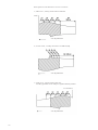 37
37
-
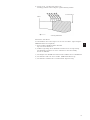 38
38
-
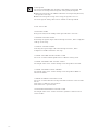 39
39
-
 40
40
-
 41
41
-
 42
42
-
 43
43
-
 44
44
-
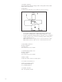 45
45
-
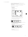 46
46
-
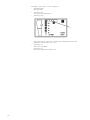 47
47
-
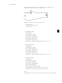 48
48
-
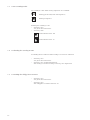 49
49
-
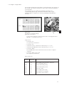 50
50
-
 51
51
-
 52
52
-
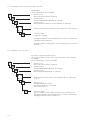 53
53
-
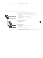 54
54
-
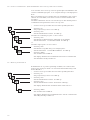 55
55
-
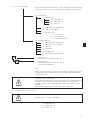 56
56
-
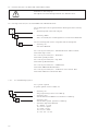 57
57
-
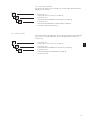 58
58
-
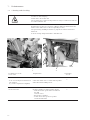 59
59
-
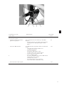 60
60
-
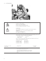 61
61
-
 62
62
-
 63
63
-
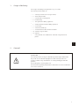 64
64
-
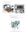 65
65
-
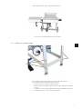 66
66
-
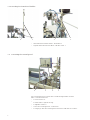 67
67
-
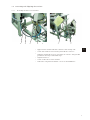 68
68
-
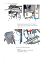 69
69
-
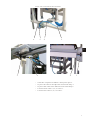 70
70
-
 71
71
-
 72
72
-
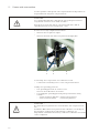 73
73
-
 74
74
-
 75
75
-
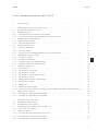 76
76
-
 77
77
-
 78
78
-
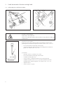 79
79
-
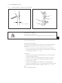 80
80
-
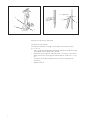 81
81
-
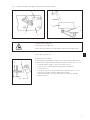 82
82
-
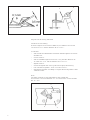 83
83
-
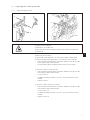 84
84
-
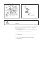 85
85
-
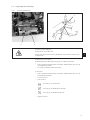 86
86
-
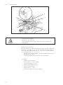 87
87
-
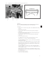 88
88
-
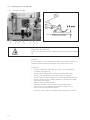 89
89
-
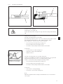 90
90
-
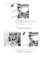 91
91
-
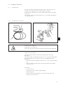 92
92
-
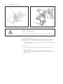 93
93
-
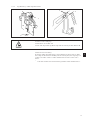 94
94
-
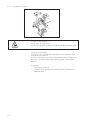 95
95
-
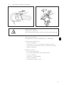 96
96
-
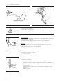 97
97
-
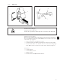 98
98
-
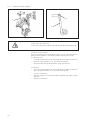 99
99
-
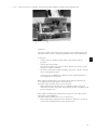 100
100
-
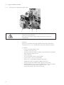 101
101
-
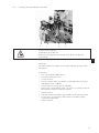 102
102
-
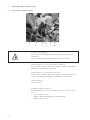 103
103
-
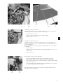 104
104
-
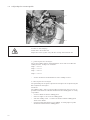 105
105
-
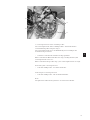 106
106
-
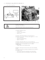 107
107
-
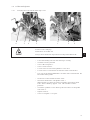 108
108
-
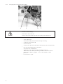 109
109
-
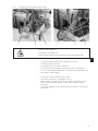 110
110
-
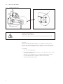 111
111
-
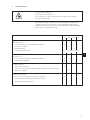 112
112
-
 113
113


Beisler 1265-5 Operating Instructions Manual
- Type
- Operating Instructions Manual
in andere talen
- English: Beisler 1265-5
- polski: Beisler 1265-5
