
GB
PHONO
DVR
STANDBY
/ON
PURE DIRECT
2CH/MULTI CH
SPEAKERS
VIDEO AUX
REC OUT/ZONE 2
INPUT MODE
SOURCE/REMOTE
DVDDTV/LD
MD/TAPE
CD-R
TUNER
CD
VIDEO AUX
VCR 2
VCR 1
SAT
CABLE
A B
STRAIGHT
EFFECT
MULTI CH
INPUT
DSP
PROGRAM
BALANCE
TONE
CONTROL
VOLUME
INPUT SELECTOR
MULTI JOG
SILENT OPTIMIZER
MIC
PHONES
OPTICAL
R
AUDIO
L
VIDEO
S VIDEO
AV Amplifier
Amplificateur Audio-Vidéo
OWNER’S MANUAL
MODE D’EMPLOI
BEDIENUNGSANLEITUNG

1 To assure the finest performance, please read this
manual carefully. Keep it in a safe place for future
reference.
2 Install this sound system in a well ventilated, cool,
dry, clean place — away from direct sunlight, heat
sources, vibration, dust, moisture, and/or cold.
Allow ventilation space of at least 30 cm on the top,
20 cm on the left and right, and 20 cm on the back
of this unit.
3 Locate this unit away from other electrical
appliances, motors, or transformers to avoid
humming sounds.
4 Do not expose this unit to sudden temperature
changes from cold to hot, and do not locate this
unit in a environment with high humidity (i.e. a
room with a humidifier) to prevent condensation
inside this unit, which may cause an electrical
shock, fire, damage to this unit, and/or personal
injury.
5 Avoid installing this unit where foreign object may
fall onto this unit and/or this unit may be exposed
to liquid dripping or splashing. On the top of this
unit, do not place:
– Other components, as they may cause damage
and/or discoloration on the surface of this unit.
– Burning objects (i.e. candles), as they may
cause fire, damage to this unit, and/or personal
injury.
– Containers with liquid in them, as they may fall
and liquid may cause electrical shock to the user
and/or damage to this unit.
6 Do not cover this unit with a newspaper, tablecloth,
curtain, etc. in order not to obstruct heat radiation.
If the temperature inside this unit rises, it may
cause fire, damage to this unit, and/or personal
injury.
7 Do not plug in this unit to a wall outlet until all
connections are complete.
8 Do not operate this unit upside-down. It may
overheat, possibly causing damage.
9 Do not use force on switches, knobs and/or cords.
10 When disconnecting the power cord from the wall
outlet, grasp the plug; do not pull the cord.
11 Do not clean this unit with chemical solvents; this
might damage the finish. Use a clean, dry cloth.
12 Only voltage specified on this unit must be used.
Using this unit with a higher voltage than specified
is dangerous and may cause fire, damage to this
unit, and/or personal injury. YAMAHA will not be
held responsible for any damage resulting from use
of this unit with a voltage other than specified.
13 To prevent damage by lightning, disconnect the
power cord from the wall outlet during an electrical
storm.
14 Do not attempt to modify or fix this unit. Contact
qualified YAMAHA service personnel when any
service is needed. The cabinet should never be
opened for any reasons.
15 When not planning to use this unit for long periods
of time (i.e. vacation), disconnect the AC power
plug from the wall outlet.
16 Be sure to read the “TROUBLESHOOTING” section
on common operating errors before concluding
that this unit is faulty.
17 Before moving this unit, press STANDBY/ON to set
this unit in the standby mode, and disconnect the
AC power plug from the wall outlet.
18 VOLTAGE SELECTOR (General model only)
The VOLTAGE SELECTOR on the rear panel of this
unit must be set for your local main voltage
BEFORE plugging into the AC main supply.
Voltages are 110/120/220/230-240 V AC, 50/60 Hz.
■ For U.K. customers
If the socket outlets in the home are not suitable for the
plug supplied with this appliance, it should be cut off and
an appropriate 3 pin plug fitted. For details, refer to the
instructions described below.
The plug severed from the mains lead must be destroyed, as a
plug with bared flexible cord is hazardous if engaged in a live
socket outlet.
■ Special Instructions for U.K. Model
CAUTION: READ THIS BEFORE OPERATING YOUR UNIT.
This unit is not disconnected from the AC power
source as long as it is connected to the wall outlet, even
if this unit itself is turned off. This state is called the
standby mode. In this state, this unit is designed to
consume a very small quantity of power.
WARNING
TO REDUCE THE RISK OF FIRE OR ELECTRIC
SHOCK, DO NOT EXPOSE THIS UNIT TO RAIN
OR MOISTURE.
Note
IMPORTANT
THE WIRES IN MAINS LEAD ARE COLOURED IN
ACCORDANCE WITH THE FOLLOWING CODE:
Blue: NEUTRAL
Brown: LIVE
As the colours of the wires in the mains lead of this
apparatus may not correspond with the coloured
markings identifying the terminals in your plug,
proceed as follows:
The wire which is coloured BLUE must be connected
to the terminal which is marked with the letter N or
coloured BLACK. The wire which is coloured
BROWN must be connected to the terminal which is
marked with the letter L or coloured RED.
Making sure that neither core is connected to the earth
terminal of the three pin plug.

1
English
PREPARATIONINTRODUCTION
BASIC
OPERATION
SOUND FIELD
PROGRAMS
ADVANCED
OPERATION
ADDITIONAL
INFORMATION
FEATURES .............................................................2
GETTING STARTED............................................3
Supplied accessories .................................................. 3
Installing batteries in the remote controls.................. 4
CONTROLS AND FUNCTIONS.......................... 5
Front panel ................................................................. 5
Remote control........................................................... 7
GUI remote control.................................................... 8
Using the remote controls .......................................... 9
Front panel display................................................... 10
Rear panel ................................................................ 11
SPEAKER SETUP................................................ 12
Speaker placement ................................................... 12
Speaker connections ................................................ 13
CONNECTIONS...................................................16
Connecting components........................................... 16
Connecting video components................................. 17
Connecting audio components................................. 24
Connecting the power supply cord .......................... 27
Speaker impedance setting....................................... 28
Turning on the power............................................... 28
USING THE GUI REMOTE CONTROL..........29
GUI remote control operations ................................ 29
AUTO SETUP....................................................... 31
Introduction.............................................................. 31
Optimizer microphone setup.................................... 31
Starting the setup ..................................................... 32
Confirming the results ............................................. 34
PLAYBACK ..........................................................37
Basic operations....................................................... 37
Selecting sound field programs................................ 39
Listening to uncompromising pure audio ................ 43
Selecting input modes.............................................. 44
RECORDING ....................................................... 46
SOUND FIELD PROGRAM
DESCRIPTIONS.............................................. 48
For movie/video sources.......................................... 48
For music sources .................................................... 51
ADVANCED OPERATIONS.............................. 53
Selecting the OSD mode.......................................... 53
Using the sleep timer ............................................... 53
Using the test tone.................................................... 54
SYSTEM OPTIONS............................................. 55
Changing parameter settings.................................... 57
Input Select .............................................................. 58
Manual setup: Sound ............................................... 61
Manual setup: Basic................................................. 64
Manual setup: Video................................................ 71
Manual setup: Option............................................... 75
Memory Guard......................................................... 78
REMOTE CONTROL FEATURES................... 80
Control area.............................................................. 80
Setting manufacturer codes...................................... 81
Programming codes from other remote controls ..... 82
Changing source names in the display window....... 83
Using the macro feature........................................... 84
Clearing function sets .............................................. 86
Clearing individual functions................................... 87
Controlling components........................................... 88
ZONE 2.................................................................. 93
Zone 2 connections .................................................. 93
Remote controlling Zone 2 ...................................... 94
USING i.LINK...................................................... 96
What is i.LINK?....................................................... 96
Connecting i.LINK components.............................. 96
Assigning i.LINK components ................................ 97
Listening to playback from an i.LINK
component ........................................................... 97
Changing i.LINK Select parameters........................ 98
i.LINK display messages ....................................... 100
SOUND FIELD OPTIONS................................ 101
What is a sound field ............................................. 101
Stereo/Surround menu ........................................... 103
TROUBLESHOOTING..................................... 108
PARAMETRIC EQUALIZER
INFORMATION ............................................ 112
GLOSSARY ........................................................ 113
BLOCK DIAGRAMS ........................................ 117
SPECIFICATIONS............................................ 119
CONTENTS
INTRODUCTION
PREPARATION
BASIC OPERATION
SOUND FIELD PROGRAMS
ADVANCED OPERATION
ADDITIONAL INFORMATION

FEATURES
2
Built-in 9-channel power amplifier
◆ Minimum RMS output power
(0.015% THD, 20 Hz – 20 kHz, 8Ω)
Front: 170 W + 170 W
Center: 170 W
Surround: 170 W + 170 W
Surround back: 170 W + 170 W
Presence: 50 W + 50 W
Sound field features
◆ Proprietary YAMAHA technology for the creation of
sound fields
◆ THX Ultra 2
◆ Dolby Digital/Dolby Digital EX decoder
◆ Dolby Pro Logic/Dolby Pro Logic II/Dolby Pro Logic
IIx decoder
◆ DTS/DTS ES Matrix 6.1, Discrete 6.1/DTS 96/24
decoder
◆ DTS Neo:6 decoder
◆ Virtual CINEMA DSP
◆ SILENT CINEMA
™
Other features
◆ YPAO: YAMAHA Parametric Room Acoustic
Optimizer for automatic speaker setup
◆ 192-kHz/24-bit D/A converter
◆ On-screen display menus that allow you to optimize
this unit to suit your individual audio/video system
◆ 8-channel external decoder input for other future
formats (compatible with DSP)
◆ PURE DIRECT for pure fidelity sound with multi or
2-channel sources
◆ On-screen display function with dedicated GUI remote
control for performing all operations
◆ S Video signal input/output capability
◆ Component video input/output capability
◆ Video signal conversion (Composite video ↔
S Video ↔ Component video) capability for monitor
out
◆ Faroudja DCDi for progressive video output
◆ Faroudja True Life Enhancer for smooth video images
◆ TBC (Time Base Corrector) for jitterless video images
◆ i.LINK interface for direct digital transfer of digital
audio signals
◆ Optical and coaxial digital audio signal jacks
◆ Sleep timer
◆ Night listening mode
◆ Remote control with preset manufacturer codes and
“learning” macro capability
◆ Zone 2 custom installation facility
• y indicates a tip for your operation.
• Some operations can be performed by using either the buttons on the main unit or on the remote control. In cases where the button
names differ between the main unit and remote control, the button name on the remote control is given in parentheses.
• This manual is printed prior to production. Design and specifications are subject to change in part as a result of improvements, etc. In
case of differences between the manual and product, the product has priority.
Manufactured under license from Dolby Laboratories.
“Dolby”, “Pro Logic”, “Surround EX”, and the double-D symbol
are trademarks of Dolby Laboratories.
SILENT CINEMA is a trademark of YAMAHA
CORPORATION.
“DCDi” is a trademark of Faroudja, a division of Genesis
Microchip, Inc.
“DTS”, “DTS-ES Digital Surround”, “Neo:6” and “DTS 96/24”
are trademarks of Digital Theater Systems, Inc.
“THX” and the “THX” logo are registered trademarks of THX
Ltd. “Surround EX” is a jointly developed technology of THX
and Dolby Laboratories, Inc. and is a trademark of Dolby
Laboratories, Inc. All rights reserved. Used under authorization.
“i.LINK” and the “i.LINK” logo are trademarks of Sony
Corporation.
FEATURES

GETTING STARTED
3
English
INTRODUCTION
Please check that you received all of the following parts.
GETTING STARTED
Supplied accessories
TRANSMIT
RE-NAME
STANDBY
TUNER
MULTI CH IN
PURE DIRECT
TOP EXIT
INPUT MODE
SOUND
SYSTEM
CLEAR LEARN MACRO
OFF ON
MACRO
PHONO
CD
DVD
DVR
VCR 2
TITLE
MENU
CHAPTER
PAUSE
STOP
POWER
REC
STEREO
EX/ES
AMP
10KEY
JAZZ
MOVIE
THX
MUTE
VOLUME
STRAIGHT
TV INPUT
TV VOL
CH
PRESET
DISC
EFFECT
ON SCREEN
TESTSLEEP
PUSH
TV MUTE
MUSIC
ENTERTAIN
ROCK
HALL 1
HALL 2
CHURCH
NIGHT
/DTS
CHP/INDEX
A/B/C/D/E
SELECT
DISPLAY
SEARCH
SOURCE
PLAY
–+
ENTER
DTV/LD
VCR 1
CD-R
MD/TAPE
SAT
CABLE
POWER
V-AU X
1
5
9
6
0 +10
+100
78
23
4
SPEAKERS
A B
Remote control
Batteries (3)
(AA, LR6)
Power cord
Optimizer microphone
Speaker terminal wrench
Batteries (2)
(AAA, R03)
POWER
VOL
MUTE
TOP
EXIT
SYSTEM
STANDBY
+
–
ENTER
GUI
Remote control
*
The optimizer microphone is
sensitive to heat.
– Keep it away from direct
sunlight.
– Do not place it on top of this unit.

GETTING STARTED
4
Notes on batteries
• Change all of the batteries if you notice the following conditions: the operation range of the remote control decreases, the indicator
does not flash or its light becomes dim.
• Do not use old batteries together with new ones.
• Do not use different types of batteries (such as alkaline and manganese batteries) together. Read the packaging carefully as these
different types of batteries may have the same shape and color.
• If the batteries have leaked, dispose of them immediately. Avoid touching the leaked material or letting it come into contact with
clothing, etc. Clean the battery compartment thoroughly before installing new batteries.
■ Remote control
1 Open the battery compartment cover.
2 Insert three supplied batteries (AA, LR6)
according to the polarity markings (+ and –)
on the inside of the battery compartment.
3 After new batteries are correctly inserted,
press the RESET button in the battery
compartment using a ball point pen or
similar object.
(This does not clear the contents of the memory.)
4 Replace the cover by pressing until it snaps
into place.
■ GUI remote control
1 Press the part and slide the battery
compartment cover off.
2 Insert two supplied batteries (AAA, R03)
according to the polarity markings (+ and –)
on the inside of the battery compartment.
3 Slide the cover back until it snaps into place.
Installing batteries in the remote controls
If the remote control is without batteries for more than
3 minutes, or if exhausted batteries remain in the
remote control, the contents of the memory may be
cleared. If the memory is cleared, insert new batteries,
set up the manufacturer code(s) and program any
acquired functions that may have been cleared.
RESET button
1
3
2

CONTROLS AND FUNCTIONS
5
English
INTRODUCTION
1 STANDBY/ON
Turns on this unit or sets it to the standby mode. When you
turn on this unit, you will hear a click and there will be a
delay of a few seconds before this unit can reproduce
sound.
In standby mode, this unit consumes a small amount of power in
order to receive infrared-signals from the remote controls.
2 INPUT SELECTOR
Selects the input source you want to listen to or watch.
3 PURE DIRECT 2CH/MULTI CH
Turns on or off the 2-channel/multi-channel PURE
DIRECT mode (see page 43).
4 Remote control sensor
Receives signals from the remote controls.
5 Front panel display
Shows information about the operational status of this
unit.
6 INPUT MODE
Sets the priority for the type of input signal (AUTO,
i.LINK, DTS, DIGITAL, D.D.RF, ANALOG) received
when one component is connected to two or more input
jacks on this unit (see page 44).
7 MULTI CH INPUT
Selects the source connected to the MULTI CH INPUT
jacks. This source takes priority over the source selected
with INPUT SELECTOR (or the input selector buttons on
the remote control).
8 STRAIGHT/EFFECT
Switches the sound fields off or on. When STRAIGHT is
selected, input signals (2-channel or multi-channel) are
output directly from their respective speakers without
effect processing.
9 DSP PROGRAM
Press this button before rotating MULTI JOG to select
sound field programs.
CONTROLS AND FUNCTIONS
Front panel
PHONO
DVR
PURE DIRECT
2CH/MULTI CH
SPEAKERS
VIDEO AUX
REC OUT/ZONE 2
INPUT MODE
SOURCE/REMOTE
DVDDTV/LD
MD/TAPE
CD-R
TUNER
CD
VIDEO AUX
VCR 2
VCR 1
SAT
CABLE
AB
STRAIGHT
EFFECT
MULTI CH
INPUT
DSP
PROGRAM
BALANCE
TONE
CONTROL
VOLUME
INPUT SELECTOR
MULTI JOG
SILENT OPTIMIZER
MIC
PHONES
OPTICAL
R
AUDIO
L
VIDEO
S VIDEO
STANDBY
/ON
12 54C3789AB06
EFG HD
Note

CONTROLS AND FUNCTIONS
6
0 MULTI JOG
Rotate to select or adjust items when used with the DSP
PROGRAM, BALANCE or TONE CONTROL buttons.
A BALANCE
Adjusts the left/right balance of the front, presence,
surround and surround back speakers.
B TONE CONTROL
Press this button before rotating MULTI JOG to adjust the
bass/treble balance for the front left/right, center and
subwoofer channels (see page 38).
C VOLUME
Controls the output level of all audio channels.
This does not affect the REC OUT level.
D SPEAKERS A/B
Turns on or off the set of front speakers connected to the A
and/or B terminals on the rear panel each time the
corresponding button is pressed.
E PHONES jack
Outputs audio signals for private listening with
headphones. When you connect headphones, no signals
are output to the OUTPUT jacks or to the speakers.
F OPTIMIZER MIC jack
Use to connect and input audio signals from the supplied
microphone for the AUTO SETUP function (see page 31).
G REC OUT/ZONE 2
Selects the source you want to direct to the audio/video
recorder and ZONE 2 outputs independently of the source
you are listening to or watching in the main room. When
set to the SOURCE/REMOTE position, the input source is
directed to all outputs. The source in Zone 2 and the
source you record are always identical.
H VIDEO AUX jacks
Inputs audio and video signals from a portable external
source such as a game console. To reproduce source
signals from these jacks, select V-AUX as the input
source.
■ Opening and closing the front panel
door
When you want to use the controls behind the front panel
door, open the door by gently pressing on the lower part of
the panel. Keep the door closed when not using these
controls.
To open, press gently on the lower part of the panel.

CONTROLS AND FUNCTIONS
7
English
INTRODUCTION
This section describes the functions of each control on the
remote control. See “REMOTE CONTROL FEATURES”
on page 80 to operate other components with this remote
control.
1 Infrared window
Outputs infrared control signals. Aim this window at the
component you want to operate.
2 RE-NAME
Used for changing the input source name in the display
window (see page 83).
3 TRANSMIT indicator
Flashes while the remote control is sending signals.
4 STANDBY
Sets this unit in the standby mode.
5 SYSTEM POWER
Turns on this unit’s power.
6 PURE DIRECT
Turns on or off the 2-channel/multi-channel PURE
DIRECT mode (see page 43).
7 Display window
Shows the name of the selected source component that
you can control.
8 SOURCE SELECT k/n
Selects another component that you can control
independently of the input component selected with the
input selector buttons.
9 LIGHT
Press to momentarily light up the display window and
buttons on this remote control.
0 INPUT MODE
Sets the priority for the type of input signal (AUTO,
i.LINK, DTS, DIGITAL, D.D.RF, ANALOG) received
when one component is connected to two or more input
jacks on this unit (see page 44).
A 10KEY/AMP
Slide to 10KEY to select a numeric button or operate the
component selected using the input selector buttons.
Slide to AMP to operate this unit.
B EX/ES
Switches between 5.1- and 6.1/7.1-channel playback of
multi-channel software.
C ON SCREEN
Selects the GUI display mode for your video monitor.
D SLEEP
Sets the sleep timer.
E TEST
Outputs the test tone to adjust the speaker levels.
F CLEAR
Used for clearing functions acquired when using the learn
and rename features and setting manufacturer codes (see
page 86).
Remote control
TRANSMIT
RE-NAME
STANDBY
TUNER
MULTI CH IN
PURE DIRECT
TOP EXIT
INPUT MODE
SOUND
SYSTEM
CLEAR LEARN MACRO
OFF ON
MACRO
PHONO
CD
DVD
DVR
VCR 2
TITLE
MENU
CHAPTER
PAUSE
STOP
POWER
REC
STEREO
EX/ES
AMP
10KEY
JAZZ
MOVIE
THX
MUTE
VOLUME
STRAIGHT
TV INPUT
TV VOL
CH
PRESET
DISC
EFFECT
ON SCREEN
TESTSLEEP
PUSH
TV MUTE
MUSIC
ENTERTAIN
ROCK
HALL 1
HALL 2
CHURCH
NIGHT
/DTS
CHP/INDEX
A/B/C/D/E
SELECT
DISPLAY
SEARCH
SOURCE
PLAY
–+
ENTER
DTV/LD
VCR 1
CD-R
MD/TAPE
SAT
CABLE
POWER
V-AUX
1
5
9
6
0 +10
+100
78
23
4
SPEAKERS
A B
F
G
H
I
O
Q
P
K
S
R
t
J
1
2
3
4
5
7
8
9
C
D
E
A
B
6
L
M
N
0

CONTROLS AND FUNCTIONS
8
G LEARN
Used for setting up the manufacturer code or for
programming the functions of other remote controls (see
pages 81 and 82).
H MACRO
Used to program a series of operations for control by a
single button (see page 84).
I MACRO ON/OFF
Turns the macro function on and off.
J Input selector buttons
Selects the input source and changes the control area.
K MULTI CH IN
Selects the source connected to the MULTI CH INPUT
jacks. This source takes priority over the source selected
with INPUT SELECTOR (or the input selector buttons on
the remote control).
L Operation buttons
Operate various parameters and commands shown in the
on-screen display.
M EXIT
Press to exit the on-screen display menus.
N TOP
Press to display the top level of the on-screen display
menus.
O Sound field program
Use to select sound field programs.
P MUTE
Mutes the sound. The MUTE indicator turns on when the
MUTE function is on. Press again to restore the audio
output to the previous volume level.
Q VOLUME +/–
Increases or decreases the volume level.
R STRAIGHT/EFFECT
Switches the sound fields off or on. When STRAIGHT is
selected, input signals (2-channel or multi-channel) are
output directly from their respective speakers without
effect processing.
S SPEAKERS A/B
Turn on or off the set of front speakers connected to the A
and/or B terminals on the rear panel each time the
corresponding button is pressed.
T Cover
Slide down to use the concealed buttons for various setup
and parameter operations.
This section describes the controls and functions of the
GUI remote control. See “USING THE GUI REMOTE
CONTROL” on page 29 for details.
1 SYSTEM POWER
Turns on this unit’s power.
2 Multi-control/ENTER
Tilt up/down or left/right to navigate through the various
parameters and commands shown in the on-screen display.
Press to choose the selected item in the on-screen display.
3 TOP
Press to display the top level of the on-screen display
menus.
4 EXIT
Press to exit the on-screen display menus.
5 STANDBY
Sets this unit in the standby mode.
6 VOLUME +/–
Increases or decreases the volume level.
7 MUTE
Mutes the sound. The MUTE indicator turns on when the
MUTE function is on. Press again to restore the audio
output to the previous volume level.
GUI remote control
POWER
VOL
MUTE
TOP
EXIT
SYSTEM
STANDBY
+
–
ENTER
6
5
1
2
3
4
7

CONTROLS AND FUNCTIONS
9
English
INTRODUCTION
The remote controls transmit directional infrared beams.
Be sure to aim the remote controls directly at the remote
control sensor on the main unit during operation.
■ Handling the remote controls
• Do not spill water or other liquids on the remote
controls.
• Do not drop the remote controls.
• Do not leave or store the remote controls in the
following types of conditions:
– high humidity such as near a bath
– high temperature such as near a heater or stove
– extremely low temperatures
– dusty locations
Using the remote controls
PHONO
DVR
PURE DIRECT
2CH/MULTI CH
SPEAKERS
VIDEO AUX
REC OUT/ZONE 2
INPUT MODE
SOURCE/REMOTE
DVDDTV/LD
MD/TAPE
CD-R
CD
TUNER
VIDEO AUX
VCR 2
VCR 1
SAT
CABLE
AB
STRAIGHT
EFFECT
MULTI CH
INPUT
DSP
PROGRAM
BALANCE
TONE
CONTROL
VOLUME
INPUT SELECTOR
MULTI JOG
SILENT OPTIMIZER
MIC
PHONES
OPTICAL
R
AUDIO
L
VIDEO
S VIDEO
STANDBY
/ON
3030
POWER
VOL
MUTE
TOP EXIT
SYSTEM
STANDBY
+
–
ENTER
Approximately 6 m (20 ft)

CONTROLS AND FUNCTIONS
10
1 i.LINK indicator
Lights up when this unit is playing back i.LINK signals.
2 Decoder indicators
When any of this unit’s decoders function, the respective
indicator lights up.
3 HiFi DSP
Lights up when you select a HiFi DSP sound field
program.
4 VIRTUAL indicator
Lights up when Virtual CINEMA DSP is active (see
page 42).
5 CINEMA DSP indicator
Lights up when you select a CINEMA DSP sound field
program.
6 NIGHT indicator
Lights up when you select the night listening mode.
7 SILENT CINEMA indicator
Lights up when headphones are connected and a sound
field program selected (see page 38).
8 Headphones indicator
Lights up when headphones are connected.
9 SP A B indicators
Lights up according to the set of front speakers selected.
Both indicators light up when both sets of speakers are
selected, or when bi-wiring.
0 Input source indicators
A cursor lights to show the current input source.
A VOLUME level indicators
Indicates the volume level.
B MUTE indicator
Lights up when the MUTE function is on.
C LFE indicator
Lights up when the input signal contains the LFE signal.
D THX indicators
Lights up when a THX program is selected.
E PCM indicator
Lights up when this unit is reproducing PCM (pulse code
modulation) digital audio signals.
F Sound field indicators
Lights to indicate the active DSP sound fields.
G OPTIMIZER indicator
Lights up during the auto setup procedure and when the
auto setup speaker settings are used without any
modifications.
H ZONE 2 indicator
Lights up when Zone 2 power is on.
I SLEEP indicator
Lights up when the sleep timer is on.
J Multi-information display
Shows the current sound field program name and other
information when adjusting or changing settings.
K Input channel indicators
Indicates the channel component of the current digital
input signal.
Front panel display
MULTI CH
V–AUX DVR
VCR 1VCR 2 DTV/LDSAT CABLE DVD
MD/TAPE
CD–R
CD
TUNER
PHONO
96
24
MATRIX DISCRETE
HiFi DSP
NIGHT
SILENT
SLEEP
ZONE2
OPTIMIZER
DIGITAL
PL
PCMTHX
PL
EX
VIRTUAL
MUTE
RL
C
SL
SR
SB
VOLUME
LFE
A B
SP
C
I
315789 B40
D
6
K
A2
E
H
FJ
G
Presence DSP sound field
Listening position
Surround left
DSP sound field
Surround right
DSP sound field
Surround back DSP sound field

CONTROLS AND FUNCTIONS
11
English
INTRODUCTION
1 PHONO
See page 24 for connection information.
2 Speaker terminals
See page 14 for connection information.
3 AC INLET
Use this inlet to plug in the supplied power cable (see
page 27).
4 AC OUTLET(S)
Use to supply power to your other A/V components (see
page 27).
5 Audio component jacks
See pages 24 and 25 for connection information.
6 Pre out jacks
See page 26 for connection information.
7 MULTI CH INPUT jacks
See page 18 for connection information.
8 2CH IN jacks
See page 18 for connection information.
9 DIGITAL INPUT jacks
See pages 17, 19-21 and 23-25 for details.
0 DIGITAL OUTPUT jacks
See pages 23 and 25 for details.
A ZONE 2 COAXIAL OUT
See page 93 for details.
B Video component jacks
See pages 17 and 19-23 for connection information.
C i.LINK connectors
See pages 26 and 96 for connection information.
D ZONE 2 video jacks
See page 93 for details.
E REMOTE IN/OUT jacks
See page 93 for details.
F CONTROL OUT jacks
These are control expansion terminals for commercial use.
G RS-232C terminal
This is a control expansion terminal for commercial use.
Consult you dealer for details.
H ZONE 2 audio jacks
See page 93 for details.
I FRONT IN/CENTER IN
See page 26 for connection information.
< General models only >
VOLTAGE SELECTOR
See page 27 for details.
Rear panel
L L
R R
++
–
+
–
+
–
–
FRONT
A
FRONT
B
FRONT
B
FRONT
A
SURROUND
SUBWOOFER
FRONT
PURE DIRECT
CD DVD DTV/LD CBL SAT VCR 1
IN(PLAY)
MD/TAPE CD-R
OUT(REC) OUT(REC)
CENTERSURROUND
BACK
PRESENCE
/ZONE 2
SPEAKERS
AUDIO
SURROUND
BACK
(SINGLE)
SURROUND
SPEAKERSAC OUTLETS
AC IN
L
R
CENTER(SINGLE)
PHONO
SURROUND
BACK
SURROUND
GND
MULTI CH INPUT 2CH IN
PRESENCE
/ZONE 2
IN(PLAY) IN(PLAY) OUT(REC)
VCR 2
IN(PLAY) OUT(REC)
DVR
IN(PLAY) OUT(REC)
OUT
ZONE 2 FRONT CENTER
IN VCR 1 OUT
IN
VCR 2 OUT IN DVR OUT ZONE 2
SURROUND
BACK
PRESENCE SUBWOOFER
OUT (SINGLE)
L
R
COMPONENT VIDEO VIDEO
VIDEO
IN OUT IN +12V 15mA MAX
S.VIDEO
DVD1
–MONITOR OUT–2
DTV/LD
CBL SAT
Y
P
B
PR
DVD CBL SAT VCR1 DVRDTV/LD
1
–MONITOR OUT–2
DIGITAL INPUT
q RF—
DTV/LD DTV SATCD CD CD-R CD-R MD/TAPEDVD DVD DVR DVR
OPTICAL COAXIAL
ZONE 2CBLDVR
DIGITAL OUTPUT
1
REMOTE
CONTROL OUT
21 2
RS
–
232C
A B C D E F
1
2
4
3
5
6
7
8
9
0
BA
C
D
S400
(AUDIO)
SURROUND
S1/S2
(AC-3)
COAXIAL
LD
TUNER
2
1
3
5
2
6
4
0A CBFIGHD78 E9
(REAR)
(FRONT)
OUT
POWER AMP IN

SPEAKER SETUP
12
Since CINEMA DSP and THX are different surround
post-processing technologies, we recommend the
following speaker setup in order to enjoy the best surround
sound of each technology.
■ CINEMA DSP speaker layout
y
The speaker layout above shows the standard ITU-R speaker
setup. You can use it to enjoy CINEMA DSP, multi-channel
audio sources and THX.
Front speakers (FR and FL)
The front speakers are used for the main source sound.
Place these speakers an equal distance from the ideal
listening position. The distance of each speaker from each
side of the video monitor should be the same.
Center speaker (C)
The center speaker is for the center channel sounds
(dialog, vocals, etc.). Align the front face of the center
speaker with the front face of your video monitor. Place
the speaker centrally between the front speakers and as
close to the monitor as possible, such as directly over or
under it.
Surround speakers (SR and SL)
The surround speakers are used for effect and surround
sounds. Place these speakers behind your listening
position, facing slightly inwards, about 1.8 m (6 ft) above
the floor.
Surround back speakers (SBR and SBL)
The surround back speakers supplement the surround
speakers and provide for more realistic front-to-back
transitions. Place these speakers directly behind the
listening position and at the same height as the surround
speakers. They should be positioned at least 30 cm (12 in.)
apart. Ideally, they should be positioned at the same width
as the front speakers.
Subwoofer
The use of a subwoofer, such as the YAMAHA Active
Servo Processing Subwoofer System, is effective not only
for reinforcing bass frequencies from any or all channels,
but also for high fidelity reproduction of the LFE (low-
frequency effect) channel included in Dolby Digital and
DTS software. The position of the subwoofer is not so
critical, because low bass sounds are not highly
directional. But it is better to place the subwoofer near the
front speakers. Turn it slightly toward the center of the
room to reduce wall reflections.
Presence speakers (PR and PL)
Presence speakers supplement the sound from the front
speakers with extra ambient effects produced by CINEMA
DSP (see page 38). These effects include sounds that
filmmakers intend to locate a little farther back behind the
screen in order to create more theater-like ambience. Place
these speakers at the front of the room about 0.5 - 1 m
(1 - 3 ft) outside the front speakers, facing slightly
inwards, and about 1.8 m (6 ft) above the floor.
SPEAKER SETUP
Speaker placement
60˚
30˚
PL
PR
SBR
SBL
FL
FR
C
SL
SR
SR
80˚
SL
more than 30 cm (12 in.)
1.8 m (6 ft)
1.8 m (6 ft)

13
English
SPEAKER SETUP
PREPARATION
■ Di-pole speaker layout
Either di-pole or direct radiating speaker types can be used
for THX surround. If you choose di-pole speakers, please
place the surround and surround back speakers according
to the speaker layout below.
Be sure to connect the left channel (L), right channel (R),
“+” (red) and “–” (black) properly. If the connections are
faulty, no sound can be heard from the speakers, and if the
polarity of the speaker connections is incorrect, the sound
will be unnatural and lack bass.
• If you intend to use 6-ohm speakers, be sure to set this
unit’s speaker impedance setting to 6 ohms before
using (see page 28).
• Before connecting the speakers, make sure that this
unit’s power is off.
• Do not let the bare speaker wires touch each other or
any metal part of this unit. This could damage this unit
and/or the speakers.
• Use magnetically shielded speakers. If this type of
speaker still creates interference with the monitor,
place the speakers away from the monitor.
A speaker cord is actually a pair of insulated cables
running side by side. One cable is colored or shaped
differently, perhaps with a stripe, groove or ridges.
Connect the striped (grooved, etc.) cable to the “+” (red)
terminals on this unit and your speaker. Connect the plain
cable to the “–” (black) terminals.
1 Remove approximately 10 mm (3/8") of
insulation from each of the speaker cables.
2 Twist the exposed wires of the cable together
to prevent short circuits.
3 Unscrew the knob.
y
The supplied speaker terminal wrench is useful for screwing
or unscrewing knobs.
4 Insert one bare wire into the hole in the side
of each terminal.
5 Tighten the knob to secure the wire.
Banana plug connections
(With the exception of U.K. and Europe models)
First, tighten the knob and then insert the banana plug
connector into the end of the corresponding terminal.
Speaker connections
FL
SR
SL
FR
C
SBR
SBL
: Di-pole speaker
: Direction of di-pole speaker
CAUTION
10 mm (3/8")
1
2
Red: positive (+)
Black: negative (–)
5
4
3
Speaker
terminal
wrench
Banana plug
(With the exception of U.K. and Europe models)

14
SPEAKER SETUP
L L
R R
++
–
+
–
+
–
–
FRONT
A
FRONT
B
FRONT
B
FRONT
A
SURROUND CENTERSURROUND
BACK
PRESENCE
/ZONE 2
SPEAKERS
SURROUND
BACK
(SINGLE)
SURROUND
SPEAKERS
PRESENCE
/ZONE 2
SUBWOOFER
R
124 11
9 7
3
6 8
510
Right
subwoofer
system
Center
speaker
Front right
speaker (A)
Surround back
right speaker
Surround
right
speaker
1
2
3
4
5
6
10
11
9
8
7
Speaker layout
Presence
right
speaker
Presence
left
speaker
Surround back
left speaker
Front left
speaker (A)
Surround
left
speaker
Left
subwoofer
system
Front speakers (B)

15
English
SPEAKER SETUP
PREPARATION
■ FRONT terminals
Connect one or two speaker systems to these terminals. If
you use only one speaker system, connect it to either of
the FRONT A or B terminals.
The Canada model cannot output to two separate speaker systems
simultaneously.
Bi-wired connection
The unit also allows you to make bi-wired connections to
one speaker system. Use two pairs of speaker cables for
each speaker (one pair for the woofer and one pair for the
tweeter/mid-range). To use the bi-wired connections, press
SPEAKERS A and SPEAKERS B on the front panel so
that both SP A and B light up on the front panel display.
■ CENTER terminals
Connect a center speaker to these terminals.
■ SURROUND terminals
Connect a surround speaker system to these terminals.
■ SUBWOOFER jacks
Connect one or two subwoofer(s) with built-in amplifier,
such as the YAMAHA Active Servo Processing
Subwoofer System, to the jack(s).
■ SURROUND BACK terminals
Connect a surround back speaker system to these
terminals. If you only connect one surround back speaker,
connect it to the left (L) terminals.
■ PRESENCE/ZONE 2 terminals
Connect presence speakers to these terminals. You can
also use these terminals for connecting Zone 2 speakers
(see page 94).
The presence speakers output ambient effects created by the DSP
sound fields. They do not output sound when other sound fields
are selected.
Note
Bi-wired connection
This unit
Note

CONNECTIONS
16
Do not connect this unit or other components to the mains
power until all connections between components are
completed.
■ Signal directions and cable indications
■ Analog jacks
You can input analog signals from audio components by
connecting an audio pin cable to each of this unit’s analog
jacks. Connect red plugs to the right jacks and white plugs
to the left jacks.
■ Digital jacks
This unit has digital jacks for direct transmission of digital
signals through either coaxial or fiber optic cables. You
can use the digital jacks to input PCM, Dolby Digital and
DTS bitstreams. When you connect components to both
the COAXIAL and OPTICAL jacks, priority is given to
the input signals from the COAXIAL jack. COAXIAL
jacks are compatible with digital signals with sampling
frequencies up to 192 kHz, and OPTICAL jacks with
sampling frequencies up to 96 kHz.
This unit handles digital and analog signals independently. Thus,
audio signals input to the analog jacks are only output to the
analog OUT (REC) jacks. Likewise audio signals input to the
digital (OPTICAL or COAXIAL) jacks are only output to the
DIGITAL OUTPUT jacks.
■ i.LINK jacks
This unit can be connected with i.LINK equipped
components using 4-pin, S400 i.LINK cables. This
connection enables you to send and receive digital audio at
high speed and with high fidelity.
■ Video jacks
This unit has three types of video jacks. The signals input
through any type of VIDEO IN jack can be output through
any of the VIDEO (MONITOR OUT) jacks (automatic
video conversion).
VIDEO jack
For conventional composite video signals.
S VIDEO jack
For S video signals, separated into luminance (Y) and
color (C) video signals to achieve high-quality color
reproduction.
COMPONENT VIDEO jacks
For component signals, separated into luminance (Y)
and color difference (P
B, PR) to provide the best quality
in picture reproduction.
• When signals are input simultaneously through the
COMPONENT VIDEO, S VIDEO and VIDEO jacks, the input
priority is as follows: COMPONENT VIDEO, S VIDEO then
VIDEO.
• Video signal conversion is only possible for signals input
through the COMPONENT VIDEO jack when Resolution is set
to 480i/576i. Signals will not be converted when Resolution is
set to 480p/576p, 720p or 1080i (see page 72).
CONNECTIONS
Connecting components
Note
CAUTION
S
O
V
L
R
V
C
video signal direction
left analog cables
right analog cables
optical cables
coaxial cables
video cables
S video cables
For analog signals
For digital signals
For video signals
audio signal direction
Notes
VIDEO
S VIDEO
COMPONENT VIDEO
P
R
P
B
Y

17
English
CONNECTIONS
PREPARATION
■ Connections for DVD playback
Connecting video components
R R
++
–
–
FRONT
A
FRONT
B
SURROUND
SUBWOOFER
FRONT
PURE DIRECT
CD DVD DTV/LD
IN(PLAY)
MD/TAPE CD-R
OUT(REC) OUT(REC)
CENTERSURROUND
BACK
PRESENCE
/ZONE 2
SPEAKERS
AC I
L
R
CENTER(SINGLE)
PHONO
TUNER
SURROUND
BACK
SURROUND
GND
MULTI CH INPUT 2CH IN
IN(PLAY)
COMPONENT VIDEO
DVD1
–MONITOR OUT–2
DTV/LD
Y
P
B
PR
DVD CBL SAT VCR1 DVRDTV/LD
1
–MONITOR OUT–2
DIGITAL INPUT
q RF—
DTV/LD DTV SATCD CD CD-R CD-R MD/TDVD DVD DVRCBLDVR
A B C D E F
1
2
4
3
5
6
7
8
90 BA
S1/S2
(AC-3)
COAXIAL
LD
L
C
R
O
DVD player
Video
monitor
Optical out
Video out
Audio out
Video in
Coaxial out

18
CONNECTIONS
■ Connecting to the MULTI CH INPUT jacks
This unit is equipped with 8 additional input jacks (left and right FRONT, CENTER, left and right SURROUND, left and
right SURROUND BACK and SUBWOOFER) for discrete multi-channel input from a universal disc player, external
decoder, sound processor or pre-amplifier.
Connect the output jacks on your multi-disc player or external decoder to the MULTI CH INPUT jacks. Be sure to match
the left and right outputs to the left and right input jacks for the front and surround channels.
■ Connecting to the 2CH IN jacks
This unit is equipped with 2 additional input jacks for discrete 2-channel input from a universal disc player, passive input
selector or other high-speed audio component.
The signals input to these jacks can be chosen by pressing PURE DIRECT (see page 43). This feature provides the best
possible sound quality from this unit.
Connect the output jacks on your multi-disc player or external decoder to the 2CH IN jacks.
SUBWOOFER
FRONT
CENTER(SINGLE)
SURROUND
BACK
SURROUND
MULTI CH INPUT
L
R
L
R
L
R
Universal disc
player/External
decoder
For multi-channel input
Front out
Surround back out
Subwoofer out
Center out
Surround out
PURE DIRECT
2CH IN
L
R
Universal disc
player, etc.
For 2-channel input
2CH out

19
English
CONNECTIONS
PREPARATION
■ Connections for digital TV broadcasts or LD playback
*
A demodulator circuit is built into the Dolby Digital RF input so you can connect it directly to the Dolby Digital RF signal output on
your LD player. Make sure you set Coaxial Input to
1 LD-RF in the Assign system parameter (page 59).
R R
++
–
–
FRONT
A
FRONT
B
SURROUND
SUBWOOFER
FRONT
PURE DIRECT
CD DVD DTV/LD CBL SAT VCR 1
IN(PLAY)
MD/TAPE CD-R
OUT(REC) OUT(REC)
CENTERSURROUND
BACK
PRESENCE
/ZONE 2
SPEAKERS
AUDIO
AC OUTLETS
AC IN
L
R
CENTER(SINGLE)
PHONO
SURROUND
BACK
SURROUND
GND
MULTI CH INPUT 2CH IN
IN(PLAY) IN(PLAY) OUT(REC)
VC
R
IN(PLAY)
IN
VCR 1
OUT IN
VC
R
COMPONENT VIDEO VIDEO
DVD1
–MONITOR OUT–2
DTV/LD
CBL SAT
Y
P
B
PR
DVD CBL SAT VCR1 DVRDTV/LD
1
–MONITOR OUT–2
DIGITAL INPUT
q RF—
DTV/LD DTV SATCD CD CD-R CD-R MD/TAPEDVD DVD DVR DVR
OPTICAL COAXIAL
ZONE 2CBLDVR
DIGITAL OUTPUT
A B C D E F
1
2
4
3
5
6
7
8
90 BA
C
D
S1/S2
(AC-3)
COAXIAL
LD
TUNER
O
L
RC
*
DTV tuner/
LD player
Audio out
Video out
Optical out
Coaxial out

20
CONNECTIONS
■ Connections for cable TV broadcasts
R R
++
–
–
FRONT
A
FRONT
B
SURROUND
SUBWOOFER
FRONT
PURE DIRECT
CD DVD DTV/LD CBL SAT VCR 1
IN(PLAY)
MD/TAPE CD-R
OUT(REC) OUT(REC)
CENTERSURROUND
BACK
PRESENCE
/ZONE 2
SPEAKERS
AUDIO
AC OUTLETS
AC IN
L
R
CENTER(SINGLE)
PHONO
SURROUND
BACK
SURROUND
GND
MULTI CH INPUT 2CH IN
IN(PLAY) IN(PLAY) OUT(REC)
VC
R
IN(PLAY)
IN
VCR 1
OUT IN
VC
R
COMPONENT VIDEO VIDEO
DVD1
–MONITOR OUT–2
DTV/LD
CBL SAT
Y
P
B
PR
DVD CBL SAT VCR1 DVRDTV/LD
1
–MONITOR OUT–2
DIGITAL INPUT
q RF—
DTV/LD DTV SATCD CD CD-R CD-R MD/TAPEDVD DVD DVR DVR
OPTICAL COAXIAL
ZONE 2CBLDVR
DIGITAL OUTPUT
A B C D E F
1
2
4
3
5
6
7
8
90 BA
C
D
S1/S2
(AC-3)
COAXIAL
LD
TUNER
O
LR
Cable TV tuner
Audio out
Video out
Optical out

21
English
CONNECTIONS
PREPARATION
■ Connections for satellite broadcasts
R R
++
–
–
FRONT
A
FRONT
B
SURROUND
SUBWOOFER
FRONT
PURE DIRECT
CD DVD DTV/LD CBL SAT VCR 1
IN(PLAY)
MD/TAPE CD-R
OUT(REC) OUT(REC)
CENTERSURROUND
BACK
PRESENCE
/ZONE 2
SPEAKERS
AUDIO
AC OUTLETS
AC IN
L
R
CENTER(SINGLE)
PHONO
SURROUND
BACK
SURROUND
GND
MULTI CH INPUT 2CH IN
IN(PLAY) IN(PLAY) OUT(REC)
VC
R
IN(PLAY)
IN
VCR 1
OUT IN
VC
R
COMPONENT VIDEO VIDEO
DVD1
–MONITOR OUT–2
DTV/LD
CBL SAT
Y
P
B
PR
DVD CBL SAT VCR1 DVRDTV/LD
1
–MONITOR OUT–2
DIGITAL INPUT
q RF—
DTV/LD DTV SATCD CD CD-R CD-R MD/TAPEDVD DVD DVR DVR
OPTICAL COAXIAL
ZONE 2CBLDVR
DIGITAL OUTPUT
A B C D E F
1
2
4
3
5
6
7
8
90 BA
C
D
S1/S2
(AC-3)
COAXIAL
LD
TUNER
O
LR
Satellite tuner
Audio out
Video out
Optical out

22
CONNECTIONS
■ Connections for VCR playback and recording
■ Connections to VIDEO AUX jacks (on the front panel)
Use these jacks to connect any video source, such as a game console or video camera, to this unit.
R R
++
–
–
FRONT
A
FRONT
B
SURROUND
SUBWOOFER
FRONT
PURE DIRECT
CD DVD DTV/LD CBL SAT VCR 1
IN(PLAY)
MD/TAPE CD-R
OUT(REC) OUT(REC)
CENTERSURROUND
BACK
PRESENCE
/ZONE 2
SPEAKERS
AUDIO
AC OUTLETS
AC IN
L
R
CENTER(SINGLE)
PHONO
SURROUND
BACK
SURROUND
GND
MULTI CH INPUT 2CH IN
IN(PLAY) IN(PLAY) OUT(REC)
VC
R
IN(PLAY)
IN
VCR 1
OUT IN
VCR
2
COMPONENT VIDEO VIDEO
DVD1
–MONITOR OUT–2
DTV/LD
CBL SAT
Y
P
B
PR
DVD CBL SAT VCR1 DVRDTV/LD
1
–MONITOR OUT–2
DIGITAL INPUT
q RF—
DTV/LD DTV SATCD CD CD-R CD-R MD/TAPEDVD DVD DVR DVR
OPTICAL COAXIAL
ZONE 2CBLDVR
DIGITAL OUTPUT
A B C D E F
1
2
4
3
5
6
7
8
90 BA
C
D
S1/S2
(AC-3)
COAXIAL
LD
TUNER
LR
LR
VCR
Video out
Audio out
Video in
Audio in
VIDEO AUX
OPTICAL
R
AUDIO
L
VIDEO
S VIDEO
O
S
L
R
V
Game console
or video
camera
Video out
S video out
Audio out L
Audio out R
Optical out

23
English
CONNECTIONS
PREPARATION
■ Connections for DVD recorder playback and recording
L
R
+ +
–
–
FRONT
A
FRONT
B
FRONT
A
SURROUND
UBWOOFER
FRONT
PURE DIRECT
CD DVD DTV/LD CBL SAT VCR 1
IN(PLAY)
MD/TAPE CD-R
OUT(REC) OUT(REC)
CENTER
D
SPEAKERS
AUDIO
AC OUTLETS
AC IN
CENTER
M
ULTI CH INPUT 2CH IN
IN(PLAY) IN(PLAY) OUT(REC)
VCR 2
IN(PLAY) OUT(REC)
DVR
IN(PLAY) OUT(REC)
ZONE
2
IN
VCR 1
OUT IN
VCR 2
OUT IN
DVR
OUT
ZONE
2
COMPONENT VIDEO VIDEO
DVD1
–MONITOR OUT–2
DTV/LD
CBL SAT
CBL SAT VCR1 DVR
1
–MONITOR OUT–2
DIGITAL INPUT
DTV SATCD CD-R CD-R MD/TAPEDVD DVD DVR DVR
OPTICAL COAXIAL
ZONE 2CBLDVR
DIGITAL OUTPUT
C
D E F
4
3
5
6
7
8
90 BA
C
D
S400
(AUDIO)
S1/S2
TUNER
OUT
O
O
LR
C
LR
DVD recorder
Audio out
Video out
Optical out
Coaxial out
Video in
Audio in
Optical in
Video out

24
CONNECTIONS
■ Connections for audio playback
■ Connecting a turntable
PHONO jacks are for connecting a turntable with an MM
or high-output MC cartridge. If you have a turntable with
a low-output MC cartridge, use an in-line boosting
transformer or MC-head amplifier when connecting to
these jacks.
y
Connect your turntable to the GND terminal to reduce noise in
the signal. However you may hear less noise by not connecting to
the GND terminal with some record players.
Connecting audio components
R R
++
–
–
FRONT
A
FRONT
B
SURROUND
SUBWOOFER
FRONT
PURE DIRECT
CD DVD DTV/LD CBL SAT
IN(PLAY)
MD/TAPE CD-R
OUT(REC) OUT(REC)
CENTERSURROUND
BACK
PRESENCE
/ZONE 2
SPEAKERS
AUDIO
AC IN
L
R
CENTER(SINGLE)
PHONO
SURROUND
BACK
SURROUND
GND
MULTI CH INPUT 2CH IN
IN(PLAY)
COMPONENT VIDEO
DVD1
–MONITOR OUT–2
DTV/LD
CBL SAT
Y
P
B
PR
DVD CBL SAT VCR1 DVRDTV/LD
1
–MONITOR OUT–2
DIGITAL INPUT
q RF—
DTV/LD DTV SATCD CD CD-R CD-R MD/TAPEDVD DVD DVR DVR
OPTICAL
CBLDVR
DIGITAL OUTP
A B C D E F
1
2
4
3
5
6
7
8
90 BA
C
D
S1/S2
(AC-3)
COAXIAL
LD
TUNER
O
L
R
L
R
C
CD player
Turntable
Optical out
Coaxial out
Audio out
Audio out
GND

25
English
CONNECTIONS
PREPARATION
■ Connections for audio playback and recording
R R
++
–
–
FRONT
A
FRONT
B
SURROUND
SUBWOOFER
FRONT
PURE DIRECT
CD DVD DTV/LD CBL SAT
IN(PLAY)
MD/TAPE CD-R
OUT(REC) OUT(REC)
CENTERSURROUND
BACK
PRESENCE
/ZONE 2
SPEAKERS
AUDIO
AC IN
L
R
CENTER(SINGLE)
PHONO
SURROUND
BACK
SURROUND
GND
MULTI CH INPUT 2CH IN
IN(PLAY)
COMPONENT VIDEO
DVD1
–MONITOR OUT–2
DTV/LD
CBL SAT
Y
P
B
PR
DVD CBL SAT VCR1 DVRDTV/LD
1
–MONITOR OUT–2
DIGITAL INPUT
q RF—
DTV/LD DTV SATCD CD CD-R CD-R MD/TAPEDVD DVD DVR DVR
OPTICAL
CBLDVR
DIGITAL OUTP
A B C D E F
1
2
4
3
5
6
7
8
90 BA
C
D
S1/S2
(AC-3)
COAXIAL
LD
TUNER
L R
L R
L R
L R
O
O
O
MD/tape
CD recorder
Audio in
Audio out
Optical in
Optical in
Optical out
Audio in
Audio out

26
CONNECTIONS
■ Connecting external power amplifiers
If you want to increase the power output to the speakers,
or want to use another power amplifier, connect an
external amplifier to the pre out jacks.
• When RCA pin plugs are connected to the pre out jacks for
output to an external amplifier, it is not necessary to use the
corresponding SPEAKERS terminals. Set the volume of the
amplifier connected to this unit to the maximum.
• The signal output through the FRONT OUT, CENTER OUT
and SUBWOOFER jacks is affected by the TONE CONTROL
settings.
• Signals will only be output from the FRONT OUT jacks if
SPEAKERS B is set to “ZONE B” (see page 77) and
SPEAKERS A is turned off (see page 77).
1 FRONT OUT jacks
Front channel line output jacks.
2 CENTER OUT jack
Center channel line output jack.
3 SURROUND jacks
Surround channel line output jacks.
4 SURROUND BACK jacks
Surround back channel line output jacks.
5 PRESENCE jacks
Presence channel line output jacks.
6 SUBWOOFER jacks
Connect one or two subwoofer(s) with built-in amplifier,
such as the YAMAHA Active Servo Processing
Subwoofer System, to these jacks.
• Adjust the volume level of the subwoofer with the control on
the subwoofer. It is also possible to adjust the volume level
using this unit’s remote control (see page 69).
• Some signals may not be output from the SUBWOOFER jack
depending on the Speaker Set (see page 67) and LFE Level (see
page 63) settings.
■ Connecting external preamplifiers
If you want to input signals from another preamplifier,
connect the external preamplifier to the FRONT IN/
CENTER IN jacks.
1 FRONT IN jacks
Line input to this unit’s front channel amplifiers. When
connecting to these jacks, signals input to this unit’s
preamplifier will not be output from the unit’s front
amplifier.
2 CENTER IN jack
Line input to this unit’s center channel amplifier. When
connecting to this jack, signals input to this unit’s
preamplifier will not be output from the unit’s center
amplifier.
■ Connecting i.LINK components
If you have a component with an i.LINK connector, you
can enjoy digital audio from CD, DVD, Super Audio CD
or DVD-A discs.
Notes
Notes
OUT
FRONT CENTER
SURROUND
BACK
PRESENCE SUBWOOFER
OUT (SINGLE)
L
R
SURROUND
(REAR)
(FRONT)
POWER AMP IN
123456
FRONT CENTER
POWER AMP INPOWER AMP IN
12
S400
(AUDIO)
i.LINK component

27
English
CONNECTIONS
PREPARATION
■ Connecting the AC power cord
Plug the power cord into the AC inlet after all other
connections are complete, then plug the power cord into
an AC wall outlet.
Do not use an AC power cord other than the one provided.
Use of other power cords may result in fire or electrical
shock.
■ AC OUTLET(S) (SWITCHED)
U.K. and Australia models.............................. 1 OUTLET
Korea model ............................................................... None
Other models ..................................................2 OUTLETS
Use the outlet(s) to connect the power cords from your
other components to this unit. Power to the AC
OUTLET(S) is turned on and off using STANDBY/ON
(or SYSTEM POWER and STANDBY). The outlet(s)
supply power to any connected component whenever this
unit is turned on. The maximum power (total power
consumption of components) that can be connected to the
AC OUTLET(S) is:
Korea model .................................................................N/A
Other models ...........................................................120 W
■ VOLTAGE SELECTOR
(General model only)
The VOLTAGE SELECTOR on the rear panel of this unit
must be set to your local main voltage BEFORE plugging
into the AC main supply. Voltages are 110/120/220/230-
240 V AC and 50/60 Hz.
■ Memory back-up
The memory back-up circuit prevents the stored data from
being lost even if this unit is in the standby mode.
However, if the power cord is disconnected from the AC
wall outlet, or the power supply is cut for more than one
week, the stored data will be lost.
Connecting the power supply cord
DTV/LD CBL SAT VCR 1
AUDIO
AC OUTLETS
AC IN
IN(PLAY) OUT(REC)
VCR 2
IN(PLAY) OUT(REC) IN(PL
IN VCR 1 OUT IN VCR 2 OUT I
N
VIDEO
DTV/LD
CBL
SAT
D
-R MD/TAPE DVR
OPTICAL COAXIAL
ZONE 2
DIGITAL OUTPUT
B
C
D
S4
0
(AU
D
R
+
–
O
NT
A
DVD DTV/LD CBL SAT V
CP
E CD-R
UT(REC) OUT(REC)
AUDIO
A
AC IN
IN(PLAY) IN(PLAY)
IN V
C
VIDEO
DVD1
–MONITOR OUT–2
DTV/LD
CBL
SAT
SAT CD-R MD/TAPEDVR DVR
OPTICAL C
O
Z
O
CBL
DIGITAL OUTPUT
8
9
0
BA
C
D
S
1/S2
VO LTAGE
SELECTOR
VOLTAGE SELECTOR
(General model)
CAUTION

28
CONNECTIONS
If you are using 6-ohm speakers, set the impedance to 6
ohms as follows before turning on the power.
Be sure this unit is in the standby mode.
1 On the front panel, while holding down
SPEAKERS A, press STANDBY/ON.
“SP Imp. Set” appears on the front panel display for a
few seconds, then “Minimum 8ohms” appears.
2 Press SPEAKERS A or SPEAKERS B to
select the impedance of your speakers.
You can select either 6 ohms or 8 ohms.
3 Press STANDBY/ON to exit the setting.
This unit is set to the standby mode.
When all connections are complete, turn on this unit’s
power.
1 Press STANDBY/ON (SYSTEM POWER on the
remote controls) to turn on this unit’s power.
2 Turn on the video monitor connected to this
unit.
Speaker impedance setting
CAUTION
SPEAKERS
A
STANDBY
/ON
MinimumA 8ohms
A SPA Imp.A Set
Turning on the power
PHONO
DVR
PURE DIRECT
2CH/MULTI CH
SPEAKERS
VIDEO AUX
REC OUT/ZONE 2
INPUT MODE
SOURCE/REMOTE
DVDDTV/LD
MD/TAPE
CD-R
CD
TUNER
VIDEO AUX
VCR 2
VCR 1
SAT
CABLE
AB
STRAIGHT
EFFECT
MULTI CH
INPUT
DSP
PROGRAM
BALANCE
TONE
CONTROL
VOLUME
INPUT SELECTOR
MULTI JOG
SILENT OPTIMIZER
MIC
PHONES
OPTICAL
R
AUDIO
L
VIDEO
S VIDEO
STANDBY
/ON
1
TRANSMIT
RE-NAME
STANDBY
TUNER
MULTI CH IN
PURE DIRECT
TOP EXIT
INPUT MODE
SOUND
SYSTEM
CLEAR LEARN MACRO
OFF ON
MACRO
PHONO
CD
DVD
DVR
VCR 2
TITLE
MENU
CHAPTER
PAUSE
STOP
POWER
REC
STEREO
AMP
10KEY
HALL
CHURCH
JAZZ
SELECT
DISPLAY
SEARCH
SOURCE
PLAY
–+
ENTER
DTV/LD
VCR 1
CD-R
MD/TAPE
SAT
CABLE
POWER
V-AU X
1
POWER
TOP
EXIT
SYSTEM
STANDBY
ENTER
1
STANDBY
/ON
SYSTEM
POWER
or
Front panel
Remote controls

USING THE GUI REMOTE CONTROL
29
English
PREPARATION
The GUI (graphical user interface) remote control
provides a simple and convenient way to control this unit
while viewing a GUI display on your video monitor. You
can use the following steps to:
• Configure i.LINK connections
• Select and configure sound field programs
• Select and configure input sources
• Manually configure your system settings
• Automatically set up your system
• Protect your system settings
• Display information about audio and video signals
1 Switch on this unit and your video monitor.
Make sure the GUI is displayed.
2 Press TOP.
The TOP display appears.
3 Press k/n repeatedly to select a category
(i.e., Manual Setup), then press h to enter
the selected category (i.e., Basic).
USING THE GUI REMOTE CONTROL
GUI remote control operations
POWER
TOP
EXIT
SYSTEM
STANDBY
ENTER
3-5
6
2
1
ENTER
ENTER

30
USING THE GUI REMOTE CONTROL
4 Use k/n/l / h to navigate through the
categories, menus and parameters.
5 To select the parameter you want to adjust
press ENTER.
6 Use k/n/l / h to adjust the parameters.
y
For details about each parameter see page 55.
7 When finished, press EXIT to exit.
All GUI remote control operations featured in this manual can
also be performed using the main remote control. When using the
main remote control to perform these operations, make sure that
10KEY/AMP on the remote controller is set to AMP.
Note
TOP
EXIT
ENTER
MULTI CH IN
PURE DIRECT
TOP EXIT
INPUT MODE
SOUND
TITLE
MENU
CHAPTER
PAUSE
STOP
POWER
REC
SELECT
DISPLAY
SEARCH
SOURCE
PLAY
–+
ENTER

AUTO SETUP
31
English
PREPARATION
This unit employs YAMAHA Parametric Room Acoustic
Optimizer (YPAO) technology which lets you avoid
troublesome listening-based speaker setup and achieves
highly accurate sound adjustments. The supplied
optimizer microphone collects and analyzes the sound
your speakers produce in your actual listening
environment.
• Please be advised that it is normal for loud test tones to be
output during the auto setup procedure.
• If auto setup stops and an error message(s) appear on the GUI
display, follow the troubleshooting on page 35.
YPAO performs the following checks and makes
appropriate adjustments to give you the best possible
sound from your system.
Wiring
Checks the polarity of each speaker.
Distance
Checks the distance of each speaker from the listening
position and adjusts the timing of each channel.
Size
Checks the speaker’s frequency response and sets the
appropriate low frequency crossover for each channel.
Equalizing
Adjusts frequency and levels of each channel’s parametric
equalizer to reduce coloration across the channels and
create a cohesive sound field. This is particularly
important if you use different brands or sizes of speakers
for some channels or have a room with unique sonic
characteristics.
YPAO equalizing calibration incorporates three
parameters (Frequency, Level and Q factor) for each of the
10 bands in its parametric equalizer (plus 5 subwoofer
bands) to provide highly precise automatic adjustment of
frequency characteristics.
Level
Checks and adjusts the sound level (volume) of each
speaker.
1 Connect the supplied optimizer microphone
to the OPTIMIZER MIC jack on the front
panel.
After you have completed the auto setup procedure, be sure to
disconnect the optimizer microphone. If it is left connected to this
unit, no sound will be output from the speakers.
2 Place the optimizer microphone on a flat
level surface with the omni-directional
microphone head upward, at your normal
listening position.
* If possible, use a tripod (etc.) to affix the optimizer
microphone at the same height as your ears would
be when you are seated in your listening position.
AUTO SETUP
Introduction
Notes
Optimizer microphone setup
Note
PHONO
DVR
SPEAKERS
VIDEO AUX
REC OUT/ZONE 2
INPUT MODE
SOURCE/REMOTE
DVDDTV/LD
MD/TAPE
CD-R
CD
TUNER
VIDEO AUX
VCR 2
VCR 1
SAT
CABLE
AB
STRAIGHT
EFFECT
MULTI CH
INPUT
DSP
PROGRAM
BALANCE
TONE
CONTROL
MULTI JOG
SILENT OPTIMIZER
MIC
PHONES
OPTICAL
R
AUDI O
L
VIDEO
S VIDEO
Optimizer microphone position

32
AUTO SETUP
For best results, make sure the room is as quiet as possible
during the auto setup procedure. If there is too much
ambient noise, the results may not be satisfactory.
y
If your subwoofer can adjust the output volume and crossover
frequency, set the volume to about half way (or slightly less), and
set the crossover frequency to the maximum.
1 Switch on the unit and video monitor, then
press TOP on the GUI remote control.
The TOP display appears.
2 Press k/n repeatedly to select Auto Setup,
then press h.
3 Press k/n repeatedly to select Setup Menu,
then press h.
4 Press k/n repeatedly to select Wiring,
Distance, Size, Equalizing or Level.
For Wiring, Distance, Size or Level, select:
Check To automatically check and adjust the selected
item.
Skip To skip the selected item and perform no
adjustments.
y
When using THX speakers, select Skip and make sure that
Small or Small x2 is selected in Speaker Set (page 67) and
that 80Hz (THX) is selected in Cross Over (page 69).
Starting the setup
TOP
EXIT
ENTER
GUI remote control
ENTER
ENTER

33
English
AUTO SETUP
PREPARATION
For Equalizing, select:
Skip To skip the selected item and perform no
adjustments.
Flat To average the frequency response of all
speakers. Recommended if all of your speakers
are of similar quality.
Front To adjust the frequency response of each speaker
in accordance with the sound of your front
speakers. Recommended if your front speakers
are of much higher quality than your other
speakers.
Low To average the frequency response of all
speakers, giving priority to the accuracy of bass
frequencies.
Mid To average the frequency response of all
speakers, giving priority to the accuracy of mid-
range frequencies.
High To average the frequency response of all
speakers, giving priority to the accuracy of high
frequencies.
5 Once you have selected the desired setting,
press l to move back to Setup Menu.
6 Press n to select Setup Type, then select:
Auto To automatically perform the entire
auto setup procedure.
Step To pause for confirmation between
each check in the auto setup procedure.
7 Press n to select Start, then press ENTER.
Loud test tones are output from each speaker and
“Measuring” appears during the auto setup
procedure.
• To pause the auto setup procedure, press one of the cursor
buttons (
k/n/l / h) or ENTER. In the pause mode,
press k to RETRY the procedure,
l to cancel auto setup,
o
r n to skip to the next item without completing the
current procedure.
• If “E10:Internal Err” appears during testing, restart the
procedure from step 3.
• If “E12:No Speaker” appears on the GUI display after the
Wiring check, all 9 speakers and 2 subwoofers are not
connected. If you did connect all of the speakers and
subwoofers, first check the physical connections, then
press ENTER, and then k (RETRY) to retry the Wiring
check.

34
AUTO SETUP
You can confirm the results of each analysis.
If you set Setup Type to Auto.
The results are displayed after all items have been
analysed.
•Press n and select Setup to set the measured values.
•Press k and select Retry to retry the auto setup procedure.
•Press h and select Detail to view information about
measurement results and error or warning messages. For
more details about error and warning messages, see
“Troubleshooting for the auto setup procedure” on
page 35.
•Press l and select Exit to cancel the auto setup procedure.
If you set Setup Type to Step.
The results are displayed individually after each analysis.
• Press n and select Next to start measurement of the next
menu item.
• Press k and select Retry to measure the current item again.
• Press h and select Detail to view information about
measurement results and error or warning messages. For
more details about error and warning messages, see
“Troubleshooting for the auto setup procedure” on
page 35.
• Press l and select Exit to cancel the auto setup procedure.
After all menu items have been measured, “Measurement
Over” appears on the screen and the results for each item
are displayed.
• Press n and select Setup to set the measured values.
• Press k and select Retry to retry the auto setup procedure.
• Press h and select Detail to view information about
measurement results and error or warning messages. For
more details about error and warning messages, see
“Troubleshooting for the auto setup procedure” on
page 35.
• Press l and select Exit to cancel the auto setup procedure.
y
If you want to make more detailed settings, change the system
parameters using the Manual Setup menu. If you want to return to
the Auto Setup settings after making settings in the Manual Setup
menu, navigate to the Information screen in the Auto Setup menu,
press k/n repeatedly to select the parameter you want to adjust,
then press ENTER.
• If you change speakers, speaker positions, or the layout of your
listening environment, perform auto setup again to re-calibrate
your system.
• In the Distance results, the distance displayed may be longer
than the actual distance depending on the characteristics of your
subwoofer. This may also be the case when using an external
amplifier.
• In the Equalizing results, different values may be set for the
same band to provide finer adjustments.
Confirming the results
Notes

35
English
AUTO SETUP
PREPARATION
■ Troubleshooting for the auto setup procedure
Before auto setup
During auto setup
Press l / h to display detailed information for individual errors. Select Retry to try the auto setup procedure again.
Error message Cause Remedy
Connect MIC! Optimizer microphone is not connected. • Connect the supplied optimizer microphone to the
OPTIMIZER MIC jack on the front panel.
Unplug Phones! Headphones are connected. • Unplug the headphones.
No Setup Menu! No setup menu items have been selected. • Select at least one setup menu item.
Memory Guard! This setting is protected. • Remove the protection setting for auto setup (see
page 78).
Error message Cause Remedy
E01:No Front SP Front L/R channel signal(s) is (are) not
detected.
• Select the front speakers with SPEAKERS A or B.
• Check the front L/R speaker connections.
E02:No Surr. SP A surround channel signal is not detected. • Check the surround speaker connections.
E03:No Pres. SP A presence channel signal is not detected. • Check the presence speaker connections.
E04:SBR ->SBL Only the surround back right channel signal is
detected.
• Connect the surround back speaker to the LEFT
SURROUND BACK SPEAKERS terminal if you
only have one surround back speaker.
E05:Noisy Background noise is too loud. • Try auto setup in a quiet environment.
• Turn off noisy electric equipment like air
conditioners, or move it away from this unit.
E06:Check Surr. Surround back speaker(s) is (are) connected,
though surround L/R speakers are not.
• Connect surround speakers when using (a) surround
back speaker(s).
E07:No MIC The optimizer microphone was unplugged
during the auto setup procedure.
• Connect the supplied optimizer microphone to the
OPTIMIZER MIC jack on the front panel.
E08:No Signal The optimizer microphone does not detect test
tones.
• Check the microphone setting.
• Check the speaker connections and placement.
E09:User Cancel The auto setup procedure was cancelled
because a setting that affects auto setup was
changed during the procedure.
• Perform the auto setup procedure again.
E10:Internal Err No DSP response. • Restart this unit, then try the auto setup procedure
again.
E11:Complex Err Multiple errors occurred. • Check the speaker connections and placement.
E12:No Speaker
All 9 speakers and 2 subwoofers are not
connected.
• Check the speaker connections and placement.

36
AUTO SETUP
After auto setup
The following warning messages are displayed after analysis is complete to inform you of possible problems. We
recommend that you check the contents of each message, then select Retry to try the auto setup procedure again.
Warning message Cause Remedy
W1:Out of Phase Speaker polarity is incorrect. This message may
appear depending on the speakers even when
they are connected correctly.
• Check the speaker connections.
W2:Over24m/80ft The distance between the speaker and the
listening position is over 24 m (80 ft).
• Bring the speaker closer to the listening position.
W3:Level Error The difference in volume level between the
speakers is excessive. (No level correction is
made.)
• Readjust the speaker installation.
• Check the speaker connections.
• Use speakers of similar quality.
• Adjust the output volume of the subwoofer.

PLAYBACK
37
English
BASIC
OPERATION
1 Press STANDBY/ON (SYSTEM POWER on the
remote control) to turn on the power.
2 Turn on the video monitor connected to this
unit.
3 Press SPEAKERS A or B to select the
speakers you want to use.
Each press turns the respective speakers on and off.
y
When bi-wiring, select both A and B.
4 Select the input source.
Rotate INPUT SELECTOR (or press one of the input
selector buttons on the remote control) to select the
input you desire.
The current input source name and input mode appear
in the front panel display and video monitor for a few
seconds.
5 Start playback or select a broadcast station
on the source component.
Refer to the operating instructions for the component.
6 Adjust the volume to the desired output level.
PLAYBACK
Basic operations
PHONO
DVR
PURE DIRECT
2CH/MULTI CH
SPEAKERS
VIDEO AUX
REC OUT/ZONE 2
INPUT MODE
SOURCE/REMOTE
DVDDTV/LD
MD/TAPE
CD-R
CD
TUNER
VIDEO AUX
VCR 2
VCR 1
SAT
CABLE
AB
STRAIGHT
EFFECT
MULTI CH
INPUT
DSP
PROGRAM
BALANCE
TONE
CONTROL
VOLUME
INPUT SELECTOR
MULTI JOG
SILENT OPTIMIZER
MIC
PHONES
OPTICAL
R
AUDIO
L
VIDEO
S VIDEO
STANDBY
/ON
7
4
6
1
3
TRANSMIT
RE-NAME
STANDBY
TUNER
MULTI CH IN
PURE DIRECT
TOP EXIT
INPUT MODE
SOUND
SYSTEM
CLEAR LEARN MACRO
OFF ON
MACRO
PHONO
CD
DVD
DVR
VCR 2
TITLE
MENU
CHAPTER
PAUSE
STOP
POWER
REC
STEREO
AMP
10KEY
HALL
CHURCH
JAZZ
SELECT
DISPLAY
SEARCH
SOURCE
PLAY
–+
ENTER
DTV/LD
VCR 1
CD-R
MD/TAPE
SAT
CABLE
POWER
V-AU X
MUTE
VOLUME
STRAIGHT
TV INPUT
TV VOL
CH
PRESET
DISC
EFFECT
ON SCREEN
TESTSLEEP
PUSH
TV MUTE
CHP/INDEX
A/B/C/D/E
SPEAKERS
AB
1
4
3
6
STANDBY
/ON
SYSTEM
POWER
Front panel Remote control
or
SPEAKERS
A B
SPEAKERS
AB
or
Front panel Remote control
TUNER
PHONO
CD
DVD
DVR
VCR 2
DTV/LD
VCR 1
CD-R
MD/TAPE
SAT
CABLE
V-A UX
INPUT SELECTOR
Front panel Remote control
or
INPUT DVD
MULTI CH
V–AUX DVR
VCR 1VCR 2 DTV/LDSAT CABLE DVD
MD/TAPE
CD–R CDTUNER
PHONO
RL
C
SL
SR
VOLUME
LFE
A
SP
AUTO:DTS
Selected input source
Input mode
VOLUME
VOLUME
or
Remote control
Front panel

38
PLAYBACK
7 Select a sound field program if desired.
Press DSP PROGRAM then rotate MULTI JOG (or
on the remote control, set 10KEY/AMP to AMP, then
press one of the sound field program buttons
repeatedly) to select a sound field program. (See
page 48 for details about sound field programs.)
When this unit detects Dolby Digital signals, the following
display appears for a few seconds. This shows how the signal
level is being corrected to become –27 dB (THX
recommendation).
To listen with headphones (SILENT CINEMA)
The SILENT CINEMA mode allows you to enjoy multi-
channel music or movie sound, including Dolby Digital
and DTS surround, through ordinary headphones.
SILENT CINEMA activates automatically whenever you
connect headphones to the PHONES jack while listening
to CINEMA DSP or HiFi DSP sound field programs. The
“SILENT CINEMA” indicator lights up on the front panel
display. (If the sound field programs are off, you listen
with normal stereo reproduction.)
To adjust the tone
You can adjust the bass/treble
balance for the front left/right,
center and subwoofer channels.
Press TONE CONTROL
repeatedly on the front panel to
select Treble or Bass.
Select Treble, then rotate MULTI JOG to the right or left
to increase or decrease the high-frequency response.
Select Bass, then rotate MULTI JOG to the right or left to
increase or decrease the low-frequency response.
To cancel the tone control, press TONE CONTROL
repeatedly to select OFF.
• If you increase or decrease the high-frequency or low-frequency
sound to an extreme level, the tonal quality of the surround
speakers may not match that of the front left/right and center
speakers.
• TONE CONTROL is not effective when:
– The THX (page 48) or DIRECT STEREO (page 43) program
is selected.
– PURE DIRECT is selected.
• If headphones are connected to this unit, the Tone Control
setting adjusts the bass/treble balance of your headphones
(page 62).
To mute the sound
Press MUTE on the remote control.
“MUTE” blinks in the front panel display.
To resume the audio output, press MUTE
again (or press VOLUME +/–). “MUTE” disappears from
the display.
y
• You can adjust the muting level (see page 64).
• You can also perform this operation using the GUI remote
control (see page 29).
Note
MULTI JOG
DSP
PROGRAM
STEREO
6.1/5.1
AMP
10KEY
JAZZ
MOVIE
THX
MUSIC
ENTERTAIN
ROCK
HALL#1
HALL#2
CHURCH
NIGHT
/DTS
CHP/INDEX
1
5
9
6
0 +10
+100
78
234
Remote control
Front panel
or
DialNorm;;+4dB
Notes
TONE
CONTROL
MULTI JOG
MUTE

39
English
PLAYBACK
BASIC
OPERATION
■ Selecting MULTI CH INPUT
Press MULTI CH INPUT so that “Input MULTI CH”
appears in the front panel display and “MULTI CH ON/
OFF” appears on the video monitor.
If you want to select another input source with INPUT
SELECTOR (or one of the input selector buttons on the remote
control) when “Input MULTI CH” is shown on the front panel
display or “MULTI CH ON” is shown on the video monitor, press
MULTI CH INPUT to turn off this setting.
■ Playing video sources in the
background
You can combine a video image from a video source with
a sound from an audio source. For example, you can enjoy
listening to classical music while having beautiful scenery
from the video source on the video monitor.
Use the input selector buttons to select a video source,
then select an audio source.
If you want to enjoy audio from the MULTI CH INPUT jacks
together with a video source, use the on-screen display menu (see
“BGV (Background video)” on page 60).
■ Front panel operation
Press DSP PROGRAM, then rotate MULTI JOG to
select the desired program.
The name of the selected program appears on the front
panel display and on the video monitor.
Note
Note
MULTI CH
INPUT
MULTI CH IN
Front panel Remote control
or
TUNER
PHONO
CD
DVD
DVR
VCR 2
DTV/LD
VCR 1
CD-R
MD/TAPE
SAT
CABLE
V-A UX
Audio sources
Video sources
Selecting sound field programs
PHONO
DVR
PURE DIRECT
2CH/MULTI CH
SPEAKERS
VIDEO AUX
REC OUT/ZONE 2
INPUT MODE
SOURCE/REMOTE
DVDDTV/LD
MD/TAPE
CD-R
CD
TUNER
VIDEO AUX
VCR 2
VCR 1
SAT
CABLE
AB
STRAIGHT
EFFECT
MULTI CH
INPUT
DSP
PROGRAM
BALANCE
TONE
CONTROL
VOLUME
INPUT SELECTOR
MULTI JOG
SILENT OPTIMIZER
MIC
PHONES
OPTICAL
R
AUDIO
L
VIDEO
S VIDEO
STANDBY
/ON
PROGRAM
JAZZ CLUB
MULTI CH
V–AUX DVR
VCR 1VCR 2 DTV/LDSAT CABLE DVD
MD/TAPE
CD–R
CD
TUNER
PHONO
HiFi DSP
RL
C
SL
SR
VOLUME
LFE
A
SP
Village Gate
Program name
MULTI JOG
DSP
PROGRAM

40
PLAYBACK
■ Remote control operation
Set 10KEY/AMP to AMP, then press one of the
sound field program buttons repeatedly to select
the desired program.
The name of the selected program appears on the front
panel display and on the video monitor.
y
• You can also perform these operations using the GUI remote
control (see page 29).
• Choose a sound field program based on your listening
preference, and not on the name of the program.
• When you select an input source, this unit automatically selects
the last sound field program used with that source.
• Sound field programs cannot be selected when PURE DIRECT
is selected.
• 128 kHz, 176.4 kHz and 192 kHz sampling frequencies are
sampled down to half their original sampling frequency before
sound field programs are applied.
• DSD signals are converted to PCM (88.2 kHz) before sound
field programs are applied.
■ Enjoying multi-channel software
If you connected a surround back speaker, use this feature
to enjoy 6.1/7.1-channel playback for multi-channel
sources using the Dolby Pro Logic IIx, Dolby Digital
Surround EX or DTS ES decoders.
Press EX/ES on the remote control to switch
between 5.1- and 6.1/7.1- channel playback.
To select a decoder, press l / h repeatedly
when PLIIx Movie (etc.) is displayed.
AUTO
When a signal (flag) that can be recognized by the unit is
input, the unit selects the optimum decoder for playing
back the signal in 6.1/7.1 channels.
If the unit cannot recognize the flag or no flag is present in
the input signal, it cannot automatically be played in 6.1/
7.1 channels.
Decoders (select with l / h)
You can select from the following modes depending on the
format of the software you are playing.
PLIIx Movie
For playing back Dolby Digital, DTS or analog
multi-channel signals in 7.1 channels using the Pro
Logic IIx movie decoder.
PLIIx Music
For playing back Dolby Digital, DTS or analog
multi-channel signals in 6.1/7.1 channels using the
Pro Logic IIx music decoder.
EX/ES
For playing back Dolby Digital or analog multi-
channel signals in 6.1/7.1 channels using the Dolby
Digital Surround EX decoder.
DTS signals are played back in 6.1/7.1 channels
using the DTS ES decoder.
EX
For playing back Dolby Digital or DTS signals in
6.1/7.1 channels using the Dolby Digital Surround
EX decoder.
OFF
Decoders are not used to create 6.1/7.1 channels.
y
When Surround Back is set to “Large x1” or “Small x1” (see
page 68), the surround back channel is output from the left
SURROUND BACK speaker terminals.
Notes
STEREO
EX/ES
AMP
10KEY
JAZZ
MOVIE
THX
MUTE
VOLUME
STRAIGHT
TV INPUT
TV VOL
CH
PRESET
DISC
EFFECT
ON SCREEN
TESTSLEEP
TV MUTE
MUSIC
ENTERTAIN
ROCK
HALL#1
HALL#2
CHURCH
NIGHT
/DTS
CHP/INDEX
A/B/C/D/E
1
5
9
6
0 +10
+100
78
234
SPEAKERS
AB
PUSH
Sound field
program
buttons
10KEY/AMP
JAZZ CLUB
MULTI CH
V–AUX DVR
VCR 1VCR 2 DTV/LDSAT CABLE DVD
MD/TAPE
CD–R
CD
TUNER
PHONO
HiFi DSP
RL
C
SL
SR
VOLUME
LFE
A
SP
Village Gate
Program name
STEREO
6.1/5.1
AMP
10KEY
JAZZ
MOVIE
THX
MUSIC
ENTERTAIN
ROCK
HALL#1
HALL#2
CHURCH
NIGHT
/DTS
CHP/INDEX
1
5
9
6
0 +10
+100
78
234
EX/ES
CHP/INDEX

41
English
PLAYBACK
BASIC
OPERATION
• 6.1/7.1-channel playback is not possible even if EX/ES is
pressed in the following cases:
– When Surround or Surround Back is set to “None” (see
page 68).
– When the source being played does not contain surround L/R
channel signals.
– When a Dolby Digital KARAOKE source is being played.
– When “2ch Stereo”, “9ch Stereo” or “Direct” is selected.
• When this unit’s power is turned off, the mode is reset to Auto.
• When the DTS ES discrete decoder is applied to DTS 96/24
signals, you cannot use the DTS 96/24 decoding feature.
• The Pro Logic IIx decoder is not available when Surround Back
in the Basic menu is set to “None” (see page 68).
• “PLIIx Movie” cannot be selected when Surround Back in the
Basic menu is set to “Large x1” or “Small x1” (see page 68).
• For 6.1/7.1-channel playback of multi-channel signals input
through MULTI CH INPUT, select MULTI CH in the Input
Select menu, then set Input Channels to 5.1ch (6.1/7.1-channel
processing using the PLIIx decoder) or 7.1ch (plays back
external 7.1-channel signals as they are).
■ Enjoying 2-channel software
Signals input from 2-channel sources can also be played
back on multiple channels using the Dolby Pro Logic,
Dolby Pro Logic II, Dolby Pro Logic IIx, or DTS Neo:6
decoders.
Press q/DTS on the remote control to switch
between Surround Standard or Surround
Enhanced decoding modes.
You can select the decoder used for each decoding mode
with the Decode Type parameter in the Stereo/Surround
menu (page 107).
For playback using Surround Standard
You can use the Decode Type parameter to select from the
following decoders.
• Pro Logic
• Pro Logic II Movie
• Pro Logic II Music
• Pro Logic II Game
• Neo:6 Cinema
• Neo:6 Music
• Pro Logic IIx Movie
• Pro Logic IIx Music
• Pro Logic IIx Game
For playback using Surround Enhanced
You can use the Decode Type parameter to select from the
following decoders.
• Pro Logic
• Pro Logic II
•Neo:6
• Pro Logic IIx
The Pro Logic IIx decoder is not available when Surround Back
in the Basic menu is set to “None” (see page 68).
Notes
Note
+10
q/DTS

42
PLAYBACK
■ Listening at night
This mode reproduces dialog clearly while reducing the
volume of loud sound effects for easier listening at low
volumes or at night.
Press NIGHT on the remote control.
The NIGHT indicator in the front panel
display lights up.
Press NIGHT again to cancel. The NIGHT
indicator goes off.
y
• You can use the night listening mode with any sound field
program except Direct Stereo (even though the NIGHT
indicator lights up during Direct Stereo mode).
• Night listening mode may vary in effectiveness depending on
the input source and surround sound settings you use.
■ Virtual CINEMA DSP
Virtual CINEMA DSP allows you to enjoy the CINEMA
DSP programs without surround speakers. It creates
virtual speakers to reproduce the natural sound field.
If you do not connect surround speakers, Virtual CINEMA
DSP activates automatically whenever you select a
CINEMA DSP sound field program.
When headphones are connected, Virtual CINEMA DSP will not
activate, even when Surround is set to “None” (see page 68).
■ Listening to unprocessed sound
Press STRAIGHT/EFFECT to select STRAIGHT.
2-channel stereo sources are output from the front left and
right speakers only. Multi-channel sources are decoded
straight into the appropriate channels without any
additional effect processing.
Press STRAIGHT/EFFECT again so that “STRAIGHT”
disappears from the display when you want to turn the
sound effect back on.
y
You can also perform this operation using the GUI remote control
(see page 29).
■ Downmixing to 2 channels
You can enjoy 2-channel stereo playback even from multi-
channel sources.
Press DSP PROGRAM, then rotate MULTI JOG (or
set 10KEY/AMP to AMP then press STEREO
repeatedly on the remote control) to select
“STEREO 2ch Stereo”.
y
• You can also perform this operation using the GUI remote
control (see page 29).
• You can use a subwoofer with this program when SWFR or
Both is selected in Bass Out (see page 67).
Note
NIGHT
+100
STRAIGHT
EFFECT
STRAIGHT
EFFECT
Front panel Remote control
or
2ch Stereo
STEREO
STEREO
6.1/5.1
AMP
10KEY
JAZZ
MOVIE
THX
MUSIC
ENTERTAIN
ROCK
HALL#1
HALL#2
CHURCH
NIGHT
/DTS
CHP/INDEX
1
5
9
6
0 +10
+100
78
234
Front panel
or
MULTI JOG
DSP
PROGRAM
Remote control

43
English
PLAYBACK
BASIC
OPERATION
PURE DIRECT allows you to enjoy the highest possible
fidelity from audio sources connected to the 2CH IN
PURE DIRECT or MULTI CH IN jacks. This function
bypasses all of this unit's decoders and digital circuitry to
provide uncompromised audio fidelity. It also turns off the
front panel display and the power to this unit's video
circuitry to eliminate noise.
y
INPUT SELECTOR cannot be used to select other sources when
PURE DIRECT is selected.
Press PURE DIRECT, to activate pure direct
mode.
• PURE DIRECT lights green when the MULTI CH IN jacks are
selected.
• PURE DIRECT lights blue when the 2CH IN PURE DIRECT
jacks are selected.
• To switch between the multi-channel and 2-channel inputs,
press MULTI CH IN.
Press PURE DIRECT again to cancel.
y
• TONE CONTROL (page 38) and system option settings
(page 55) are not effective.
• The front panel display automatically dims when the PURE
DIRECT mode is activated.
■ Listening to high fidelity sources
(Analog/DSD/PCM)
To enjoy high quality sound, select the STEREO Direct ---
sound field program. The program works with analog,
PCM and DSD sources.
Press DSP PROGRAM, then rotate MULTI JOG (or
set 10KEY/AMP to AMP and press STEREO
repeatedly on the remote control) to select
“STEREO Direct ---”.
• “STEREO Direct Analog” appears for 2-channel analog
sources.
• “STEREO Direct PCM” appears for PCM digital audio sources.
• “STEREO Direct DSD” appears for Super Audio CD sources.
y
You can also perform this operation using the GUI remote control
(see page 29).
• To avoid unexpected noise, do not play DTS-encoded CDs in
this mode.
• No sound is played back when the input mode is set to DTS or
D.D.RF.
• When multi-channel signals (Dolby Digital and DTS) are input,
this unit automatically selects an analog signal input.
• TONE CONTROL (page 38) and system option settings
(page 55) are not effective.
• The front panel display automatically dims when this sound
field program is selected.
Listening to uncompromising pure
audio
Notes
PURE DIRECT
2CH/MULTI CH
PURE DIRECT
TITLE
Front panel Remote control
or
Notes
STEREO
6.1/5.1
AMP
10KEY
JAZZ
MOVIE
THX
MUSIC
ENTERTAIN
ROCK
HALL#1
HALL#2
CHURCH
NIGHT
/DTS
CHP/INDEX
1
5
9
6
0 +10
+100
78
234
Front panel
MULTI JOG
DSP
PROGRAM
Remote control
or

44
PLAYBACK
This unit comes with a variety of input jacks. Do the
following to select the type of input signals you want to
use.
1 Select the input source.
2 Press INPUT MODE (or INPUT MODE when
10KEY/AMP is set to AMP) to select an input
mode.
In most cases, use Auto.
Auto Automatically selects input signals in the
following order:
1) i.LINK
2) Dolby Digital RF
3) Digital signals*
4) Analog signals
i.LINK Selects only i.LINK signals. If no i.LINK
signals are input, no sound is output.
D.D.RF Selects only Dolby Digital RF signals. If no
Dolby Digital RF signals are input, no
sound is output.
DTS Selects only digital signals encoded in DTS.
If no DTS signals are input, no sound is
output.
Digital Selects digital signals input from the
OPTICAL or COAXIAL jacks. Use if
i.LINK or Dolby Digital RF signals are also
being input.
Analog Selects only analog signals. If no analog
signals are input, no sound is output.
* If this unit detects a Dolby Digital or DTS signal, the
decoder automatically switches to the appropriate sound
field program.
y
• You can adjust the default input mode this unit selects when the
power is turned on (see page 76).
• If MULTI CH IN is selected, you cannot change the input
source using INPUT SELECTOR. Press MULTI CH IN on the
remote control or MULTI CH INPUT on the front panel to
remove the selection.
• You can also perform this operation using the GUI remote
control (see page 29).
• When playing back CD or LD sources encoded in DTS, set the
input mode to DTS.
• If the digital output data of the player has been processed in any
way, you may not be able to perform DTS decoding even if you
make a digital connection between this unit and the player.
• When “STEREO Direct ---” is selected, playback is not
possible in the following cases:
– For Dolby Digital playback in DDRF mode
– For DTS playback in DTS mode
– For all other compressed signal streams
Selecting input modes
INPUT SELECTOR
TUNER
PHONO
CD
DVD
DVR
VCR 2
DTV/LD
VCR 1
CD-R
MD/TAPE
SAT
CABLE
V-A UX
or
Front panel Remote control
Input DVD
MULTI CH
V–AUX DVR
VCR 1VCR 2 DTV/LDSAT CABLE DVD
MD/TAPE
CD–R
CD
TUNER
PHONO
RL
C
SL
SR
VOLUME
LFE
A
SP
Auto:DTS
Front panel Remote control
or
Input mode
INPUT MODE
MULTI CH IN
PURE DIRECT
TOP EXIT
INPUT MODE
SOUND
TITLE
MENU
CHAPTER
PAUSE
STOP
POWER
REC
STEREO
AMP
10KEY
HALL 1
HALL 2
CHURCH
SELECT
DISPLAY
SEARCH
SOURCE
PLAY
–+
ENTER
1234
Notes

45
English
PLAYBACK
BASIC
OPERATION
■ Displaying information about the input
source
You can display signal information for the audio or video
signal currently being input.
Remote control operation
1 Press TOP on the GUI remote control.
2 Press n repeatedly to select Signal Info.
The signal information appears on the GUI display.
y
Press h to switch between the Audio Info and Video Info
screens.
Audio signal information
Format
Signal format display. When the unit cannot detect a
digital signal, it automatically switches to analog input.
Sampling
Sampling frequency. When the unit is unable to detect the
sampling frequency, “Unknown” appears.
Channel
Number of source channels in the input signal. For
example, a multi-channel sound track with 3 front
channels, 2 surround channels and LFE, is displayed as
“3/2/0.1”.
Bitrate
Bit rate. When the unit is unable to detect the bit rate,
“Unknown” appears.
Dialogue
Dialog normalization information for Dolby Digital
signals.
Flag 1/Flag 2
A signal format capable of identifying special operation
commands contained in audio input signals.
Video signal information
Resolution
Resolution for video input/output signals. When the unit is
unable to detect the resolution, “–” appears.
• Both the input and output resolution are displayed
simultaneously.
Aspect
Aspect ratio for video input/output signals. When the unit
is unable to detect the aspect ratio, “–” appears.
• Both the input and output aspect ratios are displayed
simultaneously.
Copy Protect
Presence of copyright-protected video input signals. When
the unit is unable to determine whether any copyright-
protected signals are present, “– – –” appears.
y
You can also perform this operation using the GUI remote control
(see page 29).

RUNNING H/F 1
46
You can use the REC OUT/ZONE 2 control to record one
source while watching and/or listening to another source.
Recording adjustments and other operations are
performed from the recording components. Refer to the
operating instructions for these components.
.
1 Turn on this unit’s power and all connected
components.
2 Select the source component you want to
record from by using REC OUT/ZONE 2.
• To record the current input source you are watching
or listening to, set REC OUT/ZONE 2 to
SOURCE/REMOTE.
• To record a source other than the one you are
watching or listening to, set REC OUT/ZONE 2 to
the source you want to record.
After making this setting, you can change the source
you are listening to and/or watching without affecting
the recording by rotating INPUT (or pressing one of
the input selector buttons on the remote control).
The source you record and the source in Zone 2 are always
identical.
3 Start playback (or select a broadcast station)
on the source component.
4 Start recording on the recording component.
y
To record audio and video from different sources, set REC OUT/
ZONE 2 to SOURCE/REMOTE, select a video source first, then
select an audio source (see page 39).
• Do a test recording before you start an actual recording.
• When this unit is set in the standby mode, you cannot record
between other components connected to this unit.
• The setting of TONE CONTROL, VOLUME, “Speaker Level”
(page 69) and programs does not affect the recorded material.
• A source connected to this unit’s MULTI CH INPUT jacks
cannot be recorded.
• S video and composite video signals pass independently
through this unit’s video circuits. Therefore, when recording or
dubbing video signals, if your video source component is
connected to provide only an S video (or composite video)
signal, you can record only an S video (or composite video)
signal to your VCR.
• A given input source is not output on the same REC OUT
channel. (For example, the signal input from VCR 1 IN is not
output on VCR 1 OUT.)
• Check the copyright laws in your country to record from
records, CDs, radio, etc. Recording of copyrighted material may
infringe copyright laws.
• Dolby Digital RF signals are not output from the DIGITAL
OUTPUT jacks.
• Signals input through an i.LINK connection are only output to
the DIGITAL OUTPUT jacks when REC OUT/ZONE 2 is set
to SOURCE/REMOTE (priority is given to input signals from
the OPTICAL and COAXIAL jacks).
• Audio signals from CD or DVD video discs input through an
i.LINK connection are only output if they come un-encrypted
from the playback device. In other words, copy-protected
signals input through an i.LINK connection will not be output
to the REC OUT jacks.
RECORDING
Note
PHONO
DVR
PURE DIRECT
2CH/MULTI CH
SPEAKERS
VIDEO AUX
REC OUT/ZONE 2
INPUT MODE
SOURCE/REMOTE
DVDDTV/LD
MD/TAPE
CD-R
CD
TUNER
VIDEO AUX
VCR 2
VCR 1
SAT
CABLE
A B
STRAIGHT
EFFECT
MULTI CH
INPUT
DSP
PROGRAM
BALANCE
TONE
CONTROL
VOLUME
INPUT SELECTOR
MULTI JOG
SILENT OPTIMIZER
MIC
PHONES
OPTICAL
R
AUDIO
L
VIDEO
S VIDEO
STANDBY
/ON
21
PHONO
DVR
REC OUT/ZONE 2
SOURCE/REMOTE
DVDDTV/LD
MD/TAPE
CD-R
CD
TUNER
VIDEO AUX
VCR 2
VCR 1
SAT
CABLE
PHONO
DVR
REC OUT/ZONE 2
SOURCE/REMOTE
DVDDTV/LD
MD/TAPE
CD-R
VIDEO AUX
VCR 2
VCR 1
SAT
CABLE
CD
TUNER
Notes
If you play back a video source that uses scrambled or
encoded signals to prevent it from being dubbed, the
picture itself may be disturbed due to those signals.

47
English
PLAYBACK
BASIC
OPERATION
■ Special considerations when recording
DTS software
The DTS signal is a digital bitstream. Attempting to
digitally record the DTS bitstream will result in noise
being recorded. Therefore, if you want to use this unit to
record sources that have DTS signals recorded on them,
the following considerations and adjustments need to be
made.
For LDs, DVDs and CDs encoded with DTS, when your
player is compatible with the DTS format, follow its
operation instructions to make a setting so that the analog
signal is output from the player.

SOUND FIELD PROGRAM DESCRIPTIONS
48
This unit is equipped with a variety of precise digital decoders that allow you to enjoy multi-channel playback from
almost any sound source (stereo or multi-channel). This unit is also equipped with a YAMAHA digital sound field
processing (DSP) chip containing several sound field programs which you can use to enhance your playback experience.
Most of these sound field programs are precise digital recreations of actual acoustic environments found in famous
concert halls, music venues, and movie theaters.
y
The YAMAHA CINEMA DSP modes are compatible with all Dolby Digital, DTS, and Dolby Surround sources. Set the input mode to
Auto (see page 44) to enable this unit to automatically switch to the appropriate digital decoder according to the signal being input.
You can select from the following sound fields when playing movie or video sources. The sound fields marked “MULTI”
can be used with multi-channel sources, like DVD, digital TV, etc. Those marked “2-CH” can be used with 2-channel
(stereo) sources like TV programs, video tapes, etc.
SOUND FIELD PROGRAM DESCRIPTIONS
For movie/video sources
Program Features Sources
STEREO:
2ch Stereo
Downmixes multi-channel sources to 2 (left and right) channels or plays back 2-channel sources
as is.
MULTI
2-CH
MUSIC VIDEO:
Pop/Rock
This program produces an enthusiastic atmosphere and lets you feel as if you are at an actual jazz
or rock concert.
MUSIC VIDEO:
DJ
The sound field makes the voice of a disc jokey sound clearer.
MUSIC VIDEO:
Classical/Opera
This program provides excellent vocal depth and overall clarity by restraining excessive
reverberation.
The surround sound field is relatively moderate but it reproduces beautiful sound using data
collected from a concert hall.
MUSIC VIDEO:
Pavillion
This program reproduces vocals clearly, letting you feel the spaciousness of a pavilion.
Reverberation, which is somewhat delayed, reproduces the live acoustics unique to a pavilion,
and helps to make concert scenes more exciting.
MOVIE THEATER:
Spectacle
CINEMA DSP processing. This program creates the extremely wide sound field of a 70-mm
movie theater. It precisely reproduces the source sound in detail, making both the video and the
sound field incredibly real. This is ideal for any kind of video source encoded with Dolby
Surround, Dolby Digital or DTS (especially large-scale movie productions).
MOVIE THEATER:
Sci-Fi
CINEMA DSP processing. This program clearly reproduces dialog and sound effects in the latest
sound form for science fiction films, thus creating a broad and expansive cinematic space amid
silence. You can enjoy science fiction films in a virtual-space sound field that includes Dolby
Surround, Dolby Digital and DTS-encoded software employing the most advanced techniques.
MOVIE THEATER:
Adventure
CINEMA DSP processing. This program is ideal for precisely reproducing the sound design of
the newest 70-mm and multichannel soundtrack films. The sound field is made to be similar to
that of the newest movie theaters, so the reverberations of the sound field itself are restrained as
much as possible.
MOVIE THEATER:
General
CINEMA DSP processing. This program is for reproducing sounds from 70-mm and
multichannel soundtrack films, and is characterized by soft and extensive sound field. The
presence sound field. The presence sound field is relatively narrow. It spatially spreads all around
and toward the screen, restraining the echo effect of conversations without losing clarity.
THX: Cinema
THX processing for any multi-channel source. 2-channel sources are decoded by the PRO
LOGIC, PRO LOGIC II, PRO LOGIC IIx or DTS Neo: 6 decoder before THX processing. Yo u
can select the decoder using the sound field parameter described on page 107.

49
English
SOUND FIELD PROGRAM DESCRIPTIONS
SOUND FIELD
PROGRAMS
THX:
Ultra2 Cinema
THX processing for non EX/ES encoded 5.1 channel sources. This program outputs sound from
the surround back L/R speakers using ASA (advanced speaker array) processing. This mode is
only available when you have set up a 7.1 speaker system (i.e. two surround back speakers), and
the input signal has surround left and surround right contents.
MULTI
THX:
Surround EX
THX processing for Dolby Digital and Dolby Digital EX sources. This program is available only
when surround back L/R speakers are connected to this unit and when the input source contains
surround back channel signals.
THX:
qD+PLIIx Movie
THX and Dolby Pro Logic IIx Movie processing for Dolby Digital sources.
THX:
DTS+PLIIx Movie
THX and Dolby Pro Logic IIx Movie processing for DTS sources.
THX:
MltIn+PLIIxMovie
THX and Dolby Pro Logic IIx Movie processing for signals input through the MULTI CH INPUT
jacks.
ES Matrix 6.1
THX processing for DTS ES sources.
SUR. STANDARD:
Dolby Digital
Standard 5.1 channel processing for Dolby Digital sources. The ENHANCED version of this
program provides additional CINEMA DSP processing.
SUR. STANDARD:
Dolby Digital EX
Standard 6.1 channel processing for Dolby Digital EX sources. The ENHANCED version of this
program provides additional CINEMA DSP processing.
SUR. STANDARD:
qD+PLIIx Movie
Standard Dolby Digital and Dolby Pro Logic IIx Movie processing.
SUR. STANDARD:
qD+PLIIx Music
Standard Dolby Digital and Dolby Pro Logic IIx Music processing.
SUR. STANDARD:
DTS
Standard 5.1 channel processing for DTS and 96-kHz/24-bit DTS sources. The ENHANCED
version of this program provides additional CINEMA DSP processing.
SUR. STANDARD:
DTS ES Mtrx 6.1
Standard 6.1 channel processing for DTS Matrix 6.1 sources. The ENHANCED version of this
program provides additional CINEMA DSP processing.
SUR. STANDARD:
DTS ES Dscrt 6.1
Standard 6.1 channel processing for DTS Discrete 6.1 sources. The ENHANCED version of this
program provides additional CINEMA DSP processing.
SUR. STANDARD:
DTS 96/24
Standard DTS 96/24-bit processing.
SUR. STANDARD:
DTS 96/24 ES
Standard DTS 96/24 ES processing.
SUR. STANDARD:
DTS+Dolby EX
Standard DTS and Dolby Digital EX processing.
SUR. STANDARD:
DTS+PLIIx Movie
Standard DTS and Dolby Pro Logic IIx Movie processing.
SUR. STANDARD:
DTS+PLIIx Music
Standard DTS and Dolby Pro Logic IIx Music processing.
Program Features Sources

50
SOUND FIELD PROGRAM DESCRIPTIONS
SUR. STANDARD:
Multi In
Indicates that signals are being input through the MULTI CH INPUT jacks.
MULTI
SUR. STANDARD:
MultiIn+DolbyD
Dolby Digital processing for signals input through the MULTI CH INPUT jacks.
SUR. STANDARD:
MltIn+PLIIxMovie
Dolby Pro Logic IIx Movie processing for signals input through the MULTI CH INPUT jacks.
SUR. STANDARD:
MltIn+PLIIxMusic
Dolby Pro Logic IIx Music processing for signals input through the MULTI CH INPUT jacks.
SUR. STANDARD:
DSD
Indicates that DSD signals are being input via i.LINK.
SUR. STANDARD:
Multi PCM
Indicates that multi-channel PCM signals are being input via i.LINK.
SUR. STANDARD:
Pro Logic
Standard processing for Dolby Surround sources. The ENHANCED version of this program
provides additional CINEMA DSP processing.
2-CH
SUR. STANDARD:
PLII Movie
Standard Dolby Pro Logic II processing for movie software.
SUR. STANDARD:
PLII Game
Standard Dolby Pro Logic II processing for game software.
SUR. ENHANCED:
Pro Logic II
CINEMA DSP Enhanced processing for sources decoded by the PRO LOGIC II decoder.
SUR. STANDARD:
PLIIx Movie
Standard Dolby Pro Logic IIx processing for movie software.
SUR. STANDARD:
PLIIx Game
Standard Dolby Pro Logic IIx processing for game software.
SUR. ENHANCED:
Pro Logic IIx
CINEMA DSP Enhanced processing for sources decoded by the PRO LOGIC IIx decoder.
SUR. STANDARD:
Neo:6 Cinema
Standard DTS processing for movie software.
SUR. ENHANCED:
Neo:6
CINEMA DSP Enhanced processing for sources decoded by the DTS Neo:6 decoder.
Program Features Sources

51
English
SOUND FIELD PROGRAM DESCRIPTIONS
SOUND FIELD
PROGRAMS
You can select from the following sound fields when playing music sources.
For music sources
Program Features Sources
SUR. STANDARD:
PLII Music
Dolby Pro Logic II processing for music software.
2-CH
SUR. STANDARD:
PLIIx Music
Dolby Pro Logic IIx processing for music software.
SUR. STANDARD:
Neo:6 Music
DTS processing for music software.
STEREO:
Direct
Use to output sources without any processing.
MULTI
2-CH
STEREO:
9ch Stereo
Use to output sources from all speakers. This provides a larger sound field and is ideal for
background music at parties, etc.
CONCERT HALL1:
Munich A
HiFi DSP processing. This is a large fan-shaped concert hall in Munich which has
approximately 2500 seats. Almost the whole interior is made of wood. There is relatively little
reflection from the walls, and sound spreads finely and beautifully.
CONCERT HALL1:
Munich B
HiFi DSP processing. This hall is frequently used for recording orchestral music, and is a shoe-
box type concert hall with around 1300 seats. The hall is constructed from marble, resulting in
relatively flat resonance. Further, the high ceiling causes sound to reverberate for longer than
usual.
CONCERT HALL1:
Frankfurt
HiFi DSP processing. This is a large shoe-box type concert hall with around 2400 seats located
in Frankfurt. This hall has a very solid, powerful sound. The listener’s virtual seat is in the
center-right section on the first floor.
CONCERT HALL1:
Stuttgart
HiFi DSP processing. This is a large asymmetrical concert hall with around 2000 seats located
in downtown Stuttgart. Sound reflected off the concrete wall located to the left of listeners has a
powerful presence.
CONCERT HALL1:
Vienna
HiFi DSP processing. A classic shoe-box type concert hall with approximately 1700 seats.
Pillars and ornate carvings create extremely complex reflections which produce a very full, rich
sound.
CONCERT HALL1:
Amsterdam
HiFi DSP processing. This is a large 2200 seat shoe-box type concert hall in Amsterdam. It has
a circular stage with seats located behind the stage.
CONCERT HALL2:
U.S.A Hall A
HiFi DSP processing. This is a large 2600 seat concert hall in the United States which features a
fairly traditional European design. The interior is relatively simple, in the American style. The
middle and high frequencies are richly and beautifully reinforced.
CONCERT HALL2:
U.S.A Hall B
HiFi DSP processing. This spacious arch-shaped hall has a dome ceiling and can seat 2600. The
ample resonance apparent in the sound is a feature brought about by longer than average period
of reverberation. In addition to this, the reflector suspended above the stage allows listeners to
experience rich sound from the direction of the stage.
CONCERT HALL2:
LIVE CONCERT
HiFi DSP processing. A large round concert hall with a rich surround effect. Pronounced
reflections from all directions emphasize the extension of sounds. The sound field has a great
deal of presence, and your virtual seat is near the center, close to the stage.

52
SOUND FIELD PROGRAM DESCRIPTIONS
CHURCH:
Tokyo
HiFi DSP processing. The acoustic environment of an ordinary church with moderate
reverberations. The reverberation lasts 2.5 seconds. This is ideal for reproducing church organ
and choral music.
MULTI
2-CH
CHURCH:
Freiburg
HiFi DSP processing. This program recreates the acoustic environment of a big church located
in south Germany. The reverberation delay is very long while the early reflections are smaller
than with other sound field programs.
CHURCH:
Royaumont
HiFi DSP processing. This program features the sound field created by the refectory (dining
hall) of a beautiful medieval Gothic monastery located in Royaumont on the outskirts of Paris.
JAZZ CLUB:
Village Gate
HiFi DSP processing. This is the sound field at a jazz club in New York. It is in a basement and
has a relatively spacious floor area. The listener’s virtual seat is at the center left of the hall.
JAZZ CLUB:
Village Vanguard
HiFi DSP processing. A traditional jazz club in New York, located on 7th Avenue. This room
has a low ceiling, and the “stage” is located in a corner. This program creates an intimate “close-
to-the music” feel.
JAZZ CLUB:
The Bottom Line
HiFi DSP processing. This is the sound field at stage front in “The Bottom Line”, a famous New
York jazz club. The floor can seat 300 people to the left and right in a sound field offering a real
and vibrant sound.
ROCK CONCERT:
The Roxy Theatre
HiFi DSP processing. The ideal program for lively, dynamic rock music. The data for this
program was recorded at LA’s “hottest” rock club. The listener’s virtual seat is at the center-left
of the hall.
ROCK CONCERT:
Warehouse Loft
HiFi DSP processing. This program simulates a space enclosed by concrete. An energetic sound
field is created with relatively clear reflections from the walls.
ROCK CONCERT:
Arena
HiFi DSP processing. This program gives you long delays between direct sounds and effect
sounds, with the extraordinarily spacious feel of a large arena.
ENTERTAINMENT:
Disco
HiFi DSP processing. This program recreates the acoustic environment of a lively disco in the
heart of a big city. The sound is dense and highly concentrated. It is also characterized by high-
energy, “immediate” sound.
ENTERTAINMENT:
Party
HiFi DSP processing. This is a sound field suitable for back-ground music at parties where you
can hear the sound directly from the rear as well, thus realizing music enjoyment over a wide
area.
THX: Music
THX processing for all 5.1 encoded music sources. This program outputs sound from the
surround back L/R speakers using ASA (advanced speaker array) processing. This mode is only
available when you have set up a 7.1 speaker system (i.e. two surround back speakers), and the
input signal has surround left and surround right contents.
MULTI
Program Features Sources

ADVANCED OPERATIONS
53
English
ADVANCED
OPERATION
You can also display simple text information about this
unit’s operation status on your video monitor.
1 Turn on the video monitor connected to this
unit.
2 Press ON SCREEN repeatedly to turn the
OSD mode on or off.
ON
Briefly shows the contents of the front panel display at the
bottom of the screen each time you operate this unit.
OFF
The contents of the front panel display are not shown.
• When 16:9 Zoom is selected for Aspect, the OSD is not
displayed even if it is set to ON.
• The OSD signal is not output to the REC OUT jack, and will
not be recorded.
Use this feature to automatically set this unit in the
standby mode after a certain amount of time. The sleep
timer is useful when you are going to sleep while this unit
is playing or recording a source. The sleep timer also
automatically turns off any external components
connected to the AC OUTLET(S).
■ Setting the sleep timer
1 Select a source and start playback on the
source component.
2 Press SLEEP repeatedly to
set the amount of time.
Each time you press SLEEP, the front
panel display changes as shown
below. The SLEEP indicator flashes
while switching the amount of time for the sleep
timer.
The “SLEEP” indicator lights up on the front panel
display after the sleep timer has been set.
■ Canceling the sleep timer
Press SLEEP repeatedly until “Sleep Off” appears on the
front panel display.
After a few seconds, “Sleep Off” disappears, and the
“Sleep” indicator goes off.
y
The sleep timer setting can also be canceled by pressing
STANDBY on the remote controls (or STANDBY/ON on the
front panel) to set this unit in the standby mode.
ADVANCED OPERATIONS
Selecting the OSD mode
Notes
Using the sleep timer
ON SCREEN
TESTSLEEP
PUSH
SPEAKERS
AB
STEREO
6.1/5.1
AMP
10KEY
JAZZ
MOVIE
THX
MUTE
VOLUME
STRAIGHT
TV INPUT
TV VOL
CH
PRESET
DISC
EFFECT
ON SCREEN
TESTSLEEP
PUSH
TV MUTE
MUSIC
ENTERTAIN
ROCK
HALL#1
HALL#2
CHURCH
NIGHT
/DTS
CHP/INDEX
A/B/C/D/E
1
5
9
6
0 +10
+100
78
234
SPEAKERS
AB
2
SLEEP
Sleep 120min. Sleep 90min.
Sleep 60min.Sleep 30min.Sleep Off
Sleep 120min.
MULTI CH
V–AUX DVR
VCR 1VCR 2 DTV/LDSAT CABLE DVD
MD/TAPE
CD–R CDTUNER
PHONO
HiFi DSP
RL
C
SL
SR
VOLUME
LFE
A
SP
JAZZ CLUB
MULTI CH
V–AUX DVR
VCR 1VCR 2 DTV/LDSAT CABLE DVD
MD/TAPE
CD–R CD
TUNER
PHONO
HiFi DSP
SLEEP
RL
C
SL
SR
VOLUME
LFE
A
SP
Village Gate
Lights up
SLEEP

54
ADVANCED OPERATIONS
You can use the test tone feature to manually balance your
speaker levels. Please note that this operation will override
the level adjustments made in the auto setup procedure
(page 31) and “Speaker Level” (page 69). Use the test tone
to set speaker levels so that the volume from each speaker
is identical when heard from your listening position.
1 Press TEST.
The unit outputs a test tone.
2 Press k/n repeatedly to select the speaker
you want to adjust.
TEST L<->R Front left and right speakers
TEST L<->C Center speaker
TEST L<->SL Surround left speaker
TEST SL<->SR Surround right speaker
TEST SL<->SB Surround back speaker
*
TEST SL<->SBL Surround back left speaker
TEST SBL<->SBR Surround back right speaker
TEST L<->PL Presence left speaker
TEST PL<->PR Presence right speaker
TEST L<->SWL Left subwoofer
TEST SWL<->SWR Right subwoofer
TEST ALL All speakers
*
Select if you are using only one surround back
speaker.
• If a speaker is not connected, the corresponding adjustment(s)
will not be displayed.
• If you are using only one surround back speaker, balance its
level against that of the surround left speaker.
• When the Subwoofer Set “Config.” parameter is set to
Monaural (see page 66), balance the levels of both SWL and
SWR speakers against that of the front left speaker.
3 Press l / h to adjust the speaker volumes.
4 Press TEST once more when you have
completed your adjustment.
The test tone stops.
y
• Use a handheld SPL meter, hold at arms length and point
upwards so that the meter is in the listening position. With the
meter set to the 70 dB scale and to C SLOW, calibrate each
speaker to 75 dB.
• Before outputting the test tone, we recommend that you set the
output volume to 0 dB.
• Press ENTER while outputting the test tone to switch the test
tone to the currently selected set of speakers. Hold down
ENTER for 2 seconds or more to fix the test tone to output only
from the current speaker. The upper right area of the screen
changes as follows:
You cannot enter the test mode if headphones are connected to the
PHONES jack. Remove the headphones from the PHONES jack.
Using the test tone
TRANSMIT
RE-NAME
STANDBY
TUNER
MULTI CH IN
PURE DIRECT
TOP EXIT
INPUT MODE
SOUND
SYSTEM
CLEAR LEARN MACRO
OFF ON
MACRO
PHONO
CD
DVD
DVR
VCR 2
TITLE
MENU
CHAPTER
PAUSE
STOP
POWER
REC
STEREO
AMP
10KEY
JAZZ
MUSIC
TV THTR
ROCK
HALL 1
HALL 2
CHURCH
SELECT
DISPLAY
SEARCH
SOURCE
PLAY
–+
ENTER
DTV/LD
VCR 1
CD-R
MD/TAPE
SAT
CABLE
POWER
V-AU X
1234
6.1/5.1
MOVIE
THX
MUTE
VOLUME
STRAIGHT
TV INPUT
TV VOL
CH
PRESET
DISC
EFFECT
ON SCREEN
TESTSLEEP
PUSH
TV MUTE
NIGHT
/DTS
CHP/INDEX
A/B/C/D/E
9
0+10
+100
SPEAKERS
AB
2,3
1,4
TEST
Notes
Note
If you press ENTER for 2
seconds or more...
...the output speaker is fixed.

SYSTEM OPTIONS
55
English
ADVANCED
OPERATION
You can use the following parameters to adjust a variety of system settings and customize the way this unit operates.
Change the initial settings (indicated in bold under each parameter) to reflect the needs of your listening environment.
■ Stereo/Surround (Stereo/Surround)
Use to manually adjust the sound of your speakers.
■ Input Select (Input select)
Use to reassign digital input/outputs, select the input signal, rename the inputs, or adjust the output volume of each jack.
■ Manual Setup (Manual setup)
Use to manually adjust speaker and system settings.
Sound (Sound)
Use to manually adjust the sound parameters.
Basic (Basic)
Use to quickly setup basic system parameters.
SYSTEM OPTIONS
Item Features Page
Mode Selects the input signal.
58
Volume Trim Adjusts the output volume of each jack.
59
Assign Assigns jacks according to the component to be used.
59
Rename Changes the name of the input.
59
Analog Level Selects the analog input level.
60
BGV Selects the video source to be output when MULTI CH is selected.
60
Input Channels Selects the number of audio channels input through the MULTI CH INPUT jacks.
60
Item Features Page
Cinema EQ Adjusts the source sound to your liking.
61
Graphic EQ Adjusts the tonal quality of each speaker.
61
Tone Control Adjusts the tonal balance of the speakers and headphones.
62
LFE Level Adjusts the output level of the LFE channel for Dolby Digital or DTS signals.
63
Dynamic Range Adjusts the dynamic range for Dolby Digital or DTS signals.
63
Audio Option Customizes overall audio settings for this unit.
63
Item Features Page
THX Set Selects the subwoofer and surround back speaker settings suitable for THX.
65
Subwoofer Set Selects settings for your subwoofer(s).
66
Speaker Set
Selects the output mode suitable for each speaker, the speakers for low-frequency signal output,
and the cross over frequency.
67
Speaker Level Adjusts the output level of each speaker.
69
Speaker Distance Adjusts the delay time of each speaker.
70

56
SYSTEM OPTIONS
Video (Video)
Use to manually adjust the video parameters.
Option (Option)
Use to adjust the optional system settings.
■ Auto Setup (Auto setup)
Use to specify which speaker parameters auto setup will adjust, and to activate the auto setup procedure (see page 31).
■ Memory Guard (Memory Guard)
Use to lock the on-screen display menu parameter settings.
■ Signal Info. (Signal Info.)
Use to check audio and video signal information (see pages 45).
■ i.LINK Select (i.LINK Select)
Use to customize the i.LINK Select connection or display information (see page 98).
Item Features Page
Processor Turns on/off the digital video processor.
71
Picture Mode Selects and adjusts the video picture mode suitable for the video picture.
72
Resolution Selects the video resolution.
72
Aspect Selects the aspect ratio.
73
Cross Color Removes noise from image brightness.
74
TV Format Selects the video format.
74
S Video Selects the output of video devices.
75
Item Features Page
Surr.Initialize Initializes the parameters of all or a group of sound field programs.
76
Input Mode Selects the initial input mode of the source.
76
Display Adjusts the on-screen and front panel displays.
77
Multi Zone Customizes the Zone 2 and Zone B settings.
77
Item Features Page
i.LINK Setup Locks i.LINK Select settings.
78
Surr.Parameter
Locks Stereo/Surround settings.
78
Input Setup
Locks Input Select settings.
78
Manual Setup
Locks Manual Setup settings.
79
Auto Setup
Locks Auto Setup settings.
79

57
English
SYSTEM OPTIONS
ADVANCED
OPERATION
Use the GUI remote control to access and adjust each
parameter.
y
You can also perform this operation using the remote control (see
page 29).
1 Press TOP on the GUI remote control.
2 Press k/n repeatedly to select a menu, then
press h to enter the selected menu.
3 Press k/n repeatedly to select the parameter
you want to adjust.
4 Press ENTER or h, then press k/n
repeatedly to change the setting of the item
you want to adjust.
5 Press EXIT.
y
If you want to continue adjusting parameter settings, press
ENTER to return to the previously selected menu item.
Changing parameter settings
TOP
EXIT
ENTER
2-4
4
5
1
80Hz
(
THX
)
80Hz
(
THX
)
TOP
EXIT
ENTER

58
SYSTEM OPTIONS
• The available parameters may be displayed on more than one
page of the on-screen display. To scroll through pages, press
k/n.
• You cannot change parameter values when Memory Guard is
set to “Guard”. If you want to change the parameter values, set
Memory Guard to “Free” (see page 78).
Use this feature to reassign digital input/outputs, select the
input signal, rename the inputs, or adjust the level of the
signal input to each jack.
1 Press TOP on the GUI remote control.
2 Select Input Select, then press h.
3 Select the desired input (CD, DVD, etc.), then
press h to access and adjust.
■ Mode (Mode)
Use this feature to select the input signal.
Input Select > input source (DVD, etc.) > Mode
Choices: Auto, D.D.RF, DTS, Digital, i.LINK, Analog
y
• This menu is only available for input sources that have been
assigned digital jacks.
• Before you can select i.LINK, you must first connect this unit to
an i.LINK component and assign it to an input.
• Before you can select D.D.RF, you must first select DTV/LD as
the input source and then specify 1 LD-RF for the Coaxial
Input (see page 59).
Notes
Memory back-up
The memory back-up circuit prevents the stored data
from being lost even if this unit is set in the standby
mode, the power cord is disconnected from the AC
outlet, or the power supply is temporarily cut due to
power failure. However, if the power is cut for more
than one week, the parameter values will return to the
factory settings. If this happens, edit the parameter
value again.
Input Select

59
English
SYSTEM OPTIONS
ADVANCED
OPERATION
■ Volume Trim (Volume trim)
Use this feature to adjust the level of the signal input to
each jack. This is useful if you want to balance the level of
each input source to avoid sudden changes in volume
when switching between input sources.
Input Select > input source (DVD, etc.) > Volume Trim
Control range: –6.0 to +6.0
■ Assign (Assign)
You can assign the digital audio input/output and
component video jacks to other components if this unit’s
initial settings do not correspond to your needs. Change
the following parameters to reassign the jacks and
effectively connect more components.
Once the jacks are reassigned, you can select the
corresponding component using INPUT SELECTOR on
the front panel or the input selector buttons on the remote
control.
Input Select > input source (DVD, etc.) > Assign >
Example 1:
To assign the COAXIAL 1 (DTV/LD) jack to the DVD
input.
1) Select Input Select, then select DVD.
2) Select Assign > Coaxial Input, then select 1 DTV/LD.
Example 2:
To clear a jack assignment.
1) Select Input Select, then select the input source (DVD,
etc.).
2) Select Assign, then select the jack assignment (Coaxial
Input, Optical Input, Optical Output or Component
Video).
3) Select None, then press ENTER to clear the
assignment.
• You cannot select a specific item more than once for the same
type of jack.
• When you connect a component to both the COAXIAL and
OPTICAL jacks, priority is given to the input signals from the
COAXIAL jack.
• If you want to use the COAXIAL 1 (DTV/LD)
jack to input
Dolby Digital RF signals, assign the DTV/LD input source to
the Coaxial Input (1 DTV/LD), then press h to select
1 LD-RF.
■ Rename (Rename)
Use this feature to change the name of the inputs on the
GUI and front panel display. (DVD is used as the source
component in the following example.)
Input Select > input source (DVD, etc.) > Rename
1 Press an input selector button to select the
input you want to change the name of.
2 Press l / h to place the _ (under-bar) under
the space or character you want to edit.
3 Press ENTER to select a character type
(CAPITAL/SMALL/FIGURE/MARK).
4 Press k/n to select the character you want to
use and l / h to move to the next one.
• You can use up to 8 characters for each input.
•Press n to change the character in the following
order, or press k to go in the reverse order:
A to Z, 0 to 9, a to z, #, *, +, etc.
• Repeat steps 1 to 3 to rename each input.
5 Select the OK button and press ENTER when
complete.
Notes

60
SYSTEM OPTIONS
■ Analog Level (Analog level)
Use this feature to select the analog input signal.
Input Select > input source (DVD, etc.) > Analog Level
Choices: STD, HIGH
• Normally, select STD.
• Select HIGH if the analog input level is higher than
normal or the sound seems distorted.
■ BGV (Background video)
Use this feature to select which video signal will be output
when MULTI CH is selected.
Input Select > MULTI CH > BGV
Choices: DVD, DTV/LD, CABLE, SAT, VCR1, VCR2,
DVR, V-AUX, Last, OFF
• Select Last if you want this unit to use the last video
input source that was selected.
• Select OFF if you do not want a video image to be
output.
Even when Last is selected, the last video input source selected
will not be used after PURE DIRECT is selected or this unit is set
to standby mode.
■ Input Channels (Input channels)
Use this feature to specify the number of audio channels
input through the MULTI CH INPUT jacks.
Input Select > MULTI CH > Input Channels
Choices: 2ch, 5.1ch, 7.1ch
• Select 2ch if you want to input stereo audio signals
using only the FRONT L/R jacks.
• Select 5.1ch if you want to input 5.1-channel audio
signals through the FRONT L/R, CENTER,
SURROUND L/R and SUBWOOFER jacks.
• Select 7.1ch if you want to input 7.1-channel audio
signals through all jacks.
Note

61
English
SYSTEM OPTIONS
ADVANCED
OPERATION
Use this menu to adjust the sound parameters.
1 Press TOP on the GUI remote control.
2 Select Manual Setup, then press h.
3 Select Sound, then press h.
4 Select the desired parameters, then press h
to access and adjust.
■ Cinema EQ (Cinema equalizer)
Use this feature to adjust PEQ and high frequency levels
for any speaker.
Manual Setup > Sound > Cinema EQ
Choices: Off, On, PEQ*, HIGH*
*
When PEQ or HIGH is selected, you can set a frequency
between 1.0 and 12.7 kHz and a level between –9 and +3 dB.
• Front & Center adjusts levels for the front left, front
right, and center speakers.
• Surround adjusts levels for the surround left and
surround right speakers.
• Surround Back adjusts levels for the surround back
left and surround back right speakers.
• Presence adjusts levels for the front presence left and
right speakers.
■ Graphic EQ (Graphic equalizer)
Use this feature to select the parametric (Auto Setup PEQ)
or graphic equalizer (Manual GEQ).
To access these parameters, select:
Manual Setup > Sound > Graphic EQ >
Manual setup: Sound

62
SYSTEM OPTIONS
EQ Select (Equalizer select)
Choices: Auto Setup PEQ, Manual GEQ, EQ Defeat
• Select Auto Setup PEQ to use the equalizer adjusted in
auto setup.
• Select Manual GEQ to adjust the built-in 9-band
graphic equalizer so that the tonal quality of the
presence L/R, center, surround L/R and surround back
L/R speakers matches that of the front left and right
speakers.
• Select EQ Defeat to cancel equalizing.
Choices: –6 to +6 (dB)
You can adjust 9 frequency bands: 63Hz, 125Hz, 250Hz,
500Hz, 1kHz, 2kHz, 4kHz, 8kHz, 16kHz
• Front L adjusts the tonal quality of the front left
speaker.
• Front R adjusts the tonal quality of the front right
speaker.
• Center adjusts the tonal quality of the center speaker.
• Surround L adjusts the tonal quality of the surround
left speaker.
• Surround R adjusts the tonal quality of the surround
right speaker.
• Surround Back L adjusts the tonal quality of the
surround back left speaker.
• Surround Back R adjusts the tonal quality of the
surround back right speaker.
• Presence L adjusts the tonal quality of the presence
left speaker.
• Presence R adjusts the tonal quality of the presence
right speaker.
Cinema EQ and Graphic EQ adjustments do not affect the output
to your headphones.
■ Tone Control (Tone control)
Use to adjust the amount of bass and treble output to your
speakers and headphones.
Manual Setup > Sound > Tone Control >
Control (Tone control)
Choices: Defeat, Speaker, Headphone
• Select Defeat if you do not want to make any
adjustments.
• Select Speaker to adjust the bass/treble balance of your
speakers.
• Select Headphone to adjust the bass/treble balance of
your headphones.
Bass (Bass control)
Use this feature to adjust low-frequencies output to your
speakers or headphones.
Choices: –6 to +6 (dB), Initial: 0 dB
You can adjust three frequency bands: 125Hz, 350Hz,
500Hz.
Note

63
English
SYSTEM OPTIONS
ADVANCED
OPERATION
Treble (Treble control)
Use this feature to adjust high-frequencies output to your
speakers or headphones.
Choices: –6 to +6 (dB), Initial: 0 dB
You can adjust three frequency bands: 2.5kHz, 3.5kHz,
8.0kHz.
TONE CONTROL is not effective when:
– The THX (page 49) or DIRECT STEREO (page 43) program
is selected.
– PURE DIRECT is selected.
■ LFE Level (Low-frequency effect level)
Use to adjust the output level of the LFE (low-frequency
effect) channel according to the capacity of your
subwoofer or headphones. The LFE channel carries low-
frequency special effects which are only added to certain
scenes. This setting is effective only when this unit
decodes Dolby Digital or DTS signals.
To access these parameters, select:
Manual Setup > Sound > LFE Level >
Choices: –20 to 0 (dB)
Speaker (Speaker)
Select to adjust the speaker LFE level.
Headphone (Headphone)
Select to adjust the headphone LFE level.
Depending on the settings of LFE Level, some signals may not be
output from the SUBWOOFER jack.
■ Dynamic Range (Dynamic range)
Use to select the amount of dynamic range compression to
be applied to your speakers and headphones. This setting
is effective only when the unit is decoding Dolby Digital
and DTS signals.
To access these parameters, select:
Manual Setup > Sound > Dynamic Range >
Choices: MAX (maximum), STD (standard),
MIN (minimum)
Speaker (Speaker)
Select to adjust the speaker compression.
Headphone (Headphone)
Select to adjust the headphone compression.
• Select MAX for feature films.
• Select STD for general use.
• Select MIN for listening to sources at low volume
levels.
■ Audio Option (Audio option)
Use to customize this unit’s overall audio settings.
To access these parameters, select:
Manual Setup > Sound > Audio Option >
Audio Delay (Audio delay)
Use to delay the sound output and synchronize it with the
video image. This may be necessary when using certain
LCD monitors or projectors.
Choices: 0 to 200 (ms)
Note
Note

64
SYSTEM OPTIONS
Muting Type (Muting type)
Use to adjust how much the mute function reduces the
output volume.
Choices: Full, –20dB
• Select Full to completely halt all output of sound.
• Select –20dB to reduce the current volume by 20 dB.
Use this menu to set up basic system parameters.
1 Press TOP on the GUI remote control.
2 Select Manual Setup, then press h.
3 Select Basic, then press h.
4 Select the desired parameters, then press h
to access and adjust.
y
• Most of the parameters described in the basic menu are set
automatically when you run auto setup. You can use the basic
menu to make further adjustments, but we recommend running
auto setup first.
• You can reset these parameters by performing the auto setup
procedure (see page 32).
Manual setup: Basic

65
English
SYSTEM OPTIONS
ADVANCED
OPERATION
■ THX Set (THX settings)
Use to manually adjust the THX settings.
Manual Setup > Basic > THX Set >
THX Ultra2 SWFR (THX Ultra2 subwoofer)
Use this feature to select the THX Ultra2-compatible
subwoofer.
Choices: No*, Yes
• Select No if you do not want to use the subwoofer.
• Select Yes if you want to use the subwoofer.
* When No is selected, Bndry Gain Comp (boundary gain
compensation) is set to Off.
Bndry Gain Comp (Boundary gain
compensation)
Use this feature to improve boomy bass when the listening
position is close to the rear wall.
Choices: Off, On
• Select Off if you do not want to use the Bndry Gain
Comp function.
• Select On to use the Bndry Gain Comp function.
SB Speaker Dist. (Surround back speaker
distance)
Use this feature to optimize the surround sound field when
you have to place the surround back speakers apart.
Choices:
U.S.A. and Canada models: under 1ft, 1 – 4ft, over 4ft
Other models: under 0.3m, 0.3 – 1.2m, over 1.2m
• Select under 0.3m or under 1ft if the distance between
the two surround back speakers is less than 0.3 m (1
foot).
• Select 0.3 – 1.2m or 1 – 4ft if the distance between the
two surround back speakers is between 0.3 and 1.2 m
(1 and 4 feet).
• Select over 1.2m or over 4ft if the distance between the
two surround back speakers is more than 1.2 m (4 feet).
Bndry Gain Comp
THX Ultra2 SWFR
SB Speaker Dist.
Bndry Gain Comp
THX Ultra2 SWFR
SB Speaker Dist.
SB Speaker Dist.
THX Ultra2 SWFR
Bndry Gain Comp

66
SYSTEM OPTIONS
■ Subwoofer Set (Subwoofer set)
Use to manually adjust any setting for your subwoofer.
Manual Setup > Basic > Subwoofer Set >
Config. (Subwoofer configuration)
Use this feature to configure the position of the
subwoofers.
Choices: Front & Rear, Stereo, Monaural, None
• Select Front & Rear if your two subwoofers are in the
front and rear sound fields.
• Select Stereo if your two subwoofers are in the front
right and left sound fields.
• Select Monaural if your subwoofer(s) are in a single
sound field.
• Select None if you do not have any subwoofers.
Phase (Phase)
If bass sounds are lacking or unclear, use this feature to
adjust the frequency phase characteristics of your
subwoofer(s). Try reversing the phase for both the left and
right subwoofer speakers together using L&R Reverse,
and if the sound is still not satisfactory, try adjusting the
phase for these speakers individually.
Choices: Normal, L Reverse, R Reverse, L&R Reverse
• Select Normal if you do not want to reverse the phase
for your subwoofer(s).
• Select L Reverse to reverse the phase for the left
subwoofer.
• Select R Reverse to reverse the phase for the right
subwoofer.
• Select L&R Reverse to reverse the phase for both the
left and right subwoofer speakers.

67
English
SYSTEM OPTIONS
ADVANCED
OPERATION
Bass Out (Bass out)
LFE signals carry low-frequency effects when this unit
decodes Dolby Digital or DTS signals. These low-
frequency signals can be directed to both front left and
right speakers, and to the subwoofer (which can be used
for both stereo reproduction and sound field programs).
Choices: Both, SWFR, Front
You may not be able to select certain items depending on your
subwoofer configuration (Config.) settings.
• Select Both to direct LFE signals to the subwoofer.
Front L/R low-frequency signals are directed to both
the subwoofer and front channels, and all other low-
frequency signals are directed in accordance with other
speaker settings.
• Select SWFR if you connected a subwoofer. The unit
directs all LFE and low-frequency signals in
accordance with other speaker settings.
• Select Front if you have not connected a subwoofer.
The unit directs all low-frequency and LFE signals to
the front speakers (even if you have previously set
Front to Small in Speaker Set).
■ Speaker Set (Speaker set)
Use to manually adjust any speaker setting.
Manual Setup > Basic > Speaker Set >
Set any THX speakers to Small.
Front (Front speakers)
Choices: Large, Small
• Select Large if you have large front speakers. The unit
directs the entire range of the front left and right
channel signals to the front left and right speakers.
• Select Small if you have small front speakers. The unit
directs the low-frequency signals of the front channel
to the speakers selected with “Bass Out”.
Center (Center speaker)
Choices: Large, Small, None
• Select Large if you have a large center speaker. The
unit directs the entire range of the center channel signal
to the center speaker.
• Select Small if you have a small center speaker. The
unit directs the low-frequency signals of the center
channel to the speakers selected with “Bass Out”.
• Select None if you do not have a center speaker. The
unit directs all of the center channel signal to the front
left and right speakers.
Note
Note

68
SYSTEM OPTIONS
Surround (Surround left/right speakers)
Choices: Large, Small, None
• Select Large if you have large surround left and right
speakers or if a rear subwoofer is connected to the
surround speakers. The entire range of the surround
channel signal is directed to the surround left and right
speakers.
• Select Small if you have small surround left and right
speakers. The low-frequency signals of the surround
channel are directed to the speakers selected with
“Bass Out”.
• Select None if you do not have surround speakers. This
sets the unit to the Virtual CINEMA DSP mode (see
page 42) and automatically sets the surround back
speaker setting (Surround Back) to None.
Surround Back
(Surround back left/right speakers)
Choices: Large x1, Small x1, Small x2,
Large x2, None
• Select Large x1 if you have a large surround back
speaker. The unit directs the entire range of the
surround back channel signal to the surround back left
speaker.
• Select Small x1 if you have a small surround back
speaker. The low-frequency signals of the surround
back channel are directed to the speakers selected with
“Bass Out”, and the rest of the frequency signals are
directed to the surround back left speaker.
• Select Small x2 if you have two small surround back
speakers. The low-frequency signals of the surround
back channels are directed to the speakers selected with
“Bass Out”.
• Select Large x2 if you have two large surround back
speakers. The unit directs the entire range of the
surround back channel signal to the surround back
speakers.
• Select None if you do not have a surround back
speaker. The unit directs all of the surround back
channel signal to the surround left and right speakers.
If you select Large x1 or Small x1, connect a speaker to the
SURROUND BACK (SINGLE) speaker terminals.
Note

69
English
SYSTEM OPTIONS
ADVANCED
OPERATION
Presence (Presence speakers)
Choices: None, Yes
• Select None if you do not have presence speakers. This
unit directs all presence channel signals to the front left
and right speakers.
• Select Yes if you have presence speakers.
When Zone2 Amplifier is set to Internal (see page 78), Presence
is automatically set to None.
Cross Over (Cross over)
Use this feature to select a cross-over (cut-off) frequency
for all low-frequency signals. All frequencies below the
selected frequency are sent to the subwoofer.
Choices: 40Hz, 60Hz, 80Hz (THX), 90Hz, 100Hz,
110Hz, 120Hz, 160Hz, 200Hz
• Select 80Hz (THX) when using a THX system.
■ Speaker Level (Speaker level)
Use these settings to manually balance the speaker levels
between the front left speakers and each speaker selected
in Speaker Set (see page 67).
Manual Setup > Basic > Speaker Level
Choices: –10.0 dB to +10.0 dB
• Front L adjusts the balance of the front left speaker.
• Front R adjusts the balance of the front right speaker.
• Center adjusts the balance of the center speaker.
• Surround L adjusts the balance of the surround left
speaker.
• Surround R adjusts the balance of the surround right
speaker.
• Surround Back L adjusts the balance of the surround
back left speaker.
• Surround Back R adjusts the balance of the
surround back right speaker.
• Presence L adjusts the balance of the front left and
presence left speakers.
• Presence R adjusts the balance of the front left and
presence right speakers.
• Subwoofer L adjusts the balance of the left
subwoofer.
• Subwoofer R adjusts the balance of the right
subwoofer when two subwoofers are connected.
y
To calibrate correctly to THX reference levels, use the internal
pink noise generator (see page 54).
• You cannot adjust the level of channels set to None in Speaker
Set.
• If you are only using one surround back speaker, connect it to
the SURROUND BACK (SINGLE) jack, and adjust the balance
in Surround Back L.
Note
80Hz
(
THX
)
Notes

70
SYSTEM OPTIONS
■ Speaker Distance (Speaker distance)
Use this feature to manually input the distance of each
speaker and adjust the delay applied to the respective
channel. Ideally, each speaker should be the same distance
from the main listening position. However, this is not
possible in most home situations. Thus, a certain amount
of delay must be applied to the sound from each speaker
so that all sound will arrive at the listening position at the
same time.
To access these parameters, select:
Manual Setup > Basic > Speaker Distance >
Unit (Unit)
Choices: meters (m), feet (ft)
Initial setting:
U.S.A. and Canada models: feet (ft)
Other models: meters (m)
• Select meters to input speaker distances in meters.
• Select feet to input speaker distances in feet.
Choices: 0.3 to 24.00 m (1 to 80 ft)
Initial setting for all speakers:
U.S.A. and Canada models: 10.0 feet
Other models: 3.0 meters
• Front L adjusts the distance of the front left speaker.
• Front R adjusts the distance of the front right speaker.
• Center adjusts the distance of the center speaker.
• Surround L adjusts the distance of the surround left
speaker.
• Surround R adjusts the distance of the surround right
speaker.
• Surround Back L adjusts the distance of the
surround back left speaker.
• Surround Back R adjusts the distance of the
surround back right speaker.
• Presence L adjusts the distance of the presence left
speaker.
• Presence R adjusts the distance of the presence right
speaker.
• Subwoofer L adjusts the distance of the front or left
subwoofer.
• Subwoofer R adjusts the distance of the rear or right
subwoofer when two subwoofers are connected.
If you reset the default setting for Unit, the above values are also
reset.
Note

71
English
SYSTEM OPTIONS
ADVANCED
OPERATION
Use this menu to adjust the video parameters.
y
If output to the monitor fails while you are performing the
parameter setup procedure, the setting of this unit’s video
parameters could be incompatible with your video monitor. Press
and hold down EXIT on the remote control for 5 seconds or
longer to initialize the Video parameters.
Initial settings:
• TV format (TV format):
– U.S.A., Canada, Korea and General models: NTSC
– Other models: PAL
• Resolution (resolution): 480i/576i
• Only TV Format and S Video are avaiable for
progressive or high definition signals (signals with a
resolution of 480p/576p or greater).
• Image processing may not be available for non-
standard signals such as those output by some game
machines.
1 Press TOP on the GUI remote control.
2 Select Manual Setup, then press h.
3 Select Video, then press h.
4 Select the desired parameters, then press h
to access and adjust.
■ Processor (Processor)
Use this feature to turn on/off the digital video processors.
Manual Setup > Video > Processor
Choices: Off, On
• Select Off to turn off the digital video processors.
*
• Select On to turn on the digital video processors.
* The signal is output without effect processing. (This
setting does not affect the GUI display.)
• For optimal video performance, THX recommends setting
Processor to Off.
• When playing back video that contains teletext or other
additional signals, the additional signals may not be played
back if you select On. If this happens, select Off.
• When you press TOP on the GUI remote control, the video
processing system is enabled and the GUI screen displayed
even if Off is selected.
Manual setup: Video
Notes

72
SYSTEM OPTIONS
■ Picture Mode (Picture mode)
Use this feature to select the video picture mode and
adjust each mode to suit the video picture.
Manual Setup > Video > Picture Mode >
Choices: Cinema, Standard, Dynamic
• Select Cinema for movies.
• Select Standard for general video sources.
• Select Dynamic for encoded fully animated video
sources, such as video games.
Choices: Enhancer (0 to +24), 3D NR (0 to +10),
Brightness (–24 to +24), Contrast (–24 to +24), Saturation
(–24 to +24), Reset
1) Press k/n to select the item you want to adjust, then
press ENTER.
The setting adjustment screen is displayed.
2) Use l / h to adjust the settings, then press ENTER
• Select Enhancer to adjust the sharpness.
• Select 3D NR to reduce the picture noise.
• Select Brightness to adjust the brightness.
• Select Contrast to adjust the contrast.
• Select Saturation to adjust the depth of color.
• Select Reset, then press h to cancel the picture
adjustment.
With some monitors, making extreme adjustments to several
items may result in video distortion. In such cases, select Reset to
cancel the picture adjustments and use the video adjustment
features provided on your monitor.
■ Resolution (Resolution)
Use this feature to select the video resolution. This is the
resolution of the output image when Processor is set to
On.
Manual Setup > Video > Resolution
Choices: 480p/576p, 480i/576i, 720p, 1080i
• Select 480p/576p to set the resolution to 480p/576p.
• Select 480i/576i to set the resolution to 480i/576i.
• Select 720p to set the resolution to 720p.*
• Select 1080i to set the resolution to 1080i.*
* Even if 720p or 1080i is selected, signals protected by
copyright laws are output at 480p/576p.
This setting is only possible for signals output to the
COMPONENT VIDEO jacks.
Note
Note

73
English
SYSTEM OPTIONS
ADVANCED
OPERATION
■ Aspect (Aspect)
Use this feature to select the aspect ratio for the output
image converted using the video processing circuit.
Manual Setup > Video > Aspect
Choices: Through, Auto, 16:9 Normal, 16:9 Zoom
• Through: Does not change the aspect ratio of the
input video signal in any way.
• Auto: Automatically detects the aspect ratio of the
input video signal and chooses the most appropriate
setting automatically.
• 16:9 Normal: Adds black bars to the left and right
sides of the input video signal before outputting it to
the TV. Use to watch 4:3 software on a 16:9 TV.
• 16:9 Zoom: Cuts off the top and bottom of the input
video signal before outputting it to the TV. Use to
watch 4:3 letter boxed software on a 16:9 TV.
See Aspect conversion examples on the next page for
details.

74
SYSTEM OPTIONS
■ Aspect conversion examples
The images with bold outlines indicate the most suitable setting for each input signal/TV combination.
If you want to watch 16:9 software on a 4:3 TV, you need to change the aspect ratio on your TV.
■ Cross Color (Cross color)
Use this feature to remove noise from the brightness of
displayed images.
Manual Setup > Video > Cross Color
Choices: Not Suppress, Suppress
• Select Not Suppress if you do not want to adjust the
brightness of displayed images.
• Select Suppress to remove noise from the brightness of
displayed images.
■ TV Format (TV format)
Use this feature to select the video format for your TV.
Manual Setup > Video > TV Format
Choices: PAL, NTSC
Initial setting:
U.S.A., Canada, Korea and General models: NTSC
Europe, U.K., Australia and China: PAL
If no image signal is being input for the selected TV
format, select the format for the signal currently being
output. Because COMPONENT OUT relies on resolution
settings, if Resolution is set to 480i/576i, the signal is
output for NTSC at 480i and for PAL at 576i.
Input signal aspect
ratio
TV type
Setting
Through 16:9 Normal 16:9 Zoom
4:3 4:3
16:9
4:3
(Letter box)
4:3
16:9
16:9
4:3
16:9
Note

75
English
SYSTEM OPTIONS
ADVANCED
OPERATION
■ S Video (S Video)
Use this feature to match the video output to the input on
your monitor. S1 allows you to automatically resize wide
screen software compressed at 4:3 so that it is displayed at
16:9. S2 allows you to automatically resize letter box
software so that it is displayed in wide screen mode in
addition to the S1 functionality.
Manual Setup > Video > S Video
Choices: S, S1, S2
• Select S when connecting this unit to the S input
terminal on your monitor.
• Select S1 when connecting this unit to the S or S1
video input terminals on your monitor.
• Select S2 when connecting this unit to the S2 video
input terminals on your monitor.
[
This menu adjusts the optional system settings.
1 Press TOP on the GUI remote control.
2 Select Manual Setup, then press h.
3 Select Option then press h.
4 Select the desired parameters, then press h
to access and adjust.
5 When finished adjusting parameters, press
ENTER.
Manual setup: Option

76
SYSTEM OPTIONS
■ Surr.Initialize (Surround initialize)
Use this feature to initialize the parameters for each sound
field program within sound field program groups. When
you initialize a sound field program group, all of the
parameter values within that group revert to their initial
settings.
Adjusted sound field parameter settings are displayed in
blue.
Manual Setup > Option > Surr.Initialize
Choices: All, 1-11
• Select All to initialize settings for all sound field
program parameters.
• Select 1-11 to initialize individual sound
field
programs. Use the numeric keys on the remote control
to select the sound field program you want to initialize,
then press ENTER.
• Select EXIT, then press ENTER to exit this menu.
Sound field program groups cannot be initialized when the
Memory Guard Surr.Parameter is set to “Guard” (see page 78).
■ Input Mode (Input mode)
Use this feature to designate the input mode for sources
connected to the DIGITAL INPUT jacks when you turn on
this unit.
Manual Setup > Option > Input Mode
Choices: Auto, Last
• Select Auto if you want this unit to automatically
detect input signal types and select the appropriate
input mode.
• Select Last if you want this unit to automatically select
the last input mode used for the connected source.
Selecting Last does not recall the last setting for the EX/ES
button.
Note
Note

77
English
SYSTEM OPTIONS
ADVANCED
OPERATION
■ Display (Display)
Use this feature to adjust the on-screen and front panel
displays.
Manual Setup > Option > Display >
Wall Paper (Wallpaper)
Use this feature to select the background when no image is
input from an external source. If you do not want to
display the background, select None.
Choices: None, 1(DSP-Z9), 2(Horn), 3(Piano), 4(Gray)
When Processor is set to Off in the Manual Setup menu, no
background is displayed even if no image is input.
Position (Position)
Use to adjust the vertical and horizontal position of the
GUI display.
Choices: +5 (downward/left) to –5 (upward/right)
•Press k to raise the position of the GUI display.
•Press n to lower the position of the GUI display.
•Press h to shift the position of the GUI display to the
right.
•Press l to shift the position of the GUI display to the
left.
On Screen (Text OSD on/off)
Use this feature to turn on/off the text information on-
screen display.
Choices: Off, On
• Select Off to turn off the text information OSD.
• Select On to turn on the text information OSD.
When Aspect is set to 16:9 Zoom (see page 73), the OSD is not
displayed even if On Screen is set to On.
Dimmer (Dimmer)
Use to adjust the brightness of the front panel display.
Choices: –4 to 0
■ Multi Zone (Multi zone)
Use this feature to customize the Zone 2 and Zone B
settings.
Manual Setup > Option > Multi Zone >
Speaker B (Speaker B)
Use this feature to select the location of the front speakers
connected to the SPEAKERS B terminals.
Choices: Zone1, ZoneB
• Select Zone1 to turn on/off SPEAKERS A and B when
the speakers connected to the SPEAKERS B terminals
are set in the main room.
• Select ZoneB if the speakers connected to the
SPEAKERS B terminals are set in another room. If
SPEAKERS A is turned off and SPEAKERS B is
turned on, all the speakers including the subwoofer in
the main room are muted and the unit outputs sound
from SPEAKERS B only.
• If you connect headphones to the PHONES jack on this unit, the
sound is output from both the headphones and SPEAKERS B.
• When a DSP program is selected, the unit automatically enters
the Virtual CINEMA DSP mode.
Note
Note
Notes

78
SYSTEM OPTIONS
Zone2 Amplifier (Zone 2 Amplifier)
Use to select how the ZONE 2 speakers are amplified.
Choices: Internal, External, None
• Select External if you connect your Zone 2 speakers
through an external amplifier connected to this unit’s
ZONE 2 OUTPUT jacks.
• Select Internal to use this unit’s internal amplifier if
you connect your Zone 2 speakers directly to this unit’s
PRESENCE/ZONE 2 speaker terminals.
• Select None if you do not want to use the Zone2
feature.
When Internal is selected, the presence speaker setting
automatically switches to None.
Zone2 Volume (Zone 2 volume)
Use to select how the volume control will operate with
regard to the ZONE 2 OUTPUT jacks. When Zone2
Amplifier is set to Internal, this feature is automatically set
to Variable.
Choices: Fixed, Variable
• Select Fixed to fix the ZONE 2 OUTPUT volume level
to a standard line level.
• Select Variable to adjust the ZONE 2 OUTPUT volume
simultaneously using VOL +/– on the remote control.
Zone2 Tuner Sel. (Zone 2 tuner select)
(U.S.A., Canada and Australia models only)
Use this feature to enable/disable the tuner function in
Zone 2.
Choices: Enable, Disable
• Select Enable to use the tuner function in Zone 2.
• Select Disable if you do not want to use the tuner
function in Zone 2.
Use this feature to prevent accidental changes to
individual parameter settings.
1 Press TOP on the GUI remote control.
2 Select Memory Guard, then press h.
3 Select the desired parameters, then press h
to access and adjust.
■ i.LINK Setup (i.LINK setup)
Choices: Free, Guard
• Select Guard to prevent changes to the i.LINK
parameters. Even when Guard is set, you can
assign newly connected devices to the jacks on this
unit if Plug & Play is set to ON (see page 99).
• Select Free to enable changes to the i.LINK
parameters.
■ Surr.Parameter (Surround parameter)
Choices: Free, Guard
• Select Guard to prevent changes to the surround
parameters.
• Select Free to enable changes to the surround
parameters.
■ Input Setup (Input setup)
Choices: Free, Guard
• Select Guard to prevent changes to the input setup
parameters.
• Select Free to enable changes to the input setup
parameters.
Note
Memory Guard

79
English
SYSTEM OPTIONS
ADVANCED
OPERATION
■ Manual Setup (Manual setup)
Choices: Free, Guard
• Select Guard to prevent changes to the manual
setup parameters. When Guard is set, you can
select the Picture Mode (Cinema, Standard or
Dynamic), but cannot adjust the settings of each
mode.
• Select Free to enable changes to the manual setup
parameters.
■ Auto Setup (Auto setup)
Choices: Free, Guard
• Select Guard to prevent changes to the auto setup
parameters. Even when Guard is set, you can
change the Distance unit.
• Select Free to enable changes to the auto setup
parameters.
In general, front panel and remote control operations are not
affected by “Guard” functions. However, you cannot do the
following:
• Adjust the tone control
• Switch the input mode
• Switch the text information display on/off using ON SCREEN
on the remote control
Note

REMOTE CONTROL FEATURES
80
In addition to controlling this unit, the remote control can also operate other A/V components made by YAMAHA and
other manufacturers. To control other components, you must set up the remote control with the appropriate manufacturer
code(s).
This remote control also has two other sophisticated features: learn and macro. The learn feature (LEARN) allows the
remote to acquire functions from other remote controls equipped with an infrared remote control transmitter. The macro
feature (MACRO) allows you to program a series of operations in sequence for single-button operation, or use the
factory-set macros to operate other YAMAHA components.
■ Controlling this unit
The shaded area below can control this unit no matter
which component control area is selected.
■ Controlling other components
The shaded areas below can be used to control other
components. Each button has a different function
depending on the selected component. Select the
component you want to control by pressing an input
selector button or SOURCE SELECT k/n. The name of
the selected component appears in the display window.
REMOTE CONTROL FEATURES
Control area
TRANSMIT
RE-NAME
STANDBY
TUNER
MULTI CH IN
PURE DIRECT
TOP EXIT
INPUT MODE
SOUND
SYSTEM
CLEAR LEARN MACRO
OFF ON
MACRO
PHONO
CD
DVD
DVR
VCR 2
TITLE
MENU
CHAPTER
PAUSE
STOP
POWER
REC
STEREO
EX/ES
AMP
10KEY
JAZZ
MOVIE
THX
MUTE
VOLUME
STRAIGHT
TV INPUT
TV VOL
CH
PRESET
DISC
EFFECT
ON SCREEN
TESTSLEEP
PUSH
TV MUTE
MUSIC
ENTERTAIN
ROCK
HALL 1
HALL 2
CHURCH
NIGHT
/DTS
CHP/INDEX
A/B/C/D/E
SELECT
DISPLAY
SEARCH
SOURCE
PLAY
–+
ENTER
DTV/LD
VCR 1
CD-R
MD/TAPE
SAT
CABLE
POWER
V-A UX
1
5
9
6
0 +10
+100
78
23
4
SPEAKERS
AB
Set to AMP
TRANSMIT
RE-NAME
STANDBY
TUNER
MULTI CH IN
PURE DIRECT
TOP E XIT
INPUT MODE
SOUND
SYSTEM
CLEAR LEARN MACRO
OFF ON
MACRO
PHONO
CD
DVD
DVR
VCR 2
TITLE
MENU
CHAPTER
PAU S E
STOP
POWER
REC
STEREO
EX/ES
AMP
10KEY
ROCK
MOVIE
THX
MUTE
VOLUME
STRAIGHT
TV INPUT
TV VOL
CH
PRESET
DISC
EFFECT
PUSH
TV MUTE
MUSIC
TV THTR
ENTERTAIN
HALL
CHURCH
JAZZ
NIGHT
/DTS
CHP/INDEX
A/B/C/D/E
SELECT
DISPLAY
SEARCH
SOURCE
PLAY
–+
ENTER
DTV/LD
VCR 1
CD-R
MD/TAPE
SAT
CABLE
POWER
V-A UX
1
5
9
6
0 +10
+100
78
23
4
PURE DIRECT
TOP E XIT
INPUT MODE
SOUND
TITLE
MENU
CHAPTER
PAUSE
STOP
POWER
REC
STEREO
EX/ES
JAZZ
MOVIE
THX
TV INPUT
TV VOL
CH
PRESET
DISC
TV MUTE
MUSIC
ENTERTAIN
ROCK
HALL 1
HALL 2
CHURCH
NIGHT
/DTS
CHP/INDEX
A/B/C/D/E
DISPLAY
SEARCH
PLAY
–+
ENTER
1
5
9
6
0+10
+100
78
23
4
Input selector buttons for
switching the component
control area
Component control area
You can control up to 13 different components by setting the
appropriate manufacturer codes (see page 88).
Set to 10KEY

81
English
REMOTE CONTROL FEATURES
ADVANCED
OPERATION
You can control other components by setting the
appropriate manufacturer codes. Codes can be set for each
input area.
The following table shows the input area (default
component), component category (Library) and
manufacturer code for each area.
You may not be able to operate your YAMAHA component even
if a YAMAHA manufacturer code is initially set as listed above.
In this case, try to set another YAMAHA manufacturer code(s).
1 Press an input selector button to select the
source component you want to set up.
2 Press and hold LEARN for about 3 seconds
using a ballpoint pen or similar object.
“SETUP” and the selected component name appear
alternately in the display window.
Be sure to press down LEARN for at least 3 seconds,
otherwise the learning process will start.
y
Complete each of the following steps within 30 seconds.
Otherwise, the learning mode is automatically canceled. In
this case, press LEARN again.
If you want to change a library (component
category), press l / h to set a different
component type.
Library choices: L:DVD, L:LD, L:CD, L:CDR,
L:MD, L:TAP, L:TUN, L:AMP*, L:TV, L:CAB,
L:DBS, L:SAT, L:VCR
* The amplifier Library (L:AMP) code is preset to “YPC”
to operate this unit. However, you can switch between the
following four codes if necessary.
YPC To operate this unit (without ZONE 2 features).
ZONE To operate this unit (with ZONE 2 features).
DSP To operate YAMAHA DSP amplifiers that cannot
be operated with the YPC code.
NO To operate the amplifiers of other manufacturers
using this unit’s remote control.
3 Press k/n to select the name of your
component’s manufacturer.
You will find the names of most worldwide audio-
video manufacturers in alphabetical order in the
display window.
4 Press one of the buttons shaded below to
see if you can control your component. If you
can, the manufacturer code you set is
correct.
y
• If more than one code is listed for the manufacturer of
your component, try each of them until you find the
correct one.
• If you want to continue setting up a code for another
component, press ENTER and repeat steps 1, 3 and 4.
Setting manufacturer codes
Input area Component category
(Library)
Manufacturer
code
V-AUX VCR –
TUNER TUNER YAMAHA 1
PHONO TV –
CABLE CABLE –
SAT SAT –
MD/TAPE MD YAMAHA 1
CD-R CD-R YAMAHA
CD CD YAMAHA 1
DTV/LD TV –
VCR 1 VCR –
VCR 2 VCR –
DVR DVD –
DVD DVD YAMAHA 1
Note
TUNER
PHONO
CD
DVD
DVR
VCR 2
DTV/LD
VCR 1
CD-R
MD/TAPE
SAT
CABLE
V-A UX
LEARN
ENTER
MULTI CH IN
PURE DIRECT
TOP EXIT
INPUT MODE
SOUND
TITLE
MENU
CHAPTER
PAUSE
STOP
POWER
REC
SELECT
DISPLAY
SEARCH
SOURCE
PLAY
–+
ENTER

82
REMOTE CONTROL FEATURES
5 Press LEARN again to exit from the setup
mode.
• The supplied remote control does not contain all possible
manufacturer codes for commercially available AV components
(including YAMAHA AV components). If operation is not
possible with any of the manufacturer codes, program the new
remote control function with the Learn feature (see below) or
use the remote control supplied with the component.
• If you have already programmed a remote control function for a
button, the function by learning programming takes priority
over the setup manufacturer code function.
• “ERROR” appears in the display window if you press a button
not indicated in the respective step, or when you press more
than one button at the same time.
If you want to program functions not included in the basic
operations covered by the manufacturer code, or an
appropriate manufacturer code is not available, do the
following. You can program any of the buttons available in
the component control area (see page 80). The buttons can
be programmed independently for each component.
This remote control transmits infrared rays. If the other remote
control also uses infrared rays, this remote control can learn most
of its functions. However, you may not be able to program some
special signals or extremely long transmissions. (Refer to the
operating instructions for the remote control of your component.)
1 Set 10KEY/AMP to 10KEY.
y
It is also possible to program in this unit’s control area with
10KEY/AMP set to AMP. However, if you do this, you will
not be able to control this unit and select sound field
programs.
2 Press an input selector button to select a
source component.
3 Place this remote control about 5 to 10 cm
away from the remote control for your
component on a flat surface so that their
infrared transmitters are aimed at each other.
4 Press LEARN using a ballpoint pen or similar
object.
Do not press and hold LEARN. If you hold down
LEARN for more than 3 seconds, the remote control
enters the manufacturer code setting mode.
y
Complete each of the following steps within 30 seconds.
Otherwise, the learning mode is automatically canceled. In
this case, press LEARN again.
5 Press the button for which you want to
program the new function.
“LEARN” is displayed.
Notes
Programming codes from other
remote controls
Note
LEARN
AMP
10KEY
TUNER
PHONO
CD
DVD
DVR
VCR 2
DTV/LD
VCR 1
CD-R
MD/TAPE
SAT
CABLE
V-A UX
TRANSMIT
RE-NAME
STANDBY
TUNER
MULTI CH IN
PURE DIRECT
TOP EXIT
INPUT MODE
SYSTEM
CLEAR LEARN MACRO
OFF ON
MACRO
PHONO
CD
DVD
DVR
VCR 2
TITLE
SOURCE
ENTER
DTV/LD
VCR 1
CD-R
MD/TAPE
SAT
CABLE
POWER
V-AU X
5 to 10 cm (2 to 4 in.)
Flashes alternately
LEARN
TRANSMIT
RE-NAME
STANDBY
TUNER
MULTI CH IN
PURE DIRECT
TOP EXIT
INPUT MODE
SYSTEM
CLEAR LEARN MACRO
OFF ON
MACRO
PHONO
CD
DVD
DVR
VCR 2
TITLE
SOURCE
ENTER
DTV/LD
VCR 1
CD-R
MD/TAPE
SAT
CABLE
POWER
V-AU X

83
English
REMOTE CONTROL FEATURES
ADVANCED
OPERATION
6 Press and hold the button you want to
program on the remote control for your
component until “OK” appears in the display
window.
• “NG” appears in the display window if programming was
unsuccessful. In this case, start over from step 5.
• This remote control can learn approximately 120 functions.
However depending on the signals learned, “FULL” may
appear in the display before you have programmed 120
functions. In this case, clear unnecessary programmed functions
to make room for further learning.
7 Repeat steps 5 and 6 to program additional
functions.
8 Press LEARN again to exit from the learning
mode.
• Learning may not be possible in the following cases:
– When the batteries in the remote control for this unit or other
components are weak.
– When the distance between the two remote controls is too
great or too small.
– When the remote control infrared windows are not aimed at
an appropriate angle.
– When the remote control is exposed to direct sunlight.
– When the function to be programmed is continuous or
uncommon.
• “ERROR” appears in the display window if you press more than
one button at the same time.
You can change the name that appears in the display
window on the remote control if you want to use a
different name to the one that is factory preset. This is
useful when you have set the input selector to control
another component.
1 Press an input selector button to select the
source component you want to rename.
The selected component name appears in the display
window.
2 Press RE-NAME using a
ballpoint pen or similar
object.
3 Press k/n to select and enter a character.
Pressing n changes the character as follows:
A to Z, a to z, 0 to 9, space, -(hyphen), and /(slash).
(Pressing k changes the characters in reverse order.)
4 Press l / h to move the cursor to the next
position.
y
If you want to continue setting up names for other
components, press ENTER and repeat steps 1, 3 and 4.
5 Press RE-NAME again to exit from the
renaming mode.
Notes
Notes
TRANSMIT
RE-NAME
STANDBY
TUNER
MULTI CH IN
PURE DIRECT
TOP EXIT
INPUT MODE
SYSTEM
CLEAR LEARN MACRO
OFF ON
MACRO
PHONO
CD
DVD
DVR
VCR 2
TITLE
SOURCE
ENTER
DTV/LD
VCR 1
CD-R
MD/TAPE
SAT
CABLE
POWER
V-AU X
LEARN
Changing source names in the
display window
TUNER
PHONO
CD
DVD
DVR
VCR 2
DTV/LD
VCR 1
CD-R
MD/TAPE
SAT
CABLE
V-A UX
RE-NAME
ENTER
ENTER
RE-NAME

84
REMOTE CONTROL FEATURES
The macro feature makes it possible to perform a series of operations with the press of a single button. For example,
when you want to play a CD, normally you would turn on the components, select the CD input, and press the play button
to start playback. The macro feature lets you perform all of these operations simply by pressing the CD macro button.
The buttons listed as macro buttons below are factory set with macro programs. You can also program your own macros
(see page 85).
*1
You can turn on some components (including YAMAHA components) connected to this unit by connecting them to the AC
OUTLET(S) on the rear panel of this unit. (Power control may not be synchronized with this unit depending on the component. For
details, refer to the operation instructions for the connected component.)
*2
Playback can be started for any YAMAHA remote control-compatible MD recorder, CD player, CD recorder, DVD player, or LD
player. When using macros to operate other components, you will need to program the PLAY button on the control area of that
component (see pages 82 and 83) or set a manufacturer code (see page 81).
*3
When TUNER is selected as the input source, YAMAHA tuners will play the last station received before the unit was set to the
standby mode.
Using the macro feature
Macro buttons First Second Third
(*1)
—
—
—
—
—
—
(MD/TAPE area) (*2)
(CD-R area) (*2)
(CD area) (*2)
—
(VCR 1 area) (*2)
(VCR 2 area) (*2)
(DVR area) (*2)
(DVD area) (*2)
—
—
CD
SYSTEM
POWER
CD
(CD area)
PLAY
Press a macro button To automatically transmit these signals in order
SYSTEM
POWER
SYSTEM
POWER
POWER
(DTV/
LD area)
V-AUX V-AUX
TUNER
TUNER
(*3)
PHONO PHONO
CABLE CABLE
SAT SAT
MD/TAPE
MD/TAPE
PLAY
CD-R CD-R
PLAY
CD CD
PLAY
DTV/LD DTV/LD
VCR 1
VCR 1
PLAY
VCR2 VCR2
PLAY
DVR DVR
PLAY
DVD
DVD
PLAY
STANDBY STANDBY

85
English
REMOTE CONTROL FEATURES
ADVANCED
OPERATION
■ Macro operations
1 Set MACRO ON/OFF to ON.
2 Press a macro button.
• When you have finished using the macro feature, set MACRO
ON/OFF to OFF.
• While the remote is carrying out a macro program, it will not
accept any other button’s function until the macro operation is
complete (the TRANSMIT indicator stops flashing).
• Continue to aim the remote control at the component the macro
is operating until the macro operation is complete.
■ Programming macro operations
You can program your own macros and use the macro
feature to transmit several remote control commands in
sequence at the press of a button. Be sure to set up
manufacturer codes or perform learning operations before
programming the macro. We do not recommend
programming continuous operations such as volume
control in a macro.
• The default macro is not cleared when a new macro is
programmed for a button. The default macro can be used again
when the programmed macro is cleared.
• It is not possible to add a new signal (macro step) to the default
macro. Programming a macro changes all macro contents.
1 Press MACRO using a ballpoint pen or
similar object.
“MCR ?” appears in the display window.
y
Complete each of the following steps within 30 seconds.
Otherwise, the learning mode is automatically canceled. In
this case, press MACRO again.
2 Press the macro button you want to use to
operate the macro.
The macro button name and the selected component
name appear alternately in the display window.
• “AGAIN” appears in the display window if you press a button other
than a macro button.
• To change the selected source component, press SOURCE SELECT
k/n. Pressing the input selector buttons will program a macro step,
whereas SOURCE SELECT k/n only changes the selected
component and corresponding component control area.
3 Press the buttons for the functions you want
to include in the macro operation in
sequence.
You can set up to 10 steps (10 functions). After you
have set 10 steps, “FULL” appears and the remote
control automatically exits from the macro mode.
“NG” appears in the display window if programming was
unsuccessful. In this case, start over from step 2.
Notes
Notes
TRANSMIT
RE-NAME
STANDBY
TUNER
MULTI CH IN
PURE DIRECT
SYSTEM
CLEAR LEARN MACRO
OFF ON
MACRO
PHONO
CD
DVD
DVR
VCR 2
TITLE
DTV/LD
VCR 1
CD-R
MD/TAPE
SAT
CABLE
POWER
V-A UX
MACRO
MACRO ON/OFF
Macro buttons
MACRO
Notes
Note
TUNER
PHONO
CD
DVD
DVR
VCR 2
DTV/LD
VCR 1
CD-R
MD/TAPE
SAT
CABLE
V-A UX
Flashes alternately
STANDBY
TUNER
MULTI CH IN
PURE DIRECT
TOP EXIT
INPUT MODE
SOUND
SYSTEM
PHONO
CD
DVD
DVR
VCR 2
TITLE
MENU
CHAPTER
PAUSE
STOP
POWER
REC
SELECT
DISPLAY
SEARCH
SOURCE
PLAY
–+
ENTER
DTV/LD
VCR 1
CD-R
MD/TAPE
SAT
CABLE
POWER
V-A UX
1
2
MCR 1: DVD a
MCR 2: DVD h
Indicates the
number of macro
steps entered
Flashes alternately so you can
set the next step

86
REMOTE CONTROL FEATURES
4 Press MACRO again when the operation
sequence you want to program is complete.
You can clear all changes made in each function set, such
as learned functions, macros, renamed component
(source) names and setup manufacturer codes.
1 Press CLEAR by using a ballpoint pen or
similar object.
y
Complete each of the following steps within 30 seconds.
Otherwise, the learning mode is automatically canceled. In
this case, press CLEAR again.
2 Press k/n to select the clear mode.
L:DVD
(L: name of a component)
Clears all learned functions for the respective
component control area. Press an input selector
button to select the component.
L:AMP Clears all learned functions for this unit’s control
area.
L:ALL Clears all learned functions.
M:ALL Clears all programmed macros.
RNAME Clears all renamed component (source) names.
FCTRY Clears all remote functions and returns the remote
to the factory settings.
3 Press and hold CLEAR again for about 3
seconds.
“C:OK” appears in the display window.
“C:NG” appears in the display window if the operation was
unsuccessful. In this case, start over from step 2.
4 Press CLEAR to exit the clear mode.
Once you have cleared a learned function or macro
for a button, the button reverts to the factory setting.
“ERROR” appears in the display window under the following
circumstances:
– When a button other than a cursor or ENTER is pressed.
– When more than one button is pressed simultaneously.
– When MACRO ON/OFF or 10KEY/AMP is switched to
another position.
Memory back-up
If the remote control is without batteries for more than
3 minutes, or if exhausted batteries remain in the
remote control, the contents of the memory may be
cleared. If the memory is cleared, insert new batteries,
set up the manufacturer code(s) and program any
acquired functions that may have been cleared.
Clearing function sets
CLEAR
Note
Note
CLEAR
CLEAR

87
English
REMOTE CONTROL FEATURES
ADVANCED
OPERATION
■ Clearing a learned function
You can clear the functions learned in programmed
buttons for each area.
1 Press an input selector button to select the
source component that contains the function
you want to clear.
The selected component name appears in the display
window.
2 Press LEARN using a ballpoint pen or similar
object.
“LEARN” and the selected component name appear
alternately in the display window.
y
Complete each of the following steps within 30 seconds.
Otherwise the learning mode is automatically canceled. In
this case, press LEARN again.
3 Press and hold CLEAR using a ballpoint pen
or similar object, then press the button you
want to clear for about 3 seconds.
“C:OK” appears in the display window.
When you clear a learned function, the button reverts
to the factory setting (or manufacturer setting if you
have set manufacturer codes).
4 Repeat step 3 if you want to clear other
learned functions.
5 Press LEARN to exit the clear mode.
■ Clearing macro functions
1 Press MACRO using a ballpoint pen or
similar object.
y
Complete each of the following steps within 30 seconds.
Otherwise the learning mode is automatically canceled. In
this case, press MACRO again.
2 Press and hold CLEAR using a ballpoint pen
or similar object, then press the macro
button you want to clear for about 3 seconds.
“C:OK” appears in the display window.
When you clear a macro, the button reverts to the
factory setting (or manufacturer setting if you have
set manufacturer codes).
3 Repeat step 2 if you want to clear other
macro functions.
4 Press MACRO to exit the clear mode.
Clearing individual functions
TUNER
PHONO
CD
DVD
DVR
VCR 2
DTV/LD
VCR 1
CD-R
MD/TAPE
SAT
CABLE
V-A UX
LEARN
Flashes alternately
TRANSMIT
RE-NAME
STANDBY
TUNER
MULTI CH IN
SYSTEM
CLEAR LEARN MACRO
OFF ON
MACRO
PHONO
CD
DVD
DVR
VCR 2
DTV/LD
VCR 1
CD-R
MD/TAPE
SAT
CABLE
POWER
V-A UX
MACRO
TRANSMIT
RE-NAME
STANDBY
TUNER
MULTI CH IN
SYSTEM
CLEAR LEARN MACRO
OFF ON
MACRO
PHONO
CD
DVD
DVR
VCR 2
DTV/LD
VCR 1
CD-R
MD/TAPE
SAT
CABLE
POWER
V-A UX
MACRO

88
REMOTE CONTROL FEATURES
Once you set the appropriate manufacturer codes, you can use this remote to control your other components. Note that
some buttons may not correctly operate the selected component. You can use the input selector buttons to select the
component you want to operate and automatically switch the remote control to the appropriate control mode for that
component.
y
• To control a component without changing this unit’s input mode, use SOURCE SELECT k/n to select the component.
• TV VOL +/–, TV INPUT, and TV MUTE operate your TV without switching the input if the manufacturer code for your TV is set in
the DTV/LD area. If a component other than TV is set in this area, you can control your TV by setting it in the PHONO area. If your
TV is set in both the DTV/LD and PHONO areas, priority is given to the signal in the DTV/LD area.
■ Operating a DVD player (DVD and DVR areas)
■ Operating a VCR or (VCR 1, VCR 2 and V-AUX areas)
Controlling components
TITLE
SEARCH
POWER
Return
STOP
Title/Index
TV operation
MENU
DISPLAY
Menu cursor/ENTER
PLAY
PAUSE
Numeric buttons
Clear
DISC +/– (disc skip)
Audio
Skip search
MULTI CH IN
PURE DIRECT
TOP EXIT
INPUT MODE
SOUND
DVD
DVR
VCR 2
TITLE
MENU
CHAPTER
PAUSE
STOP
POWER
REC
STEREO
EX/ES
AMP
10KEY
JAZZ
MOVIE
THX
MUTE
VOLUME
STRAIGHT
TV INPUT
TV VOL
CH
PRESET
DISC
EFFECT
TV MUTE
MUSIC
ENTERTAIN
ROCK
HALL 1
HALL 2
CHURCH
NIGHT
/DTS
CHP/INDEX
A/B/C/D/E
SELECT
DISPLAY
SEARCH
SOURCE
PLAY
–+
ENTER
DTV/LD
VCR 1
1
5
9
6
0 +10
+100
78
23
4
STANDBY
TUNER
MULTI CH IN
PURE DIRECT
TOP EXIT
INPUT MODE
SOUND
SYSTEM
PHONO
CD
DVD
DVR
VCR 2
TITLE
MENU
CHAPTER
PAUSE
STOP
POWER
REC
STEREO
EX/ES
AMP
10KEY
JAZZ
MOVIE
THX
MUTE
VOLUME
STRAIGHT
TV INPUT
TV VOL
CH
PRESET
DISC
EFFECT
TV MUTE
MUSIC
ENTERTAIN
ROCK
HALL 1
HALL 2
CHURCH
NIGHT
/DTS
CHP/INDEX
A/B/C/D/E
SELECT
DISPLAY
SEARCH
SOURCE
PLAY
–+
ENTER
DTV/LD
VCR 1
CD-R
MD/TAPE
SAT
CABLE
POWER
V-AUX
1
5
9
6
0 +10
+100
78
23
4
SEARCH
POWER
Record
(Press twice to start recording)
STOP
TV/Video input
TV operation
PLAY
PAUSE
Numeric buttons
CH +/– (channel)

89
English
REMOTE CONTROL FEATURES
ADVANCED
OPERATION
■ Operating a digital TV (DTV/LD area) or cable/satellite TV (CABLE or SAT areas)
*1
SEARCH, REC, STOP, PAUSE and PLAY operate your VCR without switching the input to VCR 1 if the manufacturer code for
your VCR is set in the VCR 1 area.
*2
TV VOL +/–, TV INPUT and TV MUTE operate your TV without switching the input if the manufacturer code for your TV is set in
the DTV/LD area.
■ Operating an LD player
You need to set the manufacturer code for your LD player following the setting procedure described on page 81 because
DTV/LD is factory-set to operate TVs.
STANDBY
TUNER
MULTI CH IN
PURE DIRECT
TOP EXIT
INPUT MODE
SOUND
SYSTEM
PHONO
CD
DVD
DVR
VCR 2
TITLE
MENU
CHAPTER
PAUSE
STOP
POWER
REC
STEREO
EX/ES
AMP
10KEY
JAZZ
MOVIE
THX
MUTE
VOLUME
STRAIGHT
TV INPUT
TV VOL
CH
PRESET
DISC
EFFECT
TV MUTE
MUSIC
ENTERTAIN
ROCK
HALL 1
HALL 2
CHURCH
NIGHT
/DTS
CHP/INDEX
A/B/C/D/E
SELECT
DISPLAY
SEARCH
SOURCE
PLAY
–+
ENTER
DTV/LD
VCR 1
CD-R
MD/TAPE
SAT
CABLE
POWER
V-AUX
1
5
9
6
0 +10
+100
78
23
4
DISPLAY
POWER
Enter
TV VOL +/–
TV MUTE
*
1
Numeric buttons
MENU,
Menu cursor/Select
(CABLE and SAT only)
Recall
(CABLE and SAT only)
(CABLE and SAT only)
TV INPUT
*
2
CH +/– (channel)
MULTI CH IN
PURE DIRECT
TOP EXIT
INPUT MODE
SOUND
DVD
DVR
VCR 2
TITLE
MENU
CHAPTER
PAUSE
STOP
POWER
REC
STEREO
EX/ES
AMP
10KEY
JAZZ
MOVIE
THX
MUTE
VOLUME
STRAIGHT
TV INPUT
TV VOL
CH
PRESET
DISC
EFFECT
TV MUTE
MUSIC
ENTERTAIN
ROCK
HALL 1
HALL 2
CHURCH
NIGHT
/DTS
CHP/INDEX
A/B/C/D/E
SELECT
DISPLAY
SEARCH
SOURCE
PLAY
–+
ENTER
DTV/LD
VCR 1
1
5
9
6
0 +10
+100
78
23
4
DISPLAY
SEARCH
POWER
Chapter/Time
TV operation
SOUND
CHAPTER –/+ (chapter search)
PLAY
PAUSE
Numeric buttons
Clear
STOP

90
REMOTE CONTROL FEATURES
■ Operating a CD player (CD area)
■ Operating a CD recorder (CD-R area) or MD recorder (MD/TAPE area)
STANDBY
TUNER
MULTI CH IN
PURE DIRECT
TOP EXIT
INPUT MODE
SOUND
SYSTEM
PHONO
CD
DVD
DVR
VCR 2
TITLE
MENU
CHAPTER
PAUSE
STOP
POWER
REC
STEREO
EX/ES
AMP
10KEY
JAZZ
MOVIE
THX
MUTE
VOLUME
STRAIGHT
TV INPUT
TV VOL
CH
PRESET
DISC
EFFECT
TV MUTE
MUSIC
ENTERTAIN
ROCK
HALL 1
HALL 2
CHURCH
NIGHT
/DTS
CHP/INDEX
A/B/C/D/E
SELECT
DISPLAY
SEARCH
SOURCE
PLAY
–+
ENTER
DTV/LD
VCR 1
CD-R
MD/TAPE
SAT
CABLE
POWER
V-AUX
1
5
9
6
0 +10
+100
78
23
4
DISPLAY
SEARCH
POWER
STOP
INDEX
TV operation
Skip search
DISC –/+ (disc skip)
PLAY
PAUSE
Numeric buttons
Clear
STANDBY
TUNER
MULTI CH IN
PURE DIRECT
TOP EXIT
INPUT MODE
SOUND
SYSTEM
PHONO
CD
DVD
DVR
VCR 2
TITLE
MENU
CHAPTER
PAUSE
STOP
POWER
REC
STEREO
EX/ES
AMP
10KEY
JAZZ
MOVIE
THX
MUTE
VOLUME
STRAIGHT
TV INPUT
TV VOL
CH
PRESET
DISC
EFFECT
TV MUTE
MUSIC
ENTERTAIN
ROCK
HALL 1
HALL 2
CHURCH
NIGHT
/DTS
CHP/INDEX
A/B/C/D/E
SELECT
DISPLAY
SEARCH
SOURCE
PLAY
–+
ENTER
DTV/LD
VCR 1
CD-R
MD/TAPE
SAT
CABLE
POWER
V-AUX
1
5
9
6
0 +10
+100
78
23
4
DISPLAY
SEARCH
POWER
Record
(MD only)
INDEX
(CD-R only)
TV operation
Skip search
PLAY
Numeric buttons
Clear
(CD-R only)
STOP
PAUSE

91
English
REMOTE CONTROL FEATURES
ADVANCED
OPERATION
■ Operating a tape deck (MD/TAPE area)
You need to set the manufacturer code for your tape deck following the setting procedure described on page 81 because
MD/TAPE is factory-set to operate MD decks.
■ Operating a tuner (TUNER area)
STANDBY
TUNER
MULTI CH IN
PURE DIRECT
TOP EXIT
INPUT MODE
SOUND
SYSTEM
PHONO
CD
DVD
DVR
VCR 2
TITLE
MENU
CHAPTER
PAUSE
STOP
POWER
REC
STEREO
EX/ES
AMP
10KEY
JAZZ
MOVIE
THX
MUTE
VOLUME
STRAIGHT
TV INPUT
TV VOL
CH
PRESET
DISC
EFFECT
TV MUTE
MUSIC
ENTERTAIN
ROCK
HALL 1
HALL 2
CHURCH
NIGHT
/DTS
CHP/INDEX
A/B/C/D/E
SELECT
DISPLAY
SEARCH
SOURCE
PLAY
–+
ENTER
DTV/LD
VCR 1
CD-R
MD/TAPE
SAT
CABLE
POWER
V-AUX
1
5
9
6
0 +10
+100
78
23
4
SEARCH backward/forward
Record
STOP
INDEX
A/B
Direction A/B
PLAY
PAUSE
Numeric buttons
TV operation
STANDBY
TUNER
MULTI CH IN
PURE DIRECT
TOP EXIT
INPUT MODE
SOUND
SYSTEM
PHONO
CD
DVD
DVR
VCR 2
TITLE
MENU
CHAPTER
PAUSE
STOP
POWER
REC
STEREO
EX/ES
AMP
10KEY
JAZZ
MOVIE
THX
MUTE
VOLUME
STRAIGHT
TV INPUT
TV VOL
CH
PRESET
DISC
EFFECT
TV MUTE
MUSIC
ENTERTAIN
ROCK
HALL 1
HALL 2
CHURCH
NIGHT
/DTS
CHP/INDEX
A/B/C/D/E
SELECT
DISPLAY
SEARCH
SOURCE
PLAY
–+
ENTER
DTV/LD
VCR 1
CD-R
MD/TAPE
SAT
CABLE
POWER
V-AUX
1
5
9
6
0 +10
+100
78
23
4
POWER
Preset group A
Preset group B
Preset group A/B/C/D/E
Preset group C
Preset numbers 1 - 8
Preset group E
Preset group D
PRESET +/–

92
REMOTE CONTROL FEATURES
■ Operating optional components (OPTN area)
OPTN is an additional component control area that can be programmed with remote control functions independently
from any input source.
• You cannot set a manufacturer code for this area. See page 82 to program buttons operated within this component control area.
• The OPTN area cannot be used when ZONE is selected in the amplifier Library (page 81).
Notes
STANDBY
TUNER
MULTI CH IN
PURE DIRECT
TOP EXIT
INPUT MODE
SOUND
SYSTEM
PHONO
CD
DVD
DVR
VCR 2
TITLE
MENU
CHAPTER
PAUSE
STOP
POWER
REC
STEREO
EX/ES
AMP
10KEY
JAZZ
MOVIE
THX
MUTE
VOLUME
STRAIGHT
TV INPUT
TV VOL
CH
PRESET
DISC
EFFECT
TV MUTE
MUSIC
ENTERTAIN
ROCK
HALL 1
HALL 2
CHURCH
NIGHT
/DTS
CHP/INDEX
A/B/C/D/E
SELECT
DISPLAY
SEARCH
SOURCE
PLAY
–+
ENTER
DTV/LD
VCR 1
CD-R
MD/TAPE
SAT
CABLE
POWER
V-AUX
1
5
9
6
0 +10
+100
78
23
4

ZONE 2
93
English
ADVANCED
OPERATION
This unit allows you to configure a multi-room audio-video system. The Zone 2 feature enables you to set this unit to
reproduce separate input sources in the main room and second room (Zone 2) using the supplied remote control from the
second room.
You need the following additional equipment to use this unit’s multi-room functions:
• An amplifier and speakers for the second room.
• A video monitor for the second room.
y
• Since there are a number of ways you can connect and use this
unit in a multi-room installation, we recommend that you
consult your nearest authorized YAMAHA dealer or service
center for the Zone 2 connections that best meet your
requirements.
• Some YAMAHA models are able to connect directly to this
unit’s REMOTE CONTROL OUT jack. If you own these types
of products, you may not need to use an infrared emitter. Up to
6 YAMAHA components can be connected as shown here.
■ System configuration and connection example
Using external amplifiers
To use an external amplifier in Zone 2, select External in ZONE2 AMP.
• When not using the main room, turn down the volume of this unit in the main room. Adjust the Zone 2 volume using the amplifier in
the second room.
• To avoid unexpected noise, DO NOT USE the Zone 2 feature with CDs encoded in DTS.
• Dolby Digital RF signals and signals input through an i.LINK connection are not output from ZONE 2 COAXIAL OUT. Further, the
Zone 2 volume setting does not apply to signals output from ZONE 2 COAXIAL OUT (i.e., input signals are output at the same
volume they are input).
ZONE 2
Zone 2 connections
OUT
IN
OUT
IN
REMOTE
CONTROL OUT
This unit
Notes
This unit
Infrared emitter
DVD player
(or other component)
Amplifier Video
monitor
Remote control
Infrared signal
receiver
Second roomMain room
ZONE 2 AUDIO OUT or
ZONE 2 COAXIAL OUT
ZONE 2 VIDEO OUT
REMOTE CONTROL OUT
DVD INPUT
ZONE 2 REMOTE IN

94
ZONE 2
Using this unit’s internal amplifier
To use this unit’s internal amplifier, select ON in ZONE2 AMP.
The supplied remote control can be used to control Zone
2. You can even select the input source and control
components located in the main room directly from the
second room regardless of the listening condition in the
main room.
■ To enable Zone mode on the remote
control
This allows you to switch the remote control mode from
one room to another, and use STANDBY, SYSTEM
POWER, MUTE, and VOLUME +/– to control the
selected room.
1 Set REC OUT/ZONE 2 on the front panel to
SOURCE/REMOTE.
2 Repeat steps 1 and 2 of the procedure in
“Setting manufacturer codes” on page 81.
3 Press l / h to select “L:AMP”.
4 Press k/n to select “Zone”.
5 Press LEARN to complete the Zone setup.
The remote control is able to operate this unit from
Zone 2.
■ To control Zone 2
1 Press SOURCE SELECT k repeatedly to
display “Zone 2” in the display window.
2 Press SYSTEM POWER to turn on the power
for Zone 2.
R
+
–
PRESENCE
/ZONE 2
L
+
–
PRESENCE
/ZONE 2
Second room
This unit
Remote controlling Zone 2
PHONO
DVR
REC OUT/ZONE 2
SOURCE/REMOTE
DVDDTV/LD
MD/TAPE
CD-R
CD
TUNER
VIDEO AUX
VCR 2
VCR 1
SAT
CABLE
ENTER
ENTER
LEARN
SELECT
SOURCE

95
English
ZONE 2
ADVANCED
OPERATION
3 Press an input selector button to select the
input source you want to listen to in the
second room.
The display window shows “2: name of selected
input”.
Signals input to V-AUX and PHONO jacks cannot be sent to
Zone 2.
4 You can control this unit from Zone 2 using
the input selector, STANDBY, SYSTEM
POWER, MUTE and VOLUME +/– buttons.
* VOLUME +/– can only be used when Variable is selected
in Zone 2 Volume (see page 78). Further, you cannot
adjust the volume of signals output from ZONE 2
COAXIAL OUT.
5 Press SOURCE SELECT k/n to exit from the
Zone 2 mode.
• The source in Zone 2 and the source available for recording are
always the same.
• “Zone 2” appears in the display window only when k is
pressed, and SYSTEM only when n is pressed.
■ Turning this unit to either on or standby
SYSTEM POWER and STANDBY work differently
depending on the selected mode that appears on the
display window.
• When the Normal or Zone2 mode is selected, you can
turn the main unit or Zone 2 to on/standby individually.
• When the System mode is selected, or when YPC is
selected as the amplifier library (L:AMP) code, you
can turn the main unit and Zone 2 to on/standby
simultaneously.
*
“MAIN” appears for a few seconds when SYSTEM POWER
or STANDBY is pressed.
■ Special considerations for DTS software
The DTS signal is a digital bitstream. If you attempt to
send the DTS signal to the second room you will only hear
digital noise (that may damage your speakers). Thus, the
following considerations and adjustments need to be made
when playing DTS encoded discs.
For LDs or DVDs encoded with DTS
Only 2 channel analog audio signals may be sent to the
second/third room.
• for LDs: Set your LD player’s left and right outputs to
the analog soundtrack.
• for DVDs: Use the disc menu to set the DVD player’s
mixed 2-channel left and right audio outputs to the
PCM or Dolby Digital soundtrack.
For CDs encoded in DTS
To avoid unexpected noise, DO NOT USE the Zone 2
feature with CDs encoded in DTS.
Note
Notes
TUNER
PHONO
CD
DVD
DVR
VCR 2
DTV/LD
VCR 1
CD-R
MD/TAPE
SAT
CABLE
V-A UX
*
TRANSMIT
RE-NAME
STANDBY
TUNER
MULTI CH IN
PURE DIRECT
TOP EXIT
INPUT MODE
SOUND
SYSTEM
CLEAR LEARN MACRO
OFF ON
MACRO
PHONO
CD
DVD
DVR
VCR 2
TITLE
MENU
CHAPTER
PAUSE
STOP
POWER
REC
STEREO
AMP
10KEY
HALL
CHURCH
JAZZ
SELECT
DISPLAY
SEARCH
SOURCE
PLAY
–+
ENTER
DTV/LD
VCR 1
CD-R
MD/TAPE
SAT
CABLE
POWER
V-AU X
STEREO
6.1/5.1
AMP
10KEY
JAZZ
MOVIE
THX
MUTE
VOLUME
STRAIGHT
TV INPUT
TV VOL
CH
PRESET
DISC
EFFECT
TV MUTE
MUSIC
ENTERTAIN
ROCK
HALL 1
HALL 2
CHURCH
NIGHT
/DTS
CHP/INDEX
A/B/C/D/E
1
5
9
6
0 +10
+100
78
23
4
PUSH
LCD display SYSTEM POWER/
STANDBY
Normal mode*
Name of component Turns the main unit
to on/standby
Zone 2 mode
“Zone 2” or “2:name
of component”
Turns Zone 2 to on/
standby
SYSTEM mode
“SYSTM”
Turns everything (the
main unit and Zone
2) to on/standby

USING I.LINK
96
This unit is fitted with two i.LINK (AUDIO) connectors.
By connecting components that support i.LINK (AUDIO)
connections, in addition to digital transmission of 2-ch
linear PCM signals and audio signals that have been
compressed in multi-channel format, you can also send
and receive uncompressed multi-channel audio signals,
such as DVD audio and Super Audio CD signals for which
digital transmission was not previously possible.
i.LINK is a high-speed and bi-directional digital interface
in compliance with the IEEE1394 international standard.
• This unit supports i.LINK (AUDIO) for digital
transmission of conventional 2-channel PCM signals
and compressed multi-channel audio signals, as well as
DVD audio (multi-channel PCM) and Super Audio CD
(DSD) multi-channel audio signals using a single
IEEE1394 cable connected from an i-LINK (AUDIO)-
compatible component.
• The i.LINK transmission format supports the A&M
Protocol (Audio and Music Data Transmission
Protocol).
• i.LINK supports transmission speeds up to S400.
• Because i.LINK supports DTCP (Digital Transmission
Content Protection), digital audio signals can be
transmitted without any degradation in signal quality.
You can connect i.LINK-compatible devices to this unit
using either the daisy chain or tree connections.
■ Daisy chain connections
Use to link components together in a single chain. You can
link up to 17 different components (including this unit)
with this method.
■ Tree connections
Use to link components in a branched configuration when
3 or more i.LINK connectors are available. You can link
up to 63 different components (including this unit) with
this method.
y
• When making connections, use a 4-pin IEEE1394 cable that
supports the S400 transmission speed. We also recommend
using a cable less than 3.0 m (12 ft) in length.
• This unit supports hot plugging, a function that allows you to
disconnect or connect the IEEE1394 cable while the power is
turned on.
• The system will not work if components are connected in a loop
(where the output signal is returned to the original component).
When connecting multiple i.LINK components, be sure not to
connect them in a loop. If a loop connection is detected, the
message “Loop Connection” is displayed on this unit’s front
panel display. If this happens, disconnect the IEEE1394 cable,
and use a recommended connection method.
• Do not disconnect or connect the IEEE1394 cable from this unit
or other i.LINK components while data is being transferred.
Doing so may disrupt playback or cause noise.
• When connecting the IEEE1394 cable to this unit’s i.LINK
connectors, be sure to confirm the orientation of the connector
before connecting the cable. Using excessive force to connect
the cable to the connector in the wrong orientation will damage
the connector.
USING i.LINK
What is i.LINK?
This unit’s i.LINK interface was based on the
following design standards:
• IEEE Std 1394a-2000 (Standard for a High
Performance Serial Bus)
• Audio and Music Data Transmission Protocol 2.0
This unit’s i.LINK interface supports the following
AM824 sequence adaptation layers: IEC60958
bitstream, DVD-Audio and Super Audio CD.
Connecting i.LINK components
Notes
i.LINK
component
i.LINK
component
i.LINK
component
i.LINK
component
i.LINK
component
i.LINK
component
i.LINK
component

97
English
USING i.LINK
ADVANCED
OPERATION
When an i.LINK component is connected, this unit
automatically recognizes the connection and registers the
connected component. Registered i.LINK components,
such as CD or DVD players, can be assigned to a specific
input. Assigning an i.LINK component to a specific input
allows you to select the video input signals from that
component together with the audio signals received via the
i.LINK connection for simultaneous playback.
• If you connect an i.LINK component that does not support
i.LINK (AUDIO), or an i.LINK component that does not
support audio signal transmission, the connected component
will be registered with this unit, but cannot be assigned to a
specific input.
• i.LINK components without a vendor or model name, such as
IEEE1394 repeater/hub, are not registered.
1 Turn on the power for this unit and the
connected i.LINK component.
The i.LINK component is automatically recognized.
“Link Check” flashes on the front panel display
during this procedure.
After the i.LINK component is recognized, the name (model
number) and name of the assigned input are displayed.
2 Rotate INPUT SELECTOR to select the input
to which you want to assign the i.LINK
component.
3 After selecting, press PURE DIRECT to
complete the assignment.
If two or more i.LINK components are connected
simultaneously, repeat steps 2 and 3 to assign input
for the other i.LINK components.
y
• If you do not want to assign a specific input, select
“MULTI CH” in step 2, then press PURE DIRECT. If you do
this, the i.LINK component is assigned to MULTI CH INPUT.
Even after you assign the i.LINK component to a specific input,
you can still use MULTI CH INPUT to select i.LINK (AUDIO)
components using INPUT SELECTOR.
• After recognition in step 1 is complete, the i.LINK component
is automatically assigned to MULTI CH INPUT if no operation
is performed within 10 seconds.
• You can change the input assignment using the i.LINK Select
menu (see page 99).
Perform the following steps to listen to playback from a
registered i.LINK component.
If the i.LINK component has been assigned to a
specific input
1 Rotate INPUT SELECTOR to select the input
assigned to the i.LINK component.
2 Press INPUT MODE repeatedly to set “Auto”
or “i.LINK” as the input mode.
3 Start playback on the connected i.LINK
component.
Refer to the operating instructions supplied with the
component.
Assigning i.LINK components
Notes
PHONO
DVR
PURE DIRECT
2CH/MULTI CH
SPEAKERS
VIDEO AUX
REC OUT/ZONE 2
INPUT MODE
SOURCE/REMOTE
DVDDTV/LD
MD/TAPE
CD-R
CD
TUNER
VIDEO AUX
VCR 2
VCR 1
SAT
CABLE
AB
STRAIGHT
EFFECT
MULTI CH
INPUT
DSP
PROGRAM
BALANCE
TONE
CONTROL
VOLUME
INPUT SELECTOR
MULTI JOG
SILENT OPTIMIZER
MIC
PHONES
OPTICAL
R
AUDIO
L
VIDEO
S VIDEO
STANDBY
/ON
132
i.LINK Info.
MULTI CH
V–AUX DVR
VCR 1VCR 2 DTV/LDSAT CABLE DVD
MD/TAPE
CD–R
CD
TUNER
PHONO
RL
C
SL
SR
VOLUME
LFE
Link Check
DVD-AAAAA
MULTI CH
V–AUX DVR
VCR 1VCR 2 DTV/LDSAT CABLE DVD
MD/TAPE
CD–R
CD
TUNER
PHONO
RL
C
SL
SR
VOLUME
LFE
-> DVD
i.LINK Assign ?
MULTI CH
V–AUX DVR
VCR 1VCR 2 DTV/LDSAT CABLE DVD
MD/TAPE
CD–R
CD
TUNER
PHONO
RL
C
SL
SR
VOLUME
LFE
->InputSelector
Listening to playback from an
i.LINK component
Input DVD
MULTI CH
V–AUX DVR
VCR 1VCR 2 DTV/LDSAT CABLE DVD
MD/TAPE
CD–R
CD
TUNER
PHONO
RL
C
SL
SR
VOLUME
LFE
Auto:---
Input DVD
MULTI CH
V–AUX DVR
VCR 1VCR 2 DTV/LDSAT CABLE DVD
MD/TAPE
CD–R
CD
TUNER
PHONO
RL
C
SL
SR
VOLUME
LFE
i.LINK:---
or

98
USING i.LINK
If MULTI CH INPUT is assigned for the i.LINK
component
1 Press MULTI CH INPUT.
2 Press INPUT MODE repeatedly to set “Auto”
or “i.LINK” as the input mode.
3 Start playback on the connected i.LINK
component.
Refer to the operating instructions supplied with the
component.
y
If multiple i.LINK components are connected to this unit, rotate
INPUT SELECTOR to select the desired i.LINK component after
step 2.
Using the Auto Play function
If your i.LINK component supports automatic playback
operations, you can use the auto play function. With auto
play, you can select from the following two playback
modes.
Auto play
When you select the i.LINK component using this unit’s
INPUT SELECTOR, playback from the selected i.LINK
component begins automatically.
Auto operation
When you start playback on the i.LINK component, this
unit automatically switches the input to select the i.LINK
component.
• To set the playback mode, use “Auto Play” in the i.LINK Select
menu (see page 99).
• Auto Play is not displayed when Input Mode is set to “Digital”
or “Analog”.
■ i.LINK indicator
Use this menu to display information about registered
i.LINK components, delete any unused registered
components, or customize the operation and playback
settings to be used when this unit is connected to an
i.LINK component.
1 Press TOP on the GUI remote control.
2 Select i.LINK Select, then press h.
3 Press k/n repeatedly to select the parameter
you want to adjust.
4 Press ENTER or h, then press k/n
repeatedly to change the setting of the item
you want to adjust.
5 Press EXIT.
Notes
Input DVD
MULTI CH
V–AUX DVR
VCR 1VCR 2 DTV/LDSAT CABLE DVD
MD/TAPE
CD–R
CD
TUNER
PHONO
RL
C
SL
SR
VOLUME
LFE
i.LINK:---
Input DVD
MULTI CH
V–AUX DVR
VCR 1VCR 2 DTV/LDSAT CABLE DVD
MD/TAPE
CD–R
CD
TUNER
PHONO
RL
C
SL
SR
VOLUME
LFE
Auto:---
or
Lights This unit plays back signals
input via i.LINK.
Flashes An i.LINK component is
connected, but this unit
plays back signals input via
sources other than i.LINK.
Goes out No i.LINK component is
connected.
Changing i.LINK Select
parameters
POWER
TOP
EXIT
SYSTEM
STANDBY
ENTER
1
2-4
5

99
English
USING i.LINK
ADVANCED
OPERATION
■ Information (Information)
Use this feature to display the following information:
operation status of registered i.LINK devices, registered
i.LINK devices that have been deleted, and i.LINK signals
that are currently being received.
i.LINK Select > Information >
Choices: Details, Delete, Protect, i.LINK Status
• Select Details to display the following information
about the selected i.LINK component.
– Vendor: Displays the name of the manufacturer for
your i.LINK component.
– Model: Displays the model number for your
i.LINK component.
– Active (connected) or Non Active (not
connected): Displays depending on whether your
i.LINK component is connected.
– Audio (for audio signals) or Non Audio (for non-
audio signals): Displays depending on whether your
i.LINK component supports audio signal playback.
– Assign: Displays the name of the input assigned to
the selected i.LINK component.
• Select Delete to delete the selected i.LINK component
from the registered components list. To delete, press
ENTER.
y
To delete all of the i.LINK components from the registered
components list, set “All Delete” to
Yes in the i.LINK Status
screen and press
ENTER.
• Select Protect to prevent the selected component from
accidentally being deleted.
• Select i.LINK Status to display the number of i.LINK
components registered, the number of i.LINK components
currently connected to this unit, and the number of i.LINK
components that can be deleted. If an error occurs while using
an i.LINK component connected to this unit using an IEEE1394
cable, the contents of the error are displayed here.
• You cannot delete an i.LINK component while it is connected to
this unit.
■ Select (Select)
Use this feature to select which registered i.LINK
component’s audio signal will be selected for playback.
i.LINK Select > Select
Select the name of the desired component and press
ENTER to switch the input. When you select the desired
component, its manufacturer and model information
appear along with its input assignment at the right of the
screen.
■ Plug & Play (Plug and play)
Use this feature to select whether you want the unit to
automatically switch to the input assign mode when a new
i.LINK component is connected.
i.LINK Select > Plug & Play
Choices: ON, OFF
• Select ON to display the input assign inquiry message
and enter the input assign mode when a new i.LINK
component is connected.
• Select OFF if you want MULTI CH INPUT to be
assigned as the input without entering the input assign
function when a new i.LINK component is connected.
■ Input Assign (Input assign)
Use this feature if you want to change the input
assignment of a registered i.LINK component. You can
select to assign the i.LINK component to any of the
various inputs (PHONO to V-AUX) or MULTI CH
INPUT.
i.LINK Select > Input Assign >
Choices: PHONO, TUNER, CD, CD-R, MD/TAPE, DVD,
DTV/LD, CABLE, SAT, VCR 1, VCR 2, DVR, V-AUX,
MULTI CH IN
1 Press k/n repeatedly to select the i.LINK
component you want to assign, then press
h.
2 Press k/n repeatedly to select the input for
the i.LINK component, then press ENTER.
■ Auto Play (Auto Play)
Use this feature to turn on/off automatic playback when an
i.LINK component is selected using INPUT SELECTOR,
or select whether you want the input to switch
automatically when an input stream from a connected
i.LINK component is detected.
i.LINK Select > Auto Play
Choices: Z9
→ Player, Z9 ← Player, Z9 ↔ Player,
Z9 × Player
•Select Z9
→ Player if you want playback to start
automatically on the i.LINK component selected using
INPUT SELECTOR.
•Select Z9 ← Player if you want this unit to
automatically switch its input to the i.LINK component
which has started playing back.
•Select Z9 ↔ Player if you want both playback to start
automatically on the i.LINK component selected using
INPUT SELECTOR, and you want this unit to
automatically switch its input to the i.LINK component
which has started playing back.
•Select Z9
× Player to disable automatic playback for
the i.LINK components. This setting also prevents this
unit from automatically switching its input to the
i.LINK component.
Notes

100
USING i.LINK
Status display messages
The following messages may appear on the front panel display depending on the status of this unit.
Error messages
The following messages appear on the front panel display if a connection or registration error is detected.
i.LINK display messages
Message Contents
Link Check Appears while the i.LINK component connection is being checked.
No Name Appears if the model name of the connected i.LINK component cannot be acquired.
No Vendor Name Appears if the vendor name of the connected i.LINK component cannot be acquired.
Message Cause Remedy
Bus Full The 1394 bus transmission band is full, and no
more data can be transmitted.
This problem may be resolved by disconnecting any
unused i.LINK components.
If an i.LINK component with a slow transmission speed
(S100 or S200) is connected between this unit and the
i.LINK (AUDIO) component which you want to play
back, the bus may become full. Changing the
connection order of the i.LINK components so that this
unit and the i.LINK (AUDIO) component are directly
connected may resolve this problem.
Cannot Link The connected i.LINK component is not
recognized because the connection is
incomplete.
Check that all i.LINK components are connected
properly using an IEEE1394 cable.
Loop Connect This unit and the i.LINK component are
connected in a loop (where the output signal is
returned to the original component).
Disconnect the IEEE1394 cable, then reconnect it in
either a daisy chain or tree configuration.
Node Over More than 63 i.LINK components (including
this unit) are connected.
Reduce the number of connected components.
Hop Over More than 15 i.LINK components are
connected in a daisy chain configuration.
Reduce the number of i.LINK components connected
between the two end components to 15 or less.
Reconnect the i.LINK components using the tree-type
connections.

SOUND FIELD OPTIONS
101
English
ADDITIONAL
INFORMATION
What really creates the rich, full tones of a live instrument are the multiple reflections from the walls of the room. In
addition to making the sound “live”, these reflections enable us to tell where the player is situated, and the size and shape
of the room in which we are sitting.
■ Elements of a sound field
In any environment, in addition to the direct sound coming straight to our ears from the player’s instrument, there are two
distinct types of sound reflections that combine to make up the sound field:
Early reflections
Reflected sounds reach our ears extremely rapidly (50 ms – 100 ms after the direct sound), after reflecting from one
surface only — for example, from the ceiling or a wall. Early reflections actually add clarity to the direct sound.
Reverberations
These are caused by reflections from more than one surface — walls, ceiling, the back of the room — so numerous that
they merge together to form a continuous sonic “afterglow”. They are non-directional, and lessen the clarity of the direct
sound.
Direct sound, early reflections and subsequent reverberation taken together help us to determine the subjective size and
shape of the room, and it is this information that the digital sound field processor reproduces in order to create sound
fields.
If you could create the appropriate early reflections and subsequent reverberations in your listening room, you would be
able to create your own listening environment. The acoustics in your room could be changed to those of a concert hall, a
dance floor, or virtually any size room at all. This ability to create sound fields at will is exactly what YAMAHA has done
with the digital sound field processor.
■ Sound field parameters (Stereo/Surround)
Use to select and adjust sound field parameters.
SOUND FIELD OPTIONS
What is a sound field
Item Features Page
DSP Level Adjusts the level of all the DSP effect sounds.
103
Init. Delay Adjusts the apparent distance from the source sound.
103
Room Size Adjusts the apparent size of the sound field.
103
Liveness Adjusts the reflectivity of the virtual walls in the hall.
104
Dialogue Lift Adjusts the height of the front and center channel sounds.
104
Rev. Time Adjusts the apparent size of the acoustic environment.
104
Rev. Delay
Adjusts the time difference between the beginning of the direct sound and the beginning
of the reverberation sound.
105
Rev. Level Adjusts the volume of the reverberation sound.
105
Sur. Delay Adjusts the delay between the front (left, right and center) signals and the surround signals.
105
Initialize Initializes the parameters of the sound field program.
105
Sur.Init.Delay Adjusts the delay between the direct sound and the first reflection in the surround sound field.
105
Sur.Room Size Adjusts the apparent size of the surround sound field.
105
Sur.Liveness Adjusts the apparent reflectivity of the virtual walls in the surround sound field.
105
SB Init.Delay Adjusts the delay between the direct sound and the first reflection in the surround back sound field.
105

102
SOUND FIELD OPTIONS
SB Room Size Adjusts the apparent size of the surround back sound field.
105
SB Liveness Adjusts the apparent reflectivity of the virtual wall in the surround back sound field.
105
Panorama Extends the front stereo image to include the surround speakers for wraparound effect.
106
Center Width Adjusts the center image from all three front speakers to varying degrees.
106
Dimension Adjusts the sound field either towards the front or towards the rear.
106
Center Image Adjusts the center image from all three front speakers to varying degrees.
106
Center Level Adjusts the volume level of center channel in 9-channel stereo mode.
106
Surround L Level Adjusts the volume level of surround left channel in 9-channel stereo mode.
106
Surround R Level Adjusts the volume level of surround right channel in 9-channel stereo mode.
106
Sur.Back L Level Adjusts the volume level of surround back left channel in 9-channel stereo mode.
106
Sur.Back R Level Adjusts the volume level of surround back right channel in 9-channel stereo mode.
106
Sur.Back Level Adjusts the volume level of surround back channel in 9-channel stereo mode.
106
Presence L Level Adjusts the volume level of presence left channel in 9-channel stereo mode.
106
Presence R Level Adjusts the volume level of presence right channel in 9-channel stereo mode.
106
Decode Type
Selects the decoder used to decode 2-channel sources into multi-channel using THX Cinema,
Surround Enhanced, Surround Standard or Movie Theater programs.
107
Item Features Page

103
English
SOUND FIELD OPTIONS
ADDITIONAL
INFORMATION
You can adjust the values of certain digital sound field
parameters so that the sound fields are recreated
accurately in your listening room. The following
parameters are not always found in every program.
1 Press TOP on the GUI remote.
2 Select Stereo/Surround, then press h.
3 Select the desired sound field program, then
press h to access and adjust.
■ DSP Level (DSP level)
This parameter adjusts the level of all DSP effect sounds
within a narrow range. Depending on the acoustics of your
listening room, you may want to increase or decrease the
DSP effect level relative to the level of direct sound.
Control range: –6 dB – +3 dB
■ Init. Delay (Initial delay)
This parameter changes the apparent distance from the
source sound by adjusting the delay between the direct
sound and the first reflection heard by the listener. The
smaller the value, the closer the sound source seems to the
listener. The larger the value, the farther it seems. For a
small room, set to a small value. For a large room, set to a
large value.
Control range: 1 – 99 msec
■ Room Size (Room size)
This parameter adjusts the apparent size of the sound field.
The larger the value, the larger the sound field becomes.
As sound is repeatedly reflected around a room, the larger
that room is, the longer the time between the original
reflected sound and the subsequent reflections. By
controlling the time between the reflected sounds, you can
change the apparent size of the virtual venue. Changing
this parameter from one to two doubles the apparent
length of the room.
Control range: 0.1 – 2.0
Stereo/Surround menu
Source sound
Early
reflections
Level
Level
INIT. DLY
INIT. DLY
Time
Time
Sound source
Reflection face
Small value = 1 ms
Large value = 99 ms
Source sound
Level
Time
Level
Time
Early
reflections
Sound source
Large value = 2.0
Small value = 0.1

104
SOUND FIELD OPTIONS
■ Liveness (Liveness)
This parameter adjusts the reflectivity of the virtual walls
in the hall by changing the rate at which the early
reflections decay. The early reflections of a sound source
decay much faster in a room with acoustically absorbent
wall surfaces than in one which has highly reflective
surfaces. A room with acoustically absorbent surfaces is
referred to as “dead”, while a room with highly reflective
surfaces is referred to as “live”. The Liveness parameter
lets you adjust the early reflection decay rate, and thus the
“liveness” of the room.
Control range: 0 – 10
■ Dialogue Lift (Dialog lift)
This parameter adjusts the height of the front and center
channel sounds by assigning some of the front and center
channel elements to the presence speakers. The larger the
parameter, the higher the position of the front and center
channel sound.
Choices: 0, 1, 2, 3, 4, 5
■ Rev. Time (Reverberation time)
This parameter adjusts the amount of time it takes for the
dense, subsequent reverberation sound to decay by 60 dB
(at 1 kHz). This changes the apparent size of the acoustic
environment over an extremely wide range. Set a longer
reverberation time for “dead” sources and listening room
environments, and a shorter time for “live” sources and
listening room environments.
Control range: 1.0 – 5.0 sec
Source sound
Level
Live
Time
Level
Dead
Time
Large
reflected sound
Large value = 10
Small reflected
sound
Small value = 0
60 dB 60 dB
Reverberation
Source sound
REV.TIME
REV.TIME
Early reflections
Sound source
Large value = 5.0 sSmall value = 1.0 s
Long
reverberation
Short
reverberation

105
English
SOUND FIELD OPTIONS
ADDITIONAL
INFORMATION
■ Rev. Delay (Reverberation delay)
This parameter adjusts the time difference between the
beginning of the direct sound and the beginning of the
reverberation sound. The larger the value, the later the
reverberation sound begins. A later reverberation sound
makes you feel like you are in a larger acoustic
environment.
Control range: 0 – 250 msec
■ Rev. Level (Reverberation level)
This parameter adjusts the volume of reverberation sound.
The larger the value, the stronger the reverberations
become.
Control range: 0 – 100%
■ Sur. Delay (Surround delay)
This parameter adjusts the delay for surround signals and
surround sound fields.
Control range: 0 – 15 msec
■ Initialize (Initialize)
This parameter initializes each sound field program.
Choices: YES, NO
■ Sur.Init.Delay (Surround initial delay)
This parameter adjusts the delay between the direct sound
and the first reflection in the surround sound field.
Control range: 1 – 49 msec
■ Sur.Room Size (Surround room size)
This parameter adjusts the apparent size of the surround
sound field.
Control range: 0.1 – 2.0
■ Sur.Liveness (Surround liveness)
This parameter adjusts the apparent reflectivity of the
virtual walls in the surround sound field.
Control range: 0 – 10
■ SB Init.Delay
(Surround back initial delay)
This parameter adjusts the delay between direct sound and
the first reflection in the surround back sound field.
Control range: 1 – 49 msec
■ SB Room Size
(Surround back room size)
This parameter adjusts the apparent size of the surround
back sound field.
Control range: 0.1 – 2.0
■ SB Liveness (Surround back Liveness)
This parameter adjusts the apparent reflectivity of the
virtual wall in the surround back sound field.
Control range: 0 – 10
(dB)
60 dB
Level
Source sound
Reverberation
REV.TIME
REV.DELAY
Time
Source sound
Level
REV. LEVEL
Time

106
SOUND FIELD OPTIONS
For PRO LOGIC II Music
■ Panorama (Panorama)
This parameter extends the front stereo image to include
the surround speakers for wraparound effect.
Choices: OFF/ON, initial setting is OFF.
■ Center Width (Center width)
This parameter adjusts the center image from all three
front speakers to varying degrees. A larger value adjusts
the center image towards the front left and right speakers.
Control range: 0 (center channel sound is output only from
the center speaker) to 7 (center channel sound is output
only from the front left and right speakers), initial setting
is 3.
■ Dimension (Dimension)
This parameter gradually adjusts the sound field either
towards the front or rear.
Control range: –3 (towards the rear) to +3 (towards the
front), initial setting is STD (standard).
For DTS Neo:6 Music
■ Center Image (Center image)
This parameter adjusts the center image from all three
front speakers to varying degrees.
Control range: 0 – 1.0, initial setting is 0.3.
For 9ch Stereo
■ Center Level (Center level)
This parameter adjusts the volume level for the center
channel in 9-channel stereo mode.
Control range: 0 – 100%
■ Surround L Level (Surround left level)
This parameter adjusts the volume level for the surround
left channel in 9-channel stereo mode.
Control range: 0 – 100%
■ Surround R Level (Surround right level)
This parameter adjusts the volume level for the surround
right channel in 9-channel stereo mode.
Control range: 0 – 100%
■ Sur.Back L Level
(Surround back left level)
This parameter adjusts the volume level for the surround
back left channel in 9-channel stereo mode.
Control range: 0 – 100%
■ Sur.Back R Level
(Surround back right level)
This parameter adjusts the volume level for the surround
back right channel in 9-channel stereo mode.
Control range: 0 – 100%
■ Sur.Back Level (Surround back level)
This parameter adjusts the volume level for the surround
back channel in 9-channel stereo mode.
Control range: 0 – 100%
■ Presence L Level (Presence left level)
This parameter adjusts the volume level for the presence
left channel in 9-channel stereo mode.
Control range: 0 – 100%
■ Presence R Level (Presence right level)
This parameter adjusts the volume level for the presence
right channel in 9-channel stereo mode.
Control range: 0 – 100%

107
English
SOUND FIELD OPTIONS
ADDITIONAL
INFORMATION
■ Decode Type (Decoder type)
For THX Cinema
Function: Selects the decoder used to playback 2-
channel sources using THX Cinema.
Choices: Pro Logic / Pro Logic II / Pro Logic IIx /
Neo:6
For Surround Enhanced
Function: Selects the decoder used to playback 2-
channel sources using Surround
Enhanced.
Choices: Pro Logic / Pro Logic II / Neo:6 /
Pro Logic IIx
For Surround Standard
Function: Selects the decoder used to playback 2-
channel sources using Surround
Standard.
Choices: Pro Logic / PLII Movie / PLII Music /
PLII Game / PLIIx Movie / PLIIx Music
/ PLIIx Game / Neo:6 Cinema / Neo:6
Music
For Movie Theater Programs
Function: Selects the decoder used to playback 2-
channel sources using Movie Theater.
Choices: Pro Logic / Pro Logic II / Neo:6 /
Pro Logic IIx

TROUBLESHOOTING
108
Refer to the chart below when this unit does not function properly. If the problem you are experiencing is not listed
below, or if the remedy explanation does not help, set this unit to the standby mode, disconnect the power cord, and
contact your nearest authorized YAMAHA dealer or service center.
■ General
TROUBLESHOOTING
Problem Cause Remedy
Refer to
page
This unit fails to turn
on when STANDBY/
ON (or SYSTEM
POWER) is pressed,
or enters the standby
mode soon after the
power has been
turned on.
The power cord is not connected or the
plug is not inserted properly.
Connect the power cord firmly.
—
The impedance setting is incorrect. Set the impedance to match your speakers.
28
The protection circuitry has been
activated.
Make sure all speaker wire connections on this unit
and all speakers are secure, and that the connection
wires are not touching anything other than their
respective connections.
13—15
This unit has been exposed to a strong
external electric shock (such as lightning
or strong static electricity).
Set this unit in the standby mode, disconnect the
power cord, plug it back in after 30 seconds, then use
it as normal.
—
No sound The input or output cable connections are
incorrect.
Connect the cables properly. If the problem persists,
the cables may be defective.
17—26
The optimizer microphone is connected. Disconnect the optimizer microphone.
31
The input mode setting is incorrect. Select a different input mode.
44
No appropriate input source has been
selected.
Select an appropriate input source using INPUT
SELECTOR, MULTI CH INPUT or the input selector
buttons.
37
Speaker connections are not secure. Secure the connections.
13
The front speakers have not been selected
properly.
Select the front speakers you want to use with
SPEAKERS A and/or B.
37
The volume is turned down. Turn up the volume.
—
The sound is muted. Press MUTE or any operation button on this unit to
cancel mute and adjust the volume.
38
The signals this unit cannot reproduce are
being received from a source component
e.g.: a CD-ROM.
Play a source whose signals this unit can reproduce.
—

109
English
TROUBLESHOOTING
ADDITIONAL
INFORMATION
Problem Cause Remedy
Refer to
page
The sound suddenly
goes off.
The protection circuitry has been activated
due to a short circuit, etc.
Check that the correct impedance is set.
28
Check that the speaker wires are not touching each
other and then turn this unit back on.
—
The sleep timer has turned the unit off. Turn on the power, and playback the source again.
—
The sound is muted. Press MUTE or any operation button on this unit to
cancel mute and adjust the volume.
38
The speaker on one
side only can be
heard.
The cable connections are incorrect. Connect the cables properly. If the problem persists,
the cables may be defective.
13
The balance settings are incorrect. Adjust the Speaker Level settings.
69
No sound from the
effect speakers.
The sound field programs are turned off. Press STRAIGHT/EFFECT to turn them on.
42
A Dolby Surround, Dolby Digital or DTS
decoding DSP program is being used with
material not encoded with Dolby
Surround, Dolby Digital or DTS.
Select another sound field program.
39
A sampling digital signal of 96 kHz or
higher is being input to this unit.
No sound from the
center speaker.
The output level of the center speaker is
set to minimum.
Raise the level of the center speaker.
69
“Center” is set to None in Speaker Set. Select the appropriate mode for your center speaker.
67
One of the Hi-Fi DSP programs (except
for 9ch Stereo) has been selected.
Select another sound field program.
39
No sound from the
surround speakers.
The output level of the surround speakers
is set to minimum.
Raise the output level of the surround speakers.
69
“Surround” is set to None in Speaker Set. Select the appropriate speaker mode for the surround
L/R speakers.
68
A monaural source is being played with
STRAIGHT/EFFECT set to STRAIGHT.
Press STRAIGHT/EFFECT to turn on the sound
fields. Then select another sound field program.
—
No sound from the
surround back
speakers.
“Surround” is set to None in Speaker Set. If the speaker mode for the surround L/R speakers is
set to None, the speaker mode for the surround back
speaker is automatically set to None. Select the
appropriate speaker mode for the surround L/R
speaker mode.
68
“Surround Back” is set to None in Speaker
Set.
Select Large or Small.
68
No sound from the
subwoofer.
“Bass Out” is set to Front in Subwoofer
Set when a Dolby Digital or DTS signal is
being played.
Select SWFR or Both.
67
“Bass Out” is set to SWFR or Front in
Subwoofer Set when a 2-channel source is
being played.
Select Both.
67
The source does not contain low bass
signals.

110
TROUBLESHOOTING
Problem Cause Remedy
Refer to
page
Dolby Digital or DTS
sources cannot be
played. (The Dolby
Digital or DTS
indicator on the front
panel display does
not light up.)
The connected component is not set to
output Dolby Digital or DTS digital
signals.
Make an appropriate setting following the operating
instructions for your component.
—
The input mode is set to Analog. Change the input mode setting to Auto or DTS.
44
A “humming” sound
can be heard.
The cable connections are incorrect. Firmly connect the audio plugs. If the problem
persists, the cables may be defective.
—
The turntable is not connected to the GND
terminal.
Connect the grounding cord of your turntable to this
unit’s GND terminal.
24
The volume level is
low while playing a
record.
The record is being played on a turntable
with an MC cartridge.
The turntable should be connected to this unit through
an MC-head amplifier.
24
The volume level
cannot be increased,
or sound is distorted.
The component connected to this unit’s
OUT (REC) jacks is turned off.
Turn on the power to the component.
—
The sound effect
cannot be recorded.
It is not possible to record sound effects
with a recording component.
A source cannot be
recorded by a digital
recording component
connected to this
unit’s DIGITAL
OUTPUT jack.
The source component is not connected to
this unit’s DIGITAL INPUT jacks.
Connect the source component to the DIGITAL
INPUT jacks.
17—25
Some components cannot record the
Dolby Digital or DTS sources.
A source cannot be
recorded by an
analog component
connected to this
unit’s AUDIO OUT
jacks.
The source component is not connected to
this unit’s analog AUDIO input jacks.
Connect the source component to the analog AUDIO
input jacks.
17—25
The sound field
parameters and some
other settings on this
unit cannot be
changed.
Memory Guard is set to Guard. Select Free to enable changes to the sound field
parameters.
78
This unit does not
operate properly.
The internal microcomputer has been
frozen by an external electric shock (such
as lightning or excessive static electricity)
or by a power supply with low voltage.
Disconnect the AC power cord from the outlet and
then plug it in again after about 30 seconds.
—
“CHECK SP WIRES”
appears on the front
panel display.
The speaker cables have short-circuited. Make sure all speaker cables are connected correctly.
13

111
English
TROUBLESHOOTING
ADDITIONAL
INFORMATION
■ Remote control
Problem Cause Remedy
Refer to
page
There is noise
interference from
digital or high-
frequency equipment,
or this unit.
This unit is too close to digital or high-
frequency equipment.
Move this unit further away from such equipment.
—
The picture is
disturbed.
The video source uses scrambled or
encoded signals to prevent dubbing.
Playing back video software that has an anti-copy
signal or video signals with a lot of noise may
produce unstable images.
—
This unit suddenly
switches to the
standby mode.
The internal temperature has become too
high and the overheat protection circuitry
activated.
Wait until this unit cools down and then turn it back
on.
—
Monitor output fails. The wrong TV format is set. Press and hold down EXIT on the remote control for
5 seconds or longer to initialize Video settings.
71
Problem Cause Remedy
Refer to
page
The remote control
does not work or
function properly.
The remote control is being used at the
wrong distance or angle.
The remote control will function within a maximum
range of 6 m (20 ft) at no more than 30 degrees off-
axis from the front panel.
9
Direct sunlight or lighting (from an
inverter type fluorescent lamp, etc.) is
striking this unit’s remote control sensor.
Reposition this unit.
—
The batteries are weak. Replace all batteries.
4
The manufacturer code was not set
correctly.
Set the manufacturer code correctly.
81
Try setting another code for the same manufacturer.
81
Even if the manufacturer code is correctly
set, there are some models that do not
respond to the remote control.
Program the necessary functions independently for
the programmable buttons using the learn feature.
82
The remote control
does not “learn” new
functions.
The batteries of this remote control and/or
the remote control for your component are
too weak.
Replace the batteries.
4
The distance between the two remote
controls is too long or too short.
Place the remote controls at the proper distance.
82
Signal coding or modulation of the remote
control for your component is not
compatible with this remote control.
Learning is not possible.
—
Memory capacity is full. Delete unnecessary functions to make room for new
functions.
86, 87

PARAMETRIC EQUALIZER INFORMATION
112
This unit employs YAMAHA Parametric Room Acoustic
Optimizer (YPAO) technology to optimize the frequency
characteristics of its parametric equalizer to match your
listening environment. YPAO uses a combination of the
following three parameters (Frequency, Level and Q
factor) to provide highly precise adjustment of the
frequency characteristics.
■ Frequency
This parameter is adjustable in one-third octave
increments between 63 Hz and 16 kHz.
■ Level
This parameter is adjustable in increments of 0.5 dB
between –20 and +6 dB.
■ Q factor
The width of the specified frequency band is referred to as
the Q factor. This parameter is adjustable between the
values 0.5 and 10.
YPAO adjusts frequency characteristics to suit your
listening requirements using a combination of the above
three parameters (Frequency, Level and Q factor) for each
equalizer band in this unit’s parametric equalizer. This unit
has 10 equalizer bands for each channel (plus 5 subwoofer
bands).
The use of multiple equalizer bands enables more precise
adjustments of frequency characteristics (as in Figure 2).
This is not possible using only a single equalizer band (as
in Figure 1).
Figure 1
Figure 2
PARAMETRIC EQUALIZER INFORMATION
Level
Frequency
Original frequency
characteristic
Band 1
Frequency
characteristic after
correction
Level
Frequency
Band 1
Band 2
Frequency
characteristic after
correction

GLOSSARY
113
English
ADDITIONAL
INFORMATION
■ Dolby Surround
Dolby Surround uses a 4 channel analog recording system
to reproduce realistic and dynamic sound effects: 2 front
left and right channels (stereo), a center channel for dialog
(monaural), and a surround channel for special sound
effects (monaural). The surround channel reproduces
sound within a narrow frequency range.
Dolby Surround is widely used with nearly all video tapes
and laser discs, and in many TV and cable broadcasts as
well. The Dolby Pro Logic decoder built into this unit
employs a digital signal processing system that
automatically stabilizes the volume on each channel to
enhance moving sound effects and directionality.
■ Dolby Digital
Dolby Digital is a digital surround sound system that gives
you completely independent multi-channel audio. With 3
front channels (left, center, and right), and 2 surround
stereo channels, Dolby Digital provides 5 full-range audio
channels. With an additional channel especially for bass
effects, called LFE (low frequency effect), the system has
a total of 5.1 channels (LFE is counted as 0.1 channel). By
using 2-channel stereo for the surround speakers, more
accurate moving sound effects and surround sound
environment are possible than with Dolby Surround. The
wide dynamic range (from maximum to minimum
volume) reproduced by the 5 full-range channels and the
precise sound orientation generated using digital sound
processing provide listeners with previously unheard of
excitement and realism.
With this unit, any sound environment from monaural up
to a 5.1-channel configuration can be freely selected for
your enjoyment.
Dolby Digital EX creates 6 full-bandwidth output
channels from 5.1-channel sources. This is done using a
matrix decoder that derives 3 surround channels from the
2 in the original recording. For the best results, Dolby
Digital EX should be used with movie sound tracks
recorded with Dolby Digital Surround EX. With this
additional channel, you can experience more dynamic and
realistic moving sound especially with scenes with
“flyover” and “fly-around” effects.
■ Dolby Pro Logic II
Dolby Pro Logic II is an improved technique used to
decode vast numbers of existing Dolby Surround software.
This new technology enables a discrete 5-channel
playback with 2 front left and right channels, 1 center
channel, and 2 surround left and right channels (instead of
only 1 surround channel for conventional Pro Logic
technology). The Music and Game modes are also
available for 2-channel sources in addition to the movie
mode.
■ Dolby Pro Logic IIx
Dolby Pro Logic IIx is a new technology enabling discrete
7.1-channel playback from 2-channel or multi-channel
sources. There is a Music mode for music, a Movie mode
for movies and a Game mode for games.
■ DTS (Digital Theater Systems)
Digital Surround
DTS digital surround was developed to replace the analog
soundtracks of movies with a 6-channel digital sound
track, and is now rapidly gaining popularity in movie
theaters around the world. Digital Theater Systems Inc.
has developed a home theater system so that you can enjoy
the depth of sound and natural spatial representation of
DTS digital surround in your home. This system produces
practically distortion-free 6-channel sound (technically,
left, right and center channels, 2 surround channels, plus
an LFE 0.1 channel as a subwoofer, for a total of 5.1
channels). The unit incorporates DTS-ES decoder that
enables 6.1- channel reproduction by adding the surround
back channel to existing 5.1-channel format.
■ DTS 96/24
DTS 96/24 offers an unprecedented level of audio quality
for multi-channel sound on DVD-Video, and is fully
backward-compatible with all DTS decoders. “96” refers
to a 96 kHz sampling rate (compared to the typical 48 kHz
sampling rate). “24” refers to 24-bit word length. DTS 96/
24 offers sound quality transparent to the original 96/24
master, and 96/24 5.1-channel sound with full-quality full-
motion video for music programs and motion picture
soundtracks on DVD-video.
GLOSSARY

114
GLOSSARY
■ Neo:6
Neo:6 decodes the conventional 2-channel sources for 6
channel playback by the specific decoder. It enables
playback with the full-range channels with higher
separation just like digital discrete signal playback. Two
modes are available; “Music mode” for playing music
sources and “Cinema mode” for movies.
■ LFE 0.1 channel
This channel is for the reproduction of low bass signals.
The frequency range for this channel is 20 Hz to 120 Hz.
This channel is counted as 0.1 because it only enforces a
low frequency range compared to the full-range
reproduced by the other 5/6 channels in a Dolby Digital or
DTS 5.1/6.1 channel systems.
■ CINEMA DSP
Since the Dolby Surround and DTS systems were
originally designed for use in movie theaters, their effect
is best felt in a theater having many speakers and designed
for acoustic effects. Since home conditions, such as room
size, wall material, number of speakers, and so on, can
differ so widely, it’s inevitable that there are differences in
the sound heard as well. Based on a wealth of actually
measured data, YAMAHA CINEMA DSP uses
YAMAHA original sound field technology to combine
Dolby Pro Logic, Dolby Digital and DTS systems to
provide the visual and audio experience of movie theater
in the listening room of your own home.
■ SILENT CINEMA DSP
YAMAHA has developed a natural, realistic sound effect
DSP algorithm for headphones.
Parameters for headphones have been set for each sound
field so that accurate representations of all the sound field
programs can be enjoyed on headphones.
■ Virtual CINEMA DSP
YAMAHA has developed a Virtual CINEMA DSP
algorithm that allows you to enjoy DSP sound field
surround effects even without any surround speakers by
using virtual surround speakers.
It is even possible to enjoy Virtual CINEMA DSP using a
minimal two-speaker system that does not include a center
speaker.
■ Composite Video signal
With the composite video signal system, the video signal
is composed of three basic elements of a video picture;
color, brightness and synchronization data. A composite
video jack on a video component transmits these three
elements combined.
■ S VIDEO signal
With the S VIDEO signal system, the video signal
normally transmitted using a pin cable is separated and
transmitted as the Y signal for the luminance and the C
signal for the chrominance through the S VIDEO cable.
Using the S VIDEO jack eliminates video signal
transmission loss and allows recording and playback of
even more beautiful images.
■ Component video signal
With the component video signal system, the video signal
is separated into the Y signal for the luminance and the P
B
and PR signals for the chrominance. Color can be
reproduced more faithfully with this system because each
of these signals is independent. The component signal is
also called the “color difference signal” because the
luminance signal is subtracted from the color signal.
A monitor with component input jacks is required in order
to use the component signal for output.
■ PCM (Linear PCM)
Linear PCM is a signal format under which an analog
audio signal is digitized, recorded and transmitted without
using any compression. This is used as a method of
recording CDs and DVD audio. The PCM system uses a
technique for sampling the size of the analog signal per
very small unit of time. Standing for “pulse code
modulation”, the analog signal is encoded as pulses and
then modulated for recording.
■ Sampling frequency and number of
quantized bits
When digitizing an analog audio signal, the number of
times the signal is sampled per second is called the
sampling frequency, while the degree of fineness when
converting the sound level into a numeric value is called
the number of quantized bits.
The range of rates that can be played back is determined
based on the sampling rate, while the dynamic range
representing the sound level difference is determined by
the number of quantized bits. In principle, the higher the
sampling frequency, the wider the range of frequencies
that can be played back, and the higher the number of
quantized bits, the more finely the sound level can be
reproduced.

115
English
GLOSSARY
ADDITIONAL
INFORMATION
■ THX Cinema processing
THX is an exclusive set of standards and technologies
established by the world-renowned film production
company, Lucasfilm Ltd. THX grew from George Lucas’
personal desire to make your experience of the film
soundtrack, in both movie theatres and in your home
theatre, as faithful as possible to what the director
intended.
Movie soundtracks are mixed in special movie theatres
called dubbing stages and are designed to be played back
in movie theatres with similar equipment and conditions.
This same soundtrack is then transferred directly onto
Laserdisc, VHS tape, DVD, etc., and is not changed for
playback in a small home theatre environment.
THX engineers developed patented technologies to
accurately translate the sound from the movie theatre
environment into the home, correcting the tonal and
spatial errors that occur. On this product, when the THX
indicator is on, THX features are automatically added in
Cinema modes (e.g. THX Cinema, THX Surround EX).
■ Re-Equalization
The tonal balance of a film soundtrack will be excessively
bright and harsh when played back over audio equipment
in the home because film soundtracks were designed to be
played back in large movie theatres using very different
professional equipment. Re-Equalization restores the
correct tonal balance for watching a movie soundtrack in a
small home environment.
■ Timbre Matching
The human ear changes our perception of a sound
depending on the direction from which the sound is
coming. In a movie theatre, there is an array of surround
speakers so that the surround information is all around
you. In a home theatre, you use only two speakers located
to the side of your head. The Timbre Matching feature
filters the information going to the surround speakers so
that they more closely match the tonal characteristics of
the sound coming from the front speakers. This ensures
seamless panning between the front and surround
speakers.
■ Adaptive Decorrelation
In a movie theatre, a large number of surround speakers
help create an enveloping surround sound experience, but
in a home theatre there are usually only two speakers. This
can make the surround speakers sound like headphones
that lack spaciousness and envelopment. The surround
sounds will also collapse into the closest speaker as you
move away from the middle seating position. Adaptive
Decorrelation slightly changes one surround channel's
time and phase relationship with respect to the other
surround channel. This expands the listening position and
creates – with only two speakers – the same spacious
surround experience as in a movie theatre.
■ A.S.A. (Advanced Speaker Array)
ASA is a proprietary THX technology which processes
the sound fed to 2 surround and 2 surround back speakers
to provide the optimal surround sound experience. When
you set up your home theater system using all eight
speaker outputs (Left, Center, Right, Surround Right,
Surround Back Right, Surround Back Left, Surround Left
and Subwoofer), placing the two Surround Back speakers
close together facing the front of the room as shown in the
diagram will provide the largest sweet spot. If for practical
reasons you have to place the Surround Back speakers
apart, you will need to go to the THX Audio Set-up screen
and choose the setting that most closely corresponds to the
speaker distance, which will re-optimize the surround
sound field. ASA is used in two new surround modes;
THX Ultra2 Cinema and THX Music Mode.
■ THX ULTRA2 CINEMA MODE
THX Ultra2 Cinema mode plays 5.1 movies using all 8
speakers giving you the best possible movie watching
experience. In this mode, ASA processing blends the side
surround speakers and back surround speakers providing
the optimal mix of ambient and directional surround
sounds. This mode permits the playback of a non
Surround EX/ES encoded 5.1 movie to be played back
over a 7.1 system. DTS-ES (Matrix and 6.1 Discrete) and
Dolby Digital Surround EX encoded soundtracks will be
automatically detected, if the appropriate flag has been
encoded. Some Dolby Digital Surround EX soundtracks
are missing the digital flag that allows automatic
switching. If you know that the movie that you are
watching is encoded in Surround EX, you can manually
select the THX Surround EX playback mode, otherwise
THX Ultra2 Cinema mode will apply ASA processing to
provide optimum replay.

116
GLOSSARY
■ THX MUSIC MODE
For the replay of multi-channel music the THX Music
Mode should be selected. In this mode THX ASA
processing is applied to the surround channels of all 5.1
encoded music sources such as DTS, and Dolby Digital to
provide a wide stable rear soundstage. This mode is to be
used with multi-channel music sources such as DTS 5.1
music and Dolby Digital 5.1 music.
■ B.G.C. (Boundary Gain Compensation)
If your chosen listening room layout (for practical or
aesthetic reasons) results in most of the listeners being
close to the rear wall, the resulting bass level can be
sufficiently reinforced by the boundary that the overall
sound quality becomes ‘boomy’. THX Ultra2 receivers
contain the BGC (Boundary Gain Compensation) feature
to provide an improved bass balance. BGC can be selected
by choosing ‘On’ from the ‘BGC’ section of the ‘THX
Set’ setup menu.
■ THX Ultra2
Before any home theatre component can be THX Ultra2
certified, it must pass a rigorous series of quality and
performance tests. Only then can a product feature the
THX Ultra2 logo, which is your guarantee that the Home
Theatre products you purchase will give you superb
performance for many years to come. The THX Ultra2
specification provides uncompromised eight-channel
playback of any multi-channel program, whether movie
soundtracks or music over the widest possible seating
area. In addition, all Ultra2 controllers and receivers
incorporate video switching capable of handling all wide-
bandwidth sources, including HDTV and progressive scan
DVD, without degrading the picture.
■ THX Surround EX
THX Surround EX - Dolby Digital Surround EX is a joint
development of Dolby Laboratories and the THX Ltd.
In a movie theater, film soundtracks that have been
encoded with Dolby Digital Surround EX technology are
able to reproduce an extra channel which has been added
during the mixing of the program. This channel, called
Surround Back, places sounds behind the listener in
addition to the currently available front left, front center,
front right, surround right, surround left and subwoofer
channels. This additional channel provides the opportunity
for more detailed imaging behind the listener and brings
more depth, spacious ambience and sound localization
than ever before.
Movies that were created using the Dolby Digital
Surround EX technology, when released into the home
consumer market may exhibit wording to that effect on the
packaging. A list of movies created using this technology
can be found on the Dolby web site at www.dolby.com. A
list of available DVD software titles encoded with this
technology can be found at www.thx.com.
Only receiver and controller products bearing the THX
Surround EX logo, when in the THX Surround EX mode,
faithfully reproduce this new technology in the home.
This product may also engage the THX Surround EX
mode during the playback of 5.1 channel material that is
not Dolby Digital Surround EX encoded. In such case the
information delivered to the Surround Back channel is
program dependent and may or may not be very pleasing
depending on the particular soundtrack and the tastes of
the individual listener.
■ ITU-R
ITU-R is the radio communication sector of the ITU
(International Telecommunication Union). ITU-R
recommends a standard speaker placement which is used
in many critical listening rooms, especially for mastering
purposes.

BLOCK DIAGRAMS
117
English
ADDITIONAL
INFORMATION
■ Block diagram
\
* Tuner section for U.S.A., Canada and Australia models only.
BLOCK DIAGRAMS
COAX/RF
RF-
Demodulator
COAX
x3
OPT
RX
x8
OPT
TX
OPT
TX
OPT
TX
COAX
MULTI
ch
INPUT
i.LINK
IEEE1394
2ch
Direct IN
FM/AM
PHONO
PHONO EQ
TUNER
*
L/R
L/R
L/R
SEL
SEL
SEL
PURE
DIRECT
MULTI
PURE
DIRECT
2ch
L/R
L/R
L/R
L/R
CENTER
SPEAKER
CONFIG.
HEAD PHONES
FRONT L/R
CENTER
SURROUND
L/R
SURROUND
BACK L/R
PRESENCE
L/R
(Zone2)
SURROUND L/R
SURROUND BACK
L/R
SUB WOOFER L/R
PRESENCE L/R
SOURCE
REC
CD etc
REC
OUT
REC/
Source
SEL
Zone2
OUT
Zone2
Volume
i.LINK
INTER
-FACE
Rec OUT
Selector
INPUT
Selector
SOURCE
PCM 2ch DIRECT
REC
DIR
RXOUT
DATA
L/R
or
STREAM(Multi)
SEL
DECODER
DSP
DD
DD-EX
DTS
DTS-ES
DTS 96/24
PCM DIRECT
DSD(Direct Stream Digital) STRAIGHT
YSS930 No4
Pro Logic
Pro LogicII
Pro LogicIIx
Neo:6
YSS930 No3
YSS930 No2
YSS930 No1
YSS930 No8
YSS930 No7
YSS930 No6
YSS930 No5
SEL
PCM1792
DSD
compliant
PCM1792
DSD
compliant
PCM1792
DSD
compliant
PCM1792
DSD
compliant
PCM1792
PCM1792
DSD
compliant
SEL
SEL
SEL
SEL
YPAO
L
L-
L+
R-
R+
SL-
SL+
SR-
SR+
SBL-
SBL+
SBR-
SBR+
SWR
SWL
PR
PL
C-
C+
L/R
SL/SR
SBL/
SBR
SWL/
SWR
C
R
SL
SR
C
SBL
SBR
PR/PL
SWR
SWL
REC OUT
ZONE2
OUT
FRONT L/R
C/SW
RL/RR
SBL/SBR
PCM(Multi)
DSD
(Direct Stream
Digital)
S/PDIF
UNBAL/BAL
2ch/
Multi
CS5361
ADC
L/R
C/SW
SL/SR
SBL/
SBR
PCM(Multi)
CS5361
ADC
CS5361
ADC
CS5361
ADC
SEL.
INPUT
Selector
REC OUT
Selector
:BALANCE SIGNAL
Analog Multi
VOLUME YAC520
PRE OUT
SPEAKER OUT
ANALOG i.LINK(1394) ANALOG MULTI
DIGITAL
MAIN IN
D/A
POWER AMP
DSP
A/D

118
BLOCK DIAGRAMS
■ Video matrix
■ Power supply
DVD etc
DVD etc
DVD etc
INPUT
Selector
SOURCE
SOURCE
S1/S2
REC
REC
SOURCE
REC OUT
Selector
REC/Source
SEL
SEL
SEL
SEL
SEL
VIDEO DECODER
REC OUT
Zone2
OUT
COMPOSITE
DVD etc
INPUT
Selector
REC OUT
Selector
REC/Source
SEL
OSD
COMPONENT VIDEO DECODER
IP/CONVERTER
ENHANCER
VIDEO
ENCODER
REC OUT
Zone2
OUT
S-VIDEO
DVD etc DVD etc
DVD etc
INPUT
Selector
COMPONENT
COMPOSITE
MONITOR OUT
S-VIDEOCOMPONENT
D-TARMINAL
[J]
D/AA/D
+5V
+5V
-5V
+5V
+5V
-5V
+12V
-12V
+12V
-12V
+B
-B
TOROIDAL
TRANSFORMER
POWER CONTROL(Pure Direct)
FL DRIVERFor VIDEO/DIGITALFor POWER AMPFor AUDIO FL

SPECIFICATIONS
119
English
ADDITIONAL
INFORMATION
AUDIO SECTION
• Minimum RMS Output Power
20 Hz to 20 kHz, 0.015% THD, 8 Ω
Front, Center, Surround, Surround back........................... 170 W
1 kHz, 0.05% THD
Presence .............................................................................. 50 W
• Maximum Power (EIAJ) [China, Korea and General models]
1 kHz, 10% THD, 8 Ω
Front, Center, Surround .....................................................250 W
Surround back....................................................................200 W
Presence ...............................................................................70 W
• DIN Standard Output Power [Europe and U.K. models]
1 kHz, 0.7% THD, 4 Ω
Front, Center, Surround, Surround back............................300 W
Presence ...............................................................................90 W
• IEC Power [Europe and U.K. models]
1 kHz, 0.015% THD, 8 Ω , Front .........................................175 W
• Dynamic Power (IHF)
8/6/4/2 Ω ........................................................ 210/260/340/580 W
• Damping Factor (IHF)
20 Hz to 20 kHz, –8 Ω , Front L/R, Center ................. 200 or more
• Frequency Response
CD to Front L/R...................................... 10 Hz to 100 kHz, –3 dB
• Total Harmonic Distortion
20 Hz to 20 kHz, 85 W, 8 Ω , Front L/R ........................... 0.005%
• Signal to Noise Ratio (IHF-A Network)
Phono MM (5 mV) to Front L/R ........................................... 86 dB
CD (200 mV, shorted) to Front L/R, Effect Off..................... 97 dB
• Residual Noise (IHF-A Network)
Front L/R ................................................................ 150 µV or less
• Channel Separation (1 kHz/10 kHz)
CD (5.1 kΩ terminated) to Front L/R........................ 70 dB/60 dB
• Tone Control (Front, Center)
BASS Boost/Cut 50 Hz.............................................. +6 dB/–6 dB
TREBLE Boost/Cut 20 kHz ...................................... +6 dB/–6 dB
• Phones Output........................................................... 200 mV/100 Ω
• Input Sensitivity
PHONO................................................................... 2.5 mV/47 kΩ
CD, etc, MULTI CH .............................................. 200 mV/47 kΩ
Front, Center.................................................................. 1 V/47 kΩ
• Output Level
REC OUT ............................................................. 200 mV/0.5 kΩ
PRE OUT................................................................... 1.0 V/0.5 kΩ
SUBWOOFER, Split ................................................. 2.0 V/0.5 kΩ
SUBWOOFER, Mono ............................................... 4.0 V/0.5 kΩ
VIDEO SECTION
•TV Format
[U.S.A., Canada and Korea models]............................ NTSC/PAL
[Other models] ............................................................. PAL/NTSC
• Video Conversion ............................................................... 480i/576i
• Composite Video Signal Level...................................... 1 Vp-p/75 Ω
• S-Video Signal Level .............. Y:1 Vp-p 75 Ω , C:0.286 Vp-p/75 Ω
• Component Video Signal Level
Y..................................................................................1 Vp-p/75 Ω
PB/CB, PR/CR .......................................................... 0.7 Vp-p/75 Ω
• Video Maximum Input Level ................................ 1.5 Vp-p or more
• Signal to Noise Ratio (Processor Off)......................... 70 dB or more
• Frequency Response (MONITOR OUT)
Composite, S-Video .................................. 5 Hz to 10 MHz, –3 dB
Component .............................................. 5 Hz to 100 MHz, –3 dB
GENERAL
• Power Supply
[U.S.A. and Canada models]............................... AC 120 V/60 Hz
[Australia model] ................................................ AC 240 V/50 Hz
[Europe and U.K. models] .................................. AC 230 V/50 Hz
[China model]...................................................... AC 220 V/50 Hz
[Korea model] ..................................................... AC 220 V/60 Hz
[General model] ............ AC 110/120/220/230 to 240 V, 50/60 Hz
• Power Consumption
[U.S.A. and Canada models].............................. 1000 W/1220 VA
[Other models] .................................................................. 1000 W
• Standby Power Consumption ....................................... 1.0 W or less
•AC Outlets
[U.S.A. and Canada models]......................... 1 (Switched, 120 W/
1.0 A maximum)
[Australia and U.K. models] ........ 1 (Switched, 120 W maximum)
[Europe, China and
General models] ............... 2 (Switched, Total 120 W maximum)
• Dimension (W x H x D) ................................... 435 x 211 x 471 mm
(17-1/8” x 8-5/16” x 18-1/2”)
• Weight ...................................................................... 30.0 kg (66 lbs)
SPECIFICATIONS

1 Pour utiliser l’appareil au mieux de ses possibilités,
lisez attentivement ce mode d’emploi. Conservez-le
soigneusement pour référence.
2 Installez cet appareil audio dans un endroit bien
aéré, frais, sec et propre — à l’abri de la lumière
directe du soleil, des sources de chaleur ou de
vibration, des poussières, de l’humidité et du froid.
Ménagez un espace libre d’au moins 30 cm au-
dessus et 20 cm sur chaque côté et à l’arrière, pour
qu’il soit bien ventilé.
3 Placez l’appareil loin des équipements, moteurs et
transformateurs électriques, pour éviter les
ronflements parasites.
4 N’exposez pas l’appareil à des variations brutales
de température, ne le placez pas dans un
environnement très humide (par exemple dans une
pièce contenant un humidificateur) car cela peut
entraîner la condensation d’humidité à l’intérieur de
l’appareil qui elle-même peut être responsable de
secousse électrique, d’incendie, de dommage à
l’appareil ou de blessure corporelle.
5 Évitez d’installer l’appareil dans un endroit où des
objets peuvent tomber, ainsi que là où l’appareil
pourrait être exposé à des éclaboussures ou des
gouttes d’eau. Sur le dessus de l’appareil, ne
placez pas:
– D’autres appareils qui peuvent endommager la
surface de l’appareil ou provoquer sa
décoloration.
– Des objets se consumant (par exemple, une
bougie) qui peuvent être responsables
d’incendie, de dommage à l’appareil ou de
blessure corporelle.
– Des récipients contenant des liquides qui
peuvent être à l’origine de secousse électrique
ou de dommage à l’appareil.
6 Ne couvrez pas l’appareil d’un journal, d’une
nappe, d’un rideau, etc. car cela empêcherait la
dissipation de la chaleur. Toute augmentation de la
température intérieure de l’appareil peut être
responsable d’incendie, de dommage à l’appareil
ou de blessure corporelle.
7 Ne branchez pas la fiche du cordon d’alimentation
de l’appareil sur une prise secteur aussi longtemps
que tous les raccordements n’ont pas été effectués.
8 Ne faites pas fonctionner l’appareil à l’envers. Il
risquerait de chauffer outre mesure et d’être
endommagé.
9 N’exercez aucune force excessive sur les
commutateurs, les boutons et les cordons.
10 Pour débrancher la fiche du cordon d’alimentation
au niveau de la prise secteur, saisissez la fiche et
ne tirez pas sur le cordon.
11 Ne nettoyez pas l’appareil au moyen d’un solvant
chimique, ce qui pourrait endommager la finition.
Utilisez un chiffon sec et propre.
12 N’alimentez l’appareil qu’à partir de la tension
prescrite. Alimenter l’appareil sous une tension
plus élevée est dangereux et peut être la cause
d’incendie, de dommage à l’appareil ou de blessure
corporelle. YAMAHA ne saurait être tenue
responsable des dommages résultant de
l’alimentation de l’appareil sous une tension autre
que celle prescrite.
13 Pour empêcher tout dommage causé par les
éclairs, débranchez le cordon d’alimentation au
niveau de la prise murale pendant un orage.
14 Ne tentez pas de modifier ni de réparer l’appareil.
Consultez le service YAMAHA compétent pour
toute réparation qui serait requise. Le coffret de
l’appareil ne doit jamais être ouvert, quelle que soit
la raison.
15 Si vous envisagez de ne pas vous servir de
l’appareil pendant une longue période (par
exemple, pendant les vacances), débranchez la
fiche du cordon d’alimentation au niveau de la prise
secteur.
16 Lisez la section intitulée “GUIDE DE DÉPANNAGE”
où figurent une liste d’erreurs de manipulation
communes avant de conclure que l’appareil
présente une anomalie de fonctionnement.
17 Avant de déplacer l’appareil, appuyez sur
STANDBY/ON pour le placer en veille puis
débranchez la fiche du cordon d’alimentation au
niveau de la prise secteur.
18 VOLTAGE SELECTOR (Modèles standard
uniquement)
Le sélecteur de tension (VOLTAGE SELECTOR) qui
se trouve sur le panneau arrière de l’appareil doit
être positionné en fonction de la tension du secteur
local AVANT de brancher la fiche du cordon
d’alimentation sur une prise secteur.
Les tensions possibles sont 110/120/220/230-240 V
CA, 50/60 Hz.
ATTENTION: VEUILLEZ LIRE CE QUI SUIT AVANT D’UTILISER
L’APPAREIL.
Cet appareil n’est pas isolé du secteur aussi longtemps
qu’il demeure relié à une prise secteur, y compris
lorsqu’il n’est pas en service. Il se trouve alors “en
veille”. En veille, l’appareil consomme une très faible
quantité d’électricité.
AVERTISSEMENT
POUR RÉDUIRE LES RISQUES D’INCENDIE OU
DE SECOUSSE ÉLECTRIQUE, N’EXPOSEZ PAS
CET APPAREIL À LA PLUIE OU À L’HUMIDITÉ.

1
Français
PRÉPARATIONSINTRODUCTION
FONCTIONS DE
BASE
FONCTIONS
AVANCÉES
INFORMATIONS
COMPLÉMENTAIRIES
CORRECTIONS DE
CHAMP SONORE
PARTICULARITÉS .............................................. 2
POUR COMMENCER .......................................... 3
Accessoires fournis.................................................... 3
Mise en place des piles dans les boîtiers de
télécommande........................................................ 4
COMMANDES ET FONCTIONS........................ 5
Face avant .................................................................. 5
Boîtier de télécommande ........................................... 7
Boîtier de télécommande IGU................................... 8
Utilisation des boîtiers de télécommande.................. 9
Afficheur de la face avant........................................ 10
Panneau arrière ........................................................ 11
MISE EN ŒUVRE DES ENCEINTES .............. 12
Disposition des enceintes......................................... 12
Raccordements des enceintes .................................. 13
RACCORDEMENTS........................................... 16
Raccordements des appareils................................... 16
Raccordements des appareils vidéo ......................... 17
Raccordements des appareils audio ......................... 24
Raccordement du cordon d’alimentation................. 27
Réglage d’impédance des enceintes ........................ 28
Mise en service ........................................................ 28
EMPLOI DU BOÎTIER DE
TÉLÉCOMMANDE IGU ................................ 29
Fonctionnement du boîtier de télécommande
IGU...................................................................... 29
MISE EN ŒUVRE AUTOMATIQUE............... 31
Introduction.............................................................. 31
Mise en place du microphone d’optimisation.......... 31
Début des opérations................................................ 32
Confirmation des résultats ....................................... 34
LECTURE............................................................. 37
Opérations de base................................................... 37
Choix d’une correction de champ sonore ................ 39
Écoute des sons dans les meilleures conditions de
pureté ................................................................... 43
Sélection du mode d’entrée ..................................... 44
ENREGISTREMENT.......................................... 46
DESCRIPTION DES CORRECTIONS DE
CHAMP SONORE............................................48
Cas des films et des sources vidéo........................... 48
Sources musicales.................................................... 51
OPÉRATIONS DÉTAILLÉES............................53
Choix du mode OSD................................................ 53
Utilisation de la minuterie de mise hors service...... 53
Utilisation du signal d’essai..................................... 54
OPTIONS GÉNÉRALES .....................................55
Modification des valeurs des paramètres................. 57
Input Select .............................................................. 58
Mise en œuvre manuelle: Sound ............................. 61
Mise en œuvre manuelle: Basic............................... 64
Mise en œuvre manuelle: Video .............................. 71
Mise en œuvre manuelle: Option............................. 75
Protection de la mémoire......................................... 78
PARTICULARITÉS DE LA
TÉLÉCOMMANDE .........................................80
Section des commandes........................................... 80
Enregistrement des codes de fabricant .................... 81
Apprentissage des codes des autres boîtiers de
télécommande...................................................... 82
Changement du nom d’une source apparaissant
dans la fenêtre d’affichage .................................. 83
Utilisation de la fonction de macro.......................... 84
Effacement des modifications.................................. 86
Effacement individuel des fonctions ....................... 87
Commande des appareils ......................................... 88
ZONE 2 ..................................................................93
Raccordements pour Zone 2 .................................... 93
Commande à distance Zone 2.................................. 94
UTILISATION DE i.LINK ..................................96
Qu’est-ce que i.LINK?............................................. 96
Raccordements des appareils i.LINK ...................... 96
Association d’une entrée à un appareil i.LINK ....... 97
Écoute des signaux d’un appareil i.LINK................ 97
Modification des paramètres i.LINK Select ............ 98
Messages affichés par i.LINK ............................... 100
ÉLÉMENTS DES CHAMPS SONORES .........101
Qu’est-ce qu’un champ sonore .............................. 101
Menu Stereo/Surround........................................... 103
GUIDE DE DÉPANNAGE.................................108
INFORMATIONS SUR L’ÉGALISATION
PARAMÉTRIQUE .........................................112
GLOSSAIRE .......................................................113
BLOCS-DIAGRAMMES ...................................117
CARACTÉRISTIQUES TECHNIQUES..........119
TABLE DES MATIÉRES
INTRODUCTION
PRÉPARATIONS
FONCTIONS DE BASE
CORRECTIONS DE CHAMP SONORE
FONCTIONS AVANCÉES
INFORMATIONS COMPLÉMENTAIRIES

PARTICULARITÉS
2
Amplificateur intégré à 9 voies
◆ Puissance minimum de sortie efficace
(DHT 0,015%, 20 Hz – 20 kHz, 8Ω)
Voies avant: 170 W + 170 W
Voie centrale: 170 W
Voies d’ambiance: 170 W + 170 W
Voies arrière d’ambiance: 170 W + 170 W
Voies de présence: 50 W + 50 W
Particularités du champ sonore
◆ Technologie originale YAMAHA pour la création de
champs sonores
◆ THX Ultra 2
◆ Décodeur Dolby Digital/Dolby Digital EX
◆ Décodeur Dolby Pro Logic/Dolby Pro Logic II/Dolby
Pro Logic IIx
◆ Décodeur DTS/DTS ES Matrix 6.1, Discrete 6.1/DTS
96/24
◆ Décodeur DTS Neo:6
◆ Virtual CINEMA DSP
◆ SILENT CINEMA
™
Autres particularités
◆ YPAO: Dispositif paramétrique YAMAHA: YAMAHA
Parametric Room Acoustic Optimizer pour le réglage
automatique et optimal des enceintes
◆ Convertisseur N-A 192 kHz/24 bits
◆ Affichage de menus sur l’écran facilitant l’adaptation
optimale de l’appareil à la chaîne audiovisuelle
◆
Entrée pour un décodeur externe à 8 voies assurant la
compatibilité avec les formats futurs (compatible avec DSP)
◆ Fonction PURE DIRECT garantissant la pureté des
sonorités fournies par les sources à 2 voies ou plus
◆ Affichage sur l’écran et boîtier de télécommande
spécifique avec interface graphique (IGU) assurant la
commande de toutes les opérations
◆ Possibilité d’entrée et de sortie du signal S-vidéo
◆ Possibilité d’entrée et de sortie des composantes vidéo
◆ Possibilité de conversion du signal vidéo (Vidéo
composite ↔ S-vidéo ↔ Composantes vidéo) pour un
moniteur
◆
Faroudja DCDi pour la sortie vidéo à balayage progressif
◆ Circuits Faroudja True Life Enhancer améliorant la
régularité des images vidéo
◆ Correction de la base de temps (TBC) réduisant la
gigue des images vidéo
◆ Interface i.LINK assurant la transmission directe des
signaux audionumériques
◆
Prises optique et coaxiale pour les signaux audionumériques
◆ Minuterie de mise hors service
◆ Mode d’écoute tardive
◆
Boîtier de télécommande contenant des codes de fabricant
et disposant d’une fonction d’apprentissage (“Learning”)
◆ Possibilité de couverte d’une autre pièce (Zone 2)
• Le symbole y appelle votre attention sur un conseil d’utilisation.
• Certaines opérations peuvent être effectuées au moyen des touches de l’appareil ou de celles du boîtier de télécommande. Si le nom
d’une touche de l’appareil et le nom de celle du boîtier de télécommande diffèrent, ce dernier est donné entre parenthèses.
• Ce mode d’emploi a été imprimé avant la fabrication de l’appareil. Les caractéristiques et la présentation ont pu être modifiées à fin
d’amélioration, etc. En cas de divergence entre le mode d’emploi et l’appareil, ce dernier prime.
Fabriqué sous licence de Dolby Laboratories.
“Dolby”, “Pro Logic”, “Surround EX” et le double D sont des
marques de commerce appartenant à Dolby Laboratories.
SILENT CINEMA est une marque de commerce appartenant à
YAMAHA CORPORATION.
“DCDi” est une marque de commerce appartenant à Faroudja,
division de Genesis Microchip, Inc.
“DTS”, “DTS-ES Digital Surround”, “Neo:6” et “DTS 96/24” sont
des marques de commerce appartenant à Digital Theater Systems, Inc.
“THX” et le logo “THX” sont des marques de commerce
déposées par THX Ltd. “Surround EX” est une technologie mise
au point conjointement par THX et Dolby Laboratories, Inc.;
c’est une marque de commerce appartenant à Dolby Laboratories,
Inc. Tous droits réservés. Usage autorisé.
“i.LINK” et le logo “i.LINK” sont des marques de commerce
appartenant à Sony Corporation.
PARTICULARITÉS

POUR COMMENCER
3
Français
INTRODUCTION
Veuillez vous assurer que vous possédez bien les postes suivants.
POUR COMMENCER
Accessoires fournis
TRANSMIT
RE-NAME
STANDBY
TUNER
MULTI CH IN
PURE DIRECT
TOP EXIT
INPUT MODE
SOUND
SYSTEM
CLEAR LEARN MACRO
OFF ON
MACRO
PHONO
CD
DVD
DVR
VCR 2
TITLE
MENU
CHAPTER
PAUSE
STOP
POWER
REC
STEREO
EX/ES
AMP
10KEY
JAZZ
MOVIE
THX
MUTE
VOLUME
STRAIGHT
TV INPUT
TV VOL
CH
PRESET
DISC
EFFECT
ON SCREEN
TESTSLEEP
PUSH
TV MUTE
MUSIC
ENTERTAIN
ROCK
HALL 1
HALL 2
CHURCH
NIGHT
/DTS
CHP/INDEX
A/B/C/D/E
SELECT
DISPLAY
SEARCH
SOURCE
PLAY
–+
ENTER
DTV/LD
VCR 1
CD-R
MD/TAPE
SAT
CABLE
POWER
V-AU X
1
5
9
6
0 +10
+100
78
23
4
SPEAKERS
A B
Boîtier de
télécommande
Piles (3)
(AA, LR6)
Cordon d’alimentation
Microphone
d’optimisation
Clé pour borne d’enceinte
Piles (2)
(AAA, R03)
POWER
VOL
MUTE
TOP
EXIT
SYSTEM
STANDBY
+
–
ENTER
IGU
Boîtier de
télécommande
*
Le microphone d’optimisation est
sensible à la chaleur.
– Conservez-le loin de la lumière
directe du soleil.
– Ne le posez pas sur cet appareil.

POUR COMMENCER
4
Remarques concernant les piles
• Changez toutes les piles dès que vous notez une des conditions suivantes: la portée du boîtier de télécommande a diminué, le témoin
ne clignote plus ou sa luminosité est faible.
• N’utilisez pas tout à la fois des piles neuves et des piles usagées.
• N’utilisez pas non plus des piles de deux types différents (par exemple, des piles alcalines et des piles au manganèse). Lisez
attentivement les indications portées sur le boîtier des piles car leur apparence peut être la même bien que leur type diffère.
• Si les piles ont fui, mettez-les au rebut immédiatement. Dans la mesure du possible, ne touchez pas le produit qui a fui et évitez qu’il
ne vienne en contact avec vos vêtements, etc. Nettoyez soigneusement le logement des piles avant de mettre en place des piles neuves.
■ Boîtier de télécommande
1 Ouvrez le logement des piles.
2 Introduisez 3 piles fournies (AA, LR6) en
respectant les polarités (+ et –) indiquées
dans le logement.
3 Après la mise en place convenable des piles,
appuyez sur le bouton RESET qui se trouve
dans le logement des piles; utilisez pour cela
la pointe d’un stylo à bille ou d’un instrument
similaire.
(Cela n’efface pas le contenu de la mémoire.)
4 Replacez le couvercle du logement des piles
en exerçant une pression pour qu’il se mette
en place.
■ Boîtier de télécommande IGU
1 Appuyez sur et faites glisser le couvercle
pour dégager le logement des piles.
2 Introduisez 2 piles fournies (AAA, R03) en
respectant les polarités (+ et –) indiquées
dans le logement.
3 Replacez le couvercle en le faisant glisser
dans sa position d’origine.
Mise en place des piles dans les boîtiers de télécommande
Si les piles sont retirées pendant plus de 3 minutes, ou
si elles sont complètement usagées, le contenu de la
mémoire est effacé. Si le contenu de la mémoire est
effacé, introduisez des piles neuves, sélectionnez le
code de fabricant et programmez les fonctions
acquises qui ont pu être effacées.
Bouton RESET
1
3
2

COMMANDES ET FONCTIONS
5
Français
INTRODUCTION
1 STANDBY/ON
Cette touche met l’appareil en service ou en veille. Au
moment où vous mettez l’appareil en service, un déclic se
fait entendre; il est suivi d’une période de quelques
secondes pendant laquelle aucun son ne peut être produit.
En veille, l’appareil consomme une faible quantité d’électricité de
manière à être en mesure de recevoir les signaux infrarouges qui
peuvent être émis par les boîtiers de télécommande.
2 INPUT SELECTOR
Il assure la sélection de la source que vous désirez écouter
ou regarder.
3 PURE DIRECT 2CH/MULTI CH
Cette touche met en service ou hors service le mode 2
voies/multivoie PURE DIRECT (reportez-vous à la
page 43).
4 Capteur de télécommande
Il reçoit les signaux émis par les boîtiers de
télécommande.
5 Afficheur de la face avant
Il fournit des informations relatives à l’état de l’appareil.
6 INPUT MODE
Cette touche définit la priorité (AUTO, i.LINK, DTS,
DIGITAL, D.D.RF, ANALOG) entre les signaux
provenant d’une source qui est reliée à plusieurs prises
d’entrée de cet appareil (reportez-vous à la page 44).
7 MULTI CH INPUT
Cette touche sélectionne la source reliée aux prises
MULTI CH INPUT. Cette source a la priorité sur la source
choisie au moyen du sélecteur INPUT SELECTOR (ou
des touches de sélection d’entrée que porte le boîtier de
télécommande).
8 STRAIGHT/EFFECT
Cette touche met en service, ou non, les champs sonores.
Lorsque vous choisissez STRAIGHT, les signaux d’entrée
(2 voies ou multivoies) sont dirigés directement vers les
enceintes et ne subissent aucune correction.
9 DSP PROGRAM
Appuyez sur cette touche avant de tourner la commande
MULTI JOG pour choisir une correction de champ sonore.
COMMANDES ET FONCTIONS
Face avant
PHONO
DVR
PURE DIRECT
2CH/MULTI CH
SPEAKERS
VIDEO AUX
REC OUT/ZONE 2
INPUT MODE
SOURCE/REMOTE
DVDDTV/LD
MD/TAPE
CD-R
TUNER
CD
VIDEO AUX
VCR 2
VCR 1
SAT
CABLE
AB
STRAIGHT
EFFECT
MULTI CH
INPUT
DSP
PROGRAM
BALANCE
TONE
CONTROL
VOLUME
INPUT SELECTOR
MULTI JOG
SILENT OPTIMIZER
MIC
PHONES
OPTICAL
R
AUDIO
L
VIDEO
S VIDEO
STANDBY
/ON
12 54C3789AB06
EFG HD
Remarque

COMMANDES ET FONCTIONS
6
0 MULTI JOG
Tournez cette commande pour sélectionner ou régler un
élément en association avec les touches DSP PROGRAM,
BALANCE et TONE CONTROL.
A BALANCE
Cette touche permet d’agir sur l’équilibre gauche-droite
des enceintes avant, des enceintes de présence, des
enceintes d’ambiance et des enceintes arrière d’ambiance.
B TONE CONTROL
Appuyez sur cette touche avant de tourner la commande
MULTI JOG dans le désir de corriger les graves et les
aigus émis par les enceintes avant gauche, droite et
centrale et par le caisson de graves (reportez-vous à la
page 38).
C VOLUME
Cette commande agit globalement sur le niveau de sortie
de toutes les voies audio.
Elle ne joue aucun rôle vis-à-vis du niveau REC OUT.
D SPEAKERS A/B
Les enceintes avant reliées aux prises A ou B placées sur
le panneau arrière sont mises en service ou hors service
chaque fois que vous appuyez sur la touche
correspondante.
E Prise PHONES
Les signaux audio sont présents sur cette prise destinée à
l’écoute au casque. Lorsque le casque est branché, aucun
signal n’est présent sur les prises OUTPUT ni dirigé vers
les enceintes.
F Prise OPTIMIZER MIC
Utilisez cette prise pour brancher le microphone fourni et
appliquer les signaux qu’il produit afin d’employer la
fonction AUTO SETUP (reportez-vous à la page 31).
G REC OUT/ZONE 2
Cette commande assure la sélection de la source dont les
signaux doivent être dirigés vers l’enregistreur audiovisuel
ou vers la sortie ZONE 2, indépendamment de la source
que vous écoutez ou regardez dans la pièce principale.
Lorsque cette commande est sur la position SOURCE/
REMOTE, les signaux de la source sont appliqués sur
toutes les sorties. La source dirigée vers la Zone 2 est la
même source que celle dont vous enregistrez les signaux.
H Prises VIDEO AUX
Ces prises sont destinées à recevoir les signaux audio et
vidéo provenant d’une source externe telle qu’une console
de jeu. Pour restituer les signaux appliqués sur ces prises,
sélectionnez l’entrée V-AUX.
■ Ouverture et fermeture de la trappe
avant
Pour accéder aux commandes qui sont placées derrière la
trappe avant, appuyez doucement à sa partie inférieure.
Conservez la trappe fermée lorsque vous n’utilisez pas ces
commandes.
Pour ouvrir la trappe, appuyez doucement à la partie
inférieure.

COMMANDES ET FONCTIONS
7
Français
INTRODUCTION
Cette section traite du rôle des commandes que porte ce
boîtier. Reportez-vous à “PARTICULARITÉS DE LA
TÉLÉCOMMANDE”, page 80 pour agir sur d’autres
appareils à l’aide de ce boîtier.
1 Émetteur infrarouge
Les signaux infrarouges de commande sont émis ici.
Dirigez cette ouverture vers l’appareil à régler.
2 RE-NAME
Utilisez cette touche pour changer le nom de la source
indiqué dans la fenêtre d’affichage (reportez-vous à la
page 83).
3 Témoin TRANSMIT
Il clignote tandis que le boîtier de télécommande émet des signaux.
4 STANDBY
Cette touche met l’appareil en veille.
5 SYSTEM POWER
Cette touche met l’appareil en service.
6 PURE DIRECT
Cette touche met en service ou hors service le mode 2 voies/
multivoie PURE DIRECT (reportez-vous à la page 43).
7 Fenêtre d’affichage
Le nom de la source sur laquelle vous pouvez agir est
indiqué dans cette fenêtre.
8 SOURCE SELECT k/n
Ces touches assurent la sélection d’une autre source,
indépendamment de celle choisie au moyen des touches
de sélection d’entrée.
9 LIGHT
Appuyez sur cette touche pour éclairer momentanément la
fenêtre d’affichage et les touches de ce boîtier de
télécommande.
0 INPUT MODE
Cette touche définit la priorité (AUTO, i.LINK, DTS,
DIGITAL, D.D.RF, ANALOG) entre les signaux
provenant d’une source qui est reliée à plusieurs prises
d’entrée de cet appareil (reportez-vous à la page 44).
A 10KEY/AMP
Poussez ce commutateur sur la position 10KEY pour
utiliser les touches numériques ou agir sur l’appareil
choisi au moyen des touches de sélection d’entrée.
Poussez-le vers la position AMP pour commander cet
appareil-ci.
B EX/ES
Cette touche permet de choisir le nombre de voies, 5.1 ou 6.1/7.1,
qui seront restituées lors de la lecture d’une source multivoie.
C ON SCREEN
Cette touche sélectionne le mode d’interface graphique
utilisateur (IGU) du moniteur vidéo.
D SLEEP
Cette touche assure le réglage de la minuterie de mise hors
service.
E TEST
Cette touche commande l’émission du signal d’essai
permettant le réglage du niveau sonore émis par les enceintes.
F CLEAR
Cette touche efface les fonctions apprises ou renommées;
elle intervient également dans la définition du code du
fabricant (reportez-vous à la page 86).
Boîtier de télécommande
TRANSMIT
RE-NAME
STANDBY
TUNER
MULTI CH IN
PURE DIRECT
TOP EXIT
INPUT MODE
SOUND
SYSTEM
CLEAR LEARN MACRO
OFF ON
MACRO
PHONO
CD
DVD
DVR
VCR 2
TITLE
MENU
CHAPTER
PAUSE
STOP
POWER
REC
STEREO
EX/ES
AMP
10KEY
JAZZ
MOVIE
THX
MUTE
VOLUME
STRAIGHT
TV INPUT
TV VOL
CH
PRESET
DISC
EFFECT
ON SCREEN
TESTSLEEP
PUSH
TV MUTE
MUSIC
ENTERTAIN
ROCK
HALL 1
HALL 2
CHURCH
NIGHT
/DTS
CHP/INDEX
A/B/C/D/E
SELECT
DISPLAY
SEARCH
SOURCE
PLAY
–+
ENTER
DTV/LD
VCR 1
CD-R
MD/TAPE
SAT
CABLE
POWER
V-AUX
1
5
9
6
0 +10
+100
78
23
4
SPEAKERS
A B
F
G
H
I
O
Q
P
K
S
R
t
J
1
2
3
4
5
7
8
9
C
D
E
A
B
6
L
M
N
0

COMMANDES ET FONCTIONS
8
G LEARN
Cette touche intervient dans la définition du code du fabricant
et l’enregistrement des fonctions propres à d’autres boîtiers de
télécommande (reportez-vous aux pages 81 et 82).
H MACRO
Cette touche permet d’enregistrer une suite d’ordres qui
seront émis en appuyant ensuite sur une seule touche
(reportez-vous à la page 84).
I MACRO ON/OFF
Ce commutateur met en service, ou hors service, la
fonction de macro.
J Touches de sélection d’entrée
Elles assurent le choix de la source et de la section de commande.
K MULTI CH IN
Cette touche sélectionne la source reliée aux prises
MULTI CH INPUT. Cette source a la priorité sur la source
choisie au moyen du sélecteur INPUT SELECTOR (ou
des touches de sélection d’entrée que porte le boîtier de
télécommande).
L Touches de fonctionnement
Ces touches permettent de modifier les paramètres et
d’utiliser les commandes affichés sur l’écran.
M EXIT
Appuyez sur cette touche pour quitter les menus affichés.
N TOP
Appuyez sur cette touche pour afficher sur l’écran le menu
principal.
O Corrections de champ sonore
Utilisez ces touches pour sélectionner l’une des diverses
corrections de champ sonore.
P MUTE
Cette touche coupe les sons. Le témoin MUTE s’éclaire lorsque
le silencieux (MUTE) est en service. Appuyez une nouvelle
fois sur cette touche pour rétablir le niveau sonore initial.
Q VOLUME +/–
Ces touches augmentent ou diminuent le niveau sonore.
R STRAIGHT/EFFECT
Cette touche met en service, ou non, les champs sonores.
Lorsque vous choisissez STRAIGHT, les signaux d’entrée
(2 voies ou multivoies) sont dirigés directement vers les
enceintes et ne subissent aucune correction.
S SPEAKERS A/B
Les enceintes avant reliées aux prises A ou B placées sur le
panneau arrière sont mises en service ou hors service
chaque fois que vous appuyez sur la touche correspondante.
T Couvercle
Faites-le glisser vers le bas pour dégager l’accès aux
touches habituellement masquées qui agissent sur la
configuration et les paramètres de fonctionnement.
Cette section décrit les commandes et les fonctions du
boîtier de télécommande IGU. Pour de plus amples
détails, reportez-vous à “EMPLOI DU BOÎTIER DE
TÉLÉCOMMANDE IGU”, page 29.
1 SYSTEM POWER
Cette touche met l’appareil en service.
2 Bouton polyvalent/ENTER
Inclinez ce bouton vers le haut, le bas, la gauche ou la
droite de manière à sélectionner les paramètres et
commandes qui sont affichés sur l’écran.
Appuyez sur ce bouton pour valider un choix réalisé sur
l’écran.
3 TOP
Appuyez sur cette touche pour afficher sur l’écran le menu
principal.
4 EXIT
Appuyez sur cette touche pour quitter les menus affichés.
5 STANDBY
Cette touche met l’appareil en veille.
6 VOLUME +/–
Ces touches augmentent ou diminuent le niveau sonore.
7 MUTE
Cette touche coupe les sons. Le témoin MUTE s’éclaire
lorsque le silencieux (MUTE) est en service. Appuyez une
nouvelle fois sur cette touche pour rétablir le niveau
sonore initial.
Boîtier de télécommande IGU
POWER
VOL
MUTE
TOP
EXIT
SYSTEM
STANDBY
+
–
ENTER
6
5
1
2
3
4
7

COMMANDES ET FONCTIONS
9
Français
INTRODUCTION
Les boîtiers de télécommande émettent un faisceau
infrarouge étroit.
Veillez à les pointer directement sur le capteur de
télécommande de l’appareil pour en assurer le
fonctionnement.
■ Manipulation des boîtiers de
télécommande
• Ne renversez aucun liquide sur les boîtiers de
télécommande.
• Ne laissez pas tomber les boîtiers de télécommande.
• Ne conservez pas, ne rangez pas les boîtiers de
télécommande dans les endroits suivants:
– très humides, par exemple près d’un bain
– très chauds, par exemple près d’un appareil de
chauffage ou d’un poêle
– extrêmement froids
–poussiéreux
Utilisation des boîtiers de
télécommande
PHONO
DVR
PURE DIRECT
2CH/MULTI CH
SPEAKERS
VIDEO AUX
REC OUT/ZONE 2
INPUT MODE
SOURCE/REMOTE
DVDDTV/LD
MD/TAPE
CD-R
CD
TUNER
VIDEO AUX
VCR 2
VCR 1
SAT
CABLE
AB
STRAIGHT
EFFECT
MULTI CH
INPUT
DSP
PROGRAM
BALANCE
TONE
CONTROL
VOLUME
INPUT SELECTOR
MULTI JOG
SILENT OPTIMIZER
MIC
PHONES
OPTICAL
R
AUDIO
L
VIDEO
S VIDEO
STANDBY
/ON
3030
POWER
VOL
MUTE
TOP EXIT
SYSTEM
STANDBY
+
–
ENTER
Environ 6 mètres

COMMANDES ET FONCTIONS
10
1 Témoin i.LINK
Il s’éclaire lorsque l’appareil reproduit des signaux
i.LINK.
2 Témoins des décodeurs
Lorsque l’un des décodeurs de l’appareil est en
fonctionnement, le témoin correspondant s’éclaire.
3 HiFi DSP
Ce témoin s’éclaire lorsque vous sélectionnez un champ
sonore HiFi DSP.
4 Témoin VIRTUAL
Ce témoin s’éclaire lorsque la correction Virtual CINEMA
DSP est active (reportez-vous à la page 42).
5 Témoin CINEMA DSP
Ce témoin s’éclaire lorsque vous sélectionnez un champ
sonore CINEMA DSP.
6 Témoin NIGHT
Ce témoin s’éclaire lorsque vous avez sélectionné le mode
d’écoute tardive.
7 Témoin SILENT CINEMA
Ce témoin s’éclaire lorsque le casque est branché et
qu’une correction de champ sonore est sélectionnée
(reportez-vous à la page 38).
8 Témoin du casque
Ce témoin s’éclaire lorsque le casque est branché.
9 Témoins SP A B
Ces témoins s’éclairent en fonction du jeu d’enceintes
avant choisi. Les deux témoins s’éclairent si les deux jeux
d’enceintes sont choisis, ou associés par double câblage.
0 Témoins des sources
La source actuelle est repérée par un curseur.
A Indicateur de niveau sonore VOLUME
Il fournit une indication graphique du niveau.
B Témoin MUTE
Ce témoin s’éclaire lorsque le silencieux (MUTE) est
actif.
C Témoin LFE
Ce témoin s’éclaire lorsque le signal d’entrée contient des
éléments correctifs LFE.
D Témoins THX
Ce témoin s’éclaire lorsque vous sélectionnez une
correction THX.
E Témoin PCM
Ce témoin s’éclaire lorsque l’appareil restitue un signal
audionumérique PCM (modulation par impulsions et
codage).
F Témoins de champ sonore
Le témoin correspondant à la correction DSP de champ
sonore active, s’éclaire.
G Témoin OPTIMIZER
Ce témoin s’éclaire au cours des opérations de mise en
œuvre et de réglage automatiques des enceintes,
effectuées sans modification.
H Témoin ZONE 2
Ce témoin s’éclaire lorsque la couverture de la Zone 2
fonctionne.
I Témoin SLEEP
Ce témoin s’éclaire lorsque la minuterie de mise hors
service est active.
J Afficheur multifonction
Il fournit le nom de la correction de champ sonore utilisée
et d’autres informations relatives aux réglages et
modifications.
K Témoins des voies d’entrée
Ces témoins indiquent quelles voies sont présentes dans le
signal d’entrée.
Afficheur de la face avant
MULTI CH
V–AUX DVR
VCR 1VCR 2 DTV/LDSAT CABLE DVD
MD/TAPE
CD–R
CD
TUNER
PHONO
96
24
MATRIX DISCRETE
HiFi DSP
NIGHT
SILENT
SLEEP
ZONE2
OPTIMIZER
DIGITAL
PL
PCMTHX
PL
EX
VIRTUAL
MUTE
RL
C
SL
SR
SB
VOLUME
LFE
A B
SP
C
I
315789 B40
D
6
K
A2
E
H
FJ
G
Champ sonore DSP de présence
Position d’écoute
Champ sonore DSP
d’ambiance gauche
Champ sonore DSP
d’ambiance droite
Champ sonore DSP d’ambiance arrière

COMMANDES ET FONCTIONS
11
Français
INTRODUCTION
1 PHONO
Reportez-vous à la page 24 pour ce qui concerne les raccordements.
2 Bornes d’enceinte
Reportez-vous à la page 14 pour ce qui concerne les raccordements.
3 AC INLET
Utilisez cette prise pour le branchement du cordon
d’alimentation (reportez-vous à la page 27).
4 AC OUTLET(S)
Utilisez cette prise pour alimenter d’autres appareils A/V
(reportez-vous à la page 27).
5 Prises pour les appareils audio
Reportez-vous aux pages 24 et 25 pour ce qui concerne les
raccordements.
6 Prises de sortie au niveau préamplificateur
Reportez-vous à la page 26 pour ce qui concerne les raccordements.
7 Prises MULTI CH INPUT
Reportez-vous à la page 18 pour ce qui concerne les raccordements.
8 Prises 2CH IN
Reportez-vous à la page 18 pour ce qui concerne les
raccordements.
9 Prises DIGITAL INPUT
Reportez-vous aux pages 17, 19-21 et 23-25 pour de plus
amples détails.
0 Prises DIGITAL OUTPUT
Reportez-vous aux pages 23 et 25 pour de plus amples détails.
A ZONE 2 COAXIAL OUT
Reportez-vous à la page 93 pour de plus amples détails.
B Prises pour les appareils vidéo
Reportez-vous aux pages 17 et 19-23 pour ce qui concerne
les raccordements.
C Connecteurs i.LINK
Reportez-vous aux pages 26 et 96 pour ce qui concerne les
raccordements.
D Prises vidéo ZONE 2
Reportez-vous à la page 93 pour de plus amples détails.
E Prises REMOTE IN/OUT
Reportez-vous à la page 93 pour de plus amples détails.
F Prises CONTROL OUT
Ces prises sont prévues pour un usage commercial de l’appareil.
G Prise RS-232C
Cette prise de commande est prévue pour un usage commercial
de l’appareil. Consultez le revendeur pour de plus amples détails.
H Prises audio ZONE 2
Reportez-vous à la page 93 pour de plus amples détails.
I FRONT IN/CENTER IN
Reportez-vous à la page 26 pour ce qui concerne les raccordements.
< Modèles standard uniquement >
VOLTAGE SELECTOR
Reportez-vous à la page 27 pour de plus amples détails.
Panneau arrière
L L
R R
++
–
+
–
+
–
–
FRONT
A
FRONT
B
FRONT
B
FRONT
A
SURROUND
SUBWOOFER
FRONT
PURE DIRECT
CD DVD DTV/LD CBL SAT VCR 1
IN(PLAY)
MD/TAPE CD-R
OUT(REC) OUT(REC)
CENTERSURROUND
BACK
PRESENCE
/ZONE 2
SPEAKERS
AUDIO
SURROUND
BACK
(SINGLE)
SURROUND
SPEAKERSAC OUTLETS
AC IN
L
R
CENTER(SINGLE)
PHONO
SURROUND
BACK
SURROUND
GND
MULTI CH INPUT 2CH IN
PRESENCE
/ZONE 2
IN(PLAY) IN(PLAY) OUT(REC)
VCR 2
IN(PLAY) OUT(REC)
DVR
IN(PLAY) OUT(REC)
OUT
ZONE 2 FRONT CENTER
IN VCR 1 OUT
IN
VCR 2 OUT IN DVR OUT ZONE 2
SURROUND
BACK
PRESENCE SUBWOOFER
OUT (SINGLE)
L
R
COMPONENT VIDEO VIDEO
VIDEO
IN OUT IN +12V 15mA MAX
S.VIDEO
DVD1
–MONITOR OUT–2
DTV/LD
CBL SAT
Y
P
B
PR
DVD CBL SAT VCR1 DVRDTV/LD
1
–MONITOR OUT–2
DIGITAL INPUT
q RF—
DTV/LD DTV SATCD CD CD-R CD-R MD/TAPEDVD DVD DVR DVR
OPTICAL COAXIAL
ZONE 2CBLDVR
DIGITAL OUTPUT
1
REMOTE
CONTROL OUT
21 2
RS
–
232C
A B C D E F
1
2
4
3
5
6
7
8
9
0
BA
C
D
S400
(AUDIO)
SURROUND
S1/S2
(AC-3)
COAXIAL
LD
TUNER
2
1
3
5
2
6
4
0A CBFIGHD78 E9
(REAR)
(FRONT)
OUT
POWER AMP IN

MISE EN ŒUVRE DES ENCEINTES
12
En raison des différences existant entre les techniques de
production de champs sonores que sont CINEMA DSP et
THX, nous vous conseillons de disposer les enceintes de
la manière illustrée ci-dessous qui vous assure la meilleure
restitution avec l’une comme avec l’autre de ces
techniques.
■ Disposition des enceintes CINEMA DSP
y
La disposition des enceintes illustrée ci-dessus est conforme à la
norme ITU-R. Vous pouvez choisir cette disposition pour
CINEMA DSP, les sources audio multivoies et THX.
Enceintes avant (FR et FL)
Les enceintes avant sont utilisées comme source sonore
principale. Placez ces enceintes à égale distance de la
position d’écoute idéale. La distance d’une enceinte au
moniteur vidéo doit être la même à droite comme à
gauche.
Enceinte centrale (C)
L’enceinte centrale restitue les sons qui sont appliqués à la
voie centrale (dialogues, voix, etc.). Placez la face avant
de l’enceinte centrale dans le même plan que la face avant
du moniteur vidéo. Positionnez l’enceinte centrale entre
les enceintes avant, aussi près que possible du moniteur,
par exemple au-dessus, ou au-dessous, de lui.
Enceintes d’ambiance (SR et SL)
Les enceintes d’ambiance restituent les effets sonores et
les corrections d’ambiance. Positionnez ces enceintes
derrière la position d’écoute, légèrement tournées vers le
centre, à environ 1,8 m au-dessus du plancher.
Enceintes arrière d’ambiance (SBR et SBL)
Les enceintes arrière d’ambiance ajoutent leur effet aux
enceintes d’ambiance et apportent une amélioration dans
le rendu des transitions sonores avant-arrière. Positionnez
ces enceintes directement derrière la position d’écoute et à
la même hauteur que les enceintes d’ambiance. Elles
doivent être séparées par au moins 30 cm. En théorie, cette
distance doit être la même que celle qui sépare les
enceintes avant.
Caisson de graves
L’utilisation d’un caisson de graves tel que le modèle
YAMAHA Active Servo Processing Subwoofer System,
assure un renforcement des basses fréquences présentes
dans toutes les voies et améliore la reproduction des effets
transmis sur la voie LFE (effets basses fréquences) que
l’on note dans le cas des gravures Dolby Digital et DTS.
La position du caisson de graves n’est pas critique parce
que les sons graves ne sont pas directionnels. Toutefois, il
est souhaitable que cette enceinte soit proche des
enceintes avant. Orientez-la légèrement vers le centre de la
pièce pour réduire les réflexions sur les murs.
Enceintes de présence (PR et PL)
Les enceintes de présence complètent les enceintes avant
dont elles renforcent les sons d’ambiance produits par
CINEMA DSP (reportez-vous à la page 38). Ces effets
comprennent les sons que les metteurs en scène désirent
situer un peu en arrière de l’écran de manière à créer une
atmosphère plus théâtrale. Positionnez ces enceintes à
l’avant, entre 0,5 et 1 m à l’extérieur des enceintes avant,
orientées légèrement vers le centre, à environ 1,8 m au-
dessus du plancher.
MISE EN ŒUVRE DES ENCEINTES
Disposition des enceintes
60˚
30˚
PL
PR
SBR
SBL
FL
FR
C
SL
SR
SR
80˚
SL
au moins 30 cm
1,8 m
1,8 m

13
Français
MISE EN ŒUVRE DES ENCEINTES
PRÉPARATIONS
■ Disposition des enceintes dipôles
Des enceintes dipôles ou des enceintes à rayonnement
direct peuvent être utilisées pour restituer l’ambiance
THX. Si vous optez pour des enceintes dipôles, veillez à
ce que les enceintes d’ambiance et les enceintes arrière
d’ambiance soient placées comme le montre l’illustration
ci-dessous.
Assurez-vous que la voie gauche (L), la voie droite (R), la
borne “+” (rouge) et la borne “–” (noire), sont
correctement reliées. Si le raccordement est erroné, aucun
son n’est émis par l’enceinte, et si la polarité de la
connexion est inversée, les sons manquent de naturel et de
composantes graves.
• Si vous utilisez ces enceintes dont l’impédance est
égale à 6 Ohms, veillez à régler cet appareil pour
6 Ohms avant de le mettre en service (reportez-vous à
la page 28).
• Avant de raccorder les enceintes, assurez-vous que cet
appareil est éteint.
• Faites en sorte que la partie dénudée d’un conducteur
du câble d’enceinte ne puisse pas venir en contact avec
la partie dénudée de l’autre conducteur, ni avec une
pièce métallique de cet appareil. Ce contact pourrait
endommager l’appareil ou les enceintes.
• Utilisez des enceintes à blindage magnétique. Si
malgré cela, vous constatez un brouillage du moniteur,
éloignez les enceintes.
Un câble d’enceinte comporte deux conducteurs isolés
placés côte à côte. Un des conducteurs a une couleur ou un
marquage (ruban, rainure, dentelure) qui le distingue de
l’autre. Reliez le conducteur repéré (rainure, etc.) à la
borne “+” (rouge) de cet appareil et de l’enceinte. Reliez
l’autre conducteur (non repéré) à la borne “–” (noire).
1 Dénudez chaque conducteur du câble
d’enceinte sur environ 10 mm.
2 Torsadez les brins de la partie dénudée pour
éviter les courts-circuits.
3 Dévissez la borne.
y
La clé fournie est commode pour dévisser et visser les
bornes.
4 Introduisez l’extrémité dénudée dans le
perçage de la borne.
5 Vissez la borne pour assurer le maintien du
conducteur.
Raccordements avec des fiches banane
(Ne concerne pas les modèles pour l’Europe, le Royaume-
Uni)
Tout d’abord, vissez la borne puis introduisez la fiche
banane dans le trou de la borne qui convient.
Raccordements des enceintes
FL
SR
SL
FR
C
SBR
SBL
: Enceinte dipôle
: Sens de l’enceinte dipôle
AVERTISSEMENT
10 mm
1
2
Rouge: pôle positif (+)
Noir: pôle négatif (–)
5
4
3
Clé pour borne
d’enceinte
Fiche banane
(Ne concerne pas les modèles pour l’Europe, le Royaume
-
Uni)

14
MISE EN ŒUVRE DES ENCEINTES
L L
R R
++
–
+
–
+
–
–
FRONT
A
FRONT
B
FRONT
B
FRONT
A
SURROUND CENTERSURROUND
BACK
PRESENCE
/ZONE 2
SPEAKERS
SURROUND
BACK
(SINGLE)
SURROUND
SPEAKERS
PRESENCE
/ZONE 2
SUBWOOFER
R
124 11
9 7
3
6 8
510
Caisson de
graves
droit
Enceinte
centrale
Enceinte
avant droite
(A)
Enceinte
arrière
d’ambiance
droite
Enceinte
d’ambiance
droite
1
2
3
4
5
6
10
11
9
8
7
Disposition des enceintes
Enceinte de
présence
droite
Enceinte de
présence
gauche
Enceinte
arrière
d’ambiance
gauche
Enceinte
avant gauche
(A)
Enceinte
d’ambiance
gauche
Caisson de
graves
gauche
Enceintes avant
(B)

15
Français
MISE EN ŒUVRE DES ENCEINTES
PRÉPARATIONS
■ Prises FRONT
Reliez un ou deux jeux d’enceintes à ces bornes. Si vous
ne disposez que d’un jeu d’enceintes, vous pouvez
indifféremment le relier aux bornes FRONT A ou B.
Le modèle destiné au Canada ne peut pas fournir simultanément
des signaux à destination de deux jeux d’enceintes.
Double câblage
Cet appareil peut également être relié à un jeu d’enceintes
par une double connexion. Utilisez deux paires de câbles
d’enceinte pour chaque enceinte (une paire pour le haut-
parleur de graves et une paire pour le haut-parleur d’aigus
et le haut-parleur de médium). Pour faire usage du double
câblage, appuyez sur SPEAKERS A et sur SPEAKERS B,
sur la face avant, de telle sorte que les témoins SP A et B
de l’afficheur s’éclairent tous deux.
■ Prises CENTER
Ces prises sont destinées à l’enceinte centrale.
■ Prises SURROUND
Ces prises sont destinées à une enceinte d’ambiance.
■ Prises SUBWOOFER
Reliez à cette prise (ces prises) un caisson de graves (ou
deux caissons de graves) tel que YAMAHA Active Servo
Processing Subwoofer System.
■ Prises SURROUND BACK
Ces prises sont destinées à une enceinte arrière
d’ambiance. Si vous ne disposez que d’une seule enceinte
arrière d’ambiance, reliez-la aux prises gauche (L).
■ Prises PRESENCE/ZONE 2
Ces prises sont destinées aux enceintes de présence. Vous
avez également la possibilité d’utiliser ces prises pour le
raccordement des enceintes Zone 2 (reportez-vous à la
page 94).
Les enceintes de présence produisent les effets sonores
d’ambiance créés par les champs sonores DSP. Elles ne
produisent pas de son lorsque les autres champs sonores sont
sélectionnés.
Remarque
Double câblage
Cet appareil
Remarque

RACCORDEMENTS
16
Ne reliez aucun appareil à l’alimentation secteur aussi
longtemps que tous les raccordements ne sont pas terminés.
■ Sens de trajet du signal et repérage des
câbles
■ Prises analogiques
Vous pouvez appliquer sur cet appareil des signaux
analogiques provenant d’un appareil audio, en le reliant aux
prises analogiques au moyen de câbles pourvus de fiches
Cinch. Les fiches rouges doivent être branchées sur les prises
de droite et les fiches blanches sur les prises de gauche.
■ Prises numériques
Cet appareil est équipé de prises numériques, ce qui lui permet
de recevoir directement les signaux transmis par les câbles
coaxiaux ou les câbles à fibres optiques. Vous pouvez utiliser
ces prises pour appliquer à l’appareil les trains binaires PCM,
Dolby Digital et DTS. Si vous reliez simultanément un
appareil aux prises COAXIAL et OPTICAL, la priorité est
donnée aux signaux appliqués sur les prises COAXIAL. Les
prises COAXIAL sont prévues pour recevoir les signaux
numériques dont la fréquence d’échantillonnage peut atteindre
192 kHz, tandis que les prises OPTICAL n’acceptent pas les
signaux dont la fréquence d’échantillonnage dépasse 96 kHz.
Cet appareil traite indépendamment les signaux numériques et les
signaux analogiques. En conséquence, les signaux audio
appliqués sur les prises d’entrée analogiques ne sont disponibles
en sortie que sur les prises analogiques OUT (REC).
Pareillement, les signaux audio appliqués sur les prises d’entrée
numériques (OPTICAL ou COAXIAL) ne sont disponibles en
sortie que sur les prises numériques DIGITAL OUTPUT.
■ Prises i.LINK
Cet appareil peut être relié à d’autres appareils équipés
i.LINK en utilisant pour cela des câbles S400 i.LINK
terminés par des connecteurs à 4 broches. Une liaison de
ce type permet d’échanger les signaux audionumériques
avec des débits élevés et en toute fidélité.
■ Prises vidéo
Cet appareil est doté de 3 types de prises vidéo. Les
signaux appliqués sur l’une quelconque des prises VIDEO
IN peuvent être disponibles en sortie sur l’une quelconque
des prises VIDEO (MONITOR OUT) (en raison de la
conversion automatique des signaux vidéo).
Prise VIDEO
Cette prise est destinée aux signaux vidéo composites.
Prise S VIDEO
Cette prise est destinée aux signaux S-vidéo, lesquels
sont constitués d’un signal de luminance (Y) et d’un
signal de chrominance (C) et permettent une
reproduction de qualité des couleurs.
Prises COMPONENT VIDEO
Ces prises sont destinées aux composantes vidéo, c’est-
à-dire à la luminance (Y) et aux différences de couleur
(P
B, PR); la meilleure reproduction de l’image est
obtenue avec ce type de connexion.
• Si des signaux sont appliqués simultanément sur les prises
COMPONENT VIDEO, S VIDEO et VIDEO, la priorité est la
suivante: COMPONENT VIDEO, S VIDEO puis VIDEO.
• La conversion des signaux vidéo n’est possible que pour ceux
qui sont présents sur la prise COMPONENT VIDEO dans le cas
où la valeur du paramètre Resolution est 480i/576i. Les signaux
ne sont pas convertis si le paramètre Resolution a pour valeur
480p/576p, 720p ou1080i (reportez-vous à la page 72).
RACCORDEMENTS
Raccordements des appareils
Remarque
AVERTISSEMENT
S
O
V
L
R
V
C
sens du signal vidéo
câbles analogiques de voie gauche
câbles analogiques de voie droite
câbles optiques
câbles coaxiaux
câbles vidéo
câbles S-vidéo
Pour les signaux analogiques
Pour les signaux numériques
Pour les signaux vidéo
sens du signal audio
Remarques
VIDEO
S VIDEO
COMPONENT VIDEO
P
R
P
B
Y

17
Français
RACCORDEMENTS
PRÉPARATIONS
■ Raccordements d’un lecteur de DVD
Raccordements des appareils vidéo
R R
++
–
–
FRONT
A
FRONT
B
SURROUND
SUBWOOFER
FRONT
PURE DIRECT
CD DVD DTV/LD
IN(PLAY)
MD/TAPE CD-R
OUT(REC) OUT(REC)
CENTERSURROUND
BACK
PRESENCE
/ZONE 2
SPEAKERS
AC I
L
R
CENTER(SINGLE)
PHONO
TUNER
SURROUND
BACK
SURROUND
GND
MULTI CH INPUT 2CH IN
IN(PLAY)
COMPONENT VIDEO
DVD1
–MONITOR OUT–2
DTV/LD
Y
P
B
PR
DVD CBL SAT VCR1 DVRDTV/LD
1
–MONITOR OUT–2
DIGITAL INPUT
q RF—
DTV/LD DTV SATCD CD CD-R CD-R MD/TDVD DVD DVRCBLDVR
A B C D E F
1
2
4
3
5
6
7
8
90 BA
S1/S2
(AC-3)
COAXIAL
LD
L
C
R
O
Lecteur de DVD
Moniteur
vidéo
Sortie
optique
Sortie
vidéo
Sortie audio
Entrée
vidéo
Sortie
coaxiale

18
RACCORDEMENTS
■ Raccordements aux prises MULTI CH INPUT
Cet appareil est équipé de 8 prises d’entrée complémentaires (FRONT gauche et droite, CENTER, SURROUND gauche
et droite, SURROUND BACK gauche et droite et SUBWOOFER); ces prises permettent le raccordement multivoie d’un
lecteur polyvalent, d’un décodeur extérieur, d’un processeur acoustique ou d’un préamplificateur.
Reliez les prises de sortie du lecteur polyvalent ou du décodeur extérieur aux prises MULTI CH INPUT. Veillez à ce que
les sorties gauche et droite des voies avant et des voies d’ambiance correspondent bien aux entrées gauche et droite des
mêmes voies.
■ Raccordements aux prises 2CH IN
Cet appareil possède 2 prises d’entrée complémentaires destinées à recevoir les signaux à 2 voies indépendantes
provenant d’un lecteur polyvalent, d’un sélecteur d’entrée passif ou d’un autre appareil audio à grand débit.
La sélection des signaux présents sur ces prises s’obtient en appuyant sur PURE DIRECT (reportez-vous à la page 43).
Dans ce cas, la restitution sonore apportée par cet appareil est la meilleure possible.
Reliez les prises de sortie du lecteur polyvalent ou du décodeur extérieur aux prises 2CH IN.
SUBWOOFER
FRONT
CENTER(SINGLE)
SURROUND
BACK
SURROUND
MULTI CH INPUT
L
R
L
R
L
R
Lecteur
polyvalent,
décodeur
extérieur
Pour l’entrée multivoie
Sortie pour les
voies avant
Sortie pour les voies
arrière d’ambiance
Sortie pour le
caisson de graves
Sortie pour la
voie centrale
Sortie pour les
voies d’ambiance
PURE DIRECT
2CH IN
L
R
Lecteur
polyvalent, etc.
Dans le cas d’une entrée 2 voies
Sortie 2CH

19
Français
RACCORDEMENTS
PRÉPARATIONS
■ Raccordements d’un téléviseur numérique ou d’un lecteur de LaserDisc
*
Un démodulateur est présent au niveau de l’entrée radiofréquence Dolby Digital, ce qui veut dire que vous pouvez relier cette entrée
directement à la sortie radiofréquence Dolby Digital du lecteur de LD. Veillez à ce que la valeur de Coaxial Input soit
1 LD-RF
lorsque vous attribuez les valeurs aux paramètres (Assign) (page 59).
R R
++
–
–
FRONT
A
FRONT
B
SURROUND
SUBWOOFER
FRONT
PURE DIRECT
CD DVD DTV/LD CBL SAT VCR 1
IN(PLAY)
MD/TAPE CD-R
OUT(REC) OUT(REC)
CENTERSURROUND
BACK
PRESENCE
/ZONE 2
SPEAKERS
AUDIO
AC OUTLETS
AC IN
L
R
CENTER(SINGLE)
PHONO
SURROUND
BACK
SURROUND
GND
MULTI CH INPUT 2CH IN
IN(PLAY) IN(PLAY) OUT(REC)
VC
R
IN(PLAY)
IN
VCR 1
OUT IN
VC
R
COMPONENT VIDEO VIDEO
DVD1
–MONITOR OUT–2
DTV/LD
CBL SAT
Y
P
B
PR
DVD CBL SAT VCR1 DVRDTV/LD
1
–MONITOR OUT–2
DIGITAL INPUT
q RF—
DTV/LD DTV SATCD CD CD-R CD-R MD/TAPEDVD DVD DVR DVR
OPTICAL COAXIAL
ZONE 2CBLDVR
DIGITAL OUTPUT
A B C D E F
1
2
4
3
5
6
7
8
90 BA
C
D
S1/S2
(AC-3)
COAXIAL
LD
TUNER
O
L
RC
*
Syntoniseur de
téléviseur
numérique/
Lecteur de LD
Sortie audio
Sortie vidéo
Sortie optique
Sortie coaxiale

20
RACCORDEMENTS
■ Raccordements pour la télévision câblée
R R
++
–
–
FRONT
A
FRONT
B
SURROUND
SUBWOOFER
FRONT
PURE DIRECT
CD DVD DTV/LD CBL SAT VCR 1
IN(PLAY)
MD/TAPE CD-R
OUT(REC) OUT(REC)
CENTERSURROUND
BACK
PRESENCE
/ZONE 2
SPEAKERS
AUDIO
AC OUTLETS
AC IN
L
R
CENTER(SINGLE)
PHONO
SURROUND
BACK
SURROUND
GND
MULTI CH INPUT 2CH IN
IN(PLAY) IN(PLAY) OUT(REC)
VC
R
IN(PLAY)
IN
VCR 1
OUT IN
VC
R
COMPONENT VIDEO VIDEO
DVD1
–MONITOR OUT–2
DTV/LD
CBL SAT
Y
P
B
PR
DVD CBL SAT VCR1 DVRDTV/LD
1
–MONITOR OUT–2
DIGITAL INPUT
q RF—
DTV/LD DTV SATCD CD CD-R CD-R MD/TAPEDVD DVD DVR DVR
OPTICAL COAXIAL
ZONE 2CBLDVR
DIGITAL OUTPUT
A B C D E F
1
2
4
3
5
6
7
8
90 BA
C
D
S1/S2
(AC-3)
COAXIAL
LD
TUNER
O
LR
Syntoniseur de
télévision câblée
Sortie audio
Sortie vidéo
Sortie optique

21
Français
RACCORDEMENTS
PRÉPARATIONS
■ Raccordements pour la télévision par satellite
R R
++
–
–
FRONT
A
FRONT
B
SURROUND
SUBWOOFER
FRONT
PURE DIRECT
CD DVD DTV/LD CBL SAT VCR 1
IN(PLAY)
MD/TAPE CD-R
OUT(REC) OUT(REC)
CENTERSURROUND
BACK
PRESENCE
/ZONE 2
SPEAKERS
AUDIO
AC OUTLETS
AC IN
L
R
CENTER(SINGLE)
PHONO
SURROUND
BACK
SURROUND
GND
MULTI CH INPUT 2CH IN
IN(PLAY) IN(PLAY) OUT(REC)
VC
R
IN(PLAY)
IN
VCR 1
OUT IN
VC
R
COMPONENT VIDEO VIDEO
DVD1
–MONITOR OUT–2
DTV/LD
CBL SAT
Y
P
B
PR
DVD CBL SAT VCR1 DVRDTV/LD
1
–MONITOR OUT–2
DIGITAL INPUT
q RF—
DTV/LD DTV SATCD CD CD-R CD-R MD/TAPEDVD DVD DVR DVR
OPTICAL COAXIAL
ZONE 2CBLDVR
DIGITAL OUTPUT
A B C D E F
1
2
4
3
5
6
7
8
90 BA
C
D
S1/S2
(AC-3)
COAXIAL
LD
TUNER
O
LR
Syntoniseur de
télévision par
satellite
Sortie audio
Sortie vidéo
Sortie optique

22
RACCORDEMENTS
■ Raccordements pour un magnétoscope (lecture et enregistrement)
■ Raccordements aux prises VIDEO AUX (sur la face avant)
Utilisez ces prises pour raccorder à cet appareil une quelconque source vidéo telle qu’une console de jeu ou une caméra
vidéo.
R R
++
–
–
FRONT
A
FRONT
B
SURROUND
SUBWOOFER
FRONT
PURE DIRECT
CD DVD DTV/LD CBL SAT VCR 1
IN(PLAY)
MD/TAPE CD-R
OUT(REC) OUT(REC)
CENTERSURROUND
BACK
PRESENCE
/ZONE 2
SPEAKERS
AUDIO
AC OUTLETS
AC IN
L
R
CENTER(SINGLE)
PHONO
SURROUND
BACK
SURROUND
GND
MULTI CH INPUT 2CH IN
IN(PLAY) IN(PLAY) OUT(REC)
VC
R
IN(PLAY)
IN
VCR 1
OUT IN
VCR
2
COMPONENT VIDEO VIDEO
DVD1
–MONITOR OUT–2
DTV/LD
CBL SAT
Y
P
B
PR
DVD CBL SAT VCR1 DVRDTV/LD
1
–MONITOR OUT–2
DIGITAL INPUT
q RF—
DTV/LD DTV SATCD CD CD-R CD-R MD/TAPEDVD DVD DVR DVR
OPTICAL COAXIAL
ZONE 2CBLDVR
DIGITAL OUTPUT
A B C D E F
1
2
4
3
5
6
7
8
90 BA
C
D
S1/S2
(AC-3)
COAXIAL
LD
TUNER
LR
LR
VCR
Sortie vidéo
Sortie audio
Entrée vidéo
Entrée audio
VIDEO AUX
OPTICAL
R
AUDIO
L
VIDEO
S VIDEO
O
S
L
R
V
Console de
jeu ou
caméra vidéo
Sortie vidéo
Sortie S-vidéo
Sortie audio gauche
Sortie audio droite
Sortie optique

23
Français
RACCORDEMENTS
PRÉPARATIONS
■ Raccordements pour un lecteur-graveur de DVD
L
R
+ +
–
–
FRONT
A
FRONT
B
FRONT
A
SURROUND
UBWOOFER
FRONT
PURE DIRECT
CD DVD DTV/LD CBL SAT VCR 1
IN(PLAY)
MD/TAPE CD-R
OUT(REC) OUT(REC)
CENTER
D
SPEAKERS
AUDIO
AC OUTLETS
AC IN
CENTER
M
ULTI CH INPUT 2CH IN
IN(PLAY) IN(PLAY) OUT(REC)
VCR 2
IN(PLAY) OUT(REC)
DVR
IN(PLAY) OUT(REC)
ZONE
2
IN
VCR 1
OUT IN
VCR 2
OUT IN
DVR
OUT
ZONE
2
COMPONENT VIDEO VIDEO
DVD1
–MONITOR OUT–2
DTV/LD
CBL SAT
CBL SAT VCR1 DVR
1
–MONITOR OUT–2
DIGITAL INPUT
DTV SATCD CD-R CD-R MD/TAPEDVD DVD DVR DVR
OPTICAL COAXIAL
ZONE 2CBLDVR
DIGITAL OUTPUT
C
D E F
4
3
5
6
7
8
90 BA
C
D
S400
(AUDIO)
S1/S2
TUNER
OUT
O
O
LR
C
LR
Graveur de DVD
Sortie audio
Sortie vidéo
Sortie optique
Sortie coaxiale
Entrée vidéo
Entrée audio
Entrée optique
Sortie vidéo

24
RACCORDEMENTS
■ Raccordements pour la reproduction audio
■ Raccordement d’une table de lecture
Les prises PHONO sont destinées à une table de lecture
équipée d’une cellule à aimant mobile (MM) ou à bobine
mobile (MC) fournissant une tension élevée. Si vous
possédez une table de lecture dotée d’une cellule à bobine
mobile (MC) fournissant une basse tension, vous devez
introduire un transformateur-élévateur ou un circuit
d’amplification de cellule (MC) dans la liaison qui conduit
à ces prises.
y
En principe, reliez la table de lecture à la borne GND pour
diminuer le niveau de bruit dans le signal. Toutefois, avec
certaines platines il se peut que le niveau de bruit soit plus faible
sans la liaison à la borne GND.
Raccordements des appareils audio
R R
++
–
–
FRONT
A
FRONT
B
SURROUND
SUBWOOFER
FRONT
PURE DIRECT
CD DVD DTV/LD CBL SAT
IN(PLAY)
MD/TAPE CD-R
OUT(REC) OUT(REC)
CENTERSURROUND
BACK
PRESENCE
/ZONE 2
SPEAKERS
AUDIO
AC IN
L
R
CENTER(SINGLE)
PHONO
SURROUND
BACK
SURROUND
GND
MULTI CH INPUT 2CH IN
IN(PLAY)
COMPONENT VIDEO
DVD1
–MONITOR OUT–2
DTV/LD
CBL SAT
Y
P
B
PR
DVD CBL SAT VCR1 DVRDTV/LD
1
–MONITOR OUT–2
DIGITAL INPUT
q RF—
DTV/LD DTV SATCD CD CD-R CD-R MD/TAPEDVD DVD DVR DVR
OPTICAL
CBLDVR
DIGITAL OUTP
A B C D E F
1
2
4
3
5
6
7
8
90 BA
C
D
S1/S2
(AC-3)
COAXIAL
LD
TUNER
O
L
R
L
R
C
Lecteur de CD
Table de lecture
Sortie optiqueSortie coaxiale
Sortie audio
Sortie audio
GND

25
Français
RACCORDEMENTS
PRÉPARATIONS
■ Raccordements pour la lecture et l’enregistrement audio
R R
++
–
–
FRONT
A
FRONT
B
SURROUND
SUBWOOFER
FRONT
PURE DIRECT
CD DVD DTV/LD CBL SAT
IN(PLAY)
MD/TAPE CD-R
OUT(REC) OUT(REC)
CENTERSURROUND
BACK
PRESENCE
/ZONE 2
SPEAKERS
AUDIO
AC IN
L
R
CENTER(SINGLE)
PHONO
SURROUND
BACK
SURROUND
GND
MULTI CH INPUT 2CH IN
IN(PLAY)
COMPONENT VIDEO
DVD1
–MONITOR OUT–2
DTV/LD
CBL SAT
Y
P
B
PR
DVD CBL SAT VCR1 DVRDTV/LD
1
–MONITOR OUT–2
DIGITAL INPUT
q RF—
DTV/LD DTV SATCD CD CD-R CD-R MD/TAPEDVD DVD DVR DVR
OPTICAL
CBLDVR
DIGITAL OUTP
A B C D E F
1
2
4
3
5
6
7
8
90 BA
C
D
S1/S2
(AC-3)
COAXIAL
LD
TUNER
L R
L R
L R
L R
O
O
O
Platine MD, platine
à cassette
Graveur de CD
Entrée audio
Sortie audio
Entrée optique
Entrée optique
Sortie optique
Entrée audioSortie audio

26
RACCORDEMENTS
■ Raccordements pour des amplificateurs
extérieurs
Si vous désirez employer un autre amplificateur, que ce
soit pour augmenter la puissance fournie aux enceintes ou
toute autre raison, reliez-le aux prises pre out.
• Si des fiches audio Cinch (RCA) sont branchées sur les prises
pre out pour alimenter un amplificateur extérieur, il est inutile
d’utiliser les bornes SPEAKERS correspondantes. Réglez au
maximum le niveau de sortie de l’amplificateur relié à cet
appareil.
• Le signal disponible en sortie sur les prises FRONT OUT,
CENTER OUT et SUBWOOFER est soumis aux corrections
qu’apporte la commande TONE CONTROL.
• Les signaux ne sont présents que sur les prises de sortie FRONT
OUT si la valeur de SPEAKERS B est “ZONE B” (reportez-
vous à la page 77) et si les enceintes SPEAKERS A ne sont pas
en service (reportez-vous à la page 77).
1 Prises FRONT OUT
Il s’agit des prises de sortie ligne pour les voies avant.
2 Prise CENTER OUT
Il s’agit de la prise de sortie ligne pour la voie centrale.
3 Prises SURROUND
Il s’agit des prises de sortie ligne pour les voies
d’ambiance.
4 Prises SURROUND BACK
Il s’agit des prises de sortie ligne pour les voies arrière
d’ambiance.
5 Prises PRESENCE
Il s’agit des prises de sortie ligne pour les voies de
présence.
6 Prises SUBWOOFER
Reliez à cette prise (ces prises) un caisson de graves (ou
deux caissons de graves) tel que YAMAHA Active Servo
Processing Subwoofer System.
• Réglez le niveau de sortie du caisson de graves au moyen de la
commande prévue à cet effet sur le caisson de graves. Vous
pouvez également régler le niveau de sortie au moyen du boîtier
de télécommande de cet appareil (reportez-vous à la page 69).
• Certains signaux ne sont pas présents sur la prise
SUBWOOFER; cela dépend des valeurs retenues pour les
paramètres Speaker Set (reportez-vous à la page 67) et LFE
Level (reportez-vous à la page 63).
■ Raccordements d’un préamplificateur
extérieur
Pour appliquer à cet appareil les signaux provenant d’un
préamplificateur, reliez-le aux prises FRONT IN/
CENTER IN.
1 Prises FRONT IN
Il s’agit des prises d’entrée ligne pour les circuits
d’amplification des voies avant. Lorsque ces prises sont
reliées, les signaux appliqués à l’entrée du
préamplificateur de cet appareil ne sont pas présents sur
les sorties des voies avant.
2 Prise CENTER IN
Il s’agit des prises d’entrée ligne pour le circuit
d’amplification de la voie centrale. Lorsque ces prises sont
reliées, les signaux appliqués à l’entrée du
préamplificateur de cet appareil ne sont pas présents sur
les sorties des voies avant.
■ Raccordements des appareils i.LINK
Si vous possédez un lecteur de CD, DVD, Super Audio
CD ou DVD-A, doté d’un connecteur i.LINK, vous
pouvez profiter des signaux audionumériques fournis par
cet appareil.
Remarques
Remarques
OUT
FRONT CENTER
SURROUND
BACK
PRESENCE SUBWOOFER
OUT (SINGLE)
L
R
SURROUND
(REAR)
(FRONT)
POWER AMP IN
123456
FRONT CENTER
POWER AMP INPOWER AMP IN
12
S400
(AUDIO)
Appareil i.LINK

27
Français
RACCORDEMENTS
PRÉPARATIONS
■ Raccordement du cordon d’alimentation
secteur
Lorsque tous les raccordements sont terminés, branchez
une extrémité du cordon d’alimentation dans la prise
d’entrée secteur et l’autre extrémité dans une prise secteur.
N’utilisez pas de cordon d’alimentation secteur autre que
celui fourni. L’utilisation d’un cordon autre que celui
fourni peut entraîner un incendie ou être à l’origine de
secousses électriques.
■ AC OUTLET(S) (SWITCHED)
Modèles pour l’Australie et le Royaume-Uni
......................................................................1 prise secteur
Modèle pour la Corée........................ Aucune prise secteur
Autres modèles........................................... 2 prises secteur
Utilisez cette prise (ces prises) pour alimenter d’autres
appareils de la chaîne. L’alimentation des prises AC
OUTLET(S) s’obtient en agissant sur STANDBY/ON (ou
bien sur SYSTEM POWER et STANDBY). Cette prise
(ces prises) alimente (alimentent) les appareils qui y sont
reliés dans la mesure où celui-ci est lui-même alimenté. La
puissance maximale (consommation totale des appareils)
qui peut être tirée de la prise (des prises) AC OUTLET(S)
est égale à:
Modèle pour la Corée................................... Non concerné
Autres modèles.........................................................120 W
■ VOLTAGE SELECTOR
(Modèle standard uniquement)
Le commutateur VOLTAGE SELECTOR placé sur le
panneau arrière de cet appareil doit être convenablement
positionné AVANT de brancher la fiche du cordon
d’alimentation. Les tensions possibles sont 110/120/220/
230-240 V CA, 50/60 Hz.
■ Secours de la mémoire
Le secours de la mémoire évite que les données
sauvegardées ne soient effacées chaque fois que l’appareil
est mis en veille. Toutefois, si le cordon d’alimentation est
débranché pendant plus d’une semaine, les données seront
effacées; il en sera également ainsi en cas d’une panne
secteur de même durée.
Raccordement du cordon d’alimentation
DTV/LD CBL SAT VCR 1
AUDIO
AC OUTLETS
AC IN
IN(PLAY) OUT(REC)
VCR 2
IN(PLAY) OUT(REC) IN(PL
IN VCR 1 OUT IN VCR 2 OUT I
N
VIDEO
DTV/LD
CBL
SAT
D
-R MD/TAPE DVR
OPTICAL COAXIAL
ZONE 2
DIGITAL OUTPUT
B
C
D
S4
0
(AU
D
R
+
–
O
NT
A
DVD DTV/LD CBL SAT V
CP
E CD-R
UT(REC) OUT(REC)
AUDIO
A
AC IN
IN(PLAY) IN(PLAY)
IN V
C
VIDEO
DVD1
–MONITOR OUT–2
DTV/LD
CBL
SAT
SAT CD-R MD/TAPEDVR DVR
OPTICAL C
O
Z
O
CBL
DIGITAL OUTPUT
8
9
0
BA
C
D
S
1/S2
VO LTAGE
SELECTOR
VOLTAGE SELECTOR
(Modèle standard)
AVERTISSEMENT

28
RACCORDEMENTS
Si les enceintes utilisées ont une impédance de 6 Ohms,
réglez l’impédance sur 6 Ohms avant de mettre l’appareil
en service.
Assurez-vous que l’appareil est en veille.
1 Tout en maintenant la pression d’un doigt
sur SPEAKERS A de la face avant, appuyez
sur STANDBY/ON.
La mention “SP Imp. Set” apparaît quelques secondes
sur l’afficheur de la face avant puis est remplacée par
“Minimum 8ohms”.
2 Appuyez sur SPEAKERS A ou sur
SPEAKERS B pour sélectionner l’impédance
correspondant aux enceintes.
Vous avez le choix entre 6 Ohms et 8 Ohms.
3 Appuyez sur STANDBY/ON pour terminer le
réglage.
L’appareil se met en veille.
Tous les raccordements étant réalisés, mettez l’appareil en
service.
1 Appuyez sur STANDBY/ON (SYSTEM POWER
du boîtier de télécommande) pour mettre
l’appareil en service.
2 Mettez en service le moniteur vidéo relié à
l’appareil.
Réglage d’impédance des
enceintes
AVERTISSEMENT
SPEAKERS
A
STANDBY
/ON
MinimumA 8ohms
A SPA Imp.A Set
Mise en service
PHONO
DVR
PURE DIRECT
2CH/MULTI CH
SPEAKERS
VIDEO AUX
REC OUT/ZONE 2
INPUT MODE
SOURCE/REMOTE
DVDDTV/LD
MD/TAPE
CD-R
CD
TUNER
VIDEO AUX
VCR 2
VCR 1
SAT
CABLE
AB
STRAIGHT
EFFECT
MULTI CH
INPUT
DSP
PROGRAM
BALANCE
TONE
CONTROL
VOLUME
INPUT SELECTOR
MULTI JOG
SILENT OPTIMIZER
MIC
PHONES
OPTICAL
R
AUDIO
L
VIDEO
S VIDEO
STANDBY
/ON
1
TRANSMIT
RE-NAME
STANDBY
TUNER
MULTI CH IN
PURE DIRECT
TOP EXIT
INPUT MODE
SOUND
SYSTEM
CLEAR LEARN MACRO
OFF ON
MACRO
PHONO
CD
DVD
DVR
VCR 2
TITLE
MENU
CHAPTER
PAUSE
STOP
POWER
REC
STEREO
AMP
10KEY
HALL
CHURCH
JAZZ
SELECT
DISPLAY
SEARCH
SOURCE
PLAY
–+
ENTER
DTV/LD
VCR 1
CD-R
MD/TAPE
SAT
CABLE
POWER
V-AU X
1
POWER
TOP
EXIT
SYSTEM
STANDBY
ENTER
1
STANDBY
/ON
SYSTEM
POWER
ou
Face avant Boîtier de
télécommande

EMPLOI DU BOÎTIER DE TÉLÉCOMMANDE IGU
29
Français
PRÉPARATIONS
Le boîtier de télécommande IGU (Interface Graphique
Utilisateur) fournit un moyen commode et simple de
régler cet appareil tout en consultant l’affichage sur
l’écran. Les opérations suivantes vous permettent de:
• Définir les liaisons i.LINK
• Sélectionnez et définir les corrections de champ sonore
• Sélectionnez et définir les entrées
• Définir manuellement les réglages de la chaîne
• Régler la chaîne automatiquement
• Protéger les réglages définis
• Afficher des informations concernant les signaux audio
et vidéo
1 Mettez en service cet appareil et le moniteur
vidéo.
Assurez-vous que l’interface graphique utilisateur
(IGU) est présente sur l’écran.
2 Appuyez sur TOP.
La page TOP s’affiche.
3 Appuyez de manière répétée sur k/n pour
sélectionner une catégorie (par exemple,
Manual Setup), puis appuyez sur h pour
accéder à la catégorie choisie (par exemple,
Basic).
EMPLOI DU BOÎTIER DE TÉLÉCOMMANDE IGU
Fonctionnement du boîtier de
télécommande IGU
POWER
TOP
EXIT
SYSTEM
STANDBY
ENTER
3-5
6
2
1
ENTER
ENTER

30
EMPLOI DU BOÎTIER DE TÉLÉCOMMANDE IGU
4 Utilisez les touches k/n/l / h pour naviguer
dans les catégories, les menus et les
paramètres.
5 Pour sélectionner le paramètre à régler,
appuyez sur ENTER.
6 Utilisez les touches k/n/l / h pour donner
une valeur aux paramètres.
y
Pour de plus amples détails concernant chaque paramètre,
reportez-vous à la page 55.
7 Lorsque vous avez terminé, appuyez sur
EXIT pour quitter.
Toutes les opérations décrites pour le boîtier de télécommande
IGU peuvent également être réalisées à l’aide du boîtier de
télécommande principal. Avant d’utiliser le boîtier de
télécommande principal pour effectuer ces opérations, veillez à ce
que le commutateur 10KEY/AMP soit sur la position AMP.
Remarque
TOP
EXIT
ENTER
MULTI CH IN
PURE DIRECT
TOP EXIT
INPUT MODE
SOUND
TITLE
MENU
CHAPTER
PAUSE
STOP
POWER
REC
SELECT
DISPLAY
SEARCH
SOURCE
PLAY
–+
ENTER

MISE EN ŒUVRE AUTOMATIQUE
31
Français
PRÉPARATIONS
Cet appareil est doté de la technologie YAMAHA
Parametric Room Acoustic Optimizer (YPAO) qui permet
d’éviter les opérations habituellement fastidieuses de
réglage des enceintes et garantit une grande précision. Le
microphone fourni capte et analyse les sons émis par les
enceintes dans l’environnement d’écoute réel.
• Sachez qu’il est normal que des signaux puissants soient émis
pendant la mise en œuvre automatique.
• Si la mise en œuvre automatique s’arrête et si un message
d’erreur apparaît sur l’écran (IGU), reportez-vous au guide de
dépannage, page 35.
La technologie YPAO effectue les opérations et les
réglages convenables suivants pour que la chaîne vous
offre les sonorités les plus agréables.
Wiring
Vérification de la polarité de chaque enceinte.
Distance
Détermination de la distance entre la position d’écoute et
chaque enceinte et réglage du retard à attribuer à chaque
voie.
Size
Détermination de la réponse en fréquence de chaque
enceinte et sélection de la fréquence de recoupement qui
convient à chaque voie.
Equalizing
Égalisation paramétrique des fréquences et des niveaux
dans chaque voie pour réduire la coloration sur l’ensemble
du spectre et produire un champ sonore cohérent. Cette
opération est particulièrement importante si la chaîne
comporte des enceintes provenant de différents fabricants,
ou si la pièce présente des caractéristiques acoustiques
uniques.
L’étalonnage par YPAO tient compte de 3 paramètres
(Frequency, Level et Q factor) pour chacune des 10
bandes de l’égaliseur paramétrique (plus 5 bandes pour le
caisson de graves) de façon à assurer un réglage
automatique très précis des caractéristiques propres à
chaque bande de fréquences.
Level
Détermination et réglage du niveau de sortie de chaque
enceinte.
1 Branchez le microphone fourni sur la prise
OPTIMIZER MIC située sur la face avant.
Lorsque la mise en œuvre automatique est terminée, n’oubliez
pas de débrancher le microphone d’optimisation. En effet, aucun
son n’est émis par les enceintes si le microphone demeure
branché.
2 Posez le microphone sur une surface plate,
la tête tournée vers le haut, à l’emplacement
de la position d’écoute.
* Si possible, montez le microphone sur un trépied,
etc., pour qu’il soit à la même hauteur que celle de
vos oreilles quand vous êtes assis à la position
d’écoute.
MISE EN ŒUVRE AUTOMATIQUE
Introduction
Remarques
Mise en place du microphone
d’optimisation
Remarque
PHONO
DVR
SPEAKERS
VIDEO AUX
REC OUT/ZONE 2
INPUT MODE
SOURCE/REMOTE
DVDDTV/LD
MD/TAPE
CD-R
CD
TUNER
VIDEO AUX
VCR 2
VCR 1
SAT
CABLE
AB
STRAIGHT
EFFECT
MULTI CH
INPUT
DSP
PROGRAM
BALANCE
TONE
CONTROL
MULTI JOG
SILENT OPTIMIZER
MIC
PHONES
OPTICAL
R
AUDI O
L
VIDEO
S VIDEO
Position du microphone d’optimisation

32
MISE EN ŒUVRE AUTOMATIQUE
Pour que les résultats soient les meilleurs possible, veillez
à ce que le plus grand silence règne dans la pièce tout au
long de ces opérations automatiques. Si les bruits
ambiants sont importants, les résultats ne seront pas
satisfaisants.
y
Si le niveau de sortie du caisson de graves et sa fréquence de
recoupement sont réglables, réglez le niveau à la moitié (ou un
peu moins) et la fréquence au maximum.
1 Mettez l’appareil et le moniteur vidéo en
service puis appuyez sur TOP sur le boîtier
de télécommande IGU.
La page TOP s’affiche.
2 Appuyez de manière répétée sur k/n pour
accéder à Auto Setup puis appuyez sur h.
3 Appuyez de manière répétée sur k/n pour
accéder à Setup Menu puis appuyez sur h.
4 Appuyez de manière répétée sur k/n pour
accéder à Wiring, Distance, Size, Equalizing
ou Level.
Dans le cas de Wiring, Distance, Size et
Level, sélectionnez:
Check Afin d’effectuer la détermination et le réglage
automatiques.
Skip Afin de ne pas tenir compte de ce paramètre et de
n’effectuer aucun réglage.
y
Si la chaîne comporte des enceintes THX, sélectionnez Skip
et assurez-vous que la valeur Small ou Small x2 est adoptée
pour Speaker Set (page 67) et que la valeur 80Hz (THX)
l’est pour Cross Over (page 69).
Début des opérations
TOP
EXIT
ENTER
Boîtier de
télécommande IGU
ENTER
ENTER

33
Français
MISE EN ŒUVRE AUTOMATIQUE
PRÉPARATIONS
Dans le cas de Equalizing, sélectionnez:
Skip Afin de ne pas tenir compte de ce paramètre et de
n’effectuer aucun réglage.
Flat Afin de déterminer une réponse en fréquence
moyenne. Nous vous conseillons cette opération
si les enceintes sont de qualité similaire.
Front Afin de régler la réponse en fréquence de chaque
enceinte en fonction des sons émis par les
enceintes avant. Nous vous conseillons cette
opération si les enceintes avant sont de qualité
très supérieure aux autres.
Low Afin de déterminer une réponse en fréquence
moyenne en privilégiant la précision dans les
graves.
Mid Afin de déterminer une réponse en fréquence
moyenne en privilégiant la précision dans le
médium.
High Afin de déterminer une réponse en fréquence
moyenne en privilégiant la précision dans les
aigus.
5 Après avoir sélectionné la valeur désirée,
appuyez sur l pour revenir à Setup Menu.
6 Appuyez sur n pour accéder à Setup Type,
puis appuyez sur:
Auto Afin de réaliser automatiquement toute
la mise en œuvre.
Step Afin que la mise en œuvre automatique
attende votre confirmation à la fin de
chaque étape.
7 Appuyez sur n pour accéder à Start, puis sur
ENTER.
Un signal d’essai puissant est émis par chaque
enceinte et la mention “Measuring” apparaît sur
l’afficheur pendant cette opération.
• Pour interrompre la mise en œuvre automatique, appuyez
sur une des touches de déplacement du curseur
(k/n/l / h) ou bien sur ENTER. Tandis que la mise en
œuvre automatique est interrompue, appuyez sur k pour
reprendre l’opération (RETRY), appuyez sur l pour
annuler la mise en œuvre automatique, ou bien appuyez
sur n pour accéder au poste suivant sans terminer
l’opération en cours.
• Si le message “E10:Internal Err” s’affiche au cours de
l’étalonnage ci-dessus, recommencez à partir de
l’opération 3.
• Si le message “E12:No Speaker” apparaît sur l’afficheur
de l’IGU à la fin de l’opération Wiring, cela signifie que le
raccordement des 9 enceintes et des 2 caissons de graves
n’est pas complet. Si vous avez effectivement relié les
enceintes et les caissons de graves, assurez-vous
physiquement que les liaisons sont convenables puis
appuyez sur ENTER et k (RETRY) de façon à reprendre
l’opération Wiring.

34
MISE EN ŒUVRE AUTOMATIQUE
Vous pouvez confirmez les résultats de chaque opération.
Si la valeur de Setup Type est Auto.
Les résultats s’affichent lorsque toutes les opérations ont
été réalisées.
• Appuyez sur n puis sélectionnez Setup pour valider les
valeurs mesurées.
• Appuyez sur k puis sélectionnez Retry pour reprendre la
mise en œuvre automatique.
• Appuyez sur h puis sélectionnez Detail pour consulter les
résultats des mesures et les messages d’erreur ou
d’avertissement. Pour de plus amples détails concernant
cette question, reportez-vous à “En cas d’anomalie dans la
mise en œuvre automatique”, page 35.
• Appuyez sur l puis sélectionnez Exit pour abandonner la
mise en œuvre automatique.
Si la valeur de Setup Type est Step.
Les résultats sont affichés l’un après l’autre, à la fin de
chaque opération.
• Appuyez sur n puis sélectionnez Next pour lancer les
mesures relatives au poste suivant du menu.
• Appuyez sur k puis sélectionnez Retry pour obtenir une
nouvelle mesure de ce poste.
• Appuyez sur h puis sélectionnez Detail pour consulter les
résultats des mesures et les messages d’erreur ou
d’avertissement. Pour de plus amples détails concernant
cette question, reportez-vous à “En cas d’anomalie dans la
mise en œuvre automatique”, page 35.
• Appuyez sur l puis sélectionnez Exit pour abandonner la
mise en œuvre automatique.
Lorsque tous les postes des menus ont fait l’objet des
mesures requises, le message “Measurement Over”
s’affiche sur l’écran et il en est de même des résultats
relatifs à chaque poste.
• Appuyez sur n puis sélectionnez Setup pour valider les
valeurs mesurées.
• Appuyez sur k puis sélectionnez Retry pour reprendre la
mise en œuvre automatique.
• Appuyez sur h puis sélectionnez Detail pour consulter les
résultats des mesures et les messages d’erreur ou
d’avertissement. Pour de plus amples détails concernant
cette question, reportez-vous à “En cas d’anomalie dans la
mise en œuvre automatique”, page 35.
• Appuyez sur l puis sélectionnez Exit pour abandonner la
mise en œuvre automatique.
y
Si vous désirez effectuer des réglages plus détaillés, modifiez les
paramètres du système grâce au menu Manual Setup. Si vous
revenez à Auto Setup après avoir réalisé des réglages au moyen du
menu Manual Setup, accédez à Information du menu Auto Setup
puis appuyez de manière répétée sur
k/n
afin de sélectionner le
paramètre que vous souhaitez régler; cela fait, appuyez sur ENTER.
• Si vous changez les enceintes ou leur position, ou si vous
modifiez la disposition des éléments de la pièce d’écoute, vous
devez reprendre ces opérations et effectuer une nouvelle
calibration de la chaîne.
• En fonction des caractéristiques du caisson de graves, la valeur
donnée pour Distance peut être plus grande que la distance
réelle. La même chose peut se produire si vous utilisez un
amplificateur extérieur.
• Différentes valeurs peuvent être fournies pour Equalizing, et
cela bien qu’il s’agisse de la même bande de fréquences, afin de
permettre des réglages fins.
Confirmation des résultats
Remarques

35
Français
MISE EN ŒUVRE AUTOMATIQUE
PRÉPARATIONS
■ En cas d’anomalie dans la mise en œuvre automatique
Avant le début des opérations
Au cours des opérations
Appuyez sur l / h pour afficher les informations détaillées qui concernent chaque erreur. Sélectionnez Retry pour
reprendre la mise en œuvre automatique.
Message d’erreur Causes possibles Actions correctives
Connect MIC! Le microphone d’optimisation n’est pas
branché.
• Branchez le microphone fourni sur la prise
OPTIMIZER MIC située sur la face avant.
Unplug Phones! Le casque est branché. • Débranchez le casque.
No Setup Menu! Aucun poste du menu de mise en œuvre n’a été
sélectionné.
• Sélectionnez au moins un poste du menu de mise en
œuvre.
Memory Guard! La valeur adoptée est protégée. • Supprimez la protection pour que la mise en œuvre
automatique puisse agir (reportez-vous à la page 78).
Message d’erreur Causes possibles Actions correctives
E01:No Front SP Les signaux émis par les voies avant gauche et
droite ne sont pas détectés.
• Sélectionnez les enceintes à l’aide de SPEAKERS A
ou B.
• Vérifiez les raccordements des enceintes avant
gauche et droite.
E02:No Surr. SP Les signaux d’une voie d’ambiance ne sont pas
détectés.
• Vérifiez les raccordements des enceintes d’ambiance.
E03:No Pres. SP Les signaux d’une voie de présence ne sont pas
détectés.
• Vérifiez les raccordements des enceintes de présence.
E04:SBR ->SBL Seuls les signaux de la voie arrière droite
d’ambiance sont détectés.
• Si la chaîne ne comporte qu’une seule enceinte arrière
d’’ambiance, reliez-la à la prise LEFT SURROUND
BACK SPEAKERS.
E05:Noisy Le bruit de fond est trop élevé. • Reprenez la mise en œuvre automatique dans le
silence.
• Éteignez les appareils électriques bruyants tels que
les climatiseurs, etc., ou éloignez-les de cet appareil-
ci.
E06:Check Surr. Les enceintes arrière d’ambiance sont
raccordées mais les enceintes d’ambiance
gauche et droite ne le sont pas.
• Raccordez des enceintes d’ambiance si vous utilisez
une ou plusieurs enceintes arrière d’ambiance.
E07:No MIC Le microphone a été débranché au cours des
opérations de mise en œuvre.
• Branchez le microphone fourni sur la prise
OPTIMIZER MIC située sur la face avant.
E08:No Signal Le microphone ne détecte pas les signaux
d’essai.
• Vérifiez le réglage du microphone.
• Vérifiez les raccordements des enceintes et leur
positionnement.
E09:User Cancel La mise en œuvre automatique a été annulée du
fait qu’un paramètre crucial a été modifié en
cours d’opération.
• Reprenez toute la mise en œuvre automatique.
E10:Internal Err Pas de réponse du DSP. • Remettez cet appareil-ci en service après l’avoir
éteint puis reprenez toute le mise en œuvre
automatique.
E11:Complex Err Plusieurs erreurs sont survenues. • Vérifiez les raccordements des enceintes et leur
positionnement.
E12:No Speaker
Les 9 enceintes et les 2 caissons de graves ne
sont pas tous raccordés.
• Vérifiez les raccordements des enceintes et leur
positionnement.

36
MISE EN ŒUVRE AUTOMATIQUE
Après les opérations
Les messages d’avertissement suivants peuvent s’afficher à la fin des opérations d’analyse pour vous signaler une
anomalie. Nous vous conseillons de tenir compte du contenu de chaque message puis de sélectionner Retry pour
reprendre les opérations de mise en œuvre automatique.
Message
d’avertissement
Causes possibles Actions correctives
W1:Out of Phase La polarité des enceintes n’est pas respectée. Ce
message peut apparaître, quand bien même les
enceintes sont correctement raccordées.
• Vérifiez les raccordements des enceintes.
W2:Over 24m/80ft La distance qui sépare l’enceinte de la position
d’écoute est supérieure à 24 mètres.
• Approchez l’enceinte de la position d’écoute.
W3:Level Error La différence de niveaux sonores entre deux
enceintes est excessive. (Aucune correction de
niveau n’est effectuée.)
• Modifiez la position des enceintes.
• Vérifiez les raccordements des enceintes.
• Utilisez des enceintes de qualité similaire.
• Réglez le niveau de sortie du caisson de graves.

PLAYBACK
37
Français
FONCTIONS DE
BASE
1 Appuyez sur STANDBY/ON (SYSTEM POWER
du boîtier de télécommande) pour mettre
l’appareil sous tension.
2 Mettez en service le moniteur vidéo relié à
l’appareil.
3 Appuyez sur SPEAKERS A ou B pour
sélectionner l’enceinte que vous désirez
utiliser.
Chaque pression met en service, ou hors service, les
enceintes correspondantes.
y
Dans le cas d’un double câblage, sélectionnez tout à la fois
A et B.
4 Sélectionnez la source.
Tournez la commande INPUT SELECTOR (ou
appuyez sur une des touches de sélection d’entrée du
boîtier de télécommande) pour choisir l’entrée
désirée.
Le nom de la source et le mode d’entrée actuels
apparaissent pendant quelques secondes sur
l’afficheur de la face avant et sur le moniteur vidéo.
5 Commandez la lecture, ou choisissez une
station de radio sur la source.
Reportez-vous au mode d’emploi de l’appareil
concerné.
6 Réglez le niveau de sortie à la valeur
convenable.
LECTURE
Opérations de base
PHONO
DVR
PURE DIRECT
2CH/MULTI CH
SPEAKERS
VIDEO AUX
REC OUT/ZONE 2
INPUT MODE
SOURCE/REMOTE
DVDDTV/LD
MD/TAPE
CD-R
CD
TUNER
VIDEO AUX
VCR 2
VCR 1
SAT
CABLE
AB
STRAIGHT
EFFECT
MULTI CH
INPUT
DSP
PROGRAM
BALANCE
TONE
CONTROL
VOLUME
INPUT SELECTOR
MULTI JOG
SILENT OPTIMIZER
MIC
PHONES
OPTICAL
R
AUDIO
L
VIDEO
S VIDEO
STANDBY
/ON
7
4
6
1
3
TRANSMIT
RE-NAME
STANDBY
TUNER
MULTI CH IN
PURE DIRECT
TOP EXIT
INPUT MODE
SOUND
SYSTEM
CLEAR LEARN MACRO
OFF ON
MACRO
PHONO
CD
DVD
DVR
VCR 2
TITLE
MENU
CHAPTER
PAUSE
STOP
POWER
REC
STEREO
AMP
10KEY
HALL
CHURCH
JAZZ
SELECT
DISPLAY
SEARCH
SOURCE
PLAY
–+
ENTER
DTV/LD
VCR 1
CD-R
MD/TAPE
SAT
CABLE
POWER
V-AU X
MUTE
VOLUME
STRAIGHT
TV INPUT
TV VOL
CH
PRESET
DISC
EFFECT
ON SCREEN
TESTSLEEP
PUSH
TV MUTE
CHP/INDEX
A/B/C/D/E
SPEAKERS
AB
1
4
3
6
STANDBY
/ON
SYSTEM
POWER
Face avant Boîtier de télécommande
ou
SPEAKERS
A B
SPEAKERS
AB
ou
Face avant Boîtier de télécommande
TUNER
PHONO
CD
DVD
DVR
VCR 2
DTV/LD
VCR 1
CD-R
MD/TAPE
SAT
CABLE
V-A UX
INPUT SELECTOR
Face avant Boîtier de télécommande
ou
INPUT DVD
MULTI CH
V–AUX DVR
VCR 1VCR 2 DTV/LDSAT CABLE DVD
MD/TAPE
CD–R CDTUNER
PHONO
RL
C
SL
SR
VOLUME
LFE
A
SP
AUTO:DTS
Source sélectionnée
Mode d’entrée
VOLUME
VOLUME
ou
Boîtier de télécommande
Face avant

38
LECTURE
7 Le cas échéant, sélectionnez une correction
de champ sonore.
Appuyez sur DSP PROGRAM puis tournez la
commande MULTI JOG (sur le boîtier de
télécommande, placez le commutateur 10KEY/AMP
sur la position AMP, puis appuyez de manière répétée
sur les touches de sélection de champ sonore) afin de
sélectionner la correction sonore désirée. (Pour de
plus amples détails concernant les corrections de
champ sonore, reportez-vous à la page 48.)
Lorsque cet appareil détecte des signaux Dolby Digital, le
message suivant s’affiche quelques secondes. Il indique que le
niveau du signal a pris la valeur –27 dB (selon la recommandation
THX).
Écoute au casque (SILENT CINEMA)
Le mode SILENT CINEMA vous permet de profiter des
musiques et des pistes sonores multivoies telles que Dolby
Digital et DTS en utilisant seulement un casque. SILENT
CINEMA devient automatiquement actif quand vous
branchez un casque sur la prise PHONES et que vous avez
sélectionné la correction de champ sonore CINEMA DSP
ou HiFi DSP. Le témoin “SILENT CINEMA” s’éclaire
sur l’afficheur de la face avant. (Si aucune correction de
champ sonore n’est employée, le signal est reproduit en
stéréophonie.)
Pour régler la tonalité
Utilisez cette commande pour
corriger les graves et les aigus
émis par les enceintes avant
gauche, droite et centrale et par
les caissons de graves.
Appuyez de manière répétée sur
TONE CONTROL de la face avant pour accéder à Treble
ou à Bass.
Sélectionnez Treble, puis tournez MULTI JOG vers la
droite ou vers la gauche pour augmenter ou diminuer les
aigus.
Sélectionnez Bass, puis tournez MULTI JOG vers la droite
ou vers la gauche pour augmenter ou diminuer les graves.
Pour supprimer toute correction de tonalité, appuyez de
manière répétée sur TONE CONTROL pour accéder à
OFF.
• Si vous augmentez ou diminuez les aigus ou les graves à leurs
valeurs extrêmes, la qualité tonale des enceintes d’ambiance
peut être en désaccord avec celle des enceintes avant gauche et
droite et de l’enceinte centrale.
• La touche TONE CONTROL ne joue aucun rôle dans les cas
suivants:
– Vous avez sélectionné la correction THX (page 48), ou la
correction DIRECT STEREO (page 43).
– Vous avez sélectionné PURE DIRECT.
• Si le casque est branché sur l’appareil, les réglages de Tone
Control agissent sur l’équilibre entre les graves et les aigus émis
par le casque (page 62).
Pour couper les sons
Appuyez sur MUTE du boîtier de
télécommande. Le témoin “MUTE” de
l’afficheur de la face avant, clignote.
Pour rétablir la sortie sonore, appuyez une nouvelle fois
sur MUTE (ou bien appuyez sur VOLUME +/–). Le
témoin “MUTE” s’éteint.
y
• Vous pouvez régler l’amplitude de l’atténuation produite
(reportez-vous à la page 64).
• Vous avez également la possibilité de réaliser la même
opération au moyen du boîtier de télécommande IGU (reportez-
vous à la page 29).
Remarque
MULTI JOG
DSP
PROGRAM
STEREO
6.1/5.1
AMP
10KEY
JAZZ
MOVIE
THX
MUSIC
ENTERTAIN
ROCK
HALL#1
HALL#2
CHURCH
NIGHT
/DTS
CHP/INDEX
1
5
9
6
0 +10
+100
78
234
Boîtier de télécommande
Face avant
ou
DialNorm;;+4dB
Remarques
TONE
CONTROL
MULTI JOG
MUTE

39
Français
LECTURE
FONCTIONS DE
BASE
■ Sélection de MULTI CH INPUT
Appuyez sur MULTI CH INPUT de manière que “Input
MULTI CH” apparaisse sur l’afficheur de la face avant et
“MULTI CH ON/OFF” sur le moniteur vidéo.
Pour sélectionner une autre source au moyen de INPUT
SELECTOR (ou d’une touche de sélection d’entrée du boîtier de
télécommande) tandis que “Input MULTI CH” est présent sur
l’afficheur de la face avant, ou bien “MULTI CH ON” sur le
moniteur vidéo, appuyez sur MULTI CH INPUT de manière à
rendre ce réglage inopérant.
■ Lecture d’une source vidéo comme toile
de fond
Vous pouvez associer une image provenant d’une source
vidéo à des sons fournis par une source audio. Par
exemple, vous pouvez écouter une pièce de musique
classique tout en regardant l’image d’un beau paysage
fournie par une source vidéo.
Utilisez les touches de sélection d’entrée pour choisir la
source vidéo puis sélectionnez une source audio.
Pour écouter les sons de la source reliée aux prises MULTI CH
INPUT en même temps que vous regardez des images vidéo,
utilisez les options offertes par l’affichage sur l’écran (reportez-
vous au paragraphe “BGV (Vidéo de fond)”, page 60).
■ Utilisation des commandes de la face
avant
Appuyez sur DSP PROGRAM puis tournez la
commande MULTI JOG pour sélectionner la
correction désirée.
Le nom de cette correction apparaît sur l’afficheur de la
face avant et sur le moniteur vidéo.
Remarque
Remarque
MULTI CH
INPUT
MULTI CH IN
Face avant Boîtier de télécommande
ou
TUNER
PHONO
CD
DVD
DVR
VCR 2
DTV/LD
VCR 1
CD-R
MD/TAPE
SAT
CABLE
V-A UX
Sources audio
Sources vidéo
Choix d’une correction de champ
sonore
PHONO
DVR
PURE DIRECT
2CH/MULTI CH
SPEAKERS
VIDEO AUX
REC OUT/ZONE 2
INPUT MODE
SOURCE/REMOTE
DVDDTV/LD
MD/TAPE
CD-R
CD
TUNER
VIDEO AUX
VCR 2
VCR 1
SAT
CABLE
AB
STRAIGHT
EFFECT
MULTI CH
INPUT
DSP
PROGRAM
BALANCE
TONE
CONTROL
VOLUME
INPUT SELECTOR
MULTI JOG
SILENT OPTIMIZER
MIC
PHONES
OPTICAL
R
AUDIO
L
VIDEO
S VIDEO
STANDBY
/ON
PROGRAM
JAZZ CLUB
MULTI CH
V–AUX DVR
VCR 1VCR 2 DTV/LDSAT CABLE DVD
MD/TAPE
CD–R
CD
TUNER
PHONO
HiFi DSP
RL
C
SL
SR
VOLUME
LFE
A
SP
Village Gate
Nom de la correction
MULTI JOG
DSP
PROGRAM

40
LECTURE
■ Utilisation du boîtier de télécommande
Placez 10KEY/AMP sur la position AMP, puis
appuyez de manière répétée sur une des touches
de sélection de correction pour choisir la
correction désirée.
Le nom de cette correction apparaît sur l’afficheur de la
face avant et sur le moniteur vidéo.
y
• Vous avez également la possibilité de réaliser la même
opération au moyen du boîtier de télécommande IGU (reportez-
vous à la page 29).
• Choisissez la correction en fonction de vos préférences et non
pas en vous basant sur son nom.
• Lorsque vous sélectionnez une source, l’appareil adopte
automatiquement la dernière correction de champ sonore
associée à cette source.
• Aucune correction de champ sonore ne peut être associée à
l’entrée PURE DIRECT.
• Les échantillonnages à 128 kHz, 176,4 kHz et 192 kHz sont
divisés par 2 avant que la correction de champ sonore
n’intervienne.
• Les signaux DSD sont convertis en signaux PCM (88,2 kHz)
avant que la correction de champ sonore n’intervienne.
■ Cas des gravures multivoies
Si votre installation possède une enceinte arrière
d’ambiance, utilisez cette possibilité pour restituer sous
forme de 6.1/7.1 voies les sources multivoies qui ont été
traitées par les décodeurs Dolby Pro Logic IIx, Dolby
Digital Surround EX ou DTS ES.
Appuyez sur EX/ES, sur le boîtier de
télécommande, pour passer de la lecture à 5.1
voies à la lecture à 6.1/7.1 voies.
Pour sélectionner un décodeur, appuyez de
manière répétée sur l / h alors que PLIIx Movie
(etc.) est affiché.
AUTO
Lorsqu’un signal précis (drapeau) peut être reconnu par
l’appareil, celui-ci sélectionne le décodeur convenable
pour restituer le signal sous forme de 6.1/7.1 voies.
Si l’appareil ne peut pas reconnaître le drapeau, ou bien si
le drapeau est absent du signal d’entrée, la restitution
automatique de ce signal sous forme de 6.1/7.1 voies n’est
pas possible.
Décodeurs (sélection au moyen de l / h)
Vous disposez des modes suivants; sélectionnez celui qui
convient compte tenu de la gravure à écouter.
PLIIx Movie
Pour la restitution des signaux Dolby Digital, DTS
ou multivoies analogiques sous forme de 7.1 voies
grâce au décodeur Pro Logic IIx Cinéma.
PLIIx Music
Pour la restitution des signaux Dolby Digital, DTS
ou multivoies analogiques sous forme de 6.1/7.1
voies grâce au décodeur Pro Logic IIx Musique.
EX/ES
Pour la restitution des signaux Dolby Digital ou
multivoies analogiques sous la forme de 6.1/7.1
voies grâce au décodeur Dolby Digital Surround EX.
Pour la restitution des signaux DTS sous forme de
6.1/7.1 voies grâce au décodeur DTS ES.
EX
Pour la restitution des signaux Dolby Digital ou DTS
sous forme de 6.1/7.1 voies grâce au décodeur Dolby
Digital Surround EX.
OFF
Les décodeurs ne sont pas utilisés pour la création des 6.1/
7.1 voies.
y
Si le paramètre Surround Back a pour valeur “Large x1” ou
“Small x1” (reportez-vous à la page 68), la voie arrière
d’ambiance est appliquée sur les prises SURROUND BACK
gauche.
Remarques
STEREO
EX/ES
AMP
10KEY
JAZZ
MOVIE
THX
MUTE
VOLUME
STRAIGHT
TV INPUT
TV VOL
CH
PRESET
DISC
EFFECT
ON SCREEN
TESTSLEEP
TV MUTE
MUSIC
ENTERTAIN
ROCK
HALL#1
HALL#2
CHURCH
NIGHT
/DTS
CHP/INDEX
A/B/C/D/E
1
5
9
6
0 +10
+100
78
234
SPEAKERS
AB
PUSH
Touches de
sélection des
corrections de
champ sonore
10KEY/AMP
JAZZ CLUB
MULTI CH
V–AUX DVR
VCR 1VCR 2 DTV/LDSAT CABLE DVD
MD/TAPE
CD–R
CD
TUNER
PHONO
HiFi DSP
RL
C
SL
SR
VOLUME
LFE
A
SP
Village Gate
Nom de la correction
STEREO
6.1/5.1
AMP
10KEY
JAZZ
MOVIE
THX
MUSIC
ENTERTAIN
ROCK
HALL#1
HALL#2
CHURCH
NIGHT
/DTS
CHP/INDEX
1
5
9
6
0 +10
+100
78
234
EX/ES
CHP/INDEX

41
Français
LECTURE
FONCTIONS DE
BASE
• La lecture avec 6.1/7.1 voies n’est pas possible dans les cas
suivants, même si vous appuyez sur EX/ES:
– La valeur de Surround ou Surround Back est “None”
(reportez-vous à la page 68).
– La source écoutée ne contient aucun signal pour les voies
d’ambiance gauche et droite.
– Une source Dolby Digital KARAOKE est utilisée.
– Vous avez sélectionné “2ch Stereo”, “9ch Stereo” ou “Direct”.
• Au moment où l’alimentation de cet appareil est coupée, le
mode Auto est rétabli.
• Lorsque le décodeur DTS ES reçoit des signaux DTS 96/24,
vous ne pouvez pas utiliser le décodage DTS 96/24.
• Le décodeur Pro Logic IIx ne peut pas être utilisé lorsque la
valeur de Surround Back du menu Basic est “None” (reportez-
vous à la page 68).
• La valeur “PLIIx Movie” ne peut pas être sélectionnée lorsque
la valeur Surround Back du menu Basic est “Large x1” ou
“Small x1” (reportez-vous à la page 68).
• Pour la lecture 6.1/7.1 voies des signaux d’entrée multivoies
appliqués sur MULTI CH INPUT, sélectionnez MULTI CH sur
le menu Input Select, puis donnez la valeur 5.1ch (traitement
sur 6.1/7.1 voies en utilisant le décoteur PLIIx) ou 7.1ch
(lecture des signaux externes à 7.1 voies sans modification) à
Input Channels.
■ Cas des gravures 2 voies
Les signaux provenant de sources 2 voies peuvent
également être restitués sous forme multivoie grâce aux
décodeurs Dolby Pro Logic, Dolby Pro Logic II, Dolby
Pro Logic IIx ou DTS Neo:6.
Appuyez sur q/DTS, sur le boîtier de
télécommande, pour passer du décodage
Surround Standard au décodage Surround
Enhanced.
Vous pouvez choisir le décodeur convenant à chaque mode
grâce au paramètre Decode Type du menu Stereo/
Surround (page 107).
Pour la lecture avec Surround Standard
Vous pouvez utiliser le paramètre Decode Type pour
choisir l’un des décodeurs suivants.
• Pro Logic
• Pro Logic II Movie
• Pro Logic II Music
• Pro Logic II Game
• Neo:6 Cinema
• Neo:6 Music
• Pro Logic IIx Movie
• Pro Logic IIx Music
• Pro Logic IIx Game
Pour la lecture avec Surround Enhanced
Vous pouvez utiliser le paramètre Decode Type pour
choisir l’un des décodeurs suivants.
• Pro Logic
• Pro Logic II
•Neo:6
• Pro Logic IIx
Le décodeur Pro Logic IIx ne peut pas être utilisé lorsque la
valeur de Surround Back du menu Basic est “None” (reportez-
vous à la page 68).
Remarques
Remarque
+10
q/DTS

42
LECTURE
■ Écoute tardive
Ce mode assure une restitution claire des dialogues tout en
réduisant le niveau des effets sonores puissants de manière
à faciliter l’écoute à bas niveau, ou l’écoute tardive.
Appuyez sur NIGHT, sur le boîtier de
télécommande.
Le témoin NIGHT de l’afficheur de la face
avant, s’éclaire.
Appuyez une nouvelle fois sur NIGHT pour
quitter ce mode. Le témoin NIGHT s’éteint.
y
• Au mode d’écoute tardive, vous pouvez associer une
quelconque correction de champ sonore sauf Direct Stereo (bien
que le témoin NIGHT s’éclaire en mode Direct Stereo).
• L’effet du mode d’écoute tardive est plus ou moins notable
selon la nature de la source et les corrections sonores que vous
avez choisies.
■ Virtual CINEMA DSP
Virtual CINEMA DSP vous permet de profiter des
corrections CINEMA DSP sans faire appel à des enceintes
d’ambiance. Il crée des enceintes virtuelles de façon à
reproduire le champ sonore naturel.
Si la chaîne ne comporte pas d’enceintes d’ambiance,
Virtual CINEMA DSP devient automatiquement actif
après la sélection d’une correction de champ sonore
CINEMA DSP.
Si le casque est branché, Virtual CINEMA DSP ne joue aucun
rôle, même si le paramètre Surround a pour valeur “None”
(reportez-vous à la page 68).
■ Écoute de signaux ne faisant l’objet
d’aucun traitement
Appuyez sur STRAIGHT/EFFECT pour sélectionner
STRAIGHT.
Les sources stéréophoniques à 2 voies sont restituées par
les seules enceintes avant gauche et droite. Les sources
multivoies sont décodées directement, sans traitement
additionnel, pour disposer des voies appropriées.
Lorsque vous souhaitez rétablir les effets sonores, appuyez
une nouvelle fois sur STRAIGHT/EFFECT pour que le
témoin “STRAIGHT” disparaisse de l’afficheur.
y
Vous avez également la possibilité de réaliser la même opération
au moyen du boîtier de télécommande IGU (reportez-vous à la
page 29).
■ Réduction à 2 voies
Vous pouvez écouter en stéréophonie à 2 voies les sources
multivoies.
Appuyez sur DSP PROGRAM, puis tournez la
commande MULTI JOG (ou bien placez le
commutateur 10KEY/AMP sur la position AMP
puis appuyez de manière répétée sur STEREO,
sur le boîtier de télécommande) pour
sélectionner “STEREO 2ch Stereo”.
y
• Vous avez également la possibilité de réaliser la même
opération au moyen du boîtier de télécommande IGU (reportez-
vous à la page 29).
• Vous pouvez utiliser un caisson de graves avec ce mode si la
valeur SWFR ou la valeur Both a été sélectionnée pour Bass
Out (reportez-vous à la page 67).
Remarque
NIGHT
+100
STRAIGHT
EFFECT
STRAIGHT
EFFECT
Face avant Boîtier de télécommande
ou
2ch Stereo
STEREO
STEREO
6.1/5.1
AMP
10KEY
JAZZ
MOVIE
THX
MUSIC
ENTERTAIN
ROCK
HALL#1
HALL#2
CHURCH
NIGHT
/DTS
CHP/INDEX
1
5
9
6
0 +10
+100
78
234
Face avant
ou
MULTI JOG
DSP
PROGRAM
Boîtier de télécommande

43
Français
LECTURE
FONCTIONS DE
BASE
La fonction PURE DIRECT vous offre le moyen
d’écouter la source reliée aux prises 2CH IN PURE
DIRECT ou MULTI CH IN, dans les meilleures
conditions de pureté. Cette fonction contourne les
décodeurs et les circuits numériques dont est pourvu cet
appareil, ce qui garantit la plus extrême fidélité. Cette
fonction provoque également l’extinction de l’afficheur de
la face avant et la coupure de l’alimentation des circuits
vidéo afin de supprimer toute source possible de bruit.
y
Le bouton INPUT SELECTOR ne joue aucun rôle vis-à-vis des
autres sources lorsque la fonction PURE DIRECT opère.
Appuyez sur PURE DIRECT pour mettre en
service cette fonction.
• Le témoin PURE DIRECT est de couleur verte lorsque la
source reliée aux prises MULTI CH IN est sélectionnée.
• Le témoin PURE DIRECT est de couleur bleue lorsque la
source reliée aux prises 2CH IN PURE DIRECT est
sélectionnée.
• Pour passer de l’entrée multivoie à l’entrée 2 voies, utilisez
MULTI CH IN.
Appuyez une nouvelle fois sur PURE DIRECT
pour quitter ce mode.
• La touche TONE CONTROL (page 38) et les réglages
d’ensemble (page 55) ne jouent aucun rôle dans ce cas.
• La luminosité de l’afficheur de la face avant est
automatiquement atténuée aussitôt que la fonction PURE
DIRECT est employée.
■ Écoute de sources haute fidélité
(Analog, DSD, PCM)
Pour profiter d’une grande qualité sonore, sélectionnez la
correction de champ STEREO Direct ---. Cette correction
peut s’appliquer aux sources analogiques, PCM et DSD.
Appuyez sur DSP PROGRAM, puis tournez la
commande MULTI JOG (ou bien placez le
commutateur 10KEY/AMP sur la position AMP et
appuyez de manière répétée sur STEREO, sur le
boîtier de télécommande) de manière à
sélectionner “STEREO Direct ---”.
• La mention “STEREO Direct Analog” s’affiche dans le cas des
sources analogiques à 2 voies.
• La mention “STEREO Direct PCM” s’affiche dans le cas des
sources audionumériques PCM.
• La mention “STEREO Direct DSD” s’affiche dans le cas des
sources Super Audio CD.
y
Vous avez également la possibilité de réaliser la même opération
au moyen du boîtier de télécommande IGU (reportez-vous à la
page 29).
• Pour éviter des bruits inattendus, n’utilisez pas ce mode pour la
lecture de CD portant une gravure DTS.
• Aucun son n’est reproduit quand le mode d’entrée est réglé sur
DTS ou D.D.RF.
• Lorsque des signaux multivoies (Dolby Digital et DTS) sont
appliqués à l’entrée, l’appareil sélectionne automatiquement
l’entrée analogique.
• La touche TONE CONTROL (page 38) et les réglages
d’ensemble (page 55) ne jouent aucun rôle dans ce cas.
• La luminosité de l’afficheur de la face avant est
automatiquement atténuée lorsque vous sélectionnez cette
correction de champ sonore.
Écoute des sons dans les
meilleures conditions de pureté
Remarques
PURE DIRECT
2CH/MULTI CH
PURE DIRECT
TITLE
Face avant Boîtier de télécommande
ou
Remarques
STEREO
6.1/5.1
AMP
10KEY
JAZZ
MOVIE
THX
MUSIC
ENTERTAIN
ROCK
HALL#1
HALL#2
CHURCH
NIGHT
/DTS
CHP/INDEX
1
5
9
6
0 +10
+100
78
234
Face avant
MULTI JOG
DSP
PROGRAM
Boîtier de télécommande
ou

44
LECTURE
Cet appareil possède diverses prises d’entrée. Procédez
comme suit pour sélectionner le type des signaux d’entrée
à utiliser.
1 Sélectionnez la source.
2 Appuyez sur INPUT MODE (ou INPUT MODE
si le commutateur 10KEY/AMP est placé sur
la position AMP) pour choisir le mode
d’entrée.
Dans la plupart des cas, sélectionnez Auto.
Auto Ce mode sélectionne automatiquement les
signaux d’entrée dans l’ordre suivant:
1) Signaux i.LINK
2) Signaux radiofréquences Dolby Digital
3) Signaux numériques*
4) Signaux analogiques
i.LINK Seuls les signaux i.LINK sont sélectionnés.
Si aucun signal i.LINK n’est appliqué à
l’entrée, aucun son n’est émis.
D.D.RF Seuls les signaux radiofréquences Dolby
Digital sont sélectionnés. Si aucun signal
radiofréquence Dolby Digital n’est appliqué
à l’entrée, aucun son n’est émis.
DTS Seuls les signaux numériques au format
DTS sont sélectionnés. Si aucun signal DTS
n’est appliqué à l’entrée, aucun son n’est
émis.
Digital Les signaux numériques appliqués sur les
prises OPTICAL ou COAXIAL sont
sélectionnés. Utilisez cette valeur si des
signaux i.LINK ou Dolby Digital RF sont
appliqués à l’entrée.
Analog Seuls les signaux analogiques sont
sélectionnés. Si aucun signal analogique
n’est appliqué à l’entrée, aucun son n’est
émis.
* Lorsque l’appareil détecte un signal Dolby Digital ou
DTS, le décodeur sélectionne automatiquement la
correction de champ sonore qui convient.
y
• Vous pouvez choisir le mode d’entrée qui est adopté par défaut
au moment où l’appareil est mis en service (reportez-vous à la
page 76).
• Après avoir sélectionné MULTI CH IN, vous ne pouvez pas
changer la source au moyen du bouton INPUT SELECTOR.
Pour supprimer la sélection, appuyez sur MULTI CH IN, sur le
boîtier de télécommande, ou bien appuyez sur MULTI CH
INPUT, sur la face avant.
• Vous avez également la possibilité de réaliser la même
opération au moyen du boîtier de télécommande IGU (reportez-
vous à la page 29).
• Pour la lecture des CD et LD portant une gravure DTS,
choisissez le mode d’entrée DTS.
• Si la sortie numérique du lecteur a fait l’objet d’un quelconque
traitement, il peut être impossible de décoder les signaux DTS,
même si vous avez relié le lecteur à cet appareil par une liaison
numérique.
• Après avoir sélectionné “STEREO Direct ---”, la lecture devient
impossible dans les cas suivants:
– Lecture Dolby Digital en mode DDRF
– Lecture DTS en mode DTS
– Tous les autres trains binaires de signaux comprimés
Sélection du mode d’entrée
INPUT SELECTOR
TUNER
PHONO
CD
DVD
DVR
VCR 2
DTV/LD
VCR 1
CD-R
MD/TAPE
SAT
CABLE
V-A UX
ou
Face avant Boîtier de télécommande
Input DVD
MULTI CH
V–AUX DVR
VCR 1VCR 2 DTV/LDSAT CABLE DVD
MD/TAPE
CD–R
CD
TUNER
PHONO
RL
C
SL
SR
VOLUME
LFE
A
SP
Auto:DTS
Face avant Boîtier de télécommande
ou
Mode d’entrée
INPUT MODE
MULTI CH IN
PURE DIRECT
TOP EXIT
INPUT MODE
SOUND
TITLE
MENU
CHAPTER
PAUSE
STOP
POWER
REC
STEREO
AMP
10KEY
HALL 1
HALL 2
CHURCH
SELECT
DISPLAY
SEARCH
SOURCE
PLAY
–+
ENTER
1234
Remarques

45
Français
LECTURE
FONCTIONS DE
BASE
■ Affichage des informations relatives à la
source
Vous pouvez afficher des informations concernant les
signaux audio et vidéo appliqués à l’entrée.
Utilisation du boîtier de télécommande
1 Appuyez sur TOP, sur le boîtier de
télécommande IGU.
2 Appuyez de manière répétée sur n pour
accéder à Signal Info.
Les informations relatives aux signaux apparaissent
sur l’afficheur de l’IGU.
y
Appuyez sur h pour passer des pages Audio Info aux pages
Video Info.
Informations relatives aux signaux audio
Format
Format du signal. Si l’appareil ne détecte pas de signaux
numériques, il adopte automatiquement l’entrée
analogique.
Sampling
Fréquence d’échantillonnage. Si l’appareil ne reconnaît
pas la fréquence d’échantillonnage, il affiche la mention
“Unknown”.
Channel
Nombre de voies dans le signal d’entrée fourni par la
source. Par exemple, une piste sonore à 3 voies avant, 2
voies d’ambiance et une voie d’effet LFE, est indiquée
sous la forme “3/2/0.1”.
Bitrate
Taux binaire. Si l’appareil ne reconnaît pas le taux binaire,
il affiche la mention “Unknown”.
Dialogue
Informations de normalisation relatives aux dialogues
dans le cas des signaux Dolby Digital.
Flag 1/Flag 2
Une structure du signal servant à identifier des ordres
particuliers que contiennent les signaux audio d’entrée.
Informations relatives aux signaux vidéo
Resolution
Définition des signaux vidéo d’entrée ou de sortie. Si
l’appareil ne reconnaît pas la définition, il affiche la
mention “–”.
• La définition d’entrée et la définition de sortie sont
affichées simultanément.
Aspect
Format d’image pour les signaux vidéo d’entrée ou de
sortie. Si l’appareil ne reconnaît pas le format d’image, il
affiche la mention “–”.
• Le format d’image d’entrée et le format d’image de
sortie sont affichés simultanément.
Copy Protect
Présence de signaux vidéo d’entrée protégés contre la
copie. Si l’appareil est incapable de déterminer la présence
d’un signal protégé contre la copie, la mention “– – –”
s’affiche.
y
Vous avez également la possibilité de réaliser la même opération
au moyen du boîtier de télécommande IGU (reportez-vous à la
page 29).

RUNNING H/F 1
46
Vous pouvez utiliser la commande REC OUT/ZONE 2
pour enregistrer le signal d’une source tandis que vous
écoutez, ou regardez, le signal d’une autre source.
Les réglages d’enregistrement et autres opérations sont à
réaliser au niveau de l’appareil d’enregistrement.
Reportez-vous au mode d’emploi de l’appareil concerné.
.
1 Mettez en service cet appareil et ceux qui lui
sont reliés.
2 Sélectionnez l’appareil source d’où
proviendra le signal à enregistrer en utilisant
pour cela REC OUT/ZONE 2.
• Pour enregistrer les signaux que vous regardez ou
écoutez, placez REC OUT/ZONE 2 sur SOURCE/
REMOTE.
• Pour enregistrer le signal d’une source autre que
celle que vous écoutez, ou que vous regardez,
placez REC OUT/ZONE 2 sur la position
correspondant à la source dont le signal doit être
enregistré.
Cela fait, vous pouvez changer la source que vous
écoutez, ou que vous regardez, sans perturber
l’enregistrement; pour cela, tournez la commande
INPUT (ou appuyez sur une des touches de sélection
d’entrée du boîtier de télécommande).
La source dirigée vers la zone 2 est la même source que celle dont
vous enregistrez les signaux.
3 Commandez la lecture (ou choisissez une
station de radio) sur la source.
4 Commandez l’enregistrement sur l’appareil
d’enregistrement.
y
Pour enregistrer un signal audio et un signal vidéo provenant de
deux sources, placez REC OUT/ZONE 2 sur la position
SOURCE/REMOTE, sélectionnez tout d’abord la source vidéo
puis la source audio (reportez-vous à la page 39).
• Effectuez un essai d’enregistrement avant de procéder à
l’enregistrement définitif.
• Lorsque cet appareil est en veille, vous ne pouvez pas effectuer
d’enregistrement sur des appareils qui lui sont reliés.
• Les réglages TONE CONTROL, VOLUME, “Speaker Level”
(page 69) et les corrections de champ sonore sont sans effet sur
l’enregistrement.
• Il n’est pas possible d’enregistrer les signaux provenant d’une
source reliée aux prises MULTI CH INPUT de cet appareil.
• Les signaux S-vidéo et les signaux de vidéo composite suivent
des trajets différents à l’intérieur de cet appareil. En
conséquence, si la source est branchée pour ne fournir qu’un
signal S-vidéo (ou un signal de vidéo composite), vous ne
pouvez enregistrer qu’un signal S-vidéo (ou un signal de vidéo
composite) sur le magnétoscope.
• Le signal d’une source donnée n’est pas présent sur la sortie
REC OUT portant le nom correspondant. (Ainsi, le signal
provenant de l’entrée VCR 1 IN n’est pas présent sur la sortie
VCR 1 OUT.)
• Prenez connaissance des lois sur les droits d’auteur en vigueur
dans votre pays avant de copier un microsillon ou un CD, ou
d’enregistrer une émission de radio, etc. La copie d’une œuvre
couverte par des droits d’auteur peut être interdite par la loi.
• Les signaux Dolby Digital RF ne sont pas présents sur les prises
DIGITAL OUTPUT.
• Les signaux d’entrée provenant d’une liaison i.LINK ne sont
appliqués que sur les prises de sortie DIGITAL OUTPUT si
REC OUT/ZONE 2 est placée sur SOURCE/REMOTE (la
priorité est donnée aux signaux appliqués sur les prises d’entrée
OPTICAL et COAXIAL).
• Les signaux audio fournis par un CD ou un DVD et provenant
d’une liaison i.LINK, ne sont disponibles en sortie que si
l’appareil de lecture les livrent désembrouillés. En d’autres
termes, les signaux d’entrée protégés contre la copie et
provenant d’une liaison i.LINK ne sont pas appliqués sur les
prises REC OUT.
ENREGISTREMENT
Remarque
PHONO
DVR
PURE DIRECT
2CH/MULTI CH
SPEAKERS
VIDEO AUX
REC OUT/ZONE 2
INPUT MODE
SOURCE/REMOTE
DVDDTV/LD
MD/TAPE
CD-R
CD
TUNER
VIDEO AUX
VCR 2
VCR 1
SAT
CABLE
A B
STRAIGHT
EFFECT
MULTI CH
INPUT
DSP
PROGRAM
BALANCE
TONE
CONTROL
VOLUME
INPUT SELECTOR
MULTI JOG
SILENT OPTIMIZER
MIC
PHONES
OPTICAL
R
AUDIO
L
VIDEO
S VIDEO
STANDBY
/ON
21
PHONO
DVR
REC OUT/ZONE 2
SOURCE/REMOTE
DVDDTV/LD
MD/TAPE
CD-R
CD
TUNER
VIDEO AUX
VCR 2
VCR 1
SAT
CABLE
PHONO
DVR
REC OUT/ZONE 2
SOURCE/REMOTE
DVDDTV/LD
MD/TAPE
CD-R
VIDEO AUX
VCR 2
VCR 1
SAT
CABLE
CD
TUNER
Remarques
Lors de la lecture d’une gravure vidéo embrouillée ou
faisant appel à des signaux de codage pour interdire la
copie, l’image peut être plus ou moins déformée.

47
Français
ENREGISTREMENT
FONCTIONS DE
BASE
■ Considérations spéciales pour
l’enregistrement des gravures DTS
Le signal DTS est un train binaire. Toute tentative
d’enregistrement numérique d’un train binaire DTS se
traduit par l’enregistrement de signaux de bruit. En
conséquence, si vous désirez utiliser cet appareil pour
enregistrer une source DTS vous devez prendre en compte
les considérations suivantes et effectuer les réglages
indiqués.
Dans le cas des LD, DVD et CD portant une gravure DTS,
si le lecteur est compatible DTS, procédez de manière que
le lecteur fournisse un signal analogique.

DESCRIPTION DES CORRECTIONS DE CHAMP SONORE
48
Cet appareil est doté de plusieurs décodeurs numériques de précision qui vous garantissent la reproduction multivoie de
pratiquement toutes les sources (stéréophoniques ou multivoies). Cet appareil est aussi pourvu d’un processeur
numérique YAMAHA de champ sonore (DSP) qui, sous la forme d’une puce, contient plusieurs corrections de champ
que vous pouvez employer pour rehausser le plaisir de l’écoute. La plupart de ces corrections de champ sonore recréent
un environnement acoustique existant et fameux, que ce soit une salle de concert ou de spectacle.
y
Les modes YAMAHA CINEMA DSP sont compatibles avec toutes les sources Dolby Digital, DTS et Dolby Surround. Réglez le mode
d’entrée sur Auto (reportez-vous à la page 44) de manière que l’appareil puisse sélectionner automatiquement le décodeur qui convient
en fonction du signal d’entrée.
Lors de la reproduction d’un film ou d’une source vidéo, vous avez le choix entre les champs sonores suivants. Les
champs sonores repérés par “MULTI” peuvent être employés avec les sources multivoies telles que lecteurs de DVD,
téléviseurs numériques, etc. Ceux qui sont repérés par “2-CH” peuvent être employés pour les sources stéréophoniques à
2 voies telles les téléviseurs ordinaires, les cassettes vidéo, etc.
DESCRIPTION DES CORRECTIONS DE CHAMP SONORE
Cas des films et des sources vidéo
Correction Description Sources
STEREO:
2ch Stereo
Réduit les sources multivoies à des sources 2 voies (gauche et droite) ou restitue les sources 2
voies telles qu’elles sont.
MULTI
2-CH
MUSIC VIDEO:
Pop/Rock
Cette correction produit une atmosphère enthousiaste et vous donne le sentiment d’assister à un
concert de jazz ou de rock.
MUSIC VIDEO:
DJ
Cette correction améliore la clarté de la voix du disque-jockey.
MUSIC VIDEO:
Classical/Opera
Cette correction fournit une excellente profondeur vocale et une bonne clarté globale en
restreignant les réverbérations.
Le champ sonore d’ambiance est relativement modeste mais il restitue de belles sonorités grâce
aux données collectées dans une salle de concert.
MUSIC VIDEO:
Pavillion
Cette correction reproduit clairement les parties chantées et vous donne l’impression d’être dans
un vaste pavillon. Les réverbérations, légèrement retardées, reproduisent les caractéristiques
acoustiques uniques d’un pavillon et ajoutent au plaisir des scènes de concert.
MOVIE THEATER:
Spectacle
Traitement CINEMA DSP. Cette correction recrée le champ sonore très large d’une salle de
cinéma projetant des films en 70 mm. Elle restitue la source sonore dans tous ses détails, faisant
de la vidéo et du champ sonore deux éléments d’un incroyable réalisme. Cette correction est
idéale pour les sources au format Dolby Surround, Dolby Digital ou DTS (en particulier, dans le
cas des super-productions).
MOVIE THEATER:
Sci-Fi
Traitement CINEMA DSP. Cette correction restitue clairement les dialogues et les effets sonores
dans leur forme la plus récente appliquée aux films de science fiction, créant ainsi un vaste espace
cinématique au milieu du silence. Vous pouvez regarder les films de science fiction dans un
champ sonore d’espace virtuel convenant aux sources Dolby Surround, Dolby Digital et DTS et
faisant usage des techniques les plus perfectionnées.
MOVIE THEATER:
Adventure
Traitement CINEMA DSP. Cette correction est idéale pour restituer les pistes sonores multivoies
et celles des films en 70 mm. Le champ sonore est semblable à celui des salles les plus modernes,
avec des réverbérations aussi réduites que possible.
MOVIE THEATER:
General
Traitement CINEMA DSP. Cette correction restitue particulièrement bien les pistes sonores
multivoies des films en 70 mm et crée un champ sonore doux et ample. Le champ sonore de
présence. Le champ sonore de présence est relativement étroit. Il s’étend autour de l’auditeur et
vers l’écran, réduisant les effets d’écho des conversations sans perte de clarté.
THX: Cinema
Traitement THX pour les sources multivoies. Les sources 2 voies sont décodées par un décodeur
PRO LOGIC, PRO LOGIC II, PRO LOGIC IIx ou DTS Neo: 6 avant le traitement THX. Vous
pouvez sélectionner le décodeur en utilisant le paramètre de champ sonore mentionné à la
page 107.

49
Français
DESCRIPTION DES CORRECTIONS DE CHAMP SONORE
CORRECTIONS DE
CHAMP SONORE
THX:
Ultra2 Cinema
Traitement THX pour les sources à 5.1 voies qui ne sont pas codées EX/ES. Cette correction
assure l’émission de sons par les enceintes arrière gauche et droite d’ambiance en utilisant le
traitement ASA (Advanced Speaker Array). Elle n’est disponible que si vous possédez une
installation à 7,1 enceintes (c’est-à-dire comprenant 2 enceintes arrière d’ambiance), et sous
réserve que le signal d’entrée contienne des signaux d’ambiance gauche et droite.
MULTI
THX:
Surround EX
Traitement THX pour les sources Dolby Digital et Dolby Digital EX. Cette correction ne peut
employée que si des enceintes arrière d’ambiance gauche et droite sont reliées à cet appareil, et
dans la mesure où la source contient les signaux requis par les voies arrière d’ambiance.
THX:
qD+PLIIx Movie
Traitement THX et Dolby Pro Logic IIx Movie pour les sources Dolby Digital.
THX:
DTS+PLIIx Movie
Traitement THX et Dolby Pro Logic IIx Movie pour les sources DTS.
THX:
MltIn+PLIIxMovie
Traitement THX et Dolby Pro Logic IIx Movie pour signaux entrés par les prises MULTI CH
INPUT.
ES Matrix 6.1
Traitement THX pour les sources DTS ES.
SUR. STANDARD:
Dolby Digital
Traitement standard des sources Dolby Digital à 5.1 voies. La version ENHANCED de cette
correction assure un traitement CINEMA DSP complémentaire.
SUR. STANDARD:
Dolby Digital EX
Traitement standard des sources Dolby Digital EX à 6.1 voies. La version ENHANCED de cette
correction assure un traitement CINEMA DSP complémentaire.
SUR. STANDARD:
qD+PLIIx Movie
Traitement standard Dolby Digital et Dolby Pro Logic IIx Movie.
SUR. STANDARD:
qD+PLIIx Music
Traitement standard Dolby Digital et Dolby Pro Logic IIx Music.
SUR. STANDARD:
DTS
Traitement standard des sources DTS à 5.1 voies et des sources 96-kHz/24-bit DTS. La version
ENHANCED de cette correction assure un traitement CINEMA DSP complémentaire.
SUR. STANDARD:
DTS ES Mtrx 6.1
Traitement standard des sources DTS Matrix 6.1 à 6.1 voies. La version ENHANCED de cette
correction assure un traitement CINEMA DSP complémentaire.
SUR. STANDARD:
DTS ES Dscrt 6.1
Traitement standard des sources DTS Discrete 6.1 à 6.1 voies. La version ENHANCED de cette
correction assure un traitement CINEMA DSP complémentaire.
SUR. STANDARD:
DTS 96/24
Traitement standard DTS 96/24-bit.
SUR. STANDARD:
DTS 96/24 ES
Traitement standard DTS 96/24 ES.
SUR. STANDARD:
DTS+Dolby EX
Traitement standard DTS et Dolby Digital EX.
SUR. STANDARD:
DTS+PLIIx Movie
Traitement standard DTS et Dolby Pro Logic IIx Movie.
SUR. STANDARD:
DTS+PLIIx Music
Traitement standard DTS et Dolby Pro Logic IIx Music.
Correction Description Sources

50
DESCRIPTION DES CORRECTIONS DE CHAMP SONORE
SUR. STANDARD:
Multi In
Indique que des signaux sont appliqués sur les prises d’entrée MULTI CH INPUT.
MULTI
SUR. STANDARD:
MultiIn+DolbyD
Traitement Dolby Digital pour les signaux appliqués sur les prises d’entrée MULTI CH INPUT.
SUR. STANDARD:
MltIn+PLIIxMovie
Traitement Dolby Pro Logic IIx Movie pour les signaux appliqués sur les prises d’entrée MULTI
CH INPUT.
SUR. STANDARD:
MltIn+PLIIxMusic
Traitement Dolby Pro Logic IIx Music pour les signaux appliqués sur les prises d’entrée MULTI
CH INPUT.
SUR. STANDARD:
DSD
Indique que des signaux DSD sont appliqués sur les prises d’entrée via i.LINK.
SUR. STANDARD:
Multi PCM
Indique que des signaux PCM multivoies sont appliqués sur les prises d’entrée via i.LINK.
SUR. STANDARD:
Pro Logic
Traitement standard pour les sources Dolby Surround. La version ENHANCED de cette
correction assure un traitement CINEMA DSP complémentaire.
2-CH
SUR. STANDARD:
PLII Movie
Traitement Dolby Pro Logic II pour les films.
SUR. STANDARD:
PLII Game
Traitement Dolby Pro Logic II pour les jeux.
SUR. ENHANCED:
Pro Logic II
Traitement CINEMA DSP Enhanced pour les sources décodées par le décodeur PRO LOGIC II.
SUR. STANDARD:
PLIIx Movie
Traitement Dolby Pro Logic IIx pour les films.
SUR. STANDARD:
PLIIx Game
Traitement standard Dolby Pro Logic IIx pour les jeux.
SUR. ENHANCED:
Pro Logic IIx
Traitement CINEMA DSP Enhanced pour les sources décodées par le décodeur PRO LOGIC IIx.
SUR. STANDARD:
Neo:6 Cinema
Traitement DTS pour les films.
SUR. ENHANCED:
Neo:6
Traitement CINEMA DSP Enhanced pour les sources décodées par le décodeur DTS Neo:6.
Correction Description Sources

51
Français
DESCRIPTION DES CORRECTIONS DE CHAMP SONORE
CORRECTIONS DE
CHAMP SONORE
Lors de la reproduction des sources musicales, vous avez le choix entre les champs sonores suivants.
Sources musicales
Correction Description Sources
SUR. STANDARD:
PLII Music
Traitement Dolby Pro Logic II pour la musique.
2-CH
SUR. STANDARD:
PLIIx Music
Traitement Dolby Pro Logic IIx pour la musique.
SUR. STANDARD:
Neo:6 Music
Traitement DTS pour la musique.
STEREO:
Direct
Utilisez cette correction pour sortir les sources sans aucun traitement.
MULTI
2-CH
STEREO:
9ch Stereo
Utilisez cette correction pour sortir les sources par toutes les enceintes. Le champ sonore est très
large et convient bien pour la musique de fond des soirées entre amis, etc.
CONCERT HALL1:
Munich A
Traitement HiFi DSP. Cette correction simule une grande salle de concert de 2500 places
environ qui se trouve à Munich. La presque totalité de l’intérieur de la salle est recouvert de
bois. Les réflexions produites par les murs sont peu importantes, et les sons se répandent
magnifiquement.
CONCERT HALL1:
Munich B
Traitement HiFi DSP. Cette salle est souvent choisie pour les enregistrements de musique
orchestrale; elle a une forme rectangulaire et peut recevoir 1300 personnes environ. Elle est
recouverte de marbre, ce qui veut que sa résonance est assez plate. Par ailleurs, son importante
hauteur sous plafond allonge le temps de réverbération des sons.
CONCERT HALL1:
Frankfurt
Traitement HiFi DSP. Celle salle de concert, de forme rectangulaire, est située à Francfort et
peut recevoir environ 2400 personnes. Elle produit des sonorités puissantes, solides. La position
virtuelle de l’auditeur est dans la section centrale droite de l’orchestre.
CONCERT HALL1:
Stuttgart
Traitement HiFi DSP. Cette salle de concert, de forme dissymétrique, se trouve à Stuttgart et
peut recevoir environ 2000 personnes. Les sons réfléchis par le mur en béton qui se trouve à
gauche des auditeurs, ont une forte présence.
CONCERT HALL1:
Vienna
Traitement HiFi DSP. C’est une salle rectangulaire qui peut recevoir environ 1700 personnes.
Les piliers et les stucs ornementaux créent des réflexions extrêmement complexes produisant
des sons amples et riches.
CONCERT HALL1:
Amsterdam
Traitement HiFi DSP. C’est une salle de concert, de forme rectangulaire, pouvant recevoir 2200
personnes et se trouvant à Amsterdam. La scène est circulaire et des sièges sont disponibles des
deux côtés de la scène.
CONCERT HALL2:
U.S.A Hall A
Traitement HiFi DSP. Il s’agit d’une vaste salle de 2600 places, construite aux États-Unis selon
une conception européenne. L’intérieur est relativement dépouillé, dans un style américain. Le
médium et les fréquences aiguës sont riches et magnifiquement rehaussées.
CONCERT HALL2:
U.S.A Hall B
Traitement HiFi DSP. Cette salle de concert, en forme d’arche et couverte d’un dôme, peut
recevoir 2600 personnes. L’ample résonance apparente des sons tient à une réverbération un peu
plus longue que la moyenne. Par ailleurs, le réflecteur suspendue au-dessus de la scène fournit
aux auditeurs des sons riches, provenant directement de la scène.
CONCERT HALL2:
LIVE CONCERT
Traitement HiFi DSP. Une grande salle de concert avec un effet d’ambiance très riche. Les
réflexions amples venant de toutes les directions accroissent l’ampleur des sons. Le champ
sonore possède beaucoup de présence; votre position virtuelle est près du centre, proche de la
scène.

52
DESCRIPTION DES CORRECTIONS DE CHAMP SONORE
CHURCH:
Tokyo
Traitement HiFi DSP. Il s’agit de l’environnement acoustique d’une église où les réverbérations
sont modérées. Les réverbérations durent 2,5 secondes. Cette correction est idéale pour la
musique d’église, orgue ou chant choral.
MULTI
2-CH
CHURCH:
Freiburg
Traitement HiFi DSP. Cette correction recrée l’environnement acoustique d’une vaste église
située en Allemagne. Le retard des réverbérations est très long, les premières réflexions sont
moins importantes que dans les autres corrections.
CHURCH:
Royaumont
Traitement HiFi DSP. Cette correction reproduit le champ sonore du réfectoire du monastère
gothique de Royaumont, dans la banlieue parisienne.
JAZZ CLUB:
Village Gate
Traitement HiFi DSP. Il s’agit du champ sonore d’un club de jazz de New York. Il est en sous-
sol et possède relativement de grandes dimensions. Le siège virtuel de l’auditeur est au centre et
à gauche de la salle.
JAZZ CLUB:
Village Vanguard
Traitement HiFi DSP. Un club de jazz de New York, situé dans la 7th Avenue. Le plafond est
bas et la scène est dans un coin. Cette correction vous donne l’impression d’être “près des
interprètes”.
JAZZ CLUB:
The Bottom Line
Traitement HiFi DSP. Cette correction reproduit le champ sonore devant la scène du “The
Bottom Line”, fameux club de jazz de New York. Environ 300 personnes peuvent prendre place
à droite et à gauche dans un environnement sonore vibrant et réaliste.
ROCK CONCERT:
The Roxy Theatre
Traitement HiFi DSP. Cette correction est idéale pour la musique de rock vivante et dynamique.
Les données de cette correction proviennent du club de rock le plus “chaud” de Los Angeles. Le
siège virtuel de l’auditeur est au centre et à gauche de la salle.
ROCK CONCERT:
Warehouse Loft
Traitement HiFi DSP. Cette correction simule un environnement fermé par une structure en
béton. Le champ sonore est énergique et les réflexions dues aux murs sont relativement claires.
ROCK CONCERT:
Arena
Traitement HiFi DSP. Cette correction introduit des retards importants entre les sons directs et
les effets sonores, ce qui ajoute à l’impression d’extrême ampleur.
ENTERTAINMENT:
Disco
Traitement HiFi DSP. Cette correction simule l’environnement acoustique d’une discothèque
animée, au cœur d’une grande ville. Le son est dense et très focalisé. Il est également très
puissant; c’est un son “immédiat”.
ENTERTAINMENT:
Party
Traitement HiFi DSP. Cette correction convient bien pour la musique de fond jouée au cours
des soirées entre amis; les sons directs semblent aussi provenir de l’arrière, ce qui élargit la zone
de couverture musicale.
THX: Music
Traitement THX pour toutes les sources à 5.1 voies. Cette correction assure l’émission de sons
par les enceintes arrière gauche et droite d’ambiance en utilisant le traitement ASA (Advanced
Speaker Array). Elle n’est disponible que si vous possédez une installation à 7,1 enceintes
(c’est-à-dire comprenant 2 enceintes arrière d’ambiance), et sous réserve que le signal d’entrée
contienne des signaux d’ambiance gauche et droite.
MULTI
Correction Description Sources

OPÉRATIONS DÉTAILLÉES
53
Français
FONCTIONS
AVANCÉES
Vous avez aussi la possibilité d’afficher sur le moniteur
vidéo des informations simples concernant le
fonctionnement de cet appareil.
1
Mettez en service le moniteur vidéo relié à l’appareil.
2 Appuyez sur ON SCREEN pour adopter, ou
non, le mode OSD.
ON
Les informations présentes sur l’afficheur de la face avant sont
brièvement présentées chaque fois que vous agissez sur l’appareil.
OFF
Les informations présentes sur l’afficheur de la face avant
ne sont pas répétées.
•
Si la valeur 16:9 Zoom a été sélectionnée pour Aspect, l’affichage
sur l’écran OSD n’a pas lieu même si la valeur ON a été choisie.
• Les signaux OSD ne sont pas appliqués sur la prise REC OUT,
et ne sont donc pas enregistrés.
Utilisez cette minuterie pour placer l’appareil en veille à
l’expiration d’une certaine période. Cette minuterie est
commode si vous désirez vous coucher alors que
l’appareil fournit un signal ou enregistre celui provenant
d’une source. La minuterie met également hors service
tous les appareils alimentés par la prise AC OUTLET(S).
■
Réglage de la minuterie de mise hors service
1
Choisissez une source et commandez la lecture.
2 Appuyez de manière répétée sur
SLEEP pour préciser le temps.
À chaque pression sur SLEEP, les
indications de l’afficheur de la face
avant changent, comme il est indiqué
ci-dessous. Le témoin SLEEP clignote tandis que
vous précisez le réglage de la minuterie.
Lorsque la minuterie est réglée, le témoin “SLEEP”
de l’afficheur de la face avant, s’éclaire.
■ Arrêt de la minuterie de mise hors
service
Appuyez de manière répétée sur SLEEP de façon que
“Sleep Off” apparaisse sur l’afficheur de la face avant.
Quelques secondes plus tard, “Sleep Off” disparaît et le
témoin “Sleep” s’éteint.
y
La minuterie peut également être arrêtée en appuyant sur
STANDBY, sur les boîtiers de télécommande, (ou sur
STANDBY/ON, sur la face avant).
OPÉRATIONS DÉTAILLÉES
Choix du mode OSD
Remarques
Utilisation de la minuterie de mise
hors service
ON SCREEN
TESTSLEEP
PUSH
SPEAKERS
AB
STEREO
6.1/5.1
AMP
10KEY
JAZZ
MOVIE
THX
MUTE
VOLUME
STRAIGHT
TV INPUT
TV VOL
CH
PRESET
DISC
EFFECT
ON SCREEN
TESTSLEEP
PUSH
TV MUTE
MUSIC
ENTERTAIN
ROCK
HALL#1
HALL#2
CHURCH
NIGHT
/DTS
CHP/INDEX
A/B/C/D/E
1
5
9
6
0 +10
+100
78
234
SPEAKERS
AB
2
SLEEP
Sleep 120min. Sleep 90min.
Sleep 60min.Sleep 30min.Sleep Off
Sleep 120min.
MULTI CH
V–AUX DVR
VCR 1VCR 2 DTV/LDSAT CABLE DVD
MD/TAPE
CD–R CDTUNER
PHONO
HiFi DSP
RL
C
SL
SR
VOLUME
LFE
A
SP
JAZZ CLUB
MULTI CH
V–AUX DVR
VCR 1VCR 2 DTV/LDSAT CABLE DVD
MD/TAPE
CD–R CD
TUNER
PHONO
HiFi DSP
SLEEP
RL
C
SL
SR
VOLUME
LFE
A
SP
Village Gate
S’éclaire
SLEEP

54
OPÉRATIONS DÉTAILLÉES
Vous pouvez utiliser le signal d’essai pour effectuer
manuellement l’équilibrage des niveaux de sortie des
enceintes. Sachez que cette opération annule et remplace
les réglages effectués par la mise en œuvre automatique
(page 31) et grâce au paramètre “Speaker Level”
(page 69). Utilisez le signal d’essai pour régler le niveau
de sortie de manière qu’il semble le même pour toutes les
enceintes quand il est perçu de la position d’écoute.
1 Appuyez sur TEST.
L’appareil produit un signal d’essai.
2 Appuyez de manière répétée sur k/n pour
sélectionner l’enceinte que vous désirez
régler.
TEST L<->R Enceintes avant gauche et
droite
TEST L<->C Enceinte centrale
TEST L<->SL Enceinte d’ambiance gauche
TEST SL<->SR Enceinte d’ambiance droite
TEST SL<->SB Enceintes d’ambiance
arrière
*
TEST SL<->SBL Enceinte d’ambiance arrière
gauche
TEST SBL<->SBR Enceinte d’ambiance arrière
droite
TEST L<->PL Enceinte de présence gauche
TEST PL<->PR Enceinte de présence droite
TEST L<->SWL Caisson de graves gauche
TEST SWL<->SWR Caisson de graves droit
TEST ALL Toutes les enceintes
*
Sélectionnez cette option si vous utilisez une seule
enceinte d’ambiance arrière.
• Si une enceinte n’est pas reliée, les réglages qui lui
correspondent ne sont pas affichés.
• Si vous avez l’intention d’utiliser une seule enceinte arrière
d’ambiance, équilibrez son niveau par rapport à l’enceinte
gauche d’ambiance.
• Quand le paramètre de Subwoofer Set “Config.” est réglé sur
Monaural (reportez-vous à la page 66), équilibrez les niveaux
des enceintes SWL et SWR par rapport à l’enceinte gauche.
3 Utilisez l / h pour régler le niveau de sortie
de chaque enceinte.
4 Appuyez une nouvelle fois sur TEST lorsque
les réglages sont terminés.
Le signal d’essai cesse.
y
• Utilisez un appareil de mesure de la pression sonore tenu à bout
de bras, dirigé vers le haut et placé à la position d’écoute.
L’appareil de mesure étant réglé sur l’échelle 70 dB et
C SLOW, étalonnez chaque enceinte pour un niveau de 75 dB.
• Avant d’émettre le signal d’essai, nous vous conseillons de
régler le niveau de sortie à 0 dB.
• Appuyez sur ENTER pendant l’émission du signal d’essai pour
que le signal d’essai sorte du jeu d’enceintes actuellement
sélectionné. Maintenez la pression d’un doigt sur la touche
ENTER pendant plus de 2 secondes pour que le signal d’essai
sorte uniquement de l’enceinte actuelle. La partie en haut à
droite de l’écran change comme suit:
Vous ne pouvez pas obtenir l’émission du signal d’essai si le
casque est branché sur la prise PHONES. Débranchez le casque
de la prise PHONES.
Utilisation du signal d’essai
TRANSMIT
RE-NAME
STANDBY
TUNER
MULTI CH IN
PURE DIRECT
TOP EXIT
INPUT MODE
SOUND
SYSTEM
CLEAR LEARN MACRO
OFF ON
MACRO
PHONO
CD
DVD
DVR
VCR 2
TITLE
MENU
CHAPTER
PAUSE
STOP
POWER
REC
STEREO
AMP
10KEY
JAZZ
MUSIC
TV THTR
ROCK
HALL 1
HALL 2
CHURCH
SELECT
DISPLAY
SEARCH
SOURCE
PLAY
–+
ENTER
DTV/LD
VCR 1
CD-R
MD/TAPE
SAT
CABLE
POWER
V-AU X
1234
6.1/5.1
MOVIE
THX
MUTE
VOLUME
STRAIGHT
TV INPUT
TV VOL
CH
PRESET
DISC
EFFECT
ON SCREEN
TESTSLEEP
PUSH
TV MUTE
NIGHT
/DTS
CHP/INDEX
A/B/C/D/E
9
0+10
+100
SPEAKERS
AB
2,3
1,4
TEST
Remarques
Remarque
Si vous appuyez sur ENTER
pendant au moins 2 secondes...
...l’enceinte par laquelle le signa est sorti est sélectionnée.

OPTIONS GÉNÉRALES
55
Français
FONCTIONS
AVANCÉES
Utilisez les paramètres suivants pour régler divers éléments de la chaîne et personnaliser la manière de fonctionner de cet
appareil. Modifiez le réglage initial (indiqué en caractères gras sous chaque paramètre) pour tenir compte des besoins de
votre environnement d’écoute.
■ Stereo/Surround (Stéréophonie, Ambiance)
Pour le réglage manuel des sons émis par les enceintes.
■ Input Select (Sélection de l’entrée)
Pour modifier l’attribution des entrées et sorties numériques, pour choisir le signal d’entrée, pour renommer les entrées et
pour régler le niveau de sortie de chaque enceinte.
■ Manual Setup (Mise en œuvre manuelle)
Pour le réglage manuel des enceintes et des paramètres de la chaîne.
Sound (Sons)
Pour le réglage manuel des paramètres sonores.
Basic (Réglages de base)
Pour régler rapidement les paramètres de base de la chaîne.
OPTIONS GÉNÉRALES
Paramètre Description Page
Mode Sélection de la source.
58
Volume Trim Réglage du niveau appliqué sur chaque prise de sortie.
59
Assign Attribution des prises en fonction de l’appareil à utiliser.
59
Rename Changement du nom des entrées.
59
Analog Level Sélection du niveau d’entrée analogique.
60
BGV Sélection de la source vidéo lorsque MULTI CH a été sélectionnée.
60
Input Channels Sélection du nombre de voies audio appliquées à l’entrée sur les prises MULTI CH INPUT.
60
Paramètre Description Page
Cinema EQ Pour régler la source sonore selon vos goûts.
61
Graphic EQ Réglage de la qualité tonale de chaque enceinte.
61
Tone Control Réglage de l’équilibre tonal pour le casque et les enceintes.
62
LFE Level Réglage du niveau de sortie de la voie LFE pour les signaux Dolby Digital ou DTS.
63
Dynamic Range Réglage de la dynamique pour les signaux Dolby Digital ou DTS.
63
Audio Option Personnalisation des réglages audio généraux de cet appareil.
63
Paramètre Description Page
THX Set Sélection des réglages de caisson de graves et d’enceinte arrière d’ambiance convenant à THX.
65
Subwoofer Set Sélection des réglages pour le caisson de graves (les caissons de graves).
66
Speaker Set
Sélection du mode de sortie convenant à chaque enceinte, des enceintes chargées de reproduire les
fréquences graves et de la fréquence de recoupement.
67
Speaker Level Réglage du niveau de sortie de chaque enceinte.
69
Speaker Distance Réglage du retard de chaque enceinte.
70

56
OPTIONS GÉNÉRALES
Video (Vidéo)
Pour le réglage manuel des paramètres vidéo.
Option (Options)
Pour définir les valeurs des paramètres optionnels.
■ Auto Setup (Mise en œuvre automatique)
Pour préciser les paramètres d’enceintes concernés par la mise œuvre automatique et lancer cette opération elle-même
(reportez-vous à la page 31).
■ Memory Guard (Protection de la mémoire)
Pour empêcher toute modification des paramètres des menus affichés sur l’écran.
■ Signal Info. (Informations sur le signal)
Pour consulter les informations relatives aux signaux audio et vidéo (reportez-vous à la page 45).
■ i.LINK Select (Sélection i.LINK)
Pour personnaliser la liaison i.LINK Select ou l’affichage des informations (reportez-vous à la page 98).
Paramètre Description Page
Processor Mise en service ou hors service du processeur numérique de la vidéo.
71
Picture Mode Sélection et réglage du mode d’image vidéo convenant à l’image vidéo.
72
Resolution Sélection de la définition vidéo.
72
Aspect Sélection du format d’image.
73
Cross Color Suppression du bruit superposé à la luminosité de l’image.
74
TV Format Sélection du format vidéo.
74
S Video Sélection de la sortie des appareils vidéo.
75
Paramètre Description Page
Surr.Initialize
Initialisation des paramètres d’un groupe de corrections de champ sonore ou de toutes les
corrections.
76
Input Mode Sélection du mode d’entrée initial de la source.
76
Display Réglage de l’affichage sur l’écran et sur la face avant.
77
Multi Zone Personnalisation des réglages Zone B et Zone 2.
77
Paramètre Description Page
i.LINK Setup Verrouillage des réglages de i.LINK Select.
78
Surr.Parameter Verrouillage des réglages de Stereo/Surround.
78
Input Setup Verrouillage des réglages de Input Select.
78
Manual Setup Verrouillage des réglages de Manual Setup.
79
Auto Setup Verrouillage des réglages de Auto Setup.
79

57
Français
OPTIONS GÉNÉRALES
FONCTIONS
AVANCÉES
Utilisez le boîtier de télécommande IGU pour accéder à
chaque paramètre et définir sa valeur.
y
Vous avez également la possibilité de réaliser la même opération
au moyen du boîtier de télécommande (reportez-vous à la
page 29).
1 Appuyez sur TOP, sur le boîtier de
télécommande IGU.
2 Appuyez de manière répétée sur k/n pour
accéder à un menu, puis sur h pour ouvrir
ce menu.
3 Appuyez de manière répétée sur k/n pour
sélectionner le paramètre que vous désirez
régler.
4 Appuyez sur ENTER ou h, puis de manière
répétée sur k/n pour modifier la valeur du
paramètre.
5 Appuyez sur EXIT.
y
Pour poursuivre les réglages des paramètres, appuyez sur ENTER
de manière à revenir au poste de menu précédemment
sélectionné.
Modification des valeurs des
paramètres
TOP
EXIT
ENTER
2-4
4
5
1
80Hz
(
THX
)
80Hz
(
THX
)
TOP
EXIT
ENTER

58
OPTIONS GÉNÉRALES
• Les paramètres disponibles peuvent occuper plus d’une page de
l’affichage sur l’écran. Pour faire défiler les pages, appuyez sur
k/n.
• Vous ne pouvez pas modifier les valeurs des paramètres si
Memory Guard a pour valeur “Guard”. Pour que la modification
soit possible, donnez la valeur “Free” (reportez-vous à la
page 78) à Memory Guard.
Pour modifier l’attribution des entrées et sorties
numériques, pour choisir le signal d’entrée, pour
renommer les entrées et pour régler le niveau appliqué sur
chaque prise d’entrée.
1 Appuyez sur TOP, sur le boîtier de
télécommande IGU.
2 Sélectionnez Input Select, puis appuyez sur
h.
3 Choisissez l’entrée (CD, DVD, etc.) puis
appuyez sur h pour y accéder et effectuer le
réglage.
■ Mode (Mode)
Pour sélectionner le signal d’entrée.
Input Select > source (DVD, etc.) > Mode
Choix: Auto, D.D.RF, DTS, Digital, i.LINK, Analog
y
• Ce menu n’est disponible que pour les sources d’entrée
auxquelles une prise numérique a été attribuée.
• Avant de pouvoir sélectionner i.LINK, vous devez d’abord
raccorder cet appareil à un appareil i.LINK et attribuer une
entrée à ce dernier.
• Avant de pouvoir sélectionner D.D.RF, vous devez d’abord
sélectionner DTV/LD comme source d’entrée puis sélectionner
1 LD-RF pour Coaxial Input (reportez-vous à la page 59).
Remarques
Secours de la mémoire
Le secours de la mémoire évite que les données
sauvegardées ne soient effacées chaque fois que
l’appareil est mis en veille, que la fiche du cordon
d’alimentation est débranchée ou que survient une
panne de secteur. Toutefois, si l’alimentation est
coupée pendant plus d’une semaine, les valeurs usine
des paramètres sont rétablies. En ce cas, reprenez
l’opération de modification de la valeur du paramètre.
Input Select

59
Français
OPTIONS GÉNÉRALES
FONCTIONS
AVANCÉES
■ Volume Trim (Réglage de niveau)
Pour régler le niveau appliqué sur chaque prise d’entrée. Ce
réglage est utile pour équilibrer les niveaux de différentes
sources de manière à éviter les brusques variations sonores
au moment du passage d’une source à l’autre.
Input Select > source (DVD, etc.) > Volume Trim
Plage de réglage: –6,0 à +6,0
■ Assign (Attribution)
Si les réglages initiaux de l’appareil ne correspondent pas
à vos besoins, vous pouvez modifier l’attribution des
prises d’entrée et de sortie audio et des prises pour les
composantes vidéo. Modifiez les paramètres suivants pour
changer l’attribution des prises et relier un plus grand
nombre d’appareils.
Après avoir changé l’attribution des prises, vous pouvez
sélectionner l’appareil concerné en utilisant INPUT
SELECTOR, sur la face avant, ou une des touches de
sélection d’entrée du boîtier de télécommande.
Input Select > source (DVD, etc.) > Assign >
Exemple 1:
Pour attribuer la prise COAXIAL 1 (DTV/LD) à l’entrée
DVD.
1) Sélectionnez Input Select, puis DVD.
2) Sélectionnez Assign > Coaxial Input, puis
1 DTV/LD.
Exemple 2:
Pour supprimer une attribution.
1) Sélectionnez Input Select, puis sélectionnez la source
(DVD, etc.).
2) Sélectionnez Assign, puis l’attribution de prise
(Coaxial Input, Optical Input, Optical Output ou
Component Video).
3) Sélectionnez None, puis appuyez sur ENTER pour
supprimer l’attribution.
• Vous ne pouvez pas employer le même appareil plusieurs fois
pour le même type de prise.
• Si vous reliez simultanément les appareils aux prises
COAXIAL et OPTICAL, la priorité est donnée aux signaux
appliqués sur la prise COAXIAL.
• Si vous souhaitez utiliser la prise COAXIAL 1 (DTV/LD)
pour les signaux d’entrée Dolby Digital RF, attribuez Coaxial
Input (1 DTV/LD) à la source d’entrée DTV/LD, puis appuyez
sur h pour sélectionner 1 LD-RF.
■ Rename (Renommer)
Pour changer le nom des entrées tel qu’il apparaît sur
l’IGU et sur l’afficheur de la face avant. (Le lecteur de
DVD est la source dans l’exemple suivant.)
Input Select > source (DVD, etc.) > Rename
1 Appuyez sur une touche de sélection
d’entrée pour sélectionner l’entrée à
renommer.
2 Appuyez sur l / h pour placer le caractère _
(soulignement) sous le caractère à modifier.
3 Appuyez sur ENTER pour sélectionner le
type de caractère (CAPITAL/SMALL/FIGURE/
MARK).
4 Utilisez k/n pour sélectionner le caractère à
employer et l / h pour passer au caractère
suivant.
• Chaque entrée peut contenir 8 caractères.
• Utilisez n pour changer le caractère dans l’ordre
suivant, ou bien appuyez sur k pour changer le
caractère dans l’ordre inverse:
A à Z, 0 à 9, a à z, #, *, +, etc.
• Répétez les opérations 1 à 3 pour renommer
chaque entrée.
5 Sélectionnez OK puis appuyez sur ENTER
lorsque vous avez terminé.
Remarques

60
OPTIONS GÉNÉRALES
■ Analog Level (Niveau analogique)
Pour sélectionner le signal d’entrée analogique.
Input Select > source (DVD, etc.) > Analog Level
Choix: STD, HIGH
• En principe, choisissez STD.
• Sélectionnez HIGH si le niveau du signal d’entrée
analogique est supérieur à la normale, ou encore si les
sons paraissent déformés.
■ BGV (Vidéo de fond)
Pour sélectionner le signal vidéo qui doit être présente en
sortie après sélection de MULTI CH.
Input Select > MULTI CH > BGV
Choix: DVD, DTV/LD, CABLE, SAT, VCR1, VCR2,
DVR, V-AUX, Last, OFF
• Sélectionnez Last si vous souhaitez que l’appareil
utilise la dernière source vidéo sélectionnée.
• Sélectionnez OFF si vous ne désirez pas que s’affiche
une image vidéo.
Même quand Last est sélectionné, la dernière source d’entrée
vidéo sélectionnée ne peut pas être utilisée après la sélection de
PURE DIRECT ou après que cet appareil est mis en mode de
veille.
■ Input Channels (Voies d’entrée)
Pour préciser le nombre de voies audio appliquées à
l’entrée sur les prises MULTI CH INPUT.
Input Select > MULTI CH > Input Channels
Choix: 2ch, 5.1ch, 7.1ch
• Sélectionnez 2ch si vous désirez n’appliquer à l’entrée
que des signaux audio stéréophoniques sur les prises
FRONT L/R.
• Sélectionnez 5.1ch si vous désirez appliquer à l’entrée
des signaux audio à 5.1 voies en utilisant les prises
FRONT L/R, CENTER, SURROUND L/R et
SUBWOOFER.
• Sélectionnez 7.1ch si vous désirez appliquer à l’entrée
des signaux audio à 7.1 voies sur toutes les prises.
Remarque

61
Français
OPTIONS GÉNÉRALES
FONCTIONS
AVANCÉES
Pour le réglage manuel des paramètres audio.
1 Appuyez sur TOP, sur le boîtier de
télécommande IGU.
2 Sélectionnez Manual Setup, puis appuyez
sur h.
3 Sélectionnez Sound, puis appuyez sur h.
4 Sélectionnez les paramètres voulus, puis
appuyez sur h pour y accéder et les régler.
■ Cinema EQ (Égalisation pour les films)
Pour régler l’égalisation paramétrique et le niveau des
fréquences aiguës émises par chaque enceinte.
Manual Setup > Sound > Cinema EQ
Choix: Off, On, PEQ*, HIGH*
*
Après avoir sélectionné PEQ ou HIGH, vous pouvez choisir
une fréquence comprise entre 1,0 et 12,7 kHz et un niveau
compris entre –9 et +3 dB.
• Front & Center agit sur le niveau des enceintes avant
gauche, avant droite et centrale.
• Surround agit sur le niveau des enceintes d’ambiance
gauche et droite.
• Surround Back agit sur le niveau des enceintes
arrière d’ambiance gauche et droite.
• Presence agit sur le niveau des enceintes avant de
présence gauche et droite.
■ Graphic EQ (Égaliseur graphique)
Pour sélectionner l’égalisation paramétrique (Auto Setup
PEQ) ou graphique (Manual GEQ).
Pour accéder aux paramètres, sélectionnez:
Manual Setup > Sound > Graphic EQ >
Mise en œuvre manuelle: Sound

62
OPTIONS GÉNÉRALES
EQ Select (Sélection de l’égaliseur)
Choix: Auto Setup PEQ, Manual GEQ, EQ Defeat
• Choisissez Auto Setup PEQ pour utiliser l’égalisation
définie lors de la mise en œuvre automatique.
• Choisissez Manual GEQ pour régler l’égaliseur
graphique à 9 bandes de telle sorte que la qualité tonale
des voies de présence gauche et droite, de la voie
centrale, des voies gauche et droite d’ambiance et des
voies gauche et droite arrière d’ambiance soit similaire
à celle des voies avant gauche et droite.
• Sélectionnez EQ Defeat pour supprimer toute
égalisation.
Choix: –6 à +6 (dB)
Vous pouvez effectuer les réglages dans 9 bandes: 63Hz,
125Hz, 250Hz, 500Hz, 1kHz, 2kHz, 4kHz, 8kHz, 16kHz
• Front L agit sur la qualité tonale de l’enceinte avant
gauche.
• Front R agit sur la qualité tonale de l’enceinte avant
droite.
• Center agit sur la qualité tonale de l’enceinte centrale.
• Surround L agit sur la qualité tonale de l’enceinte
d’ambiance gauche.
• Surround R agit sur la qualité tonale de l’enceinte
d’ambiance droite.
• Surround Back L agit sur la qualité tonale de
l’enceinte arrière d’ambiance gauche.
• Surround Back R agit sur la qualité tonale de
l’enceinte arrière d’ambiance droite.
• Presence L agit sur la qualité tonale de l’enceinte de
présence gauche.
• Presence R agit sur la qualité tonale de l’enceinte de
présence droite.
Les réglages de Cinema EQ et Graphic EQ ne modifient pas la
sortie vers le casque.
■ Tone Control (Commande de tonalité)
Utilisez ce menu pour régler la quantité de graves et
d’aigus qui sont appliqués aux enceintes et au casque.
Manual Setup > Sound > Tone Control >
Control (Commande de tonalité)
Choix: Defeat, Speaker, Headphone
• Sélectionnez Defeat si vous désirez n’effectuer aucun
réglage.
• Sélectionnez Speaker pour régler l’équilibre entre les
graves et les aigus émis par les enceintes.
• Sélectionnez Headphone pour régler l’équilibre entre
les graves et les aigus émis par le casque.
Bass (Commande des graves)
Pour régler la quantité de graves émis par les enceintes ou
le casque.
Choix: –6 à +6 (dB), Valeur initiale: 0 dB
Vous pouvez effectuer les réglages dans 3 bandes: 125Hz,
350Hz, 500Hz.
Remarque

63
Français
OPTIONS GÉNÉRALES
FONCTIONS
AVANCÉES
Treble (Commande des aigus)
Pour régler la quantité d’aigus émis par les enceintes ou le
casque.
Choix: –6 à +6 (dB), Valeur initiale: 0 dB
Vous pouvez effectuer les réglages dans 3 bandes: 2,5kHz,
3,5kHz, 8,0kHz.
La touche TONE CONTROL ne joue aucun rôle dans les cas
suivants:
– Vous avez sélectionné la correction THX (page 49), ou la
correction DIRECT STEREO (page 43).
– Vous avez sélectionné PURE DIRECT.
■ LFE Level (Niveau des effets des
fréquences graves)
Pour régler le niveau des effets LFE (fréquences graves)
en fonction des possibilités du caisson de graves ou du
casque. La voie LFE transporte des effets spéciaux à
fréquences graves qui ne sont associés qu’à certaines
scènes. Le réglage effectué n’est pris en compte que si
l’appareil détecte des signaux Dolby Digital ou DTS.
Pour accéder aux paramètres, sélectionnez:
Manual Setup > Sound > LFE Level >
Choix: –20 à 0 (dB)
Speaker (Enceinte)
Choisissez ce paramètre pour régler le niveau LFE de l’enceinte.
Headphone (Casque)
Choisissez ce paramètre pour régler le niveau LFE du casque.
En fonction de la valeur retenue pour LFE Level, certains signaux
ne sont pas présents sur la prise SUBWOOFER.
■ Dynamic Range (Dynamique)
Utilisez ce menu pour définir la compression de
dynamique à appliquer aux signaux destinés aux enceintes
et au casque. Le réglage effectué n’est pris en compte que
si l’appareil détecte des signaux Dolby Digital ou DTS.
Pour accéder aux paramètres, sélectionnez:
Manual Setup > Sound > Dynamic Range >
Choix: MAX (maximum), STD (standard),
MIN (minimum)
Speaker (Enceinte)
Sélectionnez ce paramètre pour régler la compression des
enceintes.
Headphone (Casque)
Sélectionnez ce paramètre pour régler la compression du
casque.
• Choisissez MAX pour les longs métrages.
• Choisissez STD pour les applications générales.
• Choisissez MIN pour l’écoute à bas niveau.
■ Audio Option (Options audio)
Pour personnaliser les réglages audio généraux de
l’appareil.
Pour accéder aux paramètres, sélectionnez:
Manual Setup > Sound > Audio Option >
Audio Delay (Retard des sons)
Pour retarder les sons de manière à les synchroniser sur
l’image vidéo. Ce réglage peut être nécessaire si la chaîne
comporte un moniteur à cristaux liquides ou un moniteur à
projection.
Choix: 0 à 200 (ms)
Remarque
Remarque

64
OPTIONS GÉNÉRALES
Muting Type (Action du silencieux)
Pour définir l’amplitude de l’atténuation apportée par le
silencieux.
Choix: Full, –20dB
• Choisissez Full pour couper totalement les sons.
• Choisissez –20dB pour réduire de 20 dB le niveau
actuel.
Pour définir les paramètres de base de l’ensemble.
1 Appuyez sur TOP, sur le boîtier de
télécommande IGU.
2 Sélectionnez Manual Setup, puis appuyez
sur h.
3 Sélectionnez Basic, puis appuyez sur h.
4 Sélectionnez les paramètres voulus, puis
appuyez sur h pour y accéder et les régler.
y
• La plupart des paramètres décrits dans le menu de base sont
définis automatiquement lorsque vous procédez à la mise en
œuvre automatique. Vous pouvez utiliser le menu de base pour
réaliser d’autres réglages, mais nous vous conseillons de
commencer par la mise en œuvre automatique.
• Vous pouvez rétablir les valeurs initiales de ces paramètres en
réalisant la mise en œuvre automatique (reportez-vous à la
page 32).
Mise en œuvre manuelle: Basic

65
Français
OPTIONS GÉNÉRALES
FONCTIONS
AVANCÉES
■ THX Set (Valeur adoptée pour THX)
Pour le réglage manuel des paramètres THX.
Manual Setup > Basic > THX Set >
THX Ultra2 SWFR (Caisson de graves THX Ultra2)
Pour sélectionne le caisson de graves compatible THX
Ultra2.
Choix: No*, Yes
• Sélectionnez No si vous désirez ne pas utiliser de
caisson de graves.
• Sélectionnez Yes si vous désirez utiliser un caisson de
graves.
*
Après avoir sélectionné No, la valeur de Bndry Gain Comp
(compensation du gain limite) prend la valeur Off.
Bndry Gain Comp (Compensation de gain limite)
Pour accentuer les graves perçus dans une position
d’écoute proche du mur arrière.
Choix: Off, On
• Sélectionnez Off si vous désirez ne pas utiliser la
fonction Bndry Gain Comp.
• Sélectionnez On si vous désirez utiliser la fonction
Bndry Gain Comp.
SB Speaker Dist.
(Distance aux enceintes d’ambiance)
Pour optimiser le champ sonore d’ambiance lorsque les
enceintes arrière d’ambiance sont éloignées l’une de
l’autre.
Choix:
Modèles pour le Canada et les États-Unis: under 1ft,
1 – 4ft, over 4ft
Autres modèles: under 0.3m, 0.3 – 1.2m, over 1.2m
• Sélectionnez under 0.3m si la distance entre les
enceintes est inférieure à 0,3 m.
• Sélectionnez 0.3 – 1.2m si la distance entre les
enceintes est comprise entre 0,3 et 1,2 m.
• Sélectionnez over 1.2m si la distance entre les
enceintes est supérieure à 1,2 m.
Bndry Gain Comp
THX Ultra2 SWFR
SB Speaker Dist.
Bndry Gain Comp
THX Ultra2 SWFR
SB Speaker Dist.
SB Speaker Dist.
THX Ultra2 SWFR
Bndry Gain Comp

66
OPTIONS GÉNÉRALES
■ Subwoofer Set
(Réglage du caisson de graves)
Pour régler manuellement le caisson de graves.
Manual Setup > Basic > Subwoofer Set >
Config. (Emplacement du caisson de graves)
Pour préciser l’emplacement du ou des caissons de graves.
Choix: Front & Rear, Stereo, Monaural, None
• Sélectionnez Front & Rear si les 2 caissons de graves
sont dans les champs sonores avant et arrière.
• Sélectionnez Stereo si les 2 caissons de graves sont
dans les champs sonores avant gauche et droit.
• Sélectionnez Monaural si le ou les caissons de graves
sont dans un seul champ sonore.
• Sélectionnez None si la chaîne ne comporte pas de
caisson de graves.
Phase (Phase)
Pour modifier la phase des fréquences appliquées au(x)
caisson(s) de graves si les fréquences graves sont absentes
ou manquent de clarté. Tout d’abord, inversez la phase des
fréquences appliquées aux caissons gauche et droit en
utilisant L&R Reverse; si cela n’est pas satisfaisant,
essayez de modifier la phase des fréquences appliquées à
chaque caisson.
Choix: Normal, L Reverse, R Reverse, L&R Reverse
• Sélectionnez Normal si vous ne désirez pas inverser la
phase des caissons de graves.
• Sélectionnez L Reverse si vous désirez inverser la
phase du caisson de graves gauche.
• Sélectionnez R Reverse si vous désirez inverser la
phase du caisson de graves droit.
• Sélectionnez L&R Reverse si vous désirez inverser la
phase des caissons de graves gauche et droit.

67
Français
OPTIONS GÉNÉRALES
FONCTIONS
AVANCÉES
Bass Out (Sortie des signaux graves)
Les signaux LFE portent les effets aux fréquences graves
que cet appareil détecte dans les gravures Dolby Digital ou
DTS. Les signaux graves peuvent être appliqués aux
enceintes avant gauche et droite et au caisson de graves (ce
dernier peut être employé tout à la fois pour la
reproduction en stéréo et pour les corrections de champ
sonore).
Choix: Both, SWFR, Front
Il se peut que certains paramètres ne soient pas disponibles, cela
dépend de la configuration du caisson de graves (Config.).
• Choisissez Both pour appliquer les signaux LFE au
caisson de graves. Les signaux basses fréquences des
voies avant gauche et droite sont alors dirigés vers le
caisson de graves et les enceintes des voies avant; tous
les autres signaux à basse fréquence sont dirigés selon
ce qui a été défini lors du réglage des enceintes.
• Choisissez SWFR si la chaîne comporte un caisson de
graves. L’appareil dirige tous les signaux LFE et tous
les signaux basse fréquence selon ce qui a été défini
lors du réglage des enceintes.
• Choisissez Front si la chaîne ne comporte pas de
caisson de graves. L’appareil applique alors la totalité
des fréquences graves et des signaux LFE sur les
enceintes avant (même si vous avez précédemment
donné la valeur Small à Front de Speaker Set).
■ Speaker Set (Réglage des enceintes)
Pour régler manuellement les paramètres des enceintes.
Manual Setup > Basic > Speaker Set >
La valeur pour les enceintes THX doit être Small.
Front (Enceintes avant)
Choix: Large, Small
• Sélectionnez Large si les enceintes avant sont de
grande taille. L’appareil applique la totalité des signaux
des voies avant gauche et droite aux enceintes avant
gauche et droite.
• Sélectionnez Small si les enceintes avant sont de petite
taille. L’appareil applique les signaux graves des voies
avant aux enceintes sélectionnées au moyen de “Bass
Out”.
Center (Enceinte centrale)
Choix: Large, Small, None
• Sélectionnez Large si l’enceinte centrale est de grande
taille. L’appareil applique alors la totalité des signaux
de la voie centrale à l’enceinte centrale.
• Sélectionnez Small si l’enceinte centrale est de petite
taille. L’appareil applique les signaux graves de la voie
centrale aux enceintes sélectionnées au moyen de
“Bass Out”.
• Sélectionnez None si la chaîne ne comporte pas
d’enceinte centrale. L’appareil applique alors tous les
signaux de la voie centrale aux enceintes avant gauche
et droite.
Remarque
Remarque

68
OPTIONS GÉNÉRALES
Surround
(Enceintes d’ambiance gauche et droite)
Choix: Large, Small, None
• Choisissez Large si la chaîne comporte des enceintes
d’ambiance gauche et droite de grande taille, ou bien si
un caisson de graves arrière est relié aux enceintes
d’ambiance. La totalité des signaux des voies
d’ambiance est appliquée sur les enceintes d’ambiance
gauche et droite.
• Choisissez Small si la chaîne comporte des enceintes
d’ambiance gauche et droite de petite taille. Les
signaux graves des voies d’ambiance sont appliqués sur
les enceintes sélectionnées au moyen de “Bass Out”.
• Sélectionnez None si la chaîne ne comporte pas
d’enceinte d’ambiance. À ce moment-là, l’appareil
adopte le mode Virtual CINEMA DSP (reportez-vous à
la page 42) et choisit automatiquement la valeur None
pour les enceintes arrière d’ambiance (Surround Back).
Surround Back
(Enceintes arrière d’ambiance gauche et droite)
Choix: Large x1, Small x1, Small x2, Large x2, None
• Sélectionnez Large x1 si la chaîne comporte une
enceinte arrière d’ambiance de grande taille. L’appareil
applique alors la totalité des signaux de la voie arrière
d’ambiance à l’enceinte arrière d’ambiance.
• Sélectionnez Small x1 si la chaîne comporte une
enceinte arrière d’ambiance de petite taille. Les
signaux graves des voies arrière d’ambiance sont
appliqués sur les enceintes sélectionnées au moyen de
“Bass Out” et les autres signaux sont appliqués sur
l’enceinte arrière gauche d’ambiance.
• Sélectionnez Small x2 si la chaîne comporte 2
enceintes arrière d’ambiance de petite taille. Les
signaux graves des voies arrière d’ambiance sont
appliqués sur les enceintes sélectionnées au moyen de
“Bass Out”.
• Sélectionnez Large x2 si la chaîne comporte 2
enceintes d’ambiance de grande taille. L’appareil
applique alors la totalité des signaux de la voie arrière
d’ambiance aux enceintes arrière d’ambiance.
• Sélectionnez None si la chaîne ne comporte pas
d’enceinte arrière d’ambiance. L’appareil applique tous
les signaux des voies arrière d’ambiance aux enceintes
d’ambiance gauche et droite.
Si vous sélectionnez Large x1 ou Small x1, vous devez relier une
enceinte sur la prise SURROUND BACK (SINGLE).
Remarque

69
Français
OPTIONS GÉNÉRALES
FONCTIONS
AVANCÉES
Presence (Enceintes de présence)
Choix: None, Yes
• Sélectionnez None si la chaîne ne comporte pas
d’enceinte de présence. Cet appareil dirige tous les
signaux des voies de présence sur les enceintes gauche
et droite.
• Sélectionnez Yes si la chaîne comporte des enceintes
de présence.
Si la valeur de Zone2 Amplifier est Internal (reportez-vous à la
page 78), celle de Presence est automatiquement None.
Cross Over (Fréquence de recoupement)
Pour choisir la fréquence de recoupement (coupure) dans
les graves. Toutes les fréquences inférieures à la fréquence
choisie sont alors appliquées au caisson de graves.
Choix: 40Hz, 60Hz, 80Hz (THX), 90Hz, 100Hz, 110Hz,
120Hz, 160Hz, 200Hz
• Sélectionnez 80Hz (THX) si vous utilisez un système
THX.
■ Speaker Level
(Niveau de sortie des enceintes)
Pour équilibrer manuellement les niveaux de sortie des
enceintes avant et des enceintes sélectionnées grâce à
Speaker Set (reportez-vous à la page 67).
Manual Setup > Basic > Speaker Level
Choix: – 10,0 dB + 10,0 dB
• Front L règle l’équilibre pour l’enceinte avant gauche.
• Front R règle l’équilibre pour l’enceinte avant droite.
• Center règle l’équilibre pour l’enceinte centrale.
• Surround L règle l’équilibre pour l’enceinte
d’ambiance gauche.
• Surround R règle l’équilibre pour l’enceinte
d’ambiance droite.
• Surround Back L règle l’équilibre pour l’enceinte
arrière d’ambiance gauche.
• Surround Back R règle l’équilibre pour l’enceinte
arrière d’ambiance droite.
• Presence L définit l’équilibre pour l’enceinte avant
gauche et l’enceinte gauche de présence.
• Presence R définit l’équilibre pour l’enceinte avant
gauche et l’enceinte droite de présence.
• Subwoofer L règle l’équilibre pour le caisson de
graves gauche.
• Subwoofer R règle l’équilibre pour le caisson de
graves droit lorsque 2 caissons de graves sont utilisés.
y
Pour étalonnez correctement aux niveaux de référence THX,
utilisez le générateur de bruis rose interne (reportez-vous à la
page 54).
• Il est, bien sûr, impossible de régler le niveau des voies pour
lesquelles vous avez choisi la valeur None au moyen de Speaker
Set.
• Si l’installation ne comporte qu’une seule enceinte arrière
d’ambiance, reliez-la à la prise SURROUND BACK (SINGLE)
et réglez l’équilibre au moyen de Surround Back L.
Remarque
80Hz
(
THX
)
Remarques

70
OPTIONS GÉNÉRALES
■ Speaker Distance
(Distance aux enceintes)
Pour préciser manuellement la distance à chaque enceinte
et le retard qui doit être appliqué à la voie correspondante.
Dans l’idéal, chaque enceinte devrait être à la même
distance de la position d’écoute. Toutefois, cette situation
est rarement possible dans les habitations. En
conséquence, un retard doit être appliqué aux sons émis
par certaines enceintes de telle manière que tous les sons
arrivent en même temps à la position d’écoute.
Pour accéder aux paramètres, sélectionnez:
Manual Setup > Basic > Speaker Distance >
Unit (Unité)
Choix: meters (m), feet (ft)
Réglage initial:
Modèles pour le Canada et les États-Unis: feet (ft)
Autres modèles: meters (m)
• Sélectionnez meters pour taper les distances en mètre.
• Sélectionnez feet pour taper les distances en pied.
Choix: 0,3 à 24,00 m
Réglage initial pour toutes les enceintes:
Modèles pour le Canada et les États-Unis: 10,0 pieds
Autres modèles: 3,0 mètres
• Front L définit la distance à l’enceinte avant gauche.
• Front R définit la distance à l’enceinte avant droite.
• Center définit la distance à l’enceinte centrale.
• Surround L définit la distance à l’enceinte gauche
d’ambiance.
• Surround R définit la distance à l’enceinte droite
d’ambiance.
• Surround Back L définit la distance à l’enceinte
arrière gauche d’ambiance.
• Surround Back R définit la distance à l’enceinte
arrière droite d’ambiance.
• Presence L définit la distance à l’enceinte gauche de
présence.
• Presence R définit la distance à l’enceinte droite de
présence.
• Subwoofer L définit la distance au caisson de graves
avant ou gauche.
• Subwoofer R définit la distance au caisson de graves
arrière ou droit, lorsque 2 caissons de graves sont
utilisés.
Si vous changez la valeur par défaut pour Unit, les valeurs ci-
dessus sont modifiées en conséquence.
Remarque

71
Français
OPTIONS GÉNÉRALES
FONCTIONS
AVANCÉES
Pour le réglage manuel des paramètres vidéo.
y
Si la sortie vers le moniteur ne s’effectue pas comme il convient
alors que vous êtes en train de régler les paramètres, ceux de ces
paramètres qui concernent la vidéo peuvent être incompatibles
avec le moniteur vidéo. Appuyez pendant au moins 5 secondes
sur EXIT, sur le boîtier de télécommande, pour accéder au
paramètres Video.
Réglages initiaux:
• TV format (Standard de télévision):
– Modèles pour le Canada, la Corée, les États-Unis et
modèle standard: NTSC
– Autres modèles: PAL
• Resolution (Définition): 480i/576i
• Seuls TV Format et S Video sont disponibles pour les
signaux à balayage progressif ou les signaux haute
définition (signaux dont la définition est égale ou
supérieure à 480i/576p).
• Le traitement d’image peut ne pas être disponible pour
les signaux non standard tels que ceux sorties par des
consoles de jeux.
1 Appuyez sur TOP, sur le boîtier de
télécommande IGU.
2 Sélectionnez Manual Setup, puis appuyez
sur h.
3 Sélectionnez Video, puis appuyez sur h.
4 Sélectionnez les paramètres voulus, puis
appuyez sur h pour y accéder et les régler.
■ Processor (Processeur)
Pour mettre en service ou hors service les processeurs
vidéo.
Manual Setup > Video > Processor
Choix: Off, On
• Sélectionnez Off pour mettre hors service les
processeurs vidéo.
*
• Sélectionnez On pour mettre en service les processeurs
vidéo.
*
Le signal est présent en sortie sans avoir subi de traitement.
(Cela ne joue aucun rôle vis-à-vis de l’afficheur de l’IGU.)
• Pour obtenir des performances vidéo optimales, THX conseille
de choisir la valeur Off pour le paramètre Processor.
• Lors de la lecture d’une source vidéo contenant des télétextes
ou d’autres signaux complémentaires, il se peut que ces signaux
ne soient pas reproduits si vous sélectionnez On. En ce cas,
sélectionnez Off.
• Si vous appuyez sur TOP sur le boîtier de télécommande IGU,
le système de traitement vidéo entre en service et l’écran IGU
s’affiche même lorsque Off est sélectionné.
Mise en œuvre manuelle: Video
Remarques

72
OPTIONS GÉNÉRALES
■ Picture Mode (Mode image)
Pour sélectionner le mode image vidéo et le régler en
fonction de l’image vidéo.
Manual Setup > Video > Picture Mode >
Choix: Cinema, Standard, Dynamic
• Sélectionnez Cinema dans le cas des films.
• Sélectionnez Standard pour les applications générales.
• Sélectionnez Dynamic pour les sources vidéo codées et
totalement animées comme les jeux.
Choix: Enhancer (Off, +1 à +24), 3D NR (Off, +1 à +10),
Brightness (–24 à +24), Contrast (–24 à +24), Saturation
(–24 à +24), Reset
1) Appuyez sur k/n pour sélectionner le mode que vous
désirez utiliser, puis appuyez sur ENTER.
La page de réglage s’affiche sur l’écran.
2) Utilisez l / h pour effectuer le réglage, puis appuyez
sur ENTER.
• Sélectionnez Enhancer pour agir sur la netteté.
• Sélectionnez 3D NR pour réduire le bruit de l’image.
• Sélectionnez Brightness pour agir sur la luminosité.
• Sélectionnez Contrast pour agir sur le contraste.
• Sélectionnez Saturation pour agir sur la profondeur des
couleurs.
• Sélectionnez Reset, puis appuyez sur h pour annuler
les réglages image.
Les réglages extrêmes produisent une distorsion vidéo dans le cas
de certains moniteurs. Dans un tel cas, sélectionnez Reset pour
annuler les réglages image et utilisez les dispositifs de réglage
vidéo que possède le moniteur.
■ Resolution (Définition)
Pour sélectionner la définition du signal d’entrée. Il s’agit
de la définition de l’image de sortie lorsque Processor a
pour valeur On.
Manual Setup > Video > Resolution
Choix: 480p/576p, 480i/576i, 720p, 1080i
• Sélectionnez 480p/576p pour choisir la définition
480p/576p.
• Sélectionnez 480i/576i pour choisir la définition 480i/
576i.
• Sélectionnez 720p pour choisir la définition 720p.*
• Sélectionnez 1080i pour choisir la définition 1080i.*
*
Même si vous avez sélectionné 720p ou 1080i, les signaux
protégés contre la copie ne sont disponibles qu’avec la
définition 480p/576p.
Ce réglage n’est disponible que pour les signaux appliqués sur les
prises COMPONENT VIDEO.
Remarque
Remarque

73
Français
OPTIONS GÉNÉRALES
FONCTIONS
AVANCÉES
■ Aspect (Format de l’image)
Pour sélectionner le format de l’image de sortie après son
traitement vidéo.
Manual Setup > Video > Aspect
Choix: Through, Auto, 16:9 Normal, 16:9 Zoom
• Through: Le format de l’image correspondant au
signal d’entrée vidéo, n’est en rien modifié.
• Auto: Le format de l’image correspondant au signal
d’entrée vidéo est automatiquement détecté et le
réglage qui convient le mieux est adopté.
• 16:9 Normal: Des barres noires sont ajoutées à
gauche et à droite de l’image correspondant au signal
d’entrée vidéo avant qu’elle ne soit appliquée sur le
téléviseur. Ce réglage permet de regarder des images
4/3 sur un téléviseur 16/9.
• 16:9 Zoom: La partie supérieure et la partie inférieure
de l’image correspondant au signal d’entrée vidéo sont
coupées avant que l’image ne soit appliquée au
téléviseur. Ce réglage permet de regarder des images
4/3 allongées sur un téléviseur 16/9.
Pour de plus amples détails concernant cette question,
veuillez vous reporter aux exemples qui figurent sur la
page suivante.

74
OPTIONS GÉNÉRALES
■ Exemples de conversion de format
Les images entourées d’un cadre gras illustrent le réglage souhaitable pour chaque association de signal et de téléviseur.
Si vous souhaitez regarder une gravure 16/9 sur un téléviseur 4/3, il vous faut changer le format d’image sur le téléviseur.
■ Cross Color (Couleurs croisées)
Pour supprimer le bruit provenant de la luminosité de
l’image.
Manual Setup > Video > Cross Color
Choix: Not Suppress, Suppress
• Sélectionnez Not Suppress si vous ne désirez pas
supprimer le bruit dû à la luminosité de l’image
affichée.
• Sélectionnez Suppress pour supprimer le bruit
provenant de la luminosité de l’image affichée.
■ TV Format (Standard de télévision)
Pour sélectionner le standard vidéo du téléviseur.
Manual Setup > Video > TV Format
Choix: PAL, NTSC
Réglage initial:
Modèles pour le Canada, la Corée, les États-Unis et
modèle standard: NTSC
Modèles pour l’Australie, la Chine, l’Europe et le
Royaume-Uni: PAL
Si aucun signal d’entrée n’est présent pour le standard de
télévision choisi, choisissez le standard du signal de sortie.
Du fait que la sortie COMPONENT OUT est conditionnée
par le réglage de définition, si vous sélectionnez 480i/576i
pour le paramètre Resolution, le signal de sortie NTSC est
de type 480i et le signal de sortie PAL de type 576i.
Format de l’image de
la source
Type de
téléviseur
Réglage adopté
Through 16:9 Normal 16:9 Zoom
4:3 4:3
16:9
4:3
(Format allongé)
4:3
16:9
16:9
4:3
16:9
Remarque

75
Français
OPTIONS GÉNÉRALES
FONCTIONS
AVANCÉES
■ S Video (S-vidéo)
Pour associer la sortie vidéo et l’entrée vidéo du moniteur.
S1 permet de redéfinir automatiquement le format d’une
gravure pour écran large comprimée au format 4/3 de
façon qu’elle soit affichée en 16/9. S2 permet de redéfinir
une gravure allongée de façon qu’elle soit affichée au
format écran large, indépendamment de S1.
Manual Setup > Video > S Video
Choix: S, S1, S2
• Sélectionnez S si vous avez relié cet appareil à la prise
d’entrée S du moniteur.
• Sélectionnez S1 si vous avez relié cet appareil à la prise
d’entrée S ou S1 du moniteur.
• Sélectionnez S2 si vous avez relié cet appareil à la prise
d’entrée S2 du moniteur.
[
Pour définir les valeurs des paramètres optionnels.
1 Appuyez sur TOP, sur le boîtier de
télécommande IGU.
2 Sélectionnez Manual Setup, puis appuyez
sur h.
3 Sélectionnez Option, puis appuyez sur h.
4 Sélectionnez les paramètres voulus, puis
appuyez sur h pour y accéder et les régler.
5 Lorsque vous avez terminé le réglage des
paramètres, appuyez sur ENTER.
Mise en œuvre manuelle: Option

76
OPTIONS GÉNÉRALES
■ Surr.Initialize
(Initialisation des corrections
d’ambiance)
Pour initialiser les paramètres de chaque champ sonore
d’un groupe de corrections de champ sonore. Lorsque
vous initialisez un groupe de corrections de champ sonore,
tous les paramètres de ce groupe reprennent leur valeur
initiale.
Les valeurs adoptées des paramètres de champ sonore sont
affichées en bleu.
Manual Setup > Option > Surr.Initialize
Choix: All, 1-11
• Sélectionnez All pour initialiser les réglages de tous les
paramètres de champ sonore.
• Sélectionnez 1 à 11 pour initialiser individuellement
chaque correction de champ sonore. Utilisez les
touches numériques du boîtier de télécommande pour
sélectionner la correction de champ sonore que vous
désirez initialiser puis appuyez sur ENTER.
• Sélectionnez EXIT, puis appuyez sur ENTER pour
quitter le menu.
Les groupes de correction de champ sonore ne peuvent pas être
initialisés lorsque la valeur de Memory Guard Surr.Parameter est
“Guard” (reportez-vous à la page 78).
■ Input Mode (Mode d’entrée)
Pour préciser le mode d’entrée, à la mise en service de
l’appareil, des sources reliées aux prises DIGITAL
INPUT.
Manual Setup > Option > Input Mode
Choix: Auto, Last
• Sélectionnez Auto dans le cas où vous désirez que
l’appareil détecte automatiquement le type des signaux
d’entrée et sélectionne le mode convenable.
• Choisissez Last pour que cet appareil adopte
automatiquement le dernier mode d’entrée associé à la
source.
Le fait de choisir Last ne provoque pas l’adoption de la dernière
valeur associée à la touche EX/ES.
Remarque
Remarque

77
Français
OPTIONS GÉNÉRALES
FONCTIONS
AVANCÉES
■ Display (Affichage)
Pour régler l’affichage sur l’écran et sur la face avant.
Manual Setup > Option > Display >
Wall Paper (Papier peint)
Pour choisir l’image de fond affichée en l’absence de
signal d’entrée de la source. Si vous ne désirez pas
d’image de fond, sélectionnez None.
Choix: None, 1(DSP-Z9), 2(Horn), 3(Piano), 4(Gray)
Si la valeur que vous avez donnée à Processor grâce au menu de
Manual Setup est Off, aucune image de fond n’est utilisée, y
compris en l’absence de signal d’entrée d’image.
Position (Position)
Pour régler la position verticale et la position horizontale
de l’IGU.
Choix: +5 (vers le bas, vers la gauche) à –5 (vers le haut,
vers la droite)
• Appuyez sur k pour monter la position de l’IGU.
• Appuyez sur n pour abaisser la position de l’IGU.
• Appuyez sur h pour décaler la position de l’IGU vers
la droite.
• Appuyez sur l pour décaler la position de l’IGU vers
la gauche.
On Screen (Affichage, ou non, de texte sur
l’écran)
Pour afficher ou non sur l’écran les informations écrites.
Choix: Off, On
• Sélectionnez Off si vous ne désirez pas que les
informations écrites soient affichées sur l’écran.
• Sélectionnez On si vous désirez que les informations
écrites soient affichées sur l’écran.
Si Aspect a pour valeur 16:9 Zoom (reportez-vous à la page 73),
il n’y a pas d’affichage sur l’écran, même si la valeur de On
Screen est On.
Dimmer (Luminosité)
Pour régler la luminosité de l’afficheur de la face avant.
Choix: –4 à 0
■ Multi Zone
(Couverture de plusieurs zones)
Pour personnaliser les réglages de Zone 2 et de Zone B.
Manual Setup > Option > Multi Zone >
Speaker B (Enceintes B)
Pour définir l’emplacement des enceintes avant reliées aux
prises SPEAKERS B.
Choix: Zone1, ZoneB
• Sélectionnez Zone1 pour mettre en service ou hors
service SPEAKERS A et B lorsque les enceintes
reliées aux prises SPEAKERS B sont placées dans la
pièce principale.
• Sélectionnez ZoneB si les enceintes reliées aux prises
SPEAKERS B sont placées dans une autre pièce. Si les
enceintes SPEAKERS A sont hors service et les
enceintes SPEAKERS B en service, toutes les
enceintes de la pièce principale, y compris le caisson
de graves, sont silencieuses et les sons ne sont émis que
par les enceintes SPEAKERS B.
• Si le casque est branché sur la prise PHONES de l’appareil, les
sons sont émis tout à la fois par le casque et SPEAKERS B.
• Si une correction DSP est sélectionnée, l’appareil adopte
automatiquement le mode Virtual CINEMA DSP.
Remarque
Remarque
Remarques

78
OPTIONS GÉNÉRALES
Zone2 Amplifier (Amplificateur de Zone 2)
Pour sélectionner comment les signaux destinés aux
enceintes ZONE 2 sont amplifiés.
Choix: Internal, External, None
• Sélectionnez External si les enceintes Zone 2 sont
reliées à cet appareil par l’intermédiaire d’un
amplificateur extérieur branché sur les prises ZONE 2
OUTPUT de cet appareil.
• Choisissez Internal pour que cet appareil serve aux
enceintes Zone 2 que vous avez reliées aux bornes
PRESENCE/ZONE 2 de cet appareil.
• Sélectionnez None si vous désirez ne pas utiliser la
couverture de Zone2.
Si vous avez sélectionné Internal, la valeur automatiquement
adoptée pour les enceintes de présence est None.
Zone2 Volume (Niveau de sortie pour la zone 2)
Pour définir le rôle de la commande de niveau vis-à-vis
des prises ZONE 2 OUTPUT. Si la valeur donnée au
paramètre Zone2 Amplifier est Internal, Variable se trouve
automatiquement adoptée.
Choix: Fixed, Variable
• Sélectionnez Fixed pour que le niveau de sortie ZONE
2 OUTPUT ait une valeur fixe et standard.
• Sélectionnez Variable pour que le niveau de sortie
ZONE 2 OUTPUT soit réglé grâce à VOL +/–, sur le
boîtier de télécommande.
Zone2 Tuner Sel.
(Sélection du syntoniseur Zone 2)
(Modèles pour l’Australie, le Canada et les États-Unis
uniquement)
Pour permettre, ou non, l’usage du syntoniseur en Zone 2.
Choix: Enable, Disable
• Sélectionnez Enable pour utiliser le syntoniseur en
Zone 2.
• Sélectionnez Disable si vous ne désirez pas utiliser le
syntoniseur en Zone 2.
Pour éviter toute modification accidentelle des réglages
des paramètres.
1 Appuyez sur TOP, sur le boîtier de
télécommande IGU.
2 Sélectionnez Memory Guard, puis appuyez
sur h.
3 Sélectionnez les paramètres voulus, puis
appuyez sur h pour y accéder et les régler.
■ i.LINK Setup (Configuration de i.LINK)
Choix: Free, Guard
• Sélectionnez Guard pour empêcher que les
paramètres i.LINK ne soient modifiés. Même si la
protection est en service, vous pouvez attribuer de
nouveaux appareils aux prises de cet appareil si
Plug & Play a pour valeur ON (reportez-vous à la
page 99).
• Sélectionnez Free pour que les paramètres i.LINK
puissent être modifiés.
■ Surr.Parameter (Paramètre d’ambiance)
Choix: Free, Guard
• Sélectionnez Guard pour empêcher que les
paramètres d’ambiance ne soient modifiés.
• Sélectionnez Free pour que les paramètres
d’ambiance puissent être modifiés.
■ Input Setup (Réglage de l’entrée)
Choix: Free, Guard
• Sélectionnez Guard pour empêcher que les
paramètres de l’entrée ne soient modifiés.
• Sélectionnez Free pour que les paramètres de
l’entrée puissent être modifiés.
Remarque
Protection de la mémoire

79
Français
OPTIONS GÉNÉRALES
FONCTIONS
AVANCÉES
■ Manual Setup (Mise en œuvre manuelle)
Choix: Free, Guard
• Sélectionnez Guard pour empêcher que les
paramètres de la mise en œuvre manuelle ne soient
modifiés. Lorsque la Guard est en service, vous
pouvez sélectionner Picture Mode (Cinema,
Standard ou Dynamic), mais vous ne pouvez pas
agir sur les paramètres de chaque mode.
• Sélectionnez Free pour que les paramètres de la
mise en œuvre manuelle puissent être modifiés.
■ Auto Setup
(Mise en œuvre automatique)
Choix: Free, Guard
• Sélectionnez Guard pour empêcher que les
paramètres de la mise en œuvre automatique ne
soient modifiés. Même si la Guard est en service,
vous pouvez changer l’unité de distance.
• Sélectionnez Free pour que les paramètres de la
mise en œuvre automatique puissent être modifiés.
En principe, les commandes de la face avant et du boîtier de
télécommande ne sont pas sensibles à la valeur adoptée pour la
protection (“Guard”). Toutefois, la protection étant en service,
vous ne pouvez pas:
• Régler la commande de tonalité
• Modifier le mode d’entrée
• Mettre en service, ou hors service, l’affichage sur l’écran
d’informations écrites en vous servant de la touche ON
SCREEN du boîtier de télécommande
Remarque

PARTICULARITÉS DE LA TÉLÉCOMMANDE
80
Le boîtier de télécommande est conçu pour agir sur cet appareil mais aussi sur d’autres appareils fabriqués par
YAMAHA et d’autres sociétés. Pour régler d’autres appareils, vous devez introduire dans le boîtier de télécommande les
codes de commande qui conviennent.
Ce boîtier de télécommande possède en outre deux fonctions importantes: apprentissage et macro. La fonction
d’apprentissage (LEARN) lui permet d’acquérir des fonctions spécifiques à d’autres boîtiers de télécommande, dans la
mesure où ils sont eux-mêmes dotés d’un récepteur infrarouge. La fonction de macro (MACRO) vous permet d’employer
les macros usine ou de programmer une suite d’ordres dont le déroulement est commandée par la pression sur une seule
touche; dans un cas comme dans l’autre une macro permet d’agir sur d’autres appareils YAMAHA.
■ Commande de cet appareil
Les touches de la partie ombrée ci-dessous peuvent agir
sur cet appareil, quelle que soit la section des commandes
sélectionnée par ailleurs.
■ Commande des autres appareils
Les touches de la zone ombrée ci-dessous peuvent être
utilisées pour commander les autres appareils. Chaque
touche joue en rôle différent qui dépend de l’appareil.
Sélectionnez l’appareil à régler en appuyant sur une
touche de sélection d’entrée ou sur SOURCE SELECT
k/n. Le nom de l’appareil sélectionné apparaît dans la
fenêtre d’affichage.
PARTICULARITÉS DE LA TÉLÉCOMMANDE
Section des commandes
TRANSMIT
RE-NAME
STANDBY
TUNER
MULTI CH IN
PURE DIRECT
TOP EXIT
INPUT MODE
SOUND
SYSTEM
CLEAR LEARN MACRO
OFF ON
MACRO
PHONO
CD
DVD
DVR
VCR 2
TITLE
MENU
CHAPTER
PAUSE
STOP
POWER
REC
STEREO
EX/ES
AMP
10KEY
JAZZ
MOVIE
THX
MUTE
VOLUME
STRAIGHT
TV INPUT
TV VOL
CH
PRESET
DISC
EFFECT
ON SCREEN
TESTSLEEP
PUSH
TV MUTE
MUSIC
ENTERTAIN
ROCK
HALL 1
HALL 2
CHURCH
NIGHT
/DTS
CHP/INDEX
A/B/C/D/E
SELECT
DISPLAY
SEARCH
SOURCE
PLAY
–+
ENTER
DTV/LD
VCR 1
CD-R
MD/TAPE
SAT
CABLE
POWER
V-A UX
1
5
9
6
0 +10
+100
78
23
4
SPEAKERS
AB
Sur la position
AMP
TRANSMIT
RE-NAME
STANDBY
TUNER
MULTI CH IN
PURE DIRECT
TOP E XIT
INPUT MODE
SOUND
SYSTEM
CLEAR LEARN MACRO
OFF ON
MACRO
PHONO
CD
DVD
DVR
VCR 2
TITLE
MENU
CHAPTER
PAU S E
STOP
POWER
REC
STEREO
EX/ES
AMP
10KEY
ROCK
MOVIE
THX
MUTE
VOLUME
STRAIGHT
TV INPUT
TV VOL
CH
PRESET
DISC
EFFECT
PUSH
TV MUTE
MUSIC
TV THTR
ENTERTAIN
HALL
CHURCH
JAZZ
NIGHT
/DTS
CHP/INDEX
A/B/C/D/E
SELECT
DISPLAY
SEARCH
SOURCE
PLAY
–+
ENTER
DTV/LD
VCR 1
CD-R
MD/TAPE
SAT
CABLE
POWER
V-A UX
1
5
9
6
0 +10
+100
78
23
4
PURE DIRECT
TOP E XIT
INPUT MODE
SOUND
TITLE
MENU
CHAPTER
PAUSE
STOP
POWER
REC
STEREO
EX/ES
JAZZ
MOVIE
THX
TV INPUT
TV VOL
CH
PRESET
DISC
TV MUTE
MUSIC
ENTERTAIN
ROCK
HALL 1
HALL 2
CHURCH
NIGHT
/DTS
CHP/INDEX
A/B/C/D/E
DISPLAY
SEARCH
PLAY
–+
ENTER
1
5
9
6
0+10
+100
78
23
4
Touches de sélection
d’entrée qui effectuent le
choix de la section des
commandes d’appareil
Section des commandes d’appareil
Vous pouvez commander 13 appareils différents après avoir
enregistré les codes de fabricant convenable (reportez-vous à la
page 88).
Sur la position
10KEY

81
Français
PARTICULARITÉS DE LA TÉLÉCOMMANDE
FONCTIONS
AVANCÉES
Vous pouvez commander d’autres appareils en
enregistrant les codes de fabricant qui conviennent. Les
codes peuvent être définis pour chaque zone d’entrée.
Le tableau qui suit fournit la liste des appareils d’entrée
(appareil par défaut), celle des catégories (bibliothèque) et
les codes de fabricant pour chaque section.
Il se peut que vous ne soyez pas capable d’agir sur un appareil
YAMAHA bien que le code de fabricant YAMAHA soit par
défaut dans la liste ci-dessus. En ce cas, tentez d’enregistrer un
autre code de fabricant YAMAHA.
1
Appuyez sur une touche de sélection d’entrée
pour sélectionner l’appareil à commander.
2 Appuyez sur LEARN pendant environ 3
secondes au moyen de la pointe d’un stylo à
bille ou d’un objet similaire.
“SETUP” et le nom de l’appareil sélectionné
apparaissent alternativement dans la fenêtre d’affichage.
Veillez à appuyer sur LEARN pendant au moins 3
secondes, faute de quoi l’apprentissage débute.
y
Effectuez chaque opération suivante en moins de 30 secondes.
Dans le cas contraire, l’apprentissage s’annule de lui-même.
Si cela se produit, appuyez une nouvelle fois sur LEARN.
Pour changer la bibliothèque (catégorie
d’appareil), utiliser l / h pour accéder à un
type d’appareil différent.
Liste des bibliothèques: L:DVD, L:LD, L:CD,
L:CDR, L:MD, L:TAP, L:TUN, L:AMP*, L:TV,
L:CAB, L:DBS, L:SAT, L:VCR
* Le code de bibliothèque amplificateur (L:AMP) est, par
défaut, “YPC” de manière à pouvoir commander cet
appareil-ci. Toutefois, vous pouvez choisir un des 4 codes
ci-dessous si cela est nécessaire.
YPC Pour commander cet appareil-ci (sans couverture
ZONE 2).
ZONE Pour commander cet appareil-ci (avec couverture
ZONE 2).
DSP Pour agir sur les amplificateurs YAMAHA DSP qui
sont insensibles au code YPC.
NO Pour agir, avec le boîtier de télécommande de cet
appareil, sur des amplificateurs provenant d’autres
fabricants.
3 Appuyez sur k/n pour sélectionner le nom du
fabricant de l’appareil.
Les noms de la très grande majorité des fabricants
mondiaux d’appareils audiovisuels sont donnés, par
ordre alphabétique, dans la fenêtre d’affichage.
4 Appuyez sur une des touches ombrées ci-
dessous et tentez de commander l’appareil
concerné. Si vous le pouvez, le code de
fabricant utilisé est bon.
y
• Si plusieurs codes sont prévus pour le fabricant de
l’appareil, essayez chaque code l’un après l’autre pour
déterminer celui qui convient.
• Si vous désirez enregistrer un autre code de fabricant pour
un autre appareil, appuyez sur ENTER puis répétez les
opérations 1, 3 et 4.
Enregistrement des codes de fabricant
Zone d’entrée Catégorie d’appareil
(Bibliothèque)
Code de
fabricant
V-AUX VCR –
TUNER TUNER YAMAHA 1
PHONO TV –
CABLE CABLE –
SAT SAT –
MD/TAPE MD YAMAHA 1
CD-R CD-R YAMAHA
CD CD YAMAHA 1
DTV/LD TV –
VCR 1 VCR –
VCR 2 VCR –
DVR DVD –
DVD DVD YAMAHA 1
Remarque
TUNER
PHONO
CD
DVD
DVR
VCR 2
DTV/LD
VCR 1
CD-R
MD/TAPE
SAT
CABLE
V-A UX
LEARN
ENTER
MULTI CH IN
PURE DIRECT
TOP EXIT
INPUT MODE
SOUND
TITLE
MENU
CHAPTER
PAUSE
STOP
POWER
REC
SELECT
DISPLAY
SEARCH
SOURCE
PLAY
–+
ENTER

82
PARTICULARITÉS DE LA TÉLÉCOMMANDE
5 Appuyez une nouvelle fois sur LEARN pour
quitter la mise en œuvre.
• Le boîtier de télécommande fourni ne contient pas les codes de
fabricant de tous les appareils audiovisuels disponibles sur le
marché (y compris dans le cas des appareils audiovisuels
YAMAHA). Si la commande de l’appareil n’est pas possible,
quel que soit le code de fabricant choisi, programmez le boîtier
de télécommande au moyen de la fonction d’apprentissage
(reportez-vous ci-dessous), ou bien servez-vous du boîtier de
télécommande qui vous a été fourni avec l’appareil concerné.
• Si vous avez déjà programmé le rôle d’une touche du boîtier de
télécommande, sachez que la fonction apprise a la priorité sur la
fonction attachée au code de fabricant.
• La mention “ERROR” apparaît dans la fenêtre d’affichage
lorsque vous appuyez sur une touche qui ne fait pas partie de
l’opération en cours, ou encore si vous appuyez sur 2 touches à
la fois.
Procédez aux opérations suivantes soit pour programmer
une fonction ne faisant pas partie de celles auxquelles le
code de fabricant donne accès, soit pour combler
l’absence d’un code de fabricant. Vous pouvez
programmer toutes les touches disponibles dans la section
des commandes d’appareil (reportez-vous à la page 80).
Les touches peuvent être programmées indépendamment
pour chaque appareil.
Ce boîtier de télécommande émet des signaux infrarouges. Si
l’autre boîtier de télécommande émet également des signaux
infrarouges, ce boîtier-ci peut alors apprendre la plupart des
fonctions connues de l’autre. Toutefois, certains signaux
spéciaux, ou certaines séquences très longues, peuvent échapper à
vos tentatives de programmation. (Reportez-vous au mode
d’emploi du boîtier de télécommande de l’appareil concerné.)
1 Placez 10KEY/AMP sur la
position 10KEY.
y
Il est également possible de programmer la section des
commandes de cet appareil après avoir placé 10KEY/AMP
sur la position AMP. Toutefois, si vous procédez ainsi, vous
ne pourrez pas commander cet appareil ni sélectionner une
correction de champ sonore.
2 Appuyez sur une touche de sélection
d’entrée pour sélectionner une source.
3 Posez ce boîtier de télécommande à 5 à 10
cm de l’autre boîtier de télécommande, tous
deux sur une surface plate, leur émetteur
infrarouge se faisant face.
4 Appuyez sur LEARN au moyen de la pointe
d’un stylo à bille ou d’un objet similaire.
Ne maintenez pas la pression d’un doigt sur LEARN.
Si vous appuyez sur LEARN pendant plus de 3
secondes, le boîtier de télécommande passe en mode
d’enregistrement de code de fabricant.
y
Effectuez chaque opération suivante en moins de 30
secondes. Dans le cas contraire, l’apprentissage s’annule de
lui-même. Si cela se produit, appuyez une nouvelle fois sur
LEARN.
5 Appuyez sur la touche qui doit apprendre la
nouvelle fonction.
“LEARN” s’affiche.
Remarques
Apprentissage des codes des
autres boîtiers de télécommande
Remarque
LEARN
AMP
10KEY
TUNER
PHONO
CD
DVD
DVR
VCR 2
DTV/LD
VCR 1
CD-R
MD/TAPE
SAT
CABLE
V-A UX
TRANSMIT
RE-NAME
STANDBY
TUNER
MULTI CH IN
PURE DIRECT
TOP EXIT
INPUT MODE
SYSTEM
CLEAR LEARN MACRO
OFF ON
MACRO
PHONO
CD
DVD
DVR
VCR 2
TITLE
SOURCE
ENTER
DTV/LD
VCR 1
CD-R
MD/TAPE
SAT
CABLE
POWER
V-AU X
5 à 10 cm
S’éclairent alternativement
LEARN
TRANSMIT
RE-NAME
STANDBY
TUNER
MULTI CH IN
PURE DIRECT
TOP EXIT
INPUT MODE
SYSTEM
CLEAR LEARN MACRO
OFF ON
MACRO
PHONO
CD
DVD
DVR
VCR 2
TITLE
SOURCE
ENTER
DTV/LD
VCR 1
CD-R
MD/TAPE
SAT
CABLE
POWER
V-AU X

83
Français
PARTICULARITÉS DE LA TÉLÉCOMMANDE
FONCTIONS
AVANCÉES
6 Maintenez la pression d’un doigt sur la
touche, du boîtier de télécommande de
l’appareil concerné, que vous désirez
programmer jusqu’à ce que “OK” apparaisse
dans la fenêtre d’affichage.
• “NG” apparaît dans la fenêtre d’affichage si la programmation a
échoué. En ce cas, reprenez à partir de l’opération 5.
• Ce boîtier de télécommande peut apprendre environ 120
fonctions. Toutefois, selon la nature des ordres appris, “FULL”
peut apparaître avant que les 120 fonctions n’aient été apprises.
Si cela se produit, effacez les fonctions programmées qui sont
devenues inutiles pour libérer de l’espace pour un nouvel
apprentissage.
7 Répétez les opérations 5 et 6 pour
programmer d’autres fonctions.
8 Appuyez une nouvelle fois sur LEARN pour
quitter l’apprentissage.
• L’apprentissage peut échouer dans les cas suivants:
– Les piles de ce boîtier de télécommande, ou celles de l’autre,
sont déchargées.
– La distance entre les deux boîtiers de télécommande est trop
grande ou trop petite.
– Les émetteurs infrarouge ne se font pas face comme il
convient.
– Un des boîtiers de télécommande est exposé à la lumière
directe du soleil.
– La fonction à programmer est continue ou inhabituelle.
• “ERROR” apparaît dans la fenêtre d’affichage si vous appuyez
sur plusieurs touches en même temps.
Vous pouvez changer le nom apparaissant dans la fenêtre
d’affichage du boîtier de télécommande si celui défini en
usine ne vous convient pas. Cela peut être utile lorsqu’une
touche de sélection d’entrée est désormais destinée à
commander un autre appareil.
1 Appuyez sur une touche de sélection
d’entrée pour sélectionner l’appareil à
renommer.
Le nom de l’appareil sélectionné apparaît dans la
fenêtre d’affichage.
2 Appuyez sur RE-NAME au
moyen de la pointe d’un
stylo à bille ou d’un objet
similaire.
3 Appuyez sur k/n pour sélectionner et valider
un caractère.
Une pression sur n change le caractère comme suit:
A à Z, a à z, 0 à 9, espace, -(tiret), et /(barre de
fraction).
(Une pression sur k change les caractères dans
l’ordre inverse.)
4 Appuyez sur l / h pour placer le curseur
sur la position suivante.
y
Si vous désirez renommer d’autres appareils, appuyez sur
ENTER puis répétez les opérations 1, 3 et 4.
5 Appuyez une nouvelle fois sur RE-NAME
pour quitter le mode permettant le
changement de nom.
Remarques
Remarques
TRANSMIT
RE-NAME
STANDBY
TUNER
MULTI CH IN
PURE DIRECT
TOP EXIT
INPUT MODE
SYSTEM
CLEAR LEARN MACRO
OFF ON
MACRO
PHONO
CD
DVD
DVR
VCR 2
TITLE
SOURCE
ENTER
DTV/LD
VCR 1
CD-R
MD/TAPE
SAT
CABLE
POWER
V-AU X
LEARN
Changement du nom d’une source
apparaissant dans la fenêtre
d’affichage
TUNER
PHONO
CD
DVD
DVR
VCR 2
DTV/LD
VCR 1
CD-R
MD/TAPE
SAT
CABLE
V-A UX
RE-NAME
ENTER
ENTER
RE-NAME

84
PARTICULARITÉS DE LA TÉLÉCOMMANDE
La fonction de macro autorise l’exécution d’une suite d’ordres en appuyant simplement sur une touche. Par exemple,
pour écouter un CD vous commencez habituellement par mettre les appareils en service puis vous sélectionnez l’entrée
CD et enfin vous appuyez sur la touche de lecture pour commander cette opération. La fonction de macro permet
d’exécuter toutes ces commandes en appuyant simplement sur la touche de macro CD. Les touches de macro ci-dessous
ont été programmées en usine. Vous pouvez créer vos propres macros (reportez-vous à la page 85).
*1
Vous pouvez mettre en service certains appareils (y compris des appareils YAMAHA) reliés à celui-ci en les branchant sur une des
prises AC OUTLET(S) placées sur le panneau arrière. (L’alimentation ne se fait pas nécessairement en même temps que pour cet
appareil; cela dépend de l’autre appareil. Pour de plus amples détails concernant cette question, reportez-vous au mode d’emploi de
l’appareil concerné.)
*2
La lecture sur un appareil télécommandable tel que lecteur de MD, lecteur de CD, graveur de CD, lecteur de DVD ou lecteur de LD
YAMAHA peut être lancée à distance. Pour utiliser une macro afin de commander d’autres appareils, vous devez soit programmer la
touche PLAY de la section des commandes de ces appareils-là (reportez-vous aux pages 82 et 83), soit enregistrer le code de fabricant
qui convient (reportez-vous à la page 81).
*3
Si TUNER est sélectionné comme source, les syntoniseurs YAMAHA s’accordent sur la dernière station captée avant d’avoir été mis
en veille.
Utilisation de la fonction de macro
Touches de macro Première Deuxième Troisième
(*1)
—
—
—
—
—
—
(Zone MD/TAPE ) (*2)
(Zone CD-R ) (*2)
(Zone CD ) (*2)
—
(Zone VCR 1 ) (*2)
(Zone VCR 2 ) (*2)
(Zone DVR ) (*2)
(Zone DVD ) (*2)
—
—
CD
SYSTEM
POWER
CD
(Zone CD)
PLAY
Appuyez sur une touche de macro Pour émettre ces signaux de commande dans l’ordre voulu
SYSTEM
POWER
SYSTEM
POWER
POWER
(Zone
DTV/LD)
V-AUX V-AUX
TUNER
TUNER
(*3)
PHONO PHONO
CABLE CABLE
SAT SAT
MD/TAPE
MD/TAPE
PLAY
CD-R CD-R
PLAY
CD CD
PLAY
DTV/LD DTV/LD
VCR 1
VCR 1
PLAY
VCR2 VCR2
PLAY
DVR DVR
PLAY
DVD
DVD
PLAY
STANDBY STANDBY

85
Français
PARTICULARITÉS DE LA TÉLÉCOMMANDE
FONCTIONS
AVANCÉES
■ Utilisation des macros
1 Placez MACRO ON/OFF sur la position ON.
2 Appuyez sur une touche de macro.
• Lorsque vous avez terminé d’utiliser la fonction de macro,
placez MACRO ON/OFF sur la position OFF.
• Tandis que le boîtier de télécommande exécute une macro et
aussi longtemps que cette suite d’ordres n’est pas terminée (le
témoin TRANSMIT cesse alors de clignoter), il n’accepte
aucune action sur une autre touche.
• Maintenez le boîtier de télécommande dirigé vers l’appareil à
commander par la macro jusqu’à la fin des opérations
comprises dans la macro.
■ Composition d’une macro
Vous pouvez créer vos propres macros et utiliser la
fonction de macro pour transmettre une suite d’ordres en
appuyant sur une seule touche. N’oubliez pas d’enregistrer
les codes de fabricant ni d’effectuer les opérations
d’apprentissage avant de créer une macro. Nous ne
conseillons pas la création d’une macro pour
l’enregistrement d’opérations continues telles que la
commande de niveau de sortie.
• La macro par défaut n’est pas effacée quand une nouvelle macro
est créée pour une touche. La macro par défaut peut être utilisée
à nouveau après effacement de la macro créée.
• Il n’est pas possible d’ajouter une étape (un ordre
supplémentaire) à une macro par défaut. Créer une macro
modifie la totalité du contenu de la macro.
1 Appuyez sur MACRO au moyen de la pointe
d’un stylo à bille ou d’un objet similaire.
“MCR ?” apparaît sur la fenêtre d’affichage.
y
Effectuez chaque opération suivante en moins de 30
secondes. Dans le cas contraire, l’apprentissage s’annule de
lui-même. Si cela se produit, appuyez une nouvelle fois sur
MACRO.
2 Appuyez sur la touche de macro qui doit
recevoir la macro.
Le nom de la touche de macro et celui de l’appareil
sélectionné apparaissent alternativement dans la
fenêtre d’affichage.
• “AGAIN” apparaît dans la fenêtre d’affichage si vous appuyez sur
une touche autre qu’une touche de macro.
• Pour modifier la source, appuyez sur SOURCE SELECT k/n. Une
pression sur une touche de sélection d’entrée valide une étape de la
macro tandis qu’une pression sur SOURCE SELECT k/n ne fait
que changer l’appareil sélectionné et la section des commandes
d’appareil correspondante.
3 Appuyez, dans l’ordre, sur les touches
correspondant aux ordres à inclure dans la
macro.
Vous disposer de 10 étapes (10 ordres). Lorsque vous
avez utilisé les 10 étapes, “FULL” s’affiche et le
boîtier de télécommande quitte de lui-même le mode
permettant la création d’une macro.
“NG” apparaît dans la fenêtre d’affichage si la programmation a
échoué. En ce cas, reprenez à partir de l’opération 2.
Remarques
Remarques
TRANSMIT
RE-NAME
STANDBY
TUNER
MULTI CH IN
PURE DIRECT
SYSTEM
CLEAR LEARN MACRO
OFF ON
MACRO
PHONO
CD
DVD
DVR
VCR 2
TITLE
DTV/LD
VCR 1
CD-R
MD/TAPE
SAT
CABLE
POWER
V-A UX
MACRO
MACRO ON/OFF
Touches de macro
MACRO
Remarques
Remarque
TUNER
PHONO
CD
DVD
DVR
VCR 2
DTV/LD
VCR 1
CD-R
MD/TAPE
SAT
CABLE
V-A UX
S’éclairent alternativement
STANDBY
TUNER
MULTI CH IN
PURE DIRECT
TOP EXIT
INPUT MODE
SOUND
SYSTEM
PHONO
CD
DVD
DVR
VCR 2
TITLE
MENU
CHAPTER
PAUSE
STOP
POWER
REC
SELECT
DISPLAY
SEARCH
SOURCE
PLAY
–+
ENTER
DTV/LD
VCR 1
CD-R
MD/TAPE
SAT
CABLE
POWER
V-A UX
1
2
MCR 1: DVD a
MCR 2: DVD h
Est le nombre
d’étapes de macro
que vous avez déjà
enregistrées
S’éclairent alternativement
tandis que l’enregistrement de
opération suivante est possible

86
PARTICULARITÉS DE LA TÉLÉCOMMANDE
4 Appuyez une nouvelle fois sur MACRO
lorsque la suite d’ordres composant la macro
est complète.
Vous pouvez effacer toutes les modifications apportées
aux fonctions, telles que fonctions apprises, macros,
changements de nom et codes de fabricant.
1 Appuyez sur CLEAR au moyen de la pointe
d’un stylo à bille ou d’un objet similaire.
y
Effectuez chaque opération suivante en moins de 30
secondes. Dans le cas contraire, l’apprentissage s’annule de
lui-même. Si cela se produit, appuyez une nouvelle fois sur
CLEAR.
2 Appuyez sur k/n pour sélectionner le mode
permettant l’effacement.
L:DVD
(L: nom d’un appareil)
Efface toutes les fonctions apprises et conservées
par la section des commandes d’appareil
correspondante. Appuyez sur une touche de
sélection d’entrée pour sélectionner un appareil.
L:AMP Efface toutes les fonctions apprises pour la
section des commandes de cet appareil.
L:ALL Effacement de toutes les fonctions apprises.
M:ALL Efface toutes les macros créées.
RNAME Efface tous les noms de source modifiés.
FCTRY Efface toutes les fonctions de télécommande et
rétablit les réglages usine.
3 Appuyez, pendant au moins 3 secondes, sur
CLEAR.
“C:OK” apparaît sur la fenêtre d’affichage.
“C:NG” apparaît dans la fenêtre d’affichage si l’opération a
échoué. En ce cas, reprenez à partir de l’opération 2.
4 Appuyez sur CLEAR pour quitter le mode
permettant l’effacement.
Après avoir effacé une fonction apprise ou une
macro, la touche concernée retrouve le rôle défini en
usine.
“ERROR” apparaît dans la fenêtre d’affichage lorsque se
présentent les cas suivants:
– Une touche autre qu’une touche de déplacement du curseur ou
la touche ENTER est utilisée.
– Plusieurs touches sont utilisées en même temps.
– La position de MACRO ON/OFF ou de 10KEY/AMP est
modifiée.
Secours de la mémoire
Si les piles sont retirées pendant plus de 3 minutes, ou
si elles sont complètement usagées, le contenu de la
mémoire est effacé. Si le contenu de la mémoire est
effacé, introduisez des piles neuves, sélectionnez le
code de fabricant et programmez les fonctions
acquises qui ont pu être effacées.
Effacement des modifications
CLEAR
Remarque
Remarque
CLEAR
CLEAR

87
Français
PARTICULARITÉS DE LA TÉLÉCOMMANDE
FONCTIONS
AVANCÉES
■ Effacement d’une fonction apprise
Vous pouvez effacer les fonctions conservées par les
touches de chaque section.
1 Appuyez sur la touche de sélection d’entrée
correspondant à la source concernée par la
fonction à effacer.
Le nom de l’appareil sélectionné apparaît dans la
fenêtre d’affichage.
2 Appuyez sur LEARN au moyen de la pointe
d’un stylo à bille ou d’un objet similaire.
“LEARN” et le nom de l’appareil sélectionné
apparaissent alternativement dans la fenêtre
d’affichage.
y
Effectuez chaque opération suivante en moins de 30
secondes. Dans le cas contraire, l’apprentissage s’annule de
lui-même. Si cela se produit, appuyez une nouvelle fois sur
LEARN.
3 Maintenez la pression de la pointe d’un stylo
à bille ou d’un instrument similaire sur
CLEAR puis appuyez pendant 3 secondes
sur la touche dont le contenu doit être effacé.
“C:OK” apparaît sur la fenêtre d’affichage.
Après avoir effacé une fonction apprise, la touche
retrouve le rôle défini en usine (ou celui défini par le
fabricant si un code de fabricant a été enregistré).
4 Répétez l’opération 3 pour effacer d’autres
fonctions apprises.
5 Appuyez sur LEARN pour quitter le mode
permettant l’effacement.
■ Effacement des macros
1 Appuyez sur MACRO au moyen de la pointe
d’un stylo à bille ou d’un objet similaire.
y
Effectuez chaque opération suivante en moins de 30
secondes. Dans le cas contraire, l’apprentissage s’annule de
lui-même. Si cela se produit, appuyez une nouvelle fois sur
MACRO.
2 Maintenez la pression de la pointe d’un stylo
à bille ou d’un instrument similaire sur
CLEAR puis appuyez pendant 3 secondes
sur la touche de macro dont le contenu doit
être effacé.
“C:OK” apparaît sur la fenêtre d’affichage.
Après avoir effacé une macro, la touche retrouve le
rôle défini en usine (ou celui défini par le fabricant si
un code de fabricant a été enregistré).
3 Répétez l’opération 2 pour effacer d’autres
macros.
4 Appuyez sur MACRO pour quitter le mode
permettant l’effacement.
Effacement individuel des
fonctions
TUNER
PHONO
CD
DVD
DVR
VCR 2
DTV/LD
VCR 1
CD-R
MD/TAPE
SAT
CABLE
V-A UX
LEARN
S’éclairent alternativement
TRANSMIT
RE-NAME
STANDBY
TUNER
MULTI CH IN
SYSTEM
CLEAR LEARN MACRO
OFF ON
MACRO
PHONO
CD
DVD
DVR
VCR 2
DTV/LD
VCR 1
CD-R
MD/TAPE
SAT
CABLE
POWER
V-A UX
MACRO
TRANSMIT
RE-NAME
STANDBY
TUNER
MULTI CH IN
SYSTEM
CLEAR LEARN MACRO
OFF ON
MACRO
PHONO
CD
DVD
DVR
VCR 2
DTV/LD
VCR 1
CD-R
MD/TAPE
SAT
CABLE
POWER
V-A UX
MACRO

88
PARTICULARITÉS DE LA TÉLÉCOMMANDE
Après avoir enregistré les codes de fabricant qui conviennent, vous pouvez utiliser ce boîtier de télécommande pour
régler d’autres appareils. Sachez toutefois que certaines touches peuvent ne pas agir parfaitement sur l’appareil
sélectionné. Vous pouvez utiliser les touches de sélection d’entrée pour choisir l’appareil à commander, ce qui place
automatiquement le boîtier de télécommande dans les conditions convenables pour agir sur cet appareil.
y
• Pour agir sur un appareil sans changer le mode d’entrée de cet appareil-ci, utilisez SOURCE SELECT k/n de façon à sélectionner
l’appareil en question.
• TV VOL +/–, TV INPUT et TV MUTE agissent sur le téléviseur sans qu’il soit nécessaire de changer l’entrée si le code de fabricant
pour le téléviseur est défini dans la section DTV/LD. Si un appareil autre qu’un téléviseur est défini dans cette section, vous pouvez
agir sur le téléviseur en le définissant dans la section PHONO. Si le téléviseur est défini dans la section DTV/LD et dans la section
PHONO, la priorité est donnée au signal de la section DTV/LD.
■ Commande d’un lecteur de DVD (section DVD et DVR)
■ Commande d’un magnétoscope (sections VCR 1, VCR 2 et V-AUX )
Commande des appareils
TITLE
SEARCH
POWER
Retour
STOP
Titre/Index
Commande du téléviseur
MENU
DISPLAY
Touches de déplacement du curseur/
ENTER
PLAY
PAUSE
Touches numériques
Effacement
DISC +/– (saut de disque)
Audio
Saut ou recherche
MULTI CH IN
PURE DIRECT
TOP EXIT
INPUT MODE
SOUND
DVD
DVR
VCR 2
TITLE
MENU
CHAPTER
PAUSE
STOP
POWER
REC
STEREO
EX/ES
AMP
10KEY
JAZZ
MOVIE
THX
MUTE
VOLUME
STRAIGHT
TV INPUT
TV VOL
CH
PRESET
DISC
EFFECT
TV MUTE
MUSIC
ENTERTAIN
ROCK
HALL 1
HALL 2
CHURCH
NIGHT
/DTS
CHP/INDEX
A/B/C/D/E
SELECT
DISPLAY
SEARCH
SOURCE
PLAY
–+
ENTER
DTV/LD
VCR 1
1
5
9
6
0 +10
+100
78
23
4
STANDBY
TUNER
MULTI CH IN
PURE DIRECT
TOP EXIT
INPUT MODE
SOUND
SYSTEM
PHONO
CD
DVD
DVR
VCR 2
TITLE
MENU
CHAPTER
PAUSE
STOP
POWER
REC
STEREO
EX/ES
AMP
10KEY
JAZZ
MOVIE
THX
MUTE
VOLUME
STRAIGHT
TV INPUT
TV VOL
CH
PRESET
DISC
EFFECT
TV MUTE
MUSIC
ENTERTAIN
ROCK
HALL 1
HALL 2
CHURCH
NIGHT
/DTS
CHP/INDEX
A/B/C/D/E
SELECT
DISPLAY
SEARCH
SOURCE
PLAY
–+
ENTER
DTV/LD
VCR 1
CD-R
MD/TAPE
SAT
CABLE
POWER
V-AUX
1
5
9
6
0 +10
+100
78
23
4
SEARCH
POWER
STOP
Téléviseur/Entrée vidéo
Commande du téléviseur
PLAY
PAUSE
Touches numériques
CH +/– (canal)
Enregistrement (Appuyez deux fois
pour commander l’enregistrement)

89
Français
PARTICULARITÉS DE LA TÉLÉCOMMANDE
FONCTIONS
AVANCÉES
■ Commande d’un téléviseur numérique (section DTV/LD) ou d’un syntoniseur pour
télévision câblée ou par satellite (sections CABLE ou SAT)
*1
SEARCH, REC, STOP, PAUSE et PLAY agissent sur le magnétoscope sans qu’il soit nécessaire de choisir l’entrée VCR 1 si le code
de fabricant du magnétoscope est défini dans la section VCR 1.
*2
TV VOL +/–, TV INPUT et TV MUTE agissent sur le téléviseur sans qu’il soit nécessaire de changer l’entrée si le code de fabricant
du téléviseur est défini dans la section DTV/LD.
■ Commande d’un lecteur de LD
Enregistrez le code de fabricant du lecteur de LD comme il a été dit, page 81 parce que DTV/LD est prévu en usine pour
la commande des téléviseurs.
STANDBY
TUNER
MULTI CH IN
PURE DIRECT
TOP EXIT
INPUT MODE
SOUND
SYSTEM
PHONO
CD
DVD
DVR
VCR 2
TITLE
MENU
CHAPTER
PAUSE
STOP
POWER
REC
STEREO
EX/ES
AMP
10KEY
JAZZ
MOVIE
THX
MUTE
VOLUME
STRAIGHT
TV INPUT
TV VOL
CH
PRESET
DISC
EFFECT
TV MUTE
MUSIC
ENTERTAIN
ROCK
HALL 1
HALL 2
CHURCH
NIGHT
/DTS
CHP/INDEX
A/B/C/D/E
SELECT
DISPLAY
SEARCH
SOURCE
PLAY
–+
ENTER
DTV/LD
VCR 1
CD-R
MD/TAPE
SAT
CABLE
POWER
V-AUX
1
5
9
6
0 +10
+100
78
23
4
DISPLAY
POWER
Va li d at io n
TV VOL +/–
TV MUTE
*
1
Touches numériques
MENU, Touches de déplacement du
curseur/Sélection (CABLE et SAT
uniquement)
Rappel
(CABLE et SAT uniquement)
(CABLE et SAT uniquement)
TV INPUT
*
2
CH +/– (canal)
MULTI CH IN
PURE DIRECT
TOP EXIT
INPUT MODE
SOUND
DVD
DVR
VCR 2
TITLE
MENU
CHAPTER
PAUSE
STOP
POWER
REC
STEREO
EX/ES
AMP
10KEY
JAZZ
MOVIE
THX
MUTE
VOLUME
STRAIGHT
TV INPUT
TV VOL
CH
PRESET
DISC
EFFECT
TV MUTE
MUSIC
ENTERTAIN
ROCK
HALL 1
HALL 2
CHURCH
NIGHT
/DTS
CHP/INDEX
A/B/C/D/E
SELECT
DISPLAY
SEARCH
SOURCE
PLAY
–+
ENTER
DTV/LD
VCR 1
1
5
9
6
0 +10
+100
78
23
4
DISPLAY
SEARCH
POWER
Chapitre/Temps
Commande du téléviseur
SOUND
CHAPTER –/+ (recherche de chapitre)
PLAY
PAUSE
Touches numériques
Effacement
STOP

90
PARTICULARITÉS DE LA TÉLÉCOMMANDE
■ Commande d’un lecteur de CD (section CD)
■ Commande d’un graveur de CD (section CD-R) ou d’un enregistreur MD (section
MD/TAPE)
STANDBY
TUNER
MULTI CH IN
PURE DIRECT
TOP EXIT
INPUT MODE
SOUND
SYSTEM
PHONO
CD
DVD
DVR
VCR 2
TITLE
MENU
CHAPTER
PAUSE
STOP
POWER
REC
STEREO
EX/ES
AMP
10KEY
JAZZ
MOVIE
THX
MUTE
VOLUME
STRAIGHT
TV INPUT
TV VOL
CH
PRESET
DISC
EFFECT
TV MUTE
MUSIC
ENTERTAIN
ROCK
HALL 1
HALL 2
CHURCH
NIGHT
/DTS
CHP/INDEX
A/B/C/D/E
SELECT
DISPLAY
SEARCH
SOURCE
PLAY
–+
ENTER
DTV/LD
VCR 1
CD-R
MD/TAPE
SAT
CABLE
POWER
V-AUX
1
5
9
6
0 +10
+100
78
23
4
DISPLAY
SEARCH
POWER
STOP
INDEX
Commande du téléviseur
Saut ou recherche
DISC –/+ (saut de disque)
PLAY
PAUSE
Touches numériques
Effacement
STANDBY
TUNER
MULTI CH IN
PURE DIRECT
TOP EXIT
INPUT MODE
SOUND
SYSTEM
PHONO
CD
DVD
DVR
VCR 2
TITLE
MENU
CHAPTER
PAUSE
STOP
POWER
REC
STEREO
EX/ES
AMP
10KEY
JAZZ
MOVIE
THX
MUTE
VOLUME
STRAIGHT
TV INPUT
TV VOL
CH
PRESET
DISC
EFFECT
TV MUTE
MUSIC
ENTERTAIN
ROCK
HALL 1
HALL 2
CHURCH
NIGHT
/DTS
CHP/INDEX
A/B/C/D/E
SELECT
DISPLAY
SEARCH
SOURCE
PLAY
–+
ENTER
DTV/LD
VCR 1
CD-R
MD/TAPE
SAT
CABLE
POWER
V-AUX
1
5
9
6
0 +10
+100
78
23
4
DISPLAY
SEARCH
POWER
Enregistrement (MD uniquement)
INDEX
(CD-R uniquement)
Commande du téléviseur
Saut ou recherche
PLAY
Touches numériques
Effacement
(CD-R uniquement)
STOP
PAUSE

91
Français
PARTICULARITÉS DE LA TÉLÉCOMMANDE
FONCTIONS
AVANCÉES
■ Commande d’une platine à cassette (section MD/TAPE)
Enregistrez le code de fabricant de la platine à cassette comme il a été dit, page 81 parce que MD/TAPE est prévu en
usine pour la commande des platines MD.
■ Commande d’un syntoniseur (section TUNER)
STANDBY
TUNER
MULTI CH IN
PURE DIRECT
TOP EXIT
INPUT MODE
SOUND
SYSTEM
PHONO
CD
DVD
DVR
VCR 2
TITLE
MENU
CHAPTER
PAUSE
STOP
POWER
REC
STEREO
EX/ES
AMP
10KEY
JAZZ
MOVIE
THX
MUTE
VOLUME
STRAIGHT
TV INPUT
TV VOL
CH
PRESET
DISC
EFFECT
TV MUTE
MUSIC
ENTERTAIN
ROCK
HALL 1
HALL 2
CHURCH
NIGHT
/DTS
CHP/INDEX
A/B/C/D/E
SELECT
DISPLAY
SEARCH
SOURCE
PLAY
–+
ENTER
DTV/LD
VCR 1
CD-R
MD/TAPE
SAT
CABLE
POWER
V-AUX
1
5
9
6
0 +10
+100
78
23
4
SEARCH recherche vers le début/
vers la fin du support
Enregistrement
STOP
INDEX
A/B
Direction A/B
PLAY
PAUSE
Touches numériques
Commande du téléviseur
STANDBY
TUNER
MULTI CH IN
PURE DIRECT
TOP EXIT
INPUT MODE
SOUND
SYSTEM
PHONO
CD
DVD
DVR
VCR 2
TITLE
MENU
CHAPTER
PAUSE
STOP
POWER
REC
STEREO
EX/ES
AMP
10KEY
JAZZ
MOVIE
THX
MUTE
VOLUME
STRAIGHT
TV INPUT
TV VOL
CH
PRESET
DISC
EFFECT
TV MUTE
MUSIC
ENTERTAIN
ROCK
HALL 1
HALL 2
CHURCH
NIGHT
/DTS
CHP/INDEX
A/B/C/D/E
SELECT
DISPLAY
SEARCH
SOURCE
PLAY
–+
ENTER
DTV/LD
VCR 1
CD-R
MD/TAPE
SAT
CABLE
POWER
V-AUX
1
5
9
6
0 +10
+100
78
23
4
POWER
Groupe de présélections A
Groupe de présélection B
Groupes de présélections
A/B/C/D/E
Groupe de présélections C
Numéros des présélections 1 à 8
Groupe de présélections E
Groupe de présélections D
PRESET +/–

92
PARTICULARITÉS DE LA TÉLÉCOMMANDE
■ Commande d’un appareil en option (section OPTN)
OPTN est une section de commande d’appareil qui peut recevoir des fonctions de réglage à distance indépendamment de
toute source.
• Vous ne pouvez pas enregistrer un code de fabricant pour cette section. Reportez-vous à la page 82 pour ce qui concerne la
programmation des touches de cette section de commande d’appareil.
• La section OPTN ne peut pas être utilisée si vous avez sélectionné ZONE dans la bibliothèque d’amplificateurs (page 81).
Remarques
STANDBY
TUNER
MULTI CH IN
PURE DIRECT
TOP EXIT
INPUT MODE
SOUND
SYSTEM
PHONO
CD
DVD
DVR
VCR 2
TITLE
MENU
CHAPTER
PAUSE
STOP
POWER
REC
STEREO
EX/ES
AMP
10KEY
JAZZ
MOVIE
THX
MUTE
VOLUME
STRAIGHT
TV INPUT
TV VOL
CH
PRESET
DISC
EFFECT
TV MUTE
MUSIC
ENTERTAIN
ROCK
HALL 1
HALL 2
CHURCH
NIGHT
/DTS
CHP/INDEX
A/B/C/D/E
SELECT
DISPLAY
SEARCH
SOURCE
PLAY
–+
ENTER
DTV/LD
VCR 1
CD-R
MD/TAPE
SAT
CABLE
POWER
V-AUX
1
5
9
6
0 +10
+100
78
23
4

ZONE 2
93
Français
FONCTIONS
AVANCÉES
Cet appareil permet de mettre en œuvre une chaîne audiovisuelle couvrant plusieurs pièces. Zone 2 permet d’utiliser cet
appareil pour écouter une source dans la pièce principale et une autre dans une seconde pièce (Zone 2); le boîtier de
télécommande fourni peut être utilisé dans cette seconde pièce.
Pour couvrir musicalement les deux pièces, vous devez disposer des appareils complémentaires suivants:
• Un amplificateur et des enceintes dans la seconde pièce.
• Un moniteur vidéo pour la seconde pièce.
y
• Étant donné qu’il existe un si grand nombre de manières de
relier et d’utiliser cet appareil dans une installation couvrant
plusieurs pièces, nous vous conseillons de consulter un
revendeur ou un service après-vente agréés YAMAHA pour
toute question concernant les connexions Zone 2.
• Certains appareils YAMAHA peuvent être reliés directement à
la prise REMOTE CONTROL OUT de cet appareil-ci. Si vous
possédez un appareil de ce type, vous n’aurez peut-être pas
besoin d’un émetteur infrarouge. Au total 6 appareils
YAMAHA peuvent être reliés de la manière illustrée.
■ Configuration de la chaîne et exemple de raccordements
Utilisation d’amplificateurs extérieurs
Pour utiliser un amplificateur extérieur dans Zone 2, choisissez la valeur External pour ZONE2 AMP.
• Si vous n’êtes pas dans la pièce principale, baissez le niveau de sortie des enceintes dans cette pièce. Réglez le niveau de sortie dans
Zone 2 au moyen des commandes de l’amplificateur de la seconde pièce.
• Pour éviter des bruits indésirables, N’UTILISEZ PAS la couverture Zone 2 pour la lecture des CD codés DTS.
• Les signaux radiofréquence Dolby Digital et les signaux d’entrée provenant d’une liaison i.LINK ne sont pas présents sur ZONE 2
COAXIAL OUT. Par ailleurs, le réglage du niveau de sortie ne s’applique pas aux signaux de sortie appliqués sur ZONE 2 COAXIAL
OUT (autrement dit, les signaux de sortie sont au même niveau que les signaux d’entrée).
ZONE 2
Raccordements pour Zone 2
OUT
IN
OUT
IN
REMOTE
CONTROL OUT
Cet
appareil
Remarques
Cet appareil
Émetteur infrarouge
Lecteur de DVD
(ou autre appareil)
Amplificateur Moniteur
vidéo
Boîtier de
télécommande
Récepteur infrarouge
Seconde piècePièce principale
DVD INPUT
ZONE 2 AUDIO OUT ou
ZONE 2 COAXIAL OUT
ZONE 2 VIDEO OUT
REMOTE CONTROL OUT ZONE 2 REMOTE IN

94
ZONE 2
Utilisation de l’amplificateur interne de cet appareil
Pour utiliser l’amplificateur de cet appareil, choisissez la valeur ON pour ZONE2 AMP.
Le boîtier de télécommande fourni peut être utilisé pour
commander Zone 2. Vous pouvez sélectionner la source et
régler des appareils situés dans la pièce principale alors
que vous êtes dans la seconde pièce, et cela quelle que soit
la situation dans la pièce principale.
■ Pour mettre en service le mode Zone du
boîtier de télécommande
Cela vous permet de régler le boîtier de télécommande
pour une pièce ou pour l’autre, et d’utiliser les commandes
STANDBY, SYSTEM POWER, MUTE et VOLUME +/–
dans la pièce pour laquelle le boîtier est réglé.
1 Placez REC OUT/ZONE 2, sur la face avant,
dans la position SOURCE/REMOTE.
2 Répétez les opérations 1 et 2 du paragraphe
“Enregistrement des codes de fabricant”,
page 81.
3 Appuyez sur l / h pour sélectionner
“L:AMP”.
4 Appuyez sur k/n pour sélectionner “Zone”.
5 Appuyez sur LEARN pour terminer la mise en
œuvre de Zone.
Le boîtier de télécommande est alors capable de
régler cet appareil à partir de Zone 2.
■ Pour agir sur Zone 2
1 Appuyez de manière répétée sur SOURCE
SELECT k pour faire apparaître “Zone 2”
dans la fenêtre d’affichage.
2 Appuyez sur SYSTEM POWER pour mettre
en service les appareils Zone 2.
R
+
–
PRESENCE
/ZONE 2
L
+
–
PRESENCE
/ZONE 2
Seconde pièce
Cet appareil
Commande à distance Zone 2
PHONO
DVR
REC OUT/ZONE 2
SOURCE/REMOTE
DVDDTV/LD
MD/TAPE
CD-R
CD
TUNER
VIDEO AUX
VCR 2
VCR 1
SAT
CABLE
ENTER
ENTER
LEARN
SELECT
SOURCE

95
Français
ZONE 2
FONCTIONS
AVANCÉES
3 Appuyez sur une touche de sélection
d’entrée pour sélectionner la source à
écouter dans la seconde pièce.
La fenêtre d’affichage indique “2: nom de l’entrée
sélectionnée”.
Les signaux appliqués sur les prises V-AUX et PHONO ne
peuvent pas être dirigés vers Zone 2.
4 Vous pouvez commander cet appareil à partir
de Zone 2 au moyen des touches de
sélection d’entrée et des touches STANDBY,
SYSTEM POWER, MUTE et VOLUME +/–.
* VOLUME +/– n’a d’effet que si la valeur Variable a été
choisie pour Zone 2 Volume (reportez-vous à la page 78).
Sachez en outre que vous ne pouvez pas régler le niveau
de sortie du signal appliqué sur ZONE 2 COAXIAL
OUT.
5 Appuyez sur SOURCE SELECT k/n pour
quitter le mode de couverture Zone 2.
• La source de Zone 2 et la source disponible pour
l’enregistrement sont toujours les mêmes.
• “Zone 2” apparaît sur la fenêtre d’affichage uniquement dans le
cas où vous appuyez sur k; SYSTEM n’apparaît que dans le cas
où vous appuyez sur n.
■ Pour mettre cet appareil en service ou
en veille
SYSTEM POWER et STANDBY jouent un rôle différent
selon le mode sélectionné, lequel est indiqué dans la
fenêtre d’affichage.
• Avec les modes standard, Normal ou Zone2, vous
pouvez mettre en service ou en veille l’appareil et la
couverture Zone 2 individuellement.
• Avec le mode système, et encore si YPC est sélectionné
comme bibliothèque d’amplificateur (L:AMP), vous
pouvez mettre en service ou en veille l’appareil et la
couverture Zone 2 ensemble.
*
“MAIN” apparaît quelques secondes quand vous appuyez sur
SYSTEM POWER ou STANDBY.
■ Considérations particulières aux
gravures DTS
Le signal DTS est un train binaire. Si vous tentez
d’envoyer un signal DTS vers la seconde pièce, vous
n’obtiendrez que du bruit (lequel peut endommager les
enceintes). En conséquence, vous devez tenir compte des
considérations et réglages suivants pour la lecture des
disques DTS.
Dans le cas des LD et DVD codés DTS
Seules 2 voies audio analogiques peuvent être dirigées
vers la seconde pièce.
• dans le cas des LD: Réglez le lecteur de LD pour que
les sorties gauche et droite fournissent le signal
analogique.
• dans le cas des DVD: Utilisez le menu du disque pour
régler les sorties audio 2 voies mélangées gauche et
droite du lecteur de DVD, sur PCM ou Dolby Digital.
Dans le cas des CD codés DTS
Pour éviter des bruits indésirables, N’UTILISEZ PAS la
couverture Zone 2 pour la lecture de CD codés DTS.
Remarque
Remarques
TUNER
PHONO
CD
DVD
DVR
VCR 2
DTV/LD
VCR 1
CD-R
MD/TAPE
SAT
CABLE
V-A UX
*
TRANSMIT
RE-NAME
STANDBY
TUNER
MULTI CH IN
PURE DIRECT
TOP EXIT
INPUT MODE
SOUND
SYSTEM
CLEAR LEARN MACRO
OFF ON
MACRO
PHONO
CD
DVD
DVR
VCR 2
TITLE
MENU
CHAPTER
PAUSE
STOP
POWER
REC
STEREO
AMP
10KEY
HALL
CHURCH
JAZZ
SELECT
DISPLAY
SEARCH
SOURCE
PLAY
–+
ENTER
DTV/LD
VCR 1
CD-R
MD/TAPE
SAT
CABLE
POWER
V-AU X
STEREO
6.1/5.1
AMP
10KEY
JAZZ
MOVIE
THX
MUTE
VOLUME
STRAIGHT
TV INPUT
TV VOL
CH
PRESET
DISC
EFFECT
TV MUTE
MUSIC
ENTERTAIN
ROCK
HALL 1
HALL 2
CHURCH
NIGHT
/DTS
CHP/INDEX
A/B/C/D/E
1
5
9
6
0 +10
+100
78
23
4
PUSH
Écran à cristaux
liquides
SYSTEM POWER/
STANDBY
Mode normal*
Nom de l’appareil Met l’appareil en
service ou en veille
Mode Zone 2
“Zone 2” ou “2:nom
de l’appareil”
Met Zone 2 en
service ou en veille
Mode SYSTEM
“SYSTM”
Met l’ensemble
(appareil et Zone 2)
en service ou en
veille

UTILISATION DE I.LINK
96
Cet appareil est doté de 2 connecteurs i.LINK (AUDIO).
Après avoir relié des appareils qui sont en mesure de
prendre en compte les liaisons i.LINK (AUDIO), outre la
transmission des signaux PCM linéaire à 2 voies et des
signaux audio multivoie qui ont fait l’objet d’une
compression, vous avez la possibilité d’émettre et de
recevoir des signaux audio multivoies non comprimés tels
que les signaux des DVD-Audio et des Super Audio CD
pour lesquels la transmission numérique n’était pas
précédemment possible.
i.LINK est une interface numérique bidirectionnelle
conforme à la norme internationale IEEE1394.
• Cet appareil prend en compte l’interface i.LINK
(AUDIO) qui assure la transmission numérique des
signaux conventionnels PCM 2 voies et des signaux
audio multivoies comprimés, ainsi que celle des
signaux des DVD-Audio (PCM multivoie) et des
signaux audio multivoies Super Audio CD (DSD); cela
s’obtient au moyen d’un câble unique IEEE1394
provenant de l’appareil compatible i.LINK (AUDIO).
• Le format de transmission i.LINK prend en compte le
protocole A&M (Audio and Music Data Transmission
Protocol).
• L’interface i.LINK peut fonctionner avec un débit de
S400.
• Du fait que i.LINK est compatible avec DTCP (Digital
Transmission Content Protection), les signaux
audionumériques peuvent être transmis sans altération
de la qualité du signal.
Vous pouvez relier à cet appareil des appareils
compatibles i.LINK en utilisant un montage en guirlande
ou en étoile.
■ Raccordements en guirlande
Pour relier des appareils en ne formant qu’une chaîne.
Vous pouvez relier 17 appareils différents (y compris
celui-ci) en utilisant cette méthode.
■ Raccordements en étoile
Pour relier des appareils formant une arborescence, sous
réserve qu’au moins 3 connecteurs i.LINK soient
disponibles. Vous pouvez relier 63 appareils différents (y
compris celui-ci) en utilisant cette méthode.
y
• Pour effectuer les liaisons, utilisez des câbles IEEE1394 à 4
broches capables du débit S400. Nous conseillons de limiter à
3,0 m la longueur du câble.
• Cet appareil accepte les raccordements à chaud, ce qui veut dire
que vous pouvez brancher ou débrancher le câble IEEE1394
tandis que l’appareil est en service.
• Le système ne peut pas fonctionner si les appareils sont en
boucle (c’est-à-dire que le signal du dernier appareil est
appliqué sur le premier). En conséquence, prenez soin de ne pas
créer une boucle lorsque vous reliez plusieurs appareils
compatibles i.LINK. Dans le cas où une boucle est détectée, le
message “Loop Connection” s’affiche sur l’afficheur de la face
avant de l’appareil. En ce cas, débranchez le câble IEEE1394 et
reliez les appareils selon une des méthodes préconisées.
• Ne débranchez pas, ne branchez pas le câble IEEE1394 ou des
appareils i.LINK pendant la transmission de données. Cela
aurait pour effet de perturber la lecture ou d’engendrer du bruit.
• Avant de relier le câble IEEE1394 au connecteur i.LINK de cet
appareil, contrôlez l’orientation du connecteur du câble. Si vous
exercez une force excessive pour tenter de relier le câble au
connecteur en raison d’une erreur d’orientation, le connecteur
peut être endommagé.
UTILISATION DE i.LINK
Qu’est-ce que i.LINK?
L’interface i.LINK de cet appareil a été conçue à partir
des normes suivantes:
• Norme IEEE 1394a-2000 (Norme pour un bus série
à performances élevées)
• Audio and Music Data Transmission Protocol 2.0
L’interface i.LINK de cet appareil prend en compte
les couches d’adaptation séquentielle AM824
suivantes: Train binaire IEC60958, DVD-Audio et
Super Audio CD.
Raccordements des appareils
i.LINK
Remarques
Appareil
i-LINK
Appareil
i-LINK
Appareil
i-LINK
Appareil
i-LINK
Appareil
i-LINK
Appareil
i-LINK
Appareil
i-LINK

97
Français
UTILISATION DE i.LINK
FONCTIONS
AVANCÉES
Lorsqu’un appareil i.LINK est connecté, cet appareil-ci
détecte automatiquement la connexion et reconnaît
l’appareil relié. Aux appareils i.LINK ainsi reconnus, tels
que les lecteurs de CD ou de DVD, peuvent être associées
des entrées données. L’association d’un appareil i.LINK et
d’une entrée donnée permet de sélectionner l’entrée vidéo
de cet appareil et les signaux audio reçus via la liaison
i.LINK et d’en effectuer la reproduction simultanée.
• Si vous reliez un appareil i.LINK qui ne prend pas en compte
i.LINK (AUDIO) ou un appareil i.LINK qui ne prend pas en
compte la transmission du signal audio, l’appareil connecté est
reconnu par cet appareil-ci mais ne peut pas être associé à une
entrée donnée.
• Les appareils i.LINK qui ne portent ni nom de vendeur ni
numéro de modèle tels que les répéteurs et concentrateurs
IEEE1394 ne sont pas reconnus.
1 Mettez en service cet appareil-ci et l’appareil
i.LINK qui lui est connecté.
L’appareil i.LINK est automatiquement reconnu. La
mention “Link Check” clignote sur l’afficheur de la
face avant tout au long de cette opération.
Après la reconnaissance de l’appareil i.LINK, la référence
(numéro de modèle) et le nom de l’entrée associée,
s’affichent.
2 Tournez la commande INPUT SELECTOR
pour sélectionner l’entrée à laquelle vous
désirez que soit associé l’appareil i.LINK.
3 Cela fait, appuyez sur PURE DIRECT pour
valider l’association.
Si plusieurs appareils i.LINK sont connectés
simultanément, répétez les opérations 2 et 3 pour
associer une entrée à chacun des autres appareils
i.LINK.
y
• Si vous ne désirez pas associer une entrée donnée à un appareil,
sélectionnez “MULTI CH” au cours de l’opération 2 puis
appuyez sur PURE DIRECT. En procédant ainsi, l’appareil
i.LINK est associé à MULTI CH INPUT. Même après avoir
attribué une entrée spécifique à un appareil i.LINK, vous
pouvez utiliser MULTI CH INPUT pour sélectionner l’appareil
i.LINK (AUDIO) en utilisant INPUT SELECTOR.
• Après avoir été reconnu par l’opération 1, l’appareil i.LINK est
automatiquement associé à MULTI CH INPUT si aucune
opération n’est effectuée dans les 10 secondes qui suivent.
• Vous pouvez modifier l’association d’une entrée à un appareil
en utilisant le menu i.LINK Select (reportez-vous à la page 99).
Procédez aux opérations qui suivent pour écouter les
signaux provenant d’un appareil i.LINK reconnu.
Si une entrée donnée a été associée à l’appareil
i.LINK
1 Tournez la commande INPUT SELECTOR
pour sélectionner l’entrée associée à
l’appareil i.LINK.
2 Appuyez de manière répétée sur INPUT
MODE pour choisir “Auto” ou “i.LINK”
comme mode d’entrée.
3 Commandez la lecture sur l’appareil i.LINK
connecté.
Reportez-vous au mode d’emploi qui accompagne
l’appareil concerné.
Association d’une entrée à un
appareil i.LINK
Remarques
PHONO
DVR
PURE DIRECT
2CH/MULTI CH
SPEAKERS
VIDEO AUX
REC OUT/ZONE 2
INPUT MODE
SOURCE/REMOTE
DVDDTV/LD
MD/TAPE
CD-R
CD
TUNER
VIDEO AUX
VCR 2
VCR 1
SAT
CABLE
AB
STRAIGHT
EFFECT
MULTI CH
INPUT
DSP
PROGRAM
BALANCE
TONE
CONTROL
VOLUME
INPUT SELECTOR
MULTI JOG
SILENT OPTIMIZER
MIC
PHONES
OPTICAL
R
AUDIO
L
VIDEO
S VIDEO
STANDBY
/ON
132
i.LINK Info.
MULTI CH
V–AUX DVR
VCR 1VCR 2 DTV/LDSAT CABLE DVD
MD/TAPE
CD–R
CD
TUNER
PHONO
RL
C
SL
SR
VOLUME
LFE
Link Check
DVD-AAAAA
MULTI CH
V–AUX DVR
VCR 1VCR 2 DTV/LDSAT CABLE DVD
MD/TAPE
CD–R
CD
TUNER
PHONO
RL
C
SL
SR
VOLUME
LFE
-> DVD
i.LINK Assign ?
MULTI CH
V–AUX DVR
VCR 1VCR 2 DTV/LDSAT CABLE DVD
MD/TAPE
CD–R
CD
TUNER
PHONO
RL
C
SL
SR
VOLUME
LFE
->InputSelector
Écoute des signaux d’un appareil
i.LINK
Input DVD
MULTI CH
V–AUX DVR
VCR 1VCR 2 DTV/LDSAT CABLE DVD
MD/TAPE
CD–R
CD
TUNER
PHONO
RL
C
SL
SR
VOLUME
LFE
Auto:---
Input DVD
MULTI CH
V–AUX DVR
VCR 1VCR 2 DTV/LDSAT CABLE DVD
MD/TAPE
CD–R
CD
TUNER
PHONO
RL
C
SL
SR
VOLUME
LFE
i.LINK:---
ou

98
UTILISATION DE i.LINK
Si l’entrée MULTI CH INPUT a été associée à
l’appareil i.LINK
1 Appuyez sur MULTI CH INPUT.
2 Appuyez de manière répétée sur INPUT
MODE pour sélectionner “Auto” ou “i.LINK”
comme mode d’entrée.
3 Commandez la lecture sur l’appareil i.LINK
connecté.
Reportez-vous au mode d’emploi qui accompagne
l’appareil concerné.
y
Si plusieurs appareils i.LINK sont reliés à cet appareil-ci, tournez
la commande INPUT SELECTOR pour sélectionner l’appareil
i.LINK désiré une fois l’opération 2 terminée.
Utilisation de la fonction Auto Play
Si l’appareil i.LINK prend en compte la lecture
automatique, vous pouvez utiliser cette fonction. La
lecture automatique vous propose les deux modes
suivants.
Lecture automatique
Lorsque vous sélectionnez l’appareil i.LINK au moyen de
la commande INPUT SELECTOR de cet appareil-ci, la
lecture commence aussitôt sur l’appareil i.LINK.
Fonctionnement automatique
Lorsque vous commandez la lecture sur l’appareil i.LINK,
cet appareil-ci sélectionne automatiquement l’entrée qui
correspond à l’appareil i.LINK.
• Pour sélectionner le mode de lecture, utilisez “Auto Play” du
menu i.LINK Select (reportez-vous à la page 99).
• Auto Play ne s’affiche pas si Input Mode a pour valeur “Digital”
ou “Analog”.
■ Témoin i.LINK
Utilisez ce menu pour afficher des informations relatives
aux appareils i.LINK reconnus, supprimer un appareil
reconnu devenu inutile ou personnaliser les réglages de
fonctionnement et de lecture qui seront employés
lorsqu’un appareil i.LINK est relié à cet appareil-ci.
1 Appuyez sur TOP, sur le boîtier de
télécommande IGU.
2 Sélectionnez i.LINK Select, puis appuyez sur
h.
3 Appuyez de manière répétée sur k/n pour
sélectionner le paramètre que vous désirez
régler.
4 Appuyez sur ENTER ou h, puis de manière
répétée sur k/n pour modifier la valeur du
paramètre.
5 Appuyez sur EXIT.
Remarques
Input DVD
MULTI CH
V–AUX DVR
VCR 1VCR 2 DTV/LDSAT CABLE DVD
MD/TAPE
CD–R
CD
TUNER
PHONO
RL
C
SL
SR
VOLUME
LFE
i.LINK:---
Input DVD
MULTI CH
V–AUX DVR
VCR 1VCR 2 DTV/LDSAT CABLE DVD
MD/TAPE
CD–R
CD
TUNER
PHONO
RL
C
SL
SR
VOLUME
LFE
Auto:---
ou
S’éclaire Lorsque l’appareil reproduit des
signaux i.LINK.
Clignote Lorsqu’un appareil i.LINK est
connecté, mais cet appareil-ci
reproduit des signaux qui ne sont
pas appliqués par la liaison i.LINK.
Est éteint Aucun appareil i.LINK n’est
connecté.
Modification des paramètres
i.LINK Select
POWER
TOP
EXIT
SYSTEM
STANDBY
ENTER
1
2-4
5

99
Français
UTILISATION DE i.LINK
FONCTIONS
AVANCÉES
■ Information (Information)
Pour afficher les informations suivantes: condition de
fonctionnement des appareils i.LINK reconnus, appareils
i.LINK Select reconnus et qui ont été supprimés, et
signaux i.LINK Select qui sont présentement reçus.
i.LINK Select > Information >
Choix: Details, Delete, Protect, i.LINK Status
• Sélectionnez Details pour afficher les informations
suivantes relatives à l’appareil i.LINK sélectionné.
– Vendor: Affiche le nom du fabricant de l’appareil
i.LINK.
– Model: Affiche le numéro de modèle de l’appareil
i.LINK.
– Active (connecté) ou Non Active (non connecté):
S’affiche selon que l’appareil i.LINK est connecté
ou non.
– Audio (cas de signaux audio) ou Non Audio (cas
de signaux non audio): S’affiche selon que
l’appareil i.LINK est capable de reproduire les
signaux audio.
– Assign: Affiche le nom de l’entrée associée à
l’appareil i.LINK sélectionné.
• Sélectionnez Delete pour supprimer de la liste des
appareils reconnus, l’appareil i.LINK sélectionné. Pour
effectuer la suppression, appuyez sur ENTER.
y
Pour supprimer tous les appareils i.LINK de la liste des appareils
enregistrés, réglez “All Delete” sur Yes sur l’écran i.LINK Status
et appuyez sur ENTER.
• Sélectionnez Protect pour empêcher que l’appareil sélectionné
ne puisse être accidentellement supprimé.
• Sélectionnez i.LINK Status pour afficher le nombre d’appareils
i.LINK enregistrés, le nombre d’appareils i.LINK actuellement
raccordés à cet appareil et le nombre d’appareils i.LINK
pouvant être détectés. Si une erreur se produit pendant
l’utilisation d’un appareil i.LINK relié à cet appareil-ci au
moyen d’un câble IEEE1394, la nature de cette erreur est
affichée ici.
• Vous ne pouvez pas supprimer un appareil i.LINK quand celui-
ci est raccordé à cet appareil.
■ Select (Sélection)
Pour sélectionner quel appareil i.LINK reconnu doit
fournir les signaux de lecture.
i.LINK Select > Select
Sélectionnez le nom de l’appareil souhaité et appuyez sur
ENTER pour changer l’entrée. Après avoir sélectionné
l’appareil désiré, le nom de son fabricant et son numéro de
modèle s’affichent sur la droite de l’écran, en même temps
que l’entrée associée.
■ Plug & Play (Prêt à l’emploi)
Pour décider si cet appareil-ci doit automatiquement
adopter le mode d’association d’entrée lorsqu’un nouvel
appareil i.LINK est connecté.
i.LINK Select > Plug & Play
Choix: ON, OFF
• Sélectionnez ON pour afficher l’invite et adopter le
mode d’association d’entrée lorsqu’un nouvel appareil
i.LINK est connecté.
• Sélectionnez OFF si vous désirez que MULTI CH
INPUT soit l’entrée associée sans qu’il soit nécessaire
de passer par la fonction d’association, lorsqu’un
nouvel appareil i.LINK est connecté.
■ Input Assign (Attribution d’entrée)
Pour modifier l’entrée associée à un appareil i.LINK
reconnu. Vous pouvez choisir d’associer une quelconque
des entrées à l’appareil i.LINK (PHONO à V-AUX) ou
MULTI CH INPUT.
i.LINK Select > Input Assign >
Choix: PHONO, TUNER, CD, CD-R, MD/TAPE, DVD,
DTV/LD, CABLE, SAT, VCR 1, VCR 2, DVR, V-AUX,
MULTI CH IN
1 Appuyez de manière répétée sur k/n pour
sélectionner l’appareil i.LINK que vous
désirez attribuer puis appuyez sur h.
2 Appuyez de manière répétée sur k/n pour
sélectionner l’entrée à associer à l’appareil
i.LINK puis appuyez sur ENTER.
■ Auto Play (Lecture automatique)
Pour mettre en service ou hors service la lecture automatique
lancée au moment où un appareil i.LINK est sélectionné au
moyen de INPUT SELECTOR, ou bien décider que l’entrée
est choisie automatiquement dès qu’un train binaire
provenant de l’appareil i.LINK connecté est détecté.
i.LINK Select > Auto Play
Choix: Z9 → Player, Z9 ← Player, Z9 ↔ Player,
Z9 × Player
• Sélectionnez Z9
→ Player si vous désirez que la
lecture commence automatiquement sur l’appareil
i.LINK sélectionné au moyen de INPUT SELECTOR.
• Sélectionnez Z9 ← Player si vous désirez que cet
appareil-ci sélectionne automatiquement l’entrée
associée à l’appareil i.LINK sur lequel la lecture a
débuté.
• Sélectionnez Z9 ↔ Player si vous désirez tout à la
fois que la lecture commence automatiquement sur
l’appareil i.LINK sélectionné au moyen de INPUT
SELECTOR, et que cet appareil-ci sélectionne
automatiquement l’entrée associée à l’appareil i.LINK
sur lequel la lecture a commencé.
• Sélectionnez Z9
× Player pour interdire la lecture
automatique sur les appareils i.LINK. En ce cas, il est
également interdit à cet appareil-ci de sélectionner
l’entrée associée à l’appareil i.LINK.
Remarques

100
UTILISATION DE i.LINK
Messages d’état
Les messages suivants peuvent apparaître sur l’afficheur de la face avant en fonction de l’état de cet appareil.
Messages d’erreur
Les messages suivants peuvent apparaître sur l’afficheur de la face avant si une erreur de connexion ou de reconnaissance
est détectée.
Messages affichés par i.LINK
Message Signification
Link Check La connexion à l’appareil i.LINK est en cours de vérification.
No Name Le modèle de l’appareil i.LINK connecté ne peut pas être détecté.
No Vendor Name Le nom du fabricant de l’appareil i.LINK connecté ne peut pas être détecté.
Message Causes possibles Actions correctives
Bus Full Le bus de transmission 1394 est saturé et
aucune autre donnée ne peut être transmise.
Ce problème peut recevoir une solution en débranchant
les appareils i.LINK non utilisés.
Si un appareil i.LINK présentant un faible débit de
transmission (S100 ou S200), est connecté entre cet
appareil-ci et l’appareil i.LINK (AUDIO) que vous
désirez utiliser comme source, le bus peut se saturer.
Modifier l’ordre de connexion des appareils i.LINK de
telle sorte que cet appareil-ci et l’appareil i.LINK
(AUDIO) concerné se trouvent directement reliés, peut
résoudre le problème.
Cannot Link L’appareil i.LINK connecté n’est pas reconnu
parce que la liaison est incomplète.
Assurez-vous que tous les appareils i.LINK sont
convenablement connectés au moyen d’un câble
IEEE1394.
Loop Connect Cet appareil-ci et l’appareil i.LINK sont reliés
de telle sorte qu’une boucle est formée (le
signal de sortie est appliqué à l’entrée du
premier appareil).
Débranchez le câble IEEE1394 et branchez-le de
manière à former une connexion en guirlande ou en
étoile.
Node Over Plus de 63 appareils i.LINK (y compris cet
appareil-ci) sont connectés.
Réduisez le nombre d’appareils connectés.
Hop Over Plus de 15 appareils i.LINK sont connectés en
guirlande.
Réduisez à 15 au plus le nombre d’appareils i.LINK
connectés entre les deux appareils extrêmes.
Reconnectez les appareils i.LINK dans un montage
arborescent.

ÉLÉMENTS DES CHAMPS SONORES
101
Français
INFORMATIONS
COMPLÉMENTAIRIES
Ce qui, en définitive, crée les sons riches et amples d’un instrument ce sont les réflexions multiples sur les murs de la
pièce. Outre “donner de la vie” aux sons, ces réflexions nous permettent de dire où se trouve l’interprète, la taille et la
forme de la pièce dans laquelle nous sommes assis.
■ Éléments d’un champ sonore
Quel que soit l’environnement, outre les sons directs qui proviennent de l’instrument de l’interprète et atteignent
directement nos oreilles, il existe deux sons réfléchis qui se combinent pour créer le champ sonore:
Premières réflexions
Les sons réfléchis atteignent nos oreilles très rapidement (50 ms à 100 ms après les sons directs), à la suite de la rencontre
avec une seule surface — par exemple, le plafond ou un mur. Les premières réflexions ajoutent de la clarté aux sons
directs.
Réverbérations
Elles sont produites par des réflexions sur plus d’une surface — murs, plafond, paroi arrière de la salle; en fait, un si
grand nombre qu’elles forment un “halo” sonore. Elles sont non directionnelles, et diminuent la clarté des sons directs.
Les sons directs, les premières réflexions, et les réverbérations qui en découlent, lorsqu’ils sont considérés dans leur
ensemble, nous aident à nous faire une idée de la taille et de la forme de la pièce; ce sont ces informations que le
processeur numérique de champ sonore reproduit pour créer un champ sonore.
Si vous pouviez créer les premières réflexions et les réverbérations qui conviennent dans votre pièce d’écoute, vous
seriez à même de créer votre propre environnement d’écoute. L’acoustique de votre pièce d’écoute peut être changée
pour simuler celle d’une salle de concert, d’une piste de danse, en principe de n’importe quelle pièce. La possibilité de
créer un champ sonore souhaité, c’est exactement ce que YAMAHA a réalisé en mettant au point le processeur
numérique de champ sonore.
■ Paramètres du champ sonore (Stereo/Surround)
Pour sélectionner et régler les paramètres des champs sonore.
ÉLÉMENTS DES CHAMPS SONORES
Qu’est-ce qu’un champ sonore
Paramètre Description Page
DSP Level Agit sur le niveau de tous les effets sonores DSP.
103
Init. Delay Agit sur la distance apparente à la source sonore.
103
Room Size Agit sur le volume apparent du champ sonore.
103
Liveness Agit sur la réflectivité des murs virtuels qui composent la salle.
104
Dialogue Lift Agit sur la hauteur des voies sonores avant et centrale.
104
Rev. Time Agit sur le volume apparent de l’environnement acoustique.
104
Rev. Delay
Agit sur la différence de temps entre le début des sons directs et le début
des sons réverbérés.
105
Rev. Level Agit sur le niveau sonore des réverbérations.
105
Sur. Delay
Agit sur le retard entre les signaux des voies avant (gauche, droite, centre) et les signaux des voies
d’ambiance.
105
Initialize Initialise les paramètres de la correction de champ sonore.
105
Sur.Init.Delay
Règle le retard entre les sons directs et les premières réflexions au niveau du champ sonore
d’ambiance.
105
Sur.Room Size Agit sur le volume apparent du champ sonore.
105
Sur.Liveness Règle la réflectivité apparente des murs virtuels de la pièce vis-à-vis du champ sonore d’ambiance.
105
SB Init.Delay
Règle le retard entre les sons directs et les premières réflexions au niveau du champ sonore arrière
d’ambiance.
105

102
ÉLÉMENTS DES CHAMPS SONORES
SB Room Size Agit sur le volume apparent du champ sonore arrière d’ambiance.
105
SB Liveness
Règle la réflectivité apparente des murs virtuels de la pièce vis-à-vis du champ sonore arrière
d’ambiance.
105
Panorama
Étend l’image stéréo avant de façon à y inclure les enceintes d’ambiance et à produire des sons
enveloppants.
106
Center Width Agit sur l’image centrale, à divers degrés, produite par les 3 enceintes avant.
106
Dimension Déplace progressivement le champ sonore, vers l’avant ou vers l’arrière.
106
Center Image Agit sur l’image centrale, à divers degrés, produite par les 3 enceintes avant.
106
Center Level Agit sur le niveau sonore de la voie centrale dans un ensemble stéréophonique à 9 voies.
106
Surround L Level
Agit sur le niveau sonore de la voie gauche d’ambiance dans un ensemble stéréophonique à 9
voies.
106
Surround R Level Agit sur le niveau sonore de la voie droite d’ambiance dans un ensemble stéréophonique à 9 voies.
106
Sur.Back L Level
Agit sur le niveau sonore de la voie arrière gauche d’ambiance dans un ensemble stéréophonique à
9 voies.
106
Sur.Back R Level
Agit sur le niveau sonore de la voie arrière droite d’ambiance dans un ensemble stéréophonique à 9
voies.
106
Sur.Back Level Agit sur le niveau sonore de la voie arrière d’ambiance dans un ensemble stéréophonique à 9 voies.
106
Presence L Level
Agit sur le niveau sonore de la voie gauche de présence dans un ensemble stéréophonique à 9
voies.
106
Presence R Level Agit sur le niveau sonore de la voie droite de présence dans un ensemble stéréophonique à 9 voies.
106
Decode Type
Sélectionne le décodeur utilisé pour transformer les sources 2 voies en sources multivoies au
moyen des corrections THX Cinema, Surround Enhanced, Surround Standard ou Movie Theater.
107
Paramètre Description Page

103
Français
ÉLÉMENTS DES CHAMPS SONORES
INFORMATIONS
COMPLÉMENTAIRIES
Vous pouvez modifier la valeur de certains paramètres de
façon que le champ créé convienne mieux à votre pièce
d’écoute. Les paramètres suivants appartiennent à toutes
les corrections.
1 Appuyez sur TOP, sur le boîtier de
télécommande IGU.
2 Sélectionnez Stereo/Surround, puis appuyez
sur h.
3 Sélectionnez le champ sonore voulu, puis
appuyez sur h pour y accéder et les régler.
■ DSP Level (Niveau DSP)
Ce paramètre joue sur le niveau des effets DSP dans une
plage étroite. En fonction de l’acoustique de la pièce
d’écoute, vous pouvez souhaiter augmenter ou diminuer le
niveau relatif des effets DSP par rapport aux sons directs.
Plage de réglage: –6 dB – +3 dB
■ Init. Delay (Retard initial)
Ce paramètre change la distance apparente de la source
sonore; cela est obtenu par modification du retard entre les
sons directs et les premières réflexions. Plus la valeur est
faible, plus la source semble proche de l’auditeur. Plus la
valeur est grande, plus la source semble éloignée. Si la
pièce est petite, choisissez une valeur faible. Si la pièce est
grande, choisissez une valeur élevée.
Plage de réglage: 1 – 99 ms
■ Room Size (Taille de la pièce)
Ce paramètre règle la taille apparente du champ sonore.
Plus la valeur est élevée, plus le champ sonore est vaste.
Du fait que les sons se réfléchissent sans cesse sur les
parois de la pièce, plus la pièce est grande, plus le temps
qui sépare les premières réflexions des autres réflexions,
augmente. En jouant sur ce temps, vous pouvez changer la
taille apparente de la pièce virtuelle. En multipliant par
deux ce paramètre, vous doublez la longueur apparente de
la pièce.
Plage de réglage: 0,1 – 2,0
Menu Stereo/Surround
Son de la source
Premières
réflexions
Niveau
Niveau
INIT. DLY
INIT. DLY
Temps
Temps
Son de la source
Surface de réflexion
Valeur faible = 1 ms Valeur élevée = 99 ms
Son de la source
Niveau
Temps
Niveau
Temps
Premières
réflexions
Son de la source
Valeur élevée = 2,0
Valeur faible = 0,1

104
ÉLÉMENTS DES CHAMPS SONORES
■ Liveness (Vivacité)
Ce paramètre règle la réflectivité des murs virtuels de la
pièce, en modifiant la vitesse d’évanouissement des
premières réflexions. Les premières réflexions
s’évanouissent plus rapidement dans une pièce dont les
murs ont une surface qui absorbe les sons, plutôt qu’une
surface qui les réfléchit. Une salle dont les parois sont
absorbantes est dite “sourde”, une salle très réfléchissante
peut être qualifiée de “vivante”. Le paramètre Liveness
permet d’agir sur la vitesse d’évanouissement des
premières réflexions et donc sur la “vivacité” de la pièce.
Plage de réglage: 0 – 10
■ Dialogue Lift (Hauteur des dialogues)
Ce paramètre règle la hauteur des sons des voies avant et
centrale en attribuant certains éléments de ces voies aux
enceintes de présence. Plus la valeur est élevée, plus les
sons des voies avant et centrale on une position élevée.
Choix: 0, 1, 2, 3, 4, 5
■ Rev. Time (Temps de réverbération)
Ce paramètre règle le temps requis pour diminuer de
60 dB (à 1 kHz) les réverbérations denses. Cela change la
taille apparente de l’environnement acoustique sur une
plage très vaste. Adoptez un temps de réverbération long
pour les sources et les pièces d’écoute “sourdes”, et au
contraire, un temps assez bref pour les sources et les
pièces d’écoute “vivantes”.
Plage de réglage: 1,0 – 5,0 s
Son de la source
Niveau
Vivante
Temps
Niveau
Sourde
Temps
Sons réfléchis
faibles
Valeur faible = 0
Sons réfléchis
importants
Valeur élevée = 10
60 dB 60 dB
Réverbération
Son de la source
REV.TIME
REV.TIME
Premières réflexions
Son de la source
Valeur élevée = 5,0 sValeur faible = 1,0 s
Longue
réverbération
Brève
réverbération

105
Français
ÉLÉMENTS DES CHAMPS SONORES
INFORMATIONS
COMPLÉMENTAIRIES
■ Rev. Delay (Retard des réverbérations)
Ce paramètre règle la différence de temps entre le début
des sons directs et le début des réverbérations. Plus la
valeur est élevée, plus les réverbérations commencent
tardivement. Les réverbérations tardives sont synonymes
d’un vaste environnement sonore.
Plage de réglage: 0 – 250 ms
■ Rev. Level (Niveau des réverbérations)
Ce paramètre règle l’amplitude des réverbérations. Plus la
valeur est élevée, plus les réverbérations deviennent
puissantes.
Plage de réglage: 0 – 100%
■ Sur. Delay (Retard des sons d’ambiance)
Ce paramètre règle le retard des sons d’ambiance et des
champs sonores d’ambiance.
Plage de réglage: 0 – 15 ms
■ Initialize (Initialisation)
Ce paramètre initialise chaque correction de champ
sonore.
Choix: YES, NO
■ Sur.Init.Delay
(Retard initial de l’ambiance)
Ce paramètre règle le retard entre les sons directs et les
premières réflexions au niveau du champ sonore
d’ambiance.
Plage de réglage: 1 – 49 ms
■ Sur.Room Size
(Taille de la pièce pour le champ sonore
d’ambiance)
Ce paramètre règle la taille apparente du champ sonore
d’ambiance.
Plage de réglage: 0,1 – 2,0
■ Sur.Liveness
(Vivacité pour le champ sonore
d’ambiance)
Ce paramètre règle la réflectivité apparente des murs
virtuels de la pièce vis-à-vis du champ sonore d’ambiance.
Plage de réglage: 0 – 10
■ SB Init.Delay
(Retard initial de l’ambiance arrière)
Ce paramètre règle le retard entre les sons directs et les
premières réflexions au niveau du champ sonore arrière
d’ambiance.
Plage de réglage: 1 – 49 ms
■ SB Room Size
(Taille de la pièce pour le champ sonore
arrière d’ambiance)
Ce paramètre règle la taille apparente du champ sonore
d’ambiance.
Plage de réglage: 0,1 – 2,0
■ SB Liveness
(Vivacité pour le champ sonore arrière
d’ambiance)
Ce paramètre règle la réflectivité apparente des murs
virtuels de la pièce vis-à-vis du champ sonore d’ambiance.
Plage de réglage: 0 – 10
(dB)
60 dB
Niveau
Son de la source
Réverbération
REV.TIMEREV.DELAY
Temps
Son de la source
Niveau
REV. LEVEL
Temps

106
ÉLÉMENTS DES CHAMPS SONORES
Pour PRO LOGIC II Music
■ Panorama (Panorama)
Ce paramètre étend l’image stéréo avant de façon à y
inclure les enceintes d’ambiance et à produire des sons
enveloppants.
Choix: OFF/ON, la valeur initiale est OFF.
■ Center Width (Largeur au centre)
Ce paramètre agit sur l’image centrale, à divers degrés,
produite par les 3 enceintes avant. Une valeur élevée
amène l’image centrale vers les enceintes avant gauche et
droite.
Plage de réglage: 0 (les sons de la voie centrale ne sont
émis que par l’enceinte de la voie centrale) à 7 (les sons de
la voie centrale ne sont émis que par les enceintes avant
gauche et droite), la valeur initiale est 3.
■ Dimension (Position)
Ce paramètre déplace progressivement la position du
champ sonore vers l’avant ou vers l’arrière.
Plage de réglage: – 3 (vers l’arrière) à +3 (vers l’avant), la
valeur initiale est STD (standard).
Pour DTS Neo:6 Music
■ Center Image (Image centrale)
Ce paramètre agit sur l’image centrale, à divers degrés,
produite par les 3 enceintes avant.
Plage de réglage: 0 – 1,0, la valeur initiale est 0,3.
Pour 9ch Stereo
■ Center Level
(Niveau dans la voie centrale)
Ce paramètre règle le niveau de sortie de la voie centrale
lorsque l’appareil fonctionne en mode stéréophonique à 9
voies.
Plage de réglage: 0 – 100%
■ Surround L Level (Niveau dans la voie
d’ambiance gauche)
Ce paramètre règle le niveau de sortie de la voie
d’ambiance gauche lorsque l’appareil fonctionne en mode
stéréophonique à 9 voies.
Plage de réglage: 0 – 100%
■ Surround R Level (Niveau dans la voie
d’ambiance droite)
Ce paramètre règle le niveau de sortie de la voie
d’ambiance droite lorsque l’appareil fonctionne en mode
stéréophonique à 9 voies.
Plage de réglage: 0 – 100%
■ Sur.Back L Level (Niveau dans la voie
arrière d’ambiance gauche)
Ce paramètre règle le niveau de sortie de la voie arrière
d’ambiance gauche lorsque l’appareil fonctionne en mode
stéréophonique à 9 voies.
Plage de réglage: 0 – 100%
■ Sur.Back R Level (Niveau dans la voie
arrière d’ambiance droite)
Ce paramètre règle le niveau de sortie de la voie
d’ambiance droite lorsque l’appareil fonctionne en mode
stéréophonique à 9 voies.
Plage de réglage: 0 – 100%
■ Sur.Back Level (Niveau dans la voie
arrière d’ambiance)
Ce paramètre règle le niveau de sortie de la voie arrière
d’ambiance lorsque l’appareil fonctionne en mode
stéréophonique à 9 voies.
Plage de réglage: 0 – 100%
■ Presence L Level (Niveau dans la voie de
présence gauche)
Ce paramètre règle le niveau de sortie de la voie de
présence gauche lorsque l’appareil fonctionne en mode
stéréophonique à 9 voies.
Plage de réglage: 0 – 100%
■ Presence R Level (Niveau dans la voie
de présence droite)
Ce paramètre règle le niveau de sortie de la voie de
présence droite lorsque l’appareil fonctionne en mode
stéréophonique à 9 voies.
Plage de réglage: 0 – 100%

107
Français
ÉLÉMENTS DES CHAMPS SONORES
INFORMATIONS
COMPLÉMENTAIRIES
■ Decode Type (Type de décodeur)
Pour THX Cinema
Rôle: Ce paramètre sélectionne le décodeur
utilisé pour la lecture des sources à 2
voies ayant le format THX Cinema.
Choix: Pro Logic / Pro Logic II / Pro Logic IIx /
Neo:6
Pour Surround Enhanced
Rôle: Ce paramètre sélectionne le décodeur
utilisé pour la lecture des sources à 2
voies utilisant Surround Enhanced.
Choix: Pro Logic / Pro Logic II / Neo:6 /
Pro Logic IIx
Pour Surround Standard
Rôle: Ce paramètre sélectionne le décodeur
utilisé pour la lecture des sources à 2
voies utilisant Surround Standard.
Choix: Pro Logic / PLII Movie / PLII Music /
PLII Game / PLIIx Movie / PLIIx Music
/ PLIIx Game / Neo:6 Cinema /
Neo:6 Music
Pour Movie Theater Programs
Rôle: Ce paramètre sélectionne le décodeur
utilisé pour la lecture des sources à 2
voies utilisant Movie Theater.
Choix: Pro Logic / Pro Logic II / Neo:6 /
Pro Logic IIx

GUIDE DE DÉPANNAGE
108
Si vous avez le sentiment que l’appareil ne fonctionne pas convenablement, consultez le tableau ci-dessous. Si l’anomalie
constatée n’est pas mentionnée, ou encore si les actions correctives suggérées sont sans effet, mettez l’appareil en veille,
débranchez la fiche du cordon d’alimentation et prenez contact avec le revendeur ou le département des appareils audio
de YAMAHA.
■ Généralités
GUIDE DE DÉPANNAGE
Anomalies Causes possibles Actions correctives
Reportez-
vous à la
page
L’appareil ne se met
pas en service
lorsque vous appuyez
sur STANDBY/ON (ou
SYSTEM POWER), ou
encore repasse en
veille quelques
secondes après s’être
mis en service.
Le cordon d’alimentation ou la fiche de ce
cordon ne sont pas convenablement
branchés.
Branchez soigneusement le cordon d’alimentation.
—
Le réglage de l’impédance est incorrect. Réglez l’impédance pour la valeur correspondant aux
enceintes.
28
Le circuit de protection a été actionné. Assurez-vous que les cordons de liaison aux enceintes
sont bien reliés à l’appareil et aux enceintes et
qu’aucun cordon n’est en contact avec autre chose
que la borne ou la prise qui le concernent.
13—15
L’appareil a été soumis à une secousse
électrique puissante (provoquée par
exemple par un orage ou une décharge
d’électricité statique).
Placez l’appareil en veille, débranchez le cordon
d’alimentation puis rebranchez-le environ 30
secondes plus tard et utilisez l’appareil comme à
l’accoutumée.
—
Absence de son Les raccordements des câbles d’entrée ou
de sortie ne sont pas corrects.
Raccordez les câbles comme il convient. Si
l’anomalie persiste, il se peut que les câbles soient
défectueux.
17—26
Le microphone d’optimisation est
branché.
Débranchez le microphone d’optimisation.
31
Le réglage du mode d’entrée est incorrect. Sélectionnez un mode d’entrée différent.
44
Aucune source convenable n’a été
sélectionnée.
Choisissez une source convenable au moyen de
INPUT SELECTOR ou de MULTI CH INPUT ou
encore des touches de sélection d’entrée.
37
Les raccordements des enceintes sont
défectueux.
Corrigez les raccordements.
13
Les enceintes avant n’ont pas été
sélectionnées comme il convient.
Sélectionnez les enceintes avant à utiliser; appuyez
sur SPEAKERS A ou B.
37
Le niveau de sortie est réglé au minimum. Augmentez le niveau de sortie.
—
Le silencieux fonctionne. Appuyez sur MUTE ou sur une touche de commande
quelconque de l’appareil pour arrêter le
fonctionnement du silencieux puis réglez le niveau de
sortie.
38
Des signaux que cet appareil ne peut pas
reproduire sont fournis par la source, par
exemple, les signaux d’un CD-ROM.
Utilisez une source compatible avec cet appareil.
—

109
Français
GUIDE DE DÉPANNAGE
INFORMATIONS
COMPLÉMENTAIRIES
Anomalies Causes possibles Actions correctives
Reportez-
vous à la
page
Les sons
disparaissent
brusquement.
Le circuit de protection a été actionné du
fait de la présence d’un court-circuit, etc.
Assurez-vous que l’impédance correcte a été
sélectionnée.
28
Assurez-vous que les câbles d’enceintes ne sont en
contact entre eux puis mettez à nouveau cet appareil
en service.
—
La minuterie a mis l’appareil hors service. Mettez l’appareil en service et reprenez la lecture.
—
Le silencieux fonctionne. Appuyez sur MUTE ou sur une touche de commande
quelconque de l’appareil pour arrêter le
fonctionnement du silencieux puis réglez le niveau de
sortie.
38
Seule l’enceinte de
gauche ou de droite
émet des sons.
Les raccordements des câbles ne sont pas
corrects.
Raccordez les câbles comme il convient. Si
l’anomalie persiste, il se peut que les câbles soient
défectueux.
13
L’équilibrage entre les voies est mal réglé. Réglez le paramètre Speaker Level.
69
Absence de son de la
part des enceintes
chargées de
reproduire les effets.
Aucune correction de champ sonore n’est
en service.
Appuyez sur STRAIGHT/EFFECT pour les mettre en
service.
42
Une correction DSP pour Dolby
Surround, Dolby Digital ou DTS est
utilisée alors que le signal fourni par la
source n’est pas au format Dolby
Surround, Dolby Digital ou DTS.
Choisissez une autre correction de champ sonore.
39
La fréquence d’échantillonnage du signal
est égale ou supérieure à 96 kHz.
Absence de son de la
part de l’enceinte
centrale.
Le niveau de sortie de l’enceinte centrale
est réglé au minimum.
Augmentez le niveau de sortie de l’enceinte centrale.
69
La valeur de “Center” de Speaker Set est
None.
Choisissez le mode convenable pour l’enceinte
centrale.
67
Une des corrections Hi-Fi DSP (mais pas
9ch Stereo) a été sélectionnée.
Choisissez une autre correction de champ sonore.
39
Absence de son de la
part des enceintes
d’ambiance.
Le niveau de sortie des enceintes
d’ambiance est réglé au minimum.
Augmentez le niveau de sortie des enceintes
d’ambiance.
69
La valeur de “Surround” de Speaker Set
est None.
Choisissez le mode qui convient pour les enceintes
d’ambiance gauche et droite.
68
La lecture de la source monophonique
s’effectue tandis que STRAIGHT/
EFFECT a pour valeur STRAIGHT.
Appuyez sur STRAIGHT/EFFECT pour mettre en
service les corrections de champ sonore. Puis
choisissez une autre correction de champ sonore.
—
Absence de son de la
part des enceintes
arrière d’ambiance.
La valeur de “Surround” de Speaker Set
est None.
Si le mode des enceintes d’ambiance gauche et droite
est None, le mode des enceintes arrière d’ambiance
est automatiquement None. Choisissez le mode qui
convient pour les enceintes d’ambiance gauche et
droite.
68
La valeur de “Surround Back” de Speaker
Set est None.
Choisissez Large ou Small.
68
Le caisson de graves
n’émet aucun son.
Le paramètre “Bass Out” de Subwoofer
Set a pour valeur Front alors que les
signaux fournis par la source sont au
format Dolby Digital ou DTS.
Choisissez SWFR ou Both.
67
Le paramètre “Bass Out” de Subwoofer
Set a pour valeur SWFR ou Front alors
que la source fournit un signal à 2 voies.
Choisissez Both.
67
La source ne fournit aucune fréquence
grave.

110
GUIDE DE DÉPANNAGE
Anomalies Causes possibles Actions correctives
Reportez-
vous à la
page
La lecture des
sources au format
Dolby Digital ou DTS
n’est pas possible.
(Le témoin Dolby
Digital ou DTS, de
l’afficheur de la face
avant ne s’éclaire
pas).
L’appareil relié n’est pas réglé pour
fournir en sortie des signaux numériques
au format Dolby Digital ou DTS.
Effectuez le réglage qui convient après avoir consulté
le mode d’emploi de l’appareil concerné.
—
Le mode d’entrée est réglé sur Analog. Change le réglage de l’entrée sur Auto ou DTS.
44
Un ronflement se fait
entendre.
Les raccordements des câbles ne sont pas
corrects.
Branchez soigneusement les prises audio. Si
l’anomalie persiste, il se peut que les câbles soient
défectueux.
—
La platine de lecture n’est pas reliée à la
borne GND.
Reliez la tresse de masse de la platine de lecture à la
borne GND de cet appareil.
24
Les sons produits par
la lecture d’un
microsillon sont
faibles.
La table de lecture est équipée d’une
cellule à bobine mobile (MC).
La sortie de la table de lecture doit être branchée sur
un amplificateur de cellule (MC) avant d’atteindre cet
appareil.
24
Le niveau de sortie ne
peut pas être
augmenté, ou encore
les sons sont
déformés.
L’appareil relié aux prises OUT (REC) de
cet appareil n’est pas en service.
Mettez cet appareil en service.
—
Les effets sonores ne
peuvent pas être
enregistrés.
Il n’est pas possible d’enregistrer les effets
sonores sur un support.
Il n’est pas possible
d’enregistrer le signal
de la source sur un
appareil relié aux
prises DIGITAL
OUTPUT de cet
appareil-ci.
La source n’est pas reliée aux prises
DIGITAL INPUT de cet appareil.
Reliez la source aux prises DIGITAL INPUT.
17—25
Certains appareils ne peuvent pas
enregistrer les sources Dolby Digital ou
DTS.
Il n’est pas possible
d’enregistrer le signal
de la source sur un
appareil relié aux
prises AUDIO OUT de
cet appareil-ci.
La source n’est pas reliée aux prises
d’entrée AUDIO de cet appareil.
Reliez la source aux prises d’entrée analogique
AUDIO.
17—25
Il n’est pas possible
de modifier les
paramètres des
champs sonores et
d’autres réglages de
cet appareil.
La valeur de Memory Guard est Guard. Sélectionnez Free pour que les paramètres des
champs sonores d’ambiance puissent être modifiés.
78
Cet appareil ne
fonctionne pas
convenablement.
Le microprocesseur interne a cessé de
fonctionner du fait d’une secousse
électrique (provoquée par un orage ou une
décharge d’électricité statique), ou d’une
baisse importante de la tension
d’alimentation.
Débranchez le cordon d’alimentation secteur puis
rebranchez-le environ 30 secondes plus tard.
—
“CHECK SP WIRES”
apparaît sur
l’afficheur de la face
avant.
Les cordons des enceintes sont en court-
circuit.
Assurez-vous que tous les câbles d’enceintes sont
raccordés convenablement.
13

111
Français
GUIDE DE DÉPANNAGE
INFORMATIONS
COMPLÉMENTAIRIES
■ Boîtier de télécommande
Anomalies Causes possibles Actions correctives
Reportez-
vous à la
page
Un appareil
numérique, un
appareil haute
fréquence ou cet
appareil-ci génèrent
un brouillage.
Cet appareil est trop proche de l’appareil
numérique ou de l’appareil haute
fréquence.
Éloignez cet appareil de celui qui en perturbe le
fonctionnement.
—
L’image est déformée. La source vidéo fournit un signal
embrouillé ou codé dans le dessein
d’empêcher sa copie.
La lecture d’une gravure vidéo protégée contre la
copie ou génératrice de bruit peut produire des
images instables.
—
L’appareil se met
brusquement en
veille.
La température intérieure de l’appareil est
excessive et le circuit de protection contre
les surchauffes a été actionné.
Attendez que l’appareil refroidisse avant de le
remettre en service.
—
La sortie vers le
moniteur ne convient
pas.
Le standard de télévision adopté n’est pas
le bon.
Appuyez pendant au moins 5 secondes sur EXIT, sur
le boîtier de télécommande, pour initialiser les
réglages vidéo.
71
Anomalies Causes possibles Actions correctives
Reportez-
vous à la
page
Le boîtier de
télécommande ne
fonctionne pas ou
n’agit pas
convenablement.
Le boîtier de télécommande est trop
éloigné ou trop déporté.
Le boîtier de télécommande agit à une distance
inférieure à 6 m et sous un angle inférieur à 30 degrés
par rapport à une perpendiculaire à la face avant.
9
La lumière directe du soleil ou d’un
éclairage (lampe fluorescente à
convertisseur, etc.) frappe le capteur de
télécommande de cet appareil.
Changez l’emplacement de l’appareil.
—
Les piles sont usagées. Remplacez les piles.
4
Le code de fabricant n’a pas été
correctement enregistré.
Enregistrez correctement le code de fabricant.
81
Essayer un autre code pour le même fabricant.
81
Même si le code a été bien choisi et bien
enregistré, il se peut que l’appareil
concerné ne réponde pas aux ordres du
boîtier de télécommande.
Programmez les fonctions requises en vous servant de
la fonction d’apprentissage et des touches
programmables.
82
Le boîtier de
télécommande ne
peut plus apprendre
d’autres fonctions.
Les piles de ce boîtier de télécommande
ou celles de l’autre boîtier de
télécommande, sont usagées.
Remplacez les piles.
4
La distance entre les deux boîtiers de
télécommande est trop grande ou trop
petite.
Placez les boîtiers de télécommande à la distance
convenable.
82
Le codage ou la modulation employés
pour les signaux de l’autre boîtier de
télécommande ne sont pas compatibles
avec ceux de ce boîtier de télécommande.
L’apprentissage est impossible.
—
La mémoire est pleine. Effacez les fonctions apprises devenues inutiles de
manière à dégager de l’espace mémoire pour les
nouvelles fonctions.
86, 87

INFORMATIONS SUR L’ÉGALISATION PARAMÉTRIQUE
112
Cet appareil emploie la technique YAMAHA Parametric
Room Acoustic Optimizer (YPAO) pour réaliser
l’optimisation des caractéristiques en fréquence de
l’égaliseur paramétrique de sorte à d’adapter à
l’environnement d’écoute. La technique YPAO met en
œuvre 3 paramètres (Frequency, Level et Q factor) pour
obtenir un réglage très précis des caractéristiques en
fréquence.
■ Frequency
Ce paramètre peut être réglé par pas de 1/3 d’octave, entre
63 Hz et 16 kHz.
■ Level
Ce paramètre peut être réglé par pas de 0,5 dB entre –20 et
+6 dB.
■ Q factor
La largeur de la bande de fréquence est liée au facteur de
surtension (Q). Ce paramètre peut être réglé entre 0,5 et
10.
La technique YPAO agit sur les caractéristiques en
fréquence en fonction des exigences de l’environnement
d’écoute; elle fait appel à 3 paramètres (Frequency, Level
et Q factor) pour chaque bande d’égalisation de l’égaliseur
paramétrique de l’appareil. Cet appareil possède 10
bandes d’égalisation pour chaque voie (et 5 bandes pour le
caisson de graves).
L’emploi de plusieurs bandes d’égalisation permet un
réglage plus précis des caractéristiques en fréquence
(Figure 2). Les réglages possibles ici ne le seraient pas
avec une seule bande d’égalisation (Figure 1).
Figure 1
Figure 2
INFORMATIONS SUR L’ÉGALISATION PARAMÉTRIQUE
Niveau
Fréquence
Caractéristiques en
fréquence à l’origine
Bande 1
Caractéristiques en
fréquence après
correction
Niveau
Fréquence
Bande 1
Bande 2
Caractéristiques en
fréquence après
correction

GLOSSAIRE
113
Français
INFORMATIONS
COMPLÉMENTAIRIES
■ Dolby Surround
Dolby Surround fait usage d’un système analogique
d’enregistrement à 4 voies pour reproduire des effets
sonores réalistes et dynamiques: 2 voies avant gauche et
droite (stéréophonie), une voie centrale pour les dialogues
(monophonie) et une voie arrière (monophonie) pour les
effets sonores. Les voies arrière ne restituent qu’une
portion du spectre audible.
Dolby Surround est largement employé pour les cassettes
vidéo, les Laser Disc et de nombreuses émissions de
télévision câblée ou non. Le décodeur Dolby Pro Logic de
cet appareil fait appel à un traitement numérique pour
maintenir à une valeur stable le niveau sonore de chaque
voie de manière à accentuer les effets sonores produits par
les sources mobiles, ainsi que leur directivité.
■ Dolby Digital
Dolby Digital est un système numérique de correction
d’ambiance acoustique qui produit des voies totalement
indépendantes. Avec 3 voies avant (gauche, centre et
droite) et 2 voies arrière stéréophoniques, Dolby Digital
est un système à 5 voies audio. Une voie supplémentaire,
sur laquelle ne circulent que les effets basse fréquence
(LFE), dénommée voie 0.1, complète l’ensemble à 5.1
voies (la voie LFE a pour valeur 0.1). En utilisant 2 voies
stéréophoniques pour les enceintes arrière, il est permis
d’obtenir des effets sonores plus rigoureux que ceux de
Dolby Surround, en particulier lorsque la source se
déplace. La très grande dynamique (rapport entre les sons
maximum et les sons minimum) des 5 voies, qui chacune
couvre tout le spectre, et l’orientation précise de la source
grâce à un traitement numérique, apportent à l’auditoire
un plaisir et un réalisme jusqu’alors inconnus.
Cet appareil est conçu pour restituer au mieux tous les
environnements sonores, qu’ils soient monophoniques ou
à 5.1 voies.
Dolby Digital EX crée 6 voies indépendantes et couvrant
tout le spectre à partir de sources à 5.1 voies. Cela est
rendu possible par l’utilisation d’un décodeur matriciel
qui traduit en 3 voies d’ambiance les 2 voies de la gravure
d’origine. Les meilleurs résultats sont obtenus lorsque
Dolby Digital EX est utilisé pour des pistes sonores
enregistrées avec Dolby Digital Surround EX. Grâce à
cette voie complémentaire, vous pouvez bénéficier de
sonorités plus dynamiques et plus réalistes, tout
spécialement dans les scènes qui font intervenir des effets
“aériens”.
■ Dolby Pro Logic II
Dolby Pro Logic II est une technique améliorée pour
décoder un grand nombre d’enregistrements Dolby
Surround. Elle autorise la restitution de 5 voies, 2 voies
avant gauche et droite, une voie avant centrale et 2 voies
arrière gauche et droite (la version initiale de Pro Logic ne
comportait qu’une seule voie arrière). Enfin, outre le mode
Movie, cette version propose les modes Music et Game
pour les sources à 2 voies.
■ Dolby Pro Logic IIx
Dolby Pro Logic IIx est une technique récente permettant
de restituer par 7.1 voies discrètes les sources 2 voies ou
multivoies. Il existe un mode Music pour la musique, un
mode Movie pour les films et un mode Game pour les
jeux.
■ DTS (Digital Theater Systems)
Digital Surround
Le système numérique DTS a été mis au point pour
remplacer les pistes sonores analogiques des films par 6
pistes numériques; sa popularité croît rapidement et de
nombreuses salles s’équipent tous les jours avec ce
système. Digital Theater Systems, Inc a développé une
version domestique grâce à laquelle vous pouvez
bénéficier dans votre salon de musique de l’ampleur et de
l’image sonores DTS qui étaient autrefois réservées aux
cinémas. Ce système, pratiquement exempt de toute
distorsion, produit 6 voies, à savoir 3 voies avant (gauche,
droite, centre), 2 voies d’ambiance et une voie LFE,
dénommée 0.1, dont la restitution est confiée au caisson de
graves; l’ensemble est dit à 5.1 voies. Cet appareil dispose
d’un décodeur DTS-ES qui permet la restitution du signal
sur 6.1 voies en ajoutant une voie arrière d’ambiance au
format à 5.1 voies.
■ DTS 96/24
DTS 96/24 offre un niveau de qualité sonore jusqu’ici
inconnu pour les pistes des DVD-Video; il est entièrement
compatible avec tous les décodeurs DTS. “96” est la
valeur de la fréquence d’échantillonnage (96 kHz), double
de la fréquence habituelle (48 kHz). “24” est la longueur
d’un mot (24 bits). DTS 96/24 propose une qualité sonore
similaire à celle de la bande maîtresse 96/24, ainsi que 5.1
voies à 96/24 contenant tous les éléments, à leur niveau le
plus élevé de qualité, que portent les gravures DVD-Video
de films et de musique.
GLOSSAIRE

114
GLOSSAIRE
■ Neo:6
Neo:6 décode, au moyen d’un circuit approprié, les
sources 2 voies et en fournit un signal à 6 voies. Ce
système permet de disposer de voies couvrant tout le
spectre et parfaitement indépendantes, comme s’il
s’agissait de voies numériques. Deux modes de
fonctionnement sont possibles: “Music” pour les sources
musicales et “Cinema” pour les films.
■ Voie des effets sonores (LFE 0.1)
Cette voie reproduit les signaux très graves. La plage des
fréquences couvertes s’étend de 20 Hz à 120 Hz. Dans les
systèmes Dolby Digital et DTS à 5.1 voies ou 6.1 voies, on
compte cette voie pour 0.1 parce qu’elle ne fait que
renforcer les fréquences graves alors que les autres 5 ou 6
voies couvrent tout le spectre.
■ CINEMA DSP
Étant donné que Dolby Surround et DTS ont été conçus, à
l’origine, pour les salles de cinéma, leurs effets sont mieux
perçus dans une salle comprenant de nombreuses
enceintes et qui a été construite pour favoriser les effets
sonores. Chez soi, la taille de la pièce, les matériaux des
murs, le nombre d’enceintes... diffèrent très largement et il
est logique qu’il en soit de même au niveau des sons.
Prenant appui sur une très large série de mesures,
YAMAHA CINEMA DSP fait appel à une technique
originale YAMAHA de création de champ sonore pour
combiner Dolby Pro Logic, Dolby Digital et DTS afin de
permettre que l’auditoire bénéficie d’une expérience
sonore voisine de ce qu’il ressent au cinéma.
■ SILENT CINEMA DSP
YAMAHA a mis au point, pour le casque, un champ
sonore DSP naturel et réaliste.
Les valeurs des paramètres ont été calculées précisément
pour que chaque correction sonore soit restituée par le
casque comme elle l’est par les enceintes.
■ Virtual CINEMA DSP
YAMAHA a développé un algorithme, Virtual CINEMA
DSP, qui autorise les effets sonores DSP même si
l’installation ne comporte aucune enceinte arrière, car il
fait appel à ce moment-là à des enceintes arrière virtuelles.
Virtual CINEMA DSP peut être utilisé avec un système
limité ne comprenant que 2 enceintes avant.
■ Signal vidéo composite
Les signaux vidéo composites sont les 3 éléments de base
qui constituent une image vidéo: la couleur, la luminosité
et la synchronisation. La prise de vidéo composite d’un
appareil vidéo fournit ces 3 éléments sous forme
combinée.
■ Signal S VIDEO
Les signaux du système S VIDEO comprennent un signal
de luminance Y et un signal de chrominance C transmis
sur un câble spécial S VIDEO et non pas, comme c’est le
cas habituellement, un signal composite transmis par un
câble à fiche. L’utilisation de la prise S VIDEO réduit les
pertes de transmission du signal vidéo et permet d’obtenir
des images de meilleure qualité.
■ Composantes vidéo
Dans le cas d’un système utilisant les composantes vidéo,
le signal vidéo est séparé en signal de luminance Y et
signaux de chrominance P
B et PR. Les couleurs peuvent
être reproduites plus fidèlement car chaque signal est
indépendant. Le signal de composante est également
appelé “signal de différence de couleur” du fait que le
signal de luminance est soustrait au signal de
chrominance.
Pour utiliser ces signaux, il faut que le moniteur soit
pourvu de prises d’entrée pour les composantes vidéo.
■ PCM (PCM linéaire)
PCM linéaire est une technique qui, à partir d’un signal
analogique, produit un signal numérique, l’enregistre et le
transmet sans aucune compression. Cette technique est
utilisée pour la gravure des CD et des DVD Audio. Le
signal analogique est échantillonné un grand nombre de
fois par seconde pour donner naissance au signal PCM.
PCM (“Pulse Code Modulation”) se définit comme une
“modulation par impulsions et codage” du signal
analogique au moment de l’enregistrement.
■ Fréquence d’échantillonnage et nombre
de bits de quantification
Lors de la numérisation d’un signal audio analogique, le
nombre d’échantillonnages par seconde est appelé
fréquence d’échantillonnage, et la finesse avec laquelle
l’amplitude du signal est convertie sous forme numérique
est le nombre de bits de quantification.
Le spectre reproductible est déterminé par la fréquence
d’échantillonnage, tandis que la dynamique, qui
représente la différence entre les sons les plus forts et les
sons les plus faibles, dépend du nombre de bits. En
principe, plus la fréquence d’échantillonnage est élevée
plus le spectre est large, et plus le nombre de bits de
quantification est élevé, plus le niveau sonore peut être
clairement traduit.

115
Français
GLOSSAIRE
INFORMATIONS
COMPLÉMENTAIRIES
■ Traitement THX Cinema
THX est un ensemble de techniques mises au point par
Lucasfilm Ltd., société réputée de production de films.
THX est né du souhait de George Lucas de garantir, dans
la salle de cinéma comme chez soi, une reproduction de la
piste sonore aussi fidèle que possible aux intentions du
metteur en scène.
La piste sonore d’un film résulte d’un mélange de diverses
prises de son, mélange réalisé dans les laboratoires
spécialisés, et sa reproduction dans la salle de cinéma
implique l’emploi d’un équipement identique à celui du
laboratoire. Cette piste sonore est ensuite gravée telle
qu’elle est sur un support tel que le LaserDisc, la cassette
VHS, le DVD, etc., qui lui est destiné à un environnement
différent, celui de la demeure de l’auditeur.
Les ingénieurs de THX ont développé et breveté des
techniques pour traduire le son élaboré pour la salle de
cinéma en son de qualité comparable mais destiné à la
pièce d’écoute de la maison; cela s’obtient par correction
des erreurs tonales et spatiales produites. Avec cet
appareil, dès que le témoin THX est éclairé, les
particularités des techniques THX sont ajoutées aux
modes Cinéma (par exemple, THX Cinema, THX
Surround EX).
■ Reprise de l’égalisation
La tonalité de la piste sonore d’un film serait
excessivement brillante et dure si la piste était reproduite,
sans correction, à l’aide des appareils audio domestiques
parce que cette piste a été réalisée en vue d’être reproduite
par des appareils professionnels et entendue dans une
grande salle de cinéma. La reprise de l’égalisation
s’attache donc à redéfinir la qualité tonale de la piste
sonore pour l’adapter à l’environnement d’une pièce
d’écoute dans un appartement ou une maison particulière.
■ Harmonisation des timbres
L’oreille humaine change notre perception des sons en
fonction de la direction d’où ils proviennent. Une salle de
cinéma est équipée d’une série d’enceintes d’ambiance
qui assurent que les informations d’ambiance vous
environnent. Chez soi, vous n’avez, le plus souvent que
deux enceintes placées de part et d’autre de la tête.
L’harmonisation des timbres a pour objet de filtrer
l’information destinée aux enceintes d’ambiance pour que
sa tonalité soit aussi proche que possible de celle attachée
aux sons émis par les enceintes avant. Cette technique
permet un passage sans solution de continuité entre les
enceintes avant et les enceintes d’ambiance.
■ Suppression adaptative de la corrélation
Dans une salle de cinéma, les sonorités d’ambiance sont
généralement reproduites par un grand nombre
d’enceintes alors que chez soi, le plus souvent, deux
enceintes seulement sont chargées de cette tâche. Il en
résulte que les sons des enceintes d’ambiance peuvent
“sonner” comme un casque, manquer totalement
d’ampleur et de rondeur. Et, tandis que vous vous éloignez
de la position d’écoute centrale, les sons d’ambiance
disparaissent, noyés par ceux de l’enceinte la plus voisine.
La suppression adaptative de la corrélation consiste à
modifier très légèrement la relation de phase existant entre
les deux voies d’ambiance. Cela se traduit par un
élargissement de la position d’écoute favorable et crée –
avec seulement deux enceintes – le même espace sonore
d’ambiance que vous avez noté dans les salles de cinéma.
■ A.S.A. (Advanced Speaker Array)
ASA est une technique originale appartenant à THX; elle
traite les sons appliqués aux enceintes d’ambiance et aux
enceintes arrière d’ambiance pour créer un champ sonore
optimal. Lorsque vous mettez en œuvre votre chaîne de
cinéma à domicile et que vous installez 8 enceintes
(gauche, centre, droite, ambiance droite, ambiance arrière
droite, ambiance gauche, ambiance arrière gauche, caisson
de graves gauche et caisson de graves), vous avez intérêt à
placer les 2 enceintes arrière d’ambiance côte à côte et
tournées vers l’avant de la pièce, comme le montre
l’illustration, pour que le point d’écoute idéal soit aussi
large que possible. Si, pour des raisons pratiques, vous
devez éloigner les enceintes arrière d’ambiance, vous
devrez accéder à la page de réglage THX Audio et choisir
la valeur qui correspond au mieux à la distance qui sépare
les enceintes pour que s’effectue une nouvelle
optimisation du champ sonore. ASA est employée pour 2
ambiances nouvelles: THX Ultra2 Cinema et THX Music.
■ MODE THX ULTRA2 CINEMA
Le mode THX Ultra2 Cinema restitue les pistes sonores
des films à 5,1 voies en utilisant les 8 enceintes et vous
apporte ainsi le meilleur du film. Avec ce mode, le
traitement ASA associe les enceintes latérales d’ambiance
et les enceintes arrière d’ambiance pour obtenir le
mélange optimal entre les sons d’ambiance et les sons
directionnels. Ce mode permet la restitution des pistes à
5,1 voies au format Surround EX/ES par une chaîne à 7,1
voies. Les pistes aux formats DTS-ES (Matrix ou 6.1
Discrete) ou Dolby Digital Surround EX, sont
automatiquement détectées, sous réserve que le drapeau
convenable ait été introduit. Certaines pistes sonores
Dolby Digital Surround EX ne possèdent pas le drapeau
numérique qui assure la sélection convenable. Si vous
savez que le film que vous regardez possède une piste
sonore au format Surround EX, vous pouvez sélectionner
manuellement le mode THX Surround EX; dans le cas
contraire, THX Ultra2 Cinema procédera à un traitement
ASA pour assurer la reproduction optimale.

116
GLOSSAIRE
■ MODE THX MUSIC
Il convient de sélectionner THX Music pour la restitution
d’une gravure musicale multivoie. Avec ce mode, le
traitement THX ASA est appliqué aux voies d’ambiance
des sources à 5.1 voies, telles que DTS et Dolby Digital,
de manière à créer un domaine sonore arrière stable et
vaste. Ce mode doit être choisi pour les sources musicales
multivoies telles que DTS 5.1 Music et Dolby Digital 5.1
Music.
■ B.G.C. (Compensation de gain limite)
Si la disposition de la pièce d’écoute (pour des raisons
pratiques autant qu’esthétiques) implique que l’auditoire
soit près du mur de fond, le niveau des graves peut se
trouver suffisamment accentué par la paroi pour que les
sons deviennent ‘ronflants’. Les appareils THX Ultra2
possède un circuit de compensation de gain limite qui
améliore l’équilibre des graves BGC. Ce circuit de
compensation (BGC) peut être sélectionné en adoptant la
valeur ‘On’ pour ‘BGC’ du menu ‘THX Set’.
■ THX Ultra2
Avant qu’un appareil ne puise prétendre au label THX
Ultra2 il doit franchir avec succès une série d’essais de
qualité et de performance. C’est uniquement après ces
épreuves que l’appareil peut porter le logo THX Ultra2 qui
vous garantit des performances de haut niveau pendant
plusieurs années. Les caractéristiques de THX Ultra2
assurent la reproduction sans faille, au moyen de 8 voies,
des gravures multivoies (films ou musiques) et élargit
considérablement la zone d’écoute favorable. Par ailleurs,
tous les appareils Ultra2 possède un dispositif de
commutateur vidéo peut permettant de traiter des sources
à large bande passante, y compris la télévision haute
définition ou le DVD à balayage progressif, sans
dégradation de l’image.
■ THX Surround EX
THX Surround EX - Dolby Digital Surround EX est une
technologie développée conjointement par Dolby
Laboratories et la division THX de Lucasfilm Ltd.
Dans une salle de cinéma, les pistes sonores codées selon
la technique Dolby Digital Surround EX sont à même de
restituer une voie supplémentaire ajoutée au moment du
mixage. Cette voie, dénommée Surround Back, place
certaines sonorités derrière l’auditeur et s’ajoute aux voies
avant gauche, avant centre, avant droite, arrière gauche,
arrière droite et enceinte d’extrêmes graves. Grâce à cette
voie, l’auditeur profite d’une image sonore plus détaillée
qui apporte de la profondeur derrière lui et accroît la
sensation d’espace et de localisation.
Dans le commerce grand public, l’emballage des films
dont la bande sonore a été créée en utilisant la technique
Dolby Digital Surround EX, peut porter la mention Dolby
Digital Surround EX. Une liste des films ayant bénéficié
de cette technologie peut être trouvée sur le site de la firme
Dolby www.dolby.com. Une liste de gravures DVD
codées selon cette technologie peut être trouvée sur le site
www.thx.com.
Seuls les récepteurs et les contrôleurs portant le logo THX
Surround EX reproduisent fidèlement les sonorités créées
à l’aide de cette technologie, dans la mesure où le mode
THX Surround EX est choisi.
Cet appareil peut également adopter le mode THX
Surround EX au cours de la lecture d’un enregistrement à
5.1 voies qui n’est pas codé Dolby Digital Surround EX.
En ce cas l’information adressée à la voie Surround Back
dépend de l’enregistrement lui-même et peut être
agréable, ou non, selon son contenu et les goûts de
l’auditeur.
■ ITU-R
ITU-R est le secteur Radiocommunication de ITU
(International Telecommunication Union). ITU-R
conseille une disposition standard des enceintes qui est
utilisée dans de nombreuses salles d’écoute cruciales, en
particulier dans un souci d’étalonnage.

BLOCS-DIAGRAMMES
117
Français
INFORMATIONS
COMPLÉMENTAIRIES
■ Bloc-diagramme
* Section syntoniseur pour les modèles destinés à l’Australie, au Canada et aux États-Unis.
BLOCS-DIAGRAMMES
COAX/RF
RF-
Demodulator
COAX
x3
OPT
RX
x8
OPT
TX
OPT
TX
OPT
TX
COAX
MULTI
ch
INPUT
i.LINK
IEEE1394
2ch
Direct IN
FM/AM
PHONO
PHONO EQ
TUNER
*
L/R
L/R
L/R
SEL
SEL
SEL
PURE
DIRECT
MULTI
PURE
DIRECT
2ch
L/R
L/R
L/R
L/R
CENTER
SPEAKER
CONFIG.
HEAD PHONES
FRONT L/R
CENTER
SURROUND
L/R
SURROUND
BACK L/R
PRESENCE
L/R
(Zone2)
SURROUND L/R
SURROUND BACK
L/R
SUB WOOFER L/R
PRESENCE L/R
SOURCE
REC
CD etc
REC
OUT
REC/
Source
SEL
Zone2
OUT
Zone2
Volume
i.LINK
INTER
-FACE
Rec OUT
Selector
INPUT
Selector
SOURCE
PCM 2ch DIRECT
REC
DIR
RXOUT
DATA
L/R
or
STREAM(Multi)
SEL
DECODER
DSP
DD
DD-EX
DTS
DTS-ES
DTS 96/24
PCM DIRECT
DSD(Direct Stream Digital) STRAIGHT
YSS930 No4
Pro Logic
Pro LogicII
Pro LogicIIx
Neo:6
YSS930 No3
YSS930 No2
YSS930 No1
YSS930 No8
YSS930 No7
YSS930 No6
YSS930 No5
SEL
PCM1792
DSD
compliant
PCM1792
DSD
compliant
PCM1792
DSD
compliant
PCM1792
DSD
compliant
PCM1792
PCM1792
DSD
compliant
SEL
SEL
SEL
SEL
YPAO
L
L-
L+
R-
R+
SL-
SL+
SR-
SR+
SBL-
SBL+
SBR-
SBR+
SWR
SWL
PR
PL
C-
C+
L/R
SL/SR
SBL/
SBR
SWL/
SWR
C
R
SL
SR
C
SBL
SBR
PR/PL
SWR
SWL
REC OUT
ZONE2
OUT
FRONT L/R
C/SW
RL/RR
SBL/SBR
PCM(Multi)
DSD
(Direct Stream
Digital)
S/PDIF
UNBAL/BAL
2ch/
Multi
CS5361
ADC
L/R
C/SW
SL/SR
SBL/
SBR
PCM(Multi)
CS5361
ADC
CS5361
ADC
CS5361
ADC
SEL.
INPUT
Selector
REC OUT
Selector
:BALANCE SIGNAL
Analog Multi
VOLUME YAC520
PRE OUT
SPEAKER OUT
ANALOG i.LINK(1394) ANALOG MULTI
DIGITAL
MAIN IN
D/A
POWER AMP
DSP
A/D

118
BLOCS-DIAGRAMMES
■ Matrice vidéo
■ Alimentation
DVD etc
DVD etc
DVD etc
INPUT
Selector
SOURCE
SOURCE
S1/S2
REC
REC
SOURCE
REC OUT
Selector
REC/Source
SEL
SEL
SEL
SEL
SEL
VIDEO DECODER
REC OUT
Zone2
OUT
COMPOSITE
DVD etc
INPUT
Selector
REC OUT
Selector
REC/Source
SEL
OSD
COMPONENT VIDEO DECODER
IP/CONVERTER
ENHANCER
VIDEO
ENCODER
REC OUT
Zone2
OUT
S-VIDEO
DVD etc DVD etc
DVD etc
INPUT
Selector
COMPONENT
COMPOSITE
MONITOR OUT
S-VIDEOCOMPONENT
D-TARMINAL
[J]
D/AA/D
+5V
+5V
-5V
+5V
+5V
-5V
+12V
-12V
+12V
-12V
+B
-B
TOROIDAL
TRANSFORMER
POWER CONTROL(Pure Direct)
FL DRIVERFor VIDEO/DIGITALFor POWER AMPFor AUDIO FL

CARACTÉRISTIQUES TECHNIQUES
119
Français
INFORMATIONS
COMPLÉMENTAIRIES
SECTION AUDIO
• Puissance minimum efficace de sortie
20 Hz à 20 kHz, DHT 0,015%, 8 Ω
Voies avant, centrale, d’ambiance et arrière d’ambiance
.......................................................................................... 170 W
1 kHz, DHT 0,05%
Voies de présence................................................................ 50 W
• Puissance maximum (EIAJ)
[Modèles pour la Chine et la Corée et modèles standard]
1 kHz, DHT 10%, 8 Ω
Voies avant, centrale, d’ambiance..................................... 250 W
Voies arrière d’ambiance .................................................. 200 W
Voies de présence.................................................................70 W
• Puissance de sortie selon la norme DIN
[Modèles pour l’Europe et le Royaume-Uni]
1 kHz, DHT 0,7%, 4 Ω
Voies avant, centrale, d’ambiance et arrière d’ambiance
.......................................................................................... 300 W
Voies de présence................................................................ 90 W
• Puissance CEI [Modèles pour l’Europe et le Royaume-Uni]
1 kHz, DHT 0,015%, 8 Ω , Voies avant............................... 175 W
• Puissance dynamique (IHF)
8/6/4/2 Ω ........................................................ 210/260/340/580 W
• Facteur d’amortissement (IHF)
20 Hz à 20 kHz, –8 Ω , Voies avant G et D et centre
..................................................................................... 200 ou plus
• Réponse en fréquence
De la prise CD aux voies avant G et D .....10 Hz à 100 kHz, –3 dB
• Distorsion harmonique totale
20 Hz à 20 kHz, 85 W, 8 Ω , Voies G et D ........................ 0,005%
• Rapport signal/bruit (Réseau IHF-A)
De Phono MM (5 mV) aux voies avant G et D .................... 86 dB
De CD (200 mV, en court-circuit) aux voies avant G et D, sans
effet sonore ........................................................................ 97 dB
• Bruit résiduel (Réseau IHF-A)
Voies avant G et D .............................................. 150 µV ou moins
• Séparation entre les voies (1 kHz/10 kHz)
De CD (sur terminaison de 5,1 kΩ) aux voies avant G et D
.................................................................................... 70 dB/60 dB
• Commande de tonalité (voies avant, centre)
Graves, accentuation/coupure 50 Hz ...................... +6 dB à –6 dB
Aigus, accentuation/coupure 20 kHz...................... +6 dB à –6 dB
• Sortie pour le casque................................................. 200 mV/100 Ω
• Sensibilité d’entrée
PHONO................................................................... 2,5 mV/47 kΩ
CD, etc., MULTI CH ............................................. 200 mV/47 kΩ
Voies avant, centrale ...................................................... 1 V/47 kΩ
• Niveau de sortie
REC OUT ............................................................. 200 mV/0,5 kΩ
PRE OUT................................................................... 1,0 V/0,5 kΩ
SUBWOOFER, partagé............................................. 2,0 V/0,5 kΩ
SUBWOOFER, mono................................................ 4,0 V/0,5 kΩ
SECTION VIDÉO
• Standard de télévision
[Modèles pour le Canada, la Corée et les États-Unis]
...................................................................................... NTSC/PAL
[Autres modèles] .......................................................... PAL/NTSC
• Conversion vidéo................................................................ 480i/576i
• Niveau du signal de vidéo composite............................ 1 Vc-c/75 Ω
• Niveau du signal S-vidéo ......... Y:1 Vc-c/75 Ω , C:0,286 Vc-c/75 Ω
• Niveau du signal des composantes vidéo
Y.................................................................................. 1 Vc-c/75 Ω
PB/CB, PR/CR .......................................................... 0,7 Vc-c/75 Ω
• Niveau maximum d’entrée vidéo ............................ 1,5 Vc-c ou plus
• Rapport signal/bruit (Sans processeur) ........................70 dB ou plus
• Réponse en fréquence (MONITOR OUT)
Composite, S-vidéo .................................... 5 Hz à 10 MHz, –3 dB
Composantes vidéo .................................. 5 Hz à 100 MHz, –3 dB
GÉNÉRALITÉS
• Alimentation
[Modèles pour le Canada et les États-Unis]........ CA 120 V, 60 Hz
[Modèle pour l’Australie] ................................... CA 240 V, 50 Hz
[Modèles pour l’Europe et le Royaume-Uni]...... CA 230 V, 50 Hz
[Modèle pour la Chine] ....................................... CA 220 V, 50 Hz
[Modèle pour la Corée] ....................................... CA 220 V, 60 Hz
[Modèle standard] ............. CA 110/120/220/230-240 V, 50/60 Hz
• Consommation
[Modèles pour le Canada et les États-Unis]....... 1000 W/1220 VA
[Autres modèles] ............................................................... 1000 W
• Consommation en veille........................................... 1,0 W ou moins
• Prises secteur
[Modèles pour le Canada et les États-Unis]
.............................. 1 (Prise commandée, 120 W, 1,0 A maximum)
[Modèles pour l’Australie et le Royaume-Uni]
........................................ 1 (Prise commandée, 120 W maximum)
[Modèles pour la Chine et pour l’Europe et modèle standard]
............................. 2 (Prises commandées, total 120 W maximum)
• Dimensions (L x H x P) ................................... 435 x 211 x 471 mm
• Poids...................................................................................... 30,0 kg
CARACTÉRISTIQUES TECHNIQUES

1 Um optimales Leistungsvermögen sicherzustellen,
lesen Sie diese Anleitung aufmerksam durch.
Bewahren Sie die Anleitung danach für spätere
Nachschlagzwecke sorgfältig auf.
2 Installieren Sie dieses Soundsystem an einem gut
belüfteten, kühlen, trockenen und sauberen Ort,
geschützt vor direktem Sonnenlicht,
Wärmequellen, Vibrationen, Staub, Feuchtigkeit
und/oder Kälte. Halten Sie für die Belüftung einen
Abstand von mindestens 30 cm an der Oberseite,
20 cm an der linken und rechten Seite bzw. 20 cm
an der Rückseite des Gerätes ein.
3 Stellen Sie dieses Gerät entfernt von elektrischen
Haushaltgeräten, Motoren oder Transformatoren
auf, um induzierten Brumm zu vermeiden.
4 Setzen Sie dieses Gerät keinen plötzlichen
Temperaturänderungen von kalt auf warm aus, und
stellen Sie dieses Gerät niemals in einem Umfeld
mit hoher Luftfeuchtigkeit auf (z.B. in einem Raum
mit Luftbefeuchter), um Kondensation im Inneren
des Gerätes zu vermeiden, da es anderenfalls zu
Stromschlag, Feuer, Beschädigung des Gerätes
und/oder persönlichen Verletzungen kommen kann.
5 Vermeiden Sie eine Aufstellung dieses Gerätes, bei
der Fremdgegenstände auf dieses Gerät fallen
könnten und/oder dieses Gerät Flüssigkeitstropfen
oder -spritzern ausgesetzt werden kann. Stellen Sie
auf der Oberseite dieses Geräts niemals Folgendes
ab:
– Andere Komponenten, da diese Beschädigung
und/oder Verfärbung der Oberfläche des Gerätes
verursachen können.
– Brennende Objekte (z.B. Kerzen), da diese ein
Feuer verursachen, dieses Gerät beschädigen
und/oder persönliche Verletzungen verursachen
können.
– Mit Flüssigkeiten gefüllte Behälter, da diese
umfallen und die Flüssigkeiten in das Gerät
eindringen könnten, wodurch es zu elektrische
Schlägen und/oder Beschädigung des Gerätes
kommen kann.
6 Decken Sie dieses Gerät niemals mit einer Zeitung,
einem Tischtuch, einem Vorgang usw. ab, um nicht
die Wärmeabfuhr zu behindern. Falls die
Temperatur im Inneren dieses Gerätes ansteigt,
kann es zu Feuer, Beschädigung dieses Gerätes
und/oder zu persönlichen Verletzungen kommen.
7 Schließen Sie dieses Gerät erst an eine Netzdose
an, nachdem alle anderen Anschlüsse ausgeführt
wurden.
8 Stellen Sie dieses Gerät niemals für den Betrieb mit
der Oberseite nach unten auf. Es könnte überhitzen
und möglicherweise beschädigt werden.
9 Vermeiden Sie jede Kraftanwendung an den
Schaltern, Reglern und/oder Kabeln.
10 Wenn Sie das Netzkabel von der Netzdose
abtrennen, ziehen Sie immer an dem Stecker und
niemals an dem Kabel.
11 Reinigen Sie dieses Gerät niemals mit chemischen
Reinigungsmitteln; anderenfalls könnte das
Oberflächenfinish beschädigt werden. Verwenden
Sie ein sauberes, trockenes Tuch.
12 Verwenden Sie nur die an diesem Gerät
angegebene Netzspannung. Falls Sie dieses Gerät
mit einer höheren als der vorgeschriebenen
Netzspannung verwenden, kann es zu Feuer-,
Beschädigungs- und/oder Verletzungsgefahr
kommen. YAMAHA kann nicht verantwortlich
gemacht werden für Beschädigungen, die auf die
Verwendung dieses Gerätes mit einer anderen als
der vorgeschriebenen Netzspannung
zurückzuführen sind.
13 Um Beschädigungen durch Blitzschlag zu
verhindern, ziehen Sie den Netzstecker während
eines Gewitters von der Netzdose ab.
14 Versuchen Sie niemals dieses Gerät zu
modifizieren oder zu verändern. Wenden Sie sich
an einen qualifizierten YAMAHA
Kundendiensttechniker, wenn eine Wartung
erforderlich sein sollte. Sie sollten das Gehäuse
niemals selbst öffnen.
15 Wenn Sie dieses Gerät für längere Zeit (z.B. im
Urlaub) nicht verwenden werden, ziehen Sie immer
den Netzstecker von der Netzdose ab.
16 Lesen Sie unbedingt den Abschnitt
„STÖRUNGSBESEITIGUNG“ über die allgemeinen
Bedienungsfehler durch, bevor Sie einen Defekt
dieses Gerätes annehmen.
17 Bevor Sie dieses Gerät an einen anderen Ort
bringen, drücken Sie STANDBY/ON, um dieses
Gerät auf den Bereitschaftsmodus zu schalten, und
ziehen Sie den Netzstecker von der Netzdose ab.
18 VOLTAGE SELECTOR (Nur Modelle für allgemeine
Gebiete)
Sie müssen den an der Rückseite des Gerätes
angeordneten Spannungswähler (VOLTAGE
SELECTOR) auf Ihre örtliche Netzspannung
einstellen, BEVOR Sie den Netzstecker an eine
Netzdose anschließen.
Die Netzspannungen sind 110/120/220/230-240 V,
50/60 Hz.
VORSICHT: BITTE LESEN SIE DIES VOR DER BEDIENUNG IHRES GERÄTES DURCH.
Dieses Gerät ist nicht vom Netz abgetrennt, solange der
Netzstecker an die Netzdose angesteckt ist, auch wenn
dieses Gerät selbst ausgeschaltet wurde. Dieser Status
wird als Bereitschaftsmodus bezeichnet. In diesem Status
verbraucht dieses Gerät eine sehr geringe Strommenge.
WARNUNG
UM FEUER- UND STROMSCHLAGGEFAHR ZU
VERMEIDEN, SETZEN SIE DIESES GERÄT
NIEMALS REGEN ODER FEUCHTIGKEIT AUS.

1
Deutsch
VORBEREITUNGEINLEITUNG
GRUNDLEGENDE
BEDIENUNGSVORGÄNGE
SOUNDFELDPROGRAMME
WEITERFÜHRENDE
BEDIENUNGSVORGÄNGE
ZUSÄTZLICHE
INFORMATIONEN
MERKMALE.......................................................... 2
WOLLEN WIR BEGINNEN ................................ 3
Mitgeliefertes Zubehör .............................................. 3
Einsetzen der Batterien in die Fernbedienung........... 4
BEDIENUNGSELEMENTE UND IHRE
FUNKTIONEN ................................................... 5
Fronttafel.................................................................... 5
Fernbedienung ........................................................... 7
GUI Fernbedienung ................................................... 8
Verwendung der Fernbedienung................................ 9
Fronttafel-Display.................................................... 10
Rückwand ................................................................ 11
LAUTSPRECHER-SETUP ................................. 12
Anordnung der Lautsprecher ................................... 12
Lautsprecheranschlüsse ........................................... 13
ANSCHLÜSSE ..................................................... 16
Anschluss von Komponenten .................................. 16
Anschluss der Videokomponenten .......................... 17
Anschluss der Audiokomponenten .......................... 24
Anschluss des Netzkabels........................................ 27
Einstellung der Lautsprecherimpedanz.................... 28
Einschalten der Stromversorgung............................ 28
VERWENDUNG DER
GUI-FERNBEDIENUNG ................................ 29
GUI Bedienungsvorgänge auf der
Fernbedienung ..................................................... 29
AUTOMATISCHES SETUP............................... 31
Einleitung................................................................. 31
Setup des Optimierermikrofons............................... 31
Starten des Setups.................................................... 32
Bestätigung der Ergebnisse...................................... 34
WIEDERGABE .................................................... 37
Grundlegende Bedienungsvorgänge........................ 37
Wahl von Soundfeldprogrammen............................ 39
Hören von uneingeschränkt reinem Audio.............. 43
Wahl der Eingabemodi ............................................ 44
AUFNAHME......................................................... 46
BESCHREIBUNG DER
SOUNDFELDPROGRAMME.........................48
Für Film/Videoquellen ............................................ 48
Für Musikquellen..................................................... 51
WEITERFÜHRENDE
BEDIENUNGSVORGÄNGE...........................53
Wahl des OSD-Modus............................................. 53
Verwendung des Einschlaf-Timers.......................... 53
Verwendung des Testtones...................................... 54
SYSTEMOPTIONEN ...........................................55
Änderung der Parametereinstellungen..................... 57
Eingangswahl........................................................... 58
Manuelles Setup: Sound .......................................... 61
Manuelles Setup: Basic ........................................... 64
Manuelles Setup: Video........................................... 71
Manuelles Setup: Option ......................................... 75
Speicherschutz ......................................................... 78
MERKMALE DER FERNBEDIENUNG...........80
Bedienungsbereich................................................... 80
Einstellung der Herstellercodes ............................... 81
Programmierung von Codes von anderen
Fernbedienungen ................................................. 82
Änderung der Quellennamen in dem
Anzeigefenster..................................................... 83
Verwendung der Makrofunktion ............................. 84
Löschung der eingestellten Funktionen................... 86
Löschung individueller Funktionen......................... 87
Bedienung von Komponenten ................................. 88
ZONE 2 ..................................................................93
Zone 2 Anschlüsse................................................... 93
Fernbedienung Zone 2 ............................................. 94
VERWENDUNG VON i.LINK............................96
Was ist i.LINK?....................................................... 96
Anschluss von i.LINK-Komponenten ..................... 96
Zuordnung von i.LINK-Komponenten.................... 97
Wiedergabe über eine i.LINK-Komponente............ 97
Änderung von i.LINK Select-Parametern ............... 98
i.LINK-Anzeigemeldungen ................................... 100
SOUNDFELDOPTIONEN.................................101
Was ist ein Soundfeld ............................................ 101
Stereo/Surround-Menü .......................................... 103
STÖRUNGSBESEITIGUNG.............................108
INFORMATIONEN FÜR DEN
PARAMETRISCHEN EQUALIZER ...........112
GLOSSAR............................................................113
BLOCKSCHALTBILDER.................................117
TECHNISCHE DATEN .....................................119
INHALTSVERZEICHNIS
EINLEITUNG
VORBEREITUNG
GRUNDLEGENDE BEDIENUNGSVORGÄNGE
SOUNDFELDPROGRAMME
WEITERFÜHRENDE
BEDIENUNGSVORGÄNGE
ZUSÄTZLICHE INFORMATIONEN

MERKMALE
2
Eingebauter 9-Kanal-Leistungsverstärker
◆ Minimale effektive Ausgangsleistung
(0,015% Klirr, 20 Hz bis 20 kHz, 8Ω)
Vordere Lautsprecher: 170 W + 170 W
Center-Lautsprecher: 170 W
Surround-Lautsprecher: 170 W + 170 W
Hintere Surround-Lautsprecher: 170 W + 170 W
Presence-Lautsprecher: 50 W + 50 W
Soundfeldmerkmale
◆ Firmeneigene YAMAHA Technologie zur Erzeugung
von Soundfeldern
◆ THX Ultra 2
◆ Dolby Digital/Dolby Digital EX Decoder
◆ Dolby Pro Logic/Dolby Pro Logic II/Dolby Pro Logic
IIx Decoder
◆ DTS/DTS ES Matrix 6.1, Discrete 6.1/DTS 96/24
Decoder
◆ DTS Neo:6 Decoder
◆ Virtual CINEMA DSP
◆ SILENT CINEMA
™
Andere Merkmale
◆ YPAO: YAMAHA Parametric Room Acoustic
Optimizer für automatisches Lautsprecher-Setup
◆ 192-kHz/24-Bit D/A-Wandler
◆ On-Screen-Display-Menüs, die Ihnen die Optimierung
dieses Gerätes in Abhängigkeit von Ihrem
individuellen Audio/Video-System gestatten
◆ Eingang für 8-Kanal-Decoder für andere zukünftige
Formate (mit DSP kompatibel)
◆ PURE DIRECT für originalgetreuen Sound mit Multi-
oder 2-Kanal-Signalquellen
◆ On-Screen-Display-Funktion mit firmeneigener GUI
Fernbedienung für die Ausführung aller Operationen
◆ S-Videosignal-Eingang/Ausgang
◆ Komponentenvideo-Eingang/Ausgang
◆ Videosignalumwandlung (Kompositvideo ↔
S Video ↔ Komponentenvideo) für Monitorausgang
◆ Faroudja DCDi für progressiven Videoausgang
◆ Faroudja True Life Enhancer für glatte Videobilder
◆ TBC (Zeitbasiskorrektur) für Videobilder ohne Jitter
◆ i.LINK Schnittstelle für direkte Digitalübertragung der
digitalen Audiosignale
◆ Digitale Lichtleiter- und Koaxial-Audiosignalbuchsen
◆ Einschlaf-Timer
◆ Nachthörmodus
◆ Fernbedienung mit voreingestelltem Herstellercode
und „Lern“-Makrofähigkeit
◆ Zone 2 Benutzerinstallationsfunktion
• y zeigt einen Tipp für Ihre Bedienung an.
• Manche Operationen können ausgeführt werden, indem Sie entweder die Tasten an dem Gerät oder auf der Fernbedienung verwenden.
Falls die Tastenbezeichnungen zwischen dem Gerät und der Fernbedienung unterschiedlich sind, sind die Tastenbezeichnungen der
Fernbedienung in Klammern aufgeführt.
• Diese Anleitung wurde vor der Produktion gedruckt. Änderungen des Designs und der technischen Daten im Sinne ständiger
Verbesserungen usw. vorbehalten. Im Falle einer Differenz zwischen der Anleitung und dem Produkt, weist das Produkt Priorität auf.
Hergestellt unter Lizenz von Dolby Laboratories.
„Dolby“, „Pro Logic“, „Surround EX“ und das Doppel-D-
Symbol sind Warenzeichen der Dolby Laboratories.
SILENT CINEMA ist ein Warenzeichen der YAMAHA
CORPORATION.
„DCDi“ ist ein Warenzeichen der Faroudja, einer Abteilung der
Genesis Microchip, Inc.
„DTS“, „DTS-ES Digital Surround“, „Neo:6“ und „DTS 96/24“
sind Warenzeichen der Digital Theater Systems, Inc.
„THX“ und das „THX“-Logo sind eingetragene Warenzeichen
der THX Ltd. „Surround EX“ ist eine gemeinsam von THX und
Dolby Laboratories, Inc. entwickelte Technologie und ein
eingetragenes Warenzeichen der Dolby Laboratories, Inc. Alle
Rechte vorbehalten. Wird unter Autorisierung verwendet.
„i.LINK“ und das „i.LINK“ Logo sind Warenzeichen der Sony
Corporation.
MERKMALE

WOLLEN WIR BEGINNEN
3
Deutsch
EINLEITUNG
Bitte überprüfen Sie, dass Sie alle der folgenden Teile erhalten haben.
WOLLEN WIR BEGINNEN
Mitgeliefertes Zubehör
TRANSMIT
RE-NAME
STANDBY
TUNER
MULTI CH IN
PURE DIRECT
TOP EXIT
INPUT MODE
SOUND
SYSTEM
CLEAR LEARN MACRO
OFF ON
MACRO
PHONO
CD
DVD
DVR
VCR 2
TITLE
MENU
CHAPTER
PAUSE
STOP
POWER
REC
STEREO
EX/ES
AMP
10KEY
JAZZ
MOVIE
THX
MUTE
VOLUME
STRAIGHT
TV INPUT
TV VOL
CH
PRESET
DISC
EFFECT
ON SCREEN
TESTSLEEP
PUSH
TV MUTE
MUSIC
ENTERTAIN
ROCK
HALL 1
HALL 2
CHURCH
NIGHT
/DTS
CHP/INDEX
A/B/C/D/E
SELECT
DISPLAY
SEARCH
SOURCE
PLAY
–+
ENTER
DTV/LD
VCR 1
CD-R
MD/TAPE
SAT
CABLE
POWER
V-AU X
1
5
9
6
0 +10
+100
78
23
4
SPEAKERS
A B
Fernbedienung
Batterien (3)
(Mignon, LR6)
Netzkabel
Optimierermikrofon
Lautsprecherklemmenschlüssel
Batterien (2)
(Mikro, R03)
POWER
VOL
MUTE
TOP
EXIT
SYSTEM
STANDBY
+
–
ENTER
GUI
Fernbedienung
*
Das Optimierermikrofon ist
empfindlich gegenüber Hitze.
– Halten Sie es entfernt von
direktem Sonnenlicht.
– Legen Sie es nicht auf der
Oberseite dieses Gerätes ab.

WOLLEN WIR BEGINNEN
4
Hinweise zu den Batterien
• Tauschen Sie alle Batterien aus, wenn Sie die folgenden Bedingungen feststellen: Der Betriebsbereich der Fernbedienung nimmt ab,
die Anzeige blinkt nicht oder ihr Licht wird blass.
• Verwenden Sie niemals alte Batterien gemeinsam mit neuen Batterien.
• Verwenden Sie niemals gleichzeitig Batterien unterschiedlichen Typs (wie z.B. Alkali- und Manganbatterien). Lesen Sie die
Aufschrift auf der Verpackung aufmerksam durch, da diese unterschiedlichen Batterietypen gleiche Form und Farbe aufweisen
können.
• Falls die Batterien auslaufen sollten, entsorgen Sie diese unverzüglich. Vermeiden Sie eine Berührung des ausgelaufenen Materials,
und lassen Sie dieses niemals in Kontakt mit Ihrer Kleidung usw. kommen. Reinigen Sie das Batteriefach gründlich, bevor Sie neue
Batterien einsetzen.
■ Fernbedienung
1 Öffnen Sie den Batteriefachdeckel.
2 Setzen Sie die drei mitgelieferten Batterien
(Mignon, LR6) mit der im Batteriefach
bezeichneten Polarität (+ und –) ein.
3 Nachdem Sie die neuen Batterien richtig
eingesetzt haben, drücken Sie die RESET-
Taste in dem Batteriefach, indem Sie einen
Kugelschreiber oder ein ähnliches Objekt
verwenden.
(Dadurch wird der Inhalt des Speichers nicht
gelöscht.)
4 Bringen Sie den Deckel wieder an, indem Sie
ihn andrücken, bis dieser einrastet.
■ GUI Fernbedienung
1 Drücken Sie an dem Teil, und schieben
Sie den Batteriefachdeckel ab.
2 Setzen Sie die zwei mitgelieferten Batterien
(Mikro, R03) mit der im Batteriefach
bezeichneten Polarität (+ und –) ein.
3 Schieben Sie den Deckel wieder auf, bis
dieser einrastet.
Einsetzen der Batterien in die Fernbedienung
Falls Sie die Fernbedienung für länger als 3 Minuten
ohne Batterien belassen, oder wenn verbrauchte
Batterien in der Fernbedienung verbleiben, dann kann
der Inhalt des Speichers gelöscht werden. Falls der
Speicher gelöscht wurde, setzen Sie neue Batterien
ein, stellen Sie den (die) Herstellercode(s) ein, und
programmieren Sie alle erforderlichen Funktionen, die
gelöscht wurden.
RESET-Taste
1
3
2

BEDIENUNGSELEMENTE UND IHRE FUNKTIONEN
5
Deutsch
EINLEITUNG
1 STANDBY/ON
Schaltet dieses Gerät ein oder stellt es auf den
Bereitschaftsmodus ein. Wenn Sie dieses Gerät
einschalten, werden Sie ein Klickgeräusch vernehmen,
worauf eine Verzögerung von einigen Sekunden
eingehalten wird, bevor dieses Gerät den Sound
reproduzieren kann.
In dem Bereitschaftsmodus verbraucht dieses Gerät eine geringe
Strommenge, um die Infrarotsignale von der Fernbedienung
empfangen zu können.
2 INPUT SELECTOR
Wählt die Eingangsquelle, die Sie hören oder betrachten
möchten.
3 PURE DIRECT 2CH/MULTI CH
Schaltet den 2-Kanal/Multi-Kanal PURE DIRECT Modus
(siehe Seite 43) ein.
4 Fernbedienungssensor
Empfängt die Signale von der Fernbedienung.
5 Fronttafel-Display
Zeigt die Informationen über den Betriebsstatus dieses
Gerätes an.
6 INPUT MODE
Stellt den Vorrang für den Typ des empfangenen
Eingangssignals (AUTO, i.LINK, DTS, DIGITAL,
D.D.RF, ANALOG) ein, wenn eine Komponente an zwei
oder mehrere Eingangsbuchsen dieses Gerätes (siehe
Seite 44) angeschlossen ist.
7 MULTI CH INPUT
Wählt die an die MULTI CH INPUT-Buchsen
angeschlossene Quelle. Diese Quelle weist Vorrang über
die mit INPUT SELECTOR (oder den
Eingangswahltasten der Fernbedienung) gewählten Quelle
auf.
8 STRAIGHT/EFFECT
Schaltet die Soundfelder aus oder ein. Wenn STRAIGHT
gewählt ist, werden die Ausgangssignale (2-Kanal oder
Multi-Kanal) direkt von ihren entsprechenden
Lautsprechern ohne Effektverarbeitung ausgegeben.
9 DSP PROGRAM
Drücken Sie diese Taste, bevor Sie den MULTI JOG
drehen, um die Soundfeldprogramme zu wählen.
BEDIENUNGSELEMENTE UND IHRE FUNKTIONEN
Fronttafel
PHONO
DVR
PURE DIRECT
2CH/MULTI CH
SPEAKERS
VIDEO AUX
REC OUT/ZONE 2
INPUT MODE
SOURCE/REMOTE
DVDDTV/LD
MD/TAPE
CD-R
TUNER
CD
VIDEO AUX
VCR 2
VCR 1
SAT
CABLE
AB
STRAIGHT
EFFECT
MULTI CH
INPUT
DSP
PROGRAM
BALANCE
TONE
CONTROL
VOLUME
INPUT SELECTOR
MULTI JOG
SILENT OPTIMIZER
MIC
PHONES
OPTICAL
R
AUDIO
L
VIDEO
S VIDEO
STANDBY
/ON
12 54C3789AB06
EFG HD
Hinweis

BEDIENUNGSELEMENTE UND IHRE FUNKTIONEN
6
0 MULTI JOG
Drehen, um Einträge zu wählen oder einzustellen, wenn
mit der DSP PROGRAM, BALANCE oder TONE
CONTROL Taste verwendet.
A BALANCE
Stellt die linke/rechte Balance der Front-, Presence-,
Surround- und hinteren Surround-Lautsprecher ein.
B TONE CONTROL
Drücken Sie diese Taste vor dem Drehen des MULTI
JOG, um die Bass/Höhen-Balance der linken/rechten
Front-, Center- und Subwoofer-Kanäle einzustellen (siehe
Seite 38).
C VOLUME
Regelt den Ausgangspegel aller Audiokanäle.
Beeinflusst den REC OUT-Pegel nicht.
D SPEAKERS A/B
Mit jedem Drücken der entsprechenden Taste wird der an
die A und/oder B-Klemmen an der Rückseite
angeschlossene Satz der vorderen Lautsprecher ein- oder
ausgeschaltet.
E PHONES-Buchse
Gibt die Audiosignale für privates Hörvergnügen mit den
Kopfhörern aus. Wenn Sie Kopfhörer anschließen, werden
keine Signale an die OUTPUT-Buchsen oder die
Lautsprecher ausgegeben.
F OPTIMIZER MIC-Buchse
Verwenden Sie diese Buchse für den Anschluss der von
dem mitgelieferten Mikrofon eingegebenen Audiosignale
für die AUTO SETUP Funktion (siehe Seite 31).
G REC OUT/ZONE 2
Wählt die Quelle, die Sie an den Audio/Video-Recorder
weiterleiten möchten, und gibt ZONE 2 unabhängig von
der Quelle aus, die Sie im Hauptraum hören oder
betrachten. Wenn auf die SOURCE/REMOTE-Position
gestellt, wird die Eingangsquelle an alle Ausgänge
gerichtet. Die Quelle in Zone 2 und die von Ihnen
aufgezeichnete Quelle sind immer identisch.
H VIDEO AUX-Buchsen
Hier können die Audio- und Videosignale von einer
tragbaren Quelle, wie zum Beispiel einer Spielekonsole,
eingegeben werden. Um die Quellensignale von diesen
Buchsen zu reproduzieren, wählen Sie V-AUX als die
Eingangsquelle.
■ Öffnen und Schließen der
Fronttafelklappe
Falls Sie die Bedienungselemente hinter der
Fronttafelklappe verwenden möchten, öffnen Sie die
Klappe, indem Sie vorsichtig gegen den unteren Teil
der Tafel drücken. Halten Sie diese Klappe geschlossen,
wenn Sie diese Bedienungselemente nicht verwenden.
Um die Klappe zu öffnen, drücken Sie vorsichtig gegen
den unteren Teil der Tafel.

BEDIENUNGSELEMENTE UND IHRE FUNKTIONEN
7
Deutsch
EINLEITUNG
Dieser Abschnitt beschreibt die Funktionen der einzelnen
Bedienungselemente der Fernbedienung. Siehe
„MERKMALE DER FERNBEDIENUNG“ auf Seite 80
dient für die Bedienung anderer Komponenten mit dieser
Fernbedienung.
1 Infrarotfenster
Gibt die Infrarot-Steuerungssignale aus. Richten Sie
dieses Fenster auf die Komponente, die Sie bedienen
möchten.
2 RE-NAME
Wird verwendet, um den Eingangsquellennamen in dem
Anzeigefenster zu ändern (siehe Seite 83).
3 TRANSMIT Anzeige
Blinkt während die Fernbedienung Signale aussendet.
4 STANDBY
Schaltet dieses Gerät auf den Bereitschaftsmodus.
5 SYSTEM POWER
Schaltet die Stromversorgung dieses Gerätes ein.
6 PURE DIRECT
Schaltet den 2-Kanal/Multi-Kanal PURE DIRECT Modus
(siehe Seite 43) ein.
7 Display-Fenster
Zeigt den Namen der gewählten Quellenkomponente, die
Sie bedienen können.
8 SOURCE SELECT k/n
Wählt eine andere Komponente, die Sie unabhängig von
der mit den Eingangswahltasten gewählten
Eingangskomponente bedienen können.
9 LIGHT
Drücken Sie diese Taste, um das Displayfenster und die
Tasten der Fernbedienung momentan zu beleuchten.
0 INPUT MODE
Stellt den Vorrang für den Typ des empfangenen
Eingangssignals (AUTO, i.LINK, DTS, DIGITAL,
D.D.RF, ANALOG) ein, wenn eine Komponente an zwei
oder mehrere Eingangsbuchsen dieses Gerätes (siehe
Seite 44) angeschlossen ist.
A 10KEY/AMP
Schieben Sie diese Taste auf 10KEY, um eine Zifferntaste
zu wählen oder eine unter Verwendung der
Eingangswahltasten gewählte Komponente zu bedienen.
Schieben Sie diese Taste auf AMP, um dieses Gerät zu
bedienen.
B EX/ES
Schaltet zwischen der 5.1- und 6.1/7.1-Kanalwiedergabe
der Multikanal-Software um.
C ON SCREEN
Wählt den GUI-Display-Modus für Ihren Videomonitor.
D SLEEP
Stellt den Einschlaf-Timer ein.
E TEST
Gibt das Testsignal für die Einstellung der
Lautsprecherpegel aus.
F CLEAR
Wird für die Löschfunktion verwendet, wenn die Lern-
oder Neubenennungsfunktionen verwendet oder die
Herstellercodes (siehe Seite 86) eingestellt werden.
Fernbedienung
TRANSMIT
RE-NAME
STANDBY
TUNER
MULTI CH IN
PURE DIRECT
TOP EXIT
INPUT MODE
SOUND
SYSTEM
CLEAR LEARN MACRO
OFF ON
MACRO
PHONO
CD
DVD
DVR
VCR 2
TITLE
MENU
CHAPTER
PAUSE
STOP
POWER
REC
STEREO
EX/ES
AMP
10KEY
JAZZ
MOVIE
THX
MUTE
VOLUME
STRAIGHT
TV INPUT
TV VOL
CH
PRESET
DISC
EFFECT
ON SCREEN
TESTSLEEP
PUSH
TV MUTE
MUSIC
ENTERTAIN
ROCK
HALL 1
HALL 2
CHURCH
NIGHT
/DTS
CHP/INDEX
A/B/C/D/E
SELECT
DISPLAY
SEARCH
SOURCE
PLAY
–+
ENTER
DTV/LD
VCR 1
CD-R
MD/TAPE
SAT
CABLE
POWER
V-AUX
1
5
9
6
0 +10
+100
78
23
4
SPEAKERS
A B
F
G
H
I
O
Q
P
K
S
R
t
J
1
2
3
4
5
7
8
9
C
D
E
A
B
6
L
M
N
0

BEDIENUNGSELEMENTE UND IHRE FUNKTIONEN
8
G LEARN
Wird verwendet, um den Herstellercode einzustellen oder
die Programmierfunktionen von der Fernbedienung aus
durchzuführen (siehe Seite 81 und 82).
H MACRO
Wird verwendet, um eine Serie von Bedienungsvorgängen
für eine einzelne Taste zu programmieren (siehe Seite 84).
I MACRO ON/OFF
Schaltet die Makrofunktion ein oder aus.
J Eingangswahltasten
Wählen die Eingangsquelle und ändern den
Steuerungsbereich.
K MULTI CH IN
Wählt die an die MULTI CH INPUT-Buchsen
angeschlossene Quelle. Diese Quelle weist Vorrang über
die mit INPUT SELECTOR (oder den Eingangswahltasten
der Fernbedienung) gewählten Quelle auf.
L Bedienungstasten
Steuern verschiedene Parameter und Befehle, die in dem
On-Screen-Display angezeigt werden.
M EXIT
Drücken Sie diese Taste, um die On-Screen-Display-
Menüs zu verlassen.
N TOP
Drücken Sie diese Taste, um die höchste Ebene der On-
Screen-Display-Menüs anzuzeigen.
O Soundfeldprogramm
Verwenden Sie diese Taste zur Wahl der
Soundfeldprogramme.
P MUTE
Schaltet den Sound stumm. Die MUTE-Anzeige wird
eingeschaltet, wenn Sie die MUTE-Funktion einschalten.
Drücken Sie diese Taste erneut, um den Audioausgang
wiederum auf den vorhergehenden Lautstärkepegel
zurückzustellen.
Q VOLUME +/–
Erhöht oder vermindert den Lautstärkepegel.
R STRAIGHT/EFFECT
Schaltet die Soundfelder aus oder ein. Wenn STRAIGHT
gewählt ist, werden die Ausgangssignale (2-Kanal oder
Multi-Kanal) direkt von ihren entsprechenden
Lautsprechern ohne Effektverarbeitung ausgegeben.
S SPEAKERS A/B
Mit jedem Drücken der entsprechenden Taste wird der an die
A und/oder B-Klemmen an der Rückseite angeschlossene
Satz der vorderen Lautsprecher ein- oder ausgeschaltet.
T Abdeckung
Schieben Sie diese nach unten, um die abgedeckten Tasten
für verschiedene Einstellungen und Parameteroperationen
verwenden zu können.
Dieser Abschnitt beschreibt die Bedienungselemente und
Funktionen der GUI Fernbedienung. Siehe „VERWENDUNG
DER GUI-FERNBEDIENUNG“ auf Seite 29 für Einzelheiten.
1 SYSTEM POWER
Schaltet die Stromversorgung dieses Gerätes ein.
2 Mehrfachregler/ENTER
Nach oben/unten oder links/rechts neigen, um durch die
verschiedenen Parameter und Befehle zu navigieren, die
auf dem On-Screen-Display angezeigt werden.
Drücken, um den gewählten Eintrag in dem On-Screen-
Display zu wählen.
3 TOP
Drücken Sie diese Taste, um die höchste Ebene der On-
Screen-Display-Menüs anzuzeigen.
4 EXIT
Drücken Sie diese Taste, um die On-Screen-Display-
Menüs zu verlassen.
5 STANDBY
Schaltet dieses Gerät auf den Bereitschaftsmodus.
6 VOLUME +/–
Erhöht oder vermindert den Lautstärkepegel.
7 MUTE
Schaltet den Sound stumm. Die MUTE-Anzeige wird
eingeschaltet, wenn Sie die MUTE-Funktion einschalten. Drücken
Sie diese Taste erneut, um den Audioausgang wiederum auf den
vorhergehenden Lautstärkepegel zurückzustellen.
GUI Fernbedienung
POWER
VOL
MUTE
TOP
EXIT
SYSTEM
STANDBY
+
–
ENTER
6
5
1
2
3
4
7

BEDIENUNGSELEMENTE UND IHRE FUNKTIONEN
9
Deutsch
EINLEITUNG
Die Fernbedienung sendet einen gerichteten Infrarotstrahl
aus.
Richten Sie die Fernbedienung während der Bedienung
unbedingt direkt auf den Fernbedienungssensor des
Gerätes.
■ Handhabung der Fernbedienung
• Achten Sie darauf, dass kein Wasser oder andere
Flüssigkeiten auf die Fernbedienung verschüttet
werden.
• Lassen Sie die Fernbedienung nicht fallen.
• Belassen oder lagern Sie die Fernbedienung niemals
unter den folgenden Bedingungen:
– Hohe Feuchtigkeit, wie zum Beispiel in der Nähe
eines Bades
– Hohe Temperatur, wie zum Beispiel in der Nähe
einer Heizung oder eines Ofens
– Extrem niedrige Temperaturen
– Staubige Orte
Verwendung der Fernbedienung
PHONO
DVR
PURE DIRECT
2CH/MULTI CH
SPEAKERS
VIDEO AUX
REC OUT/ZONE 2
INPUT MODE
SOURCE/REMOTE
DVDDTV/LD
MD/TAPE
CD-R
CD
TUNER
VIDEO AUX
VCR 2
VCR 1
SAT
CABLE
AB
STRAIGHT
EFFECT
MULTI CH
INPUT
DSP
PROGRAM
BALANCE
TONE
CONTROL
VOLUME
INPUT SELECTOR
MULTI JOG
SILENT OPTIMIZER
MIC
PHONES
OPTICAL
R
AUDIO
L
VIDEO
S VIDEO
STANDBY
/ON
3030
POWER
VOL
MUTE
TOP EXIT
SYSTEM
STANDBY
+
–
ENTER
Ca. 6 m

BEDIENUNGSELEMENTE UND IHRE FUNKTIONEN
10
1 i.LINK Anzeige
Leuchtet auf, wenn dieses Gerät i.LINK-Signale
wiedergibt.
2 Decoder-Anzeigen
Wenn einer der Decoder dieses Gerätes arbeitet, leuchtet
die entsprechende Anzeige auf.
3 HiFi DSP
Leuchtet auf, wenn Sie ein HiFi DSP-Soundfeldprogramm
wählen.
4 VIRTUAL Anzeige
Leuchtet auf, wenn Virtual CINEMA DSP aktiviert ist
(siehe Seite 42).
5 CINEMA DSP Anzeige
Leuchtet auf, wenn Sie ein CINEMA DSP-
Soundfeldprogramm wählen.
6 NIGHT Anzeige
Leuchtet auf, wenn Sie den Nachthörmodus wählen.
7 SILENT CINEMA Anzeige
Leuchtet auf, wenn die Kopfhörer angeschlossen sind und
ein Soundfeldprogramm gewählt wurde (siehe Seite 38).
8 Kopfhöreranzeige
Leuchtet auf, wenn die Kopfhörer angeschlossen sind.
9 SP A B Anzeigen
Leuchten gemäß gewähltem Satz der vorderen
Lautsprecher auf. Beide Anzeigen leuchten auf, wenn
beide Lautsprechersätze gewählt sind oder eine doppelte
Verdrahtung ausgeführt wurde.
0 Eingangsquellenanzeigen
Ein Cursor leuchtet auf, um die aktuelle Eingangsquelle
anzuzeigen.
A VOLUME Pegelanzeigen
Zeigt den Lautstärkepegel an.
B MUTE Anzeige
Leuchtet auf, wenn die MUTE-Funktion eingeschaltet ist.
C LFE Anzeige
Leuchtet auf, wenn das Eingangssignal das LFE-Signal
enthält.
D THX Anzeigen
Leuchtet auf, wenn ein THX-Programm gewählt ist.
E PCM Anzeige
Leuchtet auf, wenn dieses Gerät PCM (Pulse Code
Modulation) Digital-Audiosignale reproduziert.
F Soundfeldanzeigen
Leuchten auf, um die aktivierten DSP-Soundfelder
anzuzeigen.
G OPTIMIZER Anzeige
Leuchtet während des automatischen Einstellvorganges
auf, und wenn die automatischen
Lautsprechereinstellungen ohne Modifikationen
verwendet werden.
H ZONE 2 Anzeige
Leuchtet auf, wenn die Zone 2-Stromversorgung
eingeschaltet ist.
I SLEEP Anzeige
Leuchtet auf, wenn der Einschlaf-Timer eingeschaltet ist.
J Multi-Informationsdisplay
Zeigt den Namen des aktuellen Soundfeldprogramms und
andere Informationen an, wenn Sie die Einstellungen
ausführen oder ändern.
K Eingangskanalanzeigen
Zeigen die Kanalkomponenten des aktuellen Digital-
Eingangssignals an.
Fronttafel-Display
MULTI CH
V–AUX DVR
VCR 1VCR 2 DTV/LDSAT CABLE DVD
MD/TAPE
CD–R
CD
TUNER
PHONO
96
24
MATRIX DISCRETE
HiFi DSP
NIGHT
SILENT
SLEEP
ZONE2
OPTIMIZER
DIGITAL
PL
PCMTHX
PL
EX
VIRTUAL
MUTE
RL
C
SL
SR
SB
VOLUME
LFE
A B
SP
C
I
315789 B40
D
6
K
A2
E
H
FJ
G
Presence-DSP-Soundfeld
Hörposition
Linkes Surround-
DSP-Soundfeld
Rechtes Surround-
DSP-Soundfeld
DSP-Soundfeld des hinteren
Surround-Lautsprechers

BEDIENUNGSELEMENTE UND IHRE FUNKTIONEN
11
Deutsch
EINLEITUNG
1 PHONO
Siehe Seite 24 für Anschlussinformationen.
2 Lautsprecherklemmen
Siehe Seite 14 für Anschlussinformationen.
3 AC INLET
Verwenden Sie diesen Einlass, um das mitgelieferte
Netzkabel anzuschließen (siehe Seite 27).
4 AC OUTLET(S)
Für die Stromversorgung Ihrer anderen A/V Komponenten
verwenden (siehe Seite 27).
5 Audiokomponentenbuchsen
Siehe Seite 24 und 25 für Anschlussinformationen.
6 Vorverstärker-Ausgangsbuchsen
Siehe Seite 26 für Anschlussinformationen.
7 MULTI CH INPUT-Buchsen
Siehe Seite 18 für Anschlussinformationen.
8 2CH IN-Buchsen
Siehe Seite 18 für Anschlussinformationen.
9 DIGITAL INPUT-Buchsen
Siehe Seite 17, 19-21 und 23-25 für Einzelheiten.
0 DIGITAL OUTPUT-Buchsen
Siehe Seite 23 und 25 für Einzelheiten.
A ZONE 2 COAXIAL OUT
Siehe Seite 93 für Einzelheiten.
B Videokomponentenbuchsen
Siehe Seite 17 und 19-23 für Anschlussinformationen.
C i.LINK-Stecker
Siehe Seite 26 und 96 für Anschlussinformationen.
D ZONE 2 Videobuchsen
Siehe Seite 93 für Einzelheiten.
E REMOTE IN/OUT-Buchsen
Siehe Seite 93 für Einzelheiten.
F CONTROL OUT-Buchsen
Dies sind Steuerungserweiterungsklemmen für die
kommerzielle Verwendung.
G RS-232C Klemme
Dies ist eine Steuerungserweiterungsklemme für die
kommerzielle Verwendung. Für Einzelheiten wenden Sie
sich an Ihren Fachhändler.
H ZONE 2 Audiobuchsen
Siehe Seite 93 für Einzelheiten.
I FRONT IN/CENTER IN
Siehe Seite 26 für Anschlussinformationen.
< Nur Modelle für allgemeine Gebiete >
VOLTAGE SELECTOR
Siehe Seite 27 für Einzelheiten.
Rückwand
L L
R R
++
–
+
–
+
–
–
FRONT
A
FRONT
B
FRONT
B
FRONT
A
SURROUND
SUBWOOFER
FRONT
PURE DIRECT
CD DVD DTV/LD CBL SAT VCR 1
IN(PLAY)
MD/TAPE CD-R
OUT(REC) OUT(REC)
CENTERSURROUND
BACK
PRESENCE
/ZONE 2
SPEAKERS
AUDIO
SURROUND
BACK
(SINGLE)
SURROUND
SPEAKERSAC OUTLETS
AC IN
L
R
CENTER(SINGLE)
PHONO
SURROUND
BACK
SURROUND
GND
MULTI CH INPUT 2CH IN
PRESENCE
/ZONE 2
IN(PLAY) IN(PLAY) OUT(REC)
VCR 2
IN(PLAY) OUT(REC)
DVR
IN(PLAY) OUT(REC)
OUT
ZONE 2 FRONT CENTER
IN VCR 1 OUT
IN
VCR 2 OUT IN DVR OUT ZONE 2
SURROUND
BACK
PRESENCE SUBWOOFER
OUT (SINGLE)
L
R
COMPONENT VIDEO VIDEO
VIDEO
IN OUT IN +12V 15mA MAX
S.VIDEO
DVD1
–MONITOR OUT–2
DTV/LD
CBL SAT
Y
P
B
PR
DVD CBL SAT VCR1 DVRDTV/LD
1
–MONITOR OUT–2
DIGITAL INPUT
q RF—
DTV/LD DTV SATCD CD CD-R CD-R MD/TAPEDVD DVD DVR DVR
OPTICAL COAXIAL
ZONE 2CBLDVR
DIGITAL OUTPUT
1
REMOTE
CONTROL OUT
21 2
RS
–
232C
A B C D E F
1
2
4
3
5
6
7
8
9
0
BA
C
D
S400
(AUDIO)
SURROUND
S1/S2
(AC-3)
COAXIAL
LD
TUNER
2
1
3
5
2
6
4
0A CBFIGHD78 E9
(REAR)
(FRONT)
OUT
POWER AMP IN

LAUTSPRECHER-SETUP
12
Da es sich bei CINEMA DSP und THX um
unterschiedliche Verarbeitungstechnologien nach den
Surround-Klängen handelt, empfehlen wir das folgende
Lautsprecher-Setup, damit Sie den besten Surround-Klang
für jede Technologie genießen können.
■ CINEMA DSP Lautsprecher-Layout
y
Das obige Lautsprecher-Layout zeigt die Standard ITU-R
Lautsprechereinstellung. Sie können diese verwenden, um sich
mit CINEMA DSP, Multi-Kanal-Audioquellen und THX zu
vergnügen.
Vordere Lautsprecher (FR und FL)
Die vorderen Lautsprecher werden für den Sound der
Hauptquelle verwendet. Stellen Sie diese Lautsprecher in
gleicher Entfernung von der idealen Hörposition auf. Der
Abstand jedes Lautsprechers von dem Videomonitor sollte
an jeder Seite gleich sein.
Center-Lautsprecher (C)
Der Center-Lautsprecher dient für die Klänge des
mittleren Kanals (Dialog, Stimme usw.). Richten Sie die
Frontseite des Center-Lautsprechers mit der Frontseite
Ihres Videomonitors aus. Stellen Sie diesen Lautsprecher
zentral zwischen den vorderen Lautsprechern und so nahe
wie möglich an dem Monitor auf, wie zum Beispiel direkt
über oder unter diesem.
Surround-Lautsprecher (SR und SL)
Die Surround-Lautsprecher werden für die Effekt- und
Surround-Sounds verwendet. Stellen Sie diese
Lautsprecher hinter Ihrer Hörposition auf, und zwar etwas
nach innen gerichtet, in einer Höhe von etwa 1,8 m über
dem Boden.
Hintere Surround-Lautsprecher (SBR und
SBL)
Die hinteren Surround-Lautsprecher ergänzen die
Surround-Lautsprecher und bieten einen mehr
realistischen Übergang zwischen vorne und hinten. Stellen
Sie diese Lautsprecher direkt hinter der Hörposition und
in der gleichen Höhe wie die Surround-Lautsprecher auf.
Sie sollten in einem Abstand von mindestens 30 cm
aufgestellt werden. Idealerweise sollte diese Lautsprecher
auf der gleichen Breite wie die vorderen Lautsprecher
aufgestellt werden.
Subwoofer (Tieftöner)
Die Verwendung eines Subwoofers, wie zum Beispiel des
YAMAHA Active Servo Processing Subwoofer Systems,
ist nicht nur für die Betonung der Bassfrequenzen von
jedem oder allen Kanälen wirksam, sondern auch für die
HiFi-Reproduktion des LFE (Niederfrequenzeffekt)
Kanals, der in der Dolby Digital- und DTS-Software
enthalten ist. Die Position des Subwoofers ist nicht so
kritisch, da die Basstöne keine starke Richtwirkung
aufweisen. Es ist jedoch besser, wenn Sie den Subwoofer
in der Nähe der Frontlautsprecher aufstellen. Drehen Sie
diesen etwas gegen die Mitte des Raumes, um die
Wandreflexionen zu reduzieren.
Presence-Lautsprecher (PR und PL)
Die Presence-Lautsprecher ergänzen der Sound von den
Frontlautsprechern mit zusätzlichen Ambienteneffekten,
die von CINEMA DSP erzeugt werden (siehe Seite 38).
Diese Effekte schließen die Sounds ein, welche die
Filmhersteller etwas weiter hinter dem Bildschirm
anordnen möchten, um eine einem Filmtheater ähnliche
Ambiente zu erzeugen. Stellen Sie diese Lautsprecher an
der Vorderseite des Raums etwa 0,5 bis 1 m außerhalb der
Frontlautsprecher, etwas nach innen gerichtet, und etwa
1,8 m über dem Fußboden auf.
LAUTSPRECHER-SETUP
Anordnung der Lautsprecher
60˚
30˚
PL
PR
SBR
SBL
FL
FR
C
SL
SR
SR
80˚
SL
mehr als 30 cm
1,8 m
1,8 m

13
Deutsch
LAUTSPRECHER-SETUP
VORBEREITUNG
■ Di-polares Lautsprecher-Layout
Entweder di-polare oder direkt abstrahlende
Lautsprechertypen können für den THX-Surround
verwendet werden. Falls Sie di-polare Lautsprecher
wählen, stellen Sie bitte die Surround- und hinteren
Surround-Lautsprecher gemäß nachfolgendem
Lautsprecher-Layout auf.
Schließen Sie unbedingt den linken Kanal (L), rechten
Kanal (R), „+“ (Rot) und „–“ (Schwarz) richtig an. Falls
die Anschlüsse fehlerhaft sind, kann kein Sound von den
Lautsprechern vernommen werden, und wenn die Polarität
der Lautsprecher falsch ist, erklingt der Sound unnatürlich
und ohne Bässe.
• Falls Sie Lautsprecher mit einer Impedanz von 6 Ohm
verwenden, stellen Sie unbedingt die
Lautsprecherimpedanzeinstellung dieses Gerätes auf
6 Ohm ein, bevor Sie dieses verwenden (siehe
Seite 28).
• Bevor Sie die Lautsprecher anschließen, stellen Sie
sicher, dass die Stromversorgung dieses Gerätes
ausgeschaltet ist.
• Achten Sie darauf, dass sich die blanken
Lautsprecherdrähte nicht gegenseitig oder andere
Metallteile dieses Gerätes berühren. Anderenfalls
könnten dieses Gerät und/oder die Lautsprecher
beschädigt werden.
• Verwenden Sie magnetisch abgeschirmte Lautsprecher.
Falls der Typ der Lautsprecher trotzdem zu
Interferenzen mit dem Monitor führt, stellen Sie die
Lautsprecher entfernt von dem Monitor auf.
Ein Lautsprecherkabel besteht eigenlicht aus einem Paar
isolierter Drähte, die nebeneinander verlaufen. Ein Kabel
weist eine unterschiedliche Farbe oder Form auf, d.h. es
ist mit einem Streifen, einer Vertiefung oder einem
Überstand versehen. Schließen Sie das gestreifte (mit Nut
versehene usw.) Kabel an die „+“ (roten) Klemmen dieses
Gerätes und Ihres Lautsprechers an. Schließen Sie das
normale Kabel an die „–“ (schwarzen) Klemmen an.
1 Entfernen Sie etwa 10 mm der Isolierung von
jedem Lautsprecherkabel.
2 Verdrillen Sie die freiliegenden Litzen des
Kabels, um elektrische Kurzschlüsse zu
vermeiden.
3 Schrauben Sie den Knopf ab.
y
Für das Anschrauben oder Abschrauben der Knöpfe sollten
Sie den mitgelieferten Schlüssel für die
Lautsprecherklemmen verwenden.
4 Stecken Sie einen blanken Draht in die
Bohrung an der Seite jeder Klemme ein.
5 Ziehen Sie den Knopf fest, um den Draht zu
sichern.
Anschlüsse mittels Bananenstecker
(Mit Ausnahme der Modelle für Großbritannien und Europa)
Ziehen Sie zuerst den Knopf fest, und stecken Sie danach den
Bananenstecker in das Ende der entsprechenden Klemme.
Lautsprecheranschlüsse
FL
SR
SL
FR
C
SBR
SBL
: Di-polarer Lautsprecher
: Richtung des di-polaren Lautsprechers
VORSICHT
10 mm
1
2
Rot: positiv (+)
Schwarz: negativ (–)
5
4
3
Lautsprecher-
klemmenschlüssel
Bananenstecker
(Mit Ausnahme der Modelle für Großbritannien
und Europa)

14
LAUTSPRECHER-SETUP
L L
R R
++
–
+
–
+
–
–
FRONT
A
FRONT
B
FRONT
B
FRONT
A
SURROUND CENTERSURROUND
BACK
PRESENCE
/ZONE 2
SPEAKERS
SURROUND
BACK
(SINGLE)
SURROUND
SPEAKERS
PRESENCE
/ZONE 2
SUBWOOFER
R
124 11
9 7
3
6 8
510
Rechts
Subwoofer-
System
Center-
Lautsprecher
Rechter vorderer
Lautsprecher
(A)
Rechter hinterer
Surround-
Lautsprecher
Rechter
Surround-
Lautsprecher
1
2
3
4
5
6
10
11
9
8
7
Lautsprecher-Layout
Rechter
Presence-
Lautsprecher
Linker
Presence-
Lautsprecher
Linker hinterer
Surround-
Lautsprecher
Linker vorderer
Lautsprecher
(A)
Linker Surround-
Lautsprecher
Linkes
Subwoofer-
System
Vordere
Lautsprecher (B)

15
Deutsch
LAUTSPRECHER-SETUP
VORBEREITUNG
■ FRONT Klemmen
Schließen Sie ein oder zwei Lautsprechersysteme an diese
Klemmen an. Falls Sie nur ein Lautsprechersystem
verwenden, schließen Sie dieses entweder an die FRONT
A- oder B-Klemmen an.
Das Modell für Kanada kann nicht gleichzeitig für die Ausgabe
an zwei separate Lautsprechersysteme verwendet werden.
Bi-verdrahteter Anschluss
Das Gerät gestattet Ihnen auch die Ausführung von bi-
verdrahteten Anschlüssen eines Lautsprechersystems.
Verwenden Sie zwei Paare von Lautsprecherkabeln für
jeden Lautsprecher (ein Paar für den Woofer und ein Paar
für den Tweeter/Mitteltöner). Um die bi-verdrahteten
Anschlüsse zu verwenden, drücken Sie SPEAKERS A
und SPEAKERS B auf der Fronttafel, so dass sowohl die
SP A als auch die B auf dem Fronttafel-Display
aufleuchtet.
■ CENTER Klemmen
Schließen Sie einen Center-Lautsprecher an diese
Klemmen an.
■ SURROUND Klemmen
Schließen Sie ein Surround-Lautsprechersystem an diese
Klemmen an.
■ SUBWOOFER-Buchsen
Schließen Sie einen oder zwei Subwoofer mit
eingebautem Verstärker, wie zum Beispiel das YAMAHA
Active Servo Processing Subwoofer System, an diese
Buchse(n) an.
■ SURROUND BACK Klemmen
Schließen Sie ein hinteres Surround-Lautsprechersystem
an diese Klemmen an. Falls Sie nur einen hinteren
Surround-Lautsprecher anschließen, schließen Sie diesen
an die linken (L) Klemmen an.
■ PRESENCE/ZONE 2 Klemmen
Schließen Sie die Presence-Lautsprecher an diese
Klemmen an. Sie können diese Klemmen auch für den
Anschluss der Zone 2 Lautsprecher verwenden (siehe
Seite 94).
Die Presence-Lautsprecher geben die von den DSP-Soundfeldern
erzeugten Ambienteneffekte aus. Sie geben keinen Sound aus,
wenn andere Soundfelder gewählt sind.
Hinweis
Bi-verdrahteter Anschluss
Dieses Gerät
Hinweis

ANSCHLÜSSE
16
Schließen Sie dieses Gerät oder andere Komponenten
nicht an das Netz an, bevor nicht alle Anschlüsse zwischen
den Komponenten fertig gestellt sind.
■ Signalrichtungen und
Kabelbezeichnungen
■ Analogbuchsen
Sie können die Analogsignale von Audiokomponenten
nicht eingeben, indem Sie das Audio-Stiftkabel an die
Analogbuchsen dieses Gerätes anschließen. Schließen Sie
die roten Stecker an die rechten Buchsen und die weißen
Stecker an die linken Buchsen an.
■ Digitalbuchsen
Dieses Gerät weist Digitalbuchsen für die
Direktübertragung der Digitalsignale über Koaxial- oder
Lichtleiterkabel auf. Sie können die Digitalbuchsen für die
Eingabe der PCM-, Dolby Digital- und DTS-Bitstreams
verwenden. Wenn Sie Komponenten sowohl an die
COAXIAL- als auch an die OPTICAL-Buchsen
anschließen, weisen die Eingangssignale von der
COAXIAL-Buchse Vorrang auf. Die COAXIAL-Buchsen
sind kompatibel mit Digitalsignalen mit einer
Abtastfrequenz von bis zu 192 kHz, und die OPTICAL-
Buchsen sind kompatibel mit Digitalsignalen mit einer
Abtastfrequenz von bis zu 96 kHz.
Dieses Gerät verarbeitet die Digital- und Analogsignale separat.
Daher werden die an den Analogbuchsen eingespeisten
Audiosignale nur an den OUT (REC)-Analogbuchsen
ausgegeben. Ähnlich werden die an den Digitalbuchsen
(OPTICAL oder COAXIAL) eingespeisten Audiosignale nur an
den DIGITAL OUTPUT-Buchsen ausgegeben.
■ i.LINK-Buchsen
An dieses Gerät können mit i.LINK versehene
Komponenten unter Verwendung von 4-poligen S400
i.LINK Kabeln angeschlossen werden. Dieser Anschluss
gestattet Ihnen das Senden und Empfangen von Digital-
Audiosignalen mit hoher Geschwindigkeit und HiFi-
Qualität.
■ Videobuchsen
Dieses Gerät weist drei Typen von Videobuchsen auf. Die
durch einen beliebigen Typ von VIDEO IN-Buchsen
eingegebenen Signale können über beliebige VIDEO
(MONITOR OUT) Buchsen (automatische
Videoumwandlung) ausgegeben werden.
VIDEO-Buchse
Für konventionelle Komposit-Videosignale.
S VIDEO-Buchse
Für S-Videosignale aufgetrennt in Luminanz- (Y) und
Farb-Videosignale (C), um eine hochwertige
Farbreproduktion sicherzustellen.
COMPONENT VIDEO-Buchsen
Für Komponentensignale aufgetrennt in Luminanz-
(Y) und Farbdifferenzsignale (P
B, PR), um die beste
Qualität bei der Bildreproduktion sicherzustellen.
• Wenn Sie Signale gleichzeitig an den COMPONENT VIDEO-,
S VIDEO- und VIDEO-Buchsen eingespeiste werden, dann
wird der folgende Vorrang eingehalten: COMPONENT
VIDEO, S VIDEO dann VIDEO.
• Die Videoumwandlung ist nur für an der COMPONENT
VIDEO Buchse eingespeisten Signale möglich, wenn
Resolution auf 480i/576i eingestellt ist. Die Signale werden
nicht umgewandelt, wenn Resolution auf 480p/576p, 720p oder
1080i eingestellt ist (siehe Seite 72).
ANSCHLÜSSE
Anschluss von Komponenten
Hinweis
VORSICHT
S
O
L
R
V
C
Richtung der Videosignale
linkes Analogkabel
rechtes Analogkabel
Lichtleiterkabel
Koaxialkabel
Videokabel
S-Videokabel
Für Analogsignale
Für Digitalsignale
Für Videosignale
Richtung der Audiosignale
Hinweise
VIDEO
S VIDEO
COMPONENT VIDEO
P
R
P
B
Y

17
Deutsch
ANSCHLÜSSE
VORBEREITUNG
■ Anschluss für die DVD-Wiedergabe
Anschluss der Videokomponenten
R R
++
–
–
FRONT
A
FRONT
B
SURROUND
SUBWOOFER
FRONT
PURE DIRECT
CD DVD DTV/LD
IN(PLAY)
MD/TAPE CD-R
OUT(REC) OUT(REC)
CENTERSURROUND
BACK
PRESENCE
/ZONE 2
SPEAKERS
AC I
L
R
CENTER(SINGLE)
PHONO
TUNER
SURROUND
BACK
SURROUND
GND
MULTI CH INPUT 2CH IN
IN(PLAY)
COMPONENT VIDEO
DVD1
–MONITOR OUT–2
DTV/LD
Y
P
B
PR
DVD CBL SAT VCR1 DVRDTV/LD
1
–MONITOR OUT–2
DIGITAL INPUT
q RF—
DTV/LD DTV SATCD CD CD-R CD-R MD/TDVD DVD DVRCBLDVR
A B C D E F
1
2
4
3
5
6
7
8
90 BA
S1/S2
(AC-3)
COAXIAL
LD
L
C
R
O
DVD-Player
Videomonitor
Lichtleiterausgang
Video-
ausgang
Audio-
ausgang
Video-
eingang
Koaxial-
ausgang

18
ANSCHLÜSSE
■ Anschluss an die MULTI CH INPUT-Buchsen
Dieses Gerät ist mit 8 zusätzlichen Eingangsbuchsen (linke und rechte FRONT, CENTER, linke und rechte
SURROUND, linke und rechte SURROUND BACK und SUBWOOFER) für diskreten Mehrkanaleingang von einem
Universal-Disk-Player, einem externen Decoder, Sound-Prozessor oder Vorverstärker ausgerüstet.
Schließen Sie die Ausgangsbuchsen Ihres Multi-Disk-Players oder externen Decoders an die MULTI CH INPUT-
Buchsen an. Achten Sie unbedingt darauf, dass die linken und rechten Ausgänge richtig an die linken und rechten
Eingangsbuchsen für die Front- und Surround-Kanäle angeschlossen werden.
■ Anschluss an die 2CH IN-Buchsen
Dieses Gerät ist mit 2 zusätzlichen Eingangsbuchsen für den diskreten 2-Kanal-Eingang von einem Universal-Disk-
Player, passivem Eingangswahlgerät oder anderen Hochgeschwindigkeits-Audiokomponenten ausgerüstet.
Die an diesen Buchsen eingegebenen Signale können durch Drücken von PURE DIRECT gewählt werden (siehe
Seite 43). Dieses Merkmal bietet die bestmögliche Klangqualität von diesem Gerät.
Schließen Sie die Ausgangsbuchsen Ihres Multi-Disk-Players oder externen Decoders an die 2CH IN-Buchsen an.
SUBWOOFER
FRONT
CENTER(SINGLE)
SURROUND
BACK
SURROUND
MULTI CH INPUT
L
R
L
R
L
R
Universal-Disk-
Player/externer
Decoder
Für Mehrkanaleingang
Front-
Ausgang
Hinterer Surround-Ausgang
Subwoofer-Ausgang
Center-
Ausgang
Surround-Ausgang
PURE DIRECT
2CH IN
L
R
Universal-Disk-
Player usw.
Für 2-Kanal-Eingang
2-Kanal-
Ausgang

19
Deutsch
ANSCHLÜSSE
VORBEREITUNG
■ Anschlüsse für TV-Digitalsendungen oder LD-Wiedergabe
*
Ein Demodulatorschaltkreis ist in den Dolby Digital HF-Eingang eingebaut, so dass Sie diesen direkt an den Dolby Digital HF-
Signalausgang Ihres LD-Players anschließen können. Achten Sie darauf, dass Sie Coaxial Input auf
1 LD-RF in dem Assign
Systemparameter einstellen (Seite 59).
R R
++
–
–
FRONT
A
FRONT
B
SURROUND
SUBWOOFER
FRONT
PURE DIRECT
CD DVD DTV/LD CBL SAT VCR 1
IN(PLAY)
MD/TAPE CD-R
OUT(REC) OUT(REC)
CENTERSURROUND
BACK
PRESENCE
/ZONE 2
SPEAKERS
AUDIO
AC OUTLETS
AC IN
L
R
CENTER(SINGLE)
PHONO
SURROUND
BACK
SURROUND
GND
MULTI CH INPUT 2CH IN
IN(PLAY) IN(PLAY) OUT(REC)
VC
R
IN(PLAY)
IN
VCR 1
OUT IN
VC
R
COMPONENT VIDEO VIDEO
DVD1
–MONITOR OUT–2
DTV/LD
CBL SAT
Y
P
B
PR
DVD CBL SAT VCR1 DVRDTV/LD
1
–MONITOR OUT–2
DIGITAL INPUT
q RF—
DTV/LD DTV SATCD CD CD-R CD-R MD/TAPEDVD DVD DVR DVR
OPTICAL COAXIAL
ZONE 2CBLDVR
DIGITAL OUTPUT
A B C D E F
1
2
4
3
5
6
7
8
90 BA
C
D
S1/S2
(AC-3)
COAXIAL
LD
TUNER
O
L
RC
*
DTV-Tuner/
LD-Player
Audioausgang
Videoausgang
Lichtleiter-
ausgang
Koaxialausgang

20
ANSCHLÜSSE
■ Anschlüsse für TV-Kabelsendungen
R R
++
–
–
FRONT
A
FRONT
B
SURROUND
SUBWOOFER
FRONT
PURE DIRECT
CD DVD DTV/LD CBL SAT VCR 1
IN(PLAY)
MD/TAPE CD-R
OUT(REC) OUT(REC)
CENTERSURROUND
BACK
PRESENCE
/ZONE 2
SPEAKERS
AUDIO
AC OUTLETS
AC IN
L
R
CENTER(SINGLE)
PHONO
SURROUND
BACK
SURROUND
GND
MULTI CH INPUT 2CH IN
IN(PLAY) IN(PLAY) OUT(REC)
VC
R
IN(PLAY)
IN
VCR 1
OUT IN
VC
R
COMPONENT VIDEO VIDEO
DVD1
–MONITOR OUT–2
DTV/LD
CBL SAT
Y
P
B
PR
DVD CBL SAT VCR1 DVRDTV/LD
1
–MONITOR OUT–2
DIGITAL INPUT
q RF—
DTV/LD DTV SATCD CD CD-R CD-R MD/TAPEDVD DVD DVR DVR
OPTICAL COAXIAL
ZONE 2CBLDVR
DIGITAL OUTPUT
A B C D E F
1
2
4
3
5
6
7
8
90 BA
C
D
S1/S2
(AC-3)
COAXIAL
LD
TUNER
O
LR
TV-Kabeltuner
AudioausgangVideoausgang
Lichtleiterausgang

21
Deutsch
ANSCHLÜSSE
VORBEREITUNG
■ Anschlüsse für Satellitensendungen
R R
++
–
–
FRONT
A
FRONT
B
SURROUND
SUBWOOFER
FRONT
PURE DIRECT
CD DVD DTV/LD CBL SAT VCR 1
IN(PLAY)
MD/TAPE CD-R
OUT(REC) OUT(REC)
CENTERSURROUND
BACK
PRESENCE
/ZONE 2
SPEAKERS
AUDIO
AC OUTLETS
AC IN
L
R
CENTER(SINGLE)
PHONO
SURROUND
BACK
SURROUND
GND
MULTI CH INPUT 2CH IN
IN(PLAY) IN(PLAY) OUT(REC)
VC
R
IN(PLAY)
IN
VCR 1
OUT IN
VC
R
COMPONENT VIDEO VIDEO
DVD1
–MONITOR OUT–2
DTV/LD
CBL SAT
Y
P
B
PR
DVD CBL SAT VCR1 DVRDTV/LD
1
–MONITOR OUT–2
DIGITAL INPUT
q RF—
DTV/LD DTV SATCD CD CD-R CD-R MD/TAPEDVD DVD DVR DVR
OPTICAL COAXIAL
ZONE 2CBLDVR
DIGITAL OUTPUT
A B C D E F
1
2
4
3
5
6
7
8
90 BA
C
D
S1/S2
(AC-3)
COAXIAL
LD
TUNER
O
LR
Satellitentuner
Audioausgang
Videoausgang
Lichtleiterausgang

22
ANSCHLÜSSE
■ Anschlüsse für VCR Wiedergabe und Aufnahme
■ Anschlüsse an die VIDEO AUX-Buchsen (auf der Fronttafel)
Verwenden Sie diese Buchsen, um eine beliebige Videoquelle, wie zum Beispiel eine Spielekonsole oder eine
Videokamera, an dieses Gerät anzuschließen.
R R
++
–
–
FRONT
A
FRONT
B
SURROUND
SUBWOOFER
FRONT
PURE DIRECT
CD DVD DTV/LD CBL SAT VCR 1
IN(PLAY)
MD/TAPE CD-R
OUT(REC) OUT(REC)
CENTERSURROUND
BACK
PRESENCE
/ZONE 2
SPEAKERS
AUDIO
AC OUTLETS
AC IN
L
R
CENTER(SINGLE)
PHONO
SURROUND
BACK
SURROUND
GND
MULTI CH INPUT 2CH IN
IN(PLAY) IN(PLAY) OUT(REC)
VC
R
IN(PLAY)
IN
VCR 1
OUT IN
VCR
2
COMPONENT VIDEO VIDEO
DVD1
–MONITOR OUT–2
DTV/LD
CBL SAT
Y
P
B
PR
DVD CBL SAT VCR1 DVRDTV/LD
1
–MONITOR OUT–2
DIGITAL INPUT
q RF—
DTV/LD DTV SATCD CD CD-R CD-R MD/TAPEDVD DVD DVR DVR
OPTICAL COAXIAL
ZONE 2CBLDVR
DIGITAL OUTPUT
A B C D E F
1
2
4
3
5
6
7
8
90 BA
C
D
S1/S2
(AC-3)
COAXIAL
LD
TUNER
LR
LR
VCR
Videoausgang
Audioausgang
Videoeingang
Audioeingang
VIDEO AUX
OPTICAL
R
AUDIO
L
VIDEO
S VIDEO
O
S
L
R
V
Spielekonsole
oder
Videokamera
Videoausgang
S-Videoausgang
Linker Audioausgang
Rechter Audioausgang
Lichtleiterausgang

23
Deutsch
ANSCHLÜSSE
VORBEREITUNG
■ Anschlüsse für DVD-Recorder-Wiedergabe und Aufnahme
L
R
+ +
–
–
FRONT
A
FRONT
B
FRONT
A
SURROUND
UBWOOFER
FRONT
PURE DIRECT
CD DVD DTV/LD CBL SAT VCR 1
IN(PLAY)
MD/TAPE CD-R
OUT(REC) OUT(REC)
CENTER
D
SPEAKERS
AUDIO
AC OUTLETS
AC IN
CENTER
M
ULTI CH INPUT 2CH IN
IN(PLAY) IN(PLAY) OUT(REC)
VCR 2
IN(PLAY) OUT(REC)
DVR
IN(PLAY) OUT(REC)
ZONE
2
IN
VCR 1
OUT IN
VCR 2
OUT IN
DVR
OUT
ZONE
2
COMPONENT VIDEO VIDEO
DVD1
–MONITOR OUT–2
DTV/LD
CBL SAT
CBL SAT VCR1 DVR
1
–MONITOR OUT–2
DIGITAL INPUT
DTV SATCD CD-R CD-R MD/TAPEDVD DVD DVR DVR
OPTICAL COAXIAL
ZONE 2CBLDVR
DIGITAL OUTPUT
C
D E F
4
3
5
6
7
8
90 BA
C
D
S400
(AUDIO)
S1/S2
TUNER
OUT
O
O
LR
C
LR
DVD-Recorder
Audioausgang
Videoausgang
Lichtleiterausgang
Koaxialausgang
Videoeingang
Audioeingang
Lichtleitereingang
Videoausgang

24
ANSCHLÜSSE
■ Anschlüsse für Audiowiedergabe
■ Anschluss eines Plattenspielers
Die PHONO-Buchsen dienen für den Anschluss eines
Plattenspielers mit MM- oder hochpegeligen MC-
Tonabnehmers. Falls Sie einen Plattenspieler mit
niederpegeligem MC-Tonabnehmer haben, verwenden Sie
einen Inline-Aufwärtstrafo oder einen MC-Vorverstärker
für den Anschluss an diese Buchsen.
y
Schließen Sie Ihren Plattenspieler an die GND-Klemme an, um
das Rauschen in dem Signal zu reduzieren. Sie können jedoch
vielleicht weniger Rauschstörungen hören, wenn Sie manche
Plattenspieler nicht an die GND-Klemme anschließen.
Anschluss der Audiokomponenten
R R
++
–
–
FRONT
A
FRONT
B
SURROUND
SUBWOOFER
FRONT
PURE DIRECT
CD DVD DTV/LD CBL SAT
IN(PLAY)
MD/TAPE CD-R
OUT(REC) OUT(REC)
CENTERSURROUND
BACK
PRESENCE
/ZONE 2
SPEAKERS
AUDIO
AC IN
L
R
CENTER(SINGLE)
PHONO
SURROUND
BACK
SURROUND
GND
MULTI CH INPUT 2CH IN
IN(PLAY)
COMPONENT VIDEO
DVD1
–MONITOR OUT–2
DTV/LD
CBL SAT
Y
P
B
PR
DVD CBL SAT VCR1 DVRDTV/LD
1
–MONITOR OUT–2
DIGITAL INPUT
q RF—
DTV/LD DTV SATCD CD CD-R CD-R MD/TAPEDVD DVD DVR DVR
OPTICAL
CBLDVR
DIGITAL OUTP
A B C D E F
1
2
4
3
5
6
7
8
90 BA
C
D
S1/S2
(AC-3)
COAXIAL
LD
TUNER
O
L
R
L
R
C
CD-Player
Plattenspieler
Lichtleiterausgang
Koaxialausgang
Audioausgang
Audioausgang
GND

25
Deutsch
ANSCHLÜSSE
VORBEREITUNG
■ Anschlüsse für Audiowiedergabe und Aufnahme
R R
++
–
–
FRONT
A
FRONT
B
SURROUND
SUBWOOFER
FRONT
PURE DIRECT
CD DVD DTV/LD CBL SAT
IN(PLAY)
MD/TAPE CD-R
OUT(REC) OUT(REC)
CENTERSURROUND
BACK
PRESENCE
/ZONE 2
SPEAKERS
AUDIO
AC IN
L
R
CENTER(SINGLE)
PHONO
SURROUND
BACK
SURROUND
GND
MULTI CH INPUT 2CH IN
IN(PLAY)
COMPONENT VIDEO
DVD1
–MONITOR OUT–2
DTV/LD
CBL SAT
Y
P
B
PR
DVD CBL SAT VCR1 DVRDTV/LD
1
–MONITOR OUT–2
DIGITAL INPUT
q RF—
DTV/LD DTV SATCD CD CD-R CD-R MD/TAPEDVD DVD DVR DVR
OPTICAL
CBLDVR
DIGITAL OUTP
A B C D E F
1
2
4
3
5
6
7
8
90 BA
C
D
S1/S2
(AC-3)
COAXIAL
LD
TUNER
L R
L R
L R
L R
O
O
O
MD/Band
CD-Recorder
Audioeingang
Audioausgang
Lichtleitereingang
Lichtleitereingang
Lichtleiterausgang
Audio-
eingang
Audioausgang

26
ANSCHLÜSSE
■ Anschluss von externen
Leistungsverstärkern
Falls Sie die Ausgangsleistung der Lautsprecher erhöhen
oder einen anderen Leistungsverstärker verwenden
möchten, schließen Sie einen externen Verstärker wie
folgt an die pre out-Buchsen an.
• Wenn die RCA-Stiftstecker an die pre out-Buchsen für den
Ausgang an einen externen Verstärker angeschlossen sind, dann
müssen die entsprechenden SPEAKERS-Klemmen nicht
verwendet werden. Stellen Sie die Lautstärke das an dieses
Gerät angeschlossenen Verstärkers auf ein Maximum ein.
• Die an den FRONT OUT-, CENTER OUT- und
SUBWOOFER-Buchsen ausgegebenen Signale werden von den
TONE CONTROL-Einstellungen beeinflusst.
• Die Signale werden nur dann von den FRONT OUT-Buchsen
ausgegeben, wenn SPEAKERS B auf „ZONE B“ (siehe
Seite 77) eingestellt und SPEAKERS A ausgeschaltet ist (siehe
Seite 77).
1 FRONT OUT-Buchsen
Frontkanal-Leitungsausgangsbuchsen
2 CENTER OUT-Buchse
Centerkanal-Leitungsausgangsbuchse
3 SURROUND-Buchsen
Surroundkanal-Leitungsausgangsbuchsen
4 SURROUND BACK-Buchsen
Hintere Surroundkanal-Leitungsausgangsbuchsen
5 PRESENCE-Buchsen
Presence-Kanal-Leitungsausgangsbuchsen
6 SUBWOOFER-Buchsen
Schließen Sie einen oder zwei Subwoofer mit
eingebautem Verstärker, wie zum Beispiel das YAMAHA
Active Servo Processing Subwoofer System, an diese
Buchsen an.
• Stellen Sie die Lautstärke des Subwoofers mit dem an dem
Subwoofer angebrachten Regler ein. Sie können den
Lautstärkepegel auch einstellen, indem Sie die Fernbedienung
dieses Gerätes verwenden (siehe Seite 69).
• Manche Signale werden vielleicht nicht an der SUBWOOFER-
Buchse ausgegeben, abhängig von den Speaker Set (siehe
Seite 67)- und LFE Level (siehe Seite 63)-Einstellungen.
■ Anschluss externer Vorverstärker
Falls Sie die Signale von einem anderen Vorverstärker
einspeisen möchten, schließen Sie den externen
Vorverstärker an die FRONT IN/CENTER IN-Buchsen
an.
1 FRONT IN-Buchsen
Leitungseingang an die Frontkanal-Verstärker dieses
Gerätes. Wenn Sie den Anschluss an diese Buchsen
tätigen, werden die an dem Vorverstärker dieses Gerätes
eingegebenen Signale nicht von dem Frontverstärker
dieses Gerätes ausgegeben.
2 CENTER IN-Buchse
Leitungseingang an die Frontkanal-Verstärker dieses
Gerätes. Wenn Sie den Anschluss an diese Buchse tätigen,
werden die an dem Vorverstärker dieses Gerätes
eingegebenen Signale nicht von dem Center-Verstärker
dieses Gerätes ausgegeben.
■ Anschluss von i.LINK-Komponenten
Falls Sie eine Komponente mit einem i.LINK-Anschluss
besitzen, können Sie Digital-Audio von CD, DVD, Super
Audio CD oder DVD-A Disks genießen.
Hinweise
Hinweise
OUT
FRONT CENTER
SURROUND
BACK
PRESENCE SUBWOOFER
OUT (SINGLE)
L
R
SURROUND
(REAR)
(FRONT)
POWER AMP IN
123456
FRONT CENTER
POWER AMP INPOWER AMP IN
12
S400
(AUDIO)
i.LINK Komponente

27
Deutsch
ANSCHLÜSSE
VORBEREITUNG
■ Anschluss des Netzkabels
Stecken Sie den Stromstecker in den Netzeinlass,
nachdem alle anderen Anschlüsse beendet wurden, und
schließen Sie danach das Netzkabel an eine Netzdose an.
Verwenden Sie niemals ein anderes als das mitgelieferte
Netzkabel. Die Verwendung eines anderen Netzkabels
kann zu Feuer- und Stromschlaggefahr führen.
■ AC OUTLET(S) (SWITCHED)
Modelle für Großbritannien und Australien..... 1 OUTLET
Modell für Korea....................................................... Keine
Andere Modelle..............................................2 OUTLETS
Verwenden Sie diese Kaltgeräte-Steckdose(n), um die
Stromkabel Ihrer anderen Komponenten an dieses Gerät
anzuschließen. Die Stromversorgung für den AC
OUTLET(S) wird ein- oder ausgeschaltet, indem Sie
STANDBY/ON (oder SYSTEM POWER und
STANDBY) verwenden. Diese Kaltgeräte-Steckdose(n)
liefert (liefern) den Strom immer an die angeschlossene
Komponente, auch wenn dieses Gerät ausgeschaltet ist.
Die maximale Leistungsaufnahme
(Gesamtleistungsaufnahme der Komponenten) der an die
AC OUTLET(S) angeschlossenen Komponenten beträgt:
Modell für Korea....................................... Nicht verfügbar
Andere Modelle........................................................120 W
■ VOLTAGE SELECTOR
(Nur Modelle für allgemeine Gebiete)
Der VOLTAGE SELECTOR an der Rückseite dieses
Gerätes muss auf Ihre örtliche Netzspannung eingestellt
werden, BEVOR Sie den Netzstecker an die Netzdose
anstecken. Der Spannungswähler kann auf 110/120/220/
230-240 V Netzspannung, 50/60 Hz, eingestellt werden.
■ Speichersicherung
Der Speichersicherungs-Schaltkreis vermeidet ein
Löschen der gespeicherten Daten, auch wenn dieses Gerät
auf den Bereitschaftsmodus geschaltet wird. Falls jedoch
der Netzstecker von der Netzdose abgezogen oder die
Stromversorgung für länger als eine Woche unterbrochen
wird, dann gehen die gespeicherten Daten verloren.
Anschluss des Netzkabels
DTV/LD CBL SAT VCR 1
AUDIO
AC OUTLETS
AC IN
IN(PLAY) OUT(REC)
VCR 2
IN(PLAY) OUT(REC) IN(PL
IN VCR 1 OUT IN VCR 2 OUT I
N
VIDEO
DTV/LD
CBL
SAT
D
-R MD/TAPE DVR
OPTICAL COAXIAL
ZONE 2
DIGITAL OUTPUT
B
C
D
S4
0
(AU
D
R
+
–
O
NT
A
DVD DTV/LD CBL SAT V
CP
E CD-R
UT(REC) OUT(REC)
AUDIO
A
AC IN
IN(PLAY) IN(PLAY)
IN V
C
VIDEO
DVD1
–MONITOR OUT–2
DTV/LD
CBL
SAT
SAT CD-R MD/TAPEDVR DVR
OPTICAL C
O
Z
O
CBL
DIGITAL OUTPUT
8
9
0
BA
C
D
S
1/S2
VO LTAGE
SELECTOR
VOLTAGE SELECTOR
(Modelle für allgemeine Gebiete)
VORSICHT

28
ANSCHLÜSSE
Falls Sie Lautsprecher mit einer Impedanz von 6 Ohm
verwenden, stellen Sie die Impedanz wie folgt auf 6 Ohm
ein, bevor Sie die Stromversorgung einschalten.
Schalten Sie dieses Gerät unbedingt auf den
Bereitschaftsmodus.
1 Während Sie SPEAKERS A auf der Fronttafel
gedrückt halten, betätigen Sie STANDBY/ON.
„SP Imp. Set“ erscheint am Fronttafel-Display für
einige Sekunden, worauf „Minimum 8ohms“
erscheint.
2 Drücken Sie SPEAKERS A oder SPEAKERS
B, um die Impedanz Ihrer Lautsprecher zu
wählen.
Sie können entweder 6 Ohm oder 8 Ohm wählen.
3 Drücken Sie STANDBY/ON, um die
Einstellung zu verlassen.
Dieses Gerät wird auf den Bereitschaftsmodus
geschaltet.
Sobald alle Anschlüsse fertig gestellt sind, schalten Sie die
Stromversorgung dieses Gerätes ein.
1 Drücken Sie STANDBY/ON (SYSTEM POWER
auf der Fernbedienung), um die
Stromversorgung dieses Gerätes
einzuschalten.
2 Schalten Sie den an dieses Gerät
angeschlossenen Videomonitor ein.
Einstellung der
Lautsprecherimpedanz
VORSICHT
SPEAKERS
A
STANDBY
/ON
MinimumA 8ohms
A SPA Imp.A Set
Einschalten der Stromversorgung
PHONO
DVR
PURE DIRECT
2CH/MULTI CH
SPEAKERS
VIDEO AUX
REC OUT/ZONE 2
INPUT MODE
SOURCE/REMOTE
DVDDTV/LD
MD/TAPE
CD-R
CD
TUNER
VIDEO AUX
VCR 2
VCR 1
SAT
CABLE
AB
STRAIGHT
EFFECT
MULTI CH
INPUT
DSP
PROGRAM
BALANCE
TONE
CONTROL
VOLUME
INPUT SELECTOR
MULTI JOG
SILENT OPTIMIZER
MIC
PHONES
OPTICAL
R
AUDIO
L
VIDEO
S VIDEO
STANDBY
/ON
1
TRANSMIT
RE-NAME
STANDBY
TUNER
MULTI CH IN
PURE DIRECT
TOP EXIT
INPUT MODE
SOUND
SYSTEM
CLEAR LEARN MACRO
OFF ON
MACRO
PHONO
CD
DVD
DVR
VCR 2
TITLE
MENU
CHAPTER
PAUSE
STOP
POWER
REC
STEREO
AMP
10KEY
HALL
CHURCH
JAZZ
SELECT
DISPLAY
SEARCH
SOURCE
PLAY
–+
ENTER
DTV/LD
VCR 1
CD-R
MD/TAPE
SAT
CABLE
POWER
V-AU X
1
POWER
TOP
EXIT
SYSTEM
STANDBY
ENTER
1
STANDBY
/ON
SYSTEM
POWER
oder
Fronttafel
Fernbedienung

VERWENDUNG DER GUI-FERNBEDIENUNG
29
Deutsch
VORBEREITUNG
Die GUI- (Graphical User Interface) Fernbedienung bietet
eine einfache und bequeme Art der Steuerung dieses
Gerätes, während Sie ein GUI-Display auf Ihrem
Videomonitor betrachten. Sie können auch die folgenden
Schritte verwenden:
• Konfigurieren der i.LINK-Anschlüsse
• Wählen und Konfigurieren der Soundfeldprogramme
• Wählen und Konfigurieren der Eingangsquellen
• Manuelles Konfigurieren Ihrer Systemeinstellungen
• Automatisches Setup Ihres Systems
• Schützen Ihrer Systemeinstellungen
• Anzeige von Informationen über die Audio- und
Videosignale
1 Schalten Sie dieses Gerät und Ihren
Videomonitor ein.
Stellen Sie sicher, dass das GUI angezeigt wird.
2 Drücken Sie TOP.
Die TOP-Anzeige erscheint.
3 Drücken Sie k/n wiederholt, um eine
Kategorie (z.B. Manual Setup) zu wählen, und
drücken Sie danach h, um die gewählte
Kategorie aufzurufen (z.B. Basic).
VERWENDUNG DER GUI-FERNBEDIENUNG
GUI Bedienungsvorgänge auf der
Fernbedienung
POWER
TOP
EXIT
SYSTEM
STANDBY
ENTER
3-5
6
2
1
ENTER
ENTER

30
VERWENDUNG DER GUI-FERNBEDIENUNG
4 Verwenden Sie k/n/l / h, um durch die
Kategorien, Menüs und Parameter zu
navigieren.
5 Um den einzustellenden Parameter zu
wählen, drücken Sie ENTER.
6 Verwenden Sie k/n/l / h, um die Parameter
einzustellen.
y
Für Einzelheiten über jeden Parameter siehe Seite 55.
7 Wenn Sie fertig sind, drücken Sie EXIT, um
diese Funktion zu verlassen.
Alle in dieser Anleitung beschrieben Operationen der GUI-
Fernbedienung können auch unter Verwendung der
Hauptfernbedienung ausgeführt werden. Wenn Sie die
Hauptfernbedienung für die Ausführung dieser Operationen
verwenden, stellen Sie sicher, dass 10KEY/AMP auf der
Fernbedienung auf AMP gestellt ist.
Hinweis
TOP
EXIT
ENTER
MULTI CH IN
PURE DIRECT
TOP EXIT
INPUT MODE
SOUND
TITLE
MENU
CHAPTER
PAUSE
STOP
POWER
REC
SELECT
DISPLAY
SEARCH
SOURCE
PLAY
–+
ENTER

AUTOMATISCHES SETUP
31
Deutsch
VORBEREITUNG
Dieses Gerät verwendet die YAMAHA Parametric Room
Acoustic Optimizer (YPAO) Technologie, die Ihnen das
zeitraubende Lautsprecher-Setup durch Hörversuche
abnimmt und sehr genaue Soundeinstellungen
gewährleistet. Das mitgelieferte Optimierermikrofon
nimmt den von Ihren Lautsprechern in Ihrem tatsächlichen
Hörumfeld erzeugten Sound auf und analysiert diesen.
• Bitte beachten Sie dass es normal ist, wenn laute Testtöne
während des automatischen Setup-Vorganges ausgegeben
werden.
• Falls das automatische Setup stoppt und eine Fehlermeldung
auf dem GUI-Display erscheint, befolgen Sie die
Störungsbeseitigung auf Seite 35.
YPAO führt die folgenden Prüfungen aus und sorgt für die
entsprechenden Einstellungen, um Ihnen den
bestmöglichen Sound Ihres Systems zu geben.
Wiring
Prüft die Polarität jedes Lautsprechers.
Distance
Überprüft, den Abstand jedes Lautsprechers von der
Hörposition und stellt das Timing jedes Kanals ein.
Size
Überprüft den Frequenzgang des Lautsprechers und stellt
die entsprechende Übernahmefrequenz im niederen
Bereich jedes Kanals ein.
Equalizing
Stellt die Frequenz und die Pegel das parametrischen
Entzerrers jedes Kanals ein, um eine Verfälschung des
Tons über die Kanäle zu reduzieren und ein
zusammenhängendes Soundfeld zu generieren. Dies ist
besonders wichtig, wenn Sie Lautsprecher
unterschiedlicher Marken oder Größen für manche Kanäle
verwenden oder einen Hörraum mit speziellen akustischen
Eigenschaften haben.
Die YPAO-Entzerrungskalibrierung schließt drei
Parameter (Frequency, Level und Q factor) für jedes der
10 Frequenzbänder n in dem parametrischen Entzerrer
(plus 5 Subwoofer-Bänder) ein, um hochgenaue
automatische Einstellung der Frequenzeigenschaften
sicherzustellen.
Level
Überprüft und stellt den Soundpegel (Lautstärke) jedes
Lautsprechers ein.
1 Schließen Sie das mitgelieferte
Optimierermikrofon an die OPTIMIZER MIC-
Buchse auf der Fronttafel an.
Nachdem Sie den automatischen Setup-Vorgang beendet haben,
trennen Sie unbedingt das Optimierermikrofon ab. Falls as an das
Gerät angeschlossen verbleibt, wird kein Ton von den
Lautsprechern ausgegeben.
2 Stellen Sie das Optimierermikrofon auf einer
waagerechten Fläche an Ihrer normalen
Hörposition ab, wobei der omnidirektionale
Mikrofonkopf nach oben gerichtet sein muss.
* Wenn möglich, verwenden Sie ein Stativ (usw.),
um das Optimierermikrofon in der gleichen Höhe
wie Ihre Ohren (wenn Sie in Ihrer Hörposition
sitzen würden) einzustellen.
AUTOMATISCHES SETUP
Einleitung
Hinweise
Setup des Optimierermikrofons
Hinweis
PHONO
DVR
SPEAKERS
VIDEO AUX
REC OUT/ZONE 2
INPUT MODE
SOURCE/REMOTE
DVDDTV/LD
MD/TAPE
CD-R
CD
TUNER
VIDEO AUX
VCR 2
VCR 1
SAT
CABLE
AB
STRAIGHT
EFFECT
MULTI CH
INPUT
DSP
PROGRAM
BALANCE
TONE
CONTROL
MULTI JOG
SILENT OPTIMIZER
MIC
PHONES
OPTICAL
R
AUDI O
L
VIDEO
S VIDEO
Position des Optimierermikrofons

32
AUTOMATISCHES SETUP
Für beste Ergebnisse, stellen Sie sicher, dass der Raum
möglichst ruhig während des automatischen Setup-
Vorganges ist. Falls zu starke Umgebungsgeräusche
auftreten, könnten die Ergebnisse unzufriedenstellend
sein.
y
Falls an Ihrem Subwoofer der Ausgangspegel und die
Übernahmefrequenz eingestellt werden könne, stellen Sie den
Pegel auf etwa die Hälfte (oder etwas weniger) und die
Übernahmefrequenz auf Maximum ein.
1 Schalten Sie dieses Gerät und den
Videomonitor ein, und drücken Sie danach
TOP auf der GUI-Fernbedienung.
Die TOP-Anzeige erscheint.
2 Drücken Sie k/n wiederholt, um Auto Setup
zu wählen, und betätigen Sie danach h.
3 Drücken Sie k/n wiederholt, um Setup Menu
zu wählen, und betätigen Sie danach h.
4 Drücken Sie k/n wiederholt, um Wiring,
Distance, Size, Equalizing oder Level zu
wählen.
Für Wiring, Distance, Size oder Level wählen
Sie:
Check Automatische Prüfung und Einstellung des
gewählten Punktes.
Skip Überspringen des gewählten Punktes, ohne
Einstellungen auszuführen.
y
Wenn Sie die THX-Lautsprecher verwenden, wählen Sie
Skip, und stellen Sie sicher, dass Small oder Small x2 in
Speaker Set (Seite 67) gewählt ist, und dass 80Hz (THX) in
Cross Over gewählt ist (Seite 69).
Starten des Setups
TOP
EXIT
ENTER
GUI Fernbedienung
ENTER
ENTER

33
Deutsch
AUTOMATISCHES SETUP
VORBEREITUNG
Für Equalizing wählen Sie:
Skip Überspringen des gewählten Punktes, ohne
Einstellungen auszuführen.
Flat Durchschnittliche Anpassung des Frequenzgangs
aller Lautsprecher. Empfohlen, wenn alle Ihre
Lautsprecher ähnliche Qualität aufweisen.
Front Einstellung des Frequenzgang jedes
Lautsprechers in Abhängigkeit von dem Sound
Ihrer Frontlautsprecher. Empfohlen, wenn Ihre
Frontlautsprecher viel bessere Qualität als Ihre
anderen Lautsprecher aufweisen.
Low Durchschnittliche Anpassung des
Frequenzganges aller Lautsprecher, wobei der
Genauigkeit der Bassfrequenzen Vorrang
eingeräumt wird.
Mid Durchschnittliche Anpassung des
Frequenzganges aller Lautsprecher, wobei der
Genauigkeit der mittleren Frequenzen Vorrang
eingeräumt wird.
High Durchschnittliche Anpassung des
Frequenzganges aller Lautsprecher, wobei der
Genauigkeit der hohen Frequenzen Vorrang
eingeräumt wird.
5 Sobald Sie die gewünschte Einstellung
gewählt haben, drücken Sie l, um zurück an
Setup Menu zu gelangen.
6 Drücken Sie n für die Wahl von Setup Type,
und wählen Sie danach:
Auto Automatische Ausführung des
gesamten automatischen Setup-
Vorganges.
Step Pause für Bestätigung zwischen jeder
Prüfung des automatischen Setup-
Vorganges.
7 Drücken Sie n, um Start zu wählen, und
betätigen Sie danach ENTER.
Laute Testtöne werden von jedem Lautsprecher
ausgegeben, und „Measuring“ erscheint während des
automatischen Setup-Vorganges.
• Um den automatischen Setup-Vorgang auf Pause zu
schalten, drücken Sie eine der Cursortasten (k/n/l / h)
oder ENTER. In dem Pausemodus drücken Sie k, um den
Vorgang z u RETRY, l, um das automatische Setup
abzubrechen, oder n, um an den nächsten Punkt zu
springen, ohne den gegenwärtigen Vorgang zu beenden.
• Falls „E10:Internal Err“ während der Prüfung erscheint,
beginnen Sie den Vorgang erneut ab Schritt 3.
• Falls „E12:No Speaker“ auf dem GUI-Display nach der
Wiring Prüfung erscheint, dann sind alle 9 Lautsprecher
und die 2 Subwoofer nicht angeschlossen. Falls Sie alle
Lautsprecher und Subwoofer angeschlossen haben,
überprüfen Sie zuerst die physikalischen Anschlüsse,
drücken Sie ENTER und danach k (RETRY), um die
Wiring Prüfung erneut zu versuchen.

34
AUTOMATISCHES SETUP
Sie können die Ergebnisse für jede Analyse bestätigen.
Falls Sie Setup Type auf Auto einstellen.
Die Ergebnisse werden angezeigt, nachdem alle Punkte
analysiert wurden.
• Drücken Sie n, und wählen Sie Setup, um die Messwerte
einzustellen.
• Drücken Sie k, und wählen Sie Retry, um den
automatischen Setup-Vorgang nochmals zu versuchen.
• Drücken Sie h und wählen Sie Detail, um die
Informationen über die Messungsergebnisse und Fehler-
oder Warnmeldungen anzuzeigen. Für weitere
Einzelheiten über die Fehler- und Warnmeldungen siehe
„Störungsbeseitigung für den automatischen Setup-
Vorgang“ auf Seite 35.
• Drücken Sie l, und wählen Sie Exit, um den
automatischen Setup-Vorgang abzubrechen.
Falls Sie Setup Type auf Step einstellen.
Die Ergebnisse werden individuell nach jeder Analyse
angezeigt.
• Drücken Sie n, und wählen Sie Next, um die Messung des
nächsten Menüpunktes zu beginnen.
• Drücken Sie k, und wählen Sie Retry, um den aktuellen
Punkt nochmals zu messen.
•
Drücken Sie
h
und wählen Sie Detail, um die Informationen
über die Messungsergebnisse und Fehler- oder
Warnmeldungen anzuzeigen. Für weitere Einzelheiten über
die Fehler- und Warnmeldungen siehe „Störungsbeseitigung
für den automatischen Setup-Vorgang“ auf Seite 35.
• Drücken Sie l, und wählen Sie Exit, um den
automatischen Setup-Vorgang abzubrechen.
Nachdem alle Menüpunkte gemessen wurden, erscheint
„Measurement Over“ auf dem Display, und die Ergebnisse
für jeden Punkt werden angezeigt.
• Drücken Sie n, und wählen Sie Setup, um die Messwerte
einzustellen.
• Drücken Sie k, und wählen Sie Retry, um den
automatischen Setup-Vorgang nochmals zu versuchen.
•
Drücken Sie
h
und wählen Sie Detail, um die Informationen
über die Messungsergebnisse und Fehler- oder
Warnmeldungen anzuzeigen. Für weitere Einzelheiten über
die Fehler- und Warnmeldungen siehe „Störungsbeseitigung
für den automatischen Setup-Vorgang“ auf Seite 35.
• Drücken Sie l, und wählen Sie Exit, um den
automatischen Setup-Vorgang abzubrechen.
y
Falls Sie Einstellungen in mehr Details ausführen möchten,
ändern Sie die Systemparameter unter Verwendung des Manual
Setup-Menüs. Falls Sie an die Auto Setup-Einstellungen
zurückkehren möchten, nachdem Sie die Einstellungen in dem
Manual Setup-Menü ausgeführt haben, navigieren Sie an die
Information-Anzeige in dem Auto Setup-Menü, drücken Sie
wiederholt k/n, um den einzustellenden Parameter zu wählen,
und drücken Sie danach ENTER.
• Falls Sie die Lautsprecher, die Positionen der Lautsprecher oder
das Layout Ihres Hörraums ändern, führen Sie das automatische
Setup erneut aus, um Ihr System erneut zu kalibrieren.
• In den Distance Ergebnissen kann die angezeigte Entfernung
länger als die aktuelle Distanz sein, abhängig von den
Eigenschaften Ihres Subwoofers. Dies kann auch der Fall sein,
wenn Sie einen externen Verstärker verwenden.
• In den Equalizing Ergebnissen können unterschiedliche Werte
für das gleiche Band eingestellt sein, um feinere Einstellungen
zu ermöglichen.
Bestätigung der Ergebnisse
Hinweise

35
Deutsch
AUTOMATISCHES SETUP
VORBEREITUNG
■ Störungsbeseitigung für den automatischen Setup-Vorgang
Vor dem automatischen Setup
Während des automatischen Setups
Drücken Sie l / h, um detaillierte Informationen für die individuellen Fehler anzuzeigen. Wählen Sie Retry, um den
automatischen Setup-Vorgang nochmals zu versuchen.
Fehlermeldung Ursache Abhilfe
Connect MIC! Optimierermikrofon ist nicht angeschlossen. • Schließen Sie das mitgelieferte Optimierermikrofon
an die OPTIMIZER MIC-Buchse auf der Fronttafel
an.
Unplug Phones! Kopfhörer sind angeschlossen. • Trennen Sie die Kopfhörer ab.
No Setup Menu! Keine Punkte des Setup-Menüs wurden
gewählt.
• Wählen Sie mindestens einen Punkt des Setup-
Menüs.
Memory Guard! Diese Einstellung ist geschützt. • Geben Sie die Schutzeinstellung für das automatische
Setup frei (siehe Seite 78).
Fehlermeldung Ursache Abhilfe
E01:No Front SP Das (die) Signal(e) des L/R-Frontkanals wird
(werden) nicht festgestellt.
• Wählen Sie die Frontlautsprecher mit SPEAKERS A
oder B.
• Überprüfen Sie die Anschlüsse der L/R-
Frontlautsprecher.
E02:No Surr. SP Ein Surround-Kanalsignal wird nicht
festgestellt.
• Überprüfen Sie die Anschlüsse der Surround-
Lautsprecher.
E03:No Pres. SP Ein Presence-Kanalsignal wird nicht
festgestellt.
• Überprüfen Sie die Anschlüsse der Presence-
Lautsprecher.
E04:SBR ->SBL Nur das Signal des rechten hinteren
Surroundkanals wird festgestellt.
• Schließen Sie den hinteren Surround-Lautsprecher an
die LEFT SURROUND BACK SPEAKERS-Klemme
an, wenn Sie nur einen hinteren Surround-
Lautsprecher verwenden.
E05:Noisy Die Hintergrundgeräusche sind zu laut. • Versuchen Sie das automatische Setup in einem
ruhigen Umfeld.
• Schalten Sie laute elektrische Haushaltgeräte wie
Klimaanlagen aus, oder entfernen Sie diese von
diesem Gerät.
E06:Check Surr. Der (die) hintere(n) Surround-Lautsprecher ist
(sind) angeschlossen, nicht aber die L/R-
Surround-Lautsprecher.
• Schließen Sie die Surround-Lautsprecher an, wenn
Sie (einen) hintere(n) Surround-Lautsprecher
verwenden.
E07:No MIC Das Optimierermikrofon wurde während des
automatischen Setup-Vorganges abgetrennt.
• Schließen Sie das mitgelieferte Optimierermikrofon
an die OPTIMIZER MIC-Buchse auf der Fronttafel
an.
E08:No Signal Das Optimierermikrofon stellt die Testtöne
nicht fest.
• Überprüfen Sie die Mikrofoneinstellung.
• Überprüfen Sie die Lautsprecheranschlüsse und die
Anordnung der Lautsprecher.
E09:User Cancel Der automatische Setup-Vorgang wurde
abgebrochen, da eine Einstellung, die das
automatische Setup beeinflusst, während des
Vorganges geändert wurde.
• Führen Sie den automatischen Setup-Vorgang erneut
aus.
E10:Internal Err Kein DSP-Ansprechen. • Starten Sie das Gerät erneut, und versuchen Sie
nochmals den automatischen Setup-Vorgang.
E11:Complex Err Mehrere Fehler sind aufgetreten. • Überprüfen Sie die Lautsprecheranschlüsse und die
Anordnung der Lautsprecher.
E12:No Speaker
Alle 9 Lautsprecher und 2 Subwoofer sind
nicht angeschlossen.
• Überprüfen Sie die Lautsprecheranschlüsse und die
Anordnung der Lautsprecher.

36
AUTOMATISCHES SETUP
Nach dem automatischen Setup
Die folgenden Warnmeldungen werden nach Beendigung der Analysen angezeigt, um Sie über mögliche Probleme zu
informieren. Wir empfehlen, dass Sie den Inhalt jeder Meldung überprüfen, und danach nochmals [Retry] wählen, um
den automatischen Setup-Vorgang erneut zu versuchen.
Warnmeldungen Ursache Abhilfe
W1:Out of Phase Die Polarität der Lautsprecher ist falsch. Diese
Meldung kann in Abhängigkeit von den
Lautsprechern erscheinen, auch wenn diese
richtig angeschlossen sind.
• Überprüfen Sie die Lautsprecheranschlüsse.
W2:Over24m/80ft Der Abstand zwischen dem Lautsprecher und
der Hörposition beträgt mehr als 24 m.
• Bringen Sie den Lautsprecher näher an die
Hörposition heran.
W3:Level Error Der Unterschied des Lautstärkepegels zwischen
den Lautsprechern ist zu groß. (Keine
Pegelberichtigung wird ausgeführt.)
• Stellen Sie die Lautsprecherinstallation neu ein.
• Überprüfen Sie die Lautsprecheranschlüsse.
• Verwenden Sie Lautsprecher ähnlicher Qualität.
• Stellen Sie den Ausgangspegel des Subwoofers ein.

PLAYBACK
37
Deutsch
GRUNDLEGENDE
BEDIENUNGSVORGÄNGE
1 Drücken Sie STANDBY/ON (SYSTEM POWER
auf der Fernbedienung), um die
Stromversorgung einzuschalten.
2 Schalten Sie den an dieses Gerät
angeschlossenen Videomonitor ein.
3 Drücken Sie SPEAKERS A oder B, um die
Lautsprecher zu wählen, die Sie verwenden
möchten.
Mit jedem Drücken werden die entsprechenden
Lautsprecher ein- oder ausgeschaltet.
y
Bei Verwendung der Bi-Verdrahtung, wählen Sie sowohl A
als auch B.
4 Wählen Sie die Eingangsquelle.
Drehen Sie INPUT SELECTOR (oder drücken Sie
eine der Eingangswahltasten auf der Fernbedienung),
um den gewünschten Eingang zu wählen.
Die Bezeichnung der aktuellen Eingangsquelle und
der Eingangsmodus erscheinen für einige Sekunden
auf dem Fronttafel-Display und dem Videomonitor.
5 Beginnen Sie mit der Wiedergabe oder
wählen Sie einen Rundfunksender auf der
Quellenkomponente.
Beziehen Sie sich auf die Bedienungsanleitung dieser
Komponente.
6 Stellen Sie die Lautstärke auf den
gewünschten Ausgangspegel ein.
WIEDERGABE
Grundlegende
Bedienungsvorgänge
PHONO
DVR
PURE DIRECT
2CH/MULTI CH
SPEAKERS
VIDEO AUX
REC OUT/ZONE 2
INPUT MODE
SOURCE/REMOTE
DVDDTV/LD
MD/TAPE
CD-R
CD
TUNER
VIDEO AUX
VCR 2
VCR 1
SAT
CABLE
AB
STRAIGHT
EFFECT
MULTI CH
INPUT
DSP
PROGRAM
BALANCE
TONE
CONTROL
VOLUME
INPUT SELECTOR
MULTI JOG
SILENT OPTIMIZER
MIC
PHONES
OPTICAL
R
AUDIO
L
VIDEO
S VIDEO
STANDBY
/ON
7
4
6
1
3
TRANSMIT
RE-NAME
STANDBY
TUNER
MULTI CH IN
PURE DIRECT
TOP EXIT
INPUT MODE
SOUND
SYSTEM
CLEAR LEARN MACRO
OFF ON
MACRO
PHONO
CD
DVD
DVR
VCR 2
TITLE
MENU
CHAPTER
PAUSE
STOP
POWER
REC
STEREO
AMP
10KEY
HALL
CHURCH
JAZZ
SELECT
DISPLAY
SEARCH
SOURCE
PLAY
–+
ENTER
DTV/LD
VCR 1
CD-R
MD/TAPE
SAT
CABLE
POWER
V-AU X
MUTE
VOLUME
STRAIGHT
TV INPUT
TV VOL
CH
PRESET
DISC
EFFECT
ON SCREEN
TESTSLEEP
PUSH
TV MUTE
CHP/INDEX
A/B/C/D/E
SPEAKERS
AB
1
4
3
6
STANDBY
/ON
SYSTEM
POWER
Fronttafel Fernbedienung
oder
SPEAKERS
A B
SPEAKERS
AB
oder
Fronttafel Fernbedienung
TUNER
PHONO
CD
DVD
DVR
VCR 2
DTV/LD
VCR 1
CD-R
MD/TAPE
SAT
CABLE
V-A UX
INPUT SELECTOR
Fronttafel Fernbedienung
oder
INPUT DVD
MULTI CH
V–AUX DVR
VCR 1VCR 2 DTV/LDSAT CABLE DVD
MD/TAPE
CD–R CDTUNER
PHONO
RL
C
SL
SR
VOLUME
LFE
A
SP
AUTO:DTS
Gewählte Eingangsquelle
Eingangsmodus
VOLUME
VOLUME
oder
Fernbedienung
Fronttafel

38
WIEDERGABE
7 Wählen Sie ein Soundfeldprogramm, wenn
Sie dies wünschen.
Drücken Sie DSP PROGRAM, und drehen Sie
danach MULTI JOG (oder stellen Sie 10KEY/AMP
auf der Fernbedienung auf AMP, und drücken Sie
danach wiederholt eine der
Soundfeldprogrammtasten), um ein
Soundfeldprogramm zu wählen. (Siehe Seite 48 für
Einzelheiten über die Soundfeldprogramme.)
Wenn dieses Gerät die Dolby Digital Signale feststellt, erscheint
die folgende Anzeige für einige Sekunden. Damit wird angezeigt,
wie der Signalpegel berichtigt wird, um –27 dB (THX
empfohlen) zu werden.
Hören über Kopfhörer (SILENT CINEMA)
Der SILENT CINEMA-Modus gestattet Ihnen,
Mehrkanalmusik oder Filmton, einschließlich Dolby
Digital- und DTS-Surround-Ton, über herkömmliche
Kopfhörer zu hören. SILENT CINEMA aktiviert
automatisch, wenn Sie die Kopfhörer an die PHONES-
Buchse anschließen, während Sie CINEMA DSP- oder
HiFi DSP-Soundfeldprogramme hören. Die „SILENT
CINEMA“-Anzeige leuchtet auf dem Fronttafel-Display
auf. (Falls die Soundfeldprogramme ausgeschaltet sind,
hören Sie mit normaler Stereo-Reproduktion.)
Einstellen des Klangs
Sie können die Bass/
Höhenbalance der linken/rechten
Front-, Center- und Subwoofer-
Kanäle einstellen.
Drücken Sie wiederholt TONE
CONTROL auf der Fronttafel, um
Treble oder Bass zu wählen.
Wählen Sie Treble, und drehen Sie danach den MULTI
JOG nach rechts oder links, um den Frequenzgang der
hohen Frequenzen zu erhöhen bzw. zu vermindern.
Wählen Sie Bass, und drehen Sie danach den MULTI JOG
nach rechts oder links, um den Frequenzgang der
niedrigen Frequenzen zu erhöhen bzw. zu vermindern.
Um die Klangregelung abzubrechen, drücken Sie
wiederholt TONE CONTROL, und wählen Sie danach
OFF.
• Falls Sie den Sound mit hohen Frequenzen oder niedrigen
Frequenzen auf einen extremen Pegel erhöhen oder vermindern,
dann stimmt die Klangqualität der Surround-Lautsprecher
vielleicht nicht mit den linken/rechten Frontlautsprechern und
dem Center-Lautsprecher überein.
• TONE CONTROL ist nicht wirksam, wenn:
– Das THX (Seite 48) oder DIRECT STEREO (Seite 43)
Programm gewählt ist.
– Wenn PURE DIRECT gewählt ist.
• Falls Kopfhörer an dieses Gerät angeschlossen sind, stellt die
Tone Control-Einstellung die Bass/Höhenbalance der
Kopfhörer ein (Seite 62).
Stummschalten des Sounds
Drücken Sie MUTE auf der
Fernbedienung. „MUTE“ blinkt auf dem
Fronttafel-Display.
Um mit der Audio-Ausgabe fortzusetzen, drücken Sie
erneut MUTE (oder drücken Sie VOLUME +/–).
„MUTE“ verschwindet aus dem Display.
y
• Sie können den Stummschaltpegel einstellen (siehe Seite 64).
• Sie können diese Operation auch unter Verwendung der GUI-
Fernbedienung ausführen (siehe Seite 29).
Hinweis
MULTI JOG
DSP
PROGRAM
STEREO
6.1/5.1
AMP
10KEY
JAZZ
MOVIE
THX
MUSIC
ENTERTAIN
ROCK
HALL#1
HALL#2
CHURCH
NIGHT
/DTS
CHP/INDEX
1
5
9
6
0 +10
+100
78
234
Fernbedienung
Fronttafel
oder
DialNorm;;+4dB
Hinweise
TONE
CONTROL
MULTI JOG
MUTE

39
Deutsch
WIEDERGABE
GRUNDLEGENDE
BEDIENUNGSVORGÄNGE
■ Wählen von MULTI CH INPUT
Drücken Sie MULTI CH INPUT, so dass „Input MULTI
CH“ auf dem Fronttafel-Display und „MULTI CH ON/
OFF“ auf dem Videomonitor erscheint.
Falls Sie eine andere Eingangsquelle mit INPUT SELECTOR
(oder den Eingangswahltasten der Fernbedienung) wählen
möchten, wenn „Input MULTI CH“ auf dem Fronttafel-Display
oder „MULTI CH ON“ auf dem Videomonitor angezeigt wird,
drücken Sie MULTI CH INPUT, um diese Einstellung
auszuschalten.
■ Wiedergabe einer Videoquelle im
Hintergrund
Sie können ein Videobild von einer Videoquelle mit dem
Sound einer Audioquelle kombinieren. So können Sie
zum Beispiel klassische Musik hören, während Sie schöne
Landschaften von der Videoquelle auf dem Videomonitor
betrachten.
Verwenden Sie die Eingangswahltasten, um eine
Videoquelle zu wählen, und wählen Sie danach eine
Audioquelle.
Falls Sie Audio von den MULTI CH INPUT-Buchsen gemeinsam
mit einer Videoquelle genießen möchten, verwenden Sie das On-
Screen-Display-Menü (siehe „BGV (Hintergrundvideo)“ auf
Seite 60).
■ Bedienungsvorgänge auf der Fronttafel
Drücken Sie DSP PROGRAM, und drehen Sie
danach MULTI JOG, um das gewünschte
Programm zu wählen.
Der Name des gewählten Programms erscheint auf dem
Fronttafel-Display und auf dem Videomonitor.
Hinweis
Hinweis
MULTI CH
INPUT
MULTI CH IN
Fronttafel Fernbedienung
oder
TUNER
PHONO
CD
DVD
DVR
VCR 2
DTV/LD
VCR 1
CD-R
MD/TAPE
SAT
CABLE
V-A UX
Audioquellen
Videoquellen
Wahl von Soundfeldprogrammen
PHONO
DVR
PURE DIRECT
2CH/MULTI CH
SPEAKERS
VIDEO AUX
REC OUT/ZONE 2
INPUT MODE
SOURCE/REMOTE
DVDDTV/LD
MD/TAPE
CD-R
CD
TUNER
VIDEO AUX
VCR 2
VCR 1
SAT
CABLE
AB
STRAIGHT
EFFECT
MULTI CH
INPUT
DSP
PROGRAM
BALANCE
TONE
CONTROL
VOLUME
INPUT SELECTOR
MULTI JOG
SILENT OPTIMIZER
MIC
PHONES
OPTICAL
R
AUDIO
L
VIDEO
S VIDEO
STANDBY
/ON
PROGRAM
JAZZ CLUB
MULTI CH
V–AUX DVR
VCR 1VCR 2 DTV/LDSAT CABLE DVD
MD/TAPE
CD–R
CD
TUNER
PHONO
HiFi DSP
RL
C
SL
SR
VOLUME
LFE
A
SP
Village Gate
Programmname
MULTI JOG
DSP
PROGRAM

40
WIEDERGABE
■ Bedienungsvorgänge auf der
Fernbedienung
Stellen Sie 10KEY/AMP auf AMP ein, und
drücken Sie danach wiederholt eine der Tasten
für die Soundfeldprogramme, um das
gewünschte Programm zu wählen.
Der Name des gewählten Programms erscheint auf dem
Fronttafel-Display und auf dem Videomonitor.
y
• Sie können diese Operation auch unter Verwendung der GUI-
Fernbedienung ausführen (siehe Seite 29).
• Wählen Sie ein Soundfeldprogramm gemäß Ihrer Bevorzugung
und nicht nach dem Namen des Programms.
• Wenn Sie eine Eingangsquelle wählen, wählt dieses Gerät
automatisch das zuletzt mit dieser Quelle verwendete
Soundfeldprogramm.
• Die Soundfeldprogramme können nicht gewählt werden, wenn
PURE DIRECT gewählt ist.
• Die Abtastfrequenzen von 129 kHz, 176,4 kHz und 192 kHz
werden auf die Hälfte ihrer ursprünglichen Abtastfrequenzen
reduziert, bevor die Soundfeldprogramme angelegt werden.
• Die DSD-Signale werden auf PCM (88,2 kHz) umgewandelt,
bevor die Soundfeldprogramme angelegt werden.
■ Genießen von Multikanal-Software
Falls Sie einen hinteren Surround-Lautsprecher
angeschlossen haben, verwenden Sie diese Funktion, um
6.1/7.1-Kanal-Wiedergabe von Multikanalquellen unter
Verwendung des Dolby Pro Logic IIx-, Dolby Digital
Surround EX- oder DTS ES-Decoders zu genießen.
Drücken Sie EX/ES auf der Fernbedienung, um
zwischen der 5.1- und 6.1/7.1-Kanalwiedergabe
umzuschalten.
Um einen Decoder zu wählen, drücken Sie
wiederholt l / h, wenn PLIIx Movie (usw.)
angezeigt wird.
AUTO
Wenn ein Signal (ein Kennzeichen) eingegeben wird, das
von dem Gerät erkannt werden kann, dann wählt das Gerät
den optimalen Decoder für die Wiedergabe der Signale
mit 6.1/7.1-Kanälen.
Falls das Gerät das Kennzeichen nicht erkennen kann,
oder kein Kennzeichen in dem Eingangssignal vorhanden
ist, dann kann die Wiedergabe nicht automatisch mit 6.1/
7.1-Kanälen erfolgen.
Decoder (gewählt mit l / h)
Sie können aus den folgenden Modi wählen, abhängig von
dem Format der von Ihnen wiedergegebenen Software.
PLIIx Movie
Für die Wiedergabe von Dolby Digital-, DTS oder
analogen Multikanal-Signalen mit 7.1-Kanälen unter
Verwendung des Pro Logic IIx-Filmdecoders.
PLIIx Music
Für die Wiedergabe von Dolby Digital-, DTS oder
analogen Multikanal-Signalen mit 6.1/7.1-Kanälen
unter Verwendung des Pro Logic IIx-Musikdecoders.
EX/ES
Für die Wiedergabe von Dolby Digital-Signalen oder
analogen Multikanal-Signalen mit 6.1/7.1-Kanälen
unter Verwendung des Dolby Digital Surround EX-
Decoders.
Die DTS-Signale werden mit 6.1/7.1-Kanälen unter
Verwendung des DTS ES-Decoders wiedergegeben.
EX
Für die Wiedergabe von Dolby Digital- oder DTS-
Signalen mit 6.1/7.1-Kanälen unter Verwendung des
Dolby Digital Surround EX-Decoders.
OFF
Decoder werden für die Erzeugung von 6.1/7.1-Kanälen
nicht verwendet.
y
Wenn der hintere Surround-Kanal auf „Large x1“ oder „Small x1“
(siehe Seite 68) gestellt ist, wird der hintere Surround-Kanal an den
linken SURROUND BACK-Lautsprecherklemmen ausgegeben.
Hinweise
STEREO
EX/ES
AMP
10KEY
JAZZ
MOVIE
THX
MUTE
VOLUME
STRAIGHT
TV INPUT
TV VOL
CH
PRESET
DISC
EFFECT
ON SCREEN
TESTSLEEP
TV MUTE
MUSIC
ENTERTAIN
ROCK
HALL#1
HALL#2
CHURCH
NIGHT
/DTS
CHP/INDEX
A/B/C/D/E
1
5
9
6
0 +10
+100
78
234
SPEAKERS
AB
PUSH
Tasten für
Soundfeld-
programme
10KEY/AMP
JAZZ CLUB
MULTI CH
V–AUX DVR
VCR 1VCR 2 DTV/LDSAT CABLE DVD
MD/TAPE
CD–R
CD
TUNER
PHONO
HiFi DSP
RL
C
SL
SR
VOLUME
LFE
A
SP
Village Gate
Programmname
STEREO
6.1/5.1
AMP
10KEY
JAZZ
MOVIE
THX
MUSIC
ENTERTAIN
ROCK
HALL#1
HALL#2
CHURCH
NIGHT
/DTS
CHP/INDEX
1
5
9
6
0 +10
+100
78
234
EX/ES
CHP/INDEX

41
Deutsch
WIEDERGABE
GRUNDLEGENDE
BEDIENUNGSVORGÄNGE
• Die 6.1/7.1-Kanal-Wiedergabe ist in den folgenden Fällen nicht
möglich, auch wenn Sie EX/ES drücken:
– Wenn Surround oder Surround Back auf „None“ eingestellt ist
(siehe Seite 68).
– Wenn die wiedergegebene Quelle keine L/R-Surround-
Kanalsignale enthält.
– Wenn eine Dolby Digital KARAOKE-Quelle wiedergegeben
wird.
– Wenn „2ch Stereo“, „9ch Stereo“ oder „Direct“ gewählt ist.
• Wenn die Stromversorgung dieses Gerätes ausgeschaltet ist,
wird der Modus auf Auto zurückgestellt.
• Wenn der DTS ES-Decoder für die DTS 96/24-Signale
verwendet wird, können Sie die DTS 96/24-
Decodierungsfunktion nicht verwenden.
• Der Pro Logic IIx-Decoder steht nicht zur Verfügung, wenn
Surround Back in dem Basic-Menü auf „None“ gestellt ist
(siehe Seite 68).
• „PLIIx Movie“ kann nicht gewählt werden, wenn Surround
Back in dem Basic-Menü auf „Large x1“ oder „Small x1“
gestellt ist (siehe Seite 68).
• Für die Wiedergabe von 6.1/7.1-Kanal- oder Multikanal-
Signalen, die an MULTI CH INPUT anliegen, ist MULTI CH
im Input Select-Menü zu wählen; danach ist Input Channels auf
5.1ch (6.1/7.1-Verarbeitung unter Verwendung des PLIIx-
Decoders) oder 7.1ch (Wiedergabe von externen 7.1-Kanal-
Signalen in ihrer ursprünglichen Form) zu setzen.
■ Genießen von 2-Kanal-Software
Von 2-Kanal-Quellen eingegebene Signale können auch
auf Multikanälen wiedergegeben werden, indem der
Dolby Pro Logic-, Dolby Pro Logic II-, Dolby Pro Logic
IIx- oder DTS Neo:6-Decoder verwendet wird.
Drücken Sie q/DTS auf der Fernbedienung, um
zwischen dem Surround Standard- oder
Surround Enhanced-Docodierungsmodus
umzuschalten.
Sie können den für jeden Decodierungsmodus
verwendeten Decodierter mit dem Decode Type-
Parameter in dem Stereo/Surround-Menü (Seite 107)
wählen.
Für Wiedergabe unter Verwendung von Surround
Standard
Sie können den Decode Type-Parameter verwenden, um
aus den folgenden Decodern zu wählen.
• Pro Logic
• Pro Logic II Movie
• Pro Logic II Music
• Pro Logic II Game
• Neo:6 Cinema
• Neo:6 Music
• Pro Logic IIx Movie
• Pro Logic IIx Music
• Pro Logic IIx Game
Für Wiedergabe unter Verwendung von Surround
Enhanced
Sie können den Decode Type-Parameter verwenden, um
aus den folgenden Decodern zu wählen.
• Pro Logic
• Pro Logic II
•Neo:6
• Pro Logic IIx
Der Pro Logic IIx-Decoder steht nicht zur Verfügung, wenn
Surround Back in dem Basic-Menü auf „None“ gestellt ist (siehe
Seite 68).
Hinweise
Hinweis
+10
q/DTS

42
WIEDERGABE
■ Hören bei Nacht
Dieser Modus reproduziert den Dialog klar und deutlich,
wobei jedoch die Lautstärke der lauten Soundeffekte
reduziert wird, um das Hören mit niedriger Lautstärke zu
späten Nachstunden zu erleichtern.
Drücken Sie NIGHT auf der Fernbedienung.
Die NIGHT-Anzeige leuchtet auf dem
Fronttafel-Display auf.
Drücken Sie erneut NIGHT, um diese
Funktion freizugeben. Die NIGHT-Anzeige erlischt.
y
• Sie können den Nachthörmodus mit jedem Soundfeldprogramm
verwenden, ausgenommen mit Direct Stereo (auch wenn die
NIGHT-Anzeige während des Direct Stereo-Modus
aufleuchtet).
• Der Nachthörmodus kann in seiner Wirkung variieren,
abhängig von der Eingangsquelle und den von Ihnen
verwendeten Surround-Soundeinstellungen.
■ Virtual CINEMA DSP
Virtual CINEMA DSP erlaubt Ihnen den Genuss von
CINEMA DSP-Programmen ohne Surround-
Lautsprecher. Dadurch werden virtuelle Lautsprecher
kreiert, um ein natürliches Soundfeld zu reproduzieren.
Falls Sie keine Surround-Lautsprecher anschließen, wird
Virtual CINEMA DSP automatisch aktiviert, sobald Sie
ein CINEMA DSP-Soundfeldprogramm wählen.
Wenn Kopfhörer angeschlossen sind, wird Virtual CINEMA DSP
nicht aktiviert, auch wenn Surround auf „None“ eingestellt ist
(siehe Seite 68).
■ Hören von nicht verarbeitetem Sound
Drücken Sie STRAIGHT/EFFECT, um STRAIGHT zu
wählen.
Zweikanal-Stereo-Quellen werden nur von den linken und
rechten Frontlautsprechern ausgegeben.
Mehrkanalquellen werden direkt in die geeigneten Kanäle
decodiert, ohne zusätzliche Effektverarbeitung
auszuführen.
Drücken Sie erneut STRAIGHT/EFFECT, so dass
„STRAIGHT“ von dem Display verschwindet, wenn Sie
die Soundeffekt wieder einschalten möchten.
y
Sie können diese Operation auch unter Verwendung der GUI-
Fernbedienung ausführen (siehe Seite 29).
■ Heruntermischen auf 2 Kanäle
Sie können 2-Kanal-Stereo-Wiedergabe auch von
Mehrkanalquellen genießen.
Drücken Sie DSP PROGRAM, und drehen Sie
danach MULTI JOG (oder stellen Sie 10KEY/AMP
auf AMP ein, und drücken Sie danach STEREO
wiederholt auf der Fernbedienung), um „STEREO
2ch Stereo“ zu wählen.
y
• Sie können diese Operation auch unter Verwendung der GUI-
Fernbedienung ausführen (siehe Seite 29).
• Sie können einen Subwoofer mit diesem Programm verwenden,
wenn SWFR oder Both in Bass Out gewählt ist (siehe Seite 67).
Hinweis
NIGHT
+100
STRAIGHT
EFFECT
STRAIGHT
EFFECT
Fronttafel Fernbedienung
oder
2ch Stereo
STEREO
STEREO
6.1/5.1
AMP
10KEY
JAZZ
MOVIE
THX
MUSIC
ENTERTAIN
ROCK
HALL#1
HALL#2
CHURCH
NIGHT
/DTS
CHP/INDEX
1
5
9
6
0 +10
+100
78
234
Fronttafel
oder
MULTI JOG
DSP
PROGRAM
Fernbedienung

43
Deutsch
WIEDERGABE
GRUNDLEGENDE
BEDIENUNGSVORGÄNGE
PURE DIRECT gestattet Ihnen die höchstmögliche HiFi-
Qualität von Audioquellen zu genießen, die an die 2CH IN
PURE DIRECT- oder MULTI CH IN-Buchsen
angeschlossen sind. Diese Funktion umgeht alle Decoder
und Klangregelschaltkreise dieses Gerätes, um
uneingeschränkte Audio-Originaltreue zu gewährleisten.
Sie schaltet auch das Fronttafel-Display und die
Stromversorgung des Videoschaltkreises des Gerätes aus,
um Rauschstörungen zu eliminieren.
y
Der INPUT SELECTOR kann nicht für die Wahl anderer Quellen
verwendet werden, wenn PURE DIRECT gewählt ist.
Drücken Sie PURE DIRECT, um den PURE
DIRECT-Modus zu aktivieren.
• PURE DIRECT leuchtet grün, wenn die MULTI CH IN-
Buchsen gewählt sind.
• PURE DIRECT leuchtet blau, wenn die 2CH IN PURE
DIRECT-Buchsen gewählt sind.
• Um zwischen Mehrkanal- und 2-Kanal-Eingängen
umzuschalten, drücken Sie MULTI CH IN.
Drücken Sie erneut PURE DIRECT, um diese
Funktion freizugeben.
y
• TONE CONTROL (Seite 38) und Systemoptionseinstellungen
(Seite 55) werden nicht betroffen.
• Das Fronttafel-Display wird automatisch abgeblendet, wenn der
PURE DIRECT-Modus aktiviert ist.
■ Hören von HiFi-Quellen (Analog/DSD/
PCM)
Um hochwertigen Sound zu genießen, wählen Sie das
STEREO Direct --- Soundfeldprogramm. Dieses
Programm arbeitet mit Analog-, PCM- und DSD-Quellen.
Drücken Sie Press DSP PROGRAM, drehen Sie
danach den MULTI JOG (oder stellen Sie
10KEY/AMP der Fernbedienung auf AMP, und
drücken Sie danach wiederholt STEREO auf der
Fernbedienung), um „STEREO Direct ---“ zu
wählen.
• „STEREO Direct Analog“ erscheint für 2-Kanal-
Analogquellen.
• „STEREO Direct PCM“ erscheint für PCM-Audio-
Digitalquellen.
• „STEREO Direct DSD“ erscheint für Super Audio-CD-
Quellen.
y
Sie können diese Operation auch unter Verwendung der GUI-
Fernbedienung ausführen (siehe Seite 29).
• Um unerwartetes Rauschen zu vermeiden, geben Sie in diesem
Modus keine DTS-codierten CDs wieder.
• Wenn der Eingangsmodus auf DTS oder D.D.RF gesetzt ist,
erfolgt keine Tonwiedergabe.
• Wenn Mehrkanalsignale (Dolby Digital und DTS) eingegeben
werden, dann wählt dieses Gerät automatisch einen
Analogsignaleingang.
• TONE CONTROL (Seite 38) und Systemoptionseinstellungen
(Seite 55) werden nicht betroffen.
• Das Fronttafel-Display wird automatisch abgeblendet, wenn Sie
dieses Soundfeldprogramm wählen.
Hören von uneingeschränkt reinem
Audio
Hinweise
PURE DIRECT
2CH/MULTI CH
PURE DIRECT
TITLE
Fronttafel Fernbedienung
oder
Hinweise
STEREO
6.1/5.1
AMP
10KEY
JAZZ
MOVIE
THX
MUSIC
ENTERTAIN
ROCK
HALL#1
HALL#2
CHURCH
NIGHT
/DTS
CHP/INDEX
1
5
9
6
0 +10
+100
78
234
Fronttafel
MULTI JOG
DSP
PROGRAM
Fernbedienung
oder

44
WIEDERGABE
Dieses Gerät ist mit einer Vielzahl von Eingangsbuchsen
ausgestattet. Führen Sie den folgenden Vorgang aus, um
den Typ der zu verwendenden Eingangssignale zu wählen.
1 Wählen Sie die Eingangsquelle.
2 Drücken Sie INPUT MODE (oder INPUT
MODE, wenn 10KEY/AMP auf AMP gestellt
ist), um einen Eingangsmodus zu wählen.
In den meisten Fällen verwenden Sie Auto.
Auto Wählt automatisch die Eingangssignale in
der folgenden Reihenfolge:
1) i.LINK
2) Dolby Digital RF
3) Digitalsignale*
4) Analogsignale
i.LINK Wählt nur i.LINK-Signale. Falls keine
i.LINK-Signale eingegeben werden, wird
kein Sound ausgegeben.
D.D.RF Wählt nur Dolby Digital RF-Signale. Falls
keine Dolby Digital RF-Signale eingegeben
werden, wird kein Sound ausgegeben.
DTS Wählt nur die in DTS codierten
Digitalsignale. Falls keine DTS-Signale
eingegeben werden, wird kein Sound
ausgegeben.
Digital Wählt Digitalsignale, die von den
OPTICAL- oder COAXIAL-Buchsen
eingegeben werden. Verwenden, wenn
i.LINK- oder Dolby Digital RF-Signale
ebenfalls eingegeben werden.
Analog Wählt nur Analogsignale. Falls keine
Analogsignale eingegeben werden, wird
kein Sound ausgegeben.
* Falls dieses Gerät Dolby Digital- oder DTS-Signale
feststellt, schaltet der Decoder automatisch auf das
entsprechende Soundfeldprogramm um.
y
• Sie können den Vorgabeeingabemodus einstellen, der von
diesem Gerät mit dem Einschalten gewählt wird (siehe
Seite 76).
• Falls MULTI CH IN gewählt ist, können Sie die Eingangsquelle
unter Verwendung des INPUT SELECTOR nicht umschalten.
Drücken Sie MULTI CH IN auf der Fernbedienung oder
MULTI CH INPUT auf der Fronttafel, um die Wahl
freizugeben.
• Sie können diese Operation auch unter Verwendung der GUI-
Fernbedienung ausführen (siehe Seite 29).
• Wenn Sie in DTS codierte CD- oder LD-Quellen wiedergeben,
stellen Sie den Eingabemodus auf DTS ein.
• Falls die Digitalausgangsdaten des Players auf irgend eine Art
verarbeitet wurden, dann können Sie vielleicht nicht die DTS-
Decodierung ausführen, auch wenn Sie die Digitalanschlüsse
zwischen diesem Gerät und dem Player herstellen.
• Wenn „STEREO Direct ---“ gewählt ist, ist die Wiedergabe in
den folgenden Fällen nicht möglich:
– Für die Dolby Digital-Wiedergabe in dem DDRF-Modus
– Für die DTS-Wiedergabe in dem DTS-Modus
– Für alle anderen komprimierten Signalströme
Wahl der Eingabemodi
INPUT SELECTOR
TUNER
PHONO
CD
DVD
DVR
VCR 2
DTV/LD
VCR 1
CD-R
MD/TAPE
SAT
CABLE
V-A UX
oder
Fronttafel Fernbedienung
Input DVD
MULTI CH
V–AUX DVR
VCR 1VCR 2 DTV/LDSAT CABLE DVD
MD/TAPE
CD–R
CD
TUNER
PHONO
RL
C
SL
SR
VOLUME
LFE
A
SP
Auto:DTS
Fronttafel Fernbedienung
oder
Eingangsmodus
INPUT MODE
MULTI CH IN
PURE DIRECT
TOP EXIT
INPUT MODE
SOUND
TITLE
MENU
CHAPTER
PAUSE
STOP
POWER
REC
STEREO
AMP
10KEY
HALL 1
HALL 2
CHURCH
SELECT
DISPLAY
SEARCH
SOURCE
PLAY
–+
ENTER
1234
Hinweise

45
Deutsch
WIEDERGABE
GRUNDLEGENDE
BEDIENUNGSVORGÄNGE
■ Anzeige der Informationen über die
Eingangsquelle
Sie können die Signalinformationen für die gegenwärtig
eingegebenen Audio- oder Videosignale anzeigen.
Bedienungsvorgänge auf der
Fernbedienung
1 Drücken Sie TOP auf der GUI-Fernbedienung.
2 Drücken Sie wiederholt n, um Signal Info zu
wählen.
Die Signalinformation erscheint auf dem GUI-
Display.
y
Drücken Sie h, um zwischen den Audio Info- und Video Info-
Anzeigen umzuschalten.
Audiosignalinformation
Format
Signalformatanzeige. Wenn das Gerät kein Digitalsignal
feststellen kann, dann schaltet es automatisch auf den
Analogeingang um.
Sampling
Abtastfrequenz. Wenn das Gerät die Abtastfrequenz nicht
feststellen kann, dann erscheint „Unknown“.
Channel
Anzahl der Quellenkanäle in dem Eingangssignal. Zum
Beispiel wird eine Mehrkanal-Tonspur mit 3
Frontkanälen, 2 Surround-Kanälen und LFE als „3/2/0.1“
angezeigt.
Bitrate
Bitrate. Wenn das Gerät die Bitrate nicht feststellen kann,
dann erscheint „Unknown“.
Dialogue
Dialog-Normalisierungsinformation für Dolby Digital-
Signale.
Flag 1/Flag 2
Ein Signalformat, das spezielle Betriebsbefehle
identifizieren kann, die in dem Audio-Eingangssignalen
enthalten sind.
Videosignalinformation
Resolution
Auflösung für Videoeingangs/Ausgangssignale. Wenn das
Gerät die Auflösung nicht feststellen kann, dann erscheint
„–“.
• Die Eingangs- und Ausgangsauflösungen werden
gleichzeitig angezeigt.
Aspect
Seitenverhältnis für Videoeingangs/Ausgangssignale.
Wenn das Gerät das Seitenverhältnis nicht feststellen
kann, dann erscheint „–“.
• Die Eingangs- und Ausgangsseitenverhältnisse werden
gleichzeitig angezeigt.
Copy Protect
Vorhandensein von mit dem Urheberrecht geschützten
Videoeingangssignalen. Wenn das Gerät nicht feststellen
kann, ob mit dem Urheberrecht geschützte Signale
anliegen oder nicht, dann erscheint „– – –“.
y
Sie können diese Operation auch unter Verwendung der GUI-
Fernbedienung ausführen (siehe Seite 29).

RUNNING H/F 1
46
Sie können den REC OUT/ZONE 2-Regler verwenden,
um eine Quelle aufzunehmen, während Sie eine andere
Quelle betrachten und/oder hören.
Die Einstellungen und anderen Operationen für die
Aufnahme werden von den Aufnahmekomponenten aus
ausgeführt. Beziehen Sie sich auf die
Bedienungsanleitung dieser Komponenten.
.
1 Schalten Sie die Stromversorgung dieses
Gerätes und aller angeschlossenen
Komponenten ein.
2 Wählen Sie die Quellenkomponenten, von
der Sie aufnehmen möchten, indem Sie REC
OUT/ZONE 2 verwenden.
• Um die Eingangsquelle aufzunehmen, die Sie
gerade sehen oder hören, stellen Sie den REC
OUT/ZONE 2-Regler auf SOURCE/REMOTE.
• Um eine andere Quelle aufzunehmen, als die
Quelle, die Sie gerade betrachten oder hören,
stellen Sie den REC OUT/ZONE 2-Regler auf die
Quelle ein, die Sie aufnehmen möchten.
Nach dieser Einstellung können Sie die Quelle
ändern, die Sie hören und/oder betrachten, ohne
dadurch die Aufnahme zu beeinflussen, indem Sie
den INPUT-Regler drehen (oder eine der
Eingangswahltasten auf der Fernbedienung drücken).
Die von Ihnen aufgezeichnete Quelle und die Quelle in Zone 2
sind immer identisch.
3 Beginnen Sie mit der Wiedergabe (oder
wählen Sie einen Rundfunksender) auf der
Quellenkomponente.
4 Beginnen Sie auf der Aufnahmekomponente
mit der Aufnahme.
y
Um Audio und Video von unterschiedlichen Quellen
aufzunehmen, stellen Sie den REC OUT/ZONE 2-Regler auf
SOURCE/REMOTE, wählen Sie zuerst eine Videoquelle und
danach eine Audioquelle (siehe Seite 39).
• Führen Sie eine Testaufnahme aus, bevor Sie mit der
eigentlichen Aufnahme beginnen.
• Wenn dieses Gerät auf den Bereitschaftsmodus geschaltet ist,
können Sie nicht zwischen anderen an dieses Gerät
angeschlossenen Komponenten aufnehmen.
• Die Einstellung von TONE CONTROL, VOLUME, „Speaker
Level“ (Seite 69) und die Programme beeinflussen nicht das
aufgezeichnete Material.
• Eine an die MULTI CH INPUT-Buchsen dieses Gerätes
angeschlossene Quelle kann nicht aufgezeichnet werden.
• S-Video- und Komposit-Videosignale werden separat durch die
Videoschaltkreise dieses Gerätes geführt. Daher können Sie nur
ein S-Videosignal (oder nur ein Komposit-Videosignal) auf
Ihrem Videorecorder aufzeichnen, wenn Ihre
Videoquellenkomponente so angeschlossen ist, dass sie nur ein
S-Videosignal (oder nur ein Komposit-Videosignal) liefert,
wenn Sie Videosignale aufnehmen oder kopieren.
• Eine gegebene Eingangsquelle wird nicht auf dem gleichen
REC OUT-Kanal ausgegeben. (Zum Beispiel, wird das an VCR
1 IN eingegebene Signal nicht an VCR 1 OUT ausgegeben.)
• Beachten Sie die Urheberrechtgesetzte in Ihrem Land, wenn Sie
von Schallplatten, CDs, Rundfunkprogrammen usw.
Aufnahmen anfertigen möchten. Die Aufnahme von durch das
Urheberrecht geschütztem Material kann einen Verstoß gegen
die Urheberrechtgesetze darstellen.
• Dolby Digital RF-Signale werden nicht über die DIGITAL
OUTPUT-Buchsen abgegeben.
• Die durch eine i.LINK-Verbindung eingegebenen Signale
werden nur an den DIGITAL OUTPUT-Buchsen ausgegeben,
wenn REC OUT/ZONE 2 auf SOURCE/REMOTE eingestellt
ist (den Eingangssignalen von den OPTICAL- und COAXIAL-
Buchsen wird Vorrang eingeräumt).
• Die Audiosignale von CD- oder DVD-Videodisks, die über eine
i.LINK-Verbindung eingegeben werden, werden nur dann
ausgegeben, wenn sie ohne Verschlüsselung von dem
Wiedergabegerät geliefert werden. Mit anderen Worten, werden
die an der i.LINK-Verbindung eingegebenen, mit Kopierschutz
versehenen Signale nicht an den REC OUT-Buchsen
ausgegeben.
AUFNAHME
Hinweis
PHONO
DVR
PURE DIRECT
2CH/MULTI CH
SPEAKERS
VIDEO AUX
REC OUT/ZONE 2
INPUT MODE
SOURCE/REMOTE
DVDDTV/LD
MD/TAPE
CD-R
CD
TUNER
VIDEO AUX
VCR 2
VCR 1
SAT
CABLE
A B
STRAIGHT
EFFECT
MULTI CH
INPUT
DSP
PROGRAM
BALANCE
TONE
CONTROL
VOLUME
INPUT SELECTOR
MULTI JOG
SILENT OPTIMIZER
MIC
PHONES
OPTICAL
R
AUDIO
L
VIDEO
S VIDEO
STANDBY
/ON
21
PHONO
DVR
REC OUT/ZONE 2
SOURCE/REMOTE
DVDDTV/LD
MD/TAPE
CD-R
CD
TUNER
VIDEO AUX
VCR 2
VCR 1
SAT
CABLE
PHONO
DVR
REC OUT/ZONE 2
SOURCE/REMOTE
DVDDTV/LD
MD/TAPE
CD-R
VIDEO AUX
VCR 2
VCR 1
SAT
CABLE
CD
TUNER
Hinweise
Falls Sie eine Videoquelle wiedergeben, die
verschlüsselte oder codierte Signale als Kopierschutz
verwendet, dann kann das Bild selbst aufgrund dieser
Signale gestört werden.

47
Deutsch
AUFNAHME
GRUNDLEGENDE
BEDIENUNGSVORGÄNGE
■ Besondere Berücksichtigungen bei
Aufnahme von DTS-Software
Bei dem DTS-Signal handelt es sich um einen digitalen
Bitstream. Falls Sie eine digitale Aufnahme des DTS-
Bitstroms versuchen, wird nur Rauschen aufgezeichnet.
Daher sollten Sie die folgenden Einstellungen
berücksichtigen, wenn Sie dieses Gerät für die Aufnahme
von Quellen verwenden möchten, auf welchen DTS-
Signale aufgezeichnet sind.
Für LDs, DVDs und CDs, die mit DTS codiert sind,
müssen Sie die Bedienungsanleitung des Players für die
Einstellungen beachten, wenn Ihr Player kompatibel mit
dem DTS-Format ist, damit die Analogsignale von dem
Player ausgegeben werden.

BESCHREIBUNG DER SOUNDFELDPROGRAMME
48
Dieses Gerät ist mit einer Vielzahl präziser Digital-Decoder ausgestattet, die Ihnen die Mehrkanalwiedergabe fast aller
Soundquellen (Stereo oder Mehrkanal) ermöglichen. Dieses Gerät verfügt auch über einen YAMAHA-Digital-
Soundfeld-Verarbeitungs-Chip (DSP), der mehrere Soundfeldprogramme enthält, die Sie für ein verbessertes
Wiedergabevergnügen einsetzen können. Die meisten dieser Soundfeldprogramme sind präzise Digitalverwirklichungen
von tatsächlichen Akustikumfeldern, die in berühmten Konzertsälen, Musikhallen und Filmtheatern anzutreffen sind.
y
Die YAMAHA CINEMA DSP-Modi sind kompatibel mit allen Dolby Digital-, DTS- und Dolby Surround-Quellen. Stellen Sie den
Eingangsmodus auf Auto (siehe Seite 44), damit dieses Gerät automatisch auf den geeigneten Digital-Decoder umschalten kann,
abhängig vom eingegebenen Signal.
Sie können aus den folgenden Soundfeldern wählen, wenn Sie Film- oder Videoquellen wiedergeben. Die mit „MULTI“
markierten Soundfelder können mit Multikanal-Quellen, wie DVD, Digital-TV usw., verwendet werden. Die mit „2-CH“
markierten Soundfelder können mit 2-Kanal-Quellen (Stereo), wie TV-Programmen, Videobändern usw., verwendet
werden.
BESCHREIBUNG DER SOUNDFELDPROGRAMME
Für Film/Videoquellen
Programm Merkmale Quellen
STEREO:
2ch Stereo
Mehrkanalquellen werden auf 2 Kanäle (linker und rechter Kanal) herunter gemischt, oder es
werden 2-Kanal-Quellen im Originalformat wiedergegeben.
MULTI
2-CH
MUSIC VIDEO:
Pop/Rock
Dieses Programm erzeugt eine enthusiastische Atmosphäre und lässt Sie sich fühlen, als ob Sie
sich auf einem aktuelle Jazz- oder Rockkonzert befinden.
MUSIC VIDEO:
DJ
Dieses Soundfeld lässt die Stimme des Diskjockeys klarer erklingen.
MUSIC VIDEO:
Classical/Opera
Dieses Programm liefert ausgezeichnete Stimmtiefe und gesamte Klarheit, durch Begrenzung
übermäßigen Nachhalls.
Das Surround-Soundfeld ist relativ mäßig, reproduziert aber den Sound ausgezeichnet unter
Verwendung der in einem Konzertsaal gesammelten Daten.
MUSIC VIDEO:
Pavillion
Dieses Programm reproduziert die Stimmen klar, so dass Sie sich in einen geräumigen Pavillon
versetzt fühlen. Der etwas verzögerte Nachhall reproduziert die einem Pavillon eigene Akustik
und hilft mit, die Konzertszenen noch erregender zu gestalten.
MOVIE THEATER:
Spectacle
CINEMA DSP Verarbeitung. Dieses Programm erstellt ein extrem weites Soundfeld eines
70-mm Filmtheaters. Es reproduziert genau den Quellensound in allen Einzelheiten, so dass
sowohl das Video als auch das Soundfeld unglaublich realistisch erscheinen. Dieses Programm ist
ideal für jede Art von Videoquelle geeignet, die mit Dolby Surround, Dolby Digital oder DTS
codiert ist (besonders groß angelegte Filmproduktionen).
MOVIE THEATER:
Sci-Fi
CINEMA DSP Verarbeitung. Dieses Programm reproduziert klar und deutlich den Dialog und die
Soundeffekte im letzten Sound von Zukunftsfilmen, wodurch ein breiter und sich ausdehnender
kinematischer Raum innerhalb absoluter Ruhe kreiert wird. Sie können Zukunftsfilme in einem
virtuellen Raumsoundfeld verwenden, das Dolby Surround-, Dolby Digital- und DTS-codierte
Software mit den meisten fortschrittlichsten Techniken umfasst.
MOVIE THEATER:
Adventure
CINEMA DSP Verarbeitung. Dieses Programm ist ideal für die präzise Reproduktion des
Sounddesigns der neueste 70-mm und anderer Filme mit Mehrkanal-Tonspur geeignet. Das
Soundfeld ähnelt dem eines neuen Filmtheaters, so dass der Nachhall des Sounds selbst
möglichst weit eingeschränkt wird.
MOVIE THEATER:
General
CINEMA DSP Verarbeitung. Dieses Programm dient für die Reproduktion von 70-mm und
anderen Filmen mit Mehrkanal-Tonspur, und zeichnet sich durch ein weiches und ausgedehntes
Soundfeld aus. Das Presence-Soundfeld. Das Presence-Soundfeld ist relativ eng. Es dehnt sich
rund und gegen den Bildschirm gerichtet aus, wobei der Echoeffekt von Konversationen begrenzt
wird, ohne dabei an Klarheit zu verlieren.
THX: Cinema
THX Verarbeitung für beliebige Mehrkanalquellen. 2-Kanal-Quellen werden von dem PRO
LOGIC-, PRO LOGIC II-, PRO LOGIC IIx- oder DTS Neo: 6-Decoder decodiert, bevor sie der
THX-Verarbeitung unterzogen werden. Sie können den Decoder unter Verwendung des
Soundfeldparameters wählen, der auf Seite 107 beschrieben ist.

49
Deutsch
BESCHREIBUNG DER SOUNDFELDPROGRAMME
SOUNDFELDPROGRAMME
THX:
Ultra2 Cinema
THX Verarbeitung für nicht mit EX/ES codierten 5.1-Kanal-Quellen. Dieses Programm gibt den
Sound von den hinteren L/R-Lautsprechern unter Verwendung der ASA-Verarbeitung (Advanced
Speaker Array) aus. Dieser Modus steht nur zur Verfügung, wenn Sie ein 7,1-Lautsprechersystem
besitzen (d.h. mit zwei hinteren Surround-Lautsprechern) und das Eingangssignal über einen
linken und rechten Surround-Inhalt verfügt.
MULTI
THX:
Surround EX
THX Verarbeitung für Dolby Digital- und Dolby Digital EX-Quellen. Dieses Programm ist nur
dann verfügbar, wenn die hinteren L/R-Surround-Lautsprecher an dieses Gerät angeschlossen
sind und die Eingangsquelle Signale des hinteren Surroundkanals enthält.
THX:
qD+PLIIx Movie
THX und Dolby Pro Logic IIx Movie-Verarbeitung für Dolby Digital-Quellen.
THX:
DTS+PLIIx Movie
THX und Dolby Pro Logic IIx Movie-Verarbeitung für DTS-Quellen.
THX:
MltIn+PLIIxMovie
THX und Dolby Pro Logic IIx Movie-Verarbeitung für Signale, die über die MULTI CH INPUT-
Buchsen eingespeist wurden.
ES Matrix 6.1
THX Verarbeitung für DTS ES-Quellen.
SUR. STANDARD:
Dolby Digital
Standard 5.1-Kanal-Verarbeitung für Dolby Digital-Quellen. Die ENHANCED-Version dieses
Programms bietet zusätzliche CINEMA DSP-Verarbeitung.
SUR. STANDARD:
Dolby Digital EX
Standard 6.1-Kanal-Verarbeitung für Dolby Digital EX-Quellen. Die ENHANCED-Version
dieses Programms bietet zusätzliche CINEMA DSP-Verarbeitung.
SUR. STANDARD:
qD+PLIIx Movie
Standard-Dolby Digital- und Dolby Pro Logic IIx Movie-Verarbeitung.
SUR. STANDARD:
qD+PLIIx Music
Standard-Dolby Digital- und Dolby Pro Logic IIx Music-Verarbeitung.
SUR. STANDARD:
DTS
Standard 5.1-Kanal-Verarbeitung für DTS- und 96-kHz/24-bit DTS-Quellen. Die ENHANCED-
Version dieses Programms bietet zusätzliche CINEMA DSP-Verarbeitung.
SUR. STANDARD:
DTS ES Mtrx 6.1
Standard 6.1-Kanal-Verarbeitung für DTS Matrix 6.1-Quellen. Die ENHANCED-Version dieses
Programms bietet zusätzliche CINEMA DSP-Verarbeitung.
SUR. STANDARD:
DTS ES Dscrt 6.1
Standard 6.1-Kanal-Verarbeitung für DTS Discrete 6.1-Quellen. Die ENHANCED-Version
dieses Programms bietet zusätzliche CINEMA DSP-Verarbeitung.
SUR. STANDARD:
DTS 96/24
Standard-Verarbeitung für DTS 96/24-bit.
SUR. STANDARD:
DTS 96/24 ES
Standard-Verarbeitung für DTS 96/24 ES.
SUR. STANDARD:
DTS+Dolby EX
Standard-Verarbeitung für DTS und Dolby Digital EX.
SUR. STANDARD:
DTS+PLIIx Movie
Standard-DTS- und Dolby Pro Logic IIx Movie-Verarbeitung.
SUR. STANDARD:
DTS+PLIIx Music
Standard-DTS- und Dolby Pro Logic IIx Music-Verarbeitung.
Programm Merkmale Quellen

50
BESCHREIBUNG DER SOUNDFELDPROGRAMME
SUR. STANDARD:
Multi In
Weist darauf hin, dass diese Signale über die MULTI CH INPUT-Buchsen eingespeist werden.
MULTI
SUR. STANDARD:
MultiIn+DolbyD
Dolby Digital-Verarbeitung für Signale, die über die MULTI CH INPUT-Buchsen eingespeist
werden.
SUR. STANDARD:
MltIn+PLIIxMovie
Dolby Pro Logic IIx Movie-Verarbeitung für Signale, die über die MULTI CH INPUT-Buchsen
eingespeist werden.
SUR. STANDARD:
MltIn+PLIIxMusic
Dolby Pro Logic IIx Music-Verarbeitung für Signale, die über die MULTI CH INPUT-Buchsen
eingespeist werden.
SUR. STANDARD:
DSD
Weist darauf hin, dass die DSD-Signale über iLINK eingespeist werden.
SUR. STANDARD:
Multi PCM
Weist darauf hin, dass die Mehrkanal-PCM-Signale über iLINK eingespeist werden.
SUR. STANDARD:
Pro Logic
Standard-Verarbeitung für Dolby Surround-Quellen. Die ENHANCED-Version dieses
Programms bietet zusätzliche CINEMA DSP-Verarbeitung.
2-CH
SUR. STANDARD:
PLII Movie
Dolby Pro Logic II Verarbeitung für Filmsoftware.
SUR. STANDARD:
PLII Game
Dolby Pro Logic II Verarbeitung für Spielesoftware.
SUR. ENHANCED:
Pro Logic II
CINEMA-DSP Betonte Verarbeitung für Signalquellen, die mit dem PRO LOGIC II-Dekoder
dekodiert wurden
SUR. STANDARD:
PLIIx Movie
Dolby Pro Logic IIx Verarbeitung für Filmsoftware.
SUR. STANDARD:
PLIIx Game
Standard-Verarbeitung mit Dolby Pro Logic IIx für Spiele-Software.
SUR. ENHANCED:
Pro Logic IIx
CINEMA DSP Betonte Verarbeitung für Signalquellen, die mit dem PRO LOGIC IIx-Dekoder
dekodiert wurden.
SUR. STANDARD:
Neo:6 Cinema
DTS Verarbeitung für Filmsoftware.
SUR. ENHANCED:
Neo:6
CINEMA-DSP Betonte Verarbeitung für Signalquellen, die mit dem DTS Neo:6-Dekoder
dekodiert wurden.
Programm Merkmale Quellen

51
Deutsch
BESCHREIBUNG DER SOUNDFELDPROGRAMME
SOUNDFELDPROGRAMME
Sie können aus folgenden Soundfeldern auswählen, wenn Sie Musikquellen wiedergeben.
Für Musikquellen
Programm Merkmale Quellen
SUR. STANDARD:
PLII Music
Dolby Pro Logic II Verarbeitung für Musiksoftware.
2-CH
SUR. STANDARD:
PLIIx Music
Dolby Pro Logic IIx Verarbeitung für Musiksoftware.
SUR. STANDARD:
Neo:6 Music
DTS Verarbeitung für Musiksoftware.
STEREO:
Direct
Wird für Ausgangsquellen ohne jede Verarbeitung verwendet.
MULTI
2-CH
STEREO:
9ch Stereo
Wird verwendet, um Ausgangssignalquellen über alle Lautsprecher wiederzugeben. Bietet ein
ausgedehnteres Soundfeld, und eignet sich ideal für Hintergrundmusik bei Partys usw.
CONCERT HALL1:
Munich A
HiFi DSP Verarbeitung. Dies ist eine große, fächerartige Konzerthalle in München, die etwa
2.500 Sitze aufweist. Fast die gesamte Inneneinrichtung ist aus Holz gefertigt. Es treten relativ
geringe Reflexionen von den Wänden auf, und der Sound dehnt sich fein und schön aus.
CONCERT HALL1:
Munich B
HiFi DSP Verarbeitung. Diese Halle wird häufig für die Aufnahme von Orchestermusik
verwendet, ist hufeisenförmig ausgelegt und weist etwa 1.300 Sitze auf. Diese Halle ist aus
Marmor gebaut, so das es zu relativ linearer Resonanz kommt. Weiters sorgt die hohe Decke
dafür, dass der Sound länger als normal nachhallt.
CONCERT HALL1:
Frankfurt
HiFi DSP Verarbeitung. Dies ist eine große, hufeinsenförmige Konzerthalle in Frankfurt mit
etwa 2.400 Sitzen. Diese Halle weist einen sehr soliden, kraftvollen Sound auf. Der virtuelle
Sitze des Zuhörers befindet sich in der Mitte rechts des ersten Geschosses.
CONCERT HALL1:
Stuttgart
HiFi DSP Verarbeitung. Diese große, asymmetrische Halle befindet sich in Stuttgart und weist
etwa 2000 Sitze auf. Der von der Betonwand rechts von den Zuhörern reflektierte Sound weist
eine kraftvolle Presence auf.
CONCERT HALL1:
Vienna
HiFi DSP Verarbeitung. Eine klassische, hufeisenförmige Konzerthalle mit etwa 1.700 Sitzen.
Säulen und Ornamente generieren extrem komplexe Reflexionen, die zu einem sehr vollen,
reichen Sound führen.
CONCERT HALL1:
Amsterdam
HiFi DSP Verarbeitung. Diese große, hufeinsenförmige Konzerthalle mit 2.200 Sitzen befindet
sich in Amsterdam. Sie weist eine kreisförmige Bühne mit auch hinter der Bühne angeordneten
Sitzen auf.
CONCERT HALL2:
U.S.A Hall A
HiFi DSP Verarbeitung. Diese große Konzerthalle mit 2.600 Sitzen befindet sich in den
Vereinigten Staaten und weist sehr traditionelles europäisches Design auf. Das Innere ist relativ
einfach im amerikanischen Stil gehalten. Die mittleren und hohen Frequenzen ertönen reich und
schön betont.
CONCERT HALL2:
U.S.A Hall B
HiFi DSP Verarbeitung. Diese geräumige, bogenförmige Konzerthalle weist die domartige
Decke auf und bietet 2.600 Personen Platz. Die reichen Resonanzen in dem Sound sind ein
Merkmal, das auf die länger als durchschnittliche Nachhallperiode zurückzuführen ist.
Zusätzlich sorgt der über der Bühne aufgehängte Reflektor dafür, dass die Zuhörer einen
reichen Sound aus Richtung der Bühne genießen können.
CONCERT HALL2:
LIVE CONCERT
HiFi DSP Verarbeitung. Eine große, runde Konzerthalle mit einem reichen Surround-Effekt.
Gewollte Reflexionen von alle Richtungen betonen die Ausbreitung des Sounds. Das Soundfeld
weist große Präsenz auf, und Sie sitzen virtuell in der Nähe der Mitte möglichst nahe zur
Bühne.

52
BESCHREIBUNG DER SOUNDFELDPROGRAMME
CHURCH:
Tokyo
HiFi DSP Verarbeitung. Das akustische Umfeld einer gewöhnlichen Kirche mit mäßigem
Nachhall. Der Nachhall hält für 2,5 Sekunden an. Dies ist ideal für die Reproduktion einer
Kirchenorgel und von Chormusik.
MULTI
2-CH
CHURCH:
Freiburg
HiFi DSP Verarbeitung. Dieses Programm erweckt das akustische Umfeld einer großen Kirche
zum Leben, die sich im Süden Deutschlands befindet. Die Nachhallverzögerung ist sehr lange,
wogegen die frühen Reflexionen kleiner als bei anderen Soundfeldprogrammen sind.
CHURCH:
Royaumont
HiFi DSP Verarbeitung. Dieses Programm zeichnet sich durch ein Soundfeld aus, das von dem
Refektorium (Speiseraum) eines schönen mittelalterlichen Klosters im gotischen Stil erzeugt
wird, das sich in Royaumont am Rande der Großstadt Paris befindet.
JAZZ CLUB:
Village Gate
HiFi DSP Verarbeitung. Dies ist das Soundfeld eines Jazzclubs in New York. Dieser befindet
sich in einem Keller und weist eine relativ große Bodenfläche auf. Der virtuelle Sitz des
Zuhörers befindet sich in der Mitte links der Halle.
JAZZ CLUB:
Village Vanguard
HiFi DSP Verarbeitung. Ein traditioneller Jazzclub in New York, auf der Siebenten Straße.
Dieser Raum weist eine niedrige Decke auf, und die „Bühne“ befindet sich in einer Ecke.
Dieses Programm kreiert das intime Gefühl „nahe zur Musik“.
JAZZ CLUB:
The Bottom Line
HiFi DSP Verarbeitung. Dies ist das Soundfeld vor der Bühne des berühmten Jazzclubs „The
Bottom Line“ in New York. Der Raum bietet Sitze für 300 Personen an der linken und rechten
Seite eines Soundfeldes, das einen reellen und vibranten Sound bietet.
ROCK CONCERT:
The Roxy Theatre
HiFi DSP Verarbeitung. Das ideale Programm für lebendige, dynamische Rockmusik. Die
Daten für dieses Programm wurden in dem „heißesten“ Rock-Club von Los Angeles
aufgezeichnet. Der virtuelle Sitz des Zuhörers befindet sich in der Mitte links der Halle.
ROCK CONCERT:
Warehouse Loft
HiFi DSP Verarbeitung. Dieses Programm simuliert einen in Beton eingefassten Raum. Das
energiereiche Soundfeld wird mit relativ klaren Reflexionen von den Wänden erzeugt.
ROCK CONCERT:
Arena
HiFi DSP Verarbeitung. Dieses Programm bietet Ihnen lange Verzögerungen zwischen dem
direkten Sound und den Soundeffekten, wobei ein außerordentlich geräumiges Gefühl einer
großen Arena vermittelt wird.
ENTERTAINMENT:
Disco
HiFi DSP Verarbeitung. Dieses Programm erzeugt das akustische Umfeld einer lebensfrohen
Disco im Herzen einer Großstadt. Der Sound ist dicht und stark konzentriert. Es wird auch
durch einen „unmittelbaren“ Sound mit hoher Energie gekennzeichnet.
ENTERTAINMENT:
Party
HiFi DSP Verarbeitung. Dies ist ein Soundfeld, das geeignet für Hintergrundmusik auf Partys
ist, wobei Sie den Sound auch direkt von hinten hören können, so dass Musikvergnügen über
einen großen Bereich erzielt wird.
THX: Music
THX Verarbeitung für alle mit 5,1 codierten Musikquellen. Dieses Programm gibt den Sound
von den hinteren
L/R-Lautsprechern unter Verwendung der ASA-Verarbeitung (Advanced Speaker Array) aus.
Dieser Modus steht nur zur Verfügung, wenn Sie ein 7,1-Lautsprechersystem besitzen (d.h. mit
zwei hinteren Surround-Lautsprechern) und das Eingangssignal über einen linken und rechten
Surround-Inhalt verfügt.
MULTI
Programm Merkmale Quellen

WEITERFÜHRENDE BEDIENUNGSVORGÄNGE
53
Deutsch
WEITERFÜHRENDE
BEDIENUNGSVORGÄNGE
Sie können auch einfache Textinformationen über den
Betriebsstatus dieses Gerätes auf Ihrem Videomonitor anzeigen.
1 Schalten Sie den an dieses Gerät
angeschlossenen Videomonitor ein.
2 Drücken Sie wiederholt ON SCREEN, um den
OSD-Modus ein- oder auszuschalten.
ON
Zeigt kurz den Inhalt des Fronttafel-Displays an der Unterseite
des Bildschirms an, wann immer Sie das Gerät bedienen.
OFF
Der Inhalt des Fronttafel-Displays ist nicht dargestellt.
• Wenn Sie 16:9 Zoom für Aspect wählen, dann wird OSD nicht
angezeigt, auch wenn auf ON eingestellt.
• Das OSD-Signal wird nicht an die REC OUT-Buchse
ausgegeben, und wird daher auch nicht aufgezeichnet.
Verwenden Sie diese Funktion, um dieses Gerät nach
Ablauf einer bestimmten Zeitspanne automatisch in den
Bereitschaftsmodus zu schalten. Der Einschlaf-Timer ist
besonders dann nützlich, wenn Sie schlafen gehen,
während das Gerät eine Wiedergabe oder Aufnahme einer
Quelle ausführt. De Einschlaf-Timer schaltet auch
automatisch die an AC OUTLET(S) angeschlossenen
externen Komponenten aus.
■ Einstellung des Einschlaf-Timers
1 Wählen Sie eine Quelle, und beginnen Sie mit
der Wiedergabe auf der Quellenkomponente.
2 Drücken Sie wiederholt SLEEP,
um die Zeitspanne einzustellen.
Mit jedem Drücken von SLEEP
ändert die Anzeige auf dem
Fronttafel-Display wie nachfolgend
gezeigt. Die SLEEP-Anzeige blinkt, während die
Zeitspanne für den Einschlaf-Timer geändert wird.
Die „SLEEP“-Anzeige leuchtet auf dem Fronttafel-
Display auf, nachdem Sie den Einschlaf-Timer
eingestellt haben.
■ Freigabe des Einschlaf-Timers
Drücken Sie wiederholt SLEEP, bis „Sleep Off“ auf dem
Fronttafel-Display erscheint.
Nach einigen Sekunden verschwindet „Sleep Off“, und die
„Sleep“-Anzeige erlischt.
y
Sie können die Einstellung des Einschlaf-Timers auf freigeben,
indem Sie STANDBY auf der Fernbedienung (oder STANDBY/
ON auf der Fronttafel) drücken, um dieses Gerät auf den
Bereitschaftsmodus zu schalten.
WEITERFÜHRENDE BEDIENUNGSVORGÄNGE
Wahl des OSD-Modus
Hinweise
Verwendung des Einschlaf-Timers
ON SCREEN
TESTSLEEP
PUSH
SPEAKERS
AB
STEREO
6.1/5.1
AMP
10KEY
JAZZ
MOVIE
THX
MUTE
VOLUME
STRAIGHT
TV INPUT
TV VOL
CH
PRESET
DISC
EFFECT
ON SCREEN
TESTSLEEP
PUSH
TV MUTE
MUSIC
ENTERTAIN
ROCK
HALL#1
HALL#2
CHURCH
NIGHT
/DTS
CHP/INDEX
A/B/C/D/E
1
5
9
6
0 +10
+100
78
234
SPEAKERS
AB
2
SLEEP
Sleep 120min. Sleep 90min.
Sleep 60min.Sleep 30min.Sleep Off
Sleep 120min.
MULTI CH
V–AUX DVR
VCR 1VCR 2 DTV/LDSAT CABLE DVD
MD/TAPE
CD–R CDTUNER
PHONO
HiFi DSP
RL
C
SL
SR
VOLUME
LFE
A
SP
JAZZ CLUB
MULTI CH
V–AUX DVR
VCR 1VCR 2 DTV/LDSAT CABLE DVD
MD/TAPE
CD–R CD
TUNER
PHONO
HiFi DSP
SLEEP
RL
C
SL
SR
VOLUME
LFE
A
SP
Village Gate
Leuchtet auf
SLEEP

54
WEITERFÜHRENDE BEDIENUNGSVORGÄNGE
Sie können die Testtonfunktion verwenden, um die
Balance der Lautsprecherpegel manuell einzustellen. Bitte
beachten Sie, dass dieser Vorgang Vorrang über die
Pegeleinstellung hat, die Sie in (Seite 31) und „Speaker
Level“ des automatischen Setup-Vorganges ausgeführt
haben (Seite 69). Verwenden Sie den Testton, um die
Lautsprecherpegel so einzustellen, dass die Lautstärke von
jedem Lautsprecher identisch ist, wenn Sie diese von der
Hörposition aus hören.
1 Drücken Sie TEST.
Das Gerät gibt nun einen Testton aus.
2 Drücken Sie wiederholt k/n, um den
einzustellenden Lautsprecher zu wählen.
TEST L<->R Linke und rechter
Frontlautsprecher
TEST L<->C Center-Lautsprecher
TEST L<->SL Linker Surround-Lautsprecher
TEST SL<->SR Rechter Surround-
Lautsprecher
TEST SL<->SB Hinterer Surround-
Lautsprecher
*
TEST SL<->SBL Linker hinterer Surround-
Lautsprecher
TEST SBL<->SBR Rechter hinterer Surround-
Lautsprecher
TEST L<->PL Linker Presence-Lautsprecher
TEST PL<->PR
Rechter Presence-Lautsprecher
TEST L<->SWL Linker Subwoofer
TEST SWL<->SWR Rechter Subwoofer
TEST ALL Alle Lautsprecher
*
Díese Position wählen, wenn Sie nur einen hinteren
Surround-Lautsprecher verwenden.
• Falls ein Lautsprecher nicht angeschlossen ist, wird (werden)
die entspreche(n) Einstellung(en) nicht angezeigt.
• Wenn Sie nur einen hinteren Surround-Lautsprecher
verwenden, ist der Pegel auf den linken Surround-Lautsprecher
abzustimmen.
• Wenn der Subwoofer Set „Config.“ auf Monaural gesetzt wurde
(siehe Seite 66), sind die Pegel der SWL- und SWR-
Lautsprecher auf den Pegel des linken vorderen Lautsprechers
abzustimmen.
3 Drücken Sie l / h, um die Lautsprecher-
Lautstärke einzustellen.
4 Drücken Sie TEST nochmals, wenn Sie die
Einstellung beendet haben.
Der Testton stoppt.
y
• Verwenden Sie ein tragbares SPL-Messgerät, halten Sie dieses
in Armlänge und richten Sie es zu aus, dass sich das Messgerät
in der Hörposition befindet. Mit dem auf die 70-dB-Skala und C
SLOW gestelltem Messgerät kalibrieren Sie jeden Lautsprecher
auf 75 dB.
• Bevor Sie den Testton ausgeben, empfehlen wir Ihnen, dass Sie
die Ausgangslautstärke auf 0 dB einstellen.
• Drücken Sie die ENTER-Taste, während der Testton
ausgegeben wird, um den Testton auf den gegenwärtig
verwendeten Lautsprecher-Satz umzuschalten. Halten Sie
ENTER mindestens 2 Sekunden lang gedrückt, um den Testton
nur auf den gegenwärtig verwendeten Lautsprecher zu fixieren.
Der obere rechte Bereich des Bildschirms ändert sich wie folgt:
Sie können nicht auf den Testmodus schalten, wenn Kopfhörer an
die PHONES-Buchse angeschlossen sind. Trennen Sie die
Kopfhörer von der PHONES-Buchse ab.
Verwendung des Testtones
TRANSMIT
RE-NAME
STANDBY
TUNER
MULTI CH IN
PURE DIRECT
TOP EXIT
INPUT MODE
SOUND
SYSTEM
CLEAR LEARN MACRO
OFF ON
MACRO
PHONO
CD
DVD
DVR
VCR 2
TITLE
MENU
CHAPTER
PAUSE
STOP
POWER
REC
STEREO
AMP
10KEY
JAZZ
MUSIC
TV THTR
ROCK
HALL 1
HALL 2
CHURCH
SELECT
DISPLAY
SEARCH
SOURCE
PLAY
–+
ENTER
DTV/LD
VCR 1
CD-R
MD/TAPE
SAT
CABLE
POWER
V-AU X
1234
6.1/5.1
MOVIE
THX
MUTE
VOLUME
STRAIGHT
TV INPUT
TV VOL
CH
PRESET
DISC
EFFECT
ON SCREEN
TESTSLEEP
PUSH
TV MUTE
NIGHT
/DTS
CHP/INDEX
A/B/C/D/E
9
0+10
+100
SPEAKERS
AB
2,3
1,4
TEST
Hinweise
Hinweis
Wenn Sie ENTER mindestens 2
Sekunden lang gedrückt halten...
...der Ausgabe-Lautsprecher ist fixiert.

SYSTEMOPTIONEN
55
Deutsch
WEITERFÜHRENDE
BEDIENUNGSVORGÄNGE
Sie können die folgenden Parameter verwenden, um verschiedene Systemeinstellungen auszuführen und den Betrieb des
Gerätes auf Ihre Anforderungen anzupassen. Ändern Sie die anfänglichen Einstellungen (angegeben in Fettschrift unter
jedem Parameter), um die Anforderungen an Ihr Hörumfeld zu berücksichtigen.
■ Stereo/Surround (Stereo/Surround)
Verwenden, um den Sound Ihrer Lautsprecher manuell einzustellen.
■ Input Select (Eingangswahl)
Verwenden, um die Digital-Eingänge/Ausgänge neu zuzuordnen, das Eingangssignal zu wählen, die Eingänge neu zu
benennen oder die Lautstärke des Ausgangs jeder Buchse einzustellen.
■ Manual Setup (Manuelles Setup)
Wird verwendet, um die Lautsprecher- und Systemeinstellungen manuell auszuführen.
Sound (Sound)
Verwenden, um die Soundparameter manuell einzustellen.
Basic (Basic)
Wird verwendet, um die grundlegenden Systemparameter schnell einzustellen.
SYSTEMOPTIONEN
Benennung Merkmale Seite
Mode Wählt die Eingangsquelle.
58
Volume Trim Stellt den Ausgangspegel jeder Buchse ein.
59
Assign Ordnet die Buchsen gemäß der verwendeten Komponente zu.
59
Rename Ändert den Namen des Eingangs.
59
Analog Level Wählt den Analog-Eingangspegel.
60
BGV Wählt die Videoquelle, die ausgegeben wird, wenn MULTI CH gewählt ist.
60
Input Channels Wählt die Anzahl der Audiokanäle, die über die MULTI CH INPUT-Buchsen eingespeist werden.
60
Benennung Merkmale Seite
Cinema EQ Stellt den Quellensound gemäß Ihren Wünschen ein.
61
Graphic EQ Stellt den Klangqualität jedes Lautsprechers ein.
61
Tone Control Stellt die Klangbalance der Lautsprecher und der Kopfhörer ein.
62
LFE Level Stellt den Ausgangspegel des LFE-Kanals für die Dolby Digital- oder DTS-Signale ein.
63
Dynamic Range Stellt den Dynamikbereich für die Dolby Digital- oder DTS-Signale ein.
63
Audio Option Passt die gesamten Audioeinstellungen dieses Gerätes an Ihre Anforderungen an.
63
Benennung Merkmale Seite
THX Set
Wählt die Einstellungen für die Subwoofer und die hinteren Surround-Lautsprecher passend für
THX.
65
Subwoofer Set Wählt die Einstellungen für Ihren (Ihre) Subwoofer.
66
Speaker Set
Wählt den für jeden Lautsprecher geeigneten Ausgangsmodus, den Signalausgang der niedrigen
Frequenzen und die Übernahmefrequenz.
67
Speaker Level Stellt den Ausgangspegel jedes Lautsprechers ein.
69
Speaker Distance Stellt die Verzögerungszeit jedes Lautsprechers ein.
70

56
SYSTEMOPTIONEN
Video (Video)
Verwenden, um die Videoparameter manuell einzustellen.
Option (Option)
Wird verwendet, um optionale Systemeinstellungen auszuführen.
■ Auto Setup (Auto Setup)
Wird verwendet, um zu spezifizieren, welches automatische Setup der Lautsprecherparameter ausgeführt werden soll,
und um den automatischen Setup-Vorgang zu aktivieren (siehe Seite 31).
■ Memory Guard (Speicherschutz)
Wird verwendet, um die Parametereinstellungen des On-Screen-Display-Menüs zu verriegeln.
■ Signal Info. (Signal Info.)
Verwenden, um die Audio- und Videosignalinformationen zu überprüfen (siehe Seite 45).
■ i.LINK Select (i.LINK Select)
Verwenden, um den i.LINK Select-Anschluss oder die Displayinformation anzupassen (siehe Seite 98).
Benennung Merkmale Seite
Processor Schaltet den Digital-Videoprozessor ein/aus.
71
Picture Mode Wählt und stellt den Video-Bildmodus geeignet für das Videobild ein.
72
Resolution Wählt die Videoauflösung.
72
Aspect Wählt das Seitenverhältnis.
73
Cross Color Eliminiert Rauschstörungen aus der Bildhelligkeit.
74
TV Format Wählt das Videoformat.
74
S Video Wählt den Ausgang der Videogeräte.
75
Benennung Merkmale Seite
Surr.Initialize Initialisiert den Parameter aller oder einer Gruppe von Soundfeldprogrammen.
76
Input Mode Wählt den anfänglichen Eingangsmodus der Quelle.
76
Display Stellt das On-Screen-Display und das Fronttafel-Display ein.
77
Multi Zone Passt die Zone 2- und Zone B-Einstellungen an Ihre Anforderungen an.
77
Benennung Merkmale Seite
i.LINK Setup Verriegelt die i.LINK Select-Einstellungen.
78
Surr.Parameter Verriegelt die Stereo/Surround-Einstellungen.
78
Input Setup Verriegelt die Input Select-Einstellungen.
78
Manual Setup Verriegelt die Manual Setup-Einstellungen.
79
Auto Setup Verriegelt die Auto Setup-Einstellungen.
79

57
Deutsch
SYSTEMOPTIONEN
WEITERFÜHRENDE
BEDIENUNGSVORGÄNGE
Verwenden Sie die GUI-Fernbedienung, um Zugriff für
die Einstellungen jedes Parameters zu erhalten.
y
Sie können diese Operation auch unter Verwendung der
Fernbedienung ausführen (siehe Seite 29).
1 Drücken Sie TOP auf der GUI-Fernbedienung.
2 Drücken Sie k/n wiederholt, um ein Menü zu
wählen, und betätigen Sie danach h, um den
Menüpunkt zu wählen.
3 Drücken Sie wiederholt k/n, um den
einzustellenden Parameter zu wählen.
4 Drücken Sie ENTER oder h, und betätigen
Sie danach wiederholt k/n, um die
Einstellung des Punktes zu ändern, den Sie
einstellen möchten.
5 Drücken Sie EXIT.
y
Falls Sie mit der Parametereinstellung fortsetzen möchten,
drücken Sie ENTER, um an den vorhergehend gewählten
Menüpunkt zurückzukehren.
Änderung der
Parametereinstellungen
TOP
EXIT
ENTER
2-4
4
5
1
80Hz
(
THX
)
80Hz
(
THX
)
TOP
EXIT
ENTER

58
SYSTEMOPTIONEN
• Die verfügbaren Parameter werden vielleicht auf mehr als einer
Seite des On-Screen-Displays angezeigt. Um durch die Seiten
zu scrollen, drücken Sie k/n.
• Sie können die Parameterwerte nicht ändern, wenn Memory
Guard auf „Guard“ eingestellt ist. Falls Sie die Parameterwerte
ändern möchten, stellen Sie Memory Guard auf „Free“ (siehe
Seite 78) ein.
Verwenden, um die Digital-Eingänge/Ausgänge neu
zuzuordnen, das Eingangssignal zu wählen, die Eingänge
neu zu benennen oder die Lautstärke des Signaleingangs
jeder Buchse einzustellen.
1 Drücken Sie TOP auf der GUI-Fernbedienung.
2 Wählen Sie Input Select, und drücken Sie
danach h.
3 Wählen Sie den gewünschten Eingang (CD,
DVD usw.), und drücken Sie danach h, um
auf diesen zugreifen und diesen einstellen zu
können.
■ Mode (Modus)
Verwenden Sie dieses Merkmal für die Wahl des
Eingangssignals.
Input Select > Eingangsquelle (DVD usw.) > Mode
Wahlmöglichkeiten: Auto, D.D.RF, DTS, Digital, i.LINK,
Analog
y
• Dieses Menü ist nur für Eingangssignalquelle verfügbar, denen
digitale Eingangsbuchsen zugeordnet wurden.
• Bevor Sie i.LINK wählen können, müssen Sie dieses Gerät
zuerst mit einer i.LINK-Komponente verbinden und dann dem
Gerät einen Eingangsanschluß zuordnen.
• Bevor Sie D.D.RF wählen können, müssen Sie zuerst DTV/LD
als Eingangssignalquelle bestimmen, und dann 1 LD-RF als
Coaxial Input spezifizieren (siehe Seite 59).
Hinweise
Speichersicherung
Der Speichersicherungs-Schaltkreis verhindert, dass
die gespeicherten Daten verloren gehen, wenn dieses
Gerät auf den Bereitschaftsmodus geschaltet, der
Netzstecker von der Netzdose abgezogen oder die
Stromversorgung aufgrund eines Stromausfalls
vorübergehend unterbrochen wird. Falls jedoch die
Stromversorgung für länger als eine Woche
unterbrochen wird, kehren die Parameterwerte auf die
Werkseinstellungen zurück. Falls dies eintritt, müssen
Sie die Parameterwerte erneut bearbeiten.
Eingangswahl

59
Deutsch
SYSTEMOPTIONEN
WEITERFÜHRENDE
BEDIENUNGSVORGÄNGE
■ Volume Trim (Lautstärketrimmung)
Verwenden Sie dieses Merkmal, um den Pegel des
Signaleingangs jeder Buchse einzustellen. Dies ist nützlich,
wenn Sie den Pegel jeder Eingangsquelle ausgleichen
möchten, um plötzliche Lautstärkeänderungen zu vermeiden,
wenn Sie zwischen den Eingangsquellen umschalten.
Input Select > Eingangsquelle (DVD usw.) > Volume Trim
Regelbereich: –6,0 bis +6,0
■ Assign (Zuordnung)
Sie können die Digital-Audio-Eingänge/Ausgänge und
Komponenten-Videobuchsen anderen Komponenten
zuordnen, wenn die anfänglichen Einstellungen dieses
Gerätes nicht Ihren Anforderungen entsprechen. Ändern Sie
die folgenden Parameter, um die Buchsen neu zuzuordnen
und weitere Komponenten anschließen zu können.
Sobald die Buchsen neu zugeordnet wurden, können Sie
die entsprechende Komponente unter Verwendung von
INPUT SELECTOR auf der Fronttafel oder der
Eingangswahltasten auf der Fernbedienung wählen.
Input Select > Eingangsquelle (DVD usw.) > Assign >
Beispiel 1:
Um die COAXIAL 1 (DTV/LD)-Buchse dem DVD-
Eingang zuzuordnen.
1) Wählen Sie Input Select, und wählen Sie danach DVD.
2) Wählen Sie Assign > Coaxial Input, und wählen Sie
danach 1 DTV/LD.
Beispiel 2:
Freigeben einer Buchsenzuordnung.
1) Wählen Sie Input Select, und wählen Sie danach die
Eingangsquelle (DVD usw.).
2) Wählen Sie Assign, und wählen Sie danach die
Buchsenzuordnung (Coaxial Input, Optical Input,
Optical Output oder Component Video).
3) Wählen Sie None, und drücken Sie danach ENTER,
um die Zuordnung freizugeben.
• Sie können einen bestimmten Punkt nicht öfters als einmal für
den gleichen Buchsentyp wählen.
•
Wenn Sie eine Komponente sowohl an die COAXIAL- als auch
an die OPTICAL-Buchsen anschließen, dann wird den von der
COAXIAL-Buchse ausgegebenen Signalen Vorrang eingeräumt.
•
Falls Sie die COAXIAL
1
(DTV/LD)-Buchse verwenden möchten,
um Dolby Digital RF-Signale einzuspeisen, ordnen Sie die
DTV/LD-Eingangssignalquelle der Coaxial Input (
1
DTV/LD)-
Buchse zu, und drücken Sie danach
h
, um
1
LD-RF zu wählen.
■ Rename (Neubenennung)
Verwenden Sie diese Funktion, um den Namen der
Eingänge auf der GUI-Fernbedienung und dem Fronttafel-
Display zu ändern. (DVD wird als Quellenkomponente in
dem folgenden Beispiel verwendet.)
Input Select > Eingangsquelle (DVD usw.) > Rename
1 Drücken Sie eine Eingangswahltaste, um den
Eingang zu wählen, dessen Namen Sie
ändern möchten.
2 Drücken Sie l / h, um _ (Unterstreichung)
unter der Leerstelle oder dem Zeichen, das
Sie bearbeiten möchten, anzuordnen.
3 Drücken Sie ENTER, um einen Zeichentyp
(CAPITAL/SMALL/FIGURE/MARK) zu wählen.
4 Drücken Sie k/n, um das zu verwendende
Zeichen zu wählen, und betätigen Sie l / h,
um an das nächste Zeichen zu gelangen.
• Sie können bis zu 8 Zeichen für jeden Eingang
verwenden.
• Drücken Sie n um das Zeichen in der folgenden
Reihenfolge zu ändern, oder betätigen Sie k für die
umgekehrte Reihenfolge:
A bis Z, 0 bis 9, a bis z, #, *, + usw.
• Wiederholen Sie die Schritte 1 bis 3, um jeden
Eingang neu zu benennen.
5 Wählen Sie die OK-Buchse, und drücken Sie
ENTER, wenn Sie fertig sind.
Hinweise

60
SYSTEMOPTIONEN
■ Analog Level (Analogpegel)
Verwenden Sie dieses Merkmal für die Wahl des Analog-
Eingangssignals.
Input Select > Eingangsquelle (DVD usw.) >
Analog Level
Wahlmöglichkeiten: STD, HIGH
• Normalerweise wählen Sie STD.
• Wählen Sie HIGH, wenn der Analog-Eingangspegel
höher als normal oder der Sound verzerrt ist.
■ BGV (Hintergrundvideo)
Verwenden Sie dieses Merkmal, um zu wählen, welches
Videosignal ausgegeben werden soll, wenn MULTI CH
gewählt ist.
Input Select > MULTI CH > BGV
Wahlmöglichkeiten: DVD, DTV/LD, CABLE, SAT,
VCR1, VCR2, DVR, V-AUX, Last, OFF
• Wählen Sie Last, wenn Sie wünschen, dass dieses
Gerät die zuletzt gewählte Video-Eingangsquelle
verwendet.
• Wählen Sie OFF, wenn Sie das Videobild nicht
ausgeben möchten.
Selbst wenn Last gewählt wurde, wird die zuletzt verwendete
Video-Eingangssignalquelle nicht wiedergegeben, nachdem
PURE DIRECT gewählt oder wenn dieses Gerät in den
Bereitschaftsmodus geschaltet wurde.
■ Input Channels (Eingangskanäle)
Verwenden Sie diese Funktion, um die Anzahl der
Audiokanäle zu spezifizieren, die über die MULTI CH
INPUT-Buchsen eingespeist werden sollen.
Input Select > MULTI CH > Input Channels
Wahlmöglichkeiten: 2ch, 5.1ch, 7.1ch
• Wählen Sie 2ch, wenn Sie Stereo-/Audiosignale
übermitteln wollen, wobei nur die FRONT L/R-
Buchsen verwendet werden sollen.
• Wählen Sie 5.1ch, wenn Sie 5.1-Kanal-Audiosignale
über die Buchsen FRONT L/R, CENTER,
SURROUND L/R und SUBWOOFER einspeisen
wollen.
• Wählen Sie 7.1ch, wenn Sie 7.1-Kanal-Audiosignale
über alle Buchsen einspeisen wollen.
Hinweis

61
Deutsch
SYSTEMOPTIONEN
WEITERFÜHRENDE
BEDIENUNGSVORGÄNGE
Verwenden Sie dieses Menü, um die Soundparameter
einzustellen.
1 Drücken Sie TOP auf der GUI-Fernbedienung.
2 Wählen Sie Manual Setup, und drücken Sie
danach h.
3 Wählen Sie Sound, und drücken Sie danach
h.
4 Wählen Sie den gewünschten Parameter, und
drücken Sie danach h, um auf diesen
Parameter zuzugreifen und diesen
einzustellen.
■ Cinema EQ (Kino-Entzerrer)
Verwenden Sie diese Funktion, um PEQ und die Pegel der
hohen Frequenzen für jeden Lautsprecher einzustellen.
Manual Setup > Sound > Cinema EQ
Wahlmöglichkeiten: Off, On, PEQ*, HIGH*
*
Wenn PEQ oder HIGH gewählt ist, können Sie die Frequenz
zwischen 1,0 und 12,7 kHz und einen Pegel zwischen –9 und
+3 dB einstellen.
• Front & Center stellt die Pegel der linken Front-,
rechten Front- und Center-Lautsprecher ein.
• Surround stellt die Pegel des linken Surround-
Lautsprechers und des rechten Surround-Lautsprechers
ein.
• Surround Back stellt die Pegel des hinteren linken
Surround-Lautsprechers und des hinteren rechten
Surround-Lautsprechers ein.
• Presence stellt die Pegel der vorderen linken und
vorderen rechten Presence-Lautsprecher ein.
■ Graphic EQ (Grafischer Equalizer)
Verwenden Sie diese Funktion, um den parametrischen
(Auto Setup PEQ) oder grafischen Equalizer (Manual
GEQ) zu wählen.
Um auf diese Parameter zuzugreifen, wählen Sie:
Manual Setup > Sound > Graphic EQ >
Manuelles Setup: Sound

62
SYSTEMOPTIONEN
EQ Select (Equalizer-Wahl)
Wahlmöglichkeiten: Auto Setup PEQ, Manual GEQ,
EQ Defeat
• Wählen Sie Auto Setup PEQ, um den im
automatischen Setup eingestellten Equalizer zu
verwenden.
• Wählen Sie Manual GEQ, um den eingebauten
grafischen Equalizer mit 9 Frequenzbändern so
einzustellen, dass die Klangqualität der linken und
rechten Presence-Lautsprecher, des Center-
Lautsprechers, der linken und rechten Surround-
Lautsprecher und der hinteren linken und rechten
Surround-Lautsprecher mit der Klangqualität der
linken und rechten Frontlautsprecher übereinstimmt.
• Wählen Sie EQ Defeat, um die Einstellung des
Equalizer freizugeben.
Wahlmöglichkeiten: –6 bis +6 (dB)
Sie können 9 Frequenzbänder einstellen: 63Hz, 125Hz,
250Hz, 500Hz, 1kHz, 2kHz, 4kHz, 8kHz, 16kHz
• Front L stellt den Klangqualität des linken
Frontlautsprechers ein.
• Front R stellt den Klangqualität des rechten
Frontlautsprechers ein.
• Center stellt den Klangqualität des Center-
Lautsprechers ein.
• Surround L stellt den Klangqualität des linken
Surround-Lautsprechers ein.
• Surround R stellt den Klangqualität des rechten
Surround-Lautsprechers ein.
• Surround Back L stellt den Klangqualität des
hinteren linken Surround-Lautsprechers ein.
• Surround Back R stellt den Klangqualität des
hinteren rechten Surround-Lautsprechers ein.
• Presence L stellt den Klangqualität des linken
Presence-Lautsprechers ein.
• Presence R stellt den Klangqualität des rechten
Presence-Lautsprechers ein.
Die Cinema EQ- und Graphic EQ-Einstellungen beeinflussen
nicht den Ausgang Ihrer Kopfhörer.
■ Tone Control (Klangregler)
Verwenden Sie diesen, um die an Ihre Lautsprecher und
Kopfhörer ausgegebenen Bässe und Höhen einzustellen.
Manual Setup > Sound > Tone Control >
Control (Klangregler)
Wahlmöglichkeiten: Defeat, Speaker, Headphone
• Wählen Sie Defeat, wenn Sie keine Einstellungen
ausführen möchten.
• Wählen Sie Speaker, um die Bass/Höhenbalance Ihrer
Lautsprecher einzustellen.
• Wählen Sie Headphone, um die Bass/Höhenbalance
Ihrer Kopfhörer einzustellen.
Bass (Bassregler)
Verwenden Sie diese Funktion, um den Ausgang der
niedrigen Frequenzen an Ihre Lautsprecher oder
Kopfhörer einzustellen.
Wahlmöglichkeiten: –6 bis +6 (dB), Anfänglich: 0 dB
Sie können drei Frequenzbänder einstellen: 125Hz,
350Hz, 500Hz.
Hinweis

63
Deutsch
SYSTEMOPTIONEN
WEITERFÜHRENDE
BEDIENUNGSVORGÄNGE
Treble (Höhenregler)
Verwenden Sie diese Funktion, um den Ausgang der hohen
Frequenzen an Ihre Lautsprecher oder Kopfhörer einzustellen.
Wahlmöglichkeiten: –6 bis +6 (dB), Anfänglich: 0 dB
Sie können drei Frequenzbänder einstellen: 2,5kHz,
3,5kHz, 8,0kHz.
TONE CONTROL ist nicht wirksam, wenn:
– Das THX (Seite 49) oder DIRECT STEREO (Seite 43)
Programm gewählt ist.
– Wenn PURE DIRECT gewählt ist.
■ LFE Level
(Effektpegel der niedrigen Frequenzen)
Verwenden Sie diese Funktion, um den Ausgangspegel des
LFE-Kanals (Effekt der niedrigen Frequenzen) gemäß der
Kapazität Ihres Subwoofers oder Ihrer Kopfhörer
einzustellen. Der LFE-Kanal trägt die Spezialeffekte der
niedrigen Frequenzen, die nur zu bestimmten Szenen
hinzugefügt werden. Diese Einstellung ist nur wirksam, wenn
dieses Gerät Dolby Digital- oder DTS-Signale decodiert.
Um auf diese Parameter zuzugreifen, wählen Sie:
Manual Setup > Sound > LFE Level >
Wahlmöglichkeiten: –20 bis 0 (dB)
Speaker (Lautsprecher)
Wählen Sie diese Funktion, um den Lautsprecherpegel
LFE einzustellen.
Headphone (Kopfhörer)
Wählen Sie diese Funktion, um den Kopfhörerpegel LFE einzustellen.
Abhängig von der Einstellung von LFE Level, werden manche
Signale vielleicht nicht an der SUBWOOFER-Buchse ausgegeben.
■ Dynamic Range (Dynamikbereich)
Verwenden Sie diese Funktion, um den Umfang der
Dynamikbereich-Kompression zu wählen, der für Ihre
Lautsprecher und Kopfhörer gelten soll. Diese Einstellung
ist nur wirksam, wenn dieses Gerät Dolby Digital- und
DTS-Signale decodiert.
Um auf diese Parameter zuzugreifen, wählen Sie:
Manual Setup > Sound > Dynamic Range >
Wahlmöglichkeiten: MAX (Maximum), STD
(Standardwert), MIN (Minimum)
Speaker (Lautsprecher)
Wählen Sie diese Funktion, um die
Lautsprecherkomprimierung einzustellen.
Headphone (Kopfhörer)
Wählen Sie diese Funktion, um die
Kopfhörerkomprimierung einzustellen.
• Wählen Sie MAX für Spielfilme.
• Wählen Sie STD für die allgemeine Verwendung.
• Wählen Sie MIN für das Hören von Quellen mit
niedrigen Lautstärkepegeln.
■ Audio Option (Audio-Option)
Verwenden Sie diese Funktion, um die gesamten
Audioeinstellungen dieses Gerätes an Ihre Anforderungen
anzupassen.
Um auf diese Parameter zuzugreifen, wählen Sie:
Manual Setup > Sound > Audio Option >
Audio Delay (Audio-Verzögerung)
Verwenden Sie diese Funktion, um den Soundausgang zu
verzögern, damit dieser mit dem Videobild synchronisiert
werden kann. Dies ist vielleicht erforderlich, wenn Sie
bestimmte LCD-Monitore oder Projektoren verwenden.
Wahlmöglichkeiten: 0 bis 200 (ms)
Hinweis
Hinweis

64
SYSTEMOPTIONEN
Muting Type (Stummschalttyp)
Verwenden Sie diese Funktion, um einzustellen, wie stark
die Stummschaltung die Ausgangslautstärke reduzieren
soll.
Wahlmöglichkeiten: Full, –20dB
• Wählen Sie Full, um den ausgegebenen Sound
vollständig stummzuschalten.
• Wählen Sie –20dB, um die aktuelle Lautstärke um
20 dB zu reduzieren.
Verwenden Sie dieses Menü, um die grundlegenden
Systemparameter einzustellen.
1 Drücken Sie TOP auf der GUI-Fernbedienung.
2 Wählen Sie Manual Setup, und drücken Sie
danach h.
3 Wählen Sie Basic, und drücken Sie danach
h.
4 Wählen Sie den gewünschten Parameter, und
drücken Sie danach h, um auf diesen
Parameter zuzugreifen und diesen
einzustellen.
y
• Die meisten in dem grundlegenden Menü beschriebenen
Parameter werden automatisch eingestellt, wenn Sie den
automatischen Setup-Vorgang ablaufen lassen. Sie können das
grundlegende Menü auch verwenden, um später Einstellungen
auszuführen, wobei wir jedoch empfehlen, zuerst den
automatischen Setup ablaufen zu lassen.
• Sie können diese Parameter zurückstellen, indem Sie den
automatischen Setup-Vorgang ausführen (siehe Seite 32).
Manuelles Setup: Basic

65
Deutsch
SYSTEMOPTIONEN
WEITERFÜHRENDE
BEDIENUNGSVORGÄNGE
■ THX Set (THX Einstellung)
Verwenden, um die THX-Einstellungen manuell
einzustellen.
Manual Setup > Basic > THX Set >
THX Ultra2 SWFR (THX Ultra2 Subwoofer)
Verwenden Sie diese Funktion, um den THX Ultra2-
kompatiblen Subwoofer zu wählen.
Wahlmöglichkeiten: No*, Yes
• Wählen Sie No, wenn Sie den Subwoofer nicht
verwenden möchten.
• Wählen Sie Yes, wenn Sie den Subwoofer verwenden
möchten.
*
Wenn No gewählt ist, wird Bndry Gain Comp
(Grenzgewinnkompensation) auf Off eingestellt.
Bndry Gain Comp (Grenzgewinnkompensation)
Verbessert dröhnende Bässe, wenn die Hörposition nahe
an der rückwärtigen Wand angeordnet ist.
Wahlmöglichkeiten: Off, On
• Wählen Sie Off, wenn Sie die Bndry Gain Comp-
Funktion nicht verwenden möchten.
• Wählen Sie On, um die Bndry Gain Comp-Funktion zu
verwenden.
SB Speaker Dist. (Abstand der hinteren
Surround-Lautsprecher)
Verwenden Sie diese Funktion, um das Surround-
Soundfeld zu optimieren, wenn Sie die hinteren Surround-
Lautsprecher entfernt von einander aufstellen müssen.
Wahlmöglichkeiten:
Modelle für U.S.A. und Kanada: under 1ft, 1 – 4ft, over
4ft
Andere Modelle: under 0.3m, 0.3 – 1.2m, over 1.2m
• Wählen Sie under 0.3m, wenn der Abstand zwischen
den beiden hinteren Surround-Lautsprechern weniger
als 0,3 m beträgt.
• Wählen Sie 0.3 – 1.2m, wenn der Abstand zwischen
den beiden hinteren Surround-Lautsprechern zwischen
0,3 m und 1,2 m beträgt.
• Wählen Sie over 1.2m, wenn der Abstand zwischen
den beiden hinteren Surround-Lautsprechern mehr als
1,2 m beträgt.
Bndry Gain Comp
THX Ultra2 SWFR
SB Speaker Dist.
Bndry Gain Comp
THX Ultra2 SWFR
SB Speaker Dist.
SB Speaker Dist.
THX Ultra2 SWFR
Bndry Gain Comp

66
SYSTEMOPTIONEN
■ Subwoofer Set (Subwoofer-Einstellung)
Verwenden, um eine beliebige Einstellung für Ihren
Subwoofer manuell auszuführen.
Manual Setup > Basic > Subwoofer Set >
Config. (Subwoofer-Konfigurierung)
Verwenden Sie diese Funktion, um die Position der
Subwoofer zu konfigurieren.
Wahlmöglichkeiten: Front & Rear, Stereo, Monaural,
None
• Wählen Sie Front & Rear, wenn Ihre beiden
Subwoofer in den vorderen und hinteren Soundfeldern
angeordnet sind.
• Wählen Sie Stereo, wenn Ihre beiden Subwoofer in den
vorderen rechten und linken Soundfeldern angeordnet
sind.
• Wählen Sie Monaural, wenn Ihr(e) Subwoofer in
einem einzigen Soundfeld angeordnet ist (sind).
• Wählen Sie None, wenn Sie keine Subwoofer
verwenden.
Phase (Phase)
Falls die Bassklänge fehlen oder undeutlich sind,
verwenden Sie diese Funktion, um die
Frequenzphaseneigenschaften Ihres(r) Subwoofer
einzustellen. Versuchen Sie die Phase für beide linken und
rechten Subwoofer gemeinsam umzukehren, indem Sie
L&R Reverse verwenden, und versuchen Sie die Phase
dieser Lautsprecher individuell einzustellen, wenn der
Klang immer noch nicht zufrieden stellend ist.
Wahlmöglichkeiten: Normal, L Reverse, R Reverse, L&R
Reverse
• Wählen Sie Normal, wenn Sie die Phase für Ihre(n)
Subwoofer nicht umkehren möchten.
• Wählen Sie L Reverse, um die Phase für den linken
Subwoofer umzukehren.
• Wählen Sie R Reverse, um die Phase für den rechten
Subwoofer umzukehren.
• Wählen Sie L&R Reverse, um die Phase für beide
(linken und rechten) Subwoofer umzukehren.

67
Deutsch
SYSTEMOPTIONEN
WEITERFÜHRENDE
BEDIENUNGSVORGÄNGE
Bass Out (Bassausgang)
Die LFE-Signale weisen Effekte der niedrigen Frequenzen
auf, wenn dieses Gerät Dolby Digital- oder DTS-Signale
decodiert. Die Signale mit niedrigen Frequenzen können
an beide linken und rechten Frontlautsprecher und an
einen Subwoofer (der Subwoofer kann sowohl für die
Stereo-Reproduktion als auch für das Soundfeldprogramm
verwendet werden) geleitet werden.
Wahlmöglichkeiten: Both, SWFR, Front
Sie können vielleicht bestimmte Punkte nicht wählen, abhängig
von den Einstellungen Ihrer Subwoofer-Konfiguration (Config.).
• Wählen Sie Both, um die LFE-Signale an den
Subwoofer zu leiten. Die niedrigen Signale der
vorderen linken und rechten Kanäle werden sowohl an
en Subwoofer als auch an die Frontkanäle geliefert,
und alle anderen Signale mit niedriger Frequenz
werden gemäß den Einstellungen der anderen
Lautsprecher weitergeleitet.
• Wählen Sie SWFR, wenn Sie einen Subwoofer
anschließen. Dieses Gerät leitet alle LFE und Signale
mit niedriger Frequenz gemäß der Einstellungen der
anderen Lautsprecher weiter.
• Wählen Sie Front, wenn Sie keinen Subwoofer
angeschlossen haben. Das Gerät leitet alle Signale mit
niedriger Frequenz und die LFE-Signale an die
Frontlautsprecher (auch wenn Sie vorher Front auf
Small in Speaker Set eingestellt haben).
■ Speaker Set (Lautsprecher-Einstellung)
Wird verwendet, um eine Lautsprechereinstellung manuell
auszuführen.
Manual Setup > Basic > Speaker Set >
Stellen Sie einen beliebigen THX-Lautsprecher auf Small ein.
Front (Frontlautsprecher)
Wahlmöglichkeiten: Large, Small
• Wählen Sie Large, wenn Sie große Frontlautsprecher
verwenden. Das Gerät leitet den gesamten Bereich der
Signale für den linken und rechten Frontkanal an die
linken und rechten Frontlautsprecher.
• Wählen Sie Small, wenn Sie kleine Frontlautsprecher
verwenden. Das Gerät leitet die Signale mit niedriger
Frequenz des Frontkanals an die mit „Bass Out“
gewählten Lautsprecher.
Center (Center-Lautsprecher)
Wahlmöglichkeiten: Large, Small, None
• Wählen Sie Large, wenn Sie einen großen Center-
Lautsprecher verwenden. Das Gerät leitet den
gesamten Bereich der Signale des Center-Kanals an
den Center-Lautsprecher.
• Wählen Sie Small, wenn Sie einen kleinen Center-
Lautsprecher verwenden. Das Gerät leitet die Signale
mit niedriger Frequenz des Center-Kanals an die mit
„Bass Out“ gewählten Lautsprecher.
• Wählen Sie None, wenn Sie keinen Center-
Lautsprecher verwenden. Das Gerät leitet alle Signale
des Center-Kanals an die linken und rechten
Frontlautsprecher.
Hinweis
Hinweis

68
SYSTEMOPTIONEN
Surround (Linke/rechte Surround-Lautsprecher)
Wahlmöglichkeiten: Large, Small, None
• Wählen Sie Large, wenn Sie große linke und rechte
Surround-Lautsprecher verwenden oder wenn ein
hinterer Subwoofer an die Surround-Lautsprecher
angeschlossen ist. Der gesamte Bereich der Signale des
Surround-Kanals wird an die linken und rechten
Surround-Lautsprecher geleitet.
• Wählen Sie Small, wenn Sie kleine linke und rechte
Surround-Lautsprecher verwenden. Die Signale mit
niedriger Frequenz des Surround-Kanals werden an die
mit „Bass Out“ gewählten Lautsprecher geleitet.
• Wählen Sie None, wenn Sie keine Surround-
Lautsprecher verwenden. Dadurch wird dieses Gerät
auf den Virtual CINEMA DSP-Modus geschaltet
(siehe Seite 42), worauf die Einstellung der hinteren
Surround-Lautsprecher (Surround Back) auf None
eingestellt wird.
Surround Back
(Linke/rechte hintere Surround-Lautsprecher)
Wahlmöglichkeiten: Large x1, Small x1, Small x2,
Large x2, None
• Wählen Sie Large x1, wenn Sie einen großen hinteren
Surround-Lautsprecher verwenden. Das Gerät leitet
den gesamten Bereich der Signale des hinteren
Surround-Kanals an den linken hinteren Surround-
Lautsprecher.
• Wählen Sie Small x1, wenn Sie einen kleinen hinteren
Surround-Lautsprecher verwenden. Die Signale mit
niedriger Frequenz des hinteren Surround-Kanals
werden an die mit „Bass Out“ gewählten Lautsprecher
geleitet, und die restlichen Frequenzsignale werden an
den linken hinteren Surround-Lautsprecher geleitet.
• Wählen Sie Small x2, wenn Sie zwei kleine hintere
Surround-Lautsprecher verwenden. Die Signale mit
niedriger Frequenz der hinteren Surround-Kanäle
werden an die mit „Bass Out“ gewählten Lautsprecher
geleitet.
• Wählen Sie Large x2, wenn Sie zwei große hintere
Surround-Lautsprecher verwenden. Das Gerät leitet
den gesamten Bereich der Signale des hinteren
Surround-Kanals an die hinteren Surround-
Lautsprecher.
• Wählen Sie None, wenn Sie keinen hinteren Surround-
Lautsprecher verwenden. Das Gerät leitet alle Signale
des hinteren Surround-Kanals an die linken und
rechten Surround-Lautsprecher.
Falls Sie Large x1 oder Small x1 wählen, schließen Sie einen
Lautsprecher an die linken SURROUND BACK (SINGLE)-
Lautsprecherklemmen an.
Hinweis

69
Deutsch
SYSTEMOPTIONEN
WEITERFÜHRENDE
BEDIENUNGSVORGÄNGE
Presence (Presence-Lautsprecher)
Wahlmöglichkeiten: None, Yes
• Wählen Sie None, wenn Sie keine Presence-
Lautsprecher verwenden. Dieses Gerät leitet alle
Signale des Presence-Kanals zu den rechten und linken
Frontlautsprechern.
• Wählen Sie Yes, wenn Sie Presence-Lautsprecher
verwenden.
Wenn Zone2 Amplifier auf Internal (siehe Seite 78) gestellt ist,
wird Presence automatisch auf None gestellt.
Cross Over (Übernahmefrequenz)
Verwenden Sie diese Funktion, um die
Übernahmefrequenz (Abschaltung) für alle Signale mit
niedriger Frequenz zu wählen. Alle Frequenzen unter der
gewählten Frequenz werden an den Subwoofer gesandt.
Wahlmöglichkeiten: 40Hz, 60Hz, 80Hz (THX), 90Hz,
100Hz, 110Hz, 120Hz, 160Hz, 200Hz
• Wählen Sie 80Hz (THX), wenn Sie ein THX-System
verwenden.
■ Speaker Level (Lautsprecherpegel)
Verwenden Sie diese Einstellungen, um die
Lautsprecherpegel zwischen dem linken Frontlautsprecher
und jedem der in Speaker Set (siehe Seite 67) gewählten
Lautsprechern manuell auszubalancieren.
Manual Setup > Basic > Speaker Level
Wahlmöglichkeiten: –10,0 dB bis +10,0 dB
• Front L stellt die Balance des linken
Frontlautsprechers ein.
• Front R stellt die Balance des rechten
Frontlautsprechers ein.
• Center stellt die Balance des Center-Lautsprechers
ein.
• Surround L stellt die Balance des linken Surround-
Lautsprechers ein.
• Surround R stellt die Balance des rechten Surround-
Lautsprechers ein.
• Surround Back L stellt die Balance des linken
hinteren Surround-Lautsprechers ein.
• Surround Back R stellt die Balance des rechten
hinteren Surround-Lautsprechers ein.
• Presence L stellt die Balance des linken
Frontlautsprechers und des linken Presence-
Lautsprechers ein.
• Presence R stellt die Balance des linken
Frontlautsprechers und des rechten Presence-
Lautsprechers ein.
• Subwoofer L stellt die Balance des Subwoofers ein.
• Subwoofer R stellt die Balance des rechten
Subwoofers ein, wenn zwei Subwoofer angeschlossen
sind.
y
Um die THX-Referenzpegel korrekt zu kalibrieren, ist der interne
Rosa-Rauschen-Generator zu verwenden (siehe Seite 54).
• Sie können den Pegel der Kanäle nicht einstellen, die auf None
in Speaker Set eingestellt sind.
• Falls Sie nur einen hinteren Surround-Lautsprecher verwenden,
schließen Sie diesen an die SURROUND BACK (SINGLE)-
Buchse an, und stellen Sie die Balance in Surround Back L ein.
Hinweis
80Hz
(
THX
)
Hinweise

70
SYSTEMOPTIONEN
■ Speaker Distance
(Lautsprecherabstand)
Verwenden Sie diese Funktion für die manuelle Eingabe
des Abstandes jedes Lautsprechers und die an den
entsprechenden Kanal angelegte Verzögerung.
Idealerweise sollte jeder Lautsprecher den gleichen
Abstand von der hauptsächlichen Hörposition aufweisen.
In den meisten Situationen ist dies jedoch nicht möglich.
Daher muss eine bestimmte Verzögerung an den Sound
von jedem Lautsprecher angelegt werden, so dass der
gesamte Sound zur gleichen Zeit an der Hörposition
ankommt.
Um auf diese Parameter zuzugreifen, wählen Sie:
Manual Setup > Basic > Speaker Distance >
Unit (Einheit)
Wahlmöglichkeiten: meters (m), feet (ft)
Anfängliche Einstellung:
Modelle für U.S.A. und Kanada: feet (ft)
Andere Modelle: meters (m)
• Wählen Sie meters, um den Lautsprecherabstand in
Metern einzugeben.
• Wählen Sie feet, um den Lautsprecherabstand in Fuß
einzugeben.
Wahlmöglichkeiten: 0.3 bis 24.00 m
Anfängliche Einstellung für alle Lautsprecher:
Modelle für U.S.A. und Kanada: 10,0 Zoll
Andere Modelle: 3,0 Meter
• Front L stellt den Abstand des linken
Frontlautsprechers ein.
• Front R stellt den Abstand des rechten
Frontlautsprechers ein.
• Center stellt den Abstand des Center-Lautsprechers
ein.
• Surround L stellt den Abstand des linken Surround-
Lautsprechers ein.
• Surround R stellt den Abstand des rechten Surround-
Lautsprechers ein.
• Surround Back L stellt den Abstand der linken
hinteren Surround-Lautsprecher ein.
• Surround Back R stellt den Abstand des rechten
hinteren Surround-Lautsprechers ein.
• Presence L stellt den Abstand des linken Presence-
Lautsprechers ein.
• Presence R stellt den Abstand des rechten Presence-
Lautsprechers ein.
• Subwoofer L stellt den Abstand des
Frontlautsprechers oder linken Subwoofers ein.
• Subwoofer R stellt den Abstand des hinteren oder
rechten Subwoofers ein, wenn zwei Subwoofer
angeschlossen sind.
Falls Sie die Vorgabeeinstellung für die Einheit zurückstellen,
dann werden auch die obigen Werte zurückgestellt.
Hinweis

71
Deutsch
SYSTEMOPTIONEN
WEITERFÜHRENDE
BEDIENUNGSVORGÄNGE
Verwenden Sie dieses Menü, um die Videoparameter
manuell einzustellen.
y
Falls der Ausgang an den Monitor versagt, während Sie einen
Parametereinstellvorgang ausführen, können die Einstellungen
der Videoparameter dieses Gerätes nicht kompatibel mit Ihrem
Videomonitor sein. Betätigen und halten Sie EXIT auf der
Fernbedienung für mindestens 5 Sekunden gedrückt, um die
Video-Parameter zu initialisieren.
Anfängliche Einstellungen:
• TV format (TV-Format):
– Modelle für U.S.A., Kanada, Korea und allgemeine
Gebiete: NTSC
– Andere Modelle: PAL
• Resolution (Auflösung): 480i/576i
• Nur TV Format und S Video stehen für progressive
oder Signale hoher Definition (Signale mit einer
Auflösung von 480i/576p oder höher) zur Verfügung.
• Eine Bildverarbeitung kann für nicht standardisierte
Signale, wie zum Beispiel die von Spielkonsolen
ausgegebene Signale, unter Umständen nicht verfügbar
sein.
1 Drücken Sie TOP auf der GUI-Fernbedienung.
2 Wählen Sie Manual Setup, und drücken Sie
danach h.
3 Wählen Sie Video, und drücken Sie danach
h.
4 Wählen Sie den gewünschten Parameter, und
drücken Sie danach h, um auf diesen
Parameter zuzugreifen und diesen
einzustellen.
■ Processor (Prozessor)
Verwenden Sie diese Funktion, um den Digital-
Videoprozessor ein- oder auszuschalten.
Manual Setup > Video > Processor
Wahlmöglichkeiten: Off, On
• Wählen Sie Off, um den Digital-Videoprozessor
auszuschalten.
*
• Wählen Sie On, um den Digital-Videoprozessor
einzuschalten.
*
Das Signal wird ohne Effektverarbeitung ausgegeben.
(Diese Einstellung beeinflusst nicht das GUI Display.)
• Für optimales Video-Leistungsvermögen empfiehlt THX die
Einstellung von Processor auf Off.
• Wenn ein Video wiedergegeben wird, das Teletext oder andere
zusätzliche Signale enthält, werden diese zusätzlichen Signale
unter Umständen nicht wiedergegeben, wenn On gewählt
wurde. In diesem Fall ist Off zu wählen.
• Wenn Sie TOP an der GUI-Fernbedienung drücken, wird das
Video-Verarbeitungssystem aktiviert; danach erscheint die
GUI-Anzeige, selbst wenn Off gewählt wurde.
Manuelles Setup: Video
Hinweise

72
SYSTEMOPTIONEN
■ Picture Mode (Bildmodus)
Verwenden Sie diese Funktion, um den Videobildmodus
zu wählen und jeden Modus passend zu dem Videobild
einzustellen.
Manual Setup > Video > Picture Mode >
Wahlmöglichkeiten: Cinema, Standard, Dynamic
• Wählen Sie Cinema für Filme.
• Wählen Sie Standard für die allgemeine Videoquellen.
• Wählen Sie Dynamic für codierte
Animationsvideoquellen, wie zum Beispiel
Videospielen.
Wahlmöglichkeiten: Enhancer (0 bis +24), 3D NR (0 bis
+10), Brightness (–24 bis +24), Contrast (–24 bis +24),
Saturation (–24 bis +24), Reset
1) Drücken Sie k/n, um den einzustellenden Punkt zu
wählen, und drücken Sie danach ENTER.
Die Einstellanzeige wird angezeigt.
2) Verwenden Sie l / h, um die Einstellungen
auszuführen, und drücken Sie danach ENTER.
• Wählen Sie Enhancer, um die Schärfe einzustellen.
• Wählen Sie 3D NR, um das Bildrauschen zu
reduzieren.
• Wählen Sie Brightness, um die Helligkeit einzustellen.
• Wählen Sie Contrast, um den Kontrast einzustellen.
• Wählen Sie Saturation, um die Farbtiefe einzustellen.
• Wählen Sie Reset, und drücken Sie danach h, um die
Bildeinstellung freizugeben.
Bei manchen Monitoren kann die Ausführung von extremen
Einstellungen mehrerer Punkte zu Videoverzerrungen führen. In
solchen Fällen, wählen Sie Reset, um die Bildeinstellungen
freizugeben, und verwenden Sie die Video-Einstellfunktionen an
Ihrem Monitor.
■ Resolution (Auflösung)
Verwenden Sie diese Funktion für die Wahl der
Videoauflösung. Dies ist die Auflösung des
Ausgabebildes, wenn Processor auf On gestellt ist.
Manual Setup > Video > Resolution
Wahlmöglichkeiten: 480p/576p, 480i/576i, 720p, 1080i
• Wählen Sie 480p/576p, um die Auflösung auf 480p/
576p einzustellen.
• Wählen Sie 480i/576i, um die Auflösung auf 480i/576i
einzustellen.
• Wählen Sie 720p, um die Auflösung auf 720p
einzustellen.*
• Wählen Sie 1080i, um die Auflösung auf 1080i
einzustellen.*
*
Auch wenn 720p oder 1080i gewählt ist, werden die durch
das Urheberrecht geschützte Signale an 480p/576p
ausgegeben.
Diese Einstellung ist nur für Signale möglich, die über die
COMPONENT VIDEO-Buchsen zugeführt werden.
Hinweis
Hinweis

73
Deutsch
SYSTEMOPTIONEN
WEITERFÜHRENDE
BEDIENUNGSVORGÄNGE
■ Aspect (Seitenverhältnis)
Verwenden Sie diese Funktion, um das Seitenverhältnis
für das Ausgabebild zu wählen, das unter Verwendung des
Videoverarbeitungsschaltkreises umgewandelt wird.
Manual Setup > Video > Aspect
Wahlmöglichkeiten: Through, Auto, 16:9 Normal,
16:9 Zoom
• Through: Das Seitenverhältnis des eingegebenen
Videosignals wird auf keine Weise geändert.
• Auto: Das Seitenverhältnis des eingegebenen
Videosignals wird automatisch festgestellt, worauf
automatisch die am besten geeignete Einstellung
gewählt wird.
• 16:9 Normal: Schwarze Balken erscheinen an der
linken und rechten Seite des eingegebenen
Videosignals, bevor dieses an den Fernseher
ausgegeben wird. Wird verwendet, um 4:3 Software
auf einem 16:9 Fernseher zu betrachten.
• 16:9 Zoom: Schneidet die Ober- und Unterseite des
eingegebenen Videosignals ab, bevor dieses an den
Fernseher ausgegeben wird. Wird verwendet, um 4:3
Letterbox-Software auf einem 16:9 Fernseher zu
betrachten.
Für Einzelheiten siehe die Beispiele für die Umwandlung
des Seitenverhältnisses auf der nächsten Seite.

74
SYSTEMOPTIONEN
■ Beispiele für die Umwandlung des Seitenverhältnisses
Die Bilder mit fetter Umrandung zeigen die am besten geeignete Einstellung für jede Eingangssignal/Fernseher-
Kombination an.
Falls Sie 16:9 Software auf einem 4:3 Fernseher betrachten möchten, dann müssen Sie das Seitenverhältnis an Ihrem Fernseher
einstellen.
■ Cross Color (Übernahmefarbe)
Verwenden Sie diese Funktion, um die Rauschstörungen
aus der Helligkeit der angezeigten Bilder zu entfernen.
Manual Setup > Video > Cross Color
Wahlmöglichkeiten: Not Suppress, Suppress
• Wählen Sie Not Suppress, wenn Sie die Helligkeit der
angezeigten Bilder nicht einstellen möchten.
• Wählen Sie Suppress, um die Rauschstörungen aus der
Helligkeit der angezeigten Bilder zu entfernen.
■ TV Format (TV-Format)
Verwenden Sie diese Funktion, um das Videoformat für
Ihren Fernseher zu wählen.
Manual Setup > Video > TV Format
Wahlmöglichkeiten: PAL, NTSC
Anfängliche Einstellung:
Modelle für U.S.A., Kanada, Korea und allgemeine
Gebiete: NTSC
Europa, Großbritannien, Australien und China: PAL
Falls kein Bildsignal für das gewählte TV-Format eingespeist
wird, wählen Sie das Format für das gegenwärtig
ausgegebene Signal. Da der COMPONENT OUT-Ausgang
auf den Auflösungseinstellungen beruht, wird das Signal für
NTSC als 480i und für PAL als 576i ausgegeben, wenn die
Auflösung auf 480i/576i eingestellt ist.
Eingangssignal-
Seitenverhältnis
TV Typ
Einstellung
Through 16:9 Normal 16:9 Zoom
4:3 4:3
16:9
4:3
(Letterbox)
4:3
16:9
16:9
4:3
16:9
Hinweis

75
Deutsch
SYSTEMOPTIONEN
WEITERFÜHRENDE
BEDIENUNGSVORGÄNGE
■ S Video (S-Video)
Verwenden Sie diese Funktion, um den Videoausgang an
den Eingang Ihres Monitors anzupassen. S1 gestattet
Ihnen die automatische Größeneinstellung der auf 4:3
komprimierten Breitbild-Software, so dass diese mit 16:9
angezeigt wird. S2 gestattet Ihnen die automatische
Größeneinstellung der Letterbox-Software, so dass diese
zusätzlich zu der S1-Funktion auch in dem
Breitbildmodus angezeigt wird.
Manual Setup > Video > S Video
Wahlmöglichkeiten: S, S1, S2
• Wählen Sie S, wenn Sie dieses Gerät an die S-
Eingangsbuchse Ihres Monitors anschließen.
• Wählen Sie, wenn Sie dieses Gerät an die S- oder S1-
Videoeingangsbuchsen Ihres Monitors anschließen.
• Wählen Sie S2, wenn Sie dieses Gerät an die S2-
Videoeingangsbuchsen Ihres Monitors anschließen.
[
Dieses Menü wird verwendet, um optionale
Systemeinstellungen auszuführen.
1 Drücken Sie TOP auf der GUI-Fernbedienung.
2 Wählen Sie Manual Setup, und drücken Sie
danach h.
3 Wählen Sie Option, und drücken Sie danach
h.
4 Wählen Sie den gewünschten Parameter, und
drücken Sie danach h, um auf diesen
Parameter zuzugreifen und diesen
einzustellen.
5 Wenn Sie mit der Einstellung der Parameter
fertig sind, drücken Sie ENTER.
Manuelles Setup: Option

76
SYSTEMOPTIONEN
■ Surr.Initialize (Surround-Initialisierung)
Verwenden Sie diese Funktion, um die Parameter für jedes
Soundfeldprogramm innerhalb einer
Soundfeldprogrammgruppe zu initialisieren. Wenn Sie
eine Soundfeldprogrammgruppe initialisieren, dann
werden alle Parameterwerte innerhalb dieser Gruppe auf
ihre anfänglichen Einstellungen zurückgestellt.
Die eingestellten Soundfeldparametereinstellungen
werden in Blau angezeigt.
Manual Setup > Option > Surr.Initialize
Wahlmöglichkeiten: All, 1-11
• Wählen Sie All, um die Einstellungen für alle
Soundfeldprogrammparameter zu initialisieren.
• Wählen Sie 1-11, um individuelle
Soundfeldprogramme zu initialisieren. Verwenden Sie
die Zifferntaste auf der Fernbedienung, um das
Soundfeldprogramm zu wählen, das Sie initialisieren
möchten, und drücken Sie danach ENTER.
• Wählen Sie EXIT, und drücken Sie danach ENTER,
um dieses Menü zu verlassen.
Die Soundfeldprogrammgruppen können nicht initialisiert
werden, wenn Memory Guard Surr.Parameter auf „Guard“
eingestellt ist (siehe Seite 78).
■ Input Mode (Eingangsmodus)
Verwenden Sie diese Funktion, um den Eingangsmodus
der an die DIGITAL INPUT-Buchsen angeschlossenen
Quellen zu bestimmen, wenn Sie dieses Gerät einschalten.
Manual Setup > Option > Input Mode
Wahlmöglichkeiten: Auto, Last
• Wählen Sie Auto, wenn Sie wünschen, dass dieses
Gerät den Eingangssignaltyp automatisch feststellt und
den entsprechenden Eingangsmodus wählt.
• Wählen Sie Last, um dieses Gerät für die automatische
Wahl des zuletzt für diese Quelle verwendeten
Eingangsmodus einzustellen.
Falls Sie Last wählen, wird nicht die letzte Einstellung für die
EX/ES-Taste aufgerufen.
Hinweis
Hinweis

77
Deutsch
SYSTEMOPTIONEN
WEITERFÜHRENDE
BEDIENUNGSVORGÄNGE
■ Display (Display)
Verwenden Sie diese Funktion, um das On-Screen-
Display und das Fronttafel-Display einzustellen.
Manual Setup > Option > Display >
Wall Paper (Wallpaper)
Verwenden Sie diese Funktion, um den Hintergrund zu
wählen, der angezeigt wird, wenn kein Signal von einer
externen Quelle eingespeist wird. Falls Sie den
Hintergrund nicht anzeigen möchten, wählen Sie None.
Wahlmöglichkeiten: None, 1(DSP-Z9), 2(Horn),
3(Piano), 4(Gray)
Wenn Processor im Manual Setup-Menü auf Off gesetzt ist, wird
kein Hintergrund angezeigt, selbst wenn kein Bild eingegeben wird.
Position (Position)
Verwenden Sie diese Funktion, um die vertikale und
horizontale Position des GUI-Displays einzustellen.
Wahlmöglichkeiten: +5 (abwärts/links) bis –5 (aufwärts/
rechts)
• Drücken Sie k, um die Position des GUI-Displays
anzuheben.
• Drücken Sie n, um die Position des GUI-Displays
abzusenken.
• Drücken Sie h, um die Position des GUI-Displays
nach rechts zu verschieben.
• Drücken Sie l, um die Position des GUI-Displays
nach links zu verschieben.
On Screen (Text OSD ein/aus)
Verwenden Sie diese Funktion, um die Textinformationen
auf dem On-Screen-Display ein- oder auszuschalten.
Wahlmöglichkeiten: Off, On
• Wählen Sie Off, um die Textinformationen
auszuschalten OSD.
• Wählen Sie On, um die Textinformationen
einzuschalten OSD.
Wenn Aspect auf 16:9 Zoom (siehe Seite 73) gestellt ist, wird das On-
Screen-Display nicht angezeigt, auch wenn On Screen auf On gestellt ist.
Dimmer (Dimmer)
Wird verwendet, um die Helligkeit des Fronttafel-
Displays einzustellen.
Wahlmöglichkeiten: –4 bis 0
■ Multi Zone (Multi-Zone)
Verwenden Sie diese Funktion, um die Zone 2- und Zone
B-Einstellungen anzupassen.
Manual Setup > Option > Multi Zone >
Speaker B (Lautsprecher B)
Verwenden Sie diese Funktion, um die Position der an die
SPEAKERS B-Klemmen angeschlossenen
Frontlautsprecher zu wählen.
Wahlmöglichkeiten: Zone1, ZoneB
• Wählen Sie Zone1, um SPEAKERS A und B ein/
auszuschalten, wenn sich die an die SPEAKERS B-
Klemmen angeschlossenen Lautsprecher in dem
Hauptraum befinden.
• Wählen Sie ZoneB, wenn sich die an die SPEAKERS
B-Klemmen angeschlossenen Lautsprecher in einem
anderen Raum befinden. Falls SPEAKERS A
ausgeschaltet und SPEAKERS B eingeschaltet ist,
dann werden alle Lautsprecher, einschließlich
Subwoofer, in dem Hauptraum stummgeschaltet, so
dass das Gerät den Sound nur von SPEAKERS B
ausgibt.
• Falls Sie Kopfhörer an die PHONES-Buchse dieses Gerätes
anschließen, dann wird der Sound sowohl an den Kopfhörern
als auch von SPEAKERS B ausgegeben.
• Wenn ein DSP-Programm gewählt ist, schaltet das Gerät
automatisch auf den Virtual CINEMA DSP-Modus.
Hinweis
Hinweis
Hinweise

78
SYSTEMOPTIONEN
Zone2 Amplifier (Zone 2 Verstärker)
Verwenden Sie diese Funktion, um zu wählen, wie die
ZONE 2-Lautsprecher verstärkt werden sollen.
Wahlmöglichkeiten: Internal, External, None
• Wählen Sie External, wenn Sie Ihre Zone 2-
Lautsprecher über einen externen Verstärker
anschließen, der an die ZONE 2 OUTPUT-Buchsen
dieses Gerätes angeschlossen ist.
• Wählen Sie Internal, um den internen Verstärker dieses
Gerätes zu verwenden, wenn Sie Ihre Zone 2-
Lautsprecher direkt an die PRESENCE/ZONE 2-
Lautsprecherklemmen dieses Gerätes anschließen.
• Wählen Sie None, wenn Sie die Zone2-Funktion nicht
verwenden möchten.
Wenn Internal gewählt ist, schaltet die Einstellung des Presence-
Lautsprechers automatisch auf None.
Zone2 Volume (Zone 2 Lautstärke)
Verwenden Sie diese Funktion, um zu wählen, wie der
Lautstärkeregler hinsichtlich der ZONE 2 OUTPUT-
Buchsen arbeiten wird. Wenn der Zone2 Amplifier auf
Internal gestellt ist, dann wird diese Funktion automatisch
auf Variable gestellt.
Wahlmöglichkeiten: Fixed, Variable
• Wählen Sie Fixed, um den ZONE 2 OUTPUT-
Lautstärkepegel auf einen normalen Leitungspegel
festzulegen.
• Wählen Sie Variable, um die ZONE 2 OUTPUT-
Lautstärke gleichzeitig mit VOL +/– auf der
Fernbedienung einzustellen.
Zone2 Tuner Sel. (Zone 2 Tunerwahl)
(Nur Modelle für U.S.A., Kanada und Australien)
Verwenden Sie diese Funktion, um die Tuner-Funktion in
Zone 2 zu aktivieren/deaktivieren.
Wahlmöglichkeiten: Enable, Disable
• Wählen Sie Enable, um die Tuner-Funktion in Zone 2
zu verwenden.
• Wählen Sie Disable, wenn Sie die Tuner-Funktion in
Zone 2 nicht verwenden möchten.
Verwenden Sie diese Funktion, um versehentliche
Änderung der individuellen Parametereinstellungen zu
verhindern.
1 Drücken Sie TOP auf der GUI-Fernbedienung.
2 Wählen Sie Memory Guard, und drücken Sie
danach h.
3 Wählen Sie den gewünschten Parameter, und
drücken Sie danach h, um auf diesen
Parameter zuzugreifen und diesen
einzustellen.
■ i.LINK Setup (i.LINK Setup)
Wahlmöglichkeiten: Free, Guard
• Wählen Sie Guard, um Änderungen der i.LINK-
Parameter zu verhindern. Auch wenn der
Speicherschutz aktiviert ist, können Sie neu
angeschlossene Geräte den Buchsen dieses Gerätes
zuordnen, falls Plug & Play auf ON gestellt ist
(siehe Seite 99).
• Wählen Sie Free, um Änderungen der i.LINK-
Parameter zu ermöglichen.
■ Surr.Parameter (Surround-Parameter)
Wahlmöglichkeiten: Free, Guard
• Wählen Sie Guard, um Änderungen der Surround-
Parameter zu verhindern.
• Wählen Sie Free, um Änderungen der Surround-
Parameter zu ermöglichen.
■ Input Setup (Eingangs-Setup)
Wahlmöglichkeiten: Free, Guard
• Wählen Sie Guard, um Änderungen der Eingangs-
Setup-Parameter zu verhindern.
• Wählen Sie Free, um Änderungen der Eingangs-
Setup-Parameter zu ermöglichen.
Hinweis
Speicherschutz

79
Deutsch
SYSTEMOPTIONEN
WEITERFÜHRENDE
BEDIENUNGSVORGÄNGE
■ Manual Setup (Manuelles Setup)
Wahlmöglichkeiten: Free, Guard
• Wählen Sie Guard, um Änderungen der manuellen
Setup-Parameter zu verhindern. Wenn der Guard
aktiviert ist, können Sie Picture Mode (Cinema,
Standard oder Dynamic) wählen, wobei Sie jedoch
die Einstellungen in jedem Modus nicht ändern
können.
• Wählen Sie Free, um Änderungen der manuellen
Setup-Parameter zu ermöglichen.
■ Auto Setup (Auto Setup)
Wahlmöglichkeiten: Free, Guard
• Wählen Sie Guard, um Änderungen der
automatischen Setup-Parameter zu verhindern.
Auch wenn der Guard aktiviert ist, können Sie die
Entfernungseinheit ändern.
• Wählen Sie Free, um Änderungen der
automatischen Setup-Parameter zu ermöglichen.
Allgemein sind die Operationen auf der Fronttafel und der
Fernbedienung nicht durch die „Guard“-Funktion beeinträchtigt.
Sie können jedoch die folgenden Vorgänge nicht ausführen:
• Einstellen des Klangreglers
• Umschalten des Eingangsmodus
• Ein/Ausschalten der Anzeige des Textinformationen unter
Verwendung von ON SCREEN der Fernbedienung
Hinweis

MERKMALE DER FERNBEDIENUNG
80
Zusätzlich zu der Steuerung dieses Gerätes, kann die Fernbedienung auch für die Bedienung anderer A/V-Komponenten
verwendet werden, die von YAMAHA oder anderen Herstellern hergestellt wurden. Um andere Komponenten bedienen
zu können, müssen Sie die Fernbedienung mit dem (den) entsprechenden Herstellercode(s) programmieren.
Diese Fernbedienung weist auch zwei andere fortschrittliche Funktionen auf: Lernfunktion und Makrofunktion. Die
Lernfunktion (LEARN) gestattet der Fernbedienung das Erlernen von Funktionen anderer Fernbedienungen, die mit
einem Infrarot-Fernbedienungssender ausgerüstet sind. Die Makrofunktion (MACRO) ermöglicht Ihnen das
Programmieren einer Serie von Bedienungsvorgängen, um diese danach durch einen einzigen Tastendruck auszuführen,
oder die Verwendung der werksseitig eingestellten Makros für die Bedienung anderer YAMAHA-Komponenten.
■ Bedienung dieses Gerätes
Der in der unteren Abbildung angelegt dargestellte
Bereich dient für die Bedienung dieses Gerätes,
unabhängig von dem gewählten Komponenten-
Bedienungsbereich.
■ Bedienung anderer Komponenten
Der in der unteren Abbildung angelegt dargestellte
Bereich dient für die Bedienung anderer Komponenten.
Jede Taste weist eine unterschiedliche Funktion auf,
abhängig von der gewählten Komponente. Wählen Sie die
zu bedienende Komponente, indem Sie eine
Eingangswahltaste oder SOURCE SELECT k/n drücken.
Der Name der gewählten Komponente erscheint in dem
Anzeigefenster.
MERKMALE DER FERNBEDIENUNG
Bedienungsbereich
TRANSMIT
RE-NAME
STANDBY
TUNER
MULTI CH IN
PURE DIRECT
TOP EXIT
INPUT MODE
SOUND
SYSTEM
CLEAR LEARN MACRO
OFF ON
MACRO
PHONO
CD
DVD
DVR
VCR 2
TITLE
MENU
CHAPTER
PAUSE
STOP
POWER
REC
STEREO
EX/ES
AMP
10KEY
JAZZ
MOVIE
THX
MUTE
VOLUME
STRAIGHT
TV INPUT
TV VOL
CH
PRESET
DISC
EFFECT
ON SCREEN
TESTSLEEP
PUSH
TV MUTE
MUSIC
ENTERTAIN
ROCK
HALL 1
HALL 2
CHURCH
NIGHT
/DTS
CHP/INDEX
A/B/C/D/E
SELECT
DISPLAY
SEARCH
SOURCE
PLAY
–+
ENTER
DTV/LD
VCR 1
CD-R
MD/TAPE
SAT
CABLE
POWER
V-A UX
1
5
9
6
0 +10
+100
78
23
4
SPEAKERS
AB
Stellen Sie auf
AMP ein
TRANSMIT
RE-NAME
STANDBY
TUNER
MULTI CH IN
PURE DIRECT
TOP E XIT
INPUT MODE
SOUND
SYSTEM
CLEAR LEARN MACRO
OFF ON
MACRO
PHONO
CD
DVD
DVR
VCR 2
TITLE
MENU
CHAPTER
PAU S E
STOP
POWER
REC
STEREO
EX/ES
AMP
10KEY
ROCK
MOVIE
THX
MUTE
VOLUME
STRAIGHT
TV INPUT
TV VOL
CH
PRESET
DISC
EFFECT
PUSH
TV MUTE
MUSIC
TV THTR
ENTERTAIN
HALL
CHURCH
JAZZ
NIGHT
/DTS
CHP/INDEX
A/B/C/D/E
SELECT
DISPLAY
SEARCH
SOURCE
PLAY
–+
ENTER
DTV/LD
VCR 1
CD-R
MD/TAPE
SAT
CABLE
POWER
V-A UX
1
5
9
6
0 +10
+100
78
23
4
PURE DIRECT
TOP E XIT
INPUT MODE
SOUND
TITLE
MENU
CHAPTER
PAUSE
STOP
POWER
REC
STEREO
EX/ES
JAZZ
MOVIE
THX
TV INPUT
TV VOL
CH
PRESET
DISC
TV MUTE
MUSIC
ENTERTAIN
ROCK
HALL 1
HALL 2
CHURCH
NIGHT
/DTS
CHP/INDEX
A/B/C/D/E
DISPLAY
SEARCH
PLAY
–+
ENTER
1
5
9
6
0+10
+100
78
23
4
Eingangswahltasten für
Umschalten des
Komponenten-
Bedienungsbereichs
Komponenten-Bedienungsbereich
Sie können bis zu 13 verschiedene Komponenten bedienen, indem
Sie die entsprechenden Herstellercodes einstellen (siehe Seite 88).
Stellen Sie auf
10KEY ein

81
Deutsch
MERKMALE DER FERNBEDIENUNG
WEITERFÜHRENDE
BEDIENUNGSVORGÄNGE
Sie können andere Komponenten bedienen, indem Sie die
entsprechenden Herstellercodes einstellen. Die Codes
können für jeden Eingangsbereich eingestellt werden.
Die folgende Tabelle zeigt den Eingagbebereich
(Vorgabekomponente), die Komponentenkategorie
(Bibliothek) und den Herstellercode für jeden Bereich.
Sie können vielleicht Ihre YAMAHA-Komponente nicht
bedienen, auch wenn der YAMAHA-Herstellercode anfänglich
gemäß obiger Tabelle eingestellt wird. In diesem Fall sollten Sie
einen anderen YAMAHA-Herstellercode versuchen.
1 Drücken Sie eine Eingangswahltaste, um die
Quellenkomponente zu wählen, die Sie
einstellen möchten.
2 Betätigen und halten Sie LEARN für etwa 3
Sekunden gedrückt, indem Sie einen
Kugelschreiber oder ein ähnliches Objekt
verwenden.
„SETUP“ und der Name der gewählten Komponente
erscheinen abwechselnd in dem Anzeigefenster.
Halten Sie LEARN unbedingt für mindestens 3
Sekunden gedrückt, da anderenfalls der Lernprozess
beginnt.
y
Beenden Sie jeden der folgenden Schritte innerhalb von 30
Sekunden. Anderenfalls wird der Lernmodus automatisch
abgebrochen. In diesem Fall drücken Sie erneut LEARN.
Falls Sie eine Bibliothek
(Komponentenkategorie) ändern möchten,
drücken Sie l / h, um einen
unterschiedlichen Komponententyp
einzustellen.
Bibliothek-Wahlmöglichkeiten: L:DVD, L:LD,
L:CD, L:CDR, L:MD, L:TAP, L:TUN, L:AMP*,
L:TV, L:CAB, L:DBS, L:SAT, L:VCR
* Der Verstärker-Bibliothekcode (L:AMP) ist auf „YPC“
voreingestellt, um dieses Gerät bedienen zu können. Sie
können jedoch zwischen den folgenden vier Codes
umschalten, wenn dies erforderlich ist.
YPC Um dieses Gerät zu bedienen (ohne ZONE 2-
Merkmale).
ZONE Um dieses Gerät zu bedienen (mit ZONE 2-
Merkmalen).
DSP Um YAMAHA DSP-Verstärker zu bedienen, die
mit dem YPC-Code nicht bedient werden können.
NO Um die Verstärker anderer Hersteller unter
Verwendung der Fernbedienung dieses Gerätes zu
bedienen.
3 Drücken Sie k/n, um den Namen des
Herstellers Ihre Komponente zu wählen.
Sie können die Namen der meisten Audio/Video-
Hersteller aus aller Welt in alphabetischer
Reihenfolge in dem Anzeigefenster finden.
4 Drücken Sie eine der in der unteren
Abbildung angelegt dargestellten Tasten,
wenn Sie Ihre Komponente bedienen können.
Falls Sie dies können, dann ist der
Herstellercode richtig eingestellt.
y
• Falls mehr als ein Code für den Hersteller Ihrer
Komponente aufgeführt ist, versuchen Sie jeden dieser
Codes, bis Sie den richtigen Code gefunden haben.
• Falls Sie mit dem Einstellen eines Codes für eine andere
Komponente fortsetzen möchten, drücken Sie ENTER,
und wiederholen Sie die Schritte 1, 3 und 4.
Einstellung der Herstellercodes
Eingangsbereich Komponentenkategorie
(Bibliothek)
Herstellercode
V-AUX VCR –
TUNER TUNER YAMAHA 1
PHONO TV –
CABLE CABLE –
SAT SAT –
MD/TAPE MD YAMAHA 1
CD-R CD-R YAMAHA
CD CD YAMAHA 1
DTV/LD TV –
VCR 1 VCR –
VCR 2 VCR –
DVR DVD –
DVD DVD YAMAHA 1
Hinweis
TUNER
PHONO
CD
DVD
DVR
VCR 2
DTV/LD
VCR 1
CD-R
MD/TAPE
SAT
CABLE
V-A UX
LEARN
ENTER
MULTI CH IN
PURE DIRECT
TOP EXIT
INPUT MODE
SOUND
TITLE
MENU
CHAPTER
PAUSE
STOP
POWER
REC
SELECT
DISPLAY
SEARCH
SOURCE
PLAY
–+
ENTER

82
MERKMALE DER FERNBEDIENUNG
5 Drücken Sie erneut LEARN, um den Setup-
Modus zu verlassen.
• Die mitgelieferte Fernbedienung enthält nicht alle möglichen
Herstellercodes für im Fachhandel erhältliche A/V-
Komponenten (einschließlich YAMAHA-A/V-Komponenten).
Falls die Bedienung mit keinem der Herstellercodes möglich ist,
programmieren Sie die neue Fernbedienungsfunktion mit der
Lernfunktion (siehe unten), oder verwenden Sie die mit der
entsprechenden Komponente mitgelieferte Fernbedienung.
• Falls Sie bereits eine Fernbedienungsfunktion für eine Taste
programmiert haben, dann wird der Funktion des Lernens durch
die Programmierung Vorrang über die mittels Herstellercode
eingestellte Funktion eingeräumt.
• „ERROR“ erscheint in dem Anzeigefenster, wenn Sie eine
Taste drücken, die in dem entsprechenden Schritt nicht
angegeben ist, oder wenn Sie gleichzeitig mit als eine Taste
drücken.
Falls Sie Funktionen programmieren möchten, die in den
von dem Herstellercode erfassten grundlegenden
Bedienungen nicht enthalten sind, oder wenn kein
geeigneter Herstellercode zur Verfügung steht, gehen Sie
wie folgt vor. Sie können jede der in dem Komponenten-
Bedienungsbereich (siehe Seite 80) verfügbare Taste
programmieren. Die Tasten lassen sich unabhängig für
jede Komponente programmieren.
Diese Fernbedienung überträgt Infrarotstrahlung. Falls die andere
Fernbedienung ebenfalls Infrarotstrahlung verwendet, dann kann
diese Fernbedienung die meisten Funktionen der anderen
Fernbedienung erlernen. Sie können jedoch vielleicht manche
speziellen Signale oder extrem lange Übertragungen nicht
programmieren. (Siehe die Bedienungsanleitung der
Fernbedienung Ihrer Komponente.)
1 Stellen Sie 10KEY/AMP auf
10KEY ein.
y
Sie können den Bedienungsbereich dieses Gerätes auch
programmieren, wenn 10KEY/AMP auf AMP eingestellt
ist. Falls Sie dies jedoch ausführen, dann können Sie dieses
Gerät nicht bedienen und auch nicht die
Soundfeldprogramme wählen.
2 Drücken Sie eine Eingangswahltaste, um
eine Quellenkomponente zu wählen.
3 Ordnen Sie diese Fernbedienung in einem
Abstand von etwa 5 bis 10 cm von der
anderen Fernbedienung auf einer ebenen
Unterlage an, so dass ihre Infrarotsender
aufeinander gerichtet sind.
4 Drücken Sie LEARN, indem Sie einen
Kugelschreiber oder ein ähnliches Objekt
verwenden.
Betätigen und halten Sie LEARN nicht gedrückt.
Falls Sie LEARN für mehr als 3 Sekunden gedrückt
halten, dann schaltet die Fernbedienung auf den
Herstellercode-Einstellmodus.
y
Beenden Sie jeden der folgenden Schritte innerhalb von 30
Sekunden. Anderenfalls wird der Lernmodus automatisch
abgebrochen. In diesem Fall drücken Sie erneut LEARN.
5 Drücken Sie die Taste, für die Sie eine neue
Funktion programmieren möchten.
„LEARN“ wird angezeigt.
Hinweise
Programmierung von Codes von
anderen Fernbedienungen
Hinweis
LEARN
AMP
10KEY
TUNER
PHONO
CD
DVD
DVR
VCR 2
DTV/LD
VCR 1
CD-R
MD/TAPE
SAT
CABLE
V-A UX
TRANSMIT
RE-NAME
STANDBY
TUNER
MULTI CH IN
PURE DIRECT
TOP EXIT
INPUT MODE
SYSTEM
CLEAR LEARN MACRO
OFF ON
MACRO
PHONO
CD
DVD
DVR
VCR 2
TITLE
SOURCE
ENTER
DTV/LD
VCR 1
CD-R
MD/TAPE
SAT
CABLE
POWER
V-AU X
5 bis 10 cm
Blinkt abwechselnd
LEARN
TRANSMIT
RE-NAME
STANDBY
TUNER
MULTI CH IN
PURE DIRECT
TOP EXIT
INPUT MODE
SYSTEM
CLEAR LEARN MACRO
OFF ON
MACRO
PHONO
CD
DVD
DVR
VCR 2
TITLE
SOURCE
ENTER
DTV/LD
VCR 1
CD-R
MD/TAPE
SAT
CABLE
POWER
V-AU X

83
Deutsch
MERKMALE DER FERNBEDIENUNG
WEITERFÜHRENDE
BEDIENUNGSVORGÄNGE
6 Betätigen und halten Sie die zu
programmierende Taste auf der
Fernbedienung Ihrer Komponente gedrückt,
bis „OK“ in dem Anzeigefenster erscheint.
• „NG“ erscheint in dem Anzeigefenster, wenn die
Programmierung nicht erfolgreich war. In diesem Fall,
beginnen Sie nochmals ab Schritt 5.
• Diese Fernbedienung kann etwa 120 Funktionen lernen.
Abhängig von den gelernten Signalen, kann jedoch „FULL“
vielleicht nicht in dem Anzeigefenster erscheinen, noch bevor
Sie 120 Funktionen programmiert haben. In diesem Falle
müssen Sie nicht erforderliche programmierte Funktionen
löschen, um Platz für weiteres Lernen zu schaffen.
7 Wiederholen Sie die Schritte 5 und 6, um
zusätzliche Funktionen zu programmieren.
8 Drücken Sie erneut LEARN, um den
Lernmodus zu verlassen.
• Das Lernen ist in den folgenden Fällen vielleicht nicht möglich:
– Wenn die Batterien in der Fernbedienung für dieses Gerät
oder die anderen Komponenten schwach sind.
– Wenn der Abstand zwischen den beiden Fernbedienungen zu
groß oder zu klein ist.
– Wenn die Fernbedienungs-Infrarotfenster nicht im richtigen
Winkel aufeinander gerichtet sind.
– Wenn die Fernbedienung dem direkten Sonnenlicht ausgesetzt
ist.
– Wenn es sich bei der zu programmierenden Funktion um eine
kontinuierliche oder ungewöhnliche Funktion handelt.
• „ERROR“ erscheint in dem Anzeigefenster, wenn Sie mehr als
eine Taste gleichzeitig drücken.
Sie können den Namen ändern, der in dem Anzeigefenster
der Fernbedienung erscheint, wenn Sie einen von der
werksseitigen Voreinstellung abweichenden Namen
verwenden möchten. Dies ist besonders dann nützlich,
wenn Sie den Eingangsregler für die Bedienung einer
anderen Komponente eingestellt haben.
1 Drücken Sie eine Eingangswahltaste, um die
Quellenkomponente zu wählen, die Sie neu
benennen möchten.
Der Name der gewählten Komponente erscheint in
dem Anzeigefenster.
2 Drücken Sie RE-NAME,
indem Sie einen
Kugelschreiber oder ein
ähnliches Objekt verwenden.
3 Drücken Sie k/n, um ein Zeichen zu wählen
und einzugeben.
Durch das Drücken von n wird das Zeichen wie folgt
geändert:
A bis Z, a bis z, 0 bis 9, Leerstelle, -(Bindestrich) und
/(Schrägstrich).
(Durch das Drücken von k werden die Zeichen in der
umgekehrten Reihenfolge geändert.)
4 Drücken Sie l / h, um den Cursor an die
nächste Position zu verschieben.
y
Falls Sie mit dem Einstellen von Namen für andere
Komponenten fortsetzen möchten, drücken Sie ENTER, und
wiederholen Sie die Schritte 1, 3 und 4.
5 Drücken Sie erneut RE-NAME, um den
Neubenennungsmodus zu verlassen.
Hinweise
Hinweise
TRANSMIT
RE-NAME
STANDBY
TUNER
MULTI CH IN
PURE DIRECT
TOP EXIT
INPUT MODE
SYSTEM
CLEAR LEARN MACRO
OFF ON
MACRO
PHONO
CD
DVD
DVR
VCR 2
TITLE
SOURCE
ENTER
DTV/LD
VCR 1
CD-R
MD/TAPE
SAT
CABLE
POWER
V-AU X
LEARN
Änderung der Quellennamen in
dem Anzeigefenster
TUNER
PHONO
CD
DVD
DVR
VCR 2
DTV/LD
VCR 1
CD-R
MD/TAPE
SAT
CABLE
V-A UX
RE-NAME
ENTER
ENTER
RE-NAME

84
MERKMALE DER FERNBEDIENUNG
Die Makrofunktion ermöglicht die Ausführung einer Serie von Operationen durch das Drücken einer einzigen Taste.
Falls Sie zum Beispiel eine CD wiedergeben möchten, müssten Sie normalerweise die Komponenten einschalten, den
CD-Eingang wählen und die Wiedergabetaste drücken, um mit der Wiedergabe zu beginnen. Die Makrofunktion lässt Sie
alle diese Operationen durch einfaches Drücken der CD-Makrotaste ausführen. Die nachfolgend als Makrotasten
aufgelisteten Tasten wurden werksseitig auf Makroprogramme eingestellt. Sie können aber auch Ihre eigenen Makros
programmieren (siehe Seite 85).
*1
Sie können einige der mit diesem Gerät verbundenen Komponenten (einschließlich der YAMAHA-Komponenten) einschalten,
indem, Sie diese an AC OUTLET(S) an der Rückseite dieses Gerätes anschließen. (Die Stromsteuerung ist vielleicht nicht mit diesem
Gerät synchronisiert, abhängig von der Komponente. Für Einzelheiten beziehen Sie sich bitte auf die Bedienungsanleitung der
angeschlossenen Komponente.)
*2
Die Wiedergabe kann mit jedem MD-Recorder, CD-Player, CD-Recorder, DVD-Player oder LD-Player begonnen werden, der
kompatibel mit der YAMAHA-Fernbedienung ist. Falls Sie Makros für die Bedienung anderer Komponenten verwenden, müssen Sie
die PLAY-Taste im Bedienungsbereich der Komponente (siehe Seite 82 und 83) programmieren oder einen Herstellercode einstellen
(siehe Seite 81).
*3
Wenn TUNER als die Eingangsquelle gewählt ist, dann empfangen YAMAHA Tuner wiederum den zuletzt empfangenen Sender,
bevor das Gerät auf den Bereitschaftsmodus umgeschaltet wurde.
Verwendung der Makrofunktion
Makrotasten Erstens Zweitens Drittens
(*1)
—
—
—
—
—
—
(MD/TAPE-Bereich) (*2)
(CD-R-Bereich) (*2)
(CD-Bereich) (*2)
—
(VCR 1-Bereich) (*2)
(VCR 2-Bereich) (*2)
(DVR-Bereich) (*2)
(DVD-Bereich) (*2)
—
—
CD
SYSTEM
POWER
CD
(CD-Bereich)
PLAY
Drücken Sie eine Makrotaste. Um diese Signale automatisch in der gegebenen Reihenfolge zu übertragen
SYSTEM
POWER
SYSTEM
POWER
POWER
(DTV/LD-
Bereich)
V-AUX V-AUX
TUNER
TUNER
(*3)
PHONO PHONO
CABLE CABLE
SAT SAT
MD/TAPE
MD/TAPE
PLAY
CD-R CD-R
PLAY
CD CD
PLAY
DTV/LD DTV/LD
VCR 1
VCR 1
PLAY
VCR2 VCR2
PLAY
DVR DVR
PLAY
DVD
DVD
PLAY
STANDBY STANDBY

85
Deutsch
MERKMALE DER FERNBEDIENUNG
WEITERFÜHRENDE
BEDIENUNGSVORGÄNGE
■ Makrobedienungen
1 Stellen Sie MACRO ON/OFF auf ON ein.
2 Drücken Sie eine Makrotaste.
• Wenn Sie mit der Verwendung der Makrofunktion fertig sind,
stellen Sie MACRO ON/OFF auf OFF ein.
• Während die Fernbedienung ein Makroprogramm ausführt,
nimmt sie keine andere Tastenfunktion an, bis die
Makrooperation beendet ist (die TRANSMIT-Anzeige stellt das
Blinken ein).
• Richten Sie weiterhin die Fernbedienung auf die Komponente,
die mit der Makro bedient wird, bis die Makrooperation beendet
ist.
■ Programmierung der Makrooperationen
Sie können Ihre eigenen Makros programmieren und die
Makrofunktion für die Übertragung mehrerer aufeinander
folgender Fernbedienungsbefehle durch Drücken einer
Taste verwenden. Stellen Sie unbedingt die
Herstellercodes ein, oder führen Sie die Lernoperationen
aus, bevor Sie eine Makro programmieren. Wir empfehlen
nicht die Programmierung von kontinuierlichen
Operationen wie zum Beispiel der Lautstärkeregelung in
einer Makro.
• Die Vorgabemakro wird nicht gelöscht, wenn Sie eine neue
Makro für eine Taste programmieren. Die Vorgabemakro kann
wieder verwendet werden, wenn die programmierte Makro
gelöscht wird.
• Es ist nicht möglich, ein neues Signal (einen neuen
Makroschritt) zu der Vorgabemakro hinzuzufügen. Durch die
Programmierung einer Makro werden alle Makroinhalte
geändert.
1 Drücken Sie MACRO, indem Sie einen
Kugelschreiber oder ein ähnliches Objekt
verwenden.
„MCR ?“ erscheint in dem Anzeigefenster.
y
Beenden Sie jeden der folgenden Schritte innerhalb von 30
Sekunden. Anderenfalls wird der Lernmodus automatisch
abgebrochen. In diesem Fall drücken Sie erneut MACRO.
2 Drücken Sie die Makrotaste, die Sie für die
Ausführung einer Makro verwenden
möchten.
Der Makrotastenname und der Name der gewählten
Komponente erscheinen abwechselnd in dem
Anzeigefenster.
• „AGAIN“ erscheint in dem Anzeigefenster, wenn Sie eine andere
Taste als eine Makrotaste drücken.
• Um die gewählte Quellenkomponente zu ändern, drücken Sie
SOURCE SELECT k/n. Durch das Drücken der
Eingangswahltasten wird ein Makroschritt programmiert, wogegen
SOURCE SELECT k/n nur die gewählte Komponente und den
entsprechenden Komponenten-Bedienungsbereich ändert.
3 Drücken Sie die Tasten für die Funktionen,
die Sie aufeinander folgend in die
Makrooperation einschließen möchten.
Sie können bis zu 10 Schritte (10 Funktionen)
einstellen. Nachdem Sie 10 Schritte eingestellt haben,
erscheint „FULL“ und die Fernbedienung verlässt
automatisch den Makromodus.
„NG“ erscheint in dem Anzeigefenster, wenn die
Programmierung nicht erfolgreich war. In diesem Fall, beginnen
Sie nochmals ab Schritt 2.
Hinweise
Hinweise
TRANSMIT
RE-NAME
STANDBY
TUNER
MULTI CH IN
PURE DIRECT
SYSTEM
CLEAR LEARN MACRO
OFF ON
MACRO
PHONO
CD
DVD
DVR
VCR 2
TITLE
DTV/LD
VCR 1
CD-R
MD/TAPE
SAT
CABLE
POWER
V-A UX
MACRO
MACRO ON/OFF
Makrotasten
MACRO
Hinweise
Hinweis
TUNER
PHONO
CD
DVD
DVR
VCR 2
DTV/LD
VCR 1
CD-R
MD/TAPE
SAT
CABLE
V-A UX
Blinkt abwechselnd
STANDBY
TUNER
MULTI CH IN
PURE DIRECT
TOP EXIT
INPUT MODE
SOUND
SYSTEM
PHONO
CD
DVD
DVR
VCR 2
TITLE
MENU
CHAPTER
PAUSE
STOP
POWER
REC
SELECT
DISPLAY
SEARCH
SOURCE
PLAY
–+
ENTER
DTV/LD
VCR 1
CD-R
MD/TAPE
SAT
CABLE
POWER
V-A UX
1
2
MCR 1: DVD a
MCR 2: DVD h
Zeigt die Anzahl der
von Ihnen
eingegebenen
Makroschritte an
Blinkt abwechselnd, so dass Sie den
nächsten Schritt einstellen können

86
MERKMALE DER FERNBEDIENUNG
4 Drücken Sie erneut MACRO, wenn die
Bedienungssequenz beendet ist, die Sie
programmieren möchten.
Sie können alle Änderungen löschen, die Sie in jeder
eingestellten Funktion vorgenommen haben, wie zum
Beispiel die Lernfunktionen, die Makros, die
Neubenennung der Komponentennamen (Quellennamen)
und die Einstellung der Herstellercodes.
1 Drücken Sie CLEAR, indem Sie einen
Kugelschreiber oder ein ähnliches Objekt
verwenden.
y
Beenden Sie jeden der folgenden Schritte innerhalb von 30
Sekunden. Anderenfalls wird der Lernmodus automatisch
abgebrochen. In diesem Fall drücken Sie erneut CLEAR.
2 Drücken Sie k/n, um einen Löschmodus zu
wählen.
L:DVD
(L: Name einer Komponente)
Löscht alle erlernten Funktionen für den
entsprechenden Komponenten-
Bedienungsbereich. Drücken Sie eine
Eingangswahltaste, um die Komponente zu
wählen.
L:AMP Löscht alle erlernten Funktionen für den
Bedienungsbereich dieses Gerätes.
L:ALL Löscht alle erlernten Funktionen.
M:ALL Löscht alle programmierten Makros.
RNAME Löscht alle neu benannten Komponentennamen
(Quellennamen).
FCTRY Löscht alle Fernbedienungsfunktionen und setzt
die Fernbedienung auf die Werkseinstellungen
zurück.
3 Betätigen und halten Sie CLEAR erneut für
etwa 3 Sekunden gedrückt.
„C:OK“ erscheint in dem Anzeigefenster.
„C:NG“ erscheint in dem Anzeigefenster, wenn die Operation
nicht erfolgreich war. In diesem Fall, beginnen Sie nochmals ab
Schritt 2.
4 Drücken Sie CLEAR, um den Löschmodus zu
verlassen.
Sobald Sie eine Lernfunktion oder eine Makro für
eine Taste gelöscht haben, kehrt die Taste auf die
Werkseinstellung zurück.
„ERROR“ erscheint unter den folgenden Umständen in dem
Anzeigefenster:
– Wenn eine andere Taste als eine Cursor- oder ENTER-Taste
gedrückt wird.
– Wenn mehr als eine Taste gleichzeitig gedrückt werden.
– Wenn MACRO ON/OFF oder 10KEY/AMP auf eine andere
Position umgeschaltet wurde.
Speichersicherung
Falls Sie die Fernbedienung für länger als 3 Minuten
ohne Batterien belassen, oder wenn verbrauchte
Batterien in der Fernbedienung verbleiben, dann kann
der Inhalt des Speichers gelöscht werden. Falls der
Speicher gelöscht wurde, setzen Sie neue Batterien
ein, stellen Sie den (die) Herstellercode(s) ein, und
programmieren Sie alle erforderlichen Funktionen, die
gelöscht wurden.
Löschung der eingestellten
Funktionen
CLEAR
Hinweis
Hinweis
CLEAR
CLEAR

87
Deutsch
MERKMALE DER FERNBEDIENUNG
WEITERFÜHRENDE
BEDIENUNGSVORGÄNGE
■ Löschung einer erlernten Funktion
Sie können die erlernte Funktion für ein programmierte
Tasten in jedem Bereich löschen.
1 Drücken Sie eine Eingangswahltaste, um die
Quellenkomponente zu wählen, welche die
zu löschende Funktion enthält.
Der Name der gewählten Komponente erscheint in
dem Anzeigefenster.
2 Drücken Sie LEARN, indem Sie einen
Kugelschreiber oder ein ähnliches Objekt
verwenden.
„LEARN“ und der Name der gewählten Komponente
erscheinen abwechselnd in dem Anzeigefenster.
y
Beenden Sie jeden der folgenden Schritte innerhalb von 30
Sekunden. Anderenfalls wird der Lernmodus automatisch
abgebrochen. In diesem Fall drücken Sie erneut LEARN.
3 Betätigen und halten Sie CLEAR mit einem
Kugelschreiber oder einem ähnlichen Objekt
gedrückt, und drücken Sie danach die Taste
für etwa 3 Sekunden, die Sie löschen
möchten.
„C:OK“ erscheint in dem Anzeigefenster.
Wenn Sie eine erlernte Funktion löschen, kehrt die
Taste auf die Werkseinstellung (oder an die
Herstellereinstellung, wenn Sie die Herstellercodes
eingestellt haben) zurück.
4 Wiederholen Sie den Schritt 3, um andere
erlernte Funktionen zu löschen.
5 Drücken Sie LEARN, um den Löschmodus zu
verlassen.
■ Löschung von Makrofunktionen
1 Drücken Sie MACRO, indem Sie einen
Kugelschreiber oder ein ähnliches Objekt
verwenden.
y
Beenden Sie jeden der folgenden Schritte innerhalb von 30
Sekunden. Anderenfalls wird der Lernmodus automatisch
abgebrochen. In diesem Fall drücken Sie erneut MACRO.
2 Betätigen und halten Sie CLEAR mit einem
Kugelschreiber oder einem ähnlichen Objekt
gedrückt, und drücken Sie danach die
Makrotaste für etwa 3 Sekunden, die Sie
löschen möchten.
„C:OK“ erscheint in dem Anzeigefenster.
Wenn Sie eine Makro löschen, kehrt die Taste auf die
Werkseinstellung (oder an die Herstellereinstellung,
wenn Sie die Herstellercodes eingestellt haben)
zurück.
3 Wiederholen Sie den Schritt 2, um andere
Makrofunktionen zu löschen.
4 Drücken Sie MACRO, um den Löschmodus
zu verlassen.
Löschung individueller Funktionen
TUNER
PHONO
CD
DVD
DVR
VCR 2
DTV/LD
VCR 1
CD-R
MD/TAPE
SAT
CABLE
V-A UX
LEARN
Blinkt abwechselnd
TRANSMIT
RE-NAME
STANDBY
TUNER
MULTI CH IN
SYSTEM
CLEAR LEARN MACRO
OFF ON
MACRO
PHONO
CD
DVD
DVR
VCR 2
DTV/LD
VCR 1
CD-R
MD/TAPE
SAT
CABLE
POWER
V-A UX
MACRO
TRANSMIT
RE-NAME
STANDBY
TUNER
MULTI CH IN
SYSTEM
CLEAR LEARN MACRO
OFF ON
MACRO
PHONO
CD
DVD
DVR
VCR 2
DTV/LD
VCR 1
CD-R
MD/TAPE
SAT
CABLE
POWER
V-A UX
MACRO

88
MERKMALE DER FERNBEDIENUNG
Sobald Sie die entsprechenden Herstellercodes eingestellt haben, können Sie diese Fernbedienung für die Bedienung
Ihrer anderen Komponenten verwenden. Achten Sie darauf, dass manche Tasten die gewählte Komponente vielleicht
nicht richtig steuern. Sie können die Eingangswahltasten verwenden, um die zu bedienenden Komponente zu wählen und
die Fernbedienung automatisch auf den Bedienungsmodus für diese Komponente umzuschalten.
y
• Um eine Komponente zu steuern, ohne den Eingangsmodus dieses Gerätes zu ändern, verwenden Sie SOURCE SELECT k/n für die
Wahl der Komponente.
• TV VOL +/–, TV INPUT und TV MUTE werden Ihren TV steuern, ohne den Eingang umzuschalten, wenn der Herstellercode Ihres
TV in dem DTV/LD-Bereich eingestellt ist. Falls eine andere Komponente als der TV in diesem Bereich eingestellt ist, können Sie
Ihren TV steuern, indem Sie diesen in dem PHONO-Bereich einstellen. Falls Ihr TV sowohl in dem DTV/LD- als auch in dem
PHONO-Bereich eingestellt ist, dann wird dem Signal in dem DTV/LD-Bereich Vorrang eingeräumt.
■ Bedienung eines DVD-Players (DVD- und DVR-Bereiche)
■ Bedienung eines Video-Kassettenrecorders (VCR) oder (VCR 1-, VCR 2- und V-AUX-
Bereiche)
Bedienung von Komponenten
TITLE
SEARCH
POWER
Zurück
STOP
Titel/Index
TV-Operation
MENU
DISPLAY
Menücursor/ENTER
PLAY
PAUSE
Zifferntasten
Löschen
DISC +/– (Disksprung)
Audio
Sprungsuche
MULTI CH IN
PURE DIRECT
TOP EXIT
INPUT MODE
SOUND
DVD
DVR
VCR 2
TITLE
MENU
CHAPTER
PAUSE
STOP
POWER
REC
STEREO
EX/ES
AMP
10KEY
JAZZ
MOVIE
THX
MUTE
VOLUME
STRAIGHT
TV INPUT
TV VOL
CH
PRESET
DISC
EFFECT
TV MUTE
MUSIC
ENTERTAIN
ROCK
HALL 1
HALL 2
CHURCH
NIGHT
/DTS
CHP/INDEX
A/B/C/D/E
SELECT
DISPLAY
SEARCH
SOURCE
PLAY
–+
ENTER
DTV/LD
VCR 1
1
5
9
6
0 +10
+100
78
23
4
STANDBY
TUNER
MULTI CH IN
PURE DIRECT
TOP EXIT
INPUT MODE
SOUND
SYSTEM
PHONO
CD
DVD
DVR
VCR 2
TITLE
MENU
CHAPTER
PAUSE
STOP
POWER
REC
STEREO
EX/ES
AMP
10KEY
JAZZ
MOVIE
THX
MUTE
VOLUME
STRAIGHT
TV INPUT
TV VOL
CH
PRESET
DISC
EFFECT
TV MUTE
MUSIC
ENTERTAIN
ROCK
HALL 1
HALL 2
CHURCH
NIGHT
/DTS
CHP/INDEX
A/B/C/D/E
SELECT
DISPLAY
SEARCH
SOURCE
PLAY
–+
ENTER
DTV/LD
VCR 1
CD-R
MD/TAPE
SAT
CABLE
POWER
V-AUX
1
5
9
6
0 +10
+100
78
23
4
SEARCH
POWER
Aufnahme
(Zweimal drücken, um mit der Aufnahme zu beginnen)
STOP
TV/Videoeingang
TV-Operation
PLAY
PAUSE
Zifferntasten
CH +/– (Kanal)

89
Deutsch
MERKMALE DER FERNBEDIENUNG
WEITERFÜHRENDE
BEDIENUNGSVORGÄNGE
■ Bedienung eines Digital-TV (DTV/LD-Bereich) oder eines Kabel/Satelliten-TV (CABLE-
oder SAT-Bereich)
*1
SEARCH, REC, STOP, PAUSE und PLAY werden Ihren VCR steuern, ohne den Eingang auf VCR 1 umzuschalten, wenn der
Herstellercode Ihres VCR in den VCR 1-Bereich eingestellt ist.
*2
TV VOL +/–, TV INPUT und TV MUTE werden Ihren TV steuern, ohne den Eingang umzuschalten, wenn der Herstellercode Ihres
TV in dem DTV/LD-Bereich eingestellt ist.
■ Bedienung eines LD-Players
Stellen Sie den Herstellercode Ihres LD-Players ein, indem Sie den unter auf Seite 81 beschriebenen Einstellvorgang
befolgen, da DTV/LD werksseitig für die Steuerung des TV eingestellt wurde.
STANDBY
TUNER
MULTI CH IN
PURE DIRECT
TOP EXIT
INPUT MODE
SOUND
SYSTEM
PHONO
CD
DVD
DVR
VCR 2
TITLE
MENU
CHAPTER
PAUSE
STOP
POWER
REC
STEREO
EX/ES
AMP
10KEY
JAZZ
MOVIE
THX
MUTE
VOLUME
STRAIGHT
TV INPUT
TV VOL
CH
PRESET
DISC
EFFECT
TV MUTE
MUSIC
ENTERTAIN
ROCK
HALL 1
HALL 2
CHURCH
NIGHT
/DTS
CHP/INDEX
A/B/C/D/E
SELECT
DISPLAY
SEARCH
SOURCE
PLAY
–+
ENTER
DTV/LD
VCR 1
CD-R
MD/TAPE
SAT
CABLE
POWER
V-AUX
1
5
9
6
0 +10
+100
78
23
4
DISPLAY
POWER
Eingeben
TV VOL +/–
TV MUTE
*
1
Zifferntasten
MENU,
Menücursor/Wählen
(nur CABLE und SAT)
Aufrufen
(nur CABLE und SAT)
(nur CABLE und SAT)
TV INPUT
*
2
CH +/– (Kanal)
MULTI CH IN
PURE DIRECT
TOP EXIT
INPUT MODE
SOUND
DVD
DVR
VCR 2
TITLE
MENU
CHAPTER
PAUSE
STOP
POWER
REC
STEREO
EX/ES
AMP
10KEY
JAZZ
MOVIE
THX
MUTE
VOLUME
STRAIGHT
TV INPUT
TV VOL
CH
PRESET
DISC
EFFECT
TV MUTE
MUSIC
ENTERTAIN
ROCK
HALL 1
HALL 2
CHURCH
NIGHT
/DTS
CHP/INDEX
A/B/C/D/E
SELECT
DISPLAY
SEARCH
SOURCE
PLAY
–+
ENTER
DTV/LD
VCR 1
1
5
9
6
0 +10
+100
78
23
4
DISPLAY
SEARCH
POWER
Kapitel/Zeit
TV-Operation
SOUND
CHAPTER –/+ (Kapitelsuche)
PLAY
PAUSE
Zifferntasten
Löschen
STOP

90
MERKMALE DER FERNBEDIENUNG
■ Bedienung eines CD-Players (CD-Bereich)
■ Bedienung eines CD-Recorders (CD-R-Bereich) oder eines MD-Recorders (MD/TAPE-
Bereich)
STANDBY
TUNER
MULTI CH IN
PURE DIRECT
TOP EXIT
INPUT MODE
SOUND
SYSTEM
PHONO
CD
DVD
DVR
VCR 2
TITLE
MENU
CHAPTER
PAUSE
STOP
POWER
REC
STEREO
EX/ES
AMP
10KEY
JAZZ
MOVIE
THX
MUTE
VOLUME
STRAIGHT
TV INPUT
TV VOL
CH
PRESET
DISC
EFFECT
TV MUTE
MUSIC
ENTERTAIN
ROCK
HALL 1
HALL 2
CHURCH
NIGHT
/DTS
CHP/INDEX
A/B/C/D/E
SELECT
DISPLAY
SEARCH
SOURCE
PLAY
–+
ENTER
DTV/LD
VCR 1
CD-R
MD/TAPE
SAT
CABLE
POWER
V-AUX
1
5
9
6
0 +10
+100
78
23
4
DISPLAY
SEARCH
POWER
STOP
INDEX
TV-Operation
Sprungsuche
DISC –/+ (Disksprung)
PLAY
PAUSE
Zifferntasten
Löschen
STANDBY
TUNER
MULTI CH IN
PURE DIRECT
TOP EXIT
INPUT MODE
SOUND
SYSTEM
PHONO
CD
DVD
DVR
VCR 2
TITLE
MENU
CHAPTER
PAUSE
STOP
POWER
REC
STEREO
EX/ES
AMP
10KEY
JAZZ
MOVIE
THX
MUTE
VOLUME
STRAIGHT
TV INPUT
TV VOL
CH
PRESET
DISC
EFFECT
TV MUTE
MUSIC
ENTERTAIN
ROCK
HALL 1
HALL 2
CHURCH
NIGHT
/DTS
CHP/INDEX
A/B/C/D/E
SELECT
DISPLAY
SEARCH
SOURCE
PLAY
–+
ENTER
DTV/LD
VCR 1
CD-R
MD/TAPE
SAT
CABLE
POWER
V-AUX
1
5
9
6
0 +10
+100
78
23
4
DISPLAY
SEARCH
POWER
Aufnahme (nur MD)
INDEX
(nur CD-R)
TV-Operation
Sprungsuche
PLAY
Zifferntasten
Löschen
(nur CD-R)
STOP
PAUSE

91
Deutsch
MERKMALE DER FERNBEDIENUNG
WEITERFÜHRENDE
BEDIENUNGSVORGÄNGE
■ Bedienung eines Kassettendecks (MD/TAPE-Bereich)
Stellen Sie den Herstellercode Ihres Kassettendecks ein, indem Sie den unter auf Seite 81 beschriebenen Einstellvorgang
befolgen, da MD/TAPE werksseitig für die Steuerung des MD-Decks eingestellt wurde.
■ Bedienung eines Tuners (TUNER-Bereich)
STANDBY
TUNER
MULTI CH IN
PURE DIRECT
TOP EXIT
INPUT MODE
SOUND
SYSTEM
PHONO
CD
DVD
DVR
VCR 2
TITLE
MENU
CHAPTER
PAUSE
STOP
POWER
REC
STEREO
EX/ES
AMP
10KEY
JAZZ
MOVIE
THX
MUTE
VOLUME
STRAIGHT
TV INPUT
TV VOL
CH
PRESET
DISC
EFFECT
TV MUTE
MUSIC
ENTERTAIN
ROCK
HALL 1
HALL 2
CHURCH
NIGHT
/DTS
CHP/INDEX
A/B/C/D/E
SELECT
DISPLAY
SEARCH
SOURCE
PLAY
–+
ENTER
DTV/LD
VCR 1
CD-R
MD/TAPE
SAT
CABLE
POWER
V-AUX
1
5
9
6
0 +10
+100
78
23
4
SEARCH Rücklauf/Vorlauf
Aufnahme
STOP
INDEX
A/B
Richtung A/B
PLAY
PAUSE
Zifferntasten
TV-Operation
STANDBY
TUNER
MULTI CH IN
PURE DIRECT
TOP EXIT
INPUT MODE
SOUND
SYSTEM
PHONO
CD
DVD
DVR
VCR 2
TITLE
MENU
CHAPTER
PAUSE
STOP
POWER
REC
STEREO
EX/ES
AMP
10KEY
JAZZ
MOVIE
THX
MUTE
VOLUME
STRAIGHT
TV INPUT
TV VOL
CH
PRESET
DISC
EFFECT
TV MUTE
MUSIC
ENTERTAIN
ROCK
HALL 1
HALL 2
CHURCH
NIGHT
/DTS
CHP/INDEX
A/B/C/D/E
SELECT
DISPLAY
SEARCH
SOURCE
PLAY
–+
ENTER
DTV/LD
VCR 1
CD-R
MD/TAPE
SAT
CABLE
POWER
V-AUX
1
5
9
6
0 +10
+100
78
23
4
POWER
Festsendergruppe A
Festsendergruppe B
Festsendergruppe A/B/C/D/E
Festsendergruppe C
Festsendernummer 1 bis 8
Festsendergruppe E
Festsendergruppe D
PRESET +/–

92
MERKMALE DER FERNBEDIENUNG
■ Bedienung einer optionalen Komponente (OPTN-Bereich)
OPTN ist ein Bedienungsbereich für eine zusätzliche Komponente, der mit Fernbedienungsfunktionen programmiert
werden kann, unabhängig von einer anderen Eingangsquellen.
• Sie können den Herstellercode in diesem Bereich nicht einstellen. Siehe Seite 82 dient für das Programmieren der Tasten in diesem
Komponenten-Bedienungsbereich.
• Der OPTN-Bereich kann nicht verwendet werden, wenn ZONE in der Verstärkerbibliothek gewählt ist (Seite 81).
Hinweise
STANDBY
TUNER
MULTI CH IN
PURE DIRECT
TOP EXIT
INPUT MODE
SOUND
SYSTEM
PHONO
CD
DVD
DVR
VCR 2
TITLE
MENU
CHAPTER
PAUSE
STOP
POWER
REC
STEREO
EX/ES
AMP
10KEY
JAZZ
MOVIE
THX
MUTE
VOLUME
STRAIGHT
TV INPUT
TV VOL
CH
PRESET
DISC
EFFECT
TV MUTE
MUSIC
ENTERTAIN
ROCK
HALL 1
HALL 2
CHURCH
NIGHT
/DTS
CHP/INDEX
A/B/C/D/E
SELECT
DISPLAY
SEARCH
SOURCE
PLAY
–+
ENTER
DTV/LD
VCR 1
CD-R
MD/TAPE
SAT
CABLE
POWER
V-AUX
1
5
9
6
0 +10
+100
78
23
4

ZONE 2
93
Deutsch
WEITERFÜHRENDE
BEDIENUNGSVORGÄNGE
Dieses Gerät ermöglicht Ihnen das Konfigurieren eines Audio/Video-Systems für mehrere Räume. Die Zone 2-Funktion
gestattet Ihnen, dieses Gerät so einzustellen, dass es separate Eingangsquellen in dem Hauptraum und in einem zweiten
Raum reproduziert (Zone 2), indem Sie die mitgelieferte Fernbedienung in dem zweiten Raum verwenden.
Sie benötigen die folgende zusätzliche Ausrüstung, um die Multi-Raum-Funktionen dieses Gerätes verwenden zu
können:
• Einen Verstärker und Lautsprecher für den zweiten Raum.
• Einen Videomonitor für den zweiten Raum.
y
• Da es verschiedene Wege gibt, wie Sie dieses Gerät in einer
Multi-Raum-Aufstellung anschließen und verwenden können,
empfehlen wir, dass Sie sich an Ihren autorisierten YAMAHA-
Fachhändler oder einen Kundendienst wenden, um die Zone 2-
Anschlüsse passend für Ihre Anforderungen ausführen zu
lassen.
• Manche YAMAHA-Modelle können direkt an die REMOTE
CONTROL OUT-Buchse dieses Gerätes angeschlossen
werden. Falls Sie diesen Typ von Produkt verwenden, benötigen
Sie vielleicht keinen Infrarot-Sender. Bis zu 6 YAMAHA-
Komponenten können wie hier gezeigt angeschlossen werden.
■ Systemkonfiguration und Anschlussbeispiel
Verwendung von externen Verstärkern
Um einen externen Verstärker in Zone 2 zu verwenden, wählen Sie External in ZONE2 AMP.
• Wenn Sie den Hauptraum nicht verwenden, reduzieren Sie die Lautstärke dieses Gerätes in dem Hauptraum. Stellen Sie die Zone 2-
Lautstärke unter Verwendung des Verstärkers in dem zweiten Raum ein.
• Um unerwartete Rauschstörungen zu vermeiden, VERWENDEN SIE NICHT die Zone 2-Funktionen mit in DTS codierten CDs.
• Dolby Digital RF-Signale und über den i.LINK-Anschluss eingespeiste Signale werden nicht von ZONE 2 COAXIAL OUT
ausgegeben. Weiters trifft die Zone 2 Lautstärkeeinstellung nicht auf das Signal zu, das von ZONE 2 COAXIAL OUT ausgegeben
wird (d.h. die Eingangssignale werden mit dem gleichen Pegel ausgegeben wie sie eingegeben werden).
ZONE 2
Zone 2 Anschlüsse
OUT
IN
OUT
IN
REMOTE
CONTROL OUT
Dieses Gerät
Hinweise
Verstärker Videomonitor
Fernbedienung
Infrarot-
Signalempfänger
Zweiter Raum
Dieses Gerät
Infrarot-Sender
DVD Player
(oder andere Komponente)
Hauptraum
ZONE 2 AUDIO OUT oder
ZONE 2 COAXIAL OUT
ZONE 2 VIDEO OUT
REMOTE CONTROL OUT ZONE 2 REMOTE IN
DVD INPUT

94
ZONE 2
Verwendung des internen Verstärkers dieses Gerätes
Um den internen Verstärker dieses Gerätes zu verwenden, wählen Sie ON in ZONE2 AMP.
Die mitgelieferte Fernbedienung kann für die Bedienung
von Zone 2 verwendet werden. Sie können sogar die
Eingangsquelle wählen und die in dem Hauptraum
angeordneten Komponenten direkt von dem zweiten
Raum aus bedienen, unabhängig von den Hörbedingungen
in dem Hauptraum.
■ Aktivieren des Zone-Modus auf der
Fernbedienung
Dies ermöglicht Ihnen das Umschalten des
Fernbedienungsmodus zu einem Raum auf einen anderen,
und die Verwendung von STANDBY, SYSTEM POWER,
MUTE und VOLUME +/– für die Steuerung des
gewählten Raumes.
1 Stellen Sie REC OUT/ZONE 2 auf der
Fronttafel auf SOURCE/REMOTE ein.
2 Wiederholen Sie die Schritte 1 und 2 in dem
Vorgang in „Einstellung der Herstellercodes“
auf Seite 81.
3 Drücken Sie l / h, um „L:AMP“ zu wählen.
4 Drücken Sie k/n, um „Zone“ zu wählen.
5 Drücken Sie LEARN, um das Zone-Setup zu
beenden.
Die Fernbedienung kann dieses Gerät von Zone 2 aus
bedienen.
■ Bedienen von Zone 2
1 Drücken Sie wiederholt SOURCE SELECT k,
um „Zone 2“ in dem Anzeigefenster
anzuzeigen.
2 Drücken Sie SYSTEM POWER, um die
Stromversorgung für Zone 2 einzuschalten.
R
+
–
PRESENCE
/ZONE 2
L
+
–
PRESENCE
/ZONE 2
Zweiter Raum
Dieses Gerät
Fernbedienung Zone 2
PHONO
DVR
REC OUT/ZONE 2
SOURCE/REMOTE
DVDDTV/LD
MD/TAPE
CD-R
CD
TUNER
VIDEO AUX
VCR 2
VCR 1
SAT
CABLE
ENTER
ENTER
LEARN
SELECT
SOURCE

95
Deutsch
ZONE 2
WEITERFÜHRENDE
BEDIENUNGSVORGÄNGE
3 Drücken Sie eine Eingangswahltaste, um die
Eingangsquelle zu wählen, die Sie in dem
zweiten Raum hören möchten.
Das Anzeigefenster zeigt „2 an: Name des gewählten
Eingangs“.
Die an den V-AUX- und PHONO-Buchsen eingespeisten Signale
können nicht an Zone 2 gesendet werden.
4 Sie können dieses Gerät von Zone 2
bedienen, indem Sie den Eingangswähler
sowie die STANDBY, SYSTEM POWER, MUTE
und VOLUME +/– -Tasten verwenden.
* VOLUME +/– kann nur verwendet werden, wenn
Variable in Zone 2 Volume (siehe Seite 78) gewählt ist.
Weiters können Sie den von der ZONE 2 COAXIAL
OUT-Buchse ausgegebenen Pegel der Signale nicht
einstellen.
5 Drücken Sie SOURCE SELECT k/n, um den
Zone 2-Modus zu verlassen.
• Die Quelle in Zone 2 und die für die Aufnahme verfügbare
Quelle sind immer gleich.
• „Zone 2“ erscheint in dem Anzeigefenster nur dann, wenn k
gedrückt wurde, und SYSTEM erscheint nur dann, wenn n
gedrückt wurde.
■ Schalten dieses Gerätes auf den
Einschalt- oder Bereitschaftsmodus
SYSTEM POWER und STANDBY arbeiten
unterschiedlich in Abhängigkeit von dem gewählten
Modus, der im Anzeigefenster erscheint.
• Wenn der Normal- oder Zone2-Modus gewählt ist,
können Sie das Hauptgerät oder Zone 2 individuell auf
den Einschaltmodus/Bereitschaftsmodus schalten.
• Wenn der Systemmodus gewählt ist, oder wenn YPC
als Verstärkerbibliothek- (L:AMP) Code gewählt ist,
können Sie das Hauptgerät und Zone 2 gleichzeitig auf
den Einschaltmodus/Bereitschaftsmodus schalten.
*
„MAIN“ erscheint für einige Sekunden, wenn SYSTEM
POWER oder STANDBY gedrückt wird.
■ Spezielle Berücksichtigung für DTS-
Software
Bei dem DTS-Signal handelt es sich um einen digitalen
Bitstream. Falls Sie das DTS-Signal in den zweiten Raum
zu senden versuchen, hören Sie nur digitales Rauschen
(das Ihre Lautsprecher beschädigen kann). Daher müssen
die folgenden Punkte berücksichtigt und die folgenden
Einstellungen ausgeführt werden, wenn Sie mit DTS
codierte Disks abspielen.
Für mit DTS codierte LDs und DVDs
Nur 2-Kanal-Analog-Audiosignale können an den
zweiten/dritten Raum gesandt werden.
• für LDs: Stellen Sie die linken und rechten Ausgänge
Ihres LD-Players auf die Analoge-Tonspur ein.
• für DVDs: Verwenden Sie das Diskmenü, um die
gemischten linken und rechten 2-Kanal-
Audioausgänge des DVD-Players auf die PCM- oder
Dolby Digital-Tonspur einzustellen.
Für in DTS codierte CDs
Um unerwartete Rauschstörungen zu vermeiden,
VERWENDEN SIE NICHT die Zone 2-Funktion mit
CDs, die in DTS codiert sind.
Hinweis
Hinweise
TUNER
PHONO
CD
DVD
DVR
VCR 2
DTV/LD
VCR 1
CD-R
MD/TAPE
SAT
CABLE
V-A UX
*
TRANSMIT
RE-NAME
STANDBY
TUNER
MULTI CH IN
PURE DIRECT
TOP EXIT
INPUT MODE
SOUND
SYSTEM
CLEAR LEARN MACRO
OFF ON
MACRO
PHONO
CD
DVD
DVR
VCR 2
TITLE
MENU
CHAPTER
PAUSE
STOP
POWER
REC
STEREO
AMP
10KEY
HALL
CHURCH
JAZZ
SELECT
DISPLAY
SEARCH
SOURCE
PLAY
–+
ENTER
DTV/LD
VCR 1
CD-R
MD/TAPE
SAT
CABLE
POWER
V-AU X
STEREO
6.1/5.1
AMP
10KEY
JAZZ
MOVIE
THX
MUTE
VOLUME
STRAIGHT
TV INPUT
TV VOL
CH
PRESET
DISC
EFFECT
TV MUTE
MUSIC
ENTERTAIN
ROCK
HALL 1
HALL 2
CHURCH
NIGHT
/DTS
CHP/INDEX
A/B/C/D/E
1
5
9
6
0 +10
+100
78
23
4
PUSH
LCD-Display SYSTEM POWER/
STANDBY
Normalmodus*
Name der
Komponente
Schaltet das
Hauptgerät auf den
Einschaltmodus/
Bereitschaftsmodus
Zone 2 Modus
„Zone 2“ oder
„2:Name der
Komponente“
Schaltet Zone 2 auf
den
Einschaltmodus/
Bereitschaftsmodus
SYSTEM
Modus
„SYSTM“
Schaltet alle Geräte
(das Hauptgerät und
Zone 2) auf den
Einschaltmodus/
Bereitschaftsmodus

VERWENDUNG VON I.LINK
96
Dieses Gerät ist mit zwei i.LINK (AUDIO)-Anschlüssen
versehen. Durch das Anschließen von Komponenten,
welche die i.LINK (AUDIO)-Anschlüsse unterstützen,
können Sie auch nicht komprimierte Multikanal-
Audiosignale senden und empfangen, wie zum Beispiel
DVD-Audio- und Super Audio CD-Signale, für welche
früher die Digitalübertragung nicht möglich war, und dies
zusätzlich zu der Digitalübertragung von linearen 2-
Kanal-PCM-Signalen und Audiosignalen, welche in ein
Multikanalformat komprimiert wurden.
i.LINK ist eine Hochgeschwindigkeits- und bidirektionale
Digital-Schnittstelle, die dem internationalen IEEE1394
Standard entspricht.
• Dieses Gerät unterstützt i.LINK (AUDIO) für die
Digitalübertragung von konventionellen 2-Kanal-
PCM-Signalen und komprimierten Multikanal-
Audiosignalen sowie DVD-Audio- (Multikanal-PCM)
und Super Audio CD- (DSD) Multikanal-
Audiosignalen unter Verwendung eines einzigen
IEEE1394 Kabels, das von einer mit i.LINK (AUDIO)
kompatiblen Komponente angeschlossen ist.
• Das i.LINK-Übertragungsformat unterstützt das A&M
Protocol (Audio and Music Data Transmission
Protocol).
• i.LINK unterstützt Übertragungsgeschwindigkeiten bis
zu S400.
• Da i.LINK den DTCP-Schutz (Digital Transmission
Content Protection) unterstützt, können die Digital-
Audiosignale unter Verschlechterung der Signalqualität
übertragen werden.
Sie können i.LINK-kompatible Komponenten an dieses
Gerät anschließen, indem Sie entweder die Daisy-Chain-
oder die Tree-Verbindungen verwenden.
■ Daisy-Chain-Verbindungen
Werden verwendet, um die Komponenten in einer
einzigen Kette zu verknüpfen. Sie können bis zu 17
unterschiedliche Komponenten (einschließlich dieses
Gerätes) mit dieser Methode verknüpfen.
■ Tree-Verbindungen
Werden verwendet, um Komponenten in einer
verzweigten Konfiguration zu verknüpfen, wenn 3 oder
mehr i.LINK-Anschlüsse zur Verfügung stehen. Sie
können bis zu 63 unterschiedliche Komponenten
(einschließlich dieses Gerätes) mit dieser Methode
verknüpfen.
y
• Wenn Sie die Anschlüsse ausführen, verwenden Sie 4-polige
Kabel gemäß IEEE1394, welche die
Übertragungsgeschwindigkeit S400 unterstützen. Wir
empfehlen auch die Verwendung eines Kabels mit einer Länge
von weniger als 3,0 m.
•
Dieses Gerät unterstützt auch das Anstecken bei unter Spannung
stehendem Gerät, d.h. Sie können das IEEE1394 Kabel auch bei
eingeschalteter Stromversorgung abtrennen oder anschließen.
•
Dieses System arbeitet nicht, wenn die Komponenten in einer
Schleife angeschlossen sind (in der das Ausgangssignal an die
Originalkomponente zurückgeführt wird). Wenn Sie mehrere
i.LINK-Komponenten anschließen, vermeiden Sie unbedingt eine
Schleifenverbindung. Falls eine Schleife festgestellt wird, wird die
Meldung „Loop Connection“ auf dem Fronttafel-Display dieses
Gerätes angezeigt. Falls dies eintritt, trennen Sie das IEEE1394
Kabel ab, und verwenden Sie eine empfohlene Verbindungsmethode.
•
Trennen Sie das IEEE1394 Kabel nicht von diesem Gerät oder
anderen i.LINK-Komponenten ab oder schließen Sie es nicht an
diese an, während die Daten übertragen werden. Anderenfalls kann
die Wiedergabe unterbrochen oder Rauschen verursacht werden.
• Wenn Sie das IEEE1394 Kabel an die i.LINK-Anschlüsse
dieses Gerätes anschließen, achten Sie auf richtige Orientierung
des Steckers, bevor Sie das Kabel anschließen. Übermäßige
Kraftanwendung beim Anschließen des Kabels mit falscher
Orientierung führt zu Beschädigung des Anschlusses.
VERWENDUNG VON i.LINK
Was ist i.LINK?
Die i.LINK-Schnittstelle dieses Gerätes beruht auf den
folgenden Designstandards:
• IEEE Std 1394a-2000 (Standard für Hochleistungs-
Serienbus)
• Audio- und Musikdaten-Übertragungsprotokoll 2.0
Die i.LINK-Schnittstelle dieses Gerätes unterstützt
die folgenden AM824 Sequenzadaptionsschichten:
IEC60958 Bitstream, DVD-Audio und Super Audio
CD.
Anschluss von i.LINK-
Komponenten
Hinweise
i.LINK-
Komponente
i.LINK-
Komponente
i.LINK-
Komponente
i.LINK-
Komponente
i.LINK-
Komponente
i.LINK-
Komponente
i.LINK-
Komponente

97
Deutsch
VERWENDUNG VON i.LINK
WEITERFÜHRENDE
BEDIENUNGSVORGÄNGE
Wenn eine i.LINK-Komponente angeschlossen ist, erkennt
dieses Gerät den Anschluss automatisch und registriert die
angeschlossene Komponente. Registrierte i.LINK-
Komponenten, wie zum Beispiel ein CD- oder DVD-
Player, können einem bestimmten Eingang zugeordnet
werden. Durch die Zuordnung einer i.LINK-Komponente
zu einem bestimmten Eingang können Sie die
Videoeingangssignale von dieser Komponente gemeinsam
mit den über die i.LINK-Verbindung empfangenen
Audiosignalen für die gleichzeitige Wiedergabe wählen.
• Falls Sie eine i.LINK-Komponente, die i.LINK (AUDIO) nicht
unterstützt, oder eine i.LINK-Komponente, welche die
Audiosignalübertragung nicht unterstützt, anschließen, dann wird
die angeschlossene Komponente mit diesem Gerät registriert,
kann aber nicht einem bestimmten Eingang zugeordnet werden.
• i.LINK-Komponenten ohne Hersteller- oder
Modellbezeichnung, wie zum Beispiel IEEE1394-
Zwischenverstärker/Verteiler, werden nicht registriert.
1 Schalten Sie die Stromversorgung dieses
Gerätes und der angeschlossenen i.LINK-
Komponente ein.
Die i.LINK-Komponente wird automatisch erkannt.
„Link Check“ blinkt während dieses Vorgangs auf
dem Fronttafel-Display.
Nachdem die i.LINK-Komponente erkannt wurde, werden
der Name (Modellnummer) und der Name des zugeordneten
Eingangs angezeigt.
2 Drehen Sie INPUT SELECTOR, um den
Eingang zu wählen, den Sie die i.LINK-
Komponente zuordnen möchten.
3 Nach der Wahl, drücken Sie PURE DIRECT,
um die Zuordnung zu beenden.
Falls zwei oder mehrere i.LINK-Komponenten
gleichzeitig angeschlossen sind, wiederholen Sie die
Schritte 2 und 3, um Eingänge den anderen i.LINK-
Komponenten zuzuordnen.
y
• Falls Sie keinen bestimmten Eingang zuordnen möchten,
wählen Sie „MULTI CH“ in Schritt 2, und drücken Sie danach
PURE DIRECT. Falls Sie dies ausführen, wird die i.LINK-
Komponente dem MULTI CH INPUT-Eingang zugeordnet.
Selbst nachdem Sie die i.LINK-Komponente einem
spezifischen Eingangsanschluß zugeordnet haben, können Sie
immer noch MULTI CH INPUT zur Wahl von i.LINK
(AUDIO)-Komponenten benutzen, unter Verwendung des
INPUT SELECTOR.
• Nachdem die Erkennung in Schritt 1 beendet ist, wird die
i.LINK-Komponente automatisch dem MULTI CH INPUT-
Eingang zugeordnet, wenn Sie innerhalb von 10 Sekunden
keine Operation ausführen.
• Sie können die Eingangszuordnung ändern, indem Sie das
i.LINK Select-Menü verwenden (siehe Seite 99).
Führen Sie die folgenden Schritte aus, um die Wiedergabe
von einer registrierten i.LINK-Komponente zu hören.
Falls die i.LINK-Komponente einem bestimmten
Eingang zugeordnet wurde
1 Drehen Sie INPUT SELECTOR, um den
Eingang zu wählen, welcher der i.LINK-
Komponente zugeordnet wurde.
2 Drücken Sie wiederholt INPUT MODE, um
„Auto“ oder „i.LINK“ als den
Eingangsmodus einzustellen.
3 Beginnen Sie mit der Wiedergabe auf der
angeschlossenen i.LINK-Komponente.
Beziehen Sie sich auf die mit der Komponente
mitgelieferte Bedienungsanleitung.
Zuordnung von i.LINK-Komponenten
Hinweise
PHONO
DVR
PURE DIRECT
2CH/MULTI CH
SPEAKERS
VIDEO AUX
REC OUT/ZONE 2
INPUT MODE
SOURCE/REMOTE
DVDDTV/LD
MD/TAPE
CD-R
CD
TUNER
VIDEO AUX
VCR 2
VCR 1
SAT
CABLE
AB
STRAIGHT
EFFECT
MULTI CH
INPUT
DSP
PROGRAM
BALANCE
TONE
CONTROL
VOLUME
INPUT SELECTOR
MULTI JOG
SILENT OPTIMIZER
MIC
PHONES
OPTICAL
R
AUDIO
L
VIDEO
S VIDEO
STANDBY
/ON
132
i.LINK Info.
MULTI CH
V–AUX DVR
VCR 1VCR 2 DTV/LDSAT CABLE DVD
MD/TAPE
CD–R
CD
TUNER
PHONO
RL
C
SL
SR
VOLUME
LFE
Link Check
DVD-AAAAA
MULTI CH
V–AUX DVR
VCR 1VCR 2 DTV/LDSAT CABLE DVD
MD/TAPE
CD–R
CD
TUNER
PHONO
RL
C
SL
SR
VOLUME
LFE
-> DVD
i.LINK Assign ?
MULTI CH
V–AUX DVR
VCR 1VCR 2 DTV/LDSAT CABLE DVD
MD/TAPE
CD–R
CD
TUNER
PHONO
RL
C
SL
SR
VOLUME
LFE
->InputSelector
Wiedergabe über eine i.LINK-
Komponente
Input DVD
MULTI CH
V–AUX DVR
VCR 1VCR 2 DTV/LDSAT CABLE DVD
MD/TAPE
CD–R
CD
TUNER
PHONO
RL
C
SL
SR
VOLUME
LFE
Auto:---
Input DVD
MULTI CH
V–AUX DVR
VCR 1VCR 2 DTV/LDSAT CABLE DVD
MD/TAPE
CD–R
CD
TUNER
PHONO
RL
C
SL
SR
VOLUME
LFE
i.LINK:---
oder

98
VERWENDUNG VON i.LINK
Falls MULTI CH INPUT der i.LINK-Komponente
zugeordnet ist
1 Drücken Sie MULTI CH INPUT.
2 Drücken Sie wiederholt INPUT MODE, um
„Auto“ order „i.LINK“ als Eingangsmodus
einzustellen.
3 Beginnen Sie mit der Wiedergabe auf der
angeschlossenen i.LINK-Komponente.
Beziehen Sie sich auf die mit der Komponente
mitgelieferte Bedienungsanleitung.
y
Falls mehrere i.LINK-Komponenten an dieses Gerät
angeschlossen sind, drehen Sie INPUT SELECTOR, um die
gewünschte i.LINK-Komponente nach Schritt 2 zu wählen.
Verwendung der Auto Play-Funktion
Falls Ihre i.LINK-Komponente die automatischen
Wiedergabeoperationen unterstützt, können Sie die
automatische Wiedergabefunktion verwenden. Mit der
automatischen Wiedergabe können Sie aus den beiden
folgenden Wiedergabemodi wählen.
Auto Play
Wenn Sie die i.LINK-Komponente unter Verwendung von
INPUT SELECTOR dieses Gerätes wählen, dann beginnt
die Wiedergabe von der gewählten i.LINK-Komponente
automatisch.
Automatischer Betrieb
Wenn Sie mit der Wiedergabe auf der i.LINK-
Komponente beginnen, dann schaltet dieses Gerät den
Eingang automatisch auf die gewählte i.LINK-
Komponente um.
• Um den Wiedergabemodus einzustellen, verwenden Sie „Auto
Play“ in dem i.LINK Select-Menü (siehe Seite 99).
• Auto Play wird nicht angezeigt, wenn Input Mode auf „Digital“
oder „Analog“ gesetzt ist.
■ i.LINK-Anzeige
Verwenden Sie dieses Menü, um Informationen über die
registrierten i.LINK-Komponenten anzuzeigen, nicht
verwendete, registrierte Komponenten zu löschen oder die
Bedienungs- und Wiedergabeeinstellungen anzupassen,
die verwendet werden sollen, wenn dieses Gerät an eine
i.LINK-Komponente angeschlossen ist.
1 Drücken Sie TOP auf der GUI-Fernbedienung.
2 Wählen Sie i.LINK Select, und drücken Sie
danach h.
3 Drücken Sie wiederholt k/n, um den
einzustellenden Parameter zu wählen.
4 Drücken Sie ENTER oder h, und betätigen
Sie danach wiederholt k/n, um die
Einstellung des Punktes zu ändern, den Sie
einstellen möchten.
5 Drücken Sie EXIT.
Hinweise
Input DVD
MULTI CH
V–AUX DVR
VCR 1VCR 2 DTV/LDSAT CABLE DVD
MD/TAPE
CD–R
CD
TUNER
PHONO
RL
C
SL
SR
VOLUME
LFE
i.LINK:---
Input DVD
MULTI CH
V–AUX DVR
VCR 1VCR 2 DTV/LDSAT CABLE DVD
MD/TAPE
CD–R
CD
TUNER
PHONO
RL
C
SL
SR
VOLUME
LFE
Auto:---
oder
Leuchtet Dieses Gerät gibt Signale wieder,
die via i.LINK eingespeist wurden.
Blinkt Eine i.LINK-Komponente ist
angeschlossen, doch gibt dieses
Gerät Signale wieder, die über eine
andere Signalquelle als i.LINK
eingespeist wurden.
Erlischt Es ist keine i.LINK-Komponente
angeschlossen.
Änderung von i.LINK Select-
Parametern
POWER
TOP
EXIT
SYSTEM
STANDBY
ENTER
1
2-4
5

99
Deutsch
VERWENDUNG VON i.LINK
WEITERFÜHRENDE
BEDIENUNGSVORGÄNGE
■ Information (Information)
Verwenden Sie diese Funktion, um die folgenden
Informationen anzuzeigen: Betriebsstatus der registrierten
i.LINK-Geräte, Bezeichnung der registrierten i.LINK-
Geräte, die gelöscht wurden, und i.LINK-Signale, die
gegenwärtig empfangen werden.
i.LINK Select > Information >
Wahlmöglichkeiten: Details, Delete, Protect, i.LINK
Status
• Wählen Sie Details, um die folgenden Informationen
über die gewählte i.LINK-Komponente anzuzeigen.
– Vendor: Zeigt den Namen des Herstellers Ihrer
i.LINK-Komponente an.
– Model: Zeigt die Modellnummer Ihrer i.LINK-
Komponente an.
– Active (angeschlossen) oder Non Active (nicht
angeschlossen): Die Anzeige richtet sich danach, ob
Ihre i.LINK-Komponente angeschlossen ist oder
nicht.
– Audio (für Audiosignale) oder Non Audio (für
andere als Audiosignale): Die Anzeige richtet sich
danach, ob Ihre i.LINK-Komponente die
Wiedergabe von Audiosignalen unterstützt oder
nicht.
– Assign: Zeigt den Namen des Eingangs an,
welcher der gewählten i.LINK-Komponente
zugeordnet ist.
• Wählen Sie Delete, um die gewählte i.LINK-Komponente
von der Liste der registrierten Komponenten zu löschen.
Um Löschen drücken Sie ENTER.
y
Um alle i.LINK-Komponenten von der Liste der registrierten
Komponenten zu löschen, muss „All Delete“ im i.LINK Status-
Menü auf Yes gesetzt und dann die ENTER-Taste gedrückt werden.
• Wählen Sie Protect, um ein versehentliches Löschen der
gewählten Komponente zu verhindern.
•
Wählen Sie i.LINK Status, um die Anzahl der registrierten i.LINK-
Komponenten, die Anzahl der gegenwärtig mit diesem Gerät
verbundenen i.LINK-Komponenten und die Anzahl der i.LINK-
Komponenten anzuzeigen, die gelöscht werden können. Falls es zu
einem Fehler kommt, während Sie eine i.LINK-Komponente
verwenden, die unter Verwendung eines IEEE1394 Kabels an dieses
Gerät angeschlossen ist, wird hier der Inhalt des Fehlers angezeigt.
• Eine i.LINK-Komponente kann nicht gelöscht werden, während
sie mit diesem Gerät verbunden ist.
■ Select (Wählen)
Verwenden Sie diese Funktion, um zu wählen, welches
Audiosignal der registrierten i.LINK-Komponente für die
Wiedergabe gewählt werden soll.
i.LINK Select > Select
Wählen Sie den Namen der gewünschten Komponente,
und drücken Sie dann ENTER, um den Eingang
umzuschalten. Wenn Sie die gewünschte Komponente
gewählt haben, erscheinen deren Hersteller- und
Modellinformationen gemeinsam mit ihrer
Eingangszuordnung auf der rechten Seite der Anzeige.
■ Plug & Play (Plug & Play)
Verwenden Sie diese Funktion, um zu wählen, ob das Gerät
automatisch auf den Eingangszuordnungsmodus schalten soll,
wenn eine neue i.LINK-Komponente angeschlossen wird.
i.LINK Select > Plug & Play
Wahlmöglichkeiten: ON, OFF
• Wählen Sie ON, um die Eingangszuordnungs-
Anfragemeldung anzuzeigen und den
Eingangszuordnungsmodus aufzurufen, wenn eine
neue i.LINK-Komponente angeschlossen wird.
• Wählen Sie OFF, wenn Sie MULTI CH INPUT als den
Eingang zuordnen möchten, ohne die
Eingangszuordnungsfunktion aufzurufen, wenn eine
neue i.LINK-Komponente angeschlossen wird.
■ Input Assign (Eingangszuordnung)
Verwenden Sie diese Funktion, wenn Sie die
Eingangszuordnung einer registrierten i.LINK-Komponente
ändern möchten. Sie können dies wählen, um die i.LINK-
Komponente einem beliebigen von verschiedenen Eingängen
(PHONO bis V-AUX) oder MULTI CH INPUT zuzuordnen.
i.LINK Select > Input Assign >
Wahlmöglichkeiten: PHONO, TUNER, CD, CD-R, MD/
TAPE, DVD, DTV/LD, CABLE, SAT, VCR 1, VCR 2,
DVR, V-AUX, MULTI CH IN
1
Die Taste
k/n
wiederholt drücken, um die
i.LINK-Komponente zu wählen, der ein Eingang
zugeordnet werden soll; danach
h
drücken.
2 Die Taste k/n wiederholt drücken, um den
Eingang für die i.LINK-Komponente zu
wählen, dann ENTER drücken.
■ Auto Play (Auto Play)
Verwenden Sie diese Funktion, um die automatische
Wiedergabe ein/auszuschalten, wenn eine i.LINK-Komponente
unter Verwendung von INPUT SELECTOR gewählt wurde,
oder um zu wählen, ob der Eingang automatisch umgeschaltet
werden soll, wenn ein Eingangsstrom von einer
angeschlossenen i.LINK-Komponente festgestellt wird.
i.LINK Select > Auto Play
Wahlmöglichkeiten: Z9
→ Player, Z9 ← Player,
Z9 ↔ Player, Z9 × Player
•
Wählen Sie den Z9
→
Player, wenn Sie die Wiedergabe
von der mit INPUT SELECTOR gewählten i.LINK-
Komponente automatisch starten möchten.
• Wählen Sie den Z9
←
Player, wenn Sie wünschen, dass dieses
Gerät seinen Eingang automatisch auf die i.LINK-Komponente
umschaltet, die mit der Wiedergabe begonnen hat.
• Wählen Sie den Z9
↔
Player, wenn Sie wünschen, dass
die Wiedergabe auf der mit INPUT SELECTOR gewählten
i.LINK-Komponente automatisch beginnt, und dieses Gerät
automatisch auf den Eingang an die i.LINK-Komponente
umschalten soll, die mit der Wiedergabe begonnen hat.
• Wählen Sie den Z9
×
Player, um die automatische Wiedergabe
für die i.LINK-Komponenten zu deaktivieren. Diese
Einstellung verhindert auch, dass dieses Gerät ihren Eingang
automatisch auf die i.LINK-Komponente umschaltet.
Hinweise

100
VERWENDUNG VON i.LINK
Statusanzeigemeldungen
Die folgenden Meldungen erscheinen in Abhängigkeit von dem Status dieses Gerätes auf dem Fronttafel-Display.
Fehlermeldungen
Die folgenden Meldungen erscheinen auf dem Fronttafel-Display, wenn ein Anschluss- oder Registrierungsfehler
festgestellt wird.
i.LINK-Anzeigemeldungen
Meldung Inhalt
Link Check Erscheint, während der Anschluss der i.LINK-Komponente überprüft wird.
No Name Erscheint, wenn der Modellname der angeschlossenen i.LINK-Komponente nicht festgestellt werden kann.
No Vendor Name Erscheint, wenn der Herstellername der angeschlossenen i.LINK-Komponente nicht festgestellt werden
kann.
Meldung Ursache Abhilfe
Bus Full Das Übertragungsband des 1394 Busses ist voll,
und keine weiteren Daten können übertragen
werden.
Dieses Problem kann vielleicht gelöst werden, indem
nicht verwendete i.LINK-Komponenten abgetrennt
werden.
Wenn eine i.LINK-Komponente, die eine niedrige
Übertragungsgeschwindigkeit aufweist (S100 oder
S200), zwischen diesem Gerät und der
wiederzugebenden i.LINK (AUDIO)-Komponente
angeschlossen ist, kann der Pufferspeicher unter
Umständen überlastet werden. Dieses Problem kann
vielleicht gelöst werden, indem Anschlußreihenfolge
der i.LINK-Komponenten verändert wird, damit dieses
Gerät und die i.LINK (AUDIO)-Komponente direkt
miteinander verbunden sind.
Cannot Link Die angeschlossene i.LINK-Komponente wird
nicht erkannt, da die Anschlüsse nicht
vollständig ausgeführt wurden.
Überprüfen Sie, dass alle i.LINK-Komponenten unter
Verwendung eines IEEE1394 Kabels richtig
angeschlossen sind.
Loop Connect Dieses Gerät und die i.LINK-Komponente sind
in einer Schleife verbunden (in welcher das
Ausgangssignal an die Originalkomponente
zurückgeführt wird).
Tennen Sie das IEEE1394 Kabel ab, und schließen Sie
dieses danach wiederum in einer Daisy-Chain- oder
Tree-Konfiguration an.
Node Over Es sind mehr als 63 i.LINK-Komponenten
(einschließlich dieses Geräts) miteinander
verbunden.
Die Anzahl der angeschlossenen Komponenten
reduzieren.
Hop Over Mehr als 15 i.LINK-Komponenten sind in einer
Daisy-Chain-Konfiguration angeschlossen.
Die Anzahl der i.LINK-Komponenten, die zwischen
den beiden Endgeräten angeschlossenen sind, muss auf
maximal 15 Geräte beschränkt sein.
Die i.LINK-Komponenten in einer Tree-Konfiguration
wieder anschließen.

SOUNDFELDOPTIONEN
101
Deutsch
ZUSÄTZLICHE
INFORMATIONE
N
Was wirklich die reichen, vollen Klangfarben eines Live-Instrumentes ausmacht, sind die Mehrfachreflexionen von den
Wänden des Raumes. Zusätzlich zur Erhaltung eines „Live“-Sounds, ermöglichen uns diese Reflexionen die Position des
Musikers sowie die Größe und Form des Raumes zu erkennen, in dem wir sitzen.
■ Elemente eines Soundfeldes
In jedem Umfeld gelangen neben den direkt von dem Instrument des Musikers an unsere Ohren gelangenden Töne auch
zwei spezielle Arten von Reflexionen an unsere Ohren, die in Kombination das Soundfeld ausmachen:
Frühe Reflexionen
Der reflektierte Sound erreicht unsere Ohren extrem schnell (50 ms bis 100 ms nach dem direkten Sound), nachdem er
von nur einer Fläche, zum Beispiel der Decke oder einer Wand, reflektiert wurde. Die frühen Reflexionen fügen
tatsächlich Klarheit zu dem direkten Sound hinzu.
Nachhall
Damit werden die von mehr als einer Fläche, den Wänden, der Decke und der Rückwand des Raumes, erzeugten
Reflexionen bezeichnet, die so zahlreich sind, dass sie gemeinsam ein akustisches „Nachglühen“ verursachen. Es handelt
sich dabei um ungerichtete Reflexionen, welche die Klarheit des direkten Sounds etwas vermindern.
Der direkte Sound, die frühen Reflexionen und der darauf folgende Nachhall helfen uns gemeinsam bei der subjektiven
Bestimmung der Größe und Form des Raumes, und es sind diese Informationen, die der Digital-Soundfeldprozessor
reproduziert, um die Soundfelder zu generieren.
Falls Sie die entsprechenden frühen Reflexionen und den nachfolgenden Nachhall in Ihrem Hörraum erzeugen könnten,
wären Sie in der Lage, Ihr eigenes Hörumfeld zu generieren. Die Akustik Ihres Raumes könnte auf die einer
Konzerthalle, eines Tanzsaals oder virtuell jede beliebige Größe eines Raumes geändert werden. Diese Fähigkeit zur
Erzeugung der gewünschten Soundfelder hat YAMAHA mit dem Digital-Soundfeldprozessor verwirklicht.
■ Soundfeldparameter (Stereo/Surround)
Verwenden, um Soundfeldparameter zu wählen und einzustellen.
SOUNDFELDOPTIONEN
Was ist ein Soundfeld
Benennung Merkmale Seite
DSP Level Stellt den Pegel aller DSP-Effektsounds ein.
103
Init. Delay Stellt die vermutete Entfernung von der Klangquelle ein.
103
Room Size Stellt die vermutete Größe des Klangfelds ein.
103
Liveness Stellt das Reflexionsvermögen der virtuellen Wände der Halle ein.
104
Dialogue Lift Stellt die Höhe des Sounds der Front- und Center-Kanäle ein.
104
Rev. Time Stellt die vermutete Größe des akustischen Umfeldes ein.
104
Rev. Delay
Stellt die Zeitdifferenz zwischen dem Beginn des direkten Sounds und dem Beginn
des Nachhallsounds ein.
105
Rev. Level Stellt die Lautstärke des Nachhallsounds ein.
105
Sur. Delay
Stellt die Verzögerung zwischen den Frontsignalen (links, rechts, Center) und den
Surroundsignalen ein.
105
Initialize Initialisiert die Parameter des Soundfeldprogramms.
105
Sur.Init.Delay
Stellt die Verzögerung zwischen dem direkten Sound und der ersten Reflexion in dem Surround-
Soundfeld ein.
105
Sur.Room Size Stellt die vermutete Größe des Surround-Klangfeldes ein.
105
Sur.Liveness
Stellt das wahrgenommene Reflexionsvermögen der virtuellen Wände in dem Surround-Soundfeld
ein.
105
SB Init.Delay
Stellt die Verzögerung zwischen dem direkten Sound und der ersten Reflexion in dem hinteren
Surround-Soundfeld ein.
105

102
SOUNDFELDOPTIONEN
SB Room Size Stellt die wahrgenommen Größe des hinteren Surround-Soundfeldes ein.
105
SB Liveness
Stellt das wahrgenommene Reflexionsvermögen der virtuellen Wände in dem hinteren Surround-
Soundfeld ein.
105
Panorama
Erweitert das vordere Stereobild, um die Surround-Lautsprecher für einen Umschlingungseffekt zu
verwenden.
106
Center Width Stellt das Center-Bild von allen drei Frontlautsprechern zu variierenden Graden ein.
106
Dimension Stellt das Soundfeld langsam gegen die Frontseite oder gegen die Rückseite ein.
106
Center Image Stellt das Center-Bild von allen drei Frontlautsprechern zu variierenden Graden ein.
106
Center Level Stellt den Lautstärkepegel des Center-Kanals in dem 9-Kanal Stereo-Modus ein.
106
Surround L Level Stellt den Lautstärkepegel des linken Surround-Kanals in dem 9-Kanal Stereo-Modus ein.
106
Surround R Level Stellt den Lautstärkepegel des rechten Surround-Kanals in dem 9-Kanal Stereo-Modus ein.
106
Sur.Back L Level Stellt den Lautstärkepegel des hinteren linken Surround-Kanals in dem 9-Kanal Stereo-Modus ein.
106
Sur.Back R Level
Stellt den Lautstärkepegel des hinteren rechten Surround-Kanals in dem 9-Kanal Stereo-Modus
ein.
106
Sur.Back Level Stellt den Lautstärkepegel des hinteren Surround-Kanals in dem 9-Kanal Stereo-Modus ein.
106
Presence L Level Stellt den Lautstärkepegel des linken Presence-Kanals in dem 9-Kanal Stereo-Modus ein.
106
Presence R Level Stellt den Lautstärkepegel des rechten Presence-Kanals in dem 9-Kanal Stereo-Modus ein.
106
Decode Type
Wählt den Decoder, der für das Decodieren der 2-Kanal-Quellen in Mehrkanal-Quellen unter
Verwendung der THX Cinema-, Surround Enhanced-, Surround Standard- oder Movie Theater-
Programme eingesetzt wird.
107
Benennung Merkmale Seite

103
Deutsch
SOUNDFELDOPTIONEN
ZUSÄTZLICHE
INFORMATIONE
N
Sie können die Werte von bestimmten Digital-
Soundfeldparametern ändern, so dass die Soundfelder
genau in Ihrem Hörraum erzeugt werden. Die folgenden
Parameter werden nicht in jedem Programm gefunden.
1 Drücken Sie TOP auf der GUI-Fernbedienung.
2 Wählen Sie Stereo/Surround, und drücken
Sie danach h.
3 Wählen Sie das gewünschte
Soundfeldprogramm, und drücken Sie
danach h, um auf dieses zuzugreifen und
dieses einzustellen.
■ DSP Level (DSP Pegel)
Dieser Parameter stellt den Pegel für alle DSP-
Effektsounds innerhalb eines schmalen Bereichs ein.
Abhängig von der Akustik Ihres Hörraumes, möchten Sie
vielleicht den DSP-Effektpegel relativ zu dem Pegel des
direkten Sounds erhöhen oder vermindern.
Regelbereich: –6 dB – +3 dB
■ Init. Delay (Anfängliche Verzögerung)
Dieser Parameter ändert den wahrgenommenen Abstand
von der Soundquelle, indem die Verzögerung zwischen
dem direkten Sound und den ersten von dem Hörer
wahrgenommenen Reflexionen eingestellt wird. Je kleiner
der Wert, um so näher erscheint die Soundquelle an dem
Hörer. Je größer der Wert, um so weiter entfernt erscheint
die Soundquelle. Für einen kleinen Raum sollten Sie einen
kleinen Wert einstellen. Für einen großen Raum sollten
Sie einen großen Wert einstellen.
Regelbereich: 1 – 99 msek
■ Room Size (Raumgröße)
Dieser Parameter stellt die wahrgenommene Größe des
Soundfeldes ein. Je größer der Wert, um so größer wird
das Soundfeld. Da der Sound wiederholt in einem Raum
reflektiert wird, nimmt mit Größe des Raumes auch die
Zeit zwischen dem ursprünglich reflektierten Sound und
den nachfolgenden Reflexionen zu. Durch Regelung der
Zeitspanne zwischen den reflektierten Sounds, können Sie
die wahrgenommene Größe der virtuellen Stätte ändern.
Falls Sie diese Parameter von ein auf zwei ändern, wird
die wahrgenommene Länge des Raumes verdoppelt.
Regelbereich: 0,1 – 2,0
Stereo/Surround-Menü
Quellensound
Frühe
Reflexionen
Pegel
Pegel
INIT. DLY
INIT. DLY
Zeit
Zeit
Soundquelle
Reflexionsfläche
Kleiner Wert = 1 ms
Großer Wert = 99 ms
Quellensound
Pegel
Zeit
Pegel
Zeit
Frühe
Reflexionen
Soundquelle
Großer Wert = 2,0
Kleiner Wert = 0,1

104
SOUNDFELDOPTIONEN
■ Liveness (Lebendigkeit)
Dieser Parameter stellt das Reflexionsvermögen der
virtuellen Wände in der Halle ein, indem die Rate des
Abklingens der frühen Reflexionen geändert wird. Die
frühen Reflexionen einer Soundquelle klingen in einem
Raum mit akustisch absorbierenden Wandflächen viel
rascher ab als in einem Raum mit stark reflektierenden
Flächen. Ein Raum mit akustisch absorbierenden Flächen
wird als „tot“ bezeichnetem wogegen ein Raum mit stark
reflektierenden Flächen als „lebendig“ bezeichnet wird.
Der Liveness-Parameter lässt Sie die Abklingrate der
frühen Reflexionen und damit die „Lebendigkeit“ des
Raumes einstellen.
Regelbereich: 0 – 10
■ Dialogue Lift (Dialoganhebung)
Dieser Parameter stellt die Höhen der Sounds der Front-
und Center-Kanäle ein, indem einige Elemente der Front-
und Center-Kanäle den Presence-Lautsprechern
zugeordnet werden. Je größer der Parameter, um so höher
die Position des Sounds der Front- und Center-Kanäle.
Wahlmöglichkeiten: 0, 1, 2, 3, 4, 5
■ Rev. Time (Nachhallzeit)
Dieser Parameter stellt die Zeitspann ein, die erforderlich
ist, damit der nachfolgende Nachhallsound um 60 dB (bei
1 kHz) abklingt. Dadurch wird die ahrgenommene Größe
des akustischen Umfelds über einen extrem weiten
Bereich geändert. Stellen Sie eine längere Nachhallzeit für
„tote“ Quellen und Hörraumumfelder, und eine kürzere
Zeit „lebendige“ Quellen und Hörraumumfelder ein.
Regelbereich: 1,0 – 5,0 sek
Quellensound
Pegel
Lebendig
Zeit
Pegel
Tot
Zeit
Großer Wert = 10
Schwach reflektierter
Sound
Kleiner Wert = 0
Stark reflektierter
Sound
60 dB 60 dB
Nachhall
Quellensound
REV.TIME
REV.TIME
Frühe Reflexionen
Soundquelle
Großer Wert = 5,0 sKleiner Wert = 1,0 s
Langer
Nachhall
Kurzer
Nachhall

105
Deutsch
SOUNDFELDOPTIONEN
ZUSÄTZLICHE
INFORMATIONE
N
■ Rev. Delay (Nachhallverzögerung)
Dieser Parameter stellt die Zeitdifferenz zwischen dem
Beginn des direkten Sounds und dem Beginn des
Nachhallsounds ein. Je größer der Wert, um so später
beginnt der Nachhallsound. Ein späterer Nachhallsound
lässt Sie fühlen, dass Sie sich in einem großen akustischen
Umfeld befinden.
Regelbereich: 0 – 250 msek
■ Rev. Level (Nachhallpegel)
Dieser Parameter stellt die Lautstärke des Nachhallsounds
ein. Je größer der Wert, um so stärker wird der Nachhall.
Regelbereich: 0 – 100%
■ Sur. Delay (Surround-Verzögerung)
Dieser Parameter stellt die Verzögerung für Surround-
Signale und Surround-Soundfelder ein.
Regelbereich: 0 – 15 msek
■ Initialize (Initialisierung)
Dieser Parameter initialisiert jedes Soundfeldprogramm.
Wahlmöglichkeiten: YES, NO
■ Sur.Init.Delay
(Anfängliche Surround-Verzögerung)
Dieser Parameter stellt die Verzögerung zwischen dem
direkten Sound und der ersten Reflexion in dem Surround-
Soundfeld ein.
Regelbereich: 1 – 49 msek
■ Sur.Room Size (Surround-Raumgröße)
Dieser Parameter stellt die wahrgenommene Größe des
Surround-Soundfeldes ein.
Regelbereich: 0,1 – 2,0
■ Sur.Liveness (Surround-Lebendigkeit)
Dieser Parameter stellt das wahrgenommene
Reflexionsvermögen der virtuellen Wände in dem
Surround-Soundfeld ein.
Regelbereich: 0 – 10
■ SB Init.Delay
(Anfängliche hintere Surround-
Verzögerung)
Dieser Parameter stellt die Verzögerung zwischen dem
direkten Sound und der ersten Reflexion in dem hinteren
Surround-Soundfeld ein.
Regelbereich: 1 – 49 msek
■ SB Room Size
(Hintere Surround-Raumgröße)
Dieser Parameter stellt die wahrgenommene Größe des
hinteren Surround-Soundfeldes ein.
Regelbereich: 0,1 – 2,0
■ SB Liveness
(Hintere Surround-Lebendigkeit)
Dieser Parameter stellt das wahrgenommene
Reflexionsvermögen der virtuellen Wände in dem
hinteren Surround-Soundfeld ein.
Regelbereich: 0 – 10
(dB)
60 dB
Pegel
Quellensound
Nachhall
REV.TIME
REV.DELAY
Zeit
Quellensound
Pegel
REV. LEVEL
Zeit

106
SOUNDFELDOPTIONEN
Für PRO LOGIC II Music
■ Panorama (Panorama)
Dieser Parameter erweitert das vordere Stereobild, um die
Surround-Lautsprecher für einen Umschlingungseffekt zu
verwenden.
Wahlmöglichkeiten: OFF/ON, anfängliche Einstellung ist
OFF.
■ Center Width (Center-Breite)
Dieser Parameter stellt das Center-Bild von allen drei
Frontlautsprechern zu variierenden Graden ein. Ein
größerer Wert stellt das Center-Bild gegen die linken und
rechten Frontlautsprecher gerichtet ein.
Regelbereich: 0 (der Sound des Center-Kanals wird nur
von dem Center-Lautsprecher ausgegeben) bis 7 (der
Sound des Center-Kanals wird nur von den linken und
rechten Frontlautsprechern ausgegeben), anfängliche
Einstellung ist 3.
■ Dimension (Dimension)
Dieser Parameter stellt das Soundfeld langsam gegen die
Vorder- oder Rückseite ein.
Regelbereich: –3 (gegen die Rückseite) bis +3 (gegen die
Vorderseite), anfängliche Einstellung ist STD (Standard).
Für DTS Neo:6 Music
■ Center Image (Center-Bild)
Dieser Parameter stellt das Center-Bild von allen drei
Frontlautsprechern zu variierenden Graden ein.
Regelbereich: 0 – 1,0, anfängliche Einstellung ist 0,3.
Für 9ch Stereo
■ Center Level (Center-Pegel)
Dieser Parameter stellt den Lautstärkepegel des Center-
Kanals in dem 9-Kanal Stereo-Modus ein.
Regelbereich: 0 – 100%
■ Surround L Level
(Linker Surround-Pegel)
Dieser Parameter stellt den Lautstärkepegel des linken
Surround-Kanals in dem 9-Kanal Stereo-Modus ein.
Regelbereich: 0 – 100%
■ Surround R Level
(Rechter Surroundpegel)
Dieser Parameter stellt den Lautstärkepegel des rechten
Surround-Kanals in dem 9-Kanal Stereo-Modus ein.
Regelbereich: 0 – 100%
■ Sur.Back L Level
(Hinterer linker Surround-Pegel)
Dieser Parameter stellt den Lautstärkepegel des hinteren
linken Surround-Kanals in dem 9-Kanal Stereo-Modus
ein.
Regelbereich: 0 – 100%
■ Sur.Back R Level
(Hinterer rechter Surround-Pegel)
Dieser Parameter stellt den Lautstärkepegel des hinteren
rechten Surround-Kanals in dem 9-Kanal Stereo-Modus
ein.
Regelbereich: 0 – 100%
■ Sur.Back Level
(Hinterer Surround-Pegel)
Dieser Parameter stellt den Lautstärkepegel des hinteren
Surround-Kanals in dem 9-Kanal Stereo-Modus ein.
Regelbereich: 0 – 100%
■ Presence L Level
(Linker Presence-Pegel)
Dieser Parameter stellt den Lautstärkepegel des linken
Presence-Kanals in dem 9-Kanal Stereo-Modus ein.
Regelbereich: 0 – 100%
■ Presence R Level
(Rechter Presence-Pegel)
Dieser Parameter stellt den Lautstärkepegel des rechten
Presence-Kanals in dem 9-Kanal Stereo-Modus ein.
Regelbereich: 0 – 100%

107
Deutsch
SOUNDFELDOPTIONEN
ZUSÄTZLICHE
INFORMATIONE
N
■ Decode Type (Decoder-Typ)
Für THX Cinema
Funktion: Wählt den Decoder, der für die
Wiedergabe von 2-Kanal-Quellen
unter Verwendung von THX
Cinema benutzt wird.
Wahlmöglichkeiten: Pro Logic / Pro Logic II /
Pro Logic IIx / Neo:6
Für Surround Enhanced
Funktion: Wählt den Decoder, der für die
Wiedergabe von 2-Kanal-Quellen
unter Verwendung von Surround-
Betonung benutzt wird.
Wahlmöglichkeiten: Pro Logic / Pro Logic II / Neo:6 /
Pro Logic IIx
Für Surround Standard
Funktion: Wählt den Decoder, der für die
Wiedergabe von 2-Kanal-Quellen
unter Verwendung von Surround-
Standard benutzt wird.
Wahlmöglichkeiten: Pro Logic / PLII Movie / PLII
Music / PLII Game / PLIIx Movie /
PLIIx Music / PLIIx Game /
Neo:6 Cinema / Neo:6 Music
Für Movie Theater Programs
Funktion: Wählt den Decoder, der für die
Wiedergabe von 2-Kanal-Quellen
unter Verwendung von Movie
Theater benutzt wird.
Wahlmöglichkeiten: Pro Logic / Pro Logic II / Neo:6 /
Pro Logic IIx

STÖRUNGSBESEITIGUNG
108
Siehe das nachfolgende Diagramm, wenn dieses Gerät nicht richtig funktionieren sollte. Falls das aufgetretene Problem
in der nachfolgenden Tabelle nicht aufgeführt ist oder die nachfolgenden Abhilfe-Instruktionen nicht helfen, schalten Sie
dieses Gerät auf den Bereitschaftsmodus, ziehen Sie den Netzstecker, und wenden Sie sich an den nächsten autorisierten
YAMAHA Fachhändler oder Kundendienst.
■ Allgemeines
STÖRUNGSBESEITIGUNG
Problem Ursache Abhilfe
Siehe
Seite
Dieses Gerät wird
nicht eingeschaltet,
wenn Sie STANDBY/
ON (oder SYSTEM
POWER) drücken,
oder schaltet bald
nach dem Einschalten
der Stromversorgung
auf den
Bereitschaftsmodus.
Das Netzkabel ist nicht angeschlossen
oder der Stecker ist nicht richtig
eingesteckt.
Schließen Sie das Netzkabel richtig an.
—
Die Impedanzeinstellung ist falsch. Stellen Sie die Impedanz richtig für Ihre Lautsprecher
ein.
28
Die Schutzschaltunbg wurde aktiviert. Stellen Sie sicher, dass die Anschlüsse der
Lautsprecherdrähte an diesem Gerät und an allen
Lautsprechern richtig ausgeführt wurden, und dass
die Drähte jedes Anschlusses nichts anderes als die
entsprechenden Klemmen berühren.
13—15
Dieses Gerät wurde einem starken
externen Stromschlag (wie Blitzschlag
oder starke statische Elektrizität)
ausgesetzt.
Schalten Sie dieses Gerät auf den
Bereitschaftsmodus, ziehen Sie den Netzstecker,
schließen Sie diesen nach 30 Sekunden wieder an,
und verwenden Sie danach das Gerät wie normal.
—
Kein Sound Der Eingang stimmt nicht oder das
Eingangskabel ist falsch angeschlossen.
Schließen Sie die Kabel richtig an. Falls das Problem
weiterhin besteht, sind vielleicht die Kabel defekt.
17—26
Das Optimierermikrofon ist
angeschlossen.
Trennen Sie das Optimierermikrofon ab.
31
Die Einstellung für den Eingangsmodus
ist inkorrekt.
Wählen Sie einen anderen Eingangsmodus.
44
Keine geeignete Eingangsquelle wurde
gewählt.
Wählen Sie eine geeignete Eingangsquelle unter
Verwendung von INPUT SELECTOR, MULTI CH
INPUT oder den Eingangswahltasten.
37
Die Lautsprecheranschlüsse sind nicht
fest.
Schließen Sie die Kabel richtig an.
13
Die Frontlautsprecher wurden nicht
richtig gewählt.
Wählen Sie die gewünschten Frontlautsprecher mit
SPEAKERS A und/oder B.
37
Die Lautstärke ist auf Minimum gestellt. Erhöhen Sie die Lautstärke.
—
Der Sound ist stummgeschaltet. Drücken Sie MUTE oder eine beliebige
Bedienungstaste dieses Gerätes, um die
Stummschaltung freizugeben, und stellen Sie danach
die Lautstärke ein.
38
Die Signale, welche dieses Gerät nicht
reproduzieren kann, werden von einer
Quellenkomponente empfangen, zum
Beispiel: eine CD-ROM.
Geben Sie nur eine Quelle wieder, deren Signale von
diesem Gerät reproduziert werden können.
—

109
Deutsch
STÖRUNGSBESEITIGUNG
ZUSÄTZLICHE
INFORMATIONE
N
Problem Ursache Abhilfe
Siehe
Seite
Der Sound bleibt
plötzlich aus.
Die Schutzschaltung wurde aufgrund
eines Kurzschlusses usw. aktiviert.
Achten Sie darauf, dass die richtige Impedanz
eingestellt ist.
28
Überprüfen Sie die Lautsprecherdrähte, damit sich
diese nicht gegenseitig berühren, und schalten Sie
danach dieses Gerät wieder ein.
—
Der Einschlaf-Timer hat dieses Gerät
ausgeschaltet.
Schalten Sie die Stromversorgung ein, und geben Sie
danach die Quelle erneut wieder.
—
Der Sound ist stummgeschaltet. Drücken Sie MUTE oder eine beliebige
Bedienungstaste dieses Gerätes, um die
Stummschaltung freizugeben, und stellen Sie danach
die Lautstärke ein.
38
Nur der Lautsprecher
einer Seite kann
gehört werden.
Die Kabelanschlüsse sind falsch. Schließen Sie die Kabel richtig an. Falls das Problem
weiterhin besteht, sind vielleicht die Kabel defekt.
13
Die Balanceeinstellungen sind falsch. Führen Sie die Speaker Level-Einstellungen aus.
69
Kein Sound von den
Effektlautsprechern.
Die Soundfeldprogramme sind
ausgeschaltet.
Drücken Sie STRAIGHT/EFFECT, um diese
einzuschalten.
42
Ein mit Dolby Surround, Dolby Digital
oder DTS decodiertes DSP-Programm
wird mit Material verwendet, das nicht
mit Dolby Surround, Dolby Digital oder
DTS codiert wurde.
Wählen Sie ein anderes Soundfeldprogramm.
39
Ein Digital-Abtastsignal mit 96 kHz oder
höher wird an diesem Gerät eingespeist.
Kein Sound von dem
Center-Lautsprecher.
Der Ausgangspegel des Center-
Lautsprechers ist auf Minimum eingestellt.
Heben Sie den Pegel des Center-Lautsprechers an.
69
„Center“ ist auf None in Speaker Set
eingestellt.
Wählen Sie den geeigneten Modus für Ihren Center-
Lautsprecher.
67
Eines der Hi-Fi DSP-Programme
(ausgenommen für 9ch Stereo) wurde
gewählt.
Wählen Sie ein anderes Soundfeldprogramm.
39
Kein Sound von den
Surround-
Lautsprechern.
Der Ausgangspegel der Surround-
Lautsprechers ist auf Minimum eingestellt.
Heben Sie den Pegel der Surround-Lautsprechers an.
69
„Surround“ ist auf None in Speaker Set
eingestellt.
Wählen Sie den geeigneten Lautsprechermodus für
die linken/rechten Surround-Lautsprecher.
68
Eine Mono-Quelle wird wiedergegeben,
wenn STRAIGHT/EFFECT auf
STRAIGHT eingestellt ist.
Drücken Sie STRAIGHT/EFFECT, um die
Soundfelder einzuschalten. Wählen Sie danach ein
anderes Soundfeldprogramm.
—
Kein Sound von den
hinteren Surround-
Lautsprechern.
„Surround“ ist auf None in Speaker Set
eingestellt.
Falls der Lautsprechermodus für die linken/rechten
Surround-Lautsprecher auf None eingestellt ist, wird
der Lautsprechermodus für die hinteren Surround-
Lautsprecher automatisch auf None eingestellt.
Wählen Sie den geeigneten Lautsprechermodus für
den linken/rechten Surround-Lautsprechermodus.
68
„Surround Back“ ist auf None in Speaker
Set eingestellt.
Wählen Sie Large oder Small.
68
Kein Sound von dem
Subwoofer.
„Bass Out“ ist auf Front in Subwoofer Set
eingestellt, wenn ein Dolby Digital- oder
DTS-Signal wiedergegeben wird.
Wählen Sie SWFR oder Both.
67
„Bass Out“ ist auf SWFR oder Front in
Subwoofer Set eingestellt, wenn eine 2-
Kanal-Quelle wiedergegeben wird.
Wählen Sie Both.
67
Die Quelle enthält keine niedrigen
Basssignale.

110
STÖRUNGSBESEITIGUNG
Problem Ursache Abhilfe
Siehe
Seite
Dolby Digital- oder
DTS-Quellen können
nicht wiedergegeben
werden. (Die Dolby
Digital- oder DTS-
Anzeige auf dem
Fronttafel-Display
leuchtet nicht.)
Die angeschlossene Komponenten ist
nicht für die Ausgabe von Dolby Digital-
oder DTS-Digitalsignalen eingestellt.
Führen Sie eine geeignete Einstellung gemäß
Bedienungsanleitung Ihrer Komponente aus.
—
Der Eingangsmodus ist auf Analog
eingestellt.
Ändern Sie den Eingangsmodus auf Auto oder DTS.
44
Ein
„Brummgeräusch“
kann vernommen
werden.
Die Kabelanschlüsse sind falsch. Schließen Sie die Audiostecker richtig an. Falls das
Problem weiterhin besteht, sind vielleicht die Kabel
defekt.
—
Der Plattenspieler ist nicht an die GND-
Klemme angeschlossen.
Schließen Sie das Erdungskabel Ihres Plattenspielers
an die GND-Klemme dieses Gerätes an.
24
Der Lautstärkepegel
ist niedrig, während
eine Schallplatte
abgespielt wird.
Die Schallplatte wird auf einem
Plattenspieler mit MC-Tonabnehmer
abgespielt.
Der Plattenspieler sollte über einen MC-
Aufwärtsverstärker an dieses Gerät angeschlossen
werden.
24
Der Lautstärkepegel
kann nicht erhöht
werden, oder der
Sound ist verzerrt.
Die an die OUT (REC)-Buchsen dieses
Gerätes angeschlossene Komponente ist
ausgeschaltet.
Schalten Sie die Stromversorgung der Komponente
ein.
—
Der Soundeffekt kann
nicht aufgezeichnet
werden.
Die Soundeffekte können mit einer
Aufnahmekomponente nicht
aufgezeichnet werden.
Eine Quelle kann von
einer an die DIGITAL
OUTPUT-Buchse
dieses Gerätes
angeschlossenen
Digital-
Aufnahmekomponent
e nicht aufgezeichnet
werden.
Die Quellenkomponente ist nicht an die
DIGITAL INPUT-Buchsen dieses Gerätes
angeschlossen.
Schließen Sie die Quellenkomponente an die
DIGITAL INPUT-Buchsen an.
17—25
Manche Komponenten können die Dolby
Digital- oder DTS-Quellen nicht
aufzeichnen.
Eine Quelle kann von
einer an die AUDIO
OUT-Buchsen dieses
Gerätes
angeschlossenen
Analogkomponente
nicht aufgezeichnet
werden.
Die Quellenkomponente ist nicht an die
analogen AUDIO-Eingangsbuchsen
dieses Geräts angeschlossen.
Schließen Sie die Quellenkomponente an die
analogen AUDIO-Eingangsbuchse an.
17—25
Die
Soundfeldparameter
und manche anderen
Einstellungen dieses
Gerätes können nicht
geändert werden.
Memory Guard ist auf Guard eingestellt. Wählen Sie Free, um Änderungen der Surround-
Parameter zu ermöglichen.
78
Dieses Gerät arbeitet
nicht richtig.
Der interne Mikrocomputer wurde
aufgrund eines externen Stromschlags
(wie zum Beispiel Blitzschlag oder
übermäßige statische Elektrizität) oder
durch eine Stromversorgung mit zu
niedriger Spannung eingefroren.
Ziehen Sie den Netzstecker von der Netzdose ab, und
stecken Sie ihn nach etwa 30 Sekunden wieder an.
—
„CHECK SP WIRES“
erscheint auf dem
Fronttafel-Display.
Die Lautsprecherkabel weisen
Kurzschluss auf.
Achten Sie darauf, dass die Lautsprecherkabel richtig
angeschlossen sind.
13

111
Deutsch
STÖRUNGSBESEITIGUNG
ZUSÄTZLICHE
INFORMATIONE
N
■ Fernbedienung
Problem Ursache Abhilfe
Siehe
Seite
Es treten
Rauschinterferenzen
von Digital- oder
Hochfrequenzgeräten
bzw. diesem Gerät
auf.
Dieses Gerät ist zu nah an dem Digital-
oder Hochfrequenzgerät angeordnet.
Stellen Sie dieses Gerät entfernt von solcher
Ausrüstung auf.
—
Das Bild ist gestört. Die Videoquelle verwendet verschlüsselte
oder codierte Signale, um Raubkopien zu
verhindern.
Die Wiedergabe von Videosoftware mit
Kopierschutzsignal oder von Videosignalen mit
starken Rauschstörungen kann zu instabilen Bildern
führen.
—
Dieses Gerät schaltet
plötzlich auf den
Bereitschaftsmodus.
Die interne Temperatur ist zu hoch
angestiegen, so dass die Schutzschaltung
zur Vermeidung von Überhitzung aktiviert
wurde.
Warten Sie, bis dieses Gerät abgekühlt ist, und
schalten Sie es danach wieder ein.
—
Der Monitorausgang
versagt.
Das falsche TV-Format ist eingestellt. Betätigen und halten Sie EXIT auf der Fernbedienung
für mindestens 5 Sekunden gedrückt, um die
Videoeinstellungen zu initialisieren.
71
Problem Ursache Abhilfe
Siehe
Seite
Die Fernbedienung
arbeitet oder
funktioniert nicht
richtig.
Die Fernbedienung wird bei falscher
Entfernung oder unter einem falschen
Winkeln verwendet.
Die Fernbedienung funktioniert in einem Bereich von
maximal 6 m und nicht mehr als 30 Grad
Winkelabweichung gegenüber der Fronttafel.
9
Direktes Sonnenlicht oder die
Beleuchtung (von einer Inverter-
Leuchtstoffröhre usw.) fällt direkt auf den
Fernbedienungssensor dieses Gerätes.
Stellen Sie das Gerät an einer anderen Stelle auf.
—
Die Batterien sind schwach. Tauschen Sie alle Batterien aus.
4
Der Herstellercode wurde nicht richtig
eingestellt.
Stellen Sie den Herstellercode richtig ein.
81
Versuchen Sie die Einstellung eines anderen Codes
für den gleichen Hersteller.
81
Auch wenn der Herstellercode richtig
eingestellt ist, sprechen manche Modelle
nicht auf die Fernbedienung an.
Programmieren Sie die erforderlichen Funktionen
unabhängig für die programmierbaren Tasten, indem
Sie die Lernfunktion verwenden.
82
Dei Fernbedienung
„lernt“ keine neuen
Funktionen.
Die Batterien der dieser Fernbedienung
und/oder der Fernbedienung für Ihre
Komponente sind schwach.
Tauschen Sie die Batterien aus.
4
Der Abstand zwischen den beiden
Fernbedienungen ist zu groß oder zu
klein.
Ordnen Sie die Fernbedienungen in dem richtigen
Abstand an.
82
Die Signalcodierung oder -modulierung
der Fernbedienung für Ihre Komponente
ist nicht kompatibel mit dieser
Fernbedienung.
Lernen ist nicht möglich.
—
Die Speicherkapazität ist vollständig
aufgebraucht.
Löschen Sie nicht mehr benötigte Funktionen, um
Platz für neue Funktionen zu schaffen.
86, 87

INFORMATIONEN FÜR DEN PARAMETRISCHEN EQUALIZER
112
Dieses Gerät verwenden YAMAHA Parametric Room
Acoustic Optimizer (YPAO) Technologie, um die
Frequenzeigenschaften seines parametrischen Equalizers
an das Hörumfeld anzupassen. YPAO verwendet eine
Kombination der drei folgenden Parameter (Frequency,
Level und Q factor), um hochgenaue Einstellung der
Frequenzeigenschaften sicherzustellen.
■ Frequency
Dieser Parameter kann in Inkrementen von einer drittel
Oktave zwischen 63 Hz und 16 kHz eingestellt werden.
■ Level
Dieser Parameter kann in Inkrementen von 0,5 dB
zwischen –20 und +6 dB eingestellt werden.
■ Q factor
Die Breite des spezifizierten Frequenzbandes wird als
Q-Faktor bezeichnet. Dieser Parameter kann zwischen 0,5
und 10 eingestellt werden.
YPAO stellt die Frequenzeigenschaften passend zu Ihrem
Hörumfeld ein, indem eine Kombination der drei obigen
Parameter (Frequency, Level und Q factor) für jedes
Frequenzband des parametrischen Equalizers dieses
Gerätes verwendet wird. Dieses Gerät weist 10 Equalizer-
Frequenzbänder für jeden Kanal auf (plus 5 Subwoofer-
Frequenzbänder).
Die Verwendung von mehreren Equalizer-
Frequenzbändern gewährleistet genauere Einstellungen
der Frequenzeigenschaften (wie in Abbildung 2
dargestellt). Dies ist mit nur einem Equalizer-
Frequenzband nicht möglich (wie in Abbildung 1
dargestellt).
Abbildung 1
Abbildung 2
INFORMATIONEN FÜR DEN PARAMETRISCHEN EQUALIZER
Pegel
Frequenz
Ursprüngliche
Frequenzeigenschaften
Frequenzband 1
Frequenzeigenschaften
nach der Korrektur
Pegel
Frequenz
Frequenzband 1
Frequenzband 2
Frequenzeigenschaften
nach der Korrektur

GLOSSAR
113
Deutsch
ZUSÄTZLICHE
INFORMATIONE
N
■ Dolby Surround
Dolby Surround verwendet ein 4-Kanal-
Analogaufnahmesystem, um realistische und dynamische
Soundeffekte zu reproduzieren: 2 linke und rechte
Frontkanäle (Stereo), einen Center-Kanal für den Dialog
(Mono) und einen Surround-Kanal für spezielle
Soundeffekte (Mono). Der Surround-Kanal reproduziert
den Sound mit einem engen Frequenzbereich.
Dolby Surround wird weit verbreitet mit fast allen
Videobändern und Laserdisks sowie auch in vielen TV-
und Kabelsendungen verwendet. Der in dieses Gerät
eingebaute Dolby Pro Logic-Decoder verwendet ein
Digitalsignal-Verarbeitungssystem, das die Lautstärke
jedes Kanals automatisch stabilisiert, um die bewegten
Soundeffekte und die Richtwirkung zu betonen.
■ Dolby Digital
Dolby Digital ist ein Digital-Surround-Soundsystem, das
Ihnen vollständig unabhängiges Mehrkanal-Audio bietet.
Mit 3 Frontkanälen (links, Center und rechts) und 2
Surround-Stereokanälen bietet Dolby Digital 5
Vollbereich-Audiokanäle. Mit einem zusätzlichen Kanal
für besondere Basseffekte, die LFE
(Niederfrequenzeffekt) genannt werden, weist das System
insgesamt 5.1-Kanäle auf (LFE wird als 0.1-Kanal
gezählt). Durch die Verwendung von 2-Kanal-Stereo für
die Surround-Lautsprecher, können genauere bewegte
Soundeffekte und ein besseres Surround-Soundumfeld als
mit Dolby Surround erzielt werden. Der von den 5
Vollbereich-Kanälen reproduzierte breite Dynamikbereich
(von maximaler bis minimaler Lautstärke) und die präzise
Ortung des Sounds, die durch die Digital-
Soundverarbeitung erreicht wird, verwöhnen den Hörer
mit bis jetzt unbekanntem Realismus und Erregung.
Mit diesem Gerät kann jedes Soundumfeld von der Mono-
bis zu der 5.1-Kanal-Konfiguration frei gewählt werden,
um Ihnen erhöhtes Vergnügen bieten zu können.
Dolby Digital EX kreiert 6 Ausgangskanäle mit voller
Bandbreite von den 5.1-Kanal-Quellen. Dies wird unter
Verwendung eines Matrixdecoders erzielt, der die 3
Surround-Kanäle von den 2 Kanälen der
Originalaufnahme ableitet. Für beste Ergebnisse sollte
Dolby Digital EX mit den mit Dolby Digital Surround EX
aufgezeichneten Tonspuren von Filmen verwendet
werden. Mit diesem zusätzlichen Kanal können Sie sich
an mehr Dynamik und realistisch bewegtem Sound
erfreuen, besonders mit Szenen mit „Flyover“- und „Fly-
Around“-Effekten.
■ Dolby Pro Logic II
Dolby Pro Logic II repräsentiert eine wesentlich
verbesserte Technik, die zur Dekodierung einer großen
Anzahl von bestehender Dolby Surround-Software
verwendet wird. Neue Technologien ermöglichen eine
diskrete 5-Kanal-Wiedergabe unter Verwendung von 2
rechten und linken Frontkanälen, einem Center-Kanal und
2 rechten und linken Surround-Kanälen (anstelle von nur
einem Surround-Kanal des konventionellen Pro Logic-
Verfahrens). Ebenso stehen - zusätzlich zum
Filmsoftware-Modus - auch Musik- und Spiele-Modi für
2-Kanal-Signalquellen zur Verfügung.
■ Dolby Pro Logic IIx
Bei Dolby Pro Logic IIx handelt es sich um eine neue
Technologie, die eine diskrete 7.1-Kanal-Wiedergabe von
2-Kanal- oder Mehrkanal-Signalquellen ermöglicht.
Außerdem steht ein Music-Modus für Musikwiedergabe,
ein Movie-Modus für Spielfilme und ein Game-Modus für
Videospiele zur Verfügung.
■ DTS (Digital Theater Systeme)
Digital Surround
DTS Digital-Surround wurde entwickelt, um die analogen
Tonspuren von Filmen mit 6-Kanal-Digital-Tonspur zu
ersetzen, und gewinnt nun in Filmtheatern in aller Welt an
Beliebtheit. Digital Theater Systems, Inc hat ein Heim-
Theater-System entwickelt, so dass Sie nun die Tiefe des
Sounds und die natürliche räumliche Repräsentation von
DTS Digital-Surround auch in Ihrem Heim genießen
können. Dieses System erzeugt praktisch
verzerrungsfreien 6-Kanal-Sound (technisch gesprochen:
einen linken, rechten und Center-Kanal, 2 Surround-
Kanäle plus einen LFE 0.1-Kanal als Subwoofer für
insgesamt 5.1-Kanäle). Das Gerät schließt einen DTS-ES-
Decoder ein, der die Reproduktion von 6.1-Kanälen
ermöglicht, indem der hintere Surround-Kanal zu dem
bestehenden 5.1-Kanal-Format hinzugefügt wird.
■ DTS 96/24
DTS 96/24 bietet ein Niveau an Audioqualität für
Multikanal-Sound von DVD-Video, das bis jetzt
unerreicht war, und ist vollständig abwärtskompatibel mit
allen DTS-Decodern. „96“ bezieht sich auf die Abtastrate
von 96 kHz (verglichen mit der typischen Abtastrate von
48 kHz). „24“ bezieht sich auf die Wortlänge von 24 Bit.
DTS 96/24 bietet eine Klangqualität, die so transparent ist,
wie das 96/24 Master-Signal, wobei der 96/24 5.1-Kanal-
Sound die volle Qualität von Filmvideos für
Musikprogramme und die Tonspuren von Filmen auf
DVD-Video aufweist.
GLOSSAR

114
GLOSSAR
■ Neo:6
Neo:6 decodiert die konventionellen 2-Kanal-Quellen für
die 6-Kanal-Wiedergabe mit einem speziellen Decoder.
Dieser ermöglicht die Wiedergabe mit Vollbereich-Kanälen
höherer Kanaltrennung, gleich wie die Wiedergabe von
diskreten Digitalsignalen. Zwei Modi stehen zur Verfügung:
der „Music Modus“ für die Wiedergabe von Musikquellen
und der „Cinema Modus“ für Filme.
■ LFE 0.1-Kanal
Dieser Kanal dient für die Reproduktion der niedrigen
Basssignale. Der Frequenzbereich dieses Kanals beträgt 20
Hz bis 120 Hz. Dieser Kanal wird als 0.1 gezählt, da er nur
den niedrigen Frequenzbereich betont, wenn mit dem von
anderen 5/6 Kanälen in einem Dolby Digital oder DTS
5.1/6.1-Kanalsystemreproduzierten Vollbereich verglichen.
■ CINEMA DSP
Da die Dolby Surround und DTS Systeme ursprünglich
für die Verwendung in Filmtheatern ausgelegt wurden,
wird ihr Effekt am besten in einem Theater mit vielen
Lautsprechern wahrgenommen, das für akustische Effekte
ausgelegt ist. Da die Bedingungen in Ihrem Heim, wie
zum Beispiel die Raumgröße, das Wandmaterial, die
Anzahl der Lautsprecher usw., sehr unterschiedlich sein
können, ist es unvermeidbar, dass auch Unterschiede in
dem gehörten Sound auftreten. Basierend auf eine
Vielzahl tatsächliche Messdaten, verwendet YAMAHA
CINEMA DSP die YAMAHA Original-
Soundfeldtechnologie, um Dolby Pro Logic, Dolby
Digital und DTS Systeme zu kombinieren, damit Sie die
visuelle und tonliche Erfahrung eines Filmtheaters auch in
Ihrem Hörraum in Ihrem Heim genießen können.
■ SILENT CINEMA DSP
YAMAHA hat einen natürlichen, realistischen DSP
Soundeffekt-Algorithmus für Kopfhörer entwickelt.
Die Parameter für Kopfhörer wurden für jedes Soundfeld
eingestellt, so dass genaue Repräsentationen aller
Soundfeldprogramme auch über Kopfhörer genossen
werden können.
■ Virtual CINEMA DSP
YAMAHA hat einen Virtual CINEMA DSP Algorithmus
entwickelt, der Ihnen das Vergnügen der DSP Soundfeld-
Surround-Effekte auch ohne Surround-Lautsprecher
gestattet, indem virtuelle Surround-Lautsprecher
verwendet werden.
Es ist sogar möglich, Virtual CINEMA DSP mit einem
minimalen Zwei-Lautsprecher-System zu genießen, das
keinen Center-Lautsprecher einschließt.
■ Kompositvideosignal
Bei dem Kompositvideosignal-System besteht das
Videosignal aus den drei Grundelementen eines
Videobildes: Farbe, Helligkeit und Synchronisationsdaten.
Eine Kompositvideobuchse an einer Videokomponente
überträgt diese drei Elemente gemeinsam.
■ S VIDEO Signal
Bei dem S VIDEO Signalsystem wird das Videosignal,
das normalerweise unter Verwendung eines Stiftkabels in
das Y Signal für die Luminanz (Leuchtdichte) sowie das C
Signal für die Chrominanz (Farbsignal) aufgetrennt und
übertragen wird, über das S VIDEO Kabel übertragen. Die
Verwendung der S VIDEO-Buchse eliminiert
Übertragungsverluste in dem Videosignal und gestattet
Aufnahme und Wiedergabe von noch schöneren Bildern.
■ Komponentenvideosignal
Bei dem Komponentenvideosignal-System wird das
Videosignal in das Y Signal für die Luminanz und die PB
und PR Signale für die Chrominanz aufgetrennt. Die Farbe
kann mit diesem System naturgetreuer reproduziert
werden, da jedes dieser Signale unabhängig von dem
anderen ist. Das Komponentensignal wird auch als
„Farbdifferenzsignal“ bezeichnet, da das Luminanzsignal
von dem Farbsignal subtrahiert wird.
Ein Monitor mit Komponenteneingangsbuchsen ist
erforderlich, um das Komponentensignal als Ausgang
verwenden zu können.
■ PCM (Linear PCM)
Linear PCM ist ein Signalformat, unter dem ein Analog-
Audiosignal digitalisiert, aufgezeichnet und übertragen
wird, ohne jegliche Komprimierung zu verwenden. Dies
wird als eine Methode für die Aufnahme von CDs und
DVD-Audio verwendet. Das PCM System verwendet eine
Technik für die Abtastung der Größe des Analogsignals
während einer sehr kleinen Zeitspanne. Mit der „Pulse
Code Modulation“ wird das Analogsignal in Impulse
codiert und danach für die Aufnahme moduliert.
■ Abtastfrequenz und Anzahl der
quantisierten Bit
Wenn ein Analog-Audiosignal digitalisiert wird, wird die
Anzahl der Abtastungen des Signals pro Sekunde als
Abtastfrequenz bezeichnet, wogegen der Feinheitsgrad bei
der Umwandlung des Soundpegels in einen numerischen
Wert als Anzahl der quantisierten Bit bezeichnet wird.
Der Bereit der Raten, die wiedergegeben werden können,
wird anhand der Abtastrate bestimmt, wogegen der die
Soundpegeldifferenz darstellende Dynamikbereich durch
die Anzahl der quantisierten Bit bestimmt wird. Im
Prinzip wird mit höherer Abtastfrequenz der
wiederzugebende Frequenzbereich verbreitert, und mit der
Zunahme der Anzahl der quantisierten Bit kann der
Soundpegel feiner reproduziert werden.

115
Deutsch
GLOSSAR
ZUSÄTZLICHE
INFORMATIONE
N
■ THX Cinema Verarbeitung
THX ist ein exklusiver Satz von Standards und
Technologien, die von der weltberühmten
Filmproduktionsfirma etabliert wurden. Lucasfilm Ltd.
THX wuchs aus dem persönlichen Verlangen von George
Lucas, Ihnen das Erlebnis der Tonspur von Filmen sowohl
in Filmtheatern als auch in Ihrem Heimtheater möglichst
genau nach den Vorstellungen des Direktors bieten zu
können.
Die Tonspuren von Filmen werden in speziellen
Filmtheatern gemischt, die als Tonmischlabors bezeichnet
sind, und sind für die Wiedergabe in Filmtheatern mit
ähnlicher Ausrüstung und unter ähnlichen Bedingungen
ausgelegt. Die gleiche Tonspur wird dann direkt auf die
Laserdisk, das VHS-Band, die DVD usw. übertragen, und
wird auch für die Wiedergabe in kleinen Heimtheatern
nicht geändert.
Die THX Ingenieure entwickelten patentierte
Technologien, um den Sound von dem Umfeld eines
Filmtheaters genau in das Umfeld eines Privathauses
übertragen zu können, wobei tonliche und räumliche
Fehler korrigiert werden. Falls an diesem Produkt die
THX-Anzeige leuchtet, werden die THX-Funktionen
automatisch in den Cinema-Modi angelegt (z.B. THX
Cinema, THX Surround EX).
■ Neuentzerrung
Die Klangbalance der Tonspur eines Filmes kann
übermäßig hell oder hart erscheinen, wenn die
Wiedergabe über eine Audioanlage in Ihrem Heim erfolgt,
da die Tonspuren der Filme für die Wiedergabe in großen
Filmtheatern unter Verwendung professioneller
Ausrüstung ausgelegt sind. Die Neuentzerrung stellt
wiederum die richtige Klangbalance für die Wiedergabe
der Tonspur eines Filmes in einem kleinen Eigenheim her.
■ Klangfarbenanpassung
Das menschliche Gehör ändert das
Wahrnehmungsvermögen des Sounds in Abhängigkeit von
der Richtung, aus welcher der Sound einfällt. In einem
Filmtheater ist eine große Anzahl von Surround-
Lautsprechern vorhanden, so dass die Surround-
Informationen von allen Seiten bei Ihnen eintreffen. In
einem Heimtheater dagegen verwenden Sie nur zwei
Lautsprecher, die seitlich von Ihrem Kopf angeordnet
sind. Die Klangfarbenanpassungsfunktion filtriert die an
die Surround-Lautsprecher gehenden Informationen aus,
so dass diese genauer zu den klanglichen Eigenschaften
des von den Frontlautsprechern kommenden Sounds
passen. Dadurch wird ein nahtloser Übergang zwischen
den Front- und Surround-Lautsprechern gewährleistet.
■ Adaptive Dekorrelation
In einem Filmtheater hilft eine große Anzahl von Surround-
Lautsprechern bei der Kreierung eines umhüllenden
Surround-Sound-Erlebnisses, wogegen in einem Heimtheater
normalerweise nur zwei Lautsprecher verwendet werden.
Dadurch können die Surround-Lautsprecher wie Kopfhörer
klingen, denen die Räumlichkeit und die Ausbreitung fehlt.
Die Surround-Sounds brechen auch in dem nahegelegensten
Lautsprecher zusammen, wenn Sie sich aus der mittleren
Sitzposition entfernen. Die adaptive Dekorrelation ändert das
Verhältnis zwischen Zeit und Phase eines Surround-Kanals
ein wenig, in Hinsicht auf den anderen Surround-Kanal.
Dadurch wird die Hörposition ausgedehnt, wobei – mit nur
zwei Lautsprechern – das gleiche räumliche Surround-
Erlebnis wie in einem Filmtheater kreiert wird.
■ A.S.A. (Advanced Speaker Array)
ASA ist eine firmeneigene THX-Technologie zur
Verarbeitung des zugeführten Sounds in 2 Surround- und 2
hinteren Surround-Lautsprechern, um ein optimales
Surround-Klangerlebnis zu vermitteln. Wenn Sie Ihr
Heimtheatersystem mit acht Lautsprecherausgängen (linker
Frontlautsprecher, Center-Lautsprecher, rechter
Frontlautsprecher, rechter Surround-Lautsprecher, rechter
hinterer Surround-Lautsprecher, linker hinterer Surround-
Lautsprecher, linker Surround-Lautsprecher und Subwoofer)
einrichten, sollten Sie die beiden hinteren Surround-
Lautsprecher möglichst nahe beisammen und nach vorne in
den Raum gerichtet aufstellen, um gemäß Diagramm die
größtmögliche Hörposition zu erhalten. Falls Sie aus
praktischen Gründen die hinteren Surround-Lautsprecher
getrennt vor einander aufstellen müssen, dann müssen Sie
die THX Audio Setup-Anzeige aufrufen und die Einstellung
wählen, die möglichst genau dem Abstand zwischen diesen
Lautsprechern entspricht, um das Surround-Soundfeld zu
optimieren. ASA wird in neuen Surround-Modi verwendet:
THX Ultra2 Cinema- und THX Music-Modus.
■ THX ULTRA2 CINEMA-MODUS
Der THX Ultra2 Cinema-Modus dient für die Wiedergabe
von 5.1-Filmen unter Verwendung aller 8 Lautsprecher, um
Ihnen das beste Filmerlebnis zu vermitteln. In diesem Modus
blendet die ASA-Verarbeitung die seitlichen Surround-
Lautsprecher richtig in die hinteren Surround-Lautsprecher
ein, wodurch ein optimales Gemisch von Ambiente und
gerichtetem Surround-Sound gewährleistet wird. Dieser
Modus gestattet die Wiedergabe von nicht mit Surround EX/
ES codierten 5.1-Filmen über ein 7.1-System. Mit DTS-ES
(Matrix und 6.1 Discrete) und Dolby Digital Surround EX
codierte Tonspuren werden automatisch festgestellt, wenn
das einschlägige Kennzeichen in der Codierung enthalten ist.
Manche Dolby Digital Surround EX-Tonspuren werden
durch das digitale Kennzeichen nicht festgestellt, welches
die automatische Umschaltung bewerkstelligt. Falls Sie
wissen, dass der betrachtete Film mit Surround EX codiert
wurde, können Sie manuell den THX Surround EX-
Wiedergabemodus wählen, da anderenfalls der THX Ultra2
Cinema-Modus für die ASA-Verarbeitung verwendet wird,
um optimale Wiedergabe sicherzustellen.

116
GLOSSAR
■ THX MUSIC-MODUS
Für die Wiedergabe von Multikanalmusik sollten Sie den
THX Music-Modus wählen. In diesem Modus wird die
THX ASA-Verarbeitung für die Surround-Kanäle aller mit
5,1 codierten Musikquellen verwendet, wie zum Beispiel
für DTS und Dolby Digital, um eine stabile hintere
Tonbühne zu erhalten. Dieser Modus ist mit Mehrkanal-
Musikquellen wie DTS 5.1 Music und Dolby Digital 5.1
Music zu verwenden.
■ B.G.C. (Grenzgewinnkompensation)
Falls Ihr gewähltes Raum-Layout (aus praktischen oder
ästhetischen Gründen) dazu führt, dass sich die meisten
Zuhörer in der Nähe der hinteren Wand befinden, dann
kann der sich ergebende Basspegel durch diese Grenze
betont werden, so dass die Gesamtqualität des Sounds
‚dröhnend‘ wird. THX Ultra2 Receiver enthalten die
BGC-Funktion (Grenzgewinnkompensation), um
verbesserte Bassbalance zu ermöglichen. BGC kann
gewählt werden, indem Sie ‚On‘ von dem Abschnitt
‚BGC‘ in dem ‚THX Set‘-Setup-Menü wählen.
■ THX Ultra2
Bevor eine Heimtheaterkomponente mit THX Ultra2
zertifiziert werden kann, muss sie einer Serie strikter
Qualitäts- und Leistungsprüfungen ausgesetzt werden.
Nur dann kann das Produkt mit dem THX Ultra2 Logo
versehen werden, wodurch Sie die Garantie erhalten, dass
das von Ihnen gekaufte Heimtheaterprodukt über viele
Jahre ein hervorragendes Leistungsvermögen sicherstellt.
Die THX Ultra2 Spezifikation bürgt für 8-Kanal-
Wiedergabe jedes beliebigen Multikanal-Programms, ob
es sich dabei um Tonspuren von Filmen oder Musik
handelt, die ohne Kompromisse über den
größtmöglichsten Sitzbereich gehört werden können.
Zusätzlich weisen alle Ultra2 Steuergeräte und Receiver
eine Video-Umschaltfunktion auf, die auch Quellen mit
breiter Bandbreite, einschließlich HDTV und DVD mit
progressiver Abtastung, ohne Beeinträchtigung des Bildes
handhaben können.
■ THX Surround EX
THX Surround EX - Dolby Digital Surround EX ist eine
Gemeinsamsentwicklung von Dolby Laboratories und
THX Ltd.
In einem Filmtheater werden die mit Dolby Digital
Surround EX Technologie codierten Tonspuren von
Filmen mit einem zusätzlichen Kanal reproduziert, der
während des Mischens des Programms hinzugefügt
wurde. Dieser als hinterer Surround-Kanal bezeichnete
Kanal generiert den Sound hinter dem Zuhörer, zusätzlich
zu den linken Front-, Center-Front-, rechten Front-,
rechten Surround-, linken Surround- und Subwoofer-
Kanälen. Dieser zusätzliche Kanal bietet mehr
Einzelheiten hinter dem Zuhörer und bringt mehr Tiefe,
räumliche Ambiente und klangliche Ortung als jemals
zuvor.
Mit Dolby Digital Surround EX Technologie kreierte
Filme sind mit entsprechenden Bezeichnungen auf der
Verpackung versehen, wenn Sie für den privaten
Konsumermarkt freigegeben werden. Eine Liste der mit
dieser Technologie kreierten Filme kann auf der Dolby
Webseite unter www.dolby.com gefunden werden. Eine
Liste der mit dieser Technologie codierten DVD-
Software-Titel kann unter www.thx.com gefunden
werden.
In dem THX Surround EX Modus reproduzieren nur mit
dem THX Surround EX Logo versehene Receiver und
Steuergeräte diese neue Technologie auch wirklich
naturgetreu.
Dieses Produkt kann auch den THX Surround EX Modus
während der Wiedergabe von 5.1-Kanal-Material
aufrufen, das nicht mit Dolby Digital Surround EX codiert
wurde. In einem solchen Fall hängen die an den hinteren
Surround-Kanal gelieferten Informationen von dem
Programm ab und können vielleicht gut oder schlecht
wirken, abhängig von der speziellen Tonspur und dem
Geschmack des individuellen Zuhörers.
■ ITU-R
ITU-R ist der Radiokommunikationsabschnitt des ITU
(International Telecommunication Union). ITU-R
empfiehlt eine Standard-Lautsprecheranordnung, die in
vielen kritischen Hörräumen verwendet wird, besonders
für Mastering-Zwecke.

BLOCKSCHALTBILDER
117
Deutsch
ZUSÄTZLICHE
INFORMATIONE
N
■ Blockschaltbild
* Tuner-Bereich nur an Modellen für die USA, Kanada und Australien verfügbar.
BLOCKSCHALTBILDER
COAX/RF
RF-
Demodulator
COAX
x3
OPT
RX
x8
OPT
TX
OPT
TX
OPT
TX
COAX
MULTI
ch
INPUT
i.LINK
IEEE1394
2ch
Direct IN
FM/AM
PHONO
PHONO EQ
TUNER
*
L/R
L/R
L/R
SEL
SEL
SEL
PURE
DIRECT
MULTI
PURE
DIRECT
2ch
L/R
L/R
L/R
L/R
CENTER
SPEAKER
CONFIG.
HEAD PHONES
FRONT L/R
CENTER
SURROUND
L/R
SURROUND
BACK L/R
PRESENCE
L/R
(Zone2)
SURROUND L/R
SURROUND BACK
L/R
SUB WOOFER L/R
PRESENCE L/R
SOURCE
REC
CD etc
REC
OUT
REC/
Source
SEL
Zone2
OUT
Zone2
Volume
i.LINK
INTER
-FACE
Rec OUT
Selector
INPUT
Selector
SOURCE
PCM 2ch DIRECT
REC
DIR
RXOUT
DATA
L/R
or
STREAM(Multi)
SEL
DECODER
DSP
DD
DD-EX
DTS
DTS-ES
DTS 96/24
PCM DIRECT
DSD(Direct Stream Digital) STRAIGHT
YSS930 No4
Pro Logic
Pro LogicII
Pro LogicIIx
Neo:6
YSS930 No3
YSS930 No2
YSS930 No1
YSS930 No8
YSS930 No7
YSS930 No6
YSS930 No5
SEL
PCM1792
DSD
compliant
PCM1792
DSD
compliant
PCM1792
DSD
compliant
PCM1792
DSD
compliant
PCM1792
PCM1792
DSD
compliant
SEL
SEL
SEL
SEL
YPAO
L
L-
L+
R-
R+
SL-
SL+
SR-
SR+
SBL-
SBL+
SBR-
SBR+
SWR
SWL
PR
PL
C-
C+
L/R
SL/SR
SBL/
SBR
SWL/
SWR
C
R
SL
SR
C
SBL
SBR
PR/PL
SWR
SWL
REC OUT
ZONE2
OUT
FRONT L/R
C/SW
RL/RR
SBL/SBR
PCM(Multi)
DSD
(Direct Stream
Digital)
S/PDIF
UNBAL/BAL
2ch/
Multi
CS5361
ADC
L/R
C/SW
SL/SR
SBL/
SBR
PCM(Multi)
CS5361
ADC
CS5361
ADC
CS5361
ADC
SEL.
INPUT
Selector
REC OUT
Selector
:BALANCE SIGNAL
Analog Multi
VOLUME YAC520
PRE OUT
SPEAKER OUT
ANALOG i.LINK(1394) ANALOG MULTI
DIGITAL
MAIN IN
D/A
POWER AMP
DSP
A/D

118
BLOCKSCHALTBILDER
■ Video-Matrix
■ Netzspannung/-frequenz
DVD etc
DVD etc
DVD etc
INPUT
Selector
SOURCE
SOURCE
S1/S2
REC
REC
SOURCE
REC OUT
Selector
REC/Source
SEL
SEL
SEL
SEL
SEL
VIDEO DECODER
REC OUT
Zone2
OUT
COMPOSITE
DVD etc
INPUT
Selector
REC OUT
Selector
REC/Source
SEL
OSD
COMPONENT VIDEO DECODER
IP/CONVERTER
ENHANCER
VIDEO
ENCODER
REC OUT
Zone2
OUT
S-VIDEO
DVD etc DVD etc
DVD etc
INPUT
Selector
COMPONENT
COMPOSITE
MONITOR OUT
S-VIDEOCOMPONENT
D-TARMINAL
[J]
D/AA/D
+5V
+5V
-5V
+5V
+5V
-5V
+12V
-12V
+12V
-12V
+B
-B
TOROIDAL
TRANSFORMER
POWER CONTROL(Pure Direct)
FL DRIVERFor VIDEO/DIGITALFor POWER AMPFor AUDIO FL

TECHNISCHE DATEN
119
Deutsch
ZUSÄTZLICHE
INFORMATIONE
N
AUDIOBEREICH
• Mindestwert der RMS-Ausgangsleistung
20 Hz bis 20 kHz, 0,015% Gesamtklirrfaktor, 8 Ω
Front-, Center-, Surround- und hinteren Surround-Lautsprecher
.......................................................................................... 170 W
1 kHz, 0,05% Gesamtklirrfaktor
Präsenzleistung ................................................................... 50 W
• Maximale Ausgangsleistung (EIAJ)
[Modelle für China, Korea und allgemeine Verkaufsgebiete]
1 kHz, 10% Gesamtklirrfaktor, 8 Ω
Front-, Center- und Surround-Lautsprecher ..................... 250 W
Hinterer Surround-Lautsprecher....................................... 200 W
Präsenzleistung ....................................................................70 W
• Ausgangsleistung nach DIN-Standard [Modelle für Europa und UK]
1 kHz, 0,7% Gesamtklirrfaktor, 4 Ω
Front-, Center-, Surround- und hinteren Surround-Lautsprecher
.......................................................................................... 300 W
Präsenzleistung ................................................................... 90 W
• IEC-Leistung [Modelle für Europa und UK]
1 kHz, 0,015% Gesamtklirrfaktor, 8
Ω
, Frontlautsprecher
...175 W
• Dynamikleistung (IHF)
8/6/4/2 Ω ........................................................ 210/260/340/580 W
• Dämpfungsfaktor (IHF)
20 Hz bis 20 kHz, –8 Ω , rechter und linker Frontlautsprecher,
Center-Lautsprecher ............................................. 200 oder mehr
• Frequenzgang
CD-Klemme bis rechter und linker Frontlautsprecher
...............................................................10 Hz bis 100 kHz, –3 dB
• Gesamtklirrfaktor
20 Hz bis 20 kHz, 85 W, 8 Ω , rechter und linker Frontlautsprecher
........................................................................................... 0,005%
• Signal-Rauschspannungsabstand (IHF-A-Netzwerk)
MM-Plattenspieler (5 mV) bis rechter und linker
Frontlautsprecher ............................................................... 86 dB
CD-Klemme (200 mV, kurzgeschlossen) bis rechter und linker
Frontlautsprecher, Effekt ausgeschaltet............................. 97 dB
• Restrauschen (IHF-A-Netzwerk)
Rechter und linker Frontlautsprecher ........... 150 µV oder weniger
• Kanaltrennung (1 kHz/10 kHz)
CD-Klemme (5,1 kΩ , abgeschlossen) bis rechter und linker
Frontlautsprecher .................................................... 70 dB/60 dB
• Klangregler (Front-, Center-Lautsprecher)
BASS Verstärkung/Abschaltung 50 Hz ..................... +6 dB/–6 dB
TREBLE Verstärkung/Abschaltung 20 kHz.............. +6 dB/–6 dB
• Kopfhörer-Ausgangsleistung .................................... 200 mV/100 Ω
• Eingangsempfindlichkeit
PHONO................................................................... 2,5 mV/47 kΩ
CD, usw., MULTI CH............................................ 200 mV/47 kΩ
Front-, Center-Lautsprecher .......................................... 1 V/47 kΩ
• Ausgangspegel
REC OUT ............................................................. 200 mV/0,5 kΩ
PRE OUT................................................................... 1,0 V/0,5 kΩ
SUBWOOFER, geteilt............................................... 2,0 V/0,5 kΩ
SUBWOOFER, mono................................................ 4,0 V/0,5 kΩ
VIDEOBEREICH
• Fernsehformat
[Modelle für USA, Kanada und Korea] ....................... NTSC/PAL
[Andere Modelle] ......................................................... PAL/NTSC
• Video-Umwandlung ........................................................... 480i/576i
• Pegel des Komposit-Videosignals .................................. 1 Vs-s/75 Ω
• Pegel des S-Videosignals .......... Y:1 Vs-s/75 Ω , C:0,286 Vs-s/75 Ω
• Komponenten-Videosignalpegel
Y...................................................................................1 Vs-s/75 Ω
PB/CB, PR/CR ........................................................... 0,7 Vs-s/75 Ω
• Maximaler Video-Eingangspegel........................ 1,5 Vs-s oder mehr
• Signal-Rauschspannungsabstand (Prozessor ausgeschaltet)
................................................................................. 70 dB oder mehr
• Frequenzgang (MONITOR OUT)
Komposit- und S-Videosignal ................. 5 Hz bis 10 MHz, –3 dB
Komponentensignal............................... 5 Hz bis 100 MHz, –3 dB
ALLGEMEINE DATEN
• Stromversorgung
[Modelle für USA und Kanada]... 120 V Wechselspannung/60 Hz
[Modelle für Australien] .............. 240 V Wechselspannung/50 Hz
[Modelle für Europa und UK]...... 230 V Wechselspannung/50 Hz
[Modelle für China]...................... 220 V Wechselspannung/50 Hz
[Modelle für Korea] ..................... 220 V Wechselspannung/60 Hz
[Modelle für allgemeine Gebiete]
.............. 110/120/220/230 bis 240 V Wechselspannung, 50/60 Hz
• Leistungsaufnahme
[Modelle für USA und Kanada]......................... 1000 W/1220 VA
[Andere Modelle] .............................................................. 1000 W
• Standby-Leistungsaufnahme ............................. 1,0 W oder weniger
• Kaltgeräte-Steckdosen
[Modelle für USA und Kanada]
..............................................1 (geschaltet, maximal 120 W/1,0 A)
[Modelle für Australien und UK]
........................................................1 (geschaltet, maximal 120 W)
[Modelle für Europa, China und allgemeine Verkaufsgebiete]
.......................................2 (geschaltet, insgesamt maximal 120 W)
• Abmessungen (B x H x T) ............................... 435 x 211 x 471 mm
• Gewicht ................................................................................. 30,0 kg
TECHNISCHE DATEN

YAMAHA ELECTRONICS CORPORATION, USA
6660 ORANGETHORPE AVE., BUENA PARK, CALIF. 90620, U.S.A.
YAMAHA CANADA MUSIC LTD.
135 MILNER AVE., SCARBOROUGH, ONTARIO M1S 3R1, CANADA
YAMAHA ELECTRONIK EUROPA G.m.b.H.
SIEMENSSTR. 22-34, 25462 RELLINGEN BEI HAMBURG, F.R. OF GERMANY
YAMAHA ELECTRONIQUE FRANCE S.A.
RUE AMBROISE CROIZAT BP70 CROISSY-BEAUBOURG 77312 MARNE-LA-VALLEE CEDEX02, FRANCE
YAMAHA ELECTRONICS (UK) LTD.
YAMAHA HOUSE, 200 RICKMANSWORTH ROAD WATFORD, HERTS WD18 7GQ, ENGLAND
YAMAHA SCANDINAVIA A.B.
J A WETTERGRENS GATA 1, BOX 30053, 400 43 VÄSTRA FRÖLUNDA, SWEDEN
YAMAHA MUSIC AUSTRALIA PTY, LTD.
17-33 MARKET ST., SOUTH MELBOURNE, 3205 VIC., AUSTRALIA
This document is printed on chlorine free (ECF) paper with soy ink.
©
2003 All rights reserved.
Printed in Japan WB74160
Documenttranscriptie
GB PURE DIRECT VOLUME REC OUT/ZONE 2 MULTI JOG SOURCE/REMOTE 2CH/MULTI CH DTV/LD CABLE SPEAKERS A B BALANCE DVD SAT INPUT SELECTOR MD/TAPE CD-R INPUT MODE MULTI CH INPUT STRAIGHT DSP PROGRAM CD VCR 1 VCR 2 TUNER TONE CONTROL EFFECT PHONO DVR VIDEO AUX STANDBY /ON SILENT PHONES VIDEO AUX OPTIMIZER MIC S VIDEO VIDEO L AUDIO R OPTICAL AV Amplifier Amplificateur Audio-Vidéo OWNER’S MANUAL MODE D’EMPLOI BEDIENUNGSANLEITUNG CAUTION: READ THIS BEFORE OPERATING YOUR UNIT. 1 To assure the finest performance, please read this manual carefully. Keep it in a safe place for future reference. 15 When not planning to use this unit for long periods of time (i.e. vacation), disconnect the AC power plug from the wall outlet. 2 Install this sound system in a well ventilated, cool, dry, clean place — away from direct sunlight, heat sources, vibration, dust, moisture, and/or cold. Allow ventilation space of at least 30 cm on the top, 20 cm on the left and right, and 20 cm on the back of this unit. 16 Be sure to read the “TROUBLESHOOTING” section on common operating errors before concluding that this unit is faulty. 3 Locate this unit away from other electrical appliances, motors, or transformers to avoid humming sounds. 4 Do not expose this unit to sudden temperature changes from cold to hot, and do not locate this unit in a environment with high humidity (i.e. a room with a humidifier) to prevent condensation inside this unit, which may cause an electrical shock, fire, damage to this unit, and/or personal injury. 18 VOLTAGE SELECTOR (General model only) The VOLTAGE SELECTOR on the rear panel of this unit must be set for your local main voltage BEFORE plugging into the AC main supply. Voltages are 110/120/220/230-240 V AC, 50/60 Hz. 5 6 Avoid installing this unit where foreign object may fall onto this unit and/or this unit may be exposed to liquid dripping or splashing. On the top of this unit, do not place: – Other components, as they may cause damage and/or discoloration on the surface of this unit. – Burning objects (i.e. candles), as they may cause fire, damage to this unit, and/or personal injury. – Containers with liquid in them, as they may fall and liquid may cause electrical shock to the user and/or damage to this unit. Do not cover this unit with a newspaper, tablecloth, curtain, etc. in order not to obstruct heat radiation. If the temperature inside this unit rises, it may cause fire, damage to this unit, and/or personal injury. 7 Do not plug in this unit to a wall outlet until all connections are complete. 8 Do not operate this unit upside-down. It may overheat, possibly causing damage. 9 Do not use force on switches, knobs and/or cords. 10 When disconnecting the power cord from the wall outlet, grasp the plug; do not pull the cord. 17 Before moving this unit, press STANDBY/ON to set this unit in the standby mode, and disconnect the AC power plug from the wall outlet. This unit is not disconnected from the AC power source as long as it is connected to the wall outlet, even if this unit itself is turned off. This state is called the standby mode. In this state, this unit is designed to consume a very small quantity of power. WARNING TO REDUCE THE RISK OF FIRE OR ELECTRIC SHOCK, DO NOT EXPOSE THIS UNIT TO RAIN OR MOISTURE. ■ For U.K. customers If the socket outlets in the home are not suitable for the plug supplied with this appliance, it should be cut off and an appropriate 3 pin plug fitted. For details, refer to the instructions described below. Note The plug severed from the mains lead must be destroyed, as a plug with bared flexible cord is hazardous if engaged in a live socket outlet. ■ Special Instructions for U.K. Model IMPORTANT THE WIRES IN MAINS LEAD ARE COLOURED IN ACCORDANCE WITH THE FOLLOWING CODE: 11 Do not clean this unit with chemical solvents; this might damage the finish. Use a clean, dry cloth. Blue: NEUTRAL Brown: LIVE 12 Only voltage specified on this unit must be used. Using this unit with a higher voltage than specified is dangerous and may cause fire, damage to this unit, and/or personal injury. YAMAHA will not be held responsible for any damage resulting from use of this unit with a voltage other than specified. As the colours of the wires in the mains lead of this apparatus may not correspond with the coloured markings identifying the terminals in your plug, proceed as follows: The wire which is coloured BLUE must be connected to the terminal which is marked with the letter N or coloured BLACK. The wire which is coloured BROWN must be connected to the terminal which is marked with the letter L or coloured RED. Making sure that neither core is connected to the earth terminal of the three pin plug. 13 To prevent damage by lightning, disconnect the power cord from the wall outlet during an electrical storm. 14 Do not attempt to modify or fix this unit. Contact qualified YAMAHA service personnel when any service is needed. The cabinet should never be opened for any reasons. CONTENTS SOUND FIELD PROGRAMS FEATURES ............................................................. 2 GETTING STARTED............................................ 3 SOUND FIELD PROGRAM DESCRIPTIONS .............................................. 48 Supplied accessories .................................................. 3 Installing batteries in the remote controls.................. 4 For movie/video sources.......................................... 48 For music sources .................................................... 51 CONTROLS AND FUNCTIONS.......................... 5 ADVANCED OPERATION ADVANCED OPERATIONS.............................. 53 Selecting the OSD mode.......................................... 53 Using the sleep timer ............................................... 53 Using the test tone.................................................... 54 SYSTEM OPTIONS............................................. 55 PREPARATION SPEAKER SETUP................................................ 12 CONNECTIONS................................................... 16 Connecting components........................................... 16 Connecting video components................................. 17 Connecting audio components................................. 24 Connecting the power supply cord .......................... 27 Speaker impedance setting....................................... 28 Turning on the power............................................... 28 USING THE GUI REMOTE CONTROL.......... 29 Introduction.............................................................. 31 Optimizer microphone setup.................................... 31 Starting the setup ..................................................... 32 Confirming the results ............................................. 34 BASIC OPERATION Basic operations....................................................... 37 Selecting sound field programs................................ 39 Listening to uncompromising pure audio ................ 43 Selecting input modes.............................................. 44 ZONE 2.................................................................. 93 Zone 2 connections .................................................. 93 Remote controlling Zone 2 ...................................... 94 USING i.LINK ...................................................... 96 What is i.LINK?....................................................... 96 Connecting i.LINK components .............................. 96 Assigning i.LINK components ................................ 97 Listening to playback from an i.LINK component ........................................................... 97 Changing i.LINK Select parameters........................ 98 i.LINK display messages ....................................... 100 RECORDING ....................................................... 46 ADVANCED OPERATION PLAYBACK .......................................................... 37 Control area.............................................................. 80 Setting manufacturer codes...................................... 81 Programming codes from other remote controls ..... 82 Changing source names in the display window....... 83 Using the macro feature........................................... 84 Clearing function sets .............................................. 86 Clearing individual functions................................... 87 Controlling components........................................... 88 SOUND FIELD PROGRAMS GUI remote control operations ................................ 29 AUTO SETUP ....................................................... 31 REMOTE CONTROL FEATURES................... 80 BASIC OPERATION Speaker placement ................................................... 12 Speaker connections ................................................ 13 Changing parameter settings.................................... 57 Input Select .............................................................. 58 Manual setup: Sound ............................................... 61 Manual setup: Basic................................................. 64 Manual setup: Video................................................ 71 Manual setup: Option............................................... 75 Memory Guard......................................................... 78 PREPARATION Front panel ................................................................. 5 Remote control........................................................... 7 GUI remote control.................................................... 8 Using the remote controls .......................................... 9 Front panel display................................................... 10 Rear panel ................................................................ 11 INTRODUCTION INTRODUCTION ADDITIONAL INFORMATION SOUND FIELD OPTIONS................................ 101 TROUBLESHOOTING..................................... 108 PARAMETRIC EQUALIZER INFORMATION ............................................ 112 GLOSSARY ........................................................ 113 BLOCK DIAGRAMS ........................................ 117 SPECIFICATIONS ............................................ 119 ADDITIONAL INFORMATION What is a sound field ............................................. 101 Stereo/Surround menu ........................................... 103 English 1 FEATURES FEATURES Built-in 9-channel power amplifier Other features ◆ Minimum RMS output power (0.015% THD, 20 Hz – 20 kHz, 8Ω) Front: 170 W + 170 W Center: 170 W Surround: 170 W + 170 W Surround back: 170 W + 170 W Presence: 50 W + 50 W ◆ YPAO: YAMAHA Parametric Room Acoustic Optimizer for automatic speaker setup ◆ 192-kHz/24-bit D/A converter ◆ On-screen display menus that allow you to optimize this unit to suit your individual audio/video system ◆ 8-channel external decoder input for other future formats (compatible with DSP) ◆ PURE DIRECT for pure fidelity sound with multi or 2-channel sources ◆ On-screen display function with dedicated GUI remote control for performing all operations ◆ S Video signal input/output capability ◆ Component video input/output capability ◆ Video signal conversion (Composite video ↔ S Video ↔ Component video) capability for monitor out ◆ Faroudja DCDi for progressive video output ◆ Faroudja True Life Enhancer for smooth video images ◆ TBC (Time Base Corrector) for jitterless video images ◆ i.LINK interface for direct digital transfer of digital audio signals ◆ Optical and coaxial digital audio signal jacks ◆ Sleep timer ◆ Night listening mode ◆ Remote control with preset manufacturer codes and “learning” macro capability ◆ Zone 2 custom installation facility Sound field features ◆ Proprietary YAMAHA technology for the creation of sound fields ◆ THX Ultra 2 ◆ Dolby Digital/Dolby Digital EX decoder ◆ Dolby Pro Logic/Dolby Pro Logic II/Dolby Pro Logic IIx decoder ◆ DTS/DTS ES Matrix 6.1, Discrete 6.1/DTS 96/24 decoder ◆ DTS Neo:6 decoder ◆ Virtual CINEMA DSP ◆ SILENT CINEMA™ • y indicates a tip for your operation. • Some operations can be performed by using either the buttons on the main unit or on the remote control. In cases where the button names differ between the main unit and remote control, the button name on the remote control is given in parentheses. • This manual is printed prior to production. Design and specifications are subject to change in part as a result of improvements, etc. In case of differences between the manual and product, the product has priority. Manufactured under license from Dolby Laboratories. “Dolby”, “Pro Logic”, “Surround EX”, and the double-D symbol are trademarks of Dolby Laboratories. “DTS”, “DTS-ES Digital Surround”, “Neo:6” and “DTS 96/24” are trademarks of Digital Theater Systems, Inc. SILENT CINEMA is a trademark of YAMAHA CORPORATION. “THX” and the “THX” logo are registered trademarks of THX Ltd. “Surround EX” is a jointly developed technology of THX and Dolby Laboratories, Inc. and is a trademark of Dolby Laboratories, Inc. All rights reserved. Used under authorization. “DCDi” is a trademark of Faroudja, a division of Genesis Microchip, Inc. 2 “i.LINK” and the “i.LINK” logo Corporation. are trademarks of Sony GETTING STARTED GETTING STARTED INTRODUCTION Supplied accessories Please check that you received all of the following parts. Remote control GUI Remote control MACRO TRANSMIT RE-NAME CLEAR LEARN MACRO OFF ON SYSTEM STANDBY V-AUX TUNER PHONO CABLE SAT MD/TAPE CD-R CD DTV/LD VCR 1 VCR 2 DVR DVD MULTI CH IN PURE DIRECT STANDBY POWER SYSTEM POWER TITLE Batteries (3) (AA, LR6) Batteries (2) (AAA, R03) ENTER ENTER SOURCE INPUT MODE TOP DISPLAY MENU SELECT POWER EXIT SOUND – SEARCH REC STOP CHAPTER PAUSE + TOP EXIT PLAY + 10KEY AMP EX/ES STEREO HALL 1 HALL 2 2 3 4 ROCK MUSIC ENTERTAIN 5 6 THX 9 0 7 /DTS +10 VOL CHURCH 1 JAZZ MOVIE – 8 MUTE NIGHT +100 CHP/INDEX A/B/C/D/E PRESET TV INPUT TV VOL MUTE CH VOLUME STRAIGHT TV MUTE DISC EFFECT A SPEAKERS ON SCREEN SLEEP TEST B PUSH Optimizer microphone Speaker terminal wrench Power cord * The optimizer microphone is sensitive to heat. – Keep it away from direct sunlight. – Do not place it on top of this unit. English 3 GETTING STARTED Installing batteries in the remote controls Notes on batteries • Change all of the batteries if you notice the following conditions: the operation range of the remote control decreases, the indicator does not flash or its light becomes dim. • Do not use old batteries together with new ones. • Do not use different types of batteries (such as alkaline and manganese batteries) together. Read the packaging carefully as these different types of batteries may have the same shape and color. • If the batteries have leaked, dispose of them immediately. Avoid touching the leaked material or letting it come into contact with clothing, etc. Clean the battery compartment thoroughly before installing new batteries. ■ Remote control ■ GUI remote control 2 RESET button 1 3 1 Open the battery compartment cover. 2 Insert three supplied batteries (AA, LR6) according to the polarity markings (+ and –) on the inside of the battery compartment. 3 After new batteries are correctly inserted, press the RESET button in the battery compartment using a ball point pen or similar object. (This does not clear the contents of the memory.) 4 Replace the cover by pressing until it snaps into place. If the remote control is without batteries for more than 3 minutes, or if exhausted batteries remain in the remote control, the contents of the memory may be cleared. If the memory is cleared, insert new batteries, set up the manufacturer code(s) and program any acquired functions that may have been cleared. 4 1 Press the part and slide the battery compartment cover off. 2 Insert two supplied batteries (AAA, R03) according to the polarity markings (+ and –) on the inside of the battery compartment. 3 Slide the cover back until it snaps into place. CONTROLS AND FUNCTIONS CONTROLS AND FUNCTIONS INTRODUCTION Front panel 1 2 3 4 5 PURE DIRECT 6 7 8 9 0 DTV/LD CABLE SPEAKERS A B MULTI JOG DVD MD/TAPE CD-R SAT INPUT SELECTOR VCR 1 INPUT MODE MULTI CH INPUT STRAIGHT BALANCE DSP PROGRAM CD TUNER VCR 2 C VOLUME REC OUT/ZONE 2 SOURCE/REMOTE 2CH/MULTI CH A B TONE CONTROL EFFECT PHONO DVR VIDEO AUX STANDBY /ON SILENT PHONES D VIDEO AUX OPTIMIZER MIC S VIDEO E F G 1 STANDBY/ON Turns on this unit or sets it to the standby mode. When you turn on this unit, you will hear a click and there will be a delay of a few seconds before this unit can reproduce sound. Note In standby mode, this unit consumes a small amount of power in order to receive infrared-signals from the remote controls. 2 INPUT SELECTOR Selects the input source you want to listen to or watch. 3 PURE DIRECT 2CH/MULTI CH Turns on or off the 2-channel/multi-channel PURE DIRECT mode (see page 43). 4 Remote control sensor Receives signals from the remote controls. L AUDIO R OPTICAL H 6 INPUT MODE Sets the priority for the type of input signal (AUTO, i.LINK, DTS, DIGITAL, D.D.RF, ANALOG) received when one component is connected to two or more input jacks on this unit (see page 44). 7 MULTI CH INPUT Selects the source connected to the MULTI CH INPUT jacks. This source takes priority over the source selected with INPUT SELECTOR (or the input selector buttons on the remote control). 8 STRAIGHT/EFFECT Switches the sound fields off or on. When STRAIGHT is selected, input signals (2-channel or multi-channel) are output directly from their respective speakers without effect processing. 9 DSP PROGRAM Press this button before rotating MULTI JOG to select sound field programs. English 5 Front panel display Shows information about the operational status of this unit. VIDEO 5 CONTROLS AND FUNCTIONS 0 MULTI JOG Rotate to select or adjust items when used with the DSP PROGRAM, BALANCE or TONE CONTROL buttons. A BALANCE Adjusts the left/right balance of the front, presence, surround and surround back speakers. B TONE CONTROL Press this button before rotating MULTI JOG to adjust the bass/treble balance for the front left/right, center and subwoofer channels (see page 38). H VIDEO AUX jacks Inputs audio and video signals from a portable external source such as a game console. To reproduce source signals from these jacks, select V-AUX as the input source. ■ Opening and closing the front panel door When you want to use the controls behind the front panel door, open the door by gently pressing on the lower part of the panel. Keep the door closed when not using these controls. C VOLUME Controls the output level of all audio channels. This does not affect the REC OUT level. D SPEAKERS A/B Turns on or off the set of front speakers connected to the A and/or B terminals on the rear panel each time the corresponding button is pressed. E PHONES jack Outputs audio signals for private listening with headphones. When you connect headphones, no signals are output to the OUTPUT jacks or to the speakers. F OPTIMIZER MIC jack Use to connect and input audio signals from the supplied microphone for the AUTO SETUP function (see page 31). G REC OUT/ZONE 2 Selects the source you want to direct to the audio/video recorder and ZONE 2 outputs independently of the source you are listening to or watching in the main room. When set to the SOURCE/REMOTE position, the input source is directed to all outputs. The source in Zone 2 and the source you record are always identical. 6 To open, press gently on the lower part of the panel. CONTROLS AND FUNCTIONS Remote control 1 2 3 4 5 TRANSMIT RE-NAME CLEAR LEARN A B STANDBY V-AUX TUNER PHONO CABLE SAT MD/TAPE CD-R CD DTV/LD VCR 1 VCR 2 DVR DVD ENTER INPUT MODE TOP DISPLAY MENU SELECT POWER 10KEY AMP EX/ES SOUND – CHAPTER + REC STOP PAUSE PLAY STEREO HALL 1 HALL 2 CHURCH 1 2 3 4 JAZZ ROCK MUSIC ENTERTAIN 5 6 MOVIE THX 9 0 7 /DTS +10 8 NIGHT O P PRESET MUTE CH VOLUME STRAIGHT TV MUTE L M N +100 CHP/INDEX TV VOL E EXIT SEARCH A/B/C/D/E D K TITLE SOURCE J 4 STANDBY Sets this unit in the standby mode. 5 SYSTEM POWER Turns on this unit’s power. 6 PURE DIRECT Turns on or off the 2-channel/multi-channel PURE DIRECT mode (see page 43). 7 Display window Shows the name of the selected source component that you can control. MULTI CH IN PURE DIRECT TV INPUT C ON SYSTEM 7 0 MACRO OFF POWER 6 8 9 MACRO F G H I 3 TRANSMIT indicator Flashes while the remote control is sending signals. INTRODUCTION This section describes the functions of each control on the remote control. See “REMOTE CONTROL FEATURES” on page 80 to operate other components with this remote control. DISC EFFECT A SPEAKERS Q R 8 SOURCE SELECT k/n Selects another component that you can control independently of the input component selected with the input selector buttons. 9 LIGHT Press to momentarily light up the display window and buttons on this remote control. 0 INPUT MODE Sets the priority for the type of input signal (AUTO, i.LINK, DTS, DIGITAL, D.D.RF, ANALOG) received when one component is connected to two or more input jacks on this unit (see page 44). A 10KEY/AMP Slide to 10KEY to select a numeric button or operate the component selected using the input selector buttons. Slide to AMP to operate this unit. ON SCREEN SLEEP TEST B S PUSH t B EX/ES Switches between 5.1- and 6.1/7.1-channel playback of multi-channel software. C ON SCREEN Selects the GUI display mode for your video monitor. D SLEEP Sets the sleep timer. E TEST Outputs the test tone to adjust the speaker levels. 1 Infrared window Outputs infrared control signals. Aim this window at the component you want to operate. F CLEAR Used for clearing functions acquired when using the learn and rename features and setting manufacturer codes (see page 86). English 2 RE-NAME Used for changing the input source name in the display window (see page 83). 7 CONTROLS AND FUNCTIONS G LEARN Used for setting up the manufacturer code or for programming the functions of other remote controls (see pages 81 and 82). H MACRO Used to program a series of operations for control by a single button (see page 84). I MACRO ON/OFF Turns the macro function on and off. GUI remote control This section describes the controls and functions of the GUI remote control. See “USING THE GUI REMOTE CONTROL” on page 29 for details. SYSTEM STANDBY POWER 1 5 J Input selector buttons Selects the input source and changes the control area. K MULTI CH IN Selects the source connected to the MULTI CH INPUT jacks. This source takes priority over the source selected with INPUT SELECTOR (or the input selector buttons on the remote control). 2 3 4 ENTER TOP L Operation buttons Operate various parameters and commands shown in the on-screen display. EXIT + VOL 6 – M EXIT Press to exit the on-screen display menus. MUTE 7 N TOP Press to display the top level of the on-screen display menus. O Sound field program Use to select sound field programs. P MUTE Mutes the sound. The MUTE indicator turns on when the MUTE function is on. Press again to restore the audio output to the previous volume level. 1 SYSTEM POWER Turns on this unit’s power. Q VOLUME +/– Increases or decreases the volume level. 2 Multi-control/ENTER Tilt up/down or left/right to navigate through the various parameters and commands shown in the on-screen display. Press to choose the selected item in the on-screen display. R STRAIGHT/EFFECT Switches the sound fields off or on. When STRAIGHT is selected, input signals (2-channel or multi-channel) are output directly from their respective speakers without effect processing. 3 TOP Press to display the top level of the on-screen display menus. S SPEAKERS A/B Turn on or off the set of front speakers connected to the A and/or B terminals on the rear panel each time the corresponding button is pressed. 5 STANDBY Sets this unit in the standby mode. T Cover Slide down to use the concealed buttons for various setup and parameter operations. 8 4 EXIT Press to exit the on-screen display menus. 6 VOLUME +/– Increases or decreases the volume level. 7 MUTE Mutes the sound. The MUTE indicator turns on when the MUTE function is on. Press again to restore the audio output to the previous volume level. CONTROLS AND FUNCTIONS Using the remote controls VOLUME REC OUT/ZONE 2 MULTI JOG SOURCE/REMOTE DTV/LD CABLE SPEAKERS A B DVD MD/TAPE CD-R SAT INPUT MODE MULTI CH INPUT STRAIGHT TUNER VCR 2 BALANCE DSP PROGRAM CD VCR 1 INTRODUCTION PURE DIRECT 2CH/MULTI CH INPUT SELECTOR TONE CONTROL EFFECT PHONO DVR VIDEO AUX STANDBY /ON SILENT VIDEO AUX OPTIMIZER MIC PHONES 30 S VIDEO 30 VIDEO L AUDIO R OPTICAL Approximately 6 m (20 ft) SYSTEM STANDBY POWER ENTER TOP EXIT + VOL – MUTE The remote controls transmit directional infrared beams. Be sure to aim the remote controls directly at the remote control sensor on the main unit during operation. ■ Handling the remote controls • Do not spill water or other liquids on the remote controls. • Do not drop the remote controls. • Do not leave or store the remote controls in the following types of conditions: – high humidity such as near a bath – high temperature such as near a heater or stove – extremely low temperatures – dusty locations English 9 CONTROLS AND FUNCTIONS Front panel display 2 3 4 1 MULTI CH V–AUX 67 5 DVR VCR 2 8 VCR 1 9 SAT CABLE A 0 DTV/LD DVD MD/TAPE CD–R TUNER B 96 24 D E VIRTUAL MUTE VOLUME NIGHT EX SILENT SP AB LFE L SL OPTIMIZER SLEEP ZONE2 F PHONO CD MATRIX DISCRETE HiFi DSP DIGITAL PL PL THX PCM C I G J C SB R SR K H 1 i.LINK indicator Lights up when this unit is playing back i.LINK signals. D THX indicators Lights up when a THX program is selected. 2 Decoder indicators When any of this unit’s decoders function, the respective indicator lights up. E PCM indicator Lights up when this unit is reproducing PCM (pulse code modulation) digital audio signals. 3 HiFi DSP Lights up when you select a HiFi DSP sound field program. F Sound field indicators Lights to indicate the active DSP sound fields. 4 VIRTUAL indicator Lights up when Virtual CINEMA DSP is active (see page 42). 5 CINEMA DSP indicator Lights up when you select a CINEMA DSP sound field program. 6 NIGHT indicator Lights up when you select the night listening mode. 7 SILENT CINEMA indicator Lights up when headphones are connected and a sound field program selected (see page 38). 8 Headphones indicator Lights up when headphones are connected. 9 SP A B indicators Lights up according to the set of front speakers selected. Both indicators light up when both sets of speakers are selected, or when bi-wiring. 0 Input source indicators A cursor lights to show the current input source. A VOLUME level indicators Indicates the volume level. B MUTE indicator Lights up when the MUTE function is on. C LFE indicator Lights up when the input signal contains the LFE signal. 10 Presence DSP sound field Listening position Surround left DSP sound field Surround right DSP sound field Surround back DSP sound field G OPTIMIZER indicator Lights up during the auto setup procedure and when the auto setup speaker settings are used without any modifications. H ZONE 2 indicator Lights up when Zone 2 power is on. I SLEEP indicator Lights up when the sleep timer is on. J Multi-information display Shows the current sound field program name and other information when adjusting or changing settings. K Input channel indicators Indicates the channel component of the current digital input signal. CONTROLS AND FUNCTIONS Rear panel 3 5 4 2 6 AC IN + + R – SURROUND BACK SURROUND CENTER FRONT FRONT B A SPEAKERS (SINGLE) L PHONO SURROUND BACK SUBWOOFER SURROUND FRONT TUNER CD IN(PLAY) OUT(REC) MD/TAPE IN(PLAY) OUT(REC) CD-R DVD DTV/LD CBL – AC OUTLETS AUDIO PURE DIRECT MULTI CH INPUT L – CENTER GND + L – PRESENCE /ZONE 2 R + R FRONT FRONT A B SURROUND SURROUND BACK (SINGLE) SPEAKERS OUT SAT IN(PLAY) OUT(REC) VCR 1 IN(PLAY) OUT(REC) VCR 2 IN(PLAY) OUT(REC) DVR OUT ZONE 2 OUT FRONT POWER AMP IN CENTER PRESENCE /ZONE 2 (FRONT) (SINGLE) SURROUND SURROUND BACK INTRODUCTION 2 1 L PRESENCE R (REAR) SUBWOOFER 2CH IN COMPONENT VIDEO VIDEO Y VIDEO PB 1–MONITOR OUT–2 S1/S2 PR A B DVD DTV/LD C CBL D SAT E VCR1 F DVR DVD DTV/LD CBL DTV/LD CD DVD DVR SAT IN VCR 1 OUT IN VCR 2 OUT CD CD-R DVD DTV CBL SAT DVR CD-R MD/TAPE DVR ZONE 2 REMOTE 1 2 3 4 5 6 7 8 9 0 A B C D 9 0 1 CONTROL OUT 2 1 2 RS–232C (AUDIO) OPTICAL 8 S.VIDEO S400 (AC-3) 7 ZONE 2 DIGITAL OUTPUT LD q RF— COAXIAL IN DVR OUT 1–MONITOR OUT–2 DIGITAL INPUT COAXIAL A IN B C D OUT E IN +12V 15mA MAX F G HI 1 PHONO See page 24 for connection information. B Video component jacks See pages 17 and 19-23 for connection information. 2 Speaker terminals See page 14 for connection information. C i.LINK connectors See pages 26 and 96 for connection information. 3 AC INLET Use this inlet to plug in the supplied power cable (see page 27). D ZONE 2 video jacks See page 93 for details. 4 AC OUTLET(S) Use to supply power to your other A/V components (see page 27). 5 Audio component jacks See pages 24 and 25 for connection information. 6 Pre out jacks See page 26 for connection information. 7 MULTI CH INPUT jacks See page 18 for connection information. 8 2CH IN jacks See page 18 for connection information. 9 DIGITAL INPUT jacks See pages 17, 19-21 and 23-25 for details. E REMOTE IN/OUT jacks See page 93 for details. F CONTROL OUT jacks These are control expansion terminals for commercial use. G RS-232C terminal This is a control expansion terminal for commercial use. Consult you dealer for details. H ZONE 2 audio jacks See page 93 for details. I FRONT IN/CENTER IN See page 26 for connection information. < General models only > VOLTAGE SELECTOR See page 27 for details. English 0 DIGITAL OUTPUT jacks See pages 23 and 25 for details. A ZONE 2 COAXIAL OUT See page 93 for details. 11 SPEAKER SETUP SPEAKER SETUP Center speaker (C) Speaker placement Since CINEMA DSP and THX are different surround post-processing technologies, we recommend the following speaker setup in order to enjoy the best surround sound of each technology. ■ CINEMA DSP speaker layout PL Surround speakers (SR and SL) PR C FR FL SL SR 60˚ 80˚ SBL SR SBR The surround back speakers supplement the surround speakers and provide for more realistic front-to-back transitions. Place these speakers directly behind the listening position and at the same height as the surround speakers. They should be positioned at least 30 cm (12 in.) apart. Ideally, they should be positioned at the same width as the front speakers. Subwoofer more than 30 cm (12 in.) y The speaker layout above shows the standard ITU-R speaker setup. You can use it to enjoy CINEMA DSP, multi-channel audio sources and THX. 1.8 m (6 ft) 1.8 m (6 ft) Front speakers (FR and FL) The front speakers are used for the main source sound. Place these speakers an equal distance from the ideal listening position. The distance of each speaker from each side of the video monitor should be the same. 12 The surround speakers are used for effect and surround sounds. Place these speakers behind your listening position, facing slightly inwards, about 1.8 m (6 ft) above the floor. Surround back speakers (SBR and SBL) 30˚ SL The center speaker is for the center channel sounds (dialog, vocals, etc.). Align the front face of the center speaker with the front face of your video monitor. Place the speaker centrally between the front speakers and as close to the monitor as possible, such as directly over or under it. The use of a subwoofer, such as the YAMAHA Active Servo Processing Subwoofer System, is effective not only for reinforcing bass frequencies from any or all channels, but also for high fidelity reproduction of the LFE (lowfrequency effect) channel included in Dolby Digital and DTS software. The position of the subwoofer is not so critical, because low bass sounds are not highly directional. But it is better to place the subwoofer near the front speakers. Turn it slightly toward the center of the room to reduce wall reflections. Presence speakers (PR and PL) Presence speakers supplement the sound from the front speakers with extra ambient effects produced by CINEMA DSP (see page 38). These effects include sounds that filmmakers intend to locate a little farther back behind the screen in order to create more theater-like ambience. Place these speakers at the front of the room about 0.5 - 1 m (1 - 3 ft) outside the front speakers, facing slightly inwards, and about 1.8 m (6 ft) above the floor. SPEAKER SETUP ■ Di-pole speaker layout Either di-pole or direct radiating speaker types can be used for THX surround. If you choose di-pole speakers, please place the surround and surround back speakers according to the speaker layout below. FL C A speaker cord is actually a pair of insulated cables running side by side. One cable is colored or shaped differently, perhaps with a stripe, groove or ridges. Connect the striped (grooved, etc.) cable to the “+” (red) terminals on this unit and your speaker. Connect the plain cable to the “–” (black) terminals. FR 10 mm (3/8") 1 SR SBL 1 Remove approximately 10 mm (3/8") of insulation from each of the speaker cables. 2 Twist the exposed wires of the cable together to prevent short circuits. 3 Unscrew the knob. SBR : Di-pole speaker y : Direction of di-pole speaker The supplied speaker terminal wrench is useful for screwing or unscrewing knobs. 4 Insert one bare wire into the hole in the side of each terminal. 5 Tighten the knob to secure the wire. Speaker connections Be sure to connect the left channel (L), right channel (R), “+” (red) and “–” (black) properly. If the connections are faulty, no sound can be heard from the speakers, and if the polarity of the speaker connections is incorrect, the sound will be unnatural and lack bass. • • • • CAUTION If you intend to use 6-ohm speakers, be sure to set this unit’s speaker impedance setting to 6 ohms before using (see page 28). Before connecting the speakers, make sure that this unit’s power is off. Do not let the bare speaker wires touch each other or any metal part of this unit. This could damage this unit and/or the speakers. Use magnetically shielded speakers. If this type of speaker still creates interference with the monitor, place the speakers away from the monitor. PREPARATION SL 2 5 4 3 Red: positive (+) Black: negative (–) Speaker terminal wrench Banana plug connections (With the exception of U.K. and Europe models) First, tighten the knob and then insert the banana plug connector into the end of the corresponding terminal. Banana plug English (With the exception of U.K. and Europe models) 13 SPEAKER SETUP Presence right speaker Front right speaker (A) Center speaker 10 5 Presence left speaker Front left speaker (A) 3 4 11 Left subwoofer system 2 Right subwoofer system 1 Front speakers (B) + + R + R – L SURROUND BACK SURROUND CENTER SPEAKERS L – – PRESENCE /ZONE 2 + – FRONT FRONT FRONT FRONT B A A B SURROUND SPEAKERS SURROUND BACK (SINGLE) PRESENCE /ZONE 2 R SUBWOOFER 6 Surround back right speaker 8 9 Surround right speaker Surround left speaker 10 11 5 3 4 1 2 9 Speaker layout 14 8 7 6 7 Surround back left speaker SPEAKER SETUP ■ FRONT terminals ■ PRESENCE/ZONE 2 terminals Connect one or two speaker systems to these terminals. If you use only one speaker system, connect it to either of the FRONT A or B terminals. Connect presence speakers to these terminals. You can also use these terminals for connecting Zone 2 speakers (see page 94). Note Note The Canada model cannot output to two separate speaker systems simultaneously. The presence speakers output ambient effects created by the DSP sound fields. They do not output sound when other sound fields are selected. PREPARATION Bi-wired connection The unit also allows you to make bi-wired connections to one speaker system. Use two pairs of speaker cables for each speaker (one pair for the woofer and one pair for the tweeter/mid-range). To use the bi-wired connections, press SPEAKERS A and SPEAKERS B on the front panel so that both SP A and B light up on the front panel display. Bi-wired connection This unit ■ CENTER terminals Connect a center speaker to these terminals. ■ SURROUND terminals Connect a surround speaker system to these terminals. ■ SUBWOOFER jacks Connect one or two subwoofer(s) with built-in amplifier, such as the YAMAHA Active Servo Processing Subwoofer System, to the jack(s). ■ SURROUND BACK terminals Connect a surround back speaker system to these terminals. If you only connect one surround back speaker, connect it to the left (L) terminals. English 15 CONNECTIONS CONNECTIONS ■ i.LINK jacks Connecting components CAUTION Do not connect this unit or other components to the mains power until all connections between components are completed. ■ Signal directions and cable indications audio signal direction This unit can be connected with i.LINK equipped components using 4-pin, S400 i.LINK cables. This connection enables you to send and receive digital audio at high speed and with high fidelity. ■ Video jacks This unit has three types of video jacks. The signals input through any type of VIDEO IN jack can be output through any of the VIDEO (MONITOR OUT) jacks (automatic video conversion). COMPONENT VIDEO video signal direction Y For analog signals PB left analog cables L right analog cables R For digital signals optical cables O coaxial cables C For video signals video cables V S video cables S V ■ Analog jacks You can input analog signals from audio components by connecting an audio pin cable to each of this unit’s analog jacks. Connect red plugs to the right jacks and white plugs to the left jacks. ■ Digital jacks This unit has digital jacks for direct transmission of digital signals through either coaxial or fiber optic cables. You can use the digital jacks to input PCM, Dolby Digital and DTS bitstreams. When you connect components to both the COAXIAL and OPTICAL jacks, priority is given to the input signals from the COAXIAL jack. COAXIAL jacks are compatible with digital signals with sampling frequencies up to 192 kHz, and OPTICAL jacks with sampling frequencies up to 96 kHz. Note This unit handles digital and analog signals independently. Thus, audio signals input to the analog jacks are only output to the analog OUT (REC) jacks. Likewise audio signals input to the digital (OPTICAL or COAXIAL) jacks are only output to the DIGITAL OUTPUT jacks. 16 S VIDEO VIDEO PR VIDEO jack For conventional composite video signals. S VIDEO jack For S video signals, separated into luminance (Y) and color (C) video signals to achieve high-quality color reproduction. COMPONENT VIDEO jacks For component signals, separated into luminance (Y) and color difference (PB, PR) to provide the best quality in picture reproduction. Notes • When signals are input simultaneously through the COMPONENT VIDEO, S VIDEO and VIDEO jacks, the input priority is as follows: COMPONENT VIDEO, S VIDEO then VIDEO. • Video signal conversion is only possible for signals input through the COMPONENT VIDEO jack when Resolution is set to 480i/576i. Signals will not be converted when Resolution is set to 480p/576p, 720p or 1080i (see page 72). CONNECTIONS Connecting video components ■ Connections for DVD playback AC I + + R R Video in – Video monitor – SURROUND BACK SURROUND CENTER SPEAKERS (SINGLE) L FRONT FRONT B A PREPARATION PRESENCE /ZONE 2 CENTER R L R PHONO SURROUND BACK SUBWOOFER SURROUND FRONT PURE DIRECT TUNER GND MULTI CH INPUT CD IN(PLAY) OUT(REC) MD/TAPE IN(PLAY) OUT(REC) CD-R DVD DTV/LD 2CH IN Audio out COMPONENT VIDEO Y DVD player Video out PB 1–MONITOR OUT–2 S1/S2 PR A DVD B DTV/LD C CBL D SAT E VCR1 F DVR DVD Optical out DTV/LD Coaxial out 1–MONITOR OUT–2 DIGITAL INPUT DTV/LD CD DVD DVR 1 2 3 4 CD CD-R DVD DTV CBL SAT DVR CD-R MD/T LD q RF— (AC-3) 5 6 7 8 9 0 A B O COAXIAL C English 17 CONNECTIONS ■ Connecting to the MULTI CH INPUT jacks This unit is equipped with 8 additional input jacks (left and right FRONT, CENTER, left and right SURROUND, left and right SURROUND BACK and SUBWOOFER) for discrete multi-channel input from a universal disc player, external decoder, sound processor or pre-amplifier. Connect the output jacks on your multi-disc player or external decoder to the MULTI CH INPUT jacks. Be sure to match the left and right outputs to the left and right input jacks for the front and surround channels. For multi-channel input R Surround out L (SINGLE) Center out CENTER R Front out L SURROUND BACK SURROUND SUBWOOFER Universal disc player/External decoder FRONT Subwoofer out MULTI CH INPUT R Surround back out L ■ Connecting to the 2CH IN jacks This unit is equipped with 2 additional input jacks for discrete 2-channel input from a universal disc player, passive input selector or other high-speed audio component. The signals input to these jacks can be chosen by pressing PURE DIRECT (see page 43). This feature provides the best possible sound quality from this unit. Connect the output jacks on your multi-disc player or external decoder to the 2CH IN jacks. For 2-channel input R L PURE DIRECT 2CH IN 18 2CH out Universal disc player, etc. CONNECTIONS ■ Connections for digital TV broadcasts or LD playback AC IN + + R R – – PRESENCE /ZONE 2 SURROUND BACK SURROUND CENTER FRONT FRONT B A SPEAKERS (SINGLE) L PHONO SURROUND BACK SUBWOOFER SURROUND FRONT PURE DIRECT CD TUNER GND MULTI CH INPUT IN(PLAY) OUT(REC) MD/TAPE IN(PLAY) OUT(REC) CD-R DVD DTV/LD CBL SAT IN(PLAY) OUT(REC) VCR 1 IN(PLAY) VCR 2CH IN COMPONENT VIDEO PREPARATION R AC OUTLETS AUDIO CENTER VIDEO Y PB 1–MONITOR OUT–2 S1/S2 PR A DVD B DTV/LD C CBL D SAT E VCR1 F DVR DVD DTV/LD CBL CD DVD DVR 1 2 3 4 IN VCR 1 OUT IN VCR 1–MONITOR OUT–2 DIGITAL OUTPUT DIGITAL INPUT DTV/LD SAT CD CD-R DVD DTV CBL SAT DVR CD-R MD/TAPE DVR ZONE 2 LD q RF— (AC-3) COAXIAL 5 6 8 7 9 0 A B C D OPTICAL C * Coaxial out O R COAXIAL L Optical out DTV tuner/ LD player Video out Audio out * A demodulator circuit is built into the Dolby Digital RF input so you can connect it directly to the Dolby Digital RF signal output on your LD player. Make sure you set Coaxial Input to 1 LD-RF in the Assign system parameter (page 59). English 19 CONNECTIONS ■ Connections for cable TV broadcasts AC IN + + R R – – PRESENCE /ZONE 2 SURROUND BACK SURROUND CENTER SPEAKERS (SINGLE) L R PHONO FRONT FRONT B A SURROUND BACK SUBWOOFER SURROUND FRONT PURE DIRECT CD TUNER GND MULTI CH INPUT AC OUTLETS AUDIO CENTER IN(PLAY) OUT(REC) MD/TAPE IN(PLAY) OUT(REC) CD-R DVD DTV/LD CBL SAT IN(PLAY) OUT(REC) VCR 1 IN(PLAY) VCR 2CH IN COMPONENT VIDEO VIDEO Y PB 1–MONITOR OUT–2 S1/S2 PR A DVD B DTV/LD C CBL D SAT E VCR1 F DVR DVD DTV/LD CBL CD DVD DVR 1 2 3 4 IN VCR 1 OUT 1–MONITOR OUT–2 DIGITAL OUTPUT DIGITAL INPUT DTV/LD SAT CD CD-R DVD DTV CBL SAT DVR CD-R MD/TAPE DVR ZONE 2 LD q RF— (AC-3) COAXIAL 5 6 7 9 8 0 A C D OPTICAL O R Optical out Cable TV tuner Video out 20 B Audio out COAXIAL L IN VCR CONNECTIONS ■ Connections for satellite broadcasts AC IN + + R R – – PRESENCE /ZONE 2 SURROUND BACK SURROUND CENTER SPEAKERS R PHONO FRONT B A SURROUND BACK SUBWOOFER SURROUND FRONT PURE DIRECT CD TUNER GND MULTI CH INPUT AC OUTLETS AUDIO CENTER IN(PLAY) OUT(REC) MD/TAPE IN(PLAY) OUT(REC) CD-R DVD DTV/LD CBL SAT IN(PLAY) OUT(REC) VCR 1 IN(PLAY) VCR 2CH IN COMPONENT VIDEO PREPARATION (SINGLE) L FRONT VIDEO Y PB 1–MONITOR OUT–2 S1/S2 PR A DVD B DTV/LD C CBL D SAT E VCR1 F DVR DVD DTV/LD CBL CD DVD DVR 1 2 3 4 IN VCR 1 OUT IN VCR 1–MONITOR OUT–2 DIGITAL OUTPUT DIGITAL INPUT DTV/LD SAT CD CD-R DVD DTV CBL SAT DVR CD-R MD/TAPE DVR ZONE 2 LD q RF— (AC-3) COAXIAL 5 6 7 8 9 0 A B C D OPTICAL O COAXIAL R L Optical out Satellite tuner Video out Audio out English 21 CONNECTIONS ■ Connections for VCR playback and recording AC IN + + R R – – PRESENCE /ZONE 2 SURROUND BACK SURROUND CENTER FRONT FRONT B A SPEAKERS (SINGLE) L R PHONO SURROUND BACK SUBWOOFER SURROUND FRONT IN(PLAY) OUT(REC) MD/TAPE PURE DIRECT TUNER GND MULTI CH INPUT AC OUTLETS AUDIO CENTER CD IN(PLAY) OUT(REC) CD-R DVD DTV/LD CBL SAT IN(PLAY) OUT(REC) VCR 1 IN(PLAY) VCR 2CH IN COMPONENT VIDEO VIDEO Y PB 1–MONITOR OUT–2 S1/S2 PR A DVD B DTV/LD C CBL D E SAT VCR1 F DVR DVD DTV/LD CBL CD DVD DVR 1 2 3 4 IN VCR 1 OUT IN VCR 2 1–MONITOR OUT–2 DIGITAL OUTPUT DIGITAL INPUT DTV/LD SAT CD CD-R DVD DTV CBL SAT DVR CD-R MD/TAPE DVR ZONE 2 LD q RF— (AC-3) COAXIAL 5 6 7 8 9 0 A B C D OPTICAL R L L Video out VCR Video in Audio in Audio out ■ Connections to VIDEO AUX jacks (on the front panel) Use these jacks to connect any video source, such as a game console or video camera, to this unit. VIDEO AUX S VIDEO VIDEO L S V L AUDIO R OPTICAL R O Optical out Audio out R Audio out L Video out S video out 22 COAXIAL Game console or video camera R CONNECTIONS ■ Connections for DVD recorder playback and recording AC IN + + R L – – D SURROUND CENTER SPEAKERS FRONT FRONT B A FRONT AUDIO UBWOOFER FRONT IN(PLAY) OUT(REC) MD/TAPE PURE DIRECT TUNER MULTI CH INPUT CD IN(PLAY) OUT(REC) CD-R DVD DTV/LD CBL SAT COMPONENT VIDEO CBL D 1–MONITOR OUT–2 SAT E VCR1 F DVR DVD DTV/LD CBL IN(PLAY) OUT(REC) DVR OUT ZONE 2 DVR SAT IN VCR 1 OUT IN VCR 2 OUT IN DVR OUT ZONE 2 1–MONITOR OUT–2 DIGITAL OUTPUT DIGITAL INPUT DVD IN(PLAY) OUT(REC) VCR 2 VIDEO S1/S2 C IN(PLAY) OUT(REC) VCR 1 2CH IN PREPARATION CENTER A AC OUTLETS CD CD-R DVD DTV CBL SAT DVR CD-R MD/TAPE DVR ZONE 2 S400 3 4 5 6 7 8 9 0 A B C D OPTICAL R O L (AUDIO) COAXIAL L O R Optical in Optical out Audio out DVD recorder Video out Video out Video in Coaxial out Audio in C English 23 CONNECTIONS Connecting audio components ■ Connections for audio playback R CD player GND L R Audio out L Turntable Audio out Coaxial out Optical out C O AC IN + + R R – – PRESENCE /ZONE 2 SURROUND BACK SURROUND CENTER SPEAKERS (SINGLE) L R PHONO FRONT FRONT B A AUDIO CENTER SURROUND BACK SUBWOOFER SURROUND FRONT IN(PLAY) OUT(REC) MD/TAPE PURE DIRECT TUNER GND MULTI CH INPUT CD IN(PLAY) OUT(REC) CD-R DVD DTV/LD CBL SAT 1–MONITOR OUT–2 DVD DTV/LD CBL SAT 2CH IN COMPONENT VIDEO Y PB S1/S2 PR A DVD B C DTV/LD CBL D SAT E VCR1 F DVR 1–MONITOR OUT–2 DIGITAL OUTP DIGITAL INPUT DTV/LD CD DVD DVR 1 2 3 4 CD CD-R DVD DTV CBL SAT DVR CD-R MD/TAPE DVR LD q RF— (AC-3) COAXIAL 5 ■ Connecting a turntable PHONO jacks are for connecting a turntable with an MM or high-output MC cartridge. If you have a turntable with a low-output MC cartridge, use an in-line boosting transformer or MC-head amplifier when connecting to these jacks. 24 6 7 8 9 0 A B C D OPTICAL y Connect your turntable to the GND terminal to reduce noise in the signal. However you may hear less noise by not connecting to the GND terminal with some record players. CONNECTIONS ■ Connections for audio playback and recording Optical in MD/tape Audio out Audio in L L R O R PREPARATION AC IN + + R R – – PRESENCE /ZONE 2 SURROUND BACK SURROUND CENTER SPEAKERS (SINGLE) L R PHONO FRONT FRONT B A AUDIO CENTER SURROUND BACK SUBWOOFER SURROUND FRONT PURE DIRECT TUNER GND MULTI CH INPUT CD IN(PLAY) OUT(REC) MD/TAPE IN(PLAY) OUT(REC) CD-R DVD DTV/LD CBL SAT 1–MONITOR OUT–2 DVD DTV/LD CBL SAT 2CH IN COMPONENT VIDEO Y PB S1/S2 PR A DVD B DTV/LD C CBL D SAT E VCR1 F DVR 1–MONITOR OUT–2 DIGITAL OUTP DIGITAL INPUT DTV/LD CD DVD DVR 1 2 3 4 CD CD-R DVD DTV CBL SAT DVR CD-R MD/TAPE DVR LD q RF— (AC-3) COAXIAL 5 6 7 9 8 0 A B C D OPTICAL O L Audio out R L R Audio in O Optical in CD recorder Optical out English 25 CONNECTIONS ■ Connecting external power amplifiers ■ Connecting external preamplifiers If you want to increase the power output to the speakers, or want to use another power amplifier, connect an external amplifier to the pre out jacks. If you want to input signals from another preamplifier, connect the external preamplifier to the FRONT IN/ CENTER IN jacks. Notes • When RCA pin plugs are connected to the pre out jacks for output to an external amplifier, it is not necessary to use the corresponding SPEAKERS terminals. Set the volume of the amplifier connected to this unit to the maximum. • The signal output through the FRONT OUT, CENTER OUT and SUBWOOFER jacks is affected by the TONE CONTROL settings. • Signals will only be output from the FRONT OUT jacks if SPEAKERS B is set to “ZONE B” (see page 77) and SPEAKERS A is turned off (see page 77). OUT POWER AMP IN OUT FRONT 1 (FRONT) (SINGLE) CENTER 2 SURROUND 3 L SURROUND BACK PRESENCE R (REAR) SUBWOOFER 4 5 6 1 FRONT OUT jacks Front channel line output jacks. 2 CENTER OUT jack Center channel line output jack. 3 SURROUND jacks Surround channel line output jacks. POWER AMP IN FRONT CENTER 1 2 1 FRONT IN jacks Line input to this unit’s front channel amplifiers. When connecting to these jacks, signals input to this unit’s preamplifier will not be output from the unit’s front amplifier. 2 CENTER IN jack Line input to this unit’s center channel amplifier. When connecting to this jack, signals input to this unit’s preamplifier will not be output from the unit’s center amplifier. ■ Connecting i.LINK components If you have a component with an i.LINK connector, you can enjoy digital audio from CD, DVD, Super Audio CD or DVD-A discs. S400 (AUDIO) 4 SURROUND BACK jacks Surround back channel line output jacks. 5 PRESENCE jacks Presence channel line output jacks. 6 SUBWOOFER jacks Connect one or two subwoofer(s) with built-in amplifier, such as the YAMAHA Active Servo Processing Subwoofer System, to these jacks. Notes • Adjust the volume level of the subwoofer with the control on the subwoofer. It is also possible to adjust the volume level using this unit’s remote control (see page 69). • Some signals may not be output from the SUBWOOFER jack depending on the Speaker Set (see page 67) and LFE Level (see page 63) settings. 26 i.LINK component CONNECTIONS Connecting the power supply cord ■ Connecting the AC power cord Plug the power cord into the AC inlet after all other connections are complete, then plug the power cord into an AC wall outlet. AC IN CAUTION CBL IN(PLAY) OUT(REC) VCR 1 SAT IN(PLAY) OUT(REC) VCR 2 IN(PL VIDEO SAT CBL DTV/LD IN VCR 1 OUT IN VCR 2 OUT IN DIGITAL OUTPUT D-R MD/TAPE DVR ZONE 2 S40 B D C (AUD OPTICAL COAXIAL VOLTAGE SELECTOR U.K. and Australia models .............................. 1 OUTLET Korea model ............................................................... None Other models ..................................................2 OUTLETS Use the outlet(s) to connect the power cords from your other components to this unit. Power to the AC OUTLET(S) is turned on and off using STANDBY/ON (or SYSTEM POWER and STANDBY). The outlet(s) supply power to any connected component whenever this unit is turned on. The maximum power (total power consumption of components) that can be connected to the AC OUTLET(S) is: Korea model .................................................................N/A Other models ...........................................................120 W ■ VOLTAGE SELECTOR (General model only) The VOLTAGE SELECTOR on the rear panel of this unit must be set to your local main voltage BEFORE plugging into the AC main supply. Voltages are 110/120/220/230240 V AC and 50/60 Hz. VOLTAGE SELECTOR AC IN + R ■ Memory back-up – ONT A A AUDIO UT(REC) PE ■ AC OUTLET(S) (SWITCHED) PREPARATION DTV/LD Do not use an AC power cord other than the one provided. Use of other power cords may result in fire or electrical shock. AC OUTLETS AUDIO IN(PLAY) OUT(REC) CD-R DVD DTV/LD CBL SAT IN(PLAY) VC The memory back-up circuit prevents the stored data from being lost even if this unit is in the standby mode. However, if the power cord is disconnected from the AC wall outlet, or the power supply is cut for more than one week, the stored data will be lost. VIDEO 1–MONITOR OUT–2 S1/S2 DVD DTV/LD CBL SAT IN VC DIGITAL OUTPUT CBL 8 SAT 9 DVR 0 CD-R A B MD/TAPE C ZO DVR D OPTICAL CO (General model) English 27 CONNECTIONS Speaker impedance setting Turning on the power When all connections are complete, turn on this unit’s power. CAUTION If you are using 6-ohm speakers, set the impedance to 6 ohms as follows before turning on the power. 1 Be sure this unit is in the standby mode. 1 On the front panel, while holding down SPEAKERS A, press STANDBY/ON. “SP Imp. Set” appears on the front panel display for a few seconds, then “Minimum 8ohms” appears. PURE DIRECT VOLUME REC OUT/ZONE 2 MULTI JOG SOURCE/REMOTE DTV/LD CABLE SPEAKERS 2CH/MULTI CH A B BALANCE DVD MD/TAPE SAT INPUT SELECTOR CD-R INPUT MODE MULTI CH INPUT STRAIGHT DSP PROGRAM CD VCR 1 TUNER VCR 2 TONE CONTROL EFFECT PHONO DVR VIDEO AUX STANDBY /ON SILENT VIDEO AUX OPTIMIZER MIC S VIDEO PHONES VIDEO L AUDIO R OPTICAL SPEAKERS A STANDBY /ON ASPAImp.ASet MinimumA8ohms TRANSMIT 1 RE-NAME CLEAR LEARN MACRO MACRO OFF ON SYSTEM 1 SYSTEM POWER STANDBY V-AUX TUNER PHONO CABLE SAT MD/TAPE CD-R CD DTV/LD VCR 1 VCR 2 DVR STANDBY POWER DVD MULTI CH IN PURE DIRECT TITLE ENTER 2 3 SOURCE Press SPEAKERS A or SPEAKERS B to select the impedance of your speakers. You can select either 6 ohms or 8 ohms. Press STANDBY/ON to exit the setting. This unit is set to the standby mode. SELECT POWER ENTER INPUT MODE TOP DISPLAY MENU EXIT SOUND – SEARCH CHAPTER + REC STOP PAUSE PLAY STEREO HALL CHURCH JAZZ TOP 10KEY AMP 1 EXIT Press STANDBY/ON (SYSTEM POWER on the remote controls) to turn on this unit’s power. SYSTEM POWER STANDBY /ON Front panel 2 28 or Remote controls Turn on the video monitor connected to this unit. USING THE GUI REMOTE CONTROL USING THE GUI REMOTE CONTROL GUI remote control operations Press k/n repeatedly to select a category (i.e., Manual Setup), then press h to enter the selected category (i.e., Basic). ENTER ENTER PREPARATION The GUI (graphical user interface) remote control provides a simple and convenient way to control this unit while viewing a GUI display on your video monitor. You can use the following steps to: • Configure i.LINK connections • Select and configure sound field programs • Select and configure input sources • Manually configure your system settings • Automatically set up your system • Protect your system settings • Display information about audio and video signals 3 SYSTEM 1 STANDBY POWER ENTER 2 TOP EXIT 3-5 6 1 Switch on this unit and your video monitor. Make sure the GUI is displayed. 2 Press TOP. The TOP display appears. English 29 USING THE GUI REMOTE CONTROL 4 Use k/n/l / h to navigate through the categories, menus and parameters. 5 To select the parameter you want to adjust press ENTER. 6 Use k/n/l / h to adjust the parameters. y For details about each parameter see page 55. 7 When finished, press EXIT to exit. ENTER TOP EXIT Note All GUI remote control operations featured in this manual can also be performed using the main remote control. When using the main remote control to perform these operations, make sure that 10KEY/AMP on the remote controller is set to AMP. MULTI CH IN PURE DIRECT TITLE ENTER SOURCE SELECT POWER 30 INPUT MODE TOP DISPLAY MENU SEARCH REC STOP EXIT SOUND – CHAPTER PAUSE + PLAY AUTO SETUP AUTO SETUP Introduction 1 Connect the supplied optimizer microphone to the OPTIMIZER MIC jack on the front panel. REC OUT/ZONE 2 MULTI JOG SOURCE/REMOTE DTV/LD CABLE SPEAKERS A B BALANCE DVD SAT MD/TAPE CD-R VCR 1 INPUT MODE MULTI CH INPUT STRAIGHT DSP PROGRAM CD TUNER VCR 2 PREPARATION This unit employs YAMAHA Parametric Room Acoustic Optimizer (YPAO) technology which lets you avoid troublesome listening-based speaker setup and achieves highly accurate sound adjustments. The supplied optimizer microphone collects and analyzes the sound your speakers produce in your actual listening environment. Optimizer microphone setup TONE CONTROL EFFECT PHONO DVR VIDEO AUX SILENT Notes PHONES VIDEO AUX OPTIMIZER MIC S VIDEO VIDEO L AUDIO R OPTICAL • Please be advised that it is normal for loud test tones to be output during the auto setup procedure. • If auto setup stops and an error message(s) appear on the GUI display, follow the troubleshooting on page 35. YPAO performs the following checks and makes appropriate adjustments to give you the best possible sound from your system. Wiring Checks the polarity of each speaker. Distance Checks the distance of each speaker from the listening position and adjusts the timing of each channel. Size Checks the speaker’s frequency response and sets the appropriate low frequency crossover for each channel. Note After you have completed the auto setup procedure, be sure to disconnect the optimizer microphone. If it is left connected to this unit, no sound will be output from the speakers. 2 Place the optimizer microphone on a flat level surface with the omni-directional microphone head upward, at your normal listening position. * If possible, use a tripod (etc.) to affix the optimizer microphone at the same height as your ears would be when you are seated in your listening position. Equalizing Adjusts frequency and levels of each channel’s parametric equalizer to reduce coloration across the channels and create a cohesive sound field. This is particularly important if you use different brands or sizes of speakers for some channels or have a room with unique sonic characteristics. YPAO equalizing calibration incorporates three parameters (Frequency, Level and Q factor) for each of the 10 bands in its parametric equalizer (plus 5 subwoofer bands) to provide highly precise automatic adjustment of frequency characteristics. Optimizer microphone position Level Checks and adjusts the sound level (volume) of each speaker. English 31 AUTO SETUP Starting the setup 3 Press k/n repeatedly to select Setup Menu, then press h. 4 Press k/n repeatedly to select Wiring, Distance, Size, Equalizing or Level. For best results, make sure the room is as quiet as possible during the auto setup procedure. If there is too much ambient noise, the results may not be satisfactory. y If your subwoofer can adjust the output volume and crossover frequency, set the volume to about half way (or slightly less), and set the crossover frequency to the maximum. 1 Switch on the unit and video monitor, then press TOP on the GUI remote control. The TOP display appears. ENTER TOP EXIT GUI remote control 2 Press k/n repeatedly to select Auto Setup, then press h. For Wiring, Distance, Size or Level, select: Check ENTER ENTER Skip To automatically check and adjust the selected item. To skip the selected item and perform no adjustments. y When using THX speakers, select Skip and make sure that Small or Small x2 is selected in Speaker Set (page 67) and that 80Hz (THX) is selected in Cross Over (page 69). 32 AUTO SETUP For Equalizing, select: Skip Flat Front Low High 5 Once you have selected the desired setting, press l to move back to Setup Menu. 6 Press n to select Setup Type, then select: Auto Step 7 Press n to select Start, then press ENTER. Loud test tones are output from each speaker and “Measuring” appears during the auto setup procedure. • To pause the auto setup procedure, press one of the cursor buttons (k/n/l / h) or ENTER. In the pause mode, press k to RETRY the procedure, l to cancel auto setup, or n to skip to the next item without completing the current procedure. • If “E10:Internal Err” appears during testing, restart the procedure from step 3. • If “E12:No Speaker” appears on the GUI display after the Wiring check, all 9 speakers and 2 subwoofers are not connected. If you did connect all of the speakers and subwoofers, first check the physical connections, then press ENTER, and then k (RETRY) to retry the Wiring check. PREPARATION Mid To skip the selected item and perform no adjustments. To average the frequency response of all speakers. Recommended if all of your speakers are of similar quality. To adjust the frequency response of each speaker in accordance with the sound of your front speakers. Recommended if your front speakers are of much higher quality than your other speakers. To average the frequency response of all speakers, giving priority to the accuracy of bass frequencies. To average the frequency response of all speakers, giving priority to the accuracy of midrange frequencies. To average the frequency response of all speakers, giving priority to the accuracy of high frequencies. To automatically perform the entire auto setup procedure. To pause for confirmation between each check in the auto setup procedure. English 33 AUTO SETUP Confirming the results If you set Setup Type to Step. The results are displayed individually after each analysis. You can confirm the results of each analysis. If you set Setup Type to Auto. The results are displayed after all items have been analysed. • Press n and select Setup to set the measured values. • Press k and select Retry to retry the auto setup procedure. • Press h and select Detail to view information about measurement results and error or warning messages. For more details about error and warning messages, see “Troubleshooting for the auto setup procedure” on page 35. • Press l and select Exit to cancel the auto setup procedure. • Press n and select Next to start measurement of the next menu item. • Press k and select Retry to measure the current item again. • Press h and select Detail to view information about measurement results and error or warning messages. For more details about error and warning messages, see “Troubleshooting for the auto setup procedure” on page 35. • Press l and select Exit to cancel the auto setup procedure. After all menu items have been measured, “Measurement Over” appears on the screen and the results for each item are displayed. • Press n and select Setup to set the measured values. • Press k and select Retry to retry the auto setup procedure. • Press h and select Detail to view information about measurement results and error or warning messages. For more details about error and warning messages, see “Troubleshooting for the auto setup procedure” on page 35. • Press l and select Exit to cancel the auto setup procedure. y If you want to make more detailed settings, change the system parameters using the Manual Setup menu. If you want to return to the Auto Setup settings after making settings in the Manual Setup menu, navigate to the Information screen in the Auto Setup menu, press k/n repeatedly to select the parameter you want to adjust, then press ENTER. Notes • If you change speakers, speaker positions, or the layout of your listening environment, perform auto setup again to re-calibrate your system. • In the Distance results, the distance displayed may be longer than the actual distance depending on the characteristics of your subwoofer. This may also be the case when using an external amplifier. • In the Equalizing results, different values may be set for the same band to provide finer adjustments. 34 AUTO SETUP ■ Troubleshooting for the auto setup procedure Before auto setup Error message Cause Remedy Connect MIC! Optimizer microphone is not connected. • Connect the supplied optimizer microphone to the OPTIMIZER MIC jack on the front panel. Unplug Phones! Headphones are connected. • Unplug the headphones. No Setup Menu! No setup menu items have been selected. • Select at least one setup menu item. Memory Guard! This setting is protected. • Remove the protection setting for auto setup (see page 78). PREPARATION During auto setup Press l / h to display detailed information for individual errors. Select Retry to try the auto setup procedure again. Error message Cause Remedy E01:No Front SP Front L/R channel signal(s) is (are) not detected. • Select the front speakers with SPEAKERS A or B. • Check the front L/R speaker connections. E02:No Surr. SP A surround channel signal is not detected. • Check the surround speaker connections. E03:No Pres. SP A presence channel signal is not detected. • Check the presence speaker connections. E04:SBR ->SBL Only the surround back right channel signal is detected. • Connect the surround back speaker to the LEFT SURROUND BACK SPEAKERS terminal if you only have one surround back speaker. E05:Noisy Background noise is too loud. • Try auto setup in a quiet environment. • Turn off noisy electric equipment like air conditioners, or move it away from this unit. E06:Check Surr. Surround back speaker(s) is (are) connected, though surround L/R speakers are not. • Connect surround speakers when using (a) surround back speaker(s). E07:No MIC The optimizer microphone was unplugged during the auto setup procedure. • Connect the supplied optimizer microphone to the OPTIMIZER MIC jack on the front panel. E08:No Signal The optimizer microphone does not detect test tones. • Check the microphone setting. • Check the speaker connections and placement. E09:User Cancel The auto setup procedure was cancelled because a setting that affects auto setup was changed during the procedure. • Perform the auto setup procedure again. E10:Internal Err No DSP response. • Restart this unit, then try the auto setup procedure again. E11:Complex Err Multiple errors occurred. • Check the speaker connections and placement. E12:No Speaker All 9 speakers and 2 subwoofers are not connected. • Check the speaker connections and placement. English 35 AUTO SETUP After auto setup The following warning messages are displayed after analysis is complete to inform you of possible problems. We recommend that you check the contents of each message, then select Retry to try the auto setup procedure again. Warning message Cause Remedy W1:Out of Phase Speaker polarity is incorrect. This message may appear depending on the speakers even when they are connected correctly. • Check the speaker connections. W2:Over24m/80ft The distance between the speaker and the listening position is over 24 m (80 ft). • Bring the speaker closer to the listening position. W3:Level Error The difference in volume level between the speakers is excessive. (No level correction is made.) • • • • 36 Readjust the speaker installation. Check the speaker connections. Use speakers of similar quality. Adjust the output volume of the subwoofer. PLAYBACK PLAYBACK 4 Basic operations 1 4 7 3 6 Select the input source. Rotate INPUT SELECTOR (or press one of the input selector buttons on the remote control) to select the input you desire. V-AUX TUNER CABLE SAT MD/TAPE CD-R CD DTV/LD VCR 1 VCR 2 DVR DVD INPUT SELECTOR or PURE DIRECT VOLUME REC OUT/ZONE 2 MULTI JOG SOURCE/REMOTE DTV/LD CABLE SPEAKERS 2CH/MULTI CH A B DVD MD/TAPE SAT INPUT SELECTOR CD-R VCR 1 INPUT MODE MULTI CH INPUT BALANCE DSP PROGRAM STRAIGHT CD TUNER VCR 2 PHONO TONE CONTROL EFFECT PHONO DVR VIDEO AUX STANDBY /ON SILENT Front panel VIDEO AUX OPTIMIZER MIC VIDEO S VIDEO PHONES L AUDIO R Remote control OPTICAL The current input source name and input mode appear in the front panel display and video monitor for a few seconds. A/B/C/D/E RE-NAME CLEAR LEARN MACRO MACRO OFF PRESET TV INPUT ON TV VOL MUTE CH VOLUME STRAIGHT TV MUTE 1 SYSTEM STANDBY V-AUX TUNER CABLE SAT MD/TAPE CD-R CD DTV/LD VCR 1 VCR 2 DVR DVD POWER PHONO DISC EFFECT A SPEAKERS MULTI CH 4 V–AUX DVR VCR 2 ON SCREEN SLEEP TEST B MULTI CH IN PURE DIRECT 6 TITLE PUSH 3 SP A ENTER SOURCE SELECT POWER 10KEY AMP 1 INPUT MODE TOP DISPLAY MENU VCR 1 SAT CABLE DTV/LD DVD MD/TAPE CD–R TUNER CD PHONO VOLUME INPUT DVD AUTO:DTS LFE L SL C R SR EXIT SOUND – SEARCH CHAPTER + REC STOP PAUSE PLAY STEREO HALL CHURCH JAZZ Input mode Press STANDBY/ON (SYSTEM POWER on the remote control) to turn on the power. 5 Start playback or select a broadcast station on the source component. Refer to the operating instructions for the component. 6 Adjust the volume to the desired output level. SYSTEM POWER STANDBY /ON BASIC OPERATION Selected input source CHP/INDEX TRANSMIT or VOLUME Front panel Remote control 2 Turn on the video monitor connected to this unit. 3 Press SPEAKERS A or B to select the speakers you want to use. Each press turns the respective speakers on and off. or Front panel VOLUME Remote control SPEAKERS A B or Front panel A SPEAKERS B Remote control y When bi-wiring, select both A and B. English 37 PLAYBACK 7 Select a sound field program if desired. Press DSP PROGRAM then rotate MULTI JOG (or on the remote control, set 10KEY/AMP to AMP, then press one of the sound field program buttons repeatedly) to select a sound field program. (See page 48 for details about sound field programs.) MULTI JOG 10KEY AMP DSP PROGRAM or 6.1/5.1 STEREO HALL#1 HALL#2 CHURCH 1 2 3 4 JAZZ ROCK MUSIC ENTERTAIN 5 6 7 MOVIE THX 9 0 /DTS +10 8 NIGHT +100 CHP/INDEX Front panel Remote control To adjust the tone You can adjust the bass/treble MULTI JOG balance for the front left/right, center and subwoofer channels. Press TONE CONTROL repeatedly on the front panel to select Treble or Bass. Select Treble, then rotate MULTI JOG to the right or left to increase or decrease the high-frequency response. Select Bass, then rotate MULTI JOG to the right or left to increase or decrease the low-frequency response. To cancel the tone control, press TONE CONTROL repeatedly to select OFF. TONE CONTROL Note Notes When this unit detects Dolby Digital signals, the following display appears for a few seconds. This shows how the signal level is being corrected to become –27 dB (THX recommendation). • If you increase or decrease the high-frequency or low-frequency sound to an extreme level, the tonal quality of the surround speakers may not match that of the front left/right and center speakers. • TONE CONTROL is not effective when: – The THX (page 48) or DIRECT STEREO (page 43) program is selected. – PURE DIRECT is selected. • If headphones are connected to this unit, the Tone Control setting adjusts the bass/treble balance of your headphones (page 62). DialNorm;;+4dB To listen with headphones (SILENT CINEMA) The SILENT CINEMA mode allows you to enjoy multichannel music or movie sound, including Dolby Digital and DTS surround, through ordinary headphones. SILENT CINEMA activates automatically whenever you connect headphones to the PHONES jack while listening to CINEMA DSP or HiFi DSP sound field programs. The “SILENT CINEMA” indicator lights up on the front panel display. (If the sound field programs are off, you listen with normal stereo reproduction.) To mute the sound Press MUTE on the remote control. “MUTE” blinks in the front panel display. MUTE To resume the audio output, press MUTE again (or press VOLUME +/–). “MUTE” disappears from the display. y • You can adjust the muting level (see page 64). • You can also perform this operation using the GUI remote control (see page 29). 38 PLAYBACK ■ Selecting MULTI CH INPUT Press MULTI CH INPUT so that “Input MULTI CH” appears in the front panel display and “MULTI CH ON/ OFF” appears on the video monitor. MULTI CH INPUT Selecting sound field programs ■ Front panel operation MULTI CH IN or PURE DIRECT VOLUME REC OUT/ZONE 2 MULTI JOG SOURCE/REMOTE Front panel Remote control DTV/LD CABLE SPEAKERS 2CH/MULTI CH A B BALANCE DVD MD/TAPE INPUT MODE CD-R SAT INPUT SELECTOR MULTI CH INPUT DSP PROGRAM STRAIGHT CD VCR 1 TUNER VCR 2 TONE CONTROL EFFECT PHONO DVR VIDEO AUX STANDBY /ON SILENT VIDEO AUX OPTIMIZER MIC S VIDEO PHONES VIDEO L AUDIO OPTICAL R PROGRAM Note If you want to select another input source with INPUT SELECTOR (or one of the input selector buttons on the remote control) when “Input MULTI CH” is shown on the front panel display or “MULTI CH ON” is shown on the video monitor, press MULTI CH INPUT to turn off this setting. Press DSP PROGRAM, then rotate MULTI JOG to select the desired program. The name of the selected program appears on the front panel display and on the video monitor. BASIC OPERATION MULTI JOG ■ Playing video sources in the background DSP PROGRAM You can combine a video image from a video source with a sound from an audio source. For example, you can enjoy listening to classical music while having beautiful scenery from the video source on the video monitor. MULTI CH V–AUX DVR VCR 2 HiFi DSP Use the input selector buttons to select a video source, then select an audio source. Video sources V-AUX TUNER PHONO CABLE SAT MD/TAPE CD-R CD DTV/LD VCR 1 VCR 2 DVR DVD Audio sources SP A VCR 1 SAT CABLE DTV/LD DVD MD/TAPE CD–R TUNER JAZZ CLUB Village Gate CD PHONO VOLUME LFE L SL C R SR Program name Note If you want to enjoy audio from the MULTI CH INPUT jacks together with a video source, use the on-screen display menu (see “BGV (Background video)” on page 60). English 39 PLAYBACK ■ Remote control operation 10KEY AMP 10KEY/AMP STEREO HALL#1 2 3 4 ROCK MUSIC ENTERTAIN 7 6 MOVIE THX 9 Sound field program buttons 8 /DTS 0 NIGHT +10 +100 CHP/INDEX A/B/C/D/E PRESET TV INPUT TV VOL MUTE CH If you connected a surround back speaker, use this feature to enjoy 6.1/7.1-channel playback for multi-channel sources using the Dolby Pro Logic IIx, Dolby Digital Surround EX or DTS ES decoders. CHURCH 1 JAZZ 5 EX/ES HALL#2 ■ Enjoying multi-channel software VOLUME STRAIGHT TV MUTE EFFECT DISC PUSH Press EX/ES on the remote control to switch between 5.1- and 6.1/7.1- channel playback. ON SCREEN SLEEP TEST A SPEAKERS B EX/ES Set 10KEY/AMP to AMP, then press one of the sound field program buttons repeatedly to select the desired program. The name of the selected program appears on the front panel display and on the video monitor. 10KEY AMP 6.1/5.1 STEREO HALL#1 HALL#2 CHURCH 1 2 3 4 JAZZ ROCK MUSIC ENTERTAIN 5 6 MOVIE THX 9 0 SAT CABLE 7 /DTS +10 8 NIGHT +100 CHP/INDEX MULTI CH V–AUX DVR VCR 2 HiFi DSP SP A VCR 1 DTV/LD DVD MD/TAPE CD–R TUNER JAZZ CLUB Village Gate CD PHONO CHP/INDEX To select a decoder, press l / h repeatedly when PLIIx Movie (etc.) is displayed. AUTO When a signal (flag) that can be recognized by the unit is input, the unit selects the optimum decoder for playing back the signal in 6.1/7.1 channels. If the unit cannot recognize the flag or no flag is present in the input signal, it cannot automatically be played in 6.1/ 7.1 channels. VOLUME LFE L SL C R SR Decoders (select with l / h) You can select from the following modes depending on the format of the software you are playing. Program name PLIIx Movie For playing back Dolby Digital, DTS or analog multi-channel signals in 7.1 channels using the Pro Logic IIx movie decoder. y • You can also perform these operations using the GUI remote control (see page 29). • Choose a sound field program based on your listening preference, and not on the name of the program. PLIIx Music For playing back Dolby Digital, DTS or analog multi-channel signals in 6.1/7.1 channels using the Pro Logic IIx music decoder. Notes • When you select an input source, this unit automatically selects the last sound field program used with that source. • Sound field programs cannot be selected when PURE DIRECT is selected. • 128 kHz, 176.4 kHz and 192 kHz sampling frequencies are sampled down to half their original sampling frequency before sound field programs are applied. • DSD signals are converted to PCM (88.2 kHz) before sound field programs are applied. EX/ES For playing back Dolby Digital or analog multichannel signals in 6.1/7.1 channels using the Dolby Digital Surround EX decoder. DTS signals are played back in 6.1/7.1 channels using the DTS ES decoder. EX For playing back Dolby Digital or DTS signals in 6.1/7.1 channels using the Dolby Digital Surround EX decoder. OFF Decoders are not used to create 6.1/7.1 channels. y When Surround Back is set to “Large x1” or “Small x1” (see page 68), the surround back channel is output from the left SURROUND BACK speaker terminals. 40 PLAYBACK Notes • 6.1/7.1-channel playback is not possible even if EX/ES is pressed in the following cases: – When Surround or Surround Back is set to “None” (see page 68). – When the source being played does not contain surround L/R channel signals. – When a Dolby Digital KARAOKE source is being played. – When “2ch Stereo”, “9ch Stereo” or “Direct” is selected. • When this unit’s power is turned off, the mode is reset to Auto. • When the DTS ES discrete decoder is applied to DTS 96/24 signals, you cannot use the DTS 96/24 decoding feature. • The Pro Logic IIx decoder is not available when Surround Back in the Basic menu is set to “None” (see page 68). • “PLIIx Movie” cannot be selected when Surround Back in the Basic menu is set to “Large x1” or “Small x1” (see page 68). • For 6.1/7.1-channel playback of multi-channel signals input through MULTI CH INPUT, select MULTI CH in the Input Select menu, then set Input Channels to 5.1ch (6.1/7.1-channel processing using the PLIIx decoder) or 7.1ch (plays back external 7.1-channel signals as they are). ■ Enjoying 2-channel software Signals input from 2-channel sources can also be played back on multiple channels using the Dolby Pro Logic, Dolby Pro Logic II, Dolby Pro Logic IIx, or DTS Neo:6 decoders. Press q/DTS on the remote control to switch between Surround Standard or Surround Enhanced decoding modes. You can select the decoder used for each decoding mode with the Decode Type parameter in the Stereo/Surround menu (page 107). q/DTS +10 BASIC OPERATION For playback using Surround Standard You can use the Decode Type parameter to select from the following decoders. • Pro Logic • Pro Logic II Movie • Pro Logic II Music • Pro Logic II Game • Neo:6 Cinema • Neo:6 Music • Pro Logic IIx Movie • Pro Logic IIx Music • Pro Logic IIx Game For playback using Surround Enhanced You can use the Decode Type parameter to select from the following decoders. • Pro Logic • Pro Logic II • Neo:6 • Pro Logic IIx Note The Pro Logic IIx decoder is not available when Surround Back in the Basic menu is set to “None” (see page 68). English 41 PLAYBACK ■ Listening at night ■ Downmixing to 2 channels This mode reproduces dialog clearly while reducing the volume of loud sound effects for easier listening at low volumes or at night. You can enjoy 2-channel stereo playback even from multichannel sources. Press NIGHT on the remote control. The NIGHT indicator in the front panel display lights up. Press NIGHT again to cancel. The NIGHT indicator goes off. NIGHT +100 Press DSP PROGRAM, then rotate MULTI JOG (or set 10KEY/AMP to AMP then press STEREO repeatedly on the remote control) to select “STEREO 2ch Stereo”. MULTI JOG y STEREO 6.1/5.1 Note When headphones are connected, Virtual CINEMA DSP will not activate, even when Surround is set to “None” (see page 68). ■ Listening to unprocessed sound Press STRAIGHT/EFFECT to select STRAIGHT. 2-channel stereo sources are output from the front left and right speakers only. Multi-channel sources are decoded straight into the appropriate channels without any additional effect processing. STRAIGHT STRAIGHT or EFFECT EFFECT Front panel Remote control Press STRAIGHT/EFFECT again so that “STRAIGHT” disappears from the display when you want to turn the sound effect back on. y You can also perform this operation using the GUI remote control (see page 29). HALL#2 CHURCH 2 3 4 ROCK MUSIC ENTERTAIN 5 6 7 MOVIE THX 9 0 /DTS +10 8 NIGHT +100 CHP/INDEX Front panel ■ Virtual CINEMA DSP Virtual CINEMA DSP allows you to enjoy the CINEMA DSP programs without surround speakers. It creates virtual speakers to reproduce the natural sound field. If you do not connect surround speakers, Virtual CINEMA DSP activates automatically whenever you select a CINEMA DSP sound field program. HALL#1 1 JAZZ or • You can use the night listening mode with any sound field program except Direct Stereo (even though the NIGHT indicator lights up during Direct Stereo mode). • Night listening mode may vary in effectiveness depending on the input source and surround sound settings you use. 42 10KEY AMP DSP PROGRAM Remote control STEREO 2ch Stereo y • You can also perform this operation using the GUI remote control (see page 29). • You can use a subwoofer with this program when SWFR or Both is selected in Bass Out (see page 67). PLAYBACK Listening to uncompromising pure audio PURE DIRECT allows you to enjoy the highest possible fidelity from audio sources connected to the 2CH IN PURE DIRECT or MULTI CH IN jacks. This function bypasses all of this unit's decoders and digital circuitry to provide uncompromised audio fidelity. It also turns off the front panel display and the power to this unit's video circuitry to eliminate noise. ■ Listening to high fidelity sources (Analog/DSD/PCM) To enjoy high quality sound, select the STEREO Direct --sound field program. The program works with analog, PCM and DSD sources. Press DSP PROGRAM, then rotate MULTI JOG (or set 10KEY/AMP to AMP and press STEREO repeatedly on the remote control) to select “STEREO Direct ---”. MULTI JOG y 10KEY AMP DSP PROGRAM INPUT SELECTOR cannot be used to select other sources when PURE DIRECT is selected. or 6.1/5.1 STEREO HALL#1 HALL#2 CHURCH 1 2 3 4 JAZZ ROCK MUSIC ENTERTAIN 5 6 7 MOVIE THX 9 0 /DTS +10 8 NIGHT +100 CHP/INDEX Press PURE DIRECT, to activate pure direct mode. PURE DIRECT PURE DIRECT or TITLE 2CH/MULTI CH Remote control • PURE DIRECT lights green when the MULTI CH IN jacks are selected. • PURE DIRECT lights blue when the 2CH IN PURE DIRECT jacks are selected. • To switch between the multi-channel and 2-channel inputs, press MULTI CH IN. Press PURE DIRECT again to cancel. y Notes • TONE CONTROL (page 38) and system option settings (page 55) are not effective. • The front panel display automatically dims when the PURE DIRECT mode is activated. Remote control • “STEREO Direct Analog” appears for 2-channel analog sources. • “STEREO Direct PCM” appears for PCM digital audio sources. • “STEREO Direct DSD” appears for Super Audio CD sources. y You can also perform this operation using the GUI remote control (see page 29). Notes BASIC OPERATION Front panel Front panel • To avoid unexpected noise, do not play DTS-encoded CDs in this mode. • No sound is played back when the input mode is set to DTS or D.D.RF. • When multi-channel signals (Dolby Digital and DTS) are input, this unit automatically selects an analog signal input. • TONE CONTROL (page 38) and system option settings (page 55) are not effective. • The front panel display automatically dims when this sound field program is selected. English 43 PLAYBACK Auto Selecting input modes This unit comes with a variety of input jacks. Do the following to select the type of input signals you want to use. 1 Select the input source. i.LINK INPUT SELECTOR or V-AUX TUNER CABLE SAT MD/TAPE CD-R CD DTV/LD VCR 1 VCR 2 DVR DVD Front panel 2 PHONO D.D.RF DTS Remote control Press INPUT MODE (or INPUT MODE when 10KEY/AMP is set to AMP) to select an input mode. In most cases, use Auto. MULTI CH IN PURE DIRECT Digital Analog TITLE ENTER SOURCE INPUT MODE or INPUT MODE TOP DISPLAY MENU SELECT Front panel MULTI CH V–AUX DVR + STOP PAUSE PLAY STEREO HALL 1 HALL 2 CHURCH 1 2 3 4 Remote control VCR 2 SP A VCR 1 SAT CABLE DTV/LD DVD MD/TAPE Input DVD Auto:DTS Input mode 44 CHAPTER REC POWER 10KEY AMP * If this unit detects a Dolby Digital or DTS signal, the decoder automatically switches to the appropriate sound field program. EXIT SOUND – SEARCH CD–R TUNER CD PHONO VOLUME LFE L SL C Automatically selects input signals in the following order: 1) i.LINK 2) Dolby Digital RF 3) Digital signals* 4) Analog signals Selects only i.LINK signals. If no i.LINK signals are input, no sound is output. Selects only Dolby Digital RF signals. If no Dolby Digital RF signals are input, no sound is output. Selects only digital signals encoded in DTS. If no DTS signals are input, no sound is output. Selects digital signals input from the OPTICAL or COAXIAL jacks. Use if i.LINK or Dolby Digital RF signals are also being input. Selects only analog signals. If no analog signals are input, no sound is output. R SR y • You can adjust the default input mode this unit selects when the power is turned on (see page 76). • If MULTI CH IN is selected, you cannot change the input source using INPUT SELECTOR. Press MULTI CH IN on the remote control or MULTI CH INPUT on the front panel to remove the selection. • You can also perform this operation using the GUI remote control (see page 29). Notes • When playing back CD or LD sources encoded in DTS, set the input mode to DTS. • If the digital output data of the player has been processed in any way, you may not be able to perform DTS decoding even if you make a digital connection between this unit and the player. • When “STEREO Direct ---” is selected, playback is not possible in the following cases: – For Dolby Digital playback in DDRF mode – For DTS playback in DTS mode – For all other compressed signal streams PLAYBACK ■ Displaying information about the input source Video signal information You can display signal information for the audio or video signal currently being input. Remote control operation 1 Press TOP on the GUI remote control. 2 Press n repeatedly to select Signal Info. The signal information appears on the GUI display. y Press h to switch between the Audio Info and Video Info screens. Audio signal information Resolution Resolution for video input/output signals. When the unit is unable to detect the resolution, “–” appears. • Both the input and output resolution are displayed simultaneously. Format Signal format display. When the unit cannot detect a digital signal, it automatically switches to analog input. Sampling Sampling frequency. When the unit is unable to detect the sampling frequency, “Unknown” appears. Copy Protect Presence of copyright-protected video input signals. When the unit is unable to determine whether any copyrightprotected signals are present, “– – –” appears. BASIC OPERATION Aspect Aspect ratio for video input/output signals. When the unit is unable to detect the aspect ratio, “–” appears. • Both the input and output aspect ratios are displayed simultaneously. y You can also perform this operation using the GUI remote control (see page 29). Channel Number of source channels in the input signal. For example, a multi-channel sound track with 3 front channels, 2 surround channels and LFE, is displayed as “3/2/0.1”. Bitrate Bit rate. When the unit is unable to detect the bit rate, “Unknown” appears. Dialogue Dialog normalization information for Dolby Digital signals. Flag 1/Flag 2 A signal format capable of identifying special operation commands contained in audio input signals. English 45 RUNNING H/F 1 RECORDING You can use the REC OUT/ZONE 2 control to record one source while watching and/or listening to another source. 3 Start playback (or select a broadcast station) on the source component. Recording adjustments and other operations are performed from the recording components. Refer to the operating instructions for these components. 4 Start recording on the recording component. . y To record audio and video from different sources, set REC OUT/ ZONE 2 to SOURCE/REMOTE, select a video source first, then select an audio source (see page 39). Notes PURE DIRECT VOLUME REC OUT/ZONE 2 MULTI JOG SOURCE/REMOTE 2CH/MULTI CH DTV/LD CABLE SPEAKERS A B BALANCE DVD MD/TAPE CD-R SAT INPUT SELECTOR INPUT MODE MULTI CH INPUT DSP PROGRAM STRAIGHT CD VCR 1 TUNER VCR 2 TONE CONTROL EFFECT PHONO DVR VIDEO AUX STANDBY /ON SILENT VIDEO AUX OPTIMIZER MIC PHONES S VIDEO 1 VIDEO AUDIO L OPTICAL R 2 1 Turn on this unit’s power and all connected components. 2 Select the source component you want to record from by using REC OUT/ZONE 2. • To record the current input source you are watching or listening to, set REC OUT/ZONE 2 to SOURCE/REMOTE. REC OUT/ZONE 2 SOURCE/REMOTE DTV/LD CABLE DVD MD/TAPE CD-R SAT CD VCR 1 TUNER VCR 2 PHONO DVR VIDEO AUX • To record a source other than the one you are watching or listening to, set REC OUT/ZONE 2 to the source you want to record. REC OUT/ZONE 2 SOURCE/REMOTE DTV/LD CABLE SAT VCR 1 VCR 2 DVR DVD MD/TAPE CD-R CD TUNER PHONO VIDEO AUX After making this setting, you can change the source you are listening to and/or watching without affecting the recording by rotating INPUT (or pressing one of the input selector buttons on the remote control). Note The source you record and the source in Zone 2 are always identical. 46 • Do a test recording before you start an actual recording. • When this unit is set in the standby mode, you cannot record between other components connected to this unit. • The setting of TONE CONTROL, VOLUME, “Speaker Level” (page 69) and programs does not affect the recorded material. • A source connected to this unit’s MULTI CH INPUT jacks cannot be recorded. • S video and composite video signals pass independently through this unit’s video circuits. Therefore, when recording or dubbing video signals, if your video source component is connected to provide only an S video (or composite video) signal, you can record only an S video (or composite video) signal to your VCR. • A given input source is not output on the same REC OUT channel. (For example, the signal input from VCR 1 IN is not output on VCR 1 OUT.) • Check the copyright laws in your country to record from records, CDs, radio, etc. Recording of copyrighted material may infringe copyright laws. • Dolby Digital RF signals are not output from the DIGITAL OUTPUT jacks. • Signals input through an i.LINK connection are only output to the DIGITAL OUTPUT jacks when REC OUT/ZONE 2 is set to SOURCE/REMOTE (priority is given to input signals from the OPTICAL and COAXIAL jacks). • Audio signals from CD or DVD video discs input through an i.LINK connection are only output if they come un-encrypted from the playback device. In other words, copy-protected signals input through an i.LINK connection will not be output to the REC OUT jacks. If you play back a video source that uses scrambled or encoded signals to prevent it from being dubbed, the picture itself may be disturbed due to those signals. PLAYBACK ■ Special considerations when recording DTS software The DTS signal is a digital bitstream. Attempting to digitally record the DTS bitstream will result in noise being recorded. Therefore, if you want to use this unit to record sources that have DTS signals recorded on them, the following considerations and adjustments need to be made. For LDs, DVDs and CDs encoded with DTS, when your player is compatible with the DTS format, follow its operation instructions to make a setting so that the analog signal is output from the player. BASIC OPERATION English 47 SOUND FIELD PROGRAM DESCRIPTIONS SOUND FIELD PROGRAM DESCRIPTIONS This unit is equipped with a variety of precise digital decoders that allow you to enjoy multi-channel playback from almost any sound source (stereo or multi-channel). This unit is also equipped with a YAMAHA digital sound field processing (DSP) chip containing several sound field programs which you can use to enhance your playback experience. Most of these sound field programs are precise digital recreations of actual acoustic environments found in famous concert halls, music venues, and movie theaters. y The YAMAHA CINEMA DSP modes are compatible with all Dolby Digital, DTS, and Dolby Surround sources. Set the input mode to Auto (see page 44) to enable this unit to automatically switch to the appropriate digital decoder according to the signal being input. For movie/video sources You can select from the following sound fields when playing movie or video sources. The sound fields marked “MULTI” can be used with multi-channel sources, like DVD, digital TV, etc. Those marked “2-CH” can be used with 2-channel (stereo) sources like TV programs, video tapes, etc. Program Features STEREO: 2ch Stereo Downmixes multi-channel sources to 2 (left and right) channels or plays back 2-channel sources as is. MUSIC VIDEO: Pop/Rock This program produces an enthusiastic atmosphere and lets you feel as if you are at an actual jazz or rock concert. MUSIC VIDEO: DJ The sound field makes the voice of a disc jokey sound clearer. MUSIC VIDEO: Classical/Opera This program provides excellent vocal depth and overall clarity by restraining excessive reverberation. The surround sound field is relatively moderate but it reproduces beautiful sound using data collected from a concert hall. MUSIC VIDEO: Pavillion This program reproduces vocals clearly, letting you feel the spaciousness of a pavilion. Reverberation, which is somewhat delayed, reproduces the live acoustics unique to a pavilion, and helps to make concert scenes more exciting. MOVIE THEATER: Spectacle CINEMA DSP processing. This program creates the extremely wide sound field of a 70-mm movie theater. It precisely reproduces the source sound in detail, making both the video and the sound field incredibly real. This is ideal for any kind of video source encoded with Dolby Surround, Dolby Digital or DTS (especially large-scale movie productions). MOVIE THEATER: Sci-Fi CINEMA DSP processing. This program clearly reproduces dialog and sound effects in the latest sound form for science fiction films, thus creating a broad and expansive cinematic space amid silence. You can enjoy science fiction films in a virtual-space sound field that includes Dolby Surround, Dolby Digital and DTS-encoded software employing the most advanced techniques. MOVIE THEATER: Adventure CINEMA DSP processing. This program is ideal for precisely reproducing the sound design of the newest 70-mm and multichannel soundtrack films. The sound field is made to be similar to that of the newest movie theaters, so the reverberations of the sound field itself are restrained as much as possible. MOVIE THEATER: General CINEMA DSP processing. This program is for reproducing sounds from 70-mm and multichannel soundtrack films, and is characterized by soft and extensive sound field. The presence sound field. The presence sound field is relatively narrow. It spatially spreads all around and toward the screen, restraining the echo effect of conversations without losing clarity. THX: Cinema THX processing for any multi-channel source. 2-channel sources are decoded by the PRO LOGIC, PRO LOGIC II, PRO LOGIC IIx or DTS Neo: 6 decoder before THX processing. You can select the decoder using the sound field parameter described on page 107. 48 Sources MULTI 2-CH SOUND FIELD PROGRAM DESCRIPTIONS Program Features THX: Ultra2 Cinema THX processing for non EX/ES encoded 5.1 channel sources. This program outputs sound from the surround back L/R speakers using ASA (advanced speaker array) processing. This mode is only available when you have set up a 7.1 speaker system (i.e. two surround back speakers), and the input signal has surround left and surround right contents. THX: Surround EX THX processing for Dolby Digital and Dolby Digital EX sources. This program is available only when surround back L/R speakers are connected to this unit and when the input source contains surround back channel signals. THX: qD+PLIIx Movie THX and Dolby Pro Logic IIx Movie processing for Dolby Digital sources. THX: DTS+PLIIx Movie THX and Dolby Pro Logic IIx Movie processing for DTS sources. Sources THX and Dolby Pro Logic IIx Movie processing for signals input through the MULTI CH INPUT THX: MltIn+PLIIxMovie jacks. ES Matrix 6.1 THX processing for DTS ES sources. SUR. STANDARD: Dolby Digital Standard 5.1 channel processing for Dolby Digital sources. The ENHANCED version of this program provides additional CINEMA DSP processing. Standard 6.1 channel processing for Dolby Digital EX sources. The ENHANCED version of this SUR. STANDARD: Dolby Digital EX program provides additional CINEMA DSP processing. SUR. STANDARD: qD+PLIIx Movie Standard Dolby Digital and Dolby Pro Logic IIx Movie processing. SUR. STANDARD: qD+PLIIx Music Standard Dolby Digital and Dolby Pro Logic IIx Music processing. SUR. STANDARD: DTS Standard 5.1 channel processing for DTS and 96-kHz/24-bit DTS sources. The ENHANCED version of this program provides additional CINEMA DSP processing. SUR. STANDARD: DTS ES Mtrx 6.1 Standard 6.1 channel processing for DTS Matrix 6.1 sources. The ENHANCED version of this program provides additional CINEMA DSP processing. MULTI SOUND FIELD PROGRAMS Standard 6.1 channel processing for DTS Discrete 6.1 sources. The ENHANCED version of this SUR. STANDARD: DTS ES Dscrt 6.1 program provides additional CINEMA DSP processing. SUR. STANDARD: DTS 96/24 Standard DTS 96/24-bit processing. SUR. STANDARD: DTS 96/24 ES Standard DTS 96/24 ES processing. SUR. STANDARD: DTS+Dolby EX Standard DTS and Dolby Digital EX processing. SUR. STANDARD: DTS+PLIIx Movie Standard DTS and Dolby Pro Logic IIx Movie processing. SUR. STANDARD: DTS+PLIIx Music Standard DTS and Dolby Pro Logic IIx Music processing. English 49 SOUND FIELD PROGRAM DESCRIPTIONS Program Features SUR. STANDARD: Multi In Indicates that signals are being input through the MULTI CH INPUT jacks. SUR. STANDARD: MultiIn+DolbyD Dolby Digital processing for signals input through the MULTI CH INPUT jacks. Sources Dolby Pro Logic IIx Movie processing for signals input through the MULTI CH INPUT jacks. SUR. STANDARD: MltIn+PLIIxMovie Dolby Pro Logic IIx Music processing for signals input through the MULTI CH INPUT jacks. SUR. STANDARD: MltIn+PLIIxMusic SUR. STANDARD: DSD Indicates that DSD signals are being input via i.LINK. SUR. STANDARD: Multi PCM Indicates that multi-channel PCM signals are being input via i.LINK. SUR. STANDARD: Pro Logic Standard processing for Dolby Surround sources. The ENHANCED version of this program provides additional CINEMA DSP processing. SUR. STANDARD: PLII Movie Standard Dolby Pro Logic II processing for movie software. SUR. STANDARD: PLII Game Standard Dolby Pro Logic II processing for game software. SUR. ENHANCED: Pro Logic II CINEMA DSP Enhanced processing for sources decoded by the PRO LOGIC II decoder. SUR. STANDARD: PLIIx Movie Standard Dolby Pro Logic IIx processing for movie software. SUR. STANDARD: PLIIx Game Standard Dolby Pro Logic IIx processing for game software. SUR. ENHANCED: Pro Logic IIx CINEMA DSP Enhanced processing for sources decoded by the PRO LOGIC IIx decoder. SUR. STANDARD: Neo:6 Cinema Standard DTS processing for movie software. SUR. ENHANCED: Neo:6 CINEMA DSP Enhanced processing for sources decoded by the DTS Neo:6 decoder. 50 MULTI 2-CH SOUND FIELD PROGRAM DESCRIPTIONS For music sources You can select from the following sound fields when playing music sources. Program Features Dolby Pro Logic II processing for music software. SUR. STANDARD: PLIIx Music Dolby Pro Logic IIx processing for music software. SUR. STANDARD: Neo:6 Music DTS processing for music software. STEREO: Direct Use to output sources without any processing. STEREO: 9ch Stereo Use to output sources from all speakers. This provides a larger sound field and is ideal for background music at parties, etc. CONCERT HALL1: Munich A HiFi DSP processing. This is a large fan-shaped concert hall in Munich which has approximately 2500 seats. Almost the whole interior is made of wood. There is relatively little reflection from the walls, and sound spreads finely and beautifully. CONCERT HALL1: Munich B HiFi DSP processing. This hall is frequently used for recording orchestral music, and is a shoebox type concert hall with around 1300 seats. The hall is constructed from marble, resulting in relatively flat resonance. Further, the high ceiling causes sound to reverberate for longer than usual. CONCERT HALL1: Frankfurt HiFi DSP processing. This is a large shoe-box type concert hall with around 2400 seats located in Frankfurt. This hall has a very solid, powerful sound. The listener’s virtual seat is in the center-right section on the first floor. CONCERT HALL1: Stuttgart HiFi DSP processing. This is a large asymmetrical concert hall with around 2000 seats located in downtown Stuttgart. Sound reflected off the concrete wall located to the left of listeners has a powerful presence. CONCERT HALL1: Vienna HiFi DSP processing. A classic shoe-box type concert hall with approximately 1700 seats. Pillars and ornate carvings create extremely complex reflections which produce a very full, rich sound. CONCERT HALL1: Amsterdam HiFi DSP processing. This is a large 2200 seat shoe-box type concert hall in Amsterdam. It has a circular stage with seats located behind the stage. CONCERT HALL2: U.S.A Hall A HiFi DSP processing. This is a large 2600 seat concert hall in the United States which features a fairly traditional European design. The interior is relatively simple, in the American style. The middle and high frequencies are richly and beautifully reinforced. CONCERT HALL2: U.S.A Hall B HiFi DSP processing. This spacious arch-shaped hall has a dome ceiling and can seat 2600. The ample resonance apparent in the sound is a feature brought about by longer than average period of reverberation. In addition to this, the reflector suspended above the stage allows listeners to experience rich sound from the direction of the stage. CONCERT HALL2: LIVE CONCERT HiFi DSP processing. A large round concert hall with a rich surround effect. Pronounced reflections from all directions emphasize the extension of sounds. The sound field has a great deal of presence, and your virtual seat is near the center, close to the stage. 2-CH MULTI 2-CH SOUND FIELD PROGRAMS SUR. STANDARD: PLII Music Sources English 51 SOUND FIELD PROGRAM DESCRIPTIONS Program Features CHURCH: Tokyo HiFi DSP processing. The acoustic environment of an ordinary church with moderate reverberations. The reverberation lasts 2.5 seconds. This is ideal for reproducing church organ and choral music. CHURCH: Freiburg HiFi DSP processing. This program recreates the acoustic environment of a big church located in south Germany. The reverberation delay is very long while the early reflections are smaller than with other sound field programs. CHURCH: Royaumont HiFi DSP processing. This program features the sound field created by the refectory (dining hall) of a beautiful medieval Gothic monastery located in Royaumont on the outskirts of Paris. JAZZ CLUB: Village Gate HiFi DSP processing. This is the sound field at a jazz club in New York. It is in a basement and has a relatively spacious floor area. The listener’s virtual seat is at the center left of the hall. JAZZ CLUB: Village Vanguard HiFi DSP processing. A traditional jazz club in New York, located on 7th Avenue. This room has a low ceiling, and the “stage” is located in a corner. This program creates an intimate “closeto-the music” feel. JAZZ CLUB: The Bottom Line HiFi DSP processing. This is the sound field at stage front in “The Bottom Line”, a famous New York jazz club. The floor can seat 300 people to the left and right in a sound field offering a real and vibrant sound. ROCK CONCERT: The Roxy Theatre HiFi DSP processing. The ideal program for lively, dynamic rock music. The data for this program was recorded at LA’s “hottest” rock club. The listener’s virtual seat is at the center-left of the hall. ROCK CONCERT: Warehouse Loft HiFi DSP processing. This program simulates a space enclosed by concrete. An energetic sound field is created with relatively clear reflections from the walls. ROCK CONCERT: Arena HiFi DSP processing. This program gives you long delays between direct sounds and effect sounds, with the extraordinarily spacious feel of a large arena. ENTERTAINMENT: Disco HiFi DSP processing. This program recreates the acoustic environment of a lively disco in the heart of a big city. The sound is dense and highly concentrated. It is also characterized by highenergy, “immediate” sound. ENTERTAINMENT: Party HiFi DSP processing. This is a sound field suitable for back-ground music at parties where you can hear the sound directly from the rear as well, thus realizing music enjoyment over a wide area. THX: Music THX processing for all 5.1 encoded music sources. This program outputs sound from the surround back L/R speakers using ASA (advanced speaker array) processing. This mode is only available when you have set up a 7.1 speaker system (i.e. two surround back speakers), and the input signal has surround left and surround right contents. 52 Sources MULTI 2-CH MULTI ADVANCED OPERATIONS ADVANCED OPERATIONS Selecting the OSD mode 2 You can also display simple text information about this unit’s operation status on your video monitor. 1 Turn on the video monitor connected to this unit. 2 Press ON SCREEN repeatedly to turn the OSD mode on or off. Press SLEEP repeatedly to SLEEP set the amount of time. Each time you press SLEEP, the front panel display changes as shown below. The SLEEP indicator flashes while switching the amount of time for the sleep timer. Sleep 120min. Sleep Off Sleep 90min. Sleep 30min. Sleep 60min. ON SCREEN MULTI CH SLEEP A TEST V–AUX DVR VCR 2 HiFi DSP B SPEAKERS VCR 1 SAT CABLE DTV/LD Sleep DVD MD/TAPE CD–R TUNER CD 120min. PHONO VOLUME SP A LFE L SL C R SR PUSH The “SLEEP” indicator lights up on the front panel display after the sleep timer has been set. ON Briefly shows the contents of the front panel display at the bottom of the screen each time you operate this unit. MULTI CH V–AUX DVR VCR 2 VCR 1 HiFi DSP SP A OFF The contents of the front panel display are not shown. SLEEP SAT CABLE DTV/LD DVD MD/TAPE CD–R TUNER JAZZ CLUB Village Gate CD PHONO VOLUME LFE L SL C R SR Lights up Notes • When 16:9 Zoom is selected for Aspect, the OSD is not displayed even if it is set to ON. • The OSD signal is not output to the REC OUT jack, and will not be recorded. Using the sleep timer Press SLEEP repeatedly until “Sleep Off” appears on the front panel display. After a few seconds, “Sleep Off” disappears, and the “Sleep” indicator goes off. SLEEP y The sleep timer setting can also be canceled by pressing STANDBY on the remote controls (or STANDBY/ON on the front panel) to set this unit in the standby mode. ADVANCED OPERATION Use this feature to automatically set this unit in the standby mode after a certain amount of time. The sleep timer is useful when you are going to sleep while this unit is playing or recording a source. The sleep timer also automatically turns off any external components connected to the AC OUTLET(S). ■ Canceling the sleep timer ■ Setting the sleep timer 10KEY AMP 6.1/5.1 STEREO HALL#1 HALL#2 CHURCH 1 2 3 4 JAZZ ROCK MUSIC ENTERTAIN 5 6 7 MOVIE THX 9 0 /DTS +10 8 NIGHT +100 CHP/INDEX A/B/C/D/E PRESET TV INPUT TV VOL MUTE CH VOLUME STRAIGHT TV MUTE DISC EFFECT A SPEAKERS ON SCREEN 2 SLEEP TEST B PUSH English 1 Select a source and start playback on the source component. 53 ADVANCED OPERATIONS Using the test tone Notes You can use the test tone feature to manually balance your speaker levels. Please note that this operation will override the level adjustments made in the auto setup procedure (page 31) and “Speaker Level” (page 69). Use the test tone to set speaker levels so that the volume from each speaker is identical when heard from your listening position. 6.1/5.1 MOVIE THX 9 0 /DTS +10 NIGHT +100 CHP/INDEX TRANSMIT RE-NAME CLEAR LEARN MACRO MACRO OFF ON A/B/C/D/E SYSTEM POWER STANDBY V-AUX TUNER TV VOL SAT MD/TAPE CD-R CD VCR 1 VCR 2 DVR DVD SLEEP TITLE ENTER INPUT MODE TOP DISPLAY MENU SELECT 10KEY AMP 1 EXIT SOUND – SEARCH Press TEST once more when you have completed your adjustment. The test tone stops. STRAIGHT DISC EFFECT A SPEAKERS MULTI CH IN PURE DIRECT POWER 4 VOLUME ON SCREEN SOURCE Press l / h to adjust the speaker volumes. MUTE CH TV MUTE CABLE DTV/LD 3 PRESET TV INPUT PHONO • If a speaker is not connected, the corresponding adjustment(s) will not be displayed. • If you are using only one surround back speaker, balance its level against that of the surround left speaker. • When the Subwoofer Set “Config.” parameter is set to Monaural (see page 66), balance the levels of both SWL and SWR speakers against that of the front left speaker. CHAPTER 2,3 TEST PUSH B 1,4 + REC STOP PAUSE PLAY STEREO HALL 1 HALL 2 CHURCH 1 2 3 4 JAZZ ROCK MUSIC TV THTR Press TEST. The unit outputs a test tone. y TEST • Use a handheld SPL meter, hold at arms length and point upwards so that the meter is in the listening position. With the meter set to the 70 dB scale and to C SLOW, calibrate each speaker to 75 dB. • Before outputting the test tone, we recommend that you set the output volume to 0 dB. • Press ENTER while outputting the test tone to switch the test tone to the currently selected set of speakers. Hold down ENTER for 2 seconds or more to fix the test tone to output only from the current speaker. The upper right area of the screen changes as follows: If you press ENTER for 2 seconds or more... ...the output speaker is fixed. 2 54 Press k/n repeatedly to select the speaker you want to adjust. TEST L<->R Front left and right speakers TEST L<->C Center speaker TEST L<->SL Surround left speaker TEST SL<->SR Surround right speaker TEST SL<->SB Surround back speaker* TEST SL<->SBL Surround back left speaker TEST SBL<->SBR Surround back right speaker TEST L<->PL Presence left speaker TEST PL<->PR Presence right speaker TEST L<->SWL Left subwoofer TEST SWL<->SWR Right subwoofer TEST ALL All speakers * Select if you are using only one surround back speaker. Note You cannot enter the test mode if headphones are connected to the PHONES jack. Remove the headphones from the PHONES jack. SYSTEM OPTIONS SYSTEM OPTIONS You can use the following parameters to adjust a variety of system settings and customize the way this unit operates. Change the initial settings (indicated in bold under each parameter) to reflect the needs of your listening environment. ■ Stereo/Surround (Stereo/Surround) Use to manually adjust the sound of your speakers. ■ Input Select (Input select) Use to reassign digital input/outputs, select the input signal, rename the inputs, or adjust the output volume of each jack. Item Features Page Mode Selects the input signal. 58 Volume Trim Adjusts the output volume of each jack. 59 Assign Assigns jacks according to the component to be used. 59 Rename Changes the name of the input. 59 Analog Level Selects the analog input level. 60 BGV Selects the video source to be output when MULTI CH is selected. 60 Input Channels Selects the number of audio channels input through the MULTI CH INPUT jacks. 60 ■ Manual Setup (Manual setup) Use to manually adjust speaker and system settings. Sound (Sound) Use to manually adjust the sound parameters. Item Features Page Adjusts the source sound to your liking. 61 Graphic EQ Adjusts the tonal quality of each speaker. 61 Tone Control Adjusts the tonal balance of the speakers and headphones. 62 LFE Level Adjusts the output level of the LFE channel for Dolby Digital or DTS signals. 63 Dynamic Range Adjusts the dynamic range for Dolby Digital or DTS signals. 63 Audio Option Customizes overall audio settings for this unit. 63 ADVANCED OPERATION Cinema EQ Basic (Basic) Use to quickly setup basic system parameters. Item Features Page THX Set Selects the subwoofer and surround back speaker settings suitable for THX. 65 Subwoofer Set Selects settings for your subwoofer(s). 66 Speaker Set Selects the output mode suitable for each speaker, the speakers for low-frequency signal output, and the cross over frequency. 67 Speaker Level Adjusts the output level of each speaker. 69 Speaker Distance Adjusts the delay time of each speaker. 70 English 55 SYSTEM OPTIONS Video (Video) Use to manually adjust the video parameters. Item Features Page Processor Turns on/off the digital video processor. 71 Picture Mode Selects and adjusts the video picture mode suitable for the video picture. 72 Resolution Selects the video resolution. 72 Aspect Selects the aspect ratio. 73 Cross Color Removes noise from image brightness. 74 TV Format Selects the video format. 74 S Video Selects the output of video devices. 75 Option (Option) Use to adjust the optional system settings. Item Features Page Surr.Initialize Initializes the parameters of all or a group of sound field programs. 76 Input Mode Selects the initial input mode of the source. 76 Display Adjusts the on-screen and front panel displays. 77 Multi Zone Customizes the Zone 2 and Zone B settings. 77 ■ Auto Setup (Auto setup) Use to specify which speaker parameters auto setup will adjust, and to activate the auto setup procedure (see page 31). ■ Memory Guard (Memory Guard) Use to lock the on-screen display menu parameter settings. Item Features Page i.LINK Setup Locks i.LINK Select settings. 78 Surr.Parameter Locks Stereo/Surround settings. 78 Input Setup Locks Input Select settings. 78 Manual Setup Locks Manual Setup settings. 79 Auto Setup Locks Auto Setup settings. 79 ■ Signal Info. (Signal Info.) Use to check audio and video signal information (see pages 45). ■ i.LINK Select (i.LINK Select) Use to customize the i.LINK Select connection or display information (see page 98). 56 SYSTEM OPTIONS Changing parameter settings 3 Use the GUI remote control to access and adjust each parameter. 4 2-4 ENTER 1 TOP Press k/n repeatedly to select the parameter you want to adjust. EXIT 5 80Hz (THX) y You can also perform this operation using the remote control (see page 29). 1 Press TOP on the GUI remote control. 2 Press k/n repeatedly to select a menu, then press h to enter the selected menu. 4 Press ENTER or h, then press k/n repeatedly to change the setting of the item you want to adjust. 80Hz (THX) 5 Press EXIT. ADVANCED OPERATION ENTER TOP EXIT y If you want to continue adjusting parameter settings, press ENTER to return to the previously selected menu item. English 57 SYSTEM OPTIONS Notes • The available parameters may be displayed on more than one page of the on-screen display. To scroll through pages, press k/n. • You cannot change parameter values when Memory Guard is set to “Guard”. If you want to change the parameter values, set Memory Guard to “Free” (see page 78). Memory back-up The memory back-up circuit prevents the stored data from being lost even if this unit is set in the standby mode, the power cord is disconnected from the AC outlet, or the power supply is temporarily cut due to power failure. However, if the power is cut for more than one week, the parameter values will return to the factory settings. If this happens, edit the parameter value again. Input Select Use this feature to reassign digital input/outputs, select the input signal, rename the inputs, or adjust the level of the signal input to each jack. 1 Press TOP on the GUI remote control. 2 Select Input Select, then press h. 3 Select the desired input (CD, DVD, etc.), then press h to access and adjust. ■ Mode (Mode) Use this feature to select the input signal. Input Select > input source (DVD, etc.) > Mode Choices: Auto, D.D.RF, DTS, Digital, i.LINK, Analog y • This menu is only available for input sources that have been assigned digital jacks. • Before you can select i.LINK, you must first connect this unit to an i.LINK component and assign it to an input. • Before you can select D.D.RF, you must first select DTV/LD as the input source and then specify 1 LD-RF for the Coaxial Input (see page 59). 58 SYSTEM OPTIONS ■ Volume Trim (Volume trim) ■ Rename (Rename) Use this feature to adjust the level of the signal input to each jack. This is useful if you want to balance the level of each input source to avoid sudden changes in volume when switching between input sources. Input Select > input source (DVD, etc.) > Volume Trim Control range: –6.0 to +6.0 Use this feature to change the name of the inputs on the GUI and front panel display. (DVD is used as the source component in the following example.) Input Select > input source (DVD, etc.) > Rename 1 Press an input selector button to select the input you want to change the name of. 2 Press l / h to place the _ (under-bar) under the space or character you want to edit. 3 Press ENTER to select a character type (CAPITAL/SMALL/FIGURE/MARK). 4 Press k/n to select the character you want to use and l / h to move to the next one. • You can use up to 8 characters for each input. • Press n to change the character in the following order, or press k to go in the reverse order: A to Z, 0 to 9, a to z, #, *, +, etc. • Repeat steps 1 to 3 to rename each input. 5 Select the OK button and press ENTER when complete. ■ Assign (Assign) You can assign the digital audio input/output and component video jacks to other components if this unit’s initial settings do not correspond to your needs. Change the following parameters to reassign the jacks and effectively connect more components. Once the jacks are reassigned, you can select the corresponding component using INPUT SELECTOR on the front panel or the input selector buttons on the remote control. Input Select > input source (DVD, etc.) > Assign > Example 1: To assign the COAXIAL 1 (DTV/LD) jack to the DVD input. 1) Select Input Select, then select DVD. 2) Select Assign > Coaxial Input, then select 1 DTV/LD. Example 2: To clear a jack assignment. 1) Select Input Select, then select the input source (DVD, etc.). 2) Select Assign, then select the jack assignment (Coaxial Input, Optical Input, Optical Output or Component Video). 3) Select None, then press ENTER to clear the assignment. ADVANCED OPERATION Notes English • You cannot select a specific item more than once for the same type of jack. • When you connect a component to both the COAXIAL and OPTICAL jacks, priority is given to the input signals from the COAXIAL jack. • If you want to use the COAXIAL 1 (DTV/LD) jack to input Dolby Digital RF signals, assign the DTV/LD input source to the Coaxial Input (1 DTV/LD), then press h to select 1 LD-RF. 59 SYSTEM OPTIONS ■ Analog Level (Analog level) ■ Input Channels (Input channels) Use this feature to select the analog input signal. Input Select > input source (DVD, etc.) > Analog Level Choices: STD, HIGH Use this feature to specify the number of audio channels input through the MULTI CH INPUT jacks. Input Select > MULTI CH > Input Channels Choices: 2ch, 5.1ch, 7.1ch • Normally, select STD. • Select HIGH if the analog input level is higher than normal or the sound seems distorted. ■ BGV (Background video) Use this feature to select which video signal will be output when MULTI CH is selected. Input Select > MULTI CH > BGV Choices: DVD, DTV/LD, CABLE, SAT, VCR1, VCR2, DVR, V-AUX, Last, OFF • Select Last if you want this unit to use the last video input source that was selected. • Select OFF if you do not want a video image to be output. Note Even when Last is selected, the last video input source selected will not be used after PURE DIRECT is selected or this unit is set to standby mode. 60 • Select 2ch if you want to input stereo audio signals using only the FRONT L/R jacks. • Select 5.1ch if you want to input 5.1-channel audio signals through the FRONT L/R, CENTER, SURROUND L/R and SUBWOOFER jacks. • Select 7.1ch if you want to input 7.1-channel audio signals through all jacks. SYSTEM OPTIONS Manual setup: Sound Use this menu to adjust the sound parameters. 1 Press TOP on the GUI remote control. 2 Select Manual Setup, then press h. 3 Select Sound, then press h. 4 Select the desired parameters, then press h to access and adjust. ■ Cinema EQ (Cinema equalizer) Use this feature to adjust PEQ and high frequency levels for any speaker. Manual Setup > Sound > Cinema EQ Choices: Off, On, PEQ*, HIGH* * When PEQ or HIGH is selected, you can set a frequency between 1.0 and 12.7 kHz and a level between –9 and +3 dB. • Front & Center adjusts levels for the front left, front right, and center speakers. • Surround adjusts levels for the surround left and surround right speakers. • Surround Back adjusts levels for the surround back left and surround back right speakers. • Presence adjusts levels for the front presence left and right speakers. ■ Graphic EQ (Graphic equalizer) Use this feature to select the parametric (Auto Setup PEQ) or graphic equalizer (Manual GEQ). To access these parameters, select: Manual Setup > Sound > Graphic EQ > ADVANCED OPERATION English 61 SYSTEM OPTIONS EQ Select (Equalizer select) Choices: Auto Setup PEQ, Manual GEQ, EQ Defeat ■ Tone Control (Tone control) Use to adjust the amount of bass and treble output to your speakers and headphones. Manual Setup > Sound > Tone Control > Control (Tone control) Choices: Defeat, Speaker, Headphone • Select Auto Setup PEQ to use the equalizer adjusted in auto setup. • Select Manual GEQ to adjust the built-in 9-band graphic equalizer so that the tonal quality of the presence L/R, center, surround L/R and surround back L/R speakers matches that of the front left and right speakers. • Select EQ Defeat to cancel equalizing. Choices: –6 to +6 (dB) You can adjust 9 frequency bands: 63Hz, 125Hz, 250Hz, 500Hz, 1kHz, 2kHz, 4kHz, 8kHz, 16kHz • Front L adjusts the tonal quality of the front left speaker. • Front R adjusts the tonal quality of the front right speaker. • Center adjusts the tonal quality of the center speaker. • Surround L adjusts the tonal quality of the surround left speaker. • Surround R adjusts the tonal quality of the surround right speaker. • Surround Back L adjusts the tonal quality of the surround back left speaker. • Surround Back R adjusts the tonal quality of the surround back right speaker. • Presence L adjusts the tonal quality of the presence left speaker. • Presence R adjusts the tonal quality of the presence right speaker. Note Cinema EQ and Graphic EQ adjustments do not affect the output to your headphones. 62 • Select Defeat if you do not want to make any adjustments. • Select Speaker to adjust the bass/treble balance of your speakers. • Select Headphone to adjust the bass/treble balance of your headphones. Bass (Bass control) Use this feature to adjust low-frequencies output to your speakers or headphones. Choices: –6 to +6 (dB), Initial: 0 dB You can adjust three frequency bands: 125Hz, 350Hz, 500Hz. SYSTEM OPTIONS Treble (Treble control) Use this feature to adjust high-frequencies output to your speakers or headphones. Choices: –6 to +6 (dB), Initial: 0 dB You can adjust three frequency bands: 2.5kHz, 3.5kHz, 8.0kHz. ■ Dynamic Range (Dynamic range) Use to select the amount of dynamic range compression to be applied to your speakers and headphones. This setting is effective only when the unit is decoding Dolby Digital and DTS signals. To access these parameters, select: Manual Setup > Sound > Dynamic Range > Choices: MAX (maximum), STD (standard), MIN (minimum) Note TONE CONTROL is not effective when: – The THX (page 49) or DIRECT STEREO (page 43) program is selected. – PURE DIRECT is selected. ■ LFE Level (Low-frequency effect level) Use to adjust the output level of the LFE (low-frequency effect) channel according to the capacity of your subwoofer or headphones. The LFE channel carries lowfrequency special effects which are only added to certain scenes. This setting is effective only when this unit decodes Dolby Digital or DTS signals. To access these parameters, select: Manual Setup > Sound > LFE Level > Choices: –20 to 0 (dB) Speaker (Speaker) Select to adjust the speaker compression. Headphone (Headphone) Select to adjust the headphone compression. • Select MAX for feature films. • Select STD for general use. • Select MIN for listening to sources at low volume levels. ■ Audio Option (Audio option) Use to customize this unit’s overall audio settings. To access these parameters, select: Manual Setup > Sound > Audio Option > ADVANCED OPERATION Audio Delay (Audio delay) Use to delay the sound output and synchronize it with the video image. This may be necessary when using certain LCD monitors or projectors. Choices: 0 to 200 (ms) Speaker (Speaker) Select to adjust the speaker LFE level. Headphone (Headphone) Select to adjust the headphone LFE level. English Note Depending on the settings of LFE Level, some signals may not be output from the SUBWOOFER jack. 63 SYSTEM OPTIONS Muting Type (Muting type) Use to adjust how much the mute function reduces the output volume. Choices: Full, –20dB Manual setup: Basic Use this menu to set up basic system parameters. 1 Press TOP on the GUI remote control. 2 Select Manual Setup, then press h. 3 Select Basic, then press h. 4 Select the desired parameters, then press h to access and adjust. • Select Full to completely halt all output of sound. • Select –20dB to reduce the current volume by 20 dB. y • Most of the parameters described in the basic menu are set automatically when you run auto setup. You can use the basic menu to make further adjustments, but we recommend running auto setup first. • You can reset these parameters by performing the auto setup procedure (see page 32). 64 SYSTEM OPTIONS ■ THX Set (THX settings) Use to manually adjust the THX settings. Manual Setup > Basic > THX Set > THX Ultra2 SWFR (THX Ultra2 subwoofer) Use this feature to select the THX Ultra2-compatible subwoofer. Choices: No*, Yes SB Speaker Dist. (Surround back speaker distance) Use this feature to optimize the surround sound field when you have to place the surround back speakers apart. Choices: U.S.A. and Canada models: under 1ft, 1 – 4ft, over 4ft Other models: under 0.3m, 0.3 – 1.2m, over 1.2m THX Ultra2 SWFR Bndry Gain Comp SB Speaker Dist. THX Ultra2 SWFR Bndry Gain Comp SB Speaker Dist. • Select No if you do not want to use the subwoofer. • Select Yes if you want to use the subwoofer. * When No is selected, Bndry Gain Comp (boundary gain compensation) is set to Off. Bndry Gain Comp (Boundary gain compensation) Use this feature to improve boomy bass when the listening position is close to the rear wall. Choices: Off, On • Select under 0.3m or under 1ft if the distance between the two surround back speakers is less than 0.3 m (1 foot). • Select 0.3 – 1.2m or 1 – 4ft if the distance between the two surround back speakers is between 0.3 and 1.2 m (1 and 4 feet). • Select over 1.2m or over 4ft if the distance between the two surround back speakers is more than 1.2 m (4 feet). THX Ultra2 SWFR Bndry Gain Comp ADVANCED OPERATION SB Speaker Dist. • Select Off if you do not want to use the Bndry Gain Comp function. • Select On to use the Bndry Gain Comp function. English 65 SYSTEM OPTIONS ■ Subwoofer Set (Subwoofer set) Use to manually adjust any setting for your subwoofer. Manual Setup > Basic > Subwoofer Set > Config. (Subwoofer configuration) Use this feature to configure the position of the subwoofers. Choices: Front & Rear, Stereo, Monaural, None • Select Front & Rear if your two subwoofers are in the front and rear sound fields. • Select Stereo if your two subwoofers are in the front right and left sound fields. • Select Monaural if your subwoofer(s) are in a single sound field. • Select None if you do not have any subwoofers. 66 Phase (Phase) If bass sounds are lacking or unclear, use this feature to adjust the frequency phase characteristics of your subwoofer(s). Try reversing the phase for both the left and right subwoofer speakers together using L&R Reverse, and if the sound is still not satisfactory, try adjusting the phase for these speakers individually. Choices: Normal, L Reverse, R Reverse, L&R Reverse • Select Normal if you do not want to reverse the phase for your subwoofer(s). • Select L Reverse to reverse the phase for the left subwoofer. • Select R Reverse to reverse the phase for the right subwoofer. • Select L&R Reverse to reverse the phase for both the left and right subwoofer speakers. SYSTEM OPTIONS Bass Out (Bass out) LFE signals carry low-frequency effects when this unit decodes Dolby Digital or DTS signals. These lowfrequency signals can be directed to both front left and right speakers, and to the subwoofer (which can be used for both stereo reproduction and sound field programs). Choices: Both, SWFR, Front Note ■ Speaker Set (Speaker set) Use to manually adjust any speaker setting. Manual Setup > Basic > Speaker Set > Note Set any THX speakers to Small. Front (Front speakers) Choices: Large, Small You may not be able to select certain items depending on your subwoofer configuration (Config.) settings. • Select Both to direct LFE signals to the subwoofer. Front L/R low-frequency signals are directed to both the subwoofer and front channels, and all other lowfrequency signals are directed in accordance with other speaker settings. • Select SWFR if you connected a subwoofer. The unit directs all LFE and low-frequency signals in accordance with other speaker settings. • Select Front if you have not connected a subwoofer. The unit directs all low-frequency and LFE signals to the front speakers (even if you have previously set Front to Small in Speaker Set). • Select Large if you have large front speakers. The unit directs the entire range of the front left and right channel signals to the front left and right speakers. • Select Small if you have small front speakers. The unit directs the low-frequency signals of the front channel to the speakers selected with “Bass Out”. Center (Center speaker) Choices: Large, Small, None ADVANCED OPERATION • Select Large if you have a large center speaker. The unit directs the entire range of the center channel signal to the center speaker. • Select Small if you have a small center speaker. The unit directs the low-frequency signals of the center channel to the speakers selected with “Bass Out”. • Select None if you do not have a center speaker. The unit directs all of the center channel signal to the front left and right speakers. English 67 SYSTEM OPTIONS Surround (Surround left/right speakers) Choices: Large, Small, None • Select Large if you have large surround left and right speakers or if a rear subwoofer is connected to the surround speakers. The entire range of the surround channel signal is directed to the surround left and right speakers. • Select Small if you have small surround left and right speakers. The low-frequency signals of the surround channel are directed to the speakers selected with “Bass Out”. • Select None if you do not have surround speakers. This sets the unit to the Virtual CINEMA DSP mode (see page 42) and automatically sets the surround back speaker setting (Surround Back) to None. Surround Back (Surround back left/right speakers) Choices: Large x1, Small x1, Small x2, Large x2, None • Select Large x1 if you have a large surround back speaker. The unit directs the entire range of the surround back channel signal to the surround back left speaker. • Select Small x1 if you have a small surround back speaker. The low-frequency signals of the surround back channel are directed to the speakers selected with “Bass Out”, and the rest of the frequency signals are directed to the surround back left speaker. • Select Small x2 if you have two small surround back speakers. The low-frequency signals of the surround back channels are directed to the speakers selected with “Bass Out”. • Select Large x2 if you have two large surround back speakers. The unit directs the entire range of the surround back channel signal to the surround back speakers. • Select None if you do not have a surround back speaker. The unit directs all of the surround back channel signal to the surround left and right speakers. Note If you select Large x1 or Small x1, connect a speaker to the SURROUND BACK (SINGLE) speaker terminals. 68 SYSTEM OPTIONS Presence (Presence speakers) Choices: None, Yes • Select None if you do not have presence speakers. This unit directs all presence channel signals to the front left and right speakers. • Select Yes if you have presence speakers. Note When Zone2 Amplifier is set to Internal (see page 78), Presence is automatically set to None. Cross Over (Cross over) Use this feature to select a cross-over (cut-off) frequency for all low-frequency signals. All frequencies below the selected frequency are sent to the subwoofer. Choices: 40Hz, 60Hz, 80Hz (THX), 90Hz, 100Hz, 110Hz, 120Hz, 160Hz, 200Hz 80Hz (THX) ■ Speaker Level (Speaker level) Use these settings to manually balance the speaker levels between the front left speakers and each speaker selected in Speaker Set (see page 67). Manual Setup > Basic > Speaker Level y To calibrate correctly to THX reference levels, use the internal pink noise generator (see page 54). • Select 80Hz (THX) when using a THX system. Notes ADVANCED OPERATION Choices: –10.0 dB to +10.0 dB • Front L adjusts the balance of the front left speaker. • Front R adjusts the balance of the front right speaker. • Center adjusts the balance of the center speaker. • Surround L adjusts the balance of the surround left speaker. • Surround R adjusts the balance of the surround right speaker. • Surround Back L adjusts the balance of the surround back left speaker. • Surround Back R adjusts the balance of the surround back right speaker. • Presence L adjusts the balance of the front left and presence left speakers. • Presence R adjusts the balance of the front left and presence right speakers. • Subwoofer L adjusts the balance of the left subwoofer. • Subwoofer R adjusts the balance of the right subwoofer when two subwoofers are connected. • You cannot adjust the level of channels set to None in Speaker Set. • If you are only using one surround back speaker, connect it to the SURROUND BACK (SINGLE) jack, and adjust the balance in Surround Back L. English 69 SYSTEM OPTIONS ■ Speaker Distance (Speaker distance) Use this feature to manually input the distance of each speaker and adjust the delay applied to the respective channel. Ideally, each speaker should be the same distance from the main listening position. However, this is not possible in most home situations. Thus, a certain amount of delay must be applied to the sound from each speaker so that all sound will arrive at the listening position at the same time. To access these parameters, select: Manual Setup > Basic > Speaker Distance > Choices: 0.3 to 24.00 m (1 to 80 ft) Initial setting for all speakers: U.S.A. and Canada models: 10.0 feet Other models: 3.0 meters • Front L adjusts the distance of the front left speaker. • Front R adjusts the distance of the front right speaker. • Center adjusts the distance of the center speaker. • Surround L adjusts the distance of the surround left speaker. • Surround R adjusts the distance of the surround right speaker. • Surround Back L adjusts the distance of the surround back left speaker. • Surround Back R adjusts the distance of the surround back right speaker. • Presence L adjusts the distance of the presence left speaker. • Presence R adjusts the distance of the presence right speaker. • Subwoofer L adjusts the distance of the front or left subwoofer. • Subwoofer R adjusts the distance of the rear or right subwoofer when two subwoofers are connected. Note Unit (Unit) Choices: meters (m), feet (ft) Initial setting: U.S.A. and Canada models: feet (ft) Other models: meters (m) • Select meters to input speaker distances in meters. • Select feet to input speaker distances in feet. 70 If you reset the default setting for Unit, the above values are also reset. SYSTEM OPTIONS Manual setup: Video Use this menu to adjust the video parameters. ■ Processor (Processor) Use this feature to turn on/off the digital video processors. Manual Setup > Video > Processor Choices: Off, On y If output to the monitor fails while you are performing the parameter setup procedure, the setting of this unit’s video parameters could be incompatible with your video monitor. Press and hold down EXIT on the remote control for 5 seconds or longer to initialize the Video parameters. Initial settings: • TV format (TV format): – U.S.A., Canada, Korea and General models: NTSC – Other models: PAL • Resolution (resolution): 480i/576i • Only TV Format and S Video are avaiable for progressive or high definition signals (signals with a resolution of 480p/576p or greater). • Image processing may not be available for nonstandard signals such as those output by some game machines. 1 Press TOP on the GUI remote control. Select Manual Setup, then press h. 3 Select Video, then press h. 4 Select the desired parameters, then press h to access and adjust. * The signal is output without effect processing. (This setting does not affect the GUI display.) Notes • For optimal video performance, THX recommends setting Processor to Off. • When playing back video that contains teletext or other additional signals, the additional signals may not be played back if you select On. If this happens, select Off. • When you press TOP on the GUI remote control, the video processing system is enabled and the GUI screen displayed even if Off is selected. ADVANCED OPERATION 2 • Select Off to turn off the digital video processors.* • Select On to turn on the digital video processors. English 71 SYSTEM OPTIONS ■ Picture Mode (Picture mode) ■ Resolution (Resolution) Use this feature to select the video picture mode and adjust each mode to suit the video picture. Manual Setup > Video > Picture Mode > Choices: Cinema, Standard, Dynamic Use this feature to select the video resolution. This is the resolution of the output image when Processor is set to On. Manual Setup > Video > Resolution Choices: 480p/576p, 480i/576i, 720p, 1080i • Select Cinema for movies. • Select Standard for general video sources. • Select Dynamic for encoded fully animated video sources, such as video games. Choices: Enhancer (0 to +24), 3D NR (0 to +10), Brightness (–24 to +24), Contrast (–24 to +24), Saturation (–24 to +24), Reset 1) Press k/n to select the item you want to adjust, then press ENTER. The setting adjustment screen is displayed. 2) Use l / h to adjust the settings, then press ENTER • • • • • • Select Enhancer to adjust the sharpness. Select 3D NR to reduce the picture noise. Select Brightness to adjust the brightness. Select Contrast to adjust the contrast. Select Saturation to adjust the depth of color. Select Reset, then press h to cancel the picture adjustment. Note With some monitors, making extreme adjustments to several items may result in video distortion. In such cases, select Reset to cancel the picture adjustments and use the video adjustment features provided on your monitor. 72 • • • • Select 480p/576p to set the resolution to 480p/576p. Select 480i/576i to set the resolution to 480i/576i. Select 720p to set the resolution to 720p.* Select 1080i to set the resolution to 1080i.* * Even if 720p or 1080i is selected, signals protected by copyright laws are output at 480p/576p. Note This setting is only possible for signals output to the COMPONENT VIDEO jacks. SYSTEM OPTIONS ■ Aspect (Aspect) Use this feature to select the aspect ratio for the output image converted using the video processing circuit. Manual Setup > Video > Aspect Choices: Through, Auto, 16:9 Normal, 16:9 Zoom • Through: Does not change the aspect ratio of the input video signal in any way. • Auto: Automatically detects the aspect ratio of the input video signal and chooses the most appropriate setting automatically. • 16:9 Normal: Adds black bars to the left and right sides of the input video signal before outputting it to the TV. Use to watch 4:3 software on a 16:9 TV. • 16:9 Zoom: Cuts off the top and bottom of the input video signal before outputting it to the TV. Use to watch 4:3 letter boxed software on a 16:9 TV. See Aspect conversion examples on the next page for details. ADVANCED OPERATION English 73 SYSTEM OPTIONS ■ Aspect conversion examples The images with bold outlines indicate the most suitable setting for each input signal/TV combination. Input signal aspect ratio 4:3 Setting TV type Through 16:9 Normal 16:9 Zoom 4:3 16:9 4:3 (Letter box) 4:3 16:9 16:9 4:3 16:9 Note If you want to watch 16:9 software on a 4:3 TV, you need to change the aspect ratio on your TV. ■ Cross Color (Cross color) ■ TV Format (TV format) Use this feature to remove noise from the brightness of displayed images. Manual Setup > Video > Cross Color Choices: Not Suppress, Suppress Use this feature to select the video format for your TV. Manual Setup > Video > TV Format Choices: PAL, NTSC Initial setting: U.S.A., Canada, Korea and General models: NTSC Europe, U.K., Australia and China: PAL • Select Not Suppress if you do not want to adjust the brightness of displayed images. • Select Suppress to remove noise from the brightness of displayed images. 74 If no image signal is being input for the selected TV format, select the format for the signal currently being output. Because COMPONENT OUT relies on resolution settings, if Resolution is set to 480i/576i, the signal is output for NTSC at 480i and for PAL at 576i. SYSTEM OPTIONS ■ S Video (S Video) Use this feature to match the video output to the input on your monitor. S1 allows you to automatically resize wide screen software compressed at 4:3 so that it is displayed at 16:9. S2 allows you to automatically resize letter box software so that it is displayed in wide screen mode in addition to the S1 functionality. Manual Setup > Video > S Video Choices: S, S1, S2 • Select S when connecting this unit to the S input terminal on your monitor. • Select S1 when connecting this unit to the S or S1 video input terminals on your monitor. • Select S2 when connecting this unit to the S2 video input terminals on your monitor. [ Manual setup: Option This menu adjusts the optional system settings. 1 Press TOP on the GUI remote control. 2 Select Manual Setup, then press h. 3 Select Option then press h. 4 Select the desired parameters, then press h to access and adjust. 5 When finished adjusting parameters, press ENTER. ADVANCED OPERATION English 75 SYSTEM OPTIONS ■ Surr.Initialize (Surround initialize) ■ Input Mode (Input mode) Use this feature to initialize the parameters for each sound field program within sound field program groups. When you initialize a sound field program group, all of the parameter values within that group revert to their initial settings. Adjusted sound field parameter settings are displayed in blue. Manual Setup > Option > Surr.Initialize Choices: All, 1-11 Use this feature to designate the input mode for sources connected to the DIGITAL INPUT jacks when you turn on this unit. Manual Setup > Option > Input Mode • Select All to initialize settings for all sound field program parameters. • Select 1-11 to initialize individual sound field programs. Use the numeric keys on the remote control to select the sound field program you want to initialize, then press ENTER. • Select EXIT, then press ENTER to exit this menu. Note Sound field program groups cannot be initialized when the Memory Guard Surr.Parameter is set to “Guard” (see page 78). 76 Choices: Auto, Last • Select Auto if you want this unit to automatically detect input signal types and select the appropriate input mode. • Select Last if you want this unit to automatically select the last input mode used for the connected source. Note Selecting Last does not recall the last setting for the EX/ES button. SYSTEM OPTIONS ■ Display (Display) ■ Multi Zone (Multi zone) Use this feature to adjust the on-screen and front panel displays. Manual Setup > Option > Display > Use this feature to customize the Zone 2 and Zone B settings. Manual Setup > Option > Multi Zone > Wall Paper (Wallpaper) Use this feature to select the background when no image is input from an external source. If you do not want to display the background, select None. Choices: None, 1(DSP-Z9), 2(Horn), 3(Piano), 4(Gray) Speaker B (Speaker B) Use this feature to select the location of the front speakers connected to the SPEAKERS B terminals. Choices: Zone1, ZoneB • Select Zone1 to turn on/off SPEAKERS A and B when the speakers connected to the SPEAKERS B terminals are set in the main room. • Select ZoneB if the speakers connected to the SPEAKERS B terminals are set in another room. If SPEAKERS A is turned off and SPEAKERS B is turned on, all the speakers including the subwoofer in the main room are muted and the unit outputs sound from SPEAKERS B only. Note When Processor is set to Off in the Manual Setup menu, no background is displayed even if no image is input. Position (Position) Use to adjust the vertical and horizontal position of the GUI display. Choices: +5 (downward/left) to –5 (upward/right) • Press k to raise the position of the GUI display. • Press n to lower the position of the GUI display. • Press h to shift the position of the GUI display to the right. • Press l to shift the position of the GUI display to the left. Notes • If you connect headphones to the PHONES jack on this unit, the sound is output from both the headphones and SPEAKERS B. • When a DSP program is selected, the unit automatically enters the Virtual CINEMA DSP mode. ADVANCED OPERATION On Screen (Text OSD on/off) Use this feature to turn on/off the text information onscreen display. Choices: Off, On • Select Off to turn off the text information OSD. • Select On to turn on the text information OSD. Note When Aspect is set to 16:9 Zoom (see page 73), the OSD is not displayed even if On Screen is set to On. Dimmer (Dimmer) Use to adjust the brightness of the front panel display. Choices: –4 to 0 English 77 SYSTEM OPTIONS Zone2 Amplifier (Zone 2 Amplifier) Use to select how the ZONE 2 speakers are amplified. Choices: Internal, External, None • Select External if you connect your Zone 2 speakers through an external amplifier connected to this unit’s ZONE 2 OUTPUT jacks. • Select Internal to use this unit’s internal amplifier if you connect your Zone 2 speakers directly to this unit’s PRESENCE/ZONE 2 speaker terminals. • Select None if you do not want to use the Zone2 feature. Memory Guard Use this feature to prevent accidental changes to individual parameter settings. 1 Press TOP on the GUI remote control. 2 Select Memory Guard, then press h. 3 Select the desired parameters, then press h to access and adjust. Note When Internal is selected, the presence speaker setting automatically switches to None. Zone2 Volume (Zone 2 volume) Use to select how the volume control will operate with regard to the ZONE 2 OUTPUT jacks. When Zone2 Amplifier is set to Internal, this feature is automatically set to Variable. Choices: Fixed, Variable • Select Fixed to fix the ZONE 2 OUTPUT volume level to a standard line level. • Select Variable to adjust the ZONE 2 OUTPUT volume simultaneously using VOL +/– on the remote control. Zone2 Tuner Sel. (Zone 2 tuner select) (U.S.A., Canada and Australia models only) Use this feature to enable/disable the tuner function in Zone 2. Choices: Enable, Disable • Select Enable to use the tuner function in Zone 2. • Select Disable if you do not want to use the tuner function in Zone 2. ■ i.LINK Setup (i.LINK setup) Choices: Free, Guard • Select Guard to prevent changes to the i.LINK parameters. Even when Guard is set, you can assign newly connected devices to the jacks on this unit if Plug & Play is set to ON (see page 99). • Select Free to enable changes to the i.LINK parameters. ■ Surr.Parameter (Surround parameter) Choices: Free, Guard • Select Guard to prevent changes to the surround parameters. • Select Free to enable changes to the surround parameters. ■ Input Setup (Input setup) Choices: Free, Guard • Select Guard to prevent changes to the input setup parameters. • Select Free to enable changes to the input setup parameters. 78 SYSTEM OPTIONS ■ Manual Setup (Manual setup) Choices: Free, Guard • Select Guard to prevent changes to the manual setup parameters. When Guard is set, you can select the Picture Mode (Cinema, Standard or Dynamic), but cannot adjust the settings of each mode. • Select Free to enable changes to the manual setup parameters. ■ Auto Setup (Auto setup) Choices: Free, Guard • Select Guard to prevent changes to the auto setup parameters. Even when Guard is set, you can change the Distance unit. • Select Free to enable changes to the auto setup parameters. Note In general, front panel and remote control operations are not affected by “Guard” functions. However, you cannot do the following: • Adjust the tone control • Switch the input mode • Switch the text information display on/off using ON SCREEN on the remote control ADVANCED OPERATION English 79 REMOTE CONTROL FEATURES REMOTE CONTROL FEATURES In addition to controlling this unit, the remote control can also operate other A/V components made by YAMAHA and other manufacturers. To control other components, you must set up the remote control with the appropriate manufacturer code(s). This remote control also has two other sophisticated features: learn and macro. The learn feature (LEARN) allows the remote to acquire functions from other remote controls equipped with an infrared remote control transmitter. The macro feature (MACRO) allows you to program a series of operations in sequence for single-button operation, or use the factory-set macros to operate other YAMAHA components. Control area ■ Controlling this unit ■ Controlling other components The shaded area below can control this unit no matter which component control area is selected. The shaded areas below can be used to control other components. Each button has a different function depending on the selected component. Select the component you want to control by pressing an input selector button or SOURCE SELECT k/n. The name of the selected component appears in the display window. TRANSMIT RE-NAME CLEAR LEARN MACRO MACRO OFF ON SYSTEM STANDBY V-AUX TUNER CABLE SAT MD/TAPE CD-R CD DTV/LD VCR 1 VCR 2 DVR DVD POWER PHONO MULTI CH IN PURE DIRECT TITLE TRANSMIT ENTER SOURCE INPUT MODE TOP EXIT DISPLAY MENU SOUND SELECT POWER Set to AMP 10KEY AMP – SEARCH REC STEREO STOP HALL 1 CHAPTER PAUSE HALL 2 RE-NAME CLEAR LEARN MACRO MACRO OFF ON SYSTEM STANDBY V-AUX TUNER CABLE SAT MD/TAPE CD-R CD DTV/LD VCR 1 VCR 2 DVR DVD POWER PHONO + PLAY CHURCH 1 2 3 4 JAZZ ROCK MUSIC ENTERTAIN 5 6 7 8 MOVIE THX 9 0 Input selector buttons for switching the component control area MULTI CH IN PURE DIRECT TITLE PURE DIRECT ENTER EX/ES /DTS +10 TITLE NIGHT SOURCE +100 CHP/INDEX A/B/C/D/E INPUT MODE TOP DISPLAY MENU SELECT PRESET EXIT SOUND CHAPTER + TOP INPUT MODE TV VOL MUTE CH POWER DISC EFFECT Set to 10KEY 10KEY AMP ON SCREEN EX/ES TEST STOP PAUSE PLAY SEARCH EXIT – CHAPTER + STRAIGHT TV MUTE SLEEP REC VOLUME SOUND MENU DISPLAY TV INPUT ENTER – SEARCH A SPEAKERS B STEREO REC CHURCH POWER HALL 1 2 ROCK ENTERTAIN 5 6 MOVIE THX 9 0 CHP/INDEX EX/ES A/B/C/D/E PRESET STOP JAZZ TV THTR HALL 1 1 2 7 /DTS +10 5 PLAY 4 3 MUSIC STEREO JAZZ PAUSE 8 HALL 2 CHURCH 3 4 MUSIC ENTERTAIN NIGHT ROCK +100 6 MOVIE THX 9 0 7 /DTS +10 8 NIGHT +100 CHP/INDEX PUSH TV INPUT TV VOL MUTE CH A/B/C/D/E PRESET VOLUME STRAIGHT TV MUTE TV INPUT TV VOL DISC EFFECT CH TV MUTE PUSH DISC Component control area You can control up to 13 different components by setting the appropriate manufacturer codes (see page 88). 80 REMOTE CONTROL FEATURES If you want to change a library (component category), press l / h to set a different component type. Setting manufacturer codes You can control other components by setting the appropriate manufacturer codes. Codes can be set for each input area. Library choices: L:DVD, L:LD, L:CD, L:CDR, L:MD, L:TAP, L:TUN, L:AMP*, L:TV, L:CAB, L:DBS, L:SAT, L:VCR The following table shows the input area (default component), component category (Library) and manufacturer code for each area. Input area Component category (Library) * The amplifier Library (L:AMP) code is preset to “YPC” to operate this unit. However, you can switch between the following four codes if necessary. YPC To operate this unit (without ZONE 2 features). ZONE To operate this unit (with ZONE 2 features). DSP To operate YAMAHA DSP amplifiers that cannot Manufacturer code V-AUX VCR – TUNER TUNER YAMAHA 1 PHONO TV – CABLE CABLE – SAT SAT – MD/TAPE MD YAMAHA 1 CD-R CD-R YAMAHA CD CD YAMAHA 1 DTV/LD TV – VCR 1 VCR – VCR 2 VCR – DVR DVD – DVD DVD YAMAHA 1 NO 3 be operated with the YPC code. To operate the amplifiers of other manufacturers using this unit’s remote control. Press k/n to select the name of your component’s manufacturer. You will find the names of most worldwide audiovideo manufacturers in alphabetical order in the display window. ENTER Note You may not be able to operate your YAMAHA component even if a YAMAHA manufacturer code is initially set as listed above. In this case, try to set another YAMAHA manufacturer code(s). 1 Press an input selector button to select the source component you want to set up. 4 Press one of the buttons shaded below to see if you can control your component. If you can, the manufacturer code you set is correct. MULTI CH IN PURE DIRECT TUNER PHONO SAT MD/TAPE CD-R CD DTV/LD VCR 1 VCR 2 DVR DVD TITLE ENTER SOURCE SELECT POWER 2 Press and hold LEARN for about 3 seconds using a ballpoint pen or similar object. “SETUP” and the selected component name appear alternately in the display window. ADVANCED OPERATION V-AUX CABLE INPUT MODE TOP DISPLAY MENU SEARCH REC STOP EXIT SOUND – CHAPTER PAUSE + PLAY y • If more than one code is listed for the manufacturer of your component, try each of them until you find the correct one. • If you want to continue setting up a code for another component, press ENTER and repeat steps 1, 3 and 4. LEARN Be sure to press down LEARN for at least 3 seconds, otherwise the learning process will start. English y Complete each of the following steps within 30 seconds. Otherwise, the learning mode is automatically canceled. In this case, press LEARN again. 81 REMOTE CONTROL FEATURES 5 Press LEARN again to exit from the setup mode. 3 LEARN Place this remote control about 5 to 10 cm away from the remote control for your component on a flat surface so that their infrared transmitters are aimed at each other. LEARN MACRO ON MACRO OFF PHONO CLEAR TUNER RE-NAME V-AUX TRANSMIT STANDBY CD SYSTEM POWER CD-R V-AUX CD-R TUNER MACRO CD PHONO OFF TRANSMIT STANDBY MD/TAPE SYSTEM POWER SAT RE-NAME CLEAR LEARN ON MACRO DVD CABLE DVD MD/TAPE DVR SAT VCR 2 MULTI CH IN VCR 1 DVR CD DTV/LD PHONO VCR 2 PURE DIRECT CD-R VCR 1 MD/TAPE EXIT TUNER SAT DTV/LD ENTER V-AUX CABLE CABLE Press the button for which you want to program the new function. “LEARN” is displayed. TOP Press an input selector button to select a source component. DVD 5 TITLE 82 MULTI CH IN Complete each of the following steps within 30 seconds. Otherwise, the learning mode is automatically canceled. In this case, press LEARN again. INPUT MODE It is also possible to program in this unit’s control area with 10KEY/AMP set to AMP. However, if you do this, you will not be able to control this unit and select sound field programs. DVR y SOURCE 10KEY AMP VCR 2 EXIT Flashes alternately y 2 TITLE ENTER Press LEARN using a ballpoint pen or similar object. Do not press and hold LEARN. If you hold down LEARN for more than 3 seconds, the remote control enters the manufacturer code setting mode. LEARN Note Set 10KEY/AMP to 10KEY. PURE DIRECT TOP 4 If you want to program functions not included in the basic operations covered by the manufacturer code, or an appropriate manufacturer code is not available, do the following. You can program any of the buttons available in the component control area (see page 80). The buttons can be programmed independently for each component. 1 VCR 1 INPUT MODE 5 to 10 cm (2 to 4 in.) Programming codes from other remote controls This remote control transmits infrared rays. If the other remote control also uses infrared rays, this remote control can learn most of its functions. However, you may not be able to program some special signals or extremely long transmissions. (Refer to the operating instructions for the remote control of your component.) DTV/LD SOURCE Notes • The supplied remote control does not contain all possible manufacturer codes for commercially available AV components (including YAMAHA AV components). If operation is not possible with any of the manufacturer codes, program the new remote control function with the Learn feature (see below) or use the remote control supplied with the component. • If you have already programmed a remote control function for a button, the function by learning programming takes priority over the setup manufacturer code function. • “ERROR” appears in the display window if you press a button not indicated in the respective step, or when you press more than one button at the same time. REMOTE CONTROL FEATURES 6 Press and hold the button you want to program on the remote control for your component until “OK” appears in the display window. Changing source names in the display window V-AUX CD-R TUNER MACRO CD PHONO OFF TRANSMIT STANDBY MD/TAPE SYSTEM POWER SAT RE-NAME CLEAR LEARN ON MACRO DVD CABLE MULTI CH IN EXIT DVR ENTER VCR 2 PURE DIRECT TOP TITLE VCR 1 INPUT MODE DTV/LD SOURCE You can change the name that appears in the display window on the remote control if you want to use a different name to the one that is factory preset. This is useful when you have set the input selector to control another component. 1 Press an input selector button to select the source component you want to rename. The selected component name appears in the display window. Notes • “NG” appears in the display window if programming was unsuccessful. In this case, start over from step 5. • This remote control can learn approximately 120 functions. However depending on the signals learned, “FULL” may appear in the display before you have programmed 120 functions. In this case, clear unnecessary programmed functions to make room for further learning. 7 Repeat steps 5 and 6 to program additional functions. 8 Press LEARN again to exit from the learning mode. 2 3 V-AUX TUNER CABLE SAT MD/TAPE CD-R CD DTV/LD VCR 1 VCR 2 DVR DVD PHONO Press RE-NAME using a ballpoint pen or similar object. RE-NAME Press k/n to select and enter a character. Pressing n changes the character as follows: A to Z, a to z, 0 to 9, space, -(hyphen), and /(slash). (Pressing k changes the characters in reverse order.) LEARN ENTER Notes 4 Press l / h to move the cursor to the next position. ADVANCED OPERATION • Learning may not be possible in the following cases: – When the batteries in the remote control for this unit or other components are weak. – When the distance between the two remote controls is too great or too small. – When the remote control infrared windows are not aimed at an appropriate angle. – When the remote control is exposed to direct sunlight. – When the function to be programmed is continuous or uncommon. • “ERROR” appears in the display window if you press more than one button at the same time. ENTER y If you want to continue setting up names for other components, press ENTER and repeat steps 1, 3 and 4. 5 Press RE-NAME again to exit from the renaming mode. RE-NAME English 83 REMOTE CONTROL FEATURES Using the macro feature The macro feature makes it possible to perform a series of operations with the press of a single button. For example, when you want to play a CD, normally you would turn on the components, select the CD input, and press the play button to start playback. The macro feature lets you perform all of these operations simply by pressing the CD macro button. The buttons listed as macro buttons below are factory set with macro programs. You can also program your own macros (see page 85). Press a macro button To automatically transmit these signals in order CD SYSTEM POWER Macro buttons First SYSTEM CD (CD area) Second POWER POWER V-AUX V-AUX TUNER TUNER PHONO PHONO CABLE CABLE SAT SAT MD/TAPE PLAY Third (DTV/ LD area) — — (*3) — — — — MD/TAPE PLAY CD-R PLAY CD CD PLAY DTV/LD DTV/LD VCR 1 VCR 1 PLAY VCR2 VCR2 PLAY DVR DVR PLAY DVD DVD PLAY SYSTEM POWER CD-R (*1) STANDBY *1 STANDBY — (MD/TAPE area) (*2) (CD-R area) (*2) (CD area) (*2) — (VCR 1 area) (*2) (VCR 2 area) (*2) (DVR area) (*2) (DVD area) (*2) — You can turn on some components (including YAMAHA components) connected to this unit by connecting them to the AC OUTLET(S) on the rear panel of this unit. (Power control may not be synchronized with this unit depending on the component. For details, refer to the operation instructions for the connected component.) *2 Playback can be started for any YAMAHA remote control-compatible MD recorder, CD player, CD recorder, DVD player, or LD player. When using macros to operate other components, you will need to program the PLAY button on the control area of that component (see pages 82 and 83) or set a manufacturer code (see page 81). *3 When TUNER is selected as the input source, YAMAHA tuners will play the last station received before the unit was set to the standby mode. 84 REMOTE CONTROL FEATURES ■ Macro operations 2 MACRO TRANSMIT RE-NAME CLEAR LEARN MACRO MACRO OFF ON MACRO ON/OFF SYSTEM STANDBY V-AUX TUNER CABLE SAT MD/TAPE CD-R CD DTV/LD VCR 1 VCR 2 DVR DVD POWER PHONO Press the macro button you want to use to operate the macro. The macro button name and the selected component name appear alternately in the display window. Macro buttons PURE DIRECT MULTI CH IN V-AUX TUNER CABLE SAT MD/TAPE CD-R CD DTV/LD VCR 1 VCR 2 DVR DVD PHONO TITLE 1 Set MACRO ON/OFF to ON. 2 Press a macro button. Flashes alternately Notes Notes • When you have finished using the macro feature, set MACRO ON/OFF to OFF. • While the remote is carrying out a macro program, it will not accept any other button’s function until the macro operation is complete (the TRANSMIT indicator stops flashing). • Continue to aim the remote control at the component the macro is operating until the macro operation is complete. • “AGAIN” appears in the display window if you press a button other than a macro button. • To change the selected source component, press SOURCE SELECT k/n. Pressing the input selector buttons will program a macro step, whereas SOURCE SELECT k/n only changes the selected component and corresponding component control area. ■ Programming macro operations You can program your own macros and use the macro feature to transmit several remote control commands in sequence at the press of a button. Be sure to set up manufacturer codes or perform learning operations before programming the macro. We do not recommend programming continuous operations such as volume control in a macro. 3 Press the buttons for the functions you want to include in the macro operation in sequence. You can set up to 10 steps (10 functions). After you have set 10 steps, “FULL” appears and the remote control automatically exits from the macro mode. SYSTEM POWER STANDBY V-AUX TUNER CABLE SAT MD/TAPE CD-R CD DTV/LD VCR 1 VCR 2 DVR DVD Notes PHONO MULTI CH IN PURE DIRECT TITLE • The default macro is not cleared when a new macro is programmed for a button. The default macro can be used again when the programmed macro is cleared. • It is not possible to add a new signal (macro step) to the default macro. Programming a macro changes all macro contents. SELECT POWER INPUT MODE TOP DISPLAY MENU SEARCH REC STOP EXIT SOUND – CHAPTER PAUSE + 1 PLAY 2 MCR 1: DVD a MCR 2: DVD h Press MACRO using a ballpoint pen or similar object. “MCR ?” appears in the display window. ADVANCED OPERATION 1 ENTER SOURCE Indicates the number of macro steps entered MACRO y Complete each of the following steps within 30 seconds. Otherwise, the learning mode is automatically canceled. In this case, press MACRO again. Flashes alternately so you can set the next step Note “NG” appears in the display window if programming was unsuccessful. In this case, start over from step 2. English 85 REMOTE CONTROL FEATURES 4 Press MACRO again when the operation sequence you want to program is complete. Memory back-up If the remote control is without batteries for more than 3 minutes, or if exhausted batteries remain in the remote control, the contents of the memory may be cleared. If the memory is cleared, insert new batteries, set up the manufacturer code(s) and program any acquired functions that may have been cleared. Clearing function sets You can clear all changes made in each function set, such as learned functions, macros, renamed component (source) names and setup manufacturer codes. 1 y Complete each of the following steps within 30 seconds. Otherwise, the learning mode is automatically canceled. In this case, press CLEAR again. Press k/n to select the clear mode. L:DVD (L: name of a component) L:AMP L:ALL M:ALL RNAME FCTRY 86 Press and hold CLEAR again for about 3 seconds. “C:OK” appears in the display window. CLEAR Note “C:NG” appears in the display window if the operation was unsuccessful. In this case, start over from step 2. 4 Press CLEAR to exit the clear mode. Once you have cleared a learned function or macro for a button, the button reverts to the factory setting. CLEAR Press CLEAR by using a ballpoint pen or similar object. CLEAR 2 3 Clears all learned functions for the respective component control area. Press an input selector button to select the component. Clears all learned functions for this unit’s control area. Clears all learned functions. Clears all programmed macros. Clears all renamed component (source) names. Clears all remote functions and returns the remote to the factory settings. Note “ERROR” appears in the display window under the following circumstances: – When a button other than a cursor or ENTER is pressed. – When more than one button is pressed simultaneously. – When MACRO ON/OFF or 10KEY/AMP is switched to another position. REMOTE CONTROL FEATURES Clearing individual functions ■ Clearing a learned function You can clear the functions learned in programmed buttons for each area. 1 Press an input selector button to select the source component that contains the function you want to clear. The selected component name appears in the display window. 4 Repeat step 3 if you want to clear other learned functions. 5 Press LEARN to exit the clear mode. ■ Clearing macro functions 1 Press MACRO using a ballpoint pen or similar object. MACRO V-AUX TUNER PHONO CABLE SAT MD/TAPE CD-R CD DTV/LD VCR 1 VCR 2 DVR DVD y 2 Press LEARN using a ballpoint pen or similar object. “LEARN” and the selected component name appear alternately in the display window. Complete each of the following steps within 30 seconds. Otherwise the learning mode is automatically canceled. In this case, press MACRO again. 2 Press and hold CLEAR using a ballpoint pen or similar object, then press the macro button you want to clear for about 3 seconds. “C:OK” appears in the display window. LEARN TRANSMIT Flashes alternately y Complete each of the following steps within 30 seconds. Otherwise the learning mode is automatically canceled. In this case, press LEARN again. 3 TRANSMIT RE-NAME CLEAR LEARN MACRO CLEAR LEARN MACRO MACRO OFF ON STANDBY V-AUX TUNER CABLE SAT MD/TAPE CD-R CD DTV/LD VCR 1 VCR 2 DVR DVD PHONO MULTI CH IN When you clear a macro, the button reverts to the factory setting (or manufacturer setting if you have set manufacturer codes). 3 Repeat step 2 if you want to clear other macro functions. 4 Press MACRO to exit the clear mode. ADVANCED OPERATION Press and hold CLEAR using a ballpoint pen or similar object, then press the button you want to clear for about 3 seconds. “C:OK” appears in the display window. RE-NAME SYSTEM POWER MACRO OFF ON SYSTEM POWER STANDBY V-AUX TUNER PHONO CABLE SAT MD/TAPE CD-R CD DTV/LD VCR 1 VCR 2 DVR MACRO DVD MULTI CH IN When you clear a learned function, the button reverts to the factory setting (or manufacturer setting if you have set manufacturer codes). English 87 REMOTE CONTROL FEATURES Controlling components Once you set the appropriate manufacturer codes, you can use this remote to control your other components. Note that some buttons may not correctly operate the selected component. You can use the input selector buttons to select the component you want to operate and automatically switch the remote control to the appropriate control mode for that component. y • To control a component without changing this unit’s input mode, use SOURCE SELECT k/n to select the component. • TV VOL +/–, TV INPUT, and TV MUTE operate your TV without switching the input if the manufacturer code for your TV is set in the DTV/LD area. If a component other than TV is set in this area, you can control your TV by setting it in the PHONO area. If your TV is set in both the DTV/LD and PHONO areas, priority is given to the signal in the DTV/LD area. ■ Operating a DVD player (DVD and DVR areas) DTV/LD DVR VCR 2 VCR 1 TITLE DVD MULTI CH IN PURE DIRECT TITLE Menu cursor/ENTER ENTER MENU DISPLAY SOURCE INPUT MODE TOP DISPLAY MENU SELECT EXIT SOUND – SEARCH CHAPTER + SEARCH POWER Return POWER REC STOP PAUSE PLAY STEREO HALL 1 HALL 2 CHURCH 1 2 3 4 JAZZ ROCK MUSIC ENTERTAIN 5 6 7 8 MOVIE THX 9 0 Audio Skip search PLAY PAUSE 10KEY AMP STOP EX/ES Title/Index /DTS +10 Numeric buttons NIGHT +100 Clear CHP/INDEX TV operation A/B/C/D/E PRESET TV INPUT MUTE TV VOL CH VOLUME DISC +/– (disc skip) STRAIGHT TV MUTE EFFECT DISC ■ Operating a VCR or (VCR 1, VCR 2 and V-AUX areas) SYSTEM POWER STANDBY V-AUX TUNER PHONO CABLE SAT MD/TAPE CD-R CD DTV/LD VCR 1 VCR 2 DVR DVD MULTI CH IN PURE DIRECT TITLE ENTER SOURCE INPUT MODE TOP DISPLAY MENU SELECT SEARCH POWER Record (Press twice to start recording) STOP POWER 10KEY AMP EX/ES TV/Video input EXIT SOUND – SEARCH CHAPTER REC STOP PAUSE STEREO HALL 1 HALL 2 + PLAY CHURCH 1 2 3 4 JAZZ ROCK MUSIC ENTERTAIN 5 6 7 8 MOVIE THX 9 0 /DTS +10 PLAY PAUSE Numeric buttons NIGHT +100 CHP/INDEX TV operation A/B/C/D/E PRESET TV INPUT TV VOL MUTE CH DISC 88 VOLUME STRAIGHT TV MUTE EFFECT CH +/– (channel) REMOTE CONTROL FEATURES ■ Operating a digital TV (DTV/LD area) or cable/satellite TV (CABLE or SAT areas) SYSTEM POWER STANDBY V-AUX TUNER PHONO CABLE SAT MD/TAPE CD-R CD DTV/LD VCR 1 VCR 2 DVR DVD MULTI CH IN PURE DIRECT TITLE ENTER SOURCE DISPLAY INPUT MODE TOP DISPLAY MENU SELECT POWER POWER EX/ES SOUND – SEARCH 10KEY AMP Enter TV INPUT EXIT + CHAPTER REC STOP PAUSE PLAY STEREO HALL 1 HALL 2 CHURCH 1 2 3 4 JAZZ ROCK MUSIC ENTERTAIN 5 6 7 8 MOVIE THX 9 0 /DTS +10 Recall (CABLE and SAT only) TV INPUT MUTE TV VOL Numeric buttons +100 PRESET *2 (CABLE and SAT only) TV VOL +/– *1 NIGHT CHP/INDEX A/B/C/D/E MENU, Menu cursor/Select (CABLE and SAT only) CH VOLUME CH +/– (channel) STRAIGHT TV MUTE EFFECT DISC TV MUTE *1 SEARCH, REC, STOP, PAUSE and PLAY operate your VCR without switching the input to VCR 1 if the manufacturer code for your VCR is set in the VCR 1 area. *2 TV VOL +/–, TV INPUT and TV MUTE operate your TV without switching the input if the manufacturer code for your TV is set in the DTV/LD area. ■ Operating an LD player You need to set the manufacturer code for your LD player following the setting procedure described on page 81 because DTV/LD is factory-set to operate TVs. DTV/LD DVR VCR 2 VCR 1 DVD MULTI CH IN PURE DIRECT TITLE ENTER SOURCE TOP EXIT DISPLAY MENU SOUND SELECT – SEARCH CHAPTER SOUND ADVANCED OPERATION DISPLAY SEARCH INPUT MODE + CHAPTER –/+ (chapter search) POWER REC STOP PAUSE PLAY STEREO HALL 1 HALL 2 CHURCH POWER PLAY PAUSE 10KEY AMP STOP EX/ES Chapter/Time 1 2 3 4 JAZZ ROCK MUSIC ENTERTAIN 5 6 7 8 MOVIE THX 9 0 /DTS +10 Numeric buttons NIGHT +100 Clear CHP/INDEX TV operation A/B/C/D/E PRESET TV INPUT TV VOL MUTE CH VOLUME STRAIGHT TV MUTE DISC EFFECT English 89 REMOTE CONTROL FEATURES ■ Operating a CD player (CD area) SYSTEM POWER STANDBY V-AUX TUNER PHONO CABLE SAT MD/TAPE CD-R CD DTV/LD VCR 1 VCR 2 DVR DVD MULTI CH IN PURE DIRECT TITLE ENTER SOURCE DISPLAY INPUT MODE TOP EXIT DISPLAY MENU SOUND SELECT – SEARCH CHAPTER + SEARCH POWER REC STOP PAUSE Skip search PLAY POWER STOP PLAY PAUSE 10KEY AMP EX/ES INDEX STEREO HALL 1 HALL 2 CHURCH 1 2 3 4 JAZZ ROCK MUSIC ENTERTAIN 5 6 7 8 MOVIE THX 9 0 /DTS +10 Numeric buttons NIGHT +100 Clear CHP/INDEX TV operation A/B/C/D/E PRESET TV INPUT MUTE TV VOL CH VOLUME DISC –/+ (disc skip) STRAIGHT TV MUTE EFFECT DISC ■ Operating a CD recorder (CD-R area) or MD recorder (MD/TAPE area) SYSTEM POWER STANDBY V-AUX TUNER PHONO CABLE SAT MD/TAPE CD-R CD DTV/LD VCR 1 VCR 2 DVR DVD MULTI CH IN PURE DIRECT TITLE ENTER SOURCE DISPLAY INPUT MODE TOP EXIT DISPLAY MENU SOUND SELECT – SEARCH SEARCH POWER POWER Record (MD only) 10KEY AMP STOP EX/ES INDEX (CD-R only) TV operation + STOP PAUSE PLAY STEREO HALL 1 HALL 2 CHURCH 1 2 3 4 JAZZ ROCK MUSIC ENTERTAIN 5 6 7 MOVIE THX 9 0 /DTS A/B/C/D/E +10 +100 MUTE CH VOLUME STRAIGHT TV MUTE DISC EFFECT Numeric buttons 8 PRESET TV INPUT Skip search PLAY PAUSE NIGHT CHP/INDEX TV VOL 90 CHAPTER REC Clear (CD-R only) REMOTE CONTROL FEATURES ■ Operating a tape deck (MD/TAPE area) You need to set the manufacturer code for your tape deck following the setting procedure described on page 81 because MD/TAPE is factory-set to operate MD decks. SYSTEM POWER STANDBY V-AUX TUNER PHONO CABLE SAT MD/TAPE CD-R CD DTV/LD VCR 1 VCR 2 DVR DVD MULTI CH IN PURE DIRECT TITLE ENTER SOURCE INPUT MODE TOP DISPLAY MENU SELECT EXIT SOUND – SEARCH SEARCH backward/forward CHAPTER A/B + Direction A/B POWER REC STOP PAUSE PLAY PLAY PAUSE Record 10KEY AMP STOP EX/ES INDEX STEREO HALL 1 HALL 2 CHURCH 1 2 3 4 JAZZ ROCK MUSIC ENTERTAIN 5 6 7 8 MOVIE THX 9 0 /DTS +10 Numeric buttons NIGHT +100 CHP/INDEX TV operation A/B/C/D/E PRESET TV INPUT MUTE TV VOL CH VOLUME STRAIGHT TV MUTE EFFECT DISC ■ Operating a tuner (TUNER area) SYSTEM POWER STANDBY V-AUX TUNER PHONO CABLE SAT MD/TAPE CD-R CD DTV/LD VCR 1 VCR 2 DVR DVD MULTI CH IN PURE DIRECT TITLE ENTER SOURCE INPUT MODE TOP DISPLAY MENU SELECT POWER 10KEY AMP EX/ES Preset group A Preset group B + REC STOP PAUSE PLAY STEREO HALL 1 HALL 2 CHURCH 1 2 3 4 JAZZ ROCK MUSIC ENTERTAIN 5 6 7 8 MOVIE THX 9 0 /DTS +10 Preset group C +100 Preset group E Preset group D PRESET TV INPUT TV VOL Preset numbers 1 - 8 NIGHT CHP/INDEX A/B/C/D/E MUTE CH VOLUME PRESET +/– STRAIGHT TV MUTE Preset group A/B/C/D/E CHAPTER ADVANCED OPERATION POWER EXIT SOUND – SEARCH DISC EFFECT English 91 REMOTE CONTROL FEATURES ■ Operating optional components (OPTN area) OPTN is an additional component control area that can be programmed with remote control functions independently from any input source. Notes • You cannot set a manufacturer code for this area. See page 82 to program buttons operated within this component control area. • The OPTN area cannot be used when ZONE is selected in the amplifier Library (page 81). SYSTEM POWER STANDBY V-AUX TUNER PHONO CABLE SAT MD/TAPE CD-R CD DTV/LD VCR 1 VCR 2 DVR DVD MULTI CH IN PURE DIRECT TITLE ENTER SOURCE INPUT MODE TOP DISPLAY MENU SELECT POWER 10KEY AMP EX/ES EXIT SOUND – SEARCH CHAPTER + REC STOP PAUSE PLAY STEREO HALL 1 HALL 2 CHURCH 1 2 3 4 JAZZ ROCK MUSIC ENTERTAIN 5 6 7 MOVIE THX 9 0 /DTS +10 8 NIGHT +100 CHP/INDEX A/B/C/D/E PRESET TV INPUT TV VOL MUTE CH DISC 92 VOLUME STRAIGHT TV MUTE EFFECT ZONE 2 ZONE 2 This unit allows you to configure a multi-room audio-video system. The Zone 2 feature enables you to set this unit to reproduce separate input sources in the main room and second room (Zone 2) using the supplied remote control from the second room. Zone 2 connections You need the following additional equipment to use this unit’s multi-room functions: • An amplifier and speakers for the second room. • A video monitor for the second room. y OUT IN OUT IN REMOTE CONTROL OUT This unit • Since there are a number of ways you can connect and use this unit in a multi-room installation, we recommend that you consult your nearest authorized YAMAHA dealer or service center for the Zone 2 connections that best meet your requirements. • Some YAMAHA models are able to connect directly to this unit’s REMOTE CONTROL OUT jack. If you own these types of products, you may not need to use an infrared emitter. Up to 6 YAMAHA components can be connected as shown here. ■ System configuration and connection example Using external amplifiers To use an external amplifier in Zone 2, select External in ZONE2 AMP. ZONE 2 VIDEO OUT ZONE 2 AUDIO OUT or ZONE 2 COAXIAL OUT Amplifier DVD player (or other component) This unit Video monitor Remote control DVD INPUT ADVANCED OPERATION Infrared signal receiver Infrared emitter Main room REMOTE CONTROL OUT Second room ZONE 2 REMOTE IN Notes • When not using the main room, turn down the volume of this unit in the main room. Adjust the Zone 2 volume using the amplifier in the second room. • To avoid unexpected noise, DO NOT USE the Zone 2 feature with CDs encoded in DTS. • Dolby Digital RF signals and signals input through an i.LINK connection are not output from ZONE 2 COAXIAL OUT. Further, the Zone 2 volume setting does not apply to signals output from ZONE 2 COAXIAL OUT (i.e., input signals are output at the same volume they are input). English 93 ZONE 2 Using this unit’s internal amplifier To use this unit’s internal amplifier, select ON in ZONE2 AMP. + + L R – – PRESENCE /ZONE 2 PRESENCE /ZONE 2 Second room This unit Remote controlling Zone 2 The supplied remote control can be used to control Zone 2. You can even select the input source and control components located in the main room directly from the second room regardless of the listening condition in the main room. ■ To enable Zone mode on the remote control This allows you to switch the remote control mode from one room to another, and use STANDBY, SYSTEM POWER, MUTE, and VOLUME +/– to control the selected room. 1 Set REC OUT/ZONE 2 on the front panel to SOURCE/REMOTE. 4 ENTER 5 ■ To control Zone 2 1 SOURCE/REMOTE SAT VCR 1 VCR 2 DVR Press LEARN to complete the Zone setup. The remote control is able to operate this unit from Zone 2. LEARN REC OUT/ZONE 2 DTV/LD CABLE Press k/n to select “Zone”. Press SOURCE SELECT k repeatedly to display “Zone 2” in the display window. SOURCE DVD MD/TAPE CD-R CD SELECT TUNER PHONO VIDEO AUX 2 Repeat steps 1 and 2 of the procedure in “Setting manufacturer codes” on page 81. 3 Press l / h to select “L:AMP”. 2 ENTER 94 Press SYSTEM POWER to turn on the power for Zone 2. ZONE 2 3 Press an input selector button to select the input source you want to listen to in the second room. The display window shows “2: name of selected input”. V-AUX TUNER CABLE SAT MD/TAPE CD-R CD DTV/LD VCR 1 VCR 2 DVR DVD PHONO ■ Turning this unit to either on or standby SYSTEM POWER and STANDBY work differently depending on the selected mode that appears on the display window. • When the Normal or Zone2 mode is selected, you can turn the main unit or Zone 2 to on/standby individually. • When the System mode is selected, or when YPC is selected as the amplifier library (L:AMP) code, you can turn the main unit and Zone 2 to on/standby simultaneously. Note LCD display SYSTEM POWER/ STANDBY Signals input to V-AUX and PHONO jacks cannot be sent to Zone 2. Normal mode* Name of component Turns the main unit to on/standby 4 Zone 2 mode “Zone 2” or “2:name of component” Turns Zone 2 to on/ standby SYSTEM mode “SYSTM” Turns everything (the main unit and Zone 2) to on/standby You can control this unit from Zone 2 using the input selector, STANDBY, SYSTEM POWER, MUTE and VOLUME +/– buttons. 10KEY AMP TRANSMIT RE-NAME CLEAR LEARN MACRO MACRO OFF STANDBY V-AUX TUNER STEREO HALL 1 CABLE SAT MD/TAPE CD-R CD DTV/LD VCR 1 VCR 2 DVR DVD 3 4 MUSIC ENTERTAIN 6 THX 9 0 7 A/B/C/D/E TV VOL MULTI CH IN /DTS +10 MUTE CH VOLUME STRAIGHT TV MUTE DISC POWER 10KEY AMP INPUT MODE TOP EXIT DISPLAY MENU SOUND – EFFECT * PUSH ENTER SEARCH * +100 PRESET TITLE SELECT 8 NIGHT CHP/INDEX TV INPUT SOURCE CHURCH 2 ROCK 5 MOVIE PHONO 6.1/5.1 PURE DIRECT HALL 2 1 JAZZ ON SYSTEM POWER CHAPTER + REC STOP PAUSE PLAY STEREO HALL CHURCH JAZZ * VOLUME +/– can only be used when Variable is selected in Zone 2 Volume (see page 78). Further, you cannot adjust the volume of signals output from ZONE 2 COAXIAL OUT. 5 Press SOURCE SELECT k/n to exit from the Zone 2 mode. Notes ■ Special considerations for DTS software The DTS signal is a digital bitstream. If you attempt to send the DTS signal to the second room you will only hear digital noise (that may damage your speakers). Thus, the following considerations and adjustments need to be made when playing DTS encoded discs. For LDs or DVDs encoded with DTS Only 2 channel analog audio signals may be sent to the second/third room. • for LDs: Set your LD player’s left and right outputs to the analog soundtrack. • for DVDs: Use the disc menu to set the DVD player’s mixed 2-channel left and right audio outputs to the PCM or Dolby Digital soundtrack. ADVANCED OPERATION • The source in Zone 2 and the source available for recording are always the same. • “Zone 2” appears in the display window only when k is pressed, and SYSTEM only when n is pressed. “MAIN” appears for a few seconds when SYSTEM POWER or STANDBY is pressed. For CDs encoded in DTS To avoid unexpected noise, DO NOT USE the Zone 2 feature with CDs encoded in DTS. English 95 USING I.LINK USING i.LINK This unit is fitted with two i.LINK (AUDIO) connectors. By connecting components that support i.LINK (AUDIO) connections, in addition to digital transmission of 2-ch linear PCM signals and audio signals that have been compressed in multi-channel format, you can also send and receive uncompressed multi-channel audio signals, such as DVD audio and Super Audio CD signals for which digital transmission was not previously possible. What is i.LINK? i.LINK is a high-speed and bi-directional digital interface in compliance with the IEEE1394 international standard. • This unit supports i.LINK (AUDIO) for digital transmission of conventional 2-channel PCM signals and compressed multi-channel audio signals, as well as DVD audio (multi-channel PCM) and Super Audio CD (DSD) multi-channel audio signals using a single IEEE1394 cable connected from an i-LINK (AUDIO)compatible component. • The i.LINK transmission format supports the A&M Protocol (Audio and Music Data Transmission Protocol). • i.LINK supports transmission speeds up to S400. • Because i.LINK supports DTCP (Digital Transmission Content Protection), digital audio signals can be transmitted without any degradation in signal quality. This unit’s i.LINK interface was based on the following design standards: • IEEE Std 1394a-2000 (Standard for a High Performance Serial Bus) • Audio and Music Data Transmission Protocol 2.0 This unit’s i.LINK interface supports the following AM824 sequence adaptation layers: IEC60958 bitstream, DVD-Audio and Super Audio CD. 96 Connecting i.LINK components You can connect i.LINK-compatible devices to this unit using either the daisy chain or tree connections. ■ Daisy chain connections Use to link components together in a single chain. You can link up to 17 different components (including this unit) with this method. i.LINK component i.LINK component i.LINK component ■ Tree connections Use to link components in a branched configuration when 3 or more i.LINK connectors are available. You can link up to 63 different components (including this unit) with this method. i.LINK component i.LINK component i.LINK component i.LINK component y • When making connections, use a 4-pin IEEE1394 cable that supports the S400 transmission speed. We also recommend using a cable less than 3.0 m (12 ft) in length. • This unit supports hot plugging, a function that allows you to disconnect or connect the IEEE1394 cable while the power is turned on. Notes • The system will not work if components are connected in a loop (where the output signal is returned to the original component). When connecting multiple i.LINK components, be sure not to connect them in a loop. If a loop connection is detected, the message “Loop Connection” is displayed on this unit’s front panel display. If this happens, disconnect the IEEE1394 cable, and use a recommended connection method. • Do not disconnect or connect the IEEE1394 cable from this unit or other i.LINK components while data is being transferred. Doing so may disrupt playback or cause noise. • When connecting the IEEE1394 cable to this unit’s i.LINK connectors, be sure to confirm the orientation of the connector before connecting the cable. Using excessive force to connect the cable to the connector in the wrong orientation will damage the connector. USING i.LINK Assigning i.LINK components When an i.LINK component is connected, this unit automatically recognizes the connection and registers the connected component. Registered i.LINK components, such as CD or DVD players, can be assigned to a specific input. Assigning an i.LINK component to a specific input allows you to select the video input signals from that component together with the audio signals received via the i.LINK connection for simultaneous playback. Notes • If you connect an i.LINK component that does not support i.LINK (AUDIO), or an i.LINK component that does not support audio signal transmission, the connected component will be registered with this unit, but cannot be assigned to a specific input. • i.LINK components without a vendor or model name, such as IEEE1394 repeater/hub, are not registered. PURE DIRECT MULTI JOG SOURCE/REMOTE 2CH/MULTI CH A B DVD MD/TAPE CD-R SAT INPUT SELECTOR VCR 1 INPUT MODE MULTI CH INPUT STRAIGHT BALANCE DSP PROGRAM CD TUNER VCR 2 TONE CONTROL EFFECT Rotate INPUT SELECTOR to select the input to which you want to assign the i.LINK component. 3 After selecting, press PURE DIRECT to complete the assignment. If two or more i.LINK components are connected simultaneously, repeat steps 2 and 3 to assign input for the other i.LINK components. y • If you do not want to assign a specific input, select “MULTI CH” in step 2, then press PURE DIRECT. If you do this, the i.LINK component is assigned to MULTI CH INPUT. Even after you assign the i.LINK component to a specific input, you can still use MULTI CH INPUT to select i.LINK (AUDIO) components using INPUT SELECTOR. • After recognition in step 1 is complete, the i.LINK component is automatically assigned to MULTI CH INPUT if no operation is performed within 10 seconds. • You can change the input assignment using the i.LINK Select menu (see page 99). Listening to playback from an i.LINK component VOLUME REC OUT/ZONE 2 DTV/LD CABLE SPEAKERS 2 PHONO DVR VIDEO AUX STANDBY /ON SILENT VIDEO AUX OPTIMIZER MIC S VIDEO PHONES VIDEO L AUDIO Perform the following steps to listen to playback from a registered i.LINK component. OPTICAL R If the i.LINK component has been assigned to a specific input 1 1 2 3 MULTI CH V–AUX DVR VCR 2 VCR 1 SAT CABLE DTV/LD DVD MD/TAPE CD–R TUNER CD Rotate INPUT SELECTOR to select the input assigned to the i.LINK component. 2 Press INPUT MODE repeatedly to set “Auto” or “i.LINK” as the input mode. MULTI CH DVR VCR 2 VCR 1 SAT CABLE DTV/LD DVD MD/TAPE CD–R V–AUX DVR VCR 2 VCR 1 SAT CABLE DTV/LD DVD VCR 1 SAT CABLE DTV/LD DVD MD/TAPE CD–R TUNER PHONO CD PHONO VOLUME LFE L SL C R SR LFE L SL TUNER CD C R SR or MULTI CH V–AUX DVR VCR 2 VCR 1 SAT CABLE DTV/LD DVD MD/TAPE CD–R Input DVD i.LINK:--- TUNER CD PHONO VOLUME LFE L SL C R SR PHONO VOLUME DVD-AAAAA -> DVD MULTI CH VCR 2 Input DVD Auto:--- After the i.LINK component is recognized, the name (model number) and name of the assigned input are displayed. V–AUX DVR VOLUME i.LINK Info. Link Check MULTI CH V–AUX ADVANCED OPERATION Turn on the power for this unit and the connected i.LINK component. The i.LINK component is automatically recognized. “Link Check” flashes on the front panel display during this procedure. 1 LFE L SL MD/TAPE CD–R TUNER CD R SR 3 Start playback on the connected i.LINK component. Refer to the operating instructions supplied with the component. PHONO English i.LINK Assign ? ->InputSelector C VOLUME LFE L SL C R SR 97 USING i.LINK ■ i.LINK indicator If MULTI CH INPUT is assigned for the i.LINK component 1 Press MULTI CH INPUT. 2 Press INPUT MODE repeatedly to set “Auto” or “i.LINK” as the input mode. MULTI CH V–AUX DVR VCR 2 VCR 1 SAT CABLE DTV/LD DVD MD/TAPE CD–R TUNER CD Lights This unit plays back signals input via i.LINK. Flashes An i.LINK component is connected, but this unit plays back signals input via sources other than i.LINK. Goes out No i.LINK component is connected. PHONO VOLUME Input DVD Auto:--- LFE L SL C R SR or MULTI CH V–AUX DVR VCR 2 VCR 1 SAT CABLE DTV/LD DVD MD/TAPE CD–R Input DVD i.LINK:--- 3 TUNER CD PHONO VOLUME LFE L SL C R SR Start playback on the connected i.LINK component. Refer to the operating instructions supplied with the component. Changing i.LINK Select parameters Use this menu to display information about registered i.LINK components, delete any unused registered components, or customize the operation and playback settings to be used when this unit is connected to an i.LINK component. SYSTEM If multiple i.LINK components are connected to this unit, rotate INPUT SELECTOR to select the desired i.LINK component after step 2. Using the Auto Play function If your i.LINK component supports automatic playback operations, you can use the auto play function. With auto play, you can select from the following two playback modes. Auto play When you select the i.LINK component using this unit’s INPUT SELECTOR, playback from the selected i.LINK component begins automatically. STANDBY POWER y ENTER 1 TOP EXIT 2-4 5 1 Press TOP on the GUI remote control. 2 Select i.LINK Select, then press h. 3 Press k/n repeatedly to select the parameter you want to adjust. 4 Press ENTER or h, then press k/n repeatedly to change the setting of the item you want to adjust. 5 Press EXIT. Auto operation When you start playback on the i.LINK component, this unit automatically switches the input to select the i.LINK component. Notes • To set the playback mode, use “Auto Play” in the i.LINK Select menu (see page 99). • Auto Play is not displayed when Input Mode is set to “Digital” or “Analog”. 98 USING i.LINK ■ Information (Information) ■ Plug & Play (Plug and play) Use this feature to display the following information: operation status of registered i.LINK devices, registered i.LINK devices that have been deleted, and i.LINK signals that are currently being received. i.LINK Select > Information > Choices: Details, Delete, Protect, i.LINK Status • Select Details to display the following information about the selected i.LINK component. Use this feature to select whether you want the unit to automatically switch to the input assign mode when a new i.LINK component is connected. i.LINK Select > Plug & Play Choices: ON, OFF • Select ON to display the input assign inquiry message and enter the input assign mode when a new i.LINK component is connected. • Select OFF if you want MULTI CH INPUT to be assigned as the input without entering the input assign function when a new i.LINK component is connected. – Vendor: Displays the name of the manufacturer for your i.LINK component. – Model: Displays the model number for your i.LINK component. – Active (connected) or Non Active (not connected): Displays depending on whether your i.LINK component is connected. – Audio (for audio signals) or Non Audio (for nonaudio signals): Displays depending on whether your i.LINK component supports audio signal playback. – Assign: Displays the name of the input assigned to the selected i.LINK component. • Select Delete to delete the selected i.LINK component from the registered components list. To delete, press ENTER. ■ 1 Press k/n repeatedly to select the i.LINK component you want to assign, then press h. 2 Press k/n repeatedly to select the input for the i.LINK component, then press ENTER. y To delete all of the i.LINK components from the registered components list, set “All Delete” to Yes in the i.LINK Status screen and press ENTER. Notes ■ Select (Select) Use this feature to select which registered i.LINK component’s audio signal will be selected for playback. i.LINK Select > Select Select the name of the desired component and press ENTER to switch the input. When you select the desired component, its manufacturer and model information appear along with its input assignment at the right of the screen. ■ Auto Play (Auto Play) 99 English Use this feature to turn on/off automatic playback when an i.LINK component is selected using INPUT SELECTOR, or select whether you want the input to switch automatically when an input stream from a connected i.LINK component is detected. i.LINK Select > Auto Play Choices: Z9 → Player, Z9 ← Player, Z9 ↔ Player, Z9 × Player • Select Z9 → Player if you want playback to start automatically on the i.LINK component selected using INPUT SELECTOR. • Select Z9 ← Player if you want this unit to automatically switch its input to the i.LINK component which has started playing back. • Select Z9 ↔ Player if you want both playback to start automatically on the i.LINK component selected using INPUT SELECTOR, and you want this unit to automatically switch its input to the i.LINK component which has started playing back. • Select Z9 × Player to disable automatic playback for the i.LINK components. This setting also prevents this unit from automatically switching its input to the i.LINK component. ADVANCED OPERATION • Select Protect to prevent the selected component from accidentally being deleted. • Select i.LINK Status to display the number of i.LINK components registered, the number of i.LINK components currently connected to this unit, and the number of i.LINK components that can be deleted. If an error occurs while using an i.LINK component connected to this unit using an IEEE1394 cable, the contents of the error are displayed here. • You cannot delete an i.LINK component while it is connected to this unit. Input Assign (Input assign) Use this feature if you want to change the input assignment of a registered i.LINK component. You can select to assign the i.LINK component to any of the various inputs (PHONO to V-AUX) or MULTI CH INPUT. i.LINK Select > Input Assign > Choices: PHONO, TUNER, CD, CD-R, MD/TAPE, DVD, DTV/LD, CABLE, SAT, VCR 1, VCR 2, DVR, V-AUX, MULTI CH IN USING i.LINK i.LINK display messages Status display messages The following messages may appear on the front panel display depending on the status of this unit. Message Contents Link Check Appears while the i.LINK component connection is being checked. No Name Appears if the model name of the connected i.LINK component cannot be acquired. No Vendor Name Appears if the vendor name of the connected i.LINK component cannot be acquired. Error messages The following messages appear on the front panel display if a connection or registration error is detected. Message Bus Full Cause The 1394 bus transmission band is full, and no more data can be transmitted. Remedy This problem may be resolved by disconnecting any unused i.LINK components. If an i.LINK component with a slow transmission speed (S100 or S200) is connected between this unit and the i.LINK (AUDIO) component which you want to play back, the bus may become full. Changing the connection order of the i.LINK components so that this unit and the i.LINK (AUDIO) component are directly connected may resolve this problem. Cannot Link The connected i.LINK component is not recognized because the connection is incomplete. Check that all i.LINK components are connected properly using an IEEE1394 cable. Loop Connect This unit and the i.LINK component are connected in a loop (where the output signal is returned to the original component). Disconnect the IEEE1394 cable, then reconnect it in either a daisy chain or tree configuration. Node Over More than 63 i.LINK components (including this unit) are connected. Reduce the number of connected components. Hop Over More than 15 i.LINK components are connected in a daisy chain configuration. Reduce the number of i.LINK components connected between the two end components to 15 or less. Reconnect the i.LINK components using the tree-type connections. 100 SOUND FIELD OPTIONS SOUND FIELD OPTIONS What is a sound field What really creates the rich, full tones of a live instrument are the multiple reflections from the walls of the room. In addition to making the sound “live”, these reflections enable us to tell where the player is situated, and the size and shape of the room in which we are sitting. ■ Elements of a sound field In any environment, in addition to the direct sound coming straight to our ears from the player’s instrument, there are two distinct types of sound reflections that combine to make up the sound field: Early reflections Reflected sounds reach our ears extremely rapidly (50 ms – 100 ms after the direct sound), after reflecting from one surface only — for example, from the ceiling or a wall. Early reflections actually add clarity to the direct sound. Reverberations These are caused by reflections from more than one surface — walls, ceiling, the back of the room — so numerous that they merge together to form a continuous sonic “afterglow”. They are non-directional, and lessen the clarity of the direct sound. Direct sound, early reflections and subsequent reverberation taken together help us to determine the subjective size and shape of the room, and it is this information that the digital sound field processor reproduces in order to create sound fields. If you could create the appropriate early reflections and subsequent reverberations in your listening room, you would be able to create your own listening environment. The acoustics in your room could be changed to those of a concert hall, a dance floor, or virtually any size room at all. This ability to create sound fields at will is exactly what YAMAHA has done with the digital sound field processor. ■ Sound field parameters (Stereo/Surround) Use to select and adjust sound field parameters. Item Features Page Adjusts the level of all the DSP effect sounds. 103 Init. Delay Adjusts the apparent distance from the source sound. 103 Room Size Adjusts the apparent size of the sound field. 103 Liveness Adjusts the reflectivity of the virtual walls in the hall. 104 Dialogue Lift Adjusts the height of the front and center channel sounds. 104 Rev. Time Adjusts the apparent size of the acoustic environment. 104 Rev. Delay Adjusts the time difference between the beginning of the direct sound and the beginning of the reverberation sound. 105 Rev. Level Adjusts the volume of the reverberation sound. 105 Sur. Delay Adjusts the delay between the front (left, right and center) signals and the surround signals. 105 Initialize Initializes the parameters of the sound field program. 105 Sur.Init.Delay Adjusts the delay between the direct sound and the first reflection in the surround sound field. 105 Sur.Room Size Adjusts the apparent size of the surround sound field. 105 Sur.Liveness Adjusts the apparent reflectivity of the virtual walls in the surround sound field. 105 SB Init.Delay Adjusts the delay between the direct sound and the first reflection in the surround back sound field. 105 ADDITIONAL INFORMATION DSP Level English 101 SOUND FIELD OPTIONS Item Features Page SB Room Size Adjusts the apparent size of the surround back sound field. 105 SB Liveness Adjusts the apparent reflectivity of the virtual wall in the surround back sound field. 105 Panorama Extends the front stereo image to include the surround speakers for wraparound effect. 106 Center Width Adjusts the center image from all three front speakers to varying degrees. 106 Dimension Adjusts the sound field either towards the front or towards the rear. 106 Center Image Adjusts the center image from all three front speakers to varying degrees. 106 Center Level Adjusts the volume level of center channel in 9-channel stereo mode. 106 Surround L Level Adjusts the volume level of surround left channel in 9-channel stereo mode. 106 Surround R Level Adjusts the volume level of surround right channel in 9-channel stereo mode. 106 Sur.Back L Level Adjusts the volume level of surround back left channel in 9-channel stereo mode. 106 Sur.Back R Level Adjusts the volume level of surround back right channel in 9-channel stereo mode. 106 Sur.Back Level Adjusts the volume level of surround back channel in 9-channel stereo mode. 106 Presence L Level Adjusts the volume level of presence left channel in 9-channel stereo mode. 106 Presence R Level Adjusts the volume level of presence right channel in 9-channel stereo mode. 106 Decode Type Selects the decoder used to decode 2-channel sources into multi-channel using THX Cinema, Surround Enhanced, Surround Standard or Movie Theater programs. 107 102 SOUND FIELD OPTIONS Stereo/Surround menu You can adjust the values of certain digital sound field parameters so that the sound fields are recreated accurately in your listening room. The following parameters are not always found in every program. 1 Press TOP on the GUI remote. 2 Select Stereo/Surround, then press h. ■ Init. Delay (Initial delay) This parameter changes the apparent distance from the source sound by adjusting the delay between the direct sound and the first reflection heard by the listener. The smaller the value, the closer the sound source seems to the listener. The larger the value, the farther it seems. For a small room, set to a small value. For a large room, set to a large value. Control range: 1 – 99 msec Source sound Level Level Early reflections Time Time INIT. DLY INIT. DLY Sound source Reflection face 3 Large value = 99 ms Small value = 1 ms Select the desired sound field program, then press h to access and adjust. ■ Room Size (Room size) This parameter adjusts the apparent size of the sound field. The larger the value, the larger the sound field becomes. As sound is repeatedly reflected around a room, the larger that room is, the longer the time between the original reflected sound and the subsequent reflections. By controlling the time between the reflected sounds, you can change the apparent size of the virtual venue. Changing this parameter from one to two doubles the apparent length of the room. Control range: 0.1 – 2.0 DSP Level (DSP level) Source sound Level This parameter adjusts the level of all DSP effect sounds within a narrow range. Depending on the acoustics of your listening room, you may want to increase or decrease the DSP effect level relative to the level of direct sound. Control range: –6 dB – +3 dB Level ■ Time ADDITIONAL INFORMATION Time Early reflections Sound source English Small value = 0.1 Large value = 2.0 103 SOUND FIELD OPTIONS ■ Liveness (Liveness) ■ Rev. Time (Reverberation time) This parameter adjusts the reflectivity of the virtual walls in the hall by changing the rate at which the early reflections decay. The early reflections of a sound source decay much faster in a room with acoustically absorbent wall surfaces than in one which has highly reflective surfaces. A room with acoustically absorbent surfaces is referred to as “dead”, while a room with highly reflective surfaces is referred to as “live”. The Liveness parameter lets you adjust the early reflection decay rate, and thus the “liveness” of the room. Control range: 0 – 10 This parameter adjusts the amount of time it takes for the dense, subsequent reverberation sound to decay by 60 dB (at 1 kHz). This changes the apparent size of the acoustic environment over an extremely wide range. Set a longer reverberation time for “dead” sources and listening room environments, and a shorter time for “live” sources and listening room environments. Control range: 1.0 – 5.0 sec Reverberation Source sound Early reflections Source sound 60 dB 60 dB Dead REV.TIME Time Large reflected sound Small value = 0 Large value = 10 ■ Dialogue Lift (Dialog lift) This parameter adjusts the height of the front and center channel sounds by assigning some of the front and center channel elements to the presence speakers. The larger the parameter, the higher the position of the front and center channel sound. Choices: 0, 1, 2, 3, 4, 5 104 REV.TIME Time Short reverberation Small reflected sound Sound source Level Level Live Small value = 1.0 s Long reverberation Large value = 5.0 s SOUND FIELD OPTIONS ■ Rev. Delay (Reverberation delay) ■ Sur. Delay (Surround delay) This parameter adjusts the time difference between the beginning of the direct sound and the beginning of the reverberation sound. The larger the value, the later the reverberation sound begins. A later reverberation sound makes you feel like you are in a larger acoustic environment. Control range: 0 – 250 msec This parameter adjusts the delay for surround signals and surround sound fields. Control range: 0 – 15 msec ■ Initialize (Initialize) This parameter initializes each sound field program. Choices: YES, NO Level ■ Sur.Init.Delay (Surround initial delay) This parameter adjusts the delay between the direct sound and the first reflection in the surround sound field. Control range: 1 – 49 msec Source sound (dB) ■ Sur.Room Size (Surround room size) 60 dB Reverberation Time This parameter adjusts the apparent size of the surround sound field. Control range: 0.1 – 2.0 ■ Sur.Liveness (Surround liveness) REV.DELAY This parameter adjusts the apparent reflectivity of the virtual walls in the surround sound field. Control range: 0 – 10 REV.TIME ■ Rev. Level (Reverberation level) This parameter adjusts the volume of reverberation sound. The larger the value, the stronger the reverberations become. Control range: 0 – 100% ■ SB Init.Delay (Surround back initial delay) This parameter adjusts the delay between direct sound and the first reflection in the surround back sound field. Control range: 1 – 49 msec ■ SB Room Size (Surround back room size) Source sound Level This parameter adjusts the apparent size of the surround back sound field. Control range: 0.1 – 2.0 ■ SB Liveness (Surround back Liveness) REV. LEVEL This parameter adjusts the apparent reflectivity of the virtual wall in the surround back sound field. Control range: 0 – 10 Time ADDITIONAL INFORMATION English 105 SOUND FIELD OPTIONS For PRO LOGIC II Music For 9ch Stereo ■ Panorama (Panorama) ■ Center Level (Center level) This parameter extends the front stereo image to include the surround speakers for wraparound effect. Choices: OFF/ON, initial setting is OFF. This parameter adjusts the volume level for the center channel in 9-channel stereo mode. Control range: 0 – 100% ■ Center Width (Center width) ■ Surround L Level (Surround left level) This parameter adjusts the center image from all three front speakers to varying degrees. A larger value adjusts the center image towards the front left and right speakers. Control range: 0 (center channel sound is output only from the center speaker) to 7 (center channel sound is output only from the front left and right speakers), initial setting is 3. This parameter adjusts the volume level for the surround left channel in 9-channel stereo mode. Control range: 0 – 100% ■ Dimension (Dimension) This parameter gradually adjusts the sound field either towards the front or rear. Control range: –3 (towards the rear) to +3 (towards the front), initial setting is STD (standard). For DTS Neo:6 Music ■ Surround R Level (Surround right level) This parameter adjusts the volume level for the surround right channel in 9-channel stereo mode. Control range: 0 – 100% ■ Sur.Back L Level (Surround back left level) This parameter adjusts the volume level for the surround back left channel in 9-channel stereo mode. Control range: 0 – 100% ■ Center Image (Center image) ■ Sur.Back R Level (Surround back right level) This parameter adjusts the center image from all three front speakers to varying degrees. Control range: 0 – 1.0, initial setting is 0.3. This parameter adjusts the volume level for the surround back right channel in 9-channel stereo mode. Control range: 0 – 100% ■ Sur.Back Level (Surround back level) This parameter adjusts the volume level for the surround back channel in 9-channel stereo mode. Control range: 0 – 100% ■ Presence L Level (Presence left level) This parameter adjusts the volume level for the presence left channel in 9-channel stereo mode. Control range: 0 – 100% ■ Presence R Level (Presence right level) This parameter adjusts the volume level for the presence right channel in 9-channel stereo mode. Control range: 0 – 100% 106 SOUND FIELD OPTIONS ■ Decode Type (Decoder type) For THX Cinema Function: Choices: Selects the decoder used to playback 2channel sources using THX Cinema. Pro Logic / Pro Logic II / Pro Logic IIx / Neo:6 For Surround Enhanced Function: Choices: Selects the decoder used to playback 2channel sources using Surround Enhanced. Pro Logic / Pro Logic II / Neo:6 / Pro Logic IIx For Surround Standard Function: Choices: Selects the decoder used to playback 2channel sources using Surround Standard. Pro Logic / PLII Movie / PLII Music / PLII Game / PLIIx Movie / PLIIx Music / PLIIx Game / Neo:6 Cinema / Neo:6 Music For Movie Theater Programs Function: Choices: Selects the decoder used to playback 2channel sources using Movie Theater. Pro Logic / Pro Logic II / Neo:6 / Pro Logic IIx ADDITIONAL INFORMATION English 107 TROUBLESHOOTING TROUBLESHOOTING Refer to the chart below when this unit does not function properly. If the problem you are experiencing is not listed below, or if the remedy explanation does not help, set this unit to the standby mode, disconnect the power cord, and contact your nearest authorized YAMAHA dealer or service center. ■ General Problem This unit fails to turn on when STANDBY/ ON (or SYSTEM POWER) is pressed, or enters the standby mode soon after the power has been turned on. No sound 108 Cause Remedy Refer to page The power cord is not connected or the plug is not inserted properly. Connect the power cord firmly. — The impedance setting is incorrect. Set the impedance to match your speakers. 28 The protection circuitry has been activated. Make sure all speaker wire connections on this unit and all speakers are secure, and that the connection wires are not touching anything other than their respective connections. This unit has been exposed to a strong external electric shock (such as lightning or strong static electricity). Set this unit in the standby mode, disconnect the power cord, plug it back in after 30 seconds, then use it as normal. — The input or output cable connections are incorrect. Connect the cables properly. If the problem persists, the cables may be defective. 17—26 The optimizer microphone is connected. Disconnect the optimizer microphone. 31 The input mode setting is incorrect. Select a different input mode. 44 No appropriate input source has been selected. Select an appropriate input source using INPUT SELECTOR, MULTI CH INPUT or the input selector buttons. 37 Speaker connections are not secure. Secure the connections. 13 The front speakers have not been selected properly. Select the front speakers you want to use with SPEAKERS A and/or B. 37 The volume is turned down. Turn up the volume. — The sound is muted. Press MUTE or any operation button on this unit to cancel mute and adjust the volume. 38 The signals this unit cannot reproduce are being received from a source component e.g.: a CD-ROM. Play a source whose signals this unit can reproduce. — 13—15 TROUBLESHOOTING Problem The sound suddenly goes off. Cause Remedy Refer to page Check that the correct impedance is set. 28 Check that the speaker wires are not touching each other and then turn this unit back on. — The sleep timer has turned the unit off. Turn on the power, and playback the source again. — The sound is muted. Press MUTE or any operation button on this unit to cancel mute and adjust the volume. 38 The speaker on one side only can be heard. The cable connections are incorrect. Connect the cables properly. If the problem persists, the cables may be defective. 13 The balance settings are incorrect. Adjust the Speaker Level settings. 69 No sound from the effect speakers. The sound field programs are turned off. Press STRAIGHT/EFFECT to turn them on. 42 A Dolby Surround, Dolby Digital or DTS decoding DSP program is being used with material not encoded with Dolby Surround, Dolby Digital or DTS. Select another sound field program. 39 The output level of the center speaker is set to minimum. Raise the level of the center speaker. 69 “Center” is set to None in Speaker Set. Select the appropriate mode for your center speaker. 67 One of the Hi-Fi DSP programs (except for 9ch Stereo) has been selected. Select another sound field program. 39 The output level of the surround speakers is set to minimum. Raise the output level of the surround speakers. 69 “Surround” is set to None in Speaker Set. Select the appropriate speaker mode for the surround L/R speakers. 68 A monaural source is being played with STRAIGHT/EFFECT set to STRAIGHT. Press STRAIGHT/EFFECT to turn on the sound fields. Then select another sound field program. — “Surround” is set to None in Speaker Set. If the speaker mode for the surround L/R speakers is set to None, the speaker mode for the surround back speaker is automatically set to None. Select the appropriate speaker mode for the surround L/R speaker mode. 68 “Surround Back” is set to None in Speaker Set. Select Large or Small. 68 “Bass Out” is set to Front in Subwoofer Set when a Dolby Digital or DTS signal is being played. Select SWFR or Both. 67 “Bass Out” is set to SWFR or Front in Subwoofer Set when a 2-channel source is being played. Select Both. 67 The protection circuitry has been activated due to a short circuit, etc. A sampling digital signal of 96 kHz or higher is being input to this unit. No sound from the center speaker. No sound from the surround speakers. No sound from the surround back speakers. No sound from the subwoofer. ADDITIONAL INFORMATION The source does not contain low bass signals. English 109 TROUBLESHOOTING Problem Cause Remedy Refer to page Dolby Digital or DTS sources cannot be played. (The Dolby Digital or DTS indicator on the front panel display does not light up.) The connected component is not set to output Dolby Digital or DTS digital signals. Make an appropriate setting following the operating instructions for your component. — The input mode is set to Analog. Change the input mode setting to Auto or DTS. 44 A “humming” sound can be heard. The cable connections are incorrect. Firmly connect the audio plugs. If the problem persists, the cables may be defective. — The turntable is not connected to the GND terminal. Connect the grounding cord of your turntable to this unit’s GND terminal. 24 The volume level is low while playing a record. The record is being played on a turntable with an MC cartridge. The turntable should be connected to this unit through an MC-head amplifier. 24 The volume level cannot be increased, or sound is distorted. The component connected to this unit’s OUT (REC) jacks is turned off. Turn on the power to the component. — The sound effect cannot be recorded. It is not possible to record sound effects with a recording component. A source cannot be recorded by a digital recording component connected to this unit’s DIGITAL OUTPUT jack. The source component is not connected to this unit’s DIGITAL INPUT jacks. A source cannot be recorded by an analog component connected to this unit’s AUDIO OUT jacks. Connect the source component to the DIGITAL INPUT jacks. 17—25 The source component is not connected to this unit’s analog AUDIO input jacks. Connect the source component to the analog AUDIO input jacks. 17—25 The sound field parameters and some other settings on this unit cannot be changed. Memory Guard is set to Guard. Select Free to enable changes to the sound field parameters. 78 This unit does not operate properly. The internal microcomputer has been frozen by an external electric shock (such as lightning or excessive static electricity) or by a power supply with low voltage. Disconnect the AC power cord from the outlet and then plug it in again after about 30 seconds. — “CHECK SP WIRES” appears on the front panel display. The speaker cables have short-circuited. Make sure all speaker cables are connected correctly. 13 110 Some components cannot record the Dolby Digital or DTS sources. TROUBLESHOOTING Problem Cause Remedy Refer to page There is noise interference from digital or highfrequency equipment, or this unit. This unit is too close to digital or highfrequency equipment. Move this unit further away from such equipment. — The picture is disturbed. The video source uses scrambled or encoded signals to prevent dubbing. Playing back video software that has an anti-copy signal or video signals with a lot of noise may produce unstable images. — This unit suddenly switches to the standby mode. The internal temperature has become too high and the overheat protection circuitry activated. Wait until this unit cools down and then turn it back on. — Monitor output fails. The wrong TV format is set. Press and hold down EXIT on the remote control for 5 seconds or longer to initialize Video settings. 71 ■ Remote control Problem The remote control does not work or function properly. The remote control does not “learn” new functions. Cause Remedy Refer to page The remote control is being used at the wrong distance or angle. The remote control will function within a maximum range of 6 m (20 ft) at no more than 30 degrees offaxis from the front panel. 9 Direct sunlight or lighting (from an inverter type fluorescent lamp, etc.) is striking this unit’s remote control sensor. Reposition this unit. — The batteries are weak. Replace all batteries. 4 The manufacturer code was not set correctly. Set the manufacturer code correctly. 81 Try setting another code for the same manufacturer. 81 Even if the manufacturer code is correctly set, there are some models that do not respond to the remote control. Program the necessary functions independently for the programmable buttons using the learn feature. 82 The batteries of this remote control and/or the remote control for your component are too weak. Replace the batteries. 4 The distance between the two remote controls is too long or too short. Place the remote controls at the proper distance. 82 Signal coding or modulation of the remote control for your component is not compatible with this remote control. Learning is not possible. — Memory capacity is full. Delete unnecessary functions to make room for new functions. 86, 87 ADDITIONAL INFORMATION English 111 PARAMETRIC EQUALIZER INFORMATION PARAMETRIC EQUALIZER INFORMATION This unit employs YAMAHA Parametric Room Acoustic Optimizer (YPAO) technology to optimize the frequency characteristics of its parametric equalizer to match your listening environment. YPAO uses a combination of the following three parameters (Frequency, Level and Q factor) to provide highly precise adjustment of the frequency characteristics. ■ Q factor The width of the specified frequency band is referred to as the Q factor. This parameter is adjustable between the values 0.5 and 10. ■ Frequency This parameter is adjustable in one-third octave increments between 63 Hz and 16 kHz. ■ Level This parameter is adjustable in increments of 0.5 dB between –20 and +6 dB. YPAO adjusts frequency characteristics to suit your listening requirements using a combination of the above three parameters (Frequency, Level and Q factor) for each equalizer band in this unit’s parametric equalizer. This unit has 10 equalizer bands for each channel (plus 5 subwoofer bands). The use of multiple equalizer bands enables more precise adjustments of frequency characteristics (as in Figure 2). This is not possible using only a single equalizer band (as in Figure 1). Figure 1 Frequency characteristic after correction Level Band 1 Frequency Original frequency characteristic Figure 2 Level Frequency characteristic after correction Band 1 Frequency Band 2 112 GLOSSARY GLOSSARY ■ Dolby Surround ■ Dolby Pro Logic II Dolby Surround uses a 4 channel analog recording system to reproduce realistic and dynamic sound effects: 2 front left and right channels (stereo), a center channel for dialog (monaural), and a surround channel for special sound effects (monaural). The surround channel reproduces sound within a narrow frequency range. Dolby Surround is widely used with nearly all video tapes and laser discs, and in many TV and cable broadcasts as well. The Dolby Pro Logic decoder built into this unit employs a digital signal processing system that automatically stabilizes the volume on each channel to enhance moving sound effects and directionality. Dolby Pro Logic II is an improved technique used to decode vast numbers of existing Dolby Surround software. This new technology enables a discrete 5-channel playback with 2 front left and right channels, 1 center channel, and 2 surround left and right channels (instead of only 1 surround channel for conventional Pro Logic technology). The Music and Game modes are also available for 2-channel sources in addition to the movie mode. ■ Dolby Digital Dolby Digital is a digital surround sound system that gives you completely independent multi-channel audio. With 3 front channels (left, center, and right), and 2 surround stereo channels, Dolby Digital provides 5 full-range audio channels. With an additional channel especially for bass effects, called LFE (low frequency effect), the system has a total of 5.1 channels (LFE is counted as 0.1 channel). By using 2-channel stereo for the surround speakers, more accurate moving sound effects and surround sound environment are possible than with Dolby Surround. The wide dynamic range (from maximum to minimum volume) reproduced by the 5 full-range channels and the precise sound orientation generated using digital sound processing provide listeners with previously unheard of excitement and realism. With this unit, any sound environment from monaural up to a 5.1-channel configuration can be freely selected for your enjoyment. Dolby Digital EX creates 6 full-bandwidth output channels from 5.1-channel sources. This is done using a matrix decoder that derives 3 surround channels from the 2 in the original recording. For the best results, Dolby Digital EX should be used with movie sound tracks recorded with Dolby Digital Surround EX. With this additional channel, you can experience more dynamic and realistic moving sound especially with scenes with “flyover” and “fly-around” effects. ■ Dolby Pro Logic IIx Dolby Pro Logic IIx is a new technology enabling discrete 7.1-channel playback from 2-channel or multi-channel sources. There is a Music mode for music, a Movie mode for movies and a Game mode for games. ■ DTS (Digital Theater Systems) Digital Surround DTS digital surround was developed to replace the analog soundtracks of movies with a 6-channel digital sound track, and is now rapidly gaining popularity in movie theaters around the world. Digital Theater Systems Inc. has developed a home theater system so that you can enjoy the depth of sound and natural spatial representation of DTS digital surround in your home. This system produces practically distortion-free 6-channel sound (technically, left, right and center channels, 2 surround channels, plus an LFE 0.1 channel as a subwoofer, for a total of 5.1 channels). The unit incorporates DTS-ES decoder that enables 6.1- channel reproduction by adding the surround back channel to existing 5.1-channel format. ■ DTS 96/24 ADDITIONAL INFORMATION DTS 96/24 offers an unprecedented level of audio quality for multi-channel sound on DVD-Video, and is fully backward-compatible with all DTS decoders. “96” refers to a 96 kHz sampling rate (compared to the typical 48 kHz sampling rate). “24” refers to 24-bit word length. DTS 96/ 24 offers sound quality transparent to the original 96/24 master, and 96/24 5.1-channel sound with full-quality fullmotion video for music programs and motion picture soundtracks on DVD-video. English 113 GLOSSARY ■ Neo:6 ■ S VIDEO signal Neo:6 decodes the conventional 2-channel sources for 6 channel playback by the specific decoder. It enables playback with the full-range channels with higher separation just like digital discrete signal playback. Two modes are available; “Music mode” for playing music sources and “Cinema mode” for movies. With the S VIDEO signal system, the video signal normally transmitted using a pin cable is separated and transmitted as the Y signal for the luminance and the C signal for the chrominance through the S VIDEO cable. Using the S VIDEO jack eliminates video signal transmission loss and allows recording and playback of even more beautiful images. ■ LFE 0.1 channel This channel is for the reproduction of low bass signals. The frequency range for this channel is 20 Hz to 120 Hz. This channel is counted as 0.1 because it only enforces a low frequency range compared to the full-range reproduced by the other 5/6 channels in a Dolby Digital or DTS 5.1/6.1 channel systems. ■ CINEMA DSP Since the Dolby Surround and DTS systems were originally designed for use in movie theaters, their effect is best felt in a theater having many speakers and designed for acoustic effects. Since home conditions, such as room size, wall material, number of speakers, and so on, can differ so widely, it’s inevitable that there are differences in the sound heard as well. Based on a wealth of actually measured data, YAMAHA CINEMA DSP uses YAMAHA original sound field technology to combine Dolby Pro Logic, Dolby Digital and DTS systems to provide the visual and audio experience of movie theater in the listening room of your own home. ■ SILENT CINEMA DSP YAMAHA has developed a natural, realistic sound effect DSP algorithm for headphones. Parameters for headphones have been set for each sound field so that accurate representations of all the sound field programs can be enjoyed on headphones. ■ Virtual CINEMA DSP YAMAHA has developed a Virtual CINEMA DSP algorithm that allows you to enjoy DSP sound field surround effects even without any surround speakers by using virtual surround speakers. It is even possible to enjoy Virtual CINEMA DSP using a minimal two-speaker system that does not include a center speaker. ■ Composite Video signal With the composite video signal system, the video signal is composed of three basic elements of a video picture; color, brightness and synchronization data. A composite video jack on a video component transmits these three elements combined. 114 ■ Component video signal With the component video signal system, the video signal is separated into the Y signal for the luminance and the PB and PR signals for the chrominance. Color can be reproduced more faithfully with this system because each of these signals is independent. The component signal is also called the “color difference signal” because the luminance signal is subtracted from the color signal. A monitor with component input jacks is required in order to use the component signal for output. ■ PCM (Linear PCM) Linear PCM is a signal format under which an analog audio signal is digitized, recorded and transmitted without using any compression. This is used as a method of recording CDs and DVD audio. The PCM system uses a technique for sampling the size of the analog signal per very small unit of time. Standing for “pulse code modulation”, the analog signal is encoded as pulses and then modulated for recording. ■ Sampling frequency and number of quantized bits When digitizing an analog audio signal, the number of times the signal is sampled per second is called the sampling frequency, while the degree of fineness when converting the sound level into a numeric value is called the number of quantized bits. The range of rates that can be played back is determined based on the sampling rate, while the dynamic range representing the sound level difference is determined by the number of quantized bits. In principle, the higher the sampling frequency, the wider the range of frequencies that can be played back, and the higher the number of quantized bits, the more finely the sound level can be reproduced. GLOSSARY ■ THX Cinema processing ■ Adaptive Decorrelation THX is an exclusive set of standards and technologies established by the world-renowned film production company, Lucasfilm Ltd. THX grew from George Lucas’ personal desire to make your experience of the film soundtrack, in both movie theatres and in your home theatre, as faithful as possible to what the director intended. Movie soundtracks are mixed in special movie theatres called dubbing stages and are designed to be played back in movie theatres with similar equipment and conditions. This same soundtrack is then transferred directly onto Laserdisc, VHS tape, DVD, etc., and is not changed for playback in a small home theatre environment. THX engineers developed patented technologies to accurately translate the sound from the movie theatre environment into the home, correcting the tonal and spatial errors that occur. On this product, when the THX indicator is on, THX features are automatically added in Cinema modes (e.g. THX Cinema, THX Surround EX). In a movie theatre, a large number of surround speakers help create an enveloping surround sound experience, but in a home theatre there are usually only two speakers. This can make the surround speakers sound like headphones that lack spaciousness and envelopment. The surround sounds will also collapse into the closest speaker as you move away from the middle seating position. Adaptive Decorrelation slightly changes one surround channel's time and phase relationship with respect to the other surround channel. This expands the listening position and creates – with only two speakers – the same spacious surround experience as in a movie theatre. ■ Re-Equalization The tonal balance of a film soundtrack will be excessively bright and harsh when played back over audio equipment in the home because film soundtracks were designed to be played back in large movie theatres using very different professional equipment. Re-Equalization restores the correct tonal balance for watching a movie soundtrack in a small home environment. ■ Timbre Matching The human ear changes our perception of a sound depending on the direction from which the sound is coming. In a movie theatre, there is an array of surround speakers so that the surround information is all around you. In a home theatre, you use only two speakers located to the side of your head. The Timbre Matching feature filters the information going to the surround speakers so that they more closely match the tonal characteristics of the sound coming from the front speakers. This ensures seamless panning between the front and surround speakers. ■ A.S.A. (Advanced Speaker Array) ASA is a proprietary THX technology which processes the sound fed to 2 surround and 2 surround back speakers to provide the optimal surround sound experience. When you set up your home theater system using all eight speaker outputs (Left, Center, Right, Surround Right, Surround Back Right, Surround Back Left, Surround Left and Subwoofer), placing the two Surround Back speakers close together facing the front of the room as shown in the diagram will provide the largest sweet spot. If for practical reasons you have to place the Surround Back speakers apart, you will need to go to the THX Audio Set-up screen and choose the setting that most closely corresponds to the speaker distance, which will re-optimize the surround sound field. ASA is used in two new surround modes; THX Ultra2 Cinema and THX Music Mode. ■ THX ULTRA2 CINEMA MODE ADDITIONAL INFORMATION THX Ultra2 Cinema mode plays 5.1 movies using all 8 speakers giving you the best possible movie watching experience. In this mode, ASA processing blends the side surround speakers and back surround speakers providing the optimal mix of ambient and directional surround sounds. This mode permits the playback of a non Surround EX/ES encoded 5.1 movie to be played back over a 7.1 system. DTS-ES (Matrix and 6.1 Discrete) and Dolby Digital Surround EX encoded soundtracks will be automatically detected, if the appropriate flag has been encoded. Some Dolby Digital Surround EX soundtracks are missing the digital flag that allows automatic switching. If you know that the movie that you are watching is encoded in Surround EX, you can manually select the THX Surround EX playback mode, otherwise THX Ultra2 Cinema mode will apply ASA processing to provide optimum replay. English 115 GLOSSARY ■ THX MUSIC MODE ■ THX Surround EX For the replay of multi-channel music the THX Music Mode should be selected. In this mode THX ASA processing is applied to the surround channels of all 5.1 encoded music sources such as DTS, and Dolby Digital to provide a wide stable rear soundstage. This mode is to be used with multi-channel music sources such as DTS 5.1 music and Dolby Digital 5.1 music. THX Surround EX - Dolby Digital Surround EX is a joint development of Dolby Laboratories and the THX Ltd. In a movie theater, film soundtracks that have been encoded with Dolby Digital Surround EX technology are able to reproduce an extra channel which has been added during the mixing of the program. This channel, called Surround Back, places sounds behind the listener in addition to the currently available front left, front center, front right, surround right, surround left and subwoofer channels. This additional channel provides the opportunity for more detailed imaging behind the listener and brings more depth, spacious ambience and sound localization than ever before. Movies that were created using the Dolby Digital Surround EX technology, when released into the home consumer market may exhibit wording to that effect on the packaging. A list of movies created using this technology can be found on the Dolby web site at www.dolby.com. A list of available DVD software titles encoded with this technology can be found at www.thx.com. Only receiver and controller products bearing the THX Surround EX logo, when in the THX Surround EX mode, faithfully reproduce this new technology in the home. This product may also engage the THX Surround EX mode during the playback of 5.1 channel material that is not Dolby Digital Surround EX encoded. In such case the information delivered to the Surround Back channel is program dependent and may or may not be very pleasing depending on the particular soundtrack and the tastes of the individual listener. ■ B.G.C. (Boundary Gain Compensation) If your chosen listening room layout (for practical or aesthetic reasons) results in most of the listeners being close to the rear wall, the resulting bass level can be sufficiently reinforced by the boundary that the overall sound quality becomes ‘boomy’. THX Ultra2 receivers contain the BGC (Boundary Gain Compensation) feature to provide an improved bass balance. BGC can be selected by choosing ‘On’ from the ‘BGC’ section of the ‘THX Set’ setup menu. ■ THX Ultra2 Before any home theatre component can be THX Ultra2 certified, it must pass a rigorous series of quality and performance tests. Only then can a product feature the THX Ultra2 logo, which is your guarantee that the Home Theatre products you purchase will give you superb performance for many years to come. The THX Ultra2 specification provides uncompromised eight-channel playback of any multi-channel program, whether movie soundtracks or music over the widest possible seating area. In addition, all Ultra2 controllers and receivers incorporate video switching capable of handling all widebandwidth sources, including HDTV and progressive scan DVD, without degrading the picture. 116 ■ ITU-R ITU-R is the radio communication sector of the ITU (International Telecommunication Union). ITU-R recommends a standard speaker placement which is used in many critical listening rooms, especially for mastering purposes. BLOCK DIAGRAMS BLOCK DIAGRAMS ■ Block diagram \ RFDemodulator COAX/RF PCM 2ch DIRECT SOURCE COAX x3 INPUT Selector DIGITAL DIR OPT RX L/R Rec OUT Selector REC OUT COAX ZONE2 OUT L/R or STREAM(Multi) UNBAL/BAL 2ch/ Multi FRONT L/R CS5361 ADC SEL. MULTI ch INPUT C/SW CS5361 ADC C/SW RL/RR CS5361 ADC SL/SR SBL/SBR CS5361 ADC SBL/ SBR SL+ SLSR+ SR- C PCM1792 DSD compliant C+ C- SBL PCM1792 DSD compliant SBL+ SBLSBR+ SBR- SR SEL DD DD-EX SBL/ SBR SEL SBR DTS DTS-ES DTS 96/24 Pro Logic Pro LogicII Pro LogicIIx Neo:6 PCM1792 DSD compliant SEL SL YPAO DECODER L/R L+ LR+ R- R C RXOUT DATA PCM1792 DSD compliant SEL SL/SR DSP OPT TX OPT TX OPT TX SEL ANALOG MULTI L REC x8 PCM1792 PR/PL YSS930 No4 YSS930 No3 YSS930 No2 YSS930 No1 SWL/ YSS930 No8 SWR YSS930 No7 YSS930 No6 YSS930 No5 SWR SEL SWL PCM1792 DSD compliant PL PR SWL SWR D/A DSP PCM(Multi) PCM DIRECT DSD(Direct Stream Digital) STRAIGHT L/R 2ch Direct IN TUNER * L/R PURE L/R PHONO L/R MULTI PHONO EQ REC OUT REC Selector CENTER CENTER L/R SOURCE Analog Multi INPUT Selector CD etc ANALOG FRONT L/R SPEAKER CONFIG. 2ch L/R DIRECT SEL REC OUT L/R SURROUND L/R REC/ Source SEL SEL SURROUND BACK L/R SURROUND L/R SPEAKER OUT FM/AM HEAD PHONES PURE DIRECT MAIN IN IEEE1394 i.LINK INTER PCM(Multi) -FACE DSD (Direct Stream Digital) PRE OUT i.LINK VOLUME YAC520 i.LINK(1394) A/D S/PDIF :BALANCE SIGNAL SURROUND BACK L/R Zone2 Volume SUB WOOFER L/R PRESENCE L/R (Zone2) PRESENCE L/R SEL Zone2 OUT ADDITIONAL INFORMATION POWER AMP * Tuner section for U.S.A., Canada and Australia models only. English 117 BLOCK DIAGRAMS ■ Video matrix SEL MONITOR OUT REC/Source SEL REC OUT DVD etc SEL Zone2 OUT S1/S2 REC OUT REC/Source SEL Zone2 OUT COMPONENT A/D DVD etc INPUT Selector SEL S-VIDEO OSD DVD etc VIDEO ENCODER REC S-VIDEO REC OUT Selector SOURCE IP/CONVERTER ENHANCER INPUT Selector COMPONENT VIDEO DECODER DVD etc D/A DVD etc SOURCE SEL DVD etc +5V +5V For VIDEO/DIGITAL +5V +5V FL DRIVER ■ Power supply -5V -5V POWER CONTROL(Pure Direct) For POWER AMP +B TOROIDAL TRANSFORMER FL -B +12V For AUDIO +12V -12V 118 COMPOSITE REC -12V COMPONENT D-TARMINAL [J] COMPOSITE REC OUT Selector SOURCE VIDEO DECODER INPUT Selector DVD etc SPECIFICATIONS SPECIFICATIONS AUDIO SECTION VIDEO SECTION • Minimum RMS Output Power 20 Hz to 20 kHz, 0.015% THD, 8 Ω Front, Center, Surround, Surround back........................... 170 W 1 kHz, 0.05% THD Presence .............................................................................. 50 W • TV Format [U.S.A., Canada and Korea models] ............................ NTSC/PAL [Other models] ............................................................. PAL/NTSC • Maximum Power (EIAJ) [China, Korea and General models] 1 kHz, 10% THD, 8 Ω Front, Center, Surround .....................................................250 W Surround back.................................................................... 200 W Presence ...............................................................................70 W • DIN Standard Output Power [Europe and U.K. models] 1 kHz, 0.7% THD, 4 Ω Front, Center, Surround, Surround back............................ 300 W Presence ...............................................................................90 W • IEC Power [Europe and U.K. models] 1 kHz, 0.015% THD, 8 Ω , Front ......................................... 175 W • Dynamic Power (IHF) 8/6/4/2 Ω ........................................................ 210/260/340/580 W • Damping Factor (IHF) 20 Hz to 20 kHz, –8 Ω , Front L/R, Center ................. 200 or more • Frequency Response CD to Front L/R...................................... 10 Hz to 100 kHz, –3 dB • Total Harmonic Distortion 20 Hz to 20 kHz, 85 W, 8 Ω , Front L/R ........................... 0.005% • Signal to Noise Ratio (IHF-A Network) Phono MM (5 mV) to Front L/R ........................................... 86 dB CD (200 mV, shorted) to Front L/R, Effect Off..................... 97 dB • Residual Noise (IHF-A Network) Front L/R ................................................................ 150 µV or less • Channel Separation (1 kHz/10 kHz) CD (5.1 kΩ terminated) to Front L/R........................ 70 dB/60 dB • Tone Control (Front, Center) BASS Boost/Cut 50 Hz.............................................. +6 dB/–6 dB TREBLE Boost/Cut 20 kHz ...................................... +6 dB/–6 dB • Phones Output........................................................... 200 mV/100 Ω • Input Sensitivity PHONO................................................................... 2.5 mV/47 kΩ CD, etc, MULTI CH .............................................. 200 mV/47 kΩ Front, Center .................................................................. 1 V/47 kΩ • Video Conversion ............................................................... 480i/576i • Composite Video Signal Level...................................... 1 Vp-p/75 Ω • S-Video Signal Level .............. Y:1 Vp-p 75 Ω , C:0.286 Vp-p/75 Ω • Component Video Signal Level Y..................................................................................1 Vp-p/75 Ω PB/CB, PR/CR .......................................................... 0.7 Vp-p/75 Ω • Video Maximum Input Level ................................ 1.5 Vp-p or more • Signal to Noise Ratio (Processor Off)......................... 70 dB or more • Frequency Response (MONITOR OUT) Composite, S-Video .................................. 5 Hz to 10 MHz, –3 dB Component .............................................. 5 Hz to 100 MHz, –3 dB GENERAL • Power Supply [U.S.A. and Canada models]............................... AC 120 V/60 Hz [Australia model] ................................................ AC 240 V/50 Hz [Europe and U.K. models] .................................. AC 230 V/50 Hz [China model]...................................................... AC 220 V/50 Hz [Korea model] ..................................................... AC 220 V/60 Hz [General model] ............ AC 110/120/220/230 to 240 V, 50/60 Hz • Power Consumption [U.S.A. and Canada models].............................. 1000 W/1220 VA [Other models] .................................................................. 1000 W • Standby Power Consumption ....................................... 1.0 W or less • AC Outlets [U.S.A. and Canada models]......................... 1 (Switched, 120 W/ 1.0 A maximum) [Australia and U.K. models] ........ 1 (Switched, 120 W maximum) [Europe, China and General models] ............... 2 (Switched, Total 120 W maximum) • Dimension (W x H x D) ................................... 435 x 211 x 471 mm (17-1/8” x 8-5/16” x 18-1/2”) • Weight ...................................................................... 30.0 kg (66 lbs) ADDITIONAL INFORMATION • Output Level REC OUT ............................................................. 200 mV/0.5 kΩ PRE OUT................................................................... 1.0 V/0.5 kΩ SUBWOOFER, Split ................................................. 2.0 V/0.5 kΩ SUBWOOFER, Mono ............................................... 4.0 V/0.5 kΩ English 119 ATTENTION: VEUILLEZ LIRE CE QUI SUIT AVANT D’UTILISER L’APPAREIL. 1 Pour utiliser l’appareil au mieux de ses possibilités, lisez attentivement ce mode d’emploi. Conservez-le soigneusement pour référence. 11 Ne nettoyez pas l’appareil au moyen d’un solvant chimique, ce qui pourrait endommager la finition. Utilisez un chiffon sec et propre. 2 Installez cet appareil audio dans un endroit bien aéré, frais, sec et propre — à l’abri de la lumière directe du soleil, des sources de chaleur ou de vibration, des poussières, de l’humidité et du froid. Ménagez un espace libre d’au moins 30 cm audessus et 20 cm sur chaque côté et à l’arrière, pour qu’il soit bien ventilé. 3 Placez l’appareil loin des équipements, moteurs et transformateurs électriques, pour éviter les ronflements parasites. 12 N’alimentez l’appareil qu’à partir de la tension prescrite. Alimenter l’appareil sous une tension plus élevée est dangereux et peut être la cause d’incendie, de dommage à l’appareil ou de blessure corporelle. YAMAHA ne saurait être tenue responsable des dommages résultant de l’alimentation de l’appareil sous une tension autre que celle prescrite. 4 5 N’exposez pas l’appareil à des variations brutales de température, ne le placez pas dans un environnement très humide (par exemple dans une pièce contenant un humidificateur) car cela peut entraîner la condensation d’humidité à l’intérieur de l’appareil qui elle-même peut être responsable de secousse électrique, d’incendie, de dommage à l’appareil ou de blessure corporelle. Évitez d’installer l’appareil dans un endroit où des objets peuvent tomber, ainsi que là où l’appareil pourrait être exposé à des éclaboussures ou des gouttes d’eau. Sur le dessus de l’appareil, ne placez pas: – D’autres appareils qui peuvent endommager la surface de l’appareil ou provoquer sa décoloration. – Des objets se consumant (par exemple, une bougie) qui peuvent être responsables d’incendie, de dommage à l’appareil ou de blessure corporelle. – Des récipients contenant des liquides qui peuvent être à l’origine de secousse électrique ou de dommage à l’appareil. 6 Ne couvrez pas l’appareil d’un journal, d’une nappe, d’un rideau, etc. car cela empêcherait la dissipation de la chaleur. Toute augmentation de la température intérieure de l’appareil peut être responsable d’incendie, de dommage à l’appareil ou de blessure corporelle. 7 Ne branchez pas la fiche du cordon d’alimentation de l’appareil sur une prise secteur aussi longtemps que tous les raccordements n’ont pas été effectués. 8 Ne faites pas fonctionner l’appareil à l’envers. Il risquerait de chauffer outre mesure et d’être endommagé. 9 N’exercez aucune force excessive sur les commutateurs, les boutons et les cordons. 10 Pour débrancher la fiche du cordon d’alimentation au niveau de la prise secteur, saisissez la fiche et ne tirez pas sur le cordon. 13 Pour empêcher tout dommage causé par les éclairs, débranchez le cordon d’alimentation au niveau de la prise murale pendant un orage. 14 Ne tentez pas de modifier ni de réparer l’appareil. Consultez le service YAMAHA compétent pour toute réparation qui serait requise. Le coffret de l’appareil ne doit jamais être ouvert, quelle que soit la raison. 15 Si vous envisagez de ne pas vous servir de l’appareil pendant une longue période (par exemple, pendant les vacances), débranchez la fiche du cordon d’alimentation au niveau de la prise secteur. 16 Lisez la section intitulée “GUIDE DE DÉPANNAGE” où figurent une liste d’erreurs de manipulation communes avant de conclure que l’appareil présente une anomalie de fonctionnement. 17 Avant de déplacer l’appareil, appuyez sur STANDBY/ON pour le placer en veille puis débranchez la fiche du cordon d’alimentation au niveau de la prise secteur. 18 VOLTAGE SELECTOR (Modèles standard uniquement) Le sélecteur de tension (VOLTAGE SELECTOR) qui se trouve sur le panneau arrière de l’appareil doit être positionné en fonction de la tension du secteur local AVANT de brancher la fiche du cordon d’alimentation sur une prise secteur. Les tensions possibles sont 110/120/220/230-240 V CA, 50/60 Hz. Cet appareil n’est pas isolé du secteur aussi longtemps qu’il demeure relié à une prise secteur, y compris lorsqu’il n’est pas en service. Il se trouve alors “en veille”. En veille, l’appareil consomme une très faible quantité d’électricité. AVERTISSEMENT POUR RÉDUIRE LES RISQUES D’INCENDIE OU DE SECOUSSE ÉLECTRIQUE, N’EXPOSEZ PAS CET APPAREIL À LA PLUIE OU À L’HUMIDITÉ. TABLE DES MATIÉRES INTRODUCTION INTRODUCTION CORRECTIONS DE CHAMP SONORE PARTICULARITÉS .............................................. 2 POUR COMMENCER .......................................... 3 DESCRIPTION DES CORRECTIONS DE CHAMP SONORE............................................48 Accessoires fournis.................................................... 3 Mise en place des piles dans les boîtiers de télécommande........................................................ 4 Cas des films et des sources vidéo........................... 48 Sources musicales.................................................... 51 COMMANDES ET FONCTIONS ........................ 5 FONCTIONS AVANCÉES PRÉPARATIONS Face avant .................................................................. 5 Boîtier de télécommande ........................................... 7 Boîtier de télécommande IGU ................................... 8 Utilisation des boîtiers de télécommande .................. 9 Afficheur de la face avant........................................ 10 Panneau arrière ........................................................ 11 OPÉRATIONS DÉTAILLÉES............................53 Choix du mode OSD................................................ 53 Utilisation de la minuterie de mise hors service...... 53 Utilisation du signal d’essai..................................... 54 OPTIONS GÉNÉRALES .....................................55 PRÉPARATIONS Disposition des enceintes......................................... 12 Raccordements des enceintes .................................. 13 RACCORDEMENTS........................................... 16 EMPLOI DU BOÎTIER DE TÉLÉCOMMANDE IGU ................................ 29 Fonctionnement du boîtier de télécommande IGU ...................................................................... 29 MISE EN ŒUVRE AUTOMATIQUE ............... 31 Introduction.............................................................. 31 Mise en place du microphone d’optimisation.......... 31 Début des opérations................................................ 32 Confirmation des résultats ....................................... 34 PARTICULARITÉS DE LA TÉLÉCOMMANDE .........................................80 Section des commandes........................................... 80 Enregistrement des codes de fabricant .................... 81 Apprentissage des codes des autres boîtiers de télécommande...................................................... 82 Changement du nom d’une source apparaissant dans la fenêtre d’affichage .................................. 83 Utilisation de la fonction de macro.......................... 84 Effacement des modifications.................................. 86 Effacement individuel des fonctions ....................... 87 Commande des appareils ......................................... 88 CORRECTIONS DE CHAMP SONORE Raccordements des appareils................................... 16 Raccordements des appareils vidéo ......................... 17 Raccordements des appareils audio ......................... 24 Raccordement du cordon d’alimentation................. 27 Réglage d’impédance des enceintes ........................ 28 Mise en service ........................................................ 28 FONCTIONS DE BASE MISE EN ŒUVRE DES ENCEINTES .............. 12 Modification des valeurs des paramètres................. 57 Input Select .............................................................. 58 Mise en œuvre manuelle: Sound ............................. 61 Mise en œuvre manuelle: Basic............................... 64 Mise en œuvre manuelle: Video .............................. 71 Mise en œuvre manuelle: Option............................. 75 Protection de la mémoire ......................................... 78 ZONE 2 ..................................................................93 Raccordements pour Zone 2 .................................... 93 Commande à distance Zone 2.................................. 94 UTILISATION DE i.LINK ..................................96 LECTURE............................................................. 37 ENREGISTREMENT .......................................... 46 INFORMATIONS COMPLÉMENTAIRIES INFORMATIONS COMPLÉMENTAIRIES Opérations de base................................................... 37 Choix d’une correction de champ sonore ................ 39 Écoute des sons dans les meilleures conditions de pureté ................................................................... 43 Sélection du mode d’entrée ..................................... 44 Qu’est-ce que i.LINK?............................................. 96 Raccordements des appareils i.LINK ...................... 96 Association d’une entrée à un appareil i.LINK ....... 97 Écoute des signaux d’un appareil i.LINK................ 97 Modification des paramètres i.LINK Select ............ 98 Messages affichés par i.LINK ............................... 100 FONCTIONS AVANCÉES FONCTIONS DE BASE ÉLÉMENTS DES CHAMPS SONORES .........101 Qu’est-ce qu’un champ sonore .............................. 101 Menu Stereo/Surround........................................... 103 Français GUIDE DE DÉPANNAGE.................................108 INFORMATIONS SUR L’ÉGALISATION PARAMÉTRIQUE .........................................112 GLOSSAIRE .......................................................113 BLOCS-DIAGRAMMES ...................................117 CARACTÉRISTIQUES TECHNIQUES..........119 1 PARTICULARITÉS PARTICULARITÉS Amplificateur intégré à 9 voies Autres particularités ◆ Puissance minimum de sortie efficace (DHT 0,015%, 20 Hz – 20 kHz, 8Ω) Voies avant: 170 W + 170 W Voie centrale: 170 W Voies d’ambiance: 170 W + 170 W Voies arrière d’ambiance: 170 W + 170 W Voies de présence: 50 W + 50 W ◆ YPAO: Dispositif paramétrique YAMAHA: YAMAHA Parametric Room Acoustic Optimizer pour le réglage automatique et optimal des enceintes ◆ Convertisseur N-A 192 kHz/24 bits ◆ Affichage de menus sur l’écran facilitant l’adaptation optimale de l’appareil à la chaîne audiovisuelle ◆ Entrée pour un décodeur externe à 8 voies assurant la compatibilité avec les formats futurs (compatible avec DSP) ◆ Fonction PURE DIRECT garantissant la pureté des sonorités fournies par les sources à 2 voies ou plus ◆ Affichage sur l’écran et boîtier de télécommande spécifique avec interface graphique (IGU) assurant la commande de toutes les opérations ◆ Possibilité d’entrée et de sortie du signal S-vidéo ◆ Possibilité d’entrée et de sortie des composantes vidéo ◆ Possibilité de conversion du signal vidéo (Vidéo composite ↔ S-vidéo ↔ Composantes vidéo) pour un moniteur ◆ Faroudja DCDi pour la sortie vidéo à balayage progressif ◆ Circuits Faroudja True Life Enhancer améliorant la régularité des images vidéo ◆ Correction de la base de temps (TBC) réduisant la gigue des images vidéo ◆ Interface i.LINK assurant la transmission directe des signaux audionumériques ◆ Prises optique et coaxiale pour les signaux audionumériques ◆ Minuterie de mise hors service ◆ Mode d’écoute tardive ◆ Boîtier de télécommande contenant des codes de fabricant et disposant d’une fonction d’apprentissage (“Learning”) ◆ Possibilité de couverte d’une autre pièce (Zone 2) Particularités du champ sonore ◆ Technologie originale YAMAHA pour la création de champs sonores ◆ THX Ultra 2 ◆ Décodeur Dolby Digital/Dolby Digital EX ◆ Décodeur Dolby Pro Logic/Dolby Pro Logic II/Dolby Pro Logic IIx ◆ Décodeur DTS/DTS ES Matrix 6.1, Discrete 6.1/DTS 96/24 ◆ Décodeur DTS Neo:6 ◆ Virtual CINEMA DSP ◆ SILENT CINEMA™ • Le symbole y appelle votre attention sur un conseil d’utilisation. • Certaines opérations peuvent être effectuées au moyen des touches de l’appareil ou de celles du boîtier de télécommande. Si le nom d’une touche de l’appareil et le nom de celle du boîtier de télécommande diffèrent, ce dernier est donné entre parenthèses. • Ce mode d’emploi a été imprimé avant la fabrication de l’appareil. Les caractéristiques et la présentation ont pu être modifiées à fin d’amélioration, etc. En cas de divergence entre le mode d’emploi et l’appareil, ce dernier prime. Fabriqué sous licence de Dolby Laboratories. “Dolby”, “Pro Logic”, “Surround EX” et le double D sont des marques de commerce appartenant à Dolby Laboratories. SILENT CINEMA est une marque de commerce appartenant à YAMAHA CORPORATION. “DCDi” est une marque de commerce appartenant à Faroudja, division de Genesis Microchip, Inc. 2 “DTS”, “DTS-ES Digital Surround”, “Neo:6” et “DTS 96/24” sont des marques de commerce appartenant à Digital Theater Systems, Inc. “THX” et le logo “THX” sont des marques de commerce déposées par THX Ltd. “Surround EX” est une technologie mise au point conjointement par THX et Dolby Laboratories, Inc.; c’est une marque de commerce appartenant à Dolby Laboratories, Inc. Tous droits réservés. Usage autorisé. “i.LINK” et le logo “i.LINK” sont des marques de commerce appartenant à Sony Corporation. POUR COMMENCER POUR COMMENCER INTRODUCTION Accessoires fournis Veuillez vous assurer que vous possédez bien les postes suivants. Boîtier de télécommande IGU Boîtier de télécommande MACRO TRANSMIT RE-NAME CLEAR LEARN MACRO OFF ON SYSTEM POWER STANDBY V-AUX TUNER PHONO CABLE SAT MD/TAPE CD-R CD DTV/LD VCR 1 VCR 2 DVR DVD SYSTEM STANDBY POWER MULTI CH IN PURE DIRECT TITLE Piles (2) (AAA, R03) Piles (3) (AA, LR6) ENTER ENTER SOURCE INPUT MODE TOP DISPLAY MENU SELECT EXIT SOUND – SEARCH CHAPTER + TOP POWER 10KEY AMP EX/ES REC STOP PAUSE PLAY STEREO HALL 1 HALL 2 CHURCH 1 2 3 4 JAZZ ROCK MUSIC ENTERTAIN 5 6 MOVIE THX 9 0 7 /DTS +10 VOL – 8 NIGHT +100 MUTE CHP/INDEX A/B/C/D/E PRESET TV INPUT TV VOL EXIT + MUTE CH VOLUME STRAIGHT TV MUTE DISC EFFECT A SPEAKERS ON SCREEN SLEEP TEST B PUSH Microphone d’optimisation Clé pour borne d’enceinte Cordon d’alimentation * Le microphone d’optimisation est sensible à la chaleur. – Conservez-le loin de la lumière directe du soleil. – Ne le posez pas sur cet appareil. Français 3 POUR COMMENCER Mise en place des piles dans les boîtiers de télécommande Remarques concernant les piles • Changez toutes les piles dès que vous notez une des conditions suivantes: la portée du boîtier de télécommande a diminué, le témoin ne clignote plus ou sa luminosité est faible. • N’utilisez pas tout à la fois des piles neuves et des piles usagées. • N’utilisez pas non plus des piles de deux types différents (par exemple, des piles alcalines et des piles au manganèse). Lisez attentivement les indications portées sur le boîtier des piles car leur apparence peut être la même bien que leur type diffère. • Si les piles ont fui, mettez-les au rebut immédiatement. Dans la mesure du possible, ne touchez pas le produit qui a fui et évitez qu’il ne vienne en contact avec vos vêtements, etc. Nettoyez soigneusement le logement des piles avant de mettre en place des piles neuves. ■ Boîtier de télécommande ■ Boîtier de télécommande IGU 2 Bouton RESET 1 3 1 Ouvrez le logement des piles. 2 Introduisez 3 piles fournies (AA, LR6) en respectant les polarités (+ et –) indiquées dans le logement. 3 Après la mise en place convenable des piles, appuyez sur le bouton RESET qui se trouve dans le logement des piles; utilisez pour cela la pointe d’un stylo à bille ou d’un instrument similaire. (Cela n’efface pas le contenu de la mémoire.) 4 Replacez le couvercle du logement des piles en exerçant une pression pour qu’il se mette en place. Si les piles sont retirées pendant plus de 3 minutes, ou si elles sont complètement usagées, le contenu de la mémoire est effacé. Si le contenu de la mémoire est effacé, introduisez des piles neuves, sélectionnez le code de fabricant et programmez les fonctions acquises qui ont pu être effacées. 4 1 Appuyez sur et faites glisser le couvercle pour dégager le logement des piles. 2 Introduisez 2 piles fournies (AAA, R03) en respectant les polarités (+ et –) indiquées dans le logement. 3 Replacez le couvercle en le faisant glisser dans sa position d’origine. COMMANDES ET FONCTIONS COMMANDES ET FONCTIONS INTRODUCTION Face avant 1 2 3 4 5 PURE DIRECT 6 7 8 9 0 DTV/LD CABLE SPEAKERS A B MULTI JOG DVD MD/TAPE CD-R SAT INPUT SELECTOR VCR 1 INPUT MODE MULTI CH INPUT STRAIGHT BALANCE DSP PROGRAM CD TUNER VCR 2 C VOLUME REC OUT/ZONE 2 SOURCE/REMOTE 2CH/MULTI CH A B TONE CONTROL EFFECT PHONO DVR VIDEO AUX STANDBY /ON SILENT PHONES D VIDEO AUX OPTIMIZER MIC S VIDEO E F G 1 STANDBY/ON Cette touche met l’appareil en service ou en veille. Au moment où vous mettez l’appareil en service, un déclic se fait entendre; il est suivi d’une période de quelques secondes pendant laquelle aucun son ne peut être produit. Remarque En veille, l’appareil consomme une faible quantité d’électricité de manière à être en mesure de recevoir les signaux infrarouges qui peuvent être émis par les boîtiers de télécommande. 2 INPUT SELECTOR Il assure la sélection de la source que vous désirez écouter ou regarder. 3 PURE DIRECT 2CH/MULTI CH Cette touche met en service ou hors service le mode 2 voies/multivoie PURE DIRECT (reportez-vous à la page 43). L AUDIO R OPTICAL H 6 INPUT MODE Cette touche définit la priorité (AUTO, i.LINK, DTS, DIGITAL, D.D.RF, ANALOG) entre les signaux provenant d’une source qui est reliée à plusieurs prises d’entrée de cet appareil (reportez-vous à la page 44). 7 MULTI CH INPUT Cette touche sélectionne la source reliée aux prises MULTI CH INPUT. Cette source a la priorité sur la source choisie au moyen du sélecteur INPUT SELECTOR (ou des touches de sélection d’entrée que porte le boîtier de télécommande). 8 STRAIGHT/EFFECT Cette touche met en service, ou non, les champs sonores. Lorsque vous choisissez STRAIGHT, les signaux d’entrée (2 voies ou multivoies) sont dirigés directement vers les enceintes et ne subissent aucune correction. 9 DSP PROGRAM Appuyez sur cette touche avant de tourner la commande MULTI JOG pour choisir une correction de champ sonore. 5 Afficheur de la face avant Il fournit des informations relatives à l’état de l’appareil. 5 Français 4 Capteur de télécommande Il reçoit les signaux émis par les boîtiers de télécommande. VIDEO COMMANDES ET FONCTIONS 0 MULTI JOG Tournez cette commande pour sélectionner ou régler un élément en association avec les touches DSP PROGRAM, BALANCE et TONE CONTROL. A BALANCE Cette touche permet d’agir sur l’équilibre gauche-droite des enceintes avant, des enceintes de présence, des enceintes d’ambiance et des enceintes arrière d’ambiance. B TONE CONTROL Appuyez sur cette touche avant de tourner la commande MULTI JOG dans le désir de corriger les graves et les aigus émis par les enceintes avant gauche, droite et centrale et par le caisson de graves (reportez-vous à la page 38). H Prises VIDEO AUX Ces prises sont destinées à recevoir les signaux audio et vidéo provenant d’une source externe telle qu’une console de jeu. Pour restituer les signaux appliqués sur ces prises, sélectionnez l’entrée V-AUX. ■ Ouverture et fermeture de la trappe avant Pour accéder aux commandes qui sont placées derrière la trappe avant, appuyez doucement à sa partie inférieure. Conservez la trappe fermée lorsque vous n’utilisez pas ces commandes. C VOLUME Cette commande agit globalement sur le niveau de sortie de toutes les voies audio. Elle ne joue aucun rôle vis-à-vis du niveau REC OUT. D SPEAKERS A/B Les enceintes avant reliées aux prises A ou B placées sur le panneau arrière sont mises en service ou hors service chaque fois que vous appuyez sur la touche correspondante. E Prise PHONES Les signaux audio sont présents sur cette prise destinée à l’écoute au casque. Lorsque le casque est branché, aucun signal n’est présent sur les prises OUTPUT ni dirigé vers les enceintes. F Prise OPTIMIZER MIC Utilisez cette prise pour brancher le microphone fourni et appliquer les signaux qu’il produit afin d’employer la fonction AUTO SETUP (reportez-vous à la page 31). G REC OUT/ZONE 2 Cette commande assure la sélection de la source dont les signaux doivent être dirigés vers l’enregistreur audiovisuel ou vers la sortie ZONE 2, indépendamment de la source que vous écoutez ou regardez dans la pièce principale. Lorsque cette commande est sur la position SOURCE/ REMOTE, les signaux de la source sont appliqués sur toutes les sorties. La source dirigée vers la Zone 2 est la même source que celle dont vous enregistrez les signaux. 6 Pour ouvrir la trappe, appuyez doucement à la partie inférieure. COMMANDES ET FONCTIONS Boîtier de télécommande 1 2 3 4 5 TRANSMIT RE-NAME CLEAR LEARN A B STANDBY V-AUX TUNER PHONO CABLE SAT MD/TAPE CD-R CD DTV/LD VCR 1 VCR 2 DVR DVD ENTER INPUT MODE TOP DISPLAY MENU SELECT POWER 10KEY AMP EX/ES SOUND – CHAPTER + REC STOP PAUSE PLAY STEREO HALL 1 HALL 2 CHURCH 1 2 3 4 JAZZ ROCK MUSIC ENTERTAIN 5 6 MOVIE THX 9 0 7 /DTS +10 8 NIGHT O P PRESET MUTE CH VOLUME STRAIGHT TV MUTE L M N +100 CHP/INDEX TV VOL E EXIT SEARCH A/B/C/D/E D K TITLE SOURCE J DISC EFFECT A SPEAKERS Q R ON SCREEN SLEEP TEST 4 STANDBY Cette touche met l’appareil en veille. 5 SYSTEM POWER Cette touche met l’appareil en service. 6 PURE DIRECT Cette touche met en service ou hors service le mode 2 voies/ multivoie PURE DIRECT (reportez-vous à la page 43). 7 Fenêtre d’affichage Le nom de la source sur laquelle vous pouvez agir est indiqué dans cette fenêtre. MULTI CH IN PURE DIRECT TV INPUT C ON SYSTEM 7 0 MACRO OFF POWER 6 8 9 MACRO F G H I 3 Témoin TRANSMIT Il clignote tandis que le boîtier de télécommande émet des signaux. INTRODUCTION Cette section traite du rôle des commandes que porte ce boîtier. Reportez-vous à “PARTICULARITÉS DE LA TÉLÉCOMMANDE”, page 80 pour agir sur d’autres appareils à l’aide de ce boîtier. B S PUSH t 8 SOURCE SELECT k/n Ces touches assurent la sélection d’une autre source, indépendamment de celle choisie au moyen des touches de sélection d’entrée. 9 LIGHT Appuyez sur cette touche pour éclairer momentanément la fenêtre d’affichage et les touches de ce boîtier de télécommande. 0 INPUT MODE Cette touche définit la priorité (AUTO, i.LINK, DTS, DIGITAL, D.D.RF, ANALOG) entre les signaux provenant d’une source qui est reliée à plusieurs prises d’entrée de cet appareil (reportez-vous à la page 44). A 10KEY/AMP Poussez ce commutateur sur la position 10KEY pour utiliser les touches numériques ou agir sur l’appareil choisi au moyen des touches de sélection d’entrée. Poussez-le vers la position AMP pour commander cet appareil-ci. B EX/ES Cette touche permet de choisir le nombre de voies, 5.1 ou 6.1/7.1, qui seront restituées lors de la lecture d’une source multivoie. C ON SCREEN Cette touche sélectionne le mode d’interface graphique utilisateur (IGU) du moniteur vidéo. 1 Émetteur infrarouge Les signaux infrarouges de commande sont émis ici. Dirigez cette ouverture vers l’appareil à régler. E TEST Cette touche commande l’émission du signal d’essai permettant le réglage du niveau sonore émis par les enceintes. F CLEAR Cette touche efface les fonctions apprises ou renommées; elle intervient également dans la définition du code du fabricant (reportez-vous à la page 86). 7 Français 2 RE-NAME Utilisez cette touche pour changer le nom de la source indiqué dans la fenêtre d’affichage (reportez-vous à la page 83). D SLEEP Cette touche assure le réglage de la minuterie de mise hors service. COMMANDES ET FONCTIONS G LEARN Cette touche intervient dans la définition du code du fabricant et l’enregistrement des fonctions propres à d’autres boîtiers de télécommande (reportez-vous aux pages 81 et 82). H MACRO Cette touche permet d’enregistrer une suite d’ordres qui seront émis en appuyant ensuite sur une seule touche (reportez-vous à la page 84). Boîtier de télécommande IGU Cette section décrit les commandes et les fonctions du boîtier de télécommande IGU. Pour de plus amples détails, reportez-vous à “EMPLOI DU BOÎTIER DE TÉLÉCOMMANDE IGU”, page 29. SYSTEM I MACRO ON/OFF Ce commutateur met en service, ou hors service, la fonction de macro. J Touches de sélection d’entrée Elles assurent le choix de la source et de la section de commande. K MULTI CH IN Cette touche sélectionne la source reliée aux prises MULTI CH INPUT. Cette source a la priorité sur la source choisie au moyen du sélecteur INPUT SELECTOR (ou des touches de sélection d’entrée que porte le boîtier de télécommande). L Touches de fonctionnement Ces touches permettent de modifier les paramètres et d’utiliser les commandes affichés sur l’écran. STANDBY POWER 1 5 2 3 4 ENTER TOP EXIT + VOL 6 – MUTE 7 M EXIT Appuyez sur cette touche pour quitter les menus affichés. N TOP Appuyez sur cette touche pour afficher sur l’écran le menu principal. O Corrections de champ sonore Utilisez ces touches pour sélectionner l’une des diverses corrections de champ sonore. P MUTE Cette touche coupe les sons. Le témoin MUTE s’éclaire lorsque le silencieux (MUTE) est en service. Appuyez une nouvelle fois sur cette touche pour rétablir le niveau sonore initial. Q VOLUME +/– Ces touches augmentent ou diminuent le niveau sonore. R STRAIGHT/EFFECT Cette touche met en service, ou non, les champs sonores. Lorsque vous choisissez STRAIGHT, les signaux d’entrée (2 voies ou multivoies) sont dirigés directement vers les enceintes et ne subissent aucune correction. 1 SYSTEM POWER Cette touche met l’appareil en service. 2 Bouton polyvalent/ENTER Inclinez ce bouton vers le haut, le bas, la gauche ou la droite de manière à sélectionner les paramètres et commandes qui sont affichés sur l’écran. Appuyez sur ce bouton pour valider un choix réalisé sur l’écran. 3 TOP Appuyez sur cette touche pour afficher sur l’écran le menu principal. 4 EXIT Appuyez sur cette touche pour quitter les menus affichés. S SPEAKERS A/B Les enceintes avant reliées aux prises A ou B placées sur le panneau arrière sont mises en service ou hors service chaque fois que vous appuyez sur la touche correspondante. 5 STANDBY Cette touche met l’appareil en veille. T Couvercle Faites-le glisser vers le bas pour dégager l’accès aux touches habituellement masquées qui agissent sur la configuration et les paramètres de fonctionnement. 7 MUTE Cette touche coupe les sons. Le témoin MUTE s’éclaire lorsque le silencieux (MUTE) est en service. Appuyez une nouvelle fois sur cette touche pour rétablir le niveau sonore initial. 8 6 VOLUME +/– Ces touches augmentent ou diminuent le niveau sonore. COMMANDES ET FONCTIONS Utilisation des boîtiers de télécommande VOLUME REC OUT/ZONE 2 MULTI JOG SOURCE/REMOTE DTV/LD CABLE SPEAKERS A B DVD MD/TAPE CD-R SAT INPUT MODE MULTI CH INPUT STRAIGHT TUNER VCR 2 BALANCE DSP PROGRAM CD VCR 1 INTRODUCTION PURE DIRECT 2CH/MULTI CH INPUT SELECTOR TONE CONTROL EFFECT PHONO DVR VIDEO AUX STANDBY /ON SILENT VIDEO AUX OPTIMIZER MIC PHONES 30 S VIDEO 30 VIDEO L AUDIO R OPTICAL Environ 6 mètres SYSTEM STANDBY POWER ENTER TOP EXIT + VOL – MUTE Les boîtiers de télécommande émettent un faisceau infrarouge étroit. Veillez à les pointer directement sur le capteur de télécommande de l’appareil pour en assurer le fonctionnement. ■ Manipulation des boîtiers de télécommande • Ne renversez aucun liquide sur les boîtiers de télécommande. • Ne laissez pas tomber les boîtiers de télécommande. • Ne conservez pas, ne rangez pas les boîtiers de télécommande dans les endroits suivants: – très humides, par exemple près d’un bain – très chauds, par exemple près d’un appareil de chauffage ou d’un poêle – extrêmement froids – poussiéreux Français 9 COMMANDES ET FONCTIONS Afficheur de la face avant 2 3 4 1 MULTI CH V–AUX 67 5 DVR VCR 2 8 VCR 1 9 SAT CABLE A 0 DTV/LD DVD MD/TAPE CD–R TUNER B 96 24 D E VIRTUAL MUTE VOLUME NIGHT EX SILENT SP AB LFE L SL OPTIMIZER SLEEP ZONE2 F PHONO CD MATRIX DISCRETE HiFi DSP DIGITAL PL PL THX PCM C I G J C SB R SR K H 1 Témoin i.LINK Il s’éclaire lorsque l’appareil reproduit des signaux i.LINK. C Témoin LFE Ce témoin s’éclaire lorsque le signal d’entrée contient des éléments correctifs LFE. 2 Témoins des décodeurs Lorsque l’un des décodeurs de l’appareil est en fonctionnement, le témoin correspondant s’éclaire. D Témoins THX Ce témoin s’éclaire lorsque vous sélectionnez une correction THX. 3 HiFi DSP Ce témoin s’éclaire lorsque vous sélectionnez un champ sonore HiFi DSP. E Témoin PCM Ce témoin s’éclaire lorsque l’appareil restitue un signal audionumérique PCM (modulation par impulsions et codage). 4 Témoin VIRTUAL Ce témoin s’éclaire lorsque la correction Virtual CINEMA DSP est active (reportez-vous à la page 42). 5 Témoin CINEMA DSP Ce témoin s’éclaire lorsque vous sélectionnez un champ sonore CINEMA DSP. 6 Témoin NIGHT Ce témoin s’éclaire lorsque vous avez sélectionné le mode d’écoute tardive. 7 Témoin SILENT CINEMA Ce témoin s’éclaire lorsque le casque est branché et qu’une correction de champ sonore est sélectionnée (reportez-vous à la page 38). F Témoins de champ sonore Le témoin correspondant à la correction DSP de champ sonore active, s’éclaire. Champ sonore DSP de présence Position d’écoute Champ sonore DSP d’ambiance gauche Champ sonore DSP d’ambiance droite Champ sonore DSP d’ambiance arrière G Témoin OPTIMIZER Ce témoin s’éclaire au cours des opérations de mise en œuvre et de réglage automatiques des enceintes, effectuées sans modification. 8 Témoin du casque Ce témoin s’éclaire lorsque le casque est branché. H Témoin ZONE 2 Ce témoin s’éclaire lorsque la couverture de la Zone 2 fonctionne. 9 Témoins SP A B Ces témoins s’éclairent en fonction du jeu d’enceintes avant choisi. Les deux témoins s’éclairent si les deux jeux d’enceintes sont choisis, ou associés par double câblage. I Témoin SLEEP Ce témoin s’éclaire lorsque la minuterie de mise hors service est active. 0 Témoins des sources La source actuelle est repérée par un curseur. A Indicateur de niveau sonore VOLUME Il fournit une indication graphique du niveau. B Témoin MUTE Ce témoin s’éclaire lorsque le silencieux (MUTE) est actif. 10 J Afficheur multifonction Il fournit le nom de la correction de champ sonore utilisée et d’autres informations relatives aux réglages et modifications. K Témoins des voies d’entrée Ces témoins indiquent quelles voies sont présentes dans le signal d’entrée. COMMANDES ET FONCTIONS Panneau arrière 3 5 4 2 6 AC IN + + R – SURROUND BACK SURROUND CENTER SPEAKERS (SINGLE) L PHONO FRONT FRONT B A SURROUND BACK SUBWOOFER SURROUND FRONT TUNER CD IN(PLAY) OUT(REC) MD/TAPE IN(PLAY) OUT(REC) CD-R DVD DTV/LD CBL – AC OUTLETS AUDIO PURE DIRECT MULTI CH INPUT L – CENTER GND + L – PRESENCE /ZONE 2 R + R FRONT FRONT A B SURROUND SURROUND BACK (SINGLE) SPEAKERS OUT SAT IN(PLAY) OUT(REC) VCR 1 IN(PLAY) OUT(REC) VCR 2 IN(PLAY) OUT(REC) DVR OUT ZONE 2 OUT FRONT POWER AMP IN CENTER PRESENCE /ZONE 2 (FRONT) (SINGLE) SURROUND SURROUND BACK INTRODUCTION 2 1 L PRESENCE R (REAR) SUBWOOFER 2CH IN COMPONENT VIDEO VIDEO Y VIDEO PB 1–MONITOR OUT–2 S1/S2 PR A B DVD DTV/LD C CBL D SAT E VCR1 F DVR DVD CBL DTV/LD DTV/LD CD DVD DVR SAT IN VCR 1 OUT IN VCR 2 OUT CD CD-R DVD DTV CBL SAT DVR CD-R MD/TAPE DVR ZONE 2 REMOTE 1 2 3 4 5 6 7 8 9 0 A B C D 9 0 1 CONTROL OUT 2 1 2 RS–232C (AUDIO) OPTICAL 8 S.VIDEO S400 (AC-3) 7 ZONE 2 DIGITAL OUTPUT LD q RF— COAXIAL IN DVR OUT 1–MONITOR OUT–2 DIGITAL INPUT COAXIAL A IN B C D OUT E IN +12V 15mA MAX F G HI 1 PHONO Reportez-vous à la page 24 pour ce qui concerne les raccordements. A ZONE 2 COAXIAL OUT Reportez-vous à la page 93 pour de plus amples détails. 2 Bornes d’enceinte Reportez-vous à la page 14 pour ce qui concerne les raccordements. B Prises pour les appareils vidéo Reportez-vous aux pages 17 et 19-23 pour ce qui concerne les raccordements. 3 AC INLET Utilisez cette prise pour le branchement du cordon d’alimentation (reportez-vous à la page 27). 4 AC OUTLET(S) Utilisez cette prise pour alimenter d’autres appareils A/V (reportez-vous à la page 27). 5 Prises pour les appareils audio Reportez-vous aux pages 24 et 25 pour ce qui concerne les raccordements. 6 Prises de sortie au niveau préamplificateur Reportez-vous à la page 26 pour ce qui concerne les raccordements. 7 Prises MULTI CH INPUT Reportez-vous à la page 18 pour ce qui concerne les raccordements. 8 Prises 2CH IN Reportez-vous à la page 18 pour ce qui concerne les raccordements. 0 Prises DIGITAL OUTPUT Reportez-vous aux pages 23 et 25 pour de plus amples détails. D Prises vidéo ZONE 2 Reportez-vous à la page 93 pour de plus amples détails. E Prises REMOTE IN/OUT Reportez-vous à la page 93 pour de plus amples détails. F Prises CONTROL OUT Ces prises sont prévues pour un usage commercial de l’appareil. G Prise RS-232C Cette prise de commande est prévue pour un usage commercial de l’appareil. Consultez le revendeur pour de plus amples détails. H Prises audio ZONE 2 Reportez-vous à la page 93 pour de plus amples détails. I FRONT IN/CENTER IN Reportez-vous à la page 26 pour ce qui concerne les raccordements. < Modèles standard uniquement > VOLTAGE SELECTOR Reportez-vous à la page 27 pour de plus amples détails. 11 Français 9 Prises DIGITAL INPUT Reportez-vous aux pages 17, 19-21 et 23-25 pour de plus amples détails. C Connecteurs i.LINK Reportez-vous aux pages 26 et 96 pour ce qui concerne les raccordements. MISE EN ŒUVRE DES ENCEINTES MISE EN ŒUVRE DES ENCEINTES Enceinte centrale (C) Disposition des enceintes En raison des différences existant entre les techniques de production de champs sonores que sont CINEMA DSP et THX, nous vous conseillons de disposer les enceintes de la manière illustrée ci-dessous qui vous assure la meilleure restitution avec l’une comme avec l’autre de ces techniques. ■ Disposition des enceintes CINEMA DSP PL PR C L’enceinte centrale restitue les sons qui sont appliqués à la voie centrale (dialogues, voix, etc.). Placez la face avant de l’enceinte centrale dans le même plan que la face avant du moniteur vidéo. Positionnez l’enceinte centrale entre les enceintes avant, aussi près que possible du moniteur, par exemple au-dessus, ou au-dessous, de lui. Enceintes d’ambiance (SR et SL) Les enceintes d’ambiance restituent les effets sonores et les corrections d’ambiance. Positionnez ces enceintes derrière la position d’écoute, légèrement tournées vers le centre, à environ 1,8 m au-dessus du plancher. FR FL Enceintes arrière d’ambiance (SBR et SBL) Les enceintes arrière d’ambiance ajoutent leur effet aux enceintes d’ambiance et apportent une amélioration dans le rendu des transitions sonores avant-arrière. Positionnez ces enceintes directement derrière la position d’écoute et à la même hauteur que les enceintes d’ambiance. Elles doivent être séparées par au moins 30 cm. En théorie, cette distance doit être la même que celle qui sépare les enceintes avant. 30˚ SL SR 60˚ 80˚ SL SBL SR SBR Caisson de graves au moins 30 cm y La disposition des enceintes illustrée ci-dessus est conforme à la norme ITU-R. Vous pouvez choisir cette disposition pour CINEMA DSP, les sources audio multivoies et THX. 1,8 m 1,8 m Enceintes avant (FR et FL) Les enceintes avant sont utilisées comme source sonore principale. Placez ces enceintes à égale distance de la position d’écoute idéale. La distance d’une enceinte au moniteur vidéo doit être la même à droite comme à gauche. 12 L’utilisation d’un caisson de graves tel que le modèle YAMAHA Active Servo Processing Subwoofer System, assure un renforcement des basses fréquences présentes dans toutes les voies et améliore la reproduction des effets transmis sur la voie LFE (effets basses fréquences) que l’on note dans le cas des gravures Dolby Digital et DTS. La position du caisson de graves n’est pas critique parce que les sons graves ne sont pas directionnels. Toutefois, il est souhaitable que cette enceinte soit proche des enceintes avant. Orientez-la légèrement vers le centre de la pièce pour réduire les réflexions sur les murs. Enceintes de présence (PR et PL) Les enceintes de présence complètent les enceintes avant dont elles renforcent les sons d’ambiance produits par CINEMA DSP (reportez-vous à la page 38). Ces effets comprennent les sons que les metteurs en scène désirent situer un peu en arrière de l’écran de manière à créer une atmosphère plus théâtrale. Positionnez ces enceintes à l’avant, entre 0,5 et 1 m à l’extérieur des enceintes avant, orientées légèrement vers le centre, à environ 1,8 m audessus du plancher. MISE EN ŒUVRE DES ENCEINTES ■ Disposition des enceintes dipôles Des enceintes dipôles ou des enceintes à rayonnement direct peuvent être utilisées pour restituer l’ambiance THX. Si vous optez pour des enceintes dipôles, veillez à ce que les enceintes d’ambiance et les enceintes arrière d’ambiance soient placées comme le montre l’illustration ci-dessous. Un câble d’enceinte comporte deux conducteurs isolés placés côte à côte. Un des conducteurs a une couleur ou un marquage (ruban, rainure, dentelure) qui le distingue de l’autre. Reliez le conducteur repéré (rainure, etc.) à la borne “+” (rouge) de cet appareil et de l’enceinte. Reliez l’autre conducteur (non repéré) à la borne “–” (noire). 10 mm FL C FR 1 1 Dénudez chaque conducteur du câble d’enceinte sur environ 10 mm. 2 Torsadez les brins de la partie dénudée pour éviter les courts-circuits. 3 Dévissez la borne. SR SBL SBR PRÉPARATIONS SL 2 y La clé fournie est commode pour dévisser et visser les bornes. : Enceinte dipôle : Sens de l’enceinte dipôle Raccordements des enceintes 4 Introduisez l’extrémité dénudée dans le perçage de la borne. 5 Vissez la borne pour assurer le maintien du conducteur. Assurez-vous que la voie gauche (L), la voie droite (R), la borne “+” (rouge) et la borne “–” (noire), sont correctement reliées. Si le raccordement est erroné, aucun son n’est émis par l’enceinte, et si la polarité de la connexion est inversée, les sons manquent de naturel et de composantes graves. • • • • AVERTISSEMENT Si vous utilisez ces enceintes dont l’impédance est égale à 6 Ohms, veillez à régler cet appareil pour 6 Ohms avant de le mettre en service (reportez-vous à la page 28). Avant de raccorder les enceintes, assurez-vous que cet appareil est éteint. Faites en sorte que la partie dénudée d’un conducteur du câble d’enceinte ne puisse pas venir en contact avec la partie dénudée de l’autre conducteur, ni avec une pièce métallique de cet appareil. Ce contact pourrait endommager l’appareil ou les enceintes. Utilisez des enceintes à blindage magnétique. Si malgré cela, vous constatez un brouillage du moniteur, éloignez les enceintes. 5 4 3 Rouge: pôle positif (+) Noir: pôle négatif (–) Clé pour borne d’enceinte Raccordements avec des fiches banane (Ne concerne pas les modèles pour l’Europe, le RoyaumeUni) Tout d’abord, vissez la borne puis introduisez la fiche banane dans le trou de la borne qui convient. Fiche banane 13 Français (Ne concerne pas les modèles pour l’Europe, le RoyaumeUni) MISE EN ŒUVRE DES ENCEINTES Enceinte de présence droite Enceinte centrale 10 Enceinte avant gauche (A) Enceinte avant droite (A) 5 3 4 Enceinte de présence gauche 11 Caisson de Caisson de graves graves gauche droit 2 1 Enceintes avant (B) + + R + R – L SURROUND BACK SURROUND CENTER SPEAKERS L – – PRESENCE /ZONE 2 + – FRONT FRONT FRONT FRONT B A A B SURROUND SPEAKERS SURROUND BACK (SINGLE) PRESENCE /ZONE 2 R SUBWOOFER 6 8 Enceinte arrière d’ambiance droite Enceinte d’ambiance droite 9 Enceinte d’ambiance gauche 10 11 3 5 4 1 2 9 8 7 Disposition des enceintes 14 6 7 Enceinte arrière d’ambiance gauche MISE EN ŒUVRE DES ENCEINTES ■ Prises FRONT ■ Prises PRESENCE/ZONE 2 Reliez un ou deux jeux d’enceintes à ces bornes. Si vous ne disposez que d’un jeu d’enceintes, vous pouvez indifféremment le relier aux bornes FRONT A ou B. Ces prises sont destinées aux enceintes de présence. Vous avez également la possibilité d’utiliser ces prises pour le raccordement des enceintes Zone 2 (reportez-vous à la page 94). Remarque Remarque Le modèle destiné au Canada ne peut pas fournir simultanément des signaux à destination de deux jeux d’enceintes. PRÉPARATIONS Double câblage Cet appareil peut également être relié à un jeu d’enceintes par une double connexion. Utilisez deux paires de câbles d’enceinte pour chaque enceinte (une paire pour le hautparleur de graves et une paire pour le haut-parleur d’aigus et le haut-parleur de médium). Pour faire usage du double câblage, appuyez sur SPEAKERS A et sur SPEAKERS B, sur la face avant, de telle sorte que les témoins SP A et B de l’afficheur s’éclairent tous deux. Les enceintes de présence produisent les effets sonores d’ambiance créés par les champs sonores DSP. Elles ne produisent pas de son lorsque les autres champs sonores sont sélectionnés. Double câblage Cet appareil ■ Prises CENTER Ces prises sont destinées à l’enceinte centrale. ■ Prises SURROUND Ces prises sont destinées à une enceinte d’ambiance. ■ Prises SUBWOOFER Reliez à cette prise (ces prises) un caisson de graves (ou deux caissons de graves) tel que YAMAHA Active Servo Processing Subwoofer System. ■ Prises SURROUND BACK Ces prises sont destinées à une enceinte arrière d’ambiance. Si vous ne disposez que d’une seule enceinte arrière d’ambiance, reliez-la aux prises gauche (L). Français 15 RACCORDEMENTS RACCORDEMENTS ■ Prises i.LINK Raccordements des appareils AVERTISSEMENT Ne reliez aucun appareil à l’alimentation secteur aussi longtemps que tous les raccordements ne sont pas terminés. ■ Sens de trajet du signal et repérage des câbles sens du signal audio sens du signal vidéo Pour les signaux analogiques ■ Prises vidéo Cet appareil est doté de 3 types de prises vidéo. Les signaux appliqués sur l’une quelconque des prises VIDEO IN peuvent être disponibles en sortie sur l’une quelconque des prises VIDEO (MONITOR OUT) (en raison de la conversion automatique des signaux vidéo). COMPONENT VIDEO câbles analogiques de voie gauche L Y câbles analogiques de voie droite R PB Pour les signaux numériques S VIDEO VIDEO PR câbles optiques O câbles coaxiaux C Pour les signaux vidéo câbles vidéo V câbles S-vidéo S V ■ Prises analogiques Vous pouvez appliquer sur cet appareil des signaux analogiques provenant d’un appareil audio, en le reliant aux prises analogiques au moyen de câbles pourvus de fiches Cinch. Les fiches rouges doivent être branchées sur les prises de droite et les fiches blanches sur les prises de gauche. ■ Prises numériques Cet appareil est équipé de prises numériques, ce qui lui permet de recevoir directement les signaux transmis par les câbles coaxiaux ou les câbles à fibres optiques. Vous pouvez utiliser ces prises pour appliquer à l’appareil les trains binaires PCM, Dolby Digital et DTS. Si vous reliez simultanément un appareil aux prises COAXIAL et OPTICAL, la priorité est donnée aux signaux appliqués sur les prises COAXIAL. Les prises COAXIAL sont prévues pour recevoir les signaux numériques dont la fréquence d’échantillonnage peut atteindre 192 kHz, tandis que les prises OPTICAL n’acceptent pas les signaux dont la fréquence d’échantillonnage dépasse 96 kHz. Remarque Cet appareil traite indépendamment les signaux numériques et les signaux analogiques. En conséquence, les signaux audio appliqués sur les prises d’entrée analogiques ne sont disponibles en sortie que sur les prises analogiques OUT (REC). Pareillement, les signaux audio appliqués sur les prises d’entrée numériques (OPTICAL ou COAXIAL) ne sont disponibles en sortie que sur les prises numériques DIGITAL OUTPUT. 16 Cet appareil peut être relié à d’autres appareils équipés i.LINK en utilisant pour cela des câbles S400 i.LINK terminés par des connecteurs à 4 broches. Une liaison de ce type permet d’échanger les signaux audionumériques avec des débits élevés et en toute fidélité. Prise VIDEO Cette prise est destinée aux signaux vidéo composites. Prise S VIDEO Cette prise est destinée aux signaux S-vidéo, lesquels sont constitués d’un signal de luminance (Y) et d’un signal de chrominance (C) et permettent une reproduction de qualité des couleurs. Prises COMPONENT VIDEO Ces prises sont destinées aux composantes vidéo, c’està-dire à la luminance (Y) et aux différences de couleur (PB, PR); la meilleure reproduction de l’image est obtenue avec ce type de connexion. Remarques • Si des signaux sont appliqués simultanément sur les prises COMPONENT VIDEO, S VIDEO et VIDEO, la priorité est la suivante: COMPONENT VIDEO, S VIDEO puis VIDEO. • La conversion des signaux vidéo n’est possible que pour ceux qui sont présents sur la prise COMPONENT VIDEO dans le cas où la valeur du paramètre Resolution est 480i/576i. Les signaux ne sont pas convertis si le paramètre Resolution a pour valeur 480p/576p, 720p ou1080i (reportez-vous à la page 72). RACCORDEMENTS Raccordements des appareils vidéo ■ Raccordements d’un lecteur de DVD AC I + + R R – PRESENCE /ZONE 2 SURROUND BACK SURROUND CENTER SPEAKERS (SINGLE) L FRONT FRONT B A Moniteur vidéo PRÉPARATIONS – Entrée vidéo CENTER R L R PHONO SURROUND BACK SUBWOOFER SURROUND FRONT PURE DIRECT TUNER GND MULTI CH INPUT CD IN(PLAY) OUT(REC) MD/TAPE IN(PLAY) OUT(REC) CD-R DVD DTV/LD 2CH IN Sortie audio COMPONENT VIDEO Y Lecteur de DVD Sortie vidéo PB 1–MONITOR OUT–2 S1/S2 PR A DVD B DTV/LD C CBL D SAT E VCR1 F DVR DVD Sortie optique DTV/LD Sortie coaxiale 1–MONITOR OUT–2 DIGITAL INPUT DTV/LD CD DVD DVR 1 2 3 4 CD CD-R DVD DTV CBL SAT DVR CD-R MD/T LD q RF— (AC-3) 5 6 7 8 9 0 A B O COAXIAL C Français 17 RACCORDEMENTS ■ Raccordements aux prises MULTI CH INPUT Cet appareil est équipé de 8 prises d’entrée complémentaires (FRONT gauche et droite, CENTER, SURROUND gauche et droite, SURROUND BACK gauche et droite et SUBWOOFER); ces prises permettent le raccordement multivoie d’un lecteur polyvalent, d’un décodeur extérieur, d’un processeur acoustique ou d’un préamplificateur. Reliez les prises de sortie du lecteur polyvalent ou du décodeur extérieur aux prises MULTI CH INPUT. Veillez à ce que les sorties gauche et droite des voies avant et des voies d’ambiance correspondent bien aux entrées gauche et droite des mêmes voies. Pour l’entrée multivoie R L (SINGLE) Sortie pour les voies d’ambiance Sortie pour la voie centrale CENTER R L SURROUND BACK SURROUND SUBWOOFER Sortie pour les voies avant Lecteur polyvalent, décodeur extérieur FRONT MULTI CH INPUT R L Sortie pour le caisson de graves Sortie pour les voies arrière d’ambiance ■ Raccordements aux prises 2CH IN Cet appareil possède 2 prises d’entrée complémentaires destinées à recevoir les signaux à 2 voies indépendantes provenant d’un lecteur polyvalent, d’un sélecteur d’entrée passif ou d’un autre appareil audio à grand débit. La sélection des signaux présents sur ces prises s’obtient en appuyant sur PURE DIRECT (reportez-vous à la page 43). Dans ce cas, la restitution sonore apportée par cet appareil est la meilleure possible. Reliez les prises de sortie du lecteur polyvalent ou du décodeur extérieur aux prises 2CH IN. Dans le cas d’une entrée 2 voies R L PURE DIRECT 2CH IN 18 Sortie 2CH Lecteur polyvalent, etc. RACCORDEMENTS ■ Raccordements d’un téléviseur numérique ou d’un lecteur de LaserDisc AC IN + + R R – – PRESENCE /ZONE 2 SURROUND BACK SURROUND CENTER FRONT FRONT B A SPEAKERS (SINGLE) R PHONO SURROUND BACK SUBWOOFER SURROUND FRONT PURE DIRECT CD TUNER GND MULTI CH INPUT AC OUTLETS AUDIO CENTER IN(PLAY) OUT(REC) MD/TAPE IN(PLAY) OUT(REC) CD-R DVD DTV/LD CBL SAT IN(PLAY) OUT(REC) VCR 1 IN(PLAY) VCR 2CH IN COMPONENT VIDEO VIDEO PRÉPARATIONS L Y PB 1–MONITOR OUT–2 S1/S2 PR A DVD B DTV/LD C CBL D SAT E VCR1 F DVR DVD DTV/LD CBL CD DVD DVR 1 2 3 4 IN VCR 1 OUT IN VCR 1–MONITOR OUT–2 DIGITAL OUTPUT DIGITAL INPUT DTV/LD SAT CD CD-R DVD DTV CBL SAT DVR CD-R MD/TAPE DVR ZONE 2 LD q RF— (AC-3) COAXIAL 5 6 8 7 0 A B C D OPTICAL C * Sortie coaxiale O R COAXIAL L Sortie optique Syntoniseur de téléviseur numérique/ Lecteur de LD * 9 Sortie vidéo Sortie audio Un démodulateur est présent au niveau de l’entrée radiofréquence Dolby Digital, ce qui veut dire que vous pouvez relier cette entrée directement à la sortie radiofréquence Dolby Digital du lecteur de LD. Veillez à ce que la valeur de Coaxial Input soit 1 LD-RF lorsque vous attribuez les valeurs aux paramètres (Assign) (page 59). Français 19 RACCORDEMENTS ■ Raccordements pour la télévision câblée AC IN + + R R – – PRESENCE /ZONE 2 SURROUND BACK SURROUND CENTER SPEAKERS (SINGLE) L R PHONO FRONT FRONT B A SURROUND BACK SUBWOOFER SURROUND FRONT PURE DIRECT CD TUNER GND MULTI CH INPUT AC OUTLETS AUDIO CENTER IN(PLAY) OUT(REC) MD/TAPE IN(PLAY) OUT(REC) CD-R DVD DTV/LD CBL SAT IN(PLAY) OUT(REC) VCR 1 IN(PLAY) VCR 2CH IN COMPONENT VIDEO VIDEO Y PB 1–MONITOR OUT–2 S1/S2 PR A DVD B DTV/LD C CBL D SAT E VCR1 F DVR DVD DTV/LD CBL CD DVD DVR 1 2 3 4 IN VCR 1 OUT 1–MONITOR OUT–2 DIGITAL OUTPUT DIGITAL INPUT DTV/LD SAT CD CD-R DVD DTV CBL SAT DVR CD-R MD/TAPE DVR ZONE 2 LD q RF— (AC-3) COAXIAL 5 6 7 9 8 0 A B D OPTICAL O R Sortie optique Sortie vidéo 20 C Syntoniseur de télévision câblée Sortie audio COAXIAL L IN VCR RACCORDEMENTS ■ Raccordements pour la télévision par satellite AC IN + + R R – – PRESENCE /ZONE 2 SURROUND BACK SURROUND CENTER SPEAKERS R PHONO FRONT B A SURROUND BACK SUBWOOFER SURROUND FRONT PURE DIRECT CD TUNER GND MULTI CH INPUT AC OUTLETS AUDIO CENTER IN(PLAY) OUT(REC) MD/TAPE IN(PLAY) OUT(REC) CD-R DVD DTV/LD CBL SAT IN(PLAY) OUT(REC) VCR 1 IN(PLAY) VCR 2CH IN COMPONENT VIDEO PRÉPARATIONS (SINGLE) L FRONT VIDEO Y PB 1–MONITOR OUT–2 S1/S2 PR A DVD B DTV/LD C CBL D SAT E VCR1 F DVR DVD DTV/LD CBL CD DVD DVR 1 2 3 4 IN VCR 1 OUT IN VCR 1–MONITOR OUT–2 DIGITAL OUTPUT DIGITAL INPUT DTV/LD SAT CD CD-R DVD DTV CBL SAT DVR CD-R MD/TAPE DVR ZONE 2 LD q RF— (AC-3) COAXIAL 5 6 7 8 9 0 A B C D OPTICAL O COAXIAL R L Sortie optique Sortie vidéo Syntoniseur de télévision par satellite Sortie audio Français 21 RACCORDEMENTS ■ Raccordements pour un magnétoscope (lecture et enregistrement) AC IN + + R R – – PRESENCE /ZONE 2 SURROUND BACK SURROUND CENTER FRONT FRONT B A SPEAKERS (SINGLE) L R PHONO SURROUND BACK SUBWOOFER SURROUND FRONT IN(PLAY) OUT(REC) MD/TAPE PURE DIRECT TUNER GND MULTI CH INPUT AC OUTLETS AUDIO CENTER CD IN(PLAY) OUT(REC) CD-R DVD DTV/LD CBL SAT IN(PLAY) OUT(REC) VCR 1 IN(PLAY) VCR 2CH IN COMPONENT VIDEO VIDEO Y PB 1–MONITOR OUT–2 S1/S2 PR A DVD B DTV/LD C CBL D E SAT VCR1 F DVR DVD DTV/LD CBL CD DVD DVR 1 2 3 4 IN VCR 1 OUT IN VCR 2 1–MONITOR OUT–2 DIGITAL OUTPUT DIGITAL INPUT DTV/LD SAT CD CD-R DVD DTV CBL SAT DVR CD-R MD/TAPE DVR ZONE 2 LD q RF— (AC-3) COAXIAL 5 6 7 8 9 0 A B C D OPTICAL R COAXIAL L L Sortie vidéo VCR R Entrée vidéo Entrée audio Sortie audio ■ Raccordements aux prises VIDEO AUX (sur la face avant) Utilisez ces prises pour raccorder à cet appareil une quelconque source vidéo telle qu’une console de jeu ou une caméra vidéo. VIDEO AUX S VIDEO VIDEO L S V L AUDIO R OPTICAL R O Sortie optique Sortie audio droite Sortie audio gauche Sortie vidéo Sortie S-vidéo 22 Console de jeu ou caméra vidéo RACCORDEMENTS ■ Raccordements pour un lecteur-graveur de DVD AC IN + + R L – – D SURROUND CENTER SPEAKERS FRONT FRONT B A FRONT UBWOOFER FRONT IN(PLAY) OUT(REC) MD/TAPE PURE DIRECT TUNER MULTI CH INPUT CD IN(PLAY) OUT(REC) CD-R DVD DTV/LD CBL SAT COMPONENT VIDEO CBL D 1–MONITOR OUT–2 SAT E VCR1 F DVR DVD CBL DTV/LD IN(PLAY) OUT(REC) DVR OUT ZONE 2 DVR SAT IN VCR 1 OUT IN VCR 2 OUT IN DVR OUT ZONE 2 1–MONITOR OUT–2 DIGITAL OUTPUT DIGITAL INPUT DVD IN(PLAY) OUT(REC) VCR 2 VIDEO S1/S2 C IN(PLAY) OUT(REC) VCR 1 2CH IN PRÉPARATIONS AUDIO CENTER A AC OUTLETS CD CD-R DVD DTV CBL SAT DVR CD-R MD/TAPE DVR ZONE 2 S400 3 4 5 6 7 8 9 0 A B C D OPTICAL R O L L O Sortie optique (AUDIO) COAXIAL R Entrée optique Sortie audio Graveur de DVD Sortie vidéo Sortie vidéo Entrée vidéo Sortie coaxiale Entrée audio C Français 23 RACCORDEMENTS Raccordements des appareils audio ■ Raccordements pour la reproduction audio R Lecteur de CD GND L R Sortie audio L Sortie audio Table de lecture Sortie coaxiale Sortie optique C O AC IN + + R R – – PRESENCE /ZONE 2 SURROUND BACK SURROUND CENTER SPEAKERS (SINGLE) L R PHONO FRONT FRONT B A AUDIO CENTER SURROUND BACK SUBWOOFER SURROUND FRONT IN(PLAY) OUT(REC) MD/TAPE PURE DIRECT TUNER GND MULTI CH INPUT CD IN(PLAY) OUT(REC) CD-R DVD DTV/LD CBL SAT 1–MONITOR OUT–2 DVD DTV/LD CBL SAT 2CH IN COMPONENT VIDEO Y PB S1/S2 PR A DVD B DTV/LD C CBL D SAT E F VCR1 DVR 1–MONITOR OUT–2 DIGITAL OUTP DIGITAL INPUT DTV/LD CD DVD DVR 1 2 3 4 CD CD-R DVD DTV CBL SAT DVR CD-R MD/TAPE DVR LD q RF— (AC-3) COAXIAL 5 ■ Raccordement d’une table de lecture Les prises PHONO sont destinées à une table de lecture équipée d’une cellule à aimant mobile (MM) ou à bobine mobile (MC) fournissant une tension élevée. Si vous possédez une table de lecture dotée d’une cellule à bobine mobile (MC) fournissant une basse tension, vous devez introduire un transformateur-élévateur ou un circuit d’amplification de cellule (MC) dans la liaison qui conduit à ces prises. 24 6 7 8 9 0 A B C D OPTICAL y En principe, reliez la table de lecture à la borne GND pour diminuer le niveau de bruit dans le signal. Toutefois, avec certaines platines il se peut que le niveau de bruit soit plus faible sans la liaison à la borne GND. RACCORDEMENTS ■ Raccordements pour la lecture et l’enregistrement audio Entrée optique Platine MD, platine à cassette Sortie audio Entrée audio L R L O R PRÉPARATIONS AC IN + + R R – – PRESENCE /ZONE 2 SURROUND BACK SURROUND CENTER SPEAKERS (SINGLE) L R PHONO FRONT FRONT B A AUDIO CENTER SURROUND BACK SUBWOOFER SURROUND FRONT PURE DIRECT TUNER GND MULTI CH INPUT CD IN(PLAY) OUT(REC) MD/TAPE IN(PLAY) OUT(REC) CD-R DVD DTV/LD CBL SAT 1–MONITOR OUT–2 DVD DTV/LD CBL SAT 2CH IN COMPONENT VIDEO Y PB S1/S2 PR A DVD B DTV/LD C CBL D SAT E VCR1 F DVR 1–MONITOR OUT–2 DIGITAL OUTP DIGITAL INPUT DTV/LD CD DVD DVR 1 2 3 4 CD CD-R DVD DTV CBL SAT DVR CD-R MD/TAPE DVR LD q RF— (AC-3) COAXIAL 5 6 7 9 8 0 A B C D OPTICAL O L Sortie audio R L R Entrée audio O Entrée optique Graveur de CD Sortie optique Français 25 RACCORDEMENTS ■ Raccordements pour des amplificateurs extérieurs ■ Raccordements d’un préamplificateur extérieur Si vous désirez employer un autre amplificateur, que ce soit pour augmenter la puissance fournie aux enceintes ou toute autre raison, reliez-le aux prises pre out. Pour appliquer à cet appareil les signaux provenant d’un préamplificateur, reliez-le aux prises FRONT IN/ CENTER IN. Remarques • Si des fiches audio Cinch (RCA) sont branchées sur les prises pre out pour alimenter un amplificateur extérieur, il est inutile d’utiliser les bornes SPEAKERS correspondantes. Réglez au maximum le niveau de sortie de l’amplificateur relié à cet appareil. • Le signal disponible en sortie sur les prises FRONT OUT, CENTER OUT et SUBWOOFER est soumis aux corrections qu’apporte la commande TONE CONTROL. • Les signaux ne sont présents que sur les prises de sortie FRONT OUT si la valeur de SPEAKERS B est “ZONE B” (reportezvous à la page 77) et si les enceintes SPEAKERS A ne sont pas en service (reportez-vous à la page 77). OUT POWER AMP IN OUT FRONT 1 (FRONT) (SINGLE) CENTER SURROUND SURROUND BACK 2 3 4 L PRESENCE R (REAR) SUBWOOFER 5 6 1 Prises FRONT OUT Il s’agit des prises de sortie ligne pour les voies avant. 2 Prise CENTER OUT Il s’agit de la prise de sortie ligne pour la voie centrale. 3 Prises SURROUND Il s’agit des prises de sortie ligne pour les voies d’ambiance. POWER AMP IN FRONT CENTER 1 2 1 Prises FRONT IN Il s’agit des prises d’entrée ligne pour les circuits d’amplification des voies avant. Lorsque ces prises sont reliées, les signaux appliqués à l’entrée du préamplificateur de cet appareil ne sont pas présents sur les sorties des voies avant. 2 Prise CENTER IN Il s’agit des prises d’entrée ligne pour le circuit d’amplification de la voie centrale. Lorsque ces prises sont reliées, les signaux appliqués à l’entrée du préamplificateur de cet appareil ne sont pas présents sur les sorties des voies avant. ■ Raccordements des appareils i.LINK Si vous possédez un lecteur de CD, DVD, Super Audio CD ou DVD-A, doté d’un connecteur i.LINK, vous pouvez profiter des signaux audionumériques fournis par cet appareil. S400 (AUDIO) 4 Prises SURROUND BACK Il s’agit des prises de sortie ligne pour les voies arrière d’ambiance. 5 Prises PRESENCE Il s’agit des prises de sortie ligne pour les voies de présence. 6 Prises SUBWOOFER Reliez à cette prise (ces prises) un caisson de graves (ou deux caissons de graves) tel que YAMAHA Active Servo Processing Subwoofer System. Remarques • Réglez le niveau de sortie du caisson de graves au moyen de la commande prévue à cet effet sur le caisson de graves. Vous pouvez également régler le niveau de sortie au moyen du boîtier de télécommande de cet appareil (reportez-vous à la page 69). • Certains signaux ne sont pas présents sur la prise SUBWOOFER; cela dépend des valeurs retenues pour les paramètres Speaker Set (reportez-vous à la page 67) et LFE Level (reportez-vous à la page 63). 26 Appareil i.LINK RACCORDEMENTS Raccordement du cordon d’alimentation ■ Raccordement du cordon d’alimentation secteur AC IN Lorsque tous les raccordements sont terminés, branchez une extrémité du cordon d’alimentation dans la prise d’entrée secteur et l’autre extrémité dans une prise secteur. AVERTISSEMENT AC OUTLETS AUDIO CBL IN(PLAY) OUT(REC) VCR 1 SAT IN(PLAY) OUT(REC) VCR 2 IN(PL ■ AC OUTLET(S) (SWITCHED) VIDEO SAT CBL DTV/LD IN VCR 1 OUT IN VCR 2 OUT IN DIGITAL OUTPUT D-R MD/TAPE DVR ZONE 2 S40 B D C (AUD OPTICAL COAXIAL VOLTAGE SELECTOR VOLTAGE SELECTOR AC IN ■ VOLTAGE SELECTOR (Modèle standard uniquement) + R – ONT A A AUDIO UT(REC) PE IN(PLAY) OUT(REC) CD-R DVD DTV/LD CBL SAT IN(PLAY) VC VIDEO 1–MONITOR OUT–2 S1/S2 DVD DTV/LD Modèles pour l’Australie et le Royaume-Uni ......................................................................1 prise secteur Modèle pour la Corée........................ Aucune prise secteur Autres modèles........................................... 2 prises secteur Utilisez cette prise (ces prises) pour alimenter d’autres appareils de la chaîne. L’alimentation des prises AC OUTLET(S) s’obtient en agissant sur STANDBY/ON (ou bien sur SYSTEM POWER et STANDBY). Cette prise (ces prises) alimente (alimentent) les appareils qui y sont reliés dans la mesure où celui-ci est lui-même alimenté. La puissance maximale (consommation totale des appareils) qui peut être tirée de la prise (des prises) AC OUTLET(S) est égale à: Modèle pour la Corée................................... Non concerné Autres modèles.........................................................120 W PRÉPARATIONS DTV/LD N’utilisez pas de cordon d’alimentation secteur autre que celui fourni. L’utilisation d’un cordon autre que celui fourni peut entraîner un incendie ou être à l’origine de secousses électriques. CBL SAT IN VC Le commutateur VOLTAGE SELECTOR placé sur le panneau arrière de cet appareil doit être convenablement positionné AVANT de brancher la fiche du cordon d’alimentation. Les tensions possibles sont 110/120/220/ 230-240 V CA, 50/60 Hz. ■ Secours de la mémoire Le secours de la mémoire évite que les données sauvegardées ne soient effacées chaque fois que l’appareil est mis en veille. Toutefois, si le cordon d’alimentation est débranché pendant plus d’une semaine, les données seront effacées; il en sera également ainsi en cas d’une panne secteur de même durée. DIGITAL OUTPUT CBL 8 SAT 9 DVR 0 CD-R A B MD/TAPE C ZO DVR D OPTICAL CO (Modèle standard) Français 27 RACCORDEMENTS Réglage d’impédance des enceintes AVERTISSEMENT Mise en service Tous les raccordements étant réalisés, mettez l’appareil en service. 1 Si les enceintes utilisées ont une impédance de 6 Ohms, réglez l’impédance sur 6 Ohms avant de mettre l’appareil en service. Assurez-vous que l’appareil est en veille. PURE DIRECT VOLUME REC OUT/ZONE 2 MULTI JOG SOURCE/REMOTE 1 DTV/LD CABLE SPEAKERS 2CH/MULTI CH A B BALANCE DVD MD/TAPE SAT INPUT SELECTOR Tout en maintenant la pression d’un doigt sur SPEAKERS A de la face avant, appuyez sur STANDBY/ON. La mention “SP Imp. Set” apparaît quelques secondes sur l’afficheur de la face avant puis est remplacée par “Minimum 8ohms”. CD-R INPUT MODE MULTI CH INPUT STRAIGHT DSP PROGRAM CD VCR 1 TUNER VCR 2 TONE CONTROL EFFECT PHONO DVR VIDEO AUX STANDBY /ON SILENT VIDEO AUX OPTIMIZER MIC S VIDEO PHONES VIDEO L AUDIO R OPTICAL SPEAKERS A STANDBY /ON TRANSMIT 1 RE-NAME CLEAR LEARN MACRO MACRO OFF ON SYSTEM 1 SYSTEM POWER STANDBY V-AUX TUNER PHONO CABLE SAT MD/TAPE CD-R CD DTV/LD VCR 1 VCR 2 DVR STANDBY POWER DVD MULTI CH IN PURE DIRECT TITLE ENTER SOURCE SELECT ASPAImp.ASet MinimumA8ohms 2 3 POWER TOP DISPLAY MENU SEARCH EXIT SOUND – CHAPTER + REC STOP PAUSE PLAY STEREO HALL CHURCH JAZZ TOP 10KEY AMP 1 Appuyez sur SPEAKERS A ou sur SPEAKERS B pour sélectionner l’impédance correspondant aux enceintes. Vous avez le choix entre 6 Ohms et 8 Ohms. EXIT Appuyez sur STANDBY/ON (SYSTEM POWER du boîtier de télécommande) pour mettre l’appareil en service. SYSTEM POWER STANDBY /ON Appuyez sur STANDBY/ON pour terminer le réglage. L’appareil se met en veille. Face avant 2 28 ENTER INPUT MODE ou Boîtier de télécommande Mettez en service le moniteur vidéo relié à l’appareil. EMPLOI DU BOÎTIER DE TÉLÉCOMMANDE IGU EMPLOI DU BOÎTIER DE TÉLÉCOMMANDE IGU Fonctionnement du boîtier de télécommande IGU Appuyez de manière répétée sur k/n pour sélectionner une catégorie (par exemple, Manual Setup), puis appuyez sur h pour accéder à la catégorie choisie (par exemple, Basic). ENTER PRÉPARATIONS Le boîtier de télécommande IGU (Interface Graphique Utilisateur) fournit un moyen commode et simple de régler cet appareil tout en consultant l’affichage sur l’écran. Les opérations suivantes vous permettent de: • Définir les liaisons i.LINK • Sélectionnez et définir les corrections de champ sonore • Sélectionnez et définir les entrées • Définir manuellement les réglages de la chaîne • Régler la chaîne automatiquement • Protéger les réglages définis • Afficher des informations concernant les signaux audio et vidéo 3 ENTER SYSTEM 1 STANDBY POWER ENTER 2 TOP EXIT 3-5 6 1 Mettez en service cet appareil et le moniteur vidéo. Assurez-vous que l’interface graphique utilisateur (IGU) est présente sur l’écran. 2 Appuyez sur TOP. La page TOP s’affiche. Français 29 EMPLOI DU BOÎTIER DE TÉLÉCOMMANDE IGU 4 Utilisez les touches k/n/l / h pour naviguer dans les catégories, les menus et les paramètres. 5 Pour sélectionner le paramètre à régler, appuyez sur ENTER. 6 Utilisez les touches k/n/l / h pour donner une valeur aux paramètres. y Pour de plus amples détails concernant chaque paramètre, reportez-vous à la page 55. 7 Lorsque vous avez terminé, appuyez sur EXIT pour quitter. ENTER TOP EXIT Remarque Toutes les opérations décrites pour le boîtier de télécommande IGU peuvent également être réalisées à l’aide du boîtier de télécommande principal. Avant d’utiliser le boîtier de télécommande principal pour effectuer ces opérations, veillez à ce que le commutateur 10KEY/AMP soit sur la position AMP. MULTI CH IN PURE DIRECT TITLE ENTER SOURCE SELECT POWER 30 INPUT MODE TOP DISPLAY MENU SEARCH REC STOP EXIT SOUND – CHAPTER PAUSE + PLAY MISE EN ŒUVRE AUTOMATIQUE MISE EN ŒUVRE AUTOMATIQUE Introduction 1 Branchez le microphone fourni sur la prise OPTIMIZER MIC située sur la face avant. REC OUT/ZONE 2 B Remarques Distance Détermination de la distance entre la position d’écoute et chaque enceinte et réglage du retard à attribuer à chaque voie. Size Détermination de la réponse en fréquence de chaque enceinte et sélection de la fréquence de recoupement qui convient à chaque voie. Equalizing Égalisation paramétrique des fréquences et des niveaux dans chaque voie pour réduire la coloration sur l’ensemble du spectre et produire un champ sonore cohérent. Cette opération est particulièrement importante si la chaîne comporte des enceintes provenant de différents fabricants, ou si la pièce présente des caractéristiques acoustiques uniques. L’étalonnage par YPAO tient compte de 3 paramètres (Frequency, Level et Q factor) pour chacune des 10 bandes de l’égaliseur paramétrique (plus 5 bandes pour le caisson de graves) de façon à assurer un réglage automatique très précis des caractéristiques propres à chaque bande de fréquences. INPUT MODE MULTI CH INPUT STRAIGHT DSP PROGRAM CD TUNER TONE CONTROL EFFECT PHONO DVR VIDEO AUX • Sachez qu’il est normal que des signaux puissants soient émis pendant la mise en œuvre automatique. • Si la mise en œuvre automatique s’arrête et si un message d’erreur apparaît sur l’écran (IGU), reportez-vous au guide de dépannage, page 35. Vérification de la polarité de chaque enceinte. MD/TAPE CD-R VCR 2 SILENT Wiring BALANCE DVD SAT VCR 1 La technologie YPAO effectue les opérations et les réglages convenables suivants pour que la chaîne vous offre les sonorités les plus agréables. MULTI JOG SOURCE/REMOTE DTV/LD CABLE SPEAKERS A PRÉPARATIONS Cet appareil est doté de la technologie YAMAHA Parametric Room Acoustic Optimizer (YPAO) qui permet d’éviter les opérations habituellement fastidieuses de réglage des enceintes et garantit une grande précision. Le microphone fourni capte et analyse les sons émis par les enceintes dans l’environnement d’écoute réel. Mise en place du microphone d’optimisation PHONES VIDEO AUX OPTIMIZER MIC S VIDEO VIDEO L AUDIO R OPTICAL Remarque Lorsque la mise en œuvre automatique est terminée, n’oubliez pas de débrancher le microphone d’optimisation. En effet, aucun son n’est émis par les enceintes si le microphone demeure branché. 2 Posez le microphone sur une surface plate, la tête tournée vers le haut, à l’emplacement de la position d’écoute. * Si possible, montez le microphone sur un trépied, etc., pour qu’il soit à la même hauteur que celle de vos oreilles quand vous êtes assis à la position d’écoute. Position du microphone d’optimisation Level Détermination et réglage du niveau de sortie de chaque enceinte. Français 31 MISE EN ŒUVRE AUTOMATIQUE Début des opérations 3 Appuyez de manière répétée sur k/n pour accéder à Setup Menu puis appuyez sur h. 4 Appuyez de manière répétée sur k/n pour accéder à Wiring, Distance, Size, Equalizing ou Level. Pour que les résultats soient les meilleurs possible, veillez à ce que le plus grand silence règne dans la pièce tout au long de ces opérations automatiques. Si les bruits ambiants sont importants, les résultats ne seront pas satisfaisants. y Si le niveau de sortie du caisson de graves et sa fréquence de recoupement sont réglables, réglez le niveau à la moitié (ou un peu moins) et la fréquence au maximum. 1 Mettez l’appareil et le moniteur vidéo en service puis appuyez sur TOP sur le boîtier de télécommande IGU. La page TOP s’affiche. ENTER TOP EXIT Boîtier de télécommande IGU 2 Appuyez de manière répétée sur k/n pour accéder à Auto Setup puis appuyez sur h. Dans le cas de Wiring, Distance, Size et Level, sélectionnez: Check ENTER ENTER Skip Afin d’effectuer la détermination et le réglage automatiques. Afin de ne pas tenir compte de ce paramètre et de n’effectuer aucun réglage. y Si la chaîne comporte des enceintes THX, sélectionnez Skip et assurez-vous que la valeur Small ou Small x2 est adoptée pour Speaker Set (page 67) et que la valeur 80Hz (THX) l’est pour Cross Over (page 69). 32 MISE EN ŒUVRE AUTOMATIQUE Dans le cas de Equalizing, sélectionnez: Skip Flat Front Low High 5 Après avoir sélectionné la valeur désirée, appuyez sur l pour revenir à Setup Menu. 6 Appuyez sur n pour accéder à Setup Type, puis appuyez sur: Auto Step 7 Appuyez sur n pour accéder à Start, puis sur ENTER. Un signal d’essai puissant est émis par chaque enceinte et la mention “Measuring” apparaît sur l’afficheur pendant cette opération. PRÉPARATIONS Mid Afin de ne pas tenir compte de ce paramètre et de n’effectuer aucun réglage. Afin de déterminer une réponse en fréquence moyenne. Nous vous conseillons cette opération si les enceintes sont de qualité similaire. Afin de régler la réponse en fréquence de chaque enceinte en fonction des sons émis par les enceintes avant. Nous vous conseillons cette opération si les enceintes avant sont de qualité très supérieure aux autres. Afin de déterminer une réponse en fréquence moyenne en privilégiant la précision dans les graves. Afin de déterminer une réponse en fréquence moyenne en privilégiant la précision dans le médium. Afin de déterminer une réponse en fréquence moyenne en privilégiant la précision dans les aigus. • Pour interrompre la mise en œuvre automatique, appuyez sur une des touches de déplacement du curseur (k/n/l / h) ou bien sur ENTER. Tandis que la mise en œuvre automatique est interrompue, appuyez sur k pour reprendre l’opération (RETRY), appuyez sur l pour annuler la mise en œuvre automatique, ou bien appuyez sur n pour accéder au poste suivant sans terminer l’opération en cours. • Si le message “E10:Internal Err” s’affiche au cours de l’étalonnage ci-dessus, recommencez à partir de l’opération 3. • Si le message “E12:No Speaker” apparaît sur l’afficheur de l’IGU à la fin de l’opération Wiring, cela signifie que le raccordement des 9 enceintes et des 2 caissons de graves n’est pas complet. Si vous avez effectivement relié les enceintes et les caissons de graves, assurez-vous physiquement que les liaisons sont convenables puis appuyez sur ENTER et k (RETRY) de façon à reprendre l’opération Wiring. Afin de réaliser automatiquement toute la mise en œuvre. Afin que la mise en œuvre automatique attende votre confirmation à la fin de chaque étape. Français 33 MISE EN ŒUVRE AUTOMATIQUE Confirmation des résultats Vous pouvez confirmez les résultats de chaque opération. Si la valeur de Setup Type est Step. Les résultats sont affichés l’un après l’autre, à la fin de chaque opération. Si la valeur de Setup Type est Auto. Les résultats s’affichent lorsque toutes les opérations ont été réalisées. • Appuyez sur n puis sélectionnez Setup pour valider les valeurs mesurées. • Appuyez sur k puis sélectionnez Retry pour reprendre la mise en œuvre automatique. • Appuyez sur h puis sélectionnez Detail pour consulter les résultats des mesures et les messages d’erreur ou d’avertissement. Pour de plus amples détails concernant cette question, reportez-vous à “En cas d’anomalie dans la mise en œuvre automatique”, page 35. • Appuyez sur l puis sélectionnez Exit pour abandonner la mise en œuvre automatique. • Appuyez sur n puis sélectionnez Next pour lancer les mesures relatives au poste suivant du menu. • Appuyez sur k puis sélectionnez Retry pour obtenir une nouvelle mesure de ce poste. • Appuyez sur h puis sélectionnez Detail pour consulter les résultats des mesures et les messages d’erreur ou d’avertissement. Pour de plus amples détails concernant cette question, reportez-vous à “En cas d’anomalie dans la mise en œuvre automatique”, page 35. • Appuyez sur l puis sélectionnez Exit pour abandonner la mise en œuvre automatique. Lorsque tous les postes des menus ont fait l’objet des mesures requises, le message “Measurement Over” s’affiche sur l’écran et il en est de même des résultats relatifs à chaque poste. • Appuyez sur n puis sélectionnez Setup pour valider les valeurs mesurées. • Appuyez sur k puis sélectionnez Retry pour reprendre la mise en œuvre automatique. • Appuyez sur h puis sélectionnez Detail pour consulter les résultats des mesures et les messages d’erreur ou d’avertissement. Pour de plus amples détails concernant cette question, reportez-vous à “En cas d’anomalie dans la mise en œuvre automatique”, page 35. • Appuyez sur l puis sélectionnez Exit pour abandonner la mise en œuvre automatique. y Si vous désirez effectuer des réglages plus détaillés, modifiez les paramètres du système grâce au menu Manual Setup. Si vous revenez à Auto Setup après avoir réalisé des réglages au moyen du menu Manual Setup, accédez à Information du menu Auto Setup puis appuyez de manière répétée sur k/n afin de sélectionner le paramètre que vous souhaitez régler; cela fait, appuyez sur ENTER. Remarques • Si vous changez les enceintes ou leur position, ou si vous modifiez la disposition des éléments de la pièce d’écoute, vous devez reprendre ces opérations et effectuer une nouvelle calibration de la chaîne. • En fonction des caractéristiques du caisson de graves, la valeur donnée pour Distance peut être plus grande que la distance réelle. La même chose peut se produire si vous utilisez un amplificateur extérieur. • Différentes valeurs peuvent être fournies pour Equalizing, et cela bien qu’il s’agisse de la même bande de fréquences, afin de permettre des réglages fins. 34 MISE EN ŒUVRE AUTOMATIQUE ■ En cas d’anomalie dans la mise en œuvre automatique Avant le début des opérations Message d’erreur Causes possibles Actions correctives Le microphone d’optimisation n’est pas branché. • Branchez le microphone fourni sur la prise OPTIMIZER MIC située sur la face avant. Unplug Phones! Le casque est branché. • Débranchez le casque. No Setup Menu! Aucun poste du menu de mise en œuvre n’a été sélectionné. • Sélectionnez au moins un poste du menu de mise en œuvre. Memory Guard! La valeur adoptée est protégée. • Supprimez la protection pour que la mise en œuvre automatique puisse agir (reportez-vous à la page 78). Au cours des opérations Appuyez sur l / h pour afficher les informations détaillées qui concernent chaque erreur. Sélectionnez Retry pour reprendre la mise en œuvre automatique. Message d’erreur Causes possibles Actions correctives E01:No Front SP Les signaux émis par les voies avant gauche et droite ne sont pas détectés. • Sélectionnez les enceintes à l’aide de SPEAKERS A ou B. • Vérifiez les raccordements des enceintes avant gauche et droite. E02:No Surr. SP Les signaux d’une voie d’ambiance ne sont pas détectés. • Vérifiez les raccordements des enceintes d’ambiance. E03:No Pres. SP Les signaux d’une voie de présence ne sont pas détectés. • Vérifiez les raccordements des enceintes de présence. E04:SBR ->SBL Seuls les signaux de la voie arrière droite d’ambiance sont détectés. • Si la chaîne ne comporte qu’une seule enceinte arrière d’’ambiance, reliez-la à la prise LEFT SURROUND BACK SPEAKERS. E05:Noisy Le bruit de fond est trop élevé. • Reprenez la mise en œuvre automatique dans le silence. • Éteignez les appareils électriques bruyants tels que les climatiseurs, etc., ou éloignez-les de cet appareilci. E06:Check Surr. Les enceintes arrière d’ambiance sont raccordées mais les enceintes d’ambiance gauche et droite ne le sont pas. • Raccordez des enceintes d’ambiance si vous utilisez une ou plusieurs enceintes arrière d’ambiance. E07:No MIC Le microphone a été débranché au cours des opérations de mise en œuvre. • Branchez le microphone fourni sur la prise OPTIMIZER MIC située sur la face avant. E08:No Signal Le microphone ne détecte pas les signaux d’essai. • Vérifiez le réglage du microphone. • Vérifiez les raccordements des enceintes et leur positionnement. E09:User Cancel La mise en œuvre automatique a été annulée du fait qu’un paramètre crucial a été modifié en cours d’opération. • Reprenez toute la mise en œuvre automatique. E10:Internal Err Pas de réponse du DSP. • Remettez cet appareil-ci en service après l’avoir éteint puis reprenez toute le mise en œuvre automatique. E11:Complex Err Plusieurs erreurs sont survenues. • Vérifiez les raccordements des enceintes et leur positionnement. E12:No Speaker Les 9 enceintes et les 2 caissons de graves ne sont pas tous raccordés. • Vérifiez les raccordements des enceintes et leur positionnement. PRÉPARATIONS Connect MIC! Français 35 MISE EN ŒUVRE AUTOMATIQUE Après les opérations Les messages d’avertissement suivants peuvent s’afficher à la fin des opérations d’analyse pour vous signaler une anomalie. Nous vous conseillons de tenir compte du contenu de chaque message puis de sélectionner Retry pour reprendre les opérations de mise en œuvre automatique. Message d’avertissement Causes possibles Actions correctives W1:Out of Phase La polarité des enceintes n’est pas respectée. Ce message peut apparaître, quand bien même les enceintes sont correctement raccordées. • Vérifiez les raccordements des enceintes. W2:Over 24m/80ft La distance qui sépare l’enceinte de la position d’écoute est supérieure à 24 mètres. • Approchez l’enceinte de la position d’écoute. W3:Level Error La différence de niveaux sonores entre deux enceintes est excessive. (Aucune correction de niveau n’est effectuée.) • • • • 36 Modifiez la position des enceintes. Vérifiez les raccordements des enceintes. Utilisez des enceintes de qualité similaire. Réglez le niveau de sortie du caisson de graves. PLAYBACK LECTURE 4 Opérations de base 1 4 7 3 6 Sélectionnez la source. Tournez la commande INPUT SELECTOR (ou appuyez sur une des touches de sélection d’entrée du boîtier de télécommande) pour choisir l’entrée désirée. V-AUX TUNER CABLE SAT MD/TAPE CD-R CD DTV/LD VCR 1 VCR 2 DVR DVD INPUT SELECTOR ou PURE DIRECT VOLUME REC OUT/ZONE 2 MULTI JOG SOURCE/REMOTE DTV/LD CABLE SPEAKERS 2CH/MULTI CH A B DVD MD/TAPE SAT INPUT SELECTOR CD-R VCR 1 INPUT MODE MULTI CH INPUT STRAIGHT BALANCE DSP PROGRAM CD TUNER VCR 2 PHONO TONE CONTROL EFFECT PHONO DVR VIDEO AUX STANDBY /ON SILENT VIDEO AUX OPTIMIZER MIC S VIDEO PHONES VIDEO L AUDIO R OPTICAL Face avant Boîtier de télécommande CHP/INDEX A/B/C/D/E TRANSMIT RE-NAME CLEAR LEARN MACRO MACRO OFF PRESET TV INPUT ON TV VOL MUTE CH VOLUME STRAIGHT TV MUTE 1 SYSTEM POWER STANDBY CABLE SAT DTV/LD VCR 1 V-AUX TUNER MD/TAPE CD-R VCR 2 DVR PHONO CD DVD 4 DISC EFFECT A SPEAKERS Source sélectionnée ON SCREEN SLEEP TEST MULTI CH IN PURE DIRECT 6 TITLE PUSH B MULTI CH 3 V–AUX DVR ENTER SOURCE SELECT POWER 10KEY AMP 1 INPUT MODE TOP DISPLAY MENU SEARCH VCR 2 SP A EXIT SOUND – CHAPTER + REC STOP PAUSE PLAY STEREO HALL CHURCH JAZZ VCR 1 SAT CABLE DTV/LD DVD MD/TAPE CD–R TUNER INPUT DVD AUTO:DTS CD PHONO VOLUME LFE L SL C R SR FONCTIONS DE BASE Le nom de la source et le mode d’entrée actuels apparaissent pendant quelques secondes sur l’afficheur de la face avant et sur le moniteur vidéo. Mode d’entrée Appuyez sur STANDBY/ON (SYSTEM POWER du boîtier de télécommande) pour mettre l’appareil sous tension. 5 Commandez la lecture, ou choisissez une station de radio sur la source. Reportez-vous au mode d’emploi de l’appareil concerné. 6 Réglez le niveau de sortie à la valeur convenable. SYSTEM POWER STANDBY /ON ou Face avant Boîtier de télécommande VOLUME 2 Mettez en service le moniteur vidéo relié à l’appareil. 3 Appuyez sur SPEAKERS A ou B pour sélectionner l’enceinte que vous désirez utiliser. Chaque pression met en service, ou hors service, les enceintes correspondantes. ou Face avant VOLUME Boîtier de télécommande SPEAKERS A B ou Face avant A SPEAKERS B Boîtier de télécommande y Français Dans le cas d’un double câblage, sélectionnez tout à la fois A et B. 37 LECTURE 7 Le cas échéant, sélectionnez une correction de champ sonore. Appuyez sur DSP PROGRAM puis tournez la commande MULTI JOG (sur le boîtier de télécommande, placez le commutateur 10KEY/AMP sur la position AMP, puis appuyez de manière répétée sur les touches de sélection de champ sonore) afin de sélectionner la correction sonore désirée. (Pour de plus amples détails concernant les corrections de champ sonore, reportez-vous à la page 48.) MULTI JOG 10KEY AMP DSP PROGRAM ou 6.1/5.1 STEREO HALL#1 HALL#2 CHURCH 1 2 3 4 JAZZ ROCK MUSIC ENTERTAIN 5 6 7 MOVIE THX 9 0 /DTS +10 8 NIGHT +100 CHP/INDEX Face avant Boîtier de télécommande Pour régler la tonalité Utilisez cette commande pour MULTI JOG corriger les graves et les aigus émis par les enceintes avant gauche, droite et centrale et par les caissons de graves. Appuyez de manière répétée sur TONE CONTROL de la face avant pour accéder à Treble ou à Bass. Sélectionnez Treble, puis tournez MULTI JOG vers la droite ou vers la gauche pour augmenter ou diminuer les aigus. Sélectionnez Bass, puis tournez MULTI JOG vers la droite ou vers la gauche pour augmenter ou diminuer les graves. Pour supprimer toute correction de tonalité, appuyez de manière répétée sur TONE CONTROL pour accéder à OFF. TONE CONTROL Remarque Remarques Lorsque cet appareil détecte des signaux Dolby Digital, le message suivant s’affiche quelques secondes. Il indique que le niveau du signal a pris la valeur –27 dB (selon la recommandation THX). • Si vous augmentez ou diminuez les aigus ou les graves à leurs valeurs extrêmes, la qualité tonale des enceintes d’ambiance peut être en désaccord avec celle des enceintes avant gauche et droite et de l’enceinte centrale. • La touche TONE CONTROL ne joue aucun rôle dans les cas suivants: – Vous avez sélectionné la correction THX (page 48), ou la correction DIRECT STEREO (page 43). – Vous avez sélectionné PURE DIRECT. • Si le casque est branché sur l’appareil, les réglages de Tone Control agissent sur l’équilibre entre les graves et les aigus émis par le casque (page 62). DialNorm;;+4dB Écoute au casque (SILENT CINEMA) Le mode SILENT CINEMA vous permet de profiter des musiques et des pistes sonores multivoies telles que Dolby Digital et DTS en utilisant seulement un casque. SILENT CINEMA devient automatiquement actif quand vous branchez un casque sur la prise PHONES et que vous avez sélectionné la correction de champ sonore CINEMA DSP ou HiFi DSP. Le témoin “SILENT CINEMA” s’éclaire sur l’afficheur de la face avant. (Si aucune correction de champ sonore n’est employée, le signal est reproduit en stéréophonie.) Pour couper les sons Appuyez sur MUTE du boîtier de télécommande. Le témoin “MUTE” de MUTE l’afficheur de la face avant, clignote. Pour rétablir la sortie sonore, appuyez une nouvelle fois sur MUTE (ou bien appuyez sur VOLUME +/–). Le témoin “MUTE” s’éteint. y • Vous pouvez régler l’amplitude de l’atténuation produite (reportez-vous à la page 64). • Vous avez également la possibilité de réaliser la même opération au moyen du boîtier de télécommande IGU (reportezvous à la page 29). 38 LECTURE ■ Sélection de MULTI CH INPUT Appuyez sur MULTI CH INPUT de manière que “Input MULTI CH” apparaisse sur l’afficheur de la face avant et “MULTI CH ON/OFF” sur le moniteur vidéo. MULTI CH INPUT MULTI CH IN Choix d’une correction de champ sonore ■ Utilisation des commandes de la face avant ou Face avant Boîtier de télécommande PURE DIRECT VOLUME REC OUT/ZONE 2 MULTI JOG SOURCE/REMOTE DTV/LD CABLE SPEAKERS 2CH/MULTI CH A B BALANCE DVD MD/TAPE SAT INPUT SELECTOR CD-R INPUT MODE MULTI CH INPUT DSP PROGRAM STRAIGHT CD VCR 1 TUNER VCR 2 TONE CONTROL EFFECT PHONO DVR VIDEO AUX STANDBY /ON SILENT VIDEO AUX OPTIMIZER MIC S VIDEO PHONES VIDEO L AUDIO OPTICAL R Remarque ■ Lecture d’une source vidéo comme toile de fond PROGRAM Appuyez sur DSP PROGRAM puis tournez la commande MULTI JOG pour sélectionner la correction désirée. Le nom de cette correction apparaît sur l’afficheur de la face avant et sur le moniteur vidéo. Vous pouvez associer une image provenant d’une source vidéo à des sons fournis par une source audio. Par exemple, vous pouvez écouter une pièce de musique classique tout en regardant l’image d’un beau paysage fournie par une source vidéo. Utilisez les touches de sélection d’entrée pour choisir la source vidéo puis sélectionnez une source audio. MULTI JOG DSP PROGRAM MULTI CH V–AUX DVR VCR 2 HiFi DSP SP A Sources vidéo V-AUX TUNER PHONO CABLE SAT MD/TAPE CD-R CD DTV/LD VCR 1 VCR 2 DVR DVD VCR 1 SAT CABLE DTV/LD DVD MD/TAPE CD–R TUNER JAZZ CLUB Village Gate CD FONCTIONS DE BASE Pour sélectionner une autre source au moyen de INPUT SELECTOR (ou d’une touche de sélection d’entrée du boîtier de télécommande) tandis que “Input MULTI CH” est présent sur l’afficheur de la face avant, ou bien “MULTI CH ON” sur le moniteur vidéo, appuyez sur MULTI CH INPUT de manière à rendre ce réglage inopérant. PHONO VOLUME LFE L SL C R SR Sources audio Nom de la correction Remarque Pour écouter les sons de la source reliée aux prises MULTI CH INPUT en même temps que vous regardez des images vidéo, utilisez les options offertes par l’affichage sur l’écran (reportezvous au paragraphe “BGV (Vidéo de fond)”, page 60). Français 39 LECTURE ■ Utilisation du boîtier de télécommande 10KEY AMP 10KEY/AMP STEREO HALL#1 3 4 MUSIC ENTERTAIN 7 6 MOVIE THX 9 Touches de sélection des corrections de champ sonore 8 /DTS 0 NIGHT +10 +100 CHP/INDEX A/B/C/D/E PRESET TV INPUT TV VOL MUTE CH VOLUME STRAIGHT TV MUTE EFFECT DISC Si votre installation possède une enceinte arrière d’ambiance, utilisez cette possibilité pour restituer sous forme de 6.1/7.1 voies les sources multivoies qui ont été traitées par les décodeurs Dolby Pro Logic IIx, Dolby Digital Surround EX ou DTS ES. CHURCH 2 ROCK 5 EX/ES HALL#2 1 JAZZ ■ Cas des gravures multivoies PUSH ON SCREEN SLEEP TEST A SPEAKERS B Appuyez sur EX/ES, sur le boîtier de télécommande, pour passer de la lecture à 5.1 voies à la lecture à 6.1/7.1 voies. Placez 10KEY/AMP sur la position AMP, puis appuyez de manière répétée sur une des touches de sélection de correction pour choisir la correction désirée. Le nom de cette correction apparaît sur l’afficheur de la face avant et sur le moniteur vidéo. 10KEY AMP 6.1/5.1 STEREO HALL#1 HALL#2 CHURCH 1 2 3 4 JAZZ ROCK MUSIC ENTERTAIN 5 6 7 8 MOVIE THX 9 0 SAT CABLE /DTS +10 NIGHT +100 CHP/INDEX MULTI CH V–AUX DVR VCR 2 HiFi DSP SP A VCR 1 DTV/LD DVD MD/TAPE CD–R TUNER JAZZ CLUB Village Gate CD PHONO VOLUME LFE L SL C R SR Nom de la correction EX/ES CHP/INDEX Pour sélectionner un décodeur, appuyez de manière répétée sur l / h alors que PLIIx Movie (etc.) est affiché. AUTO Lorsqu’un signal précis (drapeau) peut être reconnu par l’appareil, celui-ci sélectionne le décodeur convenable pour restituer le signal sous forme de 6.1/7.1 voies. Si l’appareil ne peut pas reconnaître le drapeau, ou bien si le drapeau est absent du signal d’entrée, la restitution automatique de ce signal sous forme de 6.1/7.1 voies n’est pas possible. Décodeurs (sélection au moyen de l / h) Vous disposez des modes suivants; sélectionnez celui qui convient compte tenu de la gravure à écouter. y PLIIx Movie Pour la restitution des signaux Dolby Digital, DTS ou multivoies analogiques sous forme de 7.1 voies grâce au décodeur Pro Logic IIx Cinéma. • Vous avez également la possibilité de réaliser la même opération au moyen du boîtier de télécommande IGU (reportezvous à la page 29). • Choisissez la correction en fonction de vos préférences et non pas en vous basant sur son nom. PLIIx Music Pour la restitution des signaux Dolby Digital, DTS ou multivoies analogiques sous forme de 6.1/7.1 voies grâce au décodeur Pro Logic IIx Musique. Remarques • Lorsque vous sélectionnez une source, l’appareil adopte automatiquement la dernière correction de champ sonore associée à cette source. • Aucune correction de champ sonore ne peut être associée à l’entrée PURE DIRECT. • Les échantillonnages à 128 kHz, 176,4 kHz et 192 kHz sont divisés par 2 avant que la correction de champ sonore n’intervienne. • Les signaux DSD sont convertis en signaux PCM (88,2 kHz) avant que la correction de champ sonore n’intervienne. EX/ES Pour la restitution des signaux Dolby Digital ou multivoies analogiques sous la forme de 6.1/7.1 voies grâce au décodeur Dolby Digital Surround EX. Pour la restitution des signaux DTS sous forme de 6.1/7.1 voies grâce au décodeur DTS ES. EX Pour la restitution des signaux Dolby Digital ou DTS sous forme de 6.1/7.1 voies grâce au décodeur Dolby Digital Surround EX. OFF Les décodeurs ne sont pas utilisés pour la création des 6.1/ 7.1 voies. y Si le paramètre Surround Back a pour valeur “Large x1” ou “Small x1” (reportez-vous à la page 68), la voie arrière d’ambiance est appliquée sur les prises SURROUND BACK gauche. 40 LECTURE Remarques Les signaux provenant de sources 2 voies peuvent également être restitués sous forme multivoie grâce aux décodeurs Dolby Pro Logic, Dolby Pro Logic II, Dolby Pro Logic IIx ou DTS Neo:6. Appuyez sur q/DTS, sur le boîtier de télécommande, pour passer du décodage Surround Standard au décodage Surround Enhanced. Vous pouvez choisir le décodeur convenant à chaque mode grâce au paramètre Decode Type du menu Stereo/ Surround (page 107). q/DTS +10 Pour la lecture avec Surround Standard Vous pouvez utiliser le paramètre Decode Type pour choisir l’un des décodeurs suivants. • Pro Logic • Pro Logic II Movie • Pro Logic II Music • Pro Logic II Game • Neo:6 Cinema • Neo:6 Music • Pro Logic IIx Movie • Pro Logic IIx Music • Pro Logic IIx Game FONCTIONS DE BASE • La lecture avec 6.1/7.1 voies n’est pas possible dans les cas suivants, même si vous appuyez sur EX/ES: – La valeur de Surround ou Surround Back est “None” (reportez-vous à la page 68). – La source écoutée ne contient aucun signal pour les voies d’ambiance gauche et droite. – Une source Dolby Digital KARAOKE est utilisée. – Vous avez sélectionné “2ch Stereo”, “9ch Stereo” ou “Direct”. • Au moment où l’alimentation de cet appareil est coupée, le mode Auto est rétabli. • Lorsque le décodeur DTS ES reçoit des signaux DTS 96/24, vous ne pouvez pas utiliser le décodage DTS 96/24. • Le décodeur Pro Logic IIx ne peut pas être utilisé lorsque la valeur de Surround Back du menu Basic est “None” (reportezvous à la page 68). • La valeur “PLIIx Movie” ne peut pas être sélectionnée lorsque la valeur Surround Back du menu Basic est “Large x1” ou “Small x1” (reportez-vous à la page 68). • Pour la lecture 6.1/7.1 voies des signaux d’entrée multivoies appliqués sur MULTI CH INPUT, sélectionnez MULTI CH sur le menu Input Select, puis donnez la valeur 5.1ch (traitement sur 6.1/7.1 voies en utilisant le décoteur PLIIx) ou 7.1ch (lecture des signaux externes à 7.1 voies sans modification) à Input Channels. ■ Cas des gravures 2 voies Pour la lecture avec Surround Enhanced Vous pouvez utiliser le paramètre Decode Type pour choisir l’un des décodeurs suivants. • Pro Logic • Pro Logic II • Neo:6 • Pro Logic IIx Remarque Le décodeur Pro Logic IIx ne peut pas être utilisé lorsque la valeur de Surround Back du menu Basic est “None” (reportezvous à la page 68). Français 41 LECTURE ■ Écoute tardive ■ Réduction à 2 voies Ce mode assure une restitution claire des dialogues tout en réduisant le niveau des effets sonores puissants de manière à faciliter l’écoute à bas niveau, ou l’écoute tardive. Vous pouvez écouter en stéréophonie à 2 voies les sources multivoies. Appuyez sur NIGHT, sur le boîtier de télécommande. Le témoin NIGHT de l’afficheur de la face avant, s’éclaire. Appuyez une nouvelle fois sur NIGHT pour quitter ce mode. Le témoin NIGHT s’éteint. NIGHT +100 Appuyez sur DSP PROGRAM, puis tournez la commande MULTI JOG (ou bien placez le commutateur 10KEY/AMP sur la position AMP puis appuyez de manière répétée sur STEREO, sur le boîtier de télécommande) pour sélectionner “STEREO 2ch Stereo”. MULTI JOG y • Au mode d’écoute tardive, vous pouvez associer une quelconque correction de champ sonore sauf Direct Stereo (bien que le témoin NIGHT s’éclaire en mode Direct Stereo). • L’effet du mode d’écoute tardive est plus ou moins notable selon la nature de la source et les corrections sonores que vous avez choisies. ou 6.1/5.1 Remarque Si le casque est branché, Virtual CINEMA DSP ne joue aucun rôle, même si le paramètre Surround a pour valeur “None” (reportez-vous à la page 68). ■ Écoute de signaux ne faisant l’objet d’aucun traitement Appuyez sur STRAIGHT/EFFECT pour sélectionner STRAIGHT. Les sources stéréophoniques à 2 voies sont restituées par les seules enceintes avant gauche et droite. Les sources multivoies sont décodées directement, sans traitement additionnel, pour disposer des voies appropriées. STRAIGHT STRAIGHT ou EFFECT EFFECT Face avant Boîtier de télécommande Lorsque vous souhaitez rétablir les effets sonores, appuyez une nouvelle fois sur STRAIGHT/EFFECT pour que le témoin “STRAIGHT” disparaisse de l’afficheur. y Vous avez également la possibilité de réaliser la même opération au moyen du boîtier de télécommande IGU (reportez-vous à la page 29). 42 STEREO HALL#1 HALL#2 CHURCH 1 2 3 4 JAZZ ROCK MUSIC ENTERTAIN 5 6 7 MOVIE THX 9 0 /DTS +10 8 NIGHT +100 CHP/INDEX Face avant ■ Virtual CINEMA DSP Virtual CINEMA DSP vous permet de profiter des corrections CINEMA DSP sans faire appel à des enceintes d’ambiance. Il crée des enceintes virtuelles de façon à reproduire le champ sonore naturel. Si la chaîne ne comporte pas d’enceintes d’ambiance, Virtual CINEMA DSP devient automatiquement actif après la sélection d’une correction de champ sonore CINEMA DSP. 10KEY AMP DSP PROGRAM Boîtier de télécommande STEREO 2ch Stereo y • Vous avez également la possibilité de réaliser la même opération au moyen du boîtier de télécommande IGU (reportezvous à la page 29). • Vous pouvez utiliser un caisson de graves avec ce mode si la valeur SWFR ou la valeur Both a été sélectionnée pour Bass Out (reportez-vous à la page 67). LECTURE Écoute des sons dans les meilleures conditions de pureté La fonction PURE DIRECT vous offre le moyen d’écouter la source reliée aux prises 2CH IN PURE DIRECT ou MULTI CH IN, dans les meilleures conditions de pureté. Cette fonction contourne les décodeurs et les circuits numériques dont est pourvu cet appareil, ce qui garantit la plus extrême fidélité. Cette fonction provoque également l’extinction de l’afficheur de la face avant et la coupure de l’alimentation des circuits vidéo afin de supprimer toute source possible de bruit. ■ Écoute de sources haute fidélité (Analog, DSD, PCM) Pour profiter d’une grande qualité sonore, sélectionnez la correction de champ STEREO Direct ---. Cette correction peut s’appliquer aux sources analogiques, PCM et DSD. Appuyez sur DSP PROGRAM, puis tournez la commande MULTI JOG (ou bien placez le commutateur 10KEY/AMP sur la position AMP et appuyez de manière répétée sur STEREO, sur le boîtier de télécommande) de manière à sélectionner “STEREO Direct ---”. MULTI JOG y 10KEY AMP DSP PROGRAM Le bouton INPUT SELECTOR ne joue aucun rôle vis-à-vis des autres sources lorsque la fonction PURE DIRECT opère. ou 6.1/5.1 STEREO HALL#1 HALL#2 CHURCH 1 2 3 4 JAZZ ROCK MUSIC ENTERTAIN 5 6 7 MOVIE THX 9 0 /DTS +10 8 NIGHT +100 CHP/INDEX Appuyez sur PURE DIRECT pour mettre en service cette fonction. PURE DIRECT ou TITLE 2CH/MULTI CH Face avant Boîtier de télécommande • Le témoin PURE DIRECT est de couleur verte lorsque la source reliée aux prises MULTI CH IN est sélectionnée. • Le témoin PURE DIRECT est de couleur bleue lorsque la source reliée aux prises 2CH IN PURE DIRECT est sélectionnée. • Pour passer de l’entrée multivoie à l’entrée 2 voies, utilisez MULTI CH IN. Appuyez une nouvelle fois sur PURE DIRECT pour quitter ce mode. Remarques • La touche TONE CONTROL (page 38) et les réglages d’ensemble (page 55) ne jouent aucun rôle dans ce cas. • La luminosité de l’afficheur de la face avant est automatiquement atténuée aussitôt que la fonction PURE DIRECT est employée. Boîtier de télécommande • La mention “STEREO Direct Analog” s’affiche dans le cas des sources analogiques à 2 voies. • La mention “STEREO Direct PCM” s’affiche dans le cas des sources audionumériques PCM. • La mention “STEREO Direct DSD” s’affiche dans le cas des sources Super Audio CD. y FONCTIONS DE BASE PURE DIRECT Face avant Vous avez également la possibilité de réaliser la même opération au moyen du boîtier de télécommande IGU (reportez-vous à la page 29). Remarques • Pour éviter des bruits inattendus, n’utilisez pas ce mode pour la lecture de CD portant une gravure DTS. • Aucun son n’est reproduit quand le mode d’entrée est réglé sur DTS ou D.D.RF. • Lorsque des signaux multivoies (Dolby Digital et DTS) sont appliqués à l’entrée, l’appareil sélectionne automatiquement l’entrée analogique. • La touche TONE CONTROL (page 38) et les réglages d’ensemble (page 55) ne jouent aucun rôle dans ce cas. • La luminosité de l’afficheur de la face avant est automatiquement atténuée lorsque vous sélectionnez cette correction de champ sonore. Français 43 LECTURE Auto Sélection du mode d’entrée Cet appareil possède diverses prises d’entrée. Procédez comme suit pour sélectionner le type des signaux d’entrée à utiliser. 1 Sélectionnez la source. i.LINK INPUT SELECTOR ou Face avant 2 V-AUX TUNER CABLE SAT MD/TAPE CD-R CD DTV/LD VCR 1 VCR 2 DVR DVD PHONO D.D.RF Boîtier de télécommande Appuyez sur INPUT MODE (ou INPUT MODE si le commutateur 10KEY/AMP est placé sur la position AMP) pour choisir le mode d’entrée. Dans la plupart des cas, sélectionnez Auto. DTS Digital MULTI CH IN PURE DIRECT TITLE ENTER SOURCE INPUT MODE ou INPUT MODE TOP DISPLAY MENU SELECT POWER 10KEY AMP Face avant EXIT Analog SOUND – SEARCH CHAPTER + REC STOP PAUSE PLAY STEREO HALL 1 HALL 2 CHURCH 1 2 3 4 Ce mode sélectionne automatiquement les signaux d’entrée dans l’ordre suivant: 1) Signaux i.LINK 2) Signaux radiofréquences Dolby Digital 3) Signaux numériques* 4) Signaux analogiques Seuls les signaux i.LINK sont sélectionnés. Si aucun signal i.LINK n’est appliqué à l’entrée, aucun son n’est émis. Seuls les signaux radiofréquences Dolby Digital sont sélectionnés. Si aucun signal radiofréquence Dolby Digital n’est appliqué à l’entrée, aucun son n’est émis. Seuls les signaux numériques au format DTS sont sélectionnés. Si aucun signal DTS n’est appliqué à l’entrée, aucun son n’est émis. Les signaux numériques appliqués sur les prises OPTICAL ou COAXIAL sont sélectionnés. Utilisez cette valeur si des signaux i.LINK ou Dolby Digital RF sont appliqués à l’entrée. Seuls les signaux analogiques sont sélectionnés. Si aucun signal analogique n’est appliqué à l’entrée, aucun son n’est émis. * Lorsque l’appareil détecte un signal Dolby Digital ou DTS, le décodeur sélectionne automatiquement la correction de champ sonore qui convient. Boîtier de télécommande y MULTI CH V–AUX DVR VCR 2 SP A VCR 1 SAT CABLE DTV/LD DVD MD/TAPE Input DVD Auto:DTS Mode d’entrée CD–R TUNER CD PHONO VOLUME LFE L SL C R SR • Vous pouvez choisir le mode d’entrée qui est adopté par défaut au moment où l’appareil est mis en service (reportez-vous à la page 76). • Après avoir sélectionné MULTI CH IN, vous ne pouvez pas changer la source au moyen du bouton INPUT SELECTOR. Pour supprimer la sélection, appuyez sur MULTI CH IN, sur le boîtier de télécommande, ou bien appuyez sur MULTI CH INPUT, sur la face avant. • Vous avez également la possibilité de réaliser la même opération au moyen du boîtier de télécommande IGU (reportezvous à la page 29). Remarques • Pour la lecture des CD et LD portant une gravure DTS, choisissez le mode d’entrée DTS. • Si la sortie numérique du lecteur a fait l’objet d’un quelconque traitement, il peut être impossible de décoder les signaux DTS, même si vous avez relié le lecteur à cet appareil par une liaison numérique. • Après avoir sélectionné “STEREO Direct ---”, la lecture devient impossible dans les cas suivants: – Lecture Dolby Digital en mode DDRF – Lecture DTS en mode DTS – Tous les autres trains binaires de signaux comprimés 44 LECTURE ■ Affichage des informations relatives à la source Informations relatives aux signaux vidéo Vous pouvez afficher des informations concernant les signaux audio et vidéo appliqués à l’entrée. Utilisation du boîtier de télécommande 1 Appuyez sur TOP, sur le boîtier de télécommande IGU. 2 Appuyez de manière répétée sur n pour accéder à Signal Info. Les informations relatives aux signaux apparaissent sur l’afficheur de l’IGU. y Appuyez sur h pour passer des pages Audio Info aux pages Video Info. Informations relatives aux signaux audio Aspect Format d’image pour les signaux vidéo d’entrée ou de sortie. Si l’appareil ne reconnaît pas le format d’image, il affiche la mention “–”. • Le format d’image d’entrée et le format d’image de sortie sont affichés simultanément. Format Format du signal. Si l’appareil ne détecte pas de signaux numériques, il adopte automatiquement l’entrée analogique. Sampling Fréquence d’échantillonnage. Si l’appareil ne reconnaît pas la fréquence d’échantillonnage, il affiche la mention “Unknown”. FONCTIONS DE BASE Resolution Définition des signaux vidéo d’entrée ou de sortie. Si l’appareil ne reconnaît pas la définition, il affiche la mention “–”. • La définition d’entrée et la définition de sortie sont affichées simultanément. Copy Protect Présence de signaux vidéo d’entrée protégés contre la copie. Si l’appareil est incapable de déterminer la présence d’un signal protégé contre la copie, la mention “– – –” s’affiche. y Vous avez également la possibilité de réaliser la même opération au moyen du boîtier de télécommande IGU (reportez-vous à la page 29). Channel Nombre de voies dans le signal d’entrée fourni par la source. Par exemple, une piste sonore à 3 voies avant, 2 voies d’ambiance et une voie d’effet LFE, est indiquée sous la forme “3/2/0.1”. Bitrate Taux binaire. Si l’appareil ne reconnaît pas le taux binaire, il affiche la mention “Unknown”. Dialogue Informations de normalisation relatives aux dialogues dans le cas des signaux Dolby Digital. Français Flag 1/Flag 2 Une structure du signal servant à identifier des ordres particuliers que contiennent les signaux audio d’entrée. 45 RUNNING H/F 1 ENREGISTREMENT Vous pouvez utiliser la commande REC OUT/ZONE 2 pour enregistrer le signal d’une source tandis que vous écoutez, ou regardez, le signal d’une autre source. 3 Commandez la lecture (ou choisissez une station de radio) sur la source. Les réglages d’enregistrement et autres opérations sont à réaliser au niveau de l’appareil d’enregistrement. Reportez-vous au mode d’emploi de l’appareil concerné. 4 Commandez l’enregistrement sur l’appareil d’enregistrement. . y Pour enregistrer un signal audio et un signal vidéo provenant de deux sources, placez REC OUT/ZONE 2 sur la position SOURCE/REMOTE, sélectionnez tout d’abord la source vidéo puis la source audio (reportez-vous à la page 39). PURE DIRECT VOLUME REC OUT/ZONE 2 MULTI JOG SOURCE/REMOTE 2CH/MULTI CH DTV/LD CABLE SPEAKERS A B BALANCE DVD MD/TAPE SAT INPUT SELECTOR CD-R VCR 1 INPUT MODE MULTI CH INPUT DSP PROGRAM STRAIGHT CD TUNER VCR 2 TONE CONTROL EFFECT Remarques PHONO DVR VIDEO AUX STANDBY /ON SILENT VIDEO AUX OPTIMIZER MIC S VIDEO PHONES 1 VIDEO AUDIO L OPTICAL R 2 1 Mettez en service cet appareil et ceux qui lui sont reliés. 2 Sélectionnez l’appareil source d’où proviendra le signal à enregistrer en utilisant pour cela REC OUT/ZONE 2. • Pour enregistrer les signaux que vous regardez ou écoutez, placez REC OUT/ZONE 2 sur SOURCE/ REMOTE. REC OUT/ZONE 2 SOURCE/REMOTE DTV/LD CABLE DVD MD/TAPE CD-R SAT CD VCR 1 TUNER VCR 2 PHONO DVR VIDEO AUX • Pour enregistrer le signal d’une source autre que celle que vous écoutez, ou que vous regardez, placez REC OUT/ZONE 2 sur la position correspondant à la source dont le signal doit être enregistré. REC OUT/ZONE 2 SOURCE/REMOTE DTV/LD CABLE SAT VCR 1 VCR 2 DVR DVD MD/TAPE CD-R CD TUNER PHONO VIDEO AUX Cela fait, vous pouvez changer la source que vous écoutez, ou que vous regardez, sans perturber l’enregistrement; pour cela, tournez la commande INPUT (ou appuyez sur une des touches de sélection d’entrée du boîtier de télécommande). Remarque La source dirigée vers la zone 2 est la même source que celle dont vous enregistrez les signaux. 46 • Effectuez un essai d’enregistrement avant de procéder à l’enregistrement définitif. • Lorsque cet appareil est en veille, vous ne pouvez pas effectuer d’enregistrement sur des appareils qui lui sont reliés. • Les réglages TONE CONTROL, VOLUME, “Speaker Level” (page 69) et les corrections de champ sonore sont sans effet sur l’enregistrement. • Il n’est pas possible d’enregistrer les signaux provenant d’une source reliée aux prises MULTI CH INPUT de cet appareil. • Les signaux S-vidéo et les signaux de vidéo composite suivent des trajets différents à l’intérieur de cet appareil. En conséquence, si la source est branchée pour ne fournir qu’un signal S-vidéo (ou un signal de vidéo composite), vous ne pouvez enregistrer qu’un signal S-vidéo (ou un signal de vidéo composite) sur le magnétoscope. • Le signal d’une source donnée n’est pas présent sur la sortie REC OUT portant le nom correspondant. (Ainsi, le signal provenant de l’entrée VCR 1 IN n’est pas présent sur la sortie VCR 1 OUT.) • Prenez connaissance des lois sur les droits d’auteur en vigueur dans votre pays avant de copier un microsillon ou un CD, ou d’enregistrer une émission de radio, etc. La copie d’une œuvre couverte par des droits d’auteur peut être interdite par la loi. • Les signaux Dolby Digital RF ne sont pas présents sur les prises DIGITAL OUTPUT. • Les signaux d’entrée provenant d’une liaison i.LINK ne sont appliqués que sur les prises de sortie DIGITAL OUTPUT si REC OUT/ZONE 2 est placée sur SOURCE/REMOTE (la priorité est donnée aux signaux appliqués sur les prises d’entrée OPTICAL et COAXIAL). • Les signaux audio fournis par un CD ou un DVD et provenant d’une liaison i.LINK, ne sont disponibles en sortie que si l’appareil de lecture les livrent désembrouillés. En d’autres termes, les signaux d’entrée protégés contre la copie et provenant d’une liaison i.LINK ne sont pas appliqués sur les prises REC OUT. Lors de la lecture d’une gravure vidéo embrouillée ou faisant appel à des signaux de codage pour interdire la copie, l’image peut être plus ou moins déformée. ENREGISTREMENT ■ Considérations spéciales pour l’enregistrement des gravures DTS Le signal DTS est un train binaire. Toute tentative d’enregistrement numérique d’un train binaire DTS se traduit par l’enregistrement de signaux de bruit. En conséquence, si vous désirez utiliser cet appareil pour enregistrer une source DTS vous devez prendre en compte les considérations suivantes et effectuer les réglages indiqués. Dans le cas des LD, DVD et CD portant une gravure DTS, si le lecteur est compatible DTS, procédez de manière que le lecteur fournisse un signal analogique. FONCTIONS DE BASE Français 47 DESCRIPTION DES CORRECTIONS DE CHAMP SONORE DESCRIPTION DES CORRECTIONS DE CHAMP SONORE Cet appareil est doté de plusieurs décodeurs numériques de précision qui vous garantissent la reproduction multivoie de pratiquement toutes les sources (stéréophoniques ou multivoies). Cet appareil est aussi pourvu d’un processeur numérique YAMAHA de champ sonore (DSP) qui, sous la forme d’une puce, contient plusieurs corrections de champ que vous pouvez employer pour rehausser le plaisir de l’écoute. La plupart de ces corrections de champ sonore recréent un environnement acoustique existant et fameux, que ce soit une salle de concert ou de spectacle. y Les modes YAMAHA CINEMA DSP sont compatibles avec toutes les sources Dolby Digital, DTS et Dolby Surround. Réglez le mode d’entrée sur Auto (reportez-vous à la page 44) de manière que l’appareil puisse sélectionner automatiquement le décodeur qui convient en fonction du signal d’entrée. Cas des films et des sources vidéo Lors de la reproduction d’un film ou d’une source vidéo, vous avez le choix entre les champs sonores suivants. Les champs sonores repérés par “MULTI” peuvent être employés avec les sources multivoies telles que lecteurs de DVD, téléviseurs numériques, etc. Ceux qui sont repérés par “2-CH” peuvent être employés pour les sources stéréophoniques à 2 voies telles les téléviseurs ordinaires, les cassettes vidéo, etc. Correction Description STEREO: 2ch Stereo Réduit les sources multivoies à des sources 2 voies (gauche et droite) ou restitue les sources 2 voies telles qu’elles sont. MUSIC VIDEO: Pop/Rock Cette correction produit une atmosphère enthousiaste et vous donne le sentiment d’assister à un concert de jazz ou de rock. MUSIC VIDEO: DJ Cette correction améliore la clarté de la voix du disque-jockey. MUSIC VIDEO: Classical/Opera Cette correction fournit une excellente profondeur vocale et une bonne clarté globale en restreignant les réverbérations. Le champ sonore d’ambiance est relativement modeste mais il restitue de belles sonorités grâce aux données collectées dans une salle de concert. MUSIC VIDEO: Pavillion Cette correction reproduit clairement les parties chantées et vous donne l’impression d’être dans un vaste pavillon. Les réverbérations, légèrement retardées, reproduisent les caractéristiques acoustiques uniques d’un pavillon et ajoutent au plaisir des scènes de concert. MOVIE THEATER: Spectacle Traitement CINEMA DSP. Cette correction recrée le champ sonore très large d’une salle de cinéma projetant des films en 70 mm. Elle restitue la source sonore dans tous ses détails, faisant de la vidéo et du champ sonore deux éléments d’un incroyable réalisme. Cette correction est idéale pour les sources au format Dolby Surround, Dolby Digital ou DTS (en particulier, dans le cas des super-productions). MOVIE THEATER: Sci-Fi Traitement CINEMA DSP. Cette correction restitue clairement les dialogues et les effets sonores dans leur forme la plus récente appliquée aux films de science fiction, créant ainsi un vaste espace cinématique au milieu du silence. Vous pouvez regarder les films de science fiction dans un champ sonore d’espace virtuel convenant aux sources Dolby Surround, Dolby Digital et DTS et faisant usage des techniques les plus perfectionnées. MOVIE THEATER: Adventure Traitement CINEMA DSP. Cette correction est idéale pour restituer les pistes sonores multivoies et celles des films en 70 mm. Le champ sonore est semblable à celui des salles les plus modernes, avec des réverbérations aussi réduites que possible. MOVIE THEATER: General Traitement CINEMA DSP. Cette correction restitue particulièrement bien les pistes sonores multivoies des films en 70 mm et crée un champ sonore doux et ample. Le champ sonore de présence. Le champ sonore de présence est relativement étroit. Il s’étend autour de l’auditeur et vers l’écran, réduisant les effets d’écho des conversations sans perte de clarté. THX: Cinema Traitement THX pour les sources multivoies. Les sources 2 voies sont décodées par un décodeur PRO LOGIC, PRO LOGIC II, PRO LOGIC IIx ou DTS Neo: 6 avant le traitement THX. Vous pouvez sélectionner le décodeur en utilisant le paramètre de champ sonore mentionné à la page 107. 48 Sources MULTI 2-CH DESCRIPTION DES CORRECTIONS DE CHAMP SONORE Correction Description THX: Ultra2 Cinema Traitement THX pour les sources à 5.1 voies qui ne sont pas codées EX/ES. Cette correction assure l’émission de sons par les enceintes arrière gauche et droite d’ambiance en utilisant le traitement ASA (Advanced Speaker Array). Elle n’est disponible que si vous possédez une installation à 7,1 enceintes (c’est-à-dire comprenant 2 enceintes arrière d’ambiance), et sous réserve que le signal d’entrée contienne des signaux d’ambiance gauche et droite. THX: Surround EX Traitement THX pour les sources Dolby Digital et Dolby Digital EX. Cette correction ne peut employée que si des enceintes arrière d’ambiance gauche et droite sont reliées à cet appareil, et dans la mesure où la source contient les signaux requis par les voies arrière d’ambiance. THX: qD+PLIIx Movie Traitement THX et Dolby Pro Logic IIx Movie pour les sources Dolby Digital. THX: DTS+PLIIx Movie Traitement THX et Dolby Pro Logic IIx Movie pour les sources DTS. Sources Traitement THX et Dolby Pro Logic IIx Movie pour signaux entrés par les prises MULTI CH THX: MltIn+PLIIxMovie INPUT. ES Matrix 6.1 Traitement THX pour les sources DTS ES. SUR. STANDARD: Dolby Digital Traitement standard des sources Dolby Digital à 5.1 voies. La version ENHANCED de cette correction assure un traitement CINEMA DSP complémentaire. Traitement standard des sources Dolby Digital EX à 6.1 voies. La version ENHANCED de cette SUR. STANDARD: Dolby Digital EX correction assure un traitement CINEMA DSP complémentaire. SUR. STANDARD: qD+PLIIx Movie Traitement standard Dolby Digital et Dolby Pro Logic IIx Movie. SUR. STANDARD: qD+PLIIx Music Traitement standard Dolby Digital et Dolby Pro Logic IIx Music. SUR. STANDARD: DTS Traitement standard des sources DTS à 5.1 voies et des sources 96-kHz/24-bit DTS. La version ENHANCED de cette correction assure un traitement CINEMA DSP complémentaire. SUR. STANDARD: DTS ES Mtrx 6.1 Traitement standard des sources DTS Matrix 6.1 à 6.1 voies. La version ENHANCED de cette correction assure un traitement CINEMA DSP complémentaire. MULTI CORRECTIONS DE CHAMP SONORE Traitement standard des sources DTS Discrete 6.1 à 6.1 voies. La version ENHANCED de cette SUR. STANDARD: DTS ES Dscrt 6.1 correction assure un traitement CINEMA DSP complémentaire. SUR. STANDARD: DTS 96/24 Traitement standard DTS 96/24-bit. SUR. STANDARD: DTS 96/24 ES Traitement standard DTS 96/24 ES. SUR. STANDARD: DTS+Dolby EX Traitement standard DTS et Dolby Digital EX. SUR. STANDARD: DTS+PLIIx Movie Traitement standard DTS et Dolby Pro Logic IIx Movie. SUR. STANDARD: DTS+PLIIx Music Traitement standard DTS et Dolby Pro Logic IIx Music. Français 49 DESCRIPTION DES CORRECTIONS DE CHAMP SONORE Correction Description SUR. STANDARD: Multi In Indique que des signaux sont appliqués sur les prises d’entrée MULTI CH INPUT. SUR. STANDARD: MultiIn+DolbyD Traitement Dolby Digital pour les signaux appliqués sur les prises d’entrée MULTI CH INPUT. Sources Traitement Dolby Pro Logic IIx Movie pour les signaux appliqués sur les prises d’entrée MULTI SUR. STANDARD: MltIn+PLIIxMovie CH INPUT. MULTI Traitement Dolby Pro Logic IIx Music pour les signaux appliqués sur les prises d’entrée MULTI SUR. STANDARD: MltIn+PLIIxMusic CH INPUT. SUR. STANDARD: DSD Indique que des signaux DSD sont appliqués sur les prises d’entrée via i.LINK. SUR. STANDARD: Multi PCM Indique que des signaux PCM multivoies sont appliqués sur les prises d’entrée via i.LINK. SUR. STANDARD: Pro Logic Traitement standard pour les sources Dolby Surround. La version ENHANCED de cette correction assure un traitement CINEMA DSP complémentaire. SUR. STANDARD: PLII Movie Traitement Dolby Pro Logic II pour les films. SUR. STANDARD: PLII Game Traitement Dolby Pro Logic II pour les jeux. SUR. ENHANCED: Pro Logic II Traitement CINEMA DSP Enhanced pour les sources décodées par le décodeur PRO LOGIC II. SUR. STANDARD: PLIIx Movie Traitement Dolby Pro Logic IIx pour les films. SUR. STANDARD: PLIIx Game Traitement standard Dolby Pro Logic IIx pour les jeux. SUR. ENHANCED: Pro Logic IIx Traitement CINEMA DSP Enhanced pour les sources décodées par le décodeur PRO LOGIC IIx. SUR. STANDARD: Neo:6 Cinema Traitement DTS pour les films. SUR. ENHANCED: Neo:6 Traitement CINEMA DSP Enhanced pour les sources décodées par le décodeur DTS Neo:6. 50 2-CH DESCRIPTION DES CORRECTIONS DE CHAMP SONORE Sources musicales Lors de la reproduction des sources musicales, vous avez le choix entre les champs sonores suivants. Correction Description Traitement Dolby Pro Logic II pour la musique. SUR. STANDARD: PLIIx Music Traitement Dolby Pro Logic IIx pour la musique. SUR. STANDARD: Neo:6 Music Traitement DTS pour la musique. STEREO: Direct Utilisez cette correction pour sortir les sources sans aucun traitement. STEREO: 9ch Stereo Utilisez cette correction pour sortir les sources par toutes les enceintes. Le champ sonore est très large et convient bien pour la musique de fond des soirées entre amis, etc. CONCERT HALL1: Munich A Traitement HiFi DSP. Cette correction simule une grande salle de concert de 2500 places environ qui se trouve à Munich. La presque totalité de l’intérieur de la salle est recouvert de bois. Les réflexions produites par les murs sont peu importantes, et les sons se répandent magnifiquement. CONCERT HALL1: Munich B Traitement HiFi DSP. Cette salle est souvent choisie pour les enregistrements de musique orchestrale; elle a une forme rectangulaire et peut recevoir 1300 personnes environ. Elle est recouverte de marbre, ce qui veut que sa résonance est assez plate. Par ailleurs, son importante hauteur sous plafond allonge le temps de réverbération des sons. CONCERT HALL1: Frankfurt Traitement HiFi DSP. Celle salle de concert, de forme rectangulaire, est située à Francfort et peut recevoir environ 2400 personnes. Elle produit des sonorités puissantes, solides. La position virtuelle de l’auditeur est dans la section centrale droite de l’orchestre. CONCERT HALL1: Stuttgart Traitement HiFi DSP. Cette salle de concert, de forme dissymétrique, se trouve à Stuttgart et peut recevoir environ 2000 personnes. Les sons réfléchis par le mur en béton qui se trouve à gauche des auditeurs, ont une forte présence. CONCERT HALL1: Vienna Traitement HiFi DSP. C’est une salle rectangulaire qui peut recevoir environ 1700 personnes. Les piliers et les stucs ornementaux créent des réflexions extrêmement complexes produisant des sons amples et riches. CONCERT HALL1: Amsterdam Traitement HiFi DSP. C’est une salle de concert, de forme rectangulaire, pouvant recevoir 2200 personnes et se trouvant à Amsterdam. La scène est circulaire et des sièges sont disponibles des deux côtés de la scène. CONCERT HALL2: U.S.A Hall A Traitement HiFi DSP. Il s’agit d’une vaste salle de 2600 places, construite aux États-Unis selon une conception européenne. L’intérieur est relativement dépouillé, dans un style américain. Le médium et les fréquences aiguës sont riches et magnifiquement rehaussées. CONCERT HALL2: U.S.A Hall B Traitement HiFi DSP. Cette salle de concert, en forme d’arche et couverte d’un dôme, peut recevoir 2600 personnes. L’ample résonance apparente des sons tient à une réverbération un peu plus longue que la moyenne. Par ailleurs, le réflecteur suspendue au-dessus de la scène fournit aux auditeurs des sons riches, provenant directement de la scène. CONCERT HALL2: LIVE CONCERT Traitement HiFi DSP. Une grande salle de concert avec un effet d’ambiance très riche. Les réflexions amples venant de toutes les directions accroissent l’ampleur des sons. Le champ sonore possède beaucoup de présence; votre position virtuelle est près du centre, proche de la scène. 2-CH MULTI 2-CH CORRECTIONS DE CHAMP SONORE SUR. STANDARD: PLII Music Sources Français 51 DESCRIPTION DES CORRECTIONS DE CHAMP SONORE Correction Description CHURCH: Tokyo Traitement HiFi DSP. Il s’agit de l’environnement acoustique d’une église où les réverbérations sont modérées. Les réverbérations durent 2,5 secondes. Cette correction est idéale pour la musique d’église, orgue ou chant choral. CHURCH: Freiburg Traitement HiFi DSP. Cette correction recrée l’environnement acoustique d’une vaste église située en Allemagne. Le retard des réverbérations est très long, les premières réflexions sont moins importantes que dans les autres corrections. CHURCH: Royaumont Traitement HiFi DSP. Cette correction reproduit le champ sonore du réfectoire du monastère gothique de Royaumont, dans la banlieue parisienne. JAZZ CLUB: Village Gate Traitement HiFi DSP. Il s’agit du champ sonore d’un club de jazz de New York. Il est en soussol et possède relativement de grandes dimensions. Le siège virtuel de l’auditeur est au centre et à gauche de la salle. JAZZ CLUB: Village Vanguard Traitement HiFi DSP. Un club de jazz de New York, situé dans la 7th Avenue. Le plafond est bas et la scène est dans un coin. Cette correction vous donne l’impression d’être “près des interprètes”. JAZZ CLUB: The Bottom Line Traitement HiFi DSP. Cette correction reproduit le champ sonore devant la scène du “The Bottom Line”, fameux club de jazz de New York. Environ 300 personnes peuvent prendre place à droite et à gauche dans un environnement sonore vibrant et réaliste. ROCK CONCERT: The Roxy Theatre Traitement HiFi DSP. Cette correction est idéale pour la musique de rock vivante et dynamique. Les données de cette correction proviennent du club de rock le plus “chaud” de Los Angeles. Le siège virtuel de l’auditeur est au centre et à gauche de la salle. ROCK CONCERT: Warehouse Loft Traitement HiFi DSP. Cette correction simule un environnement fermé par une structure en béton. Le champ sonore est énergique et les réflexions dues aux murs sont relativement claires. ROCK CONCERT: Arena Traitement HiFi DSP. Cette correction introduit des retards importants entre les sons directs et les effets sonores, ce qui ajoute à l’impression d’extrême ampleur. ENTERTAINMENT: Disco Traitement HiFi DSP. Cette correction simule l’environnement acoustique d’une discothèque animée, au cœur d’une grande ville. Le son est dense et très focalisé. Il est également très puissant; c’est un son “immédiat”. ENTERTAINMENT: Party Traitement HiFi DSP. Cette correction convient bien pour la musique de fond jouée au cours des soirées entre amis; les sons directs semblent aussi provenir de l’arrière, ce qui élargit la zone de couverture musicale. THX: Music Traitement THX pour toutes les sources à 5.1 voies. Cette correction assure l’émission de sons par les enceintes arrière gauche et droite d’ambiance en utilisant le traitement ASA (Advanced Speaker Array). Elle n’est disponible que si vous possédez une installation à 7,1 enceintes (c’est-à-dire comprenant 2 enceintes arrière d’ambiance), et sous réserve que le signal d’entrée contienne des signaux d’ambiance gauche et droite. 52 Sources MULTI 2-CH MULTI OPÉRATIONS DÉTAILLÉES OPÉRATIONS DÉTAILLÉES Choix du mode OSD 2 Vous avez aussi la possibilité d’afficher sur le moniteur vidéo des informations simples concernant le fonctionnement de cet appareil. 1 Mettez en service le moniteur vidéo relié à l’appareil. 2 Appuyez sur ON SCREEN pour adopter, ou non, le mode OSD. Appuyez de manière répétée sur SLEEP SLEEP pour préciser le temps. À chaque pression sur SLEEP, les indications de l’afficheur de la face avant changent, comme il est indiqué ci-dessous. Le témoin SLEEP clignote tandis que vous précisez le réglage de la minuterie. Sleep 120min. Sleep Off Sleep 90min. Sleep 30min. Sleep 60min. ON SCREEN MULTI CH SLEEP A TEST B SPEAKERS V–AUX DVR VCR 2 HiFi DSP VCR 1 SAT CABLE DTV/LD Sleep DVD MD/TAPE CD–R TUNER 120min. CD PHONO VOLUME SP A LFE L SL PUSH ON Les informations présentes sur l’afficheur de la face avant sont brièvement présentées chaque fois que vous agissez sur l’appareil. C R SR Lorsque la minuterie est réglée, le témoin “SLEEP” de l’afficheur de la face avant, s’éclaire. OFF Les informations présentes sur l’afficheur de la face avant ne sont pas répétées. MULTI CH V–AUX DVR VCR 2 VCR 1 HiFi DSP SP A SLEEP Remarques SAT CABLE DTV/LD DVD MD/TAPE CD–R TUNER CD JAZZ CLUB Village Gate PHONO VOLUME LFE L SL C R SR S’éclaire • Si la valeur 16:9 Zoom a été sélectionnée pour Aspect, l’affichage sur l’écran OSD n’a pas lieu même si la valeur ON a été choisie. • Les signaux OSD ne sont pas appliqués sur la prise REC OUT, et ne sont donc pas enregistrés. Utilisez cette minuterie pour placer l’appareil en veille à l’expiration d’une certaine période. Cette minuterie est commode si vous désirez vous coucher alors que l’appareil fournit un signal ou enregistre celui provenant d’une source. La minuterie met également hors service tous les appareils alimentés par la prise AC OUTLET(S). Appuyez de manière répétée sur SLEEP de façon que “Sleep Off” apparaisse sur l’afficheur de la face avant. Quelques secondes plus tard, “Sleep Off” disparaît et le témoin “Sleep” s’éteint. FONCTIONS AVANCÉES Utilisation de la minuterie de mise hors service ■ Arrêt de la minuterie de mise hors service SLEEP y La minuterie peut également être arrêtée en appuyant sur STANDBY, sur les boîtiers de télécommande, (ou sur STANDBY/ON, sur la face avant). ■ Réglage de la minuterie de mise hors service 10KEY AMP 6.1/5.1 STEREO HALL#1 HALL#2 CHURCH 1 2 3 4 JAZZ ROCK MUSIC ENTERTAIN 5 6 MOVIE THX 9 0 7 /DTS +10 8 NIGHT +100 CHP/INDEX A/B/C/D/E PRESET TV INPUT TV VOL MUTE CH VOLUME STRAIGHT TV MUTE DISC EFFECT A SPEAKERS ON SCREEN 2 SLEEP TEST B PUSH Français 1 Choisissez une source et commandez la lecture. 53 OPÉRATIONS DÉTAILLÉES Utilisation du signal d’essai Remarques Vous pouvez utiliser le signal d’essai pour effectuer manuellement l’équilibrage des niveaux de sortie des enceintes. Sachez que cette opération annule et remplace les réglages effectués par la mise en œuvre automatique (page 31) et grâce au paramètre “Speaker Level” (page 69). Utilisez le signal d’essai pour régler le niveau de sortie de manière qu’il semble le même pour toutes les enceintes quand il est perçu de la position d’écoute. 6.1/5.1 MOVIE THX 9 0 /DTS NIGHT +10 • Si une enceinte n’est pas reliée, les réglages qui lui correspondent ne sont pas affichés. • Si vous avez l’intention d’utiliser une seule enceinte arrière d’ambiance, équilibrez son niveau par rapport à l’enceinte gauche d’ambiance. • Quand le paramètre de Subwoofer Set “Config.” est réglé sur Monaural (reportez-vous à la page 66), équilibrez les niveaux des enceintes SWL et SWR par rapport à l’enceinte gauche. 3 Utilisez l / h pour régler le niveau de sortie de chaque enceinte. 4 Appuyez une nouvelle fois sur TEST lorsque les réglages sont terminés. Le signal d’essai cesse. +100 CHP/INDEX TRANSMIT RE-NAME CLEAR LEARN MACRO MACRO OFF ON A/B/C/D/E SYSTEM STANDBY V-AUX TUNER CABLE SAT MD/TAPE CD-R CD DTV/LD VCR 1 VCR 2 DVR DVD POWER PRESET TV INPUT PHONO TV VOL MUTE CH VOLUME STRAIGHT TV MUTE DISC EFFECT A SPEAKERS ON SCREEN MULTI CH IN PURE DIRECT SLEEP TITLE ENTER SOURCE INPUT MODE TOP DISPLAY MENU SELECT POWER 10KEY AMP 1 EXIT SOUND – SEARCH CHAPTER 2,3 TEST B PUSH 1,4 + REC STOP PAUSE PLAY STEREO HALL 1 HALL 2 CHURCH 1 2 3 4 JAZZ ROCK MUSIC TV THTR Appuyez sur TEST. L’appareil produit un signal d’essai. y TEST • Utilisez un appareil de mesure de la pression sonore tenu à bout de bras, dirigé vers le haut et placé à la position d’écoute. L’appareil de mesure étant réglé sur l’échelle 70 dB et C SLOW, étalonnez chaque enceinte pour un niveau de 75 dB. • Avant d’émettre le signal d’essai, nous vous conseillons de régler le niveau de sortie à 0 dB. • Appuyez sur ENTER pendant l’émission du signal d’essai pour que le signal d’essai sorte du jeu d’enceintes actuellement sélectionné. Maintenez la pression d’un doigt sur la touche ENTER pendant plus de 2 secondes pour que le signal d’essai sorte uniquement de l’enceinte actuelle. La partie en haut à droite de l’écran change comme suit: Si vous appuyez sur ENTER pendant au moins 2 secondes... 2 54 Appuyez de manière répétée sur k/n pour sélectionner l’enceinte que vous désirez régler. TEST L<->R Enceintes avant gauche et droite TEST L<->C Enceinte centrale TEST L<->SL Enceinte d’ambiance gauche TEST SL<->SR Enceinte d’ambiance droite TEST SL<->SB Enceintes d’ambiance arrière* TEST SL<->SBL Enceinte d’ambiance arrière gauche TEST SBL<->SBR Enceinte d’ambiance arrière droite TEST L<->PL Enceinte de présence gauche TEST PL<->PR Enceinte de présence droite TEST L<->SWL Caisson de graves gauche TEST SWL<->SWR Caisson de graves droit TEST ALL Toutes les enceintes * Sélectionnez cette option si vous utilisez une seule enceinte d’ambiance arrière. ...l’enceinte par laquelle le signa est sorti est sélectionnée. Remarque Vous ne pouvez pas obtenir l’émission du signal d’essai si le casque est branché sur la prise PHONES. Débranchez le casque de la prise PHONES. OPTIONS GÉNÉRALES OPTIONS GÉNÉRALES Utilisez les paramètres suivants pour régler divers éléments de la chaîne et personnaliser la manière de fonctionner de cet appareil. Modifiez le réglage initial (indiqué en caractères gras sous chaque paramètre) pour tenir compte des besoins de votre environnement d’écoute. ■ Stereo/Surround (Stéréophonie, Ambiance) Pour le réglage manuel des sons émis par les enceintes. ■ Input Select (Sélection de l’entrée) Pour modifier l’attribution des entrées et sorties numériques, pour choisir le signal d’entrée, pour renommer les entrées et pour régler le niveau de sortie de chaque enceinte. Paramètre Description Page Mode Sélection de la source. 58 Volume Trim Réglage du niveau appliqué sur chaque prise de sortie. 59 Assign Attribution des prises en fonction de l’appareil à utiliser. 59 Rename Changement du nom des entrées. 59 Analog Level Sélection du niveau d’entrée analogique. 60 BGV Sélection de la source vidéo lorsque MULTI CH a été sélectionnée. 60 Input Channels Sélection du nombre de voies audio appliquées à l’entrée sur les prises MULTI CH INPUT. 60 ■ Manual Setup (Mise en œuvre manuelle) Pour le réglage manuel des enceintes et des paramètres de la chaîne. Sound (Sons) Pour le réglage manuel des paramètres sonores. Paramètre Description Page Pour régler la source sonore selon vos goûts. 61 Graphic EQ Réglage de la qualité tonale de chaque enceinte. 61 Tone Control Réglage de l’équilibre tonal pour le casque et les enceintes. 62 LFE Level Réglage du niveau de sortie de la voie LFE pour les signaux Dolby Digital ou DTS. 63 Dynamic Range Réglage de la dynamique pour les signaux Dolby Digital ou DTS. 63 Audio Option Personnalisation des réglages audio généraux de cet appareil. 63 FONCTIONS AVANCÉES Cinema EQ Basic (Réglages de base) Pour régler rapidement les paramètres de base de la chaîne. Paramètre Description Page 65 Subwoofer Set Sélection des réglages pour le caisson de graves (les caissons de graves). 66 Speaker Set Sélection du mode de sortie convenant à chaque enceinte, des enceintes chargées de reproduire les fréquences graves et de la fréquence de recoupement. 67 Speaker Level Réglage du niveau de sortie de chaque enceinte. 69 Speaker Distance Réglage du retard de chaque enceinte. 70 Français Sélection des réglages de caisson de graves et d’enceinte arrière d’ambiance convenant à THX. THX Set 55 OPTIONS GÉNÉRALES Video (Vidéo) Pour le réglage manuel des paramètres vidéo. Paramètre Description Page Processor Mise en service ou hors service du processeur numérique de la vidéo. 71 Picture Mode Sélection et réglage du mode d’image vidéo convenant à l’image vidéo. 72 Resolution Sélection de la définition vidéo. 72 Aspect Sélection du format d’image. 73 Cross Color Suppression du bruit superposé à la luminosité de l’image. 74 TV Format Sélection du format vidéo. 74 S Video Sélection de la sortie des appareils vidéo. 75 Option (Options) Pour définir les valeurs des paramètres optionnels. Paramètre Description Page Surr.Initialize Initialisation des paramètres d’un groupe de corrections de champ sonore ou de toutes les corrections. 76 Input Mode Sélection du mode d’entrée initial de la source. 76 Display Réglage de l’affichage sur l’écran et sur la face avant. 77 Multi Zone Personnalisation des réglages Zone B et Zone 2. 77 ■ Auto Setup (Mise en œuvre automatique) Pour préciser les paramètres d’enceintes concernés par la mise œuvre automatique et lancer cette opération elle-même (reportez-vous à la page 31). ■ Memory Guard (Protection de la mémoire) Pour empêcher toute modification des paramètres des menus affichés sur l’écran. Paramètre Description Page i.LINK Setup Verrouillage des réglages de i.LINK Select. 78 Surr.Parameter Verrouillage des réglages de Stereo/Surround. 78 Input Setup Verrouillage des réglages de Input Select. 78 Manual Setup Verrouillage des réglages de Manual Setup. 79 Auto Setup Verrouillage des réglages de Auto Setup. 79 ■ Signal Info. (Informations sur le signal) Pour consulter les informations relatives aux signaux audio et vidéo (reportez-vous à la page 45). ■ i.LINK Select (Sélection i.LINK) Pour personnaliser la liaison i.LINK Select ou l’affichage des informations (reportez-vous à la page 98). 56 OPTIONS GÉNÉRALES Modification des valeurs des paramètres 3 Appuyez de manière répétée sur k/n pour sélectionner le paramètre que vous désirez régler. Utilisez le boîtier de télécommande IGU pour accéder à chaque paramètre et définir sa valeur. 4 2-4 ENTER 1 TOP EXIT 5 80Hz (THX) y Vous avez également la possibilité de réaliser la même opération au moyen du boîtier de télécommande (reportez-vous à la page 29). 1 2 Appuyez sur TOP, sur le boîtier de télécommande IGU. 4 Appuyez de manière répétée sur k/n pour accéder à un menu, puis sur h pour ouvrir ce menu. Appuyez sur ENTER ou h, puis de manière répétée sur k/n pour modifier la valeur du paramètre. 80Hz (THX) 5 Appuyez sur EXIT. FONCTIONS AVANCÉES ENTER TOP EXIT y Pour poursuivre les réglages des paramètres, appuyez sur ENTER de manière à revenir au poste de menu précédemment sélectionné. Français 57 OPTIONS GÉNÉRALES Remarques • Les paramètres disponibles peuvent occuper plus d’une page de l’affichage sur l’écran. Pour faire défiler les pages, appuyez sur k/n. • Vous ne pouvez pas modifier les valeurs des paramètres si Memory Guard a pour valeur “Guard”. Pour que la modification soit possible, donnez la valeur “Free” (reportez-vous à la page 78) à Memory Guard. Secours de la mémoire Le secours de la mémoire évite que les données sauvegardées ne soient effacées chaque fois que l’appareil est mis en veille, que la fiche du cordon d’alimentation est débranchée ou que survient une panne de secteur. Toutefois, si l’alimentation est coupée pendant plus d’une semaine, les valeurs usine des paramètres sont rétablies. En ce cas, reprenez l’opération de modification de la valeur du paramètre. Input Select Pour modifier l’attribution des entrées et sorties numériques, pour choisir le signal d’entrée, pour renommer les entrées et pour régler le niveau appliqué sur chaque prise d’entrée. 1 Appuyez sur TOP, sur le boîtier de télécommande IGU. 2 Sélectionnez Input Select, puis appuyez sur h. 3 Choisissez l’entrée (CD, DVD, etc.) puis appuyez sur h pour y accéder et effectuer le réglage. ■ Mode (Mode) Pour sélectionner le signal d’entrée. Input Select > source (DVD, etc.) > Mode Choix: Auto, D.D.RF, DTS, Digital, i.LINK, Analog y • Ce menu n’est disponible que pour les sources d’entrée auxquelles une prise numérique a été attribuée. • Avant de pouvoir sélectionner i.LINK, vous devez d’abord raccorder cet appareil à un appareil i.LINK et attribuer une entrée à ce dernier. • Avant de pouvoir sélectionner D.D.RF, vous devez d’abord sélectionner DTV/LD comme source d’entrée puis sélectionner 1 LD-RF pour Coaxial Input (reportez-vous à la page 59). 58 OPTIONS GÉNÉRALES ■ Volume Trim (Réglage de niveau) ■ Rename (Renommer) Pour régler le niveau appliqué sur chaque prise d’entrée. Ce réglage est utile pour équilibrer les niveaux de différentes sources de manière à éviter les brusques variations sonores au moment du passage d’une source à l’autre. Input Select > source (DVD, etc.) > Volume Trim Plage de réglage: –6,0 à +6,0 Pour changer le nom des entrées tel qu’il apparaît sur l’IGU et sur l’afficheur de la face avant. (Le lecteur de DVD est la source dans l’exemple suivant.) Input Select > source (DVD, etc.) > Rename 1 Appuyez sur une touche de sélection d’entrée pour sélectionner l’entrée à renommer. 2 Appuyez sur l / h pour placer le caractère _ (soulignement) sous le caractère à modifier. 3 Appuyez sur ENTER pour sélectionner le type de caractère (CAPITAL/SMALL/FIGURE/ MARK). 4 Utilisez k/n pour sélectionner le caractère à employer et l / h pour passer au caractère suivant. • Chaque entrée peut contenir 8 caractères. • Utilisez n pour changer le caractère dans l’ordre suivant, ou bien appuyez sur k pour changer le caractère dans l’ordre inverse: A à Z, 0 à 9, a à z, #, *, +, etc. • Répétez les opérations 1 à 3 pour renommer chaque entrée. 5 Sélectionnez OK puis appuyez sur ENTER lorsque vous avez terminé. ■ Assign (Attribution) Si les réglages initiaux de l’appareil ne correspondent pas à vos besoins, vous pouvez modifier l’attribution des prises d’entrée et de sortie audio et des prises pour les composantes vidéo. Modifiez les paramètres suivants pour changer l’attribution des prises et relier un plus grand nombre d’appareils. Après avoir changé l’attribution des prises, vous pouvez sélectionner l’appareil concerné en utilisant INPUT SELECTOR, sur la face avant, ou une des touches de sélection d’entrée du boîtier de télécommande. Input Select > source (DVD, etc.) > Assign > Exemple 1: Pour attribuer la prise COAXIAL 1 (DTV/LD) à l’entrée DVD. 1) Sélectionnez Input Select, puis DVD. 2) Sélectionnez Assign > Coaxial Input, puis 1 DTV/LD. Exemple 2: Pour supprimer une attribution. 1) Sélectionnez Input Select, puis sélectionnez la source (DVD, etc.). 2) Sélectionnez Assign, puis l’attribution de prise (Coaxial Input, Optical Input, Optical Output ou Component Video). 3) Sélectionnez None, puis appuyez sur ENTER pour supprimer l’attribution. FONCTIONS AVANCÉES Remarques Français • Vous ne pouvez pas employer le même appareil plusieurs fois pour le même type de prise. • Si vous reliez simultanément les appareils aux prises COAXIAL et OPTICAL, la priorité est donnée aux signaux appliqués sur la prise COAXIAL. • Si vous souhaitez utiliser la prise COAXIAL 1 (DTV/LD) pour les signaux d’entrée Dolby Digital RF, attribuez Coaxial Input (1 DTV/LD) à la source d’entrée DTV/LD, puis appuyez sur h pour sélectionner 1 LD-RF. 59 OPTIONS GÉNÉRALES ■ Analog Level (Niveau analogique) ■ Input Channels (Voies d’entrée) Pour sélectionner le signal d’entrée analogique. Input Select > source (DVD, etc.) > Analog Level Choix: STD, HIGH Pour préciser le nombre de voies audio appliquées à l’entrée sur les prises MULTI CH INPUT. Input Select > MULTI CH > Input Channels Choix: 2ch, 5.1ch, 7.1ch • En principe, choisissez STD. • Sélectionnez HIGH si le niveau du signal d’entrée analogique est supérieur à la normale, ou encore si les sons paraissent déformés. ■ BGV (Vidéo de fond) Pour sélectionner le signal vidéo qui doit être présente en sortie après sélection de MULTI CH. Input Select > MULTI CH > BGV Choix: DVD, DTV/LD, CABLE, SAT, VCR1, VCR2, DVR, V-AUX, Last, OFF • Sélectionnez Last si vous souhaitez que l’appareil utilise la dernière source vidéo sélectionnée. • Sélectionnez OFF si vous ne désirez pas que s’affiche une image vidéo. Remarque Même quand Last est sélectionné, la dernière source d’entrée vidéo sélectionnée ne peut pas être utilisée après la sélection de PURE DIRECT ou après que cet appareil est mis en mode de veille. 60 • Sélectionnez 2ch si vous désirez n’appliquer à l’entrée que des signaux audio stéréophoniques sur les prises FRONT L/R. • Sélectionnez 5.1ch si vous désirez appliquer à l’entrée des signaux audio à 5.1 voies en utilisant les prises FRONT L/R, CENTER, SURROUND L/R et SUBWOOFER. • Sélectionnez 7.1ch si vous désirez appliquer à l’entrée des signaux audio à 7.1 voies sur toutes les prises. OPTIONS GÉNÉRALES Mise en œuvre manuelle: Sound Pour le réglage manuel des paramètres audio. 1 Appuyez sur TOP, sur le boîtier de télécommande IGU. 2 Sélectionnez Manual Setup, puis appuyez sur h. 3 Sélectionnez Sound, puis appuyez sur h. 4 Sélectionnez les paramètres voulus, puis appuyez sur h pour y accéder et les régler. ■ Cinema EQ (Égalisation pour les films) Pour régler l’égalisation paramétrique et le niveau des fréquences aiguës émises par chaque enceinte. Manual Setup > Sound > Cinema EQ Choix: Off, On, PEQ*, HIGH* * Après avoir sélectionné PEQ ou HIGH, vous pouvez choisir une fréquence comprise entre 1,0 et 12,7 kHz et un niveau compris entre –9 et +3 dB. • Front & Center agit sur le niveau des enceintes avant gauche, avant droite et centrale. • Surround agit sur le niveau des enceintes d’ambiance gauche et droite. • Surround Back agit sur le niveau des enceintes arrière d’ambiance gauche et droite. • Presence agit sur le niveau des enceintes avant de présence gauche et droite. ■ Graphic EQ (Égaliseur graphique) Pour sélectionner l’égalisation paramétrique (Auto Setup PEQ) ou graphique (Manual GEQ). Pour accéder aux paramètres, sélectionnez: Manual Setup > Sound > Graphic EQ > FONCTIONS AVANCÉES Français 61 OPTIONS GÉNÉRALES EQ Select (Sélection de l’égaliseur) Choix: Auto Setup PEQ, Manual GEQ, EQ Defeat ■ Tone Control (Commande de tonalité) Utilisez ce menu pour régler la quantité de graves et d’aigus qui sont appliqués aux enceintes et au casque. Manual Setup > Sound > Tone Control > Control (Commande de tonalité) Choix: Defeat, Speaker, Headphone • Choisissez Auto Setup PEQ pour utiliser l’égalisation définie lors de la mise en œuvre automatique. • Choisissez Manual GEQ pour régler l’égaliseur graphique à 9 bandes de telle sorte que la qualité tonale des voies de présence gauche et droite, de la voie centrale, des voies gauche et droite d’ambiance et des voies gauche et droite arrière d’ambiance soit similaire à celle des voies avant gauche et droite. • Sélectionnez EQ Defeat pour supprimer toute égalisation. Choix: –6 à +6 (dB) Vous pouvez effectuer les réglages dans 9 bandes: 63Hz, 125Hz, 250Hz, 500Hz, 1kHz, 2kHz, 4kHz, 8kHz, 16kHz • Front L agit sur la qualité tonale de l’enceinte avant gauche. • Front R agit sur la qualité tonale de l’enceinte avant droite. • Center agit sur la qualité tonale de l’enceinte centrale. • Surround L agit sur la qualité tonale de l’enceinte d’ambiance gauche. • Surround R agit sur la qualité tonale de l’enceinte d’ambiance droite. • Surround Back L agit sur la qualité tonale de l’enceinte arrière d’ambiance gauche. • Surround Back R agit sur la qualité tonale de l’enceinte arrière d’ambiance droite. • Presence L agit sur la qualité tonale de l’enceinte de présence gauche. • Presence R agit sur la qualité tonale de l’enceinte de présence droite. Remarque Les réglages de Cinema EQ et Graphic EQ ne modifient pas la sortie vers le casque. 62 • Sélectionnez Defeat si vous désirez n’effectuer aucun réglage. • Sélectionnez Speaker pour régler l’équilibre entre les graves et les aigus émis par les enceintes. • Sélectionnez Headphone pour régler l’équilibre entre les graves et les aigus émis par le casque. Bass (Commande des graves) Pour régler la quantité de graves émis par les enceintes ou le casque. Choix: –6 à +6 (dB), Valeur initiale: 0 dB Vous pouvez effectuer les réglages dans 3 bandes: 125Hz, 350Hz, 500Hz. OPTIONS GÉNÉRALES Treble (Commande des aigus) Pour régler la quantité d’aigus émis par les enceintes ou le casque. Choix: –6 à +6 (dB), Valeur initiale: 0 dB Vous pouvez effectuer les réglages dans 3 bandes: 2,5kHz, 3,5kHz, 8,0kHz. ■ Dynamic Range (Dynamique) Utilisez ce menu pour définir la compression de dynamique à appliquer aux signaux destinés aux enceintes et au casque. Le réglage effectué n’est pris en compte que si l’appareil détecte des signaux Dolby Digital ou DTS. Pour accéder aux paramètres, sélectionnez: Manual Setup > Sound > Dynamic Range > Choix: MAX (maximum), STD (standard), MIN (minimum) Remarque La touche TONE CONTROL ne joue aucun rôle dans les cas suivants: – Vous avez sélectionné la correction THX (page 49), ou la correction DIRECT STEREO (page 43). – Vous avez sélectionné PURE DIRECT. ■ LFE Level (Niveau des effets des fréquences graves) Pour régler le niveau des effets LFE (fréquences graves) en fonction des possibilités du caisson de graves ou du casque. La voie LFE transporte des effets spéciaux à fréquences graves qui ne sont associés qu’à certaines scènes. Le réglage effectué n’est pris en compte que si l’appareil détecte des signaux Dolby Digital ou DTS. Pour accéder aux paramètres, sélectionnez: Manual Setup > Sound > LFE Level > Choix: –20 à 0 (dB) Speaker (Enceinte) Sélectionnez ce paramètre pour régler la compression des enceintes. Headphone (Casque) Sélectionnez ce paramètre pour régler la compression du casque. • Choisissez MAX pour les longs métrages. • Choisissez STD pour les applications générales. • Choisissez MIN pour l’écoute à bas niveau. ■ Audio Option (Options audio) Audio Delay (Retard des sons) Pour retarder les sons de manière à les synchroniser sur l’image vidéo. Ce réglage peut être nécessaire si la chaîne comporte un moniteur à cristaux liquides ou un moniteur à projection. Choix: 0 à 200 (ms) FONCTIONS AVANCÉES Pour personnaliser les réglages audio généraux de l’appareil. Pour accéder aux paramètres, sélectionnez: Manual Setup > Sound > Audio Option > Speaker (Enceinte) Choisissez ce paramètre pour régler le niveau LFE de l’enceinte. Français Headphone (Casque) Choisissez ce paramètre pour régler le niveau LFE du casque. Remarque En fonction de la valeur retenue pour LFE Level, certains signaux ne sont pas présents sur la prise SUBWOOFER. 63 OPTIONS GÉNÉRALES Muting Type (Action du silencieux) Pour définir l’amplitude de l’atténuation apportée par le silencieux. Choix: Full, –20dB Mise en œuvre manuelle: Basic Pour définir les paramètres de base de l’ensemble. 1 Appuyez sur TOP, sur le boîtier de télécommande IGU. 2 Sélectionnez Manual Setup, puis appuyez sur h. 3 Sélectionnez Basic, puis appuyez sur h. 4 Sélectionnez les paramètres voulus, puis appuyez sur h pour y accéder et les régler. • Choisissez Full pour couper totalement les sons. • Choisissez –20dB pour réduire de 20 dB le niveau actuel. y • La plupart des paramètres décrits dans le menu de base sont définis automatiquement lorsque vous procédez à la mise en œuvre automatique. Vous pouvez utiliser le menu de base pour réaliser d’autres réglages, mais nous vous conseillons de commencer par la mise en œuvre automatique. • Vous pouvez rétablir les valeurs initiales de ces paramètres en réalisant la mise en œuvre automatique (reportez-vous à la page 32). 64 OPTIONS GÉNÉRALES ■ THX Set (Valeur adoptée pour THX) Pour le réglage manuel des paramètres THX. Manual Setup > Basic > THX Set > THX Ultra2 SWFR (Caisson de graves THX Ultra2) Pour sélectionne le caisson de graves compatible THX Ultra2. Choix: No*, Yes SB Speaker Dist. (Distance aux enceintes d’ambiance) Pour optimiser le champ sonore d’ambiance lorsque les enceintes arrière d’ambiance sont éloignées l’une de l’autre. Choix: Modèles pour le Canada et les États-Unis: under 1ft, 1 – 4ft, over 4ft Autres modèles: under 0.3m, 0.3 – 1.2m, over 1.2m THX Ultra2 SWFR THX Ultra2 SWFR Bndry Gain Comp Bndry Gain Comp SB Speaker Dist. SB Speaker Dist. • Sélectionnez No si vous désirez ne pas utiliser de caisson de graves. • Sélectionnez Yes si vous désirez utiliser un caisson de graves. * Après avoir sélectionné No, la valeur de Bndry Gain Comp (compensation du gain limite) prend la valeur Off. Bndry Gain Comp (Compensation de gain limite) Pour accentuer les graves perçus dans une position d’écoute proche du mur arrière. Choix: Off, On • Sélectionnez under 0.3m si la distance entre les enceintes est inférieure à 0,3 m. • Sélectionnez 0.3 – 1.2m si la distance entre les enceintes est comprise entre 0,3 et 1,2 m. • Sélectionnez over 1.2m si la distance entre les enceintes est supérieure à 1,2 m. THX Ultra2 SWFR FONCTIONS AVANCÉES Bndry Gain Comp SB Speaker Dist. • Sélectionnez Off si vous désirez ne pas utiliser la fonction Bndry Gain Comp. • Sélectionnez On si vous désirez utiliser la fonction Bndry Gain Comp. Français 65 OPTIONS GÉNÉRALES ■ Subwoofer Set (Réglage du caisson de graves) Pour régler manuellement le caisson de graves. Manual Setup > Basic > Subwoofer Set > Config. (Emplacement du caisson de graves) Pour préciser l’emplacement du ou des caissons de graves. Choix: Front & Rear, Stereo, Monaural, None • Sélectionnez Front & Rear si les 2 caissons de graves sont dans les champs sonores avant et arrière. • Sélectionnez Stereo si les 2 caissons de graves sont dans les champs sonores avant gauche et droit. • Sélectionnez Monaural si le ou les caissons de graves sont dans un seul champ sonore. • Sélectionnez None si la chaîne ne comporte pas de caisson de graves. 66 Phase (Phase) Pour modifier la phase des fréquences appliquées au(x) caisson(s) de graves si les fréquences graves sont absentes ou manquent de clarté. Tout d’abord, inversez la phase des fréquences appliquées aux caissons gauche et droit en utilisant L&R Reverse; si cela n’est pas satisfaisant, essayez de modifier la phase des fréquences appliquées à chaque caisson. Choix: Normal, L Reverse, R Reverse, L&R Reverse • Sélectionnez Normal si vous ne désirez pas inverser la phase des caissons de graves. • Sélectionnez L Reverse si vous désirez inverser la phase du caisson de graves gauche. • Sélectionnez R Reverse si vous désirez inverser la phase du caisson de graves droit. • Sélectionnez L&R Reverse si vous désirez inverser la phase des caissons de graves gauche et droit. OPTIONS GÉNÉRALES Bass Out (Sortie des signaux graves) Les signaux LFE portent les effets aux fréquences graves que cet appareil détecte dans les gravures Dolby Digital ou DTS. Les signaux graves peuvent être appliqués aux enceintes avant gauche et droite et au caisson de graves (ce dernier peut être employé tout à la fois pour la reproduction en stéréo et pour les corrections de champ sonore). Choix: Both, SWFR, Front ■ Speaker Set (Réglage des enceintes) Pour régler manuellement les paramètres des enceintes. Manual Setup > Basic > Speaker Set > Remarque La valeur pour les enceintes THX doit être Small. Front (Enceintes avant) Choix: Large, Small Remarque Il se peut que certains paramètres ne soient pas disponibles, cela dépend de la configuration du caisson de graves (Config.). Center (Enceinte centrale) Choix: Large, Small, None FONCTIONS AVANCÉES • Choisissez Both pour appliquer les signaux LFE au caisson de graves. Les signaux basses fréquences des voies avant gauche et droite sont alors dirigés vers le caisson de graves et les enceintes des voies avant; tous les autres signaux à basse fréquence sont dirigés selon ce qui a été défini lors du réglage des enceintes. • Choisissez SWFR si la chaîne comporte un caisson de graves. L’appareil dirige tous les signaux LFE et tous les signaux basse fréquence selon ce qui a été défini lors du réglage des enceintes. • Choisissez Front si la chaîne ne comporte pas de caisson de graves. L’appareil applique alors la totalité des fréquences graves et des signaux LFE sur les enceintes avant (même si vous avez précédemment donné la valeur Small à Front de Speaker Set). • Sélectionnez Large si les enceintes avant sont de grande taille. L’appareil applique la totalité des signaux des voies avant gauche et droite aux enceintes avant gauche et droite. • Sélectionnez Small si les enceintes avant sont de petite taille. L’appareil applique les signaux graves des voies avant aux enceintes sélectionnées au moyen de “Bass Out”. 67 Français • Sélectionnez Large si l’enceinte centrale est de grande taille. L’appareil applique alors la totalité des signaux de la voie centrale à l’enceinte centrale. • Sélectionnez Small si l’enceinte centrale est de petite taille. L’appareil applique les signaux graves de la voie centrale aux enceintes sélectionnées au moyen de “Bass Out”. • Sélectionnez None si la chaîne ne comporte pas d’enceinte centrale. L’appareil applique alors tous les signaux de la voie centrale aux enceintes avant gauche et droite. OPTIONS GÉNÉRALES Surround (Enceintes d’ambiance gauche et droite) Choix: Large, Small, None Surround Back (Enceintes arrière d’ambiance gauche et droite) Choix: Large x1, Small x1, Small x2, Large x2, None • Choisissez Large si la chaîne comporte des enceintes d’ambiance gauche et droite de grande taille, ou bien si un caisson de graves arrière est relié aux enceintes d’ambiance. La totalité des signaux des voies d’ambiance est appliquée sur les enceintes d’ambiance gauche et droite. • Choisissez Small si la chaîne comporte des enceintes d’ambiance gauche et droite de petite taille. Les signaux graves des voies d’ambiance sont appliqués sur les enceintes sélectionnées au moyen de “Bass Out”. • Sélectionnez None si la chaîne ne comporte pas d’enceinte d’ambiance. À ce moment-là, l’appareil adopte le mode Virtual CINEMA DSP (reportez-vous à la page 42) et choisit automatiquement la valeur None pour les enceintes arrière d’ambiance (Surround Back). • Sélectionnez Large x1 si la chaîne comporte une enceinte arrière d’ambiance de grande taille. L’appareil applique alors la totalité des signaux de la voie arrière d’ambiance à l’enceinte arrière d’ambiance. • Sélectionnez Small x1 si la chaîne comporte une enceinte arrière d’ambiance de petite taille. Les signaux graves des voies arrière d’ambiance sont appliqués sur les enceintes sélectionnées au moyen de “Bass Out” et les autres signaux sont appliqués sur l’enceinte arrière gauche d’ambiance. • Sélectionnez Small x2 si la chaîne comporte 2 enceintes arrière d’ambiance de petite taille. Les signaux graves des voies arrière d’ambiance sont appliqués sur les enceintes sélectionnées au moyen de “Bass Out”. • Sélectionnez Large x2 si la chaîne comporte 2 enceintes d’ambiance de grande taille. L’appareil applique alors la totalité des signaux de la voie arrière d’ambiance aux enceintes arrière d’ambiance. • Sélectionnez None si la chaîne ne comporte pas d’enceinte arrière d’ambiance. L’appareil applique tous les signaux des voies arrière d’ambiance aux enceintes d’ambiance gauche et droite. Remarque Si vous sélectionnez Large x1 ou Small x1, vous devez relier une enceinte sur la prise SURROUND BACK (SINGLE). 68 OPTIONS GÉNÉRALES Presence (Enceintes de présence) Choix: None, Yes ■ Speaker Level (Niveau de sortie des enceintes) Pour équilibrer manuellement les niveaux de sortie des enceintes avant et des enceintes sélectionnées grâce à Speaker Set (reportez-vous à la page 67). Manual Setup > Basic > Speaker Level • Sélectionnez None si la chaîne ne comporte pas d’enceinte de présence. Cet appareil dirige tous les signaux des voies de présence sur les enceintes gauche et droite. • Sélectionnez Yes si la chaîne comporte des enceintes de présence. Remarque Si la valeur de Zone2 Amplifier est Internal (reportez-vous à la page 78), celle de Presence est automatiquement None. Cross Over (Fréquence de recoupement) Pour choisir la fréquence de recoupement (coupure) dans les graves. Toutes les fréquences inférieures à la fréquence choisie sont alors appliquées au caisson de graves. Choix: 40Hz, 60Hz, 80Hz (THX), 90Hz, 100Hz, 110Hz, 120Hz, 160Hz, 200Hz y Pour étalonnez correctement aux niveaux de référence THX, utilisez le générateur de bruis rose interne (reportez-vous à la page 54). • Sélectionnez 80Hz (THX) si vous utilisez un système THX. FONCTIONS AVANCÉES 80Hz (THX) Choix: – 10,0 dB + 10,0 dB • Front L règle l’équilibre pour l’enceinte avant gauche. • Front R règle l’équilibre pour l’enceinte avant droite. • Center règle l’équilibre pour l’enceinte centrale. • Surround L règle l’équilibre pour l’enceinte d’ambiance gauche. • Surround R règle l’équilibre pour l’enceinte d’ambiance droite. • Surround Back L règle l’équilibre pour l’enceinte arrière d’ambiance gauche. • Surround Back R règle l’équilibre pour l’enceinte arrière d’ambiance droite. • Presence L définit l’équilibre pour l’enceinte avant gauche et l’enceinte gauche de présence. • Presence R définit l’équilibre pour l’enceinte avant gauche et l’enceinte droite de présence. • Subwoofer L règle l’équilibre pour le caisson de graves gauche. • Subwoofer R règle l’équilibre pour le caisson de graves droit lorsque 2 caissons de graves sont utilisés. Remarques • Il est, bien sûr, impossible de régler le niveau des voies pour lesquelles vous avez choisi la valeur None au moyen de Speaker Set. • Si l’installation ne comporte qu’une seule enceinte arrière d’ambiance, reliez-la à la prise SURROUND BACK (SINGLE) et réglez l’équilibre au moyen de Surround Back L. Français 69 OPTIONS GÉNÉRALES ■ Speaker Distance (Distance aux enceintes) Pour préciser manuellement la distance à chaque enceinte et le retard qui doit être appliqué à la voie correspondante. Dans l’idéal, chaque enceinte devrait être à la même distance de la position d’écoute. Toutefois, cette situation est rarement possible dans les habitations. En conséquence, un retard doit être appliqué aux sons émis par certaines enceintes de telle manière que tous les sons arrivent en même temps à la position d’écoute. Pour accéder aux paramètres, sélectionnez: Manual Setup > Basic > Speaker Distance > Choix: 0,3 à 24,00 m Réglage initial pour toutes les enceintes: Modèles pour le Canada et les États-Unis: 10,0 pieds Autres modèles: 3,0 mètres • Front L définit la distance à l’enceinte avant gauche. • Front R définit la distance à l’enceinte avant droite. • Center définit la distance à l’enceinte centrale. • Surround L définit la distance à l’enceinte gauche d’ambiance. • Surround R définit la distance à l’enceinte droite d’ambiance. • Surround Back L définit la distance à l’enceinte arrière gauche d’ambiance. • Surround Back R définit la distance à l’enceinte arrière droite d’ambiance. • Presence L définit la distance à l’enceinte gauche de présence. • Presence R définit la distance à l’enceinte droite de présence. • Subwoofer L définit la distance au caisson de graves avant ou gauche. • Subwoofer R définit la distance au caisson de graves arrière ou droit, lorsque 2 caissons de graves sont utilisés. Remarque Unit (Unité) Choix: meters (m), feet (ft) Réglage initial: Modèles pour le Canada et les États-Unis: feet (ft) Autres modèles: meters (m) • Sélectionnez meters pour taper les distances en mètre. • Sélectionnez feet pour taper les distances en pied. 70 Si vous changez la valeur par défaut pour Unit, les valeurs cidessus sont modifiées en conséquence. OPTIONS GÉNÉRALES Mise en œuvre manuelle: Video Pour le réglage manuel des paramètres vidéo. y ■ Processor (Processeur) Pour mettre en service ou hors service les processeurs vidéo. Manual Setup > Video > Processor Choix: Off, On Si la sortie vers le moniteur ne s’effectue pas comme il convient alors que vous êtes en train de régler les paramètres, ceux de ces paramètres qui concernent la vidéo peuvent être incompatibles avec le moniteur vidéo. Appuyez pendant au moins 5 secondes sur EXIT, sur le boîtier de télécommande, pour accéder au paramètres Video. Réglages initiaux: • TV format (Standard de télévision): – Modèles pour le Canada, la Corée, les États-Unis et modèle standard: NTSC – Autres modèles: PAL • Resolution (Définition): 480i/576i • Seuls TV Format et S Video sont disponibles pour les signaux à balayage progressif ou les signaux haute définition (signaux dont la définition est égale ou supérieure à 480i/576p). • Le traitement d’image peut ne pas être disponible pour les signaux non standard tels que ceux sorties par des consoles de jeux. 1 Appuyez sur TOP, sur le boîtier de télécommande IGU. Sélectionnez Manual Setup, puis appuyez sur h. 3 Sélectionnez Video, puis appuyez sur h. 4 Sélectionnez les paramètres voulus, puis appuyez sur h pour y accéder et les régler. * Le signal est présent en sortie sans avoir subi de traitement. (Cela ne joue aucun rôle vis-à-vis de l’afficheur de l’IGU.) Remarques • Pour obtenir des performances vidéo optimales, THX conseille de choisir la valeur Off pour le paramètre Processor. • Lors de la lecture d’une source vidéo contenant des télétextes ou d’autres signaux complémentaires, il se peut que ces signaux ne soient pas reproduits si vous sélectionnez On. En ce cas, sélectionnez Off. • Si vous appuyez sur TOP sur le boîtier de télécommande IGU, le système de traitement vidéo entre en service et l’écran IGU s’affiche même lorsque Off est sélectionné. FONCTIONS AVANCÉES 2 • Sélectionnez Off pour mettre hors service les processeurs vidéo.* • Sélectionnez On pour mettre en service les processeurs vidéo. Français 71 OPTIONS GÉNÉRALES ■ Picture Mode (Mode image) ■ Resolution (Définition) Pour sélectionner le mode image vidéo et le régler en fonction de l’image vidéo. Manual Setup > Video > Picture Mode > Choix: Cinema, Standard, Dynamic Pour sélectionner la définition du signal d’entrée. Il s’agit de la définition de l’image de sortie lorsque Processor a pour valeur On. Manual Setup > Video > Resolution Choix: 480p/576p, 480i/576i, 720p, 1080i • Sélectionnez Cinema dans le cas des films. • Sélectionnez Standard pour les applications générales. • Sélectionnez Dynamic pour les sources vidéo codées et totalement animées comme les jeux. Choix: Enhancer (Off, +1 à +24), 3D NR (Off, +1 à +10), Brightness (–24 à +24), Contrast (–24 à +24), Saturation (–24 à +24), Reset 1) Appuyez sur k/n pour sélectionner le mode que vous désirez utiliser, puis appuyez sur ENTER. La page de réglage s’affiche sur l’écran. • Sélectionnez 480p/576p pour choisir la définition 480p/576p. • Sélectionnez 480i/576i pour choisir la définition 480i/ 576i. • Sélectionnez 720p pour choisir la définition 720p.* • Sélectionnez 1080i pour choisir la définition 1080i.* * Même si vous avez sélectionné 720p ou 1080i, les signaux protégés contre la copie ne sont disponibles qu’avec la définition 480p/576p. Remarque Ce réglage n’est disponible que pour les signaux appliqués sur les prises COMPONENT VIDEO. 2) Utilisez l / h pour effectuer le réglage, puis appuyez sur ENTER. • • • • • Sélectionnez Enhancer pour agir sur la netteté. Sélectionnez 3D NR pour réduire le bruit de l’image. Sélectionnez Brightness pour agir sur la luminosité. Sélectionnez Contrast pour agir sur le contraste. Sélectionnez Saturation pour agir sur la profondeur des couleurs. • Sélectionnez Reset, puis appuyez sur h pour annuler les réglages image. Remarque Les réglages extrêmes produisent une distorsion vidéo dans le cas de certains moniteurs. Dans un tel cas, sélectionnez Reset pour annuler les réglages image et utilisez les dispositifs de réglage vidéo que possède le moniteur. 72 OPTIONS GÉNÉRALES ■ Aspect (Format de l’image) Pour sélectionner le format de l’image de sortie après son traitement vidéo. Manual Setup > Video > Aspect Choix: Through, Auto, 16:9 Normal, 16:9 Zoom • Through: Le format de l’image correspondant au signal d’entrée vidéo, n’est en rien modifié. • Auto: Le format de l’image correspondant au signal d’entrée vidéo est automatiquement détecté et le réglage qui convient le mieux est adopté. • 16:9 Normal: Des barres noires sont ajoutées à gauche et à droite de l’image correspondant au signal d’entrée vidéo avant qu’elle ne soit appliquée sur le téléviseur. Ce réglage permet de regarder des images 4/3 sur un téléviseur 16/9. • 16:9 Zoom: La partie supérieure et la partie inférieure de l’image correspondant au signal d’entrée vidéo sont coupées avant que l’image ne soit appliquée au téléviseur. Ce réglage permet de regarder des images 4/3 allongées sur un téléviseur 16/9. Pour de plus amples détails concernant cette question, veuillez vous reporter aux exemples qui figurent sur la page suivante. FONCTIONS AVANCÉES Français 73 OPTIONS GÉNÉRALES ■ Exemples de conversion de format Les images entourées d’un cadre gras illustrent le réglage souhaitable pour chaque association de signal et de téléviseur. Format de l’image de la source 4:3 Type de téléviseur Réglage adopté Through 16:9 Normal 16:9 Zoom 4:3 16:9 4:3 (Format allongé) 4:3 16:9 16:9 4:3 16:9 Remarque Si vous souhaitez regarder une gravure 16/9 sur un téléviseur 4/3, il vous faut changer le format d’image sur le téléviseur. ■ Cross Color (Couleurs croisées) ■ TV Format (Standard de télévision) Pour supprimer le bruit provenant de la luminosité de l’image. Manual Setup > Video > Cross Color Choix: Not Suppress, Suppress Pour sélectionner le standard vidéo du téléviseur. Manual Setup > Video > TV Format Choix: PAL, NTSC Réglage initial: Modèles pour le Canada, la Corée, les États-Unis et modèle standard: NTSC Modèles pour l’Australie, la Chine, l’Europe et le Royaume-Uni: PAL • Sélectionnez Not Suppress si vous ne désirez pas supprimer le bruit dû à la luminosité de l’image affichée. • Sélectionnez Suppress pour supprimer le bruit provenant de la luminosité de l’image affichée. 74 Si aucun signal d’entrée n’est présent pour le standard de télévision choisi, choisissez le standard du signal de sortie. Du fait que la sortie COMPONENT OUT est conditionnée par le réglage de définition, si vous sélectionnez 480i/576i pour le paramètre Resolution, le signal de sortie NTSC est de type 480i et le signal de sortie PAL de type 576i. OPTIONS GÉNÉRALES ■ S Video (S-vidéo) Pour associer la sortie vidéo et l’entrée vidéo du moniteur. S1 permet de redéfinir automatiquement le format d’une gravure pour écran large comprimée au format 4/3 de façon qu’elle soit affichée en 16/9. S2 permet de redéfinir une gravure allongée de façon qu’elle soit affichée au format écran large, indépendamment de S1. Manual Setup > Video > S Video Choix: S, S1, S2 • Sélectionnez S si vous avez relié cet appareil à la prise d’entrée S du moniteur. • Sélectionnez S1 si vous avez relié cet appareil à la prise d’entrée S ou S1 du moniteur. • Sélectionnez S2 si vous avez relié cet appareil à la prise d’entrée S2 du moniteur. [ Mise en œuvre manuelle: Option Pour définir les valeurs des paramètres optionnels. 1 Appuyez sur TOP, sur le boîtier de télécommande IGU. 2 Sélectionnez Manual Setup, puis appuyez sur h. 3 Sélectionnez Option, puis appuyez sur h. 4 Sélectionnez les paramètres voulus, puis appuyez sur h pour y accéder et les régler. 5 Lorsque vous avez terminé le réglage des paramètres, appuyez sur ENTER. FONCTIONS AVANCÉES Français 75 OPTIONS GÉNÉRALES ■ Surr.Initialize (Initialisation des corrections d’ambiance) Pour initialiser les paramètres de chaque champ sonore d’un groupe de corrections de champ sonore. Lorsque vous initialisez un groupe de corrections de champ sonore, tous les paramètres de ce groupe reprennent leur valeur initiale. Les valeurs adoptées des paramètres de champ sonore sont affichées en bleu. Manual Setup > Option > Surr.Initialize Choix: All, 1-11 ■ Input Mode (Mode d’entrée) Pour préciser le mode d’entrée, à la mise en service de l’appareil, des sources reliées aux prises DIGITAL INPUT. Manual Setup > Option > Input Mode Choix: Auto, Last • Sélectionnez Auto dans le cas où vous désirez que l’appareil détecte automatiquement le type des signaux d’entrée et sélectionne le mode convenable. • Choisissez Last pour que cet appareil adopte automatiquement le dernier mode d’entrée associé à la source. • Sélectionnez All pour initialiser les réglages de tous les paramètres de champ sonore. • Sélectionnez 1 à 11 pour initialiser individuellement chaque correction de champ sonore. Utilisez les touches numériques du boîtier de télécommande pour sélectionner la correction de champ sonore que vous désirez initialiser puis appuyez sur ENTER. • Sélectionnez EXIT, puis appuyez sur ENTER pour quitter le menu. Remarque Les groupes de correction de champ sonore ne peuvent pas être initialisés lorsque la valeur de Memory Guard Surr.Parameter est “Guard” (reportez-vous à la page 78). 76 Remarque Le fait de choisir Last ne provoque pas l’adoption de la dernière valeur associée à la touche EX/ES. OPTIONS GÉNÉRALES ■ Display (Affichage) Pour régler l’affichage sur l’écran et sur la face avant. Manual Setup > Option > Display > Wall Paper (Papier peint) Pour choisir l’image de fond affichée en l’absence de signal d’entrée de la source. Si vous ne désirez pas d’image de fond, sélectionnez None. Choix: None, 1(DSP-Z9), 2(Horn), 3(Piano), 4(Gray) Remarque Si la valeur que vous avez donnée à Processor grâce au menu de Manual Setup est Off, aucune image de fond n’est utilisée, y compris en l’absence de signal d’entrée d’image. Pour personnaliser les réglages de Zone 2 et de Zone B. Manual Setup > Option > Multi Zone > Speaker B (Enceintes B) Pour définir l’emplacement des enceintes avant reliées aux prises SPEAKERS B. Choix: Zone1, ZoneB • Sélectionnez Zone1 pour mettre en service ou hors service SPEAKERS A et B lorsque les enceintes reliées aux prises SPEAKERS B sont placées dans la pièce principale. • Sélectionnez ZoneB si les enceintes reliées aux prises SPEAKERS B sont placées dans une autre pièce. Si les enceintes SPEAKERS A sont hors service et les enceintes SPEAKERS B en service, toutes les enceintes de la pièce principale, y compris le caisson de graves, sont silencieuses et les sons ne sont émis que par les enceintes SPEAKERS B. Remarques • Si le casque est branché sur la prise PHONES de l’appareil, les sons sont émis tout à la fois par le casque et SPEAKERS B. • Si une correction DSP est sélectionnée, l’appareil adopte automatiquement le mode Virtual CINEMA DSP. On Screen (Affichage, ou non, de texte sur l’écran) Pour afficher ou non sur l’écran les informations écrites. Choix: Off, On • Sélectionnez Off si vous ne désirez pas que les informations écrites soient affichées sur l’écran. • Sélectionnez On si vous désirez que les informations écrites soient affichées sur l’écran. FONCTIONS AVANCÉES Position (Position) Pour régler la position verticale et la position horizontale de l’IGU. Choix: +5 (vers le bas, vers la gauche) à –5 (vers le haut, vers la droite) • Appuyez sur k pour monter la position de l’IGU. • Appuyez sur n pour abaisser la position de l’IGU. • Appuyez sur h pour décaler la position de l’IGU vers la droite. • Appuyez sur l pour décaler la position de l’IGU vers la gauche. ■ Multi Zone (Couverture de plusieurs zones) Remarque Si Aspect a pour valeur 16:9 Zoom (reportez-vous à la page 73), il n’y a pas d’affichage sur l’écran, même si la valeur de On Screen est On. Français Dimmer (Luminosité) Pour régler la luminosité de l’afficheur de la face avant. Choix: –4 à 0 77 OPTIONS GÉNÉRALES Zone2 Amplifier (Amplificateur de Zone 2) Pour sélectionner comment les signaux destinés aux enceintes ZONE 2 sont amplifiés. Choix: Internal, External, None • Sélectionnez External si les enceintes Zone 2 sont reliées à cet appareil par l’intermédiaire d’un amplificateur extérieur branché sur les prises ZONE 2 OUTPUT de cet appareil. • Choisissez Internal pour que cet appareil serve aux enceintes Zone 2 que vous avez reliées aux bornes PRESENCE/ZONE 2 de cet appareil. • Sélectionnez None si vous désirez ne pas utiliser la couverture de Zone2. Protection de la mémoire Pour éviter toute modification accidentelle des réglages des paramètres. 1 Appuyez sur TOP, sur le boîtier de télécommande IGU. 2 Sélectionnez Memory Guard, puis appuyez sur h. 3 Sélectionnez les paramètres voulus, puis appuyez sur h pour y accéder et les régler. Remarque Si vous avez sélectionné Internal, la valeur automatiquement adoptée pour les enceintes de présence est None. Zone2 Volume (Niveau de sortie pour la zone 2) Pour définir le rôle de la commande de niveau vis-à-vis des prises ZONE 2 OUTPUT. Si la valeur donnée au paramètre Zone2 Amplifier est Internal, Variable se trouve automatiquement adoptée. Choix: Fixed, Variable • Sélectionnez Fixed pour que le niveau de sortie ZONE 2 OUTPUT ait une valeur fixe et standard. • Sélectionnez Variable pour que le niveau de sortie ZONE 2 OUTPUT soit réglé grâce à VOL +/–, sur le boîtier de télécommande. Zone2 Tuner Sel. (Sélection du syntoniseur Zone 2) (Modèles pour l’Australie, le Canada et les États-Unis uniquement) Pour permettre, ou non, l’usage du syntoniseur en Zone 2. Choix: Enable, Disable • Sélectionnez Enable pour utiliser le syntoniseur en Zone 2. • Sélectionnez Disable si vous ne désirez pas utiliser le syntoniseur en Zone 2. ■ i.LINK Setup (Configuration de i.LINK) Choix: Free, Guard • Sélectionnez Guard pour empêcher que les paramètres i.LINK ne soient modifiés. Même si la protection est en service, vous pouvez attribuer de nouveaux appareils aux prises de cet appareil si Plug & Play a pour valeur ON (reportez-vous à la page 99). • Sélectionnez Free pour que les paramètres i.LINK puissent être modifiés. ■ Surr.Parameter (Paramètre d’ambiance) Choix: Free, Guard • Sélectionnez Guard pour empêcher que les paramètres d’ambiance ne soient modifiés. • Sélectionnez Free pour que les paramètres d’ambiance puissent être modifiés. ■ Input Setup (Réglage de l’entrée) Choix: Free, Guard • Sélectionnez Guard pour empêcher que les paramètres de l’entrée ne soient modifiés. • Sélectionnez Free pour que les paramètres de l’entrée puissent être modifiés. 78 OPTIONS GÉNÉRALES ■ Manual Setup (Mise en œuvre manuelle) Choix: Free, Guard • Sélectionnez Guard pour empêcher que les paramètres de la mise en œuvre manuelle ne soient modifiés. Lorsque la Guard est en service, vous pouvez sélectionner Picture Mode (Cinema, Standard ou Dynamic), mais vous ne pouvez pas agir sur les paramètres de chaque mode. • Sélectionnez Free pour que les paramètres de la mise en œuvre manuelle puissent être modifiés. ■ Auto Setup (Mise en œuvre automatique) Choix: Free, Guard • Sélectionnez Guard pour empêcher que les paramètres de la mise en œuvre automatique ne soient modifiés. Même si la Guard est en service, vous pouvez changer l’unité de distance. • Sélectionnez Free pour que les paramètres de la mise en œuvre automatique puissent être modifiés. Remarque En principe, les commandes de la face avant et du boîtier de télécommande ne sont pas sensibles à la valeur adoptée pour la protection (“Guard”). Toutefois, la protection étant en service, vous ne pouvez pas: • Régler la commande de tonalité • Modifier le mode d’entrée • Mettre en service, ou hors service, l’affichage sur l’écran d’informations écrites en vous servant de la touche ON SCREEN du boîtier de télécommande FONCTIONS AVANCÉES Français 79 PARTICULARITÉS DE LA TÉLÉCOMMANDE PARTICULARITÉS DE LA TÉLÉCOMMANDE Le boîtier de télécommande est conçu pour agir sur cet appareil mais aussi sur d’autres appareils fabriqués par YAMAHA et d’autres sociétés. Pour régler d’autres appareils, vous devez introduire dans le boîtier de télécommande les codes de commande qui conviennent. Ce boîtier de télécommande possède en outre deux fonctions importantes: apprentissage et macro. La fonction d’apprentissage (LEARN) lui permet d’acquérir des fonctions spécifiques à d’autres boîtiers de télécommande, dans la mesure où ils sont eux-mêmes dotés d’un récepteur infrarouge. La fonction de macro (MACRO) vous permet d’employer les macros usine ou de programmer une suite d’ordres dont le déroulement est commandée par la pression sur une seule touche; dans un cas comme dans l’autre une macro permet d’agir sur d’autres appareils YAMAHA. Section des commandes ■ Commande de cet appareil ■ Commande des autres appareils Les touches de la partie ombrée ci-dessous peuvent agir sur cet appareil, quelle que soit la section des commandes sélectionnée par ailleurs. Les touches de la zone ombrée ci-dessous peuvent être utilisées pour commander les autres appareils. Chaque touche joue en rôle différent qui dépend de l’appareil. Sélectionnez l’appareil à régler en appuyant sur une touche de sélection d’entrée ou sur SOURCE SELECT k/n. Le nom de l’appareil sélectionné apparaît dans la fenêtre d’affichage. TRANSMIT RE-NAME CLEAR LEARN MACRO MACRO OFF ON SYSTEM STANDBY V-AUX TUNER CABLE SAT MD/TAPE CD-R CD DTV/LD VCR 1 VCR 2 DVR DVD POWER PHONO MULTI CH IN PURE DIRECT TITLE TRANSMIT ENTER SOURCE INPUT MODE TOP EXIT DISPLAY MENU SOUND SELECT POWER Sur la position AMP 10KEY AMP – SEARCH REC STEREO STOP HALL 1 CHAPTER PAUSE HALL 2 CHURCH 1 2 3 4 ROCK MUSIC ENTERTAIN 5 6 THX 9 0 7 CLEAR LEARN MACRO MACRO OFF ON STANDBY V-AUX TUNER CABLE SAT MD/TAPE CD-R CD DTV/LD VCR 1 VCR 2 DVR DVD PHONO + PLAY JAZZ MOVIE RE-NAME SYSTEM POWER Touches de sélection d’entrée qui effectuent le choix de la section des commandes d’appareil MULTI CH IN PURE DIRECT TITLE 8 PURE DIRECT ENTER EX/ES /DTS +10 TITLE NIGHT SOURCE +100 CHP/INDEX A/B/C/D/E INPUT MODE TOP DISPLAY MENU SELECT PRESET EXIT SOUND CHAPTER + TOP INPUT MODE TV VOL MUTE CH POWER PAUSE PLAY SEARCH EXIT – CHAPTER + STRAIGHT DISC EFFECT Sur la position 10KEY ON SCREEN 10KEY AMP EX/ES TEST STOP VOLUME TV MUTE SLEEP REC SOUND MENU DISPLAY TV INPUT ENTER – SEARCH A SPEAKERS B STEREO REC CHURCH POWER HALL 1 2 ROCK ENTERTAIN 5 6 MOVIE THX 9 0 CHP/INDEX EX/ES A/B/C/D/E PRESET STOP JAZZ 3 TV THTR HALL 1 1 2 7 /DTS +10 5 PLAY 4 MUSIC STEREO JAZZ PAUSE 8 HALL 2 CHURCH 3 4 MUSIC ENTERTAIN NIGHT ROCK +100 6 MOVIE THX 9 0 7 /DTS +10 8 NIGHT +100 CHP/INDEX PUSH TV INPUT TV VOL MUTE CH A/B/C/D/E PRESET VOLUME STRAIGHT TV MUTE TV INPUT TV VOL DISC EFFECT CH TV MUTE PUSH DISC Section des commandes d’appareil Vous pouvez commander 13 appareils différents après avoir enregistré les codes de fabricant convenable (reportez-vous à la page 88). 80 PARTICULARITÉS DE LA TÉLÉCOMMANDE Pour changer la bibliothèque (catégorie d’appareil), utiliser l / h pour accéder à un type d’appareil différent. Enregistrement des codes de fabricant Vous pouvez commander d’autres appareils en enregistrant les codes de fabricant qui conviennent. Les codes peuvent être définis pour chaque zone d’entrée. Liste des bibliothèques: L:DVD, L:LD, L:CD, L:CDR, L:MD, L:TAP, L:TUN, L:AMP*, L:TV, L:CAB, L:DBS, L:SAT, L:VCR Le tableau qui suit fournit la liste des appareils d’entrée (appareil par défaut), celle des catégories (bibliothèque) et les codes de fabricant pour chaque section. Zone d’entrée Catégorie d’appareil (Bibliothèque) * Le code de bibliothèque amplificateur (L:AMP) est, par défaut, “YPC” de manière à pouvoir commander cet appareil-ci. Toutefois, vous pouvez choisir un des 4 codes ci-dessous si cela est nécessaire. Code de fabricant V-AUX VCR – TUNER TUNER YAMAHA 1 PHONO TV – CABLE CABLE – SAT SAT – MD/TAPE MD YAMAHA 1 CD-R CD-R YAMAHA CD CD YAMAHA 1 DTV/LD TV – VCR 1 VCR – VCR 2 VCR – DVR DVD – DVD DVD YAMAHA 1 YPC Pour commander cet appareil-ci (sans couverture ZONE 2). ZONE Pour commander cet appareil-ci (avec couverture ZONE 2). DSP Pour agir sur les amplificateurs YAMAHA DSP qui sont insensibles au code YPC. NO Pour agir, avec le boîtier de télécommande de cet appareil, sur des amplificateurs provenant d’autres fabricants. 3 Appuyez sur k/n pour sélectionner le nom du fabricant de l’appareil. Les noms de la très grande majorité des fabricants mondiaux d’appareils audiovisuels sont donnés, par ordre alphabétique, dans la fenêtre d’affichage. ENTER Remarque Il se peut que vous ne soyez pas capable d’agir sur un appareil YAMAHA bien que le code de fabricant YAMAHA soit par défaut dans la liste ci-dessus. En ce cas, tentez d’enregistrer un autre code de fabricant YAMAHA. 1 Appuyez sur une touche de sélection d’entrée pour sélectionner l’appareil à commander. TUNER SAT MD/TAPE CD-R CD DTV/LD VCR 1 VCR 2 DVR DVD PHONO Appuyez sur une des touches ombrées cidessous et tentez de commander l’appareil concerné. Si vous le pouvez, le code de fabricant utilisé est bon. MULTI CH IN PURE DIRECT TITLE ENTER SOURCE 2 Appuyez sur LEARN pendant environ 3 secondes au moyen de la pointe d’un stylo à bille ou d’un objet similaire. “SETUP” et le nom de l’appareil sélectionné apparaissent alternativement dans la fenêtre d’affichage. LEARN SELECT POWER INPUT MODE TOP DISPLAY MENU SEARCH REC STOP EXIT FONCTIONS AVANCÉES V-AUX CABLE 4 SOUND – CHAPTER PAUSE + PLAY y • Si plusieurs codes sont prévus pour le fabricant de l’appareil, essayez chaque code l’un après l’autre pour déterminer celui qui convient. • Si vous désirez enregistrer un autre code de fabricant pour un autre appareil, appuyez sur ENTER puis répétez les opérations 1, 3 et 4. Français Veillez à appuyer sur LEARN pendant au moins 3 secondes, faute de quoi l’apprentissage débute. y Effectuez chaque opération suivante en moins de 30 secondes. Dans le cas contraire, l’apprentissage s’annule de lui-même. Si cela se produit, appuyez une nouvelle fois sur LEARN. 81 PARTICULARITÉS DE LA TÉLÉCOMMANDE 5 Appuyez une nouvelle fois sur LEARN pour quitter la mise en œuvre. 3 LEARN Posez ce boîtier de télécommande à 5 à 10 cm de l’autre boîtier de télécommande, tous deux sur une surface plate, leur émetteur infrarouge se faisant face. STANDBY MD/TAPE V-AUX CD-R TUNER MACRO CD PHONO OFF TRANSMIT SYSTEM POWER SAT RE-NAME CLEAR LEARN ON MACRO V-AUX CD-R TUNER MACRO CD PHONO OFF TRANSMIT STANDBY MD/TAPE SYSTEM POWER SAT RE-NAME CLEAR LEARN ON MACRO DVD CABLE DVD CABLE DVR MULTI CH IN VCR 2 DVR VCR 1 VCR 2 CD DTV/LD PHONO PURE DIRECT CD-R Appuyez sur la touche qui doit apprendre la nouvelle fonction. “LEARN” s’affiche. VCR 1 MD/TAPE 5 DTV/LD TUNER SAT DVD V-AUX CABLE Effectuez chaque opération suivante en moins de 30 secondes. Dans le cas contraire, l’apprentissage s’annule de lui-même. Si cela se produit, appuyez une nouvelle fois sur LEARN. EXIT 82 Appuyez sur une touche de sélection d’entrée pour sélectionner une source. y ENTER 2 S’éclairent alternativement TOP Il est également possible de programmer la section des commandes de cet appareil après avoir placé 10KEY/AMP sur la position AMP. Toutefois, si vous procédez ainsi, vous ne pourrez pas commander cet appareil ni sélectionner une correction de champ sonore. LEARN TITLE y MULTI CH IN Appuyez sur LEARN au moyen de la pointe d’un stylo à bille ou d’un objet similaire. Ne maintenez pas la pression d’un doigt sur LEARN. Si vous appuyez sur LEARN pendant plus de 3 secondes, le boîtier de télécommande passe en mode d’enregistrement de code de fabricant. INPUT MODE 10KEY AMP DVR 4 SOURCE Placez 10KEY/AMP sur la position 10KEY. VCR 2 EXIT 1 TITLE ENTER Ce boîtier de télécommande émet des signaux infrarouges. Si l’autre boîtier de télécommande émet également des signaux infrarouges, ce boîtier-ci peut alors apprendre la plupart des fonctions connues de l’autre. Toutefois, certains signaux spéciaux, ou certaines séquences très longues, peuvent échapper à vos tentatives de programmation. (Reportez-vous au mode d’emploi du boîtier de télécommande de l’appareil concerné.) PURE DIRECT TOP Remarque VCR 1 INPUT MODE 5 à 10 cm Apprentissage des codes des autres boîtiers de télécommande Procédez aux opérations suivantes soit pour programmer une fonction ne faisant pas partie de celles auxquelles le code de fabricant donne accès, soit pour combler l’absence d’un code de fabricant. Vous pouvez programmer toutes les touches disponibles dans la section des commandes d’appareil (reportez-vous à la page 80). Les touches peuvent être programmées indépendamment pour chaque appareil. DTV/LD SOURCE Remarques • Le boîtier de télécommande fourni ne contient pas les codes de fabricant de tous les appareils audiovisuels disponibles sur le marché (y compris dans le cas des appareils audiovisuels YAMAHA). Si la commande de l’appareil n’est pas possible, quel que soit le code de fabricant choisi, programmez le boîtier de télécommande au moyen de la fonction d’apprentissage (reportez-vous ci-dessous), ou bien servez-vous du boîtier de télécommande qui vous a été fourni avec l’appareil concerné. • Si vous avez déjà programmé le rôle d’une touche du boîtier de télécommande, sachez que la fonction apprise a la priorité sur la fonction attachée au code de fabricant. • La mention “ERROR” apparaît dans la fenêtre d’affichage lorsque vous appuyez sur une touche qui ne fait pas partie de l’opération en cours, ou encore si vous appuyez sur 2 touches à la fois. PARTICULARITÉS DE LA TÉLÉCOMMANDE 6 Maintenez la pression d’un doigt sur la touche, du boîtier de télécommande de l’appareil concerné, que vous désirez programmer jusqu’à ce que “OK” apparaisse dans la fenêtre d’affichage. Changement du nom d’une source apparaissant dans la fenêtre d’affichage V-AUX CD-R TUNER MACRO CD PHONO OFF TRANSMIT STANDBY MD/TAPE SYSTEM POWER SAT RE-NAME CLEAR LEARN ON MACRO DVD CABLE MULTI CH IN EXIT DVR ENTER VCR 2 PURE DIRECT TOP TITLE VCR 1 INPUT MODE DTV/LD SOURCE Vous pouvez changer le nom apparaissant dans la fenêtre d’affichage du boîtier de télécommande si celui défini en usine ne vous convient pas. Cela peut être utile lorsqu’une touche de sélection d’entrée est désormais destinée à commander un autre appareil. 1 Appuyez sur une touche de sélection d’entrée pour sélectionner l’appareil à renommer. Le nom de l’appareil sélectionné apparaît dans la fenêtre d’affichage. Remarques • “NG” apparaît dans la fenêtre d’affichage si la programmation a échoué. En ce cas, reprenez à partir de l’opération 5. • Ce boîtier de télécommande peut apprendre environ 120 fonctions. Toutefois, selon la nature des ordres appris, “FULL” peut apparaître avant que les 120 fonctions n’aient été apprises. Si cela se produit, effacez les fonctions programmées qui sont devenues inutiles pour libérer de l’espace pour un nouvel apprentissage. 7 Répétez les opérations 5 et 6 pour programmer d’autres fonctions. 8 Appuyez une nouvelle fois sur LEARN pour quitter l’apprentissage. 2 3 LEARN V-AUX TUNER CABLE SAT MD/TAPE CD-R CD DTV/LD VCR 1 VCR 2 DVR DVD PHONO Appuyez sur RE-NAME au moyen de la pointe d’un stylo à bille ou d’un objet similaire. RE-NAME Appuyez sur k/n pour sélectionner et valider un caractère. Une pression sur n change le caractère comme suit: A à Z, a à z, 0 à 9, espace, -(tiret), et /(barre de fraction). (Une pression sur k change les caractères dans l’ordre inverse.) Remarques ENTER 4 FONCTIONS AVANCÉES • L’apprentissage peut échouer dans les cas suivants: – Les piles de ce boîtier de télécommande, ou celles de l’autre, sont déchargées. – La distance entre les deux boîtiers de télécommande est trop grande ou trop petite. – Les émetteurs infrarouge ne se font pas face comme il convient. – Un des boîtiers de télécommande est exposé à la lumière directe du soleil. – La fonction à programmer est continue ou inhabituelle. • “ERROR” apparaît dans la fenêtre d’affichage si vous appuyez sur plusieurs touches en même temps. Appuyez sur l / h pour placer le curseur sur la position suivante. ENTER y Si vous désirez renommer d’autres appareils, appuyez sur ENTER puis répétez les opérations 1, 3 et 4. 5 Français Appuyez une nouvelle fois sur RE-NAME pour quitter le mode permettant le changement de nom. RE-NAME 83 PARTICULARITÉS DE LA TÉLÉCOMMANDE Utilisation de la fonction de macro La fonction de macro autorise l’exécution d’une suite d’ordres en appuyant simplement sur une touche. Par exemple, pour écouter un CD vous commencez habituellement par mettre les appareils en service puis vous sélectionnez l’entrée CD et enfin vous appuyez sur la touche de lecture pour commander cette opération. La fonction de macro permet d’exécuter toutes ces commandes en appuyant simplement sur la touche de macro CD. Les touches de macro ci-dessous ont été programmées en usine. Vous pouvez créer vos propres macros (reportez-vous à la page 85). Appuyez sur une touche de macro Pour émettre ces signaux de commande dans l’ordre voulu CD SYSTEM POWER Touches de macro Première SYSTEM CD (Zone CD) Deuxième POWER POWER V-AUX V-AUX TUNER TUNER PHONO PHONO CABLE CABLE SAT SAT MD/TAPE PLAY Troisième (Zone DTV/LD) — — (*3) — — — — MD/TAPE PLAY CD-R PLAY CD CD PLAY DTV/LD DTV/LD VCR 1 VCR 1 PLAY VCR2 VCR2 PLAY DVR DVR PLAY DVD DVD PLAY SYSTEM POWER CD-R (*1) STANDBY *1 STANDBY — (Zone MD/TAPE ) (*2) (Zone CD-R ) (*2) (Zone CD ) (*2) — (Zone VCR 1 ) (*2) (Zone VCR 2 ) (*2) (Zone DVR ) (*2) (Zone DVD ) (*2) — Vous pouvez mettre en service certains appareils (y compris des appareils YAMAHA) reliés à celui-ci en les branchant sur une des prises AC OUTLET(S) placées sur le panneau arrière. (L’alimentation ne se fait pas nécessairement en même temps que pour cet appareil; cela dépend de l’autre appareil. Pour de plus amples détails concernant cette question, reportez-vous au mode d’emploi de l’appareil concerné.) *2 La lecture sur un appareil télécommandable tel que lecteur de MD, lecteur de CD, graveur de CD, lecteur de DVD ou lecteur de LD YAMAHA peut être lancée à distance. Pour utiliser une macro afin de commander d’autres appareils, vous devez soit programmer la touche PLAY de la section des commandes de ces appareils-là (reportez-vous aux pages 82 et 83), soit enregistrer le code de fabricant qui convient (reportez-vous à la page 81). *3 Si TUNER est sélectionné comme source, les syntoniseurs YAMAHA s’accordent sur la dernière station captée avant d’avoir été mis en veille. 84 PARTICULARITÉS DE LA TÉLÉCOMMANDE ■ Utilisation des macros 2 MACRO TRANSMIT RE-NAME CLEAR LEARN MACRO MACRO OFF ON MACRO ON/OFF SYSTEM STANDBY V-AUX TUNER CABLE SAT MD/TAPE CD-R CD DTV/LD VCR 1 VCR 2 DVR DVD POWER PHONO Touches de macro PURE DIRECT Appuyez sur la touche de macro qui doit recevoir la macro. Le nom de la touche de macro et celui de l’appareil sélectionné apparaissent alternativement dans la fenêtre d’affichage. MULTI CH IN V-AUX TUNER CABLE SAT MD/TAPE CD-R CD DTV/LD VCR 1 VCR 2 DVR DVD PHONO TITLE 1 Placez MACRO ON/OFF sur la position ON. 2 Appuyez sur une touche de macro. S’éclairent alternativement Remarques • Lorsque vous avez terminé d’utiliser la fonction de macro, placez MACRO ON/OFF sur la position OFF. • Tandis que le boîtier de télécommande exécute une macro et aussi longtemps que cette suite d’ordres n’est pas terminée (le témoin TRANSMIT cesse alors de clignoter), il n’accepte aucune action sur une autre touche. • Maintenez le boîtier de télécommande dirigé vers l’appareil à commander par la macro jusqu’à la fin des opérations comprises dans la macro. ■ Composition d’une macro Vous pouvez créer vos propres macros et utiliser la fonction de macro pour transmettre une suite d’ordres en appuyant sur une seule touche. N’oubliez pas d’enregistrer les codes de fabricant ni d’effectuer les opérations d’apprentissage avant de créer une macro. Nous ne conseillons pas la création d’une macro pour l’enregistrement d’opérations continues telles que la commande de niveau de sortie. Remarques • “AGAIN” apparaît dans la fenêtre d’affichage si vous appuyez sur une touche autre qu’une touche de macro. • Pour modifier la source, appuyez sur SOURCE SELECT k/n. Une pression sur une touche de sélection d’entrée valide une étape de la macro tandis qu’une pression sur SOURCE SELECT k/n ne fait que changer l’appareil sélectionné et la section des commandes d’appareil correspondante. 3 Appuyez, dans l’ordre, sur les touches correspondant aux ordres à inclure dans la macro. Vous disposer de 10 étapes (10 ordres). Lorsque vous avez utilisé les 10 étapes, “FULL” s’affiche et le boîtier de télécommande quitte de lui-même le mode permettant la création d’une macro. SYSTEM POWER STANDBY V-AUX TUNER CABLE SAT MD/TAPE CD-R CD DTV/LD VCR 1 VCR 2 DVR DVD Remarques PHONO MULTI CH IN PURE DIRECT TITLE • La macro par défaut n’est pas effacée quand une nouvelle macro est créée pour une touche. La macro par défaut peut être utilisée à nouveau après effacement de la macro créée. • Il n’est pas possible d’ajouter une étape (un ordre supplémentaire) à une macro par défaut. Créer une macro modifie la totalité du contenu de la macro. SELECT POWER INPUT MODE TOP DISPLAY MENU SEARCH REC STOP EXIT SOUND – CHAPTER PAUSE + 1 PLAY 2 Appuyez sur MACRO au moyen de la pointe d’un stylo à bille ou d’un objet similaire. “MCR ?” apparaît sur la fenêtre d’affichage. MCR 1: DVD a MCR 2: DVD h FONCTIONS AVANCÉES 1 ENTER SOURCE Est le nombre d’étapes de macro que vous avez déjà enregistrées MACRO S’éclairent alternativement tandis que l’enregistrement de opération suivante est possible y Effectuez chaque opération suivante en moins de 30 secondes. Dans le cas contraire, l’apprentissage s’annule de lui-même. Si cela se produit, appuyez une nouvelle fois sur MACRO. Remarque 85 Français “NG” apparaît dans la fenêtre d’affichage si la programmation a échoué. En ce cas, reprenez à partir de l’opération 2. PARTICULARITÉS DE LA TÉLÉCOMMANDE 4 Appuyez une nouvelle fois sur MACRO lorsque la suite d’ordres composant la macro est complète. Secours de la mémoire Si les piles sont retirées pendant plus de 3 minutes, ou si elles sont complètement usagées, le contenu de la mémoire est effacé. Si le contenu de la mémoire est effacé, introduisez des piles neuves, sélectionnez le code de fabricant et programmez les fonctions acquises qui ont pu être effacées. 3 Appuyez, pendant au moins 3 secondes, sur CLEAR. “C:OK” apparaît sur la fenêtre d’affichage. CLEAR Remarque “C:NG” apparaît dans la fenêtre d’affichage si l’opération a échoué. En ce cas, reprenez à partir de l’opération 2. Effacement des modifications Vous pouvez effacer toutes les modifications apportées aux fonctions, telles que fonctions apprises, macros, changements de nom et codes de fabricant. 1 Appuyez sur CLEAR au moyen de la pointe d’un stylo à bille ou d’un objet similaire. y Effectuez chaque opération suivante en moins de 30 secondes. Dans le cas contraire, l’apprentissage s’annule de lui-même. Si cela se produit, appuyez une nouvelle fois sur CLEAR. Appuyez sur k/n pour sélectionner le mode permettant l’effacement. L:DVD (L: nom d’un appareil) L:AMP L:ALL M:ALL RNAME FCTRY 86 Appuyez sur CLEAR pour quitter le mode permettant l’effacement. Après avoir effacé une fonction apprise ou une macro, la touche concernée retrouve le rôle défini en usine. CLEAR Remarque CLEAR 2 4 Efface toutes les fonctions apprises et conservées par la section des commandes d’appareil correspondante. Appuyez sur une touche de sélection d’entrée pour sélectionner un appareil. Efface toutes les fonctions apprises pour la section des commandes de cet appareil. Effacement de toutes les fonctions apprises. Efface toutes les macros créées. Efface tous les noms de source modifiés. Efface toutes les fonctions de télécommande et rétablit les réglages usine. “ERROR” apparaît dans la fenêtre d’affichage lorsque se présentent les cas suivants: – Une touche autre qu’une touche de déplacement du curseur ou la touche ENTER est utilisée. – Plusieurs touches sont utilisées en même temps. – La position de MACRO ON/OFF ou de 10KEY/AMP est modifiée. PARTICULARITÉS DE LA TÉLÉCOMMANDE Effacement individuel des fonctions ■ Effacement d’une fonction apprise Vous pouvez effacer les fonctions conservées par les touches de chaque section. 1 Appuyez sur la touche de sélection d’entrée correspondant à la source concernée par la fonction à effacer. Le nom de l’appareil sélectionné apparaît dans la fenêtre d’affichage. V-AUX TUNER 4 Répétez l’opération 3 pour effacer d’autres fonctions apprises. 5 Appuyez sur LEARN pour quitter le mode permettant l’effacement. ■ Effacement des macros 1 Appuyez sur MACRO au moyen de la pointe d’un stylo à bille ou d’un objet similaire. MACRO PHONO CABLE SAT MD/TAPE CD-R CD DTV/LD VCR 1 VCR 2 DVR DVD y 2 Appuyez sur LEARN au moyen de la pointe d’un stylo à bille ou d’un objet similaire. “LEARN” et le nom de l’appareil sélectionné apparaissent alternativement dans la fenêtre d’affichage. Effectuez chaque opération suivante en moins de 30 secondes. Dans le cas contraire, l’apprentissage s’annule de lui-même. Si cela se produit, appuyez une nouvelle fois sur MACRO. 2 LEARN Maintenez la pression de la pointe d’un stylo à bille ou d’un instrument similaire sur CLEAR puis appuyez pendant 3 secondes sur la touche de macro dont le contenu doit être effacé. “C:OK” apparaît sur la fenêtre d’affichage. S’éclairent alternativement TRANSMIT y Effectuez chaque opération suivante en moins de 30 secondes. Dans le cas contraire, l’apprentissage s’annule de lui-même. Si cela se produit, appuyez une nouvelle fois sur LEARN. CLEAR LEARN MACRO MACRO OFF ON STANDBY V-AUX TUNER CABLE SAT MD/TAPE CD-R CD DTV/LD VCR 1 VCR 2 DVR DVD Maintenez la pression de la pointe d’un stylo à bille ou d’un instrument similaire sur CLEAR puis appuyez pendant 3 secondes sur la touche dont le contenu doit être effacé. “C:OK” apparaît sur la fenêtre d’affichage. TRANSMIT RE-NAME CLEAR LEARN MACRO MACRO OFF ON PHONO MULTI CH IN Après avoir effacé une macro, la touche retrouve le rôle défini en usine (ou celui défini par le fabricant si un code de fabricant a été enregistré). 3 Répétez l’opération 2 pour effacer d’autres macros. 4 Appuyez sur MACRO pour quitter le mode permettant l’effacement. FONCTIONS AVANCÉES 3 RE-NAME SYSTEM POWER SYSTEM STANDBY V-AUX TUNER CABLE SAT MD/TAPE CD-R CD DTV/LD VCR 1 VCR 2 DVR DVD POWER PHONO MACRO MULTI CH IN Après avoir effacé une fonction apprise, la touche retrouve le rôle défini en usine (ou celui défini par le fabricant si un code de fabricant a été enregistré). Français 87 PARTICULARITÉS DE LA TÉLÉCOMMANDE Commande des appareils Après avoir enregistré les codes de fabricant qui conviennent, vous pouvez utiliser ce boîtier de télécommande pour régler d’autres appareils. Sachez toutefois que certaines touches peuvent ne pas agir parfaitement sur l’appareil sélectionné. Vous pouvez utiliser les touches de sélection d’entrée pour choisir l’appareil à commander, ce qui place automatiquement le boîtier de télécommande dans les conditions convenables pour agir sur cet appareil. y • Pour agir sur un appareil sans changer le mode d’entrée de cet appareil-ci, utilisez SOURCE SELECT k/n de façon à sélectionner l’appareil en question. • TV VOL +/–, TV INPUT et TV MUTE agissent sur le téléviseur sans qu’il soit nécessaire de changer l’entrée si le code de fabricant pour le téléviseur est défini dans la section DTV/LD. Si un appareil autre qu’un téléviseur est défini dans cette section, vous pouvez agir sur le téléviseur en le définissant dans la section PHONO. Si le téléviseur est défini dans la section DTV/LD et dans la section PHONO, la priorité est donnée au signal de la section DTV/LD. ■ Commande d’un lecteur de DVD (section DVD et DVR) DTV/LD DVR VCR 2 VCR 1 TITLE DVD MULTI CH IN PURE DIRECT TITLE ENTER MENU DISPLAY SOURCE INPUT MODE TOP DISPLAY MENU SELECT EXIT SOUND – SEARCH CHAPTER + Saut ou recherche SEARCH POWER Retour Touches de déplacement du curseur/ ENTER Audio POWER REC STOP PAUSE PLAY PLAY PAUSE 10KEY AMP STOP EX/ES Titre/Index STEREO HALL 1 HALL 2 CHURCH 1 2 3 4 JAZZ ROCK MUSIC ENTERTAIN 5 6 7 8 MOVIE THX 9 0 /DTS +10 NIGHT +100 CHP/INDEX Commande du téléviseur A/B/C/D/E Touches numériques Effacement PRESET TV INPUT MUTE TV VOL CH VOLUME DISC +/– (saut de disque) STRAIGHT TV MUTE EFFECT DISC ■ Commande d’un magnétoscope (sections VCR 1, VCR 2 et V-AUX ) SYSTEM POWER STANDBY V-AUX TUNER PHONO CABLE SAT MD/TAPE CD-R CD DTV/LD VCR 1 VCR 2 DVR DVD MULTI CH IN PURE DIRECT TITLE ENTER SOURCE INPUT MODE TOP DISPLAY MENU SELECT EXIT SOUND – SEARCH CHAPTER + SEARCH POWER Enregistrement (Appuyez deux fois pour commander l’enregistrement) STOP POWER REC STOP PAUSE PLAY PLAY PAUSE 10KEY AMP EX/ES Téléviseur/Entrée vidéo STEREO HALL 1 HALL 2 CHURCH 1 2 3 4 JAZZ ROCK MUSIC ENTERTAIN 5 6 7 8 MOVIE THX 9 0 /DTS +10 Touches numériques NIGHT +100 CHP/INDEX Commande du téléviseur A/B/C/D/E PRESET TV INPUT TV VOL MUTE CH DISC 88 VOLUME STRAIGHT TV MUTE EFFECT CH +/– (canal) PARTICULARITÉS DE LA TÉLÉCOMMANDE ■ Commande d’un téléviseur numérique (section DTV/LD) ou d’un syntoniseur pour télévision câblée ou par satellite (sections CABLE ou SAT) SYSTEM POWER STANDBY V-AUX TUNER PHONO CABLE SAT MD/TAPE CD-R CD DTV/LD VCR 1 VCR 2 DVR DVD MULTI CH IN PURE DIRECT TITLE ENTER SOURCE DISPLAY INPUT MODE TOP DISPLAY MENU SELECT EXIT SOUND – SEARCH POWER + CHAPTER REC STOP PAUSE PLAY STEREO HALL 1 HALL 2 CHURCH 1 2 3 4 JAZZ ROCK MUSIC ENTERTAIN 5 6 7 8 MOVIE THX 9 0 POWER 10KEY AMP EX/ES Validation TV INPUT *2 (CABLE et SAT uniquement) /DTS +10 Rappel (CABLE et SAT uniquement) MUTE TV VOL Touches numériques +100 PRESET TV INPUT TV VOL +/– *1 NIGHT CHP/INDEX A/B/C/D/E MENU, Touches de déplacement du curseur/Sélection (CABLE et SAT uniquement) CH VOLUME CH +/– (canal) STRAIGHT TV MUTE EFFECT DISC TV MUTE *1 SEARCH, REC, STOP, PAUSE et PLAY agissent sur le magnétoscope sans qu’il soit nécessaire de choisir l’entrée VCR 1 si le code de fabricant du magnétoscope est défini dans la section VCR 1. *2 TV VOL +/–, TV INPUT et TV MUTE agissent sur le téléviseur sans qu’il soit nécessaire de changer l’entrée si le code de fabricant du téléviseur est défini dans la section DTV/LD. ■ Commande d’un lecteur de LD Enregistrez le code de fabricant du lecteur de LD comme il a été dit, page 81 parce que DTV/LD est prévu en usine pour la commande des téléviseurs. DTV/LD DVR VCR 2 VCR 1 DVD MULTI CH IN PURE DIRECT TITLE DISPLAY INPUT MODE TOP EXIT DISPLAY MENU SOUND SELECT – SEARCH CHAPTER FONCTIONS AVANCÉES ENTER SOURCE SOUND + CHAPTER –/+ (recherche de chapitre) SEARCH POWER REC STOP PAUSE PLAY STEREO HALL 1 HALL 2 CHURCH POWER PLAY PAUSE 10KEY AMP STOP EX/ES Chapitre/Temps 1 2 3 4 JAZZ ROCK MUSIC ENTERTAIN 5 6 7 8 MOVIE THX 9 0 /DTS +10 NIGHT +100 CHP/INDEX Commande du téléviseur A/B/C/D/E Effacement PRESET TV INPUT TV VOL Touches numériques MUTE CH VOLUME STRAIGHT TV MUTE DISC EFFECT Français 89 PARTICULARITÉS DE LA TÉLÉCOMMANDE ■ Commande d’un lecteur de CD (section CD) SYSTEM POWER STANDBY V-AUX TUNER PHONO CABLE SAT MD/TAPE CD-R CD DTV/LD VCR 1 VCR 2 DVR DVD MULTI CH IN PURE DIRECT TITLE ENTER SOURCE DISPLAY INPUT MODE TOP EXIT DISPLAY MENU SOUND SELECT – SEARCH CHAPTER + Saut ou recherche SEARCH POWER REC STOP PAUSE PLAY POWER STOP PLAY PAUSE 10KEY AMP EX/ES INDEX STEREO HALL 1 HALL 2 CHURCH 1 2 3 4 JAZZ ROCK MUSIC ENTERTAIN 5 6 7 8 MOVIE THX 9 0 /DTS +10 Touches numériques NIGHT +100 Effacement CHP/INDEX Commande du téléviseur A/B/C/D/E PRESET TV INPUT MUTE TV VOL CH VOLUME DISC –/+ (saut de disque) STRAIGHT TV MUTE EFFECT DISC ■ Commande d’un graveur de CD (section CD-R) ou d’un enregistreur MD (section MD/TAPE) SYSTEM POWER STANDBY V-AUX TUNER PHONO CABLE SAT MD/TAPE CD-R CD DTV/LD VCR 1 VCR 2 DVR DVD MULTI CH IN PURE DIRECT TITLE ENTER SOURCE DISPLAY INPUT MODE TOP EXIT DISPLAY MENU SOUND SELECT – SEARCH CHAPTER + SEARCH POWER Enregistrement (MD uniquement) Saut ou recherche POWER STOP PAUSE PLAY STEREO HALL 1 HALL 2 CHURCH PLAY PAUSE 10KEY AMP STOP INDEX (CD-R uniquement) Commande du téléviseur REC EX/ES 1 2 3 4 JAZZ ROCK MUSIC ENTERTAIN 5 6 7 MOVIE THX 9 0 A/B/C/D/E +10 +100 PRESET TV INPUT MUTE CH VOLUME STRAIGHT TV MUTE DISC EFFECT Touches numériques 8 NIGHT CHP/INDEX TV VOL 90 /DTS Effacement (CD-R uniquement) PARTICULARITÉS DE LA TÉLÉCOMMANDE ■ Commande d’une platine à cassette (section MD/TAPE) Enregistrez le code de fabricant de la platine à cassette comme il a été dit, page 81 parce que MD/TAPE est prévu en usine pour la commande des platines MD. SYSTEM POWER STANDBY V-AUX TUNER PHONO CABLE SAT MD/TAPE CD-R CD DTV/LD VCR 1 VCR 2 DVR DVD MULTI CH IN PURE DIRECT TITLE ENTER SOURCE INPUT MODE TOP DISPLAY MENU SELECT SEARCH recherche vers le début/ vers la fin du support EXIT SOUND – SEARCH CHAPTER A/B + Direction A/B POWER REC STOP PAUSE PLAY PLAY PAUSE Enregistrement 10KEY AMP STOP EX/ES INDEX STEREO HALL 1 CHURCH HALL 2 1 2 3 4 JAZZ ROCK MUSIC ENTERTAIN 5 6 7 8 MOVIE THX 9 0 /DTS Touches numériques NIGHT +10 +100 CHP/INDEX Commande du téléviseur A/B/C/D/E PRESET TV INPUT MUTE TV VOL CH VOLUME STRAIGHT TV MUTE EFFECT DISC ■ Commande d’un syntoniseur (section TUNER) SYSTEM POWER STANDBY V-AUX TUNER PHONO CABLE SAT MD/TAPE CD-R CD DTV/LD VCR 1 VCR 2 DVR DVD MULTI CH IN PURE DIRECT TITLE ENTER SOURCE INPUT MODE TOP DISPLAY MENU SELECT CHAPTER + REC STOP PAUSE PLAY STEREO HALL 1 HALL 2 CHURCH 1 2 3 4 JAZZ ROCK MUSIC ENTERTAIN 5 6 7 MOVIE THX FONCTIONS AVANCÉES POWER EXIT SOUND – SEARCH POWER 10KEY AMP EX/ES Groupe de présélections A Groupe de présélection B 9 0 +10 Groupe de présélections C +100 Groupe de présélections E Groupe de présélections D PRESET TV INPUT TV VOL Numéros des présélections 1 à 8 8 NIGHT CHP/INDEX A/B/C/D/E MUTE CH VOLUME PRESET +/– STRAIGHT TV MUTE Groupes de présélections A/B/C/D/E /DTS DISC EFFECT Français 91 PARTICULARITÉS DE LA TÉLÉCOMMANDE ■ Commande d’un appareil en option (section OPTN) OPTN est une section de commande d’appareil qui peut recevoir des fonctions de réglage à distance indépendamment de toute source. Remarques • Vous ne pouvez pas enregistrer un code de fabricant pour cette section. Reportez-vous à la page 82 pour ce qui concerne la programmation des touches de cette section de commande d’appareil. • La section OPTN ne peut pas être utilisée si vous avez sélectionné ZONE dans la bibliothèque d’amplificateurs (page 81). SYSTEM POWER STANDBY V-AUX TUNER PHONO CABLE SAT MD/TAPE CD-R CD DTV/LD VCR 1 VCR 2 DVR DVD MULTI CH IN PURE DIRECT TITLE ENTER SOURCE INPUT MODE TOP DISPLAY MENU SELECT POWER 10KEY AMP EX/ES EXIT SOUND – SEARCH CHAPTER REC STOP PAUSE STEREO HALL 1 HALL 2 + PLAY CHURCH 1 2 3 4 JAZZ ROCK MUSIC ENTERTAIN 5 6 MOVIE THX 9 0 7 /DTS +10 8 NIGHT +100 CHP/INDEX A/B/C/D/E PRESET TV INPUT TV VOL MUTE CH DISC 92 VOLUME STRAIGHT TV MUTE EFFECT ZONE 2 ZONE 2 Cet appareil permet de mettre en œuvre une chaîne audiovisuelle couvrant plusieurs pièces. Zone 2 permet d’utiliser cet appareil pour écouter une source dans la pièce principale et une autre dans une seconde pièce (Zone 2); le boîtier de télécommande fourni peut être utilisé dans cette seconde pièce. Raccordements pour Zone 2 Pour couvrir musicalement les deux pièces, vous devez disposer des appareils complémentaires suivants: • Un amplificateur et des enceintes dans la seconde pièce. • Un moniteur vidéo pour la seconde pièce. y OUT IN OUT IN REMOTE CONTROL OUT Cet appareil • Étant donné qu’il existe un si grand nombre de manières de relier et d’utiliser cet appareil dans une installation couvrant plusieurs pièces, nous vous conseillons de consulter un revendeur ou un service après-vente agréés YAMAHA pour toute question concernant les connexions Zone 2. • Certains appareils YAMAHA peuvent être reliés directement à la prise REMOTE CONTROL OUT de cet appareil-ci. Si vous possédez un appareil de ce type, vous n’aurez peut-être pas besoin d’un émetteur infrarouge. Au total 6 appareils YAMAHA peuvent être reliés de la manière illustrée. ■ Configuration de la chaîne et exemple de raccordements Utilisation d’amplificateurs extérieurs Pour utiliser un amplificateur extérieur dans Zone 2, choisissez la valeur External pour ZONE2 AMP. ZONE 2 VIDEO OUT ZONE 2 AUDIO OUT ou ZONE 2 COAXIAL OUT Lecteur de DVD (ou autre appareil) Cet appareil Amplificateur Moniteur vidéo Boîtier de télécommande DVD INPUT FONCTIONS AVANCÉES Récepteur infrarouge Émetteur infrarouge Pièce principale REMOTE CONTROL OUT Seconde pièce ZONE 2 REMOTE IN Remarques • Si vous n’êtes pas dans la pièce principale, baissez le niveau de sortie des enceintes dans cette pièce. Réglez le niveau de sortie dans Zone 2 au moyen des commandes de l’amplificateur de la seconde pièce. • Pour éviter des bruits indésirables, N’UTILISEZ PAS la couverture Zone 2 pour la lecture des CD codés DTS. • Les signaux radiofréquence Dolby Digital et les signaux d’entrée provenant d’une liaison i.LINK ne sont pas présents sur ZONE 2 COAXIAL OUT. Par ailleurs, le réglage du niveau de sortie ne s’applique pas aux signaux de sortie appliqués sur ZONE 2 COAXIAL OUT (autrement dit, les signaux de sortie sont au même niveau que les signaux d’entrée). Français 93 ZONE 2 Utilisation de l’amplificateur interne de cet appareil Pour utiliser l’amplificateur de cet appareil, choisissez la valeur ON pour ZONE2 AMP. + + L R – – PRESENCE /ZONE 2 PRESENCE /ZONE 2 Seconde pièce Cet appareil Commande à distance Zone 2 Le boîtier de télécommande fourni peut être utilisé pour commander Zone 2. Vous pouvez sélectionner la source et régler des appareils situés dans la pièce principale alors que vous êtes dans la seconde pièce, et cela quelle que soit la situation dans la pièce principale. ■ Pour mettre en service le mode Zone du boîtier de télécommande 4 ENTER 5 Cela vous permet de régler le boîtier de télécommande pour une pièce ou pour l’autre, et d’utiliser les commandes STANDBY, SYSTEM POWER, MUTE et VOLUME +/– dans la pièce pour laquelle le boîtier est réglé. 1 Placez REC OUT/ZONE 2, sur la face avant, dans la position SOURCE/REMOTE. REC OUT/ZONE 2 SOURCE/REMOTE DTV/LD CABLE SAT VCR 1 VCR 2 DVR Appuyez sur k/n pour sélectionner “Zone”. Appuyez sur LEARN pour terminer la mise en œuvre de Zone. Le boîtier de télécommande est alors capable de régler cet appareil à partir de Zone 2. LEARN ■ Pour agir sur Zone 2 1 DVD MD/TAPE CD-R CD Appuyez de manière répétée sur SOURCE SELECT k pour faire apparaître “Zone 2” dans la fenêtre d’affichage. SOURCE TUNER PHONO VIDEO AUX SELECT 2 Répétez les opérations 1 et 2 du paragraphe “Enregistrement des codes de fabricant”, page 81. 3 Appuyez sur l / h pour sélectionner “L:AMP”. 2 ENTER 94 Appuyez sur SYSTEM POWER pour mettre en service les appareils Zone 2. ZONE 2 3 Appuyez sur une touche de sélection d’entrée pour sélectionner la source à écouter dans la seconde pièce. La fenêtre d’affichage indique “2: nom de l’entrée sélectionnée”. V-AUX TUNER CABLE SAT MD/TAPE CD-R CD DTV/LD VCR 1 VCR 2 DVR DVD PHONO Remarque ■ Pour mettre cet appareil en service ou en veille SYSTEM POWER et STANDBY jouent un rôle différent selon le mode sélectionné, lequel est indiqué dans la fenêtre d’affichage. • Avec les modes standard, Normal ou Zone2, vous pouvez mettre en service ou en veille l’appareil et la couverture Zone 2 individuellement. • Avec le mode système, et encore si YPC est sélectionné comme bibliothèque d’amplificateur (L:AMP), vous pouvez mettre en service ou en veille l’appareil et la couverture Zone 2 ensemble. Les signaux appliqués sur les prises V-AUX et PHONO ne peuvent pas être dirigés vers Zone 2. 4 Vous pouvez commander cet appareil à partir de Zone 2 au moyen des touches de sélection d’entrée et des touches STANDBY, SYSTEM POWER, MUTE et VOLUME +/–. 10KEY AMP TRANSMIT RE-NAME CLEAR LEARN MACRO MACRO OFF STEREO HALL 1 HALL 2 CHURCH 1 2 3 4 JAZZ ROCK MUSIC ENTERTAIN SYSTEM STANDBY V-AUX TUNER PHONO CABLE SAT MD/TAPE CD-R CD DTV/LD VCR 1 VCR 2 DVR 6.1/5.1 5 6 MOVIE THX 9 0 A/B/C/D/E MULTI CH IN 7 /DTS +10 10KEY AMP Met Zone 2 en service ou en veille Mode SYSTEM “SYSTM” Met l’ensemble (appareil et Zone 2) en service ou en veille 8 VOLUME STRAIGHT EFFECT INPUT MODE TOP EXIT DISPLAY MENU SOUND * CHAPTER * “MAIN” apparaît quelques secondes quand vous appuyez sur SYSTEM POWER ou STANDBY. + REC STOP PAUSE PLAY STEREO HALL CHURCH JAZZ * VOLUME +/– n’a d’effet que si la valeur Variable a été choisie pour Zone 2 Volume (reportez-vous à la page 78). Sachez en outre que vous ne pouvez pas régler le niveau de sortie du signal appliqué sur ZONE 2 COAXIAL OUT. 5 “Zone 2” ou “2:nom de l’appareil” +100 PUSH ENTER – Mode Zone 2 NIGHT MUTE CH TV MUTE DISC SEARCH Met l’appareil en service ou en veille PRESET TV INPUT SELECT Nom de l’appareil DVD TV VOL POWER Mode normal* CHP/INDEX TITLE SOURCE SYSTEM POWER/ STANDBY ON POWER PURE DIRECT Écran à cristaux liquides Appuyez sur SOURCE SELECT k/n pour quitter le mode de couverture Zone 2. Remarques Le signal DTS est un train binaire. Si vous tentez d’envoyer un signal DTS vers la seconde pièce, vous n’obtiendrez que du bruit (lequel peut endommager les enceintes). En conséquence, vous devez tenir compte des considérations et réglages suivants pour la lecture des disques DTS. Dans le cas des LD et DVD codés DTS Seules 2 voies audio analogiques peuvent être dirigées vers la seconde pièce. • dans le cas des LD: Réglez le lecteur de LD pour que les sorties gauche et droite fournissent le signal analogique. • dans le cas des DVD: Utilisez le menu du disque pour régler les sorties audio 2 voies mélangées gauche et droite du lecteur de DVD, sur PCM ou Dolby Digital. FONCTIONS AVANCÉES • La source de Zone 2 et la source disponible pour l’enregistrement sont toujours les mêmes. • “Zone 2” apparaît sur la fenêtre d’affichage uniquement dans le cas où vous appuyez sur k; SYSTEM n’apparaît que dans le cas où vous appuyez sur n. ■ Considérations particulières aux gravures DTS Dans le cas des CD codés DTS Pour éviter des bruits indésirables, N’UTILISEZ PAS la couverture Zone 2 pour la lecture de CD codés DTS. Français 95 UTILISATION DE I.LINK UTILISATION DE i.LINK Cet appareil est doté de 2 connecteurs i.LINK (AUDIO). Après avoir relié des appareils qui sont en mesure de prendre en compte les liaisons i.LINK (AUDIO), outre la transmission des signaux PCM linéaire à 2 voies et des signaux audio multivoie qui ont fait l’objet d’une compression, vous avez la possibilité d’émettre et de recevoir des signaux audio multivoies non comprimés tels que les signaux des DVD-Audio et des Super Audio CD pour lesquels la transmission numérique n’était pas précédemment possible. Qu’est-ce que i.LINK? i.LINK est une interface numérique bidirectionnelle conforme à la norme internationale IEEE1394. • Cet appareil prend en compte l’interface i.LINK (AUDIO) qui assure la transmission numérique des signaux conventionnels PCM 2 voies et des signaux audio multivoies comprimés, ainsi que celle des signaux des DVD-Audio (PCM multivoie) et des signaux audio multivoies Super Audio CD (DSD); cela s’obtient au moyen d’un câble unique IEEE1394 provenant de l’appareil compatible i.LINK (AUDIO). • Le format de transmission i.LINK prend en compte le protocole A&M (Audio and Music Data Transmission Protocol). • L’interface i.LINK peut fonctionner avec un débit de S400. • Du fait que i.LINK est compatible avec DTCP (Digital Transmission Content Protection), les signaux audionumériques peuvent être transmis sans altération de la qualité du signal. L’interface i.LINK de cet appareil a été conçue à partir des normes suivantes: • Norme IEEE 1394a-2000 (Norme pour un bus série à performances élevées) • Audio and Music Data Transmission Protocol 2.0 L’interface i.LINK de cet appareil prend en compte les couches d’adaptation séquentielle AM824 suivantes: Train binaire IEC60958, DVD-Audio et Super Audio CD. 96 Raccordements des appareils i.LINK Vous pouvez relier à cet appareil des appareils compatibles i.LINK en utilisant un montage en guirlande ou en étoile. ■ Raccordements en guirlande Pour relier des appareils en ne formant qu’une chaîne. Vous pouvez relier 17 appareils différents (y compris celui-ci) en utilisant cette méthode. Appareil i-LINK Appareil i-LINK Appareil i-LINK ■ Raccordements en étoile Pour relier des appareils formant une arborescence, sous réserve qu’au moins 3 connecteurs i.LINK soient disponibles. Vous pouvez relier 63 appareils différents (y compris celui-ci) en utilisant cette méthode. Appareil i-LINK Appareil i-LINK Appareil i-LINK Appareil i-LINK y • Pour effectuer les liaisons, utilisez des câbles IEEE1394 à 4 broches capables du débit S400. Nous conseillons de limiter à 3,0 m la longueur du câble. • Cet appareil accepte les raccordements à chaud, ce qui veut dire que vous pouvez brancher ou débrancher le câble IEEE1394 tandis que l’appareil est en service. Remarques • Le système ne peut pas fonctionner si les appareils sont en boucle (c’est-à-dire que le signal du dernier appareil est appliqué sur le premier). En conséquence, prenez soin de ne pas créer une boucle lorsque vous reliez plusieurs appareils compatibles i.LINK. Dans le cas où une boucle est détectée, le message “Loop Connection” s’affiche sur l’afficheur de la face avant de l’appareil. En ce cas, débranchez le câble IEEE1394 et reliez les appareils selon une des méthodes préconisées. • Ne débranchez pas, ne branchez pas le câble IEEE1394 ou des appareils i.LINK pendant la transmission de données. Cela aurait pour effet de perturber la lecture ou d’engendrer du bruit. • Avant de relier le câble IEEE1394 au connecteur i.LINK de cet appareil, contrôlez l’orientation du connecteur du câble. Si vous exercez une force excessive pour tenter de relier le câble au connecteur en raison d’une erreur d’orientation, le connecteur peut être endommagé. UTILISATION DE i.LINK Association d’une entrée à un appareil i.LINK Lorsqu’un appareil i.LINK est connecté, cet appareil-ci détecte automatiquement la connexion et reconnaît l’appareil relié. Aux appareils i.LINK ainsi reconnus, tels que les lecteurs de CD ou de DVD, peuvent être associées des entrées données. L’association d’un appareil i.LINK et d’une entrée donnée permet de sélectionner l’entrée vidéo de cet appareil et les signaux audio reçus via la liaison i.LINK et d’en effectuer la reproduction simultanée. Remarques • Si vous reliez un appareil i.LINK qui ne prend pas en compte i.LINK (AUDIO) ou un appareil i.LINK qui ne prend pas en compte la transmission du signal audio, l’appareil connecté est reconnu par cet appareil-ci mais ne peut pas être associé à une entrée donnée. • Les appareils i.LINK qui ne portent ni nom de vendeur ni numéro de modèle tels que les répéteurs et concentrateurs IEEE1394 ne sont pas reconnus. PURE DIRECT MULTI JOG SOURCE/REMOTE DTV/LD CABLE SPEAKERS 2CH/MULTI CH A B DVD MD/TAPE CD-R SAT INPUT SELECTOR VCR 1 INPUT MODE MULTI CH INPUT STRAIGHT BALANCE DSP PROGRAM CD TUNER VCR 2 Tournez la commande INPUT SELECTOR pour sélectionner l’entrée à laquelle vous désirez que soit associé l’appareil i.LINK. 3 Cela fait, appuyez sur PURE DIRECT pour valider l’association. Si plusieurs appareils i.LINK sont connectés simultanément, répétez les opérations 2 et 3 pour associer une entrée à chacun des autres appareils i.LINK. y • Si vous ne désirez pas associer une entrée donnée à un appareil, sélectionnez “MULTI CH” au cours de l’opération 2 puis appuyez sur PURE DIRECT. En procédant ainsi, l’appareil i.LINK est associé à MULTI CH INPUT. Même après avoir attribué une entrée spécifique à un appareil i.LINK, vous pouvez utiliser MULTI CH INPUT pour sélectionner l’appareil i.LINK (AUDIO) en utilisant INPUT SELECTOR. • Après avoir été reconnu par l’opération 1, l’appareil i.LINK est automatiquement associé à MULTI CH INPUT si aucune opération n’est effectuée dans les 10 secondes qui suivent. • Vous pouvez modifier l’association d’une entrée à un appareil en utilisant le menu i.LINK Select (reportez-vous à la page 99). Écoute des signaux d’un appareil i.LINK VOLUME REC OUT/ZONE 2 2 TONE CONTROL EFFECT PHONO DVR VIDEO AUX STANDBY /ON SILENT VIDEO AUX OPTIMIZER MIC S VIDEO PHONES VIDEO L AUDIO Procédez aux opérations qui suivent pour écouter les signaux provenant d’un appareil i.LINK reconnu. OPTICAL R Si une entrée donnée a été associée à l’appareil i.LINK 1 1 2 3 MULTI CH V–AUX DVR VCR 2 VCR 1 SAT CABLE DTV/LD DVD MD/TAPE CD–R TUNER CD 1 Tournez la commande INPUT SELECTOR pour sélectionner l’entrée associée à l’appareil i.LINK. 2 Appuyez de manière répétée sur INPUT MODE pour choisir “Auto” ou “i.LINK” comme mode d’entrée. PHONO VOLUME i.LINK Info. Link Check MULTI CH LFE L SL C V–AUX DVR VCR 2 R SR DVR VCR 2 VCR 1 SAT CABLE DTV/LD DVD MD/TAPE CD–R TUNER CD C R SR 3 V–AUX DVR VCR 2 VCR 1 SAT CABLE DTV/LD DVD MD/TAPE CD–R TUNER CD i.LINK Assign ? ->InputSelector PHONO VOLUME LFE L SL MD/TAPE CD–R C TUNER CD PHONO VOLUME LFE L SL C R SR V–AUX DVR VCR 2 VCR 1 SAT CABLE DTV/LD DVD MD/TAPE CD–R TUNER CD PHONO VOLUME LFE L SL C R SR Commandez la lecture sur l’appareil i.LINK connecté. Reportez-vous au mode d’emploi qui accompagne l’appareil concerné. R SR 97 Français MULTI CH DVD Input DVD i.LINK:--- LFE L SL DTV/LD PHONO VOLUME DVD-AAAAA -> DVD CABLE ou MULTI CH V–AUX SAT Input DVD Auto:--- Après la reconnaissance de l’appareil i.LINK, la référence (numéro de modèle) et le nom de l’entrée associée, s’affichent. MULTI CH VCR 1 FONCTIONS AVANCÉES Mettez en service cet appareil-ci et l’appareil i.LINK qui lui est connecté. L’appareil i.LINK est automatiquement reconnu. La mention “Link Check” clignote sur l’afficheur de la face avant tout au long de cette opération. UTILISATION DE i.LINK ■ Témoin i.LINK Si l’entrée MULTI CH INPUT a été associée à l’appareil i.LINK 1 Appuyez sur MULTI CH INPUT. 2 Appuyez de manière répétée sur INPUT MODE pour sélectionner “Auto” ou “i.LINK” comme mode d’entrée. MULTI CH V–AUX DVR VCR 2 VCR 1 SAT CABLE DTV/LD DVD MD/TAPE CD–R TUNER CD V–AUX DVR VCR 2 VCR 1 SAT CABLE DTV/LD DVD MD/TAPE CD–R Input DVD i.LINK:--- 3 Clignote Lorsqu’un appareil i.LINK est connecté, mais cet appareil-ci reproduit des signaux qui ne sont pas appliqués par la liaison i.LINK. Est éteint Aucun appareil i.LINK n’est connecté. LFE L SL C R SR ou MULTI CH Lorsque l’appareil reproduit des signaux i.LINK. PHONO VOLUME Input DVD Auto:--- S’éclaire TUNER CD PHONO VOLUME Modification des paramètres i.LINK Select LFE L SL C R SR Commandez la lecture sur l’appareil i.LINK connecté. Reportez-vous au mode d’emploi qui accompagne l’appareil concerné. Utilisez ce menu pour afficher des informations relatives aux appareils i.LINK reconnus, supprimer un appareil reconnu devenu inutile ou personnaliser les réglages de fonctionnement et de lecture qui seront employés lorsqu’un appareil i.LINK est relié à cet appareil-ci. SYSTEM STANDBY POWER y Si plusieurs appareils i.LINK sont reliés à cet appareil-ci, tournez la commande INPUT SELECTOR pour sélectionner l’appareil i.LINK désiré une fois l’opération 2 terminée. Utilisation de la fonction Auto Play Si l’appareil i.LINK prend en compte la lecture automatique, vous pouvez utiliser cette fonction. La lecture automatique vous propose les deux modes suivants. Lecture automatique Lorsque vous sélectionnez l’appareil i.LINK au moyen de la commande INPUT SELECTOR de cet appareil-ci, la lecture commence aussitôt sur l’appareil i.LINK. ENTER 1 TOP EXIT 2-4 5 1 Appuyez sur TOP, sur le boîtier de télécommande IGU. 2 Sélectionnez i.LINK Select, puis appuyez sur h. 3 Appuyez de manière répétée sur k/n pour sélectionner le paramètre que vous désirez régler. 4 Appuyez sur ENTER ou h, puis de manière répétée sur k/n pour modifier la valeur du paramètre. 5 Appuyez sur EXIT. Fonctionnement automatique Lorsque vous commandez la lecture sur l’appareil i.LINK, cet appareil-ci sélectionne automatiquement l’entrée qui correspond à l’appareil i.LINK. Remarques • Pour sélectionner le mode de lecture, utilisez “Auto Play” du menu i.LINK Select (reportez-vous à la page 99). • Auto Play ne s’affiche pas si Input Mode a pour valeur “Digital” ou “Analog”. 98 UTILISATION DE i.LINK ■ Information (Information) ■ Plug & Play (Prêt à l’emploi) Pour afficher les informations suivantes: condition de fonctionnement des appareils i.LINK reconnus, appareils i.LINK Select reconnus et qui ont été supprimés, et signaux i.LINK Select qui sont présentement reçus. i.LINK Select > Information > Choix: Details, Delete, Protect, i.LINK Status • Sélectionnez Details pour afficher les informations suivantes relatives à l’appareil i.LINK sélectionné. Pour décider si cet appareil-ci doit automatiquement adopter le mode d’association d’entrée lorsqu’un nouvel appareil i.LINK est connecté. i.LINK Select > Plug & Play Choix: ON, OFF • Sélectionnez ON pour afficher l’invite et adopter le mode d’association d’entrée lorsqu’un nouvel appareil i.LINK est connecté. • Sélectionnez OFF si vous désirez que MULTI CH INPUT soit l’entrée associée sans qu’il soit nécessaire de passer par la fonction d’association, lorsqu’un nouvel appareil i.LINK est connecté. – Vendor: Affiche le nom du fabricant de l’appareil i.LINK. – Model: Affiche le numéro de modèle de l’appareil i.LINK. – Active (connecté) ou Non Active (non connecté): S’affiche selon que l’appareil i.LINK est connecté ou non. – Audio (cas de signaux audio) ou Non Audio (cas de signaux non audio): S’affiche selon que l’appareil i.LINK est capable de reproduire les signaux audio. – Assign: Affiche le nom de l’entrée associée à l’appareil i.LINK sélectionné. • Sélectionnez Delete pour supprimer de la liste des appareils reconnus, l’appareil i.LINK sélectionné. Pour effectuer la suppression, appuyez sur ENTER. ■ 1 Appuyez de manière répétée sur k/n pour sélectionner l’appareil i.LINK que vous désirez attribuer puis appuyez sur h. 2 Appuyez de manière répétée sur k/n pour sélectionner l’entrée à associer à l’appareil i.LINK puis appuyez sur ENTER. y Pour supprimer tous les appareils i.LINK de la liste des appareils enregistrés, réglez “All Delete” sur Yes sur l’écran i.LINK Status et appuyez sur ENTER. Remarques ■ Select (Sélection) Pour sélectionner quel appareil i.LINK reconnu doit fournir les signaux de lecture. i.LINK Select > Select Sélectionnez le nom de l’appareil souhaité et appuyez sur ENTER pour changer l’entrée. Après avoir sélectionné l’appareil désiré, le nom de son fabricant et son numéro de modèle s’affichent sur la droite de l’écran, en même temps que l’entrée associée. ■ Auto Play (Lecture automatique) 99 Français Pour mettre en service ou hors service la lecture automatique lancée au moment où un appareil i.LINK est sélectionné au moyen de INPUT SELECTOR, ou bien décider que l’entrée est choisie automatiquement dès qu’un train binaire provenant de l’appareil i.LINK connecté est détecté. i.LINK Select > Auto Play Choix: Z9 → Player, Z9 ← Player, Z9 ↔ Player, Z9 × Player • Sélectionnez Z9 → Player si vous désirez que la lecture commence automatiquement sur l’appareil i.LINK sélectionné au moyen de INPUT SELECTOR. • Sélectionnez Z9 ← Player si vous désirez que cet appareil-ci sélectionne automatiquement l’entrée associée à l’appareil i.LINK sur lequel la lecture a débuté. • Sélectionnez Z9 ↔ Player si vous désirez tout à la fois que la lecture commence automatiquement sur l’appareil i.LINK sélectionné au moyen de INPUT SELECTOR, et que cet appareil-ci sélectionne automatiquement l’entrée associée à l’appareil i.LINK sur lequel la lecture a commencé. • Sélectionnez Z9 × Player pour interdire la lecture automatique sur les appareils i.LINK. En ce cas, il est également interdit à cet appareil-ci de sélectionner l’entrée associée à l’appareil i.LINK. FONCTIONS AVANCÉES • Sélectionnez Protect pour empêcher que l’appareil sélectionné ne puisse être accidentellement supprimé. • Sélectionnez i.LINK Status pour afficher le nombre d’appareils i.LINK enregistrés, le nombre d’appareils i.LINK actuellement raccordés à cet appareil et le nombre d’appareils i.LINK pouvant être détectés. Si une erreur se produit pendant l’utilisation d’un appareil i.LINK relié à cet appareil-ci au moyen d’un câble IEEE1394, la nature de cette erreur est affichée ici. • Vous ne pouvez pas supprimer un appareil i.LINK quand celuici est raccordé à cet appareil. Input Assign (Attribution d’entrée) Pour modifier l’entrée associée à un appareil i.LINK reconnu. Vous pouvez choisir d’associer une quelconque des entrées à l’appareil i.LINK (PHONO à V-AUX) ou MULTI CH INPUT. i.LINK Select > Input Assign > Choix: PHONO, TUNER, CD, CD-R, MD/TAPE, DVD, DTV/LD, CABLE, SAT, VCR 1, VCR 2, DVR, V-AUX, MULTI CH IN UTILISATION DE i.LINK Messages affichés par i.LINK Messages d’état Les messages suivants peuvent apparaître sur l’afficheur de la face avant en fonction de l’état de cet appareil. Message Signification Link Check La connexion à l’appareil i.LINK est en cours de vérification. No Name Le modèle de l’appareil i.LINK connecté ne peut pas être détecté. No Vendor Name Le nom du fabricant de l’appareil i.LINK connecté ne peut pas être détecté. Messages d’erreur Les messages suivants peuvent apparaître sur l’afficheur de la face avant si une erreur de connexion ou de reconnaissance est détectée. Message Bus Full Causes possibles Le bus de transmission 1394 est saturé et aucune autre donnée ne peut être transmise. Actions correctives Ce problème peut recevoir une solution en débranchant les appareils i.LINK non utilisés. Si un appareil i.LINK présentant un faible débit de transmission (S100 ou S200), est connecté entre cet appareil-ci et l’appareil i.LINK (AUDIO) que vous désirez utiliser comme source, le bus peut se saturer. Modifier l’ordre de connexion des appareils i.LINK de telle sorte que cet appareil-ci et l’appareil i.LINK (AUDIO) concerné se trouvent directement reliés, peut résoudre le problème. Cannot Link L’appareil i.LINK connecté n’est pas reconnu parce que la liaison est incomplète. Assurez-vous que tous les appareils i.LINK sont convenablement connectés au moyen d’un câble IEEE1394. Loop Connect Cet appareil-ci et l’appareil i.LINK sont reliés de telle sorte qu’une boucle est formée (le signal de sortie est appliqué à l’entrée du premier appareil). Débranchez le câble IEEE1394 et branchez-le de manière à former une connexion en guirlande ou en étoile. Node Over Plus de 63 appareils i.LINK (y compris cet appareil-ci) sont connectés. Réduisez le nombre d’appareils connectés. Hop Over Plus de 15 appareils i.LINK sont connectés en guirlande. Réduisez à 15 au plus le nombre d’appareils i.LINK connectés entre les deux appareils extrêmes. Reconnectez les appareils i.LINK dans un montage arborescent. 100 ÉLÉMENTS DES CHAMPS SONORES ÉLÉMENTS DES CHAMPS SONORES Qu’est-ce qu’un champ sonore Ce qui, en définitive, crée les sons riches et amples d’un instrument ce sont les réflexions multiples sur les murs de la pièce. Outre “donner de la vie” aux sons, ces réflexions nous permettent de dire où se trouve l’interprète, la taille et la forme de la pièce dans laquelle nous sommes assis. ■ Éléments d’un champ sonore Quel que soit l’environnement, outre les sons directs qui proviennent de l’instrument de l’interprète et atteignent directement nos oreilles, il existe deux sons réfléchis qui se combinent pour créer le champ sonore: Premières réflexions Les sons réfléchis atteignent nos oreilles très rapidement (50 ms à 100 ms après les sons directs), à la suite de la rencontre avec une seule surface — par exemple, le plafond ou un mur. Les premières réflexions ajoutent de la clarté aux sons directs. Réverbérations Elles sont produites par des réflexions sur plus d’une surface — murs, plafond, paroi arrière de la salle; en fait, un si grand nombre qu’elles forment un “halo” sonore. Elles sont non directionnelles, et diminuent la clarté des sons directs. Les sons directs, les premières réflexions, et les réverbérations qui en découlent, lorsqu’ils sont considérés dans leur ensemble, nous aident à nous faire une idée de la taille et de la forme de la pièce; ce sont ces informations que le processeur numérique de champ sonore reproduit pour créer un champ sonore. Si vous pouviez créer les premières réflexions et les réverbérations qui conviennent dans votre pièce d’écoute, vous seriez à même de créer votre propre environnement d’écoute. L’acoustique de votre pièce d’écoute peut être changée pour simuler celle d’une salle de concert, d’une piste de danse, en principe de n’importe quelle pièce. La possibilité de créer un champ sonore souhaité, c’est exactement ce que YAMAHA a réalisé en mettant au point le processeur numérique de champ sonore. ■ Paramètres du champ sonore (Stereo/Surround) Pour sélectionner et régler les paramètres des champs sonore. Paramètre Description Page 103 Init. Delay Agit sur la distance apparente à la source sonore. 103 Room Size Agit sur le volume apparent du champ sonore. 103 Liveness Agit sur la réflectivité des murs virtuels qui composent la salle. 104 Dialogue Lift Agit sur la hauteur des voies sonores avant et centrale. 104 Rev. Time Agit sur le volume apparent de l’environnement acoustique. 104 Rev. Delay Agit sur la différence de temps entre le début des sons directs et le début des sons réverbérés. 105 Rev. Level Agit sur le niveau sonore des réverbérations. 105 Sur. Delay Agit sur le retard entre les signaux des voies avant (gauche, droite, centre) et les signaux des voies d’ambiance. 105 Initialize Initialise les paramètres de la correction de champ sonore. 105 Sur.Init.Delay Règle le retard entre les sons directs et les premières réflexions au niveau du champ sonore d’ambiance. 105 Sur.Room Size Agit sur le volume apparent du champ sonore. 105 Sur.Liveness Règle la réflectivité apparente des murs virtuels de la pièce vis-à-vis du champ sonore d’ambiance. 105 SB Init.Delay Règle le retard entre les sons directs et les premières réflexions au niveau du champ sonore arrière d’ambiance. 105 101 Français Agit sur le niveau de tous les effets sonores DSP. INFORMATIONS COMPLÉMENTAIRIES DSP Level ÉLÉMENTS DES CHAMPS SONORES Paramètre Description Page SB Room Size Agit sur le volume apparent du champ sonore arrière d’ambiance. 105 SB Liveness Règle la réflectivité apparente des murs virtuels de la pièce vis-à-vis du champ sonore arrière d’ambiance. 105 Panorama Étend l’image stéréo avant de façon à y inclure les enceintes d’ambiance et à produire des sons enveloppants. 106 Center Width Agit sur l’image centrale, à divers degrés, produite par les 3 enceintes avant. 106 Dimension Déplace progressivement le champ sonore, vers l’avant ou vers l’arrière. 106 Center Image Agit sur l’image centrale, à divers degrés, produite par les 3 enceintes avant. 106 Center Level Agit sur le niveau sonore de la voie centrale dans un ensemble stéréophonique à 9 voies. 106 Surround L Level Agit sur le niveau sonore de la voie gauche d’ambiance dans un ensemble stéréophonique à 9 voies. 106 Surround R Level Agit sur le niveau sonore de la voie droite d’ambiance dans un ensemble stéréophonique à 9 voies. 106 Sur.Back L Level Agit sur le niveau sonore de la voie arrière gauche d’ambiance dans un ensemble stéréophonique à 9 voies. 106 Sur.Back R Level Agit sur le niveau sonore de la voie arrière droite d’ambiance dans un ensemble stéréophonique à 9 voies. 106 Sur.Back Level Agit sur le niveau sonore de la voie arrière d’ambiance dans un ensemble stéréophonique à 9 voies. 106 Presence L Level Agit sur le niveau sonore de la voie gauche de présence dans un ensemble stéréophonique à 9 voies. 106 Presence R Level Agit sur le niveau sonore de la voie droite de présence dans un ensemble stéréophonique à 9 voies. 106 Decode Type Sélectionne le décodeur utilisé pour transformer les sources 2 voies en sources multivoies au moyen des corrections THX Cinema, Surround Enhanced, Surround Standard ou Movie Theater. 107 102 ÉLÉMENTS DES CHAMPS SONORES Menu Stereo/Surround Vous pouvez modifier la valeur de certains paramètres de façon que le champ créé convienne mieux à votre pièce d’écoute. Les paramètres suivants appartiennent à toutes les corrections. 1 Appuyez sur TOP, sur le boîtier de télécommande IGU. 2 Sélectionnez Stereo/Surround, puis appuyez sur h. ■ Init. Delay (Retard initial) Ce paramètre change la distance apparente de la source sonore; cela est obtenu par modification du retard entre les sons directs et les premières réflexions. Plus la valeur est faible, plus la source semble proche de l’auditeur. Plus la valeur est grande, plus la source semble éloignée. Si la pièce est petite, choisissez une valeur faible. Si la pièce est grande, choisissez une valeur élevée. Plage de réglage: 1 – 99 ms Son de la source Niveau Niveau Premières réflexions Temps Temps INIT. DLY INIT. DLY Son de la source Surface de réflexion Valeur faible = 1 ms 3 Sélectionnez le champ sonore voulu, puis appuyez sur h pour y accéder et les régler. Valeur élevée = 99 ms ■ Room Size (Taille de la pièce) Ce paramètre règle la taille apparente du champ sonore. Plus la valeur est élevée, plus le champ sonore est vaste. Du fait que les sons se réfléchissent sans cesse sur les parois de la pièce, plus la pièce est grande, plus le temps qui sépare les premières réflexions des autres réflexions, augmente. En jouant sur ce temps, vous pouvez changer la taille apparente de la pièce virtuelle. En multipliant par deux ce paramètre, vous doublez la longueur apparente de la pièce. Plage de réglage: 0,1 – 2,0 Temps Premières réflexions Temps Son de la source Valeur faible = 0,1 INFORMATIONS COMPLÉMENTAIRIES Ce paramètre joue sur le niveau des effets DSP dans une plage étroite. En fonction de l’acoustique de la pièce d’écoute, vous pouvez souhaiter augmenter ou diminuer le niveau relatif des effets DSP par rapport aux sons directs. Plage de réglage: –6 dB – +3 dB Niveau ■ DSP Level (Niveau DSP) Niveau Son de la source Valeur élevée = 2,0 Français 103 ÉLÉMENTS DES CHAMPS SONORES ■ Liveness (Vivacité) ■ Rev. Time (Temps de réverbération) Ce paramètre règle la réflectivité des murs virtuels de la pièce, en modifiant la vitesse d’évanouissement des premières réflexions. Les premières réflexions s’évanouissent plus rapidement dans une pièce dont les murs ont une surface qui absorbe les sons, plutôt qu’une surface qui les réfléchit. Une salle dont les parois sont absorbantes est dite “sourde”, une salle très réfléchissante peut être qualifiée de “vivante”. Le paramètre Liveness permet d’agir sur la vitesse d’évanouissement des premières réflexions et donc sur la “vivacité” de la pièce. Plage de réglage: 0 – 10 Ce paramètre règle le temps requis pour diminuer de 60 dB (à 1 kHz) les réverbérations denses. Cela change la taille apparente de l’environnement acoustique sur une plage très vaste. Adoptez un temps de réverbération long pour les sources et les pièces d’écoute “sourdes”, et au contraire, un temps assez bref pour les sources et les pièces d’écoute “vivantes”. Plage de réglage: 1,0 – 5,0 s Réverbération Son de la source Premières réflexions Son de la source 60 dB 60 dB Sourde Temps REV.TIME Niveau Niveau Vivante Valeur faible = 0 Sons réfléchis importants Valeur élevée = 10 ■ Dialogue Lift (Hauteur des dialogues) Ce paramètre règle la hauteur des sons des voies avant et centrale en attribuant certains éléments de ces voies aux enceintes de présence. Plus la valeur est élevée, plus les sons des voies avant et centrale on une position élevée. Choix: 0, 1, 2, 3, 4, 5 104 REV.TIME Temps Brève réverbération Sons réfléchis faibles Son de la source Valeur faible = 1,0 s Longue réverbération Valeur élevée = 5,0 s ÉLÉMENTS DES CHAMPS SONORES ■ Sur. Delay (Retard des sons d’ambiance) Ce paramètre règle la différence de temps entre le début des sons directs et le début des réverbérations. Plus la valeur est élevée, plus les réverbérations commencent tardivement. Les réverbérations tardives sont synonymes d’un vaste environnement sonore. Plage de réglage: 0 – 250 ms Ce paramètre règle le retard des sons d’ambiance et des champs sonores d’ambiance. Plage de réglage: 0 – 15 ms Niveau ■ Rev. Delay (Retard des réverbérations) (dB) 60 dB Réverbération Temps REV.TIME ■ Rev. Level (Niveau des réverbérations) Ce paramètre règle l’amplitude des réverbérations. Plus la valeur est élevée, plus les réverbérations deviennent puissantes. Plage de réglage: 0 – 100% Niveau Ce paramètre initialise chaque correction de champ sonore. Choix: YES, NO ■ Sur.Init.Delay (Retard initial de l’ambiance) Son de la source REV.DELAY ■ Initialize (Initialisation) Son de la source Ce paramètre règle le retard entre les sons directs et les premières réflexions au niveau du champ sonore d’ambiance. Plage de réglage: 1 – 49 ms ■ Sur.Room Size (Taille de la pièce pour le champ sonore d’ambiance) Ce paramètre règle la taille apparente du champ sonore d’ambiance. Plage de réglage: 0,1 – 2,0 ■ Sur.Liveness (Vivacité pour le champ sonore d’ambiance) Ce paramètre règle la réflectivité apparente des murs virtuels de la pièce vis-à-vis du champ sonore d’ambiance. Plage de réglage: 0 – 10 ■ SB Init.Delay (Retard initial de l’ambiance arrière) Ce paramètre règle le retard entre les sons directs et les premières réflexions au niveau du champ sonore arrière d’ambiance. Plage de réglage: 1 – 49 ms REV. LEVEL Temps ■ SB Room Size (Taille de la pièce pour le champ sonore arrière d’ambiance) Ce paramètre règle la taille apparente du champ sonore d’ambiance. Plage de réglage: 0,1 – 2,0 Ce paramètre règle la réflectivité apparente des murs virtuels de la pièce vis-à-vis du champ sonore d’ambiance. Plage de réglage: 0 – 10 INFORMATIONS COMPLÉMENTAIRIES ■ SB Liveness (Vivacité pour le champ sonore arrière d’ambiance) Français 105 ÉLÉMENTS DES CHAMPS SONORES Pour PRO LOGIC II Music Pour 9ch Stereo ■ Panorama (Panorama) ■ Center Level (Niveau dans la voie centrale) Ce paramètre étend l’image stéréo avant de façon à y inclure les enceintes d’ambiance et à produire des sons enveloppants. Choix: OFF/ON, la valeur initiale est OFF. ■ Center Width (Largeur au centre) Ce paramètre agit sur l’image centrale, à divers degrés, produite par les 3 enceintes avant. Une valeur élevée amène l’image centrale vers les enceintes avant gauche et droite. Plage de réglage: 0 (les sons de la voie centrale ne sont émis que par l’enceinte de la voie centrale) à 7 (les sons de la voie centrale ne sont émis que par les enceintes avant gauche et droite), la valeur initiale est 3. ■ Dimension (Position) Ce paramètre déplace progressivement la position du champ sonore vers l’avant ou vers l’arrière. Plage de réglage: – 3 (vers l’arrière) à +3 (vers l’avant), la valeur initiale est STD (standard). Pour DTS Neo:6 Music ■ Center Image (Image centrale) Ce paramètre agit sur l’image centrale, à divers degrés, produite par les 3 enceintes avant. Plage de réglage: 0 – 1,0, la valeur initiale est 0,3. Ce paramètre règle le niveau de sortie de la voie centrale lorsque l’appareil fonctionne en mode stéréophonique à 9 voies. Plage de réglage: 0 – 100% ■ Surround L Level (Niveau dans la voie d’ambiance gauche) Ce paramètre règle le niveau de sortie de la voie d’ambiance gauche lorsque l’appareil fonctionne en mode stéréophonique à 9 voies. Plage de réglage: 0 – 100% ■ Surround R Level (Niveau dans la voie d’ambiance droite) Ce paramètre règle le niveau de sortie de la voie d’ambiance droite lorsque l’appareil fonctionne en mode stéréophonique à 9 voies. Plage de réglage: 0 – 100% ■ Sur.Back L Level (Niveau dans la voie arrière d’ambiance gauche) Ce paramètre règle le niveau de sortie de la voie arrière d’ambiance gauche lorsque l’appareil fonctionne en mode stéréophonique à 9 voies. Plage de réglage: 0 – 100% ■ Sur.Back R Level (Niveau dans la voie arrière d’ambiance droite) Ce paramètre règle le niveau de sortie de la voie d’ambiance droite lorsque l’appareil fonctionne en mode stéréophonique à 9 voies. Plage de réglage: 0 – 100% ■ Sur.Back Level (Niveau dans la voie arrière d’ambiance) Ce paramètre règle le niveau de sortie de la voie arrière d’ambiance lorsque l’appareil fonctionne en mode stéréophonique à 9 voies. Plage de réglage: 0 – 100% ■ Presence L Level (Niveau dans la voie de présence gauche) Ce paramètre règle le niveau de sortie de la voie de présence gauche lorsque l’appareil fonctionne en mode stéréophonique à 9 voies. Plage de réglage: 0 – 100% ■ Presence R Level (Niveau dans la voie de présence droite) Ce paramètre règle le niveau de sortie de la voie de présence droite lorsque l’appareil fonctionne en mode stéréophonique à 9 voies. Plage de réglage: 0 – 100% 106 ÉLÉMENTS DES CHAMPS SONORES ■ Decode Type (Type de décodeur) Pour THX Cinema Rôle: Choix: Ce paramètre sélectionne le décodeur utilisé pour la lecture des sources à 2 voies ayant le format THX Cinema. Pro Logic / Pro Logic II / Pro Logic IIx / Neo:6 Pour Surround Enhanced Rôle: Choix: Ce paramètre sélectionne le décodeur utilisé pour la lecture des sources à 2 voies utilisant Surround Enhanced. Pro Logic / Pro Logic II / Neo:6 / Pro Logic IIx Pour Surround Standard Rôle: Choix: Ce paramètre sélectionne le décodeur utilisé pour la lecture des sources à 2 voies utilisant Surround Standard. Pro Logic / PLII Movie / PLII Music / PLII Game / PLIIx Movie / PLIIx Music / PLIIx Game / Neo:6 Cinema / Neo:6 Music Pour Movie Theater Programs Rôle: Choix: Ce paramètre sélectionne le décodeur utilisé pour la lecture des sources à 2 voies utilisant Movie Theater. Pro Logic / Pro Logic II / Neo:6 / Pro Logic IIx INFORMATIONS COMPLÉMENTAIRIES Français 107 GUIDE DE DÉPANNAGE GUIDE DE DÉPANNAGE Si vous avez le sentiment que l’appareil ne fonctionne pas convenablement, consultez le tableau ci-dessous. Si l’anomalie constatée n’est pas mentionnée, ou encore si les actions correctives suggérées sont sans effet, mettez l’appareil en veille, débranchez la fiche du cordon d’alimentation et prenez contact avec le revendeur ou le département des appareils audio de YAMAHA. ■ Généralités Causes possibles L’appareil ne se met pas en service lorsque vous appuyez sur STANDBY/ON (ou SYSTEM POWER), ou encore repasse en veille quelques secondes après s’être mis en service. Le cordon d’alimentation ou la fiche de ce cordon ne sont pas convenablement branchés. Branchez soigneusement le cordon d’alimentation. — Le réglage de l’impédance est incorrect. Réglez l’impédance pour la valeur correspondant aux enceintes. 28 Le circuit de protection a été actionné. Assurez-vous que les cordons de liaison aux enceintes sont bien reliés à l’appareil et aux enceintes et qu’aucun cordon n’est en contact avec autre chose que la borne ou la prise qui le concernent. 13—15 L’appareil a été soumis à une secousse électrique puissante (provoquée par exemple par un orage ou une décharge d’électricité statique). Placez l’appareil en veille, débranchez le cordon d’alimentation puis rebranchez-le environ 30 secondes plus tard et utilisez l’appareil comme à l’accoutumée. Les raccordements des câbles d’entrée ou de sortie ne sont pas corrects. Raccordez les câbles comme il convient. Si l’anomalie persiste, il se peut que les câbles soient défectueux. Le microphone d’optimisation est branché. Débranchez le microphone d’optimisation. 31 Le réglage du mode d’entrée est incorrect. Sélectionnez un mode d’entrée différent. 44 Aucune source convenable n’a été sélectionnée. Choisissez une source convenable au moyen de INPUT SELECTOR ou de MULTI CH INPUT ou encore des touches de sélection d’entrée. 37 Les raccordements des enceintes sont défectueux. Corrigez les raccordements. 13 Les enceintes avant n’ont pas été sélectionnées comme il convient. Sélectionnez les enceintes avant à utiliser; appuyez sur SPEAKERS A ou B. 37 Le niveau de sortie est réglé au minimum. Augmentez le niveau de sortie. — Le silencieux fonctionne. Appuyez sur MUTE ou sur une touche de commande quelconque de l’appareil pour arrêter le fonctionnement du silencieux puis réglez le niveau de sortie. 38 Des signaux que cet appareil ne peut pas reproduire sont fournis par la source, par exemple, les signaux d’un CD-ROM. Utilisez une source compatible avec cet appareil. — Absence de son 108 Actions correctives Reportezvous à la page Anomalies — 17—26 GUIDE DE DÉPANNAGE Anomalies Les sons disparaissent brusquement. Seule l’enceinte de gauche ou de droite émet des sons. Absence de son de la part des enceintes chargées de reproduire les effets. Causes possibles Le circuit de protection a été actionné du fait de la présence d’un court-circuit, etc. Actions correctives Reportezvous à la page Assurez-vous que l’impédance correcte a été sélectionnée. 28 Assurez-vous que les câbles d’enceintes ne sont en contact entre eux puis mettez à nouveau cet appareil en service. — La minuterie a mis l’appareil hors service. Mettez l’appareil en service et reprenez la lecture. — Le silencieux fonctionne. Appuyez sur MUTE ou sur une touche de commande quelconque de l’appareil pour arrêter le fonctionnement du silencieux puis réglez le niveau de sortie. 38 Les raccordements des câbles ne sont pas corrects. Raccordez les câbles comme il convient. Si l’anomalie persiste, il se peut que les câbles soient défectueux. 13 L’équilibrage entre les voies est mal réglé. Réglez le paramètre Speaker Level. 69 Aucune correction de champ sonore n’est en service. Appuyez sur STRAIGHT/EFFECT pour les mettre en service. 42 Une correction DSP pour Dolby Surround, Dolby Digital ou DTS est utilisée alors que le signal fourni par la source n’est pas au format Dolby Surround, Dolby Digital ou DTS. Choisissez une autre correction de champ sonore. 39 Le niveau de sortie de l’enceinte centrale est réglé au minimum. Augmentez le niveau de sortie de l’enceinte centrale. 69 La valeur de “Center” de Speaker Set est None. Choisissez le mode convenable pour l’enceinte centrale. 67 Une des corrections Hi-Fi DSP (mais pas 9ch Stereo) a été sélectionnée. Choisissez une autre correction de champ sonore. 39 Le niveau de sortie des enceintes d’ambiance est réglé au minimum. Augmentez le niveau de sortie des enceintes d’ambiance. 69 La valeur de “Surround” de Speaker Set est None. Choisissez le mode qui convient pour les enceintes d’ambiance gauche et droite. 68 La lecture de la source monophonique s’effectue tandis que STRAIGHT/ EFFECT a pour valeur STRAIGHT. Appuyez sur STRAIGHT/EFFECT pour mettre en service les corrections de champ sonore. Puis choisissez une autre correction de champ sonore. — La valeur de “Surround” de Speaker Set est None. Si le mode des enceintes d’ambiance gauche et droite est None, le mode des enceintes arrière d’ambiance est automatiquement None. Choisissez le mode qui convient pour les enceintes d’ambiance gauche et droite. 68 La valeur de “Surround Back” de Speaker Set est None. Choisissez Large ou Small. 68 Le paramètre “Bass Out” de Subwoofer Set a pour valeur Front alors que les signaux fournis par la source sont au format Dolby Digital ou DTS. Choisissez SWFR ou Both. 67 Le paramètre “Bass Out” de Subwoofer Set a pour valeur SWFR ou Front alors que la source fournit un signal à 2 voies. Choisissez Both. 67 La fréquence d’échantillonnage du signal est égale ou supérieure à 96 kHz. Absence de son de la part de l’enceinte centrale. Absence de son de la part des enceintes d’ambiance. Le caisson de graves n’émet aucun son. 109 Français La source ne fournit aucune fréquence grave. INFORMATIONS COMPLÉMENTAIRIES Absence de son de la part des enceintes arrière d’ambiance. GUIDE DE DÉPANNAGE Anomalies Causes possibles Actions correctives Reportezvous à la page La lecture des sources au format Dolby Digital ou DTS n’est pas possible. (Le témoin Dolby Digital ou DTS, de l’afficheur de la face avant ne s’éclaire pas). L’appareil relié n’est pas réglé pour fournir en sortie des signaux numériques au format Dolby Digital ou DTS. Effectuez le réglage qui convient après avoir consulté le mode d’emploi de l’appareil concerné. — Le mode d’entrée est réglé sur Analog. Change le réglage de l’entrée sur Auto ou DTS. 44 Un ronflement se fait entendre. Les raccordements des câbles ne sont pas corrects. Branchez soigneusement les prises audio. Si l’anomalie persiste, il se peut que les câbles soient défectueux. — La platine de lecture n’est pas reliée à la borne GND. Reliez la tresse de masse de la platine de lecture à la borne GND de cet appareil. 24 Les sons produits par la lecture d’un microsillon sont faibles. La table de lecture est équipée d’une cellule à bobine mobile (MC). La sortie de la table de lecture doit être branchée sur un amplificateur de cellule (MC) avant d’atteindre cet appareil. 24 Le niveau de sortie ne peut pas être augmenté, ou encore les sons sont déformés. L’appareil relié aux prises OUT (REC) de cet appareil n’est pas en service. Mettez cet appareil en service. — Les effets sonores ne peuvent pas être enregistrés. Il n’est pas possible d’enregistrer les effets sonores sur un support. Il n’est pas possible d’enregistrer le signal de la source sur un appareil relié aux prises DIGITAL OUTPUT de cet appareil-ci. La source n’est pas reliée aux prises DIGITAL INPUT de cet appareil. Il n’est pas possible d’enregistrer le signal de la source sur un appareil relié aux prises AUDIO OUT de cet appareil-ci. Reliez la source aux prises DIGITAL INPUT. 17—25 La source n’est pas reliée aux prises d’entrée AUDIO de cet appareil. Reliez la source aux prises d’entrée analogique AUDIO. 17—25 Il n’est pas possible de modifier les paramètres des champs sonores et d’autres réglages de cet appareil. La valeur de Memory Guard est Guard. Sélectionnez Free pour que les paramètres des champs sonores d’ambiance puissent être modifiés. 78 Cet appareil ne fonctionne pas convenablement. Le microprocesseur interne a cessé de fonctionner du fait d’une secousse électrique (provoquée par un orage ou une décharge d’électricité statique), ou d’une baisse importante de la tension d’alimentation. Débranchez le cordon d’alimentation secteur puis rebranchez-le environ 30 secondes plus tard. — “CHECK SP WIRES” apparaît sur l’afficheur de la face avant. Les cordons des enceintes sont en courtcircuit. Assurez-vous que tous les câbles d’enceintes sont raccordés convenablement. 13 110 Certains appareils ne peuvent pas enregistrer les sources Dolby Digital ou DTS. GUIDE DE DÉPANNAGE Anomalies Causes possibles Actions correctives Reportezvous à la page Un appareil numérique, un appareil haute fréquence ou cet appareil-ci génèrent un brouillage. Cet appareil est trop proche de l’appareil numérique ou de l’appareil haute fréquence. Éloignez cet appareil de celui qui en perturbe le fonctionnement. — L’image est déformée. La source vidéo fournit un signal embrouillé ou codé dans le dessein d’empêcher sa copie. La lecture d’une gravure vidéo protégée contre la copie ou génératrice de bruit peut produire des images instables. — L’appareil se met brusquement en veille. La température intérieure de l’appareil est excessive et le circuit de protection contre les surchauffes a été actionné. Attendez que l’appareil refroidisse avant de le remettre en service. — La sortie vers le moniteur ne convient pas. Le standard de télévision adopté n’est pas le bon. Appuyez pendant au moins 5 secondes sur EXIT, sur le boîtier de télécommande, pour initialiser les réglages vidéo. 71 ■ Boîtier de télécommande Anomalies Le boîtier de télécommande ne fonctionne pas ou n’agit pas convenablement. Le boîtier de télécommande ne peut plus apprendre d’autres fonctions. Causes possibles Actions correctives Reportezvous à la page Le boîtier de télécommande agit à une distance inférieure à 6 m et sous un angle inférieur à 30 degrés par rapport à une perpendiculaire à la face avant. 9 La lumière directe du soleil ou d’un éclairage (lampe fluorescente à convertisseur, etc.) frappe le capteur de télécommande de cet appareil. Changez l’emplacement de l’appareil. — Les piles sont usagées. Remplacez les piles. 4 Le code de fabricant n’a pas été correctement enregistré. Enregistrez correctement le code de fabricant. 81 Essayer un autre code pour le même fabricant. 81 Même si le code a été bien choisi et bien enregistré, il se peut que l’appareil concerné ne réponde pas aux ordres du boîtier de télécommande. Programmez les fonctions requises en vous servant de la fonction d’apprentissage et des touches programmables. 82 Les piles de ce boîtier de télécommande ou celles de l’autre boîtier de télécommande, sont usagées. Remplacez les piles. 4 La distance entre les deux boîtiers de télécommande est trop grande ou trop petite. Placez les boîtiers de télécommande à la distance convenable. 82 Le codage ou la modulation employés pour les signaux de l’autre boîtier de télécommande ne sont pas compatibles avec ceux de ce boîtier de télécommande. L’apprentissage est impossible. — La mémoire est pleine. Effacez les fonctions apprises devenues inutiles de manière à dégager de l’espace mémoire pour les nouvelles fonctions. 86, 87 INFORMATIONS COMPLÉMENTAIRIES Le boîtier de télécommande est trop éloigné ou trop déporté. Français 111 INFORMATIONS SUR L’ÉGALISATION PARAMÉTRIQUE INFORMATIONS SUR L’ÉGALISATION PARAMÉTRIQUE Cet appareil emploie la technique YAMAHA Parametric Room Acoustic Optimizer (YPAO) pour réaliser l’optimisation des caractéristiques en fréquence de l’égaliseur paramétrique de sorte à d’adapter à l’environnement d’écoute. La technique YPAO met en œuvre 3 paramètres (Frequency, Level et Q factor) pour obtenir un réglage très précis des caractéristiques en fréquence. ■ Q factor La largeur de la bande de fréquence est liée au facteur de surtension (Q). Ce paramètre peut être réglé entre 0,5 et 10. ■ Frequency Ce paramètre peut être réglé par pas de 1/3 d’octave, entre 63 Hz et 16 kHz. ■ Level Ce paramètre peut être réglé par pas de 0,5 dB entre –20 et +6 dB. La technique YPAO agit sur les caractéristiques en fréquence en fonction des exigences de l’environnement d’écoute; elle fait appel à 3 paramètres (Frequency, Level et Q factor) pour chaque bande d’égalisation de l’égaliseur paramétrique de l’appareil. Cet appareil possède 10 bandes d’égalisation pour chaque voie (et 5 bandes pour le caisson de graves). L’emploi de plusieurs bandes d’égalisation permet un réglage plus précis des caractéristiques en fréquence (Figure 2). Les réglages possibles ici ne le seraient pas avec une seule bande d’égalisation (Figure 1). Figure 1 Caractéristiques en fréquence après correction Niveau Bande 1 Fréquence Caractéristiques en fréquence à l’origine Figure 2 Niveau Caractéristiques en fréquence après correction Bande 1 Fréquence Bande 2 112 GLOSSAIRE GLOSSAIRE ■ Dolby Surround ■ Dolby Pro Logic II Dolby Surround fait usage d’un système analogique d’enregistrement à 4 voies pour reproduire des effets sonores réalistes et dynamiques: 2 voies avant gauche et droite (stéréophonie), une voie centrale pour les dialogues (monophonie) et une voie arrière (monophonie) pour les effets sonores. Les voies arrière ne restituent qu’une portion du spectre audible. Dolby Surround est largement employé pour les cassettes vidéo, les Laser Disc et de nombreuses émissions de télévision câblée ou non. Le décodeur Dolby Pro Logic de cet appareil fait appel à un traitement numérique pour maintenir à une valeur stable le niveau sonore de chaque voie de manière à accentuer les effets sonores produits par les sources mobiles, ainsi que leur directivité. Dolby Pro Logic II est une technique améliorée pour décoder un grand nombre d’enregistrements Dolby Surround. Elle autorise la restitution de 5 voies, 2 voies avant gauche et droite, une voie avant centrale et 2 voies arrière gauche et droite (la version initiale de Pro Logic ne comportait qu’une seule voie arrière). Enfin, outre le mode Movie, cette version propose les modes Music et Game pour les sources à 2 voies. ■ Dolby Digital Dolby Pro Logic IIx est une technique récente permettant de restituer par 7.1 voies discrètes les sources 2 voies ou multivoies. Il existe un mode Music pour la musique, un mode Movie pour les films et un mode Game pour les jeux. ■ DTS (Digital Theater Systems) Digital Surround Le système numérique DTS a été mis au point pour remplacer les pistes sonores analogiques des films par 6 pistes numériques; sa popularité croît rapidement et de nombreuses salles s’équipent tous les jours avec ce système. Digital Theater Systems, Inc a développé une version domestique grâce à laquelle vous pouvez bénéficier dans votre salon de musique de l’ampleur et de l’image sonores DTS qui étaient autrefois réservées aux cinémas. Ce système, pratiquement exempt de toute distorsion, produit 6 voies, à savoir 3 voies avant (gauche, droite, centre), 2 voies d’ambiance et une voie LFE, dénommée 0.1, dont la restitution est confiée au caisson de graves; l’ensemble est dit à 5.1 voies. Cet appareil dispose d’un décodeur DTS-ES qui permet la restitution du signal sur 6.1 voies en ajoutant une voie arrière d’ambiance au format à 5.1 voies. ■ DTS 96/24 DTS 96/24 offre un niveau de qualité sonore jusqu’ici inconnu pour les pistes des DVD-Video; il est entièrement compatible avec tous les décodeurs DTS. “96” est la valeur de la fréquence d’échantillonnage (96 kHz), double de la fréquence habituelle (48 kHz). “24” est la longueur d’un mot (24 bits). DTS 96/24 propose une qualité sonore similaire à celle de la bande maîtresse 96/24, ainsi que 5.1 voies à 96/24 contenant tous les éléments, à leur niveau le plus élevé de qualité, que portent les gravures DVD-Video de films et de musique. INFORMATIONS COMPLÉMENTAIRIES Dolby Digital est un système numérique de correction d’ambiance acoustique qui produit des voies totalement indépendantes. Avec 3 voies avant (gauche, centre et droite) et 2 voies arrière stéréophoniques, Dolby Digital est un système à 5 voies audio. Une voie supplémentaire, sur laquelle ne circulent que les effets basse fréquence (LFE), dénommée voie 0.1, complète l’ensemble à 5.1 voies (la voie LFE a pour valeur 0.1). En utilisant 2 voies stéréophoniques pour les enceintes arrière, il est permis d’obtenir des effets sonores plus rigoureux que ceux de Dolby Surround, en particulier lorsque la source se déplace. La très grande dynamique (rapport entre les sons maximum et les sons minimum) des 5 voies, qui chacune couvre tout le spectre, et l’orientation précise de la source grâce à un traitement numérique, apportent à l’auditoire un plaisir et un réalisme jusqu’alors inconnus. Cet appareil est conçu pour restituer au mieux tous les environnements sonores, qu’ils soient monophoniques ou à 5.1 voies. Dolby Digital EX crée 6 voies indépendantes et couvrant tout le spectre à partir de sources à 5.1 voies. Cela est rendu possible par l’utilisation d’un décodeur matriciel qui traduit en 3 voies d’ambiance les 2 voies de la gravure d’origine. Les meilleurs résultats sont obtenus lorsque Dolby Digital EX est utilisé pour des pistes sonores enregistrées avec Dolby Digital Surround EX. Grâce à cette voie complémentaire, vous pouvez bénéficier de sonorités plus dynamiques et plus réalistes, tout spécialement dans les scènes qui font intervenir des effets “aériens”. ■ Dolby Pro Logic IIx Français 113 GLOSSAIRE ■ Neo:6 ■ Signal S VIDEO Neo:6 décode, au moyen d’un circuit approprié, les sources 2 voies et en fournit un signal à 6 voies. Ce système permet de disposer de voies couvrant tout le spectre et parfaitement indépendantes, comme s’il s’agissait de voies numériques. Deux modes de fonctionnement sont possibles: “Music” pour les sources musicales et “Cinema” pour les films. Les signaux du système S VIDEO comprennent un signal de luminance Y et un signal de chrominance C transmis sur un câble spécial S VIDEO et non pas, comme c’est le cas habituellement, un signal composite transmis par un câble à fiche. L’utilisation de la prise S VIDEO réduit les pertes de transmission du signal vidéo et permet d’obtenir des images de meilleure qualité. ■ Voie des effets sonores (LFE 0.1) ■ Composantes vidéo Cette voie reproduit les signaux très graves. La plage des fréquences couvertes s’étend de 20 Hz à 120 Hz. Dans les systèmes Dolby Digital et DTS à 5.1 voies ou 6.1 voies, on compte cette voie pour 0.1 parce qu’elle ne fait que renforcer les fréquences graves alors que les autres 5 ou 6 voies couvrent tout le spectre. Dans le cas d’un système utilisant les composantes vidéo, le signal vidéo est séparé en signal de luminance Y et signaux de chrominance PB et PR. Les couleurs peuvent être reproduites plus fidèlement car chaque signal est indépendant. Le signal de composante est également appelé “signal de différence de couleur” du fait que le signal de luminance est soustrait au signal de chrominance. Pour utiliser ces signaux, il faut que le moniteur soit pourvu de prises d’entrée pour les composantes vidéo. ■ CINEMA DSP Étant donné que Dolby Surround et DTS ont été conçus, à l’origine, pour les salles de cinéma, leurs effets sont mieux perçus dans une salle comprenant de nombreuses enceintes et qui a été construite pour favoriser les effets sonores. Chez soi, la taille de la pièce, les matériaux des murs, le nombre d’enceintes... diffèrent très largement et il est logique qu’il en soit de même au niveau des sons. Prenant appui sur une très large série de mesures, YAMAHA CINEMA DSP fait appel à une technique originale YAMAHA de création de champ sonore pour combiner Dolby Pro Logic, Dolby Digital et DTS afin de permettre que l’auditoire bénéficie d’une expérience sonore voisine de ce qu’il ressent au cinéma. ■ SILENT CINEMA DSP YAMAHA a mis au point, pour le casque, un champ sonore DSP naturel et réaliste. Les valeurs des paramètres ont été calculées précisément pour que chaque correction sonore soit restituée par le casque comme elle l’est par les enceintes. ■ Virtual CINEMA DSP YAMAHA a développé un algorithme, Virtual CINEMA DSP, qui autorise les effets sonores DSP même si l’installation ne comporte aucune enceinte arrière, car il fait appel à ce moment-là à des enceintes arrière virtuelles. Virtual CINEMA DSP peut être utilisé avec un système limité ne comprenant que 2 enceintes avant. ■ Signal vidéo composite Les signaux vidéo composites sont les 3 éléments de base qui constituent une image vidéo: la couleur, la luminosité et la synchronisation. La prise de vidéo composite d’un appareil vidéo fournit ces 3 éléments sous forme combinée. 114 ■ PCM (PCM linéaire) PCM linéaire est une technique qui, à partir d’un signal analogique, produit un signal numérique, l’enregistre et le transmet sans aucune compression. Cette technique est utilisée pour la gravure des CD et des DVD Audio. Le signal analogique est échantillonné un grand nombre de fois par seconde pour donner naissance au signal PCM. PCM (“Pulse Code Modulation”) se définit comme une “modulation par impulsions et codage” du signal analogique au moment de l’enregistrement. ■ Fréquence d’échantillonnage et nombre de bits de quantification Lors de la numérisation d’un signal audio analogique, le nombre d’échantillonnages par seconde est appelé fréquence d’échantillonnage, et la finesse avec laquelle l’amplitude du signal est convertie sous forme numérique est le nombre de bits de quantification. Le spectre reproductible est déterminé par la fréquence d’échantillonnage, tandis que la dynamique, qui représente la différence entre les sons les plus forts et les sons les plus faibles, dépend du nombre de bits. En principe, plus la fréquence d’échantillonnage est élevée plus le spectre est large, et plus le nombre de bits de quantification est élevé, plus le niveau sonore peut être clairement traduit. GLOSSAIRE ■ Traitement THX Cinema ■ Suppression adaptative de la corrélation THX est un ensemble de techniques mises au point par Lucasfilm Ltd., société réputée de production de films. THX est né du souhait de George Lucas de garantir, dans la salle de cinéma comme chez soi, une reproduction de la piste sonore aussi fidèle que possible aux intentions du metteur en scène. La piste sonore d’un film résulte d’un mélange de diverses prises de son, mélange réalisé dans les laboratoires spécialisés, et sa reproduction dans la salle de cinéma implique l’emploi d’un équipement identique à celui du laboratoire. Cette piste sonore est ensuite gravée telle qu’elle est sur un support tel que le LaserDisc, la cassette VHS, le DVD, etc., qui lui est destiné à un environnement différent, celui de la demeure de l’auditeur. Les ingénieurs de THX ont développé et breveté des techniques pour traduire le son élaboré pour la salle de cinéma en son de qualité comparable mais destiné à la pièce d’écoute de la maison; cela s’obtient par correction des erreurs tonales et spatiales produites. Avec cet appareil, dès que le témoin THX est éclairé, les particularités des techniques THX sont ajoutées aux modes Cinéma (par exemple, THX Cinema, THX Surround EX). Dans une salle de cinéma, les sonorités d’ambiance sont généralement reproduites par un grand nombre d’enceintes alors que chez soi, le plus souvent, deux enceintes seulement sont chargées de cette tâche. Il en résulte que les sons des enceintes d’ambiance peuvent “sonner” comme un casque, manquer totalement d’ampleur et de rondeur. Et, tandis que vous vous éloignez de la position d’écoute centrale, les sons d’ambiance disparaissent, noyés par ceux de l’enceinte la plus voisine. La suppression adaptative de la corrélation consiste à modifier très légèrement la relation de phase existant entre les deux voies d’ambiance. Cela se traduit par un élargissement de la position d’écoute favorable et crée – avec seulement deux enceintes – le même espace sonore d’ambiance que vous avez noté dans les salles de cinéma. ■ Reprise de l’égalisation La tonalité de la piste sonore d’un film serait excessivement brillante et dure si la piste était reproduite, sans correction, à l’aide des appareils audio domestiques parce que cette piste a été réalisée en vue d’être reproduite par des appareils professionnels et entendue dans une grande salle de cinéma. La reprise de l’égalisation s’attache donc à redéfinir la qualité tonale de la piste sonore pour l’adapter à l’environnement d’une pièce d’écoute dans un appartement ou une maison particulière. ■ Harmonisation des timbres ASA est une technique originale appartenant à THX; elle traite les sons appliqués aux enceintes d’ambiance et aux enceintes arrière d’ambiance pour créer un champ sonore optimal. Lorsque vous mettez en œuvre votre chaîne de cinéma à domicile et que vous installez 8 enceintes (gauche, centre, droite, ambiance droite, ambiance arrière droite, ambiance gauche, ambiance arrière gauche, caisson de graves gauche et caisson de graves), vous avez intérêt à placer les 2 enceintes arrière d’ambiance côte à côte et tournées vers l’avant de la pièce, comme le montre l’illustration, pour que le point d’écoute idéal soit aussi large que possible. Si, pour des raisons pratiques, vous devez éloigner les enceintes arrière d’ambiance, vous devrez accéder à la page de réglage THX Audio et choisir la valeur qui correspond au mieux à la distance qui sépare les enceintes pour que s’effectue une nouvelle optimisation du champ sonore. ASA est employée pour 2 ambiances nouvelles: THX Ultra2 Cinema et THX Music. ■ MODE THX ULTRA2 CINEMA 115 Français Le mode THX Ultra2 Cinema restitue les pistes sonores des films à 5,1 voies en utilisant les 8 enceintes et vous apporte ainsi le meilleur du film. Avec ce mode, le traitement ASA associe les enceintes latérales d’ambiance et les enceintes arrière d’ambiance pour obtenir le mélange optimal entre les sons d’ambiance et les sons directionnels. Ce mode permet la restitution des pistes à 5,1 voies au format Surround EX/ES par une chaîne à 7,1 voies. Les pistes aux formats DTS-ES (Matrix ou 6.1 Discrete) ou Dolby Digital Surround EX, sont automatiquement détectées, sous réserve que le drapeau convenable ait été introduit. Certaines pistes sonores Dolby Digital Surround EX ne possèdent pas le drapeau numérique qui assure la sélection convenable. Si vous savez que le film que vous regardez possède une piste sonore au format Surround EX, vous pouvez sélectionner manuellement le mode THX Surround EX; dans le cas contraire, THX Ultra2 Cinema procédera à un traitement ASA pour assurer la reproduction optimale. INFORMATIONS COMPLÉMENTAIRIES L’oreille humaine change notre perception des sons en fonction de la direction d’où ils proviennent. Une salle de cinéma est équipée d’une série d’enceintes d’ambiance qui assurent que les informations d’ambiance vous environnent. Chez soi, vous n’avez, le plus souvent que deux enceintes placées de part et d’autre de la tête. L’harmonisation des timbres a pour objet de filtrer l’information destinée aux enceintes d’ambiance pour que sa tonalité soit aussi proche que possible de celle attachée aux sons émis par les enceintes avant. Cette technique permet un passage sans solution de continuité entre les enceintes avant et les enceintes d’ambiance. ■ A.S.A. (Advanced Speaker Array) GLOSSAIRE ■ MODE THX MUSIC ■ THX Surround EX Il convient de sélectionner THX Music pour la restitution d’une gravure musicale multivoie. Avec ce mode, le traitement THX ASA est appliqué aux voies d’ambiance des sources à 5.1 voies, telles que DTS et Dolby Digital, de manière à créer un domaine sonore arrière stable et vaste. Ce mode doit être choisi pour les sources musicales multivoies telles que DTS 5.1 Music et Dolby Digital 5.1 Music. THX Surround EX - Dolby Digital Surround EX est une technologie développée conjointement par Dolby Laboratories et la division THX de Lucasfilm Ltd. Dans une salle de cinéma, les pistes sonores codées selon la technique Dolby Digital Surround EX sont à même de restituer une voie supplémentaire ajoutée au moment du mixage. Cette voie, dénommée Surround Back, place certaines sonorités derrière l’auditeur et s’ajoute aux voies avant gauche, avant centre, avant droite, arrière gauche, arrière droite et enceinte d’extrêmes graves. Grâce à cette voie, l’auditeur profite d’une image sonore plus détaillée qui apporte de la profondeur derrière lui et accroît la sensation d’espace et de localisation. Dans le commerce grand public, l’emballage des films dont la bande sonore a été créée en utilisant la technique Dolby Digital Surround EX, peut porter la mention Dolby Digital Surround EX. Une liste des films ayant bénéficié de cette technologie peut être trouvée sur le site de la firme Dolby www.dolby.com. Une liste de gravures DVD codées selon cette technologie peut être trouvée sur le site www.thx.com. Seuls les récepteurs et les contrôleurs portant le logo THX Surround EX reproduisent fidèlement les sonorités créées à l’aide de cette technologie, dans la mesure où le mode THX Surround EX est choisi. Cet appareil peut également adopter le mode THX Surround EX au cours de la lecture d’un enregistrement à 5.1 voies qui n’est pas codé Dolby Digital Surround EX. En ce cas l’information adressée à la voie Surround Back dépend de l’enregistrement lui-même et peut être agréable, ou non, selon son contenu et les goûts de l’auditeur. ■ B.G.C. (Compensation de gain limite) Si la disposition de la pièce d’écoute (pour des raisons pratiques autant qu’esthétiques) implique que l’auditoire soit près du mur de fond, le niveau des graves peut se trouver suffisamment accentué par la paroi pour que les sons deviennent ‘ronflants’. Les appareils THX Ultra2 possède un circuit de compensation de gain limite qui améliore l’équilibre des graves BGC. Ce circuit de compensation (BGC) peut être sélectionné en adoptant la valeur ‘On’ pour ‘BGC’ du menu ‘THX Set’. ■ THX Ultra2 Avant qu’un appareil ne puise prétendre au label THX Ultra2 il doit franchir avec succès une série d’essais de qualité et de performance. C’est uniquement après ces épreuves que l’appareil peut porter le logo THX Ultra2 qui vous garantit des performances de haut niveau pendant plusieurs années. Les caractéristiques de THX Ultra2 assurent la reproduction sans faille, au moyen de 8 voies, des gravures multivoies (films ou musiques) et élargit considérablement la zone d’écoute favorable. Par ailleurs, tous les appareils Ultra2 possède un dispositif de commutateur vidéo peut permettant de traiter des sources à large bande passante, y compris la télévision haute définition ou le DVD à balayage progressif, sans dégradation de l’image. 116 ■ ITU-R ITU-R est le secteur Radiocommunication de ITU (International Telecommunication Union). ITU-R conseille une disposition standard des enceintes qui est utilisée dans de nombreuses salles d’écoute cruciales, en particulier dans un souci d’étalonnage. BLOCS-DIAGRAMMES BLOCS-DIAGRAMMES ■ Bloc-diagramme RFDemodulator COAX/RF PCM 2ch DIRECT SOURCE COAX x3 INPUT Selector DIGITAL DIR OPT RX L/R Rec OUT Selector REC OUT COAX ZONE2 OUT L/R or STREAM(Multi) UNBAL/BAL FRONT L/R 2ch/ Multi CS5361 ADC SEL. MULTI ch INPUT C/SW CS5361 ADC C/SW RL/RR CS5361 ADC SL/SR SBL/SBR CS5361 ADC SBL/ SBR SL+ SLSR+ SR- C PCM1792 DSD compliant C+ C- SBL PCM1792 DSD compliant SBL+ SBLSBR+ SBR- SR SEL DD DD-EX SBL/ SBR SEL SBR DTS DTS-ES DTS 96/24 Pro Logic Pro LogicII Pro LogicIIx Neo:6 PCM1792 DSD compliant SEL SL YPAO DECODER L/R L+ LR+ R- R C RXOUT DATA PCM1792 DSD compliant SEL SL/SR DSP OPT TX OPT TX OPT TX SEL ANALOG MULTI L REC x8 PCM1792 PR/PL YSS930 No4 YSS930 No3 YSS930 No2 YSS930 No1 SWL/ YSS930 No8 SWR YSS930 No7 YSS930 No6 YSS930 No5 SWR SEL SWL PCM1792 DSD compliant PL PR SWL SWR D/A DSP PCM(Multi) PCM DIRECT DSD(Direct Stream Digital) STRAIGHT L/R 2ch Direct IN TUNER * L/R PURE L/R PHONO L/R MULTI PHONO EQ REC OUT REC Selector CENTER CENTER L/R SOURCE Analog Multi INPUT Selector CD etc ANALOG FRONT L/R SPEAKER CONFIG. 2ch L/R DIRECT SEL REC OUT L/R SURROUND L/R REC/ Source SEL SEL SURROUND BACK L/R SURROUND L/R SPEAKER OUT FM/AM HEAD PHONES PURE DIRECT MAIN IN IEEE1394 i.LINK INTER PCM(Multi) -FACE DSD (Direct Stream Digital) PRE OUT i.LINK VOLUME YAC520 i.LINK(1394) A/D S/PDIF :BALANCE SIGNAL SURROUND BACK L/R Zone2 Volume SUB WOOFER L/R PRESENCE L/R (Zone2) PRESENCE L/R SEL INFORMATIONS COMPLÉMENTAIRIES Zone2 OUT POWER AMP * Section syntoniseur pour les modèles destinés à l’Australie, au Canada et aux États-Unis. Français 117 BLOCS-DIAGRAMMES ■ Matrice vidéo SEL MONITOR OUT REC/Source SEL REC OUT DVD etc SEL Zone2 OUT S1/S2 REC/Source SEL Zone2 OUT COMPONENT A/D DVD etc INPUT Selector DVD etc VIDEO ENCODER SEL S-VIDEO OSD IP/CONVERTER ENHANCER REC S-VIDEO REC OUT Selector SOURCE COMPONENT VIDEO DECODER INPUT Selector DVD etc REC OUT D/A DVD etc SOURCE SEL DVD etc +5V +5V For VIDEO/DIGITAL +5V +5V FL DRIVER ■ Alimentation -5V -5V POWER CONTROL(Pure Direct) For POWER AMP +B TOROIDAL TRANSFORMER FL -B +12V For AUDIO +12V -12V 118 COMPOSITE REC -12V COMPONENT D-TARMINAL [J] COMPOSITE REC OUT Selector SOURCE VIDEO DECODER INPUT Selector DVD etc CARACTÉRISTIQUES TECHNIQUES CARACTÉRISTIQUES TECHNIQUES SECTION AUDIO SECTION VIDÉO • Puissance minimum efficace de sortie 20 Hz à 20 kHz, DHT 0,015%, 8 Ω Voies avant, centrale, d’ambiance et arrière d’ambiance .......................................................................................... 170 W 1 kHz, DHT 0,05% Voies de présence................................................................ 50 W • Standard de télévision [Modèles pour le Canada, la Corée et les États-Unis] ...................................................................................... NTSC/PAL [Autres modèles] .......................................................... PAL/NTSC • Puissance maximum (EIAJ) [Modèles pour la Chine et la Corée et modèles standard] 1 kHz, DHT 10%, 8 Ω Voies avant, centrale, d’ambiance..................................... 250 W Voies arrière d’ambiance .................................................. 200 W Voies de présence.................................................................70 W • Puissance de sortie selon la norme DIN [Modèles pour l’Europe et le Royaume-Uni] 1 kHz, DHT 0,7%, 4 Ω Voies avant, centrale, d’ambiance et arrière d’ambiance .......................................................................................... 300 W Voies de présence................................................................ 90 W • Puissance CEI [Modèles pour l’Europe et le Royaume-Uni] 1 kHz, DHT 0,015%, 8 Ω , Voies avant............................... 175 W • Puissance dynamique (IHF) 8/6/4/2 Ω ........................................................ 210/260/340/580 W • Facteur d’amortissement (IHF) 20 Hz à 20 kHz, –8 Ω , Voies avant G et D et centre ..................................................................................... 200 ou plus • Réponse en fréquence De la prise CD aux voies avant G et D ..... 10 Hz à 100 kHz, –3 dB • Distorsion harmonique totale 20 Hz à 20 kHz, 85 W, 8 Ω , Voies G et D ........................ 0,005% • Rapport signal/bruit (Réseau IHF-A) De Phono MM (5 mV) aux voies avant G et D .................... 86 dB De CD (200 mV, en court-circuit) aux voies avant G et D, sans effet sonore ........................................................................ 97 dB • Bruit résiduel (Réseau IHF-A) Voies avant G et D .............................................. 150 µV ou moins • Séparation entre les voies (1 kHz/10 kHz) De CD (sur terminaison de 5,1 kΩ) aux voies avant G et D .................................................................................... 70 dB/60 dB • Conversion vidéo................................................................ 480i/576i • Niveau du signal de vidéo composite............................ 1 Vc-c/75 Ω • Niveau du signal S-vidéo ......... Y:1 Vc-c/75 Ω , C:0,286 Vc-c/75 Ω • Niveau du signal des composantes vidéo Y.................................................................................. 1 Vc-c/75 Ω PB/CB, PR/CR .......................................................... 0,7 Vc-c/75 Ω • Niveau maximum d’entrée vidéo ............................ 1,5 Vc-c ou plus • Rapport signal/bruit (Sans processeur) ........................70 dB ou plus • Réponse en fréquence (MONITOR OUT) Composite, S-vidéo .................................... 5 Hz à 10 MHz, –3 dB Composantes vidéo .................................. 5 Hz à 100 MHz, –3 dB GÉNÉRALITÉS • Alimentation [Modèles pour le Canada et les États-Unis]........ CA 120 V, 60 Hz [Modèle pour l’Australie] ................................... CA 240 V, 50 Hz [Modèles pour l’Europe et le Royaume-Uni]...... CA 230 V, 50 Hz [Modèle pour la Chine] ....................................... CA 220 V, 50 Hz [Modèle pour la Corée] ....................................... CA 220 V, 60 Hz [Modèle standard] ............. CA 110/120/220/230-240 V, 50/60 Hz • Consommation [Modèles pour le Canada et les États-Unis]....... 1000 W/1220 VA [Autres modèles] ............................................................... 1000 W • Consommation en veille........................................... 1,0 W ou moins • Prises secteur [Modèles pour le Canada et les États-Unis] .............................. 1 (Prise commandée, 120 W, 1,0 A maximum) [Modèles pour l’Australie et le Royaume-Uni] ........................................ 1 (Prise commandée, 120 W maximum) [Modèles pour la Chine et pour l’Europe et modèle standard] ............................. 2 (Prises commandées, total 120 W maximum) • Dimensions (L x H x P) ................................... 435 x 211 x 471 mm • Poids...................................................................................... 30,0 kg • Commande de tonalité (voies avant, centre) Graves, accentuation/coupure 50 Hz ...................... +6 dB à –6 dB Aigus, accentuation/coupure 20 kHz...................... +6 dB à –6 dB • Sortie pour le casque................................................. 200 mV/100 Ω INFORMATIONS COMPLÉMENTAIRIES • Sensibilité d’entrée PHONO................................................................... 2,5 mV/47 kΩ CD, etc., MULTI CH ............................................. 200 mV/47 kΩ Voies avant, centrale ...................................................... 1 V/47 kΩ • Niveau de sortie REC OUT ............................................................. 200 mV/0,5 kΩ PRE OUT................................................................... 1,0 V/0,5 kΩ SUBWOOFER, partagé............................................. 2,0 V/0,5 kΩ SUBWOOFER, mono................................................ 4,0 V/0,5 kΩ Français 119 VORSICHT: BITTE LESEN SIE DIES VOR DER BEDIENUNG IHRES GERÄTES DURCH. 1 Um optimales Leistungsvermögen sicherzustellen, lesen Sie diese Anleitung aufmerksam durch. Bewahren Sie die Anleitung danach für spätere Nachschlagzwecke sorgfältig auf. 11 Reinigen Sie dieses Gerät niemals mit chemischen Reinigungsmitteln; anderenfalls könnte das Oberflächenfinish beschädigt werden. Verwenden Sie ein sauberes, trockenes Tuch. 2 Installieren Sie dieses Soundsystem an einem gut belüfteten, kühlen, trockenen und sauberen Ort, geschützt vor direktem Sonnenlicht, Wärmequellen, Vibrationen, Staub, Feuchtigkeit und/oder Kälte. Halten Sie für die Belüftung einen Abstand von mindestens 30 cm an der Oberseite, 20 cm an der linken und rechten Seite bzw. 20 cm an der Rückseite des Gerätes ein. 3 Stellen Sie dieses Gerät entfernt von elektrischen Haushaltgeräten, Motoren oder Transformatoren auf, um induzierten Brumm zu vermeiden. 12 Verwenden Sie nur die an diesem Gerät angegebene Netzspannung. Falls Sie dieses Gerät mit einer höheren als der vorgeschriebenen Netzspannung verwenden, kann es zu Feuer-, Beschädigungs- und/oder Verletzungsgefahr kommen. YAMAHA kann nicht verantwortlich gemacht werden für Beschädigungen, die auf die Verwendung dieses Gerätes mit einer anderen als der vorgeschriebenen Netzspannung zurückzuführen sind. 4 Setzen Sie dieses Gerät keinen plötzlichen Temperaturänderungen von kalt auf warm aus, und stellen Sie dieses Gerät niemals in einem Umfeld mit hoher Luftfeuchtigkeit auf (z.B. in einem Raum mit Luftbefeuchter), um Kondensation im Inneren des Gerätes zu vermeiden, da es anderenfalls zu Stromschlag, Feuer, Beschädigung des Gerätes und/oder persönlichen Verletzungen kommen kann. 5 6 Vermeiden Sie eine Aufstellung dieses Gerätes, bei der Fremdgegenstände auf dieses Gerät fallen könnten und/oder dieses Gerät Flüssigkeitstropfen oder -spritzern ausgesetzt werden kann. Stellen Sie auf der Oberseite dieses Geräts niemals Folgendes ab: – Andere Komponenten, da diese Beschädigung und/oder Verfärbung der Oberfläche des Gerätes verursachen können. – Brennende Objekte (z.B. Kerzen), da diese ein Feuer verursachen, dieses Gerät beschädigen und/oder persönliche Verletzungen verursachen können. – Mit Flüssigkeiten gefüllte Behälter, da diese umfallen und die Flüssigkeiten in das Gerät eindringen könnten, wodurch es zu elektrische Schlägen und/oder Beschädigung des Gerätes kommen kann. Decken Sie dieses Gerät niemals mit einer Zeitung, einem Tischtuch, einem Vorgang usw. ab, um nicht die Wärmeabfuhr zu behindern. Falls die Temperatur im Inneren dieses Gerätes ansteigt, kann es zu Feuer, Beschädigung dieses Gerätes und/oder zu persönlichen Verletzungen kommen. 7 Schließen Sie dieses Gerät erst an eine Netzdose an, nachdem alle anderen Anschlüsse ausgeführt wurden. 8 Stellen Sie dieses Gerät niemals für den Betrieb mit der Oberseite nach unten auf. Es könnte überhitzen und möglicherweise beschädigt werden. 9 Vermeiden Sie jede Kraftanwendung an den Schaltern, Reglern und/oder Kabeln. 10 Wenn Sie das Netzkabel von der Netzdose abtrennen, ziehen Sie immer an dem Stecker und niemals an dem Kabel. 13 Um Beschädigungen durch Blitzschlag zu verhindern, ziehen Sie den Netzstecker während eines Gewitters von der Netzdose ab. 14 Versuchen Sie niemals dieses Gerät zu modifizieren oder zu verändern. Wenden Sie sich an einen qualifizierten YAMAHA Kundendiensttechniker, wenn eine Wartung erforderlich sein sollte. Sie sollten das Gehäuse niemals selbst öffnen. 15 Wenn Sie dieses Gerät für längere Zeit (z.B. im Urlaub) nicht verwenden werden, ziehen Sie immer den Netzstecker von der Netzdose ab. 16 Lesen Sie unbedingt den Abschnitt „STÖRUNGSBESEITIGUNG“ über die allgemeinen Bedienungsfehler durch, bevor Sie einen Defekt dieses Gerätes annehmen. 17 Bevor Sie dieses Gerät an einen anderen Ort bringen, drücken Sie STANDBY/ON, um dieses Gerät auf den Bereitschaftsmodus zu schalten, und ziehen Sie den Netzstecker von der Netzdose ab. 18 VOLTAGE SELECTOR (Nur Modelle für allgemeine Gebiete) Sie müssen den an der Rückseite des Gerätes angeordneten Spannungswähler (VOLTAGE SELECTOR) auf Ihre örtliche Netzspannung einstellen, BEVOR Sie den Netzstecker an eine Netzdose anschließen. Die Netzspannungen sind 110/120/220/230-240 V, 50/60 Hz. Dieses Gerät ist nicht vom Netz abgetrennt, solange der Netzstecker an die Netzdose angesteckt ist, auch wenn dieses Gerät selbst ausgeschaltet wurde. Dieser Status wird als Bereitschaftsmodus bezeichnet. In diesem Status verbraucht dieses Gerät eine sehr geringe Strommenge. WARNUNG UM FEUER- UND STROMSCHLAGGEFAHR ZU VERMEIDEN, SETZEN SIE DIESES GERÄT NIEMALS REGEN ODER FEUCHTIGKEIT AUS. INHALTSVERZEICHNIS SOUNDFELDPROGRAMME MERKMALE.......................................................... 2 WOLLEN WIR BEGINNEN ................................ 3 BESCHREIBUNG DER SOUNDFELDPROGRAMME.........................48 Mitgeliefertes Zubehör .............................................. 3 Einsetzen der Batterien in die Fernbedienung ........... 4 Für Film/Videoquellen ............................................ 48 Für Musikquellen..................................................... 51 EINLEITUNG EINLEITUNG BEDIENUNGSELEMENTE UND IHRE FUNKTIONEN ................................................... 5 VORBEREITUNG Anordnung der Lautsprecher ................................... 12 Lautsprecheranschlüsse ........................................... 13 ANSCHLÜSSE ..................................................... 16 VERWENDUNG DER GUI-FERNBEDIENUNG ................................ 29 GUI Bedienungsvorgänge auf der Fernbedienung ..................................................... 29 AUTOMATISCHES SETUP............................... 31 Einleitung................................................................. 31 Setup des Optimierermikrofons............................... 31 Starten des Setups .................................................... 32 Bestätigung der Ergebnisse...................................... 34 Wahl des OSD-Modus............................................. 53 Verwendung des Einschlaf-Timers.......................... 53 Verwendung des Testtones ...................................... 54 SYSTEMOPTIONEN ...........................................55 Änderung der Parametereinstellungen..................... 57 Eingangswahl........................................................... 58 Manuelles Setup: Sound .......................................... 61 Manuelles Setup: Basic ........................................... 64 Manuelles Setup: Video........................................... 71 Manuelles Setup: Option ......................................... 75 Speicherschutz ......................................................... 78 MERKMALE DER FERNBEDIENUNG...........80 Bedienungsbereich................................................... 80 Einstellung der Herstellercodes ............................... 81 Programmierung von Codes von anderen Fernbedienungen ................................................. 82 Änderung der Quellennamen in dem Anzeigefenster..................................................... 83 Verwendung der Makrofunktion ............................. 84 Löschung der eingestellten Funktionen ................... 86 Löschung individueller Funktionen......................... 87 Bedienung von Komponenten ................................. 88 SOUNDFELDPROGRAMME Anschluss von Komponenten .................................. 16 Anschluss der Videokomponenten .......................... 17 Anschluss der Audiokomponenten .......................... 24 Anschluss des Netzkabels........................................ 27 Einstellung der Lautsprecherimpedanz.................... 28 Einschalten der Stromversorgung............................ 28 WEITERFÜHRENDE BEDIENUNGSVORGÄNGE...........................53 GRUNDLEGENDE BEDIENUNGSVORGÄNGE LAUTSPRECHER-SETUP ................................. 12 WEITERFÜHRENDE BEDIENUNGSVORGÄNGE VORBEREITUNG Fronttafel.................................................................... 5 Fernbedienung ........................................................... 7 GUI Fernbedienung ................................................... 8 Verwendung der Fernbedienung................................ 9 Fronttafel-Display.................................................... 10 Rückwand ................................................................ 11 ZONE 2 ..................................................................93 WEITERFÜHRENDE BEDIENUNGSVORGÄNGE Zone 2 Anschlüsse................................................... 93 Fernbedienung Zone 2 ............................................. 94 VERWENDUNG VON i.LINK............................96 GRUNDLEGENDE BEDIENUNGSVORGÄNGE WIEDERGABE .................................................... 37 Grundlegende Bedienungsvorgänge........................ 37 Wahl von Soundfeldprogrammen............................ 39 Hören von uneingeschränkt reinem Audio .............. 43 Wahl der Eingabemodi ............................................ 44 Was ist i.LINK? ....................................................... 96 Anschluss von i.LINK-Komponenten ..................... 96 Zuordnung von i.LINK-Komponenten.................... 97 Wiedergabe über eine i.LINK-Komponente............ 97 Änderung von i.LINK Select-Parametern ............... 98 i.LINK-Anzeigemeldungen ................................... 100 ZUSÄTZLICHE INFORMATIONEN AUFNAHME......................................................... 46 ZUSÄTZLICHE INFORMATIONEN SOUNDFELDOPTIONEN.................................101 Was ist ein Soundfeld ............................................ 101 Stereo/Surround-Menü .......................................... 103 Deutsch STÖRUNGSBESEITIGUNG.............................108 INFORMATIONEN FÜR DEN PARAMETRISCHEN EQUALIZER ...........112 GLOSSAR............................................................113 BLOCKSCHALTBILDER.................................117 TECHNISCHE DATEN .....................................119 1 MERKMALE MERKMALE Eingebauter 9-Kanal-Leistungsverstärker Andere Merkmale ◆ Minimale effektive Ausgangsleistung (0,015% Klirr, 20 Hz bis 20 kHz, 8Ω) Vordere Lautsprecher: 170 W + 170 W Center-Lautsprecher: 170 W Surround-Lautsprecher: 170 W + 170 W Hintere Surround-Lautsprecher: 170 W + 170 W Presence-Lautsprecher: 50 W + 50 W ◆ YPAO: YAMAHA Parametric Room Acoustic Optimizer für automatisches Lautsprecher-Setup ◆ 192-kHz/24-Bit D/A-Wandler ◆ On-Screen-Display-Menüs, die Ihnen die Optimierung dieses Gerätes in Abhängigkeit von Ihrem individuellen Audio/Video-System gestatten ◆ Eingang für 8-Kanal-Decoder für andere zukünftige Formate (mit DSP kompatibel) ◆ PURE DIRECT für originalgetreuen Sound mit Multioder 2-Kanal-Signalquellen ◆ On-Screen-Display-Funktion mit firmeneigener GUI Fernbedienung für die Ausführung aller Operationen ◆ S-Videosignal-Eingang/Ausgang ◆ Komponentenvideo-Eingang/Ausgang ◆ Videosignalumwandlung (Kompositvideo ↔ S Video ↔ Komponentenvideo) für Monitorausgang ◆ Faroudja DCDi für progressiven Videoausgang ◆ Faroudja True Life Enhancer für glatte Videobilder ◆ TBC (Zeitbasiskorrektur) für Videobilder ohne Jitter ◆ i.LINK Schnittstelle für direkte Digitalübertragung der digitalen Audiosignale ◆ Digitale Lichtleiter- und Koaxial-Audiosignalbuchsen ◆ Einschlaf-Timer ◆ Nachthörmodus ◆ Fernbedienung mit voreingestelltem Herstellercode und „Lern“-Makrofähigkeit ◆ Zone 2 Benutzerinstallationsfunktion Soundfeldmerkmale ◆ Firmeneigene YAMAHA Technologie zur Erzeugung von Soundfeldern ◆ THX Ultra 2 ◆ Dolby Digital/Dolby Digital EX Decoder ◆ Dolby Pro Logic/Dolby Pro Logic II/Dolby Pro Logic IIx Decoder ◆ DTS/DTS ES Matrix 6.1, Discrete 6.1/DTS 96/24 Decoder ◆ DTS Neo:6 Decoder ◆ Virtual CINEMA DSP ◆ SILENT CINEMA™ • y zeigt einen Tipp für Ihre Bedienung an. • Manche Operationen können ausgeführt werden, indem Sie entweder die Tasten an dem Gerät oder auf der Fernbedienung verwenden. Falls die Tastenbezeichnungen zwischen dem Gerät und der Fernbedienung unterschiedlich sind, sind die Tastenbezeichnungen der Fernbedienung in Klammern aufgeführt. • Diese Anleitung wurde vor der Produktion gedruckt. Änderungen des Designs und der technischen Daten im Sinne ständiger Verbesserungen usw. vorbehalten. Im Falle einer Differenz zwischen der Anleitung und dem Produkt, weist das Produkt Priorität auf. Hergestellt unter Lizenz von Dolby Laboratories. „Dolby“, „Pro Logic“, „Surround EX“ und das Doppel-DSymbol sind Warenzeichen der Dolby Laboratories. „DTS“, „DTS-ES Digital Surround“, „Neo:6“ und „DTS 96/24“ sind Warenzeichen der Digital Theater Systems, Inc. SILENT CINEMA ist ein Warenzeichen der YAMAHA CORPORATION. „THX“ und das „THX“-Logo sind eingetragene Warenzeichen der THX Ltd. „Surround EX“ ist eine gemeinsam von THX und Dolby Laboratories, Inc. entwickelte Technologie und ein eingetragenes Warenzeichen der Dolby Laboratories, Inc. Alle Rechte vorbehalten. Wird unter Autorisierung verwendet. „DCDi“ ist ein Warenzeichen der Faroudja, einer Abteilung der Genesis Microchip, Inc. 2 „i.LINK“ und das „i.LINK“ Logo Corporation. sind Warenzeichen der Sony WOLLEN WIR BEGINNEN WOLLEN WIR BEGINNEN EINLEITUNG Mitgeliefertes Zubehör Bitte überprüfen Sie, dass Sie alle der folgenden Teile erhalten haben. Fernbedienung GUI Fernbedienung MACRO TRANSMIT RE-NAME CLEAR LEARN MACRO OFF ON SYSTEM STANDBY V-AUX TUNER PHONO CABLE SAT MD/TAPE CD-R CD DTV/LD VCR 1 VCR 2 DVR DVD MULTI CH IN PURE DIRECT STANDBY POWER SYSTEM POWER TITLE Batterien (3) (Mignon, LR6) Batterien (2) (Mikro, R03) ENTER ENTER SOURCE INPUT MODE TOP DISPLAY MENU SELECT POWER EXIT SOUND – SEARCH REC STOP CHAPTER PAUSE + TOP EXIT PLAY + 10KEY AMP EX/ES STEREO HALL 1 HALL 2 2 3 4 ROCK MUSIC ENTERTAIN 5 6 THX 9 0 7 /DTS +10 VOL CHURCH 1 JAZZ MOVIE – 8 MUTE NIGHT +100 CHP/INDEX A/B/C/D/E PRESET TV INPUT TV VOL MUTE CH VOLUME STRAIGHT TV MUTE DISC EFFECT A SPEAKERS ON SCREEN SLEEP TEST B PUSH Optimierermikrofon Lautsprecherklemmenschlüssel Netzkabel * Das Optimierermikrofon ist empfindlich gegenüber Hitze. – Halten Sie es entfernt von direktem Sonnenlicht. – Legen Sie es nicht auf der Oberseite dieses Gerätes ab. Deutsch 3 WOLLEN WIR BEGINNEN Einsetzen der Batterien in die Fernbedienung Hinweise zu den Batterien • Tauschen Sie alle Batterien aus, wenn Sie die folgenden Bedingungen feststellen: Der Betriebsbereich der Fernbedienung nimmt ab, die Anzeige blinkt nicht oder ihr Licht wird blass. • Verwenden Sie niemals alte Batterien gemeinsam mit neuen Batterien. • Verwenden Sie niemals gleichzeitig Batterien unterschiedlichen Typs (wie z.B. Alkali- und Manganbatterien). Lesen Sie die Aufschrift auf der Verpackung aufmerksam durch, da diese unterschiedlichen Batterietypen gleiche Form und Farbe aufweisen können. • Falls die Batterien auslaufen sollten, entsorgen Sie diese unverzüglich. Vermeiden Sie eine Berührung des ausgelaufenen Materials, und lassen Sie dieses niemals in Kontakt mit Ihrer Kleidung usw. kommen. Reinigen Sie das Batteriefach gründlich, bevor Sie neue Batterien einsetzen. ■ Fernbedienung ■ GUI Fernbedienung 2 RESET-Taste 1 3 1 Öffnen Sie den Batteriefachdeckel. 2 Setzen Sie die drei mitgelieferten Batterien (Mignon, LR6) mit der im Batteriefach bezeichneten Polarität (+ und –) ein. 3 Nachdem Sie die neuen Batterien richtig eingesetzt haben, drücken Sie die RESETTaste in dem Batteriefach, indem Sie einen Kugelschreiber oder ein ähnliches Objekt verwenden. (Dadurch wird der Inhalt des Speichers nicht gelöscht.) 4 Bringen Sie den Deckel wieder an, indem Sie ihn andrücken, bis dieser einrastet. Falls Sie die Fernbedienung für länger als 3 Minuten ohne Batterien belassen, oder wenn verbrauchte Batterien in der Fernbedienung verbleiben, dann kann der Inhalt des Speichers gelöscht werden. Falls der Speicher gelöscht wurde, setzen Sie neue Batterien ein, stellen Sie den (die) Herstellercode(s) ein, und programmieren Sie alle erforderlichen Funktionen, die gelöscht wurden. 4 1 Drücken Sie an dem Teil, und schieben Sie den Batteriefachdeckel ab. 2 Setzen Sie die zwei mitgelieferten Batterien (Mikro, R03) mit der im Batteriefach bezeichneten Polarität (+ und –) ein. 3 Schieben Sie den Deckel wieder auf, bis dieser einrastet. BEDIENUNGSELEMENTE UND IHRE FUNKTIONEN BEDIENUNGSELEMENTE UND IHRE FUNKTIONEN 1 2 3 4 5 PURE DIRECT 6 7 8 9 0 DTV/LD CABLE SPEAKERS A B MULTI JOG DVD MD/TAPE CD-R SAT INPUT SELECTOR VCR 1 INPUT MODE MULTI CH INPUT STRAIGHT BALANCE DSP PROGRAM CD TUNER VCR 2 C VOLUME REC OUT/ZONE 2 SOURCE/REMOTE 2CH/MULTI CH A B EINLEITUNG Fronttafel TONE CONTROL EFFECT PHONO DVR VIDEO AUX STANDBY /ON SILENT PHONES D VIDEO AUX OPTIMIZER MIC S VIDEO E F G 1 STANDBY/ON Schaltet dieses Gerät ein oder stellt es auf den Bereitschaftsmodus ein. Wenn Sie dieses Gerät einschalten, werden Sie ein Klickgeräusch vernehmen, worauf eine Verzögerung von einigen Sekunden eingehalten wird, bevor dieses Gerät den Sound reproduzieren kann. Hinweis In dem Bereitschaftsmodus verbraucht dieses Gerät eine geringe Strommenge, um die Infrarotsignale von der Fernbedienung empfangen zu können. 2 INPUT SELECTOR Wählt die Eingangsquelle, die Sie hören oder betrachten möchten. 3 PURE DIRECT 2CH/MULTI CH Schaltet den 2-Kanal/Multi-Kanal PURE DIRECT Modus (siehe Seite 43) ein. L AUDIO R OPTICAL H 6 INPUT MODE Stellt den Vorrang für den Typ des empfangenen Eingangssignals (AUTO, i.LINK, DTS, DIGITAL, D.D.RF, ANALOG) ein, wenn eine Komponente an zwei oder mehrere Eingangsbuchsen dieses Gerätes (siehe Seite 44) angeschlossen ist. 7 MULTI CH INPUT Wählt die an die MULTI CH INPUT-Buchsen angeschlossene Quelle. Diese Quelle weist Vorrang über die mit INPUT SELECTOR (oder den Eingangswahltasten der Fernbedienung) gewählten Quelle auf. 8 STRAIGHT/EFFECT Schaltet die Soundfelder aus oder ein. Wenn STRAIGHT gewählt ist, werden die Ausgangssignale (2-Kanal oder Multi-Kanal) direkt von ihren entsprechenden Lautsprechern ohne Effektverarbeitung ausgegeben. 9 DSP PROGRAM Drücken Sie diese Taste, bevor Sie den MULTI JOG drehen, um die Soundfeldprogramme zu wählen. Deutsch 4 Fernbedienungssensor Empfängt die Signale von der Fernbedienung. VIDEO 5 Fronttafel-Display Zeigt die Informationen über den Betriebsstatus dieses Gerätes an. 5 BEDIENUNGSELEMENTE UND IHRE FUNKTIONEN 0 MULTI JOG Drehen, um Einträge zu wählen oder einzustellen, wenn mit der DSP PROGRAM, BALANCE oder TONE CONTROL Taste verwendet. A BALANCE Stellt die linke/rechte Balance der Front-, Presence-, Surround- und hinteren Surround-Lautsprecher ein. B TONE CONTROL Drücken Sie diese Taste vor dem Drehen des MULTI JOG, um die Bass/Höhen-Balance der linken/rechten Front-, Center- und Subwoofer-Kanäle einzustellen (siehe Seite 38). H VIDEO AUX-Buchsen Hier können die Audio- und Videosignale von einer tragbaren Quelle, wie zum Beispiel einer Spielekonsole, eingegeben werden. Um die Quellensignale von diesen Buchsen zu reproduzieren, wählen Sie V-AUX als die Eingangsquelle. ■ Öffnen und Schließen der Fronttafelklappe Falls Sie die Bedienungselemente hinter der Fronttafelklappe verwenden möchten, öffnen Sie die Klappe, indem Sie vorsichtig gegen den unteren Teil der Tafel drücken. Halten Sie diese Klappe geschlossen, wenn Sie diese Bedienungselemente nicht verwenden. C VOLUME Regelt den Ausgangspegel aller Audiokanäle. Beeinflusst den REC OUT-Pegel nicht. D SPEAKERS A/B Mit jedem Drücken der entsprechenden Taste wird der an die A und/oder B-Klemmen an der Rückseite angeschlossene Satz der vorderen Lautsprecher ein- oder ausgeschaltet. E PHONES-Buchse Gibt die Audiosignale für privates Hörvergnügen mit den Kopfhörern aus. Wenn Sie Kopfhörer anschließen, werden keine Signale an die OUTPUT-Buchsen oder die Lautsprecher ausgegeben. F OPTIMIZER MIC-Buchse Verwenden Sie diese Buchse für den Anschluss der von dem mitgelieferten Mikrofon eingegebenen Audiosignale für die AUTO SETUP Funktion (siehe Seite 31). G REC OUT/ZONE 2 Wählt die Quelle, die Sie an den Audio/Video-Recorder weiterleiten möchten, und gibt ZONE 2 unabhängig von der Quelle aus, die Sie im Hauptraum hören oder betrachten. Wenn auf die SOURCE/REMOTE-Position gestellt, wird die Eingangsquelle an alle Ausgänge gerichtet. Die Quelle in Zone 2 und die von Ihnen aufgezeichnete Quelle sind immer identisch. 6 Um die Klappe zu öffnen, drücken Sie vorsichtig gegen den unteren Teil der Tafel. BEDIENUNGSELEMENTE UND IHRE FUNKTIONEN Fernbedienung 1 2 3 4 5 TRANSMIT RE-NAME CLEAR LEARN A B STANDBY V-AUX TUNER PHONO CABLE SAT MD/TAPE CD-R CD DTV/LD VCR 1 VCR 2 DVR DVD ENTER INPUT MODE TOP DISPLAY MENU SELECT POWER 10KEY AMP EX/ES SOUND – CHAPTER + REC STOP PAUSE PLAY STEREO HALL 1 HALL 2 CHURCH 1 2 3 4 JAZZ ROCK MUSIC ENTERTAIN 5 6 7 MOVIE THX 9 0 /DTS +10 8 NIGHT O P PRESET MUTE CH VOLUME STRAIGHT TV MUTE L M N +100 CHP/INDEX TV INPUT E EXIT SEARCH TV VOL D K TITLE SOURCE J MULTI CH IN PURE DIRECT A/B/C/D/E C ON SYSTEM 7 0 MACRO OFF POWER 6 8 9 MACRO F G H I DISC EFFECT A SPEAKERS Q R ON SCREEN SLEEP TEST B S 3 TRANSMIT Anzeige Blinkt während die Fernbedienung Signale aussendet. EINLEITUNG Dieser Abschnitt beschreibt die Funktionen der einzelnen Bedienungselemente der Fernbedienung. Siehe „MERKMALE DER FERNBEDIENUNG“ auf Seite 80 dient für die Bedienung anderer Komponenten mit dieser Fernbedienung. 4 STANDBY Schaltet dieses Gerät auf den Bereitschaftsmodus. 5 SYSTEM POWER Schaltet die Stromversorgung dieses Gerätes ein. 6 PURE DIRECT Schaltet den 2-Kanal/Multi-Kanal PURE DIRECT Modus (siehe Seite 43) ein. 7 Display-Fenster Zeigt den Namen der gewählten Quellenkomponente, die Sie bedienen können. 8 SOURCE SELECT k/n Wählt eine andere Komponente, die Sie unabhängig von der mit den Eingangswahltasten gewählten Eingangskomponente bedienen können. 9 LIGHT Drücken Sie diese Taste, um das Displayfenster und die Tasten der Fernbedienung momentan zu beleuchten. 0 INPUT MODE Stellt den Vorrang für den Typ des empfangenen Eingangssignals (AUTO, i.LINK, DTS, DIGITAL, D.D.RF, ANALOG) ein, wenn eine Komponente an zwei oder mehrere Eingangsbuchsen dieses Gerätes (siehe Seite 44) angeschlossen ist. A 10KEY/AMP Schieben Sie diese Taste auf 10KEY, um eine Zifferntaste zu wählen oder eine unter Verwendung der Eingangswahltasten gewählte Komponente zu bedienen. Schieben Sie diese Taste auf AMP, um dieses Gerät zu bedienen. B EX/ES Schaltet zwischen der 5.1- und 6.1/7.1-Kanalwiedergabe der Multikanal-Software um. PUSH t C ON SCREEN Wählt den GUI-Display-Modus für Ihren Videomonitor. D SLEEP Stellt den Einschlaf-Timer ein. 1 Infrarotfenster Gibt die Infrarot-Steuerungssignale aus. Richten Sie dieses Fenster auf die Komponente, die Sie bedienen möchten. F CLEAR Wird für die Löschfunktion verwendet, wenn die Lernoder Neubenennungsfunktionen verwendet oder die Herstellercodes (siehe Seite 86) eingestellt werden. Deutsch 2 RE-NAME Wird verwendet, um den Eingangsquellennamen in dem Anzeigefenster zu ändern (siehe Seite 83). E TEST Gibt das Testsignal für die Einstellung der Lautsprecherpegel aus. 7 BEDIENUNGSELEMENTE UND IHRE FUNKTIONEN G LEARN Wird verwendet, um den Herstellercode einzustellen oder die Programmierfunktionen von der Fernbedienung aus durchzuführen (siehe Seite 81 und 82). H MACRO Wird verwendet, um eine Serie von Bedienungsvorgängen für eine einzelne Taste zu programmieren (siehe Seite 84). GUI Fernbedienung Dieser Abschnitt beschreibt die Bedienungselemente und Funktionen der GUI Fernbedienung. Siehe „VERWENDUNG DER GUI-FERNBEDIENUNG“ auf Seite 29 für Einzelheiten. SYSTEM I MACRO ON/OFF Schaltet die Makrofunktion ein oder aus. J Eingangswahltasten Wählen die Eingangsquelle und ändern den Steuerungsbereich. K MULTI CH IN Wählt die an die MULTI CH INPUT-Buchsen angeschlossene Quelle. Diese Quelle weist Vorrang über die mit INPUT SELECTOR (oder den Eingangswahltasten der Fernbedienung) gewählten Quelle auf. L Bedienungstasten Steuern verschiedene Parameter und Befehle, die in dem On-Screen-Display angezeigt werden. STANDBY POWER 1 5 2 3 4 ENTER TOP EXIT + VOL 6 – MUTE M EXIT Drücken Sie diese Taste, um die On-Screen-DisplayMenüs zu verlassen. 7 N TOP Drücken Sie diese Taste, um die höchste Ebene der OnScreen-Display-Menüs anzuzeigen. O Soundfeldprogramm Verwenden Sie diese Taste zur Wahl der Soundfeldprogramme. P MUTE Schaltet den Sound stumm. Die MUTE-Anzeige wird eingeschaltet, wenn Sie die MUTE-Funktion einschalten. Drücken Sie diese Taste erneut, um den Audioausgang wiederum auf den vorhergehenden Lautstärkepegel zurückzustellen. Q VOLUME +/– Erhöht oder vermindert den Lautstärkepegel. R STRAIGHT/EFFECT Schaltet die Soundfelder aus oder ein. Wenn STRAIGHT gewählt ist, werden die Ausgangssignale (2-Kanal oder Multi-Kanal) direkt von ihren entsprechenden Lautsprechern ohne Effektverarbeitung ausgegeben. S SPEAKERS A/B Mit jedem Drücken der entsprechenden Taste wird der an die A und/oder B-Klemmen an der Rückseite angeschlossene Satz der vorderen Lautsprecher ein- oder ausgeschaltet. T Abdeckung Schieben Sie diese nach unten, um die abgedeckten Tasten für verschiedene Einstellungen und Parameteroperationen verwenden zu können. 8 1 SYSTEM POWER Schaltet die Stromversorgung dieses Gerätes ein. 2 Mehrfachregler/ENTER Nach oben/unten oder links/rechts neigen, um durch die verschiedenen Parameter und Befehle zu navigieren, die auf dem On-Screen-Display angezeigt werden. Drücken, um den gewählten Eintrag in dem On-ScreenDisplay zu wählen. 3 TOP Drücken Sie diese Taste, um die höchste Ebene der OnScreen-Display-Menüs anzuzeigen. 4 EXIT Drücken Sie diese Taste, um die On-Screen-DisplayMenüs zu verlassen. 5 STANDBY Schaltet dieses Gerät auf den Bereitschaftsmodus. 6 VOLUME +/– Erhöht oder vermindert den Lautstärkepegel. 7 MUTE Schaltet den Sound stumm. Die MUTE-Anzeige wird eingeschaltet, wenn Sie die MUTE-Funktion einschalten. Drücken Sie diese Taste erneut, um den Audioausgang wiederum auf den vorhergehenden Lautstärkepegel zurückzustellen. BEDIENUNGSELEMENTE UND IHRE FUNKTIONEN Verwendung der Fernbedienung VOLUME REC OUT/ZONE 2 MULTI JOG SOURCE/REMOTE DTV/LD CABLE SPEAKERS A B DVD MD/TAPE CD-R SAT INPUT MODE MULTI CH INPUT STRAIGHT TUNER VCR 2 BALANCE DSP PROGRAM CD VCR 1 EINLEITUNG PURE DIRECT 2CH/MULTI CH INPUT SELECTOR TONE CONTROL EFFECT PHONO DVR VIDEO AUX STANDBY /ON SILENT VIDEO AUX OPTIMIZER MIC PHONES 30 S VIDEO 30 VIDEO L AUDIO R OPTICAL Ca. 6 m SYSTEM STANDBY POWER ENTER TOP EXIT + VOL – MUTE Die Fernbedienung sendet einen gerichteten Infrarotstrahl aus. Richten Sie die Fernbedienung während der Bedienung unbedingt direkt auf den Fernbedienungssensor des Gerätes. ■ Handhabung der Fernbedienung • Achten Sie darauf, dass kein Wasser oder andere Flüssigkeiten auf die Fernbedienung verschüttet werden. • Lassen Sie die Fernbedienung nicht fallen. • Belassen oder lagern Sie die Fernbedienung niemals unter den folgenden Bedingungen: – Hohe Feuchtigkeit, wie zum Beispiel in der Nähe eines Bades – Hohe Temperatur, wie zum Beispiel in der Nähe einer Heizung oder eines Ofens – Extrem niedrige Temperaturen – Staubige Orte Deutsch 9 BEDIENUNGSELEMENTE UND IHRE FUNKTIONEN Fronttafel-Display 2 3 4 1 MULTI CH V–AUX 67 5 DVR VCR 2 8 VCR 1 9 SAT CABLE A 0 DTV/LD DVD MD/TAPE CD–R TUNER B 96 24 D E VIRTUAL MUTE VOLUME NIGHT EX SILENT SP AB LFE L SL OPTIMIZER SLEEP ZONE2 F PHONO CD MATRIX DISCRETE HiFi DSP DIGITAL PL PL THX PCM C I G J C SB R SR K H 1 i.LINK Anzeige Leuchtet auf, wenn dieses Gerät i.LINK-Signale wiedergibt. C LFE Anzeige Leuchtet auf, wenn das Eingangssignal das LFE-Signal enthält. 2 Decoder-Anzeigen Wenn einer der Decoder dieses Gerätes arbeitet, leuchtet die entsprechende Anzeige auf. D THX Anzeigen Leuchtet auf, wenn ein THX-Programm gewählt ist. 3 HiFi DSP Leuchtet auf, wenn Sie ein HiFi DSP-Soundfeldprogramm wählen. 4 VIRTUAL Anzeige Leuchtet auf, wenn Virtual CINEMA DSP aktiviert ist (siehe Seite 42). 5 CINEMA DSP Anzeige Leuchtet auf, wenn Sie ein CINEMA DSPSoundfeldprogramm wählen. 6 NIGHT Anzeige Leuchtet auf, wenn Sie den Nachthörmodus wählen. 7 SILENT CINEMA Anzeige Leuchtet auf, wenn die Kopfhörer angeschlossen sind und ein Soundfeldprogramm gewählt wurde (siehe Seite 38). 8 Kopfhöreranzeige Leuchtet auf, wenn die Kopfhörer angeschlossen sind. 9 SP A B Anzeigen Leuchten gemäß gewähltem Satz der vorderen Lautsprecher auf. Beide Anzeigen leuchten auf, wenn beide Lautsprechersätze gewählt sind oder eine doppelte Verdrahtung ausgeführt wurde. 0 Eingangsquellenanzeigen Ein Cursor leuchtet auf, um die aktuelle Eingangsquelle anzuzeigen. A VOLUME Pegelanzeigen Zeigt den Lautstärkepegel an. B MUTE Anzeige Leuchtet auf, wenn die MUTE-Funktion eingeschaltet ist. 10 E PCM Anzeige Leuchtet auf, wenn dieses Gerät PCM (Pulse Code Modulation) Digital-Audiosignale reproduziert. F Soundfeldanzeigen Leuchten auf, um die aktivierten DSP-Soundfelder anzuzeigen. Presence-DSP-Soundfeld Hörposition Linkes SurroundDSP-Soundfeld Rechtes SurroundDSP-Soundfeld DSP-Soundfeld des hinteren Surround-Lautsprechers G OPTIMIZER Anzeige Leuchtet während des automatischen Einstellvorganges auf, und wenn die automatischen Lautsprechereinstellungen ohne Modifikationen verwendet werden. H ZONE 2 Anzeige Leuchtet auf, wenn die Zone 2-Stromversorgung eingeschaltet ist. I SLEEP Anzeige Leuchtet auf, wenn der Einschlaf-Timer eingeschaltet ist. J Multi-Informationsdisplay Zeigt den Namen des aktuellen Soundfeldprogramms und andere Informationen an, wenn Sie die Einstellungen ausführen oder ändern. K Eingangskanalanzeigen Zeigen die Kanalkomponenten des aktuellen DigitalEingangssignals an. BEDIENUNGSELEMENTE UND IHRE FUNKTIONEN Rückwand 2 1 3 5 4 2 6 EINLEITUNG AC IN + + R – SURROUND BACK SURROUND CENTER FRONT FRONT B A SPEAKERS (SINGLE) L PHONO SURROUND BACK SUBWOOFER SURROUND FRONT TUNER CD IN(PLAY) OUT(REC) MD/TAPE IN(PLAY) OUT(REC) CD-R DVD DTV/LD CBL – AC OUTLETS AUDIO PURE DIRECT MULTI CH INPUT L – CENTER GND + L – PRESENCE /ZONE 2 R + R FRONT FRONT A B SURROUND SURROUND BACK (SINGLE) SPEAKERS OUT SAT IN(PLAY) OUT(REC) VCR 1 IN(PLAY) OUT(REC) VCR 2 IN(PLAY) OUT(REC) DVR OUT ZONE 2 OUT FRONT POWER AMP IN CENTER PRESENCE /ZONE 2 (FRONT) (SINGLE) SURROUND SURROUND BACK L PRESENCE R (REAR) SUBWOOFER 2CH IN COMPONENT VIDEO VIDEO Y VIDEO PB 1–MONITOR OUT–2 S1/S2 PR A B DVD DTV/LD C CBL D SAT E VCR1 F DVR DVD DTV/LD CBL DTV/LD CD DVD DVR SAT IN VCR 1 OUT IN VCR 2 OUT CD CD-R DVD DTV CBL SAT DVR CD-R MD/TAPE DVR ZONE 2 REMOTE 1 2 3 4 5 6 7 8 9 0 A B C D 9 0 1 CONTROL OUT 2 1 2 RS–232C (AUDIO) OPTICAL 8 S.VIDEO S400 (AC-3) 7 ZONE 2 DIGITAL OUTPUT LD q RF— COAXIAL IN DVR OUT 1–MONITOR OUT–2 DIGITAL INPUT COAXIAL A IN B C D OUT IN E +12V 15mA MAX F G HI 1 PHONO Siehe Seite 24 für Anschlussinformationen. B Videokomponentenbuchsen Siehe Seite 17 und 19-23 für Anschlussinformationen. 2 Lautsprecherklemmen Siehe Seite 14 für Anschlussinformationen. C i.LINK-Stecker Siehe Seite 26 und 96 für Anschlussinformationen. 3 AC INLET Verwenden Sie diesen Einlass, um das mitgelieferte Netzkabel anzuschließen (siehe Seite 27). D ZONE 2 Videobuchsen Siehe Seite 93 für Einzelheiten. 4 AC OUTLET(S) Für die Stromversorgung Ihrer anderen A/V Komponenten verwenden (siehe Seite 27). 5 Audiokomponentenbuchsen Siehe Seite 24 und 25 für Anschlussinformationen. 6 Vorverstärker-Ausgangsbuchsen Siehe Seite 26 für Anschlussinformationen. 7 MULTI CH INPUT-Buchsen Siehe Seite 18 für Anschlussinformationen. 8 2CH IN-Buchsen Siehe Seite 18 für Anschlussinformationen. 9 DIGITAL INPUT-Buchsen Siehe Seite 17, 19-21 und 23-25 für Einzelheiten. F CONTROL OUT-Buchsen Dies sind Steuerungserweiterungsklemmen für die kommerzielle Verwendung. G RS-232C Klemme Dies ist eine Steuerungserweiterungsklemme für die kommerzielle Verwendung. Für Einzelheiten wenden Sie sich an Ihren Fachhändler. H ZONE 2 Audiobuchsen Siehe Seite 93 für Einzelheiten. I FRONT IN/CENTER IN Siehe Seite 26 für Anschlussinformationen. < Nur Modelle für allgemeine Gebiete > VOLTAGE SELECTOR Siehe Seite 27 für Einzelheiten. Deutsch 0 DIGITAL OUTPUT-Buchsen Siehe Seite 23 und 25 für Einzelheiten. E REMOTE IN/OUT-Buchsen Siehe Seite 93 für Einzelheiten. A ZONE 2 COAXIAL OUT Siehe Seite 93 für Einzelheiten. 11 LAUTSPRECHER-SETUP LAUTSPRECHER-SETUP Anordnung der Lautsprecher Da es sich bei CINEMA DSP und THX um unterschiedliche Verarbeitungstechnologien nach den Surround-Klängen handelt, empfehlen wir das folgende Lautsprecher-Setup, damit Sie den besten Surround-Klang für jede Technologie genießen können. ■ CINEMA DSP Lautsprecher-Layout PL PR C FR FL 30˚ SR 60˚ 80˚ SBL Der Center-Lautsprecher dient für die Klänge des mittleren Kanals (Dialog, Stimme usw.). Richten Sie die Frontseite des Center-Lautsprechers mit der Frontseite Ihres Videomonitors aus. Stellen Sie diesen Lautsprecher zentral zwischen den vorderen Lautsprechern und so nahe wie möglich an dem Monitor auf, wie zum Beispiel direkt über oder unter diesem. Surround-Lautsprecher (SR und SL) Die Surround-Lautsprecher werden für die Effekt- und Surround-Sounds verwendet. Stellen Sie diese Lautsprecher hinter Ihrer Hörposition auf, und zwar etwas nach innen gerichtet, in einer Höhe von etwa 1,8 m über dem Boden. Hintere Surround-Lautsprecher (SBR und SBL) SL SL Center-Lautsprecher (C) SR SBR mehr als 30 cm y Das obige Lautsprecher-Layout zeigt die Standard ITU-R Lautsprechereinstellung. Sie können diese verwenden, um sich mit CINEMA DSP, Multi-Kanal-Audioquellen und THX zu vergnügen. 1,8 m 1,8 m Die hinteren Surround-Lautsprecher ergänzen die Surround-Lautsprecher und bieten einen mehr realistischen Übergang zwischen vorne und hinten. Stellen Sie diese Lautsprecher direkt hinter der Hörposition und in der gleichen Höhe wie die Surround-Lautsprecher auf. Sie sollten in einem Abstand von mindestens 30 cm aufgestellt werden. Idealerweise sollte diese Lautsprecher auf der gleichen Breite wie die vorderen Lautsprecher aufgestellt werden. Subwoofer (Tieftöner) Die Verwendung eines Subwoofers, wie zum Beispiel des YAMAHA Active Servo Processing Subwoofer Systems, ist nicht nur für die Betonung der Bassfrequenzen von jedem oder allen Kanälen wirksam, sondern auch für die HiFi-Reproduktion des LFE (Niederfrequenzeffekt) Kanals, der in der Dolby Digital- und DTS-Software enthalten ist. Die Position des Subwoofers ist nicht so kritisch, da die Basstöne keine starke Richtwirkung aufweisen. Es ist jedoch besser, wenn Sie den Subwoofer in der Nähe der Frontlautsprecher aufstellen. Drehen Sie diesen etwas gegen die Mitte des Raumes, um die Wandreflexionen zu reduzieren. Presence-Lautsprecher (PR und PL) Vordere Lautsprecher (FR und FL) Die vorderen Lautsprecher werden für den Sound der Hauptquelle verwendet. Stellen Sie diese Lautsprecher in gleicher Entfernung von der idealen Hörposition auf. Der Abstand jedes Lautsprechers von dem Videomonitor sollte an jeder Seite gleich sein. 12 Die Presence-Lautsprecher ergänzen der Sound von den Frontlautsprechern mit zusätzlichen Ambienteneffekten, die von CINEMA DSP erzeugt werden (siehe Seite 38). Diese Effekte schließen die Sounds ein, welche die Filmhersteller etwas weiter hinter dem Bildschirm anordnen möchten, um eine einem Filmtheater ähnliche Ambiente zu erzeugen. Stellen Sie diese Lautsprecher an der Vorderseite des Raums etwa 0,5 bis 1 m außerhalb der Frontlautsprecher, etwas nach innen gerichtet, und etwa 1,8 m über dem Fußboden auf. LAUTSPRECHER-SETUP ■ Di-polares Lautsprecher-Layout Entweder di-polare oder direkt abstrahlende Lautsprechertypen können für den THX-Surround verwendet werden. Falls Sie di-polare Lautsprecher wählen, stellen Sie bitte die Surround- und hinteren Surround-Lautsprecher gemäß nachfolgendem Lautsprecher-Layout auf. FL C Ein Lautsprecherkabel besteht eigenlicht aus einem Paar isolierter Drähte, die nebeneinander verlaufen. Ein Kabel weist eine unterschiedliche Farbe oder Form auf, d.h. es ist mit einem Streifen, einer Vertiefung oder einem Überstand versehen. Schließen Sie das gestreifte (mit Nut versehene usw.) Kabel an die „+“ (roten) Klemmen dieses Gerätes und Ihres Lautsprechers an. Schließen Sie das normale Kabel an die „–“ (schwarzen) Klemmen an. FR 10 mm SL SR SBL 1 Entfernen Sie etwa 10 mm der Isolierung von jedem Lautsprecherkabel. 2 Verdrillen Sie die freiliegenden Litzen des Kabels, um elektrische Kurzschlüsse zu vermeiden. 3 Schrauben Sie den Knopf ab. SBR : Di-polarer Lautsprecher y Für das Anschrauben oder Abschrauben der Knöpfe sollten Sie den mitgelieferten Schlüssel für die Lautsprecherklemmen verwenden. : Richtung des di-polaren Lautsprechers Lautsprecheranschlüsse Schließen Sie unbedingt den linken Kanal (L), rechten Kanal (R), „+“ (Rot) und „–“ (Schwarz) richtig an. Falls die Anschlüsse fehlerhaft sind, kann kein Sound von den Lautsprechern vernommen werden, und wenn die Polarität der Lautsprecher falsch ist, erklingt der Sound unnatürlich und ohne Bässe. VORSICHT • Falls Sie Lautsprecher mit einer Impedanz von 6 Ohm verwenden, stellen Sie unbedingt die Lautsprecherimpedanzeinstellung dieses Gerätes auf 6 Ohm ein, bevor Sie dieses verwenden (siehe Seite 28). • Bevor Sie die Lautsprecher anschließen, stellen Sie sicher, dass die Stromversorgung dieses Gerätes ausgeschaltet ist. • Achten Sie darauf, dass sich die blanken Lautsprecherdrähte nicht gegenseitig oder andere Metallteile dieses Gerätes berühren. Anderenfalls könnten dieses Gerät und/oder die Lautsprecher beschädigt werden. • Verwenden Sie magnetisch abgeschirmte Lautsprecher. Falls der Typ der Lautsprecher trotzdem zu Interferenzen mit dem Monitor führt, stellen Sie die Lautsprecher entfernt von dem Monitor auf. 2 VORBEREITUNG 1 4 Stecken Sie einen blanken Draht in die Bohrung an der Seite jeder Klemme ein. 5 Ziehen Sie den Knopf fest, um den Draht zu sichern. 5 4 3 Rot: positiv (+) Schwarz: negativ (–) Lautsprecherklemmenschlüssel Anschlüsse mittels Bananenstecker (Mit Ausnahme der Modelle für Großbritannien und Europa) Ziehen Sie zuerst den Knopf fest, und stecken Sie danach den Bananenstecker in das Ende der entsprechenden Klemme. Bananenstecker Deutsch (Mit Ausnahme der Modelle für Großbritannien und Europa) 13 LAUTSPRECHER-SETUP Rechter PresenceLautsprecher CenterLautsprecher 10 Linker vorderer Linkes Rechts Linker Lautsprecher Subwoofer- SubwooferPresence(A) System System Lautsprecher Rechter vorderer Lautsprecher (A) 5 3 4 11 2 1 Vordere Lautsprecher (B) + + R + R – L SURROUND BACK SURROUND CENTER SPEAKERS L – – PRESENCE /ZONE 2 + – FRONT FRONT FRONT FRONT B A A B SURROUND SPEAKERS SURROUND BACK (SINGLE) PRESENCE /ZONE 2 R SUBWOOFER 6 Rechter hinterer SurroundLautsprecher 8 9 Rechter SurroundLautsprecher Linker SurroundLautsprecher 10 11 5 3 4 1 2 9 Lautsprecher-Layout 14 8 7 6 7 Linker hinterer SurroundLautsprecher LAUTSPRECHER-SETUP ■ FRONT Klemmen ■ PRESENCE/ZONE 2 Klemmen Schließen Sie ein oder zwei Lautsprechersysteme an diese Klemmen an. Falls Sie nur ein Lautsprechersystem verwenden, schließen Sie dieses entweder an die FRONT A- oder B-Klemmen an. Schließen Sie die Presence-Lautsprecher an diese Klemmen an. Sie können diese Klemmen auch für den Anschluss der Zone 2 Lautsprecher verwenden (siehe Seite 94). Hinweis Hinweis Das Modell für Kanada kann nicht gleichzeitig für die Ausgabe an zwei separate Lautsprechersysteme verwendet werden. Die Presence-Lautsprecher geben die von den DSP-Soundfeldern erzeugten Ambienteneffekte aus. Sie geben keinen Sound aus, wenn andere Soundfelder gewählt sind. VORBEREITUNG Bi-verdrahteter Anschluss Das Gerät gestattet Ihnen auch die Ausführung von biverdrahteten Anschlüssen eines Lautsprechersystems. Verwenden Sie zwei Paare von Lautsprecherkabeln für jeden Lautsprecher (ein Paar für den Woofer und ein Paar für den Tweeter/Mitteltöner). Um die bi-verdrahteten Anschlüsse zu verwenden, drücken Sie SPEAKERS A und SPEAKERS B auf der Fronttafel, so dass sowohl die SP A als auch die B auf dem Fronttafel-Display aufleuchtet. Bi-verdrahteter Anschluss Dieses Gerät ■ CENTER Klemmen Schließen Sie einen Center-Lautsprecher an diese Klemmen an. ■ SURROUND Klemmen Schließen Sie ein Surround-Lautsprechersystem an diese Klemmen an. ■ SUBWOOFER-Buchsen Schließen Sie einen oder zwei Subwoofer mit eingebautem Verstärker, wie zum Beispiel das YAMAHA Active Servo Processing Subwoofer System, an diese Buchse(n) an. ■ SURROUND BACK Klemmen Deutsch Schließen Sie ein hinteres Surround-Lautsprechersystem an diese Klemmen an. Falls Sie nur einen hinteren Surround-Lautsprecher anschließen, schließen Sie diesen an die linken (L) Klemmen an. 15 ANSCHLÜSSE ANSCHLÜSSE Anschluss von Komponenten VORSICHT Schließen Sie dieses Gerät oder andere Komponenten nicht an das Netz an, bevor nicht alle Anschlüsse zwischen den Komponenten fertig gestellt sind. ■ Signalrichtungen und Kabelbezeichnungen An dieses Gerät können mit i.LINK versehene Komponenten unter Verwendung von 4-poligen S400 i.LINK Kabeln angeschlossen werden. Dieser Anschluss gestattet Ihnen das Senden und Empfangen von DigitalAudiosignalen mit hoher Geschwindigkeit und HiFiQualität. ■ Videobuchsen Dieses Gerät weist drei Typen von Videobuchsen auf. Die durch einen beliebigen Typ von VIDEO IN-Buchsen eingegebenen Signale können über beliebige VIDEO (MONITOR OUT) Buchsen (automatische Videoumwandlung) ausgegeben werden. Richtung der Audiosignale Richtung der Videosignale Für Analogsignale COMPONENT VIDEO linkes Analogkabel L rechtes Analogkabel R Für Digitalsignale Y PB S VIDEO VIDEO PR Lichtleiterkabel O Koaxialkabel C Für Videosignale Videokabel V S-Videokabel S ■ Analogbuchsen Sie können die Analogsignale von Audiokomponenten nicht eingeben, indem Sie das Audio-Stiftkabel an die Analogbuchsen dieses Gerätes anschließen. Schließen Sie die roten Stecker an die rechten Buchsen und die weißen Stecker an die linken Buchsen an. ■ Digitalbuchsen Dieses Gerät weist Digitalbuchsen für die Direktübertragung der Digitalsignale über Koaxial- oder Lichtleiterkabel auf. Sie können die Digitalbuchsen für die Eingabe der PCM-, Dolby Digital- und DTS-Bitstreams verwenden. Wenn Sie Komponenten sowohl an die COAXIAL- als auch an die OPTICAL-Buchsen anschließen, weisen die Eingangssignale von der COAXIAL-Buchse Vorrang auf. Die COAXIAL-Buchsen sind kompatibel mit Digitalsignalen mit einer Abtastfrequenz von bis zu 192 kHz, und die OPTICALBuchsen sind kompatibel mit Digitalsignalen mit einer Abtastfrequenz von bis zu 96 kHz. Hinweis Dieses Gerät verarbeitet die Digital- und Analogsignale separat. Daher werden die an den Analogbuchsen eingespeisten Audiosignale nur an den OUT (REC)-Analogbuchsen ausgegeben. Ähnlich werden die an den Digitalbuchsen (OPTICAL oder COAXIAL) eingespeisten Audiosignale nur an den DIGITAL OUTPUT-Buchsen ausgegeben. 16 ■ i.LINK-Buchsen VIDEO-Buchse Für konventionelle Komposit-Videosignale. S VIDEO-Buchse Für S-Videosignale aufgetrennt in Luminanz- (Y) und Farb-Videosignale (C), um eine hochwertige Farbreproduktion sicherzustellen. COMPONENT VIDEO-Buchsen Für Komponentensignale aufgetrennt in Luminanz(Y) und Farbdifferenzsignale (PB, PR), um die beste Qualität bei der Bildreproduktion sicherzustellen. Hinweise • Wenn Sie Signale gleichzeitig an den COMPONENT VIDEO-, S VIDEO- und VIDEO-Buchsen eingespeiste werden, dann wird der folgende Vorrang eingehalten: COMPONENT VIDEO, S VIDEO dann VIDEO. • Die Videoumwandlung ist nur für an der COMPONENT VIDEO Buchse eingespeisten Signale möglich, wenn Resolution auf 480i/576i eingestellt ist. Die Signale werden nicht umgewandelt, wenn Resolution auf 480p/576p, 720p oder 1080i eingestellt ist (siehe Seite 72). ANSCHLÜSSE Anschluss der Videokomponenten ■ Anschluss für die DVD-Wiedergabe AC I + + R R – PRESENCE /ZONE 2 SURROUND BACK SURROUND CENTER SPEAKERS (SINGLE) L FRONT FRONT B A VORBEREITUNG – Videomonitor Videoeingang CENTER R L R PHONO SURROUND BACK SUBWOOFER SURROUND FRONT PURE DIRECT TUNER GND MULTI CH INPUT CD IN(PLAY) OUT(REC) MD/TAPE IN(PLAY) OUT(REC) CD-R DVD DTV/LD 2CH IN Audioausgang COMPONENT VIDEO Y DVD-Player Videoausgang PB 1–MONITOR OUT–2 S1/S2 PR A DVD B DTV/LD C CBL D SAT E VCR1 F DVR DVD DTV/LD Lichtleiterausgang Koaxialausgang 1–MONITOR OUT–2 DIGITAL INPUT DTV/LD CD DVD DVR 1 2 3 4 CD CD-R DVD DTV CBL SAT DVR CD-R MD/T LD q RF— (AC-3) 5 6 7 8 9 0 A B O COAXIAL C Deutsch 17 ANSCHLÜSSE ■ Anschluss an die MULTI CH INPUT-Buchsen Dieses Gerät ist mit 8 zusätzlichen Eingangsbuchsen (linke und rechte FRONT, CENTER, linke und rechte SURROUND, linke und rechte SURROUND BACK und SUBWOOFER) für diskreten Mehrkanaleingang von einem Universal-Disk-Player, einem externen Decoder, Sound-Prozessor oder Vorverstärker ausgerüstet. Schließen Sie die Ausgangsbuchsen Ihres Multi-Disk-Players oder externen Decoders an die MULTI CH INPUTBuchsen an. Achten Sie unbedingt darauf, dass die linken und rechten Ausgänge richtig an die linken und rechten Eingangsbuchsen für die Front- und Surround-Kanäle angeschlossen werden. Für Mehrkanaleingang R Surround-Ausgang L (SINGLE) CenterAusgang CENTER R FrontAusgang L SURROUND BACK SURROUND SUBWOOFER Universal-DiskPlayer/externer Decoder FRONT Subwoofer-Ausgang MULTI CH INPUT R Hinterer Surround-Ausgang L ■ Anschluss an die 2CH IN-Buchsen Dieses Gerät ist mit 2 zusätzlichen Eingangsbuchsen für den diskreten 2-Kanal-Eingang von einem Universal-DiskPlayer, passivem Eingangswahlgerät oder anderen Hochgeschwindigkeits-Audiokomponenten ausgerüstet. Die an diesen Buchsen eingegebenen Signale können durch Drücken von PURE DIRECT gewählt werden (siehe Seite 43). Dieses Merkmal bietet die bestmögliche Klangqualität von diesem Gerät. Schließen Sie die Ausgangsbuchsen Ihres Multi-Disk-Players oder externen Decoders an die 2CH IN-Buchsen an. Für 2-Kanal-Eingang R L PURE DIRECT 2CH IN 18 2-KanalAusgang Universal-DiskPlayer usw. ANSCHLÜSSE ■ Anschlüsse für TV-Digitalsendungen oder LD-Wiedergabe AC IN + + R R – – PRESENCE /ZONE 2 SURROUND BACK SURROUND CENTER FRONT FRONT B A SPEAKERS R PHONO SURROUND BACK SUBWOOFER SURROUND FRONT PURE DIRECT CD TUNER GND MULTI CH INPUT AC OUTLETS AUDIO CENTER IN(PLAY) OUT(REC) MD/TAPE IN(PLAY) OUT(REC) CD-R DVD DTV/LD CBL SAT IN(PLAY) OUT(REC) VCR 1 IN(PLAY) VCR 2CH IN COMPONENT VIDEO VIDEO VORBEREITUNG (SINGLE) L Y PB 1–MONITOR OUT–2 S1/S2 PR A DVD B DTV/LD C CBL D SAT E VCR1 F DVR DVD DTV/LD CBL CD DVD DVR 1 2 3 4 IN VCR 1 OUT IN VCR 1–MONITOR OUT–2 DIGITAL OUTPUT DIGITAL INPUT DTV/LD SAT CD CD-R DVD DTV CBL SAT DVR CD-R MD/TAPE DVR ZONE 2 LD q RF— (AC-3) COAXIAL 5 6 8 7 9 0 A B C D OPTICAL C * Koaxialausgang O R COAXIAL L Lichtleiterausgang DTV-Tuner/ LD-Player Videoausgang Audioausgang * Ein Demodulatorschaltkreis ist in den Dolby Digital HF-Eingang eingebaut, so dass Sie diesen direkt an den Dolby Digital HFSignalausgang Ihres LD-Players anschließen können. Achten Sie darauf, dass Sie Coaxial Input auf 1 LD-RF in dem Assign Systemparameter einstellen (Seite 59). Deutsch 19 ANSCHLÜSSE ■ Anschlüsse für TV-Kabelsendungen AC IN + + R R – – PRESENCE /ZONE 2 SURROUND BACK SURROUND CENTER SPEAKERS (SINGLE) L R PHONO FRONT FRONT B A SURROUND BACK SUBWOOFER SURROUND FRONT PURE DIRECT CD TUNER GND MULTI CH INPUT AC OUTLETS AUDIO CENTER IN(PLAY) OUT(REC) MD/TAPE IN(PLAY) OUT(REC) CD-R DVD DTV/LD CBL SAT IN(PLAY) OUT(REC) VCR 1 IN(PLAY) VCR 2CH IN COMPONENT VIDEO VIDEO Y PB 1–MONITOR OUT–2 S1/S2 PR A DVD B DTV/LD C CBL D SAT E VCR1 F DVR DVD DTV/LD CBL CD DVD DVR 1 2 3 4 IN VCR 1 OUT 1–MONITOR OUT–2 DIGITAL OUTPUT DIGITAL INPUT DTV/LD SAT CD CD-R DVD DTV CBL SAT DVR CD-R MD/TAPE DVR ZONE 2 LD q RF— (AC-3) COAXIAL 5 6 7 9 8 0 A B D OPTICAL O R Lichtleiterausgang TV-Kabeltuner Videoausgang 20 C Audioausgang COAXIAL L IN VCR ANSCHLÜSSE ■ Anschlüsse für Satellitensendungen AC IN + + R R – – PRESENCE /ZONE 2 SURROUND BACK SURROUND CENTER SPEAKERS R PHONO FRONT B A SURROUND BACK SUBWOOFER SURROUND FRONT PURE DIRECT CD TUNER GND MULTI CH INPUT AC OUTLETS AUDIO CENTER IN(PLAY) OUT(REC) MD/TAPE IN(PLAY) OUT(REC) CD-R DVD DTV/LD CBL SAT IN(PLAY) OUT(REC) VCR 1 IN(PLAY) VCR 2CH IN COMPONENT VIDEO VORBEREITUNG (SINGLE) L FRONT VIDEO Y PB 1–MONITOR OUT–2 S1/S2 PR A DVD B DTV/LD C CBL D SAT E VCR1 F DVR DVD DTV/LD CBL CD DVD DVR 1 2 3 4 IN VCR 1 OUT IN VCR 1–MONITOR OUT–2 DIGITAL OUTPUT DIGITAL INPUT DTV/LD SAT CD CD-R DVD DTV CBL SAT DVR CD-R MD/TAPE DVR ZONE 2 LD q RF— (AC-3) COAXIAL 5 6 7 8 9 0 A B C D OPTICAL O COAXIAL R L Lichtleiterausgang Satellitentuner Videoausgang Audioausgang Deutsch 21 ANSCHLÜSSE ■ Anschlüsse für VCR Wiedergabe und Aufnahme AC IN + + R R – – PRESENCE /ZONE 2 SURROUND BACK SURROUND CENTER FRONT FRONT B A SPEAKERS (SINGLE) L R PHONO SURROUND BACK SUBWOOFER SURROUND FRONT IN(PLAY) OUT(REC) MD/TAPE PURE DIRECT TUNER GND MULTI CH INPUT AC OUTLETS AUDIO CENTER CD IN(PLAY) OUT(REC) CD-R DVD DTV/LD CBL SAT IN(PLAY) OUT(REC) VCR 1 IN(PLAY) VCR 2CH IN COMPONENT VIDEO VIDEO Y PB 1–MONITOR OUT–2 S1/S2 PR A DVD B DTV/LD C CBL D E SAT VCR1 F DVR DVD DTV/LD CBL CD DVD DVR 1 2 3 4 IN VCR 1 OUT IN VCR 2 1–MONITOR OUT–2 DIGITAL OUTPUT DIGITAL INPUT DTV/LD SAT CD CD-R DVD DTV CBL SAT DVR CD-R MD/TAPE DVR ZONE 2 LD q RF— (AC-3) COAXIAL 5 6 7 8 9 0 A B C D OPTICAL R COAXIAL L L Videoausgang VCR Videoeingang Audioeingang Audioausgang ■ Anschlüsse an die VIDEO AUX-Buchsen (auf der Fronttafel) Verwenden Sie diese Buchsen, um eine beliebige Videoquelle, wie zum Beispiel eine Spielekonsole oder eine Videokamera, an dieses Gerät anzuschließen. VIDEO AUX S VIDEO VIDEO L S V L AUDIO R OPTICAL R O Lichtleiterausgang Rechter Audioausgang Linker Audioausgang Videoausgang S-Videoausgang 22 Spielekonsole oder Videokamera R ANSCHLÜSSE ■ Anschlüsse für DVD-Recorder-Wiedergabe und Aufnahme AC IN + + R L – – D SURROUND CENTER FRONT FRONT B A FRONT AUDIO CENTER UBWOOFER FRONT IN(PLAY) OUT(REC) MD/TAPE PURE DIRECT TUNER MULTI CH INPUT CD IN(PLAY) OUT(REC) CD-R DVD DTV/LD CBL SAT D 1–MONITOR OUT–2 SAT E VCR1 F DVR DVD CBL DTV/LD IN(PLAY) OUT(REC) DVR OUT ZONE 2 DVR SAT IN VCR 1 OUT IN VCR 2 OUT IN DVR OUT ZONE 2 1–MONITOR OUT–2 DIGITAL OUTPUT DIGITAL INPUT DVD IN(PLAY) OUT(REC) VCR 2 VIDEO S1/S2 CBL IN(PLAY) OUT(REC) VCR 1 2CH IN COMPONENT VIDEO C A AC OUTLETS VORBEREITUNG SPEAKERS CD CD-R DVD DTV CBL SAT DVR CD-R MD/TAPE DVR ZONE 2 S400 3 4 5 6 7 8 9 0 A B C D OPTICAL R O L L O Lichtleiterausgang (AUDIO) COAXIAL R Lichtleitereingang Audioausgang DVD-Recorder Videoausgang Videoausgang Videoeingang Koaxialausgang Audioeingang C Deutsch 23 ANSCHLÜSSE Anschluss der Audiokomponenten ■ Anschlüsse für Audiowiedergabe R GND CD-Player L Audioausgang R L Plattenspieler Audioausgang Koaxialausgang Lichtleiterausgang C O AC IN + + R R – – PRESENCE /ZONE 2 SURROUND BACK SURROUND CENTER SPEAKERS (SINGLE) L R PHONO FRONT FRONT B A AUDIO CENTER SURROUND BACK SUBWOOFER SURROUND FRONT IN(PLAY) OUT(REC) MD/TAPE PURE DIRECT TUNER GND MULTI CH INPUT CD IN(PLAY) OUT(REC) CD-R DVD DTV/LD CBL SAT 1–MONITOR OUT–2 DVD DTV/LD CBL SAT 2CH IN COMPONENT VIDEO Y PB S1/S2 PR A DVD B DTV/LD C CBL D E SAT VCR1 F DVR 1–MONITOR OUT–2 DIGITAL OUTP DIGITAL INPUT DTV/LD CD DVD DVR 1 2 3 4 CD CD-R DVD DTV CBL SAT DVR CD-R MD/TAPE DVR LD q RF— (AC-3) COAXIAL 5 ■ Anschluss eines Plattenspielers Die PHONO-Buchsen dienen für den Anschluss eines Plattenspielers mit MM- oder hochpegeligen MCTonabnehmers. Falls Sie einen Plattenspieler mit niederpegeligem MC-Tonabnehmer haben, verwenden Sie einen Inline-Aufwärtstrafo oder einen MC-Vorverstärker für den Anschluss an diese Buchsen. 24 6 7 8 9 0 A B C D OPTICAL y Schließen Sie Ihren Plattenspieler an die GND-Klemme an, um das Rauschen in dem Signal zu reduzieren. Sie können jedoch vielleicht weniger Rauschstörungen hören, wenn Sie manche Plattenspieler nicht an die GND-Klemme anschließen. ANSCHLÜSSE ■ Anschlüsse für Audiowiedergabe und Aufnahme Lichtleitereingang MD/Band Audioausgang Audioeingang L R L O R VORBEREITUNG AC IN + + R R – – PRESENCE /ZONE 2 SURROUND BACK SURROUND CENTER SPEAKERS (SINGLE) L R PHONO FRONT FRONT B A AUDIO CENTER SURROUND BACK SUBWOOFER SURROUND FRONT PURE DIRECT TUNER GND MULTI CH INPUT CD IN(PLAY) OUT(REC) MD/TAPE IN(PLAY) OUT(REC) CD-R DVD DTV/LD CBL SAT 1–MONITOR OUT–2 DVD DTV/LD CBL SAT 2CH IN COMPONENT VIDEO Y PB S1/S2 PR A DVD B DTV/LD C CBL D SAT E VCR1 F DVR 1–MONITOR OUT–2 DIGITAL OUTP DIGITAL INPUT DTV/LD CD DVD DVR 1 2 3 4 CD CD-R DVD DTV CBL SAT DVR CD-R MD/TAPE DVR LD q RF— (AC-3) COAXIAL 5 6 7 9 8 0 A B C D OPTICAL O L Audioausgang R L R Audioeingang O Lichtleitereingang CD-Recorder Lichtleiterausgang Deutsch 25 ANSCHLÜSSE ■ Anschluss von externen Leistungsverstärkern ■ Anschluss externer Vorverstärker Falls Sie die Ausgangsleistung der Lautsprecher erhöhen oder einen anderen Leistungsverstärker verwenden möchten, schließen Sie einen externen Verstärker wie folgt an die pre out-Buchsen an. Falls Sie die Signale von einem anderen Vorverstärker einspeisen möchten, schließen Sie den externen Vorverstärker an die FRONT IN/CENTER IN-Buchsen an. Hinweise • Wenn die RCA-Stiftstecker an die pre out-Buchsen für den Ausgang an einen externen Verstärker angeschlossen sind, dann müssen die entsprechenden SPEAKERS-Klemmen nicht verwendet werden. Stellen Sie die Lautstärke das an dieses Gerät angeschlossenen Verstärkers auf ein Maximum ein. • Die an den FRONT OUT-, CENTER OUT- und SUBWOOFER-Buchsen ausgegebenen Signale werden von den TONE CONTROL-Einstellungen beeinflusst. • Die Signale werden nur dann von den FRONT OUT-Buchsen ausgegeben, wenn SPEAKERS B auf „ZONE B“ (siehe Seite 77) eingestellt und SPEAKERS A ausgeschaltet ist (siehe Seite 77). OUT POWER AMP IN OUT FRONT 1 (FRONT) (SINGLE) CENTER SURROUND 2 3 L SURROUND BACK PRESENCE R (REAR) SUBWOOFER 4 5 6 POWER AMP IN FRONT CENTER 1 2 1 FRONT IN-Buchsen Leitungseingang an die Frontkanal-Verstärker dieses Gerätes. Wenn Sie den Anschluss an diese Buchsen tätigen, werden die an dem Vorverstärker dieses Gerätes eingegebenen Signale nicht von dem Frontverstärker dieses Gerätes ausgegeben. 2 CENTER IN-Buchse Leitungseingang an die Frontkanal-Verstärker dieses Gerätes. Wenn Sie den Anschluss an diese Buchse tätigen, werden die an dem Vorverstärker dieses Gerätes eingegebenen Signale nicht von dem Center-Verstärker dieses Gerätes ausgegeben. ■ Anschluss von i.LINK-Komponenten 1 FRONT OUT-Buchsen Frontkanal-Leitungsausgangsbuchsen Falls Sie eine Komponente mit einem i.LINK-Anschluss besitzen, können Sie Digital-Audio von CD, DVD, Super Audio CD oder DVD-A Disks genießen. 2 CENTER OUT-Buchse Centerkanal-Leitungsausgangsbuchse S400 3 SURROUND-Buchsen Surroundkanal-Leitungsausgangsbuchsen (AUDIO) 4 SURROUND BACK-Buchsen Hintere Surroundkanal-Leitungsausgangsbuchsen 5 PRESENCE-Buchsen Presence-Kanal-Leitungsausgangsbuchsen 6 SUBWOOFER-Buchsen Schließen Sie einen oder zwei Subwoofer mit eingebautem Verstärker, wie zum Beispiel das YAMAHA Active Servo Processing Subwoofer System, an diese Buchsen an. Hinweise • Stellen Sie die Lautstärke des Subwoofers mit dem an dem Subwoofer angebrachten Regler ein. Sie können den Lautstärkepegel auch einstellen, indem Sie die Fernbedienung dieses Gerätes verwenden (siehe Seite 69). • Manche Signale werden vielleicht nicht an der SUBWOOFERBuchse ausgegeben, abhängig von den Speaker Set (siehe Seite 67)- und LFE Level (siehe Seite 63)-Einstellungen. 26 i.LINK Komponente ANSCHLÜSSE Anschluss des Netzkabels ■ Anschluss des Netzkabels AC IN Stecken Sie den Stromstecker in den Netzeinlass, nachdem alle anderen Anschlüsse beendet wurden, und schließen Sie danach das Netzkabel an eine Netzdose an. VORSICHT AUDIO CBL IN(PLAY) OUT(REC) VCR 1 SAT IN(PLAY) OUT(REC) VCR 2 IN(PL VIDEO SAT CBL DTV/LD IN VCR 1 OUT IN VCR 2 OUT IN DIGITAL OUTPUT D-R MD/TAPE DVR ZONE 2 S40 B D C (AUD OPTICAL COAXIAL VOLTAGE SELECTOR VOLTAGE SELECTOR AC IN R – ONT A A AUDIO IN(PLAY) OUT(REC) CD-R DVD DTV/LD CBL SAT IN(PLAY) VC VIDEO 1–MONITOR OUT–2 S1/S2 DVD DTV/LD Modelle für Großbritannien und Australien..... 1 OUTLET Modell für Korea....................................................... Keine Andere Modelle.............................................. 2 OUTLETS Verwenden Sie diese Kaltgeräte-Steckdose(n), um die Stromkabel Ihrer anderen Komponenten an dieses Gerät anzuschließen. Die Stromversorgung für den AC OUTLET(S) wird ein- oder ausgeschaltet, indem Sie STANDBY/ON (oder SYSTEM POWER und STANDBY) verwenden. Diese Kaltgeräte-Steckdose(n) liefert (liefern) den Strom immer an die angeschlossene Komponente, auch wenn dieses Gerät ausgeschaltet ist. Die maximale Leistungsaufnahme (Gesamtleistungsaufnahme der Komponenten) der an die AC OUTLET(S) angeschlossenen Komponenten beträgt: Modell für Korea....................................... Nicht verfügbar Andere Modelle........................................................120 W ■ VOLTAGE SELECTOR (Nur Modelle für allgemeine Gebiete) + UT(REC) PE ■ AC OUTLET(S) (SWITCHED) VORBEREITUNG DTV/LD Verwenden Sie niemals ein anderes als das mitgelieferte Netzkabel. Die Verwendung eines anderen Netzkabels kann zu Feuer- und Stromschlaggefahr führen. AC OUTLETS CBL SAT IN VC Der VOLTAGE SELECTOR an der Rückseite dieses Gerätes muss auf Ihre örtliche Netzspannung eingestellt werden, BEVOR Sie den Netzstecker an die Netzdose anstecken. Der Spannungswähler kann auf 110/120/220/ 230-240 V Netzspannung, 50/60 Hz, eingestellt werden. ■ Speichersicherung Der Speichersicherungs-Schaltkreis vermeidet ein Löschen der gespeicherten Daten, auch wenn dieses Gerät auf den Bereitschaftsmodus geschaltet wird. Falls jedoch der Netzstecker von der Netzdose abgezogen oder die Stromversorgung für länger als eine Woche unterbrochen wird, dann gehen die gespeicherten Daten verloren. DIGITAL OUTPUT CBL 8 SAT 9 DVR 0 CD-R A B MD/TAPE C ZO DVR D OPTICAL CO (Modelle für allgemeine Gebiete) Deutsch 27 ANSCHLÜSSE Einstellung der Lautsprecherimpedanz VORSICHT Einschalten der Stromversorgung Sobald alle Anschlüsse fertig gestellt sind, schalten Sie die Stromversorgung dieses Gerätes ein. 1 Falls Sie Lautsprecher mit einer Impedanz von 6 Ohm verwenden, stellen Sie die Impedanz wie folgt auf 6 Ohm ein, bevor Sie die Stromversorgung einschalten. Schalten Sie dieses Gerät unbedingt auf den Bereitschaftsmodus. PURE DIRECT VOLUME REC OUT/ZONE 2 MULTI JOG SOURCE/REMOTE DTV/LD CABLE SPEAKERS 2CH/MULTI CH A B BALANCE DVD MD/TAPE SAT INPUT SELECTOR CD-R INPUT MODE MULTI CH INPUT STRAIGHT DSP PROGRAM CD VCR 1 TUNER VCR 2 TONE CONTROL EFFECT PHONO DVR VIDEO AUX 1 STANDBY /ON SILENT Während Sie SPEAKERS A auf der Fronttafel gedrückt halten, betätigen Sie STANDBY/ON. „SP Imp. Set“ erscheint am Fronttafel-Display für einige Sekunden, worauf „Minimum 8ohms“ erscheint. VIDEO AUX OPTIMIZER MIC S VIDEO PHONES VIDEO L AUDIO R OPTICAL SPEAKERS A STANDBY /ON TRANSMIT 1 RE-NAME CLEAR LEARN MACRO MACRO OFF ON SYSTEM 1 SYSTEM POWER STANDBY V-AUX TUNER PHONO CABLE SAT MD/TAPE CD-R CD DTV/LD VCR 1 VCR 2 DVR STANDBY POWER DVD MULTI CH IN PURE DIRECT TITLE ENTER SOURCE SELECT ASPAImp.ASet MinimumA8ohms 2 POWER ENTER INPUT MODE TOP DISPLAY MENU EXIT SOUND – SEARCH CHAPTER + REC STOP PAUSE PLAY STEREO HALL CHURCH JAZZ TOP 10KEY AMP 1 Drücken Sie SPEAKERS A oder SPEAKERS B, um die Impedanz Ihrer Lautsprecher zu wählen. Sie können entweder 6 Ohm oder 8 Ohm wählen. EXIT Drücken Sie STANDBY/ON (SYSTEM POWER auf der Fernbedienung), um die Stromversorgung dieses Gerätes einzuschalten. SYSTEM POWER 3 STANDBY /ON Drücken Sie STANDBY/ON, um die Einstellung zu verlassen. Dieses Gerät wird auf den Bereitschaftsmodus geschaltet. Fronttafel 2 28 oder Fernbedienung Schalten Sie den an dieses Gerät angeschlossenen Videomonitor ein. VERWENDUNG DER GUI-FERNBEDIENUNG VERWENDUNG DER GUI-FERNBEDIENUNG GUI Bedienungsvorgänge auf der Fernbedienung Drücken Sie k/n wiederholt, um eine Kategorie (z.B. Manual Setup) zu wählen, und drücken Sie danach h, um die gewählte Kategorie aufzurufen (z.B. Basic). ENTER ENTER VORBEREITUNG Die GUI- (Graphical User Interface) Fernbedienung bietet eine einfache und bequeme Art der Steuerung dieses Gerätes, während Sie ein GUI-Display auf Ihrem Videomonitor betrachten. Sie können auch die folgenden Schritte verwenden: • Konfigurieren der i.LINK-Anschlüsse • Wählen und Konfigurieren der Soundfeldprogramme • Wählen und Konfigurieren der Eingangsquellen • Manuelles Konfigurieren Ihrer Systemeinstellungen • Automatisches Setup Ihres Systems • Schützen Ihrer Systemeinstellungen • Anzeige von Informationen über die Audio- und Videosignale 3 SYSTEM 1 STANDBY POWER ENTER 2 TOP EXIT 3-5 6 1 Schalten Sie dieses Gerät und Ihren Videomonitor ein. Stellen Sie sicher, dass das GUI angezeigt wird. 2 Drücken Sie TOP. Die TOP-Anzeige erscheint. Deutsch 29 VERWENDUNG DER GUI-FERNBEDIENUNG 4 Verwenden Sie k/n/l / h, um durch die Kategorien, Menüs und Parameter zu navigieren. 5 Um den einzustellenden Parameter zu wählen, drücken Sie ENTER. 6 Verwenden Sie k/n/l / h, um die Parameter einzustellen. y Für Einzelheiten über jeden Parameter siehe Seite 55. 7 Wenn Sie fertig sind, drücken Sie EXIT, um diese Funktion zu verlassen. ENTER TOP EXIT Hinweis Alle in dieser Anleitung beschrieben Operationen der GUIFernbedienung können auch unter Verwendung der Hauptfernbedienung ausgeführt werden. Wenn Sie die Hauptfernbedienung für die Ausführung dieser Operationen verwenden, stellen Sie sicher, dass 10KEY/AMP auf der Fernbedienung auf AMP gestellt ist. MULTI CH IN PURE DIRECT TITLE ENTER SOURCE SELECT POWER 30 INPUT MODE TOP DISPLAY MENU SEARCH REC STOP EXIT SOUND – CHAPTER PAUSE + PLAY AUTOMATISCHES SETUP AUTOMATISCHES SETUP Einleitung 1 Schließen Sie das mitgelieferte Optimierermikrofon an die OPTIMIZER MICBuchse auf der Fronttafel an. REC OUT/ZONE 2 MULTI JOG SOURCE/REMOTE DTV/LD CABLE SPEAKERS A B BALANCE DVD SAT MD/TAPE CD-R VCR 1 INPUT MODE MULTI CH INPUT STRAIGHT DSP PROGRAM CD TUNER VCR 2 VORBEREITUNG Dieses Gerät verwendet die YAMAHA Parametric Room Acoustic Optimizer (YPAO) Technologie, die Ihnen das zeitraubende Lautsprecher-Setup durch Hörversuche abnimmt und sehr genaue Soundeinstellungen gewährleistet. Das mitgelieferte Optimierermikrofon nimmt den von Ihren Lautsprechern in Ihrem tatsächlichen Hörumfeld erzeugten Sound auf und analysiert diesen. Setup des Optimierermikrofons TONE CONTROL EFFECT PHONO DVR VIDEO AUX SILENT Hinweise PHONES • Bitte beachten Sie dass es normal ist, wenn laute Testtöne während des automatischen Setup-Vorganges ausgegeben werden. • Falls das automatische Setup stoppt und eine Fehlermeldung auf dem GUI-Display erscheint, befolgen Sie die Störungsbeseitigung auf Seite 35. YPAO führt die folgenden Prüfungen aus und sorgt für die entsprechenden Einstellungen, um Ihnen den bestmöglichen Sound Ihres Systems zu geben. Wiring Prüft die Polarität jedes Lautsprechers. Distance Überprüft, den Abstand jedes Lautsprechers von der Hörposition und stellt das Timing jedes Kanals ein. Size Überprüft den Frequenzgang des Lautsprechers und stellt die entsprechende Übernahmefrequenz im niederen Bereich jedes Kanals ein. Equalizing VIDEO AUX OPTIMIZER MIC S VIDEO VIDEO L AUDIO R OPTICAL Hinweis Nachdem Sie den automatischen Setup-Vorgang beendet haben, trennen Sie unbedingt das Optimierermikrofon ab. Falls as an das Gerät angeschlossen verbleibt, wird kein Ton von den Lautsprechern ausgegeben. 2 Stellen Sie das Optimierermikrofon auf einer waagerechten Fläche an Ihrer normalen Hörposition ab, wobei der omnidirektionale Mikrofonkopf nach oben gerichtet sein muss. * Wenn möglich, verwenden Sie ein Stativ (usw.), um das Optimierermikrofon in der gleichen Höhe wie Ihre Ohren (wenn Sie in Ihrer Hörposition sitzen würden) einzustellen. Position des Optimierermikrofons Stellt die Frequenz und die Pegel das parametrischen Entzerrers jedes Kanals ein, um eine Verfälschung des Tons über die Kanäle zu reduzieren und ein zusammenhängendes Soundfeld zu generieren. Dies ist besonders wichtig, wenn Sie Lautsprecher unterschiedlicher Marken oder Größen für manche Kanäle verwenden oder einen Hörraum mit speziellen akustischen Eigenschaften haben. Die YPAO-Entzerrungskalibrierung schließt drei Parameter (Frequency, Level und Q factor) für jedes der 10 Frequenzbänder n in dem parametrischen Entzerrer (plus 5 Subwoofer-Bänder) ein, um hochgenaue automatische Einstellung der Frequenzeigenschaften sicherzustellen. Level Deutsch Überprüft und stellt den Soundpegel (Lautstärke) jedes Lautsprechers ein. 31 AUTOMATISCHES SETUP Starten des Setups 3 Drücken Sie k/n wiederholt, um Setup Menu zu wählen, und betätigen Sie danach h. 4 Drücken Sie k/n wiederholt, um Wiring, Distance, Size, Equalizing oder Level zu wählen. Für beste Ergebnisse, stellen Sie sicher, dass der Raum möglichst ruhig während des automatischen SetupVorganges ist. Falls zu starke Umgebungsgeräusche auftreten, könnten die Ergebnisse unzufriedenstellend sein. y Falls an Ihrem Subwoofer der Ausgangspegel und die Übernahmefrequenz eingestellt werden könne, stellen Sie den Pegel auf etwa die Hälfte (oder etwas weniger) und die Übernahmefrequenz auf Maximum ein. 1 Schalten Sie dieses Gerät und den Videomonitor ein, und drücken Sie danach TOP auf der GUI-Fernbedienung. Die TOP-Anzeige erscheint. ENTER TOP EXIT GUI Fernbedienung 2 Drücken Sie k/n wiederholt, um Auto Setup zu wählen, und betätigen Sie danach h. Für Wiring, Distance, Size oder Level wählen Sie: Check ENTER ENTER Skip Automatische Prüfung und Einstellung des gewählten Punktes. Überspringen des gewählten Punktes, ohne Einstellungen auszuführen. y Wenn Sie die THX-Lautsprecher verwenden, wählen Sie Skip, und stellen Sie sicher, dass Small oder Small x2 in Speaker Set (Seite 67) gewählt ist, und dass 80Hz (THX) in Cross Over gewählt ist (Seite 69). 32 AUTOMATISCHES SETUP Für Equalizing wählen Sie: Skip Flat Front Low High 5 Sobald Sie die gewünschte Einstellung gewählt haben, drücken Sie l, um zurück an Setup Menu zu gelangen. 6 Drücken Sie n für die Wahl von Setup Type, und wählen Sie danach: Auto Step 7 Drücken Sie n, um Start zu wählen, und betätigen Sie danach ENTER. Laute Testtöne werden von jedem Lautsprecher ausgegeben, und „Measuring“ erscheint während des automatischen Setup-Vorganges. VORBEREITUNG Mid Überspringen des gewählten Punktes, ohne Einstellungen auszuführen. Durchschnittliche Anpassung des Frequenzgangs aller Lautsprecher. Empfohlen, wenn alle Ihre Lautsprecher ähnliche Qualität aufweisen. Einstellung des Frequenzgang jedes Lautsprechers in Abhängigkeit von dem Sound Ihrer Frontlautsprecher. Empfohlen, wenn Ihre Frontlautsprecher viel bessere Qualität als Ihre anderen Lautsprecher aufweisen. Durchschnittliche Anpassung des Frequenzganges aller Lautsprecher, wobei der Genauigkeit der Bassfrequenzen Vorrang eingeräumt wird. Durchschnittliche Anpassung des Frequenzganges aller Lautsprecher, wobei der Genauigkeit der mittleren Frequenzen Vorrang eingeräumt wird. Durchschnittliche Anpassung des Frequenzganges aller Lautsprecher, wobei der Genauigkeit der hohen Frequenzen Vorrang eingeräumt wird. • Um den automatischen Setup-Vorgang auf Pause zu schalten, drücken Sie eine der Cursortasten (k/n/l / h) oder ENTER. In dem Pausemodus drücken Sie k, um den Vorgang zu RETRY, l, um das automatische Setup abzubrechen, oder n, um an den nächsten Punkt zu springen, ohne den gegenwärtigen Vorgang zu beenden. • Falls „E10:Internal Err“ während der Prüfung erscheint, beginnen Sie den Vorgang erneut ab Schritt 3. • Falls „E12:No Speaker“ auf dem GUI-Display nach der Wiring Prüfung erscheint, dann sind alle 9 Lautsprecher und die 2 Subwoofer nicht angeschlossen. Falls Sie alle Lautsprecher und Subwoofer angeschlossen haben, überprüfen Sie zuerst die physikalischen Anschlüsse, drücken Sie ENTER und danach k (RETRY), um die Wiring Prüfung erneut zu versuchen. Automatische Ausführung des gesamten automatischen SetupVorganges. Pause für Bestätigung zwischen jeder Prüfung des automatischen SetupVorganges. Deutsch 33 AUTOMATISCHES SETUP Bestätigung der Ergebnisse Sie können die Ergebnisse für jede Analyse bestätigen. Falls Sie Setup Type auf Step einstellen. Die Ergebnisse werden individuell nach jeder Analyse angezeigt. Falls Sie Setup Type auf Auto einstellen. Die Ergebnisse werden angezeigt, nachdem alle Punkte analysiert wurden. • Drücken Sie n, und wählen Sie Setup, um die Messwerte einzustellen. • Drücken Sie k, und wählen Sie Retry, um den automatischen Setup-Vorgang nochmals zu versuchen. • Drücken Sie h und wählen Sie Detail, um die Informationen über die Messungsergebnisse und Fehleroder Warnmeldungen anzuzeigen. Für weitere Einzelheiten über die Fehler- und Warnmeldungen siehe „Störungsbeseitigung für den automatischen SetupVorgang“ auf Seite 35. • Drücken Sie l, und wählen Sie Exit, um den automatischen Setup-Vorgang abzubrechen. • Drücken Sie n, und wählen Sie Next, um die Messung des nächsten Menüpunktes zu beginnen. • Drücken Sie k, und wählen Sie Retry, um den aktuellen Punkt nochmals zu messen. • Drücken Sie h und wählen Sie Detail, um die Informationen über die Messungsergebnisse und Fehler- oder Warnmeldungen anzuzeigen. Für weitere Einzelheiten über die Fehler- und Warnmeldungen siehe „Störungsbeseitigung für den automatischen Setup-Vorgang“ auf Seite 35. • Drücken Sie l, und wählen Sie Exit, um den automatischen Setup-Vorgang abzubrechen. Nachdem alle Menüpunkte gemessen wurden, erscheint „Measurement Over“ auf dem Display, und die Ergebnisse für jeden Punkt werden angezeigt. • Drücken Sie n, und wählen Sie Setup, um die Messwerte einzustellen. • Drücken Sie k, und wählen Sie Retry, um den automatischen Setup-Vorgang nochmals zu versuchen. • Drücken Sie h und wählen Sie Detail, um die Informationen über die Messungsergebnisse und Fehler- oder Warnmeldungen anzuzeigen. Für weitere Einzelheiten über die Fehler- und Warnmeldungen siehe „Störungsbeseitigung für den automatischen Setup-Vorgang“ auf Seite 35. • Drücken Sie l, und wählen Sie Exit, um den automatischen Setup-Vorgang abzubrechen. y Falls Sie Einstellungen in mehr Details ausführen möchten, ändern Sie die Systemparameter unter Verwendung des Manual Setup-Menüs. Falls Sie an die Auto Setup-Einstellungen zurückkehren möchten, nachdem Sie die Einstellungen in dem Manual Setup-Menü ausgeführt haben, navigieren Sie an die Information-Anzeige in dem Auto Setup-Menü, drücken Sie wiederholt k/n, um den einzustellenden Parameter zu wählen, und drücken Sie danach ENTER. Hinweise • Falls Sie die Lautsprecher, die Positionen der Lautsprecher oder das Layout Ihres Hörraums ändern, führen Sie das automatische Setup erneut aus, um Ihr System erneut zu kalibrieren. • In den Distance Ergebnissen kann die angezeigte Entfernung länger als die aktuelle Distanz sein, abhängig von den Eigenschaften Ihres Subwoofers. Dies kann auch der Fall sein, wenn Sie einen externen Verstärker verwenden. • In den Equalizing Ergebnissen können unterschiedliche Werte für das gleiche Band eingestellt sein, um feinere Einstellungen zu ermöglichen. 34 AUTOMATISCHES SETUP ■ Störungsbeseitigung für den automatischen Setup-Vorgang Vor dem automatischen Setup Fehlermeldung Ursache Abhilfe Optimierermikrofon ist nicht angeschlossen. • Schließen Sie das mitgelieferte Optimierermikrofon an die OPTIMIZER MIC-Buchse auf der Fronttafel an. Unplug Phones! Kopfhörer sind angeschlossen. • Trennen Sie die Kopfhörer ab. No Setup Menu! Keine Punkte des Setup-Menüs wurden gewählt. • Wählen Sie mindestens einen Punkt des SetupMenüs. Memory Guard! Diese Einstellung ist geschützt. • Geben Sie die Schutzeinstellung für das automatische Setup frei (siehe Seite 78). Während des automatischen Setups Drücken Sie l / h, um detaillierte Informationen für die individuellen Fehler anzuzeigen. Wählen Sie Retry, um den automatischen Setup-Vorgang nochmals zu versuchen. Fehlermeldung Ursache Abhilfe Das (die) Signal(e) des L/R-Frontkanals wird (werden) nicht festgestellt. • Wählen Sie die Frontlautsprecher mit SPEAKERS A oder B. • Überprüfen Sie die Anschlüsse der L/RFrontlautsprecher. E02:No Surr. SP Ein Surround-Kanalsignal wird nicht festgestellt. • Überprüfen Sie die Anschlüsse der SurroundLautsprecher. E03:No Pres. SP Ein Presence-Kanalsignal wird nicht festgestellt. • Überprüfen Sie die Anschlüsse der PresenceLautsprecher. E04:SBR ->SBL Nur das Signal des rechten hinteren Surroundkanals wird festgestellt. • Schließen Sie den hinteren Surround-Lautsprecher an die LEFT SURROUND BACK SPEAKERS-Klemme an, wenn Sie nur einen hinteren SurroundLautsprecher verwenden. E05:Noisy Die Hintergrundgeräusche sind zu laut. • Versuchen Sie das automatische Setup in einem ruhigen Umfeld. • Schalten Sie laute elektrische Haushaltgeräte wie Klimaanlagen aus, oder entfernen Sie diese von diesem Gerät. E06:Check Surr. Der (die) hintere(n) Surround-Lautsprecher ist (sind) angeschlossen, nicht aber die L/RSurround-Lautsprecher. • Schließen Sie die Surround-Lautsprecher an, wenn Sie (einen) hintere(n) Surround-Lautsprecher verwenden. E07:No MIC Das Optimierermikrofon wurde während des automatischen Setup-Vorganges abgetrennt. • Schließen Sie das mitgelieferte Optimierermikrofon an die OPTIMIZER MIC-Buchse auf der Fronttafel an. E08:No Signal Das Optimierermikrofon stellt die Testtöne nicht fest. • Überprüfen Sie die Mikrofoneinstellung. • Überprüfen Sie die Lautsprecheranschlüsse und die Anordnung der Lautsprecher. E09:User Cancel Der automatische Setup-Vorgang wurde abgebrochen, da eine Einstellung, die das automatische Setup beeinflusst, während des Vorganges geändert wurde. • Führen Sie den automatischen Setup-Vorgang erneut aus. E10:Internal Err Kein DSP-Ansprechen. • Starten Sie das Gerät erneut, und versuchen Sie nochmals den automatischen Setup-Vorgang. E11:Complex Err Mehrere Fehler sind aufgetreten. • Überprüfen Sie die Lautsprecheranschlüsse und die Anordnung der Lautsprecher. E12:No Speaker Alle 9 Lautsprecher und 2 Subwoofer sind nicht angeschlossen. • Überprüfen Sie die Lautsprecheranschlüsse und die Anordnung der Lautsprecher. 35 Deutsch E01:No Front SP VORBEREITUNG Connect MIC! AUTOMATISCHES SETUP Nach dem automatischen Setup Die folgenden Warnmeldungen werden nach Beendigung der Analysen angezeigt, um Sie über mögliche Probleme zu informieren. Wir empfehlen, dass Sie den Inhalt jeder Meldung überprüfen, und danach nochmals [Retry] wählen, um den automatischen Setup-Vorgang erneut zu versuchen. Warnmeldungen Ursache Abhilfe W1:Out of Phase Die Polarität der Lautsprecher ist falsch. Diese Meldung kann in Abhängigkeit von den Lautsprechern erscheinen, auch wenn diese richtig angeschlossen sind. • Überprüfen Sie die Lautsprecheranschlüsse. W2:Over24m/80ft Der Abstand zwischen dem Lautsprecher und der Hörposition beträgt mehr als 24 m. • Bringen Sie den Lautsprecher näher an die Hörposition heran. W3:Level Error Der Unterschied des Lautstärkepegels zwischen den Lautsprechern ist zu groß. (Keine Pegelberichtigung wird ausgeführt.) • • • • 36 Stellen Sie die Lautsprecherinstallation neu ein. Überprüfen Sie die Lautsprecheranschlüsse. Verwenden Sie Lautsprecher ähnlicher Qualität. Stellen Sie den Ausgangspegel des Subwoofers ein. PLAYBACK WIEDERGABE 4 Grundlegende Bedienungsvorgänge 1 4 7 3 6 Wählen Sie die Eingangsquelle. Drehen Sie INPUT SELECTOR (oder drücken Sie eine der Eingangswahltasten auf der Fernbedienung), um den gewünschten Eingang zu wählen. oder PURE DIRECT MULTI JOG SOURCE/REMOTE A B DVD MD/TAPE CD-R SAT INPUT MODE MULTI CH INPUT TUNER VCR 2 BALANCE DSP PROGRAM STRAIGHT CD VCR 1 TUNER SAT MD/TAPE CD-R CD DTV/LD VCR 1 VCR 2 DVR DVD Fronttafel VOLUME REC OUT/ZONE 2 DTV/LD CABLE SPEAKERS 2CH/MULTI CH INPUT SELECTOR V-AUX CABLE INPUT SELECTOR PHONO Fernbedienung TONE CONTROL EFFECT PHONO DVR VIDEO AUX STANDBY /ON SILENT VIDEO AUX OPTIMIZER MIC PHONES S VIDEO VIDEO L AUDIO R Die Bezeichnung der aktuellen Eingangsquelle und der Eingangsmodus erscheinen für einige Sekunden auf dem Fronttafel-Display und dem Videomonitor. OPTICAL A/B/C/D/E TRANSMIT RE-NAME CLEAR LEARN MACRO MACRO OFF PRESET TV VOL MUTE CH VOLUME STRAIGHT TV MUTE 1 MULTI CH TV INPUT ON SYSTEM STANDBY V-AUX TUNER CABLE SAT MD/TAPE CD-R CD DTV/LD VCR 1 VCR 2 DVR DVD POWER PHONO 4 DISC EFFECT A SPEAKERS DVR VCR 2 SP A ON SCREEN SLEEP TEST B MULTI CH IN PURE DIRECT V–AUX 6 TITLE PUSH VCR 1 SAT CABLE DTV/LD DVD MD/TAPE CD–R TUNER CD PHONO VOLUME INPUT DVD AUTO:DTS LFE L SL C R SR 3 GRUNDLEGENDE BEDIENUNGSVORGÄNGE Gewählte Eingangsquelle CHP/INDEX ENTER SOURCE SELECT POWER 10KEY AMP 1 INPUT MODE TOP DISPLAY MENU SEARCH Eingangsmodus EXIT SOUND – CHAPTER + REC STOP PAUSE PLAY STEREO HALL CHURCH JAZZ 5 Beginnen Sie mit der Wiedergabe oder wählen Sie einen Rundfunksender auf der Quellenkomponente. Beziehen Sie sich auf die Bedienungsanleitung dieser Komponente. 6 Stellen Sie die Lautstärke auf den gewünschten Ausgangspegel ein. Drücken Sie STANDBY/ON (SYSTEM POWER auf der Fernbedienung), um die Stromversorgung einzuschalten. SYSTEM POWER STANDBY /ON oder Fronttafel 2 3 Fernbedienung VOLUME Schalten Sie den an dieses Gerät angeschlossenen Videomonitor ein. Drücken Sie SPEAKERS A oder B, um die Lautsprecher zu wählen, die Sie verwenden möchten. Mit jedem Drücken werden die entsprechenden Lautsprecher ein- oder ausgeschaltet. oder Fronttafel VOLUME Fernbedienung SPEAKERS A B oder Fronttafel A SPEAKERS B Fernbedienung Deutsch y Bei Verwendung der Bi-Verdrahtung, wählen Sie sowohl A als auch B. 37 WIEDERGABE 7 Wählen Sie ein Soundfeldprogramm, wenn Sie dies wünschen. Drücken Sie DSP PROGRAM, und drehen Sie danach MULTI JOG (oder stellen Sie 10KEY/AMP auf der Fernbedienung auf AMP, und drücken Sie danach wiederholt eine der Soundfeldprogrammtasten), um ein Soundfeldprogramm zu wählen. (Siehe Seite 48 für Einzelheiten über die Soundfeldprogramme.) MULTI JOG 10KEY AMP DSP PROGRAM oder 6.1/5.1 STEREO HALL#1 HALL#2 CHURCH 1 2 3 4 JAZZ ROCK MUSIC ENTERTAIN 5 6 7 MOVIE THX 9 0 /DTS +10 8 NIGHT +100 CHP/INDEX Fronttafel Fernbedienung Hinweis Einstellen des Klangs Sie können die Bass/ MULTI JOG Höhenbalance der linken/rechten Front-, Center- und SubwooferKanäle einstellen. Drücken Sie wiederholt TONE CONTROL auf der Fronttafel, um Treble oder Bass zu wählen. Wählen Sie Treble, und drehen Sie danach den MULTI JOG nach rechts oder links, um den Frequenzgang der hohen Frequenzen zu erhöhen bzw. zu vermindern. Wählen Sie Bass, und drehen Sie danach den MULTI JOG nach rechts oder links, um den Frequenzgang der niedrigen Frequenzen zu erhöhen bzw. zu vermindern. Um die Klangregelung abzubrechen, drücken Sie wiederholt TONE CONTROL, und wählen Sie danach OFF. TONE CONTROL Hinweise Wenn dieses Gerät die Dolby Digital Signale feststellt, erscheint die folgende Anzeige für einige Sekunden. Damit wird angezeigt, wie der Signalpegel berichtigt wird, um –27 dB (THX empfohlen) zu werden. DialNorm;;+4dB Hören über Kopfhörer (SILENT CINEMA) Der SILENT CINEMA-Modus gestattet Ihnen, Mehrkanalmusik oder Filmton, einschließlich Dolby Digital- und DTS-Surround-Ton, über herkömmliche Kopfhörer zu hören. SILENT CINEMA aktiviert automatisch, wenn Sie die Kopfhörer an die PHONESBuchse anschließen, während Sie CINEMA DSP- oder HiFi DSP-Soundfeldprogramme hören. Die „SILENT CINEMA“-Anzeige leuchtet auf dem Fronttafel-Display auf. (Falls die Soundfeldprogramme ausgeschaltet sind, hören Sie mit normaler Stereo-Reproduktion.) • Falls Sie den Sound mit hohen Frequenzen oder niedrigen Frequenzen auf einen extremen Pegel erhöhen oder vermindern, dann stimmt die Klangqualität der Surround-Lautsprecher vielleicht nicht mit den linken/rechten Frontlautsprechern und dem Center-Lautsprecher überein. • TONE CONTROL ist nicht wirksam, wenn: – Das THX (Seite 48) oder DIRECT STEREO (Seite 43) Programm gewählt ist. – Wenn PURE DIRECT gewählt ist. • Falls Kopfhörer an dieses Gerät angeschlossen sind, stellt die Tone Control-Einstellung die Bass/Höhenbalance der Kopfhörer ein (Seite 62). Stummschalten des Sounds Drücken Sie MUTE auf der Fernbedienung. „MUTE“ blinkt auf dem MUTE Fronttafel-Display. Um mit der Audio-Ausgabe fortzusetzen, drücken Sie erneut MUTE (oder drücken Sie VOLUME +/–). „MUTE“ verschwindet aus dem Display. y • Sie können den Stummschaltpegel einstellen (siehe Seite 64). • Sie können diese Operation auch unter Verwendung der GUIFernbedienung ausführen (siehe Seite 29). 38 WIEDERGABE ■ Wählen von MULTI CH INPUT Drücken Sie MULTI CH INPUT, so dass „Input MULTI CH“ auf dem Fronttafel-Display und „MULTI CH ON/ OFF“ auf dem Videomonitor erscheint. MULTI CH INPUT Wahl von Soundfeldprogrammen ■ Bedienungsvorgänge auf der Fronttafel MULTI CH IN oder PURE DIRECT VOLUME REC OUT/ZONE 2 MULTI JOG SOURCE/REMOTE Fronttafel Fernbedienung DTV/LD CABLE SPEAKERS 2CH/MULTI CH A B BALANCE DVD MD/TAPE CD-R SAT INPUT SELECTOR INPUT MODE MULTI CH INPUT DSP PROGRAM STRAIGHT CD VCR 1 TUNER VCR 2 TONE CONTROL EFFECT PHONO DVR VIDEO AUX STANDBY /ON SILENT VIDEO AUX OPTIMIZER MIC S VIDEO PHONES VIDEO L AUDIO OPTICAL R PROGRAM Hinweis Drücken Sie DSP PROGRAM, und drehen Sie danach MULTI JOG, um das gewünschte Programm zu wählen. Der Name des gewählten Programms erscheint auf dem Fronttafel-Display und auf dem Videomonitor. ■ Wiedergabe einer Videoquelle im Hintergrund Sie können ein Videobild von einer Videoquelle mit dem Sound einer Audioquelle kombinieren. So können Sie zum Beispiel klassische Musik hören, während Sie schöne Landschaften von der Videoquelle auf dem Videomonitor betrachten. Verwenden Sie die Eingangswahltasten, um eine Videoquelle zu wählen, und wählen Sie danach eine Audioquelle. Videoquellen V-AUX TUNER CABLE SAT MD/TAPE CD-R CD DTV/LD VCR 1 VCR 2 DVR DVD MULTI JOG DSP PROGRAM MULTI CH V–AUX DVR VCR 2 HiFi DSP SP A VCR 1 SAT CABLE DTV/LD DVD MD/TAPE CD–R TUNER JAZZ CLUB Village Gate CD GRUNDLEGENDE BEDIENUNGSVORGÄNGE Falls Sie eine andere Eingangsquelle mit INPUT SELECTOR (oder den Eingangswahltasten der Fernbedienung) wählen möchten, wenn „Input MULTI CH“ auf dem Fronttafel-Display oder „MULTI CH ON“ auf dem Videomonitor angezeigt wird, drücken Sie MULTI CH INPUT, um diese Einstellung auszuschalten. PHONO VOLUME LFE L SL C R SR Programmname PHONO Audioquellen Hinweis Falls Sie Audio von den MULTI CH INPUT-Buchsen gemeinsam mit einer Videoquelle genießen möchten, verwenden Sie das OnScreen-Display-Menü (siehe „BGV (Hintergrundvideo)“ auf Seite 60). Deutsch 39 WIEDERGABE ■ Bedienungsvorgänge auf der Fernbedienung 10KEY AMP 10KEY/AMP STEREO EX/ES HALL#1 HALL#2 2 3 4 ROCK MUSIC ENTERTAIN 5 6 THX 9 7 0 Tasten für Soundfeldprogramme 8 /DTS NIGHT +10 +100 CHP/INDEX A/B/C/D/E PRESET TV INPUT TV VOL MUTE CH Falls Sie einen hinteren Surround-Lautsprecher angeschlossen haben, verwenden Sie diese Funktion, um 6.1/7.1-Kanal-Wiedergabe von Multikanalquellen unter Verwendung des Dolby Pro Logic IIx-, Dolby Digital Surround EX- oder DTS ES-Decoders zu genießen. CHURCH 1 JAZZ MOVIE ■ Genießen von Multikanal-Software VOLUME STRAIGHT TV MUTE EFFECT DISC PUSH Drücken Sie EX/ES auf der Fernbedienung, um zwischen der 5.1- und 6.1/7.1-Kanalwiedergabe umzuschalten. ON SCREEN SLEEP TEST A SPEAKERS B EX/ES Stellen Sie 10KEY/AMP auf AMP ein, und drücken Sie danach wiederholt eine der Tasten für die Soundfeldprogramme, um das gewünschte Programm zu wählen. Der Name des gewählten Programms erscheint auf dem Fronttafel-Display und auf dem Videomonitor. 10KEY AMP 6.1/5.1 STEREO HALL#1 HALL#2 CHURCH 1 2 3 4 JAZZ ROCK MUSIC ENTERTAIN 5 6 7 MOVIE THX 9 0 SAT CABLE /DTS +10 8 NIGHT +100 CHP/INDEX MULTI CH V–AUX DVR VCR 2 HiFi DSP SP A VCR 1 DTV/LD DVD MD/TAPE CD–R TUNER JAZZ CLUB Village Gate CD PHONO VOLUME LFE L SL C R SR Programmname CHP/INDEX Um einen Decoder zu wählen, drücken Sie wiederholt l / h, wenn PLIIx Movie (usw.) angezeigt wird. AUTO Wenn ein Signal (ein Kennzeichen) eingegeben wird, das von dem Gerät erkannt werden kann, dann wählt das Gerät den optimalen Decoder für die Wiedergabe der Signale mit 6.1/7.1-Kanälen. Falls das Gerät das Kennzeichen nicht erkennen kann, oder kein Kennzeichen in dem Eingangssignal vorhanden ist, dann kann die Wiedergabe nicht automatisch mit 6.1/ 7.1-Kanälen erfolgen. Decoder (gewählt mit l / h) Sie können aus den folgenden Modi wählen, abhängig von dem Format der von Ihnen wiedergegebenen Software. PLIIx Movie Für die Wiedergabe von Dolby Digital-, DTS oder analogen Multikanal-Signalen mit 7.1-Kanälen unter Verwendung des Pro Logic IIx-Filmdecoders. y • Sie können diese Operation auch unter Verwendung der GUIFernbedienung ausführen (siehe Seite 29). • Wählen Sie ein Soundfeldprogramm gemäß Ihrer Bevorzugung und nicht nach dem Namen des Programms. PLIIx Music Für die Wiedergabe von Dolby Digital-, DTS oder analogen Multikanal-Signalen mit 6.1/7.1-Kanälen unter Verwendung des Pro Logic IIx-Musikdecoders. Hinweise • Wenn Sie eine Eingangsquelle wählen, wählt dieses Gerät automatisch das zuletzt mit dieser Quelle verwendete Soundfeldprogramm. • Die Soundfeldprogramme können nicht gewählt werden, wenn PURE DIRECT gewählt ist. • Die Abtastfrequenzen von 129 kHz, 176,4 kHz und 192 kHz werden auf die Hälfte ihrer ursprünglichen Abtastfrequenzen reduziert, bevor die Soundfeldprogramme angelegt werden. • Die DSD-Signale werden auf PCM (88,2 kHz) umgewandelt, bevor die Soundfeldprogramme angelegt werden. EX/ES Für die Wiedergabe von Dolby Digital-Signalen oder analogen Multikanal-Signalen mit 6.1/7.1-Kanälen unter Verwendung des Dolby Digital Surround EXDecoders. Die DTS-Signale werden mit 6.1/7.1-Kanälen unter Verwendung des DTS ES-Decoders wiedergegeben. EX Für die Wiedergabe von Dolby Digital- oder DTSSignalen mit 6.1/7.1-Kanälen unter Verwendung des Dolby Digital Surround EX-Decoders. OFF Decoder werden für die Erzeugung von 6.1/7.1-Kanälen nicht verwendet. y Wenn der hintere Surround-Kanal auf „Large x1“ oder „Small x1“ (siehe Seite 68) gestellt ist, wird der hintere Surround-Kanal an den linken SURROUND BACK-Lautsprecherklemmen ausgegeben. 40 WIEDERGABE Hinweise Von 2-Kanal-Quellen eingegebene Signale können auch auf Multikanälen wiedergegeben werden, indem der Dolby Pro Logic-, Dolby Pro Logic II-, Dolby Pro Logic IIx- oder DTS Neo:6-Decoder verwendet wird. Drücken Sie q/DTS auf der Fernbedienung, um zwischen dem Surround Standard- oder Surround Enhanced-Docodierungsmodus umzuschalten. Sie können den für jeden Decodierungsmodus verwendeten Decodierter mit dem Decode TypeParameter in dem Stereo/Surround-Menü (Seite 107) wählen. q/DTS +10 Für Wiedergabe unter Verwendung von Surround Standard Sie können den Decode Type-Parameter verwenden, um aus den folgenden Decodern zu wählen. • Pro Logic • Pro Logic II Movie • Pro Logic II Music • Pro Logic II Game • Neo:6 Cinema • Neo:6 Music • Pro Logic IIx Movie • Pro Logic IIx Music • Pro Logic IIx Game GRUNDLEGENDE BEDIENUNGSVORGÄNGE • Die 6.1/7.1-Kanal-Wiedergabe ist in den folgenden Fällen nicht möglich, auch wenn Sie EX/ES drücken: – Wenn Surround oder Surround Back auf „None“ eingestellt ist (siehe Seite 68). – Wenn die wiedergegebene Quelle keine L/R-SurroundKanalsignale enthält. – Wenn eine Dolby Digital KARAOKE-Quelle wiedergegeben wird. – Wenn „2ch Stereo“, „9ch Stereo“ oder „Direct“ gewählt ist. • Wenn die Stromversorgung dieses Gerätes ausgeschaltet ist, wird der Modus auf Auto zurückgestellt. • Wenn der DTS ES-Decoder für die DTS 96/24-Signale verwendet wird, können Sie die DTS 96/24Decodierungsfunktion nicht verwenden. • Der Pro Logic IIx-Decoder steht nicht zur Verfügung, wenn Surround Back in dem Basic-Menü auf „None“ gestellt ist (siehe Seite 68). • „PLIIx Movie“ kann nicht gewählt werden, wenn Surround Back in dem Basic-Menü auf „Large x1“ oder „Small x1“ gestellt ist (siehe Seite 68). • Für die Wiedergabe von 6.1/7.1-Kanal- oder MultikanalSignalen, die an MULTI CH INPUT anliegen, ist MULTI CH im Input Select-Menü zu wählen; danach ist Input Channels auf 5.1ch (6.1/7.1-Verarbeitung unter Verwendung des PLIIxDecoders) oder 7.1ch (Wiedergabe von externen 7.1-KanalSignalen in ihrer ursprünglichen Form) zu setzen. ■ Genießen von 2-Kanal-Software Für Wiedergabe unter Verwendung von Surround Enhanced Sie können den Decode Type-Parameter verwenden, um aus den folgenden Decodern zu wählen. • Pro Logic • Pro Logic II • Neo:6 • Pro Logic IIx Hinweis Der Pro Logic IIx-Decoder steht nicht zur Verfügung, wenn Surround Back in dem Basic-Menü auf „None“ gestellt ist (siehe Seite 68). Deutsch 41 WIEDERGABE ■ Hören bei Nacht ■ Heruntermischen auf 2 Kanäle Dieser Modus reproduziert den Dialog klar und deutlich, wobei jedoch die Lautstärke der lauten Soundeffekte reduziert wird, um das Hören mit niedriger Lautstärke zu späten Nachstunden zu erleichtern. Sie können 2-Kanal-Stereo-Wiedergabe auch von Mehrkanalquellen genießen. Drücken Sie NIGHT auf der Fernbedienung. Die NIGHT-Anzeige leuchtet auf dem NIGHT +100 Fronttafel-Display auf. Drücken Sie erneut NIGHT, um diese Funktion freizugeben. Die NIGHT-Anzeige erlischt. Drücken Sie DSP PROGRAM, und drehen Sie danach MULTI JOG (oder stellen Sie 10KEY/AMP auf AMP ein, und drücken Sie danach STEREO wiederholt auf der Fernbedienung), um „STEREO 2ch Stereo“ zu wählen. MULTI JOG y STEREO 6.1/5.1 Hinweis Wenn Kopfhörer angeschlossen sind, wird Virtual CINEMA DSP nicht aktiviert, auch wenn Surround auf „None“ eingestellt ist (siehe Seite 68). ■ Hören von nicht verarbeitetem Sound Drücken Sie STRAIGHT/EFFECT, um STRAIGHT zu wählen. Zweikanal-Stereo-Quellen werden nur von den linken und rechten Frontlautsprechern ausgegeben. Mehrkanalquellen werden direkt in die geeigneten Kanäle decodiert, ohne zusätzliche Effektverarbeitung auszuführen. STRAIGHT STRAIGHT oder EFFECT EFFECT Fronttafel Fernbedienung Drücken Sie erneut STRAIGHT/EFFECT, so dass „STRAIGHT“ von dem Display verschwindet, wenn Sie die Soundeffekt wieder einschalten möchten. y Sie können diese Operation auch unter Verwendung der GUIFernbedienung ausführen (siehe Seite 29). HALL#2 CHURCH 2 3 4 ROCK MUSIC ENTERTAIN 5 6 7 MOVIE THX 9 0 /DTS +10 8 NIGHT +100 CHP/INDEX Fronttafel Fernbedienung STEREO 2ch Stereo ■ Virtual CINEMA DSP Virtual CINEMA DSP erlaubt Ihnen den Genuss von CINEMA DSP-Programmen ohne SurroundLautsprecher. Dadurch werden virtuelle Lautsprecher kreiert, um ein natürliches Soundfeld zu reproduzieren. Falls Sie keine Surround-Lautsprecher anschließen, wird Virtual CINEMA DSP automatisch aktiviert, sobald Sie ein CINEMA DSP-Soundfeldprogramm wählen. HALL#1 1 JAZZ oder • Sie können den Nachthörmodus mit jedem Soundfeldprogramm verwenden, ausgenommen mit Direct Stereo (auch wenn die NIGHT-Anzeige während des Direct Stereo-Modus aufleuchtet). • Der Nachthörmodus kann in seiner Wirkung variieren, abhängig von der Eingangsquelle und den von Ihnen verwendeten Surround-Soundeinstellungen. 42 10KEY AMP DSP PROGRAM y • Sie können diese Operation auch unter Verwendung der GUIFernbedienung ausführen (siehe Seite 29). • Sie können einen Subwoofer mit diesem Programm verwenden, wenn SWFR oder Both in Bass Out gewählt ist (siehe Seite 67). WIEDERGABE Hören von uneingeschränkt reinem Audio PURE DIRECT gestattet Ihnen die höchstmögliche HiFiQualität von Audioquellen zu genießen, die an die 2CH IN PURE DIRECT- oder MULTI CH IN-Buchsen angeschlossen sind. Diese Funktion umgeht alle Decoder und Klangregelschaltkreise dieses Gerätes, um uneingeschränkte Audio-Originaltreue zu gewährleisten. Sie schaltet auch das Fronttafel-Display und die Stromversorgung des Videoschaltkreises des Gerätes aus, um Rauschstörungen zu eliminieren. ■ Hören von HiFi-Quellen (Analog/DSD/ PCM) Um hochwertigen Sound zu genießen, wählen Sie das STEREO Direct --- Soundfeldprogramm. Dieses Programm arbeitet mit Analog-, PCM- und DSD-Quellen. Drücken Sie Press DSP PROGRAM, drehen Sie danach den MULTI JOG (oder stellen Sie 10KEY/AMP der Fernbedienung auf AMP, und drücken Sie danach wiederholt STEREO auf der Fernbedienung), um „STEREO Direct ---“ zu wählen. MULTI JOG y 10KEY AMP DSP PROGRAM Der INPUT SELECTOR kann nicht für die Wahl anderer Quellen verwendet werden, wenn PURE DIRECT gewählt ist. oder 6.1/5.1 STEREO HALL#1 HALL#2 CHURCH 1 2 3 4 JAZZ ROCK MUSIC ENTERTAIN 5 6 7 MOVIE THX 9 0 /DTS +10 8 NIGHT +100 CHP/INDEX Drücken Sie PURE DIRECT, um den PURE DIRECT-Modus zu aktivieren. PURE DIRECT oder TITLE 2CH/MULTI CH Fronttafel Fernbedienung • PURE DIRECT leuchtet grün, wenn die MULTI CH INBuchsen gewählt sind. • PURE DIRECT leuchtet blau, wenn die 2CH IN PURE DIRECT-Buchsen gewählt sind. • Um zwischen Mehrkanal- und 2-Kanal-Eingängen umzuschalten, drücken Sie MULTI CH IN. Drücken Sie erneut PURE DIRECT, um diese Funktion freizugeben. y Hinweise • TONE CONTROL (Seite 38) und Systemoptionseinstellungen (Seite 55) werden nicht betroffen. • Das Fronttafel-Display wird automatisch abgeblendet, wenn der PURE DIRECT-Modus aktiviert ist. Fernbedienung • „STEREO Direct Analog“ erscheint für 2-KanalAnalogquellen. • „STEREO Direct PCM“ erscheint für PCM-AudioDigitalquellen. • „STEREO Direct DSD“ erscheint für Super Audio-CDQuellen. GRUNDLEGENDE BEDIENUNGSVORGÄNGE PURE DIRECT Fronttafel y Sie können diese Operation auch unter Verwendung der GUIFernbedienung ausführen (siehe Seite 29). Hinweise • Um unerwartetes Rauschen zu vermeiden, geben Sie in diesem Modus keine DTS-codierten CDs wieder. • Wenn der Eingangsmodus auf DTS oder D.D.RF gesetzt ist, erfolgt keine Tonwiedergabe. • Wenn Mehrkanalsignale (Dolby Digital und DTS) eingegeben werden, dann wählt dieses Gerät automatisch einen Analogsignaleingang. • TONE CONTROL (Seite 38) und Systemoptionseinstellungen (Seite 55) werden nicht betroffen. • Das Fronttafel-Display wird automatisch abgeblendet, wenn Sie dieses Soundfeldprogramm wählen. Deutsch 43 WIEDERGABE Auto Wahl der Eingabemodi Dieses Gerät ist mit einer Vielzahl von Eingangsbuchsen ausgestattet. Führen Sie den folgenden Vorgang aus, um den Typ der zu verwendenden Eingangssignale zu wählen. 1 Wählen Sie die Eingangsquelle. i.LINK INPUT SELECTOR oder V-AUX TUNER CABLE SAT MD/TAPE CD-R CD DTV/LD VCR 1 VCR 2 DVR DVD Fronttafel 2 PHONO D.D.RF Fernbedienung DTS Drücken Sie INPUT MODE (oder INPUT MODE, wenn 10KEY/AMP auf AMP gestellt ist), um einen Eingangsmodus zu wählen. In den meisten Fällen verwenden Sie Auto. Digital MULTI CH IN PURE DIRECT TITLE ENTER SOURCE INPUT MODE oder INPUT MODE TOP DISPLAY MENU SELECT Fronttafel Analog + CHAPTER REC STOP PAUSE PLAY STEREO HALL 1 HALL 2 CHURCH 1 2 3 4 POWER 10KEY AMP EXIT SOUND – SEARCH Wählt automatisch die Eingangssignale in der folgenden Reihenfolge: 1) i.LINK 2) Dolby Digital RF 3) Digitalsignale* 4) Analogsignale Wählt nur i.LINK-Signale. Falls keine i.LINK-Signale eingegeben werden, wird kein Sound ausgegeben. Wählt nur Dolby Digital RF-Signale. Falls keine Dolby Digital RF-Signale eingegeben werden, wird kein Sound ausgegeben. Wählt nur die in DTS codierten Digitalsignale. Falls keine DTS-Signale eingegeben werden, wird kein Sound ausgegeben. Wählt Digitalsignale, die von den OPTICAL- oder COAXIAL-Buchsen eingegeben werden. Verwenden, wenn i.LINK- oder Dolby Digital RF-Signale ebenfalls eingegeben werden. Wählt nur Analogsignale. Falls keine Analogsignale eingegeben werden, wird kein Sound ausgegeben. * Falls dieses Gerät Dolby Digital- oder DTS-Signale feststellt, schaltet der Decoder automatisch auf das entsprechende Soundfeldprogramm um. Fernbedienung y MULTI CH V–AUX DVR VCR 2 SP A VCR 1 SAT CABLE DTV/LD DVD MD/TAPE Input DVD Auto:DTS Eingangsmodus CD–R TUNER CD PHONO VOLUME LFE L SL C R SR • Sie können den Vorgabeeingabemodus einstellen, der von diesem Gerät mit dem Einschalten gewählt wird (siehe Seite 76). • Falls MULTI CH IN gewählt ist, können Sie die Eingangsquelle unter Verwendung des INPUT SELECTOR nicht umschalten. Drücken Sie MULTI CH IN auf der Fernbedienung oder MULTI CH INPUT auf der Fronttafel, um die Wahl freizugeben. • Sie können diese Operation auch unter Verwendung der GUIFernbedienung ausführen (siehe Seite 29). Hinweise • Wenn Sie in DTS codierte CD- oder LD-Quellen wiedergeben, stellen Sie den Eingabemodus auf DTS ein. • Falls die Digitalausgangsdaten des Players auf irgend eine Art verarbeitet wurden, dann können Sie vielleicht nicht die DTSDecodierung ausführen, auch wenn Sie die Digitalanschlüsse zwischen diesem Gerät und dem Player herstellen. • Wenn „STEREO Direct ---“ gewählt ist, ist die Wiedergabe in den folgenden Fällen nicht möglich: – Für die Dolby Digital-Wiedergabe in dem DDRF-Modus – Für die DTS-Wiedergabe in dem DTS-Modus – Für alle anderen komprimierten Signalströme 44 WIEDERGABE ■ Anzeige der Informationen über die Eingangsquelle Videosignalinformation Sie können die Signalinformationen für die gegenwärtig eingegebenen Audio- oder Videosignale anzeigen. Bedienungsvorgänge auf der Fernbedienung 1 Drücken Sie TOP auf der GUI-Fernbedienung. 2 Drücken Sie wiederholt n, um Signal Info zu wählen. Die Signalinformation erscheint auf dem GUIDisplay. y Drücken Sie h, um zwischen den Audio Info- und Video InfoAnzeigen umzuschalten. Audiosignalinformation Aspect Seitenverhältnis für Videoeingangs/Ausgangssignale. Wenn das Gerät das Seitenverhältnis nicht feststellen kann, dann erscheint „–“. • Die Eingangs- und Ausgangsseitenverhältnisse werden gleichzeitig angezeigt. Format Signalformatanzeige. Wenn das Gerät kein Digitalsignal feststellen kann, dann schaltet es automatisch auf den Analogeingang um. GRUNDLEGENDE BEDIENUNGSVORGÄNGE Resolution Auflösung für Videoeingangs/Ausgangssignale. Wenn das Gerät die Auflösung nicht feststellen kann, dann erscheint „–“. • Die Eingangs- und Ausgangsauflösungen werden gleichzeitig angezeigt. Copy Protect Vorhandensein von mit dem Urheberrecht geschützten Videoeingangssignalen. Wenn das Gerät nicht feststellen kann, ob mit dem Urheberrecht geschützte Signale anliegen oder nicht, dann erscheint „– – –“. y Sie können diese Operation auch unter Verwendung der GUIFernbedienung ausführen (siehe Seite 29). Sampling Abtastfrequenz. Wenn das Gerät die Abtastfrequenz nicht feststellen kann, dann erscheint „Unknown“. Channel Anzahl der Quellenkanäle in dem Eingangssignal. Zum Beispiel wird eine Mehrkanal-Tonspur mit 3 Frontkanälen, 2 Surround-Kanälen und LFE als „3/2/0.1“ angezeigt. Bitrate Bitrate. Wenn das Gerät die Bitrate nicht feststellen kann, dann erscheint „Unknown“. Dialogue Dialog-Normalisierungsinformation für Dolby DigitalSignale. Deutsch Flag 1/Flag 2 Ein Signalformat, das spezielle Betriebsbefehle identifizieren kann, die in dem Audio-Eingangssignalen enthalten sind. 45 RUNNING H/F 1 AUFNAHME Sie können den REC OUT/ZONE 2-Regler verwenden, um eine Quelle aufzunehmen, während Sie eine andere Quelle betrachten und/oder hören. Die Einstellungen und anderen Operationen für die Aufnahme werden von den Aufnahmekomponenten aus ausgeführt. Beziehen Sie sich auf die Bedienungsanleitung dieser Komponenten. . 3 Beginnen Sie mit der Wiedergabe (oder wählen Sie einen Rundfunksender) auf der Quellenkomponente. 4 Beginnen Sie auf der Aufnahmekomponente mit der Aufnahme. y Um Audio und Video von unterschiedlichen Quellen aufzunehmen, stellen Sie den REC OUT/ZONE 2-Regler auf SOURCE/REMOTE, wählen Sie zuerst eine Videoquelle und danach eine Audioquelle (siehe Seite 39). PURE DIRECT VOLUME REC OUT/ZONE 2 MULTI JOG SOURCE/REMOTE 2CH/MULTI CH DTV/LD CABLE SPEAKERS A B BALANCE DVD MD/TAPE SAT INPUT SELECTOR CD-R INPUT MODE MULTI CH INPUT DSP PROGRAM STRAIGHT CD VCR 1 TUNER VCR 2 TONE CONTROL EFFECT Hinweise PHONO DVR VIDEO AUX STANDBY /ON SILENT VIDEO AUX OPTIMIZER MIC S VIDEO PHONES 1 VIDEO AUDIO L OPTICAL R 2 1 Schalten Sie die Stromversorgung dieses Gerätes und aller angeschlossenen Komponenten ein. 2 Wählen Sie die Quellenkomponenten, von der Sie aufnehmen möchten, indem Sie REC OUT/ZONE 2 verwenden. • Um die Eingangsquelle aufzunehmen, die Sie gerade sehen oder hören, stellen Sie den REC OUT/ZONE 2-Regler auf SOURCE/REMOTE. REC OUT/ZONE 2 SOURCE/REMOTE DTV/LD CABLE DVD MD/TAPE CD-R SAT CD VCR 1 TUNER VCR 2 PHONO DVR VIDEO AUX • Um eine andere Quelle aufzunehmen, als die Quelle, die Sie gerade betrachten oder hören, stellen Sie den REC OUT/ZONE 2-Regler auf die Quelle ein, die Sie aufnehmen möchten. REC OUT/ZONE 2 SOURCE/REMOTE DTV/LD CABLE SAT VCR 1 VCR 2 DVR DVD MD/TAPE CD-R CD TUNER PHONO VIDEO AUX Nach dieser Einstellung können Sie die Quelle ändern, die Sie hören und/oder betrachten, ohne dadurch die Aufnahme zu beeinflussen, indem Sie den INPUT-Regler drehen (oder eine der Eingangswahltasten auf der Fernbedienung drücken). Hinweis Die von Ihnen aufgezeichnete Quelle und die Quelle in Zone 2 sind immer identisch. 46 • Führen Sie eine Testaufnahme aus, bevor Sie mit der eigentlichen Aufnahme beginnen. • Wenn dieses Gerät auf den Bereitschaftsmodus geschaltet ist, können Sie nicht zwischen anderen an dieses Gerät angeschlossenen Komponenten aufnehmen. • Die Einstellung von TONE CONTROL, VOLUME, „Speaker Level“ (Seite 69) und die Programme beeinflussen nicht das aufgezeichnete Material. • Eine an die MULTI CH INPUT-Buchsen dieses Gerätes angeschlossene Quelle kann nicht aufgezeichnet werden. • S-Video- und Komposit-Videosignale werden separat durch die Videoschaltkreise dieses Gerätes geführt. Daher können Sie nur ein S-Videosignal (oder nur ein Komposit-Videosignal) auf Ihrem Videorecorder aufzeichnen, wenn Ihre Videoquellenkomponente so angeschlossen ist, dass sie nur ein S-Videosignal (oder nur ein Komposit-Videosignal) liefert, wenn Sie Videosignale aufnehmen oder kopieren. • Eine gegebene Eingangsquelle wird nicht auf dem gleichen REC OUT-Kanal ausgegeben. (Zum Beispiel, wird das an VCR 1 IN eingegebene Signal nicht an VCR 1 OUT ausgegeben.) • Beachten Sie die Urheberrechtgesetzte in Ihrem Land, wenn Sie von Schallplatten, CDs, Rundfunkprogrammen usw. Aufnahmen anfertigen möchten. Die Aufnahme von durch das Urheberrecht geschütztem Material kann einen Verstoß gegen die Urheberrechtgesetze darstellen. • Dolby Digital RF-Signale werden nicht über die DIGITAL OUTPUT-Buchsen abgegeben. • Die durch eine i.LINK-Verbindung eingegebenen Signale werden nur an den DIGITAL OUTPUT-Buchsen ausgegeben, wenn REC OUT/ZONE 2 auf SOURCE/REMOTE eingestellt ist (den Eingangssignalen von den OPTICAL- und COAXIALBuchsen wird Vorrang eingeräumt). • Die Audiosignale von CD- oder DVD-Videodisks, die über eine i.LINK-Verbindung eingegeben werden, werden nur dann ausgegeben, wenn sie ohne Verschlüsselung von dem Wiedergabegerät geliefert werden. Mit anderen Worten, werden die an der i.LINK-Verbindung eingegebenen, mit Kopierschutz versehenen Signale nicht an den REC OUT-Buchsen ausgegeben. Falls Sie eine Videoquelle wiedergeben, die verschlüsselte oder codierte Signale als Kopierschutz verwendet, dann kann das Bild selbst aufgrund dieser Signale gestört werden. AUFNAHME ■ Besondere Berücksichtigungen bei Aufnahme von DTS-Software Bei dem DTS-Signal handelt es sich um einen digitalen Bitstream. Falls Sie eine digitale Aufnahme des DTSBitstroms versuchen, wird nur Rauschen aufgezeichnet. Daher sollten Sie die folgenden Einstellungen berücksichtigen, wenn Sie dieses Gerät für die Aufnahme von Quellen verwenden möchten, auf welchen DTSSignale aufgezeichnet sind. Für LDs, DVDs und CDs, die mit DTS codiert sind, müssen Sie die Bedienungsanleitung des Players für die Einstellungen beachten, wenn Ihr Player kompatibel mit dem DTS-Format ist, damit die Analogsignale von dem Player ausgegeben werden. GRUNDLEGENDE BEDIENUNGSVORGÄNGE Deutsch 47 BESCHREIBUNG DER SOUNDFELDPROGRAMME BESCHREIBUNG DER SOUNDFELDPROGRAMME Dieses Gerät ist mit einer Vielzahl präziser Digital-Decoder ausgestattet, die Ihnen die Mehrkanalwiedergabe fast aller Soundquellen (Stereo oder Mehrkanal) ermöglichen. Dieses Gerät verfügt auch über einen YAMAHA-DigitalSoundfeld-Verarbeitungs-Chip (DSP), der mehrere Soundfeldprogramme enthält, die Sie für ein verbessertes Wiedergabevergnügen einsetzen können. Die meisten dieser Soundfeldprogramme sind präzise Digitalverwirklichungen von tatsächlichen Akustikumfeldern, die in berühmten Konzertsälen, Musikhallen und Filmtheatern anzutreffen sind. y Die YAMAHA CINEMA DSP-Modi sind kompatibel mit allen Dolby Digital-, DTS- und Dolby Surround-Quellen. Stellen Sie den Eingangsmodus auf Auto (siehe Seite 44), damit dieses Gerät automatisch auf den geeigneten Digital-Decoder umschalten kann, abhängig vom eingegebenen Signal. Für Film/Videoquellen Sie können aus den folgenden Soundfeldern wählen, wenn Sie Film- oder Videoquellen wiedergeben. Die mit „MULTI“ markierten Soundfelder können mit Multikanal-Quellen, wie DVD, Digital-TV usw., verwendet werden. Die mit „2-CH“ markierten Soundfelder können mit 2-Kanal-Quellen (Stereo), wie TV-Programmen, Videobändern usw., verwendet werden. Programm Merkmale STEREO: 2ch Stereo Mehrkanalquellen werden auf 2 Kanäle (linker und rechter Kanal) herunter gemischt, oder es werden 2-Kanal-Quellen im Originalformat wiedergegeben. MUSIC VIDEO: Pop/Rock Dieses Programm erzeugt eine enthusiastische Atmosphäre und lässt Sie sich fühlen, als ob Sie sich auf einem aktuelle Jazz- oder Rockkonzert befinden. MUSIC VIDEO: DJ Dieses Soundfeld lässt die Stimme des Diskjockeys klarer erklingen. MUSIC VIDEO: Classical/Opera Dieses Programm liefert ausgezeichnete Stimmtiefe und gesamte Klarheit, durch Begrenzung übermäßigen Nachhalls. Das Surround-Soundfeld ist relativ mäßig, reproduziert aber den Sound ausgezeichnet unter Verwendung der in einem Konzertsaal gesammelten Daten. MUSIC VIDEO: Pavillion Dieses Programm reproduziert die Stimmen klar, so dass Sie sich in einen geräumigen Pavillon versetzt fühlen. Der etwas verzögerte Nachhall reproduziert die einem Pavillon eigene Akustik und hilft mit, die Konzertszenen noch erregender zu gestalten. MOVIE THEATER: Spectacle CINEMA DSP Verarbeitung. Dieses Programm erstellt ein extrem weites Soundfeld eines 70-mm Filmtheaters. Es reproduziert genau den Quellensound in allen Einzelheiten, so dass sowohl das Video als auch das Soundfeld unglaublich realistisch erscheinen. Dieses Programm ist ideal für jede Art von Videoquelle geeignet, die mit Dolby Surround, Dolby Digital oder DTS codiert ist (besonders groß angelegte Filmproduktionen). MOVIE THEATER: Sci-Fi CINEMA DSP Verarbeitung. Dieses Programm reproduziert klar und deutlich den Dialog und die Soundeffekte im letzten Sound von Zukunftsfilmen, wodurch ein breiter und sich ausdehnender kinematischer Raum innerhalb absoluter Ruhe kreiert wird. Sie können Zukunftsfilme in einem virtuellen Raumsoundfeld verwenden, das Dolby Surround-, Dolby Digital- und DTS-codierte Software mit den meisten fortschrittlichsten Techniken umfasst. MOVIE THEATER: Adventure CINEMA DSP Verarbeitung. Dieses Programm ist ideal für die präzise Reproduktion des Sounddesigns der neueste 70-mm und anderer Filme mit Mehrkanal-Tonspur geeignet. Das Soundfeld ähnelt dem eines neuen Filmtheaters, so dass der Nachhall des Sounds selbst möglichst weit eingeschränkt wird. MOVIE THEATER: General CINEMA DSP Verarbeitung. Dieses Programm dient für die Reproduktion von 70-mm und anderen Filmen mit Mehrkanal-Tonspur, und zeichnet sich durch ein weiches und ausgedehntes Soundfeld aus. Das Presence-Soundfeld. Das Presence-Soundfeld ist relativ eng. Es dehnt sich rund und gegen den Bildschirm gerichtet aus, wobei der Echoeffekt von Konversationen begrenzt wird, ohne dabei an Klarheit zu verlieren. THX: Cinema THX Verarbeitung für beliebige Mehrkanalquellen. 2-Kanal-Quellen werden von dem PRO LOGIC-, PRO LOGIC II-, PRO LOGIC IIx- oder DTS Neo: 6-Decoder decodiert, bevor sie der THX-Verarbeitung unterzogen werden. Sie können den Decoder unter Verwendung des Soundfeldparameters wählen, der auf Seite 107 beschrieben ist. 48 Quellen MULTI 2-CH BESCHREIBUNG DER SOUNDFELDPROGRAMME Programm Merkmale THX: Ultra2 Cinema THX Verarbeitung für nicht mit EX/ES codierten 5.1-Kanal-Quellen. Dieses Programm gibt den Sound von den hinteren L/R-Lautsprechern unter Verwendung der ASA-Verarbeitung (Advanced Speaker Array) aus. Dieser Modus steht nur zur Verfügung, wenn Sie ein 7,1-Lautsprechersystem besitzen (d.h. mit zwei hinteren Surround-Lautsprechern) und das Eingangssignal über einen linken und rechten Surround-Inhalt verfügt. THX: Surround EX THX Verarbeitung für Dolby Digital- und Dolby Digital EX-Quellen. Dieses Programm ist nur dann verfügbar, wenn die hinteren L/R-Surround-Lautsprecher an dieses Gerät angeschlossen sind und die Eingangsquelle Signale des hinteren Surroundkanals enthält. THX: qD+PLIIx Movie THX und Dolby Pro Logic IIx Movie-Verarbeitung für Dolby Digital-Quellen. THX: DTS+PLIIx Movie THX und Dolby Pro Logic IIx Movie-Verarbeitung für DTS-Quellen. Quellen THX und Dolby Pro Logic IIx Movie-Verarbeitung für Signale, die über die MULTI CH INPUTTHX: MltIn+PLIIxMovie Buchsen eingespeist wurden. ES Matrix 6.1 THX Verarbeitung für DTS ES-Quellen. SUR. STANDARD: Dolby Digital Standard 5.1-Kanal-Verarbeitung für Dolby Digital-Quellen. Die ENHANCED-Version dieses Programms bietet zusätzliche CINEMA DSP-Verarbeitung. Standard 6.1-Kanal-Verarbeitung für Dolby Digital EX-Quellen. Die ENHANCED-Version SUR. STANDARD: Dolby Digital EX dieses Programms bietet zusätzliche CINEMA DSP-Verarbeitung. SUR. STANDARD: qD+PLIIx Movie Standard-Dolby Digital- und Dolby Pro Logic IIx Movie-Verarbeitung. SUR. STANDARD: qD+PLIIx Music Standard-Dolby Digital- und Dolby Pro Logic IIx Music-Verarbeitung. SUR. STANDARD: DTS Standard 5.1-Kanal-Verarbeitung für DTS- und 96-kHz/24-bit DTS-Quellen. Die ENHANCEDVersion dieses Programms bietet zusätzliche CINEMA DSP-Verarbeitung. SUR. STANDARD: DTS ES Mtrx 6.1 Standard 6.1-Kanal-Verarbeitung für DTS Matrix 6.1-Quellen. Die ENHANCED-Version dieses Programms bietet zusätzliche CINEMA DSP-Verarbeitung. MULTI SOUNDFELDPROGRAMME Standard 6.1-Kanal-Verarbeitung für DTS Discrete 6.1-Quellen. Die ENHANCED-Version SUR. STANDARD: DTS ES Dscrt 6.1 dieses Programms bietet zusätzliche CINEMA DSP-Verarbeitung. SUR. STANDARD: DTS 96/24 Standard-Verarbeitung für DTS 96/24-bit. SUR. STANDARD: DTS 96/24 ES Standard-Verarbeitung für DTS 96/24 ES. SUR. STANDARD: DTS+Dolby EX Standard-Verarbeitung für DTS und Dolby Digital EX. SUR. STANDARD: DTS+PLIIx Movie Standard-DTS- und Dolby Pro Logic IIx Movie-Verarbeitung. SUR. STANDARD: DTS+PLIIx Music Standard-DTS- und Dolby Pro Logic IIx Music-Verarbeitung. Deutsch 49 BESCHREIBUNG DER SOUNDFELDPROGRAMME Programm Merkmale SUR. STANDARD: Multi In Weist darauf hin, dass diese Signale über die MULTI CH INPUT-Buchsen eingespeist werden. SUR. STANDARD: MultiIn+DolbyD Dolby Digital-Verarbeitung für Signale, die über die MULTI CH INPUT-Buchsen eingespeist werden. Quellen Dolby Pro Logic IIx Movie-Verarbeitung für Signale, die über die MULTI CH INPUT-Buchsen SUR. STANDARD: MltIn+PLIIxMovie eingespeist werden. MULTI Dolby Pro Logic IIx Music-Verarbeitung für Signale, die über die MULTI CH INPUT-Buchsen SUR. STANDARD: MltIn+PLIIxMusic eingespeist werden. SUR. STANDARD: DSD Weist darauf hin, dass die DSD-Signale über iLINK eingespeist werden. SUR. STANDARD: Multi PCM Weist darauf hin, dass die Mehrkanal-PCM-Signale über iLINK eingespeist werden. SUR. STANDARD: Pro Logic Standard-Verarbeitung für Dolby Surround-Quellen. Die ENHANCED-Version dieses Programms bietet zusätzliche CINEMA DSP-Verarbeitung. SUR. STANDARD: PLII Movie Dolby Pro Logic II Verarbeitung für Filmsoftware. SUR. STANDARD: PLII Game Dolby Pro Logic II Verarbeitung für Spielesoftware. SUR. ENHANCED: Pro Logic II CINEMA-DSP Betonte Verarbeitung für Signalquellen, die mit dem PRO LOGIC II-Dekoder dekodiert wurden SUR. STANDARD: PLIIx Movie Dolby Pro Logic IIx Verarbeitung für Filmsoftware. SUR. STANDARD: PLIIx Game Standard-Verarbeitung mit Dolby Pro Logic IIx für Spiele-Software. SUR. ENHANCED: Pro Logic IIx CINEMA DSP Betonte Verarbeitung für Signalquellen, die mit dem PRO LOGIC IIx-Dekoder dekodiert wurden. SUR. STANDARD: Neo:6 Cinema DTS Verarbeitung für Filmsoftware. SUR. ENHANCED: Neo:6 CINEMA-DSP Betonte Verarbeitung für Signalquellen, die mit dem DTS Neo:6-Dekoder dekodiert wurden. 50 2-CH BESCHREIBUNG DER SOUNDFELDPROGRAMME Für Musikquellen Sie können aus folgenden Soundfeldern auswählen, wenn Sie Musikquellen wiedergeben. Programm Merkmale Dolby Pro Logic II Verarbeitung für Musiksoftware. SUR. STANDARD: PLIIx Music Dolby Pro Logic IIx Verarbeitung für Musiksoftware. SUR. STANDARD: Neo:6 Music DTS Verarbeitung für Musiksoftware. STEREO: Direct Wird für Ausgangsquellen ohne jede Verarbeitung verwendet. STEREO: 9ch Stereo Wird verwendet, um Ausgangssignalquellen über alle Lautsprecher wiederzugeben. Bietet ein ausgedehnteres Soundfeld, und eignet sich ideal für Hintergrundmusik bei Partys usw. CONCERT HALL1: Munich A HiFi DSP Verarbeitung. Dies ist eine große, fächerartige Konzerthalle in München, die etwa 2.500 Sitze aufweist. Fast die gesamte Inneneinrichtung ist aus Holz gefertigt. Es treten relativ geringe Reflexionen von den Wänden auf, und der Sound dehnt sich fein und schön aus. CONCERT HALL1: Munich B HiFi DSP Verarbeitung. Diese Halle wird häufig für die Aufnahme von Orchestermusik verwendet, ist hufeisenförmig ausgelegt und weist etwa 1.300 Sitze auf. Diese Halle ist aus Marmor gebaut, so das es zu relativ linearer Resonanz kommt. Weiters sorgt die hohe Decke dafür, dass der Sound länger als normal nachhallt. CONCERT HALL1: Frankfurt HiFi DSP Verarbeitung. Dies ist eine große, hufeinsenförmige Konzerthalle in Frankfurt mit etwa 2.400 Sitzen. Diese Halle weist einen sehr soliden, kraftvollen Sound auf. Der virtuelle Sitze des Zuhörers befindet sich in der Mitte rechts des ersten Geschosses. CONCERT HALL1: Stuttgart HiFi DSP Verarbeitung. Diese große, asymmetrische Halle befindet sich in Stuttgart und weist etwa 2000 Sitze auf. Der von der Betonwand rechts von den Zuhörern reflektierte Sound weist eine kraftvolle Presence auf. CONCERT HALL1: Vienna HiFi DSP Verarbeitung. Eine klassische, hufeisenförmige Konzerthalle mit etwa 1.700 Sitzen. Säulen und Ornamente generieren extrem komplexe Reflexionen, die zu einem sehr vollen, reichen Sound führen. CONCERT HALL1: Amsterdam HiFi DSP Verarbeitung. Diese große, hufeinsenförmige Konzerthalle mit 2.200 Sitzen befindet sich in Amsterdam. Sie weist eine kreisförmige Bühne mit auch hinter der Bühne angeordneten Sitzen auf. CONCERT HALL2: U.S.A Hall A HiFi DSP Verarbeitung. Diese große Konzerthalle mit 2.600 Sitzen befindet sich in den Vereinigten Staaten und weist sehr traditionelles europäisches Design auf. Das Innere ist relativ einfach im amerikanischen Stil gehalten. Die mittleren und hohen Frequenzen ertönen reich und schön betont. CONCERT HALL2: U.S.A Hall B HiFi DSP Verarbeitung. Diese geräumige, bogenförmige Konzerthalle weist die domartige Decke auf und bietet 2.600 Personen Platz. Die reichen Resonanzen in dem Sound sind ein Merkmal, das auf die länger als durchschnittliche Nachhallperiode zurückzuführen ist. Zusätzlich sorgt der über der Bühne aufgehängte Reflektor dafür, dass die Zuhörer einen reichen Sound aus Richtung der Bühne genießen können. CONCERT HALL2: LIVE CONCERT HiFi DSP Verarbeitung. Eine große, runde Konzerthalle mit einem reichen Surround-Effekt. Gewollte Reflexionen von alle Richtungen betonen die Ausbreitung des Sounds. Das Soundfeld weist große Präsenz auf, und Sie sitzen virtuell in der Nähe der Mitte möglichst nahe zur Bühne. 2-CH MULTI 2-CH SOUNDFELDPROGRAMME SUR. STANDARD: PLII Music Quellen Deutsch 51 BESCHREIBUNG DER SOUNDFELDPROGRAMME Programm Merkmale CHURCH: Tokyo HiFi DSP Verarbeitung. Das akustische Umfeld einer gewöhnlichen Kirche mit mäßigem Nachhall. Der Nachhall hält für 2,5 Sekunden an. Dies ist ideal für die Reproduktion einer Kirchenorgel und von Chormusik. CHURCH: Freiburg HiFi DSP Verarbeitung. Dieses Programm erweckt das akustische Umfeld einer großen Kirche zum Leben, die sich im Süden Deutschlands befindet. Die Nachhallverzögerung ist sehr lange, wogegen die frühen Reflexionen kleiner als bei anderen Soundfeldprogrammen sind. CHURCH: Royaumont HiFi DSP Verarbeitung. Dieses Programm zeichnet sich durch ein Soundfeld aus, das von dem Refektorium (Speiseraum) eines schönen mittelalterlichen Klosters im gotischen Stil erzeugt wird, das sich in Royaumont am Rande der Großstadt Paris befindet. JAZZ CLUB: Village Gate HiFi DSP Verarbeitung. Dies ist das Soundfeld eines Jazzclubs in New York. Dieser befindet sich in einem Keller und weist eine relativ große Bodenfläche auf. Der virtuelle Sitz des Zuhörers befindet sich in der Mitte links der Halle. JAZZ CLUB: Village Vanguard HiFi DSP Verarbeitung. Ein traditioneller Jazzclub in New York, auf der Siebenten Straße. Dieser Raum weist eine niedrige Decke auf, und die „Bühne“ befindet sich in einer Ecke. Dieses Programm kreiert das intime Gefühl „nahe zur Musik“. JAZZ CLUB: The Bottom Line HiFi DSP Verarbeitung. Dies ist das Soundfeld vor der Bühne des berühmten Jazzclubs „The Bottom Line“ in New York. Der Raum bietet Sitze für 300 Personen an der linken und rechten Seite eines Soundfeldes, das einen reellen und vibranten Sound bietet. ROCK CONCERT: The Roxy Theatre HiFi DSP Verarbeitung. Das ideale Programm für lebendige, dynamische Rockmusik. Die Daten für dieses Programm wurden in dem „heißesten“ Rock-Club von Los Angeles aufgezeichnet. Der virtuelle Sitz des Zuhörers befindet sich in der Mitte links der Halle. ROCK CONCERT: Warehouse Loft HiFi DSP Verarbeitung. Dieses Programm simuliert einen in Beton eingefassten Raum. Das energiereiche Soundfeld wird mit relativ klaren Reflexionen von den Wänden erzeugt. ROCK CONCERT: Arena HiFi DSP Verarbeitung. Dieses Programm bietet Ihnen lange Verzögerungen zwischen dem direkten Sound und den Soundeffekten, wobei ein außerordentlich geräumiges Gefühl einer großen Arena vermittelt wird. ENTERTAINMENT: Disco HiFi DSP Verarbeitung. Dieses Programm erzeugt das akustische Umfeld einer lebensfrohen Disco im Herzen einer Großstadt. Der Sound ist dicht und stark konzentriert. Es wird auch durch einen „unmittelbaren“ Sound mit hoher Energie gekennzeichnet. ENTERTAINMENT: Party HiFi DSP Verarbeitung. Dies ist ein Soundfeld, das geeignet für Hintergrundmusik auf Partys ist, wobei Sie den Sound auch direkt von hinten hören können, so dass Musikvergnügen über einen großen Bereich erzielt wird. THX: Music THX Verarbeitung für alle mit 5,1 codierten Musikquellen. Dieses Programm gibt den Sound von den hinteren L/R-Lautsprechern unter Verwendung der ASA-Verarbeitung (Advanced Speaker Array) aus. Dieser Modus steht nur zur Verfügung, wenn Sie ein 7,1-Lautsprechersystem besitzen (d.h. mit zwei hinteren Surround-Lautsprechern) und das Eingangssignal über einen linken und rechten Surround-Inhalt verfügt. 52 Quellen MULTI 2-CH MULTI WEITERFÜHRENDE BEDIENUNGSVORGÄNGE WEITERFÜHRENDE BEDIENUNGSVORGÄNGE Wahl des OSD-Modus 2 Sie können auch einfache Textinformationen über den Betriebsstatus dieses Gerätes auf Ihrem Videomonitor anzeigen. 1 Schalten Sie den an dieses Gerät angeschlossenen Videomonitor ein. 2 Drücken Sie wiederholt ON SCREEN, um den OSD-Modus ein- oder auszuschalten. Drücken Sie wiederholt SLEEP, SLEEP um die Zeitspanne einzustellen. Mit jedem Drücken von SLEEP ändert die Anzeige auf dem Fronttafel-Display wie nachfolgend gezeigt. Die SLEEP-Anzeige blinkt, während die Zeitspanne für den Einschlaf-Timer geändert wird. Sleep 120min. Sleep Off Sleep 90min. Sleep 30min. Sleep 60min. ON SCREEN MULTI CH SLEEP A TEST B SPEAKERS V–AUX DVR VCR 2 HiFi DSP VCR 1 SAT CABLE DTV/LD Sleep DVD MD/TAPE CD–R TUNER CD 120min. PHONO VOLUME SP A LFE L SL C R SR PUSH ON Zeigt kurz den Inhalt des Fronttafel-Displays an der Unterseite des Bildschirms an, wann immer Sie das Gerät bedienen. Die „SLEEP“-Anzeige leuchtet auf dem FronttafelDisplay auf, nachdem Sie den Einschlaf-Timer eingestellt haben. OFF Der Inhalt des Fronttafel-Displays ist nicht dargestellt. MULTI CH V–AUX DVR VCR 2 HiFi DSP SP A Hinweise SLEEP • Wenn Sie 16:9 Zoom für Aspect wählen, dann wird OSD nicht angezeigt, auch wenn auf ON eingestellt. • Das OSD-Signal wird nicht an die REC OUT-Buchse ausgegeben, und wird daher auch nicht aufgezeichnet. Verwendung des Einschlaf-Timers ■ Einstellung des Einschlaf-Timers 10KEY AMP 6.1/5.1 STEREO HALL#1 HALL#2 2 3 4 ROCK MUSIC ENTERTAIN 5 6 THX 9 0 7 /DTS +10 CABLE DTV/LD DVD MD/TAPE CD–R TUNER JAZZ CLUB Village Gate CD PHONO VOLUME LFE L SL C R SR Leuchtet auf ■ Freigabe des Einschlaf-Timers Drücken Sie wiederholt SLEEP, bis „Sleep Off“ auf dem Fronttafel-Display erscheint. Nach einigen Sekunden verschwindet „Sleep Off“, und die „Sleep“-Anzeige erlischt. SLEEP y Sie können die Einstellung des Einschlaf-Timers auf freigeben, indem Sie STANDBY auf der Fernbedienung (oder STANDBY/ ON auf der Fronttafel) drücken, um dieses Gerät auf den Bereitschaftsmodus zu schalten. CHURCH 1 JAZZ MOVIE SAT WEITERFÜHRENDE BEDIENUNGSVORGÄNGE Verwenden Sie diese Funktion, um dieses Gerät nach Ablauf einer bestimmten Zeitspanne automatisch in den Bereitschaftsmodus zu schalten. Der Einschlaf-Timer ist besonders dann nützlich, wenn Sie schlafen gehen, während das Gerät eine Wiedergabe oder Aufnahme einer Quelle ausführt. De Einschlaf-Timer schaltet auch automatisch die an AC OUTLET(S) angeschlossenen externen Komponenten aus. VCR 1 8 NIGHT +100 CHP/INDEX A/B/C/D/E PRESET TV INPUT TV VOL MUTE CH VOLUME STRAIGHT TV MUTE DISC EFFECT A SPEAKERS ON SCREEN 2 SLEEP TEST B PUSH Deutsch 1 Wählen Sie eine Quelle, und beginnen Sie mit der Wiedergabe auf der Quellenkomponente. 53 WEITERFÜHRENDE BEDIENUNGSVORGÄNGE Verwendung des Testtones Hinweise Sie können die Testtonfunktion verwenden, um die Balance der Lautsprecherpegel manuell einzustellen. Bitte beachten Sie, dass dieser Vorgang Vorrang über die Pegeleinstellung hat, die Sie in (Seite 31) und „Speaker Level“ des automatischen Setup-Vorganges ausgeführt haben (Seite 69). Verwenden Sie den Testton, um die Lautsprecherpegel so einzustellen, dass die Lautstärke von jedem Lautsprecher identisch ist, wenn Sie diese von der Hörposition aus hören. 6.1/5.1 MOVIE THX 9 0 /DTS +10 NIGHT • Falls ein Lautsprecher nicht angeschlossen ist, wird (werden) die entspreche(n) Einstellung(en) nicht angezeigt. • Wenn Sie nur einen hinteren Surround-Lautsprecher verwenden, ist der Pegel auf den linken Surround-Lautsprecher abzustimmen. • Wenn der Subwoofer Set „Config.“ auf Monaural gesetzt wurde (siehe Seite 66), sind die Pegel der SWL- und SWRLautsprecher auf den Pegel des linken vorderen Lautsprechers abzustimmen. 3 Drücken Sie l / h, um die LautsprecherLautstärke einzustellen. 4 Drücken Sie TEST nochmals, wenn Sie die Einstellung beendet haben. Der Testton stoppt. +100 CHP/INDEX TRANSMIT RE-NAME CLEAR LEARN MACRO MACRO OFF ON A/B/C/D/E SYSTEM POWER STANDBY V-AUX TUNER PHONO CABLE SAT MD/TAPE CD-R CD PRESET TV INPUT TV VOL MUTE CH VOLUME STRAIGHT TV MUTE DTV/LD VCR 1 VCR 2 DVR DISC EFFECT A SPEAKERS DVD ON SCREEN MULTI CH IN PURE DIRECT SLEEP TITLE ENTER SOURCE INPUT MODE TOP DISPLAY MENU SELECT POWER 10KEY AMP 1 EXIT SOUND – SEARCH CHAPTER 2,3 TEST B PUSH 1,4 + REC STOP PAUSE PLAY STEREO HALL 1 HALL 2 CHURCH 1 2 3 4 JAZZ ROCK MUSIC TV THTR Drücken Sie TEST. Das Gerät gibt nun einen Testton aus. y TEST • Verwenden Sie ein tragbares SPL-Messgerät, halten Sie dieses in Armlänge und richten Sie es zu aus, dass sich das Messgerät in der Hörposition befindet. Mit dem auf die 70-dB-Skala und C SLOW gestelltem Messgerät kalibrieren Sie jeden Lautsprecher auf 75 dB. • Bevor Sie den Testton ausgeben, empfehlen wir Ihnen, dass Sie die Ausgangslautstärke auf 0 dB einstellen. • Drücken Sie die ENTER-Taste, während der Testton ausgegeben wird, um den Testton auf den gegenwärtig verwendeten Lautsprecher-Satz umzuschalten. Halten Sie ENTER mindestens 2 Sekunden lang gedrückt, um den Testton nur auf den gegenwärtig verwendeten Lautsprecher zu fixieren. Der obere rechte Bereich des Bildschirms ändert sich wie folgt: Wenn Sie ENTER mindestens 2 Sekunden lang gedrückt halten... 2 54 Drücken Sie wiederholt k/n, um den einzustellenden Lautsprecher zu wählen. TEST L<->R Linke und rechter Frontlautsprecher TEST L<->C Center-Lautsprecher TEST L<->SL Linker Surround-Lautsprecher TEST SL<->SR Rechter SurroundLautsprecher TEST SL<->SB Hinterer SurroundLautsprecher* TEST SL<->SBL Linker hinterer SurroundLautsprecher TEST SBL<->SBR Rechter hinterer SurroundLautsprecher TEST L<->PL Linker Presence-Lautsprecher Rechter Presence-Lautsprecher TEST PL<->PR TEST L<->SWL Linker Subwoofer TEST SWL<->SWR Rechter Subwoofer TEST ALL Alle Lautsprecher * Díese Position wählen, wenn Sie nur einen hinteren Surround-Lautsprecher verwenden. ...der Ausgabe-Lautsprecher ist fixiert. Hinweis Sie können nicht auf den Testmodus schalten, wenn Kopfhörer an die PHONES-Buchse angeschlossen sind. Trennen Sie die Kopfhörer von der PHONES-Buchse ab. SYSTEMOPTIONEN SYSTEMOPTIONEN Sie können die folgenden Parameter verwenden, um verschiedene Systemeinstellungen auszuführen und den Betrieb des Gerätes auf Ihre Anforderungen anzupassen. Ändern Sie die anfänglichen Einstellungen (angegeben in Fettschrift unter jedem Parameter), um die Anforderungen an Ihr Hörumfeld zu berücksichtigen. ■ Stereo/Surround (Stereo/Surround) Verwenden, um den Sound Ihrer Lautsprecher manuell einzustellen. ■ Input Select (Eingangswahl) Verwenden, um die Digital-Eingänge/Ausgänge neu zuzuordnen, das Eingangssignal zu wählen, die Eingänge neu zu benennen oder die Lautstärke des Ausgangs jeder Buchse einzustellen. Benennung Merkmale Seite Mode Wählt die Eingangsquelle. 58 Volume Trim Stellt den Ausgangspegel jeder Buchse ein. 59 Assign Ordnet die Buchsen gemäß der verwendeten Komponente zu. 59 Rename Ändert den Namen des Eingangs. 59 Analog Level Wählt den Analog-Eingangspegel. 60 BGV Wählt die Videoquelle, die ausgegeben wird, wenn MULTI CH gewählt ist. 60 Input Channels Wählt die Anzahl der Audiokanäle, die über die MULTI CH INPUT-Buchsen eingespeist werden. 60 ■ Manual Setup (Manuelles Setup) Wird verwendet, um die Lautsprecher- und Systemeinstellungen manuell auszuführen. Sound (Sound) Verwenden, um die Soundparameter manuell einzustellen. Benennung Merkmale Seite Stellt den Quellensound gemäß Ihren Wünschen ein. 61 Graphic EQ Stellt den Klangqualität jedes Lautsprechers ein. 61 Tone Control Stellt die Klangbalance der Lautsprecher und der Kopfhörer ein. 62 LFE Level Stellt den Ausgangspegel des LFE-Kanals für die Dolby Digital- oder DTS-Signale ein. 63 Dynamic Range Stellt den Dynamikbereich für die Dolby Digital- oder DTS-Signale ein. 63 Audio Option Passt die gesamten Audioeinstellungen dieses Gerätes an Ihre Anforderungen an. 63 WEITERFÜHRENDE BEDIENUNGSVORGÄNGE Cinema EQ Basic (Basic) Wird verwendet, um die grundlegenden Systemparameter schnell einzustellen. Benennung Merkmale Seite Wählt die Einstellungen für die Subwoofer und die hinteren Surround-Lautsprecher passend für THX. 65 Subwoofer Set Wählt die Einstellungen für Ihren (Ihre) Subwoofer. 66 Speaker Set Wählt den für jeden Lautsprecher geeigneten Ausgangsmodus, den Signalausgang der niedrigen Frequenzen und die Übernahmefrequenz. 67 Speaker Level Stellt den Ausgangspegel jedes Lautsprechers ein. 69 Speaker Distance Stellt die Verzögerungszeit jedes Lautsprechers ein. 70 Deutsch THX Set 55 SYSTEMOPTIONEN Video (Video) Verwenden, um die Videoparameter manuell einzustellen. Benennung Merkmale Seite Processor Schaltet den Digital-Videoprozessor ein/aus. 71 Picture Mode Wählt und stellt den Video-Bildmodus geeignet für das Videobild ein. 72 Resolution Wählt die Videoauflösung. 72 Aspect Wählt das Seitenverhältnis. 73 Cross Color Eliminiert Rauschstörungen aus der Bildhelligkeit. 74 TV Format Wählt das Videoformat. 74 S Video Wählt den Ausgang der Videogeräte. 75 Option (Option) Wird verwendet, um optionale Systemeinstellungen auszuführen. Benennung Merkmale Seite Surr.Initialize Initialisiert den Parameter aller oder einer Gruppe von Soundfeldprogrammen. 76 Input Mode Wählt den anfänglichen Eingangsmodus der Quelle. 76 Display Stellt das On-Screen-Display und das Fronttafel-Display ein. 77 Multi Zone Passt die Zone 2- und Zone B-Einstellungen an Ihre Anforderungen an. 77 ■ Auto Setup (Auto Setup) Wird verwendet, um zu spezifizieren, welches automatische Setup der Lautsprecherparameter ausgeführt werden soll, und um den automatischen Setup-Vorgang zu aktivieren (siehe Seite 31). ■ Memory Guard (Speicherschutz) Wird verwendet, um die Parametereinstellungen des On-Screen-Display-Menüs zu verriegeln. Benennung Merkmale Seite i.LINK Setup Verriegelt die i.LINK Select-Einstellungen. 78 Surr.Parameter Verriegelt die Stereo/Surround-Einstellungen. 78 Input Setup Verriegelt die Input Select-Einstellungen. 78 Manual Setup Verriegelt die Manual Setup-Einstellungen. 79 Auto Setup Verriegelt die Auto Setup-Einstellungen. 79 ■ Signal Info. (Signal Info.) Verwenden, um die Audio- und Videosignalinformationen zu überprüfen (siehe Seite 45). ■ i.LINK Select (i.LINK Select) Verwenden, um den i.LINK Select-Anschluss oder die Displayinformation anzupassen (siehe Seite 98). 56 SYSTEMOPTIONEN Änderung der Parametereinstellungen 3 Drücken Sie wiederholt k/n, um den einzustellenden Parameter zu wählen. Verwenden Sie die GUI-Fernbedienung, um Zugriff für die Einstellungen jedes Parameters zu erhalten. 4 2-4 ENTER 80Hz (THX) 1 TOP EXIT 5 y Sie können diese Operation auch unter Verwendung der Fernbedienung ausführen (siehe Seite 29). 1 Drücken Sie TOP auf der GUI-Fernbedienung. 2 Drücken Sie k/n wiederholt, um ein Menü zu wählen, und betätigen Sie danach h, um den Menüpunkt zu wählen. 4 Drücken Sie ENTER oder h, und betätigen Sie danach wiederholt k/n, um die Einstellung des Punktes zu ändern, den Sie einstellen möchten. 80Hz (THX) 5 Drücken Sie EXIT. WEITERFÜHRENDE BEDIENUNGSVORGÄNGE ENTER TOP EXIT y Falls Sie mit der Parametereinstellung fortsetzen möchten, drücken Sie ENTER, um an den vorhergehend gewählten Menüpunkt zurückzukehren. Deutsch 57 SYSTEMOPTIONEN Hinweise • Die verfügbaren Parameter werden vielleicht auf mehr als einer Seite des On-Screen-Displays angezeigt. Um durch die Seiten zu scrollen, drücken Sie k/n. • Sie können die Parameterwerte nicht ändern, wenn Memory Guard auf „Guard“ eingestellt ist. Falls Sie die Parameterwerte ändern möchten, stellen Sie Memory Guard auf „Free“ (siehe Seite 78) ein. Speichersicherung Der Speichersicherungs-Schaltkreis verhindert, dass die gespeicherten Daten verloren gehen, wenn dieses Gerät auf den Bereitschaftsmodus geschaltet, der Netzstecker von der Netzdose abgezogen oder die Stromversorgung aufgrund eines Stromausfalls vorübergehend unterbrochen wird. Falls jedoch die Stromversorgung für länger als eine Woche unterbrochen wird, kehren die Parameterwerte auf die Werkseinstellungen zurück. Falls dies eintritt, müssen Sie die Parameterwerte erneut bearbeiten. Eingangswahl Verwenden, um die Digital-Eingänge/Ausgänge neu zuzuordnen, das Eingangssignal zu wählen, die Eingänge neu zu benennen oder die Lautstärke des Signaleingangs jeder Buchse einzustellen. 1 Drücken Sie TOP auf der GUI-Fernbedienung. 2 Wählen Sie Input Select, und drücken Sie danach h. 3 Wählen Sie den gewünschten Eingang (CD, DVD usw.), und drücken Sie danach h, um auf diesen zugreifen und diesen einstellen zu können. ■ Mode (Modus) Verwenden Sie dieses Merkmal für die Wahl des Eingangssignals. Input Select > Eingangsquelle (DVD usw.) > Mode Wahlmöglichkeiten: Auto, D.D.RF, DTS, Digital, i.LINK, Analog y • Dieses Menü ist nur für Eingangssignalquelle verfügbar, denen digitale Eingangsbuchsen zugeordnet wurden. • Bevor Sie i.LINK wählen können, müssen Sie dieses Gerät zuerst mit einer i.LINK-Komponente verbinden und dann dem Gerät einen Eingangsanschluß zuordnen. • Bevor Sie D.D.RF wählen können, müssen Sie zuerst DTV/LD als Eingangssignalquelle bestimmen, und dann 1 LD-RF als Coaxial Input spezifizieren (siehe Seite 59). 58 SYSTEMOPTIONEN ■ Volume Trim (Lautstärketrimmung) ■ Rename (Neubenennung) Verwenden Sie dieses Merkmal, um den Pegel des Signaleingangs jeder Buchse einzustellen. Dies ist nützlich, wenn Sie den Pegel jeder Eingangsquelle ausgleichen möchten, um plötzliche Lautstärkeänderungen zu vermeiden, wenn Sie zwischen den Eingangsquellen umschalten. Input Select > Eingangsquelle (DVD usw.) > Volume Trim Regelbereich: –6,0 bis +6,0 Verwenden Sie diese Funktion, um den Namen der Eingänge auf der GUI-Fernbedienung und dem FronttafelDisplay zu ändern. (DVD wird als Quellenkomponente in dem folgenden Beispiel verwendet.) Input Select > Eingangsquelle (DVD usw.) > Rename 1 Drücken Sie eine Eingangswahltaste, um den Eingang zu wählen, dessen Namen Sie ändern möchten. 2 Drücken Sie l / h, um _ (Unterstreichung) unter der Leerstelle oder dem Zeichen, das Sie bearbeiten möchten, anzuordnen. 3 Drücken Sie ENTER, um einen Zeichentyp (CAPITAL/SMALL/FIGURE/MARK) zu wählen. 4 Drücken Sie k/n, um das zu verwendende Zeichen zu wählen, und betätigen Sie l / h, um an das nächste Zeichen zu gelangen. • Sie können bis zu 8 Zeichen für jeden Eingang verwenden. • Drücken Sie n um das Zeichen in der folgenden Reihenfolge zu ändern, oder betätigen Sie k für die umgekehrte Reihenfolge: A bis Z, 0 bis 9, a bis z, #, *, + usw. • Wiederholen Sie die Schritte 1 bis 3, um jeden Eingang neu zu benennen. 5 Wählen Sie die OK-Buchse, und drücken Sie ENTER, wenn Sie fertig sind. ■ Assign (Zuordnung) Sie können die Digital-Audio-Eingänge/Ausgänge und Komponenten-Videobuchsen anderen Komponenten zuordnen, wenn die anfänglichen Einstellungen dieses Gerätes nicht Ihren Anforderungen entsprechen. Ändern Sie die folgenden Parameter, um die Buchsen neu zuzuordnen und weitere Komponenten anschließen zu können. Sobald die Buchsen neu zugeordnet wurden, können Sie die entsprechende Komponente unter Verwendung von INPUT SELECTOR auf der Fronttafel oder der Eingangswahltasten auf der Fernbedienung wählen. Input Select > Eingangsquelle (DVD usw.) > Assign > Beispiel 1: Um die COAXIAL 1 (DTV/LD)-Buchse dem DVDEingang zuzuordnen. 1) Wählen Sie Input Select, und wählen Sie danach DVD. 2) Wählen Sie Assign > Coaxial Input, und wählen Sie danach 1 DTV/LD. WEITERFÜHRENDE BEDIENUNGSVORGÄNGE Beispiel 2: Freigeben einer Buchsenzuordnung. 1) Wählen Sie Input Select, und wählen Sie danach die Eingangsquelle (DVD usw.). 2) Wählen Sie Assign, und wählen Sie danach die Buchsenzuordnung (Coaxial Input, Optical Input, Optical Output oder Component Video). 3) Wählen Sie None, und drücken Sie danach ENTER, um die Zuordnung freizugeben. Hinweise Deutsch • Sie können einen bestimmten Punkt nicht öfters als einmal für den gleichen Buchsentyp wählen. • Wenn Sie eine Komponente sowohl an die COAXIAL- als auch an die OPTICAL-Buchsen anschließen, dann wird den von der COAXIAL-Buchse ausgegebenen Signalen Vorrang eingeräumt. • Falls Sie die COAXIAL 1 (DTV/LD)-Buchse verwenden möchten, um Dolby Digital RF-Signale einzuspeisen, ordnen Sie die DTV/LD-Eingangssignalquelle der Coaxial Input (1 DTV/LD)Buchse zu, und drücken Sie danach h, um 1 LD-RF zu wählen. 59 SYSTEMOPTIONEN ■ Analog Level (Analogpegel) ■ Input Channels (Eingangskanäle) Verwenden Sie dieses Merkmal für die Wahl des AnalogEingangssignals. Input Select > Eingangsquelle (DVD usw.) > Analog Level Wahlmöglichkeiten: STD, HIGH Verwenden Sie diese Funktion, um die Anzahl der Audiokanäle zu spezifizieren, die über die MULTI CH INPUT-Buchsen eingespeist werden sollen. Input Select > MULTI CH > Input Channels Wahlmöglichkeiten: 2ch, 5.1ch, 7.1ch • Normalerweise wählen Sie STD. • Wählen Sie HIGH, wenn der Analog-Eingangspegel höher als normal oder der Sound verzerrt ist. • Wählen Sie 2ch, wenn Sie Stereo-/Audiosignale übermitteln wollen, wobei nur die FRONT L/RBuchsen verwendet werden sollen. • Wählen Sie 5.1ch, wenn Sie 5.1-Kanal-Audiosignale über die Buchsen FRONT L/R, CENTER, SURROUND L/R und SUBWOOFER einspeisen wollen. • Wählen Sie 7.1ch, wenn Sie 7.1-Kanal-Audiosignale über alle Buchsen einspeisen wollen. ■ BGV (Hintergrundvideo) Verwenden Sie dieses Merkmal, um zu wählen, welches Videosignal ausgegeben werden soll, wenn MULTI CH gewählt ist. Input Select > MULTI CH > BGV Wahlmöglichkeiten: DVD, DTV/LD, CABLE, SAT, VCR1, VCR2, DVR, V-AUX, Last, OFF • Wählen Sie Last, wenn Sie wünschen, dass dieses Gerät die zuletzt gewählte Video-Eingangsquelle verwendet. • Wählen Sie OFF, wenn Sie das Videobild nicht ausgeben möchten. Hinweis Selbst wenn Last gewählt wurde, wird die zuletzt verwendete Video-Eingangssignalquelle nicht wiedergegeben, nachdem PURE DIRECT gewählt oder wenn dieses Gerät in den Bereitschaftsmodus geschaltet wurde. 60 SYSTEMOPTIONEN Manuelles Setup: Sound Verwenden Sie dieses Menü, um die Soundparameter einzustellen. ■ Cinema EQ (Kino-Entzerrer) Verwenden Sie diese Funktion, um PEQ und die Pegel der hohen Frequenzen für jeden Lautsprecher einzustellen. Manual Setup > Sound > Cinema EQ Wahlmöglichkeiten: Off, On, PEQ*, HIGH* * 1 Drücken Sie TOP auf der GUI-Fernbedienung. 2 Wählen Sie Manual Setup, und drücken Sie danach h. 3 Wählen Sie Sound, und drücken Sie danach h. 4 Wählen Sie den gewünschten Parameter, und drücken Sie danach h, um auf diesen Parameter zuzugreifen und diesen einzustellen. Wenn PEQ oder HIGH gewählt ist, können Sie die Frequenz zwischen 1,0 und 12,7 kHz und einen Pegel zwischen –9 und +3 dB einstellen. • Front & Center stellt die Pegel der linken Front-, rechten Front- und Center-Lautsprecher ein. • Surround stellt die Pegel des linken SurroundLautsprechers und des rechten Surround-Lautsprechers ein. • Surround Back stellt die Pegel des hinteren linken Surround-Lautsprechers und des hinteren rechten Surround-Lautsprechers ein. • Presence stellt die Pegel der vorderen linken und vorderen rechten Presence-Lautsprecher ein. ■ Graphic EQ (Grafischer Equalizer) WEITERFÜHRENDE BEDIENUNGSVORGÄNGE Verwenden Sie diese Funktion, um den parametrischen (Auto Setup PEQ) oder grafischen Equalizer (Manual GEQ) zu wählen. Um auf diese Parameter zuzugreifen, wählen Sie: Manual Setup > Sound > Graphic EQ > Deutsch 61 SYSTEMOPTIONEN EQ Select (Equalizer-Wahl) Wahlmöglichkeiten: Auto Setup PEQ, Manual GEQ, EQ Defeat ■ Tone Control (Klangregler) Verwenden Sie diesen, um die an Ihre Lautsprecher und Kopfhörer ausgegebenen Bässe und Höhen einzustellen. Manual Setup > Sound > Tone Control > Control (Klangregler) Wahlmöglichkeiten: Defeat, Speaker, Headphone • Wählen Sie Auto Setup PEQ, um den im automatischen Setup eingestellten Equalizer zu verwenden. • Wählen Sie Manual GEQ, um den eingebauten grafischen Equalizer mit 9 Frequenzbändern so einzustellen, dass die Klangqualität der linken und rechten Presence-Lautsprecher, des CenterLautsprechers, der linken und rechten SurroundLautsprecher und der hinteren linken und rechten Surround-Lautsprecher mit der Klangqualität der linken und rechten Frontlautsprecher übereinstimmt. • Wählen Sie EQ Defeat, um die Einstellung des Equalizer freizugeben. Wahlmöglichkeiten: –6 bis +6 (dB) Sie können 9 Frequenzbänder einstellen: 63Hz, 125Hz, 250Hz, 500Hz, 1kHz, 2kHz, 4kHz, 8kHz, 16kHz • Front L stellt den Klangqualität des linken Frontlautsprechers ein. • Front R stellt den Klangqualität des rechten Frontlautsprechers ein. • Center stellt den Klangqualität des CenterLautsprechers ein. • Surround L stellt den Klangqualität des linken Surround-Lautsprechers ein. • Surround R stellt den Klangqualität des rechten Surround-Lautsprechers ein. • Surround Back L stellt den Klangqualität des hinteren linken Surround-Lautsprechers ein. • Surround Back R stellt den Klangqualität des hinteren rechten Surround-Lautsprechers ein. • Presence L stellt den Klangqualität des linken Presence-Lautsprechers ein. • Presence R stellt den Klangqualität des rechten Presence-Lautsprechers ein. Hinweis Die Cinema EQ- und Graphic EQ-Einstellungen beeinflussen nicht den Ausgang Ihrer Kopfhörer. 62 • Wählen Sie Defeat, wenn Sie keine Einstellungen ausführen möchten. • Wählen Sie Speaker, um die Bass/Höhenbalance Ihrer Lautsprecher einzustellen. • Wählen Sie Headphone, um die Bass/Höhenbalance Ihrer Kopfhörer einzustellen. Bass (Bassregler) Verwenden Sie diese Funktion, um den Ausgang der niedrigen Frequenzen an Ihre Lautsprecher oder Kopfhörer einzustellen. Wahlmöglichkeiten: –6 bis +6 (dB), Anfänglich: 0 dB Sie können drei Frequenzbänder einstellen: 125Hz, 350Hz, 500Hz. SYSTEMOPTIONEN Treble (Höhenregler) Verwenden Sie diese Funktion, um den Ausgang der hohen Frequenzen an Ihre Lautsprecher oder Kopfhörer einzustellen. Wahlmöglichkeiten: –6 bis +6 (dB), Anfänglich: 0 dB Sie können drei Frequenzbänder einstellen: 2,5kHz, 3,5kHz, 8,0kHz. ■ Dynamic Range (Dynamikbereich) Verwenden Sie diese Funktion, um den Umfang der Dynamikbereich-Kompression zu wählen, der für Ihre Lautsprecher und Kopfhörer gelten soll. Diese Einstellung ist nur wirksam, wenn dieses Gerät Dolby Digital- und DTS-Signale decodiert. Um auf diese Parameter zuzugreifen, wählen Sie: Manual Setup > Sound > Dynamic Range > Wahlmöglichkeiten: MAX (Maximum), STD (Standardwert), MIN (Minimum) Hinweis TONE CONTROL ist nicht wirksam, wenn: – Das THX (Seite 49) oder DIRECT STEREO (Seite 43) Programm gewählt ist. – Wenn PURE DIRECT gewählt ist. ■ LFE Level (Effektpegel der niedrigen Frequenzen) Verwenden Sie diese Funktion, um den Ausgangspegel des LFE-Kanals (Effekt der niedrigen Frequenzen) gemäß der Kapazität Ihres Subwoofers oder Ihrer Kopfhörer einzustellen. Der LFE-Kanal trägt die Spezialeffekte der niedrigen Frequenzen, die nur zu bestimmten Szenen hinzugefügt werden. Diese Einstellung ist nur wirksam, wenn dieses Gerät Dolby Digital- oder DTS-Signale decodiert. Um auf diese Parameter zuzugreifen, wählen Sie: Manual Setup > Sound > LFE Level > Wahlmöglichkeiten: –20 bis 0 (dB) Speaker (Lautsprecher) Wählen Sie diese Funktion, um die Lautsprecherkomprimierung einzustellen. Headphone (Kopfhörer) Wählen Sie diese Funktion, um die Kopfhörerkomprimierung einzustellen. • Wählen Sie MAX für Spielfilme. • Wählen Sie STD für die allgemeine Verwendung. • Wählen Sie MIN für das Hören von Quellen mit niedrigen Lautstärkepegeln. ■ Audio Option (Audio-Option) Audio Delay (Audio-Verzögerung) Verwenden Sie diese Funktion, um den Soundausgang zu verzögern, damit dieser mit dem Videobild synchronisiert werden kann. Dies ist vielleicht erforderlich, wenn Sie bestimmte LCD-Monitore oder Projektoren verwenden. Wahlmöglichkeiten: 0 bis 200 (ms) WEITERFÜHRENDE BEDIENUNGSVORGÄNGE Verwenden Sie diese Funktion, um die gesamten Audioeinstellungen dieses Gerätes an Ihre Anforderungen anzupassen. Um auf diese Parameter zuzugreifen, wählen Sie: Manual Setup > Sound > Audio Option > Speaker (Lautsprecher) Wählen Sie diese Funktion, um den Lautsprecherpegel LFE einzustellen. Deutsch Headphone (Kopfhörer) Wählen Sie diese Funktion, um den Kopfhörerpegel LFE einzustellen. Hinweis Abhängig von der Einstellung von LFE Level, werden manche Signale vielleicht nicht an der SUBWOOFER-Buchse ausgegeben. 63 SYSTEMOPTIONEN Muting Type (Stummschalttyp) Verwenden Sie diese Funktion, um einzustellen, wie stark die Stummschaltung die Ausgangslautstärke reduzieren soll. Wahlmöglichkeiten: Full, –20dB Manuelles Setup: Basic Verwenden Sie dieses Menü, um die grundlegenden Systemparameter einzustellen. 1 Drücken Sie TOP auf der GUI-Fernbedienung. 2 Wählen Sie Manual Setup, und drücken Sie danach h. 3 Wählen Sie Basic, und drücken Sie danach h. 4 Wählen Sie den gewünschten Parameter, und drücken Sie danach h, um auf diesen Parameter zuzugreifen und diesen einzustellen. • Wählen Sie Full, um den ausgegebenen Sound vollständig stummzuschalten. • Wählen Sie –20dB, um die aktuelle Lautstärke um 20 dB zu reduzieren. y • Die meisten in dem grundlegenden Menü beschriebenen Parameter werden automatisch eingestellt, wenn Sie den automatischen Setup-Vorgang ablaufen lassen. Sie können das grundlegende Menü auch verwenden, um später Einstellungen auszuführen, wobei wir jedoch empfehlen, zuerst den automatischen Setup ablaufen zu lassen. • Sie können diese Parameter zurückstellen, indem Sie den automatischen Setup-Vorgang ausführen (siehe Seite 32). 64 SYSTEMOPTIONEN ■ THX Set (THX Einstellung) Verwenden, um die THX-Einstellungen manuell einzustellen. Manual Setup > Basic > THX Set > THX Ultra2 SWFR (THX Ultra2 Subwoofer) Verwenden Sie diese Funktion, um den THX Ultra2kompatiblen Subwoofer zu wählen. Wahlmöglichkeiten: No*, Yes SB Speaker Dist. (Abstand der hinteren Surround-Lautsprecher) Verwenden Sie diese Funktion, um das SurroundSoundfeld zu optimieren, wenn Sie die hinteren SurroundLautsprecher entfernt von einander aufstellen müssen. Wahlmöglichkeiten: Modelle für U.S.A. und Kanada: under 1ft, 1 – 4ft, over 4ft Andere Modelle: under 0.3m, 0.3 – 1.2m, over 1.2m THX Ultra2 SWFR Bndry Gain Comp THX Ultra2 SWFR SB Speaker Dist. Bndry Gain Comp SB Speaker Dist. • Wählen Sie No, wenn Sie den Subwoofer nicht verwenden möchten. • Wählen Sie Yes, wenn Sie den Subwoofer verwenden möchten. * Wenn No gewählt ist, wird Bndry Gain Comp (Grenzgewinnkompensation) auf Off eingestellt. Bndry Gain Comp (Grenzgewinnkompensation) Verbessert dröhnende Bässe, wenn die Hörposition nahe an der rückwärtigen Wand angeordnet ist. Wahlmöglichkeiten: Off, On • Wählen Sie under 0.3m, wenn der Abstand zwischen den beiden hinteren Surround-Lautsprechern weniger als 0,3 m beträgt. • Wählen Sie 0.3 – 1.2m, wenn der Abstand zwischen den beiden hinteren Surround-Lautsprechern zwischen 0,3 m und 1,2 m beträgt. • Wählen Sie over 1.2m, wenn der Abstand zwischen den beiden hinteren Surround-Lautsprechern mehr als 1,2 m beträgt. WEITERFÜHRENDE BEDIENUNGSVORGÄNGE THX Ultra2 SWFR Bndry Gain Comp SB Speaker Dist. • Wählen Sie Off, wenn Sie die Bndry Gain CompFunktion nicht verwenden möchten. • Wählen Sie On, um die Bndry Gain Comp-Funktion zu verwenden. Deutsch 65 SYSTEMOPTIONEN ■ Subwoofer Set (Subwoofer-Einstellung) Verwenden, um eine beliebige Einstellung für Ihren Subwoofer manuell auszuführen. Manual Setup > Basic > Subwoofer Set > Config. (Subwoofer-Konfigurierung) Verwenden Sie diese Funktion, um die Position der Subwoofer zu konfigurieren. Wahlmöglichkeiten: Front & Rear, Stereo, Monaural, None • Wählen Sie Front & Rear, wenn Ihre beiden Subwoofer in den vorderen und hinteren Soundfeldern angeordnet sind. • Wählen Sie Stereo, wenn Ihre beiden Subwoofer in den vorderen rechten und linken Soundfeldern angeordnet sind. • Wählen Sie Monaural, wenn Ihr(e) Subwoofer in einem einzigen Soundfeld angeordnet ist (sind). • Wählen Sie None, wenn Sie keine Subwoofer verwenden. 66 Phase (Phase) Falls die Bassklänge fehlen oder undeutlich sind, verwenden Sie diese Funktion, um die Frequenzphaseneigenschaften Ihres(r) Subwoofer einzustellen. Versuchen Sie die Phase für beide linken und rechten Subwoofer gemeinsam umzukehren, indem Sie L&R Reverse verwenden, und versuchen Sie die Phase dieser Lautsprecher individuell einzustellen, wenn der Klang immer noch nicht zufrieden stellend ist. Wahlmöglichkeiten: Normal, L Reverse, R Reverse, L&R Reverse • Wählen Sie Normal, wenn Sie die Phase für Ihre(n) Subwoofer nicht umkehren möchten. • Wählen Sie L Reverse, um die Phase für den linken Subwoofer umzukehren. • Wählen Sie R Reverse, um die Phase für den rechten Subwoofer umzukehren. • Wählen Sie L&R Reverse, um die Phase für beide (linken und rechten) Subwoofer umzukehren. SYSTEMOPTIONEN Bass Out (Bassausgang) Die LFE-Signale weisen Effekte der niedrigen Frequenzen auf, wenn dieses Gerät Dolby Digital- oder DTS-Signale decodiert. Die Signale mit niedrigen Frequenzen können an beide linken und rechten Frontlautsprecher und an einen Subwoofer (der Subwoofer kann sowohl für die Stereo-Reproduktion als auch für das Soundfeldprogramm verwendet werden) geleitet werden. Wahlmöglichkeiten: Both, SWFR, Front Hinweis ■ Speaker Set (Lautsprecher-Einstellung) Wird verwendet, um eine Lautsprechereinstellung manuell auszuführen. Manual Setup > Basic > Speaker Set > Hinweis Stellen Sie einen beliebigen THX-Lautsprecher auf Small ein. Front (Frontlautsprecher) Wahlmöglichkeiten: Large, Small Sie können vielleicht bestimmte Punkte nicht wählen, abhängig von den Einstellungen Ihrer Subwoofer-Konfiguration (Config.). Center (Center-Lautsprecher) Wahlmöglichkeiten: Large, Small, None WEITERFÜHRENDE BEDIENUNGSVORGÄNGE • Wählen Sie Both, um die LFE-Signale an den Subwoofer zu leiten. Die niedrigen Signale der vorderen linken und rechten Kanäle werden sowohl an en Subwoofer als auch an die Frontkanäle geliefert, und alle anderen Signale mit niedriger Frequenz werden gemäß den Einstellungen der anderen Lautsprecher weitergeleitet. • Wählen Sie SWFR, wenn Sie einen Subwoofer anschließen. Dieses Gerät leitet alle LFE und Signale mit niedriger Frequenz gemäß der Einstellungen der anderen Lautsprecher weiter. • Wählen Sie Front, wenn Sie keinen Subwoofer angeschlossen haben. Das Gerät leitet alle Signale mit niedriger Frequenz und die LFE-Signale an die Frontlautsprecher (auch wenn Sie vorher Front auf Small in Speaker Set eingestellt haben). • Wählen Sie Large, wenn Sie große Frontlautsprecher verwenden. Das Gerät leitet den gesamten Bereich der Signale für den linken und rechten Frontkanal an die linken und rechten Frontlautsprecher. • Wählen Sie Small, wenn Sie kleine Frontlautsprecher verwenden. Das Gerät leitet die Signale mit niedriger Frequenz des Frontkanals an die mit „Bass Out“ gewählten Lautsprecher. 67 Deutsch • Wählen Sie Large, wenn Sie einen großen CenterLautsprecher verwenden. Das Gerät leitet den gesamten Bereich der Signale des Center-Kanals an den Center-Lautsprecher. • Wählen Sie Small, wenn Sie einen kleinen CenterLautsprecher verwenden. Das Gerät leitet die Signale mit niedriger Frequenz des Center-Kanals an die mit „Bass Out“ gewählten Lautsprecher. • Wählen Sie None, wenn Sie keinen CenterLautsprecher verwenden. Das Gerät leitet alle Signale des Center-Kanals an die linken und rechten Frontlautsprecher. SYSTEMOPTIONEN Surround (Linke/rechte Surround-Lautsprecher) Wahlmöglichkeiten: Large, Small, None • Wählen Sie Large, wenn Sie große linke und rechte Surround-Lautsprecher verwenden oder wenn ein hinterer Subwoofer an die Surround-Lautsprecher angeschlossen ist. Der gesamte Bereich der Signale des Surround-Kanals wird an die linken und rechten Surround-Lautsprecher geleitet. • Wählen Sie Small, wenn Sie kleine linke und rechte Surround-Lautsprecher verwenden. Die Signale mit niedriger Frequenz des Surround-Kanals werden an die mit „Bass Out“ gewählten Lautsprecher geleitet. • Wählen Sie None, wenn Sie keine SurroundLautsprecher verwenden. Dadurch wird dieses Gerät auf den Virtual CINEMA DSP-Modus geschaltet (siehe Seite 42), worauf die Einstellung der hinteren Surround-Lautsprecher (Surround Back) auf None eingestellt wird. Surround Back (Linke/rechte hintere Surround-Lautsprecher) Wahlmöglichkeiten: Large x1, Small x1, Small x2, Large x2, None • Wählen Sie Large x1, wenn Sie einen großen hinteren Surround-Lautsprecher verwenden. Das Gerät leitet den gesamten Bereich der Signale des hinteren Surround-Kanals an den linken hinteren SurroundLautsprecher. • Wählen Sie Small x1, wenn Sie einen kleinen hinteren Surround-Lautsprecher verwenden. Die Signale mit niedriger Frequenz des hinteren Surround-Kanals werden an die mit „Bass Out“ gewählten Lautsprecher geleitet, und die restlichen Frequenzsignale werden an den linken hinteren Surround-Lautsprecher geleitet. • Wählen Sie Small x2, wenn Sie zwei kleine hintere Surround-Lautsprecher verwenden. Die Signale mit niedriger Frequenz der hinteren Surround-Kanäle werden an die mit „Bass Out“ gewählten Lautsprecher geleitet. • Wählen Sie Large x2, wenn Sie zwei große hintere Surround-Lautsprecher verwenden. Das Gerät leitet den gesamten Bereich der Signale des hinteren Surround-Kanals an die hinteren SurroundLautsprecher. • Wählen Sie None, wenn Sie keinen hinteren SurroundLautsprecher verwenden. Das Gerät leitet alle Signale des hinteren Surround-Kanals an die linken und rechten Surround-Lautsprecher. Hinweis Falls Sie Large x1 oder Small x1 wählen, schließen Sie einen Lautsprecher an die linken SURROUND BACK (SINGLE)Lautsprecherklemmen an. 68 SYSTEMOPTIONEN Presence (Presence-Lautsprecher) Wahlmöglichkeiten: None, Yes • Wählen Sie None, wenn Sie keine PresenceLautsprecher verwenden. Dieses Gerät leitet alle Signale des Presence-Kanals zu den rechten und linken Frontlautsprechern. • Wählen Sie Yes, wenn Sie Presence-Lautsprecher verwenden. Hinweis Wenn Zone2 Amplifier auf Internal (siehe Seite 78) gestellt ist, wird Presence automatisch auf None gestellt. Cross Over (Übernahmefrequenz) Verwenden Sie diese Funktion, um die Übernahmefrequenz (Abschaltung) für alle Signale mit niedriger Frequenz zu wählen. Alle Frequenzen unter der gewählten Frequenz werden an den Subwoofer gesandt. Wahlmöglichkeiten: 40Hz, 60Hz, 80Hz (THX), 90Hz, 100Hz, 110Hz, 120Hz, 160Hz, 200Hz • Wählen Sie 80Hz (THX), wenn Sie ein THX-System verwenden. Verwenden Sie diese Einstellungen, um die Lautsprecherpegel zwischen dem linken Frontlautsprecher und jedem der in Speaker Set (siehe Seite 67) gewählten Lautsprechern manuell auszubalancieren. Manual Setup > Basic > Speaker Level Wahlmöglichkeiten: –10,0 dB bis +10,0 dB • Front L stellt die Balance des linken Frontlautsprechers ein. • Front R stellt die Balance des rechten Frontlautsprechers ein. • Center stellt die Balance des Center-Lautsprechers ein. • Surround L stellt die Balance des linken SurroundLautsprechers ein. • Surround R stellt die Balance des rechten SurroundLautsprechers ein. • Surround Back L stellt die Balance des linken hinteren Surround-Lautsprechers ein. • Surround Back R stellt die Balance des rechten hinteren Surround-Lautsprechers ein. • Presence L stellt die Balance des linken Frontlautsprechers und des linken PresenceLautsprechers ein. • Presence R stellt die Balance des linken Frontlautsprechers und des rechten PresenceLautsprechers ein. • Subwoofer L stellt die Balance des Subwoofers ein. • Subwoofer R stellt die Balance des rechten Subwoofers ein, wenn zwei Subwoofer angeschlossen sind. WEITERFÜHRENDE BEDIENUNGSVORGÄNGE 80Hz (THX) ■ Speaker Level (Lautsprecherpegel) y Um die THX-Referenzpegel korrekt zu kalibrieren, ist der interne Rosa-Rauschen-Generator zu verwenden (siehe Seite 54). Hinweise 69 Deutsch • Sie können den Pegel der Kanäle nicht einstellen, die auf None in Speaker Set eingestellt sind. • Falls Sie nur einen hinteren Surround-Lautsprecher verwenden, schließen Sie diesen an die SURROUND BACK (SINGLE)Buchse an, und stellen Sie die Balance in Surround Back L ein. SYSTEMOPTIONEN ■ Speaker Distance (Lautsprecherabstand) Verwenden Sie diese Funktion für die manuelle Eingabe des Abstandes jedes Lautsprechers und die an den entsprechenden Kanal angelegte Verzögerung. Idealerweise sollte jeder Lautsprecher den gleichen Abstand von der hauptsächlichen Hörposition aufweisen. In den meisten Situationen ist dies jedoch nicht möglich. Daher muss eine bestimmte Verzögerung an den Sound von jedem Lautsprecher angelegt werden, so dass der gesamte Sound zur gleichen Zeit an der Hörposition ankommt. Um auf diese Parameter zuzugreifen, wählen Sie: Manual Setup > Basic > Speaker Distance > Unit (Einheit) Wahlmöglichkeiten: meters (m), feet (ft) Anfängliche Einstellung: Modelle für U.S.A. und Kanada: feet (ft) Andere Modelle: meters (m) • Wählen Sie meters, um den Lautsprecherabstand in Metern einzugeben. • Wählen Sie feet, um den Lautsprecherabstand in Fuß einzugeben. 70 Wahlmöglichkeiten: 0.3 bis 24.00 m Anfängliche Einstellung für alle Lautsprecher: Modelle für U.S.A. und Kanada: 10,0 Zoll Andere Modelle: 3,0 Meter • Front L stellt den Abstand des linken Frontlautsprechers ein. • Front R stellt den Abstand des rechten Frontlautsprechers ein. • Center stellt den Abstand des Center-Lautsprechers ein. • Surround L stellt den Abstand des linken SurroundLautsprechers ein. • Surround R stellt den Abstand des rechten SurroundLautsprechers ein. • Surround Back L stellt den Abstand der linken hinteren Surround-Lautsprecher ein. • Surround Back R stellt den Abstand des rechten hinteren Surround-Lautsprechers ein. • Presence L stellt den Abstand des linken PresenceLautsprechers ein. • Presence R stellt den Abstand des rechten PresenceLautsprechers ein. • Subwoofer L stellt den Abstand des Frontlautsprechers oder linken Subwoofers ein. • Subwoofer R stellt den Abstand des hinteren oder rechten Subwoofers ein, wenn zwei Subwoofer angeschlossen sind. Hinweis Falls Sie die Vorgabeeinstellung für die Einheit zurückstellen, dann werden auch die obigen Werte zurückgestellt. SYSTEMOPTIONEN Manuelles Setup: Video Verwenden Sie dieses Menü, um die Videoparameter manuell einzustellen. ■ Processor (Prozessor) Verwenden Sie diese Funktion, um den DigitalVideoprozessor ein- oder auszuschalten. Manual Setup > Video > Processor Wahlmöglichkeiten: Off, On y Falls der Ausgang an den Monitor versagt, während Sie einen Parametereinstellvorgang ausführen, können die Einstellungen der Videoparameter dieses Gerätes nicht kompatibel mit Ihrem Videomonitor sein. Betätigen und halten Sie EXIT auf der Fernbedienung für mindestens 5 Sekunden gedrückt, um die Video-Parameter zu initialisieren. Anfängliche Einstellungen: • TV format (TV-Format): – Modelle für U.S.A., Kanada, Korea und allgemeine Gebiete: NTSC – Andere Modelle: PAL • Resolution (Auflösung): 480i/576i • Nur TV Format und S Video stehen für progressive oder Signale hoher Definition (Signale mit einer Auflösung von 480i/576p oder höher) zur Verfügung. • Eine Bildverarbeitung kann für nicht standardisierte Signale, wie zum Beispiel die von Spielkonsolen ausgegebene Signale, unter Umständen nicht verfügbar sein. • Wählen Sie Off, um den Digital-Videoprozessor auszuschalten.* • Wählen Sie On, um den Digital-Videoprozessor einzuschalten. * Das Signal wird ohne Effektverarbeitung ausgegeben. (Diese Einstellung beeinflusst nicht das GUI Display.) Hinweise Drücken Sie TOP auf der GUI-Fernbedienung. 2 Wählen Sie Manual Setup, und drücken Sie danach h. 3 Wählen Sie Video, und drücken Sie danach h. 4 Wählen Sie den gewünschten Parameter, und drücken Sie danach h, um auf diesen Parameter zuzugreifen und diesen einzustellen. • Für optimales Video-Leistungsvermögen empfiehlt THX die Einstellung von Processor auf Off. • Wenn ein Video wiedergegeben wird, das Teletext oder andere zusätzliche Signale enthält, werden diese zusätzlichen Signale unter Umständen nicht wiedergegeben, wenn On gewählt wurde. In diesem Fall ist Off zu wählen. • Wenn Sie TOP an der GUI-Fernbedienung drücken, wird das Video-Verarbeitungssystem aktiviert; danach erscheint die GUI-Anzeige, selbst wenn Off gewählt wurde. WEITERFÜHRENDE BEDIENUNGSVORGÄNGE 1 Deutsch 71 SYSTEMOPTIONEN ■ Picture Mode (Bildmodus) ■ Resolution (Auflösung) Verwenden Sie diese Funktion, um den Videobildmodus zu wählen und jeden Modus passend zu dem Videobild einzustellen. Manual Setup > Video > Picture Mode > Wahlmöglichkeiten: Cinema, Standard, Dynamic Verwenden Sie diese Funktion für die Wahl der Videoauflösung. Dies ist die Auflösung des Ausgabebildes, wenn Processor auf On gestellt ist. Manual Setup > Video > Resolution Wahlmöglichkeiten: 480p/576p, 480i/576i, 720p, 1080i • Wählen Sie Cinema für Filme. • Wählen Sie Standard für die allgemeine Videoquellen. • Wählen Sie Dynamic für codierte Animationsvideoquellen, wie zum Beispiel Videospielen. • Wählen Sie 480p/576p, um die Auflösung auf 480p/ 576p einzustellen. • Wählen Sie 480i/576i, um die Auflösung auf 480i/576i einzustellen. • Wählen Sie 720p, um die Auflösung auf 720p einzustellen.* • Wählen Sie 1080i, um die Auflösung auf 1080i einzustellen.* Wahlmöglichkeiten: Enhancer (0 bis +24), 3D NR (0 bis +10), Brightness (–24 bis +24), Contrast (–24 bis +24), Saturation (–24 bis +24), Reset 1) Drücken Sie k/n, um den einzustellenden Punkt zu wählen, und drücken Sie danach ENTER. Die Einstellanzeige wird angezeigt. * Auch wenn 720p oder 1080i gewählt ist, werden die durch das Urheberrecht geschützte Signale an 480p/576p ausgegeben. Hinweis Diese Einstellung ist nur für Signale möglich, die über die COMPONENT VIDEO-Buchsen zugeführt werden. 2) Verwenden Sie l / h, um die Einstellungen auszuführen, und drücken Sie danach ENTER. • Wählen Sie Enhancer, um die Schärfe einzustellen. • Wählen Sie 3D NR, um das Bildrauschen zu reduzieren. • Wählen Sie Brightness, um die Helligkeit einzustellen. • Wählen Sie Contrast, um den Kontrast einzustellen. • Wählen Sie Saturation, um die Farbtiefe einzustellen. • Wählen Sie Reset, und drücken Sie danach h, um die Bildeinstellung freizugeben. Hinweis Bei manchen Monitoren kann die Ausführung von extremen Einstellungen mehrerer Punkte zu Videoverzerrungen führen. In solchen Fällen, wählen Sie Reset, um die Bildeinstellungen freizugeben, und verwenden Sie die Video-Einstellfunktionen an Ihrem Monitor. 72 SYSTEMOPTIONEN ■ Aspect (Seitenverhältnis) Verwenden Sie diese Funktion, um das Seitenverhältnis für das Ausgabebild zu wählen, das unter Verwendung des Videoverarbeitungsschaltkreises umgewandelt wird. Manual Setup > Video > Aspect Wahlmöglichkeiten: Through, Auto, 16:9 Normal, 16:9 Zoom • Through: Das Seitenverhältnis des eingegebenen Videosignals wird auf keine Weise geändert. • Auto: Das Seitenverhältnis des eingegebenen Videosignals wird automatisch festgestellt, worauf automatisch die am besten geeignete Einstellung gewählt wird. • 16:9 Normal: Schwarze Balken erscheinen an der linken und rechten Seite des eingegebenen Videosignals, bevor dieses an den Fernseher ausgegeben wird. Wird verwendet, um 4:3 Software auf einem 16:9 Fernseher zu betrachten. • 16:9 Zoom: Schneidet die Ober- und Unterseite des eingegebenen Videosignals ab, bevor dieses an den Fernseher ausgegeben wird. Wird verwendet, um 4:3 Letterbox-Software auf einem 16:9 Fernseher zu betrachten. WEITERFÜHRENDE BEDIENUNGSVORGÄNGE Für Einzelheiten siehe die Beispiele für die Umwandlung des Seitenverhältnisses auf der nächsten Seite. Deutsch 73 SYSTEMOPTIONEN ■ Beispiele für die Umwandlung des Seitenverhältnisses Die Bilder mit fetter Umrandung zeigen die am besten geeignete Einstellung für jede Eingangssignal/FernseherKombination an. EingangssignalSeitenverhältnis 4:3 Einstellung TV Typ Through 16:9 Normal 16:9 Zoom 4:3 16:9 4:3 (Letterbox) 4:3 16:9 16:9 4:3 16:9 Hinweis Falls Sie 16:9 Software auf einem 4:3 Fernseher betrachten möchten, dann müssen Sie das Seitenverhältnis an Ihrem Fernseher einstellen. ■ Cross Color (Übernahmefarbe) ■ TV Format (TV-Format) Verwenden Sie diese Funktion, um die Rauschstörungen aus der Helligkeit der angezeigten Bilder zu entfernen. Manual Setup > Video > Cross Color Wahlmöglichkeiten: Not Suppress, Suppress Verwenden Sie diese Funktion, um das Videoformat für Ihren Fernseher zu wählen. Manual Setup > Video > TV Format Wahlmöglichkeiten: PAL, NTSC Anfängliche Einstellung: Modelle für U.S.A., Kanada, Korea und allgemeine Gebiete: NTSC Europa, Großbritannien, Australien und China: PAL • Wählen Sie Not Suppress, wenn Sie die Helligkeit der angezeigten Bilder nicht einstellen möchten. • Wählen Sie Suppress, um die Rauschstörungen aus der Helligkeit der angezeigten Bilder zu entfernen. 74 Falls kein Bildsignal für das gewählte TV-Format eingespeist wird, wählen Sie das Format für das gegenwärtig ausgegebene Signal. Da der COMPONENT OUT-Ausgang auf den Auflösungseinstellungen beruht, wird das Signal für NTSC als 480i und für PAL als 576i ausgegeben, wenn die Auflösung auf 480i/576i eingestellt ist. SYSTEMOPTIONEN ■ S Video (S-Video) Verwenden Sie diese Funktion, um den Videoausgang an den Eingang Ihres Monitors anzupassen. S1 gestattet Ihnen die automatische Größeneinstellung der auf 4:3 komprimierten Breitbild-Software, so dass diese mit 16:9 angezeigt wird. S2 gestattet Ihnen die automatische Größeneinstellung der Letterbox-Software, so dass diese zusätzlich zu der S1-Funktion auch in dem Breitbildmodus angezeigt wird. Manual Setup > Video > S Video Wahlmöglichkeiten: S, S1, S2 • Wählen Sie S, wenn Sie dieses Gerät an die SEingangsbuchse Ihres Monitors anschließen. • Wählen Sie, wenn Sie dieses Gerät an die S- oder S1Videoeingangsbuchsen Ihres Monitors anschließen. • Wählen Sie S2, wenn Sie dieses Gerät an die S2Videoeingangsbuchsen Ihres Monitors anschließen. [ Manuelles Setup: Option Dieses Menü wird verwendet, um optionale Systemeinstellungen auszuführen. 1 Drücken Sie TOP auf der GUI-Fernbedienung. 2 Wählen Sie Manual Setup, und drücken Sie danach h. 3 Wählen Sie Option, und drücken Sie danach h. 4 Wählen Sie den gewünschten Parameter, und drücken Sie danach h, um auf diesen Parameter zuzugreifen und diesen einzustellen. 5 Wenn Sie mit der Einstellung der Parameter fertig sind, drücken Sie ENTER. WEITERFÜHRENDE BEDIENUNGSVORGÄNGE Deutsch 75 SYSTEMOPTIONEN ■ Surr.Initialize (Surround-Initialisierung) ■ Input Mode (Eingangsmodus) Verwenden Sie diese Funktion, um die Parameter für jedes Soundfeldprogramm innerhalb einer Soundfeldprogrammgruppe zu initialisieren. Wenn Sie eine Soundfeldprogrammgruppe initialisieren, dann werden alle Parameterwerte innerhalb dieser Gruppe auf ihre anfänglichen Einstellungen zurückgestellt. Die eingestellten Soundfeldparametereinstellungen werden in Blau angezeigt. Manual Setup > Option > Surr.Initialize Wahlmöglichkeiten: All, 1-11 Verwenden Sie diese Funktion, um den Eingangsmodus der an die DIGITAL INPUT-Buchsen angeschlossenen Quellen zu bestimmen, wenn Sie dieses Gerät einschalten. Manual Setup > Option > Input Mode • Wählen Sie All, um die Einstellungen für alle Soundfeldprogrammparameter zu initialisieren. • Wählen Sie 1-11, um individuelle Soundfeldprogramme zu initialisieren. Verwenden Sie die Zifferntaste auf der Fernbedienung, um das Soundfeldprogramm zu wählen, das Sie initialisieren möchten, und drücken Sie danach ENTER. • Wählen Sie EXIT, und drücken Sie danach ENTER, um dieses Menü zu verlassen. Hinweis Die Soundfeldprogrammgruppen können nicht initialisiert werden, wenn Memory Guard Surr.Parameter auf „Guard“ eingestellt ist (siehe Seite 78). 76 Wahlmöglichkeiten: Auto, Last • Wählen Sie Auto, wenn Sie wünschen, dass dieses Gerät den Eingangssignaltyp automatisch feststellt und den entsprechenden Eingangsmodus wählt. • Wählen Sie Last, um dieses Gerät für die automatische Wahl des zuletzt für diese Quelle verwendeten Eingangsmodus einzustellen. Hinweis Falls Sie Last wählen, wird nicht die letzte Einstellung für die EX/ES-Taste aufgerufen. SYSTEMOPTIONEN ■ Display (Display) ■ Multi Zone (Multi-Zone) Verwenden Sie diese Funktion, um das On-ScreenDisplay und das Fronttafel-Display einzustellen. Manual Setup > Option > Display > Verwenden Sie diese Funktion, um die Zone 2- und Zone B-Einstellungen anzupassen. Manual Setup > Option > Multi Zone > Wall Paper (Wallpaper) Verwenden Sie diese Funktion, um den Hintergrund zu wählen, der angezeigt wird, wenn kein Signal von einer externen Quelle eingespeist wird. Falls Sie den Hintergrund nicht anzeigen möchten, wählen Sie None. Wahlmöglichkeiten: None, 1(DSP-Z9), 2(Horn), 3(Piano), 4(Gray) Hinweis Wenn Processor im Manual Setup-Menü auf Off gesetzt ist, wird kein Hintergrund angezeigt, selbst wenn kein Bild eingegeben wird. Hinweise • Falls Sie Kopfhörer an die PHONES-Buchse dieses Gerätes anschließen, dann wird der Sound sowohl an den Kopfhörern als auch von SPEAKERS B ausgegeben. • Wenn ein DSP-Programm gewählt ist, schaltet das Gerät automatisch auf den Virtual CINEMA DSP-Modus. On Screen (Text OSD ein/aus) Verwenden Sie diese Funktion, um die Textinformationen auf dem On-Screen-Display ein- oder auszuschalten. Wahlmöglichkeiten: Off, On • Wählen Sie Off, um die Textinformationen auszuschalten OSD. • Wählen Sie On, um die Textinformationen einzuschalten OSD. WEITERFÜHRENDE BEDIENUNGSVORGÄNGE Position (Position) Verwenden Sie diese Funktion, um die vertikale und horizontale Position des GUI-Displays einzustellen. Wahlmöglichkeiten: +5 (abwärts/links) bis –5 (aufwärts/ rechts) • Drücken Sie k, um die Position des GUI-Displays anzuheben. • Drücken Sie n, um die Position des GUI-Displays abzusenken. • Drücken Sie h, um die Position des GUI-Displays nach rechts zu verschieben. • Drücken Sie l, um die Position des GUI-Displays nach links zu verschieben. Speaker B (Lautsprecher B) Verwenden Sie diese Funktion, um die Position der an die SPEAKERS B-Klemmen angeschlossenen Frontlautsprecher zu wählen. Wahlmöglichkeiten: Zone1, ZoneB • Wählen Sie Zone1, um SPEAKERS A und B ein/ auszuschalten, wenn sich die an die SPEAKERS BKlemmen angeschlossenen Lautsprecher in dem Hauptraum befinden. • Wählen Sie ZoneB, wenn sich die an die SPEAKERS B-Klemmen angeschlossenen Lautsprecher in einem anderen Raum befinden. Falls SPEAKERS A ausgeschaltet und SPEAKERS B eingeschaltet ist, dann werden alle Lautsprecher, einschließlich Subwoofer, in dem Hauptraum stummgeschaltet, so dass das Gerät den Sound nur von SPEAKERS B ausgibt. Hinweis Wenn Aspect auf 16:9 Zoom (siehe Seite 73) gestellt ist, wird das OnScreen-Display nicht angezeigt, auch wenn On Screen auf On gestellt ist. Deutsch Dimmer (Dimmer) Wird verwendet, um die Helligkeit des FronttafelDisplays einzustellen. Wahlmöglichkeiten: –4 bis 0 77 SYSTEMOPTIONEN Zone2 Amplifier (Zone 2 Verstärker) Verwenden Sie diese Funktion, um zu wählen, wie die ZONE 2-Lautsprecher verstärkt werden sollen. Wahlmöglichkeiten: Internal, External, None • Wählen Sie External, wenn Sie Ihre Zone 2Lautsprecher über einen externen Verstärker anschließen, der an die ZONE 2 OUTPUT-Buchsen dieses Gerätes angeschlossen ist. • Wählen Sie Internal, um den internen Verstärker dieses Gerätes zu verwenden, wenn Sie Ihre Zone 2Lautsprecher direkt an die PRESENCE/ZONE 2Lautsprecherklemmen dieses Gerätes anschließen. • Wählen Sie None, wenn Sie die Zone2-Funktion nicht verwenden möchten. Speicherschutz Verwenden Sie diese Funktion, um versehentliche Änderung der individuellen Parametereinstellungen zu verhindern. 1 Drücken Sie TOP auf der GUI-Fernbedienung. 2 Wählen Sie Memory Guard, und drücken Sie danach h. 3 Wählen Sie den gewünschten Parameter, und drücken Sie danach h, um auf diesen Parameter zuzugreifen und diesen einzustellen. Hinweis Wenn Internal gewählt ist, schaltet die Einstellung des PresenceLautsprechers automatisch auf None. Zone2 Volume (Zone 2 Lautstärke) Verwenden Sie diese Funktion, um zu wählen, wie der Lautstärkeregler hinsichtlich der ZONE 2 OUTPUTBuchsen arbeiten wird. Wenn der Zone2 Amplifier auf Internal gestellt ist, dann wird diese Funktion automatisch auf Variable gestellt. Wahlmöglichkeiten: Fixed, Variable • Wählen Sie Fixed, um den ZONE 2 OUTPUTLautstärkepegel auf einen normalen Leitungspegel festzulegen. • Wählen Sie Variable, um die ZONE 2 OUTPUTLautstärke gleichzeitig mit VOL +/– auf der Fernbedienung einzustellen. Zone2 Tuner Sel. (Zone 2 Tunerwahl) (Nur Modelle für U.S.A., Kanada und Australien) Verwenden Sie diese Funktion, um die Tuner-Funktion in Zone 2 zu aktivieren/deaktivieren. Wahlmöglichkeiten: Enable, Disable • Wählen Sie Enable, um die Tuner-Funktion in Zone 2 zu verwenden. • Wählen Sie Disable, wenn Sie die Tuner-Funktion in Zone 2 nicht verwenden möchten. ■ i.LINK Setup (i.LINK Setup) Wahlmöglichkeiten: Free, Guard • Wählen Sie Guard, um Änderungen der i.LINKParameter zu verhindern. Auch wenn der Speicherschutz aktiviert ist, können Sie neu angeschlossene Geräte den Buchsen dieses Gerätes zuordnen, falls Plug & Play auf ON gestellt ist (siehe Seite 99). • Wählen Sie Free, um Änderungen der i.LINKParameter zu ermöglichen. ■ Surr.Parameter (Surround-Parameter) Wahlmöglichkeiten: Free, Guard • Wählen Sie Guard, um Änderungen der SurroundParameter zu verhindern. • Wählen Sie Free, um Änderungen der SurroundParameter zu ermöglichen. ■ Input Setup (Eingangs-Setup) Wahlmöglichkeiten: Free, Guard • Wählen Sie Guard, um Änderungen der EingangsSetup-Parameter zu verhindern. • Wählen Sie Free, um Änderungen der EingangsSetup-Parameter zu ermöglichen. 78 SYSTEMOPTIONEN ■ Manual Setup (Manuelles Setup) Wahlmöglichkeiten: Free, Guard • Wählen Sie Guard, um Änderungen der manuellen Setup-Parameter zu verhindern. Wenn der Guard aktiviert ist, können Sie Picture Mode (Cinema, Standard oder Dynamic) wählen, wobei Sie jedoch die Einstellungen in jedem Modus nicht ändern können. • Wählen Sie Free, um Änderungen der manuellen Setup-Parameter zu ermöglichen. ■ Auto Setup (Auto Setup) Wahlmöglichkeiten: Free, Guard • Wählen Sie Guard, um Änderungen der automatischen Setup-Parameter zu verhindern. Auch wenn der Guard aktiviert ist, können Sie die Entfernungseinheit ändern. • Wählen Sie Free, um Änderungen der automatischen Setup-Parameter zu ermöglichen. Hinweis Allgemein sind die Operationen auf der Fronttafel und der Fernbedienung nicht durch die „Guard“-Funktion beeinträchtigt. Sie können jedoch die folgenden Vorgänge nicht ausführen: • Einstellen des Klangreglers • Umschalten des Eingangsmodus • Ein/Ausschalten der Anzeige des Textinformationen unter Verwendung von ON SCREEN der Fernbedienung WEITERFÜHRENDE BEDIENUNGSVORGÄNGE Deutsch 79 MERKMALE DER FERNBEDIENUNG MERKMALE DER FERNBEDIENUNG Zusätzlich zu der Steuerung dieses Gerätes, kann die Fernbedienung auch für die Bedienung anderer A/V-Komponenten verwendet werden, die von YAMAHA oder anderen Herstellern hergestellt wurden. Um andere Komponenten bedienen zu können, müssen Sie die Fernbedienung mit dem (den) entsprechenden Herstellercode(s) programmieren. Diese Fernbedienung weist auch zwei andere fortschrittliche Funktionen auf: Lernfunktion und Makrofunktion. Die Lernfunktion (LEARN) gestattet der Fernbedienung das Erlernen von Funktionen anderer Fernbedienungen, die mit einem Infrarot-Fernbedienungssender ausgerüstet sind. Die Makrofunktion (MACRO) ermöglicht Ihnen das Programmieren einer Serie von Bedienungsvorgängen, um diese danach durch einen einzigen Tastendruck auszuführen, oder die Verwendung der werksseitig eingestellten Makros für die Bedienung anderer YAMAHA-Komponenten. Bedienungsbereich ■ Bedienung dieses Gerätes ■ Bedienung anderer Komponenten Der in der unteren Abbildung angelegt dargestellte Bereich dient für die Bedienung dieses Gerätes, unabhängig von dem gewählten KomponentenBedienungsbereich. Der in der unteren Abbildung angelegt dargestellte Bereich dient für die Bedienung anderer Komponenten. Jede Taste weist eine unterschiedliche Funktion auf, abhängig von der gewählten Komponente. Wählen Sie die zu bedienende Komponente, indem Sie eine Eingangswahltaste oder SOURCE SELECT k/n drücken. Der Name der gewählten Komponente erscheint in dem Anzeigefenster. TRANSMIT RE-NAME CLEAR LEARN MACRO MACRO OFF ON SYSTEM STANDBY V-AUX TUNER CABLE SAT MD/TAPE CD-R CD DTV/LD VCR 1 VCR 2 DVR DVD POWER PHONO MULTI CH IN PURE DIRECT TITLE TRANSMIT ENTER SOURCE INPUT MODE TOP EXIT DISPLAY MENU SOUND SELECT POWER Stellen Sie auf AMP ein 10KEY AMP – SEARCH REC STEREO STOP HALL 1 CHAPTER PAUSE HALL 2 RE-NAME CLEAR LEARN MACRO MACRO OFF ON SYSTEM STANDBY V-AUX TUNER CABLE SAT MD/TAPE CD-R CD DTV/LD VCR 1 VCR 2 DVR DVD POWER PHONO + PLAY CHURCH 1 2 3 4 JAZZ ROCK MUSIC ENTERTAIN 5 6 7 8 MOVIE THX 9 0 Eingangswahltasten für Umschalten des KomponentenBedienungsbereichs MULTI CH IN PURE DIRECT TITLE PURE DIRECT ENTER EX/ES /DTS +10 TITLE NIGHT SOURCE +100 CHP/INDEX A/B/C/D/E INPUT MODE TOP DISPLAY MENU SELECT PRESET EXIT SOUND CHAPTER + TOP INPUT MODE TV INPUT MUTE CH POWER DISC EFFECT Stellen Sie auf 10KEY ein ON SCREEN 10KEY AMP EX/ES TEST STOP PAUSE PLAY SEARCH EXIT – CHAPTER + STRAIGHT TV MUTE SLEEP REC VOLUME SOUND MENU DISPLAY TV VOL ENTER – SEARCH A SPEAKERS B STEREO REC CHURCH POWER HALL 1 2 ROCK ENTERTAIN 5 6 MOVIE THX 9 0 CHP/INDEX EX/ES A/B/C/D/E PRESET STOP JAZZ TV THTR HALL 1 1 2 7 /DTS +10 5 PLAY 4 3 MUSIC STEREO JAZZ PAUSE 8 HALL 2 CHURCH 3 4 MUSIC ENTERTAIN NIGHT ROCK +100 6 MOVIE THX 9 0 7 /DTS +10 8 NIGHT +100 CHP/INDEX PUSH TV INPUT TV VOL MUTE CH A/B/C/D/E PRESET VOLUME STRAIGHT TV MUTE TV INPUT TV VOL DISC EFFECT CH TV MUTE PUSH DISC Komponenten-Bedienungsbereich Sie können bis zu 13 verschiedene Komponenten bedienen, indem Sie die entsprechenden Herstellercodes einstellen (siehe Seite 88). 80 MERKMALE DER FERNBEDIENUNG y Einstellung der Herstellercodes Beenden Sie jeden der folgenden Schritte innerhalb von 30 Sekunden. Anderenfalls wird der Lernmodus automatisch abgebrochen. In diesem Fall drücken Sie erneut LEARN. Sie können andere Komponenten bedienen, indem Sie die entsprechenden Herstellercodes einstellen. Die Codes können für jeden Eingangsbereich eingestellt werden. Falls Sie eine Bibliothek (Komponentenkategorie) ändern möchten, drücken Sie l / h, um einen unterschiedlichen Komponententyp einzustellen. Die folgende Tabelle zeigt den Eingagbebereich (Vorgabekomponente), die Komponentenkategorie (Bibliothek) und den Herstellercode für jeden Bereich. Bibliothek-Wahlmöglichkeiten: L:DVD, L:LD, L:CD, L:CDR, L:MD, L:TAP, L:TUN, L:AMP*, L:TV, L:CAB, L:DBS, L:SAT, L:VCR Eingangsbereich Komponentenkategorie (Bibliothek) Herstellercode V-AUX VCR – TUNER TUNER YAMAHA 1 PHONO TV – CABLE CABLE – * Der Verstärker-Bibliothekcode (L:AMP) ist auf „YPC“ voreingestellt, um dieses Gerät bedienen zu können. Sie können jedoch zwischen den folgenden vier Codes umschalten, wenn dies erforderlich ist. SAT SAT – YPC MD/TAPE MD YAMAHA 1 CD-R CD-R YAMAHA CD CD YAMAHA 1 DTV/LD TV – VCR 1 VCR – VCR 2 VCR – DVR DVD – DVD DVD YAMAHA 1 Um dieses Gerät zu bedienen (ohne ZONE 2Merkmale). ZONE Um dieses Gerät zu bedienen (mit ZONE 2Merkmalen). DSP Um YAMAHA DSP-Verstärker zu bedienen, die mit dem YPC-Code nicht bedient werden können. NO Um die Verstärker anderer Hersteller unter Verwendung der Fernbedienung dieses Gerätes zu bedienen. 3 Hinweis Sie können vielleicht Ihre YAMAHA-Komponente nicht bedienen, auch wenn der YAMAHA-Herstellercode anfänglich gemäß obiger Tabelle eingestellt wird. In diesem Fall sollten Sie einen anderen YAMAHA-Herstellercode versuchen. 1 Drücken Sie eine Eingangswahltaste, um die Quellenkomponente zu wählen, die Sie einstellen möchten. TUNER SAT MD/TAPE CD-R CD DTV/LD VCR 1 VCR 2 DVR DVD PHONO Betätigen und halten Sie LEARN für etwa 3 Sekunden gedrückt, indem Sie einen Kugelschreiber oder ein ähnliches Objekt verwenden. „SETUP“ und der Name der gewählten Komponente erscheinen abwechselnd in dem Anzeigefenster. Drücken Sie eine der in der unteren Abbildung angelegt dargestellten Tasten, wenn Sie Ihre Komponente bedienen können. Falls Sie dies können, dann ist der Herstellercode richtig eingestellt. WEITERFÜHRENDE BEDIENUNGSVORGÄNGE V-AUX CABLE ENTER 4 2 Drücken Sie k/n, um den Namen des Herstellers Ihre Komponente zu wählen. Sie können die Namen der meisten Audio/VideoHersteller aus aller Welt in alphabetischer Reihenfolge in dem Anzeigefenster finden. MULTI CH IN PURE DIRECT TITLE ENTER SOURCE SELECT POWER INPUT MODE TOP DISPLAY MENU SEARCH REC STOP EXIT SOUND – CHAPTER PAUSE + PLAY LEARN y 81 Deutsch Halten Sie LEARN unbedingt für mindestens 3 Sekunden gedrückt, da anderenfalls der Lernprozess beginnt. • Falls mehr als ein Code für den Hersteller Ihrer Komponente aufgeführt ist, versuchen Sie jeden dieser Codes, bis Sie den richtigen Code gefunden haben. • Falls Sie mit dem Einstellen eines Codes für eine andere Komponente fortsetzen möchten, drücken Sie ENTER, und wiederholen Sie die Schritte 1, 3 und 4. MERKMALE DER FERNBEDIENUNG 5 Drücken Sie erneut LEARN, um den SetupModus zu verlassen. 3 LEARN Ordnen Sie diese Fernbedienung in einem Abstand von etwa 5 bis 10 cm von der anderen Fernbedienung auf einer ebenen Unterlage an, so dass ihre Infrarotsender aufeinander gerichtet sind. Hinweise STANDBY MD/TAPE V-AUX CD-R TUNER MACRO CD PHONO OFF TRANSMIT SYSTEM POWER SAT RE-NAME CLEAR LEARN ON MACRO V-AUX CD-R TUNER MACRO CD PHONO OFF TRANSMIT STANDBY MD/TAPE SYSTEM POWER SAT RE-NAME CLEAR LEARN ON MACRO DVD CABLE DVD CABLE DVR MULTI CH IN VCR 2 DVR VCR 1 VCR 2 CD DTV/LD PHONO PURE DIRECT CD-R VCR 1 EXIT MD/TAPE DTV/LD ENTER TUNER SAT DVD Drücken Sie die Taste, für die Sie eine neue Funktion programmieren möchten. „LEARN“ wird angezeigt. TOP V-AUX CABLE MULTI CH IN Beenden Sie jeden der folgenden Schritte innerhalb von 30 Sekunden. Anderenfalls wird der Lernmodus automatisch abgebrochen. In diesem Fall drücken Sie erneut LEARN. TITLE Drücken Sie eine Eingangswahltaste, um eine Quellenkomponente zu wählen. DVR y INPUT MODE 82 Blinkt abwechselnd SOURCE Sie können den Bedienungsbereich dieses Gerätes auch programmieren, wenn 10KEY/AMP auf AMP eingestellt ist. Falls Sie dies jedoch ausführen, dann können Sie dieses Gerät nicht bedienen und auch nicht die Soundfeldprogramme wählen. VCR 2 EXIT 10KEY AMP y 2 Drücken Sie LEARN, indem Sie einen Kugelschreiber oder ein ähnliches Objekt verwenden. Betätigen und halten Sie LEARN nicht gedrückt. Falls Sie LEARN für mehr als 3 Sekunden gedrückt halten, dann schaltet die Fernbedienung auf den Herstellercode-Einstellmodus. LEARN 5 Stellen Sie 10KEY/AMP auf 10KEY ein. TITLE ENTER 1 PURE DIRECT TOP 4 Falls Sie Funktionen programmieren möchten, die in den von dem Herstellercode erfassten grundlegenden Bedienungen nicht enthalten sind, oder wenn kein geeigneter Herstellercode zur Verfügung steht, gehen Sie wie folgt vor. Sie können jede der in dem KomponentenBedienungsbereich (siehe Seite 80) verfügbare Taste programmieren. Die Tasten lassen sich unabhängig für jede Komponente programmieren. Diese Fernbedienung überträgt Infrarotstrahlung. Falls die andere Fernbedienung ebenfalls Infrarotstrahlung verwendet, dann kann diese Fernbedienung die meisten Funktionen der anderen Fernbedienung erlernen. Sie können jedoch vielleicht manche speziellen Signale oder extrem lange Übertragungen nicht programmieren. (Siehe die Bedienungsanleitung der Fernbedienung Ihrer Komponente.) VCR 1 INPUT MODE 5 bis 10 cm Programmierung von Codes von anderen Fernbedienungen Hinweis DTV/LD SOURCE • Die mitgelieferte Fernbedienung enthält nicht alle möglichen Herstellercodes für im Fachhandel erhältliche A/VKomponenten (einschließlich YAMAHA-A/V-Komponenten). Falls die Bedienung mit keinem der Herstellercodes möglich ist, programmieren Sie die neue Fernbedienungsfunktion mit der Lernfunktion (siehe unten), oder verwenden Sie die mit der entsprechenden Komponente mitgelieferte Fernbedienung. • Falls Sie bereits eine Fernbedienungsfunktion für eine Taste programmiert haben, dann wird der Funktion des Lernens durch die Programmierung Vorrang über die mittels Herstellercode eingestellte Funktion eingeräumt. • „ERROR“ erscheint in dem Anzeigefenster, wenn Sie eine Taste drücken, die in dem entsprechenden Schritt nicht angegeben ist, oder wenn Sie gleichzeitig mit als eine Taste drücken. MERKMALE DER FERNBEDIENUNG 6 Betätigen und halten Sie die zu programmierende Taste auf der Fernbedienung Ihrer Komponente gedrückt, bis „OK“ in dem Anzeigefenster erscheint. Änderung der Quellennamen in dem Anzeigefenster V-AUX CD-R TUNER MACRO CD PHONO OFF TRANSMIT STANDBY MD/TAPE SYSTEM POWER SAT RE-NAME CLEAR LEARN ON MACRO DVD CABLE MULTI CH IN EXIT DVR ENTER VCR 2 PURE DIRECT TOP TITLE VCR 1 INPUT MODE DTV/LD SOURCE Sie können den Namen ändern, der in dem Anzeigefenster der Fernbedienung erscheint, wenn Sie einen von der werksseitigen Voreinstellung abweichenden Namen verwenden möchten. Dies ist besonders dann nützlich, wenn Sie den Eingangsregler für die Bedienung einer anderen Komponente eingestellt haben. 1 Drücken Sie eine Eingangswahltaste, um die Quellenkomponente zu wählen, die Sie neu benennen möchten. Der Name der gewählten Komponente erscheint in dem Anzeigefenster. Hinweise • „NG“ erscheint in dem Anzeigefenster, wenn die Programmierung nicht erfolgreich war. In diesem Fall, beginnen Sie nochmals ab Schritt 5. • Diese Fernbedienung kann etwa 120 Funktionen lernen. Abhängig von den gelernten Signalen, kann jedoch „FULL“ vielleicht nicht in dem Anzeigefenster erscheinen, noch bevor Sie 120 Funktionen programmiert haben. In diesem Falle müssen Sie nicht erforderliche programmierte Funktionen löschen, um Platz für weiteres Lernen zu schaffen. 7 Wiederholen Sie die Schritte 5 und 6, um zusätzliche Funktionen zu programmieren. 8 Drücken Sie erneut LEARN, um den Lernmodus zu verlassen. 2 3 LEARN V-AUX TUNER CABLE SAT MD/TAPE CD-R CD DTV/LD VCR 1 VCR 2 DVR DVD PHONO Drücken Sie RE-NAME, indem Sie einen Kugelschreiber oder ein ähnliches Objekt verwenden. RE-NAME Drücken Sie k/n, um ein Zeichen zu wählen und einzugeben. Durch das Drücken von n wird das Zeichen wie folgt geändert: A bis Z, a bis z, 0 bis 9, Leerstelle, -(Bindestrich) und /(Schrägstrich). (Durch das Drücken von k werden die Zeichen in der umgekehrten Reihenfolge geändert.) Hinweise WEITERFÜHRENDE BEDIENUNGSVORGÄNGE • Das Lernen ist in den folgenden Fällen vielleicht nicht möglich: – Wenn die Batterien in der Fernbedienung für dieses Gerät oder die anderen Komponenten schwach sind. – Wenn der Abstand zwischen den beiden Fernbedienungen zu groß oder zu klein ist. – Wenn die Fernbedienungs-Infrarotfenster nicht im richtigen Winkel aufeinander gerichtet sind. – Wenn die Fernbedienung dem direkten Sonnenlicht ausgesetzt ist. – Wenn es sich bei der zu programmierenden Funktion um eine kontinuierliche oder ungewöhnliche Funktion handelt. • „ERROR“ erscheint in dem Anzeigefenster, wenn Sie mehr als eine Taste gleichzeitig drücken. ENTER 4 Drücken Sie l / h, um den Cursor an die nächste Position zu verschieben. ENTER y Falls Sie mit dem Einstellen von Namen für andere Komponenten fortsetzen möchten, drücken Sie ENTER, und wiederholen Sie die Schritte 1, 3 und 4. Drücken Sie erneut RE-NAME, um den Neubenennungsmodus zu verlassen. Deutsch 5 RE-NAME 83 MERKMALE DER FERNBEDIENUNG Verwendung der Makrofunktion Die Makrofunktion ermöglicht die Ausführung einer Serie von Operationen durch das Drücken einer einzigen Taste. Falls Sie zum Beispiel eine CD wiedergeben möchten, müssten Sie normalerweise die Komponenten einschalten, den CD-Eingang wählen und die Wiedergabetaste drücken, um mit der Wiedergabe zu beginnen. Die Makrofunktion lässt Sie alle diese Operationen durch einfaches Drücken der CD-Makrotaste ausführen. Die nachfolgend als Makrotasten aufgelisteten Tasten wurden werksseitig auf Makroprogramme eingestellt. Sie können aber auch Ihre eigenen Makros programmieren (siehe Seite 85). Drücken Sie eine Makrotaste. Um diese Signale automatisch in der gegebenen Reihenfolge zu übertragen CD SYSTEM POWER Makrotasten Erstens SYSTEM CD (CD-Bereich) Zweitens POWER POWER V-AUX V-AUX TUNER TUNER PHONO PHONO CABLE CABLE SAT SAT MD/TAPE PLAY Drittens (DTV/LDBereich) — — (*3) — — — — MD/TAPE PLAY CD-R PLAY CD CD PLAY DTV/LD DTV/LD VCR 1 VCR 1 PLAY VCR2 VCR2 PLAY DVR DVR PLAY DVD DVD PLAY SYSTEM POWER CD-R (*1) STANDBY *1 STANDBY — (MD/TAPE-Bereich) (*2) (CD-R-Bereich) (*2) (CD-Bereich) (*2) — (VCR 1-Bereich) (*2) (VCR 2-Bereich) (*2) (DVR-Bereich) (*2) (DVD-Bereich) (*2) — Sie können einige der mit diesem Gerät verbundenen Komponenten (einschließlich der YAMAHA-Komponenten) einschalten, indem, Sie diese an AC OUTLET(S) an der Rückseite dieses Gerätes anschließen. (Die Stromsteuerung ist vielleicht nicht mit diesem Gerät synchronisiert, abhängig von der Komponente. Für Einzelheiten beziehen Sie sich bitte auf die Bedienungsanleitung der angeschlossenen Komponente.) *2 Die Wiedergabe kann mit jedem MD-Recorder, CD-Player, CD-Recorder, DVD-Player oder LD-Player begonnen werden, der kompatibel mit der YAMAHA-Fernbedienung ist. Falls Sie Makros für die Bedienung anderer Komponenten verwenden, müssen Sie die PLAY-Taste im Bedienungsbereich der Komponente (siehe Seite 82 und 83) programmieren oder einen Herstellercode einstellen (siehe Seite 81). *3 Wenn TUNER als die Eingangsquelle gewählt ist, dann empfangen YAMAHA Tuner wiederum den zuletzt empfangenen Sender, bevor das Gerät auf den Bereitschaftsmodus umgeschaltet wurde. 84 MERKMALE DER FERNBEDIENUNG ■ Makrobedienungen 2 MACRO TRANSMIT RE-NAME CLEAR LEARN MACRO MACRO OFF ON MACRO ON/OFF SYSTEM POWER STANDBY V-AUX TUNER CABLE SAT MD/TAPE CD-R CD DTV/LD VCR 1 VCR 2 DVR DVD PHONO Makrotasten PURE DIRECT Drücken Sie die Makrotaste, die Sie für die Ausführung einer Makro verwenden möchten. Der Makrotastenname und der Name der gewählten Komponente erscheinen abwechselnd in dem Anzeigefenster. MULTI CH IN TITLE 1 Stellen Sie MACRO ON/OFF auf ON ein. 2 Drücken Sie eine Makrotaste. V-AUX TUNER CABLE SAT MD/TAPE CD-R CD DTV/LD VCR 1 VCR 2 DVR DVD PHONO Blinkt abwechselnd Hinweise • Wenn Sie mit der Verwendung der Makrofunktion fertig sind, stellen Sie MACRO ON/OFF auf OFF ein. • Während die Fernbedienung ein Makroprogramm ausführt, nimmt sie keine andere Tastenfunktion an, bis die Makrooperation beendet ist (die TRANSMIT-Anzeige stellt das Blinken ein). • Richten Sie weiterhin die Fernbedienung auf die Komponente, die mit der Makro bedient wird, bis die Makrooperation beendet ist. ■ Programmierung der Makrooperationen Sie können Ihre eigenen Makros programmieren und die Makrofunktion für die Übertragung mehrerer aufeinander folgender Fernbedienungsbefehle durch Drücken einer Taste verwenden. Stellen Sie unbedingt die Herstellercodes ein, oder führen Sie die Lernoperationen aus, bevor Sie eine Makro programmieren. Wir empfehlen nicht die Programmierung von kontinuierlichen Operationen wie zum Beispiel der Lautstärkeregelung in einer Makro. Hinweise • „AGAIN“ erscheint in dem Anzeigefenster, wenn Sie eine andere Taste als eine Makrotaste drücken. • Um die gewählte Quellenkomponente zu ändern, drücken Sie SOURCE SELECT k/n. Durch das Drücken der Eingangswahltasten wird ein Makroschritt programmiert, wogegen SOURCE SELECT k/n nur die gewählte Komponente und den entsprechenden Komponenten-Bedienungsbereich ändert. 3 Drücken Sie die Tasten für die Funktionen, die Sie aufeinander folgend in die Makrooperation einschließen möchten. Sie können bis zu 10 Schritte (10 Funktionen) einstellen. Nachdem Sie 10 Schritte eingestellt haben, erscheint „FULL“ und die Fernbedienung verlässt automatisch den Makromodus. SYSTEM POWER STANDBY V-AUX TUNER CABLE SAT MD/TAPE CD-R CD DTV/LD VCR 1 VCR 2 DVR DVD Hinweise PHONO MULTI CH IN PURE DIRECT TITLE • Die Vorgabemakro wird nicht gelöscht, wenn Sie eine neue Makro für eine Taste programmieren. Die Vorgabemakro kann wieder verwendet werden, wenn die programmierte Makro gelöscht wird. • Es ist nicht möglich, ein neues Signal (einen neuen Makroschritt) zu der Vorgabemakro hinzuzufügen. Durch die Programmierung einer Makro werden alle Makroinhalte geändert. SELECT POWER INPUT MODE TOP DISPLAY MENU SEARCH REC STOP EXIT SOUND – CHAPTER PAUSE + 1 PLAY 2 Drücken Sie MACRO, indem Sie einen Kugelschreiber oder ein ähnliches Objekt verwenden. „MCR ?“ erscheint in dem Anzeigefenster. WEITERFÜHRENDE BEDIENUNGSVORGÄNGE 1 ENTER SOURCE MCR 1: DVD a MCR 2: DVD h Zeigt die Anzahl der von Ihnen eingegebenen Makroschritte an Blinkt abwechselnd, so dass Sie den nächsten Schritt einstellen können MACRO y Hinweis „NG“ erscheint in dem Anzeigefenster, wenn die Programmierung nicht erfolgreich war. In diesem Fall, beginnen Sie nochmals ab Schritt 2. 85 Deutsch Beenden Sie jeden der folgenden Schritte innerhalb von 30 Sekunden. Anderenfalls wird der Lernmodus automatisch abgebrochen. In diesem Fall drücken Sie erneut MACRO. MERKMALE DER FERNBEDIENUNG 4 Drücken Sie erneut MACRO, wenn die Bedienungssequenz beendet ist, die Sie programmieren möchten. Speichersicherung Falls Sie die Fernbedienung für länger als 3 Minuten ohne Batterien belassen, oder wenn verbrauchte Batterien in der Fernbedienung verbleiben, dann kann der Inhalt des Speichers gelöscht werden. Falls der Speicher gelöscht wurde, setzen Sie neue Batterien ein, stellen Sie den (die) Herstellercode(s) ein, und programmieren Sie alle erforderlichen Funktionen, die gelöscht wurden. Löschung der eingestellten Funktionen Sie können alle Änderungen löschen, die Sie in jeder eingestellten Funktion vorgenommen haben, wie zum Beispiel die Lernfunktionen, die Makros, die Neubenennung der Komponentennamen (Quellennamen) und die Einstellung der Herstellercodes. 1 Drücken Sie CLEAR, indem Sie einen Kugelschreiber oder ein ähnliches Objekt verwenden. CLEAR y Beenden Sie jeden der folgenden Schritte innerhalb von 30 Sekunden. Anderenfalls wird der Lernmodus automatisch abgebrochen. In diesem Fall drücken Sie erneut CLEAR. 2 Drücken Sie k/n, um einen Löschmodus zu wählen. L:DVD (L: Name einer Komponente) L:AMP L:ALL M:ALL RNAME FCTRY 86 Löscht alle erlernten Funktionen für den entsprechenden KomponentenBedienungsbereich. Drücken Sie eine Eingangswahltaste, um die Komponente zu wählen. Löscht alle erlernten Funktionen für den Bedienungsbereich dieses Gerätes. Löscht alle erlernten Funktionen. Löscht alle programmierten Makros. Löscht alle neu benannten Komponentennamen (Quellennamen). Löscht alle Fernbedienungsfunktionen und setzt die Fernbedienung auf die Werkseinstellungen zurück. 3 Betätigen und halten Sie CLEAR erneut für etwa 3 Sekunden gedrückt. „C:OK“ erscheint in dem Anzeigefenster. CLEAR Hinweis „C:NG“ erscheint in dem Anzeigefenster, wenn die Operation nicht erfolgreich war. In diesem Fall, beginnen Sie nochmals ab Schritt 2. 4 Drücken Sie CLEAR, um den Löschmodus zu verlassen. Sobald Sie eine Lernfunktion oder eine Makro für eine Taste gelöscht haben, kehrt die Taste auf die Werkseinstellung zurück. CLEAR Hinweis „ERROR“ erscheint unter den folgenden Umständen in dem Anzeigefenster: – Wenn eine andere Taste als eine Cursor- oder ENTER-Taste gedrückt wird. – Wenn mehr als eine Taste gleichzeitig gedrückt werden. – Wenn MACRO ON/OFF oder 10KEY/AMP auf eine andere Position umgeschaltet wurde. MERKMALE DER FERNBEDIENUNG Löschung individueller Funktionen ■ Löschung einer erlernten Funktion Sie können die erlernte Funktion für ein programmierte Tasten in jedem Bereich löschen. 1 2 Drücken Sie eine Eingangswahltaste, um die Quellenkomponente zu wählen, welche die zu löschende Funktion enthält. Der Name der gewählten Komponente erscheint in dem Anzeigefenster. V-AUX TUNER CABLE SAT MD/TAPE CD-R CD DTV/LD VCR 1 VCR 2 DVR DVD 4 Wiederholen Sie den Schritt 3, um andere erlernte Funktionen zu löschen. 5 Drücken Sie LEARN, um den Löschmodus zu verlassen. ■ Löschung von Makrofunktionen 1 Drücken Sie MACRO, indem Sie einen Kugelschreiber oder ein ähnliches Objekt verwenden. PHONO MACRO Drücken Sie LEARN, indem Sie einen Kugelschreiber oder ein ähnliches Objekt verwenden. „LEARN“ und der Name der gewählten Komponente erscheinen abwechselnd in dem Anzeigefenster. y Beenden Sie jeden der folgenden Schritte innerhalb von 30 Sekunden. Anderenfalls wird der Lernmodus automatisch abgebrochen. In diesem Fall drücken Sie erneut MACRO. 2 LEARN Betätigen und halten Sie CLEAR mit einem Kugelschreiber oder einem ähnlichen Objekt gedrückt, und drücken Sie danach die Makrotaste für etwa 3 Sekunden, die Sie löschen möchten. „C:OK“ erscheint in dem Anzeigefenster. Blinkt abwechselnd y MACRO TRANSMIT Beenden Sie jeden der folgenden Schritte innerhalb von 30 Sekunden. Anderenfalls wird der Lernmodus automatisch abgebrochen. In diesem Fall drücken Sie erneut LEARN. 3 TRANSMIT RE-NAME CLEAR LEARN MACRO CLEAR LEARN MACRO OFF ON STANDBY V-AUX TUNER CABLE SAT MD/TAPE CD-R CD DTV/LD VCR 1 VCR 2 DVR DVD PHONO MULTI CH IN Wenn Sie eine Makro löschen, kehrt die Taste auf die Werkseinstellung (oder an die Herstellereinstellung, wenn Sie die Herstellercodes eingestellt haben) zurück. 3 Wiederholen Sie den Schritt 2, um andere Makrofunktionen zu löschen. 4 Drücken Sie MACRO, um den Löschmodus zu verlassen. WEITERFÜHRENDE BEDIENUNGSVORGÄNGE Betätigen und halten Sie CLEAR mit einem Kugelschreiber oder einem ähnlichen Objekt gedrückt, und drücken Sie danach die Taste für etwa 3 Sekunden, die Sie löschen möchten. „C:OK“ erscheint in dem Anzeigefenster. RE-NAME SYSTEM POWER MACRO OFF ON SYSTEM POWER STANDBY V-AUX TUNER PHONO CABLE SAT MD/TAPE CD-R CD DTV/LD VCR 1 VCR 2 DVR DVD MULTI CH IN MACRO Wenn Sie eine erlernte Funktion löschen, kehrt die Taste auf die Werkseinstellung (oder an die Herstellereinstellung, wenn Sie die Herstellercodes eingestellt haben) zurück. Deutsch 87 MERKMALE DER FERNBEDIENUNG Bedienung von Komponenten Sobald Sie die entsprechenden Herstellercodes eingestellt haben, können Sie diese Fernbedienung für die Bedienung Ihrer anderen Komponenten verwenden. Achten Sie darauf, dass manche Tasten die gewählte Komponente vielleicht nicht richtig steuern. Sie können die Eingangswahltasten verwenden, um die zu bedienenden Komponente zu wählen und die Fernbedienung automatisch auf den Bedienungsmodus für diese Komponente umzuschalten. y • Um eine Komponente zu steuern, ohne den Eingangsmodus dieses Gerätes zu ändern, verwenden Sie SOURCE SELECT k/n für die Wahl der Komponente. • TV VOL +/–, TV INPUT und TV MUTE werden Ihren TV steuern, ohne den Eingang umzuschalten, wenn der Herstellercode Ihres TV in dem DTV/LD-Bereich eingestellt ist. Falls eine andere Komponente als der TV in diesem Bereich eingestellt ist, können Sie Ihren TV steuern, indem Sie diesen in dem PHONO-Bereich einstellen. Falls Ihr TV sowohl in dem DTV/LD- als auch in dem PHONO-Bereich eingestellt ist, dann wird dem Signal in dem DTV/LD-Bereich Vorrang eingeräumt. ■ Bedienung eines DVD-Players (DVD- und DVR-Bereiche) DTV/LD DVR VCR 2 VCR 1 TITLE DVD MULTI CH IN PURE DIRECT TITLE Menücursor/ENTER ENTER MENU DISPLAY SOURCE INPUT MODE TOP DISPLAY MENU SELECT EXIT SOUND – SEARCH CHAPTER POWER Zurück Audio + Sprungsuche SEARCH POWER REC STOP PAUSE PLAY PLAY PAUSE 10KEY AMP STOP EX/ES Titel/Index STEREO HALL 1 HALL 2 CHURCH 1 2 3 4 JAZZ ROCK MUSIC ENTERTAIN 5 6 7 8 MOVIE THX 9 0 /DTS +10 Zifferntasten NIGHT +100 Löschen CHP/INDEX TV-Operation A/B/C/D/E PRESET TV INPUT MUTE TV VOL CH VOLUME DISC +/– (Disksprung) STRAIGHT TV MUTE EFFECT DISC ■ Bedienung eines Video-Kassettenrecorders (VCR) oder (VCR 1-, VCR 2- und V-AUXBereiche) SYSTEM POWER STANDBY V-AUX TUNER PHONO CABLE SAT MD/TAPE CD-R CD DTV/LD VCR 1 VCR 2 DVR DVD MULTI CH IN PURE DIRECT TITLE ENTER SOURCE INPUT MODE TOP EXIT DISPLAY MENU SOUND SELECT – SEARCH CHAPTER + SEARCH POWER Aufnahme (Zweimal drücken, um mit der Aufnahme zu beginnen) STOP POWER REC STOP PAUSE PLAY PLAY PAUSE 10KEY AMP EX/ES TV/Videoeingang STEREO HALL 1 HALL 2 CHURCH 1 2 3 4 JAZZ ROCK MUSIC ENTERTAIN 5 6 7 8 MOVIE THX 9 0 /DTS +10 Zifferntasten NIGHT +100 CHP/INDEX TV-Operation A/B/C/D/E PRESET TV INPUT TV VOL MUTE CH DISC 88 VOLUME STRAIGHT TV MUTE EFFECT CH +/– (Kanal) MERKMALE DER FERNBEDIENUNG ■ Bedienung eines Digital-TV (DTV/LD-Bereich) oder eines Kabel/Satelliten-TV (CABLEoder SAT-Bereich) SYSTEM POWER STANDBY V-AUX TUNER PHONO CABLE SAT MD/TAPE CD-R CD DTV/LD VCR 1 VCR 2 DVR DVD MULTI CH IN PURE DIRECT TITLE ENTER SOURCE DISPLAY INPUT MODE TOP EXIT DISPLAY MENU SOUND SELECT – SEARCH POWER + CHAPTER REC STOP PAUSE PLAY STEREO HALL 1 HALL 2 CHURCH 1 2 3 4 JAZZ ROCK MUSIC ENTERTAIN 5 6 7 8 MOVIE THX 9 0 POWER 10KEY AMP EX/ES Eingeben TV INPUT /DTS +10 Aufrufen (nur CABLE und SAT) TV INPUT MUTE TV VOL Zifferntasten +100 PRESET *2 (nur CABLE und SAT) TV VOL +/– *1 NIGHT CHP/INDEX A/B/C/D/E MENU, Menücursor/Wählen (nur CABLE und SAT) CH VOLUME CH +/– (Kanal) STRAIGHT TV MUTE EFFECT DISC TV MUTE *1 SEARCH, REC, STOP, PAUSE und PLAY werden Ihren VCR steuern, ohne den Eingang auf VCR 1 umzuschalten, wenn der Herstellercode Ihres VCR in den VCR 1-Bereich eingestellt ist. *2 TV VOL +/–, TV INPUT und TV MUTE werden Ihren TV steuern, ohne den Eingang umzuschalten, wenn der Herstellercode Ihres TV in dem DTV/LD-Bereich eingestellt ist. ■ Bedienung eines LD-Players Stellen Sie den Herstellercode Ihres LD-Players ein, indem Sie den unter auf Seite 81 beschriebenen Einstellvorgang befolgen, da DTV/LD werksseitig für die Steuerung des TV eingestellt wurde. DTV/LD DVR VCR 2 VCR 1 DVD MULTI CH IN PURE DIRECT TITLE WEITERFÜHRENDE BEDIENUNGSVORGÄNGE ENTER SOURCE DISPLAY INPUT MODE TOP EXIT DISPLAY MENU SOUND SELECT – SEARCH CHAPTER SOUND + CHAPTER –/+ (Kapitelsuche) SEARCH POWER REC STOP PAUSE PLAY STEREO HALL 1 HALL 2 CHURCH POWER PLAY PAUSE 10KEY AMP STOP EX/ES Kapitel/Zeit 1 2 3 4 JAZZ ROCK MUSIC ENTERTAIN 5 6 7 8 MOVIE THX 9 0 /DTS +10 NIGHT +100 CHP/INDEX TV-Operation A/B/C/D/E Löschen PRESET TV INPUT TV VOL Zifferntasten MUTE CH VOLUME STRAIGHT TV MUTE DISC EFFECT Deutsch 89 MERKMALE DER FERNBEDIENUNG ■ Bedienung eines CD-Players (CD-Bereich) SYSTEM POWER STANDBY V-AUX TUNER PHONO CABLE SAT MD/TAPE CD-R CD DTV/LD VCR 1 VCR 2 DVR DVD MULTI CH IN PURE DIRECT TITLE ENTER SOURCE DISPLAY INPUT MODE TOP EXIT DISPLAY MENU SOUND SELECT – SEARCH CHAPTER + Sprungsuche SEARCH POWER REC STOP PAUSE PLAY POWER STOP PLAY PAUSE 10KEY AMP EX/ES INDEX STEREO HALL 1 HALL 2 CHURCH 1 2 3 4 JAZZ ROCK MUSIC ENTERTAIN 5 6 7 8 MOVIE THX 9 0 /DTS +10 Zifferntasten NIGHT +100 Löschen CHP/INDEX TV-Operation A/B/C/D/E PRESET TV INPUT MUTE TV VOL CH VOLUME DISC –/+ (Disksprung) STRAIGHT TV MUTE EFFECT DISC ■ Bedienung eines CD-Recorders (CD-R-Bereich) oder eines MD-Recorders (MD/TAPEBereich) SYSTEM POWER STANDBY V-AUX TUNER PHONO CABLE SAT MD/TAPE CD-R CD DTV/LD VCR 1 VCR 2 DVR DVD MULTI CH IN PURE DIRECT TITLE ENTER SOURCE DISPLAY INPUT MODE TOP EXIT DISPLAY MENU SOUND SELECT – SEARCH CHAPTER + Sprungsuche SEARCH POWER Aufnahme (nur MD) POWER STOP PAUSE PLAY STEREO HALL 1 HALL 2 CHURCH PLAY PAUSE 10KEY AMP STOP INDEX (nur CD-R) REC EX/ES 1 2 3 4 JAZZ ROCK MUSIC ENTERTAIN 5 6 7 MOVIE THX 9 0 A/B/C/D/E +10 +100 PRESET TV INPUT TV VOL MUTE CH VOLUME STRAIGHT TV MUTE DISC EFFECT Zifferntasten 8 NIGHT CHP/INDEX TV-Operation 90 /DTS Löschen (nur CD-R) MERKMALE DER FERNBEDIENUNG ■ Bedienung eines Kassettendecks (MD/TAPE-Bereich) Stellen Sie den Herstellercode Ihres Kassettendecks ein, indem Sie den unter auf Seite 81 beschriebenen Einstellvorgang befolgen, da MD/TAPE werksseitig für die Steuerung des MD-Decks eingestellt wurde. SYSTEM POWER STANDBY V-AUX TUNER PHONO CABLE SAT MD/TAPE CD-R CD DTV/LD VCR 1 VCR 2 DVR DVD MULTI CH IN PURE DIRECT TITLE ENTER SOURCE INPUT MODE TOP DISPLAY MENU SELECT EXIT SOUND – SEARCH CHAPTER A/B + Richtung A/B SEARCH Rücklauf/Vorlauf POWER REC STOP PAUSE PLAY PLAY PAUSE Aufnahme 10KEY AMP STOP EX/ES INDEX STEREO HALL 1 HALL 2 CHURCH 1 2 3 4 JAZZ ROCK MUSIC ENTERTAIN 5 6 7 8 MOVIE THX 9 0 /DTS +10 Zifferntasten NIGHT +100 CHP/INDEX TV-Operation A/B/C/D/E PRESET TV INPUT MUTE TV VOL CH VOLUME STRAIGHT TV MUTE EFFECT DISC ■ Bedienung eines Tuners (TUNER-Bereich) SYSTEM POWER STANDBY V-AUX TUNER PHONO CABLE SAT MD/TAPE CD-R CD DTV/LD VCR 1 VCR 2 DVR DVD MULTI CH IN PURE DIRECT TITLE ENTER SOURCE TOP DISPLAY MENU SELECT POWER EXIT SOUND – SEARCH CHAPTER WEITERFÜHRENDE BEDIENUNGSVORGÄNGE INPUT MODE + REC STOP PAUSE PLAY STEREO HALL 1 HALL 2 CHURCH 1 2 3 4 JAZZ ROCK MUSIC ENTERTAIN 5 6 7 MOVIE THX POWER 10KEY AMP EX/ES Festsendergruppe A Festsendergruppe B 9 0 +10 Festsendergruppe C +100 Festsendergruppe E Festsendergruppe D PRESET TV INPUT TV VOL Festsendernummer 1 bis 8 8 NIGHT CHP/INDEX A/B/C/D/E MUTE CH VOLUME PRESET +/– STRAIGHT TV MUTE Festsendergruppe A/B/C/D/E /DTS DISC EFFECT Deutsch 91 MERKMALE DER FERNBEDIENUNG ■ Bedienung einer optionalen Komponente (OPTN-Bereich) OPTN ist ein Bedienungsbereich für eine zusätzliche Komponente, der mit Fernbedienungsfunktionen programmiert werden kann, unabhängig von einer anderen Eingangsquellen. Hinweise • Sie können den Herstellercode in diesem Bereich nicht einstellen. Siehe Seite 82 dient für das Programmieren der Tasten in diesem Komponenten-Bedienungsbereich. • Der OPTN-Bereich kann nicht verwendet werden, wenn ZONE in der Verstärkerbibliothek gewählt ist (Seite 81). SYSTEM POWER STANDBY V-AUX TUNER PHONO CABLE SAT MD/TAPE CD-R CD DTV/LD VCR 1 VCR 2 DVR DVD MULTI CH IN PURE DIRECT TITLE ENTER SOURCE INPUT MODE TOP DISPLAY MENU SELECT POWER 10KEY AMP EX/ES EXIT SOUND – SEARCH CHAPTER REC STOP PAUSE STEREO HALL 1 HALL 2 + PLAY CHURCH 1 2 3 4 JAZZ ROCK MUSIC ENTERTAIN 5 6 MOVIE THX 9 0 7 /DTS +10 8 NIGHT +100 CHP/INDEX A/B/C/D/E PRESET TV INPUT TV VOL MUTE CH DISC 92 VOLUME STRAIGHT TV MUTE EFFECT ZONE 2 ZONE 2 Dieses Gerät ermöglicht Ihnen das Konfigurieren eines Audio/Video-Systems für mehrere Räume. Die Zone 2-Funktion gestattet Ihnen, dieses Gerät so einzustellen, dass es separate Eingangsquellen in dem Hauptraum und in einem zweiten Raum reproduziert (Zone 2), indem Sie die mitgelieferte Fernbedienung in dem zweiten Raum verwenden. Zone 2 Anschlüsse Sie benötigen die folgende zusätzliche Ausrüstung, um die Multi-Raum-Funktionen dieses Gerätes verwenden zu können: • Einen Verstärker und Lautsprecher für den zweiten Raum. • Einen Videomonitor für den zweiten Raum. y OUT IN OUT IN REMOTE CONTROL OUT Dieses Gerät • Da es verschiedene Wege gibt, wie Sie dieses Gerät in einer Multi-Raum-Aufstellung anschließen und verwenden können, empfehlen wir, dass Sie sich an Ihren autorisierten YAMAHAFachhändler oder einen Kundendienst wenden, um die Zone 2Anschlüsse passend für Ihre Anforderungen ausführen zu lassen. • Manche YAMAHA-Modelle können direkt an die REMOTE CONTROL OUT-Buchse dieses Gerätes angeschlossen werden. Falls Sie diesen Typ von Produkt verwenden, benötigen Sie vielleicht keinen Infrarot-Sender. Bis zu 6 YAMAHAKomponenten können wie hier gezeigt angeschlossen werden. ■ Systemkonfiguration und Anschlussbeispiel Verwendung von externen Verstärkern Um einen externen Verstärker in Zone 2 zu verwenden, wählen Sie External in ZONE2 AMP. ZONE 2 VIDEO OUT ZONE 2 AUDIO OUT oder ZONE 2 COAXIAL OUT Verstärker Videomonitor Dieses Gerät WEITERFÜHRENDE BEDIENUNGSVORGÄNGE DVD Player (oder andere Komponente) Fernbedienung DVD INPUT InfrarotSignalempfänger Infrarot-Sender Hauptraum REMOTE CONTROL OUT Zweiter Raum ZONE 2 REMOTE IN Hinweise 93 Deutsch • Wenn Sie den Hauptraum nicht verwenden, reduzieren Sie die Lautstärke dieses Gerätes in dem Hauptraum. Stellen Sie die Zone 2Lautstärke unter Verwendung des Verstärkers in dem zweiten Raum ein. • Um unerwartete Rauschstörungen zu vermeiden, VERWENDEN SIE NICHT die Zone 2-Funktionen mit in DTS codierten CDs. • Dolby Digital RF-Signale und über den i.LINK-Anschluss eingespeiste Signale werden nicht von ZONE 2 COAXIAL OUT ausgegeben. Weiters trifft die Zone 2 Lautstärkeeinstellung nicht auf das Signal zu, das von ZONE 2 COAXIAL OUT ausgegeben wird (d.h. die Eingangssignale werden mit dem gleichen Pegel ausgegeben wie sie eingegeben werden). ZONE 2 Verwendung des internen Verstärkers dieses Gerätes Um den internen Verstärker dieses Gerätes zu verwenden, wählen Sie ON in ZONE2 AMP. + + L R – – PRESENCE /ZONE 2 PRESENCE /ZONE 2 Zweiter Raum Dieses Gerät Fernbedienung Zone 2 Die mitgelieferte Fernbedienung kann für die Bedienung von Zone 2 verwendet werden. Sie können sogar die Eingangsquelle wählen und die in dem Hauptraum angeordneten Komponenten direkt von dem zweiten Raum aus bedienen, unabhängig von den Hörbedingungen in dem Hauptraum. 4 Drücken Sie k/n, um „Zone“ zu wählen. ENTER 5 ■ Aktivieren des Zone-Modus auf der Fernbedienung Drücken Sie LEARN, um das Zone-Setup zu beenden. Die Fernbedienung kann dieses Gerät von Zone 2 aus bedienen. Dies ermöglicht Ihnen das Umschalten des Fernbedienungsmodus zu einem Raum auf einen anderen, und die Verwendung von STANDBY, SYSTEM POWER, MUTE und VOLUME +/– für die Steuerung des gewählten Raumes. ■ Bedienen von Zone 2 1 1 Stellen Sie REC OUT/ZONE 2 auf der Fronttafel auf SOURCE/REMOTE ein. LEARN REC OUT/ZONE 2 SOURCE/REMOTE DTV/LD CABLE SAT VCR 1 VCR 2 DVR DVD Drücken Sie wiederholt SOURCE SELECT k, um „Zone 2“ in dem Anzeigefenster anzuzeigen. SOURCE MD/TAPE CD-R CD SELECT TUNER PHONO VIDEO AUX 2 Wiederholen Sie die Schritte 1 und 2 in dem Vorgang in „Einstellung der Herstellercodes“ auf Seite 81. 3 Drücken Sie l / h, um „L:AMP“ zu wählen. 2 ENTER 94 Drücken Sie SYSTEM POWER, um die Stromversorgung für Zone 2 einzuschalten. ZONE 2 3 Drücken Sie eine Eingangswahltaste, um die Eingangsquelle zu wählen, die Sie in dem zweiten Raum hören möchten. Das Anzeigefenster zeigt „2 an: Name des gewählten Eingangs“. V-AUX TUNER CABLE SAT MD/TAPE CD-R CD DTV/LD VCR 1 VCR 2 DVR DVD PHONO Hinweis ■ Schalten dieses Gerätes auf den Einschalt- oder Bereitschaftsmodus SYSTEM POWER und STANDBY arbeiten unterschiedlich in Abhängigkeit von dem gewählten Modus, der im Anzeigefenster erscheint. • Wenn der Normal- oder Zone2-Modus gewählt ist, können Sie das Hauptgerät oder Zone 2 individuell auf den Einschaltmodus/Bereitschaftsmodus schalten. • Wenn der Systemmodus gewählt ist, oder wenn YPC als Verstärkerbibliothek- (L:AMP) Code gewählt ist, können Sie das Hauptgerät und Zone 2 gleichzeitig auf den Einschaltmodus/Bereitschaftsmodus schalten. Die an den V-AUX- und PHONO-Buchsen eingespeisten Signale können nicht an Zone 2 gesendet werden. 4 Sie können dieses Gerät von Zone 2 bedienen, indem Sie den Eingangswähler sowie die STANDBY, SYSTEM POWER, MUTE und VOLUME +/– -Tasten verwenden. 10KEY AMP TRANSMIT RE-NAME CLEAR LEARN MACRO MACRO OFF STANDBY V-AUX TUNER SAT DTV/LD VCR 1 MD/TAPE CD-R VCR 2 DVR CD 1 2 3 4 ROCK MUSIC ENTERTAIN 5 6 THX 9 0 A/B/C/D/E 7 /DTS +10 10KEY AMP TOP MENU SEARCH VOLUME STRAIGHT EFFECT * „SYSTM“ Schaltet alle Geräte (das Hauptgerät und Zone 2) auf den Einschaltmodus/ Bereitschaftsmodus EXIT SOUND – CHAPTER + REC STOP PAUSE PLAY STEREO HALL CHURCH JAZZ * VOLUME +/– kann nur verwendet werden, wenn Variable in Zone 2 Volume (siehe Seite 78) gewählt ist. Weiters können Sie den von der ZONE 2 COAXIAL OUT-Buchse ausgegebenen Pegel der Signale nicht einstellen. 5 SYSTEM Modus 8 +100 PUSH ENTER DISPLAY Schaltet Zone 2 auf den Einschaltmodus/ Bereitschaftsmodus NIGHT MUTE CH TV MUTE DISC INPUT MODE „Zone 2“ oder „2:Name der Komponente“ PRESET TV INPUT SELECT Zone 2 Modus CHP/INDEX TV VOL POWER Schaltet das Hauptgerät auf den Einschaltmodus/ Bereitschaftsmodus CHURCH JAZZ MOVIE TITLE SOURCE Name der Komponente DVD MULTI CH IN PURE DIRECT HALL 2 Normalmodus* PHONO 6.1/5.1 CABLE HALL 1 SYSTEM POWER/ STANDBY ON SYSTEM POWER STEREO LCD-Display Drücken Sie SOURCE SELECT k/n, um den Zone 2-Modus zu verlassen. Hinweise „MAIN“ erscheint für einige Sekunden, wenn SYSTEM POWER oder STANDBY gedrückt wird. ■ Spezielle Berücksichtigung für DTSSoftware Bei dem DTS-Signal handelt es sich um einen digitalen Bitstream. Falls Sie das DTS-Signal in den zweiten Raum zu senden versuchen, hören Sie nur digitales Rauschen (das Ihre Lautsprecher beschädigen kann). Daher müssen die folgenden Punkte berücksichtigt und die folgenden Einstellungen ausgeführt werden, wenn Sie mit DTS codierte Disks abspielen. Für mit DTS codierte LDs und DVDs Nur 2-Kanal-Analog-Audiosignale können an den zweiten/dritten Raum gesandt werden. • für LDs: Stellen Sie die linken und rechten Ausgänge Ihres LD-Players auf die Analoge-Tonspur ein. • für DVDs: Verwenden Sie das Diskmenü, um die gemischten linken und rechten 2-KanalAudioausgänge des DVD-Players auf die PCM- oder Dolby Digital-Tonspur einzustellen. WEITERFÜHRENDE BEDIENUNGSVORGÄNGE • Die Quelle in Zone 2 und die für die Aufnahme verfügbare Quelle sind immer gleich. • „Zone 2“ erscheint in dem Anzeigefenster nur dann, wenn k gedrückt wurde, und SYSTEM erscheint nur dann, wenn n gedrückt wurde. * Für in DTS codierte CDs Um unerwartete Rauschstörungen zu vermeiden, VERWENDEN SIE NICHT die Zone 2-Funktion mit CDs, die in DTS codiert sind. Deutsch 95 VERWENDUNG VON I.LINK VERWENDUNG VON i.LINK Dieses Gerät ist mit zwei i.LINK (AUDIO)-Anschlüssen versehen. Durch das Anschließen von Komponenten, welche die i.LINK (AUDIO)-Anschlüsse unterstützen, können Sie auch nicht komprimierte MultikanalAudiosignale senden und empfangen, wie zum Beispiel DVD-Audio- und Super Audio CD-Signale, für welche früher die Digitalübertragung nicht möglich war, und dies zusätzlich zu der Digitalübertragung von linearen 2Kanal-PCM-Signalen und Audiosignalen, welche in ein Multikanalformat komprimiert wurden. Was ist i.LINK? i.LINK ist eine Hochgeschwindigkeits- und bidirektionale Digital-Schnittstelle, die dem internationalen IEEE1394 Standard entspricht. • Dieses Gerät unterstützt i.LINK (AUDIO) für die Digitalübertragung von konventionellen 2-KanalPCM-Signalen und komprimierten MultikanalAudiosignalen sowie DVD-Audio- (Multikanal-PCM) und Super Audio CD- (DSD) MultikanalAudiosignalen unter Verwendung eines einzigen IEEE1394 Kabels, das von einer mit i.LINK (AUDIO) kompatiblen Komponente angeschlossen ist. • Das i.LINK-Übertragungsformat unterstützt das A&M Protocol (Audio and Music Data Transmission Protocol). • i.LINK unterstützt Übertragungsgeschwindigkeiten bis zu S400. • Da i.LINK den DTCP-Schutz (Digital Transmission Content Protection) unterstützt, können die DigitalAudiosignale unter Verschlechterung der Signalqualität übertragen werden. Die i.LINK-Schnittstelle dieses Gerätes beruht auf den folgenden Designstandards: • IEEE Std 1394a-2000 (Standard für HochleistungsSerienbus) • Audio- und Musikdaten-Übertragungsprotokoll 2.0 Die i.LINK-Schnittstelle dieses Gerätes unterstützt die folgenden AM824 Sequenzadaptionsschichten: IEC60958 Bitstream, DVD-Audio und Super Audio CD. 96 Anschluss von i.LINKKomponenten Sie können i.LINK-kompatible Komponenten an dieses Gerät anschließen, indem Sie entweder die Daisy-Chainoder die Tree-Verbindungen verwenden. ■ Daisy-Chain-Verbindungen Werden verwendet, um die Komponenten in einer einzigen Kette zu verknüpfen. Sie können bis zu 17 unterschiedliche Komponenten (einschließlich dieses Gerätes) mit dieser Methode verknüpfen. i.LINKKomponente i.LINKKomponente i.LINKKomponente ■ Tree-Verbindungen Werden verwendet, um Komponenten in einer verzweigten Konfiguration zu verknüpfen, wenn 3 oder mehr i.LINK-Anschlüsse zur Verfügung stehen. Sie können bis zu 63 unterschiedliche Komponenten (einschließlich dieses Gerätes) mit dieser Methode verknüpfen. i.LINKKomponente i.LINKKomponente i.LINKKomponente i.LINKKomponente y • Wenn Sie die Anschlüsse ausführen, verwenden Sie 4-polige Kabel gemäß IEEE1394, welche die Übertragungsgeschwindigkeit S400 unterstützen. Wir empfehlen auch die Verwendung eines Kabels mit einer Länge von weniger als 3,0 m. • Dieses Gerät unterstützt auch das Anstecken bei unter Spannung stehendem Gerät, d.h. Sie können das IEEE1394 Kabel auch bei eingeschalteter Stromversorgung abtrennen oder anschließen. Hinweise • Dieses System arbeitet nicht, wenn die Komponenten in einer Schleife angeschlossen sind (in der das Ausgangssignal an die Originalkomponente zurückgeführt wird). Wenn Sie mehrere i.LINK-Komponenten anschließen, vermeiden Sie unbedingt eine Schleifenverbindung. Falls eine Schleife festgestellt wird, wird die Meldung „Loop Connection“ auf dem Fronttafel-Display dieses Gerätes angezeigt. Falls dies eintritt, trennen Sie das IEEE1394 Kabel ab, und verwenden Sie eine empfohlene Verbindungsmethode. • Trennen Sie das IEEE1394 Kabel nicht von diesem Gerät oder anderen i.LINK-Komponenten ab oder schließen Sie es nicht an diese an, während die Daten übertragen werden. Anderenfalls kann die Wiedergabe unterbrochen oder Rauschen verursacht werden. • Wenn Sie das IEEE1394 Kabel an die i.LINK-Anschlüsse dieses Gerätes anschließen, achten Sie auf richtige Orientierung des Steckers, bevor Sie das Kabel anschließen. Übermäßige Kraftanwendung beim Anschließen des Kabels mit falscher Orientierung führt zu Beschädigung des Anschlusses. VERWENDUNG VON i.LINK Zuordnung von i.LINK-Komponenten Wenn eine i.LINK-Komponente angeschlossen ist, erkennt dieses Gerät den Anschluss automatisch und registriert die angeschlossene Komponente. Registrierte i.LINKKomponenten, wie zum Beispiel ein CD- oder DVDPlayer, können einem bestimmten Eingang zugeordnet werden. Durch die Zuordnung einer i.LINK-Komponente zu einem bestimmten Eingang können Sie die Videoeingangssignale von dieser Komponente gemeinsam mit den über die i.LINK-Verbindung empfangenen Audiosignalen für die gleichzeitige Wiedergabe wählen. Hinweise • Falls Sie eine i.LINK-Komponente, die i.LINK (AUDIO) nicht unterstützt, oder eine i.LINK-Komponente, welche die Audiosignalübertragung nicht unterstützt, anschließen, dann wird die angeschlossene Komponente mit diesem Gerät registriert, kann aber nicht einem bestimmten Eingang zugeordnet werden. • i.LINK-Komponenten ohne Hersteller- oder Modellbezeichnung, wie zum Beispiel IEEE1394Zwischenverstärker/Verteiler, werden nicht registriert. PURE DIRECT MULTI JOG SOURCE/REMOTE A B DVD MD/TAPE CD-R SAT VCR 1 INPUT MODE MULTI CH INPUT STRAIGHT VIDEO AUX STANDBY /ON SILENT VIDEO AUX OPTIMIZER MIC S VIDEO PHONES Nach der Wahl, drücken Sie PURE DIRECT, um die Zuordnung zu beenden. Falls zwei oder mehrere i.LINK-Komponenten gleichzeitig angeschlossen sind, wiederholen Sie die Schritte 2 und 3, um Eingänge den anderen i.LINKKomponenten zuzuordnen. y • Falls Sie keinen bestimmten Eingang zuordnen möchten, wählen Sie „MULTI CH“ in Schritt 2, und drücken Sie danach PURE DIRECT. Falls Sie dies ausführen, wird die i.LINKKomponente dem MULTI CH INPUT-Eingang zugeordnet. Selbst nachdem Sie die i.LINK-Komponente einem spezifischen Eingangsanschluß zugeordnet haben, können Sie immer noch MULTI CH INPUT zur Wahl von i.LINK (AUDIO)-Komponenten benutzen, unter Verwendung des INPUT SELECTOR. • Nachdem die Erkennung in Schritt 1 beendet ist, wird die i.LINK-Komponente automatisch dem MULTI CH INPUTEingang zugeordnet, wenn Sie innerhalb von 10 Sekunden keine Operation ausführen. • Sie können die Eingangszuordnung ändern, indem Sie das i.LINK Select-Menü verwenden (siehe Seite 99). Wiedergabe über eine i.LINKKomponente TONE CONTROL EFFECT PHONO DVR 3 BALANCE DSP PROGRAM CD TUNER VCR 2 Drehen Sie INPUT SELECTOR, um den Eingang zu wählen, den Sie die i.LINKKomponente zuordnen möchten. VOLUME REC OUT/ZONE 2 DTV/LD CABLE SPEAKERS 2CH/MULTI CH INPUT SELECTOR 2 VIDEO L AUDIO OPTICAL R Führen Sie die folgenden Schritte aus, um die Wiedergabe von einer registrierten i.LINK-Komponente zu hören. 1 1 2 3 MULTI CH V–AUX DVR VCR 2 VCR 1 SAT CABLE DTV/LD DVD MD/TAPE CD–R TUNER CD 1 Drehen Sie INPUT SELECTOR, um den Eingang zu wählen, welcher der i.LINKKomponente zugeordnet wurde. 2 Drücken Sie wiederholt INPUT MODE, um „Auto“ oder „i.LINK“ als den Eingangsmodus einzustellen. PHONO VOLUME i.LINK Info. Link Check LFE L SL C R SR MULTI CH V–AUX DVR VCR 2 V–AUX DVR VCR 2 VCR 1 SAT CABLE DTV/LD DVD MD/TAPE CD–R TUNER CD DVR VCR 2 VCR 1 SAT CABLE DTV/LD DVD CABLE DTV/LD DVD MD/TAPE CD–R TUNER CD PHONO VOLUME LFE L SL C R SR oder PHONO MULTI CH LFE L SL MD/TAPE CD–R TUNER CD i.LINK Assign ? ->InputSelector C PHONO VOLUME LFE L SL C R SR V–AUX DVR VCR 2 VCR 1 SAT CABLE DTV/LD DVD MD/TAPE CD–R Input DVD i.LINK:--- R SR 3 TUNER CD PHONO VOLUME LFE L SL C R SR Deutsch V–AUX SAT VOLUME DVD-AAAAA -> DVD MULTI CH VCR 1 Input DVD Auto:--- Nachdem die i.LINK-Komponente erkannt wurde, werden der Name (Modellnummer) und der Name des zugeordneten Eingangs angezeigt. MULTI CH WEITERFÜHRENDE BEDIENUNGSVORGÄNGE Schalten Sie die Stromversorgung dieses Gerätes und der angeschlossenen i.LINKKomponente ein. Die i.LINK-Komponente wird automatisch erkannt. „Link Check“ blinkt während dieses Vorgangs auf dem Fronttafel-Display. Falls die i.LINK-Komponente einem bestimmten Eingang zugeordnet wurde Beginnen Sie mit der Wiedergabe auf der angeschlossenen i.LINK-Komponente. Beziehen Sie sich auf die mit der Komponente mitgelieferte Bedienungsanleitung. 97 VERWENDUNG VON i.LINK Falls MULTI CH INPUT der i.LINK-Komponente zugeordnet ist 1 Drücken Sie MULTI CH INPUT. 2 Drücken Sie wiederholt INPUT MODE, um „Auto“ order „i.LINK“ als Eingangsmodus einzustellen. MULTI CH V–AUX DVR VCR 2 VCR 1 SAT CABLE DTV/LD DVD MD/TAPE CD–R TUNER CD ■ i.LINK-Anzeige Leuchtet Dieses Gerät gibt Signale wieder, die via i.LINK eingespeist wurden. Blinkt Eine i.LINK-Komponente ist angeschlossen, doch gibt dieses Gerät Signale wieder, die über eine andere Signalquelle als i.LINK eingespeist wurden. Erlischt Es ist keine i.LINK-Komponente angeschlossen. PHONO VOLUME Input DVD Auto:--- LFE L SL C R SR oder MULTI CH V–AUX DVR VCR 2 VCR 1 SAT CABLE DTV/LD DVD MD/TAPE CD–R Input DVD i.LINK:--- 3 TUNER CD PHONO VOLUME LFE L SL C R SR Beginnen Sie mit der Wiedergabe auf der angeschlossenen i.LINK-Komponente. Beziehen Sie sich auf die mit der Komponente mitgelieferte Bedienungsanleitung. Änderung von i.LINK SelectParametern Verwenden Sie dieses Menü, um Informationen über die registrierten i.LINK-Komponenten anzuzeigen, nicht verwendete, registrierte Komponenten zu löschen oder die Bedienungs- und Wiedergabeeinstellungen anzupassen, die verwendet werden sollen, wenn dieses Gerät an eine i.LINK-Komponente angeschlossen ist. y SYSTEM STANDBY POWER Falls mehrere i.LINK-Komponenten an dieses Gerät angeschlossen sind, drehen Sie INPUT SELECTOR, um die gewünschte i.LINK-Komponente nach Schritt 2 zu wählen. ENTER Verwendung der Auto Play-Funktion Falls Ihre i.LINK-Komponente die automatischen Wiedergabeoperationen unterstützt, können Sie die automatische Wiedergabefunktion verwenden. Mit der automatischen Wiedergabe können Sie aus den beiden folgenden Wiedergabemodi wählen. 1 TOP EXIT 2-4 5 1 Drücken Sie TOP auf der GUI-Fernbedienung. 2 Wählen Sie i.LINK Select, und drücken Sie danach h. 3 Drücken Sie wiederholt k/n, um den einzustellenden Parameter zu wählen. 4 Drücken Sie ENTER oder h, und betätigen Sie danach wiederholt k/n, um die Einstellung des Punktes zu ändern, den Sie einstellen möchten. 5 Drücken Sie EXIT. Auto Play Wenn Sie die i.LINK-Komponente unter Verwendung von INPUT SELECTOR dieses Gerätes wählen, dann beginnt die Wiedergabe von der gewählten i.LINK-Komponente automatisch. Automatischer Betrieb Wenn Sie mit der Wiedergabe auf der i.LINKKomponente beginnen, dann schaltet dieses Gerät den Eingang automatisch auf die gewählte i.LINKKomponente um. Hinweise • Um den Wiedergabemodus einzustellen, verwenden Sie „Auto Play“ in dem i.LINK Select-Menü (siehe Seite 99). • Auto Play wird nicht angezeigt, wenn Input Mode auf „Digital“ oder „Analog“ gesetzt ist. 98 VERWENDUNG VON i.LINK ■ Information (Information) ■ Plug & Play (Plug & Play) Verwenden Sie diese Funktion, um die folgenden Informationen anzuzeigen: Betriebsstatus der registrierten i.LINK-Geräte, Bezeichnung der registrierten i.LINKGeräte, die gelöscht wurden, und i.LINK-Signale, die gegenwärtig empfangen werden. i.LINK Select > Information > Wahlmöglichkeiten: Details, Delete, Protect, i.LINK Status • Wählen Sie Details, um die folgenden Informationen über die gewählte i.LINK-Komponente anzuzeigen. Verwenden Sie diese Funktion, um zu wählen, ob das Gerät automatisch auf den Eingangszuordnungsmodus schalten soll, wenn eine neue i.LINK-Komponente angeschlossen wird. i.LINK Select > Plug & Play Wahlmöglichkeiten: ON, OFF • Wählen Sie ON, um die EingangszuordnungsAnfragemeldung anzuzeigen und den Eingangszuordnungsmodus aufzurufen, wenn eine neue i.LINK-Komponente angeschlossen wird. • Wählen Sie OFF, wenn Sie MULTI CH INPUT als den Eingang zuordnen möchten, ohne die Eingangszuordnungsfunktion aufzurufen, wenn eine neue i.LINK-Komponente angeschlossen wird. – Vendor: Zeigt den Namen des Herstellers Ihrer i.LINK-Komponente an. – Model: Zeigt die Modellnummer Ihrer i.LINKKomponente an. – Active (angeschlossen) oder Non Active (nicht angeschlossen): Die Anzeige richtet sich danach, ob Ihre i.LINK-Komponente angeschlossen ist oder nicht. – Audio (für Audiosignale) oder Non Audio (für andere als Audiosignale): Die Anzeige richtet sich danach, ob Ihre i.LINK-Komponente die Wiedergabe von Audiosignalen unterstützt oder nicht. – Assign: Zeigt den Namen des Eingangs an, welcher der gewählten i.LINK-Komponente zugeordnet ist. • Wählen Sie Delete, um die gewählte i.LINK-Komponente von der Liste der registrierten Komponenten zu löschen. Um Löschen drücken Sie ENTER. y Um alle i.LINK-Komponenten von der Liste der registrierten Komponenten zu löschen, muss „All Delete“ im i.LINK StatusMenü auf Yes gesetzt und dann die ENTER-Taste gedrückt werden. • Wählen Sie Protect, um ein versehentliches Löschen der gewählten Komponente zu verhindern. • Wählen Sie i.LINK Status, um die Anzahl der registrierten i.LINKKomponenten, die Anzahl der gegenwärtig mit diesem Gerät verbundenen i.LINK-Komponenten und die Anzahl der i.LINKKomponenten anzuzeigen, die gelöscht werden können. Falls es zu einem Fehler kommt, während Sie eine i.LINK-Komponente verwenden, die unter Verwendung eines IEEE1394 Kabels an dieses Gerät angeschlossen ist, wird hier der Inhalt des Fehlers angezeigt. • Eine i.LINK-Komponente kann nicht gelöscht werden, während sie mit diesem Gerät verbunden ist. ■ Select (Wählen) Verwenden Sie diese Funktion, um zu wählen, welches Audiosignal der registrierten i.LINK-Komponente für die Wiedergabe gewählt werden soll. i.LINK Select > Select 1 Die Taste k/n wiederholt drücken, um die i.LINK-Komponente zu wählen, der ein Eingang zugeordnet werden soll; danach h drücken. 2 Die Taste k/n wiederholt drücken, um den Eingang für die i.LINK-Komponente zu wählen, dann ENTER drücken. ■ Auto Play (Auto Play) Verwenden Sie diese Funktion, um die automatische Wiedergabe ein/auszuschalten, wenn eine i.LINK-Komponente unter Verwendung von INPUT SELECTOR gewählt wurde, oder um zu wählen, ob der Eingang automatisch umgeschaltet werden soll, wenn ein Eingangsstrom von einer angeschlossenen i.LINK-Komponente festgestellt wird. i.LINK Select > Auto Play Wahlmöglichkeiten: Z9 → Player, Z9 ← Player, Z9 ↔ Player, Z9 × Player • Wählen Sie den Z9 → Player, wenn Sie die Wiedergabe von der mit INPUT SELECTOR gewählten i.LINKKomponente automatisch starten möchten. • Wählen Sie den Z9 ← Player, wenn Sie wünschen, dass dieses Gerät seinen Eingang automatisch auf die i.LINK-Komponente umschaltet, die mit der Wiedergabe begonnen hat. • Wählen Sie den Z9 ↔ Player, wenn Sie wünschen, dass die Wiedergabe auf der mit INPUT SELECTOR gewählten i.LINK-Komponente automatisch beginnt, und dieses Gerät automatisch auf den Eingang an die i.LINK-Komponente umschalten soll, die mit der Wiedergabe begonnen hat. • Wählen Sie den Z9 × Player, um die automatische Wiedergabe für die i.LINK-Komponenten zu deaktivieren. Diese Einstellung verhindert auch, dass dieses Gerät ihren Eingang automatisch auf die i.LINK-Komponente umschaltet. 99 Deutsch Wählen Sie den Namen der gewünschten Komponente, und drücken Sie dann ENTER, um den Eingang umzuschalten. Wenn Sie die gewünschte Komponente gewählt haben, erscheinen deren Hersteller- und Modellinformationen gemeinsam mit ihrer Eingangszuordnung auf der rechten Seite der Anzeige. Input Assign (Eingangszuordnung) Verwenden Sie diese Funktion, wenn Sie die Eingangszuordnung einer registrierten i.LINK-Komponente ändern möchten. Sie können dies wählen, um die i.LINKKomponente einem beliebigen von verschiedenen Eingängen (PHONO bis V-AUX) oder MULTI CH INPUT zuzuordnen. i.LINK Select > Input Assign > Wahlmöglichkeiten: PHONO, TUNER, CD, CD-R, MD/ TAPE, DVD, DTV/LD, CABLE, SAT, VCR 1, VCR 2, DVR, V-AUX, MULTI CH IN WEITERFÜHRENDE BEDIENUNGSVORGÄNGE Hinweise ■ VERWENDUNG VON i.LINK i.LINK-Anzeigemeldungen Statusanzeigemeldungen Die folgenden Meldungen erscheinen in Abhängigkeit von dem Status dieses Gerätes auf dem Fronttafel-Display. Meldung Inhalt Link Check Erscheint, während der Anschluss der i.LINK-Komponente überprüft wird. No Name Erscheint, wenn der Modellname der angeschlossenen i.LINK-Komponente nicht festgestellt werden kann. No Vendor Name Erscheint, wenn der Herstellername der angeschlossenen i.LINK-Komponente nicht festgestellt werden kann. Fehlermeldungen Die folgenden Meldungen erscheinen auf dem Fronttafel-Display, wenn ein Anschluss- oder Registrierungsfehler festgestellt wird. Meldung Bus Full Ursache Das Übertragungsband des 1394 Busses ist voll, und keine weiteren Daten können übertragen werden. Abhilfe Dieses Problem kann vielleicht gelöst werden, indem nicht verwendete i.LINK-Komponenten abgetrennt werden. Wenn eine i.LINK-Komponente, die eine niedrige Übertragungsgeschwindigkeit aufweist (S100 oder S200), zwischen diesem Gerät und der wiederzugebenden i.LINK (AUDIO)-Komponente angeschlossen ist, kann der Pufferspeicher unter Umständen überlastet werden. Dieses Problem kann vielleicht gelöst werden, indem Anschlußreihenfolge der i.LINK-Komponenten verändert wird, damit dieses Gerät und die i.LINK (AUDIO)-Komponente direkt miteinander verbunden sind. Cannot Link Die angeschlossene i.LINK-Komponente wird nicht erkannt, da die Anschlüsse nicht vollständig ausgeführt wurden. Überprüfen Sie, dass alle i.LINK-Komponenten unter Verwendung eines IEEE1394 Kabels richtig angeschlossen sind. Loop Connect Dieses Gerät und die i.LINK-Komponente sind in einer Schleife verbunden (in welcher das Ausgangssignal an die Originalkomponente zurückgeführt wird). Tennen Sie das IEEE1394 Kabel ab, und schließen Sie dieses danach wiederum in einer Daisy-Chain- oder Tree-Konfiguration an. Node Over Es sind mehr als 63 i.LINK-Komponenten (einschließlich dieses Geräts) miteinander verbunden. Die Anzahl der angeschlossenen Komponenten reduzieren. Hop Over Mehr als 15 i.LINK-Komponenten sind in einer Daisy-Chain-Konfiguration angeschlossen. Die Anzahl der i.LINK-Komponenten, die zwischen den beiden Endgeräten angeschlossenen sind, muss auf maximal 15 Geräte beschränkt sein. Die i.LINK-Komponenten in einer Tree-Konfiguration wieder anschließen. 100 SOUNDFELDOPTIONEN SOUNDFELDOPTIONEN Was ist ein Soundfeld Was wirklich die reichen, vollen Klangfarben eines Live-Instrumentes ausmacht, sind die Mehrfachreflexionen von den Wänden des Raumes. Zusätzlich zur Erhaltung eines „Live“-Sounds, ermöglichen uns diese Reflexionen die Position des Musikers sowie die Größe und Form des Raumes zu erkennen, in dem wir sitzen. ■ Elemente eines Soundfeldes In jedem Umfeld gelangen neben den direkt von dem Instrument des Musikers an unsere Ohren gelangenden Töne auch zwei spezielle Arten von Reflexionen an unsere Ohren, die in Kombination das Soundfeld ausmachen: Frühe Reflexionen Der reflektierte Sound erreicht unsere Ohren extrem schnell (50 ms bis 100 ms nach dem direkten Sound), nachdem er von nur einer Fläche, zum Beispiel der Decke oder einer Wand, reflektiert wurde. Die frühen Reflexionen fügen tatsächlich Klarheit zu dem direkten Sound hinzu. Nachhall Damit werden die von mehr als einer Fläche, den Wänden, der Decke und der Rückwand des Raumes, erzeugten Reflexionen bezeichnet, die so zahlreich sind, dass sie gemeinsam ein akustisches „Nachglühen“ verursachen. Es handelt sich dabei um ungerichtete Reflexionen, welche die Klarheit des direkten Sounds etwas vermindern. Der direkte Sound, die frühen Reflexionen und der darauf folgende Nachhall helfen uns gemeinsam bei der subjektiven Bestimmung der Größe und Form des Raumes, und es sind diese Informationen, die der Digital-Soundfeldprozessor reproduziert, um die Soundfelder zu generieren. Falls Sie die entsprechenden frühen Reflexionen und den nachfolgenden Nachhall in Ihrem Hörraum erzeugen könnten, wären Sie in der Lage, Ihr eigenes Hörumfeld zu generieren. Die Akustik Ihres Raumes könnte auf die einer Konzerthalle, eines Tanzsaals oder virtuell jede beliebige Größe eines Raumes geändert werden. Diese Fähigkeit zur Erzeugung der gewünschten Soundfelder hat YAMAHA mit dem Digital-Soundfeldprozessor verwirklicht. ■ Soundfeldparameter (Stereo/Surround) Verwenden, um Soundfeldparameter zu wählen und einzustellen. Benennung Merkmale Seite 103 Init. Delay Stellt die vermutete Entfernung von der Klangquelle ein. 103 Room Size Stellt die vermutete Größe des Klangfelds ein. 103 Liveness Stellt das Reflexionsvermögen der virtuellen Wände der Halle ein. 104 Dialogue Lift Stellt die Höhe des Sounds der Front- und Center-Kanäle ein. 104 Rev. Time Stellt die vermutete Größe des akustischen Umfeldes ein. 104 Rev. Delay Stellt die Zeitdifferenz zwischen dem Beginn des direkten Sounds und dem Beginn des Nachhallsounds ein. 105 Rev. Level Stellt die Lautstärke des Nachhallsounds ein. 105 Sur. Delay Stellt die Verzögerung zwischen den Frontsignalen (links, rechts, Center) und den Surroundsignalen ein. 105 Initialize Initialisiert die Parameter des Soundfeldprogramms. 105 Sur.Init.Delay Stellt die Verzögerung zwischen dem direkten Sound und der ersten Reflexion in dem SurroundSoundfeld ein. 105 Sur.Room Size Stellt die vermutete Größe des Surround-Klangfeldes ein. 105 Sur.Liveness Stellt das wahrgenommene Reflexionsvermögen der virtuellen Wände in dem Surround-Soundfeld ein. 105 SB Init.Delay Stellt die Verzögerung zwischen dem direkten Sound und der ersten Reflexion in dem hinteren Surround-Soundfeld ein. 105 101 Deutsch Stellt den Pegel aller DSP-Effektsounds ein. ZUSÄTZLICHE INFORMATIONE N DSP Level SOUNDFELDOPTIONEN Benennung Merkmale Seite SB Room Size Stellt die wahrgenommen Größe des hinteren Surround-Soundfeldes ein. 105 SB Liveness Stellt das wahrgenommene Reflexionsvermögen der virtuellen Wände in dem hinteren SurroundSoundfeld ein. 105 Panorama Erweitert das vordere Stereobild, um die Surround-Lautsprecher für einen Umschlingungseffekt zu verwenden. 106 Center Width Stellt das Center-Bild von allen drei Frontlautsprechern zu variierenden Graden ein. 106 Dimension Stellt das Soundfeld langsam gegen die Frontseite oder gegen die Rückseite ein. 106 Center Image Stellt das Center-Bild von allen drei Frontlautsprechern zu variierenden Graden ein. 106 Center Level Stellt den Lautstärkepegel des Center-Kanals in dem 9-Kanal Stereo-Modus ein. 106 Surround L Level Stellt den Lautstärkepegel des linken Surround-Kanals in dem 9-Kanal Stereo-Modus ein. 106 Surround R Level Stellt den Lautstärkepegel des rechten Surround-Kanals in dem 9-Kanal Stereo-Modus ein. 106 Sur.Back L Level Stellt den Lautstärkepegel des hinteren linken Surround-Kanals in dem 9-Kanal Stereo-Modus ein. 106 Sur.Back R Level Stellt den Lautstärkepegel des hinteren rechten Surround-Kanals in dem 9-Kanal Stereo-Modus ein. 106 Sur.Back Level Stellt den Lautstärkepegel des hinteren Surround-Kanals in dem 9-Kanal Stereo-Modus ein. 106 Presence L Level Stellt den Lautstärkepegel des linken Presence-Kanals in dem 9-Kanal Stereo-Modus ein. 106 Presence R Level Stellt den Lautstärkepegel des rechten Presence-Kanals in dem 9-Kanal Stereo-Modus ein. 106 Decode Type Wählt den Decoder, der für das Decodieren der 2-Kanal-Quellen in Mehrkanal-Quellen unter Verwendung der THX Cinema-, Surround Enhanced-, Surround Standard- oder Movie TheaterProgramme eingesetzt wird. 107 102 SOUNDFELDOPTIONEN Stereo/Surround-Menü Sie können die Werte von bestimmten DigitalSoundfeldparametern ändern, so dass die Soundfelder genau in Ihrem Hörraum erzeugt werden. Die folgenden Parameter werden nicht in jedem Programm gefunden. 1 Drücken Sie TOP auf der GUI-Fernbedienung. 2 Wählen Sie Stereo/Surround, und drücken Sie danach h. ■ Init. Delay (Anfängliche Verzögerung) Dieser Parameter ändert den wahrgenommenen Abstand von der Soundquelle, indem die Verzögerung zwischen dem direkten Sound und den ersten von dem Hörer wahrgenommenen Reflexionen eingestellt wird. Je kleiner der Wert, um so näher erscheint die Soundquelle an dem Hörer. Je größer der Wert, um so weiter entfernt erscheint die Soundquelle. Für einen kleinen Raum sollten Sie einen kleinen Wert einstellen. Für einen großen Raum sollten Sie einen großen Wert einstellen. Regelbereich: 1 – 99 msek Quellensound Pegel Pegel Frühe Reflexionen Zeit INIT. DLY INIT. DLY Zeit Soundquelle Reflexionsfläche 3 Wählen Sie das gewünschte Soundfeldprogramm, und drücken Sie danach h, um auf dieses zuzugreifen und dieses einzustellen. Großer Wert = 99 ms Kleiner Wert = 1 ms ■ Room Size (Raumgröße) Dieser Parameter stellt die wahrgenommene Größe des Soundfeldes ein. Je größer der Wert, um so größer wird das Soundfeld. Da der Sound wiederholt in einem Raum reflektiert wird, nimmt mit Größe des Raumes auch die Zeit zwischen dem ursprünglich reflektierten Sound und den nachfolgenden Reflexionen zu. Durch Regelung der Zeitspanne zwischen den reflektierten Sounds, können Sie die wahrgenommene Größe der virtuellen Stätte ändern. Falls Sie diese Parameter von ein auf zwei ändern, wird die wahrgenommene Länge des Raumes verdoppelt. Regelbereich: 0,1 – 2,0 Quellensound Pegel Zeit Frühe Reflexionen ZUSÄTZLICHE INFORMATIONE N Dieser Parameter stellt den Pegel für alle DSPEffektsounds innerhalb eines schmalen Bereichs ein. Abhängig von der Akustik Ihres Hörraumes, möchten Sie vielleicht den DSP-Effektpegel relativ zu dem Pegel des direkten Sounds erhöhen oder vermindern. Regelbereich: –6 dB – +3 dB Pegel ■ DSP Level (DSP Pegel) Zeit Soundquelle Deutsch Kleiner Wert = 0,1 Großer Wert = 2,0 103 SOUNDFELDOPTIONEN ■ Liveness (Lebendigkeit) ■ Rev. Time (Nachhallzeit) Dieser Parameter stellt das Reflexionsvermögen der virtuellen Wände in der Halle ein, indem die Rate des Abklingens der frühen Reflexionen geändert wird. Die frühen Reflexionen einer Soundquelle klingen in einem Raum mit akustisch absorbierenden Wandflächen viel rascher ab als in einem Raum mit stark reflektierenden Flächen. Ein Raum mit akustisch absorbierenden Flächen wird als „tot“ bezeichnetem wogegen ein Raum mit stark reflektierenden Flächen als „lebendig“ bezeichnet wird. Der Liveness-Parameter lässt Sie die Abklingrate der frühen Reflexionen und damit die „Lebendigkeit“ des Raumes einstellen. Regelbereich: 0 – 10 Dieser Parameter stellt die Zeitspann ein, die erforderlich ist, damit der nachfolgende Nachhallsound um 60 dB (bei 1 kHz) abklingt. Dadurch wird die ahrgenommene Größe des akustischen Umfelds über einen extrem weiten Bereich geändert. Stellen Sie eine längere Nachhallzeit für „tote“ Quellen und Hörraumumfelder, und eine kürzere Zeit „lebendige“ Quellen und Hörraumumfelder ein. Regelbereich: 1,0 – 5,0 sek Nachhall Quellensound Frühe Reflexionen 60 dB 60 dB Quellensound Tot Pegel Pegel Lebendig Zeit Zeit REV.TIME Kurzer Nachhall Kleiner Wert = 1,0 s Schwach reflektierter Sound Kleiner Wert = 0 Stark reflektierter Sound Großer Wert = 10 ■ Dialogue Lift (Dialoganhebung) Dieser Parameter stellt die Höhen der Sounds der Frontund Center-Kanäle ein, indem einige Elemente der Frontund Center-Kanäle den Presence-Lautsprechern zugeordnet werden. Je größer der Parameter, um so höher die Position des Sounds der Front- und Center-Kanäle. Wahlmöglichkeiten: 0, 1, 2, 3, 4, 5 104 Soundquelle REV.TIME Langer Nachhall Großer Wert = 5,0 s SOUNDFELDOPTIONEN ■ Rev. Delay (Nachhallverzögerung) ■ Sur. Delay (Surround-Verzögerung) Dieser Parameter stellt die Zeitdifferenz zwischen dem Beginn des direkten Sounds und dem Beginn des Nachhallsounds ein. Je größer der Wert, um so später beginnt der Nachhallsound. Ein späterer Nachhallsound lässt Sie fühlen, dass Sie sich in einem großen akustischen Umfeld befinden. Regelbereich: 0 – 250 msek Dieser Parameter stellt die Verzögerung für SurroundSignale und Surround-Soundfelder ein. Regelbereich: 0 – 15 msek ■ Initialize (Initialisierung) Dieser Parameter initialisiert jedes Soundfeldprogramm. Wahlmöglichkeiten: YES, NO Pegel ■ Sur.Init.Delay (Anfängliche Surround-Verzögerung) Quellensound Dieser Parameter stellt die Verzögerung zwischen dem direkten Sound und der ersten Reflexion in dem SurroundSoundfeld ein. Regelbereich: 1 – 49 msek (dB) 60 dB Nachhall Zeit REV.DELAY REV.TIME ■ Sur.Room Size (Surround-Raumgröße) Dieser Parameter stellt die wahrgenommene Größe des Surround-Soundfeldes ein. Regelbereich: 0,1 – 2,0 ■ Sur.Liveness (Surround-Lebendigkeit) ■ Rev. Level (Nachhallpegel) Dieser Parameter stellt die Lautstärke des Nachhallsounds ein. Je größer der Wert, um so stärker wird der Nachhall. Regelbereich: 0 – 100% Dieser Parameter stellt das wahrgenommene Reflexionsvermögen der virtuellen Wände in dem Surround-Soundfeld ein. Regelbereich: 0 – 10 ■ SB Init.Delay (Anfängliche hintere SurroundVerzögerung) Dieser Parameter stellt die Verzögerung zwischen dem direkten Sound und der ersten Reflexion in dem hinteren Surround-Soundfeld ein. Regelbereich: 1 – 49 msek Pegel Quellensound ■ SB Room Size (Hintere Surround-Raumgröße) REV. LEVEL Dieser Parameter stellt die wahrgenommene Größe des hinteren Surround-Soundfeldes ein. Regelbereich: 0,1 – 2,0 Zeit ■ SB Liveness (Hintere Surround-Lebendigkeit) ZUSÄTZLICHE INFORMATIONE N Dieser Parameter stellt das wahrgenommene Reflexionsvermögen der virtuellen Wände in dem hinteren Surround-Soundfeld ein. Regelbereich: 0 – 10 Deutsch 105 SOUNDFELDOPTIONEN Für PRO LOGIC II Music Für 9ch Stereo ■ Panorama (Panorama) ■ Center Level (Center-Pegel) Dieser Parameter erweitert das vordere Stereobild, um die Surround-Lautsprecher für einen Umschlingungseffekt zu verwenden. Wahlmöglichkeiten: OFF/ON, anfängliche Einstellung ist OFF. Dieser Parameter stellt den Lautstärkepegel des CenterKanals in dem 9-Kanal Stereo-Modus ein. Regelbereich: 0 – 100% ■ Center Width (Center-Breite) Dieser Parameter stellt den Lautstärkepegel des linken Surround-Kanals in dem 9-Kanal Stereo-Modus ein. Regelbereich: 0 – 100% Dieser Parameter stellt das Center-Bild von allen drei Frontlautsprechern zu variierenden Graden ein. Ein größerer Wert stellt das Center-Bild gegen die linken und rechten Frontlautsprecher gerichtet ein. Regelbereich: 0 (der Sound des Center-Kanals wird nur von dem Center-Lautsprecher ausgegeben) bis 7 (der Sound des Center-Kanals wird nur von den linken und rechten Frontlautsprechern ausgegeben), anfängliche Einstellung ist 3. ■ Surround L Level (Linker Surround-Pegel) ■ Surround R Level (Rechter Surroundpegel) Dieser Parameter stellt den Lautstärkepegel des rechten Surround-Kanals in dem 9-Kanal Stereo-Modus ein. Regelbereich: 0 – 100% ■ Dimension (Dimension) ■ Sur.Back L Level (Hinterer linker Surround-Pegel) Dieser Parameter stellt das Soundfeld langsam gegen die Vorder- oder Rückseite ein. Regelbereich: –3 (gegen die Rückseite) bis +3 (gegen die Vorderseite), anfängliche Einstellung ist STD (Standard). Dieser Parameter stellt den Lautstärkepegel des hinteren linken Surround-Kanals in dem 9-Kanal Stereo-Modus ein. Regelbereich: 0 – 100% Für DTS Neo:6 Music ■ Sur.Back R Level (Hinterer rechter Surround-Pegel) ■ Center Image (Center-Bild) Dieser Parameter stellt das Center-Bild von allen drei Frontlautsprechern zu variierenden Graden ein. Regelbereich: 0 – 1,0, anfängliche Einstellung ist 0,3. Dieser Parameter stellt den Lautstärkepegel des hinteren rechten Surround-Kanals in dem 9-Kanal Stereo-Modus ein. Regelbereich: 0 – 100% ■ Sur.Back Level (Hinterer Surround-Pegel) Dieser Parameter stellt den Lautstärkepegel des hinteren Surround-Kanals in dem 9-Kanal Stereo-Modus ein. Regelbereich: 0 – 100% ■ Presence L Level (Linker Presence-Pegel) Dieser Parameter stellt den Lautstärkepegel des linken Presence-Kanals in dem 9-Kanal Stereo-Modus ein. Regelbereich: 0 – 100% ■ Presence R Level (Rechter Presence-Pegel) Dieser Parameter stellt den Lautstärkepegel des rechten Presence-Kanals in dem 9-Kanal Stereo-Modus ein. Regelbereich: 0 – 100% 106 SOUNDFELDOPTIONEN ■ Decode Type (Decoder-Typ) Für THX Cinema Funktion: Wählt den Decoder, der für die Wiedergabe von 2-Kanal-Quellen unter Verwendung von THX Cinema benutzt wird. Wahlmöglichkeiten: Pro Logic / Pro Logic II / Pro Logic IIx / Neo:6 Für Surround Enhanced Funktion: Wählt den Decoder, der für die Wiedergabe von 2-Kanal-Quellen unter Verwendung von SurroundBetonung benutzt wird. Wahlmöglichkeiten: Pro Logic / Pro Logic II / Neo:6 / Pro Logic IIx Für Surround Standard Funktion: Wählt den Decoder, der für die Wiedergabe von 2-Kanal-Quellen unter Verwendung von SurroundStandard benutzt wird. Wahlmöglichkeiten: Pro Logic / PLII Movie / PLII Music / PLII Game / PLIIx Movie / PLIIx Music / PLIIx Game / Neo:6 Cinema / Neo:6 Music Für Movie Theater Programs Funktion: Wählt den Decoder, der für die Wiedergabe von 2-Kanal-Quellen unter Verwendung von Movie Theater benutzt wird. Wahlmöglichkeiten: Pro Logic / Pro Logic II / Neo:6 / Pro Logic IIx ZUSÄTZLICHE INFORMATIONE N Deutsch 107 STÖRUNGSBESEITIGUNG STÖRUNGSBESEITIGUNG Siehe das nachfolgende Diagramm, wenn dieses Gerät nicht richtig funktionieren sollte. Falls das aufgetretene Problem in der nachfolgenden Tabelle nicht aufgeführt ist oder die nachfolgenden Abhilfe-Instruktionen nicht helfen, schalten Sie dieses Gerät auf den Bereitschaftsmodus, ziehen Sie den Netzstecker, und wenden Sie sich an den nächsten autorisierten YAMAHA Fachhändler oder Kundendienst. ■ Allgemeines Problem Dieses Gerät wird nicht eingeschaltet, wenn Sie STANDBY/ ON (oder SYSTEM POWER) drücken, oder schaltet bald nach dem Einschalten der Stromversorgung auf den Bereitschaftsmodus. Kein Sound 108 Ursache Abhilfe Siehe Seite Das Netzkabel ist nicht angeschlossen oder der Stecker ist nicht richtig eingesteckt. Schließen Sie das Netzkabel richtig an. — Die Impedanzeinstellung ist falsch. Stellen Sie die Impedanz richtig für Ihre Lautsprecher ein. 28 Die Schutzschaltunbg wurde aktiviert. Stellen Sie sicher, dass die Anschlüsse der Lautsprecherdrähte an diesem Gerät und an allen Lautsprechern richtig ausgeführt wurden, und dass die Drähte jedes Anschlusses nichts anderes als die entsprechenden Klemmen berühren. 13—15 Dieses Gerät wurde einem starken externen Stromschlag (wie Blitzschlag oder starke statische Elektrizität) ausgesetzt. Schalten Sie dieses Gerät auf den Bereitschaftsmodus, ziehen Sie den Netzstecker, schließen Sie diesen nach 30 Sekunden wieder an, und verwenden Sie danach das Gerät wie normal. — Der Eingang stimmt nicht oder das Eingangskabel ist falsch angeschlossen. Schließen Sie die Kabel richtig an. Falls das Problem weiterhin besteht, sind vielleicht die Kabel defekt. Das Optimierermikrofon ist angeschlossen. Trennen Sie das Optimierermikrofon ab. 31 Die Einstellung für den Eingangsmodus ist inkorrekt. Wählen Sie einen anderen Eingangsmodus. 44 Keine geeignete Eingangsquelle wurde gewählt. Wählen Sie eine geeignete Eingangsquelle unter Verwendung von INPUT SELECTOR, MULTI CH INPUT oder den Eingangswahltasten. 37 Die Lautsprecheranschlüsse sind nicht fest. Schließen Sie die Kabel richtig an. 13 Die Frontlautsprecher wurden nicht richtig gewählt. Wählen Sie die gewünschten Frontlautsprecher mit SPEAKERS A und/oder B. 37 Die Lautstärke ist auf Minimum gestellt. Erhöhen Sie die Lautstärke. — Der Sound ist stummgeschaltet. Drücken Sie MUTE oder eine beliebige Bedienungstaste dieses Gerätes, um die Stummschaltung freizugeben, und stellen Sie danach die Lautstärke ein. 38 Die Signale, welche dieses Gerät nicht reproduzieren kann, werden von einer Quellenkomponente empfangen, zum Beispiel: eine CD-ROM. Geben Sie nur eine Quelle wieder, deren Signale von diesem Gerät reproduziert werden können. — 17—26 STÖRUNGSBESEITIGUNG Problem Der Sound bleibt plötzlich aus. Ursache Abhilfe Siehe Seite Achten Sie darauf, dass die richtige Impedanz eingestellt ist. 28 Überprüfen Sie die Lautsprecherdrähte, damit sich diese nicht gegenseitig berühren, und schalten Sie danach dieses Gerät wieder ein. — Der Einschlaf-Timer hat dieses Gerät ausgeschaltet. Schalten Sie die Stromversorgung ein, und geben Sie danach die Quelle erneut wieder. — Der Sound ist stummgeschaltet. Drücken Sie MUTE oder eine beliebige Bedienungstaste dieses Gerätes, um die Stummschaltung freizugeben, und stellen Sie danach die Lautstärke ein. 38 Nur der Lautsprecher einer Seite kann gehört werden. Die Kabelanschlüsse sind falsch. Schließen Sie die Kabel richtig an. Falls das Problem weiterhin besteht, sind vielleicht die Kabel defekt. 13 Die Balanceeinstellungen sind falsch. Führen Sie die Speaker Level-Einstellungen aus. 69 Kein Sound von den Effektlautsprechern. Die Soundfeldprogramme sind ausgeschaltet. Drücken Sie STRAIGHT/EFFECT, um diese einzuschalten. 42 Ein mit Dolby Surround, Dolby Digital oder DTS decodiertes DSP-Programm wird mit Material verwendet, das nicht mit Dolby Surround, Dolby Digital oder DTS codiert wurde. Wählen Sie ein anderes Soundfeldprogramm. 39 Der Ausgangspegel des CenterLautsprechers ist auf Minimum eingestellt. Heben Sie den Pegel des Center-Lautsprechers an. 69 „Center“ ist auf None in Speaker Set eingestellt. Wählen Sie den geeigneten Modus für Ihren CenterLautsprecher. 67 Eines der Hi-Fi DSP-Programme (ausgenommen für 9ch Stereo) wurde gewählt. Wählen Sie ein anderes Soundfeldprogramm. 39 Der Ausgangspegel der SurroundLautsprechers ist auf Minimum eingestellt. Heben Sie den Pegel der Surround-Lautsprechers an. 69 „Surround“ ist auf None in Speaker Set eingestellt. Wählen Sie den geeigneten Lautsprechermodus für die linken/rechten Surround-Lautsprecher. 68 Eine Mono-Quelle wird wiedergegeben, wenn STRAIGHT/EFFECT auf STRAIGHT eingestellt ist. Drücken Sie STRAIGHT/EFFECT, um die Soundfelder einzuschalten. Wählen Sie danach ein anderes Soundfeldprogramm. — „Surround“ ist auf None in Speaker Set eingestellt. Falls der Lautsprechermodus für die linken/rechten Surround-Lautsprecher auf None eingestellt ist, wird der Lautsprechermodus für die hinteren SurroundLautsprecher automatisch auf None eingestellt. Wählen Sie den geeigneten Lautsprechermodus für den linken/rechten Surround-Lautsprechermodus. 68 „Surround Back“ ist auf None in Speaker Set eingestellt. Wählen Sie Large oder Small. 68 „Bass Out“ ist auf Front in Subwoofer Set eingestellt, wenn ein Dolby Digital- oder DTS-Signal wiedergegeben wird. Wählen Sie SWFR oder Both. 67 „Bass Out“ ist auf SWFR oder Front in Subwoofer Set eingestellt, wenn eine 2Kanal-Quelle wiedergegeben wird. Wählen Sie Both. 67 Die Schutzschaltung wurde aufgrund eines Kurzschlusses usw. aktiviert. Ein Digital-Abtastsignal mit 96 kHz oder höher wird an diesem Gerät eingespeist. Kein Sound von dem Center-Lautsprecher. Kein Sound von den SurroundLautsprechern. Kein Sound von dem Subwoofer. 109 Deutsch Die Quelle enthält keine niedrigen Basssignale. ZUSÄTZLICHE INFORMATIONE N Kein Sound von den hinteren SurroundLautsprechern. STÖRUNGSBESEITIGUNG Abhilfe Siehe Seite Problem Ursache Dolby Digital- oder DTS-Quellen können nicht wiedergegeben werden. (Die Dolby Digital- oder DTSAnzeige auf dem Fronttafel-Display leuchtet nicht.) Die angeschlossene Komponenten ist nicht für die Ausgabe von Dolby Digitaloder DTS-Digitalsignalen eingestellt. Führen Sie eine geeignete Einstellung gemäß Bedienungsanleitung Ihrer Komponente aus. — Der Eingangsmodus ist auf Analog eingestellt. Ändern Sie den Eingangsmodus auf Auto oder DTS. 44 Ein „Brummgeräusch“ kann vernommen werden. Die Kabelanschlüsse sind falsch. Schließen Sie die Audiostecker richtig an. Falls das Problem weiterhin besteht, sind vielleicht die Kabel defekt. — Der Plattenspieler ist nicht an die GNDKlemme angeschlossen. Schließen Sie das Erdungskabel Ihres Plattenspielers an die GND-Klemme dieses Gerätes an. 24 Der Lautstärkepegel ist niedrig, während eine Schallplatte abgespielt wird. Die Schallplatte wird auf einem Plattenspieler mit MC-Tonabnehmer abgespielt. Der Plattenspieler sollte über einen MCAufwärtsverstärker an dieses Gerät angeschlossen werden. 24 Der Lautstärkepegel kann nicht erhöht werden, oder der Sound ist verzerrt. Die an die OUT (REC)-Buchsen dieses Gerätes angeschlossene Komponente ist ausgeschaltet. Schalten Sie die Stromversorgung der Komponente ein. — Der Soundeffekt kann nicht aufgezeichnet werden. Die Soundeffekte können mit einer Aufnahmekomponente nicht aufgezeichnet werden. Eine Quelle kann von einer an die DIGITAL OUTPUT-Buchse dieses Gerätes angeschlossenen DigitalAufnahmekomponent e nicht aufgezeichnet werden. Die Quellenkomponente ist nicht an die DIGITAL INPUT-Buchsen dieses Gerätes angeschlossen. Eine Quelle kann von einer an die AUDIO OUT-Buchsen dieses Gerätes angeschlossenen Analogkomponente nicht aufgezeichnet werden. Schließen Sie die Quellenkomponente an die DIGITAL INPUT-Buchsen an. 17—25 Die Quellenkomponente ist nicht an die analogen AUDIO-Eingangsbuchsen dieses Geräts angeschlossen. Schließen Sie die Quellenkomponente an die analogen AUDIO-Eingangsbuchse an. 17—25 Die Soundfeldparameter und manche anderen Einstellungen dieses Gerätes können nicht geändert werden. Memory Guard ist auf Guard eingestellt. Wählen Sie Free, um Änderungen der SurroundParameter zu ermöglichen. 78 Dieses Gerät arbeitet nicht richtig. Der interne Mikrocomputer wurde aufgrund eines externen Stromschlags (wie zum Beispiel Blitzschlag oder übermäßige statische Elektrizität) oder durch eine Stromversorgung mit zu niedriger Spannung eingefroren. Ziehen Sie den Netzstecker von der Netzdose ab, und stecken Sie ihn nach etwa 30 Sekunden wieder an. — „CHECK SP WIRES“ erscheint auf dem Fronttafel-Display. Die Lautsprecherkabel weisen Kurzschluss auf. Achten Sie darauf, dass die Lautsprecherkabel richtig angeschlossen sind. 13 110 Manche Komponenten können die Dolby Digital- oder DTS-Quellen nicht aufzeichnen. STÖRUNGSBESEITIGUNG Problem Ursache Abhilfe Siehe Seite Es treten Rauschinterferenzen von Digital- oder Hochfrequenzgeräten bzw. diesem Gerät auf. Dieses Gerät ist zu nah an dem Digitaloder Hochfrequenzgerät angeordnet. Stellen Sie dieses Gerät entfernt von solcher Ausrüstung auf. — Das Bild ist gestört. Die Videoquelle verwendet verschlüsselte oder codierte Signale, um Raubkopien zu verhindern. Die Wiedergabe von Videosoftware mit Kopierschutzsignal oder von Videosignalen mit starken Rauschstörungen kann zu instabilen Bildern führen. — Dieses Gerät schaltet plötzlich auf den Bereitschaftsmodus. Die interne Temperatur ist zu hoch angestiegen, so dass die Schutzschaltung zur Vermeidung von Überhitzung aktiviert wurde. Warten Sie, bis dieses Gerät abgekühlt ist, und schalten Sie es danach wieder ein. — Der Monitorausgang versagt. Das falsche TV-Format ist eingestellt. Betätigen und halten Sie EXIT auf der Fernbedienung für mindestens 5 Sekunden gedrückt, um die Videoeinstellungen zu initialisieren. 71 ■ Fernbedienung Problem Die Fernbedienung arbeitet oder funktioniert nicht richtig. Dei Fernbedienung „lernt“ keine neuen Funktionen. Ursache Abhilfe Siehe Seite Die Fernbedienung funktioniert in einem Bereich von maximal 6 m und nicht mehr als 30 Grad Winkelabweichung gegenüber der Fronttafel. 9 Direktes Sonnenlicht oder die Beleuchtung (von einer InverterLeuchtstoffröhre usw.) fällt direkt auf den Fernbedienungssensor dieses Gerätes. Stellen Sie das Gerät an einer anderen Stelle auf. — Die Batterien sind schwach. Tauschen Sie alle Batterien aus. 4 Der Herstellercode wurde nicht richtig eingestellt. Stellen Sie den Herstellercode richtig ein. 81 Versuchen Sie die Einstellung eines anderen Codes für den gleichen Hersteller. 81 Auch wenn der Herstellercode richtig eingestellt ist, sprechen manche Modelle nicht auf die Fernbedienung an. Programmieren Sie die erforderlichen Funktionen unabhängig für die programmierbaren Tasten, indem Sie die Lernfunktion verwenden. 82 Die Batterien der dieser Fernbedienung und/oder der Fernbedienung für Ihre Komponente sind schwach. Tauschen Sie die Batterien aus. 4 Der Abstand zwischen den beiden Fernbedienungen ist zu groß oder zu klein. Ordnen Sie die Fernbedienungen in dem richtigen Abstand an. 82 Die Signalcodierung oder -modulierung der Fernbedienung für Ihre Komponente ist nicht kompatibel mit dieser Fernbedienung. Lernen ist nicht möglich. — Die Speicherkapazität ist vollständig aufgebraucht. Löschen Sie nicht mehr benötigte Funktionen, um Platz für neue Funktionen zu schaffen. 86, 87 ZUSÄTZLICHE INFORMATIONE N Die Fernbedienung wird bei falscher Entfernung oder unter einem falschen Winkeln verwendet. Deutsch 111 INFORMATIONEN FÜR DEN PARAMETRISCHEN EQUALIZER INFORMATIONEN FÜR DEN PARAMETRISCHEN EQUALIZER Dieses Gerät verwenden YAMAHA Parametric Room Acoustic Optimizer (YPAO) Technologie, um die Frequenzeigenschaften seines parametrischen Equalizers an das Hörumfeld anzupassen. YPAO verwendet eine Kombination der drei folgenden Parameter (Frequency, Level und Q factor), um hochgenaue Einstellung der Frequenzeigenschaften sicherzustellen. ■ Q factor Die Breite des spezifizierten Frequenzbandes wird als Q-Faktor bezeichnet. Dieser Parameter kann zwischen 0,5 und 10 eingestellt werden. ■ Frequency Dieser Parameter kann in Inkrementen von einer drittel Oktave zwischen 63 Hz und 16 kHz eingestellt werden. ■ Level Dieser Parameter kann in Inkrementen von 0,5 dB zwischen –20 und +6 dB eingestellt werden. YPAO stellt die Frequenzeigenschaften passend zu Ihrem Hörumfeld ein, indem eine Kombination der drei obigen Parameter (Frequency, Level und Q factor) für jedes Frequenzband des parametrischen Equalizers dieses Gerätes verwendet wird. Dieses Gerät weist 10 EqualizerFrequenzbänder für jeden Kanal auf (plus 5 SubwooferFrequenzbänder). Die Verwendung von mehreren EqualizerFrequenzbändern gewährleistet genauere Einstellungen der Frequenzeigenschaften (wie in Abbildung 2 dargestellt). Dies ist mit nur einem EqualizerFrequenzband nicht möglich (wie in Abbildung 1 dargestellt). Abbildung 1 Pegel Frequenzeigenschaften nach der Korrektur Frequenzband 1 Frequenz Ursprüngliche Frequenzeigenschaften Abbildung 2 Pegel Frequenzeigenschaften nach der Korrektur Frequenzband 1 Frequenz Frequenzband 2 112 GLOSSAR GLOSSAR ■ Dolby Surround ■ Dolby Pro Logic II Dolby Surround verwendet ein 4-KanalAnalogaufnahmesystem, um realistische und dynamische Soundeffekte zu reproduzieren: 2 linke und rechte Frontkanäle (Stereo), einen Center-Kanal für den Dialog (Mono) und einen Surround-Kanal für spezielle Soundeffekte (Mono). Der Surround-Kanal reproduziert den Sound mit einem engen Frequenzbereich. Dolby Surround wird weit verbreitet mit fast allen Videobändern und Laserdisks sowie auch in vielen TVund Kabelsendungen verwendet. Der in dieses Gerät eingebaute Dolby Pro Logic-Decoder verwendet ein Digitalsignal-Verarbeitungssystem, das die Lautstärke jedes Kanals automatisch stabilisiert, um die bewegten Soundeffekte und die Richtwirkung zu betonen. Dolby Pro Logic II repräsentiert eine wesentlich verbesserte Technik, die zur Dekodierung einer großen Anzahl von bestehender Dolby Surround-Software verwendet wird. Neue Technologien ermöglichen eine diskrete 5-Kanal-Wiedergabe unter Verwendung von 2 rechten und linken Frontkanälen, einem Center-Kanal und 2 rechten und linken Surround-Kanälen (anstelle von nur einem Surround-Kanal des konventionellen Pro LogicVerfahrens). Ebenso stehen - zusätzlich zum Filmsoftware-Modus - auch Musik- und Spiele-Modi für 2-Kanal-Signalquellen zur Verfügung. ■ Dolby Digital Bei Dolby Pro Logic IIx handelt es sich um eine neue Technologie, die eine diskrete 7.1-Kanal-Wiedergabe von 2-Kanal- oder Mehrkanal-Signalquellen ermöglicht. Außerdem steht ein Music-Modus für Musikwiedergabe, ein Movie-Modus für Spielfilme und ein Game-Modus für Videospiele zur Verfügung. ■ DTS (Digital Theater Systeme) Digital Surround DTS Digital-Surround wurde entwickelt, um die analogen Tonspuren von Filmen mit 6-Kanal-Digital-Tonspur zu ersetzen, und gewinnt nun in Filmtheatern in aller Welt an Beliebtheit. Digital Theater Systems, Inc hat ein HeimTheater-System entwickelt, so dass Sie nun die Tiefe des Sounds und die natürliche räumliche Repräsentation von DTS Digital-Surround auch in Ihrem Heim genießen können. Dieses System erzeugt praktisch verzerrungsfreien 6-Kanal-Sound (technisch gesprochen: einen linken, rechten und Center-Kanal, 2 SurroundKanäle plus einen LFE 0.1-Kanal als Subwoofer für insgesamt 5.1-Kanäle). Das Gerät schließt einen DTS-ESDecoder ein, der die Reproduktion von 6.1-Kanälen ermöglicht, indem der hintere Surround-Kanal zu dem bestehenden 5.1-Kanal-Format hinzugefügt wird. ■ DTS 96/24 113 Deutsch DTS 96/24 bietet ein Niveau an Audioqualität für Multikanal-Sound von DVD-Video, das bis jetzt unerreicht war, und ist vollständig abwärtskompatibel mit allen DTS-Decodern. „96“ bezieht sich auf die Abtastrate von 96 kHz (verglichen mit der typischen Abtastrate von 48 kHz). „24“ bezieht sich auf die Wortlänge von 24 Bit. DTS 96/24 bietet eine Klangqualität, die so transparent ist, wie das 96/24 Master-Signal, wobei der 96/24 5.1-KanalSound die volle Qualität von Filmvideos für Musikprogramme und die Tonspuren von Filmen auf DVD-Video aufweist. ZUSÄTZLICHE INFORMATIONE N Dolby Digital ist ein Digital-Surround-Soundsystem, das Ihnen vollständig unabhängiges Mehrkanal-Audio bietet. Mit 3 Frontkanälen (links, Center und rechts) und 2 Surround-Stereokanälen bietet Dolby Digital 5 Vollbereich-Audiokanäle. Mit einem zusätzlichen Kanal für besondere Basseffekte, die LFE (Niederfrequenzeffekt) genannt werden, weist das System insgesamt 5.1-Kanäle auf (LFE wird als 0.1-Kanal gezählt). Durch die Verwendung von 2-Kanal-Stereo für die Surround-Lautsprecher, können genauere bewegte Soundeffekte und ein besseres Surround-Soundumfeld als mit Dolby Surround erzielt werden. Der von den 5 Vollbereich-Kanälen reproduzierte breite Dynamikbereich (von maximaler bis minimaler Lautstärke) und die präzise Ortung des Sounds, die durch die DigitalSoundverarbeitung erreicht wird, verwöhnen den Hörer mit bis jetzt unbekanntem Realismus und Erregung. Mit diesem Gerät kann jedes Soundumfeld von der Monobis zu der 5.1-Kanal-Konfiguration frei gewählt werden, um Ihnen erhöhtes Vergnügen bieten zu können. Dolby Digital EX kreiert 6 Ausgangskanäle mit voller Bandbreite von den 5.1-Kanal-Quellen. Dies wird unter Verwendung eines Matrixdecoders erzielt, der die 3 Surround-Kanäle von den 2 Kanälen der Originalaufnahme ableitet. Für beste Ergebnisse sollte Dolby Digital EX mit den mit Dolby Digital Surround EX aufgezeichneten Tonspuren von Filmen verwendet werden. Mit diesem zusätzlichen Kanal können Sie sich an mehr Dynamik und realistisch bewegtem Sound erfreuen, besonders mit Szenen mit „Flyover“- und „FlyAround“-Effekten. ■ Dolby Pro Logic IIx GLOSSAR ■ Neo:6 ■ S VIDEO Signal Neo:6 decodiert die konventionellen 2-Kanal-Quellen für die 6-Kanal-Wiedergabe mit einem speziellen Decoder. Dieser ermöglicht die Wiedergabe mit Vollbereich-Kanälen höherer Kanaltrennung, gleich wie die Wiedergabe von diskreten Digitalsignalen. Zwei Modi stehen zur Verfügung: der „Music Modus“ für die Wiedergabe von Musikquellen und der „Cinema Modus“ für Filme. Bei dem S VIDEO Signalsystem wird das Videosignal, das normalerweise unter Verwendung eines Stiftkabels in das Y Signal für die Luminanz (Leuchtdichte) sowie das C Signal für die Chrominanz (Farbsignal) aufgetrennt und übertragen wird, über das S VIDEO Kabel übertragen. Die Verwendung der S VIDEO-Buchse eliminiert Übertragungsverluste in dem Videosignal und gestattet Aufnahme und Wiedergabe von noch schöneren Bildern. ■ LFE 0.1-Kanal Dieser Kanal dient für die Reproduktion der niedrigen Basssignale. Der Frequenzbereich dieses Kanals beträgt 20 Hz bis 120 Hz. Dieser Kanal wird als 0.1 gezählt, da er nur den niedrigen Frequenzbereich betont, wenn mit dem von anderen 5/6 Kanälen in einem Dolby Digital oder DTS 5.1/6.1-Kanalsystemreproduzierten Vollbereich verglichen. ■ CINEMA DSP Da die Dolby Surround und DTS Systeme ursprünglich für die Verwendung in Filmtheatern ausgelegt wurden, wird ihr Effekt am besten in einem Theater mit vielen Lautsprechern wahrgenommen, das für akustische Effekte ausgelegt ist. Da die Bedingungen in Ihrem Heim, wie zum Beispiel die Raumgröße, das Wandmaterial, die Anzahl der Lautsprecher usw., sehr unterschiedlich sein können, ist es unvermeidbar, dass auch Unterschiede in dem gehörten Sound auftreten. Basierend auf eine Vielzahl tatsächliche Messdaten, verwendet YAMAHA CINEMA DSP die YAMAHA OriginalSoundfeldtechnologie, um Dolby Pro Logic, Dolby Digital und DTS Systeme zu kombinieren, damit Sie die visuelle und tonliche Erfahrung eines Filmtheaters auch in Ihrem Hörraum in Ihrem Heim genießen können. ■ SILENT CINEMA DSP YAMAHA hat einen natürlichen, realistischen DSP Soundeffekt-Algorithmus für Kopfhörer entwickelt. Die Parameter für Kopfhörer wurden für jedes Soundfeld eingestellt, so dass genaue Repräsentationen aller Soundfeldprogramme auch über Kopfhörer genossen werden können. ■ Virtual CINEMA DSP YAMAHA hat einen Virtual CINEMA DSP Algorithmus entwickelt, der Ihnen das Vergnügen der DSP SoundfeldSurround-Effekte auch ohne Surround-Lautsprecher gestattet, indem virtuelle Surround-Lautsprecher verwendet werden. Es ist sogar möglich, Virtual CINEMA DSP mit einem minimalen Zwei-Lautsprecher-System zu genießen, das keinen Center-Lautsprecher einschließt. ■ Kompositvideosignal Bei dem Kompositvideosignal-System besteht das Videosignal aus den drei Grundelementen eines Videobildes: Farbe, Helligkeit und Synchronisationsdaten. Eine Kompositvideobuchse an einer Videokomponente überträgt diese drei Elemente gemeinsam. 114 ■ Komponentenvideosignal Bei dem Komponentenvideosignal-System wird das Videosignal in das Y Signal für die Luminanz und die PB und PR Signale für die Chrominanz aufgetrennt. Die Farbe kann mit diesem System naturgetreuer reproduziert werden, da jedes dieser Signale unabhängig von dem anderen ist. Das Komponentensignal wird auch als „Farbdifferenzsignal“ bezeichnet, da das Luminanzsignal von dem Farbsignal subtrahiert wird. Ein Monitor mit Komponenteneingangsbuchsen ist erforderlich, um das Komponentensignal als Ausgang verwenden zu können. ■ PCM (Linear PCM) Linear PCM ist ein Signalformat, unter dem ein AnalogAudiosignal digitalisiert, aufgezeichnet und übertragen wird, ohne jegliche Komprimierung zu verwenden. Dies wird als eine Methode für die Aufnahme von CDs und DVD-Audio verwendet. Das PCM System verwendet eine Technik für die Abtastung der Größe des Analogsignals während einer sehr kleinen Zeitspanne. Mit der „Pulse Code Modulation“ wird das Analogsignal in Impulse codiert und danach für die Aufnahme moduliert. ■ Abtastfrequenz und Anzahl der quantisierten Bit Wenn ein Analog-Audiosignal digitalisiert wird, wird die Anzahl der Abtastungen des Signals pro Sekunde als Abtastfrequenz bezeichnet, wogegen der Feinheitsgrad bei der Umwandlung des Soundpegels in einen numerischen Wert als Anzahl der quantisierten Bit bezeichnet wird. Der Bereit der Raten, die wiedergegeben werden können, wird anhand der Abtastrate bestimmt, wogegen der die Soundpegeldifferenz darstellende Dynamikbereich durch die Anzahl der quantisierten Bit bestimmt wird. Im Prinzip wird mit höherer Abtastfrequenz der wiederzugebende Frequenzbereich verbreitert, und mit der Zunahme der Anzahl der quantisierten Bit kann der Soundpegel feiner reproduziert werden. GLOSSAR ■ THX Cinema Verarbeitung ■ Adaptive Dekorrelation THX ist ein exklusiver Satz von Standards und Technologien, die von der weltberühmten Filmproduktionsfirma etabliert wurden. Lucasfilm Ltd. THX wuchs aus dem persönlichen Verlangen von George Lucas, Ihnen das Erlebnis der Tonspur von Filmen sowohl in Filmtheatern als auch in Ihrem Heimtheater möglichst genau nach den Vorstellungen des Direktors bieten zu können. Die Tonspuren von Filmen werden in speziellen Filmtheatern gemischt, die als Tonmischlabors bezeichnet sind, und sind für die Wiedergabe in Filmtheatern mit ähnlicher Ausrüstung und unter ähnlichen Bedingungen ausgelegt. Die gleiche Tonspur wird dann direkt auf die Laserdisk, das VHS-Band, die DVD usw. übertragen, und wird auch für die Wiedergabe in kleinen Heimtheatern nicht geändert. Die THX Ingenieure entwickelten patentierte Technologien, um den Sound von dem Umfeld eines Filmtheaters genau in das Umfeld eines Privathauses übertragen zu können, wobei tonliche und räumliche Fehler korrigiert werden. Falls an diesem Produkt die THX-Anzeige leuchtet, werden die THX-Funktionen automatisch in den Cinema-Modi angelegt (z.B. THX Cinema, THX Surround EX). In einem Filmtheater hilft eine große Anzahl von SurroundLautsprechern bei der Kreierung eines umhüllenden Surround-Sound-Erlebnisses, wogegen in einem Heimtheater normalerweise nur zwei Lautsprecher verwendet werden. Dadurch können die Surround-Lautsprecher wie Kopfhörer klingen, denen die Räumlichkeit und die Ausbreitung fehlt. Die Surround-Sounds brechen auch in dem nahegelegensten Lautsprecher zusammen, wenn Sie sich aus der mittleren Sitzposition entfernen. Die adaptive Dekorrelation ändert das Verhältnis zwischen Zeit und Phase eines Surround-Kanals ein wenig, in Hinsicht auf den anderen Surround-Kanal. Dadurch wird die Hörposition ausgedehnt, wobei – mit nur zwei Lautsprechern – das gleiche räumliche SurroundErlebnis wie in einem Filmtheater kreiert wird. ■ Neuentzerrung Die Klangbalance der Tonspur eines Filmes kann übermäßig hell oder hart erscheinen, wenn die Wiedergabe über eine Audioanlage in Ihrem Heim erfolgt, da die Tonspuren der Filme für die Wiedergabe in großen Filmtheatern unter Verwendung professioneller Ausrüstung ausgelegt sind. Die Neuentzerrung stellt wiederum die richtige Klangbalance für die Wiedergabe der Tonspur eines Filmes in einem kleinen Eigenheim her. ■ Klangfarbenanpassung ASA ist eine firmeneigene THX-Technologie zur Verarbeitung des zugeführten Sounds in 2 Surround- und 2 hinteren Surround-Lautsprechern, um ein optimales Surround-Klangerlebnis zu vermitteln. Wenn Sie Ihr Heimtheatersystem mit acht Lautsprecherausgängen (linker Frontlautsprecher, Center-Lautsprecher, rechter Frontlautsprecher, rechter Surround-Lautsprecher, rechter hinterer Surround-Lautsprecher, linker hinterer SurroundLautsprecher, linker Surround-Lautsprecher und Subwoofer) einrichten, sollten Sie die beiden hinteren SurroundLautsprecher möglichst nahe beisammen und nach vorne in den Raum gerichtet aufstellen, um gemäß Diagramm die größtmögliche Hörposition zu erhalten. Falls Sie aus praktischen Gründen die hinteren Surround-Lautsprecher getrennt vor einander aufstellen müssen, dann müssen Sie die THX Audio Setup-Anzeige aufrufen und die Einstellung wählen, die möglichst genau dem Abstand zwischen diesen Lautsprechern entspricht, um das Surround-Soundfeld zu optimieren. ASA wird in neuen Surround-Modi verwendet: THX Ultra2 Cinema- und THX Music-Modus. ■ THX ULTRA2 CINEMA-MODUS 115 Deutsch Der THX Ultra2 Cinema-Modus dient für die Wiedergabe von 5.1-Filmen unter Verwendung aller 8 Lautsprecher, um Ihnen das beste Filmerlebnis zu vermitteln. In diesem Modus blendet die ASA-Verarbeitung die seitlichen SurroundLautsprecher richtig in die hinteren Surround-Lautsprecher ein, wodurch ein optimales Gemisch von Ambiente und gerichtetem Surround-Sound gewährleistet wird. Dieser Modus gestattet die Wiedergabe von nicht mit Surround EX/ ES codierten 5.1-Filmen über ein 7.1-System. Mit DTS-ES (Matrix und 6.1 Discrete) und Dolby Digital Surround EX codierte Tonspuren werden automatisch festgestellt, wenn das einschlägige Kennzeichen in der Codierung enthalten ist. Manche Dolby Digital Surround EX-Tonspuren werden durch das digitale Kennzeichen nicht festgestellt, welches die automatische Umschaltung bewerkstelligt. Falls Sie wissen, dass der betrachtete Film mit Surround EX codiert wurde, können Sie manuell den THX Surround EXWiedergabemodus wählen, da anderenfalls der THX Ultra2 Cinema-Modus für die ASA-Verarbeitung verwendet wird, um optimale Wiedergabe sicherzustellen. ZUSÄTZLICHE INFORMATIONE N Das menschliche Gehör ändert das Wahrnehmungsvermögen des Sounds in Abhängigkeit von der Richtung, aus welcher der Sound einfällt. In einem Filmtheater ist eine große Anzahl von SurroundLautsprechern vorhanden, so dass die SurroundInformationen von allen Seiten bei Ihnen eintreffen. In einem Heimtheater dagegen verwenden Sie nur zwei Lautsprecher, die seitlich von Ihrem Kopf angeordnet sind. Die Klangfarbenanpassungsfunktion filtriert die an die Surround-Lautsprecher gehenden Informationen aus, so dass diese genauer zu den klanglichen Eigenschaften des von den Frontlautsprechern kommenden Sounds passen. Dadurch wird ein nahtloser Übergang zwischen den Front- und Surround-Lautsprechern gewährleistet. ■ A.S.A. (Advanced Speaker Array) GLOSSAR ■ THX MUSIC-MODUS ■ THX Surround EX Für die Wiedergabe von Multikanalmusik sollten Sie den THX Music-Modus wählen. In diesem Modus wird die THX ASA-Verarbeitung für die Surround-Kanäle aller mit 5,1 codierten Musikquellen verwendet, wie zum Beispiel für DTS und Dolby Digital, um eine stabile hintere Tonbühne zu erhalten. Dieser Modus ist mit MehrkanalMusikquellen wie DTS 5.1 Music und Dolby Digital 5.1 Music zu verwenden. THX Surround EX - Dolby Digital Surround EX ist eine Gemeinsamsentwicklung von Dolby Laboratories und THX Ltd. In einem Filmtheater werden die mit Dolby Digital Surround EX Technologie codierten Tonspuren von Filmen mit einem zusätzlichen Kanal reproduziert, der während des Mischens des Programms hinzugefügt wurde. Dieser als hinterer Surround-Kanal bezeichnete Kanal generiert den Sound hinter dem Zuhörer, zusätzlich zu den linken Front-, Center-Front-, rechten Front-, rechten Surround-, linken Surround- und SubwooferKanälen. Dieser zusätzliche Kanal bietet mehr Einzelheiten hinter dem Zuhörer und bringt mehr Tiefe, räumliche Ambiente und klangliche Ortung als jemals zuvor. Mit Dolby Digital Surround EX Technologie kreierte Filme sind mit entsprechenden Bezeichnungen auf der Verpackung versehen, wenn Sie für den privaten Konsumermarkt freigegeben werden. Eine Liste der mit dieser Technologie kreierten Filme kann auf der Dolby Webseite unter www.dolby.com gefunden werden. Eine Liste der mit dieser Technologie codierten DVDSoftware-Titel kann unter www.thx.com gefunden werden. In dem THX Surround EX Modus reproduzieren nur mit dem THX Surround EX Logo versehene Receiver und Steuergeräte diese neue Technologie auch wirklich naturgetreu. Dieses Produkt kann auch den THX Surround EX Modus während der Wiedergabe von 5.1-Kanal-Material aufrufen, das nicht mit Dolby Digital Surround EX codiert wurde. In einem solchen Fall hängen die an den hinteren Surround-Kanal gelieferten Informationen von dem Programm ab und können vielleicht gut oder schlecht wirken, abhängig von der speziellen Tonspur und dem Geschmack des individuellen Zuhörers. ■ B.G.C. (Grenzgewinnkompensation) Falls Ihr gewähltes Raum-Layout (aus praktischen oder ästhetischen Gründen) dazu führt, dass sich die meisten Zuhörer in der Nähe der hinteren Wand befinden, dann kann der sich ergebende Basspegel durch diese Grenze betont werden, so dass die Gesamtqualität des Sounds ‚dröhnend‘ wird. THX Ultra2 Receiver enthalten die BGC-Funktion (Grenzgewinnkompensation), um verbesserte Bassbalance zu ermöglichen. BGC kann gewählt werden, indem Sie ‚On‘ von dem Abschnitt ‚BGC‘ in dem ‚THX Set‘-Setup-Menü wählen. ■ THX Ultra2 Bevor eine Heimtheaterkomponente mit THX Ultra2 zertifiziert werden kann, muss sie einer Serie strikter Qualitäts- und Leistungsprüfungen ausgesetzt werden. Nur dann kann das Produkt mit dem THX Ultra2 Logo versehen werden, wodurch Sie die Garantie erhalten, dass das von Ihnen gekaufte Heimtheaterprodukt über viele Jahre ein hervorragendes Leistungsvermögen sicherstellt. Die THX Ultra2 Spezifikation bürgt für 8-KanalWiedergabe jedes beliebigen Multikanal-Programms, ob es sich dabei um Tonspuren von Filmen oder Musik handelt, die ohne Kompromisse über den größtmöglichsten Sitzbereich gehört werden können. Zusätzlich weisen alle Ultra2 Steuergeräte und Receiver eine Video-Umschaltfunktion auf, die auch Quellen mit breiter Bandbreite, einschließlich HDTV und DVD mit progressiver Abtastung, ohne Beeinträchtigung des Bildes handhaben können. 116 ■ ITU-R ITU-R ist der Radiokommunikationsabschnitt des ITU (International Telecommunication Union). ITU-R empfiehlt eine Standard-Lautsprecheranordnung, die in vielen kritischen Hörräumen verwendet wird, besonders für Mastering-Zwecke. BLOCKSCHALTBILDER BLOCKSCHALTBILDER ■ Blockschaltbild RFDemodulator COAX/RF PCM 2ch DIRECT SOURCE COAX x3 INPUT Selector DIGITAL DIR OPT RX L/R Rec OUT Selector REC OUT COAX ZONE2 OUT L/R or STREAM(Multi) UNBAL/BAL FRONT L/R 2ch/ Multi CS5361 ADC SEL. MULTI ch INPUT C/SW CS5361 ADC C/SW RL/RR CS5361 ADC SL/SR SBL/SBR CS5361 ADC SBL/ SBR SL+ SLSR+ SR- C PCM1792 DSD compliant C+ C- SBL PCM1792 DSD compliant SBL+ SBLSBR+ SBR- SR SEL DD DD-EX SBL/ SBR SEL SBR DTS DTS-ES DTS 96/24 Pro Logic Pro LogicII Pro LogicIIx Neo:6 PCM1792 DSD compliant SEL SL YPAO DECODER L/R L+ LR+ R- R C RXOUT DATA PCM1792 DSD compliant SEL SL/SR DSP OPT TX OPT TX OPT TX SEL ANALOG MULTI L REC x8 PCM1792 PR/PL YSS930 No4 YSS930 No3 YSS930 No2 YSS930 No1 SWL/ YSS930 No8 SWR YSS930 No7 YSS930 No6 YSS930 No5 SWR SEL SWL PCM1792 DSD compliant PL PR SWL SWR D/A DSP PCM(Multi) PCM DIRECT DSD(Direct Stream Digital) STRAIGHT L/R 2ch Direct IN TUNER * L/R PURE L/R PHONO L/R MULTI PHONO EQ REC OUT REC Selector CENTER CENTER L/R SOURCE Analog Multi INPUT Selector CD etc ANALOG FRONT L/R SPEAKER CONFIG. 2ch L/R DIRECT SEL REC OUT L/R SURROUND L/R REC/ Source SEL SEL SURROUND BACK L/R SURROUND L/R SPEAKER OUT FM/AM HEAD PHONES PURE DIRECT MAIN IN IEEE1394 i.LINK INTER PCM(Multi) -FACE DSD (Direct Stream Digital) PRE OUT i.LINK VOLUME YAC520 i.LINK(1394) A/D S/PDIF :BALANCE SIGNAL SURROUND BACK L/R Zone2 Volume SUB WOOFER L/R PRESENCE L/R (Zone2) PRESENCE L/R SEL ZUSÄTZLICHE INFORMATIONE N Zone2 OUT POWER AMP * Tuner-Bereich nur an Modellen für die USA, Kanada und Australien verfügbar. Deutsch 117 BLOCKSCHALTBILDER ■ Video-Matrix SEL MONITOR OUT REC/Source SEL REC OUT DVD etc SEL Zone2 OUT S1/S2 REC OUT REC/Source SEL Zone2 OUT COMPONENT A/D DVD etc INPUT Selector SEL S-VIDEO OSD DVD etc VIDEO ENCODER REC S-VIDEO REC OUT Selector SOURCE IP/CONVERTER ENHANCER INPUT Selector COMPONENT VIDEO DECODER DVD etc D/A DVD etc SOURCE SEL DVD etc +5V +5V For VIDEO/DIGITAL +5V +5V FL DRIVER ■ Netzspannung/-frequenz -5V -5V POWER CONTROL(Pure Direct) For POWER AMP +B TOROIDAL TRANSFORMER FL -B +12V For AUDIO +12V -12V 118 COMPOSITE REC -12V COMPONENT D-TARMINAL [J] COMPOSITE REC OUT Selector SOURCE VIDEO DECODER INPUT Selector DVD etc TECHNISCHE DATEN TECHNISCHE DATEN AUDIOBEREICH VIDEOBEREICH • Mindestwert der RMS-Ausgangsleistung 20 Hz bis 20 kHz, 0,015% Gesamtklirrfaktor, 8 Ω Front-, Center-, Surround- und hinteren Surround-Lautsprecher .......................................................................................... 170 W 1 kHz, 0,05% Gesamtklirrfaktor Präsenzleistung ................................................................... 50 W • Fernsehformat [Modelle für USA, Kanada und Korea] ....................... NTSC/PAL [Andere Modelle] ......................................................... PAL/NTSC • Maximale Ausgangsleistung (EIAJ) [Modelle für China, Korea und allgemeine Verkaufsgebiete] 1 kHz, 10% Gesamtklirrfaktor, 8 Ω Front-, Center- und Surround-Lautsprecher ..................... 250 W Hinterer Surround-Lautsprecher....................................... 200 W Präsenzleistung ....................................................................70 W • Pegel des S-Videosignals .......... Y:1 Vs-s/75 Ω , C:0,286 Vs-s/75 Ω • Ausgangsleistung nach DIN-Standard [Modelle für Europa und UK] 1 kHz, 0,7% Gesamtklirrfaktor, 4 Ω Front-, Center-, Surround- und hinteren Surround-Lautsprecher .......................................................................................... 300 W Präsenzleistung ................................................................... 90 W • Signal-Rauschspannungsabstand (Prozessor ausgeschaltet) ................................................................................. 70 dB oder mehr • IEC-Leistung [Modelle für Europa und UK] 1 kHz, 0,015% Gesamtklirrfaktor, 8 Ω , Frontlautsprecher ... 175 W • Dynamikleistung (IHF) 8/6/4/2 Ω ........................................................ 210/260/340/580 W • Dämpfungsfaktor (IHF) 20 Hz bis 20 kHz, –8 Ω , rechter und linker Frontlautsprecher, Center-Lautsprecher ............................................. 200 oder mehr • Frequenzgang CD-Klemme bis rechter und linker Frontlautsprecher ............................................................... 10 Hz bis 100 kHz, –3 dB • Gesamtklirrfaktor 20 Hz bis 20 kHz, 85 W, 8 Ω , rechter und linker Frontlautsprecher ........................................................................................... 0,005% • Signal-Rauschspannungsabstand (IHF-A-Netzwerk) MM-Plattenspieler (5 mV) bis rechter und linker Frontlautsprecher ............................................................... 86 dB CD-Klemme (200 mV, kurzgeschlossen) bis rechter und linker Frontlautsprecher, Effekt ausgeschaltet ............................. 97 dB • Restrauschen (IHF-A-Netzwerk) Rechter und linker Frontlautsprecher ........... 150 µV oder weniger • Kanaltrennung (1 kHz/10 kHz) CD-Klemme (5,1 kΩ , abgeschlossen) bis rechter und linker Frontlautsprecher .................................................... 70 dB/60 dB • Video-Umwandlung ........................................................... 480i/576i • Pegel des Komposit-Videosignals .................................. 1 Vs-s/75 Ω • Komponenten-Videosignalpegel Y...................................................................................1 Vs-s/75 Ω PB/CB, PR/CR ........................................................... 0,7 Vs-s/75 Ω • Maximaler Video-Eingangspegel........................ 1,5 Vs-s oder mehr • Frequenzgang (MONITOR OUT) Komposit- und S-Videosignal ................. 5 Hz bis 10 MHz, –3 dB Komponentensignal............................... 5 Hz bis 100 MHz, –3 dB ALLGEMEINE DATEN • Stromversorgung [Modelle für USA und Kanada]... 120 V Wechselspannung/60 Hz [Modelle für Australien] .............. 240 V Wechselspannung/50 Hz [Modelle für Europa und UK]...... 230 V Wechselspannung/50 Hz [Modelle für China]...................... 220 V Wechselspannung/50 Hz [Modelle für Korea] ..................... 220 V Wechselspannung/60 Hz [Modelle für allgemeine Gebiete] .............. 110/120/220/230 bis 240 V Wechselspannung, 50/60 Hz • Leistungsaufnahme [Modelle für USA und Kanada]......................... 1000 W/1220 VA [Andere Modelle] .............................................................. 1000 W • Standby-Leistungsaufnahme ............................. 1,0 W oder weniger • Kaltgeräte-Steckdosen [Modelle für USA und Kanada] ..............................................1 (geschaltet, maximal 120 W/1,0 A) [Modelle für Australien und UK] ........................................................1 (geschaltet, maximal 120 W) [Modelle für Europa, China und allgemeine Verkaufsgebiete] .......................................2 (geschaltet, insgesamt maximal 120 W) • Abmessungen (B x H x T) ............................... 435 x 211 x 471 mm • Gewicht ................................................................................. 30,0 kg • Klangregler (Front-, Center-Lautsprecher) BASS Verstärkung/Abschaltung 50 Hz ..................... +6 dB/–6 dB TREBLE Verstärkung/Abschaltung 20 kHz.............. +6 dB/–6 dB • Kopfhörer-Ausgangsleistung .................................... 200 mV/100 Ω ZUSÄTZLICHE INFORMATIONE N • Eingangsempfindlichkeit PHONO................................................................... 2,5 mV/47 kΩ CD, usw., MULTI CH............................................ 200 mV/47 kΩ Front-, Center-Lautsprecher .......................................... 1 V/47 kΩ • Ausgangspegel REC OUT ............................................................. 200 mV/0,5 kΩ PRE OUT................................................................... 1,0 V/0,5 kΩ SUBWOOFER, geteilt............................................... 2,0 V/0,5 kΩ SUBWOOFER, mono................................................ 4,0 V/0,5 kΩ Deutsch 119 This document is printed on chlorine free (ECF) paper with soy ink. © 2003 YAMAHA ELECTRONICS CORPORATION, USA 6660 ORANGETHORPE AVE., BUENA PARK, CALIF. 90620, U.S.A. YAMAHA CANADA MUSIC LTD. 135 MILNER AVE., SCARBOROUGH, ONTARIO M1S 3R1, CANADA YAMAHA ELECTRONIK EUROPA G.m.b.H. SIEMENSSTR. 22-34, 25462 RELLINGEN BEI HAMBURG, F.R. OF GERMANY YAMAHA ELECTRONIQUE FRANCE S.A. RUE AMBROISE CROIZAT BP70 CROISSY-BEAUBOURG 77312 MARNE-LA-VALLEE CEDEX02, FRANCE YAMAHA ELECTRONICS (UK) LTD. YAMAHA HOUSE, 200 RICKMANSWORTH ROAD WATFORD, HERTS WD18 7GQ, ENGLAND YAMAHA SCANDINAVIA A.B. J A WETTERGRENS GATA 1, BOX 30053, 400 43 VÄSTRA FRÖLUNDA, SWEDEN YAMAHA MUSIC AUSTRALIA PTY, LTD. 17-33 MARKET ST., SOUTH MELBOURNE, 3205 VIC., AUSTRALIA All rights reserved. Printed in Japan WB74160-
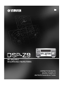 1
1
-
 2
2
-
 3
3
-
 4
4
-
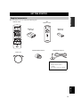 5
5
-
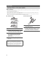 6
6
-
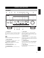 7
7
-
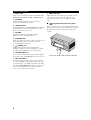 8
8
-
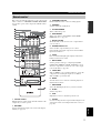 9
9
-
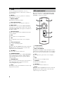 10
10
-
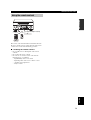 11
11
-
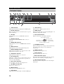 12
12
-
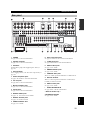 13
13
-
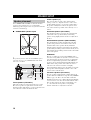 14
14
-
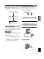 15
15
-
 16
16
-
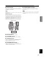 17
17
-
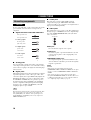 18
18
-
 19
19
-
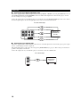 20
20
-
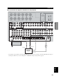 21
21
-
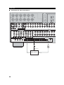 22
22
-
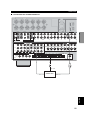 23
23
-
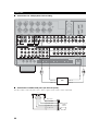 24
24
-
 25
25
-
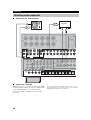 26
26
-
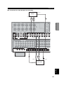 27
27
-
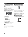 28
28
-
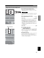 29
29
-
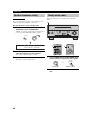 30
30
-
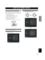 31
31
-
 32
32
-
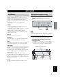 33
33
-
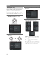 34
34
-
 35
35
-
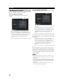 36
36
-
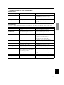 37
37
-
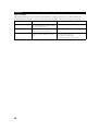 38
38
-
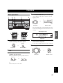 39
39
-
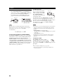 40
40
-
 41
41
-
 42
42
-
 43
43
-
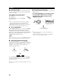 44
44
-
 45
45
-
 46
46
-
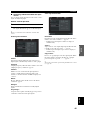 47
47
-
 48
48
-
 49
49
-
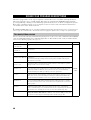 50
50
-
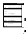 51
51
-
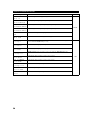 52
52
-
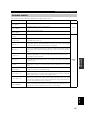 53
53
-
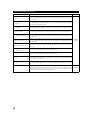 54
54
-
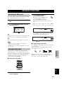 55
55
-
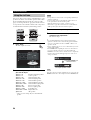 56
56
-
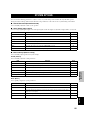 57
57
-
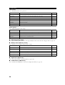 58
58
-
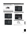 59
59
-
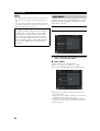 60
60
-
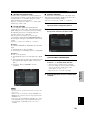 61
61
-
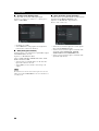 62
62
-
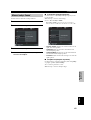 63
63
-
 64
64
-
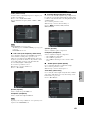 65
65
-
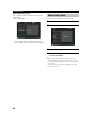 66
66
-
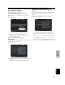 67
67
-
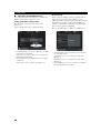 68
68
-
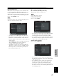 69
69
-
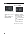 70
70
-
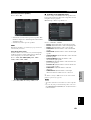 71
71
-
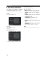 72
72
-
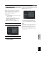 73
73
-
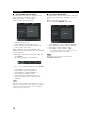 74
74
-
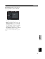 75
75
-
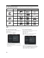 76
76
-
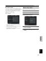 77
77
-
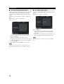 78
78
-
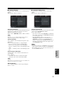 79
79
-
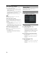 80
80
-
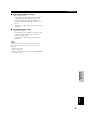 81
81
-
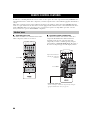 82
82
-
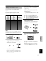 83
83
-
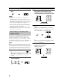 84
84
-
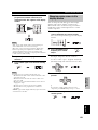 85
85
-
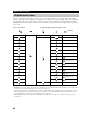 86
86
-
 87
87
-
 88
88
-
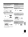 89
89
-
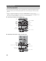 90
90
-
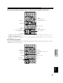 91
91
-
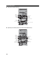 92
92
-
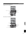 93
93
-
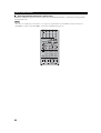 94
94
-
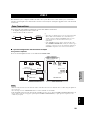 95
95
-
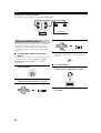 96
96
-
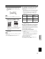 97
97
-
 98
98
-
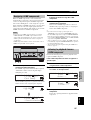 99
99
-
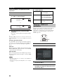 100
100
-
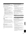 101
101
-
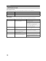 102
102
-
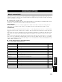 103
103
-
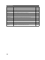 104
104
-
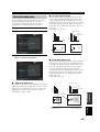 105
105
-
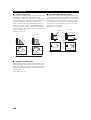 106
106
-
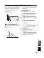 107
107
-
 108
108
-
 109
109
-
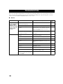 110
110
-
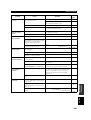 111
111
-
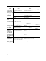 112
112
-
 113
113
-
 114
114
-
 115
115
-
 116
116
-
 117
117
-
 118
118
-
 119
119
-
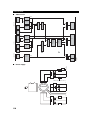 120
120
-
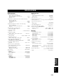 121
121
-
 122
122
-
 123
123
-
 124
124
-
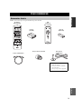 125
125
-
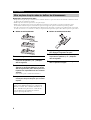 126
126
-
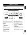 127
127
-
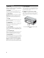 128
128
-
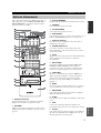 129
129
-
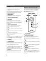 130
130
-
 131
131
-
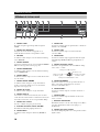 132
132
-
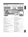 133
133
-
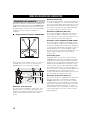 134
134
-
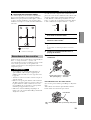 135
135
-
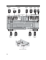 136
136
-
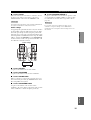 137
137
-
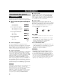 138
138
-
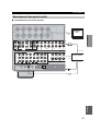 139
139
-
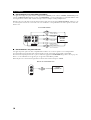 140
140
-
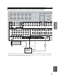 141
141
-
 142
142
-
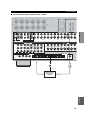 143
143
-
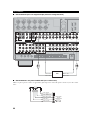 144
144
-
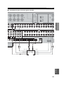 145
145
-
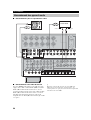 146
146
-
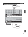 147
147
-
 148
148
-
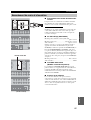 149
149
-
 150
150
-
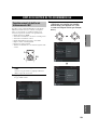 151
151
-
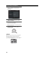 152
152
-
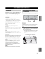 153
153
-
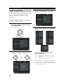 154
154
-
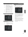 155
155
-
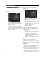 156
156
-
 157
157
-
 158
158
-
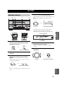 159
159
-
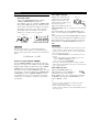 160
160
-
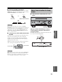 161
161
-
 162
162
-
 163
163
-
 164
164
-
 165
165
-
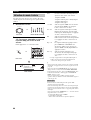 166
166
-
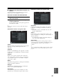 167
167
-
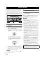 168
168
-
 169
169
-
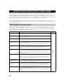 170
170
-
 171
171
-
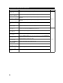 172
172
-
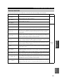 173
173
-
 174
174
-
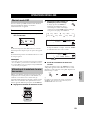 175
175
-
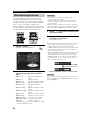 176
176
-
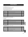 177
177
-
 178
178
-
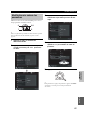 179
179
-
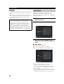 180
180
-
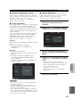 181
181
-
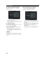 182
182
-
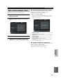 183
183
-
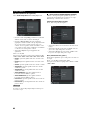 184
184
-
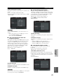 185
185
-
 186
186
-
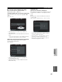 187
187
-
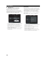 188
188
-
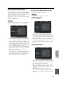 189
189
-
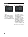 190
190
-
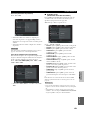 191
191
-
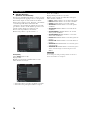 192
192
-
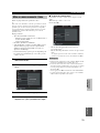 193
193
-
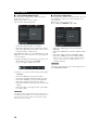 194
194
-
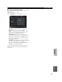 195
195
-
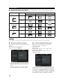 196
196
-
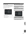 197
197
-
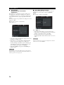 198
198
-
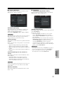 199
199
-
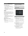 200
200
-
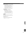 201
201
-
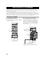 202
202
-
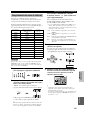 203
203
-
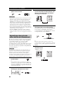 204
204
-
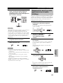 205
205
-
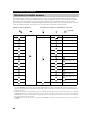 206
206
-
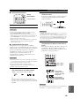 207
207
-
 208
208
-
 209
209
-
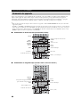 210
210
-
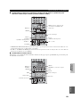 211
211
-
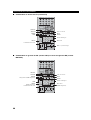 212
212
-
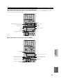 213
213
-
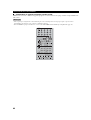 214
214
-
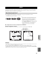 215
215
-
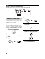 216
216
-
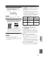 217
217
-
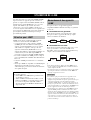 218
218
-
 219
219
-
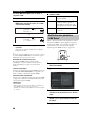 220
220
-
 221
221
-
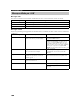 222
222
-
 223
223
-
 224
224
-
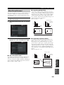 225
225
-
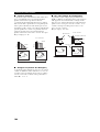 226
226
-
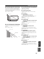 227
227
-
 228
228
-
 229
229
-
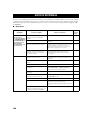 230
230
-
 231
231
-
 232
232
-
 233
233
-
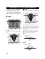 234
234
-
 235
235
-
 236
236
-
 237
237
-
 238
238
-
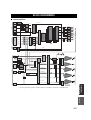 239
239
-
 240
240
-
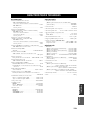 241
241
-
 242
242
-
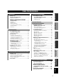 243
243
-
 244
244
-
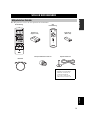 245
245
-
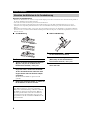 246
246
-
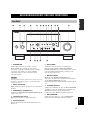 247
247
-
 248
248
-
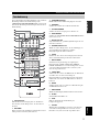 249
249
-
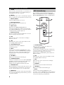 250
250
-
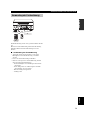 251
251
-
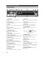 252
252
-
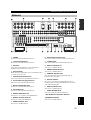 253
253
-
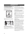 254
254
-
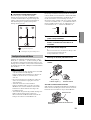 255
255
-
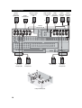 256
256
-
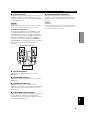 257
257
-
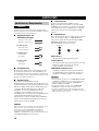 258
258
-
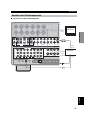 259
259
-
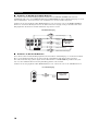 260
260
-
 261
261
-
 262
262
-
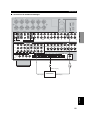 263
263
-
 264
264
-
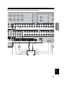 265
265
-
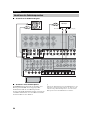 266
266
-
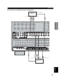 267
267
-
 268
268
-
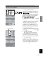 269
269
-
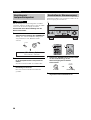 270
270
-
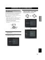 271
271
-
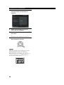 272
272
-
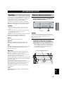 273
273
-
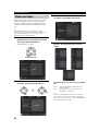 274
274
-
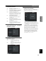 275
275
-
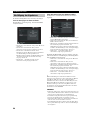 276
276
-
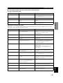 277
277
-
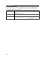 278
278
-
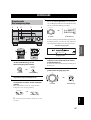 279
279
-
 280
280
-
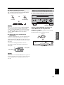 281
281
-
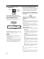 282
282
-
 283
283
-
 284
284
-
 285
285
-
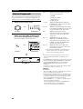 286
286
-
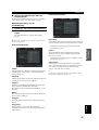 287
287
-
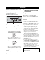 288
288
-
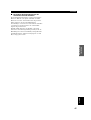 289
289
-
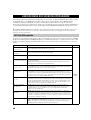 290
290
-
 291
291
-
 292
292
-
 293
293
-
 294
294
-
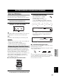 295
295
-
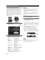 296
296
-
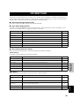 297
297
-
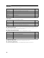 298
298
-
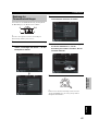 299
299
-
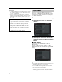 300
300
-
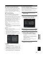 301
301
-
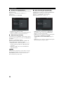 302
302
-
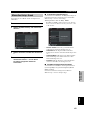 303
303
-
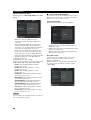 304
304
-
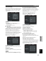 305
305
-
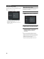 306
306
-
 307
307
-
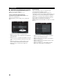 308
308
-
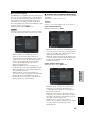 309
309
-
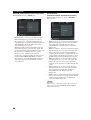 310
310
-
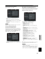 311
311
-
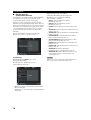 312
312
-
 313
313
-
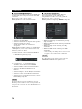 314
314
-
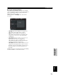 315
315
-
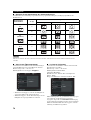 316
316
-
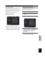 317
317
-
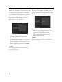 318
318
-
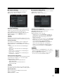 319
319
-
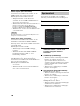 320
320
-
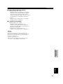 321
321
-
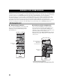 322
322
-
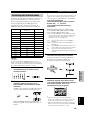 323
323
-
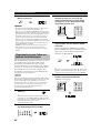 324
324
-
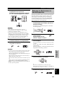 325
325
-
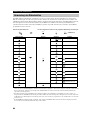 326
326
-
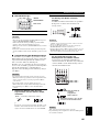 327
327
-
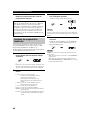 328
328
-
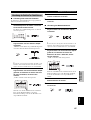 329
329
-
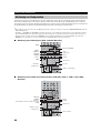 330
330
-
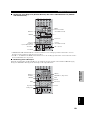 331
331
-
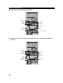 332
332
-
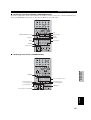 333
333
-
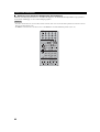 334
334
-
 335
335
-
 336
336
-
 337
337
-
 338
338
-
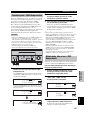 339
339
-
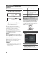 340
340
-
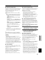 341
341
-
 342
342
-
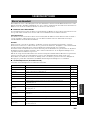 343
343
-
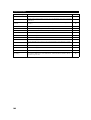 344
344
-
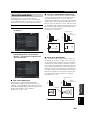 345
345
-
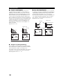 346
346
-
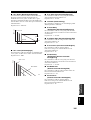 347
347
-
 348
348
-
 349
349
-
 350
350
-
 351
351
-
 352
352
-
 353
353
-
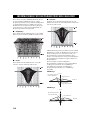 354
354
-
 355
355
-
 356
356
-
 357
357
-
 358
358
-
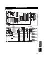 359
359
-
 360
360
-
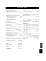 361
361
-
 362
362


in andere talen
- English: Yamaha DSP-Z9 Owner's manual
- italiano: Yamaha DSP-Z9 Manuale del proprietario
- français: Yamaha DSP-Z9 Le manuel du propriétaire
- Deutsch: Yamaha DSP-Z9 Bedienungsanleitung
- dansk: Yamaha DSP-Z9 Brugervejledning
- svenska: Yamaha DSP-Z9 Bruksanvisning
- Türkçe: Yamaha DSP-Z9 El kitabı
- română: Yamaha DSP-Z9 Manualul proprietarului
Gerelateerde artikelen
-
Yamaha RX-V4600 - AV Receiver Handleiding
-
-
-
-
-
Yamaha DSP-Z11 Handleiding
-
-
-
Yamaha RX V3900 - AV Network Receiver Handleiding
-
Andere documenten
-
Pioneer S-W90-S Handleiding
-
Magnat Cinema Ultra SUB 300-THX de handleiding
-
Sony RMVL600T.CE7 de handleiding
-
Sony TA-FA1200ES de handleiding
-
Waeco Waeco mobitronic TV-Tuner TV-120 Handleiding
-
Magnat Cinema Ultra RD 200-THX de handleiding
-
Amplicomms TV3500 Gebruikershandleiding
-
Lenco TBS 5001 de handleiding
-
 Hach AISE sc Addendum To The Operator Manual
