Eaton EX RT 11 3:1 Installation and User Manual
- Categorie
- Noodstroomvoorzieningen (UPS'en)
- Type
- Installation and User Manual
Deze handleiding is ook geschikt voor

www.eaton.com
Installation and user
manual
EX RT 5 3:1
EX RT 7 3:1
EX RT 11 3:1
English
Français
Deutsch
Italiano
Español
Nederlands

3400772400/AD

www.eaton.com
Installation and user
manual
EX RT 5 3:1
EX RT 7 3:1
EX RT 11 3:1

Page 2 - 34007724EN/AD
Introduction
Important instructions that must always be followed.
Information, tips, help.
Visual indication.
Action.
Information may be found primarily by checking:
the contents, z
the index. z
Icons
Using this document
Thank you for selecting an EATON product to protect your equipment.
The EX RT range has been designed with the utmost care.
We recommend that you take the time to read this manual to take full advantage of the many features of
your UPS.
Warning: this is a class A UPS product. In a domestic environment, this product may cause radio
interference, in which case, the user may be required to take additional measures.
If the device must be installed in overvoltage category III or IV environments, additional upstream
overvoltage protection must be provided for.
To discover the entire range of EATON products and the options available for the EX RT range,
we invite you to visit our web site at www.eaton.com or contact your EATON representative.
Audible alarm.
In the illustrations on the following pages, the symbols below are used:
LED off.
LED on.
LED flashing.
Environmental protection
EATON cares about the environmental impact of its products and has therefore implemented an eco-design
process for the entire life cycle of the EX RT product: design, usage and recycling.

34007724EN/AD - Page 3
Contents
1. Presentation
1.1 Standard configurations ........................................................................................ 5
Tower configuration ................................................................................................. 5
Rack configuration .................................................................................................... 5
1.2 Rear panels ............................................................................................................. 6
Power module EX RT 5/7/11 .................................................................................... 6
Battery module EX RT EXB 7/11 .............................................................................. 6
1.3 Display and control panel ..................................................................................... 7
1.4 Options .............................................................................................................. 7
Rack mounting kits .................................................................................................. 7
Transformer for galvanic isolation or earthing arrangement change ....................... 8
Battery extensions for UPS backup times up to 60 minutes .................................. 9
CLA module (Long backup time charger) for backup times from 2 to 8 hours ....... 9
Modules integration system .................................................................................. 10
Battery module with Remote Emergency Power Off function (REPO) ................. 10
Battery extension cable (1,8 m / 6 ft) ....................................................................10
2. Installation
2.1 Unpacking and parts check ................................................................................. 11
Power module ........................................................................................................ 11
Battery module ....................................................................................................... 11
2.2 Installation in tower configuration .................................................................... 12
2.3 Installation in rack configuration ...................................................................... 13
Adjustment of the orientation of the logo and control panels ............................... 13
Battery module rack mounting (optional rail required) ........................................... 13
Power or battery module rack mounting (optional rail required) ............................ 14
2.4 Communication ports ......................................................................................... 16
Connection to the RS232 communication port ....................................................... 16
Connection to the communications port by relays ................................................. 16
Remote Power Off ................................................................................................. 17
Remote Power Off communication port ................................................................. 17
Installation of communication cards (optional, standard with
the Network Pack version) ...................................................................................... 17
2.5 Installation depending on the system earthing arrangement (SEA) ............. 18
UPS with common Normal and Bypass AC inputs ................................................. 18
UPS with separate Normal and Bypass AC inputs ................................................. 18
UPS with separate Normal and Bypass AC inputs, supplied
by separate sources ................................................................................................ 19
Frequency converter (without Bypass AC input) .................................................... 19
Hot standby ............................................................................................................ 19
2.6 Required protective devices and cable cross-sections ................................... 20
Recommended upstream protection ..................................................................... 20
Recommended downstream protection ................................................................ 20
Required cable cross-section ................................................................................. 20
2.7 Connections of input/output power cables ...................................................... 21
UPS with common Normal and Bypass AC sources ............................................. 21
UPS with separate Normal and Bypass AC sources .............................................22
Frequency converter ............................................................................................... 23
Connection of battery cables .................................................................................. 24
Connection of galvanic isolation transformer .......................................................... 24
Connection of CLA module ..................................................................................... 25

Page 4 - 34007724EN/AD
Contents
3. Operation
3.1 Initial start up ....................................................................................................... 26
UPS personalisation ................................................................................................ 26
Accessing personalisation with front panel buttons ............................................... 26
Access to the personalisation through external software ...................................... 27
3.2 Final start up sequence ....................................................................................... 27
3.3 Operating modes .................................................................................................28
Normal (double conversion) mode .......................................................................... 28
Eco mode ............................................................................................................ 28
3.4 Operation on battery power .............................................................................. 29
Transfer to battery power ....................................................................................... 29
Threshold for the low-battery warning .................................................................... 29
End of backup time ................................................................................................. 29
3.5 Return of Normal AC source .............................................................................. 29
3.6 Shut down ............................................................................................................ 30
4. Maintenance
4.1 Troubleshooting ................................................................................................... 31
4.2 Hot-swapping the power module ...................................................................... 32
Disconnecting the power module ........................................................................... 32
Reconnecting the power module ............................................................................ 33
4.3 Hot-swapping the battery module ..................................................................... 33
Disconnecting the battery module .......................................................................... 33
Reconnecting the battery module ........................................................................... 33
4.4 Training center ..................................................................................................... 34
5. Appendices
5.1 Technical specifications ....................................................................................... 35
Electrical characteristics .......................................................................................... 35
Thermal characteristics ........................................................................................... 38
5.2 Glossary ............................................................................................................ 38

34007724EN/AD - Page 5
1. Presentation
1.1 Standard configurations
Rack configuration
Tower configuration
Battery module
(EX RT EXB 7/11)
Battery module
(EX RT EXB 7/11)
Power module
(EX RT 5/7/11)
Power module (EX RT 5/7/11)
Dimensions in mm/
inches (H x W x D)
EX RT 5
EX RT 7
EX RT 11
EX RT EXB 7
EX RT EXB 11
444 x 131 x 635
Dimensions in mm/
inches (H x W x D)
EX RT 5
EX RT 7
EX RT 11
EX RT EXB 7
EX RT EXB 11
131 (3U) x 444 x 635
Weight in kg/lbs
EX RT 5
EX RT 7
22.5
EX RT 11 27.5
EX RT EXB 7 64.5
EX RT EXB 11 68.5
Weight in kg/lbs
EX RT 5
EX RT 7
22.5
EX RT 11 27.5
EX RT EXB 7 64.5
EX RT EXB 11 68.5

Page 6 - 34007724EN/AD
BY
PASS
NORMAL
1. Presentation
1.2 Rear panels
Slot for communication cards.
Communication port by relays.
Remote Emergency Power Off communication port (REPO).
Connectors for automatic detection of battery module(s).
RS232 communications port.
Battery module connectors (to the UPS or to other battery
modules).
Manual Bypass switch.
Output terminal block.
Normal AC source circuit-breaker.
Normal AC source terminal block.
Bypass AC source terminal block.
Power module EX RT 5/7/11
Battery module EX RT EXB 7/11
Connectors for automatic detection of battery module(s).
Battery module connectors (to the UPS or to other battery
modules).
Battery circuit breaker.
1
1
6
6
6
6
8
8
10
10
11
12
12
11
2
2
3
3
4
4
4
4
5
5
7
7
9
9

34007724EN/AD - Page 7
OFF ON
E X 1 1 R T 3:1
1.4 Options
Rack mounting kits
1.3 Display and control panel
1. Presentation
Load protected LED.
Operation on battery LED.
Operation on bypass LED.
Fault LED.
Alphanumeric display.
UPS OFF button.
Function buttons (scroll up /
scroll down).
UPS ON button (or function button
in personalisation mode).
Telescopic rails for Power module mounting in 19" enclosure with mounting hardware
(Part number 68001)
Telescopic rails for Battery module mounting in 19" enclosure with mounting hardware
(Part number 68002)
Ear hangup.
Rear bracket system for
transportation.
Telescopic rails, 639 mm to
1005 mm length (27.36" to 39.96").
Input/Output box bracket system.
Ear hangup.
Rear bracket system for
transportation.
Telescopic rails, 639 mm to
1005 mm length (27.36" to 39.96").
LOAD LEVEL
4 kW / 5 kVA
22
22
22
22
23
23
23
23
24
24
24
24
25
25
13
13
18
18
14
14
19
19
15
15
20
20
16
16
21
21
17
17

Page 8 - 34007724EN/AD
Transformer for galvanic isolation or earthing arrangement change
(Part number 68003)
1. Presentation
Example of EX RT transformer connected upstream for EX RT galvanic isolation
Battery module (EX RT EXB)
Power module (EX RT 5/7/11)
Transformer module (EX RT)
UPS output to load
Normal AC input
This module is necessary either when a downstream neutral system from the UPS upstream is required, or
when a different power source connects the automatic bypass for higher availability.
Bypass AC input

34007724EN/AD - Page 9
1. Presentation
Battery extensions for UPS backup times up to 60 minutes (at full load)
EX RT offers a standard backup time of 5/9 minutes at full load.
To increase backup time, it is possible to connect EX RT EXB 7/11 modules to the UPSs.
Battery extensions for EX RT 5, EX RT 7 or EX RT 11
CLA module (Long backup time charger) for backup times from 2 to 8 hours
(Part number 68004)
Very long backup times, from 2 to 8 hours at full load, require a EX RT CLA module.
Total battery voltage : 240 V DC (20 x 12V DC).
The battery capacity must be set within the UPS (5 Ah increment possible, see UPS Personalisation
section).
+++
EX RT 5/7
+ EX RT EXB 7 RT
/
EX RT 11
+ EX RTEXB 11
EX RT EXB 7
/
EX RT
EXB 11
7 kVA:
11 kVA:
7 min
5 min
20 min
14 min
32 min
22 min
+ +
45 min
30 min
57 min
42 min
70 min
53 min
EX RT EXB 7
/
EX RT
EXB 11
EX RT EXB 7
/
EX RT
EXB 11
EX RT EXB 7
/
EX RT
EXB 11
EX RT EXB 7
/
EX RT
EXB 11
5 kVA:9 min 26 min 42 min 60 min 72 min 87 min
EX RT 5/7/11
EX RT CLA
~
50A
BY
PASS
NORMAL
Battery backup
time
Recommended batteries for:
EX RT 5 EX RT 7 EX RT 11
2 hours
50 Ah 65 Ah 100 Ah
4 hours
100 Ah 130 Ah 200 Ah
8 hours
200 Ah 260 Ah 400 Ah

Page 10 - 34007724EN/AD
1. Presentation
Modules integration system for
extended backup time configurations
to conveniently stack and secure up
to 8 modules on the same cart (swivel
wheels with brakes, leveling feet,
seismic side panels, plates to lock
modules and screws included).
Modules integration system (Part number 68005)
Battery module with Remote Emergency Power Off function (REPO)
Battery circuit breaker with Remote Emergency Power OFF shunt trip.
Battery extension cable (1,8 m / 6 ft, Part number 68006)
This extended battery cable will be used instead of the standard battery cable when battery modules are
distant from each other (located in two different enclosures, for instance).
Part number:
EX RT EXB 7 EPO: 68079
EX RT EXB 11 EPO: 68119
Transformer module
Power module
Batteries
modules
12

34007724EN/AD - Page 11
2.1 Unpacking and parts check
Two sets of tower stands.
RS232 communications cable.
Product documentation.
Telescopic rails for rack enclosure with
mounting hardware (optional, or standard
with Network Pack version).
Solution-Pac power management suite
CD-ROM.
Tower stand expanders.
Battery cable.
Battery communication cable.
Input/Output junction box (with 11 insulated ferrules).
Network Management card (optional, or standard in
Network Pack version).
Bezel screw driver.
Power module
Battery module
2. Installation
Packaging must be destroyed according to waste management standards. Recycling icons are displayed for
easy selection.
A dangerous voltage is present inside the power module and the battery module. Any operations to be carried out
on these modules must be done so by qualied staff.
22
22
23
23
24
2425
24
26
26
30
30
31
31
25
25
32
32
27
27
28
28
29
29

Page 12 - 34007724EN/AD
2. Installation
2.2 Installation in tower configuration
Use the tower stand template provided with the battery module.
1
3
4
2
1
4
3
2
4
4
Follow steps 1 to 4 to adjust the tower stands for the upright position.
Always keep 150 mm free space behind the UPS rear panel.
The distance between the tower stands should be 450 mm.

34007724EN/AD - Page 13
2.3 Installation in rack configuration
2. Installation
Adjustment of the orientation of the logo and control panels
1
2
3
4
5
6
Battery module rack mounting (optional rails required, part number: 68002)
We recommend to mount the battery module first, then mount the power module above the battery
The battery module is very heavy. To ease its rack integration, we strongly recommend to remove the
battery trays as explained below:
1
2
1
1
2
3
3
4
4

Page 14 - 34007724EN/AD
Follow steps 1 to 4 for rack mounting the UPS onto the rails.
The rails and the necessary mounting hardware are supplied by EATON.
Note for step 1: it is possible to adjust the position of both front mounting ears.
1
3
3
4
2
1
4
3
3
Power or battery module rack mounting (optional rails required, part number: 68001)
2. Installation
5
6

34007724EN/AD - Page 15
2. Installation
1
2
4
Input/output junction box bracket system (included with power module rail kit, part
number 68001)
This bracket will maintain the Input/Output box at the rear of the rack enclosure when hot-swapping the
power module.
It will then be easier to slide the replacement module into the connectors of the Input/Output box.
3
4
Rear bracket system (included with rail kits, part numbers 68001 and 68002)
1
1
To be used if you need to move the
rack enclosure with UPS already
rack-mounted inside.
3
2
2
3

Page 16 - 34007724EN/AD
BY
PASS
NORMAL
2. Installation
Connection to the RS232 communication port
1 - Connect the RS 232
23
communications cable to the serial
port on the computer.
2 - Connect the other end of the
communications cable
23
to the RS
232
5
communications port on the
UPS.
The UPS can now communicate with
various EATON power management
application software. Please note
that the configuration software is
included with Personal Solution Pac
for Windows.
Connection to the communication port by relays 2
Pin 1, 2: not used, z
Pin 3: Remote Power Off signal (5 to 27 V DC, 10 mA max), z
Pin 4: Operation on mains (not on battery), z
Pin 5: User common, z
Pin 6: Operation on automatic by-pass, z
Pin 7: Low battery, z
Pin 8: Load protected, z
Pin 9: Operation on battery. z
n.o.: contact normally open.
n.c.: contact normally closed.
When the status is active, the contact between the common (Pin 5) and the relevant information pin is
closed.
Output relays specifications
Voltage: 48 V DC max, z
Current: 2 A max, z
Power: 62,5 VA, 30 W. z
Example: for 48 V DC, Imax = 625 mA
2.4 Communication ports
EX RT provides 3 communication methods that can be used simultaneously:
The COM port provides RS232 communications using EATON SHUT protocol. Compatible with most z
power management software applications available into the enclosed Solution Pac CD-Rom.
The output contact port is used for basic signaling or for protection of IT systems like IBM iSeries z
(formerly AS400) and more.
The slot is compatible with any EATON communication card (check www.eaton.com web site for the z
complete list of compatible cards).
5
23
5432
9876
1
n.o.n.c. n.o. n.o. n.o.
common

34007724EN/AD - Page 17
RJ11
5432
1
6
5432
1
6
RJ11
BY
PASS
NORMAL
ETHERNET
100M 10MUPS data Reset
Setting/Sensor
2. Installation
Installation of communication cards (optional, standard with the Network Pack version)
It is not necessary to shut down the
UPS to install the communication card:
1 - Remove the slot cover secured by
two screws.
2 - Insert the card
1
into the slot.
3 - Secure the card with both screws.
Communication card.
Signal: z
- activation voltage: 5 V DC to 27 V DC.
- current: 10 mA max.
Remote Power Off communication port 3
5 V DC to
27 V DC
5 V DC to
27 V DC
Used in conjunction with the optional EPO battery module, this port enables total isolation of all power
sources connected to the UPS in case of emergency (the cable is not provided).
Remote power off contact normally open
Remote power off contact normally closed
Remote Power Off
Installation of a Remote power off function must be carried out in compliance with applicable regulations.
In order to fully de-energize devices and EX RT with an RPO port, it is necessary :
- To use a two-position switch (Normally Open or Closed contact should be held more than 1 second to be
taken into account).
- To use battery cabinet(s) EX RT EXB EPO.
- To connect to this RPO switch a device that allows to trip all breaker(s) located upstream
(1)
AC NORMAL
and AC BY PASS as well as downstream
(2)
the EX RT. This can be achieved through by means of a shunt
trip.
(1) If not, the output devices will remain powered through the AC BY PASS if RPO switch has been
loosened.
(2) If not, the output devices will remain powered several seconds after the RPO activation.
1

Page 18 - 34007724EN/AD
11
10
8
11
10
8
8
10
11
8
10
11
ASI avec réseaux d'entrée AC Normal et AC Bypass séparés
2. Installation
2.5 Installation depending on the system earthing arrangement (SEA)
UPS with common Normal and Bypass AC inputs
Changement de SLT entre amont et aval ou isolation galvanique requis
Changement de SLT entre amont et aval ou isolation galvanique requis
(*): The transformer is not necessary if:
Normal and Bypass AC inputs are connected to the same source, z
and wires cross sections and wires lengths on Normal and Bypass inputs are identical, z
and upstream protection is provided by only one switch with RCD (residual current device) for Normal z
and Bypass inputs.
EX RT must be fed from a 3-phase source with neutral.
Bypass AC
Normal AC
Bypass AC
Normal AC
Bypass AC
Normal AC
Main
low-voltage
switchboard
(MLVS)
load
load
Main
low-voltage
switchboard
(MLVS)
Main
low-voltage
switchboard
(MLVS)
load
Main
low-voltage
switchboard
(MLVS)
load
Bypass AC
Normal AC
(*)
(*)

34007724EN/AD - Page 19
8
10
11
8
11
10
8
10
11
Frequency converter (without Bypass AC input)
Main
low-voltage
switchboard
(MLVS)
Main
low-voltage
switchboard
(MLVS)
2. Installation
UPS with separate Normal and Bypass AC inputs, supplied by separate sources
Change in SEA between upstream and downstream or galvanic isolation required
Hot stand by
Configuration used when the frequency of the application differs from the Mains (Example: marine
requirements).
Configuration used to provide full redundancy (N+1) to critical loads.
(*)
(see page 18)
8
10
11
8
10
11
8
10
11
MLVS 1
MLVS 2
load
load
load
MLVS 1
MLVS 2
or
MLVS 1
MLVS 2
load
load
Bypass AC
Normal AC
Bypass AC
Normal AC
Bypass AC
Bypass AC
Normal AC
Normal AC
Normal AC
Normal AC

Page 20 - 34007724EN/AD
2. Installation
2.6 Required protective devices and cable cross-sections
Recommended upstream protection
Recommended downstream protection
The indicated protection ensures
discrimination for each output circuit
downstream of the UPS, whether
supplied by the Normal or the Bypass
AC source.
If these recommendations are not
followed, protection discrimination
is not achieved and may result in a
potential power interruption to the
connected devices.
Required cable cross-sections
Terminal-block cable capacity: 10 mm², solid or stranded wire (maximum 13 mm² or AWG 6). z
Capacity for earthing conductor: 10 mm², solid or stranded wire (maximum 13 mm² or AWG 6). z
Note: see the simplified diagrams in the appendix for common or separate AC inputs, indicating the
positions of the protection devices, the characteristics of the internal UPS fuses and UPS line currents
under overload conditions.
Note: see the simplified diagrams in the appendix for common or separate AC inputs, indicating the
positions of the protection devices, the characteristics of the internal UPS fuses and UPS line currents
under overload conditions.
UPS
power
rating
Common AC inputs
Upstream circuit-breaker
Normal / Bypass AC sources
Separate AC inputs
Upstream circuit-breaker
Normal AC source
Upstream circuit-breaker
Bypass AC source
5 kVA
D curve - 40 A C curve - 32 A D curve - 40 A
7 kVA
D curve - 40 A C curve - 32 A D curve - 40 A
11 kVA
D curve - 63 A C curve - 40 A D curve - 63 A
UPS power
rating
Downstream
circuit breaker
5 kVA
Z curve - 10 A
C curve - 4 A
7 kVA
Z curve - 10 A
C curve - 4 A
11 kVA
Z curve - 10 A
C curve - 6 A

34007724EN/AD - Page 21
Rectifier Input
L2
L1
L1
Bypass Input
N2
L2
N1
L3
Output
N
L
Rectifier Input
L2
L1
L1
Bypass Input
N2
L2
N1
L3
Output
N
L
Rectifier Input
L2
L1
L1
Bypass Input
N2
L2
N1
L3
Output
N
L
Card Settings
RS232 Download
66074
UPS
data
Reset
100 10
1 2
ON
ETHERNET
IP=
MAC=00E0D8FF855E
NORMAL
φ
2. Installation
2.7 Connections of input/output power cables
This type of connection must be carried out by qualified electrical personnel. z
Before carrying out any connection, check that the battery circuit breaker z
12
and that the upstream
protection devices (Normal and Bypass AC sources) are open ("0").
EX RT z UPS always comes from factory with Normal and Bypass AC inputs already connected together,
using a bridge.
Use included insulated ferrules with stranded wires. z
To access the connection terminal
blocks, see section 1.2 "Rear panel":
1 - Remove the terminal block cover
(5 screws),
2 - Insert the Normal AC cable through
the cable gland,
3 - Connect the 5 wires to the Normal
AC terminal block,
Always connect the earthing
wire rst.
4 - Insert the output cable to the load
through the output cable gland,
5 - Connect the 3 wires to the output
terminal block,
6 - Refit the terminal block cover and
tighten the cable glands,
7 - Secure the junction Input/Output
box to the rear of the power module
by means of the 3 screws.
UPS with common Normal and Bypass AC sources
1
4
2
5
3
6
1
6
1
1
6
6
7
1
6
7
7

Page 22 - 34007724EN/AD
1 - Remove the terminal block cover
(5 screws),
2 - Remove the bridge connected
between L2 and L1,
3 - Insert the Normal AC cable through
the cable gland,
4 - Connect the 5 wires to the Normal
AC terminal block,
Always connect the earthing
wire rst.
5 - Insert the Output cable to the load
through the Output cable gland,
6 - Connect the 3 wires to the output
terminal block,
7 - Insert the Bypass cable through the
cable gland,
8 - Connect the 3 wires to the Bypass
AC terminal block,
9 - Refit the terminal block cover and
tighten the cable glands,
10 - Secure the junction Input/Output
box to the rear of the power module
by means of the 3 screws.
UPS with separate Normal and Bypass AC sources
2. Installation
1
5
2
4
3
9
6
7
1
1
1
9
9
9
10
Card Settings
RS232 Download
66074
UPS
data
Reset
100 10
1 2
ON
ETHERNET
IP=
MAC=00E0D8FF855E
NORMAL
φ
Rectifier Input
L2
L1
L1
Bypass Input
N2
L2
N1
L3
Output
N
L
Rectifier Input
L2
L1
L1
Bypass Input
N2
L2
N1
L3
Output
N
L
Rectifier Inp
ut
L2
L1
L1
Bypass Input
N2
L2
N1
L3
Output
N
L
1
8
9
10
10

34007724EN/AD - Page 23
Frequency converter
1 - Remove the terminal block cover
(5 screws),
2 - Remove the bridge connected
between L2 and L1,
3 - Insert the Normal AC cable through
the cable gland,
4 - Connect the 5 wires to the Normal
AC terminal block,
Always connect the earthing
wire rst.
5 - Insert the Output cable suppling the
load through the Output cable gland,
6 - Connect the 3 wires to output
terminal block,
Do not connect anything to the
Bypass AC terminal block,
7 - Refit the terminal block cover and
tighten the cable glands,
8 - Secure the junction Input/Output
box to the rear of the power module
by means of the 3 screws.
1
5
3
6
4
7
2
1
1
1
7
7
2. Installation
8
Rectifier Input
L2
L1
L1
Bypass Input
N2
L2
N1
L3
Output
N
L
Rectifier Input
L2
L1
L1
Bypass Input
N2
L2
N1
L3
Output
N
L
Card Settings
RS232 Download
66074
UPS
data
Reset
100 10
1 2
ON
ETHERNET
IP=
MAC=00E0D8FF855E
NORMAL
φ
Rectifier Input
L2
L1
L1
Bypass Input
N2
L2
N1
L3
Output
N
L
1
7
7
8
8

Page 24 - 34007724EN/AD
BY
PASS
NORMAL
2. Installation
Connection of battery cables
1 - Check that the battery circuit
breaker
12
is OFF ("0" position),
2 - Connect the battery power cable
28
to the connectors
6
of the power
and battery modules,
3 - Connect the battery detection cable
29
to the connectors
4
of the power
and battery modules,
Connection of galvanic isolation transformer
Output cable cross-section (not provided): 10 mm², solid or stranded wire (maximum 13 mm² or AWG 6). z
Input cable cross-section (not provided): 10 mm², solid or stranded wire (maximum 13 mm² or AWG 6). z
N
L
N
L
OUTPUT
INPUT
Transformer Input
Transformer Output
12
6
29
28
4

34007724EN/AD - Page 25
BY
PASS
NORMAL
_
+
N
L
BATTERY
AC INPUT
2. Installation
Connection of CLA module
AC Input
To battery
Connect the battery cable z
28
(provided with the CLA module) between the power module and the CLA
module.
Connect the cable z
29
(provided with the CLA module) between the power module and the CLA module.
Connect the battery: z
- cable cross-section (not provided): 10 mm², solid or stranded wire (maximum 13 mm² or AWG 6).
Use a circuit-breaker (curve B, 50 A) for cable protection. z
Connect the input cable of the z CLA module to the AC input:
- AC input cable cross-section (not provided) : 2,5 mm².
Use a circuit-breaker (curve C, 10 A) for cable protection. z
29
28

Page 26 - 34007724EN/AD
OFF ON
UPS SET UP
EXIT ENT
OFF ON
3. Operation
3.1 Initial start up
Check that the manual bypass switch
7
is on Normal position.
Set the normal AC source circuit-breaker
9
to the "I" position.
Set the battery circuit breaker
12
to the "I" position.
The load is powered via the bypass AC source, but not protected by
the UPS.
Batteries are recharging, an eight-hour recharge period is necessary
to get full backup time.
LED
15
is ON.
PRESS ONTO START
UPS
If specific settings are required, it is recommended to enter the UPS personnalisation mode at this stage.
It is possible to enter this mode through the front panel buttons or the Personal Solution-Pac software for
Windows included in the EATON Solution-Pac power management suite CD-ROM.
Press "scroll up" z
19
and "scroll down"
20
function buttons
together for more than 3 seconds.
Press the function button z
20
placed under the ENT word to
enter the set up mode and follow the LCD messages using the
buttons now defined as select keys.
Local settings
Personnalisation de la sortie
(*) : - Select "I/T Network" and "AC Bypass within tolerance" for computer loads.
- Select "Industrial" and "AC Bypass out of tolerance" in case of absolute need for service continuity
(with potential 10 ms break).
Accessing personalisation with front panel buttons
UPS personalisation
15
19 20
Function Factory setting Options
Language
English French, Spanish, German, Italian.
Date / time format
International format
(DD-MM-YYYY/HH:MM)
US format (MM-DD-YYYY/HH:MM AM/PM).
Date / time change
Time in France MM-DD-YYYY/HH:MM adjustable.
Audible alarm
Quick beeps Slow beeps.
Function Factory setting Options Comments
Output voltage 230 Volts AC 200/208/220/240/250
Frequency converter Disabled Enabled
Bypass AC source disabled.
Output frequency Auto ranging 50/60 Hz
User selectable under
frequency converter mode.
Eco mode Disabled Enabled
See glossary.
Hot standby Disabled Enabled
N+1 redundancy
(See section 2.5 "Hot
standby").
Operating mode Industrial I/T Network
(*)
Transfer on Bypass AC
source
If the Bypass AC source
is out of tolerances
If the Bypass AC source
is inside tolerances
(*)
Break time 10 ms 10 to 200 ms
(by steps of 10 ms)
Break time calibration during
load transfer on Bypass AC
source out of tolerances.
Overload level 102 % 50/70 %

34007724EN/AD - Page 27
3. Operation
Personnalisation batterie
Use EXIT key when set up is completed. z
These parameters are only adjustable if z UPS is OFF.
Access to the personalisation through external software
Insert the z Solution-Pac CD ROM in your CD drive.
At the first Navigator Screen, select "Installation" and follow the instructions to install z Personal
Solution-Pac for Windows.
If nothing appears, launch startup.exe z
Then go to "Advanced settings" and "UPS settings". z
Please note that the Linux/Unix/MacOS versions of Personal Solution-Pac do not include this feature.
3.2 Final start up sequence
Press the ON button more than 3 seconds. z
After UPS internal test sequence, the green LED z
13
goes on.
During the restart, if the Bypass AC source is out of tolerance, the UPS will generate an output 10 ms calibrated
break.
ON/OFF features
Function Factory setting Options Comments
Cold start
Disabled Enabled Start on battery.
Forced reboot Enabled Disabled
Enables automatic restart of the system
even if normal AC source is restored before
the end of the shutdown sequence.
Automatic restart Enabled Disabled
UPS restarts automatically
when normal AC source is restored.
Sleep mode
Disabled
Enabled
Automatic shudown on battery if output
load level < 10%.
UPS ON/OFF by software Enabled Disabled
Enables consideration of shutdown
or restart orders from software to be
authorized.
Function Factory setting Options Comments
Battery test Every week No test / daily / monthly
Low battery signal 20 %
0 to 100 %
1% increment.
Run time choice UPS reads # of battery
modules connected
From 50 to 400 Ah
Requires EX RT CLA if using
options (see section 1.4
"Battery extensions").
Battery deep discharge
protection
Enabled Disabled If disabled, lost of EATON
warranty.

Page 28 - 34007724EN/AD
OFF ON
3. Operation
Eco mode
The main advantage of the Eco mode (see glossary) is that it
reduces the consumption of electrical power.
Three possible choices:
1 - Bypass AC source available:
LEDs
13
and
15
are ON.
The load is supplied in ECO mode.
2 - Bypass AC source not available:
LED
13
is ON.
The audio alarm sounds intermittently.
The load is automatically supplied in Normal mode via the
Normal AC input.
3 - Both Normal and Bypass AC sources not available or out of
tolerance:
LED
13
is ON.
LED
14
is ON.
The audio alarm sounds intermittently.
The load is supplied by the UPS from battery power.
The display indicates the battery remaining backup time.
OFF ON
OFF ON
OFF ON
OFF ON
BACKUP TIME
10 minutes
ECO MODE
4 kW / 5 kVA
3.3 Operating modes
This is the standard operating mode, set by default in the
factory.
Two possible choices.
1 - Normal AC source available:
LED
13
is ON.
The load is protected by the UPS.
Scroll up
19
and scroll down
20
function buttons allow you
to read the UPS measurements (Normal AC source voltage,
Bypass AC source voltage, operating mode, battery capacity
and UPS Serial Number).
Normal (double conversion) mode
LOAD LEVEL
4 kW / 5 kVA
2 - Normal AC source not available:
LED
13
flashes.
LED
14
is ON.
The audible alarm sounds intermittently.
The load is supplied by the UPS from battery power.
Do not operate the manual Bypass switch
7
when the UPS is
in the normal mode.
19 20 21
13
13
13 15
13
13 14
14

34007724EN/AD - Page 29
OFF ON
OFF ON
3. Operation
Threshold for the low-battery warning
LED
13
is ON.
LED
14
flashes.
The audio alarm beeps every 3 seconds.
Low battery warning on display. There is very little remaining
battery backup time. Close all applications because UPS
automatic shutdown is impending.
After an outage, the UPS restarts automatically when AC power is restored (unless this function has been
disabled via UPS personalisation).
OFF ON
End of backup time
LED
13
and
14
are OFF.
The audio alarm is stopped.
The load is transferred to the Bypass AC source if available. In this
case, the LED 15 is ON.
3.5 Return of Normal AC source
BACKUP TIME
2 minutes
STOP
END BACKUP TIME
3.4 Operation on battery power
The load continues to be protected by the UPS when the Normal AC source is not available. Power is
supplied by the battery.
Transfer to battery power
LED
13
is ON.
LED
14
is ON.
The audio alarm beeps every 10 seconds.
The load is supplied by the battery.
The display indicates the battery remaining backup time.
BACKUP TIME
10 minutes
13
13
13
14
14
14 15

Page 30 - 34007724EN/AD
BY
PASS
NORMAL
OFF ON
3.6 Shut down
1 - Press the OFF button
18
more than 3 seconds.
The load is no longer protected by the UPS. It is
powered via the bypass AC source. If the UPS is set in
frequency converter mode, the load will not be
powered.
If the bypass AC source is out of tolerance, the UPS
will generate a 10 ms output calibrated break.
2 - Set the battery circuit breaker(s)
12
to the "0" position.
3 - Set the Normal AC source circuit-breaker
9
to the "0"
position.
4 - For a full shutdown of UPS and connected load, the
LOAD LEVEL
4 kW / 5 kVA
3. Operation
18
12
9
15

34007724EN/AD - Page 31
4. Maintenance
(*): if bypass AC source is available.
(**): to reset this alarm permanently, press both function buttons
19
and
20
for more than 3 seconds and
access the LCM Setup menu.
Troubleshooting requiring EATON after-sales support:
4.1 Troubleshooting
If any of LEDs
15
or
16
is on, there is an operating anomaly or an alarm.
Use "scroll up" or "scroll down" function button to reset the audible alarm.
Troubleshooting not requiring EATON after-sales support:
(*) : if bypass AC source available.
Indication Signification Correction
Led
15
is on,
the alphanumeric display shows:
BAD CONNECTION
REWIRE AC NORMAL
AC source is not connected
to the correct terminals.
Rewire correctly the normal AC
source.
Led
15
is on,
the alphanumeric display shows:
LOAD LEVEL
Xx kW / XX KVA
Load supplied by bypass AC
source.
Push the ON button for more than
3 seconds.
Led
15
is on*,
the alphanumeric display shows:
THERMAL OVERLOAD
1XX%
UPS overload. Check the power drawn by the
equipment and disconnect any
non-priority devices.
Led
16
is on,
the alphanumeric display shows:
CURRENT OVERLOAD
Short circuit conditions on output
devices.
Check if any device is shorted or
failed.
Audible alarm is on,
the alphanumeric display shows:
I/O BOX REMOVED
Junction of Input/Output box
not correctly screwed.
Check if the junction Input/Output
Indication Signification Correction
Leds
15
* and
16
are on
and audible alarm is on.
The alphanumeric display shows:
xxx FAULT
www.eaton.com
Internal fault and transfer of load
on bypass AC source.
Follow the UPS replacement
procedure (see section 4.3).
Call the after sales support
department.
Led
15
is on* and audible alarm is
on.
the alphanumeric display shows:
BATTERY FAULT
Battery fault during the battery
test.
Follow the battery replacement
procedure (see section 4.3).
Call the after sales support
department.
Led
15
is on,
the alphanumeric display shows:
SHUTDOWN
STATIC SW FAILED
Static switch failure. Follow the UPS replacement
procedure (see section 4.3).
Call the after sales support
department.
Audible alarm is on, and the
alphanumeric display shows:
BATTERY CHECK
www.eaton.com
Batteries may have exceeded
there rated life period. Battery
capacity is severely reduced.
Call the local after sales support:
www.eaton.com, "Contact Us"
section**.

Page 32 - 34007724EN/AD
OFF ON
4.2 Hot-swapping the power module
Stop the UPS with the OFF button z
18
(press more than 3
seconds).
Check if UPS is on bypass AC source: z
led
15
is on (If led
15
is not on, do not turn the manual bypass
and call the after sales support department).
Turn the manual bypass switch z
7
to the BYPASS position.
Switch the battery circuit breaker(s) z
12
to the "0" position.
Switch the Normal AC source circuit-breaker z
9
to the "0"
position and wait 30 seconds.
Remove the three fixing screws to free the junction Input/ z
Output box.
Disconnect the battery cables z
28
and
29
from the power
module.
The power module can be replaced.
The connected equipment is powered by the Bypass AC
source.
Disconnecting the power module
4. Maintenance
This operation can be performed without interrupting the load.
Rack configuration
Tower configuration
XXX FAULT
1CXXXXXXX
18
29
12
28
7
9
15

34007724EN/AD - Page 33
BY
PASS
NORMAL
4.3 Hot-swapping the battery module
Disconnecting the battery module
Switch the battery circuit breaker(s) z
12
to the "0" position.
Disconnect the battery cables z
28
and
29
from the power
module.
The battery module can be replaced. The connected equipment
is powered by the UPS.
It is also possible to replace battery trays instead of battery
module.
Contact your nearest after sales support service.
To remove battery trays:
First, switch the battery circuit breaker(s) z
12
to the "0"
position.
See section 2.3 and follow instructions to remove battery z
trays.
Reconnecting the battery module
Reconnect the battery cables z
28
and
29
to the power
module.
Switch the battery circuit breaker(s) z
12
to the "I" position.
To reconnect battery trays:
See section 2.3 and follow the reverse instructions.
When battery module front panel is closed, connect the z
battery cables
28
and
29
to the power module.
Switch the battery circuit breaker(s) z
12
to the "I" position.
4. Maintenance
Reconnecting the power module
Secure the Input/Output junction box using the three screws. z
Reconnect the battery cables z
28
and
29
to the power
module.
Switch the battery circuit breaker(s) z
12
to the "I" position.
Switch the Normal AC source circuit-breaker z
9
to the "I"
position.
Turn the manual bypass switch from the BYPASS to the z
NORMAL position.
Check that the led z
15
is on.
Follow initial start up sequence (see section 3.1) in order to z
personalize the UPS.
Push the ON button z
21
for more than 3 seconds.
The green led
13
is on, and the connected equipment is now
protected by the UPS.
OFF ON
LOAD LEVEL
4 kW / 5 kVA
15
21
28
29
29
12
28

Page 34 - 34007724EN/AD
To allow you to use EATON products effectively and carry out basic maintenance, we offer a complete
range of technical training courses in English and French.
For further information, please visit our website: www.eaton.com
4.4 Training Center
4. Maintenance

34007724EN/AD - Page 35
10
8
11
9
10
8
11
9
5. Appendices
5.1 Technical specifications
Electrical characteristics
I/T network and industrial operating modes
Selection of protection devices
UPS unit with common Normal and Bypass AC inputs
UPS unit with separate Normal and Bypass AC inputs
When sizing the upstream circuit breakers, the parameters presented below must be taken into account:
Line current values
UPS
power rating
Continuous current
at 400/320 Volts
and nominal load
Continuous current
at 320 Volts and
overload = 110 %
limited to 2 minutes
Input fuse rating Output fuse rating
5 kVA 9/10 A 11 A 25 A 80 A
7 kVA 10/11 A 12 A 25 A 80 A
11 kVA 15/19 A 21 A 30 A 100 A
Discrimination of upstream/downstream protections mentioned in paragraph 2.6 is achieved for a 30 m
cable length and 10 mm
2
cross section.
Circuit breaker capacity must be selected according to the installation, length and cross section of cables.
Mode Industrial mode I/T network mode
Overload, and Bypass
AC source in tolerance.
Same as I/T network mode, but the UPS
does not return to normal mode if overload
released.
Load is transfered to Bypass AC
source.
UPS returns to normal mode if
overload released.
Overload, and Bypass
AC source not in
tolerance.
Load is transfered to Bypass AC source
with 10 milliseconds output break. The
UPS does not return to normal mode if
overload released.
The UPS shuts down and load is not
transfered to Bypass AC source.
Output short circuit and
Bypass AC source in
tolerance.
Load is transfered to Bypass AC source,
the UPS returns to normal mode if the
short circuit is released by downstream
circuit breaker action (see section 2.6).
The load remains powered by the
UPS.
The UPS shuts down after 3 minutes
if the short circuit remains.
Output short circuit and
Bypass AC source not
in tolerance.
The load is transfered to Bypass AC source
with 10 milliseconds output break. The
UPS does not return to normal mode if the
short circuit is released by downstream
circuit breaker action (see section 2.6).
The load remains powered by the
UPS. The UPS shuts down after 3
minutes if the short circuit remains.
Bypass AC
Normal AC
Bypass AC
Normal AC
Upstream
circuit breaker
(not supplied)
Downstream
circuit breaker
(not supplied)
Input
fuse
Output
fuse
Upstream
circuit breaker
(not supplied)
Downstream
circuit breaker
(not supplied)
Input
fuse
Output
fuse
Upstream
circuit breaker
(not supplied)
Normal
AC source
circuit
breaker
Normal
AC source
circuit
breaker

Page 36 - 34007724EN/AD
5. Appendices
Time/current curves for UPS input and output fuses
Intput fuses of
EX RT 5: 25 A
EX RT 7: 25 A
Output fuses of
EX RT 5: 80 A
EX RT 7: 80 A
Output fuses of
EX RT 11: 100 A
Intput fuses of
EX RT 11: 30 A
Time/current curves for UPS Normal AC source circuit-breaker
10
1
10
10
10
3
1010
I (A)
t (s)
2
-
2
-
1
10
2
10
3
10
1
10
10
10
-
3
10
-
4
10
3
1010
I (A)
t (s)
10
42
-
2
-
1
10
3
10
2
10
4
10
1
10
10
0
I / In
t (s)
-
2
-
1
10
2
10
3
12345678910
1,51,25
10
-
3

34007724EN/AD - Page 37
EX RT Transformer
5. Appendices
Permissible UPS overloads as a function of time
UPS Input / output characteristics
(*): depends on output voltage setting, can be modified by software.
(**): set to +/- 4% by default, (1,2,4,8 are possible values), can be modified by software.
Power supplied as a function of input voltage
P/Pn
1.02
0.5s
t
30s
1.1
1.25
1.5
60s 120s
Short-circuit current provided by the UPS in Normal or Batterie mode
EX RT 5 z : 110 A for 80 ms.
EX RT 7 z : 110 A for 80 ms.
EX RT 11 z : 150 A for 80 ms.
P/Pn
100%
70%
250V
U
320V 465V
Source Voltage Frequency
Normal AC source 320 to 465 Volts AC 40 to 70 Hz
Bypass AC source 187 to 264 Volts AC* 48 to 52 Hz**
Load output 230 Volts AC (200/208/220/240/250 V
are possible values)
50/60 Hz autoranging
(or frequency converter)
Nominal power
11 kVA
Nominal current
63 A
Input voltage
160-280 Volts AC
Voltage drop
7 Volts at nominal load
Frequency
50/60 Hz (+/-10 %)
Isolation (EN 61558-1-2-4)
3.75 kV / 5 M ohms
Operating temperature
From 0° to +40°C
Max. operating rel. humidity
95 %
Derating / altitude
Pn -10 % > 1000 m
Dimensions HxWxD (tower)
444 x 131 x 635 mm
Dimensions HxWxD (rack 3U)
131 x 444 x 635 mm
Weight
86.5 kg

Page 38 - 34007724EN/AD
5. Appendices
5.2 Glossary
Backup time Time that the connected loads can operate on battery power.
Bypass AC source Source supplying the bypass line. The load can be transferred to the bypass line if
an overload occurs on the UPS output, for maintenance or in the event of a
malfunction.
ECO mode Operating mode by which the load is supplied directly by the AC source if it is
within the tolerances defined by the user. This mode reduces the consumption of
electrical power.
Load Devices or systems connected to the UPS output.
Manual bypass Rotary switch controlled by the user, used to connect the loads directly to the
AC source.
Transfer of the load to the manual bypass enables UPS maintenance without
interrupting the supply of power to the connected loads.
Normal (double conversion) mode
The normal UPS operating mode in which the AC source supplies the UPS which
in turn supplies the connected loads (after electronic double conversion).
Normal AC source Normal source of power for the UPS.
Relay contacts Contacts supplying information to the user in the form of signals.
UPS Uninterruptible Power Supply.
The operating temperature is 0 to 40°C (8 hours at 45°C), however optimum operation is within the +20 z
to +25°C range.
Battery backup time is adversely affected by high and low temperatures. It is significantly reduced at z
temperatures under 10°C. Above 25°C, battery service life is cut in half every 10°C. Above 40°C, battery
manufacturers no longer guarantee operation due to the risk of thermal runaway.
◗ Air enters through the front and exits through the back.
Thermal characteristics
EX RT CLA module
AC input voltage: 160-280 Volts AC, z
Input frequency: 40-70 Hz, z
Battery charge current: 6 A DC, z
Recharge time to recover 90% of the rated backup time after discharge at full load: z
Configuration for
2 hours backup time
Configuration for
4 hours backup time
Configuration for
8 hours backup time
EX RT 5
5 hours 12 hours 20 hours
EX RT 7
5 hours 12 hours 20 hours
EX RT 11
7 hours 15 hours 24 hours

www.eaton.com
Manuel d'installation et
d'utilisation
EX RT 5 3:1
EX RT 7 3:1
EX RT 11 3:1

Page 2 - 34007724FR/AD
Introduction
Consignes à suivre impérativement.
Informations, conseils, aide.
Indication visuelle à observer.
Action à réaliser.
Les informations peuvent être recherchées par :
le sommaire, z
l'index. z
Pictogrammes utilisés
Utilisation de ce document
Nous vous remercions d'avoir choisi un produit EATON pour la sécurité de vos applications.
La gamme EX RT a été élaborée avec le plus grand soin.
Pour exploiter au mieux les performances de votre ASI (Alimentation Sans Interruption), nous vous
conseillons de prendre le temps de lire ce manuel.
Attention : EX RT est un produit de classe A. Dans un environnement domestique, il peut causer des
interférences radio. Dans ce cas, l'utilisateur pourra prendre des mesures complémentaires.
Si l’appareil doit être installé dans des environnements de surtension III ou IV, une protection
supplémentaire contre les surtensions doit être prévue en amont de celui-ci.
Nous vous invitons à découvrir l'offre de EATON ainsi que les options de la gamme EX RT en visitant notre
site WEB : www.eaton.com, ou en contactant votre représentant EATON.
Signalisation sonore.
Les conventions adoptées pour représenter les voyants dans les illustrations sont les suivantes :
Voyant éteint.
Voyant allumé.
Voyant clignotant.
Respect de l'environnement
EATON se préoccupe de l'impact de ses produits sur l'environnement en suivant une démarche d'éco-conception
pendant le cycle de vie de EX RT: conception, utilisation et recyclage.

34007724FR/AD - Page 3
Sommaire
1. Présentation
1.1 Positions standards ..............................................................................................5
Position tour ............................................................................................................5
Position rack ............................................................................................................ 5
1.2 Faces arrières .........................................................................................................6
Module de puissance EX RT 5/7/ 11 .......................................................................6
Module batterie EX RT EXB 7/ 11 ........................................................................... 6
1.3 Panneau d'affichage et de commande ................................................................7
1.4 Options .............................................................................................................7
Kits de montage en rack .........................................................................................7
Transformateur d'isolement galvanique ou d'adaptation aux schémas
de liaison à la terre ..................................................................................................8
Extensions batterie pour autonomies batterie de 60 minutes max ........................9
Module CLA (Chargeur Longue Autonomie) pour autonomies de 2 à 8 heures ....9
Système d'assemblage des modules sur chariot .................................................10
Module batterie équipé d'arrêt d'urgence (REPO) ................................................10
Câble pour module batterie éloigné (1,8 m) .........................................................10
2. Installation
2.1 Déballage et vérification du contenu ................................................................ 11
Module de puissance ............................................................................................11
Module batterie ..................................................................................................... 11
2.2 Installation en position tour ..............................................................................12
2.3 Installation en position rack .............................................................................13
Modification de l'orientation du logo et du panneau de commande .................... 13
Montage en rack du module batterie (rails optionnels requis) ............................... 13
Montage en rack des modules batterie et puissance (rails optionnels requis) ......14
2.4 Ports de communication ................................................................................... 16
Raccordement du port de communication RS232 ................................................. 16
Caractéristiques du port de communication par relais ...........................................16
Arrêt d'urgence ......................................................................................................17
Raccordement de l'arrêt d'urgence .......................................................................17
Installation des cartes de communication (en option, standard dans la version
Network pack) ........................................................................................................17
2.5 Choix d'installation selon le Schéma de Liaison à la Terre (SLT) .................18
ASI avec réseaux d'entrée AC Normal et AC Bypass communs...........................18
ASI avec réseaux d'entrée AC Normal et AC Bypass séparés ..............................18
ASI avec réseaux d'entrée AC Normal et AC Bypass séparés provenant
de sources différentes ...........................................................................................19
Convertisseur de fréquence (sans réseau d'entrée Bypass) .................................19
Redondance secours ..............................................................................................19
2.6 Organes de protection et sections de câbles recommandés ........................20
Protection amont recommandée ..........................................................................20
Protection aval recommandée ..............................................................................20
Sections de câbles recommandées ......................................................................20
2.7 Raccordement des câbles de puissance d'entrée et sortie .............................21
Raccordement d'une ASI avec réseaux d'entrée AC Normal
et AC Bypass communs ....................................................................................... 21
Raccordement d'une ASI avec réseaux d'entrée AC Normal
et AC Bypass séparés ...........................................................................................22
Raccordement du convertisseur de fréquence ......................................................23
Raccordement des câbles batterie ........................................................................24
Raccordement du transformateur d'isolement galvanique .................................... 24
Raccordement du module Chargeur Longue Autonomie (CLA) ............................25

Page 4 - 34007724FR/AD
Sommaire
3. Utilisation
3.1 Mise en service initiale .......................................................................................26
Personnalisation de l'ASI ......................................................................................26
Personnalisation par le panneau de commande .................................................... 26
Personnalisation par logiciel externe ......................................................................27
3.2 Séquence de démarrage de l'ASI ......................................................................27
3.3 Modes de fonctionnement .................................................................................28
Mode normal (double conversion) ........................................................................ 28
Mode Eco ...........................................................................................................28
3.4 Fonctionnement sur batterie ............................................................................29
Passage sur batterie ...............................................................................................29
Seuil de préalarme de fin d'autonomie ..................................................................29
Fin d'autonomie batterie ........................................................................................29
3.5 Retour du réseau AC Normal ...........................................................................29
3.6 Arrêt de l'ASI ......................................................................................................30
4. Maintenance
4.1 Anomalies ...........................................................................................................31
4.2 Remplacement du module de puissance ........................................................32
Déconnexion du module de puissance ..................................................................32
Reconnexion du module de puissance ..................................................................33
4.3 Remplacement du module batterie .................................................................33
Déconnexion du module batterie ...........................................................................33
Reconnexion du module batterie ........................................................................... 33
4.4 Centre de formation .......................................................................................... 34
5. Annexes
5.1 Caractéristiques techniques ...............................................................................35
Caractéristiques électriques ...................................................................................35
Caractéristiques thermiques ..................................................................................38
5.2 Glossaire ...........................................................................................................38

34007724FR/AD - Page 5
1. Présentation
1.1 Positions standards
Position rack
Position tour
Module batterie
(EX RT EXB 7/11)
Module batterie
(EX RT EXB 7/11)
Module de puissance
(EX RT 5/7/11)
Module de puissance (EX RT 5/7/11)
Dimensions en
mm (H x L x P)
EX RT 5
EX RT 7
EX RT 11
EX RT EXB 7
EX RT EXB 11
444 x 131 x 635
Dimensions en
mm (H x L x P)
EX RT 5
EX RT 7
EX RT 11
EX RT EXB 7
EX RT EXB 11
131 (3U) x 444 x 635
Masse en kg
EX RT 5
EX RT 7
22,5
EX RT 11 27,5
EX RT EXB 7 64,5
EX RT EXB 11 68,5
Masse en kg
EX RT 5
EX RT 7
22,5
EX RT 11 27,5
EX RT EXB 7 64,5
EX RT EXB 11 68,5

Page 6 - 34007724FR/AD
BY
PASS
NORMAL
1. Présentation
1.2 Faces arrières
Emplacement pour carte de communication.
Port de communication par relais.
Port d'arrêt d'urgence distant (REPO).
Raccordement de la détection automatique de module(s)
batterie.
Port de communication RS232.
Raccordement des câbles de puissance entre modules
batterie et avec l'ASI.
Commutateur manuel de Bypass.
Bornier de sortie pour les applications raccordées.
Disjoncteur du réseau d'entrée AC Normal.
Bornier du réseau d'entrée AC Normal.
Bornier du réseau d'entrée AC Bypass.
Module de puissance EX RT 5/7/11
Module batterie EX RT EXB 7/11
Raccordement de la détection automatique de module(s)
batterie.
Raccordement des câbles de puissance entre modules
batterie et avec l'ASI.
Disjoncteur de protection de la batterie.
1
1
6
6
6
6
8
8
10
10
11
12
12
11
2
2
3
3
4
4
4
4
5
5
7
7
9
9

34007724FR/AD - Page 7
OFF ON
E X 1 1 R T 3:1
1.4 Options
Kits de montage en rack
1.3 Panneau d'affichage et de commande
1. Présentation
Voyant applications protégées.
Voyant de fonctionnement sur
batterie.
Voyant de fonctionnement en
Bypass.
Voyant de défaut.
Affichage alphanumerique.
Bouton d'arrêt de l'ASI.
Boutons de fonctions
(défilement haut et bas).
Bouton de mise en marche de
l'ASI (ou touche de fonction
de l'afficheur en mode de
personnalisation).
Rails télescopiques et accessoires pour le montage du module de puissance en rack de 19"
(Référence 68001)
Rails télescopiques et accessoires pour le montage du module batterie en rack de 19"
(Référence 68002)
Equerres de fixation frontales du
module sur les montants latéraux
de la baie.
Système de fixation arrière pour le
transport dans la baie.
Rails télescopiques de 639 à 1005
mm de longueur supportant le
module.
Système de fixation du boîtier
d'entrées/sortie.
Equerres de fixation frontales du
module sur les montants latéraux
de la baie.
Système de fixation arrière pour le
transport dans la baie.
Rails télescopiques de 639 à 1005
mm de longueur supportant le
module.
TAUX DE CHARGE
4 kW / 5 kVA
22
22
22
22
23
23
23
23
24
24
24
24
25
25
13
13
18
18
14
14
19
19
15
15
20
20
16
16
21
21
17
17

Page 8 - 34007724FR/AD
Transformateur d'isolement galvanique ou d'adaptation aux schémas de liaison à la terre
(Référence 68003)
1. Présentation
Exemple d'un transformateur EX RT placé en amont de EX RT pour isolation galvanique
Module batterie (EX RT EXB)
Module de puissance
(EX RT 5/7/11)
Module transformateur (EX RT)
Sortie vers les applications protégées
Entrée du réseau électrique AC Normal
Ce module est nécessaire soit pour obtenir un régime de neutre aval de l'ASI différent du régime de neutre
amont, soit pour accroître la disponibilité de l'alimentation électrique avec un réseau séparé.
Entrée du réseau électrique AC Bypass

34007724FR/AD - Page 9
1. Présentation
Extensions batterie pour autonomies batterie de 60 minutes max. (à pleine puissance)
EX RT offre une autonomie standard de 5/9 minutes à puissance nominale.
Pour augmenter l'autonomie, il est possible de raccorder des modules EX RT EXB 7/11 supplémentaires.
Extensions batterie pour EX RT 5, EX RT 7 ou EX RT 11
Module CLA (Chargeur Longue Autonomie) pour autonomies de 2 à 8 heures (Réf. 68004)
Les très longues autonomies batterie, de 2 à 8 heures à puissance nominale, nécessitent un module EX RT
CLA.
Tension totale de la batterie : 240 V CC (20 x 12V CC).
La capacité de la batterie devra être personnalisée dans l'ASI (réglage possible par pas de 5 Ah : voir
paragraphe "Personnalisation de l'ASI").
+++
EX RT 5/7
+ EX RT EXB 7 RT
/
EX RT 11
+ EX RTEXB 11
EX RT EXB 7
/
EX RT
EXB 11
7 kVA:
11 kVA:
7 min
5 min
20 min
14 min
32 min
22 min
+ +
45 min
30 min
57 min
42 min
70 min
53 min
EX RT EXB 7
/
EX RT
EXB 11
EX RT EXB 7
/
EX RT
EXB 11
EX RT EXB 7
/
EX RT
EXB 11
EX RT EXB 7
/
EX RT
EXB 11
5 kVA:9 min 26 min 42 min 60 min 72 min 87 min
EX RT 5/7/11
EX RT CLA
~
50A
BY
PASS
NORMAL
Autonomie batterie
Batteries préconisées pour :
EX RT 5 EX RT 7 EX RT 11
2 heures
50 Ah 65 Ah 100 Ah
4 heures
100 Ah 130 Ah 200 Ah
8 heures
200 Ah 260 Ah 400 Ah

Page 10 - 34007724FR/AD
1. Présentation
Ce système permet d'assembler, dans
le cas d'ASI à forte autonomie batterie,
jusqu'à 8 modules empilés sur un
même chariot (roulettes à rotules et
freins, pieds de mise à niveau, plaques
latérales anti-sismique, plaquettes
d'assemblage intermodules et visserie
inclus).
Système d'assemblage des modules batterie sur chariot (Référence 68005)
Module batterie équipé d'un arrêt d'urgence (REPO)
Disjoncteur batterie avec déclencheur d'arrêt d'urgence distant
Câble pour module batterie éloigné (1,8 m, référence 68006)
Ce câble de longueur supérieure sera utilisé à la place du câble batterie quand les modules batteries sont
éloignés les uns des autres (placés dans deux baies différentes par exemple).
Référence :
EX RT EXB 7 EPO : 68079
EX RT EXB 11 EPO : 68119
Module transformateur
Module de puissance
Modules batterie
12

34007724FR/AD - Page 11
2.1 Déballage et vérification du contenu
Pieds de maintien.
Câble de communication RS232.
Manuels d'installation et d'utilisation.
Rails téléscopiques pour montage en
rack dans une baie de 19" (en option,
ou en standard dans la version
Network Pack).
CD-ROM Solution-Pac.
Allonges pour pieds de maintien.
Câble batterie.
Cordon de détection batterie.
Boîtier amovible d'entrées/sortie avec 11 embouts de
câblage.
Carte réseau (en option, ou en standard dans la
version Network Pack).
Clé BTR.
Module de puissance
Module batterie
2. Installation
Les emballages doivent être éliminés conformément aux règlementations en vigueur concernant les
déchets. Ils portent des symboles de recyclage pour faciliter le tri.
Il y a présence de tension dangereuse à l’intérieur du module de puissance et du module batterie.
Toute intervention sur ces modules doit être effectuée par un personnel qualifié.
22
22
23
23
24
2425
24
26
26
30
30
31
31
25
25
32
32
27
27
28
28
29
29

Page 12 - 34007724FR/AD
2. Installation
2.2 Installation en position tour
Utiliser le gabarit de montage des pieds de maintien livré avec le module batterie.
1
3
4
2
1
4
3
2
4
4
Suivre les étapes 1 à 4 pour ajuster les pieds de maintien en position verticale.
Veiller à toujours conserver un espace libre de 150 mm à l'arrière de l'ASI.
L'écartement entre les deux paires de pieds de maintien doit être de 450 mm.

34007724FR/AD - Page 13
2.3 Installation en position rack
2. Installation
Modification de l'orientation du logo et du panneau de commande
1
2
3
4
5
6
Montage en rack du module batterie (rails optionnels requis, référence 68006)
Il est recommandé de monter le module batterie en premier, puis de monter le module de puissance
au-dessus.
Le module batterie est très lourd. Pour une manipulation plus aisée lors du montage, il est recommandé
d'extraire les éléments batterie du module comme indiqué ci-après :
1
2
1
1
2
3
3
4
4

Page 14 - 34007724FR/AD
Suivre les étapes 1 à 4 pour le montage du module sur ses rails.
Les rails et le nécessaire de montage sont fournis par EATON.
Note pour l'étape 1 : il est possible d'ajuster la position des équerres de fixation frontales.
1
3
3
4
2
1
4
3
3
Montage en rack du module de puissance ou batterie
(rails optionnels requis, référence 68001)
2. Installation
5
6

34007724FR/AD - Page 15
2. Installation
1
2
4
Système de fixation du boîtier d'entrées/sortie amovible (inclu avec le kit rails du module
de puissance, référence 68001)
Ce système de fixation permet de maintenir le boîtier d'entrées/sortie du module à l'arrière du rack lors de
l'extraction du module sans interrompre l'alimentation des applications raccordées. Il sera ainsi plus aisé
de raccorder le module de remplacement dans les connecteurs du boîtier d'entrées/sortie.
3
4
Système de fixation arrière (inclu avec le kit rails, références 68001 et 68002)
1
1
Ce système est à utiliser pour
transporter la baie équipée des
modules.
3
2
2
3

Page 16 - 34007724FR/AD
BY
PASS
NORMAL
2. Installation
Raccordement du port de communication RS232
1 - Raccorder le câble de
communication RS 232
23
au port
série de l'ordinateur.
2 - Raccorder l'autre extrémité du
câble de communication RS 232
23
au
port de communication RS 232
5
de
l'ASI.
L'ASI peut maintenant communiquer
avec le logiciel de configuration et de
supervision EATON disponible sur le
CD-Rom.
Caractéristiques du port de communication par relais 2
Broches 1, 2 : non utilisées, z
Broche 3 : ordre d'arrêt à distance (5 à 27 V CC, 10 mA max.) z
Broche 4 : fonctionnement sur réseau (non sur batterie), z
Broche 5 : commun utilisateur, z
Broche 6 : fonctionnement sur Bypass automatique, z
Broche 7 : préalarme de fin d'autonomie batterie, z
Broche 8 : applications utilisateur protégées, z
Broche 9 : fonctionnement sur batterie. z
n.o. : contact normalement ouvert. z
n.f. : contact normalement fermé. z
Quand une information est active, le contact est fermé entre la broche commune 5 et la broche de
l'information correspondante.
Caractéristiques des relais de sortie
Tension : 48 V CC max, z
Courant : 2 A max, z
Puissance : 62,5 VA / 30 W. z
Exemple : pour une tension de 48 V CC, le courant maximal est de 625 mA.
2.4 Ports de communication
EX RT fournit trois modes de communication qui peuvent être utilisés simultanément :
Le port COM z
5
fournit une liaison RS232 utilisant le protocole SHUT de EATON compatible avec les
logiciels de supervision et de protection inclus dans le CD-Rom Solution Pac.
Le port de communication par relais z
2
est utilisé pour des signalisations basiques ou pour la protection
de systèmes IT comme IBM iSeries (principalement AS400) ou autres.
L'emplacement z
1
pour cartes de communication peut recevoir tous types de cartes EATON (voir le site
Web www.eaton.com pour connaître la liste complète des cartes compatibles).
5
23
5432
9876
1
n.o.n.f. n.o. n.o. n.o.
commun

34007724FR/AD - Page 17
BY
PASS
NORMAL
ETHERNET
100M 10MUPS data Reset
Setting/Sensor
2. Installation
Installation des cartes de communication (en option, standard dans la version Network
Pack)
Il n'est pas nécessaire d'arrêter
l'ASI pour installer la carte de
communication :
1 - Démonter le couvercle fixé par
deux vis.
2 - Insérer la carte de communication
1
dans son emplacement.
3 - Fixer la carte sur la face arrière de
l'ASI avec deux vis. Suivre les étapes 1
à 4 pour ajuster les pieds de maintien
en position verticale.
Veiller à toujours conserver
un espace libre de 150 mm à
l'arrière de l'ASI.
L'écartement entre les deux
paires de pieds de maintien
doit être de 450 mm.
Carte de communication.
Signal à fournir : z
- Tension d'alimentation : 5 à 27 V CC.
- Courant : 10 mA max.
Raccordement de l'arrêt d'urgence 3
5 à 27 V CC
Utilisé conjointement avec le module batterie EPO, ce port permet un isolement total de toutes les sources
raccordées sur l'ASI lors d'un arrêt d'urgence (le cordon de raccordement n'est pas fourni).
Contact d'arrêt d'urgence normalement ouvert
5 à 27 V CC
Contact d'arrêt d'urgence normalement fermé
RJ11
5432
1
6
5432
1
6
RJ11
Arrêt d'urgence
L’installation d’un arrêt d’urgence doit être réalisée conformément aux normes en vigueur.
Afin d’obtenir une mise hors tension totale de l’installation et de EX RT par l’action d’un arrêt d’urgence, il
est nécessaire :
- d’utiliser un bouton à accrochage (le contact NO ou NF doit être maintenu plus d’une seconde pour prise
en compte),
- d’utiliser le(s) module(s) batterie EX RT EXB EPO.
- de connecter au bouton à accrochage un dispositif unique permettant l’ouverture du(des) disjoncteurs
placé(s) en amont
(1)
AC NORMAL et AC BY PASS ainsi qu’en aval
(2)
de EX RT par l’adjonction de
déclencheurs à émission de type MX.
(1) Sinon la tension réapparaît par le AC BY PASS si le contact d’arrêt d’urgence est relâché.
(2) Sinon la tension reste présente en sortie quelques secondes après le déclenchement de l’arrêt
d’urgence).
1

Page 18 - 34007724FR/AD
11
10
8
11
10
8
8
10
11
8
10
11
ASI avec réseaux d'entrée AC Normal et AC Bypass séparés
Tableau
général
basse
tension
(TGBT)
Applications
AC Bypass
AC Normal
2. Installation
2.5 Choix d'installation selon le Schéma de Liaison à la Terre (SLT)
ASI avec réseaux d'entrée AC Normal et AC Bypass communs
Changement de SLT entre amont et aval ou isolation galvanique requis
Applications
AC Bypass
AC Normal
Tableau
général
basse
tension
(TGBT)
Tableau
général
basse
tension
(TGBT)
Applications
AC Bypass
AC Normal
Changement de SLT entre amont et aval ou isolation galvanique requis
Tableau
général
basse
tension
(TGBT)
Applications
AC Bypass
AC Normal
(*)
(*)
(*): Le transformateur n'est pas nécessaire :
si les réseaux d'entrée AC Normal et AC Bypass proviennent de la même source, z
et si la section et la longueur des câbles des réseaux d'entrée AC Normal et AC Bypass sont identiques, z
et si les réseaux d'entrée AC Normal et AC Bypass sont protégés par un seul interrupteur différentiel. z
EX RT doit être alimenté par un réseau électrique triphasé avec neutre.

34007724FR/AD - Page 19
8
10
11
8
11
10
Convertisseur de fréquence (sans réseau d'entrée AC Bypass)
Tableau
général
basse
tension
(TGBT)
Applications
AC Normal
2. Installation
ASI avec réseaux d'entrée AC Normal et AC Bypass séparés et provenant de sources
différentes
Changement de SLT entre amont et aval ou isolation galvanique requis
TGBT 1
TGBT 2
Applications
TGBT 1
TGBT 2
ou
TGBT 1
TGBT 2
Applications
Applications
AC Bypass
AC Normal
AC Bypass
AC Normal
AC Bypass
AC Normal
Redondance secours
AC Bypass
AC Normal
AC Normal
Tableau
général
basse
tension
(TGBT)
Applications
Configuration utilisée quand la fréquence de l'application diffère de celle du réseau (Exemple: ASI pour la
marine).
Configuration utilisée pour assurer la pleine redondance (N+1) à des applications critiques.
(*)
(voir page 18)
8
10
11
8
10
11
8
10
11
8
10
11

Page 20 - 34007724FR/AD
2. Installation
2.6 Organes de protection et sections de câbles préconisés
Protection amont préconisée
Protection aval préconisée
Les protections indiquées assurent la
discrimination entre chaque départ
aval de l'ASI, qu'ils soient alimentés
par le réseau AC Normal ou AC
Bypass. Si ces recommandations ne
sont pas respectées, la sélectivité
des protections n'est pas assurée
et l'alimentation des applications
raccordées risque d'être interrompue.
Sections de câble recommandées
Capacité du bornier : 10 mm², câble rigide ou souple (maximum 13 mm² ou AWG 6). z
Capacité du conducteur de terre : 10 mm², câble rigide ou souple (maximum 13 mm² ou AWG 6). z
Nota : voir en annexe le diagramme simplifié des réseaux d'entrée communs ou séparés, montrant
l'emplacement des organes de protection, les caractéristiques des fusibles internes de l'ASI et les courants
ligne avec une ASI fonctionnant en surcharge.
Nota : voir en annexe le diagramme simplifié des réseaux d'entrée communs ou séparés, montrant
l'emplacement des organes de protection, les caractéristiques des fusibles internes de l'ASI et les courants
ligne avec une ASI fonctionnant en surcharge.
Puissance
nominale de
l'ASI
Réseaux d'entrée communs
Disjoncteur de protection
amont AC Normal / AC Bypass
Réseaux d'entrée séparés
Disjoncteur de protection
amont AC Normal
Disjoncteur de protection
amont AC Bypass
5 kVA
Courbe D - 40 A Courbe C - 32 A Courbe D - 40 A
7 kVA
Courbe D - 40 A Courbe C - 32 A Courbe D - 40 A
11 kVA
Courbe D - 63 A Courbe C - 40 A Courbe D - 63 A
Puissance nominale
de l'ASI
Disjoncteur de protection
aval
5 kVA
Courbe Z - 10 A
Courbe C - 4 A
7 kVA
Courbe Z - 10 A
Courbe C - 4 A
11 kVA
Courbe Z - 10 A
Courbe C - 6 A

34007724FR/AD - Page 21
Rectifier Input
L2
L1
L1
Bypass Input
N2
L2
N1
L3
Output
N
L
Rectifier Input
L2
L1
L1
Bypass Input
N2
L2
N1
L3
Output
N
L
Rectifier Input
L2
L1
L1
Bypass Input
N2
L2
N1
L3
Output
N
L
Card Settings
RS232 Download
66074
UPS
data
Reset
100 10
1 2
ON
ETHERNET
IP=
MAC=00E0D8FF855E
NORMAL
φ
2. Installation
2.7 Raccordement des câbles de puissance d'entrée et sortie
Ces raccordements doivent être réalisés par du personnel qualifié. z
Avant d'effectuer les raccordements, vérifier que le disjoncteur batterie z
12
et les disjoncteurs de
protection amont des réseaux AC Normal et AC Bypass sont en position ouverts ("0" ou "OFF").
EX RT z est toujours livré avec les réseaux d'entrée AC Normal et AC Bypass reliés ensembles par un pont
câblé sur le bornier.
Pour des câbles souples, utiliser les embouts de câblage fournis avec le boîtier d'entrées/sortie. z
Pour accéder aux borniers, voir
paragraphe 1.2 "Faces arrières":
1 - Enlever le capot de protection des
borniers (fixé par 5 vis),
2 - Faire passer le câble AC Normal à
travers le presse étoupe,
3 - Raccorder les 5 fils au bornier AC
Normal,
Toujours connecter le fil de
terre en premier.
4 - Faire passer le câble de sortie
alimentant les applications à travers le
presse étoupe,
5 - Raccorder les 3 fils au bornier de
sortie,
6 - Replacer le capot de protection des
borniers et serrer les presse étoupes,
7 - Fixer le boîtier d'entrées/sortie à
l'arrière du module de puissance à
l'aide des 3 vis.
Raccordement d'une ASI avec réseaux d'entrée AC Normal et AC Bypass communs
1
4
2
5
3
6
1
6
1
1
6
6
7
1
6
7
7

Page 22 - 34007724FR/AD
1 - Enlever le capot de protection des
borniers (fixé par 5 vis),
2 - Enlever le pont câblé entre les
bornes L2 et L1,
3 - Faire passer le câble AC Normal à
travers le presse étoupe,
4 - Raccorder les 5 fils au bornier AC
Normal,
Toujours connecter le fil de
terre en premier.
5 - Faire passer le câble de sortie
alimentant les applications à travers le
presse étoupe,
6 - Raccorder les 3 fils au bornier de
sortie,
7 - Faire passer le câble AC Bypass à
travers le presse étoupe,
8 - Raccorder les 3 fils au bornier AC
Bypass,
9 - Replacer le capot de protection des
borniers et serrer les presse étoupes,
10 - Fixer le boîtier d'entrées/sortie
à l'arrière du module de puissance à
l'aide des 3 vis.
Raccordement d'une ASI avec réseaux d'entrée AC Normal et AC Bypass séparés
2. Installation
1
5
2
4
3
9
6
7
1
1
1
9
9
9
10
Card Settings
RS232 Download
66074
UPS
data
Reset
100 10
1 2
ON
ETHERNET
IP=
MAC=00E0D8FF855E
NORMAL
φ
Rectifier Input
L2
L1
L1
Bypass Input
N2
L2
N1
L3
Output
N
L
Rectifier Input
L2
L1
L1
Bypass Input
N2
L2
N1
L3
Output
N
L
Rectifier Inp
ut
L2
L1
L1
Bypass Input
N2
L2
N1
L3
Output
N
L
1
8
9
10
10

34007724FR/AD - Page 23
Raccordement du convertisseur de fréquence
1 - Enlever le capot de protection des
borniers (fixé par 5 vis),
2 - Enlever le pont câblé entre L2 et L1,
3 - Faire passer le câble AC Normal à
travers le presse étoupe,
4 - Raccorder les 5 fils au bornier AC
Normal,
Raccorder toujours le fil de
terre en premier.
5 - Faire passer le câble de sortie
alimentant les applications à travers le
presse étoupe,
6 - Raccorder les 3 fils au bornier de
sortie,
Ne rien raccorder sur le
bornier AC Bypass,
7 - Replacer le capot de protection des
borniers et serrer les presse étoupes,
8 - Fixer le boîtier d'entrées/sortie à
l'arrière du module de puissance à
l'aide des 3 vis.
1
5
3
6
4
7
2
1
1
1
7
7
2. Installation
8
Rectifier Input
L2
L1
L1
Bypass Input
N2
L2
N1
L3
Output
N
L
Rectifier Input
L2
L1
L1
Bypass Input
N2
L2
N1
L3
Output
N
L
Card Settings
RS232 Download
66074
UPS
data
Reset
100 10
1 2
ON
ETHERNET
IP=
MAC=00E0D8FF855E
NORMAL
φ
Rectifier Input
L2
L1
L1
Bypass Input
N2
L2
N1
L3
Output
N
L
1
7
7
8
8

Page 24 - 34007724FR/AD
BY
PASS
NORMAL
2. Installation
Raccordement des câbles batterie
1 - Vérifier que le disjoncteur batterie
12
est en position ouvert "0",
2 - Raccorder le câble batterie
28
sur
le connecteur
6
des modules de
puissance et batterie,
3 - Raccorder le cordon de détection
batterie
29
sur les connecteurs
4
des modules de puisssance et batterie.
Raccordement du transformateur d'isolement galvanique
Section du câble de sortie (non fourni) : 10 mm z
2
, câble rigide ou souple (maximum 13 mm
2
ou AWG 6).
Section du câble d'entrée (non fourni) : 10 mm z
2
, câble rigide ou souple (maximum 13 mm
2
ou AWG 6).
N
L
N
L
OUTPUT
INPUT
Entrée du transformateur
Sortie du transformateur
ENTREE
SORTIE
12
6
29
28
4

34007724FR/AD - Page 25
BY
PASS
NORMAL
_
+
N
L
BATTERY
AC INPUT
2. Installation
Raccordement du module Chargeur Longue Autonomie (CLA)
Vers réseau
électrique
Vers batterie
Raccorder le câble batterie z
28
(livré avec le module CLA) entre le module de puissance et le module
CLA.
Raccorder le cordon z
29
(livré avec le module CLA) entre le module de puissance et le module CLA.
Raccorder la batterie : z
Section du câble (non fourni) : 10 mm², câble rigide ou souple (maximum 13 mm² ou AWG 6). z
- utiliser un disjoncteur (courbe B, 50 A) pour la protection du câble.
Raccorder le câble d'alimentation du module z CLA au réseau électrique :
- section du câble d'entrée (non fourni) : 2,5 mm².
Utiliser un disjoncteur (courbe C, 10 A) pour la protection du câble. z
29
28

Page 26 - 34007724FR/AD
OFF ON
DEMARRAGE ASI
SORT ENTR
OFF ON
3. Utilisation
3.1 Mise en service initiale
Vérifier que le commutateur de Bypass manuel
7
est en
position "Normal".
Placer le disjoncteur du réseau AC Normal
9
en position
fermé "I".
Placer le disjoncteur batterie
12
en position fermé "I".
Les applications raccordées sont alimentées par la source AC
Bypass, mais ne sont pas protégées par l'ASI.
La batterie est en cours de recharge, une recharge de 8 heures
est nécessaire pour que la batterie puisse fournir l'autonomie
nominale.
Le voyant
15
est allumé.
PRESSER ON POUR
DEMARRAGE ASI
Si une personnalisation spécifique de l'ASI est envisagée, il est recommandé d'entrer dans le mode de
personnalisation de l'ASI à cette étape.
Ce mode est accessible par les touches du panneau de commande ou par le logiciel Personal Solution-Pac
pour Windows inclu dans le CD-ROM Solution-Pac de EATON.
Presser ensemble les touches de fonction z
19
et
20
pendant
plus de 3 secondes.
Presser la touche de fonction z
20
placée sous le mot ENTR
pour accéder au mode de personnalisation et suivre les
messages de l'afficheur en utilisant les touches de fonction
correspondant aux différents choix offerts.
Personnalisation locale
Personnalisation de la sortie
(*) : - Choisir "Réseau I/T" et "AC Bypass en tolérance" pour les applications informatiques.
- Choisir "Industriel" et "AC Bypass hors tolérances" dans le cas d'applications à continuité de service
extrème (coupures de 10 ms acceptées).
Personnalisation par le panneau de commande
Personnalisation de l'ASI
15
19 20
Fonction Personnalisation usine Options
Langage
Anglais Français, Espagnol, Allemand, Italien.
Format date / heure
Format international
(JJ-MM-AAAA/HH:MM)
Format US (MM-JJ-AAAA/HH:MM AM/PM).
Modification date / heure
Heure française MM-JJ-AAAA/HH:MM réglables.
Alarme sonore
Bips rapides Bips lents.
Fonction Personnalisation usine Options Commentaires
Tension de sortie 230 Volts AC 200/208/220/240/250
Convertisseur de fréquence Inactive Active
Réseau AC Bypass inactivé.
Fréquence de sortie Sélection automatique 50/60 Hz
Sélectionnable par
l'utilisateur dans le mode
convertisseur de fréquence.
Mode Eco Inactive Active
Voir le glossaire.
Redondance secours Inactive Active
Redondance N+1 (Voir § 2.5
"Redondance secours").
Mode de fonctionnement Industriel Réseau I/T
(*)
Transfert sur réseau AC
Bypass
Si le réseau AC Bypass
est hors tolérances.
Si le réseau AC Bypass
est en tolérance.
(*)
Temps de coupure 10 ms 10 à 200 ms
(par pas de 10 ms)
Calibrage du temps de
coupure lors du transfert sur
le réseau AC Bypass hors
tolérances.
Niveau de surcharge 102 % 50/70 %

34007724FR/AD - Page 27
3. Utilisation
Personnalisation batterie
Presser la touche QUIT en fin de personnalisation. z
Ces paramètres ne sont modifiables que si l' z ASI est à l'arrêt.
Personnalisation par logiciel externe
Insérer le CD ROM z Solution-Pac dans votre lecteur.
Sur le premier écran du navigateur, sélectionner "Installation" et suivre les instructions pour installer le z
logiciel Personal Solution-Pac.
Si rien n'apparaît, exécuter startup.exe. z
Sélectionner ensuite "Advanced settings" et "UPS settings". z
Noter que les versions Linux/Unix/MacOS du logiciel Personal Solution-Pac n'incluent pas cette possibilité.
3.2 Séquence de démarrage de l'ASI
Presser la touche ON plus de 3 secondes. z
Après la séquence de test interne de l' z ASI, le voyant vert
13
s'allume.
Au démarrage, si le réseau AC Bypass est hors tolérances, l'ASI va provoquer une coupure d'alimentation
des applications raccordées calibrée à 10 ms.
Personnalisation ON/OFF
Fonction Personnalisation usine Options Commentaires
Démarrage sur batterie
Inactive Active Démarrage sur batterie
Arrêt forcé Active Inactive
Assure le redémarrage automatique de
votre système même si le retour du réseau
électrique intervient avant la fin de la
séquence d'arrêt.
Redémarrage automatique Active Inactive
Redémarrage automatique de l'ASI au
retour du réseau AC Normal.
Mise en veille
Inactive
Active
Arrêt automatique de l'autonomie batterie
sur niveau de puissance <10 %.
Marche/arrêt par logiciel Active Inactive
Autorise la prise en compte des ordres
d'arrêt ou de redémarrage provenant des
logiciels.
Fonction Personnalisation usine Options Commentaires
Test de la batterie Chaque semaine Pas de test / journalier /
mensuel
Préalarme fin d'autonomie
20 %
0 à 100 % Résolution de 1 %.
Choix des autonomies
batterie
Nombre de modules
batterie détectés par
l'ASI.
De 50 à 400 Ah Requiert EX RT CLA si cette
option est utilisée (voir le §
1.4 "Extensions batterie").
Protection de la batterie
contre les décharges
profondes
Active
Inactive
Si inactive, perte de la
garantie EATON.

Page 28 - 34007724FR/AD
OFF ON
3. Utilisation
Mode Eco
Le principal avantage de ce mode est la réduction de la
consommation électrique.
En fonctionnement en mode Eco (voir glossaire), la fonction de
filtrage de l'ASI est désactivée.
Trois fonctionnements possibles :
1 - Le réseau AC Bypass est disponible :
Les voyants
13
et
15
sont allumés.
Les applications raccordées sont alimentée en mode Eco.
2 - Le réseau AC Bypass est indisponible :
Le voyant
13
est allumé.
L'alarme sonore fonctionne par intermittence.
Les applications raccordées sont automatiquement alimentées
en mode Normal par la source AC Normal.
3 - Les réseaux AC Normal et AC Bypass sont simultanément
indisponibles ou hors tolérances :
Le voyant
13
est allumé.
Le voyant
14
est allumé.
L'alarme sonore fonctionne par intermittence.
Les applications raccordées sont alimentées par l'ASI à partir
de la batterie.
L'afficheur indique l'autonomie batterie restante.
OFF ON
OFF ON
OFF ON
OFF ON
AUTONOMIE
10 minutes
MODE ECO
4 kW / 5 kVA
3.3 Modes de fonctionnement
C'est le mode de fonctionnement standard, personnalisé en
usine.
Ce mode offre deux fonctionnements possibles.
1 - Le réseau AC Normal est disponible :
Le voyant
13
est allumé.
Les applications raccordées sont protégées par l'ASI.
En mode Normal, la touche "scroll down"
19
ou "scroll up"
20
permet de lire les mesures effectuées sur l'ASI (tension des
réseaux AC Normal et AC Bypass, mode de fonctionnement,
capacité batterie et numéro de série de l'ASI).
Mode Normal (double conversion)
TAUX DE CHARGE
4 kW / 5 kVA
2 - Le réseau AC Normal est indisponible :
Le voyant
13
clignote.
Le voyant
14
est allumé.
L'alarme sonore fonctionne par intermittence.
Les applications raccordées sont alimentées par l'ASI à partir
de la batterie.
Ne pas basculer le commutateur manuel de Bypass
7
lorsque
l'ASI est en mode Normal.
19 20 21
13
13
13 15
13
13 14
14

34007724FR/AD - Page 29
OFF ON
OFF ON
3. Utilisation
Seuil de préalarme de fin d'autonomie batterie
Le voyant
13
est allumé.
Le voyant
14
clignote.
L'alarme sonore émet un bip toutes les 3 secondes.
L'autonomie batterie restante est faible. Fermer toutes les
applications raccordées car l'arrêt automatique de l'ASI est
imminent.
Après la coupure, l'ASI redémarre automatiquement au retour du réseau AC Normal (à moins que cette
fonction n'ait été désactivée via la personalisation de l'ASI).
OFF ON
Fin d'autonomie batterie
Les voyants
13
et
14
sont éteints.
L'alarme sonore est silencieuse.
Les applications raccordées sont transférées sur le réseau AC
Bypass si il est présent. Dans ce cas le voyant
15
est allumé.
3.5 Retour du réseau AC Normal
AUTONOMIE
2 minutes
ARRET
FIN D'AUTONOMIE
3.4 Fonctionnement sur batterie
Les applications raccordées continuent à être alimentées par l'ASI quand le réseau AC Normal n'est plus
disponible. L'énergie fournie provient de la batterie.
Passage sur batterie
Le voyant
13
est allumé.
Le voyant
14
est allumé.
L'alarme sonore émet un bip toutes les 10 secondes.
Les applications raccordées sont alimentées à partir de la
batterie.
L'afficheur indique l'autonomie batterie restante.
AUTONOMIE
10 minutes
13
13
13
14
14
14 15

Page 30 - 34007724FR/AD
BY
PASS
NORMAL
OFF ON
3.6 Arrêt de l'ASI
1 - Presser la touche
18
plus de 3 secondes.
Les applications raccordées ne sont plus protégées par
l'ASI. Elles sont alimentées par le réseau AC Bypass.
Si l'ASI est en mode convertisseur de fréquence, les
applications raccordées ne sont plus alimentées.
Si le réseau AC Bypass est hors tolérances, l'ASI va
générer une coupure calibrée à 10 ms.
2 - Placer le(s) disjoncteur(s)
12
en position ouvert "0".
3 - Placer le disjoncteur du réseau AC Normal
9
en position
ouvert "0".
4 - Pour une isolation complète de l'ASI et des applications
raccordées, le disjoncteur amont (non fourni) doit être en
position ouvert "0" ou "OFF".
TAUX DE CHARGE
4 kW / 5 kVA
3. Utilisation
18
12
9
15

34007724FR/AD - Page 31
4. Maintenance
(*) : si le réseau AC Bypass est disponible.
(**) : pour acquitter cette alarme définitivement, presser les touches de fonction
19
et
20
pendant plus de
3 secondes et aller dans le menu "réglages LCM".
Anomalies nécessitant l'intervention du service après vente EATON :
4.1 Anomalies
Si l'un des voyants
15
ou
16
est allumé, il y a une anomalie de fonctionnement ou une alarme.
Utiliser la touche de fonction "scroll up" ou "scroll down" pour arrêter l'alarme sonore.
Anomalies ne nécessitant pas l'intervention du service après vente EATON :
(*) : si le réseau AC Bypass est disponible.
Indication Signification Correction
Le voyant
15
est allumé,
l'afficheur alphanumérique indique :
MAUVAIS CABLAGE
RECABLER RESEAU
Erreur de raccordement
du réseau AC Normal.
Corriger le raccordement
du réseau AC Normal.
Le voyant
15
est allumé,
l'afficheur alphanumérique indique :
TAUX DE CHARGE
Xx kW / XX KVA
Les applications raccordées sont
alimentées par le réseau AC
Bypass.
Presser la touche ON
pendant plus de 3 secondes.
Le voyant
15
est allumé*,
l'afficheur alphanumérique indique :
SURCHARGE THERMIQUE
1XX%
Surcharge en sortie de l'ASI. Vérifier la puisance consommée
par les applications raccordées
et déconnecter toutes les
applications non prioritaires.
Le voyant
16
est allumé,
l'afficheur alphanumérique indique :
SURCHARGE COUR.
Court-circuit sur les applications
raccordées.
Rechercher l'application en court-
circuit ou en défaut.
L'alarme sonore est en fonction,
l'afficheur alphanumérique indique :
I/O BOX DEBRANC.
Le boîtier Entrées/sortie est mal
fixé.
Vérifier la fixation du boîtier
Entrées/sortie (face arrière).
Indication Signification Correction
Les voyants
15
* et
16
sont allumés
et l'alarme sonore est en fonction.
L'afficheur alphanumérique indique :
DEFAUT xxx
www.eaton.com
Défaut interne et transfert des
applications raccordées
sur le réseau AC Bypass.
Suivre la procédure de
remplacement de l'ASI (voir § 4.3).
Faire appel au service après vente.
Le voyant
15
est allumé* et l'alarme
sonore est en fonction. L'afficheur
alphanumérique indique :
DEFAUT BATTERIE
Défaut batterie constaté pendant
le test de la batterie.
Suivre la procédure de
remplacement de l'ASI (voir § 4.3).
Faire appel au service après vente.
Le voyant
15
est allumé,
l'afficheur alphanumérique indique :
DEFAUT CS BYPASS
SHUTDOWN
Défaut du contacteur statique. Suivre la procédure de
remplacement de l'ASI (voir § 4.3).
Faire appel au service après vente.
L'alarme sonore est en fonction, et
l'afficheur alphanumérique indique :
TESTER BATTERIE
www.eaton.com
La batterie a dépassé sa durée de
vie contractuelle.
L'autonomie de la batterie va se
réduire fortement.
Contacter le service après vente
local : www.eaton.com, rubrique
"nous contacter"**.

Page 32 - 34007724FR/AD
OFF ON
4.2 Remplacement du module de puissance
Arrêter l'ASI à l'aide de la touche z
18
pressée plus de
3 secondes.
Vérifier que l'ASI fonctionne en mode Bypass : le voyant z
15
doit être allumé (si il ne l'est pas, ne pas tourner le
commutateur manuel de Bypass et faire appel au service après
vente).
Placer le commutateur manuel de Bypass z
7
en position
BYPASS.
Placer le(s) disjoncteur(s) batterie z
12
en position ouvert(s)
"0".
Placer le disjoncteur réseau AC Normal z
9
en position
ouvert "0" et attendre 30 secondes.
Dévisser les 3 vis de fixation du boîter d'entrées/sortie à z
l'arrière de l'ASI.
Déconnecter les câbles batterie z
28
et
29
du module de
puissance.
Le module de puissance peut maintenant être remplacé.
Les applications raccordées sont alimentée par le réseau AC
Bypass.
Déconnexion du module de puissance
4. Maintenance
Cette opération peut être effectuée sans interrompre l'alimentation des applications raccordées.
Position rack
Position tour
DEFAUT XXX
1CXXXXXXX
18
29
12
28
7
9
15

34007724FR/AD - Page 33
BY
PASS
NORMAL
4.3 Remplacement du module batterie
Déconnexion du module batterie
Placer le(s) disjoncteur(s) batterie z
12
en position ouvert(s)
"0".
Déconnecter les câbles batterie z
28
et
29
du module de
puissance.
Le module batterie peut maintenant être remplacé. Les
applications raccordées continuent à être alimentées par l'ASI.
Il est également possible de remplacer les éléments batterie au
lieu du module batterie.
Contacter votre service après vente le plus proche.
Pour remplacer les éléments batterie:
Tout d'abord placer le(s) disjoncteur(s) batterie z
12
en
position ouvert(s) "0".
Voir le § 2.3 et suivre les instructions de démontage des z
éléments batterie.
Reconnexion du module batterie
Reconnecter les câbles batterie z
28
et
29
au module de
puissance.
Placer le(s) disjoncteur(s) batterie z
12
en position fermé "I".
Pour reconnecter les éléments batterie :
Voir le § 2.3 et suivre les instructions inverses.
Quand la face avant du module batterie est fermée, z
connecter les câbles batterie
28
et
29
au module de puissance.
Placer le(s) disjoncteur(s) batterie z
12
en position fermé(s) "I".
4. Maintenance
Reconnexion du module de puissance
Fixer le boîtier d'entrées/sortie à l'arrière de l'ASI par les 3 z
vis prévues.
Reconnecter les câbles batterie z
28
et
29
au module de
puissance.
Placer le(s) disjoncteur(s) batterie z
12
en position fermé "I".
Placer le disjoncteur réseau AC Normal z
9
en position fermé
"I".
Tourner le commutateur manuel de Bypass de la position z
BYPASS à la position NORMAL.
Vérifier que le voyant z
15
est allumé.
Suivre la séquence de mise en service initiale (voir § 3.1) z
pour effectuer la personnalisation de l'ASI.
Presser la touche ON z
21
plus de 3 secondes.
Le voyant vert
13
est allumé et les applications raccordées
sont maintenant protégées par l'ASI.
OFF ON
TAUX DE CHARGE
4 kW / 5 kVA
15
21
28
29
29
12
28

Page 34 - 34007724FR/AD
Pour maîtriser l'exploitation de votre appareil EATON et intervenir au premier niveau, nous mettons à votre
disposition un programme complet de formations techniques en langues anglaise et française.
Pour plus d’informations, consulter notre site internet : www.eaton.com
4.4 Centre de formation
4. Maintenance

34007724FR/AD - Page 35
10
8
11
9
10
8
11
9
5. Annexes
5.1 Spécifications techniques
Caractéristiques électriques
Modes de fonctionnement réseau I/T et industriel
AC Bypass
AC Normal
AC Bypass
AC Normal
Disjoncteur
amont
(non fourni)
Disjoncteur
aval
(non fourni)
Fusible
d'entrée
Fusible
de sortie
Disjoncteur
amont
(non fourni)
Disjoncteur
aval
(non fourni)
Fusible
d'entrée
Fusible
de sortie
Disjoncteur
amont
(non fourni)
Choix des organes de protection
ASI avec réseaux d'entrée AC Normal et AC Bypass communs
ASI avec réseaux d'entrée AC Normal et AC Bypass séparés
Pour le dimensionnement des disjoncteurs amont, il faut tenir compte des paramètres ci-après :
Valeurs des courants ligne
Puissance
nominale de l'ASI
Courant continu à
400/320 Volts et
charge nominale
Courant continu
à 320 Volts et
surcharge = 110 %
limitée à 2 minutes
Calibre des fusibles
d'entrée
Calibre des fusibles
de sortie
5 kVA 9/10 A 11 A 25 A 80 A
7 kVA 10/11 A 12 A 25 A 80 A
11 kVA 15/19 A 21 A 30 A 100 A
La sélectivité des protections amont/aval indiquée au paragraphe 2.6 est assurée pour une longueur de
câble de 30 m maximum et de section 10 mm
2
.
Il faut sélectionner le pouvoir de coupure du disjoncteur en fonction de l'installation, de la longueur, et de
la section des câbles.
Disjoncteur
du réseau
d'entrée AC
normal
Disjoncteur
du réseau
d'entrée AC
normal
Mode industriel Mode réseau I/T
Surcharge avec
réseau AC Bypass en
tolérance.
Même fonctionnement que le mode réseau
I/T, mais pas de retour en mode Normal si
la surcharge disparait.
Les applications raccordées sont
transférées sur le réseau AC Bypass.
Le retour en mode Normal s'effectue
quand la surcharge disparait.
Surcharge avec réseau
AC Bypass hors
tolérance.
Transfert des applications raccordées sur
le réseau AC Bypass avec une coupure
calibrée de 10 millisecondes, pas de retour
en mode Normal si la surcharge disparait.
Arrêt de l'ASI. Les applications
raccordées ne sont pas transférées
sur le réseau AC Bypass.
Court-circuit en sortie
avec réseau AC Bypass
en tolérance.
Transfert immédiat des applications
raccordées sur le réseau AC Bypass, retour
en mode Normal si le court-circuit est
éliminé par l'action des disjoncteurs avals
(voir § 2.6).
Les applications raccordées restent
alimentées par l'ASI. Arrêt définitif de
l'ASI au bout de 3 minutes si le court-
circuit persiste.
Court-circuit en sortie
avec réseau AC Bypass
hors tolérance.
Transfert des applications raccordées sur
le réseau AC Bypass avec une coupure
calibrée de 10 millisecondes, pas de retour
en mode Normal si le court-circuit est
éliminé par l'action des disjoncteurs avals
(voir § 2.6).
Les applications raccordées restent
alimentées par l'ASI. Arrêt définitif de
l'ASI au bout de 3 minutes si le court-
circuit persiste.

Page 36 - 34007724FR/AD
5. Annexes
Courbes Temps/Courant pour les fusibles d'entrée et sortie de l'ASI
Fusibles d'entrée de
EX RT 5 : 25 A
EX RT 7 : 25 A
Fusibles de sortie de
EX RT 5 : 80 A
EX RT 7 : 80 A
Fusibles de sortie de
EX RT 11 : 100 A
Fusibles d'entrée de
EX RT 11 : 30 A
Courbes Temps/Courant pour le disjoncteur d'entrée de l'ASI
10
1
10
10
10
3
1010
I (A)
t (s)
2
-
2
-
1
10
2
10
3
10
1
10
10
10
-
3
10
-
4
10
3
1010
I (A)
t (s)
10
42
-
2
-
1
10
3
10
2
10
4
10
1
10
10
0
I / In
t (s)
-
2
-
1
10
2
10
3
12345678910
1,51,25
10
-
3

34007724FR/AD - Page 37
Module transformateur EX RT
5. Annexes
Surcharges admissibles par l'ASI en fonction du temps
Caractéristiques d'entrée/sortie de l'ASI
(*): dépend de la tension de sortie personnalisée, modifiable par logiciel.
(**) : personnalisée à +/- 4% par défaut (autres valeurs possibles : 1,2,4,8), modifiable par logiciel.
Puissance fournie par l'ASI en fonction de la tension d'entrée
P/Pn
1.02
0.5s
t
30s
1.1
1.25
1.5
60s 120s
Courant de court-circuit fourni par l'ASI en mode Normal ou Batterie
EX RT 5 z : 110 A pendant 80 ms.
EX RT 7 z : 110 A pendant 80 ms.
EX RT 11 z : 150 A pendant 80 ms.
P/Pn
100%
70%
250V
U
320V 465V
Source Tension Fréquence
Réseau AC Normal 320 à 465 Volts AC 40 à 70 Hz
Réseau AC Bypass 187 à 264 Volts AC* 48 à 52 Hz**
Sortie applications 230 Volts AC (autres valeurs
possibles : 200/208/220/240/250 V).
Sélection automatique 50/60 Hz
(ou convertisseur de fréquence).
Puissance nominale
11 kVA
Courant nominal
63 A
Tension d'entrée
160-280 Volts AC
Chute de tension
7 Volts à charge nominale
Fréquence
50/60 Hz (+/-10 %)
Isolation (EN 61558-1-2-4)
3,75 kV / 5 M ohms
Temperature de fonctionnement
De 0° à +40 °C
Taux d'humidité max
95 %
Déclassement d'altitude
Pn -10 % > 1000 m
Dimensions HxLxP (tour)
444 x 131 x 635 mm
Dimensions HxLxP (rack 3U)
131 x 444 x 635 mm
Masse
86,5 kg

Page 38 - 34007724FR/AD
5. Annexes
5.2 Glossaire
Application Appareils ou dispositifs raccordés en sortie de l'ASI.
ASI Alimentation Sans Interruption.
Autonomie Temps pendant lequel l'application est alimentée par la batterie.
Bypass manuel Commutateur rotatif, actionné par l’utilisateur, permettant d’alimenter directement
l'application par le réseau électrique. Le passage en bypass manuel permet la
maintenance sans interrompre l'alimentation électrique de l'application connectée.
Contacts des relais Informations délivrées sous forme de contacts destinées à l'utilisateur.
Mode ECO Mode de fonctionnement qui permet d'alimenter directement l'application par le
réseau électrique si celui-ci est dans les limites de tolérances définies par
l'utilisateur. Ce mode permet d'économiser l'énergie.
Mode normal ou double conversion
Mode de fonctionnement normal de l'ASI : le réseau électrique alimente l'ASI qui
alimente l'application (après une double conversion électronique).
Réseau AC NORMAL Réseau d'alimentation normal de l'ASI.
Réseau AC BYPASS Réseau d'alimentation de la voie Bypass permettant d'alimenter l'application lors
d'une surcharge en sortie de l'ASI, d'une maintenance ou d'un dysfonctionnement.
Température de fonctionnement de l'ASI de 0 à 40 °C (8 heures à 45 °C), avec un fonctionnement z
optimum entre +20 et +25 °C.
La durée d'autonomie batterie est affectée par les hautes ou basses températures. Elle est réduite z
significativement en dessous de 10 °C. Au dessus de 25 °C, la durée de vie de la batterie est réduite
de moitié tous les 10 °C. Au dessus de 40 °C, les fabriquants de batterie ne garantissent plus son
fonctionnement à cause d'un risque d'emballement thermique.
L'entrée d'air se fait par l'avant et la sortie par l'arrière. z
Caractéristiques thermiques
Module EX RT CLA
Tension d'alimentation : 160-280 Volts AC, z
Fréquence d'alimentation : 40-70 Hz, z
Courant de recharge : 6 A CC, z
Temps de recharge pour retrouver 90 % de l'autonomie nominale après une décharge à puissance z
nominale de l'ASI :
Configuration
2 heures d'autonomie
Configuration
4 heures d'autonomie
Configuration
8 heures d'autonomie
EX RT 5
5 heures 12 heures 20 heures
EX RT 7
5 heures 12 heures 20 heures
EX RT 11
7 heures 15 heures 24 heures

www.eaton.com
Installations- und
Bedienungsanleitung
EX RT 5 3:1
EX RT 7 3:1
EX RT 11 3:1

Page 2 - 34007724DE/AD
Einführung
WICHTIG, Hinweise unbedingt befolgen.
Informationen, Ratschläge, Hilfen.
Optische Anzeige.
Maßnahmen, Handlungen.
Die Informationssuche erfolgt entweder:
über das Inhaltsverzeichnis oder z
über das Stichwortregister z
Bedeutung der Piktogramme
Verwendung des vorliegenden Handbuchs
Wir danken Ihnen, daß Sie sich für ein Produkt von EATON zum Schutz Ihrer Geräte entschieden haben.
Die Baureihe EX RT wurde mit größter Sorgfalt entwickelt.
Um die Leistungen Ihrer USV (Unterbrechungsfreien Stromversorgung) optimal nutzen zu können,
empfehlen wir Ihnen, sich ein wenig Zeit zu nehmen und das vorliegende Handbuch aufmerksam zu lesen.
Achtung! EX RT ist ein Gerät der Störfestigkeitsklasse A. Es kann bei Einsatz im häuslichen Umfeld
Funkstörungen verursachen. In diesem Fall muß der Anwender geeignete zusätzliche Schutzmaßnahmen
treffen.
Falls das Gerät in einer Umgebung der Überspannung III oder IV installiert werden soll, muss ein
zusätzlicher Überspannungsschutz auf dem hinführenden Stromkreis vorgesehen werden.
Entdecken Sie das umfassende Angebot von EATON sowie weitere Optionen zur Baureihe EX RT auf
unserer WEB-Site www.eaton.com, oder wenden Sie sich persönlich an den Vertreter von EATON in Ihrer
Nähe.
Akustischer Alarm.
In den Abbildungen der nachfolgenden Seiten sind die LED-Anzeigen mit folgenden Symbolen dargestellt:
LED AUS.
LED AN.
LED blinkt.
Umweltschutz
Für EATON ist Umweltschutz ein wichtiger Aspekt bei der Entwicklung und Herstellung seiner Produkte.
Durch konsequente Umsetzung eines ökologischen Gesamtkonzepts von der Planung bis hin zur
Entsorgung konnte die Umweltbelastung der USV-Baureihe EX RT erheblich reduziert werden.

34007724DE/AD - Page 3
Inhalt
1. Ansichten und Beschreibung
1.1 Aufstellungsarten ................................................................................................... 5
Tower-Modell ........................................................................................................... 5
Rack-Modell ............................................................................................................. 5
1.2 Rückansicht ............................................................................................................ 6
USV-Module EX RT 5/7/11 ........................................................................................ 6
Batteriemodul EX RT EXB 7/11 ................................................................................ 6
1.3 Anzeige- und Bedienfeld ....................................................................................... 7
1.4 Optionen ................................................................................................................. 7
Montagematerial für Rackeinbau ............................................................................. 7
Trenn- und Anpaßtransformator für unterschiedliche Netzformen .......................... 8
Batterie-Erweiterungsmodule für Autonomiezeiten bis zu 60 Minuten ................... 9
CLA-Modul (Hochleistungsladegerät) für Autonomiezeiten von 2 bis 8 Stunden .... 9
Fahrbares Rahmengestell für Einbau mehrerer Module ........................................ 10
Batteriemodul mit Not-AUS-Funktion (REPO) ........................................................ 10
Batterie-Verbindungskabel (1,8 m) ......................................................................... 10
2. Aufstellung und Installation
2.1 Entfernen der Verpackung und Überprüfung des Lieferumfangs ................... 11
USV-Modul ............................................................................................................ 11
Batteriemodul ......................................................................................................... 11
2.2 Aufstellung des Tower-Modells .......................................................................... 12
2.3 Einbau des Rack-Modells ................................................................................... 13
Anpassung der Position des Logos und des Bedien- und Anzeigefelds .............. 13
Einbau des Batteriemoduls (optionale Montageschienen erforderlich) .................. 13
Einbau der Batterie- und USV-Module (optionale Montageschienen erforderlich) . 14
2.4 Kommunikationsanschlüsse .............................................................................. 16
Anschluß an RS232-Schnittstelle ............................................................................ 16
Kontaktbelegung der Relais-Schnittstelle ................................................................ 16
Not-AUS-Vorrichtung .............................................................................................. 17
Anschluß der Not-AUS-Steuerverbindung ............................................................. 17
Einbau der Kommunikationskarten (Standard bei Version Network Pack,
sonst Option) ........................................................................................................... 17
2.5 Installation in Abhängigkeit von der Netzform (Erdungssystem) ......................... 18
USV mit gemeinsamer Einspeisung von Netz 1 (Gleichrichter) .................................
und Netz 2 (Bypass) ............................................................................................... 18
USV mit getrennter Einspeisung von Netz 1 (Gleichrichter) und Netz 2 (Bypass).. 18
USV mit getrennter Einspeisung von Netz 1 (Gleichrichter) und Netz 2 (Bypass)
aus unterschiedlichen Netzen ................................................................................. 19
Frequenzwandler (ohne NRE-Zweig) ....................................................................... 19
Standby-Redundanz ................................................................................................. 19
2.6 Empfohlene Schutzorgane und Leiterquerschnitte ......................................... 20
Netzseitige Absicherung ........................................................................................ 20
Absicherung am USV-Ausgang .............................................................................. 20
Leiterquerschnitte .................................................................................................. 20
2.7 Anschluß der Leistungskabel am USV-Eingang und -Ausgang ...................... 21
Anschluß einer USV mit gemeinsamer Einspeisung von Netz 1 (Gleichrichter)
und Netz 2 (Bypass) .............................................................................................. 21
Anschluß einer USV mit getrennter Einspeisung von Netz 1 (Gleichrichter)
und Netz 2 (Bypass) .............................................................................................. 22
Anschluß des Frequenzwandlers ............................................................................ 23
Anschluß der Batteriekabel ..................................................................................... 24
Anschluß des Trenntransformators ......................................................................... 24
Anschluß des Hochleistungsladegeräts (CLA) ........................................................ 25

Page 4 - 34007724DE/AD
Inhalt
3. Betriebszustände
3.1 Erstinbetriebnahme ............................................................................................. 26
Kundenspezifische Anpassung der USV ................................................................ 26
Anpassung über das Bedien- und Anzeigefeld ...................................................... 26
Anpassung über Software ....................................................................................... 27
3.2 Einschalten der USV ............................................................................................ 27
3.3 Betriebsarten ....................................................................................................... 28
Normalbetrieb (Doppelwandlerprinzip) ................................................................... 28
ECO-Mode ............................................................................................................ 28
3.4 Batteriebetrieb .................................................................................................... 29
Umschaltung auf Batteriebetrieb ............................................................................ 29
Voralarm "Ende der Autonomiezeit" ........................................................................ 29
Abschaltung am Ende der Autonomiezeit ............................................................. 29
3.5 Rückkehr von Netz 1 (AC Normal) ................................................................... 29
3.6 Abschaltung der USV .......................................................................................... 30
4. Wartung und Service
4.1 Betriebsstörungen ............................................................................................... 31
4.2 Austausch des USV-Moduls ...............................................................................32
Abschaltung und Lösen der Verbindungen ............................................................. 32
Wiederanschluß des USV-Moduls ..........................................................................33
4.3 Austausch des Batteriemoduls ........................................................................... 33
Abschaltung und Lösen der Verbindungen ............................................................ 33
Wiederanschluß des Batteriemoduls ..................................................................... 33
4.4 Schulungszentrum .............................................................................................. 34
5. Anhang
5.1 Technische Kenndaten ........................................................................................35
Elektrische Kenndaten ............................................................................................ 35
Thermische Kenndaten ........................................................................................... 38
5.2 Fachbegriffe .......................................................................................................... 38

34007724DE/AD - Page 5
1. Ansichten und Beschreibung
1.1 Aufstellungsarten
Rack-Modell
Tower-Modell
Batteriemodul
(EX RT EXB 7/11)
Batteriemodul
(EX RT EXB 7/11)
USV-Modul
(EX RT 5/7/11)
USV-Modul(EX RT 5/7/11)
Abmessungen in mm
(H x B x T)
EX RT 5
EX RT 7
EX RT 11
EX RT EXB 7
EX RT EXB 11
444 x 131 x 635
Abmessungen in mm
(H x B x T)
EX RT 5
EX RT 7
EX RT 11
EX RT EXB 7
EX RT EXB 11
131 (3U) x 444 x 635
Gewicht in kg
EX RT 5
EX RT 7
22.5
EX RT 11 27.5
EX RT EXB 7 64.5
EX RT EXB 11 68.5
Gewicht in kg
EX RT 5
EX RT 7
22.5
EX RT 11 27.5
EX RT EXB 7 64.5
EX RT EXB 11 68.5

Page 6 - 34007724DE/AD
BY
PASS
NORMAL
1. Ansichten und Beschreibung
1.2 Rückansicht
Steckplatz für zusätzliche Kommunikationskarte.
Schnittstelle der Relais-Kommunikationskarte.
Schnittstelle für Not-AUS per Fernbetätigung (REPO).
Anschluß für automatische Batteriemodulerkennung.
RS232-Schnittstelle.
Anschluß der Leistungsverbindungen USV/Batteriemodule.
Handumgehungsschalter.
Ausgangsklemmen für Verbraucheranschlüsse.
Eingangsschalter Netz 1 (AC Normal).
Anschlußklemmen Netz 1 (AC Normal).
Anschlußklemmen Netz 2 (AC Bypass).
USV-ModuleEX RT 5/7/11
Batteriemodul EX RT EXB 7/11
Anschluß für automatische Batteriemodulerkennung.
Anschluß der Leistungsverbindungen USV/Batteriemodule.
Batterie-Leistungsschalter.
1
1
6
6
6
6
8
8
10
10
11
12
12
11
2
2
3
3
4
4
4
4
5
5
7
7
9
9

34007724DE/AD - Page 7
OFF ON
E X 1 1 R T 3:1
1.4 Optionen
Montagematerial für Rackeinbau
1.3 Anzeige- und Bedienfeld
1. Ansichten und Beschreibung
LED: Verbraucher geschützt.
LED: Batteriebetrieb.
LED: NRE-Betrieb.
LED: Störung.
Alphanumerische Anzeige.
Taster USV-AUS.
Scrolltasten (aufwärts/abwärts).
Taster USV-EIN (bzw.
Funktionstaste der Anzeige bei
kundenspezifischer Anpassung).
Teleskopschienen und Schraubenmaterial für Einbau des USV-Moduls in 19"-Schränke
(Bestell-Nr. 68001)
Teleskopschienen und Schraubenmaterial für Einbau des Batteriemoduls in 19"-Schränke
(Bestell-Nr. 68002)
Vordere Montagewinkel zur
Befestigung des Moduls an den
Seitenholmen des Schranks.
Rückseitige Befestigungsbleche für
Transport des Moduls im Schrank.
Teleskopschienen (L = 639 bis
1005 mm) zur Abstützung des
Moduls.
Montagesystem zur Befestigung
des Anschlußmoduls.
Vordere Montagewinkel zur
Befestigung des Moduls an den
Seitenholmen des Schranks.
Rückseitige Befestigungsbleche für
Transport des Moduls im Schrank.
Teleskopschienen (L = 639 bis
1005 mm) zur Abstützung des
Moduls.
AUSLASTUNGSGRAD
4 kW / 5 kVA
22
22
22
22
23
23
23
23
24
24
24
24
25
25
13
13
18
18
14
14
19
19
15
15
20
20
16
16
21
21
17
17

Page 8 - 34007724DE/AD
Trenn- und Anpaßtransformator für unterschiedliche Netzformen (Bestell-Nr. 68003)
1. Ansichten und Beschreibung
Beispiel eines EX RT-Trafos zur galvanischen Trennung auf der Einspeiseite einer EX RT
Batteriemodul (EX RT EXB)
USV-Modul
(EX RT 5/7/11)
Trafomodul (EX RT)
Anschluß der geschützten Verbraucher
Eingang Netz 1 (AC Normal)
Dieses Modul ist zur Anpassung bei unterschiedlichen Netzformen auf Einspeise- und Abgangsseite der
USV bzw. zur Erhöhung der Verfügbarkeit durch galvanische Trennung der Stromversorgung erforderlich.
Eingang Netz 2 (AC Bypass)

34007724DE/AD - Page 9
1. Ansichten und Beschreibung
Batterie-Erweiterungsmodule für Autonomiezeiten bis zu 60 Minuten (bei Vollast)
EX RT bietet standardmäßig eine Autonomiezeit von 5/9 Minuten bei Nennleistung.
Zur Erhöhung der Autonomiezeit können zusätzliche Erweiterungsmodule EX RT EXB 7/11 angeschlossen
werden.
Batterie-Erweiterungsmodule für EX RT 5, EX RT 7 oder EX RT 11
CLA-Modul (Hochleistungsladegerät) für Autonomiezeiten von 2 bis 8 Stunden
(Bestell-Nr. 68004)
Für sehr lange Autonomiezeiten (2 bis 8 Stunden bei Nennleistung) wird ein Hochleistungsladegerät vom
Typ EX RT CLA benötigt.
Batterie-Gesamtspannung: 240 V DC (20 x 12V DC).
Die Batteriekapazität muß an der USV eingestellt werden (Einstellung in Schritten von 5 Ah, siehe Abschnitt
"Kundenspezifische Anpassung der USV").
+++
EX RT 5/7
+ EX RT EXB 7 RT
/
EX RT 11
+ EX RTEXB 11
EX RT EXB 7
/
EX RT
EXB 11
7 kVA:
11 kVA:
7 min
5 min
20 min
14 min
32 min
22 min
+ +
45 min
30 min
57 min
42 min
70 min
53 min
EX RT EXB 7
/
EX RT
EXB 11
EX RT EXB 7
/
EX RT
EXB 11
EX RT EXB 7
/
EX RT
EXB 11
EX RT EXB 7
/
EX RT
EXB 11
5 kVA:9 min 26 min 42 min 60 min 72 min 87 min
EX RT 5/7/11
EX RT CLA
~
50A
BY
PASS
NORMAL
Autonomiezeit
Empfohlene Batteriekapazität
EX RT 5 EX RT 7 EX RT 11
2
Stunden
50 Ah 65 Ah 100 Ah
4
Stunden
100 Ah 130 Ah 200 Ah
8
Stunden
200 Ah 260 Ah 400 Ah

Page 10 - 34007724DE/AD
1. Ansichten und Beschreibung
Das fahrbare Rahmengestell erlaubt
die Zusammenfassung von bis zu
8 Modulen, um USV-Systeme mit
hohen Autonomiezeiten zu bilden. Die
Module werden übereinander auf dem
Gestell installiert, das einschließlich
Gelenkrollen mit Feststellbremse,
höhenverstellbaren Füßen,
Vibrationsschutz-Seitenblechen,
Verbindungsplatten zur Befestigung
von je zwei aneinandergrenzenden
Modulen sowie dem erforderlichen
Schraubenmaterial geliefert wird.
Fahrbares Rahmengestell für Einbau mehrerer Module (Bestell-Nr. 68005)
Batteriemodul mit Not-AUS-Funktion (REPO)
Batterie-Leistungsschalter mit Fernauslöser für Not-AUS.
Langes Batterie-Verbindungskabel (L = 1,8 m; Bestell-Nr. 86006)
Dieses Verbindungskabel wird anstelle des normalen Batteriekabels verwendet, wenn die einzelnen
Batteriemodule in größerem Abstand voneinander aufgestellt sind (z.B. in zwei verschiedenen Schränken).
Bestell-Nr.
EX RT EXB 7 EPO : 68079
EX RT EXB 11 EPO : 68119
Trafomodul
USV-Modul
Batteriemodule
12

34007724DE/AD - Page 11
2.1 Entfernen der Verpackung und Überprüfung des Lieferumfangs
Aufstellfüße.
RS232-Kommunikationskabel.
Installations- und Bedienungsanleitung.
Teleskopschienen und
Schraubenmaterial für Einbau in
19'’-Schränke (Standard bei Version
Network Pack, sonst Option).
CD ROM mit USV-Software
Solution-Pac.
Verlängerungen für Aufstellfüße.
Batteriekabel.
Kabel für automatische Batteriemodulerkennung.
Abnehmbares Anschlußmodul für Ein- und
Ausgangsanschlüsse, incl. 11 Aderendhülsen.
Netzwerkkarte (Standard bei Network Pack, sonst
Option).
Innensechskantschlüssel.
USV-Modul
Batteriemodul
2. Aufstellung und Installation
Das Verpackungsmaterial muß gemäß den geltenden Vorschriften entsorgt werden. Um eine Trennung zu
erleichtern, sind die Verpackungsmaterialien mit den entsprechenden Recyclingsymbolen gekennzeichnet.
Im Inneren des Leistungsmoduls und des Batteriemoduls besteht eine gefährliche Spannung.
Eingriffe auf diesen Modulen dürfen nur von Fachpersonal ausgeführt werden.
22
22
23
23
24
2425
24
26
26
30
30
31
31
25
25
32
32
27
27
28
28
29
29

Page 12 - 34007724DE/AD
2. Aufstellung und Installation
2.2 Aufstellung des Tower-Modells
Zum Zusammenbau der Aufstellfüße mitgelieferte Zwischenstücke verwenden.
1
3
4
2
1
4
3
2
4
4
Zur vertikalen Ausrichtung der Füße Schritte 1 bis 4 befolgen.
Achten Sie darauf, an der Rückseite der USV einen Abstand von 150 mm zu lassen.
Der Abstand zwischen den zwei Paar Aufstellfüßen muss 450 mm betragen.

34007724DE/AD - Page 13
2.3 Einbau des Rack-Modells
2. Aufstellung und Installation
Drehen des Firmenschilds und des Bedien- und Anzeigefelds
1
2
3
4
5
6
Einbau des Batteriemoduls
(optional erhältliche Montageschienen erforderlich; Bestell-Nr.
68006)
Es empfiehlt sich, zunächst das Batteriemodul und anschließend das USV-Modul darüber einzubauen.
Das Batteriemodul ist sehr schwer. Zur leichteren Handhabung empfiehlt es sich, die Batterieelemente wie
nachstehend abgebildet für die Dauer der Montage herauszunehmen.
1
2
1
1
2
3
3
4
4

Page 14 - 34007724DE/AD
Zur Befestigung des Moduls auf den Schienen Schritte 1 bis 4 befolgen.
Die Schienen und das benötigte Montagematerial werden von EATON geliefert.
Hinweis zu Schritt 1: Die vorderen Befestigungswinkel können in mehreren Positionen montiert werden.
1
3
3
4
2
1
4
3
3
Einbau des USV-Moduls und des Batteriemoduls
(optional erhältliche Montageschienen erforderlich; Bestell-Nr. 68001)
2. Aufstellung und Installation
5
6

34007724DE/AD - Page 15
2. Aufstellung und Installation
1
2
4
Befestigungssystem für das abnehmbare Anschlußmodul (im Befestigungsmaterial des
USV-Moduls enthalten; Bestell-Nr. 68001)
Dieses Befestigungssystem fixiert das Anschlußmodul im Schrank auch wenn die USV entfernt wird. Die
angeschlossenen Verbraucher werden weiterversorgt. Anschließend läßt sich die USV wieder leicht in das
Anschlußmodul einstecken.
3
4
Hinteres Befestigungssystem (im Befestigungsmaterial der Module enthalten; Bestell-Nr.
68001 und 68002)
1
1
Diese Befestigung ist für den Transport
des Schranks mit eingebauten
Modulen erforderlich.
3
2
2
3

Page 16 - 34007724DE/AD
BY
PASS
NORMAL
2. Aufstellung und Installation
Anschluß an RS232-Schnittstelle
1 - RS 232-Kommunkationskabel
23
an die serielle Schnittstelle des
Computers anschließen.
2 - Das andere Ende des Kabels
23
an die RS232-Schnittstelle
5
der USV
anschließen.
Die USV kann nun mit
der Konfigurations- und
Überwachungssoftware von
EATON (mitgeliefert auf CD-ROM)
kommunizieren.
Kontaktbelegung der Relais-Schnittstelle 2
Pin 1, 2 : unbenutzt. z
Pin 3 : Fernabschaltung (5 bis 27 V DC, max. 10 mA). z
Pin 4 : Netz vorhanden (kein Batteriebetrieb), z
Pin 5 : gemeinsamer Rückleiter. z
Pin 6 : NRE-Betrieb. z
Pin 7 : Voralarm "Ende der Autonomiezeit". z
Pin 8 : Verbraucher geschützt. z
Pin 9 : Batteriebetrieb. z
S : Schließer.
Ö : Öffner.
Bei aktivem Signalzustand ist der Kontakt zwischen dem entsprechenden Pin und dem gemeinsamen
Rückleiter 5 geschlossen.
Kennwerte der Relaiskontakte
Spannung : max. 48 V DC, z
Strom : max. 2 A, z
Leistung : 62,5 VA / 30 W. z
Beispiel : Bei einer Spannung von 48 V DC beträgt der maximale Strom 625 mA.
2.4 Kommunikationsanschlüsse
EX RT bietet drei Kommunikationsverbindungen, die gleichzeitig genutzt werden können:
Die Schnittstelle COM z
5
steht für eine RS232-Verbindung mit eigenem SHUT-Protokoll von EATON zur
Verfügung. Diese Protokoll ist mit der auf CD-ROM mitgelieferten USV-Software Solution Pac kompatibel.
Die Relaisschnittstelle z
2
wird für wichtige Meldefunktionen oder zum Schutz von IT-Systemen wie IBM
iSeries (vormals AS400) o.ä. genutzt.
Der Steckplatz z
1
kann alle von EATON angebotenen Kommunikationskarten aufnehmen (vollständige
Liste der kompatiblen Karten siehe Internet: www.eaton.com).
5
23
SÖSSS
Gemeinsam
5432
9876
1

34007724DE/AD - Page 17
RJ11
5432
1
6
5432
1
6
RJ11
BY
PASS
NORMAL
ETHERNET
100M 10MUPS data Reset
Setting/Sensor
2. Aufstellung und Installation
Einbau der Kommunikationskarten (Standard bei Version Network Pack, sonst Option)
Die Kommunikationskarten können
bei eingeschalteter USV eingebaut
werden.
1 - Abdeckung entfernen
(2 Befestigungsschrauben).
2 - Kommunikationskarte
1
in
zugehörigen Steckplatz einstecken.
3 - Karte an der USV-Rückwand mit
den 2 Schrauben befestigen.
Kommunikationskarte
Erforderliches Signal: z
- Versorgungsspannung : 5 bis 27 V CC.
- Strom : max. 10 mA.
Anschluß der Not-AUS-Verbindung 3
5 bis 27 V CC
Dieser Anschluß wird gemeinsam mit dem EPO-Batteriemodul benutzt und erlaubt eine vollständige
Trennung sämtlicher an die USV angeschlossenen Spannungsquellen im Falle eines Not-AUS-Befehls
(Verbindungskabel nicht mitgeliefert).
Not-Aus-Kontakt als Schließer
5 bis 27 V CC
Not-Aus-Kontakt als Öffner
Not-AUS-Vorrichtung
Die Installation einer Not-Aus-Vorrichtung muss in Übereinstimmung mit den gelten Normen erfolgen.
Um eine vollständige Unterbrechung der Spannungsversorgung der Anlage und des EX RT durch
Betätigung der Not-Aus-Vorrichtung zu gewährleisten, ist es erforderlich:
- Einen Taster mit Rastfunktion zu benutzen (der S- oder Ö-Kontakt muss mehr als eine Sekunde gehalten
werden, um berücksichtigt zu werden),
- Das (die) Batteriemodul(e) EX RT EXB EPO zu benutzen.
- An den Taster mit Rastfunktion eine einzige Vorrichtung anzuschließen, die das Öffnen des (der) vor
AC NORMAL und AC BY PASS
(1)
und hinter
(2)
EX RT befindlichen Leistungsschalter durch den Einsatz
zusätzlicher Arbeitsstromauslöser MX ermöglicht.
(1) Andernfalls kehrt die Spannung über den AC BY PASS zurück, wenn der Not-Aus-Kontakt losgelassen
wird.
(2) Andernfalls bleibt die Spannung einige Sekunden nach Auslösen der Not-Aus-Vorrichtung am Ausgang
stehen.
1

Page 18 - 34007724DE/AD
11
10
8
11
10
8
8
10
11
8
10
11
USV mit getrennter Einspeisung von Netz 1 (Gleichrichter) und Netz 2 (Bypass)
2. Aufstellung und Installation
2.5 Installation in Abhängigkeit von der Netzform (Erdungssystem)
USV mit gemeinsamer Einspeisung von Netz 1 (Gleichrichter) und Netz 2 (Bypass)
Abweichende Netzformen auf Einspeise- und Abgangsseite oder galvanische Trennung
Abweichende Netzformen auf Einspeise- und Abgangsseite oder galvanische Trennung
(*)
(*)
(*): Der Trafo ist in folgenden Fällen nicht erforderlich:
Netz 1 und Netz 2 aus der gleichen Hauptverteilung, z
und gleiche Leiterquerschnitte und Länge der Eingangskabel von Netz 1 und Netz 2, z
und Schutz von Netz 1 und Netz 2 durch den gleichen FI-Schutzschalter. z
Die EX RT benötigt an ihrem Eingang einen dreiphasigen Netzanschluß mit Neutralleiter.
Nieder-
spannungs-
Haupt-
verteilung
(NS-HV)
Verbraucher
Verbraucher
Netz 2 (AC Bypass)
Netz 1 (AC Normal)
Nieder-
spannungs-
Haupt-
verteilung
(NS-HV)
Nieder-
spannungs-
Haupt-
verteilung
(NS-HV)
Verbraucher
Netz 2
(AC Bypass)
Netz 1
(AC Normal)
Nieder-
spannungs-
Haupt-
verteilung
(NS-HV)
Verbraucher
Netz 2
(AC Bypass)
Netz 1
(AC Normal)
Netz 2
(AC Bypass)
Netz 1
(AC Normal)

34007724DE/AD - Page 19
8
10
11
8
11
10
8
10
11
Frequenzwandler (ohne NRE-Zweig)
2. Aufstellung und Installation
USV mit getrennter Einspeisung von Netz 1 (Gleichrichter) und Netz 2 (Bypass) aus
unterschiedlichen Netzen
Standby-Redundanz
Anlagenkonfiguration bei abweichender Eingangs- und Ausgangsfrequenz (Beispiel: USV in Schiffsnetzen)
Konfiguration für N+1 Redundanz.
8
10
11
8
10
11
8
10
11
NS-HV 1
NS-HV 2
Verbraucher
NS-HV 1
NS-HV 2
oder
NS-HV 1
NS-HV 2
Verbraucher
Verbraucher
Netz 2
(AC Bypass)
Netz 1
(AC Normal)
Netz 2
(AC Bypass)
Netz 1
(AC Normal)
Netz 2
(AC Bypass)
Netz 1
(AC Normal)
Abweichende Netzformen auf Einspeise- und Abgangsseite oder galvanische Trennung
Nieder-
spannungs-
Haupt-
verteilung
(NS-HV)
Verbraucher
Nieder-
spannungs-
Haupt-
verteilung
(NS-HV)
Verbraucher
(*)
(siehe Seite 18)
Netz 2
(AC Bypass)
Netz 1
(AC Normal)
Netz 1
(AC Normal)
Netz 1
(AC Normal)

Page 20 - 34007724DE/AD
2. Aufstellung und Installation
2.6 Empfohlene Schutzorgane und Leiterquerschnitte
Netzseitige Absicherung
Absicherung am USV-Ausgang
Die angegebenen Absicherungen
gewährleisten die Selektivität jedes
USV-Abgangs unabhängig davon, ob
die Einspeisung aus Netz 1 oder Netz
2 erfolgt. Bei Nichteinhaltung dieser
Empfehlungen ist der Selektivschutz
nicht gewährleistet, und es kann zur
Unterbrechung der Stromversorgung
der angeschlossenen Verbraucher
kommen.
Leiterquerschnitte
Leiterquerschnitte der Anschlußklemmen: 10 mm², starres oder flexibles Kabel (max. 13 mm² oder z
AWG 6).
Leiterquerschnitt des Erdungskabels: 10 mm², starres oder flexibles Kabel (max. 13 mm² oder AWG 6). z
Hinweis: Die prinzipiellen Daten der Ein- und Ausgangsabsicherungen sowie die Auslösekurven der
internen Sicherungen und die Eingangsströme bei USV-Überlast können den Diagrammen und Tabellen in
Abschnitt 5.1 entnommen werden.
Hinweis: Die prinzipiellen Daten der Ein- und Ausgangsabsicherungen sowie die Auslösekurven der
internen Sicherungen und die Eingangsströme bei USV-Überlast können den Diagrammen und Tabellen in
Abschnitt 5.1 entnommen werden.
USV-
Nennleistung
USV mit gemeinsamer
Einspeisung
Eingangschalter Netz 1/2
AC Normal / AC Bypass
USV mit getrennter Einspeisung
Eingangschalter Netz 1
AC Normal
Eingangschalter Netz 2
AC Bypass
5 kVA
40 A, D-Kurve 32 A, C-Kurve 40 A, D-Kurve
7 kVA
40 A, D-Kurve 32 A, C-Kurve 40 A, D-Kurve
11 kVA
63 A, D-Kurve 40 A, C-Kurve 63 A, D-Kurve
USV-Nennleistung Sicherungsautomat
5 kVA
Z-Kurve - 10 A
C-Kurve - 4 A
7 kVA
Z-Kurve - 10 A
C-Kurve - 4 A
11 kVA
Z-Kurve - 10 A
C-Kurve - 6 A

34007724DE/AD - Page 21
Rectifier Input
L2
L1
L1
Bypass Input
N2
L2
N1
L3
Output
N
L
Rectifier Input
L2
L1
L1
Bypass Input
N2
L2
N1
L3
Output
N
L
Rectifier Input
L2
L1
L1
Bypass Input
N2
L2
N1
L3
Output
N
L
Card Settings
RS232 Download
66074
UPS
data
Reset
100 10
1 2
ON
ETHERNET
IP=
MAC=00E0D8FF855E
NORMAL
φ
2. Aufstellung und Installation
2.7 Anschluß der Leistungskabel am USV-Eingang und -Ausgang
Die Anschlüsse müssen durch qualifiziertes Fachpersonal ausgeführt werden. z
Vor Ausführung der Anschlüsse ist sicherzustellen, daß der Batterie-Leitungsschalter z
12
und die
Sicherungsautomaten am USV-Zuleitung (Netz 1 und Netz 2) ausgeschaltet sind (Stellung "0").
Bei Auslieferung der z EX RT sind die Eingänge für Netz 1 (AC Normal) und Netz 2 (AC Bypass) durch ein
Kabel am Klemmenblock gebrückt.
Bei flexiblen Kabeln die im Lieferumfang des Anschlußmoduls enthaltenen Kabelendhülsen verwenden. z
Zugang zu den Anschlüssen siehe
Abschnitt 1.2 "Rückansicht".
1 - Klemmenabdeckung entfernen
(5 Befestigungsschrauben),
2 - Eingangskabel für Netz 1
(Gleichrichter) durch die Stopfbuchse
führen.
3 - Die 5 Adern an die Klemmen für
Netz 1 anschließen (AC Normal).
Erdungsleiter unbedingt
zuerst anschließen.
4 - Verbraucher-Anschlußkabel durch
die Stopfbuchse führen.
5 - Die 3 Adern an die
Ausgangsklemmen anschließen.
6 - Klemmenabdeckung wieder
anbringen und Stopfbuchsen
festziehen.
7 - Anschlußmodul an der Rückseite
des USV-Moduls mit 3 Schrauben
befestigen.
Anschluß einer USV mit gemeinsamer Einspeisung von Netz 1 (Gleichrichter) und Netz 2
(Bypass)
1
4
2
5
3
6
1
6
1
1
6
6
7
1
6
7
7

Page 22 - 34007724DE/AD
1 - Klemmenabdeckung entfernen
(5 Befestigungsschrauben),
2 - Kabelbrücke zwischen den
Klemmen L2 und L1 entfernen.
3 - Eingangskabel für Netz 1
(Gleichrichter) durch die Stopfbuchse
führen.
4 - Die 5 Adern an die Klemmen für
Netz 1 (AC Normal) anschließen .
Erdungsleiter unbedingt
zuerst anschließen.
5 - Verbraucher-Anschlußkabel durch
die Stopfbuchse führen.
6 - Die 3 Adern an die
Ausgangsklemmen anschließen.
7 - Eingangskabel für Netz 2 (Bypass)
durch die Stopfbuchse führen.
8 - Die 3 Adern an die Klemmen für
Netz 2 (AC Bypass) anschließen.
9 - Klemmenabdeckung wieder
anbringen und Stopfbuchsen
festziehen.
10 - Anschlußmodul an der Rückseite
des USV-Moduls mit 3 Schrauben
befestigen.
Anschluß einer USV mit getrennter Einspeisung von Netz 1 (Gleichrichter) und Netz 2
(Bypass)
2. Aufstellung und Installation
1
5
2
4
3
9
6
7
1
1
1
9
9
9
10
Card Settings
RS232 Download
66074
UPS
data
Reset
100 10
1 2
ON
ETHERNET
IP=
MAC=00E0D8FF855E
NORMAL
φ
Rectifier Input
L2
L1
L1
Bypass Input
N2
L2
N1
L3
Output
N
L
Rectifier Input
L2
L1
L1
Bypass Input
N2
L2
N1
L3
Output
N
L
Rectifier Inp
ut
L2
L1
L1
Bypass Input
N2
L2
N1
L3
Output
N
L
1
8
9
10
10

34007724DE/AD - Page 23
Anschluß des Frequenzwandlers
1 - Klemmenabdeckung entfernen
(5 Befestigungsschrauben),
2 - Kabelbrücke zwischen den
Klemmen L2 und L1 entfernen.
3 - Eingangskabel für Netz 1 durch die
Stopfbuchse führen.
4 - Die 5 Adern an die Klemmen für
Netz 1 (AC Normal) anschließen.
Erdungsleiter unbedingt
zuerst anschließen.
5 - Verbraucher-Anschlußkabel durch
die Stopfbuchse führen.
6 - Die 3 Adern an die
Ausgangsklemmen anschließen.
Keine Anschlüsse an den
Klemmen für Netz 2 (AC
Bypass) vornehmen.
7 - Klemmenabdeckung wieder
anbringen und Stopfbuchsen
festziehen.
8 - Anschlußmodul an der Rückseite
des USV-Moduls mit 3 Schrauben
befestigen.
1
5
3
6
4
7
2
1
1
1
7
7
2. Aufstellung und Installation
8
Rectifier Input
L2
L1
L1
Bypass Input
N2
L2
N1
L3
Output
N
L
Rectifier Input
L2
L1
L1
Bypass Input
N2
L2
N1
L3
Output
N
L
Card Settings
RS232 Download
66074
UPS
data
Reset
100 10
1 2
ON
ETHERNET
IP=
MAC=00E0D8FF855E
NORMAL
φ
Rectifier Input
L2
L1
L1
Bypass Input
N2
L2
N1
L3
Output
N
L
1
7
7
8
8

Page 24 - 34007724DE/AD
BY
PASS
NORMAL
2. Aufstellung und Installation
Anschluß der Batteriekabel
1 - Der Batterie-Leistungsschalter
12
muß ausgeschaltet sein (Stellung "0").
2 - Batteriekabel
28
an die
Steckverbinder
6
des USV-Moduls
und des Batteriemoduls anschließen
und festschrauben.
3 - Kabel
29
zur automatischen
Batterieerkennung an die
Steckverbinder
4
des USV-Moduls
und des Batteriemoduls anschließen.
Anschluß des Trenntrasformators
Leiterquerschnitt des Ausgangskabels (nicht im Lieferumfang enthalten): 10 mm z
2
, starres oder flexibles
Kabel (max. 13 mm
2
oder AWG 6).
Leiterquerschnitt des Eingangskabels (nicht im Lieferumfang enthalten): 10 mm z
2
, starres oder flexibles
Kabel (max. 13 mm
2
oder AWG 6).
N
L
N
L
OUTPUT
INPUT
Trafo-Eingang
Trafo-Ausgang
ENTREE
SORTIE
12
6
29
28
4
EINGANG
AUSGANG

34007724DE/AD - Page 25
BY
PASS
NORMAL
_
+
N
L
BATTERY
AC INPUT
2. Aufstellung und Installation
Anschluß des CLA-Moduls (Hochleistungsladegerät)
zum
Einspeisenetz
zur Batterie
Im Lieferumfang des Ladegeräts enthaltenes Batteriekabel z
28
zwischen USV und CLA-Modul
anschließen.
Im Lieferumfang des Ladegeräts enthaltenes Batterieerkennungskabel z
29
zwischen USV und CLA-Modul
anschließen.
Batterie anschließen: z
- Leiterquerschnitt (Kabel nicht mitgeliefert): 10 mm², starres oder flexibles Kabel (max. 13 mm² oder
AWG 6).
Zur Kabelabsicherung Schutzschalter (50 A, B-Kurve) verwenden. z
Stromversorgungskabel des CLA-Moduls netzseitig anschließen: z
- Leiterquerschnitt des Eingangskabels (nicht mitgeliefert): 2,5 mm².
Zur Kabelabsicherung Schutzschalter (10 A, C-Kurve) verwenden. z
29
28

Page 26 - 34007724DE/AD
OFF ON
USV SETUP
EXIT ENTER
OFF ON
3. Betriebszustände
3.1 Erstinbetriebnahme
Der Handumgehungsschalter
7
muß in der Stellung "Normal"
stehen.
Eingangsschalter für Normaleinspeisung
9
einschalten
(Stellung "I").
Batterie-Leistungsschalter
12
einschalten (Stellung "I").
Die angeschlossenen Verbraucher werden über Netz 2
(NRE-Zweig) versorgt und sind nicht durch die USV geschützt.
Die Batterie wird geladen. Zum Erreichen der
Nenn-Autonomiezeit ist eine Ladedauer von 8 Stunden
erforderlich.
LED
15
leuchtet auf.
TASTE "EIN"
FUER USV START
Wenn eine kundenspezifische Anpassung der USV-Parameter vorgesehen ist, empfiehlt es sich, den
entsprechenden Einstellmodus in dieser Phase aufzurufen.
Der Anpassungsmodus kann über die Tasten des Bedien- und Anzeigefelds oder über die USV-Software
"Personal Solution-Pac für Windows" aufgerufen werden, die auf der mitgelieferten CD-ROM Solution-Pac
von EATON enthalten ist.
Die beiden Funktionstasten z
19
und
20
gleichzeitig länger als
drei Sekunden gedrückt halten.
Funktionstaste z
20
unterhalb der Anzeige "EING" drücken,
um in den Anpassungsmodus zu schalten und anschließend
Hinweise im Display befolgen. Gewünschte Einstellungen mit
den entsprechenden Funktionstasten vornehmen.
Lokale Einstellungen
Anpassung der Ausgangskennwerte
(*) : - Einstellungen "IT-Anwendung" und "wenn Netz 2 innerhalb der Toleranz" bei EDV-Verbrauchern
wählen.
- Einstellungen "Industrieanwendung" und "wenn Netz 2 außerhalb der Toleranz" wählen, wenn sehr
hohe Betriebskontinuität erforderlich ist (Unterbrechungen von 10 ms zulässig).
Anpassung über das Bedien- und Anzeigefeld
Kundenspezifische Anpassung der USV
15
19 20
Funktion Werksseitige Einstellung Optionen
Sprache
Englisch Deutsch, Französisch, Spanisch, Italienisch.
Datums-/Uhrzeitformat
Internationales Format
(TT-MM-JJJJ/HH:MM)
US-Format (MM-TT-JJJJ/HH:MM AM/PM).
Änderung Datum/Uhrzeit
MEZ MM-TT-JJJJ/HH:MM einstellbar.
Akustischer Alarm
Schnelle Tonfolge Langsame Tonfolge.
Funktion Werksseitige Einstellung Optionen Anmerkungen
Ausgangsspannung 230 Volts AC 200/208/220/240/250
Frequenzwandler Inaktiv Aktiv
Netz 2 (AC Bypass) deaktiviert.
Ausgangsfrequenz Automatische Auswahl 50/60 Hz
Einstellbar durch Anwender bei
Frequenzwandlerbetrieb .
ECO-Mode Inaktiv Aktiv
Siehe Abschnitt 5.2
"Fachbegriffe".
Standby-Redundanz Inaktiv Aktiv
N+1 Redundanz schutz (siehe
Abschnitt 2.5 "Standby-
Redundanz").
Anwendungstyp Industrieanwendung IT-Anwendung
(*)
Umschaltung auf Netz 2
(AC Bypass) zulässig
wenn Netz 2 (AC Bypass)
außerhalb der Toleranz.
wenn Netz 2 (AC Bypass)
innerhalb der Toleranz.
(*)
Umschaltzeit 10 ms 10 bis 200 ms
(in 10-ms-Schritten).
Einstellung der
Unterbrechungszeit bei
zulässiger Umschaltung auf
Netz 2 wenn Netz außerhalb der
Toleranz.
Überlast-Grenzwert 102 % 50/70 %

34007724DE/AD - Page 27
3. Betriebszustände
Anpassung Batteriefunktionen
Nach Beendigung der Anpassung Taste EXIT drücken. z
Diese Einstellungen können nur bei ausgeschalteter z USV verändert werden.
Anpassung über Software
CD ROM " z Solution-Pac" in das Laufwerk einlegen.
Im ersten Bildschirm des Einstellmenüs "Installation" auswählen und Hinweise zur Installation der z
Software Personal Solution-Pac befolgen.
Wenn die Installation nicht automatisch startet, Datei "startup.exe" ausführen. z
Anschließend "Advanced settings" und "UPS settings" auswählen. z
In den Versionen für Linux/Unix/MacOS von z Personal Solution-Pac steht diese Option nicht zur
Verfügung.
3.2 Einschalten der USV
Taste ON länger als 3 Sekunden drücken. z
Nach Ablauf eines internen USV-Tests leuchtet LED z
13
auf.
Ist beim Start der USV Netz 2 (AC Bypass) außerhalb der Toleranz, wird die Stromversorgung der
angeschlossenen Verbraucher für 10 ms durch die USV unterbrochen.
Anpassung der EIN/AUS-Funktionen
Funktion
Werksseitige
Einstellung
Optionen Anmerkungen
Start im Batteriebetrieb
Inaktiv
Aktiv Start im Batteriebetrieb (ohne
Netzeinspeisung).
Zwangsabschaltung Aktiv Inaktiv
Automatischer Neustart des Systems,
auch bei Netz rückkehr vor Ablauf der
Abschaltsequenz.
Automatischer Neustart Aktiv Inaktiv
Automatischer Neustart des USV-Systems
bei Rückkehr von Netz 1.
Sleep-Modus
Inaktiv
Aktiv
Automatische Batterieabschaltung bei
Auslastungsgrad < 10%.
USV-Start/Stop über
Software
Aktiv Inaktiv
Erlaubt die Ausführung von Ein- und
Ausschaltbefehlen, die über Software
abgesetzt wurden.
Funktion
Werksseitige
Einstellung
Optionen Anmerkungen
Batterietest Einmal pro Woche kein Test / einmal pro
Tag/ einmal pro Monat
Voralarm "Ende der
Autonomiezeit"
20 %
0 bis 100 %
Einstellbar in 1%-Schritten
Batteriekapazität/
Autonomiezeit
Anzahl der von
der USV erkannten
Batteriemodule
50 bis 400 Ah
Bei Auswahl dieser Option
Hochleistungsladegerät EX
RT CLA erforderlich (siehe
Abschnitt 1.4 "Batterie-
Erweiterungsmodule")
Schutz gegen Tiefentladung Aktiv Inaktiv Bei Einstellung "inaktiv"
Verlust der EATON-Garantie.

Page 28 - 34007724DE/AD
OFF ON
3. Betriebszustände
ECO-Mode
Der ECO-Mode erlaubt die Verringerung des
Energieverbrauchs.
Im ECO-Mode (siehe Abschnitt 5.2 "Fachbegriffe") ist die
Filterfunktion der USV deaktiviert.
Es können drei Betriebszustände vorliegen:
1 - Netz 2 (AC Bypass) ist vorhanden:
LED
13
und
15
leuchten auf.
Die angeschlossenen Verbraucher werden im ECO-Mode
versorgt.
2 - Netz 2 (AC Bypass) ist nicht vorhanden.
LED
13
leuchtet auf.
Summer ertönt.
Die angeschlossenen Verbraucher werden automatisch im
Normalbetrieb über Netz 1 (AC Normal) versorgt.
3 - Netz 1 (AC Normal) und Netz 2 (AC Bypass) sind beide nicht
vorhanden oder außerhalb der Toleranz.
LED
13
leuchtet auf.
LED
14
leuchtet auf.
Summer ertönt.
Die angeschlossenen Verbraucher sind geschützt; das
USV-System arbeitet im Batteriebetrieb.
Im Display wird die Restautonomiezeit der Batterie angezeigt.
OFF ON
OFF ON
OFF ON
OFF ON
RESTAUTONOMIE
10 Minuten
ECO MODE
4 kW / 5 kVA
3.3 Betriebsarten
Diese Betriebsart ist werksseitig voreingestellt.
Es können zwei Betriebszustände vorliegen:
1 - Das Einspeisenetz (AC Normal) ist vorhanden :
LED
13
leuchtet.
Die angeschlossenen Verbraucher sind durch die USV
geschützt.
Im Normalbetrieb können durch Betätigung der Scroll-Tasten
19
und
20
die von der USV erfaßten Meßwerte (Spannung
von Netz 1 und Netz 2, Betriebsart, Batteriekapazität und
USV-Seriennummer) abgelesen werden.
Normalbetrieb (Doppelwandlerprinzip)
AUSLASTUNGSGRAD
4 kW / 5 kVA
2 - Das Einspeisenetz (AC Normal) ist nicht vorhanden:
LED
13
blinkt.
LED
14
leuchtet auf.
Summer ertönt.
Die angeschlossenen Verbraucher sind geschützt; das
USV-System arbeitet im Batteriebetrieb.
Handumgehungsschalter
7
nicht betätigen, wenn die USV im
Normalbetrieb arbeitet.
19 20 21
13
13
13 15
13
13 14
14

34007724DE/AD - Page 29
OFF ON
OFF ON
3. Betriebszustände
Voralarm "Ende der Autonomiezeit"
LED
13
leuchtet.
LED
14
blinkt.
Summer ertönt alle 3 Sekunden.
Die Batterie ist kurz vor dem Entladeende. Es sollten alle
Anwendungen geschlossen werden, da die Abschaltung der
USV kurz bevorsteht.
Bei Netzrückkehr nach einer Abschaltung erfolgt ein automatischer Neustart der USV, sofern diese Funktion
nicht bei der kundenspezifischen Anpassung deaktiviert wurde.
OFF ON
Abschaltung am Ende der Autonomiezeit
LED
13
und
14
sind erloschen.
Summer ertönt nicht mehr.
Die angeschlossenen Verbraucher werden auf Netz 2 (AC
Bypass) umgeschaltet, falls dieses vorhanden ist. In diesem
Fall leuchtet LED
15
auf.
3.5 Rückkehr von Netz 1 (AC Normal)
RESTAUTONOMIE
2 Minuten
SHUTDOWN WEGEN
ENDE AUTONOMIE
3.4 Batteriebetrieb
Bei Ausfall von Netz 1 (AC Normal) bleiben die Verbraucher weiterhin durch die USV geschützt.
Dabei liefern die Batterien die erforderliche Versorgungsenergie.
Umschaltung auf Batteriebetrieb
LED
13
leuchtet.
LED
14
leuchtet.
Summer ertönt alle 10 Sekunden.
Die angeschlossenen Verbraucher werden über die Batterie
versorgt.
Im Display wird die Restautonomiezeit der Batterie angezeigt.
RESTAUTONOMIE
10 Minuten
13
13
13
14
14
14 15

Page 30 - 34007724DE/AD
BY
PASS
NORMAL
OFF ON
3.6 Abschaltung der USV
1 - Taste
18
OFF länger als 3 Sekunden drücken.
Die angeschlossenen Verbraucher sind nicht mehr
durch die USV geschützt. Die Versorgung erfolgt über
Netz 2 (AC Bypass). Bei Frequenzwandlerbetrieb der
USV ist die Versorgung der angeschlossenen
Verbraucher unterbrochen. Liegt Netz 2 außerhalb der
Toleranz, erfolgt die Netzumschaltung durch die USV
mit einer Unterbrechung der Stromversorgung von
10 ms.
2 - Batterie-Leistungsschalter
12
ausschalten (Stellung "0").
3 - Eingangsschalter
9
für Netz 1 (AC Normal) ausschalten
(Stellung "0").
4 - Zur vollständigen Trennung der USV und der
angeschlossenen Verbraucher Haupteingangsschalter in der
NSHV (nicht Bestandteil des Lieferumfangs) ausschalten.
AUSLASTUNGSGRAD
4 kW / 5 kVA
3. Betriebszustände
18
12
9
15

34007724DE/AD - Page 31
4. Wartung und Service
(*) : falls Netz 2 (AC Bypass) vorhanden.
(**) : Zur endgültigen Quittierung dieser Alarmmeldung Tasten
19
und
20
länger als 3 Sekunden drücken
und Menü "LCM-Einstellungen" aufrufen.
Fehlerbehebung mit Inanspruchnahme des EATON-Kundendienstes:
4.1 Betriebsstörungen
Bei Aufleuchten einer der LEDs
15
oder
16
liegt eine Betriebsstörung oder ein Alarmzustand vor.
Der akustische Alarm kann durch Betätigung einer der Scroll-Tasten abgeschaltet werden.
Fehlerbehebung ohne Inanspruchnahme des EATON-Kundendienstes
(*) : falls Netz 2 (AC Bypass) vorhanden.
Fehleranzeige Fehlerursache Fehlerbehebung
LED
15
leuchtet auf. In der Anzeige
erscheint folgende Meldung:
ANSCHLUSS FALSCH
EINGANG GLEICHR.
Falscher Anschluß von Netz 1 (AC
Normal)
Netz 1 richtig anschließen (L1-N-
PE).
LED
15
leuchtet auf. In der Anzeige
erscheint folgende Meldung:
AUSLASTUNGSGRAD
Xx kW / XX KVA
Die Versorgung der
angeschlossenen Verbraucher
erfolgt über Netz 2 (AC Bypass).
Taste ON länger als 3 Sekunden
drücken.
LED
15
leuchtet auf*. In der Anzeige
erscheint folgende Meldung:
THERM. UBERLAST
1XX%
Überlast am USV-Ausgang Leistungsaufnahme der
angeschlossenen Verbraucher
überprüfen und weniger wichtige
Systeme abschalten.
LED
16
leuchtet auf. In der Anzeige
erscheint folgende Meldung:
STROM UBERLAST
Kurzschluß im Verbraucherkreis. Kurzschlußbehafteten Kreis
lokalisieren und Kurzschluß
beseitigen
Summer ertönt und in der Anzeige
erscheint die Meldung:
I/O BOX REMOVED
Das Anschlußmodul ist nicht
richtig befestigt.
Befestigung des Anschlußmoduls
(USV-Rückseite) überprüfen.
Fehleranzeige Fehlerursache Fehlerbehebung
LEDs
15
* und
16
leuchten auf,
Summer ertönt. In der Anzeige
erscheint die Meldung:
FEHLER xxx
www.eaton.com
Interne USV-Störung
und Umschaltung der
Verbraucherversorgung auf
Netz 2 (AC Bypass).
USV austauschen (siehe Abschnitt
4.3).
Kundendienst benachrichtigen.
LED
15
leuchtet auf und Summer
ertönt. In der Anzeige erscheint die
Meldung:
BATTERIE FEHLER
Batteriestörung bei Batterietest
festgestellt.
USV austauschen (siehe Abschnitt
4.3).
Kundendienst benachrichtigen.
LED
15
leuchtet auf. In der Anzeige
erscheint folgende Meldung:
BYPASS FEHLER
SHUTDOWN
Störung des statischen Bypass. USV austauschen (siehe Abschnitt
4.3).
Kundendienst benachrichtigen.
Summer ertönt und in der Anzeige
erscheint die Meldung:
BATTERIE PRUEFEN
www.eaton.com
Die voraussichtliche
Batterielebensdauer ist
abgelaufen. Die Autonomiezeit
der Batterie nimmt deutlich ab.
Kundendienst benachrichtigen:
www.eaton.de, Rubrik "Service &
Support".**

Page 32 - 34007724DE/AD
OFF ON
4.2 Austausch des USV-Moduls
Taste z
18
OFF länger als 3 Sekunden drücken, um die USV
auszuschalten.
Überprüfen, ob die USV auf Bypass (NRE) geschaltet ist. LED z
15
muß aufleuchten (andernfalls Handumgehungs schalter
nicht in die Stellung "BYPASS" umschalten und Kundendienst
benachrichtigen).
Handumgehungsschalter z
7
in die Stellung "BYPASS"
umschalten.
Batterie-Leistungsschalter z
12
ausschalten (Stellung "0").
Eingangsschalter z
9
für Netz AC Normal ausschalten
(Stellung "0") und 30 Sekunden warten.
Zum Lösen des Anschlußmoduls die 3 z
Befestigungsschrauben an der USV-Rückseite herausdrehen.
Batteriekabel z
28
und
29
des USV-Moduls abziehen.
Das USV-Modul kann nun ausgetauscht werden.
Die Verbraucherversorgung erfolgt direkt aus dem
Einspeisenetz (AC Bypass).
Abschaltung und Lösen der Verbindungen
4. Wartung und Service
Der Austausch kann ohne Unterbrechung der Verbraucherversorgung durchgeführt werden.
Rack-Modell
Tower-Modell
FEHLER XXX
1CXXXXXXX
18
29
12
28
7
9
15

34007724DE/AD - Page 33
BY
PASS
NORMAL
4.3 Austausch des Batteriemoduls
Abschaltung und Lösen der Verbindungen
Batterie-Leistungsschalter z
12
ausschalten (Stellung "0").
Verbindungskabel z
28
und
29
zum USV-Modul abziehen.
Das Batteriemodul kann nun ausgetauscht werden. Die
angeschlossenen Verbraucher werden weiter über die USV
versorgt.
Es können auch einzelne Batterieelemente anstelle des
gesamten Moduls ausgetauscht werden.
Wenden Sie sich bitte an die örtliche EATON-Vertretung.
Zum Austausch einzelner Batterieelemente:
Batterie-Leistungsschalter z
12
ausschalten (Stellung "0").
Zum Ausbau der Batterieelemente, siehe Abschnitt 2.3. z
Wiederanschluß des Batteriemoduls
Verbindungskabel z
28
und
29
zum USV-Modul wieder
anschließen.
Batterie-Leistungsschalter z
12
einschalten (Stellung "I").
Zum Wiederanschluß der Batterieelemente:
Hinweise aus Abschnitt 2.3 in umgekehrter Reihenfolge
befolgen.
Nach Schließen der Frontabdeckung des Batteriemoduls z
Verbindungskabel
28
und
29
am USV-Modul anschließen.
Batterie-Leistungsschalter z
12
einschalten (Stellung "I").
4. Wartung und Service
Wiederanschluß des USV-Moduls
Anschlußmodul an der Rückseite des USV-Moduls mit den 3 z
Montageschrauben befestigen.
Batteriekabel z
28
und
29
erneut am USV-Modul anschließen.
Batterie-Leistungsschalter z
12
einschalten (Stellung "I").
Eingangsschalter z
9
für Netz 1 (AC Normal) einschalten
(Stellung "I").
Handumgehungsschalter von der Stellung BYPASS in die z
Stellung NORMAL umschalten.
LED z
15
muß aufleuchten.
Erneute Inbetriebnahme der USV gemäß Abschnitt 3.1; z
anschließend kundenspezifische Anpassung der Einstellungen
vornehmen.
Taste z
21
ON länger als 3 Sekunden drücken.
LED
13
leuchtet auf. Die Verbraucher sind erneut durch die
USV geschützt.
OFF ON
AUSLASTUNGSGRAD
4 kW / 5 kVA
15
21
28
29
29
12
28

Page 34 - 34007724DE/AD
Um Ihnen eine optimale Nutzung der Anlagen sowie eine umfassende Fehleranalyse und -behebung zu
ermöglichen, bietet EATON umfangreiche Kundenschulungen in englischer und französischer Sprache an.
For further information, please visit our website: www.eaton.com
4.4 Schulungszentrum
4. Wartung und Service

34007724DE/AD - Page 35
10
8
11
9
10
8
11
9
5. Anhang
5.1 Technische Kenndaten
Elektrische Kenndaten
Betriebsart IT-Anwendungen und Industrieanwendungen
Wahl der Schutzorgane
USV mit gemeinsamer Einspeisung von Netz 1 (Gleichrichter) und Netz 2 (Bypass)
USV mit getrennter Einspeisung von Netz 1 (Gleichrichter) und Netz 2 (Bypass)
Zur Dimensionierung der Einspeise-Leistungsschalter (Sicherungsautomaten) sind folgende Kennwerte zu
berücksichtigen:
Stromaufnahme
USV-
Nennleistung
Batteriestrom bei
Netz 400/320 V und
Nennlast
Batteriestrom bei
320 V und 110 %
Überlast, begrenzt
auf 2 Minuten
Nennstrom der
ingangssicherungen
Nennstrom der
usgangssicherungen
5 kVA 9/10 A 11 A 25 A 80 A
7 kVA 10/11 A 12 A 25 A 80 A
11 kVA 15/19 A 21 A 30 A 100 A
Die Selektivität der einspeise- und abgangsseitigen Schutzorgane gemäß Abschnitt 2.6 ist gewährleistet bei
einer Kabellänge von max. 30 m und einem Leiterquerschnitt von mindestens 10 mm
2
.
Das Ausschaltvermögen des Leistungsschalters ist in Abhängigkeit von der Installation, den Kabellängen
und den Leiterquerschnitten zu wählen.
Industrieanwendung IT-Anwendungen
Überlast am USV-
Ausgang / Netz 2
innerhalb der Toleranz.
Gleiches Betriebsverhalten wie bei
IT-Anwendung allerdings keine automatische
Rückkehr auf Netz 1 nach Wegfall der
Überlast.
Die Verbraucherversorgung wird auf
Netz 2 (AC Bypass) umgeschaltet.
Rückkehr zu Netz 1 (AC Normal) bei
Wegfall der Überlast.
Überlast am USV-
Ausgang / Netz 2
außerhalb der Toleranz.
Umschaltung der Lastversorgung auf Netz
2 (AC Bypass) mit Unterbrechung von
10 ms; keine automatische Rückkehr auf
Normalbetrieb nach Wegfall der Überlast.
Abschaltung der USV und keine
Umschaltung auf Netz 2 (AC Bypass).
Kurzschluß im USV-
Ausgangskreis / Netz 2
innerhalb der Toleranz.
Sofortiger Transfer der angeschlossenen
Verbraucher auf Netz 2 (AC Bypass) und
automatische Rückkehr in Normalbetrieb
nach Abschaltung des Kurzschlusses durch
den betreffenden Ausgangs-Leistungsschalter
(siehe Abschnitt 2.6).
Die angeschlossenen Verbraucher sind
weiterhin durch die USV geschützt.
Bei Fortbestehen des Kurzschlusses
endgültige Abschaltung der USV nach 3
Minuten.
Kurzschluß im USV-
Ausgang / Netz 2
außerhalb der Toleranz.
Umschaltung der angeschlossenen
Verbraucher auf Netz 2 (AC Bypass) mit
Versorgungsunterbrechung von 10 ms; keine
automatische Rückkehr in Normalbetrieb
nach Abschaltung des Kurzschlusses durch
den betreffenden Ausgangs-Leistungsschalter
(siehe Abschnitt 2.6).
Die angeschlossenen Verbraucher sind
weiterhin durch die USV geschützt.
Bei Fortbestehen des Kurzschlusses
endgültige Abschaltung der USV nach 3
Minuten.
Netz 2
(AC Bypass)
Netz 1
(AC Normal)
Netz 2
(AC Bypass)
Netz 1
(AC Normal)
Einpeise-
Leistungsschalter
(nicht mitgeliefert)
Verbraucher-
Leistungsschalter
(nicht mitgeliefert)
Eingangs-
sicherung
Ausgangs-
sicherung
Einpeise-
Leistungsschalter
(nicht mitgeliefert)
Verbraucher-
Leistungsschalter
(nicht mitgeliefert)
Eingangs-
sicherung
Ausgangs-
sicherung
Einpeise-
Leistungsschalter
(nicht mitgeliefert)
Eingangs-
schalter
Eingangs-
schalter

Page 36 - 34007724DE/AD
5. Anhang
Schmelzkurven der Eingangs- und Ausgangssicherungen der USV
Eingangssicherungen
EX RT 5 : 25 A
EX RT 7 : 25 A
Ausgangssicherungen
EX RT 5 : 80 A
EX RT 7 : 80 A
Ausgangssicherungen
EX RT 11 : 100 A
Eingangssicherungen
EX RT 11 : 30 A
Schmelzkurven der Eingangs- und Ausgangsschalter der USV
10
1
10
10
10
3
1010
I (A)
t (s)
2
-
2
-
1
10
2
10
3
10
1
10
10
10
-
3
10
-
4
10
3
1010
I (A)
t (s)
10
42
-
2
-
1
10
3
10
2
10
4
10
1
10
10
0
I / In
t (s)
-
2
-
1
10
2
10
3
12345678910
1,51,25
10
-
3

34007724DE/AD - Page 37
Trafomodul (EX RT)
5. Anhang
Zulässige USV-Überlast in Abhängigkeit von der Zeit
Eingangs-/Ausgangs-Kenndaten der USV
(*): je nach kundenspezifischer Einstellung der Ausgangsspannung; Änderung über Software möglich.
(**) : werkseitige Voreinstellung auf +/- 4% (andere mögliche Werte: 1,2,4,8); Änderung über Software
möglich.
Ausgangsleistung der USV in Abhängigkeit von der Eingangsspannung
P/Pn
1.02
0.5s
t
30s
1.1
1.25
1.5
60s 120s
Im Normal- und Batteriebetrieb von der USV gelieferter Kurzschlußstrom
EX RT 5 z : 110 A während 80 ms.
EX RT 7 z : 110 A während 80 ms.
EX RT 11 z : 150 A während 80 ms.
P/Pn
100%
70%
250V
U
320V 465V
Einspeisenetz Spannungsbereich Frequenzbereich
Netz 1 / AC Normal 320 bis 465 Volts AC 40 bis 70 Hz
Netz 2 / AC Bypass 187 bis 264 Volts AC* 48 bis 52 Hz**
Verbraucherabgänge 230 V AC (weitere mögliche
Werte: 200/208/220/240/250 V)
Automatische Auswahl 50/60 Hz
(oder Frequenzwandlerbetrieb)
Nennleistung
11 kVA
Nennstrom
63 A
Eingangsspannung
160-280 Volts AC
Spannungsabfall
7 V bei Nennlast
Frequenzbereich
50/60 Hz (+/-10 %)
Isolationsfestigkeit (EN 61558-1-2-4)
3,75 kV / 5 M ohms
Betriebstemperatur
0° bis + 40°C
Relative Luftfeuchtigkeit
95 %
Leistungsminderung in
Abhängigkeit der Aufstellhöhe
Pn -10 % > 1000 m
Abmessungen HxBxT (Tower)
444 x 131 x 635 mm
Abmessungen HxBxT (Rack/3 HE)
131 x 444 x 635 mm
Gewicht
86,5 kg

Page 38 - 34007724DE/AD
5. Anhang
5.2 Fachbegriffe
Autonomiezeit Zeitdauer, während der die Versorgung der Verbraucher durch die Batterie erfolgt.
ECO-Mode Betriebsart zur direkten Verbraucherversorgung über das Netz, wenn dessen
Kennwerte innerhalb der kundenspezifischen Toleranzgrenzen liegen. Durch diese
Betriebsart läßt sich der Energieverbrauch senken.
Handumgehung Vom Anwender manuell zu betätigender Drehschalter zur direkten
Verbraucherversorgung aus dem Einspeisenetz. Die Umschaltung auf die
Handumgehung erlaubt die Wartung der USV ohne Betriebsunterbrechung der
Verbraucher.
Netz 1 / AC NORMAL Normales Einspeisenetz der USV.
Netz 2 / AC BYPASS Einspeisung, die eine Umgehung des Wechselrichters durch Umschaltung auf den
NRE-Zweig im Überlastfall sowie eine Freischaltung bei Wartung oder Störung der
USV erlaubt.
Normalbetrieb (Doppelwandlerprinzip)
Normale Betriebsart, in der die USV die Lastversorgung über die Kette
Netz-Gleichrichter-Wechselrichter erfolgt.
NRE Netzrückschalteinrichtung.
Relaiskontakte Hilfskontakte für Anwenderfunktionen.
Serviceumgehung Siehe Handumgehung.
USV Unterbrechungsfreie Stromversorgung(sanlage)
USV-Betriebstemperatur: 0 bis 40°C (45°C über 8 Stunden); optimaler Betrieb zwischen +20 und +25°C. z
Zu hohe und zu niedrige Temperaturen beeinträchtigen die Autonomiezeit der Batterien. Unterhalb von z
10°C sinkt die Autonomiezeit erheblich. Oberhalb von 25°C verringert sich die Batterielebensdauer um 50%
pro 10°C. Oberhalb von 40°C erlischt die vom Batteriehersteller gegebene Betriebsgarantie (Gefahr von
thermischer Instabilität).
Der Lufteintritt erfolgt an der Vorderseite, der Luftaustritt an der Rückseite des Geräts. z
Thermische Kenndaten
CLA-Modul (Hochleistungsladegerät)
Eingangsspannung: 160 - 280 V AC, z
Eingangsfrequenz: 40-70 Hz, z
Ladestrom: 6 A CC, z
Wiederaufladezeit bis 90% Nennautonomie nach Entladung bei USV-Nennleistung: z
Konfiguration 2 Stunden
Autonomiezeit
Konfiguration 4 Stunden
Autonomiezeit
Konfiguration 8 Stunden
Autonomiezeit
EX RT 5
5 Stunden 12 Stunden 20 Stunden
EX RT 7
5 Stunden 12 Stunden 20 Stunden
EX RT 11
7 Stunden 15 Stunden 24 Stunden

www.eaton.com
Manuale d’installazione e
d’uso per l’utente
EX RT 5 3:1
EX RT 7 3:1
EX RT 11 3:1

Page 2 - 34007724IT/AD
Introduzione
La ricerca di informazioni si esegue principalmente in due modi:
Tramite il sommario. z
Tramite l’indice analitico. z
Pittogrammi utilizzati
Uso della documentazione
Vi ringraziamo per aver scelto un prodotto EATON per la sicurezza delle vostre apparecchiature.
La gamma EX RT è stata elaborata con notevole cura per i singoli dettagli.
Per usufruire al meglio delle prestazioni della vostra unità UPS (gruppo statico di continuità), vi consigliamo
di dedicare del tempo alla lettura del presente manuale.
Attenzione: EX RT è un prodotto di classe A. In un ambiente domestico, è possibile che generi interferenze
radio. In questo caso, l’utente potrà adottare misure complementari.
Qualora l’apparecchio debba essere installato in ambienti in sovratensione di categoria III o IV, a monte di
quest’ultimo deve essere prevista un’ulteriore protezione dalle sovratensioni.
Vi invitiamo a scoprire l’offerta EATON, nonché le opzioni della gamma EX RT visitando il nostro sito WEB
all’indirizzo www.eaton.com oppure contattando il vostro rappresentante EATON.
Le convenzioni adottate per rappresentare le spie all’interno delle illustrazioni sono le seguenti:
Spia spenta.
Spia accesa.
Spia lampeggiante.
Rispetto dell’ambiente
EATON presta una particolare attenzione all’impatto dei suoi prodotti sull’ambiente, seguendo un approccio
di ecoprogettazione nell’arco di tutto il ciclo di vita di EX RT: progettazione, uso e riciclaggio.
Seguire tassativamente queste istruzioni.
Informazioni, consigli, aiuto.
Segnalazione visiva da osservare.
Azione da realizzare.
Segnalazione acustica.

34007724IT/AD - Page 3
Indice
1. Presentazione
1.1 Posizioni standard ...................................................................................................5
Posizione "tower" ...................................................................................................... 5
Posizione "slot" ......................................................................................................... 5
1.2 Parti posteriori ......................................................................................................... 6
Modulo di potenza EX RT 5/7/11 ............................................................................ 6
Modulo batteria EX RT EXB 7/11 ............................................................................. 6
1.3 Pannello di visualizzazione e di controllo .................................................................. 7
1.4 Opzioni ..................................................................................................................... 7
Kit di montaggio in posizione slot ............................................................................ 7
Trasformatore di isolamento galvanico o di adattamento agli schemi di
collegamento alla terra ............................................................................................. 8
Estensioni batteria per autonomie batteria da 60 minuti max. ................................ 9
Modulo CLA (Caricatore a Lunga Autonomia) per autonomie da 2 a 8 ore ............. 9
Sistema di assemblaggio dei moduli su carrello .................................................... 10
Modulo batteria munito di arresto di emergenza (REPO) ...................................... 10
Cavo per modulo batteria distanziato (1,8 m) ........................................................ 10
2. Installazione
2.1 Apertura dell’imballaggio e verifica del contenuto ............................................... 11
Modulo di potenza .................................................................................................11
Modulo batteria ...................................................................................................... 11
2.2 Installazione nella posizione "tower" .................................................................... 12
2.3 Installazione nella posizione "slot" ....................................................................... 13
Modifica dell’orientamento del logo e del pannello di controllo ............................ 13
Montaggio in slot del modulo batteria (guide opzionali richieste) ........................... 13
Montaggio in slot dei moduli batteria e potenza (guide opzionali richieste) ........... 14
2.4 Porte di comunicazione ........................................................................................ 16
Collegamento della porta di comunicazione RS232 ................................................ 16
Caratteristiche della porta di comunicazione a relè ................................................. 16
Arresto di emergenza ............................................................................................. 17
Collegamento dell’arresto di emergenza ................................................................ 17
Installazione delle schede di comunicazione (opzionali, standard nella versione
Network pack) ......................................................................................................... 17
2.5 Scelta di installazione secondo lo Schema di Collegamento alla Terra (SCT) ............ 18
UPS con reti di ingresso CA Normale e CA By-pass comuni ................................. 18
UPS con reti di ingresso CA Normale e CA By-pass separate ............................... 18
UPS con reti di ingresso CA Normale e CA By-pass separate provenienti
da sorgenti differenti ............................................................................................... 19
Convertitore di frequenza (senza rete di ingresso By-pass) .................................... 19
Ridondanza di emergenza ....................................................................................... 19
2.6 Organi di protezione e sezioni di cavi raccomandati ........................................... 20
Protezione a monte raccomandata ........................................................................ 20
Protezione a valle raccomandata ............................................................................ 20
Sezioni di cavi raccomandate ................................................................................. 20
2.7 Collegamento dei cavi di potenza di ingresso e uscita ......................................... 21
Collegamento di un UPS con reti di ingresso CA Normale e CA By-pass comuni 21
Collegamento di un UPS con reti di ingresso CA Normale e CA By-pass
separate ................................................................................................................. 22
Collegamento del convertitore di frequenza ........................................................... 23
Collegamento dei cavi batteria ................................................................................ 24
Collegamento del trasformatore di isolamento galvanico ....................................... 24
Collegamento del modulo Caricatore a Lunga Autonomia (CLA) ............................ 25

Page 4 - 34007724IT/AD
Indice
3. Uso
3.1 Messa in servizio iniziale ....................................................................................... 26
Personalizzazione dell’UPS ..................................................................................... 26
Personalizzazione tramite il pannello di controllo .................................................... 26
Personalizzazione tramite software esterno ........................................................... 27
3.2 Sequenza di avviamento dell’UPS ......................................................................... 27
3.3 Modalità di funzionamento ................................................................................... 28
Modalità normale (conversione doppia) ................................................................. 28
Modalità Eco ........................................................................................................... 28
3.4 Funzionamento a batteria ..................................................................................... 29
Passaggio sulla batteria .......................................................................................... 29
Soglia di preallarme di fine autonomia .................................................................... 29
Fine autonomia della batteria .................................................................................. 29
3.5 Ripristino della rete CA Normale ........................................................................... 29
3.6 Arresto dell’UPS ..................................................................................................... 30
4. Manutenzione
4.1 Risoluzione avarie .................................................................................................. 31
4.2 Sostituzione del modulo di potenza ..................................................................... 32
Scollegamento del modulo di potenza .................................................................... 32
Ricollegamento del modulo di potenza ................................................................... 33
4.3 Sostituzione del modulo batteria .......................................................................... 33
Scollegamento del modulo batteria ........................................................................ 33
Ricollegamento del modulo batteria ....................................................................... 33
4.4 Centro di formazione ............................................................................................. 34
5. Allegati
5.1 Caratteristiche tecniche ......................................................................................... 35
Caratteristiche elettriche ......................................................................................... 35
Caratteristiche termiche .......................................................................................... 38
5.2 Glossario ................................................................................................................ 38

34007724IT/AD - Page 5
1. Presentazione
1.1 Posizioni standard
Posizione "slot"
Posizione "tower"
Modulo batteria
(EX RT EXB 7/11)
Modulo batteria
(EX RT EXB 7/11)
Modulo di potenza
(EX RT 5/7/11)
Modulo di potenza (EX RT 5/7/11)
Dimensioni in mm
(A x L x P)
EX RT 5
EX RT 7
EX RT 11
EX RT EXB 7
EX RT EXB 11
444 x 131 x 635
Dimensioni in mm
(A x L x P)
EX RT 5
EX RT 7
EX RT 11
EX RT EXB 7
EX RT EXB 11
131 (3U) x 444 x 635
Peso in Kg
EX RT 5
EX RT 7
22,5
EX RT 11 27,5
EX RT EXB 7 64,5
EX RT EXB 11 68,5
Peso in Kg
EX RT 5
EX RT 7
22,5
EX RT 11 27,5
EX RT EXB 7 64,5
EX RT EXB 11 68,5

Page 6 - 34007724IT/AD
BY
PASS
NORMAL
1. Presentazione
1.2 Parti posteriori
Alloggiamento per scheda di comunicazione.
Porta di comunicazione a relè.
Porta di arresto di emergenza remoto (REPO).
Collegamento del rilevamento automatico di modulo/i
batteria.
Porta di comunicazione RS232.
Collegamento dei cavi di potenza tra moduli batteria e con
l’UPS.
Commutatore manuale di By-pass.
Morsettiera di uscita per le apparecchiature collegate.
Disgiuntore della rete di ingresso CA Normale.
Morsettiera della rete di ingresso CA Normale.
Morsettiera della rete di ingresso CA By-pass.
Modulo di potenza EX RT 5/7/11
Modulo batteria EX RT EXB 7/11
Collegamento del rilevamento automatico di modulo/i
batteria.
Collegamento dei cavi di potenza tra moduli batteria e con
l’UPS.
Interruttore di protezione della batteria.
1
1
6
6
6
6
8
8
10
10
11
12
12
11
2
2
3
3
4
4
4
4
5
5
7
7
9
9

34007724IT/AD - Page 7
OFF ON
E X 1 1 R T 3:1
1.4 Opzioni
Kit di montaggio in slot
1.3 Pannello di controllo
1. Presentazione
Spia apparecchiature protette.
Spia funzionamento a batteria.
Spia funzionamento in modalità
By-pass.
Spia di difetto.
Display alfanumerico.
Pulsante di arresto dell’UPS.
Tasti funzione (scorrimento
verso l’alto e verso il basso).
Pulsante di messa in funzione
dell’UPS (o tasto funzione
del display in modalità di
personalizzazione).
Guide telescopiche ed accessori per il montaggio del modulo di potenza in slot da 19"
(Riferimento 68001)
Guide telescopiche ed accessori per il montaggio del modulo batteria in slot da 19"
(Riferimento 68002)
Squadrette di fissaggio anteriori
del modulo sui montanti laterali
dello slot.
Sistema di fissaggio posteriore per
il trasporto all’interno dello slot.
Guide telescopiche da 639 a 1005
mm di lunghezza in grado di
supportare il modulo.
Sistema di fissaggio della scatola
degli ingressi/uscita.
Squadrette di fissaggio anteriori
del modulo sui montanti laterali
dello slot.
Sistema di fissaggio posteriore per
il trasporto all’interno dello slot.
Guide telescopiche da 639 a 1005
mm di lunghezza in grado di
supportare il modulo.
TASSO DI CARICO
4 kW / 5 kVA
22
22
22
22
23
23
23
23
24
24
24
24
25
25
13
13
18
18
14
14
19
19
15
15
20
20
16
16
21
21
17
17

Page 8 - 34007724IT/AD
Trasformatore di isolamento galvanico o di adattamento agli schemi di collegamento alla
terra (Riferimento 68003)
1. Presentazione
Esempio di un trasformatore EX RT posto a monte di EX RT per isolamento galvanico
Modulo batteria (EX RT EXB)
Modulo di potenza
(EX RT 5/7/11)
Modulo trasformatore (EX RT)
Uscita verso le apparecchiature
protette.
Ingresso della rete elettrica CA
Normale.
Questo modulo è necessario sia per ottenere un regime di neutro a valle dell’UPS differente dal regime di
neutro a monte, sia per accrescere la disponibilità dell’alimentazione elettrica con una rete separata.
Ingresso della rete elettrica CA
By-pass.

34007724IT/AD - Page 9
1. Presentazione
Estensioni batteria per autonomie batteria da 60 minuti max. (a piena potenza)
EX RT offre un’autonomia standard di 5/9 minuti a potenza nominale.
Per aumentare l’autonomia, è possibile collegare moduli EX RT EXB 7/11 supplementari.
Estensioni batteria per EX RT 5, EX RT 7 o EX RT 11
Modulo CLA (Caricatore a Lunga Autonomia) per autonomie da 2 a 8 ore (Rif. 68004)
Le autonomie molto lunghe della batteria, ovvero da 2 a 8 ore a potenza nominale, necessitano
l’installazione di un modulo EX RT CLA.
Voltaggio totale della batteria: 240 V CC (20 x 12 V CC).
La capacità della batteria dovrà essere personalizzata nell’UPS (regolazione possibile a passi da 5 Ah: cfr.
paragrafo "Personalizzazione dell’UPS").
+++
EX RT 5/7
+ EX RT EXB 7 RT
/
EX RT 11
+ EX RTEXB 11
EX RT EXB 7
/
EX RT
EXB 11
7 kVA:
11 kVA:
7 min
5 min
20 min
14 min
32 min
22 min
+ +
45 min
30 min
57 min
42 min
70 min
53 min
EX RT EXB 7
/
EX RT
EXB 11
EX RT EXB 7
/
EX RT
EXB 11
EX RT EXB 7
/
EX RT
EXB 11
EX RT EXB 7
/
EX RT
EXB 11
5 kVA:9 min 26 min 42 min 60 min 72 min 87 min
EX RT 5/7/11
EX RT CLA
~
50A
BY
PASS
NORMAL
Autonomia batteria
Batterie raccomandate per:
EX RT 5 EX RT 7 EX RT 11
2
ore
50 Ah 65 Ah 100 Ah
4
ore
100 Ah 130 Ah 200 Ah
8
ore
200 Ah 260 Ah 400 Ah

Page 10 - 34007724IT/AD
1. Presentazione
Questo sistema consente di
assemblare, nel caso di un UPS con
un’autonomia elevata della batteria,
fino a 8 moduli impilati su uno stesso
carrello (rotelle a raccordi sferici e
freni, piedini di livellamento, piastre
laterali antisismiche, piastrine di
assemblaggio intermoduli e viteria
inclusi).
Sistema di assemblaggio dei moduli batteria su carrello (Riferimento 68005)
Modulo batteria munito di un arresto di emergenza (REPO)
Interruttore batteria con dispositivo di innesto dell’arresto
di emergenza remoto.
Cavo per modulo batteria distanziato (1,8 m, riferimento 68006)
Questo cavo di lunghezza superiore sarà utilizzato, al posto del cavo batteria standard, nel caso in cui
i moduli batteria siano distanziati gli uni dagli altri (ad esempio, nel caso in cui siano collocati in due
alloggiamenti differenti).
Riferimento:
EX RT EXB 7 EPO: 68079
EX RT EXB 11 EPO: 68119
Modulo trasformatore
Modulo di potenza
Moduli batteria
12

34007724IT/AD - Page 11
2.1 Apertura dell’imballaggio e verifica del contenuto
Piedini di sostegno.
Cavo di comunicazione RS232.
Manuali di installazione e d’uso.
Guide telescopiche per montaggio in
uno slot da 19" (optional, oppure di
serie nella versione Network Pack).
CD-ROM Solution-Pac.
Estensioni per i piedini di sostegno.
Cavo batteria.
Cavo di rilevamento batteria.
Morsettiera estraibile degli ingressi/uscita con
11 terminazioni di cablaggio.
Scheda di rete (optional, oppure di serie nella
versione Network Pack).
Chiave BTR.
Modulo di potenza
Modulo batteria
2. Installazione
È necessario che gli imballaggi siano smaltiti in conformità con le normative in vigore in materia di rifiuti.
Inoltre, su di essi sono riportati simboli di riciclaggio utili per facilitare la raccolta differenziata dei materiali.
All’interno del modulo di potenza e del modulo batteria è presente un voltaggio pericoloso. Pertanto,
qualsiasi intervento su questi moduli deve essere effettuato da personale debitamente qualicato.
22
22
23
23
24
2425
24
26
26
30
30
31
31
25
25
32
32
27
27
28
28
29
29

Page 12 - 34007724IT/AD
2. Installazione
2.2 Installazione nella posizione "tower"
Utilizzare la sagoma di montaggio dei piedini di sostegno fornita in dotazione con il modulo batteria.
1
3
4
2
1
4
3
2
4
4
Seguire le tappe da 1 a 4 per regolare i piedini di sostegno in posizione verticale.
Mantenere uno spazio libero di 150 mm dietro l'UPS.
Lo scarto tra le due coppie di piedini di sostegno deve essere di 450 mm.

34007724IT/AD - Page 13
2.3 Installazione nella posizione "slot"
2. Installazione
Modifica dell’orientamento del logo e del pannello di controllo
1
2
3
4
5
6
Montaggio in slot del modulo batteria (guide opzionali richieste, riferimento 68006)
Si raccomanda di montare il modulo batteria per primo, poi di montare il modulo di potenza al di sopra di
quest’ultimo.
Il modulo batteria è molto pesante. Per una manipolazione più agevolata in fase di montaggio, si
raccomanda di estrarre gli elementi batteria dal modulo come indicato di seguito:
1
2
1
1
2
3
3
4
4

Page 14 - 34007724IT/AD
Seguire le tappe da 1 a 4 per il montaggio del modulo sulle sue guide.
Le guide ed il kit di montaggio sono forniti da EATON.
Nota per la tappa 1: è possibile regolare la posizione delle squadrette di fissaggio frontali.
1
3
3
4
2
1
4
3
3
Montaggio in slot dei moduli potenza o del modulo batteria
(guide opzionali richieste, riferimento 68001)
2. Installazione
5
6

34007724IT/AD - Page 15
2. Installazione
1
2
4
Sistema di fissaggio della scatola degli ingressi/uscita estraibile (incluso nel kit delle guide
del modulo di potenza, riferimento 68001)
Questo sistema di fissaggio consente di mantenere la scatola degli ingressi/uscita del modulo sulla parte
posteriore dello slot in fase di estrazione del modulo, evitando così di interrompere l’alimentazione delle
apparecchiature collegate. Sarà, quindi, più agevole collegare il modulo di sostituzione nei connettori della
scatola degli ingressi/uscita.
3
4
Sistema di fissaggio posteriore (incluso nel kit delle guide, riferimenti 68001 e 68002)
1
1
Questo sistema è da utilizzare per il
trasporto dello slot dotato dei moduli.
3
2
2
3

Page 16 - 34007724IT/AD
BY
PASS
NORMAL
2. Installazione
Collegamento della porta di comunicazione RS232
1. Collegare il cavo di comunicazione
RS 232
23
alla porta seriale
dell’apparecchiatura informatica.
2. Collegare l’altra estremità del cavo
di comunicazione RS 232
23
alla porta
di comunicazione RS232
5
dell’UPS.
L’UPS è ora in grado di dialogare
con il software di configurazione e di
supervisione EATON disponibile sul
CD-Rom.
Caratteristiche della porta di comunicazione a relè 2
Contatti maschi 1, 2: non utilizzati, z
Contatto maschio 3: ordine di arresto remoto (5 a 27 V CC, z
10 mA max.),
Contatto maschio 4: funzionamento sulla rete (non a z
batteria),
Contatto maschio 5: comune utenza, z
Contatto maschio 6: funzionamento su By-pass automatico, z
Contatto maschio 7: preallarme di fine autonomia della z
batteria,
Contatto maschio 8: apparecchiature utenza protette, z
Contatto maschio 9: funzionamento a batteria. z
n.a. : contatto normalmente aperto.
n.c. : contatto normalmente chiuso.
Nel momento in cui un’informazione è attiva, il contatto è chiuso tra il contatto maschio comune 5 ed il
contatto maschio dell’informazione corrispondente.
Caratteristiche dei relè di uscita
Voltaggio: 48 V CC max., z
Corrente: 2 A max., z
Potenza: 62,5 VA / 30 W. z
Esempio: per un voltaggio da 48 V CC, la corrente massima è pari a 625 mA.
2.4 Porte di comunicazione
EX RT fornisce tre modalità di comunicazione che possono essere utilizzate simultaneamente:
La porta COM z
5
fornisce un collegamento RS232 che utilizza il protocollo SHUT di EATON compatibile
con i software di monitoraggio e di protezione inclusi nel CD-Rom Solution Pac.
La porta di comunicazione a relè z
2
è utilizzata per segnalazioni di base o per la protezione dei sistemi
informatici, quali IBM iSeries (principalmente AS400) o altri.
L’alloggiamento z
1
per schede di comunicazione può ricevere tutti i tipi di schede EATON (cfr. il sito Web
www.eaton.com per conoscere l’elenco completo delle schede compatibili).
5
23
5432
9876
1
n.a.n.c. n.a. n.a. n.a.
comune

34007724IT/AD - Page 17
RJ11
5432
1
6
5432
1
6
RJ11
BY
PASS
NORMAL
ETHERNET
100M 10MUPS data Reset
Setting/Sensor
2. Installazione
Installazione delle schede di comunicazione
(optional, standard nella versione Network Pack)
Non è necessario arrestare l’UPS per
installare la scheda di comunicazione:
1. Smontare il coperchio fissato da due
viti.
2. Inserire la scheda di comunicazione
1
nel suo alloggiamento.
3. Fissare la scheda sulla parte
posteriore dell’UPS per mezzo di due
viti.
Scheda di comunicazione.
Segnale da fornire: z
- Voltaggio di alimentazione: da 5 a 27 V CC.
- Corrente: 10 mA max.
Collegamento dell’arresto di emergenza 3
5 a 27 V CC
Utilizzata congiuntamente con il modulo batteria EPO, questa porta consente un isolamento totale di tutte
le sorgenti collegate sull’UPS in occasione di un arresto di emergenza (il cavo di collegamento non è fornito
in dotazione).
Contatto di arresto di emergenza normalmente
aperto
5 a 27 V CC
Contatto di arresto di emergenza normalmente
chiuso
Arresto di emergenza
L’installazione di un arresto di emergenza deve essere effettuata nel rispetto delle norme in vigore.
Per poter ottenere una messa fuori tensione completa dell’impianto e di EX RT mediante l’azionamento di
un arresto di emergenza, è necessario:
- utilizzare un pulsante ad aggancio (il contatto normalmente aperto o normalmente chiuso deve essere
mantenuto almeno un secondo per poter essere trasmesso);
- utilizzare il o i moduli batteria EX RT EXB EPO;
- collegare al pulsante ad aggancio un dispositivo unico che consenta l’apertura del o dei disgiuntori posti
a monte
(1)
delle reti CA NORMALE e CA BY PASS nonché a valle
(2)
di EX RT mediante l’inserimento di
dispositivi di sblocco a invio di tipo MX.
(1)n caso contrario, si verifica un ritorno di tensione attraverso la rete CA BY PASS una volta rilasciato il
contatto di arresto di emergenza.
(2) In caso contrario, la tensione rimane presente in uscita per alcuni secondi dopo l’arresto di emergenza.
1

Page 18 - 34007724IT/AD
11
10
8
11
10
8
8
10
11
8
10
11
UPS con reti di ingresso CA Normale e CA By-pass separate
2. Installazione
2.5
Scelta di installazione secondo lo Schema di Collegamento alla Terra (SCT)
UPS con reti di ingresso CA Normale e CA By-pass comuni
Cambiamento dello SCT tra monte e valle o isolamento galvanico richiesto
Cambiamento dello SCT tra monte e valle o isolamento galvanico richiesto
(*)
(*)
(*): Il trasformatore non è necessario:
nel caso in cui le reti di ingresso CA Normale e CA By-pass provengano dalla stessa sorgente, z
e nel caso in cui la sezione e la lunghezza dei cavi delle reti di ingresso CA Normale e CA By-pass siano z
identiche,
e nel caso in cui le reti di ingresso CA Normale e CA By-pass siano protette da un unico interruttore z
differenziale.
EX RT deve essere alimentato da una rete elettrica trifase con neutro.
Quadro
generale
a bassa
tensione
(QGBT)
CA By-pass
CA
Normale
CA By-pass
CA Normale
Quadro
generale
a bassa
tensione
(QGBT)
Quadro
generale
a bassa
tensione
(QGBT)
CA By-pass
CA Normale
Quadro
generale
a bassa
tensione
(QGBT)
CA By-pass
CA Normale
Apparecchiature
Apparecchiature
Apparecchiature
Apparecchiature

34007724IT/AD - Page 19
8
10
11
8
11
10
Convertitore di frequenza (senza rete di ingresso CA By-pass)
2. Installazione
UPS con reti di ingresso CA Normale e CA By-pass separate e provenienti da sorgenti
differenti
Ridondanza di emergenza
Configurazione utilizzata nel caso in cui la frequenza dell’apparecchiatura differisca dalla frequenza della
rete.
Configurazione utilizzata per garantire la piena ridondanza (N+1) in caso di applicazioni critiche.
8
10
11
8
10
11
8
10
11
8
10
11
Quadro
generale
a bassa
tensione
(QGBT)
CA Normale
QGBT 1
QGBT 2
QGBT 1
QGBT 2
oppure
QGBT 1
QGBT 2
CA By-pass
CA Normale
CA By-pass
CA Normale
CA By-pass
CA Normale
CA By-pass
CA Normale
CA Normale
Quadro
generale
a bassa
tensione
(QGBT)
(*)
(vedere pagina 18)
Apparecchiature
Apparecchiature
Apparecchiature
Apparecchiature
Apparecchiature
Cambiamento dello SCT tra monte e valle o isolamento galvanico richiesto

Page 20 - 34007724IT/AD
2. Installazione
2.6 Organi di protezione e sezioni di cavi raccomandati
Protezione a monte raccomandata
Protezione a valle raccomandata
Le protezioni indicate, siano esse
alimentate dalla rete CA Normale
o CA By-pass, garantiscono la
discriminazione tra ogni partenza a
valle dell’UPS.
Nel caso in cui queste
raccomandazioni non siano rispettate,
la selettività delle protezioni non
è garantita e l’alimentazione delle
apparecchiature collegate rischia di
essere interrotta.
Sezioni di cavo raccomandate
Capacità della morsettiera: 10 mm², cavo rigido o flessibile (massimo 13 mm² o AWG 6). z
Capacità del conduttore di terra: 10 mm², cavo rigido o flessibile (massimo 13 mm² o AWG 6). z
Nota bene: consultare in allegato il diagramma semplificato delle reti di ingresso comuni o separate,
il quale mostra l’alloggiamento degli organi di protezione, nonché le caratteristiche dei fusibili interni
dell’UPS e le correnti in linea con un UPS operante in sovraccarico.
Nota bene: consultare in allegato il diagramma semplificato delle reti di ingresso comuni o separate,
il quale mostra l’alloggiamento degli organi di protezione, nonché le caratteristiche dei fusibili interni
dell’UPS e le correnti in linea con un UPS operante in sovraccarico.
Potenza
nominale
dell’UPS
Reti di ingresso comuni
Disgiuntore di protezione
a monte CA Normale / CA
By-pass
Reti di ingresso separate
Disgiuntore di protezione a
monte CA Normale
Disgiuntore di protezione
a monte CA By-pass
5 kVA
Curva D - 40 A Curva C - 32 A Curva D - 40 A
7 kVA
Curva D - 40 A Curva C - 32 A Curva D - 40 A
11 kVA
Curva D - 63 A Curva C - 40 A Curva D - 63 A
Potenza nominale
dell’UPS
Interruttore di protezione
a valle
5 kVA
Curva Z - 10 A
Curva C - 4 A
7 kVA
Curva Z - 10 A
Curva C - 4 A
11 kVA
Curva Z - 10 A
Curva C - 6 A

34007724IT/AD - Page 21
Rectifier Input
L2
L1
L1
Bypass Input
N2
L2
N1
L3
Output
N
L
Rectifier Input
L2
L1
L1
Bypass Input
N2
L2
N1
L3
Output
N
L
Rectifier Input
L2
L1
L1
Bypass Input
N2
L2
N1
L3
Output
N
L
Card Settings
RS232 Download
66074
UPS
data
Reset
100 10
1 2
ON
ETHERNET
IP=
MAC=00E0D8FF855E
NORMAL
φ
2. Installazione
2.7 Collegamento dei cavi di potenza di ingresso ed uscita
È necessario che questi collegamenti siano realizzati ad opera di personale qualificato. z
Prima di effettuare i collegamenti, verificare che l’interruttore batteria z
12
sia sulla posizione "0" e che gli
interruttori di protezione a monte delle reti CA Normale e CA By-pass siano aperti (posizione "0").
EX RT z è fornito sempre con le reti di ingresso CA Normale e CA By-pass collegate da un ponte cablato
sulla morsettiera.
Per quanto riguarda i cavi flessibili, utilizzare le terminazioni di cablaggio fornite in dotazione con la z
scatola degli ingressi/uscita.
Per accedere alle morsettiere,
consultare il paragrafo 1.2 "Parti
posteriori".
1 - Rimuovere la copertura di
protezione delle morsettiere (fissata
con 5 viti),
2 - Far passare il cavo CA Normale
attraverso il serracavo,
3 - Collegare i 5 fili alla morsettiera CA
Normale,
Collegare sempre il lo di terra
per primo.
4 - Far passare il cavo di uscita che
alimenta le apparecchiature attraverso
il serracavo,
5 - Collegare i 3 fili alla morsettiera di
uscita,
6 - Riposizionare la copertura di
protezione delle morsettiere e serrare i
serracavi,
7 - Fissare la scatola degli ingressi/
uscita sulla parte posteriore del
modulo di potenza per mezzo delle 3
viti.
Collegamento di un UPS con reti di ingresso CA Normale e CA By-pass comuni
1
4
2
5
3
6
1
6
1
1
6
6
7
1
6
7
7

Page 22 - 34007724IT/AD
1 - Rimuovere la copertura di
protezione delle morsettiere (fissata
con 5 viti),
2 - Rimuovere il ponte cablato tra i
morsetti L2 e L1,
3 - Far passare il cavo CA Normale
attraverso il serracavo,
4 - Collegare i 5 fili alla morsettiera CA
Normale,
Collegare sempre il lo di terra
per primo.
5 - Far passare il cavo di uscita che
alimenta le apparecchiature attraverso
il serracavo,
6 - Collegare i 3 fili alla morsettiera di
uscita,
7 - Far passare il cavo CA By-pass
attraverso il serracavo,
8 - Collegare i 3 fili alla morsettiera CA
By-pass,
9 - Riposizionare la copertura di
protezione delle morsettiere e serrare i
serracavi,
10 - Fissare la scatola degli ingressi/
uscita sulla parte posteriore del
modulo di potenza per mezzo delle 3
viti.
Collegamento di un UPS con reti di ingresso CA Normale e CA By-pass separate
2. Installazione
1
5
2
4
3
9
6
7
1
1
1
9
9
9
10
Card Settings
RS232 Download
66074
UPS
data
Reset
100 10
1 2
ON
ETHERNET
IP=
MAC=00E0D8FF855E
NORMAL
φ
Rectifier Input
L2
L1
L1
Bypass Input
N2
L2
N1
L3
Output
N
L
Rectifier Input
L2
L1
L1
Bypass Input
N2
L2
N1
L3
Output
N
L
Rectifier Inp
ut
L2
L1
L1
Bypass Input
N2
L2
N1
L3
Output
N
L
1
8
9
10
10

34007724IT/AD - Page 23
Collegamento del convertitore di frequenza
1 - Rimuovere la copertura di
protezione delle morsettiere (fissata
con 5 viti),
2 - Rimuovere il ponte cablato tra L2
e L1,
3 - Far passare il cavo CA Normale
attraverso il serracavo,
4 - Collegare i 5 fili alla morsettiera CA
Normale,
Collegare sempre il lo di terra
per primo.
5 - Far passare il cavo di uscita che
alimenta le apparecchiature attraverso
il serracavo,
6 - Collegare i 3 fili alla morsettiera di
uscita,
Non collegare nulla sulla
morsettiera CA By-pass.
7 - Riposizionare la copertura di
protezione delle morsettiere e serrare i
serracavi,
8 - Fissare la scatola degli ingressi/
uscita sulla parte posteriore del
modulo di potenza per mezzo delle 3
viti.
1
5
3
6
4
7
2
1
1
1
7
7
2. Installazione
8
Rectifier Input
L2
L1
L1
Bypass Input
N2
L2
N1
L3
Output
N
L
Rectifier Input
L2
L1
L1
Bypass Input
N2
L2
N1
L3
Output
N
L
Card Settings
RS232 Download
66074
UPS
data
Reset
100 10
1 2
ON
ETHERNET
IP=
MAC=00E0D8FF855E
NORMAL
φ
Rectifier Input
L2
L1
L1
Bypass Input
N2
L2
N1
L3
Output
N
L
1
7
7
8
8

Page 24 - 34007724IT/AD
BY
PASS
NORMAL
2. Installazione
Collegamento dei cavi batteria
1 - Verificare che l’interruttore batteria
12
sia sulla posizione "0",
2 - Collegare il cavo batteria
28
sul
connettore
6
dei moduli di potenza e
batteria,
3 - Collegare il cavo di rilevamento
batteria
29
sui connettori
4
dei
moduli di potenza e batteria.
Collegamento del trasformatore di isolamento galvanico
Sezione del cavo di uscita (non fornito): 10 mm², cavo rigido o flessibile (massimo 13 mm² o AWG 6). z
Sezione del cavo di ingresso (non fornito): 10 mm², cavo rigido o flessibile (massimo 13 mm² o AWG 6). z
N
L
N
L
OUTPUT
INPUT
INGRESSO
USCITA
12
6
29
28
4
Ingresso del trasformatore
Uscita del trasformatore

34007724IT/AD - Page 25
BY
PASS
NORMAL
_
+
N
L
BATTERY
AC INPUT
2. Installazione
Collegamento del modulo Caricatore a Lunga Autonomia (CLA)
Batteria z
28
(fornito in dotazione con il modulo CLA) tra il modulo di potenza ed il modulo CLA.
Collegare il cavo z
29
(fornito unitamente al modulo CLA) tra il modulo di potenza ed il modulo CLA.
Collegare la batteria: z
- Sezione del cavo (non fornito): 10 mm², cavo rigido o flessibile (massimo 13 mm² o AWG 6).
Utilizzare un interruttore (curva B, 50 A) per la protezione del cavo. z
Collegare il cavo di alimentazione del modulo z CLA alla rete elettrica:
- Sezione del cavo di ingresso (non fornito): 2,5 mm²,
Utilizzare un interruttore (curva C, 10 A) per la protezione del cavo. z
29
28
Verso la
rete elettrica
Verso la
batteria

Page 26 - 34007724IT/AD
OFF ON
AVVIAMENTO UPS
QUIT ENT
OFF ON
3. Uso
3.1 Messa in funzione iniziale
Verificare che il commutatore di By-pass manuale
7
sia in
posizione "Normale".
Posizionare il disgiuntore della rete CA Normale
9
sulla
posizione "I".
Posizionare l’interruttore batteria
12
sulla posizione "I".
Le apparecchiature collegate sono alimentate dalla sorgente CA
By-pass, ma non sono protette dall’UPS.
La batteria è in fase di ricarica. È necessaria una ricarica pari a 8
ore, afnché la batteria possa fornire l’autonomia nominale.
La spia
15
è accesa.
PREMERE ON PER
AVVIARE L’UPS
Nel caso in cui si preveda una personalizzazione specifica dell’UPS, si raccomanda di accedere alla modalità
di personalizzazione dell’UPS in questa fase.
Questa modalità è accessibile tramite i tasti del pannello di controllo oppure tramite il software Personal
Solution Pac per Windows incluso nel CD-ROM Solution Pac di EATON.
Premere contemporaneamente i tasti funzione z
19
e
20
per
più di 3 secondi.
Premere il tasto funzione z
20
posto al di sopra della parola
INGR per accedere alla modalità di personalizzazione e seguire
i messaggi del display utilizzando i tasti funzione corrispondenti
alle diverse scelte proposte.
Personalizzazione locale
Personalizzazione dell’uscita
(*) : - Per le apparecchiature informatiche scegliere "Rete I/T" e "CA By-pass in tolleranza".
- Nel caso di continuità di servizio estrema (interruzioni di 10 ms accettate), scegliere "Industriale" e
"CA By-pass fuori tolleranza".
Personalizzazione tramite il pannello di controllo
Personalizzazione dell’UPS
15
19 20
Funzione
Personalizzazione
d’origine
Opzioni
Lingua
Inglese Francese, spagnolo, tedesco, italiano.
Formato data/ora
Formato internazionale
(GG-MM-AAAA/HH:MM)
Formato US (MM-GG-AAAA/HH:MM AM/PM).
Modifica data/ora
Ora francese MM-GG-AAAA/HH:M regolabili.
Allarme acustico
Bip rapidi Bip lenti.
Funzione
Personalizzazione
d’origine
Opzioni Commenti
Voltaggio di uscita 230 Volts AC 200/208/220/240/250
Convertitore di frequenza Disattivato Attivato
Rete CA By-pass disattivata.
Frequenza di uscita Selezione automatica 50/60 Hz
Selezionabile dall’operatore
nella modalità convertitore di
frequenza.
Modalità ECO Disattivata Attivata
Cfr. il glossario.
Ridondanza di emergenza Disattivata Attivata
Ridondanza N+1 (Cfr. § 2.5
"Ridondanza di emergenza").
Modalità di funzionamento Industriale Rete I/T
(*)
Trasferimento su rete CA
By-pass
Se la rete CA By-pass è
fuori tolleranza.
Se la rete CA By-pass
e in tolleranza.
(*)
Intervallo d'interruzione 10 ms da 10 a 200 ms
(a passi di 10 ms).
Configurazione dell'intervallo
d'interruzione al momento
del trasferimento sulla rete
CA By-pass fuori tolleranza.
Livello di sovraccarico 102 % 50/70 %

34007724IT/AD - Page 27
3. Uso
Personalizzazione batteria
Premere il tasto QUIT al termine della personalizzazione. z
Questi parametri sono modificabili soltanto nel caso in cui l’UPS sia in condizione di arresto. z
Personalizzazione tramite software esterno
Inserire il CD-ROM Solution Pac nell’apposito lettore. z
Sulla prima schermata del software di navigazione, selezionare "Installazione" e seguire le istruzioni per z
installare il software Personal Solution Pac.
Qualora non appaia nulla, eseguire il comando startup.exe z
Poi selezionare "Advanced settings" e "UPS settings". z
Si noti che le versioni Linux/Unix/MacOS del software Personal Solution Pac non comprendono questa
possibilità.
3.2 Sequenza di avviamento dell’UPS
Premere il tasto ON per più di 3 secondi. z
Dopo la sequenza di test interna dell’UPS, la spia verde z
13
si accende.
In fase di avviamento, nel caso in cui la rete CA By-pass sia al di fuori delle tolleranze, è probabile che l’UPS
provochi un’interruzione di alimentazione delle apparecchiature collegate impostata a 10 ms.
Personalizzazione ON/OFF
Funzione
Personalizzazione
d’origine
Opzioni Commenti
Avviamento a batteria
Disattivato Attivato Avviamento a batteria.
Arresto forzato Attivato Disattivato
Garantisce il riavviamento automatico del
sistema, anche se il ripristino della rete
elettrica si verifica prima della fine della
sequenza di arresto.
Riavviamento automatico Attivato Disattivato
Riavviamento automatico dell’UPS al
ripristino della rete CA Normale.
Stand-by Disattivato Attivato
Arresto automatico dell’autonomia batteria
su livello di potenza < 10%.
Funzionamento/arresto
tramite software
Attivato Disattivato
Autorizza la presa in considerazione
degli ordini di arresto o di riavviamento
provenienti dai software.
Funzione
Personalizzazione
d’origine
Opzioni Commenti
Test della batteria Ogni settimana Nessun test/giornaliero/
mensile
Preallarme di fine
autonomia
20 %
0 a 100 %
Risoluzione pari a 1 %.
Scelta delle autonomie
della batteria
Numero di moduli
batteria rilevati
dall’UPS
De 50 a 400 Ah Richiede EX RT CLA se si
utilizza questa opzione (cfr.
il § 1.4 "Estensioni batteria").
Protezione della batteria
contro le scariche profonde
Attivata Disattivata Se disattivata, perdita della
garanzia EATON.

Page 28 - 34007724IT/AD
OFF ON
3. Uso
Modalità Eco
Il vantaggio principale di questa modalità consiste nella
riduzione del consumo elettrico.
Durante il funzionamento in modalità Eco (cfr. glossario), la
funzione di filtro dell’UPS è disattivata.
Tre funzionamenti possibili:
1 - La rete CA By-pass è disponibile:
Le spie
13
e
15
sono accese.
Le apparecchiature collegate sono alimentate in modalità Eco.
2 - La rete CA By-pass non è disponibile:
La spia
13
è accesa.
L’allarme acustico funziona ad intermittenza.
Le apparecchiature collegate sono automaticamente alimentate
in modalità Normale dalla sorgente CA Normale.
3 - Le reti CA Normale e CA By-pass sono contemporaneamente
non disponibili o al di fuori delle tolleranze:
La spia
13
è accesa.
La spia
14
è accesa.
L’allarme acustico funziona ad intermittenza.
Le apparecchiature collegate sono alimentate dall’UPS grazie
alla batteria.
Il display indica l’autonomia batteria rimanente.
OFF ON
OFF ON
OFF ON
OFF ON
AUTONOMIA
10 minuti
MODALITA' ECO
4 kW / 5 kVA
3.3 Modalità di funzionamento
È la modalità di funzionamento standard, personalizzata in
origine.
Questa modalità offre due funzionamenti possibili.
1 - La rete CA Normale è disponibile:
La spia
13
è accesa.
Le apparecchiature collegate sono protette dall’UPS.
In Modalità Normale, il tasto "scroll down"
19
o "scroll up"
20
consente di leggere le misurazioni effettuate sull’UPS
(voltaggio delle reti CA Normale e CA By-pass, modalità di
funzionamento, capacità batteria e numero di serie dell’UPS).
2 - La rete CA Normale non è disponibile:
Modalità Normale (conversione doppia)
TASSO DI CARICO
4 kW / 5 kVA
La spia
13
lampeggia.
La spia
14
è accesa.
L’allarme acustico funziona ad intermittenza.
Le apparecchiature collegate sono alimentate dall’UPS grazie
alla batteria.
Non cambiare la direzione del commutatore manuale di By-pass
7 quando l’UPS si trova in modalità Normale.
19 20 21
13
13
13 15
13
13 14
14

34007724IT/AD - Page 29
OFF ON
OFF ON
3. Uso
Soglia d’allarme di fine autonomia della batteria
In seguito all’interruzione, l’UPS si riavvia automaticamente al ripristino della rete CA Normale (eccetto nel
caso in cui questa funzione sia stata disattivata tramite la personalizzazione dell’UPS).
OFF ON
Fine autonomia della batteria
3.5 Ripristino della rete CA Normale
AUTONOMIA
2 minuti
ARRESTO
FINE AUTONOMIA
3.4 Funzionamento a batteria
Le apparecchiature collegate continuano ad essere alimentate dall’UPS, benché la rete CA Normale non sia
più disponibile. L’energia fornita proviene dalla batteria.
Passaggio sulla batteria
AUTONOMIA
10 minuti
13
13
13
14
14
14 15
La spia
13
è accesa.
La spia
14
lampeggia.
L’allarme acustico emette un bip ogni 3 secondi.
Rimane soltanto un breve lasso di autonomia della batteria.
Chiudere tutte le applicazioni poiché l’arresto automatico
dell’UPS è imminente.
Le spie
13
e
14
sono spente.
L’allarme acustico è disattivato.
Le apparecchiature collegate sono trasferite sulla rete CA By-
pass, qualora quest’ultima sia presente. In questo caso, la spia
15 è accesa.
La spia
13
è accesa.
La spia
14
è accesa.
L’allarme acustico emette un bip ogni 10 secondi..
Le apparecchiature collegate sono alimentate grazie alla
batteria.
Il display indica l’autonomia della batteria rimanente.

Page 30 - 34007724IT/AD
BY
PASS
NORMAL
OFF ON
3.6 Arresto dell’UPS
1 - Premere il tasto
18
per più di 3 secondi.
Le apparecchiature collegate non sono più protette
dall’UPS. Sono alimentate dalla rete CA By-pass. Nel
caso in cui l’UPS si trovi in modalità convertitore di
frequenza, le apparecchiature collegate non sono più
alimentate. Qualora la rete CA By-pass sia fuori
tolleranza, è probabile che l’UPS generi un’interruzione
impostata a 10 ms.
2 - Posizionare lo/gli interruttore/i
12
sulla posizione "0".
3 - Posizionare il disgiuntore della rete CA Normale
9
sulla
posizione "0".
4 - Per un isolamento completo dell’UPS e delle
apparecchiature collegate, l’interruttore a monte (non fornito)
deve essere sulla posizione "0" o "OFF".
TASSO DI CARICO
4 kW / 5 kVA
3. Uso
18
12
9
15

34007724IT/AD - Page 31
4. Manutenzione
(*): se la rete CA By-pass è disponibile.
(**): per annullare questo allarme in modo definitivo, premere i tasti funzione
19
e
20
per più di 3 secondi
ed accedere al menu "Regolazioni LCM".
Risoluzione avarie con intervento del Servizio Assistenza EATON:
4.1 Risoluzione avarie
Nel caso in cui una delle spie
15
o
16
sia accesa, ciò significa che è presente un’anomalia di
funzionamento o un allarme. Utilizzare il tasto funzione "scroll up" o "scroll down" per arrestare l’allarme
acustico.
Risoluzione avarie senza intervento del Servizio Assistenza EATON
(*): se la rete CA By-pass è disponibile.
Indicazione Significato Rimedio
La spia
15
è accesa, il display
alfanumerico indica:
ERRATO CABLAGGIO
RICOLLEGARE RETE
Errore di collegamento della rete
CA Normale.
Correggere il collegamento della
rete CA Normale.
La spia
15
è accesa, il display
alfanumerico indica:
TASSO DI CARICO
Xx kW / XX KVA
Le apparecchiature collegate sono
alimentate dalla rete CA By-pass.
Premere il tasto ON per più di
3 secondi.
La spia
15
è accesa *, il display
alfanumerico indica:
SOVRACC. TERMICO
1XX%
Sovraccarico in uscita dall’UPS. Verificare la potenza consumata
dalle apparecchiature collegate e
scollegare tutte le apparecchiature
non prioritarie.
La spia
16
è accesa, il display
alfanumerico indica:
SOVRACC. INST.
Cortocircuito sulle
apparecchiature collegate.
Ricercare l’apparecchiatura in
cortocircuito o in difetto.
L’allarme acustico è in funzione, il
display alfanumerico indica:
I/O BOX SCOLLEG.
La scatola degli Ingressi/uscita
non è correttamente fissata.
Verificare il fissaggio della
scatola degli ingressi/uscita (parte
posteriore).
Indicazione Significato Rimedio
Le spie
15
* e
16
sono accese e
l’allarme acustico è in funzione. Il
display alfanumerico indica:
DIFETTO xx
www.eaton.com
Difetto interno e trasferimento
delle apparecchiature collegate
sulla rete CA By-pass.
Seguire la procedura di
sostituzione dell’UPS (cfr. § 4.3).
Chiamare il Servizio Assistenza.
La spia
15
è accesa* e l’allarme
acustico è in funzione. Il display
alfanumerico indica:
DIFETTO BATTERIE
Difetto batteria constatato nel
corso del test sulla batteria.
Seguire la procedura di
sostituzione dell’UPS (cfr. § 4.3).
Chiamare il Servizio Assistenza.
La spia
15
è accesa, il display
alfanumerico indica:
DIFETTO CS
SHUTDOWN
Difetto del contattore statico. Seguire la procedura di
sostituzione dell’UPS (cfr. § 4.3).
Chiamare il Servizio Assistenza.
L’allarme acustico è in funzione ed il
display alfanumerico indica:
FINE VITA BATT.
www.eaton.com
La batteria ha superato la sua
durata di vita contrattuale. È
probabile che l’autonomia della
batteria si riduca notevolmente.
Contattare il servizio assistenza
locale: www.eaton.com, rubrica
"Contattare
EATON" **.

Page 32 - 34007724IT/AD
OFF ON
4.2 Sostituzione del modulo di potenza
Arrestare l’UPS per mezzo del tasto z
18
, tenendolo premuto
per più di 3 secondi.
Verificare che l’UPS funzioni in modalità By-pass: la z
spia
15
deve essere accesa (in caso contrario, non girare
il commutatore manuale di By-pass e chiamare il Servizio
Assistenza).
Posizionare il commutatore manuale di By-pass z
7
in
posizione di BY-PASS.
Posizionare lo/gli interruttore/i batteria z
12
sulla posizione
"0".
Posizionare il disgiuntore rete CA Normale z
9
sulla
posizione "0" ed attendere 30 secondi.
Svitare le 3 viti di fissaggio della scatola degli ingressi/uscita z
sulla parte posteriore dell’UPS.
Scollegare i cavi batteria z
28
et
29
dal modulo di potenza.
Ora è possibile sostituire il modulo di potenza.
Le apparecchiature collegate sono alimentate dalla rete
CA By-pass.
Scollegamento del modulo di potenza
4. Manutenzione
Questa operazione può essere effettuata senza interrompere l’alimentazione delle apparecchiature
collegate.
Posizione "slot"
Posizione "tower"
DIFETTO XXX
1CXXXXXX
18
29
12
28
7
9
15

34007724IT/AD - Page 33
BY
PASS
NORMAL
4.3 Sostituzione del modulo batteria
Scollegamento del modulo batteria
Posizione lo/gli interruttore/i batteria z
12
sulla posizione "0".
Scollegare i cavi batteria z
28
e
29
dal modulo di potenza.
È ora possibile sostituire il modulo batteria. Le apparecchiature
collegate continuano ad essere alimentate dall’UPS.
È altresì possibile sostituire i singoli elementi della batteria al
posto dell’intero modulo batteria.
Contattare il Servizio Assistenza locale.
Per sostituire gli elementi della batteria:
Innanzitutto, posizionare lo/gli interruttori batteria z
12
sulla
posizione "0".
Cfr. il § 2.3 e seguire le istruzioni di smontaggio degli z
elementi della batteria.
Ricollegamento del modulo batteria
Ricollegare i cavi batteria z
28
e
29
al modulo di potenza.
Posizionare lo/gli interruttore/i batteria z
12
sulla posizione "I".
Per ricollegare gli elementi della batteria:
Cfr. il § 2.3 e seguire le istruzioni inverse.
Nel momento in cui la parte anteriore del modulo batteria è z
chiusa, collegare i cavi batteria
28
e
29
al modulo di potenza.
Posizionare lo/gli interruttore/i batteria z
12
sulla posizione "I".
4. Manutenzione
Ricollegamento del modulo di potenza
Fissare la scatola degli ingressi/uscita sulla parte posteriore z
dell’UPS per mezzo delle 3 viti previste a tale scopo.
Ricollegare i cavi batteria z
28
e
29
al modulo di potenza.
Posizione lo/gli interruttore/i batteria z
12
sulla posizione "I".
Posizionare il disgiuntore rete CA Normale z
9
sulla
posizione "I".
Girare il commutatore manuale di By-pass dalla posizione z
BY-PASS alla posizione NORMALE.
Verificare che la spia z
15
sia accesa.
Seguire la sequenza di messa in funzione iniziale (cfr. § 3.1) z
per effettuare la personalizzazione dell’UPS.
Premere il tasto ON z
21
per più di 3 secondi.
La spia verde
13
è accesa e le apparecchiature collegate sono
ora protette dall’UPS.
OFF ON
TASSO DI CARICO
4 KW / 5 KVA
15
21
28
29
29
12
28

Page 34 - 34007724IT/AD
Per trarre il massimo vantaggio dalle prestazioni del vostro apparecchio EATON ed intervenire nella
risoluzione delle avarie di primo livello, mettiamo a vostra disposizione un programma completo di
addestramento tecnico nelle lingue inglese e francese:
For further information, please visit our website: www.eaton.com
4.4 Centro di formazione
4. Manutenzione

34007724IT/AD - Page 35
10
8
11
9
10
8
11
9
5. Allegati
5.1 Specifiche tecniche
Caratteristiche elettriche
Modalità di funzionamento rete I/T e rete industriale
Scelta degli organi di protezione
UPS con reti di ingresso CA Normale e CA By-pass comuni
UPS con reti di ingresso CA Normale e CA By-pass separate
Per il dimensionamento degli interruttori a monte, è necessario prendere in considerazione i parametri sotto
riportati:
Valori delle correnti in linea
Potenza
nominale
dell’UPS
Corrente continua
a 400/320 Volt
e carica nominale
Corrente continua
a 320 Volt e
sovraccarico = 110%
limitato a 2 minuti
Calibro dei fusibili
di ingresso
Calibro dei fusibili
di uscita
5 kVA 9/10 A 11 A 25 A 80 A
7 kVA 10/11 A 12 A 25 A 80 A
11 kVA 15/19 A 21 A 30 A 100 A
La selettività delle protezioni a monte/a valle indicata al paragrafo 2.6 è garantita per una lunghezza di cavo
pari a 30 m al massimo e di sezione pari a 10 mm².
È necessario selezionare il potere di interruzione dell’interruttore in funzione dell’impianto, della lunghezza,
nonché della sezione dei cavi.
Modalità industriale Modalità rete I/T
Sovraccarico con
rete CA By-pass in
tolleranza.
Funzionamento identico alla modalità rete
I/T, ma senza ritorno in modalità Normale nel
caso in cui il sovraccarico scompaia.
Le apparecchiature collegate sono
trasferite sulla rete CA By-pass.
Ritorno in modalità Normale nel
momento in cui il sovraccarico
scompare.
Sovraccarico con
rete CA By-pass fuori
tolleranza.
Trasferimento delle apparecchiature collegate
sulla rete CA By-pass con un’interruzione
impostata a 10 ms; impossibilità di ritorno
in modalità Normale nel caso in cui il
sovraccarico scompaia.
Arresto dell’UPS e impossibilità di
trasferimento sulla rete CA By-pass.
Cortocircuito in
uscita con rete CA
By-pass in tolleranza.
Trasferimento immediato delle
apparecchiature collegate sulla rete CA
By-pass; ritorno in modalità Normale nel caso
in cui il cortocircuito sia eliminato tramite
l’azione degli interruttori a valle (cfr. § 2.6).
Le apparecchiature collegate
rimangono alimentate dall’UPS.
Arresto definitivo dell’UPS al termine
di un intervallo di 3 minuti, nel caso
in cui il cortocircuito persista.
Cortocircuito in
uscita con rete
CA By-pass fuori
tolleranza.
Trasferimento delle apparecchiature collegate
sulla rete CA By-pass con un’interruzione
impostata a 10 ms; impossibilità di ritorno
in modalità Normale nel caso in cui il
cortocircuito sia eliminato tramite l’azione
degli interruttori a valle (cfr. § 2.6).
Le apparecchiature collegate
rimangono alimentate dall’UPS.
Arresto definitivo dell’UPS al termine
di un intervallo di 3 minuti, nel caso
in cui il cortocircuito persista.
CA By-pass
CA Normale
CA By-pass
CA Normale
nterruttore a
monte (non
fornito)
Interruttore a
valle
(non fornito)
Fusibile di
ingresso
Fusibile
di uscita
nterruttore a
monte (non
fornito)
Interruttore a
valle
(non fornito)
Fusibile di
ingresso
Fusibile
di uscita
nterruttore a
monte (non
fornito)
Disgiuntore
di ingresso
Disgiuntore
di ingresso

Page 36 - 34007724IT/AD
5. Allegati
Fusibili di ingresso di
EX RT 5: 25 A
EX RT 7: 25 A
Fusibili di uscita di
EX RT 5: 80 A
EX RT 7: 80 A
Fusibili di uscita di
EX RT 11: 100 A
Fusibili di ingresso di
EX RT 11: 30 A
10
1
10
10
10
3
1010
I (A)
t (s)
2
-
2
-
1
10
2
10
3
10
1
10
10
10
-
3
10
-
4
10
3
1010
I (A)
t (s)
10
42
-
2
-
1
10
3
10
2
10
4
10
1
10
10
0
I / In
t (s)
-
2
-
1
10
2
10
3
12345678910
1,51,25
10
-
3
Curve Tempo/Corrente per i fusibili di ingresso ed uscita dell’UPS
Curve Tempo/Corrente per il disgiuntore di ingresso dell’UPS

34007724IT/AD - Page 37
5. Allegati
(*): dipende dal voltaggio di uscita personalizzato, modificabile tramite software.
(**): personalizzata a +/- 4% a livello predefinito (altri valori possibili: 1,2,4,8), modificabile tramite software.
P/Pn
1.02
0.5s
t
30s
1.1
1.25
1.5
60s 120s
Corrente di cortocircuito fornita dall’UPS in modalità Normale o Batteria
EX RT 5 z : 110 A per 80 ms.
EX RT 7 z : 110 A per 80 ms.
EX RT 11 z : 150 A per 80 ms.
P/Pn
100%
70%
250V
U
320V 465V
Sorgente Voltaggio Frequenza
Rete CA Normale Da 320 a 465 volt CA Da 40 a 70 Hz
Rete CA By-pass Da 187 a 264 volt CA* 48 a 52 Hz**
Uscita apparecchiature 230 volt CA (altri valori possibili:
200/208/220/240/250 V).
Selezione automatica 50/60
Hz (oppure convertitore di
frequenza).
Potenza nominale
11 kVA
Corrente nominale
63 A
Voltaggio di ingresso
160-280 Volts AC
Caduta di tensione
7 Volts a carica nominale
Frequenza
50/60 Hz (+/-10 %)
Isolamento (EN 61558-1-2-4)
3,75 kV / 5 M ohms
Temperatura di funzionamento
De 0° à +40 °C
Tasso di umidità max.
95 %
Declassamento di altitudine
Pn -10 % > 1000 m
Dimensioni HxLxP (tower)
444 x 131 x 635 mm
Dimensioni HxLxP (slot 3U)
131 x 444 x 635 mm
Peso
86,5 kg
Modulo trasformatore EX RT
Sovraccarichi ammissibili dall’UPS in funzione del tempo
Caratteristiche di ingresso/uscita dell’UPS
Potenza fornita dall’UPS in funzione del voltaggio di ingresso

Page 38 - 34007724IT/AD
5. Allegati
5.2 Glossario
Apparecchiatura: Apparecchi o dispositivi collegati in uscita dall’UPS.
Autonomia: Tempo durante il quale l’apparecchiatura è alimentata dalla batteria.
By-pass manuale: Commutatore rotante, azionato dall’utilizzatore, che consente di alimentare
direttamente l’apparecchiatura tramite la rete elettrica. Il passaggio in by-pass
manuale consente di effettuare operazioni di manutenzione, senza interrompere
l’alimentazione elettrica dell’apparecchiatura collegata.
Contatti dei relè: Informazioni fornite sotto forma di contatti destinate all’utenza.
Modalità ECO: Modalità di funzionamento che consente di alimentare direttamente
l’apparecchiatura tramite la rete elettrica, nel caso in cui quest’ultima rientri nei
limiti delle tolleranze definiti dall’utenza.
Questa modalità consente di risparmiare energia.
Modalità normale o doppia conversione:
Modalità di funzionamento normale dell’UPS: la rete elettrica alimenta l’UPS che
alimenta l’apparecchiatura (dopo una doppia conversione elettronica).
Rete CA BY-PASS: Rete di alimentazione del canale By-pass che consente di alimentare
l’apparecchiatura in occasione di un sovraccarico in uscita dall’UPS, di una
operazione di manutenzione o di un guasto.
Rete CA NORMALE: Rete di alimentazione normale dell’UPS.
UPS: Gruppo Statico di Continuità
Temperatura di funzionamento dell’UPS da 0 a 40°C (8 ore a 45°C), con un funzionamento ottimale tra z
+20 e +25°C.
La durata dell’autonomia della batteria è condizionata dalle alte o dalle basse temperature. Si riduce z
in modo significativo al di sotto dei 10°C. Al di sopra dei 25°C, la durata di vita della batteria è ridotta
della metà ogni 10°C. Al di sopra dei 40°C, il costruttore della batteria non garantisce più il corretto
funzionamento, a causa del rischio d’instabilità termica.
L’ingresso dell’aria avviene dal lato anteriore e l’uscita dal lato posteriore. z
Caratteristiche termiche
Modulo EX RT CLA
Voltaggio di alimentazione: 160-280 Volt CA, z
Frequenza di alimentazione: 40-70 Hz, z
Corrente di ricarica: 6 A CC, z
Tempo di ricarica per ritrovare il 90% dell’autonomia nominale dopo una scarica a potenza nominale z
dell’UPS:
Configurazione
2 ore di autonomia
Configurazione
4 ore di autonomia
Configurazione
8 ore di autonomia
EX RT 5
5 ore 12 ore 20 ore
EX RT 7
5 ore 12 ore 20 ore
EX RT 11
7 ore 15 ore 24 ore

www.eaton.com
Manual de instalación y
de utilización
EX RT 5 3:1
EX RT 7 3:1
EX RT 11 3:1

Page 2 - 34007724ES/AD
Introducción
Respetar imperativamente estas consignas.
La búsqueda de información se efectúa principalmente de dos maneras:
por el sumario, z
por el índice. z
Convenciones de los pictogramas
Utilización de este documento
Le agradecemos que haya seleccionado un producto EATON para la seguridad de sus equipos.
La gama EX RT ha sido fabricada con el más amplio cuidado.
Para aprovechar al máximo las prestaciones de su SAI (Sistema de Alimentación Ininterrumpida), le
recomendamos que lea cuidadosamente este manual.
Precaución: EX RT es un producto de clase A. En un entorno doméstico, puede causar interferencias de
radio. En este caso, el usuario podrá tomar medidas complementarias.
Si el aparato debe instalarse en entornos de sobretensión III o IV, prever una protección adicional contra las
sobretensiones aguas arriba del aparato.
Le invitamos a que descubra la oferta de EATON, así como las opciones de la gama EX RT visitando
nuestro sitio web: www.eaton.com o poniéndose en contacto con su representante EATON.
Los convenios adoptados para representar los indicadores luminosos en las ilustraciones son los
siguientes:
Indicador apagado.
Indicador encendido.
Indicador intermitente.
Respeto del medio ambiente
EATON está atento a los efectos que sus productos pudiesen causar en el medio ambiente. Para ello,
respeta un procedimiento de diseño ecológico durante el ciclo de vida de EX RT: diseño, utilización y
reciclado.
Información, consejos ayuda.
Señalización visual a observar.
Acción a realizar.
Señalización acústica.

34007724ES/AD - Page 3
Sumario
1. Presentación
1.1 Posiciones estándares ........................................................................................... 5
Posición torre ........................................................................................................... 5
Posición rack ............................................................................................................ 5
1.2 Caras traseras ......................................................................................................... 6
Módulo de potencia EX RT 5/7/11 ........................................................................... 6
Módulo de batería EX RT EXB 7/11 ......................................................................... 6
1.3 Tablero de visualización y de mando .................................................................. 7
1.4 Opciones .............................................................................................................. 7
Kits de montaje en rack ............................................................................................ 7
Transformador de aislamiento galvánico o de adaptación para esquemas
de enlace a tierra ...................................................................................................... 8
Extensiones de batería para autonomías de la batería de 60 minutos máximo. ...... 9
Módulo CLA (Cargador de larga autonomía) para autonomías de 2 a 8 horas ........ 9
Sistema de ensamblaje de los módulos en carro .................................................. 10
Módulo de batería equipado con parada de emergencia (REPO) .......................... 10
Cable para módulo de batería separado (1,8 m) .................................................... 10
2. Instalación
2.1 Desembalaje y comprobación del contenido .................................................... 11
Módulo de potencia ............................................................................................... 11
Módulo de batería .................................................................................................. 11
2.2 Instalación en posición torre .............................................................................. 12
2.3 Instalación en posición rack ..............................................................................13
Modificación de la orientación del logotipo y del tablero de mando ...................... 13
Montaje en rack del módulo de batería (se necesitan carriles opcionales) ............ 13
Montaje en rack de los módulos batería y potencia (se necesitan
carriles opcionales) .................................................................................................. 14
2.4 Puertos de comunicación ................................................................................... 16
Conexión del puerto de comunicación RS232 ........................................................ 16
Características del puerto de comunicación por relé .............................................. 16
Paro de emergencia ............................................................................................... 17
Conexión de la parada de emergencia .................................................................... 17
Instalación de las tarjetas de comunicación (opcional, estándar en la versión
Network pack) ......................................................................................................... 17
2.5 Selección de la instalación según el Esquema de enlace a tierra (EET) ....... 18
SAI con redes de entrada AC Normal y AC Bypass comunes ................................ 18
SAI con redes de entrada AC Normal y AC Bypass separadas .............................. 18
SAI con redes de entrada AC Normal y AC Bypass separadas y procedentes
de diferentes fuentes .............................................................................................. 19
Convertidor de frecuencia (sin red de entrada AC Bypass) .................................... 19
Redundancia de socorro .......................................................................................... 19
2.6 Organos de protección y secciones de cables recomendados ....................... 20
Protección aguas arriba recomendada ................................................................... 20
Protección aguas abajo recomendada ................................................................... 20
Secciones de cables recomendadas ...................................................................... 20
2.7 Conexión de los cables de potencia de entrada y salida ................................. 21
Conexión de un SAI con redes de entrada AC Normal y AC Bypass comunes .... 21
Conexión de un SAI con redes de entrada AC Normal y AC Bypass separadas ... 22
Conexión del convertidor de frecuencia .................................................................. 23
Conexión de los cables de la batería ....................................................................... 24
Conexión del transformador de aislamiento galvánico............................................ 24
Conexión del módulo Cargador de Larga Autonomía (CLA) ...................................25

Page 4 - 34007724ES/AD
Sumario
3. Utilización
3.1 Puesta en servicio inicial ..................................................................................... 26
Personalización del SAI .......................................................................................... 26
Personalización mediante el tablero de mando ...................................................... 26
Personalización mediante software exterior ........................................................... 27
3.2 Secuencia de inicio del SAI ................................................................................. 27
3.3 Modos de funcionamiento .................................................................................. 28
Modo normal (doble conversión) ........................................................................... 28
Modo Eco ............................................................................................................ 28
3.4 Funcionamiento con batería .............................................................................. 29
Cambio a batería ..................................................................................................... 29
Umbral de prealarma de fin de autonomía .............................................................. 29
Fin de autonomía de la batería ................................................................................ 29
3.5 Retorno de la red AC Normal ........................................................................... 29
3.6 Parada del SAI ..................................................................................................... 30
4. Mantenimiento
4.1 Anomalías ............................................................................................................31
4.2 Reemplazo del módulo de potencia ................................................................. 32
Desconexión del módulo de potencia ..................................................................... 32
Conexión del módulo de potencia ........................................................................... 33
4.3 Reemplazo del módulo de batería .................................................................... 33
Desconexión del módulo de batería ........................................................................ 33
Conexión del módulo de batería ............................................................................. 33
4.4 Centro de formación ........................................................................................... 34
5. Anexos
5.1 Características técnicas ....................................................................................... 35
Características eléctricas ......................................................................................... 35
Características térmicas .......................................................................................... 38
5.2 Glosario ............................................................................................................ 38

34007724ES/AD - Page 5
1. Presentación
1.1 Positions standards
Posición rack
Posición torre
Módulo de batería
(EX RT EXB 7/11)
Módulo de batería
(EX RT EXB 7/11)
Módulo de potencia
(EX RT 5/7/11)
Módulo de potencia (EX RT 5/7/11)
Dimensiones en mm
(altura x ancho x prof.)
EX RT 5
EX RT 7
EX RT 11
EX RT EXB 7
EX RT EXB 11
444 x 131 x 635
Dimensiones en mm
(altura x ancho x prof.)
EX RT 5
EX RT 7
EX RT 11
EX RT EXB 7
EX RT EXB 11
131 (3U) x 444 x 635
Pesos en kg
EX RT 5
EX RT 7
22,5
EX RT 11 27,5
EX RT EXB 7 64,5
EX RT EXB 11 68,5
Pesos en kg
EX RT 5
EX RT 7
22,5
EX RT 11 27,5
EX RT EXB 7 64,5
EX RT EXB 11 68,5

Page 6 - 34007724ES/AD
BY
PASS
NORMAL
1. Presentación
1.2 Caras traseras
Emplazamiento para tarjeta de comunicación.
Puerto de comunicación por relé.
Puerto de parada de emergencia distante (REPO).
Conexión de la detección automática de los módulo(s) de
batería.
Puerto de comunicación RS232.
Conexión de los cables de potencia entre los módulos de
batería y el SAI.
Conmutador manual de Bypass.
Bornes de salida para las aplicaciones conectadas.
Interruptor automático de la red de entrada AC Normal.
Bornes de la red de entrada AC Normal.
Bornes de la red de entrada AC Bypass.
Módulo de potencia EX RT 5/7/11
Módulo de batería EX RT EXB 7/11
Conexión de la detección automática de los módulo(s) de
batería.
Conexión de los cables de potencia entre módulos batería
y el SAI.
Interruptor automático de protección de la batería.
1
1
6
6
6
6
8
8
10
10
11
12
12
11
2
2
3
3
4
4
4
4
5
5
7
7
9
9

34007724ES/AD - Page 7
OFF ON
E X 1 1 R T 3:1
1.4 Opciones
Kits de montaje en rack
1.3 Tablero de visualización y de mando
1. Presentación
Indicador de aplicaciones
protegidas.
Indicador de funcionamiento con
batería.
Indicador de funcionamiento en
Bypass.
Indicador de presencia de defecto.
Visualización alfanumérica.
Botón de parada del SAI.
Botones de funciones (avance
hacia abajo y hacia arriba).
Botón de puesta en funcionamiento
del SAI (o tecla de función
del visualizador en modo de
personalización).
Carriles telescópicos y accesorios para el montaje del módulo de potencia en rack de 19"
(Referencia 68001)
Carriles telescópicos y accesorios para el montaje del módulo de batería en rack de 19"
(Referencia 68002)
Escuadras de fijación frontales del
módulo en los montantes laterales
del bastidor.
Sistema de fijación trasera para el
transporte en el bastidor.
Carriles telescópicos de 639 a
1005 mm de longitud que soportan
el módulo.
Sistema de fijación de la caja de
entradas/salida.
Escuadras de fijación frontales del
módulo en los montantes laterales
del bastidor.
Sistema de fijación trasera para el
transporte en el bastidor.
Carriles telescópicos de 639 a
1005 mm de longitud que soportan
el módulo.
NIVEL DE CARGA
4 kW / 5 kVA
22
22
22
22
23
23
23
23
24
24
24
24
25
25
13
13
18
18
14
14
19
19
15
15
20
20
16
16
21
21
17
17

Page 8 - 34007724ES/AD
Transformador de aislamiento galvánico o de adaptación para esquemas de enlace a tierra
(Referencia 68003)
1. Presentación
Ejemplo de un transformador EX RT situado aguas arriba de EX RT para aislamiento galvánico
Módulo de batería (EX RT EXB)
Módulo de potencia
(EX RT 5/7/11)
Módulo transformador (EX RT)
Salida hacia las aplicaciones
protegidas
Entrada de la red eléctrica AC Normal
Este módulo se utiliza para obtener un régimen de neutro aguas abajo del SAI diferente del régimen de
neutro aguas arriba o bien, para incrementar la disponibilidad de la alimentación eléctrica con una red
separada.
Entrada de la red eléctrica AC Bypass

34007724ES/AD - Page 9
1. Presentación
Extensiones de batería para autonomías de la batería de 60 minutos máximo
(de potencia máxima)
EX RT ofrece una autonomía estándar de 5/9 minutos de potencia nominal.
Para incrementar la autonomía, se pueden conectar módulos EX RT EXB 7/11 adicionales.
Extensiones de batería para EX RT 5, EX RT 7 o EX RT 11
Módulo CLA (Cargador de Larga Autonomía) para autonomías de 2 a 8 horas (Ref. 68004)
Las baterías de muy larga autonomía, de 2 a 8 horas de potencia nominal, necesitan un módulo EX RT CLA.
Tensión total de la batería: 240 V CC (20 x 12 VCC).
La capacidad de la batería deberá personalizarse en el SAI (se puede efectuar el ajuste por paso de 5 Ah:
ver párrafo "Personalización del SAI").
+++
EX RT 5/7
+ EX RT EXB 7 RT
/
EX RT 11
+ EX RTEXB 11
EX RT EXB 7
/
EX RT
EXB 11
7 kVA:
11 kVA:
7 min
5 min
20 min
14 min
32 min
22 min
+ +
45 min
30 min
57 min
42 min
70 min
53 min
EX RT EXB 7
/
EX RT
EXB 11
EX RT EXB 7
/
EX RT
EXB 11
EX RT EXB 7
/
EX RT
EXB 11
EX RT EXB 7
/
EX RT
EXB 11
5 kVA:9 min 26 min 42 min 60 min 72 min 87 min
EX RT 5/7/11
EX RT CLA
~
50A
BY
PASS
NORMAL
Autonomía de la
batería
Baterías recomendadas para:
EX RT 5 EX RT 7 EX RT 11
2 horas
50 Ah 65 Ah 100 Ah
4 horas
100 Ah 130 Ah 200 Ah
8 horas
200 Ah 260 Ah 400 Ah

Page 10 - 34007724ES/AD
1. Presentación
Este sistema permite ensamblar, en
el caso de un SAI de batería de muy
larga autonomía, hasta 8 módulos
apilados sobre un mismo carro
(ruedecillas con rótulas y frenos,
pies de nivelación, placas laterales
antisísmicas, placas de ensamblaje
intermódulos y tornillos incluidos).
Sistema de ensamblaje de los módulos de batería en carro (Referencia 68005)
Módulo de batería equipado con parada de emergencia (REPO)
Interruptor automático de batería con unidad de disparo
de parada de emergencia distante
Cable para módulo de batería separado (1,8 m, referencia 68006)
Se utilizará este cable de longitud superior en lugar del cable de batería cuando los módulos de batería
están separados unos de otros (por ejemplo, situados en dos bastidores diferentes).
Referencia:
EX RT EXB 7 EPO: 68079
EX RT EXB 11 EPO: 68119
Módulo transformador
Módulo de potencia
Módulos de
batería
12

34007724ES/AD - Page 11
2.1 Desembalaje y comprobación del contenido
Pies de fijación.
Cable de comunicación RS232.
Manuales de instalación y de
utilización.
Carriles telescópicos para montaje en
rack en un bastidor de 19" (opcional, o
estándar en la versión Network Pack).
CD-ROM Solution-Pac.
Piezas adicionales para pies de fijación.
Cable de la batería.
Cable de detección de batería.
Caja amovible de entrada/salida con 11 cabezas de
cableado.
Tarjeta de red (opcional, o estándar en la versión
Network Pack).
Llave BTR.
Módulo de potencia
Módulo de batería
2. Instalación
Los embalajes deben eliminarse conforme a las reglamentaciones en vigor relativas a los desechos. Tienen
inscritos símbolos de reciclado que facilitan su clasificación.
Presencia de tensión peligrosa al interior del módulo de potencia y del módulo de batería. Cualquier intervención
en estos módulos deberá ser efectuada por personal cualicado.
22
22
23
23
24
2425
24
26
26
30
30
31
31
25
25
32
32
27
27
28
28
29
29

Page 12 - 34007724ES/AD
2. Instalación
2.2 Instalación en posición torre
Utilizar la plantilla de montaje de los pies de fijación que se entrega con el módulo de batería.
1
3
4
2
1
4
3
2
4
4
Seguir las etapas 1 a 4 para ajustar los pies de fijación en posición vertical.
Procurar siempe que haya un espacio libre de 150 mm detrás del SAI.
La separación entre ambos pares de soportes de mantenimiento tiene que ser de 450 mm.

34007724ES/AD - Page 13
2.3 Instalación en posición rack
2. Instalación
Modificación de la orientación del logotipo y del tablero de mando
1
2
3
4
5
6
Montaje en rack del módulo batería (se necesitan carriles opcionales, referencia 68006)
Se recomienda instalar en primer lugar el módulo de batería y luego instalar encima el módulo de
potencia.
El módulo de batería es muy pesado. Para facilitar su manipulación durante su instalación, se recomienda
sacar los elementos de batería del módulo como se muestra abajo:
1
2
1
1
2
3
3
4
4

Page 14 - 34007724ES/AD
Seguir las etapas 1 a 4 para el montaje del módulo sobre sus carriles.
EATON provee los carriles y los elementos de montaje.
Nota para la etapa 1: se puede ajustar la posición de las escuadras frontales de fijación.
1
3
3
4
2
1
4
3
3
Montaje en rack de los módulo batería o potencia
(se necesitan carriles opcionales, referencia 68001)
2. Instalación
5
6

34007724ES/AD - Page 15
2. Instalación
1
2
4
Sistema de fijación de la caja de entradas/salida amovible (incluido con el kit carriles del
módulo de potencia, referencia 68001)
Este sistema de fijación permite mantener la caja de entradas/salida del módulo atrás del rack cuando se
extrae el módulo sin interrumpir la alimentación de las aplicaciones conectadas. De este modo, se facilitará
la conexión del módulo de reemplazo en los conectores de la caja de entradas/salida.
3
4
Sistema de fijación trasera (incluido con el kit carriles, referencias 68001 y 68002)
1
1
Este sistema se utiliza para transportar
el bastidor equipado con los módulos.
3
2
2
3

Page 16 - 34007724ES/AD
BY
PASS
NORMAL
2. Instalación
Conexión del puerto de comunicación RS232
1 - Conectar el cable de comunicación
RS 232
23
en el puerto serie del
ordenador.
2 - Conectar el otro extremo del cable
de comunicación RS 232
23
en el
puerto de comunicación RS 232
5
del
SAI.
El SAI está listo para comunicar con
el software de configuración y de
supervisión EATON disponible en el
CD-Rom.
Características del puerto de comunicación por relé 2
Clavija 1,2: no se utiliza, z
Clavija 3: orden de parada a distancia (5 a 27 VCC, 10 mA z
máximo)
Clavija 4: funcionamiento con red (no con batería) z
Clavija 5: común usuario, z
Clavija 6: funcionamiento con Bypass automático, z
Clavija 7: prealarma de fin de autonomía de la batería, z
Clavija 8: aplicaciones de usuario protegidas, z
Clavija 9: funcionamiento con batería, z
n.a.: contacto normalmente abierto
n.f.: contacto normalmente cerrado.
Cuando una información está activa, el contacto se mantiene cerrado entre la clavija común 5 y la clavija de
la información correspondiente.
Características de los relés de salida
Tensión: 48 VCC máximo, z
Corriente: 2A máximo, z
Potencia: 62,5 VA/30 W. z
Ejemplo: para una tensión de 48 V CC, la corriente máxima es de 625 mA.
2.4 Puertos de comunicación
EX RT ofrece tres modos de comunicación que pueden utilizarse simultáneamente:
El puerto COM z
5
brinda un enlace RS232 que utiliza el protocolo SHUT de EATON compatible con los
softwares de supervisión y de protección incluidos en el CD-Rom Solution Pac.
El puerto de comunicación por relé z
2
se utiliza para señalizaciones básicas o para la protección de
sistemas IT como IBM iSeries (principalmente AS400) u otras.
El emplazamiento z
1
para tarjetas de comunicación puede recibir todo tipo de tarjetas EATON (ver el
sitio Web www.eaton.com para conocer la lista completa de las tarjetas compatibles).
5
23
común
5432
9876
1
n.a.n.c. n.a. n.a. n.a.

34007724ES/AD - Page 17
RJ11
5432
1
6
5432
1
6
RJ11
BY
PASS
NORMAL
ETHERNET
100M 10MUPS data Reset
Setting/Sensor
2. Instalación
Instalación de las tarjetas de comunicación
(opcional, estándar en la versión Network Pack)
No se requiere interrumpir el SAI para
instalar la tarjeta de comunicación:
1 - Retirar la tapa fijada por dos
tornillos.
2 - Insertar la tarjeta de comunicación
1
en su emplazamiento.
3 - Fijar la tarjeta en la cara trasera del
SAI con los dos tornillos.
Tarjeta de comunicación.
Señal a suministrar: z
- Tensión de alimentación: 5 a 27 V CC.
- Corriente: 10 mA máximo.
Conexión de la parada de emergencia 3
5 a 27 V CC
Utilizado conjuntamente con el módulo de batería EPO, este puerto permite el total aislamiento de todas
las fuentes conectadas en el SAI en el momento de una parada de emergencia (no se entrega con cable de
conexión).
Contacto de parada de emergencia normalmente
abierto
5 a 27 V CC
Contacto de parada de emergencia normalmente
cerrado
Paro de emergencia
La instalación de un paro de emergencia debe realizarse de acuerdo con las normas vigentes.
A fin de obtener una puesta fuera de tensión total de la instalación y de EX RT mediante la acción de un
paro de emergencia, es necesario:
- utilizar un botón de enganche (el contacto NA o NC debe ser mantenido más de un segundo para que se
tenga en cuenta),
- utilizar el o los módulos batería EX RT EXB EPO.
- conectar al botón de enganche un dispositivo único que permita la apertura del o de los disyuntores
colocados aguas arriba
(1)
AC NORMAL y AC BY PASS así como aguas abajo
(2)
de EX RT añadiendo
disparadores de emisión de tipo MX.
(1) Si no la tensión reaparece por el AC BY PASS si el contacto de paro de emergencia se suelta.
(2) Si no la tensión continua presente en salida algunos segundos después del disparo del paro de
emergencia.
1

Page 18 - 34007724ES/AD
11
10
8
11
10
8
8
10
11
8
10
11
SAI con redes de entrada AC Normal y AC Bypass separadas
AC Bypass
AC Normal
2. Instalación
2.5 Selección de la instalación según el Esquema de enlace a tierra (EET)
SAI con redes de entrada AC Normal y AC Bypass comunes
Cambio de EET entre aguas arriba y aguas abajo o aislamiento galvanizado requerido
AC Bypass
AC Normal
AC Bypass
AC Normal
Cambio de EET entre aguas arriba y aguas abajo o aislamiento galvánico requerido
AC Bypass
AC Normal
(*)
(*)
(*): No se necesita el transformador:
si las redes de entrada AC Normal y AC Bypass provienen de la misma fuente, z
y si la sección y la longitud de los cables de las redes de entrada AC Normal y AC Bypass son idénticas, z
y si las redes de entrada AC Normal y AC Bypass están protegidas por un solo interruptor diferencial. z
El EX RT debe ser alimentado por una red eléctrica trifásica con neutro.
Cuadro
general
baja
tensión
(CGBT)
Aplicaciones
Aplicaciones
Cuadro
general
baja
tensión
(CGBT)
Cuadro
general
baja
tensión
(CGBT)
Aplicaciones
Cuadro
general
baja
tensión
(CGBT)
Aplicaciones

34007724ES/AD - Page 19
8
10
11
8
10
11
8
10
11
8
10
11
8
11
10
Convertidor de frecuencia (sin red de entrada AC Bypass)
AC Normal
2. Instalación
SAI con redes de entrada AC Normal y AC Bypass separadas y procedentes de diferentes
fuentes
Cambio de EET entre aguas arriba y aguas abajo o aislamiento galvánico requerido
ou
AC Bypass
AC Normal
AC Bypass
AC Normal
AC Bypass
AC Normal
Redundancia de socorro
AC Bypass
AC Normal
AC Normal
Configuración que se utiliza cuando la frecuencia de la aplicación es diferente a la de la red (Ejemplo: SAI
para la marina).
Configuración que se utiliza para asegurar la redundancia máxima (N+1) de aplicaciones críticas.
8
10
11
Cuadro
general
baja
tensión
(CGBT)
Aplicaciones
CGBT 1
CGBT 2
Aplicaciones
CGBT 1
CGBT 2
CGBT 1
CGBT 2
Aplicaciones
Aplicaciones
Cuadro
general
baja
tensión
(CGBT)
Aplicaciones
(*)
(véase página 18)

Page 20 - 34007724ES/AD
2. Instalación
2.6 Organos de protección y secciones de cables recomendados
Protección aguas arriba recomendada
Protección aguas abajo recomendada
Las protecciones indicadas aseguran
la discriminación entre cada salida
aguas abajo del SAI, alimentadas por
la red AC Normal o AC Bypass. Si no
se respetan estas recomendaciones,
no se asegurará la selectividad de las
protecciones y se corre el riesgo de
que se interrumpa la alimentación de
las aplicaciones conectadas.
Secciones de cable recomendadas
Capacidad de los bornes: 10 mm², cable rígido o flexible (máximo 13 mm² o AWG 6). z
Capacidad del conductor de tierra: 10 mm², cable rígido o flexible (máximo 13 mm² o AWG 6). z
Nota: ver en anexo el diagrama simplificado de las redes de entrada comunes o separadas, que muestra la
ubicación de los órganos de protección, las características de los fusibles internos del SAI y las corrientes
de línea con un SAI que funciona con sobrecarga.
Nota: ver en anexo el diagrama simplificado de las redes de entrada comunes o separadas, que muestra la
ubicación de los órganos de protección, las características de los fusibles internos del SAI y las corrientes
de línea con un SAI que funciona con sobrecarga.
Potencia
nominal
del SAI
Redes de entrada comunes
Interruptor automático de
protección aguas arriba
AC Normal / AC Bypass
Redes de entrada separadas
Interruptor automático de
protección aguas arriba
AC Normal
Interruptor automático de
protección aguas arriba
AC Bypass
5 kVA
Curva D - 40 A Curva C - 32 A Curva D - 40 A
7 kVA
Curva D - 40 A Curva C - 32 A Curva D - 40 A
11 kVA
Curva D - 63 A Curva C - 40 A Curva D - 63 A
Potencia nominal
del SAI
Interruptor automático de
protección aguas abajo
5 kVA
Curva Z - 10 A
Curva C - 4 A
7 kVA
Curva Z - 10 A
Curva C - 4 A
11 kVA
Curva Z - 10 A
Curva C - 6 A

34007724ES/AD - Page 21
Rectifier Input
L2
L1
L1
Bypass Input
N2
L2
N1
L3
Output
N
L
Rectifier Input
L2
L1
L1
Bypass Input
N2
L2
N1
L3
Output
N
L
Rectifier Input
L2
L1
L1
Bypass Input
N2
L2
N1
L3
Output
N
L
Card Settings
RS232 Download
66074
UPS
data
Reset
100 10
1 2
ON
ETHERNET
IP=
MAC=00E0D8FF855E
NORMAL
φ
2. Instalación
2.7 Conexión de los cables de potencia de entrada y salida
Estas conexiones deben ser realizadas por personal cualificado. z
Antes de efectuar las conexiones, comprobar que el interruptor automático de batería z
12
esté en
posición "0" y que los interruptores automáticos de protección aguas arriba de las redes AC Normal y AC
Bypass estén abiertos (posición "0").
EX RT z se entrega siempre con las redes de entrada AC Normal y AC Bypass conectadas mediante un
puente cableado en los bornes.
Para los cables flexibles, utilizar las cabezas de cableado suministradas con la caja de entradas/salida. z
Para acceder a los bornes, ver párrafo
1.2 "Caras traseras":
1 - Retirar la tapa de protección de los
bornes (fijada con 5 tornillos),
2 - Pasar el cable AC Normal a través
del prensaestopas,
3 - Conectar los 5 hilos en los bornes
AC Normal,
En todos los casos, conectar el
hilo de tierra en primer lugar.
4 - Pasar el cable de salida que
alimenta las aplicaciones a través del
prensaestopas,
5 - Conectar los 3 hilos en los bornes
de salida,
6 - Volver a colocar la tapa de
protección de los bornes y apretar los
prensaestopas,
7 - Fijar la caja de entradas/salida
atrás del módulo de potencia con los 3
tornillos.
Conexión de un SAI con redes de entrada AC Normal y AC Bypass comunes
1
4
2
5
3
6
1
6
1
1
6
6
7
1
6
7
7

Page 22 - 34007724ES/AD
1 - Retirar la tapa de protección de los
bornes (fijada con 5 tornillos),
2 - Retirar el puente cableado situado
entre los bornes L2 y L1,
3 - Pasar el cable AC Normal a través
del prensaestopas,
4 - Conectar los 5 hilos en los bornes
AC Normal,
En todos los casos, conectar el
hilo de tierra en primer lugar.
5 - Pasar el cable de salida que
alimenta las aplicaciones a través del
prensaestopas,
6 - Conectar los 3 hilos en los bornes
de salida,
7 - Pasar el cable AC Bypass a través
del prensaestopas,
8 - Conectar los 3 hilos en los bornes
AC Bypass,
9 - Volver a colocar la tapa de
protección de los bornes y apretar los
prensaestopas,
10 - Fijar la caja de entradas/salida
atrás del módulo de potencia con los 3
tornillos.
Conexión de un SAI con redes de entrada AC Normal y AC Bypass separadas
2. Instalación
1
5
2
4
3
9
6
7
1
1
1
9
9
9
10
Card Settings
RS232 Download
66074
UPS
data
Reset
100 10
1 2
ON
ETHERNET
IP=
MAC=00E0D8FF855E
NORMAL
φ
Rectifier Input
L2
L1
L1
Bypass Input
N2
L2
N1
L3
Output
N
L
Rectifier Input
L2
L1
L1
Bypass Input
N2
L2
N1
L3
Output
N
L
Rectifier Inp
ut
L2
L1
L1
Bypass Input
N2
L2
N1
L3
Output
N
L
1
8
9
10
10

34007724ES/AD - Page 23
Conexión del convertidor de frecuencia
1 - Retirar la tapa de protección de los
bornes (fijada por 5 tornillos),
2 - Retirar el puente cableado situado
entre L2 y L1,
3 - Pasar el cable AC Normal a través
del prensaestopas,
4 - Conectar los 5 hilos en los bornes
AC Normal,
En todos los casos, conectar el
hilo de tierra en primer lugar.
5 - Pasar el cable de salida que
alimenta las aplicaciones a través del
prensaestopas,
6 - Conectar los 3 hilos en los bornes
de salida,
No conectar nada en los
bornes AC Bypass,
7 - Volver a colocar la tapa de
protección de los bornes y apretar los
prensaestopas,
8 - Fijar la caja de entradas/salida
atrás del módulo de potencia con los 3
tornillos.
1
5
3
6
4
7
2
1
1
1
7
7
2. Instalación
8
Rectifier Input
L2
L1
L1
Bypass Input
N2
L2
N1
L3
Output
N
L
Rectifier Input
L2
L1
L1
Bypass Input
N2
L2
N1
L3
Output
N
L
Card Settings
RS232 Download
66074
UPS
data
Reset
100 10
1 2
ON
ETHERNET
IP=
MAC=00E0D8FF855E
NORMAL
φ
Rectifier Input
L2
L1
L1
Bypass Input
N2
L2
N1
L3
Output
N
L
1
7
7
8
8

Page 24 - 34007724ES/AD
BY
PASS
NORMAL
2. Instalación
Conexión de los cables de la batería
1 - Comprobar que el interruptor
automático de la batería
12
esté en
posición "0",
2 - Conectar el cable de la batería
28
en el conector
6
de los módulos de
potencia y batería,
3 - Conectar el cable de detección de la
batería
29
en los conectores
4
de los
módulos de potencia y batería.
Conexión del transformador de aislamiento galvánico
Sección del cable de salida (no entregada): 10 mm², cable rígido o flexible (máximo 13 mm² o AWG 6). z
Sección del cable de entrada (no entregada): 10 mm², cable rígido o flexible (máximo 13 mm² o AWG 6). z
N
L
N
L
OUTPUT
INPUT
Entrada del transformador
Salida del transformador
ENTRADA
SALIDA
12
6
29
28
4

34007724ES/AD - Page 25
BY
PASS
NORMAL
_
+
N
L
BATTERY
AC INPUT
2. Instalación
Conexión del módulo Cargador de Larga Autonomía (CLA)
Hacia red
eléctrica
Hacia
batería
Conectar el cable de batería z
28
(entregado con el módulo CLA) entre el módulo de potencia y el módulo
CLA.
Conectar el cable z
29
(entregado con el módulo CLA) entre el módulo de potencia y el módulo CLA.
Conectar la batería: z
- Sección del cable (no entregada): 10 mm², cable rígido o flexible (máximo 13 mm² o AWG 6)
Utilizar un interruptor automático (curva B, 50 A) para la protección del cable. z
Conectar el cable de alimentación del módulo z CLA en la red eléctrica:
- Sección del cable de entrada (no entregada): 2,5 mm².
Utilizar un interruptor automático (curva C, 10 A) para la protección del cable. z
29
28

Page 26 - 34007724ES/AD
OFF ON
ARRANQUE SAI
SALIR ENTRO
OFF ON
3. Utilización
3.1 Puesta en servicio inicial
Comprobar que el conmutador de Bypass manual
7
esté en
posición "Normal".
Colocar el interruptor automático de la red AC Normal
9
en
posición "I".
Colocar el interruptor automático de la batería
12
en posición
"I".
Las aplicaciones conectadas son alimentadas por la fuente AC
Bypass, pero no están protegidas por el SAI.
La batería se está recargando, se necesita recargarla durante
8 horas para que la batería pueda suministrar la autonomía
nominal.
El indicador
15
está encendido.
PULSAR 'ON'
ARRANQUE SAI
Si se desea una personalización específica del SAI, se recomienda entrar en el modo de personalización del
SAI en esta etapa.
Se puede acceder a este modo mediante las teclas del tablero de mando o mediante el software Personal
Solution-Pac para Windows incluido en el CD-ROM Solution-Pac de EATON.
Pulsar simultáneamente las teclas de función z
19
y
20
durante más de 3 segundos.
Pulsar la tecla de función z
20
situada bajo la palabra
ENTR para acceder al modo de personalización y seguir los
mensajes del visualizador utilizando las teclas de función
correspondientes a las diferentes opciones propuestas.
Personalización local
Personalización de la salida
(*) : - Elegir "Red I/T" y "AC Bypass dentro de tolerancias" para aplicaciones informáticas.
- Elegir "industrial" y "AC Bypass fuera de tolerancias" en caso de continuidad de servicios extremo (se
aceptan cortes de 10 ms).
Personalización mediante el tablero de mando
Personalización del SAI
15
19 20
Función Personalización fábrica Opciones
Idioma
Inglés Francés, español, alemán, italiano.
Formato fecha/hora
Formato internacional
(DD-MM-AAAA/HH:MM)
Formato US (MM-DD-AAAA/HH:MM AM/PM).
Modificación fecha/hora
Hora francesa MM-DD-AAAA/HH:MM ajustables.
Alarma acústica
Bips rápidos Bips lentos.
Función Personalización fábrica Opciones Comentarios
Tensión de salida 230 Volts AC 200/208/220/240/250
Convertidor de frecuencia Inactiva Activa
Red AC Bypass inactiva.
Frecuencia de salida Selección automática 50/60 Hz
El usuario puede
seleccionarla en el modo
convertidor de frecuencia.
Modo ECO Inactiva Activa
Ver el glosario.
Redundancia socorro Inactiva Activa
Redundancia N+1 (ver §2,5
"Redundancia socorro").
Modo de funcionamiento Industrial Red I/T
(*)
Transferencia en la vía del
red AC Bypass
Si la red AC Bypass está
fuera de las tolerancias.
Si la red AC Bypass
está dentro de las
tolerancias.
(*)
Tiempo de corte 10 ms 10 a 200 ms
(por paso de 10 ms).
Calibrado del tiempo de
corte durante la transferencia
en la red AC Bypass fuera de
las tolerancias.
Nivel de sobrecarga 102 % 50/70 %

34007724ES/AD - Page 27
3. Utilización
Personalización de la batería
Pulsar la tecla QUIT al final de la personalización. z
Estos parámetros se modificarán únicamente con el z SAI apagado.
Personalización mediante software exterior
Insertar el CD-ROM Solution-Pac en el lector z
En la primera pantalla del navegador, seleccionar "Instalación" y seguir las instrucciones para instalar el z
software Personal Solution-Pac.
Si no aparece nada, ejecutar startup.exe z
Seleccionar luego "Advanced setting" y "UPS settings" z
Obsérvese que las versiones Linux/Unix/MacOS del software Personal Solution-Pac no incluyen esta
posibilidad.
3.2 Secuencia de inicio del SAI
Pulsar la tecla ON durante más de 3 segundos. z
Después de la secuencia de test interna del SAI, se enciende el indicador verde z
13
.
En el momento del inicio, si la red AC Bypass está fuera de tolerancias, el SAI producirá un corte de
alimentación de las aplicaciones conectadas calibrado a 10 ms.
Personalización ON/OFF
Función Personalización fábrica Opciones Comentarios
Inicio con batería
Inactiva Activa Inicio con batería.
Parada forzada Activa Inactiva
Asegura el inicio automático de su sistema,
aún si la red eléctrica vuelve antes del final
de la secuencia de parada.
Inicio automático Activa Inactiva
Inicio automático del SAI cuando vuelve la
red AC Normal
Puesta en espera Inactiva Activa
Parada automática de la autonomía de
batería a nivel de potencia < 10%.
Marcha/parada mediante
software
Activa Inactiva
Autoriza que se tomen en cuenta las
órdenes de parada o de inicio dadas a
través de los softwares.
Función Personalización fábrica Opciones Comentarios
Test de la batería Cada semana Ausencia de test/diario/
mensual
Prealarma fin de autonomía 20 %
0 a 100 %
Resolución del 1%.
Selección de las
autonomías de batería
Número de módulos
batería detectados por
el SAI.
De 50 a 400 Ah Requiere EX RT CLA si se
utiliza esta opción
(ver §1.4
"Extensiones de la batería").
Protección de la batería
contra las descargas
profundas
Activa
Inactiva Si inactiva, pérdida de la
garantía EATON.

Page 28 - 34007724ES/AD
OFF ON
3. Utilización
Modo Eco
La principal ventaja de este modo es la reducción del consumo
eléctrico.
En funcionamiento "modo Eco" (ver glosario), la función de
filtrado del SAI está desactivada.
Existe la posibilidad de efectuar tres funciones:
1 - La red AC Bypass está disponible:
Los indicadores
13
y
15
están encendidos.
Las aplicaciones conectadas son alimentadas en modo Eco.
2 - La red AC Bypass no está disponible:
El indicador
13
está encendido.
La alarma acústica funciona con intermitencia.
La fuente AC Normal alimenta automáticamente en modo
Normal las aplicaciones conectadas.
3 - Las redes AC Normal y AC Bypass no están disponibles o
están fuera de tolerancias simultáneamente:
El indicador
13
está encendido.
El indicador
14
esta encendido.
La alarma acústica funciona con intermitencia.
Las aplicaciones conectadas son alimentadas por el SAI a
partir de la batería.
El visualizador indica la autonomía batería restante.
OFF ON
OFF ON
OFF ON
OFF ON
AUTONOMIA
10 minutos
MODO ECO
4 kW / 5 kVA
3.3 Modos de funcionamiento
Este es el modo de funcionamiento estándar, personalizado en
fábrica.
Este modo ofrece dos posibilidades de funcionamiento.
1 - La red AC normal está disponible:
El indicador
13
está encendido.
Las aplicaciones conectadas están protegidas por el SAI.
En modo Normal, la tecla "scroll down"
19
o "scroll up"
20
permite leer las mediciones efectuadas en el SAI (tensión de
las redes AC Normal y AC Bypass, modo de funcionamiento,
capacidad de la batería y número de serie del SAI).
Modo normal (doble conversión)
NIVEL DE CARGA
4 kW / 5 kVA
2 - La red AC Normal no está disponible:
El indicador
13
parpadea.
El indicador
14
está encendido.
El alarma acústica funciona con intermitencia.
Las aplicaciones conectadas son alimentadas por el SAI a
partir de la batería.
No cambiar el conmutador manual de Bypass
7
cuando el
SAI está en Modo Normal.
19 20 21
13
13
13 15
13
13 14
14

34007724ES/AD - Page 29
OFF ON
OFF ON
3. Utilización
Umbral de prealarma de fin de autonomía de la batería
El indicador
13
está encendido.
El indicador
14
parpadea.
La alarma acústica emite un bip cada 3 segundos.
Queda muy poca autonomía en la batería. Cerrar todas
las aplicaciones conectadas ya que el SAI se apagará
automáticamente.
Después del corte, el SAI se inicia automáticamente una vez que vuelve la red AC Normal (a menos que
esta función haya sido desactivada en el menú de personalización del SAI).
OFF ON
Fin de autonomía de la batería
Los indicadores
13
y
14
están apagados.
La alarma acústica está silenciosa.
Las aplicaciones conectadas son transferidas en la red AC
Bypass si está presente. En este caso el indicador
15
está
encendido.
3.5 Retorno de la red AC Normal
AUTONOMIA
2 minutos
PARO
FIN AUTONOMIA
3.4 Funcionamiento con batería
Las aplicaciones conectadas siguen siendo alimentadas por el SAI cuando la red AC Normal no está
disponible. La energía suministrada proviene de la batería.
Cambio a batería
El indicador
13
está encendido.
El indicador
14
está encendido.
La alarma acústica emite un bip cada 10 segundos.
Las aplicaciones conectadas son alimentadas a partir de la
batería.
El visualizador indica la autonomía batería restante.
AUTONOMIA
10 minutos
13
13
13
14
14
14 15

Page 30 - 34007724ES/AD
BY
PASS
NORMAL
OFF ON
3.6 Parada del SAI
1 - Pulsar la tecla
18
durante más de 3 segundos.
Las aplicaciones conectadas dejan de ser protegidas
por el SAI y son alimentadas por la red AC Bypass. Si
el SAI está en modo convertidor de frecuencia, las
aplicaciones conectadas dejan de ser alimentadas. Si la
red AC Bypass está fuera de las tolerancias, el SAI
provocará un corte calibrado a 10 ms.
2 - Colocar el(los) interruptor(es) automático(s)
12
en posición
"0".
3 - Colocar el interruptor automático
de la red AC Normal
9
en posición "0".
4 - Para un aislamiento completo del SAI y de las aplicaciones
conectadas, el interruptor automático aguas arriba (no
entregado) debe estar en posición "0" o "OFF".
NIVEL DE CARGA
4 kW / 5 kVA
3. Utilización
18
12
9
15

34007724ES/AD - Page 31
4. Mantenimiento
(*): si la red AC Bypass está disponible.
(**): para liberar esta alarma definitivamente, pulsar las teclas de función
19
y
20
durante más de 3
segundos e ir al menú "ajustes LCM".
Anomalías que requieren la intervención del servicio posventa EATON:
4.1 Anomalías
Los indicadores
15
o
16
se encienden en presencia de una anomalía de funcionamiento o de una alarma.
Utilizar la tecla de función "scroll up" o "scroll down" para apagar la alarma acústica.
Anomalías que no requieren la intervención del servicio posventa EATON:
(*): si la red AC Bypass está disponible.
Indicación Significación Corrección
El indicador
15
está encendido, el
visualizador alfanumérico indica:
MALA CONEXION
RE-CABL. ALIMEN.
Error de conexión de la red AC
Normal.
Corregir la conexión de la red AC
Normal.
El indicador
15
está encendido, el
visualizador alfanumérico indica:
NIVEL DE CARGA
Xx kW / XX KVA
Las aplicaciones conectadas son
alimentadas por la red AC Bypass
Pulsar la tecla ON durante más de
3 segundos.
El indicador
15
está encendido*,
el visualizador alfanumérico indica:
SOBRECARG. TERM.
1XX%
Sobrecarga en salida del S Comprobar la potencia
consumida por las aplicaciones
conectadas y desconectar todas
las aplicaciones no prioritarias.
El indicador
16
está encendido, el
visualizador alfanumérico indica:
SOBRECARG. CORR.
Cortocircuito en las aplicaciones
conectadas.
Buscar la aplicación en
cortocircuito o en defecto.
La alarma acústica está activada, el
visualizador alfanumérico indica: I/O
BOX MODULO DESCONEC.
La caja Entradas/salida está mal
fijada.
Comprobar la fijación de la caja
Entradas/salida (cara trasera).
Indicación Significación Corrección
Los indicadores
15
* y
16
están
encendidos y la alarma acústica
está activada. El visualizador
alfanumérico indica: FALLO xxx
www.eaton.com
Fallo interno y transferencia de
las aplicaciones conectadas en
la red AC Bypass.
Seguir el procedimiento de
reemplazo del SAI (ver § 4.3).
Llamar el servicio posventa.
El indicador
15
está encendido* y
la alarma acústica está activada.
El visualizador alfanumérico indica:
FALLO BATERIA
Se ha constatado un fallo de la
batería durante el test de
la batería.
Seguir el procedimiento de
reemplazo del SAI (ver § 4.3).
Llamar el servicio posventa.
El indicador
15
está encendido,
el visualizador alfanumérico indica:
FALLO BYPASS
APAGADO
Defecto del contacto estático. Seguir el procedimiento de
reemplazo del SAI (ver § 4.3).
Llamar el servicio posventa.
La alarma acústica está activada y
el visualizador alfanumérico indica:
COMPROB. BATERIA
www.eaton.com
La batería ha excedido su
duración de vida contractual.
La autonomía de la batería se
reducirá de manera importante.
Ponerse en contacto con
el servicio posventa local:
www.eaton.com, rúbrica
"contactarnos"**.

Page 32 - 34007724ES/AD
OFF ON
4.2 Reemplazo del módulo de potencia
Interrumpir el SAI, pulsando la tecla z
18
durante más de 3
segundos.
Comprobar que el SAI funcione en modo Bypass: el z
indicador
15
debe estar encendido (si no lo está, no cambiar el
conmutador manual de Bypass y llamar el servicio posventa).
Colocar el conmutador manual de Bypass z
7
en posición
BYPASS.
Colocar el(los) interruptor(es) automático(s) de la batería z
12
en posición "0".
Colocar el interruptor automático de la red AC Normal z
9
en
posición "0" y esperar durante 30 segundos.
Aflojar los 3 tornillos de fijación de la caja de entradas/salida z
en la parte trasera del SAI.
Desconectar los cables de la batería z
28
y
29
del módulo de
potencia.
El módulo de potencia está listo para cambiarse.
Las aplicaciones conectadas son alimentadas por la red AC
Bypass.
Desconexión del módulo de potencia
4. Mantenimiento
Esta operación puede efectuarse sin interrumpir la alimentación de las aplicaciones conectadas.
Posición rack
Posición torre
FALLO XXX
1CXXXXXXX
18
29
12
28
7
9
15

34007724ES/AD - Page 33
BY
PASS
NORMAL
4.3 Reemplazo del módulo de batería
Desconexión del módulo de batería
Colocar el(los) interruptores automáticos de batería z
12
en
posición "0".
Desconectar los cables de la batería z
28
y
29
del módulo de
potencia.
El módulo de batería está listo para cambiarse. La aplicaciones
conectadas siguen siendo alimentadas por el SAI.
También se pueden cambiar los elementos de la batería en
lugar del módulo de la batería.
Ponerse en contacto con su servicio posventa más próximo.
Para cambiar los elementos de la batería:
Primeramente, colocar el(los) interruptor(es) automático(s) z
de la batería
12
en posición "0".
Ver §2.3 y seguir las instrucciones de desmontaje de los z
elementos de la batería.
Conexión del módulo de batería
Conectar los cables de la batería z
28
y
29
en el módulo de
potencia.
Colocar el(los) interruptor(es) automático(s) de la batería z
12
en posición "I".
Para volver a conectar los elementos de la batería:
Ver § 2.3 y seguir las instrucciones inversas.
Cuando la cara delantera del módulo de batería está z
cerrado, conectar los cables de batería
28
y
29
en el módulo
de potencia.
Colocar el(los) interruptor(es) automático(s) de la batería z
12
en posición "I".
4. Mantenimiento
Conexión del módulo de potencia
Fijar la caja de entradas/salida en la parte trasera del SAI z
con los 3 tornillos previstos.
Volver a conectar los cables de la batería z
28
y
29
en el
módulo de potencia.
Colocar el(los) interruptor(es) de batería z
12
en posición "I".
Colocar el interruptor automático de la red AC Normal z
9
en
posición "I".
Pasar el conmutador manual de Bypass de la posición z
BYPASS a la posición NORMAL.
Comprobar que el indicador z
15
está encendido.
Seguir la secuencia de puesta en servicio inicial (ver § 3.1) z
para efectuar la personalización del SAI.
Pulsar la tecla ON z
21
durante más de 3 segundos.
El indicador verde
13
está encendido y las aplicaciones
conectadas son protegidas por el SAI.
OFF ON
NIVEL DE CARGA
4 kW / 5 kVA
15
21
28
29
29
12
28

Page 34 - 34007724ES/AD
Para controlar la operación correcta de su aparato EATON y efectuar intervenciones básicas, ponemos a su
disposición un programa completo de formaciones técnicas en inglés y francés.
For further information, please visit our website: www.eaton.com
4.4 Centro de formación
4. Mantenimiento

34007724ES/AD - Page 35
10
8
11
9
10
8
11
9
5. Anexos
5.1 Características técnicas
Características eléctricas
Modos de funcionamiento red I/T e industrial
AC Bypass
AC Normal
AC Bypass
AC Normal
Selección de los órganos de protección
SAI con redes de entrada AC Normal y AC Bypass comunes
SAI con redes de entrada AC Normal y AC Bypass separadas
Para determinar la dimensión de los interruptores automáticos aguas arriba, se tienen que tomar en
cuenta los parámetros siguientes:
Valores de las corrientes de línea
Potencia
Nominal
del SAI
Corriente continua
a 400/320 voltios y
carga nominal
Corriente continua
a 320 voltios y
sobrecarga = 110%
limitada a 2 minutos
Calibre
de los fusibles
de entrada
Calibre
de los fusibles
de salida
5 kVA 9/10 A 11 A 25 A 80 A
7 kVA 10/11 A 12 A 25 A 80 A
11 kVA 15/19 A 21 A 30 A 100 A
La selectividad de las protecciones aguas arriba/aguas abajo indicada en el párrafo 2.6 es asegurada por un
cable de 30 m máximo de longitud y 10 mm
2
de sección.
Se tiene que seleccionar el poder de corte del interruptor automático en función de la instalación, de la
longitud y de la sección de los cables.
Mode industriel Mode réseau I/T
Surcharge avec
réseau AC Bypass en
tolérance.
Même fonctionnement que le mode réseau
I/T, mais pas de retour en mode Normal si
la surcharge disparait.
Les applications raccordées sont
transférées sur le réseau AC Bypass.
Le retour en mode Normal s'effectue
quand la surcharge disparait.
Surcharge avec réseau
AC Bypass hors
tolérance.
Transfert des applications raccordées sur
le réseau AC Bypass avec une coupure
calibrée de 10 millisecondes, pas de retour
en mode Normal si la surcharge disparait.
Arrêt de l'ASI. Les applications
raccordées ne sont pas transférées
sur le réseau AC Bypass.
Court-circuit en sortie
avec réseau AC Bypass
en tolérance.
Transfert immédiat des applications
raccordées sur le réseau AC Bypass, retour
en mode Normal si le court-circuit est
éliminé par l'action des disjoncteurs avals
(voir § 2.6).
Les applications raccordées restent
alimentées par l'ASI. Arrêt définitif de
l'ASI au bout de 3 minutes si le court-
circuit persiste.
Court-circuit en sortie
avec réseau AC Bypass
hors tolérance.
Transfert des applications raccordées sur
le réseau AC Bypass avec une coupure
calibrée de 10 millisecondes, pas de retour
en mode Normal si le court-circuit est
éliminé par l'action des disjoncteurs avals
(voir § 2.6).
Les applications raccordées restent
alimentées par l'ASI. Arrêt définitif de
l'ASI au bout de 3 minutes si le court-
circuit persiste.
Interruptor
automático
aguas arriba
(no entregado)
Interruptor
automático
aguas abajo
(no entregado)
Fusible de
entrada
Fusible
de salida
Interruptor
automático
aguas arriba
(no entregado)
Interruptor
automático
aguas abajo
(no entregado)
Fusible de
entrada
Fusible
de salida
Interruptor
automático
aguas arriba
(no entregado)
Interruptor
automático
de entrada
Interruptor
automático
de entrada

Page 36 - 34007724ES/AD
5. Anexos
Curvas Tiempo/Corriente para los fusibles de entrada y salida del SAI
Fusible de entrada de
EX RT 5: 25 A
EX RT 7: 25 A
Fusibles de salida de
EX RT 5: 80 A
EX RT 7: 80 A
Fusibles de salida de
EX RT 11: 100 A
Fusible de entrada de
EX RT 11: 30 A
Curvas Tiempo/Corriente para el interrutor automático de entrada del SAI
10
1
10
10
10
3
1010
I (A)
t (s)
2
-
2
-
1
10
2
10
3
10
1
10
10
10
-
3
10
-
4
10
3
1010
I (A)
t (s)
10
42
-
2
-
1
10
3
10
2
10
4
10
1
10
10
0
I / In
t (s)
-
2
-
1
10
2
10
3
12345678910
1,51,25
10
-
3

34007724ES/AD - Page 37
Módulo transformador EX RT
5. Anexos
Sobrecargas admisibles por el SAI en función del tiempo
Características de entrada/salida del SAI
(*): depende de la tensión de salida personalizada, modificable por software
(**): personalizada a +/- por defecto (otros valores posible: 1,2,4,8), modificable por software.
Potencia suministrada por el SAI en función de la tensión de entrada
P/Pn
1.02
0.5s
t
30s
1.1
1.25
1.5
60s 120s
Corriente de cortocircuito suministrado por el SAI en modo Normal o Batería
EX RT 5 z : 110 A durante 80 ms.
EX RT 7 z : 110 A durante 80 ms.
EX RT 11 z : 150 A durante 80 ms.
P/Pn
100%
70%
250V
U
320V 465V
Fuente Tensión Frecuencia
Red AC Normal 320 a 465 voltios AC 40 a 70 Hz
Red AC Bypass 187 a 264 voltios AC* 48 a 52 Hz**
Salida de las aplicaciones* 230 Volts AC (autres valeurs
possibles : 200/208/220/240/250 V).
Selección automática 50/60 Hz (o
convertidor de frecuencia)
Potencial nominal
11 kVA
Corriente nominal
63 A
Tensión de entrada
160-280 voltios AC
Caída de tensión
7 voltios de carga nominal
Frecuencia
50/60 Hz (+/-10 %)
Aislamiento (EN 61558-1-2-4)
3,75 kV / 5 M ohmios
Temperatura de funcionamiento
De 0° à +40 °C
Indice de humedad máxima
95 %
Desclasificación de altitud
Pn -10 % > 1000 m
Dimensiones altura x ancho x prof. (torre)
444 x 131 x 635 mm
Dimensiones altura x ancho x prof. (rack 3U)
131 x 444 x 635 mm
Peso
86,5 kg

Page 38 - 34007724ES/AD
5. Anexos
5.2 Glosario
Aplicación Aparatos o dispositivos conectados en salida del SAI.
Autonomía Tiempo durante el cual la aplicación es alimentada por la batería.
Bypass manual Conmutador rotativo que activa el usuario y permite alimentar directamente
la aplicación mediante la red eléctrica. La operación con bypass manual permite
mantener ininterrumpidamente la alimentación eléctrica de la aplicación
conectada.
Contactos de los relés Información expedida en forma de contactos destinados al usuario.
Modo ECO Modo de funcionamiento que permite alimentar directamente las aplicaciones
mediante la red eléctrica si esta última se encuentra en los límites de tolerancia
definidos por el usuario. Este modo permite ahorrar energía.
Modo normal o doble conversión
Modo de funcionamiento normal del SAI: la red eléctrica alimenta el SAI que
alimenta las aplicaciones (tras una doble conversión electrónica).
Red AC BYPASS Red de alimentación de la vía Bypass que permite alimentar la aplicación durante
una sobrecarga en salida del SAI, un mantenimiento o en caso de mal
funcionamiento.
Red AC NORMAL Red de alimentación normal del SAI.
SAI Sistema de alimentación ininterrumpida.
Temperatura de funcionamiento del SAI de 0 a 40°C (8 horas a 45°C), con un funcionamiento óptimo z
entre +20 y +25.
La duración de autonomía de la batería puede ser afectada por las altas y bajas temperaturas. Se z
reduce significativamente a menos de 10°C. A una temperatura superior a 25°C, la duración de vida de la
batería se reduce a la mitad cada 10°C. Superior a 40°C, los fabricantes de baterías no garantizan más su
funcionamiento a causa de un riesgo de embalado térmico
El aire entra por la cara frontal y sale por la cara trasera. z
Características térmicas
Módulo EX RT CLA
Tensión de alimentación: 160-280 voltios AC, z
Frecuencia de alimentación: 40-70 Hz, z
Corriente de recarga: 6 A CC, z
Tiempo de recarga para recobrar el 90% de la autonomía nominal después de una descarga de potencia z
nominal del SAI:
Configuración
2 horas de autonomía
Configuración
4 horas de autonomía
Configuración
8 horas de autonomía
EX RT 5
5 horas 12 horas 20 horas
EX RT 7
5 horas 12 horas 20 horas
EX RT 11
7 horas 15 horas 24 horas

www.eaton.com
Installatie- en gebruiker-
shandleiding
EX RT 5 3:1
EX RT 7 3:1
EX RT 11 3:1

Page 2 - 34007724NL/AD
Inleiding
Deze instructies moeten verplicht opgevolgd worden.
Informatie, tips, hulp.
Visuele indicatie die strikt opgevolgd moet worden.
Uit te voeren handeling.
Er zijn twee manieren om informatie op te zoeken:
via de inhoudsopgave, z
via de index. z
Pictogrammen
Gebruik van deze handleiding
Wij danken u voor uw keuze van een EATON product om uw apparatuur te beveiligen.
De EX RT reeks is met de grootste zorg ontwikkeld.
Voor een optimaal gebruik van uw UPS (Uninterruptible Power Supply – Ononderbroken
Energievoorziening) adviseren wij u deze gebruikershandleiding aandachtig te lezen.
Let op: EX RT is een klasse A product. In een niet zakelijke omgeving kan het apparaat interferentie
veroorzaken. In dat geval kan de gebruiker aanvullende maatregelen nemen.
Als het apparaat wordt geïnstalleerd in een overspanningsomgeving van categorie III of IV, moet een extra
overspanningsbeveiliging stroomopwaarts worden voorzien.
Ontdek het productprogramma van EATON en de opties van de EX RT reeks door onze website www.
eaton.com te bezoeken of contact op te nemen met uw EATON dealer.
Geluidssignaal.
De status van de LED’s wordt als volgt weergegeven:
LED uit.
LED aan.
LED knippert.
Milieubehoud
EATON besteedt veel aandacht aan de invloed van zijn producten op het milieu en streeft een
milieubewuste benadering na tijdens de gehele levenscyclus van de EX RT: ontwikkeling, gebruik en
recycling.

34007724NL/AD - Page 3
Inhoudsopgave
1. Beschrijving
1.1 Standaardopstellingen ............................................................................................ 5
Tower-opstelling ....................................................................................................... 5
Rack-opstelling ......................................................................................................... 5
1.2 Achterpanelen .......................................................................................................... 6
Power module EX RT 5/7/11 .................................................................................... 6
Batterijmodule EX RT EXB 7/11 ................................................................................ 6
1.3 Display en instrumentenpaneel ............................................................................... 7
1.4 Opties ....................................................................................................................... 7
Sets voor rackmontage ............................................................................................ 7
Transformator voor galvanische isolatie of aanpassing aan aardingsschema’s ....... 8
Extra batterijmodules voor max. 60 minuten extra autonomie ................................ 9
CLA-module (lange autonomie lader) voor een autonomie van 2 tot 8 uur ............. 9
Montagesysteem voor montage van modules op een wagen .............................. 10
Batterijmodule met noodstop (REPO) .................................................................... 10
Kabel voor batterijmodule op afstand (1,8 m) ........................................................ 10
2. Installeren
2.1 Uitpakken en inhoud controleren .......................................................................... 11
Power module ........................................................................................................ 11
Batterijmodule ........................................................................................................ 11
2.2 Tower-opstelling .................................................................................................... 12
2.3 Rack-opstelling ...................................................................................................... 13
Horizontaal of verticaal plaatsen van logo en instrumentenpaneel ........................ 13
Rackmontage van batterijmodule (optionele rails vereist) ...................................... 13
Rackmontage van batterij- en power modules (optionele rails vereist) .................. 14
2.4 COM-poorten ......................................................................................................... 16
Aansluiten van de RS232-COM-poort ..................................................................... 16
Specificaties van de COM-poort met relais ............................................................ 16
Noodstop ................................................................................................................ 17
Aansluiten van de noodstop .................................................................................... 17
Installeren van de communicatiekaarten (optioneel; standaard bij
Network Pack uitvoering) ........................................................................................ 17
2.5 Installatieopties afhankelijk van Aardingsschema (SLT) ..................................... 18
UPS met gemeenschappelijke ingangen voor normale AC- en AC-bypass-circuits 18
UPS met gescheiden ingangen voor normale AC- en AC-bypass-circuits .............. 18
UPS met gescheiden ingangen voor normale AC- en AC-bypass-circuits
afkomstig van verschillende bronnen ..................................................................... 19
Frequentieomzetter (zonder ingang voor AC-bypass-circuit) .................................. 19
Noodredundantie ..................................................................................................... 19
2
.6 Aanbevolen beveiligingsorganen en kabeldiameters ........................................... 20
Aanbevolen stroomopwaartse beveiliging ............................................................. 20
Aanbevolen stroomafwaartse beveiliging .............................................................. 20
Aanbevolen kabeldiameters ................................................................................... 20
2.7 Aansluiten van ingangs- en uitgangsvermogenskabels ....................................... 21
Aansluiten van een UPS met gemeenschappelijke ingangen voor normale AC-
en AC-bypass-circuits ............................................................................................. 21
Aansluiten van een UPS met gescheiden ingangen voor normale AC- en
AC-bypass-circuits .................................................................................................. 22
Aansluiten van de frequentieomzetter .................................................................... 23
Aansluiten van de batterijkabels ............................................................................. 24
Aansluiten van de galvanische isolatietransformator .............................................. 24
Aansluiten van de lange autonomie lader (CLA-module) ........................................ 25

Page 4 - 34007724NL/AD
Inhoudsopgave
3. Gebruik
3.1 Eerste ingebruikname ............................................................................................ 26
Specifieke programmering van de UPS ................................................................. 26
Specifieke programmering via het instrumentenpaneel ......................................... 26
Specifieke programmering via externe software .................................................... 27
3.2 tartprocedure van de UPS ..................................................................................... 27
3.3 Bedrijfsmodes ........................................................................................................ 28
Normale mode (dubbele omzetting) ...................................................................... 28
Eco-mode ................................................................................................................ 28
3.4 Werking op batterij ................................................................................................ 29
Overschakelen op batterij .......................................................................................29
Vooralarmgrens einde autonomie ........................................................................... 29
Einde autonomie batterij ......................................................................................... 29
3.5 Terugkeer van normale AC-circuit ......................................................................... 29
3.6 Uitschakelen van de UPS ....................................................................................... 30
4. Onderhoud
4.1 Storingen ............................................................................................................... 31
4.2 Vervangen van de power module ........................................................................ 32
Loskoppelen van de power module ........................................................................ 32
Opnieuw aansluiten van de power module ............................................................ 33
4.3 Vervangen van de batterijmodule ......................................................................... 33
Loskoppelen van de batterijmodule ........................................................................ 33
Opnieuw aansluiten van de batterijmodule ............................................................. 33
4.4 Opleidingscentra .................................................................................................... 34
5. Bijlagen
5.1 Technische specificaties ........................................................................................ 35
Elektrische specificaties .......................................................................................... 35
Thermische specificaties ......................................................................................... 38
5.2 Woordenlijst ..........................................................................................................38

34007724NL/AD - Page 5
1. Beschrijving
1.1 Standaardopstellingen
Rack-opstelling
Tower-opstelling
Batterijmodule
(EX RT EXB 7/11)
Batterijmodule
(EX RT EXB 7/11)
Power module
(EX RT 5/7/11)
Power module (EX RT 5/7/11)
Afmetingen in mm
(H x B x D)
EX RT 5
EX RT 7
EX RT 11
EX RT EXB 7
EX RT EXB 11
444 x 131 x 635
Afmetingen in mm
(H x B x D)
EX RT 5
EX RT 7
EX RT 11
EX RT EXB 7
EX RT EXB 11
131 (3U) x 444 x 635
Gewicht in kg
EX RT 5
EX RT 7
22,5
EX RT 11 27,5
EX RT EXB 7 64,5
EX RT EXB 11 68,5
Gewicht in kg
EX RT 5
EX RT 7
22,5
EX RT 11 27,5
EX RT EXB 7 64,5
EX RT EXB 11 68,5

Page 6 - 34007724NL/AD
BY
PASS
NORMAL
1. Beschrijving
1.2 Achterpanelen
Ruimte voor communicatiekaart.
COM-poort via relais.
Aansluiting voor noodstopcontact op afstand (REPO).
Aansluiten van automatische detectie van batterijmodule(s).
RS232-COM-poort.
Aansluiten van vermogenskabels tussen batterijmodules
onderling en de UPS.
Handmatige bypass-schakelaar.
Uitgangscontactblok voor de aangesloten apparatuur.
Schakelaar van ingang normale AC-circuit.
Contactblok van ingang normale AC-circuit.
Contactblok van ingang AC-bypass-circuit.
Power module EX RT 5/7/11
Batterijmodule EX RT EXB 7/11
Aansluiten van automatische detectie van batterijmodule(s).
Aansluiten van vermogenskabels tussen batterijmodules
onderling en de UPS.
Schakelaar voor beveiliging batterij.
1
1
6
6
6
6
8
8
10
10
11
12
12
11
2
2
3
3
4
4
4
4
5
5
7
7
9
9

34007724NL/AD - Page 7
OFF ON
E X 1 1 R T 3:1
1.4 Opties
Sets voor rackmontage
1.3 Display en instrumentenpaneel
1. Beschrijving
LED apparatuur beveiligd.
LED werking op batterij.
LED werking op bypass.
LED foutmelding.
Alfanumerieke display.
Uit-knop van de UPS.
Functieknoppen (informatie
bekijken omhoog/omlaag).
Aan-knop van de UPS (of
functietoets van het display in
specifieke programmering mode).
Telescopische rails en accessoires voor montage van de power module in een 19"-rack (ref. 68001)
Telescopische rails en accessoires voor montage van de batterijmodule in een 19"-rack (ref. 68002)
Bevestigingshaken voor
bevestiging van de module op de
zijstaanders van het rack aan de
voorzijde.
Bevestigingssysteem aan
achterzijde voor transport in het
rack.
Telescopische rails met lengte 639
tot 1005 mm waarop de module
geplaatst wordt.
Bevestigingssysteem van de input/
output-box.
Bevestigingshaken voor
bevestiging van de module op de
zijstaanders van het rack aan de
voorzijde.
Bevestigingssysteem aan
achterzijde voor transport in het
rack.
Telescopische rails met lengte 639
tot 1005 mm waarop de module
geplaatst wordt.
LOAD LEVEL
4 kW / 5 kVA
22
22
22
22
23
23
23
23
24
24
24
24
25
25
13
13
18
18
14
14
19
19
15
15
20
20
16
16
21
21
17
17

Page 8 - 34007724NL/AD
1. Beschrijving
Batterijmodule (EX RT EXB)
Power module
(EX RT 5/7/11)
Transformator module (EX RT)
Transformator voor galvanische isolatie of aanpassing aan aardingsschema’s
(ref. 68003)
Voorbeeld van een EX RT transformator die stroomopwaarts van de EX RT is geplaatst voor galvanische
isolatie
Deze module is noodzakelijk hetzij om stroomafwaarts van de UPS een nulleiderstelsel te verkrijgen
dat verschilt van het nulleiderstelsel stroomopwaarts, hetzij om een hogere beschikbaarheid van de
energievoorziening te bewerkstelligen met een gescheiden net.
Uitgang naar beveiligde apparatuur
Ingang van normale AC-net
Ingang van bypass AC-net

34007724NL/AD - Page 9
1. Beschrijving
+++
EX RT 5/7
+ EX RT EXB 7 RT
/
EX RT 11
+ EX RTEXB 11
EX RT EXB 7
/
EX RT
EXB 11
7 kVA:
11 kVA:
7 min
5 min
20 min
14 min
32 min
22 min
+ +
45 min
30 min
57 min
42 min
70 min
53 min
EX RT EXB 7
/
EX RT
EXB 11
EX RT EXB 7
/
EX RT
EXB 11
EX RT EXB 7
/
EX RT
EXB 11
EX RT EXB 7
/
EX RT
EXB 11
5 kVA:9 min 26 min 42 min 60 min 72 min 87 min
EX RT 5/7/11
EX RT CLA
~
50A
BY
PASS
NORMAL
Autonomie batterij
Batterij voorgeschreven voor :
EX RT 5 EX RT 7 EX RT 11
2
ore
50 Ah 65 Ah 100 Ah
4
ore
100 Ah 130 Ah 200 Ah
8
ore
200 Ah 260 Ah 400 Ah
Extra batterijmodules voor max. 60 minuten extra autonomie (bij maximumvermogen)
EX RT biedt een standaard autonomie van 5-9 minuten bij nominaal vermogen.
Voor meer autonomie is het mogelijk extra EX RT EXB 7/11 modules aan te sluiten.
Extra batterijmodules voor EX RT 5, EX RT 7 of EX RT 11
CLA-module (lange autonomie lader) voor een autonomie van 2 tot 8 uur (ref. 68004)
Voor een zeer lange autonomie van de batterij (2 tot 8 uur bij nominaal vermogen) is een EX RT CLA
module vereist.
Totale spanning van de batterij: 240 V DC (20 x 12 V DC).
De capaciteit van de batterij moet specifiek in de UPS geprogrammeerd worden (programmering in stappen
van 5 Ah mogelijk: zie paragraaf "Specifieke programmering van de UPS").

Page 10 - 34007724NL/AD
1. Beschrijving
Ref.:
EX RT EXB 7 EPO: 68079
EX RT EXB 11 EPO: 68119
12
Dankzij dit systeem kunnen bij
een UPS met grote autonomie tot
8 modules op één wagen worden
gestapeld (kogelscharnierwieltjes
en remmen, waterpaspoten,
aarbevingbestendige zijpanelen,
montageplaatjes voor onderlinge
bevestiging van de modules en
schroevenset bijgeleverd).
Montagesysteem voor montage van batterijmodules op een wagen (ref. 68005)
Batterijmodule met noodstop (REPO)
Batterijschakelaar met inschakeling noodstop op afstand
Kabel voor batterijmodule op afstand (1,8 m – ref. 68006)
Deze extra lange kabel wordt gebruikt in plaats van de gewone batterijkabel wanneer de batterijmodules op
afstand van elkaar geplaatst zijn (bijvoorbeeld in twee verschillende racks).
Transformator
module
Power module
Batterijmodules

34007724NL/AD - Page 11
2.1 Uitpakken en inhoud controleren
Steunpoten.
RS232-communicatiekabel.
Installatie- en gebruikershandleidingen.
Telescopische rails voor montage in
19"-rack (optioneel; standaard bij
Network Pack uitvoering).
Solution-Pac CD-ROM.
Verlengstukken voor steunpoten.
Batterijkabel.
Kabel voor batterijdetectie.
Afneembare input/output-box met 11 kabeldoppen.
Netkaart (optioneel; standaard bij Network Pack
uitvoering).
Inbussleutel.
Power module
Batterijmodule
2. Installeren
Alle verpakkingen moeten worden weggegooid met inachtneming van de geldende wet- en regelgeving. Op
de verpakkingen staan recycling-symbolen vermeld om het sorteren te vergemakkelijken.
In de power module en de batterijmodule is gevaarlijke spanning aanwezig. Interventies op deze modules
mogen uitsluitend door gekwalificeerd personeel uitgevoerd worden.
22
22
23
23
24
2425
24
26
26
30
30
31
31
25
25
32
32
27
27
28
28
29
29

Page 12 - 34007724NL/AD
2. Installeren
1
3
4
2
1
4
3
2
4
4
2.2 Tower-opstelling
Gebruik de montagemal voor de steunpoten die bij de batterijmodule geleverd wordt.
Volg stappen 1 t/m 4 om de steunpoten in verticale stand te plaatsen.
Houd aan de achterkant van de UPS altijd 150 mm ruimte vrij.
Tussen de twee paar voetjes moet 450 mm afstand zitten.

34007724NL/AD - Page 13
2. Installeren
1
2
3
4
5
6
1
2
1
1
2
3
3
4
4
2.3 Rack-opstelling
Horizontaal of verticaal plaatsen van logo en instrumentenpaneel
Rackmontage van batterijmodule (optionele rails vereist, ref. 68006)
Het wordt aanbevolen de batterijmodule eerst te monteren en vervolgens de power module erboven te
plaatsen.
De batterijmodule is erg zwaar. Om de montage te vergemakkelijken wordt aanbevolen om de batterij-
elementen uit de module te verwijderen zoals aangegeven in onderstaand schema:

Page 14 - 34007724NL/AD
1
3
3
4
2
1
4
3
3
2. Installeren
5
6
Volg stappen 1 t/m 4 om de module op de rails te plaatsen.
Rails en montageset worden geleverd door EATON.
Opmerking bij stap 1: de bevestigingshaken aan de voorzijde kunnen worden bijgesteld.
Rackmontage van power of batterijmodule
(optionele rails vereist, ref. 68001)

34007724NL/AD - Page 15
2. Installeren
1
2
4
3
4
1
1
3
2
2
3
Bevestigingssysteem van de afneembare input/output-box (geleverd bij de
rails-set van de power module (ref. 68001)
Dit systeem houdt de input/output-box aan de achterzijde van het rack bevestigd tijdens het verwijderen
van de module, zodat de energievoorziening naar de aangesloten apparatuur niet onderbroken wordt. Dit
vergemakkelijkt het aansluiten van een vervangingsmodule op de connectors van de input/output-box.
Bevestigingssysteem achterzijde (geleverd bij rails-set, ref. 68001 en 68002)
Dit systeem moet worden gebruikt als
het rack compleet met de modules
getransporteerd wordt.

Page 16 - 34007724NL/AD
BY
PASS
NORMAL
2. Installeren
1 - Sluit de RS232-communicatiekabel
23
aan op de seriële poort van de
computer.
2 - Sluit het andere eind van de RS232-
communicatiekabel
23
aan op de
RS232-COM-poort
5
van de UPS.
De UPS kan nu communiceren met
de EATON programmerings- en
bewakingssoftware op de cd-rom.
Pinnen 1,2: niet in gebruik, z
Pin 3: commando uitschakelen op afstand (5 tot 27 V DC, z
10 mA max.)
Pin 4: werking op netaansluiting (niet op batterij), z
Pin 5: gemeenschappelijke geleider aangesloten apparatuur, z
Pin 6: werking op automatische bypass, z
Pin 7: vooralarm einde autonomie batterij, z
Pin 8: aangesloten apparatuur beveiligd, z
Pin 9: werking op batterij. z
n.o.: contact normaal open.
n.g.: contact normaal gesloten.
Als een statusinformatie actief is, is het contact tussen de gemeenschappelijke pin 5 en de pin van de
betreffende informatie gesloten.
Specificaties van de uitgangsrelais
Spanning: max. 48 V DC, z
Stroom: max. 2 A, z
Vermogen: 62,5 VA /30 W. z
Voorbeeld: bij een spanning van 48 V DC is de maximale stroom 625 mA.
EX RT biedt drie communicatiemodes die tegelijkertijd gebruikt kunnen worden:
De COM-poort z
5
biedt een RS232-aansluiting die gebruik maakt van het EATON SHUT-protocol dat
compatibel is met de software voor bewaking en beveiliging op de Solution Pac cd-rom.
De COM-poort met relais z
2
wordt gebruikt voor het signaleren van basisinformatie of voor de
beveiliging van IT-systemen zoals IBM iSeries (hoofdzakelijk AS400) en dergelijke.
Op de ruimte z
1
voor communicatiekaarten kunnen alle typen EATON kaarten worden aangesloten (zie
op de website www.eaton.com voor een complete lijst van compatibele kaarten).
5
23
gemeenschappelijke geleider
5432
9876
1
n.g.n.o. n.o. n.o. n.o.
Aansluiten van de RS232-COM-poort
Specificaties van de COM-poort met relais 2
2.4 Communicatieaansluitingen

34007724NL/AD - Page 17
RJ11
5432
1
6
5432
1
6
RJ11
BY
PASS
NORMAL
ETHERNET
100M 10MUPS data Reset
Setting/Sensor
2. Installeren
Non è necessario arrestare l’UPS per
installare la scheda di comunicazione:
1. Smontare il coperchio fissato da due
viti.
2. Inserire la scheda di comunicazione
1
nel suo alloggiamento.
3. Fissare la scheda sulla parte
posteriore dell’UPS per mezzo di due
viti.
Te leveren signaal: z
- Voedingsspanning: 5 tot 27 V DC.
- Stroom: max. 10 mA.
5 tot 27 V CC
5 tot 27 V CC
De noodstop moet overeenkomstig de geldende normen geïnstalleerd worden.
Om de hele installatie en de EX RT door middel van een noodstop in één keer van de spanning af te
schakelen is het noodzakelijk:
- Een houdknop te gebruiken (het NO of NC contact moet langer dan één seconde aanhouden om in
aanmerking te worden genomen),
- De EX RT EXB EPO batterijmodule(s) te gebruiken.
- Op de houdknop één enkel systeem aan te sluiten voor het omzetten van de schakelaar(s) in de AC
NORMAL en AC BY PASS circuits stroomopwaarts
(1)
en stroomafwaarts
(2)
van de EX RT, door het
toevoegen van emissie-uitschakelaars van het type MX.
(1) Zoniet dan keert de spanning terug via het AC BY PASS circuit als de noodknop wordt losgelaten.
(2) Zoniet dan blijft de spanning na het inschakelen van de noodstop nog enkele seconden aan de uitgang
aanwezig.
1
Installeren van de communicatiekaarten (optioneel; standaard bij Network Pack uitvoering)
Communicatiekaart.
Aansluiten van de noodstop 3
Bij gebruik in combinatie met de EPO-batterijmodule kunnen bij een noodstop alle op de UPS aangesloten
voedingsbronnen in één keer via deze aansluiting worden uitgeschakeld (aansluitkabel niet bijgeleverd).
Noodstopcontact normaal open
Noodstopcontact normaal gesloten
Noodstop

Page 18 - 34007724NL/AD
11
10
8
11
10
8
8
10
11
8
10
11
2. Installeren
(*)
(*)
UPS met gescheiden ingangen voor normale AC- en AC-bypass-circuits
AC Bypass
AC Normaal
2.5 Installatieopties afhankelijk van Aardingsschema
UPS met gemeenschappelijke ingangen voor normale AC- en AC-bypass-circuits
Wijziging in aardingsschema tussen stroomopwaarts en stroomafwaarts of galvanische isolatie vereist
Beveiligde
apparatuur
AC Bypass
AC Normaal
AC Bypass
AC Normaal
Wijziging in aardingsschema tussen stroomopwaarts en stroomafwaarts of galvanische isolatie vereist
AC Bypass
AC Normaal
(*): De transformator is niet noodzakelijk:
als de normale AC- en AC-bypass-circuits afkomstig zijn van dezelfde bron, z
en als de kabels van de normale AC- en AC-bypass-circuits dezelfde doorsnede en lengte hebben, z
en als de normale AC- en AC-bypass-circuits beveiligd zijn door één aardlekschakelaar. z
Beveiligde
apparatuur
Beveiligde
apparatuur
Beveiligde
apparatuur
EX RT moet worden gevoed door een drie fasen aansluiting met nulleider.
Laagspanningsschakelpaneel
Laagspanningsschakelpaneel
Laagspanningsschakelpaneel
Laagspanningsschakelpaneel

34007724NL/AD - Page 19
8
10
11
8
11
10
2. Installeren
8
10
11
8
10
11
8
10
11
8
10
11
Frequentieomzetter (zonder AC-bypass-circuit ingang)
UPS met gescheiden ingangen voor normale AC- en AC-bypass-circuits afkomstig van
verschillende bronnen
Wijziging in aardingsschema tussen stroomopwaarts en stroomafwaarts of galvanische isolatie vereist
Laagspannings-
schakelpaneel 1
of
AC Bypass
AC Normaal
AC Bypass
AC Normaal
AC Bypass
AC Bypass
AC Normaal
AC Normaal
AC Normaal
AC Normaal
Noodredundantie
Deze configuratie wordt gebruikt voor kritische apparatuur waarbij totale redundantie (N+1) vereist is.
(*)
(zie bladzijde 18)
Beveiligde
apparatuur
Beveiligde
apparatuur
Beveiligde
apparatuur
Beveiligde
apparatuur
Beveiligde
apparatuur
Laagspannings-
schakelpaneel 2
Laagspannings-
schakelpaneel 1
Laagspannings-
schakelpaneel 2
Laagspannings-
schakelpaneel 1
Laagspannings-
schakelpaneel 2
Laagspanningsschakelpaneel
Deze configuratie wordt gebruikt als de frequentie van de beveiligde apparatuur verschilt van die van de
netaansluiting (voorbeeld: UPS voor de marine).
Laagspanningsschakelpaneel

Page 20 - 34007724NL/AD
2. Installeren
Nominaal
vermogen
van de UPS
UPS met gemeenschappelijke
Stroomopwaartse schakelaar
AC Normaal / AC Bypass
UPS met gescheiden ingangen
Stroomopwaartse
schakelaar AC Normaal
Stroomopwaartse
schakelaar AC Bypass
5 kVA
D-karakteristiek - 40 A C-karakteristiek - 32 A D-karakteristiek - 40 A
7 kVA
D-karakteristiek - 40 A C-karakteristiek - 32 A D-karakteristiek - 40 A
11 kVA
D-karakteristiek - 63 A C-karakteristiek - 40 A D-karakteristiek - 63 A
Nominaal vermogen
van de UPS
Stroomafwaartse
schakelaar
5 kVA
K-karakteristiek - 10 A
C-karakteristiek - 4 A
7 kVA
K-karakteristiek - 10 A
C-karakteristiek - 4 A
11 kVA
K-karakteristiek - 10 A
C-karakteristiek - 6 A
2.6 Aanbevolen beveiligingsorganen en kabeldiameters
Aanbevolen stroomopwaartse beveiliging
Aanbevolen stroomafwaartse beveiliging
De aangegeven beveiligingen
zorgen voor de scheiding van alle
afnamepunten stroomafwaarts van
de UPS (ongeacht of deze door het
normale AC- of het AC-bypass-circuit
van energie voorzien worden). Als deze
aanbevelingen niet inachtgenomen
worden is de selectiviteit van de
beveiligingen niet verzekerd en
kan de energievoorziening naar de
aangesloten apparatuur onderbroken
worden.
Aanbevolen kabeldiameters
Capaciteit van het contactblok: 10 mm², harde of soepele kabel (maximaal 13 mm² of AWG 6). z
Capaciteit van aardgeleider: 10 mm², harde of soepele kabel (maximaal 13 mm² of AWG 6). z
N.B.: zie het overzichtsschema in bijlage met gemeenschappelijke of gescheiden ingangscircuits, waarop
de plaats van de beveiligingen, de specificaties van de interne zekeringen van de UPS en de netstromen
met overbelaste UPS zijn aangegeven.
N.B.: zie het overzichtsschema in bijlage met gemeenschappelijke of gescheiden ingangscircuits, waarop de
plaats van de beveiligingen, de specificaties van de interne zekeringen van de UPS en de netstromen met
overbelaste UPS zijn aangegeven.

34007724NL/AD - Page 21
Rectifier Input
L2
L1
L1
Bypass Input
N2
L2
N1
L3
Output
N
L
Rectifier Input
L2
L1
L1
Bypass Input
N2
L2
N1
L3
Output
N
L
Rectifier Input
L2
L1
L1
Bypass Input
N2
L2
N1
L3
Output
N
L
Card Settings
RS232 Download
66074
UPS
data
Reset
100 10
1 2
ON
ETHERNET
IP=
MAC=00E0D8FF855E
NORMAL
φ
2. Installeren
2.7 Aansluiten van ingangs- en uitgangsvermogenskabels
Deze aansluitingen moeten door gekwalificeerd personeel worden uitgevoerd. z
Voordat met het aansluiten begonnen wordt moet gecontroleerd worden of de batterijschakelaar z
12
op
"0"-stand staat en of de stroomopwaartse schakelaars van het normale AC- en het AC-bypass-circuit op "0"
staan.
EX RT z wordt standaard geleverd met de ingangen van het normale AC-circuit en het AC-bypass-circuit
onderling verbonden door middel van een brugschakeling op het contactblok.
Gebruik voor soepele kabels de kabeldoppen die bij de input/output-box geleverd worden. z
Voor toegang tot de contactblokken,
zie paragraaf 1.2 "Achterpanelen":
1 - Verwijder de beschermkap van
de contactblokken (bevestigd met 5
schroeven),
2 - Voer de kabel van het normale
AC-circuit door de pakkingbus,
3 - Sluit de 5 draden aan op het
contactblok van het normale AC-circuit,
De aarddraad altijd als eerste
aansluiten.
4 - Voer de uitgangskabel die de
aangesloten apparatuur van energie
voorziet door de pakkingbus,
5 - Sluit de 3 draden aan op het
uitgangscontactblok,
6 - Breng de beschermkap van de
contactblokken weer aan en draai de
pakkingbussen vast,
7 - Zet de input/output-box met de
3 schroeven aan de achterkant van de
power module vast.
Aansluiten van een UPS met gemeenschappelijke ingangen voor normale AC- en
AC-bypass-circuits
1
4
2
5
3
6
1
6
1
1
6
6
7
1
6
7
7

Page 22 - 34007724NL/AD
1 - Verwijder de beschermkap van
de contactblokken (bevestigd met 5
schroeven),
2 - Verwijder de brugschakeling tussen
de contactblokken L2 en L1,
3 - Voer de kabel van het normale
AC-circuit door de pakkingbus,
4 - Sluit de 5 draden aan op het
contactblok van het normale AC-circuit,
De aarddraad altijd als eerste
aansluiten.
5 - Voer de uitgangskabel die de
aangesloten apparatuur van energie
voorziet door de pakkingbus,
6-Sluit de 3 draden aan op het
uitgangscontactblok,
7 - Voer de kabel van het AC-bypass-
circuit door de pakkingbus,
8 - Sluit de 3 draden aan op het
contactblok van het AC-bypass-circuit,
9 - Breng de beschermkap van de
contactblokken weer aan en draai de
pakkingbussen vast,
10 - Zet de input/output-box met de
3 schroeven aan de achterkant van de
power module vast.
Aansluiten van een UPS met gescheiden ingangen voor normale AC- en AC-bypass-circuits
2. Installeren
1
5
2
4
3
9
6
7
1
1
1
9
9
9
10
Card Settings
RS232 Download
66074
UPS
data
Reset
100 10
1 2
ON
ETHERNET
IP=
MAC=00E0D8FF855E
NORMAL
φ
Rectifier Input
L2
L1
L1
Bypass Input
N2
L2
N1
L3
Output
N
L
Rectifier Input
L2
L1
L1
Bypass Input
N2
L2
N1
L3
Output
N
L
Rectifier Inp
ut
L2
L1
L1
Bypass Input
N2
L2
N1
L3
Output
N
L
1
8
9
10
10

34007724NL/AD - Page 23
Aansluiten van de frequentieomzetter
1 - Verwijder de beschermkap van
de contactblokken (bevestigd met 5
schroeven),
2 - Verwijder de brugschakeling tussen
L2 en L1,
3 - Voer de kabel van het normale
AC-circuit door de pakkingbus,
4 - Sluit de 5 draden aan op het
contactblok van het normale AC-circuit,
De aarddraad altijd als eerste
aansluiten.
5 - Voer de uitgangskabel die de
aangesloten apparatuur van energie
voorziet door de pakkingbus,
6 - Sluit de 3 draden aan op het
uitgangscontactblok,
Niets aansluiten op het
contactblok van het
AC-bypass-circuit,
7 - Breng de beschermkap van de
contactblokken weer aan en draai de
pakkingbussen vast,
8 - Zet de input/output-box met de 3
schroeven aan de achterkant van de
power module vast.
1
5
3
6
4
7
2
1
1
1
7
7
2. Installeren
8
Rectifier Input
L2
L1
L1
Bypass Input
N2
L2
N1
L3
Output
N
L
Rectifier Input
L2
L1
L1
Bypass Input
N2
L2
N1
L3
Output
N
L
Card Settings
RS232 Download
66074
UPS
data
Reset
100 10
1 2
ON
ETHERNET
IP=
MAC=00E0D8FF855E
NORMAL
φ
Rectifier Input
L2
L1
L1
Bypass Input
N2
L2
N1
L3
Output
N
L
1
7
7
8
8

Page 24 - 34007724NL/AD
BY
PASS
NORMAL
2. Installeren
1 - Controleer of de batterijschakelaar
12
op "0"-stand staat,
2 - Sluit de batterijkabel
28
aan op
de connector
6
van de power en
batterijmodules,
3 - Sluit de batterijdetectiekabel
29
aan
op de connectoren
4
van de power
en batterijmodules,
N
L
N
L
OUTPUT
INPUT
INGANG
UITGANG
12
6
29
28
4
Aansluiten van de batterijkabels
Aansluiten van de galvanische isolatietransformator
Doorsnede van de uitgangskabel (niet bijgeleverd): 10 mm², harde of soepele kabel (maximaal 13 mm² of z
AWG 6).
Doorsnede van de ingangskabel (niet bijgeleverd): 10 mm², harde of soepele kabel (maximaal 13 mm² of z
AWG 6).
Ingang van de transformator
Uitgang van de transformator

34007724NL/AD - Page 25
BY
PASS
NORMAL
_
+
N
L
BATTERY
AC INPUT
2. Installeren
Sluit de (bij de z CLA geleverde) batterijkabel
28
aan tussen de power module en de CLA-module.
Sluit de (bij de z CLA geleverde) kabel
29
aan tussen de power module en de CLA-module.
Aansluiten van de batterij: z
- Doorsnede van de kabel (niet bijgeleverd): 10 mm², harde of soepele kabel (maximaal 13 mm² of AWG 6).
Gebruik een schakelaar (B-karakteristiek, 50 A) om de kabel te beveiligen. z
Sluit de voedingskabel van de z CLA-module op het net aan:
- Doorsnede van de ingangskabel (niet bijgeleverd): 2,5 mm².
Gebruik een schakelaar (C-karakteristiek, 10 A) om de kabel te beveiligen. z
29
28
Aansluiten van de lange autonomie lader (CLA-module)
Naar
netaansluiting
Naar
batterij

Page 26 - 34007724NL/AD
OFF ON
UPS SET UP
EXIT ENT
OFF ON
3. Gebruik
Controleer of de handmatige bypass-schakelaar
7
op
"normaal"-stand staat.
Zet de schakelaar van het normale AC-circuit
9
op "I"-stand.
Zet de batterijschakelaar
12
op "I"-stand.
De aangesloten apparatuur wordt van energie voorzien door
het AC-bypass-circuit, maar is niet beveiligd door de UPS.
De batterij is aan het opladen. De batterij moet 8 uur opladen
om de nominale autonomie te kunnen leveren.
LED
15
brandt.
PRESS ON
TO START UPS
Wanneer specifieke programmering van de UPS gewenst is, wordt aanbevolen deze programmering in dit
stadium uit te voeren.
De specifieke programmeermode is toegankelijk via de toetsen van het instrumentenpaneel of via de
Personal Solution Pac software voor Windows op de Solution-Pac cd-rom van EATON.
Druk langer dan 3 seconden tegelijkertijd op de z
functietoetsen
19
en
20
.
Druk op de functietoets z
20
onder het woord IN om
toegang te krijgen tot de specifieke programmeermode en
volg de instructies op het display door met de betreffende
functietoetsen de gewenste opties te kiezen.
Plaatsspecifieke programmering
Specifieke programmering van de uitgang
(*) : - selecteer "I/T-netwerk" en "AC-bypass binnen tolerantie”" voor IT-toepassingen.
- selecteer "industrie" en "AC-bypass buiten tolerantie" wanneer extreme bedrijfscontinuïteit
noodzakelijk is (onderbrekingen van 10 ms aanvaard).
15
19 20
Functie Fabrieksprogrammering Opties
Taal
Engels
Frans, Spaans, Duits, Italiaans
Formaat datum/tijd
Internationaal formaat
(DD-MM-JJJJ/UU:MM)
VS-formaat (MM-DD-JJJJ/UU:MM AM/PM)
Wijziging datum/tijd
Franse tijd
MM-DD-JJJJ/UU:MM instelbaar
Geluidsalarm
Snelle bieps
Langzame bieps
Functie Fabrieksprogrammering Opties Commentaar
Uitgangsspanning 230 Volts AC 200/208/220/240/250
Frequentieomzetter Niet actief Actief
AC-bypass-circuit niet actief.
Uitgangsfrequentie Automatische selectie 50/60 Hz
Door gebruiker te selecteren
in frequentieomzetter-mode.
Eco-mode Niet actief Actief
Zie woordenlijst.
Noodredundantie Niet actief Actief
N+1 redundantie (Zie § 2.5
"Noodredundantie").
Bedrijfsmode Industrie I/T-netwerk
(*)
Overschakelen op bypass-
circuit
Als het AC-bypass-
circuit buiten tolerantie
is
Als het AC-bypass-
circuit buiten tolerantie
is
(*)
Duur van
stroomonderbreking
10 ms 10 tot 200 ms
(in stappen van
10 ms).
Kalibreren van
stroomonderbreking-duur
tijdens het overschakelen
op AC-bypass-circuit buiten
tolerantie.
Overbelastingniveau 102 % 50/70 %
3.1 Eerste ingebruikname
Specifieke programmering via het instrumentenpaneel
Specifieke programmering van de UPS

34007724NL/AD - Page 27
3. Gebruik
Druk op de QUIT-toets aan het einde van de specifieke programmering. z
Deze parameters kunnen alleen gewijzigd worden als de UPS uitgeschakeld is. z
Doe de Solution-Pac cd-rom in de cd-rom drive van uw computer. z
Selecteer in het eerste scherm van de navigator de optie "Installeren" en volg de instructies voor het z
installeren van de Personal Solution-Pac software.
Als er geen meldingen verschijnen: start startup.exe z
Selecteer vervolgens de opties "Advanced settings" en "UPS settings". z
Let op: de Linux/Unix/MacOS-versies van de z Personal Solution-Pac software bieden deze mogelijkheid
niet.
Druk langer dan 3 seconden op de ON-toets. z
Na de interne testprocedure van de z UPS gaat de groene LED
13
branden.
Als het AC-bypass-circuit bij het starten buiten tolerantie is, veroorzaakt de UPS een onderbreking van de
energievoorziening naar de aangesloten apparatuur gekalibreerd op 10 ms.
Functie Fabrieksprogrammering Opties Commentaar
Starten op batterij
Niet actief Actief Starten op batterij.
Geforceerd uitschakelen Actief Niet actief
Zorgt ervoor dat uw systeem automatisch
herstart, ook bij terugkeer van de
netspanning voor het einde van de
uitschakelprocedure.
Automatisch herstarten Actief Niet actief
Automatisch herstarten van de UPS bij
terugkeer van het normale AC-circuit.
Overschakelen op pauze Niet actief Actief
Automatisch uitschakelen van de
batterijautonomie bij vermogensniveau
<10%.
In/uitschakelen via
software
Actief Niet actief
Vrijgeven van de verwerking van start- en
stopcommando’s vanuit de software.
Functie Fabrieksprogrammering Opties Commentaar
Batterijtest Elke week Geen test / dagelijks /
maandelijks
Vooralarm einde
autonomie
20 %
0 tot 100 %
Nauwkeurigheid 1%.
Keuze van
batterijautonomie
Aantal gedetecteerde
batterijmodules per UPS
50 tot 400 Ah
Bij gebruik van deze optie is
een EX RT CLA vereist (zie §
1.4 "Extra batterijmodules").
Beveiliging van de
batterij tegen vergaande
ontlading
Actief Niet actief Bij "niet actief", vervalt de
EATON garantie.
Specifieke programmering batterij
Specifieke programmering ON/OFF
Specifieke programmering via externe software
3.2 Startprocedure van de UPS

Page 28 - 34007724NL/AD
OFF ON
3. Gebruik
Het belangrijkste voordeel van deze mode is de beperking van
het energieverbruik.
Bij werking in Eco-mode (zie woordenlijst) is de filterfunctie van
de UPS niet actief.
Er zijn drie werkingsfuncties:
1 - Het AC-bypass-circuit is beschikbaar:
De LED’s
13
en
15
branden.
De aangesloten apparatuur wordt in Eco-mode van energie
voorzien.
2 - Het AC-bypass-circuit is niet beschikbaar:
LED
13
brandt.
Het geluidsalarm gaat intermitterend over.
De aangesloten apparatuur wordt automatisch in normale
mode van energie voorzien door de normale AC-bron.
3 - De normale AC en AC-bypass-circuits zijn tegelijkertijd niet
beschikbaar of buiten tolerantie:
LED
13
brandt.
LED
14
brandt.
Het geluidsalarm gaat intermitterend over.
De aangesloten apparatuur wordt via de batterij van energie
voorzien door de UPS.
Het display signaleert de resterende batterijautonomie.
OFF ON
OFF ON
OFF ON
OFF ON
BACKUP TIME
10 minutes
ECO MODE
4 kW / 5 kVA
Dit is de standaard bedrijfsmode, met specifieke
fabrieksprogrammering.
In deze mode zijn twee werkingsfuncties mogelijk.
1 - Het normale AC-circuit is beschikbaar:
LED
13
brandt.
De aangesloten apparatuur wordt beveiligd door de UPS.
In normale mode kan de op de UPS gemeten informatie
worden afgelezen met behulp van de "scroll down" en "scroll
up" toetsen
19
en
20
(spanning van normale AC-circuit
en AC-bypass-circuit, bedrijfsmode, batterijcapaciteit en
serienummer van de UPS).
LOAD LEVEL
4 kW / 5 kVA
2 - Het normale AC-circuit is niet beschikbaar:
LED
13
knippert.
LED
14
brandt.
Het geluidsalarm gaat intermitterend over.
De aangesloten apparatuur wordt via de batterij van energie
voorzien door de UPS.
De handmatige bypass-schakelaar
7
nooit omzetten als de
UPS in normale mode werkt.
19 20 21
13
13
13 15
13
13 14
14
ECO-mode
3.3 Bedrijfsmodes
Normale mode (dubbele omzetting)

34007724NL/AD - Page 29
OFF ON
OFF ON
3. Gebruik
OFF ON
BACKUP TIME
2 minutes
STOP
END BACKUP TIME
BACKUP TIME
10 minutes
13
13
13
14
14
14 15
Vooralarmgrens einde autonomie batterij
Na een onderbreking schakelt de UPS automatisch weer in bij terugkeer van het normale AC-circuit (tenzij
deze functie via specifieke programmering van de UPS uitgeschakeld is).
Einde autonomie batterij
3.5 Terugkeer van normale AC-circuit
3.4 Werking op batterij
De aangesloten apparatuur blijft energie krijgen van de UPS als het normale AC-circuit niet meer
beschikbaar is.
De geleverde energie komt van de batterij.
Overschakelen op batterij
LED
13
brandt.
LED
14
knippert.
Het geluidsalarm laat om de 3 seconden een biep horen.
De resterende batterijautonomie is gering. Sluit alle
aangesloten toepassingen want de UPS gaat bijna automatisch
uitschakelen.
De LED’s
13
en
14
zijn uit.
Het geluidsalarm gaat niet over.
De aangesloten apparatuur wordt overgeschakeld op het
AC-bypass-circuit indien aanwezig. In dat geval brandt
LED
15
.
LED
13
brandt.
LED
14
brandt.
Het geluidsalarm laat om de 10 seconden een biep horen.
De aangesloten apparatuur wordt via de batterij van energie
voorzien.
Het display signaleert de resterende batterijautonomie.

Page 30 - 34007724NL/AD
BY
PASS
NORMAL
OFF ON
3.6 Uitschakelen van de UPS
1 - Druk langer dan 3 seconden op de toets
18
.
De aangesloten apparatuur wordt niet meer beveiligd
door de UPS. De apparatuur wordt van energie
voorzien door het AC-bypass-circuit.
Als de UPS in frequentieomzetter-mode werkt, wordt
de aangesloten apparatuur niet meer van energie
voorzien.
Als het AC-bypass-circuit buiten tolerantie is,
veroorzaakt de UPS een onderbreking gekalibreerd op
10 ms.
2 - Zet de batterijschakelaar(s)
12
op "0"-stand.
3 - Zet de schakelaar van het normale AC-circuit
9
op
"0"-stand.
4 - Om de UPS en de aangesloten apparatuur compleet
te isoleren moet de (niet bijgeleverde) stroomopwaartse
schakelaar op "0" of "OFF" staan.
LOAD LEVEL
4 kW / 5 kVA
3. Gebruik
18
12
9
15

34007724NL/AD - Page 31
4. Onderhoud
Indicatie Betekenis Correctie
LED
15
brandt, het alfanumerieke
display meldt:
BAD CONNECTION
REWIRE AC NORMAL
Aansluitfout normale AC-circuit. Aansluiting van het normale
AC-circuit in orde maken.
LED
15
brandt, het alfanumerieke
display meldt:
LOAD LEVEL
Xx kW / XX KVA
De aangesloten apparatuur wordt
van energie voorzien door het
AC-bypass-circuit.
Druk langer dan 3 seconden op de
ON-toets.
LED
15
brandt*, het alfanumerieke
display meldt:
THERMAL OVERLOAD
1XX%
Overbelasting op de uitgang van
de UPS.
Controleer het door de
aangesloten apparatuur
afgenomen vermogen en koppel
alle secundaire apparatuur los.
LED
16
brandt, het alfanumerieke
display meldt:
CURRENT OVERLOAD
Kortsluiting op de aangesloten
apparatuur.
Zoek de apparatuur met
kortsluiting of fout op.
Het geluidsalarm gaat over, het
alfanumerieke display meldt:
I/O BOX REMOVED
De input/output-box is niet goed
bevestigd.
Controleer de bevestiging van de
input/output-box (achterpaneel).
Indicatie Betekenis Correctie
LED 15 * en 16 branden en het
geluidsalarm gaat over.
Het alfanumerieke display meldt:
xxx FAULT
www.eaton.com
Interne fout en overschakelen
van aangesloten apparatuur op
AC-bypass-circuit.
Volg de UPS
vervangingsprocedure
(zie § 4.3).
Schakel de servicedienst in.
LED 15 brandt* en het
geluidsalarm gaat over. Het
alfanumerieke display meldt:
BATTERY FAULT
Batterijfout geconstateerd tijdens
batterijtest.
Volg de UPS
vervangingsprocedure
(zie § 4.3).
Schakel de servicedienst in.
LED 15 brandt, het alfanumerieke
display meldt:
SHUTDOWN
STATIC SW FAILED
Fout statische bypass schakelaar. Volg de UPS
vervangingsprocedure
(zie § 4.3).
Schakel de servicedienst in.
Het geluidsalarm gaat over en het
alfanumerieke display meldt:
BATTERY CHECK
www.eaton.com
De batterij heeft zijn contractuele
levensduur overschreden.
De autonomie van de batterij
wordt sterk verminderd.
Schakel de lokale servicedienst
in.: www.eaton.com
(*): als het AC-bypass-circuit beschikbaar
(**) : om het alarm definitief af te zetten, druk langer dan 3 seconden op de functietoetsen 19 en 20 en
ga naar het menu "LCM-instellingen".
Storingen die interventie van de EATON servicedienst vereisen:
4.1 Storingen
Als LED
15
of
16
brandt, signaleert dit een storing in de werking of een alarm.
Gebruik de "scroll up" en "scroll down" toetsen om het geluidsalarm af te zetten.
Storingen die geen interventie van de EATON servicedienst vereisen:
(*): als het AC-bypass-circuit beschikbaar is.

Page 32 - 34007724NL/AD
OFF ON
Schakel de UPS uit door de toets z
18
langer dan 3 seconden
in te drukken.
Controleer of de UPS in bypass-mode werkt : LED z
15
moet
branden (als de LED niet brandt mag de handmatige bypass-
schakelaar niet omgezet worden. Schakel in dat geval de
servicedienst in).
Zet de handmatige bypass-schakelaar z
7
op "BYPASS"-
stand.
Zet de batterijschakelaar(s) z
12
op "0"-stand.
Zet de schakelaar van het normale AC-circuit z
9
op "0"-stand
en wacht 30 seconden.
Draai de 3 bevestigingsschroeven van de input/output-box z
aan de achterkant van de UPS los.
Koppel de batterijkabels z
28
en
29
van de power module los.
De power module kan nu vervangen worden.
De aangesloten apparatuur wordt van energie voorzien door
het AC-bypass-circuit.
4. Onderhoud
XXX FAULT
1CXXXXXXX
18
29
12
28
7
9
15
4.2 Vervangen van de power module
Loskoppelen van de power module
Dit kan worden uitgevoerd zonder de energievoorziening naar de aangesloten apparatuur te onderbreken.
Rack-opstelling
Tower-opstellings

34007724NL/AD - Page 33
BY
PASS
NORMAL
4. Onderhoud
OFF ON
LOAD LEVEL
4 kW / 5 kVA
15
21
28
29
29
12
28
4.3 Vervangen van de batterijmodule
Loskoppelen van de batterijmodule
Opnieuw aansluiten van de batterijmodule
Opnieuw aansluiten van de power module
Zet de batterijschakelaar(s) z
12
op "0"-stand.
Koppel de batterijkabels z
28
en
29
van de power module los.
De batterijmodule kan nu vervangen worden. De aangesloten
apparatuur blijft energie krijgen van de UPS.
Het is ook mogelijk om de elementen te vervangen in plaats
van de batterijmodule.
Neem contact op met de plaatselijke servicedienst.
Vervangen van de batterijelementen:
Zet eerst de batterijschakelaar(s) z
12
op "0"-stand.
Zie § 2.3 en volg de instructies voor demontage van de z
batterijelementen.
Sluit de batterijkabels z
28
en
29
weer op de power module
aan.
Zet de batterijschakelaar(s) z
12
op "I"-stand.
Opnieuw aansluiten van de batterijelementen :
Zie § 2.3 en volg de instructies in omgekeerde volgorde.
Als het voorpaneel van de batterijmodule gesloten is de z
batterijkabels
28
en
29
aansluiten op de power module.
Zet de batterijschakelaar(s) z
12
op "I"-stand.
Bevestig de input/output-box aan de achterkant van de UPS z
met behulp van de 3 daarvoor bestemde schroeven.
Sluit de batterijkabels z
28
en
29
weer op de power module
aan.
Zet de batterijschakelaar(s) z
12
op "I"-stand.
Zet de schakelaar van het normale AC-circuit z
9
op "I"-stand.
Zet de handmatige bypass-schakelaar van "BYPASS"-stand z
naar "NORMAAL"-stand.
Controleer of LED z
15
brandt.
Volg de procedure voor eerste ingebruikname (zie § 3.1) om z
de UPS specifiek te programmeren.
Druk langer dan 3 seconden op de ON-toets z
21
.
LED
13
brandt en de aangesloten apparatuur wordt nu
beveiligd door de UPS.

Page 34 - 34007724NL/AD
Voor een optimaal gebruik van uw EATON apparaat en om zelf een aantal problemen te kunnen oplossen,
hebben wij een compleet programma technische opleidingen in het Engels en Frans ontwikkeld.
For further information, please visit our website: www.eaton.com
4.4 Opleidingscentra
4. Onderhoud

34007724NL/AD - Page 35
10
8
11
9
10
8
11
9
5. Bijlagen
5.1 Technische specificaties
Elektrische specificaties
Voor de dimensionering van de stroomopwaartse schakelaars moet rekening worden gehouden met de
onderstaande parameters:
Waarden van de netstromen
Nominaal
vermogen
van de UPS
Gelijkstroom bij
400/320 Volt en
nominale belasting
Gelijkstroom bij 320
Volt en overbelasting
=110% beperkt tot
2 minuten
Kaliber van
primaire
zekeringen
Kaliber van
5 kVA 9/10 A 11 A 25 A 80 A
7 kVA 10/11 A 12 A 25 A 80 A
11 kVA 15/19 A 21 A 30 A 100 A
De selectiviteit van de beveiligingen stroomopwaarts en stroomafwaarts vermeld in paragraaf 2.6 is
gegarandeerd bij een kabellengte van maximaal 30 m en een kabeldiameter van 10 mm
2
.
Het uitschakelvermogen van de schakelaar moet worden gekozen afhankelijk van de installatie, de lengte en
de diameter van de kabels.
Industrie mode I/T-netwerk mod
Overbelasting met
AC-bypass-circuit
binnen tolerantie.
Dezelfde werking als bij I/T. De aangesloten apparatuur wordt
omgeschakeld naar het AC-bypass-
circuit. Terug naar normale mode bij
verdwijnen van de overbelasting.
Overbelasting met
AC-bypass-circuit
buiten tolerantie.
De aangesloten apparatuur wordt
omgeschakeld naar AC.
De UPS schakelt uit en er wordt
niet omgeschakeld naar AC-bypass-
circuit.
Kortsluiting op
uitgang met
AC-bypass-circuit
binnen tolerantie.
De aangesloten apparatuur wordt
onmiddellijk omgeschakeld naar AC.
De aangesloten apparatuur blijft
energie krijgen van de UPS. De UPS
schakelt na 3 minuten definitief uit
als de kortsluiting voortduurt.
Kortsluiting op
uitgang met
AC-bypass-circuit
buiten tolerantie.
De aangesloten apparatuur wordt
omgeschakeld naar AC.
De aangesloten apparatuur blijft
energie krijgen van de UPS. De UPS
schakelt na 3 minuten definitief uit
als de kortsluiting voortduurt.
Bedrijfsmodes I/T-netwerk en industrie
Keuze van beveiligingsorganen
UPS met gemeenschappelijke ingangen voor normale AC- en AC-bypass-circuits
UPS met gescheiden ingangen voor normale AC- en AC-bypass-circuits
AC Bypass
AC Normaal
AC Bypass
AC Normaal
Stroomopwaartse
schakelaar
(niet bijgeleverd)
Stroomafwaartse
schakelaar
(niet bijgeleverd)
Primaire
zekering
Uitgangs-
zekering
Stroomopwaartse
schakelaar
(niet bijgeleverd)
Stroomafwaartse
schakelaar
(niet bijgeleverd)
Primaire
zekering
Uitgangs-
zekering
Stroomopwaartse
schakelaar
(niet bijgeleverd)
Ingang-
schakelaar
Ingang-
schakelaar

Page 36 - 34007724NL/AD
5. Bijlagen
Primaire zekering van
EX RT 5: 25 A
EX RT 7: 25 A
Uitgangszekering van
EX RT 5: 80 A
EX RT 7: 80 A
Uitgangszekering van
EX RT 11: 100 A
Primaire zekering van
EX RT 11: 30 A
10
1
10
10
10
3
1010
I (A)
t (s)
2
-
2
-
1
10
2
10
3
10
1
10
10
10
-
3
10
-
4
10
3
1010
I (A)
t (s)
10
42
-
2
-
1
10
3
10
2
10
4
10
1
10
10
0
I / In
t (s)
-
2
-
1
10
2
10
3
12345678910
1,51,25
10
-
3
Tijd/stroom-curven voor de primaire en uitgangszekeringen van de UPS
Tijd/stroom-curven voor de ingangsschakelaar van de UPS

34007724NL/AD - Page 37
5. Bijlagen
(*): afhankelijk van specifiek geprogrammeerde uitgangsspanning, wijzigbaar via software.
(**): standaard geprogrammeerd op +/-4% (andere mogelijke waarden: 1, 2, 4, 8), wijzigbaar via software.
P/Pn
1.02
0.5s
t
30s
1.1
1.25
1.5
60s 120s
Corrente di cortocircuito fornita dall’UPS in modalità Normale o Batteria
EX RT 5 z : 110 A gedurende 80 ms.
EX RT 7 z : 110 A gedurende 80 ms.
EX RT 11 z : 150 A gedurende 80 ms.
P/Pn
100%
70%
250V
U
320V 465V
Bron Spanning Frequentie
Normaal AC-circuit 320 tot 465 Volt AC 40 tot 70 Hz
AC-bypass-circuit 187 tot 264 Volt AC* 48 tot 52 Hz**
Uitgang naar beveiligde
apparatuur
230 Volt AC (andere mogelijke
waarden: 200/208/220/240/250 V).
Automatische selectie van 50/60
Hz (of frequentieomzetter
Nominaal vermogen
11 kVA
Nominale stroom
63 A
Ingangsspanning
160-280 Volt AC
Spanningsval
7 Volt bij nominale belasting
Frequentie
50/60 Hz (+/-10 %)
Isolatie (EN 61558-1-2-4)
3,75 kV / 5 M ohms
Bedrijfstemperatuur
De 0 tot +40°C
Max. vochtigheidsgraad
95 %
Deklassering hooggelegen locatie
Pn -10 % > 1000 m
Afmetingen H x B x D (tower)
444 x 131 x 635 mm
Afmetingen H x B x D (rack 3U)
131 x 444 x 635 mm
Gewicht
86,5 kg
Transformator module EX RT
Toelaatbare overbelasting op de UPS afhankelijk van tijdsperiode
Input/output-specificaties van de UPS
Door de UPS geleverd vermogen afhankelijk van ingangsspanning

Page 38 - 34007724NL/AD
5. Bijlagen
5.2 Woordenlijst
AC-BYPASS-circuit Bypass-energievoorzieningcircuit dat het mogelijk maakt de aangesloten
apparatuur van energie te voorzien bij overbelasting op de uitgangen van de UPS,
bij service of bij storingen.
Autonomie Tijd waarin de aangesloten apparatuur energie krijgt van de batterij.
Beveiligde apparatuur Apparaten of systemen die op de uitgang van de UPS zijn aangesloten.
ECO-mod Bedrijfsmode die het mogelijk maakt de aangesloten apparatuur rechtstreeks
door de netaansluiting van energie te voorzien als de netspanning binnen de door
de gebruiker bepaalde tolerantiewaarden valt. De ECO-mode maakt het mogelijk
op energie te besparen.
Handmatige bypass Draaischakelaar, bediend door de gebruiker, die het mogelijk maakt de aangesloten
apparatuur rechtstreeks door de netaansluiting van energie te voorzien. Door
omschakelen naar handmatige bypass kan onderhoud worden uitgevoerd zonder
de energievoorziening naar de aangesloten apparatuur te onderbreken.
NORMAAL AC-circuit Normale energievoorzieningcircuit van de UPS.
Normale mode of dubbele omzetting
Normale bedrijfsmode van de UPS: de netaansluiting voorziet de UPS van energie
die op zijn beurt de aangesloten apparatuur van energie voorziet (na een dubbele
elektronische omzetting).
Relaiscontacten Informatie die wordt afgeleverd in de vorm van contacten die bestemd zijn voor de
gebruiker.
UPS Uninterruptible Power Supply (Ononderbroken Energievoorziening).
Bedrijfstemperatuur van de UPS van 0 tot 40°C (8 uur bij 45°C), met een optimale werking tussen +20 en z
+25°C.
De autonomietijd van de batterij wordt sterk beïnvloed door hoge of lage temperaturen en is met name z
onder 10°C aanzienlijk beperkt. Boven 25°C wordt de levensduur van de batterij gehalveerd telkens als de
temperatuur met 10°C stijgt. Boven 40°C garanderen de batterijfabrikanten de werking niet meer vanwege
het risico van oververhitting.
De luchtinlaat bevindt zich aan de voorzijde en de luchtuitlaat aan de achterzijde. z
Thermische specificaties
EX RT CLA module
Voedingsspanning: 160-280 V AC, z
Voedingsfrequentie: 40-70 V Hz, z
Laadstroom: 6 A DC, z
Laadtijd noodzakelijk voor laden tot 90% van de nominale autonomie na ontlading bij nominaal z
vermogen van de UPS:
Programmering
2 uur autonomie
Programmering
4 uur autonomie
Programmering
8 uur autonomie
EX RT 5
5 uur 12 uur 20 uur
EX RT 7
5 uur 12 uur 20 uur
EX RT 11
7 uur 15 uur 24 uur

3400772400/AD

www.eaton.com
3400772400-AD
Documenttranscriptie
www.eaton.com EX RT 5 3:1 EX RT 7 3:1 EX RT 11 3:1 Installation and user manual English Français Deutsch Italiano Español Nederlands 3400772400/AD www.eaton.com EX RT 5 3:1 EX RT 7 3:1 EX RT 11 3:1 Installation and user manual Introduction Thank you for selecting an EATON product to protect your equipment. The EX RT range has been designed with the utmost care. We recommend that you take the time to read this manual to take full advantage of the many features of your UPS. Warning: this is a class A UPS product. In a domestic environment, this product may cause radio interference, in which case, the user may be required to take additional measures. If the device must be installed in overvoltage category III or IV environments, additional upstream overvoltage protection must be provided for. To discover the entire range of EATON products and the options available for the EX RT range, we invite you to visit our web site at www.eaton.com or contact your EATON representative. Environmental protection EATON cares about the environmental impact of its products and has therefore implemented an eco-design process for the entire life cycle of the EX RT product: design, usage and recycling. Using this document Information may be found primarily by checking: zz the contents, zz the index. Icons Important instructions that must always be followed. Information, tips, help. Visual indication. Action. Audible alarm. In the illustrations on the following pages, the symbols below are used: LED off. LED on. LED flashing. Page 2 - 34007724EN/AD Contents 1. Presentation 1.1 1.2 1.3 1.4 2. Standard configurations ........................................................................................ 5 Tower configuration .................................................................................................. 5 Rack configuration .................................................................................................... 5 Rear panels .............................................................................................................. 6 Power module EX RT 5/7/11 . ................................................................................... 6 Battery module EX RT EXB 7/11 .............................................................................. 6 Display and control panel ...................................................................................... 7 Options ............................................................................................................... 7 Rack mounting kits ................................................................................................... 7 Transformer for galvanic isolation or earthing arrangement change ........................ 8 Battery extensions for UPS backup times up to 60 minutes ................................... 9 CLA module (Long backup time charger) for backup times from 2 to 8 hours ........ 9 Modules integration system ................................................................................... 10 Battery module with Remote Emergency Power Off function (REPO) . ................ 10 Battery extension cable (1,8 m / 6 ft) ..................................................................... 10 Installation 2.1 2.2 2.3 2.4 2.5 2.6 2.7 Unpacking and parts check . ................................................................................ 11 Power module . ....................................................................................................... 11 Battery module ....................................................................................................... 11 Installation in tower configuration ..................................................................... 12 Installation in rack configuration ....................................................................... 13 Adjustment of the orientation of the logo and control panels ................................ 13 Battery module rack mounting (optional rail required) ............................................ 13 Power or battery module rack mounting (optional rail required) ............................ 14 Communication ports . ........................................................................................ 16 Connection to the RS232 communication port........................................................ 16 Connection to the communications port by relays.................................................. 16 Remote Power Off . ................................................................................................ 17 Remote Power Off communication port.................................................................. 17 Installation of communication cards (optional, standard with the Network Pack version)....................................................................................... 17 Installation depending on the system earthing arrangement (SEA) ............. 18 UPS with common Normal and Bypass AC inputs.................................................. 18 UPS with separate Normal and Bypass AC inputs.................................................. 18 UPS with separate Normal and Bypass AC inputs, supplied by separate sources................................................................................................. 19 Frequency converter (without Bypass AC input)..................................................... 19 Hot standby ............................................................................................................. 19 Required protective devices and cable cross-sections .................................... 20 Recommended upstream protection ...................................................................... 20 Recommended downstream protection ................................................................. 20 Required cable cross-section .................................................................................. 20 Connections of input/output power cables ....................................................... 21 UPS with common Normal and Bypass AC sources .............................................. 21 UPS with separate Normal and Bypass AC sources .............................................. 22 Frequency converter................................................................................................ 23 Connection of battery cables................................................................................... 24 Connection of galvanic isolation transformer........................................................... 24 Connection of CLA module...................................................................................... 25 34007724EN/AD - Page 3 Contents 3. Operation 3.1 3.2 3.3 3.4 3.5 3.6 4. Maintenance 4.1 4.2 4.3 4.4 5. Troubleshooting . .................................................................................................. 31 Hot-swapping the power module ....................................................................... 32 Disconnecting the power module............................................................................ 32 Reconnecting the power module............................................................................. 33 Hot-swapping the battery module . .................................................................... 33 Disconnecting the battery module........................................................................... 33 Reconnecting the battery module............................................................................ 33 Training center ...................................................................................................... 34 Appendices 5.1 5.2 Page 4 - 34007724EN/AD Initial start up ........................................................................................................ 26 UPS personalisation................................................................................................. 26 Accessing personalisation with front panel buttons................................................ 26 Access to the personalisation through external software....................................... 27 Final start up sequence ........................................................................................ 27 Operating modes .................................................................................................. 28 Normal (double conversion) mode........................................................................... 28 Eco mode ............................................................................................................. 28 Operation on battery power . ............................................................................. 29 Transfer to battery power........................................................................................ 29 Threshold for the low-battery warning..................................................................... 29 End of backup time.................................................................................................. 29 Return of Normal AC source . ............................................................................. 29 Shut down ............................................................................................................. 30 Technical specifications ....................................................................................... 35 Electrical characteristics........................................................................................... 35 Thermal characteristics............................................................................................ 38 Glossary ............................................................................................................. 38 1. Presentation 1.1 Standard configurations Tower configuration Dimensions in mm/ inches (H x W x D) EX EX EX EX EX RT RT RT RT RT 5 7 11 EXB 7 EXB 11 444 x 131 x 635 Weight in kg/lbs EX RT 5 EX RT 7 22.5 EX RT 11 27.5 EX RT EXB 7 64.5 EX RT EXB 11 68.5 Battery module (EX RT EXB 7/11) Power module (EX RT 5/7/11) Rack configuration Dimensions in mm/ inches (H x W x D) Power module (EX RT 5/7/11) EX EX EX EX EX RT RT RT RT RT 5 7 11 EXB 7 EXB 11 131 (3U) x 444 x 635 Weight in kg/lbs EX RT 5 EX RT 7 22.5 EX RT 11 27.5 EX RT EXB 7 64.5 EX RT EXB 11 68.5 Battery module (EX RT EXB 7/11) 34007724EN/AD - Page 5 1. Presentation 1.2 Rear panels Power module EX RT 5/7/11 3 1 2 4 5 1 Slot for communication cards. 2 Communication port by relays. 3 Remote Emergency Power Off communication port (REPO). 4 Connectors for automatic detection of battery module(s). 5 RS232 communications port. 6 Battery module connectors (to the UPS or to other battery modules). 6 7 Manual Bypass switch. 8 Output terminal block. NORMAL 7 BY PASS 8 9 9 Normal AC source circuit-breaker. 10 Normal AC source terminal block. 11 Bypass AC source terminal block. 10 11 Battery module EX RT EXB 7/11 4 Connectors for automatic detection of battery module(s). 6 Battery module connectors (to the UPS or to other battery modules). 12 Battery circuit breaker. 4 6 12 Page 6 - 34007724EN/AD 1. Presentation 1.3 Display and control panel 13 14 15 16 13 Load protected LED. 14 Operation on battery LED. E X 1 1 R T 3:1 15 Operation on bypass LED. 16 Fault LED. 17 Alphanumeric display. 18 UPS OFF button. LOAD LEVEL 4 kW / 5 kVA OFF 18 17 20 scroll down). 21 UPS ON button (or function button ON 19 19 20 Function buttons (scroll up / in personalisation mode). 21 1.4 Options Rack mounting kits Telescopic rails for Power module mounting in 19" enclosure with mounting hardware (Part number 68001) 22 Ear hangup. 22 23 Rear bracket system for transportation. 23 25 24 Telescopic rails, 639 mm to 1005 mm length (27.36" to 39.96"). 24 25 Input/Output box bracket system. Telescopic rails for Battery module mounting in 19" enclosure with mounting hardware (Part number 68002) 22 Ear hangup. 22 23 Rear bracket system for 23 transportation. 24 Telescopic rails, 639 mm to 24 1005 mm length (27.36" to 39.96"). 34007724EN/AD - Page 7 1. Presentation Transformer for galvanic isolation or earthing arrangement change (Part number 68003) This module is necessary either when a downstream neutral system from the UPS upstream is required, or when a different power source connects the automatic bypass for higher availability. Example of EX RT transformer connected upstream for EX RT galvanic isolation Battery module (EX RT EXB) Power module (EX RT 5/7/11) Transformer module (EX RT) Normal AC input UPS output to load Bypass AC input Page 8 - 34007724EN/AD 1. Presentation Battery extensions for UPS backup times up to 60 minutes (at full load) EX RT offers a standard backup time of 5/9 minutes at full load. To increase backup time, it is possible to connect EX RT EXB 7/11 modules to the UPSs. Battery extensions for EX RT 5, EX RT 7 or EX RT 11 EX RT 5/7 + EX RT EXB 7 RT / EX RT 11 + EX RTEXB 11 + EX RT EXB 7 / EX RT EXB 11 + EX RT EXB 7 / EX RT EXB 11 + EX RT EXB 7 / EX RT EXB 11 + EX RT EXB 7 / EX RT EXB 11 + EX RT EXB 7 / EX RT EXB 11 5 kVA: 7 kVA: 9 min 7 min 26 min 20 min 42 min 32 min 60 min 45 min 72 min 57 min 87 min 70 min 11 kVA: 5 min 14 min 22 min 30 min 42 min 53 min CLA module (Long backup time charger) for backup times from 2 to 8 hours (Part number 68004) Very long backup times, from 2 to 8 hours at full load, require a EX RT CLA module. EX RT 5/7/11 EX RT CLA 50A BY PASS Battery backup time NORMAL ~ Recommended batteries for: 2 hours EX RT 5 50 Ah EX RT 7 65 Ah EX RT 11 100 Ah 4 hours 100 Ah 130 Ah 200 Ah 8 hours 200 Ah 260 Ah 400 Ah Total battery voltage : 240 V DC (20 x 12V DC). The battery capacity must be set within the UPS (5 Ah increment possible, see UPS Personalisation section). 34007724EN/AD - Page 9 1. Presentation Modules integration system (Part number 68005) Transformer module Power module Modules integration system for extended backup time configurations to conveniently stack and secure up to 8 modules on the same cart (swivel wheels with brakes, leveling feet, seismic side panels, plates to lock modules and screws included). Batteries modules Battery module with Remote Emergency Power Off function (REPO) Part number: EX RT EXB 7 EPO: 68079 EX RT EXB 11 EPO: 68119 12 Battery circuit breaker with Remote Emergency Power OFF shunt trip. Battery extension cable (1,8 m / 6 ft, Part number 68006) This extended battery cable will be used instead of the standard battery cable when battery modules are distant from each other (located in two different enclosures, for instance). Page 10 - 34007724EN/AD 2. Installation 2.1 Unpacking and parts check Power module 23 22 24 30 31 25 26 Battery module 27 28 29 32 22 Two sets of tower stands. 23 RS232 communications cable. 24 Product documentation. 25 Telescopic rails for rack enclosure with mounting hardware (optional, or standard with Network Pack version). 26 Solution-Pac power management suite CD-ROM. 25 24 27 Tower stand expanders. 28 Battery cable. 29 Battery communication cable. 30 Input/Output junction box (with 11 insulated ferrules). 31 Network Management card (optional, or standard in Network Pack version). 32 Bezel screw driver. Packaging must be destroyed according to waste management standards. Recycling icons are displayed for easy selection. A dangerous voltage is present inside the power module and the battery module. Any operations to be carried out on these modules must be done so by qualified staff. 34007724EN/AD - Page 11 2. Installation 2.2 Installation in tower configuration Use the tower stand template provided with the battery module. 2 2 1 1 3 3 4 4 4 4 Follow steps 1 to 4 to adjust the tower stands for the upright position. Always keep 150 mm free space behind the UPS rear panel. The distance between the tower stands should be 450 mm. Page 12 - 34007724EN/AD 2. Installation 2.3 Installation in rack configuration We recommend to mount the battery module first, then mount the power module above the battery Adjustment of the orientation of the logo and control panels 4 1 2 5 3 6 Battery module rack mounting (optional rails required, part number: 68002) The battery module is very heavy. To ease its rack integration, we strongly recommend to remove the battery trays as explained below: 2 2 1 1 3 1 3 4 4 34007724EN/AD - Page 13 2. Installation 5 6 Power or battery module rack mounting (optional rails required, part number: 68001) Follow steps 1 to 4 for rack mounting the UPS onto the rails. 3 3 3 1 2 3 4 1 The rails and the necessary mounting hardware are supplied by EATON. Note for step 1: it is possible to adjust the position of both front mounting ears. Page 14 - 34007724EN/AD 4 2. Installation Rear bracket system (included with rail kits, part numbers 68001 and 68002) To be used if you need to move the rack enclosure with UPS already rack-mounted inside. 1 1 3 2 2 Input/output junction box bracket system (included with power module rail kit, part number 68001) This bracket will maintain the Input/Output box at the rear of the rack enclosure when hot-swapping the power module. It will then be easier to slide the replacement module into the connectors of the Input/Output box. 1 2 4 4 3 3 34007724EN/AD - Page 15 2. Installation 2.4 Communication ports EX RT provides 3 communication methods that can be used simultaneously: zz The COM port provides RS232 communications using EATON SHUT protocol. Compatible with most power management software applications available into the enclosed Solution Pac CD-Rom. zz The output contact port is used for basic signaling or for protection of IT systems like IBM iSeries (formerly AS400) and more. zz The slot is compatible with any EATON communication card (check www.eaton.com web site for the complete list of compatible cards). Connection to the RS232 communication port 1 - Connect the RS 232 23 communications cable to the serial port on the computer. 23 2 - Connect the other end of the communications cable 23 to the RS 232 5 communications port on the UPS. 5 The UPS can now communicate with various EATON power management application software. Please note that the configuration software is included with Personal Solution Pac for Windows. NORMAL BY PASS Connection to the communication port by relays 2 5 4 9 n.c. n.o. 3 8 n.o. 2 7 1 6 n.o. n.o. common zz Pin 1, 2: not used, zz Pin 3: Remote Power Off signal (5 to 27 V DC, 10 mA max), zz Pin 4: Operation on mains (not on battery), zz Pin 5: User common, zz Pin 6: Operation on automatic by-pass, zz Pin 7: Low battery, zz Pin 8: Load protected, zz Pin 9: Operation on battery. n.o.: contact normally open. n.c.: contact normally closed. When the status is active, the contact between the common (Pin 5) and the relevant information pin is closed. Output relays specifications zz Voltage: 48 V DC max, zz Current: 2 A max, zz Power: 62,5 VA, 30 W. Example: for 48 V DC, Imax = 625 mA Page 16 - 34007724EN/AD 2. Installation Remote Power Off Installation of a Remote power off function must be carried out in compliance with applicable regulations. In order to fully de-energize devices and EX RT with an RPO port, it is necessary : - To use a two-position switch (Normally Open or Closed contact should be held more than 1 second to be taken into account). - To use battery cabinet(s) EX RT EXB EPO. - To connect to this RPO switch a device that allows to trip all breaker(s) located upstream(1) AC NORMAL and AC BY PASS as well as downstream(2) the EX RT. This can be achieved through by means of a shunt trip. (1) If not, the output devices will remain powered through the AC BY PASS if RPO switch has been loosened. (2) If not, the output devices will remain powered several seconds after the RPO activation. Remote Power Off communication port 3 Used in conjunction with the optional EPO battery module, this port enables total isolation of all power sources connected to the UPS in case of emergency (the cable is not provided). Remote power off contact normally open RJ11 Remote power off contact normally closed RJ11 654321 654321 5 V DC to 27 V DC 5 V DC to 27 V DC zz Signal: - activation voltage: 5 V DC to 27 V DC. - current: 10 mA max. Installation of communication cards (optional, standard with the Network Pack version) 1 Communication card. It is not necessary to shut down the UPS to install the communication card: ETHERNET 100M 10M 1 - Remove the slot cover secured by two screws. Setting/Sensor UPS data Reset 2 - Insert the card 1 into the slot. 3 - Secure the card with both screws. NORMAL BY PASS 34007724EN/AD - Page 17 2. Installation 2.5 Installation depending on the system earthing arrangement (SEA) EX RT must be fed from a 3-phase source with neutral. UPS with common Normal and Bypass AC inputs Main low-voltage switchboard (MLVS) 11 Bypass AC Normal AC 10 8 load Changement de SLT entre amont et aval ou isolation galvanique requis Main low-voltage switchboard (MLVS) Bypass AC 11 10 8 load 8 load Normal AC ASI avec réseaux d'entrée AC Normal et AC Bypass séparés Main low-voltage switchboard (MLVS) Bypass AC 11 (*) 10 Normal AC Changement de SLT entre amont et aval ou isolation galvanique requis Main low-voltage switchboard (MLVS) Bypass AC 11 (*) Normal AC 10 8 load (*): The transformer is not necessary if: zz Normal and Bypass AC inputs are connected to the same source, zz and wires cross sections and wires lengths on Normal and Bypass inputs are identical, zz and upstream protection is provided by only one switch with RCD (residual current device) for Normal and Bypass inputs. Page 18 - 34007724EN/AD 2. Installation UPS with separate Normal and Bypass AC inputs, supplied by separate sources MLVS 1 Bypass AC 11 MLVS 2 Normal AC 10 8 load or MLVS 1 Bypass AC 11 MLVS 2 Normal AC 10 8 load Change in SEA between upstream and downstream or galvanic isolation required MLVS 1 Bypass AC MLVS 2 11 10 8 load Normal AC Frequency converter (without Bypass AC input) Configuration used when the frequency of the application differs from the Mains (Example: marine requirements). Main low-voltage switchboard (MLVS) 11 Normal AC 10 8 load Hot stand by Configuration used to provide full redundancy (N+1) to critical loads. Main low-voltage switchboard (MLVS) Bypass AC 11 10 Normal AC 8 (*) (see page 18) 11 Normal AC 10 8 load 34007724EN/AD - Page 19 2. Installation 2.6 Required protective devices and cable cross-sections Recommended upstream protection Separate AC inputs UPS power rating Common AC inputs Upstream circuit-breaker Normal / Bypass AC sources Upstream circuit-breaker Normal AC source Upstream circuit-breaker Bypass AC source 5 kVA D curve - 40 A C curve - 32 A D curve - 40 A 7 kVA D curve - 40 A C curve - 32 A D curve - 40 A 11 kVA D curve - 63 A C curve - 40 A D curve - 63 A Note: see the simplified diagrams in the appendix for common or separate AC inputs, indicating the positions of the protection devices, the characteristics of the internal UPS fuses and UPS line currents under overload conditions. Recommended downstream protection UPS power rating 5 kVA 7 kVA 11 kVA Downstream circuit breaker Z curve - 10 A C curve - 4 A Z curve - 10 A C curve - 4 A Z curve - 10 A C curve - 6 A The indicated protection ensures discrimination for each output circuit downstream of the UPS, whether supplied by the Normal or the Bypass AC source. If these recommendations are not followed, protection discrimination is not achieved and may result in a potential power interruption to the connected devices. Note: see the simplified diagrams in the appendix for common or separate AC inputs, indicating the positions of the protection devices, the characteristics of the internal UPS fuses and UPS line currents under overload conditions. Required cable cross-sections zz Terminal-block cable capacity: 10 mm², solid or stranded wire (maximum 13 mm² or AWG 6). zz Capacity for earthing conductor: 10 mm², solid or stranded wire (maximum 13 mm² or AWG 6). Page 20 - 34007724EN/AD 2. Installation 2.7 Connections of input/output power cables zz This type of connection must be carried out by qualified electrical personnel. zz Before carrying out any connection, check that the battery circuit breaker 12 and that the upstream protection devices (Normal and Bypass AC sources) are open ("0"). zz EX RT UPS always comes from factory with Normal and Bypass AC inputs already connected together, using a bridge. zz Use included insulated ferrules with stranded wires. UPS with common Normal and Bypass AC sources t Outpu N Bypass ut ier Inp Rectif L2 L3 N1 L1 L1 L Input N2 L2 1 1 1 t Outpu N Bypass ut ier Inp Rectif N1 L2 L3 L1 L1 1 5 L2 Always connect the earthing wire first. 4 - Insert the output cable to the load through the output cable gland, 5 - Connect the 3 wires to the output terminal block, 6 - Refit the terminal block cover and tighten the cable glands, 7 - Secure the junction Input/Output box to the rear of the power module by means of the 3 screws. L Input N2 1 To access the connection terminal blocks, see section 1.2 "Rear panel": 1 - Remove the terminal block cover (5 screws), 2 - Insert the Normal AC cable through the cable gland, 3 - Connect the 5 wires to the Normal AC terminal block, 4 2 3 t Outpu N Bypass ut ier Inp Rectif N1 L3 6 L2 L1 L1 L Input N2 6 L2 6 6 6 7 10 100 Reset 1 2 ON IP= MAC=00E0D8FF855E AL NORM 7 7 RS232 Download ETHERNET UPS data Card Settings 66074 φ 34007724EN/AD - Page 21 2. Installation UPS with separate Normal and Bypass AC sources t Outpu N L ut ass Inp Byp ut ier Inp Rectif N1 L2 L3 L1 L1 N2 1 1 1 1 t Outpu N Bypass ut ier Inp Rectif N1 2 L2 L2 L3 L1 L1 L Input N2 1 6 5 4 3 7 t Outpu N Bypass ut ier Inp Rectif N1 9 L3 L2 L1 L1 L Input N2 L2 9 9 9 9 10 10 100 Reset 1 2 ON IP= MAC=00E0D8FF855E RS232 Download ETHERNET UPS data Card Settings 66074 φ Page 22 - 34007724EN/AD NORM Always connect the earthing wire first. 5 - Insert the Output cable to the load through the Output cable gland, 6 - Connect the 3 wires to the output terminal block, 7 - Insert the Bypass cable through the cable gland, 8 - Connect the 3 wires to the Bypass AC terminal block, 9 - Refit the terminal block cover and tighten the cable glands, 10 - Secure the junction Input/Output box to the rear of the power module by means of the 3 screws. L2 8 1 - Remove the terminal block cover (5 screws), 2 - Remove the bridge connected between L2 and L1, 3 - Insert the Normal AC cable through the cable gland, 4 - Connect the 5 wires to the Normal AC terminal block, AL 10 10 2. Installation Frequency converter t Outpu N Inp Bypass ut ier Inp Rectif N1 L2 L3 L1 L1 N2 L ut 2 L2 1 1 1 1 1 1 - Remove the terminal block cover (5 screws), 2 - Remove the bridge connected between L2 and L1, 3 - Insert the Normal AC cable through the cable gland, 4 - Connect the 5 wires to the Normal AC terminal block, Always connect the earthing wire first. 5 - Insert the Output cable suppling the load through the Output cable gland, 6 - Connect the 3 wires to output terminal block, t Outpu N Bypass ier Rectif N1 Input L2 L3 L1 L1 L 6 Do not connect anything to the Bypass AC terminal block, Input N2 L2 5 7 - Refit the terminal block cover and tighten the cable glands, 8 - Secure the junction Input/Output box to the rear of the power module by means of the 3 screws. 4 3 t Outpu N Bypass ut ier Inp Rectif N1 7 L3 L2 L1 L1 L Input N2 L2 7 7 7 10 100 Reset 1 2 ON IP= MAC=00E0D8FF855E 8 AL NORM 8 8 RS232 Download ETHERNET UPS data Card Settings 66074 φ 7 34007724EN/AD - Page 23 2. Installation Connection of battery cables 4 29 1 - Check that the battery circuit breaker 12 is OFF ("0" position), 2 - Connect the battery power cable 28 to the connectors 6 of the power and battery modules, 3 - Connect the battery detection cable 29 to the connectors 4 of the power and battery modules, 28 6 NORMAL BY PASS 12 Connection of galvanic isolation transformer INPUT N L OUTPUT N L Transformer Input Transformer Output zz Output cable cross-section (not provided): 10 mm², solid or stranded wire (maximum 13 mm² or AWG 6). zz Input cable cross-section (not provided): 10 mm², solid or stranded wire (maximum 13 mm² or AWG 6). Page 24 - 34007724EN/AD 2. Installation Connection of CLA module 29 BATTERY 28 _ + AC INPUT N L NORMAL To battery BY PASS AC Input zz Connect the battery cable 28 (provided with the CLA module) between the power module and the CLA module. zz Connect the cable 29 (provided with the CLA module) between the power module and the CLA module. zz Connect the battery: - cable cross-section (not provided): 10 mm², solid or stranded wire (maximum 13 mm² or AWG 6). zz Use a circuit-breaker (curve B, 50 A) for cable protection. zz Connect the input cable of the CLA module to the AC input: - AC input cable cross-section (not provided) : 2,5 mm². zz Use a circuit-breaker (curve C, 10 A) for cable protection. 34007724EN/AD - Page 25 3. Operation 3.1 Initial start up 15 Check that the manual bypass switch 7 is on Normal position. Set the normal AC source circuit-breaker 9 to the "I" position. Set the battery circuit breaker 12 to the "I" position. The load is powered via the bypass AC source, but not protected by the UPS. Batteries are recharging, an eight-hour recharge period is necessary to get full backup time. LED 15 is ON. PRESS ONTO START UPS OFF ON UPS personalisation If specific settings are required, it is recommended to enter the UPS personnalisation mode at this stage. It is possible to enter this mode through the front panel buttons or the Personal Solution-Pac software for Windows included in the EATON Solution-Pac power management suite CD-ROM. Accessing personalisation with front panel buttons zz Press "scroll up" 19 and "scroll down" 20 function buttons together for more than 3 seconds. zz Press the function button 20 placed under the ENT word to enter the set up mode and follow the LCD messages using the buttons now defined as select keys. UPS SET UP EXIT ENT OFF ON 19 20 Local settings Function Language Factory setting Options English French, Spanish, German, Italian. Date / time format International format (DD-MM-YYYY/HH:MM) US format (MM-DD-YYYY/HH:MM AM/PM). Date / time change Time in France MM-DD-YYYY/HH:MM adjustable. Quick beeps Slow beeps. Audible alarm Personnalisation de la sortie Function Output voltage Factory setting 230 Volts AC Options 200/208/220/240/250 Comments Frequency converter Disabled Enabled Bypass AC source disabled. Output frequency Auto ranging 50/60 Hz User selectable under frequency converter mode. Eco mode Disabled Enabled See glossary. Hot standby Disabled Enabled N+1 redundancy (See section 2.5 "Hot standby"). Operating mode Industrial I/T Network (*) Transfer on Bypass AC source Break time If the Bypass AC source If the Bypass AC source (*) is out of tolerances is inside tolerances 10 ms 10 to 200 ms Break time calibration during (by steps of 10 ms) load transfer on Bypass AC source out of tolerances. Overload level 102 % 50/70 % (*) : - Select "I/T Network" and "AC Bypass within tolerance" for computer loads. - Select "Industrial" and "AC Bypass out of tolerance" in case of absolute need for service continuity (with potential 10 ms break). Page 26 - 34007724EN/AD 3. Operation ON/OFF features Function Cold start Factory setting Options Comments Disabled Enabled Start on battery. Forced reboot Enabled Automatic restart Enabled Disabled Enables automatic restart of the system even if normal AC source is restored before the end of the shutdown sequence. Disabled UPS restarts automatically when normal AC source is restored. Sleep mode Disabled UPS ON/OFF by software Enabled Disabled Enables consideration of shutdown or restart orders from software to be authorized. Function Battery test Factory setting Every week Options Comments No test / daily / monthly Low battery signal 20 % 0 to 100 % Run time choice UPS reads # of battery From 50 to 400 Ah modules connected Requires EX RT CLA if using options (see section 1.4 "Battery extensions"). Battery deep discharge protection Enabled If disabled, lost of EATON warranty. Enabled Automatic shudown on battery if output load level < 10%. Personnalisation batterie Disabled 1% increment. zz Use EXIT key when set up is completed. zz These parameters are only adjustable if UPS is OFF. Access to the personalisation through external software zz Insert the Solution-Pac CD ROM in your CD drive. zz At the first Navigator Screen, select "Installation" and follow the instructions to install Personal Solution-Pac for Windows. zz If nothing appears, launch startup.exe zz Then go to "Advanced settings" and "UPS settings". Please note that the Linux/Unix/MacOS versions of Personal Solution-Pac do not include this feature. 3.2 Final start up sequence zz Press the ON button more than 3 seconds. zz After UPS internal test sequence, the green LED 13 goes on. During the restart, if the Bypass AC source is out of tolerance, the UPS will generate an output 10 ms calibrated break. 34007724EN/AD - Page 27 3. Operation 3.3 Operating modes Normal (double conversion) mode This is the standard operating mode, set by default in the factory. Two possible choices. 13 1 - Normal AC source available: LED 13 is ON. The load is protected by the UPS. LOAD LEVEL 4 kW / 5 kVA OFF ON 19 13 20 Scroll up 19 and scroll down 20 function buttons allow you to read the UPS measurements (Normal AC source voltage, Bypass AC source voltage, operating mode, battery capacity and UPS Serial Number). 21 14 2 - Normal AC source not available: LED 13 flashes. LED 14 is ON. The audible alarm sounds intermittently. BACKUP TIME 10 minutes OFF The load is supplied by the UPS from battery power. ON Do not operate the manual Bypass switch 7 when the UPS is in the normal mode. Eco mode 13 The main advantage of the Eco mode (see glossary) is that it reduces the consumption of electrical power. Three possible choices: 15 1 - Bypass AC source available: LEDs 13 and 15 are ON. The load is supplied in ECO mode. ECO MODE 4 kW / 5 kVA OFF ON 13 2 - Bypass AC source not available: LED 13 is ON. The audio alarm sounds intermittently. The load is automatically supplied in Normal mode via the Normal AC input. 13 OFF 14 ON 3 - Both Normal and Bypass AC sources not available or out of tolerance: LED 13 is ON. LED 14 is ON. The audio alarm sounds intermittently. OFF Page 28 - 34007724EN/AD ON The load is supplied by the UPS from battery power. The display indicates the battery remaining backup time. 3. Operation 3.4 Operation on battery power The load continues to be protected by the UPS when the Normal AC source is not available. Power is supplied by the battery. Transfer to battery power 13 LED 13 is ON. LED 14 is ON. The audio alarm beeps every 10 seconds. 14 The load is supplied by the battery. The display indicates the battery remaining backup time. BACKUP TIME 10 minutes OFF ON Threshold for the low-battery warning 13 LED 13 is ON. LED 14 flashes. The audio alarm beeps every 3 seconds. 14 Low battery warning on display. There is very little remaining battery backup time. Close all applications because UPS automatic shutdown is impending. BACKUP TIME 2 minutes OFF ON End of backup time 13 14 LED 13 and 14 are OFF. The audio alarm is stopped. 15 The load is transferred to the Bypass AC source if available. In this case, the LED 15 is ON. STOP END BACKUP TIME OFF ON 3.5 Return of Normal AC source After an outage, the UPS restarts automatically when AC power is restored (unless this function has been disabled via UPS personalisation). 34007724EN/AD - Page 29 3. Operation 3.6 Shut down 15 1 - Press the OFF button 18 more than 3 seconds. The load is no longer protected by the UPS. It is powered via the bypass AC source. If the UPS is set in frequency converter mode, the load will not be powered. If the bypass AC source is out of tolerance, the UPS will generate a 10 ms output calibrated break. LOAD LEVEL 4 kW / 5 kVA OFF 18 2 - Set the battery circuit breaker(s) 12 to the "0" position. 3 - Set the Normal AC source circuit-breaker 9 to the "0" position. 4 - For a full shutdown of UPS and connected load, the ON 12 9 NORMAL BY PASS Page 30 - 34007724EN/AD 4. Maintenance 4.1 Troubleshooting If any of LEDs 15 or 16 is on, there is an operating anomaly or an alarm. Use "scroll up" or "scroll down" function button to reset the audible alarm. Troubleshooting not requiring EATON after-sales support: Indication Signification AC source is not connected to the correct terminals. Correction Rewire correctly the normal AC source. Led 15 is on, the alphanumeric display shows: LOAD LEVEL Xx kW / XX KVA Load supplied by bypass AC source. Push the ON button for more than 3 seconds. Led 15 is on*, the alphanumeric display shows: THERMAL OVERLOAD 1XX% UPS overload. Check the power drawn by the equipment and disconnect any non-priority devices. Led 16 is on, the alphanumeric display shows: CURRENT OVERLOAD Audible alarm is on, the alphanumeric display shows: I/O BOX REMOVED Short circuit conditions on output Check if any device is shorted or devices. failed. Led 15 is on, the alphanumeric display shows: BAD CONNECTION REWIRE AC NORMAL Junction of Input/Output box not correctly screwed. Check if the junction Input/Output (*) : if bypass AC source available. Troubleshooting requiring EATON after-sales support: Indication Leds 15 * and 16 are on and audible alarm is on. The alphanumeric display shows: xxx FAULT www.eaton.com Signification Correction Internal fault and transfer of load Follow the UPS replacement on bypass AC source. procedure (see section 4.3). Call the after sales support department. Led 15 is on* and audible alarm is on. the alphanumeric display shows: BATTERY FAULT Battery fault during the battery test. Follow the battery replacement procedure (see section 4.3). Call the after sales support department. Led 15 is on, the alphanumeric display shows: SHUTDOWN STATIC SW FAILED Static switch failure. Follow the UPS replacement procedure (see section 4.3). Call the after sales support department. Audible alarm is on, and the alphanumeric display shows: BATTERY CHECK www.eaton.com Batteries may have exceeded there rated life period. Battery capacity is severely reduced. Call the local after sales support: www.eaton.com, "Contact Us" section**. (*): if bypass AC source is available. (**): to reset this alarm permanently, press both function buttons 19 and 20 for more than 3 seconds and access the LCM Setup menu. 34007724EN/AD - Page 31 4. Maintenance 4.2 Hot-swapping the power module This operation can be performed without interrupting the load. Disconnecting the power module 15 XXX FAULT 1CXXXXXXX OFF ON 18 Tower configuration zz Stop the UPS with the OFF button 18 (press more than 3 seconds). zz Check if UPS is on bypass AC source: led 15 is on (If led 15 is not on, do not turn the manual bypass and call the after sales support department). zz Turn the manual bypass switch 7 to the BYPASS position. zz Switch the battery circuit breaker(s) 12 to the "0" position. zz Switch the Normal AC source circuit-breaker 9 to the "0" position and wait 30 seconds. zz Remove the three fixing screws to free the junction Input/ Output box. zz Disconnect the battery cables 28 and 29 from the power module. The power module can be replaced. The connected equipment is powered by the Bypass AC source. 29 28 7 9 12 Rack configuration Page 32 - 34007724EN/AD 4. Maintenance Reconnecting the power module 15 zz Secure the Input/Output junction box using the three screws. zz Reconnect the battery cables 28 and 29 to the power module. zz Switch the battery circuit breaker(s) 12 to the "I" position. zz Switch the Normal AC source circuit-breaker 9 to the "I" position. zz Turn the manual bypass switch from the BYPASS to the NORMAL position. zz Check that the led 15 is on. zz Follow initial start up sequence (see section 3.1) in order to personalize the UPS. zz Push the ON button 21 for more than 3 seconds. LOAD LEVEL 4 kW / 5 kVA OFF ON 21 The green led 13 is on, and the connected equipment is now protected by the UPS. 4.3 Hot-swapping the battery module Disconnecting the battery module 29 29 zz Switch the battery circuit breaker(s) 12 to the "0" position. zz Disconnect the battery cables 28 and 29 from the power module. 28 The battery module can be replaced. The connected equipment is powered by the UPS. It is also possible to replace battery trays instead of battery module. Contact your nearest after sales support service. To remove battery trays: zz First, switch the battery circuit breaker(s) 12 to the "0" position. zz See section 2.3 and follow instructions to remove battery trays. NORMAL BY PASS 28 12 Reconnecting the battery module zz Reconnect the battery cables 28 and 29 to the power module. zz Switch the battery circuit breaker(s) 12 to the "I" position. To reconnect battery trays: See section 2.3 and follow the reverse instructions. zz When battery module front panel is closed, connect the battery cables 28 and 29 to the power module. zz Switch the battery circuit breaker(s) 12 to the "I" position. 34007724EN/AD - Page 33 4. Maintenance 4.4 Training Center To allow you to use EATON products effectively and carry out basic maintenance, we offer a complete range of technical training courses in English and French. For further information, please visit our website: www.eaton.com Page 34 - 34007724EN/AD 5. Appendices 5.1 Technical specifications Electrical characteristics I/T network and industrial operating modes Mode Industrial mode I/T network mode Overload, and Bypass Same as I/T network mode, but the UPS Load is transfered to Bypass AC AC source in tolerance. does not return to normal mode if overload source. released. UPS returns to normal mode if overload released. Overload, and Bypass Load is transfered to Bypass AC source The UPS shuts down and load is not AC source not in with 10 milliseconds output break. The transfered to Bypass AC source. tolerance. UPS does not return to normal mode if overload released. Output short circuit and Load is transfered to Bypass AC source, The load remains powered by the Bypass AC source in the UPS returns to normal mode if the UPS. tolerance. short circuit is released by downstream The UPS shuts down after 3 minutes if the short circuit remains. circuit breaker action (see section 2.6). Output short circuit and The load is transfered to Bypass AC source The load remains powered by the Bypass AC source not with 10 milliseconds output break. The UPS. The UPS shuts down after 3 in tolerance. UPS does not return to normal mode if the minutes if the short circuit remains. short circuit is released by downstream circuit breaker action (see section 2.6). Selection of protection devices UPS unit with common Normal and Bypass AC inputs 11 Bypass AC Normal AC Upstream circuit breaker (not supplied) 10 Normal AC source circuit breaker Input fuse Downstream circuit breaker (not supplied) Output fuse 8 9 UPS unit with separate Normal and Bypass AC inputs Bypass AC Upstream circuit breaker (not supplied) Normal AC Upstream circuit breaker (not supplied) 11 Normal AC source circuit breaker 10 Input fuse Downstream circuit breaker (not supplied) Output fuse 8 9 When sizing the upstream circuit breakers, the parameters presented below must be taken into account: Line current values UPS power rating Continuous current at 400/320 Volts and nominal load Continuous current at 320 Volts and overload = 110 % limited to 2 minutes Input fuse rating Output fuse rating 5 kVA 9/10 A 11 A 25 A 80 A 7 kVA 10/11 A 12 A 25 A 80 A 11 kVA 15/19 A 21 A 30 A 100 A Discrimination of upstream/downstream protections mentioned in paragraph 2.6 is achieved for a 30 m cable length and 10 mm2 cross section. Circuit breaker capacity must be selected according to the installation, length and cross section of cables. 34007724EN/AD - Page 35 5. Appendices Time/current curves for UPS Normal AC source circuit-breaker t (s) 103 102 10 1 10- 1 -2 10 I / In -3 10 0 1 2 1,25 1,5 3 4 5 6 7 8 9 10 Time/current curves for UPS input and output fuses t (s) 104 t (s) 103 103 2 10 102 10 10 1 1 10- 1 I (A) -2 10 10 Intput fuses of EX RT 5: 25 A EX RT 7: 25 A 102 Intput fuses of EX RT 11: 30 A 10- 1 103 -2 10 10- 3 10- 4 I (A) 10 Output fuses of EX RT 5: 80 A EX RT 7: 80 A Page 36 - 34007724EN/AD 2 10 3 10 Output fuses of EX RT 11: 100 A 104 5. Appendices UPS Input / output characteristics Source Voltage Frequency Normal AC source 320 to 465 Volts AC 40 to 70 Hz Bypass AC source 187 to 264 Volts AC* 48 to 52 Hz** Load output 230 Volts AC (200/208/220/240/250 V are possible values) 50/60 Hz autoranging (or frequency converter) (*): depends on output voltage setting, can be modified by software. (**): set to +/- 4% by default, (1,2,4,8 are possible values), can be modified by software. Power supplied as a function of input voltage P/Pn 100% 70% 250V 320V 465V U Permissible UPS overloads as a function of time P/Pn 1.5 1.25 1.1 1.02 0.5s 30s 60s 120s t Short-circuit current provided by the UPS in Normal or Batterie mode zz EX RT 5: 110 A for 80 ms. zz EX RT 7: 110 A for 80 ms. zz EX RT 11: 150 A for 80 ms. EX RT Transformer Nominal power 11 kVA Nominal current 63 A Input voltage 160-280 Volts AC Voltage drop 7 Volts at nominal load Frequency 50/60 Hz (+/-10 %) Isolation (EN 61558-1-2-4) 3.75 kV / 5 M ohms Operating temperature From 0° to +40°C Max. operating rel. humidity 95 % Derating / altitude Pn -10 % > 1000 m Dimensions HxWxD (tower) 444 x 131 x 635 mm Dimensions HxWxD (rack 3U) 131 x 444 x 635 mm Weight 86.5 kg 34007724EN/AD - Page 37 5. Appendices EX RT CLA module zz zz zz zz AC input voltage: 160-280 Volts AC, Input frequency: 40-70 Hz, Battery charge current: 6 A DC, Recharge time to recover 90% of the rated backup time after discharge at full load: Configuration for 2 hours backup time Configuration for 4 hours backup time Configuration for 8 hours backup time EX RT 5 5 hours 12 hours 20 hours EX RT 7 5 hours 12 hours 20 hours EX RT 11 7 hours 15 hours 24 hours Thermal characteristics zz The operating temperature is 0 to 40°C (8 hours at 45°C), however optimum operation is within the +20 to +25°C range. zz Battery backup time is adversely affected by high and low temperatures. It is significantly reduced at temperatures under 10°C. Above 25°C, battery service life is cut in half every 10°C. Above 40°C, battery manufacturers no longer guarantee operation due to the risk of thermal runaway. ◗ Air enters through the front and exits through the back. 5.2 Glossary Backup time Time that the connected loads can operate on battery power. Bypass AC source Source supplying the bypass line. The load can be transferred to the bypass line if an overload occurs on the UPS output, for maintenance or in the event of a malfunction. ECO mode Operating mode by which the load is supplied directly by the AC source if it is within the tolerances defined by the user. This mode reduces the consumption of electrical power. Load Devices or systems connected to the UPS output. Manual bypass Rotary switch controlled by the user, used to connect the loads directly to the AC source. Transfer of the load to the manual bypass enables UPS maintenance without interrupting the supply of power to the connected loads. Normal (double conversion) mode The normal UPS operating mode in which the AC source supplies the UPS which in turn supplies the connected loads (after electronic double conversion). Page 38 - 34007724EN/AD Normal AC source Normal source of power for the UPS. Relay contacts Contacts supplying information to the user in the form of signals. UPS Uninterruptible Power Supply. www.eaton.com EX RT 5 3:1 EX RT 7 3:1 EX RT 11 3:1 Manuel d'installation et d'utilisation Introduction Nous vous remercions d'avoir choisi un produit EATON pour la sécurité de vos applications. La gamme EX RT a été élaborée avec le plus grand soin. Pour exploiter au mieux les performances de votre ASI (Alimentation Sans Interruption), nous vous conseillons de prendre le temps de lire ce manuel. Attention : EX RT est un produit de classe A. Dans un environnement domestique, il peut causer des interférences radio. Dans ce cas, l'utilisateur pourra prendre des mesures complémentaires. Si l’appareil doit être installé dans des environnements de surtension III ou IV, une protection supplémentaire contre les surtensions doit être prévue en amont de celui-ci. Nous vous invitons à découvrir l'offre de EATON ainsi que les options de la gamme EX RT en visitant notre site WEB : www.eaton.com, ou en contactant votre représentant EATON. Respect de l'environnement EATON se préoccupe de l'impact de ses produits sur l'environnement en suivant une démarche d'éco-conception pendant le cycle de vie de EX RT: conception, utilisation et recyclage. Utilisation de ce document Les informations peuvent être recherchées par : zz le sommaire, zz l'index. Pictogrammes utilisés Consignes à suivre impérativement. Informations, conseils, aide. Indication visuelle à observer. Action à réaliser. Signalisation sonore. Les conventions adoptées pour représenter les voyants dans les illustrations sont les suivantes : Voyant éteint. Voyant allumé. Voyant clignotant. Page 2 - 34007724FR/AD Sommaire 1. Présentation 1.1 1.2 1.3 1.4 2. Positions standards ...............................................................................................5 Position tour .............................................................................................................5 Position rack . ...........................................................................................................5 Faces arrières .........................................................................................................6 Module de puissance EX RT 5/7/ 11 . ......................................................................6 Module batterie EX RT EXB 7/ 11 . ..........................................................................6 Panneau d'affichage et de commande ................................................................7 Options ..............................................................................................................7 Kits de montage en rack ..........................................................................................7 Transformateur d'isolement galvanique ou d'adaptation aux schémas de liaison à la terre . .................................................................................................8 Extensions batterie pour autonomies batterie de 60 minutes max . .......................9 Module CLA (Chargeur Longue Autonomie) pour autonomies de 2 à 8 heures .....9 Système d'assemblage des modules sur chariot ..................................................10 Module batterie équipé d'arrêt d'urgence (REPO) ................................................10 Câble pour module batterie éloigné (1,8 m) ..........................................................10 Installation 2.1 2.2 2.3 2.4 2.5 2.6 2.7 Déballage et vérification du contenu . ...............................................................11 Module de puissance . ...........................................................................................11 Module batterie . ....................................................................................................11 Installation en position tour ...............................................................................12 Installation en position rack ..............................................................................13 Modification de l'orientation du logo et du panneau de commande .....................13 Montage en rack du module batterie (rails optionnels requis)................................13 Montage en rack des modules batterie et puissance (rails optionnels requis).......14 Ports de communication ....................................................................................16 Raccordement du port de communication RS232..................................................16 Caractéristiques du port de communication par relais............................................16 Arrêt d'urgence.......................................................................................................17 Raccordement de l'arrêt d'urgence........................................................................17 Installation des cartes de communication (en option, standard dans la version Network pack).........................................................................................................17 Choix d'installation selon le Schéma de Liaison à la Terre (SLT) . ................18 ASI avec réseaux d'entrée AC Normal et AC Bypass communs...........................18 ASI avec réseaux d'entrée AC Normal et AC Bypass séparés...............................18 ASI avec réseaux d'entrée AC Normal et AC Bypass séparés provenant de sources différentes............................................................................................19 Convertisseur de fréquence (sans réseau d'entrée Bypass)..................................19 Redondance secours...............................................................................................19 Organes de protection et sections de câbles recommandés .........................20 Protection amont recommandée ...........................................................................20 Protection aval recommandée ...............................................................................20 Sections de câbles recommandées .......................................................................20 Raccordement des câbles de puissance d'entrée et sortie .............................21 Raccordement d'une ASI avec réseaux d'entrée AC Normal et AC Bypass communs ........................................................................................21 Raccordement d'une ASI avec réseaux d'entrée AC Normal et AC Bypass séparés . ..........................................................................................22 Raccordement du convertisseur de fréquence.......................................................23 Raccordement des câbles batterie.........................................................................24 Raccordement du transformateur d'isolement galvanique.....................................24 Raccordement du module Chargeur Longue Autonomie (CLA).............................25 34007724FR/AD - Page 3 Sommaire 3. Utilisation 3.1 3.2 3.3 3.4 3.5 3.6 4. Maintenance 4.1 4.2 4.3 4.4 5. Anomalies ............................................................................................................31 Remplacement du module de puissance .........................................................32 Déconnexion du module de puissance...................................................................32 Reconnexion du module de puissance...................................................................33 Remplacement du module batterie ..................................................................33 Déconnexion du module batterie............................................................................33 Reconnexion du module batterie............................................................................33 Centre de formation ...........................................................................................34 Annexes 5.1 5.2 Page 4 - 34007724FR/AD Mise en service initiale ........................................................................................26 Personnalisation de l'ASI .......................................................................................26 Personnalisation par le panneau de commande.....................................................26 Personnalisation par logiciel externe.......................................................................27 Séquence de démarrage de l'ASI .......................................................................27 Modes de fonctionnement . ................................................................................28 Mode normal (double conversion) .........................................................................28 Mode Eco ............................................................................................................28 Fonctionnement sur batterie .............................................................................29 Passage sur batterie................................................................................................29 Seuil de préalarme de fin d'autonomie...................................................................29 Fin d'autonomie batterie.........................................................................................29 Retour du réseau AC Normal ...........................................................................29 Arrêt de l'ASI .......................................................................................................30 Caractéristiques techniques ...............................................................................35 Caractéristiques électriques....................................................................................35 Caractéristiques thermiques...................................................................................38 Glossaire ............................................................................................................38 1. Présentation 1.1 Positions standards Position tour Dimensions en mm (H x L x P) EX EX EX EX EX RT RT RT RT RT 5 7 11 EXB 7 EXB 11 444 x 131 x 635 Masse en kg EX RT 5 EX RT 7 22,5 EX RT 11 27,5 EX RT EXB 7 64,5 EX RT EXB 11 68,5 Module batterie (EX RT EXB 7/11) Module de puissance (EX RT 5/7/11) Position rack Dimensions en mm (H x L x P) Module de puissance (EX RT 5/7/11) EX EX EX EX EX RT RT RT RT RT 5 7 11 EXB 7 EXB 11 131 (3U) x 444 x 635 Masse en kg EX RT 5 EX RT 7 22,5 EX RT 11 27,5 EX RT EXB 7 64,5 EX RT EXB 11 68,5 Module batterie (EX RT EXB 7/11) 34007724FR/AD - Page 5 1. Présentation 1.2 Faces arrières Module de puissance EX RT 5/7/11 3 1 2 4 5 1 Emplacement pour carte de communication. 2 Port de communication par relais. 3 Port d'arrêt d'urgence distant (REPO). 4 Raccordement de la détection automatique de module(s) batterie. 5 Port de communication RS232. 6 Raccordement des câbles de puissance entre modules batterie et avec l'ASI. 6 7 Commutateur manuel de Bypass. 8 Bornier de sortie pour les applications raccordées. NORMAL BY PASS 7 9 Disjoncteur du réseau d'entrée AC Normal. 8 10 Bornier du réseau d'entrée AC Normal. 9 10 11 Bornier du réseau d'entrée AC Bypass. 11 Module batterie EX RT EXB 7/11 4 Raccordement de la détection automatique de module(s) batterie. 6 Raccordement des câbles de puissance entre modules batterie et avec l'ASI. 12 Disjoncteur de protection de la batterie. 4 6 12 Page 6 - 34007724FR/AD 1. Présentation 1.3 Panneau d'affichage et de commande 13 14 15 16 13 Voyant applications protégées. 14 Voyant de fonctionnement sur batterie. E X 1 1 R T 3:1 15 Voyant de fonctionnement en Bypass. 16 Voyant de défaut. 17 Affichage alphanumerique. TAUX DE CHARGE 4 kW / 5 kVA 17 18 Bouton d'arrêt de l'ASI. 19 20 Boutons de fonctions OFF (défilement haut et bas). ON 21 Bouton de mise en marche de l'ASI (ou touche de fonction de l'afficheur en mode de personnalisation). 18 19 20 21 1.4 Options Kits de montage en rack Rails télescopiques et accessoires pour le montage du module de puissance en rack de 19" (Référence 68001) 22 Equerres de fixation frontales du module sur les montants latéraux de la baie. 22 23 25 24 23 Système de fixation arrière pour le transport dans la baie. 24 Rails télescopiques de 639 à 1005 mm de longueur supportant le module. 25 Système de fixation du boîtier d'entrées/sortie. Rails télescopiques et accessoires pour le montage du module batterie en rack de 19" (Référence 68002) 22 Equerres de fixation frontales du module sur les montants latéraux de la baie. 22 23 23 Système de fixation arrière pour le transport dans la baie. 24 24 Rails télescopiques de 639 à 1005 mm de longueur supportant le module. 34007724FR/AD - Page 7 1. Présentation Transformateur d'isolement galvanique ou d'adaptation aux schémas de liaison à la terre (Référence 68003) Ce module est nécessaire soit pour obtenir un régime de neutre aval de l'ASI différent du régime de neutre amont, soit pour accroître la disponibilité de l'alimentation électrique avec un réseau séparé. Exemple d'un transformateur EX RT placé en amont de EX RT pour isolation galvanique Module batterie (EX RT EXB) Module de puissance (EX RT 5/7/11) Module transformateur (EX RT) Entrée du réseau électrique AC Normal Sortie vers les applications protégées Entrée du réseau électrique AC Bypass Page 8 - 34007724FR/AD 1. Présentation Extensions batterie pour autonomies batterie de 60 minutes max. (à pleine puissance) EX RT offre une autonomie standard de 5/9 minutes à puissance nominale. Pour augmenter l'autonomie, il est possible de raccorder des modules EX RT EXB 7/11 supplémentaires. Extensions batterie pour EX RT 5, EX RT 7 ou EX RT 11 EX RT 5/7 + EX RT EXB 7 RT / EX RT 11 + EX RTEXB 11 + EX RT EXB 7 / EX RT EXB 11 + EX RT EXB 7 / EX RT EXB 11 + EX RT EXB 7 / EX RT EXB 11 + EX RT EXB 7 / EX RT EXB 11 + EX RT EXB 7 / EX RT EXB 11 5 kVA: 7 kVA: 9 min 7 min 26 min 20 min 42 min 32 min 60 min 45 min 72 min 57 min 87 min 70 min 11 kVA: 5 min 14 min 22 min 30 min 42 min 53 min Module CLA (Chargeur Longue Autonomie) pour autonomies de 2 à 8 heures (Réf. 68004) Les très longues autonomies batterie, de 2 à 8 heures à puissance nominale, nécessitent un module EX RT CLA. EX RT 5/7/11 EX RT CLA 50A BY PASS Autonomie batterie NORMAL ~ Batteries préconisées pour : EX RT 5 EX RT 7 EX RT 11 2 heures 50 Ah 65 Ah 100 Ah 4 heures 100 Ah 130 Ah 200 Ah 8 heures 200 Ah 260 Ah 400 Ah Tension totale de la batterie : 240 V CC (20 x 12V CC). La capacité de la batterie devra être personnalisée dans l'ASI (réglage possible par pas de 5 Ah : voir paragraphe "Personnalisation de l'ASI"). 34007724FR/AD - Page 9 1. Présentation Système d'assemblage des modules batterie sur chariot (Référence 68005) Module transformateur Module de puissance Ce système permet d'assembler, dans le cas d'ASI à forte autonomie batterie, jusqu'à 8 modules empilés sur un même chariot (roulettes à rotules et freins, pieds de mise à niveau, plaques latérales anti-sismique, plaquettes d'assemblage intermodules et visserie inclus). Modules batterie Module batterie équipé d'un arrêt d'urgence (REPO) Référence : EX RT EXB 7 EPO : 68079 EX RT EXB 11 EPO : 68119 12 Disjoncteur batterie avec déclencheur d'arrêt d'urgence distant Câble pour module batterie éloigné (1,8 m, référence 68006) Ce câble de longueur supérieure sera utilisé à la place du câble batterie quand les modules batteries sont éloignés les uns des autres (placés dans deux baies différentes par exemple). Page 10 - 34007724FR/AD 2. Installation 2.1 Déballage et vérification du contenu Module de puissance 23 22 24 30 31 25 26 Module batterie 27 28 29 32 22 Pieds de maintien. 23 Câble de communication RS232. 25 24 27 Allonges pour pieds de maintien. 28 Câble batterie. 24 Manuels d'installation et d'utilisation. 29 Cordon de détection batterie. 25 Rails téléscopiques pour montage en rack dans une baie de 19" (en option, ou en standard dans la version Network Pack). 30 Boîtier amovible d'entrées/sortie avec 11 embouts de 26 CD-ROM Solution-Pac. câblage. 31 Carte réseau (en option, ou en standard dans la version Network Pack). 32 Clé BTR. Les emballages doivent être éliminés conformément aux règlementations en vigueur concernant les déchets. Ils portent des symboles de recyclage pour faciliter le tri. Il y a présence de tension dangereuse à l’intérieur du module de puissance et du module batterie. Toute intervention sur ces modules doit être effectuée par un personnel qualifié. 34007724FR/AD - Page 11 2. Installation 2.2 Installation en position tour Utiliser le gabarit de montage des pieds de maintien livré avec le module batterie. 2 2 1 1 3 3 4 4 4 4 Suivre les étapes 1 à 4 pour ajuster les pieds de maintien en position verticale. Veiller à toujours conserver un espace libre de 150 mm à l'arrière de l'ASI. L'écartement entre les deux paires de pieds de maintien doit être de 450 mm. Page 12 - 34007724FR/AD 2. Installation 2.3 Installation en position rack Il est recommandé de monter le module batterie en premier, puis de monter le module de puissance au-dessus. Modification de l'orientation du logo et du panneau de commande 4 1 2 5 3 6 Montage en rack du module batterie (rails optionnels requis, référence 68006) Le module batterie est très lourd. Pour une manipulation plus aisée lors du montage, il est recommandé d'extraire les éléments batterie du module comme indiqué ci-après : 2 2 1 1 3 1 3 4 4 34007724FR/AD - Page 13 2. Installation 5 6 Montage en rack du module de puissance ou batterie (rails optionnels requis, référence 68001) Suivre les étapes 1 à 4 pour le montage du module sur ses rails. 3 3 3 1 2 3 4 1 Les rails et le nécessaire de montage sont fournis par EATON. Note pour l'étape 1 : il est possible d'ajuster la position des équerres de fixation frontales. Page 14 - 34007724FR/AD 4 2. Installation Système de fixation arrière (inclu avec le kit rails, références 68001 et 68002) Ce système est à utiliser pour transporter la baie équipée des modules. 1 1 3 2 2 Système de fixation du boîtier d'entrées/sortie amovible (inclu avec le kit rails du module de puissance, référence 68001) Ce système de fixation permet de maintenir le boîtier d'entrées/sortie du module à l'arrière du rack lors de l'extraction du module sans interrompre l'alimentation des applications raccordées. Il sera ainsi plus aisé de raccorder le module de remplacement dans les connecteurs du boîtier d'entrées/sortie. 1 2 4 4 3 3 34007724FR/AD - Page 15 2. Installation 2.4 Ports de communication EX RT fournit trois modes de communication qui peuvent être utilisés simultanément : zz Le port COM 5 fournit une liaison RS232 utilisant le protocole SHUT de EATON compatible avec les logiciels de supervision et de protection inclus dans le CD-Rom Solution Pac. zz Le port de communication par relais 2 est utilisé pour des signalisations basiques ou pour la protection de systèmes IT comme IBM iSeries (principalement AS400) ou autres. zz L'emplacement 1 pour cartes de communication peut recevoir tous types de cartes EATON (voir le site Web www.eaton.com pour connaître la liste complète des cartes compatibles). Raccordement du port de communication RS232 1 - Raccorder le câble de communication RS 232 23 au port série de l'ordinateur. 23 2 - Raccorder l'autre extrémité du câble de communication RS 232 23 au port de communication RS 232 5 de l'ASI. 5 L'ASI peut maintenant communiquer avec le logiciel de configuration et de supervision EATON disponible sur le CD-Rom. NORMAL BY PASS Caractéristiques du port de communication par relais 2 5 4 9 n.f. n.o. 3 8 n.o. 2 7 1 6 n.o. n.o. commun zz zz zz zz zz zz zz zz zz zz Broches 1, 2 : non utilisées, Broche 3 : ordre d'arrêt à distance (5 à 27 V CC, 10 mA max.) Broche 4 : fonctionnement sur réseau (non sur batterie), Broche 5 : commun utilisateur, Broche 6 : fonctionnement sur Bypass automatique, Broche 7 : préalarme de fin d'autonomie batterie, Broche 8 : applications utilisateur protégées, Broche 9 : fonctionnement sur batterie. n.o. : contact normalement ouvert. n.f. : contact normalement fermé. Quand une information est active, le contact est fermé entre la broche commune 5 et la broche de l'information correspondante. Caractéristiques des relais de sortie zz Tension : 48 V CC max, zz Courant : 2 A max, zz Puissance : 62,5 VA / 30 W. Exemple : pour une tension de 48 V CC, le courant maximal est de 625 mA. Page 16 - 34007724FR/AD 2. Installation Arrêt d'urgence L’installation d’un arrêt d’urgence doit être réalisée conformément aux normes en vigueur. Afin d’obtenir une mise hors tension totale de l’installation et de EX RT par l’action d’un arrêt d’urgence, il est nécessaire : - d’utiliser un bouton à accrochage (le contact NO ou NF doit être maintenu plus d’une seconde pour prise en compte), - d’utiliser le(s) module(s) batterie EX RT EXB EPO. - de connecter au bouton à accrochage un dispositif unique permettant l’ouverture du(des) disjoncteurs placé(s) en amont(1) AC NORMAL et AC BY PASS ainsi qu’en aval(2) de EX RT par l’adjonction de déclencheurs à émission de type MX. (1) Sinon la tension réapparaît par le AC BY PASS si le contact d’arrêt d’urgence est relâché. (2) Sinon la tension reste présente en sortie quelques secondes après le déclenchement de l’arrêt d’urgence). Raccordement de l'arrêt d'urgence 3 Utilisé conjointement avec le module batterie EPO, ce port permet un isolement total de toutes les sources raccordées sur l'ASI lors d'un arrêt d'urgence (le cordon de raccordement n'est pas fourni). Contact d'arrêt d'urgence normalement ouvert RJ11 Contact d'arrêt d'urgence normalement fermé RJ11 654321 654321 5 à 27 V CC 5 à 27 V CC zz Signal à fournir : - Tension d'alimentation : 5 à 27 V CC. - Courant : 10 mA max. Installation des cartes de communication (en option, standard dans la version Network Pack) 1 ETHERNET 100M 10M Carte de communication. Il n'est pas nécessaire d'arrêter l'ASI pour installer la carte de communication : 1 - Démonter le couvercle fixé par deux vis. Setting/Sensor UPS data Reset 2 - Insérer la carte de communication 1 dans son emplacement. 3 - Fixer la carte sur la face arrière de l'ASI avec deux vis. Suivre les étapes 1 à 4 pour ajuster les pieds de maintien en position verticale. Veiller à toujours conserver un espace libre de 150 mm à l'arrière de l'ASI. L'écartement entre les deux paires de pieds de maintien doit être de 450 mm. NORMAL BY PASS 34007724FR/AD - Page 17 2. Installation 2.5 Choix d'installation selon le Schéma de Liaison à la Terre (SLT) EX RT doit être alimenté par un réseau électrique triphasé avec neutre. ASI avec réseaux d'entrée AC Normal et AC Bypass communs Tableau général basse tension (TGBT) 11 AC Bypass AC Normal 10 8 Applications Changement de SLT entre amont et aval ou isolation galvanique requis Tableau général basse tension (TGBT) AC Bypass 11 10 8 Applications 8 Applications AC Normal ASI avec réseaux d'entrée AC Normal et AC Bypass séparés Tableau général basse tension (TGBT) AC Bypass 11 (*) 10 AC Normal Changement de SLT entre amont et aval ou isolation galvanique requis Tableau général basse tension (TGBT) AC Bypass 11 (*) 10 8 Applications AC Normal (*): Le transformateur n'est pas nécessaire : zz si les réseaux d'entrée AC Normal et AC Bypass proviennent de la même source, zz et si la section et la longueur des câbles des réseaux d'entrée AC Normal et AC Bypass sont identiques, zz et si les réseaux d'entrée AC Normal et AC Bypass sont protégés par un seul interrupteur différentiel. Page 18 - 34007724FR/AD 2. Installation ASI avec réseaux d'entrée AC Normal et AC Bypass séparés et provenant de sources différentes TGBT 1 AC Bypass 11 TGBT 2 10 8 Applications 8 Applications AC Normal ou TGBT 1 AC Bypass 11 TGBT 2 10 AC Normal Changement de SLT entre amont et aval ou isolation galvanique requis TGBT 1 AC Bypass 11 TGBT 2 10 Applications 8 AC Normal Convertisseur de fréquence (sans réseau d'entrée AC Bypass) Configuration utilisée quand la fréquence de l'application diffère de celle du réseau (Exemple: ASI pour la marine). Tableau général basse tension (TGBT) 11 10 Applications 8 AC Normal Redondance secours Configuration utilisée pour assurer la pleine redondance (N+1) à des applications critiques. Tableau général basse tension (TGBT) AC Bypass 11 AC Normal 10 8 (*) (voir page 18) 11 AC Normal 10 8 Applications 34007724FR/AD - Page 19 2. Installation 2.6 Organes de protection et sections de câbles préconisés Protection amont préconisée Réseaux d'entrée séparés Puissance nominale de l'ASI Réseaux d'entrée communs Disjoncteur de protection amont AC Normal / AC Bypass Disjoncteur de protection amont AC Normal Disjoncteur de protection amont AC Bypass 5 kVA Courbe D - 40 A Courbe C - 32 A Courbe D - 40 A 7 kVA Courbe D - 40 A Courbe C - 32 A Courbe D - 40 A 11 kVA Courbe D - 63 A Courbe C - 40 A Courbe D - 63 A Nota : voir en annexe le diagramme simplifié des réseaux d'entrée communs ou séparés, montrant l'emplacement des organes de protection, les caractéristiques des fusibles internes de l'ASI et les courants ligne avec une ASI fonctionnant en surcharge. Protection aval préconisée Puissance nominale de l'ASI Disjoncteur de protection aval 5 kVA 7 kVA 11 kVA Courbe Z - 10 A Courbe C - 4 A Courbe Z - 10 A Courbe C - 4 A Courbe Z - 10 A Les protections indiquées assurent la discrimination entre chaque départ aval de l'ASI, qu'ils soient alimentés par le réseau AC Normal ou AC Bypass. Si ces recommandations ne sont pas respectées, la sélectivité des protections n'est pas assurée et l'alimentation des applications raccordées risque d'être interrompue. Courbe C - 6 A Nota : voir en annexe le diagramme simplifié des réseaux d'entrée communs ou séparés, montrant l'emplacement des organes de protection, les caractéristiques des fusibles internes de l'ASI et les courants ligne avec une ASI fonctionnant en surcharge. Sections de câble recommandées zz Capacité du bornier : 10 mm², câble rigide ou souple (maximum 13 mm² ou AWG 6). zz Capacité du conducteur de terre : 10 mm², câble rigide ou souple (maximum 13 mm² ou AWG 6). Page 20 - 34007724FR/AD 2. Installation 2.7 Raccordement des câbles de puissance d'entrée et sortie zz Ces raccordements doivent être réalisés par du personnel qualifié. zz Avant d'effectuer les raccordements, vérifier que le disjoncteur batterie 12 et les disjoncteurs de protection amont des réseaux AC Normal et AC Bypass sont en position ouverts ("0" ou "OFF"). zz EX RT est toujours livré avec les réseaux d'entrée AC Normal et AC Bypass reliés ensembles par un pont câblé sur le bornier. zz Pour des câbles souples, utiliser les embouts de câblage fournis avec le boîtier d'entrées/sortie. Raccordement d'une ASI avec réseaux d'entrée AC Normal et AC Bypass communs t Outpu N Bypass ut ier Inp Rectif L2 L3 N1 L1 L1 L Input N2 L2 1 1 1 t Outpu N Bypass ut ier Inp Rectif N1 L2 L3 L1 L1 1 5 L2 Toujours connecter le fil de terre en premier. 4 - Faire passer le câble de sortie alimentant les applications à travers le presse étoupe, 5 - Raccorder les 3 fils au bornier de sortie, 6 - Replacer le capot de protection des borniers et serrer les presse étoupes, 7 - Fixer le boîtier d'entrées/sortie à l'arrière du module de puissance à l'aide des 3 vis. L Input N2 1 Pour accéder aux borniers, voir paragraphe 1.2 "Faces arrières": 1 - Enlever le capot de protection des borniers (fixé par 5 vis), 2 - Faire passer le câble AC Normal à travers le presse étoupe, 3 - Raccorder les 5 fils au bornier AC Normal, 4 2 3 t Outpu N Bypass ut ier Inp Rectif N1 L3 6 L2 L1 L1 L Input N2 6 L2 6 6 6 7 10 100 Reset 1 2 ON IP= MAC=00E0D8FF855E AL NORM 7 7 RS232 Download ETHERNET UPS data Card Settings 66074 φ 34007724FR/AD - Page 21 2. Installation Raccordement d'une ASI avec réseaux d'entrée AC Normal et AC Bypass séparés t Outpu N L ut ass Inp Byp ut ier Inp Rectif N1 L2 L3 L1 L1 N2 1 1 1 1 t Outpu N Bypass ut ier Inp Rectif N1 2 L2 L2 L3 L1 L1 L Input N2 1 6 5 4 3 7 t Outpu N Bypass ut ier Inp Rectif N1 9 L3 L2 L1 L1 L Input N2 L2 9 9 9 9 10 10 100 Reset 1 2 ON IP= MAC=00E0D8FF855E RS232 Download ETHERNET UPS data Card Settings 66074 φ Page 22 - 34007724FR/AD NORM Toujours connecter le fil de terre en premier. 5 - Faire passer le câble de sortie alimentant les applications à travers le presse étoupe, 6 - Raccorder les 3 fils au bornier de sortie, 7 - Faire passer le câble AC Bypass à travers le presse étoupe, 8 - Raccorder les 3 fils au bornier AC Bypass, 9 - Replacer le capot de protection des borniers et serrer les presse étoupes, 10 - Fixer le boîtier d'entrées/sortie à l'arrière du module de puissance à l'aide des 3 vis. L2 8 1 - Enlever le capot de protection des borniers (fixé par 5 vis), 2 - Enlever le pont câblé entre les bornes L2 et L1, 3 - Faire passer le câble AC Normal à travers le presse étoupe, 4 - Raccorder les 5 fils au bornier AC Normal, AL 10 10 2. Installation Raccordement du convertisseur de fréquence t Outpu N Inp Bypass ut ier Inp Rectif N1 L2 L3 L1 L1 N2 L ut 2 L2 1 1 1 1 t Outpu N Bypass ut ier Inp Rectif N1 L2 L3 L1 L1 1 L 1 - Enlever le capot de protection des borniers (fixé par 5 vis), 2 - Enlever le pont câblé entre L2 et L1, 3 - Faire passer le câble AC Normal à travers le presse étoupe, 4 - Raccorder les 5 fils au bornier AC Normal, Raccorder toujours le fil de terre en premier. 5 - Faire passer le câble de sortie alimentant les applications à travers le presse étoupe, 6 - Raccorder les 3 fils au bornier de sortie, Ne rien raccorder sur le bornier AC Bypass, 6 Input N2 L2 7 - Replacer le capot de protection des borniers et serrer les presse étoupes, 8 - Fixer le boîtier d'entrées/sortie à l'arrière du module de puissance à l'aide des 3 vis. 5 4 3 t Outpu N Bypass ut ier Inp Rectif N1 7 L3 L2 L1 L1 L Input N2 L2 7 7 7 10 100 Reset 1 2 ON IP= MAC=00E0D8FF855E 8 AL NORM 8 8 RS232 Download ETHERNET UPS data Card Settings 66074 φ 7 34007724FR/AD - Page 23 2. Installation Raccordement des câbles batterie 4 29 1 - Vérifier que le disjoncteur batterie 12 est en position ouvert "0", 2 - Raccorder le câble batterie 28 sur le connecteur 6 des modules de puissance et batterie, 3 - Raccorder le cordon de détection batterie 29 sur les connecteurs 4 des modules de puisssance et batterie. 28 6 NORMAL BY PASS 12 Raccordement du transformateur d'isolement galvanique ENTREE INPUT N L SORTIE OUTPUT N L Entrée du transformateur Sortie du transformateur zz Section du câble de sortie (non fourni) : 10 mm2, câble rigide ou souple (maximum 13 mm2 ou AWG 6). zz Section du câble d'entrée (non fourni) : 10 mm2, câble rigide ou souple (maximum 13 mm2 ou AWG 6). Page 24 - 34007724FR/AD 2. Installation Raccordement du module Chargeur Longue Autonomie (CLA) 29 BATTERY 28 _ + AC INPUT N L NORMAL Vers batterie BY PASS Vers réseau électrique zz Raccorder le câble batterie 28 (livré avec le module CLA) entre le module de puissance et le module CLA. zz Raccorder le cordon 29 (livré avec le module CLA) entre le module de puissance et le module CLA. zz Raccorder la batterie : zz Section du câble (non fourni) : 10 mm², câble rigide ou souple (maximum 13 mm² ou AWG 6). - utiliser un disjoncteur (courbe B, 50 A) pour la protection du câble. zz Raccorder le câble d'alimentation du module CLA au réseau électrique : - section du câble d'entrée (non fourni) : 2,5 mm². zz Utiliser un disjoncteur (courbe C, 10 A) pour la protection du câble. 34007724FR/AD - Page 25 3. Utilisation 3.1 Mise en service initiale 15 Vérifier que le commutateur de Bypass manuel 7 est en position "Normal". Placer le disjoncteur du réseau AC Normal 9 en position fermé "I". Placer le disjoncteur batterie 12 en position fermé "I". PRESSER ON POUR DEMARRAGE ASI OFF Les applications raccordées sont alimentées par la source AC Bypass, mais ne sont pas protégées par l'ASI. La batterie est en cours de recharge, une recharge de 8 heures est nécessaire pour que la batterie puisse fournir l'autonomie nominale. Le voyant 15 est allumé. ON Personnalisation de l'ASI Si une personnalisation spécifique de l'ASI est envisagée, il est recommandé d'entrer dans le mode de personnalisation de l'ASI à cette étape. Ce mode est accessible par les touches du panneau de commande ou par le logiciel Personal Solution-Pac pour Windows inclu dans le CD-ROM Solution-Pac de EATON. Personnalisation par le panneau de commande zz Presser ensemble les touches de fonction 19 et 20 pendant plus de 3 secondes. zz Presser la touche de fonction 20 placée sous le mot ENTR pour accéder au mode de personnalisation et suivre les messages de l'afficheur en utilisant les touches de fonction correspondant aux différents choix offerts. DEMARRAGE ASI SORT ENTR OFF ON 19 20 Personnalisation locale Fonction Langage Personnalisation usine Options Anglais Français, Espagnol, Allemand, Italien. Format date / heure Format international (JJ-MM-AAAA/HH:MM) Format US (MM-JJ-AAAA/HH:MM AM/PM). Heure française MM-JJ-AAAA/HH:MM réglables. Bips rapides Bips lents. Modification date / heure Alarme sonore Personnalisation de la sortie Fonction Tension de sortie Personnalisation usine Options 230 Volts AC 200/208/220/240/250 Convertisseur de fréquence Inactive Active Commentaires Réseau AC Bypass inactivé. Fréquence de sortie Sélection automatique 50/60 Hz Sélectionnable par l'utilisateur dans le mode convertisseur de fréquence. Mode Eco Inactive Active Voir le glossaire. Redondance secours Inactive Active Redondance N+1 (Voir § 2.5 "Redondance secours"). Mode de fonctionnement Industriel Réseau I/T (*) Transfert sur réseau AC Bypass Temps de coupure Si le réseau AC Bypass Si le réseau AC Bypass (*) est hors tolérances. est en tolérance. 10 ms 10 à 200 ms Calibrage du temps de (par pas de 10 ms) coupure lors du transfert sur le réseau AC Bypass hors tolérances. 102 % 50/70 % Niveau de surcharge (*) : - Choisir "Réseau I/T" et "AC Bypass en tolérance" pour les applications informatiques. - Choisir "Industriel" et "AC Bypass hors tolérances" dans le cas d'applications à continuité de service extrème (coupures de 10 ms acceptées). Page 26 - 34007724FR/AD 3. Utilisation Personnalisation ON/OFF Fonction Démarrage sur batterie Personnalisation usine Options Commentaires Inactive Active Démarrage sur batterie Arrêt forcé Active Inactive Assure le redémarrage automatique de votre système même si le retour du réseau électrique intervient avant la fin de la séquence d'arrêt. Redémarrage automatique Active Inactive Redémarrage automatique de l'ASI au retour du réseau AC Normal. Mise en veille Inactive Marche/arrêt par logiciel Active Active Inactive Arrêt automatique de l'autonomie batterie sur niveau de puissance <10 %. Autorise la prise en compte des ordres d'arrêt ou de redémarrage provenant des logiciels. Personnalisation batterie Fonction Test de la batterie Personnalisation usine Options Commentaires Chaque semaine Pas de test / journalier / mensuel Préalarme fin d'autonomie 20 % 0 à 100 % Résolution de 1 %. Choix des autonomies batterie Nombre de modules batterie détectés par l'ASI. De 50 à 400 Ah Requiert EX RT CLA si cette option est utilisée (voir le § 1.4 "Extensions batterie"). Protection de la batterie contre les décharges profondes Active Inactive Si inactive, perte de la garantie EATON. zz Presser la touche QUIT en fin de personnalisation. zz Ces paramètres ne sont modifiables que si l'ASI est à l'arrêt. Personnalisation par logiciel externe zz Insérer le CD ROM Solution-Pac dans votre lecteur. zz Sur le premier écran du navigateur, sélectionner "Installation" et suivre les instructions pour installer le logiciel Personal Solution-Pac. zz Si rien n'apparaît, exécuter startup.exe. zz Sélectionner ensuite "Advanced settings" et "UPS settings". Noter que les versions Linux/Unix/MacOS du logiciel Personal Solution-Pac n'incluent pas cette possibilité. 3.2 Séquence de démarrage de l'ASI zz Presser la touche ON plus de 3 secondes. zz Après la séquence de test interne de l'ASI, le voyant vert 13 s'allume. Au démarrage, si le réseau AC Bypass est hors tolérances, l'ASI va provoquer une coupure d'alimentation des applications raccordées calibrée à 10 ms. 34007724FR/AD - Page 27 3. Utilisation 3.3 Modes de fonctionnement Mode Normal (double conversion) C'est le mode de fonctionnement standard, personnalisé en usine. Ce mode offre deux fonctionnements possibles. 13 1 - Le réseau AC Normal est disponible : Le voyant 13 est allumé. TAUX DE CHARGE 4 kW / 5 kVA OFF ON 19 13 20 Les applications raccordées sont protégées par l'ASI. En mode Normal, la touche "scroll down" 19 ou "scroll up" 20 permet de lire les mesures effectuées sur l'ASI (tension des réseaux AC Normal et AC Bypass, mode de fonctionnement, capacité batterie et numéro de série de l'ASI). 21 14 2 - Le réseau AC Normal est indisponible : Le voyant 13 clignote. Le voyant 14 est allumé. L'alarme sonore fonctionne par intermittence. AUTONOMIE 10 minutes OFF Les applications raccordées sont alimentées par l'ASI à partir de la batterie. ON Ne pas basculer le commutateur manuel de Bypass 7 lorsque l'ASI est en mode Normal. Mode Eco 13 Le principal avantage de ce mode est la réduction de la consommation électrique. En fonctionnement en mode Eco (voir glossaire), la fonction de filtrage de l'ASI est désactivée. Trois fonctionnements possibles : 15 1 - Le réseau AC Bypass est disponible : Les voyants 13 et 15 sont allumés. Les applications raccordées sont alimentée en mode Eco. MODE ECO 4 kW / 5 kVA OFF ON 13 2 - Le réseau AC Bypass est indisponible : Le voyant 13 est allumé. L'alarme sonore fonctionne par intermittence. Les applications raccordées sont automatiquement alimentées en mode Normal par la source AC Normal. 13 OFF 14 ON 3 - Les réseaux AC Normal et AC Bypass sont simultanément indisponibles ou hors tolérances : Le voyant 13 est allumé. Le voyant 14 est allumé. L'alarme sonore fonctionne par intermittence. OFF Page 28 - 34007724FR/AD ON Les applications raccordées sont alimentées par l'ASI à partir de la batterie. L'afficheur indique l'autonomie batterie restante. 3. Utilisation 3.4 Fonctionnement sur batterie Les applications raccordées continuent à être alimentées par l'ASI quand le réseau AC Normal n'est plus disponible. L'énergie fournie provient de la batterie. Passage sur batterie 13 Le voyant 13 est allumé. 14 Le voyant 14 est allumé. L'alarme sonore émet un bip toutes les 10 secondes. Les applications raccordées sont alimentées à partir de la batterie. L'afficheur indique l'autonomie batterie restante. AUTONOMIE 10 minutes OFF ON Seuil de préalarme de fin d'autonomie batterie 13 Le voyant 13 est allumé. 14 Le voyant 14 clignote. L'alarme sonore émet un bip toutes les 3 secondes. L'autonomie batterie restante est faible. Fermer toutes les applications raccordées car l'arrêt automatique de l'ASI est imminent. AUTONOMIE 2 minutes OFF ON Fin d'autonomie batterie 13 14 Les voyants 13 et 14 sont éteints. L'alarme sonore est silencieuse. 15 Les applications raccordées sont transférées sur le réseau AC Bypass si il est présent. Dans ce cas le voyant 15 est allumé. ARRET FIN D'AUTONOMIE OFF ON 3.5 Retour du réseau AC Normal Après la coupure, l'ASI redémarre automatiquement au retour du réseau AC Normal (à moins que cette fonction n'ait été désactivée via la personalisation de l'ASI). 34007724FR/AD - Page 29 3. Utilisation 3.6 Arrêt de l'ASI 15 1 - Presser la touche 18 plus de 3 secondes. Les applications raccordées ne sont plus protégées par l'ASI. Elles sont alimentées par le réseau AC Bypass. Si l'ASI est en mode convertisseur de fréquence, les applications raccordées ne sont plus alimentées. Si le réseau AC Bypass est hors tolérances, l'ASI va générer une coupure calibrée à 10 ms. TAUX DE CHARGE 4 kW / 5 kVA OFF 18 ON 12 2 - Placer le(s) disjoncteur(s) 12 en position ouvert "0". 3 - Placer le disjoncteur du réseau AC Normal 9 en position ouvert "0". 4 - Pour une isolation complète de l'ASI et des applications raccordées, le disjoncteur amont (non fourni) doit être en position ouvert "0" ou "OFF". 9 NORMAL BY PASS Page 30 - 34007724FR/AD 4. Maintenance 4.1 Anomalies Si l'un des voyants 15 ou 16 est allumé, il y a une anomalie de fonctionnement ou une alarme. Utiliser la touche de fonction "scroll up" ou "scroll down" pour arrêter l'alarme sonore. Anomalies ne nécessitant pas l'intervention du service après vente EATON : Indication Signification Erreur de raccordement Le voyant 15 est allumé, l'afficheur alphanumérique indique : du réseau AC Normal. MAUVAIS CABLAGE RECABLER RESEAU Correction Corriger le raccordement du réseau AC Normal. Les applications raccordées sont Presser la touche ON Le voyant 15 est allumé, pendant plus de 3 secondes. l'afficheur alphanumérique indique : alimentées par le réseau AC Bypass. TAUX DE CHARGE Xx kW / XX KVA Surcharge en sortie de l'ASI. Le voyant 15 est allumé*, l'afficheur alphanumérique indique : SURCHARGE THERMIQUE 1XX% Vérifier la puisance consommée par les applications raccordées et déconnecter toutes les applications non prioritaires. Court-circuit sur les applications Le voyant 16 est allumé, l'afficheur alphanumérique indique : raccordées. SURCHARGE COUR. L'alarme sonore est en fonction, Le boîtier Entrées/sortie est mal l'afficheur alphanumérique indique : fixé. I/O BOX DEBRANC. Rechercher l'application en courtcircuit ou en défaut. Vérifier la fixation du boîtier Entrées/sortie (face arrière). (*) : si le réseau AC Bypass est disponible. Anomalies nécessitant l'intervention du service après vente EATON : Indication Signification Les voyants 15 * et 16 sont allumés Défaut interne et transfert des applications raccordées et l'alarme sonore est en fonction. L'afficheur alphanumérique indique : sur le réseau AC Bypass. DEFAUT xxx www.eaton.com Correction Suivre la procédure de remplacement de l'ASI (voir § 4.3). Faire appel au service après vente. Le voyant 15 est allumé* et l'alarme Défaut batterie constaté pendant Suivre la procédure de le test de la batterie. remplacement de l'ASI (voir § 4.3). sonore est en fonction. L'afficheur Faire appel au service après vente. alphanumérique indique : DEFAUT BATTERIE Défaut du contacteur statique. Le voyant 15 est allumé, l'afficheur alphanumérique indique : DEFAUT CS BYPASS SHUTDOWN Suivre la procédure de remplacement de l'ASI (voir § 4.3). Faire appel au service après vente. L'alarme sonore est en fonction, et La batterie a dépassé sa durée de Contacter le service après vente l'afficheur alphanumérique indique : vie contractuelle. local : www.eaton.com, rubrique TESTER BATTERIE L'autonomie de la batterie va se "nous contacter"**. www.eaton.com réduire fortement. (*) : si le réseau AC Bypass est disponible. (**) : pour acquitter cette alarme définitivement, presser les touches de fonction 19 et 20 pendant plus de 3 secondes et aller dans le menu "réglages LCM". 34007724FR/AD - Page 31 4. Maintenance 4.2 Remplacement du module de puissance Cette opération peut être effectuée sans interrompre l'alimentation des applications raccordées. Déconnexion du module de puissance 15 DEFAUT XXX 1CXXXXXXX OFF ON 18 Position tour zz Arrêter l'ASI à l'aide de la touche 18 pressée plus de 3 secondes. zz Vérifier que l'ASI fonctionne en mode Bypass : le voyant 15 doit être allumé (si il ne l'est pas, ne pas tourner le commutateur manuel de Bypass et faire appel au service après vente). zz Placer le commutateur manuel de Bypass 7 en position BYPASS. zz Placer le(s) disjoncteur(s) batterie 12 en position ouvert(s) "0". zz Placer le disjoncteur réseau AC Normal 9 en position ouvert "0" et attendre 30 secondes. zz Dévisser les 3 vis de fixation du boîter d'entrées/sortie à l'arrière de l'ASI. zz Déconnecter les câbles batterie 28 et 29 du module de puissance. Le module de puissance peut maintenant être remplacé. Les applications raccordées sont alimentée par le réseau AC Bypass. 29 28 7 9 12 Position rack Page 32 - 34007724FR/AD 4. Maintenance Reconnexion du module de puissance 15 zz Fixer le boîtier d'entrées/sortie à l'arrière de l'ASI par les 3 vis prévues. zz Reconnecter les câbles batterie 28 et 29 au module de puissance. zz Placer le(s) disjoncteur(s) batterie 12 en position fermé "I". zz Placer le disjoncteur réseau AC Normal 9 en position fermé "I". zz Tourner le commutateur manuel de Bypass de la position BYPASS à la position NORMAL. zz Vérifier que le voyant 15 est allumé. zz Suivre la séquence de mise en service initiale (voir § 3.1) pour effectuer la personnalisation de l'ASI. zz Presser la touche ON 21 plus de 3 secondes. TAUX DE CHARGE 4 kW / 5 kVA OFF ON 21 Le voyant vert 13 est allumé et les applications raccordées sont maintenant protégées par l'ASI. 4.3 Remplacement du module batterie Déconnexion du module batterie 29 29 zz Placer le(s) disjoncteur(s) batterie 12 en position ouvert(s) "0". zz Déconnecter les câbles batterie 28 et 29 du module de puissance. 28 Le module batterie peut maintenant être remplacé. Les applications raccordées continuent à être alimentées par l'ASI. Il est également possible de remplacer les éléments batterie au lieu du module batterie. Contacter votre service après vente le plus proche. Pour remplacer les éléments batterie: zz Tout d'abord placer le(s) disjoncteur(s) batterie 12 en position ouvert(s) "0". zz Voir le § 2.3 et suivre les instructions de démontage des éléments batterie. NORMAL BY PASS 28 12 Reconnexion du module batterie zz Reconnecter les câbles batterie 28 et 29 au module de puissance. zz Placer le(s) disjoncteur(s) batterie 12 en position fermé "I". Pour reconnecter les éléments batterie : Voir le § 2.3 et suivre les instructions inverses. zz Quand la face avant du module batterie est fermée, connecter les câbles batterie 28 et 29 au module de puissance. zz Placer le(s) disjoncteur(s) batterie 12 en position fermé(s) "I". 34007724FR/AD - Page 33 4. Maintenance 4.4 Centre de formation Pour maîtriser l'exploitation de votre appareil EATON et intervenir au premier niveau, nous mettons à votre disposition un programme complet de formations techniques en langues anglaise et française. Pour plus d’informations, consulter notre site internet : www.eaton.com Page 34 - 34007724FR/AD 5. Annexes 5.1 Spécifications techniques Caractéristiques électriques Modes de fonctionnement réseau I/T et industriel Mode industriel Mode réseau I/T Surcharge avec réseau AC Bypass en tolérance. Même fonctionnement que le mode réseau Les applications raccordées sont I/T, mais pas de retour en mode Normal si transférées sur le réseau AC Bypass. la surcharge disparait. Le retour en mode Normal s'effectue quand la surcharge disparait. Surcharge avec réseau Transfert des applications raccordées sur Arrêt de l'ASI. Les applications AC Bypass hors le réseau AC Bypass avec une coupure raccordées ne sont pas transférées tolérance. calibrée de 10 millisecondes, pas de retour sur le réseau AC Bypass. en mode Normal si la surcharge disparait. Les applications raccordées restent Court-circuit en sortie Transfert immédiat des applications avec réseau AC Bypass raccordées sur le réseau AC Bypass, retour alimentées par l'ASI. Arrêt définitif de en tolérance. en mode Normal si le court-circuit est l'ASI au bout de 3 minutes si le courtéliminé par l'action des disjoncteurs avals circuit persiste. (voir § 2.6). Court-circuit en sortie Transfert des applications raccordées sur Les applications raccordées restent avec réseau AC Bypass le réseau AC Bypass avec une coupure alimentées par l'ASI. Arrêt définitif de hors tolérance. calibrée de 10 millisecondes, pas de retour l'ASI au bout de 3 minutes si le courtcircuit persiste. en mode Normal si le court-circuit est éliminé par l'action des disjoncteurs avals (voir § 2.6). Choix des organes de protection ASI avec réseaux d'entrée AC Normal et AC Bypass communs 11 AC Bypass AC Normal Disjoncteur amont (non fourni) 10 Disjoncteur du réseau d'entrée AC Fusible d'entrée normal Fusible de sortie 8 Disjoncteur aval (non fourni) 9 ASI avec réseaux d'entrée AC Normal et AC Bypass séparés AC Bypass Disjoncteur amont (non fourni) AC Normal Disjoncteur amont (non fourni) 11 10 Disjoncteur du réseau d'entrée AC Fusible d'entrée normal Fusible de sortie 8 Disjoncteur aval (non fourni) 9 Pour le dimensionnement des disjoncteurs amont, il faut tenir compte des paramètres ci-après : Valeurs des courants ligne Puissance nominale de l'ASI Courant continu à 400/320 Volts et charge nominale Courant continu à 320 Volts et surcharge = 110 % limitée à 2 minutes Calibre des fusibles d'entrée Calibre des fusibles de sortie 5 kVA 9/10 A 11 A 25 A 80 A 7 kVA 10/11 A 12 A 25 A 80 A 11 kVA 15/19 A 21 A 30 A 100 A La sélectivité des protections amont/aval indiquée au paragraphe 2.6 est assurée pour une longueur de câble de 30 m maximum et de section 10 mm2. Il faut sélectionner le pouvoir de coupure du disjoncteur en fonction de l'installation, de la longueur, et de la section des câbles. 34007724FR/AD - Page 35 5. Annexes Courbes Temps/Courant pour le disjoncteur d'entrée de l'ASI t (s) 103 102 10 1 10- 1 -2 10 I / In -3 10 0 1 2 1,25 1,5 3 4 5 6 7 8 9 10 Courbes Temps/Courant pour les fusibles d'entrée et sortie de l'ASI t (s) 104 t (s) 103 103 2 10 102 10 10 1 1 10- 1 I (A) -2 10 10 Fusibles d'entrée de EX RT 5 : 25 A EX RT 7 : 25 A 102 10- 1 103 Fusibles d'entrée de EX RT 11 : 30 A -2 10 10- 3 10- 4 I (A) 10 2 10 Fusibles de sortie de EX RT 5 : 80 A EX RT 7 : 80 A Page 36 - 34007724FR/AD 3 10 104 Fusibles de sortie de EX RT 11 : 100 A 5. Annexes Caractéristiques d'entrée/sortie de l'ASI Source Tension Fréquence Réseau AC Normal 320 à 465 Volts AC 40 à 70 Hz Réseau AC Bypass 187 à 264 Volts AC* 48 à 52 Hz** Sortie applications 230 Volts AC (autres valeurs Sélection automatique 50/60 Hz possibles : 200/208/220/240/250 V). (ou convertisseur de fréquence). (*): dépend de la tension de sortie personnalisée, modifiable par logiciel. (**) : personnalisée à +/- 4% par défaut (autres valeurs possibles : 1,2,4,8), modifiable par logiciel. Puissance fournie par l'ASI en fonction de la tension d'entrée P/Pn 100% 70% 250V 320V 465V U Surcharges admissibles par l'ASI en fonction du temps P/Pn 1.5 1.25 1.1 1.02 0.5s 30s 60s 120s t Courant de court-circuit fourni par l'ASI en mode Normal ou Batterie zz EX RT 5 : 110 A pendant 80 ms. zz EX RT 7 : 110 A pendant 80 ms. zz EX RT 11 : 150 A pendant 80 ms. Module transformateur EX RT Puissance nominale 11 kVA Courant nominal 63 A Tension d'entrée 160-280 Volts AC Chute de tension 7 Volts à charge nominale Fréquence 50/60 Hz (+/-10 %) Isolation (EN 61558-1-2-4) 3,75 kV / 5 M ohms Temperature de fonctionnement De 0° à +40 °C Taux d'humidité max 95 % Déclassement d'altitude Pn -10 % > 1000 m Dimensions HxLxP (tour) 444 x 131 x 635 mm Dimensions HxLxP (rack 3U) 131 x 444 x 635 mm Masse 86,5 kg 34007724FR/AD - Page 37 5. Annexes Module EX RT CLA zz Tension d'alimentation : 160-280 Volts AC, zz Fréquence d'alimentation : 40-70 Hz, zz Courant de recharge : 6 A CC, zz Temps de recharge pour retrouver 90 % de l'autonomie nominale après une décharge à puissance nominale de l'ASI : EX RT 5 Configuration 2 heures d'autonomie Configuration 4 heures d'autonomie Configuration 8 heures d'autonomie 5 heures 12 heures 20 heures EX RT 7 5 heures 12 heures 20 heures EX RT 11 7 heures 15 heures 24 heures Caractéristiques thermiques zz Température de fonctionnement de l'ASI de 0 à 40 °C (8 heures à 45 °C), avec un fonctionnement optimum entre +20 et +25 °C. zz La durée d'autonomie batterie est affectée par les hautes ou basses températures. Elle est réduite significativement en dessous de 10 °C. Au dessus de 25 °C, la durée de vie de la batterie est réduite de moitié tous les 10 °C. Au dessus de 40 °C, les fabriquants de batterie ne garantissent plus son fonctionnement à cause d'un risque d'emballement thermique. zz L'entrée d'air se fait par l'avant et la sortie par l'arrière. 5.2 Glossaire Application Appareils ou dispositifs raccordés en sortie de l'ASI. ASI Alimentation Sans Interruption. Autonomie Temps pendant lequel l'application est alimentée par la batterie. Bypass manuel Commutateur rotatif, actionné par l’utilisateur, permettant d’alimenter directement l'application par le réseau électrique. Le passage en bypass manuel permet la maintenance sans interrompre l'alimentation électrique de l'application connectée. Contacts des relais Informations délivrées sous forme de contacts destinées à l'utilisateur. Mode ECO Mode de fonctionnement qui permet d'alimenter directement l'application par le réseau électrique si celui-ci est dans les limites de tolérances définies par l'utilisateur. Ce mode permet d'économiser l'énergie. Mode normal ou double conversion Mode de fonctionnement normal de l'ASI : le réseau électrique alimente l'ASI qui alimente l'application (après une double conversion électronique). Page 38 - 34007724FR/AD Réseau AC NORMAL Réseau d'alimentation normal de l'ASI. Réseau AC BYPASS Réseau d'alimentation de la voie Bypass permettant d'alimenter l'application lors d'une surcharge en sortie de l'ASI, d'une maintenance ou d'un dysfonctionnement. www.eaton.com EX RT 5 3:1 EX RT 7 3:1 EX RT 11 3:1 Installations- und Bedienungsanleitung Einführung Wir danken Ihnen, daß Sie sich für ein Produkt von EATON zum Schutz Ihrer Geräte entschieden haben. Die Baureihe EX RT wurde mit größter Sorgfalt entwickelt. Um die Leistungen Ihrer USV (Unterbrechungsfreien Stromversorgung) optimal nutzen zu können, empfehlen wir Ihnen, sich ein wenig Zeit zu nehmen und das vorliegende Handbuch aufmerksam zu lesen. Achtung! EX RT ist ein Gerät der Störfestigkeitsklasse A. Es kann bei Einsatz im häuslichen Umfeld Funkstörungen verursachen. In diesem Fall muß der Anwender geeignete zusätzliche Schutzmaßnahmen treffen. Falls das Gerät in einer Umgebung der Überspannung III oder IV installiert werden soll, muss ein zusätzlicher Überspannungsschutz auf dem hinführenden Stromkreis vorgesehen werden. Entdecken Sie das umfassende Angebot von EATON sowie weitere Optionen zur Baureihe EX RT auf unserer WEB-Site www.eaton.com, oder wenden Sie sich persönlich an den Vertreter von EATON in Ihrer Nähe. Umweltschutz Für EATON ist Umweltschutz ein wichtiger Aspekt bei der Entwicklung und Herstellung seiner Produkte. Durch konsequente Umsetzung eines ökologischen Gesamtkonzepts von der Planung bis hin zur Entsorgung konnte die Umweltbelastung der USV-Baureihe EX RT erheblich reduziert werden. Verwendung des vorliegenden Handbuchs Die Informationssuche erfolgt entweder: zz über das Inhaltsverzeichnis oder zz über das Stichwortregister Bedeutung der Piktogramme WICHTIG, Hinweise unbedingt befolgen. Informationen, Ratschläge, Hilfen. Optische Anzeige. Maßnahmen, Handlungen. Akustischer Alarm. In den Abbildungen der nachfolgenden Seiten sind die LED-Anzeigen mit folgenden Symbolen dargestellt: LED AUS. LED AN. LED blinkt. Page 2 - 34007724DE/AD Inhalt 1. Ansichten und Beschreibung 1.1 1.2 1.3 1.4 2. Aufstellungsarten . .................................................................................................. 5 Tower-Modell ............................................................................................................ 5 Rack-Modell .............................................................................................................. 5 Rückansicht ............................................................................................................. 6 USV-Module EX RT 5/7/11......................................................................................... 6 Batteriemodul EX RT EXB 7/11 . ............................................................................... 6 Anzeige- und Bedienfeld ........................................................................................ 7 Optionen .................................................................................................................. 7 Montagematerial für Rackeinbau .............................................................................. 7 Trenn- und Anpaßtransformator für unterschiedliche Netzformen . ......................... 8 Batterie-Erweiterungsmodule für Autonomiezeiten bis zu 60 Minuten ................... 9 CLA-Modul (Hochleistungsladegerät) für Autonomiezeiten von 2 bis 8 Stunden .... 9 Fahrbares Rahmengestell für Einbau mehrerer Module . ....................................... 10 Batteriemodul mit Not-AUS-Funktion (REPO)......................................................... 10 Batterie-Verbindungskabel (1,8 m) . ........................................................................ 10 Aufstellung und Installation 2.1 2.2 2.3 2.4 2.5 2.6 2.7 Entfernen der Verpackung und Überprüfung des Lieferumfangs . .................. 11 USV-Modul ............................................................................................................. 11 Batteriemodul . ........................................................................................................ 11 Aufstellung des Tower-Modells .......................................................................... 12 Einbau des Rack-Modells .................................................................................... 13 Anpassung der Position des Logos und des Bedien- und Anzeigefelds ............... 13 Einbau des Batteriemoduls (optionale Montageschienen erforderlich)................... 13 Einbau der Batterie- und USV-Module (optionale Montageschienen erforderlich).. 14 Kommunikationsanschlüsse ............................................................................... 16 Anschluß an RS232-Schnittstelle............................................................................. 16 Kontaktbelegung der Relais-Schnittstelle................................................................. 16 Not-AUS-Vorrichtung . ............................................................................................. 17 Anschluß der Not-AUS-Steuerverbindung .............................................................. 17 Einbau der Kommunikationskarten (Standard bei Version Network Pack, sonst Option)............................................................................................................ 17 Installation in Abhängigkeit von der Netzform (Erdungssystem) . ........................ 18 USV mit gemeinsamer Einspeisung von Netz 1 (Gleichrichter) ................................. und Netz 2 (Bypass) ................................................................................................ 18 USV mit getrennter Einspeisung von Netz 1 (Gleichrichter) und Netz 2 (Bypass).. 18 USV mit getrennter Einspeisung von Netz 1 (Gleichrichter) und Netz 2 (Bypass) aus unterschiedlichen Netzen.................................................................................. 19 Frequenzwandler (ohne NRE-Zweig)........................................................................ 19 Standby-Redundanz.................................................................................................. 19 Empfohlene Schutzorgane und Leiterquerschnitte ......................................... 20 Netzseitige Absicherung ......................................................................................... 20 Absicherung am USV-Ausgang ............................................................................... 20 Leiterquerschnitte ................................................................................................... 20 Anschluß der Leistungskabel am USV-Eingang und -Ausgang ....................... 21 Anschluß einer USV mit gemeinsamer Einspeisung von Netz 1 (Gleichrichter) und Netz 2 (Bypass) . ............................................................................................. 21 Anschluß einer USV mit getrennter Einspeisung von Netz 1 (Gleichrichter) und Netz 2 (Bypass) ............................................................................................... 22 Anschluß des Frequenzwandlers............................................................................. 23 Anschluß der Batteriekabel...................................................................................... 24 Anschluß des Trenntransformators.......................................................................... 24 Anschluß des Hochleistungsladegeräts (CLA)......................................................... 25 34007724DE/AD - Page 3 Inhalt 3. Betriebszustände 3.1 3.2 3.3 3.4 3.5 3.6 4. Wartung und Service 4.1 4.2 4.3 4.4 5. Betriebsstörungen ................................................................................................ 31 Austausch des USV-Moduls ................................................................................ 32 Abschaltung und Lösen der Verbindungen.............................................................. 32 Wiederanschluß des USV-Moduls........................................................................... 33 Austausch des Batteriemoduls . .......................................................................... 33 Abschaltung und Lösen der Verbindungen . ........................................................... 33 Wiederanschluß des Batteriemoduls . .................................................................... 33 Schulungszentrum . ............................................................................................. 34 Anhang 5.1 5.2 Page 4 - 34007724DE/AD Erstinbetriebnahme .............................................................................................. 26 Kundenspezifische Anpassung der USV ................................................................. 26 Anpassung über das Bedien- und Anzeigefeld ....................................................... 26 Anpassung über Software........................................................................................ 27 Einschalten der USV ............................................................................................. 27 Betriebsarten ........................................................................................................ 28 Normalbetrieb (Doppelwandlerprinzip) . .................................................................. 28 ECO-Mode ............................................................................................................. 28 Batteriebetrieb ..................................................................................................... 29 Umschaltung auf Batteriebetrieb............................................................................. 29 Voralarm "Ende der Autonomiezeit"......................................................................... 29 Abschaltung am Ende der Autonomiezeit .............................................................. 29 Rückkehr von Netz 1 (AC Normal) .................................................................... 29 Abschaltung der USV ........................................................................................... 30 Technische Kenndaten ......................................................................................... 35 Elektrische Kenndaten............................................................................................. 35 Thermische Kenndaten............................................................................................ 38 Fachbegriffe ........................................................................................................... 38 1. Ansichten und Beschreibung 1.1 Aufstellungsarten Tower-Modell Abmessungen in mm (H x B x T) EX EX EX EX EX RT RT RT RT RT 5 7 11 EXB 7 EXB 11 444 x 131 x 635 Gewicht in kg EX RT 5 EX RT 7 22.5 EX RT 11 27.5 EX RT EXB 7 64.5 EX RT EXB 11 68.5 Batteriemodul (EX RT EXB 7/11) USV-Modul (EX RT 5/7/11) Rack-Modell Abmessungen in mm (H x B x T) USV-Modul(EX RT 5/7/11) EX EX EX EX EX RT RT RT RT RT 5 7 11 EXB 7 EXB 11 131 (3U) x 444 x 635 Gewicht in kg EX RT 5 EX RT 7 22.5 EX RT 11 27.5 EX RT EXB 7 64.5 EX RT EXB 11 68.5 Batteriemodul (EX RT EXB 7/11) 34007724DE/AD - Page 5 1. Ansichten und Beschreibung 1.2 Rückansicht USV-ModuleEX RT 5/7/11 3 1 2 4 5 1 Steckplatz für zusätzliche Kommunikationskarte. 2 Schnittstelle der Relais-Kommunikationskarte. 3 Schnittstelle für Not-AUS per Fernbetätigung (REPO). 4 Anschluß für automatische Batteriemodulerkennung. 5 RS232-Schnittstelle. 6 Anschluß der Leistungsverbindungen USV/Batteriemodule. 7 Handumgehungsschalter. 6 8 Ausgangsklemmen für Verbraucheranschlüsse. 9 Eingangsschalter Netz 1 (AC Normal). NORMAL 7 BY PASS 8 9 10 Anschlußklemmen Netz 1 (AC Normal). 11 Anschlußklemmen Netz 2 (AC Bypass). 10 11 Batteriemodul EX RT EXB 7/11 4 Anschluß für automatische Batteriemodulerkennung. 6 Anschluß der Leistungsverbindungen USV/Batteriemodule. 12 Batterie-Leistungsschalter. 4 6 12 Page 6 - 34007724DE/AD 1. Ansichten und Beschreibung 1.3 Anzeige- und Bedienfeld 14 13 15 16 13 LED: Verbraucher geschützt. 14 LED: Batteriebetrieb. E X 1 1 R T 3:1 15 LED: NRE-Betrieb. 16 LED: Störung. 17 Alphanumerische Anzeige. 18 Taster USV-AUS. AUSLASTUNGSGRAD 4 kW / 5 kVA 17 19 20 Scrolltasten (aufwärts/abwärts). 21 Taster USV-EIN (bzw. OFF 18 Funktionstaste der Anzeige bei kundenspezifischer Anpassung). ON 19 20 21 1.4 Optionen Montagematerial für Rackeinbau Teleskopschienen und Schraubenmaterial für Einbau des USV-Moduls in 19"-Schränke (Bestell-Nr. 68001) 22 Vordere Montagewinkel zur Befestigung des Moduls an den Seitenholmen des Schranks. 22 23 25 24 23 Rückseitige Befestigungsbleche für Transport des Moduls im Schrank. 24 Teleskopschienen (L = 639 bis 1005 mm) zur Abstützung des Moduls. 25 Montagesystem zur Befestigung des Anschlußmoduls. Teleskopschienen und Schraubenmaterial für Einbau des Batteriemoduls in 19"-Schränke (Bestell-Nr. 68002) 22 Vordere Montagewinkel zur Befestigung des Moduls an den Seitenholmen des Schranks. 22 23 23 Rückseitige Befestigungsbleche für Transport des Moduls im Schrank. 24 24 Teleskopschienen (L = 639 bis 1005 mm) zur Abstützung des Moduls. 34007724DE/AD - Page 7 1. Ansichten und Beschreibung Trenn- und Anpaßtransformator für unterschiedliche Netzformen (Bestell-Nr. 68003) Dieses Modul ist zur Anpassung bei unterschiedlichen Netzformen auf Einspeise- und Abgangsseite der USV bzw. zur Erhöhung der Verfügbarkeit durch galvanische Trennung der Stromversorgung erforderlich. Beispiel eines EX RT-Trafos zur galvanischen Trennung auf der Einspeiseite einer EX RT Batteriemodul (EX RT EXB) USV-Modul (EX RT 5/7/11) Trafomodul (EX RT) Eingang Netz 1 (AC Normal) Anschluß der geschützten Verbraucher Eingang Netz 2 (AC Bypass) Page 8 - 34007724DE/AD 1. Ansichten und Beschreibung Batterie-Erweiterungsmodule für Autonomiezeiten bis zu 60 Minuten (bei Vollast) EX RT bietet standardmäßig eine Autonomiezeit von 5/9 Minuten bei Nennleistung. Zur Erhöhung der Autonomiezeit können zusätzliche Erweiterungsmodule EX RT EXB 7/11 angeschlossen werden. Batterie-Erweiterungsmodule für EX RT 5, EX RT 7 oder EX RT 11 EX RT 5/7 + EX RT EXB 7 RT / EX RT 11 + EX RTEXB 11 + EX RT EXB 7 / EX RT EXB 11 + EX RT EXB 7 / EX RT EXB 11 + EX RT EXB 7 / EX RT EXB 11 + EX RT EXB 7 / EX RT EXB 11 + EX RT EXB 7 / EX RT EXB 11 5 kVA: 7 kVA: 9 min 7 min 26 min 20 min 42 min 32 min 60 min 45 min 72 min 57 min 87 min 70 min 11 kVA: 5 min 14 min 22 min 30 min 42 min 53 min CLA-Modul (Hochleistungsladegerät) für Autonomiezeiten von 2 bis 8 Stunden (Bestell-Nr. 68004) Für sehr lange Autonomiezeiten (2 bis 8 Stunden bei Nennleistung) wird ein Hochleistungsladegerät vom Typ EX RT CLA benötigt. EX RT 5/7/11 EX RT CLA 50A BY PASS Autonomiezeit NORMAL ~ Empfohlene Batteriekapazität EX RT 5 EX RT 7 EX RT 11 2 Stunden 50 Ah 65 Ah 100 Ah 4 Stunden 100 Ah 130 Ah 200 Ah 8 Stunden 200 Ah 260 Ah 400 Ah Batterie-Gesamtspannung: 240 V DC (20 x 12V DC). Die Batteriekapazität muß an der USV eingestellt werden (Einstellung in Schritten von 5 Ah, siehe Abschnitt "Kundenspezifische Anpassung der USV"). 34007724DE/AD - Page 9 1. Ansichten und Beschreibung Fahrbares Rahmengestell für Einbau mehrerer Module (Bestell-Nr. 68005) Trafomodul USV-Modul Das fahrbare Rahmengestell erlaubt die Zusammenfassung von bis zu 8 Modulen, um USV-Systeme mit hohen Autonomiezeiten zu bilden. Die Module werden übereinander auf dem Gestell installiert, das einschließlich Gelenkrollen mit Feststellbremse, höhenverstellbaren Füßen, Vibrationsschutz-Seitenblechen, Verbindungsplatten zur Befestigung von je zwei aneinandergrenzenden Modulen sowie dem erforderlichen Schraubenmaterial geliefert wird. Batteriemodule Batteriemodul mit Not-AUS-Funktion (REPO) Bestell-Nr. EX RT EXB 7 EPO : 68079 EX RT EXB 11 EPO : 68119 12 Batterie-Leistungsschalter mit Fernauslöser für Not-AUS. Langes Batterie-Verbindungskabel (L = 1,8 m; Bestell-Nr. 86006) Dieses Verbindungskabel wird anstelle des normalen Batteriekabels verwendet, wenn die einzelnen Batteriemodule in größerem Abstand voneinander aufgestellt sind (z.B. in zwei verschiedenen Schränken). Page 10 - 34007724DE/AD 2. Aufstellung und Installation 2.1 Entfernen der Verpackung und Überprüfung des Lieferumfangs USV-Modul 23 22 24 30 31 25 26 Batteriemodul 27 28 29 32 22 Aufstellfüße. 23 RS232-Kommunikationskabel. 25 24 27 Verlängerungen für Aufstellfüße. 28 Batteriekabel. 24 Installations- und Bedienungsanleitung. 29 Kabel für automatische Batteriemodulerkennung. 25 Teleskopschienen und Schraubenmaterial für Einbau in 19'’-Schränke (Standard bei Version Network Pack, sonst Option). 30 Abnehmbares Anschlußmodul für Ein- und 26 CD ROM mit USV-Software Solution-Pac. Ausgangsanschlüsse, incl. 11 Aderendhülsen. 31 Netzwerkkarte (Standard bei Network Pack, sonst Option). 32 Innensechskantschlüssel. Das Verpackungsmaterial muß gemäß den geltenden Vorschriften entsorgt werden. Um eine Trennung zu erleichtern, sind die Verpackungsmaterialien mit den entsprechenden Recyclingsymbolen gekennzeichnet. Im Inneren des Leistungsmoduls und des Batteriemoduls besteht eine gefährliche Spannung. Eingriffe auf diesen Modulen dürfen nur von Fachpersonal ausgeführt werden. 34007724DE/AD - Page 11 2. Aufstellung und Installation 2.2 Aufstellung des Tower-Modells Zum Zusammenbau der Aufstellfüße mitgelieferte Zwischenstücke verwenden. 2 2 1 1 3 3 4 4 4 4 Zur vertikalen Ausrichtung der Füße Schritte 1 bis 4 befolgen. Achten Sie darauf, an der Rückseite der USV einen Abstand von 150 mm zu lassen. Der Abstand zwischen den zwei Paar Aufstellfüßen muss 450 mm betragen. Page 12 - 34007724DE/AD 2. Aufstellung und Installation 2.3 Einbau des Rack-Modells Es empfiehlt sich, zunächst das Batteriemodul und anschließend das USV-Modul darüber einzubauen. Drehen des Firmenschilds und des Bedien- und Anzeigefelds 4 1 2 5 3 6 Einbau des Batteriemoduls (optional erhältliche Montageschienen erforderlich; Bestell-Nr. 68006) Das Batteriemodul ist sehr schwer. Zur leichteren Handhabung empfiehlt es sich, die Batterieelemente wie nachstehend abgebildet für die Dauer der Montage herauszunehmen. 2 2 1 1 3 1 3 4 4 34007724DE/AD - Page 13 2. Aufstellung und Installation 5 6 Einbau des USV-Moduls und des Batteriemoduls (optional erhältliche Montageschienen erforderlich; Bestell-Nr. 68001) Zur Befestigung des Moduls auf den Schienen Schritte 1 bis 4 befolgen. 3 3 3 1 2 3 4 1 4 Die Schienen und das benötigte Montagematerial werden von EATON geliefert. Hinweis zu Schritt 1: Die vorderen Befestigungswinkel können in mehreren Positionen montiert werden. Page 14 - 34007724DE/AD 2. Aufstellung und Installation Hinteres Befestigungssystem (im Befestigungsmaterial der Module enthalten; Bestell-Nr. 68001 und 68002) Diese Befestigung ist für den Transport des Schranks mit eingebauten Modulen erforderlich. 1 1 3 2 2 Befestigungssystem für das abnehmbare Anschlußmodul (im Befestigungsmaterial des USV-Moduls enthalten; Bestell-Nr. 68001) Dieses Befestigungssystem fixiert das Anschlußmodul im Schrank auch wenn die USV entfernt wird. Die angeschlossenen Verbraucher werden weiterversorgt. Anschließend läßt sich die USV wieder leicht in das Anschlußmodul einstecken. 1 2 4 4 3 3 34007724DE/AD - Page 15 2. Aufstellung und Installation 2.4 Kommunikationsanschlüsse EX RT bietet drei Kommunikationsverbindungen, die gleichzeitig genutzt werden können: zz Die Schnittstelle COM 5 steht für eine RS232-Verbindung mit eigenem SHUT-Protokoll von EATON zur Verfügung. Diese Protokoll ist mit der auf CD-ROM mitgelieferten USV-Software Solution Pac kompatibel. zz Die Relaisschnittstelle 2 wird für wichtige Meldefunktionen oder zum Schutz von IT-Systemen wie IBM iSeries (vormals AS400) o.ä. genutzt. zz Der Steckplatz 1 kann alle von EATON angebotenen Kommunikationskarten aufnehmen (vollständige Liste der kompatiblen Karten siehe Internet: www.eaton.com). Anschluß an RS232-Schnittstelle 1 - RS 232-Kommunkationskabel 23 an die serielle Schnittstelle des Computers anschließen. 23 2 - Das andere Ende des Kabels 23 an die RS232-Schnittstelle 5 der USV anschließen. Die USV kann nun mit der Konfigurations- und Überwachungssoftware von EATON (mitgeliefert auf CD-ROM) kommunizieren. 5 NORMAL BY PASS Kontaktbelegung der Relais-Schnittstelle 2 5 4 9 Ö S Gemeinsam 3 8 S 2 7 1 6 S S zz Pin 1, 2 : unbenutzt. zz Pin 3 : Fernabschaltung (5 bis 27 V DC, max. 10 mA). zz Pin 4 : Netz vorhanden (kein Batteriebetrieb), zz Pin 5 : gemeinsamer Rückleiter. zz Pin 6 : NRE-Betrieb. zz Pin 7 : Voralarm "Ende der Autonomiezeit". zz Pin 8 : Verbraucher geschützt. zz Pin 9 : Batteriebetrieb. S : Schließer. Ö : Öffner. Bei aktivem Signalzustand ist der Kontakt zwischen dem entsprechenden Pin und dem gemeinsamen Rückleiter 5 geschlossen. Kennwerte der Relaiskontakte zz Spannung : max. 48 V DC, zz Strom : max. 2 A, zz Leistung : 62,5 VA / 30 W. Beispiel : Bei einer Spannung von 48 V DC beträgt der maximale Strom 625 mA. Page 16 - 34007724DE/AD 2. Aufstellung und Installation Not-AUS-Vorrichtung Die Installation einer Not-Aus-Vorrichtung muss in Übereinstimmung mit den gelten Normen erfolgen. Um eine vollständige Unterbrechung der Spannungsversorgung der Anlage und des EX RT durch Betätigung der Not-Aus-Vorrichtung zu gewährleisten, ist es erforderlich: - Einen Taster mit Rastfunktion zu benutzen (der S- oder Ö-Kontakt muss mehr als eine Sekunde gehalten werden, um berücksichtigt zu werden), - Das (die) Batteriemodul(e) EX RT EXB EPO zu benutzen. - An den Taster mit Rastfunktion eine einzige Vorrichtung anzuschließen, die das Öffnen des (der) vor AC NORMAL und AC BY PASS (1) und hinter(2) EX RT befindlichen Leistungsschalter durch den Einsatz zusätzlicher Arbeitsstromauslöser MX ermöglicht. (1) Andernfalls kehrt die Spannung über den AC BY PASS zurück, wenn der Not-Aus-Kontakt losgelassen wird. (2) Andernfalls bleibt die Spannung einige Sekunden nach Auslösen der Not-Aus-Vorrichtung am Ausgang stehen. Anschluß der Not-AUS-Verbindung 3 Dieser Anschluß wird gemeinsam mit dem EPO-Batteriemodul benutzt und erlaubt eine vollständige Trennung sämtlicher an die USV angeschlossenen Spannungsquellen im Falle eines Not-AUS-Befehls (Verbindungskabel nicht mitgeliefert). Not-Aus-Kontakt als Schließer RJ11 Not-Aus-Kontakt als Öffner RJ11 654321 654321 5 bis 27 V CC 5 bis 27 V CC zz Erforderliches Signal: - Versorgungsspannung : 5 bis 27 V CC. - Strom : max. 10 mA. Einbau der Kommunikationskarten (Standard bei Version Network Pack, sonst Option) 1 ETHERNET 100M 10M Kommunikationskarte Die Kommunikationskarten können bei eingeschalteter USV eingebaut werden. 1 - Abdeckung entfernen (2 Befestigungsschrauben). Setting/Sensor UPS data Reset 2 - Kommunikationskarte 1 in zugehörigen Steckplatz einstecken. 3 - Karte an der USV-Rückwand mit den 2 Schrauben befestigen. NORMAL BY PASS 34007724DE/AD - Page 17 2. Aufstellung und Installation 2.5 Installation in Abhängigkeit von der Netzform (Erdungssystem) Die EX RT benötigt an ihrem Eingang einen dreiphasigen Netzanschluß mit Neutralleiter. USV mit gemeinsamer Einspeisung von Netz 1 (Gleichrichter) und Netz 2 (Bypass) NiederspannungsHauptverteilung (NS-HV) 11 Netz 2 (AC Bypass) Netz 1 (AC Normal) 10 8 Verbraucher Abweichende Netzformen auf Einspeise- und Abgangsseite oder galvanische Trennung Netz 2 (AC Bypass) NiederspannungsHauptverteilung (NS-HV) Netz 1 (AC Normal) 11 10 8 Verbraucher USV mit getrennter Einspeisung von Netz 1 (Gleichrichter) und Netz 2 (Bypass) NiederspannungsHauptverteilung (NS-HV) Netz 2 (AC Bypass) 11 (*) Netz 1 (AC Normal) 10 8 Verbraucher Abweichende Netzformen auf Einspeise- und Abgangsseite oder galvanische Trennung NiederspannungsHauptverteilung (NS-HV) Netz 2 (AC Bypass) 11 (*) Netz 1 (AC Normal) 10 8 (*): Der Trafo ist in folgenden Fällen nicht erforderlich: zz Netz 1 und Netz 2 aus der gleichen Hauptverteilung, zz und gleiche Leiterquerschnitte und Länge der Eingangskabel von Netz 1 und Netz 2, zz und Schutz von Netz 1 und Netz 2 durch den gleichen FI-Schutzschalter. Page 18 - 34007724DE/AD Verbraucher 2. Aufstellung und Installation USV mit getrennter Einspeisung von Netz 1 (Gleichrichter) und Netz 2 (Bypass) aus unterschiedlichen Netzen NS-HV 1 NS-HV 2 Netz 2 (AC Bypass) 11 10 Netz 1 (AC Normal) 8 Verbraucher 8 Verbraucher oder NS-HV 1 NS-HV 2 Netz 2 (AC Bypass) Netz 1 (AC Normal) 11 10 Abweichende Netzformen auf Einspeise- und Abgangsseite oder galvanische Trennung NS-HV 1 NS-HV 2 Netz 2 (AC Bypass) 11 10 8 Verbraucher Netz 1 (AC Normal) Frequenzwandler (ohne NRE-Zweig) Anlagenkonfiguration bei abweichender Eingangs- und Ausgangsfrequenz (Beispiel: USV in Schiffsnetzen) NiederspannungsHauptverteilung (NS-HV) 11 Netz 1 (AC Normal) 10 8 Verbraucher Standby-Redundanz Konfiguration für N+1 Redundanz. NiederspannungsHauptverteilung (NS-HV) Netz 2 (AC Bypass) Netz 1 (AC Normal) 11 10 8 (*) (siehe Seite 18) 11 Netz 1 (AC Normal) 10 8 Verbraucher 34007724DE/AD - Page 19 2. Aufstellung und Installation 2.6 Empfohlene Schutzorgane und Leiterquerschnitte Netzseitige Absicherung Eingangschalter Netz 1 AC Normal Eingangschalter Netz 2 AC Bypass 5 kVA USV mit gemeinsamer Einspeisung Eingangschalter Netz 1/2 AC Normal / AC Bypass 40 A, D-Kurve 32 A, C-Kurve 40 A, D-Kurve 7 kVA 40 A, D-Kurve 32 A, C-Kurve 40 A, D-Kurve 11 kVA 63 A, D-Kurve 40 A, C-Kurve 63 A, D-Kurve USVNennleistung USV mit getrennter Einspeisung Hinweis: Die prinzipiellen Daten der Ein- und Ausgangsabsicherungen sowie die Auslösekurven der internen Sicherungen und die Eingangsströme bei USV-Überlast können den Diagrammen und Tabellen in Abschnitt 5.1 entnommen werden. Absicherung am USV-Ausgang USV-Nennleistung 5 kVA 7 kVA 11 kVA Sicherungsautomat Z-Kurve - 10 A C-Kurve - 4 A Z-Kurve - 10 A C-Kurve - 4 A Z-Kurve - 10 A C-Kurve - 6 A Die angegebenen Absicherungen gewährleisten die Selektivität jedes USV-Abgangs unabhängig davon, ob die Einspeisung aus Netz 1 oder Netz 2 erfolgt. Bei Nichteinhaltung dieser Empfehlungen ist der Selektivschutz nicht gewährleistet, und es kann zur Unterbrechung der Stromversorgung der angeschlossenen Verbraucher kommen. Hinweis: Die prinzipiellen Daten der Ein- und Ausgangsabsicherungen sowie die Auslösekurven der internen Sicherungen und die Eingangsströme bei USV-Überlast können den Diagrammen und Tabellen in Abschnitt 5.1 entnommen werden. Leiterquerschnitte zz Leiterquerschnitte der Anschlußklemmen: 10 mm², starres oder flexibles Kabel (max. 13 mm² oder AWG 6). zz Leiterquerschnitt des Erdungskabels: 10 mm², starres oder flexibles Kabel (max. 13 mm² oder AWG 6). Page 20 - 34007724DE/AD 2. Aufstellung und Installation 2.7 Anschluß der Leistungskabel am USV-Eingang und -Ausgang zz Die Anschlüsse müssen durch qualifiziertes Fachpersonal ausgeführt werden. zz Vor Ausführung der Anschlüsse ist sicherzustellen, daß der Batterie-Leitungsschalter 12 und die Sicherungsautomaten am USV-Zuleitung (Netz 1 und Netz 2) ausgeschaltet sind (Stellung "0"). zz Bei Auslieferung der EX RT sind die Eingänge für Netz 1 (AC Normal) und Netz 2 (AC Bypass) durch ein Kabel am Klemmenblock gebrückt. zz Bei flexiblen Kabeln die im Lieferumfang des Anschlußmoduls enthaltenen Kabelendhülsen verwenden. Anschluß einer USV mit gemeinsamer Einspeisung von Netz 1 (Gleichrichter) und Netz 2 (Bypass) t Outpu N Bypass ut ier Inp Rectif L2 L3 N1 L1 L1 L Input N2 L2 1 1 1 t Outpu N Bypass ut ier Inp Rectif N1 L2 L3 L1 L1 1 5 L2 Erdungsleiter unbedingt zuerst anschließen. 4 - Verbraucher-Anschlußkabel durch die Stopfbuchse führen. 5 - Die 3 Adern an die Ausgangsklemmen anschließen. 6 - Klemmenabdeckung wieder anbringen und Stopfbuchsen festziehen. 7 - Anschlußmodul an der Rückseite des USV-Moduls mit 3 Schrauben befestigen. L Input N2 1 Zugang zu den Anschlüssen siehe Abschnitt 1.2 "Rückansicht". 1 - Klemmenabdeckung entfernen (5 Befestigungsschrauben), 2 - Eingangskabel für Netz 1 (Gleichrichter) durch die Stopfbuchse führen. 3 - Die 5 Adern an die Klemmen für Netz 1 anschließen (AC Normal). 4 2 3 t Outpu N Bypass ut ier Inp Rectif N1 L3 6 L2 L1 L1 L Input N2 6 L2 6 6 6 7 10 100 Reset 1 2 ON IP= MAC=00E0D8FF855E AL NORM 7 7 RS232 Download ETHERNET UPS data Card Settings 66074 φ 34007724DE/AD - Page 21 2. Aufstellung und Installation Anschluß einer USV mit getrennter Einspeisung von Netz 1 (Gleichrichter) und Netz 2 (Bypass) t Outpu N Bypass ut ier Inp Rectif N1 L2 L3 L1 Input N2 L1 2 L2 1 1 1 1 t Outpu N Bypass ut ier Inp Rectif N1 L L2 L3 L1 N2 L1 L Input Erdungsleiter unbedingt zuerst anschließen. 1 5 - Verbraucher-Anschlußkabel durch die Stopfbuchse führen. 6 - Die 3 Adern an die Ausgangsklemmen anschließen. 7 - Eingangskabel für Netz 2 (Bypass) durch die Stopfbuchse führen. 8 - Die 3 Adern an die Klemmen für Netz 2 (AC Bypass) anschließen. 9 - Klemmenabdeckung wieder anbringen und Stopfbuchsen festziehen. 10 - Anschlußmodul an der Rückseite des USV-Moduls mit 3 Schrauben befestigen. 6 L2 8 5 4 3 7 t Outpu N L ut ass Inp Byp ut ier Inp Rectif N1 9 L3 L2 L1 L1 N2 L2 9 9 9 9 10 10 100 Reset 1 2 ON IP= MAC=00E0D8FF855E RS232 Download ETHERNET UPS data Card Settings 66074 φ Page 22 - 34007724DE/AD NORM 1 - Klemmenabdeckung entfernen (5 Befestigungsschrauben), 2 - Kabelbrücke zwischen den Klemmen L2 und L1 entfernen. 3 - Eingangskabel für Netz 1 (Gleichrichter) durch die Stopfbuchse führen. 4 - Die 5 Adern an die Klemmen für Netz 1 (AC Normal) anschließen . AL 10 10 2. Aufstellung und Installation Anschluß des Frequenzwandlers t Outpu N Inp Bypass ut ier Inp Rectif N1 L2 L3 L1 L1 N2 L ut 2 L2 1 1 1 1 t Outpu N Bypass ut ier Inp Rectif N1 L2 L3 L1 L1 1 L Keine Anschlüsse an den Klemmen für Netz 2 (AC Bypass) vornehmen. 6 L2 7 - Klemmenabdeckung wieder anbringen und Stopfbuchsen festziehen. 8 - Anschlußmodul an der Rückseite des USV-Moduls mit 3 Schrauben befestigen. 5 4 3 t Outpu N Bypass ut ier Inp Rectif N1 7 L3 L2 L1 L1 L Input N2 L2 7 7 7 10 100 Reset 1 2 ON 7 8 AL NORM 8 8 RS232 Download ETHERNET UPS data Card Settings 66074 φ IP= MAC=00E0D8FF855E Erdungsleiter unbedingt zuerst anschließen. 5 - Verbraucher-Anschlußkabel durch die Stopfbuchse führen. 6 - Die 3 Adern an die Ausgangsklemmen anschließen. Input N2 1 - Klemmenabdeckung entfernen (5 Befestigungsschrauben), 2 - Kabelbrücke zwischen den Klemmen L2 und L1 entfernen. 3 - Eingangskabel für Netz 1 durch die Stopfbuchse führen. 4 - Die 5 Adern an die Klemmen für Netz 1 (AC Normal) anschließen. 34007724DE/AD - Page 23 2. Aufstellung und Installation Anschluß der Batteriekabel 4 29 28 1 - Der Batterie-Leistungsschalter 12 muß ausgeschaltet sein (Stellung "0"). 2 - Batteriekabel 28 an die Steckverbinder 6 des USV-Moduls und des Batteriemoduls anschließen und festschrauben. 3 - Kabel 29 zur automatischen Batterieerkennung an die Steckverbinder 4 des USV-Moduls und des Batteriemoduls anschließen. 6 NORMAL BY PASS 12 Anschluß des Trenntrasformators EINGANG ENTREE INPUT N L AUSGANG SORTIE OUTPUT N L Trafo-Eingang Trafo-Ausgang zz Leiterquerschnitt des Ausgangskabels (nicht im Lieferumfang enthalten): 10 mm2, starres oder flexibles Kabel (max. 13 mm2 oder AWG 6). zz Leiterquerschnitt des Eingangskabels (nicht im Lieferumfang enthalten): 10 mm2, starres oder flexibles Kabel (max. 13 mm2 oder AWG 6). Page 24 - 34007724DE/AD 2. Aufstellung und Installation Anschluß des CLA-Moduls (Hochleistungsladegerät) 29 BATTERY 28 _ + AC INPUT N L NORMAL zur Batterie BY PASS zum Einspeisenetz zz Im Lieferumfang des Ladegeräts enthaltenes Batteriekabel 28 zwischen USV und CLA-Modul anschließen. zz Im Lieferumfang des Ladegeräts enthaltenes Batterieerkennungskabel 29 zwischen USV und CLA-Modul anschließen. zz Batterie anschließen: - Leiterquerschnitt (Kabel nicht mitgeliefert): 10 mm², starres oder flexibles Kabel (max. 13 mm² oder AWG 6). zz Zur Kabelabsicherung Schutzschalter (50 A, B-Kurve) verwenden. zz Stromversorgungskabel des CLA-Moduls netzseitig anschließen: - Leiterquerschnitt des Eingangskabels (nicht mitgeliefert): 2,5 mm². zz Zur Kabelabsicherung Schutzschalter (10 A, C-Kurve) verwenden. 34007724DE/AD - Page 25 3. Betriebszustände 3.1 Erstinbetriebnahme 15 Der Handumgehungsschalter 7 muß in der Stellung "Normal" stehen. Eingangsschalter für Normaleinspeisung 9 einschalten (Stellung "I"). Batterie-Leistungsschalter 12 einschalten (Stellung "I"). Die angeschlossenen Verbraucher werden über Netz 2 (NRE-Zweig) versorgt und sind nicht durch die USV geschützt. Die Batterie wird geladen. Zum Erreichen der Nenn-Autonomiezeit ist eine Ladedauer von 8 Stunden erforderlich. LED 15 leuchtet auf. TASTE "EIN" FUER USV START OFF ON Kundenspezifische Anpassung der USV Wenn eine kundenspezifische Anpassung der USV-Parameter vorgesehen ist, empfiehlt es sich, den entsprechenden Einstellmodus in dieser Phase aufzurufen. Der Anpassungsmodus kann über die Tasten des Bedien- und Anzeigefelds oder über die USV-Software "Personal Solution-Pac für Windows" aufgerufen werden, die auf der mitgelieferten CD-ROM Solution-Pac von EATON enthalten ist. Anpassung über das Bedien- und Anzeigefeld zz Die beiden Funktionstasten 19 und 20 gleichzeitig länger als drei Sekunden gedrückt halten. zz Funktionstaste 20 unterhalb der Anzeige "EING" drücken, um in den Anpassungsmodus zu schalten und anschließend Hinweise im Display befolgen. Gewünschte Einstellungen mit den entsprechenden Funktionstasten vornehmen. USV SETUP EXIT ENTER OFF ON 19 20 Lokale Einstellungen Funktion Werksseitige Einstellung Optionen Sprache Englisch Deutsch, Französisch, Spanisch, Italienisch. Internationales Format (TT-MM-JJJJ/HH:MM) US-Format (MM-TT-JJJJ/HH:MM AM/PM). MEZ MM-TT-JJJJ/HH:MM einstellbar. Schnelle Tonfolge Langsame Tonfolge. Datums-/Uhrzeitformat Änderung Datum/Uhrzeit Akustischer Alarm Anpassung der Ausgangskennwerte Funktion Werksseitige Einstellung Optionen Ausgangsspannung 230 Volts AC Anmerkungen 200/208/220/240/250 Frequenzwandler Inaktiv Aktiv Netz 2 (AC Bypass) deaktiviert. Ausgangsfrequenz Automatische Auswahl 50/60 Hz Einstellbar durch Anwender bei Frequenzwandlerbetrieb . ECO-Mode Inaktiv Aktiv Siehe Abschnitt 5.2 "Fachbegriffe". Standby-Redundanz Inaktiv Aktiv N+1 Redundanzschutz (siehe Abschnitt 2.5 "StandbyRedundanz"). (*) Anwendungstyp Industrieanwendung IT-Anwendung Umschaltung auf Netz 2 (AC Bypass) zulässig wenn Netz 2 (AC Bypass) außerhalb der Toleranz. wenn Netz 2 (AC Bypass) (*) innerhalb der Toleranz. Umschaltzeit 10 ms 10 bis 200 ms (in 10-ms-Schritten). Überlast-Grenzwert 102 % 50/70 % Einstellung der Unterbrechungszeit bei zulässiger Umschaltung auf Netz 2 wenn Netz außerhalb der Toleranz. (*) : - Einstellungen "IT-Anwendung" und "wenn Netz 2 innerhalb der Toleranz" bei EDV-Verbrauchern wählen. - Einstellungen "Industrieanwendung" und "wenn Netz 2 außerhalb der Toleranz" wählen, wenn sehr hohe Betriebskontinuität erforderlich ist (Unterbrechungen von 10 ms zulässig). Page 26 - 34007724DE/AD 3. Betriebszustände Anpassung der EIN/AUS-Funktionen Werksseitige Funktion Einstellung Start im Batteriebetrieb Inaktiv Optionen Anmerkungen Aktiv Start im Batteriebetrieb (ohne Netzeinspeisung). Zwangsabschaltung Aktiv Inaktiv Automatischer Neustart des Systems, auch bei Netzrückkehr vor Ablauf der Abschaltsequenz. Automatischer Neustart Aktiv Inaktiv Automatischer Neustart des USV-Systems bei Rückkehr von Netz 1. Sleep-Modus Inaktiv USV-Start/Stop über Software Aktiv Aktiv Inaktiv Automatische Batterieabschaltung bei Auslastungsgrad < 10%. Erlaubt die Ausführung von Ein- und Ausschaltbefehlen, die über Software abgesetzt wurden. Anpassung Batteriefunktionen Funktion Batterietest Voralarm "Ende der Autonomiezeit" Batteriekapazität/ Autonomiezeit Werksseitige Einstellung Einmal pro Woche Optionen Anmerkungen kein Test / einmal pro Tag/ einmal pro Monat 20 % 0 bis 100 % Einstellbar in 1%-Schritten Anzahl der von der USV erkannten Batteriemodule 50 bis 400 Ah Bei Auswahl dieser Option Hochleistungsladegerät EX RT CLA erforderlich (siehe Abschnitt 1.4 "BatterieErweiterungsmodule") Inaktiv Bei Einstellung "inaktiv" Verlust der EATON-Garantie. Schutz gegen Tiefentladung Aktiv zz Nach Beendigung der Anpassung Taste EXIT drücken. zz Diese Einstellungen können nur bei ausgeschalteter USV verändert werden. Anpassung über Software zz CD ROM "Solution-Pac" in das Laufwerk einlegen. zz Im ersten Bildschirm des Einstellmenüs "Installation" auswählen und Hinweise zur Installation der Software Personal Solution-Pac befolgen. zz Wenn die Installation nicht automatisch startet, Datei "startup.exe" ausführen. zz Anschließend "Advanced settings" und "UPS settings" auswählen. zz In den Versionen für Linux/Unix/MacOS von Personal Solution-Pac steht diese Option nicht zur Verfügung. 3.2 Einschalten der USV zz Taste ON länger als 3 Sekunden drücken. zz Nach Ablauf eines internen USV-Tests leuchtet LED 13 auf. Ist beim Start der USV Netz 2 (AC Bypass) außerhalb der Toleranz, wird die Stromversorgung der angeschlossenen Verbraucher für 10 ms durch die USV unterbrochen. 34007724DE/AD - Page 27 3. Betriebszustände 3.3 Betriebsarten Normalbetrieb (Doppelwandlerprinzip) Diese Betriebsart ist werksseitig voreingestellt. Es können zwei Betriebszustände vorliegen: 13 1 - Das Einspeisenetz (AC Normal) ist vorhanden : LED 13 leuchtet. AUSLASTUNGSGRAD 4 kW / 5 kVA OFF ON 19 13 20 Die angeschlossenen Verbraucher sind durch die USV geschützt. Im Normalbetrieb können durch Betätigung der Scroll-Tasten 19 und 20 die von der USV erfaßten Meßwerte (Spannung von Netz 1 und Netz 2, Betriebsart, Batteriekapazität und USV-Seriennummer) abgelesen werden. 21 14 2 - Das Einspeisenetz (AC Normal) ist nicht vorhanden: LED 13 blinkt. LED 14 leuchtet auf. Summer ertönt. RESTAUTONOMIE 10 Minuten OFF Die angeschlossenen Verbraucher sind geschützt; das USV-System arbeitet im Batteriebetrieb. ON Handumgehungsschalter 7 nicht betätigen, wenn die USV im Normalbetrieb arbeitet. ECO-Mode 13 Der ECO-Mode erlaubt die Verringerung des Energieverbrauchs. Im ECO-Mode (siehe Abschnitt 5.2 "Fachbegriffe") ist die Filterfunktion der USV deaktiviert. Es können drei Betriebszustände vorliegen: 15 1 - Netz 2 (AC Bypass) ist vorhanden: LED 13 und 15 leuchten auf. Die angeschlossenen Verbraucher werden im ECO-Mode versorgt. ECO MODE 4 kW / 5 kVA OFF ON 13 2 - Netz 2 (AC Bypass) ist nicht vorhanden. LED 13 leuchtet auf. Summer ertönt. Die angeschlossenen Verbraucher werden automatisch im Normalbetrieb über Netz 1 (AC Normal) versorgt. 13 OFF 14 ON 3 - Netz 1 (AC Normal) und Netz 2 (AC Bypass) sind beide nicht vorhanden oder außerhalb der Toleranz. LED 13 leuchtet auf. LED 14 leuchtet auf. Summer ertönt. OFF Page 28 - 34007724DE/AD ON Die angeschlossenen Verbraucher sind geschützt; das USV-System arbeitet im Batteriebetrieb. Im Display wird die Restautonomiezeit der Batterie angezeigt. 3. Betriebszustände 3.4 Batteriebetrieb Bei Ausfall von Netz 1 (AC Normal) bleiben die Verbraucher weiterhin durch die USV geschützt. Dabei liefern die Batterien die erforderliche Versorgungsenergie. Umschaltung auf Batteriebetrieb LED 13 leuchtet. LED 14 leuchtet. Summer ertönt alle 10 Sekunden. 14 13 RESTAUTONOMIE 10 Minuten OFF Die angeschlossenen Verbraucher werden über die Batterie versorgt. Im Display wird die Restautonomiezeit der Batterie angezeigt. ON Voralarm "Ende der Autonomiezeit" LED 13 leuchtet. LED 14 blinkt. Summer ertönt alle 3 Sekunden. 14 13 RESTAUTONOMIE 2 Minuten OFF Die Batterie ist kurz vor dem Entladeende. Es sollten alle Anwendungen geschlossen werden, da die Abschaltung der USV kurz bevorsteht. ON Abschaltung am Ende der Autonomiezeit 13 14 LED 13 und 14 sind erloschen. Summer ertönt nicht mehr. 15 SHUTDOWN WEGEN ENDE AUTONOMIE OFF Die angeschlossenen Verbraucher werden auf Netz 2 (AC Bypass) umgeschaltet, falls dieses vorhanden ist. In diesem Fall leuchtet LED 15 auf. ON 3.5 Rückkehr von Netz 1 (AC Normal) Bei Netzrückkehr nach einer Abschaltung erfolgt ein automatischer Neustart der USV, sofern diese Funktion nicht bei der kundenspezifischen Anpassung deaktiviert wurde. 34007724DE/AD - Page 29 3. Betriebszustände 3.6 Abschaltung der USV 15 1 - Taste 18 OFF länger als 3 Sekunden drücken. Die angeschlossenen Verbraucher sind nicht mehr durch die USV geschützt. Die Versorgung erfolgt über Netz 2 (AC Bypass). Bei Frequenzwandlerbetrieb der USV ist die Versorgung der angeschlossenen Verbraucher unterbrochen. Liegt Netz 2 außerhalb der Toleranz, erfolgt die Netzumschaltung durch die USV mit einer Unterbrechung der Stromversorgung von 10 ms. AUSLASTUNGSGRAD 4 kW / 5 kVA OFF 18 ON 12 9 NORMAL BY PASS Page 30 - 34007724DE/AD 2 - Batterie-Leistungsschalter 12 ausschalten (Stellung "0"). 3 - Eingangsschalter 9 für Netz 1 (AC Normal) ausschalten (Stellung "0"). 4 - Zur vollständigen Trennung der USV und der angeschlossenen Verbraucher Haupteingangsschalter in der NSHV (nicht Bestandteil des Lieferumfangs) ausschalten. 4. Wartung und Service 4.1 Betriebsstörungen Bei Aufleuchten einer der LEDs 15 oder 16 liegt eine Betriebsstörung oder ein Alarmzustand vor. Der akustische Alarm kann durch Betätigung einer der Scroll-Tasten abgeschaltet werden. Fehlerbehebung ohne Inanspruchnahme des EATON-Kundendienstes Fehleranzeige LED 15 leuchtet auf. In der Anzeige erscheint folgende Meldung: ANSCHLUSS FALSCH EINGANG GLEICHR. LED 15 leuchtet auf. In der Anzeige erscheint folgende Meldung: AUSLASTUNGSGRAD Xx kW / XX KVA Fehlerursache Fehlerbehebung Falscher Anschluß von Netz 1 (AC Netz 1 richtig anschließen (L1-NNormal) PE). Die Versorgung der angeschlossenen Verbraucher erfolgt über Netz 2 (AC Bypass). LED 15 leuchtet auf*. In der Anzeige Überlast am USV-Ausgang erscheint folgende Meldung: THERM. UBERLAST 1XX% LED 16 leuchtet auf. In der Anzeige erscheint folgende Meldung: STROM UBERLAST Summer ertönt und in der Anzeige erscheint die Meldung: I/O BOX REMOVED Taste ON länger als 3 Sekunden drücken. Leistungsaufnahme der angeschlossenen Verbraucher überprüfen und weniger wichtige Systeme abschalten. Kurzschluß im Verbraucherkreis. Kurzschlußbehafteten Kreis lokalisieren und Kurzschluß beseitigen Das Anschlußmodul ist nicht richtig befestigt. Befestigung des Anschlußmoduls (USV-Rückseite) überprüfen. (*) : falls Netz 2 (AC Bypass) vorhanden. Fehlerbehebung mit Inanspruchnahme des EATON-Kundendienstes: Fehleranzeige Fehlerursache Interne USV-Störung und Umschaltung der Verbraucherversorgung auf Netz 2 (AC Bypass). Fehlerbehebung USV austauschen (siehe Abschnitt 4.3). Kundendienst benachrichtigen. LED 15 leuchtet auf und Summer ertönt. In der Anzeige erscheint die Meldung: BATTERIE FEHLER Batteriestörung bei Batterietest festgestellt. USV austauschen (siehe Abschnitt 4.3). Kundendienst benachrichtigen. LED 15 leuchtet auf. In der Anzeige erscheint folgende Meldung: BYPASS FEHLER SHUTDOWN Störung des statischen Bypass. USV austauschen (siehe Abschnitt 4.3). Kundendienst benachrichtigen. Summer ertönt und in der Anzeige erscheint die Meldung: BATTERIE PRUEFEN www.eaton.com Die voraussichtliche Batterielebensdauer ist abgelaufen. Die Autonomiezeit der Batterie nimmt deutlich ab. Kundendienst benachrichtigen: www.eaton.de, Rubrik "Service & Support".** LEDs 15 * und 16 leuchten auf, Summer ertönt. In der Anzeige erscheint die Meldung: FEHLER xxx www.eaton.com (*) : falls Netz 2 (AC Bypass) vorhanden. (**) : Zur endgültigen Quittierung dieser Alarmmeldung Tasten 19 und 20 länger als 3 Sekunden drücken und Menü "LCM-Einstellungen" aufrufen. 34007724DE/AD - Page 31 4. Wartung und Service 4.2 Austausch des USV-Moduls Der Austausch kann ohne Unterbrechung der Verbraucherversorgung durchgeführt werden. Abschaltung und Lösen der Verbindungen 15 FEHLER XXX 1CXXXXXXX OFF ON 18 zz Taste 18 OFF länger als 3 Sekunden drücken, um die USV auszuschalten. zz Überprüfen, ob die USV auf Bypass (NRE) geschaltet ist. LED 15 muß aufleuchten (andernfalls Handumgehungsschalter nicht in die Stellung "BYPASS" umschalten und Kundendienst benachrichtigen). zz Handumgehungsschalter 7 in die Stellung "BYPASS" umschalten. zz Batterie-Leistungsschalter 12 ausschalten (Stellung "0"). zz Eingangsschalter 9 für Netz AC Normal ausschalten (Stellung "0") und 30 Sekunden warten. zz Zum Lösen des Anschlußmoduls die 3 Befestigungsschrauben an der USV-Rückseite herausdrehen. zz Batteriekabel 28 und 29 des USV-Moduls abziehen. Das USV-Modul kann nun ausgetauscht werden. Die Verbraucherversorgung erfolgt direkt aus dem Einspeisenetz (AC Bypass). Tower-Modell 29 28 7 9 12 Rack-Modell Page 32 - 34007724DE/AD 4. Wartung und Service Wiederanschluß des USV-Moduls 15 zz Anschlußmodul an der Rückseite des USV-Moduls mit den 3 Montageschrauben befestigen. zz Batteriekabel 28 und 29 erneut am USV-Modul anschließen. zz Batterie-Leistungsschalter 12 einschalten (Stellung "I"). zz Eingangsschalter 9 für Netz 1 (AC Normal) einschalten (Stellung "I"). zz Handumgehungsschalter von der Stellung BYPASS in die Stellung NORMAL umschalten. zz LED 15 muß aufleuchten. zz Erneute Inbetriebnahme der USV gemäß Abschnitt 3.1; anschließend kundenspezifische Anpassung der Einstellungen vornehmen. zz Taste 21 ON länger als 3 Sekunden drücken. AUSLASTUNGSGRAD 4 kW / 5 kVA OFF ON 21 LED 13 leuchtet auf. Die Verbraucher sind erneut durch die USV geschützt. 4.3 Austausch des Batteriemoduls Abschaltung und Lösen der Verbindungen 29 29 zz Batterie-Leistungsschalter 12 ausschalten (Stellung "0"). zz Verbindungskabel 28 und 29 zum USV-Modul abziehen. 28 Das Batteriemodul kann nun ausgetauscht werden. Die angeschlossenen Verbraucher werden weiter über die USV versorgt. Es können auch einzelne Batterieelemente anstelle des gesamten Moduls ausgetauscht werden. Wenden Sie sich bitte an die örtliche EATON-Vertretung. Zum Austausch einzelner Batterieelemente: zz Batterie-Leistungsschalter 12 ausschalten (Stellung "0"). zz Zum Ausbau der Batterieelemente, siehe Abschnitt 2.3. NORMAL BY PASS 28 12 Wiederanschluß des Batteriemoduls zz Verbindungskabel 28 und 29 zum USV-Modul wieder anschließen. zz Batterie-Leistungsschalter 12 einschalten (Stellung "I"). Zum Wiederanschluß der Batterieelemente: Hinweise aus Abschnitt 2.3 in umgekehrter Reihenfolge befolgen. zz Nach Schließen der Frontabdeckung des Batteriemoduls Verbindungskabel 28 und 29 am USV-Modul anschließen. zz Batterie-Leistungsschalter 12 einschalten (Stellung "I"). 34007724DE/AD - Page 33 4. Wartung und Service 4.4 Schulungszentrum Um Ihnen eine optimale Nutzung der Anlagen sowie eine umfassende Fehleranalyse und -behebung zu ermöglichen, bietet EATON umfangreiche Kundenschulungen in englischer und französischer Sprache an. For further information, please visit our website: www.eaton.com Page 34 - 34007724DE/AD 5. Anhang 5.1 Technische Kenndaten Elektrische Kenndaten Betriebsart IT-Anwendungen und Industrieanwendungen Überlast am USVAusgang / Netz 2 innerhalb der Toleranz. Überlast am USVAusgang / Netz 2 außerhalb der Toleranz. Kurzschluß im USVAusgangskreis / Netz 2 innerhalb der Toleranz. Kurzschluß im USVAusgang / Netz 2 außerhalb der Toleranz. Industrieanwendung IT-Anwendungen Gleiches Betriebsverhalten wie bei IT-Anwendung allerdings keine automatische Rückkehr auf Netz 1 nach Wegfall der Überlast. Umschaltung der Lastversorgung auf Netz 2 (AC Bypass) mit Unterbrechung von 10 ms; keine automatische Rückkehr auf Normalbetrieb nach Wegfall der Überlast. Sofortiger Transfer der angeschlossenen Verbraucher auf Netz 2 (AC Bypass) und automatische Rückkehr in Normalbetrieb nach Abschaltung des Kurzschlusses durch den betreffenden Ausgangs-Leistungsschalter (siehe Abschnitt 2.6). Umschaltung der angeschlossenen Verbraucher auf Netz 2 (AC Bypass) mit Versorgungsunterbrechung von 10 ms; keine automatische Rückkehr in Normalbetrieb nach Abschaltung des Kurzschlusses durch den betreffenden Ausgangs-Leistungsschalter (siehe Abschnitt 2.6). Die Verbraucherversorgung wird auf Netz 2 (AC Bypass) umgeschaltet. Rückkehr zu Netz 1 (AC Normal) bei Wegfall der Überlast. Abschaltung der USV und keine Umschaltung auf Netz 2 (AC Bypass). Die angeschlossenen Verbraucher sind weiterhin durch die USV geschützt. Bei Fortbestehen des Kurzschlusses endgültige Abschaltung der USV nach 3 Minuten. Die angeschlossenen Verbraucher sind weiterhin durch die USV geschützt. Bei Fortbestehen des Kurzschlusses endgültige Abschaltung der USV nach 3 Minuten. Wahl der Schutzorgane USV mit gemeinsamer Einspeisung von Netz 1 (Gleichrichter) und Netz 2 (Bypass) 11 Netz 2 (AC Bypass) Netz 1 (AC Normal) EinpeiseLeistungsschalter (nicht mitgeliefert) Eingangs- Eingangsschalter sicherung VerbraucherLeistungsschalter (nicht mitgeliefert) Ausgangssicherung 10 8 9 USV mit getrennter Einspeisung von Netz 1 (Gleichrichter) und Netz 2 (Bypass) Netz 2 (AC Bypass) EinpeiseLeistungsschalter (nicht mitgeliefert) Netz 1 (AC Normal) EinpeiseLeistungsschalter (nicht mitgeliefert) 11 Eingangs- Eingangsschalter sicherung VerbraucherLeistungsschalter (nicht mitgeliefert) Ausgangssicherung 10 8 9 Zur Dimensionierung der Einspeise-Leistungsschalter (Sicherungsautomaten) sind folgende Kennwerte zu berücksichtigen: Stromaufnahme USVNennleistung Batteriestrom bei Netz 400/320 V und Nennlast Batteriestrom bei 320 V und 110 % Überlast, begrenzt auf 2 Minuten Nennstrom der Nennstrom der ingangssicherungen usgangssicherungen 5 kVA 9/10 A 11 A 25 A 7 kVA 10/11 A 12 A 25 A 80 A 11 kVA 15/19 A 21 A 30 A 100 A 80 A Die Selektivität der einspeise- und abgangsseitigen Schutzorgane gemäß Abschnitt 2.6 ist gewährleistet bei einer Kabellänge von max. 30 m und einem Leiterquerschnitt von mindestens 10 mm2. Das Ausschaltvermögen des Leistungsschalters ist in Abhängigkeit von der Installation, den Kabellängen und den Leiterquerschnitten zu wählen. 34007724DE/AD - Page 35 5. Anhang Schmelzkurven der Eingangs- und Ausgangsschalter der USV t (s) 103 102 10 1 10- 1 -2 10 I / In -3 10 0 1 2 1,25 1,5 3 4 5 6 7 8 9 10 Schmelzkurven der Eingangs- und Ausgangssicherungen der USV t (s) 104 t (s) 103 103 2 10 102 10 10 1 1 10- 1 I (A) -2 10 10 Eingangssicherungen EX RT 5 : 25 A EX RT 7 : 25 A 102 10- 1 103 Eingangssicherungen EX RT 11 : 30 A -2 10 10- 3 10- 4 I (A) 10 2 10 Ausgangssicherungen EX RT 5 : 80 A EX RT 7 : 80 A Page 36 - 34007724DE/AD 3 10 104 Ausgangssicherungen EX RT 11 : 100 A 5. Anhang Eingangs-/Ausgangs-Kenndaten der USV Einspeisenetz Spannungsbereich Frequenzbereich Netz 1 / AC Normal 320 bis 465 Volts AC 40 bis 70 Hz Netz 2 / AC Bypass 187 bis 264 Volts AC* 48 bis 52 Hz** Verbraucherabgänge 230 V AC (weitere mögliche Werte: 200/208/220/240/250 V) Automatische Auswahl 50/60 Hz (oder Frequenzwandlerbetrieb) (*): je nach kundenspezifischer Einstellung der Ausgangsspannung; Änderung über Software möglich. (**) : werkseitige Voreinstellung auf +/- 4% (andere mögliche Werte: 1,2,4,8); Änderung über Software möglich. Ausgangsleistung der USV in Abhängigkeit von der Eingangsspannung P/Pn 100% 70% 250V 320V 465V U Zulässige USV-Überlast in Abhängigkeit von der Zeit P/Pn 1.5 1.25 1.1 1.02 0.5s 30s 60s t 120s Im Normal- und Batteriebetrieb von der USV gelieferter Kurzschlußstrom zz EX RT 5: 110 A während 80 ms. zz EX RT 7: 110 A während 80 ms. zz EX RT 11: 150 A während 80 ms. Trafomodul (EX RT) Nennleistung 11 kVA Nennstrom 63 A Eingangsspannung 160-280 Volts AC Spannungsabfall 7 V bei Nennlast Frequenzbereich 50/60 Hz (+/-10 %) Isolationsfestigkeit (EN 61558-1-2-4) 3,75 kV / 5 M ohms Betriebstemperatur 0° bis + 40°C Relative Luftfeuchtigkeit 95 % Leistungsminderung in Abhängigkeit der Aufstellhöhe Pn -10 % > 1000 m Abmessungen HxBxT (Tower) 444 x 131 x 635 mm Abmessungen HxBxT (Rack/3 HE) 131 x 444 x 635 mm Gewicht 86,5 kg 34007724DE/AD - Page 37 5. Anhang CLA-Modul (Hochleistungsladegerät) zz zz zz zz Eingangsspannung: 160 - 280 V AC, Eingangsfrequenz: 40-70 Hz, Ladestrom: 6 A CC, Wiederaufladezeit bis 90% Nennautonomie nach Entladung bei USV-Nennleistung: Konfiguration 2 Stunden Autonomiezeit Konfiguration 4 Stunden Autonomiezeit Konfiguration 8 Stunden Autonomiezeit EX RT 5 5 Stunden 12 Stunden 20 Stunden EX RT 7 5 Stunden 12 Stunden 20 Stunden EX RT 11 7 Stunden 15 Stunden 24 Stunden Thermische Kenndaten zz USV-Betriebstemperatur: 0 bis 40°C (45°C über 8 Stunden); optimaler Betrieb zwischen +20 und +25°C. zz Zu hohe und zu niedrige Temperaturen beeinträchtigen die Autonomiezeit der Batterien. Unterhalb von 10°C sinkt die Autonomiezeit erheblich. Oberhalb von 25°C verringert sich die Batterielebensdauer um 50% pro 10°C. Oberhalb von 40°C erlischt die vom Batteriehersteller gegebene Betriebsgarantie (Gefahr von thermischer Instabilität). zz Der Lufteintritt erfolgt an der Vorderseite, der Luftaustritt an der Rückseite des Geräts. 5.2 Fachbegriffe Autonomiezeit Zeitdauer, während der die Versorgung der Verbraucher durch die Batterie erfolgt. ECO-Mode Betriebsart zur direkten Verbraucherversorgung über das Netz, wenn dessen Kennwerte innerhalb der kundenspezifischen Toleranzgrenzen liegen. Durch diese Betriebsart läßt sich der Energieverbrauch senken. Handumgehung Vom Anwender manuell zu betätigender Drehschalter zur direkten Verbraucherversorgung aus dem Einspeisenetz. Die Umschaltung auf die Handumgehung erlaubt die Wartung der USV ohne Betriebsunterbrechung der Verbraucher. Netz 1 / AC NORMAL Normales Einspeisenetz der USV. Netz 2 / AC BYPASS Einspeisung, die eine Umgehung des Wechselrichters durch Umschaltung auf den NRE-Zweig im Überlastfall sowie eine Freischaltung bei Wartung oder Störung der USV erlaubt. Normalbetrieb (Doppelwandlerprinzip) Normale Betriebsart, in der die USV die Lastversorgung über die Kette Netz-Gleichrichter-Wechselrichter erfolgt. Page 38 - 34007724DE/AD NRE Netzrückschalteinrichtung. Relaiskontakte Hilfskontakte für Anwenderfunktionen. Serviceumgehung Siehe Handumgehung. USV Unterbrechungsfreie Stromversorgung(sanlage) www.eaton.com EX RT 5 3:1 EX RT 7 3:1 EX RT 11 3:1 Manuale d’installazione e d’uso per l’utente Introduzione Vi ringraziamo per aver scelto un prodotto EATON per la sicurezza delle vostre apparecchiature. La gamma EX RT è stata elaborata con notevole cura per i singoli dettagli. Per usufruire al meglio delle prestazioni della vostra unità UPS (gruppo statico di continuità), vi consigliamo di dedicare del tempo alla lettura del presente manuale. Attenzione: EX RT è un prodotto di classe A. In un ambiente domestico, è possibile che generi interferenze radio. In questo caso, l’utente potrà adottare misure complementari. Qualora l’apparecchio debba essere installato in ambienti in sovratensione di categoria III o IV, a monte di quest’ultimo deve essere prevista un’ulteriore protezione dalle sovratensioni. Vi invitiamo a scoprire l’offerta EATON, nonché le opzioni della gamma EX RT visitando il nostro sito WEB all’indirizzo www.eaton.com oppure contattando il vostro rappresentante EATON. Rispetto dell’ambiente EATON presta una particolare attenzione all’impatto dei suoi prodotti sull’ambiente, seguendo un approccio di ecoprogettazione nell’arco di tutto il ciclo di vita di EX RT: progettazione, uso e riciclaggio. Uso della documentazione La ricerca di informazioni si esegue principalmente in due modi: zz Tramite il sommario. zz Tramite l’indice analitico. Pittogrammi utilizzati Seguire tassativamente queste istruzioni. Informazioni, consigli, aiuto. Segnalazione visiva da osservare. Azione da realizzare. Segnalazione acustica. Le convenzioni adottate per rappresentare le spie all’interno delle illustrazioni sono le seguenti: Spia spenta. Spia accesa. Spia lampeggiante. Page 2 - 34007724IT/AD Indice 1. Presentazione 1.1 1.2 1.3 1.4 2. Posizioni standard .................................................................................................... 5 Posizione "tower" ...................................................................................................... 5 Posizione "slot" .......................................................................................................... 5 Parti posteriori .......................................................................................................... 6 Modulo di potenza EX RT 5/7/11 ............................................................................. 6 Modulo batteria EX RT EXB 7/11 .............................................................................. 6 Pannello di visualizzazione e di controllo .................................................................. 7 Opzioni . .................................................................................................................... 7 Kit di montaggio in posizione slot ............................................................................. 7 Trasformatore di isolamento galvanico o di adattamento agli schemi di collegamento alla terra . ............................................................................................ 8 Estensioni batteria per autonomie batteria da 60 minuti max. ................................. 9 Modulo CLA (Caricatore a Lunga Autonomia) per autonomie da 2 a 8 ore .............. 9 Sistema di assemblaggio dei moduli su carrello ..................................................... 10 Modulo batteria munito di arresto di emergenza (REPO) ....................................... 10 Cavo per modulo batteria distanziato (1,8 m) ......................................................... 10 Installazione 2.1 2.2 2.3 2.4 2.5 2.6 2.7 Apertura dell’imballaggio e verifica del contenuto . .............................................. 11 Modulo di potenza .................................................................................................. 11 Modulo batteria ....................................................................................................... 11 Installazione nella posizione "tower" . ................................................................... 12 Installazione nella posizione "slot" ........................................................................ 13 Modifica dell’orientamento del logo e del pannello di controllo ............................. 13 Montaggio in slot del modulo batteria (guide opzionali richieste)............................ 13 Montaggio in slot dei moduli batteria e potenza (guide opzionali richieste)............ 14 Porte di comunicazione ......................................................................................... 16 Collegamento della porta di comunicazione RS232................................................. 16 Caratteristiche della porta di comunicazione a relè.................................................. 16 Arresto di emergenza . ............................................................................................ 17 Collegamento dell’arresto di emergenza................................................................. 17 Installazione delle schede di comunicazione (opzionali, standard nella versione Network pack).......................................................................................................... 17 Scelta di installazione secondo lo Schema di Collegamento alla Terra (SCT)............. 18 UPS con reti di ingresso CA Normale e CA By-pass comuni.................................. 18 UPS con reti di ingresso CA Normale e CA By-pass separate................................ 18 UPS con reti di ingresso CA Normale e CA By-pass separate provenienti da sorgenti differenti................................................................................................ 19 Convertitore di frequenza (senza rete di ingresso By-pass)..................................... 19 Ridondanza di emergenza........................................................................................ 19 Organi di protezione e sezioni di cavi raccomandati . .......................................... 20 Protezione a monte raccomandata ......................................................................... 20 Protezione a valle raccomandata ............................................................................ 20 Sezioni di cavi raccomandate .................................................................................. 20 Collegamento dei cavi di potenza di ingresso e uscita ......................................... 21 Collegamento di un UPS con reti di ingresso CA Normale e CA By-pass comuni .21 Collegamento di un UPS con reti di ingresso CA Normale e CA By-pass separate .................................................................................................................. 22 Collegamento del convertitore di frequenza............................................................ 23 Collegamento dei cavi batteria................................................................................. 24 Collegamento del trasformatore di isolamento galvanico........................................ 24 Collegamento del modulo Caricatore a Lunga Autonomia (CLA)............................. 25 34007724IT/AD - Page 3 Indice 3. Uso 3.1 3.2 3.3 3.4 3.5 3.6 4. Manutenzione 4.1 Risoluzione avarie . ................................................................................................. 31 4.2 Sostituzione del modulo di potenza ...................................................................... 32 4.3 4.4 5. Page 4 - 34007724IT/AD Messa in servizio iniziale ........................................................................................ 26 Personalizzazione dell’UPS ..................................................................................... 26 Personalizzazione tramite il pannello di controllo..................................................... 26 Personalizzazione tramite software esterno............................................................ 27 Sequenza di avviamento dell’UPS ......................................................................... 27 Modalità di funzionamento .................................................................................... 28 Modalità normale (conversione doppia) .................................................................. 28 Modalità Eco............................................................................................................ 28 Funzionamento a batteria ...................................................................................... 29 Passaggio sulla batteria . ......................................................................................... 29 Soglia di preallarme di fine autonomia..................................................................... 29 Fine autonomia della batteria................................................................................... 29 Ripristino della rete CA Normale . .......................................................................... 29 Arresto dell’UPS ..................................................................................................... 30 Scollegamento del modulo di potenza..................................................................... 32 Ricollegamento del modulo di potenza.................................................................... 33 Sostituzione del modulo batteria . ......................................................................... 33 Scollegamento del modulo batteria......................................................................... 33 Ricollegamento del modulo batteria........................................................................ 33 Centro di formazione .............................................................................................. 34 Allegati 5.1 Caratteristiche tecniche . ........................................................................................ 35 5.2 Caratteristiche elettriche.......................................................................................... 35 Caratteristiche termiche........................................................................................... 38 Glossario ................................................................................................................. 38 1. Presentazione 1.1 Posizioni standard Posizione "tower" Dimensioni in mm (A x L x P) EX EX EX EX EX RT RT RT RT RT 5 7 11 EXB 7 EXB 11 444 x 131 x 635 Peso in Kg EX RT 5 EX RT 7 22,5 EX RT 11 27,5 EX RT EXB 7 64,5 EX RT EXB 11 68,5 Modulo batteria (EX RT EXB 7/11) Modulo di potenza (EX RT 5/7/11) Posizione "slot" Dimensioni in mm (A x L x P) Modulo di potenza (EX RT 5/7/11) EX EX EX EX EX RT RT RT RT RT 5 7 11 131 (3U) x 444 x 635 EXB 7 EXB 11 Peso in Kg EX RT 5 EX RT 7 22,5 EX RT 11 27,5 EX RT EXB 7 64,5 EX RT EXB 11 68,5 Modulo batteria (EX RT EXB 7/11) 34007724IT/AD - Page 5 1. Presentazione 1.2 Parti posteriori Modulo di potenza EX RT 5/7/11 3 1 2 4 5 1 Alloggiamento per scheda di comunicazione. 2 Porta di comunicazione a relè. 3 Porta di arresto di emergenza remoto (REPO). 4 Collegamento del rilevamento automatico di modulo/i batteria. 5 Porta di comunicazione RS232. 6 Collegamento dei cavi di potenza tra moduli batteria e con l’UPS. 6 7 Commutatore manuale di By-pass. 8 Morsettiera di uscita per le apparecchiature collegate. NORMAL 7 BY PASS 8 9 10 9 Disgiuntore della rete di ingresso CA Normale. 10 Morsettiera della rete di ingresso CA Normale. 11 Morsettiera della rete di ingresso CA By-pass. 11 Modulo batteria EX RT EXB 7/11 4 Collegamento del rilevamento automatico di modulo/i batteria. 6 Collegamento dei cavi di potenza tra moduli batteria e con l’UPS. 12 Interruttore di protezione della batteria. 4 6 12 Page 6 - 34007724IT/AD 1. Presentazione 1.3 Pannello di controllo 13 14 15 16 13 Spia apparecchiature protette. 14 Spia funzionamento a batteria. E X 1 1 R T 3:1 15 Spia funzionamento in modalità By-pass. 16 Spia di difetto. 17 Display alfanumerico. 18 Pulsante di arresto dell’UPS. TASSO DI CARICO 4 kW / 5 kVA 17 19 20 Tasti funzione (scorrimento verso l’alto e verso il basso). OFF ON 21 Pulsante di messa in funzione dell’UPS (o tasto funzione del display in modalità di personalizzazione). 18 19 20 21 1.4 Opzioni Kit di montaggio in slot Guide telescopiche ed accessori per il montaggio del modulo di potenza in slot da 19" (Riferimento 68001) 22 Squadrette di fissaggio anteriori del modulo sui montanti laterali dello slot. 22 23 25 24 23 Sistema di fissaggio posteriore per il trasporto all’interno dello slot. 24 Guide telescopiche da 639 a 1005 mm di lunghezza in grado di supportare il modulo. 25 Sistema di fissaggio della scatola degli ingressi/uscita. Guide telescopiche ed accessori per il montaggio del modulo batteria in slot da 19" (Riferimento 68002) 22 Squadrette di fissaggio anteriori del modulo sui montanti laterali dello slot. 22 23 23 Sistema di fissaggio posteriore per il trasporto all’interno dello slot. 24 24 Guide telescopiche da 639 a 1005 mm di lunghezza in grado di supportare il modulo. 34007724IT/AD - Page 7 1. Presentazione Trasformatore di isolamento galvanico o di adattamento agli schemi di collegamento alla terra (Riferimento 68003) Questo modulo è necessario sia per ottenere un regime di neutro a valle dell’UPS differente dal regime di neutro a monte, sia per accrescere la disponibilità dell’alimentazione elettrica con una rete separata. Esempio di un trasformatore EX RT posto a monte di EX RT per isolamento galvanico Modulo batteria (EX RT EXB) Modulo di potenza (EX RT 5/7/11) Modulo trasformatore (EX RT) Ingresso della rete elettrica CA Normale. Uscita verso le apparecchiature protette. Ingresso della rete elettrica CA By-pass. Page 8 - 34007724IT/AD 1. Presentazione Estensioni batteria per autonomie batteria da 60 minuti max. (a piena potenza) EX RT offre un’autonomia standard di 5/9 minuti a potenza nominale. Per aumentare l’autonomia, è possibile collegare moduli EX RT EXB 7/11 supplementari. Estensioni batteria per EX RT 5, EX RT 7 o EX RT 11 EX RT 5/7 + EX RT EXB 7 RT / EX RT 11 + EX RTEXB 11 + EX RT EXB 7 / EX RT EXB 11 + EX RT EXB 7 / EX RT EXB 11 + EX RT EXB 7 / EX RT EXB 11 + EX RT EXB 7 / EX RT EXB 11 + EX RT EXB 7 / EX RT EXB 11 5 kVA: 9 min 26 min 42 min 60 min 72 min 87 min 7 kVA: 11 kVA: 7 min 5 min 20 min 14 min 32 min 22 min 45 min 30 min 57 min 42 min 70 min 53 min Modulo CLA (Caricatore a Lunga Autonomia) per autonomie da 2 a 8 ore (Rif. 68004) Le autonomie molto lunghe della batteria, ovvero da 2 a 8 ore a potenza nominale, necessitano l’installazione di un modulo EX RT CLA. EX RT 5/7/11 EX RT CLA 50A BY PASS Autonomia batteria NORMAL ~ Batterie raccomandate per: EX RT 5 EX RT 7 EX RT 11 2 ore 50 Ah 65 Ah 100 Ah 4 ore 100 Ah 130 Ah 200 Ah 8 ore 200 Ah 260 Ah 400 Ah Voltaggio totale della batteria: 240 V CC (20 x 12 V CC). La capacità della batteria dovrà essere personalizzata nell’UPS (regolazione possibile a passi da 5 Ah: cfr. paragrafo "Personalizzazione dell’UPS"). 34007724IT/AD - Page 9 1. Presentazione Sistema di assemblaggio dei moduli batteria su carrello (Riferimento 68005) Modulo trasformatore Modulo di potenza Questo sistema consente di assemblare, nel caso di un UPS con un’autonomia elevata della batteria, fino a 8 moduli impilati su uno stesso carrello (rotelle a raccordi sferici e freni, piedini di livellamento, piastre laterali antisismiche, piastrine di assemblaggio intermoduli e viteria inclusi). Moduli batteria Modulo batteria munito di un arresto di emergenza (REPO) Riferimento: EX RT EXB 7 EPO: 68079 EX RT EXB 11 EPO: 68119 12 Interruttore batteria con dispositivo di innesto dell’arresto di emergenza remoto. Cavo per modulo batteria distanziato (1,8 m, riferimento 68006) Questo cavo di lunghezza superiore sarà utilizzato, al posto del cavo batteria standard, nel caso in cui i moduli batteria siano distanziati gli uni dagli altri (ad esempio, nel caso in cui siano collocati in due alloggiamenti differenti). Page 10 - 34007724IT/AD 2. Installazione 2.1 Apertura dell’imballaggio e verifica del contenuto Modulo di potenza 23 22 24 30 31 25 26 Modulo batteria 27 28 29 32 25 22 Piedini di sostegno. 27 Estensioni per i piedini di sostegno. 24 23 Cavo di comunicazione RS232. 28 Cavo batteria. 24 Manuali di installazione e d’uso. 29 Cavo di rilevamento batteria. 25 Guide telescopiche per montaggio in 30 Morsettiera estraibile degli ingressi/uscita con uno slot da 19" (optional, oppure di serie nella versione Network Pack). 26 CD-ROM Solution-Pac. 11 terminazioni di cablaggio. 31 Scheda di rete (optional, oppure di serie nella versione Network Pack). 32 Chiave BTR. È necessario che gli imballaggi siano smaltiti in conformità con le normative in vigore in materia di rifiuti. Inoltre, su di essi sono riportati simboli di riciclaggio utili per facilitare la raccolta differenziata dei materiali. All’interno del modulo di potenza e del modulo batteria è presente un voltaggio pericoloso. Pertanto, qualsiasi intervento su questi moduli deve essere effettuato da personale debitamente qualificato. 34007724IT/AD - Page 11 2. Installazione 2.2 Installazione nella posizione "tower" Utilizzare la sagoma di montaggio dei piedini di sostegno fornita in dotazione con il modulo batteria. 2 2 1 1 3 3 4 4 4 4 Seguire le tappe da 1 a 4 per regolare i piedini di sostegno in posizione verticale. Mantenere uno spazio libero di 150 mm dietro l'UPS. Lo scarto tra le due coppie di piedini di sostegno deve essere di 450 mm. Page 12 - 34007724IT/AD 2. Installazione 2.3 Installazione nella posizione "slot" Si raccomanda di montare il modulo batteria per primo, poi di montare il modulo di potenza al di sopra di quest’ultimo. Modifica dell’orientamento del logo e del pannello di controllo 4 1 2 5 3 6 Montaggio in slot del modulo batteria (guide opzionali richieste, riferimento 68006) Il modulo batteria è molto pesante. Per una manipolazione più agevolata in fase di montaggio, si raccomanda di estrarre gli elementi batteria dal modulo come indicato di seguito: 2 2 1 1 3 1 3 4 4 34007724IT/AD - Page 13 2. Installazione 5 6 Montaggio in slot dei moduli potenza o del modulo batteria (guide opzionali richieste, riferimento 68001) Seguire le tappe da 1 a 4 per il montaggio del modulo sulle sue guide. 3 3 3 1 2 3 4 1 Le guide ed il kit di montaggio sono forniti da EATON. Nota per la tappa 1: è possibile regolare la posizione delle squadrette di fissaggio frontali. Page 14 - 34007724IT/AD 4 2. Installazione Sistema di fissaggio posteriore (incluso nel kit delle guide, riferimenti 68001 e 68002) Questo sistema è da utilizzare per il trasporto dello slot dotato dei moduli. 1 1 3 2 2 Sistema di fissaggio della scatola degli ingressi/uscita estraibile (incluso nel kit delle guide del modulo di potenza, riferimento 68001) Questo sistema di fissaggio consente di mantenere la scatola degli ingressi/uscita del modulo sulla parte posteriore dello slot in fase di estrazione del modulo, evitando così di interrompere l’alimentazione delle apparecchiature collegate. Sarà, quindi, più agevole collegare il modulo di sostituzione nei connettori della scatola degli ingressi/uscita. 1 2 4 4 3 3 34007724IT/AD - Page 15 2. Installazione 2.4 Porte di comunicazione EX RT fornisce tre modalità di comunicazione che possono essere utilizzate simultaneamente: zz La porta COM 5 fornisce un collegamento RS232 che utilizza il protocollo SHUT di EATON compatibile con i software di monitoraggio e di protezione inclusi nel CD-Rom Solution Pac. zz La porta di comunicazione a relè 2 è utilizzata per segnalazioni di base o per la protezione dei sistemi informatici, quali IBM iSeries (principalmente AS400) o altri. zz L’alloggiamento 1 per schede di comunicazione può ricevere tutti i tipi di schede EATON (cfr. il sito Web www.eaton.com per conoscere l’elenco completo delle schede compatibili). Collegamento della porta di comunicazione RS232 1. Collegare il cavo di comunicazione RS 232 23 alla porta seriale dell’apparecchiatura informatica. 23 2. Collegare l’altra estremità del cavo di comunicazione RS 232 23 alla porta di comunicazione RS232 5 dell’UPS. L’UPS è ora in grado di dialogare con il software di configurazione e di supervisione EATON disponibile sul CD-Rom. 5 NORMAL BY PASS Caratteristiche della porta di comunicazione a relè 2 5 4 9 n.c. n.a. comune 3 8 n.a. 2 7 1 6 n.a. n.a. zz Contatti maschi 1, 2: non utilizzati, zz Contatto maschio 3: ordine di arresto remoto (5 a 27 V CC, 10 mA max.), zz Contatto maschio 4: funzionamento sulla rete (non a batteria), zz Contatto maschio 5: comune utenza, zz Contatto maschio 6: funzionamento su By-pass automatico, zz Contatto maschio 7: preallarme di fine autonomia della batteria, zz Contatto maschio 8: apparecchiature utenza protette, zz Contatto maschio 9: funzionamento a batteria. n.a. : contatto normalmente aperto. n.c. : contatto normalmente chiuso. Nel momento in cui un’informazione è attiva, il contatto è chiuso tra il contatto maschio comune 5 ed il contatto maschio dell’informazione corrispondente. Caratteristiche dei relè di uscita zz Voltaggio: 48 V CC max., zz Corrente: 2 A max., zz Potenza: 62,5 VA / 30 W. Esempio: per un voltaggio da 48 V CC, la corrente massima è pari a 625 mA. Page 16 - 34007724IT/AD 2. Installazione Arresto di emergenza L’installazione di un arresto di emergenza deve essere effettuata nel rispetto delle norme in vigore. Per poter ottenere una messa fuori tensione completa dell’impianto e di EX RT mediante l’azionamento di un arresto di emergenza, è necessario: - utilizzare un pulsante ad aggancio (il contatto normalmente aperto o normalmente chiuso deve essere mantenuto almeno un secondo per poter essere trasmesso); - utilizzare il o i moduli batteria EX RT EXB EPO; - collegare al pulsante ad aggancio un dispositivo unico che consenta l’apertura del o dei disgiuntori posti a monte(1) delle reti CA NORMALE e CA BY PASS nonché a valle(2) di EX RT mediante l’inserimento di dispositivi di sblocco a invio di tipo MX. (1)n caso contrario, si verifica un ritorno di tensione attraverso la rete CA BY PASS una volta rilasciato il contatto di arresto di emergenza. (2) In caso contrario, la tensione rimane presente in uscita per alcuni secondi dopo l’arresto di emergenza. Collegamento dell’arresto di emergenza 3 Utilizzata congiuntamente con il modulo batteria EPO, questa porta consente un isolamento totale di tutte le sorgenti collegate sull’UPS in occasione di un arresto di emergenza (il cavo di collegamento non è fornito in dotazione). Contatto di arresto di emergenza normalmente aperto RJ11 Contatto di arresto di emergenza normalmente chiuso RJ11 654321 654321 5 a 27 V CC 5 a 27 V CC zz Segnale da fornire: - Voltaggio di alimentazione: da 5 a 27 V CC. - Corrente: 10 mA max. Installazione delle schede di comunicazione (optional, standard nella versione Network Pack) 1 Scheda di comunicazione. Non è necessario arrestare l’UPS per installare la scheda di comunicazione: 1. Smontare il coperchio fissato da due viti. ETHERNET 100M 10M Setting/Sensor 2. Inserire la scheda di comunicazione 1 nel suo alloggiamento. UPS data Reset 3. Fissare la scheda sulla parte posteriore dell’UPS per mezzo di due viti. NORMAL BY PASS 34007724IT/AD - Page 17 2. Installazione 2.5 Scelta di installazione secondo lo Schema di Collegamento alla Terra (SCT) EX RT deve essere alimentato da una rete elettrica trifase con neutro. UPS con reti di ingresso CA Normale e CA By-pass comuni Quadro generale a bassa tensione (QGBT) 11 CA By-pass CA Normale 10 8 Apparecchiature Cambiamento dello SCT tra monte e valle o isolamento galvanico richiesto Quadro generale a bassa tensione (QGBT) CA By-pass 11 10 8 Apparecchiature CA Normale UPS con reti di ingresso CA Normale e CA By-pass separate Quadro generale a bassa tensione (QGBT) CA By-pass 11 (*) CA Normale 10 8 Apparecchiature Cambiamento dello SCT tra monte e valle o isolamento galvanico richiesto Quadro generale a bassa tensione (QGBT) CA By-pass 11 (*) 10 CA Normale 8 Apparecchiature (*): Il trasformatore non è necessario: zz nel caso in cui le reti di ingresso CA Normale e CA By-pass provengano dalla stessa sorgente, zz e nel caso in cui la sezione e la lunghezza dei cavi delle reti di ingresso CA Normale e CA By-pass siano identiche, zz e nel caso in cui le reti di ingresso CA Normale e CA By-pass siano protette da un unico interruttore differenziale. Page 18 - 34007724IT/AD 2. Installazione UPS con reti di ingresso CA Normale e CA By-pass separate e provenienti da sorgenti differenti CA By-pass QGBT 1 QGBT 2 11 10 8 Apparecchiature 8 Apparecchiature CA Normale oppure CA By-pass QGBT 1 11 QGBT 2 10 CA Normale Cambiamento dello SCT tra monte e valle o isolamento galvanico richiesto CA By-pass QGBT 1 11 QGBT 2 10 8 Apparecchiature CA Normale Convertitore di frequenza (senza rete di ingresso CA By-pass) Configurazione utilizzata nel caso in cui la frequenza dell’apparecchiatura differisca dalla frequenza della rete. Quadro generale a bassa tensione (QGBT) 11 10 CA Normale 8 Apparecchiature Ridondanza di emergenza Configurazione utilizzata per garantire la piena ridondanza (N+1) in caso di applicazioni critiche. Quadro generale a bassa tensione (QGBT) CA By-pass 11 10 8 CA Normale (*) (vedere pagina 18) 11 10 CA Normale 8 Apparecchiature 34007724IT/AD - Page 19 2. Installazione 2.6 Organi di protezione e sezioni di cavi raccomandati Protezione a monte raccomandata Potenza nominale dell’UPS Reti di ingresso comuni Disgiuntore di protezione a monte CA Normale / CA By-pass Reti di ingresso separate Disgiuntore di protezione a monte CA Normale Disgiuntore di protezione a monte CA By-pass Curva D - 40 A 5 kVA Curva D - 40 A Curva C - 32 A 7 kVA Curva D - 40 A Curva C - 32 A Curva D - 40 A 11 kVA Curva D - 63 A Curva C - 40 A Curva D - 63 A Nota bene: consultare in allegato il diagramma semplificato delle reti di ingresso comuni o separate, il quale mostra l’alloggiamento degli organi di protezione, nonché le caratteristiche dei fusibili interni dell’UPS e le correnti in linea con un UPS operante in sovraccarico. Protezione a valle raccomandata Potenza nominale dell’UPS 5 kVA 7 kVA 11 kVA Interruttore di protezione a valle Curva Z - 10 A Curva C - 4 A Curva Z - 10 A Curva C - 4 A Curva Z - 10 A Curva C - 6 A Le protezioni indicate, siano esse alimentate dalla rete CA Normale o CA By-pass, garantiscono la discriminazione tra ogni partenza a valle dell’UPS. Nel caso in cui queste raccomandazioni non siano rispettate, la selettività delle protezioni non è garantita e l’alimentazione delle apparecchiature collegate rischia di essere interrotta. Nota bene: consultare in allegato il diagramma semplificato delle reti di ingresso comuni o separate, il quale mostra l’alloggiamento degli organi di protezione, nonché le caratteristiche dei fusibili interni dell’UPS e le correnti in linea con un UPS operante in sovraccarico. Sezioni di cavo raccomandate zz Capacità della morsettiera: 10 mm², cavo rigido o flessibile (massimo 13 mm² o AWG 6). zz Capacità del conduttore di terra: 10 mm², cavo rigido o flessibile (massimo 13 mm² o AWG 6). Page 20 - 34007724IT/AD 2. Installazione 2.7 Collegamento dei cavi di potenza di ingresso ed uscita zz È necessario che questi collegamenti siano realizzati ad opera di personale qualificato. zz Prima di effettuare i collegamenti, verificare che l’interruttore batteria 12 sia sulla posizione "0" e che gli interruttori di protezione a monte delle reti CA Normale e CA By-pass siano aperti (posizione "0"). zz EX RT è fornito sempre con le reti di ingresso CA Normale e CA By-pass collegate da un ponte cablato sulla morsettiera. zz Per quanto riguarda i cavi flessibili, utilizzare le terminazioni di cablaggio fornite in dotazione con la scatola degli ingressi/uscita. Collegamento di un UPS con reti di ingresso CA Normale e CA By-pass comuni t Outpu N Bypass ut ier Inp Rectif L2 L3 N1 L1 L1 L Input N2 L2 1 1 1 t Outpu N Bypass ut ier Inp Rectif N1 L2 L3 L1 L1 1 Collegare sempre il filo di terra per primo. 4 - Far passare il cavo di uscita che alimenta le apparecchiature attraverso il serracavo, 5 - Collegare i 3 fili alla morsettiera di uscita, 6 - Riposizionare la copertura di protezione delle morsettiere e serrare i serracavi, 7 - Fissare la scatola degli ingressi/ uscita sulla parte posteriore del modulo di potenza per mezzo delle 3 viti. L 5 Input N2 1 L2 4 2 3 t Outpu N Bypass ut ier Inp Rectif N1 L3 6 L2 L1 L1 L Input N2 Per accedere alle morsettiere, consultare il paragrafo 1.2 "Parti posteriori". 1 - Rimuovere la copertura di protezione delle morsettiere (fissata con 5 viti), 2 - Far passare il cavo CA Normale attraverso il serracavo, 3 - Collegare i 5 fili alla morsettiera CA Normale, 6 L2 6 6 6 7 10 100 Reset 1 2 ON IP= MAC=00E0D8FF855E AL NORM 7 7 RS232 Download ETHERNET UPS data Card Settings 66074 φ 34007724IT/AD - Page 21 2. Installazione Collegamento di un UPS con reti di ingresso CA Normale e CA By-pass separate t Outpu N L ut ass Inp Byp ut ier Inp Rectif N1 L2 L3 L1 L1 N2 1 1 1 1 t Outpu N Bypass ut ier Inp Rectif N1 2 L2 L2 L3 L1 L1 L Input N2 Collegare sempre il filo di terra per primo. 1 5 - Far passare il cavo di uscita che alimenta le apparecchiature attraverso il serracavo, 6 - Collegare i 3 fili alla morsettiera di uscita, 7 - Far passare il cavo CA By-pass attraverso il serracavo, 8 - Collegare i 3 fili alla morsettiera CA By-pass, 9 - Riposizionare la copertura di protezione delle morsettiere e serrare i serracavi, 10 - Fissare la scatola degli ingressi/ uscita sulla parte posteriore del modulo di potenza per mezzo delle 3 viti. 6 L2 8 5 4 3 7 t Outpu N Bypass ut ier Inp Rectif N1 9 L3 L2 L1 L1 L Input N2 L2 9 9 9 9 10 10 100 Reset 1 2 ON IP= MAC=00E0D8FF855E RS232 Download ETHERNET UPS data Card Settings 66074 φ Page 22 - 34007724IT/AD NORM 1 - Rimuovere la copertura di protezione delle morsettiere (fissata con 5 viti), 2 - Rimuovere il ponte cablato tra i morsetti L2 e L1, 3 - Far passare il cavo CA Normale attraverso il serracavo, 4 - Collegare i 5 fili alla morsettiera CA Normale, AL 10 10 2. Installazione Collegamento del convertitore di frequenza t Outpu N Inp Bypass ut ier Inp Rectif N1 L2 L3 L1 L1 N2 L ut 2 L2 1 1 1 1 t Outpu N Bypass ier Rectif N1 Input L2 L3 L1 L1 Collegare sempre il filo di terra per primo. 1 L 5 - Far passare il cavo di uscita che alimenta le apparecchiature attraverso il serracavo, 6 - Collegare i 3 fili alla morsettiera di uscita, 6 Input N2 Non collegare nulla sulla morsettiera CA By-pass. L2 5 7 - Riposizionare la copertura di protezione delle morsettiere e serrare i serracavi, 8 - Fissare la scatola degli ingressi/ uscita sulla parte posteriore del modulo di potenza per mezzo delle 3 viti. 4 3 t Outpu N Bypass ut ier Inp Rectif N1 7 L3 L2 L1 L1 L Input N2 L2 7 7 7 10 100 Reset 1 2 ON 7 8 AL NORM 8 8 RS232 Download ETHERNET UPS data Card Settings 66074 φ IP= MAC=00E0D8FF855E 1 - Rimuovere la copertura di protezione delle morsettiere (fissata con 5 viti), 2 - Rimuovere il ponte cablato tra L2 e L1, 3 - Far passare il cavo CA Normale attraverso il serracavo, 4 - Collegare i 5 fili alla morsettiera CA Normale, 34007724IT/AD - Page 23 2. Installazione Collegamento dei cavi batteria 4 29 1 - Verificare che l’interruttore batteria 12 sia sulla posizione "0", 2 - Collegare il cavo batteria 28 sul connettore 6 dei moduli di potenza e batteria, 3 - Collegare il cavo di rilevamento batteria 29 sui connettori 4 dei moduli di potenza e batteria. 28 6 NORMAL BY PASS 12 Collegamento del trasformatore di isolamento galvanico INGRESSO INPUT N L USCITA OUTPUT N L Ingresso del trasformatore Uscita del trasformatore zz Sezione del cavo di uscita (non fornito): 10 mm², cavo rigido o flessibile (massimo 13 mm² o AWG 6). zz Sezione del cavo di ingresso (non fornito): 10 mm², cavo rigido o flessibile (massimo 13 mm² o AWG 6). Page 24 - 34007724IT/AD 2. Installazione Collegamento del modulo Caricatore a Lunga Autonomia (CLA) 29 BATTERY 28 _ + AC INPUT N L NORMAL Verso la batteria BY PASS Verso la rete elettrica zz Batteria 28 (fornito in dotazione con il modulo CLA) tra il modulo di potenza ed il modulo CLA. zz Collegare il cavo 29 (fornito unitamente al modulo CLA) tra il modulo di potenza ed il modulo CLA. zz Collegare la batteria: - Sezione del cavo (non fornito): 10 mm², cavo rigido o flessibile (massimo 13 mm² o AWG 6). zz Utilizzare un interruttore (curva B, 50 A) per la protezione del cavo. zz Collegare il cavo di alimentazione del modulo CLA alla rete elettrica: - Sezione del cavo di ingresso (non fornito): 2,5 mm², zz Utilizzare un interruttore (curva C, 10 A) per la protezione del cavo. 34007724IT/AD - Page 25 3. Uso 3.1 Messa in funzione iniziale 15 Verificare che il commutatore di By-pass manuale 7 sia in posizione "Normale". Posizionare il disgiuntore della rete CA Normale 9 sulla posizione "I". Posizionare l’interruttore batteria 12 sulla posizione "I". Le apparecchiature collegate sono alimentate dalla sorgente CA By-pass, ma non sono protette dall’UPS. La batteria è in fase di ricarica. È necessaria una ricarica pari a 8 ore, affinché la batteria possa fornire l’autonomia nominale. La spia 15 è accesa. PREMERE ON PER AVVIARE L’UPS OFF ON Personalizzazione dell’UPS Nel caso in cui si preveda una personalizzazione specifica dell’UPS, si raccomanda di accedere alla modalità di personalizzazione dell’UPS in questa fase. Questa modalità è accessibile tramite i tasti del pannello di controllo oppure tramite il software Personal Solution Pac per Windows incluso nel CD-ROM Solution Pac di EATON. Personalizzazione tramite il pannello di controllo zz Premere contemporaneamente i tasti funzione 19 e 20 per più di 3 secondi. zz Premere il tasto funzione 20 posto al di sopra della parola INGR per accedere alla modalità di personalizzazione e seguire i messaggi del display utilizzando i tasti funzione corrispondenti alle diverse scelte proposte. AVVIAMENTO UPS QUIT ENT OFF ON 19 20 Personalizzazione locale Funzione Lingua Formato data/ora Modifica data/ora Allarme acustico Personalizzazione d’origine Inglese Opzioni Francese, spagnolo, tedesco, italiano. Formato internazionale (GG-MM-AAAA/HH:MM) Formato US (MM-GG-AAAA/HH:MM AM/PM). Ora francese Bip rapidi MM-GG-AAAA/HH:M regolabili. Bip lenti. Personalizzazione dell’uscita Voltaggio di uscita Personalizzazione d’origine 230 Volts AC Convertitore di frequenza Disattivato Attivato Rete CA By-pass disattivata. Frequenza di uscita Selezione automatica 50/60 Hz Selezionabile dall’operatore nella modalità convertitore di frequenza. Modalità ECO Disattivata Attivata Cfr. il glossario. Ridondanza di emergenza Disattivata Attivata Ridondanza N+1 (Cfr. § 2.5 "Ridondanza di emergenza"). Modalità di funzionamento Industriale Rete I/T (*) Funzione Opzioni Commenti 200/208/220/240/250 Trasferimento su rete CA By-pass Intervallo d'interruzione Se la rete CA By-pass è Se la rete CA By-pass fuori tolleranza. e in tolleranza. 10 ms da 10 a 200 ms (a passi di 10 ms). Livello di sovraccarico 102 % (*) Configurazione dell'intervallo d'interruzione al momento del trasferimento sulla rete CA By-pass fuori tolleranza. 50/70 % (*) : - Per le apparecchiature informatiche scegliere "Rete I/T" e "CA By-pass in tolleranza". - Nel caso di continuità di servizio estrema (interruzioni di 10 ms accettate), scegliere "Industriale" e "CA By-pass fuori tolleranza". Page 26 - 34007724IT/AD 3. Uso Personalizzazione ON/OFF Funzione Personalizzazione d’origine Opzioni Commenti Avviamento a batteria Disattivato Attivato Avviamento a batteria. Arresto forzato Attivato Disattivato Garantisce il riavviamento automatico del sistema, anche se il ripristino della rete elettrica si verifica prima della fine della sequenza di arresto. Riavviamento automatico Attivato Disattivato Riavviamento automatico dell’UPS al ripristino della rete CA Normale. Stand-by Disattivato Attivato Funzionamento/arresto tramite software Attivato Disattivato Autorizza la presa in considerazione degli ordini di arresto o di riavviamento provenienti dai software. Arresto automatico dell’autonomia batteria su livello di potenza < 10%. Personalizzazione batteria Funzione Test della batteria Preallarme di fine autonomia Scelta delle autonomie della batteria Personalizzazione d’origine Ogni settimana Opzioni Commenti Nessun test/giornaliero/ mensile 20 % 0 a 100 % Risoluzione pari a 1 %. Numero di moduli batteria rilevati dall’UPS De 50 a 400 Ah Richiede EX RT CLA se si utilizza questa opzione (cfr. il § 1.4 "Estensioni batteria"). Disattivata Se disattivata, perdita della garanzia EATON. Protezione della batteria Attivata contro le scariche profonde zz Premere il tasto QUIT al termine della personalizzazione. zz Questi parametri sono modificabili soltanto nel caso in cui l’UPS sia in condizione di arresto. Personalizzazione tramite software esterno zz Inserire il CD-ROM Solution Pac nell’apposito lettore. zz Sulla prima schermata del software di navigazione, selezionare "Installazione" e seguire le istruzioni per installare il software Personal Solution Pac. zz Qualora non appaia nulla, eseguire il comando startup.exe zz Poi selezionare "Advanced settings" e "UPS settings". Si noti che le versioni Linux/Unix/MacOS del software Personal Solution Pac non comprendono questa possibilità. 3.2 Sequenza di avviamento dell’UPS zz Premere il tasto ON per più di 3 secondi. zz Dopo la sequenza di test interna dell’UPS, la spia verde 13 si accende. In fase di avviamento, nel caso in cui la rete CA By-pass sia al di fuori delle tolleranze, è probabile che l’UPS provochi un’interruzione di alimentazione delle apparecchiature collegate impostata a 10 ms. 34007724IT/AD - Page 27 3. Uso 3.3 Modalità di funzionamento Modalità Normale (conversione doppia) È la modalità di funzionamento standard, personalizzata in origine. Questa modalità offre due funzionamenti possibili. 13 1 - La rete CA Normale è disponibile: La spia 13 è accesa. TASSO DI CARICO 4 kW / 5 kVA OFF ON 19 13 20 Le apparecchiature collegate sono protette dall’UPS. In Modalità Normale, il tasto "scroll down" 19 o "scroll up" 20 consente di leggere le misurazioni effettuate sull’UPS (voltaggio delle reti CA Normale e CA By-pass, modalità di funzionamento, capacità batteria e numero di serie dell’UPS). 2 - La rete CA Normale non è disponibile: 21 14 La spia 13 lampeggia. La spia 14 è accesa. L’allarme acustico funziona ad intermittenza. AUTONOMIA 10 minuti OFF Le apparecchiature collegate sono alimentate dall’UPS grazie alla batteria. ON Non cambiare la direzione del commutatore manuale di By-pass 7 quando l’UPS si trova in modalità Normale. Modalità Eco 13 Il vantaggio principale di questa modalità consiste nella riduzione del consumo elettrico. Durante il funzionamento in modalità Eco (cfr. glossario), la funzione di filtro dell’UPS è disattivata. Tre funzionamenti possibili: 15 1 - La rete CA By-pass è disponibile: MODALITA' ECO 4 kW / 5 kVA OFF Le spie 13 e 15 sono accese. Le apparecchiature collegate sono alimentate in modalità Eco. ON 13 2 - La rete CA By-pass non è disponibile: La spia 13 è accesa. L’allarme acustico funziona ad intermittenza. Le apparecchiature collegate sono automaticamente alimentate in modalità Normale dalla sorgente CA Normale. 13 OFF 14 ON 3 - Le reti CA Normale e CA By-pass sono contemporaneamente non disponibili o al di fuori delle tolleranze: La spia 13 è accesa. La spia 14 è accesa. L’allarme acustico funziona ad intermittenza. OFF Page 28 - 34007724IT/AD ON Le apparecchiature collegate sono alimentate dall’UPS grazie alla batteria. Il display indica l’autonomia batteria rimanente. 3. Uso 3.4 Funzionamento a batteria Le apparecchiature collegate continuano ad essere alimentate dall’UPS, benché la rete CA Normale non sia più disponibile. L’energia fornita proviene dalla batteria. Passaggio sulla batteria 13 La spia 13 è accesa. La spia 14 è accesa. L’allarme acustico emette un bip ogni 10 secondi.. 14 Le apparecchiature collegate sono alimentate grazie alla batteria. Il display indica l’autonomia della batteria rimanente. AUTONOMIA 10 minuti OFF ON Soglia d’allarme di fine autonomia della batteria 13 La spia 13 è accesa. La spia 14 lampeggia. L’allarme acustico emette un bip ogni 3 secondi. 14 Rimane soltanto un breve lasso di autonomia della batteria. Chiudere tutte le applicazioni poiché l’arresto automatico dell’UPS è imminente. AUTONOMIA 2 minuti OFF ON Fine autonomia della batteria 13 14 Le spie 13 e 14 sono spente. L’allarme acustico è disattivato. 15 ARRESTO FINE AUTONOMIA OFF 3.5 Le apparecchiature collegate sono trasferite sulla rete CA Bypass, qualora quest’ultima sia presente. In questo caso, la spia 15 è accesa. ON Ripristino della rete CA Normale In seguito all’interruzione, l’UPS si riavvia automaticamente al ripristino della rete CA Normale (eccetto nel caso in cui questa funzione sia stata disattivata tramite la personalizzazione dell’UPS). 34007724IT/AD - Page 29 3. Uso 3.6 Arresto dell’UPS 15 1 - Premere il tasto 18 per più di 3 secondi. Le apparecchiature collegate non sono più protette dall’UPS. Sono alimentate dalla rete CA By-pass. Nel caso in cui l’UPS si trovi in modalità convertitore di frequenza, le apparecchiature collegate non sono più alimentate. Qualora la rete CA By-pass sia fuori tolleranza, è probabile che l’UPS generi un’interruzione impostata a 10 ms. TASSO DI CARICO 4 kW / 5 kVA OFF 18 ON 12 2 - Posizionare lo/gli interruttore/i 12 sulla posizione "0". 3 - Posizionare il disgiuntore della rete CA Normale 9 sulla posizione "0". 4 - Per un isolamento completo dell’UPS e delle apparecchiature collegate, l’interruttore a monte (non fornito) deve essere sulla posizione "0" o "OFF". 9 NORMAL BY PASS Page 30 - 34007724IT/AD 4. Manutenzione 4.1 Risoluzione avarie Nel caso in cui una delle spie 15 o 16 sia accesa, ciò significa che è presente un’anomalia di funzionamento o un allarme. Utilizzare il tasto funzione "scroll up" o "scroll down" per arrestare l’allarme acustico. Risoluzione avarie senza intervento del Servizio Assistenza EATON Indicazione La spia 15 è accesa, il display alfanumerico indica: ERRATO CABLAGGIO RICOLLEGARE RETE Significato Errore di collegamento della rete CA Normale. Rimedio Correggere il collegamento della rete CA Normale. La spia 15 è accesa, il display alfanumerico indica: TASSO DI CARICO Xx kW / XX KVA Le apparecchiature collegate sono Premere il tasto ON per più di alimentate dalla rete CA By-pass. 3 secondi. La spia 15 è accesa *, il display alfanumerico indica: SOVRACC. TERMICO 1XX% Sovraccarico in uscita dall’UPS. Verificare la potenza consumata dalle apparecchiature collegate e scollegare tutte le apparecchiature non prioritarie. La spia 16 è accesa, il display alfanumerico indica: SOVRACC. INST. L’allarme acustico è in funzione, il display alfanumerico indica: I/O BOX SCOLLEG. Cortocircuito sulle apparecchiature collegate. Ricercare l’apparecchiatura in cortocircuito o in difetto. La scatola degli Ingressi/uscita non è correttamente fissata. Verificare il fissaggio della scatola degli ingressi/uscita (parte posteriore). (*): se la rete CA By-pass è disponibile. Risoluzione avarie con intervento del Servizio Assistenza EATON: Indicazione Significato Difetto interno e trasferimento delle apparecchiature collegate sulla rete CA By-pass. Rimedio Seguire la procedura di sostituzione dell’UPS (cfr. § 4.3). Chiamare il Servizio Assistenza. La spia 15 è accesa* e l’allarme acustico è in funzione. Il display alfanumerico indica: DIFETTO BATTERIE Difetto batteria constatato nel corso del test sulla batteria. Seguire la procedura di sostituzione dell’UPS (cfr. § 4.3). Chiamare il Servizio Assistenza. La spia 15 è accesa, il display alfanumerico indica: DIFETTO CS SHUTDOWN Difetto del contattore statico. Seguire la procedura di sostituzione dell’UPS (cfr. § 4.3). Chiamare il Servizio Assistenza. Le spie 15 * e 16 sono accese e l’allarme acustico è in funzione. Il display alfanumerico indica: DIFETTO xx www.eaton.com L’allarme acustico è in funzione ed il La batteria ha superato la sua display alfanumerico indica: durata di vita contrattuale. È FINE VITA BATT. probabile che l’autonomia della www.eaton.com batteria si riduca notevolmente. Contattare il servizio assistenza locale: www.eaton.com, rubrica "Contattare EATON" **. (*): se la rete CA By-pass è disponibile. (**): per annullare questo allarme in modo definitivo, premere i tasti funzione 19 e 20 per più di 3 secondi ed accedere al menu "Regolazioni LCM". 34007724IT/AD - Page 31 4. Manutenzione 4.2 Sostituzione del modulo di potenza Questa operazione può essere effettuata senza interrompere l’alimentazione delle apparecchiature collegate. Scollegamento del modulo di potenza 15 DIFETTO XXX 1CXXXXXX OFF ON 18 Posizione "tower" zz Arrestare l’UPS per mezzo del tasto 18 , tenendolo premuto per più di 3 secondi. zz Verificare che l’UPS funzioni in modalità By-pass: la spia 15 deve essere accesa (in caso contrario, non girare il commutatore manuale di By-pass e chiamare il Servizio Assistenza). zz Posizionare il commutatore manuale di By-pass 7 in posizione di BY-PASS. zz Posizionare lo/gli interruttore/i batteria 12 sulla posizione "0". zz Posizionare il disgiuntore rete CA Normale 9 sulla posizione "0" ed attendere 30 secondi. zz Svitare le 3 viti di fissaggio della scatola degli ingressi/uscita sulla parte posteriore dell’UPS. zz Scollegare i cavi batteria 28 et 29 dal modulo di potenza. Ora è possibile sostituire il modulo di potenza. Le apparecchiature collegate sono alimentate dalla rete CA By-pass. 29 28 7 9 12 Posizione "slot" Page 32 - 34007724IT/AD 4. Manutenzione Ricollegamento del modulo di potenza 15 zz Fissare la scatola degli ingressi/uscita sulla parte posteriore dell’UPS per mezzo delle 3 viti previste a tale scopo. zz Ricollegare i cavi batteria 28 e 29 al modulo di potenza. zz Posizione lo/gli interruttore/i batteria 12 sulla posizione "I". zz Posizionare il disgiuntore rete CA Normale 9 sulla posizione "I". zz Girare il commutatore manuale di By-pass dalla posizione BY-PASS alla posizione NORMALE. zz Verificare che la spia 15 sia accesa. zz Seguire la sequenza di messa in funzione iniziale (cfr. § 3.1) per effettuare la personalizzazione dell’UPS. zz Premere il tasto ON 21 per più di 3 secondi. TASSO DI CARICO 4 KW / 5 KVA OFF ON 21 4.3 La spia verde 13 è accesa e le apparecchiature collegate sono ora protette dall’UPS. Sostituzione del modulo batteria Scollegamento del modulo batteria 29 29 zz Posizione lo/gli interruttore/i batteria 12 sulla posizione "0". zz Scollegare i cavi batteria 28 e 29 dal modulo di potenza. 28 È ora possibile sostituire il modulo batteria. Le apparecchiature collegate continuano ad essere alimentate dall’UPS. È altresì possibile sostituire i singoli elementi della batteria al posto dell’intero modulo batteria. Contattare il Servizio Assistenza locale. Per sostituire gli elementi della batteria: zz Innanzitutto, posizionare lo/gli interruttori batteria 12 sulla posizione "0". zz Cfr. il § 2.3 e seguire le istruzioni di smontaggio degli elementi della batteria. NORMAL BY PASS 28 12 Ricollegamento del modulo batteria zz Ricollegare i cavi batteria 28 e 29 al modulo di potenza. zz Posizionare lo/gli interruttore/i batteria 12 sulla posizione "I". Per ricollegare gli elementi della batteria: Cfr. il § 2.3 e seguire le istruzioni inverse. zz Nel momento in cui la parte anteriore del modulo batteria è chiusa, collegare i cavi batteria 28 e 29 al modulo di potenza. zz Posizionare lo/gli interruttore/i batteria 12 sulla posizione "I". 34007724IT/AD - Page 33 4. Manutenzione 4.4 Centro di formazione Per trarre il massimo vantaggio dalle prestazioni del vostro apparecchio EATON ed intervenire nella risoluzione delle avarie di primo livello, mettiamo a vostra disposizione un programma completo di addestramento tecnico nelle lingue inglese e francese: For further information, please visit our website: www.eaton.com Page 34 - 34007724IT/AD 5. Allegati 5.1 Specifiche tecniche Caratteristiche elettriche Modalità di funzionamento rete I/T e rete industriale Modalità industriale Sovraccarico con rete CA By-pass in tolleranza. Modalità rete I/T Funzionamento identico alla modalità rete Le apparecchiature collegate sono I/T, ma senza ritorno in modalità Normale nel trasferite sulla rete CA By-pass. caso in cui il sovraccarico scompaia. Ritorno in modalità Normale nel momento in cui il sovraccarico scompare. Sovraccarico con Trasferimento delle apparecchiature collegate Arresto dell’UPS e impossibilità di rete CA By-pass fuori sulla rete CA By-pass con un’interruzione trasferimento sulla rete CA By-pass. tolleranza. impostata a 10 ms; impossibilità di ritorno in modalità Normale nel caso in cui il sovraccarico scompaia. Cortocircuito in Trasferimento immediato delle uscita con rete CA apparecchiature collegate sulla rete CA By-pass in tolleranza. By-pass; ritorno in modalità Normale nel caso in cui il cortocircuito sia eliminato tramite l’azione degli interruttori a valle (cfr. § 2.6). Le apparecchiature collegate rimangono alimentate dall’UPS. Arresto definitivo dell’UPS al termine di un intervallo di 3 minuti, nel caso in cui il cortocircuito persista. Cortocircuito in uscita con rete CA By-pass fuori tolleranza. Le apparecchiature collegate rimangono alimentate dall’UPS. Arresto definitivo dell’UPS al termine di un intervallo di 3 minuti, nel caso in cui il cortocircuito persista. Trasferimento delle apparecchiature collegate sulla rete CA By-pass con un’interruzione impostata a 10 ms; impossibilità di ritorno in modalità Normale nel caso in cui il cortocircuito sia eliminato tramite l’azione degli interruttori a valle (cfr. § 2.6). Scelta degli organi di protezione UPS con reti di ingresso CA Normale e CA By-pass comuni 11 CA By-pass CA Normale nterruttore a monte (non fornito) Disgiuntore Fusibile di di ingresso ingresso Interruttore a valle (non fornito) Fusibile di uscita 10 8 9 UPS con reti di ingresso CA Normale e CA By-pass separate CA By-pass nterruttore a monte (non fornito) CA Normale nterruttore a monte (non fornito) 11 Disgiuntore di ingresso Fusibile di ingresso Interruttore a valle (non fornito) Fusibile di uscita 10 8 9 Per il dimensionamento degli interruttori a monte, è necessario prendere in considerazione i parametri sotto riportati: Valori delle correnti in linea Potenza nominale dell’UPS Corrente continua a 400/320 Volt e carica nominale Corrente continua a 320 Volt e sovraccarico = 110% limitato a 2 minuti Calibro dei fusibili di ingresso Calibro dei fusibili di uscita 5 kVA 9/10 A 11 A 25 A 80 A 7 kVA 10/11 A 12 A 25 A 80 A 11 kVA 15/19 A 21 A 30 A 100 A La selettività delle protezioni a monte/a valle indicata al paragrafo 2.6 è garantita per una lunghezza di cavo pari a 30 m al massimo e di sezione pari a 10 mm². È necessario selezionare il potere di interruzione dell’interruttore in funzione dell’impianto, della lunghezza, nonché della sezione dei cavi. 34007724IT/AD - Page 35 5. Allegati Curve Tempo/Corrente per il disgiuntore di ingresso dell’UPS t (s) 103 102 10 1 10- 1 -2 10 I / In -3 10 0 1 2 1,25 1,5 3 4 5 6 7 8 9 10 Curve Tempo/Corrente per i fusibili di ingresso ed uscita dell’UPS t (s) 104 t (s) 103 103 2 10 102 10 10 1 1 10- 1 I (A) -2 10 10 Fusibili di ingresso di EX RT 5: 25 A EX RT 7: 25 A 102 10- 1 103 Fusibili di ingresso di EX RT 11: 30 A -2 10 10- 3 10- 4 I (A) 10 2 10 Fusibili di uscita di EX RT 5: 80 A EX RT 7: 80 A Page 36 - 34007724IT/AD 3 10 104 Fusibili di uscita di EX RT 11: 100 A 5. Allegati Caratteristiche di ingresso/uscita dell’UPS Sorgente Voltaggio Frequenza Rete CA Normale Da 320 a 465 volt CA Da 40 a 70 Hz Rete CA By-pass Da 187 a 264 volt CA* 48 a 52 Hz** Uscita apparecchiature 230 volt CA (altri valori possibili: 200/208/220/240/250 V). Selezione automatica 50/60 Hz (oppure convertitore di frequenza). (*): dipende dal voltaggio di uscita personalizzato, modificabile tramite software. (**): personalizzata a +/- 4% a livello predefinito (altri valori possibili: 1,2,4,8), modificabile tramite software. Potenza fornita dall’UPS in funzione del voltaggio di ingresso P/Pn 100% 70% 250V 320V U 465V Sovraccarichi ammissibili dall’UPS in funzione del tempo P/Pn 1.5 1.25 1.1 1.02 0.5s 30s 60s t 120s Corrente di cortocircuito fornita dall’UPS in modalità Normale o Batteria zz EX RT 5: 110 A per 80 ms. zz EX RT 7: 110 A per 80 ms. zz EX RT 11: 150 A per 80 ms. Modulo trasformatore EX RT Potenza nominale 11 kVA Corrente nominale 63 A Voltaggio di ingresso 160-280 Volts AC Caduta di tensione 7 Volts a carica nominale Frequenza 50/60 Hz (+/-10 %) Isolamento (EN 61558-1-2-4) 3,75 kV / 5 M ohms Temperatura di funzionamento De 0° à +40 °C Tasso di umidità max. 95 % Declassamento di altitudine Pn -10 % > 1000 m Dimensioni HxLxP (tower) 444 x 131 x 635 mm Dimensioni HxLxP (slot 3U) 131 x 444 x 635 mm Peso 86,5 kg 34007724IT/AD - Page 37 5. Allegati Modulo EX RT CLA zz Voltaggio di alimentazione: 160-280 Volt CA, zz Frequenza di alimentazione: 40-70 Hz, zz Corrente di ricarica: 6 A CC, zz Tempo di ricarica per ritrovare il 90% dell’autonomia nominale dopo una scarica a potenza nominale dell’UPS: EX RT 5 Configurazione 2 ore di autonomia Configurazione 4 ore di autonomia Configurazione 8 ore di autonomia 5 ore 12 ore 20 ore EX RT 7 5 ore 12 ore 20 ore EX RT 11 7 ore 15 ore 24 ore Caratteristiche termiche zz Temperatura di funzionamento dell’UPS da 0 a 40°C (8 ore a 45°C), con un funzionamento ottimale tra +20 e +25°C. zz La durata dell’autonomia della batteria è condizionata dalle alte o dalle basse temperature. Si riduce in modo significativo al di sotto dei 10°C. Al di sopra dei 25°C, la durata di vita della batteria è ridotta della metà ogni 10°C. Al di sopra dei 40°C, il costruttore della batteria non garantisce più il corretto funzionamento, a causa del rischio d’instabilità termica. zz L’ingresso dell’aria avviene dal lato anteriore e l’uscita dal lato posteriore. 5.2 Glossario Apparecchiatura: Apparecchi o dispositivi collegati in uscita dall’UPS. Autonomia: Tempo durante il quale l’apparecchiatura è alimentata dalla batteria. By-pass manuale: Commutatore rotante, azionato dall’utilizzatore, che consente di alimentare direttamente l’apparecchiatura tramite la rete elettrica. Il passaggio in by-pass manuale consente di effettuare operazioni di manutenzione, senza interrompere l’alimentazione elettrica dell’apparecchiatura collegata. Contatti dei relè: Informazioni fornite sotto forma di contatti destinate all’utenza. Modalità ECO: Modalità di funzionamento che consente di alimentare direttamente l’apparecchiatura tramite la rete elettrica, nel caso in cui quest’ultima rientri nei limiti delle tolleranze definiti dall’utenza. Questa modalità consente di risparmiare energia. Modalità normale o doppia conversione: Modalità di funzionamento normale dell’UPS: la rete elettrica alimenta l’UPS che alimenta l’apparecchiatura (dopo una doppia conversione elettronica). Page 38 - 34007724IT/AD Rete CA BY-PASS: Rete di alimentazione del canale By-pass che consente di alimentare l’apparecchiatura in occasione di un sovraccarico in uscita dall’UPS, di una operazione di manutenzione o di un guasto. Rete CA NORMALE: Rete di alimentazione normale dell’UPS. UPS: Gruppo Statico di Continuità www.eaton.com EX RT 5 3:1 EX RT 7 3:1 EX RT 11 3:1 Manual de instalación y de utilización Introducción Le agradecemos que haya seleccionado un producto EATON para la seguridad de sus equipos. La gama EX RT ha sido fabricada con el más amplio cuidado. Para aprovechar al máximo las prestaciones de su SAI (Sistema de Alimentación Ininterrumpida), le recomendamos que lea cuidadosamente este manual. Precaución: EX RT es un producto de clase A. En un entorno doméstico, puede causar interferencias de radio. En este caso, el usuario podrá tomar medidas complementarias. Si el aparato debe instalarse en entornos de sobretensión III o IV, prever una protección adicional contra las sobretensiones aguas arriba del aparato. Le invitamos a que descubra la oferta de EATON, así como las opciones de la gama EX RT visitando nuestro sitio web: www.eaton.com o poniéndose en contacto con su representante EATON. Respeto del medio ambiente EATON está atento a los efectos que sus productos pudiesen causar en el medio ambiente. Para ello, respeta un procedimiento de diseño ecológico durante el ciclo de vida de EX RT: diseño, utilización y reciclado. Utilización de este documento La búsqueda de información se efectúa principalmente de dos maneras: zz por el sumario, zz por el índice. Convenciones de los pictogramas Respetar imperativamente estas consignas. Información, consejos ayuda. Señalización visual a observar. Acción a realizar. Señalización acústica. Los convenios adoptados para representar los indicadores luminosos en las ilustraciones son los siguientes: Indicador apagado. Indicador encendido. Indicador intermitente. Page 2 - 34007724ES/AD Sumario 1. Presentación 1.1 1.2 1.3 1.4 2. Posiciones estándares ............................................................................................ 5 Posición torre ............................................................................................................ 5 Posición rack ............................................................................................................. 5 Caras traseras . ........................................................................................................ 6 Módulo de potencia EX RT 5/7/11 ............................................................................ 6 Módulo de batería EX RT EXB 7/11 .......................................................................... 6 Tablero de visualización y de mando ................................................................... 7 Opciones ............................................................................................................... 7 Kits de montaje en rack............................................................................................. 7 Transformador de aislamiento galvánico o de adaptación para esquemas de enlace a tierra ...................................................................................................... 8 Extensiones de batería para autonomías de la batería de 60 minutos máximo........ 9 Módulo CLA (Cargador de larga autonomía) para autonomías de 2 a 8 horas ......... 9 Sistema de ensamblaje de los módulos en carro ................................................... 10 Módulo de batería equipado con parada de emergencia (REPO) ........................... 10 Cable para módulo de batería separado (1,8 m) ..................................................... 10 Instalación 2.1 2.2 2.3 2.4 2.5 2.6 2.7 Desembalaje y comprobación del contenido ..................................................... 11 Módulo de potencia ................................................................................................ 11 Módulo de batería ................................................................................................... 11 Instalación en posición torre ............................................................................... 12 Instalación en posición rack ............................................................................... 13 Modificación de la orientación del logotipo y del tablero de mando ...................... 13 Montaje en rack del módulo de batería (se necesitan carriles opcionales)............. 13 Montaje en rack de los módulos batería y potencia (se necesitan carriles opcionales)................................................................................................... 14 Puertos de comunicación . .................................................................................. 16 Conexión del puerto de comunicación RS232......................................................... 16 Características del puerto de comunicación por relé............................................... 16 Paro de emergencia ................................................................................................ 17 Conexión de la parada de emergencia..................................................................... 17 Instalación de las tarjetas de comunicación (opcional, estándar en la versión Network pack).......................................................................................................... 17 Selección de la instalación según el Esquema de enlace a tierra (EET) ........ 18 SAI con redes de entrada AC Normal y AC Bypass comunes................................. 18 SAI con redes de entrada AC Normal y AC Bypass separadas............................... 18 SAI con redes de entrada AC Normal y AC Bypass separadas y procedentes de diferentes fuentes............................................................................................... 19 Convertidor de frecuencia (sin red de entrada AC Bypass)..................................... 19 Redundancia de socorro........................................................................................... 19 Organos de protección y secciones de cables recomendados ....................... 20 Protección aguas arriba recomendada .................................................................... 20 Protección aguas abajo recomendada .................................................................... 20 Secciones de cables recomendadas . ..................................................................... 20 Conexión de los cables de potencia de entrada y salida . ................................ 21 Conexión de un SAI con redes de entrada AC Normal y AC Bypass comunes ..... 21 Conexión de un SAI con redes de entrada AC Normal y AC Bypass separadas . .. 22 Conexión del convertidor de frecuencia................................................................... 23 Conexión de los cables de la batería........................................................................ 24 Conexión del transformador de aislamiento galvánico............................................ 24 Conexión del módulo Cargador de Larga Autonomía (CLA).................................... 25 34007724ES/AD - Page 3 Sumario 3. Utilización 3.1 3.2 3.3 3.4 3.5 3.6 4. Mantenimiento 4.1 4.2 4.3 4.4 5. Anomalías ............................................................................................................. 31 Reemplazo del módulo de potencia .................................................................. 32 Desconexión del módulo de potencia...................................................................... 32 Conexión del módulo de potencia............................................................................ 33 Reemplazo del módulo de batería ..................................................................... 33 Desconexión del módulo de batería......................................................................... 33 Conexión del módulo de batería.............................................................................. 33 Centro de formación . .......................................................................................... 34 Anexos 5.1 5.2 Page 4 - 34007724ES/AD Puesta en servicio inicial ...................................................................................... 26 Personalización del SAI ........................................................................................... 26 Personalización mediante el tablero de mando....................................................... 26 Personalización mediante software exterior............................................................ 27 Secuencia de inicio del SAI . ................................................................................ 27 Modos de funcionamiento ................................................................................... 28 Modo normal (doble conversión) ............................................................................ 28 Modo Eco ............................................................................................................. 28 Funcionamiento con batería ............................................................................... 29 Cambio a batería...................................................................................................... 29 Umbral de prealarma de fin de autonomía............................................................... 29 Fin de autonomía de la batería................................................................................. 29 Retorno de la red AC Normal ............................................................................ 29 Parada del SAI ...................................................................................................... 30 Características técnicas ........................................................................................ 35 Características eléctricas.......................................................................................... 35 Características térmicas........................................................................................... 38 Glosario ............................................................................................................. 38 1. Presentación 1.1 Positions standards Posición torre Dimensiones en mm (altura x ancho x prof.) EX EX EX EX EX RT RT RT RT RT 5 7 11 EXB 7 EXB 11 444 x 131 x 635 Pesos en kg EX RT 5 EX RT 7 22,5 EX RT 11 27,5 EX RT EXB 7 64,5 EX RT EXB 11 68,5 Módulo de batería (EX RT EXB 7/11) Módulo de potencia (EX RT 5/7/11) Posición rack Dimensiones en mm (altura x ancho x prof.) Módulo de potencia (EX RT 5/7/11) EX EX EX EX EX RT RT RT RT RT 5 7 11 131 (3U) x 444 x 635 EXB 7 EXB 11 Pesos en kg EX RT 5 EX RT 7 22,5 EX RT 11 27,5 EX RT EXB 7 64,5 EX RT EXB 11 68,5 Módulo de batería (EX RT EXB 7/11) 34007724ES/AD - Page 5 1. Presentación 1.2 Caras traseras Módulo de potencia EX RT 5/7/11 3 1 2 4 5 1 Emplazamiento para tarjeta de comunicación. 2 Puerto de comunicación por relé. 3 Puerto de parada de emergencia distante (REPO). 4 Conexión de la detección automática de los módulo(s) de batería. 5 Puerto de comunicación RS232. 6 Conexión de los cables de potencia entre los módulos de batería y el SAI. 6 7 Conmutador manual de Bypass. 8 Bornes de salida para las aplicaciones conectadas. NORMAL BY PASS 7 9 Interruptor automático de la red de entrada AC Normal. 8 10 Bornes de la red de entrada AC Normal. 9 10 11 Bornes de la red de entrada AC Bypass. 11 Módulo de batería EX RT EXB 7/11 4 Conexión de la detección automática de los módulo(s) de batería. 6 Conexión de los cables de potencia entre módulos batería y el SAI. 12 Interruptor automático de protección de la batería. 4 6 12 Page 6 - 34007724ES/AD 1. Presentación 1.3 Tablero de visualización y de mando 13 14 15 16 13 Indicador de aplicaciones protegidas. 14 Indicador de funcionamiento con E X 1 1 R T 3:1 batería. 15 Indicador de funcionamiento en Bypass. 16 Indicador de presencia de defecto. 17 Visualización alfanumérica. NIVEL DE CARGA 4 kW / 5 kVA OFF 17 18 Botón de parada del SAI. 19 20 Botones de funciones (avance ON hacia abajo y hacia arriba). 21 Botón de puesta en funcionamiento del SAI (o tecla de función del visualizador en modo de personalización). 18 19 20 21 1.4 Opciones Kits de montaje en rack Carriles telescópicos y accesorios para el montaje del módulo de potencia en rack de 19" (Referencia 68001) 22 Escuadras de fijación frontales del módulo en los montantes laterales del bastidor. 22 23 25 24 23 Sistema de fijación trasera para el transporte en el bastidor. 24 Carriles telescópicos de 639 a 1005 mm de longitud que soportan el módulo. 25 Sistema de fijación de la caja de entradas/salida. Carriles telescópicos y accesorios para el montaje del módulo de batería en rack de 19" (Referencia 68002) 22 Escuadras de fijación frontales del módulo en los montantes laterales del bastidor. 22 23 23 Sistema de fijación trasera para el transporte en el bastidor. 24 24 Carriles telescópicos de 639 a 1005 mm de longitud que soportan el módulo. 34007724ES/AD - Page 7 1. Presentación Transformador de aislamiento galvánico o de adaptación para esquemas de enlace a tierra (Referencia 68003) Este módulo se utiliza para obtener un régimen de neutro aguas abajo del SAI diferente del régimen de neutro aguas arriba o bien, para incrementar la disponibilidad de la alimentación eléctrica con una red separada. Ejemplo de un transformador EX RT situado aguas arriba de EX RT para aislamiento galvánico Módulo de batería (EX RT EXB) Módulo de potencia (EX RT 5/7/11) Módulo transformador (EX RT) Entrada de la red eléctrica AC Normal Salida hacia las aplicaciones protegidas Entrada de la red eléctrica AC Bypass Page 8 - 34007724ES/AD 1. Presentación Extensiones de batería para autonomías de la batería de 60 minutos máximo (de potencia máxima) EX RT ofrece una autonomía estándar de 5/9 minutos de potencia nominal. Para incrementar la autonomía, se pueden conectar módulos EX RT EXB 7/11 adicionales. Extensiones de batería para EX RT 5, EX RT 7 o EX RT 11 EX RT 5/7 + EX RT EXB 7 RT / EX RT 11 + EX RTEXB 11 + EX RT EXB 7 / EX RT EXB 11 + EX RT EXB 7 / EX RT EXB 11 + EX RT EXB 7 / EX RT EXB 11 + EX RT EXB 7 / EX RT EXB 11 + EX RT EXB 7 / EX RT EXB 11 5 kVA: 7 kVA: 9 min 7 min 26 min 20 min 42 min 32 min 60 min 45 min 72 min 57 min 87 min 70 min 11 kVA: 5 min 14 min 22 min 30 min 42 min 53 min Módulo CLA (Cargador de Larga Autonomía) para autonomías de 2 a 8 horas (Ref. 68004) Las baterías de muy larga autonomía, de 2 a 8 horas de potencia nominal, necesitan un módulo EX RT CLA. EX RT 5/7/11 EX RT CLA 50A BY PASS Autonomía de la batería NORMAL ~ Baterías recomendadas para: EX RT 5 EX RT 7 EX RT 11 2 horas 50 Ah 65 Ah 100 Ah 4 horas 100 Ah 130 Ah 200 Ah 8 horas 200 Ah 260 Ah 400 Ah Tensión total de la batería: 240 V CC (20 x 12 VCC). La capacidad de la batería deberá personalizarse en el SAI (se puede efectuar el ajuste por paso de 5 Ah: ver párrafo "Personalización del SAI"). 34007724ES/AD - Page 9 1. Presentación Sistema de ensamblaje de los módulos de batería en carro (Referencia 68005) Módulo transformador Módulo de potencia Este sistema permite ensamblar, en el caso de un SAI de batería de muy larga autonomía, hasta 8 módulos apilados sobre un mismo carro (ruedecillas con rótulas y frenos, pies de nivelación, placas laterales antisísmicas, placas de ensamblaje intermódulos y tornillos incluidos). Módulos de batería Módulo de batería equipado con parada de emergencia (REPO) Referencia: EX RT EXB 7 EPO: 68079 EX RT EXB 11 EPO: 68119 12 Interruptor automático de batería con unidad de disparo de parada de emergencia distante Cable para módulo de batería separado (1,8 m, referencia 68006) Se utilizará este cable de longitud superior en lugar del cable de batería cuando los módulos de batería están separados unos de otros (por ejemplo, situados en dos bastidores diferentes). Page 10 - 34007724ES/AD 2. Instalación 2.1 Desembalaje y comprobación del contenido Módulo de potencia 23 22 24 30 31 25 26 Módulo de batería 27 28 29 32 22 Pies de fijación. 23 Cable de comunicación RS232. 24 Manuales de instalación y de utilización. 25 Carriles telescópicos para montaje en rack en un bastidor de 19" (opcional, o estándar en la versión Network Pack). 26 CD-ROM Solution-Pac. 25 24 27 Piezas adicionales para pies de fijación. 28 Cable de la batería. 29 Cable de detección de batería. 30 Caja amovible de entrada/salida con 11 cabezas de cableado. 31 Tarjeta de red (opcional, o estándar en la versión Network Pack). 32 Llave BTR. Los embalajes deben eliminarse conforme a las reglamentaciones en vigor relativas a los desechos. Tienen inscritos símbolos de reciclado que facilitan su clasificación. Presencia de tensión peligrosa al interior del módulo de potencia y del módulo de batería. Cualquier intervención en estos módulos deberá ser efectuada por personal cualificado. 34007724ES/AD - Page 11 2. Instalación 2.2 Instalación en posición torre Utilizar la plantilla de montaje de los pies de fijación que se entrega con el módulo de batería. 2 2 1 1 3 3 4 4 4 4 Seguir las etapas 1 a 4 para ajustar los pies de fijación en posición vertical. Procurar siempe que haya un espacio libre de 150 mm detrás del SAI. La separación entre ambos pares de soportes de mantenimiento tiene que ser de 450 mm. Page 12 - 34007724ES/AD 2. Instalación 2.3 Instalación en posición rack Se recomienda instalar en primer lugar el módulo de batería y luego instalar encima el módulo de potencia. Modificación de la orientación del logotipo y del tablero de mando 4 1 2 5 3 6 Montaje en rack del módulo batería (se necesitan carriles opcionales, referencia 68006) El módulo de batería es muy pesado. Para facilitar su manipulación durante su instalación, se recomienda sacar los elementos de batería del módulo como se muestra abajo: 2 2 1 1 3 1 3 4 4 34007724ES/AD - Page 13 2. Instalación 5 6 Montaje en rack de los módulo batería o potencia (se necesitan carriles opcionales, referencia 68001) Seguir las etapas 1 a 4 para el montaje del módulo sobre sus carriles. 3 3 3 1 2 3 4 1 EATON provee los carriles y los elementos de montaje. Nota para la etapa 1: se puede ajustar la posición de las escuadras frontales de fijación. Page 14 - 34007724ES/AD 4 2. Instalación Sistema de fijación trasera (incluido con el kit carriles, referencias 68001 y 68002) Este sistema se utiliza para transportar el bastidor equipado con los módulos. 1 1 3 2 2 Sistema de fijación de la caja de entradas/salida amovible (incluido con el kit carriles del módulo de potencia, referencia 68001) Este sistema de fijación permite mantener la caja de entradas/salida del módulo atrás del rack cuando se extrae el módulo sin interrumpir la alimentación de las aplicaciones conectadas. De este modo, se facilitará la conexión del módulo de reemplazo en los conectores de la caja de entradas/salida. 1 2 4 4 3 3 34007724ES/AD - Page 15 2. Instalación 2.4 Puertos de comunicación EX RT ofrece tres modos de comunicación que pueden utilizarse simultáneamente: zz El puerto COM 5 brinda un enlace RS232 que utiliza el protocolo SHUT de EATON compatible con los softwares de supervisión y de protección incluidos en el CD-Rom Solution Pac. zz El puerto de comunicación por relé 2 se utiliza para señalizaciones básicas o para la protección de sistemas IT como IBM iSeries (principalmente AS400) u otras. zz El emplazamiento 1 para tarjetas de comunicación puede recibir todo tipo de tarjetas EATON (ver el sitio Web www.eaton.com para conocer la lista completa de las tarjetas compatibles). Conexión del puerto de comunicación RS232 1 - Conectar el cable de comunicación RS 232 23 en el puerto serie del ordenador. 23 2 - Conectar el otro extremo del cable de comunicación RS 232 23 en el puerto de comunicación RS 232 5 del SAI. 5 El SAI está listo para comunicar con el software de configuración y de supervisión EATON disponible en el CD-Rom. NORMAL BY PASS Características del puerto de comunicación por relé 2 5 4 9 n.c. n.a. común 3 8 n.a. 2 7 1 6 n.a. n.a. zz Clavija 1,2: no se utiliza, zz Clavija 3: orden de parada a distancia (5 a 27 VCC, 10 mA máximo) zz Clavija 4: funcionamiento con red (no con batería) zz Clavija 5: común usuario, zz Clavija 6: funcionamiento con Bypass automático, zz Clavija 7: prealarma de fin de autonomía de la batería, zz Clavija 8: aplicaciones de usuario protegidas, zz Clavija 9: funcionamiento con batería, n.a.: contacto normalmente abierto n.f.: contacto normalmente cerrado. Cuando una información está activa, el contacto se mantiene cerrado entre la clavija común 5 y la clavija de la información correspondiente. Características de los relés de salida zz Tensión: 48 VCC máximo, zz Corriente: 2A máximo, zz Potencia: 62,5 VA/30 W. Ejemplo: para una tensión de 48 V CC, la corriente máxima es de 625 mA. Page 16 - 34007724ES/AD 2. Instalación Paro de emergencia La instalación de un paro de emergencia debe realizarse de acuerdo con las normas vigentes. A fin de obtener una puesta fuera de tensión total de la instalación y de EX RT mediante la acción de un paro de emergencia, es necesario: - utilizar un botón de enganche (el contacto NA o NC debe ser mantenido más de un segundo para que se tenga en cuenta), - utilizar el o los módulos batería EX RT EXB EPO. - conectar al botón de enganche un dispositivo único que permita la apertura del o de los disyuntores colocados aguas arriba(1) AC NORMAL y AC BY PASS así como aguas abajo(2) de EX RT añadiendo disparadores de emisión de tipo MX. (1) Si no la tensión reaparece por el AC BY PASS si el contacto de paro de emergencia se suelta. (2) Si no la tensión continua presente en salida algunos segundos después del disparo del paro de emergencia. Conexión de la parada de emergencia 3 Utilizado conjuntamente con el módulo de batería EPO, este puerto permite el total aislamiento de todas las fuentes conectadas en el SAI en el momento de una parada de emergencia (no se entrega con cable de conexión). Contacto de parada de emergencia normalmente abierto RJ11 Contacto de parada de emergencia normalmente cerrado RJ11 654321 654321 5 a 27 V CC 5 a 27 V CC zz Señal a suministrar: - Tensión de alimentación: 5 a 27 V CC. - Corriente: 10 mA máximo. Instalación de las tarjetas de comunicación (opcional, estándar en la versión Network Pack) 1 Tarjeta de comunicación. No se requiere interrumpir el SAI para instalar la tarjeta de comunicación: 1 - Retirar la tapa fijada por dos tornillos. ETHERNET 100M 10M Setting/Sensor 2 - Insertar la tarjeta de comunicación 1 en su emplazamiento. UPS data Reset 3 - Fijar la tarjeta en la cara trasera del SAI con los dos tornillos. NORMAL BY PASS 34007724ES/AD - Page 17 2. Instalación 2.5 Selección de la instalación según el Esquema de enlace a tierra (EET) El EX RT debe ser alimentado por una red eléctrica trifásica con neutro. SAI con redes de entrada AC Normal y AC Bypass comunes Cuadro general baja tensión (CGBT) 11 AC Bypass AC Normal 10 8 Aplicaciones Cambio de EET entre aguas arriba y aguas abajo o aislamiento galvanizado requerido Cuadro general baja tensión (CGBT) AC Bypass 11 10 8 Aplicaciones AC Normal SAI con redes de entrada AC Normal y AC Bypass separadas Cuadro general baja tensión (CGBT) AC Bypass 11 (*) 10 8 Aplicaciones AC Normal Cambio de EET entre aguas arriba y aguas abajo o aislamiento galvánico requerido Cuadro general baja tensión (CGBT) AC Bypass 11 (*) 10 8 Aplicaciones AC Normal (*): No se necesita el transformador: zz si las redes de entrada AC Normal y AC Bypass provienen de la misma fuente, zz y si la sección y la longitud de los cables de las redes de entrada AC Normal y AC Bypass son idénticas, zz y si las redes de entrada AC Normal y AC Bypass están protegidas por un solo interruptor diferencial. Page 18 - 34007724ES/AD 2. Instalación SAI con redes de entrada AC Normal y AC Bypass separadas y procedentes de diferentes fuentes AC Bypass CGBT 1 CGBT 2 11 10 8 Aplicaciones 8 Aplicaciones AC Normal ou AC Bypass CGBT 1 CGBT 2 11 10 AC Normal Cambio de EET entre aguas arriba y aguas abajo o aislamiento galvánico requerido AC Bypass CGBT 1 11 10 CGBT 2 8 Aplicaciones AC Normal Convertidor de frecuencia (sin red de entrada AC Bypass) Configuración que se utiliza cuando la frecuencia de la aplicación es diferente a la de la red (Ejemplo: SAI para la marina). Cuadro general baja tensión (CGBT) 11 10 8 Aplicaciones AC Normal Redundancia de socorro Configuración que se utiliza para asegurar la redundancia máxima (N+1) de aplicaciones críticas. Cuadro general baja tensión (CGBT) AC Bypass 11 AC Normal 10 8 (*) (véase página 18) 11 AC Normal 10 8 Aplicaciones 34007724ES/AD - Page 19 2. Instalación 2.6 Organos de protección y secciones de cables recomendados Protección aguas arriba recomendada Potencia nominal del SAI Redes de entrada comunes Interruptor automático de protección aguas arriba AC Normal / AC Bypass Redes de entrada separadas Interruptor automático de Interruptor automático de protección aguas arriba protección aguas arriba AC Normal AC Bypass Curva C - 32 A Curva D - 40 A 5 kVA Curva D - 40 A 7 kVA Curva D - 40 A Curva C - 32 A Curva D - 40 A 11 kVA Curva D - 63 A Curva C - 40 A Curva D - 63 A Nota: ver en anexo el diagrama simplificado de las redes de entrada comunes o separadas, que muestra la ubicación de los órganos de protección, las características de los fusibles internos del SAI y las corrientes de línea con un SAI que funciona con sobrecarga. Protección aguas abajo recomendada Potencia nominal del SAI Interruptor automático de protección aguas abajo 5 kVA 7 kVA 11 kVA Curva Z - 10 A Curva C - 4 A Curva Z - 10 A Curva C - 4 A Curva Z - 10 A Las protecciones indicadas aseguran la discriminación entre cada salida aguas abajo del SAI, alimentadas por la red AC Normal o AC Bypass. Si no se respetan estas recomendaciones, no se asegurará la selectividad de las protecciones y se corre el riesgo de que se interrumpa la alimentación de las aplicaciones conectadas. Curva C - 6 A Nota: ver en anexo el diagrama simplificado de las redes de entrada comunes o separadas, que muestra la ubicación de los órganos de protección, las características de los fusibles internos del SAI y las corrientes de línea con un SAI que funciona con sobrecarga. Secciones de cable recomendadas zz Capacidad de los bornes: 10 mm², cable rígido o flexible (máximo 13 mm² o AWG 6). zz Capacidad del conductor de tierra: 10 mm², cable rígido o flexible (máximo 13 mm² o AWG 6). Page 20 - 34007724ES/AD 2. Instalación 2.7 Conexión de los cables de potencia de entrada y salida zz Estas conexiones deben ser realizadas por personal cualificado. zz Antes de efectuar las conexiones, comprobar que el interruptor automático de batería 12 esté en posición "0" y que los interruptores automáticos de protección aguas arriba de las redes AC Normal y AC Bypass estén abiertos (posición "0"). zz EX RT se entrega siempre con las redes de entrada AC Normal y AC Bypass conectadas mediante un puente cableado en los bornes. zz Para los cables flexibles, utilizar las cabezas de cableado suministradas con la caja de entradas/salida. Conexión de un SAI con redes de entrada AC Normal y AC Bypass comunes t Outpu N Bypass ut ier Inp Rectif L2 L3 N1 L1 L1 L Input N2 L2 1 1 1 t Outpu N Bypass ut ier Inp Rectif N1 L2 L3 L1 L1 1 5 L2 En todos los casos, conectar el hilo de tierra en primer lugar. 4 - Pasar el cable de salida que alimenta las aplicaciones a través del prensaestopas, 5 - Conectar los 3 hilos en los bornes de salida, 6 - Volver a colocar la tapa de protección de los bornes y apretar los prensaestopas, 7 - Fijar la caja de entradas/salida atrás del módulo de potencia con los 3 tornillos. L Input N2 1 Para acceder a los bornes, ver párrafo 1.2 "Caras traseras": 1 - Retirar la tapa de protección de los bornes (fijada con 5 tornillos), 2 - Pasar el cable AC Normal a través del prensaestopas, 3 - Conectar los 5 hilos en los bornes AC Normal, 4 2 3 t Outpu N Bypass ut ier Inp Rectif N1 L3 6 L2 L1 L1 L Input N2 6 L2 6 6 6 7 10 100 Reset 1 2 ON IP= MAC=00E0D8FF855E AL NORM 7 7 RS232 Download ETHERNET UPS data Card Settings 66074 φ 34007724ES/AD - Page 21 2. Instalación Conexión de un SAI con redes de entrada AC Normal y AC Bypass separadas t Outpu N L ut ass Inp Byp ut ier Inp Rectif N1 L2 L3 L1 L1 N2 1 1 1 1 t Outpu N Bypass ut ier Inp Rectif N1 2 L2 L2 L3 L1 L1 L Input N2 1 6 5 4 3 7 t Outpu N Bypass ut ier Inp Rectif N1 9 L3 L2 L1 L1 L Input N2 L2 9 9 9 9 10 10 100 Reset 1 2 ON IP= MAC=00E0D8FF855E RS232 Download ETHERNET UPS data Card Settings 66074 φ Page 22 - 34007724ES/AD NORM En todos los casos, conectar el hilo de tierra en primer lugar. 5 - Pasar el cable de salida que alimenta las aplicaciones a través del prensaestopas, 6 - Conectar los 3 hilos en los bornes de salida, 7 - Pasar el cable AC Bypass a través del prensaestopas, 8 - Conectar los 3 hilos en los bornes AC Bypass, 9 - Volver a colocar la tapa de protección de los bornes y apretar los prensaestopas, 10 - Fijar la caja de entradas/salida atrás del módulo de potencia con los 3 tornillos. L2 8 1 - Retirar la tapa de protección de los bornes (fijada con 5 tornillos), 2 - Retirar el puente cableado situado entre los bornes L2 y L1, 3 - Pasar el cable AC Normal a través del prensaestopas, 4 - Conectar los 5 hilos en los bornes AC Normal, AL 10 10 2. Instalación Conexión del convertidor de frecuencia t Outpu N Inp Bypass ut ier Inp Rectif N1 L2 L3 L1 L1 N2 L ut 2 L2 1 1 1 1 t Outpu N Bypass ier Rectif N1 Input L2 L3 L1 L1 1 L 6 No conectar nada en los bornes AC Bypass, L2 7 - Volver a colocar la tapa de protección de los bornes y apretar los prensaestopas, 8 - Fijar la caja de entradas/salida atrás del módulo de potencia con los 3 tornillos. 5 4 3 t Outpu N Bypass ut ier Inp Rectif N1 7 L3 L2 L1 L1 L Input N2 L2 7 7 7 10 100 Reset 1 2 ON 7 8 AL NORM 8 8 RS232 Download ETHERNET UPS data Card Settings 66074 φ IP= MAC=00E0D8FF855E En todos los casos, conectar el hilo de tierra en primer lugar. 5 - Pasar el cable de salida que alimenta las aplicaciones a través del prensaestopas, 6 - Conectar los 3 hilos en los bornes de salida, Input N2 1 - Retirar la tapa de protección de los bornes (fijada por 5 tornillos), 2 - Retirar el puente cableado situado entre L2 y L1, 3 - Pasar el cable AC Normal a través del prensaestopas, 4 - Conectar los 5 hilos en los bornes AC Normal, 34007724ES/AD - Page 23 2. Instalación Conexión de los cables de la batería 4 29 28 1 - Comprobar que el interruptor automático de la batería 12 esté en posición "0", 2 - Conectar el cable de la batería 28 en el conector 6 de los módulos de potencia y batería, 3 - Conectar el cable de detección de la batería 29 en los conectores 4 de los módulos de potencia y batería. 6 NORMAL BY PASS 12 Conexión del transformador de aislamiento galvánico ENTRADA INPUT N L SALIDA OUTPUT N L Entrada del transformador Salida del transformador zz Sección del cable de salida (no entregada): 10 mm², cable rígido o flexible (máximo 13 mm² o AWG 6). zz Sección del cable de entrada (no entregada): 10 mm², cable rígido o flexible (máximo 13 mm² o AWG 6). Page 24 - 34007724ES/AD 2. Instalación Conexión del módulo Cargador de Larga Autonomía (CLA) 29 BATTERY 28 _ + AC INPUT N L NORMAL BY PASS Hacia batería Hacia red eléctrica zz Conectar el cable de batería 28 (entregado con el módulo CLA) entre el módulo de potencia y el módulo CLA. zz Conectar el cable 29 (entregado con el módulo CLA) entre el módulo de potencia y el módulo CLA. zz Conectar la batería: - Sección del cable (no entregada): 10 mm², cable rígido o flexible (máximo 13 mm² o AWG 6) zz Utilizar un interruptor automático (curva B, 50 A) para la protección del cable. zz Conectar el cable de alimentación del módulo CLA en la red eléctrica: - Sección del cable de entrada (no entregada): 2,5 mm². zz Utilizar un interruptor automático (curva C, 10 A) para la protección del cable. 34007724ES/AD - Page 25 3. Utilización 3.1 Puesta en servicio inicial 15 Comprobar que el conmutador de Bypass manual 7 esté en posición "Normal". Colocar el interruptor automático de la red AC Normal 9 en posición "I". Colocar el interruptor automático de la batería 12 en posición "I". PULSAR 'ON' ARRANQUE SAI OFF Las aplicaciones conectadas son alimentadas por la fuente AC Bypass, pero no están protegidas por el SAI. La batería se está recargando, se necesita recargarla durante 8 horas para que la batería pueda suministrar la autonomía nominal. El indicador 15 está encendido. ON Personalización del SAI Si se desea una personalización específica del SAI, se recomienda entrar en el modo de personalización del SAI en esta etapa. Se puede acceder a este modo mediante las teclas del tablero de mando o mediante el software Personal Solution-Pac para Windows incluido en el CD-ROM Solution-Pac de EATON. Personalización mediante el tablero de mando zz Pulsar simultáneamente las teclas de función 19 y 20 durante más de 3 segundos. zz Pulsar la tecla de función 20 situada bajo la palabra ENTR para acceder al modo de personalización y seguir los mensajes del visualizador utilizando las teclas de función correspondientes a las diferentes opciones propuestas. ARRANQUE SAI SALIR ENTRO OFF ON 19 20 Personalización local Función Idioma Personalización fábrica Opciones Inglés Francés, español, alemán, italiano. Formato fecha/hora Formato internacional (DD-MM-AAAA/HH:MM) Formato US (MM-DD-AAAA/HH:MM AM/PM). Hora francesa MM-DD-AAAA/HH:MM ajustables. Bips rápidos Bips lentos. Modificación fecha/hora Alarma acústica Personalización de la salida Función Tensión de salida Personalización fábrica 230 Volts AC Opciones 200/208/220/240/250 Comentarios Convertidor de frecuencia Inactiva Activa Red AC Bypass inactiva. Frecuencia de salida Selección automática 50/60 Hz El usuario puede seleccionarla en el modo convertidor de frecuencia. Modo ECO Inactiva Activa Ver el glosario. Redundancia socorro Inactiva Activa Redundancia N+1 (ver §2,5 "Redundancia socorro"). Modo de funcionamiento Industrial Red I/T (*) Transferencia en la vía del red AC Bypass Si la red AC Bypass está Si la red AC Bypass fuera de las tolerancias. está dentro de las tolerancias. Tiempo de corte 10 ms 10 a 200 ms (por paso de 10 ms). Nivel de sobrecarga 102 % 50/70 % (*) Calibrado del tiempo de corte durante la transferencia en la red AC Bypass fuera de las tolerancias. (*) : - Elegir "Red I/T" y "AC Bypass dentro de tolerancias" para aplicaciones informáticas. - Elegir "industrial" y "AC Bypass fuera de tolerancias" en caso de continuidad de servicios extremo (se aceptan cortes de 10 ms). Page 26 - 34007724ES/AD 3. Utilización Personalización ON/OFF Función Inicio con batería Personalización fábrica Opciones Comentarios Inactiva Activa Inicio con batería. Parada forzada Activa Inactiva Asegura el inicio automático de su sistema, aún si la red eléctrica vuelve antes del final de la secuencia de parada. Inicio automático Activa Inactiva Inicio automático del SAI cuando vuelve la red AC Normal Puesta en espera Inactiva Activa Parada automática de la autonomía de batería a nivel de potencia < 10%. Marcha/parada mediante software Activa Inactiva Autoriza que se tomen en cuenta las órdenes de parada o de inicio dadas a través de los softwares. Personalización de la batería Función Test de la batería Personalización fábrica Opciones Comentarios Cada semana Ausencia de test/diario/ mensual Prealarma fin de autonomía 20 % 0 a 100 % Resolución del 1%. Selección de las autonomías de batería Número de módulos De 50 a 400 Ah batería detectados por el SAI. Requiere EX RT CLA si se utiliza esta opción (ver §1.4 "Extensiones de la batería"). Protección de la batería contra las descargas profundas Activa Si inactiva, pérdida de la garantía EATON. Inactiva zz Pulsar la tecla QUIT al final de la personalización. zz Estos parámetros se modificarán únicamente con el SAI apagado. Personalización mediante software exterior zz Insertar el CD-ROM Solution-Pac en el lector zz En la primera pantalla del navegador, seleccionar "Instalación" y seguir las instrucciones para instalar el software Personal Solution-Pac. zz Si no aparece nada, ejecutar startup.exe zz Seleccionar luego "Advanced setting" y "UPS settings" Obsérvese que las versiones Linux/Unix/MacOS del software Personal Solution-Pac no incluyen esta posibilidad. 3.2 Secuencia de inicio del SAI zz Pulsar la tecla ON durante más de 3 segundos. zz Después de la secuencia de test interna del SAI, se enciende el indicador verde 13 . En el momento del inicio, si la red AC Bypass está fuera de tolerancias, el SAI producirá un corte de alimentación de las aplicaciones conectadas calibrado a 10 ms. 34007724ES/AD - Page 27 3. Utilización 3.3 Modos de funcionamiento Modo normal (doble conversión) Este es el modo de funcionamiento estándar, personalizado en fábrica. Este modo ofrece dos posibilidades de funcionamiento. 13 1 - La red AC normal está disponible: El indicador 13 está encendido. NIVEL DE CARGA 4 kW / 5 kVA OFF ON 19 13 20 Las aplicaciones conectadas están protegidas por el SAI. En modo Normal, la tecla "scroll down" 19 o "scroll up" 20 permite leer las mediciones efectuadas en el SAI (tensión de las redes AC Normal y AC Bypass, modo de funcionamiento, capacidad de la batería y número de serie del SAI). 21 14 2 - La red AC Normal no está disponible: El indicador 13 parpadea. El indicador 14 está encendido. El alarma acústica funciona con intermitencia. AUTONOMIA 10 minutos OFF Las aplicaciones conectadas son alimentadas por el SAI a partir de la batería. ON No cambiar el conmutador manual de Bypass 7 cuando el SAI está en Modo Normal. Modo Eco 13 La principal ventaja de este modo es la reducción del consumo eléctrico. En funcionamiento "modo Eco" (ver glosario), la función de filtrado del SAI está desactivada. Existe la posibilidad de efectuar tres funciones: 15 1 - La red AC Bypass está disponible: Los indicadores 13 y 15 están encendidos. Las aplicaciones conectadas son alimentadas en modo Eco. MODO ECO 4 kW / 5 kVA OFF ON 13 2 - La red AC Bypass no está disponible: El indicador 13 está encendido. La alarma acústica funciona con intermitencia. La fuente AC Normal alimenta automáticamente en modo Normal las aplicaciones conectadas. 13 OFF 14 ON 3 - Las redes AC Normal y AC Bypass no están disponibles o están fuera de tolerancias simultáneamente: El indicador 13 está encendido. El indicador 14 esta encendido. La alarma acústica funciona con intermitencia. OFF Page 28 - 34007724ES/AD ON Las aplicaciones conectadas son alimentadas por el SAI a partir de la batería. El visualizador indica la autonomía batería restante. 3. Utilización 3.4 Funcionamiento con batería Las aplicaciones conectadas siguen siendo alimentadas por el SAI cuando la red AC Normal no está disponible. La energía suministrada proviene de la batería. Cambio a batería El indicador 13 está encendido. 14 13 El indicador 14 está encendido. La alarma acústica emite un bip cada 10 segundos. Las aplicaciones conectadas son alimentadas a partir de la batería. El visualizador indica la autonomía batería restante. AUTONOMIA 10 minutos OFF ON Umbral de prealarma de fin de autonomía de la batería El indicador 13 está encendido. 14 13 El indicador 14 parpadea. La alarma acústica emite un bip cada 3 segundos. Queda muy poca autonomía en la batería. Cerrar todas las aplicaciones conectadas ya que el SAI se apagará automáticamente. AUTONOMIA 2 minutos OFF ON Fin de autonomía de la batería 13 14 Los indicadores 13 y 14 están apagados. La alarma acústica está silenciosa. 15 Las aplicaciones conectadas son transferidas en la red AC Bypass si está presente. En este caso el indicador 15 está encendido. PARO FIN AUTONOMIA OFF ON 3.5 Retorno de la red AC Normal Después del corte, el SAI se inicia automáticamente una vez que vuelve la red AC Normal (a menos que esta función haya sido desactivada en el menú de personalización del SAI). 34007724ES/AD - Page 29 3. Utilización 3.6 Parada del SAI 15 1 - Pulsar la tecla 18 durante más de 3 segundos. Las aplicaciones conectadas dejan de ser protegidas por el SAI y son alimentadas por la red AC Bypass. Si el SAI está en modo convertidor de frecuencia, las aplicaciones conectadas dejan de ser alimentadas. Si la red AC Bypass está fuera de las tolerancias, el SAI provocará un corte calibrado a 10 ms. NIVEL DE CARGA 4 kW / 5 kVA OFF 18 ON 12 2 - Colocar el(los) interruptor(es) automático(s) 12 en posición "0". 3 - Colocar el interruptor automático de la red AC Normal 9 en posición "0". 4 - Para un aislamiento completo del SAI y de las aplicaciones conectadas, el interruptor automático aguas arriba (no entregado) debe estar en posición "0" o "OFF". 9 NORMAL BY PASS Page 30 - 34007724ES/AD 4. Mantenimiento 4.1 Anomalías Los indicadores 15 o 16 se encienden en presencia de una anomalía de funcionamiento o de una alarma. Utilizar la tecla de función "scroll up" o "scroll down" para apagar la alarma acústica. Anomalías que no requieren la intervención del servicio posventa EATON: Indicación El indicador 15 está encendido, el visualizador alfanumérico indica: MALA CONEXION RE-CABL. ALIMEN. Significación Error de conexión de la red AC Normal. Corrección Corregir la conexión de la red AC Normal. El indicador 15 está encendido, el visualizador alfanumérico indica: NIVEL DE CARGA Xx kW / XX KVA Las aplicaciones conectadas son Pulsar la tecla ON durante más de alimentadas por la red AC Bypass 3 segundos. El indicador 15 está encendido*, el visualizador alfanumérico indica: SOBRECARG. TERM. 1XX% Sobrecarga en salida del S Comprobar la potencia consumida por las aplicaciones conectadas y desconectar todas las aplicaciones no prioritarias. El indicador 16 está encendido, el visualizador alfanumérico indica: SOBRECARG. CORR. La alarma acústica está activada, el visualizador alfanumérico indica: I/O BOX MODULO DESCONEC. Cortocircuito en las aplicaciones conectadas. Buscar la aplicación en cortocircuito o en defecto. La caja Entradas/salida está mal fijada. Comprobar la fijación de la caja Entradas/salida (cara trasera). (*): si la red AC Bypass está disponible. Anomalías que requieren la intervención del servicio posventa EATON: Indicación Significación Fallo interno y transferencia de las aplicaciones conectadas en la red AC Bypass. Corrección Seguir el procedimiento de reemplazo del SAI (ver § 4.3). Llamar el servicio posventa. El indicador 15 está encendido* y la alarma acústica está activada. El visualizador alfanumérico indica: FALLO BATERIA Se ha constatado un fallo de la batería durante el test de la batería. Seguir el procedimiento de reemplazo del SAI (ver § 4.3). Llamar el servicio posventa. El indicador 15 está encendido, el visualizador alfanumérico indica: FALLO BYPASS APAGADO Defecto del contacto estático. Seguir el procedimiento de reemplazo del SAI (ver § 4.3). Llamar el servicio posventa. La alarma acústica está activada y el visualizador alfanumérico indica: COMPROB. BATERIA www.eaton.com La batería ha excedido su duración de vida contractual. La autonomía de la batería se reducirá de manera importante. Ponerse en contacto con el servicio posventa local: www.eaton.com, rúbrica "contactarnos"**. Los indicadores 15 * y 16 están encendidos y la alarma acústica está activada. El visualizador alfanumérico indica: FALLO xxx www.eaton.com (*): si la red AC Bypass está disponible. (**): para liberar esta alarma definitivamente, pulsar las teclas de función 19 y 20 durante más de 3 segundos e ir al menú "ajustes LCM". 34007724ES/AD - Page 31 4. Mantenimiento 4.2 Reemplazo del módulo de potencia Esta operación puede efectuarse sin interrumpir la alimentación de las aplicaciones conectadas. Desconexión del módulo de potencia 15 FALLO XXX 1CXXXXXXX OFF ON 18 Posición torre zz Interrumpir el SAI, pulsando la tecla 18 durante más de 3 segundos. zz Comprobar que el SAI funcione en modo Bypass: el indicador 15 debe estar encendido (si no lo está, no cambiar el conmutador manual de Bypass y llamar el servicio posventa). zz Colocar el conmutador manual de Bypass 7 en posición BYPASS. zz Colocar el(los) interruptor(es) automático(s) de la batería 12 en posición "0". zz Colocar el interruptor automático de la red AC Normal 9 en posición "0" y esperar durante 30 segundos. zz Aflojar los 3 tornillos de fijación de la caja de entradas/salida en la parte trasera del SAI. zz Desconectar los cables de la batería 28 y 29 del módulo de potencia. El módulo de potencia está listo para cambiarse. Las aplicaciones conectadas son alimentadas por la red AC Bypass. 29 28 7 9 12 Posición rack Page 32 - 34007724ES/AD 4. Mantenimiento Conexión del módulo de potencia 15 zz Fijar la caja de entradas/salida en la parte trasera del SAI con los 3 tornillos previstos. zz Volver a conectar los cables de la batería 28 y 29 en el módulo de potencia. zz Colocar el(los) interruptor(es) de batería 12 en posición "I". zz Colocar el interruptor automático de la red AC Normal 9 en posición "I". zz Pasar el conmutador manual de Bypass de la posición BYPASS a la posición NORMAL. zz Comprobar que el indicador 15 está encendido. zz Seguir la secuencia de puesta en servicio inicial (ver § 3.1) para efectuar la personalización del SAI. zz Pulsar la tecla ON 21 durante más de 3 segundos. NIVEL DE CARGA 4 kW / 5 kVA OFF ON 21 El indicador verde 13 está encendido y las aplicaciones conectadas son protegidas por el SAI. 4.3 Reemplazo del módulo de batería Desconexión del módulo de batería 29 29 zz Colocar el(los) interruptores automáticos de batería 12 en posición "0". zz Desconectar los cables de la batería 28 y 29 del módulo de potencia. 28 El módulo de batería está listo para cambiarse. La aplicaciones conectadas siguen siendo alimentadas por el SAI. También se pueden cambiar los elementos de la batería en lugar del módulo de la batería. Ponerse en contacto con su servicio posventa más próximo. Para cambiar los elementos de la batería: zz Primeramente, colocar el(los) interruptor(es) automático(s) de la batería 12 en posición "0". zz Ver §2.3 y seguir las instrucciones de desmontaje de los elementos de la batería. NORMAL BY PASS 28 12 Conexión del módulo de batería zz Conectar los cables de la batería 28 y 29 en el módulo de potencia. zz Colocar el(los) interruptor(es) automático(s) de la batería 12 en posición "I". Para volver a conectar los elementos de la batería: Ver § 2.3 y seguir las instrucciones inversas. zz Cuando la cara delantera del módulo de batería está cerrado, conectar los cables de batería 28 y 29 en el módulo de potencia. zz Colocar el(los) interruptor(es) automático(s) de la batería 12 en posición "I". 34007724ES/AD - Page 33 4. Mantenimiento 4.4 Centro de formación Para controlar la operación correcta de su aparato EATON y efectuar intervenciones básicas, ponemos a su disposición un programa completo de formaciones técnicas en inglés y francés. For further information, please visit our website: www.eaton.com Page 34 - 34007724ES/AD 5. Anexos 5.1 Características técnicas Características eléctricas Modos de funcionamiento red I/T e industrial Mode industriel Mode réseau I/T Surcharge avec réseau AC Bypass en tolérance. Même fonctionnement que le mode réseau Les applications raccordées sont I/T, mais pas de retour en mode Normal si transférées sur le réseau AC Bypass. la surcharge disparait. Le retour en mode Normal s'effectue quand la surcharge disparait. Surcharge avec réseau Transfert des applications raccordées sur Arrêt de l'ASI. Les applications AC Bypass hors le réseau AC Bypass avec une coupure raccordées ne sont pas transférées tolérance. calibrée de 10 millisecondes, pas de retour sur le réseau AC Bypass. en mode Normal si la surcharge disparait. Les applications raccordées restent Court-circuit en sortie Transfert immédiat des applications avec réseau AC Bypass raccordées sur le réseau AC Bypass, retour alimentées par l'ASI. Arrêt définitif de en tolérance. en mode Normal si le court-circuit est l'ASI au bout de 3 minutes si le courtéliminé par l'action des disjoncteurs avals circuit persiste. (voir § 2.6). Court-circuit en sortie Transfert des applications raccordées sur Les applications raccordées restent avec réseau AC Bypass le réseau AC Bypass avec une coupure alimentées par l'ASI. Arrêt définitif de hors tolérance. calibrée de 10 millisecondes, pas de retour l'ASI au bout de 3 minutes si le courtcircuit persiste. en mode Normal si le court-circuit est éliminé par l'action des disjoncteurs avals (voir § 2.6). Selección de los órganos de protección SAI con redes de entrada AC Normal y AC Bypass comunes 11 AC Bypass AC Normal Interruptor automático aguas arriba (no entregado) Interruptor automático de entrada Fusible de entrada Interruptor automático aguas abajo (no entregado) Fusible de salida 10 8 9 SAI con redes de entrada AC Normal y AC Bypass separadas AC Bypass Interruptor automático aguas arriba (no entregado) AC Normal Interruptor automático aguas arriba (no entregado) 11 Interruptor automático de entrada Fusible de entrada Interruptor automático aguas abajo (no entregado) Fusible de salida 10 8 9 Para determinar la dimensión de los interruptores automáticos aguas arriba, se tienen que tomar en cuenta los parámetros siguientes: Valores de las corrientes de línea Potencia Nominal del SAI Corriente continua a 400/320 voltios y carga nominal Corriente continua a 320 voltios y sobrecarga = 110% limitada a 2 minutos Calibre de los fusibles de entrada Calibre de los fusibles de salida 5 kVA 9/10 A 11 A 25 A 80 A 7 kVA 10/11 A 12 A 25 A 80 A 11 kVA 15/19 A 21 A 30 A 100 A La selectividad de las protecciones aguas arriba/aguas abajo indicada en el párrafo 2.6 es asegurada por un cable de 30 m máximo de longitud y 10 mm2 de sección. Se tiene que seleccionar el poder de corte del interruptor automático en función de la instalación, de la longitud y de la sección de los cables. 34007724ES/AD - Page 35 5. Anexos Curvas Tiempo/Corriente para el interrutor automático de entrada del SAI t (s) 103 102 10 1 10- 1 -2 10 I / In -3 10 0 1 2 1,25 1,5 3 4 5 6 7 8 9 10 Curvas Tiempo/Corriente para los fusibles de entrada y salida del SAI t (s) 104 t (s) 103 103 2 10 102 10 10 1 1 10- 1 I (A) -2 10 10 Fusible de entrada de EX RT 5: 25 A EX RT 7: 25 A 102 10- 1 103 Fusible de entrada de EX RT 11: 30 A -2 10 10- 3 10- 4 I (A) 10 2 10 Fusibles de salida de EX RT 5: 80 A EX RT 7: 80 A Page 36 - 34007724ES/AD 3 10 104 Fusibles de salida de EX RT 11: 100 A 5. Anexos Características de entrada/salida del SAI Fuente Tensión Frecuencia Red AC Normal 320 a 465 voltios AC 40 a 70 Hz Red AC Bypass 187 a 264 voltios AC* 48 a 52 Hz** Salida de las aplicaciones* 230 Volts AC (autres valeurs Selección automática 50/60 Hz (o possibles : 200/208/220/240/250 V). convertidor de frecuencia) (*): depende de la tensión de salida personalizada, modificable por software (**): personalizada a +/- por defecto (otros valores posible: 1,2,4,8), modificable por software. Potencia suministrada por el SAI en función de la tensión de entrada P/Pn 100% 70% 250V 320V U 465V Sobrecargas admisibles por el SAI en función del tiempo P/Pn 1.5 1.25 1.1 1.02 0.5s 30s 60s t 120s Corriente de cortocircuito suministrado por el SAI en modo Normal o Batería zz EX RT 5: 110 A durante 80 ms. zz EX RT 7: 110 A durante 80 ms. zz EX RT 11: 150 A durante 80 ms. Módulo transformador EX RT Potencial nominal 11 kVA Corriente nominal 63 A Tensión de entrada 160-280 voltios AC Caída de tensión 7 voltios de carga nominal Frecuencia 50/60 Hz (+/-10 %) Aislamiento (EN 61558-1-2-4) 3,75 kV / 5 M ohmios Temperatura de funcionamiento De 0° à +40 °C Indice de humedad máxima 95 % Desclasificación de altitud Pn -10 % > 1000 m Dimensiones altura x ancho x prof. (torre) 444 x 131 x 635 mm Dimensiones altura x ancho x prof. (rack 3U) 131 x 444 x 635 mm Peso 86,5 kg 34007724ES/AD - Page 37 5. Anexos Módulo EX RT CLA zz Tensión de alimentación: 160-280 voltios AC, zz Frecuencia de alimentación: 40-70 Hz, zz Corriente de recarga: 6 A CC, zz Tiempo de recarga para recobrar el 90% de la autonomía nominal después de una descarga de potencia nominal del SAI: EX RT 5 Configuración 2 horas de autonomía Configuración 4 horas de autonomía Configuración 8 horas de autonomía 5 horas 12 horas 20 horas EX RT 7 5 horas 12 horas 20 horas EX RT 11 7 horas 15 horas 24 horas Características térmicas zz Temperatura de funcionamiento del SAI de 0 a 40°C (8 horas a 45°C), con un funcionamiento óptimo entre +20 y +25. zz La duración de autonomía de la batería puede ser afectada por las altas y bajas temperaturas. Se reduce significativamente a menos de 10°C. A una temperatura superior a 25°C, la duración de vida de la batería se reduce a la mitad cada 10°C. Superior a 40°C, los fabricantes de baterías no garantizan más su funcionamiento a causa de un riesgo de embalado térmico zz El aire entra por la cara frontal y sale por la cara trasera. 5.2 Glosario Aplicación Aparatos o dispositivos conectados en salida del SAI. Autonomía Tiempo durante el cual la aplicación es alimentada por la batería. Bypass manual Conmutador rotativo que activa el usuario y permite alimentar directamente la aplicación mediante la red eléctrica. La operación con bypass manual permite mantener ininterrumpidamente la alimentación eléctrica de la aplicación conectada. Contactos de los relés Información expedida en forma de contactos destinados al usuario. Modo ECO Modo de funcionamiento que permite alimentar directamente las aplicaciones mediante la red eléctrica si esta última se encuentra en los límites de tolerancia definidos por el usuario. Este modo permite ahorrar energía. Modo normal o doble conversión Modo de funcionamiento normal del SAI: la red eléctrica alimenta el SAI que alimenta las aplicaciones (tras una doble conversión electrónica). Page 38 - 34007724ES/AD Red AC BYPASS Red de alimentación de la vía Bypass que permite alimentar la aplicación durante una sobrecarga en salida del SAI, un mantenimiento o en caso de mal funcionamiento. Red AC NORMAL Red de alimentación normal del SAI. SAI Sistema de alimentación ininterrumpida. www.eaton.com EX RT 5 3:1 EX RT 7 3:1 EX RT 11 3:1 Installatie- en gebruikershandleiding Inleiding Wij danken u voor uw keuze van een EATON product om uw apparatuur te beveiligen. De EX RT reeks is met de grootste zorg ontwikkeld. Voor een optimaal gebruik van uw UPS (Uninterruptible Power Supply – Ononderbroken Energievoorziening) adviseren wij u deze gebruikershandleiding aandachtig te lezen. Let op: EX RT is een klasse A product. In een niet zakelijke omgeving kan het apparaat interferentie veroorzaken. In dat geval kan de gebruiker aanvullende maatregelen nemen. Als het apparaat wordt geïnstalleerd in een overspanningsomgeving van categorie III of IV, moet een extra overspanningsbeveiliging stroomopwaarts worden voorzien. Ontdek het productprogramma van EATON en de opties van de EX RT reeks door onze website www. eaton.com te bezoeken of contact op te nemen met uw EATON dealer. Milieubehoud EATON besteedt veel aandacht aan de invloed van zijn producten op het milieu en streeft een milieubewuste benadering na tijdens de gehele levenscyclus van de EX RT: ontwikkeling, gebruik en recycling. Gebruik van deze handleiding Er zijn twee manieren om informatie op te zoeken: zz via de inhoudsopgave, zz via de index. Pictogrammen Deze instructies moeten verplicht opgevolgd worden. Informatie, tips, hulp. Visuele indicatie die strikt opgevolgd moet worden. Uit te voeren handeling. Geluidssignaal. De status van de LED’s wordt als volgt weergegeven: LED uit. LED aan. LED knippert. Page 2 - 34007724NL/AD Inhoudsopgave 1. Beschrijving 1.1 1.2 1.3 1.4 2. Standaardopstellingen ............................................................................................. 5 Tower-opstelling . ...................................................................................................... 5 Rack-opstelling .......................................................................................................... 5 Achterpanelen . ......................................................................................................... 6 Power module EX RT 5/7/11 . ................................................................................... 6 Batterijmodule EX RT EXB 7/11................................................................................. 6 Display en instrumentenpaneel . .............................................................................. 7 Opties . ...................................................................................................................... 7 Sets voor rackmontage ............................................................................................. 7 Transformator voor galvanische isolatie of aanpassing aan aardingsschema’s . ...... 8 Extra batterijmodules voor max. 60 minuten extra autonomie ................................ 9 CLA-module (lange autonomie lader) voor een autonomie van 2 tot 8 uur . ............ 9 Montagesysteem voor montage van modules op een wagen ............................... 10 Batterijmodule met noodstop (REPO) .................................................................... 10 Kabel voor batterijmodule op afstand (1,8 m) . ....................................................... 10 Installeren 2.1 2.2 2.3 2.4 2.5 2.6 2.7 Uitpakken en inhoud controleren . ......................................................................... 11 Power module . ....................................................................................................... 11 Batterijmodule . ....................................................................................................... 11 Tower-opstelling . ................................................................................................... 12 Rack-opstelling ....................................................................................................... 13 Horizontaal of verticaal plaatsen van logo en instrumentenpaneel ........................ 13 Rackmontage van batterijmodule (optionele rails vereist)....................................... 13 Rackmontage van batterij- en power modules (optionele rails vereist)................... 14 COM-poorten .......................................................................................................... 16 Aansluiten van de RS232-COM-poort...................................................................... 16 Specificaties van de COM-poort met relais............................................................. 16 Noodstop . ............................................................................................................... 17 Aansluiten van de noodstop..................................................................................... 17 Installeren van de communicatiekaarten (optioneel; standaard bij Network Pack uitvoering)......................................................................................... 17 Installatieopties afhankelijk van Aardingsschema (SLT) ...................................... 18 UPS met gemeenschappelijke ingangen voor normale AC- en AC-bypass-circuits.18 UPS met gescheiden ingangen voor normale AC- en AC-bypass-circuits............... 18 UPS met gescheiden ingangen voor normale AC- en AC-bypass-circuits afkomstig van verschillende bronnen...................................................................... 19 Frequentieomzetter (zonder ingang voor AC-bypass-circuit)................................... 19 Noodredundantie...................................................................................................... 19 Aanbevolen beveiligingsorganen en kabeldiameters ............................................ 20 Aanbevolen stroomopwaartse beveiliging .............................................................. 20 Aanbevolen stroomafwaartse beveiliging ............................................................... 20 Aanbevolen kabeldiameters .................................................................................... 20 Aansluiten van ingangs- en uitgangsvermogenskabels ........................................ 21 Aansluiten van een UPS met gemeenschappelijke ingangen voor normale ACen AC-bypass-circuits . ............................................................................................ 21 Aansluiten van een UPS met gescheiden ingangen voor normale AC- en AC-bypass-circuits . ................................................................................................. 22 Aansluiten van de frequentieomzetter..................................................................... 23 Aansluiten van de batterijkabels.............................................................................. 24 Aansluiten van de galvanische isolatietransformator............................................... 24 Aansluiten van de lange autonomie lader (CLA-module)......................................... 25 34007724NL/AD - Page 3 Inhoudsopgave 3. Gebruik 3.1 3.2 3.3 3.4 3.5 3.6 4. 4.1 Storingen ................................................................................................................ 31 4.2 Vervangen van de power module ......................................................................... 32 Loskoppelen van de power module......................................................................... 32 Opnieuw aansluiten van de power module............................................................. 33 Vervangen van de batterijmodule . ........................................................................ 33 Loskoppelen van de batterijmodule......................................................................... 33 Opnieuw aansluiten van de batterijmodule.............................................................. 33 Opleidingscentra . ................................................................................................... 34 4.4 Bijlagen 5.1 5.2 Page 4 - 34007724NL/AD Specifieke programmering van de UPS .................................................................. 26 Specifieke programmering via het instrumentenpaneel.......................................... 26 Specifieke programmering via externe software..................................................... 27 tartprocedure van de UPS ...................................................................................... 27 Bedrijfsmodes ......................................................................................................... 28 Normale mode (dubbele omzetting) ....................................................................... 28 Eco-mode................................................................................................................. 28 Werking op batterij . ............................................................................................... 29 Overschakelen op batterij........................................................................................ 29 Vooralarmgrens einde autonomie............................................................................ 29 Einde autonomie batterij.......................................................................................... 29 Terugkeer van normale AC-circuit . ........................................................................ 29 Uitschakelen van de UPS ....................................................................................... 30 Onderhoud 4.3 5. Eerste ingebruikname . ........................................................................................... 26 Technische specificaties ......................................................................................... 35 Elektrische specificaties........................................................................................... 35 Thermische specificaties.......................................................................................... 38 Woordenlijst ........................................................................................................... 38 1. Beschrijving 1.1 Standaardopstellingen Tower-opstelling Afmetingen in mm (H x B x D) EX EX EX EX EX RT RT RT RT RT 5 7 11 EXB 7 EXB 11 444 x 131 x 635 Gewicht in kg EX RT 5 EX RT 7 22,5 EX RT 11 27,5 EX RT EXB 7 64,5 EX RT EXB 11 68,5 Batterijmodule (EX RT EXB 7/11) Power module (EX RT 5/7/11) Rack-opstelling Afmetingen in mm (H x B x D) Power module (EX RT 5/7/11) EX EX EX EX EX RT RT RT RT RT 5 7 11 131 (3U) x 444 x 635 EXB 7 EXB 11 Gewicht in kg EX RT 5 EX RT 7 22,5 EX RT 11 27,5 EX RT EXB 7 64,5 EX RT EXB 11 68,5 Batterijmodule (EX RT EXB 7/11) 34007724NL/AD - Page 5 1. Beschrijving 1.2 Achterpanelen Power module EX RT 5/7/11 3 1 2 4 5 1 Ruimte voor communicatiekaart. 2 COM-poort via relais. 3 Aansluiting voor noodstopcontact op afstand (REPO). 4 Aansluiten van automatische detectie van batterijmodule(s). 5 RS232-COM-poort. 6 Aansluiten van vermogenskabels tussen batterijmodules onderling en de UPS. 6 7 Handmatige bypass-schakelaar. 8 Uitgangscontactblok voor de aangesloten apparatuur. NORMAL 7 BY PASS 8 9 9 Schakelaar van ingang normale AC-circuit. 10 Contactblok van ingang normale AC-circuit. 11 Contactblok van ingang AC-bypass-circuit. 10 11 Batterijmodule EX RT EXB 7/11 4 Aansluiten van automatische detectie van batterijmodule(s). 6 Aansluiten van vermogenskabels tussen batterijmodules onderling en de UPS. 12 Schakelaar voor beveiliging batterij. 4 6 12 Page 6 - 34007724NL/AD 1. Beschrijving 1.3 Display en instrumentenpaneel 13 14 15 16 13 LED apparatuur beveiligd. 14 LED werking op batterij. E X 1 1 R T 3:1 15 LED werking op bypass. 16 LED foutmelding. 17 Alfanumerieke display. 18 Uit-knop van de UPS. LOAD LEVEL 4 kW / 5 kVA OFF 18 17 20 bekijken omhoog/omlaag). 21 Aan-knop van de UPS (of ON 19 19 20 Functieknoppen (informatie functietoets van het display in specifieke programmering mode). 21 1.4 Opties Sets voor rackmontage Telescopische rails en accessoires voor montage van de power module in een 19"-rack (ref. 68001) 22 Bevestigingshaken voor bevestiging van de module op de zijstaanders van het rack aan de voorzijde. 22 23 25 24 23 Bevestigingssysteem aan achterzijde voor transport in het rack. 24 Telescopische rails met lengte 639 tot 1005 mm waarop de module geplaatst wordt. 25 Bevestigingssysteem van de input/ output-box. Telescopische rails en accessoires voor montage van de batterijmodule in een 19"-rack (ref. 68002) 22 Bevestigingshaken voor 22 23 bevestiging van de module op de zijstaanders van het rack aan de voorzijde. 23 Bevestigingssysteem aan 24 achterzijde voor transport in het rack. 24 Telescopische rails met lengte 639 tot 1005 mm waarop de module geplaatst wordt. 34007724NL/AD - Page 7 1. Beschrijving Transformator voor galvanische isolatie of aanpassing aan aardingsschema’s (ref. 68003) Deze module is noodzakelijk hetzij om stroomafwaarts van de UPS een nulleiderstelsel te verkrijgen dat verschilt van het nulleiderstelsel stroomopwaarts, hetzij om een hogere beschikbaarheid van de energievoorziening te bewerkstelligen met een gescheiden net. Voorbeeld van een EX RT transformator die stroomopwaarts van de EX RT is geplaatst voor galvanische isolatie Batterijmodule (EX RT EXB) Power module (EX RT 5/7/11) Transformator module (EX RT) Ingang van normale AC-net Uitgang naar beveiligde apparatuur Ingang van bypass AC-net Page 8 - 34007724NL/AD 1. Beschrijving Extra batterijmodules voor max. 60 minuten extra autonomie (bij maximumvermogen) EX RT biedt een standaard autonomie van 5-9 minuten bij nominaal vermogen. Voor meer autonomie is het mogelijk extra EX RT EXB 7/11 modules aan te sluiten. Extra batterijmodules voor EX RT 5, EX RT 7 of EX RT 11 EX RT 5/7 + EX RT EXB 7 RT / EX RT 11 + EX RTEXB 11 + EX RT EXB 7 / EX RT EXB 11 + EX RT EXB 7 / EX RT EXB 11 + EX RT EXB 7 / EX RT EXB 11 + EX RT EXB 7 / EX RT EXB 11 + EX RT EXB 7 / EX RT EXB 11 5 kVA: 9 min 26 min 42 min 60 min 72 min 87 min 7 kVA: 11 kVA: 7 min 5 min 20 min 14 min 32 min 22 min 45 min 30 min 57 min 42 min 70 min 53 min CLA-module (lange autonomie lader) voor een autonomie van 2 tot 8 uur (ref. 68004) Voor een zeer lange autonomie van de batterij (2 tot 8 uur bij nominaal vermogen) is een EX RT CLA module vereist. EX RT 5/7/11 EX RT CLA 50A BY PASS Autonomie batterij NORMAL ~ Batterij voorgeschreven voor : EX RT 5 EX RT 7 EX RT 11 2 ore 50 Ah 65 Ah 100 Ah 4 ore 100 Ah 130 Ah 200 Ah 8 ore 200 Ah 260 Ah 400 Ah Totale spanning van de batterij: 240 V DC (20 x 12 V DC). De capaciteit van de batterij moet specifiek in de UPS geprogrammeerd worden (programmering in stappen van 5 Ah mogelijk: zie paragraaf "Specifieke programmering van de UPS"). 34007724NL/AD - Page 9 1. Beschrijving Montagesysteem voor montage van batterijmodules op een wagen (ref. 68005) Transformator module Power module Dankzij dit systeem kunnen bij een UPS met grote autonomie tot 8 modules op één wagen worden gestapeld (kogelscharnierwieltjes en remmen, waterpaspoten, aarbevingbestendige zijpanelen, montageplaatjes voor onderlinge bevestiging van de modules en schroevenset bijgeleverd). Batterijmodules Batterijmodule met noodstop (REPO) Ref.: EX RT EXB 7 EPO: 68079 EX RT EXB 11 EPO: 68119 12 Batterijschakelaar met inschakeling noodstop op afstand Kabel voor batterijmodule op afstand (1,8 m – ref. 68006) Deze extra lange kabel wordt gebruikt in plaats van de gewone batterijkabel wanneer de batterijmodules op afstand van elkaar geplaatst zijn (bijvoorbeeld in twee verschillende racks). Page 10 - 34007724NL/AD 2. Installeren 2.1 Uitpakken en inhoud controleren Power module 23 22 24 30 31 25 26 Batterijmodule 27 28 29 32 22 Steunpoten. 23 RS232-communicatiekabel. 25 24 27 Verlengstukken voor steunpoten. 28 Batterijkabel. 24 Installatie- en gebruikershandleidingen. 29 Kabel voor batterijdetectie. 25 Telescopische rails voor montage in 19"-rack (optioneel; standaard bij Network Pack uitvoering). 30 Afneembare input/output-box met 11 kabeldoppen. 26 Solution-Pac CD-ROM. 31 Netkaart (optioneel; standaard bij Network Pack uitvoering). 32 Inbussleutel. Alle verpakkingen moeten worden weggegooid met inachtneming van de geldende wet- en regelgeving. Op de verpakkingen staan recycling-symbolen vermeld om het sorteren te vergemakkelijken. In de power module en de batterijmodule is gevaarlijke spanning aanwezig. Interventies op deze modules mogen uitsluitend door gekwalificeerd personeel uitgevoerd worden. 34007724NL/AD - Page 11 2. Installeren 2.2 Tower-opstelling Gebruik de montagemal voor de steunpoten die bij de batterijmodule geleverd wordt. 2 2 1 1 3 3 4 4 4 4 Volg stappen 1 t/m 4 om de steunpoten in verticale stand te plaatsen. Houd aan de achterkant van de UPS altijd 150 mm ruimte vrij. Tussen de twee paar voetjes moet 450 mm afstand zitten. Page 12 - 34007724NL/AD 2. Installeren 2.3 Rack-opstelling Het wordt aanbevolen de batterijmodule eerst te monteren en vervolgens de power module erboven te plaatsen. Horizontaal of verticaal plaatsen van logo en instrumentenpaneel 4 1 2 5 3 6 Rackmontage van batterijmodule (optionele rails vereist, ref. 68006) De batterijmodule is erg zwaar. Om de montage te vergemakkelijken wordt aanbevolen om de batterijelementen uit de module te verwijderen zoals aangegeven in onderstaand schema: 2 2 1 1 3 1 3 4 4 34007724NL/AD - Page 13 2. Installeren 5 6 Rackmontage van power of batterijmodule (optionele rails vereist, ref. 68001) Volg stappen 1 t/m 4 om de module op de rails te plaatsen. 3 3 3 1 2 3 4 1 Rails en montageset worden geleverd door EATON. Opmerking bij stap 1: de bevestigingshaken aan de voorzijde kunnen worden bijgesteld. Page 14 - 34007724NL/AD 4 2. Installeren Bevestigingssysteem achterzijde (geleverd bij rails-set, ref. 68001 en 68002) Dit systeem moet worden gebruikt als het rack compleet met de modules getransporteerd wordt. 1 1 3 2 2 Bevestigingssysteem van de afneembare input/output-box (geleverd bij de rails-set van de power module (ref. 68001) Dit systeem houdt de input/output-box aan de achterzijde van het rack bevestigd tijdens het verwijderen van de module, zodat de energievoorziening naar de aangesloten apparatuur niet onderbroken wordt. Dit vergemakkelijkt het aansluiten van een vervangingsmodule op de connectors van de input/output-box. 1 2 4 4 3 3 34007724NL/AD - Page 15 2. Installeren 2.4 Communicatieaansluitingen EX RT biedt drie communicatiemodes die tegelijkertijd gebruikt kunnen worden: zz De COM-poort 5 biedt een RS232-aansluiting die gebruik maakt van het EATON SHUT-protocol dat compatibel is met de software voor bewaking en beveiliging op de Solution Pac cd-rom. zz De COM-poort met relais 2 wordt gebruikt voor het signaleren van basisinformatie of voor de beveiliging van IT-systemen zoals IBM iSeries (hoofdzakelijk AS400) en dergelijke. zz Op de ruimte 1 voor communicatiekaarten kunnen alle typen EATON kaarten worden aangesloten (zie op de website www.eaton.com voor een complete lijst van compatibele kaarten). Aansluiten van de RS232-COM-poort 1 - Sluit de RS232-communicatiekabel 23 aan op de seriële poort van de computer. 23 2 - Sluit het andere eind van de RS232communicatiekabel 23 aan op de RS232-COM-poort 5 van de UPS. De UPS kan nu communiceren met de EATON programmerings- en bewakingssoftware op de cd-rom. 5 NORMAL BY PASS Specificaties van de COM-poort met relais 2 5 4 9 n.o. n.g. 3 8 n.o. 2 7 1 6 n.o. gemeenschappelijke geleider n.o. zz Pinnen 1,2: niet in gebruik, zz Pin 3: commando uitschakelen op afstand (5 tot 27 V DC, 10 mA max.) zz Pin 4: werking op netaansluiting (niet op batterij), zz Pin 5: gemeenschappelijke geleider aangesloten apparatuur, zz Pin 6: werking op automatische bypass, zz Pin 7: vooralarm einde autonomie batterij, zz Pin 8: aangesloten apparatuur beveiligd, zz Pin 9: werking op batterij. n.o.: contact normaal open. n.g.: contact normaal gesloten. Als een statusinformatie actief is, is het contact tussen de gemeenschappelijke pin 5 en de pin van de betreffende informatie gesloten. Specificaties van de uitgangsrelais zz Spanning: max. 48 V DC, zz Stroom: max. 2 A, zz Vermogen: 62,5 VA /30 W. Voorbeeld: bij een spanning van 48 V DC is de maximale stroom 625 mA. Page 16 - 34007724NL/AD 2. Installeren Noodstop De noodstop moet overeenkomstig de geldende normen geïnstalleerd worden. Om de hele installatie en de EX RT door middel van een noodstop in één keer van de spanning af te schakelen is het noodzakelijk: - Een houdknop te gebruiken (het NO of NC contact moet langer dan één seconde aanhouden om in aanmerking te worden genomen), - De EX RT EXB EPO batterijmodule(s) te gebruiken. - Op de houdknop één enkel systeem aan te sluiten voor het omzetten van de schakelaar(s) in de AC NORMAL en AC BY PASS circuits stroomopwaarts(1) en stroomafwaarts(2) van de EX RT, door het toevoegen van emissie-uitschakelaars van het type MX. (1) Zoniet dan keert de spanning terug via het AC BY PASS circuit als de noodknop wordt losgelaten. (2) Zoniet dan blijft de spanning na het inschakelen van de noodstop nog enkele seconden aan de uitgang aanwezig. Aansluiten van de noodstop 3 Bij gebruik in combinatie met de EPO-batterijmodule kunnen bij een noodstop alle op de UPS aangesloten voedingsbronnen in één keer via deze aansluiting worden uitgeschakeld (aansluitkabel niet bijgeleverd). Noodstopcontact normaal open RJ11 Noodstopcontact normaal gesloten RJ11 654321 654321 5 tot 27 V CC 5 tot 27 V CC zz Te leveren signaal: - Voedingsspanning: 5 tot 27 V DC. - Stroom: max. 10 mA. Installeren van de communicatiekaarten (optioneel; standaard bij Network Pack uitvoering) 1 Communicatiekaart. Non è necessario arrestare l’UPS per installare la scheda di comunicazione: 1. Smontare il coperchio fissato da due viti. ETHERNET 100M 10M Setting/Sensor 2. Inserire la scheda di comunicazione 1 nel suo alloggiamento. UPS data Reset 3. Fissare la scheda sulla parte posteriore dell’UPS per mezzo di due viti. NORMAL BY PASS 34007724NL/AD - Page 17 2. Installeren 2.5 Installatieopties afhankelijk van Aardingsschema EX RT moet worden gevoed door een drie fasen aansluiting met nulleider. UPS met gemeenschappelijke ingangen voor normale AC- en AC-bypass-circuits Laagspanningsschakelpaneel 11 AC Bypass AC Normaal 10 8 Beveiligde apparatuur Wijziging in aardingsschema tussen stroomopwaarts en stroomafwaarts of galvanische isolatie vereist Laagspanningsschakelpaneel AC Bypass 11 10 8 Beveiligde apparatuur AC Normaal UPS met gescheiden ingangen voor normale AC- en AC-bypass-circuits AC Bypass 11 (*) 10 Laagspanningsschakelpaneel 8 AC Normaal Beveiligde apparatuur Wijziging in aardingsschema tussen stroomopwaarts en stroomafwaarts of galvanische isolatie vereist AC Bypass 11 (*) AC Normaal 10 8 Beveiligde apparatuur Laagspanningsschakelpaneel (*): De transformator is niet noodzakelijk: zz als de normale AC- en AC-bypass-circuits afkomstig zijn van dezelfde bron, zz en als de kabels van de normale AC- en AC-bypass-circuits dezelfde doorsnede en lengte hebben, zz en als de normale AC- en AC-bypass-circuits beveiligd zijn door één aardlekschakelaar. Page 18 - 34007724NL/AD 2. Installeren UPS met gescheiden ingangen voor normale AC- en AC-bypass-circuits afkomstig van verschillende bronnen AC Bypass 11 Laagspanningsschakelpaneel 1 10 Laagspanningsschakelpaneel 2 8 Beveiligde apparatuur 8 Beveiligde apparatuur AC Normaal of AC Bypass Laagspanningsschakelpaneel 1 11 10 Laagspanningsschakelpaneel 2 AC Normaal Wijziging in aardingsschema tussen stroomopwaarts en stroomafwaarts of galvanische isolatie vereist AC Bypass 11 Laagspanningsschakelpaneel 1 10 Laagspanningsschakelpaneel 2 8 Beveiligde apparatuur AC Normaal Frequentieomzetter (zonder AC-bypass-circuit ingang) Deze configuratie wordt gebruikt als de frequentie van de beveiligde apparatuur verschilt van die van de netaansluiting (voorbeeld: UPS voor de marine). Laagspanningsschakelpaneel 11 AC Normaal 10 8 Beveiligde apparatuur Noodredundantie Deze configuratie wordt gebruikt voor kritische apparatuur waarbij totale redundantie (N+1) vereist is. Laagspanningsschakelpaneel AC Bypass 11 10 AC Normaal 8 (*) (zie bladzijde 18) 11 10 AC Normaal 8 Beveiligde apparatuur 34007724NL/AD - Page 19 2. Installeren 2.6 Aanbevolen beveiligingsorganen en kabeldiameters Aanbevolen stroomopwaartse beveiliging UPS met gescheiden ingangen Stroomopwaartse Stroomopwaartse schakelaar AC Bypass schakelaar AC Normaal Nominaal vermogen van de UPS UPS met gemeenschappelijke Stroomopwaartse schakelaar AC Normaal / AC Bypass 5 kVA D-karakteristiek - 40 A C-karakteristiek - 32 A D-karakteristiek - 40 A 7 kVA D-karakteristiek - 40 A C-karakteristiek - 32 A D-karakteristiek - 40 A 11 kVA D-karakteristiek - 63 A C-karakteristiek - 40 A D-karakteristiek - 63 A N.B.: zie het overzichtsschema in bijlage met gemeenschappelijke of gescheiden ingangscircuits, waarop de plaats van de beveiligingen, de specificaties van de interne zekeringen van de UPS en de netstromen met overbelaste UPS zijn aangegeven. Aanbevolen stroomafwaartse beveiliging Nominaal vermogen van de UPS 5 kVA 7 kVA 11 kVA Stroomafwaartse schakelaar K-karakteristiek - 10 A C-karakteristiek - 4 A K-karakteristiek - 10 A C-karakteristiek - 4 A K-karakteristiek - 10 A C-karakteristiek - 6 A De aangegeven beveiligingen zorgen voor de scheiding van alle afnamepunten stroomafwaarts van de UPS (ongeacht of deze door het normale AC- of het AC-bypass-circuit van energie voorzien worden). Als deze aanbevelingen niet inachtgenomen worden is de selectiviteit van de beveiligingen niet verzekerd en kan de energievoorziening naar de aangesloten apparatuur onderbroken worden. N.B.: zie het overzichtsschema in bijlage met gemeenschappelijke of gescheiden ingangscircuits, waarop de plaats van de beveiligingen, de specificaties van de interne zekeringen van de UPS en de netstromen met overbelaste UPS zijn aangegeven. Aanbevolen kabeldiameters zz Capaciteit van het contactblok: 10 mm², harde of soepele kabel (maximaal 13 mm² of AWG 6). zz Capaciteit van aardgeleider: 10 mm², harde of soepele kabel (maximaal 13 mm² of AWG 6). Page 20 - 34007724NL/AD 2. Installeren 2.7 Aansluiten van ingangs- en uitgangsvermogenskabels zz Deze aansluitingen moeten door gekwalificeerd personeel worden uitgevoerd. zz Voordat met het aansluiten begonnen wordt moet gecontroleerd worden of de batterijschakelaar 12 op "0"-stand staat en of de stroomopwaartse schakelaars van het normale AC- en het AC-bypass-circuit op "0" staan. zz EX RT wordt standaard geleverd met de ingangen van het normale AC-circuit en het AC-bypass-circuit onderling verbonden door middel van een brugschakeling op het contactblok. zz Gebruik voor soepele kabels de kabeldoppen die bij de input/output-box geleverd worden. Aansluiten van een UPS met gemeenschappelijke ingangen voor normale AC- en AC-bypass-circuits t Outpu N Bypass ut ier Inp Rectif L2 L3 N1 L1 Input N2 L1 L L2 1 1 1 t Outpu N Bypass ut ier Inp Rectif N1 L2 L3 L1 1 5 L2 De aarddraad altijd als eerste aansluiten. 4 - Voer de uitgangskabel die de aangesloten apparatuur van energie voorziet door de pakkingbus, 5 - Sluit de 3 draden aan op het uitgangscontactblok, 6 - Breng de beschermkap van de contactblokken weer aan en draai de pakkingbussen vast, 7 - Zet de input/output-box met de 3 schroeven aan de achterkant van de power module vast. L Input N2 L1 1 Voor toegang tot de contactblokken, zie paragraaf 1.2 "Achterpanelen": 1 - Verwijder de beschermkap van de contactblokken (bevestigd met 5 schroeven), 2 - Voer de kabel van het normale AC-circuit door de pakkingbus, 3 - Sluit de 5 draden aan op het contactblok van het normale AC-circuit, 4 2 3 t Outpu N L ut ass Inp Byp ut ier Inp Rectif N1 L3 6 L2 L1 L1 N2 6 L2 6 6 6 7 10 100 Reset 1 2 ON IP= MAC=00E0D8FF855E 7 7 RS232 Download ETHERNET UPS data Card Settings 66074 φ AL NORM 34007724NL/AD - Page 21 2. Installeren Aansluiten van een UPS met gescheiden ingangen voor normale AC- en AC-bypass-circuits t Outpu N L ut ass Inp Byp ut ier Inp Rectif N1 L2 L3 L1 L1 N2 1 1 1 1 t Outpu N Bypass ut ier Inp Rectif N1 2 L2 L2 L3 L1 L1 L Input N2 De aarddraad altijd als eerste aansluiten. 1 5 - Voer de uitgangskabel die de aangesloten apparatuur van energie voorziet door de pakkingbus, 6-Sluit de 3 draden aan op het uitgangscontactblok, 7 - Voer de kabel van het AC-bypasscircuit door de pakkingbus, 8 - Sluit de 3 draden aan op het contactblok van het AC-bypass-circuit, 9 - Breng de beschermkap van de contactblokken weer aan en draai de pakkingbussen vast, 10 - Zet de input/output-box met de 3 schroeven aan de achterkant van de power module vast. 6 L2 8 5 4 3 7 t Outpu N Bypass ut ier Inp Rectif N1 9 L3 L2 L1 L1 L Input N2 L2 9 9 9 9 10 10 100 Reset 1 2 ON IP= MAC=00E0D8FF855E RS232 Download ETHERNET UPS data Card Settings 66074 φ Page 22 - 34007724NL/AD NORM 1 - Verwijder de beschermkap van de contactblokken (bevestigd met 5 schroeven), 2 - Verwijder de brugschakeling tussen de contactblokken L2 en L1, 3 - Voer de kabel van het normale AC-circuit door de pakkingbus, 4 - Sluit de 5 draden aan op het contactblok van het normale AC-circuit, AL 10 10 2. Installeren Aansluiten van de frequentieomzetter t Outpu N Inp Bypass ut ier Inp Rectif N1 L2 L3 L1 L1 N2 L ut 2 L2 1 1 1 1 t Outpu N Bypass ier Rectif N1 Input L2 L3 L1 L1 De aarddraad altijd als eerste aansluiten. 1 L 5 - Voer de uitgangskabel die de aangesloten apparatuur van energie voorziet door de pakkingbus, 6 - Sluit de 3 draden aan op het uitgangscontactblok, 6 Niets aansluiten op het contactblok van het AC-bypass-circuit, Input N2 L2 5 7 - Breng de beschermkap van de contactblokken weer aan en draai de pakkingbussen vast, 8 - Zet de input/output-box met de 3 schroeven aan de achterkant van de power module vast. 4 3 t Outpu N Bypass ut ier Inp Rectif N1 7 L3 L2 L1 L1 L Input N2 L2 7 7 7 10 100 Reset 1 2 ON 7 8 AL NORM 8 8 RS232 Download ETHERNET UPS data Card Settings 66074 φ IP= MAC=00E0D8FF855E 1 - Verwijder de beschermkap van de contactblokken (bevestigd met 5 schroeven), 2 - Verwijder de brugschakeling tussen L2 en L1, 3 - Voer de kabel van het normale AC-circuit door de pakkingbus, 4 - Sluit de 5 draden aan op het contactblok van het normale AC-circuit, 34007724NL/AD - Page 23 2. Installeren Aansluiten van de batterijkabels 4 29 1 - Controleer of de batterijschakelaar 12 op "0"-stand staat, 2 - Sluit de batterijkabel 28 aan op de connector 6 van de power en batterijmodules, 3 - Sluit de batterijdetectiekabel 29 aan op de connectoren 4 van de power en batterijmodules, 28 6 NORMAL BY PASS 12 Aansluiten van de galvanische isolatietransformator INGANG INPUT N L UITGANG OUTPUT N L Ingang van de transformator Uitgang van de transformator zz Doorsnede van de uitgangskabel (niet bijgeleverd): 10 mm², harde of soepele kabel (maximaal 13 mm² of AWG 6). zz Doorsnede van de ingangskabel (niet bijgeleverd): 10 mm², harde of soepele kabel (maximaal 13 mm² of AWG 6). Page 24 - 34007724NL/AD 2. Installeren Aansluiten van de lange autonomie lader (CLA-module) 29 BATTERY 28 _ + AC INPUT N L NORMAL BY PASS Naar batterij Naar netaansluiting zz Sluit de (bij de CLA geleverde) batterijkabel 28 aan tussen de power module en de CLA-module. zz Sluit de (bij de CLA geleverde) kabel 29 aan tussen de power module en de CLA-module. zz Aansluiten van de batterij: - Doorsnede van de kabel (niet bijgeleverd): 10 mm², harde of soepele kabel (maximaal 13 mm² of AWG 6). zz Gebruik een schakelaar (B-karakteristiek, 50 A) om de kabel te beveiligen. zz Sluit de voedingskabel van de CLA-module op het net aan: - Doorsnede van de ingangskabel (niet bijgeleverd): 2,5 mm². zz Gebruik een schakelaar (C-karakteristiek, 10 A) om de kabel te beveiligen. 34007724NL/AD - Page 25 3. Gebruik 3.1 Eerste ingebruikname 15 Controleer of de handmatige bypass-schakelaar 7 op "normaal"-stand staat. Zet de schakelaar van het normale AC-circuit 9 op "I"-stand. Zet de batterijschakelaar 12 op "I"-stand. De aangesloten apparatuur wordt van energie voorzien door het AC-bypass-circuit, maar is niet beveiligd door de UPS. De batterij is aan het opladen. De batterij moet 8 uur opladen om de nominale autonomie te kunnen leveren. LED 15 brandt. PRESS ON TO START UPS OFF ON Specifieke programmering van de UPS Wanneer specifieke programmering van de UPS gewenst is, wordt aanbevolen deze programmering in dit stadium uit te voeren. De specifieke programmeermode is toegankelijk via de toetsen van het instrumentenpaneel of via de Personal Solution Pac software voor Windows op de Solution-Pac cd-rom van EATON. Specifieke programmering via het instrumentenpaneel zz Druk langer dan 3 seconden tegelijkertijd op de functietoetsen 19 en 20 . zz Druk op de functietoets 20 onder het woord IN om toegang te krijgen tot de specifieke programmeermode en volg de instructies op het display door met de betreffende functietoetsen de gewenste opties te kiezen. UPS SET UP EXIT ENT OFF ON 19 20 Plaatsspecifieke programmering Functie Fabrieksprogrammering Opties Taal Engels Frans, Spaans, Duits, Italiaans Formaat datum/tijd Internationaal formaat (DD-MM-JJJJ/UU:MM) VS-formaat (MM-DD-JJJJ/UU:MM AM/PM) Wijziging datum/tijd Franse tijd MM-DD-JJJJ/UU:MM instelbaar Geluidsalarm Snelle bieps Langzame bieps Specifieke programmering van de uitgang Functie Fabrieksprogrammering Opties Uitgangsspanning 230 Volts AC 200/208/220/240/250 Commentaar Frequentieomzetter Niet actief Actief AC-bypass-circuit niet actief. Uitgangsfrequentie Automatische selectie 50/60 Hz Door gebruiker te selecteren in frequentieomzetter-mode. Eco-mode Niet actief Actief Zie woordenlijst. Noodredundantie Niet actief Actief N+1 redundantie (Zie § 2.5 "Noodredundantie"). Bedrijfsmode Industrie I/T-netwerk (*) Overschakelen op bypasscircuit Als het AC-bypasscircuit buiten tolerantie is Als het AC-bypass(*) circuit buiten tolerantie is Duur van stroomonderbreking 10 ms 10 tot 200 ms (in stappen van 10 ms). Overbelastingniveau 102 % 50/70 % Kalibreren van stroomonderbreking-duur tijdens het overschakelen op AC-bypass-circuit buiten tolerantie. (*) : - selecteer "I/T-netwerk" en "AC-bypass binnen tolerantie”" voor IT-toepassingen. - selecteer "industrie" en "AC-bypass buiten tolerantie" wanneer extreme bedrijfscontinuïteit noodzakelijk is (onderbrekingen van 10 ms aanvaard). Page 26 - 34007724NL/AD 3. Gebruik Specifieke programmering ON/OFF Functie Fabrieksprogrammering Opties Commentaar Starten op batterij Niet actief Actief Starten op batterij. Geforceerd uitschakelen Actief Niet actief Zorgt ervoor dat uw systeem automatisch herstart, ook bij terugkeer van de netspanning voor het einde van de uitschakelprocedure. Automatisch herstarten Actief Niet actief Automatisch herstarten van de UPS bij terugkeer van het normale AC-circuit. Overschakelen op pauze Niet actief Actief In/uitschakelen via software Actief Niet actief Vrijgeven van de verwerking van start- en stopcommando’s vanuit de software. Automatisch uitschakelen van de batterijautonomie bij vermogensniveau <10%. Specifieke programmering batterij Functie Fabrieksprogrammering Opties Batterijtest Elke week Geen test / dagelijks / maandelijks Vooralarm einde autonomie Keuze van batterijautonomie 20 % 0 tot 100 % Aantal gedetecteerde 50 tot 400 Ah batterijmodules per UPS Bij gebruik van deze optie is een EX RT CLA vereist (zie § 1.4 "Extra batterijmodules"). Beveiliging van de batterij tegen vergaande ontlading Actief Bij "niet actief", vervalt de EATON garantie. Niet actief Commentaar Nauwkeurigheid 1%. zz Druk op de QUIT-toets aan het einde van de specifieke programmering. zz Deze parameters kunnen alleen gewijzigd worden als de UPS uitgeschakeld is. Specifieke programmering via externe software zz Doe de Solution-Pac cd-rom in de cd-rom drive van uw computer. zz Selecteer in het eerste scherm van de navigator de optie "Installeren" en volg de instructies voor het installeren van de Personal Solution-Pac software. zz Als er geen meldingen verschijnen: start startup.exe zz Selecteer vervolgens de opties "Advanced settings" en "UPS settings". zz Let op: de Linux/Unix/MacOS-versies van de Personal Solution-Pac software bieden deze mogelijkheid niet. 3.2 Startprocedure van de UPS zz Druk langer dan 3 seconden op de ON-toets. zz Na de interne testprocedure van de UPS gaat de groene LED 13 branden. Als het AC-bypass-circuit bij het starten buiten tolerantie is, veroorzaakt de UPS een onderbreking van de energievoorziening naar de aangesloten apparatuur gekalibreerd op 10 ms. 34007724NL/AD - Page 27 3. Gebruik 3.3 Bedrijfsmodes Normale mode (dubbele omzetting) Dit is de standaard bedrijfsmode, met specifieke fabrieksprogrammering. In deze mode zijn twee werkingsfuncties mogelijk. 13 1 - Het normale AC-circuit is beschikbaar: LED 13 brandt. De aangesloten apparatuur wordt beveiligd door de UPS. LOAD LEVEL 4 kW / 5 kVA OFF ON 19 13 20 In normale mode kan de op de UPS gemeten informatie worden afgelezen met behulp van de "scroll down" en "scroll up" toetsen 19 en 20 (spanning van normale AC-circuit en AC-bypass-circuit, bedrijfsmode, batterijcapaciteit en serienummer van de UPS). 21 14 2 - Het normale AC-circuit is niet beschikbaar: LED 13 knippert. LED 14 brandt. Het geluidsalarm gaat intermitterend over. BACKUP TIME 10 minutes OFF De aangesloten apparatuur wordt via de batterij van energie voorzien door de UPS. ON De handmatige bypass-schakelaar 7 nooit omzetten als de UPS in normale mode werkt. ECO-mode 13 Het belangrijkste voordeel van deze mode is de beperking van het energieverbruik. Bij werking in Eco-mode (zie woordenlijst) is de filterfunctie van de UPS niet actief. Er zijn drie werkingsfuncties: 15 1 - Het AC-bypass-circuit is beschikbaar: De LED’s 13 en 15 branden. De aangesloten apparatuur wordt in Eco-mode van energie voorzien. ECO MODE 4 kW / 5 kVA OFF ON 13 2 - Het AC-bypass-circuit is niet beschikbaar: LED 13 brandt. Het geluidsalarm gaat intermitterend over. De aangesloten apparatuur wordt automatisch in normale mode van energie voorzien door de normale AC-bron. 13 OFF 14 ON 3 - De normale AC en AC-bypass-circuits zijn tegelijkertijd niet beschikbaar of buiten tolerantie: LED 13 brandt. LED 14 brandt. Het geluidsalarm gaat intermitterend over. OFF Page 28 - 34007724NL/AD ON De aangesloten apparatuur wordt via de batterij van energie voorzien door de UPS. Het display signaleert de resterende batterijautonomie. 3. Gebruik 3.4 Werking op batterij De aangesloten apparatuur blijft energie krijgen van de UPS als het normale AC-circuit niet meer beschikbaar is. De geleverde energie komt van de batterij. Overschakelen op batterij 13 LED 13 brandt. 14 LED 14 brandt. Het geluidsalarm laat om de 10 seconden een biep horen. De aangesloten apparatuur wordt via de batterij van energie voorzien. Het display signaleert de resterende batterijautonomie. BACKUP TIME 10 minutes OFF ON Vooralarmgrens einde autonomie batterij 13 LED 13 brandt. 14 LED 14 knippert. Het geluidsalarm laat om de 3 seconden een biep horen. De resterende batterijautonomie is gering. Sluit alle aangesloten toepassingen want de UPS gaat bijna automatisch uitschakelen. BACKUP TIME 2 minutes OFF ON Einde autonomie batterij 13 14 De LED’s 13 en 14 zijn uit. Het geluidsalarm gaat niet over. 15 STOP END BACKUP TIME OFF De aangesloten apparatuur wordt overgeschakeld op het AC-bypass-circuit indien aanwezig. In dat geval brandt LED 15 . ON 3.5 Terugkeer van normale AC-circuit Na een onderbreking schakelt de UPS automatisch weer in bij terugkeer van het normale AC-circuit (tenzij deze functie via specifieke programmering van de UPS uitgeschakeld is). 34007724NL/AD - Page 29 3. Gebruik 3.6 Uitschakelen van de UPS 15 1 - Druk langer dan 3 seconden op de toets 18 . De aangesloten apparatuur wordt niet meer beveiligd door de UPS. De apparatuur wordt van energie voorzien door het AC-bypass-circuit. Als de UPS in frequentieomzetter-mode werkt, wordt de aangesloten apparatuur niet meer van energie voorzien. Als het AC-bypass-circuit buiten tolerantie is, veroorzaakt de UPS een onderbreking gekalibreerd op 10 ms. LOAD LEVEL 4 kW / 5 kVA OFF 18 ON 12 9 NORMAL BY PASS Page 30 - 34007724NL/AD 2 - Zet de batterijschakelaar(s) 12 op "0"-stand. 3 - Zet de schakelaar van het normale AC-circuit 9 op "0"-stand. 4 - Om de UPS en de aangesloten apparatuur compleet te isoleren moet de (niet bijgeleverde) stroomopwaartse schakelaar op "0" of "OFF" staan. 4. Onderhoud 4.1 Storingen Als LED 15 of 16 brandt, signaleert dit een storing in de werking of een alarm. Gebruik de "scroll up" en "scroll down" toetsen om het geluidsalarm af te zetten. Storingen die geen interventie van de EATON servicedienst vereisen: Indicatie LED 15 brandt, het alfanumerieke display meldt: BAD CONNECTION REWIRE AC NORMAL Betekenis Aansluitfout normale AC-circuit. Correctie Aansluiting van het normale AC-circuit in orde maken. LED 15 brandt, het alfanumerieke display meldt: LOAD LEVEL Xx kW / XX KVA De aangesloten apparatuur wordt Druk langer dan 3 seconden op de van energie voorzien door het ON-toets. AC-bypass-circuit. LED 15 brandt*, het alfanumerieke display meldt: THERMAL OVERLOAD 1XX% Overbelasting op de uitgang van de UPS. Controleer het door de aangesloten apparatuur afgenomen vermogen en koppel alle secundaire apparatuur los. LED 16 brandt, het alfanumerieke display meldt: CURRENT OVERLOAD Het geluidsalarm gaat over, het alfanumerieke display meldt: I/O BOX REMOVED Kortsluiting op de aangesloten apparatuur. Zoek de apparatuur met kortsluiting of fout op. De input/output-box is niet goed bevestigd. Controleer de bevestiging van de input/output-box (achterpaneel). (*): als het AC-bypass-circuit beschikbaar is. Storingen die interventie van de EATON servicedienst vereisen: Indicatie LED 15 * en 16 branden en het geluidsalarm gaat over. Het alfanumerieke display meldt: xxx FAULT www.eaton.com Betekenis Interne fout en overschakelen van aangesloten apparatuur op AC-bypass-circuit. Correctie Volg de UPS vervangingsprocedure (zie § 4.3). Schakel de servicedienst in. LED 15 brandt* en het geluidsalarm gaat over. Het alfanumerieke display meldt: BATTERY FAULT Batterijfout geconstateerd tijdens Volg de UPS batterijtest. vervangingsprocedure (zie § 4.3). Schakel de servicedienst in. LED 15 brandt, het alfanumerieke display meldt: SHUTDOWN STATIC SW FAILED Fout statische bypass schakelaar. Volg de UPS vervangingsprocedure (zie § 4.3). Schakel de servicedienst in. Het geluidsalarm gaat over en het alfanumerieke display meldt: BATTERY CHECK www.eaton.com De batterij heeft zijn contractuele levensduur overschreden. De autonomie van de batterij wordt sterk verminderd. Schakel de lokale servicedienst in.: www.eaton.com (*): als het AC-bypass-circuit beschikbaar (**) : om het alarm definitief af te zetten, druk langer dan 3 seconden op de functietoetsen 19 en 20 en ga naar het menu "LCM-instellingen". 34007724NL/AD - Page 31 4. Onderhoud 4.2 Vervangen van de power module Dit kan worden uitgevoerd zonder de energievoorziening naar de aangesloten apparatuur te onderbreken. Loskoppelen van de power module 15 XXX FAULT 1CXXXXXXX OFF ON 18 zz Schakel de UPS uit door de toets 18 langer dan 3 seconden in te drukken. zz Controleer of de UPS in bypass-mode werkt : LED 15 moet branden (als de LED niet brandt mag de handmatige bypassschakelaar niet omgezet worden. Schakel in dat geval de servicedienst in). zz Zet de handmatige bypass-schakelaar 7 op "BYPASS"stand. zz Zet de batterijschakelaar(s) 12 op "0"-stand. zz Zet de schakelaar van het normale AC-circuit 9 op "0"-stand en wacht 30 seconden. zz Draai de 3 bevestigingsschroeven van de input/output-box aan de achterkant van de UPS los. zz Koppel de batterijkabels 28 en 29 van de power module los. De power module kan nu vervangen worden. De aangesloten apparatuur wordt van energie voorzien door het AC-bypass-circuit. Tower-opstellings 29 28 7 9 12 Rack-opstelling Page 32 - 34007724NL/AD 4. Onderhoud Opnieuw aansluiten van de power module 15 zz Bevestig de input/output-box aan de achterkant van de UPS met behulp van de 3 daarvoor bestemde schroeven. zz Sluit de batterijkabels 28 en 29 weer op de power module aan. zz Zet de batterijschakelaar(s) 12 op "I"-stand. zz Zet de schakelaar van het normale AC-circuit 9 op "I"-stand. zz Zet de handmatige bypass-schakelaar van "BYPASS"-stand naar "NORMAAL"-stand. zz Controleer of LED 15 brandt. zz Volg de procedure voor eerste ingebruikname (zie § 3.1) om de UPS specifiek te programmeren. zz Druk langer dan 3 seconden op de ON-toets 21 . LOAD LEVEL 4 kW / 5 kVA OFF ON 21 LED 13 brandt en de aangesloten apparatuur wordt nu beveiligd door de UPS. 4.3 Vervangen van de batterijmodule Loskoppelen van de batterijmodule 29 29 zz Zet de batterijschakelaar(s) 12 op "0"-stand. zz Koppel de batterijkabels 28 en 29 van de power module los. 28 De batterijmodule kan nu vervangen worden. De aangesloten apparatuur blijft energie krijgen van de UPS. Het is ook mogelijk om de elementen te vervangen in plaats van de batterijmodule. Neem contact op met de plaatselijke servicedienst. Vervangen van de batterijelementen: zz Zet eerst de batterijschakelaar(s) 12 op "0"-stand. zz Zie § 2.3 en volg de instructies voor demontage van de batterijelementen. NORMAL BY PASS 28 12 Opnieuw aansluiten van de batterijmodule zz Sluit de batterijkabels 28 en 29 weer op de power module aan. zz Zet de batterijschakelaar(s) 12 op "I"-stand. Opnieuw aansluiten van de batterijelementen : Zie § 2.3 en volg de instructies in omgekeerde volgorde. zz Als het voorpaneel van de batterijmodule gesloten is de batterijkabels 28 en 29 aansluiten op de power module. zz Zet de batterijschakelaar(s) 12 op "I"-stand. 34007724NL/AD - Page 33 4. Onderhoud 4.4 Opleidingscentra Voor een optimaal gebruik van uw EATON apparaat en om zelf een aantal problemen te kunnen oplossen, hebben wij een compleet programma technische opleidingen in het Engels en Frans ontwikkeld. For further information, please visit our website: www.eaton.com Page 34 - 34007724NL/AD 5. Bijlagen 5.1 Technische specificaties Elektrische specificaties Bedrijfsmodes I/T-netwerk en industrie Industrie mode I/T-netwerk mod Overbelasting met AC-bypass-circuit binnen tolerantie. Dezelfde werking als bij I/T. De aangesloten apparatuur wordt omgeschakeld naar het AC-bypasscircuit. Terug naar normale mode bij verdwijnen van de overbelasting. Overbelasting met AC-bypass-circuit buiten tolerantie. De aangesloten apparatuur wordt omgeschakeld naar AC. De UPS schakelt uit en er wordt niet omgeschakeld naar AC-bypasscircuit. Kortsluiting op uitgang met AC-bypass-circuit binnen tolerantie. De aangesloten apparatuur wordt onmiddellijk omgeschakeld naar AC. De aangesloten apparatuur blijft energie krijgen van de UPS. De UPS schakelt na 3 minuten definitief uit als de kortsluiting voortduurt. Kortsluiting op uitgang met AC-bypass-circuit buiten tolerantie. De aangesloten apparatuur wordt omgeschakeld naar AC. De aangesloten apparatuur blijft energie krijgen van de UPS. De UPS schakelt na 3 minuten definitief uit als de kortsluiting voortduurt. Keuze van beveiligingsorganen UPS met gemeenschappelijke ingangen voor normale AC- en AC-bypass-circuits 11 AC Bypass AC Normaal Stroomopwaartse schakelaar (niet bijgeleverd) IngangPrimaire schakelaar zekering 10 Uitgangszekering Stroomafwaartse schakelaar (niet bijgeleverd) 8 9 UPS met gescheiden ingangen voor normale AC- en AC-bypass-circuits AC Bypass Stroomopwaartse schakelaar (niet bijgeleverd) AC Normaal Stroomopwaartse schakelaar (niet bijgeleverd) 11 IngangPrimaire schakelaar zekering 10 Uitgangszekering Stroomafwaartse schakelaar (niet bijgeleverd) 8 9 Voor de dimensionering van de stroomopwaartse schakelaars moet rekening worden gehouden met de onderstaande parameters: Waarden van de netstromen Nominaal vermogen van de UPS Gelijkstroom bij 400/320 Volt en nominale belasting Gelijkstroom bij 320 Volt en overbelasting =110% beperkt tot 2 minuten Kaliber van primaire zekeringen Kaliber van 5 kVA 9/10 A 11 A 25 A 80 A 7 kVA 10/11 A 12 A 25 A 80 A 11 kVA 15/19 A 21 A 30 A 100 A De selectiviteit van de beveiligingen stroomopwaarts en stroomafwaarts vermeld in paragraaf 2.6 is gegarandeerd bij een kabellengte van maximaal 30 m en een kabeldiameter van 10 mm2. Het uitschakelvermogen van de schakelaar moet worden gekozen afhankelijk van de installatie, de lengte en de diameter van de kabels. 34007724NL/AD - Page 35 5. Bijlagen Tijd/stroom-curven voor de ingangsschakelaar van de UPS t (s) 103 102 10 1 10- 1 -2 10 I / In -3 10 0 1 2 1,25 1,5 3 4 5 6 7 8 9 10 Tijd/stroom-curven voor de primaire en uitgangszekeringen van de UPS t (s) 104 t (s) 103 103 2 10 102 10 10 1 1 10- 1 I (A) -2 10 10 Primaire zekering van EX RT 5: 25 A EX RT 7: 25 A 102 10- 1 103 Primaire zekering van EX RT 11: 30 A -2 10 10- 3 10- 4 I (A) 10 2 10 Uitgangszekering van EX RT 5: 80 A EX RT 7: 80 A Page 36 - 34007724NL/AD 3 10 104 Uitgangszekering van EX RT 11: 100 A 5. Bijlagen Input/output-specificaties van de UPS Bron Spanning Frequentie Normaal AC-circuit 320 tot 465 Volt AC 40 tot 70 Hz AC-bypass-circuit 187 tot 264 Volt AC* 48 tot 52 Hz** Uitgang naar beveiligde apparatuur 230 Volt AC (andere mogelijke waarden: 200/208/220/240/250 V). Automatische selectie van 50/60 Hz (of frequentieomzetter (*): afhankelijk van specifiek geprogrammeerde uitgangsspanning, wijzigbaar via software. (**): standaard geprogrammeerd op +/-4% (andere mogelijke waarden: 1, 2, 4, 8), wijzigbaar via software. Door de UPS geleverd vermogen afhankelijk van ingangsspanning P/Pn 100% 70% 250V 320V U 465V Toelaatbare overbelasting op de UPS afhankelijk van tijdsperiode P/Pn 1.5 1.25 1.1 1.02 0.5s 30s 60s t 120s Corrente di cortocircuito fornita dall’UPS in modalità Normale o Batteria zz EX RT 5: 110 A gedurende 80 ms. zz EX RT 7: 110 A gedurende 80 ms. zz EX RT 11: 150 A gedurende 80 ms. Transformator module EX RT Nominaal vermogen 11 kVA Nominale stroom 63 A Ingangsspanning 160-280 Volt AC Spanningsval 7 Volt bij nominale belasting Frequentie 50/60 Hz (+/-10 %) Isolatie (EN 61558-1-2-4) 3,75 kV / 5 M ohms Bedrijfstemperatuur De 0 tot +40°C Max. vochtigheidsgraad 95 % Deklassering hooggelegen locatie Pn -10 % > 1000 m Afmetingen H x B x D (tower) 444 x 131 x 635 mm Afmetingen H x B x D (rack 3U) 131 x 444 x 635 mm Gewicht 86,5 kg 34007724NL/AD - Page 37 5. Bijlagen EX RT CLA module zz Voedingsspanning: 160-280 V AC, zz Voedingsfrequentie: 40-70 V Hz, zz Laadstroom: 6 A DC, zz Laadtijd noodzakelijk voor laden tot 90% van de nominale autonomie na ontlading bij nominaal vermogen van de UPS: EX RT 5 Programmering 2 uur autonomie Programmering 4 uur autonomie Programmering 8 uur autonomie 5 uur 12 uur 20 uur EX RT 7 5 uur 12 uur 20 uur EX RT 11 7 uur 15 uur 24 uur Thermische specificaties zz Bedrijfstemperatuur van de UPS van 0 tot 40°C (8 uur bij 45°C), met een optimale werking tussen +20 en +25°C. zz De autonomietijd van de batterij wordt sterk beïnvloed door hoge of lage temperaturen en is met name onder 10°C aanzienlijk beperkt. Boven 25°C wordt de levensduur van de batterij gehalveerd telkens als de temperatuur met 10°C stijgt. Boven 40°C garanderen de batterijfabrikanten de werking niet meer vanwege het risico van oververhitting. zz De luchtinlaat bevindt zich aan de voorzijde en de luchtuitlaat aan de achterzijde. 5.2 Woordenlijst AC-BYPASS-circuit Bypass-energievoorzieningcircuit dat het mogelijk maakt de aangesloten apparatuur van energie te voorzien bij overbelasting op de uitgangen van de UPS, bij service of bij storingen. Autonomie Tijd waarin de aangesloten apparatuur energie krijgt van de batterij. Beveiligde apparatuur Apparaten of systemen die op de uitgang van de UPS zijn aangesloten. ECO-mod Bedrijfsmode die het mogelijk maakt de aangesloten apparatuur rechtstreeks door de netaansluiting van energie te voorzien als de netspanning binnen de door de gebruiker bepaalde tolerantiewaarden valt. De ECO-mode maakt het mogelijk op energie te besparen. Handmatige bypass Draaischakelaar, bediend door de gebruiker, die het mogelijk maakt de aangesloten apparatuur rechtstreeks door de netaansluiting van energie te voorzien. Door omschakelen naar handmatige bypass kan onderhoud worden uitgevoerd zonder de energievoorziening naar de aangesloten apparatuur te onderbreken. NORMAAL AC-circuit Normale energievoorzieningcircuit van de UPS. Normale mode of dubbele omzetting Normale bedrijfsmode van de UPS: de netaansluiting voorziet de UPS van energie die op zijn beurt de aangesloten apparatuur van energie voorziet (na een dubbele elektronische omzetting). Page 38 - 34007724NL/AD Relaiscontacten Informatie die wordt afgeleverd in de vorm van contacten die bestemd zijn voor de gebruiker. UPS Uninterruptible Power Supply (Ononderbroken Energievoorziening). 3400772400/AD www.eaton.com 3400772400-AD-
 1
1
-
 2
2
-
 3
3
-
 4
4
-
 5
5
-
 6
6
-
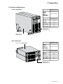 7
7
-
 8
8
-
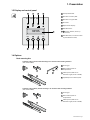 9
9
-
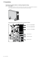 10
10
-
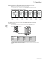 11
11
-
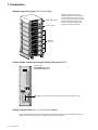 12
12
-
 13
13
-
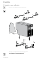 14
14
-
 15
15
-
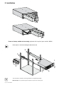 16
16
-
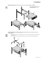 17
17
-
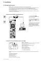 18
18
-
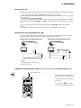 19
19
-
 20
20
-
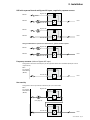 21
21
-
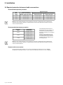 22
22
-
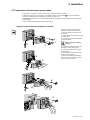 23
23
-
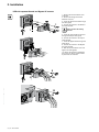 24
24
-
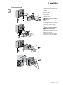 25
25
-
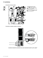 26
26
-
 27
27
-
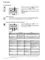 28
28
-
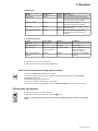 29
29
-
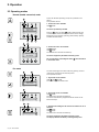 30
30
-
 31
31
-
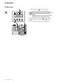 32
32
-
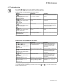 33
33
-
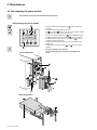 34
34
-
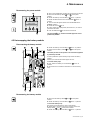 35
35
-
 36
36
-
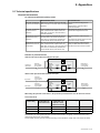 37
37
-
 38
38
-
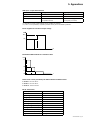 39
39
-
 40
40
-
 41
41
-
 42
42
-
 43
43
-
 44
44
-
 45
45
-
 46
46
-
 47
47
-
 48
48
-
 49
49
-
 50
50
-
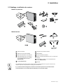 51
51
-
 52
52
-
 53
53
-
 54
54
-
 55
55
-
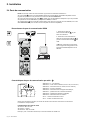 56
56
-
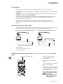 57
57
-
 58
58
-
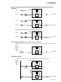 59
59
-
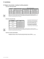 60
60
-
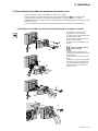 61
61
-
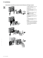 62
62
-
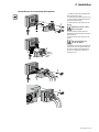 63
63
-
 64
64
-
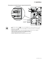 65
65
-
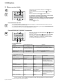 66
66
-
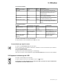 67
67
-
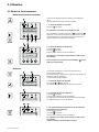 68
68
-
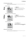 69
69
-
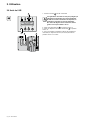 70
70
-
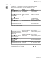 71
71
-
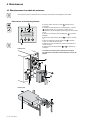 72
72
-
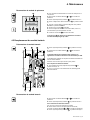 73
73
-
 74
74
-
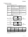 75
75
-
 76
76
-
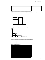 77
77
-
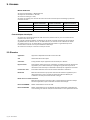 78
78
-
 79
79
-
 80
80
-
 81
81
-
 82
82
-
 83
83
-
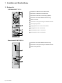 84
84
-
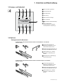 85
85
-
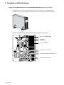 86
86
-
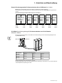 87
87
-
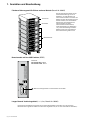 88
88
-
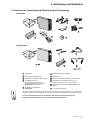 89
89
-
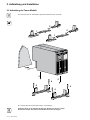 90
90
-
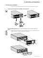 91
91
-
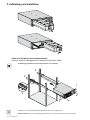 92
92
-
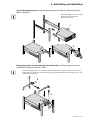 93
93
-
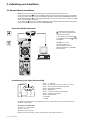 94
94
-
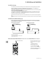 95
95
-
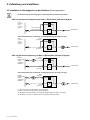 96
96
-
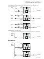 97
97
-
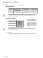 98
98
-
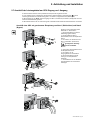 99
99
-
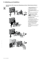 100
100
-
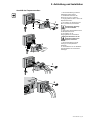 101
101
-
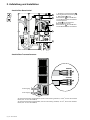 102
102
-
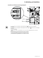 103
103
-
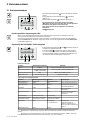 104
104
-
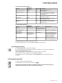 105
105
-
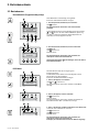 106
106
-
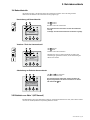 107
107
-
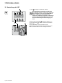 108
108
-
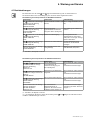 109
109
-
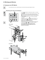 110
110
-
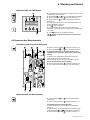 111
111
-
 112
112
-
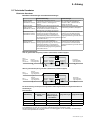 113
113
-
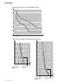 114
114
-
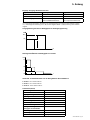 115
115
-
 116
116
-
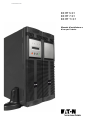 117
117
-
 118
118
-
 119
119
-
 120
120
-
 121
121
-
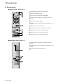 122
122
-
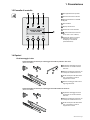 123
123
-
 124
124
-
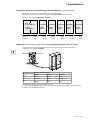 125
125
-
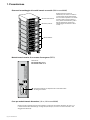 126
126
-
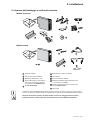 127
127
-
 128
128
-
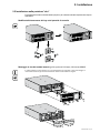 129
129
-
 130
130
-
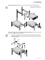 131
131
-
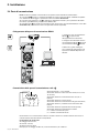 132
132
-
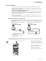 133
133
-
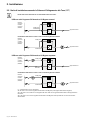 134
134
-
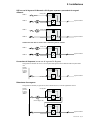 135
135
-
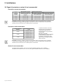 136
136
-
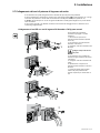 137
137
-
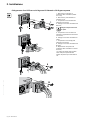 138
138
-
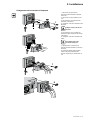 139
139
-
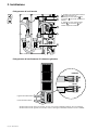 140
140
-
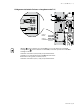 141
141
-
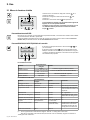 142
142
-
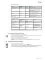 143
143
-
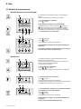 144
144
-
 145
145
-
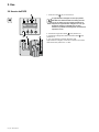 146
146
-
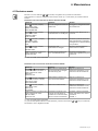 147
147
-
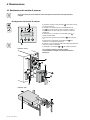 148
148
-
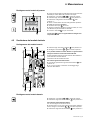 149
149
-
 150
150
-
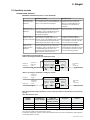 151
151
-
 152
152
-
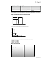 153
153
-
 154
154
-
 155
155
-
 156
156
-
 157
157
-
 158
158
-
 159
159
-
 160
160
-
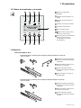 161
161
-
 162
162
-
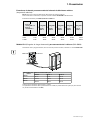 163
163
-
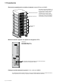 164
164
-
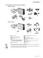 165
165
-
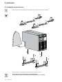 166
166
-
 167
167
-
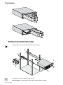 168
168
-
 169
169
-
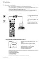 170
170
-
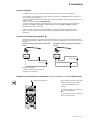 171
171
-
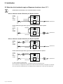 172
172
-
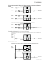 173
173
-
 174
174
-
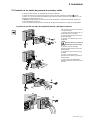 175
175
-
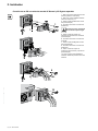 176
176
-
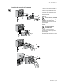 177
177
-
 178
178
-
 179
179
-
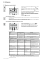 180
180
-
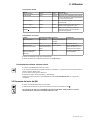 181
181
-
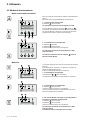 182
182
-
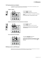 183
183
-
 184
184
-
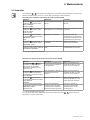 185
185
-
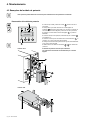 186
186
-
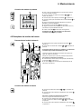 187
187
-
 188
188
-
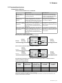 189
189
-
 190
190
-
 191
191
-
 192
192
-
 193
193
-
 194
194
-
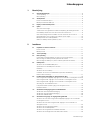 195
195
-
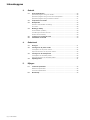 196
196
-
 197
197
-
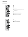 198
198
-
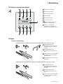 199
199
-
 200
200
-
 201
201
-
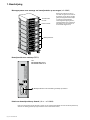 202
202
-
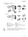 203
203
-
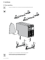 204
204
-
 205
205
-
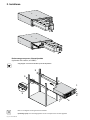 206
206
-
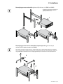 207
207
-
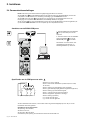 208
208
-
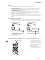 209
209
-
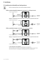 210
210
-
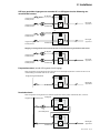 211
211
-
 212
212
-
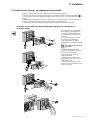 213
213
-
 214
214
-
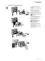 215
215
-
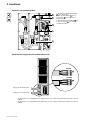 216
216
-
 217
217
-
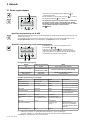 218
218
-
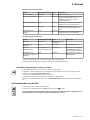 219
219
-
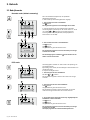 220
220
-
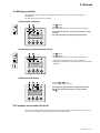 221
221
-
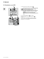 222
222
-
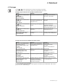 223
223
-
 224
224
-
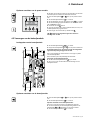 225
225
-
 226
226
-
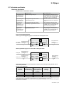 227
227
-
 228
228
-
 229
229
-
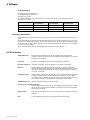 230
230
-
 231
231
-
 232
232


Eaton EX RT 11 3:1 Installation and User Manual
- Categorie
- Noodstroomvoorzieningen (UPS'en)
- Type
- Installation and User Manual
- Deze handleiding is ook geschikt voor
in andere talen
- English: Eaton EX RT 11 3:1
- italiano: Eaton EX RT 11 3:1
- français: Eaton EX RT 11 3:1
- español: Eaton EX RT 11 3:1
- Deutsch: Eaton EX RT 11 3:1
Gerelateerde papieren
-
Eaton EX RT 5 Handleiding
-
-
Eaton 93PM-150(400) Safety And Installation Quick Manual
-
-
Eaton EX 2200 RT3U HotSwap FR Handleiding
-
Eaton Pulsar EX 1000 RT 2U Installation and User Manual
-
Eaton EX 3000 RT3U XL Handleiding
-
Eaton Evolution 850 Rack Handleiding
-
-
Andere documenten
-
ABB 4NWP106819R0001 Quick Manual
-
ABB PowerValue 11 RT G2 Handleiding
-
MGE UPS Systems EX20 Handleiding
-
-
PowerWalker VI 650 SH IEC de handleiding
-
-
-
-
Marantec USV de handleiding
-
APC SRT6KRMXLI-6W Handleiding