GYS GYSARC 300 A TRI de handleiding
- Categorie
- Lassysteem
- Type
- de handleiding
Deze handleiding is ook geschikt voor

C73512_V9_12/02/2021
FR
2 / 3-10 / 59-66
GYSARC 300 TRI
GYSARC 400 TRI
www.gys.fr
Poste à souder MMA triphasé
Three-phase MMA generator
Dreiphasiges E-hand-schweissgerät
Equipo de soldadura MMA trifásico
Трехфазный сварочный аппарат ММА
Driefasen MMA lasapparaat
Sorgente di saldatura MMA trifase
EN
2 / 11-18 / 59-66
DE
2 / 19-26 / 59-66
ES
2 / 27-34 / 59-64
RU
2 / 35-42 / 59-66
NL
2 / 43-50 / 59-66
IT
2 / 51-58 / 59-66

2
GYSARC 300 / 400 TRI
FIG-2
FIG-1
5
2
4
1
3
5
6
7
2 3 4 5 6
7
8
9
121110
1
5
2
4
3
1
6
7
GYSARC 400 TRI
GYSARC 300 TRI

3
GYSARC 300 / 400 TRI
FR
AVERTISSEMENTS - RÈGLES DE SÉCURITÉ
CONSIGNE GÉNÉRALE
Ces instructions doivent être lues et bien comprises avant toute opération.
Toute modication ou maintenance non indiquée dans le manuel ne doit pas être entreprise.
Tout dommage corporel ou matériel dû à une utilisation non-conforme aux instructions de ce manuel ne pourra être retenu à la charge du fabricant.
En cas de problème ou d’incertitude, consulter une personne qualiée pour manier correctement l’installation.
ENVIRONNEMENT
Ce matériel doit être utilisé uniquement pour faire des opérations de soudage dans les limites indiquées par la plaque signalétique et/ou le manuel.
Il faut respecter les directives relatives à la sécurité. En cas d’utilisation inadéquate ou dangereuse, le fabricant ne pourra être tenu responsable.
L’installation doit être utilisée dans un local sans poussière, ni acide, ni gaz inammable ou autres substances corrosives. Il en est de même pour son
stockage. S’assurer d’une circulation d’air lors de l’utilisation.
Plages de température :
Utilisation entre -10 et +40°C (+14 et +104°F).
Stockage entre -20 et +55°C (-4 et 131°F).
Humidité de l’air :
Inférieur ou égal à 50% à 40°C (104°F).
Inférieur ou égal à 90% à 20°C (68°F).
Altitude :
Jusqu’à 1000 m au-dessus du niveau de la mer (3280 pieds).
PROTECTION INDIVIDUELLE ET DES AUTRES
Le soudage à l’arc peut être dangereux et causer des blessures graves voire mortelles.
Le soudage expose les individus à une source dangereuse de chaleur, de rayonnement lumineux de l’arc, de champs électromagnétiques (attention
au porteur de pacemaker), de risque d’électrocution, de bruit et d’émanations gazeuses.
Pour bien se protéger et protéger les autres, respecter les instructions de sécurité suivantes :
An de se protéger de brûlures et rayonnements, porter des vêtements sans revers, isolants, secs, ignifugés et en bon état, qui
couvrent l’ensemble du corps.
Utiliser des gants qui garantissent l’isolation électrique et thermique.
Utiliser une protection de soudage et/ou une cagoule de soudage d’un niveau de protection susant (variable selon les applications).
Protéger les yeux lors des opérations de nettoyage. Les lentilles de contact sont particulièrement proscrites. Il est parfois nécessaire
de délimiter les zones par des rideaux ignifugés pour protéger la zone de soudage des rayons de l’arc, des projections et des déchets
incandescents.
Informer les personnes dans la zone de soudage de ne pas xer les rayons de l’arc ni les pièces en fusion et de porter les vêtements
adéquats pour se protéger.
Utiliser un casque contre le bruit si le procédé de soudage atteint un niveau de bruit supérieur à la limite autorisée (de même pour
toute personne étant dans la zone de soudage).
Tenir à distance des parties mobiles (ventilateur) les mains, cheveux, vêtements. Ne jamais enlever les protections carter du groupe
froid lorsque la source de courant de soudage est sous tension, le fabricant ne pourrait être tenu pour responsable en cas d’accident.
Les pièces qui viennent d’être soudées sont chaudes et peuvent provoquer des brûlures lors de leur manipulation. Lors d’intervention
d’entretien sur la torche ou le porte-électrode, il faut s’assurer qu’il/elle soit susamment froid(e) en attendant au moins 10 minutes
avant toute intervention. Le groupe froid doit être allumé lors de l’utilisation d’une torche refroidie eau an d’être sûr que le liquide
ne puisse pas causer de brûlures. Il est important de sécuriser la zone de travail avant de la quitter an de protéger les personnes
et les biens.
FUMÉES DE SOUDAGE ET GAZ
Les fumées, gaz et poussières émis par le soudage sont dangereux pour la santé. Il faut prévoir une ventilation susante,
un apport d’air est parfois nécessaire. Un masque à air frais peut être une solution en cas d’aération insusante. Vérier que
l’aspiration est ecace en la contrôlant par rapport aux normes de sécurité.
Attention le soudage dans les environnements réduits nécessite une surveillance à distance de sécurité. Par ailleurs le soudage de certains matériaux
contenant du plomb, cadmium, zinc ou mercure voire du béryllium peuvent être particulièrement nocifs.
Dégraisser également les pièces avant de les souder.
Les bouteilles doivent être entreposées dans des locaux ouverts ou bien aérés. Elles doivent être en position verticale et maintenues à un support ou
sur un chariot.
Le soudage doit être proscrit à proximité de graisse ou de peinture.

4
GYSARC 300 / 400 TRI
FR
RISQUES DE FEU ET D’EXPLOSION
Protéger entièrement la zone de soudage, les matières inammables doivent être éloignées d’au moins 11 mètres.
Un équipement anti-feu doit être présent à proximité des opérations de soudage.
Attention aux projections de matières chaudes ou d’étincelles, car même à travers des ssures, elles peuvent être source
d’incendie ou d’explosion.
Éloigner les personnes, les objets inammables et les containers sous pressions à une distance de sécurité susante.
Le soudage dans des containers ou des tubes fermés est à proscrire et dans le cas où ils sont ouverts, il faut les vider de toute matière inammable
ou explosive (huile, carburant, résidus de gaz …).
Les opérations de meulage ne doivent pas être dirigées vers la source de courant de soudage ou vers des matières inammables.
BOUTEILLES DE GAZ
Le gaz sortant des bouteilles peut être source de suocation en cas de concentration dans l’espace de soudage (bien ventiler).
Le transport doit être fait en toute sécurité : bouteilles fermées et la source de courant de soudage éteinte. Elles doivent être
entreposées verticalement et maintenues par un support pour limiter le risque de chute.
Fermer la bouteille entre deux utilisations. Attention aux variations de température et aux expositions au soleil.
La bouteille ne doit pas être en contact avec une amme, un arc électrique, une torche, une pince de masse ou toutes autres sources de chaleur ou
d’incandescence.
Veiller à la tenir éloignée des circuits électriques et de soudage et donc ne jamais souder une bouteille sous pression.
Attention lors de l’ouverture du robinet de la bouteille, il faut éloigner la tête la robinetterie et s’assurer que le gaz utilisé est approprié au procédé
de soudage.
SÉCURITÉ ÉLECTRIQUE
Le réseau électrique utilisé doit impérativement avoir une mise à la terre. Utiliser la taille de fusible recommandée sur le tableau
signalétique.
Une décharge électrique peut être une source d’accident grave direct ou indirect, voire mortel.
Ne jamais toucher les parties sous tension à l’intérieur comme à l’extérieur de la source de courant sous-tension (Torches, pinces, câbles, électrodes)
car celles-ci sont branchées au circuit de soudage.
Avant d’ouvrir la source de courant de soudage, il faut la déconnecter du réseau et attendre 2 minutes. an que l’ensemble des condensateurs soit
déchargé.
Ne pas toucher en même temps la torche ou le porte-électrode et la pince de masse.
Veiller à changer les câbles et torches, par des personnes qualiées et habilitées, si ceux-ci sont endommagés. Dimensionner la section des câbles
en fonction de l’application. Toujours utiliser des vêtements secs et en bon état pour s’isoler du circuit de soudage. Porter des chaussures isolantes,
quel que soit le milieu de travail.
CLASSIFICATION CEM DU MATÉRIEL
Ce matériel de Classe A n’est pas prévu pour être utilisé dans un site résidentiel où le courant électrique est fourni par le réseau
public d’alimentation basse tension. Il peut y avoir des dicultés potentielles pour assurer la compatibilité électromagnétique
dans ces sites, à cause des perturbations conduites, aussi bien que rayonnées à fréquence radioélectrique.
Ce matériel est conforme à la CEI 61000-3-11.
Ce matériel n’est pas conforme à la CEI 61000-3-12 et est destiné à être raccordé à des réseaux basse tension privés
connectés au réseau public d’alimentation seulement au niveau moyenne et haute tension. S’il est connecté à un réseau
public d’alimentation basse tension, il est de la responsabilité de l’installateur ou de l’utilisateur du matériel de s’assurer, en
consultant l’opérateur du réseau de distribution, que le matériel peut être connecté.
EMISSIONS ELECTRO-MAGNETIQUES
Le courant électrique passant à travers n’importe quel conducteur produit des champs électriques et magnétiques (EMF)
localisés. Le courant de soudage produit un champ électromagnétique autour du circuit de soudage et du matériel de soudage.
Les champs électromagnétiques EMF peuvent perturber certains implants médicaux, par exemple les stimulateurs cardiaques. Des mesures de
protection doivent être prises pour les personnes portant des implants médicaux. Par exemple, restrictions d’accès pour les passants ou une évaluation
de risque individuelle pour les soudeurs.
Tous les soudeurs doivent utiliser les procédures suivantes an de minimiser l’exposition aux champs électromagnétiques provenant du circuit de
soudage:
• positionner les câbles de soudage ensemble – les xer avec une attache, si possible;
• se positionner (torse et tête) aussi loin que possible du circuit de soudage;
• ne jamais enrouler les câbles de soudage autour du corps;

5
GYSARC 300 / 400 TRI
FR
• ne pas positionner le corps entre les câbles de soudage. Tenir les deux câbles de soudage sur le même côté du corps;
• raccorder le câble de retour à la pièce mise en œuvre aussi proche que possible à la zone à souder;
• ne pas travailler à côté de la source de courant de soudage, ne pas s’assoir dessus ou ne pas s’y adosser ;
• ne pas souder lors du transport de la source de courant de soudage ou le dévidoir.
Les porteurs de stimulateurs cardiaques doivent consulter un médecin avant d’utiliser ce matériel.
L’exposition aux champs électromagnétiques lors du soudage peut avoir d’autres eets sur la santé que l’on ne connaît pas
encore.
RECOMMANDATIONS POUR EVALUER LA ZONE ET L’INSTALLATION DE SOUDAGE
Généralités
L’utilisateur est responsable de l’installation et de l’utilisation du matériel de soudage à l’arc suivant les instructions du fabricant. Si des perturbations
électromagnétiques sont détectées, il doit être de la responsabilité de l’utilisateur du matériel de soudage à l’arc de résoudre la situation avec
l’assistance technique du fabricant. Dans certains cas, cette action corrective peut être aussi simple qu’une mise à la terre du circuit de soudage. Dans
d’autres cas, il peut être nécessaire de construire un écran électromagnétique autour de la source de courant de soudage et de la pièce entière avec
montage de ltres d’entrée. Dans tous les cas, les perturbations électromagnétiques doivent être réduites jusqu’à ce qu’elles ne soient plus gênantes.
Evaluation de la zone de soudage
Avant d’installer un matériel de soudage à l’arc, l’utilisateur doit évaluer les problèmes électromagnétiques potentiels dans la zone environnante. Ce
qui suit doit être pris en compte:
a) la présence au-dessus, au-dessous et à côté du matériel de soudage à l’arc d’autres câbles d’alimentation, de commande, de signalisation et de
téléphone;
b) des récepteurs et transmetteurs de radio et télévision;
c) des ordinateurs et autres matériels de commande;
d) du matériel critique de sécurité, par exemple, protection de matériel industriel;
e) la santé des personnes voisines, par exemple, emploi de stimulateurs cardiaques ou d’appareils contre la surdité;
f) du matériel utilisé pour l’étalonnage ou la mesure;
g) l’immunité des autres matériels présents dans l’environnement.
L’utilisateur doit s’assurer que les autres matériels utilisés dans l’environnement sont compatibles. Cela peut exiger des mesures de protection
supplémentaires;
h) l’heure du jour où le soudage ou d’autres activités sont à exécuter.
La dimension de la zone environnante à prendre en compte dépend de la structure du bâtiment et des autres activités qui s’y déroulent. La zone
environnante peut s’étendre au-delà des limites des installations.
Évaluation de l’installation de soudage
Outre l’évaluation de la zone, l’évaluation des installations de soudage à l’arc peut servir à déterminer et résoudre les cas de perturbations. Il convient
que l’évaluation des émissions comprenne des mesures in situ comme cela est spécié à l’Article 10 de la CISPR 11:2009. Les mesures in situ peuvent
également permettre de conrmer l’ecacité des mesures d’atténuation.
RECOMMANDATIONS SUR LES METHODES DE REDUCTION DES EMISSIONS ELECTROMAGNETIQUES
a. Réseau public d’alimentation: Il convient de raccorder le matériel de soudage à l’arc au réseau public d’alimentation selon les recommandations
du fabricant. Si des interférences se produisent, il peut être nécessaire de prendre des mesures de prévention supplémentaires telles que le ltrage
du réseau public d’alimentation. Il convient d’envisager de blinder le câble d’alimentation dans un conduit métallique ou équivalent d’un matériel de
soudage à l’arc installé à demeure. Il convient d’assurer la continuité électrique du blindage sur toute sa longueur. Il convient de raccorder le blindage
à la source de courant de soudage pour assurer un bon contact électrique entre le conduit et l’enveloppe de la source de courant de soudage.
b. Maintenance du matériel de soudage à l’arc : Il convient que le matériel de soudage à l’arc soit soumis à l’entretien de routine suivant les
recommandations du fabricant. Il convient que tous les accès, portes de service et capots soient fermés et correctement verrouillés lorsque le matériel
de soudage à l’arc est en service. Il convient que le matériel de soudage à l’arc ne soit modié en aucune façon, hormis les modications et réglages
mentionnés dans les instructions du fabricant. Il convient, en particulier, que l’éclateur d’arc des dispositifs d’amorçage et de stabilisation d’arc soit
réglé et entretenu suivant les recommandations du fabricant.
c. Câbles de soudage : Il convient que les câbles soient aussi courts que possible, placés l’un près de l’autre à proximité du sol ou sur le sol.
d. Liaison équipotentielle : Il convient d’envisager la liaison de tous les objets métalliques de la zone environnante. Toutefois, des objets métalliques
reliés à la pièce à souder accroissent le risque pour l’opérateur de chocs électriques s’il touche à la fois ces éléments métalliques et l’électrode. Il
convient d’isoler l’opérateur de tels objets métalliques.
e. Mise à la terre de la pièce à souder : Lorsque la pièce à souder n’est pas reliée à la terre pour la sécurité électrique ou en raison de ses
dimensions et de son emplacement, ce qui est le cas, par exemple, des coques de navire ou des charpentes métalliques de bâtiments, une connexion
raccordant la pièce à la terre peut, dans certains cas et non systématiquement, réduire les émissions. Il convient de veiller à éviter la mise à la terre
des pièces qui pourrait accroître les risques de blessure pour les utilisateurs ou endommager d’autres matériels électriques. Si nécessaire, il convient
que le raccordement de la pièce à souder à la terre soit fait directement, mais dans certains pays n’autorisant pas cette connexion directe, il convient
que la connexion soit faite avec un condensateur approprié et choisi en fonction des réglementations nationales.
f. Protection et blindage : La protection et le blindage sélectifs d’autres câbles et matériels dans la zone environnante peuvent limiter les problèmes
de perturbation. La protection de toute la zone de soudage peut être envisagée pour des applications spéciales.

6
GYSARC 300 / 400 TRI
FR
TRANSPORT ET TRANSIT DE L’APPAREIL
La source de courant de soudage est équipée d’une (de) poignée(s) supérieure(s) permettant le portage à la main. Attention à
ne pas sous-évaluer son poids.
30°
Ne pas utiliser les câbles ou torche pour déplacer la source de courant de soudage. Elle doit être déplacée en
position verticale.
Ne pas faire transiter la source de courant au-dessus de personnes ou d’objets. Ne jamais soulever une
bouteille de gaz et la source de courant en même temps. Leurs normes de transport sont distinctes.
INSTALLATION DU MATÉRIEL
Règles à respecter :
• Mettre la source de courant de soudage sur un sol dont l’inclinaison maximum est de 10°.
• Prévoir une zone susante pour aérer la source de courant de soudage et accéder aux commandes.
• Ne pas utiliser dans un environnement comportant des poussières métalliques conductrices.
• La source de courant de soudage doit être à l’abri de la pluie battante et ne pas être exposée aux rayons du soleil.
• Le matériel est de degré de protection IP23, signiant :
- une protection contre l’accès aux parties dangereuses des corps solides de Ø >12.5mm et,
- une protection contre la pluie dirigée à 60° par rapport à la verticale.
Ce matériel peut donc être utilisé à l’extérieur en accord avec l’indice de protection IP23.
• Les câbles d’alimentation, de rallonge et de soudage doivent être totalement déroulés an d’éviter toute surchaue.
Le fabricant n’assume aucune responsabilité concernant les dommages provoqués à des personnes et objets dus à une utilisation
incorrecte et dangereuse de ce matériel.
ENTRETIEN / CONSEILS
• L’entretien ne doit être eectué que par une personne qualiée. Un entretien annuel est conseillé.
• Couper l’alimentation en débranchant la prise, et attendre deux minutes avant de travailler sur le matériel. A l’intérieur, les
tensions et intensités sont élevées et dangereuses.
• Régulièrement, enlever le capot et dépoussiérer à la souette. En proter pour faire vérier la tenue des connexions électriques avec un outil isolé
par un personnel qualié.
• Contrôler régulièrement l’état du cordon d’alimentation. Si le câble d’alimentation est endommagé, il doit être remplacé par le fabricant, son service
après-vente ou une personne de qualication similaire, an d’éviter tout danger.
• Laisser les ouïes de la source de courant de soudage libres pour l’entrée et la sortie d’air.
• Ne pas utiliser cette source de courant de soudage pour dégeler des canalisations, recharger des batteries/accumulateurs ou démarrer des moteurs.
INSTALLATION – FONCTIONNEMENT PRODUIT
Seul le personnel expérimenté et habilité par le fabricant peut eectuer l’installation. Pendant l’installation, s’assurer que le générateur est déconnecté
du réseau.
DESCRIPTION DU MATÉRIEL (FIG-1)
Le GYSARC 300/400 est une source de soudage inverter triphasé qui en fonction de son équipement permet :
- Le soudage à l’électrode enrobée (MMA)
- Le soudage à l’électrode tungstène sous gaz inerte (TIG)
Le procédé TIG requiert une protection gazeuse (Argon).
Le procédé MMA permet de souder tout type d’électrode : rutile, basique, cellulosique, inox et fonte.
Le GYSARC 300/400 peut être équipé d’une commande à distance manuelle (ref. 045675).
1- Interface homme machine 5- Poignées de transport et de levage
2- Douille de polarité Négative 6- Commutateur marche / arrêt
3- Douille de polarité Positive 7- Câble d’alimentation
4- Connectique de commande à distance
INTERFACE HOMME MACHINE (IHM) (FIG-2)
1- Acheur tension 7- Indicateur d’activation de la commande à distance
2- Indicteur de surchaue 8- Bouton d’activation de la commande à distance
3- Indicateur de fonctionnement du dispositif réducteur de risques (VRD) 9- Bouton de sélection de mode (MMA / TIG-LIFT)
4- Acheur courant 10- Molette de réglage du paramètre Arc Force
5- Indicateur mode TIG-LIFT 11- Molette de réglage du courant
6- Indicateur mode électrode enrobée MMA 12- Molette de réglage du paramètre Hot Start

7
GYSARC 300 / 400 TRI
FR
ALIMENTATION-MISE EN MARCHE
• Le GYSARC 300 TRI est livré avec prise 16 A de type EN 60309-1 et ne doit être utilisé que sur une installation électrique triphasée 400V (50-60 Hz)
à quatre ls avec un neutre relié à la terre.
• Le GYSARC 400 TRI est livré avec prise 32 A de type EN 60309-1 et ne doit être utilisé que sur une installation électrique triphasée 400V (50-60 Hz)
à quatre ls avec un neutre relié à la terre.
• Le courant eectif absorbé (I1e) est indiqué sur le matériel, pour les conditions d’utilisation maximales. Vérier que l’alimentation et ses protections
(fusible et/ou disjoncteur) sont compatibles avec le courant nécessaire en utilisation. Dans certains pays, il peut être nécessaire de changer la prise
pour permettre une utilisation aux conditions maximales.
• Lors d’utilisation intensive (> au facteur de marche) la protection thermique peut s’enclencher, dans ce cas l’arc s’éteint et le voyant de protection
s’allume.
• L’appareil est prévu pour fonctionner sur une tension électrique 400V +/- 15%.
• La mise en marche se fait par rotation du commutateur marche / arrêt (FIG 1 - 6) sur la position I, inversement l’arrêt se fait par une rotation sur
la position O. Attention ! Ne jamais couper l’alimentation lorsque le poste est en charge.
BRANCHEMENT SUR GROUPE ÉLECTROGÈNE
Le poste peut fonctionner avec des groupes électrogènes à condition que la puissance auxiliaire réponde aux exigences suivantes :
- La tension doit être alternative, sa valeur ecace doit être de 400V +/- 15%, et de tension crête inférieure à 700V,
- La fréquence doit être comprise entre 50 et 60 Hz.
Il est impératif de vérier ces conditions, car de nombreux groupes électrogènes produisent des pics de haute tension pouvant endommager les
postes.
UTILISATION DE RALLONGE ÉLECTRIQUE
Toutes les rallonges doivent avoir une taille et une section appropriées à la tension de l’appareil.
Utiliser une rallonge conforme aux réglementations nationales.
Tension d’entrée Section de la rallonge (<45m)
GYSARC 300
400 V - 3~
2.5 mm²
GYSARC 400 4 mm²
SOUDAGE A L’ÉLECTRODE ENROBÉE (MMA)
BRANCHEMENT ET CONSEILS
• Brancher les câbles, porte-électrode et pince de masse dans les connecteurs de raccordement,
• Respecter les polarités et intensités de soudage indiquées sur les boîtes d’électrodes,
• Enlever l’électrode du porte-électrode lorsque le poste n’est pas utilisé.
MMA
Les zones grisées ne sont pas utiles dans ce mode.
SÉLECTION DU MODE
Appuyer sur le bouton pour sélectionner le mode MMA.
PARAMÈTRES PRINCIPAUX
1. Réglage de l’intensité de soudage :
Ajuster le courant de soudage à l’aide de la molette centrale en fonction du diamètre d’électrode et du type d’assemblage à réaliser. La consigne de
courant est indiquée sur l’acheur de droite.
2. Régler le niveau d’Arc Force :
Ajuster le niveau d’Arc Force à l’aide de la molette de gauche. Plus le niveau d’Arc Force est faible et plus l’arc sera doux, à l’inverse plus le niveau d’Arc
Force est élevé et plus la surintensité en soudage sera élevée. Il est conseillé de positionner l’Arc Force en position médiane pour débuter le soudage
et l’ajuster en fonction des résultats et des préférences de soudage. Note : la plage de réglage de l’Arc Force est spécique au type d’électrode choisi.
3. Régler le Hot Start :
Ajuster le niveau de Hot Start à l’aide de la molette de droite. Hot Start faible pour les tôles nes et Hot Start élevé pour les métaux diciles à souder
(pièces sales ou oxydées).

8
GYSARC 300 / 400 TRI
FR
PARAMÈTRES DE SOUDAGE
RÉGLAGE DE L’INTENSITÉ DE SOUDAGE
Les réglages qui suivent correspondent à la plage d’intensité utilisable en fonction du type et du diamètre d’électrode. Ces plages sont assez larges
car elles dépendent de l’application et de la position de soudure.
Ø d’électrode
(mm)
Rutile E6013
(A)
Basique E7018
(A)
Cellulosique E6010
(A)
1.6 30-60 30-55 -
2.0 50-70 50-80 -
2.5 60-100 80-110 60-75
3.15 80-150 90-140 85-90
4.0 100-200 125-210 120-160
5 150-290 200-260 110-170
6.3 200-385 220-340 -
SOUDAGE A L’ÉLECTRODE ENROBÉE
• Le câble d’inversion de polarité doit être déconnectée en MMA pour brancher les câbles porte électrode et pince de masse dans les connecteurs.
Respecter les polarités indiquées sur l’emballage des électrodes.
• Respecter les règles classiques du soudage.
• Votre appareil est muni d’une fonctionnalité spécique aux Inverters :
L’Anti-Sticking vous permet de décoller facilement votre électrode sans la faire rougir en cas de collage. La fonction anti-sticking, après son déclen-
chement, nécessite un temps d’attente d’environ 3 secondes avant de pouvoir reprendre une soudure normale.
SOUDAGE A L’ÉLECTRODE TUNGSTENE SOUS GAZ INERTE (TIG)
BRANCHEMENT ET CONSEILS
Le soudage TIG nécessite une torche ainsi qu’une bouteille de gaz de protection équipée d’un détendeur.
• Brancher la pince de masse dans le connecteur de raccordement positif (+).
• Brancher le câble de puissance de la torche dans le connecteur de raccordement négatif (–).
• Raccorder le tuyau de gaz de la torche à la sortie du détendeur.
S’assurer que la torche est bien équipée et que les consommables (pince-étau, support collet, diuseur et buse) ne sont pas usés.
VRD
TIG Lift MMA
MODE
min maxmin max
HOT STARTARC FORCE
TIG
Les zones grisées ne sont pas utiles dans ce mode.
SÉLECTION DU MODE
Appuyer sur le bouton pour sélectionner le mode TIG.
Réglage de l’intensité de soudage :
Ajuster le courant de soudage à l’aide de la molette centrale en fonction du diamètre d’électrode et du type d’assemblage à réaliser. La consigne de
courant est indiquée sur l’acheur de droite.
AMORÇAGE
L’amorçage est de type LIFT : à l’aide de la torche, faire toucher l’électrode avec la pièce à souder puis relever doucement l’électrode, un arc se forme.
ARRÊT DE SOUDAGE / DÉCLENCHEMENT DE L’ÉVANOUISSEMENT
Pour arrêter le soudage, tirer légèrement l’arc, celui-ci va baisser en intensité graduellement (évanouissement).
AIDE AU RÉGLAGE ET CHOIX DES CONSOMMABLES
DC
Courant (A) Électrode (mm) Buse (mm) Débit Argon (L/min)
0.3 - 3 mm 5 - 75 1 6.5 6 - 7
2.4 - 6 mm 60 - 150 1.6 8 6 - 7
4 - 8 mm 100 - 200 2 9.5 7 - 8
6.8 - 8.8 mm 170 - 220 2.4 11 8 - 9
9 - 12 mm 255 - 300 3.2 12.5 9 - 10

9
GYSARC 300 / 400 TRI
FR
AFFUTAGE DE L’ÉLECTRODE
d
L
L = 3 x d pour un courant faible.
L = d pour un courant fort.
COMMANDE À DISTANCE
La commande à distance fonctionne en procédé TIG et MMA.
F
A
B
CD
E
G
C
B
A
ref. 045699 Vue extérieure Schéma électrique commande à distance.
Branchement :
1- Brancher la commande à distance sur la face avant de la source de courant de soudage (FIG 1 - 4).
2- Appuyer sur le bouton pour activer la commande à distance. La LED ON s’allume.
Connectique
Le produit est équipé d’une connectique femelle pour commande à distance.
La prise mâle spécique 7 points (option ref. 045699) permet d’y raccorder une commande à distance manuelle. Pour le câblage, suivre le schéma
ci-dessous.
TYPE DE COMMANDE À DISTANCE Désignation du l Pin du connecteur associée
Commande à distance manuelle
12 V A
Curseur B
Commun/Masse C
Fonctionnement :
• Commande à distance manuelle (option réf. 045675).
La commande à distance manuelle permet de faire varier le courant de 50% à 100% de l’intensité réglée.
VRD (VOLTAGE REDUCTION DEVICE)
1
Par défaut (réglage usine), l’interrupteur VRD est en position ON. Pour activer le VRD, an d’abaisser la tension à vide du généra-
teur (< 20 V), basculer l’interrupteur présent sur la carte de commande (page 59 - n°14 /page 60 - n°11) sur 1.
Le voyant de l’IHM (FIG 2 - N°3) s’allume.
Pour accéder à l’interrupteur VRD (voir page 61) :
LES CHOCS ÉLECTRIQUES PEUVENT ÊTRE FATALS
- DÉCONNECTER LE PRODUIT DE L’ALIMENTATION ÉLECTRIQUE.
- Retirer les 9 vis an d’ouvrir le anc du générateur.
- Repérer l’interrupteur rouge au centre de la carte de commande.
PROTECTION THERMIQUE ET CONSEILS
Ce poste est équipé d’une ventilation régulée par la température de l’appareil. Lorsque le poste passe en protection thermique, il ne délivre plus de
courant. La LED orange (FIG 2 - 2) s’allume tant que la température du poste n’est pas redevenue normale.
• Laisser les ouïes de l’appareil libres pour l’entrée et la sortie d’air.
• Laisser l’appareil branché après soudage et pendant la protection thermique pour permettre le refroidissement.
• Respecter les règles classiques du soudage.
• S’assurer que la ventilation soit susante.
• Ne pas travailler sur une surface humide.

10
GYSARC 300 / 400 TRI
FR
ANOMALIES, CAUSES, REMÈDES
Anomalies Causes Remèdes
MMA-TIG
L’appareil ne délivre pas de courant et le
voyant jaune de défaut thermique est allumé
(FIG 2 - 2).
La protection thermique du poste s’est
enclenchée.
Attendre la n de la période de refroidisse-
ment, environ 2 min. Le voyant (FIG 2 - 2)
s’éteint.
L’acheur (FIG 2 - 4) est allumé mais
l’appareil ne délivre pas de courant.
Le câble de pince de masse, le porte élec-
trode ou la torche ne sont pas connectés au
poste.
Vérier les branchements.
Le poste est alimenté, vous ressentez
des picotements en posant la main sur la
carrosserie.
La mise à la terre est défectueuse.
Contrôler la prise et la terre de votre instal-
lation.
Le poste soude mal Erreur de polarité
Vérier la polarité conseillée sur la boîte
d'électrode.
TIG
Arc instable
Défaut provenant de l'électrode en tungs-
tène
Utiliser une électrode en tungstène de taille
appropriée
Utiliser une électrode en tungstène correcte-
ment préparée
Débit de gaz trop important Réduire le débit de gaz
L’électrode en tungstène s’oxyde et se ternit
en n de soudage
Zone de soudage
Protéger la zone de soudage contre les
courants d'air.
Problème de gaz, ou coupure prématurée
du gaz
Contrôler et serrer tous les raccords de gaz.
Attendre que l'électrode refroidisse avant de
couper le gaz.
L'électrode fond Erreur de polarité
Vérier que la pince de masse est bien reliée
au +
GARANTIE
La garantie couvre tous défauts ou vices de fabrication pendant 2 ans, à compter de la date d’achat (pièces et main d’oeuvre).
La garantie ne couvre pas :
• Toutes autres avaries dues au transport.
• L’usure normale des pièces (Ex. : câbles, pinces, etc.).
• Les incidents dus à un mauvais usage (erreur d’alimentation, chute, démontage).
• Les pannes liées à l’environnement (pollution, rouille, poussière).
En cas de panne, retourner l’appareil à votre distributeur, en y joignant :
- un justicatif d’achat daté (ticket de sortie de caisse, facture….)
- une note explicative de la panne.

11
GYSARC 300 / 400 TRI
EN
WARNING - SAFETY RULES
GENERAL INSTRUCTIONS
Read and understand the following safety recommendations before using or servicing the unit.
Any change or servicing that is not specied in the instruction manual must not be undertaken.
The manufacturer is not liable for any injury or damage caused due to non-compliance with the instructions featured in this manual .
In the event of problems or uncertainties, please consult a qualied person to handle the installation properly.
ENVIRONMENT
This equipment must only be used for welding operations in accordance with the limits indicated on the descriptive panel and/or in the user manual.
The operator must respect the safety precautions that apply to this type of welding. In case of inedaquate or unsafe use, the manufacturer cannot
be held liable for damage or injury.
This equipment must be used and stored in a place protected from dust, acid or any other corrosive agent. Operate the machine in an open, or
well-ventilated area.
Operating temperature:
Use between -10 and +40°C (+14 and +104°F).
Store between -20 and +55°C (-4 and 131°F).
Air humidity:
Lower or equal to 50% at 40°C (104°F).
Lower or equal to 90% at 20°C (68°F).
Altitude:
Up to 1000 meters above sea level (3280 feet).
PROTECTION OF THE INDIVIDUALS
Arc welding can be dangerous and can cause serious and even fatal injuries.
Welding exposes the user to dangerous heat, arc rays, electromagnetic elds, noise, gas fumes, and electrical shocks. People wearing pacemakers
are advised to consult with their doctor before using this device.
To protect oneself as well as the other, ensure the following safety precautions are taken:
In order to protect you from burns and radiations, wear clothing without cus. These clothes must be insulated, dry, reproof and
in good condition, and cover the whole body.
Wear protective gloves which guarantee electrical and thermal insulation.
Use sucient welding protective gear for the whole body: hood, gloves, jacket, trousers... (varies depending on the application/
operation). Protect the eyes during cleaning operations. Do not operate whilst wearing contact lenses. It may be necessary to install
reproof welding curtains to protect the area against arc rays, weld spatters and sparks.
Inform the people around the working area to never look at the arc nor the molten metal, and to wear protective clothes.
Ensure ear protection is worn by the operator if the work exceeds the authorised noise limit (the same applies to any person in the
welding area).
Stay away from moving parts (e.g. engine, fan...) with hands, hair, clothes etc... Never remove the safety covers from the cooling
unit when the machine is plugged in - The manufacturer is not responsible for any accident or injury that happens as a result of
not following these safety precautions.
The pieces that have just been welded are hot and may cause burns when manipulated. During maintenance work on the torch or
the electrode holder, you should make sure it’s cold enough and wait at least 10 minutes before any intervention. The cooling unit
must be on when using a water cooled torch in order to ensure that the liquid does not cause any burns.
ALWAYS ensure the working area is left as safe and secure as possible to prevent damage or accidents.
WELDING FUMES AND GAS
The fumes, gases and dust produced during welding are hazardous. It is mandatory to ensure adequate ventilation and/or
extraction to keep fumes and gases away from the work area. An air fed helmet is recommended in cases of insucient air supply
in the workplace.
Check that the air intake is in compliance with safety standards.
Care must be taken when welding in small areas, and the operator will need supervision from a safe distance. Welding certain pieces of metal
containing lead, cadmium, zinc, mercury or beryllium can be extremely toxic. The user will also need to degrease the workpiece before welding.
Gas cylinders must be stored in an open or ventilated area. The cylinders must be in a vertical position secured to a support or trolley.
Do not weld in areas where grease or paint are stored.

12
GYSARC 300 / 400 TRI
EN
FIRE AND EXPLOSION RISKS
Protect the entire welding area. Compressed gas containers and other inammable material must be moved to a minimum safe
distance of 11 meters. A re extinguisher must be readily available.
Be careful of spatter and sparks, even through cracks. It can be the source of a re or an explosion.
Keep people, ammable objects and containers under pressure at a safe distance.
Welding of sealed containers or closed pipes should not be undertaken, and if opened, the operator must remove any inammable or explosive
materials (oil, petrol, gas...).
Grinding operations should not be directed towards the device itself, the power supply or any ammable materials.
GAS BOTTLE
Gas leaking from the cylinder can lead to suocation if present in high concentrations around the work area.
Transport must be done safely: Cylinders closed and product o. Always keep cylinders in an upright position securely chained
to a xed support or trolley.
Close the bottle after any welding operation. Be wary of temperature changes or exposure to sunlight.
Cylinders should be located away from areas where they may be struck or subjected to physical damage.
Always keep gas bottles at a safe distance from arc welding or cutting operations, and any source of heat, sparks or ames.
Be careful when opening the valve on the gas bottle, it is necessary to remove the tip of the valve and make sure the gas meets your welding
requirements.
ELECTRIC SAFETY
The machine must be connected to an earthed electrical supply. Use the recommended fuse size.
An electrical discharge can directly or indirectly cause serious or deadly accidents.
Do not touch any live part of the machine (inside or outside) when it is plugged in (Torches, earth cable, cables, electrodes) because they are
connected to the welding circuit.
Before opening the device, it is imperative to disconnect it from the mains and wait 2 minutes, so that all the capacitors are discharged.
Do not touch the torch or electrode holder and earth clamp at the same time.
Damaged cables and torches must be changed by a qualied and skilled professional. Make sure that the cable cross section is adequate with the
usage (extensions and welding cables). Always wear dry clothes in good condition, in order to be insulated from the electrical circuit. Wear insulating
shoes, regardless of the environment in which you work in.
EMC CLASSIFICATION
These Class A devices are not intended to be used on a residential site where the electric current is supplied by the public
network, with a low voltage power supply. There may be potential diculties in ensuring electromagnetic compatibility on these
sites, because of the interferences, as well as radio frequencies.
This equipment complies with the IEC 61000-3-11 standard.
This equipment does not comply with IEC 61000-3-12 and is intended to be connected to private low-voltage systems
interfacing with the public supply only at the medium- or high-voltage level. On a public low-voltage power grid, it is the
responsibility of the installer or user of the device to ensure, by checking with the operator of the distribution network, which
device can be connected.
ELECTROMAGNETIC INTERFERENCES
The electric currents owing through a conductor cause electrical and magnetic elds (EMF). The welding current generates an
EMF eld around the welding circuit and the welding equipment.
The EMF elds may disrupt some medical implants, such as pacemakers. Protection measures should be taken for people wearing medical implants.
For example, access restrictions for passers-by or an individual risk evaluation for the welders.
All welders should take the following precautions in order to minimise exposure to the electromagnetic elds (EMF) generated by the welding circuit::
• position the welding cables together – if possible, attach them;
• keep your head and torso as far as possible from the welding circuit;
• never enroll the cables around your body;
• never position your body between the welding cables. Hold both welding cables on the same side of your body;
• connect the earth clamp as close as possible to the area being welded;
• do not work too close to, do not lean and do not sit on the welding machine
• do not weld when you’re carrying the welding machine or its wire feeder.

13
GYSARC 300 / 400 TRI
EN
People wearing pacemakers are advised to consult their doctor before using this device.
Exposure to electromagnetic elds while welding may have other health eects which are not yet known.
RECOMMANDATIONS TO ASSES THE AREA AND WELDING INSTALLATION
Overview
The user is responsible for installing and using the arc welding equipment in accordance with the manufacturer’s instructions. If electromagnetic
disturbances are detected, it is the responsibility of the user of the arc welding equipment to resolve the situation with the manufacturer’s technical
assistance. In some cases, this remedial action may be as simple as earthing the welding circuit. In other cases, it may be necessary to construct an
electromagnetic shield around the welding power source and around the entire piece by tting input lters. In all cases, electromagnetic interferences
must be reduced until they are no longer bothersome.
Welding area assessment
Before installing the machine, the user must evaluate the possible electromagnetic problems that may arise in the area where the installation is
planned.
. In particular, it should consider the following:
a) the presence of other power cables (power supply cables, telephone cables, command cable, etc...)above, below and on the sides of the arc
welding machine.
b) television transmitters and receivers ;
c) computers and other hardware;
d) critical safety equipment such as industrial machine protections;
e) the health and safety of the people in the area such as people with pacemakers or hearing aids;
f) calibration and measuring equipment
g)The isolation of the equipment from other machinery.
The user will have to make sure that the devices and equipments that are in the same room are compatible with each other. This may require extra
precautions;
h) make sure of the exact hour when the welding and/or other operations will take place.
The surface of the area to be considered around the device depends on the the building’s structure and other activities that take place there. The area
taken in consideration can be larger than the limits determined by the companies.
Welding area assessment
Besides the welding area, the assessment of the arc welding systems intallation itself can be used to identify and resolve cases of disturbances. The
assessment of emissions must include in situ measurements as specied in Article 10 of CISPR 11: 2009. In situ measurements can also be used to
conrm the eectiveness of mitigation measures.
RECOMMENDATION ON METHODS OF ELECTROMAGNETIC EMISSIONS REDUCTION
a. National power grid: The arc welding machine must be connected to the national power grid in accordance with the manufacturer’s
recommendation. If interferences occur, it may be necessary to take additional preventive measures such as the ltering of the power suplly network.
Consideration should be given to shielding the power supply cable in a metal conduit. It is necessary to ensure the shielding’s electrical continuity
along the cable’s entire length. The shielding should be connected to the welding current’s source to ensure good electrical contact between the
conduct and the casing of the welding current source.
b. Maintenance of the arc welding equipment: The arc welding machine should be be submitted to a routine maintenance check according to
the manufacturer’s recommendations. All accesses, service doors and covers should be closed and properly locked when the arc welding equipment
is on.. The arc welding equipment must not be modied in any way, except for the changes and settings outlined in the manufacturer’s instructions.
The spark gap of the arc start and arc stabilization devices must be adjusted and maintained according to the manufacturer’s recommendations.
c. Welding cables: Cables must be as short as possible, close to each other and close to the ground, if not on the ground.
d. Electrical bonding : consideration shoud be given to bonding all metal objects in the surrounding area. However, metal objects connected to the
workpiece increase the riskof electric shock if the operator touches both these metal elements and the electrode. It is necessary to insulate the
operator from such metal objects.
e. Earthing of the welded part : When the part is not earthed - due to electrical safety reasons or because of its size and its location (which is the
case with ship hulls or metallic building structures), the earthing of the part can, in some cases but not systematically, reduce emissions It is preferable
to avoid the earthing of parts that could increase the risk of injury to the users or damage other electrical equipment. If necessary, it is appropriate
that the earthing of the part is done directly, but in some countries that do not allow such a direct connection, it is appropriate that the connection is
made with a capacitor selected according to national regulations.
f. Protection and plating : The selective protection and plating of other cables and devices in the area can reduce perturbation issues. The
protection of the entire welding area can be considered for specic situations.
TRANSPORT AND TRANSIT OF THE WELDING MACHINE
The machine is tted with handle(s) to facilitate transportation. Be careful not to underestimate the machine’s weight.
30°
Do not use the cables or torch to move the machine. The welding equipment must be moved in an upright
position.
Do not place/carry the unit over people or objects. Never lift the machine while there is a gas cylinder on the
support shelf. A clear path is available when moving the item.

14
GYSARC 300 / 400 TRI
EN
EQUIPMENT INSTALLATION
• Put the machine on the oor (maximum incline of 10°.)
• Ensure the work area has sucient ventillation for welding, and that there is easy access to the control panel.
• The machine must not be used in an area with conductive metal dusts.
• The machine must be placed in a sheltered area away from rain or direct sunlight.
• The machine protection level is IP23, which means :
- Protection against acess to dangerous parts from solid bodies of a ≥12.5mm diameter and,
- Protection against the rain inclined at 60° towards the vertical.
These devices can be used outside in accordance with the IP23 protection index.
• The power cables, extensions and welding cables must be fully uncoiled to prevent overheating.
The manufacturer does not incur any responsability regarding damages to both objects and persons that result from an incorrect
and/or dangerous use of the machine.
MAINTENANCE / RECOMMENDATIONS
• Maintenance should only be carried out by a qualied person. Annual maintenance is recommended.
• Ensure the machine is unplugged from the mains, and wait for two minutes before carrying out maintenance work. DANGER
High Voltage and Currents inside the machine.
• Remove the casing 2 or 3 times a year to remove any excess dust. Take this opportunity to have the electrical connections checked by a qualied
person, with an insulated tool.
• Regularly check the condition of the power supply cable. If the power cable is damaged, it must be replaced by the manufacturer, its after sales
service or an equally qualied person.
• Ensure the ventilation holes of the device are not blocked to allow adequate air circulation.
• Do not use this equipment to thaw pipes, to charge batteries, or to start any engine.
INSTALLATION – PRODUCT OPERATION
Only qualied personnel authorized by the manufacturer should perform the installation of the cutting equipment. During set up, the operator must
ensure that the machine is unplugged. Connecting generators in a series or a parallel circuit is forbidden.
HARDWARE DESCRIPTION (FIG-1)
The GYSARC 300/400 is a three phase inverter welder which, depending on its equipment, can do :
- Electrode welding (MMA)
- Tungsten electrode welding (TIG)
The TIG process requires gas shielding (Argon).
The MMA process can weld any type of electrode : rutile, basic, cellulosic, stainless and brass.
The GYSARC 300/400 can be equipped with a remote control (ref. 045675).
1- Man to Machine Interface 5- Transport and lifting handles
2- - polarity plug 6- On/o switch
3- + polarity plug 7- Power supply cable
4- Remote control cable connector
CONTROL BOARD (MMI) (FIG-2)
1- Voltage display 7- Active remote control indicator
2- Overheat indicator 8- Remote control activation button
3- Indicator of the functioning of the risk reduction device (VRD) 9- Mode selection button (MMA / TIG-LIFT)
4- Current display 10- Adjustment knob for Arc Force parameter
5- TIG-LIFT mode indicator 11- Current adjustment knob
6- MMA mode indicator 12- Adjustment knob for Hot Start parameter
POWER SUPPLY
• The GYSARC 300 is tted with a 16 A socket type EN 60309-1 which must be connected to a three-phase 400V (50 - 60 Hz) power supply tted
with four wires and one earthed neutral.
• The GYSARC 400 is tted with a 32 A socket type EN 60309-1 which must be connected to a three-phase 400V (50 - 60 Hz) power supply tted
with four wires and one earthed neutral.
• The absorbed eective current (I1e) is displayed on the machine, for optimal use. Check that the power supply and its protection (fuse and/or
circuit breaker) are compatible with the current needed by the machine. In some countries, it may be necessary to change the plug to allow the use
at maximum settings.
• While under intensive use (superior to the duty cycle) the thermal protection can activate, in that case, the arc switches o and the thermal pro-
tection indicator switches on.
• The machine ie designed to work on a 400V +/- 15% power supply.
• The start is done via an on / o switch (FIG 1 - 6) set to I, and the stop is done by switiching it to O. Attention ! Never disconnect the power
supply when the machine is on.

15
GYSARC 300 / 400 TRI
EN
CONNECTION ON A GENERATOR
The machine can work with generators as long as the auxiliary power matches these requirements :
- The voltage must be AC, always superior to 400 Vac ±15%, and the peak voltage below 700V,
- The frequency must be between 50 and 60 Hz.
It is imperative to check these requirements as several generators generate high voltage peaks that can damage these machines.
USE WITH EXTENSION CABLES
All extension cables must have an adequate size and section, relative to the machine’s voltage .
Use an extension that complies with national safety regulations.
Input voltage Wire section of extension cord (<45m)
GYSARC 300
400 V - 3~
2.5 mm²
GYSARC 400 4 mm²
ELECTRODE WELDING (MMA)
CONNECTIONS AND RECOMMENDATIONS
• Connect the cables, electrode holder and earth clamp in the connectors,
• Respect the welding polarities and intensities indicated on the electrodes boxes,
• Remove the electrode from the electrode holder when the machine is not in use.
MMA
The grey areas are not useful for this mode.
MODE SELECTION
Press the button to select the MMA mode.
MAIN SETTINGS
1. Welding intensity settings :
Adjust the welding current using the central knob according to the electrode diameter and the type of assembly to be carried out. The current setpoint
is indicated on the right side display.
2. Arcforce settings :
Adjust the arcforce level with the left side knob. The lower the arcforce level, the softer the arc will be. The higher the arcforce level, the higher the
welding overcurrent will be. It is recommended to set the arc force in median position to start the welding and adjust it according to the results and
welding preferences. Note : the arcforce setting range is specic to the selected electrode type.
3. Hot Start settings :
Adjust the Hot Start level with the right side knob. Low Hot start, for thin sheets and High Hot start for dicult-to-weld metals (dirty or oxydised).
WELDING PARAMETERS
WELDING INTENSITY SETTINGS
The following settings concern the intensity range that may be used depending on the electrode’s type and diameter . These ranges are quite large
as they depend on the application and the welding position.
Ø electrode
(mm)
Rutile E6013
(A)
Basic E7018
(A)
Cellulosic E6010
(A)
1.6 30-60 30-55 -
2.0 50-70 50-80 -
2.5 60-100 80-110 60-75
3.15 80-150 90-140 85-90
4.0 100-200 125-210 120-160
5 150-290 200-260 110-170
6.3 200-385 220-340 -

16
GYSARC 300 / 400 TRI
EN
ELECTRODE WELDING
• The reverse polarity cable must be disconnected in MMA (stick welding) mode in order to connect the electrode holder and earth clamp. Connect
the electrode holder and earth clamp as indicated on the electrode packaging.
• Respect the basic rules of welding.
• This device has 1 feature specic to Inverter machines :
- Anti-Sticking: Enables easy removal of the electrode from the metal. The anti-sticking feature, after its start, requires approximately a 3 seconds
delay before resuming normal welding operations.
TUNGSTEN ELECTRODE WELDING WITH INERT GAS (TIG)
CONNECTIONS AND RECOMMENDATIONS
TIG welding requires a torch as well as a gas bottle equipped with a regulator.
• Connect the earth clamp to the positive connector (+).
• Connect the torch’s earth cable to the negative plug (–).
• Connect the torch’s gas hose to the regulator’s output.
Ensure that the torch is equipped and ready to weld, and that the consumables (Vise grip, ceramic gas nozzle, collet and collet body) are not damaged.
VRD
TIG Lift MMA
MODE
min maxmin max
HOT STARTARC FORCE
TIG
The grey areas are not useful for this mode.
MODE SELECTION
Press the button to select the TIG mode.
Welding intensity settings :
Adjust the welding current using the central knob according to the diameter and the type of assembly to be carried out. The current setpoint is indi-
cated on the right side display.
ARC STRIKE / IGNITION :
LIFT start : Using the torch, make contact between the electrode and the metal piece, then slightly lift the electrode to start the arc.
WELD STOP / SWITCHING TO DOWNSLOPE :
To stop the weld, slightly lift the torch, the intensity will gradually reduce (downslope).
ASSISTANCE FOR SETTING UP AND SELECTING CONSUMABLES
DC
Current (A) Electrode (mm) Shroud (mm)
Argon ow rate
(L/min)
0.3 - 3 mm 5 - 75 1 6.5 6 - 7
2.4 - 6 mm 60 - 150 1.6 8 6 - 7
4 - 8 mm 100 - 200 2 9.5 7 - 8
6.8 - 8.8 mm 170 - 220 2.4 11 8 - 9
9 - 12 mm 255 - 300 3.2 12.5 9 - 10
ELECTRODE GRINDING
d
L
L = 3 x d for a low current.
L = 3 x d for a high current

17
GYSARC 300 / 400 TRI
EN
REMOTE CONTROL
The remote control operates in TIG mode and in MMA.
F
A
B
CD
E
G
C
B
A
ref. 045699 External view Electrical diagram for remote control.
Connection :
1- Plug the remote control into the connection at the front of the machine (FIG 1 - 4).
2- Press the button to activate the remote control. The ON LED lights up.
Connection :
The GYSARC 300/400 is equipped with a female socket for a remote control.
The specic 7-pin plug (option ref. 045699) allows a manual remote control to be connected to it. For the cabling layout, please see the diagram
below.
REMOTE CONTROL TYPE Wire description Pin
Manual remote control
12 V A
Cursor B
Common/Earth C
Operating :
• Manual remote control (option ref. 045675)
The remote control enables the variation of current from 50% to 100% of the set intensity.
VRD (VOLTAGE REDUCTION DEVICE)
1
By default (factory setting), the VRD switch is in the ON position. To activate the VRD, in order to lower the no-load voltage of the
generator (< 20 V), the switch on the control board must be toggled to 1 (page 59 - n°14/ page 60 - n°11). The HMI indicator
light (FIG 2 - N°3) lights up.
To access the VRD switch (see page 61):
ELECTRIC SHOCKS CAN BE FATAL
- Disconnect the product from the power supply.
- Remove the 9 screws to open the side of the machine.
- Locate the red switch in the centre of the control board.
ADVICE & THERMAL PROTECTION
This device is equipped with a ventilator regulated by the inside temperature. When the machine’s thermal protection is activated, it will not deliver
any current. Yellow light (FIG 2 - 2) will turn on until the temperature of the machine has returned to normal.
• Do not block/cover the ventillation holes, ensure free ow of air.
• Whilst in thermal protection mode leave the machine plugged into the mains after welding to allow it to cool.
General observations :
• Always respect the basic rules of welding.
• Always work in an adequately ventillated area.
• Do not work on a damp surface.

18
GYSARC 300 / 400 TRI
EN
TROUBLESHOOTING
Troubleshooting Causes Solutions
MMA-TIG
The machine does not deliver any current
and the yellow thermal protection indicator
is switched on (FIG 2 - 2).
The thermal protection has switched on.
Wait the end of the cooling cycle, about 2
min. The indicator (FIG 2 - 2) switches o.
The display (FIG 2 - 4) is on but the device
does not deliver current.
The earth clamp, the electrode holder or the
welding torch are not connected to the unit.
Check the connections
The product is connected to the mains, you
are feeling tingling when touching the case.
The earth contact is faulty.
Check the plug and the earth of your instal-
lation.
The machine welds poorly. Polarity error
Check the recommended polarity (+/-) on
the electrode box.
TIG
Unstable arc
Fault due to the tungsten electrode
Use an electrode size more suitable to the
thickness of your metal.
Use an tungsten electrode properly prepa-
red.
Gas ow too high Reduce the gas ow
The tungsten electrode becomes oxidized
and tainted at the end of the welding
Welding area. Protect the welding area against draught.
Gas problem, or gas ow stops too early
Check and tighten every gas connection.
Wait for the electrode to cool down before
switching o the glas ow.
The electrode melts Polarity error Check that the earth is connected to the +
WARRANTY
The warranty covers faulty workmanship for 2 years from the date of purchase (parts and labour).
The warranty does not cover:
• Transit damage.
• Normal wear of parts (eg. : cables, clamps, etc..).
• Damages due to misuse (power supply error, dropping of equipment, disassembling).
• Environment related failures (pollution, rust, dust).
In case of failure, return the unit to your distributor together with:
- The proof of purchase (receipt etc ...)
- A description of the fault reported

19
GYSARC 300 / 400 TRI
DE
SICHERHEITSANWEISUNGEN
ALLGEMEIN
Die Missachtung dieser Anweisungen und Hinweise kann zu schweren Personen- und Sachschäden
führen. Nehmen Sie keine Wartungarbeiten oder Veränderungen an dem Brenner vor, die nicht in der
Anleitung gennant werden.
Der Hersteller haftet nicht für Verletzungen oder Schäden, die durch unsachgemäße Handhabung dieses Gerätes entstanden sind.
Bei Problemen oder Fragen zum korrekten Gebrauch dieses Gerätes, wenden Sie sich bitte an entsprechend qualiziertes und geschultes Fachpersonal.
UMGEBUNG
Dieses Gerät darf ausschließlich für Schweißarbeiten für die auf dem Siebdruck-Aufdruck bzw. dieser Anleitung angegebenen Materialanforderungen
(Material, Materialstärke, usw) verwendet werden. Beachten Sie die Sicherheitsanweisungen. Der Hersteller ist nicht für Schäden bei falscher oder
gefährlichen Verwendung verantwortlich.
Verwenden Sie das Gerät nicht in Räumen, in denen sich in der Luft größere Mengen metallischer Staubpartikel benden, die Elektrizität leiten können.
Achten Sie sowohl beim Betrieb als auch bei der Lagerung des Gerätes auf eine Umgebung, die frei von Säuren, Gasen und anderen ätzenden
Substanzen ist. Achten Sie auf eine gute Belüftung und ausreichenden Schutz bzw. Ausstattung der Räumlichkeiten.
Betriebstemperatur:
zwischen -10 und +40°C (+14 und +104°F).
Lagertemperatur zwischen -20 und +55°C (-4 und 131°F).
Luftfeuchtigkeit:
Niedriger oder gleich 50% bis 40°C (104°F).
Niedriger oder gleich 90% bis 20°C (68°F).
Das Gerät ist bis in einer Höhe von 1000m (über NN) einsetzbar.
SICHERHEITSHINWEISE
Lichtbogenschweißen kann gefährlich sein und zu schweren - unter Umständen auch tödlichen - Verletzungen führen.
Beim Lichtbogen ist der Anwender einer Vielzahl potentieller Risiken ausgesetzt: gefährlicher Hitze, Lichtbogenstrahlung, elektromagnetische
Störungen (Personen mit Herzschnittmacher oder Hörgerät sollten sich vor Arbeiten in der Nähe der Maschinen von einem Arzt beraten lassen),
elektrische Schläge, Schweißlärm und -rauch.
Schützen Sie daher sich selbst und andere. Beachten Sie unbedingt die folgenden Sicherheitshinweise:
Die Strahlung des Lichtbogens kann zu schweren Augenschäden und Hautverbrennungen führen. Die Haut muss durch geeignete
trockene Schutzbekleidung (Schweißerhandschuhe, Lederschürze, Sicherheitsschuhe) geschützt werden.
Tragen Sie elektrisch- und wärmeisolierende Handschuhe.
Tragen Sie bitte Schweißschutzkleidung und einen Schweißschutzhelm mit einer genügen Schutzstufe (je nach Schweißart und
-strom). Schützen Sie Ihre Augen bei Reinigungsarbeiten. Kontaktlinsen sind ausdrücklich verboten! Schirmen Sie den Schweißbereich
bei entsprechenden Umgebungsbedingungen durch Schweißvorhänge ab, um Dritte vor Lichtbogenstrahlung, Schweißspritzen,
usw. zu schützen.
In der Nähe des Lichtbogens bendliche Personen müssen ebenfalls auf Gefahren hingewiesen werden und mit den nötigen
Schutzmitteln ausgerüstet werden.
Bei Gebrauch des Schweißgerätes entsteht sehr großer Lärm, der auf Dauer das Gehör schädigt. Tragen Sie daher im Dauereinsatz
ausreichend Gehörschutz und schützen Sie in der Nähe arbeitende Personen.
Halten Sie mit den ungeschützten Händen, Haaren und losen Kleidungstücken ausreichenden Abstand zu sich bewegenden Teilen
(Lüfter). Entfernen Sie unter keinen Umständen das Gerätegehäuse, wenn dieses am Stromnetz angeschlossen ist. Der Hersteller
haftet nicht für Verletzungen oder Schäden, die durch unsachgemäße Handhabung dieses Gerätes bzw. Nichteinhaltung der
Sicherheitshinweise entstanden sind.
ACHTUNG! Das Werkstück ist nach dem Schweißen sehr heiß! Seien Sie daher im Umgang mit dem Werkstück vorsichtig, um
Verbrennungen zu vermeiden. Lassen Sie den Brenner vor jeder Instandhaltung / Reinigung bzw. nach jedem Gebrauch unbedingt
ausreichend abkühlen (min. 10 min). damit die Kühlüssigkeit entsprechend abkühlt und Verbrennungen vermieden werden. Der
Arbeitsbereich muss zum Schutz von Personen und Geräten vor dem Verlassen gesichert werden.
SCHWEISSRAUCH/-GAS
Beim Schweißen entstehen Rauchgase bzw. toxische Dämpfen. Sorgen Sie daher immer für ausreichende Frischluftzufuhr,
technische Belüftung oder ein zugelassenes Atemgerät. Schweißen Sie nur in gut belüfteten Hallen, im Freien oder in geschlossenen
Räumen mit ausreichend starker Absaugung, die den aktuellen Sicherheitsstandards entspricht.
Achtung! Bei Schweißarbeiten in kleinen Räumen müssen Sicherheitsabstände besonders beachtet werden. Beim Schweißen von Blei, auch in form
von Überzügen, verzinkten Teilen, Kadmium, «kadmierte Schrauben», Beryllium (meist als Legierungsbestandteil, z.B. Beryllium-Kupfer) und andere
Metalle entstehen giftige Dämpfe. Vor dem Schweißen, entfetten Sie die Werkstücke.

20
GYSARC 300 / 400 TRI
DE
Die zum Schweißen benötigten Gasaschen müssen in gut belüfteter, gesicherter Umgebung aufbewahrt werden. Lagern Sie sie ausschließlich
stehend und sichern Sie sie z.B. mithilfe eines entsprechenden Fahrwagens gegen Umkippen. Informationen zum richtigen Umgang mit Gasaschen
erhalten Sie von Ihrem Gaslieferanten.
Schweißarbeiten in unmittelbarer Nähe von Fetten und Farben sind grundsätzlich verboten!
BRAND- UND EXPLOSIONSGEFAHR
Sorgen Sie für ausreichenden Schutz des Schweißbereiches. Der Sicherheitsabstand für Gasaschen (brennbare Gase) und
andere brennbare Materialien beträgt mindestens 11 Meter.
Brandschutzausrüstung muss im Schweißbereich vorhanden sein.
Beachten Sie, dass die beim Schweißen entstehende heiße Schlacke, Spritzer und Funken eine potentielle Quelle für Feuer oder
Explosionen darstellen.
Halten Sie einen Sicherheitsabstand zu Personen, entammbaren Gegenständen und Druckbehältern ein.
Schweißen Sie keine Behälter mit brennbare Materialien (auch keine Reste davon) -> Gefahr entammbarer Gase. Falls sie geönet sind, müssen
entammbares oder explosive Material entfernt werden.
Arbeiten Sie bei Schleifarbeiten immer in entgegengesetzter Richtung zu diesem Gerät und entammbaren Materialen.
UMGANG MIT GASFLASCHEN
Austretendes Gas kann in hoher Konzentration zum Erstickungstod führen. Sorgen Sie daher immer für eine gut belüftete Arbeits-
und Lagerumgebung.
Achten Sie darauf, dass die Gasaschen beim Transport gut verschlossen sind und das Schweißgerät ausgeschaltet ist. Lagern Sie
die Gasaschen ausschließlich in vertikaler Position und sichern Sie sie z.B. mithilfe eines entsprechenden Gasaschenfahrwagens
gegen Umkippen.
Verschließen Sie die Flaschen nach jedem Schweißvorgang. Schützen Sie sie vor direkter Sonneneinstrahlung, oenem Feuer und starken
Temperaturschwankungen (z.B. sehr tiefen Temperaturen).
Positionieren Sie die Gasaschen stets mit ausreichendem Abstand zu Schweiß- und Schleifarbeiten bzw. jeder Hitze-, Funken- und Flammenquelle.
Halten Sie mit den Gasaschen Abstand zu Stromleitungen und Schweißarbeiten. Das Schweißen von Druckgasaschen ist untersagt.
Bei Erstönung des Gasventils muss der Plastikverschluss / Garantiesiegel von der Flasche entfernt werden. Verwenden Sie ausschließlich Gas, das
für die Schweißarbeit mit den von Ihnen ausgewählten Materialen geeignet ist.
ELEKTRISCHE SICHERHEIT
Das Schweißgerät darf nur an einer geerdeten Netzversorgung betrieben werden. Verwenden Sie nur die empfohlenen Sicherungen.
Das Berühren stromführender Teile kann tödliche elektrische Schläge, schwere Verbrennungen bis zum Tod verursachen.
Berühren Sie daher UNTER KEINEN UMSTÄNDEN Teile des Geräteinneren oder das geönete Gehäuse wenn das Gerät mit dem Stromnetz verbunden
ist.
Trennen Siedas Gerät IMMER vom Stromnetz und warten Sie zwei weitere Minuten BEVOR Sie das Gerät önen, damit sich die Spannung der
Kondensatoren entladen kann.
Berühren Sie niemals gleichzeitig Brenner und Masseklemme!
Ausschließlich qualiziertem und geschultem Fachpersonal ist es vorbehalten beschädigte Kabel und Brenner auszutauschen. Achten Sie beim
Austausch stets darauf das entsprechende Äquivalent zu verwenden. Tragen Sie zur Isolierung beim Schweißen immer trockene Kleidung in gutem
Zustand. Achten Sie unabhängig der Umgebungsbedingungen stets auf isolierendes Schuhwerk.
CEM-KLASSE DES GERÄTES
Der Norm IEC 60974-10 entsprechend, wird dieses Gerät als Klasse A Gerät eingestuft und ist somit für den industriellen
und/oder professionellen Gebrauch geeignet. Es ist nicht für den Einsatz in Wohngebieten bestimmt, in denen die lokale
Energieversorgung über das öentliche Niederspannungsnetz geregelt wird. In diesem Umfeld ist es auf Grund von
Hochfrequenz-Störungen und Strahlungen schwierig die elektromagnetische Verträglichkeit zu gewährleisten.
Dieses Gerät ist mit der Norm EN 61000-3-11 konform.
ACHTUNG! Dieses Gerät ist nicht mit der Norm IEC 61000-3-12 konform. Es ist dafür bestimmt, an private
Niederspannungsnetze angeschloßen zu werden, die an öentliche Stromnetze mit mittlerer und hoher Spannung
angeschlossen. Bei Betrieb am öentlichen Niederspannungsnetz, muss der Betreiber des Geräts sich beim
Versorgungsnetzbetreiber informieren, ob das Gerät für den Betrieb geeignet ist.
ELEKTROMAGNETISCHE FELDER UND STÖRUNGEN
Der durch einen Leiter ießende elektrische Strom erzeugt lokale elektrische und magnetische Felder (EMV). Beim Betrieb von
Lichtbogenschweißanlagen kann es zu elektromagnetischen Störungen kommen.
Alle Schweißer sollten das folgende Verfahren folgen um die Exposition zu elektromagnetischen Feldern aus der Schaltung zum Lichtbogenschweißen
zu minimieren :
• Elektrodenhalter und Massekabel bündeln, wenn möglich machen Sie sie mit Klebeband fest;
• Achten Sie darauf, dass ihren Oberkörper und Kopf sich so weit wie möglich von der Schweißarbeit benden ;
• Achten Sie darauf, dass sich die Kabel, den Brenner oder die Masseklemme nicht um Ihren Körper wickeln;

21
GYSARC 300 / 400 TRI
DE
• Stehen Sie niemals zwischen Masse- und Brennerkabel. Die Kabel sollten stets auf einer Seite liegen;
• Verbinden Sie die Massezange mit dem Werkstück möglichst nahe der Schweißzone;
• Arbeiten Sie nicht unmittelbar neben der Schweißstromquelle;
• Während des Transportes der Stromquelle oder des Drahtvorschubkoer nicht schweißen.
Personen, die Herzschrittmacher oder Hörgeräte tragen, sollten sich vor Arbeiten in der Nähe der Maschine, von einem Arzt
beraten lassen.
Durch den Betrieb dieses Gerätes können medizinische, informationstechnische und andere Geräte in Ihrer Funktionsweise
beeinträchtigt werden.
HINWEIS ZUR PRÜFUNG DES SCHWEISSPLATZES UND DER SCHWEISSANLAGE
Allgemein
Der Anwender ist für den korrekten Einsatz des Schweißgerätes und des Materials gemäß den Herstellerangaben verantwortlich. Treten
elektromagnetischer Störungen auf, liegt es in der Verantwortung des Anwenders mit Hilfe des Herstellers eine Lösung zu nden. Die korrekte Erdung
des Schweißplatzes inklusive aller Geräte hilft in vielen Fällen. In einigen Fällen kann eine elektromagnetische Abschirmung des Schweißstroms
erforderlich sein. Eine Reduzierung der elektromagnetischen Störungen auf ein niedriges Niveau ist auf jeden Fall erforderlich.
Prüfung des Schweißplatzes
Der Anwender muss potenzielle elektromagnetische Probleme der Umgebung prüfen vor dem Installieren der Lichtbogenschweißeinrichtungen. Zur
Bewertung potentieller elektromagnetischer Probleme in der Umgebung sollte der Anwender folgendes berücksichtigen:
a) Netz-, Steuer-, Signal-, und Telekommunikationsleitungen;
b) Radio- und Fernsehgeräte;
c) Computer und andere Steuereinrichtungen;
d) sicherheitskritische Einrichtungen wie Industrieanlagen;
e) die Gesundheit benachbarter Personen, insbesondere wenn diese Herzschrittmacher oder Hörgeräte tragen;
f) Kalibrier- und Messeinrichtungen;
g) die Störfestigkeit anderer Einrichtungen in der Umgebung.
Der Anwender muss die Verfügbarkeit anderer Alternativen prüfen. Weitere Schutzmaßnahmen können erforderlich sein;
h) durch die Tageszeit, zu der die Schweißarbeiten ausgeführt werden müssen.
Die Größe der zu beachtenden Umgebung ist von den örtlichen Strukturen und anderen dort stattndenden Aktivitäten abhängig. Die Umgebung kann
sich über die Grenzen des Schweißplatzes hinaus erstrecken.
Prüfung des Schweißgerätes
Neben der Überprüfung des Schweißplatzes kann eine Überprüfung des Schweißgerätes weitere Probleme lösen. Die Prüfung solte gemäß Art. 10 der
IEC/CISPR 11:2009 durchgeführt werden. In-situ Messungen können auch die Wirksamkeit der Maßnahmen bestätigen.
HINWEIS ÜBER DIE METHODEN ZUR REDUZIERUNG ELEKTROMAGNETISCHER FELDER
a. Öentliche Stromversorgung: Das Lichtbogenschweißgerät sollte gemäß der Hinweise des Herstellers an die öentliche Versorgung angeschlossen
werden. Falls Interferenzen auftreten, können weitere Maßnahmen erforderlich sein (z.B. Netzlter). Eine Abschirmung der Versorgungskabel durch
ein Metallrohr kann erforderlich sein. Kabeltrommeln sollten vollständig abgerollt werden. Abschirmung anderer Einrichtungen in der Umgebung oder
der gesamten Schweißeinrichtung können erforderlich sein.
b. Wartung des Gerätes und des Zubehörs: Das Lichtbogenschweißgerät muss gemäß der Hinweise des Herstellers an die öentliche Versorgung
angeschlossen werden. Alle Klappen und Deckel am Gerät müssen im Betrieb geschlossen sein. Das Schweißgerät und das Zubehör dürfen nur den
Anweisungen des Geräteherstellers gemäß verändert werden. Für die Einstellung und Wartung der Lichtbogenzünd- und Stabilisierungseinrichtungen
sind die Anweisungen des Geräteherstellers besonders zu beachten.
c. Schweißkabel: Schweißkabel sollten so kurz wie möglich sein und gebündelt am Boden verlaufen.
d. Potenzialausgleich: Alle metallischen Teile des Schweißplatzes müssen in den Potentialausgleich einbezogen werden. Bei gleichzeitiger Berührung
der Brennerspitze und metallischer Teile besteht die Gefahr eines elektrischen Schlags. Berühren Sie beim Schweißen keine nicht geerdeten Metallteile.
e. Erdung des Werkstücks: Die Erdung des Werkstücks kann in bestimmten Fällen die Störung reduzieren. Erden Sie keine Werkstücke, wenn
dadurch ein Verletzungsrisiko für den Benutzer oder die Gefahr der Beschädigung anderer elektrischer Geräte entsteht. Die Erdung kann direkt oder
über einen Kondensator erfolgen. Wählen Sie den Kondensator gemäß der nationalen Normen.
f. Schutz und Trennung: Der Schutz und die selektive Abschirmung andere Leitungen und Geräte in der Umgebung können Interferenzprobleme
reduzieren. Die Abschirmung der gesamten Schweißzone kann bei speziellen Anwendungen nötig sein.
TRANSPORT DER MASCHINE
Unterschätzen Sie nicht das Eigengewicht des Gerätes! Da das Gerät über keine weitere Transporteinrichtung verfügt, liegt es
Ihrer eigenen Verantwortung dafür Sorge zu tragen, dass Transport und Bewegung des Gerätes sicher verlaufen (Achten Sie
darauf das Gerät nicht zu kippen).
30°
Ziehen Sie niemals an Brenner oder Kabeln, um das Gerät zu bewegen. Das Gerät darf ausschließlich in
vertikaler Position transportiert werden.
Das Gerät darf nicht über Personen oder Objekte hinweg gehoben werden. Halten Sie sich unbedingt an
die unterschiedlichen Transportrichtlinien für Schweißgeräte und Gasaschen. Diese haben verschiedene
Beförderungsnormen.

22
GYSARC 300 / 400 TRI
DE
AUFSTELLUNG
• Stellen Sie das Gerät ausschließlich auf festen und sicheren Untergrund, mit einem Neigungswinkel nicht größer als 10°.
• Achten Sie auf eine gute Belüftung und ausreichend Schutz bzw. Ausstattung der Räumlichkeiten. Der Netzstecker muss zu jeder Zeit frei zugänglich
sein.
• Verwenden Sie das Gerät nicht in einer elektromagnetisch sensiblen Umgebung.
• Schützen Sie das Gerät vor Regen und direkter Sonneneinstrahlung.
• Das Gerät ist IP23-Schutzart konform, d. h.:
- das Gerät ist vor dem EIndringen mittelgroßer Fremdkörpern mit einem Durchmesser >12,5 mm geschützt.
- gegen Sprühwasser (beliebige Richtungen bis 60° Abweichung von der Senkrechten) geschützt.
Dieses Gerät kann IP23 gemäß im Freien benützt werden.
• Die Versogungs-, Verlängerungs- und Schweißkabel müssen komplett abgerollt werden um ein Überhitzen zu verhindern.
Der Hersteller GYS haftet nicht für Verletzungen oder Schäden, die durch unsachgemäße Handhabung dieses Gerätes entstanden
sind.
WARTUNG / HINWEISE
• Alle Wartungsarbeiten müssen von qualiziertem und geschultem Fachpersonal durchgeführt werden. Eine jährliche Wartung
wird empfohlen.
• Trennen SIe das Gerät von der Stromversorgung und warten Sie bis der Lüfter nicht mehr läuft. Erst dann dürfen Sie das Gerät
warten. Die Spannungen und Ströme im Gerät sind hoch und gefährlich.
• Nehmen Sie regelmäßig (mindenstens 2 bis 3 Mal im Jahr) das Gehäuse ab und reinigen Sie das Innere des Gerätes mit Pressluft. Lassen Sie das
Gerät regelmäßig von einem qualizierte Techniker auf die elektrische Betriebssicherheit prüfen.
• Prüfen Sie regelmäßig den Zustand der Netzleitung. Bei Beschädigung muss sie durch den Hersteller, seinen Reparaturservice oder eine qualizierte
Person ausgetauscht werden.
• Lüftungsschlitze nicht bedecken.
• Diese Stromquelle darf nicht zum Auftauen von gefrorenen Wasserleitungen, zur Batterieladung und zum Starten von Motoren benutzt werden.
INSTALLATION - PRODUKTFUNKTION
Das Gerät darf nur von qualizierten und befugten Personen montiert und in Betrieb genommen werden. Der Aufbau darf nur im ausgeschalteten,
nicht angeschlossenen Zustand vorgenommen werden.
BESCHREIBUNG (ABB.1)
Der GYSARC 300/400 ist ein dreiphasiges Inverter-Schweißgerät, das je nach Ausrüstung die Anwendung von folgenden Schweißverfahren ermöglicht:
- Elektroden-Hand-Schweißen (MMA / E-HAND)
- Wolfram-Elektroden.Schweißen unter inertem Gas (WIG)
Für das WIG-Verfahren ist ein Gasschutz (Argon) erforderlich.
Im Bereich MMA ist dieses Gerät zum Verschweißen aller gängigen Rutil-, Edelstahl-, Guss-, Zellulose- und basischen Elektroden geeignet.
Das Gerät kann mit einer manuellen Fernregelung (Art.-Nr. 045675) ausgestattet werden.
1- Bedienfeld 5- Transport- und Hebebügel
2- Minuspolbuchse 6- Schalter Start/Stop
3- Pluspolbuchse 7- Netzleitung
4- Fernregelunganschluss
BEDIENFELD (ABB. 2)
1- Anzeige Spannung 7- Anzeige Aktivierung der Fernsteuerung
2- Temperaturwarnung 8- Taste zur Aktivierung der Fernsteuerung
3- Anzeige Betrieb des Risikoverminderungssystems (VRD) 9- Modusauswahltaste (E-HAND / TIG-LIFT)
4- Anzeige Strom 10- Drehregler Arc Force
5- Leuchte TIG-LIFT-Modus 11- Drehregler Strom
6- Anzeige E-HAND-Modus 12- Drehregler Hot Start
VERSORGUNG - INBETRIEBNAHME
• GYSARC 300 ist mit einem 400V/16A CEE-Stecker (EN 60309-1) ausgestattet und muss an eine dreiphasige, geerdete 400V/32A (50-60Hz) Steckdose
angeschlossen werden.
• GYSARC 400 ist mit einem 400V/32A CEE-Stecker (EN 60309-1) ausgestattet und muss an eine dreiphasige, geerdete 400V/32A (50-60Hz) Steckdose
angeschlossen werden.
• Der aufgenomme Strom (I1e) bei maximaler Leistung ist auf dem Gerät angegeben. Überprüfen Sie, ob ihre Stromversorgung und Schutzein-
richtungen (Sicherungen und/oder Fehlerstromschutzschalter) mit den für den Betrieb des Gerätes nötigen Werten übereinstimmen. In einigen Län-
dern ist es notwendig einen anderen Stecker zu verwenden, um die maximale Leistung abrufen zu können.
• Bei intensiver Nutzung (über die Einschaltungsdauer) kann sich die Wärmeschutz einschalten. In diesem Fall schaltet sich der Lichtbogen aus und
die Schutzkontrolllampe geht an.
• Das Gerät arbeitet mit einer elektrischen Spannung von 400V +/-15%.
• Eingeschaltet wird das Gerät mit Drehung des Hauptschalter, (Abb. 1 - 6) auf Position I, mit Drehung auf Position 0 wird das Gerät ausgeschaltet.

23
GYSARC 300 / 400 TRI
DE
Ziehen Sie niemals den Netzstecker, wenn das Gerät eingeschaltet ist.
GENERATORBETRIEB
Das Gerät kann an einem Stromaggregat betrieben werden, wenn:
- Die Wechselspannung 400V + /-15% beträgt und die Scheitelspannung kleiner als 700V ist.
- Die Frequenz muss zwischen 50 und 60Hz liegen.
Überprüfen SIe diese Angaben vor dem Betrieb. Höhere Spannungsspitzen können das Gerät beschädigen.
EINSATZ VON VERLÄNGERUNGSLEITUNGEN
Eingesetzte Verlängerungsleitungen müssen für die auftretenden Spannungen und Ströme geeignet sein
Verlängerungskabel müssen Normenkonform sein.
Versorgungsspannung Leitungsquerschnitt (<45m)
GYSARC 300
400 V - 3~
2.5 mm²
GYSARC 400 4 mm²
SCHWEISSEN MIT UMHÜLLTER ELEKTRODE (MMA-/E-HANDSCHWEISSEN)
ANSCHLUSS UND HINWEISE
• Schließen Sie Elektrodenkabel, -Halter und Masseklemme an die entsprechenden Anschlüsse an.
• Beachten Sie die auf der Elektrodenpackung beschriebenen Polaritätsangaben.
• Entfernen Sie die Elektroden aus dem Elektrodenhalter, wenn das Gerät nicht benutzt wird.
Verfahren MMA STD
Auf die grau hinterlegten Bereiche kann in diesem Modus nicht zugegrien
werden.
MODUSAUSWAHL
Zur Auswahl des E-Hand-Schweißverfahrens den Schalter drücken.
HAUPTPARAMETER
1. Schweißstrom einstellen:
Stellen Sie den Schweißstrom mit dem zentralen Drehregler je nach Elektroden- und Blechtyp ein. Der Stromsollwert wird in der rechten Digitalanzeige
angezeigt.
2 . Arc Force einstellen:
Arc Force mit dem linken Drehregler einstellen. Je niedriger die Arc Force, desto geringer wird der Lichtbogen sein. Je höher die Arc Force, desto höher
der Schweißüberstrom. Stellen Sie die Arc Force erst in einem mittleren Bereich ein und passen sie je nach Ergebniss an. Hinweis: Der Einstellbereich
des Arc Force ist abhängig vom ausgewählten Elektrodentyp.
3. Hot Start einstellen:
Hot Start mit dem rechten Drehregler einstellen. Die Hot-Start-Funktion für Dünnbleche niedrig einstellen und für schwer zu schweißende Metalle
(schmutzige oder oxidierte Teile) hoch einstellen.
SCHWEISSPARAMETER
EINSTELLUNG DES SCHWEISSSTROMS
Die folgende Einstellungen entsprechen dem anwendbaren Strombereich je nach Elektrodentyp und -durchmesser. Diese Bereiche sind abhängig von
der Anwendung und der Schweißposition.
Elektrodendurchmesser
(mm)
Rutil E6013
(A)
Basisch E7018
(A) Zellulose E6010(A)
1.6 30-60 30-55 -
2.0 50-70 50-80 -
2.5 60-100 80-110 60-75
3.15 80-150 90-140 85-90
4.0 100-200 125-210 120-160
5 150-290 200-260 110-170
6.3 200-385 220-340 -

24
GYSARC 300 / 400 TRI
DE
SCHWEISSEN MIT UMHÜLLTER ELEKTRODE (MMA-/E-HANDSCHWEISSEN)
• Das Polaritätswechselkabel nicht anschliessen und Elektrodenhalter und Massekabel anschließen. Beachten Sie die auf den Elektrodenpackungen
angegebene Schweißpolarität.
• Die beim Schweißen nötigen Sicherheitsregeln respektieren.
• Das Gerät verfügt über eine Inverter-spezische Funktion:
Das Anti-Sticking trägt dazu bei, das Festkleben der Elektroden im Schweißbad zu verringern. Nach Auslösen des Anti-Stickings ca. 3 Sekunden
warten, bevor weiter geschweißt werden kann.
SCHWEISSEN MIT WOLFRAM-ELEKTRODEN (WIG)
ANSCHLUSS UND HINWEISE
Zum WIG-Schweißen wird ein Brenner sowie eine Schutzgasasche mit Druckminderer benötigt.
• Verbinden Sie die Masseklemme mit der positiven Anschlussbuchse (+)
• Verbinden Sie das Brennerkabel mit der negativen Anschlussbuchse (–).
• Der Gasschlauch des Brenners am Druckminderer anschließen.
Kontrollieren Sie vor dem Schweißen den Brenner auf Vollständigkeit und Zustand der Verschleißteile (Keramikgasdüse, Spannhülsengehäuse, Spann-
hülse, Brennerkappe und Wolfram-Elektrode).
VRD
TIG Lift MMA
MODE
min maxmin max
HOT STARTARC FORCE
WIG
Auf die grau hinterlegten Bereiche kann in diesem Modus nicht zugegrien
werden.
MODUSAUSWAHL
Zur Auswahl des WIG-Schweißverfahrens den Schalter drücken.
Schweißstrom einstellen:
Stellen Sie den Schweißstrom mit dem zentralen Drehregler je nach Elektroden- und Blechtyp ein. Der Stromsollwert wird in der rechten Digitalanzeige
angezeigt.
ZÜNDUNG
LIFT-Zündung: mit der Elektrode das Werkstück berühren und langsam die Elektrode heben. Der Lichtbogen entsteht.
SCHWEISSENDE / AUSLÖSUNG DER ABSENKFUNKTION
Um den Schweißvorgang zu beenden, den Lichtbogen leicht nach oben ziehen. Der Lichtbogen wird langsam schwächer. (Downslope).
HINWEISE ZUR EINSTELLUNG UND AUSWAHL DES VERBRAUCHSMATERIALS
DC
Strom (A) Elektrode (mm) Düse (mm)
Gasdurchuss (Argon
L/min)
0.3 - 3 mm 5 - 75 1 6.5 6 - 7
2.4 - 6 mm 60 - 150 1.6 8 6 - 7
4 - 8 mm 100 - 200 2 9.5 7 - 8
6.8 - 8.8 mm 170 - 220 2.4 11 8 - 9
9 - 12 mm 255 - 300 3.2 12.5 9 - 10
SCHLEIFEN DER WOLFRAM-ELEKTRODE
d
L
L = 3 x d bei niedrigem Schweißstrom.
L = d bei hohem Schweißstrom.

25
GYSARC 300 / 400 TRI
DE
FERNREGELUNG
Die Fernregelung funktioniert beim WIG- und MMA-Verfahren
F
A
B
CD
E
G
C
B
A
Art.-Nr. 045699 Aufsicht Steckerseite Schaltplan Fernsteuerung
Anschluss:
1- Fernregler an der Vorderseite der Schweißstromquelle anschließen (Abb. 1 - 4).
Zur Aktivierung der Fernsteuerung den Schalter drücken. Die LED ON leuchtet.
Anschlüsse
Das Gerät ist mit einer Anschlussbuchse für Fernregler ausgestattet.
Der 7-polige Stecker (optional, Art.-Nr. 045699) eignet sich für den Anschluss verschiedener Fernregler. Für die Anschlussbelegung, siehe Verdrah-
tungsschema unten.
FERNREGLERTYP Drahtbezeichnung Steckerbelegung
Manuelle Fernreglung
12V A
Cursor B
PN/Masse C
Betrieb:
• Manuelle Fernsteuerung (Option Art.-Nr. 045675).
Mit der manuellen Fernregelung lässt sich der Strom von 50% auf 100% der eingestellten Stromstärke regeln.
VRD-SCHUTZ (VOLTAGE REDUCTION DEVICE)
1
In der Voreinstellung ab Werk ist der VRD-Schalter in der Position ON. Um die VRD-Funktion zu aktivieren und somit die Leerlaufs-
pannung der Stromquelle zu senken (< 20 V), legen Sie den auf der Steuerplatine vorhandenen Schalter (Seite 59 - n°14 /Seite 60
- n°11) auf 1. Die Kontrollleuchte des Bedienfeldes (FIG 2 - N°3) leuchtet auf.
Siehe S.60 zum Aktivieren des VRD-Schutz (Seite 61) :
STROMSCHLÄGE KÖNNEN TÖDLICH SEIN
- Trennen Sie das Gerät vom Versorgungsnetz.
- Entfernen Sie die neun Schrauben auf der Seite des Gerätes.
- Der rote Schalter bendet sich mittig auf der Steuerplatine.
THERMOSCHUTZ UND HINWEISE
Dieses Gerät verfügt über ein Lüftungssystem, das von der Gerätetemperatur gesteuert wird. Wenn der Thermoschutz ausgelöst ist, liefert es kein
Strom mehr. Die orange LED (Abb. 2 - 2) leuchtet, solange die Temperatur des Gerät die normale Betriebstemperatur überschreitet.
• Lüftungsschlitze nicht bedecken.
• Lassen Sie das Gerät nach dem Schweißvorgang und während der Thermoschutz aktiviert ist, eingeschaltet, so dass die Abkühlung erfolgen kann.
• Die beim Schweißen nötigen Sicherheitsregeln respektieren.
• Sicher stellen, dass die Belüftung ausreichend ist.
• Nicht auf feuchte Oberächen arbeiten.

26
GYSARC 300 / 400 TRI
DE
FEHLER, URSACHEN, LÖSUNGEN
Fehler Ursachen Lösungen
MMA-TIG
Das Gerät liefert keinen Strom und die gelbe
Leuchte Temperaturfehler leuchtet (Abb.
2 - 2).
Der thermische Schutz wurde ausgelöst.
Bis zum Ende der Abkühlphase warten (ca.
2min.) Die Leuchte (Abb. 2 - 2) schaltet ab.
Die Anzeige (Abb. 2 - 4) ist eingeschaltet,
aber das Gerät liefert keinen Strom.
Massekabel, Elektrodenhalter oder Brenner
sind nicht am Gerät angeschlossen.
Die Anschlüsse prüfen.
Das Gerät ist mit Strom versorgt, sie spüren
Kribbeln bei Berührung des Gehäuses.
Defekter Schutzleiteranschluss. Prüfen Sie den Schutzleiteranschluss.
Das Gerät schweißt schlecht Polaritätsfehler
Prüfen Sie die auf der Elektrodenschachtel
empfohlene Polarität.
WIG
Instabiler Lichtbogen
Fehler von der Wolframelektrode.
Nutzen Sie eine Wolframelektrode von einer
geeigneten Größe.
Nutzen Sie eine Wolframelektrode, die gut
vorbereitet wurde.
Gasdurchuss zu hoch Reduzierung des Gasdurchsatzes
Die Wolframelektrode oxidiert sich und trübt
zum Ende der Schweißarbeit.
Schweißbereich
Sorgen Sie für ausreichenden Schutz des
Schweißbereiches gegen Luftzüge.
Problem mit Gas oder vorzeitiges Gasausfall
Prüfen Sie und klemmen Sie alle Gasan-
schlüsse fest. Warten Sie auf die Kühlung
der Elektrode, bevor Sie den Gaz abschalten.
Die Elektrode schmilzt Polaritätsfehler
Prüfen Sie, dass die Masseklemme an +
angeschlossen ist.
GARANTIE
Die Garantieleistung des Herstellers erfolgt ausschließlich bei Fabrikations- oder Materialfehlern, die binnen 24 Monate nach Kauf angezeigt werden
(Nachweis Kaufbeleg).
Die Garantieleistung erfolgt nicht bei:
• Durch Transport verursachten Beschädigungen.
• Normalem Verschleiß der Teile (z.B. : Kabel, Klemmen, usw.) sowie Gebrauchsspuren.
• Von unsachgemäßem Gebrauch verursachten Defekten (Sturz, harte Stöße, Demontage).
• Durch Umwelteinüsse entstandene Defekte (Verschmutzung, Rost, Staub).
Die Reparatur erfolgt erst nach Erhalt einer schriftlichen Akzeptanz (Unterschrift) des zuvor vorgelegten Kostenvoranschlages durch den Besteller.
Im Fall einer Garantieleistung trägt GYS ausschließlich die Kosten für den Rückversand an den Fachhändler.

27
GYSARC 300 / 400 TRI
ES
ADVERTENCIAS - NORMAS DE SEGURIDAD
CONSIGNA GENERAL
Estas instrucciones se deben leer y comprender antes de toda operación.
Toda modicación o mantenimiento no indicado en el manual no se debe llevar a cabo.
Todo daño físico o material debido a un uso no conforme con las instrucciones de este manual no podrá atribuírsele al fabricante.
En caso de problema o de incertidumbre, consulte con una persona cualicada para manejar correctamente el aparato.
ENTORNO
Este material se debe utilizar solamente para realizar operaciones de soldadura dentro de los límites indicados en el aparato y el manual. Se deben
respetar las instrucciones relativas a la seguridad. En caso de uso inadecuado o peligroso, el fabricante no podrá considerarse responsable.
La instalación se debe hacer en un local sin polvo, ni ácido, ni gas inamable u otras sustancias corrosivas. Igualmente para su almacenado. Hay que
asegurarse de que haya una buena circulación de aire cuando se esté utilizando.
Zona de temperatura :
Uso entre -10 y +40°C (+14 y +104°F).
Almacenado entre -20 y +55°C (-4 y 131°F).
Humedad del aire :
Inferior o igual a 50% a 40°C (104°F).
Inferior o igual a 90% a 20°C (68°F).
Altitud:
Hasta 1000m por encima del nivel del mar (3280 pies).
PROTECCIÓN INDIVIDUAL Y DE LOS OTROS
La soldadura al arco puede ser peligrosa y causar lesiones graves e incluso mortales.
La soldadura expone a los individuos a una fuente peligrosa de calor, de radiación lumínica del arco, de campos electromagnéticos (atención a los que
lleven marcapasos), de riesgo de electrocución, de ruido y de emisiones gaseosas.
Para protegerse correctamente y proteger a los demás, siga las instrucciones de seguridad siguientes:
Para protegerse de quemaduras y de radiaciones, lleve ropas sin solapas, aislantes, secos, ignífugos y en buen estado que cubran
todo el cuerpo.
Utilice guantes que aseguren el aislamiento eléctrico y térmico.
Utilice una protección de soldadura y/o una capucha de soldadura de un nivel de protección suciente (variable según aplicaciones).
Protéjase los ojos durante operaciones de limpieza. Las lentillas de contacto están particularmente prohibidas. A veces es necesario
delimitar las zonas mediante cortinas ignífugas para proteger la zona de soldadura de los rayos del arco, proyecciones y de residuos
incandescentes.
Informe a las personas en la zona de soldadura de que no miren los rayos del arco ni las piezas en fusión y que lleven ropas
adecuadas para protegerse.
Utilice un casco contra el ruido si el proceso de soldadura alcanza un nivel de ruido superior al límite autorizado (así como cualquier
otra persona que estuviera en la zona de soldadura).
Las manos, el cabello y la ropa deben estar a distancia de las partes móviles (ventilador). No quite nunca el cárter del grupo de
refrigeración del aparato estando bajo tensión, el fabricante no podrá ser considerado responsable en caso de accidente.
Las piezas soldadas están caliente y pueden provocar quemaduras durante su manipulación. Cuando se hace un mantenimiento de
la antorcha o portaelectrodos, se debe asegurar que esta esté lo sucientemente fría y espere al menos 10 minutos antes de toda
intervención. El grupo de refrigeración se debe encender cuando se utilice una antorcha refrigerada por líquido para que el líquido
no pueda causar quemaduras. Es importante asegurar la zona de trabajo antes de dejarla para proteger las personas y los bienes
materiales.
HUMOS DE SOLDADURA Y GAS
El humo, el gas y el polvo que se emite durante la soldadura son peligrosos para la salud. Hay que prever una ventilación
suciente y en ocasiones puede ser necesario un aporte de aire. Una máscara de aire puede ser una solución en caso de aireación
insuciente. Compruebe que la aspiración es ecaz controlándola conforme a las normas de seguridad.
Atención, la soldadura en zonas reducidas requiere una vigilancia a distancia de seguridad. La soldadura de algunos materiales que contengan plomo,
cadmio, zinc, mercurio o berilio pueden ser particularmente nocivos.
Desengrase las piezas antes de soldarlas.
Las botellas se deben colocar en locales abiertos o bien aireados. Se deben colocar en posición vertical y sujetadas con un soporte o sobre un carro.
La soldadura no se debe efectuar cerca de grasa o de pintura.

28
GYSARC 300 / 400 TRI
ES
RIESGOS DE FUEGO Y DE EXPLOSIÓN
Proteja completamente la zona de soldadura, los materiales inamables deben alejarse al menos 11 metros.
Cerca de la zona de operaciones de soldadura debe haber un anti-incendios.
Atención a las proyecciones de materiales calientes o chispas incluso a través de las suras. Pueden generar un incendio o una
explosión.
Aleje las personas, objetos inamables y contenedores a presión a una distancia de seguridad suciente.
La soldadura en contenedores o tubos cerrados está prohibida y en caso de que estén abiertos se les debe vaciar de cualquier material inamable o
explosivo (aceite, carburante, residuos de gas...).
Las operaciones de pulido no se deben dirigir hacia la fuente de energía de soldadura o hacia materiales inamables.
BOTELLAS DE GAS
El gas que sale de las botella puede ser una fuente de sofocamiento en caso de concentración en el espacio de soldadura
(comprobar bien).
El transporte de este se debe hacer con toda seguridad: botellas cerradas y el aparato apagado. Se deben colocar verticalmente
y sujetadas con un soporte para limitar el riesgo de caída.
Cierre la botella entre dos usos. Atención a las variaciones de temperatura y a las exposiciones al sol.
La botella no debe entrar en contacto con una llama, un arco eléctrico, una antorcha, una pinza de masa o cualquier otra fuente de calor o de
incandescencia.
Manténgalas alejadas de los circuitos eléctricos y del circuito de soldadura y no efectúe nunca una soldadura sobre una botella a presión.
Cuidado al abrir la válvula de una botella, hay que alejar la cabeza de la válvula y asegurarse de que el gas utilizado es el apropiado para el proceso
de soldadura.
SEGURIDAD ELÉCTRICA
La red eléctrica utilizada de tener imperativamente una conexión a tierra. Utilice el tamaño de fusible recomendado sobre la tabla
de indicaciones.
Una descarga eléctrica puede ser una fuente de accidente grave directo o indirecto, incluso mortal.
No toque nunca las partes bajo tensión tanto en el interior como en el exterior del generador de corriente cuando este está encendido (antorchas,
pinzas, cables, electrodos) ya que están conectadas al circuito de soldadura.
Antes de abrir el aparato, es necesario desconectarlo de la red eléctrica y esperar dos minutos, para que el conjunto de los condensadores se
descarguen.
No toque al mismo tiempo la antorcha o el portaelectrodos y la pinza de masa.
Cambie los cables, electrodos o brazos si estos están dañados, acudiendo a una persona cualicada. Dimensione la sección de los cables de forma
adecuada a la aplicación. Utilizar siempre ropas secas y en buen estado para aislarse del circuito de soldadura. Lleve zapatos aislantes, sin importar
el lugar donde trabaje.
CLASIFICACIÓN CEM DEL MATERIAL
Este aparato de Clase A no está previstos para ser utilizado en un lugar residencial donde la corriente eléctrica está suministrada
por la red eléctrica pública de baja tensión. En estos lugares puede encontrar dicultades a nivel de potencia para asegurar
una compatibilidad electromagnética, debido a las interferencias propagadas por conducción y por radiación con frecuencia
radioeléctrica.
Este material es conforme a la norma CEI 61000-3-11.
Este material no se ajusta a la norma CEI 61000-3-12 y está destinado a ser usado en redes de baja tensión privadas
conectadas a la red pública de alimentación de media y alta tensión. En una red eléctrica pública de baja tensión, es
responsabilidad del instalador o del usuario del material asegurarse, si fuera necesario consultando al distribuidor, de que el
aparato se puede conectar.
EMISIONES ELECTROMAGNÉTICAS
La corriente eléctrica causa campos electromagnéticos (EMF) localizados al pasar por cualquier conductor. La corriente de
soldadura produce un campo electromagnético alrededor del circuito de soldadura y del material de soldadura.
Todos los soldadores deben utilizar los procedimiento siguientes para minimizar la exposición a los campos electromagnéticos que provienen del
circuito de soldadura:
• Coloque los cables de soldadura juntos - fíjelos con una brida si es posible;
• Coloque su torso y su cabeza lo más lejos posible del circuito de soldadura;
• No enrolle nunca los cables de soldadura alrededor de su cuerpo;
• No coloque su cuerpo entre los cables de soldadura. Mantenga los dos cables de soldadura sobre el mismo lado de su cuerpo;
• conecte el cable a la pieza lo más cerca posible de zona a soldar;
• no trabaje junto al generador, no se siente sobre este, ni se coloque muy cerca de este.
• no suelde cuando transporte el generador de soldadura o la devanadera.

29
GYSARC 300 / 400 TRI
ES
Las personas con marcapasos deben consultar un médico antes de utilizar este aparato.
La exposición a los campos electromagnéticos durante la soldadura puede tener otros efectos sobre la salud que se desconocen
hasta ahora.
RECOMENDACIONES PARA EVALUAR LA ZONA Y LA INSTALACIÓN DE SOLDADURA
Generalidades
El usuario se responsabiliza de instalar y usar el aparato siguiendo las instrucciones del fabricante. Si se detectan alteraciones electromagnéticas, el
usuario debe resolver la situación siguiendo las recomendaciones del manual de usuario o consultando el servicio técnico del fabricante. En algunos
casos, esta acción correctiva puede ser tan simple como una conexión a tierra del circuito de soldadura. En otros casos, puede ser necesario construir
una pantalla electromagnética alrededor de la fuente de corriente de soldadura y de la pieza entera con ltros de entrada. En cualquier caso, las
perturbaciones electromagnéticas deben reducirse hasta que no sean nocivas.
Evaluación de la zona de soldadura
Antes de instalar el aparato de soldadura al arco, el usuario deberá evaluar los problemas electromagnéticos potenciales que podría haber en la zona
donde se va a instalar. Lo que se debe tener en cuenta:
a) la presencia, encima, abajo y en los laterales del material de soldadura al arco de otros cables de red eléctrica, control, de señalización y de
teléfono;
b) receptores y transmisores de radio y televisión;
c) ordenadores y otros materiales de control;
d) material crítico, por ejemplo, protección de material industrial;
e) la salud de personas cercanas, por ejemplo, que lleven estimuladores cardíacos o aparatos de audición;
f) material utilizado para el calibrado o la medición;
g) la inmunidad de los otros materiales presentes en el entorno.
El usuario deberá asegurarse de que los aparatos del local sean compatibles entre ellos. Ello puede requerir medidas de protección complementarias;
h) la hora del día en el que la soldadura u otras actividades se ejecutan.
La dimensión de la zona conjunta a tomar en cuenta depende de la estructura del edicio y de las otras actividades que se lleven a cabo en el lugar.
La zona se puede extender más allá de los límites de las instalaciones.
Evaluación de la instalación de soldadura
Además de la evaluación de la zona, la evaluación de las instalaciones de soldadura al arco puede servir para determinar y resolver los problemas
de alteraciones. Conviene que la evaluación de las emisiones incluya las medidas hechas en el lugar como especicado en el Artículo 10 de la CISPR
11:2009. Las medidas hechas en el lugar pueden permitir al mismo tiempo conrmar la ecacia de las medidas de mitigación.
RECOMENDACIONES SOBRE LOS MÉTODOS DE REDUCCIÓN DE EMISIONES ELECTROMAGNÉTICAS
a. Red eléctrica pública: conviene conectar el equipo de soldadura a la red eléctrica pública según las recomendaciones del fabricante. Si se
produjeran interferencias, podría ser necesario tomar medidas de prevención suplementarias como el ltrado de la red pública de alimentación
eléctrica. Se recomienda apantallar el cable de red eléctrica en un conducto metálico o equivalente para material de soldadura instalado de forma
ja. Conviene asegurar la continuidad eléctrica del apantallado sobre toda la longitud. Se recomienda conectar el cable apantallado al generador de
soldadura para asegurar un buen contacto eléctrico entre el conducto y la fuente de soldadura.
b. Mantenimiento del material de soldadura al arco: conviene que el material de soldadura al arco esté sometido a un mantenimiento regular
según las recomendaciones del fabricante. Los accesos, aperturas y carcasas metálicas estén correctamente cerradas cuando se utilice el material de
soldadura al arco. El material de soldadura al arco no se debe modicar de ningún modo, salvo modicaciones y ajustes mencionados en el manual
de instrucciones del fabricante. Se recomienda, en particular, que los dispositivos de cebado y de estabilización de arco se ajusten y se les haga un
mantenimiento siguiendo las recomendaciones del fabricante.
c. Cables de soldadura: Conviene que los cables sean lo más cortos posible, colocados cerca y a proximidad del suelo sobre este.
d. Conexión equipotencial: Se recomienda comprobar los objetos metálicos de la zona de alrededor que pudieran crear un paso de corriente. En
cualquier caso, los objetos metálicos junto a la pieza que se va a soldar incrementan el riesgo del operador a sufrir descargas eléctricas si toca estos
elementos metálicos y el hilo a la vez. Conviene aislar al operador de esta clase de objetos metálicos.
e. Conexión a tierra de la pieza a soldar: Cuando la pieza a soldar no está conectada a tierra para la seguridad eléctrica o debido a su dimensiones
y lugar, como es el caso, por ejemplo de carcasas metálicas de barcos o en la carpintería metálica de edicios, una conexión a tierra de la pieza
puede reducir en algunos casos las emisiones. Conviene evitar la conexión a tierra de piezas que podrían incrementar el riesgo de heridas para los
usuarios o dañar otros materiales eléctricos. Si fuese necesario, conviene que la conexión de la pieza a tierra se haga directamente, pero en algunos
países que no autorizan la conexión directa, conviene que la conexión se realice mediante un condensador apropiado y seleccionado en función de
la normativa nacional.
f. Protección y blindaje: La protección y el blindaje selectivo de otros cables y materiales de la zona puede limitar los problemas de alteraciones.
La protección de toda la zona de soldadura puedes ser necesaria para aplicaciones especiales.
TRANSPORTE Y TRÁNSITO DEL APARATO
El aparato está equipado de (un) mango (s) en la parte superior que permiten transportarlo con la mano. No se debe subestimar
su peso.

30
GYSARC 300 / 400 TRI
ES
30°
No utilice los cables o la antorcha para desplazar el aparato. Se debe desplazar en posición vertical.
No transporte el generador de corriente por encima de otras personas u objetos. No eleve una botella de gas
y el generador al mismo tiempo. Sus normas de transporte son distintas.
INSTALACIÓN DEL MATERIAL
Normas a respetar:
• La máquina se debe colocar sobre una supercie cuya inclinación máxima sea 10°.
• Coloque la máquina en una zona lo sucientemente amplia para airearla y acceder a los comandos.
• No utilice en un entorno con polvos metálicos conductores.
• La máquina debe ser protegida de la lluvia y no se debe exponer a los rayos del sol.
• El material tiene un grado de protección IP23, lo cual signica:
- Una protección contra el acceso a las partes peligrosas con un dedo y contra objetos sólidos con un diámetro superior o igual a 12.5mm.
- una protección contra la lluvia que cae a 60% respecto a la vertical.
El material se puede utilizar en el exterior según el índice de protección IP23.
• Los cables de alimentación, de prolongación y de soldadura deben estar completamente desenrollados para evitar cualquier sobrecalentamiento.
El fabricante no asume ninguna responsabilidad respecto a daños provocados a personas y objetos debido a un uso incorrecto y
peligroso de este aparato.
MANTENIMIENTO / CONSEJOS
• El mantenimiento sólo debe realizarse por personal cualicado. Se aconseja efectuar un mantenimiento anual.
• Corte el suministro eléctrico, luego desconecte el enchufe y espere 2 minutos antes de trabajar sobre el aparato. En su interior,
la tensión y la intensidad son elevadas y peligrosas.
• De forma regular, quite el capó y desempolve con un soplador de aire. Aproveche la ocasión para pedir a un personal cualicado que compruebe
que las conexiones eléctricas estén bien en sitio con una herramienta aislada.
• Compruebe regularmente el estado del cable de alimentación. Si el cable de alimentación está dañado, debe ser sustituido por el fabricante, su
servicio post-venta o una persona con cualicación similar, para evitar cualquier peligro.
• Deje los oricios del equipo libres para la entrada y la salida de aire.
• No utilice este generador de corriente para deshelar cañerías, recargar baterías/acumuladores o arrancar motores.
INSTALACIÓN - FUNCIONAMIENTO DEL PRODUCTO
Solo el personal experimentado y habilitado por el fabricante puede efectuar la instalación. Durante la instalación, asegúrese que el generador está
desconectado de la red eléctrica.
DESCRIPCIÓN DEL MATERIAL (FIG-1)
Le GYSARC 300/400 es una fuente de soldadura inverter trifásico que en función de su equipamiento permite:
- La soldadura al electrodo revestido
- La soldadura al electrodo tungsteno bajo gas inerte (TIG)
El procedimiento TIG requiere una protección gaseosa (Argón)
El proceso MMA permite soldar todo tipo de electrodos: rutilo, básico, celulósico, acero inoxidable y hierro fundido.
El GYSARC 300/400 se le puede equipar un mando a distancia manual (ref. 045675).
1- Interfaz hombre-máquina 5- Mangos de transporte y elevación
2- Conector de polaridad negativa 6- Conmutador encendido / apagado
3- Conector de polaridad positiva 7- Cable de alimentación eléctrica
4- Conexión de control a distancia
INTERFAZ HOMBRE-MÁQUINA (IHM) (FIG-2)
1- Indicador de tensión 7- Indicador del control a distancia
2- Indicador de sobrecalentamiento 8- Botón de activación del control a distancia
3- Indicador de funcionamiento del dispositivo reductor de riesgos (VRD) 9- Botón de la selección del modo (MMA / TIG-LIFT)
4- Indicador de corriente 10- Ruedecilla de ajuste del parámetro Arc Force
5- Indicador del modo TIG-LIFT 11- Ruedecilla de ajuste de corriente.
6- Indicador del modo electrodo revestido MMA 12- Ruedecilla de ajuste del parámetro Hot Start

31
GYSARC 300 / 400 TRI
ES
RED ELÉCTRICA - PUESTA EN MARCHA
• GYSARC 300 incluye una clavija de 16 A de tipo EN 60309-1 y se debe conectar únicamente a una instalación eléctrica trifásica de 400V (50-60 Hz)
de cuatro hilos con un neutro conectado a tierra.
• GYSARC 400 incluye una clavija de 32 A de tipo EN 60309-1 y se debe conectar únicamente a una instalación eléctrica trifásica de 400V (50-60 Hz)
de cuatro hilos con un neutro conectado a tierra.
La corriente efectiva absorbida (I1e) está señalada sobre el equipo para condiciones de uso máximas. Compruebe que la alimentación y sus protec-
ciones (fusible y/o disyuntor) sean compatibles con la corriente necesaria durante su uso. En ciertos países puede ser necesario cambiar la toma de
corriente para condiciones de uso máximas.
Durante un uso intensivo (> que el ciclo de trabajo), se puede activar la protección térmica. En este caso, el arco se apaga y el indicador de protección
se enciende.
• El aparato está previsto para funcionar sobre una tensión eléctrica de 400V +/- 15%.
• La puesta en marcha del se efectúa rotando el conmutador de encendido/apagado (7) sobre la posición I, y el apagado se hace rotándolo sobre la
posición O. Atención: No interrumpa nunca la alimentación eléctrica cuando esté en uso.
CONEXIÓN SOBRE GRUPO ELECTRÓGENO
Este equipo puede funcionar con grupos electrógenos siempre y cuando la potencia auxiliar responda a las exigencias siguientes:
- La tensión debe ser alterna, su valor ecaz de 400V (+/- 15%) y la tensión pico inferior a 700V.
- La frecuencia debe estar entre 50 y 60 Hz.
Es imperativo comprobar estas condiciones, ya que muchos grupos electrógenos producen picos de alta tensión que pueden dañar los equipos.
USO DE PROLONGADOR ELÉCTRICO
Todos los prolongadores deben tener un tamaño de sección apropiados a la tensión del aparato.
Utilice un prolongador que se ajuste a las normativas nacionales.
Tensión de entrada Sección de la prolongación (<45m)
GYSARC 300
400 V - 3~
2.5 mm²
GYSARC 400 4 mm²
SOLDADURA CON ELECTRODO REVESTIDO (MODO MMA)
CONEXIÓN Y CONSEJOS
• Conectar los cables, portaelectrodos y pinza de masa a los conectores,
• Respete las polaridades e intensidades de soldadura indicadas en las cajas de electrodos,
• Quite el electrodo del portaelectrodos cuando el equipo no está siendo utilizado.
MMA
Las zonas en gris no son útiles en este modo.
SELECCIÓN DEL MODO
Presione sobre el boton para seleccionar el modo MMA.
PARÁMETROS PRINCIPALES
1. Ajuste de la intensidad de soldadura:
Ajuste la corriente de soldadura con la ayuda de la ruedecilla principal en función del diámetro del electrodo y del tipo de ensamble a realizar. La
consigna de corriente se indica en la pantalla de la derecha.
2. Ajustar el nivel del Arc force :
Ajustar el nivel del Arc force con la ayuda de ruedecillas de izquierda. En cuanto más débil el nivel del Arc Force más suave será el arco, al contrario
cuanto más alto es el nivel de Arc Force, mayor sera la sobreintensidad de soldadura. Se aconseja posicionar el Arc Force en posición media para
iniciar la soldadura y ajustarla en función de los resultados y de las preferencias de soldadura. Nota : la zona de ajuste del Arc Force es especica al
tipo de electrodos escogidos.
3. Ajustar el Hot Start :
Ajustar el nivel de Hot Start con la ayuda de la ruedecilla de la derecha. Un Hot Start débil para chapas nas, un Hot Start elevado para metales más
difíciles de soldar (piezas sucias u oxidadas).

32
GYSARC 300 / 400 TRI
ES
PARÁMETROS DE SOLDADURA
Ajuste de la intensidad de soldadura:
Los ajustes siguientes corresponden a la zona de intensidad utilizable en función del tipo y del diámetro del electrodo. Estas zonas son bastante
amplias ya que dependen de la aplicación y de la posición de soldadura.
Ø de electrodo (mm) Rutilo E6013
(A)
Básico E7018
(A)
Celulósico E6010
(A)
1.6 30-60 30-55 -
2.0 50-70 50-80 -
2.5 60-100 80-110 60-75
3.15 80-150 90-140 85-90
4.0 100-200 125-210 120-160
5 150-290 200-260 110-170
6.3 200-385 220-340 -
SOLDADURA AL ELECTRODO REVESTIDO
• El cable de inversión de polaridad tiene que estar desconectado en MMA para que conecte los cables del portaelectrodo y de la pinza de masa en
los conectores. Respete las polaridades indicadas sobre el embalaje de los electrodos.
• Respete las reglas clásicas de la soldadura.
• Su aparato posee una función especíca de los inverters:
El Anti-Sticking le permite despegar fácilmente su electrodo sin que tenga que calentarlo en caso de pegamiento. La función anti-sticking, tras su
activación, requiere un tiempo de espera de unos 3 segundos antes de poder continuar con una soldadura normal.
SOLDADURA AL ELECTRODO DE TUNGSTENO BAJO GAS INERTE (TIG)
CONEXIONES Y CONSEJOS
La soldadura TIG requiere de una antorcha y de una botella de gas de protección equipada de un manómetro.
• Conecte la pinza de masa en el conector de conexión positivo (+).
Conecte el cable de potencia de la antorcha en el conector de conexión negativo (-).
Conecte el tubo de gas al manómetro de la botella de gas.
Asegúrese de que la antorcha está bien equipada y de que los consumibles (mordazas, soporte, difusor, boquilla) no estén desgastados.
VRD
TIG Lift MMA
MODE
min maxmin max
HOT STARTARC FORCE
TIG
Las zonas en gris no son útiles en este modo.
SELECCIÓN DEL MODO
Presione sobre el boton para seleccionar el modo MMA.
Ajuste de la intensidad de soldadura:
Ajuste la corriente de soldadura con la ayuda de la ruedecilla principal en función del diámetro del electrodo y del tipo de ensamble a realizar. La
consigna de corriente se indica en la pantalla de la derecha.
CEBADO
El cebado es de tipo LIFT: mediante la antorcha, toque el electrodo con la pieza a soldar y eleve poco a poco el electrodo, se forma un arco.
INTERRUMPIR LA SOLDADURA / ACTIVAR EL DESVANECIMIENTO
Para interrumpir la soldadura, tire ligeramente del arco, este bajará su intensidad gradualmente (desvanecimiento).
AYUDA AL AJUSTE Y SELECCIÓN DE LOS CONSUMIBLES
DC
Corriente (A) Electrodo (mm) Boquilla (mm) Caudal Argón (L/min)
0.3 - 3 mm 5 - 75 1 6.5 6 - 7
2.4 - 6 mm 60 - 150 1.6 8 6 - 7
4 - 8 mm 100 - 200 2 9.5 7 - 8
6.8 - 8.8 mm 170 - 220 2.4 11 8 - 9
9 - 12 mm 255 - 300 3.2 12.5 9 - 10

33
GYSARC 300 / 400 TRI
ES
AFILADO DEL ELECTRODO
d
L
L = 3 x d para una corriente débil.
L = d para una corriente fuerte.
CONTROL A DISTANCIA
El control a distancia funciona en modo TIG y MMA.
F
A
B
CD
E
G
C
B
A
ref. 045699 Vista exterior Esquemas eléctricos en función de los tipos de control a distancia.
Conexiones:
1- Conecte un control a distancia en la parte frontal de la fuente de corriente de soldadura. (FIG 1 - 4).
2- Presione sobre el botón para activar el control a distancia. El LED ON se enciende.
Conexiones
El producto posee una conexión hembra para control a distancia.
La clavija especica de 7 puntos (opción ref. 045699) permite conectar su control a distancia manual. Para el cableado, seguir el esquema
siguiente:
TIPO DE CONTROL A DISTANCIA Designación del cable Pin del conector asociado
Control a distancia manual
12 V A
Cursor B
Común/Masa C
Funcionamiento:
• Control a distancia manual (opción ref. 045675).
El mando a distancia manual permite variar la corriente de 50% a 100% de la intensidad ajustada.
VRD (VOLTAGE REDUCTION DEVICE)
1
De forma predeterminada (conguración de fábrica), el interruptor VRD está en la posición ON. Para activar el VRD, con n de
disminuir la tensión en circuito abierto del generador (<20 V), cambie el interruptor rojo de la placa de control (página 59 - nº 14/
página 60 - nº 11) a 1. El testigo del IHM (FIG. 2 - N°3) se enciende.
Para acceder al interruptor VRD (ver pagina 61) :
LOS CHOQUES ELÉCTRICOS PUEDEN SER FATALES
- Desconecte el producto de la fuente de alimentación.
- Retire los 9 tornillos para abrir el lateral del generador.
- Identique el interruptor rojo en el centro del tablero de control.
PROTECCIÓN TÉRMICA Y CONSEJOS
Este equipo posee una ventilación regulada por la temperatura del aparato. Cuando el equipo se pone en protección térmica, no libera más cor-
riente. El LED naranja (FIG 2 -2) se enciende en cuanto la temperatura del equipo vuelve a un nivel normal.
• Deje los oricios del equipo libres para la entrada y la salida de aire.
• Deje el equipo conectado después de la soldadura y durante la protección térmica para que se enfríe.
• Respete las reglas clásicas de la soldadura.
• Asegúrese que la ventilación sea suciente.
• No trabaje sobre una supercie húmeda.

34
GYSARC 300 / 400 TRI
ES
ANOMALÍAS, CAUSAS Y SOLUCIONES
Anomalías Causas Soluciones
MMA-TIG
El aparato no libera corriente y el indicador
amarillo de fallo térmico se ha encendido
(FIG 2-2).
La protección térmica del equipo se ha
activado.
Espere a que acabe el tiempo de enfria-
miento, alrededor de 2 minutos. El indicador
(FIG 2-2) se apaga.
El indicador (FIG 2-4) se enciende, pero el
aparato no libera corriente.
El cable de la pinza de masa o del portae-
lectrodos o la antorcha no están conectado
al equipo.
Compruebe las conexiones.
El equipo está activado y usted siente un
hormigueo cuando toca la carcasa metálica.
La toma de tierra no funciona.
Compruebe el enchufe y la toma de tierra de
su instalación.
El equipo suelda mal Error de polaridad (+/-)
Compruebe la polaridad (+/-) aconsejada
sobre la caja de electrodos.
Cuando se enciende, el indicador muestra
.
La tensión de la red eléctrica ne es respe-
tada
Compruebe su instalación eléctrica o su
grupo electrógeno
TIG
Arco inestable
El fallo proviene del electrodo de tungsteno
Utilice un electrodo de tungsteno del tamaño
apropiado
Utilice un electrodo de tungsteno correcta-
mente preparado
Caudal de gas demasiado alto Reducir el caudal de gas
El electrodo de tungsteno se oxida y se
humedece al nal de la soldadura
Zona de soldadura.
Proteja la zona de soldadura contra las
corrientes de aire.
Problema de gas o interrupción prematura
del mismo
Compruebe y apriete todas las conexiones
de gas. Espere a que el electrodo se enfríe
antes de cortar el gas.
El electrodo se funde Error de polaridad (+/-)
Compruebe que la pinza de masa está bien
conectada al polo positivo (+)
GARANTÍA
La garantía cubre todos los defectos o vicios de fabricación durante 2 años, a partir de la fecha de compra (piezas y mano de obra)
La garantía no cubre:
• Todas las otras averías resultando del transporte
• El desgaste normal de las piezas (cables, pinzas…)
• Los incidentes resultando de un mal uso (error de alimentación, caída, desmontaje)
• Los fallos relacionados con el entorno (polución, oxidación, polvo…)
En caso de fallo, regresen la maquina a su distribuidor, adjuntando:
• Un justicativo de compra con fecha (recibo, factura…)
• Una nota explicativa del fallo.

35
GYSARC 300 / 400 TRI
RU
ПРЕДОСТЕРЕЖЕНИЯ - ПРАВИЛА БЕЗОПАСНОСТИ
ОБЩИЕ УКАЗАНИЯ
Эти указания должны быть прочтены и поняты до начала сварочных работ.
Изменения и ремонт, не указанные в этой инструкции, не должны быть предприняты.
Производитель не несет ответственности за травмы и материальные повреждения связанные с несоответствующим данной инструкции
использованием аппарата.
В случае проблемы или сомнений, обратитесь к квалифицированному специалисту для правильного использования установки.
ОКРУЖАЮЩАЯ СРЕДА
Это оборудование должно быть использовано исключительно для сварочных работ, ограничиваясь указаниями заводской таблички и/или
инструкции. Необходимо соблюдать директивы по мерам безопасности. В случае ненадлежащего или опасного использования производитель
не несет ответственности.
Аппарат должен быть установлен в помещении без пыли, кислоты, возгораемых газов, или других коррозийных веществ. Такие же условия
должны быть соблюдены для его хранения. Убедитесь в присутствии вентиляции при использовании аппарата.
Температурные пределы:
Использование: от -10 до +40°C (от +14 до +104°F).
Хранение: от -20 до +55°C (от -4 до 131°F).
Влажность воздуха:
50% или ниже при 40°C (104°F).
90% или ниже при 20°C (68°F).
Высота над уровнем моря:
До 1000м высоты над уровнем моря (3280 футов).
ИНДИВИДУАЛЬНАЯ ЗАЩИТА И ЗАЩИТА ОКРУЖАЮЩИХ
Дуговая сварка может быть опасной и вызвать тяжелые и даже смертельные ранения.
Сварочные работы подвергают пользователя воздействию опасного источника тепла, светового излучения дуги, электромагнитных полей
(особое внимание лицам, имеющим электрокардиостимулятор), сильному шуму, выделениям газа, а также могут стать причиной поражения
электрическим током.
Что бы правильно защитить себя и защитить окружающих, соблюдайте следующие правила безопасности:
Чтобы защитить себя от ожогов и облучения при работе с аппаратом, надевайте сухую рабочую защитную одежду (в
хорошем состоянии) из огнеупорной ткани, без отворотов, которая покрывает полностью все тело.
Работайте в защитных рукавицах, обеспечивающие электро- и термоизоляцию.
Используйте средства защиты для сварки и/или шлем для сварки соответствующего уровня защиты (в зависимости от
использования). Защитите глаза при операциях очистки. Ношение контактных линз воспрещается. В некоторых случаях
необходимо окружить зону огнеупорными шторами, чтобы защитить зону сварки от лучей, брызг и накаленного шлака.
Предупредите окружающих не смотреть на дугу и обрабатываемые детали и надевать защитную рабочую одежду.
Носите наушники против шума, если сварочный процесс достигает звукового уровня выше дозволенного (это же относится
ко всем лицам, находящимся в зоне сварки).
Держите руки, волосы, одежду подальше от подвижных частей (двигатель, вентилятор…). Никогда не снимайте защитный
корпус с системы охлаждения, когда источник под напряжением. Производитель не несет ответственности в случае
несчастного случая.
Только что сваренные детали горячи и могут вызвать ожоги при контакте с ними. Во время техобслуживания горелки или
электрододержателя убедитесь, что они достаточно охладились и подождите как минимум 10 минут перед началом работ.
При использовании горелки с жидкостным охлаждением система охлаждения должна быть включена, чтобы не обжечься
жидкостью. Очень важно обезопасить рабочую зону перед тем, как ее покинуть, чтобы защитить людей и имущество.
СВАРОЧНЫЕ ДЫМ И ГАЗ
Выделяемые при сварке дым, газ и пыль опасны для здоровья. Вентиляция должна быть достаточной, и может
потребоваться дополнительная подача воздуха. При недостаточной вентиляции можно воспользоваться маской сварщика-
респиратором. Проверьте, чтобы всасывание воздуха было эффективным в соответствии с нормами безопасности.
Будьте внимательны: сварка в небольших помещениях требует наблюдения на безопасном расстоянии. Кроме того, сварка некоторых
металлов, содержащих свинец, кадмий, цинк, ртуть или даже бериллий, может быть чрезвычайно вредной.
Очистите от жира детали перед сваркой.
Газовые баллоны должны храниться в открытых или хорошо проветриваемых помещениях. Они должны быть в вертикальном положении и
закреплены на стойке или тележке. Ни в коем случае не варить вблизи жира или краски.

36
GYSARC 300 / 400 TRI
RU
РИСК ПОЖАРА И ВЗРЫВА
Полностью защитите зону сварки. Возгораемые материалы должны быть удалены как минимум на 11 метров.
Противопожарное оборудование должно находиться вблизи проведения сварочных работ.
Берегитесь брызг горячего материала или искр, т.к. они могут вызвать пожар или взрыв даже через щели.
Удалите людей, возгораемые предметы и все емкости под давлением на безопасное расстояние.
Ни в коем случае не варите в контейнерах или закрытых трубах. В случае, если они открыты, то перед сваркой их нужно освободить от всех
взрывчатых или возгораемых веществ (масло, топливо, остаточные газы …).
Во время операции шлифования не направляйте инструмент в сторону источника сварочного тока или возгораемых материалов.
ГАЗОВЫЕ БАЛЛОНЫ
Газом, выходящим из газовых баллонов, можно задохнуться в случае его концентрации в помещении сварки (хорошо
проветривайте).
Транспортировка должна быть безопасной : при закрытых газовых баллонов и выключенном источнике. Баллоны должны
быть в вертикальном положении и закреплены на подставке, чтобы ограничить риск падения.
Закрывайте баллон в перерыве между двумя использованиями. Будьте внимательны к изменению температуры и пребыванию на солнце.
Баллон не должен соприкасаться с пламенем, электрической дугой, горелкой, зажимом массы или с любым другим источником тепла или
свечения.
Держите его подальше от электрических и сварочных цепей и, следовательно, никогда не варите баллон под давлением.
Будьте внимательны: при открытии вентиля баллона уберите голову от вентиля и убедитесь, что используемый газ соответствует методу
сварки.
ЭЛЕКТРИЧЕСКАЯ БЕЗОПАСНОСТЬ
Используемая электрическая сеть должна обязательно быть заземленной. Соблюдайте калибр предохранителя указанный
на аппарате.
Электрический разряд может вызвать прямые или косвенные ранения, и даже смерть.
Никогда не дотрагивайтесь до частей под напряжением как внутри, так и снаружи источника, когда он под напряжением (горелки, зажимы,
кабели, электроды), т.к. они подключены к сварочной цепи.
Перед тем, как открыть источник, его нужно отключить от сети и подождать 2 минуты для того, чтобы все конденсаторы разрядились.
Никогда не дотрагивайтесь одновременно до горелки или электрододержателя и до зажима массы.
Если кабели или горелки повреждены, то они должны быть заменены квалифицированными и уполномоченными специалистами. Размеры
сечения кабелей должны соответствовать применению. Всегда носите сухую одежду в хорошем состоянии для изоляции от сварочной цепи.
Носите изолирующую обувь независимо от той среды, где вы работаете.
КЛАССИФИКАЦИЯ ЭЛЕКТРОМАГНИТНОЙ СОВМЕСТИМОСТИ
Это оборудование класса A не подходит для использования в жилых кварталах, где электрический ток подается
общественной системой питания низкого напряжения. В таких кварталах могут возникнуть трудности обеспечения
электромагнитную совместимость из-за кондуктивных и индуктивных помех на радиочастоте.
Этот аппарат соответствует норме CEI 61000-3-11.
Этот аппарат не соответствует директиве CEI 61000-3-12 и предназначен для работы от частных электросетей,
подведенных к общественным электросетям только среднего и высокого напряжения. Специалист, установивший
аппарат, или пользователь, должны убедиться, обратившись при надобности к организации, отвечающей за
эксплуатацию системы питания, в том, что он может к ней подключиться.
МАГНИТНЫЕ ПОЛЯ
Электрический ток, проходящий через любой проводник вызывает локализованные электромагнитные поля (EMF).
Сварочный ток вызывает электромагнитное поле вокруг сварочной цепи и сварочного оборудования.
Чтобы свести к минимуму воздействие электромагнитных полей сварочных цепей, сварщики должны следовать следующим указаниям:
• сварочные кабели должны находиться вместе; если возможно соедините их хомутом;
• ваше туловище и голова должны находиться как можно дальше от сварочной цепи;
• не обматывайте сварочные кабели вокруг вашего тела;
• ваше тело не должно быть расположено между сварочными кабелями. Оба сварочных кабеля должны быть расположены по одну сторону
от вашего тела;
• закрепите кабель заземления на свариваемой детали как можно ближе с зоне сварки;
• не работаете рядом, не сидите и не облокачивайтесь на источник сварочного тока;
• не варите, когда вы переносите источник сварочного тока или устройство подачи проволоки.

37
GYSARC 300 / 400 TRI
RU
Лица, использующие электрокардиостимуляторы, должны проконсультироваться у врача перед работой с данным
оборудованием.
Воздействие электромагнитного поля в процессе сварки может иметь и другие, еще не известные науке, последствия
для здоровья.
РЕКОМЕНДАЦИИ ДЛЯ ОЦЕНКИ ЗОНЫ СВАРКИ И СВАРОЧНОЙ УСТАНОВКИ
Общие положения
Пользователь отвечает за установку и использование установки ручной дуговой сварки, следуя указаниям производителя. При обнаружении
электромагнитных излучений пользователь аппарата ручной дуговой сварки должен разрешить проблему с помощью технической поддержки
производителя. В некоторых случаях это корректирующее действие может быть достаточно простым, например заземление сварочной цепи.
В других случаях возможно потребуется создание электромагнитного экрана вокруг источника сварочного тока и всей свариваемой детали
путем монтирования входных фильтров. В любом случае электромагнитные излучения должны быть уменьшены так, чтобы они больше не
создавали помех.
Оценка зоны сварки
Перед установкой оборудования дуговой сварки пользователь должен оценить возможные электромагнитные проблемы, которые могу
возникнуть в окружающей среде. Следующие моменты должны быть приняты во внимание:
а) наличие над, под или рядом с оборудованием для дуговой сварки, других кабелей питания, управления, сигнализации и телефона;
b) приемники и передатчики радио и телевидения;
c) компьютеров и других устройств управления;
d) оборудование для безопасности, например, защита промышленного оборудования;
e) здоровье находящихся по-близости людей, например, использующих кардиостимуляторы и устройства от глухоты;
f) инструмент, используемый для калибровки или измерения;
g) помехоустойчивость другого оборудования, находящегося поблизости.
Пользователь должен убедиться в том, что все аппараты в помещении совместимы друг с другом. Это может потребовать соблюдения
дополнительных мер защиты:
h) определенное время дня, когда сварка или другие работы можно будет выполнить.
Размеры рассматриваемой зоны сварки зависят от структуры здания и других работ, которые в нем проводятся. Рассматриваемая зона может
простираться за пределы размещения установки.
Оценка сварочной установки
Помимо оценки зоны, оценка аппаратов ручной дуговой сварки может помочь определить и решить случаи электромагнитных помех. Оценка
излучений должна учитывать измерения в условиях эксплуатации, как это указано в Статье 10 CISPR 11:2009. Измерения в условиях
эксплуатации могут также позволить подтвердить эффективность мер по смягчению воздействия.
РЕКОМЕНДАЦИИ ПО МЕТОДИКЕ СНИЖЕНИЯ ЭЛЕКТРОМАГНИТНОГО ИЗЛУЧЕНИЯ
a. Общественная система питания: аппарат ручной дуговой сварки нужно подключить к общественной сети питания, следуя
рекомендациям производителя. В случае возникновения помех возможно будет необходимо принять дополнительные предупредительные
меры, такие как фильтрация общественной системы питания. Возможно защитить шнур питания аппарата с помощью экранизирующей
оплётки, либо похожим приспособлением (в случае если аппарат ручной дуговой сварки постоянно находится на определенном рабочем
месте). Необходимо обеспечить электрическую непрерывность экранизирующей оплётки по всей длине. Необходимо подсоединить
экранизирующую оплётку к источнику сварочного тока для обеспечения хорошего электрического контакта между шнуром и корпусом
источника сварочного тока.
b. Техобслуживание аппарата ручной дуговой сварки: аппарат ручной дуговой сварки нужно необходимо периодически обслуживать
согласно рекомендациям производителя. Необходимо, чтобы все доступы, люки и откидывающиеся части корпуса были закрыты и правильно
закреплены, когда аппарат ручной дуговой сварки готов к работе или находится в рабочем состоянии. Необходимо, чтобы аппарат ручной
дуговой сварки не был переделан каким бы то ни было образом, за исключением настроек, указанных в руководстве производителя. В
частности, следует отрегулировать и обслуживать искровой промежуток дуги устройств поджига и стабилизации дуги в соответствии с
рекомендациями производителя.
c. Сварочные кабели : кабели должны быть как можно короче и помещены друг рядом с другом вблизи от пола или на полу.
d. Эквипотенциальные соединения: необходимо обеспечить соединение всех металлических предметов окружающей зоны. Тем не
менее, металлические предметы, соединенные со свариваемой деталью, увеличивают риск для пользователя удара электрическим током,
если он одновременно коснется этих металлических предметов и электрода. Оператор должен быть изолирован он таких металлических
предметов.
e. Заземление свариваемой детали: В случае, если свариваемая деталь не заземлена по соображениям электрической безопасности или
в силу своих размеров и своего расположения, как, например, в случае корпуса судна или металлоконструкции промышленного объекта,
то соединение детали с землей, может в некоторых случаях, но не систематически, сократить выбросы. Необходимо избегать заземление
деталей, которые могли бы увеличить для пользователей риски ранений или же повредить другие электроустановки. При надобности,
следует напрямую подсоединить деталь к земле, но в некоторых странах, которые не разрешают прямое подсоединение, его нужно сделать
с помощью подходящего конденсатора, выбранного в зависимости от национального законодательства.
f. Защита и экранизирующая оплётка: выборочная защита и экранизирующая оплётка других кабелей и оборудования, находящихся в
близлежащем рабочем участке, поможет ограничить проблемы, связанные с помехами. Защита всей сварочной зоны может рассматриваться
в некоторых особых случаях.

38
GYSARC 300 / 400 TRI
RU
ТРАНСПОРТИРОВКА И ТРАНЗИТ АППАРАТА
Источника сварочного тока оснащен ручками для транспортировки, позволяющими переносить аппарат. Будьте
внимательны: не недооценивайте вес аппарата.
30°
Не пользуйтесь кабелями или горелкой для переноса источника сварочного тока. Его можно переносить
только в вертикальном положении.
Не переносить источник тока над людьми или предметами. Никогда не поднимайте газовый баллон и
источник тока одновременно. Их транспортные нормы различаются.
УСТАНОВКА АППАРАТА
Соблюдайте следующие правила :
• Поставьте источник сварочного тока на пол, максимальный наклон которого 10°.
• Предусмотрите достаточно большое пространство для хорошего проветривания источника сварочного тока и доступа к управлению.
• Не использовать в среде содержащей металлическую пыль-проводник.
• Источник сварочного тока должен быть укрыт от проливного дождя и не стоять на солнце.
• Оборудование имеет защиту IP23, что означает :
- Защиту от попадания в опасные зоны твердых тел Ø ≥12,5мм и,
- Защиту против капель дождя, направленных под углом 60° относительно вертикали.
Это оборудование может быть использовано вне помещения соответственно классу защиты IP23.
• Шнур питания, удлинитель и сварочный кабель должны полностью размотаны во избежание перегрева.
Производитель не несет ответственности относительно ущерба, нанесенного лицам или предметам, из-за неправильного
и опасного использования этого оборудования.
ОБСЛУЖИВАНИЕ / РЕКОМЕНДАЦИИ
• Техническое обслуживание должно производиться только квалифицированным специалистом. Советуется проводить
ежегодное техобслуживание.
• Отключите питание, выдернув вилку из розетки, и подождите 2 минуты перед тем, как приступить к техобслуживанию.
Внутри аппарата высокие и опасные напряжение и ток.
• Регулярно открывайте аппарат и продувайте его, чтобы очистить от пыли. Необходимо также проверять все электрические соединения с
помощью изолированного инструмента. Проверка должна осуществляться квалифицированным специалистом.
• Регулярно проверяйте состояние шнура питания. Если шнур питания поврежден, он должен быть заменен производителем, его сервисной
службой или квалифицированным специалистом во избежание опасности.
• Оставляйте отверстия источника сварочного тока свободными для прохождения воздуха.
• Не использовать данный аппарат для разморозки труб, зарядки батарей/аккумуляторов или запуска двигателей.
УСТАНОВКА И ПРИНЦИП ДЕЙСТВИЯ
Только опытный и уполномоченный производителем специалист может осуществлять установку. Во время установки убедитесь, что источник
отключен от сети.
ОПИСАНИЕ ОБОРУДОВАНИЯ (FIG-1)
GYSARC 300/400 это трехфазный инверторный сварочный источник, который в зависимости от того, как оборудован, позволяет производить:
- Сварку электродом с покрытием (MMA)
- Сварку вольфрамовым электродом в среде инертного газа (TIG)
Метод TIG требует защитную газовую среду (Аргон).
Режим MMA позволяет варить всеми типами электродов: рутиловые, с основной обмазкой, целлюлозные, из нержавейки и чугуна.
Аппарат GYSARC 300/400 может быть оборудован ручным дистанционным управлением (арт. 045675).
1- Интерфейс человек/машина 5- Ручки для транспортировки и подъема
2- Гнездо Отрицательной полярности 6- Переключатель ВКЛ/ВЫКЛ
3- Гнездо Положительной полярности 7- Шнур питания
4- Соединения дистанционного управления

39
GYSARC 300 / 400 TRI
RU
ИНТЕРФЕЙС ЧЕЛОВЕК/МАШИНА (IHM) (FIG-2)
1- Индикатор напряжения 7- Индикатор активации дистанционного управления
2- Индикатор перегрева 8- Кнопка активации дистанционного управления
3- Индикатор работы Устройства Понижения Напряжения (VRD) 9- Кнопка выбора режима (MMA / TIG-LIFT)
4- Индикатор тока 10- Колесико настройки параметра форсирования дуги (Arc Force)
5- Индикатор режима TIG-LIFT 11- Колесико регулировки тока
6- Индикатор режима MMA для электрода с обмазкой 12- Колесико настройки параметра Hot Start
ПИТАНИЕ - ВКЛЮЧЕНИЕ
• GYSARC 300 поставляется укомплектованным с вилкой 16 A типа EN 60309-1 и оно должно быть подключено исключительно к трехфазной
электрической установке 400В (50-60 Гц) с четырьмя проводами и с заземленным нулевым проводом.
• GYSARC 400 поставляется укомплектованным с вилкой 32 A типа EN 60309-1 и оно должно быть подключено исключительно к трехфазной
электрической установке 400В (50-60 Гц) с четырьмя проводами и с заземленным нулевым проводом.
• Эффективное значение потребляемого тока (I1e) для использования в максимальных условиях указано на аппарате. Проверьте что
питание и его защиты (плавкий предохранитель и/или прерыватель) совместимы с током, необходимым для работы аппарата. В некоторых
странах возможно понадобится поменять вилку для использования при максимальных условиях.
• При интенсивном использовании (> ПВ%) может включиться тепловая защита. В этом случае дуга погаснет и загорится индикатор защиты.
• Источник тока предназначен для работы при электрическом напряжении 400В +/- 15%.
• Запуск производится поворотом переключателя вкл/выкл (FIG 1 - 6) на положение I, и наоборот остановка производится поворотом на O.
Внимание ! Никогда не отключайте питание, когда аппарат под нагрузкой.
ПОДКЛЮЧЕНИЕ К ЭЛЕКТРОГЕНЕРАТОРУ
Этот аппарат может работать от электрогенераторов при условии, что вспомогательная мощность отвечает следующим требованиям :
- Напряжение должно быть переменным с эффективным значением 400Vac ±15%, и с пиковым напряжением ниже 700В,
- Частота должна быть 50 - 60 Гц.
Очень важно проверить эти условия, тк многие электрогенераторы выдают пики напряжения, которые могут повредить аппараты.
ИСПОЛЬЗОВАНИЕ УДЛИНИТЕЛЯ
Удлинители должны иметь размер и сечение в соответствии с напряжением аппарата.
Используйте удлинитель, отвечающий нормам вашей страны.
Напряжение на входе Сечение удлинителя (<45м)
GYSARC 300
400 B - 3~
2.5 мм²
GYSARC 400 4 мм²
СВАРКА ЭЛЕКТРОДОМ С ОБМАЗКОЙ (ММА)
ПОДКЛЮЧЕНИЕ И СОВЕТЫ
• Подключите кабели электрододержателя и зажима массы к коннекторам подсоединения,
• Соблюдайте полярность и сварочные токи, указанные на коробке с электродами,
• Снимайте электрод с электрододержателя, когда аппарат не используется.
MMA
Зоны серого цвета не применяются в данном режиме.
ВЫБОР РЕЖИМА
Для выбора режима ММА нажмите на кнопку .
ОСНОВНЫЕ ПАРАМЕТРЫ
1. Настройка тока сварки:
Отрегулируйте сварочный ток с помощью центрального колесика в зависимости от диаметра электрода и типа соединения, которое нужно
произвести. Значение тока указано на правом экране.
2. Настроить уровень форсирования дуги:
Отрегулировать уровень форсирования дуги помощью левого колесика. Чем меньше уровень форсирования дуги, тем мягче будет дуга и
наоборот, чем выше уровень, тем выше будет сверхток. Советуется установить переключатель в среднее положение в начале сварки, а
затем откорректировать в зависимости от результатов и предпочтений. Примечание: диапазон настройки форсирования дуги определяется
типом используемого электрода.

40
GYSARC 300 / 400 TRI
RU
3. Настройка Hot Start :
Отрегулируйте уровень Hot Start с помощью правого колесика. Слабый Hot Start для тонких листов металла и сильный Hot Start для наиболее
трудносвариваемых металлов (загрязненные или окисленные детали).
СВАРОЧНЫЕ ПАРАМЕТРЫ
НАСТРОЙКА СВАРОЧНОГО ТОКА
Настройки, указанные ниже, соответствуют диапазону необходимого тока в зависимости от типа и диаметра электрода. Эти диапазоны
достаточно широки, так как они зависят от применения и положения сварки.
Ø электрода (мм) Рутиловый E6013
(A)
С основной обмазкой E7018
(A)
Целлюлозный E6010
(A)
1.6 30-60 30-55 -
2.0 50-70 50-80 -
2.5 60-100 80-110 60-75
3.15 80-150 90-140 85-90
4.0 100-200 125-210 120-160
5 150-290 200-260 110-170
6.3 200-385 220-340 -
СВАРКА ЭЛЕКТРОДОМ С ОБМАЗКОЙ
• В режиме ММА, кабель инверсии полярности должен быть отключен для подключения кабелей держателя электрода и зажима массы
через коннекторы. Соблюдайте полярности, указанные на упаковке электродов.
• Соблюдайте общепринятые правила сварки.
• Этот сварочный аппарат имеет функции инверторов:
Anti-Sticking служит для предупреждения прокаливания электрода при его залипании и легкого отрыва залипшего электрода. После
срабатывания функция anti-sticking требует примерно 3-секундного ожидания перед тем, как продолжать варить.
СВАРКА ВОЛЬФРАМОВЫМ ЭЛЕКТРОДОМ В СРЕДЕ ИНЕРТНОГО ГАЗА (TIG)
ПОДКЛЮЧЕНИЕ И СОВЕТЫ
Для сварки TIG необходимо использовать специальную горелку и баллон с защитным газом оснащенный редуктором.
• Подключите зажим массы к положительному коннектору подсоединения (+).
• Подключите кабель мощности горелки к отрицательному коннектору подсоединения (–).
• Подсоедините газовый шланг горелки к сварочному редуктору.
Убедитесь в том, что горелка правильно оснащена и что расходные комплектующие (ручные тиски, держатель втулки, диффузор и сопло)
не изношены.
VRD
TIG Lift MMA
MODE
min maxmin max
HOT STARTARC FORCE
TIG
Зоны серого цвета не нужны в данном режиме.
ВЫБОР РЕЖИМА
Для выбора режима TIG нажмите на кнопку .
Настройка тока сварки:
Отрегулируйте сварочный ток с помощью центрального колесика в зависимости от диаметра электрода и типа соединения, которое нужно
произвести. Значение тока указано на правом экране.
ПОДЖИГ
Поджиг типа LIFT: с помощью горелки, коснитесь электродом свариваемой детали, а затем медленно поднимите его - сформируется дуга.
ПРЕКРАЩЕНИЕ СВАРКИ / НАЧАЛО ЗАТУХАНИЯ ДУГИ
Чтобы остановить сварку нужно слегка вытянуть дугу. Ток дуги начнет постепенно снижаться (затухание).
ПОМОЩЬ В НАСТРОЙКЕ И ВЫБОР РАСХОДНИКОВ
DC
Ток (A) Электрод (мм) Сопло (мм)
Расход газа Аргона
(л/мин)
0.3 - 3 мм 5 - 75 1 6.5 6 - 7
2.4 - 6 мм 60 - 150 1.6 8 6 - 7
4 - 8 мм 100 - 200 2 9.5 7 - 8
6.8 - 8.8 мм 170 - 220 2.4 11 8 - 9
9 - 12 мм 255 - 300 3.2 12.5 9 - 10

41
GYSARC 300 / 400 TRI
RU
ЗАТАЧИВАНИЕ ЭЛЕКТРОДА
d
L
L = 3 х d для слабого тока.
L = d для высокого тока.
ДИСТАНЦИОННОЕ УПРАВЛЕНИЕ
Дистанционное управление работает в режимах TIG и MMA.
F
A
B
CD
E
G
C
B
A
арт. 045699 Внешний вид Электрическая схема дистанционного управления.
Подсоединение:
1- Подключите дистанционное управление к передней панели источника сварочного тока (FIG 1 - 4).
2- Нажмите на кнопку для активации дистанционного управления. Загорается светодиод ON.
Соединения
Аппарат имеет гнездовой разъем для дистанционного управления.
Специальный штепсель с 7 штырями (опция арт. 045699) позволяет подключить ручное дистанционное управление. Для монтажа следуйте
приведенной ниже схеме.
ВИД ДИСТАНЦИОННОГО УПРАВЛЕНИЯ
Наименование
провода
Штырь соответствующего коннектора
Ручное дистанционное управление
12 В A
Курсор B
Общий/Масса C
Функционирование :
• Ручное дистанционное управление (опция арт. 045675).
Ручное дистанционное управление позволяет изменять ток от 50% до 100% от заданного тока.
ТЕПЛОВАЯ ЗАЩИТА И РЕКОМЕНДАЦИИ
Этот аппарат оснащен вентиляцией, регулируемой в зависимости от температуры источника. Когда в аппарате срабатывает тепловая
защита, то он не выдает тока. Включается оранжевый светодиод (FIG 2 - 2) и горит пока температура аппарата не понизится до
нормального уровня.
• Оставляйте отверстия в аппарате свободными для свободного прохождения воздуха.
• После сварки и во время срабатывания тепловой защиты оставляйте аппарат подключенным для охлаждения.
• Соблюдайте общепринятые правила сварки.
• Убедитесь, что вентиляция достаточная.
• Не работайте по влажной поверхности.
VRD (VOLTAGE REDUCTION DEVICE)
1
По умолчанию (заводская настройка) переключатель VRD находится в положении ON. Для активации VRD, для снижения
напряжения холостого хода генератора (< 20 В), красный переключатель на плате управления (стр. 59 - 14/ стр. 60 - 11)
следует перевести в положение 1. Загорается индикаторная лампочка ЧМИ (РИС 2 - N°3).
Для доступа к переключателю VRD (см. стр. 61):
ПОРАЖЕНИЕ ЭЛЕКТРИЧЕСКИМ ТОКОМ МОЖЕТ ПРИВЕСТИ К ЛЕТАЛЬНОМУ ИСХОДУ.
- отсоедините изделие от электросети.
- Выверните 9 винтов, чтобы открыть боковую сторону генератора.
- Найдите красный переключатель в центре платы управления.

42
GYSARC 300 / 400 TRI
RU
НЕИСПРАВНОСТИ, ИХ ПРИЧИНЫ И УСТРАНЕНИЕ
Неисправности Причины Устранение
MMA-TIG
Аппарат не выдает сварочный ток, при
этом горит желтая лампочка термозащиты
(FIG 2 - 2).
Сработала тепловая защита аппарата.
Ждите охлаждения в течение
приблизительно 2 минут. Индикатор (FIG
2 - 2) выключается.
Индикатор (FIG 2 - 4) горит, но аппарат
не выдает тока.
Кабель зажима массы, держателя
электрода или горелки не соединены с
аппаратом.
Проверьте подключения.
Аппарат включен. Вы ощущаете
покалывание при прикосновении к
корпусу.
Аппарат не заземлен.
Проверьте розетку и заземление вашего
аппарата.
Аппарат варит с трудом Ошибка полярности
Проверьте рекомендованную полярность
на коробке с электродами.
TIG
Нестабильная дуга
Дефект вольфрамового электрода
Используйте вольфрамовый электрод
подходящего размера
Используйте правильно подготовленный
вольфрамовый электрод
Слишком большой расход газа Уменьшите расход газа
Вольфрамовый электрод окисляется и
тускнеет в конце сварки
Зона сварки Защитите зону сварки от сквозняков.
Проблема подачи газа или газ был
отключен слишком рано
Проверьте и затяните все газовые
соединения. Подождать когда электрод
остынет и после этого выключить газ.
Электрод плавится Ошибка полярности
Проверить, что зажим массы подсоединен
к +
ГАРАНТИЯ
Гарантия распространяется на любой заводской дефект или брак в течение 2х лет с даты покупки изделия (запчасти и рабочая сила).
Гарантия не распространяется на:
• Любые поломки, вызванные транспортировкой.
• Нормальный износ деталей (Например : кабели, зажимы и т.д.).
• Случаи неправильного использования (ошибка питания, падение, разборка).
• Случаи выхода из строя из-за окружающей среды (загрязнение воздуха, коррозия, пыль).
При выходе из строя, обратитесь в пункт покупки аппарата с предъявлением следующих документов:
- документ, подтверждающий покупку (с датой): кассовый чек, инвойс....
- описание поломки.

43
GYSARC 300 / 400 TRI
NL
WAARSCHUWINGEN - VEILIGHEIDSINSTRUCTIES
ALGEMENE INSTRUCTIES
Voor het in gebruik nemen van dit apparaat moeten deze instructies zorgvuldig gelezen en goed
begrepen worden. Voer geen onderhoud of wijzigingen uit die niet in de handleiding vermeld staan.
Iedere vorm van lichamelijk letsel of schade, veroorzaakt door het niet naleven van de instructies in deze handleiding, kan niet verhaald worden op
de fabrikant van het apparaat.
Raadpleeg, in geval van problemen of onzekerheid over het gebruik, een bevoegd persoon om het apparaat correct te installeren.
OMGEVING
Dit apparaat mag enkel gebruikt worden om te lassen, en uitsluitend volgens de in de handleiding en/of op het typeplaatje vermelde instructies. De
veiligheidsvoorschriften moeten gerespecteerd worden. In geval van onjuist of gevaarlijk gebruik kan de fabrikant niet aansprakelijk worden gesteld.
De installatie moet worden gebruikt in een stof- en zuur- vrije ruimte, in afwezigheid van ontvlambaar gas of andere corrosieve substanties. Voor de
opslag van deze apparatuur gelden dezelfde voorwaarden. Zorg voor voldoende ventilatie tijdens het gebruik.
Gebruikstemperatuur :
Gebruik tussen -10 en +40°C (+14 en +104°F).
Opslag tussen -20 en +55°C (-4 en 131°F).
Luchtvochtigheid :
Lager of gelijk aan 50% bij 40°C (104°F).
Lager of gelijk aan 90% bij 20°C (68°F).
Hoogte :
Tot 1000 m boven de zeespiegel (3280 voet).
PERSOONLIJKE BESCHERMING EN BESCHERMING VAN ANDEREN
Booglassen kan gevaarlijk zijn en ernstige en zelfs dodelijke verwondingen veroorzaken.
Tijdens het lassen worden de individuen blootgesteld aan een gevaarlijke warmtebron, aan de lichtstraling van de lasboog, aan elektro-magnetische
velden (waarschuwing voor dragers van een pacemaker), aan elektrocutie gevaar, aan lawaai en aan uitstoting van gassen.
Bescherm uzelf en bescherm anderen, respecteer de volgende veiligheidsinstructies :
Draag, om uzelf te beschermen tegen brandwonden en straling, droge, goed isolerende kleding zonder omslagen, brandwerend en
in goede staat, die het gehele lichaam bedekt.
Draag handschoenen die de elektrische en thermische isolatie garanderen.
Draag een lasbescherming en/of een lashelm die voldoende bescherming biedt (afhankelijk van de lastoepassing). Bescherm uw
ogen tijdens schoonmaakwerkzaamheden. Contactlenzen zijn uitdrukkelijk verboden. Soms is het nodig om het lasgebied met
brandwerende gordijnen af te schermen tegen stralingen, projectie en wegspattende gloeiende deeltjes.
Informeer de personen in het lasgebied om niet naar de boog of naar gesmolten stukken te staren, en om aangepaste kleding te
dragen die voldoende bescherming biedt.
Gebruik een bescherming tegen lawaai als de laswerkzaamheden een hoger geluidsniveau bereiken dan de toegestane norm (dit
geldt tevens voor alle personen die zich in de las-zone bevinden).
Houd uw handen, haar en kleding op voldoende afstand van bewegende delen (ventilator). Verwijder nooit de behuizing van de
koelgroep wanneer de las-installatie aan een elektrische voedingsbron is aangesloten en onder spanning staat. Wanneer dit toch
gebeurt, kan de fabrikant niet verantwoordelijk worden gehouden in geval van een ongeluk.
De elementen die net gelast zijn zijn heet en kunnen brandwonden veroorzaken bij het aanraken. Zorg ervoor dat, tijdens
onderhoudswerkzaamheden aan de toorts of de elektrode-houder, deze voldoende afgekoeld zijn, en wacht ten minste 10 minuten
alvorens met deze werkzaamheden te beginnen. De koelgroep moet in werking zijn tijdens het gebruik van een watergekoelde
toorts, om te voorkomen dat de vloeistof brandwonden veroorzaakt. Het is belangrijk om, voor vertrek, het werkgebied veilig achter
te laten, om mensen en goederen niet in gevaar te brengen.
LASDAMPEN EN GAS
Dampen, gassen en stof uitgestoten tijdens het lassen zijn gevaarlijk voor de gezondheid. Zorg voor voldoende ventilatie, soms
is toevoer van verse lucht tijdens het lassen noodzakelijk. Een lashelm met verse luchtaanvoer kan een oplossing zijn als er
onvoldoende ventilatie is. Controleer of de afzuigkracht voldoende is, en verieer of deze aan de gerelateerde veiligheidsnormen
voldoet.
Waarschuwing : tijdens het lassen in kleine ruimtes moet de veiligheid op afstand gecontroleerd worden. Bovendien kan het lassen van materialen
die bepaalde stoen zoals lood, cadmium, zink, kwik of beryllium bevatten bijzonder schadelijk zijn.
Ontvet de te lassen stukken alvorens met het lassen te beginnen.
De gasessen moeten worden opgeslagen in een open of goed geventileerde ruimte. Ze moeten in verticale positie gehouden worden, in een houder
of op een trolley.
Het lassen in de buurt van vet of verf is verboden.

44
GYSARC 300 / 400 TRI
NL
BRAND- EN EXPLOSIEGEVAAR
Scherm het lasgebied volledig af, brandbare stoen moeten op minimaal 11 meter afstand geplaatst worden.
Een brandblusinstallatie moet aanwezig zijn in de buurt van laswerkzaamheden.
Pas op voor projectie van hete onderdelen of vonken. Zelfs door kieren heen kunnen deze deeltjes brand of explosies veroorzaken.
Houd personen, ontvlambare voorwerpen en containers onder druk op veilige en voldoende afstand.
Het lassen in containers of gesloten buizen moet worden verboden, en als ze open zijn dan moeten ze ontdaan worden van ieder ontvlambaar of
explosief product (olie, brandstof, gas-resten....).
Slijpwerkzaamheden mogen niet worden gericht naar het lasapparaat, of in de richting van brandbare materialen.
GASFLESSEN
Het gas dat uit de gasessen komt kan, in geval van hoge concentratie in de lasruimte, verstikking veroorzaken (goed ventileren
is absoluut noodzakelijk).
Vervoer moet veilig gebeuren: de essen moeten goed afgesloten zijn, en het lasapparaat moet uitgeschakeld zijn. Deze moeten
verticaal bewaard worden en door een ondersteuning rechtop gehouden worden, om te voorkomen dat ze omvallen.
Sluit de es na ieder gebruik. Let op temperatuurveranderingen en blootstelling aan zonlicht.
De es mag niet in contact komen met een vlam, een elektrische boog, een toorts, een massa-klem of een andere warmtebron of gloeiend voorwerp.
Uit de buurt houden van elektrische circuits en lascircuits, en dus nooit een es onder druk lassen.
Wees voorzichtig bij het openen van het ventiel van de es, houd uw hoofd ver verwijderd van het ventiel en controleer eerst of het gas geschikt is
om mee te lassen.
ELEKTRISCHE VEILIGHEID
Het elektrische netwerk dat wordt gebruikt moet altijd geaard zijn. Gebruik het op de veiligheidstabel aanbevolen type zekering.
Een elektrische schok kan, direct of indirect, ernstige en zelfs dodelijke ongelukken veroorzaken.
Raak nooit delen aan de binnen- of buitenkant van de machine aan (toortsen, klemmen, kabels, elektrodes) die onder spanning staan. Deze delen
zijn aangesloten op het lascircuit.
Koppel, voordat u het lasapparaat opent, dit los van het stroom-netwerk en wacht 2 minuten totdat alle condensatoren ontladen zijn.
Raak nooit tegelijkertijd de toorts of de elektrodehouder en de massa-klem aan.
Zorg ervoor dat de kabels en toortsen vervangen worden door gekwaliceerd en bevoegd personeel wanneer deze beschadigd zijn. Gebruik alleen
kabels met de geschikte doorsnede. Draag altijd droge, in goede staat verkerende kleren om uzelf van het lascircuit te isoleren. Draag isolerend
schoeisel, waar u ook werkt.
EMC CLASSIFICATIE VAN HET MATERIAAL
Dit Klasse A materiaal is niet geschikt voor gebruik in een woonomgeving waar de stroom wordt aangeleverd door een openbaar
laagspanningsnet. Het is mogelijk dat er problemen ontstaan met de elektromagnetische compatibiliteit in deze omgevingen,
vanwege storingen of radio-frequente straling.
Dit materiaal voldoet aan de CEI 61000-3-11 norm.
Dit materiaal is niet conform aan de IEC 61000-3-12 norm en is gemaakt om aangesloten te worden op privé
laagspanningsnetwerken, aangesloten op een openbaar netwerk met uitsluitend midden- of hoogspanning. Als het apparaat
aangesloten wordt op een openbaar laagspanningsnetwerk is het de verantwoordelijkheid van de installateur of de gebruiker
van het apparaat om de stroomleverancier te contacteren en zich ervan te verzekeren dat het apparaat daadwerkelijk zonder
risico op het betreende netwerk aangesloten kan worden.
ELEKTROMAGNETISCHE EMISSIES
Elektrische stroom die door een geleider gaat veroorzaakt elektrische en magnetische velden (EMF). De lasstroom wekt een
elektromagnetisch veld op rondom de laszone en het lasmateriaal.
Alle lassers moeten de volgende procedures opvolgen om blootstelling aan elektromagnetische straling veroorzaakt door het las-circuit zoveel mogelijk
te beperken :
• plaats de laskabels dicht bij elkaar – bind ze indien mogelijk vast;
• houd uw hoofd en uw romp zo ver mogelijk van het lascircuit af;
• wikkel nooit de kabels om uw lichaam;
• zorg ervoor dat u zich niet tussen de laskabels bevindt. Houd de twee laskabels aan dezelfde kant van uw lichaam;
• bevestig de geaarde kabel zo dicht als mogelijk is bij de te lassen plek;
• voer geen werkzaamheden uit dichtbij de laszone, ga niet zitten op of leun niet tegen het lasapparaat;
• Niet gebruiken wanneer u het apparaat of het draadaanvoersysteem verplaatst.
Personen met een pacemaker moeten een arts raadplegen voor gebruik van het apparaat.
Blootstelling aan elektromagnetische straling tijdens het lassen kan gevolgen voor de gezondheid hebben die nog niet bekend
zijn.

45
GYSARC 300 / 400 TRI
NL
AANBEVELINGEN OM DE LASZONE EN DE LASINSTALLATIE TE EVALUEREN
Algemene aanbevelingen
De gebruiker is verantwoordelijk voor het installeren en het gebruik van het booglasmateriaal volgens de instructies van de fabrikant. Als
elektromagnetische storingen worden geconstateerd, is het de verantwoordelijkheid van de gebruiker van het booglasmateriaal om het probleem
op te lossen, met hulp van de technische dienst van de fabrikant. In sommige gevallen kan de oplossing liggen in een eenvoudige aarding van het
lascircuit. In andere gevallen kan het nodig zijn om met behulp van lters een elektromagnetisch schild rondom de stroomvoorziening en om het
vertrek te creëren. In ieder geval moeten de storingen veroorzaakt door elektromagnetische stralingen beperkt worden tot een aanvaardbaar niveau.
Evaluatie van de las-zone
Voor het installeren van een booglas-installatie moet de gebruiker de mogelijke elektro-magnetische problemen in de omgeving evalueren. Daarbij
moeten de volgende gegevens in beschouwing worden genomen :
a) de aanwezigheid boven, onder, of naast het booglasmateriaal van andere voedingskabels, van besturingskabels, signaleringskabels of telefoonkabels;
b) ontvangers en zenders voor radio en televisie;
c) computers en ander besturingsapparatuur;
d) essentiële beveiligingsinstallaties, zoals bijvoorbeeld beveiliging van industriële apparatuur;
e) de gezondheid van personen in de omgeving, bijvoorbeeld bij gebruik van pacemakers of gehoorapparaten;
f) materiaal dat gebruikt wordt bij het kalibreren of meten;
g) de immuniteit van overig aanwezig materiaal.
De gebruiker moet zich ervan verzekeren dat alle apparatuur in de werkruimte compatibel is. Dit kan aanvullende veiligheidsmaatregelen vereisen;
h) het tijdstip waarop het lassen of andere activiteiten plaatsvinden.
De afmeting van het omliggende gebied dat in acht genomen moet worden hangt af van de structuur van het gebouw en van de overige activiteiten
die er plaatsvinden. Het omliggende gebied kan groter zijn dan de begrenzing van de installatie.
Evaluatie van de lasinstallatie
Naast een evaluatie van de laszone kan een evaluatie van de booglasinstallaties elementen aanreiken om storingen vast te stellen en op te lossen. Bij
het evalueren van de emissies moeten de werkelijke resultaten worden bekeken, zoals die zijn gemeten in de reële situatie, zoals vermeld in Artikel 10
van de CISPR 11:2009. De metingen in de specieke situatie, op een specieke plek, kunnen tevens helpen de doeltreendheid van de maatregelen
te testen.
AANBEVELINGEN VOOR METHODES OM ELEKTROMAGNETISCHE EMISSIES TE REDUCEREN
a. Openbare spanningsnet : het lasmateriaal moet aangesloten worden op het openbare net volgens de aanbevelingen van de fabrikant. Als
er storingen plaatsvinden kan het nodig zijn om extra voorzorgsmaatregelen te nemen, zoals het lteren van het openbare stroomnetwerk. Er kan
overwogen worden om de voedingskabel van de lasinstallatie af te schermen in een metalen leiding of een equivalent daarvan. Het is wenselijk
om de elektrische continuïteit van deze afscherming over de gehele lengte te verzekeren. De bescherming moet aangekoppeld worden aan de
lasstroomvoeding, om er zeker van te zijn dat er een goed elektrisch contact is tussen de geleider en de behuizing van de lasstroomvoeding.
b. Onderhoud van het booglasapparaat : onderhoud regelmatig het booglasmateriaal, en volg daarbij de aanbevelingen van de fabrikant
op. Alle toegangen, service ingangen en kleppen moeten gesloten en correct vergrendeld zijn wanneer het booglasmateriaal in werking is. Het
booglasmateriaal mag op geen enkele wijze veranderd worden, met uitzondering van veranderingen en instellingen zoals genoemd in de handleiding
van de fabrikant. Let u er in het bijzonder op dat het vonkenhiaat van de toorts correct afgesteld is en goed onderhouden wordt, volgens de
aanbevelingen van de fabrikant.
c. Laskabels : De kabels moeten zo kort mogelijk zijn, en dichtbij elkaar en vlakbij de grond of, indien mogelijk, op de grond gelegd worden.
d. Potentiaal-vereening : Het is wenselijk om alle metalen objecten in en om de werkomgeving te aarden. Waarschuwing : de metalen objecten
verbonden aan het te lassen voorwerp vergroten het risico op elektrische schokken voor de gebruiker, wanneer hij tegelijkertijd deze objecten en de
elektrode aanraakt. Het is aan te raden de gebruiker van deze metalen voorwerpen te isoleren.
e. Aarding van het te lassen voorwerp : wanneer het te lassen voorwerp niet geaard is, vanwege elektrische veiligheid of vanwege de afmetingen
en de locatie, zoals bijvoorbeeld het geval kan zijn bij scheepsrompen of metalen structuren van gebouwen, kan een verbinding tussen het voorwerp
en de aarde, in sommige gevallen maar niet altijd, de emissies verkleinen. Vermijd het aarden van voorwerpen, wanneer daarmee het risico op
verwondingen van de gebruikers of op beschadigingen van ander elektrisch materiaal vergroot wordt. Indien nodig, is het wenselijk dat het aarden
van het te lassen voorwerp rechtstreeks plaatsvindt, maar in sommige landen waar deze directe aarding niet toegestaan is is het aan te raden te
aarden met een daarvoor geschikte condensator, die voldoet aan de reglementen in het betreende land.
f. Beveiliging en afscherming : Selectieve afscherming en bescherming van andere kabels en materiaal in de omgeving kan problemen verminderen.
De beveiliging van de gehele laszone kan worden overwogen voor speciale toepassingen.
TRANSPORT EN DOORVOER VAN HET APPARAAT
De lasstroomvoeding is uitgerust met één of meerdere handvatten waarmee het apparaat met de hand gedragen kan worden.
Let op : onderschat het gewicht niet.
30°
Gebruik de kabels of de toorts niet om het apparaat te verplaatsen. Het apparaat moet in verticale positie
verplaatst worden.
Til nooit het apparaat boven personen of voorwerpen. Til nooit een gases en het materiaal tegelijk op. De
vervoersnormen zijn verschillend.

46
GYSARC 300 / 400 TRI
NL
INSTALLATIE VAN HET MATERIAAL
Respecteer de volgende regels :
• Plaats de voeding op een ondergrond met een helling van minder dan 10°.
• Zorg dat er voldoende ruimte is om de machine te ventileren en om toegang te hebben tot het controlepaneel.
• Niet geschikt voor gebruik in een ruimte waar geleidend metaalstof aanwezig is.
• Plaats het lasapparaat niet in de stromende regen, en stel het niet bloot aan zonlicht.
• Het materiaal heeft een beveiligingsgraad IP23, wat betekent dat :
- het beveiligd is tegen toegang in gevaarlijke delen van vaste voorwerpen waarvan de diameter >12.5mm
- het beveiligd is tegen regen regendruppels (60% ten opzichte van een verticale lijn).
Deze apparaten kunnen dus buiten gebruikt worden, in overeenstemming met veiligheidsindicatie IP23.
• De voedingskabels, het verlengsnoer en de laskabel moeten geheel uitgerold worden om oververhitting te voorkomen.
De fabrikant kan niet verantwoordelijk gehouden worden voor lichamelijk letsel of schade aan voorwerpen veroorzaakt door niet
correct of gevaarlijk gebruik van dit materiaal.
ONDERHOUD / ADVIES
• Het onderhoud mag alleen door gekwaliceerd personeel uitgevoerd worden. Een jaarlijkse onderhoudsbeurt wordt aangeraden.
• Haal de stekker uit het stopcontact om de elektriciteitsvoorziening te onderbreken en wacht twee minuten alvorens
werkzaamheden op het apparaat te verrichten. De spanning en de stroomsterkte binnen het toestel zijn hoog en gevaarlijk.
• De kap regelmatig afnemen en met een blazer stofvrij maken. Maak van deze gelegenheid gebruik om met behulp van geïsoleerd gereedschap ook
de elektrische verbindingen te laten controleren door gekwaliceerd personeel.
• Controleer regelmatig de voedingskabel. Als de voedingskabel beschadigd is, moet deze door de fabrikant, zijn reparatie dienst of een gekwaliceerde
technicus worden vervangen, om ieder gevaar te vermijden.
• Laat de ventilatieopening van de lasstroombron vrij zodat de lucht gemakkelijk kan circuleren.
• De voeding is niet geschikt voor het ontdooien van leidingen, het opladen van batterijen / accu’s of het opstarten van motoren.
INSTALLATIE EN GEBRUIK VAN HET PRODUKT
Alleen ervaren en door de fabrikant gekwaliceerd personeel mag de installatie uitvoeren. Verzekert u zich ervan dat de generator tijdens het
installeren niet op het stroomnetwerk aangesloten is.
BESCHRIJVING VAN HET MATERIAAL (FIG-1)
De GYSARC 300/400 is een driefasen inverter lasstroombron waarmee de gebruiker, afhankelijk van de uitrusting, kan :
- Lassen met beklede elektrode (MMA)
- Lassen met wolfraam elektrode met inert gas (TIG)
Met de MMA procedure kan ieder type elektrode gelast worden : rutiel, basisch, cellulose, rvs en gietijzer.
De GYSARC 300/400 kan worden uitgerust met een handmatige afstandsbediening (art. code 045675).
1- Interface human machine 5- Transport- en hefhandgrepen
2- Negatieve polariteit aansluiting 6- Schakelaar aan/uit
3- Positieve polariteit aansluiting 7- Voedingskabel
4- Aansluiting afstandsbediening
HUMAN MACHINE INTERACTION (HMI) (FIG-2)
1- Display spanning 7- Indicator aan/uit afstandsbediening
2- Indicatielampje oververhitting 8- Knop activeren afstandsbediening
3- Indicator werking risicobeperkend systeem (VRD) 9- Keuzeknop module (MMA / TIG-LIFT)
4- Display stroom 10- Draaiknop instelling Arc Force
5- Indicator module TIG-LIFT 11- Draaiknop instellen stroom
6- Indicator beklede elektrode MMA 12- Draaiknop instelling Hot Start
ELECTRISCHE VOEDING - OPSTARTEN
• GYSARC 300 wordt geleverd met een 16 A aansluiting type EN 60309-1 en mag alleen aangesloten worden op een 400V (50-60 Hz) driefasen
netwerk met vier draden waarvan één geaard.
• GYSARC 400 wordt geleverd met een 32 A aansluiting type EN 60309-1 en mag alleen aangesloten worden op een 400V (50-60 Hz) driefasen
netwerk met vier draden waarvan één geaard.
• De eectieve stroomafname (l1e) wordt aangegeven op het toestel bij optimaal gebruik. Controleer of de stroomvoorziening en de bijbehorende
beveiligingen (netzekering en/of hoofdschakelaar) geschikt zijn voor de stroom die nodig is voor het gebruik van dit apparaat. In sommige landen kan
het nodig zijn om de elektrische aansluiting aan te passen om het toestel optimaal te kunnen gebruiken.
• Bij intensief gebruik (> inschakelduur) kan de thermische beveiliging zich in werking stellen. In dat geval gaat de boog uit en gaat het waars-
chuwingslampje branden.
• Het apparaat l is geschikt om te functioneren met een elektrische spanning van 400V +/- 15%.
• Het opstarten van het apparaat gebeurt door de aan/-uitschakelaar (FIG 1 - 6) op positie I te zetten, en het uitschakelen door de schakelaar op O
te zetten. WAARSCHUWING ! Nooit de stroomvoorziening afsluiten wanneer het apparaat oplaadt.

47
GYSARC 300 / 400 TRI
NL
AANSLUITEN OP EEN STROOMGENERATOR
Dit apparaat kan functioneren met generatoren, mits de hulpstroom aan de volgende voorwaarden voldoet :
- De spanning moet wisselspanning zijn, de eectieve waarde moet 400V +/- 15% zijn, en de piekspanning moet lager zijn dan 700V,
- De frequentie moet tussen de 50 en de 60 Hz. liggen.
Het is absoluut noodzakelijk om deze voorwaarden te controleren, omdat veel generatoren hoge spanningspieken produceren die het materiaal kun-
nen beschadigen.
GEBRUIK VAN VERLENGSNOER
Alle gebruikte verlengsnoeren moeten de voor het apparaat geschikte afmeting en kabelsectie hebben.
Gebruik een verlengsnoer dat voldoet aan de nationale regelgeving.
Ingangsspanning Doorsnede van het verlengsnoer (<45m)
GYSARC 300
400 V - 3~
2.5 mm²
GYSARC 400 4 mm²
LASSEN MET BEKLEDE ELEKTRODE (MMA)
AANSLUITING EN ADVIEZEN
• Sluit de kabels, de elektrodehouder en de aardingsklem aan op de desbetreende aansluitingen,
• Respecteer de polariteiten en de lasintensiteit zoals aangegeven op de verpakking van de elektroden,
• Verwijder de elektrode uit de elektrodehouder wanneer het materiaal niet gebruikt wordt.
MMA
De grijze zones worden niet gebruikt in deze modus.
KIEZEN VAN DE MODULE
Druk op de knop om de MMA module te kiezen.
BELANGRIJKSTE INSTELLINGEN
1. Afstellen van de las-intensiteit :
Pas de lasstroom aan met behulp van de middelste draaiknop, afhankelijk van de diameter van de elektrode en het type laswerk. De aanbevolen
stroom wordt vermeld op het rechter display.
2. Instellen van het niveau van Arc Force :
Het niveau van de Arc Force kan worden ingesteld met behulp van de linker draaiknop. Hoe lager het niveau van de Arc Force, hoe zachter de boog
zal zijn. Hoe hoger het niveau van de Arc Force, hoe hoger de lasintensiteit zal zijn. Het wordt aangeraden om de Arc Force in het middenvlak te
plaatsen bij het opstarten van het lassen, en deze eventueel aan te passen naar gelang de resultaten en de lasvoorkeur. NB : het afstelbereik van de
Arc Force is afhankelijk van het gekozen type elektrode.
3. Instellen Hot Start :
Pas het niveau van Hot Start aan met behulp van de rechter draaiknop. Zwakkere Hot Start voor jn plaatwerk en hogere Hot Start voor moeilijk te
lassen metalen (vervuilde of verroeste onderdelen).
LASINSTELLINGEN
INSTELLEN VAN DE LAS-INTENSITEIT
De hiervolgende instellingen komen overeen met het bruikbare intensiteitsbereik, afhankelijk van het type en de diameter van de elektrode. Deze zijn
betrekkelijk ruim, daar ze afhangen van de lastoepassing en de laspositie.
Ø van de elektrode
(mm)
Rutiel E6013
(A)
Basisch E7018
(A)
Cellulose E6010
(A)
1.6 30-60 30-55 -
2.0 50-70 50-80 -
2.5 60-100 80-110 60-75
3.15 80-150 90-140 85-90
4.0 100-200 125-210 120-160
5 150-290 200-260 110-170
6.3 200-385 220-340 -

48
GYSARC 300 / 400 TRI
NL
LASSEN MET BEKLEDE ELEKTRODE
• In MMA dient de polariteitskabel losgekoppeld te worden, om de kabels van de elektrode-houder en van de massa-klem in de aansluitingen te
bevestigen. Respecteer de polariteit zoals aangegeven op de verpakking van de elektroden.
• Volg de standaardregels van het lassen.
• Uw lasapparaat heeft een specieke Inverter functie :
De Anti-Sticking functie vergemakkelijkt het losmaken van de elektrode bij vastplakken zonder uitgloeien van de elektrode. Na het activeren van de
anti-sticking functie moet u ongeveer 3 seconden wachten, alvorens u uw normale laswerk weer kunt hervatten.
LASSEN MET WOLFRAAM ELEKTRODE MET INERT GAS (TIG LASSEN)
AANSLUITING EN ADVIEZEN
Bij het TIG lassen zijn een lastoorts en een beschermingsgases uitgerust met een drukregelaar nodig.
• Sluit de massaklem aan op de positieve (+) aansluiting.
• Sluit de voedingskabel van de toorts aan op de negatieve (-) aansluiting.
• Sluit de gasslang van de toorts aan op de uitgang van de drukregelaar.
Verzekert u zich ervan dat de toorts correct is uitgerust en dat de lasbenodigdheden (griptang, gasmondstuk, verspreider en contactbuis) niet versle-
ten zijn.
VRD
TIG Lift MMA
MODE
min maxmin max
HOT STARTARC FORCE
TIG
De grijze zones worden niet gebruikt in deze modus.
KEUZE VAN DE MODULE
Druk op de knop om de TIG module te kiezen.
Afstellen van de las-intensiteit :
Pas de lasstroom aan met behulp van de middelste draaiknop, afhankelijk van de diameter van de elektrode en het type laswerk. De aanbevolen
stroom wordt vermeld op het rechter display.
ONTSTEKING
Het ontsteken gaat via het LIFT principe : Raak, met behulp van de toorts, het te lassen werkstuk met de elektrode aan, en trek vervolgens voorzichtig
de elektrode terug : er ontstaat een lasboog.
BEËINDIGEN VAN HET LASSEN / IN WERKING STELLEN VAN DE DOWNSLOPE
Om het lassen te beëindigen moet de gebruiker langzaam de boog uitrekken, deze zal dan geleidelijk minder intens worden (downslope).
HULP BIJ HET INSTELLEN EN KEUZE VAN DE VERBRUIKSARTIKELEN
DC
Stroom (A) Elektrode (mm) Nozzle (mm)
Gastoevoer Argon
(L/min)
0.3 - 3 mm 5 - 75 1 6.5 6 - 7
2.4 - 6 mm 60 - 150 1.6 8 6 - 7
4 - 8 mm 100 - 200 2 9.5 7 - 8
6.8 - 8.8 mm 170 - 220 2.4 11 8 - 9
9 - 12 mm 255 - 300 3.2 12.5 9 - 10
SLIJPEN VAN DE ELEKTRODE
d
L
L = 3 x d voor een zwakke stroom.
L = d voor sterke stroom

49
GYSARC 300 / 400 TRI
NL
AFSTANDSBEDIENING
De afstandsbediening werkt in de TIG en MMA module.
F
A
B
CD
E
G
C
B
A
Artikel code 045699 Buitenaanzicht Elektrische schema afstandsbediening
Aansluiting :
1-Sluit de afstandsbediening aan op de voorzijde van de lasstroombron (FIG 1 - 4).
2-Druk op de knop om de afstandsbediening te activeren. De LED ON zal gaan branden.
Aansluitingen
Het apparaat is uitgerust met een vrouwelijke aansluiting voor bediening op afstand.
Met de mannelijke 7-punts aansluiting (optioneel, art. code 045699) kan een handmatige afstandsbediening aangesloten worden. Volg het hier-
onderstaande schema voor de bekabeling.
TYPE AFSTANDSBEDIENING Aanduiding draad Pin bijbehorende aansluiting
Handmatige afstandsbediening
12 V A
Cursor B
Algemeen/Massa C
Werking :
• Afstandsbediening (optioneel, art. code 045675).
Met de handmatige afstandsbediening kan de stroom gevarieerd worden, tussen 50% en 100% ten opzichte van de ingegeven waarde.
THERMISCHE BEVEILIGING EN ADVIES
Dit apparaat is uitgerust met een ventilatie-systeem dat gereguleerd wordt door de temperatuur van het apparaat. Het lasapparaat levert geen
stroom meer wanneer het thermisch beveiligingsniveau bereikt wordt. Het oranje LED-lampje (FIG 2 - 2) zal blijven branden totdat de temperatuur
van het apparaat opnieuw de normale waarden heeft bereikt.
• Laat de ventilatie-openingen van het apparaat vrij zodat de lucht gemakkelijk kan circuleren.
• Laat na het lassen en tijdens de thermische beveiliging het toestel aanstaan om het af te laten koelen.
• Volg de standaardregels van het lassen.
• Verzekert u zich ervan dat er voldoende ventilatie is.
• Niet op een natte ondergrond werken.
VRD (VOLTAGE REDUCTION DEVICE)
1
De VRD schakelaar staat standaard (fabrieksinstelling) op positie ON. Om de VRD te activeren, zodat de nullastspanning van de
generator wordt verlaagd (< 20 V), moet de rode schakelaar op de elektronische kaart (pagina 59 - n°14/ pagina 60 - n°11) op 1
gezet worden. Het lampje van de IHM (FIG 2 - N°3) gaat branden.
Om toegang te krijgen tot de VRD schakelaar (zie pagina 61) :
WAARSCHUWING : ELEKTRISCHE SCHOKKEN KUNNEN EEN DODELIJKE AFLOOP HEBBEN
- Koppel het apparaat af van de elektrische stroomvoorziening.
- Verwijder de 9 schroeven om de zijkant van de generator te openen.
- Identiceer de rode schakelaar in het midden van de elektronische kaart.

50
GYSARC 300 / 400 TRI
NL
AFWIJKINGEN, OORZAKEN, OPLOSSINGEN
Afwijkingen Oorzaken Oplossingen
MMA-TIG
Het apparaat levert geen stroom en het
gele lampje dat de thermische beveiliging
aangeeft brandt (FIG 2 - 2).
De thermische beveiliging van het apparaat
is in werking.
Wacht ongeveer 2 minuten tot het lasap-
paraat afgekoeld is. Het lampje (FIG 2 - 2)
gaat uit.
De display (FIG 2 - 4) staat aan maar het
apparaat levert geen stroom.
De massakabel, de elektrodenhouder of
de toorts zijn niet aangesloten aan het
apparaat.
Controleer de aansluitingen.
Het apparaat wordt gevoed, een tinteling is
voelbaar wanneer u het plaatwerk aanraakt.
De aarding is defect.
Controleer het stopcontact en de aarding
van uw installatie.
Het toestel last niet goed. Verkeerde polariteitsaansluiting
Controleer de geadviseerde polariteit, zoals
aangegeven op de elektrode-doos.
TIG
Instabiele lasboog
Defect voortkomende uit de wolfraame-
lektrode
Gebruik de goede maat wolfraamelektrode
Gebruik een correct geprepareerde wolfraam
elektrode
Te hoge gastoevoer Gasdebiet verlagen
De wolfraam elektrode oxideert en bezoedelt
aan het einde van het lasproces
Laszone Bescherm de laszone tegen tocht
Probleem met gas of te vroege afsluiting van
de gastoevoer
Controleer alle gasaansluitingen en draai ze
goed aan. Wacht tot de elektrode is afge-
koeld voor u de gastoevoer afsluit.
De elektrode smelt Verkeerde polariteitsaansluiting
Controleer of de massakabel aangesloten is
aan de positieve (+) aansluiting.
GARANTIE
De garantie dekt alle gebreken en fabricagefouten gedurende twee jaar vanaf de aankoopdatum (onderdelen en arbeidsloon).
De garantie dekt niet :
• Alle overige schade als gevolg van vervoer.
• De gebruikelijke slijtage van onderdelen (Bijvoorbeeld : kabels, klemmen, enz.).
• Incidenten als gevolg van verkeerd gebruik (verkeerde elektrische voeding, vallen, ontmanteling).
• Gebreken ten gevolge van de gebruiksomgeving (vervuiling, roest, stof).
In geval van storing moet het apparaat teruggestuurd worden naar uw distributeur, samen met:
- Een gedateerd aankoopbewijs (betaalbewijs, factuur ...).
- Een beschrijving van de storing.

51
GYSARC 300 / 400 TRI
IT
AVVERTENZE - NORME DI SICUREZZA
ISTRUZIONI GENERALI
Queste istruzioni devono essere lette e comprese prima dell’uso.
Ogni modica o manutenzione non indicata nel manuale non deve essere eettuata.
Ogni danno sico o materiale dovuto ad un uso non conforme alle istruzioni presenti in questo manuale non potrà essere considerato a carico del
fabbricante. In caso di problema o incertezza, consultare una persona qualicata per manipolare correttamente l’installazione.
AMBIENTE
Questo dispositivo deve essere utilizzato solamente per eseguire delle operazioni di saldatura nei limiti indicati sulla targhetta indicativa e/o sul
manuale. Bisogna rispettare le direttive relative alla sicurezza. In caso di uso inadeguato o pericoloso, il fabbricante non potrà essere ritenuto
responsabile.
Il dispositivo dev’essere utilizzato in un locale senza polvere, acido, gas inammabile o altre sostanze corrosive. Lo stesso vale per il suo stoccaggio.
Assicurarsi che durante l’utilizzo ci sia una buona circolazione d’aria.
Intervallo di temperatura :
Utilizzo tra -10 e +40°C (+14 e +104°F).
Stoccaggio fra -20 e +55°C (-4 e 131°F).
Umidità dell’aria:
Inferiore o uguale a 50% a 40°C (104°F).
Inferiore o uguale a 90% a 20°C (68°F).
Altitudine :
Fino a 1000 m sopra il livello del mare (3280 piedi).
PROTEZIONE INDIVIDUALE E DEI TERZI
La saldatura ad arco può essere pericolosa e causare ferite gravi o mortali.
La saldatura espone gli individui ad una fonte pericolosa di calore , di radiazione luminosa dell’arco, di campi elettromagnetici (attenzione ai portatori
di pacemaker), di rischio di folgorazione, di rumore e di emanazioni gassose.
Proteggere voi e gli altri, rispettate le seguenti istruzioni di sicurezza:
Per proteggervi da ustioni e radiazioni, portare vestiti senza risvolto, isolanti, asciutti, ignifughi e in buono stato, che coprano tutto
il corpo.
Usare guanti che garantiscano l’isolamento elettrico e termico.
Utilizzare una protezione di saldatura e/o un casco per saldatura di livello di protezione suciente (variabile a seconda delle
applicazioni). Proteggere gli occhi durante le operazioni di pulizia. Le lenti a contatto sono particolarmente sconsigliate. Potrebbe
essere necessario limitare le aree con delle tende ignifughe per proteggere la zona di saldatura dai raggi dell’arco, dalle proiezioni
e dalle scorie incandescenti.
Informare le persone della zona di saldatura di non ssare le radiazioni d’arco e neanche i pezzi in fusione e di portare vestiti
adeguati per proteggersi.
Utilizzare un casco contro il rumore se le procedure di saldatura arrivano ad un livello sonoro superiore al limite autorizzato (lo stesso
per tutte le persone in zona saldatura).
Mantenere a distanza dalle parti mobili (ventilatore) le mani, i capelli, i vestiti. Non togliere mai le protezioni carter dall’unità di
refrigerazione quando la fonte di corrente di saldatura è collegata alla presa di corrente, il fabbricante non potrà essere ritenuto
responsabile in caso d’incidente.
I pezzi appena saldati sono caldi e possono causare ustioni durante la manipolazione. Quando s’interviene sulla torcia o sul porta-
elettrodo, bisogna assicurarsi che questi siano sucientemente freddi e aspettare almeno 10 minuti prima di qualsiasi intervento.
L’unità di rareddamento deve essere accesa prima dell’uso di una torcia a rareddamento liquido per assicurarsi che il liquido non
causi ustioni. È importate rendere sicura la zona di lavoro prima di abbandonarla per proteggere le persone e gli oggetti.
FUMI DI SALDATURA E GAS
Fumi, gas e polveri emessi dalla saldatura sono pericolosi per la salute. È necessario prevedere una ventilazione suciente e
a volte è necessario un apporto d’aria. Una maschera ad aria potrebbe essere una soluzione in caso di aerazione insuciente.
Vericare che l’aspirazione sia ecace controllandola in relazione alle norme di sicurezza.
Attenzione, la saldatura in ambienti di piccole dimensioni necessita di una sorveglianza a distanza di sicurezza. Inoltre la saldatura di alcuni materiali
contenenti piombo, cadmio, zinco o mercurio o berillio può essere particolarmente nociva.
Sgrassare i pezzi prima di saldarli.
Le bombole devono essere posizionate in locali aperti ed aerati. Devono essere in posizione verticale su supporto o su un carrello.
La saldatura è proibita se eettuata in prossimità di grasso o vernici.

52
GYSARC 300 / 400 TRI
PERICOLI DI INCENDIO ED ESPLOSIONE
Proteggere completamente la zona di saldatura, i materiali inammabili devono essere allontanati di almeno 11 metri.
Un’attrezzatura antincendio deve essere presente in prossimità delle operazioni di saldatura.
Attenzione alle proiezioni di materia calda o di scintille anche attraverso le fessure, queste possono essere causa di incendio o di
esplosione.
Allontanare le persone, gli oggetti inammabili e i contenitori sotto pressione ad una distanza di sicurezza suciente.
La saldatura nei container o tubature chiuse è proibita e se essi sono aperti devono prima essere svuotati di ogni materiale inammabile o esplosivo
(olio, carburante, residui di gas...).
Le operazioni di molatura non devono essere dirette verso la fonte di corrente di saldatura o verso dei materiali inammabili.
BOMBOLE DI GAS
Il gas uscendo dalle bombole potrebbe essere fonte di asssia in caso di concentrazione nello spazio di saldatura (ventilare
correttamente).
Il trasporto deve essere fatto in sicurezza: bombole chiuse e dispositivo spento. Queste devono essere messe verticalmente su
un supporto per limitare il rischio di cadute.
Chiudere la bombola tra un utilizzo ed un altro. Attenzione alle variazioni di temperatura e alle esposizioni al sole.
La bombola non deve essere in contatto con amme, arco elettrico, torce, morsetti di terra o ogni altra fonte di calore o d’incandescenza.
Tenerla lontano dai circuiti elettrici e di saldatura e mai saldare una bombola sotto pressione.
Attenzione durante l’apertura della valvola di una bombola, bisogna allontanare la testa dai raccordi e assicurarsi che il gas usato sia appropriato al
procedimento di saldatura.
SICUREZZA ELETTRICA
La rete elettrica usata deve imperativamente avere una messa a terra. Usare la grandezza del fusibile consigliata sulla tabella
segnaletica.
Una scarica elettrica potrebbe essere fonte di un grave incidente diretto, indiretto, o anche mortale.
Non toccare mai le parti sotto tensione all’interno o all’esterno della fonte di corrente di saldatura quando quest’ultima è alimentata (Torce,pinze, cavi,
elettrodi) perché sono collegate al circuito di saldatura.
Prima di aprire la fonte di corrente di saldatura, bisogna disconnetterla dalla rete e attendere 2 min. anché l’insieme dei condensatori sia scarico.
Non toccare nello stesso momento la torcia e il morsetto di massa.
Controllare e provvedere a far cambiare i cavi, gli elettrodi o i bracci, da persone qualicate e abilitate, se questi sono danneggiati. Dimensionare la
sezione dei cavi in funzione dell’applicazione. Utilizzare sempre vestiti asciutti e in buono stato per isolarsi dal circuito di saldatura. Portare scarpe
isolanti, indierentemente dall’ambiente di lavoro.
CLASSIFICAZIONE CEM DEL MATERIALE
Questo dispositivo di Classe A non è fatto per essere usato in una zona residenziale dove la corrente elettrica è fornita
dal sistema pubblico di alimentazione a basa tensione. Potrebbero esserci dicoltà potenziali per assicurare la compatibilità
elettromagnetica in questi siti, a causa delle perturbazioni condotte o irradiate.
Questi dispositivi sono conformi alla CEI 61000-3-11.
Questo materiale non è conforme alla CEI 61000-3-12 ed è destinato ad essere collegato alle reti private di bassa tensione
collegate a loro volta alla rete pubblica di alimentazione soltanto a livello di media e alta tensione. Se è collegato al sistema
pubblico di alimentazione di bassa tensione, è di responsabilità dell’installatore o dell’utilizzatore del materiale di assicurarsi,
consultando l’operatore della rete pubblica di distribuzione, che il materiale possa essere collegato ad esso.
EMISSIONI ELETTRO-MAGNETICHE
La corrente elettrica che attraversa un qualsiasi conduttore produce dei campi elettrici e magnetici (EMF) localizzati. La corrente
di saldatura produce un campo elettromagnetico attorno al circuito di saldatura e al dispositivo di saldatura.
Tutti i saldatori dovranno attenersi alle procedure seguenti al ne di minimizzare l’esposizione ai campi elettromagnetici provenienti dal circuito di
saldatura:
• posizionate i cavi di saldatura insieme - ssateli con una fascetta, se possibile;
• posizionate il vostro busto e la vostra testa il più lontano possibile dal circuito di saldatura;
• non avvolgete mai i cavi di saldatura attorno al vostro corpo;
• non posizionate il vostro corpo tra i cavi di saldatura. Tenete i due cavi di saldatura sullo stesso lato del vostro corpo;
• collegate il cavo di ritorno al pezzo da lavorare il più vicino possibile alla zona da saldare;
• non lavorate a anco, né sedetevi sopra, né addossatevi alla fonte di corrente della saldatura;
• non saldate quando spostate la fonte di corrente di saldatura o il trainalo.
IT

53
GYSARC 300 / 400 TRI
I portatori di pacemaker devono consultare un medico prima di usare questo dispositivo di saldatura.
L’esposizione ai campi elettromagnetici durante la saldatura potrebbe avere altri eetti sulla salute che non sono ancora
conosciuti.
RACCOMMANDAZIONI PER VALUTARE LA ZONA E L’INSTALLAZIONE DI SALDATURA
Generalità
L’utente è responsabile dell’installazione e dell’uso del dipsositivo di saldatura ad arco secondo le istruzioni del fabbricante. Se delle perturbazioni
elettromagnetiche sono rilevate, è responsabilità dell’utente del dispositivo di saldatura ad arco risolvere la situazione con l’assistenza tecnica del
fabbricante. In certi casi, questa azione correttiva potrebbe essere molto semplice come ad esempio la messa a terra del circuito di saldatura. In altri
casi, potrebbe essere necessario costruire uno schermo elettromagnetico intorno alla fonte di corrente di saldatura e al pezzo completo con montaggio
di ltri d’entrata. In ogni caso, le perturbazioni elettromagnetiche devono essere ridotte no a non essere più fastidiose.
Valutazione della zona di saldatura
Prima di installare un dispositivo di saldatura ad arco, l’utente deve valutare i potenziali problemi elettromagnetici nella zona circostante. Bisogna
tenere conto di ciò che segue:
a) la presenza sopra, sotto e accanto al dispositivo di saldatura ad arco di altri cavi di alimentazione, di comando, di segnalazione e telefonici;
b) di ricettori e trasmettitori radio e televisione;
c) di computer e altri dispositivi di comando;
d) di dispositivi critici di sicurezza, per esempio, protezione di dispositivi industriali;
e) la salute delle persone vicine, per esempio, l’azione di pacemaker o di apparecchi uditivi;
f) di dispositivi utilizzati per la calibratura o la misurazione;
g) l’immunità degli altri dispositivi presenti nell’ambiente.
L’utilizzatore deve assicurarsi che gli altri dispositivi usati nell’ambiente siano compatibili. Questo potrebbe richiedere delle misure di protezione
supplementari;
h) l’orario della giornata in cui la saldatura o altre attività devono essere eseguite.
La dimensione della zona circostante da prendere in considerazione dipende dalla struttura degli edici e dalle altre attività svolte sul posto. La zona
circostante può estendersi oltre ai limiti delle installazioni
Valutazione dell’installazione di saldatura
Oltre alla valutazione delle zona, la valutazione delle installazioni di saldatura ad arco può servire a determinare e risolvere i casi di perturbazioni.
Conviene che la valutazione delle emissioni includa misurazioni sul posto come specicato all’Articolo 10 della CISPR 11:2009. Le misurazioni sul posto
possono anche permettere di confermare l’ecacia delle misure di attenuazione.
CONSIGLI SUI METODI DI RIDUZIONE DELLE EMISSIONI ELETTROMAGNETICHE
a. Rete pubblica di alimentazione: conviene collegare il dispositivo di saldatura ad arco a una rete pubblica di alimentazione secondo le
raccomandazioni del fabbricante. Se ci sono interferenze, potrebbe essere necessario prendere misure di prevenzione supplementari, come il ltraggio
della rete pubblica di rifornimento [elettrico]. Converrebbe prendere in considerazione di schermare il cavo della presa elettrica passandolo in un
condotto metallico o equivalente di un dispositivo di saldatura ad arco ssati stabilmente. Converrebbe anche assicurarsi sulla continuità della
schermatura elettrica su tutta la sua lunghezza. E’ conveniente collegare la schermatura alla fonte di corrente di saldatura per garantire un buon
contatto elettrico tra il condotto e l’involucro del generatore di corrente di saldatura.
b. Manutenzione del dispositivo di saldatura ad arco: è opportuno che le manutenzioni del dispositivo di saldatura ad arco siano eseguite
seguendo le raccomandazioni del fabbricante. È opportuno che ogni accesso, porte di servizio e coperchi siano chiusi e correttamente bloccati quando
il dispositivo di saldatura ad arco è in funzione. È opportuno che il dispositivo di saldatura ad arco non sia modicato in alcun modo, tranne le modiche
e regolazioni menzionati nelle istruzioni del fabbricante. È opportuno in particolar modo che lo spinterometro dell’arco dei dispositivi di avviamento e
di stabilizzazione siano regolati e manutenzionati secondo le raccomandazioni del fabbricante.
c. Cavi di saldatura: è opportuno che i cavi siano i più corti possibili, piazzati l’uno vicino all’altro in prossimità del suolo o sul suolo.
d. Collegamento equipotenziale: converrebbe considerare il collegamento di tutti gli oggetti metallici della zona circostante. Tuttavia, oggetti
metallici collegati al pezzo da saldare potrebbero accrescere il rischio per l’operatore di scosse elettriche se costui tocca contemporaneamente questi
oggetti metallici e l’elettrodo. Converrebbe isolare l’utente di questi oggetti metallici.
e. Messa a terra del pezzo da saldare: quando il pezzo da saldare non è collegato a terra per sicurezza elettrica o a causa delle dimensioni e del
posto dove si trova, come, ad esempio, gli sca delle navi o le strutture metalliche di edici, una connessione collegando il pezzo alla terra può, in
certi casi e non sistematicamente, ridurre le emissioni. È opportuno assicurarsi di evitare la messa a terra dei pezzi che potrebbero accrescere i rischi
di ferire gli utenti o danneggiare altri materiali elettrici. Se necessario, conviene che la messa a terra del pezzo da saldare sia fatta direttamente, ma
in certi paesi che non autorizzano questa connessione diretta, è opportuno che la connessione avvenga tramite un condensatore appropriato scelto
in funzione delle regolamentazioni nazionali.
f. Protezione e schermatura: La protezione e la schermatura selettiva di altri cavi, dispositivi e materiali nella zona circostante può limitare i
problemi di perturbazioni. La protezione di tutta la zona di saldatura può essere considerata per applicazioni speciali.
TRASPORTO E TRANSITO DEL DISPOSITIVO
La fonte di corrente di saldatura è fornita con una (delle) impugnatura(e) superiore(i) permettendo il trasporto manuale. Attenzione
a non sottovalutare il peso.
IT

54
GYSARC 300 / 400 TRI
IT
30°
Non usare i cavi o la torcia per spostare la fonte di corrente di saldatura. Deve essere messa in posizione
verticale.
Non far passare la fonte di corrente di saldatura sopra a persone o oggetti. Mai sollevare una bombola di gas
e la fonte di corrente di saldatura nello stesso momento. Loro norme di trasporto sono distinte.
INSTALLAZIONE DEL DISPOSITIVO
Regole da rispettare:
• Mettere la sorgente di corrente di saldatura su un suolo inclinato al massimo di 10°.
• Prevedere una zona suciente per aerare il dispositivo di corrente di saldatura e accedere ai comandi.
• Non utilizzare in un ambiente con polveri metalliche conduttrici.
• La sorgente di corrente di saldatura deve essere al riparo dalla pioggia e non deve essere esposta ai raggi del sole.
• Il dispositivo è di grado di protezione IP23, il che signica :
- una protezione contro l’accesso alle aree pericolose di corpi solidi di Ø >12.5mm e,
- una protezione contro la pioggia inclinata del 60% rispetto alla verticale.
Questo materiale potrebbe essere usato all’aperto con l’indice di protezione IP23.
• I cavi di alimentazione, di prolunga e di saldatura devono essere totalmente srotolati al ne di evitare qualsiasi surriscaldamento.
Il fabbricante non si assume alcuna responsabilità circa i danni provocati a persone e oggetti dovuti ad un uso incorretto e
pericoloso di questo dispositivo.
MANUTENZIONE / CONSIGLI
• Le manutenzioni devono essere eettuate solo da personale qualicato. È consigliata una manutenzione annuale.
• Interrompere l’alimentazione staccando la presa, e attendere due minuti prima di lavorare sul dispositivo. All’interno, le tensioni
e l’intensità sono elevate e pericolose.
• Regolarmente, togliere il coperchio e spolverare con l’aiuto di una pistola ad aria. Cogliere l’occasione per far vericare le connessioni elettriche con
un utensile isolato da persone qualicate.
• Vericare regolarmente lo stato del cavo di alimentazione. Se il cavo di alimentazione è danneggiato, deve essere sostituito dal fabbricante, dal suo
servizio post-vendita o da una persona di qualica simile, per evitare pericoli.
• Lasciare le uscite d’aria della sorgente di corrente del dispositivo libere per l’entrata e l’uscita d’aria..
• Non usare questa sorgente di corrente di saldatura per scongelare tubature, ricaricare batterie/accumulatori né per avviare motori.
INSTALLAZIONE - FUNZIONAMENTO DEL PRODOTTO
Solo le persone esperte e abilitate dal fabbricante possono eettuare l’installazione. Durante l’installazione, assicurarsi che il generatore sia scollegato
dalla rete.
DESCRIZIONE DEL MATERIALE (FIG-1)
Il GYSARC 300/400 è una sorgente di saldatura inverter trifase che in funzione delle sue dotazioni permette:
- Saldatura ad elettrodo (MMA)
- Saldatura Tungsten Inert Gas (TIG)
Il processo TIG richiede una protezione gassosa (Argon).
Il processo MMA permette di saldare tutti i tipi di elettrodo : rutile, basico, cellulosico, inox e ghisa.
Il GYSARC 300/400 può essere dotato di un comando a distanza manuale. (rif 045675).
1- Interfaccia uomo macchina 5- Maniglie di trasporto e sollevamento
2- Connettore di Polarità Negativa 6- Commutatore avvio / arresto
3- Connettore di polarità Positiva 7- Cavo di alimentazione
4- Connessione del comando a distanza
INTERFAZ HOMBRE-MÁQUINA (IHM) (FIG-2)
1- Visualizzazione della tensione 7- Indicatore d'attivazione del comando a distanza
2- Indicatore di surrirscaldamento 8- Tasto di attivazione del comando a distanza
3- Indicatore di funzionamento del dispositivo riduttore dei rischi (VRD) 9- Tasto di selezione della modalità (MMA /TIG LIFT)
4- Visualizzazione della corrente 10- Rotella di regolazione del parametro principale
5- Indicatore modalità TIG-LIFT 11- Rotella di regolazione del corrente
6- Indicatore della modalità elettrodo rivestito MMA 12- Rotella di regolazione del parametro Hot Start

55
GYSARC 300 / 400 TRI
IT
ALIMENTAZIONE - ACCENSIONE
• GYSARC 400 è fornito con una presa 16 A di tipo EN 60309-1 e dev’essere utilizzato solo su una installazione elettrica trifase 400V (50-60 Hz) a
quattro li con un neutro collegato a terra.
• GYSARC 400 è fornito con una presa 32 A di tipo EN 60309-1 e dev’essere utilizzato solo su una installazione elettrica trifase 400V (50-60 Hz) a
quattro li con un neutro collegato a terra.
La corrente eettiva assorbita (I1e) è indicata sul dispositivo, per le condizioni d’uso ottimali. Vericare che l’alimentazione e le protezioni (fusibile
e/o disgiuntore) siano compatibili con la corrente necessaria in uso. In certi paesi, potrebbe essere necessario cambiare la spina per permettere l’uso
del dispositivo in condizioni ottimali.
Durante l’uso intensivo (> al ciclo di lavoro), la protezione termica potrebbe avviarsi; in tale caso l’arco si spegne e la spia di protezione si accende.
• Il dispositivo è progettato per funzionare con una tensione elettrica di 400V +/- 15%.
• L’avvio si eettua mediante rotazione del commutatore avvio / arresto (FIG 1-6) sulla posizione I, al contrario l’arresto si eettua mediante rotazione
sulla posizione O. Attenzione ! Non scollegare mai dalla presa quando il dispositivo è sotto carica.
COLLEGAMENTO AD UN GRUPPO ELETTROGENO
Questo dispositivo può funzionare con gruppi elettrogeni a condizione che la potenza ausiliaria risponda alle esigenze seguenti:
- La tensione deve essere alternata, regolata come specicato da 400V +/- 15%, e di tensione di picco inferiore a 700V,
- La frequenza deve essere compresa tra 50 e 60 Hz.
Queste condizioni devono essere imperativamente vericate, perché diversi generatori producono picchi di alta tensione che possono danneggiare i
dispositivi.
USO DELLA PROLUNGA ELETTRICA
Tutte le prolunghe devono avere una dimensione e una sezione appropriate alla tensione del dispositivo.
Usare una prolunga in conformità con le regolamentazioni nazionali.
Tensione d’entrata Sezione della prolunga (<45m)
GYSARC 300
400 V - 3~
2.5 mm²
GYSARC 400 4 mm²
SALDATURA ALL’ELETTRODO RIVESTITO (MODO MMA)
COLLEGAMENTO E CONSIGLIO
• Collegare i cavi, posta elettrodo e morsetto di terra nei connettori di collegamento,
• Rispettare le polarità e intensità di saldatura indicati sulle scatole di elettrodi,
• Togliere l’elettrodo dal porta-elettrodo quando il dispositivo non è in uso.
MMA
Le zone in grigio scuro non sono utili in questa modalità.
SELEZIONE DELLA MODALITÀ
Premere sul pulsante sinistro per selezionare il modo MMA.
PARAMETRI PRINCIPALI
1. Regolazione dell’intensità di saldatura :
Regolare la tensione di saldatura usando la rotella principale in funzione del diametro dell’elettrodo e del tipo di assemblaggio da realizzare. Il valore
della corrente è indicato sullo schermo di destra.
2. Regolare il livello di arcforce :
Regolare il livello dell’Arc Force usando la ruota sinistra. Più basso è il livello di Arc Force, più morbido è l’arco, più alto è il livello di Arc Force e più alta
è la sovracorrente di saldatura. Si raccomanda di posizionare l’Arc Force in posizione centrale per iniziare la saldatura e regolarla in base ai risultati di
saldatura e alle preferenze. Nota: Il campo di regolazione dell’Arc Force è specico per il tipo di elettrodo scelto.
3. Regolare l’Hot Start:
Aggiustare il livello di Hot Start usando la rotella di destra. Hot start debole, per le lamiere sottili – Hot start elevato per i metalli dicili da saldare
(pezzi sudici o ossidati).

56
GYSARC 300 / 400 TRI
IT
PARAMETRI DI SALDATURA
REGOLAZIONE DELL’INTENSITÀ DI SALDATURA
Le regolazioni che seguono corrispondono all’intervallo di intensità utilizzabile in funzione del tipo e del diametro dell’elettrodo. Questi intervalli sono
abbastanza ampi perché dipendono dall’applicazione e dalla posizione della saldatura.
Ø dell’elettrodo
(mm)
Rutilo E6013
(A)
Basico E7018
(A)
Cellulosico E6010
(A)
1.6 30-60 30-55 -
2.0 50-70 50-80 -
2.5 60-100 80-110 60-75
3.15 80-150 90-140 85-90
4.0 100-200 125-210 120-160
5 150-290 200-260 110-170
6.3 200-385 220-340 -
SALDATURA ALL’ELETTRODO RIVESTITO
• Il cavo d’inversione di polarità deve essere scollegato in MMA per collegare i cavi porta elettrodo e messa a terra nei collegamenti. Rispettare le
polarità indicate sull’imballaggio degli elettrodi.
• Rispettare le regole classiche della saldatura.
• Il vostro apparecchio è munito di una funzionalità specica degli Inverters :
L’Anti-Sticking vi permette di scollare facilmente il vostro elettrodo senza farlo arrossire in caso di incollatura. La funzione anti-sticking, dopo essere
attivata, necessita di un tempo d’attesa di circa 3 secondi prima di poter riprendere una saldatura normale.
SALDATURA AD ELETTRODO TUNGSTENO CON GAS INERTE (TIG )
COLLEGAMENTO E CONSIGLI
La saldatura TIG necessita di una torcia così come di una bombola di gas di protezione dotata di un regolatore.
• Collegare il morsetto di massa al connettore di raccordo positivo(+).
Collegare il cavo di potenza della torcia al connettore di racccordo negativo (–).
• Collegare il tubo di gas della torcia all’uscita del regolatore.
Assicurarsi che la torcia sia ben attrezzata e che i ricambi (pinze, supporto collare, diusore e porta ugello) non siano usurati.
VRD
TIG Lift MMA
MODE
min maxmin max
HOT STARTARC FORCE
TIG
Le zone grigie non sono utilizzabili in questo modo.
SELEZIONE DELLA MODALITA’
Premere sul pulsante per selezionare il modo MMA.
Regolazione dell’intensità di saldatura :
Regolare la tensione di saldatura usando la rotella principale in funzione del diametro dell’elettrodo e del tipo di assemblaggio da realizzare. Il valore
della corrente è indicato sullo schermo di destra.
INNESCO
L’innesco è di tipo LIFT : usando la torcia, far toccare l’elettrodo e il pezzo da saldare e poi togliere dolcemente l’elettrodo, un arco si forma.
ARRESTO DI SALDATURA / INNESCO DI DISSOLVENZA
Per interrompere la saldatura, tirare leggermente l’arco, che diminuirà gradualmente in intensità (evanescenza).
AIUTO ALLA REGOLAZIONE E SCELTA DEI CONSUMABILI
DC
Corrente (A) Elettrodo (mm) Ugello (mm) Flusso Argon (L/min)
0.3 - 3 mm 5 - 75 1 6.5 6 - 7
2.4 - 6 mm 60 - 150 1.6 8 6 - 7
4 - 8 mm 100 - 200 2 9.5 7 - 8
6.8 - 8.8 mm 170 - 220 2.4 11 8 - 9
9 - 12 mm 255 - 300 3.2 12.5 9 - 10

57
GYSARC 300 / 400 TRI
IT
AFFILAMENTO DELL’ELETTRODO
d
L
L = 3 x d per una corrente debole.
L = d per una corrente forte.
COMANDO A DISTANZA
Il comando a distanza funziona in processo TIG e MMA.
F
A
B
CD
E
G
C
B
A
rif. 045699 Vista esterna Schema elettrico in funzione dei comandi a distanza.
Collegamento :
1- Collegare il comando a distanza alla parte posteriore della fonte di corrente di saldatura.
2- Premere il pulsante per attivare il telecomando. Il LED ON si accende.
Connettori
Il prodotto è dotato di un connettore femmina per comando a distanza.
Lo specico connettore a 7 poli (opzione rif. 045699) permette di collegare un telecomando manuale. Per il cablaggio, seguire lo schema seguente.
TIPI DI COMANDO A DISTANZA Scelta del lo Perno del connettore associato
Comando a distanza manuale
12 V A
Cursore B
Comune/Massa C
Funzionamento:
• Funzionamento a distanza manuale (opzione rif. 045675):
Il comando a distanza manuale permette di far variare la corrente dal 50% al 100% dell’intensità regolata.
PROTEZIONE TERMICA E CONSIGLI
Questo dispositivo è provvisto di ventilazione regolata alla temperatura del dispositivo. Quando il dispositivo passa in protezione termica, non rilas-
cia più corrente. Il LED giallo (Fig 2-2) si accende no a quando la temperatura del dispositivo non rinviene alla normale.
• Lasciare le fessure del dispositivo libere per l’entrata e l’uscita d’aria.
• Lasciare il dispositivo collegato dopo la saldatura e durante la protezione termica per permetterne il rareddamento.
• Rispettare le regole classiche della saldatura.
• Assicurarsi che la ventilazione sia suciente.
• Non lavorare su superci umide.
VRD (VOLTAGE REDUCTION DEVICE)
1
Per impostazione predenita (impostazione di fabbrica), l’interruttore VRD è in posizione ON. Per attivare il VRD, per abbassare la
tensione a vuoto del generatore (< 20 V), portare l’interruttore rosso della scheda di controllo (pag. 59 - n°14/ pag. 60 - n°11) su
1. La spia HMI (FIG 2 - N°3) si accende.
Per accedere all’interruttore VRD (vedere pagina 61):
LE SCOSSE ELETTRICHE POSSONO ESSERE FATALI
- SCOLLEGARE IL PRODOTTO DALL’ALIMENTAZIONE ELETTRICA.
- Rimuovere le 9 viti per aprire il lato del generatore.
- Individuare l’interruttore rosso al centro della scheda di controllo.

58
GYSARC 300 / 400 TRI
IT
ANOMALIE, CAUSE, RIMEDI
Anomalie Cause Rimedi
MMA-TIG
Il dispositivo non eroga corrente e la spia
gialla di guasto termico è accesa (FIG 2-2).
La protezione termica del dispositivo si è
attivata.
Aspettare la ne del periodo di raredda-
mento, circa 2 minuti. La spia (FIG 2-2) si
spegne.
Lo schermo (FIG 2-4) è acceso ma il disposi-
tivo non eroga corrente.
Il cavo di massa, il porta elettrodo o la torcia
non sono collegati al dispositivo.
Vericare le connessioni.
Il dispositivo è alimentato, e si possono
sentire formicolii sulla mano quando esso è
in contatto con la carrozzeria.
La messa a terra è diettosa.
Controllare la presa e la messa a terra del
vostro impianto.
Il dispositivo salda male Errore di polarità
Vericare la polarità consigliata sulla scatola
dell'elettrodo.
TIG
Arco instabile
Difetto proveniente dall’elettrodo in
tungsteno
Usare un elettrodo in tungsteno di taglia
appropriata
Usare un elettrodo in tungsteno corretta-
mente preparato
Flusso di gas troppo elevato Ridurre la portata del gas
L'elettrodo in tungsteno si ossida e si anne-
risce alla ne della saldatura
Zona di saldatura
Proteggere la zona di saldatura contro le
correnti d'aria.
Problema di gas, o interruzione prematura
del gas
Controllare e stringere tutte le connessioni
gas. Aspettare che l'elettrodo si rareddi
prima di interrompere il gas.
L'elettrodo fonde Errore di polarità
Controllare che il morsetto di massa sia
correttamente collegato al +
GARANZIA
La garanzia copre qualsiasi difetto di fabbricazione per 2 anni, a partire dalla data d’acquisto (pezzi e mano d’opera).
La garanzia non copre:
• Danni dovuti al trasporto.
• La normale usura dei pezzi (Es. : cavi, morsetti, ecc.).
• Gli incidenti causati da uso improprio (errore di alimentazione, cadute, smontaggio).
• I guasti legati all’ambiente (inquinamento, ruggine, polvere).
In caso di guasto, rinviare il dispositivo al distributore, allegando:
- la prova d’acquisto con data (scontrino, fattura...)
- una nota esplicativa del guasto.

59
GYSARC 300 / 400 TRI
PIÈCES DE RECHANGE / SPARE PARTS / ERSATZTEILE / PIEZAS DE RECAMBIO / ЗАПЧАСТИ /
RESERVE ONDERDELEN / PEZZI DI RICAMBIO
GYSARC 300 TRI
1 Clavier / Keyboard / Bedienfeld / Teclado / Панель управления / Bedieningspaneel / Tastiera 53556
2 Load board B4062
3 Pied / Feet / Pié / Fuß / Ножка / Pootje / Piedino 56120
4 Inductance / Inductor / Drossel / Inductancia / Индуктивность / Inductie / Induttanza C32564
5
Transformateur de puissance / Main Transformer / Netztransformator / Transformador de potencia / Трансформатор мощности
/ Vermogenstransformator / Trasformatore di potenza
C32568
6
Carte de redressement secondaire / Output rectier circuit board / Sekundäre Gleichrichtungsplatine / Tarjeta de recuperación
secundaria / Вторичная плата выпрямления / Secondaire printplaat / Carta di recupero secondaria
B4090
7 Ventilateur / Fan / Lüfter / Ventilador / Вентилятор / Ventilator / Ventilatore 51001
8 Grille externe / External grill / Externes Gitter / Rejilla exterior / Внешняя решетка / Buitenste rooster / Griglia esterna 51010
9
Carte de puissance primaire / Power input circuit board / Primäre Leistungsplatine / Tarjeta de potencia primaria / Первичная
силовая плата / Primaire voedingskaart / Scheda di potenza primaria
53561
10
Commutateur marche / arrêt / On/o switch / Schalter Start/Stop / Conmutador encendido / apagado / Переключатель ВКЛ/
ВЫКЛ / Schakelaar aan/uit / Commutatore avvio / arresto
C51545
11 Poignée / Handle / Handgri / Mango / Ручка / Handvat / Impugnatura 56014
12
Carte de contrôle des IGBT / IGBT control board / IGBT-Steuerplatine / Tarjeta de control IGBT / Плата управления IGBT /
Controle-kaart IGBT / Scheda di controllo di IGBT
53565
13
Transformateur auxiliaire / Auxiliary transformer / Hilfstransformator / Transformador auxiliar / Вспомогательный
трансформатор / Hulptransformator / Trasformatore ausiliare
53562
14
Carte de contrôle principale / Main control circuit board / Hauptsteuerplatine / Tarjeta de control principal / Основная плата
управления / Primaire besturingskaart / Scheda di controllo principale
B4088
15
Carte d’achage / Display circuit board / Anzeigeplatine / Tarjeta de visualización / Плата индикации / Printplaat / Scheda di
visualizzazione
53564
16
Embase Texas / Texas base plate / Texas Grundplatte / Placa base de Texas / Техасская опорная плита / Texas bodemplaat /
Piastra di base in Texas
51478
17 Bouton noir / Black knob / Schwarze Taste / Botón negro / Черная кнопка / Zwarte knop / Pulsante nero (Ø 31mm x 3) 73009
18 AC current transformer C32505
19 Modules IGBT / IGBT module / IGBT-Module / Módulo IGBT / Модули IGBT / Modules IGBT / Moduli IGBT C13379
20
Pont redresseur / Diode bridge / Gleichrichtungsbrücke / Puente recticador / Выпрямительный мост / Gelijkrichter punt / Ponte
raddrizzatore
53567
21 Carte CEM / EMC board / EMV-Platine / Tarjeta CEM / Плата CEM / Printplaat / TCarta CEM 53568
22 Cordon secteur / Power cord / Netzkabel / Cable de alimentación / Шнур питания / Stroomkabel / Cavo di alimentazione B3118
1
2
3
4 6 7
8
10
1112131415
9
21 20 19 18
17
16
22
5

GYSARC 300 / 400 TRI
PIÈCES DE RECHANGE / SPARE PARTS / ERSATZTEILE / PIEZAS DE RECAMBIO / ЗАПЧАСТИ /
RESERVE ONDERDELEN / PEZZI DI RICAMBIO
1 Clavier / Keyboard / Bedienfeld / Teclado / Панель управления / Bedieningspaneel / Tastiera 53556
2
Transformateur de puissance / Main Transformer / Netztransformator / Transformador de potencia / Трансформатор
мощности / Vermogenstransformator / Trasformatore di potenza
53557
3 Grille externe / External grill / Externes Gitter / Rejilla exterior / Внешняя решетка / Buitenste rooster / Griglia esterna 56094
4 Pied / Feet / Pié / Fuß / Ножка / Pootje / Piedino 56120
5 Grille interne / Internal grill / Internes Gitter / Rejilla interna / Внутренняя решетка / Binnenste rooster / Griglia interna 56095
6 Inductance / Inductor / Drossel / Inductancia / Индуктивность / Inductie / Induttanza 53558
7
Carte de redressement secondaire / Output rectier circuit board / Sekundäre Gleichrichtungsplatine / Tarjeta de recuperación
secundaria / Вторичная плата выпрямления / Secondaire printplaat / Carta di recupero secondaria
53559
8 Ventilateur / Fan / Lüfter / Ventilador / Вентилятор / Ventilator / Ventilatore 53560
9
Carte de puissance primaire / Power input circuit board / Primäre Leistungsplatine / Tarjeta de potencia primaria / Первичная
силовая плата / Primaire voedingskaart / Scheda di potenza primaria
53561
10
Transformateur auxiliaire / Auxiliary transformer / Hilfstransformator / Transformador auxiliar / Вспомогательный
трансформатор / Hulptransformator / Trasformatore ausiliare
53562
11
Carte de contrôle principale / Main control circuit board / Hauptsteuerplatine / Tarjeta de control principal / Основная плата
управления / Primaire besturingskaart / Scheda di controllo principale
53563
12
Carte d’achage / Display circuit board / Anzeigeplatine / Tarjeta de visualización / Плата индикации / Printplaat / Scheda di
visualizzazione
53564
13
Commutateur marche / arrêt / On/o switch / Schalter Start/Stop / Conmutador encendido / apagado / Переключатель ВКЛ/
ВЫКЛ / Schakelaar aan/uit / Commutatore avvio / arresto
51061
14
Embase Texas / Texas base plate / Texas Grundplatte / Placa base de Texas / Техасская опорная плита / Texas bodemplaat /
Piastra di base in Texas
51478
15 Tube poignée / Handle tube / Grirohr / Tubo del mango / Трубка ручки / Handgreep / Tubo maniglia 90951GF
16
Carte de contrôle des IGBT / IGBT control board / IGBT-Steuerplatine / Tarjeta de control IGBT / Плата управления IGBT /
Controle-kaart IGBT / Scheda di controllo di IGBT
53565
17 Modules IGBT / IGBT module / IGBT-Module / Módulo IGBT / Модули IGBT / Modules IGBT / Moduli IGBT 53566
18
Ventilateur auxiliaire / Auxiliary fan / Hilfslüfter / Ventilador auxiliar / Вспомогательный вентилятор / Hulpventilator /
Ventilatore ausiliario
51018
19
Pont redresseur / Diode bridge / Gleichrichtungsbrücke / Puente recticador / Выпрямительный мост / Gelijkrichter punt /
Ponte raddrizzatore
53567
20 Carte CEM / EMC board / EMV-Platine / Tarjeta CEM / Плата CEM / Printplaat / TCarta CEM 53568
21
Support de poignée / Handle support / Handgrihalterung / Soporte mango / Подпорки ручки / Draaggreep / Supporto
impugnatura
a 56190
b 56191
22 Bouton noir / Black knob / Schwarze Taste / Botón negro / Черная кнопка / Zwarte knop / Pulsante nero (Ø 31mm x 3) 73009
23 Cordon secteur / Power cord / Netzkabel / Cable de alimentación / Шнур питания / Stroomkabel / Cavo di alimentazione 21470
3
5 8
1
2
4
7
9
3
5
13
23
20 19
101112
6
21a 21b21a 21b
15
14
22
18 1617
GYSARC 400 TRI
60

GYSARC 300 / 400 TRI
INTERRUPTEUR VRD / VRD SWITCH / VRD-EIN-AUS-SCHALTER / INTERRUPTOR VRD / VRD SCHAKE-
LAAR / INTERRUTTORE VRD
Example: GYSARC 400
1
VRD
1
1
OFF ON
61

62
GYSARC 300 / 400 TRI
SCHÉMA ÉLECTRIQUE / CIRCUIT DIAGRAM / SCHALTPLAN / ESQUEMA ELÉCTRICO / ЭЛЕКТРИЧЕСКАЯ
СХЕМА / ELEKTRISCH SCHEMA / SCHEMA ELETTRICO
GYSARC 300 TRI
BR1
SW1
EMC board
Input
capacitor
board
IN
+
-
OUT
-
+
IGBT
driver board
-HT
+HT
Control board
Output
Display circuit board
Dummy
board
Tr
Tr
load
Remote control
+
-
rectifier
board
Auxiliary
transformer
B3118
C51545
B4057A
51001
C13516
B2033
B4056
C32568
C32564
C21524
51478
51478
B4062
C32505
C13373
C13373
B4088
B3088
B4057B B4089
B4090

63
GYSARC 300 / 400 TRI
SCHÉMA ÉLECTRIQUE / CIRCUIT DIAGRAM / SCHALTPLAN / ESQUEMA ELÉCTRICO / ЭЛЕКТРИЧЕСКАЯ
СХЕМА / ELEKTRISCH SCHEMA / SCHEMA ELETTRICO
BR1
SW1
EMC board
Input
capacitor
board
IN
+
-
OUT
-
+
IGBT
driver board
-HT
+HT
Control board
Output
Display circuit board
Dummy
board
Tr
Tr
load
Remote control
+
-
rectifier
board
Auxiliary
transformer
B3087
C51549
B4057A
C16544
C13516
B2033
B4056
0604B7B504B
C32551
C32552
C21524
51461
51461
B4062
C32505
C13373
C13373
B4058
B3088
51018
GYSARC 400 TRI
B4061

GYSARC 300 / 400 TRI
SPÉCIFICATIONS TECHNIQUES / TECHNICAL SPECIFICATIONS / TECHNISCHE DATEN /
ESPECIFICACIONES TÉCNICAS/ ТЕХНИЧЕСКИЕ СПЕЦИФИКАЦИИ / TECHNISCHE GEGEVENS /
SPECIFICHE TECNICHE
GYSARC 400 GYSARC 300
Primaire / Primary / Primär / Primario / Первичка / Primaire / Primario
Tension d’alimentation / Power supply voltage / Versorgungsspannung / Tensión de red eléc-
trica / Напряжение питания / Voedingsspanning / Tensione di alimentazione
400 V +/- 15%
Fréquence secteur / Mains frequency / Netzfrequenz / Frecuencia / Частота сети / Frequentie
sector / Frequenza settore
50 / 60 Hz
Fusible disjoncteur / Fuse / Sicherung / Fusible disyuntor / Плавкий предохранитель
прерывателя / Zekering hoofdschakelaar / Fusibile disgiuntore
32 A 20 A
Secondaire / Secondary / Sekundär / Secundario / Вторичка / Secondair / Secondario
MMA
SMAW
TIG
GTAW
MMA
SMAW
TIG
GTAW
Tension à vide / No load voltage / Leerlaufspannung / Tensión al vacío / Напряжение
холостого хода / Nullastspanning / Tensione a vuoto
84 V 83 V
Courant de sortie nominal (I
2
) / Rate current output (I
2
) / nominaler Arbeitsstrom (I
2
) / Cor-
riente de salida nominal (I
2
) / Номинальный выходной ток (I
2
) / Nominale uitgangsstroom (I
2
)
/ Corrente di uscita nominale (I
2
)
20
400 A 20
300 A
Tension de sortie conventionnelle (U
2
) / Conventional voltage output (U
2
) / entsprechende
Arbeitsspannung (U
2
) / Условное выходные напряжения (U2) / Tensión de salida convencio-
nal (U2) / Conventionele uitgangsspanning (U2) / Tensione di uscita convenzionale (U2)
20.8
36 V
10.8
26 V
20.8
32 V
10.8
22 V
Facteur de marche à 40°C (10 min)*
Norme EN60974-1.
Duty cycle at 40°C (10 min)*
Standard EN60974-1.
Einschaltdauer @ 40°C (10 min)
EN60974-1-Norm
Ciclo de trabajo a 40°C (10 min)*
Norma EN60974-1
ПВ% при 40°C (10 мин)*
Норма EN60974-1.
Inschakelduur bij 40°C (10 min)*
Norm EN60974-1.
Ciclo di lavoro a 40°C (10 min)*
Norma EN60974-1.
Imax 60 % 60 %
60% 400 A 300 A
100% 350 A 230 A
Température de fonctionnement / Functionning temperature / Betriebstemperatur / Temperatura de
funcionamiento / Рабочая температура / Gebruikstemperatuur / Temperatura di funzionamento
-10°C
+40°C
Température de stockage / Storage temperature / Lagertemperatur / Temperatura de almacenaje /
Температура хранения / Bewaartemperatuur / Temperatura di stoccaggio
-25°C
+55°C
Degré de protection / Protection level / Schutzart / Grado de protección / Степень защиты / Bescher-
mingsklasse / Grado di protezione
IP23
Dimensions (Lxlxh) / Dimensions (LxWxH) / Abmessungen (Lxbxt) / Dimensiones (Lxlxh) / Размеры
(ДхШхВ) / Afmetingen (Lxlxh) / Dimensioni (Lxlxh)
58 x 52 x 30 cm 54 × 46 × 28.3 cm
Poids / Weight / Gewicht / Вес / Peso / Gewicht / Peso 37.5 kg 25.5 kg
*Les facteurs de marche sont réalisés selon la norme EN60974-1 à 40°C et sur un cycle de 10 min.
Lors d’utilisation intensive (supérieur au facteur de marche) la protection thermique peut s’enclencher, dans ce cas, l’arc s’éteint et le témoin s’allume.
Laissez l’appareil alimenté pour permettre son refroidissement jusqu’à annulation de la protection.
La source de courant de soudage décrit une caractéristique de sortie tombante.
*The duty cycles are measured according to standard EN60974-1 à 40°C and on a 10 min cycle.
While under intensive use (> to duty cycle) the thermal protection can turn on, in that case, the arc swictes o and the indicator switches on.
Keep the machine’s power supply on to enable cooling until thermal protection cancellation.
The welding power source describes an external drooping characteristic.
* Einschaltdauer gemäß EN60974-1 (10 Minuten - 40°C).
Bei sehr intensivem Gebrauch (>Einschaltdauer) kann der Thermoschutz ausgelöst werden. In diesem Fall wird der Lichtbogen abgeschaltet und die entsprechende Warnung erscheint auf der Anzeige.
Das Gerät zum Abkühlen nicht ausschalten und laufen lassen bis das Gerät wieder bereit ist.
Das Gerät entspricht in seiner Charakteristik einer Spannungsquelle mit fallender Kennlinie.
*Los ciclos de trabajo están realizados en acuerdo con la norma EN60974-1 a 40ºC y sobre un ciclo de diez minutos.
Durante un uso intensivo (superior al ciclo de trabajo), se puede activar la protección térmica. En este caso, el arco se apaga y el indicador se enciende.
Deje el aparato conectado para permitir que se enfríe hasta que se anule la protección.
La fuente de corriente de soldadura posee una salida de tipo corriente constante.
*ПВ% указаны по норме EN60974-1 при 40°C и для 10-минутного цикла.
При интенсивном использовании (> ПВ%) может включиться тепловая защита. В этом случае дуга погаснет и загорится индикатор .
Оставьте аппарат подключенным к питанию, чтобы он остыл до полной отмены защиты.
Источник сварочного тока описывает падающую внешнюю характеристику
*De inschakelduur is gemeten volgens de norm EN60974-1 bij een temperatuur van 40°C en bij een cyclus van 10 minuten.
Bij intensief gebruik (superieur aan de inschakelduur) kan de thermische beveiliging zich in werking stellen. In dat geval gaat de boog uit en gaat het beveiligingslampje gaat branden.
Laat het apparaat aan de netspanning staan om het te laten afkoelen, totdat de beveiliging afslaat.
Het beschreven lasapparaat heeft een output karakteristiek van «constante at» type.
*I cicli di lavoro sono realizzati secondo la norma EN60974-1 a 40°C e su un ciclo di 10 min.
Durante l’uso intensivo (> al ciclo di lavoro) la protezione termica può attivarsi, in questo caso, l’arco si spegne e la spia si illumina.
Lasciate il dispositivo collegato per permetterne il rareddamento no all’annullamento della protezione.
La fonte di corrente di saldatura presenta una caratteristica di uscita spiovente.
64

65
GYSARC 300 / 400 TRI
ICÔNES / SYMBOLS / SYMBOLE / ICONOS / ИКОНКИ / PICTOGRAMMEN / ICONE
- Attention ! Lire le manuel d’instruction avant utilisation.
- Caution ! Read the user manual.
- Achtung! Lesen Sie die Betriebsanleitung.
- Cuidado, leer las instrucciones de utilización.
- Внимание ! Читайте инструкцию по использованию.
- Let op! Lees voorzichtig de gebruiksaanwijzing.
- Attenzione! Leggere il manuale d’istruzioni prima dell’uso.
- Source de courant de technologie onduleur délivrant un courant continu.
- Inverter technology based welding machine direct curent.
- Invertergleichstromquelle (DC)
- Fuente de corriente de tecnología inverter de corriente continua.
- Источник тока с технологией преобразователя, выдающий постоянный ток.
- Stroomvoorziening met inverter technologie, continue stroom.
- Fonte di corrente con tecnologia inverter che rilascia una corrente continua.
EN60974-1
EN60974 - 10
Class A
- La source de courant de soudage est conforme aux normes EN60974-1/-10 et de classe A.
- This welding machine is compliant with standard EN60974-1/-3/-10 of class A.
- Die Stromquelle entspricht der Norm EN60974-1/-3/-10. Gerät Klasse A.
- El aparato es conforme a las normas EN60974-1/-10 y de clase A.
- Источник сварочного тока отвечает нормам EN60974-1/-10 и относится к классу A.
- De lasstroomvoorziening is conform aan de EN60974-1/-10 en klasse A norm.
- La fonte di corrente di saldatura è conforme alle norme EN60974-1/-10 e di classe A.
- Soudage à l’électrode enrobée (MMA – Manual Metal Arc)
- MMA welding (Manual Metal Arc)
- Schweißen mit umhüllter Elektrode (E-Handschweißen)
- Soldadura con electrodo revestido (MMA - Manual Metal Arc)
- Сварка электродом с обмазкой (MMA – Manual Metal Arc)
- Booglassen met beklede elektrode (MMA – Manual Metal Arc)
- Saldatura ad elettrodo rivestito (MMA – Manual Metal Arc)
- Soudage TIG (Tungsten Inert Gaz)
- TIG welding (Tungsten Inert Gaz)
- TIG- (WIG-)Schweißen (Tungsten (Wolfram) Inert Gas)
- Soldadura TIG (Tungsten Inert Gaz)
- Сварка TIG (Tungsten Inert Gaz)
- TIG lassen (Tungsten Inert Gaz)
- Saldatura TIG (Tungsten Inert Gaz)
- Convient au soudage dans un environnement avec risque accru de choc électrique. La source de courant elle-même ne doit toutefois pas être placée dans de tels
locaux.
- Suitable for welding in environment with an increased risk of electric shock. However this a machine should not placed in such an environment.
- Geeignet für Schweißarbeiten in Bereichen mit erhöhten elektrischen Risiken. Trotzdem sollte die Schweißquelle nicht unbedingt in solchen Bereichen betrieben
werden.
- Adaptado para soldadura en lugar con riesgo de choque eléctrico. Sin embargo, la fuente eléctrica no debe estar presente en dichos lugares.
- Подходит для сварки в среде с повышенным риском удара током. В этом случае источник тока не должен находиться в том же самом помещении.
- Geschikt voor het lassen in een ruimte met verhoogd risico op elektrische schokken. De voedingsbron zelf moet echter niet in dergelijke ruimte worden geplaatst.
- È consigliato per la saldatura in un ambiente con grandi rischi di scosse elettriche. La fonte di corrente non deve essere localizzata in tale posto.
IP23
- Protection contre l’accès aux parties dangereuses des corps solides de Ø ≥12,5mm et chute d’eau (60° par rapport à la verticale).
- Protected against the access of dangerous parts from solid bodies of a Ø ≥12,5mm and water (60° towards the vertical).
- Gegen Eindringen von Körpern mit einem Durchmesser >12,5mm und gegen Sprühwasser geschützt (Einfallwinkel 60° vertikal)
- Protección contra el acceso a las partes peligrosas de objetos sólidos con un diámetro superior o igual a 12.5mm y contra la caída de agua (60° respecto a la vertical).
- Защита от попадания в опасные зоны твердых тел Ø ≥12,5мм и капель воды (вертикальный наклон 60 °).
- Beveiligd tegen toegang tot gevaarlijke delen van Ø ≥12,5mm, en tegen regendruppels (60° ten opzichte van een verticale lijn).
- Protegge contro l’accesso alle aree pericolose dei corpi solidi di Ø ≥12,5mm e le cadute d’acqua (60° rispetto alla verticale).
- Courant de soudage continu.
- Direct welding current.
- Gleichschweißstrom
- Corriente de soldadura continua.
- Постоянный сварочный ток.
- DC lasstroom
- Corrente di saldatura continua.
U0
- Tension assignée à vide - O load voltage - Leerlaufspannung - Tensión asignada en vacío - Номинальное напряжение холостого хода - Nullastspanning - Tensione
nominale a vuoto
X(40°C)
- Facteur de marche selon la norme EN60974-1 (10 minutes – 40°C).
- Duty cycle according to standard EN 60974-1 (10 minutes – 40°C).
- Einschaltdauer: 10 min - 40°C, richtlinienkonform EN60974-1
- Ciclo de trabajo según la norma EN60974-1 (10 minutos – 40°C).
- ПВ% согласно норме EN 60974-1 (10 минут – 40°C).
- Inschakelduur volgens de norm EN60974-1 (10 minuten – 40°C).
- Ciclo di lavoro conforme alla norma EN60974-1 (10 minuti – 40°C).
I2
I2: courant de soudage conventionnnel correspondant.
I2: corresponding conventional welding current
I2: entsprechender Schweißstrom
I2: corriente de soldadura convencional correspondiente.
I2: соответствующий номинальный сварочный ток.
I2 : overeenkomstige conventionele lasstroom
I2: corrente di saldatura convenzionale corrispondente.
A
Ampères - Amperes - Ampere - Amperios - Амперы - Ampère - Amper
U2
- U2: Tensions conventionnelles en charges correspondantes.
- U2: Conventional voltage in corresponding loads.
- U2: entsprechende Arbeitsspannung
- U2: Tensiones convencionales en cargas correspondientes.
- U2: Номинальные напряжения при соответствующих нагрузках.
- U2 : Conventionele spanning in corresponderende belasting.
- U2: Tensioni convenzionali in cariche corrispondenti.
V
Volt - Volt - Volt - Voltio - Вольт - Volt
Hz
Hertz - Hertz - Hertz - Hercios - Герц - Hertz
- Alimentation électrique triphasée 50 ou 60Hz.
- Three-phase power supply 50 or 60Hz
- Dreiphasige Netzversorgung mit 50 oder 60 Hz
- Alimentación eléctrica trifásica 50 o 60Hz
- Трехфазное электропитание 50 или 60Гц.
- Driefasen elektrische voeding 50 of 60 Hz.
- Alimentazione elettrica trifase 50 o 60Hz.

GYSARC 300 / 400 TRI
66
U1
- Tension assignée d’alimentation.
- Rated power supply voltage.
- Netzspannung
- Tensión asignada de alimentación eléctrica.
- Номинальное напряжение питания.
- Nominale voedingsspanning.
- Tensione nominale di alimentazione.
I1max
- Courant d’alimentation assigné maximal (valeur ecace).
- Maximum rated power supply current (eective value).
- Maximaler Eingangsstrom (Eektiwert)
- Corriente de alimentación eléctrica asignada máxima (valor ecaz).
- Максимальный сетевой ток (эффективное значение).
- Aangewende maximale voedingsstroom (eectieve waarde).
- Corrente di alimentazione nominale massima (valore eettivo).
I1e
- Courant d’alimentation eectif maximal.
- Maximum eective rated power supply current.
- Maximaler tatsächlicher Eingangsstrom.
- Corriente de alimentación eléctrica máxima.
- Максимальная эффективная подача тока.
- Maximale eectieve voedingsstroom
- Corrente di alimentazione eettiva massima.
- Appareil(s) conforme(s) aux directives européennes. La déclaration de conformité est disponible sur notre site internet.
- Machine(s) compliant with European directives The declaration of conformity is available on our website.
- Die Anlage entspricht den folgenden europäischen Bestimmungen: Niederspannungsrichtlinie 2014/35/EU und EMV-2014/30/EU. Dieses Gerät entspricht den harmoni-
sierten Normen EN60974-1, EN60974-10 und EMV-2014/30/EU.
- Aparato conforme a las directivas europeas. La declaración de conformidad está disponible en nuestra página web.
- Аппарат соответствует директивам Евросоюза. Декларация о соответствии есть в наличии на нашем сайте.
- Appara(a)t(en) conform de Europese richtlijnen. Het certicaat van overeenstemming is beschikbaar op onze internet site.
- Dispositivo(i) conforme(i) alle direttive europee. La dichiarazione di conformità è disponibile sul nostro sito internet.
- Matériel conforme aux exigences britanniques. La déclaration de conformité britannique est disponible sur notre site (voir à la page de couverture).
- Equipment in compliance with British requirements. The British Declaration of Conformity is available on our website (see home page).
- Das Gerät entspricht den britischen Richtlinien und Normen. Die Konformitätserklärung für Grossbritannien ist auf unserer Internetseite verfügbar (siehe Titelseite).
- Equipo conforme a los requisitos británicos. La Declaración de Conformidad Británica está disponible en nuestra página web (véase la portada).
- Материал соответствует требованиям Великобритании. Заявление о соответствии для Великобритании доступно на нашем веб-сайте (см. главную страницу).
- Materiaal conform aan de Britse eisen. De Britse verklaring van overeenkomt is beschikbaar op onze website (zie omslagpagina).
- Materiale conforme alla esigenze britanniche. La dichiarazione di conformità britannica è disponibile sul nostro sito (vedere pagina di copertina).
- Marque de conformité EAC (Communauté économique Eurasienne).
- EAEC Conformity marking (Eurasian Economic Community).
- EAC-Konformitätszeichen (Eurasische Wirtschaftsgemeinschaft)
- Marca de conformidad EAC (Comunidad económica euroasiática).
- Знак соответствия EAC (Евразийское экономическое сообщество).
- EAC (Euraziatische Economische Gemeenschap) merkteken van overeenstemming.
- Marchio di conformità EAC (Comunità economica Eurasiatica).
- Ce matériel fait l’objet d’une collecte sélective selon la directive européenne 2012/19/UE. Ne pas jeter dans une poubelle domestique !
- This hardware is subject to waste collection according to the European directives 2002/96/UE. Do not throw out in a domestic bin !
- Für die Entsorgung Ihres Gerätes gelten besondere Bestimmungen (Elektroschrott) gemäß europäische Bestimmung 2012/19/EU. Es darf nicht mit dem Hausmüll
entsorgt werden.
- Este material requiere una recogida de basuras selectiva según la directiva europea 2012/19/UE. ¡No tirar este producto a la basura doméstica!
- Это оборудование подлежит переработке согласно директиве Евросоюза 2012/19/UE. Не выбрасывать в общий мусоросборник!
- Afzonderlijke inzameling vereist volgens de Europese richtlijn 2012/19/UE. Gooi het apparaat niet bij het huishoudelijk afval !
- Questo dispositivo è oggetto di raccolta dierenziata secondo la direttiva europea 2012/19/UE. Non gettare nei riuti domestici !
- Produit recyclable qui relève d’une consigne de tri.
- Producto reciclable que requiere una separación determinada.
- Этот продукт подлежит утилизации.
- Product recyclebaar, niet met het huishoudelijk afval weggooien.
- Prodotto riciclabile soggetto a raccolta dierenziata.
- Matériel conforme aux normes Marocaines. La déclaration Cم (CMIM) de conformité est disponible sur notre site (voir à la page de couverture).
- Equipment in conformity with Moroccan standards. The declaration Cم (CMIM) of conformity is available on our website (see cover page).
- Das Gerät entspricht die marokkanischen Standards. Die Konformitätserklärung Cم (CMIM) ist auf unserer Webseite verfügbar (siehe Titelseite).
- Equipamiento conforme a las normas marroquíes. La declaración de conformidad Cم (CMIM) está disponible en nuestra página web (ver página de portada).
- Товар соответствует нормам Марокко. Декларация Cم (CMIM) доступна для скачивания на нашем сайте (см на титульной странице).
- Dit materiaal voldoet aan de Marokkaanse normen. De verklaring Cم (CMIM) van overeenstemming is beschikbaar op onze internet site (vermeld op de omslag).
- Materiale conforme alle normative marocchine. La dichiarazione Cم (CMIM) di conformità è disponibile sul nostro sito (vedi scheda del prodotto)
- Information sur la température (protection thermique).
- Temperature information (thermal protection).
- Information zur Temperatur (Thermoschutz)
- Información sobre la temperatura (protección térmica)
- Информация по температуре (термозащита).
- Informatie over de temperatuur (thermische beveiliging).
- Informazioni sulla temperatura (protezione termica).
- Commande à distance
- Remote control
- Fernregler
- Control a distancia
- Дистанционное управление
- Afstandsbediening
- Comando a distanza
GYS SAS
1, rue de la Croix des Landes - CS 54159
53941 SAINT-BERTHEVIN Cedex
FRANCE
-
 1
1
-
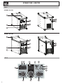 2
2
-
 3
3
-
 4
4
-
 5
5
-
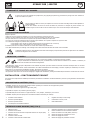 6
6
-
 7
7
-
 8
8
-
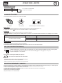 9
9
-
 10
10
-
 11
11
-
 12
12
-
 13
13
-
 14
14
-
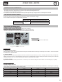 15
15
-
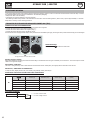 16
16
-
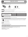 17
17
-
 18
18
-
 19
19
-
 20
20
-
 21
21
-
 22
22
-
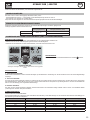 23
23
-
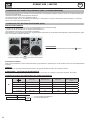 24
24
-
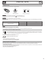 25
25
-
 26
26
-
 27
27
-
 28
28
-
 29
29
-
 30
30
-
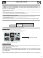 31
31
-
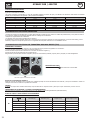 32
32
-
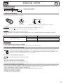 33
33
-
 34
34
-
 35
35
-
 36
36
-
 37
37
-
 38
38
-
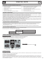 39
39
-
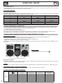 40
40
-
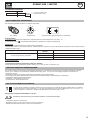 41
41
-
 42
42
-
 43
43
-
 44
44
-
 45
45
-
 46
46
-
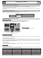 47
47
-
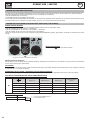 48
48
-
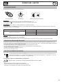 49
49
-
 50
50
-
 51
51
-
 52
52
-
 53
53
-
 54
54
-
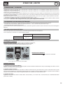 55
55
-
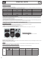 56
56
-
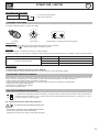 57
57
-
 58
58
-
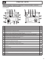 59
59
-
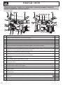 60
60
-
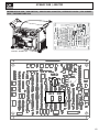 61
61
-
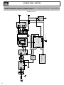 62
62
-
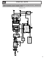 63
63
-
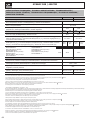 64
64
-
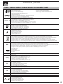 65
65
-
 66
66


GYS GYSARC 300 A TRI de handleiding
- Categorie
- Lassysteem
- Type
- de handleiding
- Deze handleiding is ook geschikt voor
in andere talen
Gerelateerde papieren
-
GYS GYSARC 160 de handleiding
-
-
GYS TIG 160 DC-LIFT (TORCH+EL.HOLDER+CLAMP) de handleiding
-
GYS GYSARC 220 FV CEL de handleiding
-
-
GYS TITANIUM 400 AC/DC TRI de handleiding
-
-
-
GYS PROTIG 200 DC HF de handleiding
-
