

English Quick Start Guide
1. Symbols used
For your safety and in order to avoid any damage of the device,
please read carefully the notes preceded by the following symbol:
The following symbol will also be used in this document, please
read carefully the information notes indicated after this symbol:
The Si-C320 is a transmitter that can measure simultaneous parameters including differential
pressure, temperature (Pt100 and thermocouple), hygrometry, air quality (CO/CO2/VOC), air
velocity, airow, air change rate...
Hereby, Sauermann Industrie SAS declares that the radio equipment type Si-C320 is in
compliance with Directive 2014/53/EU. The full text of the EU declaration of conformity is
available at the following internet address: sauermanngroup.com
To install the transmitter on a wall, x the stainless steel plate to the wall (drilling: Ø8 mm, screws
and wall-plugs supplied). Insert the transmitter on the plate (see A on the drawing below) by
aligning it at 30°. Rotate the housing in clockwise direction until you heard a “click” which conrms
that the transmitter is correctly installed. Open the housing, lock the clamping system of the housing
on the plate with the screw (see photo below). To remove the transmitter from the xing plate, do
not forget to remove this screw.
A
A
120 mm (4.73’’)
Ø 5,4 mm (0.21’’)
65 mm (2.56’’)
65 mm (2.56’’)
98 mm (3.86’’)
316L stainless steel plate Fixing screw of the housing
• Operating temperature: -10 to 50 °C (14 to 122 °F)
• Protection: IP66, resistant to VHP*
• Storage temperature: -10 to 70 °C (14 to 158 °F)
These operating instructions describe the basic handling of the device.
Please refer to the operating instructions available at sauermanngroup.com for safe use of
the product and detailed information.
Do not give this device to a child.
2. Description of the device, operating temperature, protection of the
instruments and information about storage
3. Directive 2014/53/EU
4. Mounting
*Vaporized hydrogen peroxide

Analog output 3
(OUT 3)
Analog output 4
(OUT 4)
Analog output 1
(OUT 1)
Analog output 2
(OUT 2)
(b)
24 VDC/VAC power supply:
(c)
Phase (L) +
Neutral (N) -
Operational grounding
COM
0/4-20 mA – Current
0-5/10 V – Voltage
COM
0/4-20 mA – Current
0-5/10 V – Voltage
COM
0/4-20 mA – Current
0-5/10 V – Voltage
COM
0/4-20 mA – Current
0-5/10 V – Voltage
1
2
3
4
5
6
7
8
9
12 11 10
Sortie analogique 3
(OUT 3)
Sortie analogique 4
(OUT 4)
Sortie analogique 1
(OUT 1)
Sortie analogique 2
(OUT 2)
(b)
Alimentation 24 VDC/VAC :
(c)
Phase (L) +
Neutre (N) -
Terre fonctionnelle
COM
0/4-20 mA – Courant
0-5/10 V – Tension
COM
0/4-20 mA – Couirant
0-5/10 V – Tension
COM
0/4-20 mA – Courant
0-5/10 V – Tension
COM
0/4-20 mA – Courant
0-5/10 V – Tension
Modbus
(a)
B-
A+
0 V
1
2
3
4
5
6
7
8
9
12 11 10
Salida analógica 3
(OUT 3)
Salida analógica 4
(OUT 4)
Salida analógica 1
(OUT 1)
Salida analógica 2
(OUT 2)
(b)
Alimentación 24 VDC/VAC:
(c)
Fase (L) +
Neutro (N) -
Tierra funcional
COM
0/4-20 mA – Corriente
0-5/10 V – Tensión
COM
0/4-20 mA – Corriente
0-5/10 V – Tensión
COM
0/4-20 mA – Corriente
0-5/10 V – Tensión
COM
0/4-20 mA – Corriente
0-5/10 V – Tensión
1
2
3
4
5
6
7
8
9
12 11 10
Saída analógica 3
(OUT 3)
Saída analógica 4
(OUT 4)
Saída analógica 1
(OUT 1)
Saída analógica 2
(OUT 2)
(b)
Alimentação 24 VDC/VAC:
(c)
Fase (L) +
Neutro (N) -
Terra funcional
COM
0/4-20 mA – Corrente
0-5/10 V – Tensão
COM
0/4-20 mA – Corrente
0-5/10 V – Tensão
COM
0/4-20 mA – Corrente
0-5/10 V – Tensão
COM
0/4-20 mA – Corrente
0-5/10 V – Tensão
1
2
3
4
5
6
7
8
9
12 11 10
Analoge uitgang 3
(OUT 3)
Analoge uitgang 4
(OUT 4)
Analoge uitgang 1
(OUT 1)
Analoge uitgang 2
(OUT 2)
(b)
Voeding 24 VDC/VAC:
(c)
Fase (L) +
Nulleider (N) -
Functionele aarde
COM
0/4-20 mA – Stroom
0-5/10 V – Spanning
COM
0/4-20 mA – Stroom
0-5/10 V – Spanning
COM
0/4-20 mA – Stroom
0-5/10 V – Spanning
COM
0/4-20 mA – Stroom
0-5/10 V – Spanning
1
2
3
4
5
6
7
8
9
12 11 10
Analoger Ausgang 3
(OUT 3)
Analoger Ausgang 4
(OUT 4)
Analoger Ausgang 1
(OUT 1)
Analoger Ausgang 2
(OUT 2)
(b)
Stromversorgung 24 VDC/VAC :
(c)
Phase (L) +
Neutre (N) -
Erdung
COM
0/4-20 mA – Strom
0-5/10 V – Spannung
1
2
3
4
5
6
7
8
9
12 11 10
COM
0/4-20 mA – Strom
0-5/10 V – Spannung
COM
0/4-20 mA – Strom
0-5/10 V – Spannung
COM
0/4-20 mA – Strom
0-5/10 V – Spannung
Uscita analogica 3
(OUT 3)
Uscita analogica 4
(OUT 4)
Uscita analogica 1
(OUT 1)
Uscita analogica 2
(OUT 2)
(b)
Alimentazione 24 VDC/VAC:
(c)
Fase (L) +
Neutro (N) -
Messa a terra operativa
COM
0/4-20 mA – Corrente
0-5/10 V – Tensione
COM
0/4-20 mA – Corrente
0-5/10 V – Tensione
COM
0/4-20 mA – Corrente
0-5/10 V – Tensione
COM
0/4-20 mA – Corrente
0-5/10 V – Tensione
1
2
3
4
5
6
7
8
9
12 11 10
Modbus
(a)
B-
A+
0 V
Modbus
(a)
B-
A+
0 V
Modbus
(a)
B-
A+
0 V
Modbus
(a)
B-
A+
0 V
Modbus
(a)
B-
A+
0 V
Modbus
(a)
B-
A+
0 V
1. Connection for PC software
2. Wireless module (optional)
3. Pressure module (optional)
4. Solenoid valve
5. Autozero
6. RS 485 connection (a)
7. Analog outputs (b)
8. Power supply terminal block (c)
9. Cable glands
10. Pressure connectors (delivered on models
with Si-PRO-DP pressure modules)
11. Probe 1 connection
12. Probe 2 connection
-
+
-+
24 VDC
power supply
NL
PE
N
L
240 VAC
N
L
24 VAC power supply
Class II
NL
PE
N
L
240 VAC L
24 VAC power supply
or
N
GND
0/4-20 mA
0-5/10 V
-+
Regulator display or
PLC/BMS (passive type)
GND
0/4-20 mA
0-5/10 V
-+
Regulator display or
PLC/BMS (passive type)
-
+
-+
NL
PE
N
L
240 VAC
N
L
NL
PE
N
L
240 VAC L
ou
N
GND
0/4-20 mA
0-5/10 V
-+
GND
0/4-20 mA
0-5/10 V
-+
Alimentation
24 VDC
Alimentation 24 VAC
classe II
Alimentation 24 VAC
Afcheur régulateur ou
automate de type passif
Afcheur régulateur ou
automate de type passif
-
+
-+
Alimentación
24 VDC
NL
PE
N
L
240 VAC
N
L
Alimentación 24 VAC
clase II
NL
PE
N
L
240 VAC L
Alimentación 24 VAC
o
N
GND
0/4-20 mA
0-5/10 V
-+
Pantalla regulador o
autómata tipo pasivo
GND
0/4-20 mA
0-5/10 V
-+
Pantalla regulador o
autómata tipo pasivo
-
+
-+
Alimentação
24 VDC
NL
PE
N
L
240 VAC
N
L
Alimentação 24 VAC
classe II
NL
PE
N
L
240 VAC L
Alimentação 24 VAC
o
N
GND
0/4-20 mA
0-5/10 V
-+
Display regulador ou
autómato de tipo passivo
GND
0/4-20 mA
0-5/10 V
-+
Display regulador ou
autómato de tipo passivo
-
+
-+
Voeding
24 VDC
NL
PE
N
L
240 VAC
N
L
Voeding 24 VAC
klasse II
NL
PE
N
L
240 VAC L
Voeding 24 VAC
o
N
GND
0/4-20 mA
0-5/10 V
-+
Display regelaar of
automaat passief type
GND
0/4-20 mA
0-5/10 V
-+
Display regelaar of
automaat passief type
-
+
-+
Spannungs-
versorgung
24 VDC
NL
PE
N
L
240 VAC
N
L
Spannungsversorgung 24 VAC
Klasse II
NL
PE
N
L
240 VAC L
Spannungsversorgung 24 VAC
o
N
ERDUNG
0/4-20 mA
0-5/10 V
-+
Passiver Anzeigeregler
oder SPS
ERDUNG
0/4-20 mA
0-5/10 V
-+
Passiver Regler oder
automatische Anzeige
-
+
-+
Alimentazione
24 VDC
NL
PE
N
L
240 VAC
N
L
Alimentazione 24 VAC
Classe II
NL
PE
N
L
240 VAC L
Alimentazione 24 VAC
o
N
GND
0/4-20 mA
0-5/10 V
-+
Display del regolatore o
PLC/BMS (tipo passivo)
GND
0/4-20 mA
0-5/10 V
-+
Display del regolatore o
PLC/BMS (tipo passivo)
This connection must be made by a formed and qualied technician. Whilst making the
connection, the transmitter must not be energized. The presence of a switch or a circuit
breaker upstream the device is compulsory.
• For 24 VDC models: • For 24 VAC models using power supply converters:
• 0/4-20 mA current output connection: • 0-5/10 V voltage output connection:
5. Connections
6. Electrical connections as per NFC15-100 standard

Select Date
11
11
DAY
MONTH
YEAR
01
2021
/
/
MONTH / DAY / YEAR
DAY / MONTH / YEAR
Next
Set your Time Zone
+1
DAY
MINUTES
0
Next
:
• Los Angeles: -8 winter, -7 summer
• New York: -5 winter, -4 summer
• London: +0 winter, +1 summer
• Paris: +1 winter, +2 summer
• Dubai: +4 • Beijing: +8 • Tokyo: +9
• Sydney: +10 winter, +11 summer
10:35 - 10/12/2021
Set your time
+1
DAY
MINUTES
0
0
Next
:
24 hours
AM
PM
10:35 - 10/12/2021
Please connect the probe(s)
before conguring the
channel(s)
Channel Conguration
10:35 - 10/12/2021
Next
Model: XXXXX - S/N: XXXXXX - Build: XXXXXXX - FMW:
XXXXX - Version: 5.02
Start Settings
Welcome
Skip
Languages
Next
English
German
Portuguese
Spanish
Chinese
Italian
French
Tap ‘’Start settings’’.Select your language
and tap ‘’Next’’.
Tap your continent.Tap your area.
Set the date and tap ‘’Next’’.Set your time zone and tap
‘’Next’’.Set your time and
tap ‘’Next’’.
The transmitter is set. You can
connect a probe to set a channel.
Select Continent
Africa
APAC
North America
LATAM
Europe
Northern
Rest of Europe
Southern
Middle East
Western
Europe
Netherlands
Austria
Belgium
Germany
Western
Switzerland
France
Tap your required
country then ‘’Next’’.
Next
Connect a probe to the Si-C320 transmitter
Disconnect a probe from the Si-C320 transmitter
CLICK
ab
• Present the probe connector (a)
with its arrow and padlock face
to the transmitter connector (b).
• Push in the probe connector (a)
into the transmitter connector (b)
until you hear a click. The probe
is correctly connected.
c
ab
• Turn the ring (c) of the probe
connector to the left.
• Pull the probe connector (a)
away from the transmitter
connector (b).
7. First start-up
8. Probe connection/disconnection
For models without display, please use the
app to set your transmitter.

Please avoid any aggressive solvents. Please protect the transmitter and its probes from any cleaning
product containing formalin, that may be used for cleaning rooms or ducts.
9. Set a channel
Please connect the probe(s)
before conguring the
channel(s)
Channel Conguration
10:35 - 10/12/2021
Next
Connect a probe to set a
channel and tap ‘’Next’’.
Channel 1
Channel 3
Channel 4
Channel 2
10:35 - 10/12/2021
Select Channel
Next
The list of available channel is
displayed.
Tap the required channel.
Select Channels
10:35 - 10/12/2021
Channel 1
Channel 3
Channel 4
Channel 2
Next
Tap ‘’PROBE 1’’, ‘’PROBE
2’’ or ‘’MODULE’’.
Parameters to set are now
available.
10:35 - 10/12/2021
Channel 2
Units
- - - -
Coefcient
Measures
SELECT UNIT
PROBE 1
PROBE 2
MODULE
Offset
Activate the channel taping .
‘’Measures’’, ‘’Units’’, ‘’Coefcient’’ and
‘’Offset’’ are now available.
Set the parameters according
to your needs then tap the
back arrow on the top left.
10:35 - 10/12/2021
Units
Coefcient
Measures
Rel. Humidity
PROBE 1
PROBE 2
MODULE
Channel 2
Offset
%RH
1.000
0.00
Channel 1
Channel 3
Channel 4
Channel 2
10:35 - 10/12/2021
Select Channel
Next
Next
Channel 2 is congured. Tap
next to congure outputs.
1.000
0.00
10. Set an output
Tap the output to set corres-
ponding to the previously
congured channel.
Tap ‘’Next’’ to
display measures.
Next
Output 2
10:35 - 10/12/2021
Select Analog Output
Output 3
Diagnostic
10:35 - 10/12/2021
Output 2
4-20 mA
Output type
High Range (%RH)
Low Range (%RH)
98.0
10.0
Activate the output taping .
Set the output type and high
and low range values then tap
the back arrow on the top left.
Output 1
Output 4
Next
Output 2
10:35 - 10/12/2021
Select Analog Output
Output 3
Output 1
Output 4
Next
10:35 - 10/12/2021
Measures
Channel 2
1
27.7
%RH
11. Maintenance
Please always use the device in accordance with its intended use and within parameters described in the
user manual in order not to compromise the protection ensured by the device.
12. Precautions for use
For models without display, please use the app to set your channel.
For models without display, please use the app to set your output.

Français Guide rapide
1. Symboles utilisés
Pour votre sécurité et an d’éviter tout endommagement de l’appareil,
veuillez lire attentivement les notes précédées du symbole suivant :
Le symbole suivant sera également utilisé dans ce document. Veuillez lire
attentivement les notes d’information indiquées après ce symbole.
Le capteur-transmetteur Si-C320 permet de mesurer les paramètres suivants : pression
différentielle, température (Pt100 et thermocouple), hygrométrie, qualité d'air (CO/CO2/COV),
vitesse d'air, débit d'air, taux de renouvellement d'air...
Le soussigné, Sauermann Industrie SAS, déclare que l'équipement radioélectrique du type
Si-C320 est conforme à la directive 2014/53/UE. Le texte complet de la déclaration de
conformité UE est disponible à l'adresse internet suivante : sauermanngroup.com
Pour réaliser le montage mural, xer la plaque inox au mur (perçage Ø 8 mm, vis et chevilles
fournies). Insérer le capteur-transmetteur dans la plaque de xation (aux points A sur le schéma) en
l’inclinant à 30°. Faire pivoter le boîtier dans le sens des aiguilles d’une montre jusqu’à l’obtention
d’un clipsage ferme. Ouvrir le boîtier, verrouiller la xation du boîtier sur la platine à l’aide de la vis
indiquée sur la photo ci-contre. Pour enlever le capteur-transmetteur de la plaque de xation, retirer
cette même vis.
A
A
120 mm (4.73’’)
Ø 5,4 mm (0.21’’)
65 mm (2.56’’)
65 mm (2.56’’)
98 mm (3.86’’)
Plaque inox 316L Vis de xation du boîtier
• Température d'utilisation : -10 à 50 °C (14 à 122 °F)
• Protection : IP66, résistant au VHP*
• Température de stockage : -10 à 70 °C (14 à 158 °F)
Ce document décrit les manipulations de base de l'appareil.
Veuillez consulter la notice d'utilisation disponible sur le site sauermanngroup.com pour
une utilisation sûre du produit et pour les informations détaillées.
Ne pas donner cet appareil à un enfant.
2. Description de l'appareil, température d'utilisation, protection de l'appareil
et information sur le stockage
3. Directive 2014/53/UE
4. Montage
*Peroxyde d'hydrogène vaporisé

Analog output 3
(OUT 3)
Analog output 4
(OUT 4)
Analog output 1
(OUT 1)
Analog output 2
(OUT 2)
(b)
24 VDC/VAC power supply:
(c)
Phase (L) +
Neutral (N) -
Operational grounding
COM
0/4-20 mA – Current
0-5/10 V – Voltage
COM
0/4-20 mA – Current
0-5/10 V – Voltage
COM
0/4-20 mA – Current
0-5/10 V – Voltage
COM
0/4-20 mA – Current
0-5/10 V – Voltage
1
2
3
4
5
6
7
8
9
12 11 10
Sortie analogique 3
(OUT 3)
Sortie analogique 4
(OUT 4)
Sortie analogique 1
(OUT 1)
Sortie analogique 2
(OUT 2)
(b)
Alimentation 24 VDC/VAC :
(c)
Phase (L) +
Neutre (N) -
Terre fonctionnelle
COM
0/4-20 mA – Courant
0-5/10 V – Tension
COM
0/4-20 mA – Couirant
0-5/10 V – Tension
COM
0/4-20 mA – Courant
0-5/10 V – Tension
COM
0/4-20 mA – Courant
0-5/10 V – Tension
Modbus
(a)
B-
A+
0 V
1
2
3
4
5
6
7
8
9
12 11 10
Salida analógica 3
(OUT 3)
Salida analógica 4
(OUT 4)
Salida analógica 1
(OUT 1)
Salida analógica 2
(OUT 2)
(b)
Alimentación 24 VDC/VAC:
(c)
Fase (L) +
Neutro (N) -
Tierra funcional
COM
0/4-20 mA – Corriente
0-5/10 V – Tensión
COM
0/4-20 mA – Corriente
0-5/10 V – Tensión
COM
0/4-20 mA – Corriente
0-5/10 V – Tensión
COM
0/4-20 mA – Corriente
0-5/10 V – Tensión
1
2
3
4
5
6
7
8
9
12 11 10
Saída analógica 3
(OUT 3)
Saída analógica 4
(OUT 4)
Saída analógica 1
(OUT 1)
Saída analógica 2
(OUT 2)
(b)
Alimentação 24 VDC/VAC:
(c)
Fase (L) +
Neutro (N) -
Terra funcional
COM
0/4-20 mA – Corrente
0-5/10 V – Tensão
COM
0/4-20 mA – Corrente
0-5/10 V – Tensão
COM
0/4-20 mA – Corrente
0-5/10 V – Tensão
COM
0/4-20 mA – Corrente
0-5/10 V – Tensão
1
2
3
4
5
6
7
8
9
12 11 10
Analoge uitgang 3
(OUT 3)
Analoge uitgang 4
(OUT 4)
Analoge uitgang 1
(OUT 1)
Analoge uitgang 2
(OUT 2)
(b)
Voeding 24 VDC/VAC:
(c)
Fase (L) +
Nulleider (N) -
Functionele aarde
COM
0/4-20 mA – Stroom
0-5/10 V – Spanning
COM
0/4-20 mA – Stroom
0-5/10 V – Spanning
COM
0/4-20 mA – Stroom
0-5/10 V – Spanning
COM
0/4-20 mA – Stroom
0-5/10 V – Spanning
1
2
3
4
5
6
7
8
9
12 11 10
Analoger Ausgang 3
(OUT 3)
Analoger Ausgang 4
(OUT 4)
Analoger Ausgang 1
(OUT 1)
Analoger Ausgang 2
(OUT 2)
(b)
Stromversorgung 24 VDC/VAC :
(c)
Phase (L) +
Neutre (N) -
Erdung
COM
0/4-20 mA – Strom
0-5/10 V – Spannung
1
2
3
4
5
6
7
8
9
12 11 10
COM
0/4-20 mA – Strom
0-5/10 V – Spannung
COM
0/4-20 mA – Strom
0-5/10 V – Spannung
COM
0/4-20 mA – Strom
0-5/10 V – Spannung
Uscita analogica 3
(OUT 3)
Uscita analogica 4
(OUT 4)
Uscita analogica 1
(OUT 1)
Uscita analogica 2
(OUT 2)
(b)
Alimentazione 24 VDC/VAC:
(c)
Fase (L) +
Neutro (N) -
Messa a terra operativa
COM
0/4-20 mA – Corrente
0-5/10 V – Tensione
COM
0/4-20 mA – Corrente
0-5/10 V – Tensione
COM
0/4-20 mA – Corrente
0-5/10 V – Tensione
COM
0/4-20 mA – Corrente
0-5/10 V – Tensione
1
2
3
4
5
6
7
8
9
12 11 10
Modbus
(a)
B-
A+
0 V
Modbus
(a)
B-
A+
0 V
Modbus
(a)
B-
A+
0 V
Modbus
(a)
B-
A+
0 V
Modbus
(a)
B-
A+
0 V
Modbus
(a)
B-
A+
0 V
1. Connexion pour logiciel PC
2. Module communication sans l (option)
3. Module de pression (option)
4. Electrovanne
5. Autozéro
6. Connexion RS-485 (a)
7. Sorties analogiques (b)
8. Bornier d'alimentation (c)
9. Presse-étoupes
10. Connecteurs de pression (livrés sur les
modèles avec modules de pression Si-
PRO-DP)
11. Connexion Sonde 1
12. Connexion Sonde 2
-
+
-+
24 VDC
power supply
NL
PE
N
L
240 VAC
N
L
24 VAC power supply
Class II
NL
PE
N
L
240 VAC L
24 VAC power supply
or
N
GND
0/4-20 mA
0-5/10 V
-+
Regulator display or
PLC/BMS (passive type)
GND
0/4-20 mA
0-5/10 V
-+
Regulator display or
PLC/BMS (passive type)
-
+
-+
NL
PE
N
L
240 VAC
N
L
NL
PE
N
L
240 VAC L
ou
N
GND
0/4-20 mA
0-5/10 V
-+
GND
0/4-20 mA
0-5/10 V
-+
Alimentation
24 VDC
Alimentation 24 VAC
classe II
Alimentation 24 VAC
Afcheur régulateur ou
automate de type passif
Afcheur régulateur ou
automate de type passif
-
+
-+
Alimentación
24 VDC
NL
PE
N
L
240 VAC
N
L
Alimentación 24 VAC
clase II
NL
PE
N
L
240 VAC L
Alimentación 24 VAC
o
N
GND
0/4-20 mA
0-5/10 V
-+
Pantalla regulador o
autómata tipo pasivo
GND
0/4-20 mA
0-5/10 V
-+
Pantalla regulador o
autómata tipo pasivo
-
+
-+
Alimentação
24 VDC
NL
PE
N
L
240 VAC
N
L
Alimentação 24 VAC
classe II
NL
PE
N
L
240 VAC L
Alimentação 24 VAC
o
N
GND
0/4-20 mA
0-5/10 V
-+
Display regulador ou
autómato de tipo passivo
GND
0/4-20 mA
0-5/10 V
-+
Display regulador ou
autómato de tipo passivo
-
+
-+
Voeding
24 VDC
NL
PE
N
L
240 VAC
N
L
Voeding 24 VAC
klasse II
NL
PE
N
L
240 VAC L
Voeding 24 VAC
o
N
GND
0/4-20 mA
0-5/10 V
-+
Display regelaar of
automaat passief type
GND
0/4-20 mA
0-5/10 V
-+
Display regelaar of
automaat passief type
-
+
-+
Spannungs-
versorgung
24 VDC
NL
PE
N
L
240 VAC
N
L
Spannungsversorgung 24 VAC
Klasse II
NL
PE
N
L
240 VAC L
Spannungsversorgung 24 VAC
o
N
ERDUNG
0/4-20 mA
0-5/10 V
-+
Passiver Anzeigeregler
oder SPS
ERDUNG
0/4-20 mA
0-5/10 V
-+
Passiver Regler oder
automatische Anzeige
-
+
-+
Alimentazione
24 VDC
NL
PE
N
L
240 VAC
N
L
Alimentazione 24 VAC
Classe II
NL
PE
N
L
240 VAC L
Alimentazione 24 VAC
o
N
GND
0/4-20 mA
0-5/10 V
-+
Display del regolatore o
PLC/BMS (tipo passivo)
GND
0/4-20 mA
0-5/10 V
-+
Display del regolatore o
PLC/BMS (tipo passivo)
Seul un technicien formé et qualié peut réaliser cette opération. Pour réaliser le
raccordement, l’appareil doit être HORS TENSION. La présence d’un interrupteur ou d’un
disjoncteur en amont de l’appareil est obligatoire.
• Modèles 24 VDC : • Modèles 24 VAC utilisant des convertisseurs d'alimentation :
• Raccordement de la sortie courant 0/4-20 mA : • Raccordement de la sortie tension 0-5/10 V :
5. Connexions
6. Raccordements électriques suivant normes NF C 15-100

Select Date
11
11
DAY
MONTH
YEAR
01
2021
/
/
MONTH / DAY / YEAR
DAY / MONTH / YEAR
Next
Set your Time Zone
+1
DAY
MINUTES
0
Next
:
• Los Angeles: -8 winter, -7 summer
• New York: -5 winter, -4 summer
• London: +0 winter, +1 summer
• Paris: +1 winter, +2 summer
• Dubai: +4 • Beijing: +8 • Tokyo: +9
• Sydney: +10 winter, +11 summer
10:35 - 10/12/2021
Set your time
+1
DAY
MINUTES
0
0
Next
:
24 hours
AM
PM
10:35 - 10/12/2021
Please connect the probe(s)
before conguring the
channel(s)
Channel Conguration
10:35 - 10/12/2021
Next
Model: XXXXX - S/N: XXXXXX - Build: XXXXXXX - FMW:
XXXXX - Version: 5.02
Start Settings
Welcome
Skip
Languages
Next
English
German
Portuguese
Spanish
Chinese
Italian
French
Appuyer sur
‘’Régler l’appareil’’.
Sélectionner la langue puis
appuyer sur ‘’Suivant’’.
Appuyer sur le continent sou-
haité.
Appuyer sur la zone souhai-
tée.
Régler la date et appuyer sur
‘’Suivant’’.
Dénir le fuseau horaire et
appuyer sur ‘’Suivant’’.
Régler l’heure et ap-
puyer sur ‘’Suivant’’.
Le capteur-transmetteur est con-
guré. Connecter une sonde pour
congurer une voie.
Select Continent
Africa
APAC
North America
LATAM
Europe
Northern
Rest of Europe
Southern
Middle East
Western
Europe
Netherlands
Austria
Belgium
Germany
Western
Switzerland
France
Appuyer sur le pays souhaité
puis sur ‘’Suivant’’.
Next
Connecter une sonde au capteur-transmetteur Si-C320
Déconnecter une sonde du capteur-transmetteur Si-C320
CLICK
ab
• Présenter le connecteur de la
sonde (a) avec sa èche et son
cadenas face au connecteur du
capteur-transmetteur (b).
• Enfoncer le connecteur de la
sonde (a) dans le connecteur
du capteur-transmetteur (b)
jusqu'à ce que qu'un clic se
fasse entendre. La sonde est
correctement connectée.
c
ab
• Tourner la bague (c) du
connecteur de la sonde vers la
gauche.
• Retirer le connecteur de la sonde
(a) du connecteur du capteur-
transmetteur (b).
7. Premier démarrage
8. Connexion/déconnexion d'une sonde
Pour les modèles sans écran, veuillez utiliser
l'application pour congurer votre capteur-transmetteur.

Éviter tous les solvants agressifs. Lors du nettoyage à base de produits formolés (pièces ou conduits),
protéger l’appareil et ses sondes.
9. Congurer une voie
Please connect the probe(s)
before conguring the
channel(s)
Channel Conguration
10:35 - 10/12/2021
Next
Connecter une sonde pour
congurer une voie et ap-
puyer sur ‘’Suivant’’.
Channel 1
Channel 3
Channel 4
Channel 2
10:35 - 10/12/2021
Select Channel
Next
La liste des voies disponibles
s'afche.
Appuyer sur la voie souhaitée.
Appuyer sur ‘’SONDE 1’’,
‘’SONDE 2’’ ou ‘’MODULE’’.
Les paramètres à congurer sont
maintenant disponibles.
10:35 - 10/12/2021
Channel 2
Units
- - - -
Coefcient
Measures
SELECT UNIT
PROBE 1
PROBE 2
MODULE
Offset
Dénir les paramètres en
fonction des besoins, puis
appuyer sur la èche retour
en haut à gauche.
10:35 - 10/12/2021
Units
Coefcient
Measures
Rel. Humidity
PROBE 1
PROBE 2
MODULE
Channel 2
Offset
%RH
1.000
0.00
Channel 1
Channel 3
Channel 4
Channel 2
10:35 - 10/12/2021
Select Channel
Next
Next
La voie 1 est congurée.
Appuyer sur ‘’Suivant’’ pour
congurer les sorties.
1.000
0.00
10. Congurer une sortie
Appuyer sur la sortie à congu-
rer correspondant à la voie
précédemment congurée.
Appuyer sur ‘’Suivant’’
pour afcher les mesures.
Output 2
10:35 - 10/12/2021
Select Analog Output
Output 3
Diagnostic
10:35 - 10/12/2021
Output 2
4-20 mA
Output type
High Range (%RH)
Low Range (%RH)
98.0
10.0
Activer la sortie en appuyant sur
.
Congurer le type de sortie et
les valeurs minimale et maxi-
male de la plage, puis appuyer
sur la èche de retour en haut à
gauche.
Output 1
Output 4
Next
Output 2
10:35 - 10/12/2021
Select Analog Output
Output 3
Output 1
Output 4
Next
10:35 - 10/12/2021
Measures
Channel 1
1
27.7
%RH
11. Maintenance
Veillez à toujours utiliser l’appareil conformément à l’usage prévu et dans les limites des paramètres
décrits dans les caractéristiques techniques an de ne pas compromettre la protection assurée par
l’appareil.
12. Précautions d'utilisation
Pour les modèles sans écran, veuillez utiliser l'application pour congurer une voie.
Pour les modèles sans écran, veuillez utiliser l'application pour congurer une sortie.

Español Guía rápida
1. Símbolos utilizados
Por su seguridad y para evitar posibles daños en el dispositivo, lea
atentamente las notas precedidas por el símbolo siguiente:
En este documento también se utiliza el siguiente símbolo. Lea
atentamente las notas informativas que le siguen.
El transmisor Si-C320 permite medir los siguientes parámetros: presión diferencial, temperatura
(Pt100 y termopar), higrometría, calidad del aire (CO/CO2/COV), velocidad del aire, caudal de
aire, tasa de renovación del aire, etc.
El abajo rmante, Sauermann Industrie SAS, declara que el equipo radioeléctrico de tipo
Si-C320 es conforme a la directiva 2014/53/UE. El texto completo de la declaración de
conformidad UE está disponible en la dirección web siguiente: sauermanngroup.com
Para realizar el montaje mural, je la placa inox a la pared (oricio Ø 8 mm, tornillos y tacos
incluidos). Inserte el transmisor en la placa de jación (en los puntos A en el esquema), inclinándolo
30°. Haga pivotar la carcasa en sentido horario hasta lograr un acoplamiento rme. Abra la carcasa y
bloquee su jación a la platina con el tornillo indicado en la foto siguiente. Para retirar el transmisor
de la placa de jación, retire ese mismo tornillo.
A
A
120 mm (4.73’’)
Ø 5,4 mm (0.21’’)
65 mm (2.56’’)
65 mm (2.56’’)
98 mm (3.86’’)
Placa inox 316L Tornillo de jación de la carcasa
• Temperatura de utilización: -10 a 50 °C (14 a 122 °F)
• Protección: IP66, resistente al VHP*
• Temperatura de almacenamiento: -10 a 70 °C (14 a 158 °F)
Este documento describe las manipulaciones básicas del dispositivo.
Para una utilización segura del producto o si necesita más detalles, consulte el manual de
utilización disponible en la web sauermanngroup.com.
No deje el dispositivo al alcance de los niños.
2. Descripción del dispositivo, temperatura de utilización, protección del
dispositivo y temperatura de almacenamiento
3. Directiva 2014/53/UE
4. Montaje
*Peróxido de hidrógeno vaporizado

Analog output 3
(OUT 3)
Analog output 4
(OUT 4)
Analog output 1
(OUT 1)
Analog output 2
(OUT 2)
(b)
24 VDC/VAC power supply:
(c)
Phase (L) +
Neutral (N) -
Operational grounding
COM
0/4-20 mA – Current
0-5/10 V – Voltage
COM
0/4-20 mA – Current
0-5/10 V – Voltage
COM
0/4-20 mA – Current
0-5/10 V – Voltage
COM
0/4-20 mA – Current
0-5/10 V – Voltage
1
2
3
4
5
6
7
8
9
12 11 10
Sortie analogique 3
(OUT 3)
Sortie analogique 4
(OUT 4)
Sortie analogique 1
(OUT 1)
Sortie analogique 2
(OUT 2)
(b)
Alimentation 24 VDC/VAC :
(c)
Phase (L) +
Neutre (N) -
Terre fonctionnelle
COM
0/4-20 mA – Courant
0-5/10 V – Tension
COM
0/4-20 mA – Couirant
0-5/10 V – Tension
COM
0/4-20 mA – Courant
0-5/10 V – Tension
COM
0/4-20 mA – Courant
0-5/10 V – Tension
Modbus
(a)
B-
A+
0 V
1
2
3
4
5
6
7
8
9
12 11 10
Salida analógica 3
(OUT 3)
Salida analógica 4
(OUT 4)
Salida analógica 1
(OUT 1)
Salida analógica 2
(OUT 2)
(b)
Alimentación 24 VDC/VAC:
(c)
Fase (L) +
Neutro (N) -
Tierra funcional
COM
0/4-20 mA – Corriente
0-5/10 V – Tensión
COM
0/4-20 mA – Corriente
0-5/10 V – Tensión
COM
0/4-20 mA – Corriente
0-5/10 V – Tensión
COM
0/4-20 mA – Corriente
0-5/10 V – Tensión
1
2
3
4
5
6
7
8
9
12 11 10
Saída analógica 3
(OUT 3)
Saída analógica 4
(OUT 4)
Saída analógica 1
(OUT 1)
Saída analógica 2
(OUT 2)
(b)
Alimentação 24 VDC/VAC:
(c)
Fase (L) +
Neutro (N) -
Terra funcional
COM
0/4-20 mA – Corrente
0-5/10 V – Tensão
COM
0/4-20 mA – Corrente
0-5/10 V – Tensão
COM
0/4-20 mA – Corrente
0-5/10 V – Tensão
COM
0/4-20 mA – Corrente
0-5/10 V – Tensão
1
2
3
4
5
6
7
8
9
12 11 10
Analoge uitgang 3
(OUT 3)
Analoge uitgang 4
(OUT 4)
Analoge uitgang 1
(OUT 1)
Analoge uitgang 2
(OUT 2)
(b)
Voeding 24 VDC/VAC:
(c)
Fase (L) +
Nulleider (N) -
Functionele aarde
COM
0/4-20 mA – Stroom
0-5/10 V – Spanning
COM
0/4-20 mA – Stroom
0-5/10 V – Spanning
COM
0/4-20 mA – Stroom
0-5/10 V – Spanning
COM
0/4-20 mA – Stroom
0-5/10 V – Spanning
1
2
3
4
5
6
7
8
9
12 11 10
Analoger Ausgang 3
(OUT 3)
Analoger Ausgang 4
(OUT 4)
Analoger Ausgang 1
(OUT 1)
Analoger Ausgang 2
(OUT 2)
(b)
Stromversorgung 24 VDC/VAC :
(c)
Phase (L) +
Neutre (N) -
Erdung
COM
0/4-20 mA – Strom
0-5/10 V – Spannung
1
2
3
4
5
6
7
8
9
12 11 10
COM
0/4-20 mA – Strom
0-5/10 V – Spannung
COM
0/4-20 mA – Strom
0-5/10 V – Spannung
COM
0/4-20 mA – Strom
0-5/10 V – Spannung
Uscita analogica 3
(OUT 3)
Uscita analogica 4
(OUT 4)
Uscita analogica 1
(OUT 1)
Uscita analogica 2
(OUT 2)
(b)
Alimentazione 24 VDC/VAC:
(c)
Fase (L) +
Neutro (N) -
Messa a terra operativa
COM
0/4-20 mA – Corrente
0-5/10 V – Tensione
COM
0/4-20 mA – Corrente
0-5/10 V – Tensione
COM
0/4-20 mA – Corrente
0-5/10 V – Tensione
COM
0/4-20 mA – Corrente
0-5/10 V – Tensione
1
2
3
4
5
6
7
8
9
12 11 10
Modbus
(a)
B-
A+
0 V
Modbus
(a)
B-
A+
0 V
Modbus
(a)
B-
A+
0 V
Modbus
(a)
B-
A+
0 V
Modbus
(a)
B-
A+
0 V
Modbus
(a)
B-
A+
0 V
1. Conexión para software PC
2. Módulo de comunicación inalámbrica (opcional)
3. Módulo de presión (opcional)
4. Electroválvula
5. Autocero
6. Conexión RS-485 (a)
7. Salidas analógicas (b)
8. Bloque de terminales de alimentación (c)
9. Prensaestopas
10. Conectores de presión (incluidos en los modelos
con módulos de presión Si-PRO-DP)
11. Conexión Sonda 1
12. Conexión Sonda 2
-
+
-+
24 VDC
power supply
NL
PE
N
L
240 VAC
N
L
24 VAC power supply
Class II
NL
PE
N
L
240 VAC L
24 VAC power supply
or
N
GND
0/4-20 mA
0-5/10 V
-+
Regulator display or
PLC/BMS (passive type)
GND
0/4-20 mA
0-5/10 V
-+
Regulator display or
PLC/BMS (passive type)
-
+
-+
NL
PE
N
L
240 VAC
N
L
NL
PE
N
L
240 VAC L
ou
N
GND
0/4-20 mA
0-5/10 V
-+
GND
0/4-20 mA
0-5/10 V
-+
Alimentation
24 VDC
Alimentation 24 VAC
classe II
Alimentation 24 VAC
Afcheur régulateur ou
automate de type passif
Afcheur régulateur ou
automate de type passif
-
+
-+
Alimentación
24 VDC
NL
PE
N
L
240 VAC
N
L
Alimentación 24 VAC
clase II
NL
PE
N
L
240 VAC L
Alimentación 24 VAC
o
N
GND
0/4-20 mA
0-5/10 V
-+
Pantalla regulador o
autómata tipo pasivo
GND
0/4-20 mA
0-5/10 V
-+
Pantalla regulador o
autómata tipo pasivo
-
+
-+
Alimentação
24 VDC
NL
PE
N
L
240 VAC
N
L
Alimentação 24 VAC
classe II
NL
PE
N
L
240 VAC L
Alimentação 24 VAC
o
N
GND
0/4-20 mA
0-5/10 V
-+
Display regulador ou
autómato de tipo passivo
GND
0/4-20 mA
0-5/10 V
-+
Display regulador ou
autómato de tipo passivo
-
+
-+
Voeding
24 VDC
NL
PE
N
L
240 VAC
N
L
Voeding 24 VAC
klasse II
NL
PE
N
L
240 VAC L
Voeding 24 VAC
o
N
GND
0/4-20 mA
0-5/10 V
-+
Display regelaar of
automaat passief type
GND
0/4-20 mA
0-5/10 V
-+
Display regelaar of
automaat passief type
-
+
-+
Spannungs-
versorgung
24 VDC
NL
PE
N
L
240 VAC
N
L
Spannungsversorgung 24 VAC
Klasse II
NL
PE
N
L
240 VAC L
Spannungsversorgung 24 VAC
o
N
ERDUNG
0/4-20 mA
0-5/10 V
-+
Passiver Anzeigeregler
oder SPS
ERDUNG
0/4-20 mA
0-5/10 V
-+
Passiver Regler oder
automatische Anzeige
-
+
-+
Alimentazione
24 VDC
NL
PE
N
L
240 VAC
N
L
Alimentazione 24 VAC
Classe II
NL
PE
N
L
240 VAC L
Alimentazione 24 VAC
o
N
GND
0/4-20 mA
0-5/10 V
-+
Display del regolatore o
PLC/BMS (tipo passivo)
GND
0/4-20 mA
0-5/10 V
-+
Display del regolatore o
PLC/BMS (tipo passivo)
Esta operación debe ser realizada exclusivamente por un técnico formado y cualicado.
Para realizar la conexión, el dispositivo debe estar DESCONECTADO DE LA CORRIENTE. Es
obligatorio instalar un interruptor o disyuntor antes del dispositivo.
• Modelos 24 VDC : • Modelos 24 VAC que utilizan convertidores de alimentación:
• Conexión de la salida de corriente 0/4-20 mA : • Conexión de la salida de tensión 0-5/10 V :
5. Conexiones
6. Conexiones eléctricas según las normas NF C 15-100

Select Date
11
11
DAY
MONTH
YEAR
01
2021
/
/
MONTH / DAY / YEAR
DAY / MONTH / YEAR
Next
Set your Time Zone
+1
DAY
MINUTES
0
Next
:
• Los Angeles: -8 winter, -7 summer
• New York: -5 winter, -4 summer
• London: +0 winter, +1 summer
• Paris: +1 winter, +2 summer
• Dubai: +4 • Beijing: +8 • Tokyo: +9
• Sydney: +10 winter, +11 summer
10:35 - 10/12/2021
Set your time
+1
DAY
MINUTES
0
0
Next
:
24 hours
AM
PM
10:35 - 10/12/2021
Please connect the probe(s)
before conguring the
channel(s)
Channel Conguration
10:35 - 10/12/2021
Next
Model: XXXXX - S/N: XXXXXX - Build: XXXXXXX - FMW:
XXXXX - Version: 5.02
Start Settings
Welcome
Skip
Languages
Next
English
German
Portuguese
Spanish
Chinese
Italian
French
Pulse
‘’Ajustar el dispositivo’’.
Seleccione el idioma y pulse
‘’Siguiente’’.
Seleccione el continente de-
seado.
Seleccione la zona deseada.
Ajuste la fecha y pulse
‘’Siguiente’’.
Dena el huso horario y pulse
‘’Siguiente’’.
Ajuste la hora y pulse
‘’Siguiente’’.
El transmisor está congurado.
Conecte una sonda para congurar
un canal.
Select Continent
Africa
APAC
North America
LATAM
Europe
Northern
Rest of Europe
Southern
Middle East
Western
Europe
Netherlands
Austria
Belgium
Germany
Western
Switzerland
France
Seleccione el país deseado y
pulse ‘’Siguiente’’.
Next
Conectar una sonda al transmisor Si-C320
Desconectar una sonda del transmisor Si-C320
CLICK
ab
• Presente el conector de la
sonda (a) con la echa y el
candado mirando al conector del
transmisor (b).
• Introduzca el conector de
la sonda (a) en la toma del
transmisor (b) hasta oír un clic.
La sonda está correctamente
conectada.
c
ab
• Gire el anillo (c) del conector de
la sonda hacia la izquierda.
• Retire el conector de la sonda (a)
de la toma del transmisor (b).
7. Primera puesta en marcha
8. Conexión/desconexión de una sonda
Para los modelos sin pantalla, utilice la aplicación para
congurar el transmisor.

Evite los disolventes agresivos. Durante la limpieza con productos que contengan formol (piezas o
conductos), proteja el dispositivo y sus sondas.
9. Congurar un canal
Please connect the probe(s)
before conguring the
channel(s)
Channel Conguration
10:35 - 10/12/2021
Next
Conecte una sonda para
congurar un canal y pulse
‘’Siguiente’’.
Channel 1
Channel 3
Channel 4
Channel 2
10:35 - 10/12/2021
Select Channel
Next
Aparecerá la lista de canales
disponibles.
Seleccione el canal deseado.
Seleccione ‘’SONDA 1’’, ‘’SONDA 2’’
o ‘’MÓDULO’’.
Los parámetros a congurar ya están
disponibles.
10:35 - 10/12/2021
Channel 2
Units
- - - -
Coefcient
Measures
SELECT UNIT
PROBE 1
PROBE 2
MODULE
Offset
Dena los parámetros en fun-
ción de las necesidades y
pulse la echa de retorno en
la parte superior izquierda.
10:35 - 10/12/2021
Units
Coefcient
Measures
Rel. Humidity
PROBE 1
PROBE 2
MODULE
Channel 2
Offset
%RH
1.000
0.00
Channel 1
Channel 3
Channel 4
Channel 2
10:35 - 10/12/2021
Select Channel
Next
Next
El canal 1 está congurado.
Pulse ‘’Siguiente’’ para con-
gurar las salidas.
1.000
0.00
10. Congurar una salida
Seleccione la salida a congu-
rar correspondiente al canal
anteriormente congurado.
Pulse ‘’Siguiente’’ para
visualizar las mediciones.
Output 2
10:35 - 10/12/2021
Select Analog Output
Output 3
Diagnostic
10:35 - 10/12/2021
Output 2
4-20 mA
Output type
High Range (%RH)
Low Range (%RH)
98.0
10.0
Active la salida pulsando .
Congure el tipo de salida y los
valores mínimo y máximo del
rango, y pulse la echa de retor-
no en la parte superior izquier-
da.
Output 1
Output 4
Next
Output 2
10:35 - 10/12/2021
Select Analog Output
Output 3
Output 1
Output 4
Next
10:35 - 10/12/2021
Measures
Channel 1
1
27.7
%RH
11. Mantenimiento
Utilice siempre el dispositivo de conformidad con su uso previsto y dentro de los límites de los
parámetros descritos en las especicaciones técnicas para no comprometer la protección que ofrece el
dispositivo.
12. Precauciones de utilización
En los modelos sin pantalla, utilice la aplicación para congurar un canal.
En los modelos sin pantalla, utilice la aplicación para congurar una salida.

Italiano Guida Rapida
1. Simboli utilizzati
Per la vostra sicurezza e per evitare danni al dispositivo, vi preghiamo di
leggere attentamente le note precedute dal seguente simbolo:
Anche il seguente simbolo è utilizzato in questo documento, si prega di
leggere attentamente le note informative:
Si-C320 è un trasmettitore che può misurare in simultanea vari parametri inclusi pressione differenziale,
temperatura (Pt100 e termocoppia), igrometria, qualità aria (CO/CO2/VOC), velocità e portata aria, tasso
ricambio aria...
Con la presente, Sauermann Industrie SAS dichiara che il tipo di apparecchiatura radio Si-C320 è
conforme alla Direttiva 2014/53/UE. Il testo completo della dichiarazione di conformità UE è disponibile
al seguente indirizzo Internet: sauermanngroup.com
Per installare il trasmettitore a parete, ssare la piastra in acciaio inox alla parete (foro: Ø8 mm, viti e tasselli
in dotazione). Inserire il trasmettitore sulla piastra (vedi A nel disegno sottostante) allineandolo a 30°.
Ruotare l'alloggiamento in senso orario no a sentire un "clic" che conferma che il trasmettitore è installato
correttamente. Aprire l'involucro, bloccare il sistema di ssaggio del'involucro sulla piastra con la vite (vedi foto
sotto). Per rimuovere il trasmettitore dalla piastra di ssaggio, non dimenticare di rimuovere questa vite.
A
A
120 mm (4.73’’)
Ø 5,4 mm (0.21’’)
65 mm (2.56’’)
65 mm (2.56’’)
98 mm (3.86’’)
Piastra in acciao inox 316L Vite di ssaggio dell'involucro
• Temperatura di funzionamento: da -10 a 50 °C (da 14 a 122 °F)
• Protezione: IP66, resistente a VHP*
• Temperatura di conservazione: da -10 a 70 °C (da 14 a 158 °F)
Questa guida descrive l'utilizzo base del dispositivo.
Fare riferimento alle istruzioni per l'uso disponibili su sauermanngroup.com per un uso
sicuro del prodotto e informazioni dettagliate.
Tenere lontano dalla portata dei bambini.
2. Descrizione del dispositivo, temperatura di funzionamento, protezione e
informazioni sulla conservazione
3. Direttiva 2014/53/EU
4. Montaggio
*Perossido di idrogeno vaporizzato

1. Connessione per software PC
2. Modulo wireless (opzionale)
3. Modulo pressione (opzionale)
4. Elettrovalvola
5. Auto azzeramento
6. Connettore RS 485 (a)
7. Uscite analogiche (b)
8. Morsettiera alimentazione (c)
9. Pressacavi
10. Connettori di pressione (forniti sui modelli
con moduli di pressione Si-PRO-DP)
11. Connettore sonda 1
12. Connettore sonda 2
Questo collegamento deve essere effettuato da un tecnico formato e qualicato. Durante
la connessione il trasmettitore deve essere spento. E' obbligatoria la presenza di un
interruttore o di un salvavita a monte del dispositivo.
• Per modelli 24 VDC: • Per modelli 24 VAC utilizzando convertitori di alimentazione:
• 0/4-20 mA connettore uscita in corrente: • 0-5/10 V connettore uscita in tensione:
5. Connessioni
6. Collegamenti elettrici secondo lo standard NFC15-100
Analog output 3
(OUT 3)
Analog output 4
(OUT 4)
Analog output 1
(OUT 1)
Analog output 2
(OUT 2)
(b)
24 VDC/VAC power supply:
(c)
Phase (L) +
Neutral (N) -
Operational grounding
COM
0/4-20 mA – Current
0-5/10 V – Voltage
COM
0/4-20 mA – Current
0-5/10 V – Voltage
COM
0/4-20 mA – Current
0-5/10 V – Voltage
COM
0/4-20 mA – Current
0-5/10 V – Voltage
1
2
3
4
5
6
7
8
9
12 11 10
Sortie analogique 3
(OUT 3)
Sortie analogique 4
(OUT 4)
Sortie analogique 1
(OUT 1)
Sortie analogique 2
(OUT 2)
(b)
Alimentation 24 VDC/VAC :
(c)
Phase (L) +
Neutre (N) -
Terre fonctionnelle
COM
0/4-20 mA – Courant
0-5/10 V – Tension
COM
0/4-20 mA – Couirant
0-5/10 V – Tension
COM
0/4-20 mA – Courant
0-5/10 V – Tension
COM
0/4-20 mA – Courant
0-5/10 V – Tension
Modbus
(a)
B-
A+
0 V
1
2
3
4
5
6
7
8
9
12 11 10
Salida analógica 3
(OUT 3)
Salida analógica 4
(OUT 4)
Salida analógica 1
(OUT 1)
Salida analógica 2
(OUT 2)
(b)
Alimentación 24 VDC/VAC:
(c)
Fase (L) +
Neutro (N) -
Tierra funcional
COM
0/4-20 mA – Corriente
0-5/10 V – Tensión
COM
0/4-20 mA – Corriente
0-5/10 V – Tensión
COM
0/4-20 mA – Corriente
0-5/10 V – Tensión
COM
0/4-20 mA – Corriente
0-5/10 V – Tensión
1
2
3
4
5
6
7
8
9
12 11 10
Saída analógica 3
(OUT 3)
Saída analógica 4
(OUT 4)
Saída analógica 1
(OUT 1)
Saída analógica 2
(OUT 2)
(b)
Alimentação 24 VDC/VAC:
(c)
Fase (L) +
Neutro (N) -
Terra funcional
COM
0/4-20 mA – Corrente
0-5/10 V – Tensão
COM
0/4-20 mA – Corrente
0-5/10 V – Tensão
COM
0/4-20 mA – Corrente
0-5/10 V – Tensão
COM
0/4-20 mA – Corrente
0-5/10 V – Tensão
1
2
3
4
5
6
7
8
9
12 11 10
Analoge uitgang 3
(OUT 3)
Analoge uitgang 4
(OUT 4)
Analoge uitgang 1
(OUT 1)
Analoge uitgang 2
(OUT 2)
(b)
Voeding 24 VDC/VAC:
(c)
Fase (L) +
Nulleider (N) -
Functionele aarde
COM
0/4-20 mA – Stroom
0-5/10 V – Spanning
COM
0/4-20 mA – Stroom
0-5/10 V – Spanning
COM
0/4-20 mA – Stroom
0-5/10 V – Spanning
COM
0/4-20 mA – Stroom
0-5/10 V – Spanning
1
2
3
4
5
6
7
8
9
12 11 10
Analoger Ausgang 3
(OUT 3)
Analoger Ausgang 4
(OUT 4)
Analoger Ausgang 1
(OUT 1)
Analoger Ausgang 2
(OUT 2)
(b)
Stromversorgung 24 VDC/VAC :
(c)
Phase (L) +
Neutre (N) -
Erdung
COM
0/4-20 mA – Strom
0-5/10 V – Spannung
1
2
3
4
5
6
7
8
9
12 11 10
COM
0/4-20 mA – Strom
0-5/10 V – Spannung
COM
0/4-20 mA – Strom
0-5/10 V – Spannung
COM
0/4-20 mA – Strom
0-5/10 V – Spannung
Uscita analogica 3
(OUT 3)
Uscita analogica 4
(OUT 4)
Uscita analogica 1
(OUT 1)
Uscita analogica 2
(OUT 2)
(b)
Alimentazione 24 VDC/VAC:
(c)
Fase (L) +
Neutro (N) -
Messa a terra operativa
COM
0/4-20 mA – Corrente
0-5/10 V – Tensione
COM
0/4-20 mA – Corrente
0-5/10 V – Tensione
COM
0/4-20 mA – Corrente
0-5/10 V – Tensione
COM
0/4-20 mA – Corrente
0-5/10 V – Tensione
1
2
3
4
5
6
7
8
9
12 11 10
Modbus
(a)
B-
A+
0 V
Modbus
(a)
B-
A+
0 V
Modbus
(a)
B-
A+
0 V
Modbus
(a)
B-
A+
0 V
Modbus
(a)
B-
A+
0 V
Modbus
(a)
B-
A+
0 V
-
+
-+
24 VDC
power supply
NL
PE
N
L
240 VAC
N
L
24 VAC power supply
Class II
NL
PE
N
L
240 VAC L
24 VAC power supply
or
N
GND
0/4-20 mA
0-5/10 V
-+
Regulator display or
PLC/BMS (passive type)
GND
0/4-20 mA
0-5/10 V
-+
Regulator display or
PLC/BMS (passive type)
-
+
-+
NL
PE
N
L
240 VAC
N
L
NL
PE
N
L
240 VAC L
ou
N
GND
0/4-20 mA
0-5/10 V
-+
GND
0/4-20 mA
0-5/10 V
-+
Alimentation
24 VDC
Alimentation 24 VAC
classe II
Alimentation 24 VAC
Afcheur régulateur ou
automate de type passif
Afcheur régulateur ou
automate de type passif
-
+
-+
Alimentación
24 VDC
NL
PE
N
L
240 VAC
N
L
Alimentación 24 VAC
clase II
NL
PE
N
L
240 VAC L
Alimentación 24 VAC
o
N
GND
0/4-20 mA
0-5/10 V
-+
Pantalla regulador o
autómata tipo pasivo
GND
0/4-20 mA
0-5/10 V
-+
Pantalla regulador o
autómata tipo pasivo
-
+
-+
Alimentação
24 VDC
NL
PE
N
L
240 VAC
N
L
Alimentação 24 VAC
classe II
NL
PE
N
L
240 VAC L
Alimentação 24 VAC
o
N
GND
0/4-20 mA
0-5/10 V
-+
Display regulador ou
autómato de tipo passivo
GND
0/4-20 mA
0-5/10 V
-+
Display regulador ou
autómato de tipo passivo
-
+
-+
Voeding
24 VDC
NL
PE
N
L
240 VAC
N
L
Voeding 24 VAC
klasse II
NL
PE
N
L
240 VAC L
Voeding 24 VAC
o
N
GND
0/4-20 mA
0-5/10 V
-+
Display regelaar of
automaat passief type
GND
0/4-20 mA
0-5/10 V
-+
Display regelaar of
automaat passief type
-
+
-+
Spannungs-
versorgung
24 VDC
NL
PE
N
L
240 VAC
N
L
Spannungsversorgung 24 VAC
Klasse II
NL
PE
N
L
240 VAC L
Spannungsversorgung 24 VAC
o
N
ERDUNG
0/4-20 mA
0-5/10 V
-+
Passiver Anzeigeregler
oder SPS
ERDUNG
0/4-20 mA
0-5/10 V
-+
Passiver Regler oder
automatische Anzeige
-
+
-+
Alimentazione
24 VDC
NL
PE
N
L
240 VAC
N
L
Alimentazione 24 VAC
Classe II
NL
PE
N
L
240 VAC L
Alimentazione 24 VAC
o
N
GND
0/4-20 mA
0-5/10 V
-+
Display del regolatore o
PLC/BMS (tipo passivo)
GND
0/4-20 mA
0-5/10 V
-+
Display del regolatore o
PLC/BMS (tipo passivo)

Select Date
11
11
DAY
MONTH
YEAR
01
2021
/
/
MONTH / DAY / YEAR
DAY / MONTH / YEAR
Next
Set your Time Zone
+1
DAY
MINUTES
0
Next
:
• Los Angeles: -8 winter, -7 summer
• New York: -5 winter, -4 summer
• London: +0 winter, +1 summer
• Paris: +1 winter, +2 summer
• Dubai: +4 • Beijing: +8 • Tokyo: +9
• Sydney: +10 winter, +11 summer
10:35 - 10/12/2021
Set your time
+1
DAY
MINUTES
0
0
Next
:
24 hours
AM
PM
10:35 - 10/12/2021
Please connect the probe(s)
before conguring the
channel(s)
Channel Conguration
10:35 - 10/12/2021
Next
Model: XXXXX - S/N: XXXXXX - Build: XXXXXXX - FMW:
XXXXX - Version: 5.02
Start Settings
Welcome
Skip
Languages
Next
English
German
Portuguese
Spanish
Chinese
Italian
French
Toccare ‘’Impostazioni di
avvio’’.
Selezionare la linguae
toccare "Prossimo".
Toccare il continente richiesto.Toccare l'area richiesta.
Impostare la data e toccare
"Prossimo".
Impostare il fuso orario e toc-
care "Prossimo".Impostare l'ora e
toccare "Prossimo".
Il trasmettitore è impostato. Puoi
collegare una sonda per impostare
un canale
Select Continent
Africa
APAC
North America
LATAM
Europe
Northern
Rest of Europe
Southern
Middle East
Western
Europe
Netherlands
Austria
Belgium
Germany
Western
Switzerland
France
Toccare il paese richiesto
e "Prossimo".
Next
Collegare una sonda al trasmettitore Si-C320
Scollegare una sonda dal trasmettitore Si-C320
CLICK
ab
• Avvicinare il connettore della sonda
(a) con la freccia e il lucchetto al
connettore del trasmettitore (b).
• Spingere il connettore della sonda (a)
nel connettore del trasmettitore (b)
nché non si sente un clic. La sonda
è correttamente collegata.
c
ab
• Ruotare verso sinistra la ghiera (c)
del connettore della sonda.
• Estrarre il connettore della sonda
(a) dal connettore del trasmettitore
(b).
7. Primo avviamento
8. Collegare/scollegare la sonda
Per i modelli senza display, utilizzare l'app
per impostare il trasmettitore.

Si prega di evitare solventi aggressivi. Si prega di proteggere il trasmettitore e le sue sonde da
qualsiasi prodotto detergente contenente formalina, che potrebbe essere utilizzato per la pulizia di
stanze o canali.
9. Impostare un canale
Please connect the probe(s)
before conguring the
channel(s)
Channel Conguration
10:35 - 10/12/2021
Next
Collegare una sonda per im-
postare un canale e toccare
"Prossimo".
Channel 1
Channel 3
Channel 4
Channel 2
10:35 - 10/12/2021
Select Channel
Next
Viene visualizzata la lista dei
canali disponibili. Toccare sul
canale desiderato.
Select Channels
10:35 - 10/12/2021
Channel 1
Channel 3
Channel 4
Channel 2
Next
Toccare "SONDA 1",
"SONDA 2" o "Modulo".
Sono disponibili i parame-
tri da impostare.
10:35 - 10/12/2021
Channel 2
Units
- - - -
Coefcient
Measures
SELECT UNIT
PROBE 1
PROBE 2
MODULE
Offset
Activate the channel taping .
‘’Measures’’, ‘’Units’’, ‘’Coefcient’’ and
‘’Offset’’ are now available.
Impostare i parametri in base
alle tue esigenze, quindi toc-
care la freccia indietro in alto
a sinistra.
10:35 - 10/12/2021
Units
Coefcient
Measures
Rel. Humidity
PROBE 1
PROBE 2
MODULE
Channel 2
Offset
%RH
1.000
0.00
Channel 1
Channel 3
Channel 4
Channel 2
10:35 - 10/12/2021
Select Channel
Next
Next
Canale 2 è congurato.Toc-
care "Prossimo" per congu-
rare le uscite.
1.000
0.00
10. Impostare un'uscita
Toccare l'uscita da impostare
corrispondente al canale pre-
cedentemente congurato.
Toccare "Prossimo"
per visualizzare le
misure
Next
Output 2
10:35 - 10/12/2021
Select Analog Output
Output 3
Diagnostic
10:35 - 10/12/2021
Output 2
4-20 mA
Output type
High Range (%RH)
Low Range (%RH)
98.0
10.0
Attiva l'uscita toccando .
Imposta il tipo di output e i
valori dell'intervallo alto e basso,
quindi tocca la freccia indietro in
alto a sinistra.
Output 1
Output 4
Next
Output 2
10:35 - 10/12/2021
Select Analog Output
Output 3
Output 1
Output 4
Next
10:35 - 10/12/2021
Measures
Channel 2
1
27.7
%RH
11. Manutenzione
Si prega di utilizzare sempre il dispositivo secondo la sua destinazione d'uso e rimanendo all'interrno del
campo dei parametri di funzionamento descritti nel manuale d'uso per non comprometterne l'integrità.
12. Precauzioni per l'uso
Per i modelli senza display, usare la app per impostare il vostro canale.
Per i modelli senza display, usare la app per impostare la vostra uscita.

Deutsch Schnellstartanleitung
1. Verwendete Symbole
Zu Ihrer Sicherheit und um Schäden am Gerät zu vermeiden, lesen Sie bitte
sorgfältig die Hinweise, die mit dem folgenden Symbol gekennzeichnet sind:
In diesem Dokument wird auch das folgende Symbol verwendet. Bitte lesen
Sie die nach diesem Symbol angegebenen Informationen sorgfältig durch:
Der Si-C320 ist ein Transmitter, der gleichzeitig Parameter wie Differenzdruck, Temperatur (Pt100
und Thermoelement), Hygrometrie, Luftqualität (CO/CO2/VOC), Luftgeschwindigkeit, Luftstrom,
Luftwechselrate messen kann...
Hiermit erklärt Sauermann Industrie SAS, dass die Funkanlage des Typs Si-C320 mit der
Richtlinie 2014/53/EU konform ist. Der vollständige Text der EU-Konformitätserklärung ist unter
der folgenden Internetadresse verfügbar: sauermanngroup.com
Um den Transmitter an einer Wand zu installieren, befestigen Sie die Edelstahlplatte an der Wand
(Bohrung: Ø8 mm, Schrauben und Dübel werden mitgeliefert). Setzen Sie den Transmitter auf die
Platte (siehe A in der Zeichnung unten), indem Sie ihn in einem Winkel von 30° ausrichten. Drehen
Sie das Gehäuse im Uhrzeigersinn, bis Sie ein "Klicken" hören, das bestätigt, dass der Transmitter
korrekt installiert ist. Öffnen Sie das Gehäuse, verriegeln Sie das Klemmsystem des Gehäuses auf
der Platte mit der Schraube (siehe Foto unten). Um den Transmitter von der Befestigungsplatte
abzunehmen, vergessen Sie nicht, diese Schraube zu entfernen.
A
A
120 mm (4.73’’)
Ø 5,4 mm (0.21’’)
65 mm (2.56’’)
65 mm (2.56’’)
98 mm (3.86’’)
Platte aus rostfreiem Stahl 316L Feststellschraube des Gehäuses
• Betriebstemperatur: -10 bis 50 °C (14 bis 122 °F)
• Schutzklasse: IP66, beständig gegen VHP*
• Lagertemperatur: -10 bis 70 °C (14 bis 158 °F)
Diese Betriebsanleitung beschreibt die grundsätzliche Handhabung des Gerätes.
Für den sicheren Umgang mit dem Produkt und detaillierte Informationen lesen Sie bitte
die Bedienungsanleitung, die Sie unter sauermanngroup.com nden.
Geben Sie dieses Gerät nicht in die Hände von Kindern.
2. Beschreibung des Geräts, Betriebstemperatur, Schutz der Instrumente und
Informationen zur Lagerung
3. Richtlinie 2014/53/EU
4. Montage
*Verdampftes Wasserstoffperoxid

1. Anschluss für PC-Software
2. Funkmodul (optional)
3. Druckmodul (optional)
4. Solenoidventil
5. Autozero
6. RS 485-Anschluss (a)
7. Analoge Ausgänge (b)
8. Klemmenleiste für die Stromversorgung (c
9. Kabelverschraubungen
10. Druckanschlüsse (geliefert bei Modellen mit
Si-PRO-DP Druckmodulen)
11. Anschluss Sonde 1
12. Anschluss Sonde 2
Dieser Anschluss muss von einem ausgebildeten und qualizierten Techniker vorgenommen
werden. Während des Anschlusses darf der Transmitter nicht unter Spannung stehen. Das
Vorhandensein eines Schalters oder eines Trennschalters vor dem Gerät ist obligatorisch.
• Für 24 VDC Modelle: • Für 24-VAC-Modelle mit Stromversorgungskonverter:
• Anschluss für 0/4-20 mA-Stromausgang: • Anschluss für 0-5/10 V Spannungsausgang:
5. Anschlüsse
6. Elektrische Anschlüsse nach NFC15-100 Standard
Analoger Ausgang 3
(OUT 3)
Analoger Ausgang 4
(OUT 4)
Analoger Ausgang 1
(OUT 1)
Analoger Ausgang 2
(OUT 2)
(b)
Stromversorgung 24 VDC/VAC :
(c)
Phase (L) +
Neutre (N) -
Erdung
COM
0/4-20 mA – Strom
0-5/10 V – Spannung
Modbus
(a)
B
A
0 V
1
2
3
4
5
6
7
8
9
12 11 10
COM
0/4-20 mA – Strom
0-5/10 V – Spannung
COM
0/4-20 mA – Strom
0-5/10 V – Spannung
COM
0/4-20 mA – Strom
0-5/10 V – Spannung
-
+
-+
Spannungs-
versorgung
24 VDC
NL
PE
N
L
240 VAC
N
L
Spannungsversorgung 24 VAC
Klasse II
NL
PE
N
L
240 VAC L
Spannungsversorgung 24 VAC
o
N
ERDUNG
0/4-20 mA
0-5/10 V
-+
Passiver Anzeigeregler
oder SPS
ERDUNG
0/4-20 mA
0-5/10 V
-
+
Passiver Regler oder
automatische Anzeige

Anschließen einer Sonde an den Si-C320 Transmitter
Trennen einer Sonde vom Si-C320 Transmitter
CLICK
ab
• Führen Sie den Sondenstecker
(a) mit der Pfeil- und
Vorhängeschlossäche an den
Transmitter-Stecker (b) heran.
• Stecken Sie den Sondenstecker (a)
in den Anschluss des Transmitters
(b), bis Sie ein Klicken hören. Die
Sonde ist korrekt angeschlossen.
c
ab
• Drehen Sie den Ring (c) des
Sondenanschlusses nach links.
• Ziehen Sie den Sondenanschluss
(a) vom Anschluss des
Transmitters (b) ab.
7. Erstinbetriebnahme
8. Anschluss/Trennung der Sonde
Bei Modellen ohne Display verwenden Sie bitte die App,
um Ihren Transmitter einzustellen.
Select Date
11
11
DAY MONT HY EA R
01 2021
//
MONTH / DAY / YEAR
DAY / MONTH / YEA R
Next
Set your Time Zone
+1
DAY MINUTES
0
Next
:
• Los Angeles: -8 winter, -7 summer
• New York: -5 winter, -4 summer
• London: +0 winter, +1 summer
• Paris: +1 winter, +2 summer
• Dubai: +4 • Beijing: +8 • Tokyo: +9
• Sydney: +10 winter, +11 summer
10:35 - 10/12/202 1
Set your time
+1
DAY MINUTE S
00
Next
:
24 hours
AM PM
10:35 - 10/12/202 1
Please connect the probe(s)
channel(s)
10:35 - 10/12/202 1
Next
Model: XXXXX - S/N: XXXXXX - Build: XXXXXXX - FMW :
XXXXX - V ersion: 5.02 Start Settings
Welcome Skip Languages
Next
English
German Portugues e
Spanish
Chinese
ItalianFrench
Tippen Sie auf '
'Starteinstellungen''.
Wählen Sie Ihre Sprache und
tippen Sie auf ''Weiter''.
Tippen Sie auf Ihren Kontinent.Tippen Sie auf Ihre Region.
Stellen Sie das Datum ein und
tippen Sie auf ''Weiter''.
Stellen Sie Ihre Zeitzone ein
und tippen Sie auf ''Weiter''. Stellen Sie die Uhrzeit ein und
tippen Sie auf ''Weiter''.
Der Transmitter ist eingestellt. Sie
können eine Sonde anschließen,
um einen Kanal einzustellen.
Select Continent
Africa
APAC
North Americ a LATAM
Europe
Northern
Rest of Europ e
Southern Middle Eas t
Western
Europe
Netherlands
Austria
Belgium Germany
Western
Switzerland
France
Tippen Sie auf Ihr Land
und dann auf ''Weiter''.
Next

Vermeiden Sie bitte alle aggressiven Lösungsmittel. Schützen Sie den Transmitter und seine Sonden
vor formalinhaltigen Reinigungsmitteln, die zur Reinigung von Räumen oder Kanälen verwendet
werden können.
9. Einstellen eines Kanals
10. Parameter einstellen
11. Wartung
Bitte verwenden Sie das Gerät immer entsprechend seiner Bestimmung und innerhalb der im
Benutzerhandbuch beschriebenen Parameter, um den durch das Gerät gewährleisteten Schutz nicht zu
beeinträchtigen.
12. Sicherheitshinweise zum Gebrauch
Bei Modellen ohne Display verwenden Sie bitte die App, um Ihren Kanal einzustellen.
Bei Modellen ohne Display verwenden Sie bitte die App, um Ihre Parameter einzustellen.
Please connect the probe(s)
channel(s)
10:35 - 10/12/202 1
Next
Schließen Sie eine Sonde an,
um einen Kanal einzustellen,
und tippen Sie auf "Weiter".
Channel 1
Channel 3
Channel 4
Channel 2
10:35 - 10/12/202 1
Select Channel
Next
Die Liste der verfügbaren
Sender wird angezeigt.
Tippen Sie auf den
gewünschten Kanal.
Tippen Sie auf ''SONDE 1'',
'SONDE 2'' oder ''MODUL''.
Die einzustellenden Parame-
ter sind nun verfügbar.
10:35 - 10/12/202 1
Channel 2
Units - - - -
Measures SELECT UNIT
PROBE 1 PROBE 2 MODULE
Offset
Stellen Sie die Parameter nach
Ihren Wünschen ein und
tippen Sie dann oben links auf
den Zurück-Pfeil.
10:35 - 10/12/202 1
Units
Measures Rel. Humidity
PROBE 1 PROBE 2 MODULE
Channel 2
Offset
%RH
1.000
0.00
Channel 1
Channel 3
Channel 4
Channel 2
10:35 - 10/12/202 1
Select Channel
Next
Next
Sie auf Weiter, um die
1.000
0.00
Tippen Sie auf den einzus-
tellenden Ausgang, der dem
entspricht.
Tippen Sie auf ''Weiter'', um
die Messwerte anzuzeigen.
Output 2
10:35 - 10/12/202 1
Select Analog Outpu t
O
utput
3
D
ia
g
nostic
10:35 - 10/12/202 1
Output 2
4-20 mAOutput typ e
High Range (%RH)
Low Range (%RH )
98.0
10.0
Aktivieren Sie das
Ausgangssignal.
Stellen Sie den Ausgangstyp und
die Werte für den oberen und
unteren Bereich ein und tippen
Sie dann auf den Zurück-Pfeil
oben links.
O
utput 1
O
ut
p
ut 4
Next
Output 2
10:35 - 10/12/202 1
Select Analog Outpu t
O
utput
3
Out
p
ut 1
O
ut
p
ut 4
Next
10:35 - 10/12/202 1
Measures
Channel 2 1
27.7 %RH

Português Guia rápido
1. Símbolos utilizados
Para a sua segurança e para evitar qualquer dano ao equipamento, leia
cuidadosamente as notas precedidas pelo símbolo:
O seguinte símbolo será também utilizado neste documento. Leia
atentamente as notas informativas indicadas após esse símbolo.
O transmissor Si-C320 permite medir os parâmetros seguintes: pressão diferencial, temperatura
(Pt100 e termopar), higrometria, qualidade do ar (CO/CO2/COV), velocidade do ar, caudal do ar,
taxa de renovação do ar, etc.
O abaixo assinado, Sauermann Industrie SAS, declara que o equipamento radioelétrico do tipo
Si-C320 cumpre a diretiva 2014/53/UE. O texto completo da Declaração de Conformidade da
UE está disponível no seguinte endereço web: sauermanngroup.com.
Para realizar a montagem na parede, xar a placa em inox na parede (perfuração Ø 8 mm, parafusos
e cavilhas fornecidos). Introduzir o transmissor na placa de xação (nos pontos A no esquema)
inclinando-o a 30°. Rodar a caixa no sentido dos ponteiros do relógio até se obter um encaixe rme.
Abrir a caixa, bloquear a xação da caixa na placa através do parafuso indicado na foto ao lado.
Para remover o transmissor da placa de xação, retirar esse mesmo parafuso.
A
A
120 mm (4.73’’)
Ø 5,4 mm (0.21’’)
65 mm (2.56’’)
65 mm (2.56’’)
98 mm (3.86’’)
Placa em inox 316L Parafuso de xação da caixa
• Temperatura de utilização: -10 a 50 °C (14 a 122 °F)
• Proteção: IP66, resistente ao VHP*
• Temperatura de armazenamento: -10 a 70 °C (14 a 158 °F)
Este documento descreve as operações básicas do equipamento.
Verique o manual de utilização, disponível no sítio sauermanngroup.com, para uma
utilização segura do produto e para informações pormenorizadas.
Não dê este equipamento a uma criança.
2. Descrição do equipamento, temperatura de utilização, proteção do
equipamento e informação sobre o armazenamento
3. Diretiva 2014/53/UE
4. Montagem
*Vapor de peróxido de hidrogénio

Analog output 3
(OUT 3)
Analog output 4
(OUT 4)
Analog output 1
(OUT 1)
Analog output 2
(OUT 2)
(b)
24 VDC/VAC power supply:
(c)
Phase (L) +
Neutral (N) -
Operational grounding
COM
0/4-20 mA – Current
0-5/10 V – Voltage
COM
0/4-20 mA – Current
0-5/10 V – Voltage
COM
0/4-20 mA – Current
0-5/10 V – Voltage
COM
0/4-20 mA – Current
0-5/10 V – Voltage
1
2
3
4
5
6
7
8
9
12 11 10
Sortie analogique 3
(OUT 3)
Sortie analogique 4
(OUT 4)
Sortie analogique 1
(OUT 1)
Sortie analogique 2
(OUT 2)
(b)
Alimentation 24 VDC/VAC :
(c)
Phase (L) +
Neutre (N) -
Terre fonctionnelle
COM
0/4-20 mA – Courant
0-5/10 V – Tension
COM
0/4-20 mA – Couirant
0-5/10 V – Tension
COM
0/4-20 mA – Courant
0-5/10 V – Tension
COM
0/4-20 mA – Courant
0-5/10 V – Tension
Modbus
(a)
B-
A+
0 V
1
2
3
4
5
6
7
8
9
12 11 10
Salida analógica 3
(OUT 3)
Salida analógica 4
(OUT 4)
Salida analógica 1
(OUT 1)
Salida analógica 2
(OUT 2)
(b)
Alimentación 24 VDC/VAC:
(c)
Fase (L) +
Neutro (N) -
Tierra funcional
COM
0/4-20 mA – Corriente
0-5/10 V – Tensión
COM
0/4-20 mA – Corriente
0-5/10 V – Tensión
COM
0/4-20 mA – Corriente
0-5/10 V – Tensión
COM
0/4-20 mA – Corriente
0-5/10 V – Tensión
1
2
3
4
5
6
7
8
9
12 11 10
Saída analógica 3
(OUT 3)
Saída analógica 4
(OUT 4)
Saída analógica 1
(OUT 1)
Saída analógica 2
(OUT 2)
(b)
Alimentação 24 VDC/VAC:
(c)
Fase (L) +
Neutro (N) -
Terra funcional
COM
0/4-20 mA – Corrente
0-5/10 V – Tensão
COM
0/4-20 mA – Corrente
0-5/10 V – Tensão
COM
0/4-20 mA – Corrente
0-5/10 V – Tensão
COM
0/4-20 mA – Corrente
0-5/10 V – Tensão
1
2
3
4
5
6
7
8
9
12 11 10
Analoge uitgang 3
(OUT 3)
Analoge uitgang 4
(OUT 4)
Analoge uitgang 1
(OUT 1)
Analoge uitgang 2
(OUT 2)
(b)
Voeding 24 VDC/VAC:
(c)
Fase (L) +
Nulleider (N) -
Functionele aarde
COM
0/4-20 mA – Stroom
0-5/10 V – Spanning
COM
0/4-20 mA – Stroom
0-5/10 V – Spanning
COM
0/4-20 mA – Stroom
0-5/10 V – Spanning
COM
0/4-20 mA – Stroom
0-5/10 V – Spanning
1
2
3
4
5
6
7
8
9
12 11 10
Analoger Ausgang 3
(OUT 3)
Analoger Ausgang 4
(OUT 4)
Analoger Ausgang 1
(OUT 1)
Analoger Ausgang 2
(OUT 2)
(b)
Stromversorgung 24 VDC/VAC :
(c)
Phase (L) +
Neutre (N) -
Erdung
COM
0/4-20 mA – Strom
0-5/10 V – Spannung
1
2
3
4
5
6
7
8
9
12 11 10
COM
0/4-20 mA – Strom
0-5/10 V – Spannung
COM
0/4-20 mA – Strom
0-5/10 V – Spannung
COM
0/4-20 mA – Strom
0-5/10 V – Spannung
Uscita analogica 3
(OUT 3)
Uscita analogica 4
(OUT 4)
Uscita analogica 1
(OUT 1)
Uscita analogica 2
(OUT 2)
(b)
Alimentazione 24 VDC/VAC:
(c)
Fase (L) +
Neutro (N) -
Messa a terra operativa
COM
0/4-20 mA – Corrente
0-5/10 V – Tensione
COM
0/4-20 mA – Corrente
0-5/10 V – Tensione
COM
0/4-20 mA – Corrente
0-5/10 V – Tensione
COM
0/4-20 mA – Corrente
0-5/10 V – Tensione
1
2
3
4
5
6
7
8
9
12 11 10
Modbus
(a)
B-
A+
0 V
Modbus
(a)
B-
A+
0 V
Modbus
(a)
B-
A+
0 V
Modbus
(a)
B-
A+
0 V
Modbus
(a)
B-
A+
0 V
Modbus
(a)
B-
A+
0 V
1. Ligação para software PC
2. Módulo de comunicação sem os (opção)
3. Módulo de pressão (opção)
4. Eletroválvula
5. Autozero
6. Ligação RS-485 (a)
7. Saídas analógicas (b)
8. Bloco terminal de alimentação (c)
9. Prensa-cabos
10. Conectores de pressão (equipam os modelos
com módulos de pressão Si-PRO-DP)
11. Ligação Sonda 1
12. Ligação Sonda 2
-
+
-+
24 VDC
power supply
NL
PE
N
L
240 VAC
N
L
24 VAC power supply
Class II
NL
PE
N
L
240 VAC L
24 VAC power supply
or
N
GND
0/4-20 mA
0-5/10 V
-+
Regulator display or
PLC/BMS (passive type)
GND
0/4-20 mA
0-5/10 V
-+
Regulator display or
PLC/BMS (passive type)
-
+
-+
NL
PE
N
L
240 VAC
N
L
NL
PE
N
L
240 VAC L
ou
N
GND
0/4-20 mA
0-5/10 V
-+
GND
0/4-20 mA
0-5/10 V
-+
Alimentation
24 VDC
Alimentation 24 VAC
classe II
Alimentation 24 VAC
Afcheur régulateur ou
automate de type passif
Afcheur régulateur ou
automate de type passif
-
+
-+
Alimentación
24 VDC
NL
PE
N
L
240 VAC
N
L
Alimentación 24 VAC
clase II
NL
PE
N
L
240 VAC L
Alimentación 24 VAC
o
N
GND
0/4-20 mA
0-5/10 V
-+
Pantalla regulador o
autómata tipo pasivo
GND
0/4-20 mA
0-5/10 V
-+
Pantalla regulador o
autómata tipo pasivo
-
+
-+
Alimentação
24 VDC
NL
PE
N
L
240 VAC
N
L
Alimentação 24 VAC
classe II
NL
PE
N
L
240 VAC L
Alimentação 24 VAC
o
N
GND
0/4-20 mA
0-5/10 V
-+
Display regulador ou
autómato de tipo passivo
GND
0/4-20 mA
0-5/10 V
-+
Display regulador ou
autómato de tipo passivo
-
+
-+
Voeding
24 VDC
NL
PE
N
L
240 VAC
N
L
Voeding 24 VAC
klasse II
NL
PE
N
L
240 VAC L
Voeding 24 VAC
o
N
GND
0/4-20 mA
0-5/10 V
-+
Display regelaar of
automaat passief type
GND
0/4-20 mA
0-5/10 V
-+
Display regelaar of
automaat passief type
-
+
-+
Spannungs-
versorgung
24 VDC
NL
PE
N
L
240 VAC
N
L
Spannungsversorgung 24 VAC
Klasse II
NL
PE
N
L
240 VAC L
Spannungsversorgung 24 VAC
o
N
ERDUNG
0/4-20 mA
0-5/10 V
-+
Passiver Anzeigeregler
oder SPS
ERDUNG
0/4-20 mA
0-5/10 V
-+
Passiver Regler oder
automatische Anzeige
-
+
-+
Alimentazione
24 VDC
NL
PE
N
L
240 VAC
N
L
Alimentazione 24 VAC
Classe II
NL
PE
N
L
240 VAC L
Alimentazione 24 VAC
o
N
GND
0/4-20 mA
0-5/10 V
-+
Display del regolatore o
PLC/BMS (tipo passivo)
GND
0/4-20 mA
0-5/10 V
-+
Display del regolatore o
PLC/BMS (tipo passivo)
Apenas um técnico formado e qualicado pode realizar esta operação. Antes de realizar
a ligação, o equipamento deve ser DESLIGADO DA REDE ELÉTRICA. A presença de um
interruptor ou de um disjuntor a montante do equipamento é obrigatória.
• Modelos 24 VDC : • Modelos 24 VAC que utilizam conversores de alimentação:
• Ligação da saída de corrente 0/4-20 mA: • Ligação da saída de tensão 0-5/10 V:
5. Ligações
6. Ligações elétricas de acordo com as normas NF C 15-100

Select Date
11
11
DAY
MONTH
YEAR
01
2021
/
/
MONTH / DAY / YEAR
DAY / MONTH / YEAR
Next
Set your Time Zone
+1
DAY
MINUTES
0
Next
:
• Los Angeles: -8 winter, -7 summer
• New York: -5 winter, -4 summer
• London: +0 winter, +1 summer
• Paris: +1 winter, +2 summer
• Dubai: +4 • Beijing: +8 • Tokyo: +9
• Sydney: +10 winter, +11 summer
10:35 - 10/12/2021
Set your time
+1
DAY
MINUTES
0
0
Next
:
24 hours
AM
PM
10:35 - 10/12/2021
Please connect the probe(s)
before conguring the
channel(s)
Channel Conguration
10:35 - 10/12/2021
Next
Model: XXXXX - S/N: XXXXXX - Build: XXXXXXX - FMW:
XXXXX - Version: 5.02
Start Settings
Welcome
Skip
Languages
Next
English
German
Portuguese
Spanish
Chinese
Italian
French
Pressionar
‘’Regular o equipamento’’.
Selecionar a língua e pres-
sionar ‘’Próximo’’.
Pressionar o continente pre-
tendido.
Pressionar a zona pretendida.
Ajustar a data e pressionar
‘’Próximo’’.
Denir o fuso horário e pres-
sionar ‘’Próximo’’.
Ajustar a hora e pres-
sionar ‘’Próximo’’.
O transmissor está congurado.
Ligar uma sonda para congurar
uma via.
Select Continent
Africa
APAC
North America
LATAM
Europe
Northern
Rest of Europe
Southern
Middle East
Western
Europe
Netherlands
Austria
Belgium
Germany
Western
Switzerland
France
Pressionar o país pretendido
e, em seguida ‘’Próximo’’.
Next
Ligar uma sonda ao transmissor Si-C320
Desligar uma sonda do transmissor Si-C320
CLICK
ab
• Posicionar o conector da sonda
(a) com a seta e o cadeado face
ao conector do transmissor (b).
• Empurrar o conector da sonda (a)
no conector do transmissor (b)
até ouvir um estalido. A sonda
está corretamente ligada.
c
ab
• Rodar o anel (c) do conector da
sonda para a esquerda.
• Retirar o conector da sonda (a)
do conector do transmissor (b).
7. Primeiro arranque
8. Ligar/desligar uma sonda
Nos modelos sem écran, utilizar a aplicação para
congurar o transmissor.

Evitar qualquer solvente agressivo. Durante a limpeza com produtos à base de formol (peças ou
condutas), proteger o equipamento e as sondas.
9. Congurar uma via
Please connect the probe(s)
before conguring the
channel(s)
Channel Conguration
10:35 - 10/12/2021
Next
Ligar uma sonda para con-
gurar uma via e pressionar
‘’Próximo’’.
Channel 1
Channel 3
Channel 4
Channel 2
10:35 - 10/12/2021
Select Channel
Next
A lista de vias disponíveis é
apresentada.
Pressionar a via pretendida.
Pressionar ‘’SONDA 1’’, ‘’SONDA 2’’
ou ‘’MÓDULO’’.
Os parâmetros a congurar estão
agora disponíveis.
10:35 - 10/12/2021
Channel 2
Units
- - - -
Coefcient
Measures
SELECT UNIT
PROBE 1
PROBE 2
MODULE
Offset
Denir os parâmetros de
acordo com as necessidades e
pressionar a seta voltar no
alto à esquerda.
10:35 - 10/12/2021
Units
Coefcient
Measures
Rel. Humidity
PROBE 1
PROBE 2
MODULE
Channel 2
Offset
%RH
1.000
0.00
Channel 1
Channel 3
Channel 4
Channel 2
10:35 - 10/12/2021
Select Channel
Next
Next
A via 1 está congurada.
Pressionar ‘’Próximo’’ para
congurar as saídas.
1.000
0.00
10. Congurar uma saída
Pressionar a saída a congurar
correspondente a via ante-
riormente congurada.
Pressionar ‘’Próximo’’
para exibir as medições.
Output 2
10:35 - 10/12/2021
Select Analog Output
Output 3
Diagnostic
10:35 - 10/12/2021
Output 2
4-20 mA
Output type
High Range (%RH)
Low Range (%RH)
98.0
10.0
Pressionar para ativar a
saída.
Congurar o tipo de saída e os
valores mínimo e máximo do
intervalo e, em seguida, pressio-
nar a seta voltar no alto à
esquerda.
Output 1
Output 4
Next
Output 2
10:35 - 10/12/2021
Select Analog Output
Output 3
Output 1
Output 4
Next
10:35 - 10/12/2021
Measures
Channel 1
1
27.7
%RH
11. Manutenção
Utilize sempre o equipamento para o m previsto, respeitando os limites dos parâmetros descritos nas
suas características técnicas, de modo a não comprometer a proteção proporcionada pelo equipamento.
12. Precaução de utilização
Nos modelos sem écran, utilizar a aplicação para congurar uma via.
Nos modelos sem écran, utilizar a aplicação para congurar uma saída.

Nederlands Snelgids
1. Gebruikte symbolen
Voor uw veiligheid en om beschadigingen aan het apparaat te vermijden,
dient u de achter het volgende symbool vermelde opmerkingen aandachtig
door te lezen:
Het volgende symbool wordt eveneens in dit document gebruikt. Lees de na
dit symbool vermelde informatie aandachtig door.
Met de transmitter Si-C320 kunnen de volgende parameters gemeten worden: differentiaaldruk,
temperatuur (Pt100 en thermokoppel), vocht, luchtkwaliteit (CO/CO2/VOS), luchtsnelheid,
luchtverwerkingssnelheid, ventilatievoud...
Ondergetekende, Sauermann Industrie SAS, verklaart hierbij dat de radio-elektrische
apparatuur van het type Si-C320 voldoet aan de richtlijn 2014/53/EU. De complete tekst van de
EU-conformiteitsverklaring is te vinden op het volgende internetadres: sauermanngroup.com.
Bevestig voor een wandmontage de rvs plaat op de muur (boorgat Ø 8 mm, schroeven en pluggen
worden meegeleverd). Steek de transmitter in de bevestigingsplaat (op de punten A op het schema)
op een 30° schuine stand. Laat het kastje met de klok meedraaien totdat het geheel stevig is
vastgeklikt. Open het kastje, vergrendel de bevestiging van het kastje op het plaatje met behulp
van de op de foto hieronder aangegeven schroef. Om de transmitter van de bevestigingsplaat te
verwijderen moet dezelfde schroef verwijderd worden.
A
A
120 mm (4.73’’)
Ø 5,4 mm (0.21’’)
65 mm (2.56’’)
65 mm (2.56’’)
98 mm (3.86’’)
Rvs plaat 316L Bevestigingsschroef van het kastje
• Gebruikstemperatuur: -10 tot 50 °C (14 tot 122 °F)
• Beschermingsfactor: IP66, bestendig tegen VHP*
• Opslagtemperatuur: -10 tot 70 °C (14 tot 158 °F)
Dit document beschrijft de basisbediening van het apparaat.
Raadpleeg de gebruiksaanwijzing op de website sauermanngroup.com voor een veilig
gebruik van het product en uitgebreide informatie.
Geef dit apparaat niet aan een kind.
2. Beschrijving van het apparaat, gebruikstemperatuur, bescherming van het
apparaat en opslagtemperatuur
3. Richtlijn 2014/53/EU
4. Montage
*Verdampt waterstofperoxide

Analog output 3
(OUT 3)
Analog output 4
(OUT 4)
Analog output 1
(OUT 1)
Analog output 2
(OUT 2)
(b)
24 VDC/VAC power supply:
(c)
Phase (L) +
Neutral (N) -
Operational grounding
COM
0/4-20 mA – Current
0-5/10 V – Voltage
COM
0/4-20 mA – Current
0-5/10 V – Voltage
COM
0/4-20 mA – Current
0-5/10 V – Voltage
COM
0/4-20 mA – Current
0-5/10 V – Voltage
1
2
3
4
5
6
7
8
9
12 11 10
Sortie analogique 3
(OUT 3)
Sortie analogique 4
(OUT 4)
Sortie analogique 1
(OUT 1)
Sortie analogique 2
(OUT 2)
(b)
Alimentation 24 VDC/VAC :
(c)
Phase (L) +
Neutre (N) -
Terre fonctionnelle
COM
0/4-20 mA – Courant
0-5/10 V – Tension
COM
0/4-20 mA – Couirant
0-5/10 V – Tension
COM
0/4-20 mA – Courant
0-5/10 V – Tension
COM
0/4-20 mA – Courant
0-5/10 V – Tension
Modbus
(a)
B-
A+
0 V
1
2
3
4
5
6
7
8
9
12 11 10
Salida analógica 3
(OUT 3)
Salida analógica 4
(OUT 4)
Salida analógica 1
(OUT 1)
Salida analógica 2
(OUT 2)
(b)
Alimentación 24 VDC/VAC:
(c)
Fase (L) +
Neutro (N) -
Tierra funcional
COM
0/4-20 mA – Corriente
0-5/10 V – Tensión
COM
0/4-20 mA – Corriente
0-5/10 V – Tensión
COM
0/4-20 mA – Corriente
0-5/10 V – Tensión
COM
0/4-20 mA – Corriente
0-5/10 V – Tensión
1
2
3
4
5
6
7
8
9
12 11 10
Saída analógica 3
(OUT 3)
Saída analógica 4
(OUT 4)
Saída analógica 1
(OUT 1)
Saída analógica 2
(OUT 2)
(b)
Alimentação 24 VDC/VAC:
(c)
Fase (L) +
Neutro (N) -
Terra funcional
COM
0/4-20 mA – Corrente
0-5/10 V – Tensão
COM
0/4-20 mA – Corrente
0-5/10 V – Tensão
COM
0/4-20 mA – Corrente
0-5/10 V – Tensão
COM
0/4-20 mA – Corrente
0-5/10 V – Tensão
1
2
3
4
5
6
7
8
9
12 11 10
Analoge uitgang 3
(OUT 3)
Analoge uitgang 4
(OUT 4)
Analoge uitgang 1
(OUT 1)
Analoge uitgang 2
(OUT 2)
(b)
Voeding 24 VDC/VAC:
(c)
Fase (L) +
Nulleider (N) -
Functionele aarde
COM
0/4-20 mA – Stroom
0-5/10 V – Spanning
COM
0/4-20 mA – Stroom
0-5/10 V – Spanning
COM
0/4-20 mA – Stroom
0-5/10 V – Spanning
COM
0/4-20 mA – Stroom
0-5/10 V – Spanning
1
2
3
4
5
6
7
8
9
12 11 10
Analoger Ausgang 3
(OUT 3)
Analoger Ausgang 4
(OUT 4)
Analoger Ausgang 1
(OUT 1)
Analoger Ausgang 2
(OUT 2)
(b)
Stromversorgung 24 VDC/VAC :
(c)
Phase (L) +
Neutre (N) -
Erdung
COM
0/4-20 mA – Strom
0-5/10 V – Spannung
1
2
3
4
5
6
7
8
9
12 11 10
COM
0/4-20 mA – Strom
0-5/10 V – Spannung
COM
0/4-20 mA – Strom
0-5/10 V – Spannung
COM
0/4-20 mA – Strom
0-5/10 V – Spannung
Uscita analogica 3
(OUT 3)
Uscita analogica 4
(OUT 4)
Uscita analogica 1
(OUT 1)
Uscita analogica 2
(OUT 2)
(b)
Alimentazione 24 VDC/VAC:
(c)
Fase (L) +
Neutro (N) -
Messa a terra operativa
COM
0/4-20 mA – Corrente
0-5/10 V – Tensione
COM
0/4-20 mA – Corrente
0-5/10 V – Tensione
COM
0/4-20 mA – Corrente
0-5/10 V – Tensione
COM
0/4-20 mA – Corrente
0-5/10 V – Tensione
1
2
3
4
5
6
7
8
9
12 11 10
Modbus
(a)
B-
A+
0 V
Modbus
(a)
B-
A+
0 V
Modbus
(a)
B-
A+
0 V
Modbus
(a)
B-
A+
0 V
Modbus
(a)
B-
A+
0 V
Modbus
(a)
B-
A+
0 V
1. Verbinding voor PC-software
2. Draadloze communicatiemodule (optie)
3. Drukmodule (optie)
4. Magneetklep
5. Auto-zero
6. Verbinding RS-485 (a)
7. Analoge uitgangen (b)
8. Klemmenstrook van voeding (c)
9. Pakkingbus
10. Drukconnectors (geleverd op de modellen met
de drukmodules Si-PRO-DP)
11. Verbinding Sonde 1
12. Verbinding Sonde 2
-
+
-+
24 VDC
power supply
NL
PE
N
L
240 VAC
N
L
24 VAC power supply
Class II
NL
PE
N
L
240 VAC L
24 VAC power supply
or
N
GND
0/4-20 mA
0-5/10 V
-+
Regulator display or
PLC/BMS (passive type)
GND
0/4-20 mA
0-5/10 V
-+
Regulator display or
PLC/BMS (passive type)
-
+
-+
NL
PE
N
L
240 VAC
N
L
NL
PE
N
L
240 VAC L
ou
N
GND
0/4-20 mA
0-5/10 V
-+
GND
0/4-20 mA
0-5/10 V
-+
Alimentation
24 VDC
Alimentation 24 VAC
classe II
Alimentation 24 VAC
Afcheur régulateur ou
automate de type passif
Afcheur régulateur ou
automate de type passif
-
+
-+
Alimentación
24 VDC
NL
PE
N
L
240 VAC
N
L
Alimentación 24 VAC
clase II
NL
PE
N
L
240 VAC L
Alimentación 24 VAC
o
N
GND
0/4-20 mA
0-5/10 V
-+
Pantalla regulador o
autómata tipo pasivo
GND
0/4-20 mA
0-5/10 V
-+
Pantalla regulador o
autómata tipo pasivo
-
+
-+
Alimentação
24 VDC
NL
PE
N
L
240 VAC
N
L
Alimentação 24 VAC
classe II
NL
PE
N
L
240 VAC L
Alimentação 24 VAC
o
N
GND
0/4-20 mA
0-5/10 V
-+
Display regulador ou
autómato de tipo passivo
GND
0/4-20 mA
0-5/10 V
-+
Display regulador ou
autómato de tipo passivo
-
+
-+
Voeding
24 VDC
NL
PE
N
L
240 VAC
N
L
Voeding 24 VAC
klasse II
NL
PE
N
L
240 VAC L
Voeding 24 VAC
o
N
GND
0/4-20 mA
0-5/10 V
-+
Display regelaar of
automaat passief type
GND
0/4-20 mA
0-5/10 V
-+
Display regelaar of
automaat passief type
-
+
-+
Spannungs-
versorgung
24 VDC
NL
PE
N
L
240 VAC
N
L
Spannungsversorgung 24 VAC
Klasse II
NL
PE
N
L
240 VAC L
Spannungsversorgung 24 VAC
o
N
ERDUNG
0/4-20 mA
0-5/10 V
-+
Passiver Anzeigeregler
oder SPS
ERDUNG
0/4-20 mA
0-5/10 V
-+
Passiver Regler oder
automatische Anzeige
-
+
-+
Alimentazione
24 VDC
NL
PE
N
L
240 VAC
N
L
Alimentazione 24 VAC
Classe II
NL
PE
N
L
240 VAC L
Alimentazione 24 VAC
o
N
GND
0/4-20 mA
0-5/10 V
-+
Display del regolatore o
PLC/BMS (tipo passivo)
GND
0/4-20 mA
0-5/10 V
-+
Display del regolatore o
PLC/BMS (tipo passivo)
Deze handeling mag uitsluitend worden uitgevoerd door een opgeleide en bevoegde
monteur. Bij het uitvoeren van de aansluiting moet het apparaat SPANNINGSLOOS zijn. Er
moet een schakelaar of stroomonderbreker vóór het apparaat geplaatst zijn.
• Modellen 24 VDC : • Modellen 24 VAC die gebruik maken van voedingsomvormers:
• Aansluiting van de stroomuitgang 0/4-20 mA: • Aansluiting van de spanningsuitgang 0-5/10 V:
5. Verbindingen
6. Elektrische aansluitingen volgens de normen NF C 15-100

Select Date
11
11
DAY
MONTH
YEAR
01
2021
/
/
MONTH / DAY / YEAR
DAY / MONTH / YEAR
Next
Set your Time Zone
+1
DAY
MINUTES
0
Next
:
• Los Angeles: -8 winter, -7 summer
• New York: -5 winter, -4 summer
• London: +0 winter, +1 summer
• Paris: +1 winter, +2 summer
• Dubai: +4 • Beijing: +8 • Tokyo: +9
• Sydney: +10 winter, +11 summer
10:35 - 10/12/2021
Set your time
+1
DAY
MINUTES
0
0
Next
:
24 hours
AM
PM
10:35 - 10/12/2021
Please connect the probe(s)
before conguring the
channel(s)
Channel Conguration
10:35 - 10/12/2021
Next
Model: XXXXX - S/N: XXXXXX - Build: XXXXXXX - FMW:
XXXXX - Version: 5.02
Start Settings
Welcome
Skip
Languages
Next
English
German
Portuguese
Spanish
Chinese
Italian
French
Druk op
‘’Apparaat instellen’’.
Selecteer de taal en druk
daarna op ‘’Volgende’’.
Druk op het gewenste conti-
nent.
Druk op de gewenste zone.
Stel de datum in en druk op
‘’Volgende’’.
Kies de juiste tijdzone en druk
op ‘’Volgende’’.
Stel de tijd in en druk
op ‘’Volgende’’.
De transmitter is gecongureerd.
Een sonde verbinden voor de
conguratie van een weg.
Select Continent
Africa
APAC
North America
LATAM
Europe
Northern
Rest of Europe
Southern
Middle East
Western
Europe
Netherlands
Austria
Belgium
Germany
Western
Switzerland
France
Druk op het gewenste land
en daarna op ‘’Volgende’’.
Next
Een sonde verbinden met de transmitter Si-C320
Een sonde loskoppelen van de transmitter Si-C320
CLICK
ab
• De connector van de sonde
(a) met zijn pijl en hangslot
tegenover de connector van de
transmitter (b) plaatsen.
• De connector van de sonde (a) in
de connector van de transmitter
(b) steken totdat u een klik hoort.
De sonde is goed verbonden.
c
ab
• De ring (c) van de connector van
de sonde naar links draaien.
• De connector van de sonde (a)
uit de connector van transmitter
(b) trekken.
7. Eerste ingebruikname
8. Verbinding/loskoppeling van een sonde
Voor de modellen zonder scherm moet u voor het
congureren van de transmitter de applicatie gebruiken.

Vermijd agressieve oplosmiddelen. Bescherm het apparaat en zijn sondes bij reiniging met
formolhoudende producten (onderdelen of leidingen).
9. Een weg congureren
Please connect the probe(s)
before conguring the
channel(s)
Channel Conguration
10:35 - 10/12/2021
Next
Verbind een sonde voor de
conguratie van een weg en
druk op ‘’Volgende’’.
Channel 1
Channel 3
Channel 4
Channel 2
10:35 - 10/12/2021
Select Channel
Next
De lijst met beschikbare wegen
wordt weergegeven.
Druk op de gewenste weg.
Druk op ‘’SONDE 1’’, ‘’SONDE 2’’
ou ‘’MODULE’’.
De te congureren parameters zijn
nu beschikbaar.
10:35 - 10/12/2021
Channel 2
Units
- - - -
Coefcient
Measures
SELECT UNIT
PROBE 1
PROBE 2
MODULE
Offset
Bepaal de parameters aan de
hand van de behoeften, en
druk daarna op de terug-pijl
linksboven.
10:35 - 10/12/2021
Units
Coefcient
Measures
Rel. Humidity
PROBE 1
PROBE 2
MODULE
Channel 2
Offset
%RH
1.000
0.00
Channel 1
Channel 3
Channel 4
Channel 2
10:35 - 10/12/2021
Select Channel
Next
Next
De weg 1 is gecongureerd.
Druk op ‘’Volgende’’ om de
uitgangen te congureren.
1.000
0.00
10. Een uitgang congureren
Druk op de te congureren
uitgang die bij de hiervoor
gecongureerde weg hoort.
Druk op ‘’Volgende’’ om
de metingen weer te geven.
Output 2
10:35 - 10/12/2021
Select Analog Output
Output 3
Diagnostic
10:35 - 10/12/2021
Output 2
4-20 mA
Output type
High Range (%RH)
Low Range (%RH)
98.0
10.0
Activeer de uitgang door op
te drukken.
Congureer het type uitgang en
de minimum- en maxi-
mumwaarde van het bereik en
druk daarna op de terug-pijl
linksboven.
Output 1
Output 4
Next
Output 2
10:35 - 10/12/2021
Select Analog Output
Output 3
Output 1
Output 4
Next
10:35 - 10/12/2021
Measures
Channel 1
1
27.7
%RH
11. Onderhoud
Zorg dat het apparaat uitsluitend gebruikt wordt waarvoor het bedoeld is, binnen de limieten van de in
de technische gegevens beschreven parameters, om de door het apparaat verzekerde bescherming niet in
gevaar te brengen.
12. Voorzorgsmaatregelen bij gebruik
Voor de modellen zonder scherm moet u voor het congureren van een weg de
applicatie gebruiken.
Voor de modellen zonder scherm moet u voor het congureren van een uitgang de
applicatie gebruiken.

快速入门指南
本指南仅描述了此变送器的基本操作方法。
更详细的操作手册以及产品使用安全等信息请参阅官网的内容 (sauermanngroup.com)。
请勿让儿童接触设备。
中文
1. 符号使用说明
为了您的人身安全和避免设备发生损坏,请严格参照本手册
的使用方法操作仪器,并仔细阅读标注此符号注释内容:
此操作手册中也使用下述符号,请仔细阅读此符号后面标注
的信息说明。
Si-C320 多功能变送器可同时测量多种参数:包括压差,温度(Pt100铂电阻和热电偶),
湿度,空气质量(CO/CO2/VOC),风速,风量,换气率…
索尔曼的 Si-C320 符合欧盟 2014/53/EU 标准。
欧盟符合性声明的全文可在官网查询: sauermanngroup.com
首先将不锈钢背板固定在墙面(钻孔直径 8 mm, 随货提供螺丝和胀塞)。将变送器倾斜
30° 插入背板孔中(见下图 A ),顺时针旋转变送器,当听到"咔"的一声则变送器安装正
确。打开变送器外壳并拧紧固定外壳用螺丝(见下图)。拆下变送器时,请不要忘记拧
下该螺丝。
A
A
120 mm (4.73’’)
Ø 5,4 mm (0.21’’)
65 mm (2.56’’)
65 mm (2.56’’)
98 mm (3.86’’)
316L 不锈钢背板 外壳固定螺丝
• 操作温度: -10 ~ 50 °C (14 ~ 122 °F)
• 防护等级: IP66, 抗过氧化氢氧化(VHP)*
• 储存温度: -10 ~ 70 °C (14 ~ 158 °F)
*过氧化氢蒸气
2. 产品描述, 操作温度, 防护等级和存储要求
3. 符合欧盟 2014/53/EU 标准
4. 安装方法

Analog output 3
(OUT 3)
Analog output 4
(OUT 4)
Analog output 1
(OUT 1)
Analog output 2
(OUT 2)
(b)
24 VDC/VAC power supply:
(c)
Phase (L) +
Neutral (N) -
Operational grounding
COM
0/4-20 mA – Current
0-5/10 V – Voltage
COM
0/4-20 mA – Current
0-5/10 V – Voltage
COM
0/4-20 mA – Current
0-5/10 V – Voltage
COM
0/4-20 mA – Current
0-5/10 V – Voltage
1
2
3
4
5
6
7
8
9
12 11 10
Sortie analogique 3
(OUT 3)
Sortie analogique 4
(OUT 4)
Sortie analogique 1
(OUT 1)
Sortie analogique 2
(OUT 2)
(b)
Alimentation 24 VDC/VAC :
(c)
Phase (L) +
Neutre (N) -
Terre fonctionnelle
COM
0/4-20 mA – Courant
0-5/10 V – Tension
COM
0/4-20 mA – Couirant
0-5/10 V – Tension
COM
0/4-20 mA – Courant
0-5/10 V – Tension
COM
0/4-20 mA – Courant
0-5/10 V – Tension
Modbus
(a)
B-
A+
0 V
1
2
3
4
5
6
7
8
9
12 11 10
Salida analógica 3
(OUT 3)
Salida analógica 4
(OUT 4)
Salida analógica 1
(OUT 1)
Salida analógica 2
(OUT 2)
(b)
Alimentación 24 VDC/VAC:
(c)
Fase (L) +
Neutro (N) -
Tierra funcional
COM
0/4-20 mA – Corriente
0-5/10 V – Tensión
COM
0/4-20 mA – Corriente
0-5/10 V – Tensión
COM
0/4-20 mA – Corriente
0-5/10 V – Tensión
COM
0/4-20 mA – Corriente
0-5/10 V – Tensión
1
2
3
4
5
6
7
8
9
12 11 10
Saída analógica 3
(OUT 3)
Saída analógica 4
(OUT 4)
Saída analógica 1
(OUT 1)
Saída analógica 2
(OUT 2)
(b)
Alimentação 24 VDC/VAC:
(c)
Fase (L) +
Neutro (N) -
Terra funcional
COM
0/4-20 mA – Corrente
0-5/10 V – Tensão
COM
0/4-20 mA – Corrente
0-5/10 V – Tensão
COM
0/4-20 mA – Corrente
0-5/10 V – Tensão
COM
0/4-20 mA – Corrente
0-5/10 V – Tensão
1
2
3
4
5
6
7
8
9
12 11 10
Analoge uitgang 3
(OUT 3)
Analoge uitgang 4
(OUT 4)
Analoge uitgang 1
(OUT 1)
Analoge uitgang 2
(OUT 2)
(b)
Voeding 24 VDC/VAC:
(c)
Fase (L) +
Nulleider (N) -
Functionele aarde
COM
0/4-20 mA – Stroom
0-5/10 V – Spanning
COM
0/4-20 mA – Stroom
0-5/10 V – Spanning
COM
0/4-20 mA – Stroom
0-5/10 V – Spanning
COM
0/4-20 mA – Stroom
0-5/10 V – Spanning
1
2
3
4
5
6
7
8
9
12 11 10
Analoger Ausgang 3
(OUT 3)
Analoger Ausgang 4
(OUT 4)
Analoger Ausgang 1
(OUT 1)
Analoger Ausgang 2
(OUT 2)
(b)
Stromversorgung 24 VDC/VAC :
(c)
Phase (L) +
Neutre (N) -
Erdung
COM
0/4-20 mA – Strom
0-5/10 V – Spannung
1
2
3
4
5
6
7
8
9
12 11 10
COM
0/4-20 mA – Strom
0-5/10 V – Spannung
COM
0/4-20 mA – Strom
0-5/10 V – Spannung
COM
0/4-20 mA – Strom
0-5/10 V – Spannung
Uscita analogica 3
(OUT 3)
Uscita analogica 4
(OUT 4)
Uscita analogica 1
(OUT 1)
Uscita analogica 2
(OUT 2)
(b)
Alimentazione 24 VDC/VAC:
(c)
Fase (L) +
Neutro (N) -
Messa a terra operativa
COM
0/4-20 mA – Corrente
0-5/10 V – Tensione
COM
0/4-20 mA – Corrente
0-5/10 V – Tensione
COM
0/4-20 mA – Corrente
0-5/10 V – Tensione
COM
0/4-20 mA – Corrente
0-5/10 V – Tensione
1
2
3
4
5
6
7
8
9
12 11 10
Modbus
(a)
B-
A+
0 V
Modbus
(a)
B-
A+
0 V
Modbus
(a)
B-
A+
0 V
Modbus
(a)
B-
A+
0 V
Modbus
(a)
B-
A+
0 V
Modbus
(a)
B-
A+
0 V
1. 电脑软件连接口
2. 无线模块 (选购)
3. 差压或大气压模块 (选购)
4. 电磁阀
5. 自动零点校准
6. 总线通讯 RS 485 (a)
7. 模拟输出 (b)
8. 电源供应 (c)
9. 电缆接入
10. 压力连接端口(搭配含有 Si-PRO-DP 差
压模块的型号)
11. 智能探头接口 1
12. 智能探头接口 2
-
+
-+
24 VDC
power supply
NL
PE
N
L
240 VAC
N
L
24 VAC power supply
Class II
NL
PE
N
L
240 VAC L
24 VAC power supply
or
N
GND
0/4-20 mA
0-5/10 V
-+
Regulator display or
PLC/BMS (passive type)
GND
0/4-20 mA
0-5/10 V
-+
Regulator display or
PLC/BMS (passive type)
-
+
-+
NL
PE
N
L
240 VAC
N
L
NL
PE
N
L
240 VAC L
ou
N
GND
0/4-20 mA
0-5/10 V
-+
GND
0/4-20 mA
0-5/10 V
-+
Alimentation
24 VDC
Alimentation 24 VAC
classe II
Alimentation 24 VAC
Afcheur régulateur ou
automate de type passif
Afcheur régulateur ou
automate de type passif
-
+
-+
Alimentación
24 VDC
NL
PE
N
L
240 VAC
N
L
Alimentación 24 VAC
clase II
NL
PE
N
L
240 VAC L
Alimentación 24 VAC
o
N
GND
0/4-20 mA
0-5/10 V
-+
Pantalla regulador o
autómata tipo pasivo
GND
0/4-20 mA
0-5/10 V
-+
Pantalla regulador o
autómata tipo pasivo
-
+
-+
Alimentação
24 VDC
NL
PE
N
L
240 VAC
N
L
Alimentação 24 VAC
classe II
NL
PE
N
L
240 VAC L
Alimentação 24 VAC
o
N
GND
0/4-20 mA
0-5/10 V
-+
Display regulador ou
autómato de tipo passivo
GND
0/4-20 mA
0-5/10 V
-+
Display regulador ou
autómato de tipo passivo
-
+
-+
Voeding
24 VDC
NL
PE
N
L
240 VAC
N
L
Voeding 24 VAC
klasse II
NL
PE
N
L
240 VAC L
Voeding 24 VAC
o
N
GND
0/4-20 mA
0-5/10 V
-+
Display regelaar of
automaat passief type
GND
0/4-20 mA
0-5/10 V
-+
Display regelaar of
automaat passief type
-
+
-+
Spannungs-
versorgung
24 VDC
NL
PE
N
L
240 VAC
N
L
Spannungsversorgung 24 VAC
Klasse II
NL
PE
N
L
240 VAC L
Spannungsversorgung 24 VAC
o
N
ERDUNG
0/4-20 mA
0-5/10 V
-+
Passiver Anzeigeregler
oder SPS
ERDUNG
0/4-20 mA
0-5/10 V
-+
Passiver Regler oder
automatische Anzeige
-
+
-+
Alimentazione
24 VDC
NL
PE
N
L
240 VAC
N
L
Alimentazione 24 VAC
Classe II
NL
PE
N
L
240 VAC L
Alimentazione 24 VAC
o
N
GND
0/4-20 mA
0-5/10 V
-+
Display del regolatore o
PLC/BMS (tipo passivo)
GND
0/4-20 mA
0-5/10 V
-+
Display del regolatore o
PLC/BMS (tipo passivo)
接线应由合格技术人员操作。 当接线时, 变送器必须停止供应电源。
必须在设备上游安装开关或断路器。
• 电源供应 24 Vdc :
• 电流输出信号 0/4 - 20 mA 接线方式:
5. 接线图
6. 电气接线 - 符合 NFC15-100 标准
• 电源供应 24 Vac (使用电源转换器):
• 电压输出信号 0 - 5/10 V 接线方式:

Select Date
11
11
DAY
MONTH
YEAR
01
2021
/
/
MONTH / DAY / YEAR
DAY / MONTH / YEAR
Next
Set your Time Zone
+1
DAY
MINUTES
0
Next
:
• Los Angeles: -8 winter, -7 summer
• New York: -5 winter, -4 summer
• London: +0 winter, +1 summer
• Paris: +1 winter, +2 summer
• Dubai: +4 • Beijing: +8 • Tokyo: +9
• Sydney: +10 winter, +11 summer
10:35 - 10/12/2021
Set your time
+1
DAY
MINUTES
0
0
Next
:
24 hours
AM
PM
10:35 - 10/12/2021
Please connect the probe(s)
before conguring the
channel(s)
Channel Conguration
10:35 - 10/12/2021
Next
Model: XXXXX - S/N: XXXXXX - Build: XXXXXXX - FMW:
XXXXX - Version: 5.02
Start Settings
Welcome
Skip
Languages
Next
English
German
Portuguese
Spanish
Chinese
Italian
French
Tap ‘’Start settings’’.Select your language
and tap ‘’Next’’.
Tap your continent.Tap your area.
Set the date and tap ‘’Next’’.Set your time zone and tap
‘’Next’’.Set your time and
tap ‘’Next’’.
The transmitter is set. You can
connect a probe to set a channel.
Select Continent
Africa
APAC
North America
LATAM
Europe
Northern
Rest of Europe
Southern
Middle East
Western
Europe
Netherlands
Austria
Belgium
Germany
Western
Switzerland
France
Tap your required
country then ‘’Next’’.
Next
将探头连接到 Si-C320 变送器
CLICK
ab
• 将探头接口(a)按照左图箭头
方向连接到变送器接口(b)。
• 用力向上推,当听到"咔"的一
声则安装正确。
c
ab
对于无显示屏的型号,请使用移动应用
App设置变送器。
7. 首次开机
点击"开始设置" 选择语言然后点击
"下一步"
选择您所在的大洲选择您所在的地区
选择国家然后点击
"下一步"
选择日期然后点击
"下一步"
选择时区然后点击
"下一步"
选择时间然后点击
"下一步"
设置完成。
然后连接探头并设置通道。
8. 连接或断开探头
断开 Si-C320 变送器连接的探头
• 向左旋转探头(图c位置)。
• 将探头(a)拉出变送器接口
(b)。

请避免使用刺激性溶剂或使用含有甲醛(福尔马林)成分的清洁剂清洁变送器和探头。
Please connect the probe(s)
before conguring the
channel(s)
Channel Conguration
10:35 - 10/12/2021
Next
Connect a probe to set a
channel and tap ‘’Next’’.
Channel 1
Channel 3
Channel 4
Channel 2
10:35 - 10/12/2021
Select Channel
Next
The list of available channel is
displayed.
Tap the required channel.
Select Channels
10:35 - 10/12/2021
Channel 1
Channel 3
Channel 4
Channel 2
Next
Tap ‘’PROBE 1’’, ‘’PROBE
2’’ or ‘’MODULE’’.
Parameters to set are now
available.
10:35 - 10/12/2021
Channel 2
Units
- - - -
Coefcient
Measures
SELECT UNIT
PROBE 1
PROBE 2
MODULE
Offset
Activate the channel taping .
‘’Measures’’, ‘’Units’’, ‘’Coefcient’’ and
‘’Offset’’ are now available.
Set the parameters according
to your needs then tap the
back arrow on the top left.
10:35 - 10/12/2021
Units
Coefcient
Measures
Rel. Humidity
PROBE 1
PROBE 2
MODULE
Channel 2
Offset
%RH
1.000
0.00
Channel 1
Channel 3
Channel 4
Channel 2
10:35 - 10/12/2021
Select Channel
Next
Next
Channel 2 is congured. Tap
next to congure outputs.
1.000
0.00
Tap the output to set corres-
ponding to the previously
congured channel.
Tap ‘’Next’’ to
display measures.
Next
Output 2
10:35 - 10/12/2021
Select Analog Output
Output 3
Diagnostic
10:35 - 10/12/2021
Output 2
4-20 mA
Output type
High Range (%RH)
Low Range (%RH)
98.0
10.0
Activate the output taping .
Set the output type and high
and low range values then tap
the back arrow on the top left.
Output 1
Output 4
Next
Output 2
10:35 - 10/12/2021
Select Analog Output
Output 3
Output 1
Output 4
Next
10:35 - 10/12/2021
Measures
Channel 2
1
27.7
%RH
为了不损害设备的保护功能,请始终遵照仪器的用途在测量参数范围内使用。
9. 设置通道
对于无显示屏的型号,请使用移动应用App设置通道。
10. 设置输出
对于无显示屏的型号,请使用移动应用App设置输出。
11. 维修保养
12. 使用注意事项
连接探头然后点击"下一步" 显示可用通道列表, 选择想要
设置的通道。
选择"探头1", "探头2"
或"模块", 显示可设置
的参数。
设置参数然后点击左上角箭
头返回。
通道 1 设置完成点击下一步
设置输出。
点击输出设置与先前配置的
通道相对应的输出。
点击右边标记
激活输出功能。设置输出种类
和高低报警值。点击左上角箭
头返回。
点击下一步执行测量。


128191 - QSG – Si-C320 – 01/09/2023 – Non-contractual document – We reserve the right to modify the characteristics of our products without prior notice
sauermanngroup.com
https://sauermann-en.custhelp.com
Customer service portal / Portail service clients
Portal de servicio al cliente / Portale servizio clienti/
Kundendienst-Portal
Use our Customer service portal to contact us
Utilisez notre Portail service clients pour nous contacter
Contacte con nosotros a través del Portal de servicio al cliente
Utilizzate il nostro Portale servizio clienti per contattarci
Nutzen Sie unser Kundendienstportal, um mit uns Kontakt aufzunehmen
Access all documentation about the device.
Accédez à toute la documentation sur l'appareil.
Accede a toda la documentación sobre el instrumento.
Accedi a tutta la documentazione del dispositivo.
Zugriff auf die gesamte technische Dokumentation des Geräts.
Acesse toda a documentação sobre o instrumento.
Krijg alle documentatie over jouw apparaat.
访问设备的所有文档。
Make the most of your device's capabilities by downloading the
app
Protez au maximum des capacités de votre appareil en
téléchargeant l'application
Aprovecha al máximo las capacidades de tu instrumento
descargando la app
Sfrutta al massimo le capacità del tuo dispositivo
scaricando l'app
Nutzen Sie die volle Leistungsfähigkeit Ihres Geräts, indem Sie
die App herunterladen
Aproveite ao máximo os recursos do seu instrumento baixando
o aplicativo
Haal het meeste uit uw apparaat door de app te downloaden
下载应用程序,充分管理您的设备。
-
 1
1
-
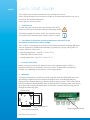 2
2
-
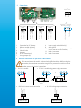 3
3
-
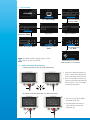 4
4
-
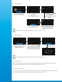 5
5
-
 6
6
-
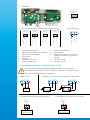 7
7
-
 8
8
-
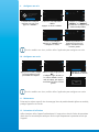 9
9
-
 10
10
-
 11
11
-
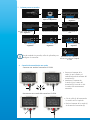 12
12
-
 13
13
-
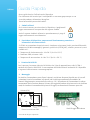 14
14
-
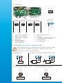 15
15
-
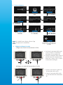 16
16
-
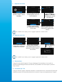 17
17
-
 18
18
-
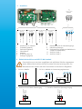 19
19
-
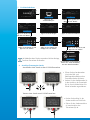 20
20
-
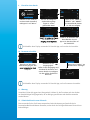 21
21
-
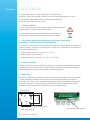 22
22
-
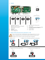 23
23
-
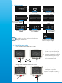 24
24
-
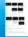 25
25
-
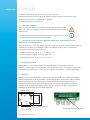 26
26
-
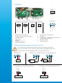 27
27
-
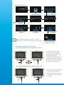 28
28
-
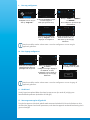 29
29
-
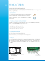 30
30
-
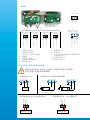 31
31
-
 32
32
-
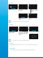 33
33
-
 34
34
-
 35
35
-
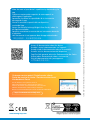 36
36


in andere talen
- italiano: sauermann Si-C320 Guida Rapida
- français: sauermann Si-C320 Guide de démarrage rapide
- português: sauermann Si-C320 Guia rápido
Andere documenten
-
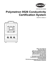 Hach Polymetron 9526 Basic User Manual
-
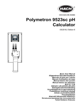 Hach Polymetron 9523sc pH Basic User Manual
-
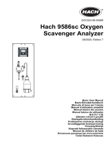 Hach 9586sc Basic User Manual
-
Vaisala DMT340 de handleiding
-
Mettler Toledo M300 Handleiding
-
-
-
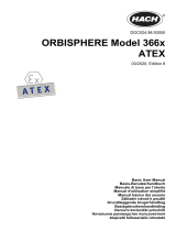 Hach ORBISPHERE 366 Series Basic User Manual
-
 Hach Polymentron 9500 Basic User Manual
-
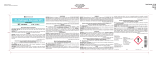 Steris 3% Hydrogen Peroxide Wfi Sterile Solution Handleiding


