
ISTRUZIONI PER L'INSTALLAZIONE E LA MANUTENZIONE (IT)
INSTRUCTIONS POUR L'INSTALLATION ET LA MAINTENANCE (FR)
INSTRUCTIONS FOR INSTALLATION AND MAINTENANCE (GB)
INSTALLATIONSANWEISUNG UND WARTUNG (DE)
INSTRUCTIES VOOR INGEBRUIKNAME EN ONDERHOUD (NL)
AQUATWIN TOP 132
AQUATWIN TOP 40/50
AQUATWIN TOP 40/80

ITALIANO
pag.
1
FRANÇAIS
page
19
ENGLISH
page
37
DEUTSCH
Seite
55
NEDERLANDS
bladz
73

ITALIANO
1
INDICE
1. Legenda ................................................................................................................................................................................................ 2
2. Generalità ............................................................................................................................................................................................. 2
2.1 Sicurezza ..................................................................................................................................................................................... 2
2.2 Responsabilità ........................................................................................................................................................................... 2
2.3 Avvertenze Particolari ............................................................................................................................................................... 2
3. OGGETTO DELLA FORNITURA ........................................................................................................................................................ 3
4. DESCRIZIONE GENERALE DEL SISTEMA ...................................................................................................................................... 3
5. DATI TECNICI ...................................................................................................................................................................................... 4
6. INSTALLAZIONE IDRAULICA ............................................................................................................................................................ 4
7. COLLEGAMENTI ELETTRICI ............................................................................................................................................................. 7
8. RIFERIMENTI SCHEMA DI COLLEGAMENTO ................................................................................................................................. 7
9. COLLEGAMENTO ELETTRICO E SETTAGIO PER UNA VASCA ................................................................................................. 8
10. COLLEGAMENTO ELETTRICO E SETTAGIO PER DUE VASCHE .............................................................................................. 9
11. PANNELLO FRONTALE DI CONTROLLO POMPE .......................................................................................................................10
12. REGOLAZIONE QUADRO CONTROLLO POMPE .........................................................................................................................11
13. PROTEZIONI ED ALLARMI QUADRO .............................................................................................................................................12
13.1 Protezione/Allarme proveniente dagli ingressi digitali R e N ...........................................................................................13
- Allarme Relé/teleruttore .................................................................................................................................................................... 14
- Pompa scollegata ............................................................................................................................................................................. 14
- Protezione/Allarme Marcia a secco ................................................................................................................................................. 14
- Protezione avviamenti troppo frequenti ........................................................................................................................................... 14
- Protezione/Allarme sovracorrente (Protezione amperometrica) .................................................................................................... 14
- Allarme sensore di pressione o profondità ...................................................................................................................................... 14
- Allarme incoerenza galleggianti e/o sonde ...................................................................................................................................... 14
- Allarme Dip Switch............................................................................................................................................................................ 14
- Allarme errore ................................................................................................................................................................................... 14
- Tensione d’ingresso ......................................................................................................................................................................... 15
- Errore selettore di tensione .............................................................................................................................................................. 15
- Errore di tensione ............................................................................................................................................................................. 15
- Errore interno .................................................................................................................................................................................... 15
- Errore generale pompa P1 + P2 ...................................................................................................................................................... 15
13.2 Allarmi visualizzati a display ..................................................................................................................................................15
- JR: Allarme Relé/teleruttore incollato .............................................................................................................................................. 16
- NC: Pompa Scollegata .................................................................................................................................................................... 16
- BL: Protezione/Allarme Marcia a secco........................................................................................................................................... 16
- LK: Protezione avviamenti troppo frequenti .................................................................................................................................... 16
- OC: Protezione/Allarme sovracorrente (Protezione amperometrica) ............................................................................................. 16
- RI: Allarmi RI ..................................................................................................................................................................................... 16
- NI: Allarmi NI ..................................................................................................................................................................................... 17
- HL: Allarme livello massimo ............................................................................................................................................................. 17
- LL: Allarme livello minimo................................................................................................................................................................. 17
- BP1/BP2: Allarme sensore di pressione / sensore di profondità .................................................................................................... 17
- FI: Incoerenza stato galleggianti o sonde di livello ......................................................................................................................... 17
- DS: Allarme Dip Switch .................................................................................................................................................................... 17
- W1: Trimmer SP ............................................................................................................................................................................... 17
- W2: Trimmer DP ............................................................................................................................................................................... 17
- W3: Trimmer Imax ............................................................................................................................................................................ 18
- PK: Errore Tasti ................................................................................................................................................................................ 18
- NL: Errore tensione d’ingresso ........................................................................................................................................................ 18
- VS: Errore selettore di tensione ....................................................................................................................................................... 18
- V0..V15: Errore tensione .................................................................................................................................................................. 18
- OM: Cambio Modalità di funzionamento ......................................................................................................................................... 18
- E0..E15: Errore interno ..................................................................................................................................................................... 18

ITALIANO
2
1. LEGENDA
Nel presente documento si utilizzeranno i seguenti simboli per evidenziare situazioni di pericolo:
Situazione di pericolo generico. Il mancato rispetto delle prescrizioni che lo seguono può provocare danni alle persone e
alle cose.
Situazione di pericolo shock elettrico. Il mancato rispetto delle prescrizioni che lo seguono può provocare una situazione
di grave rischio per l’incolumità delle persone.
2. GENERALITÀ
Prima di procedere all’installazione leggere attentamente questa documentazione.
L’installazione, l’allacciamento elettrico e la messa in esercizio devono essere eseguite da personale specializzato, nel
rispetto delle norme di sicurezza generali e locali vigenti nel paese d’installazione del prodotto. Il mancato rispetto delle
presenti istruzioni, oltre a creare pericolo per l’incolumità delle persone e danneggiare le apparecchiature, farà decadere
ogni diritto di intervento in garanzia.
L’apparecchio non è destinato ad essere usato da persone (bambini compresi) le cui capacità fisiche sensoriali e mentali
siano ridotte, oppure con mancanza di esperienza o di conoscenza, a meno che esse abbiano potuto beneficiare, attraverso
l’intermediazione di una persona responsabile della loro sicurezza, di una sorveglianza o di istruzioni riguardanti l’uso
dell’apparecchio. I bambini devono essere sorvegliati per sincerarsi che non giochino con l’apparecchio.
Verificare che il prodotto non abbia subito danni dovuti al trasporto o al magazzinaggio. Controllare che l’involucro
esterno sia integro ed in ottime condizioni.
L’utilizzatore è responsabile verso terzi per tutto ciò che coinvolge l’utilizzo del sistema (impianto elettrico, idrico, ecc...) nel
rispetto delle normative locali in fatto di sicurezza ed installazione. Prima della messa in funzione si deve far controllare da
un elettricista esperto che esistano le misure di sicurezza richieste. Per l’utilizzo è obbligatorio installare sull’impianto
elettrico un interruttore di protezione (salvavita) da IΔn=30mA. Controllare il voltaggio della rete elettrica corrisponda a
quello di alimentazione del sistema. Le indicazioni riportate sulla targhetta dati tecnici devono corrispondere a quelle
dell’impianto elettrico. Assicurarsi che l’itero sistema sia a riparo da inondazioni o dal getto diretto dell’acqua. Per eventuali
guasti la riparazione deve essere effettuata solo da officine autorizzate e devono essere utilizzai solo ricambi originali.
Vi facciamo presente che non siamo responsabili per danni derivati da:
a) riparazioni non appropriate eseguite da punti di servizio non autorizzati,
b) sostituzioni di parti di ricambio non originali,
Per gli accessori valgono le medesime indicazioni.
2.1 Sicurezza
L’utilizzo è consentito solamente se l’impianto elettrico è contraddistinto da misure di sicurezza secondo le Normative vigenti nel paese di
installazione del prodotto.
2.2 Responsabilità
Il costruttore non risponde del buon funzionamento della macchina o di eventuali danni da questa provocati, qualora la stessa venga manomessa,
modificata e/o fatta funzionare fuori dal campo di lavoro consigliato o in contrasto con altre disposizioni contenute in questo manuale.
2.3 Avvertenze Particolari
Prima di intervenire sulla parte elettrica o meccanica dell’impianto togliere sempre la tensione di rete. Attendere lo
spegnimento delle spie luminose sul pannello di controllo prima di aprire l’apparecchio stesso. Il condensatore del
circuito intermedio in continua resta carico con tensione pericolosamente alta anche dopo la disinserzione della
tensione di rete.
Sono ammissibili solo allacciamenti di rete saldamente cablati. L’apparecchio deve essere messo a terra (IEC 536
classe 1, NEC ed altri standard al riguardo).
Morsetti di rete e i morsetti motore possono portare tensione pericolosa anche a motore fermo.
Se il cavo di alimentazione è danneggiato, esso deve essere sostituito dal servizio assistenza tecnica o da
personale qualificato, in modo da prevenire ogni rischio.

ITALIANO
3
3. OGGETTO DELLA FORNITURA
Unità AQUATWIN TOP per la gestione dell’acqua piovana, composta da:
Fig.1
Rif.
Descrizione
1
Antivibranti regolabili
2
Pompe auto adescanti
3
Valvole tre vie
4
Valvola intercettazione mandata
5
Vaso espansione 8L
6
Sensore pressione
7
Manometro controllo pressione
8
Pannello di controllo e protezione
9
Serbatoio riserva idrica civile
10
Valvola collegamento rete idrica civile
11
Vaso espansione 2L
12
Filtro ispezionabile tipo “Y”
13
Elettro Valvola alimentazione serbatoio
14
Filtro ingresso serbatoio riserva idrica
4. DESCRIZIONE GENERALE DEL SISTEMA
L’unità AQUATWIN TOP serve per la gestione e distribuzione dell’acqua piovana. L’unità rileva gli eventuali guasti nel sistema di raccolta sia
dell’acqua piovana che della rete, e apporta le correzioni per garantire il corretto funzionamento dell’impianto (ovvero non fa mancare mai l’acqua
alle utenze identificate). Avvisa in caso anomalia e indica il tipo di problema rilevato.
Generalmente l’impianto serve ad alimentare utenze non a uso potabile: tipo lavatrice, scarico WC e il sistema di lavaggio dei pavimento o di
irrigazione. Lo scopo principale del sistema AQUATWIN TOP, è di dare priorità al consumo dell’acqua piovana all’acqua di rete. Quando l’acqua
piovana contenuta nel serbatoio (in caso di uso di un unico serbatoio) di raccolta è insufficiente, l’unità di controllo passa all’alimentazione idrica
di rete tramite un serbatoio di riserva idrica di 150L, assicurando cosi un afflusso di acqua ai punti di prelievo (N.B: L’acqua fornita dal sistema
non è potabile). Il collegamento tra il serbatoio o serbatoi (il sistema può essere collegato a due cisterne di acqua piovana indipendenti) di acqua
piovana ed il serbatoio di acqua di rete integrato nel sistema viene selezionato mediante valvole a tre vie installate all’aspirazione delle pompe.
In caso che solo uno dei due serbatoi di acqua piovana non abbia sufficiente disponibilità di acqua il sistema funzionerà in modalità ibrida acqua
di rete e acqua piovana.
Il funzionamento delle pompe è similare a una tradizionale stazione di pressurizzazione a due pompe con sistema “start-stop” tramite sensore di
pressione e alternanza degli avviamenti ad ogni richiesta da parte delle utenze, al calare della pressione di un valore preimpostato (set-point) la
pompa si avvia, in caso non fosse sufficiente per riportare la pressione al valore desiderato la seconda pompa si attiva, con la chiusura delle
utenze e al ripristino della pressione le pompe si disattivano automaticamente. In caso di mancanza di acqua le pompe si arrestano e viene
segnalata l’anomalia nel frontale del pannello di controllo, al ripristino dell’acqua il sistema si riabilita automaticamente.
Il serbatoio di riserva idrica è provvisto di galleggiamenti interni per il rintegro dell’acqua da rete in maniera automatica, e per la segnalazione di
anomalia di troppo pieno in caso di mal funzionamento dell’elettrovalvola, l’anomalia viene segnalata in loco tramite una cicalina ed è possibile
rimontare l’allarme in luogo presidiato.
Il sistema è dotato di:
– Sistema air-gap per evitare la contaminazione tra l’acqua di rete e l’acqua presente nella vasca di riserva idrica, che ristagnando
potrebbe favorire una prolificazione batterica, a tale scopo si consiglia di utilizzare la funzione MAN presente nel pannello per il ricambio
dell’acqua nella vasca (il ricambio è vincolato alla richiesta di acqua da parte dell’utilizzatore).
– Filtro posto in ingresso serbatoio riserva idrica per impedire l’accesso di corpi solidi o piccoli insetti che possano accelerare la
proliferazione di batteri.
– Connessione da 2” per lo smaltimento di acqua in caso di troppo pieno, da collegare a un pozzetto a perdere.

ITALIANO
4
Fig.2
5. DATI TECNICI
AQUATWIN
TOP 132
AQUATWIN
TOP 40/50
AQUATWIN
TOP 40/80
Portata (lt/min) max
80+80
80+80
120+120
Prevalenza Hm max
48
57,7
59
Temperatura del liquido pompato
Da +5°C a +35°C
Da +5°C a +35°C
Da +5°C a +35°C
Pressione massima del sistema
10 bar
10 bar
10 bar
Pressione massima rete
10 bar
10 bar
10 bar
Tensione di alimentazione
1x230 50Hz
1x230 50Hz
1x230 50Hz
Potenza max assorbita
2,1kW
1,6kW
2,1kW
Grado di protezione IP
40
40
40
Temperatura ambiente
min +5°C max +40°C
min +5°C max +40°C
min +5°C max +40°C
Materiale struttura
Acciaio cataforizzato
Acciaio cataforizzato
Acciaio cataforizzato
Materiale serbatoio
Polietilene clearflex RL50
Polietilene clearflex RL50
Polietilene clearflex RL50
Dimensione collegamento rete
1”F
1”F
1”F
Dimensione collegamento aspirazione
1”F
1”F
1”F
Dimensione collegamento mandata
1”1/2M
1”1/2M
1”1/2M
Dimensione collegamento troppo pieno
2”M
2”M
2”M
Altitudine max m
1000
1000
1000
Tipo di acqua
Piovana/non potabile
Piovana/non potabile
Piovana/non potabile
Peso a vuoto
115
115
115
Dimensioni ingombro (bxhxp) mm
811x1412x813
811x1412x813
811x1412x813
6. INSTALLAZIONE IDRAULICA
ATTENZIONE!!
È indispensabile che nel locale dove l’AQUATWIN TOP viene installato, sia previsto un pozzetto di scarico di opportune dimensioni al fine di
drenare eventuali rotture del sistema, o traboccamento dall’apposito sifone previsto per il troppo pieno. Tale pozzetto o sistema di drenaggio deve
essere dimensionato in base alla quantità di acqua alimentata dalla rete idrica.
Assicurarsi che il piano di appoggio sia il più uniforme possibile, sarà comunque possibile livellare il sistema con gli appositi piedini regolabili.

ITALIANO
5
Fig. 3
L’installazione idraulica comprende i seguenti collegamenti
1. Collegamento da 1” dalla rete civile (acqua potabile).
2. Collegamento da 2” per il troppo pieno vasca di riserva
idrica.
3. Collegamento da 2” per il troppo pieno vasca di riserva
idrica.
4. Collegamenti da 1” per le aspirazioni da una o due
cisterne di acqua piovana.
N.B. Le due aspirazioni sono indipendenti
Collegamento in aspirazione:
Il sistema AQUATWIN TOP da la possibilità di gestire una o due serbatoi separati di raccolta acqua piovana. Per il collegamento di un unico
serbatoio di raccolta procedere con il collegamento delle due aspirazioni separate che dovranno essere riportate singolarmente alla cisterna.
Installazione:
Posizionare l’AQUATWIN TOP in un luogo ben areato, protetto dalle intemperie e con una temperatura ambiente non superiore a 40°C, su un
piano regolare, in caso non fosse possibile, utilizzare i piedini antivibranti regolabili (Fig.1). Dopo aver posizionato e stabilizzato l’AQUATWIN
TOP procedere con il collegamento alla rete idrica civile con tubazione da 1” all’apposita valvola di intercettazione (Fig.3).
Collegare le aspirazioni (Fig.3) alle tubazioni provenienti dalle cisterne di accumulo acqua piovana, facendo particolare attenzione che abbiano
una inclinazione verso il serbatoio per evitare la formazioni di sacche d’aria (evitare colli di cigno, le tubazioni non devono mai passare al di sopra
delle pompe) evitare che le tubazioni creino sforzi alle bocche di aspirazione. Installare il sistema più vicino possibile alla cisterna di raccolta
acqua piovana, per assicurarsi un buon rendimento della pompa non superare mai i 20 metri di lunghezza e i 3 metri di altezza di aspirazione.
Nel caso in cui la lunghezza e l’altezza di aspirazione risultino maggiori, utilizzare un’altra pompa collegata in serie a quella del sistema per ovviare
la problema di aspirazione del sistema. Il punto di aspirazione deve sempre garantire l’aspirazione di acqua pulita, utilizzare un Kit di aspirazione
e delle valvole con filtro, per garantire la fornitura ed evitare che impurità vadano a bloccare valvole o parti interne delle pompe. Le tubazioni, che
possono gestire una o due cisterne indipendenti non dovranno essere di diametro inferiore alle bocche di aspirazione (1”) pur essendo il sistema
dotato di valvole di ritegno, si consiglia di adottare valvole di fondo all’interno delle cisterne. Se la tubazione aspirante fosse in materiale flessibile,
verificare sempre che sia del tipo rinforzato per evitare restringimenti per effetto dell’aspirazione.
Il collegamento alla rete delle utenze secondarie (acqua non potabile) può essere eseguita in entrambi i lati del collettore di mandata (Fig.3) con
una tubazione flessibile da 1”1/2, non è necessario inserire un vaso di espansione il sistema AQUATWIN TOP è già dotato di un vaso da 8 Litri.
Collegare il troppo pieno con una tubazione da 2” (Fig.3), questa tubazione dovrà essere indirizzata ad un pozzetto a perdere per evitare
allagamenti in caso di malfunzionamenti o traboccamenti del sistema.
NON COLLEGARE MAI UN TUBO DI SEZIONE INFERIORE AL DN50 PER PREVENIRE MALFUNZIONAMENTI DEL
SISTEMA.
CIÓ CHE VIENE EVACUATO NEL TROPPO PIENO DEVE ESSERE VISIBILE (PREVEDERE UN RACCORDO A “IMBUTO”)
Verificare che il tubo di scarico abbia una pendenza atta a garantire il normale riflusso di eventuali scarichi. Collegare lo scarico al sistema
fognario. Se la pendenza del tubo di scarico risultasse insufficiente, installare una stazione di sollevamento al fine di garantire lo smaltimento.

ITALIANO
6
Rif. 1
Alimentazione dalla rete civile
Rif. 2
Collegamento troppo pieno
Rif. 3
Collegamento utenze (collegabile a dx o sx)
Rif. 4
Collegamento aspirazione cisterne raccolta acqua piovana

ITALIANO
7
7. COLLEGAMENTI ELETTRICI
Assicurarsi che l’interruttore generale del quadro di distribuzione di energia sia in posizione OFF(0) e che nessuno possa ripristinare accidentalmente
il funzionamento, prima di procedere al collegamento dei cavi di alimentazione ai morsetti: L – N all’interruttore sezionatore QS1.
SI RACCOMANDA UN CORRETTO E SICURO COLLEGAMENTO A TERRA DELL’IMPIANTO COME RICHIESTO DALLE
NORMATIVE VIGENTI IN MATERIA.
CONTROLLARE CHE L’INTERRUTTORE DIFFERENZIALE A PROTEZIONE DELL’IMPIANTO RISULTI CORRETTAMENTE
DIMENSIONATO.
8. RIFERIMENTI SCHEMA DI COLLEGAMENTO
Rif
Funzione (vedere riferimenti su schema elettrico)
-QS1
Interruttore sezionatore della linea di alimentazione con maniglia di blocco porta, lucchettabile.
L – N
Morsetti di collegamento linea di alimentazione MONOFASE
Rispettare rigorosamente la corrispondenza prevista
KM1-KM2
Contattori di comando elettropompa P1 ed elettropompa P2
L-N
Morsetti di collegamento elettropompe P1 e P2
Rispettare rigorosamente la corrispondenza prevista
L-N
R
7-8
Morsetti di collegamento per galleggiante o pressostato di massima pressione (P. max)
In caso di uso di un pressostato di sicurezza, togliere ponticello di by-pass previsto di serie tra i relativi morsetti!
Caratteristiche elettriche: 24V AC 10mA, impedenza max. 55kOhm
N
9-10
Morsetti di collegamento contro la marcia a secco.
In caso di uso di un pressostato di sicurezza, togliere ponticello di by-pass previsto di serie tra i relativi morsetti!
Caratteristiche elettriche: 24V AC 10mA, impedenza max. 55kOhm
Q1
14-15
Morsetti di collegamento allarme elettropompa P1 a distanza (vedi tabella allarmi)
Caratteristiche di contatto: contatto pulito, 250V AC/30V DC, a doppio isolamento (AC1)
Q2
16-17
Morsetti di collegamento allarme elettropompa P2 a distanza (vedi tabella allarmi)
Caratteristiche di contatto: contatto pulito, 250V AC/30V DC, a doppio isolamento (AC1)
Q3
18-19
Morsetti di collegamento allarme generico a distanza (vedi tabella allarmi)
Caratteristiche di contatto: contatto pulito, 250V AC/30V DC, a doppio isolamento (AC1)
CONTATTO N.O. CON QUADRO ALIMENTATO E CON NESSUN ALLARME ATTIVO
13-14
Morsetti di collegamento per segnalazione pompe alimentate (P1 e P2)
Caratteristiche di contatto: NO 250V 3° (AC 15)
13-14
H1
11-12
Morsetti di collegamento ingresso analogico per sensore di pressione
H1 – 11 = uscita alimentazione per sensore: 24V, max 100mA
H1 – 12 = caratteristiche di ingresso: 4...20mA con DS_B7 in ON
1–2
(G1)
Morsetti di collegamento per galleggiante controllo livello vasca piovana (vasca 1)
Caratteristiche elettriche: 24V AC 10mA, impedenza max. 55kOhm
3 – 4
(G2)
Morsetti di collegamento per galleggiante controllo livello vasca piovana (vasca 2)
Caratteristiche elettriche: 24V AC 10mA, impedenza max. 55kOhm
5–6
(G3)
Morsetti di collegamento per galleggiante ripristino vasca accumulo acqua potabile
Caratteristiche elettriche: 24V AC 10mA, impedenza max. 55kOhm
7–8
(G4)
Morsetti di collegamento (RISERVA)
9–10–11
EV1
Morsetti di collegamento per alimentazione valvola a tre vie (EV1)
Caratteristiche elettriche: 230V AC 1A uscita protetta da fusibili
12–13–14
EV1
Morsetti di collegamento segnalazione stato elettrovalvola tre vie (EV1)
Caratteristiche elettriche: 24V AC 10mA, impedenza max. 55kOhm
15–16–17
EV1
Morsetti di collegamento per alimentazione valvola a tre vie (EV2)
Caratteristiche elettriche: 230V AC 1A uscita protetta da fusibili
18–19–20
EV1
Morsetti di collegamento segnalazione stato elettrovalvola tre vie (EV2)
Caratteristiche elettriche: 24V AC 10mA, impedenza max. 55kOhm
21–22
(G5)
Morsetti di collegamento galleggiante controllo del troppo pieno in casca di riserva acqua potabile
Caratteristiche elettriche: 24V AC 10mA, impedenza max. 55kOhm
23–24
Morsetti di collegamento alimentazione EV3 per ripristino riserva idrica da rete civile
Caratteristiche elettriche: 24V AC 1A, uscita protetta da fusibili

ITALIANO
8
25–26
Morsetti di riserva (non abilitatati)
FU1
Fusibile disabilitato
FU2
Fusibile di protezione del trasformatore scheda elettronica contro cortocircuiti del circuito primaria e della linea di alimentazione
dello stesso.
Caratteristiche elettriche: 5x20T 100mA
FU3
Fusibili di protezione del trasformatore contro l’errato collegamento dei cavi del motore (controllare la protezione termica).
FUNZIONE NON UTILIZZATA
FU4
Fusibili di protezione da cortocircuito dell’elettropompa P1.
Caratteristiche elettriche: 10x38 16Amp (aM)
Togliere tensione prima di procedere alla manutenzione
FU5
Fusibili di protezione da cortocircuito dell’elettropompa P2.
Caratteristiche elettriche: 10x38 16Amp (aM)
Togliere tensione prima di procedere alla manutenzione
FU6
Fusibile di protezione del trasformatore contro cortocircuiti del circuito primario e della linea di alimentazione dello stesso.
Caratteristiche elettriche: 10,3x38 1A tipo (gG)
FU7
Fusibile di protezione del trasformatore contro cortocircuiti del circuito secondario e della linea del circuito ausiliario bassa
tensione.
Caratteristiche elettriche: 10,3x38 1A tipo (gG)
9. COLLEGAMENTO ELETTRICO E SETTAGIO PER UNA VASCA
Per il funzionamento dell’AQUATWIN TOP in configurazione con un’unica cisterna di raccolta dell’acqua piovana procedere nel seguente modo:
Collegare il galleggiante (-G1) presente nella cisterna della raccolta acqua piovana ai morsetti (1-2) e settare la centralina (MC1) in modalità 1
TANK mediate il pulsantino ( )
N.B. In caso di una singola cisterna le due aspirazioni possono essere collettate in una unica tubazione di aspirazione.
EV
G5
H1
G1 G2 G3 G4 EV1 EV2

ITALIANO
9
10. COLLEGAMENTO ELETTRICO E SETTAGIO PER DUE VASCHE
Per il funzionamento dell’AQUATWIN TOP in configurazione con due cisterne distinte di raccolta dell’acqua piovana procedere nel seguente modo:
Collegare il galleggiante (-G1) presente nella prima cisterna di raccolta acqua piovana ai morsetti (1-2)
Collegare il galleggiante (-G2) presente nella seconda cisterna di raccolta acqua piovana ai morsetti (3-4)
Settare la centralina (MC1) in modalità 2 TANKS mediate il pulsantino ( )
N.B. Le tubazioni devono essere separate per le singole una per ciascuna cisterna.
Settaggi e funzionalità centralina gestione
FUNZIONE
Descrizione della funzione
Tasti di selezione funzioni
Utilizzando il tasto( ) si seleziona la funzione una o due TANK/TANKS, premendo ripetutamente questo tasto
viene visualizzato nello schermo la funzionalità desiderata.
In funzione “1TANK” il sistema viene gestito da un singolo galleggiante posto nella cisterna, le EV1 e EV2 gestiscono
l’aspirazione contemporaneamente, gestendo l’acqua piovana o di rete.
In funzione “2TANKS” il sistema viene gestito da due galleggianti posti nelle vasche di accumulo in modo autonomo,
le EV1 e EV2 vengono gestite autonomamente in funzione della presenza dell’acqua piovana o meno, in questa
modalità se potrà avere l’uso misto delle due riserve idriche (piovana e di rete).
Utilizzando il tasto ( ) si arresta l’allarme acustico che segnala l’allarme di troppo pieno.
Il pulsante arresta l’allarme acustico, ma rimane la segnalazione di “ALLARM OVER FLOW” lampeggiante sino a
quando il galleggiante posto all’interno della vasca di accumulo non ritorna in posizione ottimale.
Utilizzando il pulsante ( ) si attiva in maniera manuale l’elettrovalvola “EV3” questa funzione permette di testare il
funzionamento della elettrovalvola o di gestire il riempimento della vasca di accumulo acqua di rete in maniera
manuale, di standard questa elettrovalvola è comandata in maniera automatica da un galleggiante (G3) posto
all’interno della vasca stessa.
Utilizzando il pulsante ( ) si attiva la funzione “MAN MAIN”, questa funzione permette di forzare il funzionamento in
modalità MAIN (acqua da rete) in presenza di acqua piovana nelle cisterne di accumulo.
N.B. Questa operazione permette il ricambio dell’acqua presente nella vasca di riserva acqua da rete civile, si
consiglia di usare questa funzione una volta alla settimana per garantire il ricambio dell’acqua.
Indicazione di funzionamento P1 in modalità “RAIN WATER” in questa modalità la pompa uno preleva l’acqua dalla
cisterna di acqua piovana.
Indicazione di funzionamento P2 in modalità “RAIN WATER” in questa modalità la pompa due preleva l’acqua dalla
cisterna di acqua piovana.

ITALIANO
10
Indicazione di funzionamento P1 in modalità “MAIN WATER” in questa modalità la pompa uno preleva l’acqua dalla
cisterna di riserva con acqua di rete civile.
In questa modalità le scritte lampeggiano per evidenziare il consumo dell’acqua potabile.
Indicazione di funzionamento P2 in modalità “MAIN WATER” in questa modalità la pompa uno preleva l’acqua dalla
cisterna di riserva con acqua di rete civile.
In questa modalità le scritte lampeggiano per evidenziare il consumo dell’acqua potabile.
11. PANNELLO FRONTALE DI CONTROLLO POMPE
Fig. 4: Etichetta frontale
Rif.
Funzione
1
Indicazione luminosa bianca che segnala il corretto funzionamento dei circuiti ausiliari.
2
Indicazione luminosa rossa che segnala allarme generico.
3
Pulsante RESET allarmi.
Elettropompa P1
4
Indicazione luminosa verde: luce accesa fissa che segnala pompa in moto.
Indicazione luminosa verde: luce accesa lampeggiante che segnala pompa non disponibile.
5
Indicazione luminosa gialla che segnala allarme malfunzionamento pompa P1.
6
Pulsante di comando manuale o di disattivazione pompa P1:
- se premuto per più di 3 secondi consente l’accensione manuale della pompa,
- se premuto velocemente consente di disattivare la relativa pompa o attivare il funzionamento automatico.
Elettropompa P2
7
Indicazione luminosa verde: luce accesa fissa che segnala pompa in moto.
Indicazione luminosa verde: luce accesa lampeggiante che segnala pompa non disponibile.
8
Indicazione luminosa gialla che segnala allarme malfunzionamento pompa P2.
9
Pulsante comando manuale o di disattivazione pompa P2:
- se premuto per più di 3 secondi consente l’accensione manuale della pompa,
- se premuto velocemente consente di disattivare la relativa pompa o attivare il funzionamento automatico.

ITALIANO
11
12. REGOLAZIONE QUADRO CONTROLLO POMPE
Prima di procedere con la regolazione, togliere la tensione di rete agendo sul sezionatore QS1.
Per accedere al pannello interno svitare le viti, capovolgere il coperchio del quadro elettrico verso il basso e agire sui comandi.
Rif.
Funzione
1
Segnalazioni luminose per attivazione degli ingressi digitali (N-A-B-C-R)
2
Trimmer di regolazione dell’impianto (Imax – SP – DP).
3
Dip-Switch di selezione funzioni (DS_A – DS_B).
4
Led di segnalazione sovracorrente tarato ai dati di targa del motore.
Per una corretta taratura il Led dev’essere spento.
Trimmer di regolazione dell’impianto (Imax – SP – DP)
T1 – Trimmer (Imax)
Trimmer di taratura della massima corrente per le due elettropompe P1 e P2 (0.25A –13A).
Tarare il Trimmer sul valore di targa del motore (il led giallo deve risultare spento).
T2 – Trimmer (SP – Set Point impianto) / Trimmer 3 (DP – Differenziale di livello pressione)
Trimmer di taratura delle pressioni o del livello dell’impianto.
- Il trimmer SP (impostato dal DS_B5) presenta una doppia scala di regolazione in bar: da 1 a 10 bar oppure da 7 a 15 bar
corrispondente al led acceso, in caso di utilizzo di un sensore di pressione nei gruppi di pressurizzazione.
La regolazione di DP viene espressa in percentuale rispetto al valore impostato in SP.
1
2
33
22
4

ITALIANO
12
13. PROTEZIONI ED ALLARMI QUADRO
Le protezioni e gli allarmi vengono segnalati a bordo quadro tramite l’accensione dei relativi led luminosi e a distanza tramite i relè Q1, Q2, Q3.
Tabella generale allarmi: segnalazioni e contatti
Segnalazione led
pannello frontale
Proprietà dell’allarme Segnalazione remota
Nome allarme/anomalia
Anomalia
Pompa
P1
(led giallo)
Anomalia
Pompa
P2
(led giallo)
Allarme generico
(led rosso)
Allarme acqua
Allarme pompe
Allarme
auto ripristinabile
Allarme bloccante
Contatti
d’ allarme P1
relè Q1
Contatti
d’
allarme P2
relè Q2
Contatti
d’ allarme
generico
relè Q3
Allarme incoerenza
relè comando pompe
** X X X X X **
Allarme mancanza
fase - KK
** X X X X X **
Allarme marcia a
secco
** X X X X
Allarme protezione
contro i rapidi
avviamenti
** X X X X X
Allarme sovracorrente
** X X * X X **
Allarme proveniente
da R
X X X
Allarme proveniente
da N
X X X
Allarme sensore
di pressione
X X X
Allarme incoerenza
galleggianti
X X X
Allarme Incoerenza
Dip-Switch
X
X
Allarme incoerenza
pulsanti
Allarme tensione
d’ingresso
X X X
Allarme errore
selettore di tensione
X X
Allarme errore
tensione.
X X
Allarme errore interno
X X
Allarme generale
pompa P1+P2
X X X X

ITALIANO
13
Indica il numero di lampeggi che effettua il led luminoso.
Led acceso fisso.
**
Qualora si verificassero su entrambe le pompe contemporaneamente delle anomalie/allarmi, viene attivato l’ALLARME
REMOTIZZATO (Relè Q1,Q2,Q3) ed il led ALLARME GENERICO (rosso) si accende fisso.
*
L’allarme di sovracorrente può presentarsi fino ad un massimo di 6 volte durante le 24 ore, dopo di che diventa bloccante.
Allarme Acqua = rappresenta un allarme legato alla marcia a secco (troppo pieno, sovra-pressione impianto ecc.).
Allarme Pompa = rappresenta un allarme legato alla salvaguardia della pompa (protezione termica pompa, sovracorrente ecc.).
Allarme Auto ripristinabile = il centralino riattiva la pompa se viene rimossa la causa che ha generato l’allarme, oppure nei casi in cui questo
non è possibile, effettua dei tentativi ad intervalli di tempo.
Allarme Bloccante = il centralino mantiene la pompa ferma fino a che non viene effettuato un reset manuale.
Allarme sensore di pressione = Se viene rilevato un sensore di pressione dal quadro con una configurazione dei Dip-switch non coerente con
il dispositivo installato, viene segnalato un allarme. É possibile comunque far funzionare ugualmente il quadro. Se viene selezionato tramite Dip-
witch un funzionamento con sensore, ma il sensore non viene rilevato dal quadro, le pompe vengono disattivate e viene segnalato l’allarme. Se
l’installazione del sensore di pressione è avvenuta correttamente, ma il segnale del sensore è fuori campo misura, le pompe vengono disattivate
e viene segnalato l’allarme.
Allarme Dip Switch = L’allarme dei Dip Switch si attiva nei seguenti casi:
Incoerenza Dip Swich con le relative funzioni (regolazione errata).
Per ripristinare l’allarme:
- Riportare i Dip Switch nella posizione corretta.
- Premere il tasto RESET.
Regolazione Dip Switch con il quadro sotto tensione.
Per ripristinare l’allarme:
- Premere il tasto RESET.
Protezione/Allarme sovracorrente (protezione amperometrica) = All’intervento dell’allarme per sovracorrente si accende la spia luminosa
gialla della relativa pompa P1 o P2, presente nel pannello frontale del quadro elettrico (par.8–rif.5/8). Per ciascuna pompa l’allarme di
sovracorrente consente 6 tentativi di auto ripristino, ogni 10 minuti, nell’arco delle 24 ore di funzionamento. Al settimo tentativo il quadro non
esegue più degli auto ripristini se non dopo un reset manuale da parte dell’utente.
Protezione/Allarme Marcia a secco = La protezione/allarme per marcia a secco viene attivata nella situazione di pressurizzazione quando viene
collegato 1 sensore di pressione analogico. Questa protezione è selezionabile dal DS_A4. Quando la pressione va ad un valore inferiore a 0,5
bar per circa 10 secondi, l’allarme viene attivato con l’arresto della pompa e l’accensione del led luminoso giallo. Dopo 1 minuto si avrà 1 tentativo
di ripristino per massimo 30 secondi. Se tale tentativo riesce l’allarme viene resettato, in caso contrario la pompa rimarrà in stato di blocco.
13.1 Protezione/Allarme proveniente dagli ingressi digitali R e N
Ingressi
digitali
Funzione Pressurizzazione
e Pressurizzazione KIWA
Funzione Riempimento
Funzione Svuotamento
R
Pressione Max.
Le 2 pompe si arrestano con:
- segnalazione allarme generico,
- segnalazione a distanza Q3.
Livello Min. (nel serbatoio)
Le 2 pompe si avviano con:
- segnalazione allarme generico,
- segnalazione a distanza Q3.
Intervento e ripristino dopo 0,5
secondi.
Livello Max.
Le 2 pompe si avviano con:
- segnalazione allarme generico,
- segnalazione a distanza Q3.
Intervento e ripristino dopo 0,5
secondi.
N
Pressione Min.
Le 2 pompe si arrestano con:
- segnalazione allarme generico,
- segnalazione allarme contro la
marcia a secco,
- segnalazione a distanza Q3.
Livello Max. (nel serbatoio)
Le 2 pompe si arrestano con:
- segnalazione allarme generico,
- segnalazione a distanza Q3
Livello Min. (riserva idrica).
Le 2 pompe si arrestano con:
- segnalazione allarme generico,
- segnalazione contro la marcia
a secco,
- segnalazione a distanza Q3.
Intervento e ripristino dopo 1
secondo.
Livello Min.
Le 2 pompe si arrestano con:
- segnalazione allarme generico,
- segnalazione allarme contro la
marcia a secco,
- segnalazione a distanza Q3.
Intervento e ripristino dopo 1
secondo.
Att.ne! se non sono utilizzati i Morsetti
R e N devono essere ponticellati!
Att.ne! se non è utilizzato il Morsetto
N
deve essere ponticellato! Se si
usano sonde di livello va ponticellato
solamente R, nel caso non sia usato.
Att.ne! se non è utilizzato il Morsetto
N deve essere ponticellato!

ITALIANO
14
- Allarme Relé/teleruttore
Questo errore si presenta nel caso in cui i teleruttori di controllo delle pompe abbiano delle anomalie. Se si presenta questo allarme controllare i
cablaggi. Se non si riscontrano difetti il quadro deve essere riparato.
- Pompa scollegata
Questo errore si presenta nel caso in cui i il quadro E.Box non “sente” corrente verso una pompa. Questo errore si presenta anche nel caso
l’ingresso KK (protezione termica del motori) si apra. L’allarme è specifico per la pompa. Per ciascuna pompa l’allarme consente una serie di
tentativi di riavvio con tempo variabile di pausa tra un avvio e l’altro incrementale di 1 minuto per i primi 60 minuti (1-2-3 min. 60 min.), dopo di
che si avrà un tentativo ogni ora. Per risolvere questo errore, controllare le pompe ed i cablaggi e controllare il valore di corrente nominale
impostato (trimmer Imax).
- Protezione/Allarme Marcia a secco
Quando la pressione va ad un valore inferiore a 0,5 bar per circa 10 secondi, l’allarme viene attivato con l’arresto della pompa e l’accensione del
led luminoso. La protezione/allarme per marcia a secco viene attivata nella modalità pressurizzazione quando viene collegato un sensore di
pressione analogico. Questa protezione è selezionabile dal DS_A4.
Dopo 1 minuto si avrà 1 tentativo di ripristino per massimo 30 secondi. Se tale tentativo riesce l’allarme viene resettato, in caso contrario la pompa
rimarrà in stato di blocco.
La protezione/allarme contro la marcia a secco non viene attivata in caso di partenza manuale delle elettropompe.
Per risolvere il problema controllare la parte idraulica dell’impianto. Verificare che sia tutto regolare. Verificare anche il sensore di pressione e che
la pressione letta sia regolare.
- Protezione avviamenti troppo frequenti
Questo errore si presenta quando il sistema necessita di più di 8 partenze per pompa al minuto, questo normalmente si verifica quando si hanno
perdite nel sistema o il vaso di espansione è sgonfio.
La protezione dai rapidi avviamenti concede a ciascuna pompa un numero massimo di 8 avviamenti al minuto.
La protezione non interviene se il numero di avviamenti al minuto è inferiore a 8.
Per risolvere il problema controllare se vi siano perdite ed il vaso di espansione se presente.
- Protezione/Allarme sovracorrente (Protezione amperometrica)
In caso di sovracorrente sulle pompe si presenta questo allarme. L’allarme è specifico della pompa.
Per ciascuna pompa l’allarme di sovracorrente consente 6 tentativi di auto ripristino, ogni 10 minuti, nell’arco delle 24 ore di funzionamento. Al
settimo tentativo il quadro non esegue più degli auto ripristini se non dopo un reset manuale da parte dell’utente. Per risolvere questo problema
controllare le pompe, il cablaggio e che la corrente nominale delle pompe sia impostata correttamente. Questo errore può essere generato da
una pompa bloccata.
- Allarme sensore di pressione o profondità
Se viene selezionato il funzionamento con sensore, ma il sensore non viene rilevato dal quadro, le pompe vengono disattivate e viene segnalato
l’allarme. In questo caso controllare il cablaggio.
Se l’installazione del sensore è avvenuta correttamente, ma il segnale del sensore è fuori campo misura, le pompe vengono disattivate e viene
segnalato l’allarme. Controllare la pressione nell’impianto e se la lettura del sensore non è corretta cambiare il sensore.
- Allarme incoerenza galleggianti e/o sonde
Questo errore si verifica quando lo stato dei galleggianti o delle sonde di livello non è corretto, ad esempio il galleggiante sul livello più alto della
vasca segnala la presenza di acqua e i galleggianti più in basso no. Per risolvere questi problemi verificare il cablaggio e lo stato dei galleggianti.
Sul display è possibile vedere la posizione rilevata dal quadro. Si consiglia di controllare che i galleggianti non siano bucati.
- Allarme Dip Switch
L’allarme dei Dip Switch si attiva nei seguenti casi:
Incoerenza Dip Swich con le relative funzioni (configurazione errata).
Per ripristinare l’allarme:
• Riportare i Dip Switch nella posizione corretta.
• Premere il tasto RESET.
Regolazione Dip Switch con il quadro sotto tensione.
Per ripristinare l’allarme premere il tasto RESET.
- Allarme errore
Se nei primi 30 secondi di alimentazione viene rilevato uno schiacciamento dei pulsanti posti a fronte quadro, si attiva l’allarme incoerenza pulsanti.
Controllare l’effettiva funzionalità dei pulsanti!

ITALIANO
15
- Tensione d’ingresso
Se la tensione alternata d’ingresso del quadro non è entro i limiti stabiliti nelle specifiche, si attiva l’allarme tensione AC d’ingresso irregolare.
L’allarme si disattiva un minuto dopo che la tensione alternata d’ingresso è tornata entro i limiti. Nel caso si presenti questo allarme controllare la
tensione di ingresso del quadro. Se è regolare il quadro deve essere sostituito.
- Errore selettore di tensione
Questo errore può verificarsi sull’E.Box Plus, in caso di guasto dell’E.Box Plus o di rottura del fusibile FU2. In caso di allarme controllare il fusibile
FU2 e che il quadro sia alimentato con una tensione adeguata, come specificato nella Tabella 1 - Dati Tecnici.
- Errore di tensione
Se la scheda elettronica ha un guasto che porta una delle sue tensioni interne a livelli non accettabili, si attiva l’allarme Errore tensione interna al
quadro. Non è un errore ripristinabile.
In caso compaia questo errore, controllare le tensioni di alimentazioni ed il cablaggio. Se è tutto regolare L’E.Box ha subito un danneggiamento
interno e deve essere riparato.
- Errore interno
Errore interno al quadro. Non è un errore ripristinabile. In caso compaia questo errore, controllare le tensioni di alimentazioni ed il cablaggio. Se
è tutto regolare L’E.Box ha subito un danneggiamento interno e deve essere riparato.
- Errore generale pompa P1 + P2
Questo errore compare quando nessuna pompa è disponibile per il pompaggio. Per risolvere il problema guardare gli errori delle pompe.
13.2 Allarmi visualizzati a display
Nel caso si presenti un allarme, nel display viene visualizzata una pagina che indica:
• Con un’icona se si tratta di un allarme di sistema o della pompa P1 o P2.
• Sigla e descrizione sintetica del tipo di allarme.
La finestra con l’allarme resta visibile fino alla pressione di un tasto o alla scomparsa della causa dell’allarme.
Una segnalazione completa degli allarmi è reperibile nello storico degli allarmi.
13.2.1.1 10.3.1 Allarmi segnalati a display
Nella tabella seguente di ciascun allarme sono indicati:
• Descrizione sintetica e sigla, corrispondente a quella mostrata, eventualmente in forma abbreviata, a display. Nei paragrafi seguenti
vengono fornite descrizioni più dettagliate.
• Se l’allarme riguarda la singola pompa o il sistema.
• Se l’allarme è autoripristinante o se il ripristino deve essere manuale tramite i pulsanti di reset.
• Quali contatti relè vengono chiusi in presenza dell’allarme. In generale Q1 segnala gli errori della pompa P1, Q2 quelli della pompa P2
e Q3 quelli di sistema.
Gli allarmi sono anche segnalati tramite i led allarme presenti sul pannello frontale, ma in presenza di display si ritiene preferibile far riferimento
alle segnalazioni provenienti dal display, che contengono maggiori informazioni.
Descrizione Sigla Pompa/Sistema Allarme
autoripristinante Q1 Q2 Q3
Relé/teleruttore
JR
P
X
X
X
Pompa scollegata
NC
P
X
X
X
Marcia a secco
BL
P/S
X
X
X
X
Avviamenti troppo frequenti
LK
P/S
X
X
X
X
Sovracorrente
OC
P
X
X
X
Pressostato pressione massima
RI
S
X
X
Galleggiante livello massimo
Galleggiante livello minimo
Sonda livello Minimo
Sonda livello Massimo
Pressostato pressione minima
NI S
X (**)
X
Galleggiante livello massimo
X
Galleggiante livello minimo
Sonda livello Minimo
Sonda livello Massimo
Livello massimo
HL
S
X
X
Livello minimo
LL
S
X
X
Sensore di pressione
BP1/BP2 S X X
Sensore di profondità

ITALIANO
16
Incoerenza stato galleggianti
FI S X X
Incoerenza stato sonde di livello
Dip switch
DS
S
X
X
Trimmer SP
W1
S
X
X
Trimmer DP
W2
S
X
X
Trimmer Imax
W3
S
X
X
Errore tasti
PK
S
X
X
Tensione d’ingresso
NL
S
X
X
Errore Selettore tensione
VS
S
X
Errore di tensione
V0..V15
S
X
X
Cambio modalità funzionamento
OM
S
Errore interno
E0..E15
S
X
(*) in modalità pressurizzazione (non KIWA) l’allarme potrebbe essere generato anche da un galleggiante/sonda di livello immerso nel serbatoio
da cui pescano le pompe.
(**) in modalità pressurizzazione KIWA l’allarme non è auto ripristinante e deve essere resettato manualmente.
- JR: Allarme Relé/teleruttore incollato
Questo errore si presenta nel caso in cui i teleruttori di controllo delle pompe abbiano delle anomalie. Se si presenta questo allarme controllare i
cablaggi. Se non si riscontrano difetti il quadro deve essere riparato.
- NC: Pompa Scollegata
Questo errore si presenta nel caso in cui i il quadro E.Box non “sente” corrente verso una pompa. Questo errore si presenta anche nel caso
l’ingresso KK (protezione termica del motori) si apra.
L’allarme è specifico per la pompa. Per ciascuna pompa l’allarme consente una serie di tentativi di riavvio con tempo variabile di pausa tra un
avvio e l’altro incrementale di 1 minuto per i primi 60 minuti (1-2-3 min.... 60 min.), dopo di che si avrà un tentativo ogni ora.
- BL: Protezione/Allarme Marcia a secco
La protezione/allarme per marcia a secco viene attivata nella situazione di pressurizzazione quando viene collegato un sensore di pressione
analogico, mentre nelle altre modalità di funzionamento è necessario impostare il parametro SO ad un valore diverso da “OFF”.
Questa protezione è attivabile impostando il parametro TB ad un valore diverso da zero.
La protezione interviene:
• Quando la pressione va ad un valore inferiore al parametro MP (default 0,45bar) per un tempo uguale al parametro TB, l’allarme viene
attivato con l’arresto della pompa e l’accensione del led luminoso.
• Nel caso in cui il fattore di marcia a secco per una delle pompe scenda al disotto di tale valore durante la marcia. Per ulteriori informazioni
sull’impostazione di SO, vedere il paragrafo 9.4.4 e 9.4.5.
Dopo 1 minuto si avrà 1 tentativo di ripristino per massimo 30 secondi. Se tale tentativo riesce l’allarme viene resettato, in caso contrario la pompa
rimarrà in stato di blocco.
La protezione/allarme contro la marcia a secco non viene attivata in caso di partenza manuale delle elettropompe.
Per risolvere il problema controllare la parte idraulica dell’impianto. Verificare che sia tutto regolare. Verificare anche il sensore di pressione e che
la pressione letta sia regolare.
- LK: Protezione avviamenti troppo frequenti
Questo errore si presenta quando il sistema necessita di più di 8 partenze per pompa al minuto, questo normalmente si verifica quando si hanno
perdite nel sistema o il vaso di espansione è sgonfio.
La protezione dai rapidi avviamenti concede a ciascuna pompa un numero massimo di 8 avviamenti al minuto.
La protezione non interviene se il numero di avviamenti al minuto è inferiore a 8.
Per risolvere il problema controllare se vi siano perdite ed il vaso di espansione se presente.
- OC: Protezione/Allarme sovracorrente (Protezione amperometrica)
In caso di sovracorrente sulle pompe si presenta questo allarme. L’allarme è specifico della pompa.
Per ciascuna pompa l’allarme di sovracorrente consente 6 tentativi di auto ripristino, ogni 10 minuti, nell’arco delle 24 ore di funzionamento. Al
settimo tentativo il quadro non esegue più degli auto ripristini se non dopo un reset manuale da parte dell’utente. Per risolvere questo problema
controllare le pompe, il cablaggio e che la corrente nominale delle pompe sia impostata correttamente. Questo errore può essere generato da
una pompa bloccata.
- RI: Allarmi RI
Questi errori provengono dall’ingresso R. Il comportamento del quadro è diverso in funzione della modalità operativa. La risoluzione del
problema consiste sempre nel controllare il segnale proveniente dall’ingresso R.

ITALIANO
17
Messaggio
Significato e descrizione
Pressostato pressione massima
Questo errore si presenta in pressurizzazione ed indica che si è attivato il pressostato di
massima o non è stato eseguito il ponticello sul contatto R. L’E.Box ferma le pompe.
Galleggiante livello massimo
Questo errore si presenta in drenaggio ed indica che si è attivato il galleggiante di livello
massimo o è stato eseguito il ponticello sul contatto R. L’E.Box attiva le pompe.
Galleggiante livello minimo
Questo errore si presenta in riempimento ed indica che si è attivato il galleggiante di livello
minimo o è stato eseguito il ponticello sul contatto R. L’E.Box attiva le pompe.
Sonda livello minimo
Questo errore si presenta in riempimento ed indica che si è attivata la sonda di livello per il
livello minimo o non è stato eseguito il ponticello sul contatto R. L’E.Box attiva le pompe.
Sonda livello massimo
Questo errore si presenta in drenaggio ed indica che si è attivata la sonda di livello per il
livello massimo o è stato eseguito il ponticello sul contatto R. L’E.Box attiva le pompe.
- NI: Allarmi NI
Questi errori provengono dall’ingresso N. Il comportamento del quadro è diverso in funzione della modalità operativa. La risoluzione del
problema consiste sempre nel controllare il segnale proveniente dall’ingresso N.
Messaggio
Significato e descrizione
Pressostato pressione minima
Questo errore si presenta in pressurizzazione ed indica che si è attivato il pressostato di
minima o non è stato eseguito il ponticello sul contatto N. L’E.Box si ferma. In
pressurizzazione KIWA l’errore non è autoripristinante ed è necessario l’intervento manuale
Galleggiante livello massimo
Questo errore si presenta in riempimento ed indica che si è attivato il galleggiante di livello
massimo o non è stato eseguito il ponticello sul contatto N. L’E.Box ferma le pompe.
Galleggiante livello minimo
Questo errore si presenta in drenaggio ed indica che si è attivato il galleggiante di livello
minimo o non è stato eseguito il ponticello sul contatto N. L’E.Box ferma le pompe.
Sonda livello minimo
Questo errore si presenta in drenaggio ed indica che si è attivata la sonda di livello per il
livello minimo o non è stato eseguito il ponticello sul contatto N. L’E.Box ferma le pompe.
Sonda livello massimo
Questo errore si presenta in riempimento ed indica che si è attivata la sonda di livello per il
livello massimo o è stato eseguito il ponticello sul contatto N. L’E.Box attiva le pompe.
- HL: Allarme livello massimo
Questo errore proviene dal sensore di profondità quando la sua indicazione supera la soglia ML (Massimo Livello). Questo può accadere quando
il sensore di profondità è utilizzato per gli allarmi di livello massimo e minimo. La risoluzione del problema consiste sempre nel verificare le soglie
impostate, il livello di liquido nel serbatoio e lo stato del sensore. Il comportamento del quadro è diverso in funzione della modalità operativa. In
drenaggio questo errore provoca la partenza forzata delle pompe, in riempimento l’arresto forzato delle pompe.
- LL: Allarme livello minimo
Questo errore proviene dal sensore di profondità quando la sua indicazione è inferiore alla soglia LL (Minimo Livello). Questo può accadere
quando il sensore di profondità è utilizzato per gli allarmi di livello massimo e minimo. La risoluzione del problema consiste sempre nel verificare
le soglie impostate, il livello di liquido nel serbatoio e lo stato del sensore. Il comportamento del quadro è diverso in funzione della modalità
operativa. In riempimento questo errore provoca la partenza forzata delle pompe, in drenaggio l’arresto forzato delle pompe.
- BP1/BP2: Allarme sensore di pressione / sensore di profondità
Se viene selezionato il funzionamento con sensore di pressione o profondità, ma il sensore non viene rilevato dal quadro, le pompe vengono
disattivate e viene segnalato l’allarme. In questo caso controllare il cablaggio.
Se l’installazione del sensore è avvenuta correttamente, ma il segnale del sensore è fuori campo misura, le pompe vengono disattivate e viene
segnalato l’allarme. Controllare la pressione nell’impianto, se la lettura del sensore non è corretta cambiare il sensore.
- FI: Incoerenza stato galleggianti o sonde di livello
Questo errore si verifica quando lo stato dei galleggianti o delle sonde di livello non è corretto, ad esempio il galleggiante sul livello più alto della
vasca segnala la presenza di acqua e i galleggianti più in basso no. Per risolvere questi problemi verificare il cablaggio e lo stato dei galleggianti.
Sul display è possibile vedere la posizione rilevata dal quadro. Si consiglia di controllare che i galleggianti non siano bucati.
- DS: Allarme Dip Switch
L’allarme dei Dip Switch si presenta nel caso in sui siano state cambiate le posizioni dei dip switch.
Se la nuova configurazione dei Dip Switch è valida, viene chiesto se accettarla o ignorarla. Se accettata L’E.Box inizierà a funzionare con la nuova
configurazione. Se la nuova configurazione non è valida si propone di ignorarla.
- W1: Trimmer SP
Questo errore si presenta se è stato mosso il trimmer SP all’interno del quadro. Viene chiesto se accettare o ignorare il nuovo valore di SP. Se
accettato verrà accettato anche il valore dei DIP SWITCH.
- W2: Trimmer DP
Questo errore si presenta se è stato mosso il trimmer DP all’interno del quadro. Viene chiesto se accettare o ignorare il nuovo valore di DP. Se
accettato, verrà accettato anche il valore dei DIP SWITCH.

ITALIANO
18
- W3: Trimmer Imax
Questo errore si presenta se è stato mosso il trimmer Imax all’interno del quadro. Viene chiesto se accettare o ignorare il nuovo valore di Imax.
Se accettato, verrà accettato anche il valore dei DIP SWITCH.
- PK: Errore Tasti
Se nei primi 30 secondi di alimentazione viene rilevato uno schiacciamento dei pulsanti posti a fronte quadro, si attiva l’allarme incoerenza
pulsanti. Controllare l’effettiva funzionalità dei pulsanti!
- NL: Errore tensione d’ingresso
Se la tensione alternata d’ingresso del quadro non è entro i limiti stabiliti nelle specifiche, si attiva l’allarme tensione d’ingresso. L’allarme si
disattiva un minuto dopo che la tensione alternata d’ingresso è tornata entro i limiti. Se compare questo errore controllare che la tensione di
alimentazione sia entro i limiti accettati dal quadro E.box, vedi tabella 1 - Dati Tecnici.
- VS: Errore selettore di tensione
Questo errore può verificarsi sull’E.Box Plus, in caso di guasto dell’E.Box Plus o di rottura del fusibile FU2. In caso di allarme controllare il fusibile
FU2 e che il quadro sia alimentato con una tensione adeguata, come specificato nella Tabella 1 – Dati Tecnici.
- V0..V15: Errore tensione
Se la scheda elettronica ha un guasto che porta una delle sue tensioni interne a livelli non accettabili, si attiva l’allarme Errore Tensione V0..V15.
Non è un errore ripristinabile. La sigla Vx indica la parte di circuito dove è stata riscontrata l’anomalia. In caso compaia questo errore, controllare
le tensioni di alimentazione ed il cablaggio. Se è tutto regolare L’E.Box ha subito un danneggiamento interno e deve essere riparato.
- OM: Cambio Modalità di funzionamento
Questo messaggio è solo un avvertimento e non è un errore. Compare solo nello storico degli allarmi ed indica che L’E.Box è stato cambiato di
configurazione, per esempio da drenaggio a pressurizzazione.
- E0..E15: Errore interno
Errore interno al quadro. Non è un errore ripristinabile. In caso compaia questo errore, controllare le tensioni di alimentazioni ed il cablaggio. Se
è tutto regolare L’E.Box ha subito un danneggiamento interno e deve essere riparato.

FRANÇAIS
19
SOMMAIRE
1. LÉGENDE ...........................................................................................................................................................................................20
2. GÉNÉRALITÉS...................................................................................................................................................................................20
2.1 Sécurité .....................................................................................................................................................................................20
2.2 Responsabilités .......................................................................................................................................................................20
2.3 Recommandations particulières ...........................................................................................................................................20
3. OBJET DE LA FOURNITURE ...........................................................................................................................................................21
4. DESCRIPTION GENERALE DU SYSTEME .....................................................................................................................................21
5. DONNÉES TECHNIQUES .................................................................................................................................................................22
6. INSTALLATION HYDRAULIQUE .....................................................................................................................................................22
7. BRANCHEMENTS ÉLECTRIQUES ..................................................................................................................................................25
8. RÉFÉRENCE SCHÉMA DE CONNEXION .......................................................................................................................................25
9. BRANCHEMENT ÉLECTRIQUE ET RÉGLAGE POUR UN RÉSERVOIR ....................................................................................26
10. BRANCHEMENT ÉLECTRIQUE ET RÉGLAGE POUR DEUX RÉSERVOIRS .............................................................................27
11. PANNEAU FRONTAL DE CONTRÔLE POMPE .............................................................................................................................28
12. RÉGLAGE TABLEAU CONTRÔLE POMPES .................................................................................................................................29
13. PROTECTIONS ET ALARMES COFFRET ......................................................................................................................................30
13.1 Protection/alarme provenant des entrées numériques R et N ..........................................................................................31
- Alarme relais/télérupteur .................................................................................................................................................................. 32
- Pompe déconnectée ......................................................................................................................................................................... 32
- Protection/alarme fonctionnement à sec ......................................................................................................................................... 32
- Protection démarrages trop fréquents ............................................................................................................................................. 32
- Protection/alarme surcourant (protection ampérométrique) ........................................................................................................... 32
- Alarme capteur de pression ou profondeur ..................................................................................................................................... 32
- Alarme incohérence des flotteurs et/ou des sondes ....................................................................................................................... 32
- Alarme commutateur DIP ................................................................................................................................................................. 32
- Alarme erreur .................................................................................................................................................................................... 32
- Tension d'entrée ............................................................................................................................................................................... 33
- Erreur du sélecteur de tension ......................................................................................................................................................... 33
- Erreur de tension .............................................................................................................................................................................. 33
- Erreur interne .................................................................................................................................................................................... 33
- Erreur générale pompe P1 + P2 ...................................................................................................................................................... 33
13.2 Alarmes affichées à l'écran ....................................................................................................................................................33
13.2.2 - JR : Alarme relais/télérupteur collé ................................................................................................................................ 34
13.2.3 - NC : Pompe déconnectée ............................................................................................................................................. 34
13.2.4 - BL : Protection/alarme fonctionnement à sec ............................................................................................................... 34
13.2.5 - LK : Protection démarrages trop fréquents ................................................................................................................... 34
13.2.6 - OC : Protection/alarme surcourant (protection ampérométrique) ................................................................................ 34
13.2.7 - RI : Alarmes RI ............................................................................................................................................................... 35
13.2.8 - NI : Alarmes NI ............................................................................................................................................................... 35
13.2.9 - HL : Alarme de niveau maximum................................................................................................................................... 35
13.2.10 - LL : Alarme de niveau minimum .................................................................................................................................... 35
13.2.11 - BP1/BP2 : Alarme capteur de pression/capteur de profondeur ................................................................................... 35
13.2.12 - FI : Incohérence de l'état des flotteurs ou des sondes de niveau ................................................................................ 35
13.2.13 - DS : Alarme commutateur DIP....................................................................................................................................... 35
13.2.14 - W1 : Trimmer SP ............................................................................................................................................................ 36
13.2.15 - W2 : Trimmer DP ............................................................................................................................................................ 36
13.2.16 - W3 : Trimmer Imax ......................................................................................................................................................... 36
13.2.17 - PK : Erreur touches ........................................................................................................................................................ 36
13.2.18 - NL : Erreur de tension d'entrée ...................................................................................................................................... 36
13.2.19 - VS : Erreur du sélecteur de tension ............................................................................................................................... 36
13.2.20 - V0..V15 : Erreur de tension ............................................................................................................................................ 36
13.2.21 - OM : Changement de mode de fonctionnement ........................................................................................................... 36
13.2.22 - E0..E15 : Erreur interne ................................................................................................................................................. 36

FRANÇAIS
20
1. LÉGENDE
Dans le présent document nous utiliserons les symboles suivants pour indiquer les situations de danger:
Situation de danger générique. Le non-respect des prescriptions qui accompagnent ce symbole peut provoquer des
dommages aux personnes et aux biens.
Situation de danger de décharge électrique. Le non-respect des prescriptions qui accompagnent ce symbole peut
provoquer une situation de risque grave pour la sécurité des personnes.
2. GÉNÉRALITÉS
Avant de procéder à l’installation lire attentivement cette documentation.
L’installation, le branchement électrique et la mise en service doivent être effectués par du personnel spécialisé dans le respect
des normes de sécurité générales et locales en vigueur dans le pays d’installation du produit. Le non-respect de ces
instructions, en plus de créer un danger pour la sécurité des personnes et d’endommager les appareils, fera perdre tout droit
d’intervention sous garantie. L’appareil n’est pas destiné à être utilisé par des personnes (enfants compris) dont les capacités
physiques, sensorielles et mentales sont réduites, ou manquant d’expérience ou de connaissance, à moins qu’elles aient pu
bénéficier, à travers l’intervention d’une personne responsable de leur sécurité, d’une surveillance ou d’instructions concernant
l’utilisation de l’appareil. Il faut surveiller les enfants pour s’assurer qu’ils ne jouent pas avec l’appareil.
Vérifier que le produit n’a pas subi de dommages dus au transport ou au stockage. Contrôler que l’enveloppe est
intacte et en excellentes conditions.
L’utilisateur est responsable envers les tiers de tout ce qui est impliqué dans l’utilisation du système (installation électrique,
hydraulique, etc.) dans le respect des normes locales en matière de sécurité et d’installation. Avant la mise en service, il
faut faire contrôler par un électricien expérimenté que les mesures de sécurité requises sont bien réunies. Pour l’utilisation,
il faut installer obligatoirement sur l’installation électrique un interrupteur de protection (disjoncteur différentiel) de
I∆n=30mA. Contrôler que le voltage du réseau électrique correspond à la tension d’alimentation du système. Les
indications figurant sur la plaquette des données techniques doivent correspondre à celles de l’installation électrique. Ne
pas soulever ni transporter le système par le câble d’alimentation. Contrôler que le câble et la fiche électrique d’alimentation
ne sont pas endommagés. S’assurer que la fiche d’alimentation et tout le système sont à l’abri d’inondations ou d’un jet
d’eau direct. En cas de panne, la réparation doit être effectuée uniquement par des ateliers agréés et en utilisant
exclusivement des pièces originales.
Nous précisons que nous déclinons toute responsabilité en cas de dommages dérivant de:
a) réparations inappropriées exécutées par des ateliers non agréés,
b) utilisation de pièces de rechange non originales,
Pour les accessoires, on appliquera les indications habituelles.
2.1 Sécurité
L’utilisation est autorisée seulement si l’installation électrique possède les caractéristiques de sécurité requises par les normes en vigueur
dans le pays d’installation du produit.
2.2 Responsabilités
Le constructeur décline toute responsabilité en cas de mauvais fonctionnement de la machine ou en cas d’éventuels dommages provoqués par
cette dernière si elle a été manipulée et modifiée ou bien, si on l’a fait fonctionner au-delà des valeurs de fonctionnement conseillées ou en
contraste avec d’autres dispositions contenues dans ce manuel.
2.3 Recommandations particulières
Avant d’intervenir sur la partie électrique ou mécanique de l’installation couper toujours la tension de secteur.
Attendre l’extinction des voyants sur le panneau de commande avant d’ouvrir l’appareil. Le condensateur du circuit
intermédiaire en courant continu reste sous tension à une valeur particul
ièrement élevée même après le
débranchement de l’appareil.
Seuls les branchements de secteur solidement câblés sont admissibles. L’appareil doit être mis à la terre (CEI 536
classe 1, NEC et autres normes concernant cette disposition).
Les bornes de secteur et les bornes moteur peuvent porter une tension dangereuse même quand le moteur est
arrêté.

FRANÇAIS
21
Si le câble d’alimentation est abîmé, il doit être remplacé par le service après-vente ou par du personnel qualifié,
de manière à prévenir n’importe quel risque.
3. OBJET DE LA FOURNITURE
Unité AQUATWIN TOP pour la gestion de l’eau de pluie, composée de:
Fig.1
Réf.
Description
1
Antivibratoires réglables
2
Pompes auto-amorçantes
3
Vannes à trois voies
4
Vanne d’arrêt refoulement
5
Vase d’expansion 8L
6
Capteur de pression
7
Manomètre contrôle pression
8
Panneau de contrôle et protection
9
Réservoir de stockage d’eau civile
10
Vanne de raccordement réseau d’eau
civile
11
Vase d’expansion 2L
12
Filtre accessible pour contrôle type « Y »
13
Électrovanne alimentation réservoir
14
Filtre entrée réservoir stockage d’eau
4. DESCRIPTION GENERALE DU SYSTEME
L’unité AQUATWIN TOP sert à la gestion et à la distribution de l’eau de pluie. L’unité détecte les éventuelles pannes dans le système collecteur,
tant de l’eau de pluie que de l’eau de ville, et apporte les corrections nécessaires pour garantir le fonctionnement correct de l’installation (afin
d’assurer en permanence la distribution d’eau aux utilisations identifiées). Elle avertit en cas d’anomalie et indique le type de problème détecté.
Généralement l’installation sert à alimenter des utilisations à usage non potable comme une machine à laver, les chasses d’eau pour WC, un
système de lavage des sols ou un système d’irrigation. Le but principal du système AQUATWIN TOP, est de donner la priorité à la consommation
d’eau de pluie par rapport à l’eau de ville. Quand l’eau de pluie contenue dans le réservoir collecteur (en cas d’utilisation d’un unique réservoir)
est insuffisante, l’unité de contrôle passe à l’alimentation en eau de ville à travers un réservoir de stockage d’eau de 150 litres, assurant ainsi un
afflux d’eau aux points de puisage (N.B. : l’eau fournie par le système n’est pas potable). Le raccordement entre le ou les réservoirs (le système
peut être raccordé à deux citernes d’eau de pluie indépendantes) d’eau de pluie et le réservoir d’eau de ville intégré dans le système est
sélectionné par des vannes à trois voies installées sur l’aspiration des pompes. Si un seul des deux réservoirs d’eau de pluie n’a pas suffisamment
d’eau disponible, le système fonctionnera en modalité hybride eau de ville et eau de pluie.
Le fonctionnement des pompes est similaire à une station traditionnelle de surpression à deux pompes avec système « start-stop » par
l’intermédiaire d’un capteur de pression et démarrages alternés à chaque demande provenant des utilisations ; à la baisse de la pression d’une
valeur préprogrammée (set-point), la pompe se met en marche ; si elle ne suffit pas à reporter la pression à la valeur désirée, la deuxième pompe
se met en marche ; avec la fermeture des utilisations et au rétablissement de la pression, les pompes se désactivent automatiquement. En cas
de manque d’eau, les pompes s’arrêtent et l’anomalie est signalée sur la façade du panneau de commande, quand le niveau d’eau est rétabli, le
système est automatiquement réarmé. Le réservoir de stockage est muni de flotteurs internes pour compléter le niveau de manière automatique
avec de l’eau de ville, et pour la signalisation d’anomalie de trop-plein en cas de mauvais fonctionnement de l’électrovanne ; l’anomalie est
signalée sur place à l’aide d’un avertisseur sonore et l’alarme peut être déportée dans un lieu surveillé.
Le système est muni de:
– Système air-gap pour éviter la contamination entre l’eau de ville et l’eau présente dans le réservoir de stockage, qui en stagnant pourrait
favoriser une prolifération bactérienne. Dans ce but, il est conseillé d’utiliser la fonction MAN présente sur le panneau pour le
renouvellement de l’eau dans le réservoir (le renouvellement est conditionné par la demande d’eau de la part de l’utilisateur).

FRANÇAIS
22
– Filtre placé à l’entrée du réservoir de stockage pour empêcher l’accès de corps solides ou de petits insectes qui peuvent accélérer la
prolifération de bactéries.
– Raccord de 2” pour l’évacuation de l’eau en cas de trop-plein, à renvoyer dans un puisard.
Fig.2
5. DONNÉES TECHNIQUES
AQUATWIN
TOP 132
AQUATWIN
TOP 40/50
AQUATWIN
TOP 40/80
Débit (l/min) max.
80+80
80+80
120+120
Hauteur d’élévation Hm max.
48
57,7
59
Température du liquide pompé
De +5 °C à +35 °C
De +5 °C à +35 °C
De +5 °C à +35 °C
Pression maximum du système
10 bar
10 bar
10 bar
Pression maximum service d’eau
10 bar
10 bar
10 bar
Tension d’alimentation
1x230 50Hz
1x230 50Hz
1x230 50Hz
Puissance max. absorbée
2,1kW
1,6kW
2,1kW
Indice de protection IP
40
40
40
Température ambiante
min +5°C max +40°C
min +5°C max +40°C
min +5°C max +40°C
Matériau structure
Acier traité par cataphorèse
Acier traité par cataphorèse
Acier traité par cataphorèse
Matériau réservoir
Polyéthylène clearflex RL50
Polyéthylène clearflex RL50
Polyéthylène clearflex RL50
Dimension raccord réseau
1”F
1”F
1”F
Dimension raccord aspiration
1”F
1”F
1”F
Dimension raccord refoulement
1”1/2M
1”1/2M
1”1/2M
Dimension raccord trop-plein
2”M
2”M
2”M
Altitude max. m
1000
1000
1000
Type d’eau
de pluie/non potable
de pluie/non potable
de pluie/non potable
Poids à vide
115
115
115
Dimensions d’encombrement (bxhxp)mm
811x1412x813
811x1412x813
811x1412x813
6. INSTALLATION HYDRAULIQUE
ATTENTION!!
Dans le local où est installé l’AQUATWIN TOP, il est indispensable de prévoir un puisard de dimensions adéquates afin de drainer les fuites liées
aux éventuelles ruptures du système, ou le débordement du siphon prévu pour le trop-plein. Ce puisard ou système de drainage doit être
dimensionné suivant la quantité d’eau alimentée par le réseau public.
Contrôler que le plan d’appui est le plus uniforme possible; on peut dans tous les cas mettre de niveau le système en agissant sur les vérins de
réglage.

FRANÇAIS
23
Fig. 3
L’installation hydraulique comprend les raccords suivants
1. Raccord de 1” d’alimentation en eau de ville (eau
potable).
2. Raccord de 2” pour le trop-plein réservoir de stockage.
3. Raccord de 1”1/2 pour l’alimentation du circuit des
utilisations (installable à droite ou à gauche du système.
4. Raccords de 1” pour l’aspiration dans une ou deux
citernes d’eau de pluie.
N.B. Les deux aspirations sont indépendantes
Raccord en aspiration:
Le système AQUATWIN TOP permet de gérer un ou deux réservoirs séparés de collecte d’eau de pluie.
En présence d’un unique réservoir collecteur, les deux aspirations séparées devront être raccordées à la citerne de manière distincte.
Installation:
Positionner l’AQUATWIN TOP dans un endroit bien aéré, à l’abri des intempéries et avec une température ambiante ne dépassant pas 40 °C,
sur une surface plane ; en présence d’une surface d’appui irrégulière, utiliser les supports antivibratoires réglables (réf.1 fig.1).
Après avoir positionné et stabilisé l’AQUATWIN TOP procéder au raccordement avec le réseau public en utilisant un tuyau de 1” branché à la
vanne d’arrêt (réf.1. fig.3).
Raccorder les aspirations (réf.4. fig.3) aux tuyaux provenant des citernes d’accumulation de l’eau de pluie, en veillant à créer une pente desdits
tuyaux vers le réservoir pour éviter la formation de poches d’air (éviter les cols de cygne, les tuyaux ne doivent jamais passer au-dessus des
pompes), éviter également que les tuyaux créent des efforts au niveau des orifices d’aspiration. Installer le système le plus près possible de la
citerne de collecte de l’eau de pluie, pour assurer un bon rendement de la pompe ; ne jamais dépasser 20 mètres de longueur et 3 mètres de
hauteur d’aspiration. Si la longueur et la hauteur d’aspiration sont supérieures, utiliser une autre pompe reliée en série à celle du système pour
éviter tout problème du système. Le point d’aspiration doit toujours garantir l’aspiration d’eau propre, utiliser un kit d’aspiration et des vannes avec
filtre pour protéger l’équipement et éviter que des impuretés bloquent les vannes ou des parties internes des pompes.
Les tuyaux, qui peuvent gérer une ou deux citernes indépendantes, ne devront pas être de diamètre inférieur aux orifices d’aspiration (1”) ; même
si le système est muni de clapet antiretour, nous conseillons d’installer des clapets de pied à l’intérieur des citernes. Se le tuyau d’aspiration est
en matériau flexible, vérifier toujours qu’il est de type renforcé pour éviter les étranglements par effet de l’aspiration.
Le raccordement au réseau des utilisations secondaires (eau non potable) peut être effectué d’un côté ou de l’autre du collecteur de refoulement
(réf.3 fig.3) avec un tuyau flexible de 1”1/2; il n’est pas nécessaire d’installer un vase d’expansion, le système AQUATWIN TOP est déjà muni d’un
vase de 8 litres.
Raccorder le trop-plein avec un tuyau de 2” (réf.2 fig.3), ce tuyau devra aboutir à un puisard d’évacuation pour éviter les inondations en cas de
mauvais fonctionnements ou débordements du système.
NE JAMAIS RACCORDER UN TUYAU DE SECTION INFÉRIEURE À DN50 POUR PRÉVENIR LES PROBLÈMES DE
FONCTIONNEMENT DU SYSTÈME.
CE QUI S’EVACUE DANS LE TROP PLEIN DOIT ETRE VISIBLE (PREVOIR RACCORD « ENTONNOIR »)
Vérifier que la pente du tuyau d’évacuation est suffisante pour garantir le reflux normal vers l’égout. Raccorder le tuyau à l’égout. Si la pente du
tuyau d’évacuation se révèle insuffisante, installer une station de relevage afin d’en garantir l’évacuation.

FRANÇAIS
24
Réf. 1
Alimentation réseau eau de ville
Réf. 2
Raccord trop-plein
Réf. 3
Raccord utilisations (possible à droite ou à
gauche)
Réf. 4
Raccord aspiration citernes collecte eau de pluie

FRANÇAIS
25
7. BRANCHEMENTS ÉLECTRIQUES
S’assurer que l'interrupteur général du tableau de distribution de l’énergie est sur OFF (0), et que personne ne peut rétablir accidentellement le
fonctionnement, avant de procéder à la connexion des câbles d’alimentation aux bornes : L – N à l’interrupteur sectionneur QS1.
ATTENTION ! EFFECTUER UNE MISE A LA TERRE CORRECTE ET SURE DE L’INSTALLATION COMME L’EXIGENT
LES NORMES EN VIGUEUR EN LA MATIERE.
CONTROLER QUE L’INTERRUPTEUR DIFFERENTIEL PROTEGEANT L’INSTALLATION EST CORRECTEMENT
DIMENSIONNE.
8. RÉFÉRENCE SCHÉMA DE CONNEXION
Rif
Fonction (voir références sur schémas électriques)
-QS1
Interrupteur sectionneur de la ligne d’alimentation avec poignée de blocage porte, cadenassable
L – N
Bornes de connexion ligne d’alimentation MONOPHASÉE.
Respecter rigoureusement la correspondance prévue.
KM1-KM2
Contacteurs de commande électropompe P1 et électropompe P2.
L-N
Bornes de connexion électropompes P1 et P2.
Respecter rigoureusement la correspondance prévue.
L-N
R
7-8
Bornes de connexion pour le flotteur ou pressostat de pression maximale (P.max)
En cas d’utilisation d’un pressostat de sécurité, couper le shunt de by-pass prévu de série entre les bornes correspondantes !
Caractéristiques électriques: 24 Vca 10 mA, impédance max. 55 kOhm
N
9-10
Bornes de connexion contre le fonctionnement à sec.
En cas d’utilisation d’un pressostat de sécurité, couper le shunt de by-pass prévu de série entre les bornes correspondantes !
Caractéristiques électriques: 24 Vca 10 mA, impédance max. 55 kOhm
Q1
14-15
Bornes de connexion alarme électropompe P1 à distance (voir tableau alarmes).
Caractéristiques de contact : contact sec, 250 Vca/30 Vcc 5 A, double isolement (AC 1).
Q2
16-17
Bornes de connexion alarme électropompe P2 à distance (voir tableau alarmes).
Caractéristiques de contact : contact sec, 250 Vca/30 Vcc 5 A, double isolement (AC 1).
Q3
18-19
Bornes de connexion alarme générique à distance (voir tableau alarmes).
Caractéristiques de contact : contact sec, 250 Vca/30 Vcc 5 A, double isolement (AC 1).
CONTACT NO AVEC COFFRET ALIMENTE ET AUCUNE ALARME ACTIVE.
13-14
Bornes de connexion pour signalisation pompes alimentées (P1 et P2).
Caractéristiques de contact: NO 250 V 3 A (AC 15).
13-14
H1
11-12
Bornes de connexion pour entrée analogique capteur de pression.
H1 – 11 = sortie alimentation pour capteur : 24 V, max. 100 mA.
H1 – 12 = caractéristiques d’entrée : 4...20 mA avec DS_B7 sur ON
1–2
(G1)
Bornes de connexion pour flotteur contrôle niveau réservoir eau de pluie (réservoir 1)
Caractéristiques électriques : 24 Vca 10 mA, impédance max. 55 kOhm
3 – 4
(G2)
Bornes de connexion pour flotteur contrôle niveau réservoir eau de pluie (réservoir 2)
Caractéristiques électriques : 24 Vca 10 mA, impédance max. 55 kOhm
5–6
(G3)
Bornes de connexion pour flotteur rétablissement niveau réservoir d’accumulation eau potable
Caractéristiques électriques : 24 Vca 10 mA, impédance max. 55 kOhm
7–8
(G4)
Bornes de connexion (réserve)
9–10–11
EV1
Bornes de connexion pour alimentation vanne à trois voies (EV1)
Caractéristiques électriques : 230 Vca 1 A sortie protégée par fusibles
12–13–14
EV1
Bornes de connexion signalisation état électrovanne à trois voies (EV1)
Caractéristiques électriques : 24 Vca 10 mA, impédance max. 55 kOhm
15–16–17
EV1
Bornes de connexion pour alimentation vanne à trois voies (EV2)
Caractéristiques électriques : 230 Vca 1 A, sortie protégée par fusibles
18–19–20
EV1
Bornes de connexion signalisation état électrovanne à trois voies (EV2)
Caractéristiques électriques : 24 Vca 10 mA, impédance max. 55 kOhm
21–22
(G5)
Bornes de connexion flotteur contrôle du trop-plein dans réservoir de réserve eau potable
Caractéristiques électriques : 24 Vca 10 mA, impédance max. 55 kOhm
23–24
Bornes de connexion alimentation EV3 pour rétablissement niveau d’eau réservoir de stockage avec de l’eau de ville
Caractéristiques électriques : 24 Vca 1 A, sortie protégée par fusibles

FRANÇAIS
26
25–26
Bornes de réserve (non activées)
FU1
Fusible désactivé
FU2
Fusible de protection du transformateur carte électronique contre les courts-circuits du circuit primaire et de la ligne
d’alimentation de celui-ci.
Caractéristiques électriques : 5x20T 100 mA
FU3
Fusibles de protection du transformateur contre la connexion erronée des câbles du moteur (contrôler la protection thermique).
FONCTION NON UTILISÉE
FU4
Fusible de protection de l’électropompe P1 contre le court-circuit.
Caractéristiques électriques : 10x38 16 Amp (aM)
Couper la tension avant de procéder à la maintenance.
FU5
Fusible de protection de l’électropompe P2 contre le court-circuit.
Caractéristiques électriques : 10x38 16 Amp (aM)
Couper la tension avant de procéder à la maintenance.
FU6
Fusible de protection du transformateur contre les courts-circuits du circuit primaire et de la ligne d’alimentation de celui-ci.
Caractéristiques électriques : 10,3x38 1 A type (gG)
FU7
Fusible de protection du transformateur contre les courts-circuits du circuit secondaire et de la ligne du circuit auxiliaire Basse
Tension.
Caractéristiques électriques : 10,3x38 1 A type (gG)
9. BRANCHEMENT ÉLECTRIQUE ET RÉGLAGE POUR UN RÉSERVOIR
Pour le fonctionnement de l’AQUATWIN TOP dans la configuration avec une seule citerne de collecte de l’eau de pluie, procéder de la façon
suivante : Connecter le flotteur (-G1) présent dans la citerne de collecte d’eau de pluie aux bornes (1-2) et régler le coffret (MC1) dans la
modalité 1 TANK à l’aide de la touche ()
N.B. Dans le cas d’une seule citerne, les deux aspirations peuvent être raccordées sur un seul tuyau d’aspiration.
EV
G5
H1
G1 G2 G3 G4 EV1 EV2

FRANÇAIS
27
10. BRANCHEMENT ÉLECTRIQUE ET RÉGLAGE POUR DEUX RÉSERVOIRS
Pour le fonctionnement de l’AQUATWIN TOP dans la configuration avec deux citernes distinctes de collecte de l’eau de pluie, procéder de la façon
suivante:
Connecter le flotteur (-G1) présent dans la première citerne de collecte d’eau de pluie aux bornes (1-2)
Connecter le flotteur (-G2) présent dans la deuxième citerne de collecte d’eau de pluie aux bornes (3-4)
Régler le coffret (MC1) sur la modalité 2 TANKS à l’aide de la touche ()
N.B. Les tuyaux d’aspiration doivent être séparés, à savoir un pour chaque citerne.
Réglages et fonctionnement coffret de gestion
FONCTION
Description de la fonction
Touches de sélection fonctions
En utilisant la touche ( ) on sélectionne la fonction un ou deux TANK(S), en appuyant plusieurs fois sur cette touche,
l’écran affiche la fonction désirée.
Avec la fonction « 1TANK », le système est géré par un seul flotteur situé dans la citerne, les électrovannes EV1 et
EV2 commandent l’aspiration simultanément, en sélectionnant l’eau de pluie ou l’eau de ville.
Avec la fonction « 2TANKS », le système est géré par deux flotteurs situés dans les réservoirs d’accumulation de
manière autonome, les EV1 et EV2 interviennent de manière autonome en fonction de la présence d’eau de pluie ou
pas ; dans cette modalité on pourra avoir l’usage mixte des deux types de stockage (eau de pluie et eau de ville).
Avec la touche ( ) on arrête le signal sonore de l’alarme de trop-plein.
La touche acquitte le signal sonore, mais la signalisation « ALARM OVER FLOW » continue à clignoter jusqu’à ce que
le flotteur situé à l’intérieur du réservoir d’accumulation revienne dans la position optimale.
Avec la touche ( ) on active manuellement l’électrovanne « EV3 ». Cette fonction permet de tester le fonctionnement
de l’électrovanne ou de gérer le remplissage du réservoir d’accumulation d’eau de ville de manière progressive.
Normalement, cette électrovanne est commandée de manière automatique par un flotteur (G3) situé à l’intérieur du
réservoir.
Avec la touche ( ) on active la fonction « MAN MAIN », cette fonction permet de forcer le fonctionnement en modalité
MAIN (eau de ville) en présence d’eau de pluie dans les citernes d’accumulation.
N.B. : cette opération permet le renouvellement de l’eau présente dans le réservoir de stockage de l’eau de ville ; il est
conseillé d’utiliser cette fonction une fois par semaine pour garantir le renouvellement de l’eau.
Indication de fonctionnement P1 en modalité « RAIN WATER » ; dans cette modalité la pompe n° 1 puise l’eau dans
la citerne d’eau de pluie.
Indication de fonctionnement P2 en modalité « RAIN WATER » ; dans cette modalité la pompe n° 2 puise l’eau dans
la citerne d’eau de pluie.

FRANÇAIS
28
Indication de fonctionnement P1 en modalité « MAIN WATER » ; dans cette modalité la pompe n° 1 puise l’eau dans
la citerne de stockage eau de ville.
Dans cette modalité, les mots clignotent pour mettre en évidence la consommation d’eau potable.
Indication de fonctionnement P2 en modalité « MAIN WATER » ; dans cette modalité la pompe n° 2 puise l’eau dans
la citerne de stockage eau de ville.
Dans cette modalité, les mots clignotent pour mettre en évidence la consommation d’eau potable.
11. PANNEAU FRONTAL DE CONTRÔLE POMPE
Fig. 4: Étiquette avant
Réf.
Fonction
1
Voyant blanc qui signale le fonctionnement correct des circuits auxiliaires.
2
Voyant rouge qui signale une alarme générique.
3
Touche RÉINITIALISATION alarmes.
Électropompe P1
4
Voyant vert : la lumière fixe signale que la pompe est en marche.
Voyant vert : la lumière clignotante signale que la pompe n’est pas disponible.
5
Voyant jaune qui signale une alarme d’anomalie de fonctionnement de la pompe P1.
6
Touche de commande manuelle ou de désactivation pompe P1:
- si elle est enfoncée pendant plus de 3 secondes, elle permet l’allumage manuel de la pompe,
- si elle est enfoncée rapidement, elle permet de désactiver la pompe correspondante ou d’activer le fonctionnement automatique.
Électropompe P2
7
Voyant vert : la lumière fixe signale que la pompe est en marche.
Voyant vert : la lumière clignotante signale que la pompe n’est pas disponible.
8
Voyant jaune qui signale une alarme d’anomalie de fonctionnement de la pompe P2.
9
Touche de commande manuelle ou de désactivation pompe P2:
- si elle est enfoncée pendant plus de 3 secondes, elle permet l’allumage manuel de la pompe,
- si elle est enfoncée rapidement, elle permet de désactiver la pompe correspondante ou activer le fonctionnement automatique.

FRANÇAIS
29
12. RÉGLAGE TABLEAU CONTRÔLE POMPES
Avant de procéder au réglage, couper la tension de secteur en agissant sur le sectionneur QS1.
Pour accéder au panneau interne, dévisser les vis, rabattre le couvercle du coffret électrique vers le bas et agir sur les commandes.
Réf.
Fonction
1
Signalisations lumineuses pour activation des entrées numériques (N-A-B-C-R)
2
Trimmera de réglage de l’installation (Imax – SP – DP).
3
Dip-switchs de sélection des fonctions (DS_A – DS_B).
4
Led de signalisation surintensité étalonnée sur la base des données de la plaque du moteur.
Pour un étalonnage correct la led doit être éteinte.
T1 – Trimmer (Imax)
Trimmer de réglage du courant maximum pour les deux électropompes P1 et P2 (0,25 A –13 A).
Régler le Trimmer sur la valeur de plaque du moteur (la led jaune doit être éteinte).
T2 – Trimmer (SP – Point de consigne installation) / Trimmer 3 (DP – Différentiel de niveau pression)
Trimmer de réglage des pressions ou du niveau de l’installation.
- Le trimmer SP (configuré par le DS_B5) présente une double échelle de réglage en bars : de 1 à 10 bars ou de 7 à 15 bars
correspondant à la led allumée, en cas d’utilisation d’un capteur de pression dans les groupes de surpression.
Le réglage de DP est exprimé en pourcentage par rapport à la valeur de consigne sélectionnée dans SP.
1
2
33
22
4

FRANÇAIS
30
13. PROTECTIONS ET ALARMES COFFRET
Le protections et les alarmes sont signalées sur le coffret par l’allumage des leds correspondantes et à distance, par l’intermédiaire des relais
Q1, Q2, Q3.
Tableau général des alarmes : signalisations et contacts
Signalisation led
panneau frontal
Propriété de l’alarme Signalisation à distance
Nom alarme/anomalie
Anomalie Pompe
P1
(led jaune)
Anomalie Pompe
P2
(led jaune)
Alarme générique
(led rouge)
Alarme eau
Alarme pompes
Alarme
auto
-
réarmable
Alarme bloquante
Contacts
d’ alarme P1
relais Q1
Contacts
d’ alarme P2
relais Q2
Contacts
d’ alarme
générique
relais Q3
Alarme
incohérence relais
commande pompes
** X X X X X **
Alarme
manque
phase - KK
** X X X X X **
Alarme
marche
à sec
** X X X X
Alarme
protection contre
démarrages
rapides
** X X X X X
Alarme
surintensité
** X X * X X **
Alarme
provenant de R
X X X
Alarme
provenant de N
X X X
Alarme
capteur
de pression
X X X
Alarme
incohérence
flotteurs
X X X
Alarme
incohérence
dip-switch
X
X
Alarme
incohérence
touches
Alarme
générale
pompe P1+P2
X X X
Alarme
incohérence relais
commande pompes
X X
Alarme
manque
phase - KK
X X
Alarme
marche
à sec
X X
Alarme
protection contre
démarrages
rapides
X X X X

FRANÇAIS
31
Indique le nombre de clignotements qu’effectue la led
Led allumée fixe.
**
Si des anomalies/alarmes se vérifient simultanément sur les deux pompes, on a l’activation de l’ALARME À DISTANCE (Relais
Q1,Q2,Q3) tandis que la led ALARME GÉNÉRIQUE (rouge) s’allume fixe.
*
L’alarme de surintensité peut se présenter jusqu’à un maximum de 6 fois au cours des 24 heures puis elle devient bloquante.
Alarme eau = représente une alarme liée à la marche à sec (trop-plein, surpression installation etc.).
Alarme pompe = représente une alarme liée à la sauvegarde de la pompe (protection thermique pompe, surintensité etc.).
Alarme Auto-réarmable = le coffret réactive la pompe si la cause qui a provoqué l’alarme est éliminée ou bien, quand ce n’est pas possible, il
effectue des tentatives à intervalles de temps.
Alarme bloquante = le coffret maintient la pompe à l’arrêt jusqu’à ce qu’on effectue une réinitialisation manuelle.
Alarme capteur de pression = Si un capteur de pression est détecté par le coffret avec une configuration des dip-switchs qui n’est pas cohérente
avec le dispositif installé, une alarme est signalée. Il est tout de même possible de faire fonctionner le coffret.
Si on a sélectionné avec les dip-switchs un fonctionnement avec capteur, mais que le capteur n’est pas détecté par le coffret, les pompes sont
désactivées et l’alarme est signalée. Si l’installation du capteur de pression a été effectuée correctement, mais que le signal du capteur est hors
plage de mesure, les pompes sont désactivées et l’alarme est signalée.
Alarme dip-switchs = L’alarme des dip-switchs s’active dans les cas suivants:
Incohérence dip-switchs avec les fonctions correspondantes (réglage erroné).
Pour réarmer l’alarme:
- Remettre les dip-switchs dans la position correcte.
- Presser la touche RESET.
Réglage des dip-switchs avec le coffret sous tension.
Pour réarmer l’alarme:
- Presser la touche RESET.
Protection/alarme surintensité (protection ampèremétrique) = À l’intervention de l’alarme pour surintensité la led jaune de la pompe P1 ou
P2 s’allume sur le panneau frontal du coffret électrique (par.8 – réf. 5/8). Pour chaque pompe, l’alarme de surintensité permet 6 tentatives d’auto-
réarmement, toutes les 10 minutes, dans l’espace de 24 heures de fonctionnement. À la septième tentative, le coffret n’effectue plus d’auto-
réarmements à moins d’une réinitialisation manuelle de la part de l’utilisateur.
Protection/alarme Marche à sec = La protection/alarme en cas de marche à sec est activée dans la situation de surpression quand 1 capteur
de pression analogique est connecté. Cette protection est sélectionnable à l’aide du DS_A4. Quand la pression va à une valeur inférieure à 0,5
bar pendant environ 10 secondes, l’alarme est activée avec l’arrêt de la pompe et l’allumage de la led lumineuse jaune (par.9 – réf. 5/8). Au bout
d’1 minute, on aura 1 tentative de réarmement pendant 30 secondes maximum. Si cette tentative réussit, l’alarme est réinitialisée, en cas contraire
la pompe restera en état de blocage.
13.1 Protection/alarme provenant des entrées numériques R et N
Entrées
numériques
Fonction pressurisation
et pressurisation KIWA
Fonction remplissage Fonction vidange
R
Pression max.
Les 2 pompes s'arrêtent avec :
- signalement d'alarme générale,
- signalement à distance Q3
Niveau min. (dans le réservoir)
Les 2 pompes entrent en fonction
avec :
- signalement d'alarme générale,
- signalement à distance Q3
Intervention et réinitialisation au bout
de 0,5 secondes.
Niveau max.
Les 2 pompes entrent en fonction
avec :
- signalement d'alarme générale,
- signalement à distance Q3
Intervention et réinitialisation au bout
de 0,5 secondes.
N
Pression min.
Les 2 pompes s'arrêtent avec :
- signalement d'alarme générale,
- signalement alarme contre le
fonctionnement à sec.
- signalement à distance Q3
Niveau max. (dans le réservoir)
Les 2 pompes s'arrêtent avec :
- signalement d'alarme générale,
- signalement à distance Q3
Niveau min. (réserve hydrique)
Les 2 pompes s'arrêtent avec :
- signalement d'alarme générale,
- signalement contre le
fonctionnement à sec.
- signalement à distance Q3
Intervention et réinitialisation au bout
de 1 seconde.
Niveau min.
Les 2 pompes s'arrêtent avec :
- signalement d'alarme générale,
- signalement alarme contre le
le fonctionnement à sec,
- signalement à distance Q3
Intervention et réinitialisation au bout
de 1 seconde.
Attention ! Si les bornes R et N ne
sont pas utilisées, un pont doit y être
placé !
Attention ! Si la borne N n'est pas
utilisée, un pont doit y être placé ! Si
des sondes de niveau sont utilisées,
Attention ! Si la borne N n'est pas
utilisée, un pont doit y être placé !

FRANÇAIS
32
un pont doit être placé uniquement sur
la borne R, si elle n'est pas utilisée.
- Alarme relais/télérupteur
Cette erreur survient lorsque les télérupteurs de commande des pompes présentent des anomalies. Si cette alarme se produit, vérifier les
câblages. Si aucun défaut ne se produit, le tableau doit être réparé.
- Pompe déconnectée
Cette erreur se produit lorsque le tableau E.Box ne « sent » pas de courant vers une pompe. Cette erreur se présente également lorsque l'entrée
KK (protection thermique des moteurs) s'ouvre. L'alarme est spécifique à la pompe. L'alarme permet d'effectuer, pour chaque pompe, une série
de tentatives de redémarrages, selon un temps de pause variable entre les réamorçages qui augmente d'une minute pendant les 60 première
minutes (1-2-3 min. 60 min.) ; ensuite, une tentative sera effectuée toutes les heures. Pour corriger cette erreur, vérifier les pompes et les câblages,
puis contrôler la valeur du courant nominal réglé (trimmer Imax).
- Protection/alarme fonctionnement à sec
Lorsque la pression diminue à une valeur inférieure à 0,5 bar pendant 10 secondes environ, l'alarme est activée, la pompe s'arrête et la DEL
s'allume. La protection/alarme de fonctionnement à sec est activée en mode pressurisation, lorsqu'un capteur de pression analogique est
branché. Cette protection peut être sélectionnée à l'aide de DS_A4.
Au bout d'une minute, une tentative de réinitialisation sera effectuée pendant 30 secondes au maximum. Si cette tentative fonctionne, l'alarme
est réinitialisée. Dans le cas contraire, la pompe reste bloquée.
La protection/alarme contre le fonctionnement à sec n'est pas activée si les électropompes sont lancées
manuellement.
Pour résoudre le problème, vérifier la partie hydraulique de l'installation. Vérifier que tout est correct. Vérifier également le capteur de pression et
s'assurer que la pression relevée est juste.
- Protection démarrages trop fréquents
Cette erreur se présente lorsque le système a besoin de plus de 8 démarrages par pompe par minute. Cela se produit normalement en cas de
fuites dans le système ou si le vase d'expansion est dégonflé.
La protection contre les démarrages rapides permet à chaque pompe d'effectuer au maximum 8 démarrages par minute.
La protection n'entre pas en fonction si le nombre de démarrages par minute est inférieur à 8.
Pour résoudre le problème, vérifier si des fuites sont présentes et si le vase d'expansion est présent.
- Protection/alarme surcourant (protection ampérométrique)
Cette alarme se produit en cas de surcourant dans les pompes. L'alarme est spécifique à la pompe.
Pour chaque pompe, l'alarme de surcourant permet d'effectuer 6 tentatives de réinitialisation automatique, toutes les 10 minutes, pendant 24
heures de fonctionnement. À la septième tentative, le tableau n'effectue plus les réinitialisations automatiques, sauf après une réinitialisation
manuelle de l'utilisateur. Pour résoudre ce problème, vérifier les pompes, le câblage, et s'assurer que le courant nominal des pompes est bien
réglé. Cette erreur peut être générée par une pompe bloquée.
- Alarme capteur de pression ou profondeur
Si le fonctionnement avec un capteur est sélectionné, mais que le tableau ne relève pas le capteur, les pompes sont désactivées et l'alarme est
déclenchée. Dans ce cas, vérifier le câblage.
Si l'installation du capteur a été effectuée correctement mais que le signal du capteur est en-dehors de la plage de mesure, les pompes sont
désactivées et l'alarme est déclenchée. Vérifier la pression de l'installation ; si la lecture du capteur n'est pas correcte, remplacer le capteur.
- Alarme incohérence des flotteurs et/ou des sondes
Cette erreur indique que l'état des flotteurs ou des sondes n'est pas correct, par exemple lorsque le flotteur sur le niveau le plus élevé de la cuve
signale la présence d'eau et que les flotteurs plus bas ne le font pas. Pour résoudre ces problèmes, vérifier le câblage et l'état des flotteurs. La
position relevée par le tableau est visible à l'écran. Il est conseillé de vérifier que les capteurs ne sont pas perforés.
- Alarme commutateur DIP
L'alarme des commutateurs DIP est activée dans les cas suivants:
Incohérence entre le commutateur DIP et les fonctions pertinentes (configuration erronée).
Pour réinitialiser l'alarme:
• Ramener les commutateurs DIP à la bonne position.
• Appuyer sur la touche RESET.
Réglage du commutateur DIP lorsque le tableau est sous tension.
Pour réinitialiser l'alarme, appuyer sur la touche RESET.
- Alarme erreur
Si le système relève que les boutons situés à l'avant du tableau sont enfoncés durant les 30 premières secondes d'alimentation, l'alarme
d'incohérence des boutons est activée. Vérifier que les boutons fonctionnent effectivement!

FRANÇAIS
33
- Tension d'entrée
Si la tension alternative d'entrée du tableau n'est pas comprise dans la plage établie dans les spécifications, l'alarme de tension CA d'entrée
incorrecte est activée. L'alarme se désactive une minute après que la tension alternée d'entrée est revenue dans les limites. Si cette alarme se
produit, vérifier la tension d'entrée du tableau. Si elle est correcte, remplacer le tableau.
- Erreur du sélecteur de tension
Cette erreur peut se produire sur E.Box plus, en cas de panne de E.Box Plus ou de rupture du fusible FU2. En cas d'alarme, vérifier le fusible
FU2 et s'assurer que le tableau est alimenté par une tension adéquate, comme indiqué dans le Tableau 1 - Données techniques.
- Erreur de tension
Si la carte électronique comprend une défaillance qui porte l'une de ses tensions internes à des niveaux non acceptables, l'alarme et l'erreur de
tension interne du tableau sont déclenchées. Cette erreur ne peut pas être réinitialisée.
Si cette erreur se produit, vérifier les tensions d'alimentation et le câblage. Si tout est normal, E.Box a subi un dommage interne et doit être réparé.
- Erreur interne
Erreur interne du tableau. Cette erreur ne peut pas être réinitialisée. Si cette erreur se produit, vérifier les tensions d'alimentation et le câblage. Si
tout est normal, E.Box a subi un dommage interne et doit être réparé.
- Erreur générale pompe P1 + P2
Cette erreur apparaît lorsqu'aucune pompe n'est disponible pour le pompage. Pour résoudre le problème, consulter les erreurs de la pompe.
13.2 Alarmes affichées à l'écran
Si une alarme se produit, une page s'affiche à l'écran et indique:
• Par une icône s'il s'agit d'une alarme du système ou des pompes P1 ou P2.
• Le sigle et la description synthétique du type d'alarme.
La fenêtre avec l'alarme reste visible jusqu'à ce qu'un bouton soit enfoncé ou que la cause de l'alarme soit éliminée.
Un signalement complet des alarmes est disponible dans l'historique des alarmes.
13.2.1.1 Alarmes signalées à l'écran
Le tableau suivant de chaque alarme indique:
• Une description synthétique et le sigle, correspondant à celui qui est affiché à l'écran, éventuellement sous forme abrégée. Des
descriptions plus détaillées sont fournies aux paragraphes suivants.
• Si l'alarme porte uniquement sur la pompe ou sur le système.
• Si l'alarme se réinitialise automatiquement ou si la réinitialisation doit être manuelle, à l'aide des boutons de réinitialisation.
• Les contacts relais qui sont fermés en présence de l'alarme. En général, Q1 signale les erreurs de la pompe P1, Q2 celles de la pompe
P2 et Q3 celles du système.
Les alarmes sont également signalées à travers les DEL d'alarme du panneau avant. Toutefois, si un écran est présent, il est préférable de faire
référence aux signalements de l'écran, car il comprennent de plus amples informations.
Description Sigle Pompe/système
Alarme à
réinitialisation
automatique
Q1 Q2 Q3
Relais/télérupteur
JR
P
X
X
X
Pompe déconnectée
NC
P
X
X
X
Fonctionnement à sec
BL
P/S
X
X
X
X
Démarrages trop fréquents
LK
P/S
X
X
X
X
Surcourant
OC
P
X
X
X
Pressostat pression maximum
RI
S
X
X
Flotteur niveau maximum
Flotteur niveau minimum
Sonde niveau minimum
Sonde niveau maximum
Pressostat pression minimum
NI S
X(**)
X
Flotteur niveau maximum
X
Flotteur niveau minimum
Sonde niveau minimum
Sonde niveau maximum

FRANÇAIS
34
Niveau maximum
HL
S
X
X
Niveau minimum
LL
S
X
X
Capteur de pression
BP1/BP2 S X X
Capteur de profondeur
Incohérence état des flotteurs
FI S X X
Incohérence état des sondes de niveau
Commutateurs DIP
DS
S
X
X
Trimmer SP
W1
S
X
X
Trimmer DP
W2
S
X
X
Trimmer Imax
W3
S
X
X
Erreur touches
PK
S
X
X
Tension d'entrée
NL
S
X
X
Erreur sélecteur de tension
VS
S
X
Erreur de tension
V0..V15
S
X
X
Changement mode de fonctionnement
OM
S
Erreur interne
E0..E15
S
X
(*) en mode pressurisation (non KIWA), l'alarme pourrait être générée par un flotteur/une sonde de niveau immergé(e) dans le réservoir dans
lequel les pompes prélèvent.
(**) en mode pressurisation KIWA, l'alarme ne se réinitialise pas automatiquement et doit donc être réinitialisée manuellement.
13.2.2 - JR : Alarme relais/télérupteur collé
Cette erreur survient lorsque les télérupteurs de commande des pompes présentent des anomalies. Si cette alarme se produit, vérifier les
câblages. Si aucun défaut ne se produit, le tableau doit être réparé.
13.2.3 - NC : Pompe déconnectée
Cette erreur se produit lorsque le tableau E.Box ne « sent » pas de courant vers une pompe. Cette erreur se présente également lorsque l'entrée
KK (protection thermique des moteurs) s'ouvre.
L'alarme est spécifique à la pompe. L'alarme permet d'effectuer, pour chaque pompe, une série de tentatives de redémarrages, selon un temps
de pause variable entre les réamorçages qui augmente d'une minute pendant les 60 première minutes (1-2-3 min.... 60 min.) ; ensuite, une
tentative sera effectuée toutes les heures.
13.2.4 - BL : Protection/alarme fonctionnement à sec
La protection/alarme de fonctionnement à sec est activée en situation de pressurisation, lorsqu'un capteur de pression analogique est branché.
Dans les autres modes de fonctionnement, il faut régler le paramètre SO à une valeur différente de « OFF ».
Cette protection peut être activée en réglant le paramètre TB sur une valeur différente de zéro.
La protection intervient :
• Lorsque la pression diminue à une valeur inférieure au paramètre MP (0,45 bar par défaut) pendant une durée égale au paramètre TB,
l'alarme est activée, la pompe s'arrête et la DEL s'allume.
• Si le facteur de fonctionnement à sec de l'une des pompes passe sous cette valeur durant le fonctionnement. Pour de plus amples
informations quant au réglage de SO, se reporter aux paragraphes 9.4.4 et 9.4.5.
Au bout d'une minute, une tentative de réinitialisation sera effectuée pendant 30 secondes au maximum. Si cette tentative fonctionne, l'alarme
est réinitialisée. Dans le cas contraire, la pompe reste bloquée.
La protection/alarme contre le fonctionnement à sec n'est pas activée si les électropompes sont lancées
manuellement.
Pour résoudre le problème, vérifier la partie hydraulique de l'installation. Vérifier que tout est correct. Vérifier également le capteur de pression et
s'assurer que la pression relevée est juste.
13.2.5 - LK : Protection démarrages trop fréquents
Cette erreur se présente lorsque le système a besoin de plus de 8 démarrages par pompe par minute. Cela se produit normalement en cas de
fuites dans le système ou si le vase d'expansion est dégonflé. La protection contre les démarrages rapides permet à chaque pompe d'effectuer
au maximum 8 démarrages par minute. La protection n'entre pas en fonction si le nombre de démarrages par minute est inférieur à 8. Pour
résoudre le problème, vérifier si des fuites sont présentes et si le vase d'expansion est présent.
13.2.6 - OC : Protection/alarme surcourant (protection ampérométrique)
Cette alarme se produit en cas de surcourant dans les pompes. L'alarme est spécifique à la pompe.
Pour chaque pompe, l'alarme de surcourant permet d'effectuer 6 tentatives de réinitialisation automatique, toutes les 10 minutes, pendant 24
heures de fonctionnement. À la septième tentative, le tableau n'effectue plus les réinitialisations automatiques, sauf après une réinitialisation
manuelle de l'utilisateur. Pour résoudre ce problème, vérifier les pompes, le câblage, et s'assurer que le courant nominal des pompes et bien
réglé. Cette erreur peut être générée par une pompe bloquée.

FRANÇAIS
35
13.2.7 - RI : Alarmes RI
Ces erreurs proviennent de l'entrée R. Le comportement du tableau change en fonction du mode opératoire. La résolution du problème consiste
à toujours vérifier le signal provenant de l'entrée R.
Message
Signification et description
Pressostat pression maximum
Cette erreur se présente en pressurisation. Elle indique que le pressostat de pression
maximum s'est activé ou qu'aucun pont n'a été placé sur le contact R. E.Box arrête les
pompes.
Flotteur niveau maximum
Cette erreur se présente en drainage. Elle indique que le flotteur de niveau maximum s'est
activé ou qu'un pont a été placé sur le contact R. E.Box active les pompes.
Flotteur niveau minimum
Cette erreur se présente en remplissage. Elle indique que le flotteur de niveau minimum s'est
activé ou qu'un pont a été placé sur le contact R. E.Box active les pompes.
Sonde niveau minimum
Cette erreur se présente en remplissage. Elle indique que la sonde de niveau minimum s'est
activée ou qu'aucun pont n'a été placé sur le contact R. E.Box active les pompes.
Sonde niveau maximum
Cette erreur se présente en drainage. Elle indique que la sonde de niveau maximum s'est
activée ou qu'un pont a été placé sur le contact R. E.Box active les pompes.
13.2.8 - NI : Alarmes NI
Ces erreurs proviennent de l'entrée N. Le comportement du tableau change en fonction du mode opératoire. La résolution du problème consiste
à toujours vérifier le signal provenant de l'entrée N.
Message
Signification et description
Pressostat pression minimum
Cette erreur se présente en pressurisation. Elle indique que le pressostat de pression
minimum s'est activé ou qu'aucun pont n'a été placé sur le contact N. E.Box s'arrête. En
pressurisation KIWA l'erreur n'est pas réinitialisée automatiquement, une intervention
manuelle est nécessaire.
Flotteur niveau maximum
Cette erreur se présente en remplissage. Elle indique que le flotteur de niveau maximum
s'est activé ou qu'aucun pont n'a été placé sur le contact N. E.Box arrête les pompes.
Flotteur niveau minimum
Cette erreur se présente en drainage. Elle indique que le flotteur de niveau minimum s'est
activé ou qu'aucun pont n'a été placé sur le contact N. E.Box arrête les pompes.
Sonde niveau minimum
Cette erreur se présente en drainage. Elle indique que la sonde de niveau minimum s'est
activée ou qu'aucun pont n'a été placé sur le contact N. E.Box arrête les pompes.
Sonde niveau maximum
Cette erreur se présente en remplissage. Elle indique que la sonde de niveau maximum s'est
activée ou qu'un pont a été placé sur le contact N. E.Box active les pompes.
13.2.9 - HL : Alarme de niveau maximum
Cette erreur provient du capteur de profondeur, lorsque son indication dépasse le seuil ML (niveau maximum). Cela peut survenir quand le capteur
de profondeur est utilisé pour les alarmes de niveau maximum et minimum. La résolution du problème consiste toujours à vérifier les seuils
paramétrés, le niveau de liquide dans le réservoir et l'état du capteur. Le comportement du tableau change en fonction du mode opératoire. En
drainage, cette erreur provoque le démarrage forcé des pompes ; en remplissage, l'arrêt forcé des pompes.
13.2.10 - LL : Alarme de niveau minimum
Cette erreur provient du capteur de profondeur, lorsque son indication est inférieure au seuil LL (niveau minimum). Cela peut survenir quand le
capteur de profondeur est utilisé pour les alarmes de niveau maximum et minimum. La résolution du problème consiste toujours à vérifier les
seuils paramétrés, le niveau de liquide dans le réservoir et l'état du capteur. Le comportement du tableau change en fonction du mode opératoire.
En remplissage, cette erreur provoque le démarrage forcé des pompes ; en drainage, l'arrêt forcé des pompes.
13.2.11 - BP1/BP2 : Alarme capteur de pression/capteur de profondeur
Si le fonctionnement avec un capteur de pression ou de profondeur est sélectionné, mais que le tableau ne relève pas le capteur, les pompes
sont désactivées et l'alarme est déclenchée. Dans ce cas, vérifier le câblage.
Si l'installation du capteur a été effectuée correctement mais que le signal du capteur est en-dehors de la plage de mesure, les pompes sont
désactivées et l'alarme est déclenchée. Vérifier la pression de l'installation ; si la lecture du capteur n'est pas correcte, remplacer le capteur.
13.2.12 - FI : Incohérence de l'état des flotteurs ou des sondes de niveau
Cette erreur indique que l'état des flotteurs ou des sondes n'est pas correct, par exemple lorsque le flotteur sur le niveau le plus élevé de la cuve
signale la présence d'eau et les flotteurs plus bas ne le font pas. Pour résoudre ces problèmes, vérifier le câblage et l'état des flotteurs. La position
relevée par le tableau est visible à l'écran. Il est conseillé de vérifier que les capteurs ne sont pas perforés.
13.2.13 - DS : Alarme commutateur DIP
L'alarme des commutateurs DIP se présente lorsque les positions des commutateurs DIP ont été interverties.
Si la nouvelle configuration des commutateurs DIP est valide, le système demande de l'accepter ou de l'ignorer. Si elle est acceptée, E.Box
commencera à fonctionner avec la nouvelle configuration. Si la nouvelle configuration n'est pas valide, le système propose de l'ignorer.

FRANÇAIS
36
13.2.14 - W1 : Trimmer SP
Cette erreur se présente si le trimmer SP a été déplacé dans le tableau. Le système demande d'accepter ou d'ignorer la nouvelle valeur de SP.
Si elle est acceptée, la valeur des commutateurs DIP sera également acceptée.
13.2.15 - W2 : Trimmer DP
Cette erreur se présente si le trimmer DP a été déplacé dans le tableau. Le système demande d'accepter ou d'ignorer la nouvelle valeur de DP.
Si elle est acceptée, la valeur des commutateurs DIP sera également acceptée.
13.2.16 - W3 : Trimmer Imax
Cette erreur se présente si le trimmer Imax a été déplacé dans le tableau. Le système demande d'accepter ou d'ignorer la nouvelle valeur de
Imax. Si elle est acceptée, la valeur des commutateurs DIP sera également acceptée.
13.2.17 - PK : Erreur touches
Si le système relève que les boutons situés à l'avant du tableau sont enfoncés durant les 30 premières secondes d'alimentation, l'alarme
d'incohérence des boutons est activée. Vérifier que les boutons fonctionnent effectivement !
13.2.18 - NL : Erreur de tension d'entrée
Si la tension alternative d'entrée du tableau n'est pas comprise dans la plage établie dans les spécifications, l'alarme de tension d'entrée est
activée. L'alarme se désactive une minute après que la tension alternée d'entrée est revenue dans les limites. Si cette erreur s'affiche, vérifier
que la tension d'alimentation est comprise dans les limites acceptées par le tableau E.box. Voir le Tableau 1 - Données techniques.
13.2.19 - VS : Erreur du sélecteur de tension
Cette erreur peut se produire sur E.Box plus, en cas de panne de E.Box Plus ou de rupture du fusible FU2. En cas d'alarme, vérifier le fusible
FU2 et s'assurer que le tableau est alimenté par une tension adéquate, comme indiqué dans le Tableau 1 - Données techniques.
13.2.20 - V0..V15 : Erreur de tension
Si la carte électronique comprend une défaillance qui porte l'une de ses tensions internes à des niveaux non acceptables, l'alarme de tension
V0..V15. est déclenchée. Cette erreur ne peut pas être réinitialisée. Le sigle Vx indique la partie du circuit dans laquelle l'anomalie a été relevée.
Si cette erreur se produit, vérifier les tensions d'alimentation et le câblage. Si tout est normal, E.Box a subi un dommage interne et doit être réparé.
13.2.21 - OM : Changement de mode de fonctionnement
Ce message n'est qu'un avertissement, ce n'est pas une erreur. Il s'affiche uniquement dans l'historique des alarmes et indique que la configuration
de E.Box a été modifiée, par exemple de drainage à pressurisation.
13.2.22 - E0..E15 : Erreur interne
Erreur interne du tableau. Cette erreur ne peut pas être réinitialisée. Si cette erreur se produit, vérifier les tensions d'alimentation et le câblage. Si
tout est normal, E.Box a subi un dommage interne et doit être réparé.

ENGLISH
37
INDEX
1. KEY .....................................................................................................................................................................................................38
2. GENERAL ...........................................................................................................................................................................................38
2.1 Safety .........................................................................................................................................................................................38
2.2 Responsibility...........................................................................................................................................................................38
2.3 Particular warnings .................................................................................................................................................................38
3. OBJECT OF THE SUPPLY ...............................................................................................................................................................39
4. GENERAL DESCRIPTION OF THE SYSTEM .................................................................................................................................39
5. TECHNICAL DATA ............................................................................................................................................................................40
6. PLUMBING INSTALLATION .............................................................................................................................................................40
7. ELECTRICAL CONNECTIONS .........................................................................................................................................................43
8. CONNECTION DIAGRAM REFERENCE .........................................................................................................................................43
9. ELECTRICAL CONNECTION AND SETTING FOR ONE TANK ....................................................................................................44
10. ELECTRICAL CONNECTION AND SETTING FOR TWO TANKS .................................................................................................44
11. PUMP FRONT CONTROL PANEL ...................................................................................................................................................46
12. ADJUSTING THE PUMP CONTROL PANEL ..................................................................................................................................47
13. PROTECTIONS AND PANEL ALARMS ..........................................................................................................................................48
13.1 Digital inputs R and N protection /alarm ..............................................................................................................................49
- Relay/remote control switch alarm ................................................................................................................................................... 50
- Pump disconnected .......................................................................................................................................................................... 50
- Dry running protection/alarm ............................................................................................................................................................ 50
- Protection against too frequent starts .............................................................................................................................................. 50
- Current overload protection/alarm (overload protection) ................................................................................................................ 50
- Pressure or depth sensor alarm ....................................................................................................................................................... 50
- Floats and/or probes incoherence alarm ......................................................................................................................................... 50
- Dip-Switch alarm ............................................................................................................................................................................... 50
- Error alarm ........................................................................................................................................................................................ 50
- Input voltage ..................................................................................................................................................................................... 50
- Voltage selector error ....................................................................................................................................................................... 51
- Voltage Error ..................................................................................................................................................................................... 51
- Internal error ..................................................................................................................................................................................... 51
- General pump error P1 + P2 ............................................................................................................................................................ 51
13.2 Alarms shown on the display ................................................................................................................................................51
- JR: Relay/remote control switch stuck alarm .................................................................................................................................. 52
- NC: Pump Disconnected ................................................................................................................................................................. 52
- BL: Dry running protection/alarm ..................................................................................................................................................... 52
- LK: Protection against too frequent starts ....................................................................................................................................... 52
- OC: Current overload protection/alarm (overload protection) ........................................................................................................ 52
- RI: RI alarms ..................................................................................................................................................................................... 52
- NI: NI alarms ..................................................................................................................................................................................... 53
- HL: Maximum level alarm ................................................................................................................................................................. 53
- LL: Minimum level alarm .................................................................................................................................................................. 53
- BP1/BP2: Pressure sensor / depth sensor alarm ........................................................................................................................... 53
- FI: Floats or level probes state incoherence ................................................................................................................................... 53
- DS: Dip Switch alarm ........................................................................................................................................................................ 53
- W1: Trimmer SP ............................................................................................................................................................................... 53
- W2: Trimmer DP ............................................................................................................................................................................... 53
- W3: Trimmer Imax ............................................................................................................................................................................ 54
- PK: Key error .................................................................................................................................................................................... 54
- NL: Input voltage error ...................................................................................................................................................................... 54
- VS: Voltage selector error ................................................................................................................................................................ 54
- V0..V15: Voltage error ...................................................................................................................................................................... 54
- OM: Changed operating mode ......................................................................................................................................................... 54
- E0..E15: Internal error ...................................................................................................................................................................... 54

ENGLISH
38
1. KEY
In this document the following symbols will be used to avoid situations of ranger:
Situation of general danger. Failure to respect the instructions that follow may cause harm to persons and property.
Situation of electric shock hazard. Failure to respect the instructions that follow may cause a situation of grave risk for
personal safety.
2. GENERAL
Read this documentation carefully before installation.
Installation, electrical connection and commissioning must be carried out by specialized personnel, in compliance with the
general and local safety regulations in force in the country in which the product is installed. Failure to respect these
instructions not only causes risk to personal safety and damage to the equipment, but invalidates every right to assistance
under guarantee.
The appliance is not intended to be used by persons (including children) with reduced physical, sensory or mental capacities,
or who lack experience or knowledge, unless, through the mediation of a person responsible for their safety, they have had
the benefit of supervision or of instructions on the use of the appliance. Children must be supervised to ensure that they do
not play with the appliance.
Ensure that the product has not suffered any damage during transport or storage. Check that the outer casing is
unbroken and in excellent conditions.
The user is responsible for all that concerns the use of the system (electrical, hydraulic systems etc…) in accordance with
the local safety and installation regulations in force. A qualified electrician must ensure that the required safety measures
are present before the system is started. The installation of a I∆n=30mA circuit breaker on the electrical system is
compulsory prior to its use. Check that the voltage of the mains power supply corresponds to the power supply required by
the system. The indications specified on the rating plate must correspond to those of the electrical system. Do not lift or
move the system with the power supply cable. Check that the power supply cable and plug are intact. Avoid that the power
supply plug and the system itself are subjected to flooding or direct jets of water. In the event of faults, repair must be carried
out by authorized workshops only and only original spare parts must be used.
We wish to emphasize that we shall not be held responsible for damage caused by:
a) unsuitable repair carried out by unauthorized technicians,
b) replacement with non original spare parts,
these indications are also valid for the accessories.
2.1 Safety
Use is allowed only if the electric system is in possession of safety precautions in accordance with the regulations in force in the country
where the product is installed.
2.2 Responsibility
The Manufacturer does not vouch for correct operation of the machine or answer for any damage that it may cause if it has been tampered with,
modified and/or run outside the recommended work range or in contrast with other indications given in this manual.
2.3 Particular warnings
Always switch off the mains power supply before working on the electrical or mechanical part of the system. Wait
for the warning lights on the control panel to go out before opening the appliance. The capacitor of the direct
current intermediate circuit remains charged with dangerously high voltage even after the mains power has been
turned off. Only firmly cabled mains connections are admissible. The appliance must be earthed (IEC 536 class 1,
NEC and other applicable standards).
Mains terminals and motor terminals may still have dangerous voltage when the motor is stopped.
If the power cable is damaged, it must be replaced by the technical assistance service or by qualified personnel,
so as to avoid any risk.

ENGLISH
39
3. OBJECT OF THE SUPPLY
AQUATWIN TOP unit for managing rain water, composed of:
Fig.1
Ref.
Description
1
Adjustable vibration dampers
2
Self-priming pumps
3
Three-way valves
4
Delivery interception valve
5
Expansion vessel 8L
6
Pressure sensor
7
Pressure control gauge
8
Control and protection panel
9
Mains water storage tank
10
Mains water connection valve
11
Expansion vessel 2L
12
Inspectable filter type “Y”
13
Tank feeding solenoid valve
14
Water storage tank input filter
4. GENERAL DESCRIPTION OF THE SYSTEM
The AQUATWIN TOP unit is used for the management and distribution of rain water. The unit detects the lack of water in both rain water and
mains collection system and corrects it to guarantee that the system operates correctly (or rather, it never lets the identified users run out of water).
Notify in the event of faults and indicate the type of problem incurred. The system is generally used for supplying utilities with non-drinking water
such as washing machines, toilet discharge and floor-washing or irrigation systems.
The main aim of the AQUATWIN TOP system is to give priority to the consumption of rain water rather than mains water. When the rain water in
the collection tank is insufficient (where a single tank is used), the control unit passes to the mains water supply by means of the 150L storage
tank, thus ensuring a flow of water to the water drawing points (N.B: The water supplied by the system is not fit for drinking). The connection
between the rain water tank or tanks (the system may be connected to two independent rain water tanks) and the mains water tank built into the
system is selected by means of three-way valves installed on the pump intake. If only one of the two rain water tanks does not have sufficient
water available, the system will work in hybrid mode with mains water and rain water.
The operation of the pumps is similar to a traditional pressure-boosting station with two pumps and “start-stop” system by means of a pressure
sensor and alternation of starts at each user request. When the pressure drops by a predetermined value (set point) the pump starts; if it is not
sufficient to bring the pressure to the desired value the second pump starts. When the utilities are turned off and pressure is restored the pumps
are automatically deactivated. In the event of water lack the pumps stop and the fault is indicated on the front of the control panel; the system is
automatically reenabled when the water returns.
The water storage tank is provided with internal floats for automatically replenishing with mains water and for indicating an overflow fault in the
event of a malfunction of the solenoid valve. The fault is indicated locally by a buzzer and it is possible to fit an alarm in a manned location.
The system is equipped with:
– Air-gap system to avoid contamination between the mains water and the water present in the water storage tank, which by stagnating
could favors the proliferation of bacteria; for this purpose it is recommended the MAN function on the panel to replace the water in the
tank (the replacement is bound to the request of water from the user).
– Filter placed at the entry to the water storage tank to prevent the access of solid bodies or small insects that could accelerate the
proliferation of bacteria.
– 2” connections for eliminating excess water in the event of overflow, to be connected to a drain.

ENGLISH
40
Fig.2
5. TECHNICAL DATA
AQUATWIN
TOP 132
AQUATWIN
TOP 40/50
AQUATWIN
TOP 40/80
Max flow rate (lt/min)
80+80
80+80
120+120
Head Hm max
48
57,7
59
Pumped liquid temperature
Da +5°C a +35°C
Da +5°C a +35°C
Da +5°C a +35°C
Maximum system pressure
10 bar
10 bar
10 bar
Maximum mains pressure
10 bar
10 bar
10 bar
Supply voltage
1x230 50Hz
1x230 50Hz
1x230 50Hz
Maximum absorbed power
2,1kW
1,6kW
2,1kW
IP protection class
40
40
40
Ambient temperature
min +5°C max +40°C
min +5°C max +40°C
min +5°C max +40°C
Structure material
Cataphoresis treated steel
Cataphoresis treated steel
Cataphoresis treated steel
Tank material
Polyethylene clearflex RL50
Polyethylene clearflex RL50
Polyethylene clearflex RL50
Mains connection dimension
1”F
1”F
1”F
Intake connection dimension
1”F
1”F
1”F
Delivery connection dimension
1”1/2M
1”1/2M
1”1/2M
Overflow connection dimension
2”M
2”M
2”M
Max. altitude m
1000
1000
1000
Type of water
Rain water/non drinking
Rain water/non drinking
Rain water/non drinking
No-load weight
115
115
115
Overall dimensions (wxhxd)mm
811x1412x813
811x1412x813
811x1412x813
6. PLUMBING INSTALLATION
ATTENTION!!
In the premises where the AQUATWIN TOP is to be installed, it is indispensable to have a suitably sized drain in order to eliminate any bursts of
the system, or excess water from the overflow siphon provided. The dimensions of the drain or drainage system must be suited to the quantity of
water supplied by the mains.
Make sure that the work surface is as uniform as possible, however it will be possible to level the system with its adjustable feet.

ENGLISH
41
Fig. 3
The plumbing installation comprises the following connections
1. 1" connection from the mains (drinking water).
2. 2” connection for the overflow of the water storage tank.
3. 1½” connection for feeding the utilities circuit (may be fitted
on right or left of the system.
4. 1” connections for intakes from one or two rain water
tanks.
N.B. The two intakes are independent
Connection on intake:
The AQUATWIN TOP system offers the possibility of managing one or two separate rain water collection tanks.
For the connection of a single collection tank, make the connection of the two separate intakes which must be taken individually to the tank.
Installation:
Place the AQUATWIN TOP in a well ventilated place, protected from unfavorable weather conditions, and with an environment temperature not
higher than 40°C, on an even surface; if this is not possible, use the adjustable vibration-damping feet (ref.1 Fig.1). After having positioned and
stabilized the AQUATWIN TOP, make the connection to the water mains with a 1” pipe connected to the interception valve provided (ref.1.fig.3).
Connect the intakes (ref.4. fig.3) to the pipes arriving from the rain water storage tanks, paying particular attention that they are inclined towards
the tank to avoid the formation of air pockets (avoid swan necks, the pipes must never pass over the pumps), avoid letting the pipes exert forces
on the intake mouths. Install the system as close as possible to the rain water collection tank, to ensure a good yield of the pump it must never
exceed a suction length of 20 meters and a height of 3 meters. If the suction length and height are greater, use another pump connected in series
to the system pump to overcome the system suction problem.
The suction point must always guarantee the intake of clean water; use a suction kit and valves with a filter to guarantee the supply and prevent
impurities blocking the valves or the internal parts of the pumps. The pipes, which can manage one or two independent tanks, must not have a
diameter smaller than the suction mouths (1”); although the system is provided with check valves, it is recommended to fit foot valves inside the
tanks. If the suction pipe is made of flexible material, always check that it is of the reinforced type to avoid shrinkage due to suction.
The connection of the secondary utilities (non drinking water) to the mains may be made on both sides of the delivery manifold with a 1½” flexible
pipe; it is not necessary to insert an expansion tank as the AQUATWIN TOP system already has an 8 liter tank.
Connect the overflow with a 2” pipe (ref.2 fig.3), this pipe must be directed towards a drain to avoid flooding in the event of malfunction or
overflowing of the system.
NEVER CONNECT A PIPE WITH A SECTION SMALLER THAN DN50 TO PREVENT SYSTEM MALFUNCTIONS
ANYTHING THAT IS EMPTIED INTO THE OVERFLOW MUST BE VISIBLE (PROVIDE A “FUNNEL-TYPE”CONNECTION)
Make sure that the discharge pipe has an incline that will guarantee the normal flow of possible discharges.
Connect the discharge to the sewerage system. If the incline of the discharge pipe is insufficient, install a lifting station in order to guarantee the
discharge.

ENGLISH
42
Ref. 1
Supply from the mains
Ref. 2
Overflow connection
Ref. 3
Utilities connection (fitted on right or left)
Ref. 4
Suction connection of rain water collection tank

ENGLISH
43
7. ELECTRICAL CONNECTIONS
Ensure that the main switch on the power distribution panel is in OFF position (0) and that no one can switch on the power accidentally before
connecting the power cables to the terminals: L – N to the isolating switch QS1.
THE SYSTEM MUST BE CORRECTLY AND SAFELY EARTHED AS REQUIRED BY THE REGULATIONS IN FORCE.
CHECK THAT THE DIFFERENTIAL SWITCH THAT PROTECTS THE SYSTEM IS OF THE CORRECT DIMENSIONS.
8. CONNECTION DIAGRAM REFERENCE
Ref
Function (see references on the wiring diagrams)
-QS1
Supply line insulating switch with door locking handle which may be padlocked
L – N
SINGLE-PHASE power supply line connection terminals.
Strictly respect the correspondence provided.
KM1-KM2
Control contactors of electropump P1 and electropump P2.
L-N
Electropump connecting terminals (P1 and P2)
Strictly respect the correspondence provided.
L-N
R
7-8
Terminals for connecting float or pressure switch for maximum pressure (P.Max).
If a safety pressure switch is used, remove the by-pass jumper supplied as a standard feature between the respective terminals!
Electrical characteristics: 24V AC 10mA, max. impedance 55kOhm
N
9-10
Connecting terminals against dry operation.
If a safety pressure switch is used, remove the by-pass jumper supplied as a standard feature between the respective terminals!
Electrical characteristics: 24V AC 10mA, max. impedance 55kOhm
Q1
14-15
Terminals for connecting the electropump P1 remote alarm (see alarms table).
Contact characteristics: clean contact, 250VAC/30VDC 5A, double insulation (AC 1).
Q2
16-17
Terminals for connecting the electropump P2 remote alarm (see alarms table).
Contact characteristics: clean contact, 250VAC/30VDC 5A, double insulation (AC 1).
Q3
18-19
Terminals for connecting the general remote alarm (see alarms table).
Contact characteristics: clean contact, 250VAC/30VDC 5A, double insulation (AC 1).
NO CONTACT WITH PANEL FED AND WITH NO ACTIVE ALARM.
13-14
Connecting terminals for indicating pumps being fed (P1 and P2).
Contact characteristics: NO 250V 3A (AC 15)
13-14
H1
11-12
Terminals for connecting the analog input for pressure sensor.
H1 – 11 = power supply output for sensor: 24V, max 100mA
H1 – 12 = input characteristics: 4...20mA with DS_B7 in ON
1–2
(G1)
Connecting terminals for rain water tank level control float (tank 1)
Electrical characteristics: 24V AC 10mA, max. impedance 55kOhm
3 – 4
(G2)
Connecting terminals for rain water tank level control float (tank 2)
Electrical characteristics: 24V AC 10mA, max. impedance 55kOhm
5–6
(G3)
Connecting terminals for float for topping up drinking water storage tank
Electrical characteristics: 24V AC 10mA, max. impedance 55kOhm
7–8
(G4)
Connecting terminals (RESERVE)
9–10–11
EV1
Connecting terminals for supplying the three-way valve (EV1)
Electrical characteristics: 230V AC 1A outlet protected by fuses
12–13–14
EV1
Connecting terminals for indicating status of three-way solenoid valve (EV1)
Electrical characteristics: 24V AC 10mA, max. impedance 55kOhm
15–16–17
EV1
Connecting terminals for supplying the three-way valve (EV2)
Electrical characteristics: 230V AC 1A outlet protected by fuses
18–19–20
EV1
Connecting terminals for indicating status of three-way solenoid valve (EV2)
Electrical characteristics: 24V AC 10mA, max. impedance 55kOhm
21–22
(G5)
Connecting terminals for overflow control float in drinking water storage tank
Electrical characteristics: 24V AC 10mA, max. impedance 55kOhm
23–24
Connecting terminals for supplying EV3 to top up water storage from the mains
Electrical characteristics: 24V AC 1A, outlet protected by fuses

ENGLISH
44
25–26
Spare terminals (not enabled
FU1
Disabled fuse
FU2
Fuses protecting the electronic board transformer against short circuiting of the primary circuit and of its supply line.
Electrical characteristics: 5x20T 100mA
FU3
Fuses protecting the transformer against incorrect connection of the motor cables (check the thermal protection). FUNCTION
NOT USED
FU4
Fuse protecting the electropump P1 against short circuiting.
Electrical characteristics: 10x38 16A (aM)
Switch off power before performing maintenance.
FU5
Fuses protecting the electropump P2 against short circuiting.
Electrical characteristics: 10x38 16A (aM)
Switch off power before performing maintenance.
FU6
Fuse protecting the transformer against short circuiting of the primary circuit and of its supply line.
Electrical characteristics: 10.3x38 1A tipo (gG)
FU7
Fuse protecting the transformer against short circuiting of the secondary circuit and of the low voltage auxiliary circuit line.
Electrical characteristics: 10.3x38 1A tipo (gG)
9. ELECTRICAL CONNECTION AND SETTING FOR ONE TANK
For operation of the AQUATWIN TOP in configuration with a single rain water collection tank, proceed as follows: connect the float (- G1) in the
rain water collection tank to the terminals ( 1- 2 ) and set the control unit (MC1) in 1 TANK mode with the button ()
N.B. In the case of a single tank the two intakes can be combined in a single suction pipe.
10. ELECTRICAL CONNECTION AND SETTING FOR TWO TANKS
For operation of the AQUATWIN TOP in configuration with two separate rain water collection tanks, proceed as follows:
Connect the float (-G1) in the first rain water collection tank to the terminals (1-2)
Connect the float (-G2) in the second rain water collection tank to the terminals (3-4)
Set the control unit (MC1) in 2 TANKS mode with the button ()
EV
G5
H1
G1 G2 G3 G4 EV1 EV2

ENGLISH
45
N.B. The pipes must be separate, one for each tank.
Settings and functions of the management control unit
FUNCTION
Function description
Function selection buttons
Using the ( ) button, select the one or two TANK/TANKS function, pressing this button repeatedly will display the
desired function on the screen.
In “1TANK” function the system is managed by a single float placed in the tank, EV1 and EV2 manage suction at the
same time, managing rain water or mains water.
In “2TANKS” function the system is managed by two floats placed autonomously in the storage tanks; depending on
the presence or absence of rain water, EV1 and EV2 are managed autonomously; in this mode there may be a
mixed use of the two water reserves (rain water and mains water).
The ( ) button stops the buzzer which indicates the overflow alarm.
The button stops the buzzer, but the “OVERFLOW ALARM” signal continues blinking until the float inside the storage
tank returns to optimum position.
The ( ) button manually activates the solenoid valve “EV3”; this function allows you to test the solenoid valve
operation or to manage manual filling of the mains water storage tank; as a standard feature this solenoid valve is
controlled automatically by a float (G3) located inside the tank.
The ( ) button activates the “MAN MAIN” function; this function allows you to force operation in MAIN mode (mains
water) when rain water is present in the storage tanks
!!NB. this operation allows the changing of the water present in the mains water storage tank; it is recommended to
use this function once a week to guarantee the changing of the water.
Indication of P1 operation in “RAIN WATER” mode; in this mode pump one takes the water from the rain water tank.
Indication of P2 operation in “RAIN WATER” mode; in this mode pump two takes the water from the rain water tank.
Indication of P1 operation in “MAIN WATER” mode; in this mode pump one takes the water from the mains water
tank. In this mode the messages blink to highlight the consumption of drinking water.

ENGLISH
46
Indication of P2 operation in “MAIN WATER” mode; in this mode pump two takes the water from the mains water
tank.In this mode the messages blink to highlight the consumption of drinking water.
11. PUMP FRONT CONTROL PANEL
Fig. 4: Front label
Ref.
Function
1
White warning light indicating correct operation of the auxiliary circuits.
2
Red warning light indicating a general alarm.
3
Alarm RESET button.
Electropump P1
4
Green warning light: fixed light indicating pump running.
Green warning light: blinking light indicating pump not available.
5
Yellow warning light indicating pump P1 malfunction alarm
6
Button for manual control or deactivation of pump P1:
- if held down for more than 3 seconds, allows the pump to be switched on manually,
- if pressed quickly, allows deactivation of the respective pump or activation of automatic operation.
Electropump P2
7
Green warning light: fixed light indicating pump running.
Green warning light: blinking light indicating pump not available.
8
Yellow warning light indicating pump P2 malfunction alarm
9
Button for manual control or deactivation of pump P2:
- if held down for more than 3 seconds, allows the pump to be switched on manually,
- if pressed quickly, allows deactivation of the respective pump or activation of automatic operation.

ENGLISH
47
12. ADJUSTING THE PUMP CONTROL PANEL
Before starting regulation, switch off the mains power by means of the insulating switch QS1.
To access the internal panel, slacken the screws, turn the cover of the electric panel downwards and operate the commands.
Ref.
Function
1
Warning lights for activating the digital inputs (N-A-B-C-R)
2
Trimmer for regulating the system (Imax – SP – DP).
3
Dip-switch for selecting functions (DS_A – DS_B).
4
Led indicating current overload set at the motor data plate values.
For a correct setting the Led must be off.
Trimmer di regolazione dell’impianto (Imax – SP – DP)
T1 – Trimmer (Imax)
Trimmer for setting the maximum current for the two electropumps P1 and P2 (0.25A –13A).
Set the Trimmer at the motor data plate value (the yellow led must be off).
T2 – Trimmer (SP – system Set Point) / Trimmer 3 (DP – Pressure level differential)
Trimmer for setting the pressures or level of the system.
- The trimmer SP (set by DS_B5) presents a double regulating scale in bar: from 1 to 10 bar or from 7 to 15 bar corresponding to the
led lit, if a pressure sensor is used in the booster sets.
DP regulation is expressed as a percentage of the value set in SP.
1
2
33
22
4

ENGLISH
48
13. PROTECTIONS AND PANEL ALARMS
The protections and the alarms are indicated on the panel by the lighting of the respective leds and at a distance by the relays Q1, Q2, Q3.
General alarms table: signals and contacts
Led signal
on front board
Alarm properties Remote signal
Name of alarm/malfunction
Malfunction
Pump
P1
(yellow led)
Malfunction
Pump
P2
(yellow led)
General alarm
(red led)
Water alarm
Pumps alarm
Resettable
alarm
Blocking alarm
Alarm contacts
P1
relay Q1
Alarm
contacts
P2
relay Q2
General alarm
contacts
relay Q3
Pumps control
relay
incoherence
alarm
** X X X X X **
Phase lack
alarm - KK
** X X X X X **
Dry running
alarm
** X X X X
Protection alarm
against rapid
starts
** X X X X X
Overcurrent
alarm
** X X * X X **
Alarm coming
from R
X X X
Alarm coming
from N
X X X
Pressure sensor
alarm
X X X
Floats
incoherence
alarm
X X X
Dip-Switch
incoherence
alarm
X
X
Buttons
incoherence
alarm
Input voltage
alarm
X X X
Voltage selector
error alarm
X X
Voltage error
alarm
X X
Internal error
alarm
X X
Pump P1+P2
general alarm
X X X X

ENGLISH
49
Indicates the number of blinks made by the led.
Led with fixed light.
**
If malfunctions/alarms should occur on both pumps at the same time, the REMOTE ALARM is activated (Relays Q1,Q2,Q3)
and the GENERAL ALARM (red) is shown with a fixed light.
*
The current overload alarm may occur up to a maximum of 6 times in 24 hours, after which it becomes a blocking alarm.
Water alarm = represents an alarm linked with dry running (overflow, system excess pressure, etc.).
Pump alarm = represents an alarm linked with pump protection (pump thermal protection, current overload, etc.).
Self-resettable alarm = the control unit reactivates the pump if the cause that generated the alarm is removed, or in cases where this is not
possible it makes attempts at intervals.
Blocking alarm = the control unit keeps the pump stopped until it is manually reset.
Pressure sensor alarm = If the panel detects a pressure sensor with a dip-switch configuration incoherent with the device installed, an alarm
signal is given. However it is possible to operate the panel. If sensor operation is selected with a dip-switch, but the panel does not detect the
sensor, the pumps are deactivated and an alarm signal is given. If the pressure sensor has been correctly installed, but the sensor signal is outside
the measuring range, the pumps are deactivated and an alarm signal is given.
Dip-Switch alarm = The Dip Switch alarm is activated in the following cases:
Incoherence of the Dip Switch with the respective functions (incorrect regulation).
To reset the alarm:
- Return the Dip Switches to the correct position.
- Press the RESET key.
Dip Switch regulation with the panel live.
To reset the alarm:
- Press the RESET key.
Overcurrent protection/alarm (overload protection) = When the overcurrent alarm intervenes the yellow warning light is lit for the respective
pump P1 or P2, located on the front board of the electric panel (par. 8 – ref. 5/8).
For each pump the overcurrent alarm allows 6 auto-reset attempts, every 10 minutes, in the space of 24 working hours. At the seventh attempt
the panel no longer makes auto-resets, unless after manual reset by the user.
Dry running protection/alarm = The dry running protection/alarm is activated in a pressure boosting situation when 1 analog pressure sensor is
connected. This protection may be selected by the DS_A4. When the pressure falls to a value of less than 0.5 bar for about 10 seconds, the alarm
is activated with stopping of the pump and lighting of the yellow led (par. 9 – ref. 5/8). After 1 minute there will be 1 reset attempt for maximum 30
seconds. If this attempt succeeds the alarm is reset, otherwise the pump will remain in blocked status.
13.1 Digital inputs R and N protection /alarm
Digital inputs
Pressure boosting and KIWA
pressure boosting function
Filling function
Draining function
R
Max. Pressure
The 2 pumps stop with:
- general alarm signal,
- Q3 remote signal
Min. Level (in tank)
The 2 pumps start with:
- general alarm signal,
- Q3 remote signal
Tripping and reset after 0.5 seconds.
Max. level
The 2 pumps start with:
- general alarm signal,
- Q3 remote signal
Tripping and reset after 0.5 seconds.
N
Min. Pressure
The 2 pumps stop with:
- general alarm signal,
- alarm signal against dry running.
- Q3 remote signal
Max. level (in tank)
The 2 pumps stop with:
- general alarm signal,
- Q3 remote signal
Min. Level (water reserve)
The 2 pumps stop with:
- general alarm signal,
- signal against dry running.
- Q3 remote signal
Tripping and reset after 1 second.
Min. Level
The 2 pumps stop with:
- general alarm signal,
- alarm signal against dry running,
- Q3 remote signal
Tripping and reset after 1 second.
Attention! if terminals R and N are not
used they must be jumpered!
Attention! if terminal N is not used it
must be jumpered! If level probes are
used, only R must be jumpered, if it is
not used.
Attention! if terminal N is not used it
must be jumpered!

ENGLISH
50
- Relay/remote control switch alarm
This error appears if the pump remote control switches have malfunctions. If this alarm occurs, check the wiring. If defects are found, the panel
must be repaired.
- Pump disconnected
This error appears if the E.Box panel does not “feel” current towards a pump. This error also appears if input KK (motor thermal protection) opens.
The alarm is specific for the pump. For each pump the alarm allows a series of restart attempts with a variable pause time between one start and
the next which is increased by 1 minute for the first 60 minutes (1-2-3 min.... 60 min.), after which there will be one attempt every hour.
To solve this error, check the pumps and the wiring and check the value of the set rated current (trimmer lmax).
- Dry running protection/alarm
When the pressure falls to a value of less than 0.5 bar for about 10 seconds, the alarm is activated with stopping of the pump and lighting of the
led. The dry running protection/alarm is activated in pressure boosting mode when an analog pressure sensor is connected.
This protection may be selected by the DS_A4.
After 1 minute there will be 1 reset attempt for maximum 30 seconds. If this attempt succeeds the alarm is reset, otherwise the pump will remain
in blocked status.
The dry running protection/alarm is not activated if the electropumps are started manually.
To solve the problem, check the hydraulic part of the plant. Check that everything is in order. Check also the pressure sensor and ensure the
pressure reading is regular.
- Protection against too frequent starts
This error appears when the system needs more than 8 starts per pump per minute; this normally occurs when there are leaks in the system or
the expansion vessel is deflated.
The protection against rapid starts allows each pump a maximum number of 8 starts per minute.
The protection does not intervene if the number of starts per minute is less than 8.
To solve the problem, check whether there are any leaks and check the expansion vessel if present.
- Current overload protection/alarm (overload protection)
This alarm appears in the event of a current overload on the pumps. The alarm is specific for the pump.
For each pump the current overload alarm allows 6 auto-reset attempts, every 10 minutes, in the space of 24 working hours. At the seventh
attempt the panel no longer makes auto-resets, unless after manual reset by the user. To solve this problem, check the pumps, the wiring, and
ensure the rated current of the pumps is set correctly. This error may be generated by a blocked pump.
- Pressure or depth sensor alarm
If operation with a sensor is selected, but the panel does not detect the sensor, the pumps are deactivated and an alarm is indicated. In this case
check the wiring.
If the sensor has been correctly installed, but the sensor signal is outside the measuring range, the pumps are deactivated and an alarm is
indicated. Check the pressure in the plant and, if the sensor reading is not correct, change the sensor.
- Floats and/or probes incoherence alarm
This error occurs when the state of the floats or of the level probes is not correct, for example the float on the highest level of the tank indicates
the presence of water and the lower floats do not. To solve these problems, check the wiring and the state of the floats. It is possible to see the
position detected by the panel on the display. It is recommended to check that there are no holes in the floats.
- Dip-Switch alarm
The Dip Switch alarm is activated in the following cases:
Incoherence of the Dip Switch with the respective functions (incorrect configuration).
To reset the alarm:
• Return the Dip Switches to the correct position.
• Press the RESET key.
Dip Switch regulation with the panel live.
To reset the alarm, press the RESET key.
- Error alarm
If pressing of the buttons on the front board is detected in the first 30 seconds of power supply, the buttons incoherence alarm is activated. Check
that the buttons function efficiently!
- Input voltage
If the alternating input voltage of the panel is not within the limits established in the specifications, the alarm is given for irregular alternating input
voltage. The alarm is deactivated one minute after the alternating input voltage returns within the limits. If this alarm occurs, check the panel input
voltage. If it is regular, the panel must be replaced.

ENGLISH
51
- Voltage selector error
This error may occur on the E.Box plus, in the case of a fault of the E.Box Plus or breakage of the fuse FU2. In the case of an alarm, check the
fuse FU2 and ensure the panel is supplied with an adequate voltage, as specified in Table 1 – Technical Data.
- Voltage Error
If the electronic board has a fault that takes one of its internal voltages to unacceptable levels, the alarm is activated for panel internal voltage
error. This error cannot be reset.
If this error appears, check the supply voltages and the wiring. If everything is in order, the E.Box has suffered internal damage and must be
repaired.
- Internal error
Panel internal error. This error cannot be reset. If this error appears, check the supply voltages and the wiring. If everything is in order, the E.Box
has suffered internal damage and must be repaired.
- General pump error P1 + P2
This error appears when no pump is available for pumping. To solve the problem, look at the pump errors
13.2 Alarms shown on the display
If an alarm occurs, a page is shown on the display indicating:
• With an icon whether it is a system alarm or an pump P1 or P2 alarm.
• Code and brief description of the type of alarm.
The window with the alarm remains visible until a key is pressed or until the cause of the alarm disappears.
A complete indication of the alarms can be found in the alarm log.
13.2.1 Alarms indicated on the display
The table below indicates for each alarm:
• Brief description and code, corresponding to the one shown, possibly in abbreviated form, on the display. More detailed descriptions
are supplied in the following paragraphs.
• If the alarm concerns the individual pump or the system.
• If the alarm is self-resetting or if it must be manually reset with the reset buttons.
• Which relay contacts are closed in the presence of the alarm. In general, Q1 indicates errors of the pump P1, Q2 those of the pump P2,
and Q3 those of the system.
The alarms are also indicated by the alarm leds present on the front panel, but if there is a display it is preferable to refer to the indications given
on the display, which contain more information.
Description Code Pump/System
Self-
resetting
alarm
Q1 Q2 Q3
Relay/remote control switch
JR
P
X
X
X
Pump disconnected
NC
P
X
X
X
Dry operation
BL
P/S
X
X
X
X
Too frequent starts
LK
P/S
X
X
X
X
Current overload
OC
P
X
X
X
Pressure switch for maximum pressure
RI
S
X
X
Maximum level float
Minimum level float
Minimum level probe
Maximum level probe
Pressure switch for minimum pressure
NI S
X(**)
X
Maximum level float
X
Minimum level float
Minimum level probe
Maximum level probe
Maximum level
HL
S
X
X
Minimum level
LL
S
X
X
Pressure sensor
BP1/BP2 S X X
Depth sensor
Float state incoherence
FI S X X
Level probes state incoherence

ENGLISH
52
Dip switch
DS
S
X
X
Trimmer SP
W1
S
X
X
Trimmer DP
W2
S
X
X
Trimmer Imax
W3
S
X
X
Key error
PK
S
X
X
Input voltage
NL
S
X
X
Voltage selector error
VS
S
X
Voltage error
V0..V15
S
X
X
Change operating mode
OM
S
Internal error
E0..E15
S
X
(*) in pressure boosting mode (not KIWA) the alarm could be generated also by a float/level probe immersed in the pump from which the pumps
are drawing.
(**) in KIWA pressure boosting mode the alarm is not self-resetting and must be reset manually.
- JR: Relay/remote control switch stuck alarm
This error appears if the pump remote control switches have malfunctions. If this alarm occurs, check the wiring. If defects are found, the panel
must be repaired.
- NC: Pump Disconnected
This error appears if the E.Box panel does not “feel” current towards a pump. This error also appears if input KK (motor thermal protection)
opens.
The alarm is specific for the pump. For each pump the alarm allows a series of restart attempts with a variable pause time between one start
and the next which is increased by 1 minute for the first 60 minutes (1-2-3 min.... 60 min.), after which there will be one attempt every hour.
- BL: Dry running protection/alarm
The dry running protection/alarm is activated in a pressure boosting situation when an analog pressure sensor is connected, while in other
operating modes it is necessary to set the parameter SO at a value other than “OFF”.
This protection can be activated by setting the parameter TB at a value other than zero.
The protection intervenes:
• When the pressure falls to a value lower than the parameter MP (default 0.45bar) for a time equal to the parameter TB, the alarm is
activated with stopping of the pump and lighting of the led.
• If the dry running factor for one of the pumps falls below this value during operation. For further information on the setting of SO, see
paragraphs 9.4.4 and 9.4.5.
After 1 minute there will be 1 reset attempt for maximum 30 seconds. If this attempt succeeds the alarm is reset, otherwise the pump will remain
in blocked status.
The dry running protection/alarm is not activated if the electropumps are started manually.
To solve the problem, check the hydraulic part of the plant. Check that everything is in order. Check also the pressure sensor and ensure the
pressure reading is regular.
- LK: Protection against too frequent starts
This error appears when the system needs more than 8 starts per pump per minute; this normally occurs when there are leaks in the system or
the expansion vessel is deflated.
The protection against rapid starts allows each pump a maximum number of 8 starts per minute.
The protection does not intervene if the number of starts per minute is less than 8.
To solve the problem, check whether there are any leaks and check the expansion vessel if present.
- OC: Current overload protection/alarm (overload protection)
This alarm appears in the event of a current overload on the pumps. The alarm is specific for the pump.
For each pump the current overload alarm allows 6 auto-reset attempts, every 10 minutes, in the space of 24 working hours. At the seventh
attempt the panel no longer makes auto-resets, unless after manual reset by the user. To solve this problem, check the pumps, the wiring, and
ensure the rated current of the pumps is set correctly. This error may be generated by a blocked pump.
- RI: RI alarms
These errors come from input R. The panel behaviour is different depending on the operating mode. The solution of the problem always
consists of checking the signal arriving from the input R.

ENGLISH
53
Message
Meaning and description
Pressure switch for maximum pressure
This error appears in pressure boosting and indicates that the maximum pressure switch is
activated or that the contact R has not been jumpered. The E.Box stops the pumps.
Maximum level float
This error appears in drainage and indicates that the maximum level float is activated or that
the contact R has been jumpered. The E.Box activates the pumps.
Minimum level float
This error appears in filling and indicates that the minimum level float is activated or that the
contact R has been jumpered. The E.Box activates the pumps.
Minimum level probe
This error appears in filling and indicates that the level probe for minimum level is activated
or that the contact R has not been jumpered. The E.Box activates the pumps.
Maximum level probe
This error appears in drainage and indicates that the level probe for maximum level is
activated or that the contact R has been jumpered. The E.Box activates the pumps.
- NI: NI alarms
These errors come from input N. The panel behaviour is different depending on the operating mode. The solution of the problem always
consists of checking the signal arriving from the input N.
Message
Meaning and description
Pressure switch for minimum pressure
This error appears in pressure boosting and indicates that the maximum pressure switch is
activated or that the contact N has not been jumpered. The E.Box stops. In KIWA pressure
boosting the error is not self-resetting and manual intervention is necessary.
Maximum level float
This error appears in filling and indicates that the minimum level float is activated or that the
contact N has not been jumpered. The E.Box stops the pumps.
Minimum level float
This error appears in drainage and indicates that the minimum level float is activated or that
the contact N has not been jumpered. The E.Box stops the pumps.
Minimum level probe
This error appears in drainage and indicates that the level probe for minimum level is
activated or that the contact N has not been jumpered. The E.Box stops the pumps.
Maximum level probe
This error appears in filling and indicates that the level probe for maximum level is activated
or that the contact N has been jumpered. The E.Box activates the pumps.
- HL: Maximum level alarm
This error comes from the depth sensor, when its indication exceeds the threshold ML (Maximum Level). This can happen when the depth sensor
is used for the maximum and minimum level alarms. The solution of the problem always consists of checking the set thresholds, the level of liquid
in the tank and the sensor status. The panel behaviour is different depending on the operative mode. In drainage this error causes the forced start
of the pumps and in filling the forced stop of the pumps.
- LL: Minimum level alarm
This error comes from the depth sensor, when its indication is below the threshold LOL (Minimum Level). This can happen when the depth sensor
is used for the maximum and minimum level alarms. The solution of the problem always consists of checking the set thresholds, the level of liquid
in the tank and the sensor status. The panel behaviour is different depending on the operative mode. In filling this error causes the forced start of
the pumps and in drainage the forced stop of the pumps.
- BP1/BP2: Pressure sensor / depth sensor alarm
If operation with a pressure or depth sensor is selected, but the panel does not detect the sensor, the pumps are deactivated and an alarm is
indicated. In this case check the wiring.
If the sensor has been correctly installed, but the sensor signal is outside the measuring range, the pumps are deactivated and an alarm is
indicated. Check the pressure in the plant and, if the sensor reading is not correct, change the sensor.
- FI: Floats or level probes state incoherence
This error occurs when the state of the floats or of the level probes is not correct, for example the float on the highest level of the tank indicates
the presence of water and the lower floats do not. To solve these problems, check the wiring and the state of the floats. It is possible to see the
position detected by the panel on the display. It is recommended to check that there are no holes in the floats.
- DS: Dip Switch alarm
The Dip Switch alarm appears if the positions of the dip switches have been changed.
If the new configuration of the dip switches is valid, you are asked whether to accept it or ignore it. If it is accepted, the E.Box will start to work
with the new configuration. If the new configuration is not valid, it is proposed that you ignore it.
- W1: Trimmer SP
This error appears if the trimmer SP inside the panel has been moved. You are asked whether to accept or ignore the new value of SP. If it is
accepted, the value of the dip switches will also be accepted.
- W2: Trimmer DP
This error appears if the trimmer DP inside the panel has been moved. You are asked whether to accept or ignore the new value of DP. If it is
accepted, the value of the dip switches will also be accepted.

ENGLISH
54
- W3: Trimmer Imax
This error appears if the trimmer Imax inside the panel has been moved. You are asked whether to accept or ignore the new value of Imax. If it is
accepted, the value of the dip switches will also be accepted.
- PK: Key error
If pressing of the buttons on the front board is detected in the first 30 seconds of power supply, the buttons incoherence alarm is activated.
Check that the buttons function efficiently!
- NL: Input voltage error
If the alternating input voltage of the panel is not within the limits established in the specifications, the input voltage alarm is given. The alarm is
deactivated one minute after the alternating input voltage returns within the limits. If this error appears, check that the supply voltage is within
the limits accepted by the E.Box panel, see table 1 - Technical Data.
- VS: Voltage selector error
This error may occur on the E.Box plus, in the case of a fault of the E.Box Plus or breakage of the fuse FU2. In the case of an alarm, check the
fuse FU2 and ensure the panel is supplied with an adequate voltage, as specified in Table 1 – Technical Data.
- V0..V15: Voltage error
If the electronic board has a fault that takes one of its internal voltages to unacceptable levels, the alarm is activated for panel internal voltage
error V0..V15. This error cannot be reset. The code Vx indicates the part of the circuit where the malfunction was found. If this error appears,
check the supply voltages and the wiring. If everything is in order, the E.Box has suffered internal damage and must be repaired.
- OM: Changed operating mode
This message is only a warning and is not an error. It appears only in the alarm log and indicates that the configuration of the E.Box has been
changed, for example from drainage to pressure boosting.
- E0..E15: Internal error
Panel internal error. This error cannot be reset. If this error appears, check the supply voltages and the wiring. If everything is in order, the E.Box
has suffered internal damage and must be repaired.

DEUTSCH
55
INHALT
1. LEGENDE ...........................................................................................................................................................................................56
2. ALLGEMEINES ..................................................................................................................................................................................56
2.1 Sicherheit ..................................................................................................................................................................................56
2.2 Haftung ......................................................................................................................................................................................56
2.3 Sonderhinweise .......................................................................................................................................................................56
3. GEGENSTAND DER LIEFERUNG ...................................................................................................................................................57
4. ALLGEMEINE BESCHREIBUNG DES SYSTEMS ..........................................................................................................................57
5. TECHNISCHE DATEN .......................................................................................................................................................................58
6. MANAGEMENT ..................................................................................................................................................................................58
7. ELEKTROANSCHLÜSSE ..................................................................................................................................................................61
8. SCHALTPLANBEZUG .......................................................................................................................................................................61
9. ELEKTROANSCHLUSS UND EINSTELLUNG FÜR EIN BECKEN ...............................................................................................62
10. ELEKTROANSCHLUSS UND EINSTELLUNG FÜR ZWEI BECKEN ............................................................................................63
11. FRONTALES STEUERPANEEL DER PUMPEN .............................................................................................................................64
12. EINSTELLUNG DES STEUERPANEELS DER PUMPEN ..............................................................................................................65
13. SCHUTZVORRICHTUNGEN UND ALARME DER SCHALTTAFEL ..............................................................................................66
13.1 Schutzeinrichtung/Alarm von den Digitaleingängen R und N ..........................................................................................67
- Alarm Relais/Schütz ......................................................................................................................................................................... 68
- Pumpe abgehängt ............................................................................................................................................................................ 68
- Schutzeinrichtung/Trockenlauf-Alarm .............................................................................................................................................. 68
- Schutz gegen zu häufiges Anlaufen ................................................................................................................................................ 68
- Schutzeinrichtung/Alarm für Überstrom (Überstromschutz) ........................................................................................................... 68
- Alarm Druck- oder Tiefensensor ...................................................................................................................................................... 68
- Alarm für fehlenden Zusammenhang zwischen Schwimmerschaltern und/oder Sonden ............................................................. 68
- Alarm DIP-Switch .............................................................................................................................................................................. 68
- Fehler-Alarm ..................................................................................................................................................................................... 69
- Eingangsspannung ........................................................................................................................................................................... 69
- Fehler Spannungs-Wahlschalter...................................................................................................................................................... 69
- Spannungsfehler ............................................................................................................................................................................... 69
- Interner Fehler .................................................................................................................................................................................. 69
- Allgemeiner Fehler Pumpe P1 + P2 ................................................................................................................................................ 69
13.2 Am Display angezeigte Alarme ..............................................................................................................................................69
- JR: Alarm Relais/Schütz verklebt..................................................................................................................................................... 70
- NC: Pumpe abgehängt .................................................................................................................................................................... 70
- BL: Schutzeinrichtung/Trockenlauf-Alarm ....................................................................................................................................... 70
- LK: Schutz gegen zu häufiges Anlaufen.......................................................................................................................................... 70
- OC: Schutz/Alarm für Überstrom (Überstromschutz) ..................................................................................................................... 71
- RI: Alarme RI .................................................................................................................................................................................... 71
- NI: Alarme NI .................................................................................................................................................................................... 71
- HL: Alarm für Höchststand ............................................................................................................................................................... 71
- LL: Alarm für Mindeststand .............................................................................................................................................................. 71
- BP1/BP2: Alarm Druck-/Tiefensensor ............................................................................................................................................. 71
- FI: Kein Zusammenhang zwischen Status der Schwimmerschalter oder der Standsonden ........................................................ 71
- DS: Alarm DIP-Switch ...................................................................................................................................................................... 72
- W1: Trimmer SP ............................................................................................................................................................................... 72
- W2: Trimmer DP ............................................................................................................................................................................... 72
- W3: Trimmer Imax ............................................................................................................................................................................ 72
- PK: Fehler Tasten ............................................................................................................................................................................. 72
- NL: Fehler Eingangsspannung ........................................................................................................................................................ 72
- VS: Fehler Spannungs-Wahlschalter............................................................................................................................................... 72
- V0..V15: Spannungsfehler ............................................................................................................................................................... 72
- OM: Wechsel des Betriebsmodus ................................................................................................................................................... 72
- E0..E15: Interner Fehler ................................................................................................................................................................... 72

DEUTSCH
56
1. LEGENDE
Das vorliegende Dokument weist mit den folgenden Symbolen auf bestimmte Gefahrensituationen hin:
Allgemeine Gefahrensituation. Die Nichteinhaltung der neben dem Symbol stehenden Vorschriften kann Personen- und
Sachschäden verursachen.
Stromschlaggefahr. Die Nichteinhaltung der neben dem Symbol stehenden Anweisungen kann schwerwiegende Risiken
für die Unversehrtheit von Personen verursachen.
2. ALLGEMEINES
Bevor mit der Installation begonnen wird, muss diese Anleitung aufmerksam durchgelesen werden.
Installation, Elektroanschlüsse und Inbetriebsetzung müssen von Fachpersonal unter Einhaltung der allgemeinen und
lokalen Sicherheitsvorschriften des Anwenderlands erfolgen. Die Nichteinhaltung dieser Vorschriften stellt nicht nur eine
Gefahr für Personen dar und kann Sachschäden verursachen, sondern lässt außerdem auch jeden Garantieanspruch
verfallen.
Das Gerät darf nicht von Personen (einschließlich Kindern) benutzt werden, deren sensorische und mentale Fähigkeiten
eingeschränkt sind, oder denen es an Erfahrung oder Kenntnissen mangelt, sofern ihnen nicht eine für ihre Sicherheit
verantwortliche Personen zur Seite steht, die sie überwacht oder beim Gebrauch des Gerätes anleitet. Kinder nicht
unbeaufsichtigt in die Nähe des Gerätes lassen und sicherstellen, dass sie nicht damit herumspielen.
Sicherstellen, dass das Produkt keine Transport- oder Lagerungsschäden aufweist. Kontrollieren, ob die äußere
Hülle unversehrt und in gutem Zustand ist.
Unter Einhaltung der örtlichen Sicherheits- und Installationsvorschriften haftet der Benutzer gegenüber Dritten für alles, was
mit der Benutzung des Systems zu tun hat (elektrische Anlage, Wasseranlage, usw.). Vor der Inbetriebsetzung muss ein
Fachelektriker prüfen, dass die verlangten Sicherheitsmaßnahmen erfüllt sind.
Für die Benutzung ist es Pflicht, einen Schutzschalter (I∆n=30mA) in die elektrische Anlage einzubauen. Prüfen, dass die
Spannung des Stromnetzes mit der Versorgungsspannung der Anlage übereinstimmt. Die Angaben auf dem Schild mit den
technischen Daten müssen mit jenen der elektrischen Anlage übereinstimmen. Das System nicht am Versorgungskabel
heben oder befördern. Versorgungskabel und Stecker auf Schäden prüfen. Der Versorgungsstecker und das ganze System
dürfen Überschwemmungen oder direktem Wasserstrahl nicht ausgesetzt sein. Defekte dürfen nur von autorisierten
Werkstätten mit Originalersatzteilen behoben werden.
Wir weisen Sie darauf hin, dass wir für Schäden infolge von:
a) Unkorrekten Reparaturen, ausgeführt durch nicht autorisierte Kundendienststellen,
b) Verwendung von Nichtoriginal-Ersatzteilen,
keinerlei Haftung übernehmen. Für Zubehör gelten die üblichen Angaben.
2.1 Sicherheit
Der Gebrauch ist nur dann zulässig, wenn die Elektrik unter Anwendung der Sicherheitsmaßnahmen gemäß der geltenden Normen des
Anwenderlandes erstellt wurde.
2.2 Haftung
Der Hersteller haftet nicht für die mangelhafte Funktion der Maschine oder etwaige von ihr verursachte Schäden, wenn diese manipuliert,
verändert oder über die Daten des Geräteschilds hinaus betrieben wurde, oder andere in diesem Handbuch enthaltenen Anweisungen nicht
befolgt wurden.
2.3 Sonderhinweise
Bevor auf die Elektrik oder Mechanik zugegriffen wird, muss immer die Spannungsversorgung unterbrochen
werden. Bevor das Gerät geöffnet wird, müssen alle Kontrolllampen am Steuerpaneel verlöscht sein. Der
Kondensator des Zwischenkreises bleibt auch nach dem Trennen von der Netzspannung unter gefährlich hoher
Spannung.
Nur fest verkabelte Anschlüsse sind zulässig. Das Gerät muss geerdet werden (IEC 536 Klasse 1, NEC und andere
entsprechende Standards).
Netz- und Motorklemmen können auch bei stillstehendem Motor gefährliche Spannungen führen.

DEUTSCH
57
Schadhafte Gerätekabel müssen durch den Kundendienst oder anderes Fachpersonal ausgewechselt werden,
damit jedes Risiko ausgeschlossen wird.
3. GEGENSTAND DER LIEFERUNG
Einheit AQUATWIN TOP für das Management von Regenwasser, bestehend aus:
Abb.1
Bez.
Beschreibung
1
Verstellbare Schwingungsdämpfer
2
Selbstansaugende Pumpen
3
3-Wege-Ventil
4
Sperrventil an der Druckseite
5
8 l Ausdehnungsgefäß
6
Drucksensor
7
Manometer für die Druckkontrolle
8
Paneel für Steuerung und Sicherheit
9
Wasserreservetank für zivile Zwecke
10
Ventile für den Anschluss an das
Wasserversorgungsnetz
11
2 l Ausdehnungsgefäß
12
Inspektionierbarer Y-Filter
13
Magnetventil Tankfüllung
14
Filter am Eingang des Wassertanks
4. ALLGEMEINE BESCHREIBUNG DES SYSTEMS
Die Einheit AQUATWIN TOP dient zur Verwaltung und Verteilung von Regenwasser.
Die Einheit nimmt eventuelle Defekte im Sammelsystem sowohl von Regenwasser als auch des Wassernetzes wahr und führt die Berichtigungen
aus, um den korrekten Betrieb der Anlage zu gewährleisten (bzw. sie bewirkt, dass die Abnehmer nie ohne Wasser sind). Im Fall einer Störung
gibt sie eine Meldung und die Angabe des Problems ab.
Im Allgemeinen dient die Anlage zur Versorgung von Verbrauchern mit Brauchwasser, wie Waschmaschinen, WC, Fußbodenwischsysteme und
Bewässerungen.
Hauptzweck des Systems AQUATWIN TOP ist es, vorzugsweise Regenwasser statt Leitungswasser zu verbrauchen. Ist im Wassertank nicht
genügend Regenwasser enthalten (und nur ein Tank vorhanden), wechselt die Steuereinheit zur Versorgung mit Leitungswasser aus einem 150
l Reservetank, so dass die Versorgung der Entnahmestellen gesichert bleibt (NB: das gelieferte Wasser ist Brauchwasser). Der Anschluss
zwischen Tank oder Tanks (das System kann mit zwei voneinander unabhängigen Regenwasserzisternen verbunden sein) des Regenwassers
und dem in das System integrierten Leitungswassertank wird mittels eines 3-Wege-Ventils am Saugteil der Pumpen gewählt. Wenn nur einer der
Regenwassertanks nicht ausreichend gefüllt ist, funktioniert das System in Hybridmodalität mit Leitungs- und Regenwasser.
Die Funktionsweise der Pumpen ist ähnlich wie bei einer herkömmlichen Verdichtungsstation mit zwei Pumpen mit „Start-Stopp-System” mittels
Drucksensor und abwechselnder Aktivierung bei jeder Anforderung seitens der Verbraucher; bei Druckminderung um einen voreingestellten Wert
(Setpoint) schaltet sich die Pumpe ein, falls dies nicht ausreicht, um den gewünschten Druckwert wieder herzustellen, läuft die zweite Pumpe an.
Bei Schließen der Verbraucher und Wiederherstellung des Drucks schalten sich die Pumpen automatisch ab. Bei Wassermangel werden die
Pumpen angehalten und die Anomalie wird an der Front des Steuerpaneels angezeigt. Ist der Wasserstand wieder aufgefüllt, wird das System
automatisch wieder aktiviert.
Der Wassertank ist mit Schwimmerschaltern versehen, die für die automatische Auffüllung mit Leitungswasser sorgen und Überlaufanomalien
wegen Funktionsstörungen des Magnetventils anzeigt; die Anomalie wird mittels Summer vor Ort gemeldet und der Alarm kann an einer
überwachten Stelle montiert werden.

DEUTSCH
58
Das System ist ausgestattet mit:
– Air-Gap-System zur Vermeidung von Kontamination zwischen Leitungswasser und dem Wasser im Wassertank, die bei einem Stau die
Vermehrung von Bakterien begünstigen könnte. Zu diesem Zweck empfiehlt sich die Nutzung der Funktion MAN am Paneel für den
Austausch des Wassers im Tank (der Austausch ist auf die Anforderung von Wasser seitens der Verbraucher angewiesen).
– Filter am Zufluss des Wassertanks, der Festkörper und Insekten zurückhält, die die Bakterienvermehrung beschleunigen könnten.
– 2” Anschluss zum Ableiten von Überlaufwasser, der mit einem Sickerschaft verbunden wird.
Abb.2
5. TECHNISCHE DATEN
AQUATWIN
TOP 132
AQUATWIN
TOP 40/50
AQUATWIN
TOP 40/80
Max. Fassungsvermögen (l/min)
80+80
80+80
120+120
Förderhöhe Hm max.
48
57,7
59
Temperatur der gepumpten Flüssigkeit
Von +5°C bis +35°C
Von +5°C bis +35°C
Von +5°C bis +35°C
Höchstdruck der Anlage
10 bar
10 bar
10 bar
Höchstdruck des Netzes
10 bar
10 bar
10 bar
Versorgungsspannung
1x230 50Hz
1x230 50Hz
1x230 50Hz
Max. Leistungsaufnahme
2,1kW
1,6kW
2,1kW
Schutzart IP
40
40
40
Umgebungstemperatur
min +5°C max +40°C
min +5°C max +40°C
min +5°C max +40°C
Material der Struktur
Stahl kataphorisiert
Stahl kataphorisiert
Stahl kataphorisiert
Werkstoff des Speichers
Poliethylen Clearflex RL50
Poliethylen Clearflex RL50
Poliethylen Clearflex RL50
Durchmesser Netzanschluss
1 Zoll IG
1 Zoll IG
1 Zoll IG
Durchmesser Sauganschluss
1 Zoll IG
1 Zoll IG
1 Zoll IG
Durchmesser Druckleitungsanschluss
1 1/2 Zoll AG
1 1/2 Zoll AG
1 1/2 Zoll AG
Durchmesser Überlaufanschluss
2 Zoll AG
2 Zoll AG
2 Zoll AG
Max. Höhe m
1000
1000
1000
Wassertyp:
Regenwasser/Brauchwasser
Regenwasser/Brauchwasser
Regenwasser/Brauchwasser
Leergewicht
115
115
115
Raumbedarf (BxHxT)mm
811x1412x813
811x1412x813
811x1412x813
6. MANAGEMENT
ACHTUNG!!
Im Installationsraum von AQUATWIN TOP muss unbedingt ein ausreichend großer Abflussschacht vorgesehen werden, der bei etwaigen
Rohrbrüchen oder Überlaufen aus dem speziellen Siphon das Wasser aufnehmen kann. Dieser Schacht muss entsprechend der vom
Wassernetz gelieferten Wassermenge dimensioniert sein.
Sicherstellen, dass die Stellfläche so gerade wie möglich ist und eventuell mit den Stellfüßen ausrichten.

DEUTSCH
59
Abb. 3
Die Hydraulikinstallation sieht die folgenden Anschlüsse vor
1. 1 Zoll Anschluss am Versorgungsnetz (Trinkwasser).
2. 2 Zoll Anschluss für den Überlauf des
Reservewassertanks.
3. 1 1/2 Zoll Anschluss für die Versorgung des
Verbrauchernetzes (rechts oder links am System
installierbar.
4. 1 Zoll Anschluss für die Ansaugung aus einer oder zwei
Regenwasserzisternen.
N.B. Die beiden Saugleitungen sind voneinander
unabhängig
Sauganschluss:
Das System AQUATWIN TOP ermöglicht das Management von einem oder zwei getrennten Regenwassertanks.
Für den Anschluss von nur einem Tank werden di beiden separaten Saugleitungen einzeln mit der Zisterne verbunden.
Installation:
AQUATWIN TOP wird an einem gut belüfteten, wettergeschützten Raum mit einer Umgebungstemperatur unter 40°C auf einer ebenen Fläche
aufgestellt; gegebenenfalls mit den schwingungsdämpfenden Stellfüßen gerade ausrichten (Bez.1, Abb.1).
Nachdem AQUATWIN TOP korrekt aufgestellt wurde, wird die Verbindung zwischen Wasserversorgungsnetz und Sperrventil mit einer 1 Zoll
Leitung hergestellt (Bez.1, Abb.3).
Die Saugleitungen (Bez.4, Abb.3) mit den Ableitungen der Regenwasserzisternen verbinden, wobei besonders darauf zu achten ist, dass die
Leitungen schräg zum Tank verlaufen, damit sich keine Luftlöcher bilden können (Schwanenhalsbögen vermeiden, die Leitungen dürfen auf
keinen Fall oberhalb der Pumpen verlaufen); außerdem vermeiden, dass die Leitungen die Saugmündungen belasten.
Das System so nahe wie möglich an der Regenwasserzisterne installieren. Die Leitungslänge soll dabei auf keinen Fall 20 Meter und die Saughöhe
3 Meter überschreiten. Falls Leitungslänge und Saughöhe größer sein sollten, muss eine weitere Pumpe in Serie mit der Systempumpe geschaltet
werden, damit das Saugproblem des Systems gelöst wird. Der Ansaugpunkt muss immer die Ansaugung von sauberem Wasser gewährleisten.
Einen Ansaug-Kit und Ventile mit Filtern verwenden, damit die Versorgung sichergestellt wird und keine Verunreinigungen eindringen, die Ventile
oder innere Pumpenteile blockieren könnten. Die Leitungen, die eine oder zwei unabhängige Zisternen bedienen können, müssen einen kleineren
Durchmesser haben, als die Saugmündungen (1”); obwohl das System mit Rückschlagventilen ausgestattet ist, empfiehlt es sich im Innern der
Zisternen Fußventile anzuwenden. Falls die Saugleitung aus flexiblem Material ist, muss dieses verstärkt sein, damit Einschnürungen aufgrund
des Ansaugvorgangs vermieden werden.
Der Anschluss an das Netz der Nebenverbraucher (Brauchwasser) kann an beiden Seiten des Vorlaufverteilers (Bez.3, Abb.3) mit einem biegsamen
Rohr zu 1 1/2 Zoll erfolgen. Ein Ausdehnungsgefäß ist nicht erforderlich, weil AQUATWIN TOP bereits mit einem 8 Liter-Ausdehnungsgefäß
ausgestattet ist.
Den Überlauf mit einer 2 Zoll Leitung anschließen (Bez.2, Abb.3). Die Leitung muss zu einem Sickerschaft führen, damit Überschwemmungen
im Falle von Funktionsstörungen oder Überlaufen vermieden werden.
DAMIT FUNKTIONSSTÖRUNGEN VERMIEDEN WERDEN, AUF KEINEN FALL ROHRE MIT EINEM QUERSCHNITT VON
WENIGER ALS DN50 VERWENDEN.
DER INHALT DES ÜBERLAUFS MUSS SICHTBAR SEIN (EINE TRICHTERFÖRMIGE VERBINDUNG VORSEHEN).
Prüfen, dass die Neigung des Abflussrohrs den normalen Abfluss gewährleistet. Den Abfluss mit der Kanalisation verbinden. Sollte die Neigung
des Abflussrohrs ungenügend sein, muss ein Fördersystem installiert werden.

DEUTSCH
60
Bez. 1
Versorgung vom Netz
Bez. 2
Überlaufanschluss
Bez. 3
Verbraucheranschluss (rechts oder links)
Bez. 4
Anschluss für Ansaugen aus den Regenwasserzisternen

DEUTSCH
61
7. ELEKTROANSCHLÜSSE
Sicherstellen, dass sich der Hauptschalter der Verteilertafel auf der Position OFF (0) befindet und niemand die Funktion unerwartet wiederherstellen
kann, bevor die Versorgungsdrähte an die folgenden Klemmen angeschlossen werden: L – N zum Trennschalter QS.
DIE VORSCHRIFTSMÄSSIGE UND SICHERE ERDUNG SICHERSTELLEN.
SICHERSTELLEN, DASS DER FEHLERSTROMSCHUTZSCHALTER DER ANLAGE KORREKT BEMESSEN IST.
8. SCHALTPLANBEZUG
Bez.
Funktion (siehe Schaltplanbezüge)
-QS1
Trennschalter der Versorgungsleitung mit verriegelbarem Türblockgriff
L – N
Anschlussklemmen der EINPHASIGEN Versorgungsleitung
Die vorgesehene Übereinstimmung genau einhalten
KM1-KM2
Steuerschütze Elektropumpe P1 und Elektropumpe P2
L-N
Anschlussklemmen für Elektropumpen (P1 und P2)
Die vorgesehene Übereinstimmung genau einhalten
L-N
R
7-8
Anschlussklemmen für Schwimmer oder Höchstdruckwächter (P. Max).
Im Falle der Verwendung eines Sicherheitsdruckwächters ist die serienmäßig zwischen den entsprechenden Klemmen
vorgesehene Bypass-Brücke zu entfernen.
Elektrische Charakteristiken: 24V AC 10 mA, max. Impedanz 55 kOhm
N
9-10
Anschlussklemmen gegen Trockenlauf.
Im Falle der Verwendung eines Sicherheitsdruckwächters ist die serienmäßig zwischen den entsprechenden Klemmen
vorgesehene Bypass-Brücke zu entfernen.
Elektrische Charakteristiken: 24V AC 10 mA, max. Impedanz 55 kOhm
Q1
14-15
Anschlussklemmen für Fernalarm Elektropumpe P1 (siehe Tabelle der Alarme).
Kontaktmerkmale: sauberer Kontakt, 250VAC/30VDC 5A, doppelt isoliert (AC 1).
Q2
16-17
Anschlussklemmen für Fernalarm Elektropumpe P2 (siehe Tabelle der Alarme).
Kontaktmerkmale: sauberer Kontakt, 250VAC/30VDC 5A, doppelt isoliert (AC 1).
Q3
18-19
Anschlussklemmen für allgemeinen Fernalarm (siehe Tabelle der Alarme).
Kontaktmerkmale: sauberer Kontakt, 250VAC/30VDC 5A, doppelt isoliert (AC 1).
SCHLIEßERKONTAKT MIT GESPEISTER SCHALTTAFEL UND OHNE AKTIVEN ALARM
13-14
Anschlussklemmen für Anzeige der gespeisten Pumpen (P1 und P2).
Kontaktmerkmale: NO 250V 3A (AC 15).
13-14
H1
11-12
Anschlussklemmen Analogeingang für Drucksensor
H1 – 11 = Speiseausgang für Sensor: 24V, max. 100mA.
H1 – 12 = Eingangsmerkmale: 4...20mA bei DS_B7 in ON
1–2
(G1)
Anschlussklemmen für Schwimmer zur Kontrolle des Stands im Regenwasserbecken (Becken 1)
Elektrische Charakteristiken: 24V AC 10 mA, max. Impedanz 55 kOhm
3 – 4
(G2)
Anschlussklemmen für Schwimmer zur Kontrolle des Stands im Regenwasserbecken (Becken 2)
Elektrische Charakteristiken: 24V AC 10 mA, max. Impedanz 55 kOhm
5–6
(G3)
Anschlussklemmen für Schwimmer zum Auffüllen des Trinkwasserbeckens
Elektrische Charakteristiken: 24V AC 10 mA, max. Impedanz 55 kOhm
7–8
(G4)
Anschlussklemmen (RESERVE)
9–10–11
EV1
Anschlussklemmen für Speisung des 3-Wege-Ventils (EV1)
Elektrische Charakteristiken: 230V AC 1A Ausgang mit Sicherungen
12–13–14
EV1
Anschlussklemmen Statusanzeige 3-Wege-Ventil (EV1)
Elektrische Charakteristiken: 24V AC 10 mA, max. Impedanz 55 kOhm
15–16–17
EV1
Anschlussklemmen für Speisung des 3-Wege-Ventils (EV2)
Elektrische Charakteristiken: 230V AC 1A Ausgang mit Sicherungen
18–19–20
EV1
Anschlussklemmen Statusanzeige 3-Wege-Ventil (EV2)
Elektrische Charakteristiken: 24V AC 10 mA, max. Impedanz 55 kOhm
21–22
(G5)
Anschlussklemmen für Schwimmer für Kontrolle des Überlaufs im Trinkwasserbecken
Elektrische Charakteristiken: 24V AC 10 mA, max. Impedanz 55 kOhm

DEUTSCH
62
23–24
Anschlussklemmen für Speisung EV3 zum Auffüllen der Wasserreserve aus dem Wasserversorgungsnetz
Elektrische Charakteristiken: 24V AC 1A Ausgang mit Sicherungen
25–26
Reserveklemmen (nicht freigegeben)
FU1
Deaktivierte Sicherung
FU2
Sicherungen der Elektronikplatine des Transformators gegen Kurzschluss des Primärkreises und dessen Versorgungsleitung.
Elektrische Charakteristiken: 5x20T 100mA
FU3
Sicherung des Transformators gegen falsche Verkabelung des Motors (Wärmeschutz kontrollieren). NICHT VERWENDETE
FUNKTION
FU4
Sicherung gegen Kurzschluss der Elektropumpe P1.
Elektrische Charakteristiken: 10x38 16A (aM)
Vor Wartungseingriffen spannungslos machen.
FU5
Sicherung gegen Kurzschluss der Elektropumpe P2.
Elektrische Charakteristiken: 10x38 16A (aM)
Vor Wartungseingriffen spannungslos machen.
FU6
Sicherungen des Transformators gegen Kurzschluss des Primärkreises und dessen Versorgungsleitung.
Elektrische Charakteristiken: 10,3x38 1A Typ (gG)
FU7
Sicherungen des Transformators gegen Kurzschluss des Sekundärkreises und der Leitung des Niederspannungs-Hilfskreises.
Elektrische Charakteristiken: 10,3x38 1A Typ (gG)
9. ELEKTROANSCHLUSS UND EINSTELLUNG FÜR EIN BECKEN
Für die Funktion von AQUATWIN TOP in der Konfiguration mit nur einer Regenwasserzisterne, wie folgt vorgehen: den Schwimmer (- G1) der
Regenwasserzisterne an die Klemmen ( 1- 2 ) anschließen und das Steuergerät (MC1) mit der Taste ( ) auf die Modalität 1 TANK
einstellen.
NB: im Falle von nur einer Zisterne können die beiden Saugteile in einer einzigen Saugleitung zusammengelegt werden.
EV
G5
H1
G1 G2 G3 G4 EV1 EV2

DEUTSCH
63
10. ELEKTROANSCHLUSS UND EINSTELLUNG FÜR ZWEI BECKEN
Für die Funktion von AQUATWIN TOP in der Konfiguration mit zwei separaten Regenwasserzisternen, wie folgt vorgehen:
Den Schwimmer (-G1) in der ersten Regenwasserzisterne an die Klemmen (1- 2) anschließen
Den Schwimmer (-G2) in der zweiten Regenwasserzisterne an die Klemmen (3- 4) anschließen und
das Steuergerät (MC1) mit der Taste ( ) auf die Modalität 2 TANKS einstellen
N.B. Die Leitungen müssen für die einzelnen Zisternen separat sein, eine pro Zisterne.
Einstellung und Funktion des Steuergeräts
FUNKTION
Funktionsbeschreibung
Tasten zur Selektion der Funktionen
Mit der Taste ( ) wird die Funktion 1 oder 2 TANK/TANKS selektiert; bei wiederholtem Drücken der Taste wird auf
dem Bildschirm die gewünschte Funktionsweise angezeigt.
Mit der Funktion „1TANK” wird das System von einem einzelnen Schwimmer in der Zisterne gesteuert, die Ventile
EV1 und EV2 verwalten das gleichzeitige Ansaugen von Regenwasser oder Leitungswasser.
Mit der Funktion „2TANKS” wird das System autonom von zwei Schwimmern in den Tanks verwaltet, die Ventile EV1
und EV2 werden autonom verwaltet, je nachdem, ob Regenwasser vorhanden ist oder nicht. Bei diesem Modus ist
die kombinierte Nutzung der beiden Wasserreserven (Regenwasser und Leitungswasser) möglich.
Mit der Taste ( ) wird der akustische Überlauf-Alarm abgestellt.
Die Taste stellt den akustischen Alarm ab, wobei die Aufschrift „ALARM OVER FLOW” weiter blinkt, bis der
Schwimmer im Tank wieder an die optimale Position zurückkehrt.
Mit der Taste ( ) wird das Magnetventil „EV3” manuell aktiviert. Mit dieser Funktion kann die Funktion des
Magnetventils getestet oder das Füllen des Leitungswassertanks manuell gesteuert werden. Standardmäßig wird
dieses Magnetventil automatisch von einem Schwimmer (G3) im Tankinnern gesteuert.
Mit der Taste ( ) wird die Funktion „MAN MAIN” aktiviert; mit dieser Funktion kann die Modalität MAIN
(Leitungswasser) forciert werden, auch wenn Regenwasser in der Zisterne zur Verfügung steht.
NB: Mit diesem Vorgang kann das Wasser im Leitungswassertank erneuert werden, wie es einmal wöchentlich
erfolgen sollte.
Funktionsanzeige P1 in Modalität „RAIN WATER”, wobei die Pumpe 1 Wasser aus der Regenwasserzisterne
entnimmt.
Funktionsanzeige P2 in Modalität „RAIN WATER”, wobei die Pumpe 2 Wasser aus der Regenwasserzisterne
entnimmt.

DEUTSCH
64
Funktionsanzeige P1 in Modalität „MAIN WATER”, wobei die Pumpe 1 Wasser aus der Leitungswasserzisterne
entnimmt. In dieser Modalität blinken die Meldungen, um den Verbrauch von Trinkwasser anzuzeigen.
Funktionsanzeige P2 in Modalität „MAIN WATER”, wobei die Pumpe 2 Wasser aus der Leitungswasserzisterne
entnimmt. In dieser Modalität blinken die Meldungen, um den Verbrauch von Trinkwasser anzuzeigen.
11. FRONTALES STEUERPANEEL DER PUMPEN
Abb. 4: Frontetikett
Bez.
Funktion
1
Weiße Leuchtanzeige für korrekte Funktion der Hilfskreise.
2
Rote Leuchtanzeige für allgemeinen Alarm.
3
RESET-Taste der Alarme.
Elektropumpe P1
4
Grüne Kontrolllampe: bleibend eingeschaltetes Licht für laufende Pumpe.
Grüne Kontrolllampe:b linkendes Licht für nicht verfügbare Pumpe.
5
Gelbe Leuchtanzeige für Alarm wegen Funktionsstörung der Pumpe P1.
6
Taste für die manuelle Steuerung oder Ausschalten der Pumpe P1:
- durch mehr als 3 Sekunden langes Drücken wird das manuelle Einschalten der Pumpe ermöglicht,
- bei schnellem Drücken wird die entsprechende Pumpe abgestellt oder der Automatikbetrieb aktiviert.
Elektropumpe P2
7
Grüne Kontrolllampe: bleibend eingeschaltetes Licht für laufende Pumpe.
Grüne Kontrolllampe:b linkendes Licht für nicht verfügbare Pumpe.
8
Gelbe Leuchtanzeige für Alarm wegen Funktionsstörung der Pumpe P2.
9
Taste für die manuelle Steuerung oder Ausschalten der Pumpe P2:
- durch mehr als 3 Sekunden langes Drücken wird das manuelle Einschalten der Pumpe ermöglicht,
- bei schnellem Drücken wird die entsprechende Pumpe abgestellt oder der Automatikbetrieb aktiviert.

DEUTSCH
65
12. EINSTELLUNG DES STEUERPANEELS DER PUMPEN
Vor dem Einstellen mit dem Trennschalter QS1 die Netzspannung abschalten.
Für den Zugriff auf das innere Paneel die Schrauben aufschrauben, den Deckel der Schalttafel nach unten klappen und auf die Steuerteile
einwirken.
Bez.
Funktion
1
Kontrolllampen für Aktivierung der Digitaleingänge (N-A-B-C-R)
2
Trimmer für die Regulierung der Anlage (Imax – SP – DP).
3
Dip-Switch zur Selektion von Funktionen (DS_A – DS_B).
4
LED zur Anzeige von Überstrom, auf die Typenschilddaten des Motors eingestellt.
Für die korrekte Einstellung muss die LED aus sein.
Trimmer für die Regulierung der Anlage (Imax – SP – DP)
T1 – Trimmer (Imax)
Trimmer für Einstellung des Höchststroms für die Pumpen P1 und P2 (0.25A –13A).
Den Trimmer auf den Wert des Motortypenschilds einstellen (die gelbe LED muss aus sein).
T2 – Trimmer (SP – Sollwert der Anlage) / Trimmer 3 (DP – Differenzwert des Druckpegels)
Trimmer zur Einstellung der Drücke oder des Anlagenpegels
- Der Trimmer SP (eingestellt von DS_B5) hat eine doppelte Regelskala in bar: von 1 bis 10 bar oder von 7 bis 15 bar je nach
leuchtender LED, falls in den Verdichtungsaggregaten ein Drucksensor verwendet wird.
Die Einstellung von DP wird ausgedrückt als Prozentsatz des unter SP eingestellten Werts.
1
2
33
22
4

DEUTSCH
66
13. SCHUTZVORRICHTUNGEN UND ALARME DER SCHALTTAFEL
Die Schutzvorrichtungen und die Alarme werden an der Schalttafel mittels Einschalten der entsprechenden LEDs, und entfernt mittels der
Relais Q1, Q2, Q3 signalisiert.
Haupttabelle der Alarme: Signale und Kontakte
LED-Anzeige
Frontpaneel
Eigenschaft des Alarms Fernanzeige
Name Alarm/Anomali
Anomalie Pumpe
P1
(gelbe LED)
Anomalie Pumpe
P2
(gelbe LED
Allgemeiner
Alarm (rote LED)
Wasser
-Alarm
Pumpen
-Alarm
autom.
rücksetzbarer
blockierender
Alarm
Alarmkontakte P1
Relais Q1
Alarmkontakte
P2.
Relais Q2
allgemeine
Alarmkontakte
Relais Q3
Alarm Inkohärenz
Relais
Pumpensteuerung
** X X X X X **
Alarm Phasenausfall -
KK
** X X X X X **
Alarm Trockenlauf
** X X X X
Alarm Schutz gegen
kurz
aufeinanderfolgende
Anläufe
** X X X X X
Alarm Überstrom
** X X * X X **
Alarm von R
X X X
Alarm von N
X X X
Alarm Drucksensor
X X X
Alarm Inkohärenz
Schwimmer
X X X
Alarm Inkohärenz DIP-
Switch
X
X
Alarm Inkohärenz
Tasten
Alarm
Spannungseingang
X X X
Alarm Fehler
Spannungswahlschalter
X X
Alarm wegen
Spannungsfehler
X X
Alarm Interner Fehler
X X
Generalalarm Pumpe
P1+P2
X X X X

DEUTSCH
67
Gibt an, wie oft die LED blinkt.
Bleibend eingeschaltete LED.
**
Falls an beiden Pumpen gleichzeitig Anomalien oder Alarme auftreten, wird der FERNALARM (Relais Q1,Q2,Q3) aktiviert
und die (rote) LED für ALLGEMEINEN ALARM leuchtet bleibend.
*
Der Überstromalarm kann innerhalb von 24 Stunden bis zu maximal 6 Mal auftreten und löst danach eine Blockierung aus.
Wasseralarm = steht für einen Alarm wegen Trockenlauf (Überlauf, Überdruck Anlage, usw.).
Pumpenalarm = steht für einen Alarm zum Schutz der Pumpe (Wärmeschutz der Pumpe, Überstromschutz, usw.).
Rücksetzbarer Alarm = das Steuergerät aktiviert die Pumpe erneut, sobald die den Alarm auslösende Ursache beseitigt ist, oder führt, falls dies
nicht möglich ist, Versuche nach bestimmten Intervallen durch.
Blockierender Alarm = das Steuergerät hält die Pumpe solange im Stillstand, bis ein manuelles Reset durchgeführt wurde.
Alarm Drucksensor = Wenn von der Schalttafel ein Drucksensor mit einer nicht mit der installierten Vorrichtung kohärenten Konfiguration der
DIP-Switches festgestellt wird, erfolgt eine Alarmanzeige. Die Schalttafel kann aber trotzdem funktionieren. Wenn über DIP-Switch die Funktion
mit Sensor selektiert wird, dieser aber von der Schalttafel nicht erfasst wird, werden die Pumpen deaktiviert und es erfolgt die Alarmanzeige.
Wenn der Drucksensor korrekt installiert wurde, das Sensorensignal aber außerhalb des Messbereichs ist, werden die Pumpen deaktiviert und
es erfolgt die Alarmanzeige.
Alarm DIP-Switch = Der Alarm der DIP-Switches wird in den folgenden Fällen aktiviert:
Inkohärenz der DIP-Switches mit den entsprechenden Funktionen (fehlerhafte Einstellung).
Um die Alarme zurückzusetzen:
- Die DIP-Switches wieder auf die korrekte Position einstellen.
- Die RESET-Taste drücken.
Einstellung der DIP-Switches bei unter Spannung stehender Schalttafel.
Um die Alarme zurückzusetzen:
- Die RESET-Taste drücken.
Schutzvorrichtung/Überstromalarm (Überspannungsschütz) = Bei Auslösen des Überstromalarms leuchtet die gelbe Kontrolllampe der
entsprechenden Pumpe P1 oder P2 am Frontpaneel der Schalttafel (Abs.8 – Bez. 5/8). Für jede Pumpe ermöglicht der Überstromalarm während
24 Betriebsstunden alle 10 Minuten 6 automatische Rücksetzversuche. Beim siebten Versuch führt die Schalttafel erst nach einem manuellen
Reset durch den Benutzer weitere automatische Rücksetzversuche durch.
Schutzvorrichtung/Alarm Trockenlauf = Die Schutzvorrichtung/Alarm wegen Trockenlauf wird in der Verdichtungssituation aktiviert, wenn ein
analoger Drucksensor angeschlossen wird. Dieser Schutz wird mit DS_A4 selektiert. Wenn der Druck zirka 10 Sekunden lang auf einen Wert
unter 0,5 bar absinkt, wird der Alarm aktiviert, die Pumpe angehalten und die gelbe LED leuchtet (Abs.9 – Bez. 5/8). Nach 1 Minute erfolgt der
erste Rücksetzungsversuch für maximal 30 Sekunden . Sofern der Versuch gelingt, wird der Alarm zurückgesetzt, andernfalls bleibt die Pumpe
blockiert.
13.1 Schutzeinrichtung/Alarm von den Digitaleingängen R und N
Digital-
Eingänge
Druckerhöhungsfunktion
und KIWA-Druckerhöhung
Füllungsfunktion
Entleerungsfunktion
R
Max. Druck
Die beiden Pumpen halten an, bei:
- Signalisierung eines allgemeinen
Alarms
- Fernanzeige Q3
Min. Stand (im Tank)
Die beiden Pumpen laufen an, bei:
- Signalisierung eines allgemeinen
Alarms
- Fernanzeige Q3
Auslösen und Reset nach 0,5
Sekunden.
Max. Stand
Die beiden Pumpen laufen an, bei:
- Signalisierung eines allgemeinen
Alarms
- Fernanzeige Q3
Auslösen und Reset nach 0,5
Sekunden.
N
Min. Druck
Die beiden Pumpen halten an, bei:
- Signalisierung eines allgemeinen
Alarms
- Signalisierung Alarm für
Trockenlauf.
- Fernanzeige Q3
Max. Stand (im Tank)
Die beiden Pumpen halten an, bei:
- Signalisierung eines allgemeinen
Alarms
- Fernanzeige Q3
Min. Stand (Wasserreservoir)
Die beiden Pumpen halten an, bei:
- Signalisierung eines allgemeinen
Alarms
- Signalisierung Alarm für
Trockenlauf.
- Fernanzeige Q3
Auslösen und Reset nach 1 Sekunde.
Min. Stand
Die beiden Pumpen halten an, bei:
- Signalisierung eines allgemeinen
Alarms
- Signalisierung Alarm für
Trockenlauf
- Fernanzeige Q3
Auslösen und Reset nach 1 Sekunde.

DEUTSCH
68
Achtung! Falls nicht verwendet,
müssen die Klemmen R und N
überbrückt werden!
Achtung! Wenn die Klemme N nicht
verwendet wird, muss sie überbrückt
werden! Werden Standsonden
verwendet, wird nur R überbrückt, falls
sie nicht benutzt wird.
Achtung! Falls nicht verwendet, muss
die Klemme N überbrückt werden!
- Alarm Relais/Schütz
Dieser Fehler tritt auf wenn die Schütze der Pumpenkontrolle Anomalien aufweisen. Bei Auftreten dieses Alarms die Verdrahtungen kontrollieren.
Werden keine Defekte festgestellt, muss die Schalttafel repariert werden.
- Pumpe abgehängt
Dieser Fehler tritt auf, wenn die Schalttafel E.Box keinen Stromfluss zu einer Pumpe feststellt. Er tritt auch dann auf, wenn der Eingang KK
(Wärmeschutz des Motors) öffnet.
Dieser Alarm bezieht sich spezifisch auf die Pumpe. Der Alarm erlaubt jeder Pumpe eine Reihe von Anlaufversuchen mit variablen Intervallen mit
einem Inkrement von 1 Minute zwischen den Versuchen während der ersten 60 Minuten (1-2-3 min. 60 min.), danach erfolgt ein Versuch pro
Stunde.
Um diesen Fehler zu beheben, die Pumpe und die Verdrahtungen kontrollieren und den eingegebenen Wert des Nennstroms prüfen (Trimmer
Imax).
- Schutzeinrichtung/Trockenlauf-Alarm
Wenn der Druck zirka 10 Sekunden lang auf einen Wert unter 0,5 bar absinkt, wird der Alarm aktiviert, die Pumpe angehalten und die LED
leuchtet. Die Schutzeinrichtung/Alarm wegen Trockenlauf wird im Druckerhöhungsmodus aktiviert, wenn ein analoger Drucksensor
angeschlossen wird.
Dieser Schutz wird mit DS_A4 selektiert.
Nach 1 Minute erfolgt der erste Rücksetzungsversuch für maximal 30 Sekunden . Sofern der Versuch gelingt, wird der Alarm zurückgesetzt,
andernfalls bleibt die Pumpe blockiert.
Die Schutzeinrichtung/Alarm gegen Trockenlauf wird im Falle des manuellen Anlaufs der Pumpen nicht aktiviert.
Um dieses Problem zu beheben muss die Hydraulik der Anlage kontrolliert werden. Sicherstellen, dass alles regulär funktioniert. Auch am
Drucksensor kontrollieren, ob der abgelesene Druck regulär ist.
- Schutz gegen zu häufiges Anlaufen
Dieser Fehler tritt auf, wenn das System mehr als 8 Anläufe pro Minute benötigt, was normalerweise dann auftritt, wenn Verluste am System
vorliegen oder das Ausdehnungsgefäß zusammenfällt.
Der Schutz gegen kurz aufeinanderfolgende Anläufe ermöglicht jeder Pumpe maximal 8 Anlaufvorgänge pro Minute.
Der Schutz wird nicht ausgelöst, wenn weniger als 8 Anlaufversuche pro Minute erfolgen.
Um diesem Problem abzuhelfen auf Verluste kontrollieren und das Ausdehnungsgefäß prüfen, falls vorhanden.
- Schutzeinrichtung/Alarm für Überstrom (Überstromschutz)
Dieser Alarm tritt auf, wenn an den Pumpen ein Überstrom vorliegt. Der Alarm bezieht sich spezifisch auf die Pumpe.
Der Überstromalarm ermöglicht jeder Pumpe während 24 Betriebsstunden 6 automatische Rücksetzungsversuche, die alle 10 Minuten erfolgen.
Beim siebten Versuch führt die Schalttafel erst nach einem manuellen Reset durch den Benutzer weitere automatische Rücksetzungsversuch
durch. Um diesem Problem abzuhelfen, die Pumpen und die Verdrahtung prüfen und kontrollieren, ob der Nennstrom der Pumpen korrekt
eingestellt ist. Dieser Fehler kann von einer blockierten Pumpe generiert werden.
- Alarm Druck- oder Tiefensensor
Wenn die Funktion mit Sensor selektiert wird, dieser aber von der Schalttafel nicht erfasst wird, werden die Pumpen deaktiviert und es erfolgt die
Alarmanzeige. In diesem Fall muss die Verdrahtung kontrolliert werden.
Wenn der Sensor korrekt installiert wurde, das Sensorensignal aber außerhalb des Messbereichs ist, werden die Pumpen deaktiviert und es
erfolgt eine Alarmmeldung. Den Anlagendruck kontrollieren und prüfen, ob der Ablesewert des Sensors korrekt ist; andernfalls muss der Sensor
ersetzt werden.
- Alarm für fehlenden Zusammenhang zwischen Schwimmerschaltern und/oder Sonden
Dieser Fehler tritt auf, wenn der Status der Schwimmerschalter oder der Standsonden nicht korrekt ist, und der Schwimmerschalter am oberen
Pegel des Beckens beispielsweise die Präsenz von Wasser meldet, der tiefere Schwimmerschalter aber nicht. Um diesen Problemen abzuhelfen
die Verdrahtung und den Status der Schwimmerschalter prüfen. Am Display ist die von der Schalttafel erfasste Position sichtbar. Es empfiehlt
sich zu kontrollieren, ob die Schwimmerschalter ein Leck haben.
- Alarm DIP-Switch
Der Alarm der DIP-Switches wird in den folgenden Fällen aktiviert:
Kein Zusammenhang zwischen den DIP-Switches mit den entsprechenden Funktionen (fehlerhafte Einstellung).
Um die Alarme zurückzusetzen:
• Die DIP-Switches wieder auf die korrekte Position einstellen.

DEUTSCH
69
• Die RESET-Taste drücken:
Einstellung der DIP-Switches bei unter Spannung stehender Schalttafel.
Die Rücksetzung erfolgt mit der RESET-Taste
- Fehler-Alarm
Wenn während der ersten 30 Sekunden der Speisung eine der Tasten an der Schalttafelfront betätigt wird, wird der Alarm wegen fehlendem
Zusammenhang zwischen den Tasten aktiviert. Die effektive Funktionsfähigkeit der Tasten kontrollieren!
- Eingangsspannung
Wenn die Wechselspannung am Eingang der Schalttafel nicht innerhalb der in den Spezifikationen festgesetzten Grenzen liegt, wird der Alarm für
irreguläre Eingangsspannung AC aktiviert. Der Alarm wird eine Minute nach Rückkehr der Eingangswechselspannung in die Grenzwerte deaktiviert.
Bei Auftreten dieses Alarms die Eingangsspannung der Schalttafel kontrollieren. Ist sie regulär, muss die Schalttafel ausgetauscht werden.
- Fehler Spannungs-Wahlschalter
Dieser Fehler kann an der E.Box plus auftreten, wenn die E.Box Plus oder die Schmelzsicherung FU2 defekt ist. Im Falle eines Alarms die
Schmelzsicherung FU2 prüfen und kontrollieren, ob die Schalttafel mit adäquater Spannung versorgt wird, wie in der Tabelle 1 - Technische Daten
angegeben.
- Spannungsfehler
Wenn die Platine einen Defekt hat der eine seiner internen Spannungen auf nicht akzeptierbare Werte bringt, wird der Alarm für Fehler der internen
Spannung der Schalttafel aktiviert. Dieser Fehler ist nicht wiederherstellbar.
Tritt dieser Fehler auf, die Versorgungsspannung und die Verdrahtung kontrollieren. Ist alles regulär, hat die E.Box einen internen Schaden erlitten
und muss repariert werden.
- Interner Fehler
Interner Fehler der Schalttafel. Dieser Fehler kann nicht zurückgesetzt werden. Tritt dieser Fehler auf muss die Versorgungsspannung und die
Verdrahtung kontrolliert werden. Ist alles regulär, hat die E.Box einen internen Schaden erlitten und muss repariert werden.
- Allgemeiner Fehler Pumpe P1 + P2
Dieser Fehler tritt auf, wenn keine Pumpe zum Pumpen verfügbar ist. Um das Problem zu lösen, die Fehler der Pumpen einsehen.
13.2 Am Display angezeigte Alarme
Wenn ein Alarm auftritt, erscheint am Display eine Seite mit den folgenden Angaben:
• Eine Ikone, wenn es sich um einen Alarm des Systems oder der Pumpe P1 oder P2 handelt.
• Das Kurzzeichen und die zusammenfassende Beschreibung des Alarmtyps.
Das Fenster mit dem Alarm bleibt sichtbar, bis eine Taste gedrückt wird oder die Ursache des Alarms beseitigt wurde.
Die komplette Meldung der Alarme ist in der Alarm-Historie enthalten.
13.2.1 Am Display angezeigte Alarme
In der nachstehenden Tabelle der einzelnen Alarme sind angegeben:
• Zusammenfassende Beschreibung und Kurzzeichen, wie gezeigt, eventuell in Kurzform, am Display. Die folgenden Absätze enthalten
detaillierte Beschreibungen.
• Ob der Alarm eine einzelne Pumpe oder das System betrifft.
• Ob der Alarm selbstrückstellend ist oder mit den Tasten für Alarm-Reset von Hand zurückgesetzt werden muss.
• Welche Relaiskontakte bei Vorliegen eines Alarms schließen. Im Allgemeinen meldet Q1 die Fehler der Pumpe P1, Q2 die der Pumpe
P2 und Q3 die Systemfehler.
Die Alarme werden auch über die Alarm-LEDs am Frontpaneel angezeigt, doch wenn ein Display vorhanden ist, wird die Displayanzeige
vorgezogen, weil sie mehr Informationen enthält.
Beschreibung Kurzzeichen Pumpe/System
Selbstrückstellender
Alarm
Q1 Q2 Q3
Relais/Schütz
JR
P
X
X
X
Pumpe abgehängt
NC
P
X
X
X
Trockenlauf
BL
P/S
X
X
X
X
Z häufiges Anlaufen
LK
P/S
X
X
X
X
Überstrom
OC
P
X
X
X
Höchstdruckwächter
RI S X
X
Schwimmerschalter für Höchststand
Schwimmerschalter für Mindeststand
Mindeststandsonde
Höchststandsonde
Mindestdruckwächter
NI
S
X(**)
X

DEUTSCH
70
Schwimmerschalter für Höchststand
X
Schwimmerschalter für Mindeststand
Mindeststandsonde
Höchststandsonde
Max. Stand
HL
S
X
X
Min. Stand
LL
S
X
X
Drucksensor
BP1/BP2 S X X
Tiefensonde
Kein Zusammenhang zwischen Status der
Schwimmerschalter
FI S X X
Kein Zusammenhang zwischen Status der Standsonde
DIP-Switch
DS
S
X
X
Trimmer SP
W1
S
X
X
Trimmer DP
W2
S
X
X
Trimmer Imax
W3
S
X
X
Fehler Tasten
PK
S
X
X
Eingangsspannung
NL
S
X
X
Fehler Spannungs-Wahlschalter
VS
S
X
Spannungsfehler
V0..V15
S
X
X
Wechsel des Betriebsmodus
OM
S
Interner Fehler
E0..E15
S
X
(*) Im Druckerhöhungsmodus (nicht KIWA) kann der Alarm auch von einem Schwimmerschalter oder einer Standsonde im Tank, aus dem die
Pumpen ansaugen, generiert werden.
(**) Im Druckerhöhungsmodus KIWA ist der Fehler nicht selbstrückstellend und muss von Hand zurückgesetzt werden.
- JR: Alarm Relais/Schütz verklebt
Dieser Fehler tritt auf wenn die Schütze der Pumpenkontrolle Anomalien aufweisen. Bei Auftreten dieses Alarms die Verdrahtungen kontrollieren.
Werden keine Defekte festgestellt, muss die Schalttafel repariert werden.
- NC: Pumpe abgehängt
Dieser Fehler tritt auf, wenn die Schalttafel E.Box keinen Stromfluss zu einer Pumpe feststellt. Er tritt auch dann auf, wenn der Eingang KK
(Wärmeschutz des Motors) öffnet.
Dieser Alarm bezieht sich spezifisch auf die Pumpe. Der Alarm erlaubt jeder Pumpe eine Reihe von Anlaufversuchen mit variablen Intervallen mit
einem Inkrement von 1 Minute zwischen den Versuchen während der ersten 60 Minuten (1-2-3 min. 60 min.), danach erfolgt ein Versuch pro
Stunde.
- BL: Schutzeinrichtung/Trockenlauf-Alarm
Die Schutzeinrichtung/Alarm für Trockenlauf wird bei der Druckerhöhung aktiviert, wenn ein analoger Drucksensor angeschlossen wird, während
bei den anderen Betriebsarten der Parameter SO auf einen anderen Wert als „OFF“ eingestellt werden muss.
Dieser Schutz kann aktiviert werden, indem der Parameter TB auf einen anderen Wert als Null eingestellt wird.
Die Schutzeinrichtung wird ausgelöst:
• Wenn der Druck für eine Zeit gleich Parameter TB auf einen niedrigeren Wert als Parameter MP (Default 0,45 bar) absinkt, wird der
Alarm aktiviert, die Pumpe angehalten und die LED leuchtet.
• • Falls der Trockenlauf-Faktor einer der Pumpen während des Betriebs bis unter diesen Wert absinkt. Für weitere Informationen
zur Einstellung von SO, siehe Absatz 9.4.4 und 9.4.5.
Nach 1 Minute erfolgt der erste Rücksetzungsversuch für maximal 30 Sekunden . Sofern der Versuch gelingt, wird der Alarm zurückgesetzt,
andernfalls bleibt die Pumpe blockiert.
Die Schutzeinrichtung/Alarm gegen Trockenlauf wird im Falle des manuellen Anlaufs der Pumpen nicht aktiviert.
Um dieses Problem zu beheben muss die Hydraulik der Anlage kontrolliert werden. Sicherstellen, dass alles regulär funktioniert. Auch am
Drucksensor kontrollieren, ob der abgelesene Druck regulär ist.
- LK: Schutz gegen zu häufiges Anlaufen
Dieser Fehler tritt auf, wenn das System mehr als 8 Anläufe pro Minute benötigt, was normalerweise dann auftritt, wenn Verluste am System
vorliegen oder das Ausdehnungsgefäß zusammenfällt.
Der Schutz gegen kurz aufeinanderfolgende Anläufe ermöglicht jeder Pumpe maximal 8 Anlaufvorgänge pro Minute.
Der Schutz wird nicht ausgelöst, wenn weniger als 8 Anlaufversuche pro Minute erfolgen.
Um diesem Problem abzuhelfen auf Verluste kontrollieren und das Ausdehnungsgefäß prüfen, falls vorhanden.

DEUTSCH
71
- OC: Schutz/Alarm für Überstrom (Überstromschutz)
Dieser Alarm tritt auf, wenn an den Pumpen ein Überstrom vorliegt. Der Alarm bezieht sich spezifisch auf die Pumpe.
Der Überstromalarm ermöglicht jeder Pumpe während 24 Betriebsstunden 6 automatische Rücksetzversuche, die alle 10 Minuten erfolgen. Beim
siebten Versuch führt die Schalttafel erst nach einem manuellen Reset durch den Benutzer weitere automatische Rücksetzversuche durch. Um
diesem Problem abzuhelfen müssen die Pumpen kontrolliert werden. Kontrollieren, ob der Nennstrom der Pumpen korrekt eingestellt ist. Dieser
Fehler kann von einer blockierten Pumpe generiert werden.
- RI: Alarme RI
Diese Fehler stammen vom Eingang R. Das Verhalten der Schalttafel ist je nach Betriebsart unterschiedlich. Die Lösung des Problems besteht
immer aus der Kontrolle des vom Eingang R kommenden Signals.
Meldung
Bedeutung und Beschreibung
Höchstdruckwächter
Dieser Fehler tritt bei Druckerhöhung auf und gibt an, dass der Höchstdruckwächter aktiviert
wurde, oder dass der Kontakt R nicht überbrückt wurde. E.Box hält die Pumpen an.
Schwimmerschalter für Höchststand
Dieser Fehler tritt bei Drainage auf und gibt an, dass der Höchststand-Schwimmerschalter
aktiviert wurde, oder dass der Kontakt R überbrückt wurde. E.Box hält die Pumpen an.
Schwimmerschalter für Mindeststand
Dieser Fehler tritt bei Füllung auf und gibt an, dass der Mindeststand-Schwimmerschalter
aktiviert wurde, oder dass der Kontakt R überbrückt wurde. E.Box hält die Pumpen an.
Mindeststandsonde
Dieser Fehler tritt bei Füllung auf und gibt an, dass die Mindeststandsonde aktiviert wurde,
oder dass der Kontakt R nicht überbrückt wurde. E.Box hält die Pumpen an.
Höchststandsonde
Dieser Fehler tritt bei Drainage auf und gibt an, dass die Höchststandsonde aktiviert wurde,
oder dass der Kontakt R überbrückt wurde. E.Box hält die Pumpen an.
- NI: Alarme NI
Diese Fehler stammen vom Eingang N. Das Verhalten der Schalttafel ist je nach Betriebsart unterschiedlich. Die Lösung des Problems besteht
immer aus der Kontrolle des vom Eingang N kommenden Signals.
Meldung
Bedeutung und Beschreibung
Mindestdruckwächter
Dieser Fehler tritt bei Druckerhöhung auf und gibt an, dass der Mindestdruckwächter aktiviert
wurde, oder dass der Kontakt N nicht überbrückt wurde. E.Box hält die Pumpen an. In KIWA
Druckerhöhung ist der Fehler nicht selbstrückstellend und muss von Hand zurückgesetzt
werden.
Schwimmerschalter für Höchststand
Dieser Fehler tritt bei Füllung auf und gibt an, dass der Mindeststand-Schwimmerschalter
aktiviert wurde, oder dass der Kontakt N nicht überbrückt wurde. E.Box hält die Pumpen an.
Schwimmerschalter für Mindeststand
Dieser Fehler tritt bei Drainage auf und gibt an, dass der Mindeststand-Schwimmerschalter
aktiviert wurde, oder dass der Kontakt N nicht überbrückt wurde. E.Box hält die Pumpen an.
Mindeststandsonde
Dieser Fehler tritt bei Drainage auf und gibt an, dass die Mindeststandsonde aktiviert wurde,
oder dass der Kontakt N nicht überbrückt wurde. E.Box hält die Pumpen an.
Höchststandsonde
Dieser Fehler tritt bei Füllung auf und gibt an, dass die Höchststandsonde aktiviert wurde,
oder dass der Kontakt R überbrückt wurde. E.Box hält die Pumpen an.
- HL: Alarm für Höchststand
Dieser Fehler wird vom Tiefensensor gemeldet, wenn seine Anzeige die Schwelle ML (Höchststand) übersteigt. Dies kann vorkommen, wenn der
Tiefensensor für die Alarme für Höchst- und Mindeststand eingesetzt wird. Die Lösung des Problems besteht immer aus der Kontrolle der
eingestellten Schwellen, des Flüssigkeitsstands im Tank und des Status des Sensors. Das Verhalten der Schalttafel ist je nach Betriebsart
unterschiedlich. Bei Drainage verursacht dieser Fehler den forcierten Anlauf der Pumpen, bei Füllung das forcierte Anhalten der Pumpen.
- LL: Alarm für Mindeststand
Dieser Fehler wird vom Tiefensensor gemeldet, wenn seine Anzeige die Schwelle LL (Mindeststand) unterschreitet. Dies kann vorkommen, wenn
der Tiefensensor für die Alarme für Höchst- und Mindeststand eingesetzt wird Die Lösung des Problems besteht immer aus der Kontrolle der
eingestellten Schwellen, des Flüssigkeitsstands im Tank und des Status des Sensors. Das Verhalten der Schalttafel ist je nach Betriebsart
unterschiedlich. Bei Füllung verursacht dieser Fehler den forcierten Anlauf der Pumpen, bei Drainage das forcierte Anhalten der Pumpen.
- BP1/BP2: Alarm Druck-/Tiefensensor
Wenn die Funktion mit Sensor selektiert wird, dieser aber von der Schalttafel nicht erfasst wird, werden die Pumpen deaktiviert und es erfolgt die
Alarmanzeige. In diesem Fall muss die Verdrahtung kontrolliert werden.
Wenn der Drucksensor korrekt installiert wurde, das Sensorensignal aber außerhalb des Messbereichs ist, werden die Pumpen deaktiviert und
es erfolgt die Alarmmeldung. Den Anlagendruck kontrollieren; wenn der Ablesewert des Sensors nicht korrekt ist muss der Sensor ersetzt werden.
- FI: Kein Zusammenhang zwischen Status der Schwimmerschalter oder der Standsonden
Dieser Fehler tritt auf, wenn der Status der Schwimmerschalter oder der Standsonden nicht korrekt ist, und der Schwimmerschalter am oberen
Pegel des Beckens beispielsweise die Präsenz von Wasser meldet, der tiefere Schwimmerschalter aber nicht. Um diesen Problemen abzuhelfen
die Verdrahtung und den Status der Schwimmerschalter prüfen. Am Display ist die von der Schalttafel erfasste Position sichtbar. Es empfiehlt
sich zu kontrollieren, ob die Schwimmerschalter ein Leck haben.

DEUTSCH
72
- DS: Alarm DIP-Switch
Der DIP-Switch Alarm tritt auf, wenn die Position der DIP-Switches geändert wurde.
Sofern die neue Konfiguration der DIP-Switches gültig ist, wird gefragt, ob sie akzeptiert oder ignoriert werden soll. Wird sie akzeptiert, beginnt
die E.Box mit der neuen Konfiguration zu funktionieren. Ist die neue Konfiguration nicht gültig, wird sie ignoriert.
- W1: Trimmer SP
Dieser Fehler tritt auf, wenn der Trimmer SP im Innern der Schalttafel bewegt wurde. Es wird gefragt, ob der neue Wert SP akzeptiert oder ignoriert
werden soll Wird er akzeptiert, gilt das auch für den Wert der DIP-Switches.
- W2: Trimmer DP
Dieser Fehler tritt auf, wenn der Trimmer DP im Innern der Schalttafel bewegt wurde. Es wird gefragt, ob der neue Wert DP akzeptiert oder
ignoriert werden soll Wird er akzeptiert, gilt das auch für den Wert der DIP-Switches.
- W3: Trimmer Imax
Dieser Fehler tritt auf, wenn der Trimmer Imax im Innern der Schalttafel bewegt wurde. Es wird gefragt, ob der neue Wert Imax akzeptiert oder
ignoriert werden soll Wird er akzeptiert, gilt das auch für den Wert der DIP-Switches.
- PK: Fehler Tasten
Wenn während der ersten 30 Sekunden der Speisung eine der Tasten an der Schalttafelfront betätigt wird, wird der Alarm wegen fehlendem
Zusammenhang zwischen den Tasten aktiviert. Die effektive Funktionsfähigkeit der Tasten kontrollieren!
- NL: Fehler Eingangsspannung
Wenn die Wechselspannung am Eingang der Schalttafel nicht innerhalb der in den Spezifikationen festgesetzten Grenzen liegt, wird der Alarm
für Eingangsspannung aktiviert. Der Alarm wird eine Minute nach Rückkehr der Eingangswechselspannung in die Grenzwerte deaktiviert. Tritt
dieser Fehler auf, muss kontrolliert werden, ob die Versorgungsspannung innerhalb der von der Schalttafel E.box akzeptierten Grenzen liegt,
siehe Tabelle 1 - Technische Daten.
- VS: Fehler Spannungs-Wahlschalter
Dieser Fehler kann an der E.Box plus auftreten, wenn die E.Box Plus oder die Schmelzsicherung FU2 defekt ist. Im Falle eines Alarms die
Schmelzsicherung FU2 prüfen und kontrollieren, ob die Schalttafel mit adäquater Spannung versorgt wird, wie in der
Tabelle 1 - Technische Daten angegeben.
- V0..V15: Spannungsfehler
Wenn die Platine einen Defekt hat der eine seiner internen Spannungen auf nicht akzeptierbare Werte bringt, wird der Alarm für Fehler Spannung
V0..V15 aktiviert. Dieser Fehler ist nicht wiederherstellbar. Das Kurzzeichen Vx weist auf den Teil des Kreises hin, an dem die Anomalie
aufgetreten ist. Tritt dieser Fehler auf, die Versorgungsspannung und die Verdrahtung kontrollieren. Ist alles regulär, hat die E.Box einen internen
Schaden erlitten und muss repariert werden.
- OM: Wechsel des Betriebsmodus
Diese Meldung ist lediglich als Hinweis zu verstehen und keine Fehlermeldung. Sie erscheint nur in der Alarm-Historie und gibt an, dass die
Konfiguration der E.Box zum Beispiel von Drainage auf Druckerhöhung geändert wurde.
- E0..E15: Interner Fehler
Interner Fehler der Schalttafel. Dieser Fehler ist nicht wiederherstellbar. Tritt dieser Fehler auf muss die Versorgungsspannung und die
Verdrahtung kontrolliert werden. Ist alles regulär, hat die E.Box einen internen Schaden erlitten und muss repariert werden.

NEDERLANDS
73
INHOUD
1. LEGENDA ...........................................................................................................................................................................................74
2. ALGEMENE INFORMATIE ................................................................................................................................................................74
2.1 Veiligheid ..................................................................................................................................................................................74
2.2 Verantwoordelijkheid ..............................................................................................................................................................74
2.3 Bijzondere aanwijzingen .........................................................................................................................................................74
3. ONDERWERP VAN DE LEVERING .................................................................................................................................................75
4. ALGEMENE BESCHRIJVING VAN HET SYSTEEM .......................................................................................................................75
5. TECHNISCHE GEGEVENS ...............................................................................................................................................................76
6. INSTALLATIE WATERSYSTEEM ....................................................................................................................................................76
7. ELEKTRISCHE AANSLUITINGEN ...................................................................................................................................................79
8. REFERENTIES AANSLUITSCHEMA ...............................................................................................................................................79
9. ELEKTRISCHE AANSLUITING EN INSTELLING VOOR ÉÉN TANK ...........................................................................................80
10. ELEKTRISCHE AANSLUITING EN INSTELLING VOOR TWEE TANKS .....................................................................................81
11. POMPENBEDIENINGSPANEEL AAN VOORZIJDE .......................................................................................................................82
12. REGELING POMPENBEDIENINGSPANEEL ..................................................................................................................................83
13. BEVEILIGINGEN EN ALARMEN SCHAKELBORD ........................................................................................................................84
13.1 Beveiliging/Alarm afkomstig van de digitale ingangen R en N.........................................................................................85
- Alarm relais/contactgever ................................................................................................................................................................. 86
- Pomp afgekoppeld ............................................................................................................................................................................ 86
- Beveiliging/Alarm droogbedrijf ......................................................................................................................................................... 86
- Beveiliging tegen te veel starts ........................................................................................................................................................ 86
- Beveiliging/Alarm te hoge stroom (stroomopnamebeveiliging) ...................................................................................................... 86
- Alarm druk- of dieptesensor ............................................................................................................................................................. 86
- Alarm incoherentie vlotters en/of voelers ........................................................................................................................................ 86
- Alarm dipswitches ............................................................................................................................................................................. 86
- Alarm wegens fout ............................................................................................................................................................................ 87
- Ingangsspanning .............................................................................................................................................................................. 87
- Fout spanningskeuzeschakelaar ..................................................................................................................................................... 87
- Spanningsfout ................................................................................................................................................................................... 87
- Interne fout ........................................................................................................................................................................................ 87
- Algemene fout pomp P1 + P2 .......................................................................................................................................................... 87
13.2 Op het display weergegeven alarmen ..................................................................................................................................87
- JR: Alarm relais/contactgever zit vast ............................................................................................................................................. 88
- NC: Pomp afgekoppeld ................................................................................................................................................................... 88
- BL: Beveiliging/Alarm droogbedrijf ................................................................................................................................................... 88
- LK: Beveiliging tegen te veelvuldige starts ...................................................................................................................................... 88
- OC: Beveiliging/Alarm wegens te hoge stroom (stroomopnamebeveiliging)................................................................................. 88
- RI: RI-alarmen................................................................................................................................................................................... 89
- NI: NI-alarmen................................................................................................................................................................................... 89
- HL: Alarm wegens maximumniveau ................................................................................................................................................ 89
- LL: Alarm wegens minimumniveau .................................................................................................................................................. 89
- BP1/BP2: Alarm druksensor/dieptesensor ...................................................................................................................................... 89
- FI: Incoherentie staat van vlotters of niveauvoelers........................................................................................................................ 89
- DS: Alarm dipswitches...................................................................................................................................................................... 89
- W1: Trimmer SP ............................................................................................................................................................................... 90
- W2: Trimmer DP ............................................................................................................................................................................... 90
- W3: Trimmer Imax ............................................................................................................................................................................ 90
- PK: Fout toetsen ............................................................................................................................................................................... 90
- NL: Fout ingangsspanning ............................................................................................................................................................... 90
- VS: Fout spanningskeuzeschakelaar .............................................................................................................................................. 90
- V0..V15: Spanningsfout .................................................................................................................................................................... 90
- OM: Verandering bedrijfswijze ......................................................................................................................................................... 90
- E0..E15: Interne fout ......................................................................................................................................................................... 90

NEDERLANDS
74
1. LEGENDA
In dit document worden de volgende symbolen gebruikt om gevaarlijke situaties aan te duiden:
Situatie met algemeen gevaar. Veronachtzaming van de voorschriften die na dit symbool volgen kan persoonlijk letsel of
materiële schade tot gevolg hebben.
Situatie met gevaar voor elektrische schok. Veronachtzaming van de voorschriften die na dit symbool volgen kan een
situatie met ernstig risico voor de gezondheid van personen tot gevolg hebben.
2. ALGEMENE INFORMATIE
Alvorens de installatie uit te voeren moet deze documentatie aandachtig worden doorgelezen.
De installatie, de elektrische aansluiting en de inbedrijfstelling moeten worden uitgevoerd door gespecialiseerd personeel,
in overeenstemming met de algemene en plaatselijke veiligheidsvoorschriften die van kracht zijn in het land waar het product
wordt geïnstalleerd. Veronachtzaming van deze instructies leidt tot verval van elk recht op garantie, nog afgezien van het
feit dat het gevaar oplevert voor de gezondheid van personen en beschadiging van de apparatuur.
Het apparaat is niet bedoeld voor gebruik door personen (waaronder kinderen) met beperkte lichamelijke, sensoriële en
mentale vermogens of die onvoldoende ervaring of kennis ervan hebben, tenzij zij bij het gebruik van het apparaat onder
toezicht staan van, of geïnstrueerd worden door iemand die verantwoordelijk is voor hun veiligheid. Op kinderen moet
toezicht gehouden worden om er zeker van te zijn dat zij niet met het apparaat spelen.
Controleer of het product geen schade heeft opgelopen die te wijten is aan het transport of de opslag. Controleer
of het externe omhulsel onbeschadigd en in optimale conditie is.
De gebruiker is tegenover derden aansprakelijk voor alles wat met het gebruik van het systeem (elektrische installatie,
waterinstallatie, etc…) inzake plaatselijke regelgeving ten aanzien van veiligheid en installatie van doen heeft. Voordat de
installatie in bedrijf wo
rdt gesteld, dient u door een ervaren elektricien te laten controleren of de vereiste
veiligheidsmaatregelen getroffen zijn. De gebruiker is verplicht op de elektrische installatie een veiligheidsschakelaar van
I∆n=30mA te installeren. Controleer of de spanning van het elektriciteitsnet overeenkomt met die van de stroomvoorziening
van het systeem. De op het typeplaatje aangebrachte technische gegevens dienen overeen te komen met die van de
elektrische installatie. Til of vervoer het systeem niet bij de netkabel. Controleer of de elektriciteitskabel en de stekker niet
beschadigd zijn. Vergewis u ervan dat de stekker van de netkabel net als het gehele systeem beschermd is tegen
overstroming of rechtstreekse waterstralen. In geval van eventuele defecten dient reparatie daarvan uitsluitend uitgevoerd
te worden door officiële werkplaatsen en dienen er uitsluitend originele onderdelen gebruikt te worden.
Wij herinneren u eraan dat voor schade als gevolg van:
a) niet juist uitgevoerde reparaties door servicediensten die daartoe niet gemachtigd zijn,
b) vervanging met onderdelen die niet origineel zijn,
wij niet aansprakelijk zijn. Voor accessoires zijn de normale aanwijzingen van kracht.
2.1 Veiligheid
Het gebruik is uitsluitend toegestaan als de elektrische installatie is aangelegd met de veiligheidsmaatregelen volgens de normen die van
kracht zijn in het land waar het product geïnstalleerd is..
2.2 Verantwoordelijkheid
De fabrikant is niet aansprakelijk voor de goede werking van de machine of eventuele schade die hierdoor wordt veroorzaakt, indien zij onklaar
gemaakt of gewijzigd wordt en/of als zij gebruikt wordt buiten het aanbevolen werkveld of in strijd met andere voorschriften die in deze handleiding
worden gegeven.
2.3 Bijzondere aanwijzingen
Alvorens ingrepen te verrichten op het elektrische of mechanische gedeelte van de installatie, moet altijd eerst de
netspanning worden uitgeschakeld. Wacht tot de indicatielampjes op het bedieningspaneel uitgaan, alvorens het
apparaat zelf te openen. De condensator van het tussencircuit blijft ook na de uitschakeling van de netspanning
belast met gevaarlijke hoogspanning.
Alleen stevig bedrade netaansluitingen zijn toegestaan. Het apparaat moet worden geaard (IEC 536 klasse 1, NEC
en andere toepasselijke normen).
Netklemmen en motorklemmen kunnen ook bij stilstaande motor gevaarlijke spanning bevatten.

NEDERLANDS
75
Als de voedingskabel beschadigd is, moet hij worden vervangen door de technische assistentiedienst of door
gekwalificeerd personeel, om elk risico te vermijden.
3. ONDERWERP VAN DE LEVERING
AQUATWIN TOP eenheid voor het beheer van regenwater, bestaande uit:
Afb.1
Ref.
Beschrijving
1
Verstelbare trillingsdempers
2
Zelfaanzuigende pompen
3
Driewegkleppen
4
Afsluitklep perszijde
5
Expansievat 8 l.
6
Druksensor
7
Manometer drukcontrole
8
Bedienings- en beschermpaneel
9
Tank voor leidingwater
10
Verbindingsklep met openbare
waterleiding
11
Expansievat 2 l.
12
Inspecteerbaar filter, type “Y”
13
Magneetklep tankvoeding
14
Ingangsfilter waterreservetank
4. ALGEMENE BESCHRIJVING VAN HET SYSTEEM
Het AQUATWIN TOP dient voor het beheer en distributie van het regenwater. Het systeem constateert eventuele storingen in het opvangsysteem
van zowel het regenwater als het leidingwater en brengt de nodige correcties aan om u ervan te verzekeren dat de installatie correct werkt (ofwel
zorgt ervoor dat de vastgestelde tappunten nooit zonder water zijn). Het waarschuwt in geval van abnormaliteiten en geeft het door het systeem
geconstateerde type probleem aan. In het algemeen is de installatie bedoeld om gebruikers te voeden die geen drinkwater behoeven, zoals
wasmachines, wc's en wegreinigings- of irrigatiesystemen.
Het belangrijkste doel van het AQUATWIN TOP-systeem is dat prioriteit wordt gegeven aan het verbruik van regenwater boven dat van
leidingwater. Wanneer het regenwater dat in de opvangtank zit (indien er gebruik gemaakt wordt van één tank) onvoldoende is, gaat de
regeleenheid over op voeding met leidingwater door middel van een tank met een waterreserve van 150 liter, zodat de watertoevoer naar de
afnamepunten gewaarborgd blijft (NB: het water dat door het systeem wordt geleverd is niet drinkbaar). De verbinding tussen de tank of tanks
(het systeem kan worden verbonden met twee zelfstandige regenwatertanks) met regenwater en de tank met leidingwater die in het systeem is
opgenomen wordt geselecteerd door middel van driewegkleppen die op de aanzuigzijde van de pompen zijn geïnstalleerd. Als slechts één van
de twee regenwatertanks onvoldoende water beschikbaar heeft, functioneert het systeem in de hybride modus met leiding- en regenwater.
De werking van de pompen is gelijk aan die van een traditioneel drukopbouwsysteem met twee pompen, met "start-stop"-systeem door middel
van een druksensor en afwisseling van de starts. Bij elk verzoek door een gebruiker, start de pomp wanneer de druk met een vooringestelde
waarde (set-point) daalt. Als deze niet voldoende zou zijn om de druk op de gewenste waarde te brengen wordt de tweede pomp geactiveerd,
wanneer de gebruikers gesloten worden en wanneer de druk hersteld is, gaan de pompen automatisch uit. Bij gebrek aan water stoppen de
pompen en wordt de storing gesignaleerd op de voorkant van het bedieningspaneel. Wanneer er weer water is, herstelt het systeem zich
automatisch. De waterreservetank heeft interne vlotters voor een automatische aanvulling met leidingwater en voor het signaleren van een storing
door overloop door slechte werking van de magneetklep. De storing wordt ter plaatse gesignaleerd door een zoemer en is het mogelijk de
alarmsignalering ook elders te monteren, op een plaats waar iemand aanwezig is om toezicht te houden.

NEDERLANDS
76
Het systeem is voorzien van:
– Een airgap-systeem om verontreiniging van leidingwater en het water in de waterreservetank te voorkomen. Het stagnerende water in
de tank zou bacteriegroei kunnen bevorderen, daarom wordt geadviseerd de MAN-functie op het paneel te gebruiken om het water in
de tank te verversen (de verversing is gebonden aan de vraag om water door een gebruiker).
– Filter op de ingang van de waterreservetank om te voorkomen dat vaste voorwerpen of insecten de tank kunnen binnengaan waardoor
de bacteriegroei zou kunnen worden versneld.
– Aansluiting van 2” voor de afvoer van water als de tank te vol is. Deze dient te worden verbonden met een afvoerput.
Afb.2
5. TECHNISCHE GEGEVENS
AQUATWIN
TOP 132
AQUATWIN
TOP 40/50
AQUATWIN
TOP 40/80
Max. debiet (l./min)
80+80
80+80
120+120
Max. opvoerhoogte Hm
48
57,7
59
Temperatuur van de verpompte vloeistof
Van +5°C tot +35°C
Van +5°C tot +35°C
Van +5°C tot +35°C
Maximumdruk van het systeem
10 bar
10 bar
10 bar
Maximumdruk waterleiding
10 bar
10 bar
10 bar
Voedingsspanning
1x230 50Hz
1x230 50Hz
1x230 50Hz
Max. opgenomen vermogen
2,1kW
1,6kW
2,1kW
Beveiligingsklasse IP
40
40
40
Omgevingstemperatuur
min. +5°C max. +40°C
min. +5°C max. +40°C
min. +5°C max. +40°C
Materiaal voor structuur
Elektrisch gecoat staal
Elektrisch gecoat staal
Elektrisch gecoat staal
Materiaal reservoir
Polyethyleen clearflex RL50
Polyethyleen clearflex RL50
Polyethyleen clearflex RL50
Afmeting netverbinding
1”F
1”F
1”F
Afmeting verbinding aan aanzuigzijde
1”F
1”F
1”F
Afmeting verbinding aan perszijde
1”1/2M
1”1/2M
1”1/2M
Afmeting overloopverbinding
2”M
2”M
2”M
Maximumhoogte m
1000
1000
1000
Type water
Regenwater/niet drinkbaar
Regenwater/niet drinkbaar
Regenwater/niet drinkbaar
Leeg gewicht
115
115
115
Afmetingen ruimtebeslag (bxhxd) mm
811x1412x813
811x1412x813
811x1412x813
6. INSTALLATIE WATERSYSTEEM
LET OP!!
In de ruimte waar de AQUATWIN TOP wordt geïnstalleerd moet beslist een voldoende grote put aanwezig zijn om het water af te voeren bij
eventuele breuk van het systeem of overlopen van de overloopsifon. Dit putje of afvoersysteem moet gekalibreerd zijn op de hoeveelheid water
die wordt toegevoerd via de waterleiding.
Verzekerd moet worden dat de ondergrond zo gelijkmatig mogelijk is, het is echter wel mogelijk het systeem waterpas te zetten met de verstelbare
pootjes.

NEDERLANDS
77
Afb. 3
De installatie van het watersysteem vereist de volgende
verbindingen
1. Verbinding van 1” met de waterleiding (drinkwater).
2. Verbinding van 2” voor de overloop van de
waterreservetank.
3. Verbinding van 1”1/2 voor voeding van het
gebruikerscircuit (kan rechts of links van het systeem
worden geplaatst.
4. Verbindingen van 1” voor aanzuiging uit één of twee
regenwatertanks.
N.B. De twee aanzuigingen zijn onafhankelijk
Verbinding op aanzuiging:
Het AQUATWIN TOP systeem biedt de mogelijkheid om een of twee gescheiden opvangtanks van regenwater te beheren.
Voor de verbinding van één opvangtank moeten de twee gescheiden aanzuigingen worden verbonden, die afzonderlijk naar de tank moeten
worden gebracht.
Installatie:
Plaats de AQUATWIN TOP op een goed geventileerde plaats, beschermd tegen weersinvloeden en met een omgevingstemperatuur van niet
meer dan 40°C, op een effen ondergrond. Als dit laatste niet mogelijk is, moeten de verstelbare trillings dempende pootjes worden gebruikt (ref.1
Afb.1). Nadat de AQUATWIN TOP gepositioneerd en gestabiliseerd is, moet de verbinding met de waterleiding tot stand worden gebracht met
een leiding van 1” op de hiervoor bestemde afsluitklep (ref.1.afb.3).
Verbind de aanzuigingen (ref.4. afb.3) met de leidingen die afkomstig zijn van de opvangtanks van het regenwater, en let er hierbij vooral op dat
ze aflopen naar de tank toe, om te voorkomen dat er zich luchtzakken vormen (vermijd zwanehalzen, de leidingen mogen nooit boven de pompen
langs lopen). Voorkom dat de leidingen belastingen veroorzaken op de aanzuigopeningen. Installeer het systeem zo dicht mogelijk bij de
opvangtank van regenwater; om een goed rendement van de pomp te verzekeren mag de afstand nooit langer zijn dan 20 meter en de
aanzuighoogte nooit meer dan 3 meter. Als de aanzuiglengte en -hoogte groter zijn, moet een andere pomp worden gebruikt die in serie verbonden
wordt met de pomp van het systeem, om het aanzuigprobleem van het systeem op te lossen.
Het aanzuigpunt moet altijd verzekeren dat er schoon water wordt aangezogen. Gebruik een aanzuigkit en kleppen met filter om de voorziening
te waarborgen en om te voorkomen dat de kleppen of inwendige pomponderdelen verstopt raken door vuil. De leidingen die één of twee
zelfstandige tanks kunnen beheren mogen geen kleinere doorsnede hebben dan de aanzuigopeningen (1”), ook al is het systeem voorzien van
terugslagkleppen, geadviseerd wordt om bodemkleppen in de tanks aan te brengen. Als de aanzuigleiding gemaakt is van buigzaam materiaal,
moet dit altijd van het verstevigde type zijn om vernauwingen door toedoen van de aanzuiging te voorkomen.
De aansluiting op de waterleiding van de secundaire gebruikers (geen drinkwater) kan worden uitgevoerd aan beide kanten van het persverdeelstuk
(ref.3 afb.3) met een buigzame leiding van 1”1/2. Het is niet nodig een expansievat aan te brengen, aangezien het AQUATWIN TOP-systeem al een
vat van 8 liter heeft.
Verbind de overloop met een leiding van 2” (ref.2 afb.3), deze leiding moet naar een afvoerput lopen om overstromingen te voorkomen als het
systeem slecht zou functioneren of over zou lopen.
VERBIND NOOIT EEN BUIS MET KLEINERE DIAMETER DAN DN50, OM SLECHTE WERKING VAN HET SYSTEEM TE
VOORKOMEN.
DE VLOEISTOF DIE UIT DE OVERLOOP KOMT MOET ZICHTBAAR ZIJN (ZORG VOOR EEN
"TRECHTERVERBINDINGSSTUK”).
Controleer dat de afvoerleiding een zodanige helling heeft dat een normale terugstroom van eventuele afvoer wordt gegarandeerd. Sluit de afvoer
op het rioolstelsel aan. Als de helling van de afvoerbuis onvoldoende mocht blijken te zijn, dient u een opvoerstation te installeren om de verwerking
van de afvoer zeker te stellen.

NEDERLANDS
78
Ref. 1
Voeding met leidingwater
Ref. 2
Overloopverbinding
Ref. 3
Verbinding gebruikers (rechts of links)
Ref. 4
Verbinding aanzuiging regenwatertanks

NEDERLANDS
79
7. ELEKTRISCHE AANSLUITINGEN
Verzeker u ervan dat de hoofdschakelaar van het vermogensdistributiepaneel in de stand UIT (0) staat en dat niemand de werking ongewild kan
hervatten, alvorens de voedingskabels te verbinden met de klemmen: L – N naar scheidingsschakelaar QS1.
WIJ DRINGEN AAN OP EEN CORRECTE, VEILIGE AARDING VAN DE INSTALLATIE, ZOALS WORDT VEREIST DOOR
DE GELDENDE VOORSCHRIFTEN OP DIT GEBIED.
CONTROLEER OF DE AARDLEKSCHAKELAAR DIE DE INSTALLATIE BEVEILIGT CORRECT GEDIMENSIONEERD IS.
8. REFERENTIES AANSLUITSCHEMA
Ref
Functie (zie referenties op schakelschema's)
-QS1
Scheidingsschakelaar van de voedingslijn met vergrendelbare blokkeerhendel van de deur.
L – N
Aansluitklemmen EENFASE voedingslijn.
Neem de voorziene overeenstemming nauwgezet in acht.
KM1-KM2
Bedieningsschakelaars elektropomp P1 en elektropomp P2
L-N
Aansluitklemmen elektropompen P1 en P2
Neem de voorziene overeenstemming nauwgezet in acht.
L-N
R
7-8
Aansluitklemmen voor vlotter of drukschakelaar van maximale druk (P.max)
Als er een veiligheidsdrukschakelaar wordt gebruikt, moet de bypassbrug worden verwijderd die in serie is aangebracht tussen
de betreffende klemmen!
Elektrische kenmerken:24V AC 10mA, max. impedantie 55kOhm
N
9-10
Aansluitklemmen tegen drooglopen.
Als er een veiligheidsdrukschakelaar wordt gebruikt, moet de bypassbrug worden verwijderd die in serie is aangebracht tussen
de betreffende klemmen!
Elektrische kenmerken:24V AC 10mA, max. impedantie 55kOhm
Q1
14-15
Aansluitklemmen alarm elektropomp P1 van afstand (zie alarmentabel).
Contactkenmerken: potentiaalvrij contact, 250VAC/30VDC 5A, dubbele isolatie (AC 1)
Q2
16-17
Aansluitklemmen alarm elektropomp P2 van afstand (zie alarmentabel).
Contactkenmerken: potentiaalvrij contact, 250VAC/30VDC 5A, dubbele isolatie (AC 1)
Q3
18-19
Aansluitklemmen algemeen alarm van afstand (zie alarmentabel).
Contactkenmerken: potentiaalvrij contact, 250VAC/30VDC 5A, dubbele isolatie (AC 1).
ARBEIDSCONTACT MET GEVOED SCHAKELBORD EN ZONDER ACTIEVE ALARMEN.
13-14
Aansluitklemmen voor signalering “pompen worden gevoed” (P1 en P2)
Contacteigenschappen: NO 250V 3A (AC 15)
13-14
H1
11-12
Aansluitklemmen analoge ingang voor druksensor.
H1 – 11 = voedingsuitgang voor sensor: 24V, max 100mA.
H1 – 12 = ingangskenmerken: 4...20mA met DS_B7 op ON
1–2
(G1)
Aansluitklemmen voor vlotter niveaucontrole in regenwatertank (tank 1)
Elektrische kenmerken:24V AC 10mA, max. impedantie 55kOhm
3 – 4
(G2)
Aansluitklemmen voor vlotter niveaucontrole in regenwatertank (tank 2)
Elektrische kenmerken:24V AC 10mA, max. impedantie 55kOhm
5–6
(G3)
Aansluitklemmen voor vlotter herstel drinkwatertank
Elektrische kenmerken:24V AC 10mA, max. impedantie 55kOhm
7–8
(G4)
Aansluitklemmen (RESERVE)
9–10–11
EV1
Aansluitklemmen voor voeding driewegklep (EV1)
Elektrische kenmerken:230V AC 1A uitgang beveiligd met zekeringen
12–13–14
EV1
Aansluitklemmen signalering toestand drieweg-magneetklep (EV1)
Elektrische kenmerken:24V AC 10mA, max. impedantie 55kOhm
15–16–17
EV1
Aansluitklemmen voor voeding driewegklep (EV2)
Elektrische kenmerken:230V AC 1A uitgang beveiligd met zekeringen
18–19–20
EV1
Aansluitklemmen signalering toestand drieweg-magneetklep (EV2)
Elektrische kenmerken:24V AC 10mA, max. impedantie 55kOhm
21–22
(G5)
Aansluitklemmen vlotter overloopcontrole in drinkwatertank
Elektrische kenmerken:24V AC 10mA, max. impedantie 55kOhm

NEDERLANDS
80
23–24
Aansluitklemmen voeding EV3 voor herstel waterreserve door waterleiding
Elektrische kenmerken:24V AC 1A, uitgang beveiligd met zekeringen
25–26
Reserveklemmen (niet vrijgegeven)
FU1
Zekering buiten werking
FU2
Veiligheidszekering van transformator elektronische kaart tegen kortsluitingen van het primaire circuit en van de voedingslijn
hiervan.
Elektrische kenmerken: 5x20T 100mA
FU3
Veiligheidszekeringen van de transformator tegen onjuiste verbinding van de motorkabels (controleer de thermische
beveiliging). FUNCTIE NIET GEBRUIKT
FU4
Veiligheidszekering tegen kortsluiting van elektropomp P1.
Elektrische kenmerken: 10x38 16Amp (aM)
Schakel de spanning uit alvorens onderhoud te gaan plegen.
FU5
Veiligheidszekering tegen kortsluiting van elektropomp P2.
Elektrische kenmerken: 10x38 16Amp (aM)
Schakel de spanning uit alvorens onderhoud te gaan plegen.
FU6
Veiligheidszekering van de transformator tegen kortsluitingen van het primaire circuit en van de voedingslijn hiervan.
Elektrische kenmerken: 10,3x38 1A type (gG)
FU7
Veiligheidszekering van de transformator tegen kortsluitingen van het secundaire circuit en van de lijn van het
laagspanningshulpcircuit.
Elektrische kenmerken: 10,3x38 1A type (gG)
9. ELEKTRISCHE AANSLUITING EN INSTELLING VOOR ÉÉN TANK
Voor de werking van de AQUATWIN TOP in de configuratie met één opvangtank van regenwater gaat u als volgt te werk: verbind de vlotter (-
G1) die in de regenwatertank zit met de klemmen (1- 2) en stel de besturingseenheid (MC1) in op de modus 1 TANK door middel van het
knopje ( )
NB. in het geval van één tank kunnen de twee aanzuigingen samen worden aangesloten met een verdeelstuk op één aanzuigleiding.
EV
G5
H1
G1 G2 G3 G4 EV1 EV2

NEDERLANDS
81
10. ELEKTRISCHE AANSLUITING EN INSTELLING VOOR TWEE TANKS
Voor de werking van de AQUATWIN TOP in de configuratie met twee opvangtanks van regenwater, gaat u als volgt te werk:
Verbind de vlotter (-G1) die in de eerste regenwatertank zit met de klemmen (1-2)
Verbind de vlotter (-G2) die in de tweede regenwatertank zit met de klemmen (3-4)
Zet de besturingseenheid (MC1) op de modus 2 TANKS door middel van het knopje ()
NB. De leidingen moeten gescheiden zijn voor de afzonderlijke tanks (een per tank).
Instellingen en werking besturingseenheid
FUNCTIE
Beschrijving van de functie
Functiekeuzetoetsen
Met de knop ( ) wordt de functie met één TANK/twee TANKS geselecteerd, door deze toets meerdere malen in te
drukken verschijnt het scherm met de gewenste functie.
Bij de functie “1TANK” wordt het systeem beheerd door één vlotter in de tank, de magneetkleppen EV1 en EV2
beheren de aanzuiging gelijktijdig, door beheer van regenwater of leidingwater.
Bij de functie “2TANKS” wordt het systeem beheerd door twee vlotters die zelfstandig in de opvangtanks zitten. De
magneetkleppen EV1 en EV2 worden zelfstandig beheerd, afhankelijk daarvan of er al of geen regenwater aanwezig
is. In deze modus is gemengd gebruik van de twee waterreserves (regenwater en leidingwater) mogelijk.
Met de knop ( ) wordt het geluidssignaal gestopt dat waarschuwt voor het overloopalarm.
De stopknop stopt het geluidssignaal, maar de signalering “ALLARM OVER FLOW” blijft knipperen totdat de vlotter
in de opvangtank weer terugkeert in de optimale positie.
Met de knop ( ) wordt de magneetklep “EV3” handmatig geactiveerd. Met deze functie kan de werking van de
magneetklep worden getest of kan het vullen van de leidingwatertank met de hand worden beheerd. Standaard
wordt deze magneetklep automatisch bediend door een vlotter (G3) in de tank zelf.
Met de knop ( ) wordt de functie “MAN MAIN” geactiveerd. Met deze functie kan de werking in de modus MAIN
(waterleiding) worden beheerd als er regenwater aanwezig is in de opvangtanks.
!!NB. Met deze handeling kan het water in de leidingwatertank worden ververst, geadviseerd wordt om deze functie
eenmaal per week te gebruiken om de waterverversing te garanderen.
Indicatie van werking P1 in de modus “RAIN WATER”. In deze modus neemt pomp nr. 1 water op uit de
regenwatertank
Indicatie van werking P2 in de modus “RAIN WATER”. In deze modus neemt pomp nr. 2 water op uit de
regenwatertank

NEDERLANDS
82
Indicatie van werking P1 in de modus “MAIN WATER”. In deze modus neemt pomp nr. 1 water op uit de reservetank
met leidingwater. In deze modus knipperen de opschriften om aan te geven dat er drinkwater wordt verbruikt
Indicatie van werking P2 in de modus “MAIN WATER”. In deze modus neemt pomp nr. 2 water op uit de reservetank
met leidingwater. In deze modus knipperen de opschriften om aan te geven dat er drinkwater wordt verbruikt
11. POMPENBEDIENINGSPANEEL AAN VOORZIJDE
Afb. 4: Etiket op voorkant
Ref.
Functie
1
Witte lichtindicatie die signaleert dat de hulpcircuits correct functioneren.
2
Rode lichtindicatie die een algemeen alarm signaleert.
3
RESET-knop van alarmen.
Elektropomp P1
4
Groene lichtindicatie: vast brandend licht dat signaleert dat de pomp in werking is.
Groene lichtindicatie: knipperend licht dat signaleert dat de pomp niet beschikbaar is.
5
Gele lichtindicatie die een alarm signaleert vanwege een storing in pomp P1.
6
Drukknop voor handbediening of uitschakeling van pomp P1:
- als hij langer dan 3 seconden wordt ingedrukt, kan de pomp met de hand worden ingeschakeld,
- als hij snel wordt ingedrukt, kan de betreffende pomp worden gedeactiveerd of de automatische werking worden geactiveerd.
Elektropomp P2
7
Groene lichtindicatie: vast brandend licht dat signaleert dat de pomp in werking is.
Groene lichtindicatie: knipperend licht dat signaleert dat de pomp niet beschikbaar is.
8
Gele lichtindicatie die een alarm signaleert vanwege een storing in pomp P2.
9
Drukknop voor handbediening of uitschakeling van pomp P2:
- als hij langer dan 3 seconden wordt ingedrukt, kan de pomp met de hand worden ingeschakeld,
- als hij snel wordt ingedrukt, kan de betreffende pomp worden gedeactiveerd of de automatische werking worden geactiveerd.

NEDERLANDS
83
12. REGELING POMPENBEDIENINGSPANEEL
Alvorens de regeling te gaan uitvoeren moet de netspanning worden uitgeschakeld met de scheidingsschakelaar
QS1.
Om bij het interne paneel te kunnen moeten de schroeven worden losgehaald, het deksel van het schakelbord naar beneden worden gekanteld
en moeten de bedieningen worden gebruikt.
Ref.
Functie
1
Lichtsignaleringen voor activering van de digitale ingangen (N-A-B-C-R)
2
Regeltrimmer van de installatie (Imax – SP – DP).
3
Dipswitch voor selectie van functies (DS_A – DS_B).
4
Signaleringsled overstroom afgesteld op de nominale motorgegevens.
Als de led uit is, is de afstelling correct.
Trimmer voor regeling van de installatie (Imax – SP – DP)
T1 – Trimmer (Imax)
Trimmer voor afstelling van de maximumstroom voor de twee elektropompen P1 en P2 (0,25A –13A).
Stel de trimmer af op de nominale waarde van de motor (de gele led moet uit zijn).
T2 – Trimmer (SP – Set Point installatie / Trimmer 3 (DP – Drukniveauverschil)
Trimmer voor afstelling van de druk of het niveau van de installatie.
- De trimmer SP (ingesteld door DS_B5) heeft een dubbele instellingsschaal in bar: van 1 tot 10 bar of van 7 tot 15 bar (waarbij de led
brandt), in het geval er een druksensor in de drukopbouwgroepen wordt gebruikt.
De regeling van DP wordt uitgedrukt in een percentage van de waarde die is ingesteld in SP.
1
2
33
22
4

NEDERLANDS
84
13. BEVEILIGINGEN EN ALARMEN SCHAKELBORD
De beveiligingen en de alarmen worden gesignaleerd op het schakelbord doordat de betreffende leds gaan branden, en op afstand via de relais
Q1, Q2, Q3.
Algemene alarmentabel: signaleringen en contacten
Signalering led
frontpaneel
Eigenschappen van het alarm Signalering op afstand
Naam alarm/storing
Storing Pomp
P1
(gele led)
Storing Pomp
P2
(gele led)
Algemeen alarm
(rode led)
Wateralarm
Pompalarm
Alarm aut.
herstelbaar
Blokkerend alarm
Alarmcontacten
P1 relais Q1
Alarmcontacten
P2 relais Q2
Algemene
alarmcontacten
relais Q3
Alarm
incoherentie relais
bediening pompen
** X X X X X **
Alarm ontbreken
fase - KK
** X X X X X **
Alarm droog-
draaien
** X X X X
Alarm beveiliging
tegen snelle starts
** X X X X X
Alarm overstroom
** X X * X X **
Alarm afkomstig
van R
X X X
Alarm afkomstig
van N
X X X
Alarm druk-
sensor
X X X
Alarm
incoherentie
vlotters
X X X
Alarm
Incoherentie dip-
switches
X
X
Alarm
incoherentie
drukknoppen
Alarm
ingangsspanning
X X X
Alarm fout
spannings-
keuzeschakelaar
X X
Alarm
spanningsfout
X X
Alarm interne fout
X X
Algemeen alarm
pomp P1+P2
X X X X

NEDERLANDS
85
Geeft het aantal keer aan dat de verlichte led knippert.
Vast brandende led.
**
Als er zich op beide pompen tegelijkertijd storingen/alarmen zouden voordoen, wordt het AFSTANDSALARM (relais
Q1,Q2,Q3) geactiveerd en gaat het ALGEMENE ALARM (rood) vast branden.
*
Het overstroomalarm kan zich maximaal 6 keer voordoen in 24 uur, daarna wordt het een blokkerend alarm.
Wateralarm = dit is een alarm dat wordt gegeven bij droogdraaien (te vol, overdruk in installatie enz.).
Pompalarm = dit is een alarm dat wordt geactiveerd om de pomp te beschermen (thermische beveiliging pomp, overstroom enz.).
Automatisch herstelbaar alarm = de besturingseenheid activeert de pomp weer als de oorzaak van het alarm wordt opgeheven, of, in de
gevallen waarin dit niet mogelijk is, doet hij met tussenpozen pogingen hiertoe.
Blokkerend alarm = de besturingseenheid houdt de pomp gestopt totdat er een handmatige reset wordt uitgevoerd.
Alarm druksensor = Als er een druksensor wordt gedetecteerd door het schakelbord met een configuratie van de dip-switches die niet coherent
is met de geïnstalleerde inrichting, wordt er een alarm gesignaleerd. Het schakelbord kan echter toch functioneren.
Als via de dip-switches werking met sensor wordt geselecteerd, maar er wordt geen sensor gedetecteerd door het schakelbord, dan worden de
pompen gedeactiveerd en wordt het alarm gesignaleerd. Als de druksensor correct geïnstalleerd is, maar het sensorsignaal ligt buiten het
meetveld, dan worden de pompen gedeactiveerd en wordt het alarm gesignaleerd.
Alarm dip-switches = Het alarm van de dip-switches wordt geactiveerd in de volgende gevallen:
Incoherentie dip-switches met de bijbehorende functies (onjuiste regeling).
Om het alarm te herstellen:
- Zet de dip-switches in de juiste stand.
- Druk op de RESET-toets.
Regeling dip-switches met spanning op schakelbord.
Om het alarm te herstellen:
- Druk op de RESET-toets.
Beveiliging/alarm overstroom (stroombeveiliging) = Bij een ingreep door het overstroomalarm gaat het gele lampje van de betreffende pomp
P1 of P2 branden, dat aanwezig is op het frontpaneel van het schakelbord (par.8 – ref. 5/8). Voor elke pomp staat het overstroomalarm 6
automatische herstelpogingen toe, elke 10 minuten, in een tijdsbestek van 24 bedrijfsuren. Bij de zevende poging voert het schakelbord geen
automatisch herstel meer uit, tenzij na een handbediende reset door de gebruiker.
Beveiliging/Alarm Droogdraaien = De beveiliging/het alarm wegens droogdraaien wordt geactiveerd in de situatie met drukopbouw wanneer er
1 analoge druksensor wordt aangesloten. Deze beveiliging kan worden geselecteerd door DS_A4. Wanneer de druk daalt tot een waarde onder
0,5 bar gedurende circa 10 seconden, wordt het alarm geactiveerd zodat de pomp gestopt wordt en de gele led gaat branden (par.9 – ref. 5/8).
Na 1 minuut volgt 1 herstelpoging gedurende maximaal 30 seconden. Als deze poging lukt, wordt het alarm gereset - anders blijft de pomp in
geblokkeerde toestand.
13.1 Beveiliging/Alarm afkomstig van de digitale ingangen R en N
Digitale
ingangen
Functie Drukopbouw
en KIWA drukopbouw
Vulfunctie
Ontwateringsfunctie
R
Max. druk
De 2 pompen stoppen met:
- signalering van een algemeen
alarm,
- signalering op afstand Q3
Min. niveau (in de tank)
De 2 pompen starten met:
- signalering van een algemeen
alarm,
- signalering op afstand Q3
Ingreep en herstel na 0,5 seconden.
Max. niveau
De 2 pompen starten met:
- signalering van een algemeen
alarm,
- signalering op afstand Q3
Ingreep en herstel na 0,5 seconden.
N
Min. druk
De 2 pompen stoppen met:
- signalering van een algemeen
alarm,
- signalering van een alarm tegen
droogbedrijf.
- signalering op afstand Q3
Max. niveau (in de tank)
De 2 pompen stoppen met:
- signalering van een algemeen
alarm,
- signalering op afstand Q3
Min. niveau (waterreserve)
De 2 pompen stoppen met:
- signalering van een algemeen
alarm,
- signalering tegen
droogbedrijf.
- signalering op afstand Q3
Ingreep en herstel na 1 seconde.
Min. niveau
De 2 pompen stoppen met:
- signalering van een algemeen
alarm,
- signalering van een alarm tegen
droogbedrijf,
- signalering op afstand Q3
Ingreep en herstel na 1 seconde.
Let op! Als de klemmen R en N niet
worden gebruikt, moeten ze worden
overbrugd!
Let op! Als de klem N niet wordt
gebruikt, moet hij worden overbrugd!
Als er niveauvoelers worden gebruikt
Let op! Als de klem N niet wordt
gebruikt, moet hij worden overbrugd!

NEDERLANDS
86
moet alleen R worden overbrugd in
het geval hij niet wordt gebruikt.
- Alarm relais/contactgever
Deze fout doet zich voor als de controlecontactgevers van de pompen storingen hebben. Controleer de bedradingen als dit alarm optreedt. Als er
geen defecten worden geconstateerd moet het paneel worden gerepareerd.
- Pomp afgekoppeld
Deze fout doet zich voor als het E.Box-paneel de stroom naar een pomp niet "voelt". Deze fout treedt ook op als de ingang KK (thermische
beveiliging van de motor) opengaat.
Het alarm is specifiek voor de pomp. Voor elke pomp staat het alarm een serie herstartpogingen toe met een variabele pauzetijd tussen de ene
start en de andere, die telkens toeneemt met 1 minuut gedurende de eerste 60 minuten (1-2-3 min.... 60 min.), waarna er één poging per uur
wordt gedaan.
Om deze fout op te lossen, controleer de pompen en de bedradingen en controleer de waarde van de nominale stroom die is ingesteld (trimmer
Imax).
- Beveiliging/Alarm droogbedrijf
Wanneer de druk een waarde krijgt van minder dan 0,5 bar gedurende ongeveer 10 seconden, wordt het alarm geactiveerd met stopzetting van
de pomp en inschakeling van de led. De beveiliging/alarm wegens droogbedrijf wordt geactiveerd in de drukopbouwmodus wanneer er een
analoge druksensor wordt verbonden.
Deze beveiliging kan worden geselecteerd door DS_A4.
Na 1 minuut vindt 1 herstelpoging plaats per maximaal 30 seconden. Als deze poging lukt, wordt het alarm gereset, anders blijft de pomp
geblokkeerd.
De beveiliging/alarm tegen droogbedrijf wordt niet geactiveerd als de elektropomp handmatig wordt gestart.
Controleer het hydraulische deel van de installatie om het probleem op te lossen. Controleer of alles regulier is. Controleer ook de druksensor en
of de gelezen druk in orde is.
- Beveiliging tegen te veel starts
Deze fout treedt op wanneer het systeem meer dan 8 starts per pomp per minuut nodig heeft. Dit gebeurt gewoonlijk wanneer er lekken in het
systeem zijn of het expansievat leeg is.
De beveiliging tegen snelle starts staat elke pomp maximaal 8 starts per minuut toe.
De beveiliging grijpt niet in als het aantal starts per minuut lager is dan 8.
Om het probleem op te lossen, controleer of er lekken zijn en controleer het expansievat indien aanwezig.
- Beveiliging/Alarm te hoge stroom (stroomopnamebeveiliging)
Dit alarm treedt op in het geval van te hoge stroom op de pompen. Het alarm is specifiek voor de pomp.
Voor elke pomp staat het overstroomalarm 6 pogingen tot zelfherstel toe, elke 10 minuten, in een periode van 24 bedrijfsuren. Bij de zevende
poging voert het paneel geen zelfherstel meer uit tenzij na een handmatige reset door de gebruiker. Om dit probleem op te lossen, controleer de
pompen, de bedrading, en ga na of de nominale stroom van de pompen correct is ingesteld. Deze fout kan worden gegenereerd door een
geblokkeerde pomp.
- Alarm druk- of dieptesensor
Als de werking met sensor wordt geselecteerd, maar de sensor wordt niet waargenomen door het paneel, worden de pompen uitgeschakeld en
het alarm gesignaleerd. Controleer in dit geval de bedrading.
Als de sensor goed is geïnstalleerd, maar het signaal van de sensor ligt buiten het meetveld, worden de pompen uitgeschakeld en wordt het alarm
gesignaleerd. Controleer de druk in het systeem, en als de uitlezing van de sensor niet correct is, moet de sensor worden vervangen.
- Alarm incoherentie vlotters en/of voelers
Deze fout treedt op wanneer de staat van de vlotters of de niveauvoelers niet correct is, bijvoorbeeld de vlotter op het hoogste niveau van de tank
signaleert de aanwezigheid van water en de lagere vlotters niet. Om deze problemen op te lossen, controleer de bedrading en de staat van de
vlotters. Op het display kan de positie worden gezien die door het paneel wordt waargenomen. Geadviseerd wordt te controleren of de vlotters
niet kapot zijn.
- Alarm dipswitches
Het alarm van de dipswitches gaat in de volgende gevallen af:
Incoherentie dipswitches met bijbehorende functies (onjuiste configuratie).
Om het alarm te herstellen:
• zet de dipswitches terug in de juiste stand.
• Druk op de RESET-toets.
Regeling dipswitches met paneel onder spanning.
Druk op de RESET-toets om het alarm te herstellen.

NEDERLANDS
87
- Alarm wegens fout
Als tijdens de eerste 30 seconden voeding wordt waargenomen dat de knoppen op het frontpaneel worden ingedrukt, wordt het alarm wegens
incoherente knoppen geactiveerd. Controleer of de knoppen daadwerkelijk functioneren!
- Ingangsspanning
Als de ingangswisselspanning van het paneel niet binnen de grenzen ligt die zijn bepaald in de specificaties, wordt het alarm wegens een onjuiste
ingangswisselspanning geactiveerd. Het alarm wordt één minuut nadat de ingangswisselspanning binnen de grenzen is teruggekeerd
gedeactiveerd. Als dit alarm optreedt, controleer de ingangsspanning van het paneel. Als deze in orde is, moet het paneel worden vervangen.
- Fout spanningskeuzeschakelaar
Deze fout kan optreden op de E.Box Plus, als de E.Box Plus een storing heeft of de zekering FU2 defect is. Controleer in het geval van een alarm
de zekering FU2 en of het paneel met een geschikte spanning wordt gevoed, zoals wordt gespecificeerd in Tabel 1 - Technische gegevens.
- Spanningsfout
Als de printplaat een defect heeft waardoor een van de spanningen onaanvaardbare niveaus krijgt, worden het alarm geactiveerd en een fout
vanwege de interne spanning in het paneel. Deze fout kan niet worden hersteld.
Wanneer deze fout verschijnt, controleer de voedingsspanningen en de bedrading. Als alles in orde is, heeft de E.Box een interne beschadiging
opgelopen en moet worden gerepareerd.
- Interne fout
Interne fout in het paneel. Deze fout kan niet worden hersteld. Wanneer deze fout verschijnt, controleer de voedingsspanningen en de bedrading.
Als alles in orde is, heeft de E.Box een interne beschadiging opgelopen en moet worden gerepareerd.
- Algemene fout pomp P1 + P2
Deze fout verschijnt wanneer er geen pomp beschikbaar is om te pompen. Bekijk de fouten van de pompen om dit probleem op te lossen.
13.2 Op het display weergegeven alarmen
Als een alarm zich voordoet, verschijnt op het display een pagina met de volgende aanduidingen:
• met een pictogram, als het gaat om een systeemalarm of een alarm van pomp P1 of P2.
• Een afkorting en korte beschrijving van het type alarm.
Het venster met het alarm blijft zichtbaar totdat er een toets wordt ingedrukt of totdat de oorzaak van het alarm wordt opgeheven.
Een volledige signalering van de alarmen is te vinden in het historische alarmenoverzicht.
13.2.1 Op het display gesignaleerde alarmen
In de volgende tabel wordt van elk alarm aangegeven:
• Een korte beschrijving en afkorting die overeenkomt met de getoonde afkorting, eventueel in afgekorte vorm, op het display. In de
volgende paragrafen worden meer gedetailleerde beschrijvingen gegeven.
• Of het alarm betrekking heeft op een pomp of het systeem.
• Of het alarm zichzelf herstelt, of dat het herstel handmatig moet plaatsvinden door middel van de resetknoppen.
• Welke relaiscontacten worden gesloten als er een alarm aanwezig is. In het algemeen signaleert Q1 de fouten van pomp P1, Q2 die
van pomp P2 en Q3 de fouten van het systeem.
De alarmen worden ook gesignaleerd door middel van alarmleds op het frontpaneel, maar als er een display is, heeft het de voorkeur de
signaleringen op het display te bekijken, omdat deze meer informatie bevatten.
Beschrijving Afkorting Pomp/Systeem
Zelfherstellend
alarm
Q1 Q2 Q3
Relais/contactgever
JR
P
X
X
X
Pomp afgekoppeld
NC
P
X
X
X
Droogbedrijf
BL
P/S
X
X
X
X
Te veel starts
LK
P/S
X
X
X
X
Te hoge stroom
OC
P
X
X
X
Drukschakelaar maximumdruk
RI S X
X
Vlotter maximumniveau
Vlotter minimumniveau
Voeler minimumniveau
Voeler maximumniveau
Drukschakelaar minimumdruk
NI S
X(**)
X
Vlotter maximumniveau
X
Vlotter minimumniveau
Voeler minimumniveau
Voeler maximumniveau

NEDERLANDS
88
Maximumniveau
HL
S
X
X
Minimumniveau
LL
S
X
X
Druksensor
BP1/BP2 S X X
Dieptesensor
Incoherentie staat van vlotters
FI S X X
Incoherentie staat van niveauvoelers
Dipswitches
DS
S
X
X
Trimmer SP
W1
S
X
X
Trimmer DP
W2
S
X
X
Trimmer Imax
W3
S
X
X
Fout toetsen
PK
S
X
X
Ingangsspanning
NL
S
X
X
Fout spanningskeuzeschakelaar
VS
S
X
Spanningsfout
V0..V15
S
X
X
Verandering bedrijfswijze
OM
S
Interne fout
E0..E15
S
X
(*) in de drukopbouwmodus (niet-KIWA) kan het alarm ook worden veroorzaakt door een vlotter/niveausensor die in de tank is ondergedompeld
waaruit de pompen aanzuigen.
(**) In de KIWA drukopbouwmodus is het alarm niet zelfherstellend en moet het met de hand worden gereset.
- JR: Alarm relais/contactgever zit vast
Deze fout doet zich voor als de controlecontactgevers van de pompen storingen hebben. Controleer de bedradingen als dit alarm optreedt. Als
er geen defecten worden geconstateerd moet het paneel worden gerepareerd.
- NC: Pomp afgekoppeld
Deze fout doet zich voor als het E.Box-paneel de stroom naar een pomp niet "voelt". Deze fout treedt ook op als de ingang KK (thermische
beveiliging van de motor) opengaat.
Het alarm is specifiek voor de pomp. Voor elke pomp staat het alarm een serie herstartpogingen toe met een variabele pauzetijd tussen de ene
start en de andere, die telkens toeneemt met 1 minuut gedurende de eerste 60 minuten (1-2-3 min.... 60 min.), waarna er één poging per uur
wordt gedaan.
- BL: Beveiliging/Alarm droogbedrijf
De beveiliging/alarm wegens droogbedrijf wordt geactiveerd in situaties met drukopbouw wanneer er een analoge druksensor wordt
aangesloten, terwijl in de andere bedrijfswijzen de parameter SO moet worden ingesteld op een andere waarde dan “OFF”.
Deze beveiliging kan worden geactiveerd door de parameter TB in te stellen op een andere waarde dan nul.
De beveiliging grijpt in:
• Wanneer de druk een waarde krijgt die lager is dan de parameter MP (standaard 0,45 bar) gedurende een tijd die gelijk is aan parameter
TB, wordt het alarm geactiveerd met stopzetting van de pomp en inschakeling van de led.
• In het geval dat de droogbedrijffactor voor een van de pompen onder deze waarde daalt tijdens het bedrijf. Voor meer informatie over
de instelling van SO, zie paragraaf 9.4.4 en 9.4.5.
Na 1 minuut vindt 1 herstelpoging plaats per maximaal 30 seconden. Als deze poging lukt, wordt het alarm gereset, anders blijft de pomp
geblokkeerd.
De beveiliging/alarm tegen droogbedrijf wordt niet geactiveerd als de elektropomp handmatig wordt gestart.
Controleer het hydraulische deel van de installatie om het probleem op te lossen. Controleer of alles regulier is. Controleer ook de druksensor
en of de gelezen druk in orde is.
- LK: Beveiliging tegen te veelvuldige starts
Deze fout treedt op wanneer het systeem meer dan 8 starts per pomp per minuut nodig heeft. Dit gebeurt gewoonlijk wanneer er lekken in het
systeem zijn of het expansievat leeg is.
De beveiliging tegen snelle starts staat elke pomp maximaal 8 starts per minuut toe.
De beveiliging grijpt niet in als het aantal starts per minuut lager is dan 8.
Om het probleem op te lossen, controleer of er lekken zijn en controleer het expansievat indien aanwezig.
- OC: Beveiliging/Alarm wegens te hoge stroom (stroomopnamebeveiliging)
Dit alarm treedt op in het geval van te hoge stroom op de pompen. Het alarm is specifiek voor de pomp.
Voor elke pomp staat het overstroomalarm 6 pogingen tot zelfherstel toe, elke 10 minuten, in een periode van 24 bedrijfsuren. Bij de zevende
poging voert het paneel geen zelfherstel meer uit tenzij na een handmatige reset door de gebruiker. Controleer om dit probleem op te lossen de

NEDERLANDS
89
pompen, de bedrading, en ga na of de nominale stroom van de pompen correct is ingesteld. Deze fout kan worden gegenereerd door een
geblokkeerde pomp.
- RI: RI-alarmen
Deze fouten zijn afkomstig van de ingang R. Het gedrag van het paneel varieert afhankelijk van de bedrijfswijze. Het probleem wordt opgelost
door het signaal te controleren dat afkomstig is van de ingang R.
Bericht
Betekenis en beschrijving
Drukschakelaar maximumdruk
Deze fout doet zich voor bij drukopbouw en geeft aan dat de drukschakelaar van de
maximumdruk is geactiveerd, of dat er geen brug is aangebracht over het contact R. De
E.Box stopt de pompen.
Vlotter maximumniveau
Deze fout doet zich voor bij ontwatering en geeft aan dat de vlotter van het maximumniveau
is geactiveerd, of dat er een brug is aangebracht op contact R. De E.Box activeert de pompen.
Vlotter minimumniveau
Deze fout doet zich voor bij het vullen en geeft aan dat de vlotter van het minimumniveau is
geactiveerd, of dat er een brug is aangebracht op contact R. De E.Box activeert de pompen.
Voeler minimumniveau
Deze fout doet zich voor bij het vullen en geeft aan dat de niveauvoeler van het
minimumniveau is geactiveerd, of dat er geen brug is aangebracht op contact R. De E.Box
activeert de pompen.
Voeler maximumniveau
Deze fout doet zich voor bij ontwatering en geeft aan dat de niveauvoeler van het
maximumniveau is geactiveerd, of dat er een brug is aangebracht op contact R. De E.Box
activeert de pompen.
- NI: NI-alarmen
Deze fouten zijn afkomstig van de ingang N. Het gedrag van het paneel varieert afhankelijk van de bedrijfswijze. Het probleem wordt opgelost
door het signaal te controleren dat afkomstig is van de ingang N.
Bericht
Betekenis en beschrijving
Drukschakelaar minimumdruk
Deze fout doet zich voor bij drukopbouw en geeft aan dat de drukschakelaar van de
minimumdruk is geactiveerd, of dat er geen brug is aangebracht over het contact N. De E.Box
stopt. Bij KIWA drukopbouw herstelt de fout niet vanzelf, en is een handmatige ingreep nodig
Vlotter maximumniveau
Deze fout doet zich voor bij het vullen en geeft aan dat de vlotter van het maximumniveau is
geactiveerd, of dat er geen brug is aangebracht op contact N. De E.Box stopt de pompen.
Vlotter minimumniveau
Deze fout doet zich voor bij ontwatering en geeft aan dat de vlotter van het minimumniveau
is geactiveerd, of dat er geen brug is aangebracht op contact N. De E.Box stopt de pompen.
Voeler minimumniveau
Deze fout doet zich voor bij ontwatering en geeft aan dat de niveauvoeler van het
minimumniveau is geactiveerd, of dat er geen brug is aangebracht op contact N. De E.Box
stopt de pompen.
Voeler maximumniveau
Deze fout doet zich voor bij vullen en geeft aan dat de niveauvoeler van het maximumniveau
is geactiveerd, of dat er een brug is aangebracht op contact N. De E.Box activeert de pompen.
- HL: Alarm wegens maximumniveau
Deze fout is afkomstig van de dieptesensor, wanneer de aanduiding hoger is dan de grens ML (maximumniveau). Dit kan gebeuren wanneer de
dieptesensor wordt gebruikt voor de alarmen van het maximum- en minimumniveau. Het probleem wordt opgelost door steeds de ingestelde
grenzen, het vloeistofniveau in de tank en de staat van de sensor te controleren. Het gedrag van het paneel varieert afhankelijk van de
bedrijfswijze. Bij ontwatering veroorzaakt deze fout een geforceerde start van de pompen, bij het vullen geforceerde stopzetting van de pompen.
- LL: Alarm wegens minimumniveau
Deze fout is afkomstig van de dieptesensor, wanneer de aanduiding ervan lager is dan de grens LL (minimumniveau). Dit kan gebeuren wanneer
de dieptesensor wordt gebruikt voor de alarmen van maximum- en minimumniveau. Het probleem wordt opgelost door steeds de ingestelde
grenzen, het vloeistofniveau in de tank en de staat van de sensor te controleren. Het gedrag van het paneel varieert afhankelijk van de
bedrijfswijze. Bij het vullen veroorzaakt deze fout een geforceerde start van de pompen, bij ontwatering geforceerde stopzetting van de pompen.
- BP1/BP2: Alarm druksensor/dieptesensor
Als de werking met druk- of dieptesensor wordt geselecteerd, maar de sensor wordt niet waargenomen door het paneel, worden de pompen
uitgeschakeld en het alarm gesignaleerd. Controleer in dit geval de bedrading.
Als de sensor goed is geïnstalleerd, maar het signaal van de sensor ligt buiten het meetveld, worden de pompen uitgeschakeld en wordt het alarm
gesignaleerd. Controleer de druk in het systeem, als de uitlezing van de sensor niet correct is, moet de sensor worden vervangen.
- FI: Incoherentie staat van vlotters of niveauvoelers
Deze fout treedt op wanneer de staat van de vlotters of de niveauvoelers niet correct is, bijvoorbeeld de vlotter op het hoogste niveau van de tank
signaleert de aanwezigheid van water en de lagere vlotters niet. Om deze problemen op te lossen, controleer de bedrading en de staat van de
vlotters. Op het display kan de positie worden gezien die door het paneel wordt waargenomen. Geadviseerd wordt te controleren of de vlotters
niet kapot zijn.
- DS: Alarm dipswitches
Het alarm van de dipswitches doet zich voor in het geval dat de standen van de dipswitches zijn veranderd.

NEDERLANDS
90
Als de nieuwe configuratie van de dipswitches geldig is, wordt gevraagd of u deze wilt accepteren of negeren. Als ze wordt geaccepteerd, begint
de E.Box te werken met de nieuwe configuratie. Als de nieuwe configuratie niet geldig is, wordt voorgesteld deze te negeren
- W1: Trimmer SP
Deze fout doet zich voor als de trimmer SP in het paneel verzet is. Gevraagd wordt of u de nieuwe SP-waarde wilt accepteren of negeren. Indien
hij wordt geaccepteerd, wordt ook de waarde van de dipswitches geaccepteerd.
- W2: Trimmer DP
Deze fout doet zich voor als de trimmer DP in het paneel verzet is. Gevraagd wordt of u de nieuwe DP-waarde wilt accepteren of negeren. Indien
hij wordt geaccepteerd, wordt ook de waarde van de dipswitches geaccepteerd.
- W3: Trimmer Imax
Deze fout doet zich voor als de trimmer Imax in het paneel verzet is. Gevraagd wordt of u de nieuwe Imax-waarde wilt accepteren of negeren.
Indien hij wordt geaccepteerd, wordt ook de waarde van de dipswitches geaccepteerd.
- PK: Fout toetsen
Als tijdens de eerste 30 seconden voeding wordt waargenomen dat de knoppen op het frontpaneel worden ingedrukt, wordt het alarm wegens
incoherente knoppen geactiveerd. Controleer of de knoppen daadwerkelijk functioneren!
- NL: Fout ingangsspanning
Als de ingangswisselspanning van het paneel niet binnen de grenzen ligt die zijn bepaald in de specificaties, wordt het alarm van de
ingangsspanning geactiveerd. Het alarm wordt één minuut nadat de ingangswisselspanning binnen de grenzen is teruggekeerd gedeactiveerd.
Als deze fout verschijnt, moet worden gecontroleerd of de voedingsspanning binnen voor het E-Box-paneel aanvaardbare grenzen ligt, zie de
tabel 1 - Technische gegevens.
- VS: Fout spanningskeuzeschakelaar
Deze fout kan optreden op de E.Box Plus, als de E.Box Plus een storing heeft of de zekering FU2 defect is. Controleer in het geval van een
alarm de zekering FU2 en of het paneel met een geschikte spanning wordt gevoed, zoals is gespecificeerd in
Tabel 1 - Technische gegevens.
- V0..V15: Spanningsfout
Als de printplaat een defect heeft waardoor een van de interne spanningen onaanvaardbare niveaus krijgt, wordt het alarm Spanningsfout V0...V15
geactiveerd. Deze fout kan niet worden hersteld. De afkorting Vx geeft het circuitgedeelte aan waar de storing is geconstateerd. Wanneer deze
fout verschijnt, controleer de voedingsspanningen en de bedrading. Als alles in orde is, heeft de E.Box een interne beschadiging opgelopen en
moet worden gerepareerd.
- OM: Verandering bedrijfswijze
Dit bericht is slechts een waarschuwing en betreft geen fout. Het verschijnt alleen in de alarmengeschiedenis en geeft aan dat de configuratie van
de E.Box veranderd is, bijvoorbeeld van ontwatering in drukopbouw.
- E0..E15: Interne fout
Interne fout in het paneel. Deze fout kan niet worden hersteld. Wanneer deze fout verschijnt, controleer de voedingsspanningen en de bedrading.
Als alles in orde is, heeft de E.Box een interne beschadiging opgelopen en moet worden gerepareerd.

DAB PUMPS LTD.
6 Gilbert Court
Newcomen Way
Severalls Business Park
Colchester
Essex
C04 9WN - UK
Tel. +44 0333 777 5010
DAB PUMPS GmbH
Am Nordpark 3
41069 Mönchengladbach, Germany
Tel. +49 2161 47 388 0
Fax +49 2161 47 388 36
DAB PUMPS HUNGARY KFT.
H-8800
Nagykanizsa, Buda Ernő u.5
Hungary
Tel. +36 93501700
DAB PUMPS DE MÉXICO, S.A. DE C.V.
Av Amsterdam 101 Local 4
Col. Hipódromo Condesa,
Del. Cuauhtémoc CP 06170
Ciudad de México
Tel. +52 55 6719 0493
DAB PUMPS OCEANIA PTY LTD
426 South Gippsland Hwy,
Dandenong South VIC 3175 – Australia
Tel. +61 1300 373 677
DAB PUMPS B.V.DAB PUMPS B.V.
Albert Einsteinweg, 4Albert Einsteinweg, 4
5151 DL Drunen - Nederland5151 DL Drunen - Nederland
Tel. +31 416 387280Tel. +31 416 387280
Fax +31 416 387299Fax +31 416 387299
DAB PUMPS BVDAB PUMPS BV
‘tHofveld 6 C1‘tHofveld 6 C1
1702 Groot Bijgaarden - Belgium1702 Groot Bijgaarden - Belgium
Tel. +32 2 4668353Tel. +32 2 4668353
DAB PUMPS IBERICA S.L.DAB PUMPS IBERICA S.L.
Calle Verano 18-20-22Calle Verano 18-20-22
28850 - Torrejón de Ardoz - Madrid28850 - Torrejón de Ardoz - Madrid
SpainSpain
Tel. +34 91 6569545Tel. +34 91 6569545
Fax: + 34 91 6569676Fax: + 34 91 6569676
DAB PUMPS INC.
3226 Benchmark Drive
Ladson, SC 29456 - USA
Tel. 1- 843-797-5002
Fax 1-843-797-3366
OOO DAB PUMPS
Novgorodskaya str. 1, block G
office 308, 127247, Moscow - Russia
Tel. +7 495 122 0035
Fax +7 495 122 0036
DAB PUMPS (QINGDAO) CO. LTD.
No.40 Kaituo Road, Qingdao Economic &
Technological Development Zone
Qingdao City, Shandong Province - China
PC: 266500
Tel. +86 400 186 8280
Fax +86 53286812210
DAB PUMPS S.p.A.
Via M. Polo, 14 - 35035 Mestrino (PD) - Italy
Tel. +39 049 5125000 - Fax +39 049 5125950
www.dabpumps.com
DAB PUMPS SOUTH AFRICA
Twenty One industrial Estate,
16 Purlin Street, Unit B, Warehouse 4
Olifantsfontein - 1666 - South Africa
Tel. +27 12 361 3997
DAB PUMPS POLAND SP. z.o.o.
Ul. Janka Muzykanta 60
02-188 Warszawa - Poland
02/22 cod.00028184
-
 1
1
-
 2
2
-
 3
3
-
 4
4
-
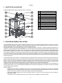 5
5
-
 6
6
-
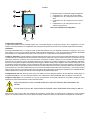 7
7
-
 8
8
-
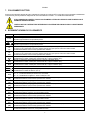 9
9
-
 10
10
-
 11
11
-
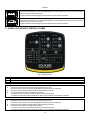 12
12
-
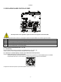 13
13
-
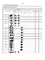 14
14
-
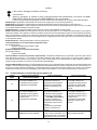 15
15
-
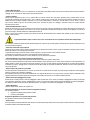 16
16
-
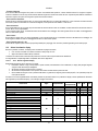 17
17
-
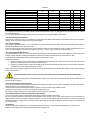 18
18
-
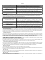 19
19
-
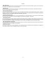 20
20
-
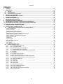 21
21
-
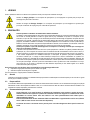 22
22
-
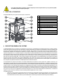 23
23
-
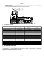 24
24
-
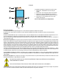 25
25
-
 26
26
-
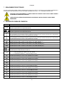 27
27
-
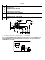 28
28
-
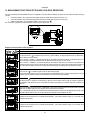 29
29
-
 30
30
-
 31
31
-
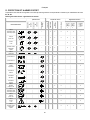 32
32
-
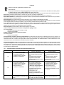 33
33
-
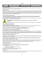 34
34
-
 35
35
-
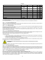 36
36
-
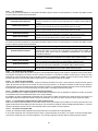 37
37
-
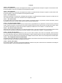 38
38
-
 39
39
-
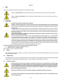 40
40
-
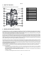 41
41
-
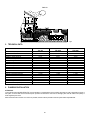 42
42
-
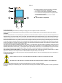 43
43
-
 44
44
-
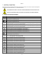 45
45
-
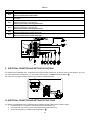 46
46
-
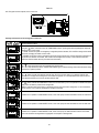 47
47
-
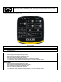 48
48
-
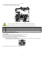 49
49
-
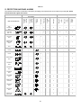 50
50
-
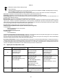 51
51
-
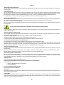 52
52
-
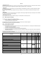 53
53
-
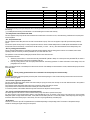 54
54
-
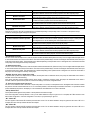 55
55
-
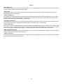 56
56
-
 57
57
-
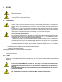 58
58
-
 59
59
-
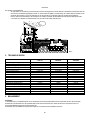 60
60
-
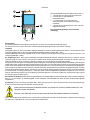 61
61
-
 62
62
-
 63
63
-
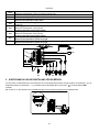 64
64
-
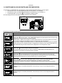 65
65
-
 66
66
-
 67
67
-
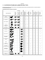 68
68
-
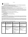 69
69
-
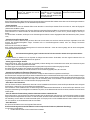 70
70
-
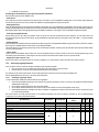 71
71
-
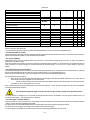 72
72
-
 73
73
-
 74
74
-
 75
75
-
 76
76
-
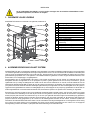 77
77
-
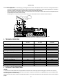 78
78
-
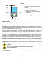 79
79
-
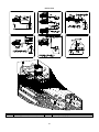 80
80
-
 81
81
-
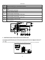 82
82
-
 83
83
-
 84
84
-
 85
85
-
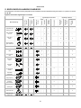 86
86
-
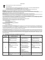 87
87
-
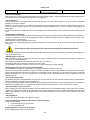 88
88
-
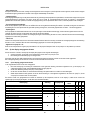 89
89
-
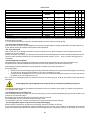 90
90
-
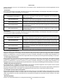 91
91
-
 92
92
-
 93
93


in andere talen
- English: DAB AQUATWIN TOP Operating instructions
- italiano: DAB AQUATWIN TOP Istruzioni per l'uso
- français: DAB AQUATWIN TOP Mode d'emploi
- Deutsch: DAB AQUATWIN TOP Bedienungsanleitung
