
PL-REM-200
Manual
English....................Page 2
Nederlands.......Pagina 8
Français...............Page 14
Deutsch...............Seite 20
LINK Driver
12-09-22

2
Table of contents
Technical specifications
Box contents
Installation instructions
Pairing Handheld Transmitter & controller
Handheld transmitter functions
Replacing transmitter battery
Troubleshooting
Page 3
Page 4
Page 5
Page 6
Page 7
Page 7
Page 7

3
ENG
Technical specifications
Electrical specifications
General specifications Controller
Ambient air temperature
Humidity
Dimensions
Weight
Ingress protection rate
0°C ... +40°C
10% ... 90% RH
non condensing
195x194x90 mm
3,2 kg
IP54
Nominal Input voltage
Output voltage on Lamp Output
Max output current on Lamp Output
Max rating Relay Contact A and B
Resistive Load
Inductive Load
Transformer VA rating
Fuse type
Frequency band transmitter
IEC Protection Class
230 VAC 50 Hz
12 VAC
16,7 A
14A 250VAC
14A 30VDC
6A 250VAC
6A 30VDC
200VA
5x20mm cartridge fuse
5A 250V slow blow/time lag
868 MHz
Class II

4
Box contents
12
45
1. PL-REM-200 controller
2. Handheld transmitter (DuraLink™ version)
3. Spare battery (type A23 12V)
4. Screws (4x) & wall plugs (4x)
5. Owners’s manual
3

5
ENG
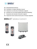
Installation instructions
• Connect a 230VAC power source to the “220-240VAC INPUT”
terminal
• Connect the swimming pool lights to the “Lamp 12VAC output”
terminal
Optional: The “Switch A” & “switch B” terminals can be used to control
auxiliary circuits like a pool cover or garden lights.
Make sure the total load of pool lights does not exceed 200Watt
Red status LED
Spare fuse

6
Pairing handheld transmitter & controller
The handheld transmitter is already paired in the factory and ready to
use. The PL-REM-200 can pair with up to 6 handheld transmitters. In
case a problem arises, the pairing process can be done manually:
Manual Pairing process:
Make sure the PL-REM-200 is connected to a power source.
1. Press the pairing button on the small circuit board, inside the con-
troller for at least 5 seconds.
--> The LED will start to blink fast
2. Within 25 seconds, press any button on the handheld transmitter.
--> If the transmitter is paired correctly, the LED will flash slowly for 5 times
--> If the PL-REM-200 pairing memory is full, the LED will flash 15 times.
This means 6 handheld devices have already been paired.
To unpair all handheld transmitters with the controller: Push the pair-
ing button for at least 5 seconds, then do nothing for at least 25 sec-
onds.
--> The pair memory will be erased - the green LED will flash 5x on/o.
If no transmitters are paired, the PL-REM-200 will accept messages from any transmitter!
Green LED
Pairing button

7
ENG
Handheld transmitter functions
PROBLEM SOLUTION
The controller doesn’t react
to transmitter commands
• Check the battery of the hand-
held transmitter
• The transmitter is not paired-
correctly with the controller.
Repeat the pairing process
• Reduce the distance between
handheld transmitter and PL-
REM-200 and/or remove ob-
stacles
The pool lights don’t work • Check the red status LED
• Check if there is 12VAC output
at the terminals of the controller
• Check the fuse of the controller
Troubleshooting
Toggle Output A ON/OFF
Toggle Output B ON/OFF
Toggle the lamps ON/OFF
Go to next color scenario
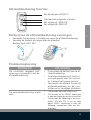
Replacing transmitter battery
• Remove the philips head screw and open the transmitter
• Replace the battery, respecting the polarity
Battery type: A23 12V
-
+
If the fuse is ok, and there is still no
12VAC output, contact your distributor

8
Inhoudstafel
Technische specificaties
Inhoud van de doos
Installatie-instructies
Afstandsbediening en controller koppelen
Afstandsbediening functies
Batterij van de afstandsbediening vervangen
Probleemoplossing
Pagina 9
Pagina 10
Pagina 11
Pagina 12
Pagina 13
Pagina 13
Pagina 13

9
NL
Technische specificaties
Elektrische specificaties
Algemene specificaties Controller
Omgevingstemperatuur
Vochtigheidsgraad
Afmetingen
Gewicht
IP klasse
0°C ... +40°C
10% ... 90% RH
non condensing
195x194x90 mm
3,2 kg
IP54
Ingangsspanning (nominaal)
Uitgangsspanning “Lamp 12VAC Output”
Max stroom “Lamp 12VAC Output”
Max vermogen Relais contact A en B
Resistieve Belasting
Inductieve Belasting
Transformator vermogen
Zekering type
Frequentie band afstandsbediening
IEC beschermingsklasse:
230 VAC 50 Hz
12 VAC
16,7 A
14A 250VAC
14A 30VDC
6A 250VAC
6A 30VDC
200VA
5x20mm smeltzekering
5A 250V slow blow/time lag
868 MHz
Class II

10
Inhoud van de doos
12
45
1. PL-REM-200 controller
2. Afstandsbediening (DuraLink™ versie)
3. Reserve batterij (type A23 12V)
4. Schroeven (4x) & muurpluggen (4x)
5. Handleiding
3

11
NL
Installatie instructies
• Verbind een 230VAC voedingsbron met de “220-240VAC INPUT”
aansluitklem
• Verbind de zwembadverlichting met de “Lamp 12VAC output”
aansluitklem
Optioneel: De “Switch A” & “switch B” aansluitklemmen kunnen
gebruikt worden om additionele circuits (zoals tuin-
verlichting of zwembadafdekking) aan te sturen
Zorg ervoor dat het totale vermogen van de zwembadverlichting
niet hoger is dan 200Watt
Rode status LED
Reserve zekering
Zwembadafdekking
Tuinverlichting

12
Afstandsbediening en controller koppelen
Groene LED
koppel-knop
De afstandsbediening is reeds gekoppeld van in de fabriek en is klaar
voor gebruik. The PL-REM-200 kan gekoppeld worden met maximaal
6 afstandsbedieningen. In probleemgevallen kan men de afstandsbe-
diening ook manueel koppelen.
Manueel koppel proces:
Zorg ervoor dat de PL-REM-200 verbonden is met een 230VAC voeding.
1. Druk op de rode koppel-knop op het kleine printplaatje binnen
in de controller, gedurende 5 seconden.
--> de rode LED zal nu snel knipperen
2. Druk op eender welke knop van afstandsbediening binnen
de 25 seconden
--> Als de afstandsbediening correct gekopeld is, zal de rode LED 5x
traag knipperen
--> Als er al 6 verschillende afstandsbedieningen met de controller gekoppeld
zijn, zal de rode LED 15x knipperen. Dit wil zeggen dat het geheugen vol is
Om ALLE afstandsbedieningen te ontkoppelen van de controller:
Druk op de rode koppel-knop gedurende 5 seconden.
Druk daarna op GEEN ENKELE knop binnen de 25 seconden.
--> Het geheugen is nu gewist. De groene LED zal 5x knipperen
Als er geen afstandsbedieningen gekoppeld zijn, zal de PL-REM-200 boodschappen
ontvangen van alle afstandsbedieningen!

13
NL
Afstandsbediening functies
PROBLEEM OPLOSSING
De controller reageert niet
meer op commando’s van de
afstandsbediening
• Controleer de batterij van de af-
standsbediening
• De afstandsbediening is niet cor-
rect gekoppeld met de control-
ler, herhaal het koppel proces
• Verminder de afstand tussen de
afstandsbediening en de con-
troller en/of verwijder obstakels
De zwembadverlichting werkt
niet
• Controleer de rode status LED
• Controleer of er 12VAC spanning
is aan de uitgang van de controller
• Controleer de zekering in de con-
troller. Als die OK is, en er nog
geen 12VAC spanning is aan de
uitgang, contacteer dan uw dis-
tributeur
Probleemoplossing
Zet uitgang A AAN/UIT
Zet uitgang B AAN/UIT
Zet de lampen AAN/UIT
Ga naar het volgende scenario
Batterij van de afstandsbediening vervangen
• Verwijder het kruiskop schroee en open de afstandsbediening
• Vervang de batterij en respecteer de polariteit
Battery type: A23 12V
-
+

14
Table des matières
Spécifications techniques
Contenu de la boîte
Instructions d’installation
Appairage du contrôleur et de l’émetteur portatif
Fonctions de l’émetteur portatif
Remplacer la batterie de l’émetteur
Résolution des problèmes
Page 15
Page 16
Page 17
Page 18
Page 19
Page 19
Page 19

15
FR
Spécifications techniques
Spécifications électriques
Spécifications générales du contrôleur
Température de l’air ambiant
Humidité
Dimensions
Poids
Indice de protection
De 0 °C à +40 °C
De 10 % à 90 % (HR)
sans condensation
195 x 194 x 90 mm
3,2 kg
IP54
Tension d’entrée nominale
Tension de sortie à la sortie de la lampe
Intensité électrique maximale à la sortie de la lampe
Valeurs maximales des contacts de relais A et B
Charge résistive
Charge inductive
Indice VA du transformateur
Types de fusibles
Bande de fréquences de l’émetteur
Classe de protection IEC
230 VAC - 50 Hz
12 VAC
16,7 A
14 A 250 VAC
14 A 30 VDC
6 A 250 VAC
6 A 30 VDC
200 VA
5 x 20 mm (fusibles car-
touches)
5A 250V (à fusion lente/
temporisé)
868 MHz
Classe II

16
Contenu de la boîte
12
45
1. Contrôleur PL-REM-200
2. Émetteur portatif (version DuraLink™)
3. Batterie de rechange (type A23 12V)
4. Vis (4x) & chevilles (4x)
5. Mode d’emploi
3

17
FR
Instructions d’installation
• Raccordez une source d’alimentation de 230 VAC à la borne
« 220-240 VAC INPUT »
• Raccordez les lampes de la piscine à la borne « Lamp 12 VAC out-
put »
Optionnel : Les bornes « Switch A » et « Switch B » peuvent être
utilisées pour contrôler des circuits auxiliaires tels qu’un
système de couverture de piscine ou des lampes de jardin.
Assurez-vous que la charge totale des lampes de la piscine ne
dépasse pas 200 Watts
LED d’état rouge
Fusible de
rechange

18
Appairage du contrôleur et de l’émetteur portatif
L’émetteur portatif est déjà appairé en usine et est donc prêt à l’emploi.
Le PL-REM-200 peut être appairé avec un maximum de 6 émetteurs por-
tatifs. Si un problème devait survenir, voici comment eectuer l’appairage
manuellement:
Appairage manuel:
Assurez-vous que le PL-REM-200 soit raccordé à une source d’alimentation.
1. Appuyez sur le bouton d’appairage sur le petit circuit imprimé situé à
l’intérieur du contrôleur pendant au moins 5 secondes.
--> Le LED se mettra à clignoter rapidement
2. Dans les 25 secondes, appuyez sur n’importe quel bouton sur l’émetteur
portatif.
--> Si l’émetteur est appairé correctement, le LED clignotera
lentement 5 fois
--> Si la mémoire d’appairage du PL-REM-200 est saturée, le LED
clignotera 15 fois. Cela signifie que 6 appareils portatifs ont déjà
été appairés.
Pour désappairer tous les émetteurs portatifs du contrôleur : Appuyez sur
le bouton d’appairage pendant au moins 5 secondes. Ensuite, ne faites rien
pendant au moins 25 secondes.
--> La mémoire d’appairage sera eacée – le LED verte clignotera 5 fois.
LED verte
Bouton
d’appairage
Si aucun émetteur n’est couplé, le PL-REM-200 acceptera les messages de n’importe quel
émetteur!

19
FR
Fonctions de l’émetteur portatif
PROBLÈME SOLUTION
Le contrôleur ne réagit pas
aux commandes de l’émet-
teur.
• Vérifiez la batterie ou l’émetteur
portatif.
• L’émetteur n’est pas appairé cor-
rectement au contrôleur.
• Répétez le processus d’ap-
pairage.
• Réduisez la distance entre l’émet-
teur portatif et le PL-REM-200 et/
ou éliminez les obstacles.
Les lampes de la piscine ne
fonctionnent pas
• Vérifiez le LED d’état rouge.
• Vérifiez s’il y a bien une tension
de 12 VAC aux bornes du con-
trôleur.
• Vérifiez le fusible ou le contrôleur
Résolution des problèmes
Allumer/éteindre la sortie A
Allumer/éteindre la sortie B
Allumer/éteindre les lampes
Programme de couleurs suivant
Remplacement de la batterie de l’émetteur
• Ôtez la vis Phillips et ouvrez l’émetteur
• Remplacez la batterie, en respectant la polarité
Type de batterie : A23 12V
-
+
Si le fusible est en bon état et qu’il n’y a toujours
aucune tension de 12 VAC en sortie, veuillez
contacter votre distributeur.

20
Inhaltsverzeichnis
Technische Spezifikationen
Lieferumfang
Installationsanleitung
Kopplung von Handsender und Regler
Funktionen des Handsenders
Handsenderbatterien auswechseln
Störungsbehebung
Seite 21
Seite 22
Seite 23
Seite 24
Seite 25
Seite 25
Seite 25

21
DE
Technische Spezifikationen
Elektrische Spezifikationen
Allgemeine Spezifikationen des Reglers
Umgebungslufttemperatur
Luftfeuchtigkeit
Maße
Gewicht
IEC-Schutzart
0°C ... +40°C
10% ... 90% RH
nicht kondensierend
195x194x90 mm
3,2 kg
IP54
Nominale Eingangsspannung
Ausgangsspannung des Strahlerausgangs
Max. Ausgangsstrom des Strahlerausgangs
Max. Kapazität des Relaisausgangs A und B
Ohmsche Last
Induktive Last
VA-Leistung Transformator
Sicherungstyp
RF-Band
IP-Schutzklasse
230 VAC 50 Hz
12 VAC
16,7 A
14A 250VAC
14A 30VDC
6A 250VAC
6A 30VDC
200VA
5 x 20mm Sicherungs-
einsatz 5A250V träge-
Schmelzsicherung
868 MHz
Class II

22
Lieferumfang
12
45
1. PL-REM-200-Regler
2. Handsender (DuraLink™-Version)
3. Ersatzbatterie (Typ A23 12V)
4. Schrauben (4x) & Wanddübel (4x)
5. Betriebsanleitung
3

23
DE
Installationsanleitung
• Schließen Sie eine 230VAC-Stromquelle an den “220-240VAC IN-
PUT”-Anschluss
• Verbinden Sie die Poolstrahler mit dem “Lamp 12VAC Output”-An-
schluss
Optional: Die “Switch A” & “Switch B”-Anschlüsse können zur
Steuerung zusätzlicher Schaltkreise wie Pool
abdeckung oder Gartenbeleuchtung verwendet
werden.
Stellen Sie sicher, dass die Gesamtleistung aller Poolstrahler
200 Watt nicht überschreitet.
Rote Status-LED
Ersatzsicherung

24
Kopplung von Handsender und Regler
Der Handsender ist bereits mit dem Regler gekoppelt und kann direkt einge-
setzt werden. Der PLA-REM-Regler kann mit bis zu 6 Handsendern verbun-
den werden. Sollten Probleme auftreten, kann die Kopplung manuell durch-
geführt werden:
Manuelle Kopplung:
Stellen Sie sicher, dass die PL-REM-200 an eine Stromquelle angeschlossen ist.
1. Halten Sie den Kopplungsknopf auf der kleinen Schaltplatte im
Regler für mindestens 5 Sekunden gedrückt.
--> Das LED-Lämpchen beginnt schnell zu blinken.
2. Drücken Sie innerhalb von 25 Sekunden einen beliebigen Knopf
auf dem Handsender.
--> Wenn der Handsender korrekt gekoppelt ist, blinkt die LED langsam
fünfmal
--> Wenn der PL-REM-200-Kopplungsspeicher voll ist, blinkt die LED
fünfzehnmal. Dies zeigt Ihnen an, dass bereits 6 Fernbedienungen
mit dem Gerät verbunden sind.
Entkopplung aller Handsender vom Regler: Halten Sie den Kopplungsknopf
mindestens 5 Sekunden lang gedrückt und betätigen Sie in den darauolgen-
den 25 Sekunden keinen Knopf.
--> Der Kopplungsspeicher wird dadurch gelöscht. - Die LED blinkt fünfmal.
Grüne LED
Kopplungsknopf
Wenn kein Sender gekoppelt ist, akzeptiert der PL-REM-200 Nachrichten von jedem
Sender!

25
DE
Funktionen des Handsenders
PROBLEM LÖSUNG
Der Regler reagiert nicht auf die
Befehle des Handsenders
• Batterie des Handsenders kontrol-
lieren
• Der Handsender ist nicht korrekt
mit dem Regler gekoppelt.
• Kopplungsvorgang wiederholen
• Entfernung zwischen Handsender
und PL-REM-200 verringern bzw.
Störquellen beseitigen
Die Poolbeleuchtung funktioniert
nicht
• Rote Status-LED überprüfen
• Kontrollieren Sie, ob an den An-
schlüssen des Reglers eine Span-
nung von 12VAC besteht
• Sicherung des Reglers überprüfen
Störungsbehebung
Schaltet Ausgang A EIN/AUS
Schaltet Ausgang B EIN/AUS
Schaltet die Strahler EIN/AUS
Wechselt zum nächsten Beleuchtungsmodus
Handsenderbatterien auswechseln
• Entfernen Sie die Kreuzschlitzschraube und önen Sie den Handsender.
• Wechseln Sie die Batterie aus, achten Sie dabei auf die Polarität.
Batterietyp: A23 12V
-
+
Kontaktieren Sie Ihren Händler, wenn die
Sicherung in Ordnung ist, aber keine 12VAC
Ausgangsspannung besteht

26
Declaraction of Conformity
Declarations of conformity covering this product are available for
download from the House of Duratech website: www.duratech.be

VISION Moonlight
VISION Spectra
VISION Adagio Pro
VISION Wall Conduits
VISION Faces Plates
VISION Specials
COVER Tube
COVER Wall Duct
COVER Motor
VISION Pro
HEAT Hot Splash
HEAT Sun Spring
HEAT Dura +i
HEAT Dura Vi
HEAT Dura V
HEAT Dura Pro
HEAT Accessories
LINK Touch
LINK Driver
LINK Master
LINK Controller
LINK Accessoires
LINK Cover
FLOW Inverter
COVER Hanging System
COVER Cable Duct

Contact details
Propulsion Systems bv
Dooren 72
1785 Merchtem, Belgium
Tel +32 2 461 02 53
www.duratech.be
402-0019-2
We reserve the rights to change all or part of the contents of this document without prior notice
-
 1
1
-
 2
2
-
 3
3
-
 4
4
-
 5
5
-
 6
6
-
 7
7
-
 8
8
-
 9
9
-
 10
10
-
 11
11
-
 12
12
-
 13
13
-
 14
14
-
 15
15
-
 16
16
-
 17
17
-
 18
18
-
 19
19
-
 20
20
-
 21
21
-
 22
22
-
 23
23
-
 24
24
-
 25
25
-
 26
26
-
 27
27
-
 28
28


in andere talen
- français: Duratech PL-REM-200 Manuel utilisateur
- Deutsch: Duratech PL-REM-200 Benutzerhandbuch
Gerelateerde papieren
Andere documenten
-
Chamberlain LiftMaster 5002 EX de handleiding
-
 Speck pumpen Stainless steel hand rail for JET smart, 25 x 250 mm Handleiding
-
Chamberlain TPD10 de handleiding
-
-
-
-
