Eaton 3200RT Handleiding
- Categorie
- Noodstroomvoorzieningen (UPS'en)
- Type
- Handleiding

www.eaton.com
Installation and user
manual
English
Français
Deutsch
Italiano
Español
Nederlands
EX
2200 RT 2U
2200 RT 3U
3000 RT 2U
3000 RT 3U
3000 RT 3U XL
EXB RT 3U
Pulsar Series

3400777600/AD

www.eaton.com
Installation and user
manual
EX
2200 RT 2U
2200 RT 3U
3000 RT 2U
3000 RT 3U
3000 RT 3U XL
EXB RT 3U
Pulsar Series

34007776EN/AD - Page 2

34007776EN/AD - Page 3
Introduction
Environmental protection
EATON has implemented an environmental-protection policy.
Products are developed according to an eco-design approach.
Substances
This product does not contain CFCs, HCFCs or asbestos.
Packing
To improve waste treatment and facilitate recycling, separate the various packing components.
◗ The cardboard we use comprises over 50% of recycled cardboard.
◗ Sacks and bags are made of polyethylene.
◗ Packing materials are recyclable and bear the appropriate identification symbol .
Follow all local regulations for the disposal of packing materials.
End of life
EATON will process products at the end of their service life in compliance with local regulations.
EATON works with companies in charge of collecting and eliminating our products at the end of their service life.
Product
The product is made up of recyclable materials.
Dismantling and destruction must take place in compliance with all local regulations concerning waste.
At the end of its service life, the product must be transported to a processing centre for electrical and electronic waste.
Battery
The product contains lead-acid batteries that must be processed according to applicable local regulations concerning
batteries.
The battery may be removed to comply with regulations and in view of correct disposal.
Thank you for selecting an EATON product to protect your electrical equipment.
The EX range has been designed with the utmost care.
We recommend that you take the time to read this manual to take full advantage of the many features of your UPS
(Uninterruptible Power System).
Before installing EX, please read the booklet on the required safety instructions. Then follow the indications in this
manual.
To discover the entire range of EATON products and the options available for the EX range, we invite you to visit our
web site at www.eaton.com or contact your EATON representative.
Material Abbreviation Symbol
number
Polyethylene terephthalate PET 01
High-density polyethylene HDPE 02
Polyvinyl chloride PVC 03
Low-density polyethylene LDPE 04
Polypropylene PP 05
Polystyrene PS 06

34007776EN/AD - Page 4
Introduction
Pictograms
Important instructions that must always be followed.
Information, advice, help.
Visual indication.
Action.
Audio signal.
In the illustrations on the following pages, the symbols below are used:
LED off
LED on
LED flashing

34007776EN/AD - Page 5
Contents
1. Presentation
1.1 Standard positions ...................................................................................................................... 6
Tower position................................................................................................................................ 6
Rack position.................................................................................................................................. 6
1.2 Rear panels................................................................................................................................... 7
EX 2200 / 3000 .............................................................................................................................. 7
EX EXB (optional battery module) .................................................................................................. 7
1.3 Control panel................................................................................................................................7
2. Installation
2.1 Unpacking and contents check................................................................................................... 8
2.2 Installation in tower position...................................................................................................... 9
2.3 Installation in rack position ........................................................................................................ 9
2.4 Communication ports.................................................................................................................10
Connection of RS232 or USB communication port (optional) .......................................................10
Installation of the communication cards (optional) .......................................................................10
2.5 Connection with a FlexPDU (Power Distribution Unit) module.................................................11
2.6 Connection with a HotSwap MBP module...............................................................................11
HotSwap MBP-module operation .................................................................................................12
2.7 UPS connection without a FlexPDU or HotSwap MBP module.............................................12
3. Operation
3.1 Start-up and normal operation..................................................................................................13
3.2 Operation on battery power ......................................................................................................13
3.3 Return of AC input power ..........................................................................................................14
3.4 UPS shutdown ............................................................................................................................14
3.5 Using the UPS remote control functions..................................................................................14
4. Access to measurements and personalisation data
4.1 Display menus arrangement......................................................................................................16
4.2 Access to measurements ...........................................................................................................16
4.3 Personalisation using the control panel ...................................................................................16
4.4 Personalisation using external software...................................................................................17
5. Maintenance
5.1 Troubleshooting ..........................................................................................................................18
Troubleshooting a UPS equipped with the HotSwap MBP module ..............................................19
5.2 Battery-module replacement .....................................................................................................19
Safety recommendations..............................................................................................................19
Battery-module removal................................................................................................................19
Mounting the new battery module .............................................................................................. 20
5.3 Maintenance on a UPS equipped with the HotSwap MBP module...................................... 20
5.4 Training centre............................................................................................................................ 21
6. Appendices
6.1 Technical specifications............................................................................................................. 22
6.2 Glossary ...................................................................................................................................... 23

34007776EN/AD - Page 6
1. Presentation
1.1 Standard positions
Tower position
Rack position
Dimensions (H x W x D) in mm
EX 2200 RT 2U 440 x 86 x 640
EX 2200 RT 3U 440 x 131 x 490
EX 3000 RT 2U 440 x 86 x 640
EX 3000 RT 3U 440 x 131 x 490
EX 3000 RT 3U XL
440 x 131 x 490
EX EXB RT 3U 440 x 131 x 490
Weights in kg
EX 2200 RT 2U 31
EX 2200 RT 3U 30
EX 3000 RT 2U 31
EX 3000 RT 3U 30
EX 3000 RT 3U XL
17
EX EXB RT 3U 42

34007776EN/AD - Page 7
1. Presentation
1.2 Rear panels
EX 2200 / 3000 / 3000 XL
EX EXB (optional battery module)
1.3 Control panel
(1) USB communication port
(2) RS232 communication port
(3) Connector for automatic recognition of
an additional battery module
(4) Slot for optional communication card
(5) Connector for remote ON/OFF and RPO
(Remote Power Off) control
(6) Connector for additional battery
module
(7) 16 A outlet for connection of equipment
(8) Two groups of 2 programmable outlets
for connection of equipment
(9) Groups of 4 outlets for connection of
equipment
(10) Socket for connection to AC-power
source
(11) LED (SWF) indicating distribution
system phase/neutral reversal
(12) Connectors for battery modules (to
the UPS or to the other battery modules)
(13) Connectors for automatic recognition
of battery modules
(20) Load protected LED
(21) Downgraded operation LED
(22) Load not protected LED
(23) Alphanumeric display
(24) Escape (cancel) button
(25) Scroll button
(26) Enter (confirm) button
(27) ON/OFF button for UPS and outlets
21
3 7
8
9 104
5
6
11
1312 12
20
21
22
23
24 25 26
27
ESC

34007776EN/AD - Page 8
2. Installation
2.1 Unpacking and contents check
(30) EX 2200 / 3000 / 3000 XL UPS
(31) connection cable to AC-power source
(32) 2 connection cables for the protected equipment
(33) RS232 communication cable
(34) USB communication cable
(35) 2 systems to secure power plugs
(36) Solution-Pac CD-ROM
(37) Documentation
Elements supplied depending on the version or optional
(38) Mounting kit for 19-inch bays
(39) 2 supports for the upright position (2U version only)
(40) FlexPDU module (optional)
(41) connection cable between FlexPDU module and UPS
(42) NMC communication card (optional)
(43) HotSwap MBP module (optional)
(44) connection cables between HotSwap MBP module
and UPS
Packing materials must be disposed of in compliance with all local regulations concerning waste.
Recycling symbols are printed on the packing materials to facilitate sorting.

34007776EN/AD - Page 9
2. Installation
2.2 Installation in tower position
2.3 Installation in rack position
It is advised to first install the battery module, then the power module above.
Follow steps 1 to 4 for module mounting on the rails.
The rails and necessary hardware are supplied by EATON.

34007776EN/AD - Page 10
2. Installation
2.4 Communication ports
Connection of RS232 or USB communication port (optional)
Installation of the communication cards (optional)
The RS232 and USB communication ports cannot operate simultaneously.
1 - Connect the RS232 (33) or USB (34)
communication cable to the serial or USB
port on the computer equipment.
2 - Connect the other end of the
communication cable (33) or (34) to the
USB (1) or RS232 (2) communication port
on the UPS.
The UPS can now communicate with
EATON power management software.
Communication card slot
(restricted access)
It is not necessary to shutdown the UPS
before installing a communication card.
1 - Remove the UPS cover (4) secured by
screws.
2 - Insert the communication card in the
slot.
3 - Put the UPS cover back in place using
the screws.
34
2
1
33
4

34007776EN/AD - Page 11
2. Installation
2.5 Connections with a FlexPDU (Power Distribution Unit) module (optional)
2.6 Connections with a HotSwap MBP module (optional)
The HotSwap MBP module makes it possible to service or even replace the UPS without affecting the connected
loads (HotSwap function).
1 - Connect the UPS socket (10) to the AC-
power source using the cable (31)
supplied.
2 - Connect the input socket on the
FlexPDU module (48) to the UPS outlet (7)
using the cable (41) supplied. The cable
and the connectors are marked in red.
3 - Connect the equipment to the outlets
(45), (46) and (47) on the FlexPDU module.
These outlets differ, depending on the
version of the FlexPDU module.
4 - Fit the connection securing system that
prevents the plugs from being pulled out
accidentally.
1 - Connect the input socket (56) on the
HotSwap MBP module to the AC-power
source using the cable (31) supplied.
2 - Connect the UPS input socket (10) to
the "UPS Input" (55) on the HotSwap MBP
module, using the cable (44) supplied.
These cables and the connectors are
marked blue.
3 - Connect the UPS outlet (7) to the "UPS
Output" (54) on the HotSwap MBP
module, using the cable (44) supplied.
These cables and the connectors are
marked red.
4 - Connect the equipment to the outlets
(49) and (50) on the HotSwap MBP
module. These outlets differ, depending
on the version of the HotSwap MBP
module.
Caution. Do not use UPS outlets (8) and
(9) to supply equipment because use of
switch (53) on the HotSwap MBP module
would cut supply to the equipment. It is
advised not to remove the protective film
from outlets (8) and (9).
7
8
9 10
48474645
FlexPDU
41
31
7
8
9 10
By-pass
Normal
UPS ON -
OK to switch
BY PASS SWITCH
56
5549
HotSwap MBP
50
545351 52
44
31

34007776EN/AD - Page 12
2. Installation
HotSwap MBP-module operation
UPS start-up with the HotSwap MBP module
1 - Check that the UPS is correctly connected to the HotSwap MBP module.
2 - Set switch (53) to the Normal position.
3 - Start the UPS by pressing the ON/OFF button (27) on the UPS control panel.
The load is supplied by the UPS.
LED (51) "UPS ON - OK to switch" on the HotSwap MBP module goes ON.
HotSwap MBP-module test
1 - Set switch (53) to the Bypass position and check that the load is still supplied.
2 - Set switch (53) back to the Normal position.
2.7 UPS connection without a FlexPDU or HotSwap MBP module
The HotSwap MBP module has a rotary
switch (53) with two positions:
Normal - the load is supplied by the UPS,
Bypass - the load is supplied directly by
the AC-power source.
Check that the indications on the name plate located on the back of the UPS correspond to the AC-power source
and the true electrical consumption of the total load.
1 - Connect the supplied cable (31) (250 V -
16 A) to the socket (10), then to the AC-
power source.
2 - Connect the loads to the UPS using the
cables (32).
It is preferable to connect the priority loads
to the four outlets marked (9) and the non-
priority loads to the four outlets marked (8)
that can be programmed in pairs (1 and 2).
Connect any high-power devices to the 16
A outlet (7).
To program shutdown of outlets (8) during
operation on battery power and thus
optimise the available backup time, the
EATON communication software is
required.
3 - Fit the connection securing system (35)
that prevents the plugs from being pulled
out accidentally.
Note. The UPS charges the battery as soon as it is connected to the AC-power source, even if button (27) is not
pressed.
Once the UPS is connected to the AC-power source, eight hours of charging are required before the battery can
supply the rated backup time.
EX 3000 XL: at least one additionnal EXB battery module must be connected to the UPS because it does not have
internal batteries.
Refer to EXB battery module installation manual (doc n° 34008167) for further information about connections.
By-pass
Normal
UPS ON -
OK to switch
BY PASS SWITCH
51
52 53
10
8
9
31
32
35
7

34007776EN/AD - Page 13
3. Operation
3.1 Start-up and normal operation
UPS personalisation
3.2 Operation on battery power
Transfer to battery power
Low-battery warning
For the initial start, AC input power must be present to detect any wiring errors. Subsequently, the UPS can start even
if AC input power is not present.
Press button (27) for approximately 1 second.
◗ The buzzer beeps once and all the LEDs go ON simultaneously.
◗ The buzzer then beeps twice during the self-test, then button (27)
remains ON, indicating that the load outputs are supplied.
The connected devices are protected by the UPS.
◗ LED (20) is ON.
If LED (22) is ON, a fault has occurred (see the
"Troubleshooting"
section).
◗ During normal operation, the scroll button (25) may be used to read
UPS measurements (voltage on normal and bypass AC inputs,
operating mode, battery capacity and UPS serial number).
If UPS personalisation is desired, it is advised to enter the personalisation mode at this time.
This mode may be entered using the buttons on the control panel or the Personal Solution-Pac software (Windows)
included on the Solution-Pac CD-ROM provided by EATON.
◗ The connected devices continue to be supplied by the UPS when AC
input power is no longer available. The necessary energy is provided
by the battery.
◗ LEDs (20) and (21) go ON.
◗ The audio alarm beeps every ten seconds.
The connected devices are supplied by the battery.
The display indicates the remaining backup time.
◗ LEDs (20) and (21) go ON.
◗ The audio alarm beeps every three seconds.
The remaining battery power is low.
Shut down all applications on the connected equipment because
automatic UPS shutdown is imminent.
20
27
22
21
25
ESC
20
21
ESC
20
21
ESC

34007776EN/AD - Page 14
3. Operation
End of battery backup time
3.3 Return of AC input power
Following an outage, the UPS restarts automatically when AC input power returns (unless the restart function was
disabled via UPS personalisation) and the load is again supplied.
3.4 UPS shutdown
3.5 Using the UPS remote control functions
EX offers a choice between two remote control functions.
◗ RPO: Remote Power Off allows a remote contact to be used to disconnect all the equipment connected to the UPS.
Restarting the UPS requires manual intervention.
◗ ROO: Remote ON/OFF allows remote action of button (27) to shut down the UPS.
These functions are obtained by opening a contact connected between the appropriate pins of connector (5) on the
rear panel of the UPS (see diagram on figures below).
Remote control connection and test
◗ All the LEDs go OFF.
◗ The audio alarms stops.
The UPS is completely shut down.
Press button (27) for approximately 2 seconds.
The devices connected to the UPS are no longer supplied.
1 - Check that the UPS is off and disconnected from the AC input source.
2 - Remove connector (5) after unscrewing the screws.
3 - Connect a normally closed volt-free contact (60 Vdc / 30 Vac max, 20 mA max, 0.75 mm² cable cross section)
between the two pins of connector (5), see diagram.
20
21
27
22
ESC
5

34007776EN/AD - Page 15
3. Operation
Contact open: shut down of UPS
Contact closed: start-up of UPS (UPS connected to the network and network energized)
Note: local On/Off control via button (27) has priority over the remote control order.
Contact open: shut down of UPS
To return to normal operation, deactivate the external remote shut down contact and
restart the UPS using button (27).
4 - Plug connector (5) into the back of the UPS.
5 - Connect and restart the UPS according to the previously described procedures.
6 - Activate the external remote shut down contact to test the function.
Warning: this connector must only be connected to SELV (Safety Extra Low Voltage) circuits
5
ROO
5
RPO

34007776EN/AD - Page 16
4. Access to measurements and personalisation data
4.1 Display menus arrangement
4.2 Access to measurements
Press the scroll button (25) to access any status conditions and alarms, then the measurements for voltage, current,
frequency, power output and battery backup time.
4.3 Personalisation using the control panel
Local personalisation
◗ Press the scroll button (25) several times until the personalisation
menu is reached.
◗ Press the Enter button (26) to access the different possibilities.
◗ Finally, confirm the selection by pressing the Enter button (26)
again.
Function Factory setting Other available settings
Language English French, Spanish, German, Italian, Dutch
Audio alarm Enabled Disabled
Status and Alarms
Status and Alarms
Measurements
UPS input measurements
UPS output measurements
Battery measurements
Personalisation
Local personalisation
Output personalisation
ON/OFF personalisation
Battery personnalisation
25
26
ESC

34007776EN/AD - Page 17
4. Access to measurements and personalisation data
Output personalisation
(1) These parameters may be modified only when the UPS is OFF.
Detailed comments are available in the Personal Solution-Pac software.
ON/OFF personalisation
Battery personalisation
4.4 Personalisation using external software
Function Factory setting Other available settings Comments
Output voltage
(1)
230 Volts AC 200/208/220/240 Volts AC
Frequency converter
(1)
Disabled Enabled The connected devices are never
transferred to the bypass.
Output frequency
(1)
Automatic selection 50 or 60 Hz User selectable only if the
frequency-converter function is
enabled.
Transfer to the bypass
AC input
(1)
Bypass AC power must
be within tolerances
Bypass AC power may be
outside tolerances
Overload level
(1)
102% 50 / 70% Alarm if threshold is overrun.
Function Factory setting Other available settings Comments
Cold start Enabled Disabled
Automatic restart Enabled Disabled The UPS restarts automatically
when AC input power returns.
Energy savings Disabled Enabled When function enabled, battery
shuts down when power drops to
<5%.
Detection of phase/
neutral inversion (SWF)
Disabled Enabled When function enabled, the UPS
remains OFF if the system detects
phase/neutral inversion.
Function Factory setting Other available settings Comments
Battery test Weekly test No test / daily test /
monthly test
Selection of the backup
time
Automatic detection of
number of battery
modules
65 to 400 Ah
Battery protection
against deep discharge
Enabled Disabled When function disabled, EATON
warranty no longer applies.
◗ Insert the Solution-Pac CD-ROM in the drive.
◗ On the first navigation screen, select "Point to Point solution" and follow the instructions on how to install the
Personal Solution-Pac software.
◗ Then select "Settings", "Advanced settings" and "UPS settings".
Note that the Linux/Unix/MacOS versions of the Personal Solution-Pac software do not offer this possibility.

34007776EN/AD - Page 18
5. Maintenance
5.1 Troubleshooting
If LED (21) or (22) is ON, a fault or an alarm has occurred.
Use the escape button (24) to stop the audio alarm.
Indication Diagnostic Correction
1 The UPS does not start,
the alphanumeric display indicates:
COLD START NOK
CHECK AC WIRING
The AC input power is not
connected or is connected to the
UPS output.
Check the UPS is correctly
connected to the AC input power.
2 LED (22) is ON, the SWF LED (11) at
the rear of the UPS is ON.
The alphanumeric display indicates:
SITE WIR. FAULT
CHECK AC WIRING
Phase inversion on AC input
power. The UPS does not start.
◗ In an earthed-neutral system, to
correct the wiring, disconnect and
turn the AC-power outlet 180°
(DIN-SCHUKO type) or call an
electrician to modify the
connections.
◗ For all other types of system,
disable the detection function.
3 LED (22) is ON,
the alphanumeric display indicates:
NO BATTERY
CHECK CONNECTION
The battery is incorrectly
connected.
Check battery connections (see
section 5.2, Battery-module
replacement).
4 LED (22) is ON,
the alphanumeric display indicates:
BATTERY FAULT
SERV REQUIRED
A fault is detected on the battery. Replace the battery (see section
5.2, Battery-module replacement).
Call the after-sales support
department.
5 LED (21) is ON,
the alphanumeric display indicates:
OVERLOAD ALARM
REDUCE LOAD
The load level exceeds the
programmed overload level or
UPS capacity.
Check the power drawn by the
connected devices and disconnect
any non-priority devices. Check
the programmed overload level.
6 LED (22) is ON,
the alphanumeric display indicates:
LOAD UNPROTECTED
OUTPUT OVERLOAD
The UPS is overloaded. Devices
connected to the UPS are
supplied directly by the AC input
source via the By-pass.
Check the power drawn by the
connected devices and disconnect
any non-priority devices.
7 LED (22) is ON,
the alphanumeric display indicates:
REDUCE LOAD
RESTART UPS
After repetitive overloads, the
UPS is locked in the By-pass
position. Devices connected to the
UPS are supplied directly by the
AC input source.
Check the power drawn by the
connected devices and disconnect
any non-priority devices.
Shut down and restart the UPS to
return to normal operation.
8 LED (22) is ON,
the alphanumeric display indicates:
OVERLOAD FAULT
REDUCE LOAD
The UPS shut down automatically
because of overload at the UPS
output.
Check the power drawn by the
connected devices and disconnect
any non-priority devices.
9 LED (22) is ON,
the alphanumeric display indicates:
LOAD SHORT-CIRCU
CHECK WIRING
The UPS has shut down
automatically because of a short-
circuit at the UPS output.
Check the installation at the UPS
output (wiring, load equipment
faults).
10 LED (22) is ON,
the alphanumeric display indicates:
INTERNAL FAULT
SERV REQUIRED
A UPS internal fault has occurred.
There are two possible situations:
◗ the load is still supplied, but
directly with AC input power via
the bypass,
◗ the load is no longer supplied.
Call the after-sales support
department.
11 The alphanumeric display indicates:
REMOTE POWER OFF
RPO
The Remote Power Off (RPO)
contact has been activated to shut
down the UPS.
Set the contact back to its the
normal position, and press the ON/
OFF button to restart.

34007776EN/AD - Page 19
5. Maintenance
Troubleshooting a UPS equipped with the HotSwap MBP module
5.2 Battery-module replacement
Safety recommendations
The battery can cause electrocution and high short-circuit currents. The following safety precautions are required
before servicing the battery components:
◗ Remove watches, rings, bracelets and all other metal objects from the hands and arms,
◗ Use tools with an insulated handle.
Battery-module removal
Indication Diagnostic Correction
12 The load is no longer supplied when
the rotary switch (49) on the
HotSwap MBP module is set to the
Bypass position.
◗ The protected devices are
connected to the UPS output
instead of to the HotSwap MBP
module.
◗ The AC-power cord is connected
to the UPS input instead of to the
HotSwap MBP module.
Check the wiring between the UPS
and the HotSwap MBP module
(see section 2.6).
13 The load is no longer supplied when
the rotary switch (49) on the
HotSwap MBP module is set to the
Normal position.
◗ The UPS is shut down.
◗ The wiring between the UPS and
the HotSwap MBP module is not
correct.
◗ Start the UPS.
◗ Check the wiring between the
UPS and the HotSwap MBP
module (see section 2.6).
14 The load is no longer supplied after
AC-power fails.
◗ The rotary switch (49) on the
HotSwap MBP module is set to
the Bypass position.
◗ The wiring between the UPS and
the HotSwap MBP module is not
correct.
◗ Set the rotary switch (49) on the
HotSwap MBP module to the
Normal position.
◗ Check the wiring between the
UPS and the HotSwap MBP
module (see section 2.6).
If a fault leads to UPS shutdown, press the ON/OFF button (27) to clear the fault.
A - Unscrew the left-hand side of the front
panel (two screws).
B - Remove the part.
C - Disconnect the battery block by
separating the two connectors (never pull
on the wires).
C

34007776EN/AD - Page 20
5. Maintenance
Mounting the new battery module
Carry out the above instructions in reverse order.
5.3 Maintenance on a UPS equipped with the HotSwap MBP module
D - Remove the metal protection cover in
front of the battery (two screws).
E - Pull the plastic tab to remove the
battery block and replace it.
◗ To ensure safety and high performance, use only batteries supplied by EATON.
◗ Take care to firmly press together the two parts of the connector during remounting.
The HotSwap MBP module makes it
possible to service or even replace the
UPS without affecting the connected loads
(HotSwap function).
Maintenance:
1 - Set switch (53) to the Bypass position.
The red LED on the HotSwap MBP module
goes ON, indicating that the load is
supplied directly with AC input power.
2 - Stop the UPS by pressing the ON/OFF
button (27) on the UPS control panel. LED
(51) "UPS ON - OK to switch" goes OFF, the
UPS can now be disconnected and
replaced.
Return to normal operation:
1 - Check that the UPS is correctly
connected to the HotSwap MBP module.
2 - Start the UPS by pressing the ON/OFF
button (27) on the UPS control panel. LED
(51) "UPS ON - OK to switch" on the
HotSwap MBP module goes ON
(otherwise, there is a connection error
between the HotSwap MBP module and
the UPS).
3 - Set switch (53) to the Normal position.
The red LED on the HotSwap MBP module
goes OFF.
D
E
7
8
9 10
By-pass
Normal
UPS ON -
OK to switch
BY PASS SWITCH
56
5549
HotSwap MBP
50
545351 52
44
31

34007776EN/AD - Page 21
5. Maintenance
5.4 Training centre
To fully master operation of your EATON product and carry out level 1 servicing, see our complete range of technical
training courses, available in both French and English.
For further information, please visit our website: www.eaton.com

34007776EN/AD - Page 22
6. Appendices
6.1 Technical specifications
(1) Depending on the output voltage selected: 200V / 208V / 220V / 230V / 240V, the output power is
1980VA / 1980VA / 2200VA / 2200VA / 2200VA.
(2) Depending on the output voltage selected: 200V / 208V / 220V / 230V / 240V, the output power is
2700VA / 2700VA / 3000VA / 3000VA / 3000VA.
(3) Standard output power is 2700 W, 2400 W with an EXB module.
(4) Values for 33% / 66% / 100% of UPS output.
(5) Programmable: 200V / 208V / 220V / 230V / 240V using the UPS Config software.
(6) Frequency-converter mode is programmable using the UPS Config software.
(7) Depending on the output voltage selected: 200V / 208V / 220V / 230V / 240V, the maximum output current is
9.9A / 9.5A / 10A / 9.6A / 9.2A.
(8) Depending on the output voltage selected: 200V / 208V / 220V / 230V / 240V, the output current is
13.5A / 13A / 13.6A / 13A / 12.5A.
EX 2200 EX 3000
EX 3000 XL
EX EXB
Output power 2200 VA
(1)
/
1980 W
3000 VA
(2)
/
2700 W
(3)
3000 VA
(2)
/
2700 W
(3)
Electrical supply network
◗ Rated input voltage
◗ Input voltage range
◗ Frequency
◗ Power factor
◗ Leakage current
Single phase 230 V
110 / 140 / 200 V to 284 V
(4)
50/60 Hz (autoselection)
> 0.95
< 2 mA
Load output
◗ Voltage
◗ Frequency
◗ Harmonic distortion
◗ Overload capacity
◗ Current
Single phase 230 V ±3%
(5)
50/60 Hz ±0,5%
(6)
< 4% for linear load,
< 6% for nonlinear load
102% continuous, 105% 20s, > 130% 1.5s
9.6 A
(7)
13 A
(8)
Battery 6 x 12V - 7 Ah,
sealed lead acid,
maintenance free
6 x 12V - 9 Ah,
sealed lead acid,
maintenance free
without internal
battery
Two 6 x 12 V - 9 Ah
strings, sealed
lead acid,
maintenance free
Environment
◗ Operating temperature range
◗ Relative humidity
◗ Storage temperature range
◗ Altitude
◗ Noise level
0°C to 40°C
20% to 90% (without condensation)
-25°C to 40°C
1000 m
< 46 dBA < 50 dBA

34007776EN/AD - Page 23
6. Appendices
6.2 Glossary
Bypass AC input Bypass line from the AC-power source, controlled by the UPS, used to directly supply the
load if an overload or a malfunction occurs on the UPS.
Backup time Time during which the load can be supplied by the UPS operating on battery power.
Battery test Internal UPS test to check battery status.
Cold start The devices connected to the UPS can be started even if AC input power is not available.
The UPS operates on battery power alone.
Deep discharge Battery discharge beyond the permissible limit, resulting in irreversible damage to the
battery.
FlexPDU Module with UPS outlets for installation in a bay. There are different modules with different
types of outlets.
Frequency converter Operating mode used to convert the AC-power frequency between the UPS input and
output
(50 Hz -> 60 Hz or 60 Hz -> 50 Hz).
HotSwap MBP UPS manual-bypass module for maintenance. There are different modules with different
types of outlets.
Load Devices or equipment connected to the UPS output.
Low-battery
warning
This is a battery-voltage level indicating that battery power is low and that the user must
take action in light of the imminent break in the supply of power to the load.
Normal AC input The AC-power line supplying the UPS under normal conditions.
Percent load Ratio of the power effectively drawn by the load to the maximum output of the UPS.
Personalisation It is possible to modify certain UPS parameters set in the factory. Certain UPS functions
can also be modified by the Personal Solution-Pac software to better suit user needs.
Programmable
outlets
These outlets can be automatically shut down during operation on battery power
(shutdown time delays can be programmed with the Personal Solution Pac software). The
UPS has two sets of two programmable outlets.
UPS Uninterruptible Power System.
UPS ON/OFF
controlled by
software
This function enables or disables initiation of UPS ON/OFF control sequences by computer
power management software.

34007776EN/AD
www.eaton.com

www.eaton.com
Manuel d’installation et
d’utilisation
EX
2200 RT 2U
2200 RT 3U
3000 RT 2U
3000 RT 3U
3000 RT 3U XL
EXB RT 3U
Pulsar Series

34007776FR/AD - Page 2

34007776FR/AD - Page 3
Introduction
Respect de l'environnement
La société EATON s’est engagée dans une politique de protection et de préservation de l’environnement.
Nos produits sont développés selon une démarche d’éco-conception.
Substances
Ce produit ne contient ni de CFC, ni de HCFC, ni d’amiante.
Emballage
Pour améliorer le traitement des déchets et faciliter le recyclage, séparez les éléments de l’emballage.
◗ Le carton est composé de plus de 50% de carton recyclé.
◗ Les sacs et sachets sont en polyéthylène.
◗ Les matériaux constituant l’emballage sont recyclables et marqués du symbole d’identification .
Suivre les règlementations locales en vigueur pour l’élimination de l’emballage.
Fin de vie
La société EATON s’est engagée à traiter les produits en fin de vie selon les règlementations locales.
EATON travaille avec des sociétés en charge de la collecte et de l’élimination de nos produits en fin de vie.
Produit
Le produit est composé de matériaux recyclables.
Son démantèlement et sa destruction doivent se faire en accord avec les règlementations locales en vigueur
concernant les déchets.
Le produit en fin de vie doit être déposé dans un centre de traitement des déchets électriques et électroniques.
Batterie
Le produit contient des batteries au plomb qui doivent être traitées suivant les règlementations locales en vigueur
concernant les batteries.
Pour suivre ces règlementations et éliminer la batterie de manière propre, il est possible de l’extraire du produit.
Nous vous remercions d'avoir choisi un produit EATON pour la sécurité de vos applications.
La gamme EX a été élaborée avec le plus grand soin.
Pour exploiter au mieux les performances de votre ASI (Alimentation Sans Interruption), nous vous conseillons de
prendre le temps de lire ce manuel.
Avant l’installation de EX, lire le livret qui présente les consignes de sécurité à respecter. Suivre ensuite les
instructions du présent manuel.
Nous vous invitons à découvrir l'offre de EATON ainsi que les options de la gamme EX en visitant notre site WEB :
www.eaton.com, ou en contactant votre représentant EATON.
Matériaux Abbréviation Numéro
dans le symbole
Polyéthylène Téraphthalate PET 01
Polyéthylène Haute Densité HDPE 02
Polyvinyle Chloride PVC 03
Polyéthylène Basse Densité LDPE 04
Polypropylène PP 05
Polystyrène PS 06

34007776FR/AD - Page 4
Introduction
Pictogrammes utilisés
Consignes à suivre impérativement.
Informations, conseils, aide.
Indication visuelle à observer.
Action à réaliser.
Signalisation sonore.
Les conventions adoptées pour représenter les voyants dans les illustrations sont les suivantes :
Voyant éteint.
Voyant allumé.
Voyant clignotant.

34007776FR/AD - Page 5
Sommaire
1. Présentation
1.1 Positions standards ..................................................................................................................... 6
Position tour................................................................................................................................... 6
Position rack................................................................................................................................... 6
1.2 Faces arrières................................................................................................................................7
EX 2200 / 3000 .............................................................................................................................. 7
EX EXB (module batterie optionnel)............................................................................................... 7
1.3 Panneau d'affichage et de commande ....................................................................................... 7
2. Installation
2.1 Déballage et vérification du contenu ......................................................................................... 8
2.2 Installation en position tour ....................................................................................................... 9
2.3 Installation en position rack ....................................................................................................... 9
2.4 Ports de communication ............................................................................................................10
Raccordement du port de communication RS232 ou USB (facultatif) ..........................................10
Installation des cartes de communication (option) .......................................................................10
2.5 Raccordements avec un module FlexPDU (Power Distribution Unit)........................................11
2.6 Raccordements avec un module HotSwap MBP......................................................................11
Fonctionnement du module HotSwap MBP .................................................................................12
2.7 Raccordements d’une ASI dépourvue de module FlexPDU ou HotSwap MBP ....................12
3. Utilisation
3.1 Mise en service et fonctionnement normal..............................................................................13
3.2 Fonctionnement sur batterie .....................................................................................................13
3.3 Retour du réseau électrique.......................................................................................................14
3.4 Arrêt de l'ASI ...............................................................................................................................14
3.5 Utilisation des fonctions de commande à distance de l’ASI...................................................14
4. Personnalisation et accès aux mesures
4.1 Synoptique de l’afficheur ...........................................................................................................16
4.2 Accès aux mesures .....................................................................................................................16
4.3 Personnalisation par le panneau de commande......................................................................16
4.4 Personnalisation par logiciel externe........................................................................................17
5. Maintenance
5.1 Dépannage...................................................................................................................................18
Dépannage d’une ASI équipée d’un module HotSwap MBP........................................................19
5.2 Remplacement du module batterie...........................................................................................19
Rappel sur les consignes de sécurité ...........................................................................................19
Démontage du module batterie ....................................................................................................19
Remontage du nouveau module batterie..................................................................................... 20
5.3 Maintenance d’une ASI équipée d’un module HotSwap MBP .............................................. 20
5.4 Centre de formation................................................................................................................... 21
6. Annexes
6.1 Spécifications techniques ......................................................................................................... 22
6.2 Glossaire ..................................................................................................................................... 23

34007776FR/AD - Page 6
1. Présentation
1.1 Positions standards
Position tour
Position rack
Tableau des dimensions (H x L x P)
en mm
EX 2200 RT 2U 440 x 86 x 640
EX 2200 RT 3U 440 x 131 x 490
EX 3000 RT 2U 440 x 86 x 640
EX 3000 RT 3U 440 x 131 x 490
EX 3000 RT 3U XL
440 x 131 x 490
EX EXB RT 3U 440 x 131 x 490
Tableau des masses en kg
EX 2200 RT 2U 31
EX 2200 RT 3U 30
EX 3000 RT 2U 31
EX 3000 RT 3U 30
EX 3000 RT 3U XL
17
EX EXB RT 3U 42

34007776FR/AD - Page 7
1. Présentation
1.2 Faces arrières
EX 2200 / 3000 / 3000 XL
EX EXB (module batterie optionnel)
1.3 Panneau d'affichage et de commande
(1) Port de communication USB
(2) Port de communication RS232
(3) Connecteur de reconnaissance
automatique d’un module batterie
supplémentaire
(4) Emplacement pour carte de
communication optionnelle.
(5) Connecteur pour le raccordement
d’une commande Marche/Arrêt distante et
d’un arrêt d’urgence.
(6) Connecteur pour le raccordement d’un
module batterie supplémentaire
(7) Prise 16A pour le raccordement des
équipements
(8) 2 groupes de 2 prises programmables
pour le raccordement des équipements
(9) Groupe de 4 prises pour le
raccordement des équipements
(10) Prise pour le raccordement au réseau
électrique d’alimentation
(11) Voyant de signalisation d’inversion
phase/neutre du réseau électrique (SWF)
(12) Connecteurs pour le raccordement
des modules batterie (vers l’ASI ou vers
les autres modules batterie)
(13) Connecteurs de reconnaissance
automatique des modules batterie
(20) Voyant équipements protégés
(21) Voyant de fonctionnement dégradé
(22) Voyant équipements non protégés
(23) Affichage alphanumérique
(24) Bouton d’abandon, de retour
(25) Bouton de défilement
(26) Bouton de validation
(27) Bouton de commande Marche/Arrêt
(ON/OFF) de l’ASI et des prises de sortie
21
3 7
8
9 104
5
6
11
1312 12
20
21
22
23
24 25 26
27
ESC

34007776FR/AD - Page 8
2. Installation
2.1 Déballage et vérification du contenu
(30) ASI EX 2200 / 3000 / 3000 XL.
(31) cordon de raccordement au réseau électrique.
(32) 2 cordons pour raccorder les équipements.
(33) Câble de communication RS232.
(34) Câble de communication USB.
(35) 2 systèmes de verrouillage des cordons
d’alimentation des équipements.
(36) CD-ROM Solution-Pac.
(37) Documentation.
Eléments fournis selon la version ou en option :
(38) Kit de montage en armoire 19 pouces.
(39) 2 Pieds de maintien en position verticale (version 2U
seulement).
(40) Module FlexPDU (option).
(41) Cordon de raccordement du module FlexPDU avec
l’ASI.
(42) Carte de communication NMC (option).
(43) Module HotSwap MBP (option).
(44) Cordons de raccordement du module HotSwap MBP
avec l’ASI.
Les emballages doivent être éliminés conformément aux règlementations en vigueur concernant les déchets.
Ils portent des symboles de recyclage pour faciliter le tri.

34007776FR/AD - Page 9
2. Installation
2.2 Installation en position tour
2.3 Installation en position rack
Il est recommandé de monter le module batterie en premier, puis de monter le module de puissance au-dessus.
Suivre les étapes 1 à 4 pour le montage du module sur ses rails.
Les rails et le nécessaire de montage sont fournis par EATON.

34007776FR/AD - Page 10
2. Installation
2.4 Ports de communication
Raccordement du port de communication RS232 ou USB (facultatif)
Installation des cartes de communication (en option)
Le port de communication RS232 et le port de communication USB ne peuvent fonctionner simultanément.
1 - Connecter le câble de communication
RS 232 (33) ou USB (34) sur le port série ou
USB de l’équipement informatique.
2 - Connecter l’autre extrémité du câble de
communication (33) ou (34) sur le port de
communication USB (1) ou RS232 (2) de
l’ASI.
L'ASI peut désormais dialoguer avec un
logiciel d’administration, de
personnalisation ou de sécurité EATON.
Emplacement, à accès
restreint, de la carte de
communication.
Il n'est pas nécessaire d'arrêter l'ASI pour
installer la carte de communication :
1 - Oter le plastron (4) de l’ASI fixé par des
vis.
2 - Insérer la carte de communication dans
l’emplacement prévu.
3 - Fixer le plastron de la carte à l’aide des
vis.
34
2
1
33
4

34007776FR/AD - Page 11
2. Installation
2.5 Raccordements avec un module FlexPDU (Power Distribution Unit) (Option)
2.6 Raccordements avec un module HotSwap MBP (Option)
Le rôle du module HotSwap MBP est de permettre la maintenance et éventuellement le remplacement de l’ASI sans
affecter l’alimentation électrique des équipements connectés (fonction HotSwap).
1 - Relier la prise d’entrée (10) de l’ASI au
réseau électrique à l’aide du cordon (31)
fourni.
2 - Relier la prise d’entrée réseau
électrique du module FlexPDU (48) à la
prise de sortie (7) de l’ASI à l’aide du
cordon (41) fourni. Ce câble et ces prises
sont repérés en rouge.
3 - Connecter les équipements sur les
prises (45), (46) et (47) du module
FlexPDU. Ces prises sont de type différent
selon la version du module FlexPDU.
4 - Verrouiller les câbles en position avec
les brides métalliques des prises.
1 - Relier la prise d’entrée (56) du module
HotSwap MBP au réseau électrique à
l’aide du cordon (31) fourni.
2 - Relier la prise d’entrée réseau
électrique de l’ASI (10) à la prise "UPS
Input" (55) du module HotSwap MBP, à
l’aide du cordon (44) fourni. Ces câbles et
prises sont repérés en bleu.
3 - Relier la prise de sortie de l’ASI (7) à la
prise "UPS Output" (54) du module
HotSwap MBP, à l’aide du cordon (44)
fourni. Ces câbles et prises sont repérés en
rouge.
4 - Connecter les équipements sur les
prises de sortie (49) et (50) du module
HotSwap MBP. Ces prises sont de type
différent selon la version du module
HotSwap MBP.
Attention : ne pas utiliser les prises de
sortie (8) et (9) de l’ASI pour alimenter les
équipements, car dans ce cas la
manoeuvre du commutateur (53) du
module HotSwap MBP provoquera une
coupure d’alimentation sur ces
équipements. A cet effet nous conseillons
de ne pas retirer le film protecteur des
prises (8) et (9).
7
8
9 10
48474645
FlexPDU
41
31
7
8
9 10
By-pass
Normal
UPS ON -
OK to switch
BY PASS SWITCH
56
5549
HotSwap MBP
50
545351 52
44
31

34007776FR/AD - Page 12
2. Installation
Fonctionnement du module HotSwap MBP
Mise en service de l’ASI avec le module HotSwap MBP :
1 - Vérifier que l’ASI est raccordée correctement au module HotSwap MBP.
2 - Placer le commutateur (53) en position Normal.
3 - Mettre en marche l’ASI en appuyant sur le bouton Marche/Arrêt (27) sur la face avant de l’ASI.
Les équipements sont alors alimentés par l’ASI.
Le voyant (51) "UPS ON - OK to switch" s’allume sur le module HotSwap MBP.
Test du module HotSwap MBP
1 - Placer le commutateur (53) en position By-pass et vérifier que les équipements sont alors toujours alimentés.
2 - Remettre le commutateur (53) en position Normal.
2.7 Raccordement d’une ASI dépourvue de module FlexPDU ou HotSwap MBP
Le module HotSwap MBP utilise un
commutateur rotatif (53) à 2 positions :
Normal : les équipements sont alimentés
par l’ASI.
By-pass : les équipements sont alimentés
par le réseau électrique.
Vérifier que les indications portées sur la plaque d'identification située à l'arrière de l'appareil correspondent au
réseau électrique d'alimentation et à la consommation électrique réelle des équipements.
1 - Connecter le cordon d'alimentation (31)
fourni (250V - 16A) sur la prise (10) , puis
sur la prise du réseau électrique
d'alimentation.
2 - Raccorder les équipements à l'ASI à
l'aide des cordons (32).
Connecter de préférence les équipements
prioritaires sur les 4 prises (9) et les
équipements non prioritaires sur les 4
prises (8) programmables par paire (1 et
2).
Connecter les équipements de plus forte
puissance sur la prise (7) qui peut délivrer
un courant de 16A.
Pour pouvoir programmer l'arrêt des
prises (8) en cours d'autonomie batterie et
optimiser ainsi la durée de cette
autonomie, il est nécessaire d'avoir accès
au logiciel de communication EATON.
3 - Verrouiller le raccordement en fixant le
système de maintien des câbles (35).
Nota : l’appareil recharge sa batterie dès qu’il est raccordé au réseau électrique, même sans appuyer sur le bouton
(27).
Après la première mise sous tension, il faudra au moins 8 heures pour que la batterie puisse fournir l'autonomie
nominale.
EX 3000 XL: il faut connecter au moins un module de batteries supplémentaire EXB à l’onduleur car ce dernier ne
possède pas de batteries internes.
Voir le manuel d’installation des modules de batteries EXB (doc. n° 34008167) pour plus d’informations sur les
connexions.
By-pass
Normal
UPS ON -
OK to switch
BY PASS SWITCH
51
52 53
10
8
9
31
32
35
7

34007776FR/AD - Page 13
3. Utilisation
3.1 Mise en service et fonctionnement normal
Personnalisation de l'ASI
3.2 Fonctionnement sur batterie
Passage sur batterie
Seuil de préalarme de fin d'autonomie batterie
Lors du premier démarrage, la présence du réseau électrique est indispensable pour détecter une éventuelle erreur
de câblage. Par la suite, l’appareil pourra démarrer en absence du réseau électrique.
Appuyer sur le bouton (27) environ 1 seconde.
◗ Le buzzer émet un bip et tous les voyants s’allument simultanément.
◗ Le buzzer émet ensuite 2 bips pendant l’auto-test, puis le bouton (27)
reste allumé, signalant l’alimentation des prises de sortie.
Les équipements connectés sont protégés par l'ASI.
◗ Le voyant (20) est allumé.
Si le voyant (22) est allumé, un défaut est présent (voir chapitre
"Anomalies").
◗ En mode de fonctionnement normal, le bouton de défilement (25)
permet de lire les mesures effectuées sur l'ASI (tension des réseaux
électriques AC Normal et AC By-pass, mode de fonctionnement,
capacité de la batterie et numéro de série de l'ASI).
Si une personnalisation spécifique de l'ASI est envisagée, il est recommandé d'entrer dans le mode de
personnalisation de l'ASI à cette étape.
Ce mode est accessible par les boutons du panneau de commande ou par le logiciel Personal Solution-Pac pour
Windows inclu dans le CD-ROM Solution-Pac de EATON.
◗ Les équipements connectés continuent à être alimentés par l'ASI
quand le réseau électrique n'est plus disponible. L'énergie fournie
provient de la batterie.
◗ Les voyants (20) et (21) sont allumés.
◗ L'alarme sonore émet un bip toutes les 10 secondes.
Les équipements connectés sont alimentés à partir de la batterie.
L'afficheur indique l'autonomie batterie restante.
◗ Les voyants (20) et (21) sont allumés.
◗ L'alarme sonore émet un bip toutes les 3 secondes.
L'autonomie batterie restante est faible.
Fermer toutes les applications des équipements connectés car l'arrêt
automatique de l'ASI est imminent.
20
27
22
21
25
ESC
20
21
ESC
20
21
ESC

34007776FR/AD - Page 14
3. Utilisation
Fin d'autonomie batterie
3.3 Retour du réseau électrique
Après la coupure, l'ASI redémarre automatiquement au retour du réseau électrique (à moins que cette fonction n'ait
été désactivée via la personalisation de l'ASI) et les équipements sont à nouveau alimentés.
3.4 Arrêt de l'ASI
3.5 Utilisation des fonctions de commande à distance de l’ASI
EX dispose au choix de deux dispositifs de commande à distance.
◗ RPO : c’est une fonction d’arrêt à distance de l’ASI (Remote Power Off) qui permet de mettre hors tension l'ensemble
des équipements connectés à l'ASI par un contact utilisateur déporté.
Le redémarrage de l’ASI nécessite une intervention manuelle.
◗ ROO : c’est une fonction de marche/arrêt à distance de l’ASI (Remote ON/OFF) qui permet d’avoir l’action du bouton
(27) déportée.
Ces fonctions sont obtenues par l’ouverture du contact que l’on raccorde entre les broches appropriées du
connecteur (5) sur la face arrière de l’ASI (voir figures ci-après).
Raccordement et test des commandes à distance
◗ Tous les voyants sont éteints.
◗ L’alarme sonore est silencieuse.
L'ASI est arrêtée complètement.
Presser le bouton (27) plus de 2 secondes.
Les équipements connectés à l’ASI ne sont plus alimentés.
1 - Vérifier que l'ASI est en position arrêt et que le réseau électrique d'alimentation est déconnecté.
2 - Oter le connecteur (5) en dévissant les vis.
3 - Raccorder un contact sec isolé, de type normalement fermé (60 Vdc / 30 Vac max, 20 mA max, section de câble de
0,75 mm
2
) entre les deux broches du connecteur (5), voir figure.
20
21
27
22
ESC
5

34007776FR/AD - Page 15
3. Utilisation
Contact ouvert : arrêt de l’ASI
Contact fermé : mise en marche de l’ASI (ASI raccordée au réseau et réseau présent)
Nota : la commande Marche/Arrêt locale par le bouton (27) reste prioritaire par rapport à
la commande à distance.
Contact ouvert : arrêt de l’ASI
Pour revenir en fonctionnement normal, désactiver le contact externe d'arrêt à distance et
redémarrer l'ASI par le bouton (27).
4 - Embrocher le connecteur (5) à son emplacement sur la face arrière de l'ASI.
5 - Raccorder et redémarrer l'ASI selon les procédures décrites précédemment.
6 - Activer le contact externe d'arrêt à distance pour tester la fonction.
Attention : ce connecteur doit être exclusivement relié à des circuits de niveau TBTS (Très Basse Tension de Sécurité).
5
ROO
5
RPO

34007776FR/AD - Page 16
4. Accès aux mesures et personnalisation
4.1 Synoptique de l’afficheur
4.2 Accès aux mesures
L’appui successif sur le bouton de défilement (25) permet d’accéder aux états et alarmes éventuelles, ainsi qu’aux
mesures de tension, de courant, de fréquence, de puissance fournie, et d’autonomie batterie.
4.3 Personnalisation par le panneau de commande
Personnalisation locale
◗ Presser sucessivement le bouton de défilement (25) pour accéder au
menu de personnalisation.
◗ Le bouton de validation (26) permet d’accéder aux différents choix.
◗ Enfin, confirmer votre choix en pressant à nouveau le bouton de
validation (26).
Fonction Personnalisation usine Autres choix
Langage Anglais Français, Espagnol, Allemand, Italien, Néerlandais
Alarme sonore Active Inactive
Etats et Alarmes
Etats et Alarmes
Mesures
Mesures sur lentrée de lASI
Mesures sur la sortie de lASI
Mesures sur la batterie
Personnalisation
Personnalisation locale
Personnalisation de la sortie
Personnalisation ON/OFF
Personnalisation batterie
25
26
ESC

34007776FR/AD - Page 17
4. Accès aux mesures et personnalisation
Personnalisation de la sortie
(1) Ces paramètres ne sont modifiables que si l'ASI est en position OFF.
Les commentaires détaillés sont disponibles dans le logiciel Personal Solution-Pac.
Personnalisation Marche/Arrêt (ON/OFF)
Personnalisation batterie
4.4 Personnalisation par logiciel externe
Fonction Personnalisation usine Autres choix Commentaires
Tension de sortie
(1)
230 Volts AC 200/208/220/240 Volts AC
Convertisseur de
fréquence
(1)
Inactive Active Les équipements connectés ne
sont jamais transférés sur By-pass
Fréquence de sortie
(1)
Sélection automatique 50/60 Hz Sélectionnable par l’utilisateur
uniquement si la fonction
convertisseur de fréquence est
active
Transfert sur réseau
électrique AC By-pass
(1)
Si le réseau électrique
AC By-pass est en
tolérance
Si le réseau électrique AC
By-pass est hors
tolérance
Niveau de surcharge
(1)
102% 50 / 70% Alarme en cas de dépassement de
seuil
Fonction Personnalisation usine Autres choix Commentaires
Démarrage sur batterie Active Inactive
Redémarrage
automatique
Active Inactive Redémarrage automatique de l’ASI
au retour du réseau électrique
Economie d’énergie Inactive Active Si fonction active : arrêt
automatique de l’autonomie
batterie sur niveau de puissance
<5%
Détection d’inversion
phase/neutre (SWF)
Inactive Active Si fonction active : l’ASI reste en
position OFF si il y a détection
d’inversion phase/neutre
Fonction Personnalisation usine Autres choix Commentaires
Test de la batterie Chaque semaine Pas de test / journalier /
mensuel
Choix des autonomies
batterie
Détection automatique
du nombre de modules
batterie
De 65 à 400 Ah
Protection de la batterie
contre les décharges
profondes
Active Inactive Si fonction inactive : perte de la
garantie EATON
◗ Insérer le CD ROM Solution-Pac dans votre lecteur.
◗ Sur le premier écran du navigateur, sélectionner "Solution Point à Point" et suivre les instructions pour installer le
logiciel Personal Solution-Pac.
◗ Sélectionner ensuite "Configuration", puis "Configuration avancée" et "Paramètres onduleur".
Noter que les versions Linux/Unix/MacOS du logiciel Personal Solution-Pac n'incluent pas cette possibilité.

34007776FR/AD - Page 18
5. Maintenance
5.1 Dépannage
Si le voyant (21) ou (22) est allumé, il y a une anomalie de fonctionnement ou une alarme.
Utiliser le bouton d’abandon (24) pour arrêter l'alarme sonore.
Symptôme Diagnostic Remède
1 L’ASI ne démarre pas,
l'afficheur alphanumérique indique :
COLD START NOK
CHECK AC WIRING
Le réseau électrique est absent ou
raccordé à la sortie de l’ASI.
Vérifier que l’ASI est raccordée
correctement au réseau électrique.
2 Le voyant (22) est allumé, et le voyant
SWF (11) est allumé sur la face arrière
de l’ASI.
L'afficheur alphanumérique indique :
INV PHASE/NEUTR
CONTROLER CONNEX
Inversion de phase du réseau
d’alimentation. L’ASI reste à
l’arrêt.
◗ Pour les réseaux électriques de
type neutre à la terre, pour corriger
le câblage : débrancher et tourner
la prise réseau de 180° (type DIN-
SCHUKO), ou faire appel à un
électricien pour modifier le
raccordement.
◗ Pour tout autre type de réseau,
désactiver la détection.
3 Le voyant (22) est allumé,
l'afficheur alphanumérique indique :
PAS DE BATTERIE
CONTROLER CONNEX
La batterie est mal raccordée. Vérifier le raccordement de la
batterie (voir §5.2, Remplacement
du module batterie).
4 Le voyant (22) est allumé,
l'afficheur alphanumérique indique :
DEFAUT BATTERIE
CONTACTER SAV
Un défaut a été constaté sur la
batterie.
Procéder au remplacement de la
batterie (voir §5.2, Remplacement
du module batterie).
Faire appel au service après vente.
5 Le voyant (21) est allumé,
l'afficheur alphanumérique indique :
ALARME SURCHARGE
REDUIRE CHARGE
Le taux de charge dépasse le
niveau de surcharge paramétré,
ou dépasse la capacité de l’ASI.
Vérifier la puissance absorbée par
les équipements raccordés et
déconnecter les équipements non
prioritaires. Vérifier le niveau de
surcharge paramétré.
6 Le voyant (22) est allumé,
l'afficheur alphanumérique indique :
NON PROTEGE
SURCHARGE SORTIE
L’ASI est en surcharge. Les
équipements raccordés sont
directement alimentés par le
réseau électrique via le By-pass.
Vérifier la puissance absorbée par
les équipements raccordés et
déconnecter les équipements non
prioritaires.
7 Le voyant (22) est allumé,
l'afficheur alphanumérique indique :
REDUIRE CHARGE
REDEMARRER ASI
Suite à des surcharges répétitives,
l’ASI est bloquée en position By-
pass. Les équipements raccordés
sont directement alimentés par le
réseau électrique.
Vérifier la puissance absorbée par
les équipements raccordés et
déconnecter les équipements non
prioritaires.
Arrêter et redémarrer l’ASI pour
revenir au fonctionnement normal.
8 Le voyant (22) est allumé,
l'afficheur alphanumérique indique :
DEFAUT SURCHARGE
REDUIRE CHARGE
L’ASI s’est arrêtée
automatiquement pour cause de
surcharge importante.
Vérifier la puissance absorbée par
les équipements raccordés et
déconnecter les équipements non
prioritaires.
9 Le voyant (22) est allumé,
l'afficheur alphanumérique indique :
COUR-CIRC CHARGE
CONTROLER CONNEX
L’ASI s’est arrêtée
automatiquement pour cause de
court-circuit en sortie de l’ASI.
Vérifier l’installation en sortie de
l’ASI (câblage, équipement en
défaut).
10 Le voyant (22) est allumé,
l'afficheur alphanumérique indique :
DEFAUT INTERNE
CONTACTER SAV
L’ASI présente un défaut interne.
Deux cas possibles :
◗ les équipement raccordés sont
toujours alimentés, mais
directement par le réseau
électrique via le By-pass,
◗ les équipement raccordés ne
sont plus alimentés.
Faire appel au service après vente.
11 L'afficheur alphanumérique indique :
ARRET A DISTANCE
RPO
L’action du contact «Arrêt
d’urgence» (RPO) a provoqué
l’arrêt de l’ASI.
Remettre le contact en position
normale, et appuyer sur le bouton
ON/OFF pour redémarrer.

34007776FR/AD - Page 19
5. Maintenance
Dépannage d’une ASI équipée d’un module HotSwap MBP
5.2 Remplacement du module batterie
Rappel sur les consignes de sécurité :
La batterie présente un risque d'électrocution et un courant de court-circuit élevé. Les précautions suivantes doivent
être prises pour toute intervention sur les éléments batterie :
◗ Oter des mains montres, bagues, alliances, bracelets ou tout autre objet métallique,
◗ Utiliser des outils dont le manche est isolé.
Démontage du module batterie
Symptôme Diagnostic Remède
12 Les équipements raccordés ne sont
pas alimentés lorsque le
commutateur rotatif (49) du module
HotSwap MBP est en position By-
pass.
◗ Les équipements sont raccordés
en sortie de l’ASI au lieu d’être
raccordés sur le module HotSwap
MBP.
◗ Le cordon du réseau électrique
d’alimentation est raccordé en
entrée de l’ASI au lieu d’être
raccordé sur le module HotSwap
MBP.
Vérifier le câblage entre l’ASI et le
module HotSwap MBP (voir §2.6).
13 Les équipements raccordés ne sont
pas alimentés lorsque le
commutateur rotatif (49) du module
HotSwap MBP est en position
Normal.
◗ L’ASI est à l’arrêt.
◗ Le câblage n’est pas conforme
entre l’ASI et le module HotSwap
MBP.
◗ Démarrer l’ASI.
◗ Vérifier le câblage entre l’ASI et le
module HotSwap MBP (voir §2.6).
14 Les équipements raccordés ne sont
pas alimentés en cas de coupure du
réseau électrique.
◗ Le commutateur rotatif (49) du
module HotSwap MBP est en
position By-pass.
◗ Le câblage n’est pas conforme
entre l’ASI et le module HotSwap
MBP.
◗ Mettre le commutateur rotatif (49)
du module HotSwap MBP en
position Normal.
◗ Vérifier le câblage entre l’ASI et le
module HotSwap MBP (voir §2.6).
En cas de défaut entraînant l’arrêt de l’ASI, appuyer sur le bouton Marche/Arrêt (27) pour acquitter le défaut.
A - Dévisser la partie gauche de la face
avant fixée par 2 vis.
B - Retirer cette partie.
C - Débrancher le bloc batterie en séparant
les 2 connecteurs (ne jamais tirer sur les
câbles).
C

34007776FR/AD - Page 20
5. Maintenance
Remontage du nouveau module batterie
Réaliser les opérations décrites ci-dessus en sens inverse.
5.3 Maintenance d’une ASI équipée d’un module HotSwap MBP
D - Enlever le capot métallique de
protection batterie fixé par 2 vis.
E - Extraire le bloc batterie en tirant sur la
languette plastique et procéder à son
remplacement.
◗ Pour préserver la sécurité et le même niveau de performance, utiliser des éléments batterie fournis par EATON.
◗ Veillez à bien enfoncer les parties mâles et femelles du connecteur lors du raccordement.
Le rôle du module HotSwap MBP est de
permettre la maintenance et
éventuellement le remplacement de l’ASI
sans affecter l’alimentation électrique des
équipements connectés (fonction
HotSwap).
Maintenance :
1 - Placer le commutateur (53) en position
By-pass : le voyant rouge du module
HotSwap MBP s’allume pour indiquer que
les équipements sont alimentés
directement par le réseau électrique.
2 - Arrêter l’ASI en appuyant sur le bouton
Marche/Arrêt (27) sur la face avant de
l’ASI : le voyant (51) "UPS ON - OK to
switch" s’éteint, l’ASI peut alors être
déconnectée et remplacée.
Retour en fonctionnement normal :
1 - Vérifier que l’ASI est raccordée
correctement au module HotSwap MBP.
2 - Mettre en marche l’ASI en appuyant sur
le bouton Marche/Arrêt (27) sur la face
avant de l’ASI : le voyant (51) "UPS ON -
OK to switch" s’allume sur le module
HotSwap MBP (sinon il y a erreur de
raccordement du module HotSwap MBP
avec l’ASI).
3 - Mettre le commutateur (53) en position
Normal : le voyant rouge du module
HotSwap MBP s’éteint.
D
E
7
8
9 10
By-pass
Normal
UPS ON -
OK to switch
BY PASS SWITCH
56
5549
HotSwap MBP
50
545351 52
44
31

34007776FR/AD - Page 21
5. Maintenance
5.4 Centre de formation
Pour maîtriser l'exploitation de votre appareil EATON et intervenir au premier niveau, nous mettons à votre
disposition un programme complet de formations techniques en langues anglaise et française.
Pour plus d'informations, consulter notre site internet : www.eaton.com

34007776FR/AD - Page 22
6. Annexes
6.1 Spécifications techniques
(1) Selon la tension de sortie sélectionnée parmi 200 V / 208 V / 220 V / 230 V / 240 V, la puissance de sortie est de
1980 VA / 1980 VA / 2200 VA / 2200 VA / 2200 VA.
(2) Selon la tension de sortie sélectionnée parmi 200 V / 208 V / 220 V / 230 V / 240 V, la puissance de sortie est de
2700 VA / 2700 VA / 3000 VA / 3000 VA / 3000 VA.
(3) Puissance de sortie de 2700 W en standard et de 2400 W avec un module EXB.
(4) Valeurs données à 33% / 66% / 100% de la puissance de l’ASI.
(5) Ajustable parmi 200 V / 208 V / 220 V / 230 V / 240 V par le logiciel UPS Config.
(6) Mode convertisseur de fréquence programmable par le logiciel UPS Config.
(7) Selon la tension de sortie sélectionnée parmi 200 V / 208 V / 220 V / 230 V / 240 V, le courant maximal de sortie est
de 9,9 A / 9,5 A / 10 A / 9,6 A / 9,2 A.
(8) Selon la tension de sortie sélectionnée parmi 200 V / 208 V / 220 V / 230 V / 240 V, la puissance de sortie est de
13,5 A / 13 A / 13,6 A / 13 A / 12,5 A.
EX 2200 EX 3000
EX 3000 XL
EX EXB
Puissance de sortie 2200 VA
(1)
/
1980 W
3000 VA
(2)
/
2700 W
(3)
3000 VA
(2)
/
2700 W
(3)
Réseau électrique
d’alimentation
◗ Tension d’entrée nominale
◗ Plage de tension d’entrée
◗ Fréquence
◗ Facteur de puissance
◗ Courant de fuite
Monophasée 230 V
110 / 140 / 200 V à 284 V
(4)
50/60 Hz (auto-sélection)
> 0,95
< 2 mA
Sortie utilisation
◗ Tension
◗ Fréquence
◗ Distorsion harmonique
◗ Capacité de surcharge
◗ Courant
Monophasée 230 V ±3%
(5)
50/60 Hz ±0,5%
(6)
< 4% sur charge linéaire,
< 6% sur charge non linéaire
102% permanent, 105% 20s, > 130% 1,5s
9,6 A
(7)
13 A
(8)
Batterie 6 x 12V - 7 Ah,
au plomb,
étanche,
sans entretien
6 x 12V - 9 Ah,
au plomb,
étanche,
sans entretien
sans batterie
interne
2 chaines de
6 x 12V - 9 Ah,
au plomb,
étanche, sans
entretien
Environnement
◗ Température de fonctionnement
◗ Humidité
◗ Température de stockage
◗ Altitude
◗ Niveau de bruit
O°C à 40°C
20% à 90% (sans condensation)
-25°C à 40°C
1000 m
< 46 dBA < 50 dBA

34007776FR/AD - Page 23
6. Annexes
6.2 Glossaire
AC By-pass Voie dérivée du réseau électrique d’alimentation, commandée par l’ASI et permettant une
alimentation directe des équipements par le réseau électrique en cas de surcharge ou de
dysfonctionnement de l’onduleur.
AC Normal Il s’agit du réseau électrique d’alimentation normal de l’ASI.
ASI Alimentation Sans Interruption.
Autonomie Temps pendant lequel les équipements sont alimentés par l’ASI fonctionnant sur batterie.
Convertisseur de
fréquence
Fonction permettant de convertir la fréquence du réseau électrique entre l’entrée et la
sortie de l’ASI (50 Hz -> 60 Hz ou 60 Hz -> 50 Hz).
Décharge profonde Décharge de la batterie au delà de la limite permise occasionnant des dommages
irréversibles sur la batterie.
Démarrage sur
batterie
Permet la mise sous tension des équipements connectés à l’ASI en absence du réseau
électrique d’alimentation. L’ASI fonctionne alors sur batterie uniquement.
Equipements Appareils ou dispositifs raccordés en sortie de l'ASI.
FlexPDU Module de prises de sortie ASI pour installation dans une baie. Il existe différents types de
modules correspondant à différents type de prises.
HotSwap MBP Module de dérivation manuelle de l’ASI en vue d’une maintenance. Il existe différents
types de modules correspondant à différents type de prises.
Marche/Arrêt
onduleur par logiciel
Permet d'autoriser ou d'interdire au logiciel de protection des systèmes informatiques le
déclenchement de séquences Marche/Arrêt de l'ASI.
Personnalisation Programmation de certains paramètres différente de la configuration standard de sortie
usine. Certaines fonctions de l'ASI peuvent être modifiées par le logiciel Personal Solution-
Pac afin de mieux satisfaire vos besoins.
Prises
programmables
Prises pouvant être délestées automatiquement pendant l'autonomie batterie
(temporisation d'ouverture programmable par le logiciel Personal Solution Pac). L’ASI
comporte deux groupes de deux prises programmables.
Seuil de préalarme
de fin d’autonomie
batterie
Il s’agit d’un seuil du niveau de tension batterie permettant de détecter la fin prochaine de
l’autonomie batterie et prendre alors les disposition imposées par la coupure prochaine de
tension sur les équipements.
Taux de charge Rapport de la puissance consommée par les équipements connectés à l'ASI sur la
puissance maximale que peut fournir l'ASI.
Test de la batterie Test interne à l’ASI permettant de vérifier l’état de la batterie.

34007776FR/AD
www.eaton.com

www.eaton.com
Installations- und
Bedienungsanleitung
EX
2200 RT 2U
2200 RT 3U
3000 RT 2U
3000 RT 3U
3000 RT 3U XL
EXB RT 3U
Pulsar Series

34007776DE/AD - Seite 2

34007776DE/AD - Seite 3
Einleitung
Umweltfreundlichkeit
Für EATON sind der Schutz und die Erhaltung der Umwelt wichtige Unternehmensziele.
Alle unsere Produkte werden im Hinblick auf ihre Umweltverträglichkeit entwickelt.
Schadstoffe
Dieses Produkt enthält weder FKW- oder FCKW-Verbindungen noch Asbest.
Verpackung
Zur umweltgerechten Entsorgung und Wiederaufbereitung sollten die Verpackungsmaterialien nach einzelnen
Stoffarten sortiert werden.
◗ Die verwendeten Kartonnagen bestehen zu 50% aus Recylingpappe.
◗ Sämtliche Beutel bestehen aus Polyethylen.
◗ Alle verwendeten Materialien sind wiederverwertbar und mit dem Symbol gekennzeichnet.
Verpackungsmaterial muss gemäß den gesetzlichen Bestimmungen entsorgt werden.
Recycling der USV nach Ablauf der Lebensdauer
EATON verpflichtet sich, sämtliche nach Ablauf der Lebensdauer rückgeführten Komponenten einer
Wiederverwertung gemäß den gesetzlichen Bestimmungen zuzuführen (wenden Sie sich bitte an ihre örtliche
EATON-Vertretung).
Zu diesem Zweck arbeitet EATON mit zugelassenen Entsorgungsunternehmen zusammen.
Produkt
Das Produkt besteht aus wiederverwertbaren Materialien
Ihre Entsorgung muss gemäß den geltenden gesetzlichen Bestimmungen erfolgen.
Nach Ablauf der Lebensdauer muss das Produkt in einer zugelassenen Annahmestelle für Elektronikschrott entsorgt
werden.
Batterie
Das Produkt enthält Bleibatterien, die gemäß den geltenden gesetzlichen Bestimmungen entsorgt werden müssen.
Zur Einhaltung dieser Vorschriften und ordnungsgemäßen Entsorgung der Batterien können diese aus der Anlage
ausgebaut werden.
Wir danken Ihnen, dass Sie sich für ein Produkt von EATON zum Schutz Ihrer Anwendungen entschieden haben.
Die Baureihe EX wurde mit größter Sorgfalt entwickelt.
Um die Leistungen Ihrer USV (Unterbrechungsfreien Stromversorgung) optimal nutzen zu können, empfehlen wir
Ihnen, sich ein wenig Zeit zu nehmen und die vorliegende Anleitung aufmerksam zu lesen.
Vor der Installation von EX sollten Sie sich mit den geltenden Sicherheitsvorschriften vertraut machen und
anschließend die Hinweise der vorliegenden Anleitung befolgen.
Entdecken Sie das umfassende Angebot von EATON sowie weitere Optionen zur Baureihe EX auf unserer WEB-Site
www.eaton.com bzw. www.eaton.com, oder wenden Sie sich persönlich an den Vertreter von EATON in Ihrer Nähe.
Material Kurzbezeichnung Kennziffer
im Symbol
Polyethylenterephthalat PET 01
Polyethylen hoher Dichte HDPE 02
Polyvinylchlorid PVC 03
Polyethylen niedriger Dichte LDPE 04
Polypropylen PP 05
Polystyrol PS 06

34007776DE/AD - Seite 4
Allgemeines
Bedeutung der Piktogramme
Unbedingt zu befolgende Hinweise.
Informationen, Ratschläge, Hilfen.
Optische Anzeige.
Maßnahmen, Handlungen.
Akustischer Alarm.
In den Abbildungen der nachfolgenden Seiten sind die LED-Anzeigen mit folgenden Symbolen dargestellt:
LED AUS
LED AN
LED blinkt

34007776DE/AD - Seite 5
Inhalt
1. Ansichten und Beschreibung
1.1 Aufstellvarianten .......................................................................................................................... 6
Tower-Modell.................................................................................................................................. 6
Rack-Modell ................................................................................................................................... 6
1.2 Rückansicht .................................................................................................................................. 7
EX 2200 / 3000 .............................................................................................................................. 7
EX EXB (Batterie-Erweiterungsmodul) ........................................................................................... 7
1.3 Bedien- und Anzeigefeld ............................................................................................................. 7
2. Aufstellung und Installation
2.1 Entfernen der Verpackung und Überprüfung des Lieferumfangs ............................................ 8
2.2 Aufstellung des Tower-Modells................................................................................................... 9
2.3 Einbau des Rack-Modells ............................................................................................................ 9
2.4 Kommunikationsschnittstellen..................................................................................................10
Anschluss der RS232- bzw. der USB-Schnittstelle (wahlweise)....................................................10
Einbau der optionalen Kommunikationskarten..............................................................................10
2.5 USV-Anschluss mit optionalem FlexPDU-Installationsverteiler (Power Distribution Unit).....11
2.6 USV-Anschluss mit optionalem HotSwap MBP-Modul...........................................................11
Funktionsweise des HotSwap MBP-Moduls.................................................................................12
2.7 USV-Anschluss ohne FlexPDU- oder HotSwap MBP-Modul ...................................................12
3. Betriebszustände
3.1 Inbetriebnahme und Normalbetrieb..........................................................................................13
3.2 Batteriebetrieb.............................................................................................................................13
3.3 Rückkehr der Netzspannung......................................................................................................14
3.4 Abschaltung der USV .................................................................................................................14
3.5 Verwendung der Fernbetätigungsfunktionen der USV...........................................................14
4. Kundenspezifische Anpassung und Abfrage der Messwerte
4.1 Darstellungsmöglichkeiten des Displays ..................................................................................16
4.2 Abfrage der Messwerte ..............................................................................................................16
4.3 Kundenspezifische Anpassung über Bedienfeld ......................................................................16
4.4 Kundenspezifische Anpassung über externe Software...........................................................17
5. Wartung und Service
5.1 Fehlerbehebung ..........................................................................................................................18
Betriebsstörungen bei einer USV mit HotSwap MBP-Modul ........................................................19
5.2 Austausch des Batteriemoduls..................................................................................................19
Sicherheitshinweise ......................................................................................................................19
Ausbau des Batteriemoduls ..........................................................................................................19
Einbau des neuen Batteriemoduls ............................................................................................... 20
5.3 Wartung einer USV mit HotSwap MBP-Modul ....................................................................... 20
5.4 Trainingscenter .......................................................................................................................... 21
6. Anhang
6.1 Technische Daten ....................................................................................................................... 22
6.2 Fachbegriffe ................................................................................................................................23

34007776DE/AD - Seite 6
1. Ansichten und Beschreibung
1.1 Aufstellvarianten
Tower-Modell
Rack-Modell
Abmessungen (H x B x T)
in mm
EX 2200 RT 2U 440 x 86 x 640
EX 2200 RT 3U 440 x 131 x 490
EX 3000 RT 2U 440 x 86 x 640
EX 3000 RT 3U 440 x 131 x 490
EX 3000 RT 3U XL
440 x 131 x 490
EX EXB RT 3U 440 x 131 x 490
Gewicht in kg
EX 2200 RT 2U 31
EX 2200 RT 3U 30
EX 3000 RT 2U 31
EX 3000 RT 3U 30
EX 3000 RT 3U XL
17
EX EXB RT 3U 42

34007776DE/AD - Seite 7
1. Ansichten und Beschreibung
1.2 Rückansicht
EX 2200 / 3000 / 3000 XL
EX EXB (Batterie-Erweiterungsmodul)
1.3 Bedien- und Anzeigefeld
(1) USB-Schnittstelle
(2) RS232-Schnittstelle
(3) Stecker zur automatischen Erkennung
eines externen Batteriemoduls
(4) Steckplatz für optionale
Kommunikationskarte.
(5) Steckverbinder für EIN/AUS-
Fernbetätigung und NOT-AUS.
(6) Steckverbinder zum Anschluss eines
externen Batteriemoduls
(7) 16A-Ausgangssteckdose
(8) 2 Gruppen mit je 2 programmierbaren
Ausgangssteckdosen
(9) Gruppe mit 4 normalen
Ausgangssteckdosen
(10) Netzanschluss
(11) LED-Anzeige für Überprüfung des
korrekten Netzanschlusses Phase/N-Leiter
(SWF)
(12) Steckverbinder zum Anschluss an
USV oder weitere Batteriemodule
(13) Stecker zur automatischen Erkennung
des externen Batteriemoduls
(20) LED "Verbraucher geschützt"
(21) LED "Störbetrieb"
(22) LED "Verbraucher nicht geschützt"
(23) Alphanumerisches Display
(24) Taste Funktionsabbruch, Rückkehr
zum vorherigen Menüpunkt
(25) Scroll-Taste
(26) Bestätigungstaste
(27) EIN/AUS-Taste für USV und
Ausgangsteckdosen
21
3 7
8
9 104
5
6
11
1312 12
20
21
22
23
24 25 26
27
ESC

34007776DE/AD - Seite 8
2. Aufstellung und Installation
2.1 Entfernen der Verpackung und Überprüfung des Lieferumfangs
(30) USV EX 2200 / 3000 / 3000 XL.
(31) Netzkabel.
(32) 2 Verbraucher-Anschlusskabel.
(33) RS232-Kabel.
(34) USB-Kabel.
(35) 2 Verriegelungsabdeckungen für Verbraucher-
Anschlusskabel.
(36) CD-ROM Solution-Pac.
(37) Dokumentation.
Lieferbestandteile je nach Version und Optionen
(38) Montagekit für Einbau in 19"-Schränke.
(39) 2 Stützfüße für Toweraufstellung (nur für Modelle RT
2U).
(40) FlexPDU-Modul (Option).
(41) Verbindungskabel FlexPDU-Modul/USV.
(42) NMC-Kommunikationskarte (Option).
(43) HotSwap MBP-Modul (Option).
(44) Verbindungskabel HotSwap MBP- Modul/USV.
Verpackungen müssen entsprechend den geltenden gesetzlichen Bestimmungen entsorgt werden.
Um die Sortierung zu erleichtern, sind die Verpackungsmaterialien mit entsprechenden Symbolen gekennzeichnet.

34007776DE/AD - Seite 9
2. Aufstellung und Installation
2.2 Aufstellung des Tower-Modells
2.3 Einbau des Rack-Modells
Es sollte zunächst das Batteriemodul und anschließend das USV-Modul darüber montiert werden.
Zur Befestigung des Moduls auf den Teleskopschienen Schritte 1 bis 4 befolgen.
Die Teleskopschienen und das benötigte Montagezubehör werden von EATON geliefert.

34007776DE/AD - Seite 10
2. Aufstellung und Installation
2.4 Kommunikationsschnittstellen
Anschluss der RS232- bzw. der USB-Schnittstelle (wahlweise)
Einbau der optionalen Kommunikationskarten
RS232- und USB-Schnittstelle können nicht gleichzeitig verwendet werden.
1 - Ka bel (33) oder (34) an die RS232- bzw.
USB-Schittstelle des zu schützenden
Rechnersystems anschließen.
2 - Das jeweils andere Ende des Kabels
(34) oder (33) an die USB-Schnittstelle (1)
bzw. den RS232-Port (2) der USV
anschließen.
Die USV kann nun über verschiedene
Softwarepakete von EATON mit dem
angeschlossenen Rechnersystem
kommunizieren (Überwachung,
Konfiguration, Sicherheitsparameter).
Steckplatz für
Kommunikationskarte
(beschränkter Zugang)
Die Kommunikationskarten können bei
eingeschalteter USV installiert werden.
1 - Kartenfachabdeckung (4) an der USV-
Rückseite abschrauben und
herausnehmen.
2 – Kommunikationskarte in den
entsprechenden Steckplatz einstecken.
3 - Abdeckung erneut anschrauben.
34
2
1
33
4

34007776DE/AD - Seite 11
2. Aufstellung und Installation
2.5 USV-Anschluss mit optionalem FlexPDU-Installationsverteiler
(Power Distribution Unit)
2.6 USV-Anschluss mit optionalem HotSwap MBP-Modul
Das HotSwap MBP-Modul ermöglicht die Wartung und ggf. den Austausch der USV, ohne die Spannungsversorgung
der angeschlossenen Verbraucher unterbrechen zu müssen (HotSwap-Funktion).
1 - Eingangssteckdose (10) der USV über
das mitgelieferte Netzkabel (31) mit dem
Versorgungsnetz verbinden.
2 - Eingangssteckdose (48) des FlexPDU-
Moduls über das mitgelieferte Kabel (41)
mit der Ausgangssteckdose (7) der USV
verbinden. Das Kabel und die genannten
Steckdosen sind rot gekennzeichnet.
3 - Verbraucher an die Steckdosen (45),
(46) und (47) des FlexPDU-Moduls
anschließen. Die Steckdosen entsprechen
je nach Ausführung des FlexPDU-Moduls
unterschiedlichen Normen.
4 - Kabel mit Hilfe der
Steckdosenabdeckungen sichern.
1 - Eingangssteckdose (56) des HotSwap
MBP-Moduls über das mitgelieferte
Netzkabel (31) mit dem Versorgungsnetz
verbinden.
2 - Eingangssteckdose (10) der USV über
das mitgelieferte Kabel (44) mit der
Steckdose "UPS Input" (55) des HotSwap
MBP-Moduls verbinden. Diese Kabel und
Steckdosen sind blau gekennzeichnet.
3 - Ausgangssteckdose (7) der USV über
das mitgelieferte Kabel (44) mit der
Steckdose "UPS Output" (54) des
HotSwap MBP-Moduls verbinden. Diese
Kabel und Steckdosen sind rot
gekennzeichnet.
4 - Verbraucher an die
Ausgangssteckdosen (49) und (50) des
HotSwap MBP-Moduls anschließen. Die
Steckdosen entsprechen je nach
Ausführung des HotSwap MBP-Moduls
unterschiedlichen Normen.
Achtung: Verbraucher nicht an die
Ausgangssteckdosen (8) und (9) der USV
anschließen, da sonst bei Betätigung des
Schalters (53) die Versorgung der
angeschlossenen Geräte unterbrochen
wird. Aus Sicherheitsgründen sollte daher
der Schutzfilm auf den Steckdosen (8) und
(9) nicht entfernt werden.
7
8
9 10
48474645
FlexPDU
41
31
7
8
9 10
By-pass
Normal
UPS ON -
OK to switch
BY PASS SWITCH
56
5549
HotSwap MBP
50
545351 52
44
31

34007776DE/AD - Seite 12
2. Aufstellung und Installation
Funktionsweise des HotSwap MBP-Moduls
Einschalten der USV bei Verwendung des HotSwap MBP-Moduls:
1 - Korrekten Anschluss der USV an das HotSwap MBP-Modul überprüfen.
2 - Drehschalter (53) in die Stellung "Normal" bringen.
3 - USV durch Betätigung der EIN/AUS-Taste (27) an der Frontseite des Geräts einschalten.
Die Verbraucher werden über die USV versorgt.
Die LED (51) "UPS ON - OK to switch" am HotSwap MBP-Modul leuchtet auf.
Funktionstest des HotSwap MBP-Moduls.
1 - Schalter (53) in die Stellung "By-pass" bringen und überprüfen, dass die Verbraucher weiter versorgt werden.
2 - Drehschalter (53) erneut in die Stellung "Normal" zurückstellen.
2.7 USV-Anschluss ohne FlexPDU- und oder HotSwap MBP-Modul
An der Rückseite des HotSwap MBP-
Moduls befindet sich ein Drehschalter (53)
mit 2 Schaltstellungen:
Stellung Normal:
Die Verbraucherversorgung erfolgt über
die USV.
Stellung Bypass:
Die Verbraucherversorgung erfolgt aus
dem Einspeisenetz.
Kenndaten auf dem Typenschild (siehe Geräte-Rückseite) hinsichtlich Übereinstimmung mit den vorhandenen
Netzparametern und der Leistungsaufnahme aller angeschlossenen Verbraucher überprüfen.
1 - Mitgeliefertes Netzkabel (31) (250V -
16A) in die Gerätesteckdose (10) der USV
und dann in die Netzsteckdose einstecken.
2 - Verbraucher mit Hilfe der
Anschlusskabel (32) an die USV
anschließen.
Verbraucher mit hoher Priorität
vorzugsweise an die 4 Steckdosen (9) und
weniger wichtige Verbraucher an die 4
paarweise programmierbaren Steckdosen
(8) (Gruppe 1/Gruppe 2) anschließen.
Verbraucher mit hoher Nennleistung an
die 16A-Steckdose (7) anschließen.
Um den Abwurf der Steckdosen (8) im
Batterietrieb zu programmieren und so die
Nutzung der Autonomiereserve zu
optimieren, wird die mitgelieferte USV-
Software benötigt.
3 - Verriegelungsabdeckungen (35) für
Verbraucher-Anschlusskabel anbringen.
Hinweis: Die Aufladung der Batterie beginnt sofort nach dem Netzanschluss der USV, selbst wenn die EIN/AUS-Taste
(27) noch nicht betätigt wurde.
Nach dem erstmaligen Netzanschluss der USV benötigt das Gerät eine Ladezeit von mindestens 8 Stunden, um die
volle Autonomiezeit der Batterie zur Verfügung zu stellen.
EX 3000 XL: Da die USV nicht über interne Batterien verfügt, mindestens ein zusätzliches EXB-Batteriemodul
anschließen.
Für nähere Informationen zu den Anschlüssen siehe die Installationsanleitung des EXB-Batteriemoduls (Dok.-Nr.
34008167).
By-pass
Normal
UPS ON -
OK to switch
BY PASS SWITCH
51
52 53
10
8
9
31
32
35
7

34007776DE/AD - Seite 13
3. Betriebszustände
3.1 Inbetriebnahme und Normalbetrieb
Kundenspezifische Anpassung der USV
3.2 Batteriebetrieb
Umschaltung auf Batteriebetrieb
Voralarm "Ende der Autonomiezeit"
Ber der erstmaligen Inbetriebnahme muss das elektrische Einspeisnetz vorhanden sein, damit mögliche
Anschlussfehler erkannt werden können. Anschließend kann die USV auch ohne vorhandene Netzspannung
gestartet werden.
Taste (27) etwa 1 Sekunde lang drücken.
◗ Der Summer ertönt kurz, und sämtliche LEDs leuchten gleichzeitig
auf.
◗ Während des anschließenden Selbstests ertönt der Summer
zweimal. Die LED der Drucktaste (27) leuchtet kontinuierlich und zeigt
an, dass die Ausgangssteckdosen versorgt werden.
Die angeschlossenen Verbraucher sind durch die USV geschützt.
◗ LED (20) leuchtet auf.
Wenn LED (22) aufleuchtet, liegt eine Störung vor (siehe Abschnitt
"Betriebsstörungen").
◗ Im Normalbetrieb können mit der Scroll-Taste (25) verschiedene
Messwerte und Kenndaten der USV abgerufen werden
(Eingangsspannung von Netz 1 [Gleichrichter] und Netz 2 [Bypass],
Betriebsart, Batteriekapazität und Seriennummer der USV).
Ist eine kundenspezifische Anpassung der USV vorgesehen, sollte sie in an dieser Stelle durch Aufruf des
entsprechenden Konfigurationsmenüs durchgeführt werden.
Die Anpassung erfolgt über das Bedien- und Anzeigefeld oder über die USV-Software Personal Solution-Pac für
Windows, die sich auf der mitgelieferten CD-ROM Solution-Pac befindet.
◗ Bei einem Netzausfall werden die angeschlossenen Verbraucher aus
der Batterie weiter versorgt.
◗ Die LEDs (20) und (21) leuchten auf.
◗ Der Summer ertönt alle 10 Sekunden.
Die angeschlossenen Verbraucher werden über die Batterie
versorgt.
Das Display zeigt die verbleibende Autonomiezeit an.
◗ Die LEDs (20) und (21) leuchten auf.
◗ Der Summer ertönt alle 3 Sekunden.
Die verbleibende Autonomiezeit ist gering.
Schließen Sei alle Anwendungen, da die Abschaltung der USV kurz
bevorsteht.
20
27
22
21
25
ESC
20
21
ESC
20
21
ESC

34007776DE/AD - Seite 14
3. Betriebszustände
Abschaltung am Ende der Autonomiezeit
3.3 Rückkehr der Netzspannung
Bei Netzrückkehr nach einer Abschaltung erfolgt ein automatischer Neustart der USV, sofern die Funktion nicht durch
kundenspezifische Anpassung deaktiviert wurde.
3.4 Abschaltung der USV
3.5 Verwendung der Fernbetätigungsfunktionen der USV
EX arbeitet wahlweise mit zwei Fernbetätigungsvorrichtungen.
◗ RPO: Fernabschaltung der USV (Remote Power Off), mit der alle an die USV angeschlossenen Verbraucher durch
eine dezentrale Betätigung des Anwenders abgeschaltet werden können.
Das erneute Einschalten der USV muss manuell erfolgen.
◗ ROO: Fernbedientes Ein-/Ausschalten der UVS (Remote ON/OFF). Diese Funktion ermöglicht eine Betätigung der
dezentralen Taste (27).
Die Nutzung dieser Funktionen erfolgt über einen Kontact, der an zwei entsprechende Klemmen des Steckverbinders
(5) auf der USV-Rückseite angeschlossen wird (siehe nachstehende Abbildung).
Anschluss und Test der Fernbetätigungen
◗ Alle LEDs sind aus.
◗ Der Summer gibt keinen Ton ab.
Die USV ist vollständig abgeschaltet.
Taste (27) mehr als 2 Sekunden gedrückt halten.
Die an die USV angeschlossenen Systeme werden nicht mehr
versorgt.
1 - Prüfen, dass die USV abgeschaltet ist und dass sie nicht an das Stromnetz angeschlossen ist.
2 - Die Schrauben lösen und den Steckverbinder (5) abnehmen.
3 - Einen isolierten Trockenkontakt vom Typ ‘normal geschlossen’ (max. 60 Vdc/ 30 Vac, max. 20 mA, Kabelquerschnitt
0,75 mm
2
) zwischen den beiden Pins des Steckverbinders (5) anschließen (siehe Abbildung).
20
21
27
22
ESC
5

34007776DE/AD - Seite 15
3. Betriebszustände
Kontakt offen: Abschaltung der USV
Kontakt geschlossen: Einschaltung der USV (wenn die USV an das Stromnetz
angeschlossen ist und das Stromnetz Strom führt).
Anmerkung: Das lokale Ein/Aus durch die Taste (27) hat Vorrang vor der Fernbetätigung.
Kontakt offen: Abschaltung der USV
Für die Rückkehr in Normalbetrieb den externen Fernabschaltungskontakt deaktivieren
und die USV mit der Taste (27) wieder einschalten.
4 - Den Steckverbinder (5) in seinen Steckplatz an der RückPage der USV einstecken.
5 - Die USV gemäß den weiter oben beschriebenen Verfahren anschließen und wieder starten.
6 - Den externen Fernabschaltungskontakt aktivieren, um die Funktion zu testen.
Achtung: Dieser Steckverbinder darf ausschließlich an SELV-Stromkreise (Schutzkleinspannung) angeschlossen
werden.
5
ROO
5
RPO

34007776DE/AD - Seite 16
4. Kundenspezifische Anpassung und Abfrage der Messwerte
4.1 Darstellungsmöglichkeiten des Displays
4.2 Abfrage der Messwerte
Durch wiederholte Betätigung der Scroll-Taste (25) können ggf. anstehende Alarme sowie die Messwerte für
Spannung, Strom, Frequenz, Ausgangsleistung und Autonomiezeit der Batterie aufgerufen werden.
4.3 Kundenspezifische Anpassung über Bedienfeld
Anzeigesprache und Summerfunktion
◗ Scroll-Taste mehrmals drücken (25) um in das Menü zur
kundenspezifischen Anpassung zu gelangen.
◗ Mit Hilfe der Betätigungstaste (26) können die einzelnen Funktionen
ausgewählt werden.
◗ Durch erneutes Drücken der Betätigungstaste (26) können die
ausgewählten Einstellungen abgespeichert werden.
Funktion Werksseitige
Voreinstellung
Verfügbare Einstellungen
Sprache Englisch Französisch, Spanisch, Deutsch, Italienisch, Niederländisch
Summer Aktiv Inaktiv
Status und Alarmen
Status und Alarmen
Messwerte
Ingang Messwerte der USV
Ausgang Messwerte der USV
Messwerte der Batterie
Voreinstellung
Anzeigesprache und Summerfunktion
Ausganggrößen
EIN/AUS-Funktion (ON/OFF)
Batterie
25
26
ESC

34007776DE/AD - Seite 17
4. Kundenspezifische Anpassung und Abfrage der Messwerte
Ausgangsgrößen
(1) Diese Einstellungen können nur bei ausgeschalteter USV verändert werden.
Eine genauere Beschreibung der Einstellungen steht unter der USV-Software Personal Solution-Pac zur Verfügung.
EIN/AUS-Funktion (ON/OFF)
Batterie
4.4 Kundenspezifische Anpassung über externe Software
Funktion Werksseitige
Voreinstellung
Verfügbare
Einstellungen
Anmerkung
Ausgangsspannung
(1)
230 Volt AC 200/208/220/240 Volt
AC
Frequenzwandler
(1)
Inaktiv Aktiv Umschaltung der angeschlossenen
Verbraucher auf den NRE-Zweig
(Bypass) nicht zulässig.
Ausgangsfrequenz
(1)
Automatische
Auswahl
50/60 Hz Auswahl durch den Anwender nur bei
aktivierter Frequenzwandlerfunktion.
Umschaltung auf Netz 2
(Bypass)
(1)
wenn Netz 2 innerhalb
der zulässigen
Toleranzen
wenn Netz 2
außerhalb der
zulässigen Toleranzen
Überlastvermögen
(1)
102% 50 / 70% Alarm bei Überschreitung des
Grenzwerts
Funktion Werksseitige
Voreinstellung
Verfügbare
Einstellungen
Anmerkung
USV-Start im
Batteriebetrieb
Aktiv Inaktiv
Automatischer Neustart Aktiv Inaktiv Automatischer Neustart bei Rückkehr
des Netzes
Energiesparfunktion Inaktiv Aktiv Bei Aktivierung dieser Funktion erfolgt
die automatische Abschaltung im
Batteriebetrieb bei einem
Auslastungsgrad von <5%
Erkennung des korrekten
Netzanschlusses Phase/
N-Leiter (SWF)
Inaktiv Aktiv Bei Aktivierung dieser Funktion bleibt
die USV ausgeschaltet (Stellung OFF),
wenn ein falscher Netzanschluss
erkannt wird.
Funktion Werksseitige
Voreinstellung
Verfügbare
Einstellungen
Anmerkungen
Batterietest einmal pro Woche Kein Test / täglich /
einmal pro Monat
Autonomiezeit
(Batteriekapazität)
Automatische
Erfassung der
vorhandenen
Batteriemodule
65 bis 400 Ah
Schutz gegen
Tiefentladung
Aktiv Inaktiv Bei Aktivierung dieser Funktion Verlust
der EATON-Garantie
◗ CD ROM Solution-Pac in das Laufwerk des Rechners einlegen.
◗ Auf der ersten Seite des Auswahlmenüs "Solution Schritt für Schritt" auswählen und Anweisungen befolgen, um
die Software Personal Solution-Pac zu installieren.
◗ Anschließend "Konfiguration" und danach "Erweiterte Konfiguration" und "USV-Einstellungen" auswählen.
Achtung: In der Linux/Unix/MacOS-Version der Software
Personal Solution-Pac
steht diese Auswahloption nicht zur
Verfügung.

34007776DE/AD - Seite 18
5. Wartung und Service
5.1 Fehlerbehebung
Bei Aufleuchten der LED (21) oder (22) liegt eine Betriebsstörung oder ein Alarmzustand vor.
Zur Abschaltung des Summers Taste (24) drücken.
Fehleranzeige Fehlerursache Fehlerbehebung
1 Die USV geht nicht an,
Das alphanumerische Display zeigt
folgende Meldung:
COLD START NOK
CHECK AC WIRING
Es ist entweder keine
Netzspannung vorhanden oder
sie ist an den Ausgang der USV
angeschlossen.
Prüfen Sie, ob die USV
ordnungsgemäß an das Stromnetz
angeschlossen ist.
2 LED (22) leuchtet auf und LED (11)
(SWF-Funktion) an der USV-
Rückseite leuchtet auf.
Das alphanumerische Display zeigt
folgende Meldung:
ANSCHLUSS FALSCH
UEBERPRUEFEN
Fehlerhafter Anschluss von Phase
und Neutralleiter des
Eingangsnetzes. Die USV lässt
sich nicht einschalten.
◗ Bei TT-Netzen (Sternpunkt
geerdet) Netzanschluss
korrigieren. Hierzu DIN-
Schukostecker abziehen und um
180° drehen oder Umstellung
durch Wartungs-personal
vornehmen lassen.
◗ Bei allen anderen Netzformen
SWF-Funktion deaktivieren.
3 LED (22) leuchtet auf.
Das alphanumerische Display zeigt
folgende Meldung:
KEINE BATTERIE
PRUEFE ANSCHLUSS
Die Batterie ist falsch
angeschlossen.
Batterieanschluss überprüfen
(siehe Abschnitt 5.2: "Austausch
des Batteriemoduls").
4 LED (22) leuchtet auf.
Das alphanumerische Display zeigt
folgende Meldung:
BATTERIEFEHLER
SERV NOTWENDIG
Es wurde eine Batteriestörung
festgestellt.
Batterie austauschen (siehe
Abschnitt 5.2: "Austausch des
Batteriemoduls").
Kundendienst verständigen.
5 LED (21) leuchtet auf.
Das alphanumerische Display zeigt
folgende Meldung:
UEBERLASTMELDUNG
LAST REDUZIEREN
Der Auslastungsgrad übersteigt
das eingestellte
Überlastvermögen oder die
Ausgangsleistung der USV.
Leistungsaufnahme der
angeschlossenen Systeme
überprüfen und weniger wichtige
Verbraucher abschalten.
Eingestelltes Überlastvermögen
prüfen.
6 LED (22) leuchtet auf.
Das alphanumerische Display zeigt
folgende Meldung:
LAST UNGESICHERT
UEBERLAST
Die USV ist überlastet. Die
angeschlossenen Verbraucher
werden über den Bypass direkt
vom Netz gespeist.
Leistungsaufnahme der
angeschlossenen Systeme
überprüfen und weniger wichtige
Verbraucher abschalten.
7 LED (22) leuchtet auf.
Das alphanumerische Display zeigt
folgende Meldung:
LAST REDUZIEREN
USV NEU STARTEN
Infolge wiederholt aufgetretener
Überlast ist die USV in der
Bypassposition blockiert. Die
angeschlossenen Verbraucher
werden direkt vom Netz gespeist.
Leistungsaufnahme der
angeschlossenen Systeme
überprüfen und weniger wichtige
Verbraucher abschalten.
Schalten Sie die USV ab und
wieder ein, um in den normalen
Betrieb zurückzukehren.
8 LED (22) leuchtet auf.
Das alphanumerische Display zeigt
folgende Meldung:
FEHLER UEBERLAST
LAST REDUZIEREN
Die USV wurde wegen einer
unzulässigen Überlast
abgeschaltet.
Leistungsaufnahme der
angeschlossenen Systeme
überprüfen und weniger wichtige
Verbraucher abschalten.
9 LED (22) leuchtet auf.
Das alphanumerische Display zeigt
folgende Meldung:
VERBRAUCHER
KURZSCHLUSS
Die USV wurde aufgrund eines
Kurzschlusses im Ausgangskreis
abgeschaltet.
Verbraucherkreise überprüfen
(Anschlüsse, Gerätefehler).
10 LED (22) leuchtet auf.
Das alphanumerische Display zeigt
folgende Meldung:
INTERNER FEHLER
SERV NOTWENDIG
Es liegt eine interne
Betriebsstörung der USV vor.
Diese kann zwei Betriebszustände
zur Folge haben:
◗ Die angeschlossenen
Verbraucher werden über den
NRE-Zweig direkt aus Netz 2
(Bypass) weiter versorgt;
◗ Die angeschlossenen
Verbraucher werden nicht mehr
versorgt.
Kundendienst verständigen.
11 Das alphanumerische Display zeigt
folgende Meldung:
FERNABSCHALTUNG
RPO
Die Betätigung des Schaltkontakts
“Not-Ausschaltung” (RPO) hat
eine Abschaltung der USV
bewirkt
.
Setzen Sie den Schaltkontakt
wieder in seine normale Position
und drücken Sie die Taste ON/OFF,
um die USV wiedereinzuschalten.

34007776DE/AD - Seite 19
5. Wartung und Service
Betriebsstörungen bei einer USV mit HotSwap MBP-Modul
5.2 Austausch des Batteriemoduls
Sicherheitsmaßnahmen:
Die Batterie hat einen hohen Kurzschlußstrom und kann Stromschläge verursachen. Bei jeder Handhabung der
Batterien sind daher folgende Sicherheitsmaßnahmen einzuhalten:
◗ Armbanduhren, Ringe, Armreifen und sonstige an Händen oder Armen getragene Metallgegenstände abnehmen.
◗ Werkzeuge mit Isoliergriff verwenden.
Ausbau des Batteriemoduls
Fehleranzeige Fehlerursache Fehlerbehebung
12 Die angeschlossenen Verbraucher
werden nicht versorgt, wenn der
Drehschalter (49) des HotSwap MBP-
Moduls in der Stellung "By-pass"
steht.
◗ Die Verbraucher sind an den
Ausgang der USV anstatt an das
HotSwap MBP-Modul
angeschlossen..
◗ Das Netzkabel ist an den USV-
Eingang anstatt an das HotSwap
MBP-Modul angeschlossen.
Anschlussverbindungen zwischen
USV und HotSwap MBP-Modul
überprüfen (siehe Abschnitt 2.6).
13 Die angeschlossenen Verbraucher
werden nicht versorgt, wenn der
Drehschalter (49) des HotSwap MBP-
Moduls in der Stellung "Normal"
steht.
◗ Die USV ist ausgeschaltet.
◗ Die Anschlussverbindungen
zwischen USV und HotSwap
MBP-Modul sind fehlerhaft.
◗ USV einschalten.
◗ Anschlussverbindungen zwischen
USV und HotSwap MBP-Modul
überprüfen (siehe Abschnitt 2.6).
14 Die angeschlossenen Verbraucher
werden bei Netzausfall nicht weiter
versorgt.
◗ Der Drehschalter (49) des
HotSwap MBP-Moduls steht in
Stellung "By-pass".
◗ Die Anschlussverbindungen
zwischen USV und HotSwap
MBP-Modul sind fehlerhaft.
◗ Drehschalter (49) des HotSwap
MBP-Moduls in Stellung "Normal"
bringen.
◗ Anschlussverbindungen zwischen
USV und HotSwap MBP-Modul
überprüfen (siehe Abschnitt 2.6).
Bei Störungen mit Abschaltung der USV nach Behebung des Fehlers erneut EIN/AUS-Taste (27) betätigen.
A - Linken Teil des Frontblechs lösen (2
Schrauben).
B - Blech abnehmen.
C - Batteriemodul durch Lösen der 2
Steckverbinder abklemmen (nicht an den
Kabeln ziehen!)
C

34007776DE/AD - Seite 20
5. Wartung und Service
Einbau des neuen Batteriemoduls
Die oben beschriebenen Handgriffe in umgekehrter Reihenfolge ausführen.
5.3 Wartung und Service bei USV-Anlagen mit HotSwap MBP-Modul
D - Batterie-Schutzabdeckung entfernen (
Schrauben).
E - Batteriemodul durch Greifen der
Kunststofflasche herausziehen und durch
neues ersetzen.
◗ Zur Gewährleistung der Sicherheit und des Betriebsverhaltens dürfen nur Austauschmodule verwendet werden,
die mit den eingebauten Batterien baugleich sind.
◗ Es ist sicherzustellen, dass der Batteriestecker vollständig in die zugehörige Buchse des Steckverbinders
eingesteckt ist.
Das HotSwap MBP-Modul ermöglicht die
Wartung und ggf. den Austausch der USV,
ohne die Spannungsversorgung der
angeschlossenen Verbraucher
unterbrechen zu müssen (HotSwap-
Funktion).
Wartung:
1 - Drehschalter (53) in die Stellung "By-
pass" bringen. Die rote LED des HotSwap
MBP-Moduls leuchtet auf und zeigt an,
dass die angeschlossenen Verbraucher
direkt aus dem Netz versorgt werden.
2 - USV durch Betätigung der EIN/AUS-
Taste (27) an der Frontseite des Geräts
ausschalten. Die LED (51) "UPS ON - OK to
switch" erlischt; anschließend kann die
USV abgeklemmt und ausgetauscht
werden.
Rückkehr in Normalbetrieb:
1 - Korrekten Anschluss der USV an das
HotSwap MBP-Modul überprüfen.
2 - USV durch Betätigung der EIN/AUS-
Taste (27) an der Frontseite des Geräts
einschalten. Die LED (51) "UPS ON - OK to
switch" am HotSwap MBP-Modul leuchtet
auf (andernfalls liegt ein Anschlussfehler
zwischen USV und HotSwap MBP-Modul
vor).
3 - Drehschalter (53) in die Stellung
"Normal" bringen; die rote LED am
HotSwap MBP-Modul erlischt.
D
E
7
8
9 10
By-pass
Normal
UPS ON -
OK to switch
BY PASS SWITCH
56
5549
HotSwap MBP
50
545351 52
44
31

34007776DE/AD - Seite 21
5. Wartung und Service
5.4 Trainingscenter
Um Ihnen eine optimale Betriebsführung Ihrer Anlage sowie eine kompetente Fehleranalyse und -behebung zu
ermöglichen, bietet EATON umfangreiche Kundenschulungen in englischer und französischer Sprache an.
For further information, please visit our website: www.eaton.com

34007776DE/AD - Seite 22
6. Anhang
6.1 Technische Daten
(1) Entsprechend der gewählten Ausgangsspannung 200 V / 208 V / 220 V / 230 V / 240 V beträgt die Ausgangsleistung
1980 VA / 1980 VA / 2200 VA / 2200 VA / 2200 VA.
(2) Entsprechend der gewählten Ausgangsspannung 200 V / 208 V / 220 V / 230 V / 240 V beträgt die Ausgangsleistung
2700 VA / 2700 VA / 3000 VA / 3000 VA / 3000 VA.
(3) Ausgangsleistung 2700 W als Standard, 2400 W mit EXB-Modul.
(4) Werte für 33, 66 und 100% USV-Ausgangsleistung.
(5) Einstellbar auf 200 V / 208 V / 220 V / 230 V / 240 V mit Hilfe der Software UPS Config.
(6) Frequenzwandlerbetrieb, einstellbar über Software UPS Config.
(7) Entsprechend der gewählten Ausgangsspannung 200 V / 208 V / 220 V / 230 V / 240 V beträgt der maximale
Ausgangsstrom 9,9 A / 9,5 A / 10 A / 9,6 A / 9,2 A.
(8) Entsprechend der gewählten Ausgangsspannung 200 V / 208 V / 220 V / 230 V / 240 V beträgt die Ausgangsleistung
13,5 A / 13 A / 13,6 A / 13 A / 12,5 A.
EX 2200 EX 3000
EX 3000 XL
EX EXB
Ausgangsleistung 2200 VA
(1)
/
1980 W
3000 VA
(2)
/
2700 W
(3)
3000 VA
(2)
/
2700 W
(3)
Einspeisenetz
◗ Nenneingangsspannung
◗ Eingangsspannungsbereich
◗ Frequenz
◗ Leistungsfaktor
◗ Erdableitstrom
Einphasennetz 230 V
110 / 140 / 200 V bis 284 V
(4)
50/60 Hz (automatische Einstellung)
> 0,95
< 2 mA
USV-Ausgang
◗ Spannung
◗ Frequenz
◗ Klirrfaktor
◗ Überlastvermögen
◗ Strom
Einphasennetz 230 V ±3%
(5)
50/60 Hz ±0,5%
(6)
< 4% bei linearer Last,
< 6% bei nichtlinearer Last
102% unbegrenzt, 105% 20s, > 130% 1,5s
9,6 A
(7)
13 A
(8)
Batterie 6 x 12V - 7 Ah,
verschlossene,
wartungsfreie
Bleibatterien
6 x 12V - 9 Ah,
verschlossene,
wartungsfreie
Bleibatterien
ohne interne
Batterie
2 Gruppen mit
6 x 12 V - 9 Ah,
verschlossene
wartungsfreie
Bleibatterien
Umgebungsbedingungen
◗ Betriebstemperatur
◗ Luftfeuchtigkeit
◗ Lagertemperatur
◗ Aufstellhöhe
◗ Geräuschpegel
O°C bis 40°C
20% bis 90% (ohne Kondensation)
-25°C bis 40°C
1000 m
< 46 dBA < 50 dBA

34007776DE/AD - Seite 23
6. Anhang
6.2 Fachbegriffe
Auslastungsgrad Verhältnis der durch die angeschlossenen Verbraucher aufgenommenen Leistung zur
verfügbaren USV-Leistung.
Autonomiezeit Zur Versorgung der Verbraucher nutzbare Batteriekapazität.
Batterietest Interne Überprüfung der Batterie zur Feststellung ihres Betriebszustands.
FlexPDU-Modul Mit der USV verbundener Installationsverteiler zur Montage in einem Baugruppenträger.
Es gibt mehrere Ausführungen des Verteilers mit unterschiedlichen Normsteckdosen.
Frequenzwandler Betriebsart der USV zur Anpassung von Eingangs- und Ausgangsfrequenz (50 Hz -> 60 Hz
bzw. 60 Hz -> 50 Hz).
HotSwap MBP-
Modul
Modul zur manuellen Umgehung der USV zu Wartungszwecken. Es gibt mehrere
Ausführungen des HotSwap MBP-Moduls mit unterschiedlichen Normsteckdosen.
Kundenspezifische
Anpassung
Programmierung bestimmter Kenndaten durch Änderung der werksseitigen
Voreinstellungen. Einige Einstellungen können über die USV-Software Personal Solution-
Pac von EATON vorgenommen werden.
Netz 2 (Bypass) Ersatzeinspeisung, die eine Umgehung des Wechselrichters durch Umschaltung auf den
NRE-Zweig im Überlastfall sowie eine Freischaltung bei Wartung oder Störung der USV
erlaubt.
Netz 1
(Gleichrichter)
Normales Einspeisenetz der USV.
Programmierbare
Steckdosen
Steckdosen, die bei Batteriebetrieb automatisch abgeworfen werden können
(Abwurfverzögerung über Software Personal Solution Pac). Die programmierbaren
Steckdosen sind zu jeweils zwei Gruppen zusammengefasst.
Start im
Batteriebetrieb
Betriebsart, die ein Einschalten der an die USV angeschlossenen Verbraucher bei
fehlender Netzeinspeisung erlaubt (USV arbeitet im Batteriebetrieb)
Tiefentladung Entladung der Batterie unter einen zulässigen Grenzwert, die eine dauerhafte Schädigung
der Batterie zur Folge hat.
USV Unterbrechungsfreie Stromversorgung.
USV-Start/Stop
über Software
Aktivierung/Deaktivierung von Start/Stop-Bedingungen für die USV über die USV-
Managementsoftware der angeschlossenen Rechnersysteme.
Verbraucher An die USV angeschlossene Geräte und Verbraucher.
Voralarm "Ende der
Autonomiezeit"
Grenzwert der Batteriespannung, der das bevorstehende Ende der Autonomiezeit anzeigt,
so dass entsprechende Maßnahmen auf Verbraucherseite getroffen werden können.

34007776DE/AD
www.eaton.com

www.eaton.com
Manuale di installazione
e di utilizzazione
EX
2200 RT 2U
2200 RT 3U
3000 RT 2U
3000 RT 3U
3000 RT 3U XL
EXB RT 3U
Pulsar Series

34007776IT/AD - Page 2

34007776IT/AD - Page 3
Introduzione
Tutela dell’ambiente
La società EATON si è impegnata in una politica di protezione e preservazione dell'ambiente.
I nostri prodotti sono sviluppati secondo un metodo di concezione che tiene conto del problema ecologico.
Sostanze
Questo prodotto non contiene né CFC, né HCFC, né amianto.
Imballaggio
Per migliorare il trattamento dei rifiuti e facilitarne il riciclaggio, separare gli elementi dell'imballo.
◗ Il cartone è composto da più di un 50% di cartone riciclato.
◗ I sacchetti e i sacchi sono in polietilene.
◗ I materiali che costituiscono l'imballo sono riciclabili e sono marcati con simbolo di identificazione .
Per l'eliminazione dell'imballo, seguire le regolamentazioni locali in vigore.
Fine della vita utile
La società EATON si è impegnata a trattare i prodotti in fin di vita secondo le regolamentazioni locali.
La società EATON lavora con società che si incaricano della raccolta e dell'eliminazione dei nostri prodotti in fin di
vita.
Prodotto
Il prodotto è composto da materiali riciclabili.
Lo smantellamento e la distruzione dei prodotti devono avvenire nel rispetto della regolamentazione locale in vigore
per i rifiuti.
I prodotti in fin di vita devono essere depositati in un centro per il trattamento dei rifiuti elettrici ed elettronici.
Batteria
Il prodotto contiene delle batterie al piombo che devono essere trattate secondo le regolamentazioni locali in vigore
per le batterie.
Grazie per aver scelto un prodotto EATON per la sicurezza delle vostre applicazioni.
La gamma EX è stata elaborata con la più grande cura.
Per sfruttare nel modo migliore le performance del vostro ASI (Alimentazione Senza Interruzione), vi consigliamo di
leggere attentamente questo manuale.
Prima di installare EX, leggere attentamente il libretto contenente le norme di sicurezza da rispettare. Leggere quindi
le istruzioni del presente manuale.
Vi invitiamo a scoprire l’offerta della EATON, come pure le opzioni della gamma EX visitando il nostro sito WEB:
www.eaton.com o contattando il vostro rappresentante EATON.
Materiali Abbreviazione Numero
nel simbolo
Polietilene teraftalato PET 01
Polietilene ad alta densità HDPE 02
Cloruro di polivinile PVC 03
Polietilene a bassa densità LDPE 04
Polipropilene PP 05
Polistirene PS 06

34007776IT/AD - Page 4
Introduzione
Pittogrammi utilizzati
Istruzioni da seguire tassativamente.
Informazioni, consigli, guida.
Indicazione visiva da osservare.
Azione da eseguire.
Segnalazione acustica.
Le convenzioni adottate per rappresentare le spie all'interno delle illustrazioni sono le seguenti:
Spia spenta.
Spia accesa.
Spia lampeggiante.

34007776IT/AD - Page 5
Sommario
1. Presentazione
1.1 Posizioni standard........................................................................................................................ 6
Posizione tower.............................................................................................................................. 6
Posizione slot ................................................................................................................................. 6
1.2 Vista posteriore............................................................................................................................ 7
EX 2200 / 3000 .............................................................................................................................. 7
EX EXB (modulo batteria opzionale)............................................................................................... 7
1.3 Pannello di visualizzazione e di comando ................................................................................. 7
2. Installazione
2.1 Apertura dell’imballaggio e verifica del contenuto................................................................... 8
2.2 Installazione nella posizione tower............................................................................................ 9
2.3 Installazione nella posizione slot ............................................................................................... 9
2.4 Porte di comunicazione..............................................................................................................10
Raccordo della porta di comunicazione RS232 o USB (facoltativa)...............................................10
Installazione delle schede di comunicazione (opzione) .................................................................10
2.5 Raccordi con un modulo FlexPDU (Power Distribution Unit)..................................................... 11
2.6 Raccordi con un modulo HotSwap MBP...................................................................................11
Funzionamento del modulo HotSwap MBP ..................................................................................12
2.7 Raccordo di un ASI privo di modulo FlexPDU o HotSwap MBP.............................................12
3. Utilizzo
3.1 Messa in servizio e funzionamento normale............................................................................13
3.2 Funzionamento su batteria ........................................................................................................13
3.3 Ritorno della rete elettrica..........................................................................................................14
3.4 Arresto dell’ASI............................................................................................................................14
3.5 Utilizzo delle funzioni di controllo remoto dell’ASI .................................................................14
4. Personalizzazione e accesso alle misure
4.1 Sinottico del display ...................................................................................................................16
4.2 Accesso alle misure ....................................................................................................................16
4.3 Personalizzazione tramite il pannello di comando ..................................................................16
4.4 Personalizzazione tramite software esterno ............................................................................17
5. Manutenzione
5.1 Riparazione dei guasti................................................................................................................18
Anomalie su un ASI dotato di modulo HotSwap MBP..................................................................19
5.2 Sostituzione del modulo batteria..............................................................................................19
Richiamo sulle istruzioni di sicurezza ............................................................................................19
Smontaggio del modulo batteria ...................................................................................................19
Rimontaggio del nuovo modulo batteria ...................................................................................... 20
5.3 Manutenzione di un ASI dotato di modulo HotSwap MBP ................................................... 20
5.4 Centro di formazione ................................................................................................................. 21
6. Allegati
6.1 Specifiche tecniche .................................................................................................................... 22
6.2 Glossario..................................................................................................................................... 23

34007776IT/AD - Page 6
1. Presentazione
1.1 Posizioni standard
Posizione tower
Posizione slot
Tabella delle dimensioni (A x L x P)
in mm
EX 2200 RT 2U 440 x 86 x 640
EX 2200 RT 3U 440 x 131 x 490
EX 3000 RT 2U 440 x 86 x 640
EX 3000 RT 3U 440 x 131 x 490
EX 3000 RT 3U XL
440 x 131 x 490
EX EXB RT 3U 440 x 131 x 490
Tabella delle masse in kg
EX 2200 RT 2U 31
EX 2200 RT 3U 30
EX 3000 RT 2U 31
EX 3000 RT 3U 30
EX 3000 RT 3U XL
17
EX EXB RT 3U 42

34007776IT/AD - Page 7
1. Presentazione
1.2 Vista posteriore
EX 2200 / 3000 / 3000 XL
EX EXB (modulo batteria opzionale)
1.3 Pannello di visualizzazione e di comando
(1) Porta di comunicazione USB
(2) Porta di comunicazione RS232
(3) Connettore di riconoscimento
automatico di un modulo batteria
supplementare
(4) Sede per una scheda di comunicazione
opzionale.
(5) Connettore per il raccordo di un
comando Avvio/Arresto a distanza e di un
arresto di emergenza.
(6) Connettore per il raccordo di un
modulo batteria supplementare
(7) Presa 16A per il raccordo diretto degli
impianti
(8) 2 gruppi di 2 prese programmabili per
il raccordo diretto degli impianti
(9) Gruppo di 4 prese per il raccordo
diretto degli impianti
(10) Presa per il raccordo alla rete elettrica
di alimentazione
(11) Spia di segnalazione di inversione
fase/neutro della rete elettrica (SWF)
(12) Connettori per il raccordo dei moduli
batteria (verso l’ASI o verso gli altri moduli
batteria)
(13) Connettori di riconoscimento
automatico dei moduli batteria
(20) Spia impianti protetti
(21) Spia di funzionamento deteriorato
(22) Spia impianti non protetti
(23) Display alfanumerico
(24) Pulsante di uscita/ritorno
(25) Pulsante di scorrimento
(26) Pulsante di convalida
(27) Pulsante di comando Avvio/Arresto
(ON/OFF) dell’ASI e delle prese di uscita
21
3 7
8
9 104
5
6
11
1312 12
20
21
22
23
24 25 26
27
ESC

34007776IT/AD - Page 8
2. Installazione
2.1 Apertura dell’imballaggio e verifica del contenuto
(30) ASI EX 2200 / 3000 / 3000 XL.
(31) cavo di raccordo alla rete elettrica.
(32) 2 cavi per collegare gli impianti.
(33) Cavo di comunicazione RS232.
(34) Cavo di comunicazione USB.
(35) 2 sistemi di fissaggio dei cavi di alimentazione
degli impianti.
(36) CD-ROM Solution-Pac.
(37) Documentazione.
Componenti forniti solo in alcune versioni o come
opzione:
(38) Kit di montaggio all’interno di un armadio rack 19
pollici.
(39) 2 piedini di sostegno in posizione verticale (solo
versione 2U).
(40) Modulo FlexPDU (opzione).
(41) cavo di raccordo del modulo FlexPDU all’ASI.
(42) Scheda di comunicazione NMC (opzione).
(43) Modulo HotSwap MBP (opzione).
(44) cavi di raccordo del modulo HotSwap MBP all’ASI.
Gli imballi devono essere eliminati nel rispetto della regolamentazione in vigore per i rifiuti.
Per facilitare il trattamento differenziato, i vari materiali recano appositi simboli di riciclaggio.

34007776IT/AD - Page 9
2. Installazione
2.2 Installazione nella posizione tower
2.3 Installazione nella posizione slot
Si raccomanda di montare inizialmente il modulo batteria, quindi di montare sopra questo il modulo di potenza.
Per il montaggio del modulo sulle guide, seguire i passaggi da 1 a 4.
Le guide e il materiale necessario per il montaggio sono forniti da EATON.

34007776IT/AD - Page 10
2. Installazione
2.4 Porte di comunicazione
Raccordo della porta di comunicazione RS232 o USB (facoltativa)
Installazione delle schede di comunicazione (opzione)
La porta di comunicazione RS232 e la porta di comunicazione USB non possono funzionare contemporaneamente.
1 - Collegare il cavo di comunicazione
RS 232 (33) o USB (34) alla porta seriale o
USB dell’apparecchiatura informatica.
2 - Collegare l’altra estremità del cavo di
comunicazione (33) o (34) alla porta di
comunicazione USB (1) o RS232 (2)
dell’ASI.
L'ASI è ora in grado di dialogare con un
software di amministrazione, di
configurazione o di sicurezza EATON.
Posizione della scheda di
comunicazione (accesso
ristretto)
Non è necessario arrestare il
funzionamento dell’ASI per installare una
scheda di comunicazione:
1 - Rimuovere la piastra di copertura (4)
dell’ASI fissata tramite viti.
2 - Inserire la scheda di comunicazione
all’interno dell’apposito alloggiamento.
3 - Fissare la piastra della scheda con le
apposite viti.
34
2
1
33
4

34007776IT/AD - Page 11
2. Installazione
2.5 Raccordi con un modulo FlexPDU (Power Distribution Unit) (Opzione)
2.6 Raccordi con un modulo HotSwap MBP (Opzione)
La funzione del modulo HotSwap MBP è quella di consentire la manutenzione ed eventualmente la sostituzione
dell’ASI senza interferire sull'alimentazione elettrica delle apparecchiature collegate (funzione HotSwap).
1 – Collegare la presa d’entrata (10)
dell’ASI alla rete elettrica mediante il cavo
(31) fornito.
2 - Collegare la presa d’entrata della rete
elettrica del modulo FlexPDU (48) alla
presa di uscita (7) dell’ASI mediante il cavo
(41) fornito. Questo cavo e queste prese
sono contrassegnati in colore rosso.
3 - Collegare gli impianti alle prese (45),
(46) e (47) del modulo FlexPDU. Queste
prese variano a seconda della versione del
modulo FlexPDU.
4 - Bloccare i cavi in posizione con le
flange metalliche delle prese.
1 - Collegare la presa d’entrata (56) del
modulo HotSwap MBP alla rete elettrica
mediante il cavo (31) fornito.
2 - Collegare la presa d’entrata della rete
elettrica dell’ASI (10) alla presa "UPS
Input" (55) del modulo HotSwap MBP,
mediante il cavo (44) fornito. Questi cavi e
queste prese sono contrassegnati in
colore blu.
3 - Collegare la presa di uscita dell’ASI (7)
alla presa "UPS Output" (54) del modulo
HotSwap MBP, mediante il cavo (44)
fornito. Questi cavi e queste prese sono
contrassegnati in colore rosso.
4 - Collegare gli impianti alle prese di
uscita (49) e (50) del modulo HotSwap
MBP. Queste prese variano a seconda
della versione del modulo HotSwap MBP.
Attenzione: non utilizzare le prese di
uscita (8) e (9) dell’ASI per alimentare gli
impianti, perché in tal caso l’azionamento
del commutatore (53) del modulo
HotSwap MBP provocherebbe una
interruzione dell’alimentazione di tali
impianti. A tale proposito, consigliamo di
non rimuovere la pellicola di protezione
delle prese (8) e (9).
7
8
9 10
48474645
FlexPDU
41
31
7
8
9 10
By-pass
Normal
UPS ON -
OK to switch
BY PASS SWITCH
56
5549
HotSwap MBP
50
545351 52
44
31

34007776IT/AD - Page 12
2. Installazione
Funzionamento del modulo HotSwap MBP
Attivazione dell’ASI con il modulo HotSwap MBP:
1 - Verificare che l’ASI sia collegato correttamente al modulo HotSwap MBP.
2 - Portare il commutatore (53) in posizione Normale.
3 - Avviare l’ASI premendo il pulsante Avvio/Arresto (27) sulla parte anteriore dell'ASI.
Gli impianti sono ora alimentati dall’ASI.
La spia (51) "UPS ON - OK to switch" si accende sul modulo HotSwap MBP.
Test del modulo HotSwap MBP
1 - Portare il commutatore (53) in posizione By-pass e verificare che gli impianti continuino ad essere alimentati.
2 - Riportare il commutatore (53) in posizione Normale.
2.7 Raccordo di un ASI privo di modulo FlexPDU o HotSwap MBP
Il modulo HotSwap MBP utilizza un
commutatore rotativo (53) a 2 posizioni:
Normale: gli impianti sono alimentati
dall’ASI.
By-pass: gli impianti sono alimentati dalla
rete elettrica.
Verificare che le indicazioni riportate sulla targhetta di identificazione situata nella parte posteriore dell’apparecchio
corrispondano alla rete elettrica di alimentazione ed ai consumi elettrici reali degli impianti.
1 - Collegare il cavo di alimentazione (31)
fornito (250V - 16A) alla presa (10), poi alla
presa della rete elettrica di alimentazione.
2 - Collegare gli impianti all’ASI per mezzo
dei cavi (32).
Collegare preferibilmente gli impianti
prioritari alle 4 prese (9) e gli impianti non
prioritari alle 4 prese (8) programmabili a
coppia (1 e 2).
Collegare gli impianti di maggior potenza
alla presa (7) che può erogare una corrente
da 16A.
Per poter programmare l’arresto delle
prese (8) in fase di autonomia della
batteria ed ottimizzare così la durata di tale
autonomia, è necessario utilizzare il
software di comunicazione EATON.
3 - Chiudere il raccordo fissando il sistema
di mantenimento dei cavi (35).
Nota: l’apparecchio ricarica la batteria dal momento in cui è collegato alla rete elettrica, anche senza premere il
pulsante (27).
Dopo la prima messa sotto tensione, è necessario attendere almeno 8 ore affinché la batteria possa fornire
l’autonomia nominale.
EX 3000 XL: all’UPS deve essere collegato almeno un modulo batteria supplementare EXB, poiché non sono presenti
batterie interne.
Per ulteriori informazioni sulle connessioni, si rimanda al manuale di installazione del modulo batteria EXB
(doc. n° 34008167)
By-pass
Normal
UPS ON -
OK to switch
BY PASS SWITCH
51
52 53
10
8
9
31
32
35
7

34007776IT/AD - Page 13
3. Utilizzo
3.1 Messa in servizio e funzionamento normale
Personalizzazione dell’ASI
3.2 Funzionamento su batteria
Passaggio su batteria
Soglia di preallarme per fine autonomia della batteria
Durante il primo avviamento, la presenza della rete elettrica è indispensabile per rilevare un eventuale errore di
cablaggio. In seguito, l’apparecchio potrà essere avviato anche in assenza della rete elettrica.
Premere il pulsante (27) per 1 secondo circa.
◗ Il cicalino emette un bip e tutte le spie si accendono
contemporaneamente.
◗ Il cicalino emette in seguito 2 bip durante l’autotest, poi il pulsante
(27) rimane acceso per segnalare l’alimentazione delle prese di
uscita.
Gli impianti collegati sono protetti dall’ASI.
◗ La spia (20) è accesa.
Se la spia (22) è accesa, si è verificato un guasto (vedere capitolo
"Anomalie").
◗ Con il funzionamento in modalità normale, il pulsante di
scorrimento (25) permette di leggere le misure effettuate sull'ASI
(tensione delle reti elettriche AC Normale e AC By-pass, modalità di
funzionamento, capacità della batteria e numero di serie dell’ASI).
Se si ritiene di dover effettuare una personalizzazione specifica dell’ASI, si raccomanda di entrare in modalità di
personalizzazione dell’ASI in questo passaggio.
Questa modalità è accessibile agendo sui pulsanti del pannello di comando o tramite il software Personal Solution-
Pac per Windows incluso nel CD-ROM Solution-Pac di EATON.
◗ Quando la rete elettrica non è più disponibile, gli impianti collegati
all’ASI continuano ad essere alimentati. L’energia fornita proviene
dalla batteria.
◗ Le spie (20) e (21) sono accese.
◗ L’allarme acustico emette un bip ogni 10 secondi.
Gli impianti collegati sono alimentati tramite la batteria.
Il display indica l’autonomia rimanente della batteria.
◗ Le spie (20) e (21) sono accese.
◗ L’allarme acustico emette un bip ogni 3 secondi.
L'autonomia rimanente della batteria è in esaurimento.
Chiudere tutte le applicazioni degli impianti collegati poiché l'arresto
automatico dell'ASI è imminente.
20
27
22
21
25
ESC
20
21
ESC
20
21
ESC

34007776IT/AD - Page 14
3. Utilizzo
Fine dell’autonomia della batteria
3.3 Ritorno della rete elettrica
Dopo l’interruzione, l’ASI si riavvia automaticamente al ritorno della rete elettrica (a meno che questa funzione non
sia stata disattivata tramite la personalizzazione dell’ASI) e gli impianti sono nuovamente alimentati.
3.4 Arresto dell’ASI
3.5 Utilizzo delle funzioni di controllo remoto dell’ASI
EX dispone, a scelta, di due dispositivi di controllo remoto.
◗ RPO: si tratta di una funzione di arresto remoto dell’ASI (Remote Power Off) che consente di mettere fuori tensione
l’insieme delle apparecchiature collegate all'ASI mediante un contatto di utenza remoto.
Il riavvio dell’ASI richiede un intervento manuale.
◗ ROO: si tratta di una funzione di On/Off remoto dell’ASI (Remote ON/OFF) che consente di controllare l’azione del
pulsante (27) a livello remoto.
Queste funzioni si ottengono tramite l’apertura del contatto che si raccorda tra i pin del connettore appropriati (5) sul
lato posteriore dell’ASI (cfr. figure di seguito).
Collegamento e test dei comandi remoti
◗ Tutte le spiesono spente.
◗ L’allarme acustico non emette alcun bip.
L'ASI è completamente all’arresto.
Tenere premuto il pulsante (27) per almeno 2 secondi.
Gli impianti collegati all’ASI non sono più alimentati.
1 - Verificare che l'ASI sia in posizione di arresto e che la rete elettrica di alimentazione sia scollegata.
2 - Rimuovere il connettore (5) svitando le viti.
3 - Collegare un contatto secco isolato, di tipo normalmente chiuso (60 Vdc / 30 Vac max, 20 mA max, sezione del
cavo pari a 0,75 mm
²
) tra i due pin del connettore (5), cfr. figura.
20
21
27
22
ESC
5

34007776IT/AD - Page 15
3. Utilizzo
Contatto aperto: arresto dell’ASI.
Contatto chiuso: accensione dell’ASI (ASI collegato alla rete e rete presente).
Nota: il comando On/Off locale tramite il pulsante (27) rimane prioritario rispetto al
comando remoto.
Contatto aperto: arresto dell’ASI.
Per ritornare in modalità di funzionamento normale, disattivare il contatto esterno di
arresto remoto e riavviare l'ASI tramite il pulsante (27).
4 – Inserire il connettore (5) nel suo alloggiamento sul lato posteriore dell'ASI.
5 – Collegare e riavviare l'ASI secondo le procedure descritte in precedenza.
6 – Attivare il contatto esterno di arresto remoto per testare la funzione.
Attenzione: questo connettore deve essere esclusivamente collegato a circuiti di livello TBTS (Tensione di sicurezza
molto bassa)
5
ROO
5
RPO

34007776IT/AD - Page 16
4. Accesso alle misure e personalizzazione
4.1 Sinottico del display
4.2 Accesso alle misure
Premendo ripetutamente il pulsante di scorrimento (25) è possibile accedere alle indicazioni di stato e agli eventuali
allarmi, nonché alle misure di tensione, corrente, frequenza, potenza erogata e autonomia della batteria.
4.3 Personalizzazione tramite il pannello di comando
Personalizzazione locale
◗ Premere ripetutamente il pulsante di scorrimento (25) per accedere
al menu di personalizzazione.
◗ Il pulsante di convalida (26) permette di accedere alle diverse
impostazioni.
◗ Infine, confermare l’impostazione effettuata premendo nuovamente
il pulsante di convalida (26).
Funzione Configurazione di
fabbrica
Altre impostazioni
Lingua Inglese Francese, Spagnolo, Tedesco, Italiano, Olandese
Allarme acustico Attivo Disattivo
Stati e Allarmi
Stati e Allarmi
Misurazioni
Misurazioni su entrata UPS
Misurazioni su uscita UPS
Misurazioni sulla batteria
Personalizzazione
Personalizzazione locale
Personalizzazione uscita
Personalizzazione ON/OFF
Personalizzazione batteria
25
26
ESC

34007776IT/AD - Page 17
4. Accesso alle misure e personalizzazione
Personalizzazione dell’uscita
(1) Questi parametri possono essere modificati unicamente quando l'ASI è in posizione OFF.
I commenti dettagliati sono disponibili nel software Personal Solution-Pac.
Personalizzazione Avvio/Arresto (ON/OFF)
Personalizzazione batteria
4.4 Personalizzazione tramite software esterno
Funzione Configurazione di
fabbrica
Altre impostazioni Commenti
Tensione di uscita
(1)
230 Volt AC 200/208/220/240 Volt AC
Convertitore di
frequenza
(1)
Disattivo Attivo Gli impianti collegati non vengono
mai trasferiti sulla via By-pass
Frequenza di uscita
(1)
Selezione automatica 50/60 Hz Selezionabile dall’utente
unicamente se la funzione del
convertitore di frequenza è attiva
Trasferimento sulla rete
elettrica AC By-pass
(1)
Se la rete elettrica AC By-
pass rientra nella
tolleranza
Se la rete elettrica AC By-
pass è fuori tolleranza
Livello di sovraccarico
(1)
102% 50 / 70% Allarme in caso di superamento
della soglia
Funzione Configurazione di
fabbrica
Altre impostazioni Commenti
Avviamento su batteria Attivo Disattivo
Riavviamento
automatico
Attivo Disattivo Riavviamento automatico dell’ASI
al ritorno della rete elettrica
Risparmio energetico Disattivo Attivo Se la funzione è attiva: arresto
automatico dell'autonomia della
batteria al livello di potenza <5%
Rilevazione di inversione
fase/neutro (SWF)
Disattivo Attivo Se la funzione è attiva: in caso di
rilevazione di inversione fase/
neutro, l’ASI rimane in posizione
OFF
Funzione Configurazione di
fabbrica
Altre impostazioni Commenti
Test della batteria Tutte le settimane Nessun test / giornaliero
/ mensile
Impostazione
dell’autonomia batteria
Rilevazione automatica
del numero di moduli
batteria
Da 65 a 400 Ah
Protezione della batteria
dalle scariche profonde
Attivo Disattivo Se la funzione è disattiva: perdita
della garanzia EATON
◗ Inserire il CD ROM Solution-Pac nell’apposito lettore.
◗ Nella prima schermata del programma che appare, selezionare "Soluzione Punto a Punto" e seguire le istruzioni
visualizzate per installare il software Personal Solution-Pac.
◗ Selezionare quindi “Configurazione”, “Configurazione avanzata” e “Parametri UPS”.
Tenere presente che le versioni Linux/Unix/MacOS del software Personal Solution-Pac non prevedono questa
possibilità.

34007776IT/AD - Page 18
5. Manutenzione
5.1 Riparazione dei guasti
Se la spia (21) o (22) è accesa, si è verificata una anomalia di funzionamento o è scattato un allarme.
Utilizzare il pulsante di uscita/ritorno (24) per arrestare l’allarme acustico.
Sintomo Diagnostica Rimedio
1 L’ASI non si avvia,
il display alfanumerica indica:
COLD START NOK
CHECK AC WIRING
Le rete elettrica è assente oppure
è collegata all’uscita dell’ASI.
Verificare che l’ASI sia
correttamente collegato alla rete
elettrica.
2 La spia (22) è accesa e la spia SWF
(11) è accesa sulla parte posteriore
dell’ASI.
Il display alfanumerico indica:
INV FASE/NEUTRO
VERIF. COLLEG.
Inversione di fase della rete di
alimentazione. L’ASI rimane
all’arresto.
◗ Per le reti elettriche del tipo neutro
alla massa, per correggere il
cablaggio: scollegare e ruotare la
presa di rete di 180° (tipo DIN-
SCHUKO) oppure rivolgersi a un
elettricista per modificare il
raccordo.
◗ Per qualsiasi altro tipo di rete,
disattivare la rilevazione.
3 La spia (22) è accesa,
il display alfanumerica indica:
NO BATTERIA
VERIFICA COLLEGA
La batteria non è raccordata
correttamente.
Verificare il raccordo della batteria
(vedere §5.2, Sostituzione del
modulo batteria).
4 La spia (22) è accesa,
il display alfanumerica indica:
GUASTO BATTERIE
CHIAMA SERVICE
È stato rilevato un guasto alla
batteria.
Procedere alla sostituzione della
batteria (vedere §5.2, Sostituzione
del modulo batteria).
Rivolgersi al servizio post vendita.
5 La spia (21) è accesa,
il display alfanumerica indica:
SOVRACCARICO
RIDURRE CARICO
Il tasso di carico supera il livello di
sovraccarico configurato o supera
la capacità dell’ASI.
Verificare la potenza assorbita
dagli impianti e scollegare gli
impianti non prioritari. Verificare il
livello di sovraccarico configurato.
6 La spia (22) è accesa,
il display alfanumerica indica:
NON PROTETTO
SOVRACC. USCITA
L’ASI è in sovraccarico. Gli
impianti collegati sono alimentati
direttamente dalla rete elettrica
attraverso il by-pass.
Verificare la potenza assorbita
dagli impianti e scollegare gli
impianti non prioritari.
7 La spia (22) è accesa,
il display alfanumerica indica:
RIDURRE CARICO
RIPARTENZA UPS
In seguito a sovraccarichi ripetuti,
l’ASI è bloccato in posizione by-
pass. Gli impianti collegati sono
alimentati direttamente dalla rete
elettrica.
Verificare la potenza assorbita
dagli impianti e scollegare gli
impianti non prioritari.
Arrestare e riavviare l’ASI per
ritornare al funzionamento
normale.
8 La spia (22) è accesa,
il display alfanumerica indica:
DIF SOVRACCARICO
RIDURRE CARICO
L’ASI si è arrestato
automaticamente a causa di un
grave sovraccarico.
Verificare la potenza assorbita
dagli impianti e scollegare gli
impianti non prioritari.
9 La spia (22) è accesa,
il display alfanumerica indica:
C.C. CARICABATT
VERIFICA COLLEGA
L’ASI si è arrestato
automaticamente a causa di un
cortocircuito in uscita dall’ASI.
Verificare l’impianto in uscita
dall’ASI (cablaggio, guasto a una
apparecchiatura).
10 La spia (22) è accesa,
il display alfanumerica indica:
GUASTO INTERNO
CHIAMA SERVICE
L’ASI presenta un guasto interno.
Due casi possibili:
◗ gli impianti collegati continuano
ad essere alimentati, ma
direttamente dalla rete elettrica
tramite il By-pass,
◗ gli impianti collegati non sono
più alimentati.
Rivolgersi al servizio post vendita.
11 Il display alfanumerica indica:
REMOTE POWER OFF
RPO
L’azione sul contatto “Arresto
d’emergenza” (RPO) ha provocato
l’arresto dell’ASI.
Riportare il contatto in posizione
normale e premere il pulsante ON/
OFF per riavviare l’ASI.

34007776IT/AD - Page 19
5. Manutenzione
Anomalie su un ASI dotato di modulo HotSwap MBP
5.2 Sostituzione del modulo batteria
Richiamo sulle istruzioni di sicurezza:
La batteria presenta un rischio di elettrocuzione ed una corrente di cortocircuito elevata. Per qualsiasi intervento
sugli elementi della batteria, occorre prendere le seguenti precauzioni:
◗ Togliere orologi, anelli, fedi, braccialetti o qualsiasi altro oggetto metallico,
◗ Utilizzare utensili con impugnatura isolata.
Smontaggio del modulo batteria
Sintomo Diagnostica Rimedio
12 Gli impianti collegati non sono
alimentati quando il commutatore
rotativo (49) del modulo HotSwap
MBP si trova in posizione By-pass.
◗ Gli impianti sono collegati in
uscita dall’ASI anziché essere
collegati al modulo HotSwap
MBP.
◗ Il cavo della rete elettrica di
alimentazione è collegato in
entrata dell’ASI anziché essere
collegato al modulo HotSwap
MBP.
Verificare il cablaggio tra l’ASI e il
modulo HotSwap MBP (vedere
§2.6).
13 Gli impianti collegati non sono
alimentati quando il commutatore
rotativo (49) del modulo HotSwap
MBP si trova in posizione Normale.
◗ L’ASI è all’arresto.
◗ Il cablaggio tra l’ASI e il modulo
HotSwap MBP non è corretto.
◗ Avviare l’ASI.
◗ Verificare il cablaggio tra l’ASI e il
modulo HotSwap MBP (vedere
§2.6).
14 Gli impianti collegati non vengono
alimentati in caso di interruzione
della rete elettrica.
◗ Il commutatore rotativo (49) del
modulo HotSwap MBP si trova in
posizione By-pass.
◗ Il cablaggio tra l’ASI e il modulo
HotSwap MBP non è corretto.
◗ Portare il commutatore rotativo
(49) del modulo HotSwap MBP in
posizione Normale.
◗ Verificare il cablaggio tra l’ASI e il
modulo HotSwap MBP (vedere
§2.6).
In caso di guasto tale da comportare l’arresto dell’ASI, premere il pulsante Avvio/Arresto (27) per uscire dallo stato di
guasto.
A - Svitare la sezione sinistra della parte
anteriore fissata da 2 viti.
B - Rimuovere questa sezione.
C - Scollegare il gruppo batteria
separando i 2 connettori (evitando
rigorosamente di tirare i cavi).
C

34007776IT/AD - Page 20
5. Manutenzione
Rimontaggio del nuovo modulo batteria
Ripetere le operazioni sopra descritte in senso inverso.
5.3 Manutenzione di un ASI dotato di modulo HotSwap MBP
D - Rimuovere il coperchio metallico di
protezione della batteria fissato da 2 viti.
E - Estrarre il gruppo batteria tirando sulla
linguetta di plastica e procedere alla
sostituzione.
◗ Per preservare la sicurezza e lo stesso livello di performance, utilizzare elementi batteria forniti da EATON.
◗ Fare attenzione ad inserire correttamente i componenti maschio e femmina del connettore durante il raccordo.
La funzione del modulo HotSwap MBP è
quella di consentire la manutenzione ed
eventualmente la sostituzione dell’ASI
senza interferire sull'alimentazione
elettrica delle apparecchiature collegate
(funzione HotSwap).
Manutenzione:
1 - Portare il commutatore (53) in
posizione By-pass: la spia rossa del
modulo HotSwap MBP si accende per
segnalare che gli impianti sono alimentati
direttamente dalla rete elettrica.
2 - Arrestare l’ASI premendo il pulsante
Avvio/Arresto (27) sulla parte anteriore
dell'ASI: la spia (51) "UPS ON - OK to
switch" si spegne e a questo punto l’ASI
può essere scollegato e sostituito.
Ritorno al funzionamento normale:
1 - Verificare che l’ASI sia collegato
correttamente al modulo HotSwap MBP.
2 - Avviare l’ASI premendo il pulsante
Avvio/Arresto (27) sulla parte anteriore
dell'ASI: la spia (51) "UPS ON - OK to
switch" si accende sul modulo HotSwap
MBP (in caso contrario si è verificato un
errore di raccordo del modulo HotSwap
MBP all’ASI).
3 - Portare il commutatore (53) in
posizione Normale: la spia rossa del
modulo HotSwap MBP si spegne.
D
E
7
8
9 10
By-pass
Normal
UPS ON -
OK to switch
BY PASS SWITCH
56
5549
HotSwap MBP
50
545351 52
44
31

34007776IT/AD - Page 21
5. Manutenzione
5.4 Centro di formazione
Per tenere sotto controllo l'impianto EATON ed intervenire al primo livello, viene da noi messo a disposizione dei
clienti un programma completo di formazione tecnica in lingua inglese e in lingua francese.
For further information, please visit our website: www.eaton.com

34007776IT/AD - Page 22
6. Allegati
6.1 Specifiche tecniche
(1) In base alla tensione in uscita selezionata tra 200 V / 208 V / 220 V / 230 V / 240 V, la potenza in uscita è di 1980 VA /
1980 VA / 2200 VA / 2200 VA / 2200 VA.
(2) In base alla tensione in uscita selezionata tra 200 V / 208 V / 220 V / 230 V / 240 V, la potenza in uscita è di 2700 VA /
2700 VA / 3000 VA / 3000 VA / 3000 VA.
(3) Potenza di uscita da 2700 W in versione standard e da 2400 W con un modulo EXB.
(4) Valori forniti al 33% / 66% / 100% della potenza dell’ASI.
(5) Regolabile tra 200 V / 208 V / 220 V / 230 V / 240 V con il software UPS Config.
(6) Modalità convertitore di frequenza programmabile mediante il software UPS Config.
(7) In base alla tensione in uscita selezionata tra 200 V / 208 V / 220 V / 230 V / 240 V, la corrente massima in uscita è
di 9,9 A / 9,5 A / 10 A / 9,6 A / 9,2 A.
(8) In base alla tensione in uscita selezionata tra 200 V / 208 V / 220 V / 230 V / 240 V, la potenza in uscita è di 13,5 A /
13 A / 13,6 A / 13 A / 12,5 A.
EX 2200 EX 3000
EX 3000 XL
EX EXB
Potenza di uscita 2200 VA
(1)
/
1980 W
3000 VA
(2)
/
2700 W
(3)
3000 VA
(2)
/
2700 W
(3)
Rete elettrica di alimentazione
◗ Tensione in ingresso nominale
◗ Campo di tensione in ingresso
◗ Frequenza
◗ Fattore di potenza
◗ Corrente di fuga
Monofase 230 V
110 / 140 / 200 V a 284 V
(4)
50/60 Hz (selezione automatica)
> 0,95
< 2 mA
Uscita utenza
◗ Tensione
◗ Frequenza
◗ Distorsione armonica
◗ Capacità di sovraccarico
◗ Corrente
Monofase 230 V ±3%
(5)
50/60 Hz ±0,5%
(6)
< 4% su carico lineare, < 6% su carico non lineare
102% permanente, 105% 20s, > 130% 1,5s
9,6 A
(7)
13 A
(8)
Batteria 6 x 12V - 7 Ah,
al piombo, a
tenuta ermetica,
senza
manutenzione
6 x 12V - 9 Ah,
al piombo, a
tenuta
ermetica,senza
manutenzione
Senza batteria
interna
2 catene da
6 x 12 V - 9 Ah, al
piombo, a tenuta
ermetica, senza
manutenzione
Ambiente
◗ Temperatura di funzionamento
◗ Umidità
◗ Temperatura di stoccaggio
◗ Altitudine
◗ Soglia di rumore
O°C a 40°C
20% à 90% (senza condensazione)
-25°C a 40°C
1000 m
< 46 dBA < 50 dBA

34007776IT/AD - Page 23
6. Allegati
6.2 Glossario
AC By-pass Via derivata dalla rete elettrica di alimentazione, comandata dall’ASI per consentire
l’alimentazione diretta degli impianti mediante la rete elettrica in caso di sovraccarico o di
malfunzionamento dell’ASI.
AC Normale Si tratta della normale rete elettrica di alimentazione dell’ASI.
ASI Alimentazione Senza Interruzione
Autonomia Periodo di tempo durante il quale gli impianti vengono alimentati dall’ASI funzionante su
batteria.
Avviamento su
batteria
Rende possibile la messa sotto tensione degli impianti collegati all'ASI in caso di assenza
della rete elettrica di alimentazione. In tal caso l’ASI funziona unicamente su batteria.
Avvio/Arresto ASI
mediante software
Permette di autorizzare o impedire al software di protezione dei sistemi informatici
l'attivazione delle sequenze di Avvio/Arresto dell’ASI.
Convertitore di
frequenza
Funzione che permette di convertire la frequenza della rete elettrica tra l’entrata e l’uscita
dell’ASI (50 Hz -> 60 Hz o 60 Hz -> 50 Hz).
FlexPDU Modulo di prese di uscita ASI per l’installazione a pannello. Esistono diverse tipologie di
moduli, a seconda dei diversi tipi di prese.
HotSwap MBP Modulo di derivazione manuale dell’ASI per consentirne la manutenzione. Esistono
diverse tipologie di moduli, a seconda dei diversi tipi di prese.
Impianti Apparecchi o dispositivi raccordati in uscita dall'ASI.
Percentuale di
caricamento
Rapporto tra la potenza assorbita dagli impianti collegati all'ASI e la potenza massima
erogabile dall'ASI.
Personalizzazione Programmazione di alcuni parametri diversa dalla configurazione standard di fabbrica.
Alcune funzioni dell’ASI possono essere modificate mediante il software Personal
Solution-Pac al fine di soddisfare meglio le necessità dell’utente.
Prese programmabili Prese che possono essere disinserite automaticamente durante l’autonomia della batteria
(temporizzazione di apertura programmabile mediante il software Personal Solution Pac).
L’ASI è dotato di 2 gruppi di 2 prese programmabili.
Scarica profonda Livello di scarica della batteria oltre il minimo consentito, tale da provocare danni
irreversibili alla batteria.
Soglia di preallarme
per fine autonomia
della batteria
Si tratta di un valore minimo del livello di tensione della batteria che permette di rilevare
la fine imminente dell’autonomia della batteria ed assumere pertanto le disposizioni
previste in caso di interruzione di corrente agli impianti.
Test della batteria Test interno dell’ASI che permette di verificare lo stato della batteria.

34007776IT/AD
www.eaton.com

www.eaton.com
Manual de instalación y
empleo
EX
2200 RT 2U
2200 RT 3U
3000 RT 2U
3000 RT 3U
3000 RT 3U XL
EXB RT 3U
Pulsar Series

34007776ES/AD - Página 2

34007776ES/AD - Página 3
Introducción
Respeto medioambiental
La sociedad EATON se ha comprometido en aplicar una política de protección y preservación del medio ambiente.
Nuestros productos han sido desarrollados siguiendo una estrategia de ecodiseño.
Sustancias
Este producto no contiene ni CFC, ni HCFC, ni amianto.
Embalaje
Para mejorar el tratamiento de los vertidos y facilitar el reciclaje, separen los elementos del embalaje.
◗ La caja de cartón está hecha con más de un 50% de cartón reciclado.
◗ Las bolsas y las bolsitas son de polietileno.
◗ Los materiales que forman el embalaje son reciclables y están marcados con el símbolo de identificación .
Cumplir con las normativas locales vigentes para la eliminación del embalaje.
Final de vida útil
La sociedad EATON se ha comprometido en tratar los productos al final de su vida útil de acuerdo con lo dispuesto
en las normativas locales.
EATON trabaja con empresas encargadas de la recogida y eliminación de nuestros productos al final de su vida útil.
Producto
El producto está hecho con materiales reciclables.
Su desmantelamiento y destrucción tendrán que realizarse conforme a lo dispuesto en las normativas locales
vigentes relativas a los vertidos.
El producto, al final de su vida útil, tendrá que ser depositado en un centro de tratamiento de vertidos eléctricos y
electrónicos.
Batería
El producto contiene baterías de plomo que tendrán que ser tratadas conforme a lo dispuesto en las normativas
locales vigentes relativas a las baterías.
Para cumplir lo dispuesto en esas normativas y eliminar la batería limpiamente, se puede extraer la misma del
producto.
Les agradecemos que hayan optado por un producto EATON para la seguridad de sus aplicaciones.
La gama Pulsar EX ha sido elaborada con el mayor esmero.
Para explotar al máximo las altas prestaciones de su SAI (Sistema de Alimentación Ininterrumpida), les aconsejamos
que se tomen el tiempo necesario para leer este manual.
Antes de la instalación de Pulsar EX, leerse el cuaderno con las instrucciones de seguridad a seguir. Seguir, a
continuación, las instrucciones del presente manual.
Les invitamos a que descubran la oferta de EATON así como las opciones de la gama Pulsar EX visitando nuestro
sitio WEB: www.eaton.com, o poniéndose en contacto con su representante EATON.
Materiales Abreviatura Número
en el símbolo
Polietileno Teraftalate PET 01
Polietileno de Alta Densidad HDPE 02
Polivinilo de Cloruro PVC 03
Polietileno de Baja Densidad LDPE 04
Polipropileno PP 05
Poliestireno PS 06

34007776ES/AD - Página 4
Introducción
Pictogramas utilizados
Instrucciones a seguir obligatoriamente
Informaciones, consejos, ayuda.
Indicación visual de obligatoria observancia
Operación a realizar.
Señalización acústica.
Los símbolos convencionales adoptados para representar los indicadores luminosos en las ilustraciones son los
siguientes:
Indicador luminoso apagado.
Indicador luminoso encendido.
Indicador luminoso parpadeando.

34007776ES/AD - Página 5
Índice
1. Presentación
1.1 Posiciones estándar..................................................................................................................... 6
Posición torre ................................................................................................................................. 6
Posición rack .................................................................................................................................. 6
1.2 Caras traseras............................................................................................................................... 7
Pulsar EX 2200 / 3000.................................................................................................................... 7
Pulsar EX EXB (módulo batería opcional) ....................................................................................... 7
1.3 Panel de visualización y de mando ............................................................................................ 7
2. Instalación
2.1 Desembalaje y comprobación del contenido ............................................................................ 8
2.2 Instalación en posición de torre ................................................................................................. 9
2.3 Instalación en posición de rack .................................................................................................. 9
2.4 Puertos de comunicación...........................................................................................................10
Conexión del puerto de comunicación RS232 o USB (facultativo)................................................10
Instalación de las tarjetas de comunicación (opcional) .................................................................10
2.5 Conexiones a un módulo FlexPDU (Power Distribution Unit)....................................................11
2.6 Conexiones a un módulo HotSwap MBP .................................................................................11
Funcionamiento del módulo HotSwap ..........................................................................................12
2.7 Conexiones de un SAI sin módulo FlexPDU o HotSwap MBP ...............................................12
3. Utilización
3.1 Puesta en servicio y en funcionamiento normal......................................................................13
3.2 Funcionamiento con batería ......................................................................................................13
3.3 Vuelta de la corriente eléctrica ..................................................................................................14
3.4 Parada del SAI .............................................................................................................................14
3.5 Utilización de las funciones de mando a distancia del SAI ....................................................14
4. Personalización y acceso a las medidas
4.1 Descripción sinóptica del visualizador......................................................................................16
4.2 Acceso a las medidas .................................................................................................................16
4.3 Personalización mediante el panel de mando..........................................................................16
4.4 Personalización mediante el software externo ........................................................................17
5. Mantenimiento
5.1 Solución de averías.....................................................................................................................18
Anomalías en un SAI equipado con un módulo HotSwap MBP....................................................19
5.2 Sustitución del módulo de la batería........................................................................................19
Recordatorio de las instrucciones de seguridad ...........................................................................19
Desmontaje del módulo de batería...............................................................................................19
Montaje del nuevo módulo de batería ......................................................................................... 20
5.3 Mantenimiento de un SAI equipado con un módulo HotSwap MBP ................................... 20
5.4 Centro de formación ................................................................................................................. 21
6. Anexos
6.1 Especificaciones técnicas.......................................................................................................... 22
6.2 Glosario....................................................................................................................................... 23

34007776ES/AD - Página 6
1. Presentación
1.1 Posiciones estándar
Posición de torre
Posición de rack
Cuadro de dimensiones (A x L x P)
en mm
Pulsar EX 2200 RT 2U 440 x 86 x 640
Pulsar EX 2200 RT 3U 440 x 131 x 490
Pulsar EX 3000 RT 2U 440 x 86 x 640
Pulsar EX 3000 RT 3U 440 x 131 x 490
Pulsar EX 3000 RT 3U XL
440 x 131 x 490
Pulsar EX EXB RT 3U 440 x 131 x 490
Cuadro de masas en kg.
Pulsar EX 2200 RT 2U 31
Pulsar EX 2200 RT 3U 30
Pulsar EX 3000 RT 2U 31
Pulsar EX 3000 RT 3U 30
Pulsar EX 3000 RT 3U XL
17
Pulsar EX EXB RT 3U 42

34007776ES/AD - Página 7
1. Presentación
1.2 Caras traseras
Pulsar EX 2200 / 3000 / 3000 XL
Pulsar EX EXB (módulo de batería opcional)
1.3 Panel de visualización y de mando
(1) Puerto de comunicación USB
(2) Puerto de comunicación RS232
(3) Conector de reconocimiento
automático de un módulo de batería
adicional
(4) Emplazamiento para tarjeta de
comunicación opcional.
(5) Conector para la conexión de un
mando a distancia de Marcha/Parada y de
una parada de emergencia.
(6) Conector para la conexión de un
módulo de batería adicional
(7) Toma 16A para la conexión de los
equipos
(8) 2 grupos de 2 tomas programables
para la conexión de los equipos
(9) Grupo de 4 tomas para la conexión de
los equipos
(10) Toma para la conexión a la red
eléctrica de alimentación
(11) Indicador luminoso de señalización de
inversión fase/neutro de la red eléctrica
(SWF)
(12) Conectores para la conexión de los
módulos de batería (hacia el SAI o hacia
los otros módulos de batería)
(13) Conectores de reconocimiento
automático de los módulos de batería
(20) Indicador luminoso equipos
protegidos
(21) Indicador luminoso de
funcionamiento degradado
(22) Indicador luminoso equipos no
protegidos
(23) Pantalla de visualización alfanumérica
(24) Botón de salir y de volver atrás
(25) Botón de desplazamiento
(26) Botón de validación
(27) Botón de control Marcha/Parada
(ON/OFF) del SAI y de las tomas de salida
21
3 7
8
9 104
5
6
11
1312 12
20
21
22
23
24 25 26
27
ESC

34007776ES/AD - Página 8
2. Instalación
2.1 Desembalaje y comprobación del contenido
(30) SAI Pulsar EX 2200 / 3000 / 3000 XL.
(31) cordón de conexión a la red eléctrica.
(32) 2 cordones para conectar los equipos.
(33) Cable de comunicación RS232.
(34) Cable de comunicación USB.
(35) 2 sistemas de fijación de los cordones de
alimentación de los equipos.
(36) CD-ROM Solution-Pac.
(37) Documentación.
Elementos suministrados según la versión u
opcionalmente:
(38) Kit de montaje en armario de 19 pulgadas.
(39) 2 Pies de mantenimiento en posición vertical (versión
2U únicamente).
(40) Módulo FlexPDU (opcional).
(41) cordón de conexión del módulo FlexPDU al SAI.
(42) Tarjeta de comunicación NMC (opcional).
(43) Módulo HotSwap MBP (opcional).
(44) cordones de conexión del módulo HotSwap MBP al
SAI.
Los embalajes tendrán que ser eliminados de conformidad con las normativas vigentes en materia de residuos.
Llevan símbolos de reciclado para facilitar la clasificación.

34007776ES/AD - Página 9
2. Instalación
2.2 Instalación en posición de torre
2.3 Instalación en posición de rack
Se recomienda montar el módulo de batería en primer lugar, luego montar el módulo de potencia encima.
Seguir las etapas 1 a 4 para el montaje del módulo sobre sus rieles.
Los rieles y el material necesario para el montaje son suministrados por EATON.

34007776ES/AD - Página 10
2. Instalación
2.4 Puertos de comunicación
Conexión del puerto de comunicación RS232 o USB (facultativo)
Instalación de las tarjetas de comunicación (opcionales)
El puerto de comunicación RS232 y el puerto de comunicación USB no pueden funcionar de forma simultánea.
1 - Conectar el cable de comunicación RS
232 (33) o USB (34) al puerto serie o USB
del equipo informático.
2 - Conectar la otra extremidad del cable
de comunicación (33) o (34) al puerto de
comunicación USB (1) o RS232 (2) del SAI.
El SAI ya podrá dialogar con un software
de administración, de personalización o
de seguridad EATON.
Ubicación de la tarjeta de
comunicación (acceso
restringido)
No será necesario parar el SAI para
instalar la tarjeta de comunicación:
1 - Quitar la placa protectora (4) del SAI
fijada con tornillos.
2 - Insertar la tarjeta de comunicación en el
emplazamiento previsto.
3 - Fijar la placa protectora de la tarjeta con
los tornillos.
34
2
1
33
4

34007776ES/AD - Página 11
2. Instalación
2.5 Conexión al módulo FlexPDU (Power Distribution Unit) (Opcional)
2.6 Conexiones a un módulo HotSwap MBP (Opcional)
La función del módulo HotSwap MBP es permitir el mantenimiento y, eventualmente, la sustitución del SAI sin que
ello afecte a la alimentación eléctrica de los equipos conectados (función HotSwap).
1 - Conectar la toma de entrada (10) del
SAI a la red eléctrica por medio del cordón
(31) suministrado.
2 - Conectar la toma de entrada de red
eléctrica del módulo FlexPDU (48) a la
toma de salida (7) del SAI por medio del
cordón (41) suministrado. Este cable y
estas tomas están marcadas de color rojo.
3 - Conectar los equipos a las tomas (45),
(46) et (47) del módulo FlexPDU. Estas
tomas son de tipo diferente según la
versión del módulo FlexPDU.
4 - Fijar los cables en su posición con las
bridas metálicas de las tomas.
1 - Conectar la toma de entrada (56) del
módulo HotSwap MBP a la red eléctrica
por medio del cordón (31) suministrado.
2 - Conectar la toma de entrada de red
eléctrica del SAI (10) a la toma "UPS Input"
(55) del módulo HotSwap MBP, por medio
del cordón (44) suministrado. Estos cables
y estas tomas están marcadas de color
azul.
3 - Conectar la toma de salida del SAI (7) a
la toma "UPS Output" (54) del módulo
HotSwap MBP, por medio del cordón (44)
suministrado. Estos cables y estas tomas
están marcadas de color rojo.
4 - Conectar los equipos a las tomas de
salida (49) y (50) del módulo HotSwap
MBP. Estas tomas son de tipo diferente
según la versión del módulo HotSwap
MBP.
Atención: no utilizar las tomas de salida
(8) y (9) del SAI para alimentar los equipos
ya que en ese caso la maniobra del
conmutador (53) del módulo HotSwap
MBP provocaría un corte en la
alimentación de estos equipos. A este
respecto, aconsejamos no retirar la
película protectora de las tomas (8) y (9).
7
8
9 10
48474645
FlexPDU
41
31
7
8
9 10
By-pass
Normal
UPS ON -
OK to switch
BY PASS SWITCH
56
5549
HotSwap MBP
50
545351 52
44
31

34007776ES/AD - Página 12
2. Instalación
Funcionamiento del módulo HotSwap MBP
Puesta en servicio del SAI con el módulo HotSwap MBP:
1 - Comprobar que el SAI esté correctamente conectado al módulo HotSwap MBP.
2 - Colocar el conmutador (53) en posición Normal.
3 - Poner en marcha el SAI pulsando el botón Marcha/Parada (27) en la cara delantera del SAI.
Los equipos están siendo alimentados ya por el SAI.
El indicador luminoso (51) "UPS ON - OK to switch" se enciende en el módulo HotSwap MBP.
Test del módulo HotSwap MBP
1 - Colocar el conmutador (53) en posición Bypass y comprobar que los equipos sigan estando alimentados.
2 - Volver a poner el conmutador (53) en posición Normal.
2.7 Conexión de un SAI sin módulo FlexPDU o HotSwap MBP
El módulo HotSwap MBP utiliza un
conmutador rotativo (53) de 2 posiciones:
Normal: los equipos están siendo
alimentados por el SAI.
Bypass: los equipos están siendo
alimentados por la red eléctrica.
Comprobar que las indicaciones señaladas en la placa de identificación situada en la parte trasera del aparato
correspondan a la red eléctrica de alimentación y al consumo eléctrico real de los equipos.
1 - Conectar el cordón de alimentación (31)
suministrado (250V - 16A) a la toma (10) ,
luego a la toma de la red eléctrica de
alimentación.
2 - Conectar los equipos al SAI por medio
de los cordones (32).
Conectar, preferentemente, los equipos
prioritarios a las 4 tomas (9) y los equipos
no prioritarios a las 4 tomas (8)
programables por pares (1 y 2).
Conectar los equipos de mayor potencia a
la toma (7) que puede suministrar una
corriente 16A.
Para poder programar la desconexión de
las tomas (8) mientras la batería funciona
en modo autónomo y optimizar así la
duración de esa autonomía, será
necesario tener acceso al software de
comunicación EATON.
3 - Sujetar los cables de conexionado
fijando el sistema de mantenimiento de
los cables (35).
Nota: el aparato recarga su batería al ser conectado a la red eléctrica, incluso sin pulsar el botón (27).
Tras la primera puesta en tensión, se necesitarán al menos 8 horas para que la batería pueda suministrar la
autonomía nominal.
EX 3000 XL: debe conectarse, al menos, un módulo de batería de EXB adicional al UPS ya que no tiene baterías
internas.
Consulte el manual de instalación del módulo de batería de EXB (nº de doc. 34008167) para obtener más información
acerca de las conexiones.
By-pass
Normal
UPS ON -
OK to switch
BY PASS SWITCH
51
52 53
10
8
9
31
32
35
7

34007776ES/AD - Página 13
3. Utilización
3.1 Puesta en servicio y en funcionamiento normal
Personalización del SAI
3.2 Funcionamiento con batería
Cambio a batería
Umbral de prealarma de final de autonomía de la batería
En el momento del primer arranque, la presencia de la corriente eléctrica es imprescindible para detectar un eventual
error de cableado. Después, el aparato podrá arrancar estando ausente la corriente eléctrica.
Pulsar el botón (27) durante aproximadamente 1 segundo.
◗ El buzzer o zumbador emite un bip y todos los indicadores
luminosos se encienden simultáneamente.
◗ A continuación, el buzzer emite 2 bips durante el autotest y el botón
(27) sigue encendido, indicando la alimentación de las tomas de
salida.
Los equipos conectados están siendo protegidos por el SAI.
◗ El indicador luminoso (20) está encendido.
Si el indicador luminoso (22) está encendido, es que existe un fallo
(ver capítulo
"Anomalías").
◗ En modo de funcionamiento normal, el botón de desplazamiento
(25) permite leer las medidas realizadas en el SAI (tensión de las
redes eléctricas AC Normal y AC Bypass, modo de funcionamiento,
capacidad de la batería y número de serie del SAI).
Si se tiene previsto proceder a una personalización específica del SAI, se recomienda entrar en el modo de
personalización del SAI al llegar a esta fase.
Este modo es accesible a través de los botones del panel de mando o con el software Personal Solution-Pac para
Windows incluido en el CD-ROM Solution-Pac de EATON.
◗ Los equipos conectados siguen siendo alimentados por el SAI
cuando la red eléctrica ya no está disponible. La energía suministrada
procede de la batería.
◗ Los indicadores luminosos (20) y (21) están encendidos.
◗ La alarma acústica emite un bip cada 10 segundos.
Los equipos conectados están siendo alimentados a partir de la
batería.
El visualizador indica la autonomía restante de la batería.
◗ Los indicadores luminosos (20) y (21) están encendidos.
◗ La alarma acústica emite un bip cada 3 segundos.
La autonomía restante de la batería está a bajo nivel.
Cerrar todas las aplicaciones de los equipos conectados ya que la
parada automática del SAI es inminente.
20
27
22
21
25
ESC
20
21
ESC
20
21
ESC

34007776ES/AD - Página 14
3. Utilización
Final de autonomía de la batería
3.3 Vuelta de la corriente eléctrica
Tras el corte, el SAI vuelve a arrancar automáticamente cuando vuelve la corriente eléctrica (a menos que esta
función haya sido desactivada mediante la personalización del SAI) y los equipos vuelven a recibir alimentación.
3.4 Parada del SAI
3.5 Utilización de las funciones de mando a distancia del SAI
Pulsar EX dispone de dos dispositivos de mando a distancia a elegir.
◗ RPO: es una función de parada a distanica del SAI (Remote Power Off) que permite dejar sin tensión todos los
equipos conectados al SAI a través de un contacto remoto de usuario.
El rearranque del SAI requiere una intervención manual.
◗ ROO: es una función de marcha/parada a distancia del SAI (Remote ON/OFF) que permite accionar el botón (27) de
forma remota.
Estas funciones se obtienen abriendo el contacto que se conecta entre las patillas adecuadas del conector (5) a
la cara trasera del SAI (ver figuras siguientes).
Conexión y test de los mandos a distancia
◗ Todos los indicadores luminosos están apagados.
◗ La alarma acústica está en silencio.
El SAI está completamente parado.
Presionar el botón (27) durante más de 2 segundos.
Los equipos conectados al SAI ya no están siendo alimentados.
1 - Verificar que el SAI está en posición de parada y que la red eléctrica de alimentación está desconectada.
2 - Retirar el conector (5) dasatornillando los tornillos.
3 - Conectar un contacto seco aislado, del tipo normalmente cerrado (60 Vdc / 30 Vac máx, 20 mA máx, sección de
cable de 0,75 mm
2
) entre ambas patillas del conector (5), ver figura.
20
21
27
22
ESC
5

34007776ES/AD - Página 15
3. Utilización
Contacto abierto: parada del SAI
Contacto cerrado: puesta en marcha del SAI (SAI conectado a la red y red presente)
Nota: el mando Marcha/Parada local con el botón (27) sigue siendo prioritario respecto del
mando a distancia.
Contacto abierto: parada del SAI
Para volver a funcionamiento normal, desactivar el contacto externo de parada a distancia
y volver a arrancar el SAI con el botón (27).
4 - Enganchar el conector (5) en su emplazamiento en la cara trasera del SAI.
5 - Conectar y volver a arrancar el SAI según los procedimientos descritos anteriormente.
6 - Activar el contacto externo de parada a distancia para testar la función.
Atención: este conector debe ser exclusivamente conectado a circuitos de nivel TBTS (Muy Baja Tensión de
Seguridad)
5
ROO
5
RPO

34007776ES/AD - Página 16
4. Acceso a las medidas y personalización
4.1 Descripción sinóptica del visualizador
4.2 Acceso a las medidas
Pulsando sucesivamente el botón de desplazamiento (25) se accede a los estados y alarmas eventuales, así como a
las medidas de tensión, corriente, frecuencia, potencia suministrada y autonomía de la batería.
4.3 Personalización con el panel de mando
Personalización local
◗ Presionar sucesivamente el botón de desplazamiento (25) para
acceder al menú de personalización.
◗ El botón de validación (26) permite acceder a las diferentes
opciones a elegir.
◗ Por último, confirmar la opción elegida presionando de nuevo el
botón de validación (26).
Función Personalización de
fábrica
Otras opciones a elegir
Idioma Inglés Francés, Español, Alemán, Italiano, Neerlandés
Alarma acústica Activa Inactiva
Estados y Alarmas
Estados y Alarmas
Medidas
Medidas en la entrada del SAI
Medidas en la salida del SAI
Medidas en la batería
Personalizaci
ón
Personalización local
Personalización de la salida
Personalización ON/OFF
Personalización batería
25
26
ESC

34007776ES/AD - Página 17
4. Acceso a las medidas y personalización
Personalización de la salida
(1) Estos parámetros únicamente son modificables cuando el SAI está en posición OFF.
Los comentarios detallados están disponibles en el software Personal Solution-Pac.
Personalización Marcha/Parada (ON/OFF)
Personalización de la batería
4.4 Personalización mediante software externo
Función Personalización de
fábrica
Otras opciones a elegir Comentarios
Tensión de salida
(1)
230 Voltios AC 200/208/220/240 Voltios AC
Convertidor de
frecuencia
(1)
Inactiva Activa Los equipos conectados nunca son
transferidos a la vía Bypass
Frecuencia de salida
(1)
Selección automática 50/60 Hz Seleccionable por el usuario
solamente si la función de
convertidor de frecuencia está
activa
Transferencia a red
eléctrica AC By-pass
(1)
Si la red eléctrica AC
By-pass está dentro de
tolerancia
Si la red eléctrica AC By-
pass está fuera de
tolerancia
Nivel de sobrecarga
(1)
102% 50 / 70% Alarma en caso de sobrepasarse el
umbral
Función Personalización de
fábrica
Otras opciones a elegir Comentarios
Arranque con batería Activa Inactiva
Rearranque automático Activa Inactiva Rearranque automático del SAI a la
vuelta de la corriente eléctrica
Ahorro de energía Inactiva Activa Si función activa: parada
automática de la autonomía de la
batería al llegar a un nivel de
potencia de un <5%
Detección de inversión
fase/neutro (SWF)
Inactiva Activa Si función activa: el SAI sigue en
posición OFF en caso de detección
de inversión fase/neutro
Función Personalización de
fábrica
Otras opciones a elegir Comentarios
Test de la batería Cada semana Ningún test / diario /
mensual
Elección de las
autonomías de la batería
Detección automática
del número de
módulos de batería
De 65 a 400 Ah
Protección de la batería
contra las descargas
profundas
Activa Inactiva Si función inactiva: pérdida de la
garantía de EATON
◗ Insertar el CD ROM Solution-Pac en su lector.
◗ En la primera pantalla del navegador, seleccionar "Solución Punto a Punto" y seguir las instrucciones para instalar
el software Personal Solution-Pac.
◗ A continuación, seleccionar "Configuración" y, luego, "Configuración avanzada" y "Parámetros ondulador".
Tener en cuenta que las versiones Linux/Unix/MacOS del software Personal Solution-Pac no incluyen esta
posibilidad.

34007776ES/AD - Página 18
5. Mantenimiento
5.1 Solución de averías
Si el indicador luminoso (21) o (22) está encendido, es que existe una anomalía de funcionamiento o una alarma.
Utilizar el botón de salir y de volver atrás (24) para parar la alarma acústica.
Síntoma Diagnóstico Corrección
1 El SAI no arranca, la pantalla de
visualización alfanumérica indica:
COLD START NOK
CHECK AC WIRING
La red eléctrica está ausente o
conectada a la salida del SAI.
Verificar que el SAI está conectado
correctamente a la red eléctrica.
2 El indicador luminoso (22) está
encendido, y el indicador luminoso
SWF (11) está encendido en la cara
trasera del SAI. La pantalla de
visualización alfanumérica indica:
INV FASE/NEUTRO
VERIF CONEXION
Inversión de fase de la red de
alimentación El SAI sigue parado.
◗ En las redes eléctricas de tipo
neutro a tierra, para corregir el
cableado: desenchufar y girar la
toma de red 180° (tipo DIN-
SCHUKO), o llamar a un
electricista para modificar la
conexión.
◗ Para cualquier otro tipo de red,
desactivar la detección.
3 El indicador luminoso (22) está
encendido, la pantalla de
visualización alfanumérica indica:
SIN BATERIA
CONTROL CONEXION
La batería está conectada de
forma incorrecta.
Comprobar la conexión de la
batería (ver §5.2, Sustitución del
módulo de batería).
4 El indicador luminoso (22) está
encendido, la pantalla de
visualización alfanumérica indica:
DEF BATERIA
CONTACTAR SAT
Se ha comprobado un fallo en la
batería.
Proceder a la sustitución de la
batería (ver §5.2, Sustitución del
módulo de batería).
Ponerse en contacto con el
servicio postventa.
5 El indicador luminoso (21) está
encendido, la pantalla de
visualización alfanumérica indica:
SOBRECARG SALIDA
REDUCIR CARGA
La tasa de carga supera el nivel de
sobrecarga configurado, o supera
la capacidad del SAI.
Comprobar la potencia absorbida
por los equipos conectados y
desconectar los equipos que no
sean prioritarios. Verificar el nivel
de sobrecarga configurado.
6 El indicador luminoso (22) está
encendido, la pantalla de
visualización alfanumérica indica:
CARGA NO PROTEG
SOBRECARG SALIDA
El SAI está en sobrecarga. Los
equipos conectados están
directamente alimentados por la
red eléctrica via el By-pass.
Comprobar la potencia absorbida
por los equipos conectados y
desconectar los equipos que no
sean prioritarios.
7 El indicador luminoso (22) está
encendido, la pantalla de
visualización alfanumérica indica:
REDUCIR CARGA
REARRANQ. SAI
Después de sobrecargas
repetitivas, el SAI está bloqueado
en posición By-pass. Los equipos
conectados están directamente
alimentados por la red eléctrica.
Comprobar la potencia absorbida
por los equipos conectados y
desconectar los equipos que no
sean prioritarios.
Parar y reiniciar el SAI para volver
al funcionamiento normal.
8 El indicador luminoso (22) está
encendido, la pantalla de
visualización alfanumérica indica:
DEF SOBRECARGA
REDUCIR CARGA
El SAI se ha parado
automáticamente a causa de
sobrecarga importante.
Comprobar la potencia absorbida
por los equipos conectados y
desconectar los equipos que no
sean prioritarios.
9 El indicador luminoso (22) está
encendido, la pantalla de
visualización alfanumérica indica:
CORTCIRCUIT CARG
CONTROL CONEXION
El SAI se ha parado
automáticamente a causa de
cortocircuito en la salida del SAI.
Comprobar la instalación de salida
del SAI (cableado, equipo con
fallo).
10 El indicador luminoso (22) está
encendido, la pantalla de
visualización alfanumérica indica:
DEF INTERNO
CONTACTAR SAT
El SAI tiene un fallo interno.
Dos casos posibles:
◗ los equipos conectados siguen
estando alimentados, pero
directamente por la red eléctrica a
través del Bypass,
◗ los equipos conectados ya no
están siendo alimentados.
Ponerse en contacto con el
servicio postventa.
11 La pantalla de visualización
alfanumérica indica:
PARO A DISTANCIA
RPO
La acción del contacto “Paro de
emergencia” (RPO) ha provocado
la parada del SAI.
Volver a colocar el contacto en
posición normal, y pulsar el botón
ON/OFF para reiniciar.

34007776ES/AD - Página 19
5. Mantenimiento
Anomalías en un SAI equipado con un módulo HotSwap MBP
5.2 Sustitución del módulo de batería
Recordatorio de las instrucciones de seguridad:
La batería presenta un riesgo de electrocución y una corriente de cortocircuito elevada. Se tendrán que tomar las
precauciones siguientes para cualquier intervención en los elementos de la batería:
◗ Quitarse de las manos relojes, anillos, alianzas, pulseras o cualquier otro objeto metálico,
◗ Utilizar herramientas cuyo mango esté aislado.
Desmontaje del módulo de batería
Síntoma Diagnóstico Corrección
12 Los equipos conectados no están
siendo alimentados cuando el
conmutador rotativo (49) del módulo
HotSwap MBP está en posición
Bypass.
◗ Los equipos están conectados en
la salida del SAI en lugar de estar
conectados al módulo HotSwap
MBP.
◗ El cordón de la red eléctrica de
alimentación está conectado en la
entrada del SAI en lugar de estar
conectado al módulo HotSwap
MBP.
Comprobar el cableado entre el
SAI y el módulo HotSwap MBP
(ver §2.6).
13 Los equipos conectados no están
siendo alimentados cuando el
conmutador rotativo (49) del módulo
HotSwap MBP está en posición
Normal.
◗ El SAI está parado.
◗ El cableado no es conforme
entre el SAI y el módulo HotSwap
MBP.
◗ Arrancar el SAI.
◗ Comprobar el cableado entre el
SAI y el módulo HotSwap MBP
(ver §2.6).
14 Los equipos conectados no reciben
alimentación en caso de corte de la
corriente eléctrica.
◗ El conmutador rotativo (49) del
módulo HotSwap MBP está en
posición Bypass.
◗ El cableado no es conforme
entre el SAI y el módulo HotSwap
MBP.
◗ Poner el conmutador rotativo (49)
del módulo HotSwap MBP en
posición Normal.
◗ Comprobar el cableado entre el
SAI y el módulo HotSwap MBP
(ver §2.6).
En caso de fallo que provoque la parada del SAI, pulsar el botón Marcha/Parada (27) para solventar el fallo.
A - Desatornillar la parte izquierda de la
cara delantera fijada con 2 tornillos.
B - Retirar esa parte.
C - Desconectar el bloque de batería
separando los 2 conectores (no tirar nunca
de los cables).
C

34007776ES/AD - Página 20
5. Mantenimiento
Montaje del nuevo módulo de batería
Realizar las operaciones descritas más arriba en sentido inverso.
5.3 Mantenimiento de un SAI equipado con un módulo HotSwap MBP
D - Quitar la cubierta metálica de
protección de la batería fijada con 2
tornillos.
E - Extraer el bloque de la batería tirando
de la lengüeta de plástico y proceder a su
sustitución.
◗ Para preservar la seguridad y el mismo nivel de prestaciones, utilizar elementos de batería suministrados por
EATON.
◗ Procuren acoplar bien hasta el fondo las partes machos y hembras del conector cuando realicen la conexión.
La función del módulo HotSwap MBP es
permitir el mantenimiento y,
eventualmente, la sustitución del SAI sin
que ello afecte a la alimentación eléctrica
de los equipos conectados (función
HotSwap).
Mantenimiento:
1 - Colocar el conmutador (53) en posición
Bypass: el indicador luminoso rojo del
módulo HotSwap MBP se enciende para
indicar que los equipos están siendo
alimentados directamente por la red
eléctrica.
2 - Parar el SAI pulsando el botón Marcha/
Parada (27) en la cara delantera del SAI:
El indicador luminoso (51) "UPS ON - OK
to switch" se apaga, ya se puede
desconectar el SAI y sustituirlo.
Vuelta a funcionamiento normal:
1 - Comprobar que el SAI esté
correctamente conectado al módulo
HotSwap MBP
.
2 - Poner en marcha el SAI pulsando el
botón Marcha/Parada (27) en la cara
delantera del SAI: el indicador luminoso
(51) "UPS ON - OK to switch" se enciende
en el módulo HotSwap MBP (en caso
contrario, hay un error en la conexión
entre el módulo HotSwap MBP y el SAI).
3 - Poner el conmutador (53) en posición
Normal: el indicador luminoso rojo del
módulo HotSwap MBP se apaga.
D
E
7
8
9 10
By-pass
Normal
UPS ON -
OK to switch
BY PASS SWITCH
56
5549
HotSwap MBP
50
545351 52
44
31

34007776ES/AD - Página 21
5. Mantenimiento
5.4 Centro de formación
Para adquirir dominio en la explotación de su aparato EATON e intervenir a primer nivel, ponemos a su disposición
un programa completo de formaciones técnicas en inglés y en francés.
For further information, please visit our website: www.eaton.com

34007776ES/AD - Página 22
6. Anexos
6.1 Especificaciones técnicas
(1) Según la tensión de salida seleccionada entre 200 V / 208 V / 220 V / 230 V / 240 V, la potencia de salida es de
1980 VA / 1980 VA / 2200 VA / 2200 VA / 2200 VA.
(2) Según la tensión de salida seleccionada entre 200 V / 208 V / 220 V / 230 V / 240 V, la potencia de salida es de
2700 VA / 2700 VA / 3000 VA / 3000 VA / 3000 VA.
(3) Potencia de salida de 2700 W en estándar y de 2400 W con un módulo EXB.
(4) Valores dados a un 33% / 66% / 100% de la potencia del SAI.
(5) Ajustable entre 200 V / 208 V / 220 V / 230 V / 240 V por el software UPS Config.
(6) Modo convertidor de frecuencia programable mediante el software UPS Config.
(7) Según la tensión de salida seleccionada entre 200 V / 208 V / 220 V / 230 V / 240 V, la corriente máxima de salida
es de 9,9 A / 9,5 A / 10 A / 9,6 A / 9,2 A.
(8) Según la tensión de salida seleccionada entre 200 V / 208 V / 220 V / 230 V / 240 V, la potencia de salida es de
13,5 A / 13 A / 13,6 A / 13 A / 12,5 A.
Pulsar EX 2200 Pulsar EX 3000
Pulsar EX 3000 XL
Pulsar EX EXB
Potencia de salida 2200 VA
(1)
/
1980 W
3000 VA
(2)
/
2700 W
(3)
3000 VA
(2)
/
2700 W
(3)
Red eléctrica de alimentación
◗ Tensión de entrada nominal
◗ Intervalo de tensión de entrada
◗ Frecuencia
◗ Factor de potencia
◗ Corriente de fuga
Monofásica 230 V
110 / 140 / 200 V a 284 V
(4)
50/60 Hz (autoselección)
> 0,95
< 2 mA
Salida utilización
◗ Tensión
◗ Frecuencia
◗ Distorsión armónica
◗ Capacidad de sobrecarga
◗ Corriente
Monofásica 230 V ±3%
(5)
50/60 Hz ±0,5%
(6)
< 4% con carga lineal, < 6% con carga no lineal
102% permanente, 105% 20s, > 130% 1,5s
9,6 A
(7)
13 A
(8)
Batería 6 x 12V - 7 Ah,
de plomo
hermético sin
mantenimiento
6 x 12V - 9 Ah,
de plomo
hermético sin
mantenimiento
Sin batería interna 2 cadenas de
6 x 12 V - 9 Ah, de
plomo hermético,
sin mantenimiento
Environnement
◗ Temperatura de funcionamiento
◗ Humedad
◗ Temperatura de almacenamiento
◗ Altitud
◗ Nivel acústico
O°C a 40°C
20% a 90% (sin condensación)
-25°C a 40°C
1000 m
< 46 dBA < 50 dBA

34007776ES/AD - Página 23
6. Anexos
6.2 Glosario
AC By-pass Vía derivada de la red eléctrica de alimentación, controlada por el SAI y que permite una
alimentación directa de los equipos a través de la red eléctrica en caso de sobrecarga o de
fallo en el funcionamiento del ondulador.
AC Normal Se trata de la red eléctrica de alimentación normal del SAI.
Arranque con batería Permite la puesta en tensión de los equipos conectados al SAI en ausencia de corriente
eléctrica de alimentación. El SAI funciona entonces solamente con la batería.
Autonomía Tiempo durante el cual los equipos son alimentados por el SAI funcionando con batería.
Convertidor de
frecuencia
Función que permite convertir la frecuencia de la red eléctrica entre la entrada y la salida
del SAI (50 Hz -> 60 Hz ó 60 Hz -> 50 Hz).
Descarga profunda Descarga de la batería superior al límite permitido y que provoca daños irreversibles en la
batería.
Equipos Aparatos o dispositivos conectados en la salida del SAI.
FlexPDU Módulo de tomas de salida del SAI para instalación en un bastidor. Existen diferentes tipos
de módulos correspondientes a diferentes tipos de tomas.
HotSwap MBP Módulo de derivación manual del SAI con vistas al mantenimiento. Existen diferentes
tipos de módulos correspondientes a diferentes tipos de tomas.
Índice de carga Relación entre la potencia consumida por los equipos conectados al SAI y la potencia
máxima que puede suministrar el SAI.
Marcha/Parada del
ondulador mediante
software
Permite autorizar o prohibir al software de protección de los sistemas informáticos la
activación de secuencias de Marcha/Parada del SAI.
Personalización Programación de determinados parámetros diferente de la configuración estándar de
salida de fábrica. Determinadas funciones del SAI pueden ser modificadas con el software
Personal Solution-Pac para satisfacer mejor sus necesidades.
SAI Alimentación Ininterrumpida.
Tomas
programables
Tomas que pueden quedar desconectadas automáticamente durante la autonomía de la
batería (temporización de apertura programable con el software Personal Solution Pac). El
SAI lleva dos grupos de dos tomas programables.
Umbral de
prealarma de final de
autonomía de la
batería
Se trata de un umbral del nivel de tensión de la batería que permite detectar la proximidad
del final de autonomía de la batería y tomar entonces las medidas que impone el corte
próximo de tensión en los equipos.
Test de la batería Test interno del SAI que permite comprobar el estado de la batería.

34007776ES/AD
www.eaton.com

www.eaton.com
Installatie- en
gebruikershandleiding
EX
2200 RT 2U
2200 RT 3U
3000 RT 2U
3000 RT 3U
3000 RT 3U XL
EXB RT 3U
Pulsar Series

34007776NL/AD - Pagina 2

34007776NL/AD - Pagina 3
Inleiding
Zorg voor het milieu
Het beleid van EATON is gericht op bescherming en behoud van het milieu.
Onze producten worden milieuvriendelijk ontworpen.
Stoffen
Dit toestel bevat geen CFC's, HCFC's of asbest.
Verpakking
Om afval beter te verwerken en recycling te bevorderen moeten de onderdelen van de verpakking gescheiden
worden verwerkt.
◗ De doos bestaat voor meer dan 50% uit gerecycled karton.
◗ Zakken en zakjes zijn gemaakt van polyethyleen.
◗ Het verpakkingsmateriaal is geschikt voor recycling en voorzien van het -symbool.
Houd u aan de ter plaatse geldende voorschriften voor het verwerken van de verpakking.
Einde levensduur
EATON streeft ernaar om afgedankte producten te verwerken volgens de ter plaatse geldende wettelijke
voorschriften.
EATON werkt samen met bedrijven die onze afgedankte producten inzamelen en verwerken.
Product
Het product is vervaardigd van recyclebare materialen.
Ontmanteling en vernietiging moeten plaatsvinden volgens de ter plaatse geldende voorschriften voor de verwerking
van afval.
Afgedankte producten moeten worden aangeboden bij een centrum voor verwerking van elektrisch en elektronisch
afval.
Accu
Het toestel bevat loodaccu's die moeten worden verwerkt volgens de ter plaatse geldende voorschriften voor accu's.
Om aan deze voorschriften te voldoen en de accu op milieuvriendelijke wijze te verwerken, kan hij uit het toestel
worden verwijderd.
Hartelijk dank dat u een van de producten van EATON hebt gekozen voor de beveiliging van uw apparatuur.
De EX-lijn is met de grootst mogelijke zorg ontwikkeld.
Voor een optimaal gebruik van uw UPS (Uninterruptible Power Supply - ononderbroken stroomvoorziening)
adviseren wij u om de tijd te nemen en deze handleiding goed te lezen.
Lees voor het plaatsen van de EX dit boekje goed door. U vindt er belangrijke veiligheidsvoorschriften. Volg daarna
de aanwijzingen uit deze handleiding op.
Maak kennis met het leveringsprogramma van EATON en met de opties van de EX-lijn en surf naar onze website:
www.eaton.com, of neem contact op met uw vertegenwoordiger van EATON.
Materiaal Afkorting Nummer in het -symbool
Polyethyleen tereftalaat PET 01
Hoge-dichtheid polyethyleen HDPE 02
Polyvinylchloride PVC 03
Lage-dichtheid polyethyleen LDPE 04
Polypropyleen PP 05
Polystyreen PS 06

34007776NL/AD - Pagina 4
Inleiding
Gebruikte pictogrammen
Volg deze aanwijzingen altijd op.
Informatie, tips, hulp.
Handel volgens de zichtbare aanduiding.
Voer de aangegeven handeling uit.
Geluidssignaal.
In deze handleiding wordt het branden van lampjes in de illustraties als volgt aangegeven:
Lampje uit.
Lampje aan.
Knipperend lampje.

34007776NL/AD - Pagina 5
Inhoud
1. Beschrijving
1.1 Standaardopstellingen ................................................................................................................ 6
Tower-opstelling ............................................................................................................................. 6
Rack-opstelling............................................................................................................................... 6
1.2 Achterkant .................................................................................................................................... 7
EX 2200 / 3000 .............................................................................................................................. 7
EX EXB (optionele accumodule)..................................................................................................... 7
1.3 Bedieningspaneel......................................................................................................................... 7
2. Installatie
2.1 Uitpakken en controle van de inhoud........................................................................................ 8
2.2 Plaatsing in tower-opstelling ...................................................................................................... 9
2.3 Plaatsen in rack-opstelling.......................................................................................................... 9
2.4 Communicatiepoorten ...............................................................................................................10
Aansluiten van de RS232- of USB-communicatiepoort (facultatief) ..............................................10
Installatie van communicatiekaarten (optie)..................................................................................10
2.5 Aansluiting op een FlexPDU-module (Power Distribution Unit - elektrische verdeeldoos) .......11
2.6 Aansluiting op een HotSwap MBP-module..............................................................................11
Werking van de HotSwap MBP-module........................................................................................12
2.7 Aansluiten van een UPS zonder FlexPDU- of HotSwap MBP-module ...................................12
3. Gebruik
3.1 Ingebruikname en normaal bedrijf ............................................................................................13
3.2 Accubedrijf...................................................................................................................................13
3.3 Terugkeer van het elektriciteitsnet ............................................................................................14
3.4 Uitschakelen van de UPS ...........................................................................................................14
3.5 Gebruik van de remote bedieningsfuncties van de UPS.........................................................14
4. Instellingen en toegang tot metingen
4.1 Overzicht van de display ............................................................................................................16
4.2 Toegang tot metingen ................................................................................................................16
4.3 Instellingen via bedieningspaneel.............................................................................................16
4.4 Instellingen met externe software.............................................................................................17
5. Onderhoud
5.1 Problemen oplossen ...................................................................................................................18
Storingen bij een UPS met HotSwap MBP-module ......................................................................19
5.2 Vervangen van de accumodule..................................................................................................19
Veiligheidsvoorschriften ................................................................................................................19
Demonteren van de accumodule..................................................................................................19
Plaatsen van de nieuwe accumodule........................................................................................... 20
5.3 Onderhoud van een UPS met een HotSwap MBP-module .................................................... 20
5.4 Trainingscentrum ....................................................................................................................... 21
6. Bijlagen
6.1 Technische gegevens ................................................................................................................. 22
6.2 Definities..................................................................................................................................... 23

34007776NL/AD - Pagina 6
1. Beschrijving
1.1 Standaardopstellingen
Tower-opstelling
Rack-opstelling
Overzicht afmetingen (H x B x D)
in mm
EX 2200 RT 2U 440 x 86 x 640
EX 2200 RT 3U 440 x 131 x 490
EX 3000 RT 2U 440 x 86 x 640
EX 3000 RT 3U 440 x 131 x 490
EX 3000 RT 3U XL
440 x 131 x 490
EX EXB RT 3U 440 x 131 x 490
Overzicht gewichten in kg
EX 2200 RT 2U 31
EX 2200 RT 3U 30
EX 3000 RT 2U 31
EX 3000 RT 3U 30
EX 3000 RT 3U XL
17
EX EXB RT 3U 42

34007776NL/AD - Pagina 7
1. Beschrijving
1.2 Achterkant
EX 2200 / 3000 / 3000 XL
EX EXB (optionele accumodule)
1.3 Bedieningspaneel
(1) USB-communicatiepoort
(2) RS232-communicatiepoort
(3) Connector voor automatische
herkenning van een extra accumodule
(4) Plaats voor optionele
communicatiekaart.
(5) Connector voor aansluiting van een
Remote On/Off en een noodstop.
(6) Connector voor aansluiting van een
extra accumodule
(7) 16A-contactdoos voor het aansluiten
van apparatuur
(8) 2 groepen van 2 instelbare
contactdozen voor het aansluiten van
apparatuur
(9) Groep van 4 contactdozen voor het
aansluiten van beveiligde apparatuur
(10) Aansluiting voor het elektrische
voedingsnet
(11) Waarschuwingslampje voor fase-
omkering/nulleider van het elektrische net
(SWF)
(12) Connectoren voor het aansluiten van
de accumodules (op de UPS of de andere
accumodules)
(13) Connectoren voor automatische
herkenning van accumodules
(20) Lampje beveiligde apparatuur
(21) Lampje storingsbedrijf
(22) Lampje niet-beveiligde apparatuur
(23) Alfanumeriek display
(24) Knop Stoppen, Terug
(25) Scrolltoets
(26) Bevestigingstoets
(27) Aan-/Uitknop (ON/OFF) van de UPS en
de uitgaande contactdozen
21
3 7
8
9 104
5
6
11
1312 12
20
21
22
23
24 25 26
27
ESC

34007776NL/AD - Pagina 8
2. Installatie
2.1 Uitpakken en controle van de inhoud
(30) UPS EX 2200 / 3000 / 3000 XL.
(31) aansluitsnoer op het elektriciteitsnet.
(32) 2 snoeren voor het aansluiten van de apparatuur.
(33) RS232 communicatiekabel.
(34) USB-communicatiekabel.
(35) 2 borgsystemen voor de voedingskabels van de
apparatuur.
(36) Solution-Pac-CD-ROM.
(37) Documentatie.
Afhankelijk van uitvoering of opties worden geleverd:
(38) Montageset voor 19 inch kast.
(39) 2 steunen voor verticale plaatsing (alleen model 2U).
(40) FlexPDU-module (optie).
(41) aansluitsnoer van FlexPDU-module naar UPS.
(42) NMC-communicatiekaart (optie).
(43) HotSwap MBP-module (optie).
(44) aansluitsnoeren van HotSwap MBP-module naar
UPS.
De verpakkingen moeten worden verwerkt volgens de geldende voorschriften voor afval.
Ze zijn voorzien van recyclingsymbolen om gescheiden verwerking te vergemakkelijken.

34007776NL/AD - Pagina 9
2. Installatie
2.2 Plaatsing in tower-opstelling
2.3 Plaatsing in rack-opstelling
Geadviseerd wordt om de accumodule eerst te monteren en vervolgens de vermogensmodule daar bovenop.
Volg de stappen 1 tot en met 4 voor het monteren van de module op zijn rails.
De rails en de montagebenodigdheden worden geleverd door EATON.

34007776NL/AD - Pagina 10
2. Installatie
2.4 Communicatiepoorten
Aansluiten van de RS232- of USB-communicatiepoort (facultatief)
Installatie van communicatiekaarten (optie)
De RS232-communicatiepoort en de USB-communicatiepoort kunnen niet tegelijkertijd in werking zijn.
1 - Sluit de RS 232-communicatiekabel (33)
of de USB-communicatiekabel (34) aan op
de seriële of USB-poort van de
computerapparatuur.
2 - Sluit het andere eind van de
communicatiekabel (33) of (34) aan op de
USB-communicatiepoort (1) of de RS232-
communicatiepoort (2) van de UPS.
De UPS kan nu communiceren met
besturings-, configuratie- of
beveiligingssoftware van EATON.
Plaatsing van de
communicatiekaart, met
beperkte toegang.
De UPS hoeft niet te worden uitgeschakeld
om de communicatiekaart te installeren:
1 - Verwijder het beschermplaatje (4) van
de UPS (dit is bevestigd met schroeven).
2 - Plaats de communicatiekaart op de
daarvoor bestemde plaats.
3 - Breng het afdekplaatje weer op zijn
plaats en schroef het vast.
34
2
1
33
4

34007776NL/AD - Pagina 11
2. Installatie
2.5 Aansluiting op een FlexPDU-module (Power Distribution Unit - elektrische
verdeeldoos) (optie)
2.6 Aansluiting op HotSwap MBP-module (Optie)
Met een HotSwap MBP-module kan de UPS worden onderhouden en eventueel vervangen zonder gevolgen voor de
elektrische voeding van de aangesloten apparatuur (HotSwap-functie).
1 - Sluit de ingang (10) van de UPS met
bijgeleverd snoer (31) aan op het
elektriciteitsnet.
2 - Verbind de ingang voor het
elektriciteitsnet van de FlexPDU-module
(48) met de uitgang (7) van de UPS door
middel van het bijgeleverde snoer (41).
Deze kabel en aansluitingen zijn in rood
aangegeven.
3 - Sluit de apparatuur aan op de
contactdozen (45), (46) en (47) van de
FlexPDU-module. Het type contactdoos
verschilt per model FlexPDU-module.
4 - Borg de kabels met de metalen
klemmen van de contactdozen.
1 - Sluit de ingang (56) van de HotSwap
MBP-module op het elektriciteitsnet aan
door middel van het bijgeleverde snoer
(31).
2 - Verbind de ingang voor het
elektriciteitsnet van de UPS (10) met de
"UPS Input" (55) van de HotSwap MBP-
module door middel van het bijgeleverde
snoer (44). Deze kabels en aansluitingen
zijn in blauw aangegeven.
3 - Verbind de uitgang van de UPS (7) met
de "UPS Output" (54) van de HotSwap
MBP-module door middel van het
bijgeleverde snoer (44). Deze kabels en
aansluitingen zijn in rood aangegeven.
4 - Sluit de apparatuur aan op de
uitgaande contactdozen (49) en (50) van
de HotSwap MBP-module. Het type
contactdoos verschilt per model HotSwap
MBP-module.
Let op: de contactdozen (8) en (9) van de
UPS niet gebruiken voor de voeding van
de apparatuur: als de schakelaar (53) van
de HotSwap MBP-module namelijk wordt
omgezet, zal de stroomtoevoer naar deze
apparatuur worden onderbroken. Daarom
adviseren wij om de beschermfolie van
contactdoos (8) en (9) niet te verwijderen.
7
8
9 10
48474645
FlexPDU
41
31
7
8
9 10
By-pass
Normal
UPS ON -
OK to switch
BY PASS SWITCH
56
5549
HotSwap MBP
50
545351 52
44
31

34007776NL/AD - Pagina 12
2. Installatie
Werking van de HotSwap MBP-module
In bedrijf stellen van de UPS met de HotSwap MBP-module:
1 - Controleer of de UPS goed op de HotSwap MBP-module is aangesloten.
2 - Zet de schakelaar (53) op Normal.
3 - Start de UPS door op de Aan/Uit-knop (27) aan de voorkant van de UPS te drukken.
De apparatuur wordt nu door de UPS gevoed.
Lampje (51) "UPS ON - OK to switch" gaat nu branden op de HotSwap MBP-module.
Testen van de HotSwap MBP-module
1 - Zet de schakelaar (53) op By-pass en controleer of de apparatuur nog steeds wordt gevoed.
2 - Zet de schakelaar (53) weer op Normal.
2.7 Aansluiten van een UPS zonder FlexPDU-of HotSwap MBP-module
De HotSwap MBP-module is voorzien van
een draaischakelaar (53) met 2 standen:
Normal: de apparatuur wordt gevoed door
de UPS.
By-pass: de apparatuur wordt gevoed
door het elektriciteitsnet.
Controleer de opschriften op het typeplaatje aan de achterkant van het toestel overeenkomen met de gegevens van
het elektriciteitsnet en het feitelijke stroomverbruik van de aangesloten apparatuur.
1 - Sluit de bijgeleverde voedingskabel
(31) (250V - 16A) aan op contactdoos (10)
en vervolgens op het elektriciteitsnet.
2 - Sluit de apparatuur op de UPS aan met
de snoeren (32).
Sluit de belangrijkste apparatuur bij
voorkeur aan op de 4 contactdozen (9) en
minder belangrijke apparatuur op de 4
contactdozen (8) die per paar kunnen
worden geprogrammeerd (1 en 2).
Sluit apparatuur met een hoger vermogen
aan op contactdoos (7), die een stroom
van 16A kan leveren.
Om de contactdozen (8) bij accubedrijf te
kunnen afschakelen en daarmee de
gebruikstijd van de accu te kunnen
verlengen moet gebruik kunnen worden
gemaakt van de communicatiesoftware
van EATON.
3 - Borg de aansluitingen door middel van
het kabelklemsysteem (35).
NB: het toestel laadt de accu op zodra het op het elektriciteitsnet wordt aangesloten. Knop (27) hoeft niet te worden
ingedrukt.
Nadat het toestel voor het eerst onder spanning is gebracht duurt het ten minste 8 uur voordat de accu gedurende
de nominale gebruiksduur energie kan leveren.
EX 3000 XL: er moet minstens één extra EXB batterijmodule op de UPS worden aangesloten omdat de UPS geen
interne batterijen heeft.
Kijk in de EXB batterijmodule installatiegids (doc. nr. 34008167) voor gedetailleerde informatie over de aansluiting.
By-pass
Normal
UPS ON -
OK to switch
BY PASS SWITCH
51
52 53
10
8
9
31
32
35
7

34007776NL/AD - Pagina 13
3. Gebruik
3.1 Ingebruikname en normaal bedrijf
Instellen van de UPS
3.2 Accubedrijf
Overschakelen op accubedrijf
Drempelwaarde voor de voorwaarschuwing "Accu bijna leeg"
Wanneer het toestel voor de eerste maal wordt opgestart, moet de netspanning aanwezig zijn om eventuele
bekabelingsfouten aan het licht te brengen. Daarna kan het toestel ook worden opgestart zonder dat netspanning
aanwezig is.
Druk gedurende ongeveer 1 seconde op knop (27).
◗ De zoemer geeft een geluidssignaal en alle lampjes gaan tegelijk
branden.
◗ Vervolgens geeft de zoemer tijdens de automatische test 2
geluidssignalen, waarna knop (27) blijft branden, waarmee wordt
aangegeven dat de uitgaande contactdozen worden gevoed.
De aangesloten apparatuur wordt nu door de UPS gevoed.
◗ Lampje (20) brandt.
Als lampje (22) brandt, is er een storing aanwezig (zie hoofdstuk
"Storingen").
◗ Bij normaal bedrijf kunnen met de scrolltoets (25) de metingen
worden uitgelezen die op de UPS worden gedaan(spanning van AC
Normal- en AC By-passnetten, bedrijfstype, capaciteit van de accu en
serienummer van de UPS).
Wanneer het de bedoeling is om de UPS op een bepaalde manier in te stellen, wordt aanbevolen om die instellingen
bij deze stap te maken via het menu Instellingen van de UPS.
Dit menu is toegankelijk via de knoppen van het bedieningspaneel of met de Personal Solution-Pac-software voor
Windows die op de Solution-Pac-CD-ROM van EATON staat.
◗ De voeding van de aangesloten apparatuur wordt door de UPS
overgenomen op het moment dat het elektriciteitsnet uitvalt. De
energie wordt dan door de accu geleverd.
◗ De lampjes (20) en (21) branden.
◗ Om de 10 seconden klinkt een geluidssignaal.
De aangesloten apparatuur wordt door de accu gevoed.
Op de display staat aangegeven hoe lang de accu de voeding nog
kan leveren.
◗ De lampjes (20) en (21) branden.
◗ Om de drie seconden klinkt een waarschuwingssignaal.
De accu is bijna leeg.
Sluit alle toepassingen op de aangesloten apparatuur: de UPS zal
binnen zeer korte tijd worden uitgeschakeld.
20
27
22
21
25
ESC
20
21
ESC
20
21
ESC

34007776NL/AD - Pagina 14
3. Gebruik
Accu leeg
3.3 Terugkeer van de netspanning
Nadat hij is uitgeschakeld, start de UPS automatisch weer op zodra de netspanning terugkeert (tenzij deze functie is
uitgeschakeld via instellingen van de UPS); de aangesloten apparatuur wordt weer gevoed.
3.4 Uitschakelen van de UPS
3.5 Gebruik van de remote bedieningsfuncties van de UPS
EX biedt keus uit twee remote bedieningssystemen.
◗ RPO: functie voor remote uitschakelen van de UPS (Remote Power Off) die gebruikt wordt om alle op de UPS
aangesloten apparatuur door middel van een remote gebruikerscontact uit te schakelen.
De UPS moet daarna handmatig weer ingeschakeld worden.
◗ ROO: functie voor remote in- en uitschakelen van de UPS (Remote On/Off) die remote gebruik van knop (27) mogelijk
maakt.
Deze functies worden mogelijk gemaakt door opening van een contact dat wordt aangesloten tussen de betreffende
pinnen van de connector (5) aan de achterkant van de UPS (zie de figuren hierna).
Aansluiten en testen van remote bedieningsfuncties
◗ Alle lampjes zijn uit.
◗ Het akoestische waarschuwingssignaal is uit.
De UPS is volledig uitgeschakeld.
Druk langer dan 2 seconden op knop (27).
De op de UPS aangesloten apparatuur wordt niet meer gevoed.
1 - Controleer of de UPS op OFF staat en van het elektrische voedingsnet losgekoppeld is.
2 - Verwijder de connector (5) door de schroeven los te draaien.
3 - Sluit een geïsoleerd droog normaal gesloten contact (60 VDC / 30 VAC max., 20 mA max., kabeldiameter 0,75 mm²)
aan tussen de twee pinnen van de connector (5), zie figuur.
20
21
27
22
ESC
5

34007776NL/AD - Pagina 15
3. Gebruik
Contact open: UPS schakelt uit
Contact gesloten: UPS schakelt in (indien UPS aangesloten op netspanning en
netspanning aanwezig)
N.B.: lokaal in/uit-schakelen met knop (27) blijft voorrang hebben boven remote bediening.
Contact open: UPS schakelt uit
Om terug te gaan naar normale modus moet u het externe contact voor remote
uitschakelen desactiveren en de UPS herstarten met knop (27).
4 - Steek de connector (5) in het daarvoor bestemde contactgat aan de achterkant van de UPS.
5 - Sluit de UPS aan en herstart het systeem volgens de hierboven beschreven procedures.
6 - Activeer het externe contact voor remote uitschakelen om de functie te testen.
Waarschuwing: deze connector mag uitsluitend op ZLVS-circuits (zeer lage veiligheidsspanning) aangesloten
worden.
5
ROO
5
RPO

34007776NL/AD - Pagina 16
4. Toegang tot metingen en instellingen
4.1 Overzicht displayweergaves
4.2 Toegang tot metingen
Door meerdere keren op de scrolltoets (25) te drukken komt u bij de status en eventuele alarmmeldingen en bij de
metingen van spanning, stroom , frequentie, geleverd vermogen en gebruiksduur van de accu.
4.3 Instellingen via bedieningspaneel
Lokale instellingen
◗ Druk een aantal keren op de scrolltoets (25) om naar het
instellingenmenu te gaan.
◗ Met de Bevestigingstoets (26) gaat u naar de verschillende
keuzemogelijkheden.
◗ Bevestig ten slotte uw keuze door opnieuw op de Bevestigingstoets
(26) te drukken.
Functie Fabrieksinstellingen Andere keuzemogelijkheden
Taal Engels Frans, Spaans, Duits, Italiaans, Nederlands
Akoestische
waarschuwing
Aan Uit
Status- en alarmmeldingen
Status- en alarmmeldingen
Metingen
Metingen aan de ingang van de UPS
Metingen aan de uitgang van de UPS
Batterijmetingen
Specifieke programmering
Plaatsspecifieke programmering
Specifieke programmering van
de uitgang
Specifieke ON/OFF-
programmering
Specifieke programmering
van de batterij
25
26
ESC

34007776NL/AD - Pagina 17
4. Toegang tot metingen en instellingen
Output-instellingen
(1) Deze parameters kunnen alleen worden gewijzigd wanneer de UPS is uitgeschakeld (OFF).
Een uitgebreide toelichting is opgenomen in de Personal Solution-Pac-software.
Instellen Aan/Uit (ON/OFF)
Instellingen accu
4.4 Instellingen via externe software
Functie Fabrieksinstellingen Andere
keuzemogelijkheden
Opmerkingen
Uitgangsspanning
(1)
230 volt AC 200/208/220/240 volt AC
Frequentie-omzetter
(1)
Uit Aan De aangesloten apparatuur wordt
nooit overgeschakeld op de By-
pass
Uitgangsfrequentie
(1)
Automatische selectie 50/60 Hz Kan alleen door de gebruiker
worden gekozen wanneer de
frequentie-omzetter is
ingeschakeld
Overschakeling op AC
By-pass-elektriciteitsnet
(1)
Als het AC By-pass-
elektriciteitsnet de
toleranties niet
overschrijdt
Als het AC By-pass de
toleranties overschrijdt
Overbelastingsniveau
(1)
102% 50 / 70% Waarschuwing bij overschrijding
drempelwaarde
Functie Fabrieksinstellingen Andere
keuzemogelijkheden
Opmerkingen
Opstarten op accu Aan Uit
Automatisch opnieuw
opstarten
Aan Uit Automatisch opnieuw opstarten van de
UPS bij terugkeer van de netspanning
Energiebesparing Uit Aan Als de functie is ingeschakeld:
automatisch uitschakelen van de accu
bij vermogensniveau <5%
Waarnemen van fase-
omkering/nulleider
(SWF)
Uit Aan Als de functie is ingeschakeld: de UPS
blijft op OFF staan als er een fase-
omkering/nulleider wordt
waargenomen
Functie Fabrieksinstellingen Andere
keuzemogelijkheden
Opmerkingen
Accutest Wekelijks Geen test / dagelijks /
maandelijks
Keuzemogelijkheden
gebruiksduur accu
Automatische detectie
van het aantal
accumodules
65-400 Ah
Beveiliging van de accu
tegen volledig ontladen
Aan Uit Als de functie is uitgeschakeld vervalt
de garantie van EATON
◗ Plaats de Solution-Pac-CD-ROM in de CD-speler.
◗ Kies in het eerste venster van de browser "Solution Point à Point" (stapsgewijze oplossing) en volg de aanwijzingen
om de Personal Solution-Pac-software te installeren.
◗ Kies vervolgens "Configuration" (configuratie) en dan "Configuration avancée" (geavanceerd) en "Paramètres
onduleur" (parameters wisselrichter).
Let op: de versies voor Linux/Unix/MacOS van de Personal Solution-Pac-software hebben deze mogelijkheid niet.

34007776NL/AD - Pagina 18
5. Onderhoud
5.1 Problemen oplossen
Als lampje (21) of (22) brandt, is er sprake van een storing of van een alarm.
Gebruik de Knop Stoppen toets (24) om het alarm uit te schakelen.
Gebeurtenis Oorzaak Oplossing
1 De UPS start niet,
op de alfanumerieke display staat:
COLD START NOK
CHECK AC WIRING
De netspanning is afwezig of
aangesloten op de uitgang van de
UPS.
Controleer of de UPS correct op de
netspanning aangesloten is.
2 Lampje (22) brandt, en lampje SWF
(11) brandt op de achterkant van de
UPS.
Op de alfanumerieke display staat:
FASE/NUL VERW.
CONTR. BEDRADING
Fase-omkering van het
voedingsnet. De UPS schakelt niet
in.
◗ Herstel voor elektriciteitsnetten
met geaarde nulleider de
bekabeling als volgt: maak de
netwerkaansluiting los en draai
hem 180° (type DIN-SCHUKO) of
schakel een elektricien in om de
aansluiting te wijzingen.
◗ Schakel de detectie uit voor alle
andere typen elektriciteitsnetten.
3 Lampje (22) brandt,
op de alfanumerieke display staat:
GEEN BATTERIJ
CONTR. AANSLUIT.
De accu is niet goed aangesloten. Controleer de aansluiting van de
accu (zie §5.2, Vervangen van de
accumodule).
4 Lampje (22) brandt,
op de alfanumerieke display staat:
BATTERIJ FOUT
BEL EATON SERVICE
Er is een storing aan de accu
waargenomen.
Vervang de accu (zie §5.2,
Vervangen van de accumodule).
Neem contact op met de service-
afdeling.
5 Lampje (21) brandt,
op de alfanumerieke display staat:
BEL. TE GROOT
VERMINDER BEL.
Het belastingniveau is hoger dan
het geprogrammeerde
overbelastingniveau of de
capaciteit van de UPS.
Controleer het vermogen dat
wordt opgenomen door de
aangesloten apparatuur en
ontkoppel minder belangrijke
apparatuur. Controleer de
geprogrammeerde
overbelastingniveau.
6 Lampje (22) brandt,
op de alfanumerieke display staat:
BEL. ONBESCHERMD
BEL. TE GROOT
De UPS is overbelast. De
aangesloten apparatuur wordt
direct door de netspanning
gevoed via het Bypass-circuit.
Controleer het vermogen dat
wordt opgenomen door de
aangesloten apparatuur en
ontkoppel minder belangrijke
apparatuur.
7 Lampje (22) brandt,
op de alfanumerieke display staat:
VERMINDER BEL.
RESTART UPS
Als gevolg van herhaaldelijke
overbelasting is de UPS
geblokkeerd in Bypass-stand. De
aangesloten apparatuur wordt
direct door de netspanning
gevoed.
Controleer het vermogen dat
wordt opgenomen door de
aangesloten apparatuur en
ontkoppel minder belangrijke
apparatuur.
Schakel de UPS uit en vervolgens
weer in om terug te gaan naar
normale modus.
8 Lampje (22) brandt,
op de alfanumerieke display staat:
BEL. TE GROOT
VERMINDER BEL.
De UPS is automatisch
uitgeschakeld vanwege een
aanzienlijke overbelasting.
Controleer het vermogen dat
wordt opgenomen door de
aangesloten apparatuur en
ontkoppel minder belangrijke
apparatuur.
9 Lampje (22) brandt,
op de alfanumerieke display staat:
UITG. KORTGESL.
CONTR. BEDRADING
De UPS is automatisch
uitgeschakeld vanwege
kortsluiting aan de uitgang van de
UPS.
Controleer de installatie aan de
uitgang van de UPS (bekabeling,
storingen in apparatuur).
10 Lampje (22) brandt,
op de alfanumerieke display staat:
INTERNE FOUT
BEL EATON SERVICE
in de UPS heeft zich een interne
storing voorgedaan. Er zijn twee
mogelijkheden:
◗ de aangesloten apparatuur
wordt nog steeds gevoed maar
dan wel rechtstreeks door het
elektrische By-passnet,
◗ de aangesloten apparatuur
wordt niet meer gevoed.
Neem contact op met de service-
afdeling.
11 Op de alfanumerieke display staat:
WORDT UITGESCH.
RPO
De UPS is uitgeschakeld door
inwerkingtreding van het
"noodstop"-contact (RPO).
Zet het contact weer in zijn
normale stand en druk op de ON/
OFF-knop om weer in te schakelen.

34007776NL/AD - Pagina 19
5. Onderhoud
Storingen op een UPS met HotSwap MBP-module
5.2 Vervangen van de accumodule
Let op: neem de volgende veiligheidsvoorschriften in acht:
Bij werken aan de accu bestaat de kans op elektrische schokken en een hoge kortsluitstroom. Neem daarom altijd
de volgende veiligheidsmaatregelen in acht:
◗ Draag geen horloges, ringen, armbanden of andere metalen voorwerpen aan uw handen,
◗ Gebruik gereedschap met een geïsoleerde handgreep.
Demonteren van de accumodule
Probleem Oorzaak Oplossing
12 De aangesloten apparatuur wordt
niet gevoed wanneer de
draaischakelaar (49) van de HotSwap
MBP-module op By-pass staat.
◗ De apparatuur is aangesloten op
de uitgang van de UPS en niet op
de HotSwap MBP-module.
◗ De voedingskabel naar het
elektriciteitsnet is aangesloten op
de ingang van de UPS en niet op
de HotSwap MBP-module.
Controleer de bekabeling tussen
de UPS en de HotSwap MBP-
module (zie §2.6).
13 De aangesloten apparatuur wordt
niet gevoed wanneer de
draaischakelaar (49) van de HotSwap
MBP-module op Normal staat.
◗ De UPS is uit.
◗ Er is een probleem met de kabels
tussen de UPS en de HotSwap
MBP-module.
◗ Start de UPS.
◗ Controleer de kabels tussen de
UPS en de HotSwap MBP-module
(zie §2.6).
14 De aangesloten apparatuur wordt
niet gevoed vanwege een storing in
het elektriciteitsnet.
◗ De draaischakelaar (49) van de
HotSwap MBP-module staat op
By-pass.
◗ Er is een probleem met de kabels
tussen de UPS en de HotSwap
MBP-module.
◗ Zet de draaischakelaar (49) van de
HotSwap MBP-module op Normal.
◗ Controleer de kabels tussen de
UPS en de HotSwap MBP-module
(zie §2.6).
Druk bij uitval van de UPS door een storing op de Aan/Uit-knop (27) om de storing te kwiteren.
A - Schroef het linkerdeel van de voorkant
los. Dit is met 2 schroeven bevestigd.
B - Verwijder dit deel.
C - Koppel het accublok af door de beide
connectoren uit elkaar te trekken (nooit
aan de kabels trekken).
C

34007776NL/AD - Pagina 20
5. Onderhoud
Plaatsen van de nieuwe accumodule
Voer bovenstaande handelingen in omgekeerde volgorde uit.
5.3 Onderhoud van een UPS met een HotSwap MBP-module
D - Verwijder de metalen beschermkap
van de accu. Deze is met 2 schroeven
bevestigd.
E - Trek aan de plastic lip om het accublok
uit het toestel te halen en vervang het
accublok.
◗ Gebruik met het oog op de veiligheid en optimale prestaties alleen accu-elementen die door EATON worden
geleverd.
◗ Druk bij het aansluiten de connectoren goed in elkaar.
De HotSwap MBP-module dient om
onderhoud en eventueel vervanging van
de UPS mogelijk te maken zonder
gevolgen voor de elektrische voeding van
de aangesloten apparatuur (HotSwap-
functie).
Onderhoud:
1 - Zet schakelaar (53) op By-pass: het rode
lampje van de HotSwap MBP-module gaat
branden om aan te geven dat de
apparatuur rechtstreeks vanuit het
elektriciteitsnet wordt gevoed.
2 - Schakel de UPS uit door op de Aan/Uit-
knop (27) aan de voorkant van de UPS te
drukken: het lampje (51) "UPS ON - OK to
switch" gaat uit, de UPS kan nu worden
afgekoppeld en vervangen.
Terug naar normaal bedrijf:
1 - Controleer of de UPS goed is
aangesloten op de HotSwap MBP-
module.
2 - Schakel de UPS in door op de Aan/Uit-
knop (27) op de voorkant van de UPS te
drukken: het lampje (51) "UPS ON - OK to
switch" gaat branden op de HotSwap
MBP-module (zo niet, dan is er een
probleem met de aansluiting van de
HotSwap MBP-module op de UPS).
3 - Zet de schakelaar (53) op Normal: het
rode lampje van de HotSwap MBP-
module gaat uit.
D
E
7
8
9 10
By-pass
Normal
UPS ON -
OK to switch
BY PASS SWITCH
56
5549
HotSwap MBP
50
545351 52
44
31

34007776NL/AD - Pagina 21
5. Onderhoud
5.4 Trainingscentrum
Om volledig vertrouwd te raken met het gebruik van uw toestel van EATON en om op het hoogste niveau problemen
te kunnen verhelpen, bieden wij u een compleet programma met technische trainingen aan. Deze worden in het
Engels en het Frans gegeven.
For further information, please visit our website: www.eaton.com

34007776NL/AD - Pagina 22
6. Bijlagen
6.1 Technische gegevens
(1) Afhankelijk van de geselecteerde uitgangsspanning (200 V / 208 V / 220 V / 230 V / 240 V), is het uitgangsvermogen
1980 VA / 1980 VA / 2200 VA / 2200 VA / 2200 VA.
(2) Afhankelijk van de geselecteerde uitgangsspanning (200 V / 208 V / 220 V / 230 V / 240 V), is het uitgangsvermogen
2700 VA / 2700 VA / 3000 VA / 3000 VA / 3000 VA.
(3) Uitgangsvermogen van 2700 W standaard en 2400 W met EXB-module.
(4) Waarden voor 33% / 66% / 100% van het vermogen van de UPS.
(5) Instelbaar via de UPS Config software (200 V / 208 V / 220 V / 230 V / 240 V).
(6) Frequentie-omzetting programmeerbaar met UPS Config-software.
(7) Afhankelijk van de geselecteerde uitgangsspanning (200 V / 208 V / 220 V / 230 V / 240 V), is het uitgangsvermogen
9,9 A / 9,5 A / 10 A / 9,6 A / 9,2 A.
(8) Afhankelijk van de geselecteerde uitgangsspanning (200 V / 208 V / 220 V / 230 V / 240 V), is het uitgangsvermogen
13,5 A / 13 A / 13,6 A / 13 A / 12,5 A.
EX 2200 EX 3000
EX 3000 XL
EX EXB
Uitgangsvermogen 2200 VA
(1)
/
1980 W
3000 VA
(2)
/
2700 W
(3)
3000 VA
(2)
/
2700 W
(3)
Elektrisch voedingsnet
◗ Nominale ingangsspanning
◗ Bereik ingangsspanning
◗ Frequentie
◗ Vermogensfactor
◗ Lekstroom
Enkelfasig 230 V
110 / 140 / 200 V tot 284 V
(4)
50/60 Hz (automatische keuze)
> 0,95
< 2 mA
Gebruikersoutput
◗ Spanning
◗ Frequentie
◗ Harmonische vervorming
◗ Overbelastingscapaciteit
◗ Stroom
Enkelfasig 230 V ±3%
(5)
50/60 Hz ±0,5%
(6)
< 4% op lineaire belasting,
< 6% op niet-lineaire belasting
102% permanent, 105% 20s, > 130% 1,5s
9,6 A
(7)
13 A
(8)
Accu 6 x 12V - 7 Ah,
lood,
vloeistofdicht,
onderhoudsvrij
6 x 12V - 9 Ah,
lood,
vloeistofdicht,
onderhoudsvrij
Zonder interne
batterij
2 ketens van
6 x 12 V - 9 Ah,
lood,
vloeistofdicht,
onderhoudsvrij
Omgeving
◗ Bedrijfstemperatuur
◗ Luchtvochtigheid
◗ Opslagtemperatuur
◗ Hoogte
◗ Geluidsniveau
O°C tot 40°C
20% tot 90% (zonder condensatie)
-25°C tot 40°C
1000 m
< 46 dBA < 50 dBA

34007776NL/AD - Pagina 23
6. Bijlagen
6.2 Definities
AC By-pass Aftakking van het elektriciteitsnet die door de UPS wordt bediend en waarmee apparatuur
rechtstreeks vanuit het elektriciteitsnet kan worden gevoed bij overbelasting of storing van
de wisselrichter.
Accutest Interne test van de UPS om de toestand van de accu te controleren.
AC Normal Dit is het elektriciteitsnet waarmee de UPS onder normale omstandigheden wordt gevoed.
Apparatuur Toestellen of voorzieningen die op de uitgang van de UPS zijn aangesloten.
Belasting Verhouding tussen het door de op de UPS aangesloten apparatuur opgenomen vermogen
en het maximale vermogen dat de UPS kan leveren.
Drempelwaarde
voor de
voorwaarschuwing
"Accu bijna leeg"
Dit is een drempelwaarde voor het niveau van de accuspanning waarmee kan worden
gemeten of de gebruiksduur van de accu binnenkort zal verstrijken; er kunnen dan de
nodige maatregelen worden genomen met het oog op het wegvallen van de spanning op
de apparatuur.
FlexPDU Module met contactdozen van de UPS ten behoeve van installatie in een kast. Er bestaan
verschillende modules met verschillende contactdozen.
Frequentie-omzetter Functie voor het omzetten van de frequentie van het elektriciteitsnet tussen de ingang en
de uitgang van de UPS (50 Hz -> 60 Hz of 60 Hz -> 50 Hz).
Gebruiksduur De tijd gedurende welke de apparatuur wordt gevoed door de UPS wanneer deze op
accubedrijf draait.
HotSwap MBP Module voor handmatig omschakelen van de UPS met het oog op onderhoud. Er bestaan
verschillende modules met verschillende contactdozen.
Instellingen Programmering van een aantal parameters die afwijkt van de standaardconfiguratie die in
de fabriek is ingesteld. Een aantal functies van de UPS kan worden gewijzigd met de
Personal Solution-Pac-software, om ze beter af te stemmen op uw wensen.
Opstarten op accu Hiermee kan de spanning op de aangesloten apparatuur worden ingeschakeld wanneer
het elektriciteitsnet uitvalt. De UPS werkt dan alleen op de accu.
Programmeerbare
contactdozen
Contactdozen die automatisch kunnen worden ontlast gedurende de gebruikstijd van de
accu (openingsvertraging instelbaar met de Personal Solution Pac)-software. De UPS heeft
twee groepen van twee programmeerbare contactdozen.
Softwarematig in-
en uitschakelen van
de wisselrichter
De beveiligingssoftware van computersystemen kan zo worden ingesteld dat het starten
van in- en uitschakelprocedures van de UPS al dan niet wordt geblokkeerd.
UPS Uninterruptible Power Supply (ononderbroken stroomvoorziening).
Volledige ontlading Ontlading van de accu tot voorbij het toegestane niveau, met onherstelbare schade aan de
accu tot gevolg.

34007776NL/AD
www.eaton.com

34003641FR/AA - Page 1
Pulsar Series


XL


EX 3000 XL: по крайней мере один дополнительный батарейный блок EXB должен быть подсоединен к ИБП, так
как он не имеет внутренних батарей.
Более подробную информацию о соединениях можно найти в руководстве по установке батарейного блока EXB
(документ № 34008167).


◗

12
13
14

EATON


D

3400777600/AD

3400777600/AD
www.eaton.com
Documenttranscriptie
www.eaton.com EX 2200 RT 2U 2200 RT 3U 3000 RT 2U 3000 RT 3U 3000 RT 3U XL EXB RT 3U Installation and user manual English Français Deutsch Italiano Español Nederlands Pulsar Series 3400777600/AD www.eaton.com EX 2200 RT 2U 2200 RT 3U 3000 RT 2U 3000 RT 3U 3000 RT 3U XL EXB RT 3U Installation and user manual Pulsar Series 34007776EN/AD - Page 2 Introduction Thank you for selecting an EATON product to protect your electrical equipment. The EX range has been designed with the utmost care. We recommend that you take the time to read this manual to take full advantage of the many features of your UPS (Uninterruptible Power System). Before installing EX, please read the booklet on the required safety instructions. Then follow the indications in this manual. To discover the entire range of EATON products and the options available for the EX range, we invite you to visit our web site at www.eaton.com or contact your EATON representative. Environmental protection EATON has implemented an environmental-protection policy. Products are developed according to an eco-design approach. Substances This product does not contain CFCs, HCFCs or asbestos. Packing To improve waste treatment and facilitate recycling, separate the various packing components. ◗ The cardboard we use comprises over 50% of recycled cardboard. ◗ Sacks and bags are made of polyethylene. ◗ Packing materials are recyclable and bear the appropriate identification symbol . Material Abbreviation Symbol number Polyethylene terephthalate PET 01 High-density polyethylene HDPE 02 Polyvinyl chloride PVC 03 Low-density polyethylene LDPE 04 Polypropylene PP 05 Polystyrene PS 06 Follow all local regulations for the disposal of packing materials. End of life EATON will process products at the end of their service life in compliance with local regulations. EATON works with companies in charge of collecting and eliminating our products at the end of their service life. Product The product is made up of recyclable materials. Dismantling and destruction must take place in compliance with all local regulations concerning waste. At the end of its service life, the product must be transported to a processing centre for electrical and electronic waste. Battery The product contains lead-acid batteries that must be processed according to applicable local regulations concerning batteries. The battery may be removed to comply with regulations and in view of correct disposal. 34007776EN/AD - Page 3 Introduction Pictograms Important instructions that must always be followed. Information, advice, help. Visual indication. Action. Audio signal. In the illustrations on the following pages, the symbols below are used: LED off LED on LED flashing 34007776EN/AD - Page 4 Contents 1. Presentation 1.1 Standard positions ...................................................................................................................... 6 Tower position................................................................................................................................ 6 1.2 Rack position.................................................................................................................................. 6 Rear panels ................................................................................................................................... 7 EX 2200 / 3000 .............................................................................................................................. 7 1.3 2. EX EXB (optional battery module) .................................................................................................. 7 Control panel................................................................................................................................ 7 Installation 2.1 Unpacking and contents check................................................................................................... 8 2.2 Installation in tower position...................................................................................................... 9 2.3 Installation in rack position ........................................................................................................ 9 2.4 Communication ports.................................................................................................................10 Connection of RS232 or USB communication port (optional) .......................................................10 Installation of the communication cards (optional) .......................................................................10 3. 4. 5. 2.5 Connection with a FlexPDU (Power Distribution Unit) module .................................................11 2.6 Connection with a HotSwap MBP module...............................................................................11 2.7 HotSwap MBP-module operation .................................................................................................12 UPS connection without a FlexPDU or HotSwap MBP module .............................................12 Operation 3.1 Start-up and normal operation..................................................................................................13 3.2 Operation on battery power ......................................................................................................13 3.3 Return of AC input power ..........................................................................................................14 3.4 UPS shutdown ............................................................................................................................14 3.5 Using the UPS remote control functions..................................................................................14 Access to measurements and personalisation data 4.1 Display menus arrangement ......................................................................................................16 4.2 Access to measurements ...........................................................................................................16 4.3 Personalisation using the control panel ...................................................................................16 4.4 Personalisation using external software...................................................................................17 Maintenance 5.1 Troubleshooting ..........................................................................................................................18 Troubleshooting a UPS equipped with the HotSwap MBP module ..............................................19 5.2 Battery-module replacement .....................................................................................................19 Safety recommendations..............................................................................................................19 Battery-module removal ................................................................................................................19 6. 5.3 Mounting the new battery module .............................................................................................. 20 Maintenance on a UPS equipped with the HotSwap MBP module...................................... 20 5.4 Training centre............................................................................................................................ 21 Appendices 6.1 Technical specifications ............................................................................................................. 22 6.2 Glossary ...................................................................................................................................... 23 34007776EN/AD - Page 5 1. Presentation 1.1 Standard positions Tower position Dimensions (H x W x D) in mm EX 2200 RT 2U 440 x 86 x 640 EX 2200 RT 3U 440 x 131 x 490 EX 3000 RT 2U 440 x 86 x 640 EX 3000 RT 3U 440 x 131 x 490 EX 3000 RT 3U XL 440 x 131 x 490 EX EXB RT 3U 440 x 131 x 490 Weights in kg Rack position 34007776EN/AD - Page 6 EX 2200 RT 2U 31 EX 2200 RT 3U 30 EX 3000 RT 2U 31 EX 3000 RT 3U 30 EX 3000 RT 3U XL 17 EX EXB RT 3U 42 1. Presentation 1.2 Rear panels EX 2200 / 3000 / 3000 XL 1 4 2 6 3 11 5 7 8 9 10 (1) USB communication port (2) RS232 communication port (3) Connector for automatic recognition of an additional battery module (4) Slot for optional communication card (5) Connector for remote ON/OFF and RPO (Remote Power Off) control (6) Connector for additional battery module (7) 16 A outlet for connection of equipment (8) Two groups of 2 programmable outlets for connection of equipment (9) Groups of 4 outlets for connection of equipment (10) Socket for connection to AC-power source (11) LED (SWF) indicating distribution system phase/neutral reversal EX EXB (optional battery module) (12) Connectors for battery modules (to the UPS or to the other battery modules) (13) Connectors for automatic recognition of battery modules 12 12 13 1.3 Control panel 20 21 22 23 (20) Load protected LED (21) Downgraded operation LED (22) Load not protected LED (23) Alphanumeric display (24) Escape (cancel) button (25) Scroll button (26) Enter (confirm) button (27) ON/OFF button for UPS and outlets ESC 24 25 27 26 34007776EN/AD - Page 7 2. Installation 2.1 Unpacking and contents check (30) EX 2200 / 3000 / 3000 XL UPS Elements supplied depending on the version or optional (31) connection cable to AC-power source (38) Mounting kit for 19-inch bays (32) 2 connection cables for the protected equipment (39) 2 supports for the upright position (2U version only) (33) RS232 communication cable (40) FlexPDU module (optional) (34) USB communication cable (41) connection cable between FlexPDU module and UPS (35) 2 systems to secure power plugs (42) NMC communication card (optional) (36) Solution-Pac CD-ROM (43) HotSwap MBP module (optional) (37) Documentation (44) connection cables between HotSwap MBP module and UPS Packing materials must be disposed of in compliance with all local regulations concerning waste. Recycling symbols are printed on the packing materials to facilitate sorting. 34007776EN/AD - Page 8 2. Installation 2.2 Installation in tower position 2.3 Installation in rack position It is advised to first install the battery module, then the power module above. Follow steps 1 to 4 for module mounting on the rails. The rails and necessary hardware are supplied by EATON. 34007776EN/AD - Page 9 2. Installation 2.4 Communication ports Connection of RS232 or USB communication port (optional) The RS232 and USB communication ports cannot operate simultaneously. 1 - Connect the RS232 (33) or USB (34) communication cable to the serial or USB port on the computer equipment. 34 2 - Connect the other end of the communication cable (33) or (34) to the USB (1) or RS232 (2) communication port on the UPS. 33 The UPS can now communicate with EATON power management software. 2 1 Installation of the communication cards (optional) 4 Communication card slot (restricted access) It is not necessary to shutdown the UPS before installing a communication card. 1 - Remove the UPS cover (4) secured by screws. 2 - Insert the communication card in the slot. 3 - Put the UPS cover back in place using the screws. 34007776EN/AD - Page 10 2. Installation 2.5 Connections with a FlexPDU (Power Distribution Unit) module (optional) 1 - Connect the UPS socket (10) to the ACpower source using the cable (31) supplied. 8 2 - Connect the input socket on the FlexPDU module (48) to the UPS outlet (7) using the cable (41) supplied. The cable and the connectors are marked in red. 7 9 10 31 41 3 - Connect the equipment to the outlets (45), (46) and (47) on the FlexPDU module. These outlets differ, depending on the version of the FlexPDU module. 4 - Fit the connection securing system that prevents the plugs from being pulled out accidentally. FlexPDU 45 46 47 48 2.6 Connections with a HotSwap MBP module (optional) The HotSwap MBP module makes it possible to service or even replace the UPS without affecting the connected loads (HotSwap function). 1 - Connect the input socket (56) on the HotSwap MBP module to the AC-power source using the cable (31) supplied. 8 7 9 10 3 - Connect the UPS outlet (7) to the "UPS Output" (54) on the HotSwap MBP module, using the cable (44) supplied. These cables and the connectors are marked red. 44 BY PASS SWITCH By-pass Normal UPS ON OK to switch HotSwap MBP 49 50 51 52 53 54 2 - Connect the UPS input socket (10) to the "UPS Input" (55) on the HotSwap MBP module, using the cable (44) supplied. These cables and the connectors are marked blue. 55 56 31 4 - Connect the equipment to the outlets (49) and (50) on the HotSwap MBP module. These outlets differ, depending on the version of the HotSwap MBP module. Caution. Do not use UPS outlets (8) and (9) to supply equipment because use of switch (53) on the HotSwap MBP module would cut supply to the equipment. It is advised not to remove the protective film from outlets (8) and (9). 34007776EN/AD - Page 11 2. Installation 51 The HotSwap MBP module has a rotary switch (53) with two positions: Normal - the load is supplied by the UPS, Bypass - the load is supplied directly by the AC-power source. BY PASS SWITCH Normal UPS ON OK to switch By-pass HotSwap MBP-module operation 52 53 UPS start-up with the HotSwap MBP module 1 - Check that the UPS is correctly connected to the HotSwap MBP module. 2 - Set switch (53) to the Normal position. 3 - Start the UPS by pressing the ON/OFF button (27) on the UPS control panel. The load is supplied by the UPS. LED (51) "UPS ON - OK to switch" on the HotSwap MBP module goes ON. HotSwap MBP-module test 1 - Set switch (53) to the Bypass position and check that the load is still supplied. 2 - Set switch (53) back to the Normal position. 2.7 UPS connection without a FlexPDU or HotSwap MBP module Check that the indications on the name plate located on the back of the UPS correspond to the AC-power source and the true electrical consumption of the total load. 1 - Connect the supplied cable (31) (250 V 16 A) to the socket (10), then to the ACpower source. 2 - Connect the loads to the UPS using the cables (32). It is preferable to connect the priority loads to the four outlets marked (9) and the nonpriority loads to the four outlets marked (8) that can be programmed in pairs (1 and 2). Connect any high-power devices to the 16 A outlet (7). 7 8 To program shutdown of outlets (8) during operation on battery power and thus optimise the available backup time, the EATON communication software is required. 9 35 10 32 3 - Fit the connection securing system (35) that prevents the plugs from being pulled out accidentally. 31 Note. The UPS charges the battery as soon as it is connected to the AC-power source, even if button (27) is not pressed. Once the UPS is connected to the AC-power source, eight hours of charging are required before the battery can supply the rated backup time. EX 3000 XL: at least one additionnal EXB battery module must be connected to the UPS because it does not have internal batteries. Refer to EXB battery module installation manual (doc n° 34008167) for further information about connections. 34007776EN/AD - Page 12 3. Operation 3.1 Start-up and normal operation For the initial start, AC input power must be present to detect any wiring errors. Subsequently, the UPS can start even if AC input power is not present. 20 21 22 Press button (27) for approximately 1 second. ◗ The buzzer beeps once and all the LEDs go ON simultaneously. ◗ The buzzer then beeps twice during the self-test, then button (27) remains ON, indicating that the load outputs are supplied. The connected devices are protected by the UPS. LED (20) is ON. If LED (22) is ON, a fault has occurred (see the "Troubleshooting" section). ◗ During normal operation, the scroll button (25) may be used to read UPS measurements (voltage on normal and bypass AC inputs, operating mode, battery capacity and UPS serial number). ◗ ESC 25 27 UPS personalisation If UPS personalisation is desired, it is advised to enter the personalisation mode at this time. This mode may be entered using the buttons on the control panel or the Personal Solution-Pac software (Windows) included on the Solution-Pac CD-ROM provided by EATON. 3.2 Operation on battery power Transfer to battery power 20 21 ◗ The connected devices continue to be supplied by the UPS when AC input power is no longer available. The necessary energy is provided by the battery. ◗ LEDs (20) and (21) go ON. ◗ The audio alarm beeps every ten seconds. The connected devices are supplied by the battery. The display indicates the remaining backup time. ESC Low-battery warning 20 21 ESC ◗ ◗ LEDs (20) and (21) go ON. The audio alarm beeps every three seconds. The remaining battery power is low. Shut down all applications on the connected equipment because automatic UPS shutdown is imminent. 34007776EN/AD - Page 13 3. Operation End of battery backup time ◗ ◗ All the LEDs go OFF. The audio alarms stops. The UPS is completely shut down. 3.3 Return of AC input power Following an outage, the UPS restarts automatically when AC input power returns (unless the restart function was disabled via UPS personalisation) and the load is again supplied. 3.4 UPS shutdown 20 21 22 Press button (27) for approximately 2 seconds. The devices connected to the UPS are no longer supplied. ESC 27 3.5 Using the UPS remote control functions EX offers a choice between two remote control functions. ◗ RPO: Remote Power Off allows a remote contact to be used to disconnect all the equipment connected to the UPS. Restarting the UPS requires manual intervention. ◗ ROO: Remote ON/OFF allows remote action of button (27) to shut down the UPS. These functions are obtained by opening a contact connected between the appropriate pins of connector (5) on the rear panel of the UPS (see diagram on figures below). 5 Remote control connection and test 1 - Check that the UPS is off and disconnected from the AC input source. 2 - Remove connector (5) after unscrewing the screws. 3 - Connect a normally closed volt-free contact (60 Vdc / 30 Vac max, 20 mA max, 0.75 mm² cable cross section) between the two pins of connector (5), see diagram. 34007776EN/AD - Page 14 3. Operation 5 ROO Contact open: shut down of UPS Contact closed: start-up of UPS (UPS connected to the network and network energized) Note: local On/Off control via button (27) has priority over the remote control order. 5 RPO Contact open: shut down of UPS To return to normal operation, deactivate the external remote shut down contact and restart the UPS using button (27). 4 - Plug connector (5) into the back of the UPS. 5 - Connect and restart the UPS according to the previously described procedures. 6 - Activate the external remote shut down contact to test the function. Warning: this connector must only be connected to SELV (Safety Extra Low Voltage) circuits 34007776EN/AD - Page 15 4. Access to measurements and personalisation data 4.1 Display menus arrangement Status and Alarms Status and Alarms Measurements UPS input measurements UPS output measurements Battery measurements Personalisation Local personalisation Output personalisation ON/OFF personalisation Battery personnalisation 4.2 Access to measurements Press the scroll button (25) to access any status conditions and alarms, then the measurements for voltage, current, frequency, power output and battery backup time. 4.3 Personalisation using the control panel 25 ◗ Press the scroll button (25) several times until the personalisation menu is reached. ◗ Press the Enter button (26) to access the different possibilities. ◗ Finally, confirm the selection by pressing the Enter button (26) again. 26 ESC Local personalisation Function 34007776EN/AD - Page 16 Factory setting Other available settings Language English French, Spanish, German, Italian, Dutch Audio alarm Enabled Disabled 4. Access to measurements and personalisation data Output personalisation Function Output voltage Factory setting (1) Other available settings Comments 230 Volts AC 200/208/220/240 Volts AC Disabled Enabled The connected devices are never transferred to the bypass. Output frequency (1) Automatic selection 50 or 60 Hz User selectable only if the frequency-converter function is enabled. Transfer to the bypass AC input (1) Bypass AC power must be within tolerances Bypass AC power may be outside tolerances Overload level (1) 102% 50 / 70% Frequency converter (1) Alarm if threshold is overrun. (1) These parameters may be modified only when the UPS is OFF. Detailed comments are available in the Personal Solution-Pac software. ON/OFF personalisation Function Factory setting Other available settings Comments Cold start Enabled Disabled Automatic restart Enabled Disabled The UPS restarts automatically when AC input power returns. Energy savings Disabled Enabled When function enabled, battery shuts down when power drops to <5%. Detection of phase/ neutral inversion (SWF) Disabled Enabled When function enabled, the UPS remains OFF if the system detects phase/neutral inversion. Battery personalisation Function Factory setting Other available settings Battery test Weekly test No test / daily test / monthly test Selection of the backup time Automatic detection of number of battery modules 65 to 400 Ah Battery protection against deep discharge Enabled Disabled Comments When function disabled, EATON warranty no longer applies. 4.4 Personalisation using external software Insert the Solution-Pac CD-ROM in the drive. On the first navigation screen, select "Point to Point solution" and follow the instructions on how to install the Personal Solution-Pac software. ◗ Then select "Settings", "Advanced settings" and "UPS settings". Note that the Linux/Unix/MacOS versions of the Personal Solution-Pac software do not offer this possibility. ◗ ◗ 34007776EN/AD - Page 17 5. Maintenance 5.1 Troubleshooting If LED (21) or (22) is ON, a fault or an alarm has occurred. Use the escape button (24) to stop the audio alarm. Indication 34007776EN/AD - Page 18 Diagnostic Correction 1 The UPS does not start, the alphanumeric display indicates: COLD START NOK CHECK AC WIRING The AC input power is not connected or is connected to the UPS output. Check the UPS is correctly connected to the AC input power. 2 LED (22) is ON, the SWF LED (11) at the rear of the UPS is ON. The alphanumeric display indicates: SITE WIR. FAULT CHECK AC WIRING Phase inversion on AC input power. The UPS does not start. ◗ In an earthed-neutral system, to correct the wiring, disconnect and turn the AC-power outlet 180° (DIN-SCHUKO type) or call an electrician to modify the connections. ◗ For all other types of system, disable the detection function. 3 LED (22) is ON, the alphanumeric display indicates: NO BATTERY CHECK CONNECTION The battery is incorrectly connected. Check battery connections (see section 5.2, Battery-module replacement). 4 LED (22) is ON, the alphanumeric display indicates: BATTERY FAULT SERV REQUIRED A fault is detected on the battery. Replace the battery (see section 5.2, Battery-module replacement). Call the after-sales support department. 5 LED (21) is ON, the alphanumeric display indicates: OVERLOAD ALARM REDUCE LOAD The load level exceeds the programmed overload level or UPS capacity. Check the power drawn by the connected devices and disconnect any non-priority devices. Check the programmed overload level. 6 LED (22) is ON, the alphanumeric display indicates: LOAD UNPROTECTED OUTPUT OVERLOAD The UPS is overloaded. Devices connected to the UPS are supplied directly by the AC input source via the By-pass. Check the power drawn by the connected devices and disconnect any non-priority devices. 7 LED (22) is ON, the alphanumeric display indicates: REDUCE LOAD RESTART UPS After repetitive overloads, the UPS is locked in the By-pass position. Devices connected to the UPS are supplied directly by the AC input source. Check the power drawn by the connected devices and disconnect any non-priority devices. Shut down and restart the UPS to return to normal operation. 8 LED (22) is ON, the alphanumeric display indicates: OVERLOAD FAULT REDUCE LOAD The UPS shut down automatically Check the power drawn by the connected devices and disconnect because of overload at the UPS any non-priority devices. output. 9 LED (22) is ON, the alphanumeric display indicates: LOAD SHORT-CIRCU CHECK WIRING The UPS has shut down automatically because of a shortcircuit at the UPS output. 10 LED (22) is ON, the alphanumeric display indicates: INTERNAL FAULT SERV REQUIRED A UPS internal fault has occurred. Call the after-sales support There are two possible situations: department. ◗ the load is still supplied, but directly with AC input power via the bypass, ◗ the load is no longer supplied. 11 The alphanumeric display indicates: REMOTE POWER OFF RPO The Remote Power Off (RPO) Set the contact back to its the contact has been activated to shut normal position, and press the ON/ down the UPS. OFF button to restart. Check the installation at the UPS output (wiring, load equipment faults). 5. Maintenance Troubleshooting a UPS equipped with the HotSwap MBP module Indication Diagnostic Correction 12 The load is no longer supplied when ◗ The protected devices are Check the wiring between the UPS the rotary switch (49) on the and the HotSwap MBP module connected to the UPS output HotSwap MBP module is set to the (see section 2.6). instead of to the HotSwap MBP Bypass position. module. ◗ The AC-power cord is connected to the UPS input instead of to the HotSwap MBP module. 13 The load is no longer supplied when ◗ The UPS is shut down. ◗ Start the UPS. the rotary switch (49) on the ◗ The wiring between the UPS and ◗ Check the wiring between the HotSwap MBP module is set to the the HotSwap MBP module is not UPS and the HotSwap MBP Normal position. correct. module (see section 2.6). 14 The load is no longer supplied after AC-power fails. ◗ The rotary switch (49) on the HotSwap MBP module is set to the Bypass position. ◗ The wiring between the UPS and the HotSwap MBP module is not correct. ◗ Set the rotary switch (49) on the HotSwap MBP module to the Normal position. ◗ Check the wiring between the UPS and the HotSwap MBP module (see section 2.6). If a fault leads to UPS shutdown, press the ON/OFF button (27) to clear the fault. 5.2 Battery-module replacement Safety recommendations The battery can cause electrocution and high short-circuit currents. The following safety precautions are required before servicing the battery components: ◗ Remove watches, rings, bracelets and all other metal objects from the hands and arms, ◗ Use tools with an insulated handle. Battery-module removal A - Unscrew the left-hand side of the front panel (two screws). B - Remove the part. C - Disconnect the battery block by separating the two connectors (never pull on the wires). C 34007776EN/AD - Page 19 5. Maintenance D - Remove the metal protection cover in front of the battery (two screws). D E - Pull the plastic tab to remove the battery block and replace it. E Mounting the new battery module Carry out the above instructions in reverse order. ◗ ◗ To ensure safety and high performance, use only batteries supplied by EATON. Take care to firmly press together the two parts of the connector during remounting. 5.3 Maintenance on a UPS equipped with the HotSwap MBP module 8 7 9 10 44 49 BY PASS SWITCH By-pass Normal UPS ON OK to switch HotSwap MBP 50 51 52 53 54 55 56 31 34007776EN/AD - Page 20 The HotSwap MBP module makes it possible to service or even replace the UPS without affecting the connected loads (HotSwap function). Maintenance: 1 - Set switch (53) to the Bypass position. The red LED on the HotSwap MBP module goes ON, indicating that the load is supplied directly with AC input power. 2 - Stop the UPS by pressing the ON/OFF button (27) on the UPS control panel. LED (51) "UPS ON - OK to switch" goes OFF, the UPS can now be disconnected and replaced. Return to normal operation: 1 - Check that the UPS is correctly connected to the HotSwap MBP module. 2 - Start the UPS by pressing the ON/OFF button (27) on the UPS control panel. LED (51) "UPS ON - OK to switch" on the HotSwap MBP module goes ON (otherwise, there is a connection error between the HotSwap MBP module and the UPS). 3 - Set switch (53) to the Normal position. The red LED on the HotSwap MBP module goes OFF. 5. Maintenance 5.4 Training centre To fully master operation of your EATON product and carry out level 1 servicing, see our complete range of technical training courses, available in both French and English. For further information, please visit our website: www.eaton.com 34007776EN/AD - Page 21 6. Appendices 6.1 Technical specifications Output power EX 2200 EX 3000 (1) (2) 2200 VA / 1980 W Electrical supply network Rated input voltage ◗ Input voltage range ◗ Frequency ◗ Power factor ◗ Leakage current Load output Voltage ◗ Frequency ◗ Harmonic distortion ◗ ◗ Overload capacity Current Battery Environment temperature range ◗ Relative humidity ◗ Storage temperature range ◗ Altitude ◗ Operating ◗ Noise level EX EXB (2) 3000 VA / 2700 W (3) 3000 VA / 2700 W (3) Single phase 230 V 110 / 140 / 200 V to 284 V (4) 50/60 Hz (autoselection) > 0.95 < 2 mA ◗ ◗ EX 3000 XL Single phase 230 V ±3% (5) 50/60 Hz ±0,5% (6) < 4% for linear load, < 6% for nonlinear load 102% continuous, 105% 20s, > 130% 1.5s 9.6 A (7) 13 A (8) 6 x 12V - 7 Ah, sealed lead acid, maintenance free 6 x 12V - 9 Ah, sealed lead acid, maintenance free without internal battery Two 6 x 12 V - 9 Ah strings, sealed lead acid, maintenance free 0°C to 40°C 20% to 90% (without condensation) -25°C to 40°C 1000 m < 46 dBA < 50 dBA (1) Depending on the output voltage selected: 200V / 208V / 220V / 230V / 240V, the output power is 1980VA / 1980VA / 2200VA / 2200VA / 2200VA. (2) Depending on the output voltage selected: 200V / 208V / 220V / 230V / 240V, the output power is 2700VA / 2700VA / 3000VA / 3000VA / 3000VA. (3) Standard output power is 2700 W, 2400 W with an EXB module. (4) Values for 33% / 66% / 100% of UPS output. (5) Programmable: 200V / 208V / 220V / 230V / 240V using the UPS Config software. (6) Frequency-converter mode is programmable using the UPS Config software. (7) Depending on the output voltage selected: 200V / 208V / 220V / 230V / 240V, the maximum output current is 9.9A / 9.5A / 10A / 9.6A / 9.2A. (8) Depending on the output voltage selected: 200V / 208V / 220V / 230V / 240V, the output current is 13.5A / 13A / 13.6A / 13A / 12.5A. 34007776EN/AD - Page 22 6. Appendices 6.2 Glossary Bypass AC input Bypass line from the AC-power source, controlled by the UPS, used to directly supply the load if an overload or a malfunction occurs on the UPS. Backup time Time during which the load can be supplied by the UPS operating on battery power. Battery test Internal UPS test to check battery status. Cold start The devices connected to the UPS can be started even if AC input power is not available. The UPS operates on battery power alone. Deep discharge Battery discharge beyond the permissible limit, resulting in irreversible damage to the battery. FlexPDU Module with UPS outlets for installation in a bay. There are different modules with different types of outlets. Frequency converter Operating mode used to convert the AC-power frequency between the UPS input and output (50 Hz -> 60 Hz or 60 Hz -> 50 Hz). HotSwap MBP UPS manual-bypass module for maintenance. There are different modules with different types of outlets. Load Devices or equipment connected to the UPS output. Low-battery warning This is a battery-voltage level indicating that battery power is low and that the user must take action in light of the imminent break in the supply of power to the load. Normal AC input The AC-power line supplying the UPS under normal conditions. Percent load Ratio of the power effectively drawn by the load to the maximum output of the UPS. Personalisation It is possible to modify certain UPS parameters set in the factory. Certain UPS functions can also be modified by the Personal Solution-Pac software to better suit user needs. Programmable outlets These outlets can be automatically shut down during operation on battery power (shutdown time delays can be programmed with the Personal Solution Pac software). The UPS has two sets of two programmable outlets. UPS Uninterruptible Power System. UPS ON/OFF controlled by software This function enables or disables initiation of UPS ON/OFF control sequences by computer power management software. 34007776EN/AD - Page 23 www.eaton.com 34007776EN/AD www.eaton.com EX 2200 RT 2U 2200 RT 3U 3000 RT 2U 3000 RT 3U 3000 RT 3U XL EXB RT 3U Manuel d’installation et d’utilisation Pulsar Series 34007776FR/AD - Page 2 Introduction Nous vous remercions d'avoir choisi un produit EATON pour la sécurité de vos applications. La gamme EX a été élaborée avec le plus grand soin. Pour exploiter au mieux les performances de votre ASI (Alimentation Sans Interruption), nous vous conseillons de prendre le temps de lire ce manuel. Avant l’installation de EX, lire le livret qui présente les consignes de sécurité à respecter. Suivre ensuite les instructions du présent manuel. Nous vous invitons à découvrir l'offre de EATON ainsi que les options de la gamme EX en visitant notre site WEB : www.eaton.com, ou en contactant votre représentant EATON. Respect de l'environnement La société EATON s’est engagée dans une politique de protection et de préservation de l’environnement. Nos produits sont développés selon une démarche d’éco-conception. Substances Ce produit ne contient ni de CFC, ni de HCFC, ni d’amiante. Emballage Pour améliorer le traitement des déchets et faciliter le recyclage, séparez les éléments de l’emballage. ◗ Le carton est composé de plus de 50% de carton recyclé. ◗ Les sacs et sachets sont en polyéthylène. ◗ Les matériaux constituant l’emballage sont recyclables et marqués du symbole d’identification Matériaux Abbréviation . Numéro dans le symbole Polyéthylène Téraphthalate PET 01 Polyéthylène Haute Densité HDPE 02 Polyvinyle Chloride PVC 03 Polyéthylène Basse Densité LDPE 04 Polypropylène PP 05 Polystyrène PS 06 Suivre les règlementations locales en vigueur pour l’élimination de l’emballage. Fin de vie La société EATON s’est engagée à traiter les produits en fin de vie selon les règlementations locales. EATON travaille avec des sociétés en charge de la collecte et de l’élimination de nos produits en fin de vie. Produit Le produit est composé de matériaux recyclables. Son démantèlement et sa destruction doivent se faire en accord avec les règlementations locales en vigueur concernant les déchets. Le produit en fin de vie doit être déposé dans un centre de traitement des déchets électriques et électroniques. Batterie Le produit contient des batteries au plomb qui doivent être traitées suivant les règlementations locales en vigueur concernant les batteries. Pour suivre ces règlementations et éliminer la batterie de manière propre, il est possible de l’extraire du produit. 34007776FR/AD - Page 3 Introduction Pictogrammes utilisés Consignes à suivre impérativement. Informations, conseils, aide. Indication visuelle à observer. Action à réaliser. Signalisation sonore. Les conventions adoptées pour représenter les voyants dans les illustrations sont les suivantes : Voyant éteint. Voyant allumé. Voyant clignotant. 34007776FR/AD - Page 4 Sommaire 1. Présentation 1.1 Positions standards ..................................................................................................................... 6 Position tour ................................................................................................................................... 6 1.2 Position rack ................................................................................................................................... 6 Faces arrières ................................................................................................................................ 7 EX 2200 / 3000 .............................................................................................................................. 7 1.3 2. EX EXB (module batterie optionnel) ............................................................................................... 7 Panneau d'affichage et de commande ....................................................................................... 7 Installation 2.1 Déballage et vérification du contenu ......................................................................................... 8 2.2 Installation en position tour ....................................................................................................... 9 2.3 Installation en position rack ....................................................................................................... 9 2.4 Ports de communication ............................................................................................................10 Raccordement du port de communication RS232 ou USB (facultatif) ..........................................10 Installation des cartes de communication (option) .......................................................................10 3. 2.5 Raccordements avec un module FlexPDU (Power Distribution Unit)........................................11 2.6 Raccordements avec un module HotSwap MBP......................................................................11 2.7 Fonctionnement du module HotSwap MBP .................................................................................12 Raccordements d’une ASI dépourvue de module FlexPDU ou HotSwap MBP ....................12 Utilisation 3.1 4. 5. Mise en service et fonctionnement normal..............................................................................13 3.2 Fonctionnement sur batterie .....................................................................................................13 3.3 Retour du réseau électrique.......................................................................................................14 3.4 Arrêt de l'ASI ...............................................................................................................................14 3.5 Utilisation des fonctions de commande à distance de l’ASI...................................................14 Personnalisation et accès aux mesures 4.1 Synoptique de l’afficheur ...........................................................................................................16 4.2 Accès aux mesures .....................................................................................................................16 4.3 Personnalisation par le panneau de commande......................................................................16 4.4 Personnalisation par logiciel externe ........................................................................................17 Maintenance 5.1 Dépannage...................................................................................................................................18 Dépannage d’une ASI équipée d’un module HotSwap MBP........................................................19 5.2 Remplacement du module batterie...........................................................................................19 Rappel sur les consignes de sécurité ...........................................................................................19 Démontage du module batterie ....................................................................................................19 6. 5.3 Remontage du nouveau module batterie..................................................................................... 20 Maintenance d’une ASI équipée d’un module HotSwap MBP .............................................. 20 5.4 Centre de formation................................................................................................................... 21 Annexes 6.1 Spécifications techniques ......................................................................................................... 22 6.2 Glossaire ..................................................................................................................................... 23 34007776FR/AD - Page 5 1. Présentation 1.1 Positions standards Position tour Tableau des dimensions (H x L x P) en mm EX 2200 RT 2U 440 x 86 x 640 EX 2200 RT 3U 440 x 131 x 490 EX 3000 RT 2U 440 x 86 x 640 EX 3000 RT 3U 440 x 131 x 490 EX 3000 RT 3U XL 440 x 131 x 490 EX EXB RT 3U 440 x 131 x 490 Tableau des masses en kg Position rack 34007776FR/AD - Page 6 EX 2200 RT 2U 31 EX 2200 RT 3U 30 EX 3000 RT 2U 31 EX 3000 RT 3U 30 EX 3000 RT 3U XL 17 EX EXB RT 3U 42 1. Présentation 1.2 Faces arrières EX 2200 / 3000 / 3000 XL 1 4 2 6 3 11 5 7 8 9 10 (1) Port de communication USB (2) Port de communication RS232 (3) Connecteur de reconnaissance automatique d’un module batterie supplémentaire (4) Emplacement pour carte de communication optionnelle. (5) Connecteur pour le raccordement d’une commande Marche/Arrêt distante et d’un arrêt d’urgence. (6) Connecteur pour le raccordement d’un module batterie supplémentaire (7) Prise 16A pour le raccordement des équipements (8) 2 groupes de 2 prises programmables pour le raccordement des équipements (9) Groupe de 4 prises pour le raccordement des équipements (10) Prise pour le raccordement au réseau électrique d’alimentation (11) Voyant de signalisation d’inversion phase/neutre du réseau électrique (SWF) EX EXB (module batterie optionnel) (12) Connecteurs pour le raccordement des modules batterie (vers l’ASI ou vers les autres modules batterie) (13) Connecteurs de reconnaissance automatique des modules batterie 12 12 13 1.3 Panneau d'affichage et de commande 20 21 22 23 ESC 24 25 27 (20) Voyant équipements protégés (21) Voyant de fonctionnement dégradé (22) Voyant équipements non protégés (23) Affichage alphanumérique (24) Bouton d’abandon, de retour (25) Bouton de défilement (26) Bouton de validation (27) Bouton de commande Marche/Arrêt (ON/OFF) de l’ASI et des prises de sortie 26 34007776FR/AD - Page 7 2. Installation 2.1 Déballage et vérification du contenu (30) ASI EX 2200 / 3000 / 3000 XL. Eléments fournis selon la version ou en option : (31) cordon de raccordement au réseau électrique. (38) Kit de montage en armoire 19 pouces. (32) 2 cordons pour raccorder les équipements. (39) 2 Pieds de maintien en position verticale (version 2U seulement). (33) Câble de communication RS232. (34) Câble de communication USB. (35) 2 systèmes de verrouillage des cordons d’alimentation des équipements. (36) CD-ROM Solution-Pac. (37) Documentation. (40) Module FlexPDU (option). (41) Cordon de raccordement du module FlexPDU avec l’ASI. (42) Carte de communication NMC (option). (43) Module HotSwap MBP (option). (44) Cordons de raccordement du module HotSwap MBP avec l’ASI. Les emballages doivent être éliminés conformément aux règlementations en vigueur concernant les déchets. Ils portent des symboles de recyclage pour faciliter le tri. 34007776FR/AD - Page 8 2. Installation 2.2 Installation en position tour 2.3 Installation en position rack Il est recommandé de monter le module batterie en premier, puis de monter le module de puissance au-dessus. Suivre les étapes 1 à 4 pour le montage du module sur ses rails. Les rails et le nécessaire de montage sont fournis par EATON. 34007776FR/AD - Page 9 2. Installation 2.4 Ports de communication Raccordement du port de communication RS232 ou USB (facultatif) Le port de communication RS232 et le port de communication USB ne peuvent fonctionner simultanément. 1 - Connecter le câble de communication RS 232 (33) ou USB (34) sur le port série ou USB de l’équipement informatique. 34 2 - Connecter l’autre extrémité du câble de communication (33) ou (34) sur le port de communication USB (1) ou RS232 (2) de l’ASI. 33 L'ASI peut désormais dialoguer avec un logiciel d’administration, de personnalisation ou de sécurité EATON. 2 1 Installation des cartes de communication (en option) 4 34007776FR/AD - Page 10 Emplacement, à accès restreint, de la carte de communication. Il n'est pas nécessaire d'arrêter l'ASI pour installer la carte de communication : 1 - Oter le plastron (4) de l’ASI fixé par des vis. 2 - Insérer la carte de communication dans l’emplacement prévu. 3 - Fixer le plastron de la carte à l’aide des vis. 2. Installation 2.5 Raccordements avec un module FlexPDU (Power Distribution Unit) (Option) 1 - Relier la prise d’entrée (10) de l’ASI au réseau électrique à l’aide du cordon (31) fourni. 8 7 9 10 3 - Connecter les équipements sur les prises (45), (46) et (47) du module FlexPDU. Ces prises sont de type différent selon la version du module FlexPDU. 31 41 2 - Relier la prise d’entrée réseau électrique du module FlexPDU (48) à la prise de sortie (7) de l’ASI à l’aide du cordon (41) fourni. Ce câble et ces prises sont repérés en rouge. 4 - Verrouiller les câbles en position avec les brides métalliques des prises. FlexPDU 45 46 47 48 2.6 Raccordements avec un module HotSwap MBP (Option) Le rôle du module HotSwap MBP est de permettre la maintenance et éventuellement le remplacement de l’ASI sans affecter l’alimentation électrique des équipements connectés (fonction HotSwap). 1 - Relier la prise d’entrée (56) du module HotSwap MBP au réseau électrique à l’aide du cordon (31) fourni. 8 7 9 10 3 - Relier la prise de sortie de l’ASI (7) à la prise "UPS Output" (54) du module HotSwap MBP, à l’aide du cordon (44) fourni. Ces câbles et prises sont repérés en rouge. 44 BY PASS SWITCH By-pass Normal UPS ON OK to switch HotSwap MBP 49 50 51 52 53 54 2 - Relier la prise d’entrée réseau électrique de l’ASI (10) à la prise "UPS Input" (55) du module HotSwap MBP, à l’aide du cordon (44) fourni. Ces câbles et prises sont repérés en bleu. 55 56 31 4 - Connecter les équipements sur les prises de sortie (49) et (50) du module HotSwap MBP. Ces prises sont de type différent selon la version du module HotSwap MBP. Attention : ne pas utiliser les prises de sortie (8) et (9) de l’ASI pour alimenter les équipements, car dans ce cas la manoeuvre du commutateur (53) du module HotSwap MBP provoquera une coupure d’alimentation sur ces équipements. A cet effet nous conseillons de ne pas retirer le film protecteur des prises (8) et (9). 34007776FR/AD - Page 11 2. Installation 51 Le module HotSwap MBP utilise un commutateur rotatif (53) à 2 positions : Normal : les équipements sont alimentés par l’ASI. By-pass : les équipements sont alimentés par le réseau électrique. BY PASS SWITCH Normal UPS ON OK to switch By-pass Fonctionnement du module HotSwap MBP 52 53 Mise en service de l’ASI avec le module HotSwap MBP : 1 - Vérifier que l’ASI est raccordée correctement au module HotSwap MBP. 2 - Placer le commutateur (53) en position Normal. 3 - Mettre en marche l’ASI en appuyant sur le bouton Marche/Arrêt (27) sur la face avant de l’ASI. Les équipements sont alors alimentés par l’ASI. Le voyant (51) "UPS ON - OK to switch" s’allume sur le module HotSwap MBP. Test du module HotSwap MBP 1 - Placer le commutateur (53) en position By-pass et vérifier que les équipements sont alors toujours alimentés. 2 - Remettre le commutateur (53) en position Normal. 2.7 Raccordement d’une ASI dépourvue de module FlexPDU ou HotSwap MBP Vérifier que les indications portées sur la plaque d'identification située à l'arrière de l'appareil correspondent au réseau électrique d'alimentation et à la consommation électrique réelle des équipements. 1 - Connecter le cordon d'alimentation (31) fourni (250V - 16A) sur la prise (10) , puis sur la prise du réseau électrique d'alimentation. 2 - Raccorder les équipements à l'ASI à l'aide des cordons (32). Connecter de préférence les équipements prioritaires sur les 4 prises (9) et les équipements non prioritaires sur les 4 prises (8) programmables par paire (1 et 2). Connecter les équipements de plus forte puissance sur la prise (7) qui peut délivrer un courant de 16A. 7 8 9 Pour pouvoir programmer l'arrêt des prises (8) en cours d'autonomie batterie et optimiser ainsi la durée de cette autonomie, il est nécessaire d'avoir accès au logiciel de communication EATON. 35 10 32 31 3 - Verrouiller le raccordement en fixant le système de maintien des câbles (35). Nota : l’appareil recharge sa batterie dès qu’il est raccordé au réseau électrique, même sans appuyer sur le bouton (27). Après la première mise sous tension, il faudra au moins 8 heures pour que la batterie puisse fournir l'autonomie nominale. EX 3000 XL: il faut connecter au moins un module de batteries supplémentaire EXB à l’onduleur car ce dernier ne possède pas de batteries internes. Voir le manuel d’installation des modules de batteries EXB (doc. n° 34008167) pour plus d’informations sur les connexions. 34007776FR/AD - Page 12 3. Utilisation 3.1 Mise en service et fonctionnement normal Lors du premier démarrage, la présence du réseau électrique est indispensable pour détecter une éventuelle erreur de câblage. Par la suite, l’appareil pourra démarrer en absence du réseau électrique. 20 21 22 Appuyer sur le bouton (27) environ 1 seconde. ◗ Le buzzer émet un bip et tous les voyants s’allument simultanément. ◗ Le buzzer émet ensuite 2 bips pendant l’auto-test, puis le bouton (27) reste allumé, signalant l’alimentation des prises de sortie. Les équipements connectés sont protégés par l'ASI. Le voyant (20) est allumé. Si le voyant (22) est allumé, un défaut est présent (voir chapitre "Anomalies"). ◗ En mode de fonctionnement normal, le bouton de défilement (25) permet de lire les mesures effectuées sur l'ASI (tension des réseaux électriques AC Normal et AC By-pass, mode de fonctionnement, capacité de la batterie et numéro de série de l'ASI). ◗ ESC 25 27 Personnalisation de l'ASI Si une personnalisation spécifique de l'ASI est envisagée, il est recommandé d'entrer dans le mode de personnalisation de l'ASI à cette étape. Ce mode est accessible par les boutons du panneau de commande ou par le logiciel Personal Solution-Pac pour Windows inclu dans le CD-ROM Solution-Pac de EATON. 3.2 Fonctionnement sur batterie Passage sur batterie 20 21 Les équipements connectés continuent à être alimentés par l'ASI quand le réseau électrique n'est plus disponible. L'énergie fournie provient de la batterie. ◗ Les voyants (20) et (21) sont allumés. ◗ L'alarme sonore émet un bip toutes les 10 secondes. ◗ Les équipements connectés sont alimentés à partir de la batterie. L'afficheur indique l'autonomie batterie restante. ESC Seuil de préalarme de fin d'autonomie batterie 20 21 ESC ◗ ◗ Les voyants (20) et (21) sont allumés. L'alarme sonore émet un bip toutes les 3 secondes. L'autonomie batterie restante est faible. Fermer toutes les applications des équipements connectés car l'arrêt automatique de l'ASI est imminent. 34007776FR/AD - Page 13 3. Utilisation Fin d'autonomie batterie ◗ ◗ Tous les voyants sont éteints. L’alarme sonore est silencieuse. L'ASI est arrêtée complètement. 3.3 Retour du réseau électrique Après la coupure, l'ASI redémarre automatiquement au retour du réseau électrique (à moins que cette fonction n'ait été désactivée via la personalisation de l'ASI) et les équipements sont à nouveau alimentés. 3.4 Arrêt de l'ASI 20 21 22 Presser le bouton (27) plus de 2 secondes. Les équipements connectés à l’ASI ne sont plus alimentés. ESC 27 3.5 Utilisation des fonctions de commande à distance de l’ASI EX dispose au choix de deux dispositifs de commande à distance. ◗ RPO : c’est une fonction d’arrêt à distance de l’ASI (Remote Power Off) qui permet de mettre hors tension l'ensemble des équipements connectés à l'ASI par un contact utilisateur déporté. Le redémarrage de l’ASI nécessite une intervention manuelle. ◗ ROO : c’est une fonction de marche/arrêt à distance de l’ASI (Remote ON/OFF) qui permet d’avoir l’action du bouton (27) déportée. Ces fonctions sont obtenues par l’ouverture du contact que l’on raccorde entre les broches appropriées du connecteur (5) sur la face arrière de l’ASI (voir figures ci-après). 5 Raccordement et test des commandes à distance 1 - Vérifier que l'ASI est en position arrêt et que le réseau électrique d'alimentation est déconnecté. 2 - Oter le connecteur (5) en dévissant les vis. 3 - Raccorder un contact sec isolé, de type normalement fermé (60 Vdc / 30 Vac max, 20 mA max, section de câble de 0,75 mm2) entre les deux broches du connecteur (5), voir figure. 34007776FR/AD - Page 14 3. Utilisation 5 ROO Contact ouvert : arrêt de l’ASI Contact fermé : mise en marche de l’ASI (ASI raccordée au réseau et réseau présent) Nota : la commande Marche/Arrêt locale par le bouton (27) reste prioritaire par rapport à la commande à distance. 5 RPO Contact ouvert : arrêt de l’ASI Pour revenir en fonctionnement normal, désactiver le contact externe d'arrêt à distance et redémarrer l'ASI par le bouton (27). 4 - Embrocher le connecteur (5) à son emplacement sur la face arrière de l'ASI. 5 - Raccorder et redémarrer l'ASI selon les procédures décrites précédemment. 6 - Activer le contact externe d'arrêt à distance pour tester la fonction. Attention : ce connecteur doit être exclusivement relié à des circuits de niveau TBTS (Très Basse Tension de Sécurité). 34007776FR/AD - Page 15 4. Accès aux mesures et personnalisation 4.1 Synoptique de l’afficheur Etats et Alarmes Etats et Alarmes Mesures Mesures sur lentrée de lASI Mesures sur la sortie de lASI Mesures sur la batterie Personnalisation Personnalisation locale Personnalisation de la sortie Personnalisation ON/OFF Personnalisation batterie 4.2 Accès aux mesures L’appui successif sur le bouton de défilement (25) permet d’accéder aux états et alarmes éventuelles, ainsi qu’aux mesures de tension, de courant, de fréquence, de puissance fournie, et d’autonomie batterie. 4.3 Personnalisation par le panneau de commande 25 ◗ Presser sucessivement le bouton de défilement (25) pour accéder au menu de personnalisation. ◗ Le bouton de validation (26) permet d’accéder aux différents choix. ◗ Enfin, confirmer votre choix en pressant à nouveau le bouton de validation (26). 26 ESC Personnalisation locale Fonction 34007776FR/AD - Page 16 Personnalisation usine Autres choix Langage Anglais Français, Espagnol, Allemand, Italien, Néerlandais Alarme sonore Active Inactive 4. Accès aux mesures et personnalisation Personnalisation de la sortie Fonction Tension de sortie Personnalisation usine (1) Autres choix Commentaires 230 Volts AC 200/208/220/240 Volts AC Convertisseur de fréquence (1) Inactive Active Les équipements connectés ne sont jamais transférés sur By-pass Fréquence de sortie (1) Sélection automatique 50/60 Hz Sélectionnable par l’utilisateur uniquement si la fonction convertisseur de fréquence est active Transfert sur réseau Si le réseau électrique électrique AC By-pass (1) AC By-pass est en tolérance Si le réseau électrique AC By-pass est hors tolérance Niveau de surcharge (1) 50 / 70% 102% Alarme en cas de dépassement de seuil (1) Ces paramètres ne sont modifiables que si l'ASI est en position OFF. Les commentaires détaillés sont disponibles dans le logiciel Personal Solution-Pac. Personnalisation Marche/Arrêt (ON/OFF) Fonction Personnalisation usine Autres choix Commentaires Démarrage sur batterie Active Inactive Redémarrage automatique Active Inactive Redémarrage automatique de l’ASI au retour du réseau électrique Economie d’énergie Inactive Active Si fonction active : arrêt automatique de l’autonomie batterie sur niveau de puissance <5% Détection d’inversion phase/neutre (SWF) Inactive Active Si fonction active : l’ASI reste en position OFF si il y a détection d’inversion phase/neutre Personnalisation batterie Fonction Personnalisation usine Autres choix Test de la batterie Chaque semaine Pas de test / journalier / mensuel Choix des autonomies batterie Détection automatique du nombre de modules batterie De 65 à 400 Ah Protection de la batterie contre les décharges profondes Active Inactive Commentaires Si fonction inactive : perte de la garantie EATON 4.4 Personnalisation par logiciel externe Insérer le CD ROM Solution-Pac dans votre lecteur. Sur le premier écran du navigateur, sélectionner "Solution Point à Point" et suivre les instructions pour installer le logiciel Personal Solution-Pac. ◗ Sélectionner ensuite "Configuration", puis "Configuration avancée" et "Paramètres onduleur". Noter que les versions Linux/Unix/MacOS du logiciel Personal Solution-Pac n'incluent pas cette possibilité. ◗ ◗ 34007776FR/AD - Page 17 5. Maintenance 5.1 Dépannage Si le voyant (21) ou (22) est allumé, il y a une anomalie de fonctionnement ou une alarme. Utiliser le bouton d’abandon (24) pour arrêter l'alarme sonore. Symptôme 34007776FR/AD - Page 18 Diagnostic Remède 1 L’ASI ne démarre pas, l'afficheur alphanumérique indique : COLD START NOK CHECK AC WIRING Le réseau électrique est absent ou Vérifier que l’ASI est raccordée raccordé à la sortie de l’ASI. correctement au réseau électrique. 2 Le voyant (22) est allumé, et le voyant Inversion de phase du réseau SWF (11) est allumé sur la face arrière d’alimentation. L’ASI reste à de l’ASI. l’arrêt. L'afficheur alphanumérique indique : INV PHASE/NEUTR CONTROLER CONNEX ◗ 3 Le voyant (22) est allumé, l'afficheur alphanumérique indique : PAS DE BATTERIE CONTROLER CONNEX La batterie est mal raccordée. Vérifier le raccordement de la batterie (voir §5.2, Remplacement du module batterie). 4 Le voyant (22) est allumé, l'afficheur alphanumérique indique : DEFAUT BATTERIE CONTACTER SAV Un défaut a été constaté sur la batterie. Procéder au remplacement de la batterie (voir §5.2, Remplacement du module batterie). Faire appel au service après vente. 5 Le voyant (21) est allumé, l'afficheur alphanumérique indique : ALARME SURCHARGE REDUIRE CHARGE Le taux de charge dépasse le niveau de surcharge paramétré, ou dépasse la capacité de l’ASI. Vérifier la puissance absorbée par les équipements raccordés et déconnecter les équipements non prioritaires. Vérifier le niveau de surcharge paramétré. 6 Le voyant (22) est allumé, l'afficheur alphanumérique indique : NON PROTEGE SURCHARGE SORTIE L’ASI est en surcharge. Les équipements raccordés sont directement alimentés par le réseau électrique via le By-pass. Vérifier la puissance absorbée par les équipements raccordés et déconnecter les équipements non prioritaires. 7 Le voyant (22) est allumé, l'afficheur alphanumérique indique : REDUIRE CHARGE REDEMARRER ASI Suite à des surcharges répétitives, l’ASI est bloquée en position Bypass. Les équipements raccordés sont directement alimentés par le réseau électrique. Vérifier la puissance absorbée par les équipements raccordés et déconnecter les équipements non prioritaires. Arrêter et redémarrer l’ASI pour revenir au fonctionnement normal. 8 Le voyant (22) est allumé, l'afficheur alphanumérique indique : DEFAUT SURCHARGE REDUIRE CHARGE L’ASI s’est arrêtée automatiquement pour cause de surcharge importante. Vérifier la puissance absorbée par les équipements raccordés et déconnecter les équipements non prioritaires. 9 Le voyant (22) est allumé, l'afficheur alphanumérique indique : COUR-CIRC CHARGE CONTROLER CONNEX L’ASI s’est arrêtée automatiquement pour cause de court-circuit en sortie de l’ASI. Vérifier l’installation en sortie de l’ASI (câblage, équipement en défaut). 10 Le voyant (22) est allumé, l'afficheur alphanumérique indique : DEFAUT INTERNE CONTACTER SAV L’ASI présente un défaut interne. Deux cas possibles : ◗ les équipement raccordés sont toujours alimentés, mais directement par le réseau électrique via le By-pass, ◗ les équipement raccordés ne sont plus alimentés. Faire appel au service après vente. 11 L'afficheur alphanumérique indique : L’action du contact «Arrêt ARRET A DISTANCE d’urgence» (RPO) a provoqué RPO l’arrêt de l’ASI. Pour les réseaux électriques de type neutre à la terre, pour corriger le câblage : débrancher et tourner la prise réseau de 180° (type DINSCHUKO), ou faire appel à un électricien pour modifier le raccordement. ◗ Pour tout autre type de réseau, désactiver la détection. Remettre le contact en position normale, et appuyer sur le bouton ON/OFF pour redémarrer. 5. Maintenance Dépannage d’une ASI équipée d’un module HotSwap MBP Symptôme Diagnostic Les équipements sont raccordés Vérifier le câblage entre l’ASI et le module HotSwap MBP (voir §2.6). en sortie de l’ASI au lieu d’être raccordés sur le module HotSwap MBP. ◗ Le cordon du réseau électrique d’alimentation est raccordé en entrée de l’ASI au lieu d’être raccordé sur le module HotSwap MBP. 12 Les équipements raccordés ne sont pas alimentés lorsque le commutateur rotatif (49) du module HotSwap MBP est en position Bypass. ◗ 13 Les équipements raccordés ne sont pas alimentés lorsque le commutateur rotatif (49) du module HotSwap MBP est en position Normal. ◗ Les équipements raccordés ne sont pas alimentés en cas de coupure du réseau électrique. ◗ 14 Remède L’ASI est à l’arrêt. ◗ Démarrer l’ASI. Le câblage n’est pas conforme ◗ Vérifier le câblage entre l’ASI et le entre l’ASI et le module HotSwap module HotSwap MBP (voir §2.6). MBP. ◗ Le commutateur rotatif (49) du ◗ Mettre le commutateur rotatif (49) module HotSwap MBP est en du module HotSwap MBP en position By-pass. position Normal. ◗ Le câblage n’est pas conforme ◗ Vérifier le câblage entre l’ASI et le entre l’ASI et le module HotSwap module HotSwap MBP (voir §2.6). MBP. En cas de défaut entraînant l’arrêt de l’ASI, appuyer sur le bouton Marche/Arrêt (27) pour acquitter le défaut. 5.2 Remplacement du module batterie Rappel sur les consignes de sécurité : La batterie présente un risque d'électrocution et un courant de court-circuit élevé. Les précautions suivantes doivent être prises pour toute intervention sur les éléments batterie : ◗ Oter des mains montres, bagues, alliances, bracelets ou tout autre objet métallique, ◗ Utiliser des outils dont le manche est isolé. Démontage du module batterie A - Dévisser la partie gauche de la face avant fixée par 2 vis. B - Retirer cette partie. C - Débrancher le bloc batterie en séparant les 2 connecteurs (ne jamais tirer sur les câbles). C 34007776FR/AD - Page 19 5. Maintenance D - Enlever le capot métallique de protection batterie fixé par 2 vis. D E - Extraire le bloc batterie en tirant sur la languette plastique et procéder à son remplacement. E Remontage du nouveau module batterie Réaliser les opérations décrites ci-dessus en sens inverse. ◗ ◗ Pour préserver la sécurité et le même niveau de performance, utiliser des éléments batterie fournis par EATON. Veillez à bien enfoncer les parties mâles et femelles du connecteur lors du raccordement. 5.3 Maintenance d’une ASI équipée d’un module HotSwap MBP 8 7 9 10 44 49 BY PASS SWITCH By-pass Normal UPS ON OK to switch HotSwap MBP 50 51 52 53 54 55 56 31 34007776FR/AD - Page 20 Le rôle du module HotSwap MBP est de permettre la maintenance et éventuellement le remplacement de l’ASI sans affecter l’alimentation électrique des équipements connectés (fonction HotSwap). Maintenance : 1 - Placer le commutateur (53) en position By-pass : le voyant rouge du module HotSwap MBP s’allume pour indiquer que les équipements sont alimentés directement par le réseau électrique. 2 - Arrêter l’ASI en appuyant sur le bouton Marche/Arrêt (27) sur la face avant de l’ASI : le voyant (51) "UPS ON - OK to switch" s’éteint, l’ASI peut alors être déconnectée et remplacée. Retour en fonctionnement normal : 1 - Vérifier que l’ASI est raccordée correctement au module HotSwap MBP. 2 - Mettre en marche l’ASI en appuyant sur le bouton Marche/Arrêt (27) sur la face avant de l’ASI : le voyant (51) "UPS ON OK to switch" s’allume sur le module HotSwap MBP (sinon il y a erreur de raccordement du module HotSwap MBP avec l’ASI). 3 - Mettre le commutateur (53) en position Normal : le voyant rouge du module HotSwap MBP s’éteint. 5. Maintenance 5.4 Centre de formation Pour maîtriser l'exploitation de votre appareil EATON et intervenir au premier niveau, nous mettons à votre disposition un programme complet de formations techniques en langues anglaise et française. Pour plus d'informations, consulter notre site internet : www.eaton.com 34007776FR/AD - Page 21 6. Annexes 6.1 Spécifications techniques Puissance de sortie EX 2200 EX 3000 (1) (2) 2200 VA / 1980 W Réseau électrique d’alimentation ◗ Tension d’entrée nominale ◗ Plage de tension d’entrée ◗ Fréquence ◗ Facteur de puissance ◗ Courant de fuite Sortie utilisation Tension ◗ Fréquence ◗ Distorsion harmonique ◗ ◗ Capacité de surcharge ◗ Courant Batterie Environnement Température de fonctionnement ◗ Humidité ◗ Température de stockage ◗ Altitude ◗ Niveau de bruit EX 3000 XL EX EXB (2) 3000 VA / 2700 W (3) 3000 VA / 2700 W (3) Monophasée 230 V 110 / 140 / 200 V à 284 V (4) 50/60 Hz (auto-sélection) > 0,95 < 2 mA Monophasée 230 V ±3% (5) 50/60 Hz ±0,5% (6) < 4% sur charge linéaire, < 6% sur charge non linéaire 102% permanent, 105% 20s, > 130% 1,5s 9,6 A (7) 13 A (8) 6 x 12V - 7 Ah, au plomb, étanche, sans entretien 6 x 12V - 9 Ah, au plomb, étanche, sans entretien sans batterie interne 2 chaines de 6 x 12V - 9 Ah, au plomb, étanche, sans entretien O°C à 40°C 20% à 90% (sans condensation) -25°C à 40°C 1000 m ◗ < 46 dBA < 50 dBA (1) Selon la tension de sortie sélectionnée parmi 200 V / 208 V / 220 V / 230 V / 240 V, la puissance de sortie est de 1980 VA / 1980 VA / 2200 VA / 2200 VA / 2200 VA. (2) Selon la tension de sortie sélectionnée parmi 200 V / 208 V / 220 V / 230 V / 240 V, la puissance de sortie est de 2700 VA / 2700 VA / 3000 VA / 3000 VA / 3000 VA. (3) Puissance de sortie de 2700 W en standard et de 2400 W avec un module EXB. (4) Valeurs données à 33% / 66% / 100% de la puissance de l’ASI. (5) Ajustable parmi 200 V / 208 V / 220 V / 230 V / 240 V par le logiciel UPS Config. (6) Mode convertisseur de fréquence programmable par le logiciel UPS Config. (7) Selon la tension de sortie sélectionnée parmi 200 V / 208 V / 220 V / 230 V / 240 V, le courant maximal de sortie est de 9,9 A / 9,5 A / 10 A / 9,6 A / 9,2 A. (8) Selon la tension de sortie sélectionnée parmi 200 V / 208 V / 220 V / 230 V / 240 V, la puissance de sortie est de 13,5 A / 13 A / 13,6 A / 13 A / 12,5 A. 34007776FR/AD - Page 22 6. Annexes 6.2 Glossaire AC By-pass Voie dérivée du réseau électrique d’alimentation, commandée par l’ASI et permettant une alimentation directe des équipements par le réseau électrique en cas de surcharge ou de dysfonctionnement de l’onduleur. AC Normal Il s’agit du réseau électrique d’alimentation normal de l’ASI. ASI Alimentation Sans Interruption. Autonomie Temps pendant lequel les équipements sont alimentés par l’ASI fonctionnant sur batterie. Convertisseur de fréquence Fonction permettant de convertir la fréquence du réseau électrique entre l’entrée et la sortie de l’ASI (50 Hz -> 60 Hz ou 60 Hz -> 50 Hz). Décharge profonde Décharge de la batterie au delà de la limite permise occasionnant des dommages irréversibles sur la batterie. Démarrage sur batterie Permet la mise sous tension des équipements connectés à l’ASI en absence du réseau électrique d’alimentation. L’ASI fonctionne alors sur batterie uniquement. Equipements Appareils ou dispositifs raccordés en sortie de l'ASI. FlexPDU Module de prises de sortie ASI pour installation dans une baie. Il existe différents types de modules correspondant à différents type de prises. HotSwap MBP Module de dérivation manuelle de l’ASI en vue d’une maintenance. Il existe différents types de modules correspondant à différents type de prises. Marche/Arrêt onduleur par logiciel Permet d'autoriser ou d'interdire au logiciel de protection des systèmes informatiques le déclenchement de séquences Marche/Arrêt de l'ASI. Personnalisation Programmation de certains paramètres différente de la configuration standard de sortie usine. Certaines fonctions de l'ASI peuvent être modifiées par le logiciel Personal SolutionPac afin de mieux satisfaire vos besoins. Prises programmables Prises pouvant être délestées automatiquement pendant l'autonomie batterie (temporisation d'ouverture programmable par le logiciel Personal Solution Pac). L’ASI comporte deux groupes de deux prises programmables. Seuil de préalarme de fin d’autonomie batterie Il s’agit d’un seuil du niveau de tension batterie permettant de détecter la fin prochaine de l’autonomie batterie et prendre alors les disposition imposées par la coupure prochaine de tension sur les équipements. Taux de charge Rapport de la puissance consommée par les équipements connectés à l'ASI sur la puissance maximale que peut fournir l'ASI. Test de la batterie Test interne à l’ASI permettant de vérifier l’état de la batterie. 34007776FR/AD - Page 23 www.eaton.com 34007776FR/AD www.eaton.com EX 2200 RT 2U 2200 RT 3U 3000 RT 2U 3000 RT 3U 3000 RT 3U XL EXB RT 3U Installations- und Bedienungsanleitung Pulsar Series 34007776DE/AD - Seite 2 Einleitung Wir danken Ihnen, dass Sie sich für ein Produkt von EATON zum Schutz Ihrer Anwendungen entschieden haben. Die Baureihe EX wurde mit größter Sorgfalt entwickelt. Um die Leistungen Ihrer USV (Unterbrechungsfreien Stromversorgung) optimal nutzen zu können, empfehlen wir Ihnen, sich ein wenig Zeit zu nehmen und die vorliegende Anleitung aufmerksam zu lesen. Vor der Installation von EX sollten Sie sich mit den geltenden Sicherheitsvorschriften vertraut machen und anschließend die Hinweise der vorliegenden Anleitung befolgen. Entdecken Sie das umfassende Angebot von EATON sowie weitere Optionen zur Baureihe EX auf unserer WEB-Site www.eaton.com bzw. www.eaton.com, oder wenden Sie sich persönlich an den Vertreter von EATON in Ihrer Nähe. Umweltfreundlichkeit Für EATON sind der Schutz und die Erhaltung der Umwelt wichtige Unternehmensziele. Alle unsere Produkte werden im Hinblick auf ihre Umweltverträglichkeit entwickelt. Schadstoffe Dieses Produkt enthält weder FKW- oder FCKW-Verbindungen noch Asbest. Verpackung Zur umweltgerechten Entsorgung und Wiederaufbereitung sollten die Verpackungsmaterialien nach einzelnen Stoffarten sortiert werden. ◗ Die verwendeten Kartonnagen bestehen zu 50% aus Recylingpappe. ◗ Sämtliche Beutel bestehen aus Polyethylen. ◗ Alle verwendeten Materialien sind wiederverwertbar und mit dem Symbol gekennzeichnet. Material Kurzbezeichnung Kennziffer im Symbol Polyethylenterephthalat PET 01 Polyethylen hoher Dichte HDPE 02 Polyvinylchlorid PVC 03 Polyethylen niedriger Dichte LDPE 04 Polypropylen PP 05 Polystyrol PS 06 Verpackungsmaterial muss gemäß den gesetzlichen Bestimmungen entsorgt werden. Recycling der USV nach Ablauf der Lebensdauer EATON verpflichtet sich, sämtliche nach Ablauf der Lebensdauer rückgeführten Komponenten einer Wiederverwertung gemäß den gesetzlichen Bestimmungen zuzuführen (wenden Sie sich bitte an ihre örtliche EATON-Vertretung). Zu diesem Zweck arbeitet EATON mit zugelassenen Entsorgungsunternehmen zusammen. Produkt Das Produkt besteht aus wiederverwertbaren Materialien Ihre Entsorgung muss gemäß den geltenden gesetzlichen Bestimmungen erfolgen. Nach Ablauf der Lebensdauer muss das Produkt in einer zugelassenen Annahmestelle für Elektronikschrott entsorgt werden. Batterie Das Produkt enthält Bleibatterien, die gemäß den geltenden gesetzlichen Bestimmungen entsorgt werden müssen. Zur Einhaltung dieser Vorschriften und ordnungsgemäßen Entsorgung der Batterien können diese aus der Anlage ausgebaut werden. 34007776DE/AD - Seite 3 Allgemeines Bedeutung der Piktogramme Unbedingt zu befolgende Hinweise. Informationen, Ratschläge, Hilfen. Optische Anzeige. Maßnahmen, Handlungen. Akustischer Alarm. In den Abbildungen der nachfolgenden Seiten sind die LED-Anzeigen mit folgenden Symbolen dargestellt: LED AUS LED AN LED blinkt 34007776DE/AD - Seite 4 Inhalt 1. Ansichten und Beschreibung 1.1 Aufstellvarianten .......................................................................................................................... 6 Tower-Modell.................................................................................................................................. 6 1.2 Rack-Modell ................................................................................................................................... 6 Rückansicht .................................................................................................................................. 7 EX 2200 / 3000 .............................................................................................................................. 7 1.3 2. EX EXB (Batterie-Erweiterungsmodul) ........................................................................................... 7 Bedien- und Anzeigefeld ............................................................................................................. 7 Aufstellung und Installation 2.1 Entfernen der Verpackung und Überprüfung des Lieferumfangs ............................................ 8 2.2 Aufstellung des Tower-Modells................................................................................................... 9 2.3 Einbau des Rack-Modells ............................................................................................................ 9 2.4 Kommunikationsschnittstellen..................................................................................................10 Anschluss der RS232- bzw. der USB-Schnittstelle (wahlweise)....................................................10 Einbau der optionalen Kommunikationskarten..............................................................................10 3. 4. 5. 2.5 USV-Anschluss mit optionalem FlexPDU-Installationsverteiler (Power Distribution Unit) .....11 2.6 USV-Anschluss mit optionalem HotSwap MBP-Modul........................................................... 11 2.7 Funktionsweise des HotSwap MBP-Moduls.................................................................................12 USV-Anschluss ohne FlexPDU- oder HotSwap MBP-Modul ...................................................12 Betriebszustände 3.1 Inbetriebnahme und Normalbetrieb..........................................................................................13 3.2 Batteriebetrieb.............................................................................................................................13 3.3 Rückkehr der Netzspannung......................................................................................................14 3.4 Abschaltung der USV .................................................................................................................14 3.5 Verwendung der Fernbetätigungsfunktionen der USV...........................................................14 Kundenspezifische Anpassung und Abfrage der Messwerte 4.1 Darstellungsmöglichkeiten des Displays ..................................................................................16 4.2 Abfrage der Messwerte ..............................................................................................................16 4.3 Kundenspezifische Anpassung über Bedienfeld ......................................................................16 4.4 Kundenspezifische Anpassung über externe Software...........................................................17 Wartung und Service 5.1 Fehlerbehebung ..........................................................................................................................18 Betriebsstörungen bei einer USV mit HotSwap MBP-Modul ........................................................19 5.2 Austausch des Batteriemoduls ..................................................................................................19 Sicherheitshinweise ......................................................................................................................19 Ausbau des Batteriemoduls ..........................................................................................................19 6. 5.3 Einbau des neuen Batteriemoduls ............................................................................................... 20 Wartung einer USV mit HotSwap MBP-Modul ....................................................................... 20 5.4 Trainingscenter .......................................................................................................................... 21 Anhang 6.1 Technische Daten ....................................................................................................................... 22 6.2 Fachbegriffe ................................................................................................................................ 23 34007776DE/AD - Seite 5 1. Ansichten und Beschreibung 1.1 Aufstellvarianten Tower-Modell Abmessungen (H x B x T) in mm EX 2200 RT 2U 440 x 86 x 640 EX 2200 RT 3U 440 x 131 x 490 EX 3000 RT 2U 440 x 86 x 640 EX 3000 RT 3U 440 x 131 x 490 EX 3000 RT 3U XL 440 x 131 x 490 EX EXB RT 3U 440 x 131 x 490 Gewicht in kg Rack-Modell 34007776DE/AD - Seite 6 EX 2200 RT 2U 31 EX 2200 RT 3U 30 EX 3000 RT 2U 31 EX 3000 RT 3U 30 EX 3000 RT 3U XL 17 EX EXB RT 3U 42 1. Ansichten und Beschreibung 1.2 Rückansicht EX 2200 / 3000 / 3000 XL 1 4 2 6 3 11 5 7 8 9 10 (1) USB-Schnittstelle (2) RS232-Schnittstelle (3) Stecker zur automatischen Erkennung eines externen Batteriemoduls (4) Steckplatz für optionale Kommunikationskarte. (5) Steckverbinder für EIN/AUSFernbetätigung und NOT-AUS. (6) Steckverbinder zum Anschluss eines externen Batteriemoduls (7) 16A-Ausgangssteckdose (8) 2 Gruppen mit je 2 programmierbaren Ausgangssteckdosen (9) Gruppe mit 4 normalen Ausgangssteckdosen (10) Netzanschluss (11) LED-Anzeige für Überprüfung des korrekten Netzanschlusses Phase/N-Leiter (SWF) EX EXB (Batterie-Erweiterungsmodul) (12) Steckverbinder zum Anschluss an USV oder weitere Batteriemodule (13) Stecker zur automatischen Erkennung des externen Batteriemoduls 12 12 13 1.3 Bedien- und Anzeigefeld 20 21 22 23 ESC 24 25 27 (20) LED "Verbraucher geschützt" (21) LED "Störbetrieb" (22) LED "Verbraucher nicht geschützt" (23) Alphanumerisches Display (24) Taste Funktionsabbruch, Rückkehr zum vorherigen Menüpunkt (25) Scroll-Taste (26) Bestätigungstaste (27) EIN/AUS-Taste für USV und Ausgangsteckdosen 26 34007776DE/AD - Seite 7 2. Aufstellung und Installation 2.1 Entfernen der Verpackung und Überprüfung des Lieferumfangs (30) USV EX 2200 / 3000 / 3000 XL. Lieferbestandteile je nach Version und Optionen (31) Netzkabel. (38) Montagekit für Einbau in 19"-Schränke. (32) 2 Verbraucher-Anschlusskabel. (39) 2 Stützfüße für Toweraufstellung (nur für Modelle RT 2U). (33) RS232-Kabel. (34) USB-Kabel. (35) 2 Verriegelungsabdeckungen für VerbraucherAnschlusskabel. (40) FlexPDU-Modul (Option). (41) Verbindungskabel FlexPDU-Modul/USV. (42) NMC-Kommunikationskarte (Option). (36) CD-ROM Solution-Pac. (43) HotSwap MBP-Modul (Option). (37) Dokumentation. (44) Verbindungskabel HotSwap MBP- Modul/USV. Verpackungen müssen entsprechend den geltenden gesetzlichen Bestimmungen entsorgt werden. Um die Sortierung zu erleichtern, sind die Verpackungsmaterialien mit entsprechenden Symbolen gekennzeichnet. 34007776DE/AD - Seite 8 2. Aufstellung und Installation 2.2 Aufstellung des Tower-Modells 2.3 Einbau des Rack-Modells Es sollte zunächst das Batteriemodul und anschließend das USV-Modul darüber montiert werden. Zur Befestigung des Moduls auf den Teleskopschienen Schritte 1 bis 4 befolgen. Die Teleskopschienen und das benötigte Montagezubehör werden von EATON geliefert. 34007776DE/AD - Seite 9 2. Aufstellung und Installation 2.4 Kommunikationsschnittstellen Anschluss der RS232- bzw. der USB-Schnittstelle (wahlweise) RS232- und USB-Schnittstelle können nicht gleichzeitig verwendet werden. 1 - Kabel (33) oder (34) an die RS232- bzw. USB-Schittstelle des zu schützenden Rechnersystems anschließen. 34 2 - Das jeweils andere Ende des Kabels (34) oder (33) an die USB-Schnittstelle (1) bzw. den RS232-Port (2) der USV anschließen. 33 Die USV kann nun über verschiedene Softwarepakete von EATON mit dem angeschlossenen Rechnersystem kommunizieren (Überwachung, Konfiguration, Sicherheitsparameter). 2 1 Einbau der optionalen Kommunikationskarten 4 34007776DE/AD - Seite 10 Steckplatz für Kommunikationskarte (beschränkter Zugang) Die Kommunikationskarten können bei eingeschalteter USV installiert werden. 1 - Kartenfachabdeckung (4) an der USVRückseite abschrauben und herausnehmen. 2 – Kommunikationskarte in den entsprechenden Steckplatz einstecken. 3 - Abdeckung erneut anschrauben. 2. Aufstellung und Installation 2.5 USV-Anschluss mit optionalem FlexPDU-Installationsverteiler (Power Distribution Unit) 1 - Eingangssteckdose (10) der USV über das mitgelieferte Netzkabel (31) mit dem Versorgungsnetz verbinden. 8 7 9 10 3 - Verbraucher an die Steckdosen (45), (46) und (47) des FlexPDU-Moduls anschließen. Die Steckdosen entsprechen je nach Ausführung des FlexPDU-Moduls unterschiedlichen Normen. 31 41 2 - Eingangssteckdose (48) des FlexPDUModuls über das mitgelieferte Kabel (41) mit der Ausgangssteckdose (7) der USV verbinden. Das Kabel und die genannten Steckdosen sind rot gekennzeichnet. 4 - Kabel mit Hilfe der Steckdosenabdeckungen sichern. FlexPDU 45 46 47 48 2.6 USV-Anschluss mit optionalem HotSwap MBP-Modul Das HotSwap MBP-Modul ermöglicht die Wartung und ggf. den Austausch der USV, ohne die Spannungsversorgung der angeschlossenen Verbraucher unterbrechen zu müssen (HotSwap-Funktion). 1 - Eingangssteckdose (56) des HotSwap MBP-Moduls über das mitgelieferte Netzkabel (31) mit dem Versorgungsnetz verbinden. 8 7 9 10 3 - Ausgangssteckdose (7) der USV über das mitgelieferte Kabel (44) mit der Steckdose "UPS Output" (54) des HotSwap MBP-Moduls verbinden. Diese Kabel und Steckdosen sind rot gekennzeichnet. 44 BY PASS SWITCH By-pass Normal UPS ON OK to switch HotSwap MBP 49 50 51 52 53 54 2 - Eingangssteckdose (10) der USV über das mitgelieferte Kabel (44) mit der Steckdose "UPS Input" (55) des HotSwap MBP-Moduls verbinden. Diese Kabel und Steckdosen sind blau gekennzeichnet. 55 56 31 4 - Verbraucher an die Ausgangssteckdosen (49) und (50) des HotSwap MBP-Moduls anschließen. Die Steckdosen entsprechen je nach Ausführung des HotSwap MBP-Moduls unterschiedlichen Normen. Achtung: Verbraucher nicht an die Ausgangssteckdosen (8) und (9) der USV anschließen, da sonst bei Betätigung des Schalters (53) die Versorgung der angeschlossenen Geräte unterbrochen wird. Aus Sicherheitsgründen sollte daher der Schutzfilm auf den Steckdosen (8) und (9) nicht entfernt werden. 34007776DE/AD - Seite 11 2. Aufstellung und Installation 51 An der Rückseite des HotSwap MBPModuls befindet sich ein Drehschalter (53) mit 2 Schaltstellungen: Stellung Normal: Die Verbraucherversorgung erfolgt über die USV. Stellung Bypass: Die Verbraucherversorgung erfolgt aus dem Einspeisenetz. BY PASS SWITCH Normal UPS ON OK to switch By-pass Funktionsweise des HotSwap MBP-Moduls 52 53 Einschalten der USV bei Verwendung des HotSwap MBP-Moduls: 1 - Korrekten Anschluss der USV an das HotSwap MBP-Modul überprüfen. 2 - Drehschalter (53) in die Stellung "Normal" bringen. 3 - USV durch Betätigung der EIN/AUS-Taste (27) an der Frontseite des Geräts einschalten. Die Verbraucher werden über die USV versorgt. Die LED (51) "UPS ON - OK to switch" am HotSwap MBP-Modul leuchtet auf. Funktionstest des HotSwap MBP-Moduls. 1 - Schalter (53) in die Stellung "By-pass" bringen und überprüfen, dass die Verbraucher weiter versorgt werden. 2 - Drehschalter (53) erneut in die Stellung "Normal" zurückstellen. 2.7 USV-Anschluss ohne FlexPDU- und oder HotSwap MBP-Modul Kenndaten auf dem Typenschild (siehe Geräte-Rückseite) hinsichtlich Übereinstimmung mit den vorhandenen Netzparametern und der Leistungsaufnahme aller angeschlossenen Verbraucher überprüfen. 1 - Mitgeliefertes Netzkabel (31) (250V 16A) in die Gerätesteckdose (10) der USV und dann in die Netzsteckdose einstecken. 2 - Verbraucher mit Hilfe der Anschlusskabel (32) an die USV anschließen. Verbraucher mit hoher Priorität vorzugsweise an die 4 Steckdosen (9) und weniger wichtige Verbraucher an die 4 paarweise programmierbaren Steckdosen (8) (Gruppe 1/Gruppe 2) anschließen. Verbraucher mit hoher Nennleistung an die 16A-Steckdose (7) anschließen. 7 8 9 Um den Abwurf der Steckdosen (8) im Batterietrieb zu programmieren und so die Nutzung der Autonomiereserve zu optimieren, wird die mitgelieferte USVSoftware benötigt. 35 10 32 3 - Verriegelungsabdeckungen (35) für Verbraucher-Anschlusskabel anbringen. 31 Hinweis: Die Aufladung der Batterie beginnt sofort nach dem Netzanschluss der USV, selbst wenn die EIN/AUS-Taste (27) noch nicht betätigt wurde. Nach dem erstmaligen Netzanschluss der USV benötigt das Gerät eine Ladezeit von mindestens 8 Stunden, um die volle Autonomiezeit der Batterie zur Verfügung zu stellen. EX 3000 XL: Da die USV nicht über interne Batterien verfügt, mindestens ein zusätzliches EXB-Batteriemodul anschließen. Für nähere Informationen zu den Anschlüssen siehe die Installationsanleitung des EXB-Batteriemoduls (Dok.-Nr. 34008167). 34007776DE/AD - Seite 12 3. Betriebszustände 3.1 Inbetriebnahme und Normalbetrieb Ber der erstmaligen Inbetriebnahme muss das elektrische Einspeisnetz vorhanden sein, damit mögliche Anschlussfehler erkannt werden können. Anschließend kann die USV auch ohne vorhandene Netzspannung gestartet werden. 20 21 22 ESC 25 27 Taste (27) etwa 1 Sekunde lang drücken. ◗ Der Summer ertönt kurz, und sämtliche LEDs leuchten gleichzeitig auf. ◗ Während des anschließenden Selbstests ertönt der Summer zweimal. Die LED der Drucktaste (27) leuchtet kontinuierlich und zeigt an, dass die Ausgangssteckdosen versorgt werden. Die angeschlossenen Verbraucher sind durch die USV geschützt. ◗ LED (20) leuchtet auf. Wenn LED (22) aufleuchtet, liegt eine Störung vor (siehe Abschnitt "Betriebsstörungen"). ◗ Im Normalbetrieb können mit der Scroll-Taste (25) verschiedene Messwerte und Kenndaten der USV abgerufen werden (Eingangsspannung von Netz 1 [Gleichrichter] und Netz 2 [Bypass], Betriebsart, Batteriekapazität und Seriennummer der USV). Kundenspezifische Anpassung der USV Ist eine kundenspezifische Anpassung der USV vorgesehen, sollte sie in an dieser Stelle durch Aufruf des entsprechenden Konfigurationsmenüs durchgeführt werden. Die Anpassung erfolgt über das Bedien- und Anzeigefeld oder über die USV-Software Personal Solution-Pac für Windows, die sich auf der mitgelieferten CD-ROM Solution-Pac befindet. 3.2 Batteriebetrieb Umschaltung auf Batteriebetrieb 20 21 ◗Bei einem Netzausfall werden die angeschlossenen Verbraucher aus der Batterie weiter versorgt. ◗ Die LEDs (20) und (21) leuchten auf. ◗ Der Summer ertönt alle 10 Sekunden. Die angeschlossenen Verbraucher werden über die Batterie versorgt. Das Display zeigt die verbleibende Autonomiezeit an. ESC Voralarm "Ende der Autonomiezeit" 20 21 ESC ◗ ◗ Die LEDs (20) und (21) leuchten auf. Der Summer ertönt alle 3 Sekunden. Die verbleibende Autonomiezeit ist gering. Schließen Sei alle Anwendungen, da die Abschaltung der USV kurz bevorsteht. 34007776DE/AD - Seite 13 3. Betriebszustände Abschaltung am Ende der Autonomiezeit ◗ ◗ Alle LEDs sind aus. Der Summer gibt keinen Ton ab. Die USV ist vollständig abgeschaltet. 3.3 Rückkehr der Netzspannung Bei Netzrückkehr nach einer Abschaltung erfolgt ein automatischer Neustart der USV, sofern die Funktion nicht durch kundenspezifische Anpassung deaktiviert wurde. 3.4 Abschaltung der USV 20 21 22 Taste (27) mehr als 2 Sekunden gedrückt halten. Die an die USV angeschlossenen Systeme werden nicht mehr versorgt. ESC 27 3.5 Verwendung der Fernbetätigungsfunktionen der USV EX arbeitet wahlweise mit zwei Fernbetätigungsvorrichtungen. ◗ RPO: Fernabschaltung der USV (Remote Power Off), mit der alle an die USV angeschlossenen Verbraucher durch eine dezentrale Betätigung des Anwenders abgeschaltet werden können. Das erneute Einschalten der USV muss manuell erfolgen. ◗ ROO: Fernbedientes Ein-/Ausschalten der UVS (Remote ON/OFF). Diese Funktion ermöglicht eine Betätigung der dezentralen Taste (27). Die Nutzung dieser Funktionen erfolgt über einen Kontact, der an zwei entsprechende Klemmen des Steckverbinders (5) auf der USV-Rückseite angeschlossen wird (siehe nachstehende Abbildung). 5 Anschluss und Test der Fernbetätigungen 1 - Prüfen, dass die USV abgeschaltet ist und dass sie nicht an das Stromnetz angeschlossen ist. 2 - Die Schrauben lösen und den Steckverbinder (5) abnehmen. 3 - Einen isolierten Trockenkontakt vom Typ ‘normal geschlossen’ (max. 60 Vdc/ 30 Vac, max. 20 mA, Kabelquerschnitt 0,75 mm2) zwischen den beiden Pins des Steckverbinders (5) anschließen (siehe Abbildung). 34007776DE/AD - Seite 14 3. Betriebszustände 5 ROO Kontakt offen: Abschaltung der USV Kontakt geschlossen: Einschaltung der USV (wenn die USV an das Stromnetz angeschlossen ist und das Stromnetz Strom führt). Anmerkung: Das lokale Ein/Aus durch die Taste (27) hat Vorrang vor der Fernbetätigung. 5 RPO Kontakt offen: Abschaltung der USV Für die Rückkehr in Normalbetrieb den externen Fernabschaltungskontakt deaktivieren und die USV mit der Taste (27) wieder einschalten. 4 - Den Steckverbinder (5) in seinen Steckplatz an der RückPage der USV einstecken. 5 - Die USV gemäß den weiter oben beschriebenen Verfahren anschließen und wieder starten. 6 - Den externen Fernabschaltungskontakt aktivieren, um die Funktion zu testen. Achtung: Dieser Steckverbinder darf ausschließlich an SELV-Stromkreise (Schutzkleinspannung) angeschlossen werden. 34007776DE/AD - Seite 15 4. Kundenspezifische Anpassung und Abfrage der Messwerte 4.1 Darstellungsmöglichkeiten des Displays Status und Alarmen Status und Alarmen Messwerte Ingang Messwerte der USV Ausgang Messwerte der USV Messwerte der Batterie Voreinstellung Anzeigesprache und Summerfunktion Ausganggrößen EIN/AUS-Funktion (ON/OFF) Batterie 4.2 Abfrage der Messwerte Durch wiederholte Betätigung der Scroll-Taste (25) können ggf. anstehende Alarme sowie die Messwerte für Spannung, Strom, Frequenz, Ausgangsleistung und Autonomiezeit der Batterie aufgerufen werden. 4.3 Kundenspezifische Anpassung über Bedienfeld 25 26 ESC ◗ Scroll-Taste mehrmals drücken (25) um in das Menü zur kundenspezifischen Anpassung zu gelangen. ◗ Mit Hilfe der Betätigungstaste (26) können die einzelnen Funktionen ausgewählt werden. ◗ Durch erneutes Drücken der Betätigungstaste (26) können die ausgewählten Einstellungen abgespeichert werden. Anzeigesprache und Summerfunktion Funktion 34007776DE/AD - Seite 16 Werksseitige Voreinstellung Verfügbare Einstellungen Sprache Englisch Französisch, Spanisch, Deutsch, Italienisch, Niederländisch Summer Aktiv Inaktiv 4. Kundenspezifische Anpassung und Abfrage der Messwerte Ausgangsgrößen Funktion Werksseitige Voreinstellung Verfügbare Einstellungen Anmerkung Ausgangsspannung (1) 230 Volt AC 200/208/220/240 Volt AC Frequenzwandler (1) Inaktiv Aktiv Umschaltung der angeschlossenen Verbraucher auf den NRE-Zweig (Bypass) nicht zulässig. Ausgangsfrequenz (1) Automatische Auswahl 50/60 Hz Auswahl durch den Anwender nur bei aktivierter Frequenzwandlerfunktion. Umschaltung auf Netz 2 (Bypass) (1) wenn Netz 2 innerhalb wenn Netz 2 der zulässigen außerhalb der Toleranzen zulässigen Toleranzen Überlastvermögen (1) 102% 50 / 70% Alarm bei Überschreitung des Grenzwerts (1) Diese Einstellungen können nur bei ausgeschalteter USV verändert werden. Eine genauere Beschreibung der Einstellungen steht unter der USV-Software Personal Solution-Pac zur Verfügung. EIN/AUS-Funktion (ON/OFF) Funktion Werksseitige Voreinstellung Verfügbare Einstellungen Anmerkung USV-Start im Batteriebetrieb Aktiv Inaktiv Automatischer Neustart Aktiv Inaktiv Automatischer Neustart bei Rückkehr des Netzes Energiesparfunktion Inaktiv Aktiv Bei Aktivierung dieser Funktion erfolgt die automatische Abschaltung im Batteriebetrieb bei einem Auslastungsgrad von <5% Erkennung des korrekten Inaktiv Netzanschlusses Phase/ N-Leiter (SWF) Aktiv Bei Aktivierung dieser Funktion bleibt die USV ausgeschaltet (Stellung OFF), wenn ein falscher Netzanschluss erkannt wird. Batterie Funktion Werksseitige Voreinstellung Verfügbare Einstellungen Batterietest einmal pro Woche Kein Test / täglich / einmal pro Monat Autonomiezeit (Batteriekapazität) Automatische Erfassung der vorhandenen Batteriemodule 65 bis 400 Ah Schutz gegen Tiefentladung Aktiv Inaktiv Anmerkungen Bei Aktivierung dieser Funktion Verlust der EATON-Garantie 4.4 Kundenspezifische Anpassung über externe Software ◗ CD ROM Solution-Pac in das Laufwerk des Rechners einlegen. Auf der ersten Seite des Auswahlmenüs "Solution Schritt für Schritt" auswählen und Anweisungen befolgen, um die Software Personal Solution-Pac zu installieren. ◗ Anschließend "Konfiguration" und danach "Erweiterte Konfiguration" und "USV-Einstellungen" auswählen. Achtung: In der Linux/Unix/MacOS-Version der Software Personal Solution-Pac steht diese Auswahloption nicht zur Verfügung. ◗ 34007776DE/AD - Seite 17 5. Wartung und Service 5.1 Fehlerbehebung Bei Aufleuchten der LED (21) oder (22) liegt eine Betriebsstörung oder ein Alarmzustand vor. Zur Abschaltung des Summers Taste (24) drücken. Fehleranzeige 34007776DE/AD - Seite 18 Fehlerursache Fehlerbehebung 1 Die USV geht nicht an, Das alphanumerische Display zeigt folgende Meldung: COLD START NOK CHECK AC WIRING Es ist entweder keine Netzspannung vorhanden oder sie ist an den Ausgang der USV angeschlossen. Prüfen Sie, ob die USV ordnungsgemäß an das Stromnetz angeschlossen ist. 2 LED (22) leuchtet auf und LED (11) (SWF-Funktion) an der USVRückseite leuchtet auf. Das alphanumerische Display zeigt folgende Meldung: ANSCHLUSS FALSCH UEBERPRUEFEN Fehlerhafter Anschluss von Phase ◗ Bei TT-Netzen (Sternpunkt und Neutralleiter des geerdet) Netzanschluss Eingangsnetzes. Die USV lässt korrigieren. Hierzu DINsich nicht einschalten. Schukostecker abziehen und um 180° drehen oder Umstellung durch Wartungs-personal vornehmen lassen. ◗ Bei allen anderen Netzformen SWF-Funktion deaktivieren. 3 LED (22) leuchtet auf. Das alphanumerische Display zeigt folgende Meldung: KEINE BATTERIE PRUEFE ANSCHLUSS Die Batterie ist falsch angeschlossen. Batterieanschluss überprüfen (siehe Abschnitt 5.2: "Austausch des Batteriemoduls"). 4 LED (22) leuchtet auf. Das alphanumerische Display zeigt folgende Meldung: BATTERIEFEHLER SERV NOTWENDIG Es wurde eine Batteriestörung festgestellt. Batterie austauschen (siehe Abschnitt 5.2: "Austausch des Batteriemoduls"). Kundendienst verständigen. 5 LED (21) leuchtet auf. Das alphanumerische Display zeigt folgende Meldung: UEBERLASTMELDUNG LAST REDUZIEREN Der Auslastungsgrad übersteigt das eingestellte Überlastvermögen oder die Ausgangsleistung der USV. Leistungsaufnahme der angeschlossenen Systeme überprüfen und weniger wichtige Verbraucher abschalten. Eingestelltes Überlastvermögen prüfen. 6 LED (22) leuchtet auf. Das alphanumerische Display zeigt folgende Meldung: LAST UNGESICHERT UEBERLAST Die USV ist überlastet. Die angeschlossenen Verbraucher werden über den Bypass direkt vom Netz gespeist. Leistungsaufnahme der angeschlossenen Systeme überprüfen und weniger wichtige Verbraucher abschalten. 7 LED (22) leuchtet auf. Das alphanumerische Display zeigt folgende Meldung: LAST REDUZIEREN USV NEU STARTEN Infolge wiederholt aufgetretener Überlast ist die USV in der Bypassposition blockiert. Die angeschlossenen Verbraucher werden direkt vom Netz gespeist. Leistungsaufnahme der angeschlossenen Systeme überprüfen und weniger wichtige Verbraucher abschalten. Schalten Sie die USV ab und wieder ein, um in den normalen Betrieb zurückzukehren. 8 LED (22) leuchtet auf. Das alphanumerische Display zeigt folgende Meldung: FEHLER UEBERLAST LAST REDUZIEREN Die USV wurde wegen einer unzulässigen Überlast abgeschaltet. Leistungsaufnahme der angeschlossenen Systeme überprüfen und weniger wichtige Verbraucher abschalten. 9 LED (22) leuchtet auf. Das alphanumerische Display zeigt folgende Meldung: VERBRAUCHER KURZSCHLUSS Die USV wurde aufgrund eines Kurzschlusses im Ausgangskreis abgeschaltet. Verbraucherkreise überprüfen (Anschlüsse, Gerätefehler). 10 LED (22) leuchtet auf. Das alphanumerische Display zeigt folgende Meldung: INTERNER FEHLER SERV NOTWENDIG Es liegt eine interne Kundendienst verständigen. Betriebsstörung der USV vor. Diese kann zwei Betriebszustände zur Folge haben: ◗ Die angeschlossenen Verbraucher werden über den NRE-Zweig direkt aus Netz 2 (Bypass) weiter versorgt; ◗ Die angeschlossenen Verbraucher werden nicht mehr versorgt. 11 Das alphanumerische Display zeigt folgende Meldung: FERNABSCHALTUNG RPO Die Betätigung des Schaltkontakts “Not-Ausschaltung” (RPO) hat eine Abschaltung der USV bewirkt. Setzen Sie den Schaltkontakt wieder in seine normale Position und drücken Sie die Taste ON/OFF, um die USV wiedereinzuschalten. 5. Wartung und Service Betriebsstörungen bei einer USV mit HotSwap MBP-Modul Fehleranzeige Fehlerursache Fehlerbehebung 12 Die angeschlossenen Verbraucher ◗ Die Verbraucher sind an den werden nicht versorgt, wenn der Ausgang der USV anstatt an das Drehschalter (49) des HotSwap MBP- HotSwap MBP-Modul Moduls in der Stellung "By-pass" angeschlossen.. steht. ◗ Das Netzkabel ist an den USVEingang anstatt an das HotSwap MBP-Modul angeschlossen. Anschlussverbindungen zwischen USV und HotSwap MBP-Modul überprüfen (siehe Abschnitt 2.6). 13 Die angeschlossenen Verbraucher ◗ Die USV ist ausgeschaltet. werden nicht versorgt, wenn der ◗ Die Anschlussverbindungen Drehschalter (49) des HotSwap MBP- zwischen USV und HotSwap Moduls in der Stellung "Normal" MBP-Modul sind fehlerhaft. steht. ◗ 14 Die angeschlossenen Verbraucher werden bei Netzausfall nicht weiter versorgt. ◗ Der Drehschalter (49) des HotSwap MBP-Moduls steht in Stellung "By-pass". ◗ Die Anschlussverbindungen zwischen USV und HotSwap MBP-Modul sind fehlerhaft. USV einschalten. ◗Anschlussverbindungen zwischen USV und HotSwap MBP-Modul überprüfen (siehe Abschnitt 2.6). ◗ Drehschalter (49) des HotSwap MBP-Moduls in Stellung "Normal" bringen. ◗Anschlussverbindungen zwischen USV und HotSwap MBP-Modul überprüfen (siehe Abschnitt 2.6). Bei Störungen mit Abschaltung der USV nach Behebung des Fehlers erneut EIN/AUS-Taste (27) betätigen. 5.2 Austausch des Batteriemoduls Sicherheitsmaßnahmen: Die Batterie hat einen hohen Kurzschlußstrom und kann Stromschläge verursachen. Bei jeder Handhabung der Batterien sind daher folgende Sicherheitsmaßnahmen einzuhalten: ◗ Armbanduhren, Ringe, Armreifen und sonstige an Händen oder Armen getragene Metallgegenstände abnehmen. ◗ Werkzeuge mit Isoliergriff verwenden. Ausbau des Batteriemoduls A - Linken Teil des Frontblechs lösen (2 Schrauben). B - Blech abnehmen. C - Batteriemodul durch Lösen der 2 Steckverbinder abklemmen (nicht an den Kabeln ziehen!) C 34007776DE/AD - Seite 19 5. Wartung und Service D - Batterie-Schutzabdeckung entfernen ( Schrauben). D E - Batteriemodul durch Greifen der Kunststofflasche herausziehen und durch neues ersetzen. E Einbau des neuen Batteriemoduls Die oben beschriebenen Handgriffe in umgekehrter Reihenfolge ausführen. ◗ Zur Gewährleistung der Sicherheit und des Betriebsverhaltens dürfen nur Austauschmodule verwendet werden, die mit den eingebauten Batterien baugleich sind. ◗ Es ist sicherzustellen, dass der Batteriestecker vollständig in die zugehörige Buchse des Steckverbinders eingesteckt ist. 5.3 Wartung und Service bei USV-Anlagen mit HotSwap MBP-Modul 8 7 9 10 44 49 BY PASS SWITCH By-pass Normal UPS ON OK to switch HotSwap MBP 50 51 52 53 54 55 56 31 34007776DE/AD - Seite 20 Das HotSwap MBP-Modul ermöglicht die Wartung und ggf. den Austausch der USV, ohne die Spannungsversorgung der angeschlossenen Verbraucher unterbrechen zu müssen (HotSwapFunktion). Wartung: 1 - Drehschalter (53) in die Stellung "Bypass" bringen. Die rote LED des HotSwap MBP-Moduls leuchtet auf und zeigt an, dass die angeschlossenen Verbraucher direkt aus dem Netz versorgt werden. 2 - USV durch Betätigung der EIN/AUSTaste (27) an der Frontseite des Geräts ausschalten. Die LED (51) "UPS ON - OK to switch" erlischt; anschließend kann die USV abgeklemmt und ausgetauscht werden. Rückkehr in Normalbetrieb: 1 - Korrekten Anschluss der USV an das HotSwap MBP-Modul überprüfen. 2 - USV durch Betätigung der EIN/AUSTaste (27) an der Frontseite des Geräts einschalten. Die LED (51) "UPS ON - OK to switch" am HotSwap MBP-Modul leuchtet auf (andernfalls liegt ein Anschlussfehler zwischen USV und HotSwap MBP-Modul vor). 3 - Drehschalter (53) in die Stellung "Normal" bringen; die rote LED am HotSwap MBP-Modul erlischt. 5. Wartung und Service 5.4 Trainingscenter Um Ihnen eine optimale Betriebsführung Ihrer Anlage sowie eine kompetente Fehleranalyse und -behebung zu ermöglichen, bietet EATON umfangreiche Kundenschulungen in englischer und französischer Sprache an. For further information, please visit our website: www.eaton.com 34007776DE/AD - Seite 21 6. Anhang 6.1 Technische Daten Ausgangsleistung Einspeisenetz Nenneingangsspannung ◗ Eingangsspannungsbereich ◗ Frequenz ◗ Leistungsfaktor ◗ Erdableitstrom ◗ USV-Ausgang Spannung ◗ Frequenz ◗ Klirrfaktor ◗ ◗ Überlastvermögen ◗ Strom Batterie Umgebungsbedingungen Betriebstemperatur ◗ Luftfeuchtigkeit ◗ Lagertemperatur ◗ Aufstellhöhe ◗ ◗ Geräuschpegel EX 2200 EX 3000 (1) (2) 2200 VA / 1980 W EX 3000 XL EX EXB (2) 3000 VA / 2700 W (3) 3000 VA / 2700 W (3) Einphasennetz 230 V 110 / 140 / 200 V bis 284 V (4) 50/60 Hz (automatische Einstellung) > 0,95 < 2 mA Einphasennetz 230 V ±3% (5) 50/60 Hz ±0,5% (6) < 4% bei linearer Last, < 6% bei nichtlinearer Last 102% unbegrenzt, 105% 20s, > 130% 1,5s 9,6 A (7) 13 A (8) 6 x 12V - 7 Ah, verschlossene, wartungsfreie Bleibatterien 6 x 12V - 9 Ah, verschlossene, wartungsfreie Bleibatterien ohne interne Batterie 2 Gruppen mit 6 x 12 V - 9 Ah, verschlossene wartungsfreie Bleibatterien O°C bis 40°C 20% bis 90% (ohne Kondensation) -25°C bis 40°C 1000 m < 46 dBA < 50 dBA (1) Entsprechend der gewählten Ausgangsspannung 200 V / 208 V / 220 V / 230 V / 240 V beträgt die Ausgangsleistung 1980 VA / 1980 VA / 2200 VA / 2200 VA / 2200 VA. (2) Entsprechend der gewählten Ausgangsspannung 200 V / 208 V / 220 V / 230 V / 240 V beträgt die Ausgangsleistung 2700 VA / 2700 VA / 3000 VA / 3000 VA / 3000 VA. (3) Ausgangsleistung 2700 W als Standard, 2400 W mit EXB-Modul. (4) Werte für 33, 66 und 100% USV-Ausgangsleistung. (5) Einstellbar auf 200 V / 208 V / 220 V / 230 V / 240 V mit Hilfe der Software UPS Config. (6) Frequenzwandlerbetrieb, einstellbar über Software UPS Config. (7) Entsprechend der gewählten Ausgangsspannung 200 V / 208 V / 220 V / 230 V / 240 V beträgt der maximale Ausgangsstrom 9,9 A / 9,5 A / 10 A / 9,6 A / 9,2 A. (8) Entsprechend der gewählten Ausgangsspannung 200 V / 208 V / 220 V / 230 V / 240 V beträgt die Ausgangsleistung 13,5 A / 13 A / 13,6 A / 13 A / 12,5 A. 34007776DE/AD - Seite 22 6. Anhang 6.2 Fachbegriffe Auslastungsgrad Verhältnis der durch die angeschlossenen Verbraucher aufgenommenen Leistung zur verfügbaren USV-Leistung. Autonomiezeit Zur Versorgung der Verbraucher nutzbare Batteriekapazität. Batterietest Interne Überprüfung der Batterie zur Feststellung ihres Betriebszustands. FlexPDU-Modul Mit der USV verbundener Installationsverteiler zur Montage in einem Baugruppenträger. Es gibt mehrere Ausführungen des Verteilers mit unterschiedlichen Normsteckdosen. Frequenzwandler Betriebsart der USV zur Anpassung von Eingangs- und Ausgangsfrequenz (50 Hz -> 60 Hz bzw. 60 Hz -> 50 Hz). HotSwap MBPModul Modul zur manuellen Umgehung der USV zu Wartungszwecken. Es gibt mehrere Ausführungen des HotSwap MBP-Moduls mit unterschiedlichen Normsteckdosen. Kundenspezifische Anpassung Programmierung bestimmter Kenndaten durch Änderung der werksseitigen Voreinstellungen. Einige Einstellungen können über die USV-Software Personal SolutionPac von EATON vorgenommen werden. Netz 2 (Bypass) Ersatzeinspeisung, die eine Umgehung des Wechselrichters durch Umschaltung auf den NRE-Zweig im Überlastfall sowie eine Freischaltung bei Wartung oder Störung der USV erlaubt. Netz 1 (Gleichrichter) Normales Einspeisenetz der USV. Programmierbare Steckdosen Steckdosen, die bei Batteriebetrieb automatisch abgeworfen werden können (Abwurfverzögerung über Software Personal Solution Pac). Die programmierbaren Steckdosen sind zu jeweils zwei Gruppen zusammengefasst. Start im Batteriebetrieb Betriebsart, die ein Einschalten der an die USV angeschlossenen Verbraucher bei fehlender Netzeinspeisung erlaubt (USV arbeitet im Batteriebetrieb) Tiefentladung Entladung der Batterie unter einen zulässigen Grenzwert, die eine dauerhafte Schädigung der Batterie zur Folge hat. USV Unterbrechungsfreie Stromversorgung. USV-Start/Stop über Software Aktivierung/Deaktivierung von Start/Stop-Bedingungen für die USV über die USVManagementsoftware der angeschlossenen Rechnersysteme. Verbraucher An die USV angeschlossene Geräte und Verbraucher. Voralarm "Ende der Autonomiezeit" Grenzwert der Batteriespannung, der das bevorstehende Ende der Autonomiezeit anzeigt, so dass entsprechende Maßnahmen auf Verbraucherseite getroffen werden können. 34007776DE/AD - Seite 23 www.eaton.com 34007776DE/AD www.eaton.com EX 2200 RT 2U 2200 RT 3U 3000 RT 2U 3000 RT 3U 3000 RT 3U XL EXB RT 3U Manuale di installazione e di utilizzazione Pulsar Series 34007776IT/AD - Page 2 Introduzione Grazie per aver scelto un prodotto EATON per la sicurezza delle vostre applicazioni. La gamma EX è stata elaborata con la più grande cura. Per sfruttare nel modo migliore le performance del vostro ASI (Alimentazione Senza Interruzione), vi consigliamo di leggere attentamente questo manuale. Prima di installare EX, leggere attentamente il libretto contenente le norme di sicurezza da rispettare. Leggere quindi le istruzioni del presente manuale. Vi invitiamo a scoprire l’offerta della EATON, come pure le opzioni della gamma EX visitando il nostro sito WEB: www.eaton.com o contattando il vostro rappresentante EATON. Tutela dell’ambiente La società EATON si è impegnata in una politica di protezione e preservazione dell'ambiente. I nostri prodotti sono sviluppati secondo un metodo di concezione che tiene conto del problema ecologico. Sostanze Questo prodotto non contiene né CFC, né HCFC, né amianto. Imballaggio Per migliorare il trattamento dei rifiuti e facilitarne il riciclaggio, separare gli elementi dell'imballo. ◗ Il cartone è composto da più di un 50% di cartone riciclato. ◗ I sacchetti e i sacchi sono in polietilene. ◗ I materiali che costituiscono l'imballo sono riciclabili e sono marcati con simbolo di identificazione Materiali Abbreviazione . Numero nel simbolo Polietilene teraftalato PET 01 Polietilene ad alta densità HDPE 02 Cloruro di polivinile PVC 03 Polietilene a bassa densità LDPE 04 Polipropilene PP 05 Polistirene PS 06 Per l'eliminazione dell'imballo, seguire le regolamentazioni locali in vigore. Fine della vita utile La società EATON si è impegnata a trattare i prodotti in fin di vita secondo le regolamentazioni locali. La società EATON lavora con società che si incaricano della raccolta e dell'eliminazione dei nostri prodotti in fin di vita. Prodotto Il prodotto è composto da materiali riciclabili. Lo smantellamento e la distruzione dei prodotti devono avvenire nel rispetto della regolamentazione locale in vigore per i rifiuti. I prodotti in fin di vita devono essere depositati in un centro per il trattamento dei rifiuti elettrici ed elettronici. Batteria Il prodotto contiene delle batterie al piombo che devono essere trattate secondo le regolamentazioni locali in vigore per le batterie. 34007776IT/AD - Page 3 Introduzione Pittogrammi utilizzati Istruzioni da seguire tassativamente. Informazioni, consigli, guida. Indicazione visiva da osservare. Azione da eseguire. Segnalazione acustica. Le convenzioni adottate per rappresentare le spie all'interno delle illustrazioni sono le seguenti: Spia spenta. Spia accesa. Spia lampeggiante. 34007776IT/AD - Page 4 Sommario 1. Presentazione 1.1 Posizioni standard........................................................................................................................ 6 Posizione tower.............................................................................................................................. 6 1.2 Posizione slot ................................................................................................................................. 6 Vista posteriore ............................................................................................................................ 7 EX 2200 / 3000 .............................................................................................................................. 7 1.3 2. EX EXB (modulo batteria opzionale) ............................................................................................... 7 Pannello di visualizzazione e di comando ................................................................................. 7 Installazione 2.1 Apertura dell’imballaggio e verifica del contenuto................................................................... 8 2.2 Installazione nella posizione tower............................................................................................ 9 2.3 Installazione nella posizione slot ............................................................................................... 9 2.4 Porte di comunicazione ..............................................................................................................10 Raccordo della porta di comunicazione RS232 o USB (facoltativa) ...............................................10 Installazione delle schede di comunicazione (opzione) .................................................................10 3. 4. 5. 2.5 Raccordi con un modulo FlexPDU (Power Distribution Unit).....................................................11 2.6 Raccordi con un modulo HotSwap MBP...................................................................................11 2.7 Funzionamento del modulo HotSwap MBP ..................................................................................12 Raccordo di un ASI privo di modulo FlexPDU o HotSwap MBP .............................................12 Utilizzo 3.1 Messa in servizio e funzionamento normale............................................................................13 3.2 Funzionamento su batteria ........................................................................................................13 3.3 Ritorno della rete elettrica..........................................................................................................14 3.4 Arresto dell’ASI............................................................................................................................14 3.5 Utilizzo delle funzioni di controllo remoto dell’ASI .................................................................14 Personalizzazione e accesso alle misure 4.1 Sinottico del display ...................................................................................................................16 4.2 Accesso alle misure ....................................................................................................................16 4.3 Personalizzazione tramite il pannello di comando ..................................................................16 4.4 Personalizzazione tramite software esterno ............................................................................17 Manutenzione 5.1 Riparazione dei guasti ................................................................................................................18 Anomalie su un ASI dotato di modulo HotSwap MBP ..................................................................19 5.2 Sostituzione del modulo batteria ..............................................................................................19 Richiamo sulle istruzioni di sicurezza ............................................................................................19 Smontaggio del modulo batteria ...................................................................................................19 6. 5.3 Rimontaggio del nuovo modulo batteria ...................................................................................... 20 Manutenzione di un ASI dotato di modulo HotSwap MBP ................................................... 20 5.4 Centro di formazione ................................................................................................................. 21 Allegati 6.1 Specifiche tecniche .................................................................................................................... 22 6.2 Glossario ..................................................................................................................................... 23 34007776IT/AD - Page 5 1. Presentazione 1.1 Posizioni standard Posizione tower Tabella delle dimensioni (A x L x P) in mm EX 2200 RT 2U 440 x 86 x 640 EX 2200 RT 3U 440 x 131 x 490 EX 3000 RT 2U 440 x 86 x 640 EX 3000 RT 3U 440 x 131 x 490 EX 3000 RT 3U XL 440 x 131 x 490 EX EXB RT 3U 440 x 131 x 490 Tabella delle masse in kg Posizione slot 34007776IT/AD - Page 6 EX 2200 RT 2U 31 EX 2200 RT 3U 30 EX 3000 RT 2U 31 EX 3000 RT 3U 30 EX 3000 RT 3U XL 17 EX EXB RT 3U 42 1. Presentazione 1.2 Vista posteriore EX 2200 / 3000 / 3000 XL 1 4 2 6 3 11 5 7 8 9 10 (1) Porta di comunicazione USB (2) Porta di comunicazione RS232 (3) Connettore di riconoscimento automatico di un modulo batteria supplementare (4) Sede per una scheda di comunicazione opzionale. (5) Connettore per il raccordo di un comando Avvio/Arresto a distanza e di un arresto di emergenza. (6) Connettore per il raccordo di un modulo batteria supplementare (7) Presa 16A per il raccordo diretto degli impianti (8) 2 gruppi di 2 prese programmabili per il raccordo diretto degli impianti (9) Gruppo di 4 prese per il raccordo diretto degli impianti (10) Presa per il raccordo alla rete elettrica di alimentazione (11) Spia di segnalazione di inversione fase/neutro della rete elettrica (SWF) EX EXB (modulo batteria opzionale) (12) Connettori per il raccordo dei moduli batteria (verso l’ASI o verso gli altri moduli batteria) (13) Connettori di riconoscimento automatico dei moduli batteria 12 12 13 1.3 Pannello di visualizzazione e di comando 20 21 22 23 ESC 24 25 27 (20) Spia impianti protetti (21) Spia di funzionamento deteriorato (22) Spia impianti non protetti (23) Display alfanumerico (24) Pulsante di uscita/ritorno (25) Pulsante di scorrimento (26) Pulsante di convalida (27) Pulsante di comando Avvio/Arresto (ON/OFF) dell’ASI e delle prese di uscita 26 34007776IT/AD - Page 7 2. Installazione 2.1 Apertura dell’imballaggio e verifica del contenuto (30) ASI EX 2200 / 3000 / 3000 XL. (31) cavo di raccordo alla rete elettrica. (32) 2 cavi per collegare gli impianti. (33) Cavo di comunicazione RS232. (34) Cavo di comunicazione USB. (35) 2 sistemi di fissaggio dei cavi di alimentazione degli impianti. (36) CD-ROM Solution-Pac. (37) Documentazione. Componenti forniti solo in alcune versioni o come opzione: (38) Kit di montaggio all’interno di un armadio rack 19 pollici. (39) 2 piedini di sostegno in posizione verticale (solo versione 2U). (40) Modulo FlexPDU (opzione). (41) cavo di raccordo del modulo FlexPDU all’ASI. (42) Scheda di comunicazione NMC (opzione). (43) Modulo HotSwap MBP (opzione). (44) cavi di raccordo del modulo HotSwap MBP all’ASI. Gli imballi devono essere eliminati nel rispetto della regolamentazione in vigore per i rifiuti. Per facilitare il trattamento differenziato, i vari materiali recano appositi simboli di riciclaggio. 34007776IT/AD - Page 8 2. Installazione 2.2 Installazione nella posizione tower 2.3 Installazione nella posizione slot Si raccomanda di montare inizialmente il modulo batteria, quindi di montare sopra questo il modulo di potenza. Per il montaggio del modulo sulle guide, seguire i passaggi da 1 a 4. Le guide e il materiale necessario per il montaggio sono forniti da EATON. 34007776IT/AD - Page 9 2. Installazione 2.4 Porte di comunicazione Raccordo della porta di comunicazione RS232 o USB (facoltativa) La porta di comunicazione RS232 e la porta di comunicazione USB non possono funzionare contemporaneamente. 1 - Collegare il cavo di comunicazione RS 232 (33) o USB (34) alla porta seriale o USB dell’apparecchiatura informatica. 34 2 - Collegare l’altra estremità del cavo di comunicazione (33) o (34) alla porta di comunicazione USB (1) o RS232 (2) dell’ASI. 33 L'ASI è ora in grado di dialogare con un software di amministrazione, di configurazione o di sicurezza EATON. 2 1 Installazione delle schede di comunicazione (opzione) 4 34007776IT/AD - Page 10 Posizione della scheda di comunicazione (accesso ristretto) Non è necessario arrestare il funzionamento dell’ASI per installare una scheda di comunicazione: 1 - Rimuovere la piastra di copertura (4) dell’ASI fissata tramite viti. 2 - Inserire la scheda di comunicazione all’interno dell’apposito alloggiamento. 3 - Fissare la piastra della scheda con le apposite viti. 2. Installazione 2.5 Raccordi con un modulo FlexPDU (Power Distribution Unit) (Opzione) 1 – Collegare la presa d’entrata (10) dell’ASI alla rete elettrica mediante il cavo (31) fornito. 8 7 9 10 3 - Collegare gli impianti alle prese (45), (46) e (47) del modulo FlexPDU. Queste prese variano a seconda della versione del modulo FlexPDU. 31 41 2 - Collegare la presa d’entrata della rete elettrica del modulo FlexPDU (48) alla presa di uscita (7) dell’ASI mediante il cavo (41) fornito. Questo cavo e queste prese sono contrassegnati in colore rosso. 4 - Bloccare i cavi in posizione con le flange metalliche delle prese. FlexPDU 45 46 47 48 2.6 Raccordi con un modulo HotSwap MBP (Opzione) La funzione del modulo HotSwap MBP è quella di consentire la manutenzione ed eventualmente la sostituzione dell’ASI senza interferire sull'alimentazione elettrica delle apparecchiature collegate (funzione HotSwap). 1 - Collegare la presa d’entrata (56) del modulo HotSwap MBP alla rete elettrica mediante il cavo (31) fornito. 8 7 9 10 3 - Collegare la presa di uscita dell’ASI (7) alla presa "UPS Output" (54) del modulo HotSwap MBP, mediante il cavo (44) fornito. Questi cavi e queste prese sono contrassegnati in colore rosso. 44 BY PASS SWITCH By-pass Normal UPS ON OK to switch HotSwap MBP 49 50 51 52 53 54 2 - Collegare la presa d’entrata della rete elettrica dell’ASI (10) alla presa "UPS Input" (55) del modulo HotSwap MBP, mediante il cavo (44) fornito. Questi cavi e queste prese sono contrassegnati in colore blu. 55 56 31 4 - Collegare gli impianti alle prese di uscita (49) e (50) del modulo HotSwap MBP. Queste prese variano a seconda della versione del modulo HotSwap MBP. Attenzione: non utilizzare le prese di uscita (8) e (9) dell’ASI per alimentare gli impianti, perché in tal caso l’azionamento del commutatore (53) del modulo HotSwap MBP provocherebbe una interruzione dell’alimentazione di tali impianti. A tale proposito, consigliamo di non rimuovere la pellicola di protezione delle prese (8) e (9). 34007776IT/AD - Page 11 2. Installazione 51 Il modulo HotSwap MBP utilizza un commutatore rotativo (53) a 2 posizioni: Normale: gli impianti sono alimentati dall’ASI. By-pass: gli impianti sono alimentati dalla rete elettrica. BY PASS SWITCH Normal UPS ON OK to switch By-pass Funzionamento del modulo HotSwap MBP 52 53 Attivazione dell’ASI con il modulo HotSwap MBP: 1 - Verificare che l’ASI sia collegato correttamente al modulo HotSwap MBP. 2 - Portare il commutatore (53) in posizione Normale. 3 - Avviare l’ASI premendo il pulsante Avvio/Arresto (27) sulla parte anteriore dell'ASI. Gli impianti sono ora alimentati dall’ASI. La spia (51) "UPS ON - OK to switch" si accende sul modulo HotSwap MBP. Test del modulo HotSwap MBP 1 - Portare il commutatore (53) in posizione By-pass e verificare che gli impianti continuino ad essere alimentati. 2 - Riportare il commutatore (53) in posizione Normale. 2.7 Raccordo di un ASI privo di modulo FlexPDU o HotSwap MBP Verificare che le indicazioni riportate sulla targhetta di identificazione situata nella parte posteriore dell’apparecchio corrispondano alla rete elettrica di alimentazione ed ai consumi elettrici reali degli impianti. 1 - Collegare il cavo di alimentazione (31) fornito (250V - 16A) alla presa (10), poi alla presa della rete elettrica di alimentazione. 2 - Collegare gli impianti all’ASI per mezzo dei cavi (32). Collegare preferibilmente gli impianti prioritari alle 4 prese (9) e gli impianti non prioritari alle 4 prese (8) programmabili a coppia (1 e 2). Collegare gli impianti di maggior potenza alla presa (7) che può erogare una corrente da 16A. 7 8 9 Per poter programmare l’arresto delle prese (8) in fase di autonomia della batteria ed ottimizzare così la durata di tale autonomia, è necessario utilizzare il software di comunicazione EATON. 35 10 32 3 - Chiudere il raccordo fissando il sistema di mantenimento dei cavi (35). 31 Nota: l’apparecchio ricarica la batteria dal momento in cui è collegato alla rete elettrica, anche senza premere il pulsante (27). Dopo la prima messa sotto tensione, è necessario attendere almeno 8 ore affinché la batteria possa fornire l’autonomia nominale. EX 3000 XL: all’UPS deve essere collegato almeno un modulo batteria supplementare EXB, poiché non sono presenti batterie interne. Per ulteriori informazioni sulle connessioni, si rimanda al manuale di installazione del modulo batteria EXB (doc. n° 34008167) 34007776IT/AD - Page 12 3. Utilizzo 3.1 Messa in servizio e funzionamento normale Durante il primo avviamento, la presenza della rete elettrica è indispensabile per rilevare un eventuale errore di cablaggio. In seguito, l’apparecchio potrà essere avviato anche in assenza della rete elettrica. 20 21 22 ESC 25 27 Premere il pulsante (27) per 1 secondo circa. ◗ Il cicalino emette un bip e tutte le spie si accendono contemporaneamente. ◗ Il cicalino emette in seguito 2 bip durante l’autotest, poi il pulsante (27) rimane acceso per segnalare l’alimentazione delle prese di uscita. Gli impianti collegati sono protetti dall’ASI. ◗ La spia (20) è accesa. Se la spia (22) è accesa, si è verificato un guasto (vedere capitolo "Anomalie"). ◗ Con il funzionamento in modalità normale, il pulsante di scorrimento (25) permette di leggere le misure effettuate sull'ASI (tensione delle reti elettriche AC Normale e AC By-pass, modalità di funzionamento, capacità della batteria e numero di serie dell’ASI). Personalizzazione dell’ASI Se si ritiene di dover effettuare una personalizzazione specifica dell’ASI, si raccomanda di entrare in modalità di personalizzazione dell’ASI in questo passaggio. Questa modalità è accessibile agendo sui pulsanti del pannello di comando o tramite il software Personal SolutionPac per Windows incluso nel CD-ROM Solution-Pac di EATON. 3.2 Funzionamento su batteria Passaggio su batteria 20 21 ◗ Quando la rete elettrica non è più disponibile, gli impianti collegati all’ASI continuano ad essere alimentati. L’energia fornita proviene dalla batteria. ◗ Le spie (20) e (21) sono accese. ◗ L’allarme acustico emette un bip ogni 10 secondi. Gli impianti collegati sono alimentati tramite la batteria. Il display indica l’autonomia rimanente della batteria. ESC Soglia di preallarme per fine autonomia della batteria 20 21 ESC ◗ ◗ Le spie (20) e (21) sono accese. L’allarme acustico emette un bip ogni 3 secondi. L'autonomia rimanente della batteria è in esaurimento. Chiudere tutte le applicazioni degli impianti collegati poiché l'arresto automatico dell'ASI è imminente. 34007776IT/AD - Page 13 3. Utilizzo Fine dell’autonomia della batteria ◗ ◗ Tutte le spiesono spente. L’allarme acustico non emette alcun bip. L'ASI è completamente all’arresto. 3.3 Ritorno della rete elettrica Dopo l’interruzione, l’ASI si riavvia automaticamente al ritorno della rete elettrica (a meno che questa funzione non sia stata disattivata tramite la personalizzazione dell’ASI) e gli impianti sono nuovamente alimentati. 3.4 Arresto dell’ASI 20 21 22 Tenere premuto il pulsante (27) per almeno 2 secondi. Gli impianti collegati all’ASI non sono più alimentati. ESC 27 3.5 Utilizzo delle funzioni di controllo remoto dell’ASI EX dispone, a scelta, di due dispositivi di controllo remoto. ◗ RPO: si tratta di una funzione di arresto remoto dell’ASI (Remote Power Off) che consente di mettere fuori tensione l’insieme delle apparecchiature collegate all'ASI mediante un contatto di utenza remoto. Il riavvio dell’ASI richiede un intervento manuale. ◗ ROO: si tratta di una funzione di On/Off remoto dell’ASI (Remote ON/OFF) che consente di controllare l’azione del pulsante (27) a livello remoto. Queste funzioni si ottengono tramite l’apertura del contatto che si raccorda tra i pin del connettore appropriati (5) sul lato posteriore dell’ASI (cfr. figure di seguito). 5 Collegamento e test dei comandi remoti 1 - Verificare che l'ASI sia in posizione di arresto e che la rete elettrica di alimentazione sia scollegata. 2 - Rimuovere il connettore (5) svitando le viti. 3 - Collegare un contatto secco isolato, di tipo normalmente chiuso (60 Vdc / 30 Vac max, 20 mA max, sezione del cavo pari a 0,75 mm²) tra i due pin del connettore (5), cfr. figura. 34007776IT/AD - Page 14 3. Utilizzo 5 ROO Contatto aperto: arresto dell’ASI. Contatto chiuso: accensione dell’ASI (ASI collegato alla rete e rete presente). Nota: il comando On/Off locale tramite il pulsante (27) rimane prioritario rispetto al comando remoto. 5 RPO Contatto aperto: arresto dell’ASI. Per ritornare in modalità di funzionamento normale, disattivare il contatto esterno di arresto remoto e riavviare l'ASI tramite il pulsante (27). 4 – Inserire il connettore (5) nel suo alloggiamento sul lato posteriore dell'ASI. 5 – Collegare e riavviare l'ASI secondo le procedure descritte in precedenza. 6 – Attivare il contatto esterno di arresto remoto per testare la funzione. Attenzione: questo connettore deve essere esclusivamente collegato a circuiti di livello TBTS (Tensione di sicurezza molto bassa) 34007776IT/AD - Page 15 4. Accesso alle misure e personalizzazione 4.1 Sinottico del display Stati e Allarmi Stati e Allarmi Misurazioni Misurazioni su entrata UPS Misurazioni su uscita UPS Misurazioni sulla batteria Personalizzazione Personalizzazione locale Personalizzazione uscita Personalizzazione ON/OFF Personalizzazione batteria 4.2 Accesso alle misure Premendo ripetutamente il pulsante di scorrimento (25) è possibile accedere alle indicazioni di stato e agli eventuali allarmi, nonché alle misure di tensione, corrente, frequenza, potenza erogata e autonomia della batteria. 4.3 Personalizzazione tramite il pannello di comando Premere ripetutamente il pulsante di scorrimento (25) per accedere al menu di personalizzazione. ◗ Il pulsante di convalida (26) permette di accedere alle diverse impostazioni. ◗ Infine, confermare l’impostazione effettuata premendo nuovamente il pulsante di convalida (26). ◗ 25 26 ESC Personalizzazione locale Funzione 34007776IT/AD - Page 16 Configurazione di fabbrica Altre impostazioni Lingua Inglese Francese, Spagnolo, Tedesco, Italiano, Olandese Allarme acustico Attivo Disattivo 4. Accesso alle misure e personalizzazione Personalizzazione dell’uscita Funzione Configurazione di fabbrica Altre impostazioni Commenti Tensione di uscita (1) 230 Volt AC 200/208/220/240 Volt AC Convertitore di frequenza (1) Disattivo Attivo Gli impianti collegati non vengono mai trasferiti sulla via By-pass Frequenza di uscita (1) Selezione automatica 50/60 Hz Selezionabile dall’utente unicamente se la funzione del convertitore di frequenza è attiva Trasferimento sulla rete elettrica AC By-pass (1) Se la rete elettrica AC By- Se la rete elettrica AC Bypass è fuori tolleranza pass rientra nella tolleranza Livello di sovraccarico (1) 102% 50 / 70% Allarme in caso di superamento della soglia (1) Questi parametri possono essere modificati unicamente quando l'ASI è in posizione OFF. I commenti dettagliati sono disponibili nel software Personal Solution-Pac. Personalizzazione Avvio/Arresto (ON/OFF) Funzione Configurazione di fabbrica Altre impostazioni Commenti Avviamento su batteria Attivo Disattivo Riavviamento automatico Attivo Disattivo Riavviamento automatico dell’ASI al ritorno della rete elettrica Risparmio energetico Disattivo Attivo Se la funzione è attiva: arresto automatico dell'autonomia della batteria al livello di potenza <5% Rilevazione di inversione Disattivo fase/neutro (SWF) Attivo Se la funzione è attiva: in caso di rilevazione di inversione fase/ neutro, l’ASI rimane in posizione OFF Personalizzazione batteria Funzione Configurazione di fabbrica Altre impostazioni Test della batteria Tutte le settimane Nessun test / giornaliero / mensile Impostazione dell’autonomia batteria Rilevazione automatica del numero di moduli batteria Da 65 a 400 Ah Protezione della batteria Attivo dalle scariche profonde Disattivo Commenti Se la funzione è disattiva: perdita della garanzia EATON 4.4 Personalizzazione tramite software esterno Inserire il CD ROM Solution-Pac nell’apposito lettore. Nella prima schermata del programma che appare, selezionare "Soluzione Punto a Punto" e seguire le istruzioni visualizzate per installare il software Personal Solution-Pac. ◗ Selezionare quindi “Configurazione”, “Configurazione avanzata” e “Parametri UPS”. Tenere presente che le versioni Linux/Unix/MacOS del software Personal Solution-Pac non prevedono questa possibilità. ◗ ◗ 34007776IT/AD - Page 17 5. Manutenzione 5.1 Riparazione dei guasti Se la spia (21) o (22) è accesa, si è verificata una anomalia di funzionamento o è scattato un allarme. Utilizzare il pulsante di uscita/ritorno (24) per arrestare l’allarme acustico. Sintomo 34007776IT/AD - Page 18 Diagnostica Rimedio 1 L’ASI non si avvia, il display alfanumerica indica: COLD START NOK CHECK AC WIRING Le rete elettrica è assente oppure è collegata all’uscita dell’ASI. Verificare che l’ASI sia correttamente collegato alla rete elettrica. 2 La spia (22) è accesa e la spia SWF (11) è accesa sulla parte posteriore dell’ASI. Il display alfanumerico indica: INV FASE/NEUTRO VERIF. COLLEG. Inversione di fase della rete di alimentazione. L’ASI rimane all’arresto. ◗Per le reti elettriche del tipo neutro alla massa, per correggere il cablaggio: scollegare e ruotare la presa di rete di 180° (tipo DINSCHUKO) oppure rivolgersi a un elettricista per modificare il raccordo. ◗ Per qualsiasi altro tipo di rete, disattivare la rilevazione. 3 La spia (22) è accesa, il display alfanumerica indica: NO BATTERIA VERIFICA COLLEGA La batteria non è raccordata correttamente. Verificare il raccordo della batteria (vedere §5.2, Sostituzione del modulo batteria). 4 La spia (22) è accesa, il display alfanumerica indica: GUASTO BATTERIE CHIAMA SERVICE È stato rilevato un guasto alla batteria. Procedere alla sostituzione della batteria (vedere §5.2, Sostituzione del modulo batteria). Rivolgersi al servizio post vendita. 5 La spia (21) è accesa, il display alfanumerica indica: SOVRACCARICO RIDURRE CARICO Il tasso di carico supera il livello di Verificare la potenza assorbita sovraccarico configurato o supera dagli impianti e scollegare gli la capacità dell’ASI. impianti non prioritari. Verificare il livello di sovraccarico configurato. 6 La spia (22) è accesa, il display alfanumerica indica: NON PROTETTO SOVRACC. USCITA L’ASI è in sovraccarico. Gli Verificare la potenza assorbita impianti collegati sono alimentati dagli impianti e scollegare gli direttamente dalla rete elettrica impianti non prioritari. attraverso il by-pass. 7 La spia (22) è accesa, il display alfanumerica indica: RIDURRE CARICO RIPARTENZA UPS In seguito a sovraccarichi ripetuti, l’ASI è bloccato in posizione bypass. Gli impianti collegati sono alimentati direttamente dalla rete elettrica. Verificare la potenza assorbita dagli impianti e scollegare gli impianti non prioritari. Arrestare e riavviare l’ASI per ritornare al funzionamento normale. 8 La spia (22) è accesa, il display alfanumerica indica: DIF SOVRACCARICO RIDURRE CARICO L’ASI si è arrestato automaticamente a causa di un grave sovraccarico. Verificare la potenza assorbita dagli impianti e scollegare gli impianti non prioritari. 9 La spia (22) è accesa, il display alfanumerica indica: C.C. CARICABATT VERIFICA COLLEGA L’ASI si è arrestato automaticamente a causa di un cortocircuito in uscita dall’ASI. Verificare l’impianto in uscita dall’ASI (cablaggio, guasto a una apparecchiatura). 10 La spia (22) è accesa, il display alfanumerica indica: GUASTO INTERNO CHIAMA SERVICE L’ASI presenta un guasto interno. Rivolgersi al servizio post vendita. Due casi possibili: ◗ gli impianti collegati continuano ad essere alimentati, ma direttamente dalla rete elettrica tramite il By-pass, ◗ gli impianti collegati non sono più alimentati. 11 Il display alfanumerica indica: REMOTE POWER OFF RPO L’azione sul contatto “Arresto Riportare il contatto in posizione d’emergenza” (RPO) ha provocato normale e premere il pulsante ON/ l’arresto dell’ASI. OFF per riavviare l’ASI. 5. Manutenzione Anomalie su un ASI dotato di modulo HotSwap MBP Sintomo Diagnostica Rimedio Verificare il cablaggio tra l’ASI e il modulo HotSwap MBP (vedere §2.6). 12 Gli impianti collegati non sono alimentati quando il commutatore rotativo (49) del modulo HotSwap MBP si trova in posizione By-pass. ◗ Gli impianti sono collegati in uscita dall’ASI anziché essere collegati al modulo HotSwap MBP. ◗ Il cavo della rete elettrica di alimentazione è collegato in entrata dell’ASI anziché essere collegato al modulo HotSwap MBP. 13 Gli impianti collegati non sono alimentati quando il commutatore rotativo (49) del modulo HotSwap MBP si trova in posizione Normale. L’ASI è all’arresto. ◗ Avviare l’ASI. Il cablaggio tra l’ASI e il modulo ◗ Verificare il cablaggio tra l’ASI e il HotSwap MBP non è corretto. modulo HotSwap MBP (vedere §2.6). Gli impianti collegati non vengono alimentati in caso di interruzione della rete elettrica. ◗ Il commutatore rotativo (49) del ◗ Portare il commutatore rotativo modulo HotSwap MBP si trova in (49) del modulo HotSwap MBP in posizione By-pass. posizione Normale. ◗ Il cablaggio tra l’ASI e il modulo ◗ Verificare il cablaggio tra l’ASI e il HotSwap MBP non è corretto. modulo HotSwap MBP (vedere §2.6). 14 ◗ ◗ In caso di guasto tale da comportare l’arresto dell’ASI, premere il pulsante Avvio/Arresto (27) per uscire dallo stato di guasto. 5.2 Sostituzione del modulo batteria Richiamo sulle istruzioni di sicurezza: La batteria presenta un rischio di elettrocuzione ed una corrente di cortocircuito elevata. Per qualsiasi intervento sugli elementi della batteria, occorre prendere le seguenti precauzioni: ◗ Togliere orologi, anelli, fedi, braccialetti o qualsiasi altro oggetto metallico, ◗ Utilizzare utensili con impugnatura isolata. Smontaggio del modulo batteria A - Svitare la sezione sinistra della parte anteriore fissata da 2 viti. B - Rimuovere questa sezione. C - Scollegare il gruppo batteria separando i 2 connettori (evitando rigorosamente di tirare i cavi). C 34007776IT/AD - Page 19 5. Manutenzione D - Rimuovere il coperchio metallico di protezione della batteria fissato da 2 viti. D E - Estrarre il gruppo batteria tirando sulla linguetta di plastica e procedere alla sostituzione. E Rimontaggio del nuovo modulo batteria Ripetere le operazioni sopra descritte in senso inverso. ◗ ◗ Per preservare la sicurezza e lo stesso livello di performance, utilizzare elementi batteria forniti da EATON. Fare attenzione ad inserire correttamente i componenti maschio e femmina del connettore durante il raccordo. 5.3 Manutenzione di un ASI dotato di modulo HotSwap MBP 8 7 9 10 44 49 BY PASS SWITCH By-pass Normal UPS ON OK to switch HotSwap MBP 50 51 52 53 54 55 56 31 34007776IT/AD - Page 20 La funzione del modulo HotSwap MBP è quella di consentire la manutenzione ed eventualmente la sostituzione dell’ASI senza interferire sull'alimentazione elettrica delle apparecchiature collegate (funzione HotSwap). Manutenzione: 1 - Portare il commutatore (53) in posizione By-pass: la spia rossa del modulo HotSwap MBP si accende per segnalare che gli impianti sono alimentati direttamente dalla rete elettrica. 2 - Arrestare l’ASI premendo il pulsante Avvio/Arresto (27) sulla parte anteriore dell'ASI: la spia (51) "UPS ON - OK to switch" si spegne e a questo punto l’ASI può essere scollegato e sostituito. Ritorno al funzionamento normale: 1 - Verificare che l’ASI sia collegato correttamente al modulo HotSwap MBP. 2 - Avviare l’ASI premendo il pulsante Avvio/Arresto (27) sulla parte anteriore dell'ASI: la spia (51) "UPS ON - OK to switch" si accende sul modulo HotSwap MBP (in caso contrario si è verificato un errore di raccordo del modulo HotSwap MBP all’ASI). 3 - Portare il commutatore (53) in posizione Normale: la spia rossa del modulo HotSwap MBP si spegne. 5. Manutenzione 5.4 Centro di formazione Per tenere sotto controllo l'impianto EATON ed intervenire al primo livello, viene da noi messo a disposizione dei clienti un programma completo di formazione tecnica in lingua inglese e in lingua francese. For further information, please visit our website: www.eaton.com 34007776IT/AD - Page 21 6. Allegati 6.1 Specifiche tecniche Potenza di uscita EX 2200 EX 3000 (1) (2) 2200 VA / 1980 W Rete elettrica di alimentazione Tensione in ingresso nominale ◗ Campo di tensione in ingresso ◗ Frequenza ◗ Fattore di potenza ◗ Corrente di fuga Uscita utenza Tensione ◗ Frequenza ◗ Distorsione armonica ◗ Capacità di sovraccarico ◗ Corrente Batteria Ambiente Temperatura di funzionamento ◗ Umidità ◗ Temperatura di stoccaggio ◗ Altitudine ◗ ◗ Soglia di rumore EX EXB (2) 3000 VA / 2700 W (3) 3000 VA / 2700 W (3) Monofase 230 V 110 / 140 / 200 V a 284 V (4) 50/60 Hz (selezione automatica) > 0,95 < 2 mA ◗ ◗ EX 3000 XL Monofase 230 V ±3% (5) 50/60 Hz ±0,5% (6) < 4% su carico lineare, < 6% su carico non lineare 102% permanente, 105% 20s, > 130% 1,5s 9,6 A (7) 13 A (8) 6 x 12V - 7 Ah, al piombo, a tenuta ermetica, senza manutenzione 6 x 12V - 9 Ah, al piombo, a tenuta ermetica,senza manutenzione Senza batteria interna 2 catene da 6 x 12 V - 9 Ah, al piombo, a tenuta ermetica, senza manutenzione O°C a 40°C 20% à 90% (senza condensazione) -25°C a 40°C 1000 m < 46 dBA < 50 dBA (1) In base alla tensione in uscita selezionata tra 200 V / 208 V / 220 V / 230 V / 240 V, la potenza in uscita è di 1980 VA / 1980 VA / 2200 VA / 2200 VA / 2200 VA. (2) In base alla tensione in uscita selezionata tra 200 V / 208 V / 220 V / 230 V / 240 V, la potenza in uscita è di 2700 VA / 2700 VA / 3000 VA / 3000 VA / 3000 VA. (3) Potenza di uscita da 2700 W in versione standard e da 2400 W con un modulo EXB. (4) Valori forniti al 33% / 66% / 100% della potenza dell’ASI. (5) Regolabile tra 200 V / 208 V / 220 V / 230 V / 240 V con il software UPS Config. (6) Modalità convertitore di frequenza programmabile mediante il software UPS Config. (7) In base alla tensione in uscita selezionata tra 200 V / 208 V / 220 V / 230 V / 240 V, la corrente massima in uscita è di 9,9 A / 9,5 A / 10 A / 9,6 A / 9,2 A. (8) In base alla tensione in uscita selezionata tra 200 V / 208 V / 220 V / 230 V / 240 V, la potenza in uscita è di 13,5 A / 13 A / 13,6 A / 13 A / 12,5 A. 34007776IT/AD - Page 22 6. Allegati 6.2 Glossario AC By-pass Via derivata dalla rete elettrica di alimentazione, comandata dall’ASI per consentire l’alimentazione diretta degli impianti mediante la rete elettrica in caso di sovraccarico o di malfunzionamento dell’ASI. AC Normale Si tratta della normale rete elettrica di alimentazione dell’ASI. ASI Alimentazione Senza Interruzione Autonomia Periodo di tempo durante il quale gli impianti vengono alimentati dall’ASI funzionante su batteria. Avviamento su batteria Rende possibile la messa sotto tensione degli impianti collegati all'ASI in caso di assenza della rete elettrica di alimentazione. In tal caso l’ASI funziona unicamente su batteria. Avvio/Arresto ASI mediante software Permette di autorizzare o impedire al software di protezione dei sistemi informatici l'attivazione delle sequenze di Avvio/Arresto dell’ASI. Convertitore di frequenza Funzione che permette di convertire la frequenza della rete elettrica tra l’entrata e l’uscita dell’ASI (50 Hz -> 60 Hz o 60 Hz -> 50 Hz). FlexPDU Modulo di prese di uscita ASI per l’installazione a pannello. Esistono diverse tipologie di moduli, a seconda dei diversi tipi di prese. HotSwap MBP Modulo di derivazione manuale dell’ASI per consentirne la manutenzione. Esistono diverse tipologie di moduli, a seconda dei diversi tipi di prese. Impianti Apparecchi o dispositivi raccordati in uscita dall'ASI. Percentuale di caricamento Rapporto tra la potenza assorbita dagli impianti collegati all'ASI e la potenza massima erogabile dall'ASI. Personalizzazione Programmazione di alcuni parametri diversa dalla configurazione standard di fabbrica. Alcune funzioni dell’ASI possono essere modificate mediante il software Personal Solution-Pac al fine di soddisfare meglio le necessità dell’utente. Prese programmabili Prese che possono essere disinserite automaticamente durante l’autonomia della batteria (temporizzazione di apertura programmabile mediante il software Personal Solution Pac). L’ASI è dotato di 2 gruppi di 2 prese programmabili. Scarica profonda Livello di scarica della batteria oltre il minimo consentito, tale da provocare danni irreversibili alla batteria. Soglia di preallarme per fine autonomia della batteria Si tratta di un valore minimo del livello di tensione della batteria che permette di rilevare la fine imminente dell’autonomia della batteria ed assumere pertanto le disposizioni previste in caso di interruzione di corrente agli impianti. Test della batteria Test interno dell’ASI che permette di verificare lo stato della batteria. 34007776IT/AD - Page 23 www.eaton.com 34007776IT/AD www.eaton.com EX 2200 RT 2U 2200 RT 3U 3000 RT 2U 3000 RT 3U 3000 RT 3U XL EXB RT 3U Manual de instalación y empleo Pulsar Series 34007776ES/AD - Página 2 Introducción Les agradecemos que hayan optado por un producto EATON para la seguridad de sus aplicaciones. La gama Pulsar EX ha sido elaborada con el mayor esmero. Para explotar al máximo las altas prestaciones de su SAI (Sistema de Alimentación Ininterrumpida), les aconsejamos que se tomen el tiempo necesario para leer este manual. Antes de la instalación de Pulsar EX, leerse el cuaderno con las instrucciones de seguridad a seguir. Seguir, a continuación, las instrucciones del presente manual. Les invitamos a que descubran la oferta de EATON así como las opciones de la gama Pulsar EX visitando nuestro sitio WEB: www.eaton.com, o poniéndose en contacto con su representante EATON. Respeto medioambiental La sociedad EATON se ha comprometido en aplicar una política de protección y preservación del medio ambiente. Nuestros productos han sido desarrollados siguiendo una estrategia de ecodiseño. Sustancias Este producto no contiene ni CFC, ni HCFC, ni amianto. Embalaje Para mejorar el tratamiento de los vertidos y facilitar el reciclaje, separen los elementos del embalaje. ◗ La caja de cartón está hecha con más de un 50% de cartón reciclado. ◗ Las bolsas y las bolsitas son de polietileno. ◗ Los materiales que forman el embalaje son reciclables y están marcados con el símbolo de identificación Materiales Abreviatura . Número en el símbolo Polietileno Teraftalate PET 01 Polietileno de Alta Densidad HDPE 02 Polivinilo de Cloruro PVC 03 Polietileno de Baja Densidad LDPE 04 Polipropileno PP 05 Poliestireno PS 06 Cumplir con las normativas locales vigentes para la eliminación del embalaje. Final de vida útil La sociedad EATON se ha comprometido en tratar los productos al final de su vida útil de acuerdo con lo dispuesto en las normativas locales. EATON trabaja con empresas encargadas de la recogida y eliminación de nuestros productos al final de su vida útil. Producto El producto está hecho con materiales reciclables. Su desmantelamiento y destrucción tendrán que realizarse conforme a lo dispuesto en las normativas locales vigentes relativas a los vertidos. El producto, al final de su vida útil, tendrá que ser depositado en un centro de tratamiento de vertidos eléctricos y electrónicos. Batería El producto contiene baterías de plomo que tendrán que ser tratadas conforme a lo dispuesto en las normativas locales vigentes relativas a las baterías. Para cumplir lo dispuesto en esas normativas y eliminar la batería limpiamente, se puede extraer la misma del producto. 34007776ES/AD - Página 3 Introducción Pictogramas utilizados Instrucciones a seguir obligatoriamente Informaciones, consejos, ayuda. Indicación visual de obligatoria observancia Operación a realizar. Señalización acústica. Los símbolos convencionales adoptados para representar los indicadores luminosos en las ilustraciones son los siguientes: Indicador luminoso apagado. Indicador luminoso encendido. Indicador luminoso parpadeando. 34007776ES/AD - Página 4 Índice 1. Presentación 1.1 Posiciones estándar ..................................................................................................................... 6 Posición torre ................................................................................................................................. 6 1.2 Posición rack .................................................................................................................................. 6 Caras traseras............................................................................................................................... 7 Pulsar EX 2200 / 3000.................................................................................................................... 7 1.3 2. Pulsar EX EXB (módulo batería opcional) ....................................................................................... 7 Panel de visualización y de mando ............................................................................................ 7 Instalación 2.1 Desembalaje y comprobación del contenido ............................................................................ 8 2.2 Instalación en posición de torre ................................................................................................. 9 2.3 Instalación en posición de rack .................................................................................................. 9 2.4 Puertos de comunicación ...........................................................................................................10 Conexión del puerto de comunicación RS232 o USB (facultativo)................................................10 Instalación de las tarjetas de comunicación (opcional) .................................................................10 3. 4. 5. 2.5 Conexiones a un módulo FlexPDU (Power Distribution Unit)....................................................11 2.6 Conexiones a un módulo HotSwap MBP .................................................................................11 2.7 Funcionamiento del módulo HotSwap ..........................................................................................12 Conexiones de un SAI sin módulo FlexPDU o HotSwap MBP ...............................................12 Utilización 3.1 Puesta en servicio y en funcionamiento normal......................................................................13 3.2 Funcionamiento con batería ......................................................................................................13 3.3 Vuelta de la corriente eléctrica ..................................................................................................14 3.4 Parada del SAI .............................................................................................................................14 3.5 Utilización de las funciones de mando a distancia del SAI ....................................................14 Personalización y acceso a las medidas 4.1 Descripción sinóptica del visualizador......................................................................................16 4.2 Acceso a las medidas .................................................................................................................16 4.3 Personalización mediante el panel de mando..........................................................................16 4.4 Personalización mediante el software externo ........................................................................17 Mantenimiento 5.1 Solución de averías.....................................................................................................................18 Anomalías en un SAI equipado con un módulo HotSwap MBP....................................................19 5.2 Sustitución del módulo de la batería ........................................................................................19 Recordatorio de las instrucciones de seguridad ...........................................................................19 Desmontaje del módulo de batería ...............................................................................................19 6. 5.3 Montaje del nuevo módulo de batería ......................................................................................... 20 Mantenimiento de un SAI equipado con un módulo HotSwap MBP ................................... 20 5.4 Centro de formación ................................................................................................................. 21 Anexos 6.1 Especificaciones técnicas .......................................................................................................... 22 6.2 Glosario....................................................................................................................................... 23 34007776ES/AD - Página 5 1. Presentación 1.1 Posiciones estándar Posición de torre Cuadro de dimensiones (A x L x P) en mm Pulsar EX 2200 RT 2U 440 x 86 x 640 Pulsar EX 2200 RT 3U 440 x 131 x 490 Pulsar EX 3000 RT 2U 440 x 86 x 640 Pulsar EX 3000 RT 3U 440 x 131 x 490 Pulsar EX 3000 RT 3U XL 440 x 131 x 490 Pulsar EX EXB RT 3U 440 x 131 x 490 Cuadro de masas en kg. Pulsar EX 2200 RT 2U 31 Pulsar EX 2200 RT 3U 30 Pulsar EX 3000 RT 2U 31 Pulsar EX 3000 RT 3U 30 Pulsar EX 3000 RT 3U XL 17 Pulsar EX EXB RT 3U Posición de rack 34007776ES/AD - Página 6 42 1. Presentación 1.2 Caras traseras Pulsar EX 2200 / 3000 / 3000 XL 1 4 2 6 3 11 5 7 8 9 10 (1) Puerto de comunicación USB (2) Puerto de comunicación RS232 (3) Conector de reconocimiento automático de un módulo de batería adicional (4) Emplazamiento para tarjeta de comunicación opcional. (5) Conector para la conexión de un mando a distancia de Marcha/Parada y de una parada de emergencia. (6) Conector para la conexión de un módulo de batería adicional (7) Toma 16A para la conexión de los equipos (8) 2 grupos de 2 tomas programables para la conexión de los equipos (9) Grupo de 4 tomas para la conexión de los equipos (10) Toma para la conexión a la red eléctrica de alimentación (11) Indicador luminoso de señalización de inversión fase/neutro de la red eléctrica (SWF) Pulsar EX EXB (módulo de batería opcional) (12) Conectores para la conexión de los módulos de batería (hacia el SAI o hacia los otros módulos de batería) (13) Conectores de reconocimiento automático de los módulos de batería 12 12 13 1.3 Panel de visualización y de mando 20 21 22 23 ESC 24 25 27 (20) Indicador luminoso equipos protegidos (21) Indicador luminoso de funcionamiento degradado (22) Indicador luminoso equipos no protegidos (23) Pantalla de visualización alfanumérica (24) Botón de salir y de volver atrás (25) Botón de desplazamiento (26) Botón de validación (27) Botón de control Marcha/Parada (ON/OFF) del SAI y de las tomas de salida 26 34007776ES/AD - Página 7 2. Instalación 2.1 Desembalaje y comprobación del contenido (30) SAI Pulsar EX 2200 / 3000 / 3000 XL. (31) cordón de conexión a la red eléctrica. (32) 2 cordones para conectar los equipos. (33) Cable de comunicación RS232. (34) Cable de comunicación USB. (35) 2 sistemas de fijación de los cordones de alimentación de los equipos. (36) CD-ROM Solution-Pac. (37) Documentación. Elementos suministrados según la versión u opcionalmente: (38) Kit de montaje en armario de 19 pulgadas. (39) 2 Pies de mantenimiento en posición vertical (versión 2U únicamente). (40) Módulo FlexPDU (opcional). (41) cordón de conexión del módulo FlexPDU al SAI. (42) Tarjeta de comunicación NMC (opcional). (43) Módulo HotSwap MBP (opcional). (44) cordones de conexión del módulo HotSwap MBP al SAI. Los embalajes tendrán que ser eliminados de conformidad con las normativas vigentes en materia de residuos. Llevan símbolos de reciclado para facilitar la clasificación. 34007776ES/AD - Página 8 2. Instalación 2.2 Instalación en posición de torre 2.3 Instalación en posición de rack Se recomienda montar el módulo de batería en primer lugar, luego montar el módulo de potencia encima. Seguir las etapas 1 a 4 para el montaje del módulo sobre sus rieles. Los rieles y el material necesario para el montaje son suministrados por EATON. 34007776ES/AD - Página 9 2. Instalación 2.4 Puertos de comunicación Conexión del puerto de comunicación RS232 o USB (facultativo) El puerto de comunicación RS232 y el puerto de comunicación USB no pueden funcionar de forma simultánea. 34 1 - Conectar el cable de comunicación RS 232 (33) o USB (34) al puerto serie o USB del equipo informático. 33 2 - Conectar la otra extremidad del cable de comunicación (33) o (34) al puerto de comunicación USB (1) o RS232 (2) del SAI. El SAI ya podrá dialogar con un software de administración, de personalización o de seguridad EATON. 2 1 Instalación de las tarjetas de comunicación (opcionales) 4 34007776ES/AD - Página 10 Ubicación de la tarjeta de comunicación (acceso restringido) No será necesario parar el SAI para instalar la tarjeta de comunicación: 1 - Quitar la placa protectora (4) del SAI fijada con tornillos. 2 - Insertar la tarjeta de comunicación en el emplazamiento previsto. 3 - Fijar la placa protectora de la tarjeta con los tornillos. 2. Instalación 2.5 Conexión al módulo FlexPDU (Power Distribution Unit) (Opcional) 1 - Conectar la toma de entrada (10) del SAI a la red eléctrica por medio del cordón (31) suministrado. 8 7 9 10 3 - Conectar los equipos a las tomas (45), (46) et (47) del módulo FlexPDU. Estas tomas son de tipo diferente según la versión del módulo FlexPDU. 31 41 2 - Conectar la toma de entrada de red eléctrica del módulo FlexPDU (48) a la toma de salida (7) del SAI por medio del cordón (41) suministrado. Este cable y estas tomas están marcadas de color rojo. 4 - Fijar los cables en su posición con las bridas metálicas de las tomas. FlexPDU 45 46 47 48 2.6 Conexiones a un módulo HotSwap MBP (Opcional) La función del módulo HotSwap MBP es permitir el mantenimiento y, eventualmente, la sustitución del SAI sin que ello afecte a la alimentación eléctrica de los equipos conectados (función HotSwap). 1 - Conectar la toma de entrada (56) del módulo HotSwap MBP a la red eléctrica por medio del cordón (31) suministrado. 8 7 9 10 3 - Conectar la toma de salida del SAI (7) a la toma "UPS Output" (54) del módulo HotSwap MBP, por medio del cordón (44) suministrado. Estos cables y estas tomas están marcadas de color rojo. 44 BY PASS SWITCH By-pass Normal UPS ON OK to switch HotSwap MBP 49 50 51 52 53 54 2 - Conectar la toma de entrada de red eléctrica del SAI (10) a la toma "UPS Input" (55) del módulo HotSwap MBP, por medio del cordón (44) suministrado. Estos cables y estas tomas están marcadas de color azul. 55 56 31 4 - Conectar los equipos a las tomas de salida (49) y (50) del módulo HotSwap MBP. Estas tomas son de tipo diferente según la versión del módulo HotSwap MBP. Atención: no utilizar las tomas de salida (8) y (9) del SAI para alimentar los equipos ya que en ese caso la maniobra del conmutador (53) del módulo HotSwap MBP provocaría un corte en la alimentación de estos equipos. A este respecto, aconsejamos no retirar la película protectora de las tomas (8) y (9). 34007776ES/AD - Página 11 2. Instalación 51 El módulo HotSwap MBP utiliza un conmutador rotativo (53) de 2 posiciones: Normal: los equipos están siendo alimentados por el SAI. Bypass: los equipos están siendo alimentados por la red eléctrica. BY PASS SWITCH Normal UPS ON OK to switch By-pass Funcionamiento del módulo HotSwap MBP 52 53 Puesta en servicio del SAI con el módulo HotSwap MBP: 1 - Comprobar que el SAI esté correctamente conectado al módulo HotSwap MBP. 2 - Colocar el conmutador (53) en posición Normal. 3 - Poner en marcha el SAI pulsando el botón Marcha/Parada (27) en la cara delantera del SAI. Los equipos están siendo alimentados ya por el SAI. El indicador luminoso (51) "UPS ON - OK to switch" se enciende en el módulo HotSwap MBP. Test del módulo HotSwap MBP 1 - Colocar el conmutador (53) en posición Bypass y comprobar que los equipos sigan estando alimentados. 2 - Volver a poner el conmutador (53) en posición Normal. 2.7 Conexión de un SAI sin módulo FlexPDU o HotSwap MBP Comprobar que las indicaciones señaladas en la placa de identificación situada en la parte trasera del aparato correspondan a la red eléctrica de alimentación y al consumo eléctrico real de los equipos. 1 - Conectar el cordón de alimentación (31) suministrado (250V - 16A) a la toma (10) , luego a la toma de la red eléctrica de alimentación. 2 - Conectar los equipos al SAI por medio de los cordones (32). Conectar, preferentemente, los equipos prioritarios a las 4 tomas (9) y los equipos no prioritarios a las 4 tomas (8) programables por pares (1 y 2). Conectar los equipos de mayor potencia a la toma (7) que puede suministrar una corriente 16A. 7 8 9 Para poder programar la desconexión de las tomas (8) mientras la batería funciona en modo autónomo y optimizar así la duración de esa autonomía, será necesario tener acceso al software de comunicación EATON. 35 10 32 31 3 - Sujetar los cables de conexionado fijando el sistema de mantenimiento de los cables (35). Nota: el aparato recarga su batería al ser conectado a la red eléctrica, incluso sin pulsar el botón (27). Tras la primera puesta en tensión, se necesitarán al menos 8 horas para que la batería pueda suministrar la autonomía nominal. EX 3000 XL: debe conectarse, al menos, un módulo de batería de EXB adicional al UPS ya que no tiene baterías internas. Consulte el manual de instalación del módulo de batería de EXB (nº de doc. 34008167) para obtener más información acerca de las conexiones. 34007776ES/AD - Página 12 3. Utilización 3.1 Puesta en servicio y en funcionamiento normal En el momento del primer arranque, la presencia de la corriente eléctrica es imprescindible para detectar un eventual error de cableado. Después, el aparato podrá arrancar estando ausente la corriente eléctrica. 20 21 22 ESC 25 27 Pulsar el botón (27) durante aproximadamente 1 segundo. ◗ El buzzer o zumbador emite un bip y todos los indicadores luminosos se encienden simultáneamente. ◗ A continuación, el buzzer emite 2 bips durante el autotest y el botón (27) sigue encendido, indicando la alimentación de las tomas de salida. Los equipos conectados están siendo protegidos por el SAI. ◗ El indicador luminoso (20) está encendido. Si el indicador luminoso (22) está encendido, es que existe un fallo (ver capítulo "Anomalías"). ◗ En modo de funcionamiento normal, el botón de desplazamiento (25) permite leer las medidas realizadas en el SAI (tensión de las redes eléctricas AC Normal y AC Bypass, modo de funcionamiento, capacidad de la batería y número de serie del SAI). Personalización del SAI Si se tiene previsto proceder a una personalización específica del SAI, se recomienda entrar en el modo de personalización del SAI al llegar a esta fase. Este modo es accesible a través de los botones del panel de mando o con el software Personal Solution-Pac para Windows incluido en el CD-ROM Solution-Pac de EATON. 3.2 Funcionamiento con batería Cambio a batería 20 21 ◗ Los equipos conectados siguen siendo alimentados por el SAI cuando la red eléctrica ya no está disponible. La energía suministrada procede de la batería. ◗ Los indicadores luminosos (20) y (21) están encendidos. ◗ La alarma acústica emite un bip cada 10 segundos. Los equipos conectados están siendo alimentados a partir de la batería. El visualizador indica la autonomía restante de la batería. ESC Umbral de prealarma de final de autonomía de la batería 20 21 ESC ◗ ◗ Los indicadores luminosos (20) y (21) están encendidos. La alarma acústica emite un bip cada 3 segundos. La autonomía restante de la batería está a bajo nivel. Cerrar todas las aplicaciones de los equipos conectados ya que la parada automática del SAI es inminente. 34007776ES/AD - Página 13 3. Utilización Final de autonomía de la batería ◗ ◗ Todos los indicadores luminosos están apagados. La alarma acústica está en silencio. El SAI está completamente parado. 3.3 Vuelta de la corriente eléctrica Tras el corte, el SAI vuelve a arrancar automáticamente cuando vuelve la corriente eléctrica (a menos que esta función haya sido desactivada mediante la personalización del SAI) y los equipos vuelven a recibir alimentación. 3.4 Parada del SAI 20 21 22 Presionar el botón (27) durante más de 2 segundos. Los equipos conectados al SAI ya no están siendo alimentados. ESC 27 3.5 Utilización de las funciones de mando a distancia del SAI Pulsar EX dispone de dos dispositivos de mando a distancia a elegir. ◗ RPO: es una función de parada a distanica del SAI (Remote Power Off) que permite dejar sin tensión todos los equipos conectados al SAI a través de un contacto remoto de usuario. El rearranque del SAI requiere una intervención manual. ◗ ROO: es una función de marcha/parada a distancia del SAI (Remote ON/OFF) que permite accionar el botón (27) de forma remota. Estas funciones se obtienen abriendo el contacto que se conecta entre las patillas adecuadas del conector (5) a la cara trasera del SAI (ver figuras siguientes). 5 Conexión y test de los mandos a distancia 1 - Verificar que el SAI está en posición de parada y que la red eléctrica de alimentación está desconectada. 2 - Retirar el conector (5) dasatornillando los tornillos. 3 - Conectar un contacto seco aislado, del tipo normalmente cerrado (60 Vdc / 30 Vac máx, 20 mA máx, sección de cable de 0,75 mm2) entre ambas patillas del conector (5), ver figura. 34007776ES/AD - Página 14 3. Utilización 5 ROO Contacto abierto: parada del SAI Contacto cerrado: puesta en marcha del SAI (SAI conectado a la red y red presente) Nota: el mando Marcha/Parada local con el botón (27) sigue siendo prioritario respecto del mando a distancia. 5 RPO Contacto abierto: parada del SAI Para volver a funcionamiento normal, desactivar el contacto externo de parada a distancia y volver a arrancar el SAI con el botón (27). 4 - Enganchar el conector (5) en su emplazamiento en la cara trasera del SAI. 5 - Conectar y volver a arrancar el SAI según los procedimientos descritos anteriormente. 6 - Activar el contacto externo de parada a distancia para testar la función. Atención: este conector debe ser exclusivamente conectado a circuitos de nivel TBTS (Muy Baja Tensión de Seguridad) 34007776ES/AD - Página 15 4. Acceso a las medidas y personalización 4.1 Descripción sinóptica del visualizador Estados y Alarmas Estados y Alarmas Medidas Medidas en la entrada del SAI Medidas en la salida del SAI Medidas en la batería Personalización Personalización local Personalización de la salida Personalización ON/OFF Personalización batería 4.2 Acceso a las medidas Pulsando sucesivamente el botón de desplazamiento (25) se accede a los estados y alarmas eventuales, así como a las medidas de tensión, corriente, frecuencia, potencia suministrada y autonomía de la batería. 4.3 Personalización con el panel de mando 25 26 ESC ◗ Presionar sucesivamente el botón de desplazamiento (25) para acceder al menú de personalización. ◗ El botón de validación (26) permite acceder a las diferentes opciones a elegir. ◗ Por último, confirmar la opción elegida presionando de nuevo el botón de validación (26). Personalización local Función 34007776ES/AD - Página 16 Personalización de fábrica Otras opciones a elegir Idioma Inglés Francés, Español, Alemán, Italiano, Neerlandés Alarma acústica Activa Inactiva 4. Acceso a las medidas y personalización Personalización de la salida Función Personalización de fábrica Otras opciones a elegir Comentarios Tensión de salida (1) 230 Voltios AC 200/208/220/240 Voltios AC Convertidor de frecuencia (1) Inactiva Activa Los equipos conectados nunca son transferidos a la vía Bypass Frecuencia de salida (1) Selección automática 50/60 Hz Seleccionable por el usuario solamente si la función de convertidor de frecuencia está activa Transferencia a red eléctrica AC By-pass (1) Si la red eléctrica AC Si la red eléctrica AC ByBy-pass está dentro de pass está fuera de tolerancia tolerancia Nivel de sobrecarga (1) 102% 50 / 70% Alarma en caso de sobrepasarse el umbral (1) Estos parámetros únicamente son modificables cuando el SAI está en posición OFF. Los comentarios detallados están disponibles en el software Personal Solution-Pac. Personalización Marcha/Parada (ON/OFF) Función Personalización de fábrica Otras opciones a elegir Comentarios Arranque con batería Activa Inactiva Rearranque automático Activa Inactiva Rearranque automático del SAI a la vuelta de la corriente eléctrica Ahorro de energía Inactiva Activa Si función activa: parada automática de la autonomía de la batería al llegar a un nivel de potencia de un <5% Detección de inversión fase/neutro (SWF) Inactiva Activa Si función activa: el SAI sigue en posición OFF en caso de detección de inversión fase/neutro Personalización de la batería Función Test de la batería Personalización de fábrica Cada semana Otras opciones a elegir Ningún test / diario / mensual Elección de las Detección automática autonomías de la batería del número de módulos de batería De 65 a 400 Ah Protección de la batería contra las descargas profundas Inactiva Activa Comentarios Si función inactiva: pérdida de la garantía de EATON 4.4 Personalización mediante software externo Insertar el CD ROM Solution-Pac en su lector. En la primera pantalla del navegador, seleccionar "Solución Punto a Punto" y seguir las instrucciones para instalar el software Personal Solution-Pac. ◗ A continuación, seleccionar "Configuración" y, luego, "Configuración avanzada" y "Parámetros ondulador". Tener en cuenta que las versiones Linux/Unix/MacOS del software Personal Solution-Pac no incluyen esta posibilidad. ◗ ◗ 34007776ES/AD - Página 17 5. Mantenimiento 5.1 Solución de averías Si el indicador luminoso (21) o (22) está encendido, es que existe una anomalía de funcionamiento o una alarma. Utilizar el botón de salir y de volver atrás (24) para parar la alarma acústica. Síntoma 34007776ES/AD - Página 18 Diagnóstico Corrección 1 El SAI no arranca, la pantalla de visualización alfanumérica indica: COLD START NOK CHECK AC WIRING La red eléctrica está ausente o conectada a la salida del SAI. 2 El indicador luminoso (22) está encendido, y el indicador luminoso SWF (11) está encendido en la cara trasera del SAI. La pantalla de visualización alfanumérica indica: INV FASE/NEUTRO VERIF CONEXION ◗ En las redes eléctricas de tipo Inversión de fase de la red de alimentación El SAI sigue parado. neutro a tierra, para corregir el cableado: desenchufar y girar la toma de red 180° (tipo DINSCHUKO), o llamar a un electricista para modificar la conexión. ◗ Para cualquier otro tipo de red, desactivar la detección. 3 El indicador luminoso (22) está encendido, la pantalla de visualización alfanumérica indica: SIN BATERIA CONTROL CONEXION La batería está conectada de forma incorrecta. Comprobar la conexión de la batería (ver §5.2, Sustitución del módulo de batería). 4 El indicador luminoso (22) está encendido, la pantalla de visualización alfanumérica indica: DEF BATERIA CONTACTAR SAT Se ha comprobado un fallo en la batería. Proceder a la sustitución de la batería (ver §5.2, Sustitución del módulo de batería). Ponerse en contacto con el servicio postventa. 5 El indicador luminoso (21) está encendido, la pantalla de visualización alfanumérica indica: SOBRECARG SALIDA REDUCIR CARGA La tasa de carga supera el nivel de Comprobar la potencia absorbida sobrecarga configurado, o supera por los equipos conectados y la capacidad del SAI. desconectar los equipos que no sean prioritarios. Verificar el nivel de sobrecarga configurado. 6 El indicador luminoso (22) está encendido, la pantalla de visualización alfanumérica indica: CARGA NO PROTEG SOBRECARG SALIDA El SAI está en sobrecarga. Los equipos conectados están directamente alimentados por la red eléctrica via el By-pass. Comprobar la potencia absorbida por los equipos conectados y desconectar los equipos que no sean prioritarios. 7 El indicador luminoso (22) está encendido, la pantalla de visualización alfanumérica indica: REDUCIR CARGA REARRANQ. SAI Después de sobrecargas repetitivas, el SAI está bloqueado en posición By-pass. Los equipos conectados están directamente alimentados por la red eléctrica. Comprobar la potencia absorbida por los equipos conectados y desconectar los equipos que no sean prioritarios. Parar y reiniciar el SAI para volver al funcionamiento normal. 8 El indicador luminoso (22) está encendido, la pantalla de visualización alfanumérica indica: DEF SOBRECARGA REDUCIR CARGA El SAI se ha parado automáticamente a causa de sobrecarga importante. Comprobar la potencia absorbida por los equipos conectados y desconectar los equipos que no sean prioritarios. 9 El indicador luminoso (22) está encendido, la pantalla de visualización alfanumérica indica: CORTCIRCUIT CARG CONTROL CONEXION El SAI se ha parado automáticamente a causa de cortocircuito en la salida del SAI. Comprobar la instalación de salida del SAI (cableado, equipo con fallo). 10 El indicador luminoso (22) está encendido, la pantalla de visualización alfanumérica indica: DEF INTERNO CONTACTAR SAT Ponerse en contacto con el El SAI tiene un fallo interno. servicio postventa. Dos casos posibles: ◗ los equipos conectados siguen estando alimentados, pero directamente por la red eléctrica a través del Bypass, ◗ los equipos conectados ya no están siendo alimentados. 11 La pantalla de visualización alfanumérica indica: PARO A DISTANCIA RPO La acción del contacto “Paro de Volver a colocar el contacto en emergencia” (RPO) ha provocado posición normal, y pulsar el botón la parada del SAI. ON/OFF para reiniciar. Verificar que el SAI está conectado correctamente a la red eléctrica. 5. Mantenimiento Anomalías en un SAI equipado con un módulo HotSwap MBP Síntoma Diagnóstico Corrección 12 Los equipos conectados no están ◗ Los equipos están conectados en Comprobar el cableado entre el siendo alimentados cuando el la salida del SAI en lugar de estar SAI y el módulo HotSwap MBP (ver §2.6). conmutador rotativo (49) del módulo conectados al módulo HotSwap HotSwap MBP está en posición MBP. Bypass. ◗ El cordón de la red eléctrica de alimentación está conectado en la entrada del SAI en lugar de estar conectado al módulo HotSwap MBP. 13 Los equipos conectados no están ◗ El SAI está parado. ◗ Arrancar el SAI. siendo alimentados cuando el ◗ El cableado no es conforme ◗ Comprobar el cableado entre el conmutador rotativo (49) del módulo entre el SAI y el módulo HotSwap SAI y el módulo HotSwap MBP HotSwap MBP está en posición MBP. (ver §2.6). Normal. 14 Los equipos conectados no reciben alimentación en caso de corte de la corriente eléctrica. ◗ El conmutador rotativo (49) del módulo HotSwap MBP está en posición Bypass. ◗ El cableado no es conforme entre el SAI y el módulo HotSwap MBP. ◗ Poner el conmutador rotativo (49) del módulo HotSwap MBP en posición Normal. ◗ Comprobar el cableado entre el SAI y el módulo HotSwap MBP (ver §2.6). En caso de fallo que provoque la parada del SAI, pulsar el botón Marcha/Parada (27) para solventar el fallo. 5.2 Sustitución del módulo de batería Recordatorio de las instrucciones de seguridad: La batería presenta un riesgo de electrocución y una corriente de cortocircuito elevada. Se tendrán que tomar las precauciones siguientes para cualquier intervención en los elementos de la batería: ◗ Quitarse de las manos relojes, anillos, alianzas, pulseras o cualquier otro objeto metálico, ◗ Utilizar herramientas cuyo mango esté aislado. Desmontaje del módulo de batería A - Desatornillar la parte izquierda de la cara delantera fijada con 2 tornillos. B - Retirar esa parte. C - Desconectar el bloque de batería separando los 2 conectores (no tirar nunca de los cables). C 34007776ES/AD - Página 19 5. Mantenimiento D - Quitar la cubierta metálica de protección de la batería fijada con 2 tornillos. D E - Extraer el bloque de la batería tirando de la lengüeta de plástico y proceder a su sustitución. E Montaje del nuevo módulo de batería Realizar las operaciones descritas más arriba en sentido inverso. ◗ Para preservar la seguridad y el mismo nivel de prestaciones, utilizar elementos de batería suministrados por EATON. ◗ Procuren acoplar bien hasta el fondo las partes machos y hembras del conector cuando realicen la conexión. 5.3 Mantenimiento de un SAI equipado con un módulo HotSwap MBP 8 7 9 10 44 49 BY PASS SWITCH By-pass Normal UPS ON OK to switch HotSwap MBP 50 51 52 53 54 55 56 31 34007776ES/AD - Página 20 La función del módulo HotSwap MBP es permitir el mantenimiento y, eventualmente, la sustitución del SAI sin que ello afecte a la alimentación eléctrica de los equipos conectados (función HotSwap). Mantenimiento: 1 - Colocar el conmutador (53) en posición Bypass: el indicador luminoso rojo del módulo HotSwap MBP se enciende para indicar que los equipos están siendo alimentados directamente por la red eléctrica. 2 - Parar el SAI pulsando el botón Marcha/ Parada (27) en la cara delantera del SAI: El indicador luminoso (51) "UPS ON - OK to switch" se apaga, ya se puede desconectar el SAI y sustituirlo. Vuelta a funcionamiento normal: 1 - Comprobar que el SAI esté correctamente conectado al módulo HotSwap MBP. 2 - Poner en marcha el SAI pulsando el botón Marcha/Parada (27) en la cara delantera del SAI: el indicador luminoso (51) "UPS ON - OK to switch" se enciende en el módulo HotSwap MBP (en caso contrario, hay un error en la conexión entre el módulo HotSwap MBP y el SAI). 3 - Poner el conmutador (53) en posición Normal: el indicador luminoso rojo del módulo HotSwap MBP se apaga. 5. Mantenimiento 5.4 Centro de formación Para adquirir dominio en la explotación de su aparato EATON e intervenir a primer nivel, ponemos a su disposición un programa completo de formaciones técnicas en inglés y en francés. For further information, please visit our website: www.eaton.com 34007776ES/AD - Página 21 6. Anexos 6.1 Especificaciones técnicas Pulsar EX 2200 Potencia de salida (1) Salida utilización Tensión ◗ Frecuencia ◗ Distorsión armónica ◗ Capacidad de sobrecarga ◗ Corriente Batería 3000 VA / 2700 W (3) 9,6 A (7) 13 A (8) 6 x 12V - 7 Ah, de plomo hermético sin mantenimiento 6 x 12V - 9 Ah, de plomo hermético sin mantenimiento Environnement Temperatura de funcionamiento ◗ Humedad ◗ Temperatura de almacenamiento ◗ Altitud Nivel acústico 3000 VA / 2700 W (3) Monofásica 230 V ±3% (5) 50/60 Hz ±0,5% (6) < 4% con carga lineal, < 6% con carga no lineal 102% permanente, 105% 20s, > 130% 1,5s Sin batería interna 2 cadenas de 6 x 12 V - 9 Ah, de plomo hermético, sin mantenimiento O°C a 40°C 20% a 90% (sin condensación) -25°C a 40°C 1000 m ◗ ◗ Pulsar EX EXB (2) Monofásica 230 V 110 / 140 / 200 V a 284 V (4) 50/60 Hz (autoselección) > 0,95 < 2 mA ◗ ◗ Pulsar EX 3000 XL (2) 2200 VA / 1980 W Red eléctrica de alimentación Tensión de entrada nominal ◗ Intervalo de tensión de entrada ◗ Frecuencia ◗ Factor de potencia ◗ Corriente de fuga Pulsar EX 3000 < 46 dBA < 50 dBA (1) Según la tensión de salida seleccionada entre 200 V / 208 V / 220 V / 230 V / 240 V, la potencia de salida es de 1980 VA / 1980 VA / 2200 VA / 2200 VA / 2200 VA. (2) Según la tensión de salida seleccionada entre 200 V / 208 V / 220 V / 230 V / 240 V, la potencia de salida es de 2700 VA / 2700 VA / 3000 VA / 3000 VA / 3000 VA. (3) Potencia de salida de 2700 W en estándar y de 2400 W con un módulo EXB. (4) Valores dados a un 33% / 66% / 100% de la potencia del SAI. (5) Ajustable entre 200 V / 208 V / 220 V / 230 V / 240 V por el software UPS Config. (6) Modo convertidor de frecuencia programable mediante el software UPS Config. (7) Según la tensión de salida seleccionada entre 200 V / 208 V / 220 V / 230 V / 240 V, la corriente máxima de salida es de 9,9 A / 9,5 A / 10 A / 9,6 A / 9,2 A. (8) Según la tensión de salida seleccionada entre 200 V / 208 V / 220 V / 230 V / 240 V, la potencia de salida es de 13,5 A / 13 A / 13,6 A / 13 A / 12,5 A. 34007776ES/AD - Página 22 6. Anexos 6.2 Glosario AC By-pass Vía derivada de la red eléctrica de alimentación, controlada por el SAI y que permite una alimentación directa de los equipos a través de la red eléctrica en caso de sobrecarga o de fallo en el funcionamiento del ondulador. AC Normal Se trata de la red eléctrica de alimentación normal del SAI. Arranque con batería Permite la puesta en tensión de los equipos conectados al SAI en ausencia de corriente eléctrica de alimentación. El SAI funciona entonces solamente con la batería. Autonomía Tiempo durante el cual los equipos son alimentados por el SAI funcionando con batería. Convertidor de frecuencia Función que permite convertir la frecuencia de la red eléctrica entre la entrada y la salida del SAI (50 Hz -> 60 Hz ó 60 Hz -> 50 Hz). Descarga profunda Descarga de la batería superior al límite permitido y que provoca daños irreversibles en la batería. Equipos Aparatos o dispositivos conectados en la salida del SAI. FlexPDU Módulo de tomas de salida del SAI para instalación en un bastidor. Existen diferentes tipos de módulos correspondientes a diferentes tipos de tomas. HotSwap MBP Módulo de derivación manual del SAI con vistas al mantenimiento. Existen diferentes tipos de módulos correspondientes a diferentes tipos de tomas. Índice de carga Relación entre la potencia consumida por los equipos conectados al SAI y la potencia máxima que puede suministrar el SAI. Marcha/Parada del ondulador mediante software Permite autorizar o prohibir al software de protección de los sistemas informáticos la activación de secuencias de Marcha/Parada del SAI. Personalización Programación de determinados parámetros diferente de la configuración estándar de salida de fábrica. Determinadas funciones del SAI pueden ser modificadas con el software Personal Solution-Pac para satisfacer mejor sus necesidades. SAI Alimentación Ininterrumpida. Tomas programables Tomas que pueden quedar desconectadas automáticamente durante la autonomía de la batería (temporización de apertura programable con el software Personal Solution Pac). El SAI lleva dos grupos de dos tomas programables. Umbral de prealarma de final de autonomía de la batería Se trata de un umbral del nivel de tensión de la batería que permite detectar la proximidad del final de autonomía de la batería y tomar entonces las medidas que impone el corte próximo de tensión en los equipos. Test de la batería Test interno del SAI que permite comprobar el estado de la batería. 34007776ES/AD - Página 23 www.eaton.com 34007776ES/AD www.eaton.com EX 2200 RT 2U 2200 RT 3U 3000 RT 2U 3000 RT 3U 3000 RT 3U XL EXB RT 3U Installatie- en gebruikershandleiding Pulsar Series 34007776NL/AD - Pagina 2 Inleiding Hartelijk dank dat u een van de producten van EATON hebt gekozen voor de beveiliging van uw apparatuur. De EX-lijn is met de grootst mogelijke zorg ontwikkeld. Voor een optimaal gebruik van uw UPS (Uninterruptible Power Supply - ononderbroken stroomvoorziening) adviseren wij u om de tijd te nemen en deze handleiding goed te lezen. Lees voor het plaatsen van de EX dit boekje goed door. U vindt er belangrijke veiligheidsvoorschriften. Volg daarna de aanwijzingen uit deze handleiding op. Maak kennis met het leveringsprogramma van EATON en met de opties van de EX-lijn en surf naar onze website: www.eaton.com, of neem contact op met uw vertegenwoordiger van EATON. Zorg voor het milieu Het beleid van EATON is gericht op bescherming en behoud van het milieu. Onze producten worden milieuvriendelijk ontworpen. Stoffen Dit toestel bevat geen CFC's, HCFC's of asbest. Verpakking Om afval beter te verwerken en recycling te bevorderen moeten de onderdelen van de verpakking gescheiden worden verwerkt. ◗ De doos bestaat voor meer dan 50% uit gerecycled karton. ◗ Zakken en zakjes zijn gemaakt van polyethyleen. ◗ Het verpakkingsmateriaal is geschikt voor recycling en voorzien van het -symbool. Materiaal Afkorting Nummer in het Polyethyleen tereftalaat PET 01 Hoge-dichtheid polyethyleen HDPE 02 Polyvinylchloride PVC 03 Lage-dichtheid polyethyleen LDPE 04 Polypropyleen PP 05 Polystyreen PS 06 -symbool Houd u aan de ter plaatse geldende voorschriften voor het verwerken van de verpakking. Einde levensduur EATON streeft ernaar om afgedankte producten te verwerken volgens de ter plaatse geldende wettelijke voorschriften. EATON werkt samen met bedrijven die onze afgedankte producten inzamelen en verwerken. Product Het product is vervaardigd van recyclebare materialen. Ontmanteling en vernietiging moeten plaatsvinden volgens de ter plaatse geldende voorschriften voor de verwerking van afval. Afgedankte producten moeten worden aangeboden bij een centrum voor verwerking van elektrisch en elektronisch afval. Accu Het toestel bevat loodaccu's die moeten worden verwerkt volgens de ter plaatse geldende voorschriften voor accu's. Om aan deze voorschriften te voldoen en de accu op milieuvriendelijke wijze te verwerken, kan hij uit het toestel worden verwijderd. 34007776NL/AD - Pagina 3 Inleiding Gebruikte pictogrammen Volg deze aanwijzingen altijd op. Informatie, tips, hulp. Handel volgens de zichtbare aanduiding. Voer de aangegeven handeling uit. Geluidssignaal. In deze handleiding wordt het branden van lampjes in de illustraties als volgt aangegeven: Lampje uit. Lampje aan. Knipperend lampje. 34007776NL/AD - Pagina 4 Inhoud 1. Beschrijving 1.1 Standaardopstellingen ................................................................................................................ 6 Tower-opstelling ............................................................................................................................. 6 1.2 Rack-opstelling ............................................................................................................................... 6 Achterkant .................................................................................................................................... 7 EX 2200 / 3000 .............................................................................................................................. 7 1.3 2. EX EXB (optionele accumodule)..................................................................................................... 7 Bedieningspaneel......................................................................................................................... 7 Installatie 2.1 Uitpakken en controle van de inhoud ........................................................................................ 8 2.2 Plaatsing in tower-opstelling ...................................................................................................... 9 2.3 Plaatsen in rack-opstelling .......................................................................................................... 9 2.4 Communicatiepoorten ...............................................................................................................10 Aansluiten van de RS232- of USB-communicatiepoort (facultatief) ..............................................10 Installatie van communicatiekaarten (optie)..................................................................................10 3. 4. 5. 2.5 Aansluiting op een FlexPDU-module (Power Distribution Unit - elektrische verdeeldoos) .......11 2.6 Aansluiting op een HotSwap MBP-module ..............................................................................11 2.7 Werking van de HotSwap MBP-module........................................................................................12 Aansluiten van een UPS zonder FlexPDU- of HotSwap MBP-module ...................................12 Gebruik 3.1 Ingebruikname en normaal bedrijf ............................................................................................13 3.2 Accubedrijf...................................................................................................................................13 3.3 Terugkeer van het elektriciteitsnet ............................................................................................14 3.4 Uitschakelen van de UPS ...........................................................................................................14 3.5 Gebruik van de remote bedieningsfuncties van de UPS .........................................................14 Instellingen en toegang tot metingen 4.1 Overzicht van de display ............................................................................................................16 4.2 Toegang tot metingen ................................................................................................................16 4.3 Instellingen via bedieningspaneel .............................................................................................16 4.4 Instellingen met externe software.............................................................................................17 Onderhoud 5.1 Problemen oplossen ...................................................................................................................18 Storingen bij een UPS met HotSwap MBP-module ......................................................................19 5.2 Vervangen van de accumodule..................................................................................................19 Veiligheidsvoorschriften ................................................................................................................19 Demonteren van de accumodule..................................................................................................19 6. 5.3 Plaatsen van de nieuwe accumodule........................................................................................... 20 Onderhoud van een UPS met een HotSwap MBP-module .................................................... 20 5.4 Trainingscentrum ....................................................................................................................... 21 Bijlagen 6.1 Technische gegevens ................................................................................................................. 22 6.2 Definities..................................................................................................................................... 23 34007776NL/AD - Pagina 5 1. Beschrijving 1.1 Standaardopstellingen Tower-opstelling Overzicht afmetingen (H x B x D) in mm EX 2200 RT 2U 440 x 86 x 640 EX 2200 RT 3U 440 x 131 x 490 EX 3000 RT 2U 440 x 86 x 640 EX 3000 RT 3U 440 x 131 x 490 EX 3000 RT 3U XL 440 x 131 x 490 EX EXB RT 3U 440 x 131 x 490 Overzicht gewichten in kg Rack-opstelling 34007776NL/AD - Pagina 6 EX 2200 RT 2U 31 EX 2200 RT 3U 30 EX 3000 RT 2U 31 EX 3000 RT 3U 30 EX 3000 RT 3U XL 17 EX EXB RT 3U 42 1. Beschrijving 1.2 Achterkant EX 2200 / 3000 / 3000 XL 1 4 2 6 3 11 5 7 8 9 10 (1) USB-communicatiepoort (2) RS232-communicatiepoort (3) Connector voor automatische herkenning van een extra accumodule (4) Plaats voor optionele communicatiekaart. (5) Connector voor aansluiting van een Remote On/Off en een noodstop. (6) Connector voor aansluiting van een extra accumodule (7) 16A-contactdoos voor het aansluiten van apparatuur (8) 2 groepen van 2 instelbare contactdozen voor het aansluiten van apparatuur (9) Groep van 4 contactdozen voor het aansluiten van beveiligde apparatuur (10) Aansluiting voor het elektrische voedingsnet (11) Waarschuwingslampje voor faseomkering/nulleider van het elektrische net (SWF) EX EXB (optionele accumodule) (12) Connectoren voor het aansluiten van de accumodules (op de UPS of de andere accumodules) (13) Connectoren voor automatische herkenning van accumodules 12 12 13 1.3 Bedieningspaneel 20 21 22 23 ESC 24 25 27 (20) Lampje beveiligde apparatuur (21) Lampje storingsbedrijf (22) Lampje niet-beveiligde apparatuur (23) Alfanumeriek display (24) Knop Stoppen, Terug (25) Scrolltoets (26) Bevestigingstoets (27) Aan-/Uitknop (ON/OFF) van de UPS en de uitgaande contactdozen 26 34007776NL/AD - Pagina 7 2. Installatie 2.1 Uitpakken en controle van de inhoud (30) UPS EX 2200 / 3000 / 3000 XL. Afhankelijk van uitvoering of opties worden geleverd: (31) aansluitsnoer op het elektriciteitsnet. (38) Montageset voor 19 inch kast. (32) 2 snoeren voor het aansluiten van de apparatuur. (39) 2 steunen voor verticale plaatsing (alleen model 2U). (33) RS232 communicatiekabel. (40) FlexPDU-module (optie). (34) USB-communicatiekabel. (41) aansluitsnoer van FlexPDU-module naar UPS. (35) 2 borgsystemen voor de voedingskabels van de apparatuur. (42) NMC-communicatiekaart (optie). (36) Solution-Pac-CD-ROM. (37) Documentatie. (43) HotSwap MBP-module (optie). (44) aansluitsnoeren van HotSwap MBP-module naar UPS. De verpakkingen moeten worden verwerkt volgens de geldende voorschriften voor afval. Ze zijn voorzien van recyclingsymbolen om gescheiden verwerking te vergemakkelijken. 34007776NL/AD - Pagina 8 2. Installatie 2.2 Plaatsing in tower-opstelling 2.3 Plaatsing in rack-opstelling Geadviseerd wordt om de accumodule eerst te monteren en vervolgens de vermogensmodule daar bovenop. Volg de stappen 1 tot en met 4 voor het monteren van de module op zijn rails. De rails en de montagebenodigdheden worden geleverd door EATON. 34007776NL/AD - Pagina 9 2. Installatie 2.4 Communicatiepoorten Aansluiten van de RS232- of USB-communicatiepoort (facultatief) De RS232-communicatiepoort en de USB-communicatiepoort kunnen niet tegelijkertijd in werking zijn. 34 1 - Sluit de RS 232-communicatiekabel (33) of de USB-communicatiekabel (34) aan op de seriële of USB-poort van de computerapparatuur. 33 2 - Sluit het andere eind van de communicatiekabel (33) of (34) aan op de USB-communicatiepoort (1) of de RS232communicatiepoort (2) van de UPS. De UPS kan nu communiceren met besturings-, configuratie- of beveiligingssoftware van EATON. 2 1 Installatie van communicatiekaarten (optie) 4 34007776NL/AD - Pagina 10 Plaatsing van de communicatiekaart, met beperkte toegang. De UPS hoeft niet te worden uitgeschakeld om de communicatiekaart te installeren: 1 - Verwijder het beschermplaatje (4) van de UPS (dit is bevestigd met schroeven). 2 - Plaats de communicatiekaart op de daarvoor bestemde plaats. 3 - Breng het afdekplaatje weer op zijn plaats en schroef het vast. 2. Installatie 2.5 Aansluiting op een FlexPDU-module (Power Distribution Unit - elektrische verdeeldoos) (optie) 1 - Sluit de ingang (10) van de UPS met bijgeleverd snoer (31) aan op het elektriciteitsnet. 8 7 9 10 3 - Sluit de apparatuur aan op de contactdozen (45), (46) en (47) van de FlexPDU-module. Het type contactdoos verschilt per model FlexPDU-module. 31 41 2 - Verbind de ingang voor het elektriciteitsnet van de FlexPDU-module (48) met de uitgang (7) van de UPS door middel van het bijgeleverde snoer (41). Deze kabel en aansluitingen zijn in rood aangegeven. 4 - Borg de kabels met de metalen klemmen van de contactdozen. FlexPDU 45 46 47 48 2.6 Aansluiting op HotSwap MBP-module (Optie) Met een HotSwap MBP-module kan de UPS worden onderhouden en eventueel vervangen zonder gevolgen voor de elektrische voeding van de aangesloten apparatuur (HotSwap-functie). 1 - Sluit de ingang (56) van de HotSwap MBP-module op het elektriciteitsnet aan door middel van het bijgeleverde snoer (31). 8 7 9 10 44 3 - Verbind de uitgang van de UPS (7) met de "UPS Output" (54) van de HotSwap MBP-module door middel van het bijgeleverde snoer (44). Deze kabels en aansluitingen zijn in rood aangegeven. BY PASS SWITCH By-pass Normal UPS ON OK to switch HotSwap MBP 49 50 51 52 53 54 2 - Verbind de ingang voor het elektriciteitsnet van de UPS (10) met de "UPS Input" (55) van de HotSwap MBPmodule door middel van het bijgeleverde snoer (44). Deze kabels en aansluitingen zijn in blauw aangegeven. 55 56 31 4 - Sluit de apparatuur aan op de uitgaande contactdozen (49) en (50) van de HotSwap MBP-module. Het type contactdoos verschilt per model HotSwap MBP-module. Let op: de contactdozen (8) en (9) van de UPS niet gebruiken voor de voeding van de apparatuur: als de schakelaar (53) van de HotSwap MBP-module namelijk wordt omgezet, zal de stroomtoevoer naar deze apparatuur worden onderbroken. Daarom adviseren wij om de beschermfolie van contactdoos (8) en (9) niet te verwijderen. 34007776NL/AD - Pagina 11 2. Installatie 51 De HotSwap MBP-module is voorzien van een draaischakelaar (53) met 2 standen: Normal: de apparatuur wordt gevoed door de UPS. By-pass: de apparatuur wordt gevoed door het elektriciteitsnet. BY PASS SWITCH Normal UPS ON OK to switch By-pass Werking van de HotSwap MBP-module 52 53 In bedrijf stellen van de UPS met de HotSwap MBP-module: 1 - Controleer of de UPS goed op de HotSwap MBP-module is aangesloten. 2 - Zet de schakelaar (53) op Normal. 3 - Start de UPS door op de Aan/Uit-knop (27) aan de voorkant van de UPS te drukken. De apparatuur wordt nu door de UPS gevoed. Lampje (51) "UPS ON - OK to switch" gaat nu branden op de HotSwap MBP-module. Testen van de HotSwap MBP-module 1 - Zet de schakelaar (53) op By-pass en controleer of de apparatuur nog steeds wordt gevoed. 2 - Zet de schakelaar (53) weer op Normal. 2.7 Aansluiten van een UPS zonder FlexPDU-of HotSwap MBP-module Controleer de opschriften op het typeplaatje aan de achterkant van het toestel overeenkomen met de gegevens van het elektriciteitsnet en het feitelijke stroomverbruik van de aangesloten apparatuur. 1 - Sluit de bijgeleverde voedingskabel (31) (250V - 16A) aan op contactdoos (10) en vervolgens op het elektriciteitsnet. 2 - Sluit de apparatuur op de UPS aan met de snoeren (32). Sluit de belangrijkste apparatuur bij voorkeur aan op de 4 contactdozen (9) en minder belangrijke apparatuur op de 4 contactdozen (8) die per paar kunnen worden geprogrammeerd (1 en 2). Sluit apparatuur met een hoger vermogen aan op contactdoos (7), die een stroom van 16A kan leveren. 7 8 9 Om de contactdozen (8) bij accubedrijf te kunnen afschakelen en daarmee de gebruikstijd van de accu te kunnen verlengen moet gebruik kunnen worden gemaakt van de communicatiesoftware van EATON. 35 10 32 31 3 - Borg de aansluitingen door middel van het kabelklemsysteem (35). NB: het toestel laadt de accu op zodra het op het elektriciteitsnet wordt aangesloten. Knop (27) hoeft niet te worden ingedrukt. Nadat het toestel voor het eerst onder spanning is gebracht duurt het ten minste 8 uur voordat de accu gedurende de nominale gebruiksduur energie kan leveren. EX 3000 XL: er moet minstens één extra EXB batterijmodule op de UPS worden aangesloten omdat de UPS geen interne batterijen heeft. Kijk in de EXB batterijmodule installatiegids (doc. nr. 34008167) voor gedetailleerde informatie over de aansluiting. 34007776NL/AD - Pagina 12 3. Gebruik 3.1 Ingebruikname en normaal bedrijf Wanneer het toestel voor de eerste maal wordt opgestart, moet de netspanning aanwezig zijn om eventuele bekabelingsfouten aan het licht te brengen. Daarna kan het toestel ook worden opgestart zonder dat netspanning aanwezig is. 20 21 22 ESC 25 27 Druk gedurende ongeveer 1 seconde op knop (27). ◗ De zoemer geeft een geluidssignaal en alle lampjes gaan tegelijk branden. ◗ Vervolgens geeft de zoemer tijdens de automatische test 2 geluidssignalen, waarna knop (27) blijft branden, waarmee wordt aangegeven dat de uitgaande contactdozen worden gevoed. De aangesloten apparatuur wordt nu door de UPS gevoed. ◗ Lampje (20) brandt. Als lampje (22) brandt, is er een storing aanwezig (zie hoofdstuk "Storingen"). ◗ Bij normaal bedrijf kunnen met de scrolltoets (25) de metingen worden uitgelezen die op de UPS worden gedaan(spanning van AC Normal- en AC By-passnetten, bedrijfstype, capaciteit van de accu en serienummer van de UPS). Instellen van de UPS Wanneer het de bedoeling is om de UPS op een bepaalde manier in te stellen, wordt aanbevolen om die instellingen bij deze stap te maken via het menu Instellingen van de UPS. Dit menu is toegankelijk via de knoppen van het bedieningspaneel of met de Personal Solution-Pac-software voor Windows die op de Solution-Pac-CD-ROM van EATON staat. 3.2 Accubedrijf Overschakelen op accubedrijf 20 21 ◗ De voeding van de aangesloten apparatuur wordt door de UPS overgenomen op het moment dat het elektriciteitsnet uitvalt. De energie wordt dan door de accu geleverd. ◗ De lampjes (20) en (21) branden. ◗ Om de 10 seconden klinkt een geluidssignaal. De aangesloten apparatuur wordt door de accu gevoed. Op de display staat aangegeven hoe lang de accu de voeding nog kan leveren. ESC Drempelwaarde voor de voorwaarschuwing "Accu bijna leeg" 20 21 ESC ◗ ◗ De lampjes (20) en (21) branden. Om de drie seconden klinkt een waarschuwingssignaal. De accu is bijna leeg. Sluit alle toepassingen op de aangesloten apparatuur: de UPS zal binnen zeer korte tijd worden uitgeschakeld. 34007776NL/AD - Pagina 13 3. Gebruik Accu leeg ◗ ◗ Alle lampjes zijn uit. Het akoestische waarschuwingssignaal is uit. De UPS is volledig uitgeschakeld. 3.3 Terugkeer van de netspanning Nadat hij is uitgeschakeld, start de UPS automatisch weer op zodra de netspanning terugkeert (tenzij deze functie is uitgeschakeld via instellingen van de UPS); de aangesloten apparatuur wordt weer gevoed. 3.4 Uitschakelen van de UPS 20 21 22 Druk langer dan 2 seconden op knop (27). De op de UPS aangesloten apparatuur wordt niet meer gevoed. ESC 27 3.5 Gebruik van de remote bedieningsfuncties van de UPS EX biedt keus uit twee remote bedieningssystemen. ◗ RPO: functie voor remote uitschakelen van de UPS (Remote Power Off) die gebruikt wordt om alle op de UPS aangesloten apparatuur door middel van een remote gebruikerscontact uit te schakelen. De UPS moet daarna handmatig weer ingeschakeld worden. ◗ ROO: functie voor remote in- en uitschakelen van de UPS (Remote On/Off) die remote gebruik van knop (27) mogelijk maakt. Deze functies worden mogelijk gemaakt door opening van een contact dat wordt aangesloten tussen de betreffende pinnen van de connector (5) aan de achterkant van de UPS (zie de figuren hierna). 5 Aansluiten en testen van remote bedieningsfuncties 1 - Controleer of de UPS op OFF staat en van het elektrische voedingsnet losgekoppeld is. 2 - Verwijder de connector (5) door de schroeven los te draaien. 3 - Sluit een geïsoleerd droog normaal gesloten contact (60 VDC / 30 VAC max., 20 mA max., kabeldiameter 0,75 mm²) aan tussen de twee pinnen van de connector (5), zie figuur. 34007776NL/AD - Pagina 14 3. Gebruik 5 ROO Contact open: UPS schakelt uit Contact gesloten: UPS schakelt in (indien UPS aangesloten op netspanning en netspanning aanwezig) N.B.: lokaal in/uit-schakelen met knop (27) blijft voorrang hebben boven remote bediening. 5 RPO Contact open: UPS schakelt uit Om terug te gaan naar normale modus moet u het externe contact voor remote uitschakelen desactiveren en de UPS herstarten met knop (27). 4 - Steek de connector (5) in het daarvoor bestemde contactgat aan de achterkant van de UPS. 5 - Sluit de UPS aan en herstart het systeem volgens de hierboven beschreven procedures. 6 - Activeer het externe contact voor remote uitschakelen om de functie te testen. Waarschuwing: deze connector mag uitsluitend op ZLVS-circuits (zeer lage veiligheidsspanning) aangesloten worden. 34007776NL/AD - Pagina 15 4. Toegang tot metingen en instellingen 4.1 Overzicht displayweergaves Status- en alarmmeldingen Status- en alarmmeldingen Metingen Metingen aan de ingang van de UPS Metingen aan de uitgang van de UPS Batterijmetingen Specifieke programmering Plaatsspecifieke programmering Specifieke programmering van de uitgang Specifieke ON/OFFprogrammering Specifieke programmering van de batterij 4.2 Toegang tot metingen Door meerdere keren op de scrolltoets (25) te drukken komt u bij de status en eventuele alarmmeldingen en bij de metingen van spanning, stroom , frequentie, geleverd vermogen en gebruiksduur van de accu. 4.3 Instellingen via bedieningspaneel Druk een aantal keren op de scrolltoets (25) om naar het instellingenmenu te gaan. ◗ Met de Bevestigingstoets (26) gaat u naar de verschillende keuzemogelijkheden. ◗ Bevestig ten slotte uw keuze door opnieuw op de Bevestigingstoets (26) te drukken. ◗ 25 26 ESC Lokale instellingen Functie 34007776NL/AD - Pagina 16 Fabrieksinstellingen Andere keuzemogelijkheden Taal Engels Frans, Spaans, Duits, Italiaans, Nederlands Akoestische waarschuwing Aan Uit 4. Toegang tot metingen en instellingen Output-instellingen Functie Fabrieksinstellingen Andere keuzemogelijkheden Opmerkingen Uitgangsspanning (1) 230 volt AC 200/208/220/240 volt AC Frequentie-omzetter (1) Uit Aan De aangesloten apparatuur wordt nooit overgeschakeld op de Bypass Uitgangsfrequentie (1) Automatische selectie 50/60 Hz Kan alleen door de gebruiker worden gekozen wanneer de frequentie-omzetter is ingeschakeld Overschakeling op AC By-pass-elektriciteitsnet Als het AC By-passelektriciteitsnet de toleranties niet overschrijdt Als het AC By-pass de toleranties overschrijdt (1) Overbelastingsniveau (1) 102% 50 / 70% Waarschuwing bij overschrijding drempelwaarde (1) Deze parameters kunnen alleen worden gewijzigd wanneer de UPS is uitgeschakeld (OFF). Een uitgebreide toelichting is opgenomen in de Personal Solution-Pac-software. Instellen Aan/Uit (ON/OFF) Functie Fabrieksinstellingen Andere keuzemogelijkheden Opmerkingen Opstarten op accu Aan Uit Automatisch opnieuw opstarten Aan Uit Automatisch opnieuw opstarten van de UPS bij terugkeer van de netspanning Energiebesparing Uit Aan Als de functie is ingeschakeld: automatisch uitschakelen van de accu bij vermogensniveau <5% Waarnemen van faseomkering/nulleider (SWF) Uit Aan Als de functie is ingeschakeld: de UPS blijft op OFF staan als er een faseomkering/nulleider wordt waargenomen Instellingen accu Functie Fabrieksinstellingen Andere keuzemogelijkheden Accutest Wekelijks Keuzemogelijkheden gebruiksduur accu Automatische detectie 65-400 Ah van het aantal accumodules Beveiliging van de accu tegen volledig ontladen Aan Opmerkingen Geen test / dagelijks / maandelijks Uit Als de functie is uitgeschakeld vervalt de garantie van EATON 4.4 Instellingen via externe software Plaats de Solution-Pac-CD-ROM in de CD-speler. Kies in het eerste venster van de browser "Solution Point à Point" (stapsgewijze oplossing) en volg de aanwijzingen om de Personal Solution-Pac-software te installeren. ◗ Kies vervolgens "Configuration" (configuratie) en dan "Configuration avancée" (geavanceerd) en "Paramètres onduleur" (parameters wisselrichter). Let op: de versies voor Linux/Unix/MacOS van de Personal Solution-Pac-software hebben deze mogelijkheid niet. ◗ ◗ 34007776NL/AD - Pagina 17 5. Onderhoud 5.1 Problemen oplossen Als lampje (21) of (22) brandt, is er sprake van een storing of van een alarm. Gebruik de Knop Stoppen toets (24) om het alarm uit te schakelen. Gebeurtenis 34007776NL/AD - Pagina 18 Oorzaak Oplossing 1 De UPS start niet, op de alfanumerieke display staat: COLD START NOK CHECK AC WIRING De netspanning is afwezig of Controleer of de UPS correct op de aangesloten op de uitgang van de netspanning aangesloten is. UPS. 2 Lampje (22) brandt, en lampje SWF (11) brandt op de achterkant van de UPS. Op de alfanumerieke display staat: FASE/NUL VERW. CONTR. BEDRADING ◗ Herstel voor elektriciteitsnetten Fase-omkering van het voedingsnet. De UPS schakelt niet met geaarde nulleider de bekabeling als volgt: maak de in. netwerkaansluiting los en draai hem 180° (type DIN-SCHUKO) of schakel een elektricien in om de aansluiting te wijzingen. ◗ Schakel de detectie uit voor alle andere typen elektriciteitsnetten. 3 Lampje (22) brandt, op de alfanumerieke display staat: GEEN BATTERIJ CONTR. AANSLUIT. De accu is niet goed aangesloten. Controleer de aansluiting van de accu (zie §5.2, Vervangen van de accumodule). 4 Lampje (22) brandt, op de alfanumerieke display staat: BATTERIJ FOUT BEL EATON SERVICE Er is een storing aan de accu waargenomen. Vervang de accu (zie §5.2, Vervangen van de accumodule). Neem contact op met de serviceafdeling. 5 Lampje (21) brandt, op de alfanumerieke display staat: BEL. TE GROOT VERMINDER BEL. Het belastingniveau is hoger dan het geprogrammeerde overbelastingniveau of de capaciteit van de UPS. Controleer het vermogen dat wordt opgenomen door de aangesloten apparatuur en ontkoppel minder belangrijke apparatuur. Controleer de geprogrammeerde overbelastingniveau. 6 Lampje (22) brandt, op de alfanumerieke display staat: BEL. ONBESCHERMD BEL. TE GROOT De UPS is overbelast. De aangesloten apparatuur wordt direct door de netspanning gevoed via het Bypass-circuit. Controleer het vermogen dat wordt opgenomen door de aangesloten apparatuur en ontkoppel minder belangrijke apparatuur. 7 Lampje (22) brandt, op de alfanumerieke display staat: VERMINDER BEL. RESTART UPS Als gevolg van herhaaldelijke overbelasting is de UPS geblokkeerd in Bypass-stand. De aangesloten apparatuur wordt direct door de netspanning gevoed. Controleer het vermogen dat wordt opgenomen door de aangesloten apparatuur en ontkoppel minder belangrijke apparatuur. Schakel de UPS uit en vervolgens weer in om terug te gaan naar normale modus. 8 Lampje (22) brandt, op de alfanumerieke display staat: BEL. TE GROOT VERMINDER BEL. De UPS is automatisch uitgeschakeld vanwege een aanzienlijke overbelasting. Controleer het vermogen dat wordt opgenomen door de aangesloten apparatuur en ontkoppel minder belangrijke apparatuur. 9 Lampje (22) brandt, op de alfanumerieke display staat: UITG. KORTGESL. CONTR. BEDRADING De UPS is automatisch Controleer de installatie aan de uitgeschakeld vanwege uitgang van de UPS (bekabeling, kortsluiting aan de uitgang van de storingen in apparatuur). UPS. 10 Lampje (22) brandt, op de alfanumerieke display staat: INTERNE FOUT BEL EATON SERVICE in de UPS heeft zich een interne storing voorgedaan. Er zijn twee mogelijkheden: ◗ de aangesloten apparatuur wordt nog steeds gevoed maar dan wel rechtstreeks door het elektrische By-passnet, ◗ de aangesloten apparatuur wordt niet meer gevoed. Neem contact op met de serviceafdeling. 11 Op de alfanumerieke display staat: WORDT UITGESCH. RPO De UPS is uitgeschakeld door inwerkingtreding van het "noodstop"-contact (RPO). Zet het contact weer in zijn normale stand en druk op de ON/ OFF-knop om weer in te schakelen. 5. Onderhoud Storingen op een UPS met HotSwap MBP-module Probleem Oorzaak Oplossing 12 De aangesloten apparatuur wordt ◗ De apparatuur is aangesloten op Controleer de bekabeling tussen niet gevoed wanneer de de uitgang van de UPS en niet op de UPS en de HotSwap MBPmodule (zie §2.6). draaischakelaar (49) van de HotSwap de HotSwap MBP-module. MBP-module op By-pass staat. ◗ De voedingskabel naar het elektriciteitsnet is aangesloten op de ingang van de UPS en niet op de HotSwap MBP-module. 13 De aangesloten apparatuur wordt ◗ De UPS is uit. ◗ Start de UPS. niet gevoed wanneer de ◗ Er is een probleem met de kabels ◗ Controleer de kabels tussen de draaischakelaar (49) van de HotSwap tussen de UPS en de HotSwap UPS en de HotSwap MBP-module MBP-module op Normal staat. MBP-module. (zie §2.6). 14 De aangesloten apparatuur wordt niet gevoed vanwege een storing in het elektriciteitsnet. ◗ De draaischakelaar (49) van de ◗ Zet de draaischakelaar (49) van de HotSwap MBP-module staat op HotSwap MBP-module op Normal. By-pass. ◗ Controleer de kabels tussen de ◗ Er is een probleem met de kabels UPS en de HotSwap MBP-module tussen de UPS en de HotSwap (zie §2.6). MBP-module. Druk bij uitval van de UPS door een storing op de Aan/Uit-knop (27) om de storing te kwiteren. 5.2 Vervangen van de accumodule Let op: neem de volgende veiligheidsvoorschriften in acht: Bij werken aan de accu bestaat de kans op elektrische schokken en een hoge kortsluitstroom. Neem daarom altijd de volgende veiligheidsmaatregelen in acht: ◗ Draag geen horloges, ringen, armbanden of andere metalen voorwerpen aan uw handen, ◗ Gebruik gereedschap met een geïsoleerde handgreep. Demonteren van de accumodule A - Schroef het linkerdeel van de voorkant los. Dit is met 2 schroeven bevestigd. B - Verwijder dit deel. C - Koppel het accublok af door de beide connectoren uit elkaar te trekken (nooit aan de kabels trekken). C 34007776NL/AD - Pagina 19 5. Onderhoud D - Verwijder de metalen beschermkap van de accu. Deze is met 2 schroeven bevestigd. D E - Trek aan de plastic lip om het accublok uit het toestel te halen en vervang het accublok. E Plaatsen van de nieuwe accumodule Voer bovenstaande handelingen in omgekeerde volgorde uit. ◗ Gebruik met het oog op de veiligheid en optimale prestaties alleen accu-elementen die door EATON worden geleverd. ◗ Druk bij het aansluiten de connectoren goed in elkaar. 5.3 Onderhoud van een UPS met een HotSwap MBP-module 8 7 9 10 44 49 BY PASS SWITCH By-pass Normal UPS ON OK to switch HotSwap MBP 50 51 52 53 54 55 56 31 34007776NL/AD - Pagina 20 De HotSwap MBP-module dient om onderhoud en eventueel vervanging van de UPS mogelijk te maken zonder gevolgen voor de elektrische voeding van de aangesloten apparatuur (HotSwapfunctie). Onderhoud: 1 - Zet schakelaar (53) op By-pass: het rode lampje van de HotSwap MBP-module gaat branden om aan te geven dat de apparatuur rechtstreeks vanuit het elektriciteitsnet wordt gevoed. 2 - Schakel de UPS uit door op de Aan/Uitknop (27) aan de voorkant van de UPS te drukken: het lampje (51) "UPS ON - OK to switch" gaat uit, de UPS kan nu worden afgekoppeld en vervangen. Terug naar normaal bedrijf: 1 - Controleer of de UPS goed is aangesloten op de HotSwap MBPmodule. 2 - Schakel de UPS in door op de Aan/Uitknop (27) op de voorkant van de UPS te drukken: het lampje (51) "UPS ON - OK to switch" gaat branden op de HotSwap MBP-module (zo niet, dan is er een probleem met de aansluiting van de HotSwap MBP-module op de UPS). 3 - Zet de schakelaar (53) op Normal: het rode lampje van de HotSwap MBPmodule gaat uit. 5. Onderhoud 5.4 Trainingscentrum Om volledig vertrouwd te raken met het gebruik van uw toestel van EATON en om op het hoogste niveau problemen te kunnen verhelpen, bieden wij u een compleet programma met technische trainingen aan. Deze worden in het Engels en het Frans gegeven. For further information, please visit our website: www.eaton.com 34007776NL/AD - Pagina 21 6. Bijlagen 6.1 Technische gegevens Uitgangsvermogen EX 2200 EX 3000 (1) (2) 2200 VA / 1980 W Elektrisch voedingsnet Nominale ingangsspanning ◗ Bereik ingangsspanning ◗ Frequentie ◗ Vermogensfactor ◗ Lekstroom Gebruikersoutput Spanning ◗ Frequentie ◗ Harmonische vervorming ◗ Overbelastingscapaciteit ◗ Stroom Accu Omgeving Bedrijfstemperatuur ◗ Luchtvochtigheid ◗ Opslagtemperatuur ◗ Hoogte ◗ ◗ Geluidsniveau EX EXB (2) 3000 VA / 2700 W (3) 3000 VA / 2700 W (3) Enkelfasig 230 V 110 / 140 / 200 V tot 284 V (4) 50/60 Hz (automatische keuze) > 0,95 < 2 mA ◗ ◗ EX 3000 XL Enkelfasig 230 V ±3% (5) 50/60 Hz ±0,5% (6) < 4% op lineaire belasting, < 6% op niet-lineaire belasting 102% permanent, 105% 20s, > 130% 1,5s 9,6 A (7) 13 A (8) 6 x 12V - 7 Ah, lood, vloeistofdicht, onderhoudsvrij 6 x 12V - 9 Ah, lood, vloeistofdicht, onderhoudsvrij Zonder interne batterij 2 ketens van 6 x 12 V - 9 Ah, lood, vloeistofdicht, onderhoudsvrij O°C tot 40°C 20% tot 90% (zonder condensatie) -25°C tot 40°C 1000 m < 46 dBA < 50 dBA (1) Afhankelijk van de geselecteerde uitgangsspanning (200 V / 208 V / 220 V / 230 V / 240 V), is het uitgangsvermogen 1980 VA / 1980 VA / 2200 VA / 2200 VA / 2200 VA. (2) Afhankelijk van de geselecteerde uitgangsspanning (200 V / 208 V / 220 V / 230 V / 240 V), is het uitgangsvermogen 2700 VA / 2700 VA / 3000 VA / 3000 VA / 3000 VA. (3) Uitgangsvermogen van 2700 W standaard en 2400 W met EXB-module. (4) Waarden voor 33% / 66% / 100% van het vermogen van de UPS. (5) Instelbaar via de UPS Config software (200 V / 208 V / 220 V / 230 V / 240 V). (6) Frequentie-omzetting programmeerbaar met UPS Config-software. (7) Afhankelijk van de geselecteerde uitgangsspanning (200 V / 208 V / 220 V / 230 V / 240 V), is het uitgangsvermogen 9,9 A / 9,5 A / 10 A / 9,6 A / 9,2 A. (8) Afhankelijk van de geselecteerde uitgangsspanning (200 V / 208 V / 220 V / 230 V / 240 V), is het uitgangsvermogen 13,5 A / 13 A / 13,6 A / 13 A / 12,5 A. 34007776NL/AD - Pagina 22 6. Bijlagen 6.2 Definities AC By-pass Aftakking van het elektriciteitsnet die door de UPS wordt bediend en waarmee apparatuur rechtstreeks vanuit het elektriciteitsnet kan worden gevoed bij overbelasting of storing van de wisselrichter. Accutest Interne test van de UPS om de toestand van de accu te controleren. AC Normal Dit is het elektriciteitsnet waarmee de UPS onder normale omstandigheden wordt gevoed. Apparatuur Toestellen of voorzieningen die op de uitgang van de UPS zijn aangesloten. Belasting Verhouding tussen het door de op de UPS aangesloten apparatuur opgenomen vermogen en het maximale vermogen dat de UPS kan leveren. Drempelwaarde voor de voorwaarschuwing "Accu bijna leeg" Dit is een drempelwaarde voor het niveau van de accuspanning waarmee kan worden gemeten of de gebruiksduur van de accu binnenkort zal verstrijken; er kunnen dan de nodige maatregelen worden genomen met het oog op het wegvallen van de spanning op de apparatuur. FlexPDU Module met contactdozen van de UPS ten behoeve van installatie in een kast. Er bestaan verschillende modules met verschillende contactdozen. Frequentie-omzetter Functie voor het omzetten van de frequentie van het elektriciteitsnet tussen de ingang en de uitgang van de UPS (50 Hz -> 60 Hz of 60 Hz -> 50 Hz). Gebruiksduur De tijd gedurende welke de apparatuur wordt gevoed door de UPS wanneer deze op accubedrijf draait. HotSwap MBP Module voor handmatig omschakelen van de UPS met het oog op onderhoud. Er bestaan verschillende modules met verschillende contactdozen. Instellingen Programmering van een aantal parameters die afwijkt van de standaardconfiguratie die in de fabriek is ingesteld. Een aantal functies van de UPS kan worden gewijzigd met de Personal Solution-Pac-software, om ze beter af te stemmen op uw wensen. Opstarten op accu Hiermee kan de spanning op de aangesloten apparatuur worden ingeschakeld wanneer het elektriciteitsnet uitvalt. De UPS werkt dan alleen op de accu. Programmeerbare contactdozen Contactdozen die automatisch kunnen worden ontlast gedurende de gebruikstijd van de accu (openingsvertraging instelbaar met de Personal Solution Pac)-software. De UPS heeft twee groepen van twee programmeerbare contactdozen. Softwarematig inen uitschakelen van de wisselrichter De beveiligingssoftware van computersystemen kan zo worden ingesteld dat het starten van in- en uitschakelprocedures van de UPS al dan niet wordt geblokkeerd. UPS Uninterruptible Power Supply (ononderbroken stroomvoorziening). Volledige ontlading Ontlading van de accu tot voorbij het toegestane niveau, met onherstelbare schade aan de accu tot gevolg. 34007776NL/AD - Pagina 23 www.eaton.com 34007776NL/AD Pulsar Series 34003641FR/AA - Page 1 XL EX 3000 XL: по крайней мере один дополнительный батарейный блок EXB должен быть подсоединен к ИБП, так как он не имеет внутренних батарей. Более подробную информацию о соединениях можно найти в руководстве по установке батарейного блока EXB (документ № 34008167). ◗ 12 13 14 EATON D 3400777600/AD www.eaton.com 3400777600/AD-
 1
1
-
 2
2
-
 3
3
-
 4
4
-
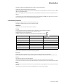 5
5
-
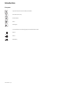 6
6
-
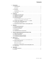 7
7
-
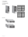 8
8
-
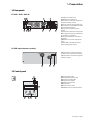 9
9
-
 10
10
-
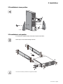 11
11
-
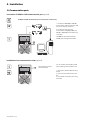 12
12
-
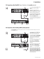 13
13
-
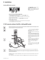 14
14
-
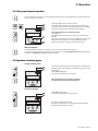 15
15
-
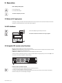 16
16
-
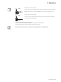 17
17
-
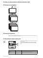 18
18
-
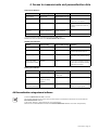 19
19
-
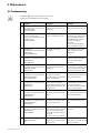 20
20
-
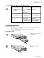 21
21
-
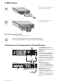 22
22
-
 23
23
-
 24
24
-
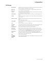 25
25
-
 26
26
-
 27
27
-
 28
28
-
 29
29
-
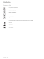 30
30
-
 31
31
-
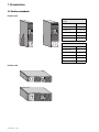 32
32
-
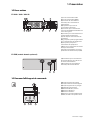 33
33
-
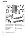 34
34
-
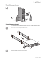 35
35
-
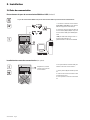 36
36
-
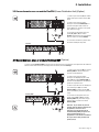 37
37
-
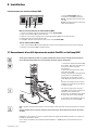 38
38
-
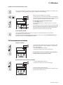 39
39
-
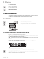 40
40
-
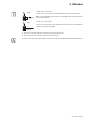 41
41
-
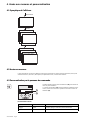 42
42
-
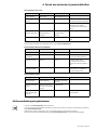 43
43
-
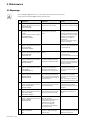 44
44
-
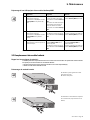 45
45
-
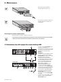 46
46
-
 47
47
-
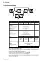 48
48
-
 49
49
-
 50
50
-
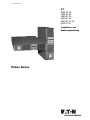 51
51
-
 52
52
-
 53
53
-
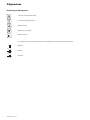 54
54
-
 55
55
-
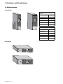 56
56
-
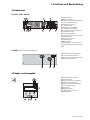 57
57
-
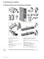 58
58
-
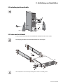 59
59
-
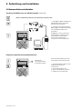 60
60
-
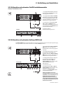 61
61
-
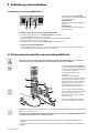 62
62
-
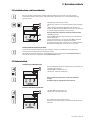 63
63
-
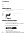 64
64
-
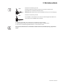 65
65
-
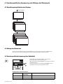 66
66
-
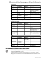 67
67
-
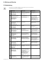 68
68
-
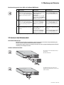 69
69
-
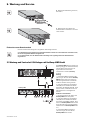 70
70
-
 71
71
-
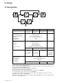 72
72
-
 73
73
-
 74
74
-
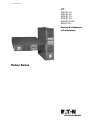 75
75
-
 76
76
-
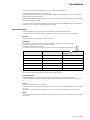 77
77
-
 78
78
-
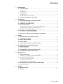 79
79
-
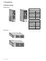 80
80
-
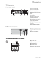 81
81
-
 82
82
-
 83
83
-
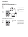 84
84
-
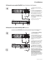 85
85
-
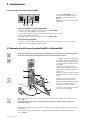 86
86
-
 87
87
-
 88
88
-
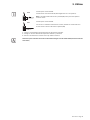 89
89
-
 90
90
-
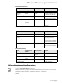 91
91
-
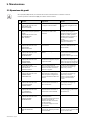 92
92
-
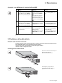 93
93
-
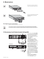 94
94
-
 95
95
-
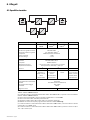 96
96
-
 97
97
-
 98
98
-
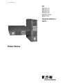 99
99
-
 100
100
-
 101
101
-
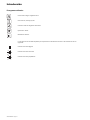 102
102
-
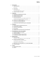 103
103
-
 104
104
-
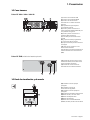 105
105
-
 106
106
-
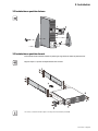 107
107
-
 108
108
-
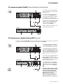 109
109
-
 110
110
-
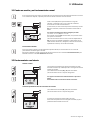 111
111
-
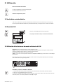 112
112
-
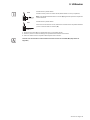 113
113
-
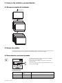 114
114
-
 115
115
-
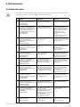 116
116
-
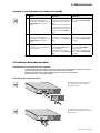 117
117
-
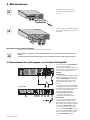 118
118
-
 119
119
-
 120
120
-
 121
121
-
 122
122
-
 123
123
-
 124
124
-
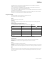 125
125
-
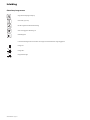 126
126
-
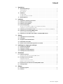 127
127
-
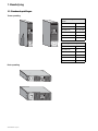 128
128
-
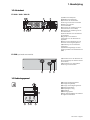 129
129
-
 130
130
-
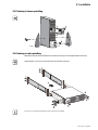 131
131
-
 132
132
-
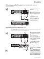 133
133
-
 134
134
-
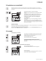 135
135
-
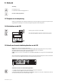 136
136
-
 137
137
-
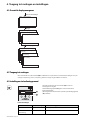 138
138
-
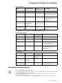 139
139
-
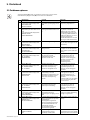 140
140
-
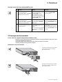 141
141
-
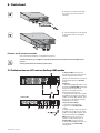 142
142
-
 143
143
-
 144
144
-
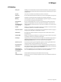 145
145
-
 146
146
-
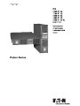 147
147
-
 148
148
-
 149
149
-
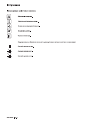 150
150
-
 151
151
-
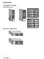 152
152
-
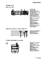 153
153
-
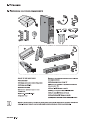 154
154
-
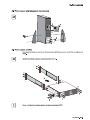 155
155
-
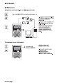 156
156
-
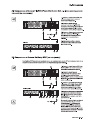 157
157
-
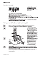 158
158
-
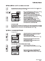 159
159
-
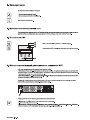 160
160
-
 161
161
-
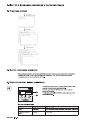 162
162
-
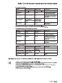 163
163
-
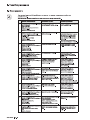 164
164
-
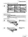 165
165
-
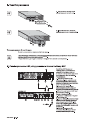 166
166
-
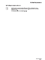 167
167
-
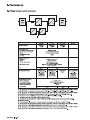 168
168
-
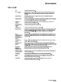 169
169
-
 170
170
-
 171
171
-
 172
172


Eaton 3200RT Handleiding
- Categorie
- Noodstroomvoorzieningen (UPS'en)
- Type
- Handleiding
in andere talen
- English: Eaton 3200RT User manual
- italiano: Eaton 3200RT Manuale utente
- français: Eaton 3200RT Manuel utilisateur
- español: Eaton 3200RT Manual de usuario
- Deutsch: Eaton 3200RT Benutzerhandbuch
Gerelateerde papieren
-
Eaton Pulsar EX 1000 RT 2U Installation and User Manual
-
Eaton EX 2200 RT3U HotSwap FR Handleiding
-
Eaton Evolution S 1250 RT 2U Installation and User Manual
-
Eaton Evolution 850 Rack Handleiding
-
-
-
Eaton 93PM-150(400) Safety And Installation Quick Manual
-
-
-
MGE UPS Systems Evolution 850 Rack Handleiding
Andere documenten
-
ABB PowerValue 11 RT G2 Handleiding
-
ABB 4NWP106819R0001 Quick Manual
-
Marantec USV de handleiding
-
Velleman UPS600N1 Handleiding
-
-
MGE UPS Systems PULSAR EVOLUTION 3000 Handleiding
-
-
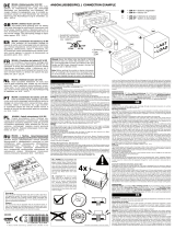 Kemo Electronic M148A Snelstartgids
-
