Yamaha AP-U70 de handleiding
- Categorie
- Audio versterkers
- Type
- de handleiding
Deze handleiding is ook geschikt voor

PERSONAL AMPLIFIER
AP-U70
PERSONAL SOUND PROCESSOR
DP-U50
SET UP MANUAL
MANUEL DE CONFIGURATION
U C A
USB
PC
AUX1
AUX2
DSP MUTE

The owner’s manual for this model consists of two volumes, “SET UP MANUAL” and
“OPERATION MANUAL”.
Le manuel d'utilisation pour ce modèle se compose de deux volumes, le “MANUEL DE
CONFIGURATION” et le “MANUEL D’UTILISATION”.
* This manual uses terms utilized by the English operating system as shown on the computer monitor. If the operating
system you are using is in another language, please replace the English terms with the terms used in your computer’s
operating system.
* Ce manuel utilise des termes employés par les systèmes d’exploitation en langue anglaise tels qu’ils apparaîssent sur le
moniteur d’un ordinateur. Si votre système d’exploitation utilise une autre langue, veuillez remplacer la terminologie
anglaise par celle qu’il utilise.

E-1
● This unit brings high-quality audio to your
computer.
● The USB interface allows remote control of this
unit from your computer, using the supplied
Application Software, plus various audio I/O
options.
● Ideal for use with computer games, internet
music, CD-ROM, DVD, multimedia software, and
more.
● Yamaha’s Near-Field Cinema DSP (Digital Sound
field Processing) technology provides live music
performance and movie theater surround sound.
The sound effect of DSP is also available for
headphone listening.
● Sophisticated Virtual 3D technology reproduces
multichannel sources such as Dolby Digital* and
DTS
** providing a realistic surround effect with
just two speakers.
● This unit is compatible with the following audio
signals received via a USB connection:
multi-channel (two, four and six channels) audio,
high quality digital audio of 24 bits/48 kHz and
Dolby Digital-encoded signals. (Some operating
systems and software programs do not support
this feature.)
*
Manufactured under license from Dolby Laboratories. “Dolby”,
“Pro Logic” and the double-D symbol are trademarks of Dolby
Laboratories. Confidential Unpublished Works. q1992–1997
Dolby Laboratories, Inc. All rights reserved.
**
Manufactured under license from Digital Theater Systems, Inc.
US Pat. No. 5,451,942 and other world-wide patents issued and
pending. “DTS”, “DTS Digital Surround”, are trademarks of Digital
Theater Systems, Inc. Copyright 1996 Digital Theater Systems,
Inc. All Rights Reserved.
CONNECTIONS
Terminals and their functions ........... 3
Connecting your computer................ 4
Connecting audio equipment ............ 5
Connecting speakers ......................... 6
Plugging in this unit ........................... 8
INSTALLING USB DRIVER AND
APPLICATION SOFTWARE
Preparations before installation........ 9
System requirements......................... 9
Installing the software...................... 10
Microsoft Windows 98/98SE
or Windows Me ............................................... 10
Microsoft Windows 2000 Professional ......... 13
Macintosh computer ...................................... 16
APPENDIX
Troubleshooting ......................... 18
CONNECTIONS
INSTALLING USB DRIVER AND
APPLICATION SOFTWARE
APPENDIX
English
GETTING STARTED
Unpacking........................................... 2
Battery installation ............................. 2
Battery replacement........................... 2
Remote control operation range ....... 2
GETTING STARTED
FEATURES CONTENTS

E-2
GETTING STARTED
Battery installation
Since the remote control will be used for many of this unit’s
control operations, you should begin by installing the
supplied batteries.
1
Turn the remote control over and remove the battery
compartment cover by sliding it in the direction of
the arrow.
2
Insert the batteries (AA, R6, UM-3 type) according to
the polarity markings on the inside of the battery
compartment.
3
Close the battery compartment cover.
Battery replacement
If you notice that the remote control must be used closer to
the main unit, the batteries are weak. Replace both
batteries with new ones.
Notes
● Use AA, R6, UM-3 batteries.
● Be sure the polarities are correct. (See the illustration inside
the battery compartment.)
● Remove the batteries if the remote control is not to be used for
an extended period of time.
● If the batteries leak, dispose of them immediately. Avoid
touching the leaked material and avoid contact with clothing,
etc. Clean the battery compartment thoroughly before
installing new batteries.
USB
POWER
PC
AUX1
AUX2
JAZZ CHURCHHALL
B
VOLUMEMUTE
CA
MOVIE LIVEGAME
TEST
ON
/
OFF
VDD
2
1
3
Remote control operation range
Notes
● The area between the remote control and the main unit must
be clear of large obstacles.
● Do not expose the remote control sensor to strong lighting, in
particular, an inverter type fluorescent lamp; otherwise, the
remote control may not work properly. If necessary, position
the main unit away from direct lighting.
USB
PC
AUX1
AUX2
DSP MUTE
VOL
VIRTUAL
5.I
CH
DIGITAL
PROLOGIC FMAM ST
USB PCM D.
DSP
30°
30°
Remote control
sensor
Unpacking
After unpacking, check that the following items are
supplied.
● Remote control
● CD-ROM
The CD-ROM contains
the Application Software
and online help for
controlling this unit from
your computer.
● Batteries (AA, R6, UM-3
type)
● USB cable
Within
approximately
6 m (19.7 feet)

E-3
English
CONNECTIONS
CONNECTIONS
Never
plug in this unit and other equipment until
all connections are completed.
1.
Make connections between this unit and other
components by following the procedure below.
2.
After all connections are finished, check that the
connection cords are correctly connected.
3.
After all connections are completed, plug in this unit and
other equipment.
Note
Also, refer to the owner’s manual for other equipment in the
system.
CONNECTIONS
Terminals and their functions
1 ANALOG inputs
These connectors are used to connect to the analog
outputs of a PC sound card, CD player, MD recorder, tape
deck, etc.
+–
R
L
R L
R L
ANALOG
PC IN
AUX 1
IN
AUX 2
IN
REC
OUT
OUTPUT
SUB
WOOFER
DIGITAL
USB
COAX
IN
OPT
IN
AUX 1
OPT IN
OPT
OUT
PC
SPEAKERS
6Ω MIN.
/
SPEAKER
MAINS
MAIN
1
2
5
6
3
4
PRE
OUT
[
DP-U50
]
REC
OUT
[
AP-U70
]
2 SUBWOOFER OUTPUT
This connector can be connected to an optional subwoofer,
such as the Yamaha YST-SW45, for enhanced bass
performance.
3 SPEAKERS outputs [AP-U70 only]
These connectors are used to connect a pair of
speakers, such as the Yamaha NS-U30.
4 REC OUT [AP-U70 only]
These connectors are used to connect to the
analog inputs of an MD recorder or tape deck.
4 PRE OUT [DP-U50 only]
These connectors are used to connect to the
analog inputs (INPUT etc.) of speakers
incorporated with an amplifier, or a power amplifier.
The level of signals outputted from the PRE OUT
varies by the use of the volume control on the front
panel or the VOLUME keys on the remote control.
5 PC inputs & output (DIGITAL)
USB: If your computer has a USB port, connect it to this
unit, using the supplied USB cable, for remote control of
this unit from your computer.
PC COAX IN/OPT IN: These coaxial and optical
connectors are used to connect to the digital outputs of a
PC sound card, DVD-Video decoder board, etc.
6 Optical input & output (DIGITAL)
AUX 1 OPT IN: This connector is used to connect to an
optical output of a CD player, MD recorder, etc.
OPT OUT: This connector is used to connect to an optical
input of an MD recorder, a DAT deck, etc.
Use commercially available connection cords (except the supplied USB cable).
The color of this unit’s inputs/outputs and connection cords to be used for connecting to them are as follows:
White Audio connection cord (analog/stereo), left
Red Audio connection cord (analog/stereo), right
Black Audio connection cord (analog/monaural)
Orange Coaxial digital connection cord
L
R
L
R

E-4
CONNECTIONS
Connecting to the USB port (1)
If your computer has a USB port, connect it to this unit’s
USB terminal using the supplied USB cable, as shown
below.
A single USB connection is all that’s required to listen to
audio from your computer on this unit, feed audio from an
external source connected to this unit to your computer,
and control this unit remotely from your computer, using
the supplied Application Software.
If your computer doesn’t have a USB port, you can still
connect it to this unit using the analog or digital input, but in
this case you cannot use this unit’s Application Software.
Note
Connect the USB cable when installing the USB driver software
on your computer. Refer to the section “INSTALLING USB
DRIVER AND APPLICATION SOFTWARE”.
Connecting to analog inputs (2)
Connect the analog audio outputs on your computer or a
PC sound card to this unit’s ANALOG PC IN.
Use a commercially available pin-plug connection cord for
connection, and be careful not to mix up the left and right
connections.
Connecting your computer
Audio from your computer can be fed to this unit using any of the following connectors: USB, DIGITAL PC COAX IN, DIGITAL
PC OPT IN, or ANALOG PC IN. If you use all of these connectors for connection, you can select the connector(s) to use on
this unit’s front panel or the remote control.
R L
R L
ANALOG
PC IN
AUX 1
IN
AUX 2
IN
REC
OUT
OUTPUT
SUB
WOOFER
DIGITAL
USB
COAX
IN
OPT
IN
AUX 1
OPT IN
OPT
OUT
PC
LINE OUT
USB
DIGITAL
OUT
DIGITAL
OUT
2
1
3
3
L
R
L
R
(coaxial)
(optical)
Connecting to digital inputs (3)
To play DVD-Video discs encoded with Dolby Digital or
DTS, your computer must have a DVD-ROM drive and
DVD-Video decoder board, which should be connected to
this unit via the DIGITAL PC COAX IN or DIGITAL PC OPT
IN.
Use a commercially available pin-plug cord for connecting
to the DIGITAL PC COAX IN, and use a commercially
available optical fiber cable for connecting to the DIGITAL
PC OPT IN.
Note
The DIGITAL PC OPT IN has priority over the DIGITAL PC
COAX IN, so if you connect to both inputs, the signal received at
the DIGITAL PC OPT IN is used.
Protective Caps
When connecting to an optical connector, remove its protective
cap first. When an optical connector is not being used, replace its
cap to prevent dust entering the connector.
: Indicates the direction of signals.

E-5
English
CONNECTIONS
CONNECTIONS
Connecting audio equipment
The following illustrations show how to connect a CD player, MD recorder, etc. using both analog and digital connections.
However, it’s not necessary to make both connections.
R L
R L
ANALOG
PC IN
AUX 1
IN
AUX 2
IN
REC
OUT
OUTPUT
SUB
WOOFER
DIGITAL
USB
LINE OUT
LINE IN
(REC)
LINE OUT
(PLAY)
L
R
L
R
L
R
L
R
L
R
L
R
+–
R
L
DIGITAL
USB
COAX
IN
OPT
IN
AUX 1
OPT IN
OPT
OUT
PC
SPEAKERS
6Ω MIN.
/
SPEAKER
MAIN
DIGITAL OUT
DIGITAL IN
(optical)
(optical)
CD player
MD recorder
CD player
Tape deck
or MD recorder
Audio connections
● Be careful not to mix up the left and right connections.
● [AP-U70 only]
If you wish to record analog sound signals inputted
to this unit, connect the analog inputs of a tape deck
or MD recorder to this unit’s REC OUT OUTPUT.
Digital connections
If you wish to record digital sound signals inputted to this
unit, connect the optical digital input of an MD recorder or a
DAT deck to this unit’s DIGITAL OPT OUT.
Notes
● When playing an ordinary CD on this unit following
playback of a CD or an LD encoded with DTS, some
operations, such as resetting the input selector keys, may be
required.
● Even if connected to this unit with a digital connection, some
CD, LD, and DVD players may make this unit fail to decode
DTS or produce noise. This is because certain digital output
data processing by such a player results in DTS-encoded data
errors that cause playback failure although the same data
processing may cause only a slight change in volume or in
frequency response in normal digital sound.
● When an error occurs in the player’s digital output data
during playback of an LD or CD encoded with DTS,
playback may be disrupted. If this occurs, stop playback and
repower the player.
● When digital sound signals from the computer are played,
errors in WAVE signals, etc. may occur resulting in noise or a
playback failure.
: [AP-U70 only]
Notes
● Connecting a turntable
A turntable cannot be connected to this unit directly. Use a
commercially available phono equalizer amplifier to connect a
turntable to this unit, or connect a turntable incorporated with a
phono equalizer amplifier.
● [AP-U70 only]
The REC OUT OUTPUT and DIGITAL OPT OUT can
be used at the same time since they output signals
independently.

E-6
CONNECTIONS
+–
R
L
R L
R L
ANALOG
PC IN
AUX 1
IN
AUX 2
IN
REC
OUT
OUTPUT
SUB
WOOFER
DIGITAL
USB
COAX
IN
OPT
IN
AUX 1
OPT IN
OPT
OUT
PC
SPEAKERS
6Ω MIN.
/
SPEAKER
MAIN
Left speaker Right speaker
10 mm
➁
➂
➀
Connecting speakers
[AP-U70 only]
Connect this unit to your speakers with speaker cables
with a proper gauge (keep them as short as possible).
Notes
● Use speakers which do not have a built-in amplifier.
● Use speakers whose impedance is 6Ω or more.
● Connect the left speaker to the left speaker connector on this
unit and the right speaker to the right speaker connector.
● Make sure that the + and – polarity markings of the speaker
cables are observed and set correctly. If these cables are
reversed, the sound will be unnatural and lack bass.
Speaker Cables
Strip 10 mm of insulation off the end of each speaker
cable, and then twist the bare wires to prevent lose
strands, which can cause short circuits.
How to connect:
1 Press and hold the speaker connector levers.
2 Insert the bare ends of the speaker cables into the
terminal holes.
3 Then release the levers.
* Try pulling gently on each cable to make sure that it is
secure.

E-7
English
CONNECTIONS
CONNECTIONS
R L
R L
ANALOG
PC IN
AUX 1
IN
AUX 2
IN
PRE
OUT
OUTPUT
SUB
WOOFER
DIGITAL
USB
INPUT
L
R
L
R
R L
R L
ANALOG
PC IN
AUX 1
IN
AUX 2
IN
REC
OUT
OUTPUT
SUB
WOOFER
DIGITAL
USB
SUPERWOOFER SYSTEM YST-SW45
HIGH CUTSTANDBY/ON
150Hz50Hz
VOLUME
100
LINE IN
Speakers with a built-in
amplifier
Subwoofer
Left Right
[DP-U50 only]
To reproduce sound signals inputted to this unit over
speakers, connect this unit to speakers with a built-in
amplifier, a mini-component system, etc., or connect this
unit to speakers by using an external power amplifier.
Connect the analog inputs of speakers with a built-in
amplifier, etc. to this unit’s PRE OUT using a commercially
available analog pin-plug cord or a pin (stereo)-to-mini
(stereo) plug cord.
Note
The level of signals outputted from the PRE OUT varies by the
use of the volume control on the front panel or the VOLUME
keys on the remote control. So, it is recommended to adjust the
speaker output level on this unit or the remote control, and fix
the volume of speakers with a built-in amplifier, etc. at a
certain level.
Adding a subwoofer
Bass performance can be extended by connecting a
subwoofer to this unit’s SUBWOOFER OUTPUT using a
commercially available audio pin-plug cord.
The use of a subwoofer is also suitable for reproducing the
effects of sound field programs.
Note
The SUBWOOFER OUTPUT is a line-level output. Use a
subwoofer which has its own built-in power amplifier, such as
the Yamaha YST-SW45.

E-8
CONNECTIONS
SUPERWOOFER SYSTEM YST-SW45
HIGH CUTSTANDBY/ON
150Hz50Hz
VOLUME
100
USB
PC
AUX1
AUX2
DSP MUTE
VOL
VIRTUAL 5.ICH
DIGITAL
PROLOGICFMAMST
USBPCM D.
DSP
4
3
Left speaker Right speaker
AC outlet
Recommended listening position
Note
Use magnetically shielded speakers and subwoofer. Using non-
magnetically shielded speakers near the computer monitor may
impair picture color or damage the monitor.
Plugging in this unit
After completing all connections, plug the AC power
cord into a household AC outlet.
Note
Unplug the AC power cord from the AC outlet if this unit is not
to be used for a long period of time.
(U.S.A. model)
Recommended Speaker Placement
For best performance, place the left and right speakers on
either side of your computer monitor, as shown below, and
position them so that their fronts are flush with the monitor
screen. To get the best from the sound field programs and
surround effects, the left and right speakers and the
listener should be positioned so as to form a triangle with a
3:4 ratio, so if, for example, the speakers are 60 cm (23.5”)
apart, the listener should be 80 cm (31.5”) away from each
speaker.
If your system includes a subwoofer (YST-SW45, etc.),
place it on the floor.

E-9
English
INSTALLING USB DRIVER AND APPLICATION SOFTWARE
INSTALLING USB DRIVER AND
APPLICATION SOFTWARE
Microsoft Windows 98/98SE, Windows Me or
Windows 2000 Professional
Operating System
Microsoft Windows 98/98SE, Windows Me or Windows
2000 Professional
Computer
A computer with a USB port as a standard equipment and
preinstalled with the above OS.
Windows is a registered trademark of Microsoft Corporation in
the United States and/or other countries.
When connecting this unit and your computer with the USB
cable and controlling this unit from the computer, you must
install the following software on your computer.
◆ USB driver software: Necessary for this unit to
communicate with your computer .......... Use the
software originally supplied with the OS (Operating
System) running on your computer
◆ Application Software: Used to control this unit from a
computer .......... Download from the supplied CD-ROM
◆ Online help : Instructions for using the Application
......... Access from the supplied CD-ROM
This section explains how to install the software. The
installation method differs from the OS running on your
computer.
Refer to the instructions suitable for your OS below.
Preparations before installation
● Make sure that the USB cable is not connected to
this unit and that your computer is not activated.
● Make sure that your computer meets the system
requirements listed below.
If your computer does not meet the system
requirements, you can use the computer as an input
source by connecting it to the analog or digital input(s)
of this unit. In that case, however, the supplied
Application Software cannot be used.
● You may be requested to insert your OS’s CD-ROM
during the installation, so please have it ready before
commencing.
● The installing method may differ from the instructions
below depending on the operating environment of your
computer. In such a case, follow the instructions shown
on the monitor. If you still have any question, inquire at
the manufacturer of your computer or a computer
dealer.
System requirements
Your computer must meet the following system requirements to use the supplied Application Software.
INSTALLING USB DRIVER AND APPLICATION SOFTWARE
Macintosh
Operating System
Mac OS 9.0.4 or greater (USB Driver 1.4 or greater)
Computer
Macintosh computer with a USB port as a standard
equipment
Macintosh is a trademark of Apple Computer, Inc., registered in
the U.S. and other countries.

E-10
INSTALLING USB DRIVER AND APPLICATION SOFTWARE
Installing the software
Microsoft Windows 98/98SE or Windows Me
m Installing and checking the USB driver
1
Turn on your computer and, if it’s not running
already, start Windows 98/98SE or Windows Me.
2
Plug the AC power cord of this unit into the AC
outlet.
This unit can be on or in standby mode when installing the
driver.
3
Connect this unit to a USB port on the computer
using the supplied USB cable.
Windows automatically detects this unit and installs the
necessary driver software. Make operations as indicated in
the dialog box. You may be requested to insert your
Windows OS CD-ROM.
* The installation may take a longer time depending on
the system environment. After the installation dialog
box disappears, wait several minutes.
Check that the USB driver has been installed successfully
by following the procedure below.
4
Click the Windows “Start” button and select
“Settings”, and then “Control Panel”.
The Control Panel window appears.
5
Double-click the “System” icon.
The System Properties window appears.
6
Click the “Device Manager” tab.
The Device Manager window appears.
7
Click the “View devices by type” option button.
8
Click the “+” symbol next to “Sound, video and
game controllers,” and make sure that “USB Audio
Device” appears in the list, as shown.
* The screen image is for Windows 98SE.
* When using Windows Me, “?” may be shown at the
head of “USB Copmposite Device” in green. This
means the USB driver has been installed with the
Generic ID supplied with the operating system. (This is
not an error message.)
9
Click the “+” symbol next to “Human Interface
Devices”, and make sure that “HID-compliant
consumer control device” and “USB Human
Interface Device” appear in the list, as shown.
* The screen image is for Windows 98SE.
10
Click the “+” symbol next to “Universal Serial
Bus controllers” and make sure that “USB
Composite Device” appears in the list, as
shown.
* The screen image is for Windows 98SE.
Notes
● The device list on your computer may differ to that shown
here.
● If “!” or “?” is shown at the head of the device name, check
the followings:
* The USB cable is firmly connected.
* The AC power cord of this unit is plugged into an AC
outlet.
● If the driver has not been successfully installed, disconnect
the USB cable and connect it again. Then try to install the
driver again. If installation still fails, restart Windows and try
again.

E-11
English
INSTALLING USB DRIVER AND APPLICATION SOFTWARE
INSTALLING USB DRIVER AND
APPLICATION SOFTWARE
Make the following settings on your computer after the installation of the driver is finished.
Setting of Audio and Audio CD
[Windows 98/98SE only]
* Terminate all the activated applications.
* When using Windows 98SE, restart Windows, first.
1
Click the Windows “Start” button and select
“Settings”, and then “Control Panel”.
2
Double-click the “Multimedia” icon.
3
Click the “Audio” tab and select “USB Audio
Device” at “Preferred device” of “Playback”.
* Usually, this setting is automatically made.
* If “USB Audio Device” does not appear, restart
Windows.
4
Click the “CD Music” tab and select the CD-ROM
drive for playing audio CDs.
5
Click the check box of “Enable digital CD audio for
this CD-ROM device” to enter the check mark.
* It may happen that the check box cannot be clicked
because some CD-ROM drives cannot be used for
playing audio CDs.
6
Click “OK” and close the “Multimedia” setting
panel.
7
Restart Windows.
Note
When using two or more drives, you must make the above setting
for each drive.
Checking the Audio setting
[Windows Me only]
1
Click the Windows Me “Start” button and select
“Settings”, and then “Control Panel”.
2
Double-click the “Sounds and Multimedia” icon.
3
Click the “Audio” tab and select “USB Audio
Device” at “Preferred device” of “Sound
Playback”.
* Usually, this setting is automatically made.
* If “USB Audio Device” does not appear, restart
Windows.
Checking sound output and adjusting volume
[Windows 98/98SE and Windows Me]
1
Make the following operations on the front panel of
this unit.
a)Press the power switch to turn on this unit.
(Some messages are shown on the display.)
b)Press the USB input selector key.
c)Use the volume control to adjust the volume.
(Set the control to about “30”.)
2
Adjust the volume on the computer as follows.
a)Double-click the speaker icon on the task tray,
or select “Start”, “Programs”, “Accessories”,
“Entertainment” in this order and click “Volume
Control”.
(The volume adjustment window appears.)
b)Adjust the volume by dragging the “Volume”
slider. Set the slider between the center and
max. positions.
* Do not enter the check mark in the “Mute” check
box. If entered, sound output will stop.
3
Click the Windows “Start” button and select
“Settings”, and then “Control Panel”.
4
Double-click the “Sounds” (or “Sounds and
Multimedia”) icon.
5
Click the “Sounds” tab.
6
Check that the sound is output normally by
outputting “Default sound”, etc. from “Events” (or
“Sound Events”).
* If no sound is heard, restart Windows and check again.
DSP MUTE
VOL
VIRTUAL
5.I
CH
DIGITAL
PROLOGIC FMAM ST
USB PCM D.
DSP
USB
PC
AUX1
AUX2
USB
Display
Volume control
Power switch

E-12
INSTALLING USB DRIVER AND APPLICATION SOFTWARE
Next, install the Application Software and Online Help
from the supplied CD-ROM.
m Installing the Application Software
* Terminate all the activated applications (including virus
checkers) on the computer first.
1
Insert the CD-ROM into the CD-ROM or DVD-ROM
drive.
If the Windows Autorun feature is turned on, the
installation start-up screen appears automatically.
2
Continue with the installation as prompted.
If the Windows Autorun feature is not turned on
Display the contents of the CD-ROM by using “My
Computer” etc., and double-click on “Readme.txt.”. The
installation method is described in this file.
m Using the Application Software and
Online Help
This section explains how to start the Application Software
and view the online help.
1
Click the Windows “Start” button and select
“Programs”, “YAMAHA AP-U70 (or DP-U50)”, “AP-
U70 (or DP-U50)” in this order.
The Application Software starts.
2
To view the online help, click the Windows “Start”
button and select “Programs”, “YAMAHA AP-U70
(or DP-U50)”, “Help” in this order.
The online help, which explains how to use the Application
Software, starts.
Note
Never disconnect the USB cable while starting up the
Application Software. If disconnected, the computer may hang.
m Uninstalling the Application Software
This section explains how to uninstall the Application
Software.
1
Terminate the Application Software and online
help.
2
Click the Windows “Start” button and select
“Settings”, and then “Control Panel”.
The Control Panel window appears.
3
Double-click the “Add/Remove Programs” icon.
The “Add/Remove Programs Properties” window appears.
4
Select “YAMAHA AP-U70 (or DP-U50) Application”
in the software list.
“YAMAHA AP-U70 (or DP-U50) Application” is
highlighted.
5
Click the “Add/Remove Programs” button and
continue as prompted.

E-13
English
INSTALLING USB DRIVER AND APPLICATION SOFTWARE
INSTALLING USB DRIVER AND
APPLICATION SOFTWARE
Microsoft Windows 2000 Professional
m Installing and checking the USB driver
1
Turn on your computer and, if it’s not running
already, start Windows 2000 Professional, and log
in with Administrator.
2
Plug the AC power cord of this unit into the AC
outlet.
This unit can be on or in the standby mode when installing
the driver.
3
Connect this unit to a USB port on the computer
using the supplied USB cable.
Windows automatically detects this unit and installs the
necessary driver software.
* The installation may take a longer time depending on
the system environment. After the dialog box for
installation disappears, wait several minutes.
Check that the USB driver has been installed successfully
by following the procedure below.
4
Click the Windows “Start” button and select
“Settings”, and then “Control Panel”.
The Control Panel window appears.
5
Double-click the “System” icon.
The System Properties window appears.
6
Select the “Hardware” tab, and click the “Device
Manager”.
The Device Manager window appears.
7
Select the “View” tab, and click the “Devices by
type” option button.
8
Click the “+” symbol next to “Sound, video and
game controllers,” and make sure that “USB Audio
Device” appears in the list, as shown.
9
Click the “+” symbol next to “Human Interface
Devices”, and make sure that “HID-compliant
consumer control device” and “USB Human
Interface Device” appear in the list, as shown.
10
Click the “+” symbol next to “Universal Serial
Bus controllers” and make sure that “USB
Composite Device” appears in the list, as
shown.
Notes
● The device list on your computer may differ to that shown
here.
● If “!” or “?” is shown at the head of the device name, check
the followings:
* The USB cable is firmly connected.
* The AC power cord of this unit is plugged into an AC
outlet.
● If the driver has not been successfully installed, disconnect
the USB cable and connect it again. Then try to install the
driver again. If installation still fails, restart Windows and try
again.

E-14
INSTALLING USB DRIVER AND APPLICATION SOFTWARE
Make the following settings on your computer after the installation of the driver is finished.
Setting of Audio and Audio CD
1
Click the Windows “Start” button and select
“Settings”, and then “Control Panel”.
2
Double-click the “Sounds and Multimedia” icon.
3
Click the “Audio” tab and select “USB Audio
Device” at “Preferred device” of “Sound
Playback”.
* Usually, this setting is automatically made.
4
Click the “Hardware” tab and double-click the item
of the DVD or CD-ROM to be used in the “Devices”.
5
Click the “Properties” tab, and click the check box
of “Enable digital CD audio for this CD-ROM
device” to enter the check mark.
* It may happen that the check box cannot be clicked
because some CD-ROM drives cannot be used for
playing audio CDs.
6
Restart Windows, and log in with Administrator.
Note
When using two or more drives, you must make the above setting
for each drive.
Checking sound output and adjusting volume
1
Make the following operations on the front panel of
this unit.
a)Press the power switch to turn on this unit.
(Some messages are shown on the display.)
b)Press the USB input selector key.
c) Use the volume control to adjust the volume.
(Set the control to about “30”.)
2
Adjust the volume on the computer as follows.
a) Double-click the speaker icon on the task tray,
or select “Start”, “Programs”, “Accessories”,
“Entertainment” in this order and click “Volume
Control”.
(The volume adjustment window appears.)
b)Adjust the volume by dragging the “Volume”
slider. Set the slider between the center and
max. position.
* Do not enter the check mark in the “Mute” check
box. If entered, sound output will stop.
3
Click the Windows “Start” button and select
“Settings”, and then “Control Panel”.
4
Double-click the “Sounds and Multimedia” icon.
5
Click the “Sounds” tab.
6
Check that the sound is output normally by
outputting “Default Beep”, etc. from “Sound
Events”.
* If no sound is heard, restart Windows and check again.
DSP MUTE
VOL
VIRTUAL
5.I
CH
DIGITAL
PROLOGIC FMAM ST
USB PCM D.
DSP
USB
PC
AUX1
AUX2
USB
Display
Volume control
Power switch

E-15
English
INSTALLING USB DRIVER AND APPLICATION SOFTWARE
INSTALLING USB DRIVER AND
APPLICATION SOFTWARE
Next, install the Application Software and Online Help
from the supplied CD-ROM.
m Installing the Application Software
1
Insert the CD-ROM into the CD-ROM or DVD-ROM
drive.
If the Windows Autorun feature is turned on, the
installation start-up screen appears automatically.
2
Continue with the installation as prompted.
If the Windows Autorun feature is not turned on
Display the contents of the CD-ROM by using “My
Computer” etc., and double-click on “Readme.txt.”. The
installation method is described in this file.
m Using the Application Software and
Online Help
This section explains how to start the Application Software
and view the online help.
1
Click the Windows “Start” button and select
“Programs”, “YAMAHA AP-U70 (or DP-U50)”, “AP-
U70 (or DP-U50)” in this order.
The Application Software starts.
2
To view the online help, click the Windows “Start”
button and select “Programs”, “YAMAHA AP-U70
(or DP-U50)”, “Help” in this order.
The online help, which explains how to use the Application
Software, starts.
Note
Never disconnect the USB cable while starting up the
Application Software. If disconnected, the computer may hang.
m Uninstalling the Application Software
This section explains how to uninstall the Application
Software.
1
Terminate the Application Software and online
help.
2
Click the Windows “Start” button and select
“Settings”, and then “Control Panel”.
The Control Panel window appears.
3
Double-click the “Add/Remove Programs” icon.
The “Add/Remove Programs” window appears.
4
Select “YAMAHA AP-U70 (or DP-U50) Application”
in the software list.
“YAMAHA AP-U70 (or DP-U50) Application” is
highlighted.
5
Click the “Change/Remove” button and continue
as prompted.

E-16
INSTALLING USB DRIVER AND APPLICATION SOFTWARE
Macintosh computer
m Connections and setup
1
Plug the AC power cord of this unit into the AC
outlet.
2
Start the Macintosh.
3
Connect this unit to a USB port on the computer
using the supplied USB cable.
The driver software for USB audio is automatically
installed.
4
Press the power switch of this unit to turn on this
unit.
Some messages are shown on the display.
Checking sound output and adjusting volume
1
Make the following operations on the front panel of
this unit.
a)Press the USB input selector key.
b)Use the volume control to adjust the volume.
(Set the control to about “30”.)
2
Check that the sound is output normally by
outputting “Alert Sounds”, etc. from “Sound” on
the “Control Panels” on the Macintosh.
3
Adjust the volume by dragging the “Sound” tab on
the “Control Panels”. Set the tab between the
center and max. position.
Notes
● The sound output destination cannot be changed from
“Choose a device for sound output” on the “Control Panels”.
When using the internal speaker of the Macintosh as the
sound output destination, disconnect the USB cable
connecting this unit and the Macintosh.
● When using headphones with this unit connected to the USB
port on the Macintosh, use the headphone jack on this unit,
not the jack on the Macintosh.
● Since the Macintosh issues a start-up sound at power-on
before the sound signal via the USB connection is activated,
the start-up sound cannot be issued via the USB connection.
To play the start-up sound via this unit, you need a separate
analog connection between this unit and the Macintosh.
(When USB MIX is set to “ON” from the Setup Panel of the
Application Software, you can mix the start-up sound via the
analog connection with the same sound via the USB
connection without making any change in the input selector
settings.)
DSP MUTE
VOL
VIRTUAL
5.I
CH
DIGITAL
PROLOGIC FMAM ST
USB PCM D.
DSP
USB
PC
AUX1
AUX2
USB
Display
Volume control
Power switch

E-17
English
INSTALLING USB DRIVER AND APPLICATION SOFTWARE
INSTALLING USB DRIVER AND
APPLICATION SOFTWARE
Next, install the Application Software and Online Help
from the supplied CD-ROM.
m Installing the Application Software
1
Insert the CD-ROM into the CD-ROM or DVD-ROM
drive.
The CD-ROM includes the simple installer “AP-U70 (or
DP-U50) Installer” and the installation data folder.
2
Double-click the simple installer “AP-U70 (or DP-
U50) Installer” to start it.
The Application Software and Online Help are installed on
the hard disk.
* Files installed by the simple installer
The simple installer “AP-U70 (or DP-U50) Installer”
copies the “AP-U70 (or DP-U50) Application” folder in
the installation data folder to a specified location. It
additionally copies the “AP-U70 (or DP-U50) Help”
folder into the “Help” folder in the “System Folder” on the
startup disk.
* To install the Application Software without using the
simple installer, follow the instructions below.
Installing the Application Software without using
the simple installer “AP-U70 (or DP-U50)
Installer”:
1
Copy the “AP-U70 (or DP-U50) Application” folder
in the installation data folder to any hard disk.
2
Copy the “AP-U70 (or DP-U50) Help” folder in the
installation data folder to the “Help” folder in the
“System Folder” on the startup disk.
You can refer to this Online Help file with Mac Help.
m How to use the Application Software and
Online Help
All operating instructions for the Application Software is
available from the Online Help. To refer to the instructions,
select the Online Help from the menu displayed upon
activation of the Application Software.
Relationship between operation on this unit and the
Application Software
When an operation button or the volume control on this unit
is operated with the Application Software activated, the
display screen of the Application Software automatically
changes to reflect the changes made on the unit. When
this unit is operated as above while the display shows the
screens of the Application Software data and another
program, the display of the other program (for example, the
playback display of QuickTime) may be partially disturbed
as the screen of the Application Software responds to the
operation on this unit. To avoid this, operate this unit
without activating the Application Software.

E-18
APPENDIX
Problem
The unit cannot be turned on
though the power switch on the
front panel or the POWER key on
the remote control is pressed.
No sound.
Application does not start.
The driver software cannot be
installed successfully.
Using this unit affects TV
reception or the performance of
other equipment.
Cause
The power cord is not plugged in or is not
completely inserted.
This unit is in the standby mode.
Incorrect output cord connections.
This unit and the computer is not connected
with the USB cable.
The power cord is not plugged in or is not
completely inserted.
The USB cable is not firmly connected between
this unit and the computer.
The power cord is not plugged in or is not
completely inserted.
The equipment may be too close to this unit.
Remedy
Firmly plug in the power cord.
Turn on this unit by pressing the Power switch on the
front panel or the POWER key on the remote control.
Connect the cords properly. If the problem
persists, the cords may be defective.
Connect this unit and the computer with the USB
cable.
Firmly plug in the power cord.
Disconnect the USB cable, and then connect it
firmly again.
Firmly plug in the power cord.
Move the equipment away from this unit.
Troubleshooting
Refer to the chart below if this unit does not function properly. If the problem you are experiencing is not listed below or if the
instructions given below do not help, disconnect the power cord and contact your authorized YAMAHA dealer or service
center.
APPENDIX
Depending on some computer hardware or operating systems, all functions of this unit cannot be used. You can refer to the
following Yamaha website for details and related information.
http://www.yamaha.co.jp/audio/

YAMAHA ELECTRONICS CORPORATION, USA 6660 ORANGETHORPE AVE., BUENA PARK, CALIF. 90620, U.S.A.
YAMAHA CANADA MUSIC LTD. 135 MILNER AVE., SCARBOROUGH, ONTARIO M1S 3R1, CANADA
YAMAHA ELECTRONIK EUROPA G.m.b.H. SIEMENSSTR, 22-34, 25462 RELLINGEN, BEI HAMBURG, F.R. OF GERMANY
YAMAHA ELECTRONIQUE FRANCE S.A. RUE AMBROISE CROIZAT BP70 CROISSY-BEAUBOURG 77312 MARNE-LA-VALLEE CEDEX02, FRANCE
YAMAHA ELECTRONICS (UK) LTD. YAMAHA HOUSE, 200 RICKMANSWORTH ROAD WATFORD, HERTS WD1 7JS, ENGLAND
YAMAHA SCANDINAVIA A.B. J A WETTERGRENS GATA 1, BOX 30053, 400 43 VASTRA FRÖLUNDA, SWEDEN
YAMAHA MUSIC AUSTRALIA PTY, LTD. 17-33 MARKET ST., SOUTH MELBOURNE, 3205 VIC., AUSTRALIA
Printed in Malaysia V664210

1
PERSONAL AMPLIFIER
AP-U70
PERSONAL SOUND PROCESSOR
DP-U50
OPERATION MANUAL
MANUEL D’UTILISATION
U C A
USB
PC
AUX1
AUX2
DSP MUTE

2
• Explanation of Graphical Symbols
The lightning flash with arrowhead
symbol, within an equilateral triangle,
is intended to alert you to the
presence of uninsulated “dangerous
voltage” within the product’s
enclosure that may be of sufficient
magnitude to constitute a risk of
electric shock to persons.
The exclamation point within an
equilateral triangle is intended to alert
you to the presence of important
operating and maintenance
(servicing) instructions in the
literature accompanying the
appliance.
IMPORTANT SAFETY INSTRUCTIONS
1 Read these instructions.
2 Keep these instructions.
3 Heed all warnings.
4 Follow all instructions.
5 Do not use this apparatus near water.
6 Clean only with dry cloth.
7 Do not block any ventilation openings. Install in
accordance with the manufacturer’s instructions.
8 Do not install near any heat sources such as radiators,
heat registers, stoves, or other apparatus (including
amplifiers) that produce heat.
9 Do not defeat the safety purpose of the polarized or
grounding-type plug. A polarized plug has two blades
with one wider than the other. A grounding type plug
has two blades and a third grounding prong. The wide
blade or the third prong are provided for your safety. If
the provided plug does not fit into your outlet, consult
an electrician for replacement of the obsolete outlet.
10 Protect the power cord from being walked on or
pinched particularly at plugs, convenience receptacles,
and the point where they exit from the apparatus.
11 Only use attachments/accessories specified by the
manufacturer.
12 Use only with the cart, stand, tripod,
bracket, or table specified by the
manufacturer, or sold with the
apparatus. When a cart is used, use
caution when moving the cart/
apparatus combination to avoid injury
from tip-over.
13 Unplug this apparatus during lightning storms or when
unused for long periods of time.
14 Refer all servicing to qualified service personnel.
Servicing is required when the apparatus has been
damaged in any way, such as power-supply cord or
plug is damaged, liquid has been spilled or objects
have fallen into the apparatus, the apparatus has been
exposed to rain or moisture, does not operate normally,
or has been dropped.
WARNING
TO REDUCE THE RISK OF FIRE OR ELECTRIC
SHOCK, DO NOT EXPOSE THIS APPLIANCE TO RAIN
OR MOISTURE.
CAUTION
CAUTION: TO REDUCE THE RISK OF
ELECTRIC SHOCK, DO NOT REMOVE
COVER (OR BACK). NO USER-SERVICEABLE
PARTS INSIDE. REFER SERVICING TO
QUALIFIED SERVICE PERSONNEL.
RISK OF ELECTRIC SHOCK
DO NOT OPEN
IMPORTANT
Please record the serial number of this system in the
space below.
Model:
Serial No.:
The serial number is located on the rear of the main
unit.
Retain this Owner’s Manual in a safe place for future
reference.

3
We Want You Listening For A Lifetime
YAMAHA and the Electronic Industries Association’s
Consumer Electronics Group want you to get the most out
of your equipment by playing it at a safe level. One that lets
the sound come through loud and clear without annoying
blaring or distortion – and, most importantly, without
affecting your sensitive hearing.
Since hearing damage from loud sounds is
often undetectable until it is too late, YAMAHA
and the Electronic Industries Association’s
Consumer Electronics Group recommend you
to avoid prolonged exposure from excessive
volume levels.
FCC INFORMATION (for US customers only)
1. IMPORTANT NOTICE: DO NOT MODIFY THIS UNIT!
This product, when installed as indicated in the instructions contained in this manual, meets FCC requirements.
Modifications not expressly approved by Yamaha may void your authority, granted by the FCC, to use the product.
2. IMPORTANT: When connecting this product to accessories and/or another product use only high quality shielded
cables. Cable/s supplied with this product MUST be used. Follow all installation instructions. Failure to follow
instructions could void your FCC authorization to use this product in the USA.
3. NOTE: This product has been tested and found to comply with the requirements listed in FCC Regulations, Part 15 for
Class “B” digital devices. Compliance with these requirements provides a reasonable level of assurance that your use
of this product in a residential environment will not result in harmful interference with other electronic devices. This
equipment generates/uses radio frequencies and, if not installed and used according to the instructions found in the
users manual, may cause interference harmful to the operation of other electronic devices. Compliance with FCC
regulations does not guarantee that interference will not occur in all installations. If this product is found to be the
source of interference, which can be determined by turning the product “OFF” and “ON”, please try to eliminate the
problem by using one of the following measures:
Relocate either this product or the device that is being affected by the interference.
Utilize power outlets that are on different branch (circuit breaker or fuse) circuits or install AC line filter/s.
In the case of radio or TV interference, relocate/reorient the antenna. If the antenna lead-in is 300 ohm ribbon lead,
change the lead-in to coaxial type cable.
If these corrective measures do not produce satisfactory results, please contact the local retailer authorized to
distributethis type of product. If you can not locate the appropriate retailer, please contact Yamaha Electronics Corp.,
6660 Orangethorpe Ave. Buena Park, CA90620
The above statements apply ONLY to those products distributed by Yamaha Corporation of America or its
subsidiaries.
COMPLIANCE INFORMATION STATEMENT
(DECLARATION OF CONFORMITY PROCEDURE)
Responsible Party:
Address:
Telephone:
Type of Equipment:
Model Name:
Yamaha Electronics Corp.,
6660 Orangethorpe Ave.
Buena Park, CA90620
714-522-9105
Amplifier/sound processor
AP-U70/DP-U50
This device complies with Part 15 of the FCC Rules.
Operation is subject to the following conditions:
1) this device may not cause harmful interference, and
2) this device must accept any interference received including interference that may cause undesired operation.
See the user manual instructions if interference to radio reception is suspected.

4
INTRODUCTION
Features
● This unit brings high-quality audio to your
computer.
● The USB interface allows remote control of this
unit from your computer, using the supplied
Application Software, plus various audio I/O
options.
● Ideal for use with computer games, internet
music, CD-ROM, DVD, multimedia software, and
more.
● Yamaha’s Near-Field Cinema DSP (Digital Sound
field Processing) technology provides live music
performance and movie theater surround sound.
The sound effect of DSP is also available for
headphone listening.
● Sophisticated Virtual 3D technology reproduces
multichannel sources such as Dolby Digital
* and
DTS
** providing a realistic surround effect with
just two speakers.
● This unit is compatible with the following audio
signals received via a USB connection:
multi-channel (two, four and six channels) audio,
high quality digital audio of 24 bits/48 kHz and
Dolby Digital-encoded signals. (Some operating
systems and software programs do not support
this feature.)
*
Manufactured under license from Dolby Laboratories. “Dolby”,
“Pro Logic” and the double-D symbol are trademarks of Dolby
Laboratories. Confidential Unpublished Works. q1992–1997
Dolby Laboratories, Inc. All rights reserved.
**
Manufactured under license from Digital Theater Systems, Inc.
US Pat. No. 5,451,942 and other world-wide patents issued and
pending. “DTS”, “DTS Digital Surround”, are trademarks of Digital
Theater Systems, Inc. Copyright 1996 Digital Theater Systems,
Inc. All Rights Reserved.
About this manual
● This manual explains how to operate this unit. Refer to
the separate “SET UP MANUAL” for how to connect
this unit with other equipment, and to install the
Application Software, etc. to your computer from the
supplied CD-ROM.
● This manual mainly explains how to operate this unit
using the front panel of this unit and the supplied
remote control.
● When this unit and your computer is connected with the
USB cable, and the supplied Application Software is
installed on the computer, you can operate this unit
from the computer using the Application Software. Refer
to the online help of the Application Software for how to
use the Application Software.
The Application Software extends the use of this unit
with additional functions which cannot be used with the
front panel keys or the remote control. This manual
introduces those functions by the following style.
Example:
m Adjusting USB MIX LEVEL
When an input other than the USB terminal is selected,
you can listen to the mixed sound signals from the
selected input and from the USB terminal. Also, the
mixing ratio of the signals from the USB terminal can be
adjusted.
* Refer to the online help of the Application Software for
details.
This manual also offers brief explanations about the
functions available with the Application Software on page
15–18. Refer to the online help of the Application
Software for details of how to use the functions.

E-1
CAUTION................................ 2
OUTLINE OF THIS UNIT
Main features of this unit.............. 3
Virtual 3D....................................... 4
Digital Sound Field Processing
(DSP).............................................. 4
CONTROLS AND THEIR
FUNCTIONS
Front panel & Remote control...... 5
About the display.......................... 7
BASIC OPERATION
Playing a source ........................... 8
Using sound field programs ...... 10
Recording.................................... 11
ADVANCED OPERATION
Adjusting surround effect.......... 13
Setting USB channel .................. 14
Operating this unit with the
Application Software.................. 15
APPENDIX
Troubleshooting ......................... 19
Specifications ............................. 20
CAUTION
OUTLINE OF
THIS UNIT
CONTROLS &
THEIR FUNCTIONS
BASIC
OPERATION
ADVANCED
OPERATION
APPENDIX
English
CONTENTS

E-2
1. To assure the finest performance, please read this
manual carefully. Keep it in a safe place for future
reference.
2. Install this unit in a cool, dry, clean place – away from
windows, heat sources, sources of excessive
vibration, dust, moisture and cold. Avoid sources of
humming (transformers, motors). To prevent fire or
electric shock, do not expose the unit to rain or water.
3. Never open the cabinet. If something drops into the
set, contact your dealer.
4. Do not use force on switches, controls or connection
wires. When moving the unit, first disconnect the
power plug and the wires connected to other
equipment. Never pull the wires themselves.
5. The openings on the unit cover assure proper
ventilation of the unit. If these openings are
obstructed, the temperature inside the unit will rise
rapidly; therefore, avoid placing objects against these
openings. To prevent fire or damage, install the unit in
a well-ventilated area.
<Europe and U.K. models only>
To prevent fire or damage, be sure to allow a space of
at least 10 cm behind, 10 cm on both sides and 10 cm
above the top panel of the unit.
6. The voltage used must be the same as that specified
on this unit. Using this unit with a higher voltage than
specified is dangerous and may result in fire or other
accidents. YAMAHA will not be held responsible for
any damage resulting from use of this unit with a
voltage other than that specified.
7. Always set the volume to minimum before starting
audio playback. Increase the volume gradually to an
appropriate level after playback has been started.
8. Do not attempt to clean the unit with chemical solvents
as this might damage the finish. Use a clean, dry
cloth.
9. Be sure to read the “TROUBLESHOOTING” section
regarding common operating errors before concluding
that the unit is faulty.
10. When not planning to use this unit for a long period
(i.e., vacation, etc.), disconnect the AC power plug
from the wall outlet.
11.
To prevent lightning damage, disconnect the AC power
plug when there is an electric storm.
12. Grounding or polarization – Precautions should be
taken so that the grounding or polarization of
appliances is not defeated.
For U.K. customers
If the socket outlets in the home are not suitable for the
plug supplied with this appliance, it should be cut off and
an appropriate 3 pin plug fitted. For details, refer to the
instructions described below.
Note: The plug severed from the mains lead must be
destroyed, as a plug with bared flexible cord is hazardous if
engaged in a live socket outlet.
SPECIAL INSTRUCTIONS FOR U.K. MODEL
IMPORTANT:
THE WIRES IN MAINS LEAD ARE COLOURED IN
ACCORDANCE WITH THE FOLLOWING CODE:
Blue: NEUTRAL
Brown: LIVE
As the colours of the wires in the mains lead of this
apparatus may not correspond with the coloured
markings identifying the terminals in your plug, proceed
as follows: The wire which is coloured BLUE must be
connected to the terminal which is marked with the
letter N or coloured BLACK. The wire which is coloured
BROWN must be connected to the terminal which is
marked with the letter L or coloured RED. Making sure
that neither core is connected to the earth terminal of
the three pin plug.
For Canadian Customers
To prevent electric shock, match wide blade of plug to
wide slot and fully insert.
This Class B digital apparatus complies with Canadian
ICES-003.
When this unit is turned off by pressing the power switch
on the front panel or the POWER key on the remote
control, this unit turns into the standby mode. In this
mode, this unit is designed to consume a small amount
of power. This unit’s power supply is completely cut off
from the AC line only when the AC power cord is
disconnected.
CAUTION:
Read this before operating this unit

E-3
English
OUTLINE OF THIS UNIT
OUTLINE OF
THIS UNIT
English
Main features of this unit
Using Yamaha’s unique DSP technology, this unit can bring
excitement and realism to any audio source by simulating
the acoustic environments of concert halls, movie theaters,
and so on with only two speakers. With its stylish, vertical
design, this unit allows you to use various audio sources,
including your computer, CD player, MD or tape deck, as
shown below.
OUTLINE OF THIS UNIT
Although this unit can be used as part of a typical hi-fi
system, connecting it to your computer via the USB
terminal, and running the supplied Application Software,
allows you to remotely control this unit from your computer
and edit the sound field programs.
USB
PC
AUX1
AUX2
DSP MUTE
VOL
VIRTUAL 5.ICH
DIGITAL
PROLOGIC FM AMST
USB PCM D.
DSP
CD player
MD recorder
etc.
This unit
Personal computer
Left speaker
Right speaker
[For DP-U50 only]
This unit cannot be connected with speakers directly.
Connect this unit to speakers with a built-in amplifier, a
mini-component system, etc., or connect this unit to
speakers via a power amplifier.
* Refer to the separate “SET UP MANUAL” for
connections.

E-4
OUTLINE OF THIS UNIT
Virtual 3D
FL C FR
RL RR
FL C FR
RL RR
Virtual speakers
Typical surround system Virtual 3D
Early sound
reflections
Reverberation
Direct sound
Surround sound typically requires several speakers
situated in front of and behind the listening position, which
requires a substantial amount of space that may not always
be available. This unit uses Yamaha’s unique “Virtual 3D
(three-dimensional)” technology to simulate a typical
surround sound system using only two speakers. Virtual
3D, which is used by this unit’s sound field programs,
simulates the surround effect provided by rear and center
speakers, creating “virtual” surround speakers, as shown,
so even with only two front speakers, you can still enjoy
surround sound.
Digital Sound Field Processing (DSP)
When you listen to a performance in a concert hall, jazz
club, or other live music venue, you not only hear the direct
sound coming from the musical instruments and singers,
but also the “early reflections” and natural reverberation.
Early reflections are the initial sound waves that bounce off
the floor, ceiling, and walls. Natural reverberation is made
up of sound waves that gradually attenuate as they bounce
repeatedly off multiple surfaces.
Since the way you hear early reflections and reverberation
depends on the shape and size of the building as well as
the material and construction of the walls and ceiling, each
venue has its own unique “sound,” called its “sound field.”
At Yamaha, we have measured all the elements that make
up a typical sound field—direction and level of the
reflections, band-width characteristics, and delay times—at
famous concert halls and opera houses around the world.
The information gained in this process has been converted
into programs that can be reproduced using Yamaha’s DSP
technology. Using its on-board DSP, this unit can process
any audio source and recreate the atmosphere of the
original venue.

E-5
CONTROLS &
THEIR FUNCTIONS
English
CONTROLS AND THEIR FUNCTIONS
CONTROLS AND THEIR FUNCTIONS
Front panel & Remote control
Front panel
Remote control
USB
PC
AUX1
AUX2
DSP MUTE
VOL
VIRTUAL 5.ICH
DIGITAL
PROLOGIC FM AM ST
USB PCM D.
DSP
1
2
3
4
5
6
7 8
USB
POWER
PC
AUX1
AUX2
JAZZ CHURCHHALL
B
VOLUMEMUTE
CA
MOVIE LIVEGAME
TEST
ON
/
OFF
VDD
8
9
4
0
A
1
3
6

E-6
CONTROLS AND THEIR FUNCTIONS
1 Input selectors & indicators
These four keys, explained below, are used to select
the input source. The indicator of the selected source
lights up.
● USB key
This key selects input signals sent from your computer
by way of the USB terminal.
● PC key
This key selects your computer as the input source.
Pressing this key repeatedly selects the digital
(DIGITAL PC COAX IN or DIGITAL PC OPT IN) or
analog (ANALOG PC IN) input. The DIGITAL PC OPT
IN has priority over the DIGITAL PC COAX IN, so if you
connect to both inputs, the signal received at the
DIGITAL PC OPT IN is used.
● AUX1 key
This key selects the equipment connected to the
ANALOG AUX 1 IN or DIGITAL AUX 1 OPT IN
connector as the input source. Pressing this key
repeatedly selects the digital or analog input.
● AUX2 key
This key selects the equipment connected to the
ANALOG AUX 2 IN connectors as the input source.
2 Display
The display shows various settings, selected input
source, sound field program and various other
information.
3 DSP key [front panel]
ON/OFF key [remote control]
This key activates the sound field programs produced
by the internal DSP.
4 MUTE key
This key is used to cut off sound output temporarily.
Turning the volume control on the front panel or
pressing the VOLUME keys on the remote control
restores sound output. Pressing this key again also
restores sound output.
* Sound output will also be restored by changing the
status of this unit between standby and power-on,
changing the input source or the sound field program,
and so on.
5 / (Down/Up) keys
These keys are used to select sound field programs.
These keys only work when the internal DSP is
activated (when “DSP” is illuminated on the display).
6 Volume control [front panel]
VOLUME
(Down/Up) keys [remote control]
These control and keys adjust the speaker and
headphone volume. The volume cannot be adjusted
when this unit is in the standby mode.
7 Headphone jack
Stereo headphones can be connected to this mini-jack
for private listening, with Virtual 3D effects specifically
tailored for headphone listening.
8 Power switch ( ) [front panel]
POWER key [remote control]
Each click of this switch changes the status of this unit
between standby mode and power on.
* In the standby mode, this unit can be turned on
remotely from your computer, using the supplied
Application Software. Note that this unit uses a small
amount of power in the standby mode.
9 Sound field program selector keys
Each of these keys selects the corresponding sound
field program.
0 TEST key
This key is used to output a test tone. The test tone is
used when adjusting the volume balance between the
left and right front speakers, or among all speakers in
the system including the virtual rear speakers. (Refer to
page 13 for details.)
A Custom keys (A, B, C)
These keys are available when this unit and your
computer are connected with the USB cable, and the
supplied Application Software is installed on the
computer.
Each of these keys can be programmed with a set of
commands (input selector, sound field program,
volume setting, etc.) by using the Application Software.
After storing, simply pressing each key will execute the
stored command.
* Refer to the online help of the Application Software for
details.

E-7
CONTROLS &
THEIR FUNCTIONS
English
CONTROLS AND THEIR FUNCTIONS
About the display
This section explains what the various display indicators mean.
1 VIRTUAL
This indicator appears when this unit is using Virtual
3D.
2 (DTS)
This indicator appears when an input signal is decoded
with DTS.
3 PCM
This indicator appears when a PCM digital audio signal
is selected as the input source.
4
This indicator appears when headphones are
connected to the headphone jack of this unit.
5 5.1CH
This indicator appears when a 5.1 channel digital audio
signal is selected as the input source.
6 DSP
This indicator appears when the DSP is processing the
input signal.
7 Sound output indicators
This indicator shows the currently used speakers
(including virtual speakers).
8 D.
This indicator appears when an audio signal encoded
with Dolby Digital is selected as the input source.
9 (DOLBY) DIGITAL
This indicator appears when an input signal is decoded
with Dolby Digital.
0 (DOLBY) PROLOGIC
This indicator appears when an input signal is decoded
with Dolby ProLogic.
A USB
This indicator appears when audio signals are sent or
received via the USB terminal.
B Multi-information display
Various messages and information appear here.
C VOL (volume)
This indicator graphically displays the volume level
setting.
VOL
VIRTUAL
5.ICH
DIGITAL
PROLOGIC
USB PCM D.
DSP
1
9
C
2
8
543
0
A
B
7
6

E-8
BASIC OPERATION
BASIC OPERATION
Playing a source
4
Start the selected input source.
5
Adjust the volume to the desired level.
6
As you prefer, use a sound field program.
Refer to page 10 for details about the sound field programs.
About the input selector keys
Each of the input selector keys selects the following input signals.
USB: Press the USB key to select
input signals at the USB
terminal.
PC: Press the PC key repeatedly to select the PC inputs:
“PC_DIGT” and “PC_ANLG”. PC_DIGT selects the
DIGITAL PC COAX IN or DIGITAL PC OPT IN, and
PC_ANLG selects the ANALOG PC IN.
Note: The DIGITAL PC OPT IN has priority over the
DIGITAL PC COAX IN, so if you connect to both inputs,
the signal received at the DIGITAL PC OPT IN is used.
AUX1: Press the AUX1 key repeatedly to select the inputs:
“AUX1_DG” and “AUX1_AN”. AUX1_DG selects the
equipment connected to the DIGITAL AUX 1 OPT IN, and
AUX1_AN selects the equipment connected to the
ANALOG AUX 1 IN connector as the input source.
AUX2: Press the AUX2 key to select
the equipment connected to
the ANALOG AUX 2 IN
connectors as the input
source.
This section explains how to turn on this unit and select
input sources. If any external audio equipment is
connected to this unit, turn it on first.
1
Turn on this unit.
The message “Hello” appears for a few seconds, and this
unit returns to the state in which it was last used (e.g., the
input source that was selected when this unit was turned off
is selected).
2
Decrease the volume to minimum (MIN).
3
Select an input source by using the input selector
keys.
The corresponding indicator on the front panel lights up.
Refer to the explanation on the right side for details about
using the input selector keys.
USB
POWER
PC
AUX1
AUX2
JAZZ CHURCHHALL
B
VOLUMEMUTE
CA
MOVIE LIVEGAME
TEST
ON
/
OFF
VDD
DSP MUTE
VOL
VIRTUAL
5.ICH
DIGITAL
PROLOGIC FM AMST
USB PCM D.
DSP
USB
PC
AUX1
AUX2
3
2, 5
1
3
5
1
POWER
Front panel
or
Remote control
VOLUME
Front panel
or
Remote control
USB
PC
AUX1
AUX2
USB
PC
AUX1
AUX2
Front panel
or
Remote control
VOLUME
Front panel
or
Remote control
VOL
VOL VOL
VOL
VOL
VOL

E-9
BASIC OPERATION
BASIC
OPERATION
English
Note
When an input selector key is pressed, the display shows the
name of the selected input source for a short while, and then
shows the currently selected sound field program.
When no sound field program is selected, “THROUGH” is
shown on the display.
The names of input sources shown on the display can be changed
with the Application Software. Refer to the Online Help of the
Application Software for details.
m To cut off sound output temporarily
Press the MUTE key. To restore sound output, turn the
volume control on the front panel or press the VOLUME
keys on the remote control. Pressing the MUTE key again
also restores sound output.
Note
Sound output will also be restored by changing the status of this
unit between standby and power-on modes, changing the input
source or the sound field program, using the test tone, or using
the A, B, C keys on the remote control.
m When you listen with headphones
Connect the headphones to the headphone jack. No
sound will be outputted from the speakers.
Note
[DP-U50 only]
The PRE OUT terminals on the rear panel will output signals
even if headphones are used.
m When you have finished using this unit
Set this unit to the standby mode by pressing the power
switch on the front panel or the POWER key on the remote
control.
Note
When not planning to use this unit for a long period (i.e.,
vacation, etc.), disconnect the AC power plug from the wall
outlet.
m Setting USB MIX
When an input other than the USB terminal is selected, you
can listen to the mixed signals from the selected input and
from the USB terminal. Also, the mixing ratio of the signals
from the USB terminal can be adjusted.
* Refer to the online help of the Application Software for details.
m Setting graphic equalizer
You can adjust the frequency characteristics as you prefer
by using the 7-band graphic equalizer.
* Refer to the online help of the Application Software for details.
Notes
● Some setting changes may be needed on the computer to
reproduce signals sent from the computer to this unit via the
USB connection. Refer to the separate “SET UP MANUAL”
for details.
● Some setting changes may be needed on the computer to
reproduce signals sent from the computer to this unit via a
sound card, etc.
Automatic power saving function
If there is no operation on this unit’s front panel, the
remote control or the Application Software for about 24
hours with the power of this unit on, this unit will
automatically be set to the standby mode.
MUTE
MUTE
Front panel
or
Remote control
POWER
Front panel
or
Remote control

E-10
BASIC OPERATION
Using sound field programs
This unit’s built-in DSP (Digital Sound field Processor) can simulate various acoustic environments, including a concert hall
and movie theater, with its seven sound field programs. For best results, choose a program appropriate for the selected audio
source.
First follow steps 1–5 of “Playing a source” on page 8.
1
Turn on the DSP.
The name of the selected sound field program appears on
the display.
2
Select the desired sound field program.
Front panel: Pressing or repeatedly changes the
program.
Remote control: Press the key of the desired program.
The following programs are available.
USB
POWER
PC
AUX1
AUX2
JAZZ CHURCHHALL
B
VOLUMEMUTE
CA
MOVIE LIVEGAME
TEST
ON
/
OFF
VDD
DSP MUTE
VOL
VIRTUAL
5.I
CH
DIGITAL
PROLOGIC FM AMST
USB PCM D.
DSP
USB
PC
AUX1
AUX2
21
2
1
ON
/
OFF
DSP
Front panel
or
Remote control
JAZZ CHURCHHALL
MOVIE LIVEGAME
TEST
ON
/
OFF
VDD
Front panel
or
Remote control
VOL
VIRTUAL
DSP
Active program
Program
HALL (CONCERT HALL
EUROPE)
JAZZ (JAZZ CLUB
VILLAGE GATE)
CHURCH (CHURCH
ROYAUMONT)
GAME (GAME
AMUSEMENT)
MOVIE (MOVIE THEATER)
LIVE (LIVE CONCERT)
VDD [HP3D*]
(VIRTUAL DOLBY DIGITAL)
DTS [HP3D*]
(DTS VIRTUAL 5.1)
Feature
This program simulates the sound field of a medium-
sized hall, with a beautiful and rich reverberation.
This program simulates the sound field of a famous
New York jazz club.
This program simulates the sound field of a Gothic
church, with the unique effect of sound reverberating
back and forth in a domed ceiling.
This program adds depth and surround effects to
computer games, enhancing the gaming experience.
The realism provided by this program gives the
impression that you’re actually in the scene.
This program produces an enthusiastic atmosphere
and lets you feel that you are in the midst of the
action, as if attending an actual jazz or rock concert.
This program simulates the effect of Dolby Digital
and DTS and is ideal for DVD software encoded
using Dolby Digital or DTS.
Note
These programs create a sound
field that feels real, just as if you
were actually there.
For these sound field programs, a
Yamaha DSP effect is applied to
Dolby Pro Logic, Dolby Digital,
DTS, and other surround sounds
for motion-picture audio.
*
: HP3D
When headphones are
connected, this program
changes to a simulation
program called HP3D, which
is specifically tailored for
headphone listening.
Hi-Fi DSP (for music sources)
CINEMA DSP (for video sources)
Note
Just after selecting a program, the program name scrolls from right to left on the display, and then its short-version name lights up.

E-11
BASIC OPERATION
BASIC
OPERATION
English
Recording
Input sources (e.g., a computer or CD player) selected on
this unit can be recorded by an MD recorder, tape deck,
etc. connected to this unit. Also, input signals can be fed to
your computer via the USB connection.
* When a source is recorded using a sound field
program, sound field effects are recorded with the
source.
m Recording on an external recording unit
USB
POWER
PC
AUX1
AUX2
JAZZ CHURCHHALL
B
VOLUMEMUTE
CA
MOVIE LIVEGAME
TEST
ON
/
OFF
VDD
DSP MUTE
VOL
VIRTUAL
5.I
CH
DIGITAL
PROLOGIC FM AMST
USB PCM D.
DSP
USB
PC
AUX1
AUX2
1 1
USB
PC
AUX1
AUX2
USB
PC
AUX1
AUX2
Front panel
or
Remote control
First turn on the external unit to be used, and then this
unit.
1
Select the source to be recorded by using the
input selector keys.
2
Start recording on a recording unit (an MD
recorder, tape deck, etc.).
3
Start playing the input source .
m Playing the recorded result via this unit
Select the input signals sent from the recording unit with
the input selector keys.
Notes
● If input signals received at any digital input terminal other
than the USB terminal is outputted at the digital output
terminal, the sampling frequency for the output signals is the
same as that for input signals.
● The sampling frequency for digital signals converted from
analog signals on this unit is 44.1 kHz or 48 kHz.
● When digital input signals are outputted at the digital output
terminal, track information (CD-text data, automatic track
renewal when recording is made on an MD, etc.) is invalid if
any sound field program (including the graphic equalizer
effect) is used.
m To turn off the DSP
Press the DSP key on the front panel or the ON/OFF key on
the remote control. “THROUGH” appears on the display.
ON
/
OFF
DSP
Front panel
or
Remote control
m Adjusting DSP sound field parameters
The surround effect of each program or the Virtual 3D effect can
be adjusted to the desired taste by using the Application
Software. Refer to the online help of the Application Software
for details.

E-12
BASIC OPERATION
m Recording on a computer (via the USB connection)
1
Select the source to be recorded by using the
input selector keys.
2
Start recording with the recording software on the
computer.
3
Start playing the input source.
m Playing the recorded result via this unit
Press the USB input selector key, and play the recorded
result on the computer.
Notes
● If the number of USB channels is set to six, recording cannot
be made via the USB connection. Reset the number of USB
channels to two or four.
● To record digital input signals with a 48 kHz sampling
frequency, the frequency of the input signals must be 48 kHz.
● To record sound signals received at an analog or digital input
of the sound card etc., and not via the USB connection, select
the corresponding device, such as “Sound Card”, from
“Preferred device” of “Recording” (or “Sound Recording”)
on the computer.
● The sampling frequency and resolution of signals recordable
on the computer differ from operating systems. You can refer
to the following Yamaha website for details about the related
information.
http://www.yamaha.co.jp/audio/
USB
PC
AUX1
AUX2
USB
PC
AUX1
AUX2
Front panel
or
Remote control
USB
POWER
PC
AUX1
AUX2
JAZZ CHURCHHALL
B
VOLUMEMUTE
CA
MOVIE LIVEGAME
TEST
ON
/
OFF
VDD
DSP MUTE
VOL
VIRTUAL
5.I
CH
DIGITAL
PROLOGIC FM AMST
USB PCM D.
DSP
USB
PC
AUX1
AUX2
1 1
When recording or processing signals inputted to your
computer via the USB connection, the following setting is
needed on the computer.
j Selecting Recording Device
When using Windows
1. Click the Windows “Start” button and select
“Settings”, and then “Control Panel”.
2. Double-click the “Multimedia” icon (or the “Sounds
and Multimedia” icon).
3. Click the “Audio” tab and select “USB Audio Device”
at “Preferred device” of “Recording” (or “Sound
Recording”).
When using a Macintosh
Select “USB Audio” as the input device at “Sound” on
the Control Panel.
j Setting of Recording Software
Select a sampling frequency from 44.1 kHz and 48
kHz. Select a resolution from 16 bits and 24 bits. The
sampling frequency of 44.1 kHz with the resolution of
16 bits produces a sound quality comparable to the
compact disc (CD).
Notes
● Please check the copyright laws in your country before recording, compact discs, radio, etc. Recording of copyright
material may infringe copyright laws.
● You cannot make a recording from a CD-R, MD, etc. which is a copy of an audio CD, to another CD-R, MD, etc. via the USB
connection or the digital terminal connection. Also, you cannot make a recording from an MD which is recorded with digital
signals received via the USB connection, to another MD.

E-13
ADVANCED OPERATION
ADVANCED
OPERATION
English
ADVANCED OPERATION
Adjusting surround effect
This unit features YAMAHA’s unique “Virtual 3D” technology, which provides a virtual surround sound effect with only two
speakers. In the sound field of the “Virtual 3D” mode, two virtual rear speakers are provided as well as two front speakers (L,
R) to achieve the surround-sound effect.
To optimize the surround-sound effect, adjust the volume of each speaker in the sound field by listening to a series of test
tones.
1
Press the TEST key on the remote control.
A test tone is outputted from the following speakers in turn.
2
When the test tone is outputted from the left (L ch)
or right (R ch) front speaker:
Using the VOLUME keys on the remote control
adjusts the volume balance between the left and
right front speakers.
(Adjustable range: –12 to +12)
3
When the test tone is outputted from the left (Ls
ch) or right (Rs ch) virtual rear speaker:
Using the VOLUME keys on the remote control
adjusts the surround effect level.
(Adjustable range: –6 to +6)
4
When adjustments are finished, press the TEST
key.
Test tone stops.
VOLUME
Remote control
VOLUME
Remote control
USB
POWER
PC
AUX1
AUX2
JAZZ CHURCHHALL
B
VOLUMEMUTE
CA
MOVIE LIVEGAME
TEST
ON
/
OFF
VDD
2, 3
1, 4
TEST
Remote control
Front speaker (L)
Virtual rear speaker (L)
Front speaker (R)
Virtual rear speaker (R)
TEST
Remote control

E-14
ADVANCED OPERATION
m How to set
* When playback or recording is performed on the
computer via the USB connection, terminate the
playback or recording software used on the computer.
1
Turn on this unit.
2
Hold down the USB input selector key until the
current channel setting is shown (for about two
seconds).
* When the display of this unit shows “USB” in red, the
USB connection is currently used, disabling this USB
channel setting function. Terminate the software used on
the computer.
3
Press or repeatedly until the desired
number of channels is shown on the display.
The display changes as follows.
4
Hold down the USB input selector key until the
selected number of channels disappears (for
about two seconds).
Although no further operation is required, wait a short time
until the computer completes the changes in the setting.
Notes
● When the number of channels is changed for the first time,
the device driver for the USB audio is installed in the
computer. Wait a short time until the computer completes the
changes in the setting.
● Do not change the USB channel setting under any
circumstance during playback or recording via the USB
connection on the computer. If changed, the computer may
hang.
POWER
Front panel
or
Remote control
DSP MUTE
VOL
VIRTUAL
5.I
CH
DIGITAL
PROLOGIC FM AM ST
USB PCM D .
DSP
USB
PC
AUX1
AUX2
2,
4
3
1
USB
PC
AUX1
AUX2
USB
PC
AUX1
AUX2
Front panel
Front panel
Front panel
Setting USB channel
Typical USB audio features multi-channel modes, such as four-channel and six-channel modes, in addition to a normal two-
channel (stereo) mode. This unit is compatible with each of these modes. When a multi-channel mode is selected, you can
receive surround sound of computer games compatible with the 4ch Direct Sound 3D and the surround sound (5.1 channels)
of DVD video on this unit via the USB connection and enjoy it as virtual surround sound.
Note that some operating systems and software programs are not multi-channel compatible. Yamaha websites list the names
of multi-channel compatible operating systems and software.
Notes
●
MacOS9 does not support this feature. Only the two-channel mode can be used. Some versions of Windows also do not support the six
and/or four-channel modes. You can refer to the following Yamaha website for details and related information.
http://www.yamaha.co.jp/audio/
● When the six channel mode is selected, recording cannot be made to the computer. To record, select the two- or four-channel mode.

E-15
ADVANCED OPERATION
ADVANCED
OPERATION
English
Operating this unit with the Application Software
If this unit is connected to your computer via the USB
connection and the Application Software is installed in your
computer from the supplied CD-ROM, you can operate this
unit with the Application Software from your computer.
Moreover, the Application Software, once installed on your
computer, offers various settings unavailable from this unit
or the remote control. (For instructions on how to install
the Application Software, see the separate “SET UP
MANUAL”.)
This section briefly explains how to use the Application
Software, the setting screens, and the available functions.
For further details, refer to the Online Help of the
Application Software.
Notes
● The screen images shown in this section are of the basic
screens for the Windows version. The Macintosh version
slightly differs in button arrangement, etc.
● The screen design, functions, etc., are subject to change due
to version upgrades.
About the Main Panel
The Main Panel allows you to perform the following basic operations.
Tabs are shown at the bottom of the detailed-setting screen. To make detailed settings of the desired function available from
any detailed-setting screen, click on the tab for the function.
1 Display
This section shows the current status of the volume,
input selectors, sound field programs, etc. by
characters.
2 Input selector
The input selector allows you to directly change the
input source.
3 Volume control
You can adjust the volume by dragging the indicator or
by clicking the up ( ) and down ( ) arrows.
You can also alternately turn on and off the speakers
by clicking the speaker icon below.
4 Changing the panel size
You can minimize the size of the Main Panel.
5 SETUP
Open this panel to change available settings in the
Setup panel. (See page 18 for details on the Setup
panel.)
6 DSP selector
You can directly select a DSP sound field program.
7 Detailed-setting screens
Select one of the detailed-setting screen tabs at the
bottom of the current detailed-setting screen. The new
detailed-setting screen will be displayed, where you
can make detailed settings of the function.
DSP-EDIT: For adjusting the DSP sound field
parameters (See page 16.)
VIRTUAL: For adjusting the virtual 3D
(See page 17.)
D-RANGE: For adjusting the dynamic range
(See page 17.)
EQUALIZER: For operating the graphic equalizer
(See page 17.)
8 POWER
Each click changes the status of the main unit between
standby and power-on.
1
2
3
4
5
6
7
8

E-16
ADVANCED OPERATION
Adjusting DSP sound field parameters
How to adjust parameters
1. Select the program whose parameters you wish to
adjust. (Parameter adjustment is effective for the
currently selected program only.)
2. Select the DSP-EDIT tab at the bottom of the Main
Panel. The basic parameter screen appears.
3. This screen allows you to adjust the basic parameters.
Open the “ADVANCED SETTING” panel for adjusting
the detailed parameters.
Basic parameters
Effect Level Selects the level of effect sound from the three levels.
Room Size Selects the apparent size of the listening space from the three levels.
Seat Position Selects the simulated listening position from the three positions.
Detailed parameters
The following parameters are available on the “ADVANCED SETTING” panel. Depending on the selected program and input signals,
not all of the parameters can be adjusted.
Effect Trim Makes fine adjustment of the level of the overall effect sound.
Rear Effect Trim Makes fine adjustment of the level of the rear effect sound.
Initial Delay Adjusts the apparent distance from the sound source to the walls.
Room Size Adjusts the apparent size of the listening space.
Liveness Adjusts the apparent reflectivity of the walls.
Surround Delay Adjusts the delay time of the surround sound field.
S. Initial Delay (Surround Initial Delay) Adjusts the initial delay time of the surround sound field.
S. Room Size (Surround Room Size) Adjusts the apparent size of the surround sound field.
Reverb Time Adjusts the duration of reverberations.
Reverb Level Adjusts the level of reverberations.
Reverb Delay Adjusts the delay time of reverberations.
Restores all parameters to their
default values.
Restores the basic parameter screen.
Select a parameter by clicking its name, and adjust the
parameter by sliding the indicator at the bottom of the panel.
You can adjust various parameters of the DSP sound field
programs.
The default parameters of the sound field programs provide
great sound, but it is also possible to fine-tune the
parameters to suit the acoustics of the room, individual
preferences, and program source. Parameter adjustment
is required for each selected sound field program.
Basic parameters
Opens the “ADVANCED
SETTING” panel.

E-17
ADVANCED OPERATION
ADVANCED
OPERATION
English
Adjusting the virtual 3D effect
The surround sound effect of the virtual 3D sound field is affected by the room configuration and the position of the listener,
resulting in sound unique to each environment. The procedure below shows you how to adjust the effect of the virtual 3D to
suit your preferences and environment.
Select the VIRTUAL tab at the bottom of the Main Panel. The following screen appears.
1 Balance adjustment
You can adjust the volume balance between the right
and left speakers.
2 Virtual rear speaker position setting
You can set the position of the virtual rear speakers
(the speakers are positioned symmetrically.)
3 HRTF (Head-related Transfer Function) adjustment
You can make an adjustment to personal
characteristics.
4 Test tone
You can output a test tone successively from the
speakers at their current positions, allowing setting and
adjustment while listening to the tone.
Adjusting the dynamic range
You can set the dynamic range for playing a source with Dolby Digital decoded. This is especially effective for low-volume
listening. Select the D-RANGE tab at the bottom of the Main Panel. The following screen appears.
1 Dynamic range setting
Select the dynamic range for playing a source with
Dolby Digital decoded from MIN, STANDARD, and
MAX. The MAX setting provides a dynamic range of a
movie theater while MIN provides a dynamic range
suitable for late night, low-volume listening.
2 Dynamic range adjustment
This setting becomes available when you choose
STANDARD for the dynamic range. This adjusts high-
level cut scale (H-LEVELCut) and low-level boost scale
(L-LEVELBST), allowing you to freely adjust the
dynamic range between MAX and MIN.
Operating the graphic equalizer
The 7-band graphic equalizer allows you to set the frequency characteristics according to the type of the music that is played
and to compensate for the room characteristics and the speakers’ frequency characteristics.
This panel is always shown when no DSP sound field program is selected. When a DSP sound field program is selected,
selecting the EQUALIZER tab at the bottom of the Main Panel will show this panel.
1 Preset patterns
Five patterns of frequency characteristics have been
preset for different types of music, such as “ROCK” and
“POPS”. Click a button to select the effect that suits
the music type.
2 Storing and calling user’s patterns
You can store and call up to two patterns of frequency
characteristics you specify.
3 FLAT
This makes the frequency response curves flat.
4 Graphic equalizer
The 7-band equalizer allows you to set your desired
frequency response curves. By dragging the indicator
for each frequency band, you can adjust the
frequencies within the range of +6 to –6 dB.
4
3
1
2
2
1
4
3
1
2

E-18
ADVANCED OPERATION
Setting adjustment on the Setup panel
When you click SETUP of the Main Panel, the Setup panel appears, allowing you to perform the following settings.
USB Setting
m USB Multi-Channel Setting (for Windows only)
This allows you to select the number of channels for
sending playback signals via the USB connection from
two, four, and six channels. (Note that you cannot
record signals from the USB connection on the
computer when six channels are selected.)
Custom Keys
m Skin Selection
This allows you to select the skin (the design of the
background picture of the Application Software) from
several preset patterns.
m Setting Remote Control Custom keys
This allows you to store a set of commands (input
selector, sound field program, volume setting, etc.) to
each of the A, B and C keys on the remote control. After
storing, simply pressing each key will execute the
stored command.
Note
The screen design, functions, etc. are subject to change
due to software upgrades. For details, refer to the
Online Help of the Application Software.
Edit Names of Input Sources
You can assign a name consisting up to seven characters
to each input source. For example, if a tape deck is
connected to the AUX 1 terminals, you can change the
name, AUX 1, to TAPE. As this name change information
is sent to the main unit, the display on the main unit
changes accordingly.
Volume Settings
m USB Mix
When USB Mix is on, even if signals received at input
terminal(s) other than the USB terminal when it is
selected, you can mix the input signals from that
selection with the signals from the computer via the
USB connection and play the mixed signals. For
example, while you are listening to music from the tape
deck connected to AUX 1, mail arrival beeps and
warning beeps are also available.
Clicking the check box to enter the check mark in the
box will turn on the USB Mix. This status allows you to
adjust the volume level of the signals from the USB
connection. (As this adjusts the volume balance
between the selected input signals and the input signals
from the USB connection, it does not affect the volume
when USB is selected by the input selector keys.)
Clicking the check box to delete the check mark will turn
off the USB Mix. In this status, the signals from the USB
connection can be played only when USB is selected by
the input selector keys.
m Maximum Volume Setting
When adjusting the volume on the Application Software,
you may inadvertently turn up the volume too high. To
avoid this, you can use this function to set a maximum
volume for the Application Software.
m Digital Volume Setting
This allows you to digitally turn up and down the volume
in the DSP. Take care not to turn up the volume when
the level of the digital input signal is high as it may
cause sound distortion due to digital processing. If
sound distortion occurs, turn down the volume.

E-19
APPENDIX
English
APPENDIX
Problem
The unit cannot be turned on
though the power switch is
pressed.
No sound.
No surround effect.
When making a recording from an
audio CD to an MD, CD-R, etc., all
tracks are recorded as one track.
Program sources on an MD, CD-R,
etc. which is a copy of an audio
CD, cannot be recorded on the
computer via the USB connection.
Signals inputted to your computer
via the USB connection cannot be
recorded on the computer.
No effect of Dolby Digital or DTS
though the sound field program
“VDD” is selected.
Different sounds are heard
together.
Left and right volume levels are
different.
Cause
The power cord is not plugged in or is not
completely inserted.
This unit is in the standby mode.
Incorrect output cord connections.
The muting function of this unit is on.
Headphones are connected to the headphone
jack of this unit.
The volume is set to minimum.
The playback source is not selected by the
input selector keys.
The power of the equipment selected as the input
source is off.
The DSP is off.
A DSP sound field program is selected or the
built-in graphic equalizer is used.
You cannot make a recording from a CD-R,
MD, etc. which is a copy of an audio CD, to
another CD-R, MD, etc. via the USB
connection or the digital terminal connection.
Incorrect setting of the recording device on the
computer.
The playback source is encoded with neither
Dolby Digital nor DTS.
Sound from the computer via the USB
connection may be mixed with sound from
other sources because the “USB Mix” setting is
set to “ON” with the Application Software.
The level balance is not set to center on the
“Balance” setting on the VIRTUAL panel in the
Application Software.
Remedy
Firmly plug in the power cord.
Turn on this unit by pressing the power switch on the
front panel or the POWER key on the remote control.
Connect the cords properly. If the problem
persists, the cords may be defective.
Turn off the muting by pressing the MUTE key.
Disconnect the headphones from the
headphone jack to output sound from the
speakers.
Increase the volume.
Select the playback source using the input
selector keys.
When PC is selected as the input source, check
that the digital or analog input is correctly
selected.
Turn on the equipment.
Turn on the DSP.
Turn off the DSP and the graphic equalizer.
Record the signals of such an MD, CD-R, etc. on
the computer by sending the signals via an
analog connection.
Correctly set the recording device on the
computer. [Refer to “Recording on computer (via
the USB connection”) on page 12.]
Use a source encoded with Dolby Digital or DTS.
Set the “USB Mix” setting to “OFF” if you do not
want to hear mixed sounds.
Set the level balance to center.
Troubleshooting
Refer to the chart below if this unit does not function properly. If the problem you are experiencing is not listed below or if the
instructions given below do not help, disconnect the power cord and contact your authorized YAMAHA dealer or service
center.
APPENDIX

E-20
APPENDIX
Problem
The remote control does not work.
The remote control does not
function properly.
Cause
The batteries of the remote control are weak.
Wrong distance or angle.
Direct sunlight or strong light (of an inverter
type fluorescent lamp etc.) is striking the
remote control sensor of the main unit.
What to Do
Replace the batteries with new ones.
The remote control will function from a maximum
range of 6 meters and no more than 30 degrees
off-axis from the front panel.
Reposition the main unit.
Specifications
[AP-U70]
Minimum RMS Output Power per Channel
20W + 20W (20 Hz–20 kHz, 6Ω, 0.4% THD)
Maximum Power 26W + 26W (1 kHz, 6Ω, 10% THD)
Input Sensitivity/Input Impedance
PC IN, AUX1 IN, AUX2 IN (ANALOG) 150 mV/35 kΩ
Maximum Input Signal
PC, AUX1, AUX2 2.1V or more (1 kHz)
Output Level/Output Impedance
REC OUT 150 mV/2.0 kΩ
SUBWOOFER OUTPUT 2.0V/1.7 kΩ (50 Hz)
Headphone Jack Output Level/Output Impedance
ANALOG PC IN, etc. 320 mV/61Ω (1 kHz, 150 mV)
Frequency Response
USB, DIGITAL IN (PC, AUX1) to SP Output
20 Hz–20 kHz (51.0 dB)
Total Harmonic Distortion (1 kHz, 20 kLPF)
USB, DIGITAL IN (PC, AUX1) to SP Output
0.06% or less (4V/6Ω)
Signal-to-Noise Ratio
USB to SP Output 85 dB or more (11V/6Ω)
PC IN, AUX1 IN (DIGITAL) to SP Output
90 dB or more (11V/6Ω)
Residual Noise (IHF-A Network)
–68 dB or less (SP Output, L/R)
Power Supply
[U.S.A. and Canada models] AC 120V, 60 Hz
[Europe and U.K. models] AC 230V, 50 Hz
[Australia model] AC 240V, 50 Hz
Power Consumption
[U.S.A. and Canada models] 60W
[Europe, U.K. and Australia models] 55W
Dimensions (W 2 H 2 D) 120 2 294 2 355 mm
(4-3/4” 2 11-9/16” 2 14”)
Weight 5.5 kg (12 lbs. 2 oz.)
Accessories CD-ROM (Windows/Macintosh-hybrid)
USB cable
Remote control
Battery22
Specifications are subject to change without notice.

E-21
APPENDIX
English
APPENDIX
[DP-U50]
Output Level/Output Impedance
PRE OUT 2.0V/2.0 kΩ
SUBWOOFER OUTPUT 2.0V/1.7 kΩ (50 Hz)
Input Sensitivity/Input Impedance
PC IN, AUX1 IN, AUX2 IN (ANALOG) 150 mV/35 kΩ
Maximum Input Signal
PC, AUX1, AUX2 2.1V or more (1 kHz)
Headphone Jack Output Level/Output Impedance
ANALOG PC IN, etc. 320 mV/61Ω (1 kHz, 150 mV)
Frequency Response
USB, DIGITAL IN (PC, AUX1) to PRE OUT
20 Hz–20 kHz (51.0 dB)
Total Harmonic Distortion (1 kHz, 20 kLPF)
USB, DIGITAL IN (PC, AUX1) to PRE OUT
0.01% or less
Signal-to-Noise Ratio
USB to PRE OUT 100 dB or more
PC IN, AUX1 IN (DIGITAL) to PRE OUT
110 dB or more
Residual Noise (IHF-A Network)
20µV or less (PRE OUT, L/R)
Power Supply
[U.S.A. and Canada models] AC 120V, 60 Hz
[Europe and U.K. models] AC 230V, 50 Hz
[Australia model] AC 240V, 50 Hz
Power Consumption 20W
Dimensions (W 2 H 2 D) 120 2 294 2 355 mm
(4-3/4” 2 11-9/16” 2 14”)
Weight 5.0 kg (11 lbs.)
Accessories CD-ROM (Windows/Macintosh-hybrid)
USB cable
Remote control
Battery22
Specifications are subject to change without notice.

YAMAHA ELECTRONICS CORPORATION, USA 6660 ORANGETHORPE AVE., BUENA PARK, CALIF. 90620, U.S.A.
YAMAHA CANADA MUSIC LTD. 135 MILNER AVE., SCARBOROUGH, ONTARIO M1S 3R1, CANADA
YAMAHA ELECTRONIK EUROPA G.m.b.H. SIEMENSSTR, 22-34, 25462 RELLINGEN, BEI HAMBURG, F.R. OF GERMANY
YAMAHA ELECTRONIQUE FRANCE S.A. RUE AMBROISE CROIZAT BP70 CROISSY-BEAUBOURG 77312 MARNE-LA-VALLEE CEDEX02, FRANCE
YAMAHA ELECTRONICS (UK) LTD. YAMAHA HOUSE, 200 RICKMANSWORTH ROAD WATFORD, HERTS WD1 7JS, ENGLAND
YAMAHA SCANDINAVIA A.B. J A WETTERGRENS GATA 1, BOX 30053, 400 43 VASTRA FRÖLUNDA, SWEDEN
YAMAHA MUSIC AUSTRALIA PTY, LTD. 17-33 MARKET ST., SOUTH MELBOURNE, 3205 VIC., AUSTRALIA
Printed in Malaysia V664160
Documenttranscriptie
UCA PERSONAL AMPLIFIER AP-U70 USB PC PERSONAL SOUND PROCESSOR AUX1 DP-U50 AUX2 DSP MUTE SET UP MANUAL MANUEL DE CONFIGURATION The owner’s manual for this model consists of two volumes, “SET UP MANUAL” and “OPERATION MANUAL”. Le manuel d'utilisation pour ce modèle se compose de deux volumes, le “MANUEL DE CONFIGURATION” et le “MANUEL D’UTILISATION”. * This manual uses terms utilized by the English operating system as shown on the computer monitor. If the operating system you are using is in another language, please replace the English terms with the terms used in your computer’s operating system. * Ce manuel utilise des termes employés par les systèmes d’exploitation en langue anglaise tels qu’ils apparaîssent sur le moniteur d’un ordinateur. Si votre système d’exploitation utilise une autre langue, veuillez remplacer la terminologie anglaise par celle qu’il utilise. FEATURES CONTENTS computer. ● The USB interface allows remote control of this unit from your computer, using the supplied Application Software, plus various audio I/O options. ● Ideal for use with computer games, internet GETTING STARTED Unpacking ........................................... Battery installation ............................. Battery replacement ........................... Remote control operation range ....... 2 2 2 2 music, CD-ROM, DVD, multimedia software, and more. field Processing) technology provides live music performance and movie theater surround sound. The sound effect of DSP is also available for headphone listening. ● Sophisticated Virtual 3D technology reproduces ● This unit is compatible with the following audio signals received via a USB connection: multi-channel (two, four and six channels) audio, high quality digital audio of 24 bits/48 kHz and Dolby Digital-encoded signals. (Some operating systems and software programs do not support this feature.) Terminals and their functions ........... Connecting your computer ................ Connecting audio equipment ............ Connecting speakers ......................... Plugging in this unit ........................... 3 4 5 6 8 INSTALLING USB DRIVER AND APPLICATION SOFTWARE Preparations before installation ........ 9 System requirements ......................... 9 Installing the software ...................... 10 Microsoft Windows 98/98SE or Windows Me ............................................... 10 Microsoft Windows 2000 Professional ......... 13 Macintosh computer ...................................... 16 Troubleshooting ......................... 18 APPENDIX APPENDIX INSTALLING USB DRIVER AND APPLICATION SOFTWARE multichannel sources such as Dolby Digital* and DTS** providing a realistic surround effect with just two speakers. CONNECTIONS CONNECTIONS ● Yamaha’s Near-Field Cinema DSP (Digital Sound GETTING STARTED ● This unit brings high-quality audio to your * Manufactured under license from Dolby Laboratories. “Dolby”, “Pro Logic” and the double-D symbol are trademarks of Dolby Laboratories. Confidential Unpublished Works. q1992–1997 Dolby Laboratories, Inc. All rights reserved. ** Manufactured under license from Digital Theater Systems, Inc. US Pat. No. 5,451,942 and other world-wide patents issued and pending. “DTS”, “DTS Digital Surround”, are trademarks of Digital Theater Systems, Inc. Copyright 1996 Digital Theater Systems, English Inc. All Rights Reserved. E-1 GETTING STARTED Unpacking Battery installation After unpacking, check that the following items are supplied. Since the remote control will be used for many of this unit’s control operations, you should begin by installing the ● Remote control supplied batteries. ● Batteries (AA, R6, UM-3 type) POWER 1 3 USB 2 PC AUX1 AUX2 HALL JAZZ GAME MOVIE LIVE VDD TEST ON/OFF A B C MUTE CHURCH ● USB cable 1 Turn the remote control over and remove the battery compartment cover by sliding it in the direction of the arrow. 2 Insert the batteries (AA, R6, UM-3 type) according to the polarity markings on the inside of the battery compartment. 3 Close the battery compartment cover. VOLUME ● CD-ROM The CD-ROM contains the Application Software and online help for controlling this unit from your computer. Battery replacement If you notice that the remote control must be used closer to the main unit, the batteries are weak. Replace both batteries with new ones. Notes ● Use AA, R6, UM-3 batteries. ● Be sure the polarities are correct. (See the illustration inside the battery compartment.) ● Remove the batteries if the remote control is not to be used for an extended period of time. ● If the batteries leak, dispose of them immediately. Avoid touching the leaked material and avoid contact with clothing, etc. Clean the battery compartment thoroughly before installing new batteries. Remote control operation range USB PC AUX1 AUX2 VIRTUAL 5.ICH DIGITAL USB PCM D. DSP PROLOGIC FM AM ST VOL DSP Remote control sensor MUTE Within approximately 6 m (19.7 feet) 30° E-2 30° Notes ● The area between the remote control and the main unit must be clear of large obstacles. ● Do not expose the remote control sensor to strong lighting, in particular, an inverter type fluorescent lamp; otherwise, the remote control may not work properly. If necessary, position the main unit away from direct lighting. CONNECTIONS CONNECTIONS Never plug in this unit and other equipment until all connections are completed. 1. Make connections between this unit and other components by following the procedure below. 2. After all connections are finished, check that the connection cords are correctly connected. 3. After all connections are completed, plug in this unit and other equipment. Note Also, refer to the owner’s manual for other equipment in the system. White Audio connection cord (analog/stereo), left L L Red Audio connection cord (analog/stereo), right R R Black Audio connection cord (analog/monaural) Orange Coaxial digital connection cord CONNECTIONS Use commercially available connection cords (except the supplied USB cable). The color of this unit’s inputs/outputs and connection cords to be used for connecting to them are as follows: Terminals and their functions 1 ANALOG inputs 2 SUBWOOFER OUTPUT These connectors are used to connect to the analog outputs of a PC sound card, CD player, MD recorder, tape deck, etc. This connector can be connected to an optional subwoofer, such as the Yamaha YST-SW45, for enhanced bass performance. 4 [AP-U70] ANALOG R REC OUT L PC IN 1 [DP-U50] AUX 1 IN AUX 2 IN SUB WOOFER 2 PRE OUT REC OUT OUTPUT R L DIGITAL USB COAX IN 5 3 SPEAKERS outputs [AP-U70 only] These connectors are used to connect a pair of speakers, such as the Yamaha NS-U30. 4 REC OUT [AP-U70 only] These connectors are used to connect to the analog inputs of an MD recorder or tape deck. 4 PRE OUT [DP-U50 only] These connectors are used to connect to the analog inputs (INPUT etc.) of speakers incorporated with an amplifier, or a power amplifier. The level of signals outputted from the PRE OUT varies by the use of the volume control on the front panel or the VOLUME keys on the remote control. PC 5 PC inputs & output (DIGITAL) OPT IN SPEAKERS 6Ω MIN. /SPEAKER – 3 + AUX 1 OPT IN L MAIN OPT OUT R 6 MAINS 6 Optical input & output (DIGITAL) AUX 1 OPT IN: This connector is used to connect to an optical output of a CD player, MD recorder, etc. OPT OUT: This connector is used to connect to an optical input of an MD recorder, a DAT deck, etc. English USB: If your computer has a USB port, connect it to this unit, using the supplied USB cable, for remote control of this unit from your computer. PC COAX IN/OPT IN: These coaxial and optical connectors are used to connect to the digital outputs of a PC sound card, DVD-Video decoder board, etc. E-3 CONNECTIONS Connecting your computer Audio from your computer can be fed to this unit using any of the following connectors: USB, DIGITAL PC COAX IN, DIGITAL PC OPT IN, or ANALOG PC IN. If you use all of these connectors for connection, you can select the connector(s) to use on this unit’s front panel or the remote control. Connecting to the USB port (1) Connecting to digital inputs (3) If your computer has a USB port, connect it to this unit’s USB terminal using the supplied USB cable, as shown below. A single USB connection is all that’s required to listen to audio from your computer on this unit, feed audio from an external source connected to this unit to your computer, and control this unit remotely from your computer, using the supplied Application Software. If your computer doesn’t have a USB port, you can still connect it to this unit using the analog or digital input, but in this case you cannot use this unit’s Application Software. To play DVD-Video discs encoded with Dolby Digital or DTS, your computer must have a DVD-ROM drive and DVD-Video decoder board, which should be connected to this unit via the DIGITAL PC COAX IN or DIGITAL PC OPT IN. Use a commercially available pin-plug cord for connecting to the DIGITAL PC COAX IN, and use a commercially available optical fiber cable for connecting to the DIGITAL PC OPT IN. Note The DIGITAL PC OPT IN has priority over the DIGITAL PC COAX IN, so if you connect to both inputs, the signal received at the DIGITAL PC OPT IN is used. Note Connect the USB cable when installing the USB driver software on your computer. Refer to the section “INSTALLING USB DRIVER AND APPLICATION SOFTWARE”. Protective Caps When connecting to an optical connector, remove its protective cap first. When an optical connector is not being used, replace its cap to prevent dust entering the connector. Connecting to analog inputs (2) Connect the analog audio outputs on your computer or a PC sound card to this unit’s ANALOG PC IN. Use a commercially available pin-plug connection cord for connection, and be careful not to mix up the left and right connections. ANALOG R L : Indicates the direction of signals. PC IN AUX 1 IN L AUX 2 IN SUB WOOFER R 2 REC OUT OUTPUT R L R L DIGITAL LINE OUT 1 USB USB DIGITAL OUT (coaxial) COAX IN PC OPT IN AUX 1 OPT IN 3 OPT OUT 3 E-4 DIGITAL OUT (optical) CONNECTIONS Connecting audio equipment The following illustrations show how to connect a CD player, MD recorder, etc. using both analog and digital connections. However, it’s not necessary to make both connections. Audio connections Digital connections ● Be careful not to mix up the left and right connections. If you wish to record digital sound signals inputted to this unit, connect the optical digital input of an MD recorder or a DAT deck to this unit’s DIGITAL OPT OUT. DIGITAL OUT (optical) CD player LINE OUT R CD player L CONNECTIONS ● [AP-U70 only] If you wish to record analog sound signals inputted to this unit, connect the analog inputs of a tape deck or MD recorder to this unit’s REC OUT OUTPUT. DIGITAL USB COAX IN ANALOG PC R L R PC IN OPT IN SPEAKERS L 6Ω MIN. /SPEAKER – AUX 1 IN + AUX 1 OPT IN L AUX 2 IN L R SUB WOOFER MAIN OPT OUT R REC OUT OUTPUT R L L DIGITAL DIGITAL IN (optical) R USB MD recorder LINE IN (REC) R L Tape deck or MD recorder R L LINE OUT (PLAY) : [AP-U70 only] ● [AP-U70 only] The REC OUT OUTPUT and DIGITAL OPT OUT can be used at the same time since they output signals independently. English Notes ● Connecting a turntable A turntable cannot be connected to this unit directly. Use a commercially available phono equalizer amplifier to connect a turntable to this unit, or connect a turntable incorporated with a phono equalizer amplifier. Notes ● When playing an ordinary CD on this unit following playback of a CD or an LD encoded with DTS, some operations, such as resetting the input selector keys, may be required. ● Even if connected to this unit with a digital connection, some CD, LD, and DVD players may make this unit fail to decode DTS or produce noise. This is because certain digital output data processing by such a player results in DTS-encoded data errors that cause playback failure although the same data processing may cause only a slight change in volume or in frequency response in normal digital sound. ● When an error occurs in the player’s digital output data during playback of an LD or CD encoded with DTS, playback may be disrupted. If this occurs, stop playback and repower the player. ● When digital sound signals from the computer are played, errors in WAVE signals, etc. may occur resulting in noise or a playback failure. E-5 CONNECTIONS Connecting speakers [AP-U70 only] Connect this unit to your speakers with speaker cables with a proper gauge (keep them as short as possible). ANALOG R L PC IN Notes ● Use speakers which do not have a built-in amplifier. ● Use speakers whose impedance is 6Ω or more. ● Connect the left speaker to the left speaker connector on this unit and the right speaker to the right speaker connector. ● Make sure that the + and – polarity markings of the speaker cables are observed and set correctly. If these cables are reversed, the sound will be unnatural and lack bass. AUX 1 IN AUX 2 IN SUB WOOFER REC OUT OUTPUT R L Left speaker Right speaker DIGITAL USB COAX IN PC OPT IN SPEAKERS 6Ω MIN. /SPEAKER – + AUX 1 OPT IN L MAIN OPT OUT R Speaker Cables 10 mm Strip 10 mm of insulation off the end of each speaker cable, and then twist the bare wires to prevent lose strands, which can cause short circuits. How to connect: 1 Press and hold the speaker connector levers. 2 Insert the bare ends of the speaker cables into the terminal holes. 3 Then release the levers. * Try pulling gently on each cable to make sure that it is secure. ➁ E-6 ➂ ➀ CONNECTIONS [DP-U50 only] To reproduce sound signals inputted to this unit over speakers, connect this unit to speakers with a built-in amplifier, a mini-component system, etc., or connect this unit to speakers by using an external power amplifier. Connect the analog inputs of speakers with a built-in amplifier, etc. to this unit’s PRE OUT using a commercially available analog pin-plug cord or a pin (stereo)-to-mini (stereo) plug cord. Note The level of signals outputted from the PRE OUT varies by the use of the volume control on the front panel or the VOLUME keys on the remote control. So, it is recommended to adjust the speaker output level on this unit or the remote control, and fix the volume of speakers with a built-in amplifier, etc. at a certain level. Left CONNECTIONS ANALOG Speakers with a built-in amplifier R L PC IN Right AUX 1 IN AUX 2 IN SUB WOOFER PRE OUT OUTPUT R L DIGITAL INPUT R L L R USB Adding a subwoofer Bass performance can be extended by connecting a subwoofer to this unit’s SUBWOOFER OUTPUT using a commercially available audio pin-plug cord. The use of a subwoofer is also suitable for reproducing the effects of sound field programs. Note The SUBWOOFER OUTPUT is a line-level output. Use a subwoofer which has its own built-in power amplifier, such as the Yamaha YST-SW45. ANALOG R L PC IN AUX 1 IN STANDBY/ON HIGH CUT 50Hz 150Hz AUX 2 IN VOLUME 0 10 SUPERWOOFER SYSTEM YST-SW45 LINE IN SUB WOOFER REC OUT OUTPUT R L English DIGITAL USB Subwoofer E-7 CONNECTIONS Recommended Speaker Placement For best performance, place the left and right speakers on either side of your computer monitor, as shown below, and position them so that their fronts are flush with the monitor screen. To get the best from the sound field programs and surround effects, the left and right speakers and the listener should be positioned so as to form a triangle with a 3:4 ratio, so if, for example, the speakers are 60 cm (23.5”) apart, the listener should be 80 cm (31.5”) away from each speaker. If your system includes a subwoofer (YST-SW45, etc.), place it on the floor. Recommended listening position 3 Left speaker Right speaker 4 USB PC AUX1 AUX2 VIRTUAL 5.ICH DIGITAL USB PCM D. DSP PROLOGIC FM AM ST VOL DSP MUTE STANDBY/ON HIGH CUT 50Hz 150Hz VOLUME 0 10 SUPERWOOFER SYSTEM YST-SW45 Note Use magnetically shielded speakers and subwoofer. Using nonmagnetically shielded speakers near the computer monitor may impair picture color or damage the monitor. Plugging in this unit After completing all connections, plug the AC power cord into a household AC outlet. Note Unplug the AC power cord from the AC outlet if this unit is not to be used for a long period of time. AC outlet (U.S.A. model) E-8 INSTALLING USB DRIVER AND APPLICATION SOFTWARE INSTALLING USB DRIVER AND APPLICATION SOFTWARE When connecting this unit and your computer with the USB cable and controlling this unit from the computer, you must install the following software on your computer. ◆ USB driver software: Necessary for this unit to communicate with your computer .......... Use the software originally supplied with the OS (Operating System) running on your computer ◆ Application Software: Used to control this unit from a computer .......... Download from the supplied CD-ROM ◆ Online help : Instructions for using the Application ......... Access from the supplied CD-ROM This section explains how to install the software. The installation method differs from the OS running on your computer. Refer to the instructions suitable for your OS below. Preparations before installation System requirements Your computer must meet the following system requirements to use the supplied Application Software. Microsoft Windows 98/98SE, Windows Me or Windows 2000 Professional Operating System Microsoft Windows 98/98SE, Windows Me or Windows 2000 Professional Computer A computer with a USB port as a standard equipment and preinstalled with the above OS. INSTALLING USB DRIVER AND APPLICATION SOFTWARE ● Make sure that the USB cable is not connected to this unit and that your computer is not activated. ● Make sure that your computer meets the system requirements listed below. If your computer does not meet the system requirements, you can use the computer as an input source by connecting it to the analog or digital input(s) of this unit. In that case, however, the supplied Application Software cannot be used. ● You may be requested to insert your OS’s CD-ROM during the installation, so please have it ready before commencing. ● The installing method may differ from the instructions below depending on the operating environment of your computer. In such a case, follow the instructions shown on the monitor. If you still have any question, inquire at the manufacturer of your computer or a computer dealer. Macintosh Operating System Mac OS 9.0.4 or greater (USB Driver 1.4 or greater) Computer Macintosh computer with a USB port as a standard equipment Macintosh is a trademark of Apple Computer, Inc., registered in the U.S. and other countries. Windows is a registered trademark of Microsoft Corporation in the United States and/or other countries. English E-9 INSTALLING USB DRIVER AND APPLICATION SOFTWARE Installing the software Microsoft Windows 98/98SE or Windows Me m Installing and checking the USB driver 1 Turn on your computer and, if it’s not running already, start Windows 98/98SE or Windows Me. 2 Plug the AC power cord of this unit into the AC outlet. 9 Click the “+” symbol next to “Human Interface Devices”, and make sure that “HID-compliant consumer control device” and “USB Human Interface Device” appear in the list, as shown. This unit can be on or in standby mode when installing the driver. 3 Connect this unit to a USB port on the computer using the supplied USB cable. Windows automatically detects this unit and installs the necessary driver software. Make operations as indicated in the dialog box. You may be requested to insert your Windows OS CD-ROM. * The installation may take a longer time depending on the system environment. After the installation dialog box disappears, wait several minutes. * The screen image is for Windows 98SE. 10 Check that the USB driver has been installed successfully by following the procedure below. 4 Click the “+” symbol next to “Universal Serial Bus controllers” and make sure that “USB Composite Device” appears in the list, as shown. Click the Windows “Start” button and select “Settings”, and then “Control Panel”. The Control Panel window appears. 5 Double-click the “System” icon. The System Properties window appears. 6 Click the “Device Manager” tab. The Device Manager window appears. 7 Click the “View devices by type” option button. 8 Click the “+” symbol next to “Sound, video and game controllers,” and make sure that “USB Audio Device” appears in the list, as shown. * The screen image is for Windows 98SE. * When using Windows Me, “?” may be shown at the head of “USB Copmposite Device” in green. This means the USB driver has been installed with the Generic ID supplied with the operating system. (This is not an error message.) E-10 * The screen image is for Windows 98SE. Notes ● The device list on your computer may differ to that shown here. ● If “!” or “?” is shown at the head of the device name, check the followings: * The USB cable is firmly connected. * The AC power cord of this unit is plugged into an AC outlet. ● If the driver has not been successfully installed, disconnect the USB cable and connect it again. Then try to install the driver again. If installation still fails, restart Windows and try again. INSTALLING USB DRIVER AND APPLICATION SOFTWARE Make the following settings on your computer after the installation of the driver is finished. Setting of Audio and Audio CD [Windows 98/98SE only] * * Checking sound output and adjusting volume [Windows 98/98SE and Windows Me] Terminate all the activated applications. When using Windows 98SE, restart Windows, first. USB 1 2 AUX1 AUX2 VIRTUAL 5.ICH DIGITAL USB PCM D. DSP PROLOGIC FM AM ST Double-click the “Multimedia” icon. * Usually, this setting is automatically made. Volume control * If “USB Audio Device” does not appear, restart Windows. Power switch 5 Click the check box of “Enable digital CD audio for this CD-ROM device” to enter the check mark. 1 a) Press the power switch to turn on this unit. (Some messages are shown on the display.) b) Press the USB input selector key. c) Use the volume control to adjust the volume. (Set the control to about “30”.) * It may happen that the check box cannot be clicked because some CD-ROM drives cannot be used for playing audio CDs. Click “OK” and close the “Multimedia” setting panel. Make the following operations on the front panel of this unit. 2 Adjust the volume on the computer as follows. a) Double-click the speaker icon on the task tray, or select “Start”, “Programs”, “Accessories”, “Entertainment” in this order and click “Volume Control”. (The volume adjustment window appears.) Restart Windows. Note When using two or more drives, you must make the above setting for each drive. b) Adjust the volume by dragging the “Volume” slider. Set the slider between the center and max. positions. Checking the Audio setting [Windows Me only] * Do not enter the check mark in the “Mute” check box. If entered, sound output will stop. 1 Click the Windows Me “Start” button and select “Settings”, and then “Control Panel”. 3 Click the Windows “Start” button and select “Settings”, and then “Control Panel”. 2 Double-click the “Sounds and Multimedia” icon. 4 3 Click the “Audio” tab and select “USB Audio Device” at “Preferred device” of “Sound Playback”. Double-click the “Sounds” (or “Sounds and Multimedia”) icon. 5 Click the “Sounds” tab. 6 Check that the sound is output normally by outputting “Default sound”, etc. from “Events” (or “Sound Events”). * Usually, this setting is automatically made. INSTALLING USB DRIVER AND APPLICATION SOFTWARE Click the “CD Music” tab and select the CD-ROM drive for playing audio CDs. 7 MUTE Click the “Audio” tab and select “USB Audio Device” at “Preferred device” of “Playback”. 4 6 Display VOL DSP 3 USB PC Click the Windows “Start” button and select “Settings”, and then “Control Panel”. * If “USB Audio Device” does not appear, restart Windows. If no sound is heard, restart Windows and check again. English * E-11 INSTALLING USB DRIVER AND APPLICATION SOFTWARE Next, install the Application Software and Online Help from the supplied CD-ROM. m Installing the Application Software * 1 Terminate all the activated applications (including virus checkers) on the computer first. This section explains how to uninstall the Application Software. 1 Terminate the Application Software and online help. 2 Click the Windows “Start” button and select “Settings”, and then “Control Panel”. Insert the CD-ROM into the CD-ROM or DVD-ROM drive. If the Windows Autorun feature is turned on, the installation start-up screen appears automatically. 2 m Uninstalling the Application Software The Control Panel window appears. 3 The “Add/Remove Programs Properties” window appears. Continue with the installation as prompted. 4 If the Windows Autorun feature is not turned on Display the contents of the CD-ROM by using “My Computer” etc., and double-click on “Readme.txt.”. The installation method is described in this file. m Using the Application Software and Online Help This section explains how to start the Application Software and view the online help. 1 Click the Windows “Start” button and select “Programs”, “YAMAHA AP-U70 (or DP-U50)”, “APU70 (or DP-U50)” in this order. The Application Software starts. 2 To view the online help, click the Windows “Start” button and select “Programs”, “YAMAHA AP-U70 (or DP-U50)”, “Help” in this order. The online help, which explains how to use the Application Software, starts. Note Never disconnect the USB cable while starting up the Application Software. If disconnected, the computer may hang. E-12 Double-click the “Add/Remove Programs” icon. Select “YAMAHA AP-U70 (or DP-U50) Application” in the software list. “YAMAHA AP-U70 (or DP-U50) Application” is highlighted. 5 Click the “Add/Remove Programs” button and continue as prompted. INSTALLING USB DRIVER AND APPLICATION SOFTWARE Microsoft Windows 2000 Professional m Installing and checking the USB driver 1 Turn on your computer and, if it’s not running already, start Windows 2000 Professional, and log in with Administrator. 2 Plug the AC power cord of this unit into the AC outlet. 9 Click the “+” symbol next to “Human Interface Devices”, and make sure that “HID-compliant consumer control device” and “USB Human Interface Device” appear in the list, as shown. This unit can be on or in the standby mode when installing the driver. 3 Connect this unit to a USB port on the computer using the supplied USB cable. 10 Check that the USB driver has been installed successfully by following the procedure below. 4 INSTALLING USB DRIVER AND APPLICATION SOFTWARE Windows automatically detects this unit and installs the necessary driver software. * The installation may take a longer time depending on the system environment. After the dialog box for installation disappears, wait several minutes. Click the “+” symbol next to “Universal Serial Bus controllers” and make sure that “USB Composite Device” appears in the list, as shown. Click the Windows “Start” button and select “Settings”, and then “Control Panel”. The Control Panel window appears. 5 Double-click the “System” icon. The System Properties window appears. 6 Select the “Hardware” tab, and click the “Device Manager”. The Device Manager window appears. 7 Select the “View” tab, and click the “Devices by type” option button. 8 Click the “+” symbol next to “Sound, video and game controllers,” and make sure that “USB Audio Device” appears in the list, as shown. Notes ● The device list on your computer may differ to that shown here. ● If “!” or “?” is shown at the head of the device name, check the followings: * The USB cable is firmly connected. * The AC power cord of this unit is plugged into an AC outlet. ● If the driver has not been successfully installed, disconnect the USB cable and connect it again. Then try to install the driver again. If installation still fails, restart Windows and try again. English E-13 INSTALLING USB DRIVER AND APPLICATION SOFTWARE Make the following settings on your computer after the installation of the driver is finished. Setting of Audio and Audio CD 1 Checking sound output and adjusting volume Click the Windows “Start” button and select “Settings”, and then “Control Panel”. USB USB PC AUX1 AUX2 2 Double-click the “Sounds and Multimedia” icon. 3 Click the “Audio” tab and select “USB Audio Device” at “Preferred device” of “Sound Playback”. VIRTUAL 5.ICH DIGITAL USB PCM D. DSP PROLOGIC FM AM ST Display VOL DSP MUTE * Usually, this setting is automatically made. Volume control 4 Click the “Hardware” tab and double-click the item of the DVD or CD-ROM to be used in the “Devices”. Power switch 5 Click the “Properties” tab, and click the check box of “Enable digital CD audio for this CD-ROM device” to enter the check mark. 1 * It may happen that the check box cannot be clicked because some CD-ROM drives cannot be used for playing audio CDs. 6 a) Press the power switch to turn on this unit. (Some messages are shown on the display.) b) Press the USB input selector key. c) Use the volume control to adjust the volume. (Set the control to about “30”.) Restart Windows, and log in with Administrator. Note When using two or more drives, you must make the above setting for each drive. Make the following operations on the front panel of this unit. 2 Adjust the volume on the computer as follows. a) Double-click the speaker icon on the task tray, or select “Start”, “Programs”, “Accessories”, “Entertainment” in this order and click “Volume Control”. (The volume adjustment window appears.) b) Adjust the volume by dragging the “Volume” slider. Set the slider between the center and max. position. * Do not enter the check mark in the “Mute” check box. If entered, sound output will stop. 3 Click the Windows “Start” button and select “Settings”, and then “Control Panel”. 4 Double-click the “Sounds and Multimedia” icon. 5 Click the “Sounds” tab. 6 Check that the sound is output normally by outputting “Default Beep”, etc. from “Sound Events”. * If no sound is heard, restart Windows and check again. E-14 INSTALLING USB DRIVER AND APPLICATION SOFTWARE Next, install the Application Software and Online Help from the supplied CD-ROM. m Installing the Application Software 1 Insert the CD-ROM into the CD-ROM or DVD-ROM drive. m Uninstalling the Application Software This section explains how to uninstall the Application Software. 1 Terminate the Application Software and online help. 2 Click the Windows “Start” button and select “Settings”, and then “Control Panel”. If the Windows Autorun feature is turned on, the installation start-up screen appears automatically. 2 Continue with the installation as prompted. The Control Panel window appears. 3 Double-click the “Add/Remove Programs” icon. The “Add/Remove Programs” window appears. If the Windows Autorun feature is not turned on Display the contents of the CD-ROM by using “My Computer” etc., and double-click on “Readme.txt.”. The installation method is described in this file. 4 “YAMAHA AP-U70 (or DP-U50) Application” is highlighted. This section explains how to start the Application Software and view the online help. 1 Click the Windows “Start” button and select “Programs”, “YAMAHA AP-U70 (or DP-U50)”, “APU70 (or DP-U50)” in this order. Click the “Change/Remove” button and continue as prompted. INSTALLING USB DRIVER AND APPLICATION SOFTWARE 5 m Using the Application Software and Online Help Select “YAMAHA AP-U70 (or DP-U50) Application” in the software list. The Application Software starts. 2 To view the online help, click the Windows “Start” button and select “Programs”, “YAMAHA AP-U70 (or DP-U50)”, “Help” in this order. The online help, which explains how to use the Application Software, starts. Note Never disconnect the USB cable while starting up the Application Software. If disconnected, the computer may hang. English E-15 INSTALLING USB DRIVER AND APPLICATION SOFTWARE Macintosh computer m Connections and setup 1 Plug the AC power cord of this unit into the AC outlet. 2 Start the Macintosh. 3 Connect this unit to a USB port on the computer using the supplied USB cable. The driver software for USB audio is automatically installed. 4 Press the power switch of this unit to turn on this unit. Some messages are shown on the display. Checking sound output and adjusting volume USB USB PC AUX1 AUX2 VIRTUAL 5.ICH DIGITAL USB PCM D. DSP PROLOGIC FM AM ST Display VOL DSP MUTE Volume control Power switch 1 Make the following operations on the front panel of this unit. a) Press the USB input selector key. b) Use the volume control to adjust the volume. (Set the control to about “30”.) 2 Check that the sound is output normally by outputting “Alert Sounds”, etc. from “Sound” on the “Control Panels” on the Macintosh. 3 Adjust the volume by dragging the “Sound” tab on the “Control Panels”. Set the tab between the center and max. position. E-16 Notes ● The sound output destination cannot be changed from “Choose a device for sound output” on the “Control Panels”. When using the internal speaker of the Macintosh as the sound output destination, disconnect the USB cable connecting this unit and the Macintosh. ● When using headphones with this unit connected to the USB port on the Macintosh, use the headphone jack on this unit, not the jack on the Macintosh. ● Since the Macintosh issues a start-up sound at power-on before the sound signal via the USB connection is activated, the start-up sound cannot be issued via the USB connection. To play the start-up sound via this unit, you need a separate analog connection between this unit and the Macintosh. (When USB MIX is set to “ON” from the Setup Panel of the Application Software, you can mix the start-up sound via the analog connection with the same sound via the USB connection without making any change in the input selector settings.) INSTALLING USB DRIVER AND APPLICATION SOFTWARE Next, install the Application Software and Online Help from the supplied CD-ROM. m How to use the Application Software and Online Help m Installing the Application Software All operating instructions for the Application Software is available from the Online Help. To refer to the instructions, select the Online Help from the menu displayed upon activation of the Application Software. 1 Insert the CD-ROM into the CD-ROM or DVD-ROM drive. The CD-ROM includes the simple installer “AP-U70 (or DP-U50) Installer” and the installation data folder. 2 Double-click the simple installer “AP-U70 (or DPU50) Installer” to start it. The Application Software and Online Help are installed on the hard disk. * Installing the Application Software without using the simple installer “AP-U70 (or DP-U50) Installer”: 1 Copy the “AP-U70 (or DP-U50) Application” folder in the installation data folder to any hard disk. 2 Copy the “AP-U70 (or DP-U50) Help” folder in the installation data folder to the “Help” folder in the “System Folder” on the startup disk. INSTALLING USB DRIVER AND APPLICATION SOFTWARE * Files installed by the simple installer The simple installer “AP-U70 (or DP-U50) Installer” copies the “AP-U70 (or DP-U50) Application” folder in the installation data folder to a specified location. It additionally copies the “AP-U70 (or DP-U50) Help” folder into the “Help” folder in the “System Folder” on the startup disk. To install the Application Software without using the simple installer, follow the instructions below. Relationship between operation on this unit and the Application Software When an operation button or the volume control on this unit is operated with the Application Software activated, the display screen of the Application Software automatically changes to reflect the changes made on the unit. When this unit is operated as above while the display shows the screens of the Application Software data and another program, the display of the other program (for example, the playback display of QuickTime) may be partially disturbed as the screen of the Application Software responds to the operation on this unit. To avoid this, operate this unit without activating the Application Software. You can refer to this Online Help file with Mac Help. English E-17 APPENDIX APPENDIX Troubleshooting Refer to the chart below if this unit does not function properly. If the problem you are experiencing is not listed below or if the instructions given below do not help, disconnect the power cord and contact your authorized YAMAHA dealer or service center. Problem Cause Remedy The unit cannot be turned on though the power switch on the front panel or the POWER key on the remote control is pressed. The power cord is not plugged in or is not completely inserted. Firmly plug in the power cord. No sound. This unit is in the standby mode. Turn on this unit by pressing the Power switch on the front panel or the POWER key on the remote control. Incorrect output cord connections. Connect the cords properly. If the problem persists, the cords may be defective. This unit and the computer is not connected with the USB cable. Connect this unit and the computer with the USB cable. The power cord is not plugged in or is not completely inserted. Firmly plug in the power cord. The USB cable is not firmly connected between this unit and the computer. Disconnect the USB cable, and then connect it firmly again. The power cord is not plugged in or is not completely inserted. Firmly plug in the power cord. The equipment may be too close to this unit. Move the equipment away from this unit. Application does not start. The driver software cannot be installed successfully. Using this unit affects TV reception or the performance of other equipment. Depending on some computer hardware or operating systems, all functions of this unit cannot be used. You can refer to the following Yamaha website for details and related information. http://www.yamaha.co.jp/audio/ E-18 YAMAHA YAMAHA YAMAHA YAMAHA YAMAHA YAMAHA YAMAHA ELECTRONICS CORPORATION, USA 6660 ORANGETHORPE AVE., BUENA PARK, CALIF. 90620, U.S.A. CANADA MUSIC LTD. 135 MILNER AVE., SCARBOROUGH, ONTARIO M1S 3R1, CANADA ELECTRONIK EUROPA G.m.b.H. SIEMENSSTR, 22-34, 25462 RELLINGEN, BEI HAMBURG, F.R. OF GERMANY ELECTRONIQUE FRANCE S.A. RUE AMBROISE CROIZAT BP70 CROISSY-BEAUBOURG 77312 MARNE-LA-VALLEE CEDEX02, FRANCE ELECTRONICS (UK) LTD. YAMAHA HOUSE, 200 RICKMANSWORTH ROAD WATFORD, HERTS WD1 7JS, ENGLAND SCANDINAVIA A.B. J A WETTERGRENS GATA 1, BOX 30053, 400 43 VASTRA FRÖLUNDA, SWEDEN MUSIC AUSTRALIA PTY, LTD. 17-33 MARKET ST., SOUTH MELBOURNE, 3205 VIC., AUSTRALIA Printed in Malaysia V664210 UCA PERSONAL AMPLIFIER AP-U70 USB PC PERSONAL SOUND PROCESSOR AUX1 DP-U50 AUX2 DSP MUTE OPERATION MANUAL MANUEL D’UTILISATION 1 IMPORTANT SAFETY INSTRUCTIONS 1 Read these instructions. CAUTION 2 Keep these instructions. RISK OF ELECTRIC SHOCK DO NOT OPEN 3 Heed all warnings. 4 Follow all instructions. 5 Do not use this apparatus near water. 6 Clean only with dry cloth. 7 Do not block any ventilation openings. Install in accordance with the manufacturer’s instructions. 8 Do not install near any heat sources such as radiators, heat registers, stoves, or other apparatus (including amplifiers) that produce heat. 9 Do not defeat the safety purpose of the polarized or grounding-type plug. A polarized plug has two blades with one wider than the other. A grounding type plug has two blades and a third grounding prong. The wide blade or the third prong are provided for your safety. If the provided plug does not fit into your outlet, consult an electrician for replacement of the obsolete outlet. 10 Protect the power cord from being walked on or pinched particularly at plugs, convenience receptacles, and the point where they exit from the apparatus. 11 Only use attachments/accessories specified by the manufacturer. 12 Use only with the cart, stand, tripod, bracket, or table specified by the manufacturer, or sold with the apparatus. When a cart is used, use caution when moving the cart/ apparatus combination to avoid injury from tip-over. 13 Unplug this apparatus during lightning storms or when unused for long periods of time. 14 Refer all servicing to qualified service personnel. Servicing is required when the apparatus has been damaged in any way, such as power-supply cord or plug is damaged, liquid has been spilled or objects have fallen into the apparatus, the apparatus has been exposed to rain or moisture, does not operate normally, or has been dropped. CAUTION: TO REDUCE THE RISK OF ELECTRIC SHOCK, DO NOT REMOVE COVER (OR BACK). NO USER-SERVICEABLE PARTS INSIDE. REFER SERVICING TO QUALIFIED SERVICE PERSONNEL. • Explanation of Graphical Symbols The lightning flash with arrowhead symbol, within an equilateral triangle, is intended to alert you to the presence of uninsulated “dangerous voltage” within the product’s enclosure that may be of sufficient magnitude to constitute a risk of electric shock to persons. The exclamation point within an equilateral triangle is intended to alert you to the presence of important operating and maintenance (servicing) instructions in the literature accompanying the appliance. WARNING TO REDUCE THE RISK OF FIRE OR ELECTRIC SHOCK, DO NOT EXPOSE THIS APPLIANCE TO RAIN OR MOISTURE. IMPORTANT Please record the serial number of this system in the space below. Model: Serial No.: The serial number is located on the rear of the main unit. Retain this Owner’s Manual in a safe place for future reference. 2 COMPLIANCE INFORMATION STATEMENT (DECLARATION OF CONFORMITY PROCEDURE) Responsible Party: Yamaha Electronics Corp., Address: 6660 Orangethorpe Ave. Buena Park, CA90620 Telephone: 714-522-9105 Type of Equipment: Amplifier/sound processor Model Name: AP-U70/DP-U50 This device complies with Part 15 of the FCC Rules. Operation is subject to the following conditions: 1) this device may not cause harmful interference, and 2) this device must accept any interference received including interference that may cause undesired operation. See the user manual instructions if interference to radio reception is suspected. FCC INFORMATION (for US customers only) 1. 2. 3. IMPORTANT NOTICE: DO NOT MODIFY THIS UNIT! This product, when installed as indicated in the instructions contained in this manual, meets FCC requirements. Modifications not expressly approved by Yamaha may void your authority, granted by the FCC, to use the product. IMPORTANT: When connecting this product to accessories and/or another product use only high quality shielded cables. Cable/s supplied with this product MUST be used. Follow all installation instructions. Failure to follow instructions could void your FCC authorization to use this product in the USA. NOTE: This product has been tested and found to comply with the requirements listed in FCC Regulations, Part 15 for Class “B” digital devices. Compliance with these requirements provides a reasonable level of assurance that your use of this product in a residential environment will not result in harmful interference with other electronic devices. This equipment generates/uses radio frequencies and, if not installed and used according to the instructions found in the users manual, may cause interference harmful to the operation of other electronic devices. Compliance with FCC regulations does not guarantee that interference will not occur in all installations. If this product is found to be the source of interference, which can be determined by turning the product “OFF” and “ON”, please try to eliminate the problem by using one of the following measures: Relocate either this product or the device that is being affected by the interference. Utilize power outlets that are on different branch (circuit breaker or fuse) circuits or install AC line filter/s. In the case of radio or TV interference, relocate/reorient the antenna. If the antenna lead-in is 300 ohm ribbon lead, change the lead-in to coaxial type cable. If these corrective measures do not produce satisfactory results, please contact the local retailer authorized to distribute this type of product. If you can not locate the appropriate retailer, please contact Yamaha Electronics Corp., 6660 Orangethorpe Ave. Buena Park, CA90620 The above statements apply ONLY to those products distributed by Yamaha Corporation of America or its subsidiaries. We Want You Listening For A Lifetime YAMAHA and the Electronic Industries Association’s Consumer Electronics Group want you to get the most out of your equipment by playing it at a safe level. One that lets the sound come through loud and clear without annoying blaring or distortion – and, most importantly, without affecting your sensitive hearing. Since hearing damage from loud sounds is often undetectable until it is too late, YAMAHA and the Electronic Industries Association’s Consumer Electronics Group recommend you to avoid prolonged exposure from excessive volume levels. 3 INTRODUCTION About this manual ● This manual explains how to operate this unit. Refer to the separate “SET UP MANUAL” for how to connect this unit with other equipment, and to install the Application Software, etc. to your computer from the supplied CD-ROM. ● This manual mainly explains how to operate this unit using the front panel of this unit and the supplied remote control. ● When this unit and your computer is connected with the USB cable, and the supplied Application Software is installed on the computer, you can operate this unit from the computer using the Application Software. Refer to the online help of the Application Software for how to use the Application Software. The Application Software extends the use of this unit with additional functions which cannot be used with the front panel keys or the remote control. This manual introduces those functions by the following style. Features ● This unit brings high-quality audio to your computer. ● The USB interface allows remote control of this unit from your computer, using the supplied Application Software, plus various audio I/O options. ● Ideal for use with computer games, internet music, CD-ROM, DVD, multimedia software, and more. ● Yamaha’s Near-Field Cinema DSP (Digital Sound field Processing) technology provides live music performance and movie theater surround sound. The sound effect of DSP is also available for headphone listening. ● Sophisticated Virtual 3D technology reproduces multichannel sources such as Dolby Digital* and DTS** providing a realistic surround effect with just two speakers. Example: m Adjusting USB MIX LEVEL When an input other than the USB terminal is selected, you can listen to the mixed sound signals from the selected input and from the USB terminal. Also, the mixing ratio of the signals from the USB terminal can be adjusted. * Refer to the online help of the Application Software for details. ● This unit is compatible with the following audio signals received via a USB connection: multi-channel (two, four and six channels) audio, high quality digital audio of 24 bits/48 kHz and Dolby Digital-encoded signals. (Some operating systems and software programs do not support this feature.) This manual also offers brief explanations about the functions available with the Application Software on page 15–18. Refer to the online help of the Application Software for details of how to use the functions. * Manufactured under license from Dolby Laboratories. “Dolby”, “Pro Logic” and the double-D symbol are trademarks of Dolby Laboratories. Confidential Unpublished Works. q1992–1997 Dolby Laboratories, Inc. All rights reserved. ** Manufactured under license from Digital Theater Systems, Inc. US Pat. No. 5,451,942 and other world-wide patents issued and pending. “DTS”, “DTS Digital Surround”, are trademarks of Digital Theater Systems, Inc. Copyright 1996 Digital Theater Systems, Inc. All Rights Reserved. 4 CONTENTS Main features of this unit .............. 3 Virtual 3D ....................................... 4 Digital Sound Field Processing (DSP).............................................. 4 Front panel & Remote control ...... 5 About the display .......................... 7 Playing a source ........................... 8 Using sound field programs ...... 10 Recording.................................... 11 Adjusting surround effect .......... 13 Setting USB channel .................. 14 Operating this unit with the Application Software .................. 15 Troubleshooting ......................... 19 Specifications ............................. 20 APPENDIX APPENDIX ADVANCED OPERATION ADVANCED OPERATION BASIC OPERATION BASIC OPERATION CONTROLS & THEIR FUNCTIONS CONTROLS AND THEIR FUNCTIONS OUTLINE OF THIS UNIT OUTLINE OF THIS UNIT CAUTION CAUTION ................................ 2 English E-1 CAUTION: Read this before operating this unit 1. To assure the finest performance, please read this manual carefully. Keep it in a safe place for future reference. 2. Install this unit in a cool, dry, clean place – away from windows, heat sources, sources of excessive vibration, dust, moisture and cold. Avoid sources of humming (transformers, motors). To prevent fire or electric shock, do not expose the unit to rain or water. 3. Never open the cabinet. If something drops into the set, contact your dealer. 4. Do not use force on switches, controls or connection wires. When moving the unit, first disconnect the power plug and the wires connected to other equipment. Never pull the wires themselves. 5. 6. 7. 8. The openings on the unit cover assure proper ventilation of the unit. If these openings are obstructed, the temperature inside the unit will rise rapidly; therefore, avoid placing objects against these openings. To prevent fire or damage, install the unit in a well-ventilated area. <Europe and U.K. models only> To prevent fire or damage, be sure to allow a space of at least 10 cm behind, 10 cm on both sides and 10 cm above the top panel of the unit. The voltage used must be the same as that specified on this unit. Using this unit with a higher voltage than specified is dangerous and may result in fire or other accidents. YAMAHA will not be held responsible for any damage resulting from use of this unit with a voltage other than that specified. Always set the volume to minimum before starting audio playback. Increase the volume gradually to an appropriate level after playback has been started. Do not attempt to clean the unit with chemical solvents as this might damage the finish. Use a clean, dry cloth. 9. Be sure to read the “TROUBLESHOOTING” section regarding common operating errors before concluding that the unit is faulty. 10. When not planning to use this unit for a long period (i.e., vacation, etc.), disconnect the AC power plug from the wall outlet. 11. To prevent lightning damage, disconnect the AC power plug when there is an electric storm. 12. Grounding or polarization – Precautions should be taken so that the grounding or polarization of appliances is not defeated. E-2 For U.K. customers If the socket outlets in the home are not suitable for the plug supplied with this appliance, it should be cut off and an appropriate 3 pin plug fitted. For details, refer to the instructions described below. Note: The plug severed from the mains lead must be destroyed, as a plug with bared flexible cord is hazardous if engaged in a live socket outlet. SPECIAL INSTRUCTIONS FOR U.K. MODEL IMPORTANT: THE WIRES IN MAINS LEAD ARE COLOURED IN ACCORDANCE WITH THE FOLLOWING CODE: Blue: NEUTRAL Brown: LIVE As the colours of the wires in the mains lead of this apparatus may not correspond with the coloured markings identifying the terminals in your plug, proceed as follows: The wire which is coloured BLUE must be connected to the terminal which is marked with the letter N or coloured BLACK. The wire which is coloured BROWN must be connected to the terminal which is marked with the letter L or coloured RED. Making sure that neither core is connected to the earth terminal of the three pin plug. For Canadian Customers To prevent electric shock, match wide blade of plug to wide slot and fully insert. This Class B digital apparatus complies with Canadian ICES-003. When this unit is turned off by pressing the power switch on the front panel or the POWER key on the remote control, this unit turns into the standby mode. In this mode, this unit is designed to consume a small amount of power. This unit’s power supply is completely cut off from the AC line only when the AC power cord is disconnected. OUTLINE OF THIS UNIT OUTLINE OF THIS UNIT Main features of this unit Using Yamaha’s unique DSP technology, this unit can bring excitement and realism to any audio source by simulating the acoustic environments of concert halls, movie theaters, and so on with only two speakers. With its stylish, vertical design, this unit allows you to use various audio sources, including your computer, CD player, MD or tape deck, as shown below. Although this unit can be used as part of a typical hi-fi system, connecting it to your computer via the USB terminal, and running the supplied Application Software, allows you to remotely control this unit from your computer and edit the sound field programs. OUTLINE OF THIS UNIT This unit USB PC AUX1 CD player AUX2 Personal computer VIRTUAL 5.ICH DIGITAL USB PCM D. DSP PROLOGIC FM AM ST VOL DSP MUTE MD recorder etc. Left speaker [For DP-U50 only] * Refer to the separate “SET UP MANUAL” for connections. English This unit cannot be connected with speakers directly. Connect this unit to speakers with a built-in amplifier, a mini-component system, etc., or connect this unit to speakers via a power amplifier. Right speaker E-3 OUTLINE OF THIS UNIT Virtual 3D Surround sound typically requires several speakers situated in front of and behind the listening position, which requires a substantial amount of space that may not always be available. This unit uses Yamaha’s unique “Virtual 3D (three-dimensional)” technology to simulate a typical surround sound system using only two speakers. Virtual FL C FR 3D, which is used by this unit’s sound field programs, simulates the surround effect provided by rear and center speakers, creating “virtual” surround speakers, as shown, so even with only two front speakers, you can still enjoy surround sound. FL C FR Virtual speakers RL RR RL Typical surround system RR Virtual 3D Digital Sound Field Processing (DSP) When you listen to a performance in a concert hall, jazz club, or other live music venue, you not only hear the direct sound coming from the musical instruments and singers, but also the “early reflections” and natural reverberation. Early reflections are the initial sound waves that bounce off the floor, ceiling, and walls. Natural reverberation is made up of sound waves that gradually attenuate as they bounce repeatedly off multiple surfaces. Since the way you hear early reflections and reverberation depends on the shape and size of the building as well as the material and construction of the walls and ceiling, each venue has its own unique “sound,” called its “sound field.” At Yamaha, we have measured all the elements that make up a typical sound field—direction and level of the reflections, band-width characteristics, and delay times—at famous concert halls and opera houses around the world. The information gained in this process has been converted into programs that can be reproduced using Yamaha’s DSP technology. Using its on-board DSP, this unit can process any audio source and recreate the atmosphere of the original venue. Early sound reflections Reverberation Direct sound E-4 CONTROLS AND THEIR FUNCTIONS CONTROLS AND THEIR FUNCTIONS Front panel & Remote control Remote control Front panel POWER 8 USB 1 PC PC AUX1 AUX2 2 AUX2 9 VIRTUAL 5.ICH DIGITAL USB PCM D. DSP PROLOGIC FM AM ST 0 VOL 3 DSP 1 AUX1 HALL JAZZ CHURCH GAME MOVIE LIVE VDD TEST ON/OFF A B C CONTROLS & THEIR FUNCTIONS USB 3 A MUTE 4 5 4 MUTE VOLUME 6 6 7 8 English E-5 CONTROLS AND THEIR FUNCTIONS 1 Input selectors & indicators 6 Volume control [front panel] These four keys, explained below, are used to select the input source. The indicator of the selected source lights up. ● USB key This key selects input signals sent from your computer by way of the USB terminal. ● PC key This key selects your computer as the input source. Pressing this key repeatedly selects the digital (DIGITAL PC COAX IN or DIGITAL PC OPT IN) or analog (ANALOG PC IN) input. The DIGITAL PC OPT IN has priority over the DIGITAL PC COAX IN, so if you connect to both inputs, the signal received at the DIGITAL PC OPT IN is used. ● AUX1 key This key selects the equipment connected to the ANALOG AUX 1 IN or DIGITAL AUX 1 OPT IN connector as the input source. Pressing this key repeatedly selects the digital or analog input. ● AUX2 key This key selects the equipment connected to the ANALOG AUX 2 IN connectors as the input source. 2 Display The display shows various settings, selected input source, sound field program and various other information. 3 DSP key [front panel] ON/OFF key [remote control] This key activates the sound field programs produced by the internal DSP. 4 MUTE key This key is used to cut off sound output temporarily. Turning the volume control on the front panel or pressing the VOLUME keys on the remote control restores sound output. Pressing this key again also restores sound output. * Sound output will also be restored by changing the status of this unit between standby and power-on, changing the input source or the sound field program, and so on. 5 / (Down/Up) keys These keys are used to select sound field programs. These keys only work when the internal DSP is activated (when “DSP” is illuminated on the display). E-6 VOLUME (Down/Up) keys [remote control] These control and keys adjust the speaker and headphone volume. The volume cannot be adjusted when this unit is in the standby mode. 7 Headphone jack Stereo headphones can be connected to this mini-jack for private listening, with Virtual 3D effects specifically tailored for headphone listening. 8 Power switch ( ) [front panel] POWER key [remote control] Each click of this switch changes the status of this unit between standby mode and power on. * In the standby mode, this unit can be turned on remotely from your computer, using the supplied Application Software. Note that this unit uses a small amount of power in the standby mode. 9 Sound field program selector keys Each of these keys selects the corresponding sound field program. 0 TEST key This key is used to output a test tone. The test tone is used when adjusting the volume balance between the left and right front speakers, or among all speakers in the system including the virtual rear speakers. (Refer to page 13 for details.) A Custom keys (A, B, C) These keys are available when this unit and your computer are connected with the USB cable, and the supplied Application Software is installed on the computer. Each of these keys can be programmed with a set of commands (input selector, sound field program, volume setting, etc.) by using the Application Software. After storing, simply pressing each key will execute the stored command. * Refer to the online help of the Application Software for details. CONTROLS AND THEIR FUNCTIONS About the display This section explains what the various display indicators mean. 1 9 0 A B 2 34 5 6 VIRTUAL DIGITAL USB PCM PROLOGIC 5.ICH D. DSP 7 8 CONTROLS & THEIR FUNCTIONS VOL C 1 VIRTUAL 7 Sound output indicators This indicator shows the currently used speakers (including virtual speakers). This indicator appears when this unit is using Virtual 3D. 2 (DTS) 8 3 PCM 9 This indicator appears when a PCM digital audio signal is selected as the input source. 4 5 5.1CH This indicator appears when a 5.1 channel digital audio signal is selected as the input source. 6 DSP (DOLBY) PROLOGIC This indicator appears when an input signal is decoded with Dolby ProLogic. A USB This indicator appears when audio signals are sent or received via the USB terminal. B Multi-information display Various messages and information appear here. C VOL (volume) This indicator graphically displays the volume level setting. English This indicator appears when the DSP is processing the input signal. (DOLBY) DIGITAL This indicator appears when an input signal is decoded with Dolby Digital. 0 This indicator appears when headphones are connected to the headphone jack of this unit. D. This indicator appears when an audio signal encoded with Dolby Digital is selected as the input source. This indicator appears when an input signal is decoded with DTS. E-7 BASIC OPERATION BASIC OPERATION Playing a source This section explains how to turn on this unit and select input sources. If any external audio equipment is connected to this unit, turn it on first. 1 POWER AUX1 Start the selected input source. 5 Adjust the volume to the desired level. USB USB PC 4 3 3 PC AUX1 AUX2 VOLUME or AUX2 HALL JAZZ GAME MOVIE CHURCH LIVE VDD TEST ON/OFF A B C Front panel VIRTUAL 5.ICH DIGITAL USB PCM D. DSP PROLOGIC FM AM ST Remote control VOL DSP 6 MUTE MUTE VOLUME As you prefer, use a sound field program. Refer to page 10 for details about the sound field programs. 5 2, 5 About the input selector keys 1 Each of the input selector keys selects the following input signals. USB: 1 Press the USB key to select input signals at the USB terminal. Turn on this unit. VOL POWER PC: or Front panel Press the PC key repeatedly to select the PC inputs: “PC_DIGT” and “PC_ANLG”. PC_DIGT selects the DIGITAL PC COAX IN or DIGITAL PC OPT IN, and PC_ANLG selects the ANALOG PC IN. Remote control Note: The DIGITAL PC OPT IN has priority over the DIGITAL PC COAX IN, so if you connect to both inputs, The message “Hello” appears for a few seconds, and this unit returns to the state in which it was last used (e.g., the input source that was selected when this unit was turned off the signal received at the DIGITAL PC OPT IN is used. is selected). 2 Decrease the volume to minimum (MIN). VOL VOLUME AUX1: or VOL Press the AUX1 key repeatedly to select the inputs: “AUX1_DG” and “AUX1_AN”. AUX1_DG selects the equipment connected to the DIGITAL AUX 1 OPT IN, and AUX1_AN selects the equipment connected to the Front panel 3 ANALOG AUX 1 IN connector as the input source. Remote control Select an input source by using the input selector keys. VOL The corresponding indicator on the front panel lights up. USB USB PC AUX1 PC or AUX1 AUX2 AUX2 Front panel E-8 Remote control Refer to the explanation on the right side for details about using the input selector keys. AUX2: VOL Press the AUX2 key to select the equipment connected to the ANALOG AUX 2 IN connectors as the input VOL source. BASIC OPERATION m When you have finished using this unit Note When an input selector key is pressed, the display shows the name of the selected input source for a short while, and then shows the currently selected sound field program. When no sound field program is selected, “THROUGH” is shown on the display. Set this unit to the standby mode by pressing the power switch on the front panel or the POWER key on the remote control. POWER or The names of input sources shown on the display can be changed with the Application Software. Refer to the Online Help of the Application Software for details. m To cut off sound output temporarily Press the MUTE key. To restore sound output, turn the volume control on the front panel or press the VOLUME keys on the remote control. Pressing the MUTE key again also restores sound output. MUTE MUTE or Front panel Remote control m When you listen with headphones Connect the headphones to the headphone jack. No sound will be outputted from the speakers. Remote control Note When not planning to use this unit for a long period (i.e., vacation, etc.), disconnect the AC power plug from the wall outlet. m Setting USB MIX When an input other than the USB terminal is selected, you can listen to the mixed signals from the selected input and from the USB terminal. Also, the mixing ratio of the signals from the USB terminal can be adjusted. * Refer to the online help of the Application Software for details. m Setting graphic equalizer You can adjust the frequency characteristics as you prefer by using the 7-band graphic equalizer. * Refer to the online help of the Application Software for details. BASIC OPERATION Note Sound output will also be restored by changing the status of this unit between standby and power-on modes, changing the input source or the sound field program, using the test tone, or using the A, B, C keys on the remote control. Front panel Notes ● Some setting changes may be needed on the computer to reproduce signals sent from the computer to this unit via the USB connection. Refer to the separate “SET UP MANUAL” for details. ● Some setting changes may be needed on the computer to reproduce signals sent from the computer to this unit via a sound card, etc. Automatic power saving function If there is no operation on this unit’s front panel, the remote control or the Application Software for about 24 hours with the power of this unit on, this unit will automatically be set to the standby mode. Note [DP-U50 only] The PRE OUT terminals on the rear panel will output signals even if headphones are used. English E-9 BASIC OPERATION Using sound field programs This unit’s built-in DSP (Digital Sound field Processor) can simulate various acoustic environments, including a concert hall and movie theater, with its seven sound field programs. For best results, choose a program appropriate for the selected audio source. First follow steps 1–5 of “Playing a source” on page 8. 1 POWER Turn on the DSP. USB USB ON/OFF DSP PC PC AUX1 or AUX1 AUX2 AUX2 HALL JAZZ CHURCH GAME MOVIE LIVE VDD TEST ON/OFF A B C VIRTUAL 5.ICH DIGITAL USB PCM D. DSP PROLOGIC FM AM ST VOL 1 DSP MUTE Front panel 2 1 The name of the selected sound field program appears on the display. 2 2 MUTE Remote control Select the desired sound field program. VOLUME or Front panel HALL JAZZ CHURCH GAME MOVIE LIVE VDD TEST ON/OFF Remote control Front panel: Pressing or repeatedly changes the program. Remote control: Press the key of the desired program. VIRTUAL DSP Active program VOL The following programs are available. Hi-Fi DSP (for music sources) Feature This program simulates the sound field of a mediumsized hall, with a beautiful and rich reverberation. JAZZ (JAZZ CLUB VILLAGE GATE) This program simulates the sound field of a famous New York jazz club. CHURCH (CHURCH ROYAUMONT) This program simulates the sound field of a Gothic church, with the unique effect of sound reverberating back and forth in a domed ceiling. CINEMA DSP (for video sources) Program HALL (CONCERT HALL EUROPE) GAME (GAME AMUSEMENT) Note These programs create a sound field that feels real, just as if you were actually there. This program adds depth and surround effects to For these sound field programs, a computer games, enhancing the gaming experience. Yamaha DSP effect is applied to Dolby Pro Logic, Dolby Digital, MOVIE (MOVIE THEATER) The realism provided by this program gives the DTS, and other surround sounds impression that you’re actually in the scene. for motion-picture audio. This program produces an enthusiastic atmosphere LIVE (LIVE CONCERT) *: HP3D and lets you feel that you are in the midst of the When headphones are action, as if attending an actual jazz or rock concert. connected, this program This program simulates the effect of Dolby Digital VDD [HP3D*] changes to a simulation (VIRTUAL DOLBY DIGITAL) and DTS and is ideal for DVD software encoded program called HP3D, which is specifically tailored for using Dolby Digital or DTS. DTS [HP3D*] headphone listening. (DTS VIRTUAL 5.1) Note Just after selecting a program, the program name scrolls from right to left on the display, and then its short-version name lights up. E-10 BASIC OPERATION m To turn off the DSP Press the DSP key on the front panel or the ON/OFF key on the remote control. “THROUGH” appears on the display. ON/OFF DSP or Front panel m Adjusting DSP sound field parameters The surround effect of each program or the Virtual 3D effect can be adjusted to the desired taste by using the Application Software. Refer to the online help of the Application Software for details. Remote control Recording Input sources (e.g., a computer or CD player) selected on this unit can be recorded by an MD recorder, tape deck, etc. connected to this unit. Also, input signals can be fed to your computer via the USB connection. * When a source is recorded using a sound field program, sound field effects are recorded with the source. First turn on the external unit to be used, and then this unit. 1 Select the source to be recorded by using the input selector keys. USB USB PC AUX1 PC BASIC OPERATION m Recording on an external recording unit or AUX1 AUX2 POWER AUX2 USB USB PC AUX1 1 AUX2 Front panel 1 PC AUX1 Remote control AUX2 HALL JAZZ CHURCH GAME MOVIE LIVE VDD TEST ON/OFF A B C 2 Start recording on a recording unit (an MD recorder, tape deck, etc.). 3 Start playing the input source . VIRTUAL 5.ICH DIGITAL USB PCM D. DSP PROLOGIC FM AM ST VOL DSP MUTE MUTE VOLUME m Playing the recorded result via this unit Select the input signals sent from the recording unit with the input selector keys. English Notes ● If input signals received at any digital input terminal other than the USB terminal is outputted at the digital output terminal, the sampling frequency for the output signals is the same as that for input signals. ● The sampling frequency for digital signals converted from analog signals on this unit is 44.1 kHz or 48 kHz. ● When digital input signals are outputted at the digital output terminal, track information (CD-text data, automatic track renewal when recording is made on an MD, etc.) is invalid if any sound field program (including the graphic equalizer effect) is used. E-11 BASIC OPERATION m Recording on a computer (via the USB connection) When recording or processing signals inputted to your computer via the USB connection, the following setting is needed on the computer. 1 Select the source to be recorded by using the input selector keys. USB j Selecting Recording Device When using Windows 1. Click the Windows “Start” button and select “Settings”, and then “Control Panel”. 2. Double-click the “Multimedia” icon (or the “Sounds and Multimedia” icon). 3. Click the “Audio” tab and select “USB Audio Device” at “Preferred device” of “Recording” (or “Sound Recording”). When using a Macintosh Select “USB Audio” as the input device at “Sound” on the Control Panel. USB PC PC or AUX1 AUX1 AUX2 AUX2 Front panel Remote control 2 Start recording with the recording software on the computer. 3 Start playing the input source. j Setting of Recording Software Select a sampling frequency from 44.1 kHz and 48 kHz. Select a resolution from 16 bits and 24 bits. The sampling frequency of 44.1 kHz with the resolution of 16 bits produces a sound quality comparable to the compact disc (CD). POWER USB USB PC AUX1 1 1 PC AUX1 AUX2 AUX2 HALL JAZZ GAME MOVIE CHURCH LIVE VDD TEST ON/OFF A B C VIRTUAL 5.ICH DIGITAL USB PCM D. DSP PROLOGIC FM AM ST VOL DSP MUTE MUTE VOLUME m Playing the recorded result via this unit Press the USB input selector key, and play the recorded result on the computer. Notes ● If the number of USB channels is set to six, recording cannot be made via the USB connection. Reset the number of USB channels to two or four. ● To record digital input signals with a 48 kHz sampling frequency, the frequency of the input signals must be 48 kHz. ● To record sound signals received at an analog or digital input of the sound card etc., and not via the USB connection, select the corresponding device, such as “Sound Card”, from “Preferred device” of “Recording” (or “Sound Recording”) on the computer. ● The sampling frequency and resolution of signals recordable on the computer differ from operating systems. You can refer to the following Yamaha website for details about the related information. http://www.yamaha.co.jp/audio/ Notes ● Please check the copyright laws in your country before recording, compact discs, radio, etc. Recording of copyright material may infringe copyright laws. ● You cannot make a recording from a CD-R, MD, etc. which is a copy of an audio CD, to another CD-R, MD, etc. via the USB connection or the digital terminal connection. Also, you cannot make a recording from an MD which is recorded with digital signals received via the USB connection, to another MD. E-12 ADVANCED OPERATION ADVANCED OPERATION Adjusting surround effect This unit features YAMAHA’s unique “Virtual 3D” technology, which provides a virtual surround sound effect with only two speakers. In the sound field of the “Virtual 3D” mode, two virtual rear speakers are provided as well as two front speakers (L, R) to achieve the surround-sound effect. To optimize the surround-sound effect, adjust the volume of each speaker in the sound field by listening to a series of test tones. POWER 1 USB Press the TEST key on the remote control. A test tone is outputted from the following speakers in turn. PC AUX1 TEST AUX2 Remote control HALL JAZZ CHURCH GAME MOVIE LIVE VDD TEST ON/OFF A B C 1, 4 Front speaker (L) Virtual rear speaker (L) Front speaker (R) Virtual rear speaker (R) MUTE VOLUME 2, 3 2 When the test tone is outputted from the left (L ch) or right (R ch) front speaker: Using the VOLUME keys on the remote control adjusts the volume balance between the left and right front speakers. (Adjustable range: –12 to +12) VOLUME Remote control 3 (Adjustable range: –6 to +6) VOLUME ADVANCED OPERATION When the test tone is outputted from the left (Ls ch) or right (Rs ch) virtual rear speaker: Using the VOLUME keys on the remote control adjusts the surround effect level. Remote control 4 When adjustments are finished, press the TEST key. TEST Remote control Test tone stops. English E-13 ADVANCED OPERATION Setting USB channel Typical USB audio features multi-channel modes, such as four-channel and six-channel modes, in addition to a normal twochannel (stereo) mode. This unit is compatible with each of these modes. When a multi-channel mode is selected, you can receive surround sound of computer games compatible with the 4ch Direct Sound 3D and the surround sound (5.1 channels) of DVD video on this unit via the USB connection and enjoy it as virtual surround sound. Note that some operating systems and software programs are not multi-channel compatible. Yamaha websites list the names of multi-channel compatible operating systems and software. Notes ● MacOS9 does not support this feature. Only the two-channel mode can be used. Some versions of Windows also do not support the six and/or four-channel modes. You can refer to the following Yamaha website for details and related information. http://www.yamaha.co.jp/audio/ ● When the six channel mode is selected, recording cannot be made to the computer. To record, select the two- or four-channel mode. USB 2, 4 3 PC Press or repeatedly until the desired number of channels is shown on the display. AUX1 AUX2 Front panel VIRTUAL 5.ICH DIGITAL USB PCM D. DSP PROLOGIC FM AM ST VOL DSP MUTE 3 1 The display changes as follows. 4 Hold down the USB input selector key until the selected number of channels disappears (for about two seconds). m How to set * When playback or recording is performed on the computer via the USB connection, terminate the playback or recording software used on the computer. USB PC AUX1 1 Turn on this unit. AUX2 POWER Front panel or Front panel 2 Remote control Hold down the USB input selector key until the current channel setting is shown (for about two seconds). USB PC AUX1 AUX2 Front panel * When the display of this unit shows “USB” in red, the USB connection is currently used, disabling this USB channel setting function. Terminate the software used on the computer. E-14 Although no further operation is required, wait a short time until the computer completes the changes in the setting. Notes ● When the number of channels is changed for the first time, the device driver for the USB audio is installed in the computer. Wait a short time until the computer completes the changes in the setting. ● Do not change the USB channel setting under any circumstance during playback or recording via the USB connection on the computer. If changed, the computer may hang. ADVANCED OPERATION Operating this unit with the Application Software If this unit is connected to your computer via the USB connection and the Application Software is installed in your computer from the supplied CD-ROM, you can operate this unit with the Application Software from your computer. Moreover, the Application Software, once installed on your computer, offers various settings unavailable from this unit or the remote control. (For instructions on how to install the Application Software, see the separate “SET UP MANUAL”.) This section briefly explains how to use the Application Software, the setting screens, and the available functions. For further details, refer to the Online Help of the Application Software. Notes ● The screen images shown in this section are of the basic screens for the Windows version. The Macintosh version slightly differs in button arrangement, etc. ● The screen design, functions, etc., are subject to change due to version upgrades. About the Main Panel The Main Panel allows you to perform the following basic operations. Tabs are shown at the bottom of the detailed-setting screen. To make detailed settings of the desired function available from any detailed-setting screen, click on the tab for the function. 1 5 2 6 3 7 8 ADVANCED OPERATION 4 1 Display This section shows the current status of the volume, input selectors, sound field programs, etc. by characters. 2 Input selector The input selector allows you to directly change the input source. 3 Volume control You can adjust the volume by dragging the indicator or by clicking the up ( ) and down ( ) arrows. You can also alternately turn on and off the speakers by clicking the speaker icon below. 4 Changing the panel size 5 SETUP Open this panel to change available settings in the Setup panel. (See page 18 for details on the Setup panel.) You can directly select a DSP sound field program. 7 Detailed-setting screens Select one of the detailed-setting screen tabs at the bottom of the current detailed-setting screen. The new detailed-setting screen will be displayed, where you can make detailed settings of the function. DSP-EDIT: For adjusting the DSP sound field parameters (See page 16.) VIRTUAL: For adjusting the virtual 3D (See page 17.) D-RANGE: For adjusting the dynamic range (See page 17.) EQUALIZER: For operating the graphic equalizer (See page 17.) 8 POWER Each click changes the status of the main unit between standby and power-on. English You can minimize the size of the Main Panel. 6 DSP selector E-15 ADVANCED OPERATION Adjusting DSP sound field parameters You can adjust various parameters of the DSP sound field programs. The default parameters of the sound field programs provide great sound, but it is also possible to fine-tune the parameters to suit the acoustics of the room, individual preferences, and program source. Parameter adjustment is required for each selected sound field program. How to adjust parameters 1. Select the program whose parameters you wish to adjust. (Parameter adjustment is effective for the currently selected program only.) 2. Select the DSP-EDIT tab at the bottom of the Main Panel. The basic parameter screen appears. 3. This screen allows you to adjust the basic parameters. Open the “ADVANCED SETTING” panel for adjusting the detailed parameters. Basic parameters Opens the “ADVANCED SETTING” panel. Basic parameters Effect Level Selects the level of effect sound from the three levels. Room Size Selects the apparent size of the listening space from the three levels. Seat Position Selects the simulated listening position from the three positions. Restores all parameters to their default values. Restores the basic parameter screen. Select a parameter by clicking its name, and adjust the parameter by sliding the indicator at the bottom of the panel. Detailed parameters The following parameters are available on the “ADVANCED SETTING” panel. Depending on the selected program and input signals, not all of the parameters can be adjusted. Effect Trim Makes fine adjustment of the level of the overall effect sound. Rear Effect Trim Makes fine adjustment of the level of the rear effect sound. Initial Delay Adjusts the apparent distance from the sound source to the walls. Room Size Adjusts the apparent size of the listening space. Liveness Adjusts the apparent reflectivity of the walls. Surround Delay Adjusts the delay time of the surround sound field. S. Initial Delay (Surround Initial Delay) Adjusts the initial delay time of the surround sound field. S. Room Size (Surround Room Size) Adjusts the apparent size of the surround sound field. Reverb Time Adjusts the duration of reverberations. Reverb Level Adjusts the level of reverberations. Reverb Delay Adjusts the delay time of reverberations. E-16 ADVANCED OPERATION Adjusting the virtual 3D effect The surround sound effect of the virtual 3D sound field is affected by the room configuration and the position of the listener, resulting in sound unique to each environment. The procedure below shows you how to adjust the effect of the virtual 3D to suit your preferences and environment. Select the VIRTUAL tab at the bottom of the Main Panel. The following screen appears. 1 1 3 2 4 3 2 4 Balance adjustment You can adjust the volume balance between the right and left speakers. Virtual rear speaker position setting You can set the position of the virtual rear speakers (the speakers are positioned symmetrically.) HRTF (Head-related Transfer Function) adjustment You can make an adjustment to personal characteristics. Test tone You can output a test tone successively from the speakers at their current positions, allowing setting and adjustment while listening to the tone. Adjusting the dynamic range You can set the dynamic range for playing a source with Dolby Digital decoded. This is especially effective for low-volume listening. Select the D-RANGE tab at the bottom of the Main Panel. The following screen appears. 1 1 2 ADVANCED OPERATION 2 Dynamic range setting Select the dynamic range for playing a source with Dolby Digital decoded from MIN, STANDARD, and MAX. The MAX setting provides a dynamic range of a movie theater while MIN provides a dynamic range suitable for late night, low-volume listening. Dynamic range adjustment This setting becomes available when you choose STANDARD for the dynamic range. This adjusts highlevel cut scale (H-LEVELCut) and low-level boost scale (L-LEVELBST), allowing you to freely adjust the dynamic range between MAX and MIN. Operating the graphic equalizer The 7-band graphic equalizer allows you to set the frequency characteristics according to the type of the music that is played and to compensate for the room characteristics and the speakers’ frequency characteristics. This panel is always shown when no DSP sound field program is selected. When a DSP sound field program is selected, selecting the EQUALIZER tab at the bottom of the Main Panel will show this panel. 1 1 3 2 2 4 4 English 3 Preset patterns Five patterns of frequency characteristics have been preset for different types of music, such as “ROCK” and “POPS”. Click a button to select the effect that suits the music type. Storing and calling user’s patterns You can store and call up to two patterns of frequency characteristics you specify. FLAT This makes the frequency response curves flat. Graphic equalizer The 7-band equalizer allows you to set your desired frequency response curves. By dragging the indicator for each frequency band, you can adjust the frequencies within the range of +6 to –6 dB. E- 17 ADVANCED OPERATION Setting adjustment on the Setup panel When you click SETUP of the Main Panel, the Setup panel appears, allowing you to perform the following settings. Edit Names of Input Sources USB Setting You can assign a name consisting up to seven characters to each input source. For example, if a tape deck is connected to the AUX 1 terminals, you can change the name, AUX 1, to TAPE. As this name change information is sent to the main unit, the display on the main unit changes accordingly. m USB Multi-Channel Setting (for Windows only) Volume Settings Custom Keys m USB Mix m Skin Selection When USB Mix is on, even if signals received at input terminal(s) other than the USB terminal when it is selected, you can mix the input signals from that selection with the signals from the computer via the USB connection and play the mixed signals. For example, while you are listening to music from the tape deck connected to AUX 1, mail arrival beeps and warning beeps are also available. Clicking the check box to enter the check mark in the box will turn on the USB Mix. This status allows you to adjust the volume level of the signals from the USB connection. (As this adjusts the volume balance between the selected input signals and the input signals from the USB connection, it does not affect the volume when USB is selected by the input selector keys.) Clicking the check box to delete the check mark will turn off the USB Mix. In this status, the signals from the USB connection can be played only when USB is selected by the input selector keys. m Maximum Volume Setting When adjusting the volume on the Application Software, you may inadvertently turn up the volume too high. To avoid this, you can use this function to set a maximum volume for the Application Software. m Digital Volume Setting This allows you to digitally turn up and down the volume in the DSP. Take care not to turn up the volume when the level of the digital input signal is high as it may cause sound distortion due to digital processing. If sound distortion occurs, turn down the volume. E-18 This allows you to select the number of channels for sending playback signals via the USB connection from two, four, and six channels. (Note that you cannot record signals from the USB connection on the computer when six channels are selected.) This allows you to select the skin (the design of the background picture of the Application Software) from several preset patterns. m Setting Remote Control Custom keys This allows you to store a set of commands (input selector, sound field program, volume setting, etc.) to each of the A, B and C keys on the remote control. After storing, simply pressing each key will execute the stored command. Note The screen design, functions, etc. are subject to change due to software upgrades. For details, refer to the Online Help of the Application Software. APPENDIX APPENDIX Troubleshooting Refer to the chart below if this unit does not function properly. If the problem you are experiencing is not listed below or if the instructions given below do not help, disconnect the power cord and contact your authorized YAMAHA dealer or service center. Cause Problem Remedy The unit cannot be turned on though the power switch is pressed. The power cord is not plugged in or is not completely inserted. Firmly plug in the power cord. No sound. This unit is in the standby mode. Turn on this unit by pressing the power switch on the front panel or the POWER key on the remote control. Incorrect output cord connections. Connect the cords properly. If the problem persists, the cords may be defective. The muting function of this unit is on. Turn off the muting by pressing the MUTE key. Headphones are connected to the headphone jack of this unit. Disconnect the headphones from the headphone jack to output sound from the speakers. The volume is set to minimum. Increase the volume. The playback source is not selected by the input selector keys. Select the playback source using the input selector keys. When PC is selected as the input source, check that the digital or analog input is correctly selected. Turn on the equipment. No surround effect. The DSP is off. Turn on the DSP. When making a recording from an audio CD to an MD, CD-R, etc., all tracks are recorded as one track. A DSP sound field program is selected or the built-in graphic equalizer is used. Turn off the DSP and the graphic equalizer. Program sources on an MD, CD-R, etc. which is a copy of an audio CD, cannot be recorded on the computer via the USB connection. You cannot make a recording from a CD-R, MD, etc. which is a copy of an audio CD, to another CD-R, MD, etc. via the USB connection or the digital terminal connection. Record the signals of such an MD, CD-R, etc. on the computer by sending the signals via an analog connection. Signals inputted to your computer via the USB connection cannot be recorded on the computer. Incorrect setting of the recording device on the computer. Correctly set the recording device on the computer. [Refer to “Recording on computer (via the USB connection”) on page 12.] No effect of Dolby Digital or DTS though the sound field program “VDD” is selected. The playback source is encoded with neither Dolby Digital nor DTS. Use a source encoded with Dolby Digital or DTS. Different sounds are heard together. Sound from the computer via the USB connection may be mixed with sound from other sources because the “USB Mix” setting is set to “ON” with the Application Software. Set the “USB Mix” setting to “OFF” if you do not want to hear mixed sounds. Left and right volume levels are different. The level balance is not set to center on the “Balance” setting on the VIRTUAL panel in the Application Software. Set the level balance to center. APPENDIX The power of the equipment selected as the input source is off. English E-19 APPENDIX Cause Problem What to Do The remote control does not work. The batteries of the remote control are weak. Replace the batteries with new ones. The remote control does not function properly. Wrong distance or angle. The remote control will function from a maximum range of 6 meters and no more than 30 degrees off-axis from the front panel. Direct sunlight or strong light (of an inverter type fluorescent lamp etc.) is striking the remote control sensor of the main unit. Reposition the main unit. Specifications [AP-U70] Minimum RMS Output Power per Channel 20W + 20W (20 Hz–20 kHz, 6Ω, 0.4% THD) Residual Noise (IHF-A Network) –68 dB or less (SP Output, L/R) Maximum Power Power Supply [U.S.A. and Canada models] [Europe and U.K. models] [Australia model] 26W + 26W (1 kHz, 6Ω, 10% THD) Input Sensitivity/Input Impedance PC IN, AUX1 IN, AUX2 IN (ANALOG) Maximum Input Signal PC, AUX1, AUX2 Output Level/Output Impedance REC OUT SUBWOOFER OUTPUT 150 mV/35 kΩ 2.1V or more (1 kHz) 150 mV/2.0 kΩ 2.0V/1.7 kΩ (50 Hz) Headphone Jack Output Level/Output Impedance ANALOG PC IN, etc. 320 mV/61Ω (1 kHz, 150 mV) Frequency Response USB, DIGITAL IN (PC, AUX1) to SP Output 20 Hz–20 kHz (51.0 dB) Total Harmonic Distortion (1 kHz, 20 kLPF) USB, DIGITAL IN (PC, AUX1) to SP Output 0.06% or less (4V/6Ω) Signal-to-Noise Ratio USB to SP Output 85 dB or more (11V/6Ω) PC IN, AUX1 IN (DIGITAL) to SP Output 90 dB or more (11V/6Ω) E-20 AC 120V, 60 Hz AC 230V, 50 Hz AC 240V, 50 Hz Power Consumption [U.S.A. and Canada models] [Europe, U.K. and Australia models] Dimensions (W 2 H 2 D) Weight Accessories 60W 55W 120 2 294 2 355 mm (4-3/4” 2 11-9/16” 2 14”) 5.5 kg (12 lbs. 2 oz.) CD-ROM (Windows/Macintosh-hybrid) USB cable Remote control Battery22 Specifications are subject to change without notice. APPENDIX [DP-U50] Output Level/Output Impedance PRE OUT SUBWOOFER OUTPUT 2.0V/2.0 kΩ 2.0V/1.7 kΩ (50 Hz) Input Sensitivity/Input Impedance PC IN, AUX1 IN, AUX2 IN (ANALOG) Maximum Input Signal PC, AUX1, AUX2 150 mV/35 kΩ 2.1V or more (1 kHz) Residual Noise (IHF-A Network) 20µV or less (PRE OUT, L/R) Power Supply [U.S.A. and Canada models] [Europe and U.K. models] [Australia model] Power Consumption 20W Headphone Jack Output Level/Output Impedance ANALOG PC IN, etc. 320 mV/61Ω (1 kHz, 150 mV) Dimensions (W 2 H 2 D) Frequency Response USB, DIGITAL IN (PC, AUX1) to PRE OUT 20 Hz–20 kHz (51.0 dB) Weight Total Harmonic Distortion (1 kHz, 20 kLPF) USB, DIGITAL IN (PC, AUX1) to PRE OUT AC 120V, 60 Hz AC 230V, 50 Hz AC 240V, 50 Hz Accessories 120 2 294 2 355 mm (4-3/4” 2 11-9/16” 2 14”) 5.0 kg (11 lbs.) CD-ROM (Windows/Macintosh-hybrid) USB cable Remote control Battery22 0.01% or less Signal-to-Noise Ratio USB to PRE OUT 100 dB or more PC IN, AUX1 IN (DIGITAL) to PRE OUT 110 dB or more Specifications are subject to change without notice. APPENDIX English E-21 YAMAHA YAMAHA YAMAHA YAMAHA YAMAHA YAMAHA YAMAHA ELECTRONICS CORPORATION, USA 6660 ORANGETHORPE AVE., BUENA PARK, CALIF. 90620, U.S.A. CANADA MUSIC LTD. 135 MILNER AVE., SCARBOROUGH, ONTARIO M1S 3R1, CANADA ELECTRONIK EUROPA G.m.b.H. SIEMENSSTR, 22-34, 25462 RELLINGEN, BEI HAMBURG, F.R. OF GERMANY ELECTRONIQUE FRANCE S.A. RUE AMBROISE CROIZAT BP70 CROISSY-BEAUBOURG 77312 MARNE-LA-VALLEE CEDEX02, FRANCE ELECTRONICS (UK) LTD. YAMAHA HOUSE, 200 RICKMANSWORTH ROAD WATFORD, HERTS WD1 7JS, ENGLAND SCANDINAVIA A.B. J A WETTERGRENS GATA 1, BOX 30053, 400 43 VASTRA FRÖLUNDA, SWEDEN MUSIC AUSTRALIA PTY, LTD. 17-33 MARKET ST., SOUTH MELBOURNE, 3205 VIC., AUSTRALIA Printed in Malaysia V664160-
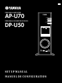 1
1
-
 2
2
-
 3
3
-
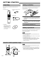 4
4
-
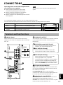 5
5
-
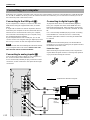 6
6
-
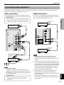 7
7
-
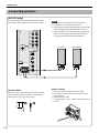 8
8
-
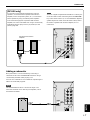 9
9
-
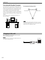 10
10
-
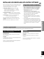 11
11
-
 12
12
-
 13
13
-
 14
14
-
 15
15
-
 16
16
-
 17
17
-
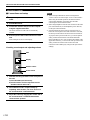 18
18
-
 19
19
-
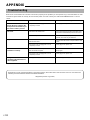 20
20
-
 21
21
-
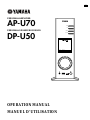 22
22
-
 23
23
-
 24
24
-
 25
25
-
 26
26
-
 27
27
-
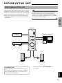 28
28
-
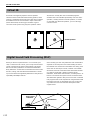 29
29
-
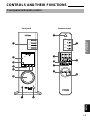 30
30
-
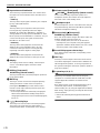 31
31
-
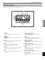 32
32
-
 33
33
-
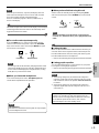 34
34
-
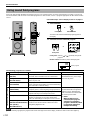 35
35
-
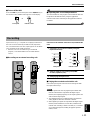 36
36
-
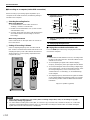 37
37
-
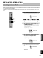 38
38
-
 39
39
-
 40
40
-
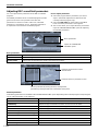 41
41
-
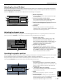 42
42
-
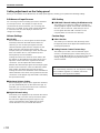 43
43
-
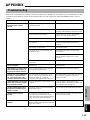 44
44
-
 45
45
-
 46
46
-
 47
47


Yamaha AP-U70 de handleiding
- Categorie
- Audio versterkers
- Type
- de handleiding
- Deze handleiding is ook geschikt voor
in andere talen
- English: Yamaha AP-U70 Owner's manual
- italiano: Yamaha AP-U70 Manuale del proprietario
- русский: Yamaha AP-U70 Инструкция по применению
- français: Yamaha AP-U70 Le manuel du propriétaire
- español: Yamaha AP-U70 El manual del propietario
- Deutsch: Yamaha AP-U70 Bedienungsanleitung
- português: Yamaha AP-U70 Manual do proprietário
- dansk: Yamaha AP-U70 Brugervejledning
- suomi: Yamaha AP-U70 Omistajan opas
- čeština: Yamaha AP-U70 Návod k obsluze
- svenska: Yamaha AP-U70 Bruksanvisning
- Türkçe: Yamaha AP-U70 El kitabı
- polski: Yamaha AP-U70 Instrukcja obsługi
- română: Yamaha AP-U70 Manualul proprietarului
Gerelateerde papieren
-
Yamaha RP-U200 de handleiding
-
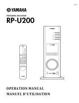 Tamaha RP-U200 Handleiding
-
-
-
-
-
-
-
Yamaha NX-U02 de handleiding
-
Yamaha RX V2700 - AV Network Receiver de handleiding
