
Owner’s Manual
Bedienungsanleitung
Mode d’emploi
Manual de instrucciones
EN
DE
FR
ES
EnglishDeutschFrançaisEspañol
Features
Input Channels...................................................................page 16
With up to 16 (MG166CX-USB/MG166C-USB: 10) mic/line inputs
or up to four stereo inputs, the MG mixer can simultaneously
connect to a wide range of devices: microphones, line-level
devices, stereo synthesizers, and more.
Compression........................................................................page 9
Compression increases the overall level without introducing
distortion by compressing excessive peaks in the signals from
microphones and guitars.
Cubase AI 4 DAW Software Supplied...............................page 10
By connecting the MG mixer to the computer via a USB cable an
audio data mixed by the MG mixer can be recorded on Cubase AI
4.
High-quality digital effects (MG166CX-USB)...........pages 19, 23
With digital effects built in, the MG166CX-USB can deliver a wide
range of sound variations all by itself.
Caractéristiques
Canaux d’entrée.................................................................page 64
Avec 16 entrées micro/ligne (MG166CX-USB/MG166C-USB: 10)
ou quatre entrées stéréo maximum, la console de mixage MG peut
connecter simultanément une grande variété d’appareils : micros,
appareils de ligne, synthétiseurs stéréo, etc.
Compression......................................................................page 57
La compression augmente le niveau général sans engendrer de
distorsion en comprimant les pics excessifs des signaux des
micros et des guitares.
Le logiciel DAW Cubase AI 4 fournit................................page 58
En connectant la console de mixage MG à un ordinateur via un
câble USB, des donnés audio créées par la console de mixage MG
peuvent être enregistrées sur Cubase AI 4.
Effets numériques de qualité supérieure
(MG166CX-USB).........................................................pages 67, 71
Grâce aux effets numériques intégrés, la console MG166CX-USB
peut proposer de nombreuses variations de sons.
Funktionen
Eingangskanäle..................................................................Seite 40
Mit bis zu 16 Mikrofon-/Line-Eingängen (MG166CX-USB/MG166C-
USB: 10) oder bis zu vier Stereoeingängen können viele Geräte
gleichzeitig am MG-Mischpult angeschlossen werden: Mikrofone,
Geräte mit Leitungspegel, Stereo-Synthesizer uvm.
Kompression......................................................................Seite 33
Kompression erhöht den Durchschnittspegel, ohne Verzerrung
hinzuzufügen, indem übermäßige Pegelspitzen der Signale von
Mikrofonen oder Gitarren komprimiert werden.
DAW-Software Cubase AI 4 mitgeliefert.........,................Seite 34
Wenn Sie Ihr MG-Mischpult über ein USB-Kabel am Computer
anschließen, können durch das MG-Mischpult gemischte
Audiodaten in Cubase AI 4 aufgenommen werden.
Hochwertige Digitaleffekte (MG166CX-USB)...........Seiten 43, 47
Mit den eingebauten digitalen Effekten kann das MG166CX-USB
aus sich heraus eine Reihe von Klangvariationen liefern.
Características
Canales de entrada.........................................................página 88
Con un máximo de 16 entradas de micrófono/línea (MG166CX-
USB/MG166C-USB: 10) o cuatro entradas estereofónicas, la
mezcladora MG puede conectarse simultáneamente con una gran
variedad de dispositivos: micrófonos, dispositivos de nivel de línea,
sintetizadores estereofónicos, etc.
Compresión.....................................................................página 81
La compresión aumenta el nivel general sin causar distorsión,
mediante la compresión del exceso de picos en las señales de los
micrófonos y guitarras.
El software DAW Cubase AI 4 suministrado................página 82
Al conectar la mezcladora MG con un ordenador por medio de un
cable USB, se puede grabar en Cubase AI 4 datos de audio
creados por la mezcladora MG.
Efectos digitales de alta calidad (MG166CX-USB)
...páginas 91, 95
Gracias a sus efectos digitales incorporados, la mezcladora
MG166CX-USB puede producir por sí misma una amplia gama de
variaciones de sonido.

MG206C-USB/MG166CX-USB/MG166C-USB Owner’s Manual
2
* This applies only to products distributed by Yamaha-Kemble Music (U.K.) Ltd. (2 wires)
* This applies only to products distributed by YAMAHA CORPORATION OF AMERICA. (FCC DoC)
IMPORTANT NOTICE FOR THE UNITED KINGDOM
Connecting the Plug and Cord
IMPORTANT. The wires in this mains lead are coloured in accordance with the following code:
BLUE : NEUTRAL
BROWN : LIVE
As the colours of the wires in the mains lead of this apparatus may not correspond with the coloured makings identifying the terminals
in your plug proceed as follows:
The wire which is coloured BLUE must be connected to the terminal which is marked with the letter N or coloured BLACK.
The wire which is coloured BROWN must be connected to the terminal which is marked with the letter L or coloured RED.
Making sure that neither core is connected to the earth terminal of the three pin plug.
COMPLIANCE INFORMATION STATEMENT
(DECLARATION OF CONFORMITY PROCEDURE)
Responsible Party : Yamaha Corporation of America
Address : 6600 Orangethorpe Ave., Buena Park, Calif. 90620
Telephone : 714-522-9011
Type of Equipment : Mixing Console
Model Name : MG206C-USB/MG166CX-USB/MG166C-USB
This device complies with Part 15 of the FCC Rules.
Operation is subject to the following two conditions:
1) this device may not cause harmful interference, and
2) this device must accept any interference received including interference that may cause undesired operation.
See user manual instructions if interference to radio reception is suspected.
1. IMPORTANT NOTICE: DO NOT MODIFY THIS UNIT!
This product, when installed as indicated in the instructions
contained in this manual, meets FCC requirements. Modifi-
cations not expressly approved by Yamaha may void your
authority, granted by the FCC, to use the product.
2. IMPORTANT: When connecting this product to accessories
and/or another product use only high quality shielded cables.
Cable/s supplied with this product MUST be used. Follow all
installation instructions. Failure to follow instructions could
void your FCC authorization to use this product in the USA.
3. NOTE: This product has been tested and found to comply
with the requirements listed in FCC Regulations, Part 15 for
Class “B” digital devices. Compliance with these require-
ments provides a reasonable level of assurance that your use
of this product in a residential environment will not result in
harmful interference with other electronic devices. This
equipment generates/uses radio frequencies and, if not
installed and used according to the instructions found in the
users manual, may cause interference harmful to the opera-
tion of other electronic devices. Compliance with FCC regula-
* This applies only to products distributed by YAMAHA CORPORATION OF AMERICA. (class B)
tions does not guarantee that interference will not occur in all
installations. If this product is found to be the source of inter-
ference, which can be determined by turning the unit “OFF”
and “ON”, please try to eliminate the problem by using one of
the following measures:
Relocate either this product or the device that is being
affected by the interference.
Utilize power outlets that are on different branch (circuit
breaker or fuse) circuits or install AC line filter/s.
In the case of radio or TV interference, relocate/reorient the
antenna. If the antenna lead-in is 300 ohm ribbon lead,
change the lead-in to co-axial type cable.
If these corrective measures do not produce satisfactory
results, please contact the local retailer authorized to distrib-
ute this type of product. If you can not locate the appropriate
retailer, please contact Yamaha Corporation of America,
Electronic Service Division, 6600 Orangethorpe Ave, Buena
Park, CA90620
The above statements apply ONLY to those products distrib-
uted by Yamaha Corporation of America or its subsidiaries.
FCC INFORMATION (U.S.A.)

MG206C-USB/MG166CX-USB/MG166C-USB Owner’s Manual
3
PRECAUTIONS
PLEASE READ CAREFULLY BEFORE PROCEEDING
* Please keep this manual in a safe place for future reference.
WARNING
Always follow the basic precautions listed below to avoid the possibility of serious injury or even death from electrical
shock, short-circuiting, damages, fire or other hazards. These precautions include, but are not limited to, the following:
• Only use the voltage specified as correct for the device. The required voltage is
printed on the name plate of the device.
• Use only the included power adaptor (PA-30 or an equivalent recommended by
Yamaha).
• Do not place the power cord near heat sources such as heaters or radiators, and
do not excessively bend or otherwise damage the cord, place heavy objects on
it, or place it in a position where anyone could walk on, trip over, or roll anything
over it.
• Do not open the device or attempt to disassemble the internal parts or modify
them in any way. The device contains no user-serviceable parts. If it should
appear to be malfunctioning, discontinue use immediately and have it inspected
by qualified Yamaha service personnel.
• Do not expose the device to rain, use it near water or in damp or wet conditions,
or place containers on it containing liquids which might spill into any openings.
• Never insert or remove an electric plug with wet hands.
• If the power cord or plug becomes frayed or damaged, or if there is a sudden
loss of sound during use of the device, or if any unusual smells or smoke
should appear to be caused by it, immediately turn off the power switch,
disconnect the electric plug from the outlet, and have the device inspected by
qualified Yamaha service personnel.
• If this device or the AC power adaptor should be dropped or damaged,
immediately turn off the power switch, disconnect the electric plug from the
outlet, and have the device inspected by qualified Yamaha service personnel.
CAUTION
Always follow the basic precautions listed below to avoid the possibility of physical injury to you or others, or damage
to the device or other property. These precautions include, but are not limited to, the following:
• Remove the electric plug from the outlet when the device is not to be used for
extended periods of time, or during electrical storms.
• When removing the electric plug from the device or an outlet, always hold the
plug itself and not the cord. Pulling by the cord can damage it.
•To avoid generating unwanted noise, make sure there is adequate distance (50
cm or more) between the AC power adaptor and the device.
• Do not cover or wrap the AC power adaptor with a cloth or blanket.
• Before moving the device, remove all connected cables.
• When setting up the device, make sure that the AC outlet you are using is easily
accessible. If some trouble or malfunction occurs, immediately turn off the
power switch and disconnect the plug from the outlet. Even when the power
switch is turned off, electricity is still flowing to the product all the minimum
level. When you are not using the product for a long time, make sure to unplug
the power cord from the wall AC outlet.
• If this device is to be mounted in an EIA-standard rack, leave the back of the rack
open and make sure that it is at least 10 cm away from walls or surfaces. Also, if
this device is to be mounted with devices that tend to generate heat, such as
power amplifiers, be sure to keep an adequate gap between this device and the
heat-generating devices or install ventilation panels to prevent high
temperatures from developing inside this device.
Inadequate ventilation can result in overheating, possibly causing damage to the
device(s), or even fire.
•Avoid setting all equalizer controls and faders to their maximum. Depending on
the condition of the connected devices, doing so may cause feedback and may
damage the speakers.
• Do not expose the device to excessive dust or vibrations, or extreme cold or heat
(such as in direct sunlight, near a heater, or in a car during the day) to prevent
the possibility of panel disfiguration or damage to the internal components.
• Do not place the device in an unstable position where it might accidentally fall
over.
• Do not block the vents. This device has ventilation holes at the bottom/rear to
prevent the internal temperature from becoming too high. In particular, do not
place the device on its side or upside down. Inadequate ventilation can result in
overheating, possibly causing damage to the device(s), or even fire.
• Do not use the device in the vicinity of a TV, radio, stereo equipment, mobile
phone, or other electric devices. Doing so may result in noise, both in the device
itself and in the TV or radio next to it.
• Before connecting the device to other devices, turn off the power for all devices.
Before turning the power on or off for all devices, set all volume levels to
minimum.
• When turning on the AC power in your audio system, always turn on the power
amplifier LAST, to avoid speaker damage. When turning the power off, the power
amplifier should be turned off FIRST for the same reason.
• Do not insert your fingers or hands in any gaps or openings on the device
(vents, etc.).
•Avoid inserting or dropping foreign objects (paper, plastic, metal, etc.) into any
gaps or openings on the device (vents, etc.) If this happens, turn off the power
immediately and unplug the power cord from the AC outlet. Then have the
device inspected by qualified Yamaha service personnel.
• Do not use the device or headphones for a long period of time at a high or
uncomfortable volume level, since this can cause permanent hearing loss. If you
experience any hearing loss or ringing in the ears, consult a physician.
• Do not rest your weight on the device or place heavy objects on it, and avoid use
excessive force on the buttons, switches or connectors.
Power supply/Power cord
Do not open
Water warning
If you notice any abnormality
Power supply/Power cord
Location
Connections
Handling caution
(5)-4 1/2

MG206C-USB/MG166CX-USB/MG166C-USB Owner’s Manual
4
Always turn the power off when the device is not in use.
Even when the power switch is in the “STANDBY” position, electricity is still flowing to the device at the minimum level. When you are not using the device for a long time,
make sure you unplug the power cord from the wall AC outlet.
The performance of components with moving contacts, such as switches, volume controls, and connectors, deteriorates over time. Consult qualified Yamaha service
personnel about replacing defective components.
The MG mixer may heat up by as much as 15 to 20°C while the power is on. This is normal. Please note that the panel temperature may exceed 50°C in ambient temperatures
higher than 30°C, and use caution to prevent burns.
* This Owner’s Manual applies to the MG206C-USB/MG166CX-USB/MG166C-USB. The main differences between the three models are the number of input channels and
whether the internal effects are included. The MG206C-USB has 20 input channels while the MG166CX-USB/MG166C-USB have 16 channels. And only the MG166CX-
USB has internal effects.
* In this manual the term “MG mixsers” refers to the MG206C-USB/MG166CX-USB/MG166C-USB.
Specifications and descriptions in this owner’s manual are for information purposes only. Yamaha Corp. reserves the right to change or modify products or specifications at
any time without prior notice. Since specifications, equipment or options may not be the same in every locale, please check with your Yamaha dealer.
SPECIAL NOTICES
• The owner’s manual is the exclusive copyright of Yamaha Corporation.
• The included software is the exclusive copyright of Steinberg Media Technologies GmbH.
• Use of the software and this manual is governed by the license agreement which the purchaser fully agrees to upon breaking the seal of the software packaging. (Please
read carefully the Software Licensing Agreement at the end of this manual before installing the application.)
• Copying of the software or reproduction of this manual in whole or in part by any means is expressly forbidden without the written consent of the manufacturer.
•Yamaha makes no representations or warranties with regard to the use of the software and documentation and cannot be held responsible for the results of the use of this
manual and the software.
• This disk is a DVD-ROM. Do not attempt to play the disk on a DVD player. Doing so may result in irreparable damage to your DVD player.
• Visit the web address below for the latest information on supplied software and operating system requirements.
<http://www.yamahasynth.com/>
The illustrations and LCD screens as shown in this owner’s manual are for instructional purposes only, and may appear somewhat different from those on your instrument.
This product incorporates and bundles computer programs and contents in which Yamaha owns copyrights or with respect to which it has license to use others’ copyrights.
Such copyrighted materials include, without limitation, all computer software, style files, MIDI files, WAVE data, musical scores and sound recordings. Any unauthorized use
of such programs and contents outside of personal use is not permitted under relevant laws. Any violation of copyright has legal consequences. DON’T MAKE, DISTRIBUTE
OR USE ILLEGAL COPIES.
Copying of the commercially available musical data including but not limited to MIDI data and/or audio data is strictly prohibited except for your personal use.
• Windows is the registered trademarks of Microsoft® Corporation.
• Apple and Macintosh are trademarks of Apple Computer, Inc., registered in the U.S. and other countries.
• Steinberg and Cubase are the registered trademarks of Steinberg Media Technologies GmbH.
• The company names and product names in this Owner’s Manual are the trademarks or registered trademarks of their respective companies.
Specifications and descriptions in this owner’s manual are for information purposes only. Yamaha Corp. reserves the right to change or modify products or specifications at
any time without prior notice. Since specifications, equipment or options may not be the same in every locale, please check with your Yamaha dealer.
XLR-type connectors are wired as follows (IEC60268 standard): pin 1: ground, pin 2: hot (+), and pin 3: cold (-).
Insert TRS phone jacks are wired as follows: sleeve: ground, tip: send, and ring: return.
Yamaha cannot be held responsible for damage caused by improper use or modifications to the device, or data that is lost or destroyed.
Copying of commercially available music or other audio data for purposes other than personal use is strictly prohibited by copyright law. Please respect all
copyrights, and consult with a copyright specialist if you are in doubt about permissible use.

MG206C-USB/MG166CX-USB/MG166C-USB Owner’s Manual
5
Introduction.......................................... 5
Contents...........................................................5
Before Turning on the Mixer ............................6
Turning the Power On/OFF..............................6
Computer System Requirements.....................6
Cubase AI 4 System Requirements.................6
■ Mixer Basics................................ 7
Quick Guide.......................................... 7
1. Installing Cubase AI 4..................................7
2. Connecting to the MG mixer ........................7
3. Powering Up the System .............................8
4. Adjusting Level and Tone ............................9
5. Recording with Cubase AI 4 ......................10
6. Mixing with Cubase AI 4 ............................13
Introduction
Thank you for your purchase of the Yamaha MG206C-USB/MG166CX-USB/MG166C-USB mixing
console. The MG206C-USB/MG166CX-USB/MG166C-USB feature input channels suitable for a
wide range of usage environments. Furthermore, the mixer has the USB connector that enables you to
record an audio data mixed with the mixer on the included Cubase AI 4 DAW software.
Please read through this manual carefully before beginning use, so that you will be able to take full
advantage of this mixer’s superlative features and enjoy trouble-free operation for years to come.
Contents
■ Reference .................................. 15
Setup....................................................15
Front & Rear Panels ...........................16
Channel Control Section................................16
Digital Effects.................................................19
Master Control Section ..................................20
Digital Effect Program List
(Only MG166CX-USB)................................23
Jack List.........................................................23
Troubleshooting .................................24
Specifications .....................................99
About the accessory disk................106
SOFTWARE LICENSE AGREEMENT
...106
Accessories
• Cubase AI 4 DVD-ROM
• USB cable
• Owner’s Manual
•AC power adaptor (PA-30)*
*May not be included depending on your particular area. Please
check with your Yamaha dealer.

Introduction
MG206C-USB/MG166CX-USB/MG166C-USB Owner’s Manual
6
1
Be sure that the mixer’s power switch is in the
STANDBY position.
Use only the included power adaptor (PA-30) or
an equivalent recommended by Yamaha. Use of a
different adaptor may result in equipment dam-
age, overheating, or fire.
2
Connect the power adaptor to the AC ADAPTOR IN
connector (
q) on the rear of the mixer, and then
turn the fastening ring clockwise (
w) to secure the
connection.
3
Plug the power adaptor into a standard household
power outlet.
• Be sure to unplug the adaptor from the outlet
when not using the mixer, or when there are
lightning storms in the area.
•To avoid generating unwanted noise, make
sure there is 50 cm or more between the power
adaptor and the mixer.
Press the mixer’s power switch to the ON position.
When you are ready to turn the power off, press the
power switch to the STANDBY position.
Note that trace current continues to flow while the
switch is in the STANDBY position. If you do not plan
to use the mixer again for a long while, please be sure
to unplug the adaptor from the wall outlet.
Windows Vista
Windows XP
Macintosh
Windows
Macintosh
•A DVD driver is required for installation.
•To activate your software license, install the application
while the computer is connected to the internet.
Before Turning on the Mixer
Turning the Power On/OFF
CAUTION
q
w
CAUTION
CAUTION
Computer System Requirements
Computer
Windows-based computer with built-in USB inter-
face
OS Windows Vista
CPU
1 GHz or higher Intel Core/Pentium/Celeron proces-
sor
Memory 1 GB or more
Computer
Windows-based computer with built-in USB inter-
face
OS Windows XP Professional/XP Home Edition
CPU
750 MHz or higher Intel Core/Pentium/Celeron pro-
cessor
Memory 96 MB or more (128 MB or more recommended)
Computer Macintosh computer with built-in USB interface
OS MacOS X 10.3.3 or higher
CPU Macintosh G3 300 MHz or higher/Intel processor
Memory 128 MB or more
Cubase AI 4 System Require-
ments
OS Windows XP Professional/XP Home Edition
CPU 1.4 GHz or higher Intel Pentium processor
Memory 512 MB or more
Audio
Interface
Windows DirectX compatible
Hard Disk 400 MB or more
OS MacOS X 10.4 or higher
CPU Power Mac G4 1 GHz/Core Solo 1.5 GHz or higher
Memory 512 MB or more
Hard Disk 400 MB or more
NOTE

Mixer Basics
MG206C-USB/MG166CX-USB/MG166C-USB Owner’s Manual
7
Quick Guide
This quick setup and operation guide covers everything from installing the Cubase AI 4 software to
using Cubase AI 4 for recording and mixdown. While going through this section you might find it
useful to also refer to the “Front and Rear Panels” section on page 16, as well as the pdf manual
supplied with the Cubase AI 4 software.
Since the End-User Software License Agreement (EUSLA) shown on your PC-display in your
installing the “DAW” software is replaced by the agreement at the end of this manual, you
should disregard the EUSLA. Read the Software License Agreement at the end of this man-
ual carefully, and install the software if you agree to it.
1
Start the computer and log on to the Administrator account.
2
Insert the included DVD-ROM into the computer’s DVD-ROM drive.
3
Open the “Cubase AI 4 for Windows” folder and double-click on the “CubaseAI4.msi”.
Follow the on-screen instructions to install the Cubase AI 4 software.
• When installing Cubase AI 4, you will need a working internet connection to register your Cubase AI 4. Make
sure to fill in all required fields for user registration. If you do not register the product, you will be unable to use
the application after a limited period of time expires.
•For a Macintosh computer, double-click the “CubaseAI4.mkpg” icon for installation.
1
Turn the power to the MG mixer and all
gear that is to be connected to the MG
mixer off/standby (except the computer),
and set the channel faders, STEREO OUT
Master fader, GROUP 1-2 fader and GROUP
3-4 fader to their minimum settings.
2
Connect the MG mixer to your computer
using the supplied USB cable.
When connecting or disconnecting the USB
cable be sure to turn the 2TR IN/USB control
all the way down.
Disconnect the USB cable when using the MG
mixer without the computer.
Step
1
Installing Cubase AI 4
IMPORTANT !
NOTE
Step
2
Connecting to the MG mixer
Channel fader
STEREO OUT Master fader
GROUP 3-4 fader
GROUP 1-2 fader
USB Connection Precautions
Be sure to observe the following points when connecting to
the computer’s USB interface.
Failure to observe these rules can result in computer freezes/
hang-ups and possibly data loss or corruption. If the MG
mixer or computer does hang up, turn the power to both
devices off and then on again, and restart the computer.
• Be sure to wake the computer from sleep/sus-
pended/standby mode before making a con-
nection to the computer’s USB connector.
• Connect the MG mixer to the computer before
turning the MG mixer power on.
•Always quit all applications running on the
computer before turning the MG mixer’s power
on or off, or connecting or disconnecting the
USB cable.
•Wait at least 6 seconds between turning the
MG mixer on or off, and between connecting
or disconnecting the USB cable.
CAUTION
CAUTION
NOTE
Mixer Basics

Quick Guide
MG206C-USB/MG166CX-USB/MG166C-USB Owner’s Manual
Mixer Basics
8
3
Connecting Microphones and/or Instru-
ments.
For details on making connections refer to the “Setup”
section on page 15 and the “Front & Rear Panels” sec-
tion on page 16.
To prevent loud pops and noises, turn on the
power to your sound gear starting with the
sources (instruments, CD players, etc.) and end-
ing with the power amplifier or powered speakers.
Example : Instruments, microphones, and CD players first, then
the mixer, and finally the power amplifier or powered
speakers.
Observe the following precautions when
turning on phantom power.
• Make sure that the PHANTOM switch is off when
phantom power is not needed.
• When turning the switch on, be sure that only con-
denser microphones are connected to the XLR input
jacks. Other devices may be damaged if connected
to phantom power. This precaution does not apply to
balanced dynamic microphones, however, as these
will not be affected by phantom power.
•To minimize the possibility of speaker damage, turn
phantom power on ONLY while your power amplifier
or powered speakers are switched off. It’s also a
good idea to turn the mixer’s output controls—STE-
REO OUT Master fader , GROUP 1-2 fader and
GROUP 3-4 fader—all the way down.
•We recommend that you set the computer output to the
maximum level and mute the computer’s internal
speaker. For details on how to make the setting refer to
the “The recorded sound is too low in level.” in the “Trou-
bleshooting” on page 24.
• The first time you connect to the computer’s USB con-
nector, or change the connection to a different USB port,
a driver installation display may appear after turning the
power to the MG mixer on. If this occurs, wait until the
installation is complete before proceeding.
DI
USB cable
Be sure to turn the MG mixer
PHANTOM switch on when
using phantom-powered con-
denser microphones.
Although electric guitars
and basses can be con-
nected directly to the
mixer’s inputs, the sound is
likely to be thin and possi-
bly noisy. For best results
with these types of instru-
ments use a DI box (direct
box) or amp simulator
between the instrument
and the mixer.
Step
3
Powering Up the System
CAUTION
NOTE
Balanced, Unbalanced—What’s the Difference?
In a word: “noise.” The whole point of balanced lines is noise
rejection, and it’s something they’re very good at. Any length of
wire will act as an antenna to pick up the random electromag-
netic radiation we’re constantly surrounded by: radio and TV sig-
nals as well as spurious electromagnetic noise generated by
power lines, motors, electric appliances, computer monitors, and
a variety of other sources. The longer the wire, the more noise it
is likely to pick up.
That’s why balanced lines are the best choice for long cable runs.
If your “studio” is basically confined to your desktop and all con-
nections are no more than a meter or two in length, then unbal-
anced lines are fine—unless you’re surrounded by extremely
high levels of electromagnetic noise. Another place balanced
lines are almost always used is in microphone cables. The rea-
son for this is that the output signal from most microphones is
very small, so even a tiny amount of noise will be relatively large,
and will be amplified to an alarming degree in the mixer’s high-
gain head amplifier.
Noise
Hot (+)
Cold (–)
Ground
Source
Cable
Noise cancelled
Noise-free
signal
Phase
inversion
Receiving device
Phase
inversion
Balanced noise cancellation
Cable Guidelines
Microphone cable Balanced is best.
Short line-level cables
Unbalanced cable is fine in a rela-
tively noise-free environment.
Long line-level cables Balanced is best.

Mixer Basics
Quick Guide
MG206C-USB/MG166CX-USB/MG166C-USB Owner’s Manual
9
Level Adjustment
1
The first step is to set the level controls on
all instruments and other sources appro-
priately.
2
Adjust the channel GAIN controls so that
the corresponding PEAK indicators flash
briefly on the highest peak levels.
3
Engage the ON and ST switches of the input
channels that you would like to record.
4
Make sure that the PFL switch is off ( ),
and that the MONITOR switch is set to STE-
REO ( ).
5
Raise the STEREO OUT Master fader to the
0 dB position.
6
Set the channel faders to create the
desired initial balance while monitoring via
headphones or monitor speakers. The
overall headphone level is adjusted by the
MONITOR/PHONES control.
Tone Adjustment
The MG mixer’s compressors, 3-band equalizers and digital
effects make it easy to shape the tone of independent
channels to achieve the best possible mix.
The MG166CX-USB has built-in digital effects. Refer to
“Use the Built-in Digital Effects to Refine Your Mixes” on
page 14 and “Digital Effect Program List” on page 23 for
details.
Step
4
Adjusting Level and Tone
PEAK
indicator
GAIN control
ON switch
ST switch
PFL switch
Channel fader
STEREO OUT Master fader
MONITOR switch
MONITOR/PHONES control
NOTE
Compression
One form of compression known as “limiting” can, when
properly used, produce a smooth, unified sound with no
excessive peaks or distortion. A common example of the use
of compression is to “tame” a vocal that has a wide dynamic
range in order to tighten up the mix. Compression can also
be applied to guitar tracks to add extra sustain. Too much
compression can be a cause of feedback, however, so use it
sparingly.
Equalizer Tips
The best advice that can be given regarding equalization
while recording is simply to use as little equalization as possi-
ble. If you want a little more presence you can turn the HIGH
end up a bit. Or you can boost the bass a little if you feel the
low end is lacking. During recording it’s better to use EQ
sparingly for compensation only.
●
Cut for a Cleaner Mix
For example: pianos have a lot of energy in the mid and
low frequency ranges that you don’t really perceive as
musical sound, but which can interfere with the clarity of
other instruments in these ranges. You can basically turn
the low EQ on piano channels all the way down without
changing the way they sound in the mix. You’ll hear the dif-
ference, however, in the way the mix sounds more “spa-
cious,” and instruments in the lower ranges will have better
definition. Naturally you won’t want to do this if the piano is
playing solo.
The reverse applies to kick drums and bass guitars: you
can often roll off the high end to create more space in the
mix without compromising the character of the instru-
ments. You’ll have to use your ears, though, because each
instrument is different and sometimes you’ll want the
“snap” of a bass guitar, for example, to come through.
(Min)
(Max)
INPUT
OUTPUT
20 50 100 200 500 1 k 2 k 5 k 10 k 20 k
(
Hz
)
Piano
Bass Drum
Snare Drum
Bass
Guitar
Trombone
Tr umpet
Cymba
l
Fundamental: The frequency that determines the basic musical pitch.
Harmonics: Multiples of the fundamental frequency that play a role in
determining the timbre of the instrument.
The fundamental and harmonic frequency ranges of
some musical instruments.

Quick Guide
MG206C-USB/MG166CX-USB/MG166C-USB Owner’s Manual
Mixer Basics
10
This section describes the procedure for recording to the Cubase AI 4 software we installed earlier via the MG mixer.
For details on operation of the Cubase AI 4 software refer to the pdf-format manual provided with the software.
Cubase AI 4 Setup
1
To prevent the playback sound from
Cubase AI 4 from being directly rere-
corded, set the MG mixer’s 2TR IN/USB
switch to TO MONITOR ( ).
2
Launch Cubase AI 4.
Windows:
Click [Start] → [All Program] → [Steinberg Cubase AI
4] → [Cubase AI 4] to launch the program. If the ASIO
Multimedia dialog window appears, click [Yes].
Macintosh:
Double-click the [Application] → [Cubase AI 4].
• If you specified a file destination when installing
the Cubase AI 4 software, launch the applica-
tion from that location.
• Create a Cubase AI 4 shortcut or alias on your
desktop so you can easily launch the program
when required.
3
Select [Device Setup] from the [Device]
menu to open the Device Setup window.
Windows:
Select [VST Audio System] in the [Device] field on the
left side of the window. Select [ASIO DirectX Full
Duplex Driver] in the [ASIO Driver] field on the right
side of the window. A dialog window will appear asking
“Do you want to switch the ASIO driver?”. Click
[Switch].
Macintosh:
Select [VST Audio System] in the [Device] field on the
left side of the window. Select [USB Audio CODEC (2)]
in the [ASIO Driver] field on the right side of the win-
dow, and click [OK]. Skip ahead to step 6, below.
Under Mac OS X you can select either [USB
Audio CODEC (1)] or [USB Audio CODEC (2)]
in the [ASIO Driver] field. Normally you should
select [USB Audio CODEC (2)], but if you will
only be playing back and mixing previously
recorded data you can select [USB Audio
CODEC (1)] to lighten the load on the com-
puter’s CPU.
4
On a Windows computer select [ASIO
DirectX Full Duplex Driver] in the [Devices]
field on the left side of the Device Setup
window, and click [Control Panel] on the
right side of the window.
Step
5
Recording with Cubase AI 4
NOTE
NOTE
NOTE

Mixer Basics
Quick Guide
MG206C-USB/MG166CX-USB/MG166C-USB Owner’s Manual
11
5
The ASIO Direct Sound Full Duplex Setup
dialog window will be displayed. Check
only the input port and output port [USB
Audio CODEC] checkbox.
6
Make sure that “USB Audio CODEC 1/2”
are shown in the [Port System Name] field,
and check the [Visible] column in the
Device Setup window. Click [OK] to close
the window.
If the [Port System Name] field does not
change, close and restart the Cubase AI 4,
then open the Device Setup window.
7
Select [New Project] from the [File] menu
to create a new project file.
The new project dialog window will open. For this
example select [CAI4 - 4 Stereo 8 Mono Audio Track
Recorder] and click [OK].
Recorded Cubase AI 4 data is stored as a
“project file”.
8
When the directory selection dialog win-
dow appears, select the folder to which the
project and audio files for the project are to
be stored, and click [OK].
An empty project window with 4 stereo and 8 monaural
tracks will appear.
NOTE
NOTE
Project window
Transport panel
Mixer window

Quick Guide
MG206C-USB/MG166CX-USB/MG166C-USB Owner’s Manual
Mixer Basics
12
Preparing to Record
1
Click in the track list (the area in which the
track names are displayed) to select a
track to record on.
The various settings for the selected track are available
in the Inspector on the left side of the display.
You will normally use a stereo track when
recording synthesizers, and a monaural track
when recording vocals or guitar.
2
Click the Input Routing field in the Inspec-
tor to select the audio input source. Select
“Stereo In 1” for a stereo track and “Left
(Right)-Stereo In 1” for a monaural track.
3
Make sure the [Record Enable] button for
the track to be recorded is turned on.
If the [Record Enable] button is off, click it to turn it on.
4
Play the instrument to be recorded, and
adjust the MG mixer’s GAIN controls, chan-
nel faders and STEREO OUT Master fader
so that the Clipping indicator never light.
5
Specify the point at which you want to start
recording via the ruler at the top of the
project window.
Click the black area of the ruler to move the project cur-
sor (the vertical black line) to that position.
Recording and Playback
1
Click the Transport panel [Record] button
to begin recording.
When recording is started the project cursor will begin
moving to the right and a box that displays the recording
results will be created.
2
Play the part.
3
When you finish recording the track, click
the Transport panel [Stop] button.
Inspector
Input routing
[Record Enable] button Track list
NOTE
<Transport panel>
Clipping indicator
Ruler
Stop
Record
Start
Rewind
Forward
<Transport panel>
Recording results

Mixer Basics
Quick Guide
MG206C-USB/MG166CX-USB/MG166C-USB Owner’s Manual
13
4
To hear playback of the track you have just
recorded, use either the Transport panel
[Rewind] button or the ruler to rewind to
the beginning of the recorded section, then
click the Transport panel [Start] button.
The overall playback level will be displayed via the mas-
ter section bus level meter on the right side of the mixer
window, and the channel level will be displayed via the
channel strip level meter.
• Click the [Narrow/Wide] button in the upper left
corner of the mixer window to increase the
width of the mixer’s channel strips.
• The output signal from Cubase AI 4 is routed to
the MG mixer’s 2TR IN inputs. To hear the play-
back sound via a pair of headphones plugged
into the MG mixer, set the bus select switch to
TO MONITOR ( ) and adjust the volume with
the 2TR IN/USB control and the MONITOR/
PHONES control.
5
To save the project file select [Save]
from the [File] menu and enter a file
name before actually saving the file.
Save your project file frequently to insure against losing
large amounts of data if a problem occurs.
6
Repeat steps 1 through 5 to record further
material on the same track.
7
To record additional material on a different
track, select a new track and repeat the
record procedure.
You can monitor the sound being recorded and
a previously recorded sound simultaneously
while recording (MONITOR MIX). Refer to “F
2TR IN/USB” on page 22 for details.
In this section we’ll try mixing down multiple recorded audio tracks to stereo, and creating a wav file. Mixes can be stored as
WAV or AIFF files, which can then be recorded to audio CDs.
1
Launch Cubase AI 4 and open a project
file.
2
Click the [Start] button on the Transport
Panel.
3
While listening to playback, drag the chan-
nel strip level faders up and down to create
the desired initial balance, then adjust the
overall volume using the bus volume fader.
4
Drag the pan controls on the top of the
channel strips left and right to set the
stereo position of each track.
NOTE
Level meter Bus level meter
[Narrow/Wide] button[Narrow/Wide] button
NOTE
Step
6
Mixing with Cubase AI 4

Quick Guide
MG206C-USB/MG166CX-USB/MG166C-USB Owner’s Manual
Mixer Basics
14
5
At this point you can begin to use EQ to
refine your mix, and add effects.
As an example let’s try adding reverb. Click the [Edit]
button ( ) on the left side of the channel strip to
open the VST audio channel settings window. Click
Insert 1 and select Earlier VST Plug-ins → Reverb →
RoomWorks SE.
For further details refer to the pdf manual pro-
vided with the Cubase AI 4 software.
It’s a good idea to lower the channel fader a
bit before adding an effect, since the effect
can cause an increase in the overall channel
level.
6
When the final mix adjustments have
been made, go to the [File] menu and
select [Export] → [Audio Mixdown].
7
Enter a file name and select a destina-
tion for the file as well as a file type.
If you intend to use the file to create an audio CD, select
the WAV file type (AIFF on Macintosh OS X), Stereo
Out (stereo), 16 bit, and 44.1 kHz.
8
Click [Export].
Progress of the mixdown operation will be shown in a
progress window. When the progress window closes the
mixdown is complete.
Wave files created by mixdown can be directly
played back using the Windows Media Player,
or iTunes on a Macintosh computer.
NOTE
CAUTION
NOTE
Use the Built-in Digital Effects to Refine Your Mixes (Only MG166CX-USB)
●
Reverb and Delay Time
The optimum reverb time for a piece of music will depend on the
music’s tempo and density, but as a general rule longer reverb
times are good for ballads, while shorter reverb times are more
suited to uptempo tunes. Delay times can be adjusted to create a
wide variety of “grooves”. When adding delay to a vocal, for
example, try setting the delay time to dotted eighth notes corre-
sponding to the tune’s tempo.
●
Reverb Tone
Different reverb programs will have different “reverb tone” due to
differences in the reverb time of the high or low frequencies. Too
much reverb, particularly in the high frequencies, can result in
unnatural sound and interfere with the high frequencies in other
parts of the mix. It’s always a good idea to choose a reverb pro-
gram that gives you the depth you want without detracting from
the clarity of the mix.
●
Reverb Level
It’s amazing how quickly your ears can lose perspective and fool
you into believing that a totally washed-out mix sounds perfectly
fine. To avoid falling into this trap start with reverb level all the way
down, then gradually bring the reverb into the mix until you can
just hear the difference. Any more than this normally becomes a
“special effect.”
For details on the modulation effects, refer to “Digital
Effect Program List (Only MG166CX-USB)” on page 23.
NOTE

Reference
MG206C-USB/MG166CX-USB/MG166C-USB Owner’s Manual
15
Setup
DI
Recorder
Synthesizer
CD Player
Microphone
Powered speakers
Powered monitor
speakers
Bass
Headphones
Guitar
Effect processor
Effect processor
(exciter)
Powered monitor
speakers
MG206C-USB
Rear panel
Personal Computer
Reference

MG206C-USB/MG166CX-USB/MG166C-USB Owner’s Manual
Reference
16
Front & Rear Panels
Channel Control Section
Channels
13/14 and 15/16
(Stereo)
Channels
1 to 8
(Monaural)
Channels
9 to 12
(Monaural)
● MG206C-USB
Channels
17/18 and 19/20
(Stereo)
1
2
1
5
6 6
C C
D D
F
G
H
F
G
H
I I
E E
0
A
9 9
7 7
8
0
A
BB
4
3
Channels
9/10 and 11/12
(Stereo)
Channels
1 to 6
(Monaural)
Channels
7 and 8
(Monaural)
Channels
13/14 and 15/16
(Stereo)
● MG166CX-USB/MG166C-USB
* A MG166C-USB : EFFECT → AUX3
1
2
1
5
6
6
C
D
F
G
H
I
E
0
A
9 9
7
7
8
3
4
B
C
D
F
G
H
I
E
0
B
A

Reference
Front & Rear Panels
MG206C-USB/MG166CX-USB/MG166C-USB Owner’s Manual
17
1 MIC Input jacks
These are balanced XLR-type microphone input jacks. (1:
Ground; 2: Hot; 3: Cold)
2 LINE Input Jacks (monaural channels)
These are balanced TRS phone-jack line inputs. (T: Hot; R:
Cold; S: Ground). You can connect either balanced or unbal-
anced phone plugs to these jacks.
3 LINE Input Jacks (stereo channels)
These are unbalanced phone-jack stereo line inputs.
4 LINE Input Jacks (stereo channels)
These are unbalanced stereo RCA pin jacks.
On channels that provide multiple input jack options
only one type of jack can be used at a time.
5 INSERT Jacks
These jacks can be used to insert an external signal-process-
ing device between the equalizer and fader of the corre-
sponding monaural input channel. The INSERT jacks are
ideal for connecting devices such as graphic equalizers,
compressors, or noise filters into the corresponding chan-
nels.
These are TRS (tip, ring, sleeve) phone jacks that
carry both the send and return signal (tip = send/out;
ring = return/in; sleeve = ground). Patching external
devices via an INSERT jack requires a special cable
such as illustrated below (insert cable sold sepa-
rately).
The signal output from the INSERT jacks is
reverse-phased. This should not be a problem
when connecting to an effect unit, but please be
aware of the possibility of phase conflict when
connecting to other types of device. A reversed-
phased signal may result in degraded sound
quality or even complete sound cancellation.
6 GAIN Control
Adjusts the input signal level. To get the best balance
between the S/N ratio and the dynamic range, adjust the gain
so that the PEAK indicator
9 lights only occasionally and
briefly on the highest input transients. The -60 to -16 scale is
the MIC input adjustment range. The -34 to +10 scale is the
LINE input adjustment range.
7 Switch (High-Pass Filter)
This switch toggles the HPF on or off. To turn the HPF on,
press the switch in ( ). The HPF cuts frequencies below
80 Hz (the HPF does not apply to the line inputs of stereo
input channels
3, 4).
8 COMP Control
Adjusts the amount of compression applied to the channel.
As the knob is turned to the right the compression ratio
increases while the output gain is automatically adjusted
accordingly. The result is smoother, more even dynamics
because louder signals are attenuated while the overall level
is boosted.
Avoid setting the compression too high, as the higher
average output level that results may lead to feed-
back.
9 PEAK indicator
The peak level of the post-EQ signal is detected, and the
PEAK indicator lights red when the level reaches 3 dB
below clipping.
For XLR-equipped stereo input channels, both the post-EQ
and post-mic-amp peak levels are detected, and the indicator
lights red if either of these levels reaches 3 dB below clip-
ping.
0 Equalizer (HIGH, MID and LOW)
This three-band equalizer adjusts the channel’s high, mid,
and low frequency bands. Setting the knob to the “▼” posi-
tion produces a flat response in the corresponding band.
Turning the knob to the right boosts the corresponding fre-
quency band, while turning to the left attenuates the band.
The monaural channels have MID frequency controls to
adjust the midrange frequency band.
The following table shows the EQ type, frequency, and max-
imum cut/boost for each of the three bands.
* The monaural channel MID frequency can be adjusted from
250 Hz to 5 kHz. The MID frequency is 2.5 kHz when the
MID frequency control is set at the center position.
NOTE
NOTE
To the INSERT I/O jack
To the input jack of the
external processor
Tip: OUT
Tip: IN
To the output jack of
the external processor
Sleeve (Ground)
Ring: IN
Tip: OUT
CAUTION
Band Type Frequency
Maximum
Cut/Boost
HIGH
Shelving 10 kHz
±15 dBMID Peaking 2.5 kHz*
LOW
Shelving 100 Hz
NOTE

Front & Rear Panels
MG206C-USB/MG166CX-USB/MG166C-USB Owner’s Manual
Reference
18
A AUX, EFFECT Control
Adjusts the level of the signal sent from the channel to the
AUX and EFFECT buses. These knobs should generally be
set close to the “▼” position. These controls send either the
signal from immediately prior to the channel fader (pre-fader
signal) or the signal after the channel fader (post-fader sig-
nal) to the corresponding buses. The types of signals sent by
the AUX and EFFECT controls on each mixer model are as
follows:
• MG206C-USB
AUX1: Pre-fader
AUX2, 3: Pre-fader/post-fader (determined by the AUX
PRE switch
B)
AUX4: Post-fader
• MG166CX-USB
AUX1: Pre-fader
AUX2: Pre-fader/post-fader (determined by the AUX
PRE switch
B)
EFFECT: Post-fader
• MG166C-USB
AUX1: Pre-fader
AUX2: Pre-fader/post-fader (determines by the AUX
PRE switch
B)
AUX3: Post-fader
•To send the signal to the STEREO bus engage the
ON switch ( ).
• On stereo channels, the L (odd) and R (even) input
signals are mixed and sent to the AUX and
EFFECT buses.
B AUX PRE Switch
Selects whether the pre-fader or the post-fader signal is fed
to the AUX buses. If the switch is on ( ), the mixer sends
the pre-fader signal to the AUX buses, so that AUX outputs
are not affected by the channel fader
I. If the switch is off
() the mixer sends the post-fader signal to the AUX
buses.
C PAN Control
PAN/BAL Control
BAL Control
The PAN control determines the stereo positioning of the
channel signal on the GROUP 1/2 and GROUP 3/4 buses or
on the STEREO L/R bus. The BAL control knob sets the
balance between left and right channels. Signals input to the
L input (odd channel) go to the GROUP 1 or 3 buses or to
the STEREO L bus; signals input to the R input (even chan-
nel) go to the GROUP 2 or 4 buses or the STEREO R bus.
On channels where this knob provides both PAN and
BAL control, the knob operates as a PAN control
when input is received via the MIC jack or L (MONO)
input only, and as a BAL control when input is
received via both L and R inputs.
D ON Switch
Turn this switch on to send the signal to the buses. The
switch lights orange when on.
E PFL (Pre-Fader Listen) Switch
This switch lets you monitor the channel’s pre-fader signal.
Press the switch in ( ) so that it lights to turn it on. When
the switch is on the channel pre-fader signal is output to the
PHONES and MONITOR OUT jacks for monitoring.
F 1-2 Switch
This switch assigns the channel’s signal to the GROUP 1/2
bus.
To send the signal to the GROUP 1/2 bus turn the
ON switch on ( ).
G 3-4 Switch
This switch assigns the channel’s signal to the GROUP 3/4
bus.
To send the signal to the GROUP 3/4 bus turn the
ON switch on ( ).
H ST Switch
This switch assigns the channel’s signal to the STEREO L/R
bus.
To send the signal to the STEREO bus turn the ON
switch on ( ).
I Channel Fader
Adjusts the level of the channel signal. Use these faders to
adjust the balance between the various channels.
Set the fader sliders for unused channels all the way
down to minimize noise.
NOTE
NOTE
NOTE
NOTE
NOTE
NOTE

Reference
Front & Rear Panels
MG206C-USB/MG166CX-USB/MG166C-USB Owner’s Manual
19
Digital Effects * Only the MG166CX-USB has digital effects.
4
3
5
0
2
6
1
7
8
9
1 FOOT SWITCH Jack
A Yamaha FC5 foot switch (sold separately) can be connected to this jack
and used to toggle the digital effects ON and OFF.
2 PROGRAM Dial
Selects one of the 16 internal effects. See page 23 for details about the
internal effects.
3 PARAMETER Control
Adjusts the parameter (depth, speed, etc.) for the selected effect. The last
value used with each effect type is saved.
When you change to a different effect type, the mixer automatically
restores the value that was previously used with that type (regard-
less of the current position of the PARAMETER knob).
These parameter values are reset when the power is turned off.
4 AUX Control
Adjusts the level of the signal sent from the internal digital effect unit to
the AUX buses.
The signal level sent to the AUX buses is not affected by the
EFFECT RTN fader.
5 ON Switch
Switches the internal effect on or off. The internal effect is applied only if
this switch is turned on. The switch lights orange when on.
An optional Yamaha FC5 foot switch (sold separately) can be used to tog-
gle the digital effects ON and OFF.
The ON switch lights and the internal effect unit is active when the
power is initially turned on.
6 PFL Switch
Turn this switch on to send the effect signal to the PFL bus.
7 1-2 Switch
This switch assigns the effect signal to the GROUP 1/2 bus.
8 3-4 Switch
This switch assigns the effect signal to the GROUP 3/4 bus.
9 ST Switch
This switch assigns the effect signal to the STEREO L/R bus.
0 EFFECT RTN Fader
Adjusts the signal level sent from the internal digital effect unit to the STE-
REO bus.
NOTE
NOTE
NOTE

Front & Rear Panels
MG206C-USB/MG166CX-USB/MG166C-USB Owner’s Manual
Reference
20
Master Control Section
A
B
J
F
0
C
I
G
7
9
5
2
4
8
36
E
D
H
1
A
B
J
E
F
D
0
C
7
9
8
I
G
H
1
3
6542
Rear panel
● MG206C-USB
● MG166CX-USB/MG166C-USB
Rear panel
*
2, D MG166C-USB :
EFFECT → AUX3

Reference
Front & Rear Panels
MG206C-USB/MG166CX-USB/MG166C-USB Owner’s Manual
21
1 USB Connector
Connects to the computer via the included cable. The USB
connector outputs the same signal as the REC OUT jacks.
When connecting or disconnecting the USB
cable be sure to turn the 2TR IN/USB control all
the way down.
2 SEND Jacks (AUX, EFFECT)
These impedance balanced* TRS phone jacks output the sig-
nals from the AUX/EFFECT buses. The pre-fader send
option should be selected if you are connecting to a monitor
system, while the post-fader send option is the best choice
when connecting to external signal processors (e.g. effects
units).
See “AUX, EFFECT Control” on page 18 for information on
the types of signals sent by the AUX and EFFECT controls
on each mixer model.
3 GROUP OUT (1 to 4) Jacks
These impedance-balanced* TRS phone jacks output the
GROUP 1/2 and 3/4 signals. Use these jacks to connect to
the input jacks of an multi-track recorder, external mixer, or
other such device.
4 REC OUT (L, R) Jacks
These RCA pin jacks can be connected to an external
recorder such as an MD recorder in order to record the same
signal that is being output via the STEREO OUT jacks.
The mixer’s STEREO OUT Master fader has no
affect on the signal output via these jacks.
Be sure to make appropriate level adjustments at the
recording device.
5 2TR IN Jacks
These RCA pin jacks input a stereo sound source.
Use these jacks when you want to connect a CD player
directly to the mixer.
• Select where you want to send the signal using the
2TR IN/USB switch, and adjust the signal level
using the 2TR IN/USB control in the Master Control
section.
• If signals are input via both the 2TR IN jacks and
the USB connector, the signals are mixed.
6 RETURN L (MONO), R Jacks
These are unbalanced phone-jack type line inputs.
The signal received by these jacks can be sent to the STE-
REO L/R bus as well as the AUX1 and AUX2 buses. When a
stereo signal is returned a mono mix of the signal is sent to
the AUX1 and AUX2 buses. These jacks are typically used to
receive the signal returned from an external effect device
(reverb, delay, etc.).
• These jacks can also be used as an auxiliary ste-
reo input.
• If you connect to the L (MONO) jack only, the mixer
will recognize the signal as monaural and will send
the identical signal to both the L and R jacks.
7 STEREO OUT (L, R) Jacks
These jacks deliver the mixer’s stereo output. You use these
jacks, for example, to connect to the power amplifier driving
your main speakers. You can also connect these jacks to a
recording device when you wish to record mixer’s stereo
output while using the STEREO OUT Master fader
J for
level control.
• XLR jacks
XLR-type balanced output jacks.
• LINE jacks
TRS phone-type balanced output jacks.
8 MONITOR OUT jacks
These are impedance-balanced* TRS phone-type output
jacks.
The signal output by these jacks is determined by the
MONITOR switch, the 2TR IN/USB switch, and the
PFL switches on the input channels.
9 PHONES Jack
Connect a pair of headphones to this TRS phone-type output
jack. The PHONES jack outputs the same signal as the
MONITOR OUT jacks.
0 PHANTOM +48 V Switch
This switch toggles phantom power on and off. When the
switch is on the mixer supplies +48V phantom power to all
channels that have XLR mic input jacks. Turn this switch on
when using one or more phantom-powered condenser micro-
phones.
When this switch is on the mixer supplies DC +48 V
power to pins 2 and 3 of all XLR-type MIC INPUT
jacks.
• Be sure to leave this switch off if you do not
need phantom power.
• When turning the switch on, be sure that only
condenser microphones are connected to the
XLR input jacks. Devices other than condenser
mics may be damaged if connected to the
phantom power supply. Note, however, that the
switch may be left on when connecting to bal-
anced dynamic microphones.
•To prevent damage to speakers, be sure to turn
off power amplifiers (or powered speakers)
before turning this switch on or off. We also
recommend that you turn all output controls
(STEREO OUT Master fader, GROUP 1-2 fader,
GROUP 3-4 fader, etc.) to their minimum set-
tings before operating the switch to avoid the
risk of loud noises that could cause hearing
loss or device damage.
A POWER Indicator
This indicator lights when the mixer’s power is ON.
CAUTION
NOTE
NOTE
NOTE
NOTE
NOTE
CAUTION
* impedance balanced
Since the hot and cold terminals of impedance balanced output
jacks have the same impedance, these output jacks are less
affected by induced noise.

Front & Rear Panels
MG206C-USB/MG166CX-USB/MG166C-USB Owner’s Manual
Reference
22
B Level Meter
This LED meter displays the level of the signal selected by
the MONITOR switch
E, 2TR IN/USB switch F and PFL
switch. The “0” segment corresponds to the nominal output
level. The PEAK indicator lights red when the output
reaches the clipping level.
C RETURN
•AUX1, AUX2 Control
Adjusts the level at which the L/R signal received at the
RETURN jacks (L (MONO) and R) is sent to the AUX1 and
AUX2 buses.
• STEREO Control
Adjusts the level at which the signal received at the
RETURN jacks (L (MONO) and R) is sent to the STEREO
L/R bus.
• If you supply a signal to the RETURN L (MONO)
jack only, the mixer sends the same signal to both
the L and R STEREO buses.
• (MG206C-USB) Signals input via the RETURN1
jacks are adjusted using the RETURN1 AUX1,
AUX2 and the STEREO controls, and signals input
via the RETURN2 jacks are adjusted using the
RETURN2 AUX1, AUX2 and the STEREO controls.
D Master SEND Controls (AUX, EFFECT)
Adjusts the signal level sent to the SEND (AUX, EFFECT)
jacks.
If you are using the MG166CX-USB, the Master
SEND control (EFFECT) does not affect the level of
the signal sent from the EFFECT bus to the internal
digital effect processor.
E MONITOR/PHONES
• MONITOR switches
These switches select the signal sent to the MONITOR OUT
jacks, PHONES jack and the level meter from STEREO L/R
bus, GROUP 1/2 bus or GROUP 3/4 bus.
STEREO L/R bus: STEREO ( )
GROUP 1/2 bus: GROUP ( ), 1-2 ( )
GROUP 3/4 bus: GROUP ( ), 3-4 ( )
• MONITOR Control
Controls the level of the signal output to the PHONES jack
and the MONITOR OUT jacks.
F 2TR IN/USB
• 2TR IN/USB Switch
If this switch is set to TO MONITOR ( ), the signals input
via the 2TR IN jacks and the USB connector are sent to the
MONITOR OUT jacks, the PHONES jack, and the level
meter. If it is set to TO STEREO ( ), the signals are sent to
the STEREO L/R bus.
• 2TR IN/USB Control
Adjusts the level of the signal sent from the 2TR IN jacks
and the USB connector.
The following illustration shows how the switch settings cor-
respond to the signal selection.
*: When overdubbing, you can adjust the levels of the mon-
itor playback signal and the signal being recorded separately.
MONITOR MIX Signal Flow
If the input channel PFL switch is on ( ), then only
the PFL output from that channel is sent to the MON-
ITOR OUT jacks, PHONES jack, and level meter.
G GROUP 1-2 Fader
Adjusts the signal level sent to the GROUP OUT 1/2 jacks.
H GROUP 3-4 Fader
Adjust the signal level to the GROUP OUT 3/ 4 jacks.
I ST Switch
If this switch is on, the signals are sent to the STEREO L/R
bus via the GROUP 1-2 fader or GROUP 3-4 fader. The
GROUP 1 and 3 signals go to STEREO L and the GROUP 2
and 4 signals go to STEREO R.
J STEREO OUT Master Fader
Adjusts the signal level sent to the STEREO OUT jacks.
NOTE
NOTE
Switches
Signals output via the
MONITOR/PHONES
jacks
PFL
MONITOR/
PHONES
2TR IN/USB
ON
— — PFL
OFF
STEREO
TO STEREO
STEREO
(+ 2TR IN/USB)
TO MONITOR
STEREO + 2TR IN/USB
*
GROUP
1-2
TO STEREO
GROUP 1-2
TO MONITOR
GROUP 1-2
(+ 2TR IN/USB)
3-4
TO STEREO
GROUP 3-4
TO MONITOR
GROUP 3-4
(+ 2TR IN/USB)
Playback
signal
Recording
signal
2TR IN/USB
2TR IN/USB control
STEREO OUT Master fader
MONITOR/PHONES controls
STEREO
bus
REC OUT/USB
jacks
MONITOR
OUT/PHONES
jacks
NOTE

Reference
Front & Rear Panels
MG206C-USB/MG166CX-USB/MG166C-USB Owner’s Manual
23
Digital Effect Program List (Only MG166CX-USB)
* “LFO” stands for Low Frequency Oscillator. An LFO is normally used to modulate another signal, determining the modulation speed and
waveform shape.
Jack List
* These jacks will also accept connection to phone plugs. If you use monaural plugs, the connection will be unbalanced.
No Program Parameter Description
1 REVERB HALL 1 REVERB TIME
Reverb simulating a large space such as a concert hall.
2 REVERB HALL 2 REVERB TIME
3 REVERB ROOM 1 REVERB TIME
Reverb simulating the acoustics of a small space (room).
4 REVERB ROOM 2 REVERB TIME
5 REVERB STAGE 1 REVERB TIME
Reverb simulating a large stage.
6 REVERB STAGE 2 REVERB TIME
7 REVERB PLATE REVERB TIME Simulation of a metal-plate reverb unit, producing a more hard-edged sound.
8DRUM AMBIENCE REVERB TIME A short reverb that is ideal for use with kick drum.
9 KARAOKE ECHO DELAY TIME Echo designed for karaoke (sing-along) applications.
10 VOCAL ECHO DELAY TIME Echo suitable for vocals.
11 CHORUS 1 LFO Frequency Creates a thick sound by modulating the delay time.
The PARAMETER control adjusts the frequency of the LFO* that modulates the
delay time.
12 CHORUS 2 LFO Frequency
13 FLANGER LFO Frequency
A sweeping pitched effect.
The PARAMETER control adjusts the frequency of the LFO* that modulates the
delay time.
14 PHASER LFO Frequency
Phase modulation produces a cyclical phasing effect.
The PARAMETER control adjusts the frequency of the LFO* that modulates the
delay time.
15 AUTO WAH LFO Frequency
A wah-wah effect with cyclical filter modulation.
The PARAMETER control adjusts the frequency of the LFO* that modulates the
delay time.
16 DISTORTION DRIVE Adds a sharp-edged distortion to the sound.
Input and Output Jacks Polarities Configurations
MIC INPUT, STEREO OUT
Pin 1: Ground
Pin 2: Hot (+)
Pin 3: Cold (–)
LINE INPUT (monaural channels)
GROUP OUT, STEREO OUT,
MONITOR OUT, AUX SEND,
EFFECT SEND (Only MG166CX-USB)*
Tip: Hot (+)
Ring: Cold (–)
Sleeve: Ground
INSERT
Tip: Output
Ring: Input
Sleeve: Ground
PHONES
Tip: L
Ring: R
Sleeve: Ground
RETURN
LINE INPUT (stereo channels)
Tip: Hot
Sleeve: Ground
OUTPUTINPUT
XLR Jack
TipSleeve
Ring
TRS Phone Jack
TipSleeve
Phone Jack

MG206C-USB/MG166CX-USB/MG166C-USB Owner’s Manual
Reference
24
Troubleshooting
■ While using the MG mixer
Power doesn’t come on.
❑ Is the supplied power adaptor properly plugged into an appropriate AC wall outlet?
❑ Is the supplied power adaptor properly plugged into the mixer?
No sound.
❑ Are microphones, external devices, and speakers connected correctly?
❑ Are the ON switch and ST switch of the channels you are using turned ON?
❑ Are the channel GAIN controls, Channel fader, STEREO OUT Master fader and
GROUP 1-2/3-4 fader set to appropriate levels?
❑ Are the MONITOR switch and 2TR IN/USB switch set properly?
❑ Are your speaker cables connected properly, or are they shorted?
❑ If the above checks do not identify the problem, call Yamaha for service. (Refer to
the page 71 for a list of service centers.)
Sound is faint, distorted, or
noisy.
❑ Are the channel GAIN controls, Channel fader, STEREO OUT Master fader and
GROUP 1-2/3-4 fader set to appropriate levels?
❑ Are two different instruments connected to the XLR-type and phone jacks, or to the
phone and RCA pin jacks on one channel? Please connect to only one of these
jacks on each channel.
❑ Is the input signal from the connected device set to an appropriate level?
❑ Are you applying the effects at an appropriate level?
❑ Are microphones connected to the MIC input jacks?
❑ If you are using condenser microphones, is the PHANTOM +48 V switch turned
ON?
No effect is applied.
(If you are using MG166CX-
USB)
❑ Check that the EFFECT control on each channel is correctly adjusted.
❑ Be sure that the internal effect unit’s ON switch is turned ON.
❑ Be sure that the EFFECT PARAMETER control and EFFECT RTN fader are cor-
rectly adjusted.
I want spoken words to be
heard more clearly.
❑ Be sure that the switches are ON.
❑ Adjust the equalizers (HIGH, MID and LOW) on each channel.
I want to output a monitor
signal through speakers.
❑ Connect a powered speaker to the AUX 1, 2 or 3 jack (MG206C-USB), or to the
AUX1 or 2 jack (MG166CX-USB/MG166C-USB) and turn the PRE switch on each
channel on. Then adjust the output signal by using the AUX controls on each chan-
nel and the Master SEND control.
The level meter doesn’t
show the output signal
level.
❑ Are the PFL switches for the channels that you are not using turned on?

Reference
Troubleshooting
MG206C-USB/MG166CX-USB/MG166C-USB Owner’s Manual
25
■ While using the MG mixer with Cubase AI 4
The system doesn’t work
properly.
❑ Are the USB cable and all necessary audio cables properly connected?
❑ Are you using a USB hub?
USB hubs can interfere with proper operation, so try connecting the MG mixer
directly to a USB port on the computer. If the computer has multiple USB ports, try a
different USB port.
❑ Are you using other USB devices at the same time?
If so, try removing the other device(s) and connecting only the Yamaha USB device.
No sound.
❑ Is the output of your computer operating system muted?
❑ Do you have several applications running at the same time?
Be sure to quit all applications you are not using.
❑ Is the sound output of your computer operating system assigned properly?
Windows:
1. From the [START] menu click [Control Panel], then double-click the “Sounds and
Audio Devices” icon to open the “Sounds and Audio Devices Properties” dialog
window.
2. Click the “Audio” tab.
3. Set “Sound playback: Default device” and “Sound recording: Default device” to
“USB Audio CODEC.”
4. Click [OK].
Macintosh:
1. Select “System Preferences ...” from the Apple menu and then select “Sound” to
open the “Sound” dialog window.
2. Click the “Input” tab and under “Choose a device for sound input” select “USB
Audio CODEC”.
3. Click the “Output” tab and under “Choose a device for sound output” select “USB
Audio CODEC”.
❑ Is the sound output of the Cubase AI 4 application assigned properly?
For setup details refer to page 7 of the Quick Guide.
The recorded sound is too
low in level.
❑ Is the computer’s output level setting too low?
We recommend that you set the computer output to the maximum level and mute
the computer’s internal speaker.
Windows:
1. From the [START] menu click [Control Panel], then double-click the “Sounds and
Audio Devices” icon to open the “Sounds and Audio Devices Properties” dialog
window.
2. Click the “Volume” tab.
3. Set “Device volume” to “High.”
4. Click the “Sound” tab.
5. Select “No sound” in the “Sound scheme.”
Macintosh:
1. Select [System Preferences ...] from the Apple menu and then select “Sound” to
open the “Sound” dialog window.
2. Click the “Output” tab and set the volume slider at the bottom of the window to its
maximum level.
3. Click the “Sound Effect” tab and set the volume slider of the “Alert volume” slider
to its minimum level.
❑ Have you connected or disconnected the USB cable while Cubase AI 4 is running?
Doing so can sometimes cause the Windows output level to be reset to its default
level. Check and raise the output level if necessary.

Troubleshooting
MG206C-USB/MG166CX-USB/MG166C-USB Owner’s Manual
Reference
26
The sound is intermittent or
distorted.
❑ Does the computer you are using meet the listed system requirements?
Refer to “Computer System Requirements” on page 6 for details.
❑ Are any other applications, device drivers, or USB devices (scanners, printers, etc.)
running at the same time?
Be sure to quit all applications you are not using.
❑ Are you playing back a large number of audio tracks?
The number of tracks you can play at the same time will depend on the perfor-
mance of the computer you are using. You may experience intermittent playback if
you exceed your computer’s capabilities.
❑ Are you recording or playing long continuous sections of audio?
The audio data processing capabilities of your computer will depend on a number of
factors including CPU speed and access to external devices.
On Windows computers, changing some settings as outlined below can improve
performance.
1. Click [Control Panel] from the [START] menu, and double-click the “Sounds and
Audio Devices” icon to open the “Sounds and Audio Devices Properties” dialog
window.
2. Click the “Volume” tab and click “Advanced” in “Speaker settings.” The
“Advanced Audio Properties” dialog window will open.
3. Click the “Performance” tab. Set “Hardware acceleration” to “Full”, and “Sample
rate conversion quality” to “Good.”
Don’t change these settings if you are not familiar with your computer’s operating
system.
Check that the file system is set properly, and make sure that you have a plenty of
free memory (more than 128 megabytes). If the wave files you are recording or
playing are not too large, changing the virtual memory settings can sometimes
improve audio performance.
In some cases it might be necessary to update your hard disk controller, device
drivers, or BIOS. Refer to your computer’s support center or support page on the
web for more information.
❑ Try adding memory.
Adding more RAM memory can significantly increase your computer’s audio perfor-
mance. Refer to your computer’s owner’s manual for information on installing and
setting up extra memory.
There is a delay when play-
ing a software synthesizer
via a MIDI keyboard
(latency).
❑ Check the URL listed below for the latest information.
<http://www.yamahaproaudio.com/>

Reference
MG206C-USB/MG166CX-USB/MG166C-USB Owner’s Manual
99
Specifications
■ Electrical Specifications
■ General Specifications
All faders are nominal if not specified.
Output impedance of signal generator: 150 ohms
MG206C-USB
MIN TYP MAX UNIT
Frequency Response STEREO OUT GAIN: min (CHs 1–19/20)
20 Hz–20 kHz
Nominal output level @1 kHz
Input: CHs 1 to 19/20, RETURN, 2TR IN
-3.0 0.0 1.0 dB
GROUP OUT
AUX SEND
MONITOR OUT, REC OUT
Total Harmonic Distor-
tion (THD + N)
STEREO OUT +14 dBu @ 20 Hz–20 kHz, Input GAIN Control at minimum
0.1 %
Hum & Noise
Hum & Noise are mea-
sured with a 6
dB/octave filter @ 12.7
kHz; equivalent to a 20
kHz filter with infinite
dB/octave attenuation.
CH INPUT 1–12 MIC EIN (Equivalent Input Noise): Rs = 150 Ω, GAIN: maximum -128
dBu
STEREO OUT STEREO OUT, GROUP 1-2 fader and GROUP 3-4 fader at
nominal level and all channels’ ST and 1-2, 3-4 switches off.
-88
GROUP OUT
AUX SEND Master/AUX control at nominal level and all CH AUX controls at
minimum.
-81
STEREO OUT STEREO OUT, GROUP 1-2, GROUP 3-4 faders and one CH
fader at nominal level.
-64
GROUP OUT
STEREO OUT Residual Output Noise -98
Crosstalk (1 kHz) Adjacent Input CHs 1–12 -70
dB
Input to Output STEREO L/R, CHs 1–12, PAN: panned hard left or right -70
Maximum voltage gain
(1 kHz)
All faders and controls
are maximum when
measured.
PAN/BAL: panned
hard left or hard right
Rs = 150 Ω
INPUT GAIN: maximum
MIC to CH INSERT OUT 60
dB
MIC to STEREO OUT
84
MIC to GROUP OUT
MIC to GROUP to ST 94
MIC to REC OUT 62.2
MIC to MONITOR OUT, ST TO MONITOR 94
MIC to PHONES OUT 83
MIC to AUX SEND PRE 76
MIC to AUX SEND POST 86
CH 17/18, 19/20 LINE to STEREO OUT
58
CH 17/18, 19/20 LINE to GROUP OUT
CH 17/18, 19/20 LINE to AUX SEND PRE 47
CH 17/18, 19/20 LINE to AUX SEND POST 57
Rs = 150 Ω RETURN to STEREO OUT 16
RETURN to AUX SEND 9
Rs = 600 Ω 2TR IN to STEREO OUT 27.8
Phantom Voltage MIC no load 48 V
USB Audio Input/Output: 44.1/48 kHz
Input HPF 80 Hz, 12 dB/oct
Input equalization
±15 dB maximum
Turn over/roll-off frequency of
shelving: 3 dB blow maximum
variable level.
CHs 1–12 HIGH: 10 kHz (shelving)
MID: 250 Hz–5 kHz (peaking)
LOW: 100 Hz (shelving)
CH 13/14–19/20 HIGH: 10 kHz (shelving)
MID: 2.5 kHz (peaking)
LOW: 100 Hz (shelving)
PEAK Indicator Red LED turns on when post EQ signal (either post MIC HA or post EQ signal for
CHs 13/14–19/20) reaches -3 dB below clipping (+17 dBu).
LED Level Meter Pre MONITOR Level
STEREO/GROUP/PFL bus
2x12 points LED meter (PEAK, +10, +6, +3, 0, -3, -6, -10, -15, -20, -25, -30 dB)
PEAK lights if the signal level reaches 3 dB below the clipping level.
Power Supply Adaptor PA-30 AC 35 VCT, 1.4 A, Cable Length = 3.6 m
Power Consumption 40 W
Dimensions (W x H x D) 478 mm x 102 mm x 496 mm
Net Weight 6.0 kg

Specifications
MG206C-USB/MG166CX-USB/MG166C-USB Owner’s Manual
Reference
100
■ Analog Input Specifications
Where 0 dBu = 0.775 Vrms and 0 dBV= 1 Vrms
* Sensitivity : The lowest level that will produce an output of +4 dB (1.23 V), or the nominal output level when the unit is set to
the maximum level. (All faders and level controls are at their maximum position.)
■ Analog Output Specifications
Where 0 dBu = 0.775 Vrms and 0 dBV = 1 Vrms
■ Digital Input/Output Specifications
Input Connectors Gain
Input
Impedance
Appropriate
Impedance
Sensitivity *
Nominal
Level
Max. before
Clipping
Connector Specifications
CH INPUT MIC
(CHs 1–12)
-60 dB
3kΩ
50–600Ω
Mics
-80 dBu
(0.078 mV)
-60 dBu
(0.775 mV)
-40 dBu
(7.75 mV)
XLR-3-31 type (balanced [1 = GND, 2 =
HOT, 3 = COLD])
-16 dB
-36 dBu
(12.3 mV)
-16 dBu
(123 mV)
+4 dBu
(1.23 V)
CH INPUT LINE
(CHs 1–12)
-34 dB
10kΩ
600Ω
Lines
-54 dBu
(1.55 mV)
-34 dBu
(15.5 mV)
-14 dBu
(155 mV)
TRS phone jack (balanced [Tip = HOT,
Ring = COLD, Sleeve = GND])
+10 dB
-10 dBu
(245 mV)
+10 dBu
(2.45 V)
+30 dBu
(24.5 V)
ST CH MIC INPUT
(CHs 13/14–19/20)
-60 dB
3kΩ
50–600Ω
Mics
-80 dBu
(0.078 mV)
-60 dBu
(0.775 mV)
-40 dBu
(7.75 mV)
XLR-3-31 type (balanced [1 = GND, 2 =
HOT, 3 = COLD])
-16 dB
-36 dBu
(12.3 mV)
-16 dBu
(123 mV)
-6 dBu
(389 mV)
ST CH LINE INPUT
(CHs 13/14, 15/16)
-34 dB
10kΩ
600Ω
Lines
-54 dBu
(1.55 mV)
-34 dBu
(15.5 mV)
-14 dBu
(155 mV)
Phone jack (unbalanced)
+10 dB
-10 dBu
(245 mV)
+10 dBu
(2.45 V)
+30 dBu
(24.5 V)
ST CH INPUT
(CHs 17/18, 19/20)
-34 dB
10kΩ
600Ω
Lines
-54 dB
(1.55 mV)
-34 dB
(15.5 mV)
-14 dB
(155 mV)
Phone jack (unbalanced)
RCA pin jack
+10 dB
-10 dBu
(245 mV)
+10 dBu
(2.45 V)
+30 dBu
(24.5 V)
CH INSERT IN
(CHs 1–12)
— 10kΩ
600Ω
Lines
-20 dBu
(77.5 mV)
0 dBu
(0.775 V)
+20 dBu
(7.75 V)
TRS phone Jack (unbalanced [Tip =
Out, Ring = In, Sleeve = GND])
RETURN (L, R) — 10kΩ
600Ω
Lines
-12 dBu
(195 mV)
+4 dBu
(1.23 V)
+24 dBu
(12.3 V)
Phone jack (unbalanced)
2TR IN (L, R) — 10kΩ
600Ω
Lines
-26 dBV
(50.1 mV)
-10dBV
(0.316V)
+10dBV
(3.16 V)
RCA pin jack
Output Connectors
Output
Impedance
Appropriate
Impedance
Nominal Level
Max. before
clipping
Connector Specifications
STEREO OUT (L, R) 75Ω 600Ω Lines +4dBu (1.23 V) +24 dBu (12.3 V)
XLR-3-32 type (balanced [1 = GND, 2 =
HOT, 3 = COLD])
TRS phone jack (balanced [Tip = HOT, Ring
= COLD, Sleeve = GND])
GROUP OUT (1–4) 150Ω 10kΩ Lines +4dBu (1.23 V) +20 dBu (7.75 V)
TRS phone jack (impedance balanced [Tip
= HOT, Ring = COLD, Sleeve = GND])
AUX SEND (1–4) 150Ω 10kΩ Lines +4dBu (1.23 V) +20 dBu (7.75 V)
TRS phone jack (impedance balanced [Tip
= HOT, Ring = COLD, Sleeve = GND])
CH INSERT OUT
(CHs 1–12)
75Ω 10kΩ Lines 0 dBu (0.775 V) +20 dBu (7.75 V)
TRS phone jack (unbalanced [Tip = Out,
Ring = In, Sleeve = GND])
REC OUT (L, R) 600Ω 10kΩ Lines -10 dBV (0.316 V) +10 dBV (3.16 V) RCA pin jack
MONITOR OUT (L, R) 150Ω 10kΩ Lines +4 dBu (1.23 V) +20 dBu (7.75 V)
TRS phone jack (impedance balanced [Tip
= HOT, Ring = COLD, Sleeve = GND])
PHONES OUT 100Ω 40Ω Phones 3 mW 75 mW TRS phone jack
Connector Format Data Length Connector Specification
USB USB Audio 1.1 16 bit USB B type

Reference
Specifications
MG206C-USB/MG166CX-USB/MG166C-USB Owner’s Manual
101
■ Electrical Specifications
■ General Specifications
All faders are nominal if not specified.
Output impedance of signal generator: 150 ohms
* MG166CX-USB: AUX1, 2, EFFECT
MG166C-USB: AUX1, 2, 3
MG166CX-USB/MG166C-USB
MIN TYP MAX UNIT
Frequency Response STEREO OUT GAIN: min (CHs 1–11/12)
20 Hz–20 kHz
Nominal output level @1 kHz
Input: CHs 1 to 15/16, RETURN, 2TR IN
-3.0 0.0 1.0 dB
GROUP OUT
EFFECT/AUX* SEND
MONITOR OUT, REC OUT
Total Harmonic Distor-
tion (THD + N)
STEREO OUT +14 dBu @ 20 Hz–20 kHz, Input GAIN Control at minimum
0.1 %
Hum & Noise
Hum & Noise are mea-
sured with a 6
dB/octave filter @ 12.7
kHz; equivalent to a 20
kHz filter with infinite
dB/octave attenuation.
CH INPUT 1–8 MIC EIN (Equivalent Input Noise): Rs = 150 Ω, GAIN: maximum -128
dBu
STEREO OUT STEREO OUT, GROUP 1-2 fader and GROUP 3-4 fader at
nominal level and all channels’ ST and 1-2, 3-4 switches off.
-88
GROUP OUT
EFFECT/AUX* SEND Master EFFECT/AUX* control at nominal level and all CH
EFFECT/AUX* controls at minimum.
-81
STEREO OUT STEREO OUT, GROUP 1-2, GROUP 3-4 faders and one CH
fader at nominal level.
-64
GROUP OUT
STEREO OUT Residual Output Noise -98
Crosstalk (1 kHz) Adjacent Input CHs 1–8 -70
dB
Input to Output STEREO L/R, CHs 1–8, PAN: panned hard left or right -70
Maximum voltage gain
(1 kHz)
All faders and controls
are maximum when
measured.
PAN/BAL: panned
hard left or hard right
Rs = 150 Ω
INPUT GAIN: maximum
MIC to CH INSERT OUT 60
dB
MIC to STEREO OUT
84
MIC to GROUP OUT
MIC to GROUP to ST 94
MIC to REC OUT 62.2
MIC to MONITOR OUT, ST TO MONITOR 94
MIC to PHONES OUT 83
MIC to AUX SEND PRE 76
MIC to AUX SEND POST, EFFECT* SEND 86
CH 9/10, 11/12 LINE to STEREO OUT
58
CH 9/10, 11/12 LINE to GROUP OUT
CH 9/10, 11/12 LINE to AUX SEND PRE 47
CH 9/10, 11/12 LINE to AUX SEND POST, EFFECT* SEND 57
CH 13/14, 15/16 to STEREO OUT
34
CH 13/14, 15/16 to GROUP OUT
Rs = 150 Ω RETURN to STEREO OUT 16
RETURN to EFFECT/AUX* SEND 9
Rs = 600 Ω 2TR IN to STEREO OUT 27.8
Phantom Voltage MIC no load 48 V
USB Audio Input/Output: 44.1/48 kHz
Input HPF CHs 1–11/12 80 Hz, 12 dB/oct
Input equalization
±15 dB maximum
Turn over/roll-off frequency of
shelving: 3 dB blow maximum
variable level.
CHs 1–8 HIGH: 10 kHz (shelving)
MID: 250 Hz–5 kHz (peaking)
LOW: 100 Hz (shelving)
CH 9/10–15/16 HIGH: 10 kHz (shelving)
MID: 2.5 kHz (peaking)
LOW: 100 Hz (shelving)
PEAK Indicator Red LED turns on when post EQ signal (either post MIC HA or post EQ signal for
CHs 9/10–15/16) reaches -3 dB below clipping (+17 dBu).
Internal Digital Effect
(Only MG166CX-USB)
16 PROGRAM, PARAMETER control
Foot Switch (Digital Effect On/Off)
LED Level Meter Pre MONITOR Level
STEREO/GROUP/PFL bus
2x12 points LED meter (PEAK, +10, +6, +3, 0, -3, -6, -10, -15, -20, -25, -30 dB)
PEAK lights if the signal level reaches 3 dB below the clipping level.
Power Supply Adaptor PA-30 AC 35 VCT, 1.4 A, Cable Length = 3.6 m
Power Consumption 35 W (MG166CX-USB), 30 W (MG166C-USB)
Dimensions (W x H x D) 478 mm x 102 mm x 496 mm
Net Weight 5.5 kg (MG166CX-USB), 5.3 kg (MG166C-USB)

Specifications
MG206C-USB/MG166CX-USB/MG166C-USB Owner’s Manual
Reference
102
■ Analog Input Specifications
Where 0 dBu = 0.775 Vrms and 0 dBV= 1 Vrms
* Sensitivity : The lowest level that will produce an output of +4 dB (1.23 V), or the nominal output level when the unit is set to
the maximum level. (All faders and level controls are at their maximum position.)
■ Analog Output Specifications
Where 0 dBu = 0.775 Vrms and 0 dBV= 1 Vrms
* MG166CX-USB: AUX1, 2, EFFECT
MG166C-USB: AUX1, 2, 3
■ Digital Input/Output Specifications
Input Connectors Gain
Input
Impedance
Appropriate
Impedance
Sensitivity *
Nominal
Level
Max. before
Clipping
Connector Specifications
CH INPUT MIC
(CHs 1–8)
-60 dB
3kΩ
50–600Ω
Mics
-80 dBu
(0.078 mV)
-60 dBu
(0.775 mV)
-40 dBu
(7.75 mV)
XLR-3-31 type (balanced [1 = GND, 2
= HOT, 3 = COLD])
-16 dB
-36 dBu
(12.3 mV)
-16 dBu
(123 mV)
+4 dBu
(1.23 V)
CH INPUT LINE
(CHs 1–8)
-34 dB
10kΩ
600Ω
Lines
-54 dBu
(1.55 mV)
-34 dBu
(15.5 mV)
-14 dBu
(155 mV)
TRS phone jack (balanced [Tip =
HOT, Ring = COLD, Sleeve = GND])
+10 dB
-10 dBu
(245 mV)
+10 dBu
(2.45 V)
+30 dBu
(24.5 V)
ST CH MIC INPUT
(CHs 9/10, 11/12)
-60 dB
3kΩ
50–600Ω
Mics
-80 dBu
(0.078 mV)
-60 dBu
(0.775 mV)
-40 dBu
(7.75 mV)
XLR-3-31 type (balanced [1 = GND, 2
= HOT, 3 = COLD])
-16 dB
-36 dBu
(12.3 mV)
-16 dBu
(123 mV)
-6 dBu
(389 mV)
ST CH LINE
INPUT
(CHs 9/10, 11/12)
-34 dB
10kΩ
600Ω
Lines
-54 dBu
(1.55 mV)
-34 dBu
(15.5 mV)
-14 dBu
(155 mV)
Phone jack (unbalanced)
+10 dB
-10 dBu
(245 mV)
+10 dBu
(2.45 V)
+30 dBu
(24.5 V)
ST CH INPUT
(CHs 13/14, 15/16)
— 10kΩ
600Ω
Lines
-30 dBu
(24.5 mV)
-10 dBu
(245 mV)
+10 dBu
(2.45 V)
Phone jack (unbalanced)
RCA pin jack
CH INSERT IN
(CHs 1–8)
— 10kΩ
600Ω
Lines
-20 dBu
(77.5 mV)
0 dBu
(0.775 V)
+20 dBu
(7.75 V)
TRS phone Jack (unbalanced [Tip =
Out, Ring = In, Sleeve = GND])
RETURN (L, R) — 10kΩ
600Ω
Lines
-12 dBu
(195 mV)
+4 dBu
(1.23 V)
+24 dBu
(12.3 V)
Phone jack (unbalanced)
2TR IN (L, R) — 10kΩ
600Ω
Lines
-26 dBV
(50.1 mV)
-10dBV
(0.316V)
+10dBV
(3.16 V)
RCA pin jack
Output Connectors
Output
Impedance
Appropriate
Impedance
Nominal Level
Max. before
clipping
Connector Specifications
STEREO OUT (L, R) 75Ω 600Ω Lines +4dBu (1.23 V) +24 dBu (12.3 V)
XLR-3-32 type (balanced [1 = GND, 2 =
HOT, 3 = COLD])
TRS phone jack (balanced [Tip = HOT, Ring
= COLD, Sleeve = GND])
GROUP OUT (1–4) 150Ω 10kΩ Lines +4dBu (1.23 V) +20 dBu (7.75 V)
TRS phone jack (impedance balanced [Tip
= HOT, Ring = COLD, Sleeve = GND])
EFFECT/AUX* SEND 150Ω 10kΩ Lines +4dBu (1.23 V) +20 dBu (7.75 V)
TRS phone jack (impedance balanced [Tip
= HOT, Ring = COLD, Sleeve = GND])
CH INSERT OUT
(CHs 1–8)
75Ω 10kΩ Lines 0 dBu (0.775 V) +20 dBu (7.75 V)
TRS phone jack (unbalanced [Tip = Out,
Ring = In, Sleeve = GND])
REC OUT (L, R) 600Ω 10kΩ Lines -10 dBV (0.316 V) +10 dBV (3.16 V) RCA pin jack
MONITOR OUT (L, R) 150Ω 10kΩ Lines +4 dBu (1.23 V) +20 dBu (7.75 V)
TRS phone jack (impedance balanced [Tip
= HOT, Ring = COLD, Sleeve = GND])
PHONES OUT 100Ω 40Ω Phones 3 mW 75 mW TRS phone jack
Connector Format Data Length Connector Specification
USB USB Audio 1.1 16 bit USB B type

Reference
Specifications
MG206C-USB/MG166CX-USB/MG166C-USB Owner’s Manual
103
■ Dimensional Diagrams (MG206C-USB/MG166CX-USB/MG166C-USB)
■ Rack Mounting
To mount the MG mixer, it requires 12U of rack space.
If the MG mixer is to be mounted with devices that tend
to generate heat, such as power amplifiers, be sure to
install ventilation panels to prevent high temperatures
from developing inside the mixer.
* Specifications and descriptions in this owner’s manual are for information purposes only. Yamaha Corp. reserves
the right to change or modify products or specifications at any time without prior notice. Since specifications,
equipment or options may not be the same in every locale, please check with your Yamaha dealer.
496
488.5
102
43
41
98
478
5
444
Unit: mm
12U
* 12U (Approx. 534mm)
CAUTION

Specifications
MG206C-USB/MG166CX-USB/MG166C-USB Owner’s Manual
Reference
104
■ Block Diagram and Level Diagram (MG206C-USB)
USB
D+
D-
Vbus
GND
REG
AUX SEND 1
[+4dBu]
L
MONITOR OUT
[+4dBu]
R
PHONES
[3mW,40ohms]
USB IN(L)
USB IN(R)
R
L
YE
CH Fader
[-10dBu]
BA
USB OUT (L)
USB OUT (R)
RE
+48V
PHANTOM
MIC
[-60 to -16dBu]
[-34 to +10dBu]
[-34 to +10dBu]
LINE R
LINE L/MONO
AUX1
[-6dBu]
TH+GAIN
COMP
CH1 to 8
LED Meter
SUM
DR
AUX2
[-6dBu]
AUX4
[-6dBu]
BAL/PAN
[-6dBu]
STEREO
2TR IN
HPF
[0dBu]
HPF
MIC
[-60 to -16dBu]
LINE
INSERT
I/O
[-34 to +10dBu]
[0dBu]
CH INPUT
(CH1 to 12)
HA
[16 to 60dB]
GAIN Trim
HPF
[-34 to +10dBu]
HPF
MIC
[-60 to -16dBu]
ST CH INPUT
HA
(CH13/14, 15/16)
HA
HPF
HPF
ST CH INPUT
(CH17/18, 19/20)
[-34 to +10dBu]
LINE L
[-34 to +10dBu]
LINE R
[-34 to +10dBu]
[0dBu]
CH9 to 12
RE
PEAK
Hi G
Mid G
Lo G
3-Stage EQ
Mid f
HA
[0dBu]
[6 to 50dB]
GAIN Trim
HA
Hi
Mid
Lo
3-Stage EQ
3-Stage EQ
RE
PEAK
[0dBu]
YE
ON
[0dBu]
R
L/MONO
RETURN
(RETURN1/2)
[+4dBu]
HA
[0dBu]
HA
[6 to 50dB]
GAIN Trim
INV
INV
[0dBu]
[0dBu]
L
R
2TR IN
[-10dBV]
[-7.8dBu]
[-10dBu]
BA
CH Fader
BA
[0dBu]
PA N
ST
G1–2
G3–4
[0dBu]
[0dBu]
[0dBu]
AUX3
[-6dBu]
PRE
PRE
+15V
PFL
[0dBu]
ST
G1–2
[0dBu]
G3–4
[0dBu]
[-6dBu]
AUX 1
[-6dBu]
AUX 2
AUX 3
[-6dBu]
AUX 4
[-6dBu]
PFL
+15V
ST CH INPUT 17/18-19/20
— Same as ST CH INPUT 13/14-15/16
AUX 1
[-14dBu]
AUX 2
[-14dBu]
ST/MONITOR
[-6dBu]
AUX1
AUX2
AUX3
AUX4
STEREO L
STEREO R
GROUP 1
GROUP 2
GROUP 3
GROUP 4
PFL L
PFL R
PFL CTRL
SUM
SUM
SUM
SUM
[0dBu]
GROUP Fader
[0dBu] [-10dBu]
BA
BA
GROUP Fader
[0dBu] [-10dBu]
BA
BA
TO STEREO
SUM
SUM
SUM
1
GROUP OUT
[+4dBu]
2
3
4
1-2/3-4
[-10dBu]
ST Fader
BA
BA
[0dBu] [0dBu]
SUM
R
STEREO OUT
[+4dBu]
L
REC OUT
[-10dBV]
[-7.8dBu]
MONI/PHONES
[-16dBu]
INV
INV
[0dBu]
LED Meter
SUM
DR
ST/GROUP
[0dBu]
SUM
[0dBu]
SUM
[-6dBu]
BA
AUX SEND 1
[-6dBu][0dBu]
SUM
AUX SEND 2 to 4 — Same as AUX SEND 1
MONITOR MIX
[0dBu]
[0dBu]
LIN
RIN
LO
RO
USB IN(L)
USB IN(R)
USB OUT(L)
USB OUT(R)
LPF
LPF
LPF
LPF
USB
AUDIO
(Bus Powered)
12MHz
PCM2900
+20dBu
+30dBu
0dBu
+10dBu
-20dBu
-10dBu
-30dBu
+20dBu
+30dBu
0dBu
+10dBu
-20dBu
-10dBu
-40dBu
-30dBu
-60dBu
-50dBu
CH IN LINE Gain:Min [+10dBu]
CH IN MIC Gain:Min [-16dBu]
CH IN LINE Gain:Max [-34dBu]
CH IN MIC Gain:Max [-60dBu]
Clip Level
ST CH IN LINE Gain:Min [+10dBu]
ST CH IN MIC Gain:Min [-16dBu]
ST CH IN LINE Gain:Max [-34dBu]
ST CH IN MIC Gain:Max [-60dBu]
Clip Level
ST CH IN
[-10dBu]
Clip Level
RETURN [+4dBu]
[-7.8dBu]
2TR IN [-10dBV]
CH Level
ST CH Level
[Nominal:-10dB]
Clip Level
CH AUX *1
[Nominal:-6dB]
ST CH AUX *1
[Nominal:-6dB]
RETURN
2TR IN
[Nominal:-6dB]
Clip Level
AUX SEND *1
[Nominal:-6dB]
AUX SEND *1 [+4dBu]
Clip Level
GROUP OUT [+4dBu]
GROUP Fader
[Nominal:-10dB]
ST Master
[Nominal:-10dB]
Clip Level
ST OUT [+4dBu]
REC OUT [-7.8dBu]
Clip Level
MONI/PHONES
[Nominal:-16dB]
MONITOR OUT [+4dBu]
PHONES [3mW @ 40ohms]
PRE
PRE
SUM
SUM

Reference
Specifications
MG206C-USB/MG166CX-USB/MG166C-USB Owner’s Manual
105
■ Block Diagram and Level Diagram (MG166CX-USB/MG166C-USB)
BA
[-10dBu]
L
USB OUT (L)
USB OUT (R)
R
2TR IN
[-10dBV]
[-7.8dBu]
Hi
Mid
Hi
Mid
Lo
Hi G
Mid G
Lo G
[-34 to +10dBu]
HPF
HPF
[0dBu]
HPF
REC OUT
R
L
INV
[0dBu]
TO ST
GROUP Fader
GROUP Fader
1
GROUP OUT
[+4dBu]
2
STEREO Fader
STEREO OUT
[+4dBu]
R
L
[0dBu]
STEREO/GROUP
[0dBu]
[0dBu]
L
MONITOR OUT
[+4dBu]
R
PHONES
[3mW,40ohms]
[0dBu]
[0dBu]
[0dBu]
AUX SEND 1
AUX SEND 2
AUX SEND*
[-6dBu]
[-6dBu]
[-6dBu]
AUX SEND 1
[+4dBu]
[+4dBu]
[+4dBu]
[0dBu]
[-6dBu]
CH Fader
MONI/PHONES
[-16dBu]
AUX SEND 2
LED Meter
LED Meter
AUX2
AUX1
BA
INV
ON
YE
PROGRAM
(1–16)
PA RAMETER
SUM
SUM
3
4
SUM
SUM
AUX SEND *
AUX*
SUM
SUM
USB IN(L)
USB IN(R)
[0dBu]
[0dBu]
USB
AUDIO
(Bus Powered)
USB
LIN
RIN
LO
RO
D+
D-
Vbus
GND
12MHz
REG
PCM2900
USB IN(L)
USB IN(R)
USB OUT(L)
USB OUT(R)
1-2/3-4
MONITOR OUT [+4dBu]
PHONES [3mW @ 40ohms]
MONI/PHONES
[Nominal:-16dB]
ST Master
[Nominal:-10dB]
ST OUT [+4dBu]
GROUP OUT [+4dBu]
GROUP Fader
[Nominal:-10dB]
Clip Level
Clip LevelClip Level
Clip Level
REC OUT [-7.8dBu]
MONITOR MIX
MIC
[-60 to -16dBu]
LINE
INSERT
I/O
[-34 to +10dBu]
[0dBu]
CH INPUT
(CH1 to 8)
MIC
[-60 to -16dBu]
(CH9/10, 11/12)
ST CH INPUT
HA
[16 to 60dB]
GAIN Trim
HA
[-34 to +10dBu]
[-34 to +10dBu]
LINE R
LINE L/MONO
TH+GAIN
COMP
CH1 to 6
CH7 to 8
RE
+48V
PHANTOM
RE
PEAK
3-Stage EQ
Mid f
[0dBu]
HA
[0dBu]
[6 to 50dB]
GAIN Trim
HA
RE
PEAK
[0dBu]
3-Stage EQ
3-Stage EQ
L
ST CH INPUT
(CH13/14, 15/16)
[-10dBu]
R
R
L/MONO
RETURN
[+4dBu]
HA
[0dBu]
[0dBu]
3-Stage EQ
3-Stage EQ
Lo
[0dBu]
HA
YE
ON
[0dBu]
YE
YE
ON
[0dBu]
[-10dBu]
BA
[0dBu]
PRE
PA N
ST
G1–2
G3–4
[0dBu]
[0dBu]
[0dBu]
[0dBu]
[-6dBu]
[-6dBu]
[-6dBu]
+15V
PFL
ST
G1–2
[0dBu]
G3–4
[0dBu]
[-6dBu]
CH Fader
[0dBu]
PRE
AUX 1
AUX 2
AUX*
[-6dBu]
[-6dBu]
PFL
+15V
Same as CH9/10
[-6dBu]
ST
AUX 2
[-14dBu]
AUX 1
[-14dBu]
TO ST/TO MONITOR
2TR IN
[-6dBu]
ST
[0dBu]
G1–2
[0dBu]
G3–4
[0dBu]
[-10dBu]
BA
BA
EFFECT RETURN
[-14dBu]
[-14dBu]
AUX 1
AUX 2
+15V
PFL
L out
R out
IN
DIGITAL
EFFECT
(DSP)
FOOT SW
EFFECT ON/OFF
AUX1
AUX2
AUX*
STEREO L
STEREO R
GROUP 1
GROUP 2
GROUP 3
GROUP 4
PFL L
PFL R
PFL CTRL
[0dBu]
[0dBu]
[0dBu]
[-10dBu]
[-10dBu]
[-10dBV]
[-7.8dBu]
SUM
SUM
SUM
HPF
+20dBu
+30dBu
0dBu
+10dBu
-20dBu
-10dBu
-30dBu
+20dBu
+30dBu
0dBu
+10dBu
-20dBu
-10dBu
-40dBu
-30dBu
-60dBu
-50dBu
AUX SEND *1
[Nominal:-6dB]
AUX SEND *1 [+4dBu]
RETURN
2TR IN
[Nominal:-6dB]
CH AUX *1
[Nominal:-6dB]
ST CH AUX *1
[Nominal:-6dB]
RETURN [+4dBu]
[-7.8dBu]
2TR IN [-10dBV]
Clip Level
CH Level
ST CH Level
[Nominal:-10dB]
Clip Level
Clip Level
ST CH IN
[-10dBu]
Clip Level
ST CH IN LINE Gain:Min [+10dBu]
ST CH IN MIC Gain:Min [-16dBu]
ST CH IN LINE Gain:Max [-34dBu]
ST CH IN MIC Gain:Max [-60dBu]
CH IN LINE Gain:Min [+10dBu]
CH IN MIC Gain:Min [-16dBu]
CH IN LINE Gain:Max [-34dBu]
CH IN MIC Gain:Max [-60dBu]
SUM
SUM
SUM
SUM
BA
BA
BA
BA
BA
BA
SUM
SUM SUM
SUM
DR
DR
BA
BA
BA
INV
INV
LPF
LPF
LPF
LPF
[-10dBu]
BAL/PAN
MODEL
MG166C-USB AUX 3
EFFECT
AUX *
MG166CX-USB
only MG166CX-USB

MG206C-USB/MG166CX-USB/MG166C-USB Owner’s Manual
106
About the accessory disk
SPECIAL NOTICE
• The software included in the accessory disk and the
copyrights thereof are under exclusive ownership by
Steinberg Media Technologies GmbH.
• Use of the software and this manual is governed by the
license agreement which the purchaser fully agrees to
upon breaking the seal of the software packaging.
(Please read carefully the Software Licensing Agreement
at the end of this manual before installing the applica-
tion.)
• Copying of the software or reproduction of this manual in
whole or in part by any means is expressly forbidden
without the written consent of the manufacturer.
•Yamaha makes no representations or warranties with
regard to the use of the software and documentation and
cannot be held responsible for the results of the use of
this manual and the software.
• This disk is NOT for audio/visual purpose. Do not
attempt to play the disk on an audio/visual CD/DVD
player. Doing so may result in irreparable damage to
your player.
• For information about the minimum system requirements
and latest information of the software in the disk, check
the web site below.
<http://www.yamahasynth.com/>
• Note that Yamaha does not offer technical support for
the DAW software in the accessory disk.
About the DAW software in the accessory
disk
The accessory disk contains DAW software both for Win-
dows and Macintosh.
• In order to install the software in the accessory disk,
you’ll need a working Internet connection. Make sure to
fill in all required fields when installing.
• If you are using a Macintosh computer, double-click the
“***.mpkg” file to start installation.
For information about the minimum system requirements
and latest information on the software in the disk, check
the web site below.
<http://www.yamahasynth.com/>
About software support
Support for the DAW software in the accessory disk is pro-
vided by Steinberg on its website at the following address.
http://www.steinberg.net
You can visit the Steinberg site also via the Help menu of
the included DAW software. (The Help menu also includes
the PDF manual and other information on the software.)
ATTENTION
SOFTWARE LICENSE AGREEMENT
PLEASE READ THIS SOFTWARE LICENSE AGREEMENT (“AGREEMENT”) CAREFULLY BEFORE USING THIS SOFTWARE.
YOU ARE ONLY PERMITTED TO USE THIS SOFTWARE PURSUANT TO THE TERMS AND CONDITIONS OF THIS AGREE-
MENT. THIS AGREEMENT IS BETWEEN YOU (AS AN INDIVIDUAL OR LEGAL ENTITY) AND YAMAHA CORPORATION
(“YAMAHA”).
BY BREAKING THE SEAL OF THIS PACKAGE YOU ARE AGREEING TO BE BOUND BY THE TERMS OF THIS LICENSE. IF
YOU DO NOT AGREE WITH THE TERMS, DO NOT INSTALL, COPY, OR OTHERWISE USE THIS SOFTWARE.
THIS AGREEMENT PROVIDES YOUR USE-CONDITIONS ABOUT THE “DAW” SOFTWARE OF STEINBERG MEDIA TECH-
NOLOGIES GMBH(“STEINBERG”) WHICH IS BUNDLED WITH THIS PRODUCT. SINCE THE END-USER SOFTWARE
LICENSE AGREEMENT (EUSLA) SHOWED ON YOUR PC-DISPLAY IN YOUR INSTALLING THE “DAW” SOFTWARE IS
REPLACED BY THIS AGREEMENT, YOU SHOULD DISREGARD THE EUSLA. THAT IS, IN THE INSTALLING PROCESS,
YOU SHOULD SELECT “AGREE” WITH THE EUSLA, WITHOUT YOUR JUDGMENT THERETO, SO AS TO PROCEED TO
THE NEXT PAGE.
1. GRANT OF LICENSE AND COPYRIGHT
Yamaha hereby grants you the right to use one copy of the
software program(s) and data (“SOFTWARE”) accompany-
ing this Agreement. The term SOFTWARE shall encom-
pass any updates to the accompanying software and data.
The SOFTWARE is owned by STEINBERG, and is pro-
tected by relevant copyright laws and all applicable treaty
provisions. Yamaha has acquired the sublicense right to
license you to use the SOFTWARE. While you are entitled
to claim ownership of the data created with the use of
SOFTWARE, the SOFTWARE will continue to be protected
under relevant copyrights.
• You may use the SOFTWARE on a single computer.
• You may make one copy of the SOFTWARE in machine-
readable form for backup purposes only, if the SOFT-
WARE is on media where such backup copy is permit-
ted. On the backup copy, you must reproduce Yamaha’s
copyright notice and any other proprietary legends that
were on the original copy of the SOFTWARE.
• You may permanently transfer to a third party all your
rights in the SOFTWARE, provided that you do not retain
any copies and the recipient reads and agrees to the
terms of this Agreement.
NOTE

MG206C-USB/MG166CX-USB/MG166C-USB Owner’s Manual
107
2. RESTRICTIONS
• You may not engage in reverse engineering, disassem-
bly, decompilation or otherwise deriving a source code
form of the SOFTWARE by any method whatsoever.
• You may not reproduce, modify, change, rent, lease, or
distribute the SOFTWARE in whole or in part, or create
derivative works of the SOFTWARE.
• You may not electronically transmit the SOFTWARE from
one computer to another or share the SOFTWARE in a
network with other computers.
• You may not use the SOFTWARE to distribute illegal
data or data that violates public policy.
• You may not initiate services based on the use of the
SOFTWARE without permission by Yamaha Corporation.
Copyrighted data, including but not limited to MIDI data for
songs, obtained by means of the SOFTWARE, are subject
to the following restrictions which you must observe.
• Data received by means of the SOFTWARE may not be
used for any commercial purposes without permission of
the copyright owner.
• Data received by means of the SOFTWARE may not be
duplicated, transferred, or distributed, or played back or
performed for listeners in public without permission of
the copyright owner.
• The encryption of data received by means of the SOFT-
WARE may not be removed nor may the electronic
watermark be modified without permission of the copy-
right owner.
3. TERMINATION
This Agreement becomes effective on the day that you
receive the SOFTWARE and remains effective until termi-
nated. If any copyright law or provisions of this Agreement
is violated, the Agreement shall terminate automatically
and immediately without notice from Yamaha. Upon such
termination, you must immediately destroy the licensed
SOFTWARE, any accompanying written documents and all
copies thereof.
4. LIMITED WARRANTY ON MEDIA
As to SOFTWARE sold on tangible media, Yamaha war-
rants that the tangible media on which the SOFTWARE is
recorded will be free from defects in materials and work-
manship under normal use for a period of fourteen (14)
days from the date of receipt, as evidenced by a copy of
the receipt. Yamaha’s entire liability and your exclusive
remedy will be replacement of the defective media if it is
returned to Yamaha or an authorized Yamaha dealer within
fourteen days with a copy of the receipt. Yamaha is not
responsible for replacing media damaged by accident,
abuse or misapplication. TO THE FULLEST EXTENT PER-
MITTED BY LAW, YAMAHA EXPRESSLY DISCLAIMS ANY
IMPLIED WARRANTIES ON THE TANGIBLE MEDIA,
INCLUDING THE IMPLIED WARRANTIES OF MERCHANT-
ABILITY AND FITNESS FOR A PARTICULAR PURPOSE.
5. DISCLAIMER OF WARRANTY ON
SOFTWARE
You expressly acknowledge and agree that use of the
SOFTWARE is at your sole risk. The SOFTWARE and
related documentation are provided “AS IS” and without
warranty of any kind. NOTWITHSTANDING ANY OTHER
PROVISION OF THIS AGREEMENT, YAMAHA EXPRESSLY
DISCLAIMS ALL WARRANTIES AS TO THE SOFTWARE,
EXPRESS, AND IMPLIED, INCLUDING BUT NOT LIMITED
TO THE IMPLIED WARRANTIES OF MERCHANTABILITY,
FITNESS FOR A PARTICULAR PURPOSE AND NON-
INFRINGEMENT OF THIRD PARTY RIGHTS. SPECIFI-
CALLY, BUT WITHOUT LIMITING THE FOREGOING,
YAMAHA DOES NOT WARRANT THAT THE SOFTWARE
WILL MEET YOUR REQUIREMENTS, THAT THE OPERA-
TION OF THE SOFTWARE WILL BE UNINTERRUPTED OR
ERROR-FREE, OR THAT DEFECTS IN THE SOFTWARE
WILL BE CORRECTED.
6. LIMITATION OF LIABILITY
YAMAHA’S ENTIRE OBLIGATION HEREUNDER SHALL BE
TO PERMIT USE OF THE SOFTWARE UNDER THE TERMS
HEREOF. IN NO EVENT SHALL YAMAHA BE LIABLE TO
YOU OR ANY OTHER PERSON FOR ANY DAMAGES,
INCLUDING, WITHOUT LIMITATION, ANY DIRECT, INDI-
RECT, INCIDENTAL OR CONSEQUENTIAL DAMAGES,
EXPENSES, LOST PROFITS, LOST DATA OR OTHER DAM-
AGES ARISING OUT OF THE USE, MISUSE OR INABILITY
TO USE THE SOFTWARE, EVEN IF YAMAHA OR AN
AUTHORIZED DEALER HAS BEEN ADVISED OF THE
POSSIBILITY OF SUCH DAMAGES. In no event shall
Yamaha’s total liability to you for all damages, losses and
causes of action (whether in contract, tort or otherwise)
exceed the amount paid for the SOFTWARE.
7. GENERAL
This Agreement shall be interpreted according to and gov-
erned by Japanese law without reference to principles of
conflict of laws. Any dispute or procedure shall be heard
before the Tokyo District Court in Japan. If for any reason a
court of competent jurisdiction finds any portion of this
Agreement to be unenforceable, the remainder of this
Agreement shall continue in full force and effect.
8. COMPLETE AGREEMENT
This Agreement constitutes the entire agreement between
the parties with respect to use of the SOFTWARE and any
accompanying written materials and supersedes all prior
or contemporaneous understandings or agreements, writ-
ten or oral, regarding the subject matter of this Agreement.
No amendment or revision of this Agreement will be bind-
ing unless in writing and signed by a fully authorized repre-
sentative of Yamaha.

CANADA
Yamaha Canada Music Ltd.
135 Milner Avenue, Scarborough, Ontario,
M1S 3R1, Canada
Tel: 416-298-1311
U.S.A.
Yamaha Corporation of America
6600 Orangethorpe Ave., Buena Park, Calif. 90620,
U.S.A.
Tel: 714-522-9011
MEXICO
Yamaha de México S.A. de C.V.
Calz. Javier Rojo Gómez #1149,
Col. Guadalupe del Moral
C.P. 09300, México, D.F., México
Tel: 55-5804-0600
BRAZIL
Yamaha Musical do Brasil Ltda.
Rua Joaquim Floriano, 913 - 4' andar, Itaim Bibi,
CEP 04534-013 Sao Paulo, SP. BRAZIL
Tel: 011-3704-1377
ARGENTINA
Yamaha Music Latin America, S.A.
Sucursal de Argentina
Viamonte 1145 Piso2-B 1053,
Buenos Aires, Argentina
Tel: 1-4371-7021
PANAMA AND OTHER LATIN
AMERICAN COUNTRIES/
CARIBBEAN COUNTRIES
Yamaha Music Latin America, S.A.
Torre Banco General, Piso 7, Urbanización Marbella,
Calle 47 y Aquilino de la Guardia,
Ciudad de Panamá, Panamá
Tel: +507-269-5311
THE UNITED KINGDOM
Yamaha-Kemble Music (U.K.) Ltd.
Sherbourne Drive, Tilbrook, Milton Keynes,
MK7 8BL, England
Tel: 01908-366700
GERMANY
Yamaha Music Central Europe GmbH
Siemensstraße 22-34, 25462 Rellingen, Germany
Tel: 04101-3030
SWITZERLAND/LIECHTENSTEIN
Yamaha Music Central Europe GmbH,
Branch Switzerland
Seefeldstrasse 94, 8008 Zürich, Switzerland
Tel: 01-383 3990
AUSTRIA
Yamaha Music Central Europe GmbH,
Branch Austria
Schleiergasse 20, A-1100 Wien, Austria
Tel: 01-60203900
CZECH REPUBLIC/SLOVAKIA/
HUNGARY/SLOVENIA
Yamaha Music Central Europe GmbH,
Branch Austria, CEE Department
Schleiergasse 20, A-1100 Wien, Austria
Tel: 01-602039025
POLAND
Yamaha Music Central Europe GmbH
Sp.z. o.o. Oddzial w Polsce
ul. 17 Stycznia 56, PL-02-146 Warszawa, Poland
Tel: 022-868-07-57
THE NETHERLANDS/
BELGIUM/LUXEMBOURG
Yamaha Music Central Europe GmbH,
Branch Benelux
Clarissenhof 5-b, 4133 AB Vianen, The Netherlands
Tel: 0347-358 040
FRANCE
Yamaha Musique France
BP 70-77312 Marne-la-Vallée Cedex 2, France
Tel: 01-64-61-4000
ITALY
Yamaha Musica Italia S.P.A.
Combo Division
Viale Italia 88, 20020 Lainate (Milano), Italy
Tel: 02-935-771
SPAIN/PORTUGAL
Yamaha-Hazen Música, S.A.
Ctra. de la Coruna km. 17, 200, 28230
Las Rozas (Madrid), Spain
Tel: 91-639-8888
SWEDEN
Yamaha Scandinavia AB
J. A. Wettergrens Gata 1
Box 30053
S-400 43 Göteborg, Sweden
Tel: 031 89 34 00
DENMARK
YS Copenhagen Liaison Office
Generatorvej 6A
DK-2730 Herlev, Denmark
Tel: 44 92 49 00
NORWAY
Norsk filial av Yamaha Scandinavia AB
Grini Næringspark 1
N-1345 Østerås, Norway
Tel: 67 16 77 70
OTHER EUROPEAN COUNTRIES
Yamaha Music Central Europe GmbH
Siemensstraße 22-34, 25462 Rellingen, Germany
Tel: +49-4101-3030
Yamaha Corporation,
Asia-Pacific Music Marketing Group
Nakazawa-cho 10-1, Naka-ku, Hamamatsu,
Japan 430-8650
Tel: +81-53-460-2313
TURKEY/CYPRUS
Yamaha Music Central Europe GmbH
Siemensstraße 22-34, 25462 Rellingen, Germany
Tel: 04101-3030
OTHER COUNTRIES
Yamaha Music Gulf FZE
LOB 16-513, P.O.Box 17328, Jubel Ali,
Dubai, United Arab Emirates
Tel: +971-4-881-5868
THE PEOPLE’S REPUBLIC OF CHINA
Yamaha Music & Electronics (China) Co.,Ltd.
25/F., United Plaza, 1468 Nanjing Road (West),
Jingan, Shanghai, China
Tel: 021-6247-2211
INDONESIA
PT. Yamaha Music Indonesia (Distributor)
PT. Nusantik
Gedung Yamaha Music Center, Jalan Jend. Gatot
Subroto Kav. 4, Jakarta 12930, Indonesia
Tel: 21-520-2577
KOREA
Yamaha Music Korea Ltd.
8F, 9F, Dongsung Bldg. 158-9 Samsung-Dong,
Kangnam-Gu, Seoul, Korea
Tel: 080-004-0022
MALAYSIA
Yamaha Music Malaysia, Sdn., Bhd.
Lot 8, Jalan Perbandaran, 47301 Kelana Jaya,
Petaling Jaya, Selangor, Malaysia
Tel: 3-78030900
SINGAPORE
Yamaha Music Asia Pte., Ltd.
#03-11 A-Z Building
140 Paya Lebor Road, Singapore 409015
Tel: 747-4374
TAIWAN
Yamaha KHS Music Co., Ltd.
3F, #6, Sec.2, Nan Jing E. Rd. Taipei.
Taiwan 104, R.O.C.
Tel: 02-2511-8688
THAILAND
Siam Music Yamaha Co., Ltd.
891/1 Siam Motors Building, 15-16 floor
Rama 1 road, Wangmai, Pathumwan
Bangkok 10330, Thailand
Tel: 02-215-2626
OTHER ASIAN COUNTRIES
Yamaha Corporation,
Asia-Pacific Music Marketing Group
Nakazawa-cho 10-1, Naka-ku, Hamamatsu,
Japan 430-8650
Tel: +81-53-460-2317
AUSTRALIA
Yamaha Music Australia Pty. Ltd.
Level 1, 99 Queensbridge Street, Southbank,
Victoria 3006, Australia
Tel: 3-9693-5111
COUNTRIES AND TRUST
TERRITORIES IN PACIFIC OCEAN
Yamaha Corporation,
Asia-Pacific Music Marketing Group
Nakazawa-cho 10-1, Naka-ku, Hamamatsu,
Japan 430-8650
Tel: +81-53-460-2313
NORTH AMERICA
CENTRAL & SOUTH AMERICA
EUROPE
AFRICA
MIDDLE EAST
ASIA
OCEANIA
HEAD OFFICE Yamaha Corporation, Pro Audio & Digital Musical Instrument Division
Nakazawa-cho 10-1, Naka-ku, Hamamatsu, Japan 430-8650
Tel: +81-53-460-2441
PA17
For details of products, please contact your nearest Yamaha
representative or the authorized distributor listed below.
Pour plus de détails sur les produits, veuillez-vous adresser à Yamaha ou
au distributeur le plus proche de vous figurant dans la liste suivante.
Die Einzelheiten zu Produkten sind bei Ihrer unten aufgeführten
Niederlassung und bei Yamaha Vertragshändlern in den jeweiligen
Bestimmungsländern erhältlich.
Para detalles sobre productos, contacte su tienda Yamaha más cercana
o el distribuidor autorizado que se lista debajo.

Yamaha Pro Audio global web site:
http://www.yamahaproaudio.com/
Yamaha Manual Library
http://www.yamaha.co.jp/manual/
U.R.G., Pro Audio & Digital Musical Instrument Division, Yamaha Corporation
© 2007 Yamaha Corporation
WJ56020 703POCR?.?-01A0
Printed in Indonesia
Documenttranscriptie
English Canaux d’entrée.................................................................page 64 Avec 16 entrées micro/ligne (MG166CX-USB/MG166C-USB: 10) ou quatre entrées stéréo maximum, la console de mixage MG peut connecter simultanément une grande variété d’appareils : micros, appareils de ligne, synthétiseurs stéréo, etc. Compression........................................................................page 9 Compression increases the overall level without introducing distortion by compressing excessive peaks in the signals from microphones and guitars. Compression......................................................................page 57 La compression augmente le niveau général sans engendrer de distorsion en comprimant les pics excessifs des signaux des micros et des guitares. Cubase AI 4 DAW Software Supplied...............................page 10 By connecting the MG mixer to the computer via a USB cable an audio data mixed by the MG mixer can be recorded on Cubase AI 4. Le logiciel DAW Cubase AI 4 fournit................................page 58 En connectant la console de mixage MG à un ordinateur via un câble USB, des donnés audio créées par la console de mixage MG peuvent être enregistrées sur Cubase AI 4. High-quality digital effects (MG166CX-USB)...........pages 19, 23 With digital effects built in, the MG166CX-USB can deliver a wide range of sound variations all by itself. Effets numériques de qualité supérieure (MG166CX-USB).........................................................pages 67, 71 Grâce aux effets numériques intégrés, la console MG166CX-USB peut proposer de nombreuses variations de sons. Funktionen Características Eingangskanäle..................................................................Seite 40 Mit bis zu 16 Mikrofon-/Line-Eingängen (MG166CX-USB/MG166CUSB: 10) oder bis zu vier Stereoeingängen können viele Geräte gleichzeitig am MG-Mischpult angeschlossen werden: Mikrofone, Geräte mit Leitungspegel, Stereo-Synthesizer uvm. Canales de entrada.........................................................página 88 Con un máximo de 16 entradas de micrófono/línea (MG166CXUSB/MG166C-USB: 10) o cuatro entradas estereofónicas, la mezcladora MG puede conectarse simultáneamente con una gran variedad de dispositivos: micrófonos, dispositivos de nivel de línea, sintetizadores estereofónicos, etc. Kompression......................................................................Seite 33 Kompression erhöht den Durchschnittspegel, ohne Verzerrung hinzuzufügen, indem übermäßige Pegelspitzen der Signale von Mikrofonen oder Gitarren komprimiert werden. DAW-Software Cubase AI 4 mitgeliefert.........,................Seite 34 Wenn Sie Ihr MG-Mischpult über ein USB-Kabel am Computer anschließen, können durch das MG-Mischpult gemischte Audiodaten in Cubase AI 4 aufgenommen werden. Hochwertige Digitaleffekte (MG166CX-USB)...........Seiten 43, 47 Mit den eingebauten digitalen Effekten kann das MG166CX-USB aus sich heraus eine Reihe von Klangvariationen liefern. Deutsch Caractéristiques Input Channels...................................................................page 16 With up to 16 (MG166CX-USB/MG166C-USB: 10) mic/line inputs or up to four stereo inputs, the MG mixer can simultaneously connect to a wide range of devices: microphones, line-level devices, stereo synthesizers, and more. Français Features Español Owner’s Manual Bedienungsanleitung Mode d’emploi Manual de instrucciones Compresión.....................................................................página 81 La compresión aumenta el nivel general sin causar distorsión, mediante la compresión del exceso de picos en las señales de los micrófonos y guitarras. El software DAW Cubase AI 4 suministrado................página 82 Al conectar la mezcladora MG con un ordenador por medio de un cable USB, se puede grabar en Cubase AI 4 datos de audio creados por la mezcladora MG. Efectos digitales de alta calidad (MG166CX-USB)...páginas 91, 95 Gracias a sus efectos digitales incorporados, la mezcladora MG166CX-USB puede producir por sí misma una amplia gama de variaciones de sonido. EN DE FR ES IMPORTANT NOTICE FOR THE UNITED KINGDOM Connecting the Plug and Cord IMPORTANT. The wires in this mains lead are coloured in accordance with the following code: BLUE : NEUTRAL BROWN : LIVE As the colours of the wires in the mains lead of this apparatus may not correspond with the coloured makings identifying the terminals in your plug proceed as follows: The wire which is coloured BLUE must be connected to the terminal which is marked with the letter N or coloured BLACK. The wire which is coloured BROWN must be connected to the terminal which is marked with the letter L or coloured RED. Making sure that neither core is connected to the earth terminal of the three pin plug. * This applies only to products distributed by Yamaha-Kemble Music (U.K.) Ltd. (2 wires) COMPLIANCE INFORMATION STATEMENT (DECLARATION OF CONFORMITY PROCEDURE) Responsible Party : Address : Telephone : Type of Equipment : Model Name : Yamaha Corporation of America 6600 Orangethorpe Ave., Buena Park, Calif. 90620 714-522-9011 Mixing Console MG206C-USB/MG166CX-USB/MG166C-USB This device complies with Part 15 of the FCC Rules. Operation is subject to the following two conditions: 1) this device may not cause harmful interference, and 2) this device must accept any interference received including interference that may cause undesired operation. See user manual instructions if interference to radio reception is suspected. * This applies only to products distributed by YAMAHA CORPORATION OF AMERICA. (FCC DoC) FCC INFORMATION (U.S.A.) 1. IMPORTANT NOTICE: DO NOT MODIFY THIS UNIT! This product, when installed as indicated in the instructions contained in this manual, meets FCC requirements. Modifications not expressly approved by Yamaha may void your authority, granted by the FCC, to use the product. 2. IMPORTANT: When connecting this product to accessories and/or another product use only high quality shielded cables. Cable/s supplied with this product MUST be used. Follow all installation instructions. Failure to follow instructions could void your FCC authorization to use this product in the USA. 3. NOTE: This product has been tested and found to comply with the requirements listed in FCC Regulations, Part 15 for Class “B” digital devices. Compliance with these requirements provides a reasonable level of assurance that your use of this product in a residential environment will not result in harmful interference with other electronic devices. This equipment generates/uses radio frequencies and, if not installed and used according to the instructions found in the users manual, may cause interference harmful to the operation of other electronic devices. Compliance with FCC regula- tions does not guarantee that interference will not occur in all installations. If this product is found to be the source of interference, which can be determined by turning the unit “OFF” and “ON”, please try to eliminate the problem by using one of the following measures: Relocate either this product or the device that is being affected by the interference. Utilize power outlets that are on different branch (circuit breaker or fuse) circuits or install AC line filter/s. In the case of radio or TV interference, relocate/reorient the antenna. If the antenna lead-in is 300 ohm ribbon lead, change the lead-in to co-axial type cable. If these corrective measures do not produce satisfactory results, please contact the local retailer authorized to distribute this type of product. If you can not locate the appropriate retailer, please contact Yamaha Corporation of America, Electronic Service Division, 6600 Orangethorpe Ave, Buena Park, CA90620 The above statements apply ONLY to those products distributed by Yamaha Corporation of America or its subsidiaries. * This applies only to products distributed by YAMAHA CORPORATION OF AMERICA. 2 MG206C-USB/MG166CX-USB/MG166C-USB Owner’s Manual (class B) PRECAUTIONS PLEASE READ CAREFULLY BEFORE PROCEEDING * Please keep this manual in a safe place for future reference. WARNING Always follow the basic precautions listed below to avoid the possibility of serious injury or even death from electrical shock, short-circuiting, damages, fire or other hazards. These precautions include, but are not limited to, the following: Power supply/Power cord Water warning • Only use the voltage specified as correct for the device. The required voltage is printed on the name plate of the device. • Do not expose the device to rain, use it near water or in damp or wet conditions, or place containers on it containing liquids which might spill into any openings. • Use only the included power adaptor (PA-30 or an equivalent recommended by Yamaha). • Never insert or remove an electric plug with wet hands. • Do not place the power cord near heat sources such as heaters or radiators, and do not excessively bend or otherwise damage the cord, place heavy objects on it, or place it in a position where anyone could walk on, trip over, or roll anything over it. Do not open • Do not open the device or attempt to disassemble the internal parts or modify them in any way. The device contains no user-serviceable parts. If it should appear to be malfunctioning, discontinue use immediately and have it inspected by qualified Yamaha service personnel. If you notice any abnormality • If the power cord or plug becomes frayed or damaged, or if there is a sudden loss of sound during use of the device, or if any unusual smells or smoke should appear to be caused by it, immediately turn off the power switch, disconnect the electric plug from the outlet, and have the device inspected by qualified Yamaha service personnel. • If this device or the AC power adaptor should be dropped or damaged, immediately turn off the power switch, disconnect the electric plug from the outlet, and have the device inspected by qualified Yamaha service personnel. CAUTION Always follow the basic precautions listed below to avoid the possibility of physical injury to you or others, or damage to the device or other property. These precautions include, but are not limited to, the following: • Do not place the device in an unstable position where it might accidentally fall over. Power supply/Power cord • Remove the electric plug from the outlet when the device is not to be used for extended periods of time, or during electrical storms. • When removing the electric plug from the device or an outlet, always hold the plug itself and not the cord. Pulling by the cord can damage it. • To avoid generating unwanted noise, make sure there is adequate distance (50 cm or more) between the AC power adaptor and the device. • Do not cover or wrap the AC power adaptor with a cloth or blanket. Location • Do not block the vents. This device has ventilation holes at the bottom/rear to prevent the internal temperature from becoming too high. In particular, do not place the device on its side or upside down. Inadequate ventilation can result in overheating, possibly causing damage to the device(s), or even fire. • Do not use the device in the vicinity of a TV, radio, stereo equipment, mobile phone, or other electric devices. Doing so may result in noise, both in the device itself and in the TV or radio next to it. Connections • Before moving the device, remove all connected cables. • When setting up the device, make sure that the AC outlet you are using is easily accessible. If some trouble or malfunction occurs, immediately turn off the power switch and disconnect the plug from the outlet. Even when the power switch is turned off, electricity is still flowing to the product all the minimum level. When you are not using the product for a long time, make sure to unplug the power cord from the wall AC outlet. • If this device is to be mounted in an EIA-standard rack, leave the back of the rack open and make sure that it is at least 10 cm away from walls or surfaces. Also, if this device is to be mounted with devices that tend to generate heat, such as power amplifiers, be sure to keep an adequate gap between this device and the heat-generating devices or install ventilation panels to prevent high temperatures from developing inside this device. Inadequate ventilation can result in overheating, possibly causing damage to the device(s), or even fire. • Before connecting the device to other devices, turn off the power for all devices. Before turning the power on or off for all devices, set all volume levels to minimum. Handling caution • When turning on the AC power in your audio system, always turn on the power amplifier LAST, to avoid speaker damage. When turning the power off, the power amplifier should be turned off FIRST for the same reason. • Do not insert your fingers or hands in any gaps or openings on the device (vents, etc.). • Avoid inserting or dropping foreign objects (paper, plastic, metal, etc.) into any gaps or openings on the device (vents, etc.) If this happens, turn off the power immediately and unplug the power cord from the AC outlet. Then have the device inspected by qualified Yamaha service personnel. • Avoid setting all equalizer controls and faders to their maximum. Depending on the condition of the connected devices, doing so may cause feedback and may damage the speakers. • Do not use the device or headphones for a long period of time at a high or uncomfortable volume level, since this can cause permanent hearing loss. If you experience any hearing loss or ringing in the ears, consult a physician. • Do not expose the device to excessive dust or vibrations, or extreme cold or heat (such as in direct sunlight, near a heater, or in a car during the day) to prevent the possibility of panel disfiguration or damage to the internal components. • Do not rest your weight on the device or place heavy objects on it, and avoid use excessive force on the buttons, switches or connectors. (5)-4 1/2 MG206C-USB/MG166CX-USB/MG166C-USB Owner’s Manual 3 XLR-type connectors are wired as follows (IEC60268 standard): pin 1: ground, pin 2: hot (+), and pin 3: cold (-). Insert TRS phone jacks are wired as follows: sleeve: ground, tip: send, and ring: return. Yamaha cannot be held responsible for damage caused by improper use or modifications to the device, or data that is lost or destroyed. Always turn the power off when the device is not in use. Even when the power switch is in the “STANDBY” position, electricity is still flowing to the device at the minimum level. When you are not using the device for a long time, make sure you unplug the power cord from the wall AC outlet. The performance of components with moving contacts, such as switches, volume controls, and connectors, deteriorates over time. Consult qualifi ed Yamaha service personnel about replacing defective components. The MG mixer may heat up by as much as 15 to 20°C while the power is on. This is normal. Please note that the panel temperature may exceed 50°C in ambient temperatures higher than 30°C, and use caution to prevent burns. * This Owner’s Manual applies to the MG206C-USB/MG166CX-USB/MG166C-USB. The main differences between the three models are the number of input channels and whether the internal effects are included. The MG206C-USB has 20 input channels while the MG166CX-USB/MG166C-USB have 16 channels. And only the MG166CXUSB has internal effects. * In this manual the term “MG mixsers” refers to the MG206C-USB/MG166CX-USB/MG166C-USB. Copying of commercially available music or other audio data for purposes other than personal use is strictly prohibited by copyright law. Please respect all copyrights, and consult with a copyright specialist if you are in doubt about permissible use. Specifications and descriptions in this owner’s manual are for information purposes only. Yamaha Corp. reserves the right to change or modify products or specifications at any time without prior notice. Since specifications, equipment or options may not be the same in every locale, please check with your Yamaha dealer. SPECIAL NOTICES • The owner’s manual is the exclusive copyright of Yamaha Corporation. • The included software is the exclusive copyright of Steinberg Media Technologies GmbH. • Use of the software and this manual is governed by the license agreement which the purchaser fully agrees to upon breaking the seal of the software packaging. (Please read carefully the Software Licensing Agreement at the end of this manual before installing the application.) • Copying of the software or reproduction of this manual in whole or in part by any means is expressly forbidden without the written consent of the manufacturer. • Yamaha makes no representations or warranties with regard to the use of the software and documentation and cannot be held responsible for the results of the use of this manual and the software. • This disk is a DVD-ROM. Do not attempt to play the disk on a DVD player. Doing so may result in irreparable damage to your DVD player. • Visit the web address below for the latest information on supplied software and operating system requirements. <http://www.yamahasynth.com/> The illustrations and LCD screens as shown in this owner’s manual are for instructional purposes only, and may appear somewhat different from those on your instrument. This product incorporates and bundles computer programs and contents in which Yamaha owns copyrights or with respect to which it has license to use others’ copyrights. Such copyrighted materials include, without limitation, all computer software, style files, MIDI files, WAVE data, musical scores and sound recordings. Any unauthorized use of such programs and contents outside of personal use is not permitted under relevant laws. Any violation of copyright has legal consequences. DON’T MAKE, DISTRIBUTE OR USE ILLEGAL COPIES. Copying of the commercially available musical data including but not limited to MIDI data and/or audio data is strictly prohibited except for your personal use. • Windows is the registered trademarks of Microsoft® Corporation. • Apple and Macintosh are trademarks of Apple Computer, Inc., registered in the U.S. and other countries. • Steinberg and Cubase are the registered trademarks of Steinberg Media Technologies GmbH. • The company names and product names in this Owner’s Manual are the trademarks or registered trademarks of their respective companies. Specifications and descriptions in this owner’s manual are for information purposes only. Yamaha Corp. reserves the right to change or modify products or specifications at any time without prior notice. Since specifications, equipment or options may not be the same in every locale, please check with your Yamaha dealer. 4 MG206C-USB/MG166CX-USB/MG166C-USB Owner’s Manual Introduction Thank you for your purchase of the Yamaha MG206C-USB/MG166CX-USB/MG166C-USB mixing console. The MG206C-USB/MG166CX-USB/MG166C-USB feature input channels suitable for a wide range of usage environments. Furthermore, the mixer has the USB connector that enables you to record an audio data mixed with the mixer on the included Cubase AI 4 DAW software. Please read through this manual carefully before beginning use, so that you will be able to take full advantage of this mixer’s superlative features and enjoy trouble-free operation for years to come. Contents Introduction .......................................... 5 ■ Reference .................................. 15 Contents...........................................................5 Before Turning on the Mixer ............................6 Turning the Power On/OFF..............................6 Computer System Requirements.....................6 Cubase AI 4 System Requirements.................6 Setup....................................................15 ■ Mixer Basics................................ 7 Quick Guide.......................................... 7 1. 2. 3. 4. 5. 6. Installing Cubase AI 4..................................7 Connecting to the MG mixer ........................7 Powering Up the System .............................8 Adjusting Level and Tone ............................9 Recording with Cubase AI 4 ......................10 Mixing with Cubase AI 4 ............................13 Front & Rear Panels ...........................16 Channel Control Section ................................16 Digital Effects .................................................19 Master Control Section ..................................20 Digital Effect Program List (Only MG166CX-USB)................................23 Jack List .........................................................23 Troubleshooting .................................24 Specifications .....................................99 About the accessory disk ................106 SOFTWARE LICENSE AGREEMENT ...106 Accessories • • • • Cubase AI 4 DVD-ROM USB cable Owner’s Manual AC power adaptor (PA-30)* * May not be included depending on your particular area. Please check with your Yamaha dealer. MG206C-USB/MG166CX-USB/MG166C-USB Owner’s Manual 5 Introduction Before Turning on the Mixer 1 Be sure that the mixer’s power switch is in the STANDBY position. CAUTION 2 Use only the included power adaptor (PA-30) or an equivalent recommended by Yamaha. Use of a different adaptor may result in equipment damage, overheating, or fire. Connect the power adaptor to the AC ADAPTOR IN connector (q) on the rear of the mixer, and then turn the fastening ring clockwise (w) to secure the connection. w q Computer System Requirements Windows Vista Computer Windows-based computer with built-in USB interface OS Windows Vista CPU 1 GHz or higher Intel Core/Pentium/Celeron processor Memory 1 GB or more Windows XP Computer Windows-based computer with built-in USB interface OS Windows XP Professional/XP Home Edition CPU 750 MHz or higher Intel Core/Pentium/Celeron processor Memory 96 MB or more (128 MB or more recommended) Macintosh 3 Plug the power adaptor into a standard household power outlet. CAUTION • Be sure to unplug the adaptor from the outlet when not using the mixer, or when there are lightning storms in the area. • To avoid generating unwanted noise, make sure there is 50 cm or more between the power adaptor and the mixer. Computer Macintosh computer with built-in USB interface OS MacOS X 10.3.3 or higher CPU Macintosh G3 300 MHz or higher/Intel processor Memory 128 MB or more Cubase AI 4 System Requirements Windows Turning the Power On/OFF Press the mixer’s power switch to the ON position. When you are ready to turn the power off, press the power switch to the STANDBY position. CAUTION Note that trace current continues to flow while the switch is in the STANDBY position. If you do not plan to use the mixer again for a long while, please be sure to unplug the adaptor from the wall outlet. OS Windows XP Professional/XP Home Edition CPU 1.4 GHz or higher Intel Pentium processor Memory 512 MB or more Audio Interface Windows DirectX compatible Hard Disk 400 MB or more Macintosh OS MacOS X 10.4 or higher CPU Power Mac G4 1 GHz/Core Solo 1.5 GHz or higher Memory 512 MB or more Hard Disk 400 MB or more NOTE • A DVD driver is required for installation. • To activate your software license, install the application while the computer is connected to the internet. 6 MG206C-USB/MG166CX-USB/MG166C-USB Owner’s Manual Mixer Basics Quick Guide Mixer Basics This quick setup and operation guide covers everything from installing the Cubase AI 4 software to using Cubase AI 4 for recording and mixdown. While going through this section you might find it useful to also refer to the “Front and Rear Panels” section on page 16, as well as the pdf manual supplied with the Cubase AI 4 software. Step 1 Installing Cubase AI 4 IMPORTANT ! 1 2 3 Since the End-User Software License Agreement (EUSLA) shown on your PC-display in your installing the “DAW” software is replaced by the agreement at the end of this manual, you should disregard the EUSLA. Read the Software License Agreement at the end of this manual carefully, and install the software if you agree to it. Start the computer and log on to the Administrator account. Insert the included DVD-ROM into the computer’s DVD-ROM drive. Open the “Cubase AI 4 for Windows” folder and double-click on the “CubaseAI4.msi”. Follow the on-screen instructions to install the Cubase AI 4 software. NOTE • When installing Cubase AI 4, you will need a working internet connection to register your Cubase AI 4. Make sure to fill in all required fields for user registration. If you do not register the product, you will be unable to use the application after a limited period of time expires. • For a Macintosh computer, double-click the “CubaseAI4.mkpg” icon for installation. Step 1 2 Connecting to the MG mixer Turn the power to the MG mixer and all gear that is to be connected to the MG mixer off/standby (except the computer), and set the channel faders, STEREO OUT Master fader, GROUP 1-2 fader and GROUP 3-4 fader to their minimum settings. 2 Connect the MG mixer to your computer using the supplied USB cable. USB Connection Precautions Be sure to observe the following points when connecting to the computer’s USB interface. Failure to observe these rules can result in computer freezes/ hang-ups and possibly data loss or corruption. If the MG mixer or computer does hang up, turn the power to both devices off and then on again, and restart the computer. CAUTION • Be sure to wake the computer from sleep/suspended/standby mode before making a connection to the computer’s USB connector. • Connect the MG mixer to the computer before turning the MG mixer power on. • Always quit all applications running on the computer before turning the MG mixer’s power on or off, or connecting or disconnecting the USB cable. • Wait at least 6 seconds between turning the MG mixer on or off, and between connecting or disconnecting the USB cable. Channel fader GROUP 1-2 fader GROUP 3-4 fader CAUTION NOTE When connecting or disconnecting the USB cable be sure to turn the 2TR IN/USB control all the way down. Disconnect the USB cable when using the MG mixer without the computer. STEREO OUT Master fader MG206C-USB/MG166CX-USB/MG166C-USB Owner’s Manual 7 Mixer Basics Quick Guide 3 Connecting Microphones and/or Instruments. Step For details on making connections refer to the “Setup” section on page 15 and the “Front & Rear Panels” section on page 16. 3 Powering Up the System To prevent loud pops and noises, turn on the power to your sound gear starting with the sources (instruments, CD players, etc.) and ending with the power amplifier or powered speakers. Example : Instruments, microphones, and CD players first, then the mixer, and finally the power amplifier or powered speakers. Be sure to turn the MG mixer PHANTOM switch on when using phantom-powered condenser microphones. Observe the following precautions when turning on phantom power. CAUTION • Make sure that the PHANTOM switch is off when phantom power is not needed. • When turning the switch on, be sure that only condenser microphones are connected to the XLR input jacks. Other devices may be damaged if connected to phantom power. This precaution does not apply to balanced dynamic microphones, however, as these will not be affected by phantom power. DI • To minimize the possibility of speaker damage, turn phantom power on ONLY while your power amplifier or powered speakers are switched off. It’s also a good idea to turn the mixer’s output controls—STEREO OUT Master fader , GROUP 1-2 fader and GROUP 3-4 fader—all the way down. USB cable Although electric guitars and basses can be connected directly to the mixer’s inputs, the sound is likely to be thin and possibly noisy. For best results with these types of instruments use a DI box (direct box) or amp simulator between the instrument and the mixer. NOTE • We recommend that you set the computer output to the maximum level and mute the computer’s internal speaker. For details on how to make the setting refer to the “The recorded sound is too low in level.” in the “Troubleshooting” on page 24. • The first time you connect to the computer’s USB connector, or change the connection to a different USB port, a driver installation display may appear after turning the power to the MG mixer on. If this occurs, wait until the installation is complete before proceeding. Balanced, Unbalanced—What’s the Difference? In a word: “noise.” The whole point of balanced lines is noise rejection, and it’s something they’re very good at. Any length of wire will act as an antenna to pick up the random electromagnetic radiation we’re constantly surrounded by: radio and TV signals as well as spurious electromagnetic noise generated by power lines, motors, electric appliances, computer monitors, and a variety of other sources. The longer the wire, the more noise it is likely to pick up. That’s why balanced lines are the best choice for long cable runs. If your “studio” is basically confined to your desktop and all connections are no more than a meter or two in length, then unbalanced lines are fine—unless you’re surrounded by extremely high levels of electromagnetic noise. Another place balanced lines are almost always used is in microphone cables. The reason for this is that the output signal from most microphones is very small, so even a tiny amount of noise will be relatively large, and will be amplified to an alarming degree in the mixer’s highgain head amplifier. Balanced noise cancellation Cable Guidelines Microphone cable Noise Short line-level cables Hot (+) Long line-level cables Cold (–) Phase inversion Noise-free signal Phase inversion Ground Noise cancelled Source 8 Cable Receiving device MG206C-USB/MG166CX-USB/MG166C-USB Owner’s Manual Balanced is best. Unbalanced cable is fine in a relatively noise-free environment. Balanced is best. Mixer Basics Quick Guide 4 Adjusting Level and Tone Step Level Adjustment Compression 1 The first step is to set the level controls on all instruments and other sources appropriately. 2 Adjust the channel GAIN controls so that the corresponding PEAK indicators flash briefly on the highest peak levels. 3 Engage the ON and ST switches of the input channels that you would like to record. 4 Make sure that the PFL switch is off ( ), and that the MONITOR switch is set to STEREO ( ). 5 Raise the STEREO OUT Master fader to the 0 dB position. 6 Set the channel faders to create the desired initial balance while monitoring via headphones or monitor speakers. The overall headphone level is adjusted by the MONITOR/PHONES control. One form of compression known as “limiting” can, when properly used, produce a smooth, unified sound with no excessive peaks or distortion. A common example of the use of compression is to “tame” a vocal that has a wide dynamic range in order to tighten up the mix. Compression can also be applied to guitar tracks to add extra sustain. Too much compression can be a cause of feedback, however, so use it sparingly. OUTPUT (Min) (Max) INPUT Equalizer Tips The best advice that can be given regarding equalization while recording is simply to use as little equalization as possible. If you want a little more presence you can turn the HIGH end up a bit. Or you can boost the bass a little if you feel the low end is lacking. During recording it’s better to use EQ sparingly for compensation only. MONITOR/PHONES control ● Cut for a Cleaner Mix For example: pianos have a lot of energy in the mid and low frequency ranges that you don’t really perceive as musical sound, but which can interfere with the clarity of other instruments in these ranges. You can basically turn the low EQ on piano channels all the way down without changing the way they sound in the mix. You’ll hear the difference, however, in the way the mix sounds more “spacious,” and instruments in the lower ranges will have better definition. Naturally you won’t want to do this if the piano is playing solo. The reverse applies to kick drums and bass guitars: you can often roll off the high end to create more space in the mix without compromising the character of the instruments. You’ll have to use your ears, though, because each instrument is different and sometimes you’ll want the “snap” of a bass guitar, for example, to come through. GAIN control PEAK indicator ON switch PFL switch ST switch The fundamental and harmonic some musical instruments. frequency ranges of Cymbal Channel fader Piano STEREO OUT Master fader Bass Drum MONITOR switch Snare Drum Bass Tone Adjustment Guitar The MG mixer’s compressors, 3-band equalizers and digital effects make it easy to shape the tone of independent channels to achieve the best possible mix. NOTE The MG166CX-USB has built-in digital effects. Refer to “Use the Built-in Digital Effects to Refine Your Mixes” on page 14 and “Digital Effect Program List” on page 23 for details. Trombone Trumpet 20 50 100 200 500 1k 2k 5k 10 k 20 k (Hz) Fundamental: The frequency that determines the basic musical pitch. Harmonics: Multiples of the fundamental frequency that play a role in determining the timbre of the instrument. MG206C-USB/MG166CX-USB/MG166C-USB Owner’s Manual 9 Mixer Basics Quick Guide Step 5 Recording with Cubase AI 4 This section describes the procedure for recording to the Cubase AI 4 software we installed earlier via the MG mixer. NOTE For details on operation of the Cubase AI 4 software refer to the pdf-format manual provided with the software. Cubase AI 4 Setup 1 To prevent the playback sound from Cubase AI 4 from being directly rerecorded, set the MG mixer’s 2TR IN/USB switch to TO MONITOR ( ). 2 Launch Cubase AI 4. Windows: Click [Start] → [All Program] → [Steinberg Cubase AI 4] → [Cubase AI 4] to launch the program. If the ASIO Multimedia dialog window appears, click [Yes]. Macintosh: Select [VST Audio System] in the [Device] field on the left side of the window. Select [USB Audio CODEC (2)] in the [ASIO Driver] field on the right side of the window, and click [OK]. Skip ahead to step 6, below. NOTE 4 Macintosh: Double-click the [Application] → [Cubase AI 4]. NOTE • If you specified a file destination when installing the Cubase AI 4 software, launch the application from that location. • Create a Cubase AI 4 shortcut or alias on your desktop so you can easily launch the program when required. 3 Select [Device Setup] from the [Device] menu to open the Device Setup window. Windows: Select [VST Audio System] in the [Device] field on the left side of the window. Select [ASIO DirectX Full Duplex Driver] in the [ASIO Driver] field on the right side of the window. A dialog window will appear asking “Do you want to switch the ASIO driver?”. Click [Switch]. 10 MG206C-USB/MG166CX-USB/MG166C-USB Owner’s Manual Under Mac OS X you can select either [USB Audio CODEC (1)] or [USB Audio CODEC (2)] in the [ASIO Driver] field. Normally you should select [USB Audio CODEC (2)], but if you will only be playing back and mixing previously recorded data you can select [USB Audio CODEC (1)] to lighten the load on the computer’s CPU. On a Windows computer select [ASIO DirectX Full Duplex Driver] in the [Devices] field on the left side of the Device Setup window, and click [Control Panel] on the right side of the window. Mixer Basics Quick Guide 5 The ASIO Direct Sound Full Duplex Setup dialog window will be displayed. Check only the input port and output port [USB Audio CODEC] checkbox. 7 Select [New Project] from the [File] menu to create a new project file. The new project dialog window will open. For this example select [CAI4 - 4 Stereo 8 Mono Audio Track Recorder] and click [OK]. NOTE 6 Recorded Cubase AI 4 data is stored as a “project file”. Make sure that “USB Audio CODEC 1/2” are shown in the [Port System Name] field, and check the [Visible] column in the Device Setup window. Click [OK] to close the window. NOTE If the [Port System Name] field does not change, close and restart the Cubase AI 4, then open the Device Setup window. 8 When the directory selection dialog window appears, select the folder to which the project and audio files for the project are to be stored, and click [OK]. An empty project window with 4 stereo and 8 monaural tracks will appear. Project window Mixer window Transport panel MG206C-USB/MG166CX-USB/MG166C-USB Owner’s Manual 11 Mixer Basics Quick Guide 4 Preparing to Record 1 Click in the track list (the area in which the track names are displayed) to select a track to record on. The various settings for the selected track are available in the Inspector on the left side of the display. [Record Enable] button Play the instrument to be recorded, and adjust the MG mixer’s GAIN controls, channel faders and STEREO OUT Master fader so that the Clipping indicator never light. <Transport panel> Clipping indicator Track list 5 Specify the point at which you want to start recording via the ruler at the top of the project window. Click the black area of the ruler to move the project cursor (the vertical black line) to that position. Ruler Recording and Playback Inspector Input routing NOTE 1 When recording is started the project cursor will begin moving to the right and a box that displays the recording results will be created. You will normally use a stereo track when recording synthesizers, and a monaural track when recording vocals or guitar. 2 Click the Input Routing field in the Inspector to select the audio input source. Select “Stereo In 1” for a stereo track and “Left (Right)-Stereo In 1” for a monaural track. 3 Make sure the [Record Enable] button for the track to be recorded is turned on. Click the Transport panel [Record] button to begin recording. <Transport panel> Rewind Record Start Forward Stop If the [Record Enable] button is off, click it to turn it on. Recording results 2 3 12 MG206C-USB/MG166CX-USB/MG166C-USB Owner’s Manual Play the part. When you finish recording the track, click the Transport panel [Stop] button. Mixer Basics Quick Guide 4 To hear playback of the track you have just recorded, use either the Transport panel [Rewind] button or the ruler to rewind to the beginning of the recorded section, then click the Transport panel [Start] button. The overall playback level will be displayed via the master section bus level meter on the right side of the mixer window, and the channel level will be displayed via the channel strip level meter. NOTE 5 Save your project file frequently to insure against losing large amounts of data if a problem occurs. 6 Repeat steps 1 through 5 to record further material on the same track. 7 To record additional material on a different track, select a new track and repeat the record procedure. • Click the [Narrow/Wide] button in the upper left corner of the mixer window to increase the width of the mixer’s channel strips. NOTE • The output signal from Cubase AI 4 is routed to the MG mixer’s 2TR IN inputs. To hear the playback sound via a pair of headphones plugged into the MG mixer, set the bus select switch to TO MONITOR ( ) and adjust the volume with the 2TR IN/USB control and the MONITOR/ PHONES control. [Narrow/Wide] button Level meter Step To save the project file select [Save] from the [File] menu and enter a file name before actually saving the file. You can monitor the sound being recorded and a previously recorded sound simultaneously while recording (MONITOR MIX). Refer to “ F 2TR IN/USB” on page 22 for details. [Narrow/Wide] button Bus level meter 6 Mixing with Cubase AI 4 In this section we’ll try mixing down multiple recorded audio tracks to stereo, and creating a wav file. Mixes can be stored as WAV or AIFF files, which can then be recorded to audio CDs. 1 Launch Cubase AI 4 and open a project file. 4 2 Click the [Start] button on the Transport Panel. 3 While listening to playback, drag the channel strip level faders up and down to create the desired initial balance, then adjust the overall volume using the bus volume fader. Drag the pan controls on the top of the channel strips left and right to set the stereo position of each track. MG206C-USB/MG166CX-USB/MG166C-USB Owner’s Manual 13 Mixer Basics Quick Guide 5 7 At this point you can begin to use EQ to refine your mix, and add effects. As an example let’s try adding reverb. Click the [Edit] button ( ) on the left side of the channel strip to open the VST audio channel settings window. Click Insert 1 and select Earlier VST Plug-ins → Reverb → RoomWorks SE. NOTE CAUTION 6 Enter a file name and select a destination for the file as well as a file type. If you intend to use the file to create an audio CD, select the WAV file type (AIFF on Macintosh OS X), Stereo Out (stereo), 16 bit, and 44.1 kHz. For further details refer to the pdf manual provided with the Cubase AI 4 software. It’s a good idea to lower the channel fader a bit before adding an effect, since the effect can cause an increase in the overall channel level. When the final mix adjustments have been made, go to the [File] menu and select [Export] → [Audio Mixdown]. 8 Click [Export]. Progress of the mixdown operation will be shown in a progress window. When the progress window closes the mixdown is complete. NOTE Wave files created by mixdown can be directly played back using the Windows Media Player, or iTunes on a Macintosh computer. Use the Built-in Digital Effects to Refine Your Mixes (Only MG166CX-USB) ● Reverb and Delay Time The optimum reverb time for a piece of music will depend on the music’s tempo and density, but as a general rule longer reverb times are good for ballads, while shorter reverb times are more suited to uptempo tunes. Delay times can be adjusted to create a wide variety of “grooves”. When adding delay to a vocal, for example, try setting the delay time to dotted eighth notes corresponding to the tune’s tempo. ● Reverb Level It’s amazing how quickly your ears can lose perspective and fool you into believing that a totally washed-out mix sounds perfectly fine. To avoid falling into this trap start with reverb level all the way down, then gradually bring the reverb into the mix until you can just hear the difference. Any more than this normally becomes a “special effect.” NOTE ● Reverb Tone Different reverb programs will have different “reverb tone” due to differences in the reverb time of the high or low frequencies. Too much reverb, particularly in the high frequencies, can result in unnatural sound and interfere with the high frequencies in other parts of the mix. It’s always a good idea to choose a reverb program that gives you the depth you want without detracting from the clarity of the mix. 14 MG206C-USB/MG166CX-USB/MG166C-USB Owner’s Manual For details on the modulation effects, refer to “Digital Effect Program List (Only MG166CX-USB)” on page 23. Reference Setup Reference Powered monitor speakers Guitar Rear panel Effect processor Recorder Bass Personal Computer CD Player Powered speakers Synthesizer Microphone DI Effect processor (exciter) Headphones Powered monitor speakers MG206C-USB MG206C-USB/MG166CX-USB/MG166C-USB Owner’s Manual 15 Reference Front & Rear Panels Channel Control Section ● MG206C-USB ● MG166CX-USB/MG166C-USB * A MG166C-USB : EFFECT → AUX3 Channels 1 to 8 (Monaural) Channels 9 to 12 (Monaural) Channels 13/14 and 15/16 (Stereo) Channels 17/18 and 19/20 (Stereo) Channels 1 to 6 (Monaural) 1 1 1 2 3 4 5 6 7 16 Channels 9/10 and 11/12 (Stereo) 1 2 3 5 6 7 8 6 7 6 7 8 9 9 0 0 A Channels 7 and 8 (Monaural) 9 9 0 0 A A B B A B B C C C C D E D E D E D E F G H F G H F G H F G H I I I I MG206C-USB/MG166CX-USB/MG166C-USB Owner’s Manual Channels 13/14 and 15/16 (Stereo) 4 Reference Front & Rear Panels 1 MIC Input jacks 7 These are balanced XLR-type microphone input jacks. (1: Ground; 2: Hot; 3: Cold) 2 LINE Input Jacks (monaural channels) These are balanced TRS phone-jack line inputs. (T: Hot; R: Cold; S: Ground). You can connect either balanced or unbalanced phone plugs to these jacks. 3 LINE Input Jacks (stereo channels) These are unbalanced phone-jack stereo line inputs. 4 LINE Input Jacks (stereo channels) These are unbalanced stereo RCA pin jacks. Switch (High-Pass Filter) This switch toggles the HPF on or off. To turn the HPF on, press the switch in ( ). The HPF cuts frequencies below 80 Hz (the HPF does not apply to the line inputs of stereo input channels 3, 4). 8 COMP Control Adjusts the amount of compression applied to the channel. As the knob is turned to the right the compression ratio increases while the output gain is automatically adjusted accordingly. The result is smoother, more even dynamics because louder signals are attenuated while the overall level is boosted. NOTE On channels that provide multiple input jack options only one type of jack can be used at a time. NOTE 5 INSERT Jacks 9 PEAK indicator These jacks can be used to insert an external signal-processing device between the equalizer and fader of the corresponding monaural input channel. The INSERT jacks are ideal for connecting devices such as graphic equalizers, compressors, or noise filters into the corresponding channels. These are TRS (tip, ring, sleeve) phone jacks that carry both the send and return signal (tip = send/out; ring = return/in; sleeve = ground). Patching external devices via an INSERT jack requires a special cable such as illustrated below (insert cable sold separately). NOTE To the input jack of the external processor To the INSERT I/O jack Sleeve (Ground) Ring: IN Tip: OUT Tip: OUT Tip: IN To the output jack of the external processor CAUTION Avoid setting the compression too high, as the higher average output level that results may lead to feedback. The signal output from the INSERT jacks is reverse-phased. This should not be a problem when connecting to an effect unit, but please be aware of the possibility of phase conflict when connecting to other types of device. A reversedphased signal may result in degraded sound quality or even complete sound cancellation. The peak level of the post-EQ signal is detected, and the PEAK indicator lights red when the level reaches 3 dB below clipping. For XLR-equipped stereo input channels, both the post-EQ and post-mic-amp peak levels are detected, and the indicator lights red if either of these levels reaches 3 dB below clipping. 0 Equalizer (HIGH, MID and LOW) This three-band equalizer adjusts the channel’s high, mid, and low frequency bands. Setting the knob to the “▼” position produces a flat response in the corresponding band. Turning the knob to the right boosts the corresponding frequency band, while turning to the left attenuates the band. The monaural channels have MID frequency controls to adjust the midrange frequency band. The following table shows the EQ type, frequency, and maximum cut/boost for each of the three bands. Band Type Frequency HIGH Shelving 10 kHz MID Peaking 2.5 kHz* LOW Shelving 100 Hz Maximum Cut/Boost ±15 dB * The monaural channel MID frequency can be adjusted from 250 Hz to 5 kHz. The MID frequency is 2.5 kHz when the MID frequency control is set at the center position. 6 GAIN Control Adjusts the input signal level. To get the best balance between the S/N ratio and the dynamic range, adjust the gain so that the PEAK indicator 9 lights only occasionally and briefly on the highest input transients. The -60 to -16 scale is the MIC input adjustment range. The -34 to +10 scale is the LINE input adjustment range. MG206C-USB/MG166CX-USB/MG166C-USB Owner’s Manual 17 Reference Front & Rear Panels A AUX, EFFECT Control Adjusts the level of the signal sent from the channel to the AUX and EFFECT buses. These knobs should generally be set close to the “▼” position. These controls send either the signal from immediately prior to the channel fader (pre-fader signal) or the signal after the channel fader (post-fader signal) to the corresponding buses. The types of signals sent by the AUX and EFFECT controls on each mixer model are as follows: D ON Switch Turn this switch on to send the signal to the buses. The switch lights orange when on. E PFL (Pre-Fader Listen) Switch This switch lets you monitor the channel’s pre-fader signal. Press the switch in ( ) so that it lights to turn it on. When the switch is on the channel pre-fader signal is output to the PHONES and MONITOR OUT jacks for monitoring. • MG206C-USB AUX1: Pre-fader AUX2, 3: Pre-fader/post-fader (determined by the AUX PRE switch B) AUX4: Post-fader F 1-2 Switch • MG166CX-USB AUX1: Pre-fader AUX2: Pre-fader/post-fader (determined by the AUX PRE switch B) EFFECT: Post-fader G 3-4 Switch • MG166C-USB AUX1: Pre-fader AUX2: Pre-fader/post-fader (determines by the AUX PRE switch B) AUX3: Post-fader NOTE • To send the signal to the STEREO bus engage the ON switch ( ). • On stereo channels, the L (odd) and R (even) input signals are mixed and sent to the AUX and EFFECT buses. This switch assigns the channel’s signal to the GROUP 1/2 bus. NOTE This switch assigns the channel’s signal to the GROUP 3/4 bus. NOTE This switch assigns the channel’s signal to the STEREO L/R bus. NOTE To send the signal to the STEREO bus turn the ON switch on ( ). I Channel Fader Selects whether the pre-fader or the post-fader signal is fed to the AUX buses. If the switch is on ( ), the mixer sends the pre-fader signal to the AUX buses, so that AUX outputs are not affected by the channel fader I. If the switch is off ( ) the mixer sends the post-fader signal to the AUX buses. C PAN Control PAN/BAL Control BAL Control The PAN control determines the stereo positioning of the channel signal on the GROUP 1/2 and GROUP 3/4 buses or on the STEREO L/R bus. The BAL control knob sets the balance between left and right channels. Signals input to the L input (odd channel) go to the GROUP 1 or 3 buses or to the STEREO L bus; signals input to the R input (even channel) go to the GROUP 2 or 4 buses or the STEREO R bus. 18 To send the signal to the GROUP 3/4 bus turn the ON switch on ( ). H ST Switch B AUX PRE Switch NOTE To send the signal to the GROUP 1/2 bus turn the ON switch on ( ). On channels where this knob provides both PAN and BAL control, the knob operates as a PAN control when input is received via the MIC jack or L (MONO) input only, and as a BAL control when input is received via both L and R inputs. MG206C-USB/MG166CX-USB/MG166C-USB Owner’s Manual Adjusts the level of the channel signal. Use these faders to adjust the balance between the various channels. NOTE Set the fader sliders for unused channels all the way down to minimize noise. Reference Front & Rear Panels Digital Effects * Only the MG166CX-USB has digital effects. 1 FOOT SWITCH Jack A Yamaha FC5 foot switch (sold separately) can be connected to this jack and used to toggle the digital effects ON and OFF. 1 2 PROGRAM Dial Selects one of the 16 internal effects. See page 23 for details about the internal effects. 3 PARAMETER Control 2 Adjusts the parameter (depth, speed, etc.) for the selected effect. The last value used with each effect type is saved. 3 NOTE 4 When you change to a different effect type, the mixer automatically restores the value that was previously used with that type (regardless of the current position of the PARAMETER knob). These parameter values are reset when the power is turned off. 4 AUX Control Adjusts the level of the signal sent from the internal digital effect unit to the AUX buses. NOTE The signal level sent to the AUX buses is not affected by the EFFECT RTN fader. 5 ON Switch Switches the internal effect on or off. The internal effect is applied only if this switch is turned on. The switch lights orange when on. An optional Yamaha FC5 foot switch (sold separately) can be used to toggle the digital effects ON and OFF. 5 6 7 8 9 NOTE The ON switch lights and the internal effect unit is active when the power is initially turned on. 6 PFL Switch Turn this switch on to send the effect signal to the PFL bus. 7 1-2 Switch 0 This switch assigns the effect signal to the GROUP 1/2 bus. 8 3-4 Switch This switch assigns the effect signal to the GROUP 3/4 bus. 9 ST Switch This switch assigns the effect signal to the STEREO L/R bus. 0 EFFECT RTN Fader Adjusts the signal level sent from the internal digital effect unit to the STEREO bus. MG206C-USB/MG166CX-USB/MG166C-USB Owner’s Manual 19 Reference Front & Rear Panels Master Control Section ● MG206C-USB ● MG166CX-USB/MG166C-USB 2 Rear panel 4 5 6 * 2, D MG166C-USB : EFFECT → AUX3 Rear panel 1 1 3 2 5 7 4 7 8 9 6 3 9 8 0 A 0 A B B D D C E C F 20 F I I H H G J MG206C-USB/MG166CX-USB/MG166C-USB Owner’s Manual E G J Reference Front & Rear Panels 1 USB Connector 7 STEREO OUT (L, R) Jacks Connects to the computer via the included cable. The USB connector outputs the same signal as the REC OUT jacks. CAUTION When connecting or disconnecting the USB cable be sure to turn the 2TR IN/USB control all the way down. 2 SEND Jacks (AUX, EFFECT) These impedance balanced* TRS phone jacks output the signals from the AUX/EFFECT buses. The pre-fader send option should be selected if you are connecting to a monitor system, while the post-fader send option is the best choice when connecting to external signal processors (e.g. effects units). See “AUX, EFFECT Control” on page 18 for information on the types of signals sent by the AUX and EFFECT controls on each mixer model. These jacks deliver the mixer’s stereo output. You use these jacks, for example, to connect to the power amplifier driving your main speakers. You can also connect these jacks to a recording device when you wish to record mixer’s stereo output while using the STEREO OUT Master fader J for level control. • XLR jacks XLR-type balanced output jacks. • LINE jacks TRS phone-type balanced output jacks. 8 MONITOR OUT jacks These are impedance-balanced* TRS phone-type output jacks. NOTE 3 GROUP OUT (1 to 4) Jacks These impedance-balanced* TRS phone jacks output the GROUP 1/2 and 3/4 signals. Use these jacks to connect to the input jacks of an multi-track recorder, external mixer, or other such device. 4 REC OUT (L, R) Jacks These RCA pin jacks can be connected to an external recorder such as an MD recorder in order to record the same signal that is being output via the STEREO OUT jacks. NOTE The mixer’s STEREO OUT Master fader has no affect on the signal output via these jacks. Be sure to make appropriate level adjustments at the recording device. 9 PHONES Jack Connect a pair of headphones to this TRS phone-type output jack. The PHONES jack outputs the same signal as the MONITOR OUT jacks. 0 PHANTOM +48 V Switch This switch toggles phantom power on and off. When the switch is on the mixer supplies +48V phantom power to all channels that have XLR mic input jacks. Turn this switch on when using one or more phantom-powered condenser microphones. NOTE 5 2TR IN Jacks These RCA pin jacks input a stereo sound source. Use these jacks when you want to connect a CD player directly to the mixer. NOTE • Select where you want to send the signal using the 2TR IN/USB switch, and adjust the signal level using the 2TR IN/USB control in the Master Control section. • If signals are input via both the 2TR IN jacks and the USB connector, the signals are mixed. 6 RETURN L (MONO), R Jacks These are unbalanced phone-jack type line inputs. The signal received by these jacks can be sent to the STEREO L/R bus as well as the AUX1 and AUX2 buses. When a stereo signal is returned a mono mix of the signal is sent to the AUX1 and AUX2 buses. These jacks are typically used to receive the signal returned from an external effect device (reverb, delay, etc.). NOTE • These jacks can also be used as an auxiliary stereo input. • If you connect to the L (MONO) jack only, the mixer will recognize the signal as monaural and will send the identical signal to both the L and R jacks. The signal output by these jacks is determined by the MONITOR switch, the 2TR IN/USB switch, and the PFL switches on the input channels. When this switch is on the mixer supplies DC +48 V power to pins 2 and 3 of all XLR-type MIC INPUT jacks. • Be sure to leave this switch off if you do not need phantom power. CAUTION • When turning the switch on, be sure that only condenser microphones are connected to the XLR input jacks. Devices other than condenser mics may be damaged if connected to the phantom power supply. Note, however, that the switch may be left on when connecting to balanced dynamic microphones. • To prevent damage to speakers, be sure to turn off power amplifiers (or powered speakers) before turning this switch on or off. We also recommend that you turn all output controls (STEREO OUT Master fader, GROUP 1-2 fader, GROUP 3-4 fader, etc.) to their minimum settings before operating the switch to avoid the risk of loud noises that could cause hearing loss or device damage. A POWER Indicator This indicator lights when the mixer’s power is ON. * impedance balanced Since the hot and cold terminals of impedance balanced output jacks have the same impedance, these output jacks are less affected by induced noise. MG206C-USB/MG166CX-USB/MG166C-USB Owner’s Manual 21 Reference Front & Rear Panels B Level Meter The following illustration shows how the switch settings correspond to the signal selection. This LED meter displays the level of the signal selected by the MONITOR switch E, 2TR IN/USB switch F and PFL switch. The “0” segment corresponds to the nominal output level. The PEAK indicator lights red when the output reaches the clipping level. Switches C RETURN PFL MONITOR/ PHONES 2TR IN/USB ON — — • AUX1, AUX2 Control STEREO Adjusts the level at which the L/R signal received at the RETURN jacks (L (MONO) and R) is sent to the AUX1 and AUX2 buses. OFF Adjusts the level at which the signal received at the RETURN jacks (L (MONO) and R) is sent to the STEREO L/R bus. Adjusts the signal level sent to the SEND (AUX, EFFECT) jacks. If you are using the MG166CX-USB, the Master SEND control (EFFECT) does not affect the level of the signal sent from the EFFECT bus to the internal digital effect processor. E MONITOR/PHONES TO STEREO TO MONITOR GROUP 3-4 (+ 2TR IN/USB) * : When overdubbing, you can adjust the levels of the monitor playback signal and the signal being recorded separately. MONITOR MIX Signal Flow 2TR IN/USB control 2TR IN/USB Playback MONITOR/PHONES controls signal MONITOR STEREO OUT/PHONES bus jacks Recording signal STEREO OUT Master fader REC OUT/USB jacks NOTE ) ), 1-2 ( ), 3-4 ( ) ) • MONITOR Control Controls the level of the signal output to the PHONES jack and the MONITOR OUT jacks. F 2TR IN/USB If the input channel PFL switch is on ( ), then only the PFL output from that channel is sent to the MONITOR OUT jacks, PHONES jack, and level meter. G GROUP 1-2 Fader Adjusts the signal level sent to the GROUP OUT 1/2 jacks. H GROUP 3-4 Fader Adjust the signal level to the GROUP OUT 3/ 4 jacks. I ST Switch If this switch is on, the signals are sent to the STEREO L/R bus via the GROUP 1-2 fader or GROUP 3-4 fader. The GROUP 1 and 3 signals go to STEREO L and the GROUP 2 and 4 signals go to STEREO R. • 2TR IN/USB Switch If this switch is set to TO MONITOR ( ), the signals input via the 2TR IN jacks and the USB connector are sent to the MONITOR OUT jacks, the PHONES jack, and the level meter. If it is set to TO STEREO ( ), the signals are sent to the STEREO L/R bus. GROUP 3-4 3-4 These switches select the signal sent to the MONITOR OUT jacks, PHONES jack and the level meter from STEREO L/R bus, GROUP 1/2 bus or GROUP 3/4 bus. STEREO L/R bus: STEREO ( GROUP 1/2 bus: GROUP ( GROUP 3/4 bus: GROUP ( GROUP 1-2 TO MONITOR GROUP 1-2 (+ 2TR IN/USB) GROUP • MONITOR switches J STEREO OUT Master Fader • 2TR IN/USB Control Adjusts the level of the signal sent from the 2TR IN jacks and the USB connector. 22 1-2 • If you supply a signal to the RETURN L (MONO) jack only, the mixer sends the same signal to both the L and R STEREO buses. D Master SEND Controls (AUX, EFFECT) NOTE TO STEREO STEREO (+ 2TR IN/USB) TO STEREO • (MG206C-USB) Signals input via the RETURN1 jacks are adjusted using the RETURN1 AUX1, AUX2 and the STEREO controls, and signals input via the RETURN2 jacks are adjusted using the RETURN2 AUX1, AUX2 and the STEREO controls. PFL TO MONITOR STEREO + 2TR IN/USB * • STEREO Control NOTE Signals output via the MONITOR/PHONES jacks MG206C-USB/MG166CX-USB/MG166C-USB Owner’s Manual Adjusts the signal level sent to the STEREO OUT jacks. Reference Front & Rear Panels Digital Effect Program List (Only MG166CX-USB) No Program Parameter Description 1 REVERB HALL 1 REVERB TIME 2 REVERB HALL 2 REVERB TIME 3 REVERB ROOM 1 REVERB TIME 4 REVERB ROOM 2 REVERB TIME 5 REVERB STAGE 1 REVERB TIME 6 REVERB STAGE 2 REVERB TIME 7 REVERB PLATE REVERB TIME Simulation of a metal-plate reverb unit, producing a more hard-edged sound. 8 DRUM AMBIENCE REVERB TIME A short reverb that is ideal for use with kick drum. 9 KARAOKE ECHO DELAY TIME Echo designed for karaoke (sing-along) applications. 10 VOCAL ECHO DELAY TIME Echo suitable for vocals. 11 CHORUS 1 LFO Frequency 12 CHORUS 2 LFO Frequency Creates a thick sound by modulating the delay time. The PARAMETER control adjusts the frequency of the LFO* that modulates the delay time. 13 FLANGER LFO Frequency A sweeping pitched effect. The PARAMETER control adjusts the frequency of the LFO* that modulates the delay time. 14 PHASER LFO Frequency Phase modulation produces a cyclical phasing effect. The PARAMETER control adjusts the frequency of the LFO* that modulates the delay time. 15 AUTO WAH LFO Frequency A wah-wah effect with cyclical filter modulation. The PARAMETER control adjusts the frequency of the LFO* that modulates the delay time. 16 DISTORTION DRIVE Adds a sharp-edged distortion to the sound. Reverb simulating a large space such as a concert hall. Reverb simulating the acoustics of a small space (room). Reverb simulating a large stage. * “LFO” stands for Low Frequency Oscillator. An LFO is normally used to modulate another signal, determining the modulation speed and waveform shape. Jack List Input and Output Jacks Polarities Configurations INPUT MIC INPUT, STEREO OUT OUTPUT Pin 1: Ground Pin 2: Hot (+) Pin 3: Cold (–) XLR Jack LINE INPUT (monaural channels) GROUP OUT, STEREO OUT, MONITOR OUT, AUX SEND, EFFECT SEND (Only MG166CX-USB)* Tip: Hot (+) Ring: Cold (–) Sleeve: Ground INSERT Tip: Output Ring: Input Sleeve: Ground PHONES Tip: L Ring: R Sleeve: Ground RETURN LINE INPUT (stereo channels) Ring Sleeve Tip TRS Phone Jack Tip: Hot Sleeve: Ground Sleeve Tip Phone Jack * These jacks will also accept connection to phone plugs. If you use monaural plugs, the connection will be unbalanced. MG206C-USB/MG166CX-USB/MG166C-USB Owner’s Manual 23 Reference Troubleshooting ■ While using the MG mixer 24 Power doesn’t come on. ❑ Is the supplied power adaptor properly plugged into an appropriate AC wall outlet? ❑ Is the supplied power adaptor properly plugged into the mixer? No sound. ❑ Are microphones, external devices, and speakers connected correctly? ❑ Are the ON switch and ST switch of the channels you are using turned ON? ❑ Are the channel GAIN controls, Channel fader, STEREO OUT Master fader and GROUP 1-2/3-4 fader set to appropriate levels? ❑ Are the MONITOR switch and 2TR IN/USB switch set properly? ❑ Are your speaker cables connected properly, or are they shorted? ❑ If the above checks do not identify the problem, call Yamaha for service. (Refer to the page 71 for a list of service centers.) Sound is faint, distorted, or noisy. ❑ Are the channel GAIN controls, Channel fader, STEREO OUT Master fader and GROUP 1-2/3-4 fader set to appropriate levels? ❑ Are two different instruments connected to the XLR-type and phone jacks, or to the phone and RCA pin jacks on one channel? Please connect to only one of these jacks on each channel. ❑ Is the input signal from the connected device set to an appropriate level? ❑ Are you applying the effects at an appropriate level? ❑ Are microphones connected to the MIC input jacks? ❑ If you are using condenser microphones, is the PHANTOM +48 V switch turned ON? No effect is applied. (If you are using MG166CXUSB) ❑ Check that the EFFECT control on each channel is correctly adjusted. ❑ Be sure that the internal effect unit’s ON switch is turned ON. ❑ Be sure that the EFFECT PARAMETER control and EFFECT RTN fader are correctly adjusted. I want spoken words to be heard more clearly. ❑ Be sure that the switches are ON. ❑ Adjust the equalizers (HIGH, MID and LOW) on each channel. I want to output a monitor signal through speakers. ❑ Connect a powered speaker to the AUX 1, 2 or 3 jack (MG206C-USB), or to the AUX1 or 2 jack (MG166CX-USB/MG166C-USB) and turn the PRE switch on each channel on. Then adjust the output signal by using the AUX controls on each channel and the Master SEND control. The level meter doesn’t show the output signal level. ❑ Are the PFL switches for the channels that you are not using turned on? MG206C-USB/MG166CX-USB/MG166C-USB Owner’s Manual Reference Troubleshooting ■ While using the MG mixer with Cubase AI 4 The system doesn’t work properly. ❑ Are the USB cable and all necessary audio cables properly connected? ❑ Are you using a USB hub? USB hubs can interfere with proper operation, so try connecting the MG mixer directly to a USB port on the computer. If the computer has multiple USB ports, try a different USB port. ❑ Are you using other USB devices at the same time? If so, try removing the other device(s) and connecting only the Yamaha USB device. No sound. ❑ Is the output of your computer operating system muted? ❑ Do you have several applications running at the same time? Be sure to quit all applications you are not using. ❑ Is the sound output of your computer operating system assigned properly? Windows: 1. From the [START] menu click [Control Panel], then double-click the “Sounds and Audio Devices” icon to open the “Sounds and Audio Devices Properties” dialog window. 2. Click the “Audio” tab. 3. Set “Sound playback: Default device” and “Sound recording: Default device” to “USB Audio CODEC.” 4. Click [OK]. Macintosh: 1. Select “System Preferences ...” from the Apple menu and then select “Sound” to open the “Sound” dialog window. 2. Click the “Input” tab and under “Choose a device for sound input” select “USB Audio CODEC”. 3. Click the “Output” tab and under “Choose a device for sound output” select “USB Audio CODEC”. ❑ Is the sound output of the Cubase AI 4 application assigned properly? For setup details refer to page 7 of the Quick Guide. The recorded sound is too low in level. ❑ Is the computer’s output level setting too low? We recommend that you set the computer output to the maximum level and mute the computer’s internal speaker. Windows: 1. From the [START] menu click [Control Panel], then double-click the “Sounds and Audio Devices” icon to open the “Sounds and Audio Devices Properties” dialog window. 2. Click the “Volume” tab. 3. Set “Device volume” to “High.” 4. Click the “Sound” tab. 5. Select “No sound” in the “Sound scheme.” Macintosh: 1. Select [System Preferences ...] from the Apple menu and then select “Sound” to open the “Sound” dialog window. 2. Click the “Output” tab and set the volume slider at the bottom of the window to its maximum level. 3. Click the “Sound Effect” tab and set the volume slider of the “Alert volume” slider to its minimum level. ❑ Have you connected or disconnected the USB cable while Cubase AI 4 is running? Doing so can sometimes cause the Windows output level to be reset to its default level. Check and raise the output level if necessary. MG206C-USB/MG166CX-USB/MG166C-USB Owner’s Manual 25 Reference Troubleshooting The sound is intermittent or distorted. ❑ Does the computer you are using meet the listed system requirements? Refer to “Computer System Requirements” on page 6 for details. ❑ Are any other applications, device drivers, or USB devices (scanners, printers, etc.) running at the same time? Be sure to quit all applications you are not using. ❑ Are you playing back a large number of audio tracks? The number of tracks you can play at the same time will depend on the performance of the computer you are using. You may experience intermittent playback if you exceed your computer’s capabilities. ❑ Are you recording or playing long continuous sections of audio? The audio data processing capabilities of your computer will depend on a number of factors including CPU speed and access to external devices. On Windows computers, changing some settings as outlined below can improve performance. 1. Click [Control Panel] from the [START] menu, and double-click the “Sounds and Audio Devices” icon to open the “Sounds and Audio Devices Properties” dialog window. 2. Click the “Volume” tab and click “Advanced” in “Speaker settings.” The “Advanced Audio Properties” dialog window will open. 3. Click the “Performance” tab. Set “Hardware acceleration” to “Full”, and “Sample rate conversion quality” to “Good.” Don’t change these settings if you are not familiar with your computer’s operating system. Check that the file system is set properly, and make sure that you have a plenty of free memory (more than 128 megabytes). If the wave files you are recording or playing are not too large, changing the virtual memory settings can sometimes improve audio performance. In some cases it might be necessary to update your hard disk controller, device drivers, or BIOS. Refer to your computer’s support center or support page on the web for more information. ❑ Try adding memory. Adding more RAM memory can significantly increase your computer’s audio performance. Refer to your computer’s owner’s manual for information on installing and setting up extra memory. There is a delay when playing a software synthesizer via a MIDI keyboard (latency). 26 ❑ Check the URL listed below for the latest information. <http://www.yamahaproaudio.com/> MG206C-USB/MG166CX-USB/MG166C-USB Owner’s Manual Reference Specifications MG206C-USB ■ Electrical Specifications Frequency Response Total Harmonic Distortion (THD + N) Hum & Noise STEREO OUT GROUP OUT AUX SEND MONITOR OUT, REC OUT STEREO OUT Hum & Noise are measured with a 6 dB/octave filter @ 12.7 kHz; equivalent to a 20 kHz filter with infinite dB/octave attenuation. Crosstalk (1 kHz) Maximum voltage gain (1 kHz) All faders and controls are maximum when measured. PAN/BAL: panned hard left or hard right Phantom Voltage CH INPUT 1–12 MIC STEREO OUT GROUP OUT AUX SEND GAIN: min (CHs 1–19/20) 20 Hz–20 kHz Nominal output level @1 kHz Input: CHs 1 to 19/20, RETURN, 2TR IN MIN TYP MAX UNIT -3.0 0.0 1.0 dB 0.1 % +14 dBu @ 20 Hz–20 kHz, Input GAIN Control at minimum EIN (Equivalent Input Noise): Rs = 150 Ω, GAIN: maximum STEREO OUT, GROUP 1-2 fader and GROUP 3-4 fader at nominal level and all channels’ ST and 1-2, 3-4 switches off. Master/AUX control at nominal level and all CH AUX controls at minimum. STEREO OUT STEREO OUT, GROUP 1-2, GROUP 3-4 faders and one CH GROUP OUT fader at nominal level. STEREO OUT Residual Output Noise Adjacent Input CHs 1–12 Input to Output STEREO L/R, CHs 1–12, PAN: panned hard left or right Rs = 150 Ω MIC to CH INSERT OUT INPUT GAIN: maximum MIC to STEREO OUT MIC to GROUP OUT MIC to GROUP to ST MIC to REC OUT MIC to MONITOR OUT, ST TO MONITOR MIC to PHONES OUT MIC to AUX SEND PRE MIC to AUX SEND POST CH 17/18, 19/20 LINE to STEREO OUT CH 17/18, 19/20 LINE to GROUP OUT CH 17/18, 19/20 LINE to AUX SEND PRE CH 17/18, 19/20 LINE to AUX SEND POST Rs = 150 Ω RETURN to STEREO OUT RETURN to AUX SEND Rs = 600 Ω 2TR IN to STEREO OUT MIC no load -128 -88 -81 dBu -64 -98 -70 -70 dB 60 84 94 62.2 94 83 76 86 dB 58 47 57 16 9 27.8 48 V ■ General Specifications USB Audio Input HPF Input equalization ±15 dB maximum Turn over/roll-off frequency of shelving: 3 dB blow maximum variable level. CHs 1–12 CH 13/14–19/20 PEAK Indicator LED Level Meter Power Supply Adaptor Power Consumption Dimensions (W x H x D) Net Weight Pre MONITOR Level STEREO/GROUP/PFL bus PA-30 Input/Output: 44.1/48 kHz 80 Hz, 12 dB/oct HIGH: 10 kHz (shelving) MID: 250 Hz–5 kHz (peaking) LOW: 100 Hz (shelving) HIGH: 10 kHz (shelving) MID: 2.5 kHz (peaking) LOW: 100 Hz (shelving) Red LED turns on when post EQ signal (either post MIC HA or post EQ signal for CHs 13/14–19/20) reaches -3 dB below clipping (+17 dBu). 2x12 points LED meter (PEAK, +10, +6, +3, 0, -3, -6, -10, -15, -20, -25, -30 dB) PEAK lights if the signal level reaches 3 dB below the clipping level. AC 35 VCT, 1.4 A, Cable Length = 3.6 m 40 W 478 mm x 102 mm x 496 mm 6.0 kg All faders are nominal if not specified. Output impedance of signal generator: 150 ohms MG206C-USB/MG166CX-USB/MG166C-USB Owner’s Manual 99 Reference Specifications ■ Analog Input Specifications Input Connectors CH INPUT MIC (CHs 1–12) CH INPUT LINE (CHs 1–12) ST CH MIC INPUT (CHs 13/14–19/20) ST CH LINE INPUT (CHs 13/14, 15/16) ST CH INPUT (CHs 17/18, 19/20) Gain Input Impedance Appropriate Impedance 3kΩ 50–600Ω Mics 10kΩ 600Ω Lines 3kΩ 50–600Ω Mics 10kΩ 600Ω Lines 10kΩ 600Ω Lines -60 dB -16 dB -34 dB +10 dB -60 dB -16 dB -34 dB +10 dB -34 dB +10 dB Sensitivity * Nominal Level Max. before Clipping -80 dBu (0.078 mV) -60 dBu (0.775 mV) -40 dBu (7.75 mV) -36 dBu (12.3 mV) -16 dBu (123 mV) +4 dBu (1.23 V) -54 dBu (1.55 mV) -34 dBu (15.5 mV) -14 dBu (155 mV) -10 dBu (245 mV) +10 dBu (2.45 V) +30 dBu (24.5 V) -80 dBu (0.078 mV) -60 dBu (0.775 mV) -40 dBu (7.75 mV) -36 dBu (12.3 mV) -16 dBu (123 mV) -6 dBu (389 mV) -54 dBu (1.55 mV) -34 dBu (15.5 mV) -14 dBu (155 mV) -10 dBu (245 mV) +10 dBu (2.45 V) +30 dBu (24.5 V) -54 dB (1.55 mV) -34 dB (15.5 mV) -14 dB (155 mV) -10 dBu (245 mV) +10 dBu (2.45 V) +30 dBu (24.5 V) Connector Specifications XLR-3-31 type (balanced [1 = GND, 2 = HOT, 3 = COLD]) TRS phone jack (balanced [Tip = HOT, Ring = COLD, Sleeve = GND]) XLR-3-31 type (balanced [1 = GND, 2 = HOT, 3 = COLD]) Phone jack (unbalanced) Phone jack (unbalanced) RCA pin jack CH INSERT IN (CHs 1–12) — 10kΩ 600Ω Lines -20 dBu (77.5 mV) 0 dBu (0.775 V) +20 dBu (7.75 V) TRS phone Jack (unbalanced [Tip = Out, Ring = In, Sleeve = GND]) RETURN (L, R) — 10kΩ 600Ω Lines -12 dBu (195 mV) +4 dBu (1.23 V) +24 dBu (12.3 V) Phone jack (unbalanced) 2TR IN (L, R) — 10kΩ 600Ω Lines -26 dBV (50.1 mV) -10dBV (0.316V) +10dBV (3.16 V) RCA pin jack Where 0 dBu = 0.775 Vrms and 0 dBV= 1 Vrms * Sensitivity : The lowest level that will produce an output of +4 dB (1.23 V), or the nominal output level when the unit is set to the maximum level. (All faders and level controls are at their maximum position.) ■ Analog Output Specifications Output Impedance Appropriate Impedance Nominal Level Max. before clipping Connector Specifications STEREO OUT (L, R) 75Ω 600Ω Lines +4dBu (1.23 V) +24 dBu (12.3 V) XLR-3-32 type (balanced [1 = GND, 2 = HOT, 3 = COLD]) TRS phone jack (balanced [Tip = HOT, Ring = COLD, Sleeve = GND]) GROUP OUT (1–4) 150Ω 10kΩ Lines +4dBu (1.23 V) +20 dBu (7.75 V) TRS phone jack (impedance balanced [Tip = HOT, Ring = COLD, Sleeve = GND]) AUX SEND (1–4) 150Ω 10kΩ Lines +4dBu (1.23 V) +20 dBu (7.75 V) TRS phone jack (impedance balanced [Tip = HOT, Ring = COLD, Sleeve = GND]) CH INSERT OUT (CHs 1–12) 75Ω 10kΩ Lines 0 dBu (0.775 V) +20 dBu (7.75 V) TRS phone jack (unbalanced [Tip = Out, Ring = In, Sleeve = GND]) REC OUT (L, R) 600Ω 10kΩ Lines -10 dBV (0.316 V) +10 dBV (3.16 V) RCA pin jack TRS phone jack (impedance balanced [Tip = HOT, Ring = COLD, Sleeve = GND]) Output Connectors MONITOR OUT (L, R) 150Ω 10kΩ Lines +4 dBu (1.23 V) +20 dBu (7.75 V) PHONES OUT 100Ω 40Ω Phones 3 mW 75 mW TRS phone jack Where 0 dBu = 0.775 Vrms and 0 dBV = 1 Vrms ■ Digital Input/Output Specifications 100 Connector Format Data Length Connector Specification USB USB Audio 1.1 16 bit USB B type MG206C-USB/MG166CX-USB/MG166C-USB Owner’s Manual Reference Specifications MG166CX-USB/MG166C-USB ■ Electrical Specifications Frequency Response Total Harmonic Distortion (THD + N) Hum & Noise STEREO OUT GROUP OUT EFFECT/AUX* SEND MONITOR OUT, REC OUT STEREO OUT Hum & Noise are measured with a 6 dB/octave filter @ 12.7 kHz; equivalent to a 20 kHz filter with infinite dB/octave attenuation. Crosstalk (1 kHz) Maximum voltage gain (1 kHz) All faders and controls are maximum when measured. PAN/BAL: panned hard left or hard right Phantom Voltage CH INPUT 1–8 MIC STEREO OUT GROUP OUT EFFECT/AUX* SEND GAIN: min (CHs 1–11/12) 20 Hz–20 kHz Nominal output level @1 kHz Input: CHs 1 to 15/16, RETURN, 2TR IN MIN TYP MAX UNIT -3.0 0.0 1.0 dB 0.1 % +14 dBu @ 20 Hz–20 kHz, Input GAIN Control at minimum EIN (Equivalent Input Noise): Rs = 150 Ω, GAIN: maximum STEREO OUT, GROUP 1-2 fader and GROUP 3-4 fader at nominal level and all channels’ ST and 1-2, 3-4 switches off. Master EFFECT/AUX* control at nominal level and all CH EFFECT/AUX* controls at minimum. STEREO OUT STEREO OUT, GROUP 1-2, GROUP 3-4 faders and one CH GROUP OUT fader at nominal level. STEREO OUT Residual Output Noise Adjacent Input CHs 1–8 Input to Output STEREO L/R, CHs 1–8, PAN: panned hard left or right Rs = 150 Ω MIC to CH INSERT OUT INPUT GAIN: maximum MIC to STEREO OUT MIC to GROUP OUT MIC to GROUP to ST MIC to REC OUT MIC to MONITOR OUT, ST TO MONITOR MIC to PHONES OUT MIC to AUX SEND PRE MIC to AUX SEND POST, EFFECT* SEND CH 9/10, 11/12 LINE to STEREO OUT CH 9/10, 11/12 LINE to GROUP OUT CH 9/10, 11/12 LINE to AUX SEND PRE CH 9/10, 11/12 LINE to AUX SEND POST, EFFECT* SEND CH 13/14, 15/16 to STEREO OUT CH 13/14, 15/16 to GROUP OUT Rs = 150 Ω RETURN to STEREO OUT RETURN to EFFECT/AUX* SEND Rs = 600 Ω 2TR IN to STEREO OUT MIC no load -128 -88 -81 dBu -64 -98 -70 -70 dB 60 84 94 62.2 94 83 76 86 dB 58 47 57 34 16 9 27.8 48 V ■ General Specifications USB Audio Input HPF Input equalization ±15 dB maximum Turn over/roll-off frequency of shelving: 3 dB blow maximum variable level. PEAK Indicator Internal Digital Effect (Only MG166CX-USB) LED Level Meter Power Supply Adaptor Power Consumption Dimensions (W x H x D) Net Weight Input/Output: 44.1/48 kHz CHs 1–11/12 80 Hz, 12 dB/oct CHs 1–8 HIGH: 10 kHz (shelving) MID: 250 Hz–5 kHz (peaking) LOW: 100 Hz (shelving) CH 9/10–15/16 HIGH: 10 kHz (shelving) MID: 2.5 kHz (peaking) LOW: 100 Hz (shelving) Red LED turns on when post EQ signal (either post MIC HA or post EQ signal for CHs 9/10–15/16) reaches -3 dB below clipping (+17 dBu). 16 PROGRAM, PARAMETER control Foot Switch (Digital Effect On/Off) Pre MONITOR Level 2x12 points LED meter (PEAK, +10, +6, +3, 0, -3, -6, -10, -15, -20, -25, -30 dB) STEREO/GROUP/PFL bus PEAK lights if the signal level reaches 3 dB below the clipping level. PA-30 AC 35 VCT, 1.4 A, Cable Length = 3.6 m 35 W (MG166CX-USB), 30 W (MG166C-USB) 478 mm x 102 mm x 496 mm 5.5 kg (MG166CX-USB), 5.3 kg (MG166C-USB) All faders are nominal if not specified. Output impedance of signal generator: 150 ohms * MG166CX-USB: AUX1, 2, EFFECT MG166C-USB: AUX1, 2, 3 MG206C-USB/MG166CX-USB/MG166C-USB Owner’s Manual 101 Reference Specifications ■ Analog Input Specifications Input Connectors Gain 3kΩ 50–600Ω Mics 10kΩ 600Ω Lines 3kΩ 50–600Ω Mics 10kΩ 600Ω Lines -16 dB -34 dB +10 dB -60 dB ST CH MIC INPUT (CHs 9/10, 11/12) ST CH LINE INPUT (CHs 9/10, 11/12) Appropriate Impedance -60 dB CH INPUT MIC (CHs 1–8) CH INPUT LINE (CHs 1–8) Input Impedance -16 dB -34 dB +10 dB Sensitivity * Nominal Level Max. before Clipping -80 dBu (0.078 mV) -60 dBu (0.775 mV) -40 dBu (7.75 mV) -36 dBu (12.3 mV) -16 dBu (123 mV) +4 dBu (1.23 V) -54 dBu (1.55 mV) -34 dBu (15.5 mV) -14 dBu (155 mV) -10 dBu (245 mV) +10 dBu (2.45 V) +30 dBu (24.5 V) -80 dBu (0.078 mV) -60 dBu (0.775 mV) -40 dBu (7.75 mV) -36 dBu (12.3 mV) -16 dBu (123 mV) -6 dBu (389 mV) -54 dBu (1.55 mV) -34 dBu (15.5 mV) -14 dBu (155 mV) -10 dBu (245 mV) +10 dBu (2.45 V) +30 dBu (24.5 V) Connector Specifications XLR-3-31 type (balanced [1 = GND, 2 = HOT, 3 = COLD]) TRS phone jack (balanced [Tip = HOT, Ring = COLD, Sleeve = GND]) XLR-3-31 type (balanced [1 = GND, 2 = HOT, 3 = COLD]) Phone jack (unbalanced) ST CH INPUT (CHs 13/14, 15/16) — 10kΩ 600Ω Lines -30 dBu (24.5 mV) -10 dBu (245 mV) +10 dBu (2.45 V) Phone jack (unbalanced) RCA pin jack CH INSERT IN (CHs 1–8) — 10kΩ 600Ω Lines -20 dBu (77.5 mV) 0 dBu (0.775 V) +20 dBu (7.75 V) TRS phone Jack (unbalanced [Tip = Out, Ring = In, Sleeve = GND]) RETURN (L, R) — 10kΩ 600Ω Lines -12 dBu (195 mV) +4 dBu (1.23 V) +24 dBu (12.3 V) Phone jack (unbalanced) 2TR IN (L, R) — 10kΩ 600Ω Lines -26 dBV (50.1 mV) -10dBV (0.316V) +10dBV (3.16 V) RCA pin jack Where 0 dBu = 0.775 Vrms and 0 dBV= 1 Vrms * Sensitivity : The lowest level that will produce an output of +4 dB (1.23 V), or the nominal output level when the unit is set to the maximum level. (All faders and level controls are at their maximum position.) ■ Analog Output Specifications Output Impedance Appropriate Impedance Nominal Level Max. before clipping Connector Specifications STEREO OUT (L, R) 75Ω 600Ω Lines +4dBu (1.23 V) +24 dBu (12.3 V) XLR-3-32 type (balanced [1 = GND, 2 = HOT, 3 = COLD]) TRS phone jack (balanced [Tip = HOT, Ring = COLD, Sleeve = GND]) GROUP OUT (1–4) 150Ω 10kΩ Lines +4dBu (1.23 V) +20 dBu (7.75 V) TRS phone jack (impedance balanced [Tip = HOT, Ring = COLD, Sleeve = GND]) EFFECT/AUX* SEND 150Ω 10kΩ Lines +4dBu (1.23 V) +20 dBu (7.75 V) TRS phone jack (impedance balanced [Tip = HOT, Ring = COLD, Sleeve = GND]) CH INSERT OUT (CHs 1–8) 75Ω 10kΩ Lines 0 dBu (0.775 V) +20 dBu (7.75 V) TRS phone jack (unbalanced [Tip = Out, Ring = In, Sleeve = GND]) REC OUT (L, R) 600Ω 10kΩ Lines -10 dBV (0.316 V) +10 dBV (3.16 V) RCA pin jack TRS phone jack (impedance balanced [Tip = HOT, Ring = COLD, Sleeve = GND]) Output Connectors MONITOR OUT (L, R) 150Ω 10kΩ Lines +4 dBu (1.23 V) +20 dBu (7.75 V) PHONES OUT 100Ω 40Ω Phones 3 mW 75 mW TRS phone jack Where 0 dBu = 0.775 Vrms and 0 dBV= 1 Vrms * MG166CX-USB: AUX1, 2, EFFECT MG166C-USB: AUX1, 2, 3 ■ Digital Input/Output Specifications 102 Connector Format Data Length Connector Specification USB USB Audio 1.1 16 bit USB B type MG206C-USB/MG166CX-USB/MG166C-USB Owner’s Manual Reference Specifications ■ Dimensional Diagrams (MG206C-USB/MG166CX-USB/MG166C-USB) 444 102 5 488.5 496 98 478 43 41 Unit: mm ■ Rack Mounting To mount the MG mixer, it requires 12U of rack space. CAUTION If the MG mixer is to be mounted with devices that tend to generate heat, such as power amplifiers, be sure to install ventilation panels to prevent high temperatures from developing inside the mixer. 12U * 12U (Approx. 534mm) * Specifications and descriptions in this owner’s manual are for information purposes only. Yamaha Corp. reserves the right to change or modify products or specifications at any time without prior notice. Since specifications, equipment or options may not be the same in every locale, please check with your Yamaha dealer. MG206C-USB/MG166CX-USB/MG166C-USB Owner’s Manual 103 (CH1 to 12) [-60 to -16dBu] MG206C-USB/MG166CX-USB/MG166C-USB Owner’s Manual -60dBu -50dBu -40dBu -30dBu -20dBu -10dBu 0dBu +10dBu +20dBu +30dBu (CH17/18, 19/20) ST CH INPUT [6 to 50dB] [-10dBV] [-7.8dBu] 2TR IN R CH IN MIC Gain:Max [-60dBu] CH IN LINE Gain:Max [-34dBu] CH IN MIC Gain:Min [-16dBu] ST CH IN MIC Gain:Max [-60dBu] ST CH IN LINE Gain:Max [-34dBu] ST CH IN MIC Gain:Min [-16dBu] 3-Stage EQ 3-Stage EQ [0dBu] PEAK RE YE [0dBu] YE ON ST CH IN [-10dBu] [-7.8dBu] 2TR IN [-10dBV] RETURN [+4dBu] Clip Level CH Level ST CH Level [Nominal:-10dB] Clip Level [0dBu] [0dBu] [-10dBu] CH Fader [-10dBu] CH Fader ST CH INPUT 17/18-19/20 — Same as ST CH INPUT 13/14-15/16 3-Stage EQ Clip Level [0dBu] ST CH IN LINE Gain:Min [+10dBu] Clip Level SUM SUM INV HA L [6 to 50dB] GAIN Trim HA INV USB OUT (L) USB OUT (R) HPF HA HA [0dBu] TH+GAIN CH9 to 12 GAIN Trim HPF [0dBu] [-34 to +10dBu] HPF HPF [-34 to +10dBu] HPF COMP CH1 to 8 (RETURN1/2) [+4dBu] R RETURN L/MONO [-34 to +10dBu] LINE R [-34 to +10dBu] LINE L HA [-34 to +10dBu] LINE R [-34 to +10dBu] LINE L/MONO HA [16 to 60dB] GAIN Trim CH IN LINE Gain:Min [+10dBu] [-60 to -16dBu] MIC (CH13/14, 15/16) ST CH INPUT [-60 to -16dBu] MIC [0dBu] INSERT I/O [-34 to +10dBu] CH INPUT LINE HPF Lo G Lo HA Hi G MIC Mid f [0dBu] PHANTOM +48V PEAK RE Mid G Mid 104 Hi RE BA BA BA AUX3 ST CH AUX *1 [Nominal:-6dB] CH AUX *1 [Nominal:-6dB] [-6dBu] [0dBu] [-6dBu] [-6dBu] [-6dBu] ST/MONITOR AUX 2 [-14dBu] AUX 1 [-14dBu] [-6dBu] STEREO PFL AUX 4 AUX 3 AUX 2 AUX 1 [-6dBu] G3–4 [0dBu] G1–2 [0dBu] ST PFL [-6dBu] [-6dBu] [-6dBu] G3–4 [0dBu] AUX2 +15V PRE [0dBu] [-6dBu] +15V PRE ST G1–2 [0dBu] RETURN 2TR IN [Nominal:-6dB] AUX1 AUX2 AUX3 AUX4 STEREO L STEREO R GROUP 1 GROUP 2 GROUP 3 GROUP 4 PFL L PFL R PFL CTRL AUX1 PRE AUX4 PRE 2TR IN BAL/PAN [0dBu] PAN SUM [0dBu] SUM SUM [0dBu] [0dBu] [0dBu] AUX SEND *1 [+4dBu] [-10dBu] BA SUM SUM BA BA LED Meter DR [0dBu] DR [0dBu] GROUP OUT [+4dBu] Clip Level INV INV ST Master [Nominal:-10dB] D+ USB 4 3 2 1 [-10dBV] REC OUT [+4dBu] [+4dBu] [+4dBu] PHONES [3mW @ 40ohms] -30dBu -20dBu -10dBu 0dBu +10dBu +20dBu +30dBu AUX SEND 1 [3mW,40ohms] PHONES R MONITOR OUT L R [-7.8dBu] L R STEREO OUT L [+4dBu] GROUP OUT MONITOR OUT [+4dBu] Clip Level MONI/PHONES [Nominal:-16dB] REG Vbus GND ST OUT [+4dBu] 12MHz (Bus Powered) PCM2900 USB AUDIO D- USB IN(R) USB IN(L) REC OUT [-7.8dBu] RO LO RIN LIN Clip Level LPF USB OUT(R) LPF LPF LPF [0dBu] [0dBu] USB OUT(L) USB IN(R) GROUP Fader [Nominal:-10dB] [-16dBu] MONI/PHONES LED Meter AUX SEND 2 to 4 — Same as AUX SEND 1 USB IN(L) MONITOR MIX [-10dBu] ST Fader BA BA BA BA TO STEREO GROUP Fader [-10dBu] GROUP Fader AUX SEND 1 [-6dBu] SUM [0dBu] SUM [0dBu] ST/GROUP Clip Level 1-2/3-4 [0dBu] AUX SEND *1 [Nominal:-6dB] SUM SUM SUM SUM SUM SUM Reference Specifications ■ Block Diagram and Level Diagram (MG206C-USB) [-6dBu] [-60 to -16dBu] MG206C-USB/MG166CX-USB/MG166C-USB Owner’s Manual -60dBu -50dBu -40dBu -30dBu -20dBu -10dBu 0dBu +10dBu +20dBu +30dBu (CH9/10, 11/12) L R L R CH IN MIC Gain:Max [-60dBu] CH IN LINE Gain:Max [-34dBu] CH IN MIC Gain:Min [-16dBu] CH IN LINE Gain:Min [+10dBu] FOOT SW EFFECT ON/OFF only MG166CX-USB [-10dBV] [-7.8dBu] 2TR IN [+4dBu] RETURN L/MONO R (CH13/14, 15/16) [-10dBu] ST CH INPUT [-34 to +10dBu] LINE R [-34 to +10dBu] LINE L/MONO [-60 to -16dBu] MIC [0dBu] INSERT I/O [-34 to +10dBu] ST CH INPUT (CH1 to 8) CH INPUT LINE HA HPF [6 to 50dB] GAIN Trim SUM SUM INV INV HA HA HA HA ST CH IN MIC Gain:Max [-60dBu] ST CH IN LINE Gain:Max [-34dBu] ST CH IN MIC Gain:Min [-16dBu] ST CH IN [-10dBu] Clip Level [0dBu] [0dBu] [0dBu] [0dBu] TH+GAIN CH7 to 8 [0dBu] COMP ST CH IN LINE Gain:Min [+10dBu] Clip Level USB OUT (L) USB OUT (R) HPF HPF [-34 to +10dBu] [16 to 60dB] GAIN Trim HA 3-Stage EQ Lo G MIC 3-Stage EQ Hi G CH1 to 6 Mid f 3-Stage EQ 3-Stage EQ Lo YE [0dBu] YE ON [-7.8dBu] 2TR IN [-10dBV] RETURN [+4dBu] IN R out L out [-10dBu] CH Fader [-10dBu] CH Fader DIGITAL EFFECT (DSP) Clip Level YE ON [0dBu] YE CH Level ST CH Level [Nominal:-10dB] Clip Level ON PARAMETER [0dBu] [0dBu] PEAK RE PROGRAM (1–16) 3-Stage EQ Lo HPF Mid G Mid Mid [0dBu] PHANTOM +48V PEAK RE Hi Hi RE BA BA BA +15V PRE ST CH AUX *1 [Nominal:-6dB] CH AUX *1 [Nominal:-6dB] PFL [-10dBu] [0dBu] [-6dBu] [-6dBu] [-6dBu] [-6dBu] AUX 2 [-14dBu] AUX 1 [-14dBu] ST AUX* PFL AUX 2 AUX 1 G3–4 [0dBu] G1–2 [0dBu] ST PFL [-6dBu] [-6dBu] AUX 2 [-14dBu] [-14dBu] [-6dBu] SUM SUM SUM SUM SUM SUM SUM SUM [0dBu] [0dBu] MG166CX-USB [-10dBu] BA BA BA SUM SUM BA BA TO ST BA BA BA BA GROUP Fader [Nominal:-10dB] Clip Level USB OUT(R) USB OUT(L) USB IN(R) USB IN(L) LED Meter DR [0dBu] DR [0dBu] ST Master [Nominal:-10dB] GROUP OUT [+4dBu] Clip Level EFFECT AUX 3 AUX * MONITOR MIX AUX SEND* [-6dBu] AUX SEND 2 [-6dBu] MG166C-USB [-10dBu] GROUP Fader AUX SEND 1 [-6dBu] MODEL [0dBu] [0dBu] [0dBu] SUM [-10dBu] GROUP Fader STEREO Fader [0dBu] SUM [0dBu] STEREO/GROUP [0dBu] AUX SEND *1 [+4dBu] Clip Level SUM SUM SUM 1-2/3-4 [0dBu] AUX SEND *1 [Nominal:-6dB] STEREO L STEREO R GROUP 1 GROUP 2 GROUP 3 GROUP 4 PFL L PFL R PFL CTRL RETURN 2TR IN [Nominal:-6dB] ST [0dBu] G1–2 [0dBu] G3–4 [0dBu] TO ST/TO MONITOR AUX 1 BA BA 2TR IN EFFECT RETURN +15V AUX* [-6dBu] AUX2 +15V PRE [-6dBu] G3–4 [0dBu] G1–2 [0dBu] [0dBu] AUX1 AUX2 AUX* AUX1 Same as CH9/10 BAL/PAN [0dBu] PAN ST LPF LPF LPF LPF INV INV REC OUT [-7.8dBu] ST OUT [+4dBu] [0dBu] [0dBu] [-16dBu] MONI/PHONES LED Meter REG Vbus GND D+ D- [+4dBu] [3mW,40ohms] PHONES R MONITOR OUT L [-10dBV] [-7.8dBu] REC OUT [+4dBu] USB PHONES [3mW @ 40ohms] -30dBu -20dBu -10dBu 0dBu +10dBu +20dBu +30dBu [+4dBu] AUX SEND * [+4dBu] AUX SEND 2 [+4dBu] AUX SEND 1 R L R STEREO OUT L [+4dBu] GROUP OUT MONITOR OUT [+4dBu] Clip Level 12MHz (Bus Powered) PCM2900 USB AUDIO MONI/PHONES [Nominal:-16dB] RO LO RIN LIN USB IN(R) USB IN(L) 4 3 2 1 Reference Specifications ■ Block Diagram and Level Diagram (MG166CX-USB/MG166C-USB) 105 About the accessory disk SPECIAL NOTICE • The software included in the accessory disk and the copyrights thereof are under exclusive ownership by Steinberg Media Technologies GmbH. • Use of the software and this manual is governed by the license agreement which the purchaser fully agrees to upon breaking the seal of the software packaging. (Please read carefully the Software Licensing Agreement at the end of this manual before installing the application.) • Copying of the software or reproduction of this manual in whole or in part by any means is expressly forbidden without the written consent of the manufacturer. • Yamaha makes no representations or warranties with regard to the use of the software and documentation and cannot be held responsible for the results of the use of this manual and the software. • This disk is NOT for audio/visual purpose. Do not attempt to play the disk on an audio/visual CD/DVD player. Doing so may result in irreparable damage to your player. • For information about the minimum system requirements and latest information of the software in the disk, check the web site below. <http://www.yamahasynth.com/> • Note that Yamaha does not offer technical support for the DAW software in the accessory disk. About the DAW software in the accessory disk The accessory disk contains DAW software both for Windows and Macintosh. NOTE • In order to install the software in the accessory disk, you’ll need a working Internet connection. Make sure to fill in all required fields when installing. • If you are using a Macintosh computer, double-click the “***.mpkg” file to start installation. For information about the minimum system requirements and latest information on the software in the disk, check the web site below. <http://www.yamahasynth.com/> About software support Support for the DAW software in the accessory disk is provided by Steinberg on its website at the following address. http://www.steinberg.net You can visit the Steinberg site also via the Help menu of the included DAW software. (The Help menu also includes the PDF manual and other information on the software.) ATTENTION SOFTWARE LICENSE AGREEMENT PLEASE READ THIS SOFTWARE LICENSE AGREEMENT (“AGREEMENT”) CAREFULLY BEFORE USING THIS SOFTWARE. YOU ARE ONLY PERMITTED TO USE THIS SOFTWARE PURSUANT TO THE TERMS AND CONDITIONS OF THIS AGREEMENT. THIS AGREEMENT IS BETWEEN YOU (AS AN INDIVIDUAL OR LEGAL ENTITY) AND YAMAHA CORPORATION (“YAMAHA”). BY BREAKING THE SEAL OF THIS PACKAGE YOU ARE AGREEING TO BE BOUND BY THE TERMS OF THIS LICENSE. IF YOU DO NOT AGREE WITH THE TERMS, DO NOT INSTALL, COPY, OR OTHERWISE USE THIS SOFTWARE. THIS AGREEMENT PROVIDES YOUR USE-CONDITIONS ABOUT THE “DAW” SOFTWARE OF STEINBERG MEDIA TECHNOLOGIES GMBH(“STEINBERG”) WHICH IS BUNDLED WITH THIS PRODUCT. SINCE THE END-USER SOFTWARE LICENSE AGREEMENT (EUSLA) SHOWED ON YOUR PC-DISPLAY IN YOUR INSTALLING THE “DAW” SOFTWARE IS REPLACED BY THIS AGREEMENT, YOU SHOULD DISREGARD THE EUSLA. THAT IS, IN THE INSTALLING PROCESS, YOU SHOULD SELECT “AGREE” WITH THE EUSLA, WITHOUT YOUR JUDGMENT THERETO, SO AS TO PROCEED TO THE NEXT PAGE. 1. GRANT OF LICENSE AND COPYRIGHT Yamaha hereby grants you the right to use one copy of the software program(s) and data (“SOFTWARE”) accompanying this Agreement. The term SOFTWARE shall encompass any updates to the accompanying software and data. The SOFTWARE is owned by STEINBERG, and is protected by relevant copyright laws and all applicable treaty provisions. Yamaha has acquired the sublicense right to license you to use the SOFTWARE. While you are entitled to claim ownership of the data created with the use of SOFTWARE, the SOFTWARE will continue to be protected under relevant copyrights. 106 • You may use the SOFTWARE on a single computer. • You may make one copy of the SOFTWARE in machinereadable form for backup purposes only, if the SOFTWARE is on media where such backup copy is permitted. On the backup copy, you must reproduce Yamaha’s copyright notice and any other proprietary legends that were on the original copy of the SOFTWARE. • You may permanently transfer to a third party all your rights in the SOFTWARE, provided that you do not retain any copies and the recipient reads and agrees to the terms of this Agreement. MG206C-USB/MG166CX-USB/MG166C-USB Owner’s Manual 2. RESTRICTIONS • You may not engage in reverse engineering, disassembly, decompilation or otherwise deriving a source code form of the SOFTWARE by any method whatsoever. • You may not reproduce, modify, change, rent, lease, or distribute the SOFTWARE in whole or in part, or create derivative works of the SOFTWARE. • You may not electronically transmit the SOFTWARE from one computer to another or share the SOFTWARE in a network with other computers. • You may not use the SOFTWARE to distribute illegal data or data that violates public policy. • You may not initiate services based on the use of the SOFTWARE without permission by Yamaha Corporation. Copyrighted data, including but not limited to MIDI data for songs, obtained by means of the SOFTWARE, are subject to the following restrictions which you must observe. • Data received by means of the SOFTWARE may not be used for any commercial purposes without permission of the copyright owner. • Data received by means of the SOFTWARE may not be duplicated, transferred, or distributed, or played back or performed for listeners in public without permission of the copyright owner. • The encryption of data received by means of the SOFTWARE may not be removed nor may the electronic watermark be modified without permission of the copyright owner. 3. TERMINATION This Agreement becomes effective on the day that you receive the SOFTWARE and remains effective until terminated. If any copyright law or provisions of this Agreement is violated, the Agreement shall terminate automatically and immediately without notice from Yamaha. Upon such termination, you must immediately destroy the licensed SOFTWARE, any accompanying written documents and all copies thereof. 4. LIMITED WARRANTY ON MEDIA As to SOFTWARE sold on tangible media, Yamaha warrants that the tangible media on which the SOFTWARE is recorded will be free from defects in materials and workmanship under normal use for a period of fourteen (14) days from the date of receipt, as evidenced by a copy of the receipt. Yamaha’s entire liability and your exclusive remedy will be replacement of the defective media if it is returned to Yamaha or an authorized Yamaha dealer within fourteen days with a copy of the receipt. Yamaha is not responsible for replacing media damaged by accident, abuse or misapplication. TO THE FULLEST EXTENT PERMITTED BY LAW, YAMAHA EXPRESSLY DISCLAIMS ANY IMPLIED WARRANTIES ON THE TANGIBLE MEDIA, INCLUDING THE IMPLIED WARRANTIES OF MERCHANTABILITY AND FITNESS FOR A PARTICULAR PURPOSE. 5. DISCLAIMER OF WARRANTY ON SOFTWARE You expressly acknowledge and agree that use of the SOFTWARE is at your sole risk. The SOFTWARE and related documentation are provided “AS IS” and without warranty of any kind. NOTWITHSTANDING ANY OTHER PROVISION OF THIS AGREEMENT, YAMAHA EXPRESSLY DISCLAIMS ALL WARRANTIES AS TO THE SOFTWARE, EXPRESS, AND IMPLIED, INCLUDING BUT NOT LIMITED TO THE IMPLIED WARRANTIES OF MERCHANTABILITY, FITNESS FOR A PARTICULAR PURPOSE AND NONINFRINGEMENT OF THIRD PARTY RIGHTS. SPECIFICALLY, BUT WITHOUT LIMITING THE FOREGOING, YAMAHA DOES NOT WARRANT THAT THE SOFTWARE WILL MEET YOUR REQUIREMENTS, THAT THE OPERATION OF THE SOFTWARE WILL BE UNINTERRUPTED OR ERROR-FREE, OR THAT DEFECTS IN THE SOFTWARE WILL BE CORRECTED. 6. LIMITATION OF LIABILITY YAMAHA’S ENTIRE OBLIGATION HEREUNDER SHALL BE TO PERMIT USE OF THE SOFTWARE UNDER THE TERMS HEREOF. IN NO EVENT SHALL YAMAHA BE LIABLE TO YOU OR ANY OTHER PERSON FOR ANY DAMAGES, INCLUDING, WITHOUT LIMITATION, ANY DIRECT, INDIRECT, INCIDENTAL OR CONSEQUENTIAL DAMAGES, EXPENSES, LOST PROFITS, LOST DATA OR OTHER DAMAGES ARISING OUT OF THE USE, MISUSE OR INABILITY TO USE THE SOFTWARE, EVEN IF YAMAHA OR AN AUTHORIZED DEALER HAS BEEN ADVISED OF THE POSSIBILITY OF SUCH DAMAGES. In no event shall Yamaha’s total liability to you for all damages, losses and causes of action (whether in contract, tort or otherwise) exceed the amount paid for the SOFTWARE. 7. GENERAL This Agreement shall be interpreted according to and governed by Japanese law without reference to principles of conflict of laws. Any dispute or procedure shall be heard before the Tokyo District Court in Japan. If for any reason a court of competent jurisdiction finds any portion of this Agreement to be unenforceable, the remainder of this Agreement shall continue in full force and effect. 8. COMPLETE AGREEMENT This Agreement constitutes the entire agreement between the parties with respect to use of the SOFTWARE and any accompanying written materials and supersedes all prior or contemporaneous understandings or agreements, written or oral, regarding the subject matter of this Agreement. No amendment or revision of this Agreement will be binding unless in writing and signed by a fully authorized representative of Yamaha. MG206C-USB/MG166CX-USB/MG166C-USB Owner’s Manual 107 For details of products, please contact your nearest Yamaha representative or the authorized distributor listed below. Pour plus de détails sur les produits, veuillez-vous adresser à Yamaha ou au distributeur le plus proche de vous figurant dans la liste suivante. NORTH AMERICA CANADA Yamaha Canada Music Ltd. 135 Milner Avenue, Scarborough, Ontario, M1S 3R1, Canada Tel: 416-298-1311 U.S.A. Yamaha Corporation of America 6600 Orangethorpe Ave., Buena Park, Calif. 90620, U.S.A. Tel: 714-522-9011 Die Einzelheiten zu Produkten sind bei Ihrer unten aufgeführten Niederlassung und bei Yamaha Vertragshändlern in den jeweiligen Bestimmungsländern erhältlich. Para detalles sobre productos, contacte su tienda Yamaha más cercana o el distribuidor autorizado que se lista debajo. ASIA POLAND Yamaha Music Central Europe GmbH Sp.z. o.o. Oddzial w Polsce ul. 17 Stycznia 56, PL-02-146 Warszawa, Poland Tel: 022-868-07-57 THE NETHERLANDS/ BELGIUM/LUXEMBOURG Yamaha Music Central Europe GmbH, Branch Benelux Clarissenhof 5-b, 4133 AB Vianen, The Netherlands Tel: 0347-358 040 FRANCE CENTRAL & SOUTH AMERICA MEXICO Yamaha de México S.A. de C.V. Calz. Javier Rojo Gómez #1149, Col. Guadalupe del Moral C.P. 09300, México, D.F., México Tel: 55-5804-0600 BRAZIL Yamaha Musical do Brasil Ltda. Rua Joaquim Floriano, 913 - 4' andar, Itaim Bibi, CEP 04534-013 Sao Paulo, SP. BRAZIL Tel: 011-3704-1377 ARGENTINA Yamaha Music Latin America, S.A. Sucursal de Argentina Viamonte 1145 Piso2-B 1053, Buenos Aires, Argentina Tel: 1-4371-7021 PANAMA AND OTHER LATIN AMERICAN COUNTRIES/ CARIBBEAN COUNTRIES Yamaha Music Latin America, S.A. Torre Banco General, Piso 7, Urbanización Marbella, Calle 47 y Aquilino de la Guardia, Ciudad de Panamá, Panamá Tel: +507-269-5311 EUROPE THE UNITED KINGDOM Yamaha-Kemble Music (U.K.) Ltd. Sherbourne Drive, Tilbrook, Milton Keynes, MK7 8BL, England Tel: 01908-366700 GERMANY Yamaha Music Central Europe GmbH Siemensstraße 22-34, 25462 Rellingen, Germany Tel: 04101-3030 SWITZERLAND/LIECHTENSTEIN Yamaha Music Central Europe GmbH, Branch Switzerland Seefeldstrasse 94, 8008 Zürich, Switzerland Tel: 01-383 3990 AUSTRIA Yamaha Music Central Europe GmbH, Branch Austria Schleiergasse 20, A-1100 Wien, Austria Tel: 01-60203900 CZECH REPUBLIC/SLOVAKIA/ HUNGARY/SLOVENIA Yamaha Music Central Europe GmbH, Branch Austria, CEE Department Schleiergasse 20, A-1100 Wien, Austria Tel: 01-602039025 Yamaha Musique France BP 70-77312 Marne-la-Vallée Cedex 2, France Tel: 01-64-61-4000 ITALY Yamaha Musica Italia S.P.A. Combo Division Viale Italia 88, 20020 Lainate (Milano), Italy Tel: 02-935-771 SPAIN/PORTUGAL Yamaha-Hazen Música, S.A. Ctra. de la Coruna km. 17, 200, 28230 Las Rozas (Madrid), Spain Tel: 91-639-8888 SWEDEN Yamaha Scandinavia AB J. A. Wettergrens Gata 1 Box 30053 S-400 43 Göteborg, Sweden Tel: 031 89 34 00 THE PEOPLE’S REPUBLIC OF CHINA Yamaha Music & Electronics (China) Co.,Ltd. 25/F., United Plaza, 1468 Nanjing Road (West), Jingan, Shanghai, China Tel: 021-6247-2211 INDONESIA PT. Yamaha Music Indonesia (Distributor) PT. Nusantik Gedung Yamaha Music Center, Jalan Jend. Gatot Subroto Kav. 4, Jakarta 12930, Indonesia Tel: 21-520-2577 KOREA Yamaha Music Korea Ltd. 8F, 9F, Dongsung Bldg. 158-9 Samsung-Dong, Kangnam-Gu, Seoul, Korea Tel: 080-004-0022 MALAYSIA Yamaha Music Malaysia, Sdn., Bhd. Lot 8, Jalan Perbandaran, 47301 Kelana Jaya, Petaling Jaya, Selangor, Malaysia Tel: 3-78030900 SINGAPORE Yamaha Music Asia Pte., Ltd. #03-11 A-Z Building 140 Paya Lebor Road, Singapore 409015 Tel: 747-4374 TAIWAN Yamaha KHS Music Co., Ltd. 3F, #6, Sec.2, Nan Jing E. Rd. Taipei. Taiwan 104, R.O.C. Tel: 02-2511-8688 DENMARK YS Copenhagen Liaison Office Generatorvej 6A DK-2730 Herlev, Denmark Tel: 44 92 49 00 NORWAY Norsk filial av Yamaha Scandinavia AB Grini Næringspark 1 N-1345 Østerås, Norway Tel: 67 16 77 70 OTHER EUROPEAN COUNTRIES Yamaha Music Central Europe GmbH Siemensstraße 22-34, 25462 Rellingen, Germany Tel: +49-4101-3030 THAILAND Siam Music Yamaha Co., Ltd. 891/1 Siam Motors Building, 15-16 floor Rama 1 road, Wangmai, Pathumwan Bangkok 10330, Thailand Tel: 02-215-2626 OTHER ASIAN COUNTRIES Yamaha Corporation, Asia-Pacific Music Marketing Group Nakazawa-cho 10-1, Naka-ku, Hamamatsu, Japan 430-8650 Tel: +81-53-460-2317 OCEANIA AFRICA Yamaha Corporation, Asia-Pacific Music Marketing Group Nakazawa-cho 10-1, Naka-ku, Hamamatsu, Japan 430-8650 Tel: +81-53-460-2313 MIDDLE EAST TURKEY/CYPRUS Yamaha Music Central Europe GmbH Siemensstraße 22-34, 25462 Rellingen, Germany Tel: 04101-3030 AUSTRALIA Yamaha Music Australia Pty. Ltd. Level 1, 99 Queensbridge Street, Southbank, Victoria 3006, Australia Tel: 3-9693-5111 COUNTRIES AND TRUST TERRITORIES IN PACIFIC OCEAN Yamaha Corporation, Asia-Pacific Music Marketing Group Nakazawa-cho 10-1, Naka-ku, Hamamatsu, Japan 430-8650 Tel: +81-53-460-2313 OTHER COUNTRIES Yamaha Music Gulf FZE LOB 16-513, P.O.Box 17328, Jubel Ali, Dubai, United Arab Emirates Tel: +971-4-881-5868 HEAD OFFICE Yamaha Corporation, Pro Audio & Digital Musical Instrument Division Nakazawa-cho 10-1, Naka-ku, Hamamatsu, Japan 430-8650 Tel: +81-53-460-2441 PA17 Yamaha Pro Audio global web site: http://www.yamahaproaudio.com/ Yamaha Manual Library http://www.yamaha.co.jp/manual/ U.R.G., Pro Audio & Digital Musical Instrument Division, Yamaha Corporation © 2007 Yamaha Corporation WJ56020 703POCR?.?-01A0 Printed in Indonesia-
 1
1
-
 2
2
-
 3
3
-
 4
4
-
 5
5
-
 6
6
-
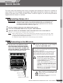 7
7
-
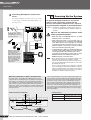 8
8
-
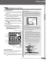 9
9
-
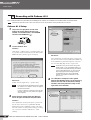 10
10
-
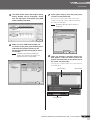 11
11
-
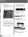 12
12
-
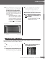 13
13
-
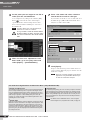 14
14
-
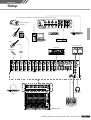 15
15
-
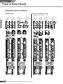 16
16
-
 17
17
-
 18
18
-
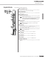 19
19
-
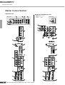 20
20
-
 21
21
-
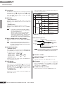 22
22
-
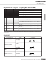 23
23
-
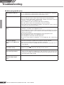 24
24
-
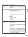 25
25
-
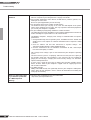 26
26
-
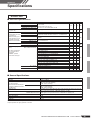 27
27
-
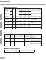 28
28
-
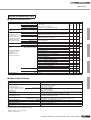 29
29
-
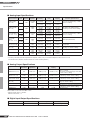 30
30
-
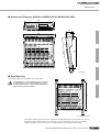 31
31
-
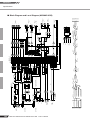 32
32
-
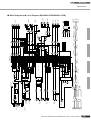 33
33
-
 34
34
-
 35
35
-
 36
36
-
 37
37


Yamaha MG166C de handleiding
- Categorie
- DJ-controllers
- Type
- de handleiding
in andere talen
- English: Yamaha MG166C Owner's manual
- italiano: Yamaha MG166C Manuale del proprietario
- русский: Yamaha MG166C Инструкция по применению
- français: Yamaha MG166C Le manuel du propriétaire
- español: Yamaha MG166C El manual del propietario
- Deutsch: Yamaha MG166C Bedienungsanleitung
- português: Yamaha MG166C Manual do proprietário
- dansk: Yamaha MG166C Brugervejledning
- suomi: Yamaha MG166C Omistajan opas
- čeština: Yamaha MG166C Návod k obsluze
- svenska: Yamaha MG166C Bruksanvisning
- Türkçe: Yamaha MG166C El kitabı
- polski: Yamaha MG166C Instrukcja obsługi
- română: Yamaha MG166C Manualul proprietarului
Gerelateerde artikelen
-
Yamaha MW8cx de handleiding
-
Yamaha MW12CX de handleiding
-
-
-
-
-
Yamaha EMX5 de handleiding
-
-
Yamaha EMX2 de handleiding
-
Andere documenten
-
Ibiza 15-2393 de handleiding
-
JBSYSTEMS MM-10 MIXER de handleiding
-
Belkin TUNESTUDIO #F8Z109EA de handleiding
-
 JBSYSTEMS SMP 12.22 de handleiding
-
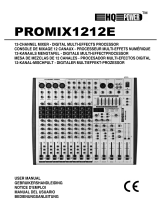 HQ Power PROMIX1212E Handleiding
-
 JBSYSTEMS SMP 8.2 de handleiding
-
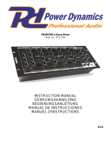 Power Dynamics PDZM700 de handleiding
-
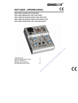 HQ Power PROMIX20U Handleiding
-
Subzero BASE-2 HOME RECORDING BUNDLE Handleiding
-
 HQ Power PROMIX20U Handleiding


