
EN
Owner’s Manual

AW2400 Owner’s Manual
2
* This applies only to products distributed by YAMAHA CORPORATION OF AMERICA. (class B)
FCC INFORMATION (U.S.A.)
1. IMPORTANT NOTICE: DO NOT MODIFY THIS
UNIT!
This product, when installed as indicated in the instruc-
tions contained in this manual, meets FCC requirements.
Modifications not expressly approved by Yamaha may
void your authority, granted by the FCC, to use the prod-
uct.
2. IMPORTANT: When connecting this product to acces-
sories and/or another product use only high quality
shielded cables. Cable/s supplied with this product MUST
be used. Follow all installation instructions. Failure to fol-
low instructions could void your FCC authorization to use
this product in the USA.
3. NOTE: This product has been tested and found to com-
ply with the requirements listed in FCC Regulations, Part
15 for Class “B” digital devices. Compliance with these
requirements provides a reasonable level of assurance
that your use of this product in a residential environment
will not result in harmful interference with other electronic
devices. This equipment generates/uses radio frequen-
cies and, if not installed and used according to the
instructions found in the users manual, may cause inter-
ference harmful to the operation of other electronic
devices. Compliance with FCC regulations does not guar-
antee that interference will not occur in all installations. If
this product is found to be the source of interference,
which can be determined by turning the unit “OFF” and
“ON”, please try to eliminate the problem by using one of
the following measures:
Relocate either this product or the device that is being
affected by the interference.
Utilize power outlets that are on different branch (circuit
breaker or fuse) circuits or install AC line filter/s.
In the case of radio or TV interference, relocate/reorient
the antenna. If the antenna lead-in is 300 ohm ribbon
lead, change the lead-in to co-axial type cable.
If these corrective measures do not produce satisfactory
results, please contact the local retailer authorized to dis-
tribute this type of product. If you can not locate the
appropriate retailer, please contact Yamaha Corporation
of America, Electronic Service Division, 6600 Orangetho-
rpe Ave, Buena Park, CA90620
The above statements apply ONLY to those products dis-
tributed by Yamaha Corporation of America or its subsid-
iaries.
COMPLIANCE INFORMATION STATEMENT
(DECLARATION OF CONFORMITY PROCEDURE)
Responsible Party : Yamaha Corporation of America
Address : 6600 Orangethorpe Ave., Buena Park, Calif. 90620
Telephone : 714-522-9011
Type of Equipment : Professional Audio Workstation
Model Name : AW2400
This device complies with Part 15 of the FCC Rules.
Operation is subject to the following two conditions:
1) this device may not cause harmful interference, and
2) this device must accept any interference received including interfer-
ence that may cause undesired operation.
See user manual instructions if interference to radio reception is sus-
pected.
* This applies only to products distributed by
YAMAHA CORPORATION OF AMERICA.
(FCC DoC)
IMPORTANT NOTICE FOR THE UNITED KINGDOM
Connecting the Plug and Cord
WARNING: THIS APPARATUS MUST BE EARTHED
IMPORTANT. The wires in this mains lead are coloured in accordance
with the following code:
GREEN-AND-YELLOW : EARTH
BLUE : NEUTRAL
BROWN : LIVE
As the colours of the wires in the mains lead of this apparatus may not
correspond with the coloured markings identifying the terminals in your
plug proceed as follows:
The wire which is coloured GREEN-and-YELLOW must be connected to
the terminal in the plug which is marked by the letter E or by the safety
earth symbol or colored GREEN or GREEN-and-YELLOW.
The wire which is coloured BLUE must be connected to the terminal
which is marked with the letter N or coloured BLACK.
The wire which is coloured BROWN must be connected to the terminal
which is marked with the letter L or coloured RED.
• This applies only to products distributed by Yamaha-Kemble Music (U.K.) Ltd. (3 wires)

3
AW2400 Owner’s Manual
The above warning is located on the rear of the unit.
Explanation of Graphical Symbols
The lightning flash with arrowhead symbol
within an equilateral triangle is intended to
alert the user to the presence of
uninsulated “dangerous voltage” within
the product’s enclosure that may be of
sufficient magnitude to constitute a risk of
electric shock to persons.
The exclamation point within an
equilateral triangle is intended to alert the
user to the presence of important operating
and maintenance (servicing) instructions
in the literature accompanying the product.
IMPORTANT SAFETY INSTRUCTIONS
1 Read these instructions.
2Keep these instructions.
3 Heed all warnings.
4 Follow all instructions.
5 Do not use this apparatus near water.
6 Clean only with dry cloth.
7 Do not block any ventilation openings. Install in
accordance with the manufacturer’s instructions.
8 Do not install near any heat sources such as
radiators, heat registers, stoves, or other apparatus
(including amplifiers) that produce heat.
9 Do not defeat the safety purpose of the polarized or
grounding-type plug. A polarized plug has two blades
with one wider than the other. A grounding type plug
has two blades and a third grounding prong. The wide
blade or the third prong are provided for your safety. If
the provided plug does not fit into your outlet, consult
an electrician for replacement of the obsolete outlet.
10 Protect the power cord from being walked on or
pinched particularly at plugs, convenience
receptacles, and the point where they exit from the
apparatus.
11 Only use attachments/accessories specified by the
manufacturer.
12 Use only with the cart, stand,
tripod, bracket, or table
specified by the manufacturer,
or sold with the apparatus.
When a cart is used, use
caution when moving the cart/
apparatus combination to
avoid injury from tip-over.
13 Unplug this apparatus during lightning storms or
when unused for long periods of time.
14 Refer all servicing to qualified service personnel.
Servicing is required when the apparatus has been
damaged in any way, such as power-supply cord or
plug is damaged, liquid has been spilled or objects
have fallen into the apparatus, the apparatus has
been exposed to rain or moisture, does not operate
normally, or has been dropped.
(98-6500)
CAUTION: TO REDUCE THE RISK OF
ELECTRIC SHOCK, DO NOT REMOVE
COVER (OR BACK). NO USER-SERVICEABLE
PARTS INSIDE. REFER SERVICING TO
QUALIFIED SERVICE PERSONNEL.
CAUTION
RISK OF ELECTRIC SHOCK
DO NOT OPEN
WARNING
TO REDUCE THE RISK OF FIRE OR ELECTRIC SHOCK, DO NOT EXPOSE THIS APPARATUS TO RAIN OR MOISTURE.
* This applies only to products distributed by YAMAHA CORPORATION OF AMERICA.
This product contains a high intensity lamp that contains a small amount of mercury.
Disposal of this material may be regulated due to environmental considerations.
For disposal information in the United States, refer to the Electronic Industries Alliance web site:
www.eiae.org
(mercury)

AW2400 Owner’s Manual
4
PLEASE READ CAREFULLY BEFORE PROCEEDING
* Please keep this manual in a safe place for future reference.
WARNING
Always follow the basic precautions listed below to avoid the possibility of serious injury or even death from
electrical shock, short-circuiting, damages, fire or other hazards. These precautions include, but are not
limited to, the following:
• Only use the voltage specified as correct for the device. The required
voltage is printed on the name plate of the device.
• Use only the included power cord.
• Do not place the power cord near heat sources such as heaters or
radiators, and do not excessively bend or otherwise damage the cord,
place heavy objects on it, or place it in a position where anyone could
walk on, trip over, or roll anything over it.
• Be sure to connect to an appropriate outlet with a protective grounding
connection. Improper grounding can result in electrical shock.
• Do not open the device or attempt to disassemble the internal parts or
modify them in any way. The device contains no user-serviceable parts. If
it should appear to be malfunctioning, discontinue use immediately and
have it inspected by qualified Yamaha service personnel.
• Do not expose the device to rain, use it near water or in damp or wet
conditions, or place containers on it containing liquids which might spill
into any openings.
• Never insert or remove an electric plug with wet hands.
• If the power cord or plug becomes frayed or damaged, or if there is a
sudden loss of sound during use of the device, or if any unusual smells
or smoke should appear to be caused by it, immediately turn off the
power switch, disconnect the electric plug from the outlet, and have the
device inspected by qualified Yamaha service personnel.
• If this device should be dropped or damaged, immediately turn off the
power switch, disconnect the electric plug from the outlet, and have the
device inspected by qualified Yamaha service personnel.
CAUTION
Always follow the basic precautions listed below to avoid the possibility of physical injury to you or others, or
damage to the device or other property. These precautions include, but are not limited to, the following:
• Remove the electric plug from the outlet when the device is not to be
used for extended periods of time, or during electrical storms.
• When removing the electric plug from the device or an outlet, always
hold the plug itself and not the cord. Pulling by the cord can damage it.
• Before moving the device, remove all connected cables.
• When setting up the product, make sure that the AC outlet you are using
is easily accessible. If some trouble or malfunction occurs, immediately
turn off the power switch and disconnect the plug from the outlet. Even
when the power switch is turned off, electricity is still flowing to the
product at the minimum level. When you are not using the product for a
long time, make sure to unplug the power cord from the wall AC outlet.
•Avoid setting all equalizer controls and faders to their maximum.
Depending on the condition of the connected devices, doing so may
cause feedback and may damage the speakers.
• Do not expose the device to excessive dust or vibrations, or extreme cold
or heat (such as in direct sunlight, near a heater, or in a car during the
day) to prevent the possibility of panel disfiguration or damage to the
internal components.
• Do not place the device in an unstable position where it might
accidentally fall over.
• The plastic side panels do not provide a secure grip, and should not be
used as handles when moving or transporting the unit. Carrying the unit
by the plastic side panels can result in the unit being dropped, which
could damage the unit and/or cause personal injury.
• Do not block the vents. This device has ventilation holes at the top/front/
rear to prevent the internal temperature from becoming too high. In
particular, do not place the device on its side or upside down. Inadequate
ventilation can result in overheating, possibly causing damage to the
device(s), or even fire.
• Do not use the device in the vicinity of a TV, radio, stereo equipment,
mobile phone, or other electric devices. Doing so may result in noise,
both in the device itself and in the TV or radio next to it.
PRECAUTIONS
Power supply/Power cord
Do not open
Water warning
If you notice any abnormality
Power supply/Power cord
Location
(5)-4 1/2

5
AW2400 Owner’s Manual
• Before connecting the device to other devices, turn off the power for all
devices. Before turning the power on or off for all devices, set all volume
levels to minimum.
• Be sure to connect to a properly grounded power source. A ground screw
is provided on the rear panel of this device for maximum safety and
shock prevention. If the mains outlet is not grounded, be sure to connect
the ground screw to a confirmed ground point before plugging the device
into the mains. Improper grounding can result in electrical shock.
• When turning on the AC power in your audio system, always turn on the
power amplifier LAST, to avoid speaker damage. When turning the power
off, the power amplifier should be turned off FIRST for the same reason.
• Do not insert your fingers or hands in any gaps or openings on the
device (vents, disc slots, etc.).
•Avoid inserting or dropping foreign objects (paper, plastic, metal, etc.)
into any gaps or openings on the device (vents, disc slots, etc.) If this
happens, turn off the power immediately and unplug the power cord from
the AC outlet. Then have the device inspected by qualified Yamaha
service personnel.
• Do not use headphones for a long period of time at a high or
uncomfortable volume level, since this can cause permanent hearing
loss. If you experience any hearing loss or ringing in the ears, consult a
physician.
• Do not rest your weight on the device or place heavy objects on it, and
avoid use excessive force on the buttons, switches or connectors.
Always turn the power off when the device is not in use.
The performance of components with moving contacts, such as switches, volume controls, and connectors, deteriorates over time. Consult qualified Yamaha
service personnel about replacing defective components.
Connections
Handling caution
XLR-type connectors are wired as follows (IEC60268 standard): pin 1: ground, pin 2: hot (+), and pin 3: cold (-).
Insert TRS phone jacks are wired as follows: sleeve: ground, tip: send, and ring: return.
Yamaha cannot be held responsible for damage caused by improper use or modifications to the device, or data that is lost or destroyed.
(5)-4 2/2

AW2400 Owner’s Manual
6
This product utilizes a laser.
Use of control, adjustment or performance of procedures other than those specified herein may result in haz-
ardous radiation exposure.
Do not open covers and do not repair yourself. Refer servicing to qualified personnel.
The label shown below is located on the rear of this product.
The label shown below is located on the top of the internal CD-RW drive.
Please observe the following points when handling the disc.
Failure to do so may cause problems such as the recorded data being lost, the drive to malfunction, or the
printed label to become blurred.
• Do not place the disc in locations of direct sunlight, high temperature, or high humidity.
• Do not touch the recording surface of the disc.
Hold the disc at the edges.
• Gently wipe dust or dirt off of the recording surface of the disc.
Use an air duster or cleaner to remove dust. Vigorously rubbing the surface of the disc with a dry cloth may
scratch the disc.
• If the disc surface needs cleaning, wipe gently from the center to the outside of the disc with a soft damp
cloth, then gently wipe off remaining moisture in the same way with a clean dry cloth.
• Do not write on the disc or affix labels to it.
• Do not wipe the disc with chemicals or detergents.
• Do not bend or drop the disc.
Caution for Laser
Laser properties of the Drive
Laser Class : Class 1 (HHS and IEC 825-1)
Wavelength : for CD 784 nm
for DVD 662 nm
Handling the CD-R/RW media
CLASS 1 LASER PRODUCT
CAUTION
CLASS 3B VISIBLE AND INVISIBLE LASER RADIATION WHEN OPEN. AVOID EXPOSURE TO BEAM.
ATTENTION
CLASSE 3B RAYONNEMENT LASER VISIBLE ET INVISIBLE EN CAS D’OUVERTURE.
EXPOSITION DANGEREUSE AU FAISCEAU.
VORSICHT
KLASSE 3B SICHTBARE UND UNSICHTBARE LASERSTRAHLUNG, WENN ABDECKUNG GEÖFFNET.
NICHT DEM STRAHL AUSSETZEN.
ADVARSEL
KLASSE 3B SYNLIG OG USYNLIG LASERSTRÅLING VED ÅBNING. UNDGÅ UDS/ETTELSE FOR STRÅLING.
ADVARSEL
KLASSE 3B SYNLIG OG USYNLIG LASERSTRÅLING NÅR DEKSEL ÅPNES. UNNGÅ EKSPONERING FOR STRÅLEN.
VARNING
KLASS 3B SYNLIG OCH OSYNLIG LASERSTRÅLNING NÄR DENNA DEL ÄR ÖPPNAD. STRÅLEN ÄR FARLIG.
VARO!
KURSSI 3B NÄKYVÄ JA NÄKYMÄTÖN AVATTAESSA OLET ALTTIINA LASERSÄTEILYLLE, ÄLÄ KATSO SÄTEESEN.
CAUTION: CLASS 3B VISIBLE AND INVISIBLE LASER RADIATION WHEN OPEN. AVOID EXPOSURE TO BEAM.

7
AW2400 Owner’s Manual
• During some hard disk operations a small amount of vibration might be felt at the control panel and you
might hear some mechanical noises. This is normal.
• Do not subject the unit to strong physical shock. Excessive physical shock can damage the internal hard
disk.
•Always turn the power off when moving the unit from one location to another. Data on the internal hard disk
can be lost or corrupted if the unit is moved while the power is on.
Copyright and other intellectual property laws in various countries permit reproduction of copyrighted materi-
als under certain requirements. The observance of applicable laws for use of this product, however, is your
responsibility. Yamaha disclaims any liability for violation of such laws in association with the use of this
product.
Although this product is designed for original music production, it can be utilized to make reproduction of
copyrighted music and other sound products. While certain reproduction and use of reproduced materials are
permitted under applicable laws, such reproduction and use without license may constitute copyright infringe-
ment and other violation of laws. Since violation of such laws can have serious consequences, you may wish
to consult a legal expert about your planned use of this product.
This product incorporates and bundles computer programs and contents in which Yamaha owns copyrights or
with respect to which it has license to use others’ copyrights. Such copyrighted materials include, without lim-
itation, all computer software, styles files, MIDI files, WAVE data and sound recordings. Any unauthorized use
of such programs and contents outside of personal use is not permitted under relevant laws. Any violation of
copyright has legal consequences. DON’T MAKE, DISTRIBUTE OR USE ILLEGAL COPIES.
Internal Hard Disk Precautions
Copyright Notice
The illustrations and LCD screens as shown in this owner’s manual are for instructional purposes only, and may
appear somewhat different from those on your instrument.

AW2400 Owner’s Manual
8
Contents
1. Before you start 11
Introduction................................................................. 11
Remember to back up your data ................................ 11
About the built-in CD-RW drive ..................................12
Using the CD-RW drive .............................................. 12
Installing an optional card........................................... 13
2. Introducing the AW2400 15
Features of the AW2400 ............................................15
AW2400 terminology .................................................. 17
Recorder section....................................................17
Mixer section..........................................................18
Overall.................................................................... 19
Parts of the AW2400 and what they do...................... 20
Top panel ...............................................................20
Rear panel ............................................................. 28
Front panel.............................................................29
Basic operation of the AW2400.................................. 30
Viewing the display ................................................30
Accessing a screen/page.......................................31
Switching a button on/off........................................ 31
Editing a value in the display ................................. 31
Using Additional Function Buttons .........................31
Entering text...........................................................32
Switching Mixing Layers ........................................ 33
Using the Selected Channel section ......................33
3. Connection and Setup 37
Connection .................................................................37
Turning the power on/off ............................................38
Adjusting the input level .............................................39
4. Listening to the demo song 41
Loading the demo song.............................................. 41
Playing the demo song............................................... 42
5. Recording to a sound clip 43
Recording a sound clip............................................... 43
Playing a sound clip ...................................................45
6. Track recording 47
Creating a new song ..................................................47
Direct recording and Mixed recording.........................49
Assigning input signals to tracks
(Direct recording)...............................................51
Assigning input signals to tracks
(Mixed recording) ..............................................54
Recording on a track...................................................56
Saving the current song..............................................57
Pairing channels .........................................................58
Applying EQ To an Input Signal..................................60
Applying Compression to an Input Signal...................61
Handy Recording Functions .......................................62
Using the Metronome .............................................62
Switching virtual tracks...........................................63
Using the Undo List ................................................64
7. Overdubbing 65
About overdubbing......................................................65
Assigning the input signal to a track ...........................66
Setting the mix balance and pan ................................67
Overdubbing ...............................................................68
Punch-in/out................................................................69
Manual punch-in/out...............................................69
Auto punch-in/out ...................................................70
8. Mixdown and bounce operations 73
About mixdown and bouncing.....................................73
Mixdown procedure ....................................................75
Playing back the stereo track......................................78
Bounce (ping-pong) recording procedure ...................79
Convenient functions for mixdown/bounce .................82
Fader Group assignments......................................82
Mute Group assignments .......................................83
Using the Solo function ..........................................84
9. Transport/Locate Operation 87
The Transport Section Keys .......................................87
Move To a Specified Location ....................................87
Using the locator.........................................................88
Using markers.............................................................90
Adjusting the position of a locate point or marker.......91
Adjusting the position of a locate point...................91
Adjusting the position of a marker ..........................92
Erasing a locate point or marker.................................93
Repeat playback of a specific region
(the A-B Repeat function) ...........................................93
Finding a location while monitoring the sound
(the Nudge function) ...................................................94
Finding a location while viewing the waveform...........95
10. Meters 97
Level Meter Types ......................................................97

9
AW2400 Owner’s Manual
Contents
11. Patching and signal flow 99
Input signal patching ..................................................99
Patching for Direct Recording ................................99
Patching for Mixed Recording..............................102
Output signal patching.............................................. 104
12. Channel Operation 105
Displaying the mix parameters
for individual channels.............................................. 105
Channel Library Operation .......................................108
Calling the Channel Library screen......................108
Changing Channel Library Names.......................109
Storing Channel Library settings..........................109
Recalling Channel Library settings ...................... 110
Erasing Channel Library settings .........................110
13. AUX 111
About the AUX buses ............................................... 111
AUX Send Level Adjustment .................................... 111
Using external effects with the AUX buses ..............113
14. Effects 115
About the Internal Effects ......................................... 115
Recalling Effect Library settings ............................... 116
Applying Effects via Send and Return...................... 117
Inserting an Effect Into a Channel ............................ 119
Editing Effects ..........................................................121
Effect Library Operations.......................................... 122
Call the Effect Library Screen ..............................122
Changing Effect Library Names ...........................122
Storing Effect Library settings ..............................123
Erasing Effect Library settings .............................123
Correcting a Vocal Track (Pitch Fix)......................... 124
15. Track operations and editing 127
About the AW2400’s tracks ...................................... 127
Audio track operations.............................................. 128
About audio tracks ...............................................128
Viewing all audio tracks ....................................... 128
Muting a specific audio track................................ 129
Switching the virtual track of an audio track......... 129
Editing virtual track names for an audio track ......130
Stereo track operations ............................................130
About the stereo track..........................................130
Recording on the stereo track..............................131
Playing back the stereo track...............................131
Switching the virtual track of the stereo track ...... 132
Editing the name of a virtual track
for the stereo track ..........................................132
The Trigger Track Function ......................................133
About Trigger Track..............................................133
Using the Trigger Track Function .........................134
Editing tracks ............................................................135
Basic procedure for track editing ..............................136
List of editing command............................................138
ERASE .................................................................138
DELETE ...............................................................138
INSERT ................................................................138
COPY ...................................................................139
MOVE...................................................................140
EXCHANGE .........................................................141
TIME COMP (Time Compression/Expansion)......141
PITCH (Pitch Change)..........................................142
IMPORT CD AUDIO.............................................142
IMPORT CD WAV ................................................142
IMPORT USB WAV..............................................142
IMPORT TRACK ..................................................142
EXPORT...............................................................142
MERGE ................................................................142
Importing audio data/WAV files ................................143
Importing from the CD-RW drive ..........................143
Importing audio data from another song ..............145
16. Pan, EQ, and Dynamics Processing 147
Pan Control...............................................................147
4-band EQ ................................................................149
Dynamics Processing ...............................................151
Using the Gates....................................................151
Using the Compressors........................................152
EQ/Dynamics Processor Library Operation..............154
Accessing the EQ/Dynamics Library screens ......154
Changing EQ/Dynamics Library Names...............156
Recalling EQ/Dynamics Library settings ..............156
Storing EQ/Dynamics Library settings..................157
Erasing EQ/Dynamics Library settings.................157
17. Scene Memory 159
About Scene Memory ...............................................159
Scene Memory Operation.........................................159
Renaming a scene ...............................................160
Recalling scene data............................................160
Storing scene data ...............................................161
Deleting scene data..............................................161
Protecting a scene................................................161
Using the Recall Safe function..................................162
Moving scenes..........................................................163

AW2400 Owner’s Manual
10
Contents
18. Song management 165
About songs .............................................................165
Managing Your Songs.............................................. 167
Editing various settings for the song ........................174
Creating a tempo map.............................................. 175
Backing up songs ..................................................... 177
Restoring songs .......................................................178
Exchanging Song Data
With Other AW-series Audio Workstations............... 180
19. Automix 181
About Automix .......................................................... 181
Automix Operation.................................................... 181
Creating a New Automix Recording.....................182
Recording the Automix Data ................................ 183
Automix Playback ................................................ 185
Punch In and Out of Automix ............................... 185
Command Editing Automix data
In a Specified Region ...............................................186
Editing Individual Automix Events ............................188
Automix Library Operation........................................ 190
About the Automix Library Page ..........................190
Changing Automix Names ...................................190
Storing Automix settings ......................................191
Recalling Automix settings...................................191
Erasing Automix settings ..................................... 191
Protecting Automix Data ......................................192
20. MIDI 193
What you can do using MIDI ....................................193
Basic MIDI Settings .................................................. 194
MIDI Synchronization Message Setup .....................198
Connecting to External Equipment........................... 200
Synchronizing the AW2400
With External MIDI Devices.............................200
Switching AW2400 scenes
from an external MIDI device ..........................201
Recording/playing AW2400
mix operations on an external sequencer .......202
Using the MIDI Remote function ..............................204
About the MIDI Remote function..........................204
Using the MIDI Remote function presets .............204
Using User-defined Remote function ................... 206
Remotely controlling a tone generator module ....207
21. Utility functions 209
Using the test tone oscillator ....................................209
AW2400 Preferences ...............................................210
Initializing the internal hard disk ...............................212
22. Creating an audio CD 213
Creating an audio CD ...............................................213
Types of media that you can use
with the CD-RW drive ...............................................213
Writing an audio CD..................................................214
Basic settings for the CD-RW drive ..........................215
Writing audio data.....................................................216
Writing Track At Once ..........................................217
Writing Disc At Once ............................................218
Finalizing CD-R/RW media.......................................220
Erasing CD-RW media .............................................221
Playing an audio CD .................................................222
23. Digital Input/Output &
Optional Card Settings 223
Wordclock and Cascade Settings.............................223
Select the Wordclock Source ...............................223
Fine Adjustment Of Overall
Song Pitch (Vari-pitch).....................................226
Cascade-connecting External Devices.................226
Check the Status Of the Digital Input Signal.............227
Plug-in Card Settings................................................228
24. USB 229
What You Can Do With USB ....................................229
WAV File Transfer (USB Storage Mode) ..................230
Switching to the USB Storage Mode....................230
Exiting the USB Storage Mode.............................232
Copying Exported WAV Files
To the Computer..............................................233
Importing Copied WAV Files
From the Computer..........................................234
Appendix 237
Mastering library list..................................................237
EQ Parameter list .....................................................238
Dynamics Parameters ..............................................240
Gate Parameter list...................................................243
Compressor Parameter list .......................................243
Effects Parameters ...................................................245
Troubleshooting ........................................................258
Display message list .................................................263
About the CD-ROM included with the AW2400 ........266
MIDI data format .......................................................272
MIDI Implementation Chart.......................................276
Specifications............................................................277
Dimensions ...............................................................279
Index .........................................................................280
Block diagram ...........................................................284

11
AW2400 Owner’s Manual
Before you start
1
Chapter 1
Before you start
This chapter explains what you should know before you begin using the
AW2400.
The AW2400 package contains the following items. If any
are missing, please contact your dealer.
• The AW2400
•Power cord
• Owner’s manual (this book)
• CD-ROM
Copying of commercially available music sequence data
and/or digital audio files for any purpose other than your
own personal use is strictly prohibited.
• Macintosh is a registered trademark of Apple Computer,
Inc. USA in the United States and other countries.
• Windows is a registered trademark of Microsoft Corpora-
tion USA in the United States and other countries.
• Cubase SX and Nuendo are trademarks of Steinberg
Media Technologies AG.
• Logic is a registered trademark of Apple Computer, Inc.
USA in the United States and other countries.
• SONAR is a registered trademark of Twelve Tone Sys-
tems, Inc.
• ProTools is a trademark or registered trademark of Avid
Technology, Inc. and affiliated companies.
• Other company names and product names in this docu-
ment are the trademarks or registered trademarks of
their respective owners.
http://www.yamahasynth.com/
http://www.yamaha.co.jp/manual/
Produced data can be lost due to breakdown or mistaken
operation. We recommend that you store all important
data on your computer, CD-R/CD-RW discs, or other
external storage medium.
Yamaha will accept no responsibility for any damages
(including consequential or incidental) incurred by the
customer or any third party as a result of loss or impair-
ment of the data stored on the hard disk or CD-R media,
regardless of whether such loss could have been or actu-
ally was foreseen by Yamaha.
Nor does Yamaha guarantee the media against any defect
that may render it unusable.
Introduction
■ Check the included items
■ Copyright
■ Trademarks
■ Yamaha Website (English only)
■ Yamaha Manual Library
Remember to back up your data
■ Storing produced data
■ Responsibility for loss of data, etc.

AW2400 Owner’s Manual
12
Before you start
1
A built-in CD-RW drive is a device that lets you create or
play audio CDs, backup and restore data from the internal
hard disk, and read data from a CD-ROM.
1 Never touch the objective lens.
B Be careful that the objective lens does not become
dusty or dirty.
C If the objective lens becomes dusty, use a commer-
cially available blower etc. to blow the dust off with
clean air.
D Since the inside of the drive contains powerful mag-
netic circuitry, do not allow any magnetic material to
come near the drive. (In particular, any metallic frag-
ments, screws, or pins that enter the drive mechanism
will cause operation to fail.)
To insert a disc into the CD-RW drive, press the eject
switch. The disc tray will open. Place the disc on the tray,
and gently push the disc tray in.
If you are unable to remove the disc by pressing the eject
switch, insert a wire of less than 2 mm diameter (such as a
straightened paper clip) into the eject hole, and push gen-
tly. However, pressing the eject switch will not eject the
disc when the AW2400 is in the following states, so do not
use this method in such cases.
• When the AW2400’s power is “OFF”
• When the disc is being accessed (data is being read,
written, or erased)
• While in CD PLAY mode
About the built-in CD-RW drive
• Even if a CD-RW drive is operating normally, it may fail a read
or write operation approximately once in five hundred times.
•Yamaha will take no responsibility for any damages, direct or
consequential, that may result from the use of the above CD-
RW drive.
IMPORTANT
■ Handling
Using the CD-RW drive
• The disc tray is ejected electrically. If the disc tray is not ejected
when you press the eject switch, turn on the power of the AW2400
and press the eject switch once again.
NOTE
Eject switchEject hole
■ Removing a CD in an emergency
• This removal method is for use in emergencies such as when
you cannot remove the disc due to a malfunction of the disc
tray or a power failure. Do not use this method unnecessarily,
since doing so will damage the CD-RW drive.
CAUTION
About the built-in CD-RW drive • Using the CD-RW drive

Installing an optional card
13
AW2400 Owner’s Manual
Before you start
1
By installing a separately sold mini-YGDAI card in a rear-
panel slot, you can add analog input/output jacks to the
AW2400 or allow connection of external digital devices.
The following types of cards can be used.
Refer to the Yamaha Pro Audio global website for the
most recent information on I/O cards.
http://www.yamahaproaudio.com
Before installing a card, you must check the Yamaha web-
site to make sure that this device is compatible.
http://www.yamahaproaudio.com
To install an optional mini-YGDAI card, proceed as
follows.
1
Make sure that the power is turned off.
2
Loosen the screws that hold the slot cover
in place, and remove the slot cover.
Keep the removed slot cover in a safe place.
3
Align the edges of the card with the guard
rails inside the slot, and insert the card into
the slot.
Push the card all the way into the slot so that the con-
nector at the end of the card is correctly mated with the
connector inside the slot.
4
Use the screws included with the card to
fasten the card in place.
Malfunctions or incorrect operation may occur if the
card is not fastened.
Installing an optional card
Card type Model
Number of
channels
Digital
format
Bit
depth
AD card
MY4-AD 4
—
24 bit
MY8-AD
8
20 bit
MY8-AD24
24 bit
MY8-AD96
DA card
MY4-DA 4
—
20 bit
MY8-DA96 8 24 bit
Digital I/O card
MY8-AE
8
AES/EBU
24 bit
MY8-AE96
MY8-AE96S
MY16-AE 16
MY8-AT 8
ADAT
MY16-AT 16
MY8-TD 8
TASCAM
MY16-TD 16
Waves Plug-in
DSP card
Y96K 8 ADAT 24bit
mLAN card MY16-mLAN 16 IEEE1394 24bit
■ Available optional cards
■ Installing an optional card

AW2400 Owner’s Manual
14
Before you start
1

15
AW2400 Owner’s Manual
Introducing the AW2400
2
Chapter 2
Introducing the AW2400
This chapter describes the features of the AW2400, the name of each part
and its function, and introduces terminology you need to know when using
the AW2400.
The AW2400 is an audio workstation that combines a digital mixer, multi-effect processor, hard
disk recorder, and CD-RW drive.
The following diagram shows the signal flow within the AW2400.
Now let’s take a more detailed look at each section of the AW2400.
● Plenty of input channels with professional
features
The AW2400 digital mixer features 24-bit AD/DA conver-
sion with 32-bit internal processing for uncompromised
sound quality. 16 input channels, 24 track channels, and 4
stereo effect return channels provide plenty of input
capacity for most mixing situations.
The 8 AD input ([MIC/LINE INPUT] jacks 1–8), chan-
nels 1–16 on an optional I/O card installed in I/O slot, or
the stereo [DIGITAL STEREO IN] connector can be
selected for input.
The track channel 1–24 inputs are permanently assigned
to tracks 1–24, and the effect return channel 1–4 inputs are
permanently assigned to the outputs of internal effect pro-
cessors 1–4.
Features of the AW2400
Input channels 1–16
Track channels 1–24
Effect return channels 1–4
Bus1 L/R, Bus2 L/R
AUX buses 1–4
Effect buses 1–4
Stereo buses L/R
Stereo output channel
×8
×16
[MIC/LINE
INPUT]
jacks 1–8
×2
[DIGITAL
STEREO IN]
connector
I/O slot
Mixer
×
2
×2
Sound clip
×
24 ×24×2
Recorder input
patching
Recorder CD-R/RW drive
CD Write
Data Backup/Restore
WAV File Import
CD Play
×2
I/O card
[OMNI OUT] jacks 1-4
[DIGITAL STEREO OUT] connector
[STEREO OUT] jacks
[MONITOR OUT] jacks
[PHONES] jack
I/O card
×2
Metronome
Effect 1
×
2
×2
Effect 2
×
2
×2
Effect 3
×
2
×2
Effect 4
×
2
Internal Effects
×2
×16
×4
×2
×2
■ Mixer section

AW2400 Owner’s Manual
Features of the AW2400
Introducing the AW2400
16
2
● Totally redesigned operation
The AW2400 is designed to be operated directly by the
musician (guitarist, vocalist, drummer etc.). Input signal
track assignment, mixdown and bounce recording set-
tings, tracking with effects/EQ/dynamics, compressor set-
tings, and much more can be easily handled with simple,
straightforward operation.
● Four-band EQ and dynamics processors on
each channel
Four-band full-parametric EQ and dynamics processing is
provided on virtually every channel. You can recall the
desired preset from the library, and use the panel knobs
and keys to quickly adjust the settings.
● Four high-quality multi-effect units built-in
The four built-in effect units deliver a wide variety of
effects including ambience effects such as reverb and
delay, modulation type effects such as chorus and flanger,
and guitar-type effects such as distortion and amp simula-
tion. These effects can be used either via send/return, or
inserted into a desired channel.
● Automix capability
Full automix production power is provided with 13 motor
faders for comprehensive fader control, pan control, scene
recall and library recall capability.
● I/O slot for expansion with optional I/O cards
Expanded inputs and outputs can be provided in ADAT,
TASCAM, AES/EBU, and other formats. Optional DSP
cards can also be used to provide extra signal processing
capability via the I/O slot.
● 16-track Simultaneous Recording & 24-track
Simultaneous Playback (16-bit songs)
You can record multiple instrument tracks one by one, or
set up multiple mics to record a drum set or a live perfor-
mance by an entire band. A stereo track for direct mix-
down of all 24 tracks is also provided, letting you manage
the multi-track audio and the two-track mix as a single
data package.
8 virtual tracks are available for the recorder tracks as well
as the stereo track. When recording parts or when doing a
mix, you can switch virtual tracks to record multiple takes
and select the best take later.
The “bit depth” (number of quantization bits) of the audio
data recorded on each track can individually be set to 16
or 24 bits for each song. 16-bit songs allow simultaneous
recording of up to 16 tracks, and simultaneous playback of
up to 24 tracks. 24-bit songs allow simultaneous recording
up to 8 tracks, and simultaneous playback of up to 12
tracks (→ p. 165).
The recording sampling frequency can also be set to either
44.1 kHz or 48 kHz (the selected sampling has no effect
on the number of simultaneous record or playback tracks).
● Trigger track function
The “Trigger Track” function allows the track [ON] keys
and faders to be used to start and stop playback of
recorded tracks. This is ideal for performance situations in
which you want to switch phrases or patterns in real time,
or when you need to start background music on cue, for
example.
● Versatile editing functionality
Audio data recorded on a track can be copied, moved, or
edited using a variety of commands. You can make
detailed edits, or even make radical changes to the struc-
ture of the song by using the same riff repeatedly or
increasing the number of choruses.
“Time Compression” lets you compress or expand the
time axis of the audio data over a range of 50%–200%.
“Pitch Change” lets you modify the pitch over a range of
up or down one octave. You can use the Undo function to
undo the results of as many as the last fifteen editing oper-
ations.
● A variety of Locate methods, and auto
punch-in/out
Eight locate points (start/end, relative zero, A/B, in/out,
quick locator) and 99 markers can be assigned at any
desired point in the song for quick access via Locate oper-
ations. Auto punch-in/out and A-B repeat playback func-
tions are also provided. The AW2400 also has a
metronome that follows the tempo map.
● Sound Clip function
The Sound Clip function lets you record and play back an
input signal without using the recorder tracks. You can use
this function to make quick sketches of song or arrange-
ment ideas. You can transfer recorded sound clip data to
the recorder as required.
● Vocal Editing with Pitch Fix
A Pitch Fix function is provided to allow precise adjust-
ment of the pitch of a vocal track as well as the generation
of chorus parts from a main vocal line. This feature can
also be used to change the character of a vocal sound.
■ Recorder section

17
AW2400 Owner’s Manual
Introducing the AW2400
2
A dedicated CD-RW drive is installed in the AW2400. You
can produce an audio CD containing the stereo mixes of
songs recorded on the hard disk. Markers assigned within
a song can also be used as the CD track numbers. You can
even use advanced techniques such as assigning more than
one track number within a single song. The CD-RW drive
can also be used to backup/restore songs, to play back
audio CDs, and to load WAV data from a CD-ROM.
The AW2400 can be directly connected to a computer via
the built-in USB interface, which enables transferring
audio files as well as MIDI messages. This allows WAV-
format audio files to be copied between the AW2400 and
computer for convenient management and processing in
computer-based applications, and “backup” song files can
be stored on the computer’s memory media.
Here’s a quick overview of terminology used with the AW2400.
A location where data is recorded is called a “track.” The
AW2400’s recorder section uses the following types of
track.
● Audio tracks
The physical tracks used to record and play back audio
data are called “audio tracks,” or simply “tracks.” The
AW2400 has 24 audio tracks. You can record 16 tracks
simultaneously, and play back 24 tracks simultaneously
(16-bit songs).
● Stereo track
The AW2400 has a “stereo track” that is independent from
audio tracks 1–24, and which records and plays a stereo
audio signal. The stereo track is used mainly as a dedi-
cated mixdown track for recording the final mix.
● Virtual tracks
Each of the 24 audio tracks and the stereo track consists of
eight “virtual” tracks. For the audio tracks and the stereo
track, only one virtual track can be recorded or played at
any time. However, you can switch virtual tracks to con-
tinue recording other takes while preserving the previ-
ously-recorded content.
The diagram below shows the concept of virtual tracks.
The horizontal rows indicate audio tracks 1–24, and the
vertical columns correspond to virtual tracks 1–8. The
shaded areas indicate the virtual track that is currently
selected for recording or playback.
● Trigger tracks
The “Trigger Track” function allows the track [ON] keys
and faders to be used to start and stop playback of
recorded tracks. When the Trigger Track function is
engaged and you press a track channel [ON] key, the cor-
responding track will playback one time from the begin-
ning of the song to the end of the recorded data.
■ CD-RW drive
■ Connecting to a Computer
AW2400 terminology
Recorder section
■ Tracks
1
2
3
4
5
6
7
8
1
2 3 4 5 6 7 8
1
2
3
4
5
6
7
8
21 22 23 24
Audio tracks
Stereo track
Virtual tracksVirtual tracks
Features of the AW2400 • AW2400 terminology

AW2400 Owner’s Manual
AW2400 terminology
Introducing the AW2400
18
2
Locations within a song that you specified in order to exe-
cute a function such as auto punch-in/out or A-B repeat
playback are called “locate points.” Locate points include
in/out points and the A/B points. You can use the Locate
section keys to move instantly to these points.
You can assign “markers” at desired locations within a
song independently of the locate points so that you can
find these locations quickly. The AW2400 lets you set up
to ninety-nine markers (1–99). By using the keys Locate
section you can move instantly to the previous or next
marker.
A signal path that processes a single signal within the
mixer and sends it to various sections is called a “chan-
nel.”
The mixer section of the AW2400 provides the following
channels.
● Input channels 1–16
Input channels provide level control, EQ, and dynamics
processing for signals that are input via the [MIC/LINE
INPUT] jacks 1–8, the [DIGITAL STEREO IN] connec-
tor, and/or an I/O card installed in the rear-panel slot, and
send them to the recorder tracks or to the [STEREO OUT]
jacks.
● Track channels 1–24
These channels provide level adjustment, EQ, and dynam-
ics processing for the audio playback signals from audio
tracks 1–24 of the recorder, and send the signals to the ste-
reo track and the [STEREO OUT] jacks. You can also per-
form “bounce recording” by sending these channels to
different tracks.
● Effect return channels 1–4
These channels send the signals returned from the internal
effects to the stereo track and the [STEREO OUT] jacks.
● Stereo output channel
This channel provides level adjustment, EQ, and dynamics
processing for the stereo bus signal (which carries the mix
of the other channels), and sends it to the stereo track or to
the [STEREO OUT] jacks. The same signal is also output
from the [MONITOR OUT] jacks and from the
[PHONES] jack.
● Bus master channels 1/2
Provide level adjustment, EQ, and dynamics processing
for the signals from bus 1 and bus 2, and sends the signals
to the audio tracks.
● AUX send master channels 1–4
Provide final level adjustment for the AUX buses, as well
as EQ and dynamics processing.
● Effect send master channels 1–4
Provide final level adjustment for the effect buses, as well
as dynamics processing.
In order to efficiently handle numerous input channels the
AW2400 mixer section channels are organized in “mixing
layers”. The diagram shows an overview of the AW2400’s
6 mixing layers.
The channels available in each of the mixing layers are as
follows.
1 Mixing Layer IN 1-8
Input channels 1–8 and effect return channels 1–4.
B Mixing Layer IN 9-16
Input channels 9–16 and effect return channels 1–4.
C Mixing Layer MASTER
Bus master channels 1/2, AUX send master channels 1–4,
and effect send master channels 1–4.
D Mixing Layer TRACK 1-12
Track channels 1–12.
E Mixing Layer TRACK 13-24
Track channels 13–24.
F REMOTE Layer
A special layer for remote control of external MIDI
devices.
■ Locate points/markers
Mixer section
■ Channels
■ Mixing Layers
A
B
C
D
E
F

AW2400 terminology
19
AW2400 Owner’s Manual
Introducing the AW2400
2
Channel pan, EQ, dynamics processor and other settings
are known as “mix parameters”. All mix parameters can
be saved together as “scenes” that can be recalled when-
ever necessary. Furthermore, specialized libraries are pro-
vided for various parameter groups – EQ, effects, etc. –
that can be saved and recalled individually for each chan-
nel.
For effect return channels 1–4, stereo output channel, and
bus master channel 1–2, the parameters (except for pan)
are always linked for adjacent pairs of channels. These are
called “paired channels.”
For input channels 1–16, track channels 1–24, and AUX
send master channels 1–4, you can also assign adjacent
odd-numbered/even-numbered channels to function as
paired channels. The parameters (except for pan and
phase) of paired channels will be linked, so that adjusting
one parameter will cause the same parameter of the other
channel to be adjusted accordingly.
A signal route that mixes the signals from multiple chan-
nels and sends them to an output jack or recorder track
input is called a “bus.”
Unlike channels, which handle only a single signal, a bus
can combine multiple signals into one or two (stereo) out-
puts and send them to a destination.
The AW2400’s mixer section provides the following
buses.
● Stereo bus
This bus mixes the input signals to stereo, and sends them
via the stereo output channel to the stereo track of the
recorder or to the [STEREO OUT] jacks. Normally the
same signal output via the [STEREO OUT] jacks is also
output via the [MONITOR OUT] and [PHONES] jacks.
● AUX buses 1–4
These buses mix the signals from the track, input, and
effect return channels and send them to the specified out-
put connector. Use these when you will use an external
effect processor, or to create a mix differing from the ste-
reo channel for musicians to monitor.
● Effect buses 1–4
These buses combine the signals from the track and input
channels, and input them to built-in effects 1–4.
● Bus 1, Bus 2
These buses mix track, input, and effect return channels
and send them to the inputs of free tracks. Bus 1 and bus 2
are used for bounce (ping-pong) recording.
The smallest unit by which the AW2400 manages a com-
position is called a “song.” When you save a song on the
hard disk, all data necessary for reproducing that song will
be saved; i.e., not just the audio data, but also the mixer
settings and the automix settings. You can return to the
original state at any time by loading the saved song.
A “scene” is a stored set of settings for the mixer section
and effects. The area of memory that holds the scenes is
called “scene memory,” and 99 scenes can be stored for
each song. Scene memories are saved on the hard disk as
part of the song.
A “library” is an area of memory that stores individual set-
tings such as for EQ or dynamics. The AW2400 has sepa-
rate libraries for EQ, dynamics, effect, channel, and
mastering settings.
Recalling a scene affects all mixer section settings, while
the libraries allow only specified settings to be recalled as
required. You can also save the settings from one channel
and copy them to other channels, for example.
Each library is saved on the hard disk as part of the song.
The “tempo map” records changes in tempo and time sig-
nature that occur during the course of a song. The tempo
map is saved on the hard disk as part of the song.
Various global settings that apply to all songs are collec-
tively referred to as “system data.” System data is stored
on the hard disk independently of the individual songs.
■ Mix Parameters
■ Paired channels
■ Buses
Overall
■ Songs
■ Scenes and scene memories
■ Libraries
■ Tempo map
■ System data

AW2400 Owner’s Manual
Parts of the AW2400 and what they do
Introducing the AW2400
20
2
This section explains the names and functions of the various items on the AW2400’s top panel,
rear panel, and front panel.
Parts of the AW2400 and what they do
Top panel
Work Navigate
section (P. 21)
Analog Input section (P. 21)
Quick Navigate section
(P. 21)
Display section (P. 22)
Mixer section (P. 23)
Selected Channel
section (P. 24)
Monitor section (P. 24)
Scene/Automix/USB section (P. 24) Data entry/control
section (P. 25)
Locate/Number section (P. 25)
Layer section (P. 26)
Locate section (P. 27)
Transport section
(P. 27)

Parts of the AW2400 and what they do
21
AW2400 Owner’s Manual
Introducing the AW2400
2
1 [GAIN] knobs 1–8
These adjust the sensitivity of the rear panel MIC/LINE
INPUT jacks 1–8 to input signals.
B [PEAK] Indicators
These indicators will light red if the peak signal level after
the [GAIN] knob reaches or exceeds 3-dB below clipping.
To set the optimum record level, set the [GAIN] knob so
that the indicator flashes only briefly on the highest peaks
that will be encountered during the recording.
C [INPUT SEL] keys 1–8
These keys select the mixer input channel that you will
operate.
1 [SONG] key
This key accesses the SONG screen, where you can save
or load songs, and perform the shut-down procedure.
B [CD] key
This key accesses the CD screen, where you can write or
play an audio CD, and backup or restore data.
C [TRACK] key
This key accesses the TRACK screen, where you can
check whether each track contains data, and switch the
virtual tracks that will be used for recording and playback.
D [EDIT] key
This key accesses the EDIT screen, where you can copy or
erase tracks.
E [MIDI] key
Accesses the MIDI screen where you can set up MIDI
synchronization, scene change, and other settings.
F [UTILITY] key
Press this key to access the UTILITY screen with settings
for the unit’s test tone oscillator, digital inputs and out-
puts, and other utility parameters.
G [PATCH] key
Accesses the PATCH screen where you can patch output
signals as required.
H [DIO] key
The [DIO] key accesses the DIO screen which includes
the clock source and I/O card settings.
1 [RECORD] key
This key accesses the RECORD screen, where you can
quickly assign the signal to be recorded to the input of
each track, and make settings for recording.
B [MONITOR] key
The MONITOR screen, accessed by this key, includes set-
tings for fader grouping, the solo function, and more.
■ Analog Input section
1
C
2
■ Work Navigate section
2
4
6
1
3
5
H
G
■ Quick Navigate section
2
1

AW2400 Owner’s Manual
Parts of the AW2400 and what they do
Introducing the AW2400
22
2
1 Display
The backlit display screen provides easy visual access to
all functions and parameters.
B Stereo Meters
These 12-segment levels meters show the final output sig-
nals levels on the stereo bus.
C [METER] key
Calls the METER screen which includes the channel, bus,
and other level meters.
D Contrast
Adjusts the brightness of the display.
E Access indicator
This indicator indicates the access status of the internal
hard disk. When the hard disk is being read or written, this
indicator will light.
F [F1]–[F4] keys
These keys operate the “tabs” shown at the bottom of the
display screen. They can access other pages in a group of
functions, or in some cases execute specific functions.
G [SHIFT] key
“Shifts” the function of the tabs at the bottom of the dis-
play to show additional functions, when applicable. “Shift
functions” can be executed by pressing the appropriate
functions key – [F1] to [F4] – while holding the [SHIFT]
key.
■ Display section
2
E4
6
1
C
G
•Never turn off the power of the AW2400 when the access indi-
cator is lit. Doing so will not only damage the data on the
internal hard disk, but may also damage the hard disk itself.
When you want to turn off the power of the AW2400, you must
perform the shutdown procedure (
→
p. 38).
CAUTION

Parts of the AW2400 and what they do
23
AW2400 Owner’s Manual
Introducing the AW2400
2
1 [SEL] keys 1–12
B [STEREO SEL] key
Selects the channel to be operated. The [SEL] key of the
currently selected channel will light.
C [ON] keys 1–12
D [STEREO ON] key
Turns the corresponding channel ON or OFF. The [ON]
key will be lit when the corresponding channel is ON, and
out when the channel is OFF. The [ON] keys are also used
to specify solo channels when the solo function is on.
E Faders 1–12
The faders adjust recorder track playback levels, input
channel input levels, and effect return channel input levels
according to the mixing layer currently selected via the
LAYER section.
F [STEREO] fader
Adjusts the output level of the stereo bus.
G [SOLO] key
Turns the solo function ON or OFF.
■ Mixer section
E6
1C B D G
• When Trigger Track mode is engaged, the [ON] key can be used to
start/stop playback of the corresponding track.
HINT
• The [STEREO SEL] keys, [STEREO ON] keys, and [STEREO]
faders always operate stereo channels. These keys and faders are
not affected by the LAYER section settings.
NOTE

AW2400 Owner’s Manual
Parts of the AW2400 and what they do
Introducing the AW2400
24
2
1 [VIEW] key
This key accesses the CH VIEW screen, where you can
check the level of each channel, or perform on-screen
adjustments to the faders and other mix parameters of
each channel.
B [DYN] key
Calls the DYNAMICS screen for the currently selected
channel. You can then press any of the SELECTED
CHANNEL knobs — 1 through 4 — to access the corre-
sponding dynamics parameters.
C [AUX] key
Calls the AUX screen for the currently selected channel.
You can then press any of the SELECTED CHANNEL
knobs — 1 through 4 — to access the corresponding AUX
parameters.
D [EFFECT] key
Calls the EFFECT screen for the currently selected chan-
nel. You can then press any of the SELECTED CHAN-
NEL knobs — 1 through 4 — to access the corresponding
EFFECT parameters.
E [PAN/EQ] key
Calls the PAN/EQ screen for the currently selected chan-
nel. After pressing the [PAN/EQ] key, you can press any
of the Selected Channel knobs 1 through 4 to switch the
PAN/EQ screen pages.
F SELECTED CHANNEL knobs 1–4
These knobs are used to adjust the various parameters for
the selected channel. Press any of these knobs after press-
ing the [DYN], [AUX], [EFFECT] or [PAN/EQ] key to
call the corresponding parameter screen.
G [LOW], [LO-MID], [HI-MID], and [HIGH] keys
These keys specify the EQ band to be adjusted by the
SELECTED CHANNEL knobs when the EQ screen EQ
page is showing.
1 [MONITOR] knob
This knob adjusts the level of the signal that is output from
the [MONITOR OUT] jacks.
B [PHONES] knob
This knob adjusts the level of the signal that is output from
the [PHONES] jack.
1 [SCENE] key
This key accesses the SCENE screen, where you can save
or recall scene memories.
B [AUTOMIX] key
This key accesses the AUTOMIX screen which allows
control and editing of automix operations.
C [USB] key
The [USB] keys calls up the USB screen with parameters
related to USB operation.
■ Selected Channel section
1
B
C
D
E
G
F
■ Monitor section
2
1
■ Scene/Automix/USB section
1 2 3

Parts of the AW2400 and what they do
25
AW2400 Owner’s Manual
Introducing the AW2400
2
1 [INC] key
Increments (increases) the selected value by 1.
B [DEC] key
Decrements (decreases) the selected value by 1.
C [Cursor] keys ([ ]/[ ]/[ ]/[ ] keys)
These keys move the cursor (the blinking frame) around
the screen to select a specific item.
D [JOG ON] key
This key is an on/off switch for the Nudge function which
uses the [DATA/JOG] dial. When this function is on, the
key will light.
E [UNDO/REDO] key
This key cancels the results of a recording or track editing
operation (Undo), or re-executes a cancelled operation
(Redo).
F [ENTER] key
Use this key to operate an on-screen button, or to execute
a specific function.
G [DATA/JOG] dial
Use this dial to change the value of a parameter. If the
[JOG ON] key is on, this dial operates the Nudge function.
1 [LOCATE] keys
These keys allow you to move directly to preset “locate”
points. These keys are also used for character and number
entry.
B [NUM.LOCK] key
This key allows you to specify a destination locate point in
measures/beats.
■ Data entry/control section
BA
C
D
E
F
G
• This key will light if Undo is possible.
• If you press and hold this key, the UNDO LIST screen will appear.
Here you can turn the [DATA/JOG] dial to revert to as many as the
last fifteen operations (
→
p. 64).
HINT
■ Locate/Number section
1
B

AW2400 Owner’s Manual
Parts of the AW2400 and what they do
Introducing the AW2400
26
2
1 [IN 1-8] key
B [IN 9-16] key
C [MASTER] key
D [TRACK 1-12] key
E [TRACK 13-24] key
Select the mixing layer to be operated by the [SEL] 1–12
keys, the [ON] 1–12 keys, and faders 1–12. The mixing
layers that can be controlled when each of these keys are
engaged are as follows:
F [REMOTE] key
This key accesses the REMOTE screen, where you can
use the front panel faders and [ON] keys to control an
external MIDI device or sequencer software on your com-
puter.
■ Layer section
5D F
ABC
● [IN 1-8] key
Input channels 1–8 Effect Return channels 1–4
● [IN 9-16] key
Input channels 9–16 Effect Return channels 1–4
● [MASTER] key
Bus Master 1–2 AUX Send Master 1–4
No Control Effect Send Master 1–4
● [TRACK 1-12] key
Track channels 1–12
● [TRACK 13-24] key
Track channels 13–24

Parts of the AW2400 and what they do
27
AW2400 Owner’s Manual
Introducing the AW2400
2
1 [SOUND CLIP] key
This key accesses the SOUND CLIP screen, where you
can record or play sound clips.
B MARK SEARCH [ ]/[ ] keys
These keys search for markers placed within the song.
C [MARK] key
This key places a marker at the current location of the
song.
D [AUTO PUNCH] key
This key switches the audio punch-in/out function on/off,
letting you automate recording.
E [IN]/[OUT] keys
These keys specify the points at which auto punch-in/out
recording will begin (the In point) and end (the Out point).
These keys can also be used as locate keys to move
directly to the In point or Out point.
F [SET] key
Sets the in/out or A/B points in conjunction with the [IN]/
[OUT], [A]/[B], and [LOCATE] keys. Also sets the rela-
tive zero time point when pressed simultaneously with the
RTZ [ ] key.
G [REPEAT] key
This key switches the A-B repeat function on/off, letting
you repeatedly play a specified region.
H [A]/[B] keys
These keys specify the points at which the Repeat function
will begin (point A) and end (point B). These keys can
also be used as locate keys to move directly to point A or
point B.
I [CANCEL] key
Use this key in conjunction with the [IN]/[OUT] keys, the
[A]/[B] keys or the [LOCATE] key to cancel a locater that
you registered.
1 RTZ [ ] key
This key moves directly to the absolute zero time location
or the relative zero time location. Used in conjunction
with the [SET] key, this registers the current location as
the relative zero time.
B REW [ ] key
This key rewinds the song location. Press the key repeat-
edly to alternate between 8x speed and 16x speed.
Press the STOP[■] key or PLAY[ ] key to stop rewind.
C FF [ ] key
This key fast-forwards the song location. Press the key
repeatedly to alternate between 8x speed and 16x speed.
Press the STOP[■] key or PLAY[ ] key to stop fast-for-
ward.
D STOP [■] key
This key stops playback, recording, fast-forward, or
rewind. Trigger track playback will also stop.
E PLAY [ ] key
If you press this key while the recorder is stopped, play-
back will begin. If you press this key while holding down
the REC [●] key, recording will begin. If you press this
key during fast-forward or rewind, normal-speed playback
will begin. If you press this key during recording, record-
ing will stop and playback will resume (“punch-out”).
F REC [●] key
If you hold down this key and press the PLAY [ ] key
while the recorder is stopped, recording will begin. If you
hold down this key and press the PLAY [ ] key during
playback, you will switch from playback to recording
(“punch-in”).
■ Locate section
D
1C
7
F
E
I
B
H
■ Transport section
1 B C
4 E F

AW2400 Owner’s Manual
Parts of the AW2400 and what they do
Introducing the AW2400
28
2
1 [MIC/LINE INPUT] jacks 1–8 (XLR)
These are XLR-3-31 type balanced input jacks. Nominal input level is
from -46 dBu to +4 dBu. Connector wiring is as shown below.
B [MIC/LINE INPUT] jacks 1–8 (TRS phone)
These are TRS phone type balanced input jacks. Nominal input level is
from -46 dBu to +4 dBu. Connector wiring is as shown below.
C [INSERT I/O] jacks 1–2
These TRS phone jacks allow external signal processing gear to be inserted
into the signal received at the [MIC/LINE INPUT] jacks 1–2. Nominal
input level is 0 dBu, and the pin assignments are as follows:
D [STEREO OUT] jacks
These are TRS phone type balanced output jacks that out-
put the signals of the stereo bus. Nominal output level is
+4 dBu.
E [MONITOR OUT] jacks
These are TRS phone type balanced output jacks that out-
put the monitor signals of the stereo bus or the solo bus.
Nominal output level is +4 dBu.
F [OMNI OUT] jacks 1–4
The unbalanced phone jacks output the signals specified in
the PATCH screen Output page. Nominal output level is 0
dBu.
G [PHONES] jack
This is a 1/4" TRS phone output jack for connecting your
headphones for monitoring. This jack always outputs the
same signal as the [MONITOR OUT] jacks.
H [POWER] switch
Switches the power ON and OFF.
I [AC IN] connector
Connect the supplied power cord to this connector.
J Ground Screw
For maximum safety the ground screw should be properly
connected to a confirmed ground point. Proper grounding
will also ensure minimum hum, noise, and interference.
Rear panel
4G EF
H I KJ O P
Q
L M N
B1C
Male XLR connector
1 (ground)
3 (cold)
2 (hot)
1/4" TRS phone plug
Ring (cold)
Tip (hot)
Sleeve (ground)
OUT
IN
Sleeve (ground)
1/4" TRS
phone plug
1/4" TRS
phone plug
1/4" TRS
phone plug
Tip (OUT)
Sleeve (ground)
Tip (IN)
Sleeve (ground)
To the INSERT I/O
jack of the AW2400
To the input jack of the
external processor
To the output jack of the
external processor
• When switching the power of the AW2400 ON or OFF, always fol-
low the “Turning the power on/off” procedures described on
page 38.
NOTE
• Use only the supplied power cord for this unit. The use of an
inappropriate replacement may be a fire and electrical shock
hazard.
CAUTION

Parts of the AW2400 and what they do
29
AW2400 Owner’s Manual
Introducing the AW2400
2
K PHANTOM +48V [CH1-4] and [CH5-8] switches
Independent phantom power switches are provided for the
XLR-type [MIC/LINE INPUT] jack groups 1 through 4
(CH1-4) and 5 through 8 (CH5-8). Turn phantom power to
the appropriate jacks ON when using one or more phan-
tom-powered condenser microphones.
L [MIDI IN] connector
M [MIDI OUT/THRU] connector
These connectors allow MIDI messages to be exchanged
with external devices.
MIDI IN receives MIDI messages.
MIDI OUT/THRU can be internally switched to function
either as a MIDI OUT (which transmits MIDI messages
generated within the AW2400) or MIDI THRU (which re-
transmits messages that are received at the MIDI IN con-
nector).
N FOOT SW jack
An optional foot switch (Yamaha FC5) can be connected
here to control transport operations such as start/stop, or to
perform punch-in/out operations.
O [DIGITAL STEREO IN/OUT] connectors
This RCA pin jack allows digital-audio connection to
external equipment via coaxial cable. The connector sup-
ports IEC-60958 consumer-format digital audio.
P USB connector
This connector allows the unit to be directly connected to
a USB-equipped computer via a standard USB cable
(compatible with USB 2.0). When the USB Storage mode
is selected WAV files and song files can be transferred
between the AW2400 and the computer. In the “normal”
mode the USB connection can be used for MIDI control.
The USB interface does not directly handle audio signals.
Q SLOT
An optional card can be installed here.
1 Eject switch
This switch ejects the disc tray.
B Eject hole
This hole allows you to open the disc tray manually.
C Access indicator
This indicator will light while the CD inserted in the drive
is being accessed.
• Be sure to turn the phantom power switches off when phan-
tom power is not required.
• Make sure that no equipment other than phantom-powered
microphones is connected to the XLR inputs of the input
group for which phantom power is turned on. Applying phan-
tom power to devices that are not phantom-powered can
cause damage. Balanced dynamic microphones, however,
can usually be connected without adverse effect.
•To prevent speakers damage turn power amplifiers (or pow-
ered speakers) off when switching phantom power on or off.
It’s also a good idea to turn all master faders and output vol-
ume controls down to minimum. The noise generated when
phantom power is switched on or off can damage system
components and may even cause hearing damage if ampli-
fied to sufficiently high levels.
CAUTION
• The appropriate operation may not occur if you use a foot switch
other than the Yamaha FC5 (or equivalent).
NOTE
Caution when using the USB connector
You must observe the following points when connect-
ing the AW2400 to your computer via the USB con-
nector. If you fail to observe these points, your
computer or the AW2400 may stop operating (“hang
up”), causing data to be corrupted or lost. If the com-
puter or the AW2400 stops working, turn the power
off and then on again, and restart the computer.
• Before connecting the computer via the USB con-
nector, disable the power management mode (sus-
pend/sleep/standby/hibernate) on your computer.
• Connect the USB connector to the computer before
you power-on the AW2400.
•Execute the following before turning the power to the
AW2400 on/off, connecting/disconnecting the USB
cable, or turning the USB Storage mode on/off.
• Close all application programs.
• If the USB Storage mode is off, make sure that data is
not being transmitted from and to the AW2400.
• If the USB Storage mode is engaged, make sure that
no read or write operations are in progress.
• If the USB Storage mode is engaged, safely remove
the AW2400 from the Windows taskbar or drag the
AW2400 icons from the Macintosh desktop to the
trash after closing all AW2400 windows.
• Leave an interval of at least six seconds between
powering the AW2400 on and off, or between dis-
connecting and connecting the USB cable.
• The USB interface cannot be directly connected to external hard
disks or CD-R/RW drives.
• The AW2400 can be connected to either a USB 2.0 or USB 1.1
interface, but data transfer will be slower if a USB 1.1 interface is
used.
• When connecting via USB 2.0 be sure to use a cable specified for
USB 2.0 use.
• The USB MIDI driver provided on the supplied CD-ROM must be
properly installed to allow MIDI message transmission and recep-
tion.
NOTE
Front panel
■ CD-RW drive
123

AW2400 Owner’s Manual
Basic operation of the AW2400
Introducing the AW2400
30
2
This section explains basic operation of the AW2400.
The display of the AW2400 shows the following informa-
tion.
1 Screen name
This is the name of the currently selected screen.
B Selected channel
This indicates the mixer channel that is selected for opera-
tion.
C Song name
The name of the currently selected song.
D Counter (left side)
This indicates the current location within the song. The
current-time display format can be selected via the SONG
screen Setting page. The choices are standard time (hours
: minutes : seconds . milliseconds) or timecode (hours :
minutes : seconds : frames . sub-frames)
E Counter (right side)
This indicates the current location within the song in mea-
sures/beats. The measures/beats are calculated according
to the tempo and time signature specified in the tempo
map for the song. The current tempo and time signature
are displayed above this value.
F Scene information
The number and name (first eight characters) of the cur-
rently selected scene.
G Sampling Rate/Quantization Bits
The sampling rate and quantization bits (bit depth) of the
currently selected song.
H Main screen
The information displayed in this area will depend on the
key/knob that was last pressed. The following types of
object are displayed in the main screen.
● Cursor
The blinking frame within the dis-
play is called the “cursor.” When an
object in the screen is enclosed by
the cursor, that object is selected for
operation.
● Buttons
Buttons in the display are used to
switch a parameter on/off, to select
one of multiple choices, or to execute
a specific function. A button that is
currently on will be displayed in
“inverse” form (black background
with white text). A button that is cur-
rently off will be displayed in normal
form (black text against a white
background).
● Knob/parameter display area
The knob/parameter display area
within the display is used to edit the
value of the corresponding parame-
ter.
I Tabs
When a screen includes a number of pages, corresponding
tabs will appear along the bottom of the display. The tabs
are used to switch between the various pages related to the
current screen.
In some cases the tabs also become “additional function
buttons” when the [SHIFT] key is pressed. When addi-
tional functions are available an mark will appear in
the lower left corner of the display.
Basic operation of the AW2400
Viewing the display
B
D
EFG
H
I
C
A
On
Off
Knob
parameter
display area

Basic operation of the AW2400
31
AW2400 Owner’s Manual
Introducing the AW2400
2
When you want to edit an internal setting of the AW2400,
or to edit a parameter that cannot be operated by a fader or
knob on the top panel, you will need to access the desired
screen and page.
1
Press the key or knob for the desired
screen.
The keys and knobs of various sections listed below
have their own screens, and the corresponding screen
will be displayed when you press a key or knob.
• All keys in the Work Navigate section
• All keys in the Quick Navigate section
• The [METER] key in the Display section
• The [VIEW]/[DYN]/[AUX]/[EFFET]/[PAN/EQ] keys of
the Selected Channel section
• All knobs of the Selected Channel section
• All keys of the Scene/Automix/USB section
• The [REMOTE] key of the Layer section
• The [SOUND CLIP] key of the Locate section
2
Use the [F1]–[F4] keys to select different
pages within a screen.
The [F1]–[F4] keys correspond to the tabs as follows.
Here’s how to switch a button in the screen on/off.
1
Use the [CURSOR] keys to
move the cursor to the
desired button in the screen.
2
Press the [ENTER] key.
The button will be switched on/off.
If you move the cursor to a button
that executes a specific function and
then press the [ENTER] key, that
function will be executed.
Here’s how to edit the value of a knob or parameter shown
in the display.
1
Use the [CURSOR] keys to
move the cursor to the
desired knob or parameter
value.
2
Turn the [DATA/JOG] dial or
press the [INC]/[DEC] keys to
edit the value.
When an mark appears in the lower left corner of the
display the tabs shown along the bottom of the display can
be switched to provide additional functions.
1
Press the [SHIFT] key when any screen with
an mark in the lower left corner is
showing.
The additional function buttons will appear in place of
the tabs along the bottom of the display while the
[SHIFT] key is held.
2
While holding the [SHIFT] key press the
[F1]–[F4] button to execute the correspond-
ing function.
Accessing a screen/page
• Press a SELECTED CHANNEL knob after pressing the
SELECTED CHANNEL [DYN], [AUX], [EFFECT, or [PAN/EQ]
key to access the related display screen.
• When you switch screens, the page that was last used in that
screen will be displayed.
HINT
[F1] key [F2] key [F3] key [F4] key
•You can access the pages in sequence by repeatedly press-
ing the key referred to in step 1, above.
HINT
Switching a button on/off
Editing a value in the display
Using Additional Function Buttons
Additional Function Buttons

AW2400 Owner’s Manual
Basic operation of the AW2400
Introducing the AW2400
32
2
When you create a new song or save a scene memory or
library setting, a popup window will appear allowing you
to assign a name for the song or setting.
This popup window contains the following items and
functions.
1 Text input box
This box lets you input characters, numbers, and symbols.
The character currently selected for editing is shown
inverted (white on black). When you save the data for the
first time, the box will contain a default name. The
inverted highlight can be moved as required by using the
[DATA/JOG] dial.
B CANCEL button
If you move the cursor to this button and press the
[ENTER] key, you will return to the previous screen with-
out changing the name.
C OK button
If you move the cursor to this button and press the
[ENTER] key, the scene/library will be saved or the new
song will be created.
D SHIFT LOCK button
Switches between upper or lower case characters, or the
type of symbol to be entered at the current edit position in
the text entry box.
E / buttons
Move the inverted edit position left or right.
F INS button
Inserts an under-bar space (“_”) at the inverted edit posi-
tion. All characters following the insert are moved to the
right. Pressing the [INC] key has the same effect as the
INS button.
G DEL button
Deletes the character at the inverted edit position. All
characters following the delete are moved to the left.
Pressing the [DEC] key has the same effect as the DEL
button.
H Text palette
This displays the characters, numbers, and symbols that
can be input in the text input box. To enter a new character
at the inverted edit position, move the cursor to the desired
character in the text palette and press the [ENTER] key.
The available characters and symbols are as follows:
A–Z a–z SPC(space) , . ! " # & / * + - < > : ;
I Number Palette
Selects the number to be entered in the text entry box. To
enter a number at the inverted edit position, move the cur-
sor to the desired number in the palette and press the
[ENTER] key.
By repeatedly pressing the [ENTER] key you can sequen-
tially select and enter the characters displayed for each
number button. For example, if you move the cursor to “1”
in the number palette and then repeatedly press the
[ENTER] key you will sequentially select the following
number/characters for entry: 1 → P → Q → R → S → p →
q → r → s → 1, and then the cycle repeats.
The [LOCATE] keys in the LOCATE/NUMBER section
can be used to enter characters and numbers in the same
way as the number palette. Repeatedly press the appropri-
ate [LOCATE] key (0–9) to select the required number or
character.
The numbers and characters selected by each key are as
follows:
Entering text
B
D
C
A
E
H I
G
F
• The inverted edit position can also be moved left or right by using
the [DATA/JOG] dial.
HINT
•To add characters to a name that has less than the maximum
number of characters, move the cursor to the INS button and
press the [ENTER] key to insert “_”, then change the name as
required.
NOTE
[LOCATE]
Key Number
Selected Number/Character
(Arrows indicate selection sequence)
00
11 → P → Q → R → S → p → q → r → s
22 → T → U → V → t → u → v
33 → W → X → Y → Z → w → x → y → z
44 → G → H → I → g → h → i
55 → J → K → L → j → k → l
66 → M → N → O → m → n → o
77
88 → A → B → C → a → b → c
99 → D → E → F → d → e → f
■ Using the [LOCATE] Keys
To Enter Characters & Numbers

Basic operation of the AW2400
33
AW2400 Owner’s Manual
Introducing the AW2400
2
Switching mixing layers affects the functions of [ON] keys 1–12, [SEL]
keys 1–12, and faders 1–12, allowing efficient control in a variety of signal-
routing configurations. Remote control of external equipment is also possi-
ble.
Different mixing layers are selected via the keys in the LAYER section. The
key corresponding to the currently selected mixing layer will be lit.
The mixer section controls correspond to the various mixing layers as fol-
lows:
* Operation depends on settings. Refer to page 204 for details.
For example, if the LAYER section [IN 1-8] key is engaged and the [SEL] 1
key is pressed, input channel 1 will be selected. If the LAYER section
[TRACK 1-12] is then engaged and the same [SEL] 1 key is pressed, track
channel 1 will be selected.
You can use the knobs and keys of the Selected Channel section to directly
operate the mix parameters (EQ, dynamics, pan, etc.) of the currently
selected channel.
1
Use the [SEL] keys or [STEREO SEL] key to select the
channel that you want to operate.
The currently selected channel is indicated in the upper left of the
screen. The channels correspond to each key as follows.
• [SEL] keys 1–12............ Input channels 1–16, Track channels 1–24,
Effect Return channels 1–4
• [STEREO SEL] key....... Stereo output channel
LAYER
Section Key
Fader Section
1 2 3 4 5 6 7 8 9 10 11 12 STEREO
[IN 1-8] Input Channels 1–8 Effect Return Channels 1–4
Stereo Output
Channel Control
[IN 9-16] Input Channels 9–16 Effect Return Channels 1–4
[MASTER]
Bus Masters
1–2
No Control AUX Send Masters 1–4 Effect Send Masters 1–4
[TRACK 1-12] Track Channels 1–12
[TRACK 13-24] Track Channels 13–24
[REMOTE] *
Switching Mixing Layers
Layer Section
• The [STEREO SEL] key, [STEREO ON] key, and [STEREO] fader always control the
stereo output channel. These controls are not affected by layer switching.
HINT
Using the Selected Channel section
Currently selected channel.
• The channels to be selected by [SEL] keys 1–12 are switched via the LAYER
section.
HINT

AW2400 Owner’s Manual
Basic operation of the AW2400
Introducing the AW2400
34
2
2
Press the SELECTED CHANNEL section [DYN], [AUX],
[EFFECT], or [PAN/EQ] key so that its indicator light,
according to the parameters you want to control.
With the default settings the screen corresponding to the pressed key will
appear automatically. The display will not change if the UTILITY screen
Preference page AUTO DISPLAY button is set to OFF (→ p. 211).
The parameters that can be controlled by the SELECTED CHANNEL
knobs are as follows:
3
Rotate SELECTED CHANNEL knobs 1–4 to adjust the cor-
responding parameters as required.
If the UTILITY screen Preference page AUTO DISPLAY button is set to
OFF, a popup window showing the corresponding parameter name and
the value will appear while the knob is being operated.
Selected Key (Lit) Knob 1 Knob 2 Knob 3 Knob 4
[DYN]
Multiple compressor parame-
ters, or the last parameter
operated, depending on the
control status.
Compressor threshold. Compressor ratio. Compressor gain.
[AUX]
Send level from channel to
AUX 1.
Send level from channel to
AUX 2.
Send level from channel to
AUX 3.
Send level from channel to
AUX 4.
[EFFECT]
Send level from channel to
EFFECT 1.
Send level from channel to
EFFECT 2.
Send level from channel to
EFFECT 3.
Send level from channel to
EFFECT 4.
[PAN/EQ] Pan Equalizer Q. Equalizer frequency. Equalizer gain.
• After selecting a channel, press the SELECTED CHANNEL [VIEW] key to call
the CH VIEW screen where you can edit the channel signal routing and all of the
channel parameters. Refer to page 105 for details on the CH VIEW screen.
HINT
• The parameter controlled by SELECTED CHANNEL knob 1 when the [DYN] key
is engaged depends on the current operating status (
→
p. 153).
• If you operate SELECTED CHANNEL knob 1 immediately after recalling a setup
from the compressor preset library, multiple compressor parameters will be
adjusted simultaneously, changing the overall effect of the compressor (the type
of change depends on the recalled preset library setup).
• When individual compressor parameters for a channel have been adjusted via
the DYNAMICS screen, the last parameter adjusted is assigned to SELECTED
CHANNEL knob 1 (the last-adjusted parameter is individually retained for each
channel).
NOTE

Basic operation of the AW2400
35
AW2400 Owner’s Manual
Introducing the AW2400
2
4
If you want more precise editing control over the parame-
ter selected in step 2, above, press the corresponding
SELECTED CHANNEL knob (1–4) to call up the screen
containing the related parameters.
5
Move the cursor in the screen to the desired parameter,
and use the [DATA/JOG] dial or the [ENTER] key to oper-
ate the parameter.
Selected Key (Lit) Knob 1 Knob 2 Knob 3 Knob 4
[DYN] DYNAMICS Screen DYNAMICS Screen DYNAMICS Screen DYNAMICS Screen
[AUX] AUX1 Screen AUX2 Screen AUX3 Screen AUX4 Screen
[EFFECT] EFFECT1 Screen EFFECT2 Screen EFFECT3 Screen EFFECT4 Screen
[PAN/EQ] PAN/EQ Screen PAN/EQ Screen PAN/EQ Screen PAN/EQ Screen
• The display will not change if the SELECTED CHANNEL knob is simply rotated.
To switch screens the knobs must be pressed.
• Other gate functions can be accessed via the DYNAMICS screen, but only
pages and parameters related to compressor operation can be accessed via the
SELECTED CHANNEL knobs.
NOTE

AW2400 Owner’s Manual
36
Introducing the AW2400
2

37
AW2400 Owner’s Manual
Connection and Setup
3
Chapter 3
Connection and Setup
This chapter will describe the AW2400 setup process from connection to
instruments and other external equipment up to getting sound from a monitor
system.
The following connection diagram shows a typical AW2400 setup. Connect your microphones,
instruments, and other external gear as shown in the diagram.
Connection
I/O SLOT
[INSERT I/O] jacks
[PHONES] jack
[USB] connector
[DIGITAL STEREO
IN/OUT] connectors
[MONITOR OUT] jacks
[OMNI OUT] jacks
[MIC/LINE INPUT] jacks
Rhythm machine
Microphones
Headphones
Effect processor
DAW system Monitor system
HDR
Audio interface
Synthesizer
I/O card
Effect processor
MUSIC PRODUCTION SYNTHESIZER

AW2400 Owner’s Manual
Turning the power on/off
Connection and Setup
38
3
Follow the procedure outlined below when turning the AW2400 power ON and OFF. Failure to fol-
low this procedure can result in damage to the internal hard disk or your external monitor system.
In a system that includes the AW2400, turn the power to
each device on in the following order.
1 External devices such as audio sources and effect
processors connected to the input/output jacks of
the AW2400
B The AW2400 itself
C The monitor system connected to the AW2400’s out-
put jacks
When you turn on the AW2400 power a startup screen will
appear briefly, and then the following screen will appear.
In a system that includes the AW2400, turn the power to
each device off in the following order.
1 The monitor system connected to the AW2400’s out-
put jacks
B The AW2400 itself
C External devices such as audio sources and effect
processors connected to the input/output jacks of
the AW2400
When turning the AW2400 power off, be sure to perform
the following “shut-down” procedure.
1
Call the SONG screen Song List page by
pressing the Work Navigate section [SONG]
key located in the upper left of the top panel
as many times as necessary.
2
Using the CURSOR keys located in the
upper right of the top panel, move the cur-
sor (the blinking area in the screen) to the
SHUTDOWN button.
3
Press the [ENTER] key located in the mid-
dle right of the top panel.
A popup window will ask you whether you want to
save the current song.
4
Move the cursor to the YES button if you
want to save the current song, or to the NO
button if you do not want to save it. Then
press the [ENTER] key.
5
When the “Now safe to turn off...” message
appears, turn off the [POWER] switch
located on the rear panel.
Turning the power on/off
■ Turning the power on
• Before you turn on the power, make sure that the power cord
is securely connected to the AW2400 and to the AC outlet. If
the power is disconnected while the AW2400 is in use, the
AW2400 or it’s internal hard disk may be damaged.
CAUTION
■ Turning the power off (shut down)
SHUTDOWN button
• If you turn off the AW2400 power without performing the
above shutdown procedure, not only will any unsaved
changes be lost, but you also risk damaging the data on
the hard disk, and damaging or drastically shortening the
lifespan of the hard disk itself as well as the internal CD-
RW drive. Please use caution.
IMPORTANT

Adjusting the input level
39
AW2400 Owner’s Manual
Connection and Setup
3
Here’s the basic procedure for setting up an input channel to which a microphone or instrument
is connected via [MIC/LINE INPUT] jack 1–8, and adjusting the input level while monitoring the
signal via the stereo bus.
1
Turn down the [GAIN] knob for the [MIC/
LINE INPUT] jack to which your instrument/
mic is connected. Also lower the [STEREO]
fader to the – ∞ position.
2
Connect a microphone or instrument to the
appropriate [MIC/LINE INPUT] jack.
[MIC/LINE INPUT] jacks 1–8 can be used with the
following sources.
● [MIC/LINE INPUT (XLR)] jacks 1–8
These are XLR-type balanced input jacks. Use a male
XLR ↔ female XLR cable to connect your micro-
phone, direct box, or a guitar/bass preamp that has a
balanced output jack.
● [MIC/LINE INPUT (TRS phone)] jacks 1–8
These are TRS-type balanced input jacks. Use a 1/4"
TRS phone ↔ female XLR cable to connect your
microphone, direct box, or a guitar/bass preamp that
has a balanced output jack.
These connectors will also accept unbalanced output
from instruments such as synthesizers or rhythm
machines via standard mono 1/4" phone ↔ 1/4" phone
jack cables.
3
While playing the connected
instrument or supplying
appropriate sound to the
connected microphone,
rotate the corresponding
[GAIN] knob clockwise to
adjust the input sensitivity
so that the [PEAK] indicator
lights only occasionally.
Adjusting the input level
[MIC/LINE INPUT]
jacks 1–8 (XLR)
Balanced cable
(male XLR ↔ female XLR)
Mic
Electric
guitar/bass
Preamp or effect proces-
sor with balanced output
Direct box
• When using condenser microphones or direct boxes that
require phantom power, turn on the rear-panel [CH1-4] switch
which supplies phantom power to [MIC/LINE INPUT] jacks 1–
4, and/or the [CH5-8] switch which supplies phantom power to
[MIC/LINE INPUT] jacks 5–8 as required.
HINT
1/4" TRS phone ↔
female XLR cable
Mic
Electric
guitar/bass
Preamp or effect proces-
sor with balanced output
Direct box
[MIC/LINE INPUT] jacks
1–8 (TRS phone)
1/4" phone ↔ phone cable
Synthesizer/
rhythm machine
[MIC/LINE INPUT] jacks
1–8 (TRS phone)
• The XLR and TRS phone jacks for the same channel cannot
be used simultaneously. Connecting sources to both inputs
on the same channel at the same time can result in interfer-
ence and a severely degraded input signal.
NOTE
• The [GAIN] knobs adjust the gain (sensitivity) of the analog
input stage. In order to make recordings with the greatest
dynamic range and minimum noise, set the [GAIN] knob as
high as possible without causing clipping.
HINT

AW2400 Owner’s Manual
Adjusting the input level
Connection and Setup
40
3
4
Call the METER screen Input/RTN page by
either pressing the Display section
[METER] key as many times as necessary,
or by pressing the [F1] key after pressing
the [METER] key.
The input channel input levels are displayed at the top
of this screen.
5
Move the cursor to the POST FADER button
in the lower area of the screen and press
the [ENTER] key.
When the POST FADER button is turned on the signal
levels immediately following the fader are displayed
on the meters.
6
Press the Layer section [IN 1-8] so that it’s
indicator lights to switch to the IN 1-8 mix-
ing layer.
You can now use [ON] keys 1–8, [SEL] keys 1–8, and
faders 1–8 to operate input channels 1–8.
7
Make sure that the [ON] key for the channel
receiving the microphone or instrument
signal is engaged and its indicator is lit,
then raise the channel fader to the 0dB
position.
If you play the instrument or
play into the microphone you
should see the level meter on
the display respond accord-
ingly, but you won’t hear any
output from your monitor sys-
tem yet because the [STE-
REO] fader is still all the way
down.
8
While playing the connected instrument,
raise the [STEREO] fader to the 0 dB posi-
tion.
With the initial default settings the
input channels are patched to the
AW2400’s stereo bus. Signals sent to
the stereo bus are output via the
[STEREO OUT], [MONITOR
OUT], and [OMNI OUT] jacks after
being adjusted by the [STEREO]
fader. When the [STEREO] fader is
raised the level of the stereo bus sig-
nal will be displayed on the Display
section stereo meter. You can now
rotate the [MONITOR] or
[PHONES] knob clockwise to hear
sound from your monitor system or
headphones.
That completes the initial setup and level adjustment pro-
cedure required to begin recording on the AW2400. Levels
will have to be readjusted whenever you change the
microphone or instrument input connections or change the
output level of an instrument (level changes will often
occur when you change synth patches).
By using the [GAIN] knob to raise the level as far as pos-
sible without allowing distortion to occur, you can ensure
that the input signal is converted into digital form with the
highest possible quality before it is input to the mixer sec-
tion.
Input channel input level display
• With the initial default settings the signals from [MIC/LINE
INPUT] jacks 1–8 are assigned to the corresponding input
channels 1–8. You can change these settings as required.
Refer to “Direct recording and Mixed recording” on page 49
for details.
HINT
• If the level meter goes into the “OVER” region, check that the
corresponding input fader is set to 0dB and reduce the level of
the [GAIN] knob.
HINT
• If the stereo meter does not respond even though the input
channel level meter is showing the presence of a signal when
the [STEREO] fader is raised, check that the input channel is
patched to the stereo bus (
→
p. 105).
NOTE

41
AW2400 Owner’s Manual
Listening to the demo song
4
Chapter 4
Listening to the demo song
When the AW2400 is shipped from the factory, its hard disk contains a demo song. This chapter
explains how to load and play back the demo song.
Here’s how to load the demo song from the hard disk.
1
Press the Work Navigate section [SONG]
key.
The SONG screen will appear, where you can save or
load songs.
2
Call the Song List page by either pressing
the [SONG] key as many times as neces-
sary, or by pressing the [F1] key after
pressing the [SONG] key.
In this page, you can select a song on the hard disk,
and load or delete it.
1 Song list
This area lists the songs that are saved on the hard
disk. The line enclosed by the dotted frame in the cen-
ter of the list indicates the song that is selected for
operations. The highlighted line indicates the song that
is currently loaded into the AW2400. (This is called
the “current song.”)
B LOAD button
Loads the selected song.
3
Move the cursor to the song list, and then
use the [DATA/JOG] dial or [INC]/[DEC] keys
to select the song “The_Only_One.”
4
Move the cursor to the LOAD button in the
screen, and press the [ENTER] key.
A popup window like the following will appear. This
window asks you whether you want to save the current
song.
5
Move the cursor to either YES (save the cur-
rent song) or NO (don’t save the current
song), and press the [ENTER] key.
The song data will be loaded, and “The_Only_One”
will become the current song.
“You’re the Only One”
© Timothy Akers
Loading the demo song
B
A
• Each row of the list will display the song name, data size, bit
depth (16/24 bit), and sampling rate (44.1/48 kHz).
NOTE
• If you select NO, any changes that you made to the current
song since you last saved it will be lost.
NOTE

AW2400 Owner’s Manual
Playing the demo song
Listening to the demo song
42
4
Here’s how to play back the demo song you loaded, and adjust the monitor level.
1
Make sure that the AW2400’s [MONITOR]
knob, [PHONES] knob, and the volume of
your monitor system are turned down.
2
Press the PLAY [ ] key.
The demo song will begin playing.
3
To adjust the monitor level appropriately,
use the AW2400’s [MONITOR] knob,
[PHONES] knob and the volume control of
your monitor system.
4
To stop the song, press the STOP [■] key.
Playing the demo song
• The demo song uses the Scene function to switch the settings
of the mixer. This means that playback will occur using the
pre-specified balance — you do not need to operate the fad-
ers.
HINT

43
AW2400 Owner’s Manual
Recording to a sound clip
5
Chapter 5
Recording to a sound clip
The AW2400 has a Sound Clip function that lets you record and play back
independently of the recorder section. You can use a sound clip to quickly
record and play back your performances on an audio source connected to
the AW2400. This is an ideal way to capture ideas for a song or arrangement,
or to record a simple accompaniment for practicing a part.
This chapter explains how sound clips can be recorded using an instrument
or microphone connected to an input jack.
The post-fader signal of the stereo output channel can be recorded directly to a sound clip. For
playback, the signal will be sent to the stereo output channel immediately before the stereo fader
(EQ and dynamics cannot be applied to sound clip playback).
● Signal flow when using a sound clip
Recording a sound clip
Metronome
Sound
clip
Stereo
output
channel
Input
channels
Stereo bus
[MIC/LINE INPUT]
jacks
Mixer section

AW2400 Owner’s Manual
Recording a sound clip
Recording to a sound clip
44
5
1
Connect the required instrument and/or
microphone input sources and set up the
levels as described in “Connection and
Setup” on page 37.
2
Press the Locate section [SOUND CLIP]
key.
The SOUND CLIP screen will appear, where you can
record and play sound clips.
1 Tempo
Sets the tempo of the metronome used when recording
sound clips.
B Time signature
Shows the time signature of the metronome.
C Metronome button
Switches the metronome on/off.
D Metronome knob
Adjusts the volume of the metronome. The value
above the knob shows the current setting in dB.
E START button
Specifies the current location as the start point of the
sound clip (the location at which playback will begin).
The current location is shown in minutes/seconds/mil-
liseconds to the left.
F END button
Specifies the current location as the end point of the
sound clip (the location at which playback will end).
The current location is shown in minutes/seconds/mil-
liseconds to the left.
G CLIP button
Turn this button on to enable the START button (
E)
and END button (
F) settings.
3
To use the metronome, move the cursor to
the metronome button and press the
[ENTER] key.
4
To change the tempo of the metronome,
move the cursor to the tempo value and
turn the [DATA/JOG] dial.
5
Hold down the Transport section REC [●]
key and press the PLAY [ ] key.
The metronome will start and the counter display will
advance. The SOUND CLIP screen counter always
starts from 0 and indicates the current time in minutes/
seconds/milliseconds. This counter is separate from
the normal song counter.
6
Play the part to be recorded in time with the
metronome.
7
Press the STOP [■] key to stop recording.
and symbols on the display indicate the start and
end point.
B
D
EFG
C
A
• The Recorder section cannot be used for recording and play-
back while the SOUND CLIP screen is showing.
NOTE
• The time signature of the metronome is determined by the
tempo map setting that was active prior to accessing the
SOUND CLIP screen. Please be aware that the setting can-
not be edited from this screen. (For details on tempo map set-
tings
→
p. 62)
NOTE
• The metronome sound will not be recorded. If necessary, you
can move the cursor to the metronome knob and turn the
[DATA/JOG] dial to adjust the volume of the metronome
sound.
• The knobs/keys of the selected channel are active even while
the SOUND CLIP screen is showing. If necessary, you can
apply EQ and dynamics processing to the signal being
recorded.
HINT
• With the default AW2400 settings a maximum of 30 seconds
can be recorded to a sound clip. If you continue recording for
longer than 30 seconds, the last 30 seconds recorded will be
retained (the counter display during recording will continue to
advance).
•You can specify up to 180 seconds as the maximum length
that can be recorded in a sound clip. You are free to make this
setting before creating a new song, but this cannot be
changed once the song has been created. (
→
p. 47)
HINT

Playing a sound clip
45
AW2400 Owner’s Manual
Recording to a sound clip
5
1
Press the PLAY [ ] key to hear the
recorded sound clip.
The sound clip will play repeatedly from the start
point to the end point. To stop playback press the
STOP [■] key. If you record again, the previous data
will be overwritten.
The Transport section keys will have the following
functions while the SOUND CLIP screen is showing.
2
The playback region of a sound clip can be
changed by specifying new Start and End
points as described below.
● Specifying the Start point
Stop at the location that you want to specify as the
Start point, move the cursor to the START button, and
press the [ENTER] key.
The START button will be engaged and the current
location will be registered as the Start point.
● Specifying the End point
Stop at the location that you want to specify as the End
point, move the cursor to the END button, and press
the [ENTER] key.
The END button will be engaged and the current loca-
tion will be registered as the End point.
3
Stop playback, move the cursor to the CLIP
button, and press the [ENTER] key.
The CLIP button will be engaged, and the specified
Start point and End point will be enabled.
4
To exit the SOUND CLIP screen, press the
Work Navigate section (except for [PATCH]
key) or Quick Navigate section keys,
[AUTOMIX] key, [USB] key, [REMOTE] key,
or [SOUND CLIP] key.
A popup window will ask you for confirmation. Move
the cursor to the OK button to exit the SOUND CLIP
screen, or to the CANCEL button to cancel, then press
the [ENTER] key.
You can return to the SOUND CLIP screen by press-
ing the [SOUND CLIP] key even after having exited
the screen, then play back the previously recorded
content or record a new performance.
Playing a sound clip
Key Function
RTZ [ ] key
Returns to the location at which you
began recording. If the CLIP button is on,
this returns to the Start point.
REW [ ] key
Rewinds the current location toward the
beginning. You will stop when you reach
the location at which you began recording
or the Start point.
FF [ ] key
Fast-forwards the current location. You will
stop when you reach the location at which
you stopped recording or the End point.
STOP [■] key
Stops playback, recording, rewind, or fast-
forward.
PLAY [ ] key
Starts playback. Pressing this key during
playback does nothing.
REC [●] key
If you hold down this key while stopped
and press the PLAY [ ] key, recording
will begin. Pressing this key during play-
back does nothing.
•You will not hear the metronome while a sound clip is playing,
but you can still monitor the signals of input channels 1–16.
HINT
• The START button, END button, and CLIP button are disabled
while the sound clip is playing.
NOTE
• The data region between the specified Start and End points
can be copied to an audio track of the Recorder section by
using the EDIT screen COPY command (
→
p. 139).
HINT
• When you record a new sound clip, the previous recorded
sound clip will be erased. Please be aware that the Undo
function cannot be used to recover a deleted sound clip. Even
if you save the song immediately prior to recording a new
sound clip, the previous sound clip will not be restored if you
recall the song data.
NOTE
• The recorded contents of the sound clip are stored individu-
ally for each song.
HINT

AW2400 Owner’s Manual
46
Recording to a sound clip
5

47
AW2400 Owner’s Manual
Track recording
6
Chapter 6
Track recording
This chapter explains how to record the audio signal from an instrument or
microphone connected to the AW2400 to the tracks of a song.
Before you can begin recording on the AW2400 you need to create a new song.
1
Call the SONG screen Song List page by
either pressing the Work Navigate section
[SONG] key as many times as necessary, or
by pressing the [F1] key after pressing the
[SONG] key.
The currently selected song in the Song List will be
highlighted (inverted).
2
Move the cursor to the NEW button and
press the [ENTER] key.
A popup window will ask you whether you want to
save the current song.
3
Move the cursor to YES (to save the current
song) or NO (if you don’t want to save the
current song) and press the [ENTER] key.
A popup window containing the various settings for
the new song will appear.
The following settings can be made via this popup
window.
•Fs............................... The sample rate of the new
song can be set to either
44.1 kHz or 48 kHz.
• Recbit ........................ The bit depth of the new
song can be set to either 16
or 24 bits.
• Sound Clip Time ....... The sound clip record time
can be set to between 30–
180 seconds.
Creating a new song
• When you start up the AW2400 for the first time, an empty song will be loaded automatically.
If you use this automatically-loaded song, the procedure described here is not necessary.
HINT
NEW button
• Songs recorded with a sampling frequency of 48 kHz cannot
be written to an audio CD.
NOTE

AW2400 Owner’s Manual
Creating a new song
Track recording
48
6
4
When each parameter has been set as
required, move the cursor to the OK button
and press the [ENTER] key.
Next, a popup window will appear allowing you to
specify settings that will be carried over from the cur-
rent song.
The following items are available:
• SCENE button............Scene memories
• TEMPO button ...........Tempo map
• LIBRARY button ........EQ, dynamics, effects, and
channel libraries
For example, if you have saved effect settings in a
library for the current song and would like to use these
settings for the new song as well, you would turn on
the LIBRARY button.
5
Select the buttons of the items you want to
carry over from the current song, move the
cursor to the OK button, and press the
[ENTER] key.
The NAME EDIT popup window will appear, allow-
ing you to enter a name for the song.
6
Enter a name for the song (for details on
name entry refer to page 32).
7
To create the new song, move the cursor to
the OK button and press the [ENTER] key.
A new song will be created, and you will return to the
SONG screen Song List page.
If you move the cursor to the CANCEL button
(instead of the OK button) and press the [ENTER] key,
you will return to the SONG screen Song List page
without creating a new song.
•A new song cannot be given the same name as an existing
song.
• The song name can also be edited later (
→
p. 169).
NOTE

Direct recording and Mixed recording
49
AW2400 Owner’s Manual
Track recording
6
Instruments and/or microphones connected to the AW2400 can be recorded to tracks in one of
the following two ways.
With this method only one input channel is assigned to each recorder track. Although
direct recording requires the same number of tracks as the number of input channels
you use, it has the advantage that you will be free to adjust the volume, pan (stereo posi-
tion), and EQ of each individual instrument after it has been recorded.
Direct recording and Mixed recording
■ Direct recording
Track 1
Track 2
Track 3
Track 4
Track 5
Mixer section
Input
channels
Stereo
output
channel
[MIC/LINE INPUT]
jacks
Recorder section

AW2400 Owner’s Manual
Direct recording and Mixed recording
Track recording
50
6
With this method, you can send multiple input channels to Bus 1 or Bus 2, and assign
the mixed signal to one through four tracks. Mixed recording requires fewer tracks, but
you will need to decide on the final volume, pan, and tone of each instrument at the time
of recording (you will not be able to adjust these parameters independently after record-
ing.)
■ Mixed recording
Track 1
Track 2
Track 3
Track 4
Track 5
Track 6
Bus 1
Mixer section
Input
channels
Stereo
output
channel
Recorder section
Bus 2
[MIC/LINE INPUT]
jacks
• The way in which you assign the input signals to tracks will depend on the
method you choose.
NOTE

Direct recording and Mixed recording
51
AW2400 Owner’s Manual
Track recording
6
This section describes the patching procedure to assign
instruments and/or microphones connected to [MIC/LINE
INPUT] jacks 1–8 to independent tracks for direct record-
ing.
1
Lower the [STEREO] fader to the – ∞ posi-
tion.
2
Referring to “Connection and Setup” on
page 37, connect your instruments and/or
microphones and set up the input levels.
3
Call the RECORD screen Direct page by
either pressing the Quick Navigate section
[RECORD] key as many times as necessary,
or by pressing the [F1] key after pressing
the [RECORD] key.
Input channel signals can be directly patched to the
recorder’s tracks via the RECORD screen Direct page.
When this page is called the [INPUT SEL] keys in the
upper area of the top panel will flash red.
4
Check that “AD1–8” appears in the input
select field on the left side of the page.
Input channels 1–8 or 9–16 can be selected as the
input source via the input select field. When “AD1–8”
is showing the AW2400’s AD inputs ([MIC/LINE
INPUT] jacks 1–8) are selected as the input source. If
a different input source is selected move the cursor to
the input select field and use the [DATA/JOG] dial or
[INC]/[DEC] keys to select “AD1–8”.
5
Press the [INPUT SEL] key for the input
channel to which your instrument/micro-
phone is connected.
The corresponding [INPUT SEL] key will light red,
and the remaining [INPUT SEL] keys will go dark.
If, for example, you have selected input channel 1 as
your record source the top panel keys will appear as
follows.
The display will appear as shown here.
6
Press the Layer section [TRACK 1-12] key
so that its indicator lights.
This selects the TRACK 1-12 mixing layer so you can
use [ON] keys 1–12, [SEL] keys 1–12, and faders 1–
12 to operate track channels 1–12. At this point faders
1–12 will move to the current level settings for track
channels 1–12.
7
Press the [SEL] key of the track channel on
which you want to record.
The selected input channel and track will be connected
internally. At this time, only the selected [INPUT
SEL] key and [SEL] key will be flashing red. The
flashing [SEL] key indicates that the corresponding
track is in record-ready mode.
If, for example, you have patched input channel 1 to
track 1 the top panel keys will appear as follows.
Assigning input signals to tracks
(Direct recording)
• See page 99 for more details on patching for direct recording.
HINT
Tracks
Input channels
Input select
lit
•You can also select an input channel by
moving the cursor to the symbol of the
desired input channel and pressing the
[ENTER] key.
HINT
•To select the [DIGITAL STEREO IN] con-
nector as the record source you will need
to assign the [DIGITAL STEREO IN] con-
nector to an adjacent pair of odd- and
even-numbered tracks via the DIGITAL IN
field (1.2–15.16). See page 100 for details.
NOTE

AW2400 Owner’s Manual
Direct recording and Mixed recording
Track recording
52
6
The display will appear as shown here.
8
If you want to record more than
one instrument or microphone
simultaneously, assign other
input channels to tracks in the
same way.
9
Raise the [STEREO] fader to the 0 dB posi-
tion.
At this point the track channel faders are set to – ∞, so
no sound will be heard from the monitor system.
10
Check that the Layer section [TRACK 1-12]
key is lit, then raise the fader of the track
selected as the record destination to an
appropriate monitor level.
Normally when recording you don’t monitor the input
channel signal before it is recorded, but rather via the
track channel after it has passed through the recorder.
This lets you monitor the signal that is actually being
recorded as well as adjust the volume and tone of the
monitor signal without affecting the signal that is
being recorded.
● To Adjust Volume/Balance
Set the fader of the corresponding track channel as
required.
● To Adjust Pan
After pressing the [SEL] key of the corresponding
channel press the Selected Channel section [PAN/EQ]
key so that its indicator lights. Selected Channel knob
1 can now be used to adjust panning for the channel
currently selected via the [SEL] keys. For more details
refer to “Pan Control” on page 147.
11
To check the level of a signal being applied
to a record-ready track press the [METER]
key and then the [F2] key.
This calls the METER screen Track page. In this page
you can monitor the levels of the signals at the inputs
of track channels 1–24, sent from the input channels to
the recorder tracks.
12
Move the cursor to the PRE EQ button and
press the [ENTER] key.
The input levels of the track channels corresponding to
the record-ready tracks will be displayed. If any of the
signals reach the “OVER” level the input level setting
will need to be reduced. Refer to “Connection and
Setup” on page 37 and readjust the input levels.
Track channels
(Layer section [TRACK 1-12] key lit)
flash
• Input channels that are patched to tracks
will be automatically disconnected from the
stereo bus and their signal will not be out-
put via the [STEREO OUT] or [MONITOR
OUT] jacks (the signals being recorded can
be monitored via the track channel being
recorded).
• When an input is disconnected from a
track, that input is automatically re-patched
to the stereo bus.
•You can also select a track by moving the
cursor to the symbol of the desired track
and pressing the [ENTER] key.
HINT
• The track numbers of muted tracks will be displayed as
(mute), but you can still record to muted tracks.
• Since 24-bit songs can have a maximum of 12 play tracks (
→
p. 165), tracks 13–24 are muted and will not play back.
NOTE
•To cancel a patched connection press the
[INPUT SEL] key so that it lights red, then
press the [SEL] key of the track that is
selected as the record destination. To can-
cel all connections, move the cursor to the
SAFE button and press the [ENTER] key.
HINT
• In the direct-record mode adjusting the pan of the record
source input channel has no effect.
NOTE

Direct recording and Mixed recording
53
AW2400 Owner’s Manual
Track recording
6
● Monitor signal flow during recording
This completes the patch setup for direct recording.
Track 1
Track 2
Track 3
Track 4
Track 5
Mixer section
Track
channels
Stereo
output
channel
Recorder section
from the input
channels
Stereo bus
• If you switch the RECORD display page after doing the patch setup all your patch
settings will be undone and lost (a confirmation popup window will appear).
Remember to stay on the same RECORD page until recording is finished.
NOTE

AW2400 Owner’s Manual
Direct recording and Mixed recording
Track recording
54
6
Use the following procedure to set up the patching so you
can mix and record the signals from multiple instruments/
mics connected to [MIC/LINE INPUT] jacks 1–8 to one
or more tracks.
1
Lower the [STEREO] fader to the – ∞ posi-
tion.
2
Referring to “Connection and Setup” on
page 37, connect your instruments and/or
microphones and set up the input levels.
3
Call the RECORD screen Mixed page by
either pressing the Quick Navigate section
[RECORD] key as many times as necessary,
or by pressing the [F2] key after pressing
the [RECORD] key.
Via the RECORD screen Mixed page you can patch
multiple input channels to either of the AW2400’s ste-
reo buses (Bus1 and Bus2), allowing mixed signals to
be assigned to up to four tracks.
4
Check that “AD1–8” appears in the input
select field on the left side of the page. If a
different input source is selected move the
cursor to the input select field and use the
[DATA/JOG] dial or [INC]/[DEC] keys to
select “AD1–8”.
5
Press the [INPUT SEL] key for the input
channel to which your instrument/micro-
phone is connected.
The currently selected [INPUT
SEL] key will light orange, and
that input channel will be selected
for operation.
The symbol for the correspond-
ing input channel will be high-
lighted in the screen, and a line
will appear indicating that this
channel is connected to the bus.
6
Repeatedly press the same [INPUT SEL]
key to select the bus to which you want to
send the signal from that input channel.
Each time you press the [INPUT SEL] key the screen
will change as follows.
7
Use the same procedure to specify other
input channels as recording sources as
required.
Assigning input signals to tracks
(Mixed recording)
• Refer to page 102 for more details on patching for mixed record-
ing.
HINT
Tracks
Input channels
Input select
AOff
To
A
E
Bus 2 L/R
On
BBus 1 L/R
On
CBus 1 L
On
FBus 2 L
On
GBus 2 R
On
DBus 1 R
On
• Input channels that are patched to Bus1 or Bus2 will be auto-
matically disconnected from the stereo bus and their signal
will not be output via the [STEREO OUT] or [MONITOR OUT]
jacks (the signals being recorded can be monitored via the
track channel being recorded).
• When an input is disconnected from Bus1 or Bus2, that input
is automatically re-patched to the stereo bus.
•You can also switch to Bus1/Bus2 by moving the cursor to the
symbol of the desired input channel and pressing the
[ENTER] key.
HINT
•To select the [DIGITAL STEREO IN] connector as the record
source you will need to assign the [DIGITAL STEREO IN]
connector to an adjacent pair of odd- and even-numbered
tracks via the DIGITAL IN field (1.2–15.16). See page 102 for
details.
NOTE

Direct recording and Mixed recording
55
AW2400 Owner’s Manual
Track recording
6
8
Press the Layer section [TRACK 1-12] key
so that its indicator lights.
This selects the TRACK 1-12 mixing layer so you can
use [ON] keys 1–12, [SEL] keys 1–12, and faders 1–
12 to operate track channels 1–12. At this point check
that all faders are set to their minimum –
∞ positions.
9
Press the [SEL] key(s) for the record-desti-
nation track(s).
You can select up to four tracks for recording. Bus1 L
and Bus2 L can be assigned to odd-numbered tracks,
while Bus1 R and Bus2 R can be assigned to even-
numbered tracks. The [SEL] keys of track channels to
which buses have been assigned will flash red and the
record-ready mode will be engaged.
For example, the display will change as shown when
the track channel 1 [SEL] key is pressed repeatedly.
10
Raise the [STEREO] fader to the 0 dB posi-
tion.
11
Check that the Layer section [TRACK 1-12]
key is lit, then raise the fader of the track
selected as the record destination to an
appropriate monitor level.
The signal sent to the track via Bus1/Bus2 will be out-
put via the [STEREO OUT] and [MONITOR OUT]
jacks.
12
To set the level and pan for input channels
1–8 press the Layer section [IN 1-8] key so
that its indicator lights.
If multiple input channels are patched to the same bus
the individual level and pan settings for each input
cannot be changed after recording. For this reason it is
necessary to set up the individual channel levels and
pan applied to Bus1/Bus2 as required before record-
ing.
● To Adjust Volume/Balance
Set the input channel 1–8 faders as required.
● To Adjust Pan
After pressing the [SEL] key of the corresponding
input channel press the Selected Channel section
[PAN/EQ] key so that its indicator lights. Selected
Channel knob 1 can now be used to adjust panning for
the channel currently selected via the [SEL] keys. For
more details refer to “Pan Control” on page 147.
To A
C
No Connection
B Connected to Bus2 L
A Connected to Bus1 L
• This operation can also be carried out by moving the cursor to
the mark of the record track and repeatedly pressing the
[ENTER] key.
• When paired tracks (
→
p. 58) are selected as the record desti-
nation the pan settings of the odd- and even-numbered tracks
will automatically be set to left and right, respectively, allowing
the pair to be used as a stereo track.
• When a single track is selected as the record destination the
pan of the corresponding track channel will automatically be
set to center.
•To cancel all connections, move the cursor to the SAFE but-
ton and press the [ENTER] key.
HINT
• The track numbers of muted tracks will be displayed as
(mute), but you can still record to muted tracks.
• Since 24-bit songs can have a maximum of 12 play tracks (
→
p. 165), tracks 13–24 are muted and will not play back.
NOTE
• When the outputs from multiple channels are mixed and
recorded it may be necessary to adjust the input channel fad-
ers to prevent the combined signal level from getting too high.
•We recommend that you not use the [GAIN] knob to adjust
the volume balance of the input channels. This will degrade
the S/N ratio, and may cause the sound to distort.
•To hear the input channel pan settings via the monitor system
the track channels corresponding to the two record-destina-
tion tracks should be assigned as a pair.
NOTE

AW2400 Owner’s Manual
56
Track recording
6
13
To monitor the signal levels sent from
Bus1/Bus2 to the record-ready tracks press
the [METER] key and then the [F3] key.
This calls the METER screen Master page, allowing
visual monitoring of the output levels from Bus1 and
Bus2.
14
Move the cursor to the POST FADER button
and press the [ENTER] key.
The post-fader signal levels will be displayed.
If the signal levels reach “OVER” on the meters press
the Layer section [MASTER] key so that it lights to
select the MASTER mixing layer, and use fader 1
(Bus1) and fader 2 (Bus2) to adjust the master levels
for Bus1 and Bus2 as required.
Now that the necessary preparations have been completed, let’s record on a track.
1
Call the TRACK screen View page by either
pressing the Work Navigate section
[TRACK] key as many times as necessary,
or by pressing the [F1] key after pressing
the [TRACK] key.
This page can be used to confirm which tracks do and
do not contain recorded data. You can also make any
required metronome settings via this page (refer to
page 62 for metronome instructions).
2
Press the Transport section RTZ [ ] key to
return to the beginning of the song.
3
Hold down the Transport section REC [●]
key and press the PLAY [ ] key to start
recording.
Recording will begin on the track set up as the record
destination. In the track view within the screen, the
vertical line that indicates the current location will
advance towards the right.
4
To stop recording, press the STOP [■] key.
The recorded audio data will appear in bar-graph form
in the track view.
The data entry/control section [UNDO/REDO] key
will light. This indicates that you can press the
[UNDO/REDO] key to execute the Undo function.
5
To hear the recording from the beginning,
press the RTZ [ ] key to return the
counter display to zero and press the PLAY
[] key.
Bus1 and Bus2 output level.
• If you switch the RECORD display page after doing the patch
setup all your patch settings will be undone and lost (a confir-
mation popup window will appear). Remember to stay on the
same RECORD page until recording is finished.
NOTE
Recording on a track
Track view
• Recording will not begin if no track is in the record-ready
mode.
NOTE
Direct recording and Mixed recording • Recording on a track

57
AW2400 Owner’s Manual
Track recording
6
6
If you want to redo the recording, press the
[UNDO/REDO] key.
The [UNDO/REDO] key will go out, and you will
return to the state prior to recording. Repeat steps 2–5.
7
If you are satisfied with the recorded con-
tent, save the song. (For details on saving,
refer to “Saving the current song”.)
Please be aware that the recorded content will be lost
if you turn off the AW2400 power before saving the
song.
8
When you finish recording, press the Quick
Navigate Section [RECORD] key once
again, move the cursor to the SAFE button,
and press the [ENTER] key.
When the confirmation popup window appears so
move the cursor to the OK button and press the
[ENTER] key. The input-to-track assignments will be
cancelled. The REC [●] key will be disabled to pre-
vent accidental recording.
This section explains how to save the current song to the hard disk. If you accidentally turn off
the AW2400 power without saving the song, all recordings or operations that you performed
since last saving the song will be lost. You should make a habit of saving the song at appropriate
breaks in your work.
1
Call the SONG screen Song List page by
either pressing the Work Navigate section
[SONG] key as many times as necessary, or
by pressing the [F1] key after pressing the
[SONG] key.
2
Move the cursor to the SAVE button and
press the [ENTER] key.
A popup window will ask you to confirm that you
want to save the current song.
3
To save the song, move the cursor to the
YES button and press the [ENTER] key.
If you move the cursor to the NO button (instead of the
YES button) and press the [ENTER] key, the Save
operation will be cancelled.
Saving the current song
SAVE button
• The song save operation always saves the current song,
regardless of the song that is selected in the list.
•You cannot save a song that is protected. If, for example, you
have edited the mixer settings and need to save the song, you
must disable the protect setting and then save the song. (For
details on song protection, refer to page 172)
NOTE
•A number of other operations are available in the SONG
screen List page. Refer to “Managing Your Songs” on
page 167 for details.
• In the following situations a popup window will ask whether
you want to save the current song: when you load an existing
song from the hard disk, when you create a new song, or
when you shut-down the AW2400.
•We recommend that you frequently save the song you are
working on or enable the Auto Save function (
→
p. 211) as a
safeguard against accidents such as the AW2400’s power
cable being accidentally disconnected.
HINT
Recording on a track • Saving the current song

AW2400 Owner’s Manual
Pairing channels
Track recording
58
6
Adjacent odd- and even-numbered input channels (1/2–15/16), track channels (1/2–23/24), and
AUX send master channels (1/2 and 3/4) can be set as pairs. When channels are paired most of
their parameters are linked for optimum efficiency and easy when handling stereo signals.
Channels can be set as pairs either via the MONITOR screen or by using the panel [INPUT SEL]
or [SEL] keys.
1
Call the MONITOR screen Pair page by
either pressing the Quick Navigate section
[MONITOR] key as many times as neces-
sary, or by pressing the [F1] key after
pressing the [MONITOR] key.
This page contains the following items.
1 INPUT field
Pairs or disengages pairing for input channels 1–16.
B TRACK field
Pairs or disengages pairing for track channels 1–24.
C AUX OUT field
Pairs or disengages pairing for AUX send channels 1–
4.
D MONOx2 buttons
Indicate that the adjacent channels are functioning as
independent mono channels.
E STEREO buttons
Indicate that the two channels are functioning as a ste-
reo pair.
2
Move the cursor to the MONOx2 button of a
channel you want to assign as a stereo pair
and press the [ENTER] key.
A pairing confirmation popup window will appear.
The popup window contains the following items.
• INPUT (TRACK, AUX OUT) x → y
(x= odd number, y= even number)
.................. Copy the settings of channel x
to y, and pair them.
• INPUT (TRACK, AUX OUT) y →x
(x= odd number, y= even number)
.................. Copy the settings of channel y
to x, and pair them.
• RESET BOTH ....... Initialize both channels, and
pair them.
• CANCEL ............... Cancel pairing.
3
Move the cursor to the appropriate button
in the popup window and press the
[ENTER] key.
The MONOx2 button will change to a STEREO but-
ton. The following parameters are linked for paired
channels.
● Input Channels
All mix parameters other than the [GAIN] knob and
phase/pan settings.
● Track Channels
All mix parameters other than the phase/pan settings.
● AUX Send Master Channels
All mix parameters.
Pairing channels
• When channels are paired always operate only the fader of one channel. Attempting to
operate both faders at once can result in damage to the faders’ motor drive system.
NOTE
■ Pairing Channels via
the MONITOR Screen
DE
B
C
A

Pairing channels
59
AW2400 Owner’s Manual
Track recording
6
4
To disengage a pair, move the cursor to the
corresponding STEREO button and press
the [ENTER] key.
A popup window will ask you to confirm that you
want to disengage the pair.
5
Move the cursor to the OK button and press
the [ENTER] key to confirm and disengage
the pair.
The STEREO button will change to a MONOx2 but-
ton. If you move the cursor to the CANCEL button
rather than the OK button and press the [ENTER] key
the disengage-pair operation will be aborted and the
channels will remain paired.
1
Use the Layer section keys to select the mix
layer containing the channels you want to
pair.
2
While holding the [SEL] key of one channel
that you want to pair, press the [SEL] key of
the adjacent channel.
A popup window will appear, asking you to confirm
the pairing.
The popup window contains the same items as the
MONITOR screen used for channel pairing.
3
Move the cursor to the appropriate button
in the popup window and press the
[ENTER] key.
The channels specified via the [SEL] keys will be
paired.
4
To disengage pairing, press the [SEL] key
of one of the paired channels while holding
the [SEL] key of the other channel.
A popup window will ask you to confirm that you
want to disengage the pair.
5
To disengage the pair, press the OK button.
If you decide not to disengage the pair,
move the cursor to the CANCEL button and
press the [ENTER] key.
• All channel pairs can be disengaged at once by pressing the
[F1] key while holding the Display section [SHIFT] key.
•For paired channels set the pan control to either full left or
right to achieve nominal level (i.e. the same level before and
after the pan control). For channels that are not paired nomi-
nal level is achieved with the pan control set to center.
HINT
■ Channel Pairing Using
the Panel Keys
• The [INPUT SEL] 1–8 keys can also be used to pair input
channels 1–8.
HINT

AW2400 Owner’s Manual
Applying EQ To an Input Signal
Track recording
60
6
The AW2400 provides versatile 4-band equalizers on every channel that can be directly operated
via the Selected Channel section keys and knobs.
This section describes the procedure for applying EQ to input channels 1–8.
1
Press the Layer section [IN 1-8] key so that
its indicator lights, the press the [SEL] key
for the channel to which EQ is to be
applied.
2
Press the Selected Channel section [PAN/
EQ] key so that its indicator lights. Press
Selected Channel knob 1, 2, 3, or 4 and the
PAN/EQ screen will appear.
3
Press the Display section [F3] key to call
the EQ/Att. page.
The EQ settings are available via this page.
4
To turn the EQ on, move the cursor to the
EQ ON/OFF button and press the [ENTER]
key.
5
Press the Selected Channel section [LOW],
[LO-MID], [HI-MID] or [HIGH] key to select
the EQ band to be adjusted.
6
Use Selected Channel section knobs 2–4 to
adjust the EQ as required.
When the [PAN/EQ] key is lit, Selected Channel
knobs 2–4 perform the following functions: knob 2
adjusts the Q, knob 3 adjusts the center frequency, and
knob 4 adjusts the gain of the selected band.
7
Repeat steps 5 and 6 to set all bands as
required.
Applying EQ To an Input Signal
• The [INPUT SEL] 1–8 keys can also be used to select an
input channel for equalization.
HINT
EQ ON/OFF button
•Pages can also be selected by repeatedly pressing Selected
Channel section knobs 1–4.
HINT
• In addition to the ability for fine EQ control as described
above, the supplied EQ library contains preset EQ setups for
a variety of instruments that can be recalled and used or
edited as required. Refer to “Pan, EQ, and Dynamics Pro-
cessing” on page 147 for details.
HINT

Applying Compression to an Input Signal
61
AW2400 Owner’s Manual
Track recording
6
The AW2400 provides dynamics processing capability on all input and track channels: compres-
sion on the track channels, and both compression and gating on the input channels. The dynam-
ics processor parameters are adjusted manually via the Selected Channel section in the same
way as the EQ parameters. A range of dynamics presets for a variety of instruments is also pro-
vided in the dynamics library.
In this section we’ll see how to recall dynamics processor preset from the library and apply com-
pression to the channel 1–8 signals.
1
Press the Layer section [IN 1-8] key so that
its indicator lights, the press the [SEL] key
for the channel to which compression is to
be applied.
2
Press the Selected Channel section [DYN]
key so that its indicator lights.
The DYNAMICS screen will appear.
3
Press the Display section [F3] key, or press
the [DYN] key as many times as necessary
until the Comp Edit page appears.
The compressor settings are available via this page.
4
Move the cursor to the COMP ON/OFF but-
ton and press the [ENTER] key to turn the
compressor on.
This activates the compressor for the corresponding
input channel.
5
Press the Display section [F4] key.
The DYNAMICS screen Comp Lib. page will appear.
Compressor library presets can be recalled via this
page. The currently selected compressor type and its
graphic response curve are shown at the top of the dis-
play.
6
Use the [DATA/JOG] dial or [INC]/[DEC]
keys to select the library setting to be
recalled.
The setting highlighted by a dotted frame is currently
selected for recall.
Each setting has a name that indicates the instrument
or application it is intended to be used for. The com-
pressor types and response curves are displayed to the
left of the list.
Applying Compression to an Input Signal
• The [INPUT SEL] 1–8 keys can also be used to select an
input channel for compression.
HINT
• If the AUTO DISPLAY function is set to OFF, the DYNAMICS
screen will not appear automatically when the [DYN] key is
pressed. In this case press one of the Selected Channel
knobs (1–4) after pressing the [DYN] key so that its indicator
lights. For details about the AUTO DISPLAY function refer to
“AW2400 Preferences” on page 210.
NOTE
COMP ON/OFF button
•Pages can also be switched by repeatedly pressing a
Selected Channel knob.
HINT
• If necessary the individual compressor parameters can be
adjusted via this page. Refer to “Using the Compressors” on
page 152 for details.
HINT
List RECALL button

AW2400 Owner’s Manual
62
Track recording
6
7
Move the cursor to the RECALL button and
press the [ENTER] key.
A popup window confirming the recall operation will
appear.
8
To actually recall the selected setting move
the cursor to the OK button and press the
[ENTER] key.
The selected setting will be recalled and the compres-
sor type and parameters will change accordingly.
Repeat steps 6–8 as necessary to select various presets
until you find one that best suits your application.
9
Use Selected Channel knob 1 to change the
overall effect of the compressor.
When the knob is operated the DYNAMICS screen
Comp Edit page will appear. If Selected Channel knob
1 is operated while the [DYN] key is engaged, multi-
ple compressor parameters are adjusted simulta-
neously to change the overall effect of the compressor
(the actual change will depend on the preset selected
from the library).
This section describes a number of functions that are handy for recording.
Activating the metronome and setting the tempo and vol-
ume.
1
Call the TRACK screen View page by either
pressing the Work Navigate section
[TRACK] key as many times as necessary,
or by pressing the [F1] key after pressing
the [TRACK] key.
1 Metronome button
Switches the metronome on/off.
B Metronome knob
Adjusts the metronome volume level. The current
value is shown above the knob in dB units.
2
Move the cursor to the metronome button
and press the [ENTER] key.
The metronome will be turned on. In this state the
metronome will sound during recording and playback.
3
The metronome will begin sounding when
the PLAY [ ] key is pressed to begin play-
back.
Move the cursor to the metronome knob and use the
[DATA/JOG] dial or [INC]/[DEC] keys to adjust the
metronome level as required.
4
To change the tempo or time signature, first
press the STOP [■] key to stop the
recorder. Call the EDIT screen Tempo Map
page by either pressing the Work Navigate
section [EDIT] key as many times as neces-
sary, or by pressing the [F2] key after
pressing the [EDIT] key.
The Tempo Map page lets you create a tempo map that
specifies the tempo and time signature of the song.
The tempo and time signature that you specify here
will be the basis for the measure/beat display counter,
the internal metronome, and the MTC (MIDI Time
Code) transmitted and received by the AW2400.
• If a Selected Channel knob is operated while the AUTO DIS-
PLAY function is OFF, rather than the display switching to the
Comp Edit page a popup window containing the relevant
parameters will appear. For details about the AUTO DISPLAY
function refer to “AW2400 Preferences” on page 210.
NOTE
Handy Recording Functions
Using the Metronome
B
A
Applying Compression to an Input Signal • Handy Recording Functions

Handy Recording Functions
63
AW2400 Owner’s Manual
Track recording
6
1 Tempo map events
These are the events recorded in the tempo map. When
you create a new song, a tempo map event of time sig-
nature = 4/4 and tempo = 120 will be created at the
beginning of the song (measure 1, beat 1).
5
Move the cursor to the TEMPO field of the
event, and use the [DATA/JOG] dial or [INC]/
[DEC] keys to set the tempo value.
The tempo can be set from 30 to 250 (BPM).
6
If necessary, move the cursor to the METER
field and use the [DATA/JOG] dial or [INC]/
[DEC] keys to change the time signature.
The time signature can be set from 1/4 to 8/4.
Each audio track contains eight virtual tracks. After over-
dubbing a solo part, you can switch the virtual track for
that track, and record a different take while preserving the
previously-recorded content.
1
Call the TRACK screen Virtual TR page by
either pressing the Work Navigate section
[TRACK] key as many times as necessary,
or by pressing the [F2] key after pressing
the [TRACK] key.
1 Virtual tracks
Indicates the status of virtual tracks 1–8. The virtual
track that is currently selected for each track is indi-
cated by a “●” symbol. Of the virtual tracks that are
currently not selected, those that have been recorded
are indicated by “ ”, and those that have not yet been
recorded are indicated as “–”.
B Tracks
2
Use the cursor keys to select the virtual
track number that you want to assign to the
desired track.
3
Press the [ENTER] key.
The “●” symbol will be displayed at the position of
the newly-selected virtual track. This virtual track will
now be used for recording/playback.
A
• It is also possible to change the tempo or time signature dur-
ing a song. For details, refer to “Creating a tempo map” (
→
p. 175).
HINT
Switching virtual tracks
B
A

AW2400 Owner’s Manual
Handy Recording Functions
Track recording
64
6
By using the AW2400’s Undo list, you can not only cancel
the most recent recording or editing operation, but even
backtrack through your work for as many as fifteen opera-
tions.
This is convenient when, for example, after performing
several overdubs you decide that you would rather go back
to the state immediately after you had recorded the third
solo.
1
Press and hold the [UNDO/REDO] key.
The UNDO LIST popup window will appear.
1 Undo list
This is a list of the previous recording and editing
operations. From the left, the list shows a step number
that indicates the order in which the operations were
performed, the content of the operation, and the track/
virtual track that was affected by the recording or edit-
ing operation.
The current song is now in the state of the step that is
highlighted.
The step enclosed by a dotted frame indicates the step
to which the song will be returned by the Undo func-
tion.
2
Use the [DATA/JOG] dial or [INC]/[DEC]
keys to select a step number.
3
Move the cursor to the OK button and press
the [ENTER] key.
The current song will revert to the state of the step you
selected.
4
Move the cursor to the EXIT button and
press the [ENTER] key.
The popup window will close, and you will return to
the previous screen.
Using the Undo List
A
• If you have already cancelled recent operations using the
Undo function before displaying the Undo list, previous steps
may not remain at all.
NOTE
• Please note that if you record or edit after “undoing” back to a
certain step, the undo/redo data subsequent to that step will
be erased. For example if you “undo” the previous three
steps, and then perform a recording or editing operation, the
undo/redo data for the previous steps 1 and 2 will be erased.
• If you press the [UNDO/REDO] key while it is lit the previous
operation will be undone without opening the Undo List (the
key indicator will go out when the UNDO operation is per-
formed). Press the [UNDO/REDO] key a second time to
“redo” the undone operation.
HINT

65
AW2400 Owner’s Manual
Overdubbing
7
Chapter 7
Overdubbing
This chapter explains how you can record additional performances on other
tracks while you listen to the previously-recorded tracks.
“Overdubbing” is the process of recording additional performances on other tracks while you
monitor the playback of previously-recorded tracks.
The diagram below shows the signal flow when you play back tracks 1–4 and overdub track 5. In
this example, the signal that is input from [MIC/LINE INPUT] jack 1 is routed through recorder
track 5 and sent to track channel 5. This signal is then sent to the stereo bus, mixed with the play-
back sound of track channels 1–4, and output from the [STEREO OUT] jacks and the [MONITOR
OUT] jacks / [PHONES] jack.
● Signal flow when overdubbing
About overdubbing
Track 1
Track 2
Track 3
Track 4
Track 5
Mixer section
Input
channels
Stereo output
channel
Recorder section
Track
channels
Stereo bus
[MIC/LINE
INPUT] jacks

AW2400 Owner’s Manual
Assigning the input signal to a track
Overdubbing
66
7
In order to overdub, you must first assign the mic or instrument to a new track. The basic proce-
dure is the same as when recording the first track.
1
Lower the [STEREO] fader to the – ∞ posi-
tion.
2
Connect your instrument or mic to a [MIC/
LINE INPUT] jack.
3
Call the RECORD screen Direct page by
either pressing the Work Navigate section
[RECORD] key as many times as necessary,
or by pressing the [F1] key after pressing
the [RECORD] key.
4
Assign the input channel to which your
instrument/mic is connected to a new track,
and adjust the level.
For details on this step, refer to “Assigning input sig-
nals to tracks (Direct recording)” (→ p. 51).
The diagram below shows an example of when input
channel 1 is assigned to track 5.
Assigning the input signal to a track
• In this example we will use “direct recording,” in which one
input channel is assigned to one track. However, you may
also use “mixed recording,” in which multiple input channels
are sent to the Bus 1/2 and recorded on one through four
tracks.
HINT

Setting the mix balance and pan
67
AW2400 Owner’s Manual
Overdubbing
7
Here’s how to set the volume balance and pan for the previously-recorded tracks and the tracks
that you now will be overdubbing.
1
While you play back the song, raise the
track channel faders for the previously-
recorded tracks to an appropriate monitor-
ing level.
2
Press the [SEL] key for a previously-
recorded track, and press the Selected
Channel section [PAN/EQ] key so that its
indicator lights.
3
Rotate the Selected Channel knob 1 to
adjust the pan.
Adjust the pan in the same way for the other track
channels.
4
Stop the recorder, and while producing
sound on your instrument, adjust the fader
of the recording-destination track channel
so that the monitoring level is appropriate.
The track channel for the recording-destination track
will send the input signal to the stereo bus while
recording or stopped, and will send the track playback
signal to the stereo bus during playback. This means
that in order to monitor the input signal, you must stop
the recorder.
5
Press the [SEL] key for the recording-desti-
nation track channel, and press the
Selected Channel section [PAN/EQ] key so
that its indicator lights.
6
Rotate the Selected Channel knob 1 to
adjust the pan.
In the same way as for the input channel signal, you
can also use EQ and dynamics (compressor) to process
the track channel.
By operating the track channel you’ve selected as the
recording-destination, you can adjust the panning or
tone of the monitor signal without affecting the signal
that is actually recorded.
Setting the mix balance and pan
•For example if you’ve already recorded tracks 1–4, press the
Layer section [TRACK 1-12] key to make it light, and use the
top panel faders 1–4 to control track channels 1–4.
HINT
• The position of the track channel faders will not affect the
recording level. However if you set the faders to 0 dB, the
playback volume will be the same as when you recorded the
tracks.
HINT
•For details on how to adjust the pan, EQ, and dynamics pro-
cessing, refer to “Pan, EQ, and Dynamics Processing” (
→
p. 147).
HINT

AW2400 Owner’s Manual
Overdubbing
Overdubbing
68
7
Now you can overdub onto the track that you selected as the recording-destination.
1
Call the TRACK screen View page by either
pressing the Work Navigate section
[TRACK] key as many times as necessary,
or by pressing the [F1] key after pressing
the [TRACK] key.
This page displays all tracks side by side, making it
easy to see the relationship between tracks and the cur-
rent location within the song.
2
In the transport section, hold down the REC
[●] key and press the PLAY [ ] key.
Recording will begin.
3
While monitoring the previously-recorded
tracks, play the instrument that you want to
overdub.
4
To stop recording, press the STOP [■] key.
The [UNDO/REDO] key in the data entry / control
section will light.
5
To listen to the recorded performance from
the beginning, press the RTZ [ ] key to
return the counter display to zero, and
press the PLAY [ ] key.
6
If you are satisfied with the recorded perfor-
mance, save the song. (For details on sav-
ing → p. 57)
If you decide to re-do the recording, press the [UNDO/
REDO] key to cancel the recording, and repeat steps
2–6.
Overdubbing
• If you recorded from the middle of the song, you can press the
[IN] key to move to the location at which you began recording.
HINT

Punch-in/out
69
AW2400 Owner’s Manual
Overdubbing
7
If you make a mistake while overdubbing, you can re-record just the region in which you made
the mistake. This process is called “punch-in/out.”
Punch-in/out can be performed either as “manual punch-in/out” in which you switch between
recording and playback manually, or as “auto punch-in/out” in which recording and playback will
switch automatically when you reach the locations you specify beforehand.
Here’s how to perform punch-in/out using the keys of the
transport section or a foot switch.
1
If you want to perform punch-in/out using a
foot switch, connect a separately sold foot
switch (Yamaha FC5 or equivalent) to the
rear panel FOOT SW jack.
2
Call the RECORD screen Direct page, and
make sure that your instrument/mic is
assigned to the track on which you want to
punch-in.
3
Locate to a point earlier than where you
want to punch-in.
For details on Locate operation, refer to “Move To a
Specified Location” on page 87.
You may find it convenient to register a marker at a
location one or two measures earlier than the point at
which you want to punch-in, so you can quickly return
to that point. (For details on registering a marker →
p. 90)
4
Press the Transport section PLAY [ ] key.
(Alternatively, press the foot switch.)
The song will begin playing. At this time, the track
playback sound of the recording-destination track
channel will be sent to the stereo bus, so you will not
be able to monitor the input signal.
5
At the point where you want to begin
recording, hold down the PLAY [ ] key
and press the REC [●] key (or press the
foot switch once again), and begin playing
your instrument.
The recording-destination track will switch from play-
back to recording (“punch-in”).
6
At the point where you want to stop record-
ing, press the PLAY [ ] key (or press the
foot switch).
The recording-destination track will switch from
recording back to playback (“punch-out”).
7
To stop playback, press the STOP [■] key
(or press the foot switch).
The [UNDO/REDO] key in the data entry / control
section will light.
8
To listen to the newly-recorded content,
locate to a point just before the punch-in
point, and press the PLAY [ ] key.
9
If you are satisfied with the newly-recorded
content, save the song. (For details on sav-
ing → p. 57)
If you decide to re-do the recording, press the [UNDO/
REDO] key to cancel the recording, and repeat steps
3–7.
The following diagram shows the manual punch-in/out
procedure.
Punch-in/out
Manual punch-in/out
• If no track has been enabled for recording, the foot switch will
alternate between Play and Stop operations.
HINT
3
2
1
4
5
24
play playrecord
punch-in punch-out

AW2400 Owner’s Manual
Punch-in/out
Overdubbing
70
7
Auto punch-in/out is a function that performs the punch-in
and punch-out operations automatically. In order to use
this function, you must first specify the punch-in location
(the In point) and the punch-out location (the Out point).
1
Call the RECORD screen Direct page, and
make sure that your instrument/mic is
assigned to the track on which you want to
punch-in.
2
Locate to the point at which you want to
punch-in.
3
Hold down the Locate section [SET] key
and press the [IN] key.
The current location will be registered as the In point.
4
Locate to the point at which you want to
punch-out.
5
Hold down the Locate section [SET] key
and press the [OUT] key.
The current location will be registered as the Out
point.
6
Press the Locate section [AUTO PUNCH]
key.
The [AUTO PUNCH] key will light, and the Auto
Punch-in/out function will be enabled. You will auto-
matically locate to a point a specific distance (the “pre-
roll time”) ahead of the In point. This point is called
the “pre-roll point.”
7
To rehearse the auto punch-in/out, press
the PLAY [ ] key.
When you press the PLAY [ ] key while the [AUTO
PUNCH] key is lit, the following will occur.
1 The PLAY [ ] key will light, and playback will
begin from the pre-roll point.
B When you reach the auto punch-in point, the REC
[●] key will begin blinking, and the signal that you
are monitoring from the recording-destination
track channel will switch from the track playback
to the input signal (recording-source). (However,
recording will not actually occur.)
C When you reach the auto punch-out point, the
REC [●] key will go dark, and the signal that you
are monitoring from the recording-destination
track channel will return to the track playback.
D When you reach a point that is a specific distance
(the “post-roll time”) after the Out point (this point
is called the “post-roll point”), you will return to
the pre-roll point and stop.
8
To perform the actual auto punch-in/out,
stop the recorder, then hold down the REC
[●] key and press the PLAY [ ] key.
When you press the REC [●] key + PLAY [ ] key
while the [AUTO PUNCH] key is lit, the following
will occur.
1 Only the PLAY [ ] key will light, and playback
will begin from the pre-roll point.
B When you reach the auto punch-in point, the REC
[●] key will light, and recording will begin
(“punch-in”).
C When you reach the auto punch-out point, the
REC [●] key will go dark, recording will stop, and
you will return to playback mode (“punch-out”).
D When you reach the post-roll point, you will return
to the pre-roll point and stop. At this time, the
[UNDO/REDO] key in the data entry / control sec-
tion will light.
9
To check the newly-recorded content, press
the [AUTO PUNCH] key to make it go dark,
and then press the PLAY [ ] key.
Auto punch-in/out
• If you want to set the In and Out points more precisely, you
can use the Nudge function (
→
p. 94) which repeatedly plays
a short region before or after the current location, or use the
WAVE DISPLAY popup window (
→
p. 69) which lets you view
the contents of the track as a waveform.
• The In point and Out point will be updated each time you
record. The location at which you last started recording will be
registered as the In point, and the location at which you last
stopped recording will be registered as the Out point.
HINT
• If the auto punch-in/out region is too short or too long (less
than approximately 100 msec or greater than one hour), an
error message will appear, and you won’t be able to specify
the Out point.
•You can’t change the In/Out points if the [AUTO PUNCH] key
is lit. If you need to change the In/Out points, you must first
defeat the Auto Punch-in/out function.
NOTE
• If you turn the Locate section [REPEAT] key on before step 7,
operations 1–4 of step 7 will be repeated up to fifteen times.
(The A-B Repeat function is disabled during this time.) If you
want to stop repeating the rehearsal, press the [REPEAT] key
once again or press the STOP [■] key.
• With the initial settings of the AW2400, the pre-roll and post-
roll times are each set to four seconds. You can adjust these
values in a range of 0–20 seconds (
→
p. 210, 211).
HINT

Punch-in/out
71
AW2400 Owner’s Manual
Overdubbing
7
10
If you are satisfied with the newly-recorded
content, save the song. (For the Save pro-
cedure → p. 57)
If you decide to re-do the recording, you can go back
to the best take using the Undo list after performing
several overdubs by repeating steps 6–9 (→ p. 64).
The following diagram shows the auto punch-in/out
procedure.
3
2
1
4
5
24
play playrehearsal
punch-in punch-out
locate
rehearsal
actual recording
Pre-roll
point
Post-roll
point
Auto punch-out
point
Auto punch-in
point

AW2400 Owner’s Manual
72
Overdubbing
7

73
AW2400 Owner’s Manual
Mixdown and bounce operations
8
Chapter 8
Mixdown and bounce operations
This chapter explains mixdown operations, in which you mix previously-
recorded tracks and record the result on the stereo track. This chapter also
explains how bouncing (ping-pong recording), in which you combine multiple
tracks into one to four tracks.
“Mixdown” is the process by which the signals recorded on the recorder tracks are mixed to ste-
reo, and recorded on the internal stereo track to complete the song. The contents of the stereo
track can be used without further processing as material to create an audio CD.
The diagram below shows the signal flow during mix-
down. The playback of each track is sent to the stereo bus,
passes through the stereo output channel, and is recorded
on the stereo track. At this time you can also add the sig-
nals from input channels.
● Signal flow during mixdown
About mixdown and bouncing
Track 1
Track 2
Track 3
Track 4
Track 5
Stereo
track
Internal Effects
Stereo bus
[MIC/LINE
INPUT]
jacks
Effect
return
Effect
send
Recorder section
Mixer section
Input channels
Track channels
Effect return channels
Stereo output channel

AW2400 Owner’s Manual
About mixdown and bouncing
Mixdown and bounce operations
74
8
“Bouncing” is the action of mixing the signals recorded
on multiple tracks, and recording the mixed result into one
to four vacant tracks. (This action is also called “ping-
pong recording.”) For example if you’ve recorded individ-
ual instruments of a drum set on multiple tracks, you can
bounce these tracks down to two tracks, and then switch
the bounce-source tracks to different virtual tracks so that
they will be free to record new instruments.
Bouncing differs from mixdown in the following ways.
• The destination of the track channels is Bus 1/Bus 2
rather than the stereo bus.
• The recording-destination will be a vacant audio
track (or tracks).
•You can’t add the signals of input channels.
The diagram below shows the signal flow during bounc-
ing. This diagram shows an example in which the track 1–
8 signals are bounced to tracks 9–12. After bouncing, you
can switch the virtual tracks for tracks 1–8, and use these
tracks to record other instrumental performances.
● Signal flow during bouncing
Track 9
Track 10
Track 11
Track 12
Track 1
Track 2
Track 3
Track 4
Track 5
Track 6
Track 7
Track 8
Internal Effects
Bus 1
Bus 2
Effect return
Recorder
section
Mixer section
Effect send
Effect return channels
Track channels
Stereo output channel

Mixdown procedure
75
AW2400 Owner’s Manual
Mixdown and bounce operations
8
In this procedure you will select the channels that you want to mix down (track channels, input
channels, and effect return channels), and record them to the stereo track.
1
Lower the [STEREO] fader to the – ∞ posi-
tion.
2
Call the RECORD screen Mixdown page by
either pressing the Quick Navigate section
[RECORD] key as many times as necessary,
or by pressing the [F4] key after pressing
the [RECORD] key.
The Mixdown page is where you can perform mix-
down operations. In this page you can select the chan-
nels that will be recorded via the stereo bus onto the
stereo track.
1 DIGITAL IN
This lets you assign an input channel to the [DIGITAL
STEREO IN] connector.
Here you can choose from the following items.
• 1.2–15.16...... The signal from the [DIGITAL STE-
REO IN] connector will be assigned
to adjacent odd-numbered/even-
numbered input channels 1/2–15/16.
• ---- ................. The [DIGITAL STEREO IN] connec-
tor will not be used.
B Input Select
Here you can select the input sources that will be
patched to input channels 1–8 or 9–16. You can select
the following input sources.
• AD1–8 ................. The input signals from the AD
inputs ([MIC/LINE INPUT] jacks
1–8)
• SLOT1–8............. The input signals from inputs
1–8 of the digital I/O card
• SLOT9–16........... The input signals from inputs
9–16 of the digital I/O card
• ----........................ Not selected
C Stereo bus
Indicates the on/off status of the channels being sent to
the stereo bus. The numbers within the screen corre-
spond to the following channels.
• INPUT 1–16......... Input channels 1–16
• RETURN 1–4 ...... Effect Return channels 1–4
• TRACK 1–24....... Track channels 1–24
D Tracks
This is the track channel number. Move the cursor to
the number and press the [ENTER] key to switch track
muting on/off.
E LIBRARY button
Accesses the mastering library, where you can recall
EQ and dynamics settings specifically for the stereo
output channel.
F DITHER ON/OFF button
This is an on/off switch for “dithering,” which is a pro-
cess that reduces the perceived quantization noise
when you convert a digital audio signal to a lower bit
depth.
G REC button
Puts the stereo track in record-ready mode.
H SAFE button
Defeats the record-ready state of the stereo track. This
will also execute MUTE CLEAR (
I).
I MUTE CLEAR button
This clears the Mute status of all tracks.
However depending on the bit depth of the song, there
may be cases in which some tracks cannot be
unmuted. If so, tracks will be muted consecutively
starting with the last-numbered track.
Mixdown procedure
BA
C
D
E
F G HI
• In order for the digital audio signal sent from an external
device to the [DIGITAL STEREO IN] connector to be assigned
to an input channel, the clock of the external device and the
AW2400 must be synchronized (
→
p. 223).
• The DIGITAL IN setting takes priority over the setting of the
Input Select field. If you assign DIGITAL IN to an input chan-
nel, a symbol will be displayed for the two corresponding
input numbers in the Input Select field. This symbol indicates
that DIGITAL IN is assigned.
• If the STEREO BUS CASCADE button in the DIO screen Set-
ting page is set to ENABLE, “ST BUS” will appear as the DIG-
ITAL IN assignment, and the assignment can’t be changed.
HINT
• Pressing the [F1] key while holding the Display section
[SHIFT] key has the same effect as the SAFE button.
HINT

AW2400 Owner’s Manual
Mixdown procedure
Mixdown and bounce operations
76
8
3
Use the Layer section keys, the [INPUT
SEL] keys, and the [SEL] keys to select the
channels that you want to send to the ste-
reo bus.
For example, repeatedly pressing [INPUT SEL] key 1
(or the [SEL] key of input channel 1) will make the
screen change as follows.
4
Raise the [STEREO] fader to the 0 dB posi-
tion.
5
While you play back the song, raise the
track channel faders to an appropriate level.
6
Adjust the mix parameters of each channel,
such as EQ, dynamics, and pan.
7
If you want to use the mastering library,
move the cursor to the LIBRARY button and
press the [ENTER] key.
The MASTERING LIBRARY popup window will
appear.
You can use the mastering library to quickly recall
dedicated settings for the stereo output channel. These
settings include EQ and dynamics processor settings
that are appropriate for application to the final mix.
Library numbers 0–13 are read-only, and library num-
ber 0 is data to initialize the stereo output channel.
8
Use the [DATA/JOG] dial or [INC]/[DEC]
keys to select the desired library data, then
move the cursor to the RECALL button and
press the [ENTER] key.
The mastering library settings will be recalled. Play
back your song while you try various settings to find
the best one.
To exit the MASTERING LIBRARY popup window,
move the cursor to the EXIT button and press the
[ENTER] key.
9
If necessary, you can press the [STEREO
SEL] key to select the stereo output chan-
nel, and use the Selected Channel section
to make fine adjustments to the EQ and
dynamics processor settings.
Operations are the same as for an input channel,
except for the fact that the EQ and dynamics processor
of the stereo output channel always operate in stereo,
and that the dynamics processor has no gate.
• The track numbers of muted tracks will be displayed as
(mute).
• Since 24-bit songs can have a maximum of 12 play tracks (
→
p. 165), tracks 13–24 are muted and will not play back.
•You can switch track muting on/off by moving the cursor to the
track channel number and pressing the [ENTER] key.
• If you’re using effects via an effect bus, the mixdown will not
include the effect sound unless you add the corresponding
effect return channel to the stereo bus. For details on using
effects, refer to “Applying Effects via Send and Return” (
→
p. 117).
NOTE
• All channels will be turned on by default. However in order to
obtain the best S/N ratio, you should turn off any channels
that you are not using.
HINT
•You can use the CH VIEW screen View page to view a list of
the mix parameters (EQ, pan, effect send etc.) of a desired
channel (
→
p. 105).
HINT

Mixdown procedure
77
AW2400 Owner’s Manual
Mixdown and bounce operations
8
10
To check the level of the signal that is being
output to the stereo track, press the
[METER] key, then press the [F3] key.
The METER screen Master page will appear.
11
Move the cursor to the POST FADER button
and press the [ENTER] key.
The post-fader signal level will be displayed.
If the level meter reaches the “OVER” position, lower
the [STEREO] fader.
12
Press the [RECORD] key to return to the
RECORD screen Mixdown page.
13
Move the cursor to the REC button, and
press the [ENTER] key to turn the button
on.
The top panel [STEREO SEL] key will blink red. This
blinking indicates that the stereo track is in record-
ready mode.
14
Press the RTZ [ ] key to rewind the song.
Then hold down the REC [●] key and press
the PLAY [ ] key.
The song will begin playing, and the playback will be
recorded on the stereo track.
15
When you reach the end of the song, move
the cursor to the SAFE button in the screen
and press the [ENTER] key.
A popup window will ask you to confirm that you
want to cancel record-ready mode. Move the cursor to
the OK button and press the [ENTER] key.
16
Save the song.
If the song is not saved after it has been recorded as a
stereo track, it cannot be selected for burning to a CD.
Indicates the output level of
the stereo output channel
• Instead of using the AW2400’s internal stereo track, you can
also mixdown to an external recorder connected to the [STE-
REO OUT] jacks or [DIGITAL STEREO OUT] connector. In
this case, start playback on the AW2400 after you’ve put your
external recorder in record mode.
HINT

AW2400 Owner’s Manual
Playing back the stereo track
Mixdown and bounce operations
78
8
When you’ve finished the mixdown, you can play back the stereo track as follows.
1
Call the TRACK screen Stereo TR page by
either pressing the Work Navigate section
[TRACK] key as many times as necessary,
or by pressing the [F3] key after pressing
the [TRACK] key.
2
Switch the ST TR MODE ON/OFF button ON.
When this button is on, the stereo track output will be
sent to a point directly before the [STEREO] fader,
and can be monitored from the [STEREO OUT] jack,
the [MONITOR OUT] jack, or the [PHONE] jack. At
this time, the record-ready status of all tracks will be
cancelled.
3
Press the RTZ [ ] key to rewind the song,
and press the PLAY [ ] key.
The stereo track will be played back. Use the [STE-
REO] fader to adjust the monitor level.
4
When you are ready to return to normal
recording/playback of the audio tracks,
switch the ST TR MODE ON/OFF button off.
Playing back the stereo track
ST TR MODE ON/OFF button
• If any audio tracks are in record-ready mode, a popup window
will ask you to confirm that you want to defeat the record-
ready status. If you want to play back the stereo track, move
the cursor to the OK button and press the [ENTER] key.
HINT
• The EQ and dynamics processor of the stereo output channel
are disabled while the stereo track is playing back.
NOTE

Bounce (ping-pong) recording procedure
79
AW2400 Owner’s Manual
Mixdown and bounce operations
8
Here’s how to bounce (ping-pong) multiple tracks down to one to four tracks.
1
Lower the [STEREO] fader to the – ∞ posi-
tion.
2
Call the RECORD screen Bounce page by
either pressing the Quick Navigate section
[RECORD] key as many times as necessary,
or by pressing the [F3] key after pressing
the [RECORD] key.
In the Bounce page you can select the bounce-source
tracks, and then record them via bus 1 or bus 2 onto
one to four tracks.
1 PLAY TRACK
Selects the bounce-source tracks.
B Bus 1, Bus 2
The four horizontal lines indicate the Bus1 L/R and
Bus2 L/R signal route. This lets you see the on/off sta-
tus of the signals that are sent from the bounce-source
tracks, and see the selected bounce-destination
track(s).
C RETURN
Selects the bounce-source effect return channels.
D RECORD TRACK
Here you can select the bounce-destination track(s).
E PITCH FIX button
Position the cursor at this button and press [ENTER]
to engage the PITCH FIX mode. Use PITCH FIX to
correct the pitch and other properties of a vocal track
(→ p. 124).
F MUTE CLEAR button
This button clears the mute status of all tracks.
However depending on the bit depth of the song and
on the number of tracks that are enabled for recording,
there may be cases in which some tracks cannot be
unmuted. If so, tracks will be muted consecutively
starting with the last-numbered track.
G SAFE button
When you move the cursor to this button and press the
[ENTER] key, all bounce-source and bounce-destina-
tion assignments will be cancelled. This will also exe-
cute the MUTE CLEAR (
F) operation.
3
In the PLAY TRACK area, select a bounce-
source track, move the cursor to the
symbol for that track, and press the
[ENTER] key.
Each time you press the [ENTER] key, the screen will
change as follows.
Bounce (ping-pong) recording procedure
B
C
A
D
E F G
• Pressing the [F1] key while holding the Display section
[SHIFT] key has the same effect as the SAFE button.
HINT
AOff
To
A
E
Bus2 L/R
On
BBus1 L/R
On
CBus1 L
On
FBus2 L
On
GBus2 R
On
DBus1 R
On
• If a track channel is selected as a bounce-source, its assign-
ment to the stereo bus will automatically be turned off.
• The track numbers of muted tracks will be displayed as
(mute), but you can still record to muted tracks.
• Since 24-bit songs can have a maximum of 12 play tracks (
→
p. 165), tracks 13–24 are muted and will not play back.
•To switch track muting on/off, move the cursor to a track chan-
nel number and press the [ENTER] key.
HINT

AW2400 Owner’s Manual
Bounce (ping-pong) recording procedure
Mixdown and bounce operations
80
8
4
If you want to add an effect return channel
as a bounce-source, press the [SEL] key of
that effect return channel.
In the same way as for PLAY TRACK in step 3, you
can repeatedly press the [SEL] key to select the bus to
which the signal is sent.
5
In the RECORD TRACK area, select a
bounce-destination track, move the cursor
to the symbol for that track, and press
the [ENTER] key.
You can select up to four bounce-destination tracks.
The odd-numbered tracks can be connected to Bus1 L
or Bus2 L, and the even-numbered tracks can be con-
nected to Bus1 R or Bus2 R. The [SEL] key will blink
red, indicates that the corresponding track is selected
as the bounce-destination.
In the same way as for the PLAY TRACK, you can
repeatedly press the [ENTER] key to select the signal
of the desired input bus.
For example if you move the cursor to the symbol
for RECORD TRACK 1 and repeatedly press the
[ENTER] key, the screen will change as follows.
6
Raise the [STEREO] fader and the faders of
the track channel(s) you selected as the
bounce-destination to the 0 dB position.
7
Press the RTZ [ ] key to rewind the song.
Then hold down the REC [●] key and press
the PLAY [ ] key.
The song will begin playing back, and will be
recorded on the bounce-destination track(s).
8
While you record the song, raise the faders
of the bounce-source track channels and
effect return channels to an appropriate
level. Adjust the pan, EQ, and dynamics of
each channel as necessary.
9
To check the level that is being output from
Bus 1/Bus 2 to the bounce-destination
tracks, press the [METER] key and then the
[F3] key.
The METER screen Master page will appear.
Here you can check the output levels for Bus 1 and
Bus 2.
• If you are using an effect via an effect bus, the bounce opera-
tion will not include the effect sound unless you add the signal
of the corresponding effect return channel to the bounce-des-
tination bus. For details, refer to “Applying Effects via Send
and Return” (
→
p. 117).
NOTE
•To control the effect return channels, make the Layer section
[IN 1-8] key (or [IN 9-16] key) light.
HINT
C No connection
B Connected to BUS2 L
A Connected to BUS1 L
To
A
•You can also select a track by repeatedly pressing the [SEL]
key of a track channel.
• If you move the cursor to the SAFE button and press the
[ENTER] key, all connections will be cancelled.
• The track numbers of muted tracks will be displayed as
(mute), but you can still record to muted tracks.
• If an unpaired track is selected as a recording-destination, the
pan of the corresponding track channels will be set to the cen-
ter. If two paired tracks are selected, the pan of the corre-
sponding odd-numbered/even-numbered track channels will
be spread to left and right respectively.
HINT
• The bounce-destination faders and pans will not affect the
content that is recorded.
• When Auto Punch-in/out is engaged, you can monitor the
bounce source track channels during playback even when not
recording.
NOTE
Bus 1 and Bus 2 output levels

Bounce (ping-pong) recording procedure
81
AW2400 Owner’s Manual
Mixdown and bounce operations
8
10
Move the cursor to the POST FADER but-
ton, and press the [ENTER] key.
The post-fader signal levels will be displayed.
If the level meter reaches the “OVER” position, press
the Layer section [MASTER] key to make it light (the
MASTER mixing layer is selected), and lower fader 1
(Bus 1) and fader 2 (Bus 2).
11
To stop bounce-recording, press the STOP
[■] key.
12
To hear the bounce-recorded results from
the beginning, press the RTZ [ ] key to
return the counter display to zero, and then
press the PLAY [ ] key.
When playing back the bounce-destination tracks, be
careful not to switch the RECORD screen to a page
other than the Bounce page or to defeat the bounce set-
tings.
If you do so, the connection from the bounce-source
track channels to the stereo bus will automatically be
restored. This will cause the bounce-source and
bounce-destination signals to be duplicated.
13
When you’ve finished the bounce opera-
tion, press the Quick Navigation section
[RECORD] key once again, move the cursor
to the SAFE button in the screen, and press
the [ENTER] key.
A popup message will ask you for confirmation. Move
the cursor to the OK button and press the [ENTER]
key to defeat all bounce settings.
• All of the current patch settings will be erased if you switch the
RECORD screen page after making signal assignments. (A
popup window will ask you whether you really want to erase
the assignments.) Be careful not to switch the RECORD
screen page until you’ve finished recording.
NOTE
• If desired, you can use the [UNDO/REDO] key to cancel the
bounce-recording operation (
→
p. 64), or switch the virtual
track of the bounce-destination and record another take (
→
p. 63).
HINT

AW2400 Owner’s Manual
Convenient functions for mixdown/bounce
Mixdown and bounce operations
82
8
Here we will explain some functions that you will find convenient when performing mixdown or
bounce operations.
Fader Grouping is a function that links the fader opera-
tions of multiple channels. For example if you’ve recorded
multiple track channels of drums or chorus, you can
assign these drum channels or chorus channels to the same
fader group so that moving any one of the faders in the
group will adjust all of the levels together.
1
Call the MONITOR screen Fader Grp. page
by either pressing the Quick Navigate sec-
tion [MONITOR] key as many times as nec-
essary, or by pressing the [F2] key after
pressing the [MONITOR] key.
This page contains the following items.
1 ENABLE field
Use these buttons to switch fader groups A–D on/off.
The A–D buttons will be highlighted to indicate fader
groups that are turned on. You will also use this field to
select the fader group that you want to operate.
B INPUT field
C TRACK field
These areas indicate the fader group to which each
input channel 1–16 and track channel 1–24 is
assigned. The “●” symbol indicates channels that are
assigned, and the “...” symbol indicates channels that
are not assigned.
2
In the ENABLE field, move the cursor to the
button A–D of the fader group that you want
to operate.
3
Use the Layer section keys, the [INPUT
SEL] keys, and the [SEL] keys to select the
channels that you want to assign to this
fader group.
The assignment to the fader group will alternately be
switched on or off each time you press the [INPUT
SEL] key or [SEL] key.
4
Repeat steps 2–3 to make assignments for
other fader groups.
5
To enable a fader group, move the cursor to
the A–D buttons and press the [ENTER]
key.
Buttons A–D can be turned on/off independently.
6
Operate a channel that is assigned to a
fader group.
The faders of all channels assigned to that fader group
will move in tandem.
Convenient functions for mixdown/bounce
Fader Group assignments
CBA
• If you want to defeat all assignments for the fader group
you’re currently operating, hold down the Display section
[SHIFT] key and press the [F1] key.
• If you want to defeat all assignments in the Fader Grp. page,
hold down the [Display section [SHIFT] key and press the [F2]
key.
HINT
•You can’t assign a single channel to more than one fader
group.
NOTE
• When operating channels that are assigned to a fader group,
you must use only one fader. If you attempt to move two or
more faders simultaneously, the motor faders will be stressed,
and possibly damaged.
NOTE
• If you want to adjust the fader value for only a specific channel
that is assigned to a fader group, operate its fader while hold-
ing down the [SEL] key or [INPUT SEL] key for that channel.
• The fader group assignments are available even when Trigger
Track mode is engaged.
• The fader group assignments in the Fader Grp. page can be
copied to the Mute Grp. page by holding down the Display
section [SHIFT] key and pressing the [F4] key.
HINT

Convenient functions for mixdown/bounce
83
AW2400 Owner’s Manual
Mixdown and bounce operations
8
Mute Grouping is a function that links the [ON] key oper-
ations of multiple channels. This lets you mute multiple
instruments by pressing a single [ON] key, or press a sin-
gle key to alternate the on/off status of multiple track
channels.
1
Call the MONITOR screen Mute Grp. page
by either pressing the Quick Navigate sec-
tion [MONITOR] key as many times as nec-
essary, or by pressing the [F3] key after
pressing the [MONITOR] key.
This page contains the following items.
1 ENABLE field
Use these buttons to switch mute groups E–H on/off,
or to select the mute group that you want to operate.
The E–H buttons will be highlighted to indicate mute
groups that are turned on.
B INPUT field
C TRACK field
These areas indicate the mute group to which each
input channel 1–16 and track channel 1–24 is
assigned. The “●” symbol indicates channels that are
assigned, and the “...” symbol indicates channels that
are not assigned.
2
In the ENABLE field, move the cursor to the
button E–H of the mute group that you want
to operate.
3
Use the Layer section keys, the [INPUT
SEL] keys, and the [SEL] keys to select the
channels that you want to assign to this
mute group.
The assignment to the mute group will alternately be
switched on or off each time you press the [INPUT
SEL] key or [SEL] key.
4
Repeat steps 2–3 to make assignments for
other mute groups.
5
To enable a mute group, move the cursor to
the E–H buttons and press the [ENTER] key.
Buttons E–H can be turned on/off independently.
6
Operate a channel that is assigned to a
mute group.
The [ON] keys of all channels assigned to that mute
group will operate simultaneously.
Mute Group assignments
CBA
• If you want to defeat all assignments for the mute group you’re
currently operating, hold down the Display section [SHIFT]
key and press the [F1] key.
• If you want to defeat all assignments in the Mute Grp. page,
hold down the [Display section [SHIFT] key and press the [F2]
key.
HINT
•You can’t assign a single channel to more than one mute
group.
NOTE
• If you make mute group assignments while the [ON] keys of
the assigned channels are in a mixed state (some on, some
off), the on/off setting of each channel will alternate.
• The mute group assignments in the Mute Grp. page can be
copied to the Fader Grp. page by holding down the Display
section [SHIFT] key and pressing the [F4] key.
HINT

AW2400 Owner’s Manual
Convenient functions for mixdown/bounce
Mixdown and bounce operations
84
8
Solo is a function that lets you monitor only a specific
channel. The AW2400 provides a versatile Solo function
that lets you make Solo settings that are best for your situ-
ation.
1
Call the MONITOR screen Solo page by
either pressing the Quick Navigate section
[MONITOR] key as many times as neces-
sary, or by pressing the [F4] key after
pressing the [MONITOR] key.
This page contains the following items.
1 SEL MODE field
This selects how you will select the signal(s) to be
monitored when the Solo function is on.
B SOLO MODE field
This selects the mode in which the Solo function will
operate.
C SOLO SAFE CHANNEL field
Here you can select channels that will be excluded
from the Solo function if MIXDOWN SOLO mode is
selected in the SOLO MODE field.
2
In the SEL MODE field, choose the way in
which the signal(s) to be monitored will be
selected when the Solo function is on.
You can turn on one or the other of the following but-
tons.
• LAST SOLO button
If this button is on, you will be monitoring only the
single channel whose [ON] key was last pressed.
• MIX SOLO button
If this button is on, you will be monitoring all chan-
nels whose [ON] key was pressed after enabling the
Solo function.
3
Use the SOLO MODE field to choose the
operating mode for the Solo function.
You can turn on one or the other of the following but-
tons.
• RECORDING SOLO button
If this button is on, the soloed signal(s) will be sent
via the dedicated Solo bus and output from the
[MONITOR OUT] jacks and [PHONES] jack. This
will not affect the signals that are being output from
the stereo bus or Bus 1/Bus 2. With this setting,
even channels that are not assigned to the stereo
bus or Bus B/bus 2, or channels whose [ON] key is
off, can be monitored from the [MONITOR OUT]
jacks or [PHONES] jack.
This setting is convenient when you want to monitor
only specific channels without affecting the
recorded content while recording tracks or during
mixdown.
• MIXDOWN SOLO button
If this button is on, only the soloed signal(s) will be
sent via the stereo bus and output from the [STE-
REO OUT] jacks, [MONITOR OUT] jacks, and
[PHONES] jack; other channels will be muted. With
this setting, you won’t be able to monitor channels
that are not assigned to the stereo bus, or channels
whose [ON] key is turned off.
This setting is convenient when you want everything
except for the specified channel(s) to be muted.
4
If you selected RECORDING SOLO mode in
step 3, use the SOLO MODE field to select
the point from which the soloed signal will
be sent.
Use the following two buttons of the SOLO MODE
field to select the send point.
• PRE FADER button
If this button is on, the pre-fader signal will be sent
to the Solo bus. In this case, the fader and pan set-
tings of each channel will be ignored, and the signal
that is output from the [MONITOR OUT] jacks and
the [PHONES] jack will be monaural.
• AFTER PAN button
If this button is on, the post-fader post-pan signal
will be sent to the Solo bus. In this case, the fader
and pan setting of each channel will affect the signal
that is sent from the [MONITOR OUT] jacks and the
[PHONES] jack.
Using the Solo function
CBA
• If RECORDING SOLO mode is selected, you can turn the
SOLO MODE field’s TRIM knob to adjust the signal level sent
to the Solo bus.
HINT

Convenient functions for mixdown/bounce
85
AW2400 Owner’s Manual
Mixdown and bounce operations
8
5
If you selected MIXDOWN SOLO mode in
step 3, you can (if desired) select channels
that will be excluded from Solo operations.
Use the buttons in the SOLO SAFE CHANNEL field
to specify the channels that will be excluded from Solo
operations. Move the cursor to a desired button and
press the [ENTER] key (you may select more than
one). These buttons correspond to the following chan-
nels.
• INPUT .........................Input channels 1–16
• EFFECT RETURN......Effect return channels 1–4
• TRACK........................Track channels 1–24
The channels you select here will not be muted even if
you turn on the Solo function. If you select effect
return channels 1–4 here, you’ll be able to monitor
with effects even when the Solo function is on.
6
To activate the Solo function, press the
Mixer section [SOLO] key.
The [SOLO] key and the [ON] key of the selectable
channels will blink.
7
Use the Layer section keys and [ON] keys
to select the channels that you want to
solo.
The operations that are valid while Solo is activated
will depend on the settings in the MONITOR screen
Solo page.
8
To defeat the Solo function, press the
[SOLO] key once again.

AW2400 Owner’s Manual
86
Mixdown and bounce operations
8

87
AW2400 Owner’s Manual
Transport/Locate Operation
9
Chapter 9
Transport/Locate Operation
This chapter covers transport key operation, use of the locate/marker functions, and a range of
other playback features.
The functions of the Transport section keys change according to the current state of the recorder
(playback, stopped, etc.), as listed in the chart below.
The REC [●] key has no effect if no tracks are set to the record standby mode.
The AW2400 allows you to move directly to any location in a song by numerically specifying the
desired locate point.
1
With the recorder stopped, press the
Locate/Number section [NUM.LOCK] key so
that its indicator lights.
A popup window will appear into which you can enter
the destination locate point.
2
Enter the locate point in measures/beats.
You can use either of the following two methods to
enter the locate point.
● Use the [DATA/JOG] dial or [INC]/[DEC]
keys
Move the cursor to the measure or beat field, and use
the [DATA/JOG] dial or [INC]/[DEC] keys to set as
required.
Key
Recorder Status
Playing Stopped Rewinding Fast Forwarding Recording
PLAY[ ] key — Play Play Play
Stop record and play
(Punch Out)
STOP[■] key Stop — Stop Stop Stop
REW[ ] key Rewind Rewind
Rewind speed
(8x ↔ 16x)
Rewind —
FF[ ] key Fast forward Fast forward Fast forward
Fast forward speed
(8x ↔ 16x)
—
RTZ[ ] key Return to zero and play Return to zero and stop
Return to zero and play
or stop (depending on
Play/Stop status prior to
rewind)
Return to zero and play
or stop (depending on
Play/Stop status prior to
fast forward)
—
REC[●] key
Press simultaneously
with PLAY [ ] key to
begin recording (Punch
In)
Press simultaneously
with PLAY [ ] key to
begin recording
———
The Transport Section Keys
Move To a Specified Location

AW2400 Owner’s Manual
88
Transport/Locate Operation
9
● Use the [LOCATE] keys
The locate point can also be numerically entered
directly using the [LOCATE] keys 1–9. Move the cur-
sor to the measure or beat field and use the [LOCATE]
1–9 keys to enter the locate point numerically.
The “.” key can be used to quickly move the cursor
between the beat and measure fields.
3
When the locate point has been specified
press the [ENTER] key.
As long as the cursor is not on the CANCEL button
pressing the [ENTER] will execute the move to the
specified location. If you move the cursor to the CAN-
CEL button and press the [ENTER] key no change in
location will occur and the popup window will close.
“Locate points” can be specified within a song in order to execute functions such as auto punch-
in/out and A-B repeat. You can use this function to “locate” (move the current location of the
song) to one of these points just by pressing a single key. On the AW2400, you can use the fol-
lowing locate points.
● In/Out points
These locate points are used to specify the region for auto
punch-in/out (→ p. 70). Normally, the beginning and end
of the recording you last performed will be automatically
set as the In point and Out point. However, you may
change these points as desired.
● A/B points
These locate points are used to specify the region for the
A-B Repeat function (→ p. 93). The A point and B point
can be set to any point in a song, either via the panel keys
or on-screen editing.
● Quick Locator points
Locate/Number section [LOCATE] keys 1–9 can be
assigned to specific locations within a song, and then you
can move directly to the assigned locations simply by
pressing the corresponding [LOCATE] keys.
● Start/end points
These locate points normally correspond to the beginning
and end of the song. When you create a new song, the
Start point will initially be set to absolute time
00:00:00.000. When you record, the end of the song will
automatically be set as the End point. If you record past
the previously-set End point, the End point will automati-
cally be adjusted to the new song end point.
If you select SECOND or TIME CODE as the counter dis-
play format, the Start point will be the origin (“zero
point”) of the time and time code that are displayed. This
means that if you change the Start point, the display will
change accordingly, depending on the counter display for-
mat.
● Relative zero point
This locate point stores the relative zero position. You will
move to this location when you press the RTZ [ ] key
in the transport section. Initially the relative zero point
will be the same as absolute time 00:00:00.000, but you
can change this if desired via the panel controls or on-
screen editing.
If you select RELATIVE as the counter display format,
the current location will be displayed with the Relative
Zero point as 0.
Using the locator
= 00:00:05:00.00
= 00:00:00:00.00
00:00:00:00.00 00:00:05:00.00
00:00:00:00.00 00:00:05:00.00
00:00:10:00.00
00:00:10:00.00
00:00:00:00.00 00:00:05:00.00 00:00:10:00.00
S
–00:00:05:00.00 00:00:00:00.00 00:00:05:00.00
23:59:55:00.00 00:00:00:00.00 00:00:05:00.00
00:00:00:00.00 00:00:05:00.00 00:00:10:00.00
S
TIME CODE
ABS
SECOND
TIME CODE
ABS
SECOND
Counter
display format
Counter
display format
Start point
Start point
• When you create an audio CD, the Start and End points can be
used to specify the region of the stereo track that will be written to
the audio CD (
→
p. 214).
• When the AW2400 transmits MTC to an external device, the Start
point will be the origin (“zero point”) of the time code that is gener-
ated. The Start point will also serve as the origin (measure 1 beat
1) for the measures displayed in the counter.
HINT
Move To a Specified Location • Using the locator

Using the locator
89
AW2400 Owner’s Manual
Transport/Locate Operation
9
The procedure for registering the current location in one
of the locate points, and then moving to that locate point is
as follows.
1
Move the song to the point that you want to
register as a locate point.
You can set locate points while the song is playing or
stopped.
2
Hold down the [SET] key and press the key
for the desired locate point.
The locate points correspond to the following keys.
1 [IN] key ......................... In point
B [OUT] key ..................... Out point
C [A] key .......................... A point
D [B] key .......................... B point
E [LOCATE] key 1–9........ Quick Locator points
F RTZ [ ] key ............... Relative Zero point
3
To move to a registered locate point, press
the corresponding key while the song is
stopped or playing.
The song will move to that location.
Registered locate points are displayed in the TRACK
screen Track View page as shown below.
The characters/numbers shown on the display corre-
spond to the locate types are as follows:
AEB
C
F
D
• The In point and Out point will be updated automatically when
you perform a record operation.
• If you want to change the Start point or End point, use the
EDIT screen Mark Adj. page. These points cannot be set
directly via the panel controls.
NOTE
Displayed Character/
Number
Locate Type
I In point
O Out point
AA point
BB point
L1–L9 Quick Locator points
S Start point
E End point
R Relative Zero point
Locator icons
• Locate point settings are stored on the hard disk as part of
the song.
• Locate points can be adjusted as desired (
→
p. 91). Locate
points other than the Start point and End point may also be
erased (
→
p. 93).
HINT

AW2400 Owner’s Manual
Using markers
Transport/Locate Operation
90
9
“Markers” are symbols that you assign to desired locations in a song so that those points can be
quickly located later. You can assign up to 99 markers in each song. Use the MARK SEARCH
[ ]/[ ] keys to find and move to markers.
1
Move to the position in the song at which
you want to assign a marker.
You can assign markers while the song is playing or
stopped.
2
Press the [MARK] key.
The display will briefly indicate “MARK POINT
SET.” This indicates that a marker has been set. A new
marker will be added each time you press the [MARK]
key. Markers are automatically numbered 1–99 start-
ing at the beginning of the song. If you register a new
marker between two existing markers, markers follow-
ing the insert will be automatically renumbered.
3
Press the [ ] key to locate to the previous
marker, or press the [ ] key to locate to
the next marker.
The song will move to that location.
Assigned markers will appear as numbers 1–99 in the
TRACK screen Track View page.
Using markers
Register a new marker
• Marker settings are stored on the hard disk as part of the
song.
• Markers can be deleted (
→
p. 93) or moved (
→
p. 92) as
desired.
• If you press the [MARK] key at a location in which a marker
has already been registered, the display will indicate “CAN-
NOT SET MARK,” and a new marker will not be created.
HINT
Marker icon
• When creating an audio CD, you can use markers to divide
the stereo track into individual tracks that will be written to the
audio CD (
→
p. 214).
HINT

Adjusting the position of a locate point or marker
91
AW2400 Owner’s Manual
Transport/Locate Operation
9
Here’s how you can adjust the position of a previously-registered locate point or marker. These
operations are performed via the EDIT screen Mark Adj. page.
To call this page press the Work Navigate section [EDIT]
key as many times as necessary, or press the [F3] key after
pressing the [EDIT] key.
1 Locator Position field
Shows the various locate points (Quick Locator points not
included).
B Quick Locator/Marker field
Shows the Quick Locator or Marker points.
C LOCATOR button
D MARKER button
These buttons determine whether the Quick Locator or
Marker points appear in the Quick Locator/Marker field.
E DELETE button (Marker display only)
Deletes the currently selected marker.
1
Call the EDIT screen Mark Adj. page by
either pressing the Work Navigate section
[EDIT] key as many times as necessary, or
by pressing the [F3] key after pressing the
[EDIT] key.
2
The Locator Position field is used to edit
the various locate points (not including the
Quick Locator points).
The positions for each locator are displayed in the
Locator Position field.
1 Locate points
Shows the type of locate point and its abbreviation.
B Position
Shows the position of each locate point in time code or
the current counter display format.
C Measure/beat
Shows the position of each locate point as measures/
beats. This value is calculated based on the tempo and
time signature of the tempo map (→ p. 175).
The format in which the position is displayed will
depend on the locate point. The following table shows
the display format for each locate point.
Adjusting the position of a locate point or marker
B
D
E
C
A
Locate point Position Measure/Beat
REL.ZERO Time code --
START Time code Measure/beat
END Time code Measure/beat
IN Counter display format Measure/beat
OUT Counter display format Measure/beat
A Counter display format Measure/beat
B Counter display format Measure/beat
Adjusting the position of
a locate point
B
C
A
• If a locate point has not been registered “--” will appear in the
numerical field.
HINT

AW2400 Owner’s Manual
Adjusting the position of a locate point or marker
Transport/Locate Operation
92
9
3
Move the cursor to the locate point value
that you want to adjust, and use the [DATA/
JOG] dial or [INC]/[DEC] keys to change the
value.
A “Change START Position?” popup window will ask
you for confirmation when you attempt to change the
Start point value. Move the cursor to the OK button
and press the [ENTER] key, and then change the
value.
4
To adjust the location of a quick locator
point, move the cursor to the LOCATOR
button in the Quick Locator/Marker filed
and press the [ENTER] key.
When the LOCATOR button is on, the Quick Locator/
Marker field will list the quick locate points that have
been registered.
1 List
Lists the quick locator points that have been regis-
tered. The line that is enclosed by a dotted frame is
selected for editing.
B Quick locator points
These are the quick locator point numbers 1–9.
C Position
Shows the position of each quick locator point using
the counter display format.
D Measure/beat
Shows the position of each quick locator point in mea-
sure/beat units.
5
Move the cursor to the quick locator point
numbers, and use the [DATA/JOG] dial or
[INC]/[DEC] keys to scroll through the list
so that the dotted frame encloses the quick
locator point number that you want to edit.
6
Move the cursor to the value that you want
to edit, and use the [DATA/JOG] dial or
[INC]/[DEC] keys to edit the value.
1
Call the EDIT screen Mark Adj. page by
either pressing the Work Navigate section
[EDIT] key as many times as necessary, or
by pressing the [F3] key after pressing the
[EDIT] key.
2
If you want to adjust the position of a
marker, move the cursor to the MARKER
button in the Quick Locator/Marker field.
When the MARKER button is on, the Quick Locator/
Marker field will list the markers that have been regis-
tered.
1 List
Lists the markers that have been registered. The line
that is enclosed by a dotted frame is selected for edit-
ing.
B Markers
These are the marker numbers 1–99.
C Position
Shows the position of each marker using the counter
display format.
D Measure/beat
Shows the position of each marker in measure/beat
units.
3
Move the cursor to the marker numbers,
and use the [DATA/JOG] dial or [INC]/[DEC]
keys to scroll through the list so that the
dotted frame encloses the marker number
that you want to edit.
4
Move the cursor to the value that you want
to edit, and use the [DATA/JOG] dial or
[INC]/[DEC] keys to edit the value.
• Changing the Start point will cause locations already
recorded in a track to move relative to the measure lines
defined by the tempo map. Please keep this in mind if you are
using measure display for the metronome.
NOTE
A
C
D
B
Adjusting the position of a
marker
C
D
B
A

93
AW2400 Owner’s Manual
Transport/Locate Operation
9
If necessary, you can erase a registered locate point (except for the Relative Zero, Start, and End
points) or marker.
To erase a locate point, hold down the Locate section
[CANCEL] key and press the corresponding locate key
([IN]/[OUT] key, [A]/[B] key or [LOCATE] key 1–9). The
selected locate point will be erased, and the “LOCATE
POINT ERASED” message will be displayed briefly.
To erase a marker, locate to the marker that you want to
erase, and then press the [MARK] key while holding
down the Locate section [CANCEL] key. The correspond-
ing marker will be erased, and the “MARK POINT
ERASED” message of will be displayed briefly.
Markers can also be erased by using the DELETE button
in the EDIT screen Mark Adj. page.
The AW2400 provides an “A-B Repeat” function that repeatedly plays the region between the A
point and B point. This is useful when you want to repeatedly play back a certain region of the
song while adjusting the mix.
1
Register the A point and B point at the loca-
tions at which you want to start and end
repeat playback.
For details on how to set the A point and B point, refer
to “Using the locator” (→ p. 88).
2
Press the [REPEAT] key while the transport
is stopped.
The [REPEAT] key will light and the A-B Repeat
function will be engaged. The song will automatically
locate to the A point.
3
Press the PLAY [ ] key to begin repeat
playback.
Playback will begin from the A point. When the B
point is reached playback will automatically begin
again from the A point.
4
To stop playback, press the STOP [■] key.
Playback will stop, but the A-B Repeat function will
remain active. When the A-B Repeat function is on,
pressing the PLAY [ ] key will immediately resume
repeat playback regardless of the current position.
5
Press the [REPEAT] key to cancel repeat
playback.
The [REPEAT] key indicator will go out and the A-B
Repeat function will be cancelled. If you cancel the A-
B Repeat function during repeat playback, normal
playback will continue from that point.
Erasing a locate point or marker
•A locate point that has been erased cannot be recovered.
NOTE
■ Erasing a locate point
■ Erasing a marker
Repeat playback of a specific region (the A-B Repeat function)
• If you set the B point earlier than the A point, the B
→
A region
will play repeatedly.
HINT
• The A and B points must be at least one second apart. If they
are closer than one second a “REPEAT POINTS TOO
CLOSE” message will appear when you press the [REPEAT]
key and repeat playback will not be possible.
NOTE
• Playback will stop automatically when the A/B region has
been repeated 99 times.
• If you press the [REPEAT] key while the song is playing,
repeat playback between the A and B points will begin auto-
matically, regardless of the current position.
HINT
• If you perform a record operation while the A-B Repeat func-
tion is engaged, the A-B Repeat function will be temporarily
disabled.
HINT
Erasing a locate point or marker • Repeat playback of a specific region (the A-B Repeat function)

AW2400 Owner’s Manual
Finding a location while monitoring the sound (the Nudge function)
Transport/Locate Operation
94
9
“Nudge” is a function that repeatedly plays a short region before or after the current location. By
using the Nudge function, you can find a precise location while listening to playback. This is use-
ful when you need to specify a location precisely, such as when specifying auto punch-in/out
points, or when editing the contents of a track.
1
Locate to the vicinity of the point you want
to find.
2
Press the [JOG ON] key while the transport
is stopped.
The [JOG ON] key will light, and the Nudge function
will be engaged. A fixed region (referred to as the
“nudge time”) starting at the current location will play
repeatedly.
3
To move the current location forward, turn
the [DATA/JOG] dial to the right. To move
the current location backward, turn the
[DATA/JOG] dial to the left.
If time display is selected as the counter display for-
mat, you can move the current location forward or
backward in millisecond units. If time code display is
selected, you can move in sub-frame units.
4
To turn off the Nudge function, press the
[JOG ON] key or the transport section
STOP [■] key.
The [JOG ON] key indicator will go out, and the
Nudge function will be cancelled.
Finding a location while monitoring the sound (the Nudge function)
Current
location
Nudge time
Song
track
•You can use locate points or markers to change the location,
or register locate points or markers while using the Nudge
function.
• The nudge direction and time can be adjusted as required.
Refer to “AW2400 Preferences” on page 210 for details.
HINT

Finding a location while viewing the waveform
95
AW2400 Owner’s Manual
Transport/Locate Operation
9
The AW2400 lets you find a location while viewing the waveform of the sound recorded on a
track.
1
Locate to the vicinity of the point you want
to find.
2
Call the TRACK screen Track View page by
either pressing the Work Navigate section
[TRACK] key as many times as necessary,
or by pressing the [F1] key after pressing
the [TRACK] key.
3
Move the cursor to the TRACK field, and
use the [DATA/JOG] dial or [INC]/[DEC] keys
to select the number of the track corre-
sponding to waveform you want to view.
4
Move the cursor to the WAVE button and
press the [ENTER] key.
The WAVE DISPLAY popup window will appear.
This popup window displays the waveform of the
audio data recorded in the track selected in step 3 (1–
24 or ST-L/R).
1 TRACK
Indicates the currently selected track number. You can
also move the cursor to this field and use the [DATA/
JOG] dial or [INC]/[DEC] keys to switch tracks.
B Counter
Displays the location of the vertical line (pointer) indi-
cating the current location in the WAVE DISPLAY
popup window. You can move the cursor to this field
and use the [DATA/JOG] dial or [INC]/[DEC] keys to
move the current location forward or backward.
C SCALE
By moving the cursor to this area and using the
[DATA/JOG] dial or [INC]/[DEC] keys you can
expand or shrink the waveform display along the time
axis. The value of this field indicates the length of time
displayed in the WAVE DISPLAY popup window.
If you select 1SEC, the distance from the left to right
edge of the screen will correspond to one second.
Selecting SAMPLE will produce the highest magnifi-
cation, and each horizontal pixel will correspond to
one sample.
D AMP
By moving the cursor to this area and using the
[DATA/JOG] dial or [INC]/[DEC] keys you can
expand or shrink the waveform display along the
amplitude axis. The value of this field indicates the
level range of the waveform displayed in the WAVE
DISPLAY popup window. If you select 0 dB, the top
and bottom edges of the screen will correspond to the
maximum level.
E LISTEN button
If you move the cursor to this button and press the
[ENTER] key the waveform in the display area of the
WAVE DISPLAY popup window will be played once.
During playback the vertical line (pointer) that indi-
cates the current location will move, and the counter
value will change accordingly.
Normal transport operation is disabled while using the
LISTEN button.
F EXIT button
Move the cursor to this button and press the [ENTER]
key to exit the WAVE DISPLAY popup window and
return to the previous Track View page.
Finding a location while viewing the waveform
TRACK field
WAVE button
B
D
E
F
C
A
• The WAVE DISPLAY popup window cannot be displayed
while the recorder is running.
•You can use the Mixer section [SEL] or [STEREO SEL] keys
to switch the track being viewed even after displaying the
WAVE DISPLAY popup window.
HINT

AW2400 Owner’s Manual
Finding a location while viewing the waveform
Transport/Locate Operation
96
9
5
Move the cursor to the SCALE/AMP fields
and use the [DATA/JOG] dial or [INC]/[DEC]
keys to adjust the vertical and horizontal
scale of the waveform display as required.
6
To specify a location within the popup win-
dow, move the cursor to the counter and
turn the [DATA/JOG] dial.
Turning the dial to the right will move the pointer for-
ward, and turning the dial to the left will move it back-
ward. If necessary, you can use the LISTEN button to
play the waveform region shown in the WAVE DIS-
PLAY popup window, and check the location by lis-
tening.
7
When you have finished specifying the
location, move the cursor to the EXIT but-
ton and press the [ENTER] key.
You will return to the previous Track View page, and
the location that you specified in the popup window
will remain the current location. Register the location
as a locate point or marker as required.
• The locators and markers within a song can also be used to
position the pointer (
→
p. 88, 90).
• The current counter location can be saved to a locater or
marker (
→
p. 88, 90).
HINT

97
AW2400 Owner’s Manual
Meters
10
Chapter 10
Meters
This section describes how the level meters can be shown on the display
screen, and how they can be used to the check levels of various signals
through the system.
Four display pages accessible via the METER screen are used to access the various level meter
displays. Press the [METER] key to call the METER screen, and then either press the [METER]
key as many times as necessary until the desired page appears, or press the function key ([F1]–
[F4]) corresponding to the desired page.
The contents of the various METER displays are as fol-
lows:
■ METER screen Input/RTN page ([F1] key)
■ METER screen Track page ([F2] key)
● Input/RTN Page
Displays the input and fader levels for input channels 1–
16 as well as effect return channels 1–4.
● Track Page
Displays the input and fader levels for track channels 1–
24.
The following items are displayed:
1 Input channel 1–16 input levels
B
Effect return channel 1–4 input levels
C Track channel 1–24 input levels
The level meters display the input levels for the corre-
sponding channels, while the numbers below the level
meters show the fader levels in dB.
D PRE EQ button
Pre-EQ levels (levels prior to the EQ stage) are displayed
when this button is on.
E PRE FADER button
Pre-fader levels (levels prior to the faders) are displayed
when this button is on.
F POST FADER button
Post-fader levels (levels after the faders) are displayed
when this button is on.
Level Meter Types
B
D
EF G
A
C
D
EF G

AW2400 Owner’s Manual
Level Meter Types
98
Meters
10
G PEAK HOLD button
This button switches the level meter peak hold function
on/off. When this button is on, an indicator will show the
signal peaks.
■ METER screen Master page ([F3] key)
Displays the output and fader levels for BUS1 L/R, BUS2
L/R, AUX bus 1–4, effect bus 1–4, and the stereo bus.
The following items are displayed:
1 BUS1 L/R, BUS2 L/R output levels
B
AUX bus 1–4 output levels
C Effect bus 1–4 output levels
D Stereo bus output level
The level meters display the output levels for the corre-
sponding channels, while the numbers below the level
meters show the fader levels in dB.
E PRE EQ button
Pre-EQ levels (levels prior to the EQ stage) are displayed
when this button is on.
F PRE FADER button
Pre-fader levels (levels prior to the faders) are displayed
when this button is on.
G POST FADER button
Post-fader levels (levels after the faders) are displayed
when this button is on.
H PEAK HOLD button
This button switches the level meter peak hold function
on/off.
■ METER screen Output page ([F4] key)
Displays the output and fader levels for a digital I/O card
installed in the card slot, the [OMNI OUT] 1–4 outputs,
and the [DIGITAL STEREO OUT] outputs.
The following items are displayed:
1 Output levels for the card installed in the
slot
B
[OMNI OUT] 1–4 output levels
C [DIGITAL STEREO OUT] output levels
The level meters display the output levels for the corre-
sponding channels, while the numbers below the level
meters show the fader levels in dB.
D PEAK HOLD button
This button switches the level meter peak hold function
on/off.
• The Input/RTN page and Track page PRE EQ/PRE FADER/POST
FADER button settings are linked, while the Master page settings
are independent.
• The PEAK HOLD button setting affects all METER pages.
• Pressing the [F1] key while holding the Display section [SHIFT]
key has the same effect as the PEAK HOLD button.
HINT
D
E
FG H
ABC
• These PRE EQ/PRE FADER/POST FADER settings are indepen-
dent from those on other pages.
• The PEAK HOLD button setting affects all METER pages.
• Pressing the [F1] key while holding the Display section [SHIFT]
key has the same effect as the PEAK HOLD button.
HINT
BC D
A
• The PEAK HOLD button setting affects all METER pages.
• Pressing the [F1] key while holding the Display section [SHIFT]
key has the same effect as the PEAK HOLD button.
HINT

99
AW2400 Owner’s Manual
Patching and signal flow
11
Chapter 11
Patching and signal flow
This chapter explains patching and channel signal flow.
To record a mic or instrument connected to the AW2400, you can use either of two recording
methods; Direct Recording or Mixed Recording. The patching method will depend on the record-
ing method you use.
With this method only one input channel is assigned to
each recorder track. Although direct recording requires the
same number of tracks as the number of input channels
you use, it has the advantage that you will be free to adjust
the volume, pan (stereo position), and EQ of each track
after it has been recorded.
With this method, you can send multiple input channels to
Bus 1 or Bus 2, and assign the mixed signal to one through
four tracks. Mixed recording requires fewer tracks, but
you will need to decide on the final volume, pan, and tone
of each instrument at the time of recording (you will not
be able to adjust these parameters independently after
recording.)
This section explains how to patch the signals of input
channels to tracks when you’re using the Direct Recording
method.
1
Call the RECORD screen Direct page by
either pressing the Quick Navigate section
[RECORD] key as many times as necessary,
or by pressing the [F1] key after pressing
the [RECORD] key.
This page contains the following items.
1 Input Select
Here you can select the inputs (input signals) that will
be patched to input channels 1–8 or 9–16. You can
choose from the following inputs.
• AD 1–8 ........... Analog input signals from [MIC/LINE
INPUT] jacks 1–8
• SLOT 1–8....... Input signals from inputs 1–8 of an
I/O card installed in the slot
• SLOT 9–16..... Input signals from inputs 9–16 of an
I/O card installed in the slot
• ----................... Not selected
Input signal patching
■ Direct Recording
Input channel 1
Input channel 2
Input channel 3
Input channel 4
Input channel 15
Input channel 16
Audio track 1
Audio track 2
Audio track 3
Audio track 4
Audio track 23
Audio track 24
■ Mixed Recording
Input channel 1
Bus 1
L/R
Bus 2
L/R
Input channel 2
Input channel 3
Input channel 4
Input channel 15
Input channel 16
Audio track 1
Audio track 2
Audio track 3
Audio track 4
Audio track 23
Audio track 24
Patching for Direct Recording
B
C
A
IH
GE F
D

AW2400 Owner’s Manual
Input signal patching
Patching and signal flow
100
11
B Input channels
This area indicates the connection state of input chan-
nels 1–16. When you move the cursor to the sym-
bol and press the [ENTER] key, the symbol will be
highlighted and the corresponding input channel will
be selected as a recording source.
C Tracks
This area indicates the connection state of tracks 1–24.
When you move the cursor to the symbol and press
the [ENTER] key, the symbol will be highlighted and
the corresponding track will be selected as a recording
destination. You can switch a track’s mute status on/off
by moving the cursor to the number that indicates the
track number and pressing the [ENTER] key.
D REMAIN
This indicates the remaining recordable time. The
remaining time will depend on the number of tracks
that are enabled for recording.
E DIGITAL IN
This assigns the [DIGITAL STEREO IN] connector to
an input channel. Here you can select from the follow-
ing items.
• 1.2–15.16........Assign the signal of the [DIGITAL
STEREO IN] connector to a pair of
adjacent odd-numbered/even-num-
bered input channels (1/2–15/16).
• ---- ...................The [DIGITAL STEREO IN] connec-
tor will not be used.
The DIGITAL IN setting takes priority over other inputs
selected in the Input Select area. When you assign the
DIGITAL IN to an input channel, the corresponding
input number in the Input Select area will change to a
symbol. This indicates that a signal has already been
assigned to the corresponding input channel.
F DIRECT OUT
Here you can select the send position from which the
signal of an input channel or track channel is sent to
direct output.
• PRE FADER................The pre-fader signal
• POST FADER .............The post-fader signal
G MULTI CONNECTION ON/OFF button
If this button is on, you can connect a set of eight input
channels and eight tracks in a single operation.
H MUTE CLEAR button
This button clears the mute status of all tracks.
However depending on the bit depth of the song and
on the number of tracks that are enabled for recording,
there may be cases in which some tracks cannot be
unmuted. If so, tracks will be muted consecutively
starting with the last-numbered track.
I SAFE button
When you move the cursor to this button and press the
[ENTER] key, all input channel and track channel
assignments will be cancelled. This will also execute
the MUTE CLEAR (
H) operation.
2
Move the cursor to the Input Select field,
and use the [DATA/JOG] dial or the [INC]/
[DEC] keys to select the input that will be
patched to each input channel.
For example if you want mics/instruments connected
to [MIC/LINE INPUT] jacks 1–8 to be patched to
input channels 1–8, you would make settings as shown
below.
3
Move the cursor to the symbol for the
record-source input channel, and press the
[ENTER] key.
The symbol will be highlighted, and the corresponding
input channel will be selected as a recording source.
The corresponding [INPUT SEL] key (or the [SEL]
key of the corresponding input channel) will light red,
and the remaining [INPUT SEL] keys (or the [SEL]
keys of the remaining input channels) will go dark.
If the selected input channel is not yet assigned to a
track, all [SEL] keys for the track channels will blink
red, indicating that they can be selected as the record-
ing destination.
If the selected input channel has already been assigned
to a track, only the [SEL] key of the corresponding
track channel will blink red.
For example if you selected input channel 1 as the
recording source, the top panel keys will be as follows.
• If you enable cascade connection, the digital audio signal
received from the [DIGITAL STEREO IN] connector will be
sent directly to the stereo bus. While this state exists, the DIG-
ITAL IN field will indicate “ST BUS,” and cannot be changed
until you disable cascade connection.
NOTE
• Pressing the [F1] key while holding the Display section
[SHIFT] key has the same effect as the SAFE button.
HINT
Tr ack channels
(Layer section [TRACK 1-12] key lit)
lit
flash

Input signal patching
101
AW2400 Owner’s Manual
Patching and signal flow
11
The indication in the screen will be as
follows.
4
Move the cursor to the symbol for the
recording-destination track, and press the
[ENTER] key.
The selected input channel and track will be internally
connected.
At this time, the connected [INPUT SEL] key (or the
input channel’s [SEL] key) and the track channel’s
[SEL] key will change to blinking red.
The blinking track channel [SEL] key indicates that
the corresponding track is in record-ready mode.
For example if input channel 1 and track 1 are con-
nected, the top panel keys will be as follows.
The indication in the screen will be as
follows.
5
If you want to record multiple instruments
or mics simultaneously, assign other input
channels to other tracks in the same way.
6
If you want to connect a set of eight input
channels and eight tracks in a single opera-
tion, turn the MULTI CONNECTION ON/OFF
button on.
For example if the MULTI CONNECTION ON/OFF
button is on, and you select any one of input channels
1–8 as a recording-source and any one of tracks 1–8 as
a recording-destination, the following popup window
will appear.
Move the cursor to the YES button and press the
[ENTER] key to execute the connection; input chan-
nels 1–8 will be connected to tracks 1–8. Move the
cursor to the NO button and press the [ENTER] key to
connect the selected input channel and track.
•You can also select the record-source input
channel by pressing an [INPUT SEL] key
(or the [SEL] key of an input channel).
• The [INPUT SEL] keys always control input
channels 1–8, regardless of the settings of
the Layer section
HINT
Tr ack channels
(Layer section [TRACK 1-12] key lit)
flash
•You can also select the record-destina-
tion track by pressing a track channel’s
[SEL] key.
• The same internal connection will be
established even if you perform steps 3
and 4 in the reverse order.
• The fader will automatically be set to 0
dB for input channels that are internally
connected to a track.
• If an input channel is selected as a recording-source, its
assignment to the stereo bus will automatically be turned off.
If you want to monitor the signal you’re recording, you’ll need
to raise the fader of the recording-destination track channel.
• EQ and dynamics settings will be set to a flat state for track
channels corresponding to tracks selected as recording-desti-
nations.
HINT
• Input channels and tracks are always connected one-to-one.
• The track numbers of muted tracks will be displayed as
(mute), but you can still record to muted tracks.
• Since 24-bit songs can have a maximum of 12 play tracks (
→
p. 165), tracks 13–24 are muted and will not play back.
NOTE
•To cancel a connection you established, simply repeat the
same operation you did when establishing the connection.
•To change a recording-destination (track) that you’ve already
connected, move the cursor to the recording-source and
press the [ENTER] key; then move the cursor to a different
track and press the [ENTER] key.
•To change a recording-source (input channel) that you’ve
already connected, move the cursor to the recording-destina-
tion and press the [ENTER] key; then move the cursor to a
different input channel and press the [ENTER] key.
•To cancel all connections, move the cursor to the SAFE but-
ton and press the [ENTER] key.
• If a recording-source input channel and the recording-destina-
tion track are both paired, two adjacent odd-numbered/even-
numbered channels will be assigned to two adjacent odd-
numbered/even-numbered tracks.
HINT

AW2400 Owner’s Manual
Input signal patching
Patching and signal flow
102
11
Similarly if you specify input channels 9–16 as the
recording-source, input channels 9–16 will be con-
nected to tracks 1–8. If you specify any one of tracks
9–16 (or 17–24) as the recording destination, the spec-
ified input channels will be connected to tracks 9–16
(or 17–24).
This section explains patching when you’re using the
Mixed Recording method.
1
Call the RECORD screen Mixed page by
either pressing the Quick Navigate section
[RECORD] key as many times as necessary,
or by pressing the [F2] key after pressing
the [RECORD] key.
The RECORD screen Mixed page lets you send the
signals of the input channels via two stereo buses (bus
1 and bus 2) to one to four tracks you specify.
This page contains the following items.
1 Input Select
Here you can select the inputs that will be patched to
input channels 1–8 or 9–16. You can choose from the
same inputs as in the RECORD screen Direct page.
B Input channels
This area indicates the connection status of input chan-
nels 1–16.
C Tracks
This area indicates the connection status of tracks 1–
24.
You can switch track muting on/off by moving the cur-
sor to the track number and pressing the [ENTER] key.
D REMAIN
This indicates the remaining recordable time.
E DIGITAL IN
Here you can assign the [DIGITAL STEREO IN] con-
nector to an input channel. The available choices and
operations are the same as in the RECORD screen
Direct page.
F Bus 1, Bus 2
These four lines indicate the bus 1 L/R and bus 2 L/R
signal routes. This shows the recording-source input
channels whose signals are being sent to bus 1/bus 2,
and the recording-destination tracks to which the bus
1/bus 2 signal are being sent.
G MUTE CLEAR button
This button clears the mute status of all tracks.
However depending on the bit depth of the song and
on the number of tracks that are enabled for recording,
there may be cases in which some tracks cannot be
unmuted. If so, tracks will be muted consecutively
starting with the last-numbered track.
H SAFE button
When you move the cursor to this button and press the
[ENTER] key, all input channel and track channel
assignments will be cancelled. This will also execute
the MUTE CLEAR (
G) operation.
2
Move the cursor to the Input Select area,
and use the [DATA/JOG] dial or the [INC]/
[DEC] keys to select an input that you want
to patch to an input channel.
3
Move the cursor to the symbol for the
desired recording-source input channel,
and press the [ENTER] key.
The symbol will be highlighted, and the corresponding
input channel will be connected to bus 1.
4
Press the [ENTER] key repeatedly at the
same cursor location as in step 3 to select
the send-destination for the signal of that
input channel.
Each time you press the [ENTER] key, the screen will
change as follows.
Patching for Mixed Recording
B
C
HG
FE
D
A
• Pressing the [F1] key while holding the Display section
[SHIFT] key has the same effect as the SAFE button.
HINT
AOff
To
A
E
Bus 2 L/R
On
BBus 1 L/R
On
CBus 1 L
On
FBus 2 L
On
GBus 2 R
On
DBus 1 R
On

Input signal patching
103
AW2400 Owner’s Manual
Patching and signal flow
11
5
In the same way, select other input chan-
nels as recording-sources.
6
Move the cursor to the symbol for the
desired recording-destination track, and
press the [ENTER] key.
A popup window will appear, asking you to confirm
whether you want to initialize the channel parameters.
7
Move the cursor to the OK button and press
the [ENTER] key.
You can select up to four tracks as recording-destina-
tions. Bus 1L/bus 2L can be connected to odd-num-
bered tracks, and bus 1R/bus 2R can be connected to
even-numbered tracks. The [SEL] key of the con-
nected track channels will blink red, indicating that
they are in record-ready mode.
You can select the bus signal to be input by repeatedly
pressing the [ENTER] key in the same way as for the
input channels.
For example if you move the cursor to the symbol
for track 1 and repeatedly press the [ENTER] key, the
screen will change as follows.
8
Proceed with recording.
For details on recording, refer to “Track recording” (→
p. 47).
•You can also perform steps 3–4 by repeatedly pressing the
[INPUT SEL] key (or the input channel’s [SEL] key).
• The [INPUT SEL] keys always control input channels 1–8,
regardless of the settings of the Layer section.
• If an input channel is selected as a recording-source, its
assignment to the stereo bus will automatically be turned off,
and it will be connected via bus 1 or bus 2 so that it can be
monitored by the track channel.
HINT
C No Connection
B Connected to Bus 2 L
A Connected to Bus 1 L
To
A
•You can also perform this operation by repeatedly pressing
the track channel’s [SEL] key.
• EQ and dynamics setting will be set to a flat state for track
channels corresponding to tracks that are selected as a
record destination.
• When a single track is selected as the record destination the
pan of the corresponding track channel will automatically be
set to center. When paired tracks are selected as the record
destination the pan settings of the odd- and even-numbered
tracks will automatically be set to left and right, respectively.
•To cancel all connections, move the cursor to the SAFE but-
ton and press the [ENTER] key.
HINT
• The track numbers of muted tracks will be displayed as
(mute), but you can still record to muted tracks.
• Since 24-bit songs can have a maximum of 12 play tracks (
→
p. 165), tracks 13–24 are muted and will not play back.
NOTE

AW2400 Owner’s Manual
Output signal patching
Patching and signal flow
104
11
The PATCH screen Output page lets you select the signals that are assigned to the AW2400’s
[OMNI OUT] jacks, [DIGITAL STEREO OUT] connector, and the output channels of an I/O card
installed in the I/O slot.
To call this page press the Work Navigate section
[PATCH] key.
This page contains the following items.
1 OMNI OUT ASSIGN field
Move the cursor to fields 1–4 and use the [DATA/JOG]
dial or the [INC]/[DEC] keys to select the signal that will
be assigned to each [OMNI OUT] jack. Press the
[ENTER] key to finalize your selection.
You have the following choices.
B OPTION I/O SLOT OUT ASSIGN field
Move the cursor to fields 1–16 and use the [DATA/JOG]
dial or the [INC]/[DEC] keys to select the signal that will
be assigned to each output channel of a digital I/O card
installed in the I/O slot. Press the [ENTER] key to finalize
your selection.
You have the following choices.
*1. “INS” will appear only if SLOT1–SLOT16 is selected for INSERT
EFF in the CH VIEW screen View page. If you attempt to change
“INS” to a different item in the PATCH screen Output page, a popup
message (“Used As Effect Insert!”) will appear, and you won’t be
able to execute the change. In order to change this, you will first
have to defeat the selection for the corresponding output channel in
the CH VIEW screen View page.
C D.ST OUT ASSIGN field
Move the cursor to this field and use the [DATA/JOG] dial
or the [INC]/[DEC] keys to select the signal that will be
assigned to the [DIGITAL STEREO OUT] connector.
Press the [ENTER] key to finalize your selection.
You have the following choices.
Output signal patching
Display Type of signal
--- No assignment
ST L/ST R Stereo output channel L/R
AUX 1–4 AUX send master 1–4
EFF 1–4 Effect send master 1–4
TR 1–24 Track channel direct outputs 1–24
Display Type of signal
--- No assignment
ST L/ST R Stereo output channel L/R
AUX 1–4 AUX send master 1–4
EFF 1–4 Effect send master 1–4
TR 1–24 Track channel direct outputs 1–24
INS
*1
Insert send
B
C
A
Display Type of signal
--- No assignment
ST L&R Stereo output channel L&R
AUX 1&2, 3&4 AUX send master 1&2, 3&4
EFF 1&2, 3&4 Effect send master 1&2, 3&4
TR 1&2–23&24 Track channel direct outputs 1&2–23&24
• The signal of the stereo bus is always assigned to the [STEREO
OUT] jacks.
HINT

105
AW2400 Owner’s Manual
Channel Operation
12
Chapter 12
Channel Operation
This chapter describes procedures for displaying and operating the parame-
ters for individual channels as well as for saving and recalling data library
settings for individual settings.
If you access the CH VIEW screen View page, you can not only see the signal flow for the
selected channel, but also adjust the mix parameters within the displayed signal path.
To call this page press the Selected Channel section
[VIEW] key as many times as necessary, or press the [F1]
key after pressing the [VIEW] key.
Immediately after pressing the [VIEW] key the signal
flow of the currently selected channel will appear on the
display. You can select any other channel to be displayed
by using the Layer section keys to select a mixing layer,
and the [INPUT SEL], [SEL], and [STEREO SEL] keys to
select individual channels.
The items included in the individual channel displays are
as follows.
Displaying the mix parameters for individual channels
■ Input channels 1–16
C
A
LK
J
D
F
GE H I
B
■ Track channels 1–24
C
A
LK
D
F
G H IE
B
■ Effect return channels 1–4
C
A
LK
D
F
H I

AW2400 Owner’s Manual
Displaying the mix parameters for individual channels
Channel Operation
106
12
1 INITIALIZE button
Initializes all parameters for the currently displayed chan-
nel.
B Channel Pair Indicator
Indicates whether the displayed channel is part of a pair or
not. You can also move the cursor to this indicator and
press the [ENTER] key to turn pairing on or off.
C PHASE button, GATE button
• PHASE button..... Switches the phase (polarity) of the
input signal. Move the cursor to this
button and press the [ENTER] key
to switch between normal (N : NOR-
MAL) and reverse (R : REVERSE)
polarity.
•GATE button (input channels only)
................. Move the cursor to this button and
press the [ENTER] key to turn the
gate for that channel on or off. Refer
to “Using the Gates” on page 151 for
details.
D ATT button, EQ button
•ATT button........... Move the cursor to this knob and
use the [DATA/JOG] dial or [INC]/
[DEC] keys to adjust the attenuation
as required (range: -96–+12dB).
This capability can be used to atten-
uate the pre-EQ signal level to pre-
vent clipping in the EQ stage.
• EQ button ............ Move the cursor to this button and
press the [ENTER] key to turn the
EQ for that channel on or off. Refer
to “4-band EQ” on page 149 for
details.
■ Stereo output channel
A
K
D
F
G HE
■ Bus master channels 1, 2
A
K
D
F
GE
■ AUX send master channels 1–4
A
K
D
F
GE
B
■ Effect send master channels 1–4
A
K
F
E
• Pressing the [F1] key while holding the Display section [SHIFT]
key has the same effect as the INITIALIZE button.
HINT

Displaying the mix parameters for individual channels
107
AW2400 Owner’s Manual
Channel Operation
12
E COMP
Move the cursor to the symbol below COMP and press
the [ENTER] key to turn the compressor for that channel
on or off or select the compressor insert point.
Press the [ENTER] key repeatedly to sequentially select
the following insert points.
Refer to “Using the Compressors” on page 152 for details.
F ON/OFF, LVL knob
• ON/OFF ..........Move the cursor to this position and
press the [ENTER] key to turn the chan-
nel on or off. This function is linked to
the channel [ON] keys.
•LVL knob........Move the cursor to this knob and use
the [DATA/JOG] dial or [INC]/[DEC] keys
to adjust the channel level. This function
is linked to the channel faders.
G INSERT EFF
This parameter is used to insert an internal effect to a
specified point in the channel, or to specify an insert point
for insertion of an external effect.
If you move the cursor to the field to the right of INSERT
EFF and press the [ENTER] key, a popup window will
appear allowing selection of an internal effect or I/O chan-
nel on an optional I/O card.
H PAN/BAL knob
Move the cursor to this knob and use the [DATA/JOG]
dial or [INC]/[DEC] keys to pan the channel signal to the
stereo bus or bus 1 and bus 2 (for stereo input channels
this functions as a balance control). The effect return
channel L and R signals can be adjusted individually.
These knobs are linked to the PAN/EQ screen knobs (→
p. 147).
I BUS1, BUS2, ST
Move the cursor to any of these points and press the
[ENTER] key to turn assignment of the channel signal to
the corresponding bus – bus 1, bus 2, or stereo bus – on or
off.
J REC TR
Displays the input channel to track assignment, as speci-
fied in the RECORD screen Direct page.
K Level meter
The level meters display input channel, track channel and
effect return channel input levels, as well as stereo output
channel, bus master channel, AUX send master channel,
effect send master channel output levels.
L AUX, EFFECT
Move the cursor to the appropriate knob and use the
[DATA/JOG] dial or [INC]/[DEC] keys to adjust send lev-
els to AUX bus 1–4 or effect bus 1–4 over a range of from
–
∞ to +10dB. You can also move the cursor to one of
these knobs and press the [ENTER] key to turn the corre-
sponding send off. Further, if you move the cursor to the
signal path above the knob and press the [ENTER] key
you can switch between pre-fader (PRE) and post-fader
(POST) send.
These functions are linked to the AUX and EFFECT
screens (→ p. 111, 115).
C After the channel fader
D Compressor off
B Before the channel fader
A Before the channel EQ
To A
•You can move the cursor to the insert point and press the [ENTER]
key to reverse the order of the COMP and an INSERT EFF.
HINT
• Since no EQ is provided on the effect send master channels, the
compressor can be inserted either pre-fader or post-fader.
NOTE
•For details on insert effect operation refer to “Inserting an Effect
Into a Channel” on page 119.
• When SLOT1–16 is selected the specified channel insert point is
assigned to the corresponding channel on an optional I/O card
installed in the AW2400. This assignment is shown in the PATCH
screen Output page OPTION I/O SLOT OUT ASSIGN field.
•You can move the cursor to the insert point and press the [ENTER]
key to reverse the order of the COMP and an INSERT EFF.
HINT
• Signals cannot be sent to the effect buses from an effect return
channel.
NOTE

AW2400 Owner’s Manual
Channel Library Operation
Channel Operation
108
12
The mix parameters for individual channels can be saved to and recalled from dedicated libraries
as required. This is particularly handy when you want to use the settings made for one channel in
one or more other channels as well. Library numbers 0–1 contain read-only data for channel ini-
tialization, while numbers 2–64 can be used save and recall your own data. The following param-
eters can be saved to the channel library.
Channel library save and recall operations are carried out
via the CH VIEW screen Library page.
To call this page press the Selected Channel section
[VIEW] key as many times as necessary, or press the [F2]
key after pressing the [VIEW] key.
This page contains the following items.
1 Selected channel
Displays the selected channel.
B EQ/COMP
Displays the EQ and compressor settings for the selected
channel.
C Input/Output meter
Displays the input levels for the selected channel and adja-
cent odd-even channel pairs. When the stereo output chan-
nel is selected, however, this meter displays the L/R
output channel levels.
D Buttons
These buttons execute the RENAME, RECALL, STORE,
and CLEAR functions.
E List
A list of all the settings stored in the library. The row high-
lighted by a dotted frame is the setting currently selected
for operation. An icon indicates read-only library set-
tings.
F SOURCE CHANNEL
Displays the source channel for the settings shown in the
library list. “GENERAL” appears for preset data.
Channel Library Operation
• Channel on/off
• Channel attenuator
• EQ on/off
• EQ parameter settings
• Dynamics processor on/off
• Dynamics processor parameter settings
•Fader position
•AUX bus 1–4 pre-fader/post-fader setting
•AUX bus 1–4 send level
• Effect bus 1–4 pre-fader/post-fader setting
• Effect bus 1–4 send level
•Pan, effect parameter, and the INSERT EFF settings displayed in the CH VIEW
screen View page are not saved to the channel library.
NOTE
Calling the Channel Library
screen
A
EF
C
B
D
• When data cannot be recalled to the selected channel the “Recall
Channel Data Conflict!” error message will appear.
NOTE

Channel Library Operation
109
AW2400 Owner’s Manual
Channel Operation
12
Here’s how you can change the names of the settings in
the libraries.
1
Call the CH VIEW screen Library page by
either pressing the [VIEW] key as many
times as necessary, or by pressing the [F2]
key after pressing the [VIEW] key.
2
Use the [DATA/JOG] dial or [INC]/[DEC]
keys to select the library setting to be
edited.
The setting highlighted by a dotted frame is currently
selected for editing.
3
Move the cursor to the RENAME button and
press the [ENTER] key.
The NAME EDIT popup window will appear.
4
Enter a name for the selected library set-
ting, move the cursor to the OK button, and
press the [ENTER] key (refer to page 32 for
details on name entry).
This confirms and enters the new name.
The procedure for storing library settings is as follows.
1
Call the CH VIEW screen Library page by
either pressing the [VIEW] key as many
times as necessary, or by pressing the [F2]
key after pressing the [VIEW] key.
2
Use the [DATA/JOG] dial or [INC]/[DEC]
keys to select the library number to which
the settings are to be stored.
The setting highlighted by a dotted frame is currently
selected for storage.
3
Move the cursor to the STORE button and
press the [ENTER] key.
The NAME EDIT popup window will appear.
4
As required, enter a name for the selected
library setting, move the cursor to the OK
button, and press the [ENTER] key (refer to
page 32 for details on name entry).
The library setting will be stored.
Changing Channel Library Names
• Pressing the [F4] key while holding the Display section
[SHIFT] key has the same effect as the RENAME button.
HINT
Storing Channel Library settings
•New settings cannot be stored to read-only library settings (those
marked with an icon).
• If you select and store to a library number that contains previously-
stored data, the previous data will be overwritten.
NOTE
• Pressing the [F2] key while holding the Display section
[SHIFT] key has the same effect as the STORE button.
HINT

AW2400 Owner’s Manual
Channel Library Operation
Channel Operation
110
12
The procedure for recalling stored library settings is as
follows.
1
Call the CH VIEW screen Library page by
either pressing the [VIEW] key as many
times as necessary, or by pressing the [F2]
key after pressing the [VIEW] key.
2
Use the [DATA/JOG] dial or [INC]/[DEC]
keys to select the library setting to be
recalled.
The setting highlighted by a dotted frame is currently
selected for recall.
3
Move the cursor to the RECALL button and
press the [ENTER] key.
A popup window confirming the recall operation will
appear.
4
To actually recall the selected setting move
the cursor to the OK button and press the
ENTER] key.
The procedure for erasing unwanted library settings is as
follows.
1
Call the CH VIEW screen Library page by
either pressing the [VIEW] key as many
times as necessary, or by pressing the [F2]
key after pressing the [VIEW] key.
2
Use the [DATA/JOG] dial or [INC]/[DEC]
keys to select the library setting to be
erased.
The setting highlighted by a dotted frame is currently
selected to be erased.
3
Move the cursor to the CLEAR button and
press the [ENTER] key.
A popup window confirming the clear operation will
appear.
4
To actually erase the selected setting move
the cursor to the OK button and press the
[ENTER] key.
Recalling Channel Library settings
• Pressing the [F1] key while holding the Display section
[SHIFT] key has the same effect as the RECALL button.
HINT
•Parameters that do not exist in the target channel will be
ignored.
• INSERT EFF settings as shown in the CH VIEW screen View
page are not included in the channel libraries and will not
change.
• When the target channel is a stereo channel or a channel
pair, all parameters except phase and pan will be set to the
same values (phase and pan will not change).
• When data cannot be recalled to the selected channel the
“Recall Channel Data Conflict!” error message will appear.
HINT
Erasing Channel Library settings
• Read-only library settings (those marked with an icon) cannot
be erased.
NOTE
• Pressing the [F3] key while holding the Display section
[SHIFT] key has the same effect as the CLEAR button.
HINT

111
AW2400 Owner’s Manual
AUX
13
Chapter 13
AUX
This chapter describes operation of the AW2400 AUX buses.
The AW2400 has 4 auxiliary buses that can be assigned to the [OMNI OUT] jacks, the [DIGITAL
STEREO OUT] connectors, or the outputs of an optional I/O card installed in the I/O slot. This
can be useful for sending signals to external signal processing gear, or for monitoring specific
signals within a mix.
Signals from the following channels can be sent to the AUX buses.
• Input channels
•Track channels
• Effect return channels
AUX send levels can be adjusted either by using the graphic knobs in the AUX screen or by using
the Selected Channel section controls.
AUX send levels can be adjusted using the graphic knobs
in the AUX screen.
1
Press the Selected Channel section [AUX]
key so that its indicator lights.
The AUX screen will appear.
2
To adjust levels for the AUX1 bus press
Selected Channel knob 1.
The AUX1 screen will appear.
To adjust levels for the AUX2–AUX4 buses press the
corresponding Selected Channel knob (2–4) in the
same way. If the [AUX] key is lit pressing one of the
Selected Channel knobs will take you directly to the
corresponding AUX screen.
3
Press the Display section [F1] (Input/RTN
page) or [F2] (Track page) key.
The page displays and the items they contain are as
follows.
About the AUX buses
• Refer to “Output signal patching” on page 104 for details on assigning the AUX bus outputs.
•AUX 1/2 and 3/4 can be assigned as pairs (
→
p. 58).
HINT
AUX Send Level Adjustment
■ Adjusting AUX send levels via
the AUX screen
• If the AUTO DISPLAY function is set to OFF, press one of the
Selected Channel knobs (1–4) after pressing the [AUX] key
so that its indicator lights. For details about the AUTO DIS-
PLAY function refer to “AW2400 Preferences” on page 210.
NOTE

AW2400 Owner’s Manual
AUX Send Level Adjustment
AUX
112
13
● AUX screen Input/RTN page
1 INPUT field
Adjusts the AUX send levels for input channels 1–16.
The PRE/POST buttons below each knob can be used
to select pre-fader or post-fader send.
B RETURN field
Adjusts the AUX send levels for effect return channels
1–4. The PRE/POST buttons below each knob can be
used to select pre-fader or post-fader send.
● AUX screen Track page
1 TRACK field
Adjusts the AUX send levels for track channels 1–24.
The PRE/POST buttons below each knob can be used
to select pre-fader or post-fader send.
4
Move the cursor to a knob and use the
[DATA/JOG] dial or the [INC]/[DEC] keys to
adjust the send level.
The range is from – ∞ – +10 dB.
5
To set the point from which the AUX send
signal will be derived in each channel,
move the cursor to the appropriate PRE/
POST button and press the [ENTER] key to
select either PRE (pre-fader: the signal is
sent from a point before the channel fader)
or POST (post-fader: the signal is sent from
a point after the channel fader).
6
To adjust send levels to a different AUX
bus, press the corresponding Selected
Channel knob to switch to the appropriate
screen, then adjust the send levels as
described in steps 4 and 5, above.
Selected Channel section knobs 1–4 can be used to
directly adjust AUX send levels.
1
Use the Layer section keys, [INPUT SEL]
keys, and [SEL] keys to select the channel
for which AUX send level is to be adjusted.
2
Press the Selected Channel section [AUX]
key so that its indicator lights.
The AUX screen will appear.
3
Rotate Selected Channel
knobs 1–4.
This will adjust the AUX send
level for the channel selected in
step 1.
A
B
A
• While the [AUX] key is lit you can press one of the Selected
Channel knobs repeatedly to switch between the display
pages for the corresponding AUX screen. For example, press-
ing Selected Channel knob 1 repeatedly will switch back and
forth between the AUX1 screen Input/RTN page and the Track
page.
• By pressing the [F1] or [F2] key while holding the Display sec-
tion [SHIFT] key you can simultaneously set all channels in
the display to PRE ([F1]) or POST ([F2]).
HINT
• Knobs can also be selected via the Layer section keys,
[INPUT SEL] keys, and [SEL] keys.
•Move the cursor to a knob and press the [ENTER] key to turn
that AUX send on or off.
HINT
■ Adjusting AUX send levels via
the Selected Channel section
• If AUTO DISPLAY function is disabled the AUX screen will not
appear automatically when step 2, above, is performed, but
the AUX send levels can still be adjusted by rotating the
Selected Channel knobs.
• If AUTO DISPLAY function is disabled a popup window will
appear when a value is adjusted for easy visual confirmation,
regardless of the display that is showing at the time.
HINT

Using external effects with the AUX buses
113
AW2400 Owner’s Manual
AUX
13
External effect processing gear connected via the [OMNI OUT] jacks can be used in place of the
internal effects. The example given in this section describes the procedure for applying an exter-
nal mono-in/stereo-out reverb processor to a track channel via the AUX1 bus.
1
Lower the [STEREO] fader to the – ∞ posi-
tion.
2
Call the PATCH screen Output page by
pressing the Work Navigate section
[PATCH] key.
This page is used to assign the AW2400’s various
internal signals to the output connectors.
3
Move the cursor to the OMNI OUT ASSIGN 1
field and use the [DATA/JOG] dial or the
[INC]/[DEC] keys to select “AUX1”.
This assigns the AUX1 bus signal to [OMNI OUT]
jack 1.
4
Referring to the diagram, connect the exter-
nal signal processor to the AW2400.
5
Press the Selected Channel section [AUX]
key so that its indicator lights, then press
Selected Channel knob 1.
The AUX1 screen will appear.
6
Press the Display section [F2] key to dis-
play the Track page.
The send levels from the track channels to the AUX1
bus can be adjusted via this page.
7
Set the knobs for each channel to an appro-
priate level, and set the PRE/POST buttons
as required.
At this point the track channel signals are being sent to
the [OMNI OUT] jack 1 via the AUX1 bus, and are
being fed to the external effect processor’s input.
8
Use the Quick Navigate section [RECORD]
key to call the RECORD screen Mixdown
page, and set the parameters as shown in
the illustration.
With these settings track channels 1–24 and the effect
signals returned to input channels 3/4 are mixed and
sent to the stereo bus.
Using external effects with the AUX buses
• The AUX bus signals can also be assigned to an I/O card
installed in the I/O slot, or the [DIGITAL STEREO OUT] con-
nector.
HINT
AW2400
Effect Processor
[OMNI OUT] jack 1
[MONITOR
OUT] jacks
[MIC/LINE
INPUT] jacks
3/4

AW2400 Owner’s Manual
Using external effects with the AUX buses
AUX
114
13
● Signal Flow When Using an External Effect Processor
9
Press the Selected Channel section [PAN/
EQ] key so that its indicator lights, then
press Selected Channel knob 1 as many
times as necessary to display the PAN/EQ
screen Input/RTN page.
10
Set the input channel 3 and 4 pan controls
fully left and right, respectively.
This ensures full stereo effect from the stereo effect
processor. You could also pair inputs 3 and 4 for easy
stereo control.
11
Raise the [STEREO] fader to the 0-dB level
and, while playing back the song, adjust the
input level of the external effect processor
as well as the input levels of input channels
3 and 4 using the [GAIN] knobs.
If necessary return to step 7 and readjust the send lev-
els from the track channels to the AUX1 bus as
required. You can also adjust the AUX1 bus master
level by selecting the appropriate layer and fader via
the Layer section [MASTER] key and channel [SEL]
key, or by using the CH VIEW screen View page LVL
knob.
12
Turn the RECORD screen Mixdown page
REC button on and begin the actual mix-
down process.
Track 1
Track 2
Track 3
Track 4
Track 5
x Number of
play tracks
x Number of
play tracks
Mixer section
Stereo bus
AUX bus 1
[MIC/LINE
INPUT]
jacks 3/4
[OMNI OUT]
jack 1
Effect Processor
Track channels
AUX Bus master channel
Input channels
Stereo output channel
• With this setup be sure to set all AUX send levels for input
channels 3 and 4 to –
∞ to prevent feedback.
NOTE

115
AW2400 Owner’s Manual
Effects
14
Chapter 14
Effects
In this section we’ll cover operation of the AW2400’s internal effects.
The AW2400 has four independent multi-effect processors built in (Effect 1–4). The internal
effects can be used in the following two ways.
This method uses the mixer section’s effect “sends” and
“returns”. To apply an effect to a channel the channel’s
effect send controls are used to send the signal to the input
of Effect 1–4 via the corresponding effect bus. The output
from the effect processor used is returned to the stereo bus
or bus 1/bus 2 via the corresponding effect return channel
(Effect Return 1–4), and is mixed with the direct sound.
The following diagram shows the input and output signal
flow for effects 1–4.
In this case an effect is inserted into a channel’s signal
path in order to apply the effect only to that channel. The
effect sound is mixed with the direct channel signal within
the channel itself and then sent to the stereo bus or a
recorder track. Please note that an effect which has been
inserted into one channel cannot be simultaneously
inserted into another channel or used via the effect sends
and returns.
Effects can be inserted on the following channels.
• Input channels
•Track channels
• Stereo output channel
• Bus master channels
•AUX send master channels
Effects can be inserted at any of the following three points
in a channel (the diagram shows an input channel).
1 Before the EQ stage (pre-EQ).
B Between the EQ stage and fader (post-EQ
pre-fader).
C After the fader (post-fader).
About the Internal Effects
■ Effect Sends and Returns
Effect 1
Effect 2
Effect 3
Effect 4
Effect return channel 1
Mixer section
Effect return channel 2
Input channels 1–16
Track channels 1–24
Effect return channel 3
Effect return channel 4
Effect bus 1
Effect bus 2
Effect bus 3
Effect bus 4
■ Channel Insertion
ON
PHASE GATE EQ
PA NLVLAT T
ABC
• In addition to the effects provided by the four effect processors, the
AW2400 provides a “Pitch Fix” function for correcting the pitch of
vocal tracks. Refer to “Correcting a Vocal Track (Pitch Fix)” on
page 124 for details.
HINT

AW2400 Owner’s Manual
Recalling Effect Library settings
Effects
116
14
The first step in using an effect is to recall a preset from the effect library that uses the required
effect.
1
Press the Selected Channel section
[EFFECT] key so that its indicator lights.
The EFFECT screen will appear.
2
Press Selected Channel knob 1–4, corre-
sponding to the effect processor to which
you want to load the effect.
While the EFFECT screen is showing Selected Chan-
nel knobs correspond to effect processors 1–4. So, for
example, the EFFECT1 screen will be selected if you
press Selected Channel knob 1.
3
Press the Display section [F4] key to call
the FX Lib. Page.
You can select the effect library preset to be loaded
into the effect processor selected in step 2 via this
page.
4
Move the cursor to the List, and use the
[DATA/JOG] dial or [INC]/[DEC] keys to
select the library setting to be recalled.
The setting highlighted by a dotted frame is currently
selected for recall.
5
Move the cursor to the RECALL button and
press the [ENTER] key.
A popup window confirming the recall operation will
appear.
6
To actually recall the selected setting move
the cursor to the OK button and press the
[ENTER] key.
The library setting will be recalled.
Recalling Effect Library settings
• The effect type for a recalled effect library preset cannot be changed. For this reason even
when you want to program an effect from scratch it is necessary to begin by recalling an
effect library preset that includes the effect type you want to use.
HINT
• If the AUTO DISPLAY function is set to OFF (
→
p. 211), the
EFFECT screen will not appear automatically when step 1,
above, is performed. In this case press one of the Selected
Channel knobs (1–4) will cause the corresponding EFFECT
screen to appear.
HINT
List RECALL button
• Library numbers 1–43 contain pre-programmed read-only
effect presets.
• Refer to “Effect Library Operations” on page 122 for details on
the effect library RENAME, STORE, and CLEAR functions.
HINT
• Pressing the [F1] key while holding the Display section
[SHIFT] key has the same effect as the RECALL button.
HINT

Applying Effects via Send and Return
117
AW2400 Owner’s Manual
Effects
14
The procedure for applying effects 1–4 via the effect sends and returns is described below.
1
Referring to the instructions in “Recalling
Effect Library settings” on page 116, recall
an effect library preset that is based on the
effect you want to use.
2
Make sure that the Selected Channel sec-
tion [EFFECT] key is engaged and its indi-
cator is lit.
3
Make sure that the EFFECT screen selected
in step 1 is showing.
Selected Channel knobs 1–4 correspond to EFFECT
screens 1–4. Press the appropriate knob to call the
desired screen.
4
To adjust the send level to an effect bus
start by pressing the Display section [F1]
key to call the FX Input page, or the [F2] key
to call the FX Track page.
The FX Input page allows adjustment of the input
channel send levels, while the FX Track page allows
adjustment of the track channel send levels. The items
included in the FX Input and FX Track pages are as
follows.
● EFFECT screen FX Input page
1 INPUT field
Allows adjustment of the effect send levels for input
channels 1–16. You can also select the point from
which the send signal is derived via the PRE/POST
button below each knob.
● EFFECT screen FX Track page
1 TRACK field
Allows adjustment of the effect send levels for track
channels 1–24. You can also select the point from
which the send signal is derived via the PRE/POST
button below each knob.
5
Move the cursor to an effect send knob and
use the [DATA/JOG] dial or [INC]/[DEC] keys
to set the effect send level.
Applying Effects via Send and Return
• An effect that has been inserted into a channel cannot be simultaneously used with the effect
sends and returns.
• All effects can be used via the effect sends and returns in new song with the initial default set-
tings. If an effect has been inserted in a specific channel it can be removed and freed for use
with the sends and returns as described in “Inserting an Effect Into a Channel” on page 119.
NOTE
A
A
• When the [EFFECT] key is lit you can repeatedly press a
Selected Channel knob to sequentially select the related
effect pages.
• By pressing the [F1] or [F2] key while holding the Display sec-
tion [SHIFT] key you can set all channels within the display to
PRE ([F1]) or POST ([F2]) with one operation.
HINT
• By moving the cursor to an effect send knob and pressing the
[ENTER] key the effect send for that channel can be turned
off or on.
• Effect send levels can also be adjusted while the [EFFECT]
key is engaged by pressing the [INPUT SEL] or [SEL] key for
the target channel and using Selected Channel knobs 1–4 to
adjust the send level to the corresponding effect processor.
HINT

AW2400 Owner’s Manual
Applying Effects via Send and Return
Effects
118
14
6
Move the cursor to the PRE/POST button
and press the [ENTER] key to switch the
location from which the signal will be sent
from each channel to the Effect buses.
Select PRE for pre-fader or POST for post-fader send.
7
To adjust the effect mix balance (the bal-
ance between the effect and direct signals),
press the [F3] key.
The EFFECT screen FX Edit page will appear.
8
Use MIX BALANCE field knob to adjust the
balance between the direct and effect sig-
nals.
When applying an effect via the effect sends and
returns the effect mix level is usually set to 100%
(effect sound only).
9
The effect send master levels can be
adjusted via faders 9–12 after pressing the
Layer section [MASTER] key.
When the MASTER mixing layer is selected faders 9–
12 control the master send levels for effects 1–4,
respectively. You can view and edit the various param-
eters for each master send channel by pressing [SEL]
key 9–12 and then calling the CH VIEW screen View
page.
10
To adjust the effect return levels press the
Layer section [IN 1-8] or [IN 9-16] key, and
use faders 9–12 to adjust the correspond-
ing return levels.
When mixing layer IN 1-8 or IN 9-16 is selected fad-
ers 9–12 control the return levels for effects 1–4,
respectively. You can view and edit the various param-
eters for each return channel by pressing [SEL] key 9–
12 and then calling the CH VIEW screen View page.
• The effect parameters can be edited as required via the FX
Edit page. Refer to “Editing Effects” on page 121 for details.
HINT
• See “Displaying the mix parameters for individual channels”
on page 105 for details.
HINT

Inserting an Effect Into a Channel
119
AW2400 Owner’s Manual
Effects
14
Effects can be directly inserted into the signal path of specified channels as follows.
1
Referring to the instructions in “Recalling
Effect Library settings” on page 116, recall
an effect library preset that is based on the
effect you want to use.
2
Call the CH VIEW screen View page by
either pressing the Selected Channel sec-
tion [VIEW] key as many times as neces-
sary, or by pressing the [F1] key after
pressing the [VIEW] key.
The signal flow and mix parameters for each channel
are displayed in this page.
3
Use the Layer section keys, [INPUT SEL]
keys, [SEL] keys, or [STEREO SEL] key to
select the channel into which the effect is to
be inserted.
The signal flow for the selected channel will be dis-
played.
To insert an effect that is to be used on just one instru-
ment connected to the AW2400, for example, insert
the required effect into the appropriate input channel.
The example diagram shows input channel 1 selected
for effect insertion.
4
Move the cursor to the field to the right of
INSERT EFF on the display and press the
[ENTER] key.
A popup window allowing selection of the effect to be
inserted as well as an I/O card channel to and from
which the signal will be sent/received will appear.
The popup window includes the following items.
• NONE.............. No effect inserted.
• EFF1–4............ Effect 1–4 inserted.
• SLOT1–16....... Select one of these options to
insert an external effect unit via an
I/O card. If SLOT1 is selected, for
example, Output channel 1 of the I/
O card is used to send the signal to
the external effect processor, and
input channel 1 of the same card is
used to return the output from the
external effect processor to the
channel.
When an item other than NONE is selected, an abbre-
viation of the insert destination will appear to the right
of the colon (“ : ”).
The meanings of the abbreviations are as follows.
Inserting an Effect Into a Channel
INSERT EFF
• Effects cannot be inserted into the effect send master or
effect return channels.
NOTE
Abbreviations Descriptions
SEND
(EFF1–4 only)
Effect send/return operation (not inserted in
any channel).
IN1–IN16 Inserted in input channel 1–16.
TR1–TR24 Inserted in track channel 1–24.
STEREO Inserted in stereo output channel.
BUS1–2 Inserted in bus master channel 1, 2.
AUX1–4 Inserted in AUX send master channel 1–4.
• The same effect number can not be selected for multiple
channels.
• Inserted internal effects cannot be used with the effect
sends and returns.
NOTE
• When SLOT1–16 is selected for a stereo channel (stereo out-
put or bus master), an odd-even channel pair (“SLOT 1-2” for
example) will be assigned to the stereo channels and
inserted.
HINT

AW2400 Owner’s Manual
Inserting an Effect Into a Channel
Effects
120
14
5
Use the [DATA/JOG] dial or [INC]/[DEC]
keys to select the desired effect and/or I/O
card channel, then press the [ENTER] key.
When EFF1–4 is selected the corresponding effect
will be inserted in the signal path.
The signal flow is as follows.
When SLOT1–16 is selected an external effect processor
can be inserted into the channel via the selected I/O card
channel. In this case the signal flow is as follows.
6
To select the insert point move the cursor
to the symbol below INSERT EFF on the
display and press the [ENTER] key.
Press [ENTER] repeatedly to sequentially select the
pre-EQ → post-EQ pre-fader → post-fader insert
points.
When an effect and compressor are both inserted at the
same point you can move the cursor directly to the
insert point and press the [ENTER] key to swap the
positions of the effect and compressor.
7
Call the EFFECT screen FX Edit page or FX
Lib. page to adjust the internal effect mix
balance (the balance between the effect and
direct signals).
8
Use the MIX BALANCE field knob to bal-
ance the effect and direct sound as
required.
A setting of 0% produces only the direct sound while a
setting of 100% produces only the effect sound.
Insert points
ON
PHASE GATE
LVL
● INSERT EFF = EFF 1
EQ
AT T
Effect 1
■ External effect inserted pre-EQ
(input channel)
ON
PHASE GATE
LVL
● INSERT EFF = SLOT1
EQ
AT T
Output channel = 1 Input channel = 1
I/O card
External effect
processor
■ Internal effect inserted pre-EQ
(input channel)
• Refer to “Editing Effects” on page 121 for details on the
EFFECT screen FX Edit page.
HINT

Editing Effects
121
AW2400 Owner’s Manual
Effects
14
The AW2400 internal effect parameters can be edited to create precisely the effect your music
requires.
1
Referring to the instructions in “Recalling
Effect Library settings” on page 116, recall
an effect library preset that is based on the
effect type you want to use.
2
Make sure that the Selected Channel sec-
tion [EFFECT] key is engaged and its indi-
cator is lit.
3
Make sure that the EFFECT screen selected
in step 1 is showing.
Selected Channel knobs 1–4 correspond to EFFECT
screens 1–4. Press the appropriate knob to call the
desired screen.
4
Press the Display section [F3] key to
access and edit the effect parameters.
The EFFECT screen FX Edit page will appear.
This page contains the following items.
1 NAME
Indicates the name of the currently selected effect.
B TYPE
Indicates the type of the currently selected effect.
C MIX BALANCE field
• BYPASS button............Switches effect bypass on/
off.
• MIX BALANCE knob....Sets the balance between
the effect and direct sig-
nals. 0% produces direct
sound only, while 100%
produces effect sound only.
D USED AS
Indicates how this effect is being used. “EFF1”–
“EFF4” indicate that the effect is internally connected
to the mixer section via send/return. If the effect is
inserted into a specific channel the name of the chan-
nel into which the effect is inserted will be shown
(e.g., “INPUT 1”).
E Level Meter
Displays the effect input or output level. Select input
(IN) or output (OUT) via the button above the meters.
F Parameter page
In this area you can edit the various effect parameters.
The content and range of the parameters will depend
on the currently selected effect type.
5
Move the cursor to the effect parameter that
you want to edit, and use the [DATA/JOG]
dial or [INC]/[DEC] keys to edit the value.
Depending on the effect type, this area may be used to
show multiple parameter pages. In this case repeatedly
press the CURSOR [ ] key to access the parameter
page that contains the parameter you want to edit.
6
To switch effect BYPASS on/off, move the
cursor to the BYPASS button and press the
[ENTER] key.
Editing Effects
B DCA
E
F
•You cannot change the effect type via this page. If you want to
use a different type you will need to recall a library setting that
uses the desired effect type.
NOTE
• Edited effect settings can be stored in the effect library (
→
p. 123).
HINT

AW2400 Owner’s Manual
Effect Library Operations
Effects
122
14
The AW2400 provides an effect library for storage and recall of effect settings. Effect library oper-
ation is described in this section.
Effect library save and recall operations are carried out via
the EFFECT screen FX Lib. page.
1
Press the Selected Channel section
[EFFECT] key so that its indicator lights.
The EFFECT screen will appear.
2
Press one of the Selected Channel section
knobs 1–4.
The corresponding EFFECT screen will appear.
3
Press the [F4] key to access the FX Lib.
page.
All effect library operations are carried out via the FX
Lib. page. The items in this page are as follows.
1 Current effect information
This is the same as the EFFECT screen FX Edit page
(→ p. 121).
B RENAME button
Accesses the NAME EDIT popup window, where you
can edit the name of the library selected in the list.
C RECALL button
Recalls the library data that is selected in the list.
Refer to “Recalling Effect Library settings” on
page 116 for details on recalling from the library.
D STORE button
Stores the current effect settings into the location
selected in the list.
E CLEAR button
Deletes the library data that is selected in the list.
F List
This area lists the effect data stored in the library.
Library numbers 001–043 are read-only, and original
settings can be saved to numbers 044–128. The line
enclosed by the dotted frame indicates the data that is
selected for operation. An icon indicates a read-
only library setup.
Here’s how you can change the names of the settings in
the Effect library.
1
Call the FX Lib. page.
Refer to “Call the Effect Library Screen” on page 122
for details.
2
Move the cursor to the list, and use the
[DATA/JOG] dial or [INC]/[DEC] keys to
select the library setting to be edited.
The setting highlighted by a dotted frame is currently
selected for editing.
3
Move the cursor to the RENAME button and
press the [ENTER] key.
The NAME EDIT popup window will appear.
4
Enter a name for the selected library set-
ting, move the cursor to the OK button, and
press the [ENTER] key (refer to page 32 for
details on name entry).
This confirms and enters the new name.
Effect Library Operations
Call the Effect Library Screen
• The Effect Library is common to all four internal effect proces-
sors, so save and recall operations can be carried out from
any EFFECT screen.
HINT
A
B
C
D
E
F
Changing Effect Library Names
• Pressing the [F4] key while holding the Display section
[SHIFT] key has the same effect as the RENAME button.
HINT

Effect Library Operations
123
AW2400 Owner’s Manual
Effects
14
Save the current effect setting from any one of the effect
processors (1–4) to the effect library.
1
Press the Selected Channel section
[EFFECT] key so that its indicator lights.
2
Press one of the Selected Channel section
knobs 1–4 to access EFFECT screen for the
effect processor that will be the store
source.
3
Call the FX Lib. page.
Refer to “Call the Effect Library Screen” on page 122
for details.
4
Move the cursor to the list, and use the
[DATA/JOG] dial or [INC]/[DEC] keys to
select the library number to which the set-
tings are to be stored.
The setting highlighted by a dotted frame is currently
selected for storage.
5
Move the cursor to the STORE button and
press the [ENTER] key.
The NAME EDIT popup window will appear.
6
If necessary enter a name for the selected
library setting, move the cursor to the OK
button, and press the [ENTER] key (refer to
page 32 for details on name entry).
The library setting will be stored.
The procedure for erasing unwanted library settings is as
follows.
1
Call the FX Lib. page.
Refer to “Call the Effect Library Screen” on page 122
for details.
2
Move the cursor to the list, and use the
[DATA/JOG] dial or [INC]/[DEC] keys to
select the library setting to be erased.
The setting highlighted by a dotted frame is currently
selected to be erased.
3
Move the cursor to the CLEAR button and
press the [ENTER] key.
A popup window confirming the clear operation will
appear.
4
To actually erase the selected setting move
the cursor to the OK button and press the
[ENTER] key.
Storing Effect Library settings
•New settings cannot be stored to read-only library numbers (those
marked with an icon).
• If store to a library number that contains previously-stored data,
the previous data will be overwritten.
NOTE
• Pressing the [F2] key while holding the Display section
[SHIFT] key has the same effect as the STORE button.
HINT
Erasing Effect Library settings
• Read-only library settings (those marked with an icon) cannot
be erased.
NOTE
• Pressing the [F3] key while holding the Display section
[SHIFT] key has the same effect as the CLEAR button.
HINT

AW2400 Owner’s Manual
Correcting a Vocal Track (Pitch Fix)
Effects
124
14
The Pitch Fix function can be used to “fix” the pitch of a vocal track, or create chorus parts based
on a main vocal part. An Auto Punch-in/out function is also provided which allows a specified
segment of a vocal track to be processed and replaced.
Pitch Fix can be useful in the following situations:
• Correct the pitch of slightly flat or sharp vocals.
• Correct the pitch of a specified segment or phrase of a vocal track using the Auto Punch-in/out function.
• Create a chorus part using an external MIDI keyboard to specify the pitch of the chorus part — a third
above the main vocal, for example.
• Change the key of a vocal track.
1
When you want to specify a segment of a
vocal track to be processed and recorded to
another track, it is necessary to specify the
In and Out points and press the [AUTO
PUNCH] key for the Auto Punch-in/out func-
tion.
For details on the Auto Punch-in/out function refer to
“Auto punch-in/out” on page 70.
2
Call the RECORD screen Bounce page by
either pressing the Quick Navigate section
[RECORD] key as many times as necessary,
or by pressing the [F3] key after pressing
the [RECORD] key.
3
Move the cursor to the PITCH FIX button
and press the [ENTER] key.
A popup window will appear which allows you to
select the source edit track.
4
Specify the source edit track in the TRACK
field, then move the cursor to the OK button
and press the [ENTER] key.
A popup window will appear which allows you to
select the record destination track and the virtual track.
Correcting a Vocal Track (Pitch Fix)
• If you will be using an external MIDI keyboard to specify the pitch for vocal pitch correction or
a chorus part, the MIDI OUT connector of an appropriate MIDI keyboard must be connected
to the AW2400 [MIDI IN] connector via a standard MIDI cable. In this case the MIDI screen
Setting 1 page PORT RX (reception) parameter must be set to MIDI. Keyboard connection
can also be made via the USB port.
NOTE
PITCH FIX button
TRACK field
V.TR fieldTRACK field
• Different tracks must be specified for the source and destina-
tion.
NOTE

Correcting a Vocal Track (Pitch Fix)
125
AW2400 Owner’s Manual
Effects
14
5
Specify the record destination track in the
TRACK field and the virtual track in the V.TR
field, then move the cursor to the OK button
and press the [ENTER] key.
This will select the PITCH FIX display.
1 PITCH FIX field
• EXIT button................Move the cursor to this but-
ton and press [ENTER] to
exit from the PITCH FIX
mode and return to the
Bounce page.
• BYPASS button .........To monitor the vocal track
prior to pitch correction,
move the cursor to this but-
ton and press [ENTER].
B TRACK field
•FROM TR ....................Indicates the track to be
edited (the source track).
This field is only for display,
and cannot be edited.
•TO TR/TO V.TR ...........Indicates the track and vir-
tual track to which the pro-
cessed source track will be
recorded (the destination
track). This field is only for
display, and cannot be
edited.
C CONTROL field
Selects the method of pitch correction/shift from the
three listed below.
• SCALE ................. Specify the scale via received
MIDI notes to adjust the pitch.
For example, if you play a chord
on a connected MIDI keyboard,
the pitch is shifted by the notes
included in the chord.
•NOTE.................... The pitch is changed according
to the received MIDI note.
•PANEL.................. This lets you adjust the pitch by
specifying a scale from the key-
board on the display.
D PARAMETERS field
• TYPE.................... Set this to an appropriate value
to maximize the accuracy of the
pitch correction. Generally this
should be set to Normal, but for
low-pitched vocals it might be
preferable to use the Male set-
ting, and for high-pitched vocals
try the Female setting.
• KEEP FORMANT button
................. When this button is engaged the
basic character (timbre) of the
voice will not change when the
pitch is corrected.
• DETECT knob ..... Determines the pitch detection
speed. The shorter the setting,
the more quickly the pitch is
detected allowing faster
response. The longer the set-
ting, the more slowly the pitch is
detected which can result in
abrupt, step-like pitch changes.
•RATE knob .......... This determines the speed of
pitch change. The faster the set-
ting, the more quickly the pitch is
changed so that pitch correction
more accurately tracks the origi-
nal signal. When this is set to
“000,” there is no pitch change.
• PITCH knob......... This determines the octave set-
ting of the pitch-adjusted signal.
The range is from -2 to 2
octaves in semitone steps. The
integer and fraction segments of
the value are set separately.
• FORMANT knob.. This determines the vocal char-
acter (timbre) of the pitch-
adjusted signal. Positive (+) val-
ues result in a higher voice char-
acter and negative (–) values
result in a deeper voice charac-
ter.
B EA
C F
D
• The following occur when the PITCH FIX mode is engaged:
• No other display can be selected from the panel keys.
• Record track assignments are ignored.
• No internal effects other than Pitch fix can be accessed.
• The Automix function is temporarily disabled.
• MIDI program and control change messages cannot be
received.
NOTE

AW2400 Owner’s Manual
Correcting a Vocal Track (Pitch Fix)
Effects
126
14
E FIX NOTE field
These parameters are only available when PANEL is
selected in the CONTROL field.
• KEY.......................Sets the key of the graphic key-
board on the display.
• SCALE..................Sets the scale of the graphic
keyboard on the display:
CHROMATIC, MAJOR, MINOR,
or CUSTOM. When CUSTOM is
selected the keyboard’s buttons
can be used to directly specify a
scale for pitch correction.
F MASTER TUNING field
• IN/OUT knob ........The IN knob sets the reference
pitch before correction, and the
OUT knob sets the reference
pitch after correction. The inte-
ger and fraction segments of the
value are set separately.
6
Raise the [STEREO] fader and the fader of
the source track channel to about 0dB on
the scale.
7
Raise the fader of the destination track
channel to about 0dB on the scale.
8
To set the scale for pitch correction select
PANEL in the CONTROL field and specify
the key in the FIX NOTE field.
For example, if PANEL is selected in the CONTROL
field and CHROMATIC is selected in the FIX NOTE
SCALE field, pitch will be corrected to the nearest
note in the chromatic (semitone) scale. You can also
specify the notes to be used for pitch correction by
selecting CUSTOM in the FIX NOTE SCALE field
and specifying the notes via the on-screen keyboard.
9
Press the RTZ [ ] key to rewind the song
to the beginning, then press the PLAY [ ]
key while holding the REC [●] key.
Song playback will begin and the processed data will
be recorded to the destination track.
The corrected signal can be monitored via the record
destination track channel.
10
Adjust the DETECT, RATE, and PITCH
parameters as required while recording the
song.
If NOTE is selected in the CONTROL field, you can
use a MIDI keyboard to specify the pitches for pitch
correction in real time while recording. This capability
can be useful when creating a harmony vocal track
based on the original vocal melody.
11
When the end of the song is reached,
rewind the song and press the PLAY [ ]
key.
The recorded pitch-corrected track will play back with
the other recorded tracks (the original uncorrected
track will not play back).
If you’re not satisfied with what has been recorded,
press the [UNDO/REDO] key to undo the recording
and go back to step 9.
12
Move the cursor to the EXIT button and
press [ENTER].
A popup window will appear asking you to confirm
that it’s OK to exit from the PITCH FIX mode.
13
To return to the Bounce page move the cur-
sor to the OK button and press the [ENTER]
key.
The PITCH FIX mode will be exited and the Bounce
display will appear.
• When the BYPASS button is engaged the signal before pitch
correction is output unaffected, regardless of the IN and OUT
knob settings.
NOTE
• The fader of the destination track — the track to which the
processed vocal track will be recorded — has no effect on the
recorded signal. The source track fader determines the final
balance, so set it with care.
NOTE
• The source track (the signal before correction) cannot be
monitored while the PITCH FIX mode screen is showing. Also
note that the record destination (the corrected signal) can
only be monitored when the recorder is set to the record
mode.
• When Auto Punch-in/out is engaged, you can monitor the
destination channel during playback even when not recording.
•To check the signal before pitch correction, engage the
BYPASS button to temporarily disable the Pitch Fix effect.
NOTE
•For optimum effect use the DETECT knob in addition to the
RATE knob in order to set the “depth” of the pitch correction
effect.
•You can create “robot voice” type effects by setting the RATE
and DETECT knobs to high values and using a MIDI key-
board to trigger sudden pitch changes.
HINT

127
AW2400 Owner’s Manual
Track operations and editing
15
Chapter 15
Track operations and editing
This chapter explains how to use and edit the tracks of the recorder section.
The AW2400 has the following types of track.
● Audio Tracks
The physical tracks used to record and play back audio
data are called “audio tracks,” or simply “tracks.” The
AW2400 has twenty-four audio tracks.
● Stereo Track
Independently from audio tracks 1–24, the AW2400 has a
“stereo track” that records and plays a stereo audio signal.
The stereo track is used mainly as a dedicated mixdown
track for recording the final mix.
● Virtual Tracks
Each audio track 1–24 and the stereo track consists of
eight tracks. Each of these eight tracks is called a “virtual
track.” For the audio tracks and the stereo track, only one
virtual track can be recorded or played at any time.
The diagram below shows the concept of virtual tracks.
The horizontal rows indicate audio tracks 1–24, and the
vertical columns correspond to virtual tracks 1–8. The
shaded areas indicate the virtual track that is currently
selected for recording or playback.
● Trigger Tracks
The “Trigger Track” function allows the track [ON] keys
and faders to be used to start and stop playback of
recorded tracks. When the Trigger Track function is active
pressing a track channel [ON] key begins playback of the
corresponding track from the beginning of the song to the
end of the data recorded on that track.
About the AW2400’s tracks
1
2
3
4
5
6
7
8
1
2 3 4 5 6 7 8
1
2
3
4
5
6
7
8
21 22 23 24
Audio tracks
Stereo track
Virtual tracksVirtual tracks

AW2400 Owner’s Manual
Audio track operations
Track operations and editing
128
15
Audio tracks are physical recording areas used to record
and play back audio data.
The AW2400 lets you use 24 audio tracks. In a 16-bit song
you can play back up to 24 tracks simultaneously, and in a
24-bit song you can play back up to 12 tracks simulta-
neously. However, the number of tracks that can actually
be played back simultaneously is limited by the number of
tracks that are currently in record-ready mode. Please note
that putting more tracks in record-ready mode will forc-
ibly mute a corresponding number of playback tracks. The
following table shows the number of tracks that can be
simultaneously recorded/played for a 16-bit or 24-bit
song.
*For mixdown the number of simultaneous record tracks is two, and the
number of simultaneous playback tracks is 24 for 16-bit songs, or 12
for 24-bit songs.
For example in a 16-bit song, each track you place in
record-ready mode will decrease the number of simulta-
neously-playable tracks by one. (Muting will begin with
higher-numbered tracks.) If you’ve placed the maximum
of sixteen tracks in record-ready mode, a maximum of
eight tracks can be played back simultaneously. If you
want to return a muted track to playable condition, you
must first reduce the number of tracks that are in record-
ready mode, and then defeat muting on the track you want
to play back.
In the TRACK screen View page you can view all tracks
to see whether they contain data, and switch muting on/off
for each track.
To call this page press the Work Navigate section
[TRACK] key as many times as necessary, or press the
[F1] key after pressing the [TRACK] key.
This page contains the following items.
1 TRACK
Here you can select the track to be controlled in the
screen. Choose from 1–24 (audio tracks 1–24) or ST (ste-
reo track). The number and name of the virtual track
selected for the current track are shown below this field.
B MUTE button
You can move the cursor to this button and press the
[ENTER] key to switch muting on/off for the currently
selected track.
C RENAME button
You can move the cursor to this button and press the
[ENTER] key to access the NAME EDIT popup window,
where you can edit the name of the currently selected
track.
D WAVE button
If you move the cursor to this button and press the
[ENTER] key, the waveform of the currently selected
track will be displayed. For details, refer to “Finding a
location while viewing the waveform” (→ p. 95).
E REMAIN
This indicates the remaining recordable time.
F Metronome button/knob
Here you can switch the metronome on/off and adjust the
volume. The volume can be adjusted in a range of -96 to
+12 dB. For details, refer to “Using the Metronome” (→
p. 62).
G MUTE indicator
If a track is muted, its MUTE indicator changes to “●”.
H Track View
This area shows whether tracks 1–24 contain data, and
indicates the marker locations.
Audio track operations
Song Bit Depth
Max. Simultaneous
Record Tracks
Max. Simultaneous
Play Tracks
16 bits
16 8
::
123
0* 24*
24 bits
84
::
111
0* 12*
About audio tracks
Viewing all audio tracks
B
A
GH
C
D
E
F

Audio track operations
129
AW2400 Owner’s Manual
Track operations and editing
15
1
Call the TRACK screen View page.
2
Move the cursor to the TRACK field, and
use the [DATA/JOG] dial or the [INC]/[DEC]
keys to select the number of the track you
want to mute.
3
Move the cursor to the MUTE button and
press the [ENTER] key.
Muting will be switched on/off.
If a track is muted, the MUTE symbol changes to “●.”
When you press the [ENTER] key once again, muting
will be defeated and the MUTE symbol will change to
“.”
1
Call the TRACK screen Virtual TR page by
either pressing the Work Navigate section
[TRACK] key as many times as necessary,
or by pressing the [F2] key after pressing
the [TRACK] key.
This page contains the following items.
1 Virtual tracks
Indicates the status of virtual tracks 1–8. The virtual
track that is currently selected for each track is indi-
cated by a “●” symbol. Of the virtual tracks that are
currently not selected, those that have been recorded
are indicated by “ ”, and those that have not yet been
recorded are indicated as “–”.
B Virtual track name
This indicates the name of the virtual track selected by
the cursor. This will indicate “-NO REC-” for tracks
on which nothing has been recorded.
C Tracks
Indicates the track number 1–24.
2
Use the cursor keys to select the virtual
track number that you want to assign to the
desired track.
3
Press the [ENTER] key.
The “●” symbol will be displayed at the position of
the newly-selected virtual track. This virtual track will
now be used for recording/playback.
Muting a specific audio track
• This mute function switches muting on or off for the recorder
track playback. This also affects the number of simultaneous
playback tracks in the recorder section (
→
p. 128). It’s a good
idea to mute all unused tracks.
• Since 24-bit songs allow a maximum of 12 playback tracks,
mute cannot be disengaged for tracks 13-24.
• In some cases, depending on the number of tracks that are in
record-ready mode, you won’t be able to un-mute a track. In
this case, decrease the number of tracks that are in record-
ready mode, and then un-mute the desired track.
HINT
Switching the virtual track of
an audio track
B
C
A
• When the AW2400 is in its default state, virtual track 1 is
selected for every track.
HINT
•To switch the virtual track of the stereo track, use the TRACK
screen Stereo TR page.
HINT

AW2400 Owner’s Manual
130
Track operations and editing
15
Here’s how to assign a name to the virtual track that is cur-
rently selected for an audio track.
1
Call the TRACK screen View page by either
pressing the Work Navigate section
[TRACK] key as many times as necessary,
or by pressing the [F1] key after pressing
the [TRACK] key.
2
Move the cursor to the TRACK field, and
use the [DATA/JOG] dial or the [INC]/[DEC]
keys to select the number of the track
whose name you want to edit.
You can edit the name of the currently-enabled virtual
track for the track you selected in the TRACK field.
3
Move the cursor to the RENAME button and
press the [ENTER] key.
The NAME EDIT popup window will appear, allow-
ing you to assign a name to the virtual track.
4
Edit the name of the virtual track, move the
cursor to the OK button and press the
[ENTER] key. (For details on editing a name
→ p. 32)
The edited name will be applied.
Independently from audio tracks 1–24, the AW2400 has a
“stereo track” that records and plays a stereo audio signal.
The stereo track is used mainly as a dedicated mixdown
track for recording the final mix.
The signal of the stereo output channel is always con-
nected to the stereo track; you will always be able to
record the signal of the stereo bus simply by putting the
stereo track in record-ready mode.
You cannot record audio tracks while recording the stereo
track. While the stereo track is playing, audio tracks 1–24
will be forcibly muted.
In the TRACK screen Stereo TR page you can check
whether the stereo track contains data, and switch the vir-
tual track for the stereo track. To call this page press the
Work Navigate section [TRACK] key as many times as
necessary, or press the [F3] key after pressing the
[TRACK] key.
This page contains the following items.
Editing virtual track names for
an audio track
RENAME button
TRACK field
Stereo track operations
About the stereo track
CD
F
G H I
E
A
B
Audio track operations • Stereo track operations

Stereo track operations
131
AW2400 Owner’s Manual
Track operations and editing
15
1 ST TR MODE ON/OFF button
This switches playback of the stereo track on/off.
B INPUT CH MIX/MUTE button
This selects whether the signals of the input channels will
be monitored (MIX) or will not be monitored (MUTE)
while the stereo track is playing.
C Track View
This area graphically indicates whether the stereo track
contains data, and indicates the marker locations.
D Virtual tracks
Here you can select the virtual track that is assigned to the
stereo track. The currently selected virtual track is indi-
cated by a “●” symbol. Of the other virtual tracks, those
that have been recorded are indicated by “ ”, and those
that have not been recorded are indicated by “–”.
E Level meter
This indicates the output level of the stereo track. The
fader level is numerically indicated at the left of the meter,
and the hold level is numerically indicated at the right.
F PRE EQ button
Pre-EQ levels (levels prior to the EQ stage) are displayed
when this button is on.
G PRE FADER button
Pre-fader levels (levels prior to the faders) are displayed
when this button is on.
H POST FADER button
Post-fader levels (levels after the faders) are displayed
when this button is on.
I PEAK HOLD button
This button switches the level meter peak hold function
on/off.
Here’s how to send the signals from track channels, input
channels, and effect return channels to the stereo bus, and
record the mixed signal onto the stereo track.
1
Call the RECORD screen Mixdown page by
either pressing the Quick Navigate section
[RECORD] key as many times as necessary,
or by pressing the [F4] key after pressing
the [RECORD] key.
When you access this page, record-ready status will be
defeated for all audio tracks, and only the stereo track
will be recordable.
Use the Mixdown page to patch the channels that you
want to record on the stereo track to the stereo bus. For
details on patching, refer to page 75.
2
Move the cursor to the REC button and
press the [ENTER] key to turn the button
on.
The panel [STEREO SEL] key will blink red. This
blinking indicates that the stereo track is in record-
ready mode.
3
Press the RTZ [ ] key to rewind the song.
Then hold down the REC [●] key and press
the PLAY [ ] key.
The song will begin playing, and the playback will be
recorded on the stereo track.
4
When you reach the end of the song, press
the STOP [■] key.
To listen to the recorded result, refer to “Playing back
the stereo track” (following section).
Here’s how to play back the stereo track that you’ve
recorded.
1
Call the TRACK screen Stereo TR page by
either pressing the Work Navigate section
[TRACK] key as many times as necessary,
or by pressing the [F3] key after pressing
the [TRACK] key.
2
To play back the stereo track, switch the ST
TR MODE ON/OFF button to ON.
When this button is on, the output of the stereo track is
sent to a point immediately before the [STEREO]
fader, and can be monitored from the [STEREO OUT]
jacks, [MONITOR OUT] jacks, and [PHONES] jack.
At this time, record-ready status for all tracks will be
defeated.
Recording on the stereo track
REC button
• If desired, you can use the [UNDO/REDO] key to cancel the
recording that was made on the stereo track (
→
p. 64), or
switch virtual tracks and record another take.
HINT
Playing back the stereo track
• If any audio tracks are in record-ready mode, a popup window
will ask you to confirm that record-ready status will be can-
celled.
• If the INPUT CH MIX/MUTE button is set to MIX, you’ll be
able to monitor the signal of the input channels even while the
stereo track is playing.
HINT
• EQ and dynamics processing are not applied to the stereo
track playback.
NOTE

AW2400 Owner’s Manual
Stereo track operations
Track operations and editing
132
15
3
Press the RTZ [ ] key to rewind the song,
and press the PLAY [ ] key.
The stereo track will play back. Use the [STEREO]
fader to adjust the monitor level.
To return to normal playback of the audio tracks,
switch the ST TR MODE ON/OFF button back OFF.
1
Call the TRACK screen Stereo TR page by
either pressing the Work Navigate section
[TRACK] key as many times as necessary,
or by pressing the [F3] key after pressing
the [TRACK] key.
2
Use the CURSOR keys to select the virtual
track number that you want to assign.
The currently selected virtual track is indicated by a
“●” symbol. Of the other virtual tracks, those that
have been recorded are indicated by “ ,” and those
that have not yet been recorded are indicated by “–.”
3
Press the [ENTER] key.
The “●” symbol will be displayed at the position of
the newly-selected virtual track. This virtual track will
now be used for recording/playback.
Here’s how to edit the name of the virtual track currently
selected for the stereo track.
1
Call the TRACK screen View page by either
pressing the Work Navigate section
[TRACK] key as many times as necessary,
or by pressing the [F1] key after pressing
the [TRACK] key.
2
Move the cursor to the TRACK field, and
use the [DATA/JOG] dial or the [INC]/[DEC]
keys to make it read “ST.”
You can edit the name of the virtual track that is cur-
rently enabled for the stereo track.
3
Move the cursor to the RENAME button and
press the [ENTER] key.
The NAME EDIT popup window will appear, allow-
ing you to assign a name to the virtual track.
4
Edit the name of the virtual track, move the
cursor to the OK button, and press the
[ENTER] key. (For details on entering a
name → p. 32)
The edited name will be finalized.
• If the ST TR MODE ON/OFF button is ON, pressing the
[RECORD] key while the recorder is stopped will display a
popup window asking you to confirm that you want to defeat
stereo track playback mode. If you want to do so, move the
cursor to the OK button and press the [ENTER] key.
HINT
Switching the virtual track of the
stereo track
Editing the name of a virtual track
for the stereo track
TRACK field
RENAME button

The Trigger Track Function
133
AW2400 Owner’s Manual
Track operations and editing
15
Operation of the Trigger Track function is described in this section.
The “Trigger Track” function allows the track [ON] keys
and faders to be used to start and stop playback of
recorded tracks. This is ideal for performance situations in
which you want to switch phrases or patterns in real time,
or when you need to start background music on cue, for
example.
When the Trigger Track function is active pressing a track
channel [ON] key begins playback of the corresponding
track from the beginning of the song to the end of the data
recorded on that track (blank sections in the middle of the
track will be played normally.) The track is played once.
If you press the [ON] key once again during playback the
playback will be stopped. Pressing the STOP [■] key will
stop playback of all tracks.
Recorded tracks can be registered in up to four groups (A–
D), and playback of those tracks can then be started and
stopped as a group. In this case pressing the [ON] key for
any track in the group will start playback of the entire
group. Press the [ON] key a second time to stop playback
of the group.
The faders can be used to start playback instead of the
[ON] keys (the Fader Start function). Playback of a track
(or group including the track) will start from the beginning
of the song when a track fader for which the Fader Start
function is turned on is raised above the –
∞ position.
Playback will stop at the end of the recorded data. Play-
back can be stopped by returning the fader to the –
∞ posi-
tion.
The Trigger Track Function
About Trigger Track
Playback start Playback stop
[ON] key lit
[ON] key out
Playback start Playback stop
or
[ON] key lit
[ON] key out STOP [■] key
Recorded section
Track 1
(Group A)
Track 2
(Group A)
Track 3
(Group A)
Play
Stop
Track 1
(Group A)
Track 2
(Group A)
Track 3
(Group A)
Any [ON] key for tracks 1–3
Play
Stop
Play
Stop
Playback start Playback stop

AW2400 Owner’s Manual
The Trigger Track Function
Track operations and editing
134
15
The Trigger Track function can be used as described
below.
1
Call the TRACK screen Trigger page by
either pressing the Work Navigate section
[TRACK] key as many times as necessary,
or by pressing the [F4] key after pressing
the [TRACK] key.
This page contains the following items.
1 NORMAL button
For normal audio track operation this button should be
turned on (normal track mode).
B TRIGGER button
Turn this button on to engage the Trigger Track mode
(trigger track mode).
C GROUP
Move the cursor to this field and use the [DATA/JOG]
dial or [INC]/[DEC] keys to set the trigger track group
for each track. Groups can only be assigned when the
Trigger Track mode is engaged.
D FADER START button
When this button is on playback of the corresponding
track (or group including the track) will start when the
track fader is raised above the -∞ position. Playback
will stop at the end of the recorded data. Playback can
be stopped by returning the fader to the -∞ position.
This button can only be turned on or off when the
Trigger Track mode is engaged.
2
Move the cursor to the TRIGGER button and
press the [ENTER] key to engage the Trig-
ger Track mode.
A popup window asking you to confirm that you want
to exit from the normal track mode will appear. Move
the cursor to the OK button and press the [ENTER]
key.
3
To set the group to which each track
belongs move the cursor to the GROUP
field and use the [DATA/JOG] dial or [INC]/
[DEC] keys.
The Trigger Track mode allows each track to be
assigned to one of four groups A–D so that playback
of entire groups of tracks can be started and stopped
by simply pressing one [ON] key or operating one
fader.
4
To engage the Fader Start function for a
track move the cursor to the FADER START
button and press the [ENTER] key.
When the Fader Start function is on, playback of the
corresponding track (or group including the track) will
start when the track fader is raised above the –
∞ posi-
tion. Playback can be stopped by returning the fader to
the –
∞ position.
• When the Trigger Track function is active the Transport,
Locate, and Locate/Navigate section keys (with the exception
of the STOP [
■
] key) will not function, and normal record/play-
back operations are not available.
NOTE
• The Trigger Track settings are saved individually with each
song.
• When a song is saved with the Trigger Track function active,
the Trigger Track function will still be active and a message
indicating that status will appear when that song is later
recalled.
HINT
Using the Trigger Track Function
DC BA
• Since a maximum of 12 tracks can be played back for 24-bit
songs (
→
p. 165), mute cannot be disengaged for tracks 13–
24 and they will remain in the normal track mode.
NOTE
• “_” will be displayed for tracks that are not assigned to a
group, and those tracks will be triggered independently.
• Channel pairs to be used for linked stereo operation should
be assigned as paired channels beforehand (
→
p. 58).
HINT
• The Fader Start function can be turned off for all tracks by
pressing the [F1] key while holding the [SHIFT] key (“–” will be
displayed for all tracks).
• The Trigger Track group A–D settings can be copied to fader
groups (
→
p. 82) by pressing the [F2] key while holding the
[SHIFT] key. This can be useful for linking fader start opera-
tion of multiple trigger tracks.
HINT

135
AW2400 Owner’s Manual
Track operations and editing
15
5
Use the Layer section [TRACK 1-12] and
[TRACK 13-24] keys to select the mixing
layer to be operated.
6
Start playback of the target track or group
by pressing the appropriate [ON] key or
operating the appropriate fader.
The [ON] keys of triggered tracks will light during
playback. If you press a lit [ON] key playback of that
track or the group that includes that track will stop.
Pressing the STOP [■] key will stop playback of all
tracks.
7
Move the cursor to the NORMAL button and
press the [ENTER] key to exit from the Trig-
ger Track mode and return to the normal
mode.
A popup window asking you to confirm that you want
to exit from the Trigger Track mode will appear. Move
the cursor to the OK button and press the [ENTER]
key.
This section explains how to edit the audio data recorded on an audio track.
The AW2400 provides various editing commands that let you edit the audio tracks that have
been recorded. Using these commands, you can specify the track or region that you want to edit,
and delete or move data. You can use special commands to import audio data or WAV files from
outside the AW2400, or to export WAV files to an external device.
The AW2400 provides the following editing commands.
● ERASE
Erases the data of the specified region.
● DELETE
Deletes the data of the specified region. Any data that fol-
lows the deleted region will be moved forward by the cor-
responding distance.
● INSERT
Inserts blank space into the specified region.
● COPY
Copies the data from the specified region to the desired
location of the desired track.
● MOVE
Moves the data from the specified region to the desired
location of the desired track. The move-source data will be
erased.
● EXCHANGE
Exchanges data between the specified tracks.
● TIME COMP (Time Compression/Expansion)
Adjusts the length of the specified region of an audio track
without affecting its pitch.
● PITCH (Pitch Change)
Adjusts the pitch of the specified region of an audio track
without affecting its length.
● IMPORT CD AUDIO
Imports audio data (CD-DA) from CD-R/RW media in the
CD-RW drive into an audio track of the AW2400.
● IMPORT CD WAV
Imports a WAV file from CD-R/RW media in the CD-RW
drive into an audio track of the AW2400.
● IMPORT USB WAV
Imports a WAV file copied from a computer into the
“Transport” folder into an audio track of the AW2400.
● IMPORT TRACK
Imports audio data recorded in another song into an audio
track of the current song.
● EXPORT
Exports the specified region of an audio track to a WAV
file in the “Transport” folder.
• If a channel is turned off by pressing the [ON] key before the
Tr igger Track mode is engaged, operating the appropriate
[ON] key or fader does not play back the channel.
NOTE
• If you attempt to select the RECORD, EDIT, SOUND CLIP,
CD, AUTOMIX, or USB screen while the Trigger Track mode is
engaged a confirmation popup window will appear. To actually
move to the selected screen move the cursor to the OK button
and press the [ENTER] to switch to the normal track mode.
You cannot select any of the above screens during song play-
back.
NOTE
Editing tracks
The Trigger Track Function • Editing tracks

AW2400 Owner’s Manual
136
Track operations and editing
15
Here are some ways in which you can use these editing
commands.
1 Erase unwanted regions
You can use the ERASE command to erase just a specific
region of a specific track. For example, this provides a
convenient way to erase a few wrong notes from a perfor-
mance, or to eliminate noise that occurred while an instru-
ment was not playing.
B Change the structure of the tracks
You can use the EXCHANGE command to exchange an
entire track with another track. By using this command
you can bring tracks of widely separated track numbers
closer to each other for easier operation during mixdown.
You can use the COPY or MOVE commands to copy/
move the specified region of a track to a different track.
This is convenient when you have recorded a solo part
among two or more virtual tracks, and want to assemble
the best parts into a single track.
C Change the structure of the song
You can use the DELETE or COPY commands to delete/
copy entire tracks, changing the structure of the song
itself. Even after all parts of the song have been recorded,
you can use this method to adjust the length of the song,
for example by shortening the number of measures or
increasing the number of choruses.
D Create special effects
You can also use editing commands to create special
effects. For example, you can copy a guitar or vocal solo
part to another track and use the PITCH CHANGE com-
mand to slightly detune one of these tracks, creating a
chorus effect without using the internal effect processor.
By applying the PITCH CHANGE command to a drum
track to lower the pitch, you can create a unique lo-fi
effect.
Here is the basic procedure for using a track editing command. The procedure is essentially the
same for all track editing commands.
1
Call the EDIT screen Edit page by either
pressing the Work Navigate section [EDIT]
key as many times as necessary, or by
pressing the [F1] key after pressing the
[EDIT] key.
This screen displays the following information.
1 Editing command
Indicates the currently selected editing command.
B Locator/marker
Indicates the approximate location of the currently set
locate points and markers. This also indicates whether
recorded data exists in the current track of each track.
C Parameters
Sets various parameters (track/virtual track number,
editing region, etc.) required in order to execute the
command. The type of parameters and the ranges of
the settings will depend on the command that is
selected.
D EXECUTE button
Move the cursor to this button and press the [ENTER]
key to execute the editing command.
2
Move the cursor to the edit command field,
use the [DATA/JOG] dial or the [INC]/[DEC]
keys to select an editing command, and
press the [ENTER] key.
The displayed content of the page will depend on the
edit command you selected.
Basic procedure for track editing
■ Select the editing command
B
DC
A
Editing tracks • Basic procedure for track editing

Basic procedure for track editing
137
AW2400 Owner’s Manual
Track operations and editing
15
After you choose an editing command, the next step is to
specify the track(s) that will be edited.
3
To select the track for editing, move the cur-
sor to the TR (Track) field in the left of the
screen, and use the [DATA/JOG] dial or
[INC]/[DEC] keys.
In the TR field you can select the following types of
data.
• 1–24.................. An audio track
• 1&2–23&24....... A pair of adjacent odd-numbered/
even-numbered audio tracks
•ST..................... The stereo track
• ALL................... Audio tracks 1–24
• CLIP.................. Sound clip
4
Select the virtual track that you want to edit.
If you selected an audio track (1–24, 1&2–23&24, ST)
in step 3, the V.TR field will appear at the right, allow-
ing you to select the virtual track number. Move the
cursor to this field and select a virtual track number 1–
8.
For most commands, you will need to set the Start (the
beginning of the edited region) and End (the end of the
edited region) parameters to specify the region that will be
affected by the command.
5
To specify the beginning of the region to be
edited, move the cursor to the desired digit
of the Start field, and use the [DATA/JOG]
dial or [INC]/[DEC] keys.
The Start/End parameters are displayed at the right of
the TR field.
You can set the Start/End parameters in terms of the
counter display format (the value at the left) or in units
of measures/beats (the value at the right). Move the cur-
sor to the digit that you want to change, and use the
[DATA/JOG] dial or [INC]/[DEC] keys to set the value.
6
To specify the end of the region to be
edited, move the cursor to the desired digit
of the End field, and use the [DATA/JOG]
dial or [INC]/[DEC] keys.
When you have finished setting parameters, execute the
command.
7
Move the cursor to the EXECUTE button,
and press the [ENTER] key.
A popup window will ask you to confirm the opera-
tion.
8
Move the cursor to the OK button to exe-
cute the command, or move the cursor to
the CANCEL button to cancel without exe-
cuting. Then press the [ENTER] key.
■ Select the track(s) to edit
TR field
V.TR field
•For some commands, you will need to specify both source
and destination tracks.
HINT
■ Specify the editing region
Start parameter (beginning of the region to be edited)
End parameter (end of the region to be edited)
• If you selected the sound clip as the object for editing, the
region from the start point of the sound clip to its end point will
always be the object of editing. If necessary, you should spec-
ify the start point and end point of the sound clip beforehand.
NOTE
• If you move the cursor to the Start or End parameter and
press the [ENTER] key, the current counter location will be
input. Alternatively, you can recall a locate point or marker to
move to that location in the song, and then press the [ENTER]
key to input that location as the value of the Start or End
parameter.
HINT
•For some commands, you will also need to specify a location
in the editing-destination track. In the same way as described
above, move the cursor to the counter display format field or
the measure/beat field, and specify the location.
NOTE
■ Execute the command
•Even after you press the [ENTER] key to execute the com-
mand, you can press the [UNDO/REDO] key to return to the
state prior to executing the command. You can use this func-
tion to compare the original data with the results produced by
executing the command.
HINT
• If as a result of executing a command, a track no longer con-
tains any recorded data, the name of that track will change to
“-NO REC-“.
NOTE

AW2400 Owner’s Manual
List of editing command
Track operations and editing
138
15
This section lists all the commands that are provided in the EDIT screen, and explains their
parameters.
Erases the data in the specified region (between Start and
End) of the specified track(s).
*1. V.TR can be selected only if TR=1–24, 1&2–23&24, or ST.
Deletes the data from the specified region of the specified
track(s).
This command is similar to ERASE, but differs in that the
data that follows the specified region will move forward to
fill the gap.
The parameters are the same as for the ERASE command.
Inserts blank space into the specified region. Data follow-
ing the location of the Start parameter will be moved
backward to make room.
The parameters are the same as for the ERASE command.
However instead of
D End, use D Size to specify the
region that will be inserted.
List of editing command
Parameter Range Explanation
A TR
1–24 A single audio track
1&2–23&24
A pair of adjacent odd-numbered/
even-numbered audio tracks
ST The stereo track
ALL Tracks 1–24
B V.TR
*1
1–8 Virtual track number
C Start Specify a point Beginning of the edited region
D End Specify a point End of the edited region
ERASE
AB DC
ERASE
Start End
1 2 3 4 5 6 7 8
1 2 3 4 5 6 7 8
■ Parameter list
DELETE
AB DC
DELETE
Start End
1 2 3 4 5 6 7 8
1 2 3 7 8
■ Parameter list
INSERT
AB D
C
INSERT
Start
Size
1 2 3 4 5
1 2 3 4 5 6 4 5
■ Parameter list

List of editing command
139
AW2400 Owner’s Manual
Track operations and editing
15
Copies the specified region of data to the specified loca-
tion of the specified track.
*1. V.TR can be selected only if From TR=1–24, 1&2–23&24, or ST.
*2. Measure lock function
(E Start Measure Lock, F End Measure Lock)
Measure Lock allows a measure/
beat to be specified within a
region to be copied so that it
aligns with the specified mea-
sure/beat in the copy destination.
For example, in a situation in
which you have an abstract or
rubato segment before the in-
tempo performance begins, you
can “Measure Lock” the beginning of the in-tempo segment so that it
is copied to the appropriate location in the destination.
To use the measure lock function, move the cursor to the measure
display field of From Start or From End, specify the measure/beat
location that will be the reference point for the matching, and press
the [ENTER] key. A “lock” icon will appear beside the value that you
specified, and the measure lock function will be turned on for From
Start or From End. (This can be turned on for either Start or End, not
both.)
While the measure lock function is on, the value of that measure dis-
play format setting will be fixed, and cannot be modified. In this state
if you use the counter display format field to specify the From Start
and From End locations, and execute the copy, the location you
specified in the measure display format field will be aligned with the
copy-destination To Start setting.
COPY
C
G H I J K
D E FA B
COPY
Start
To Start
From
Track
To
Track
From
Track
To
Track
End
1 2 3 4 5 6 7 8
A B C D E F G H
1 2 3 4 5 6 7 8
A B 4 5 6 F G H
• If you set From TR to ALL (INS), the copy-destination track will be
moved backward by the size of the copied region. Note that this
may cause the bar lines specified by the tempo map to change
their location relative to the audio data.
• If you set From TR to other than ALL (INS), the copy-destination
track will be overwritten, and the data that follows the copied
region will not be moved backward.
NOTE
•Audio data recorded in the sound clip (
→
p. 43) can be copied to
an audio track by using the COPY command.
• The metronome of the sound clip is independent of the song
tempo. If you record into the sound clip with the intention of copy-
ing it to an audio track, you should match the tempo ahead of time.
HINT
Parameter Range Explanation
A From TR
1–24 A single audio track
1&2–23&24
A pair of adjacent odd-num-
bered/even-numbered audio
tracks
ST The stereo track
ALL (OVER)
Tracks 1–24 (overwrite onto
the copy-destination)
ALL (INS)
Tracks 1–24 (insert into the
copy-destination)
CLIP
Sound clip contents (the
range is specified by CLIP)
B From V.TR
*1
1–8
Copy-source virtual track
number
C From Start Specify a point Copy-source starting location
D From End Specify a point Copy-source ending location
E Start Measure
Lock
*2
F End Measure
Lock
*2
On/off
(indicated by
“lock” icon)
Switch the measure lock func-
tion for From Start/From End
G To TR
*3
1–24 A single audio track
1&2–23&24
A pair of adjacent odd-num-
bered/even-numbered audio
tracks
ST The stereo track
H To V.TR
*1
1–8 Copy-destination virtual track
I To Start Specify a point
Copy-destination starting
location
J COPY TIMES 1–99 Number of copies
K GRID
*4
ON/OFF
(indicated by
highlighted GRID
text when on)
Switch the grid function
■ Parameter list

AW2400 Owner’s Manual
List of editing command
Track operations and editing
140
15
● When measure lock = on
*3. The possible choices for G To TR (copy-destination track) will
depend on your selection for
A From TR (copy-source track).
If
A From TR is a single audio track 1–24, you will be able to select
only a single audio track 1–24.
If
A From TR is CLIP, ST, 1&2–23&24 (a pair of adjacent audio
tracks), you will be able to select only ST or 1&2–23&24 (a pair of
adjacent audio tracks).
If
A From TR is ALL OVER or ALL INS, you cannot select TO TR.
*4. Grid function (
K GRID)
When this function is on, the To Start location cannot be specified in
counter-display format; it can be specified only in measure/beat
units.
By using the Grid function in conjunction with the Measure Lock
function, you can easily copy measure/beat-length segments of data
whose divisions do not fall precisely on the measure or beat.
Moves the specified region of data to the specified loca-
tion of the specified track. This is similar to COPY, but
differs in that the move-source data will be deleted.
The parameters are the same as for the COPY command.
However, you cannot select CLIP for
A From TR. Also,
there is no
J COPY TIMES setting.
A 4 5 6 E F G H
COPY
Start
To Start
From
Track
To
Track
From
Track
To
Track
End
Measure Lock
1 2 3 4 5 6 7 8
1 2 3 4 5 6 7 8
A B C D E F G H
To Start
MOVE
C
G H I K
D E FA B
MOVE
Start
To Start
From
Track
To
Track
From
Track
To
Track
End
1 2 3 4 5 6 7 8
A B C D E F G H
1 2 3 4 5 6 7 8
A B 4 5 6 F G H
■ Parameter list

List of editing command
141
AW2400 Owner’s Manual
Track operations and editing
15
Exchanges data between the specified tracks.
*1. The items that you can select in D To TR (copy-destination track)
will depend on the
A From TR (copy-source track) setting.
If
A From TR is a single audio track 1–24, you can select only a sin-
gle audio track 1–24.
If
A From TR is ST or 1&2–23&24 (a pair of adjacent audio tracks),
you can select only 1&2–23&24 (a pair of adjacent audio tracks).
Adjusts the length of the specified region of an audio
track, without changing the pitch.
● If you set Ratio = 50%
● If you set Ratio = 200%
Parameter Range Explanation
A From TR
1–24 A single audio track
1&2–23&24
A pair of adjacent odd-numbered/
even-numbered audio tracks
ST The stereo track
B From V.TR 1–8
Exchange-source virtual track
number
C Name
Up to eight
alphanumeric
characters
Exchange-source virtual track
name (display only)
D To TR
*1
1–24 A single audio track
1&2–23&24
A pair of adjacent odd-numbered/
even-numbered audio tracks
E To V.TR 1–8
Exchange-destination virtual track
number
F Name
Up to eight
alphanumeric
characters
Exchange-destination virtual track
name (display only)
EXCHANGE
C
AB
D
EF
EXCHANGE
From
Track
To
Track
From
Track
To
Track
1 2 3 4 5 6
A B C D E F
1 2 3 4 5 6
A B C D E F
■ Parameter list
• The track names will not be exchanged.
NOTE
Parameter Range Explanation
A From TR
1–24 A single audio track
1&2–23&24
A pair of adjacent odd-numbered/
even-numbered audio tracks
ST The stereo track
B From V.TR 1–8 Virtual track number
C From Start Specify a point Beginning of the edited region
D From End Specify a point End of the edited region
E TO END Specify a point
Specify the length to which the
selected region will be com-
pressed or expanded
F To Ratio 50–200%
Specify the percentage by which
the selected region will be com-
pressed or expanded
TIME COMP
(Time Compression/Expansion)
E
F
A
C D
B
TIME
COMP/EXP
From End
1 2 3 4 A B C D
12 3 4
A B C D
From Start
To END
TIME
COMP/EXP
From End
1 2 3 4 A B C D
1
C D
From Start
To END
2 3 4
■ Parameter list
•TO END and To Ratio are linked, so that editing one field will
cause the other field to change.
•You cannot set TO END or To Ratio to a value that would cause
the ratio to exceed 50–200 percent.
•From Start value and From End value must be at least 45 msec
apart. These cannot be set to a shorter interval.
NOTE

AW2400 Owner’s Manual
List of editing command
Track operations and editing
142
15
Adjusts the pitch of the specified region of an audio track,
without changing the length.
Imports audio data (CD-DA) from CD-R/RW media in the
CD-RW drive into an audio track of the AW2400.
For details on the parameters and operation of the
IMPORT CD AUDIO command, refer to “Importing from
the CD-RW drive” (→ p. 143).
Imports a WAV file from CD-R/RW media in the CD-RW
drive into an audio track of the AW2400.
For details on the parameters and operation of the
IMPORT CD WAV command, refer to “Importing from
the CD-RW drive” (→ p. 143)
Imports a WAV file copied from a computer into the
“Transport” folder into an audio track of the AW2400.
For details on the parameters and operation of the
IMPORT USB WAV command, refer to “Importing Cop-
ied WAV Files From the Computer” (→ p. 234).
Imports audio data recorded in another song into an audio
track of the current song.
For details on the parameters and operation of the
IMPORT TRACK command, refer to “Importing audio
data from another song” (→ p. 145).
Exports the specified region of an audio track to a WAV
file in the “Transport” folder.
For details on the parameters and operation of the
EXPORT command, refer to“Copying Exported WAV
Files To the Computer” (→ p. 233).
Audio playback performance can be improved by using
this command to merge a number of separate regions (sec-
tions of audio data created in separate recording passes) in
a specified track into one continuous region.
The merge command creates a continuous region from the
beginning of the track to the end of the last region on the
track, and sections of the track that contained no regions
are replaced with audio silence.
Parameter Range Explanation
A From TR
1–24 A single audio track
1&2–23&24
A pair of adjacent odd-numbered/
even-numbered audio tracks
ST The stereo track
B From V.TR 1–8 Virtual track number
C From Start Specify a point Beginning of the edited region
D From End Specify a point End of the edited region
E NOTE
-12 to +12
semitones
Specify the amount of pitch
change in semitone units
F CENT
-50 to +50
cents
Specify the amount of pitch
change in one-cent units (1/100th
of a semitone)
PITCH (Pitch Change)
E
F
A
C
B
D
From Start From End
PITCH
CHANGE
From Start From End
PITCH
CHANGE
■ Parameter list
IMPORT CD AUDIO
IMPORT CD WAV
Parameter Range Explanation
A From TR
1–24 A single audio track
1&2–23&24
A pair of adjacent odd-numbered/
even-numbered audio tracks
B From V.TR 1–8 Virtual track number
IMPORT USB WAV
IMPORT TRACK
EXPORT
MERGE
AB
MERGE
■ Parameter list

Importing audio data/WAV files
143
AW2400 Owner’s Manual
Track operations and editing
15
This section explains how to load (import) audio data or WAV files from the CD-RW drive or from
the desired track of a different song.
CD audio data (CD-DA) or a WAV file from a CD-ROM
or CD-R can be imported (loaded) into an AW2400 audio
track. After being imported, this data can be handled in the
same way as any recorded audio track.
1
Call the UTILITY screen Preference page by
either pressing the Work Navigate section
[UTILITY] key as many times as necessary,
or by pressing the [F2] key after pressing
the [UTILITY] key.
Immediately after the AW2400 is powered-on, it will
be set to prohibit digital recording from an external
source or importing from a CD. Before you can
import, you will need to disable this prohibition in the
UTILITY screen Preference page.
2
Move the cursor to the CD/DAT DIGITAL
REC button, and press the [ENTER] key.
A message will ask you to confirm that you will
observe the applicable copyright laws.
3
Carefully read “Copyright Notice” (→ p. 7),
and if you accept these terms, move the
cursor to the OK button and press the
[ENTER] key.
The button display will change from DISABLE to
ENABLE, and digital recording and importing from a
CD will be enabled.
4
Insert a CD into the CD-RW drive.
You can import data from the following types of
media.
● Audio data (CD-DA)
•Audio CD
• CD-Extra (only the first session of CD-DA)
• Mixed Mode CD (only CD-DA data of the second
and later tracks)
● WAV files
• ISO9660 Level 1 format CD-ROM, CD-R,
CD-RW*
• Mixed Mode CD
* The directory name and file name cannot use charac-
ters other than uppercase alphanumeric characters
and the “_” (underscore) character.
5
Call the EDIT screen Edit page by either
pressing the Work Navigate section [EDIT]
key as many times as necessary, or by
pressing the [F1] key after pressing the
[EDIT] key.
6
Move the cursor to the editing command
field, use the [DATA/JOG] dial or [INC]/
[DEC] keys to select the desired editing
command.
Select “IMPORT CD AUDIO” if the import-source is
an audio CD or CD-Extra, or select “IMPORT CD
WAV” if the import-source is a WAV file.
7
Press the [ENTER] key to confirm the edit
command.
The READ CD INFO button will appear in the center
of the display.
The following illustration shows the screen when
you’ve selected IMPORT CD AUDIO as the edit com-
mand.
8
Move the cursor to the READ CD INFO but-
ton and press the [ENTER] key.
The display will indicate “Read CD Info...”, and infor-
mation will be read from the CD inserted in the CD-
RW drive.
Depending on the import-source data, the screen will
change as follows.
Importing audio data/WAV files
Importing from the CD-RW drive
• The CD/DAT DIGITAL REC button will return to the DISABLE
setting each time you turn on the power.
NOTE
• If you choose a song whose sample rate is 48 kHz in the
IMPORT CD AUDIO command, a message of “Current Song
is 48kHz Fs Type.” appears, and you won’t be able to load the
audio data.
NOTE
• If the CD/DAT DIGITAL REC button is set to “DISABLE” in the
UTILITY screen Preference page, the display will indicate “CD
Import Prohibited!”, and you won’t be able to import from the
CD. If this occurs, refer to steps 1–3 and check your settings
once again.
NOTE

AW2400 Owner’s Manual
Importing audio data/WAV files
Track operations and editing
144
15
● When using IMPORT CD AUDIO
1 Track list
This shows each track of the audio CD inserted in the
CD-RW drive, in units of minutes/seconds/frames (1/
75 second). Move the cursor to the list, and use the
[DATA/JOG] dial or the [INC]/[DEC] keys to specify
the number of the audio track you want to import.
Operations in the track list are linked with the From
CD TRACK field.
B From CD TRACK
Specifies the audio track number (01–99) of the
import-source CD.
C From Start
Specifies the beginning of the data that will be
imported, in minutes/seconds/frames (1/75 second).
D From End
Specifies the end of the data that will be imported, in
minutes/seconds/frames (1/75 second).
E LISTEN button
You can move the cursor to this button and press the
[ENTER] key to repeatedly hear the currently selected
region of the CD-DA.
F To TR
Selects the track number into which the data will be
imported. If the import-source is an audio CD or a ste-
reo WAV file, you will only be able to select a pair of
tracks 1&2–23&24.
G To V.TR
Selects the virtual track number (1–8) into which the
data will be imported.
H To Start
Specifies the starting location (in counter-display for-
mat) of the import-destination to which the data will
be imported.
I EXECUTE button
Executes the import operation.
● When using IMPORT CD WAV
1 File list
This shows the WAV files and folders (directories)
stored on the CD. Move the cursor to the list, and use
the [DATA/JOG] dial or the [INC]/[DEC] keys to
specify the WAV file that you want to import.
B FILE
This indicates the name of the WAV file or directory.
The displayed icons have the following meaning.
• .........Indicates a WAV file.
• .........Indicates a folder in the same level. You
can select this icon and press the
[ENTER] key to move down one level.
• ...........You can select this icon and press the
[ENTER] key to move up one level.
C TOTAL
Indicates the playback length (in units of hours/min-
utes/seconds/milliseconds) of the WAV file. This field
is for display only, and cannot be changed.
D TYPE
Indicates whether the WAV file is monaural ( ) or
stereo ( ). The numerical value at the right indicates
the bit depth of the WAV file. This field is for display
only, and cannot be changed.
E LISTEN/ENTER/UP button
If a WAV file is selected, the LISTEN button will be
displayed, allowing you to hear the WAV file repeat-
edly. If a folder is selected, the ENTER button will be
displayed, allowing you to move into that folder. If the
button is selected, the UP button will be displayed,
allowing you to move to the next higher folder.
F To TR
Selects the track number into which the data will be
imported. If the import-source is a stereo WAV file,
you will only be able to select a pair of tracks 1&2–
23&24.
G To V.TR
H To Start
I EXECUTE button
These are the same as for IMPORT CD AUDIO.
B ECD
G
H
I
A
F
• The “frames” referred to here are the minimum time-axis units
used in CD-DA. Do not confuse them with the frames used in
MTC or SMPTE.
HINT
B C
F
G H I
A
D E
•You cannot audition WAV files whose bit depth or sample rate
differs from the current song.
NOTE

Importing audio data/WAV files
145
AW2400 Owner’s Manual
Track operations and editing
15
9
Move the cursor to the track list (file list),
and use the [DATA/JOG] dial or the [INC]/
[DEC] keys to select the track or WAV file
that you want to import.
If you’re using IMPORT CD WAV, and the is
located at the line enclosed by the dotted line, you can
press the [ENTER] key to move to the next lower
level.
To move to the next higher level, move the cursor to
the and press the [ENTER] key.
10
If you’re using IMPORT CD AUDIO, use
From Start/From End to specify the region
that will be imported.
11
Use the To TR, To V.TR, and To Start fields to
specify the track number, virtual track num-
ber, and starting location into which the
data will be imported.
12
When you have finished making settings,
move the cursor to the EXECUTE button
and press the [ENTER] key.
A popup window will ask you to confirm the opera-
tion.
13
To execute the import operation, move the
cursor to the OK button and press the
[ENTER] key.
Importing will begin. If you move the cursor to the
CANCEL button and press the [ENTER] key, import-
ing will be cancelled.
Here’s how you can import audio data from another song
saved on the AW2400’s hard disk.
1
Call the EDIT screen Edit page by either
pressing the Work Navigate section [EDIT]
key as many times as necessary, or by
pressing the [F1] key after pressing the
[EDIT] key.
2
Move the cursor to the edit command field,
and use the [DATA/JOG] dial or the [INC]/
[DEC] keys to select IMPORT TRACK.
3
Press the [ENTER] key to conform your
choice of edit command.
The screen will change as follows.
1 Song List
This area lists the songs that are saved on the
AW2400’s internal hard disk. In this list, select the
song that contains the track you want to import.
B Song name
C Song size
D Song Bit Depth/Sampling Frequency
E Song Protect Status
F SORT
Move the cursor to this box, and use the [DATA/JOG]
dial or the [INC]/[DEC] keys to choose the order in
which you want the songs in the list to appear.
• NAME...........Song names in alphabetical order.
• SIZE .............Song size, from largest to smallest.
• OLD..............The order in which the songs were
saved, from newest to oldest.
G From TR/From V.TR
Here you can select the desired track number (1–24,
ST) and virtual track number (1–8) of the import-
source song.
• In the case of a Mixed Mode CD, the edit command you use
will depend on the data you’re importing. Use IMPORT CD
AUDIO to import audio data (CD-DA), or use IMPORT CD
WAV to import a WAV file.
•You cannot import a WAV file whose bit depth or sample rate
differs from the current song.
• When the import source is an audio CD or CD Extra disc and
the song is 24-bit, the audio data will be automatically con-
verted to 24-bit format during the import operation.
• When you move the cursor to the LISTEN button and press
the [ENTER] key, there will be a slight time lag while the data
is read from the CD before you hear it.
NOTE
• If the import-destination contains data, it will be overwritten.
Be careful not to overwrite important data by accident.
NOTE
Importing audio data from
another song
H I
G
A
B C D E F

AW2400 Owner’s Manual
Importing audio data/WAV files
Track operations and editing
146
15
H To TR/To V.TR
Here you can select the track number (1–24, ST) and
virtual track number (1–8) of the import-destination
song (the current song).
If From TR is 1–24, you cannot select ST in the To TR
field. If From TR is ST, only ST can be selected.
I EXECUTE button
Executes the import operation.
4
Move the cursor to the song list, and use
the [DATA/JOG] dial or the [INC]/[DEC] keys
to select the song that includes the track
you want to import.
5
Move the cursor to From TR/From V.TR, and
use the [DATA/JOG] dial or the [INC]/[DEC]
keys to select the track number and virtual
track number that you want to import.
The track number and virtual track number of the song
you selected in step 4 will be assigned as the import-
source.
6
Move the cursor to To TR/To V.TR, and use
the [DATA/JOG] dial or the [INC]/[DEC] keys
to select the track number and virtual track
number of the desired import-destination.
7
When you’ve finished making settings,
move the cursor to the EXECUTE button
and press the [ENTER] key.
A popup window will ask you to confirm the opera-
tion.
8
To execute the Import operation, move the
cursor to the OK button and press the
[ENTER] key.
Importing will begin. If you decide to cancel the
Import operation, move the cursor to the CANCEL
button and press the [ENTER] key.
•You cannot import from a song whose bit depth or sample
rate differs from the current song.
NOTE
• If the import-destination contains data, it will be overwritten.
Be careful that you don’t accidentally overwrite important
data.
NOTE

147
AW2400 Owner’s Manual
Pan, EQ, and Dynamics Processing
16
Chapter 16
Pan, EQ, and Dynamics Processing
In this section we’ll cover operation of the channel pan (or balance), equal-
izer, and dynamics processing controls.
These controls adjust the “pan” position (or balance on stereo channels) of the input, effect
return, track, and stereo output channels. Pan can be adjusted either by using the knobs in the
PAN/EQ screen, or by using the physical pan control in the Selected Channel section.
Pan operation via the dedicated display screen.
1
Press the Seleceted Channel section [PAN/
EQ] key so that its indicator lights, then
press Selected Channel knob 1 to call the
PAN/EQ screen.
2
Press the Display section [F1] (Input/RTN
page) or [F2] (Track page) key.
The pan operations available via each page are as fol-
lows:
● PAN/EQ Screen Input/RTN Page
1 INPUT field
Pan controls for input channels 1–16.
B EFFECT RETURN field
Pan controls for effect return channels 1–4.
● PAN/EQ Screen Track Page
1 TRACK field
Pan controls for track channels 1–24.
B STEREO BAL. field
Balance control for the stereo output channel.
3
Move the cursor to a knob and use the
[DATA/JOG] dial or the [INC]/[DEC] keys to
set the pan as required.
The pan value range is from L63 (full left)–C (center)–
R63 (full right).
Pan Control
■ Pan Control via the PAN/EQ Screen
B
A
B
A
•You can switch back and forth between the Input and Track
pages while the PAN/EQ screen is showing by pressing the
[PAN/EQ] key.
HINT
• Knobs can also be selected via the Layer section keys,
[INPUT SEL] keys, [SEL] keys, and [STEREO SEL] key.
•You can alternately select the left and right effect return chan-
nels by repeatedly pressing the effect return channel [SEL]
key.
• The pan “C” (center) setting can be instantly recalled by
pressing the [ENTER] key after moving the cursor to a pan
knob.
HINT

AW2400 Owner’s Manual
Pan Control
Pan, EQ, and Dynamics Processing
148
16
4
The panning for paired channels can be
adjusted in three different ways: hold the
Display section [SHIFT] key while pressing
the [F1], [F2], or [F3] key.
• [F1] key — INDIVIDUAL
The pan positions of the paired
channels can be adjusted individ-
ually.
• [F2] key — GANG
The pan positions of the paired
channels are adjusted simulta-
neously in the same direction,
maintaining the relative posi-
tions of each channel.
• [F3] key — INV.GANG
The pan positions of the paired
channels are adjusted simulta-
neously in opposite directions.
Adjusting pan via Selected Channel section knob 1.
1
Use the Layer section, [INPUT SEL], [SEL],
and [STEREO SEL] keys to select the chan-
nel for which pan is to be controlled.
2
Press the Selected Channel section [PAN/
EQ] key so that its indicator lights.
With the default settings the PAN/EQ screen will
appear automatically. The display will not change if
the UTILITY screen Preference page AUTO DIS-
PLAY button is set to OFF.
3
Rotate Selected Channel knob 1 to adjust
the pan of the channel selected in step 1.
If the UTILITY screen Preference
page AUTO DISPLAY button is set
to OFF, a popup window showing
the current pan setting will appear
while knob 1 is being operated.
• This operation can be accessed via both the Input/RTN and
Track pages, and affects both pages.
HINT
■ Pan Control via
the Selected Channel section

4-band EQ
Pan, EQ, and Dynamics Processing
149
AW2400 Owner’s Manual
16
The AW2400 provides 4-band parametric equalization (LOW, LO-MID, HI-MID, HIGH) on the
channels listed below.
The LO-MID and HI-MID bands provide peaking EQ control, while the LOW and HIGH bands can
be used in shelving, peaking or high-pass filter (LOW)/low-pass filter (HIGH) mode. EQ can be
adjusted either by calling the PAN/EQ screen and using the graphic knobs, or by using the phys-
ical controllers in the Selected Channel section.
Adjusting equalization via the PAN/EQ screen.
1
Use the Layer section, [INPUT SEL], [SEL],
and [STEREO SEL] keys to select the chan-
nel for which EQ is to be controlled.
2
Press the Selected Channel section [PAN/
EQ] key so that its indicator lights. Press
Selected Channel knob 2, 3, or 4 and the
PAN/EQ screen will appear.
3
Press the Display section [F3] key, or press
the [PAN/EQ] key as many times as neces-
sary until the EQ/Att. page appears.
The EQ/Att. page includes the following items.
1 EQ ON/OFF button
Switches the EQ on/off.
B ATT. (Attenuation) knob
Attenuates the signal immediately before the EQ stage
over a range of -96 to 12.0 dB. This is used mainly to
prevent the signal from clipping when you use the EQ
to boost a specific frequency region.
C TYPE field
Selects the EQ algorithm type. When the TYPE I but-
ton is on the same EQ algorithm that was used in the
02R is selected. The TYPE II button selects the latest
EQ algorithm which provides minimum inter-band
interference. TYPE II can only be selected for the
track channels, stereo output channels, and bus master
channels.
D Response curve
Graphically indicates the approximate response of the
EQ.
E Output meter
Indicates the level of the signal after it has passed
through the EQ.
F Q knobs
Specify the Q (steepness) at which each band (HIGH,
HI-MID, LO-MID, LOW) will be boosted or cut. The
range is 10–0.10, and higher settings will produce a
steeper curve.
G F (Frequency) knobs
Specify the center frequency of the boost/cut, over a
range of 21.2 Hz–20.0 kHz.
H G (Gain) knobs
Specify the amount of boost/cut, over a range of -18.0
dB to +18.0 dB.
4
To switch the EQ on, move the cursor to the
EQ ON/OFF button and press the [ENTER]
key.
5
When working on a track channel, stereo
output channel, or bus master channel, the
EQ type can be selected via the TYPE field.
4-band EQ
• Input
• Effect Return
•Track
• Stereo Output
• Bus Master
•AUX Send Master
■ EQ Control via the PAN/EQ Screen
B
D
E
F
G
H
C
A

AW2400 Owner’s Manual
4-band EQ
Pan, EQ, and Dynamics Processing
150
16
6
Move the cursor to the parameter that you
want to edit, and use the [DATA/JOG] dial or
the [INC]/[DEC] keys to adjust the value.
7
To switch the LOW band type, move the cur-
sor to the LOW band Q knob and continue
turning the [DATA/JOG] dial toward the left
or right.
If you continue turning the Q knob toward the right,
the Q knob value will indicate “L.SHELF,” and will
switch to the shelving type.
If you turn the Q knob toward the left, the Q knob
value field will change to a numerical value, and will
switch to the same boost/cut type as the HI-MID and
LO-MID bands.
If you continue turning the Q knob toward the left, the
Q knob value field will indicate “HPF,” and the LOW
band will function as a high-pass filter. If “HPF” is
selected, you can use the LOW band G knob to switch
the high-pass filter on/off.
8
To switch the HIGH band type, move the
cursor to the HIGH band Q knob and con-
tinue turning the [DATA/JOG] dial toward
the left or right.
If you continue turning the Q knob toward the right,
the Q knob value will indicate “H.SHELF,” and will
switch to the shelving type.
If you turn the Q knob toward the left, the Q knob
value field will change to a numerical value, and will
switch to the same boost/cut type as the HI-MID and
LO-MID bands.
If you continue turning the Q knob toward the left, the
Q knob value field will indicate “LPF,” and the HIGH
band will function as a low-pass filter. If “LPF” is
selected, you can use the HIGH band G knob to switch
the low-pass filter on/off.
Using Selected Channel section knobs 2–4 to adjust EQ.
1
Use the Layer section, [INPUT SEL], [SEL],
and [STEREO SEL] keys to select the chan-
nel for which EQ is to be controlled.
2
Press the Selected Channel section [LOW],
[LO-MID], [HI-MID], or [HIGH] key, according
to the band you want to control.
The selected key’s indicator will light, as will the
[PAN/EQ] key.
With the default settings the PAN/EQ screen will
appear automatically. The display will not change if
the UTILITY screen Preference page AUTO DIS-
PLAY button is set to OFF.
3
Rotate Selected Channel knobs 2–4.
The parameters for the channels selected in step 1 and
the band selected in step 2 will change accordingly.
The knobs control the following parameters.
If the UTILITY screen Preference
page AUTO DISPLAY button is set
to OFF, a popup window showing
the current EQ settings will appear
while Selected Channel knobs 2–4
are being operated.
• If you press the [F1] (FLAT) key while holding the [SHIFT] key
from the PAN/EQ screen EQ/Att. page, all G knobs for the
currently selected channel will be set to 0.0dB (or OFF).
HINT
• EQ settings can also be recalled from the EQ library, or your
own settings can be saved for later recall. See “EQ/Dynamics
Processor Library Operation” on page 154 for details.
• If boost in a particular band results clipping on the meters,
use the ATT. knob to reduce the signal level.
• Selected Channel knobs 2, 3, and 4 also function while the
PAN/EQ screen EQ/Att. page is showing.
HINT
Selected Channel
knobs 2–4
2 3 4
Parameters Q
Frequency
(center
frequency)
Gain
■ EQ Control via the Selected
Channel section

Dynamics Processing
Pan, EQ, and Dynamics Processing
151
AW2400 Owner’s Manual
16
The AW2400 provides gate and compressor facilities for dynamics processing. In this section
operation of the gate and compressor will be explained individually.
The gate attenuates signals below a specified threshold
level, and can be used to eliminate noise in silent sections
of a track. Gates are only provided on input channels.
1
Use the Layer section, [INPUT SEL] and
[SEL] keys to select the channel to which
the gate is to be applied.
2
Press the Selected Channel section [DYN]
key so that its indicator lights, then press
Selected Channel knob 1, 2, 3, or 4.
The DYNAMICS screen will appear.
3
Press the Display section [F1] key, or press
the [DYN] key as many times as necessary
until the Gate Edit page appears.
The Gate Edit Page includes the following items.
1 GATE ON/OFF button
Switches the gate on/off.
B STEREO LINK button
Turning this button on links gate operation for paired
channels.
C KEYIN SOURCE field
Selects one of the following trigger sources for the
gate.
• SELF button ... Selects the signal from the cur-
rently selected channel.
• CHANNEL button
............ Selects the signal from the channel
specified in the box below the but-
ton (CH1–CH16). After selecting a
channel in the channel box, press
the [ENTER] key to confirm the
selection.
•AUX button..... Selects the signal from the AUX
send specified in the box below the
button (AUX1–AUX4). After select-
ing an AUX send in the box, press
the [ENTER] key to confirm the
selection.
D Response curve
This graph indicates the approximate response of the
gate settings. The horizontal axis of the graph is the
input level, and the vertical axis is the output level.
E TYPE
Indicates the currently selected gate type. The dis-
played indication has the following meaning.
•GATE............... Gate
• DUCKING........ Ducking
F GR (Gain Reduction)
Indicates the amount of gain reduction produced by
the gate processor over a range of -18 dB to 0 dB.
G Output meter
Indicates the level of the signal after it has passed
through the gate processor.
H PARAMETER
Here you can edit the parameters of the gate processor.
The type of parameters and their ranges will differ
depending on the gate type. For details on the types of
parameter and their function, refer to the appendix.
Dynamics Processing
Using the Gates
H
F
D ECA
G
B
• Gate operation can only be linked for adjacent odd and even
numbered channels that can be paired.
NOTE
•You cannot change the gate type via this page. If you want to
use a different gate type, you must recall a library setting that
uses the desired type. For details on recalling library gate set-
tings, refer to “EQ/Dynamics Processor Library Operation” on
page 154.
HINT

AW2400 Owner’s Manual
Dynamics Processing
Pan, EQ, and Dynamics Processing
152
16
4
Move the cursor to the GATE ON/OFF but-
ton and press the [ENTER] key to turn the
gate on.
5
Use the STEREO LINK button to turn gate
linking for paired channels on or off, and
the KEYIN SOURCE field to select a trigger
source as required.
6
Move the cursor to the parameter you want
to edit and use either the [DATA/JOG] dial
or [INC]/[DEC] keys to set the parameter as
required.
Compression can be used to prevent signals from exceed-
ing a preset level in order to avoid distortion, and to
smooth out the levels of certain instruments or tracks. The
AW2400 provides compression on the following tracks.
• Input
•Track
• Stereo Output
• Bus Master
•AUX Send Master
• Effect Send Master
Compression can be controlled either via the knobs in the
DYNAMICS screen or the physical controllers in the
Selected Channel section.
Applying and controlling compression via the dedicated
dynamics screen.
1
Use the Layer section, [INPUT SEL], [SEL],
and [STEREO SEL] keys to select the chan-
nel to which compression is to be applied.
2
Press the Selected Channel section [DYN]
key so that its indicator lights, then press
Selected Channel knob 1, 2, 3, or 4.
The DYNAMICS screen will appear.
3
Press the Display section [F3] key, or press
the [DYN] key as many times as necessary
until the Comp Edit page appears.
The Comp Edit page includes the following items.
1 COMPT ON/OFF button
Switches the compressor on/off.
B STEREO LINK button
Turning this button on links compressor operation for
paired channels.
C POSITION field
Specifies the position in the signal chain at which the
compressor will be inserted.
• PRE EQ................ Before the channel’s EQ stage
(except for the effect send mas-
ter)
• PRE FADER......... Immediately before the channel
fader
• POST FADER....... Immediately after the channel
fader
D Response curve
This graph indicates the approximate response of the
compressor settings. The horizontal axis of the graph
is the input level, and the vertical axis is the output
level.
• Pressing the [F1] key while holding the Display section
[SHIFT] key has the same effect as the GATE ON/OFF but-
ton.
HINT
• Pressing the [F2] key while holding the Display section
[SHIFT] key has the same effect as the STEREO LINK button.
HINT
•You can save your current gate settings in the library as
described in “EQ/Dynamics Processor Library Operation” on
page 154.
HINT
Using the Compressors
■ Compressor Control via
the DYNAMICS screen
H
F
D ECA
G
B
• This item will not appear for the stereo output channel and
bus master channels.
NOTE

Dynamics Processing
Pan, EQ, and Dynamics Processing
153
AW2400 Owner’s Manual
16
E TYPE
Indicates the currently selected compressor type. The
displayed indication has the following meaning.
• COMP ...................Compressor
• EXPAND ...............Expander
• COMP.(H)..............Compander (hard)
• COMP.(S)..............Compander (soft)
F GR (Gain Reduction)
Indicates the amount of gain reduction produced by
the compressor, in a range of -18 dB to 0 dB.
G Output meter
Indicates the level of the signal after it has passed
through the compressor.
H PARAMETER
Here you can edit the parameters of the compressor.
The type of parameters and their ranges will differ
depending on the compressor type. For details on the
types of parameter and their function, refer to the
appendix.
4
Move the cursor to the COMP ON/OFF but-
ton and press the [ENTER] key to turn the
compressor on.
5
Use the STEREO LINK button to turn com-
pressor linking for paired channels on or
off, and the POSITION field to select the
compressor insert point as required.
6
Move the cursor to the parameter you want
to edit and use either the [DATA/JOG] dial
or [INC]/[DEC] keys to set the parameter as
required.
Applying and controlling compression by using knobs 1–
4 in the Selected Channel section.
1
Use the Layer section, [INPUT SEL], [SEL],
and [STEREO SEL] keys to select the chan-
nel to which compression is to be applied.
2
Press the Selected Channel section [DYN]
key so that it’s indicator lights.
With the default settings the DYNAMICS screen will
appear automatically. The display will not change if
the UTILITY screen Preference page AUTO DIS-
PLAY button is set to OFF.
3
Rotate Selected Channel knobs 1–4.
The parameters for the channels selected in step 1 will
change accordingly.
The knobs control the following parameters.
* TOTAL: Multiple parameters are changed simultaneously to vary
the compression effect.
If the UTILITY screen Preference
page AUTO DISPLAY button is set
to OFF, a popup window showing
the current compression settings
will appear while Selected Channel
knobs 1–4 are being operated.
•You cannot change the compressor type via this page. If you
want to use a different type, you must recall a library setting
that uses the desired type. For details on recalling library
compression settings, refer to “EQ/Dynamics Processor
Library Operation” on page 154.
HINT
• Pressing the [F1] key while holding the Display section
[SHIFT] key has the same effect as the ON/OFF button.
HINT
• Pressing the [F2] key while holding the Display section
[SHIFT] key has the same effect as the STEREO LINK button.
HINT
•You can save your current compressor settings in the library
as described in “EQ/Dynamics Processor Library Operation”
on page 154.
HINT
Selected Channel
knobs 1–4
1 2 3 4
Parameters TOTAL* Threshold Ratio Gain
■ Compressor Control via
the Selected Channel section

AW2400 Owner’s Manual
EQ/Dynamics Processor Library Operation
Pan, EQ, and Dynamics Processing
154
16
The AW2400 includes “setup libraries” that contain preset EQ, gate, and compressor settings
that can be recalled and used in a variety of situations. The libraries can also be used to store
your own settings for easy recall as needed.
This section describes the procedure for accessing the EQ/
Dynamics Library screens and recalling library presets.
From this library you can recall EQ settings to the cur-
rently selected channel. Of library numbers 001–128,
numbers 001–040 are read-only, and 041–128 can be used
to store your own settings.
EQ library operations are performed via the PAN/EQ
screen EQ Lib. page.
1
Use the Layer section, [INPUT SEL], [SEL],
and [STEREO SEL] keys to select the target
channel.
2
Press the Selected Channel section [PAN/
EQ] key so that its indicator lights, then
press Selected Channel knob 2, 3, or 4.
The PAN/EQ screen will appear.
3
Press the Display section [F2] key, or press
the [PAN/EQ] key as many times as neces-
sary until the EQ Lib. page appears.
The EQ Lib. page includes the following items.
1 Current Response Curve
A graphic representation of the current EQ curve for
the currently selected channel.
B Output Meter
Displays the signal level after the EQ stage.
C EQ Curve
A graphic representation of the EQ curve of the cur-
rently selected EQ setting in the library list.
D List
A list of all the settings stored in the library. The row
highlighted by a dotted frame is the setting currently
selected for operation. An icon indicates read-only
library settings.
E Buttons
These buttons execute the RENAME, RECALL,
STORE, and CLEAR functions. Detailed description
of their operation begins on page 156.
From this library you can recall gate settings to the cur-
rently selected input channel. Of library numbers 001–
128, numbers 001–004 are read-only, and 005–128 can be
used to store your own settings.
Gate library operations are performed via the DYNAM-
ICS screen Gate Lib. page.
1
Use the Layer section, [INPUT SEL] and
[SEL] keys to select the target channel.
2
Press the Selected Channel section [DYN]
key so that its indicator lights, then press
Selected Channel knob 1, 2, 3, or 4.
The DYNAMICS screen will appear.
EQ/Dynamics Processor Library Operation
• If necessary library recall can be automated using the AW2400’s Automix record/playback
capabilities (
→
p. 181).
HINT
Accessing the EQ/Dynamics
Library screens
■ Recalling EQ Library settings
BC
D
A
E
• When a TYPE II EQ library preset is recalled to a channel
that only allows TYPE
I EQ (the input channels, effect return
channels, and AUX channels), the EQ preset will be recalled
as TYPE
I EQ.
NOTE
■ Recalling Gate Library settings

EQ/Dynamics Processor Library Operation
Pan, EQ, and Dynamics Processing
155
AW2400 Owner’s Manual
16
3
Press the Display section [F2] key, or press
the [DYN] key as many times as necessary
until the Gate Lib. page appears.
The Gate Lib. page includes the following items.
1 Current Type
The currently selected gate type for the currently
selected channel.
B Current Gate Response
A graphic representation of the current gate response
for the currently selected channel. The horizontal axis
represents input level, and the vertical axis represents
output level.
C Meter
Displays the signal level after the gate, and the amount
of gain reduction.
D Gate Curve
A graphic representation of the gate curve of the cur-
rently selected gate setting in the library list.
E List
A list of all the settings stored in the library. The row
highlighted by a dotted frame is the setting currently
selected for operation. An icon indicates read-only
library settings.
F Buttons
These buttons execute the RENAME, RECALL,
STORE, and CLEAR functions. Detailed description
of their operation begins on page 156.
From this library you can recall compressor settings to the
currently selected channel. Of library numbers 001–128,
numbers 001–036 are read-only, and 037–128 can be used
to store your own settings.
Compressor library operations are performed via the
DYNAMICS screen Comp Lib. page.
1
Use the Layer section, [INPUT SEL], [SEL],
and [STEREO SEL] keys to select the target
channel.
2
Press the Selected Channel section [DYN]
key so that its indicator lights, then press
Selected Channel knob 1, 2, 3, or 4.
The DYNAMICS screen will appear.
3
Press the Display section [F4] key, or press
the [DYN] key as many times as necessary
until the Comp Lib. page appears.
The Comp Lib. page includes the following items.
1 Current Type
The currently selected compressor type for the cur-
rently selected channel.
B Current Compression Response
A graphic representation of the current compression
response for the currently selected channel. The hori-
zontal axis represents input level, and the vertical axis
represents output level.
C Meter
Displays the signal level after the compressor, and the
amount of gain reduction.
D Compression Curve
A graphic representation of the compression curve of
the currently selected compressor setting in the library
list.
E List
A list of all the settings stored in the library. The row
highlighted by a dotted frame is the setting currently
selected for operation. An icon indicates read-only
library settings.
C
B
F
D
A
E
■ Recalling Compressor Library Settings
C
B
F
D
E
A

AW2400 Owner’s Manual
EQ/Dynamics Processor Library Operation
Pan, EQ, and Dynamics Processing
156
16
F Buttons
These buttons execute the RENAME, RECALL,
STORE, and CLEAR functions. For details on their
operation refer to the following explanations.
Here’s how you can change the names of the settings in
the libraries.
1
Access the page containing the library to
be edited.
For details on accessing the various library pages refer
to “Accessing the EQ/Dynamics Library screens” on
page 154.
2
Rotate the [DATA/JOG] dial to select the
library setting to be edited.
The setting highlighted by a dotted frame is currently
selected for editing.
3
Move the cursor to the RENAME button and
press the [ENTER] key.
The NAME EDIT popup window will appear.
4
Enter a name for the selected library set-
ting, move the cursor to the OK button, and
press the [ENTER] key (refer to page 32 for
details on name entry).
This confirms and enters the new name.
The procedure for recalling stored library settings is as
follows.
1
Access the page containing the library set-
tings to be recalled.
For details on accessing the various library pages refer
to “Accessing the EQ/Dynamics Library screens” on
page 154.
2
Rotate the [DATA/JOG] dial to select the
library setting to be recalled.
The setting highlighted by a dotted frame is currently
selected for recall.
3
Move the cursor to the RECALL button and
press the [ENTER] key.
A popup window confirming the recall operation will
appear.
The following illustration is an example of when the
RECALL button is pressed in the PAN/EQ screen EQ
Lib. page.
4
To actually recall the selected setting move
the cursor to the OK button and press the
[ENTER] key.
Changing EQ/Dynamics Library
Names
• The names of read-only library settings (those marked with an
icon) cannot be changed.
NOTE
• The [INC]/[DEC] keys can also be used to select library set-
tings.
HINT
• Pressing the [F4] key while holding the Display section
[SHIFT] key has the same effect as the RENAME button.
HINT
Recalling EQ/Dynamics Library
settings
• Pressing the [F1] key while holding the Display section
[SHIFT] key has the same effect as the RECALL button.
HINT
• The recall confirmation popup window can be disabled if
desired. Refer to “AW2400 Preferences” on page 211 for
details.
HINT

EQ/Dynamics Processor Library Operation
Pan, EQ, and Dynamics Processing
157
AW2400 Owner’s Manual
16
The procedure for storing library settings is as follows.
1
Access the page containing the library to
which the settings are to be stored.
For details on accessing the various library pages refer
to “Accessing the EQ/Dynamics Library screens” on
page 154.
2
Rotate the [DATA/JOG] dial to select the
library number to which the settings are to
be stored.
The setting highlighted by a dotted frame is currently
selected for storage.
3
Move the cursor to the STORE button and
press the [ENTER] key.
The NAME EDIT popup window will appear.
4
As required, enter a name for the selected
library setting, move the cursor to the OK
button, and press the [ENTER] key (refer to
page 32 for details on name entry).
The library setting will be stored.
The procedure for erasing unwanted library settings is as
follows.
1
Access the page containing the library set-
tings to be erased.
For details on accessing the various library pages refer
to “Accessing the EQ/Dynamics Library screens” on
page 154.
2
Rotate the [DATA/JOG] dial to select the
library setting to be erased.
The setting highlighted by a dotted frame is currently
selected to be erased.
3
Move the cursor to the CLEAR button and
press the [ENTER] key.
A popup window confirming the clear operation will
appear.
The following illustration is an example of when the
CLEAR button is pressed in the PAN/EQ screen EQ
Lib. page.
4
To actually erase the selected setting move
the cursor to the OK button and press the
[ENTER] key.
Storing EQ/Dynamics Library
settings
•New settings cannot be stored to read-only library settings (those
marked with an icon).
• If you select and store to a library number that contains previously-
stored data, the previous data will be overwritten.
NOTE
• Pressing the [F2] key while holding the Display section
[SHIFT] key has the same effect as the STORE button.
HINT
• The store NAME EDIT popup window can be disabled if
desired. Refer to “AW2400 Preferences” on page 211 for
details.
HINT
Erasing EQ/Dynamics Library
settings
• Read-only library settings (those marked with an icon) cannot
be erased.
NOTE
• Pressing the [F3] key while holding the Display section
[SHIFT] key has the same effect as the CLEAR button.
HINT

158
AW2400 Owner’s Manual
Pan, EQ, and Dynamics Processing
16

159
AW2400 Owner’s Manual
Scene Memory
17
Chapter 17
Scene Memory
In this section we’ll cover the functions and operation of the AW2400’s scene
memory.
The AW2400 allows the mix, effect, and other parameters for all channels to be stored in internal
“scene” memory. Up to 99 scenes can be stored for each song. Stored scenes can be recalled at
any time via the AW2400 panel controls or via MIDI program change commands. Scene recall
operations can also be recorded and played back as Automix data.
The main parameters stored with each scene are as follows:
Scene store and recall operations are carried out from the SCENE screen Library page.
To call this page press the SCENE/AUTOMIX/USB sec-
tion [SCENE] key as many times as necessary, or press the
[F1] key after pressing the [SCENE] key.
This page contains the following items.
1 List
This area lists the data stored in the scene memory. The
line enclosed by the dotted frame indicates the data that is
selected for operation. Read-only data is indicated by a
“lock” icon.
B RENAME button
Accesses the NAME EDIT popup window, where you can
edit the name of the scene selected in the list.
C RECALL button
Recalls the scene that is selected in the list.
D STORE button
Stores the current settings into the location selected in the
list.
E CLEAR button
Deletes the scene that is selected in the list.
F PROTECT button
Applies protection to the scene that is selected in the list.
About Scene Memory
•Fader positions for all channels and buses
• [ON] key settings
•Pan settings
• EQ settings
• Dynamics settings
• Attenuation settings
• Phase settings
• Routing settings
•Pair/group settings
•AUX send settings
• Effect parameter settings
Scene Memory Operation
A
B
C
D
E
F

AW2400 Owner’s Manual
Scene Memory Operation
Scene Memory
160
17
Entering a new name for a scene.
1
Call the SCENE screen Library page by
either pressing the [SCENE] key as many
times as necessary, or by pressing the [F1]
key after pressing the [SCENE] key.
2
Rotate the [DATA/JOG] dial to select the
scene to be renamed.
The dotted frame indicates the currently selected
scene. You can use the [DATA/JOG] dial to scroll
through the list regardless of the position of the cursor.
3
Move the cursor to the RENAME button and
press the [ENTER] key.
The NAME EDIT popup window will appear.
4
Enter the new name. Then move the cursor
to the OK button and press the [ENTER]
key. (For details on entering a name
→ p. 32)
The new name will be applied.
Here’s how to recall (load) settings from a scene.
1
Call the SCENE screen Library page by
either pressing the [SCENE] key as many
times as necessary, or by pressing the [F1]
key after pressing the [SCENE] key.
2
Turn the [DATA/JOG] dial to scroll the list so
that the scene you want to recall is
enclosed in the dotted frame.
3
Move the cursor to the RECALL button and
press the [ENTER] key.
A popup window will ask you to confirm the Recall
operation.
4
To execute the recall operation, move the
cursor to the OK button and press the
[ENTER] key.
The scene will be recalled.
Renaming a scene
• In addition to the [DATA/JOG] dial, the [INC]/[DEC] keys can
be used to make selections.
HINT
• Pressing the [F4] key while holding the Display section
[SHIFT] key has the same effect as the RENAME button.
HINT
Recalling scene data
• Pressing the [F1] key while holding the Display section
[SHIFT] key has the same effect as the RECALL button.
HINT
• The confirmation popup window can be disabled so that it
does not appear when you perform a Recall operation. For
details, refer to “AW2400 Preferences” (
→
p. 211).
HINT

Scene Memory Operation
Scene Memory
161
AW2400 Owner’s Manual
17
Here’s how to store the current settings in a scene mem-
ory.
1
Call the SCENE screen Library page by
either pressing the [SCENE] key as many
times as necessary, or by pressing the [F1]
key after pressing the [SCENE] key.
2
Use the [DATA/JOG] dial to scroll through
the list to select the store destination (the
store destination should be enclosed in the
dotted frame).
3
Move the cursor to the STORE button and
press the [ENTER] key.
The NAME EDIT popup window will appear, allow-
ing you to assign a name to the data.
4
Enter the name as required, then move the
cursor to the OK button and press the
[ENTER] key. (For details on entering a
name → p. 32)
The scene will be stored.
Here’s how you can delete unwanted scene data.
1
Call the SCENE screen Library page by
either pressing the [SCENE] key as many
times as necessary, or by pressing the [F1]
key after pressing the [SCENE] key.
2
Use the [DATA/JOG] dial to scroll through
the list to select the scene to be deleted
(the selected scene should be enclosed in
the dotted frame).
3
Move the cursor to the CLEAR button and
press the [ENTER] key.
A popup window will appear, asking you to confirm
the Delete operation.
4
To execute the Delete operation, move the
cursor to the OK button and press the
[ENTER] key.
The scene will be deleted.
Applying protection to a scene so that it can’t be edited or
erased.
1
Call the SCENE screen Library page by
either pressing the [SCENE] key as many
times as necessary, or by pressing the [F1]
key after pressing the [SCENE] key.
2
Use the [DATA/JOG] dial to scroll through
the list to select the scene to be protected
(the selected scene should be enclosed in
the dotted frame).
3
Move the cursor to the PROTECT button
and press the [ENTER] key.
When protection is turned on the PROTECT button
will appear inverted and a lock icon will appear to the
right of the scene name.
Storing scene data
• Scene 0 is a recall-only scene to which new data cannot be
stored.
• If you select and store to a scene that already contains data, the
previous scene data will be overwritten and lost. Be careful not to
overwrite scene data you want to keep.
NOTE
• Pressing the [F2] key while holding the Display section
[SHIFT] key has the same effect as the STORE button.
HINT
Deleting scene data
• Pressing the [F3] key while holding the Display section
[SHIFT] key has the same effect as the CLEAR button.
HINT
Protecting a scene
“lock” icon

AW2400 Owner’s Manual
Using the Recall Safe function
Scene Memory
162
17
You can specify that specific faders or specific channels will be excluded from Recall operations
when the scene is changed either manually or from an external MIDI device. This function is
called “Recall Safe.”
This is convenient, for example, if you are performing a mixdown while switching scenes, but
want to control specific channels manually.
1
Call the RCL Safe page by either pressing
the [SCENE] key as many times as neces-
sary, or by pressing the [F2] key after
pressing the [SCENE] key.
The SCENE screen RCL Safe page will appear.
1 RCL.SAFE button
This button switches Recall Safe between ENABLE
and DISABLE. Move the cursor to this button and
press the [ENTER] key to switch to either ENABLE or
DISABLE.
B MODE field
The recall safe parameters can be selected from the
following:
• ALL button...........This prevents all parameters in
the scene from being recalled.
The entire scene is “recall safe”
and no change will occur if it is
inadvertently recalled.
•FADER button......Only the fader settings will not
be recalled.
• ON button.............Only the [ON] key settings will
not be recalled.
C EFFECT button
Turn this button on to prevent recall (recall safe) of the
effect settings. The button will appear inverted when
on.
D CHANNEL field
Selects the recall safe channels. The mix parameters of
selected channels will not be recalled.
The CHANNEL field buttons correspond to the fol-
lowing channels.
• INPUT......................... Input channels 1–16
• EFFECT RETURN ..... Effect Return channels 1–4
• TRACK....................... Track channels 1–24
•BUS............................ Bus master 1, 2
•AUX............................ AUX send master 1–4
• EFFECT SEND .......... Effect send master 1–4
• STEREO..................... Stereo output channel
2
Select the parameter(s) or channel(s) that
you want to set to Recall Safe, and activate
the corresponding button(s).
3
Move the cursor to the RCL.SAFE button
and press the [ENTER] key.
Recall Safe has now been enabled. The selected
parameter(s) and/or channel(s) will not be affected by
scene recall operations until you change this setting.
Using the Recall Safe function
B
D
C
A
• Pressing the [F1] key while holding the Display section
[SHIFT] key has the same effect as the RCL.SAFE button.
HINT
• Both the FADER and ON buttons can be on at the same time.
• When the ALL button is turned on the FADER and ON buttons
are automatically turned off.
HINT
• Effect return settings are not affected by Recall Safe.
NOTE
• All CHANNEL field buttons can be cleared (de-selected) by
pressing the [F2] key while holding the Display section
[SHIFT] key.
HINT
• The RCL Safe page settings are shared by all songs.
HINT

Moving scenes
Scene Memory
163
AW2400 Owner’s Manual
17
Scene data stored in any scene number from 1 through 99 can be moved to any other scene
number.
1
Call the Sort page by either pressing the
[SCENE] key as many times as necessary,
or by pressing the [F3] key after pressing
the [SCENE] key.
The SCENE screen Sort page will appear.
1 SOURCE list
Displays the scenes in their current order. The scene to
be moved is selected from this list.
B DESTINATION list
The move destination for the source scene selected
from the SOURCE list is selected here.
C EXECUTE button
Executes the scene move operation.
2
Move the cursor to the SOURCE list and
use the [DATA/JOG] dial to select the scene
to be moved.
3
Move the cursor to the DESTINATION list
and use the [DATA/JOG] dial to select the
destination.
The destination will be indicated by the “INSERT
POINT” indication in this list.
4
Move the cursor to the EXECUTE button
and press the [ENTER] key.
The selected scene will be moved and the SOURCE
and DESTINATION lists will be updated to reflect the
results of the operation.
Moving scenes
B
C
A
• In addition to the [DATA/JOG] dial, the [INC]/[DEC] keys can
be used to make selections.
HINT
• Pressing the [F1] key while holding the Display section
[SHIFT] key has the same effect as the EXECUTE button.
HINT

164
AW2400 Owner’s Manual
Scene Memory
17

165
AW2400 Owner’s Manual
Song management
18
Chapter 18
Song management
This chapter explains how to perform song management operations such as
copying, deleting, backing up, and restoring songs.
On the AW2400, your recorded compositions are man-
aged in units called “songs.” When you save a song on the
hard disk, the audio data, scene memories, and the data for
each library are all stored together. By loading a saved
song, you can return it to the original condition at any
time.
You can store as many songs on the internal hard disk as
its capacity allows. Songs stored on hard disk are divided
into a song file containing all the basic setup information
for the song, and WAV files containing the audio data.
The AW2400 allows the bit depth of individual songs to
be set to either 16 or 24 bits. 24-bit songs are capable of
providing higher audio quality than 16-bit songs, but the
following limitations on the number of simultaneous
record/playback tracks apply.
*For mixdown the number of simultaneous record tracks is two, and the
number of simultaneous playback tracks is 24 for 16-bit songs, or 12
for 24-bit songs.
Only 24-bit audio data can be used in 24-bit songs. 16-bit
WAV files cannot be imported from a computer or CD-
RW drive. Audio data imported from audio CDs, however,
will be automatically converted to 24-bit format. In the
same way, only 16-bit audio data can be used in 16-bit
songs.
About songs
■ Song Organization
Song Bit Depth
Max. Simultaneous
Record Tracks
Max. Simultaneous
Play Tracks
16 bits
16 8
::
123
0* 24*
24 bits
84
::
111
0* 12*
■ Song Bit Depth

AW2400 Owner’s Manual
About songs
Song management
166
18
Song and related data stored on hard disk can be accessed from a computer
connected via USB in the same way as the hierarchical files and folders on the
computer’s hard disk. The folders are organized as follows:
■ Song Folder Organization
004 Song Name.AWS
Song2
002 Song Name.AWS
002 Song Name.AWS
Song1
001 Song Name.AWS
003 Song Name.AWS
Audio
0.WAV
Render
005 Song Name.AWS
001 Song Name.AWS
AW2400_SYS.BIN
1.WAV
2.WAV
3.WAV
“AW2400-1” Drive “AW2400-2” Drive
File Name1.WAV
File Name2.WAV
Transport
0.WAV
1.WAV
2.WAV
3.WAV
Render
Audio
■ “Song1” Folder
Songs are stored in either the “Song1” or “Song2” folder.
■ Individual Song Folders
Each song is stored in a folder bearing the song’s name
(extension .AWS).
● Song Files
The following song settings are stored in a file bearing
the name of the song (extension .AWS):
• Recorder section settings (SONG screen, TRACK screen).
• Mixer section settings (channels, effects).
• Library settings.
• REMOTE screen settings.
■ “Audio” Folder
The following song audio data is saved in WAV file for-
mat. File names are automatically created in the order of
recording, as in: “0.WAV”, “1.WAV”, “2.WAV”, etc. 24-bit
song data is saved as 32-bit WAV files.
• 24 + 2 (stereo track) audio x 8 virtual tracks.
• Sound clip audio data.
•Audio data for undo and redo operations.
● System File (AW2400_SYS.BIN)
Stores UTILITY screen settings and information for data man-
agement.
■ “Song2” Folder
Songs are stored in either the “Song1” or “Song2” folder.
■ “Transport” Folder
This folder is used to store WAV files for import and export.
Data is stored as 16-bit or 24-bit WAV files.

167
AW2400 Owner’s Manual
Song management
18
The following operations are possible by directly access-
ing the data on the internal hard disk from a computer. For
detailed operating procedures refer to “WAV File Transfer
(USB Storage Mode)” on page 230.
• Specified audio data on the internal hard disk can be
directly edited from a computer using an appropriate
waveform editor application. The song will become
unplayable if you change the sampling frequency or
quantization of the audio data, but you can change the
length of the waveforms without problems.
•WAV files transferred from a computer to the “Transport”
folder can be imported to the AW2400 audio tracks as
required, and specified regions of audio data can be
exported to the computer as WAV files which can then
be imported into computer-based DAW applications.
• The entire contents of the internal hard disk or individual
songs can be backed up to the computer.
Song management operations are accessed via the SONG screen Song List page. This page
also includes the shutdown functions.
To call this page press the [SONG] key in the Work Navi-
gate section a number of times, or press the [F1] key after
pressing the [SONG] key.
This page contains the following items.
1 Song List
The songs stored on the internal AW2400 hard disk are
displayed here.
B LOAD button
Loads a specified song.
C SAVE button
Saves a song.
D NEW button
Creates a new song.
E COPY button
Copies a song.
F OPTIMIZE button
Optimizes a song.
G MIXER IMP button
Imports data from another song.
H DELETE button
Deletes a song.
I SHUTDOWN button
This function is used when turning the AW2400 power
off. Refer to page 38 for detailed shutdown instructions.
•For 24-bit songs, the audio data contained in the “Audio” folders is
stored in 32-bit WAV format. If your waveform editor application
cannot handle 32-bit data, first export the WAV file(s) to the “Trans-
port” folder. WAV files imported or exported via the “Transport”
folder are automatically converted to 24-bit format that can be
edited using most waveform editor software.
• Song data is created in either the “Song1” or “Song2” folder. You
may have to check both of these folders to locate a specific song.
• If you initialize the AW2400 hard disk from your computer it will
become unreadable by the AW2400. Always use the SONG
screen Song List page to initialize the AW2400 hard disk.
• The song folders also contain audio data for undo and redo opera-
tions that is not normally used. The undo/redo data can be deleted
by performing an Optimize operation (
→
p. 172).
NOTE
Managing Your Songs
A
B
C
D
E
F
G
H
I
About songs • Managing Your Songs

AW2400 Owner’s Manual
Managing Your Songs
Song management
168
18
J Song Name
K Song Size
L Song Bit Depth/Sampling Frequency
M Song Protect Status
N SORT box
Changes the order of songs displayed in the Song List.
O The currently-selected song
In order to begin recording on the AW2400, you must first
create a new song.
1
Call the Song List page by either pressing
the Work Navigate section [SONG] key as
many times as necessary, or by pressing
the [F1] key after pressing the [SONG] key.
The SONG screen Song List page will appear. The
currently selected song in the Song List will be high-
lighted (inverted).
2
Move the cursor to the NEW button and
press the [ENTER] key.
A popup window will ask you whether you want to
save the current song.
3
Move the cursor to YES (to save the current
song) or NO (if you don’t want to save the
current song) and press the [ENTER] key.
A popup window containing the various settings for
the new song will appear.
The following settings can be made via this popup
window.
•Fs............................... The sample rate of the new
song can be set to either
44.1 kHz or 48 kHz.
• Recbit ........................ The bit depth of the new
song can be set to either 16
or 24 bits.
• Sound Clip Time ....... The record time of the
Sound Clip.
4
When each parameter has been set as
required, move the cursor to the OK button
and press the [ENTER] key.
Next, a popup window will appear allowing you to
specify settings that will be carried over from the cur-
rent song.
You may choose one or more of the following items.
• SCENE Button .......... Scene memories
• TEMPO button........... Tempo map
• LIBRARY button ....... EQ, dynamics, effects, and
channel libraries
For example, if you have saved effect settings in a
library for the current song and would like to use these
settings for the new song as well, you would turn on
the LIBRARY button.
J
K
LM
O
N
■ Creating a new song
• Pressing the [F3] key while holding the Display section
[SHIFT] key has the same effect as the NEW button.
HINT
• If you set the sample rate to 48 kHz, the song data will not be
able to be written as an audio CD.
NOTE

Managing Your Songs
Song management
169
AW2400 Owner’s Manual
18
5
Select the buttons of the items you want to
carry over from the current song, move the
cursor to the OK button, and press the
[ENTER] key.
The NAME EDIT popup window will appear, allow-
ing you to enter a name for the song.
6
Assign a name to the song (for details on
assigning a name → p. 32).
7
To create the new song, move the cursor to
the OK button and press the [ENTER] key.
A new song will be created, and you will return to the
SONG screen Song List page.
Here’s how to edit the song name that is assigned when
you create a new song.
1
Call the Setting page by either pressing the
Work Navigate section [SONG] key as many
times as necessary, or by pressing the [F2]
key after pressing the [SONG] key.
The SONG screen Setting page will appear.
2
To edit the song name, move the cursor to
the RENAME button and press the [ENTER]
key.
The NAME EDIT popup window will appear, allow-
ing you to edit the song name.
3
Enter the new name. Then move the cursor
to the OK button and press the [ENTER]
key.
The new name will be applied, and the popup window
will close. (For details on inputting a name → p. 32)
•A new song cannot be given the same name as an existing
song.
NOTE
• If you move the cursor to the CANCEL button (instead of the
OK button) and press the [ENTER] key, you will return to the
SONG screen Song List page without creating a new song.
•You may also edit the song name later.
HINT
■ Editing the song name
• This setting applies only to the current song. Before you perform
this procedure, load the song for which the name is to be edited.
NOTE

AW2400 Owner’s Manual
Managing Your Songs
Song management
170
18
Here’s how to load an existing song from the hard disk.
1
Call the Song List page by either pressing
the Work Navigate section [SONG] key as
many times as necessary, or by pressing
the [F1] key after pressing the [SONG] key.
The SONG screen Song List page will appear. The
currently selected song in the Song List will be high-
lighted (inverted).
2
To change the order of the songs move the
cursor to the SORT box, use the [DATA/
JOG] dial to select the desired sort crite-
rion, and then press the [ENTER] key.
Using the SORT box songs can be sorted according to
the following criteria:
• NAME ........Song names in alphabetical order.
• OLD ...........The order in which the songs were
saved, from newest to oldest.
• SIZE...........Song size, from largest to smallest.
3
To load a song move the cursor to a loca-
tion outside the SORT box, and use the
[DATA/JOG] dial to select the song to be
loaded.
The line enclosed by the dotted frame indicates the
selected song.
4
Move the cursor to the LOAD button in the
screen, and press the [ENTER] key.
A popup window will ask you whether you want to
save the current song.
5
Move the cursor to either YES (if you want
to save the current song) or NO (if you do
not want to save the current song), and
press the [ENTER] key.
If you select “YES”, the song will be loaded after the
current song has been saved. If you select “NO”, the
song will be loaded and any changes to the current
song will be discarded.
The load operation can be aborted by moving the cur-
sor to the CANCEL button and pressing the [ENTER]
key.
Here’s how to save the current song to the hard disk.
1
Call the Song List page by either pressing
the Work Navigate section [SONG] key as
many times as necessary, or by pressing
the [F1] key after pressing the [SONG] key.
The SONG screen Song List page will appear.
2
Move the cursor to the SAVE button and
press the [ENTER] key.
A popup window will ask you to confirm that you
want to save the current song.
3
To save the song, move the cursor to the
OK button and press the [ENTER] key.
The song will be saved and the display will revert to
the Song List (step 1). If you move the cursor to the
CANCEL button (instead of the OK button) and press
the [ENTER] key, the Save operation will be can-
celled.
■ Loading and Sorting Songs
SORT Box
• Pressing the [F2] key while holding the Display section
[SHIFT] key has the same effect as the LOAD button.
HINT
• If you select NO, all changes you made after last saving the
current song will be lost.
NOTE
■ Saving the current song
• Pressing the [F1] key while holding the Display section
[SHIFT] key has the same effect as the SAVE button.
HINT
• The song save operation always saves the current song,
regardless of the song that is selected in the list.
•You cannot save a song that is protected. If for example you
have edited the mixer settings and need to save the song, you
must disable the protect setting and then save the song.
NOTE
• If necessary, you can change the name of the song before
you save it (
→
p. 169).
• In the following situations, a popup window will ask whether
you want to save the current song; when you load an existing
song from the hard disk, when you create a new song, or
when you shut-down the AW2400.
•We recommend that you frequently save the song you are
working on or enable the Auto Save function (
→
p. 211) as a
safeguard against data loss due to accidents such as the
AW2400’s power cable being inadvertently disconnected.
HINT

Managing Your Songs
Song management
171
AW2400 Owner’s Manual
18
Here’s how to delete a song from the hard disk.
1
Call the Song List page by either pressing
the Work Navigate section [SONG] key as
many times as necessary, or by pressing
the [F1] key after pressing the [SONG] key.
The SONG screen Song List page will appear. The
currently selected song in the Song List will be high-
lighted (inverted).
2
Move the cursor to a location outside the
SORT box, and use the [DATA/JOG] dial to
select the song to be deleted.
The line enclosed by the dotted frame indicateds the
selected song to be deleted.
3
Move the cursor to the DELETE button and
press the [ENTER] key.
A popup window will ask you to confirm the delete
operation.
4
To delete the song, move the cursor to the
OK button and press the [ENTER] key.
The song you selected in step 2 will be deleted, and
you will return to step 1. If you move the cursor to the
CANCEL button and press the [ENTER] key, the
delete operation will be cancelled.
Here’s how to copy a song in the hard disk.
1
Call the Song List page by either pressing
the Work Navigate section [SONG] key as
many times as necessary, or by pressing
the [F1] key after pressing the [SONG] key.
The SONG screen Song List page will appear. The
currently selected song in the Song List will be high-
lighted (inverted).
2
Move the cursor to a location outside the
SORT box, and use the [DATA/JOG] dial to
select the song to be copied.
The line enclosed by the dotted frame indicates the
selected song to be copied.
3
Move the cursor to the COPY button and
press the [ENTER] key.
A popup window will prompt you to enter new song
name.
4
Enter a new song title. (For details on input-
ting a name → p. 32)
5
When the song name has been entered,
move the cursor to the OK button and press
the [ENTER] key.
A popup window will ask you to confirm the copy
operation.
6
To execute the copy, move the cursor to the
OK button and press the [ENTER] key.
The song you selected in step 2 will be copied, and
you will return to step 1. If you move the cursor to the
CANCEL button and press the [ENTER] key, the copy
operation will be cancelled.
■ Deleting a song
•A deleted song will be lost forever. Use great caution when delet-
ing a song.
•You cannot delete a song for which protect is on, or delete the cur-
rent song (the highlighted song). In order to delete a protected
song or the current song, you must first turn off the protect setting
or switch to a different song.
NOTE
■ Copying a song
• If you have selected the current song as the song to be cop-
ied, a popup window will ask you whether you want to save
the current song. Move the cursor to either the YES button (if
you want to save) or the NO button (if you don’t want to save),
and then press the [ENTER] key.
HINT

AW2400 Owner’s Manual
Managing Your Songs
Song management
172
18
Songs can be “protected” to prevent unwanted changes to
the data. When a song is protected it can’t be recorded to,
edited, or deleted.
1
Call the Setting page by either pressing the
Work Navigate section [SONG] key as many
times as necessary, or by pressing the [F2]
key after pressing the [SONG] key.
The SONG screen Setting page will appear.
2
Move the cursor to a location outside the
SORT box, and use the [DATA/JOG] dial to
select the song to be protected.
The line enclosed by the dotted frame indicates the
selected song to be protected.
3
Move the cursor to the PROTECT button
and press the [ENTER] key.
When protection is turned on the PROTECT button
will be highlighted and a “lock” icon will appear to the
right of the song name.
“Optimize” is an operation that deletes the undo/redo
audio data maintained within the song. When you have
finished recording and editing a song you can Optimize it
to increase the amount of free space on the hard disk.
1
Call the Song List page by either pressing
the Work Navigate section [SONG] key as
many times as necessary, or by pressing
the [F1] key after pressing the [SONG] key.
The SONG screen Song List page will appear. The
currently selected song in the Song List will be high-
lighted (inverted).
2
Move the cursor to a location outside the
SORT box, and use the [DATA/JOG] dial to
select the song to be optimized.
The line enclosed by the dotted frame indicates the
selected song to be optimized.
3
Move the cursor to the OPTIMIZE button,
and press the [ENTER] key.
A popup window will ask you to confirm the optimize
operation.
4
To execute the optimize operation, move
the cursor to the OK button and press the
[ENTER] key.
The undo/redo audio data of the song you selected in
step 2 will be deleted, and you will return to step 1. If
you decide not to execute the optimize operation,
move the cursor to the CANCEL button and press the
[ENTER] key.
■ Song Protection
Lock icon
•We recommend that you turn protect on for important songs.
•Even if protect is on, you can still copy the song (
→
p. 171)
and adjust the mixer settings.
HINT
■ Optimizing a song
• The deleted undo/redo audio data will be lost forever. Use this
operation with caution.
NOTE
•You may select the current song to be optimized. In this case,
a popup window will ask you whether you want to save the
current song. Move the cursor to the OK button (if you want to
save) or the CANCEL button (if you don’t want to save), and
press the [ENTER] key.
HINT

Managing Your Songs
Song management
173
AW2400 Owner’s Manual
18
Here’s how selected types of data such as scenes or librar-
ies can be imported into the current song from a song
saved on the hard disk.
1
Call the Song List page by either pressing
the Work Navigate section [SONG] key as
many times as necessary, or by pressing
the [F1] key after pressing the [SONG] key.
The SONG screen Song List page will appear. The
currently selected song in the Song List will be high-
lighted (inverted).
2
Move the cursor to a location outside the
SORT box, and use the [DATA/JOG] dial to
select the song to be imported.
The line enclosed by the dotted frame is the song you
have selected as the import-source.
3
Move the cursor to the MIXER IMP button,
and press the [ENTER] key.
A popup window will appear which allows you to
select the data to be imported.
You can choose one or more of the following items.
• SCENE button .............. Scene memories
• TEMPO button .............. Tempo map
• LIBRARY button ........... EQ, dynamics, effects,
and channel libraries
4
Select the button(s) corresponding to the
items you want to import to the current
song, then move the cursor to the OK but-
ton and press the [ENTER] key.
Importing will begin. When the data has been
imported, you will return to the screen of step 1.
■ Importing data from an existing song
• When you execute this import operation, the previous data for that
item in the current song will be lost. Use this procedure with cau-
tion.
NOTE

AW2400 Owner’s Manual
Editing various settings for the song
Song management
174
18
Here’s how to edit various settings for a song, such as selecting the counter display format and
time code format.
1
Call the Setting page by either pressing the
Work Navigate section [SONG] key as many
times as necessary, or by pressing the [F2]
key after pressing the [SONG] key.
The SONG screen Setting page will appear.
2
To change the counter display format move
the cursor to the ABS, RELATIVE, SECOND,
or TIME CODE button and press the
[ENTER] key.
In the Setting page, use the following buttons to select
the display format for the counter that is shown in the
center of the top line in the display.
• ABS (absolute time)
................ Displays the current location in
hours/minutes/seconds/millisec-
onds, with the absolute time zero
location as 0.
• RELATIVE (relative time)
................ Displays the current location in
hours/minutes/seconds/millisec-
onds, with the relative time zero
location as 0.
• SECOND........... Displays the current location in
hours/minutes/seconds/millisec-
onds, with the Start point as 0.
• TIME CODE...... Displays the current location in
time code (hours/minutes/sec-
onds/frames), with the Start point
as 0.
3
To change the time code frame rate move
the cursor to the 24, 25, 30, or 30D button
and press the [ENTER] key.
You can choose one of the following frame rates to
specify the minimum unit of time code.
•24..........24 frames/second
•25..........25 frames/second
•30..........30 frames/second (30 non-drop frame)
• 30D........29.97 frames/second (30 drop-frame)
Editing various settings for the song
• These settings apply only to the current song. Before you perform this procedure, load the song to be
edited.
• The counter display setting will be saved with the song data when the song is saved.
NOTE
• The counter in the upper right of the display always shows the
current location in measure/beat units, relative to the Start
point.
• The measure/beat display will depend on the settings in the
Tempo page of the EDIT screen. For details, refer to “Creating
a tempo map” (
→
p. 175).
NOTE
• This setting affects both the counter time code display and the
MTC that the AW2400 transmits and receives. If the AW2400
is sending or receiving MTC to or from an external device, you
must set both devices to the same frame rate.
HINT
• The frame rate cannot be changed while the AW2400 is run-
ning.
NOTE

Creating a tempo map
Song management
175
AW2400 Owner’s Manual
18
The “tempo map” contains data that changes the tempo or time signature at the beginning of the
song or at any measure or beat within the song. The measure/beat display counter, the internal
metronome, and the MIDI clock data generated within the AW2400 are all based on this tempo
map.
When you create a new song, the following tempo map
event will be input at the beginning of the tempo map (the
first beat of the first measure).
• Time signature: 4/4
•Tempo: 120.0
Here’s how to edit the values of this tempo map event.
1
Call the EDIT screen Tempo Map page by
either pressing the Work Navigate section
[EDIT] key as many times as necessary, or
by pressing the [F2] key after pressing the
[EDIT] key.
In this page you can input or edit tempo map events
for the current song.
This page contains the following items.
1 List
This area lists the tempo map events that have been
entered for the current song. The line enclosed by a
dotted frame is the currently selected tempo map
event.
B LOCATE button
By moving the cursor to this button and pressing the
[ENTER] key, you can move the song to the location
of the tempo map event currently selected in the list.
C NEW button
To create an event at the beginning of the measure fol-
lowing the last step, move the cursor to this button and
press the [ENTER] key.
D INSERT button
To insert a blank event at the step preceding the tempo
map event currently selected in the list, move the cur-
sor to this button and press the [ENTER] key.
E DELETE button
To delete the tempo map event currently selected in
the list, move the cursor to this button and press the
[ENTER] key.
F STEP
Indicates the step number of the tempo map event.
G MEASURE
Indicates the location (measure/beat) of the tempo
map event.
H METER
I TEMPO
These fields show the time signature and tempo of
each tempo map event.
Creating a tempo map
• The Start point of the song corresponds to the starting location of the tempo map.
• The data (“tempo map events”) recorded in the tempo map will continue to apply until the
next event of the same type is encountered.
HINT
• If you modify the tempo map after recording on an audio track, the measure/beat counter
display values will be affected. For this reason if you want to use MIDI clock to synchro-
nize with an external MIDI device, or if you want to control the song in measure units, you
should create the tempo map before you record. If you modify the tempo map after a
track has already been recorded, a popup window will ask you for confirmation.
NOTE
■ Editing a tempo map event
A
B
C
D
E
F
G
H
I

AW2400 Owner’s Manual
Creating a tempo map
Song management
176
18
2
Move the cursor to the item that you want to
edit, and use the [DATA/JOG] dial to edit the
value.
If the METER or TEMPO is “–”, move the cursor to
the item and press the [ENTER] key before you edit
the value.
1
Access the Tempo Map page, move the cur-
sor to the NEW button, and press the
[ENTER] key.
A blank tempo map event will be created after the last
step that is currently input.
2
Make sure that the cursor is outside the list,
and use the [DATA/JOG] dial to select a
tempo map event that you created.
When the cursor is located outside the list, you can use
the [DATA/JOG] dial to scroll the contents of the list.
3
Move the cursor to the MEASURE field of
the event that is selected in the list, and
turn the [DATA/JOG] dial to specify the
location of the event.
You can adjust the location of a tempo map event in
units of measures or beats. However, you cannot move
an event past the preceding or following event.
4
Move the cursor to the item that you want to
edit, and use the [DATA/JOG] dial to adjust
the value.
If necessary, you can play back the song to check that
the tempo map event works as you expect.
5
In the same way, use the NEW or INSERT
button to add new events, and set their
parameters.
Here’s how to delete an unwanted event from the tempo
map. (However, you cannot delete the event that is located
at the beginning of the song.)
1
Access the Tempo Map page, and scroll the
list to select the tempo map event that you
want to delete.
2
Move the cursor to the DELETE button and
press the [ENTER] key.
The selected event will be deleted.
Event Range Content
METER 1/4 to 8/4, –
Specifies the time signature of the
song.
TEMPO 30.0 to 250.0, –
Specifies the tempo of the song.
You can set the tempo in units of
0.1 over a range of 30.0–250.0
BPM.
• The METER and TEMPO at the beginning of the song cannot
be set to “–”.
•You cannot change the METER value to other than “–” for a
step that is not located at beat 1.
NOTE
•You cannot delete the tempo map event located at the begin-
ning of the song, or change its location. If you want to change
the tempo or time signature during the song, you can insert a
new event.
HINT
■ Adding a tempo map event
• If you use the INSERT button instead of the NEW button, a
blank tempo map event will be inserted before the currently
selected step. However, you cannot insert an event before the
tempo map event at the beginning of the song (i.e., the tempo
map event that is input when you create the song).
HINT
■ Deleting a tempo map event

Backing up songs
Song management
177
AW2400 Owner’s Manual
18
Here’s how you can back up songs from the internal hard disk to CD-R/RW media.
1
Insert CD-R/RW media into the CD-RW
drive.
2
Call the SONG screen Backup page by
either pressing the Work Navigate section
[SONG] key as many times as necessary, or
by pressing the [F3] key after pressing the
[SONG] key.
In this page you can back up songs from the internal
hard disk to CD-R/RW media.
This page contains the following items.
1 List
This area lists the songs that are saved on the hard
disk. The symbols at the right of the list indicate
whether the song has been selected (●) or disabled
() for backup.
B SORT box
Changes the order of the songs displayed in the song
list. Operation is the same as for the Song List page (→
p. 170).
C ALL SET button
Move the cursor to this button and press the [ENTER]
key to select all songs in the list for backup. Pressing
the [F1] key whiled holding the Display section
[SHIFT] key has the same affect as the ALL SET but-
ton.
D ALL CLEAR Button
Move the cursor to this button and press the [ENTER]
key to deselect all songs so that they won’t be backed
up. Pressing the [F2] key whiled holding the Display
section [SHIFT] key has the same affect as the ALL
CLEAR button.
E AW2400 button / AW2816 button
Selects the backup format. If the songs are to be
restored on a Yamaha AW-series workstation other
than the AW2400 (AW4416, AW2816, AW1600,
AW16G), select the AW2816 button. This mode only
supports 44.1kHz/16-bit songs, and only one song can
be backed up at a time.
F BACKUP button
Executes backup of the selected song(s). Pressing the
[F4] key whiled holding the Display section [SHIFT]
key has the same affect as the BACKUP button.
3
Make sure that the cursor is in the list area,
use the [DATA/JOG] dial to select the song
you want to back up, and then press the
[ENTER] key.
The symbol for the selected song will change to the
(●) symbol, indicating that this song has been selected
for backup. You can repeat this step to select multiple
songs for backup.
If you turn on the ALL SET button, you can select all
data in the list in one step.
Backing up songs
•To backup AW2400 data to a computer, connect the AW2400 to the computer via a USB cable and copy the
song folders directly from the internal AW2400 hard disk to the computer. For detailed operation refer to
“WAV File Transfer (USB Storage Mode)” on page 230.
NOTE
D
E
C
F
AB

178
AW2400 Owner’s Manual
Song management
18
4
To execute the backup, move the cursor to
the BACKUP button and press the [ENTER]
key.
A popup window will ask you to confirm the opera-
tion.
5
Move the cursor to the OK button and press
the [ENTER] key.
Writing to the CD-R/RW media will begin. If you
decide to cancel the backup operation, move the cursor
to the CANCEL button and press the [ENTER] key.
While the backup operation is being executed, a popup
window will indicate the progress of the operation.
When the backup has been completed, you will return
to step 2.
If the backup data does not fit on a single volume of
media, a message of “Number Ejected Media, Insert
Blank Media.” will appear, and the media will be
ejected. Insert a new media volume. Then move the
cursor to the OK button and press the [ENTER] key.
Here’s how song data that you backed up to CD-R/RW media can be restored to the hard disk of
the AW2400.
1
Insert the CD-R/RW media containing the
backup data into the CD-RW drive.
If the backup data occupies more than one volume of
media, insert the first volume.
2
Call the SONG screen Restore page by
either pressing the Work Navigate section
[SONG] key as many times as necessary, or
by pressing the [F4] key after pressing the
[SONG] key.
In this page, song data that you backed up to CD-R/
RW media can be restored to the internal hard disk.
3
Make sure that the cursor is located at the
READ CD INFO button, and press the
[ENTER] key.
Information will be read from the inserted CD-R/RW
media. When the information has been read, a display
like the following will appear.
• If previously-recorded CD-RW media is inserted in the CD-
RW drive, a popup window will ask you if it is OK to erase the
media first. Move the cursor to the OK button and press the
[ENTER] key, and the media will be erased.
• If a CD-ROM or previously-recorded CD-R media is inserted
in the CD-RW drive, a popup window with a message of
“Change Media, Please” will appear, and the media will be
ejected. Remove the media, and replace it with writable
media.
NOTE
•You cannot execute the backup operation without selecting
data.
• If you execute the backup operation with the AS AW2400 but-
ton turned on, system data (the settings you make in the
UTILITY screen or the MIDI screen) will be backed up on the
media together with the selected data.
• If you execute the backup operation with the AS AW2816 but-
ton turned on, data other than audio tracks will not be backed
up. All virtual tracks for tracks 1–16 are backup up. Tracks 17–
24 are not backed up. Only the current track data for stereo
track is backed up. Only 44.1kHz/16-bit songs are supported.
• When you restore data that was backed up to more than one
media volume, you must insert the media in the order in which
it was backed up. Be sure to make a note of the backup
sequence on the label surface of each CD-R/RW disc.
NOTE
Restoring songs
D
C
F
E
AB
Backing up songs • Restoring songs

Restoring songs
Song management
179
AW2400 Owner’s Manual
18
This page contains the following items.
1 List
This area lists the data that has been backed up on the
CD-R/RW media. The symbols at the right of the list
indicate whether an item of data has been selected (●)
or disabled ( ) for restore.
B SORT box
Changes the order of the songs displayed in the song
list. Operation is the same as for the Song List page (→
p. 170).
C ALL SET button
Move the cursor to this button and press the [ENTER]
key to select all songs in the list to be restored. Press-
ing the [F1] key whiled holding the Display section
[SHIFT] key has the same affect as the ALL SET but-
ton.
D ALL CLEAR button
Move the cursor to this button and press the [ENTER]
key to deselect all songs so that they won’t be restored.
Pressing the [F2] key whiled holding the Display sec-
tion [SHIFT] key has the same affect as the ALL
CLEAR button.
E SYSTEM button
Selects the system data (AW2400 settings you make in
the UTILITY screen) for restoring.
F RESTORE button
Restores of the selected song(s). Pressing the [F4] key
whiled holding the Display section [SHIFT] key has
the same affect as the RESTORE button.
4
Make sure the cursor is in the list area, use
the [DATA/JOG] dial to select the song you
want to restore, then press the [ENTER]
key.
The symbol at the right will change to the (●) symbol,
indicating that this song data has been selected for
restoring.
If you turn on the ALL SET button, all data shown in
the list will be selected in one step.
5
If you want to restore the system data,
move the cursor to the SYSTEM button and
press the [ENTER] key.
The button will be turned on, and the system data will
be selected for restoring.
6
To execute the restore operation, move the
cursor to the RESTORE button and press
the [ENTER] key.
A popup window will ask you to confirm the opera-
tion.
7
Move the cursor to the OK button if you
want to execute the restore operation (or to
the CANCEL button if you decide not to
restore), and press the [ENTER] key.
The current song will be saved automatically, and the
restore operation will begin.
A popup window will indicate the progress of the
restore operation. When the operation is finished, you
will return to step 3.
If the backup occupied more than one CD-R/RW disc,
a message of “Exchange Next Media #XXX” (where
XXX is a number) will be displayed during the restore
process. Exchange the CD-R/RW media for the media
of the corresponding number. Then move the cursor to
the OK button and press the [ENTER] key.
• The maximum number of songs that can be displayed is 100.
NOTE
• When a song with the same name already exists, the name of
the restored song will automatically be changed. For exam-
ple, if “001_Song” already exists, the song name will be
altered as in: “001_Song0”, “001_Song1” ... etc.
NOTE

AW2400 Owner’s Manual
Exchanging Song Data With Other AW-series Audio Workstations
Song management
180
18
You can back up an AW2400 song in a format that is compatible with the other AW-series
(AW4416/AW2816/AW1600/AW16G). Conversely, a song that was backed up by the other AW-
series can be restored into the AW2400.
If you turn on the AW2816 button in the Backup page of
the SONG screen, the data will be saved in the AW2816
backup file format.
An AW2816 backup file can be restored into the other
AW-series (version 2.0 or later for AW4416). For the pro-
cedure, refer to “Backing up songs,” earlier in this manual.
1
Insert the CD-R/RW media containing
songs from other AW-series workstations
to be restored into the AW2400.
2
Call the SONG screen Restore page by
either pressing the Work Navigate section
[SONG] key as many times as necessary, or
by pressing the [F4] key after pressing the
[SONG] key.
3
Make sure that the cursor is located at the
READ CD INFO button, and press the
[ENTER] key.
Information will be read from the inserted CD-R/RW
media.
4
Make sure the cursor is in the list area, use
the [DATA/JOG] dial to select the song you
want to restore, then press the [ENTER]
key.
A “●” mark will appear for songs selected to be
restored.
5
Repeat step 4 to select all of the other AW-
series songs that you want to restore.
6
Move the cursor to the RESTORE button
and press the [ENTER] key.
A popup window will ask you to confirm the opera-
tion.
7
Move the cursor to the OK button if you
want to execute the restore operation, and
press the [ENTER] key.
The restore operation will begin. While the song data
is being loaded, a popup window will indicate the
progress.
Exchanging Song Data With Other AW-series Audio Workstations
• Only the audio data recorded in a song can be exchanged with the other AW-series workstations.
Mix parameters, libraries, and system data cannot be backed-up/restored in this way.
NOTE
■ Backing up an AW2400 song in a format
compatible with the other AW-series
• Backup in the AW2816 backup file format is limited to one song at
a time.
• When you perform a backup in the AW2816 backup file format,
data other than the audio tracks will not be backed up. All virtual
tracks for tracks 1–16 are backup up. Tracks 17–24 are not backed
up. Only the current track data for stereo track is backed up. Only
44.1kHz/16-bit songs are supported.
• Depending on the data size, some songs can’t be saved as
AW2816 backup files. If this problem occurs use the Optimize
function to reduce the data size.
NOTE
■ Restoring songs from other
AW-series workstations
• The list will show all the songs that were backed up to CD-R/
RW media, but you can execute the restore operation only for
44.1 kHz/16-bit songs.
NOTE

181
AW2400 Owner’s Manual
Automix
19
Chapter 19
Automix
Operation of the AW2400 Automix features is described below.
Automix allows operations such as fader moves and [ON] switch state changes to be recorded
and played back in real time. For example, you can record complex mixdown/bounce operations
using Automix so that they can be precisely reproduced as many times as necessary.
The parameters that can be recorded by Automix are as follows.
When recording to Automix you can break complex oper-
ations down and record them channel by channel or
parameter by parameter in several takes, and even “punch
in/out” so you can record just a specified region of a song.
Furthermore, the recorded Automix data can be displayed
in a list and edited for precise control.
Up to 16 Automix sequences can be recorded in a dedi-
cated library and recalled whenever needed. The current
Automix data as well as the Library contents are saved
independently with each AW2400 song.
Automix operation is carried out from the AUTOMIX screen Automix page.
To call this page press the SCENE/AUTOMIX/USB sec-
tion [AUTOMIX] key as many times as necessary, or
press the [F1] key after pressing the [AUTOMIX] key.
This page contains the following items.
1 MODE field
Turns Automix on or off, as well as switching between the
record and playback modes.
• ENABLE/DISABLE button
................... Enables or disables Automix.
•STOP button....... Stops Automix recording or playback
(does not affect recorder operation).
Appears inverted when Automix is
stopped.
• PLAY button ....... While the recorder section is running
and Automix recording/playback is
stopped, pressing this button after
pressing the REC button engages
the Automix record standby mode.
Appears inverted during Automix
recording and playback.
About Automix
•Fader operation for each channel
• [ON] key operation for each channel
•Pan operation for each channel
• EQ operation for each channel
•AUX and effect send operation for each channel
• Scene and library recall operations
Automix Operation
A B C
D

AW2400 Owner’s Manual
Automix Operation
Automix
182
19
• REC button ..........Turning this button on while the
recorder section is stopped engages
the Automix record standby mode.
When the recorder section is run-
ning it is necessary to press the
PLAY button after the REC button to
engage the Automix record standby
mode.
This button is automatically disen-
gaged when recording is completed.
•AUTOREC button
.....................Engages the Automix record
standby mode. Unlike the REC but-
ton, this button remains engaged
after recording is completed and the
record standby mode will remain
engaged until it is manually turned
off.
B COMMAND field
Allows creation of a new Automix recording, and provides
an undo function.
• NEW button..........Clears the current Automix data to
make way for a new Automix record-
ing.
• UNDO button .......Clears the last recorded Automix
data, returning to the state immedi-
ately before the last Automix record-
ing pass.
C OVERWRITE field
Selects the parameters to be recorded (or overwritten) by
Automix recording.
The buttons correspond to the parameters as follows.
• CH ON button ......[ON] key operation for each channel
•FADER button......Fader operation for each channel
•AUX/EFFECT SEND ON button
.....................AUX and effect send operation for
each channel (mute on/off)
•AUX/EFFECT SEND button
.....................AUX and effect send level operation
for each channel
• EQ button.............EQ operation for each channel
•PAN button...........Pan operation for each channel
D FREE
Displays the amount of free Automix memory available in
kilobytes (KB) and as a percentage.
A new Automix recording must be created before actual
Automix recording can occur.
1
Use the channel faders, pan controls, EQ,
etc., to set up the mix at the beginning of
the current song, and save the mix as a
scene.
The saved “initial” scene will serve as the starting
point for the Automix recording. To use a different
scene as the starting point for the Automix recording,
recall the desired scene. Refer to “Scene Memory
Operation” on page 159 for details.
2
Call the AUTOMIX screen Automix page by
either pressing the [AUTOMIX] key as many
times as necessary, or by pressing the [F1]
key after pressing the [AUTOMIX] key.
3
Move the cursor to the NEW button in the
COMMAND field and press the [ENTER]
key.
A confirmation popup window for the new Automix
recording will appear.
4
Move the cursor to the OK button and press
the [ENTER] key.
The current Automix data will be erased and a new
Automix recording will be created.
Creation of a new Automix recording can be aborted
by moving the cursor to the CANCEL button and
pressing the [ENTER] key.
• Pressing the [F1]–[F4] keys while holding the Display section
[SHIFT] key has the same effect as the ENABLE/DISABLE ([F1]
key), STOP ([F2] key), PLAY ([F3] key), and REC ([F4] key) but-
tons, respectively.
HINT
• Using the RETURN TIME field to the right of the FADER button
you can specify how long it will take the faders to return to their
original positions when Automix recording is stopped or punched
out (
→
p. 185).
• Scene and library recall operations are always recorded, regard-
less of the OVERWRITE field settings.
HINT
Creating a New Automix
Recording
• The contents of the current Automix recording will be erased when
a new Automix recording is created. To save the current Automix
data refer to “Automix Library Operation” on page 190.
NOTE
• When a new Automix recording is created, a “recall event” for
the last saved or recalled scene is recorded at the very begin-
ning of the Automix recording. This initial scene can be
changed later, as described on page 188.
HINT

Automix Operation
183
AW2400 Owner’s Manual
Automix
19
Here’s how to record mix operation data to the newly cre-
ated Automix recording.
1
Move the song location to just before the
point at which you want to begin recording
the Automix data.
2
Call the AUTOMIX screen Automix page by
either pressing the [AUTOMIX] key as many
times as necessary, or by pressing the [F1]
key after pressing the [AUTOMIX] key.
3
Move the cursor to the
ENABLE/DISABLE button in
the MODE field and press the
[ENTER] key.
The button will switch to
“ENABLE”, and Automix operation
will be enabled.
4
Move the cursor to the OVERWRITE field
and engage the buttons corresponding to
the parameters you want to record.
Use the OVERWRITE field buttons to select the types
of data you want to record: CH ON. FADER, AUX/
EFFECT SEND ON, AUX EFFECT SEND, EQ, PAN.
Parameters corresponding to buttons that are not
engaged will not be recorded even if they are operated
during Automix recording.
5
Move the cursor to the MODE field and
press the REC button.
The REC button will flash. The Automix record
standby mode is now engaged, and the [AUTOMIX]
key will flash red.
6
Use the Layer section keys to select the
mixing layer that includes the channels you
want to operate.
For example, to record operations on the track channel
faders engage either the Layer section [TRACK 1-12]
or [TRACK 13-24] key.
7
Press the top-panel PLAY [ ] key to start
song playback.
The [AUTOMIX] key will light red and Automix
recording will begin. But at this point no channel has
been selected so no data recording will actually take
place.
8
Use the [INPUT SEL], [SEL], or [STEREO
SEL] keys to select the channel for which
Automix data is to be recorded.
The selected key will flash orange and the correspond-
ing channel’s parameters can be recorded to Automix.
Recording the Automix Data
• Scene and library recall operations will be recorded regard-
less of the OVERWRITE field button selections.
HINT
•You can also begin recording after engaging the AUTOREC
button rather than the REC button. The REC button is auto-
matically turned off when you stop recording and the record
standby mode is disengaged, but the AUTOREC button
remains on and the record standby mode remains engaged
until it is manually turned off.
HINT
•You can switch mixing layers even after Automix recording
has been started.
• If you plan to record operations performed in the Selected
Channel section it is a good idea to select the appropriate
parameters before starting recording. For example, if you plan
to record pan changes, engage the Selected Channel section
[PAN/EQ] key before beginning.
HINT
• Multiple channels can be selected for Automix recording.
• If you press a key that is flashing orange during Automix
recording, the key will light continuously and Automix record-
ing for the corresponding channel will be disengaged
(punched out). Refer to “Punch In and Out of Automix” on
page 185 for details.
HINT

AW2400 Owner’s Manual
Automix Operation
Automix
184
19
9
Perform the required mix operations.
The specified mix parameters will be recorded for the
specified channel(s).
The parameters specified for recording in step 4 are
actually recorded as follows.
● CH ON/FADER
Operate the channel [ON] key or fader.
● AUX/EFFECT SEND ON
Call the AUX or EFFECT screen, move the cursor to
the channel for which AUX or effect send is to be
turned on or off, and press the [ENTER] key.
● AUX/EFFECT SEND
Call the AUX or EFFECT screen and rotate the appro-
priate Selected Channel knob, 1–4. Alternatively you
can move the cursor to the appropriate on-screen knob
and use the [DATA/JOG] dial or [INC]/[DEC] keys to
adjust the send level.
● EQ
Recall the PAN/EQ screen and use the [LOW], [LO-
MID], [HI-MID], or [HIGH] key to band to be
adjusted, then use Selected Channel knobs 2–4 to
adjust the selected band as required. Alternatively you
can move the cursor to the appropriate knobs in the
PAN/EQ screen EQ/Att. page and use the [DATA/
JOG] dial or [INC]/[DEC] keys to adjust the EQ. EQ
ON/OFF switching is also recorded.
● PAN
Recall the PAN/EQ screen and rotate Selected Chan-
nel knob 1. Alternatively you can move the cursor to
the on-screen knobs and use the [DATA/JOG] dial or
[INC]/[DEC] keys to adjust the PAN.
● Scene/Library
Scene, channel, EQ, gate, compressor, and effect set-
ups are recalled via the corresponding library pages.
10
When all required mix operations have
been recorded, press the top-panel STOP
[■] key to stop the song.
The [AUTOMIX] key will go out, the MODE field
REC button will be turned off, and the Automix record
standby mode will be disengaged. At the same time a
popup window asking you to confirm whether you
want to update the recorded Automix data will appear.
11
To confirm and update the recorded data
move the cursor to the OK button and press
the [ENTER] key.
The recorded Automix data will be updated. You can
abort this operation and revert to the previously
recorded Automix data by moving the cursor to the
CANCEL button rather than the OK button and press-
ing the [ENTER] key.
• Effect parameter operations can not be recorded to Automix.
NOTE
•ATT. knob operation and EQ type selections are not recorded
to Automix.
NOTE
• When making an Automix recording for multiple channels,
only the last channel selected can be operated via the
Selected Channel controls.
• During Automix recording the [INPUT SEL], [SEL], and [STE-
REO SEL] keys are used to punch the corresponding chan-
nels in or out. The safest way to switch the selected channel
during Automix recording is to move the cursor to the appro-
priate location in the PAN/EQ, EFFECT, or AUX screen.
NOTE
•Automix recording can be stopped without stopping song
playback by moving the cursor to the STOP button in the
AUTOMIX screen Automix page and pressing the [ENTER]
key (or by pressing the [F2] key while holding the [SHIFT]
key).
• If you turn on the AUTOREC button rather than the REC but-
ton in step 5, the Automix record standby mode will remain
engaged even when song playback is stopped. This method
is best when you want to make repeated passes at an Auto-
mix recording.
HINT
• After confirming and updating the recorded Automix data you
can still undo the operation and revert to the previously
recorded Automix data by moving the cursor to the UNDO
button in the COMMAND field and pressing the [ENTER] key.
Please note that the top-panel [UNDO] key cannot be used to
undo Automix recordings.
• The current Automix data can be stored to the Automix library
or a preciously stored Automix recording can be recalled from
the library. Refer to “Automix Library Operation” on page 190
for details.
HINT

Automix Operation
185
AW2400 Owner’s Manual
Automix
19
Playing back an Automix recording.
1
Call the AUTOMIX screen Automix page by
either pressing the [AUTOMIX] key as many
times as necessary, or by pressing the [F1]
key after pressing the [AUTOMIX] key.
2
Make sure that the ENABLE/DISABLE but-
ton is set to “ENABLE”.
If it is set to “DISABLE” move the cursor to the but-
ton and press the [ENTER] key. The [AUTOMIX] key
will light green.
3
Press the top-panel PLAY [ ] key to start
song playback.
Automix playback will begin along with song play-
back. During this time the MODE field PLAY button
will appear inverted.
4
To stop Automix playback press the top-
panel STOP [■] key.
Both song playback and Automix playback will stop.
Automix playback will stop automatically if song
playback is continued past the point at which Automix
recording was stopped (song playback will continue).
Punch-In/Out recording is handy if you want to re-record
just a portion of an Automix recording. The procedure will
be described in this section, using re-recording of a track
channel fader move as an example.
1
Locate the song to a point just before you
want to begin re-recording the Automix
data.
2
Call the AUTOMIX screen Automix page by
either pressing the [AUTOMIX] key as many
times as necessary, or by pressing the [F1]
key after pressing the [AUTOMIX] key.
3
Make sure that the MODE field ENABLE/
DISABLE button is set to “ENABLE”.
4
Move the cursor to the OVERWRITE field
and engage the buttons corresponding to
the parameters you want to record.
5
Set the return time as required by moving
the cursor to the RETURN TIME field and
using the [DATA/JOG] dial or [INC]/[DEC].
Return time determines the length of time it will take
for the faders to return to the previously-recorded lev-
els after Automix recording has been punched out. The
RETURN TIME range is OFF, 0.0–30.0 seconds.
● Return Time Operation
Automix Playback
• If playback of a recorded Automix track is started from a point
other than the beginning of the track, the mix at that point will
be recalled (the parameters immediately prior to the point at
which playback was begun will be recalled). This means that
you will hear the correct mix no matter where you start play-
back.
HINT
Punch In and Out of Automix
• If you re-record a previously-recorded parameter to the same
channel, the previously recorded data for that parameter will
be overwritten. If the parameter to be recorded has not
already been recorded in the target track, no data will be over-
written.
NOTE
Return Time
No return time
(“0” setting).
Original data Original data
Return time
Punch in Punch out Punch in Punch out

AW2400 Owner’s Manual
186
Automix
19
6
Move the cursor to the MODE field and turn
the REC button on.
The REC button will flash. This engages the Automix
record standby mode, and the [AUTOMIX] key will
flash red.
7
Use the Layer section keys to select the
mixing layer that includes the channels you
want to operate.
8
Press the top-panel PLAY [ ] key to start
song playback.
The [AUTOMIX] key will light red and Automix
recording will begin. But at this point no channel has
been selected so no data recording will actually take
place.
9
When the punch-in point is reached use the
[INPUT SEL], [SEL], or [STEREO SEL] keys
to select the channel for which Automix
data is to be recorded.
The selected key will flash orange and the correspond-
ing channel’s parameters can be recorded to Automix.
10
Operate the fader as required.
11
When the required operations have been
performed press the same key that you
pressed in step 9.
The key will go out and Automix recording will stop
(punch out). The Automix record mode will remain
active, but since no channel is selected no data can
actually be recorded (you can press the key again to
punch in again and continue recording if desired).
12
When all required mix operations have
been recorded, press the top-panel STOP
[■] key to stop the song.
A popup window asking you to confirm whether you
want to update the recorded Automix data will appear.
13
To confirm and update the recorded data
move the cursor to the OK button and press
the [ENTER] key.
The recorded Automix data will be updated.
This section describes how you can edit specified Automix data within a specified region using
commands.
1
Call the AUTOMIX screen Edit page by
either pressing the [AUTOMIX] key as many
times as necessary, or by pressing the [F2]
key after pressing the [AUTOMIX] key.
This page contains the following items.
• The AUTOREC button can be turned on rather than the REC
button to engage the Automix record standby mode.
HINT
• If no operations are performed between the punch-in and
punch-out points all data corresponding to the selected
parameter data in the selected channel will be erased. This is
a handy way to erase all occurrences of specified data in a
specified punch-in/out region.
HINT
• After punching the fader move in and out, the fader will return
to the previously-recorded level at a rate determined by the
specified return time.
HINT
Command Editing Automix data In a Specified Region
A
B
C
D
Automix Operation • Command Editing Automix data In a Specified Region

Command Editing Automix data In a Specified Region
187
AW2400 Owner’s Manual
Automix
19
1 PARAMETERS field
The following parameters can be selected for editing.
•FADER, CH ON, PAN, EQ buttons
...........Faders, Channel [ON] keys, pan, and
EQ operations.
• LIBRARY (CH, GATE, COMP, EQ) buttons
...........Channel library (CH), gate library
(GATE), compressor library (COMP),
and EQ library (EQ) recall.
• SCENE button .................Scene recall.
• EFF LIB 1–4 buttons .......Effect 1–4 library recall.
•AUX/ON 1–4 buttons .......AUX 1–4 send level and
on/off switching.
• EFF/ON 1–4 buttons........Effect 1–4 send level
and on/off switching.
B COMMAND
Displays the currently selected edit command.
C Channel/Region
The channel and region to which the edit command
will apply are specified here. The display will change
according to the command selected in
B.
D EXECUTE button
The selected edit command is executed when the cur-
sor is moved to this button and the [ENTER] key is
pressed.
2
Move the cursor to the button in the
PARAMETERS field corresponding to the
parameter to be edited, and press the
[ENTER] key.
Multiple parameters can be selected.
3
Move the cursor to the COMMAND field and
use the [DATA/JOG] dial or the [INC]/[DEC]
keys to select a command, then press the
[ENTER] key.
The following commands can be selected.
• ERASE........ Erase all occurrences of the specified
parameter(s) in the specified region.
• COPY.......... Copy all occurrences of the specified
parameter(s) in the specified region to
the specified position in the specified
destination channel.
•MOVE.......... Move all occurrences of the specified
parameter(s) in the specified region to
the specified position in the specified
destination channel. The original
parameters will be erased.
The display will change according to the selected edit
command as follows.
● When the ERASE command is selected:
1 The target channel can be selected from
the following.
• IN 1–16 ....... Input channels 1–16
• TR 1–24 ...... Track channels 1–24
•RTN 1–4...... Effect return channels 1–4
•BUS 1, 2 ..... Bus master channels 1, 2
•AUX 1–4...... AUX send master channels 1–4
• EFF 1–4 ...... Effect send master channels 1–4
•ST............... Stereo output channel
• ALL............. All channels
B The start point of the region to be edited is
specified in counter format.
C The end point of the region to be edited is
specified in counter format.
● When the COPY or MOVE command is
selected:
1 Specifies the source channel for the copy
or move operation.
The channels that can be selected are the same as
for ERASE, above.
B The start point of the source region for the
copy or move operation specified in
counter format.
C The end point of the source region for the
copy or move operation is specified in
counter format.
D Specifies the destination channel for the
copy or move operation.
Depending on the source channel for copy or
move operation, the channels that can be selected
vary.
E The start point of the destination region
for the copy or move operation specified
in counter format.
• The channel selection will be ignored when editing library,
scene or effect settings.
HINT
A
B
C
D E
B
A
C

AW2400 Owner’s Manual
188
Automix
19
4
Move the cursor to the appropriate fields
and use the [DATA/JOG] dial or [INC]/[DEC]
keys to selected the channel and/or region.
5
Move the cursor to the EXECUTE button,
and press the [ENTER] key.
A popup window will ask you to confirm the opera-
tion.
6
Move the cursor to the OK button to exe-
cute the command, or move the cursor to
the CANCEL button to cancel without exe-
cuting. Then press the [ENTER] key.
Individual Automix events can be moved, erased, or value-edited via an Automix event list.
1
Call the AUTOMIX screen Event List page
by either pressing the [AUTOMIX] key as
many times as necessary, or by pressing
the [F3] key after pressing the [AUTOMIX]
key.
This page contains the following items.
1 SELECTED CH ONLY button
When this button is engaged only events in the cur-
rently selected channel are shown in the list.
B PARAM
Selects the type of parameters to be shown in the event
list.
C Event list
Individual events of the parameter type selected in the
PARAM field are shown in the event list. The event
enclosed by a dotted frame is currently selected for
editing.
Move the cursor to the icon to the left of the list
and use the [DATA/JOG] dial or [INC]/[DEC] keys to
scroll through the event list.
D DUPLICATE button
Move the cursor to this button and press the [ENTER]
key to create a duplicate of the selected event at the
same location.
E DELETE button
Move the cursor to this button and press the [ENTER]
key to delete the selected event.
Editing Individual Automix Events
A B
D
E
C
Command Editing Automix data In a Specified Region • Editing Individual Automix Events

Editing Individual Automix Events
189
AW2400 Owner’s Manual
Automix
19
2
To display only events in a specific channel,
move the cursor to the SELECTED CH
ONLY button and press the [ENTER] key,
then select the desired channel.
3
Move the cursor to the PARAM field and
press the [ENTER] key to select the type of
parameter to be displayed in the event list.
The available parameter types are as follows.
4
Use the [DATA/JOG] dial or [INC]/[DEC]
keys to select the type of parameter to be
displayed in the list, then press the
[ENTER] key.
The specified events will appear in the event list.
5
Move the cursor to the icon to the left of
the list and use the [DATA/JOG] dial or
[INC]/[DEC] keys to scroll through the event
list and select the event to be edited.
The event enclosed by a dotted frame is currently
selected for editing.
Items that can be edited in the event list are as follows.
1 TIME
Specifies the position of the event.
B CH
Specifies the channel to which the event will apply.
C Value
Edits the value of the event type specified in the
PARAM field.
6
Move the cursor to the appropriate item in
the even list. Use the [DATA/JOG] dial or
[INC]/[DEC] keys to set the value as
required, then press the [ENTER] key.
The edited data will change immediately.
7
When you want to add a new event, first
move the cursor to the DUPLICATE button
and press the [ENTER] key.
A copy of the currently selected event will be created
at the same location. You can then edit the time, chan-
nel, or value as required.
8
To delete an unneeded event move the cur-
sor to the DELETE button and press the
[ENTER] key.
The currently selected event will be deleted.
Display Parameter
SCENE/LIB Scene/library recall
FADER Fader operation
ON [ON] key operation
PANPan operation
AUX/EFF AUX/effect send operation
AUX/EFF ON AUX/effect on/off
EQ (ON) EQ on/off
EQ (FREQ) EQ center frequency
EQ (Q) EQ bandwidth
EQ (GAIN) EQ gain
• The cursor can be quickly moved to the icon by pressing
the [F1] key while holding the Display section [SHIFT] key.
• When the cursor is inside the event list the cursor keys can
also be used to scroll up and down the event list.
HINT
A B C
Parameter
Value
(Display)
Description
SCENE SCENE/LIB
Scene/library type and scene/
library number
FADER dB, SEC Fader level, return time
ON ON/OFF Channel on/off status
PAN L-C-R
L63 (full left)–C (center)–
R63 (full right)
AUX/EFF AUX/EFF, dB AUX/effect type and send level
AUX/EFF ON
AUX/EFF,
ON/OFF
AUX/effect type and on/off
status
EQ (ON) ON/OFF EQ on/off status
EQ (FREQ) Hz EQ center frequency
EQ (Q) Q EQ bandwidth
EQ (GAIN) dB Level of the operated band
• Pressing the [F2] key while holding the Display section
[SHIFT] key has the same effect as the DUPLICATE button.
HINT
• Pressing the [F3] key while holding the Display section
[SHIFT] key has the same effect as the DELETE button.
HINT

AW2400 Owner’s Manual
Automix Library Operation
Automix
190
19
Automix data can be stored to a specialized Automix library and recalled whenever needed. Up
to 16 Automix recordings can be saved for each song, so you can easily create and compare
multiple mixes for the same song.
Automix data can be saved to and recalled from the Auto-
mix library via the AUTOMIX screen Library page.
To call this page press the SCENE/AUTOMIX/USB sec-
tion [AUTOMIX] key as many times as necessary, or
press the [F4] key after pressing the [AUTOMIX] key.
This page contains the following items.
1 List
A list of all the Automix data stored in the library. The
Automix data enclosed in a dotted frame is the one cur-
rently selected for operation. A “lock” icon indicates pro-
tected Automix data.
B RENAME button
Accesses the NAME EDIT popup window, where you can
edit the name of the Automix selected in the list.
C RECALL button
Recalls the Automix data that is selected in the list.
D STORE button
Stores the current Automix settings into the location
selected in the list.
E CLEAR button
Deletes the Automix data that is selected in the list.
F PROTECT
Applies protection to the Automix data that is selected in
the list.
G FREE
Displays the amount of free Automix memory available in
kilobytes (KB), as a percentage, and as a graph.
Here’s how you can change the names of the data in the
Automix library.
1
Call the AUTOMIX screen Library page by
either pressing the [AUTOMIX] key as many
times as necessary, or by pressing the [F4]
key after pressing the [AUTOMIX] key.
2
Use the [DATA/JOG] dial or [INC]/[DEC]
keys to select the Automix data to be
edited.
The data highlighted by a dotted frame is currently
selected for editing.
3
Move the cursor to the RENAME button and
press the [ENTER] key.
The NAME EDIT popup window will appear.
4
Enter a name for the selected Automix data,
move the cursor to the OK button, and
press the [ENTER] key (refer to page 32 for
details on name entry).
This confirms and enters the new name.
Automix Library Operation
About the Automix Library Page
A
G
B
C
D
E
F
Changing Automix Names
• Pressing the [F4] key while holding the Display section
[SHIFT] key has the same effect as the RENAME button.
HINT

Automix Library Operation
191
AW2400 Owner’s Manual
Automix
19
Storing the current Automix data to the Automix library.
1
Call the AUTOMIX screen Library page by
either pressing the [AUTOMIX] key as many
times as necessary, or by pressing the [F4]
key after pressing the [AUTOMIX] key.
2
Use the [DATA/JOG] dial or [INC]/[DEC]
keys to select the library number to which
the data is to be stored.
The data highlighted by a dotted frame is currently
selected for storage.
3
Move the cursor to the STORE button and
press the [ENTER] key.
The NAME EDIT popup window will appear.
4
As required, enter a name for the selected
Automix data, move the cursor to the OK
button, and press the [ENTER] key (refer to
page 32 for details on name entry).
The automix setting will be stored.
Recalling stored Automix data from the library.
1
Call the AUTOMIX screen Library page by
either pressing the [AUTOMIX] key as many
times as necessary, or by pressing the [F4]
key after pressing the [AUTOMIX] key.
2
Use the [DATA/JOG] dial or [INC]/[DEC]
keys to select the library data to be
recalled.
The data highlighted by a dotted frame is currently
selected for recall.
3
Move the cursor to the RECALL button and
press the [ENTER] key.
A popup window confirming the recall operation will
appear.
4
To actually recall the selected data move
the cursor to the OK button and press the
[ENTER] key.
The library data will be recalled.
Erasing unneeded Automix data from the library.
1
Call the AUTOMIX screen Library page by
either pressing the [AUTOMIX] key as many
times as necessary, or by pressing the [F4]
key after pressing the [AUTOMIX] key.
2
Use the [DATA/JOG] dial or [INC]/[DEC]
keys to select the Automix data to be
erased.
The data highlighted by a dotted frame is currently
selected to be erased.
3
Move the cursor to the CLEAR button and
press the [ENTER] key.
A popup window confirming the clear operation will
appear.
4
To actually erase the selected data move
the cursor to the OK button and press the
[ENTER] key.
Storing Automix settings
• If you select and store to a library number that contains previously-
stored data, the previous data will be overwritten.
NOTE
• Pressing the [F2] key while holding the Display section
[SHIFT] key has the same effect as the STORE button.
HINT
Recalling Automix settings
• Pressing the [F1] key while holding the Display section
[SHIFT] key has the same effect as the RECALL button.
HINT
Erasing Automix settings
•Erased Automix data cannot be recovered. Use this function with
caution.
NOTE
• Pressing the [F3] key while holding the Display section
[SHIFT] key has the same effect as the CLEAR button.
HINT

AW2400 Owner’s Manual
Automix Library Operation
Automix
192
19
Applying protection to Automix data to prevent accidental
erasure.
1
Call the AUTOMIX screen Library page by
either pressing the [AUTOMIX] key as many
times as necessary, or by pressing the [F4]
key after pressing the [AUTOMIX] key.
2
Use the [DATA/JOG] dial or [INC]/[DEC]
keys to select the Automix data to be pro-
tected.
The data highlighted by a dotted frame is currently
selected for operation.
3
Move the cursor to the PROTECT button
and press the [ENTER] key.
When protection is turned on the PROTECT button
will appear inverted and a lock icon will appear to the
right of the Automix name.
Protecting Automix Data

193
AW2400 Owner’s Manual
MIDI
20
Chapter 20
MIDI
This section will describe the basic MIDI settings as well as the various MIDI
features and capabilities provided.
On the AW2400, you can use MIDI to do the following things.
● Synchronize operation with an external
device
You can synchronize an AW2400 song with playback of
an external device (such as a MIDI sequencer) by
exchanging synchronization messages such as MTC
(MIDI Time Code) or MIDI Clock with the external
device.
● Remote control of AW2400 transport func-
tions
You can transmit MMC (MIDI Machine Control) mes-
sages from a MIDI sequencer or other external MIDI
device to the AW2400 to remotely control the AW2400’s
transport functions. Conversely, you can also transmit
MMC from the AW2400 to an external device for remote
transport control.
• Example: using MTC/MMC to synchronize the oper-
ation of the AW2400 and a MIDI sequencer (com-
puter).
● Automate scene changes and mix parame-
ters
When you recall a scene on the AW2400 or operate its
mix parameters, the corresponding messages (program
change or control change) can be transmitted to an exter-
nal device.
If you record these messages on a MIDI sequencer that is
synchronized to the AW2400, the scene recall operations
or mix parameter operations can be precisely reproduced
at any time.
• Example: recording/playing scene selections and
mix parameter operations on a MIDI sequencer
(computer)
● MIDI Remote
“MIDI Remote” is a function that lets you use the
AW2400 as a physical controller for an external device.
You can assign the desired MIDI messages to the top-
panel faders and [ON] keys, and use them to remotely
control a MIDI device or computer program.
• Example: using the AW2400 as a physical control-
ler for a MIDI sound module
What you can do using MIDI
AW2400
MY16-mLAN
MTC
MMC
MIDI OUT/
THRU connector
MIDI IN
MIDI IN
connector
MIDI OUT
MTC/MMC
USB cable
External MIDI
device
(e.g., computer)
or
MTC/MMC
IEEE1394 cable
or
AW2400
MY16-mLAN
Control changes
Program changes
MIDI OUT/
THRU connector MIDI IN
MIDI IN
connector
MIDI OUT
USB cable
Control changes
Program changes
External MIDI
device
(e.g., computer)
or
or
IEEE1394 cable
AW2400
MY16-mLAN
Control changes
System exclusive messages, etc.
MIDI OUT/THRU
connector
MIDI IN
USB cable
or
External MIDI
device
(e.g., computer)
IEEE1394 cable
or

AW2400 Owner’s Manual
Basic MIDI Settings
MIDI
194
20
The MIDI screen Setting 1 page lets you specify the connector/port to be used for MIDI message
transmission and reception to and from external MIDI devices.
To call this page press the Work Navigate section [MIDI]
key as many times as necessary, or press the [F1] key after
pressing the [MIDI] key.
This page contains the following items.
1 PORT field
Selects the connector(s)/port(s) to be used for MIDI mes-
sage transmission and reception. Press the [ENTER] key
to confirm your selection.
The connectors/ports that can be selected for MIDI trans-
mission (TX) and reception (RX) are as follows:
B CHANNEL field
Selects the MIDI channel that will be used to transmit and
receive MIDI messages such as program changes and con-
trol changes. This area contains the following two items.
•TX.......... Selects the transmit MIDI channel, in a range
of 1–16.
•RX.......... Selects the receive MIDI channel, in a range
of 1–16.
C PROGRAM CHANGE field
Turns program change transmission and reception on or
off. When program change reception is on, the corre-
sponding scene will be recalled when a program change
message is received via the AW2400 MIDI IN connector
(or USB connector or digital I/O card input port). When
program change transmission is on, when a scene is
recalled on the AW2400 the corresponding program
change message is transmitted via the MIDI OUT/THRU
connector (or USB connector or digital I/O card output
port).
The following items are available:
• ON/OFF button (TX)...... Turns program change trans-
mission on or off.
• ECHO button (TX).........Received program change
messages are re-transmitted
(“echoed”) via the MIDI OUT/
THRU connector (or USB con-
nector or digital I/O card out-
put port).
• ON/OFF button (RX) .....Turns program change recep-
tion on or off.
• OMNI button (RX)..........Program change messages
can be received on all MIDI
channels, regardless of the
MIDI receive channel setting.
D CONTROL CHANGE field
Specifies how MIDI control change messages will be
transmitted and received. If control change transmission
and reception are enabled, the corresponding control
change message will be transmitted when you operate any
of the AW2400’s channel mix parameters (fader, pan,
effect send, etc.). When a control change message is
received, the corresponding AW2400 mix parameter will
change.
The following items are available:
• ON/OFF button (TX)...... Turns control change trans-
mission on or off.
• ECHO button (TX).........Received control change
messages are re-transmitted
(“echoed”) via the MIDI OUT/
THRU connector (or USB con-
nector or digital I/O card out-
put port).
• ON/OFF button (RX) .....Turns control change recep-
tion on or off.
• OMNI button (RX)..........Control change messages
can be received on all MIDI
channels, regardless of the
MIDI receive channel setting.
Basic MIDI Settings
Items TX (Transmission) RX (Reception)
MIDI [MIDI OUT/THRU] connector [MIDI IN] connector
USB 1 USB connector output port 1 USB connector input port 1
USB 2 USB connector output port 2 USB connector input port 2
USB 3 USB connector output port 3 USB connector input port 3
SLOT Digital I/O card output port Digital I/O card output port
A
B
C
D
F
E
HG
• It may be necessary to install an appropriate USB MIDI driver in
order to use the USB connector for MIDI communication on com-
puters (
→
p. 266).
•To connect to a computer using the MY16-mLAN digital I/O card,
install the MY16-mLAN card in the digital I/O slot and select
“SLOT”. The appropriate mLAN driver must be installed on the
computer.
NOTE
• In the SCENE screen PGM Assign page you can specify the
scene number that will correspond to each program change num-
ber (
→
p. 201).
HINT

Basic MIDI Settings
MIDI
195
AW2400 Owner’s Manual
20
E CONTROL CHANGE MODE box
Selects the channels via which MIDI control change mes-
sages will be transmitted and received. The following
choices are available:
•1...........Control change messages will be transmitted
and received on MIDI channels 1–16. (MIDI
channels 1–16 will correspond to AW2400
track channels 1–16.)
•2...........Control change messages will be transmitted
and received only on the MIDI channel that is
selected in the CHANNEL field.
•3...........This is the same as 2 in that control change
messages are only received and transmitted
via one MIDI channel, but the parameter map-
ping differs from 2.
● When CONTROL CHANGE MODE = 1
•For details on the mix parameters that correspond to each control
change message, refer to the tables that follow.
HINT
MIDI CH CC# PARAMETER
1
7
TRACK CHANNEL 1
FADER
10 PAN
91 EFF1 SEND
93 EFF2 SEND
2
7
TRACK CHANNEL 2
FADER
10 PAN
91 EFF1 SEND
93 EFF2 SEND
3
7
TRACK CHANNEL 3
FADER
10 PAN
91 EFF1 SEND
93 EFF2 SEND
4
7
TRACK CHANNEL 4
FADER
10 PAN
91 EFF1 SEND
93 EFF2 SEND
5
7
TRACK CHANNEL 5
FADER
10 PAN
91 EFF1 SEND
93 EFF2 SEND
6
7
TRACK CHANNEL 6
FADER
10 PAN
91 EFF1 SEND
93 EFF2 SEND
7
7
TRACK CHANNEL 7
FADER
10 PAN
91 EFF1 SEND
93 EFF2 SEND
8
7
TRACK CHANNEL 8
FADER
10 PAN
91 EFF1 SEND
93 EFF2 SEND
9
7
TRACK CHANNEL 9
FADER
10 PAN
91 EFF1 SEND
93 EFF2 SEND
10
7
TRACK CHANNEL 10
FADER
10 PAN
91 EFF1 SEND
93 EFF2 SEND
11
7
TRACK CHANNEL 11
FADER
10 PAN
91 EFF1 SEND
93 EFF2 SEND
12
7
TRACK CHANNEL 12
FADER
10 PAN
91 EFF1 SEND
93 EFF2 SEND
13
7
TRACK CHANNEL 13
FADER
10 PAN
91 EFF1 SEND
93 EFF2 SEND
14
7
TRACK CHANNEL 14
FADER
10 PAN
91 EFF1 SEND
93 EFF2 SEND
15
7
TRACK CHANNEL 15
FADER
10 PAN
91 EFF1 SEND
93 EFF2 SEND
16
7
TRACK CHANNEL 16
FADER
10 PAN
91 EFF1 SEND
93 EFF2 SEND
MIDI CH CC# PARAMETER

AW2400 Owner’s Manual
Basic MIDI Settings
MIDI
196
20
● When CONTROL CHANGE MODE = 2
CC# PARAMETER
0 NO ASSIGN
1FADER CHANNEL INPUT 1
2FADER CHANNEL INPUT 2
3FADER CHANNEL INPUT 3
4FADER CHANNEL INPUT 4
5FADER CHANNEL INPUT 5
6FADER CHANNEL INPUT 6
7FADER CHANNEL INPUT 7
8FADER CHANNEL INPUT 8
9FADER CHANNEL INPUT 9
10 FADER CHANNEL INPUT 10
11 FADER CHANNEL INPUT 11
12 FADER CHANNEL INPUT 12
13 FADER CHANNEL INPUT 13
14 FADER CHANNEL INPUT 14
15 FADER CHANNEL INPUT 15
16 FADER CHANNEL INPUT 16
17 NO ASSIGN
18 NO ASSIGN
19 NO ASSIGN
20 NO ASSIGN
21 FADER CHANNEL RETURN 1
22 FADER CHANNEL RETURN 2
23 FADER MASTER STEREO OUT
24 FADER MASTER AUX 1
25 FADER MASTER AUX 2
26 FADER MASTER AUX 3
27 FADER MASTER AUX 4
28 FADER MASTER EFF 1
29 FADER MASTER EFF 2
30 FADER MASTER EFF 3
31 FADER MASTER EFF 4
32 NO ASSIGN
33 FADER MASTER BUS 1
34 FADER MASTER BUS 2
35 NO ASSIGN
36 NO ASSIGN
37 NO ASSIGN
38 NO ASSIGN
39 NO ASSIGN
40 NO ASSIGN
41 ON CHANNEL INPUT 1
42 ON CHANNEL INPUT 2
43 ON CHANNEL INPUT 3
44 ON CHANNEL INPUT 4
45 ON CHANNEL INPUT 5
46 ON CHANNEL INPUT 6
47 ON CHANNEL INPUT 7
48 ON CHANNEL INPUT 8
49 ON CHANNEL INPUT 9
50 ON CHANNEL INPUT 10
51 ON CHANNEL INPUT 11
52 ON CHANNEL INPUT 12
53 ON CHANNEL INPUT 13
54 ON CHANNEL INPUT 14
55 ON CHANNEL INPUT 15
56 ON CHANNEL INPUT 16
57 NO ASSIGN
58 NO ASSIGN
59 NO ASSIGN
60 NO ASSIGN
61 ON CHANNEL RETURN 1
62 ON CHANNEL RETURN 2
63 ON MASTER STEREO OUT
64 PAN CHANNEL INPUT 1
65 PAN CHANNEL INPUT 2
66 PAN CHANNEL INPUT 3
67 PAN CHANNEL INPUT 4
68 PAN CHANNEL INPUT 5
69 PAN CHANNEL INPUT 6
70 PAN CHANNEL INPUT 7
71 PAN CHANNEL INPUT 8
72 PAN CHANNEL INPUT 9
73 PAN CHANNEL INPUT 10
74 PAN CHANNEL INPUT 11
75 PAN CHANNEL INPUT 12
76 PAN CHANNEL INPUT 13
77 PAN CHANNEL INPUT 14
78 PAN CHANNEL INPUT 15
79 PAN CHANNEL INPUT 16
80 NO ASSIGN
81 NO ASSIGN
82 NO ASSIGN
83 NO ASSIGN
84 NO ASSIGN
85 NO ASSIGN
86 NO ASSIGN
87 NO ASSIGN
88 PAN CHANNEL RETURN 1L
89 PAN CHANNEL RETURN 1R
90 PAN CHANNEL RETURN 2L
91 PAN CHANNEL RETURN 2R
92 PAN BALANCE STEREO OUT
93 NO ASSIGN
94 NO ASSIGN
95 NO ASSIGN
96 NO ASSIGN
97 NO ASSIGN
98 NO ASSIGN
99 NO ASSIGN
100 NO ASSIGN
101 NO ASSIGN
102 FADER EFF1 SEND INPUT 1
103 FADER EFF1 SEND INPUT 2
104 FADER EFF1 SEND INPUT 3
105 FADER EFF1 SEND INPUT 4
106 FADER EFF1 SEND INPUT 5
107 FADER EFF1 SEND INPUT 6
108 FADER EFF1 SEND INPUT 7
109 FADER EFF1 SEND INPUT 8
110 FADER EFF1 SEND INPUT 9
111 FADER EFF1 SEND INPUT 10
112 FADER EFF1 SEND INPUT 11
113 FADER EFF1 SEND INPUT 12
114 FADER EFF1 SEND INPUT 13
115 FADER EFF1 SEND INPUT 14
116 FADER EFF1 SEND INPUT 15
117 FADER EFF1 SEND INPUT 16
118 NO ASSIGN
119 NO ASSIGN
120 NO ASSIGN
121 NO ASSIGN
122 NO ASSIGN
123 NO ASSIGN
124 NO ASSIGN
125 NO ASSIGN
126 NO ASSIGN
127 NO ASSIGN
CC# PARAMETER

Basic MIDI Settings
MIDI
197
AW2400 Owner’s Manual
20
● When CONTROL CHANGE MODE = 3
CC# PARAMETER
0 NO ASSIGN
1FADER CHANNEL TRACK 1
2FADER CHANNEL TRACK 2
3FADER CHANNEL TRACK 3
4FADER CHANNEL TRACK 4
5FADER CHANNEL TRACK 5
6FADER CHANNEL TRACK 6
7FADER CHANNEL TRACK 7
8FADER CHANNEL TRACK 8
9FADER CHANNEL TRACK 9
10 FADER CHANNEL TRACK 10
11 FADER CHANNEL TRACK 11
12 FADER CHANNEL TRACK 12
13 FADER CHANNEL TRACK 13
14 FADER CHANNEL TRACK 14
15 FADER CHANNEL TRACK 15
16 FADER CHANNEL TRACK 16
17 FADER CHANNEL TRACK 17
18 FADER CHANNEL TRACK 18
19 FADER CHANNEL TRACK 19
20 FADER CHANNEL TRACK 20
21 FADER CHANNEL RETURN 1
22 FADER CHANNEL RETURN 2
23 FADER MASTER STEREO OUT
24 FADER MASTER AUX 1
25 FADER MASTER AUX 2
26 FADER MASTER AUX 3
27 FADER MASTER AUX 4
28 FADER MASTER EFF 1
29 FADER MASTER EFF 2
30 FADER MASTER EFF 3
31 FADER MASTER EFF 4
32 NO ASSIGN
33 FADER MASTER BUS 1
34 FADER MASTER BUS 2
35 NO ASSIGN
36 NO ASSIGN
37 NO ASSIGN
38 NO ASSIGN
39 NO ASSIGN
40 NO ASSIGN
41 ON CHANNEL TRACK 1
42 ON CHANNEL TRACK 2
43 ON CHANNEL TRACK 3
44 ON CHANNEL TRACK 4
45 ON CHANNEL TRACK 5
46 ON CHANNEL TRACK 6
47 ON CHANNEL TRACK 7
48 ON CHANNEL TRACK 8
49 ON CHANNEL TRACK 9
50 ON CHANNEL TRACK 10
51 ON CHANNEL TRACK 11
52 ON CHANNEL TRACK 12
53 ON CHANNEL TRACK 13
54 ON CHANNEL TRACK 14
55 ON CHANNEL TRACK 15
56 ON CHANNEL TRACK 16
57 ON CHANNEL TRACK 17
58 ON CHANNEL TRACK 18
59 ON CHANNEL TRACK 19
60 ON CHANNEL TRACK 20
61 ON CHANNEL RETURN 1
62 ON CHANNEL RETURN 2
63 ON MASTER STEREO OUT
64 PAN CHANNEL TRACK 1
65 PAN CHANNEL TRACK 2
66 PAN CHANNEL TRACK 3
67 PAN CHANNEL TRACK 4
68 PAN CHANNEL TRACK 5
69 PAN CHANNEL TRACK 6
70 PAN CHANNEL TRACK 7
71 PAN CHANNEL TRACK 8
72 PAN CHANNEL TRACK 9
73 PAN CHANNEL TRACK 10
74 PAN CHANNEL TRACK 11
75 PAN CHANNEL TRACK 12
76 PAN CHANNEL TRACK 13
77 PAN CHANNEL TRACK 14
78 PAN CHANNEL TRACK 15
79 PAN CHANNEL TRACK 16
80 PAN CHANNEL TRACK 17
81 PAN CHANNEL TRACK 18
82 PAN CHANNEL TRACK 19
83 PAN CHANNEL TRACK 20
84 PAN CHANNEL TRACK 21
85 PAN CHANNEL TRACK 22
86 PAN CHANNEL TRACK 23
87 PAN CHANNEL TRACK 24
88 PAN CHANNEL RETURN 1L
89 PAN CHANNEL RETURN 1R
90 PAN CHANNEL RETURN 2L
91 PAN CHANNEL RETURN 2R
92 PAN BALANCE STEREO OUT
93 NO ASSIGN
94 NO ASSIGN
95 NO ASSIGN
96 NO ASSIGN
97 NO ASSIGN
98 NO ASSIGN
99 NO ASSIGN
100 NO ASSIGN
101 NO ASSIGN
102 FADER EFF1 SEND TRACK 1
103 FADER EFF1 SEND TRACK 2
104 FADER EFF1 SEND TRACK 3
105 FADER EFF1 SEND TRACK 4
106 FADER EFF1 SEND TRACK 5
107 FADER EFF1 SEND TRACK 6
108 FADER EFF1 SEND TRACK 7
109 FADER EFF1 SEND TRACK 8
110 FADER EFF1 SEND TRACK 9
111 FADER EFF1 SEND TRACK 10
112 FADER EFF1 SEND TRACK 11
113 FADER EFF1 SEND TRACK 12
114 FADER EFF1 SEND TRACK 13
115 FADER EFF1 SEND TRACK 14
116 FADER EFF1 SEND TRACK 15
117 FADER EFF1 SEND TRACK 16
118 NO ASSIGN
119 NO ASSIGN
120 NO ASSIGN
121 NO ASSIGN
122 NO ASSIGN
123 NO ASSIGN
124 NO ASSIGN
125 NO ASSIGN
126 NO ASSIGN
127 NO ASSIGN
CC# PARAMETER

198
AW2400 Owner’s Manual
MIDI
20
F OTHER field
MIDI messages other than program change and control
change messages are set up here.
• ECHO button (TX)........ Received MIDI messages
other than program and control
change are re-transmitted
(“echoed”) via the MIDI OUT/
THRU connector (or USB con-
nector or digital I/O card output
port).
G REMOTE OUT box
Selects the connector/port via which MIDI messages will
be transmitted when the MIDI Remote function is active
(when the REMOTE screen is showing). Refer to
page 204 for details on the MIDI Remote function.
H THRU box
Specifies the connector/port for “THRU” output of MIDI
messages received via the MIDI IN connector (or USB
connector or digital I/O card input port). If “MIDI” and
“USB 1” are selected for the two THRU boxes, THRU
output will be as follows:
• Messages received at the MIDI IN connector will be
THRU output via the USB output port 1.
• Messages received at the USB input port 1 will be
THRU output via the MIDI OUT/THRU connector.
MIDI messages generated by the AW2400 itself are not
transmitted via connectors/ports selected for THRU out-
put.
The MIDI screen Setting 2 page allows selection of MIDI messages used for synchronization
with external equipment (MTC and MIDI clock) as well as messages used for remote control.
To call this page press the Work Navigate section [MIDI]
key as many times as necessary, or press the [F2] key after
pressing the [MIDI] key.
This page contains the following items.
1 MMC field
Specifies how MMC will be transmitted/received.
B MMC OFF button
Engage this button (it will appear inverted) to disable
MMC transmission and reception.
C MMC MASTER button
When this button is turned on the AW2400 functions as
MMC master, and the appropriate MMC commands will
be output via the MIDI OUT/THRU connector (or USB
connector or digital I/O card output port) when the trans-
port is operated. Turn this button on when you want to
remotely control external equipment from the AW2400.
D MMC SLAVE button
When this button is turned on the AW2400 functions as
MMC slave, and will respond to appropriate MMC com-
mands received via the MIDI IN connector (or USB con-
nector or digital I/O card input port). Turn this button on
when you want to remotely control the AW2400 from
external equipment.
• The same connector/port as selected in the PORT field or THRU
box cannot be selected here.
NOTE
• The same connector/port cannot be specified for both boxes.
• The same connector/port as selected in the PORT field or
REMOTE OUT box cannot be selected here.
NOTE
MIDI Synchronization Message Setup
FABC HGJI
KED
Basic MIDI Settings • MIDI Synchronization Message Setup

MIDI Synchronization Message Setup
MIDI
199
AW2400 Owner’s Manual
20
E DEVICE NO. box
Specifies the MMC device number (1–127) that the
AW2400 will receive.
F MTC field
Specifies how the AW2400 operates when synchronized
with an external MIDI device using MTC (MIDI Time
Code).
G MTC MASTER button
When this button is on the AW2400 functions as MTC
master. Turn this button on when you want external equip-
ment to synchronize to the AW2400.
H MTC SLAVE button
When this button is turned on the AW2400 functions as
MTC slave, and will follow MTC received via the MIDI
IN connector (or USB connector or digital I/O card input
port). Turn this button on when you want to synchronize
two AW2400 units, or synchronize the AW2400 to an
external device that can only function in MTC master
mode.
I SYNC AVERAGE box
Select one of the following to specify how closely the
AW2400 will follow the incoming MTC data when func-
tioning as an MTC slave.
•0............. The AW2400 will synchronize to the incoming
MTC data with the highest precision. If the
incoming MTC has significant instability, syn-
chronization may be interrupted or become
unreliable with this setting.
•1............. This setting provides more tolerance to MTC
instability than the OFF setting.
•2............. This setting allows the maximum tolerance.
Use this setting if the MTC master is an exter-
nal MIDI device that has significant instability.
J OFFSET
When using the AW2400 as an MTC slave, this parameter
shifts the absolute time of the AW2400 forward or back-
ward relative to the incoming MTC. The range is
-24:00:00:00.00 to +24:00:00:00.00.
K SYNC OUT field
Selects the type of MIDI message to be used for synchro-
nization.
• OFF button ........Engage this button (it will appear
inverted) to disable transmission of
MIDI synchronization messages.
• MTC button .......When this button is ON MTC will be
transmitted while the recorder is run-
ning.
• MIDI CLOCK Button
...............When this button is ON the MIDI clock
will be transmitted while the recorder
is running. Also, appropriate START,
STOP, CONTINUE and SONG POSI-
TION messages will be transmitted
when the transport is operated.
• The MMC device number is an identifying number used to distin-
guish devices that transmit and receive MMC commands. When
using MMC, the AW2400 and the external MIDI device must be set
to the same MMC device number.
• When transmitting MMC data from the AW2400, the MMC device
number is always set to “128” (allowing control of all MMC-com-
patible devices).
NOTE
• If the accuracy of the incoming MTC becomes unstable when the
AW2400 is functioning as an MTC slave and is synchronized to an
external MIDI device, the AW2400 will make slight adjustments in
playback pitch in an attempt to maintain synchronization. The
SYNC AVERAGE parameter specifies the range of MTC variance
that will be tolerated.
HINT
00:00:10:00.00 00:00:15:00.00
00:00:10:00.00 00:00:15:00.00
00:00:20:00.00
00:00:20:00.00
OFFSET = 00:00:00:00.00
00:00:10:00.00 00:00:15:00.00
00:00:15:00.00 00:00:20:00.00
00:00:20:00.00
00:00:25:00.00
OFFSET = +00:00:05:00.00
00:00:10:00.00 00:00:15:00.00
00:00:05:00.00 00:00:10:00.00
00:00:20:00.00
00:00:15:00.00
OFFSET = –00:00:05:00.00
Incoming time
code
Time code
display (ABS)
Song
Incoming time
code
Time code
display (ABS)
Song
Incoming time
code
Time code
display (ABS)
Song
• The OFFSET setting has no effect on MTC output via the MIDI
OUT/THRU connector (or USB connector or digital I/O card output
port).
HINT
• MIDI clock operation is based on the tempo specified in the Tempo
Map (refer to page 175 for Tempo Map setup details).
HINT

AW2400 Owner’s Manual
Connecting to External Equipment
MIDI
200
20
This section will provide some examples of how the AW2400 can be connected to and used with
external MIDI devices.
Using MTC AW2400 song playback and recording can be
synchronized to external MIDI devices such as a com-
puter-based sequencer application or a workstation type
synthesizer with a built-in sequencer. Furthermore, MMC
can be used to allow remote control of the AW2400 trans-
port functions from the external MIDI device.
1
Refer to the following diagram, and connect
the AW2400 to your workstation synthe-
sizer or computer.
2
Use the Work Navigate section [MIDI] key to
access the MIDI screen Setting 1 page.
Select the connector(s)/port(s) to be used
for MIDI message transmission and recep-
tion in the PORT field.
3
Use the Work Navigate section [MIDI] key to
access the MIDI screen Setting 2 page. Turn
on the MASTER button in the MTC field, and
turn on the MTC button in the SYNC OUT
field.
This sets the AW2400 to function as MTC master.
4
Turn on the SLAVE button in the MMC field.
This sets the AW2400 to function as MMC slave.
● Example settings for synchronization using
MTC and MMC
5
Move the cursor to the DEVICE No. field,
and set the value to match the device num-
ber of the external MIDI device.
When using MMC, you must set the AW2400 and the
external MIDI device to the same MMC device num-
ber. For details on the device numbers that your MIDI
device can use, refer to its owner’s manual.
6
Use the Work Navigate section [SONG] key
to access the SONG screen Setting page.
Select a frame rate.
7
Set the external MIDI device to function as
MMC master and MTC slave, and set its
MMC device number and MTC frame rate to
the same settings as the AW2400.
For details on how to make these settings, refer to the
owner’s manual provided with the device.
Connecting to External Equipment
Synchronizing the AW2400 With
External MIDI Devices
MIDI OUT/
THRU
MIDI
IN
MIDI
IN
MIDI
OUT
AW2400
MY16-mLAN
MTC
MMC
USB cable
Computer-based
sequencer application
or
IEEE1394 cable
or
Workstation synthesizer
with a built-in sequencer
MTC/MMC
MTC/MMC
Frame rate
• When using MTC with an external device be sure to set both
the AW2400 and the external device to the same frame rate.
• The frame rate you specify here will affect not only synchroni-
zation with the external device, but also the time code that is
displayed in the counter, etc.
HINT

Connecting to External Equipment
MIDI
201
AW2400 Owner’s Manual
20
8
Play back the external MIDI device.
When you play back the external MIDI device, the
corresponding MMC commands will be sent to the
AW2400, and the AW2400 will begin running.
At the same time, the AW2400 will transmit MTC to
the external MIDI device, and the external MIDI
device will run in synchronization with it.
Here’s how you can transmit program changes from an
external MIDI device to switch scenes on the AW2400.
1
In the Scene/Automix/USB section, use the
[SCENE] key to access the SONG screen
PGM Assign page.
This page lets you assign a scene number to each pro-
gram change number.
1 List
This lists the scenes of the current song. The line
enclosed by a dotted frame is the scene currently
selected for operation.
B Program change number
This indicates the program change number (001–128).
Move the cursor to this number and use the [DATA/
JOG] dial to scroll the list upward or downward.
C Scene
Move the cursor to this area and use the [DATA/JOG]
dial to select the scene that you want to assign to the
corresponding program number.
D INITIALIZE button
Returns the program change assignments to their ini-
tial state.
2
Move the cursor to the program change
number, and use the [DATA/JOG] dial to
select the program change number for
which you want to change the assignment.
3
Move the cursor to the scene in the list, and
use the [DATA/JOG] dial to select the scene
that you want to assign to the correspond-
ing program change number.
4
Repeat steps 2–3 to assign the desired
scenes to other program change numbers.
•You can synchronize using MIDI Clock and Start/Stop/Con-
tinue messages instead of using MTC and MMC. For details
on the settings used in this case, refer to “Recording/playing
AW2400 mix operations on an external sequencer” (
→
p. 202).
HINT
Switching AW2400 scenes from
an external MIDI device
■ Assign scenes to program changes
B DC
A
• In the initial state Program change numbers 1–99 correspond
to scenes 1–99, program change number 100 = Initial Data
(all scene parameters in their initial state), and program
change numbers 101–128 are “NO ASSIGN” (unassigned).
HINT
• The [INC]/[DEC] keys can also be used to select program
change numbers.
HINT
• The PGM Assign page settings apply to all songs.
• If you want to reset the scene assignments to the initial set-
ting, move the cursor to the INITIALIZE button and press the
[ENTER] key.
HINT

AW2400 Owner’s Manual
Connecting to External Equipment
MIDI
202
20
1
Connect the AW2400 and your sequencer
as shown in the diagram below.
2
Use the Work Navigate section [MIDI] key to
access the MIDI screen Setting 1 page.
3
Set the connector/port and channel to be
used for program change message recep-
tion in the RX PORT and CHANNEL fields.
4
Turn the PROGRAM CHANGE (RX) field ON/
OFF button on.
If you want to receive program change messages on all
channels regardless of the MIDI receive channel set-
ting, also turn the OMNI (RX) button on.
This sets up the AW2400 to receive MIDI program
change messages.
5
Transmit a program change message from
your sequencer to the AW2400 on the MIDI
channel that you selected.
The scene assigned to that program change number
will be recalled.
Here’s how you can synchronize the AW2400 and your
external sequencer, and use the sequencer to record/play
the fader and pan operations you perform on the AW2400.
Since operating the AW2400’s mix parameters will cause
a large number of control change messages to be transmit-
ted, we will use MIDI Clock (which uses less data) as the
synchronization signal rather than MTC.
1
Connect the AW2400 and your sequencer
as shown in the following diagram.
2
Use the Work Navigate section [MIDI] key to
access the MIDI screen Setting 2 page. Turn
on the MASTER button in the MTC field, and
turn on the MIDI CLOCK button in the SYNC
OUT field.
● Example settings for synchronization
using MIDI Clock and Start/Stop/Con-
tinue
■ Transmit program
changes to switch scenes
MIDI
IN
MIDI
OUT
AW2400
MY16-mLAN
Program
changes
USB cable
Computer-based
sequencer application
or
IEEE1394 cable
or
Workstation synthesizer
with a built-in sequencer
• If you insert program changes into the appropriate locations
of your sequencer track, scenes will be recalled automatically
as the AW2400 and your sequencer run in synchronization.
HINT
Recording/playing AW2400 mix oper-
ations on an external sequencer
AW2400
MIDI OUT/
THRU
MIDI
IN
MIDI
IN
MIDI
OUT
MY16-mLAN
Control
changes
USB cable
Computer-based
sequencer application
or
IEEE1394 cable
Workstation synthesizer
with a built-in sequencer
MIDI Clock
Control
changes
or

Connecting to External Equipment
MIDI
203
AW2400 Owner’s Manual
20
3
Use the Work Navigate section [MIDI] key to
access the MIDI screen Setting 1 page.
Select the connector(s)/port(s) to be used
for MIDI message transmission and recep-
tion.
4
Turn the CONTROL CHANGE field ON/OFF
buttons (TX and RX) on.
This sets the AW2400 to transmit and receive control
change messages.
5
Select a CONTROL CHANGE MODE (1–3).
The CONTROL CHANGE MODE lets you choose
one of three combinations (1–3) that specify how con-
trol changes will correspond to the mix parameters of
the AW2400. (For details on the contents of each
choice, refer to page 195.)
If you want to transmit and receive messages via sepa-
rate MIDI channels for each of the AW2400’s track
channels, choose 1. If you want all track channels to
be controlled via a single MIDI channel, choose 2 or 3.
If you chose 2 or 3, you will also need to set the
CHANNEL field to specify the MIDI channel that will
be used to transmit and receive the control changes.
6
Make the appropriate settings on your
sequencer so that it will follow external
MIDI Clock messages. Also set the
sequencer to record-ready mode.
For details on how to make these settings, refer to the
manual for your sequencer.
7
Store the initial fader, pan, and mix parame-
ters as a scene at the beginning of the
song.
When the following operations are performed this
scene will always be recalled at the beginning. Also, if
you record a program change number corresponding
to this scene at the beginning of a sequencer track the
scene will automatically be recalled each time the
sequence is played back. (refer to “Switching AW2400
scenes from an external MIDI device” on page 201 for
details).
8
Play back the AW2400 song from the begin-
ning.
When the AW2400 begins playback, it will transmit a
Start message and MIDI Clock messages to the
sequencer, and the sequencer will begin running in
synchronization with the AW2400.
9
Operate the AW2400’s mix parameters
(fader, pan, etc.) as required.
The control changes assigned to each parameter will
be recorded on the sequencer.
The type of mix parameters that can be recorded will
depend on the setting of the CONTROL CHANGE
MODE field (→ p. 195).
10
When you are finished recording, stop play-
back of the AW2400 song.
11
Set the sequencer to the playback standby
mode, recall the previously stored scene,
and start AW2400 playback from the begin-
ning of the song.
The recorded control changes will be transmitted to
the AW2400, and the corresponding mix parameters
will change accordingly. If necessary, you can use the
editing functionality of your sequencer to edit the val-
ues and timing of the control changes that were
recorded.
• If your sequencer has a function by which MIDI messages
received at its MIDI IN connector are retransmitted from its
MIDI OUT connector (a function called “MIDI Echo” or “MIDI
Thru”), be sure to turn it off. If this function is turned on while
you are recording, the control change messages transmitted
when you operate the AW2400 will be immediately returned
to the AW2400, causing improper operation.
NOTE
• If you set CONTROL CHANGE MODE to 1, operating track
channels 1–16 will transmit control changes via the corre-
sponding MIDI channel (1–16). For this reason, you should
normally record operations only for a single channel at a time,
unless your sequencer is able to record multiple MIDI chan-
nels simultaneously.
NOTE

AW2400 Owner’s Manual
Using the MIDI Remote function
MIDI
204
20
The AW2400 provides a MIDI Remote function that lets
you use the top-panel controls to transmit the desired
MIDI messages.
By using the MIDI Remote function, you can use the
AW2400 as a physical controller for a computer program
or MIDI tone generator.
MIDI messages can be assigned to the following controls.
● Mixer section
• Faders 1–12, 13–16
• [ON] keys 1–12, 13–16
● Transport section
• RTZ [ ] key • REW [ ] key
• FF [ ] key • STOP [ ■ ] key
• PLAY [ ] key • REC [ ● ] key
Of these, MIDI messages assigned to the faders and [ON]
keys can be freely reassigned. You can assign the follow-
ing types of message.
A MIDI message whose value
changes over a range of 0–127 can
be assigned to each fader. For
example if you assign control
change #7 (volume) to a fader, you
can use the fader to control the vol-
ume of a MIDI tone generator.
A MIDI message whose value changes between the two
states, 0 and 127, can be assigned to each [ON] key. For
example if you assign control change #64 (hold) to an
[ON] key and specify that the control change value alter-
nates between 0 and 127, pressing the [ON] key to turn it
on (indicator lit) will transmit control change #64 with a
value of 127 (Hold on), and turning it off (indicator out)
will transmit control change #64 with a value of 0 (Hold
off).
Alternatively, you can specify that a MIDI message with a
fixed value is transmitted only when you press the [ON]
key to turn it on (indicator lit). For example if you assign
program change #1, that program change number will be
transmitted each time you turn on the [ON] key.
The REMOTE screen 1–12 page and 13–16 page provide
14 different MIDI Remote presets (ten factory presets and
four user presets). These presets have been created with
specific devices and computer sequencer programs in
mind, and assign the necessary messages to the AW2400’s
faders and [ON] keys. You can use the MIDI Remote func-
tion immediately, just by selecting a preset in this page
and connecting the appropriate external MIDI device.
Sequencer programs that are supported
*1 Use the setting file from the included CD-ROM to map the
AW2400’s faders/[ON] keys/transport keys to the Logic key com-
mands. Track assignments must be made within Logic as appro-
priate for your system.
*2 Select the CS-10 settings as the MIDI controller type. For details
on the CS-10 settings, ask Digidesign.
Using the MIDI Remote function
About the MIDI Remote function
■ Messages that can
be assigned to faders
Control change
number 7
Value = 127
Value =0
transmit
■ Messages that can be
assigned to the [ON] keys
transmit transmit
Control change
number 64 (value= 127)
Control change
number 64 (value= 0)
Program change
number 1
Program change
number 1
transmit transmit
Using the MIDI Remote function
presets
● Windows
• Cubase SX 3.0.1
• Logic Platinum 5.5.1
(*1)
• Nuendo 3.0.1
• Sonar 4.0.1 Producer
Edition
● Macintosh
• Cubase SX 3.0.1
• Logic Pro 7.0.1
(*1)
• Nuendo 3.0.1
• Protools TDM 6.7
(*2)

Using the MIDI Remote function
MIDI
205
AW2400 Owner’s Manual
20
The MIDI channels corresponding to the faders and [ON]
keys appears as follows when the REMOTE screen 1–12
and 13–16 pages are selected.
■ When the 1–12 page is showing.
■ When the 13–16 page is showing.
To call the REMOTE screen 1–12 page press the Layer
section [REMOTE] key as many times as necessary, or
press the [F1] key after pressing the [REMOTE] key.
To call the REMOTE screen 13–16 page press the Layer
section [REMOTE] key as many times as necessary, or
press the [F2] key after pressing the [REMOTE] key
(Operation of the 13–16 page is the same as the 1–12
page).
This page contains the following items.
1 MODE box
Selects one of the ten presets. Move the cursor to a box
and use the [DATA/JOG] dial or [INC]/[DEC] keys to
select the corresponding preset for instantaneous MIDI
message assignment.
The AW2400 provides the following presets.
● Cubase
● Logic
● Sonar
● Protools
These presets let you use the AW2400 as a physical con-
troller for various software sequencers.
• [ON] key operations will control mute on/off opera-
tions on the sequencer software.
•Fader operations will control the volume of the
sequencer software tracks.
You will need to install the appropriate setting file into
your sequencer software, and make the necessary settings.
For details, refer to the “About the CD-ROM included
with the AW2400” (→ p. 266).
● Volume/Rec TR
Use this preset to control the volume of an external tone
generator or the record tracks of an external recorder.
• [ON] key operations will transmit MMC commands to
select recording tracks.
•Fader operations will transmit Volume control changes
(CC#=07).
● Volume
Use this preset to control the volume of an external tone
generator.
• When you turn an [ON] key off (indicator out), volume
= 0 will be transmitted.
• When you turn an [ON] key on (lit green), the volume
value corresponding to the fader position will be trans-
mitted.
• When an [ON] key is on, operating the fader will trans-
mit Volume control change messages (CC#=07).
Fader/[ON] Key 1 2 3 4 5 6 7 8 9 10 11 12
MIDI Channel 123456789101112
Fader/[ON] Key 1 2 3 4 5 6 7 8 9 10 11 12
MIDI Channel 13 14 15 16 N/A
A
C
D
B
• The MIDI Remote function will automatically be on while the
REMOTE screen is displayed. The channel faders and [ON] keys
will not perform their usual functions, but will work as specified by
the preset you have selected in the REMOTE screen.
HINT

AW2400 Owner’s Manual
Using the MIDI Remote function
MIDI
206
20
● XG 1–16
● XG 17–32
● XG 33–48
● XG 49–64
These presets let you use the AW2400 as a volume con-
troller for an XG tone generator. Each preset will control
the XG-compatible tone generator’s parts 1–16, 17–32,
33–48, and 49–64 respectively.
• [ON] key operations will switch the part on/off.
•Fader operations will control the volume of the part.
● USER1
● USER2
● USER3
● USER4
These 4 presets can be set up by the user. Refer to “Using
User-defined Remote function”.
B TRANSPORT field
Select one of the following to specify how the transport
section keys will function while using the MIDI Remote
function.
• NORMAL button ...... The transport keys will perform
their normal functions: play, stop,
or locate etc. for the current
song. MTC/MMC/MIDI Clock
messages will be transmitted and
received as specified in the MIDI
screen Setting 2 page.
• LOCAL button.......... The transport keys will play, stop,
or locate the current song. How-
ever, MTC/MMC/MIDI Clock
messages will not be transmitted
or received.
• REMOTE button....... The transport keys will not oper-
ate the recorder, but will only
transmit the MIDI messages that
have been preset for each key.
C ON field
D FADER field
This field is used when setting up a user-defined preset.
The REMOTE screen 1–12 page and 13–16 page let you
assign your own MIDI messages to each fader and [ON]
key.
To call the REMOTE screen 1–12 page (or 13–16 page)
press the Layer section [REMOTE] key as many times as
necessary, or press the [F1] key (or [F2] key) after press-
ing the [REMOTE] key.
1 Fader/[ON] key function name
Displays the name that is assigned to the currently dis-
played fader or [ON] key.
B RENAME button
Edits the name that is assigned to the fader/[ON] key.
Move the cursor to the button and press the [ENTER] key,
and the NAME EDIT popup window will appear.
C LATCH/UNLATCH button
Selects one of the following types of operation for the
[ON] keys.
•LATCH............. The setting will alternate on/off each
time you press the [ON] key.
• These settings will also apply if you use a foot switch to operate
the song transport.
HINT
Using User-defined Remote
function
• USER1–USER4 must be selected in the MODE box in order to set
up user-defined assignments.
NOTE
CBDE
A
MIDI data transmitted
(SW=7F)
MIDI data
transmitted (SW=00)
off
on
off

Using the MIDI Remote function
MIDI
207
AW2400 Owner’s Manual
20
• UNLATCH........The [ON] key will be engaged only
while held, and will turn off when
released.
D LEARN button
When this button is on, the MIDI message received from
an external device will be assigned to the currently
selected fader or [ON] key. This is a convenient way to
assign MIDI messages quickly.
E MIDI message
This area displays the MIDI message that is assigned to
the currently selected fader or [ON] key in hexadecimal
form.
You can move the cursor to each number box and use the
[DATA/JOG] dial to edit the value of each byte (two-digi-
tal hexadecimal number). You can select the following val-
ues.
• 00–FF (hexadecimal)
............ Corresponds to the actual value of the MIDI
message that is transmitted.
• END ....... Indicates the end of the MIDI message. When
you operate a fader or [ON] key, the MIDI
message starting with the first byte and end-
ing with the byte that precedes END will be
transmitted.
• SW ([ON] key only)
............ Indicates the on/off status of the [ON] key.
The byte you specify as SW will be transmit-
ted as 7F (hexadecimal) when the key is
turned on, or 00 (hexadecimal) when the key
is turned off.
•FAD........ Indicates the current position of the fader. If
the message is assigned to a fader, the byte
you specify as FAD will be transmitted as a
value of 00–7F (hexadecimal) corresponding
to the fader position when you operate the
fader. If the message is assigned to an [ON]
key, this byte will be transmitted as a value
corresponding to the current position of the
fader when the [ON] key is turned on, and will
be transmitted as a value of 00 (hexadecimal)
when the [ON] key is turned off.
Here’s how you can use the AW2400’s MIDI Remote
function to remotely control a tone generator module.
1
Connect the AW2400 to your tone generator
module as shown in the following diagram.
2
Use the Layer section [REMOTE] key to call
the REMOTE screen 1–12 page or 13–16
page.
This enables the Remote function.
MIDI data
transmitted (SW=7F)
MIDI data
transmitted (SW=00)
off
on
off
• If two or more MIDI messages are received while the LEARN but-
ton is on, the last-received MIDI message will be entered in the
MIDI message field.
• If a system exclusive message longer than sixteen bytes is
received, the first sixteen bytes will be displayed.
HINT
• The [ON] key and fader LEARN buttons cannot be engaged simul-
taneously.
NOTE
• The MIDI message assigned to a single fader or key cannot be
longer than sixteen bytes.
• If a SW byte is not assigned to an [ON] key, the MIDI message you
enter will be transmitted only when you turn the key on. (In this
case you will normally use the UNLATCH setting.)
• When you use the LEARN button to assign a control change mes-
sage to a fader, the END byte will automatically be entered at the
end of the MIDI message.
• When you use the LEARN button to assign a control change mes-
sage to a fader, the FAD byte will be automatically entered as the
variable value.
HINT
• If you assign a MIDI message manually, be sure to enter END at
the end of the message.
• When you assign a MIDI message to a fader, FAD must be
entered for one of the bytes. If FAD is not entered the fader will not
function.
• If you enter the values manually, it is possible that an invalid MIDI
message will be entered. For this reason, you should use the
LEARN button to assign MIDI messages whenever possible.
NOTE
Remotely controlling
a tone generator module
MIDI OUT/
THRU
MIDI
IN
AW2400
Tone generator
module
MIDI messages
• While the REMOTE screen is displayed, the functions of the faders
and [ON] keys will be disabled; the faders and keys will function as
controllers that transmit MIDI messages.
• When the MIDI Remote function is enabled, the MIDI messages
are transmitted via the connector/port selected in the MIDI screen
Setting 1 page REMOTE OUT box.
HINT

AW2400 Owner’s Manual
Using the MIDI Remote function
MIDI
208
20
3
Select the preset you want to use in the
MODE box and press the [ENTER] key.
For example if you select preset “XG 1-16”, the
AW2400’s faders will control the volume of parts 1–
16 of your XG tone generator, and [ON] keys 1–16
will control the on/off status of parts 1–16.
4
If necessary, select the REMOTE screen 1–
12 or 13–16 pages and set the MIDI channel
assignments to the faders and [ON] keys as
required.
The MIDI channel assignments on each page are
described in “Using the MIDI Remote function pre-
sets” on page 204.
5
Operate the AW2400 faders and [ON] keys.
The messages assigned to the faders and [ON] keys
will be transmitted via the MIDI OUT/THRU connec-
tor, and the parameters of your tone generator module
will change accordingly.

209
AW2400 Owner’s Manual
Utility functions
21
Chapter 21
Utility functions
This chapter explains the AW2400’s various utility functions.
The Oscillator page of the UTILITY screen lets you send the signal of the AW2400’s built-in test
oscillator to the desired bus.
To call this page press the Work Navigate section [UTIL-
ITY] as many times as necessary, or press the [F1] key
after pressing the [UTILITY] key.
This page contains the following items.
1 OSC ON button
When you turn this button on, the oscillator output will
immediately be sent to the specified bus. Use the D–G
buttons to specify the bus to which the signal will be sent.
B LEVEL knob
Adjusts the output level of the oscillator.
C WAVEFORM
Selects one of the following oscillator signals.
• 100Hz button................... 100 Hz sine wave
• 1kHz button..................... 1 kHz sine wave
• 10kHz button................... 10 kHz sine wave
• PINK NOISE button ........ Pink noise
•BURST NOISE button..... Burst noise (20-millisecond
pink-noise bursts as 4-sec-
ond intervals)
D BUS1 L/R, BUS2 L/R buttons
Sends the oscillator output to the Bus 1 L/R or Bus 2 L/R.
E AUX1–4 buttons
Send the oscillator output to AUX buses 1–4.
F EFFECT1–4 buttons
Send the oscillator output to effect buses 1–4.
G STEREO L/R buttons
Sends the oscillator output to the stereo bus.
H Level Meter
Displays the BUS 1–2, AUX 1–4, and EFFECT BUS 1–4
output levels.
Using the test tone oscillator
B
D
E
F
G
C
AH
• Pressing the [F1] key while holding the Display section [SHIFT]
key has the same affect as the OSC ON button.
HINT
• Be sure to lower the setting of the LEVEL knob before turning on
the oscillator to prevent sudden high-volume output.
NOTE
• Sine waves and white noise have a higher actual sound pressure
level than perceived by the ear, and may damage your speakers if
played at a high volume. Please use caution.
NOTE

AW2400 Owner’s Manual
AW2400 Preferences
Utility functions
210
21
The UTILITY screen Preference page provides a number of basic “preference” parameters for the
AW2400 operating environment, including digital input/output setup, copy protection, and others.
To call this page press the Work Navigate section [UTIL-
ITY] key as many times as necessary, or press the [F2] key
after pressing the [UTILITY] key.
This page contains the following items.
1 DIGITAL OUT COPYRIGHT button
Specifies whether SCMS (Serial Copy Management Sys-
tem) copy protect flags will be written into the digital sig-
nal that is output from the DIGITAL STEREO OUT jack.
Protect is enabled if the button is set to ENABLE, and dis-
abled if the button is set to DISABLE.
If copy protect is enabled, you will be able to copy the sig-
nal from the DIGITAL STEREO OUT jack to an MD or
DAT recorder, but it will not be possible to make a second-
generation digital copy from that data.
● When copy protect is enabled
B CD/DAT DIGITAL REC button
Enables or disables digital recording from the DIGITAL
STEREO IN jack, and importing of digital audio data
from an audio CD or WAV file inserted in the CD-RW
drive.
When this parameter is ON, the following message will be
displayed.
If you agree to the conditions stipulated in the “Copyright
Notice” (→ p. 7), select [OK]. Recording and importing of
digital audio data will be enabled when you select [OK].
C NUDGE PLAY MODE
Selects the playback method that will be used by the
Nudge function (a function that lets you use the [JOG ON]
key and [DATA/JOG] dial to search for a location). Press
the [ENTER] key to confirm your selection.
• AFTER .......... Play repeatedly for the duration specified
by the NUDGE TIME, starting at the cur-
rent location.
• BEFORE ....... Play repeatedly for the duration specified
by the NUDGE TIME, ending at the cur-
rent location.
D NUDGE TIME
Specifies the duration (Nudge Time) of each repeat played
by the Nudge function. The nudge time can be set from 25
to 800 ms in 1 ms (millisecond) steps.
E PREROLL TIME
Specifies the duration of the preroll (the amount of play-
back time before the punch-in point) when you use Auto
Punch-in from 0 to 20 seconds.
AW2400 Preferences
G
B
D
E
F
C
A
J
KI
H
M
N
L
DIGITAL OUT COPYRIGHT= ENABLE
AW2400
DIGITAL STEREO OUT jack
DAT or MD, etc.
Digital recording
possible
Digital recording
not possible
• The CD/DAT DIGITAL REC button will always be set to the default
DISABLE setting when you turn on the power.
HINT
MODE: BEFORE MODE: AFTER
Current location Current location

AW2400 Preferences
Utility functions
211
AW2400 Owner’s Manual
21
F POSTROLL TIME
Specifies the duration of postroll (the amount of playback
time after the punch-out point) when you use Auto Punch-
out from 0 to 20 seconds.
G DIRECT OUT EXTRACT POSITION
Selects the point in the input channel or track channel
from which the signal will be taken when using DIRECT
OUT. Press the [ENTER] key to confirm your selection.
• PRE FADER..........the signal prior to the channel fader
• POST FADER .......the signal after the channel fader
H STORE CONFIRMATION button
Specifies whether the NAME EDIT popup window
(allowing you to assign a name) will appear when you
store a scene/library.
I RECALL CONFIRMATION button
Specifies whether a popup window will ask you for confir-
mation when recalling a scene or library.
J SYNC CAUTION DIGITAL ST IN button
Determines whether an error message will be displayed
when a signal that is not synchronized with the word clock
source appears at the DIGITAL STEREO IN connector.
K SYNC CAUTION SLOT IN button
Determines whether an error message will be displayed
when a signal that is not synchronized with the word clock
source appears at a digital input on an I/O card installed in
the I/O slot.
L AUTO SAVE button
Enables or disables the Auto Save function. When the
Auto Save function is enabled the current song state will
be backed up to temporary memory when one of the fol-
lowing occurs. If the power is accidentally turned off
before the unit is properly shut down, the song will be
restored from the backup data in temporary memory the
next time the power is turned on.
• Recording is stopped.
•Track editing is ended.
• Import from the CD-RW drive is completed.
• Import of a WAV file is completed.
M AUTO DISPLAY button
Determines whether the display screen related to a key or
knob operated in the Selected Channel section will appear
automatically (ON), or whether the display will remain as
it is and a popup window for the corresponding parameter
will appear (OFF).
N CD/ST TR PLAY MODE MUTE/MIX button
Determines whether the input channels will be output
together with CD or stereo playback (MIX), or whether
only the CD or stereo track signal will be output (MUTE).

AW2400 Owner’s Manual
Initializing the internal hard disk
Utility functions
212
21
The UTILITY screen Format page lets you initialize the internal hard disk. Prior to exporting and
importing WAV files to or from a Macintosh computer (Mac OS X 10.3) it may be necessary to ini-
tialize the hard disk in order to change the hard disk cluster size.
To call this page press the Work Navigate section [UTIL-
ITY] key as many times as necessary, or press the [F3] key
after pressing the [UTILITY] key.
1 CLUSTER field
Set the disk cluster size to either 32K or 64K.
If you will be using Mac OS X 10.3 for WAV file transfer
operations, set the cluster size to 32K. Select the 64K
cluster size for maximum speed if you will be using Win-
dows, or Mac OS X 10.4 or higher. When the AW2400 is
shipped from the factory, the cluster size is set to 64K.
B EXECUTE button
Execute the disk initialization. A popup window will show
the progress of the initialization operation.
The popup window will close when initialization has been
completed.
Initializing the internal hard disk
•Executing the Format operation will erase all data from the internal hard disk, and the data cannot be recov-
ered. We recommend that you backup all data on the internal hard disk to a computer before executing the
Format operation.
•You cannot abort the Format operation once it has been started.
•Never turn off or disconnect the power during formatting, since this may damage the hard disk and cause
malfunctions.
NOTE
B
A

213
AW2400 Owner’s Manual
Creating an audio CD
22
Chapter 22
Creating an audio CD
This chapter explains how you can use the CD-RW drive to create an audio
CD, and how to play back an audio CD.
You can select one or more songs on the AW2400 hard disk, and write the audio data from the
stereo track of each song to a CD-R/RW disc in CD-DA format. The CD-R/RW media to which
you write this data can be played by a CD-RW drive or a conventional CD player in the same way
as a standard audio CD.
In order to create a CD, you must first register one or more
songs in a “track list,” and then write the virtual track cur-
rently selected for the stereo track of each song (the “cur-
rent track”) to the CD in the order specified by the track
list.
A maximum of 99 tracks (areas on CD media to which
audio data can be written individually) can be written to
one CD-R/RW disc, and each track must be at least four
seconds long. The maximum length of audio that can be
written to a single disc is approximately 74 minutes for
650 MB discs, or approximately 80 minutes for 700 MB
discs.
The AW2400 CD-RW drive can use two types of media: “CD-R” which lets you record and
append data, and “CD-RW” which can be erased and rewritten as required. These types of
media have the following characteristics.
● CD-R
You can write data to a new CD-R disc, and append addi-
tional data later on. You cannot erase data that has already
been written and rewrite the disc. Once you perform a pro-
cess known as “finalizing the disc,” the audio data written
to the CD-R can be played by a CD-RW drive or by most
CD players.
● CD-RW
In addition to writing and appending data, this type of
media lets you erase all recorded data and write new data
to the disc. Audio data written to a CD-RW can be played
back by a CD-RW drive or by CD players that support
CD-RW media.
Creating an audio CD
• Some CD players do not support CD-R/RW media, and may not be able to play back CDs created by the
AW2400.
NOTE
• The total size of audio data that can be written to a single disc is
746 MB (approximately 74 minutes) for 650 MB discs, or 807 MB
(approximately 80 minutes) for 700 MB discs.
HINT
Types of media that you can use with the CD-RW drive

AW2400 Owner’s Manual
Writing an audio CD
Creating an audio CD
214
22
There are two ways in which you can write audio data to CD-R/RW media.
● Track At Once
This method writes the data one CD track at a time. The
advantage of this method is that you can add new data to a
disc that already contains data.
With the Track At Once method, the data from the begin-
ning to the end of a song’s stereo track is written to the CD
as one track. (Even if there is a portion during the song
that contains no data, it will be written as silent audio.)
Since each track is written individually, an interval of
approximately two seconds will be created between each
track.
In order for a disc written using Track At Once to be play-
able by the AW2400 CD-RW drive or a CD player, you
must perform a process known as “finalizing” to write
track information to the disc. Once you have finalized a
disc, no more data can be written to it.
● Disc At Once
This method writes all tracks at once. As when using the
Track At Once method, the data from the beginning to the
end of the stereo track of each song is written to the CD as
one track.
However since writing does not stop until all data has been
written, there does not necessarily have to be gaps
between the tracks.
When using Disc At Once to write a CD, you can use the
start point, end point and markers that were assigned
within the AW2400 song to divide a single continuous
song into multiple tracks.
This is convenient, for example, when you have recorded
a live performance as a single song and want to assign
track numbers while leaving playback in continuous form.
Media written using Disc At Once will be finalized auto-
matically, and can be played back by a CD-RW drive or
CD player that supports that type of media. However, no
further data can be written to a disc that was written using
Disc At Once.
Writing an audio CD
Track 1
Start
Track 2
End
Start End
Song A
interval (2 seconds)
Song B
Audio CD
Track 1
Start
Track 2
End
Start End
Song A
Marker = off
no gap
Audio CD
Song B
Marker = off
Track 1
Start
Track 4
End
Track 2
1
Track 3
2
Start End1 2
Song A
Marker = on
Audio CD
Song B
Marker = off
•Tracks shorter than four seconds cannot be written to an audio
CD. If you use start point/end point/markers to divide a song into
multiple tracks, make sure that each track is at least four seconds
long.
• If the length of the stereo track exceeds the writable length of the
media, you can create an audio CD by adjusting the start point/
end point so that the region is within the allowable length. (
→
p. 88)
NOTE

Basic settings for the CD-RW drive
215
AW2400 Owner’s Manual
Creating an audio CD
22
Before you actually write data to a CD, you will need to make basic settings for the CD-RW drive.
1
Call the Setting page by either pressing the
Work Navigate section [CD] key as many
times as necessary, or by pressing the [F3]
key after pressing the [CD] key.
The CD screen Setting page will appear.
1 AUDIO WRITE SPEED
Selects the speed at which audio data will be written to
CD-R/RW media.
B AUDIO WRITE TYPE
Selects the write method to be used when writing
audio data to CD-R/RW media.
C UNDERRUN PROTECT button
Enables/disables the function that prevents buffer
underrun (an error that can occur when data transfer
cannot keep up with write speed).
D DATA WRITE SPEED
This indicates the speed at which data other than CD
audio (e.g., backup data or WAV files) is written to
CD-R/RW media. Normally this will indicate x8, but
may be x4 if the media supports a maximum write
speed of x4. This field is for display only, and cannot
be edited.
E DATA WRITE TYPE
Selects the write method to be used when writing
backup data to CD-R/RW media.
If the COMPARE button is on, the original data will
be compared with the backed-up data or the exported
WAV file after a backup or export operation, to check
whether any errors occurred while writing the data.
Refer to “Backing up songs” on page 177 for informa-
tion on backup procedures.
F CD-RW MEDIA ERASE
Erases the data that was written to CD-RW media. For
details, refer to “Erasing CD-RW media” (→ p. 221).
2
Move the cursor to the AUDIO WRITE
SPEED field, and turn the [DATA/JOG] dial
to select the write speed.
You can select either x8 (eight times audio playback
speed) or x4 (four times audio playback speed). Nor-
mally you should use x8, and reduce the speed to x4
only if errors occur during writing.
3
Use the TEST and WRITE buttons of the
AUDIO WRITE TYPE field to select the write
operation(s).
The combination of buttons will determine the opera-
tion(s) that will occur, as follows.
• Only the TEST button On
...........Only a write test will be performed.
• Only the WRITE button On
...........Writing will occur immediately.
• Both the WRITE and TEST buttons On
...........First a write test will be performed, and
then the actual writing will be performed.
Depending on the media and the state of the hard disk,
it is possible that an error may occur while the data is
being written. (If you are using a CD-R, this will make
the media unusable.) You can turn on the TEST button
to check whether an error will occur before you actu-
ally write the disc. If an error occurs during the test,
halt the procedure, and either reduce the write speed or
set the UNDERRUN PROTECT button to ENABLE.
4
If desired, set the UNDERRUN PROTECT
button to ENABLE.
The AW2400 CD-RW drive has a function to prevent
“buffer underrun” errors that can occur if data transfer
cannot keep up with the write speed.
Switch the UNDERRUN PROTECT button to the
“ENABLE” setting to prevent buffer underruns.
Basic settings for the CD-RW drive
B
F
DE
C
A
• In addition to the [DATA/JOG] dial, the [INC]/[DEC] keys can
be used to make selections.
HINT
• The CD-RW drive factory settings can be restored from the
CD screen CD Setting page by pressing the [F3] key
(DEFAULT) while holding the [SHIFT] key.
HINT
• If the UNDERRUN PROTECT button is set to ENABLE, the
TEST button will automatically be turned off. Also, if the TEST
button is turned on, the UNDERRUN PROTECT button will
automatically be set to DISABLE.
NOTE

AW2400 Owner’s Manual
Writing audio data
Creating an audio CD
216
22
Here’s how to write the audio data from the stereo track of each song to a CD-R/RW disc in CD-
DA format.
Audio data write operations are accessed via the CD
screen Write page.
To call this page press the Work Navigate section [CD]
key as many times as necessary, or press the [F1] key after
pressing the [CD] key.
This page contains the following items.
1 Track list
This is a list of the songs containing stereo tracks that will
be written to the CD-R/RW media. The line enclosed by a
dotted frame is currently selected for operations. If no
songs have been registered, this will indicate “-NO
TRACK-”.
If audio data has already been written to the inserted CD-
R/RW media but the media has not yet been finalized,
“--EXIST--” will be displayed for the already-written data.
B TRACK AT ONCE button
Turn this button on to create an audio CD using the Track
At Once method.
C DISC AT ONCE button
Turn this button on to create an audio CD using the Disc
At Once method.
D ADD button
Adds a song at the end of the track list.
E INSERT button
Inserts a new song in front of the song currently selected
in the list.
F DELETE button
Deletes the selected song from the list.
G WRITE button
Executes the actual CD write operation.
H FINALIZE button
(only displayed for TRACK AT ONCE)
Finalizes the disc so that it can be played on a CD-RW
drive or standard audio CD player.
I MARKER button
(only displayed for DISC AT ONCE)
For each stereo track, this enables or disables the markers
that have been set within that song.
When you move the cursor to this button and press the
[ENTER] key, the start point, end point and markers
within the currently selected stereo track will be enabled.
(A “flag” icon will appear at the right of the list.) If mark-
ers are enabled for a stereo track, a track number will be
written to the CD at the location of each marker. Regard-
less of any areas of silence, the entire region from the Start
point to the End point will be written.
Writing audio data
■ If you turn on
the TRACK AT ONCE button
B C
A
G
H
D
E
F
■ If you turn on the DISC AT ONCE button
I

Writing audio data
217
AW2400 Owner’s Manual
Creating an audio CD
22
Here’s how to use the Track At Once method to write ste-
reo tracks from songs saved on the hard disk to CD-R/RW
media. Use this method if you expect to be adding tracks
to the disc later, or if you want an automatic two-second
gap between tracks.
1
Make sure that the appropriate virtual track
is selected for the stereo track of the
song(s) you want to write.
Only the virtual track that can be played by the stereo
track (i.e., the “current track”) will be written to disc.
If the correct virtual track is not selected, load the
desired song, use the TRACK screen Stereo TR page
to switch to the correct virtual track, and then save the
song.
2
Call the CD screen Write page by either
pressing the Work Navigate section [CD]
key as many times as necessary, or by
pressing the [F1] key after pressing the
[CD] key.
3
Insert a CD-R/RW disc in the drive, move
the cursor to the TRACK AT ONCE button,
and press the [ENTER] key.
The inserted CD-RW will be automatically checked.
4
Move the cursor to the ADD button and
press the [ENTER] key.
The track list will show information (track number/
song name/size of the stereo track) for the song that
will be written to track 1 of the CD.
5
Move the cursor to the dotted frame in the
track list, and use the [DATA/JOG] dial or
the [INC]/[DEC] keys to select the song that
will be written to track 1.
6
Repeat steps 4 and 5 to select the songs
that will be written to track 2 and following.
Writing Track At Once
• If data has already been written on the inserted CD-RW disc,
a popup window will appear immediately after step 3 asking
whether you want to erase the data. If you want to erase the
entire disc move the cursor to the OK button. If you want to
cancel the audio CD write operation, move the cursor to the
CANCEL button. Then press the [ENTER] key.
HINT
• When you move the cursor to the ADD button and press the
[ENTER] key, a new song will be added following the existing
songs.
• By using the INSERT button instead of the ADD button, you
can insert a new song immediately before the song that is
selected in the list.
•You can use the DELETE button to delete the currently
selected song from the track list.
HINT
or
• Songs in which data has not been recorded on the virtual
tracks selected for the stereo track will not be displayed. A
current song that was not saved after the stereo track was
recorded will also not be displayed.
• Songs with a stereo track shorter than four seconds will not
be displayed.
• Songs with the sampling frequency of 48 kHz will not be dis-
played.
HINT
• Pressing the [F1]–[F3] keys while holding the Display section
[SHIFT] key has the same effect as the ADD ([F1] key),
INSERT ([F2] key), and DELETE ([F3] key) buttons, respec-
tively.
HINT
• When you add a song to the track list, the added song will
always be initially selected. Change this as required.
NOTE

AW2400 Owner’s Manual
Writing audio data
Creating an audio CD
218
22
7
Move the cursor to the WRITE button and
press the [ENTER] key.
A popup window will ask you to confirm.
8
To begin writing the disc, move the cursor
to the OK button and press the [ENTER]
key.
A popup window will indicate “CD Writing...” while
data is being written to the disc. When writing is com-
pleted, a popup window will ask you whether you
want to finalize.
9
To finalize the disc, move the cursor to the
OK button and press the [ENTER] key.
If you do not want to finalize the disc, move the cursor
to the CANCEL button and press the [ENTER] key.
This completes the writing process.
Here’s how to use the Disc At Once method to write stereo
tracks from songs saved on the hard disk to CD-R/RW
media. Use this method if you do not want to create
silence between each track of the CD, or if you want to
write a single song divided into multiple tracks on the CD.
1
Make sure that the appropriate virtual track
is selected for the stereo track of the
song(s) you want to write.
2
If you want to divide the song into CD
tracks at the marker locations specified
within the song, check that markers have
been set at the appropriate locations.
3
Call the CD screen Write page by either
pressing the Work Navigate section [CD]
key as many times as necessary, or by
pressing the [F1] key after pressing the
[CD] key.
4
Move the cursor to DISC AT ONCE and
press the [ENTER] key.
The CD-RW disc inserted in the drive will automati-
cally be checked.
5
Move the cursor to the ADD button and
press the [ENTER] key.
The track list will show information (track number/
song name/size of the stereo track) for the song that
will be written to track 1 of the CD.
• Pressing the [F4] key while holding the Display section
[SHIFT] key has the same effect as the WRITE button.
HINT
•A “BUFFER UNDERRUN!” error message will appear if a
buffer underrun occurs while writing. In this case, either
decrease the writing speed to 4x or set the UNDERRUN
PROTECT button to ENABLE (
→
p. 215).
• If you enabled the write test in “Basic settings for the CD-RW
drive” (
→
p. 215), a write test will be performed before the
data is actually written. An error message will appear if a
problem occurs during the write test.
• Copy-prohibit data will automatically be written into the CD
that is created.
NOTE
Writing Disc At Once
• If data has already been written on the CD-RW disc that you
insert, a popup window will appear immediately after step 4
asking whether you want to erase the data. Move the cursor
to the OK button if you want to erase the entire disc, or to the
CANCEL button if you want to cancel execution. Then press
the [ENTER] key.
HINT
• When you move the cursor to the ADD button and press the
[ENTER] key, a new song will be added following the existing
songs.
• By using the INSERT button instead of the ADD button, you
can insert a new song immediately before the song that is
selected in the list.
•You can use the DELETE button to delete the currently
selected song from the track list.
HINT

Writing audio data
219
AW2400 Owner’s Manual
Creating an audio CD
22
6
Move the cursor to the dotted frame in the
track list, and use the [DATA/JOG] dial or
the [INC]/[DEC] keys to select the song that
will be written to track 1.
7
If you want the stereo track of the selected
song to be divided into CD tracks at the
location of each marker, move the cursor to
the MARKER button and press the [ENTER]
key.
Markers will be enabled for that song, and a “flag”
icon will appear at the right of the list.
8
Repeat steps 5–7 to select the songs that
will be written to track 2 and following.
9
Move the cursor to the WRITE button and
press the [ENTER] key.
A popup window will ask you to confirm.
10
To begin writing the disc, move the cursor
to the OK button and press the [ENTER]
key.
A popup window will indicate “CD Writing...” while
data is being written to the media. When writing is
completed, the CD-R/RW media will be ejected, and
the following popup window will appear.
11
If you want to create another CD with identi-
cal contents, insert a new disc, and move
the cursor to the OK button and press the
[ENTER] key.
Writing will begin again. Alternatively, you can move
the cursor to the CANCEL button and press the
[ENTER] key to exit the write operation.
or
• Songs in which data has not been recorded on the virtual
tracks selected for the stereo track will not be displayed. A
current song that was not saved after the stereo track was
recorded will also not be displayed.
• Songs with a stereo track shorter than four seconds will not
be displayed.
• Songs with the sampling frequency of 48 kHz will not be dis-
played.
HINT
• Markers can be enabled/disabled independently for each
song.
• When you use markers to divide a stereo track, the location of
the divisions will be specified in units of 1/75 second.
HINT
• Note that if markers are enabled, the track numbers shown in
the list will not match the number of tracks written to the CD.
•A maximum of 99 tracks can be written to an audio CD. If, for
example, markers are enabled for the song you write to CD
track 1, and this song contains 98 markers, it will not be possi-
ble to write any more songs to that CD-R/RW disc.
NOTE
• Pressing the [F1]–[F3] keys while holding the Display section
[SHIFT] key has the same effect as the ADD ([F1] key),
INSERT ([F2] key), and DELETE ([F3] key) buttons, respec-
tively.
HINT
• When you add a song to the track list, the added song will
always be initially selected. Change this as required.
NOTE
• Pressing the [F4] key while holding the Display section
[SHIFT] key has the same effect as the WRITE button.
HINT
• If you enabled the write test in “Basic settings for the CD-RW
drive” (
→
p. 215), a write test will be performed before the
data is actually written. An error message will appear if a
problem occurs during the write test.
• Copy-prohibit data will automatically be written to the CD.
NOTE

AW2400 Owner’s Manual
Finalizing CD-R/RW media
Creating an audio CD
220
22
Here’s how to finalize CD-R/RW media created using Track At Once so that the disc can be
played by a CD-RW drive or a CD player.
1
Insert the CD-R/RW disc that you want to
finalize into the CD-RW drive.
2
Call the CD screen Write page by either
pressing the Work Navigate section [CD]
key as many times as necessary, or by
pressing the [F1] key after pressing the
[CD] key.
3
Move the cursor to the TRACK AT ONCE
button, and press the [ENTER] key.
The track list will show the tracks that have been writ-
ten to that CDR/RW disc. Already-recorded tracks will
be displayed as “--EXIST--”.
4
Move the cursor to the FINALIZE button,
and press the [ENTER] key.
A popup window will ask you to confirm the finalize
operation.
5
To finalize the disc, move the cursor to the
OK button and press the [ENTER] key.
If you decide not to finalize the disc, move the cursor
to the CANCEL button and press the [ENTER] key.
Finalizing CD-R/RW media
• CD-R/RW media written by the AW2400 using Track At Once (and not yet finalized) can-
not be played by another CD-RW drive or a CD player, but it can be played by the
AW2400’s CD Play function. (
→
p. 222)
HINT
• The finalize operation cannot be halted once it has been
started. Perform this operation with care.
NOTE

Erasing CD-RW media
221
AW2400 Owner’s Manual
Creating an audio CD
22
Here’s how to erase all data that has been written to CD-RW media so that the CD-RW disc can
be used to record new data. You will need to perform this operation on a disc that has been used
to store data from a computer or other equipment if you want to use that disc with the AW2400.
1
Call the CD screen Setting page by either
pressing the Work Navigate section [CD]
key as many times as necessary, or by
pressing the [F3] key after pressing the
[CD] key.
2
Move the cursor to the CD-RW MEDIA
ERASE field, and press the [ENTER] key to
select the desired erasure method.
The buttons select the following erasure methods.
• SIMPLY button...........Only the TOC (Table Of Con-
tents) data written to the CD-
RW disc will be erased. This
is the quickest way to erase
a CD-RW disc.
• PERFECTLY button...All data written to the CD-
RW disc will be erased com-
pletely. This method erases
all data from the media and
thus will take longer than the
SIMPLY option.
Move the cursor to the appropriate button and press
the [ENTER] key. A popup window will ask you to
confirm the erasure.
● If you turn on the SIMPLY button
● If you turn on the PERFECTLY button
3
To execute the erasure move the cursor to
the OK button. If you decide not to erase
the disc move the cursor to the CANCEL
button. Then press the [ENTER] key.
Erasure will begin if you selected the OK button. (This
operation cannot be halted.)
Erasing CD-RW media
• Since data is erased as necessary when you back up AW2400 data to CD-RW media or
when you write audio data to CD-RW media, you do not need to perform the following
procedure each time you re-use the disc.
HINT
• The erased data cannot be recovered. Perform this operation with care.
NOTE
• Pressing the [F1]–[F2] keys while holding the Display section
[SHIFT] key has the same effect as the SIMPLY ([F1] key) and
PERFECTLY ([F2] key) buttons, respectively.
HINT

AW2400 Owner’s Manual
Playing an audio CD
Creating an audio CD
222
22
The AW2400 CD Play function lets you play back a conventional audio CD or CD-R/RW media to
which audio data has been written via the CD-RW drive.
1
Call the CD screen Play page by either
pressing the Work Navigate section [CD]
key as many times as necessary, or by
pressing the [F2] key after pressing the
[CD] key.
In this page you can play back an audio CD inserted in
the CD-RW drive.
1 CD PLAY MODE button
Switches the CD Play function on/off.
B INPUT CH MUTE/MIX button
Use this button to specify whether the signals from
input channels 1–16 will be output together with CD
playback (MIX button), or whether only the CD signal
will be output (MUTE button).
C List
Displays the tracks on the audio CD that is inserted in
the CD-RW drive.
2
Insert the audio CD that you want to play
into the CD-RW drive.
3
Move the cursor to the CD PLAY MODE but-
ton and press the [ENTER] key.
The CD Play function will be activated, and the CD
track data will be read.
4
To play the CD tracks, press the PLAY [ ]
key. To stop, press the STOP [■] key.
During playback the audio output of the CD-RW drive
will be sent directly to the stereo output channel. Use
the STEREO fader to adjust the volume.
When the CD Play function is on, the transport section
keys have the following functions.
5
To exit the CD Play function, move the cur-
sor to the CD PLAY MODE button and press
the [ENTER] key.
Playing an audio CD
• The CD Play function can also be used to play mixed-mode CDs (tracks 2 and above)
and CD Extra CDs (1st session only).
• CD-R/RW discs can also be played prior to finalization.
HINT
A
B
C
Key Operation
PLAY [ ] key Play
STOP [■] key Stop
REW [ ] key/FF [ ] key Rewind/Fast-forward
[DATA/JOG] dial
Select tracks
(Press the [ENTER] key
to confirm the selection)
[] key/[ ] key Select tracks
• Pressing the [F1] key while holding the Display section
[SHIFT] key has the same effect as the CD PLAY MODE but-
ton.
HINT
• The CD PLAY MODE button can be switched on/off only while
CD playback is stopped.
• While the CD PLAY MODE button is on, the CD-RW drive will
be locked and it will not be possible to eject the disc.
NOTE

223
AW2400 Owner’s Manual
Digital Input/Output & Optional Card Settings
23
Chapter 23
Digital Input/Output & Optional Card Settings
This section covers settings that apply to digital I/O and optional I/O cards.
Wordclock source selection and settings for Vari-pitch and cascade connection are made via the
DIO screen Setting page.
To call this page press the Work Navigate section [DIO]
key as many times as necessary, or press the [F1] key after
pressing the [DIO] key.
This page includes the following items.
1 WORDCLOCK SOURCE field
Selects the wordclock source to which the AW2400 will
synchronize. The condition of the received wordclock and
synchronization status are also displayed here.
B VARI field
Provides fine adjustment of the internal clock in order to
control the Vari-pitch function.
C STEREO BUS CASCADE field
Provides settings that allow an external device connected
to the [DIGITAL STEREO IN] connector to cascade-con-
nected to the AW2400 stereo bus.
“Wordclock” refers to the clock signal that provides the
basic timing for all digital audio signals. When transfer-
ring digital audio signals between the AW2400 and an
external device such as a computer-based DAW (Digital
Audio Workstation) or HDR (Hard-Disk Recorder) it is
necessary to ensure that both devices are synchronized to
the same wordclock signal. If the wordclock used by the
two devices is not perfectly synchronized the digital audio
cannot be accurately transferred and severe noise will
often be the result.
The normal procedure is to designate one device that will
be the source of the wordclock signal for the entire system
as the “wordclock master,” or simply “clock master”, and
all devices that receive and synchronize to the wordclock
master as “wordclock slaves”. The AW2400 can be set to
function either as the wordclock master or slave.
1
Call the DIO screen Setting page by either
pressing the Work Navigate section [DIO]
key as many times as necessary, or by
pressing the [F1] key after pressing the
[DIO] key.
Wordclock settings are made in the WORDCLOCK
SOURCE field.
Wordclock and Cascade Settings
B
A
C
Select the Wordclock Source
B
DEF
C
A

AW2400 Owner’s Manual
Wordclock and Cascade Settings
224
Digital Input/Output & Optional Card Settings
23
1 INT button
When this button is on the AW2400’s internal clock is
selected as the wordclock source. Use this setting
when using the AW2400 on it’s own, or when using
the AW2400 as the wordclock master for other
devices.
B D.ST IN button
When this button is turned on the clock signal
included in the digital audio signal received at the
[DIGITAL STEREO IN] connector is used as the
wordclock source.
Use this setting when you want the AW2400 to func-
tion as a wordclock slave that synchronizes to the sig-
nal received via the [DIGITAL STEREO IN]
connector. Choose this setting when, for example, you
will be cascade-connecting the digital audio from an
external device to the AW2400 stereo bus, or when
receiving digital audio from a DAT recorder or similar
digital audio source.
C 1/2–15/16 buttons
When one of these buttons is turned on the clock sig-
nal included in the corresponding digital audio signal
received via the rear-panel slot is used as the word-
clock source (i.e. the clock signal included in one ste-
reo pair: 1/2, 3/4–15/16).
Use one of these settings when using an external HDR
or other digital audio source as the wordclock master
to which the AW2400 will be synchronized as the
wordclock slave.
The CLOCK and SYNC rows show the condition of
the received wordclock signal and the synchronization
status, respectively.
• CLOCK ... A “●” symbol will appear when an appro-
priate wordclock signal is detected.
• SYNC...... A “●” symbol will appear when the
AW2400 is properly synchronized to the
incoming wordclock signal. A “ ” symbol
will appear when an appropriate word-
clock signal is not detected.
D SLOT
When an I/O card is installed in the rear-panel slot a
graphic symbol that indicates the type of card will
appear here. “NO CARD” will appear when no card is
installed.
E IN, OUT
Indicates the number of input channels (IN) and output
channels (OUT) available on an I/O card installed in
the rear-panel slot.
F Fs
Indicates the sampling frequency of the wordclock
signal currently selected as the wordclock source.
• When the internal clock is selected the sampling frequency of
the current song becomes the sampling frequency for the
entire system.
HINT
• Buttons that appear gray indicate that an appropriate digital
signal is not available at the corresponding connector or slot,
and cannot be used.
NOTE
• When using the AW2400 as wordclock slave, check that the
sampling frequency of the current song matches the sampling
frequency shown in the Fs filed. For example, a song that was
recorded with a sampling frequency of 44.1 kHz will play back
with the wrong pitch and tempo if slaved to a 48 kHz word-
clock signal.
• “Unlock” in the Fs field indicates that proper synchronization
with the wordclock source has not been achieved. In such
cases check that an appropriate wordclock signal has been
selected as the source.
NOTE

Wordclock and Cascade Settings
225
AW2400 Owner’s Manual
Digital Input/Output & Optional Card Settings
23
2
Select a wordclock source via the WORDCLOCK SOURCE field.
The wordclock source setting will depend on how the AW2400 is being used. Here are a few
examples.
● AW2400 As Wordclock Master
When the AW2400 is used on its own, or when it is used as the wordclock master for an external
HDR, DAW, or similar digital audio device, turn the INT button on. The external device(s) must
be set to synchronize to the master wordclock from the AW2400.
● Using an HDR or DAW As Wordclock Master
Set the HDR or DAW to use it’s internal clock in order to function as wordclock master so that
the AW2400 can synchronize to the digital signal received at a digital input on an I/O card. Select
the 1/2–15/16 button corresponding to the digital input at which the master signal is being
received.
● Using an MD or DAT Recorder as Wordclock Master
Connect the digital audio output of the MD or DAT recorder to the AW2400 [DIGITAL STEREO
IN] connector, and turn the D.ST IN button on so that the AW2400 can synchronize to the
received digital signal.
3
Move the cursor to the appropriate button and press the [ENTER] key.
The AW2400 clock source will change accordingly, and the sampling frequency of the selected
clock source will appear in the Fs field.
AW2400
(Wordclock master)
WORDCLOCK SOURCE=INT
[DIGITAL STEREO OUT]
connector
Wordclock
I/O slot
Digital I/O card
HDR
(Wordclock slave)
[DIGITAL STEREO IN]
connector
or
Wordclock
AW2400
(Wordclock slave)
WORDCLOCK SOURCE=1/2–15/16
I/O slot
Digital I/O card
HDR
(Wordclock master)
Wordclock
AW2400
(Wordclock slave)
WORDCLOCK SOURCE=D.ST IN
[DIGITAL STEREO OUT]
connector
Wordclock
DAT recorder, etc.
(Wordclock master)
[DIGITAL STEREO IN]
connector

AW2400 Owner’s Manual
Wordclock and Cascade Settings
226
Digital Input/Output & Optional Card Settings
23
When the AW2400 is set to use it’s own internal clock as
the wordclock source it is possible to adjust the sampling
frequency over a small range to adjust the pitch and tempo
of song playback (Vari-pitch). This function can be useful
to match the playback pitch of an AW2400 song to an
acoustic instrument, or to adjust the length of a song.
1
Call the DIO screen Setting page by either
pressing the Work Navigate section [DIO]
key as many times as necessary, or by
pressing the [F1] key after pressing the
[DIO] key.
2
Move the cursor to the WORDCLOCK
SOURCE field INT button and press the
[ENTER] key.
This selects the AW2400 internal clock as the word-
clock source.
3
Move the cursor to the VARI field.
Vari-pitch settings are made via the VARI field.
1 FIX button
When this button is turned on the sampling frequency
is fixed at the sampling frequency shown to the right of
the button (default).
B VARI button
The Vari-pitch function is active when this button is
turned on.
C VARI knob
Adjusts the sampling frequency of the current song in
a range of -5.97 to +6.00%.
4
Move the cursor to the VARI button and
press the [ENTER] key.
This activates the Vari-pitch function.
5
Move the cursor to the VARI knob and use
the [DATA/JOG] dial or [INC]/[DEC] keys to
set the sampling frequency as required.
6
To disable the Vari-pitch function move the
cursor to the FIX button and press the
[ENTER] key.
The Vari-pitch function will be turned off and the sam-
pling frequency will be fixed at the value shown to the
right of the FIX button.
Digital audio signals received at the AW2400 [DIGITAL
STEREO IN] connector can be mixed directly into the
AW2400’s stereo bus (cascade connection). The output
from a digital mixer could be cascade-connected in this
way to allow the mixer’s inputs to be mixed to stereo
along with the AW2400’s own inputs.
● AW2400 Cascade Connection
1
Connect the digital output from the device
to be cascade connected to the AW2400
[DIGITAL STEREO IN] connector.
2
Call the DIO screen Setting page by either
pressing the Work Navigate section [DIO]
key as many times as necessary, or by
pressing the [F1] key after pressing the
[DIO] key.
3
Move the cursor to the D.ST IN button in the
WORDCLOCK SOURCE field and press the
[ENTER] key.
This selects the signal received at the [DIGITAL STE-
REO IN] connector as the wordclock source.
Fine Adjustment Of Overall Song
Pitch (Vari-pitch)
B
C
A
• When the Vari-pitch function is enabled and sampling fre-
quency is adjusted, any external devices slaved to the
AW2400 wordclock signal will be affected. Some slave
devices may not be able to synchronize properly to the
AW2400 wordclock signal when it is adjusted using the Vari-
pitch function.
NOTE
Cascade-connecting External
Devices
Input channels
Track channels
Effect return channels
Stereo bus
Stereo track
[STEREO OUT] jack, etc.
Digital audio
output
[DIGITAL STEREO IN]
connector
AW2400
(Wordclock slave)
Stereo output channel
External device
(Wordclock master)

227
AW2400 Owner’s Manual
Digital Input/Output & Optional Card Settings
23
4
Move the cursor to the STEREO BUS CAS-
CADE field.
Cascade connection settings are made in the STEREO
BUS CASCADE field.
1 STEREO BUS CASCADE button
Enables or disables the cascade connection.
B ATT knob
Adjusts the level of the signal received at the [DIGI-
TAL STEREO IN] connector.
5
Move the cursor to the STEREO BUS CAS-
CADE button and press the [ENTER] key.
This connects the digital audio signal received from
the external device directly to the AW2400 stereo bus.
6
Use the ATT knob to adjust the level of the
received digital signal as required.
You can now mix and record the signals from the
AW2400’s own inputs along with the digital audio
received at the [DIGITAL STEREO IN] connector to
the AW2400 stereo track.
You can visually check the status of the signals received at the [DIGITAL STEREO IN] connector
as well as signals received via an I/O card installed in the rear-panel slot in the DIO screen Sta-
tus page.
To call this page press the Work Navigate section [DIO]
key as many times as necessary, or press the [F2] key after
pressing the [DIO] key. This is a display-only page that
does not include any editable settings.
This page contains the following items.
1 Status
Indicates the status of received digital signals. The mean-
ings of the displays are as follows:
• Fs (Sampling Frequency)
Indicates the sampling frequency of the received digital
signal.
• EMPHASIS
Indicates whether emphasis is on or off for the received
digital signal.
B
A
• In order to record the signal received at the [DIGITAL STE-
REO IN] connector the UTILITY screen Preference page CD/
DAT DIGITAL REC button must be set to ENABLE.
NOTE
Check the Status Of the Digital Input Signal
B
D
C
A
Parameter values Description
44.1k Sampling frequency = 44.1kHz
48k Sampling frequency = 48kHz
None Unknown sampling frequency
UNLOCK
No input signal, or inappropriate input
signal.
Parameter values Description
On Emphasis ON
Off Emphasis OFF
??? Unknown
• The following status displays will appear as “----” when a MY8-AT,
MY8-TD, MY16-AT, or MY16-TD I/O card is installed.
NOTE
Wordclock and Cascade Settings • Check the Status Of the Digital Input Signal

AW2400 Owner’s Manual
228
Digital Input/Output & Optional Card Settings
23
•CATEGORY
Indicates the status of “Category Code Bit” included in
the IEC958 Part 2 (S/PDIF-Consumer) format. This
parameter can display the following values:
• COPY
Indicates the status of copy protection information
included in the IEC958 Part2 (S/PDIF-Consumer) for-
mat signals.
B [DIGITAL STEREO IN] connector status
Indicates the status of the digital audio signal received at
the [DIGITAL STEREO IN] connector.
C SLOT
When an I/O card is installed in the rear-panel slot a
graphic symbol that indicates the type of card appears
here. “NO CARD” will appear when no card is installed.
D Digital I/O card status
Displays the status of the digital audio signal received via
a digital I/O card.
Settings for plug-in DSP cards installed in the rear-panel slot are made via the DIO screen Plug-
in page.
To call this page press the Work Navigate section [DIO]
key as many times as necessary, or press the [F3] key after
pressing the [DIO] key.
The content of the display will depend on the plug-in card
installed. Refer to the plug-in card owner’s manual for
details.
As of July 2005 the available plug-in card is:
•Waves .................. Y96K
Check the following Yamaha website for the latest infor-
mation on plug-in cards.
http://www.yamahaproaudio.com/
Parameter values Description
General Temporarily used.
Laser Optical Laser optical device
D/D Conv
Digital - Digital converter and signal pro-
cessing device
Magnetic
Magnetic tape device and magnetic disk
device
D.Broadcast Digital broadcast reception
Instrument
Musical instrument, microphone, and
sources that generate string signals
AD Conv
A/D converter
(without copyright information)
AD Conv with (c)
A/D converter
(with copyright information)
Solid Memory Solid memory device
Experiment Experimental device
Unknown Unknown device
• “AES/EBU” appears in the Category row when you are moni-
toring IEC958 Part 3 (AES/EBU-Professional) format signals
(that do not include Category Code Bit).
NOTE
Parameter values Description
OK Copy allowed
Prohibit Copy prohibited
• The status of digital signals received via a digital I/O card is dis-
played in odd/even channel pairs.
HINT
Plug-in Card Settings
Check the Status Of the Digital Input Signal • Plug-in Card Settings

229
AW2400 Owner’s Manual
USB
24
Chapter 24
USB
This chapter explains operation and use of the AW2400 USB interface.
The AW2400 USB interface can be connected to a personal computer to allow data transfer
between the AW2400 and the computer. The following types of operation are possible.
● MIDI Message Transfer (Normal Mode)
In this type of operation the USB connector performs the
functions of the three MIDI connectors usually used for
MIDI data transfer, allowing efficient MIDI communica-
tion with the computer. The USB port is normally in this
mode immediately after the AW2400 power is turned on.
● WAV File Transfer (USB Storage Mode)
Audio data recorded on the AW2400 can be transferred to
the computer in the form of WAV files for storage or fur-
ther manipulation. Conversely, WAV files can be trans-
ferred to the AW2400 from the computer.
For example, you might transfer a recording made on the
AW2400 to the computer and use a computer-based wave-
form editing program to edit the waveform. Once edited
the WAV file can be transferred back to the AW2400
where it can be processed and mixed with other audio
data. It is also possible to directly access data on the inter-
nal AW2400 hard disk from the computer and directly edit
the data “in place”.
What You Can Do With USB
• In order to use the USB connector for MIDI communication the
MIDI port settings must be correct. Refer to “Basic MIDI Settings”
on page 194 for details on the MIDI port settings.
• Before connecting the AW2400 USB connector to the computer
the appropriate USB-MIDI driver must be properly installed on the
computer (
→
p. 266).
NOTE
• Either the Windows XP SP1 or Mac OS X 10.3 or higher operating
system is required for computer WAV file management with the
AW2400.
NOTE
● USB Storage mode
WAV files
WAV files
(Direct audio data
editing is also possible.)
Computer
AW2400

AW2400 Owner’s Manual
WAV File Transfer (USB Storage Mode)
230
USB
24
In this mode you can directly access the AW2400 hard disk from the computer to manipulate and
manage the audio data (WAV files). The following two methods can be used.
This method uses the “Transport” folder on the AW2400
as the transit point for transferring files to and from the
computer.
WAV files are first exported to the “Transport” folder on
the AW2400 hard disk from the audio tracks. The
AW2400 is then connected to the computer via a USB
cable, the “Transport” folder is accessed and opened from
the computer, and the WAV files are copied to the com-
puter hard disk. Files to be moved from the computer to
the AW2400 are first copied from the computer to the
AW2400 “Transport” folder, and then imported into the
audio tracks from there.
In this case the AW2400 and computer are connected via a
USB cable, and the target WAV files in specific folders on
the AW2400 hard disk are directly accessed from the com-
puter. Waveform editing software running on the computer
can be used to directly edit WAV files residing on the
AW2400 hard disk, and complete songs can be backed up
(copied to) the computer hard disk. Refer to “Song Folder
Organization” on page 166 for details on how the folders
are organized.
To directly access files on the AW2400 internal hard disk,
first follow the procedure outlined below to switch to the
USB Storage Mode.
1
Make sure that your computer meets the
following requirements.
•OS...........................Windows XP Professional/
Home Edition SP1 or higher, or
Mac OSX 10.3 or higher.
• USB Interface.........USB 2.0
2
Make sure the POWER switch on the
AW2400 is set to OFF, then connect the
AW2400 to the computer via a USB cable.
WAV File Transfer (USB Storage Mode)
■ Using the Transport Folder
AW2400
WAV file transfer (USB)
● Transfer to Computer via the “Transport” Folder
Computer
“Transport” folder
Export
Audio tracks/
stereo track
• Files in the “Transport” folder can also be directly accessed and
manipulated from applications running on the computer.
HINT
AW2400
WAV file transfer (USB)
● Transfer to AW2400 via the “Transport” Folder
Computer
“Transport” folder
Import
Audio tracks/
stereo track
■ Directly Accessing AW2400 Audio Data
AW2400
Backup of Song Data etc.
(USB)
● Directly Accessing Audio Data
Computer
Direct Editing of
Audio Data (USB)
“Transport” folder
Audio tracks/
stereo track
Switching to the USB Storage
Mode
•A USB 1.1 interface can also be used, but in that case file
transfer will occur at USB 1.1 speed.
•To use Mac OS X 10.3 you will need to re-initialize the
AW2400 hard disk and set the hard disk cluster size to 32K
(
→
p. 212).
NOTE

WAV File Transfer (USB Storage Mode)
231
AW2400 Owner’s Manual
USB
24
3
Turn on the AW2400.
No driver installation is necessary for WAV file trans-
fer. If it is the first time you have connected a USB
cable on a Windows machine, however, you may see a
message prompting you to install a USB MIDI driver.
Even if you will not send and receive MIDI messages
via the USB cable, install the USB MIDI driver as
described on page 266.
4
Call the USB screen USB page by pressing
the SCENE/AUTOMIX/USB section [USB]
key.
5
Move the cursor to the CONNECT button,
and press the [ENTER] key.
A popup window will ask you whether you want to
save the current song.
6
Move the cursor to YES (to save the current
song) or NO (if you don’t want to save the
current song) and press the [ENTER] key.
The AW2400 USB Storage Mode will be engaged, and
the button will change to “CANCEL”. Most of the
AW2400 functions are temporarily disabled while this
mode is engaged.
7
Display the AW2400 internal hard disk on
the computer screen.
● In the case of Windows XP:
The two windows will appear.
● In the case of Mac OS X:
The “AW2400-1” and “AW2400-2” drive icons will
appear on the desktop.
CONNECT button
• Before turning the USB Storage Mode on, make sure that no
MIDI data is being transferred via the USB connection with
your computer.
NOTE
• If the windows shown above do not appear, choose to display
the “AW2400-1” and “AW2400-2” drives from the Windows
Start
→
My Computer menu.
NOTE
• If the icons are not displayed properly, use the Disk Utility to
temporarily un-mount the appropriate volume, and then
mount it again.
NOTE

AW2400 Owner’s Manual
WAV File Transfer (USB Storage Mode)
232
USB
24
8
Open the appropriate drive/folder and copy
the required WAV files or directly edit the
WAV files using a waveform editor applica-
tion.
To access the Transport folder open the “AW2400-2”
drive.
To directly access WAV files on the AW2400 open the
“Song1” folder on the “AW2400-1” drive and the
“Song2” folder on the “AW2400-2” drive. These fold-
ers contain folders bearing the names of the recorded
songs (extension .AWS), and those folders further con-
tain folders labeled “Audio” that contain the actual
audio data.
To backup a complete song to the computer simply
copy the folder bearing the name of the song you want
to backup to the computer.
Refer to “Song Folder Organization” on page 166 for
information on how the folders are organized.
Be sure to carry out the steps outlined in “Exiting the
USB Storage Mode” when disconnecting the AW2400
from the computer.
Use the following procedure to exit from the USB Storage
Mode.
1
Be sure the “unmount” the AW2400 hard
disk from your computer after closing all
AW2400 windows.
● In the case of Windows XP:
Click the “Safely Remove Hardware” icon in the task-
bar and remove the corresponding two “USB mass
storage devices”.
● In the case of Mac OSX:
Drag the “AW2400-1” and “AW2400-2” icons from
the desktop to the trash.
2
In the AW2400 screen, move the cursor to
the CANCEL button and press the [ENTER]
key.
A popup window confirming whether the AW2400 has
been safely removed from the computer will appear.
3
To return to the normal mode move the cur-
sor to the OK button and press the [ENTER]
key.
•Verification and repair of the internal hard disk can be carried
out from the computer. From a Windows computer enter the
“chkdsk” command at the command prompt, or from a Macin-
tosh computer running OS X use the Disk Utility First Aid
function.
HINT
•For 24-bit songs, the audio data contained in the “Audio” fold-
ers is stored in 32-bit WAV format. If your waveform editor
application cannot handle 32-bit data, first export the WAV
file(s) to the “Transport” folder. WAV files imported or exported
via the “Transport” folder are automatically converted to 24-bit
format that can be edited using most waveform editor soft-
ware.
• Do not change the names of any folders/files other than those
in the Transport folder. Any folder/file names that have been
added or changed outside the Transport folder from the com-
puter will be automatically deleted. Be especially careful not
to change a song folder or song file name.
• Files larger than 4 GB cannot be copied.
NOTE
Exiting the USB Storage Mode
• If an error message appears, execute “Safely Remove Hard-
ware” one or two more times. You should then be able to
remove the device without seeing an error message.
NOTE

WAV File Transfer (USB Storage Mode)
233
AW2400 Owner’s Manual
USB
24
The WAV files corresponding to the audio tracks you want
to transfer to a computer must first be exported to the
“Transport” folder on the internal hard disk drive. Once
these files have been exported they can be edited using
appropriate waveform editing software, or imported into a
DAW application for further processing or integration
with other projects.
1
Call the EDIT screen Edit page by either
pressing the Work Navigate section [EDIT]
key as many times as necessary, or by
pressing the [F1] key after pressing the
[EDIT] key.
2
Move the cursor to the edit command field
and use the [DATA/JOG] dial or [INC]/[DEC]
keys to select EXPORT.
3
Press the [ENTER] key to confirm the
selected edit command.
The display will appear as follows.
1 From TR
Selects the source track for the export operation (1–24,
1&2–23&24, ST, ALL).
B From V.TR
Selects the source virtual track for the export operation
(1–8).
C From Start
Specifies the start point of the data to be exported in
counter format.
D From End
Specifies the end point of the data to be exported in
counter format.
E File Name
Displays the name of the WAV file to be exported. The
default name is the name of the virtual track (the odd-
numbered virtual track in track pairs) to be exported.
F EXECUTE button
Executes the export operation.
4
Move the cursor to the From TR field, and
select the audio track that you want to
export.
If you select “ALL,” the current tracks 1–24 will be
exported as separate monaural WAV files.
If you select “1”–“24,” the single specified track will
be exported as a monaural WAV file.
If you select “1&2”–“23&24” or ST, the specified pair
of tracks (or the Stereo track) will be exported as a ste-
reo WAV file.
5
Move the cursor to the From V.TR, From
Start, and From End fields, and specify the
virtual track number and region to be
exported.
Copying Exported WAV Files To
the Computer
Edit commands
A
B
C
DEF
• If you selected “ALL” as the export source, all the recorded
tracks will be exported automatically. It is not possible to spec-
ify the virtual track number for each.
NOTE

AW2400 Owner’s Manual
WAV File Transfer (USB Storage Mode)
234
USB
24
6
When you have finished setting the param-
eters, move the cursor to the EXECUTE but-
ton and press the [ENTER] key.
If a source other than “ALL” is selected the NAME
EDIT popup window will appear, allowing you to
enter a file name.
If you select “ALL” as the source the NAME EDIT
popup window will appear, allowing you to enter a
folder name. The WAV files (“TRACK_01.WAV”–
“TRACK_24.WAV”) will be stored in the new folder,
which will be created inside the “Transport” folder.
7
Enter an appropriate file or folder name via
the NAME EDIT popup window, as required.
For details on how to enter a name, refer to page 32.
8
To execute the export operation, move the
cursor to the OK button and press the
[ENTER] key.
The export operation will begin. If you move the cur-
sor to the CANCEL button (instead of the OK button)
and press the [ENTER] key, the export operation will
be cancelled. (However, it is not possible to abort the
export process once it has been started.)
9
Switch to the USB Storage Mode (→ p. 230)
and display the AW2400 internal hard disk
on the computer screen.
10
Open the “AW2400-2” drive to access the
“Transport” folder.
11
Copy the WAV files exported to the “Trans-
port” folder to the computer.
WAV files in the “Transport” folder can also be
directly accessed from computer applications.
12
When the files have been copied, discon-
nect the AW2400 from the computer and
exit the USB Storage Mode (→ p. 232).
This procedure allows you to import WAV files transferred
from a computer to the “Transport” folder to be imported
into specified audio tracks.
1
Switch to the USB Storage Mode (→ p. 230)
and display the AW2400 internal hard disk
on the computer screen.
2
Copy the WAV files from the computer to
the AW2400 “Transport” folder.
The “Transport” folder is located in the “AW2400-2”
drive.
3
When the files have been copied, discon-
nect the AW2400 from the computer and
exit the USB Storage Mode (→ p. 232).
4
Call the EDIT screen Edit page by either
pressing the Work Navigate section [EDIT]
key as many times as necessary, or by
pressing the [F1] key after pressing the
[EDIT] key.
5
Move the cursor to the edit command field
and use the [DATA/JOG] dial or [INC]/[DEC]
keys to select IMPORT USB WAV.
6
Press the [ENTER] key to confirm the
selected edit command.
The display will appear as follows.
• Since the AW2400 does not keep track of the date and time,
dummy values will be written as the file creation date and time
of the WAV files.
•Tracks that do not contain data in the specified region will not
be exported.
NOTE
Importing Copied WAV Files
From the Computer
A
B
HGFI
DEC

WAV File Transfer (USB Storage Mode)
235
AW2400 Owner’s Manual
USB
24
1 File list
This shows the WAV files and folders (directories) in
the “Transport” folder. Move the cursor to the list, and
use the [DATA/JOG] dial or the [INC]/[DEC] keys to
specify the WAV file that you want to import.
B FILE
This indicates the name of the WAV file or folder. The
icons shown here have the following meaning.
• .............Indicates a WAV file.
• .............Indicates a folder in the same level. You
can select this icon and press the
[ENTER] key to move down one level.
• ..............You can select this icon and press the
[ENTER] key to move up one level.
C TOTAL
Indicates the playback length (in units of hours/min-
utes/seconds/milliseconds) of the WAV file selected
for importing. This field is for display only, and cannot
be changed.
D TYPE
Indicates whether the WAV file selected for importing
is monaural ( ) or stereo ( ). The numerical value
at the right indicates the bit depth of the WAV file.
This field is for display only, and cannot be changed.
E LISTEN/ENTER/UP button
This display will change according to the selected file
or folder in the file list.
• LISTEN ......If a WAV file is selected, you can move
the cursor to this button and press the
[ENTER] key to repeatedly hear the
currently selected WAV file.
• ENTER.......If a folder is selected, you can move the
cursor to this button and press the
[ENTER] key to move into that folder.
•UP..............If the icon is selected, you can
move the cursor to this button and
press the [ENTER] key to move up one
folder.
F To TR
Selects the track number into which the WAV file will
be imported. If the import source is a stereo WAV file,
only tracks 1&2–23&24 can be selected.
G To V.TR
Selects the virtual track number (1–8) into which the
WAV file will be imported.
H To Start
Specifies the start location (in counter-display and
measure/beat format) to which the WAV file will be
imported.
I EXECUTE button
Executes the import operation.
7
Move the cursor to the file list and use the
[DATA/JOG] dial or [INC]/[DEC] keys to
select the WAV file that you want to import.
When a is included in the field enclosed by the
dotted frame you can press the [ENTER] key to move
down one level. To move up one level display the
icon and press the [ENTER] key.
8
Use the To TR, To V.TR, and To Start fields to
specify the track number, virtual track num-
ber, and starting location into which the
WAV file will be imported.
9
When you have finished making the
required settings, move the cursor to the
EXECUTE button and press the [ENTER]
key.
A popup window will ask you to confirm the opera-
tion.
10
To execute the import operation, move the
cursor to the OK button and press the
[ENTER] key.
The import operation will begin. If you move the cur-
sor to the CANCEL button and press the [ENTER]
key, the import operation will be cancelled.
• Only 16-bit or 24-bit, 44.1 kHz or 48 kHz, mono or stereo
WAV files can be imported. Also, WAV files having a different
bit depth or sample rate from the song cannot be imported.
NOTE
•Any existing data at the import destination will be overwritten.
Be careful not to accidentally overwrite important data.
NOTE

AW2400 Owner’s Manual
236
USB
24

237
AW2400 Owner’s Manual
Appendix
Appendix
Mastering library list
No. Name Description
00 Initial Data Initialize to a state in which EQ and DYN are not applied.
01 VITAL MIX
Standard mastering effect that enhances the overall loudness, creating a mix with extended low and high ranges.
Use on the two-track mix for any type of song.
02 SOFT COMP
Soft compressor that enhances the overall loudness without greatly changing the original nuances (dynamics).
Ideal for songs in which the mid and low ranges are important.
03 HARD ATTACKY
Limiter that emphasizes the attacks and produces an overall “flattened” feel. Ideal for songs that emphasize the
rhythm.
04 SOFT ATTACKY
Soft compressor that enhances the overall loudness and emphasizes the attacks without greatly changing the origi-
nal nuances (dynamics). Ideal for songs in which the low and mid ranges are important, and that emphasize the
rhythm.
05 LO-FI Limiter that produces a “lo-fi” character.
06 DARK/SOFT
Soft limiter that produces the slightly flattened feel characteristic of the 60’s and 70’s.
(Ideal for Beatles-type rock of the 60’s and 70’s, or more recently for a Vincent Gallo feel.)
07 DARK/HARD
Hard limiter that produces a strongly flattened feel characteristic of the 60’s and 70’s.
(Ideal when you want to make the song sound like 60’s or 70’s rock such as the Beatles.)
08 BRIGHT Compressor that produces a boosted high range.
09 LO BOOST Compressor that produces a boosted low range.
10 HARD LIMIT Limiter that produces an extremely flattened feel. Ideal for hard-edged songs.
11 LIMITER Limiter without EQ. Ideal when you need only limiting.
12 NARROW Limiter that produces a sound like that of a small AM radio.
13 DIST Limiter that distorts the sound within the effect.

EQ Parameter list
238
Appendix
AW2400 Owner’s Manual
EQ Parameter list
# Title
Parameter
LOW L-MID H-MID HIGH
01 Bass Drum 1
PEAKING PEAKING PEAKING H.SHELF
G +3.5 dB -3.5 dB 0.0 dB +4.0 dB
F 100 Hz 265 Hz 1.06 kHz 5.30 kHz
Q 1.2 10 0.9 —
02 Bass Drum 2
PEAKING PEAKING PEAKING LPF
G +8.0 dB -7.0 dB +6.0 dB ON
F 80 Hz 400 Hz 2.50 kHz 12.5 kHz
Q 1.4 4.5 2.2 —
03 Snare Drum 1
PEAKING PEAKING PEAKING H.SHELF
G -0.5 dB 0.0 dB +3.0 dB +4.5 dB
F 132 Hz 1.00 kHz 3.15 kHz 5.00 kHz
Q 1.2 4.5 0.11 —
04 Snare Drum 2
L.SHELF PEAKING PEAKING PEAKING
G +1.5 dB -8.5 dB +2.5 dB +4.0 dB
F 180 Hz 335 Hz 2.36 kHz 4.00 kHz
Q— 10 0.7 0.1
05 Tom-tom 1
PEAKING PEAKING PEAKING PEAKING
G +2.0 dB -7.5 dB +2.0 dB +1.0 dB
F 212 Hz 670 Hz 4.50 kHz 6.30 kHz
Q 1.4 10 1.2 0.28
06 Cymbal
L.SHELF PEAKING PEAKING H.SHELF
G -2.0 dB 0.0 dB 0.0 dB +3.0 dB
F 106 Hz 425 Hz 1.06 kHz 13.2 kHz
Q— 8 0.9 —
07 High Hat
L.SHELF PEAKING PEAKING H.SHELF
G -4.0 dB -2.5 dB +1.0 dB +0.5 dB
F 95 Hz 425 Hz 2.80 kHz 7.50 kHz
Q— 0.5 1 —
08 Percussion
L.SHELF PEAKING PEAKING H.SHELF
G -4.5 dB 0.0 dB +2.0 dB 0.0 dB
F 100 Hz 400 Hz 2.80 kHz 17.0 kHz
Q— 4.5 0.56 —
09 E. Bass 1
L.SHELF PEAKING PEAKING H.SHELF
G -7.5 dB +4.5 dB +2.5 dB 0.0 dB
F 35.5 Hz 112 Hz 2.00 kHz 4.00 kHz
Q— 5 4.5 —
10 E. Bass 2
PEAKING PEAKING PEAKING H.SHELF
G +3.0 dB 0.0 dB +2.5 dB +0.5 dB
F 112 Hz 112 Hz 2.24 kHz 4.00 kHz
Q 0.1 5 6.3 —
11 Syn. Bass 1
PEAKING PEAKING PEAKING H.SHELF
G +3.5 dB +8.5 dB 0.0 dB 0.0 dB
F 85 Hz 950 Hz 4.00 kHz 12.5 kHz
Q 0.1 8 4.5 —
12 Syn. Bass 2
PEAKING PEAKING PEAKING H.SHELF
G +2.5 dB 0.0 dB +1.5 dB 0.0 dB
F 125 Hz 180 Hz 1.12 kHz 12.5 kHz
Q 1.6 8 2.2 —
13 Piano 1
L.SHELF PEAKING PEAKING H.SHELF
G -6.0 dB 0.0 dB +2.0 dB +4.0 dB
F 95 Hz 950 Hz 3.15 kHz 7.50 kHz
Q— 8 0.9 —
14 Piano 2
PEAKING PEAKING PEAKING H.SHELF
G +3.5 dB -8.5 dB +1.5 dB +3.0 dB
F 224 Hz 600 Hz 3.15 kHz 5.30 kHz
Q 5.6 10 0.7 —
15 E. G. Clean
PEAKING PEAKING PEAKING H.SHELF
G +2.0 dB -5.5 dB +0.5 dB +2.5 dB
F 265 Hz 400 Hz 1.32 kHz 4.50 kHz
Q 0.18 10 6.3 —
16 E. G. Crunch 1
PEAKING PEAKING PEAKING PEAKING
G +4.5 dB 0.0 dB +4.0 dB +2.0 dB
F 140 Hz 1.00 kHz 1.90 kHz 5.60 kHz
Q8 4.5 0.63 9
17 E. G. Crunch 2
PEAKING PEAKING PEAKING H.SHELF
G +2.5 dB +1.5 dB +2.5 dB 0.0 dB
F 125 Hz 450 Hz 3.35 kHz 19.0 kHz
Q8 0.4 0.16 —
18 E. G. Dist. 1
L.SHELF PEAKING PEAKING H.SHELF
G +5.0 dB 0.0 dB +3.5 dB 0.0 dB
F 355 Hz 950 Hz 3.35 kHz 12.5 kHz
Q— 9 10 —
19 E. G. Dist. 2
L.SHELF PEAKING PEAKING H.SHELF
G +6.0 dB -8.5 dB +4.5 dB +4.0 dB
F 315 Hz 1.06 kHz 4.25 kHz 12.5 kHz
Q— 10 4 —
20 A. G. Stroke 1
PEAKING PEAKING PEAKING H.SHELF
G -2.0 dB 0.0 dB +1.0 dB +4.0 dB
F 106 Hz 1.00 kHz 1.90 kHz 5.30 kHz
Q 0.9 4.5 3.5 —
21 A. G. Stroke 2
L.SHELF PEAKING PEAKING H.SHELF
G -3.5 dB -2.0 dB 0.0 dB +2.0 dB
F 300 Hz 750 Hz 2.00 kHz 3.55 kHz
Q— 9 4.5 —
22 A. G. Arpeg. 1
L.SHELF PEAKING PEAKING PEAKING
G -0.5 dB 0.0 dB 0.0 dB +2.0 dB
F 224 Hz 1.00 kHz 4.00 kHz 6.70 kHz
Q— 4.5 4.5 0.12
23 A. G. Arpeg. 2
L.SHELF PEAKING PEAKING H.SHELF
G 0.0 dB -5.5 dB 0.0 dB +4.0 dB
F 180 Hz 355 Hz 4.00 kHz 4.25 kHz
Q— 7 4.5 —
24 Brass Sec.
PEAKING PEAKING PEAKING PEAKING
G -2.0 dB -1.0 dB +1.5 dB +3.0 dB
F 90 Hz 850 Hz 2.12 kHz 4.50 kHz
Q 2.8 2 0.7 7
25 Male Vocal 1
PEAKING PEAKING PEAKING PEAKING
G -0.5 dB 0.0 dB +2.0 dB +3.5 dB
F 190 Hz 1.00 kHz 2.00 kHz 6.70 kHz
Q 0.11 4.5 0.56 0.11
26 Male Vocal 2
PEAKING PEAKING PEAKING H.SHELF
G +2.0 dB -5.0 dB -2.5 dB +4.0 dB
F 170 Hz 236 Hz 2.65 kHz 6.70 kHz
Q 0.11 10 5.6 —
27 Female Vo. 1
PEAKING PEAKING PEAKING PEAKING
G -1.0 dB +1.0 dB +1.5 dB +2.0 dB
F 118 Hz 400 Hz 2.65 kHz 6.00 kHz
Q 0.18 0.45 0.56 0.14
28 Female Vo. 2
L.SHELF PEAKING PEAKING H.SHELF
G -7.0 dB +1.5 dB +1.5 dB +2.5 dB
F 112 Hz 335 Hz 2.00 kHz 6.70 kHz
Q— 0.16 0.2 —
# Title
Parameter
LOW L-MID H-MID HIGH

EQ Parameter list
239
Appendix
AW2400 Owner’s Manual
29
Chorus &
Harmo
PEAKING PEAKING PEAKING PEAKING
G -2.0 dB -1.0 dB +1.5 dB +3.0 dB
F 90 Hz 850 Hz 2.12 kHz 4.50 kHz
Q 2.8 2 0.7 7
30 Total EQ 1
PEAKING PEAKING PEAKING H.SHELF
G -0.5 dB 0.0 dB +3.0 dB +6.5 dB
F 95 Hz 950 Hz 2.12 kHz 16.0 kHz
Q7 2.2 5.6 —
31 Total EQ 2
PEAKING PEAKING PEAKING H.SHELF
G +4.0 dB +1.5 dB +2.0 dB +6.0 dB
F 95 Hz 750 Hz 1.80 kHz 18.0 kHz
Q7 2.8 5.6 —
32 Total EQ 3
L.SHELF PEAKING PEAKING H.SHELF
G +1.5 dB +0.5 dB +2.0 dB +4.0 dB
F 67 Hz 850 Hz 1.90 kHz 15.0 kHz
Q— 0.28 0.7 —
33 Bass Drum 3
PEAKING PEAKING PEAKING PEAKING
G +3.5 dB -10.0 dB +3.5 dB 0.0 dB
F 118 Hz 315 Hz 4.25 kHz 20.0 kHz
Q2 10 0.4 0.4
34 Snare Drum 3
L.SHELF PEAKING PEAKING PEAKING
G 0.0 dB +2.0 dB +3.5 dB 0.0 dB
F 224 Hz 560 Hz 4.25 kHz 4.00 kHz
Q— 4.5 2.8 0.1
35 Tom-tom 2
L.SHELF PEAKING PEAKING H.SHELF
G -9.0 dB +1.5 dB +2.0 dB 0.0 dB
F 90 Hz 212 Hz 5.30 kHz 17.0 kHz
Q— 4.5 1.2 —
36 Piano 3
PEAKING PEAKING PEAKING H.SHELF
G +4.5 dB -13.0 dB +4.5 dB +2.5 dB
F 100 Hz 475 Hz 2.36 kHz 10.0 kHz
Q8 10 9 —
37 Piano Low
PEAKING PEAKING PEAKING H.SHELF
G -5.5 dB +1.5 dB +6.0 dB 0.0 dB
F 190 Hz 400 Hz 6.70 kHz 12.5 kHz
Q10 6.3 2.2 —
38 Piano High
PEAKING PEAKING PEAKING PEAKING
G -5.5 dB +1.5 dB +5.0 dB +3.0 dB
F 190 Hz 400 Hz 6.70 kHz 5.60 kHz
Q10 6.3 2.2 0.1
39 Fine-EQ Cass
L.SHELF PEAKING PEAKING H.SHELF
G -1.5 dB 0.0 dB +1.0 dB +3.0 dB
F 75 Hz 1.00 kHz 4.00 kHz 12.5 kHz
Q— 4.5 1.8 —
40 Narrator
PEAKING PEAKING PEAKING H.SHELF
G -4.0 dB -1.0 dB +2.0 dB 0.0 dB
F 106 Hz 710 Hz 2.50 kHz 10.0 kHz
Q4 7 0.63 —
# Title
Parameter
LOW L-MID H-MID HIGH

Dynamics Parameters
240
Appendix
AW2400 Owner’s Manual
Dynamics processors are generally used to correct or control signal levels. However, you can
also use them creatively to shape the volume envelope of a sound. The AW2400 features com-
prehensive dynamics processors for all the input channels, tape returns, and the bus and stereo
outputs. These processors allow you to compress, expand, compress-expand (compand), gate,
or duck the signals passing through the mixer, giving you unparalleled sonic quality and flexibil-
ity.
A compressor provides a form of automatic level control.
By attenuating high levels, thus effectively reducing the
dynamic range, the compressor makes it much easier to
control signals and set appropriate fader levels. Reducing
the dynamic range also means that recording levels can be
set higher, therefore improving the signal-to-noise perfor-
mance.
Compressor (CMP) parameters:
• Threshold — determines the level of input signal
required to trigger the compressor. Signals at a level below
the threshold pass through unaffected. Signals at and
above the threshold level are compressed by the amount
specified using the Ratio parameter. The trigger signal is
determined using the KEYIN SOURCE parameter.
• Ratio — controls the amount of compression-the change
in output signal level relative to change in input signal
level. With a 2:1 ratio, for example, a 10 dB change in
input level (above the threshold) results in a 5 dB change
in output level. For a 5:1 ratio, a 10 dB change in input
level (above the threshold) results in a 2 dB change in out-
put level.
• Attack — controls how soon the signal is compressed
once the compressor has been triggered. With a fast attack
time, the signal is compressed almost immediately. With a
slow attack time, the initial transient of a sound passes
through unaffected.
• Out Gain — sets the compressor’s output signal level.
Compression tends to reduce the average signal level. Out
Gain can be used to counter this level reduction and set an
appropriate level for the next stage in the audio path.
• Knee — sets the transition of the signal at the threshold.
With a hard knee, the transition between uncompressed
and compressed signal is immediate. With the softest
knee, knee5, the transition starts before the signal reaches
the threshold and gradually ends above the threshold.
• Release — determines how soon the compressor returns
to its normal gain once the trigger signal level drops below
the threshold. If the release time is too short, the gain will
recover too quickly causing level pumping-noticeable gain
fluctuations. If it is set too long, the compressor may not
have time to recover before the next high level signal
appears, and it will be compressed incorrectly.
Dynamics Parameters
Parameter Value
Threshold (dB) -54 to 0 (541 points)
Ratio 1.0, 1.1, 1.3, 1.5, 1.7, 2.0, 2.5, 3.0, 3.5, 4.0, 5.0,
6.0, 8.0, 10, 20,
∞ (16 points)
Attack (ms) 0 to 120 (121 points)
Outgain (dB) 0 to +18 (181 points)
Knee hard,1,2,3,4,5 (6 points)
Release (ms) 6 ms to 46.1 sec (160 points)
■ Compressor
–70
–60
–50
–40
–30
–20
–10
0
+10
+20
–70 –60 –50 –40 –30 –20 –10 0 +10 +20
dB
dB
Threshold = –20dB
Output Level
Input Level
Compression ratio = 2:1
Knee = hard

Dynamics Parameters
241
Appendix
AW2400 Owner’s Manual
An expander is another form of automatic level control.
By attenuating the signal below the threshold, the
expander reduces low-level noise and effectively increases
the dynamic range of the recorded material.
Expander (EXP) parameters:
• Threshold — determines the level of input signal
required to trigger the expander. Signals above the thresh-
old pass through unaffected. Signals at and below the
threshold level are attenuated by the amount specified
using the Ratio parameter. The trigger signal is deter-
mined using the KEYIN SOURCE parameter.
• Ratio — controls the amount of expansion-the change in
output signal level relative to change in input signal level.
With a 1:2 ratio, for example, a 5 dB change in input level
(below the threshold) results in a 10 dB change in output
level. For a 1:5 ratio, a 2 dB change in input level (below
the threshold) results in a 10 dB change in output level.
• Attack — controls how soon the signal is expanded once
the expander has been triggered. With a fast attack time,
the signal is expanded almost immediately. With a slow
attack time, the initial transient of a sound passes through
unaffected.
• Out Gain — sets the expander’s output signal level.
• Knee — sets the transition of the signal at the threshold.
With a hard knee, the transition between unexpanded and
expanded signal is immediate. With the softest knee,
knee5, the transition starts before the signal reaches the
threshold and gradually ends above the threshold.
• Release — determines how soon the expander returns to
its normal gain once the trigger signal level drops below
the threshold.
A compander is a compressor-expander-a combination of
signal compression and expansion. The compander attenu-
ates the input signal above the threshold as well as the
level below the width. For very dynamic material, this
program allows you to retain the dynamic range without
having to be concerned with excessive output signal levels
and clipping.
CompanderH (CPH) and
CompanderS (CPS) parameters:
• Threshold — determines the level of input signal
required to trigger the compander. Signals above the
threshold pass through unaffected. Signals at and below
the threshold level are attenuated by the amount specified
using the Ratio parameter. The trigger signal is deter-
mined using the KEYIN SOURCE parameter.
• Ratio — controls the amount of companding-the change
in output signal level relative to change in input signal
level. With a 2:1 ratio, for example, a 10 dB change in
input level (above the threshold) results in a 5 dB change
in output level. The hard compander (CPH) has a fixed
ratio of 5:1 for expansion and the soft compander (CPS)
has a fixed ratio of 1.5:1 for expansion.
• Attack — controls how soon the signal is companded
once the compander has been triggered. With a fast attack
time, the signal is companded almost immediately. With a
slow attack time, the initial transient of a sound passes
through unaffected.
• Out Gain — sets the compander’s output signal level.
• Width — is used to determine the distance, in decibels,
between the expander and the compressor. With a width of
90 dB, the expander is effectively switched off and the
compander is simply a compressor-limiter. With a smaller
width (30 dB) and a high threshold (0 dB), the compander
is an expander-compressor-limiter.
• Release — determines how soon the compander returns
to its normal gain once the trigger signal level drops below
the threshold.
Parameter Value
Threshold (dB) -54 to 0 (541 points)
Ratio 1.0, 1.1, 1.3, 1.5, 1.7, 2.0, 2.5, 3.0, 3.5, 4.0, 5.0,
6.0, 8.0, 10, 20,
∞ (16 points)
Attack (ms) 0 to 120 (121 points)
Outgain (dB) 0 to +18 (181 points)
Knee hard,1,2,3,4,5 (6 points)
Release (ms) 6 ms to 46.1 sec (160 points)
■ Expander
Threshold = –10dB
Knee = knee5
–70
–60
–50
–40
–30
–20
–10
0
+10
+20
–70 –60 –50 –40 –30 –20 –10 0 +10 +20
dB
dB
Output Level
Input Level
Expansion ratio = 2:1
Parameter Value
Threshold (dB) -54 to 0 (541 points)
Ratio 1.0, 1.1, 1.3, 1.5, 1.7, 2.0, 2.5, 3.0, 3.5, 4.0, 5.0,
6.0, 8.0, 10, 20 (15 points)
Attack (ms) 0 to 120 (121 points)
Outgain (dB) -18 to 0 (181 points)
Width (dB) 1 to 90 (90 points)
Release (ms) 6 ms to 46.1 sec (160 points)
■ Compander
Threshold
Width
–70
–60
–50
–40
–30
–20
–10
0
+10
+20
–70 –60 –50 –40 –30 –20 –10 0 +10 +20
dB
dB
Output Level
Input Level

Dynamics Parameters
242
Appendix
AW2400 Owner’s Manual
A gate, or noise gate is an audio switch used to mute sig-
nals below a set threshold level. It can be used to suppress
background noise and hiss from valve (tube) amps, effects
pedals, and microphones.
Ducking is used to automatically reduce the levels of one
signal when the level of a source signal exceeds a speci-
fied threshold. It is used for voice-over applications
where, for example, level of background music is auto-
matically reduced, allowing an announcer to be heard
clearly.
Gate (GAT) and Ducking (DUK) parameters:
• Threshold — sets the level at which the gate closes, cut-
ting off the signal. Signals above the threshold level pass
through unaffected. Signals at or below the threshold
cause the gate to close.
For ducking, trigger signal levels at and above the thresh-
old level activate ducking, and the signal level is reduced
to a level set by the Range parameter.
The trigger signal is determined using the KEYIN
SOURCE parameter.
• Range — controls the level to which the gate closes. It
can be used to reduce the signal level rather than cut it
completely. At a setting of -70 dB, the gate closes com-
pletely when the input signal falls below the threshold. At
a setting of -30 dB, the gate only closes so far allowing an
attenuated signal through. At a setting of 0 dB, the gate
has no effect. When signals are gated abruptly, the sudden
cutoff can sound odd.
For ducking, a setting of -70 dB causes the signal to be
virtually cutoff. At a setting of -30 dB the signal is ducked
by 30 dB. At a setting of 0 dB, the duck has no effect.
• Attack — determines how fast the gate opens when the
signal exceeds the threshold level. Slow attack times can
be used to remove the initial transient edge of percussive
sounds. Too slow an attack time makes some signals
sound backwards.
For ducking, this controls how soon the signal is ducked
once the duck has been triggered. With a fast attack time,
the signal is ducked almost immediately. With a slow
attack time, ducking fades the signal. Too fast an attack
time may sound abrupt.
• Hold — sets how long the gate stays open or the ducking
remains active once the trigger signal has fallen below the
threshold level.
• Decay — controls how fast the gate closes once the hold
time has expired. A longer decay time produces a more
natural gating effect, allowing the natural decay of an
instrument to pass through.
For ducking, this determines how soon the ducker returns
to its normal gain after the hold time has expired.
Parameter Value
Threshold (dB) -54 to 0 (541 points)
Range (dB) -70 to 0 (701 points)
Attack (ms) 0 to 120 (121 points)
Hold (ms) 0.02 ms to 2.14 sec (216 points)
Decay (ms) 6 ms to 46.1 sec (160 points)
■ Gate and Ducking
Threshold = –10dB
Range = –30dB
Range = –70dB
–70
–60
–50
–40
–30
–20
–10
0
+10
+20
–70 –60 –50 –40 –30 –20 –10 0 +10 +20
dB
dB
Range = –30dB
Threshold = –20dB
–70
–60
–50
–40
–30
–20
–10
0
+10
+20
–70 –60 –50 –40 –30 –20 –10 0 +10 +20
dB
dB
Output Level
Input Level
Output Level
Input Level

243
AW2400 Owner’s Manual
Appendix
(fs = 44.1 kHz)
Gate Parameter list
# Title Type Parameter Value
1 Gate GATE
Threshold (dB) -26
Range (dB) -56
Attack (ms) 0
Hold (ms) 2.56
Decay (ms) 331
2 Ducking DUCKING
Threshold (dB) -19
Range (dB) -22
Attack (ms) 93
Hold (ms) 1.20 S
Decay (ms) 6.32 S
3A. Dr. BD GATE
Threshold (dB) -11
Range (dB) -53
Attack (ms) 0
Hold (ms) 1.93
Decay (ms) 400
4A. Dr. SN GATE
Threshold (dB) -8
Range (dB) -23
Attack (ms) 1
Hold (ms) 0.63
Decay (ms) 238
# Title Type Parameter Value
Gate Parameter list • Compressor Parameter list
(fs = 44.1 kHz)
Compressor Parameter list
# Title Type Parameter Value
1 Comp COMP
Threshold (dB) -8
Ratio ( :1) 2.5
Attack (ms) 60
Out gain (dB) 0.0
Knee 2
Release (ms) 250
2 Expand EXPAND
Threshold (dB) -23
Ratio ( :1) 1.7
Attack (ms) 1
Out gain (dB) 3.5
Knee 2
Release (ms) 70
3
Compander
(H)
COMPAND-H
Threshold (dB) -10
Ratio ( :1) 3.5
Attack (ms) 1
Out gain (dB) 0.0
Width (dB) 6
Release (ms) 250
4 Compander (S) COMPAND-S
Threshold (dB) -8
Ratio ( :1) 4
Attack (ms) 25
Out gain (dB) 0.0
Width (dB) 24
Release (ms) 180
5A. Dr. BD COMP
Threshold (dB) -24
Ratio ( :1) 3
Attack (ms) 9
Out gain (dB) 5.5
Knee 2
Release (ms) 58
6A. Dr. BD COMPAND-H
Threshold (dB) -11
Ratio ( :1) 3.5
Attack (ms) 1
Out gain (dB) -1.5
Width (dB) 7
Release (ms) 192
7A. Dr. SN COMP
Threshold (dB) -17
Ratio ( :1) 2.5
Attack (ms) 8
Out gain (dB) 3.5
Knee 2
Release (ms) 12
8A. Dr. SN EXPAND
Threshold (dB) -23
Ratio ( :1) 2
Attack (ms) 0
Out gain (dB) 0.5
Knee 2
Release (ms) 151
9A. Dr. SN COMPAND-S
Threshold (dB) -8
Ratio ( :1) 1.7
Attack (ms) 11
Out gain (dB) 0.0
Width (dB) 10
Release (ms) 128
10 A. Dr. Tom EXPAND
Threshold (dB) -20
Ratio ( :1) 2
Attack (ms) 2
Out gain (dB) 5.0
Knee 2
Release (ms) 749
11 A. Dr. OverTop COMPAND-S
Threshold (dB) -24
Ratio ( :1) 2
Attack (ms) 38
Out gain (dB) -3.5
Width (dB) 54
Release (ms) 842
12 E. B. Finger COMP
Threshold (dB) -12
Ratio ( :1) 2
Attack (ms) 15
Out gain (dB) 4.5
Knee 2
Release (ms) 470
13 E. B. Slap COMP
Threshold (dB) -12
Ratio ( :1) 1.7
Attack (ms) 6
Out gain (dB) 4.0
Knee hard
Release (ms) 133
14 Syn. Bass COMP
Threshold (dB) -10
Ratio ( :1) 3.5
Attack (ms) 9
Out gain (dB) 3.0
Knee hard
Release (ms) 250
# Title Type Parameter Value

Compressor Parameter list
244
Appendix
AW2400 Owner’s Manual
15 Piano1 COMP
Threshold (dB) -9
Ratio ( :1) 2.5
Attack (ms) 17
Out gain (dB) 1.0
Knee hard
Release (ms) 238
16 Piano2 COMP
Threshold (dB) -18
Ratio ( :1) 3.5
Attack (ms) 7
Out gain (dB) 6.0
Knee 2
Release (ms) 174
17 E. Guitar COMP
Threshold (dB) -8
Ratio ( :1) 3.5
Attack (ms) 7
Out gain (dB) 2.5
Knee 4
Release (ms) 261
18 A. Guitar COMP
Threshold (dB) -10
Ratio ( :1) 2.5
Attack (ms) 5
Out gain (dB) 1.5
Knee 2
Release (ms) 238
19 Strings1 COMP
Threshold (dB) -11
Ratio ( :1) 2
Attack (ms) 33
Out gain (dB) 1.5
Knee 2
Release (ms) 749
20 Strings2 COMP
Threshold (dB) -12
Ratio ( :1) 1.5
Attack (ms) 93
Out gain (dB) 1.5
Knee 4
Release (ms) 1.35 S
21 Strings3 COMP
Threshold (dB) -17
Ratio ( :1) 1.5
Attack (ms) 76
Out gain (dB) 2.5
Knee 2
Release (ms) 186
22 BrassSection COMP
Threshold (dB) -18
Ratio ( :1) 1.7
Attack (ms) 18
Out gain (dB) 4.0
Knee 1
Release (ms) 226
23 Syn. Pad COMP
Threshold (dB) -13
Ratio ( :1) 2
Attack (ms) 58
Out gain (dB) 2.0
Knee 1
Release (ms) 238
24 SamplingPerc COMPAND-S
Threshold (dB) -18
Ratio ( :1) 1.7
Attack (ms) 8
Out gain (dB) -2.5
Width (dB) 18
Release (ms) 238
25 Sampling BD COMP
Threshold (dB) -14
Ratio ( :1) 2
Attack (ms) 2
Out gain (dB) 3.5
Knee 4
Release (ms) 35
# Title Type Parameter Value
26 Sampling SN COMP
Threshold (dB) -18
Ratio ( :1) 4
Attack (ms) 8
Out gain (dB) 8.0
Knee hard
Release (ms) 354
27 Hip Comp COMPAND-S
Threshold (dB) -23
Ratio ( :1) 20
Attack (ms) 15
Out gain (dB) 0.0
Width (dB) 15
Release (ms) 163
28 Solo Vocal1 COMP
Threshold (dB) -20
Ratio ( :1) 2.5
Attack (ms) 31
Out gain (dB) 2.0
Knee 1
Release (ms) 342
29 Solo Vocal2 COMP
Threshold (dB) -8
Ratio ( :1) 2.5
Attack (ms) 26
Out gain (dB) 1.5
Knee 3
Release (ms) 331
30 Chorus COMP
Threshold (dB) -9
Ratio ( :1) 1.7
Attack (ms) 39
Out gain (dB) 2.5
Knee 2
Release (ms) 226
31 Click Erase EXPAND
Threshold (dB) -33
Ratio ( :1) 2
Attack (ms) 1
Out gain (dB) 2.0
Knee 2
Release (ms) 284
32 Announcer COMPAND-H
Threshold (dB) -14
Ratio ( :1) 2.5
Attack (ms) 1
Out gain (dB) -2.5
Width (dB) 18
Release (ms) 180
33 Limiter1 COMPAND-S
Threshold (dB) -9
Ratio ( :1) 3
Attack (ms) 20
Out gain (dB) -3.0
Width (dB) 90
Release (ms) 3.90 s
34 Limiter2 COMP
Threshold (dB) 0
Ratio ( :1) ∞
Attack (ms) 0
Out gain (dB) 0.0
Knee hard
Release (ms) 319
35 Total Comp1 COMP
Threshold (dB) -18
Ratio ( :1) 3.5
Attack (ms) 94
Out gain (dB) 2.5
Knee hard
Release (ms) 447
36 Total Comp2 COMP
Threshold (dB) -16
Ratio ( :1) 6
Attack (ms) 11
Out gain (dB) 6.0
Knee 1
Release (ms) 180
# Title Type Parameter Value

Effects Parameters
245
Appendix
AW2400 Owner’s Manual
■ REVERB HALL, REVERB ROOM, REVERB STAGE, REVERB PLATE
One input, two output hall, room, stage, and plate reverb simulations, all with gates.
■ EARLY REF.
One input, two output early reflections.
■ GATE REVERB, REVERSE GATE
One input, two output early reflections with gate, and early reflections with reverse gate.
Parameter Range Description
REV TIME 0.3–99.0 s Reverb time
INI. DLY 0.0–500.0 ms Initial delay before reverb begins
HI. RATIO 0.1–1.0 High-frequency reverb time ratio
LO. RATIO 0.1–2.4 Low-frequency reverb time ratio
DIFF. 0–10 Reverb diffusion (left–right reverb spread)
DENSITY 0–100% Reverb density
E/R DLY 0.0–100.0 ms Delay between early reflections and reverb
E/R BAL. 0–100% Balance of early reflections and reverb (0% = all reverb, 100% = all early reflections)
HPF THRU, 21.2 Hz–8.00 kHz High-pass filter cutoff frequency
LPF 50.0 Hz–16.0 kHz, THRU Low-pass filter cutoff frequency
GATE LVL OFF, -60 to 0 dB Level at which gate kicks in
ATTACK 0–120 ms Gate opening speed
HOLD
*1
*1. 0.02 ms–2.13 s (fs=44.1 kHz), 0.02 ms–1.96 s (fs=48 kHz)
Gate open time
DECAY
*2
*2. 6 ms–46.0 s (fs=44.1 kHz), 5 ms–42.3 s (fs=48 kHz)
Gate closing speed
Parameter Range Description
TYPE
S-Hall, L-Hall, Random,
Revers, Plate, Spring
Type of early reflection simulation
ROOMSIZE 0.1–20.0 Reflection spacing
LIVENESS 0–10 Early reflections decay characteristics (0 = dead, 10 = live)
INI. DLY 0.0–500.0 ms Initial delay before reverb begins
DIFF. 0–10 Reflection diffusion (left–right reflection spread)
DENSITY 0–100% Reflection density
ER NUM. 1–19 Number of early reflections
FB.GAIN -99 to +99% Feedback gain
HI. RATIO 0.1–1.0 High-frequency feedback ratio
HPF THRU, 21.2 Hz–8.00 kHz High-pass filter cutoff frequency
LPF 50.0 Hz–16.0 kHz, THRU Low-pass filter cutoff frequency
Parameter Range Description
TYPE Type-A, Type-B Type of early reflection simulation
ROOMSIZE 0.1–20.0 Reflection spacing
LIVENESS 0–10 Early reflections decay characteristics (0 = dead, 10 = live)
INI. DLY 0.0–500.0 ms Initial delay before reverb begins
DIFF. 0–10 Reflection diffusion (left–right reflection spread)
DENSITY 0–100% Reflection density
HI. RATIO 0.1–1.0 High-frequency feedback ratio
ER NUM. 1–19 Number of early reflections
FB.GAIN -99 to +99% Feedback gain
HPF THRU, 21.2 Hz–8.00 kHz High-pass filter cutoff frequency
LPF 50.0 Hz–16.0 kHz, THRU Low-pass filter cutoff frequency
Effects Parameters

Effects Parameters
246
Appendix
AW2400 Owner’s Manual
■ MONO DELAY
One input, two output basic repeat delay.
■ STEREO DELAY
Two input, two output basic stereo delay.
■ MOD. DELAY
One input, two output basic repeat delay with modulation.
■ DELAY LCR
One input, two output 3-tap delay (left, center, right).
Parameter Range Description
DELAY 0.0–2730.0 ms Delay time
FB. GAIN -99 to +99% Feedback gain (plus values for normal-phase feedback, minus values for reverse-phase feedback)
HI. RATIO 0.1–1.0 High-frequency feedback ratio
HPF THRU, 21.2 Hz–8.00 kHz High-pass filter cutoff frequency
LPF 50.0 Hz–16.0 kHz, THRU Low-pass filter cutoff frequency
Parameter Range Description
DELAY L 0.0–1350.0 ms Left channel delay time
DELAY R 0.0–1350.0 ms Right channel delay time
FB. G L -99 to +99%
Left channel feedback (plus values for normal-phase feedback, minus values for reverse-phase
feedback)
FB. G R -99 to +99%
Right channel feedback (plus values for normal-phase feedback, minus values for reverse-phase
feedback)
HI. RATIO 0.1–1.0 High-frequency feedback ratio
HPF THRU, 21.2 Hz–8.00 kHz High-pass filter cutoff frequency
LPF 50.0 Hz–16.0 kHz, THRU Low-pass filter cutoff frequency
Parameter Range Description
DELAY 0.0–2725.0 ms Delay time
FB. GAIN -99 to +99% Feedback gain (plus values for normal-phase feedback, minus values for reverse-phase feedback)
HI. RATIO 0.1–1.0 High-frequency feedback ratio
FREQ. 0.05–40.00 Hz Modulation speed
DEPTH 0–100% Modulation depth
WAVE Sine, Tri Modulation waveform
HPF THRU, 21.2 Hz–8.00 kHz High-pass filter cutoff frequency
LPF 50.0 Hz–16.0 kHz, THRU Low-pass filter cutoff frequency
SYNC OFF, ON Tempo parameter sync on/off
Parameter Range Description
DELAY L 0.0–2730.0 ms Left channel delay time
DELAY C 0.0–2730.0 ms Center channel delay time
DELAY R 0.0–2730.0 ms Right channel delay time
FB. DLY 0.0–2730.0 ms Feedback delay time
LEVEL L -100 to +100% Left channel delay level
LEVEL C -100 to +100% Center channel delay level
LEVEL R -100 to +100% Right channel delay level
FB. GAIN -99 to +99% Feedback gain (plus values for normal-phase feedback, minus values for reverse-phase feedback)
HI. RATIO 0.1–1.0 High-frequency feedback ratio
HPF THRU, 21.2 Hz–8.00 kHz High-pass filter cutoff frequency
LPF 50.0 Hz–16.0 kHz, THRU Low-pass filter cutoff frequency

Effects Parameters
247
Appendix
AW2400 Owner’s Manual
■ ECHO
Two input, two output stereo delay with crossed feedback loop.
■ CHORUS
Two input, two output chorus effect.
■ FLANGE
Two input, two output flange effect.
Parameter Range Description
DELAY L 0.0–1350.0 ms Left channel delay time
DELAY R 0.0–1350.0 ms Right channel delay time
FB.DLY L 0.0–1350.0 ms Left channel feedback delay time
FB.DLY R 0.0–1350.0 ms Right channel feedback delay time
FB. G L -99 to +99%
Left channel feedback gain (plus values for normal-phase feedback, minus values for reverse-phase
feedback)
FB. G R -99 to +99%
Right channel feedback gain (plus values for normal-phase feedback, minus values for
reverse-phase feedback)
L->R FBG -99 to +99%
Left to right channel feedback gain (plus values for normal-phase feedback, minus values for
reverse-phase feedback)
R->L FBG -99 to +99%
Right to left channel feedback gain (plus values for normal-phase feedback, minus values for
reverse-phase feedback)
HI. RATIO 0.1–1.0 High-frequency feedback ratio
HPF THRU, 21.2 Hz–8.00 kHz High-pass filter cutoff frequency
LPF 50.0 Hz–16.0 kHz, THRU Low-pass filter cutoff frequency
Parameter Range Description
FREQ. 0.05–40.00 Hz Modulation speed
AM DEPTH 0–100% Amplitude modulation depth
PM DEPTH 0–100% Pitch modulation depth
MOD. DLY 0.0–500.0 ms Modulation delay time
WAVE Sine, Tri Modulation waveform
LSH F 21.2 Hz–8.00 kHz Low shelving filter frequency
LSH G -12.0 to +12.0 dB Low shelving filter gain
EQ F 100 Hz–8.00 kHz EQ (peaking type) frequency
EQ G -12.0 to +12.0 dB EQ (peaking type) gain
EQ Q 10.0–0.10 EQ (peaking type) bandwidth
HSH F 50.0 Hz–16.0 kHz High shelving filter frequency
HSH G -12.0 to +12.0 dB High shelving filter gain
Parameter Range Description
FREQ. 0.05–40.00 Hz Modulation speed
DEPTH 0–100% Modulation depth
MOD. DLY 0.0–500.0 ms Modulation delay time
FB. GAIN -99 to +99% Feedback gain (plus values for normal-phase feedback, minus values for reverse-phase feedback)
WAVE Sine, Tri Modulation waveform
LSH F 21.2 Hz–8.00 kHz Low shelving filter frequency
LSH G -12.0 to +12.0 dB Low shelving filter gain
EQ F 100 Hz–8.00 kHz EQ (peaking type) frequency
EQ G -12.0 to +12.0 dB EQ (peaking type) gain
EQ Q 10.0–0.10 EQ (peaking type) bandwidth
HSH F 50.0 Hz–16.0 kHz High shelving filter frequency
HSH G -12.0 to +12.0 dB High shelving filter gain

Effects Parameters
248
Appendix
AW2400 Owner’s Manual
■ SYMPHONIC
Two input, two output symphonic effect.
■ PHASER
Two input, two output 16-stage phaser.
■ AUTO PAN
Two input, two output autopanner.
Parameter Range Description
FREQ. 0.05–40.00 Hz Modulation speed
DEPTH 0–100% Modulation depth
MOD. DLY 0.0–500.0 ms Modulation delay time
WAVE Sine, Tri Modulation waveform
LSH F 21.2 Hz–8.00 kHz Low shelving filter frequency
LSH G -12.0 to +12.0 dB Low shelving filter gain
EQ F 100 Hz–8.00 kHz EQ (peaking type) frequency
EQ G -12.0 to +12.0 dB EQ (peaking type) gain
EQ Q 10.0–0.10 EQ (peaking type) bandwidth
HSH F 50.0 Hz–16.0 kHz High shelving filter frequency
HSH G -12.0 to +12.0 dB High shelving filter gain
Parameter Range Description
FREQ. 0.05–40.00 Hz Modulation speed
DEPTH 0–100% Modulation depth
FB. GAIN -99 to +99% Feedback gain (plus values for normal-phase feedback, minus values for reverse-phase feedback)
OFFSET 0–100 Lowest phase-shifted frequency offset
PHASE 0.00–354.38 degrees Left and right modulation phase balance
STAGE 2, 4, 6, 8, 10, 12, 14, 16 Number of phase shift stages
LSH F 21.2 Hz–8.00 kHz Low shelving filter frequency
LSH G -12.0 to +12.0 dB Low shelving filter gain
HSH F 50.0 Hz–16.0 kHz High shelving filter frequency
HSH G -12.0 to +12.0 dB High shelving filter gain
Parameter Range Description
FREQ. 0.05–40.00 Hz Modulation speed
DEPTH 0–100% Modulation depth
DIR.
*1
*1. L<->R, L—>R, L<—R, Turn L, Turn R
Panning direction
WAVE Sine, Tri, Square Modulation waveform
LSH F 21.2 Hz–8.00 kHz Low shelving filter frequency
LSH G -12.0 to +12.0 dB Low shelving filter gain
EQ F 100 Hz–8.00 kHz EQ (peaking type) frequency
EQ G -12.0 to +12.0 dB EQ (peaking type) gain
EQ Q 10.0–0.10 EQ (peaking type) bandwidth
HSH F 50.0 Hz–16.0 kHz High shelving filter frequency
HSH G -12.0 to +12.0 dB High shelving filter gain

Effects Parameters
249
Appendix
AW2400 Owner’s Manual
■ TREMOLO
Two input, two output tremolo effect.
■ HQ. PITCH
One input, two output high-quality pitch shifter (Available for internal effects 1 and 2.).
■ DUAL PITCH
Two input, two output pitch shifter.
■ ROTARY
One input, two output rotary speaker simulator.
Parameter Range Description
FREQ. 0.05–40.00 Hz Modulation speed
DEPTH 0–100% Modulation depth
WAVE Sine, Tri, Square Modulation waveform
LSH F 21.2 Hz–8.00 kHz Low shelving filter frequency
LSH G -12.0 to +12.0 dB Low shelving filter gain
EQ F 100 Hz–8.00 kHz EQ (peaking type) frequency
EQ G -12.0 to +12.0 dB EQ (peaking type) gain
EQ Q 10.0–0.10 EQ (peaking type) bandwidth
HSH F 50.0 Hz–16.0 kHz High shelving filter frequency
HSH G -12.0 to +12.0 dB High shelving filter gain
Parameter Range Description
PITCH -12 to +12 semitones Pitch shift
FINE -50 to +50 cents Pitch shift fine
DELAY 0.0–1000.0 ms Delay time
FB. GAIN -99 to +99% Feedback gain (plus values for normal-phase feedback, minus values for reverse-phase feedback)
MODE 1–10 Pitch shift precision
Parameter Range Description
PITCH 1 -24 to +24 semitones Channel #1 pitch shift
FINE 1 -50 to +50 cents Channel #1 pitch shift fine
LEVEL 1 -100 to +100% Channel #1 level (plus values for normal phase, minus values for reverse phase)
PAN 1 L63 to R63 Channel #1 pan
DELAY 1 0.0–1000.0 ms Channel #1 delay time
FB. G 1 -99 to +99%
Channel #1 feedback gain (plus values for normal-phase feedback, minus values for reverse-phase
feedback)
PITCH 2 -24 to +24 semitones Channel #2 pitch shift
FINE 2 -50 to +50 cents Channel #2 pitch shift fine
LEVEL 2 -100 to +100% Channel #2 level (plus values for normal phase, minus values for reverse phase)
PAN 2 L63 to R63 Channel #2 pan
DELAY 2 0.0–1000.0 ms Channel #2 delay time
FB. G 2 -99 to +99%
Channel #2 feedback gain (plus values for normal-phase feedback, minus values for reverse-phase
feedback)
MODE 1–10 Pitch shift precision
Parameter Range Description
ROTATESTOP, START Rotation stop, start
SPEED SLOW, FAST Rotation speed (see SLOW and FAST parameters)
SLOW 0.05–10.00 Hz SLOW rotation speed
FAST 0.05–10.00 Hz FAST rotation speed
DRIVE 0–100 Overdrive level
ACCEL 0–10 Acceleration at speed changes
LOW 0–100 Low-frequency filter
HIGH 0–100 High-frequency filter

Effects Parameters
250
Appendix
AW2400 Owner’s Manual
■ RING MOD.
Two input, two output ring modulator.
■ MOD. FILTER
Two input, two output modulation filter.
■ DISTORTION
One input, two output distortion effect.
■ AMP SIMULATE
One input, two output guitar amp simulator.
Parameter Range Description
SOURCE OSC, SELF Modulation source: oscillator or input signal
OSC FREQ 0.0–5000.0 Hz Oscillator frequency
FM FREQ. 0.05–40.00 Hz Oscillator frequency modulation speed
FM DEPTH 0–100% Oscillator frequency modulation depth
Parameter Range Description
FREQ. 0.05–40.00 Hz Modulation speed
DEPTH 0–100% Modulation depth
PHASE 0.00–354.38 degrees Left-channel modulation and right-channel modulation phase difference
TYPE LPF, HPF, BPF Filter type: low pass, high pass, band pass
OFFSET 0–100 Filter frequency offset
RESO. 0–20 Filter resonance
LEVEL 0–100 Output level
Parameter Range Description
DST TYPE
DST1, DST2, OVD1, OVD2,
CRUNCH
Distortion type (DST = distortion, OVD = overdrive)
DRIVE 0–100 Distortion drive
MASTER 0–100 Master volume
TONE -10 to +10 Tone
N. GATE 0–20 Noise reduction
Parameter Range Description
AMP TYPE
*1
*1. STK-M1, STK-M2, THRASH, MIDBST, CMB-PG, CMB-VR, CMB-DX, CMB-TW, MINI, FLAT
Guitar amp simulation type
DST TYPE
DST1, DST2, OVD1, OVD2,
CRUNCH
Distortion type (DST = distortion, OVD = overdrive)
DRIVE 0–100 Distortion drive
MASTER 0–100 Master volume
BASS 0–100 Bass tone control
MIDDLE 0–100 Middle tone control
TREBLE 0–100 High tone control
CAB DEP 0–100% Speaker cabinet simulation depth
EQ F 100–8.00 kHz Parametric equalizer frequency
EQ G -12.0 to +12.0 dB Parametric equalizer gain
EQ Q 10.0–0.10 Parametric equalizer bandwidth
N. GATE 0–20 Noise reduction

Effects Parameters
251
Appendix
AW2400 Owner’s Manual
■ DYNA. FILTER
Two input, two output dynamically controlled filter.
■ DYNA. FLANGE
Two input, two output dynamically controlled flanger.
■ DYNA. PHASER
Two input, two output dynamically controlled phaser.
Parameter Range Description
SOURCE INPUT, MIDI Control source: input signal or MIDI Note On velocity
SENSE 0–100 Sensitivity
DIR. UP, DOWN Upward or downward frequency change
DECAY
*1
*1. 6 ms–46.0 s (fs=44.1 kHz), 5 ms–42.3 s (fs=48 kHz)
Filter frequency change decay speed
TYPE LPF, HPF, BPF Filter type
OFFSET 0–100 Filter frequency offset
RESO. 0–20 Filter resonance
LEVEL 0–100 Output Level
Parameter Range Description
SOURCE INPUT, MIDI Control source: input signal or MIDI Note On velocity
SENSE 0–100 Sensitivity
DIR. UP, DOWN Upward or downward frequency change
DECAY
*1
*1. 6 ms–46.0 s (fs=44.1 kHz), 5 ms–42.3 s (fs=48 kHz)
Decay speed
OFFSET 0–100 Delay time offset
FB.GAIN -99 to +99% Feedback gain (plus values for normal-phase feedback, minus values for reverse-phase feedback)
LSH F 21.2 Hz–8.00 kHz Low shelving filter frequency
LSH G -12.0 to +12.0 dB Low shelving filter gain
EQ F 100 Hz–8.00 kHz EQ (peaking type) frequency
EQ G -12.0 to +12.0 dB EQ (peaking type) gain
EQ Q 10.0–0.10 EQ (peaking type) bandwidth
HSH F 50.0 Hz–16.0 kHz High shelving filter frequency
HSH G -12.0 to +12.0 dB High shelving filter gain
Parameter Range Description
SOURCE INPUT, MIDI Control source: input signal or MIDI Note On velocity
SENSE 0–100 Sensitivity
DIR. UP, DOWN Upward or downward frequency change
DECAY
*1
*1. 6 ms–46.0 s (fs=44.1 kHz), 5 ms–42.3 s (fs=48 kHz)
Decay speed
OFFSET 0–100 Lowest phase-shifted frequency offset
FB.GAIN -99 to +99% Feedback gain (plus values for normal-phase feedback, minus values for reverse-phase feedback)
STAGE 2, 4, 6, 8, 10, 12, 14, 16 Number of phase shift stages
LSH F 21.2 Hz–8.00 kHz Low shelving filter frequency
LSH G -12.0 to +12.0 dB Low shelving filter gain
HSH F 50.0 Hz–16.0 kHz High shelving filter frequency
HSH G -12.0 to +12.0 dB High shelving filter gain

Effects Parameters
252
Appendix
AW2400 Owner’s Manual
■ REV+CHORUS
One input, two output reverb and chorus effects in parallel.
■ REV->CHORUS
One input, two output reverb and chorus effects in series.
■ REV+FLANGE
One input, two output reverb and flanger effects in parallel.
Parameter Range Description
REV TIME 0.3–99.0 s Reverb time
INI. DLY 0.0–500.0 ms Initial delay before reverb begins
HI. RATIO 0.1–1.0 High-frequency reverb time ratio
DIFF. 0–10 Spread
DENSITY 0–100% Reverb density
HPF THRU, 21.2 Hz–8.00 kHz High-pass filter cutoff frequency
LPF 50.0 Hz–16.0 kHz, THRU Low-pass filter cutoff frequency
REV/CHO 0–100% Reverb and chorus balance (0% = all reverb, 100% = all chorus)
FREQ. 0.05–40.00 Hz Modulation speed
AM DEPTH 0–100% Amplitude modulation depth
PM DEPTH 0–100% Pitch modulation depth
MOD. DLY 0.0–500.0 ms Modulation delay time
WAVE Sine, Tri Modulation waveform
Parameter Range Description
REV TIME 0.3–99.0 s Reverb time
INI. DLY 0.0–500.0 ms Initial delay before reverb begins
HI. RATIO 0.1–1.0 High-frequency reverb time ratio
DIFF. 0–10 Spread
DENSITY 0–100% Reverb density
HPF THRU, 21.2 Hz–8.00 kHz High-pass filter cutoff frequency
LPF 50.0 Hz–16.0 kHz, THRU Low-pass filter cutoff frequency
REV.BAL 0–100% Reverb and chorused reverb balance (0% = all chorused reverb, 100% = all reverb)
FREQ. 0.05–40.00 Hz Modulation speed
AM DEPTH 0–100% Amplitude modulation depth
PM DEPTH 0–100% Pitch modulation depth
MOD. DLY 0.0–500.0 ms Modulation delay time
WAVE Sine, Tri Modulation waveform
Parameter Range Description
REV TIME 0.3–99.0 s Reverb time
INI. DLY 0.0–500.0 ms Initial delay before reverb begins
HI. RATIO 0.1–1.0 High-frequency reverb time ratio
DIFF. 0–10 Spread
DENSITY 0–100% Reverb density
HPF THRU, 21.2 Hz–8.00 kHz High-pass filter cutoff frequency
LPF 50.0 Hz–16.0 kHz, THRU Low-pass filter cutoff frequency
REV/FLG 0–100% Reverb and flange balance (0% = all reverb, 100% = all flange)
FREQ. 0.05–40.00 Hz Modulation speed
DEPTH 0–100% Modulation depth
MOD. DLY 0.0–500.0 ms Modulation delay time
FB. GAIN -99 to +99% Feedback gain (plus values for normal-phase feedback, minus values for reverse-phase feedback)
WAVE Sine, Tri Modulation waveform

Effects Parameters
253
Appendix
AW2400 Owner’s Manual
■ REV->FLANGE
One input, two output reverb and flanger effects in series.
■ REV+SYMPHO.
One input, two output reverb and symphonic effects in parallel.
■ REV->SYMPHO.
One input, two output reverb and symphonic effects in series.
Parameter Range Description
REV TIME 0.3–99.0 s Reverb time
INI. DLY 0.0–500.0 ms Initial delay before reverb begins
HI. RATIO 0.1–1.0 High-frequency reverb time ratio
DIFF. 0–10 Spread
DENSITY 0–100% Reverb density
HPF THRU, 21.2 Hz–8.00 kHz High-pass filter cutoff frequency
LPF 50.0 Hz–16.0 kHz, THRU Low-pass filter cutoff frequency
REV.BAL 0–100% Reverb and flanged reverb balance (0% = all flanged reverb, 100% = all reverb)
FREQ. 0.05–40.00 Hz Modulation speed
DEPTH 0–100% Modulation depth
MOD. DLY 0.0–500.0 ms Modulation delay time
FB. GAIN -99 to +99% Feedback gain (plus values for normal-phase feedback, minus values for reverse-phase feedback)
WAVE Sine, Tri Modulation waveform
Parameter Range Description
REV TIME 0.3–99.0 s Reverb time
INI. DLY 0.0–500.0 ms Initial delay before reverb begins
HI. RATIO 0.1–1.0 High-frequency reverb time ratio
DIFF. 0–10 Spread
DENSITY 0–100% Reverb density
HPF THRU, 21.2 Hz–8.00 kHz High-pass filter cutoff frequency
LPF 50.0 Hz–16.0 kHz, THRU Low-pass filter cutoff frequency
REV/SYM 0–100% Reverb and symphonic balance (0% = all reverb, 100% = all symphonic)
FREQ. 0.05–40.00 Hz Modulation speed
DEPTH 0–100% Modulation depth
MOD. DLY 0.0–500.0 ms Modulation delay time
WAVE Sine, Tri Modulation waveform
Parameter Range Description
REV TIME 0.3–99.0 s Reverb time
INI. DLY 0.0–500.0 ms Initial delay before reverb begins
HI. RATIO 0.1–1.0 High-frequency reverb time ratio
DIFF. 0–10 Spread
DENSITY 0–100% Reverb density
HPF THRU, 21.2 Hz–8.00 kHz High-pass filter cutoff frequency
LPF 50.0 Hz–16.0 kHz, THRU Low-pass filter cutoff frequency
REV.BAL 0–100% Reverb and symphonic reverb balance (0% = all symphonic reverb, 100% = all reverb)
FREQ. 0.05–40.00 Hz Modulation speed
DEPTH 0–100% Modulation depth
MOD. DLY 0.0–500.0 ms Modulation delay time
WAVE Sine, Tri Modulation waveform

Effects Parameters
254
Appendix
AW2400 Owner’s Manual
■ REV->PAN
One input, two output reverb and autopan effects in parallel.
■ DELAY+ER.
One input, two output delay and early reflections effects in parallel.
Parameter Range Description
REV TIME 0.3–99.0 s Reverb time
INI. DLY 0.0–500.0 ms Initial delay before reverb begins
HI. RATIO 0.1–1.0 High-frequency reverb time ratio
DIFF. 0–10 Spread
DENSITY 0–100% Reverb density
HPF THRU, 21.2 Hz–8.00 kHz High-pass filter cutoff frequency
LPF 50.0 Hz–16.0 kHz, THRU Low-pass filter cutoff frequency
REV.BAL 0–100% Reverb and panned reverb balance (0% = all panned reverb, 100% = all reverb)
FREQ. 0.05–40.00 Hz Modulation speed
DEPTH 0–100% Modulation depth
DIR.
*1
*1. L<–>R, L–>R, L<–R, Turn L, Turn R
Panning direction
WAVE Sine, Tri, Square Modulation waveform
Parameter Range Description
DELAY L 0.0–1000.0 ms Left channel delay time
DELAY R 0.0–1000.0 ms Right channel delay time
FB. DLY 0.0–1000.0 ms Feedback delay time
FB. GAIN -99 to +99% Feedback gain (plus values for normal-phase feedback, minus values for reverse-phase feedback)
HI. RATIO 0.1–1.0 High-frequency feedback ratio
HPF THRU, 21.2 Hz–8.00 kHz High-pass filter cutoff frequency
LPF 50.0 Hz–16.0 kHz, THRU Low-pass filter cutoff frequency
DLY/ER 0–100% Delay and early reflections balance (0% = all delay, 100% = all early reflections)
TYPE
S-Hall, L-Hall, Random,
Revers, Plate, Spring
Type of early reflection simulation
ROOMSIZE 0.1–20.0 Reflection spacing
LIVENESS 0–10 Early reflections decay characteristics (0 = dead, 10 = live)
INI. DLY 0.0–500.0 ms Initial delay before reverb begins
DIFF. 0–10 Spread
DENSITY 0–100% Reverb density
ER NUM. 1–19 Number of early reflections

Effects Parameters
255
Appendix
AW2400 Owner’s Manual
■ DELAY->ER.
One input, two output delay and early reflections effects in series.
■ DELAY+REV
One input, two output delay and reverb effects in parallel.
■ DELAY->REV
One input, two output delay and reverb effects in series.
Parameter Range Description
DELAY L 0.0–1000.0 ms Left channel delay time
DELAY R 0.0–1000.0 ms Right channel delay time
FB. DLY 0.0–1000.0 ms Feedback delay time
FB. GAIN -99 to +99% Feedback gain (plus values for normal-phase feedback, minus values for reverse-phase feedback)
HI. RATIO 0.1–1.0 High-frequency feedback ratio
HPF THRU, 21.2 Hz–8.00 kHz High-pass filter cutoff frequency
LPF 50.0 Hz–16.0 kHz, THRU Low-pass filter cutoff frequency
DLY.BAL 0–100% Delay and early reflected delay balance (0% = all early reflected delay, 100% = all delay)
TYPE
S-Hall, L-Hall, Random,
Revers, Plate, Spring
Type of early reflection simulation
ROOMSIZE 0.1–20.0 Reflection spacing
LIVENESS 0–10 Early reflections decay characteristics (0 = dead, 10 = live)
INI. DLY 0.0–500.0 ms Initial delay before reverb begins
DIFF. 0–10 Spread
DENSITY 0–100% Reverb density
ER NUM. 1–19 Number of early reflections
Parameter Range Description
DELAY L 0.0–1000.0 ms Left channel delay time
DELAY R 0.0–1000.0 ms Right channel delay time
FB. DLY 0.0–1000.0 ms Feedback delay time
FB. GAIN -99 to +99% Feedback gain (plus values for normal-phase feedback, minus values for reverse-phase feedback)
DELAY HI 0.1–1.0 Delay high-frequency feedback ratio
HPF THRU, 21.2 Hz–8.00 kHz High-pass filter cutoff frequency
LPF 50.0 Hz–16.0 kHz, THRU Low-pass filter cutoff frequency
DLY.BAL 0–100% Delay and reverb balance (0% = all delay, 100% = all reverb)
REV TIME 0.3–99.0 s Reverb time
INI. DLY 0.0–500.0 ms Initial delay before reverb begins
REV HI 0.1–1.0 High-frequency reverb time ratio
DIFF. 0–10 Spread
DENSITY 0–100% Reverb density
Parameter Range Description
DELAY L 0.0–1000.0 ms Left channel delay time
DELAY R 0.0–1000.0 ms Right channel delay time
FB. DLY 0.0–1000.0 ms Feedback delay time
FB. GAIN -99 to +99% Feedback gain (plus values for normal-phase feedback, minus values for reverse-phase feedback)
DELAY HI 0.1–1.0 Delay high-frequency feedback ratio
HPF THRU, 21.2 Hz–8.00 kHz High-pass filter cutoff frequency
LPF 50.0 Hz–16.0 kHz, THRU Low-pass filter cutoff frequency
DLY.BAL 0–100% Delay and delayed reverb balance (0% = all delayed reverb, 100% = all delay)
REV TIME 0.3–99.0 s Reverb time
INI. DLY 0.0–500.0 ms Initial delay before reverb begins
REV HI 0.1–1.0 High-frequency reverb time ratio
DIFF. 0–10 Spread
DENSITY 0–100% Reverb density

Effects Parameters
256
Appendix
AW2400 Owner’s Manual
■ DIST->DELAY
One input, two output distortion and delay effects in series.
■ MULTI FILTER
Two input, two output 3-band multi-filter (24 dB/octave).
Parameter Range Description
DST TYPE
DST1, DST2, OVD1, OVD2,
CRUNCH
Distortion type (DST = distortion, OVD = overdrive)
DRIVE 0–100 Distortion drive
MASTER 0–100 Master volume
TONE -10 to +10 Tone control
N. GATE 0–20 Noise reduction
DELAY 0.0–2725.0 ms Delay time
FB. GAIN -99 to +99% Feedback gain (plus values for normal-phase feedback, minus values for reverse-phase feedback)
HI. RATIO 0.1–1.0 High-frequency feedback ratio
FREQ. 0.05–40.00 Hz Modulation speed
DEPTH 0–100% Modulation depth
DLY.BAL 0–100% Distortion and delay balance (0% = all distortion, 100% = all delayed distortion)
Parameter Range Description
TYPE 1 HPF, LPF, BPF Filter 1 type: high pass, low pass, band pass
TYPE 2 HPF, LPF, BPF Filter 2 type: high pass, low pass, band pass
TYPE 3 HPF, LPF, BPF Filter 3 type: high pass, low pass, band pass
FREQ. 1 28.0 Hz–16.0 kHz Filter 1 frequency
FREQ. 2 28.0 Hz–16.0 kHz Filter 2 frequency
FREQ. 3 28.0 Hz–16.0 kHz Filter 3 frequency
LEVEL 1 0–100 Filter 1 level
LEVEL 2 0–100 Filter 2 level
LEVEL 3 0–100 Filter 3 level
RESO. 1 0–20 Filter 1 resonance
RESO. 2 0–20 Filter 2 resonance
RESO. 3 0–20 Filter 3 resonance

Effects Parameters
257
Appendix
AW2400 Owner’s Manual
■ GATE
This is a 2-in/2-out gate that attenuates signals below the specified threshold level.
■ M.BAND DYNA.
Two input, two output 3-band dynamics processor, with individual solo and gain reduction metering for each band.
Parameter Range Description
GATE ON ON, OFF Turns the gate function on or off.
THRESH -54 to 0 dB Sets the threshold level at which the gate begins to affect the input signal.
RANGE -70 to 0 dB Sets the level when the gate is closed.
ATTACK 0–120 ms Sets the time it take for the gate to actually open after the threshold level is exceeded.
DECAY
*1
*1. 6–46.0 s (fs=44.1kHz), 5–42.3 s (fs=48kHz)
Sets the time it takes for the gate to close completely after it begins closing.
HOLD
*2
*2. 0.02–2.13 s (fs=44.1kHz), 0.02–1.96 s (fs=48kHz)
Sets the time it takes for the gate to begin closing after the signal drops below the threshold level.
Parameter Range Description
LOW GAIN -96.0 to +12.0 dB Low band level
MID GAIN -96.0 to +12.0 dB Mid band level
HI. GAIN -96.0 to +12.0 dB High band level
PRESENCE -10 to +10
For positive values, the threshold of the high band is lowered and the threshold of the low band is
increased. For negative values, the opposite will occur. When set to 0, all three bands are affected
the same.
CMP. THRE 24.0 to 0.0 dB Compressor threshold
CMP. RAT 1:1 to 20:1 Compressor ratio
CMP. ATK 0–120 ms Compressor attack
CMP. REL
*1
Compressor release time
CMP. KNEE 0–5 Compressor knee
LOOKUP 0.0–100.0 ms Lookup delay
CMP. BYP OFF, ON Compressor bypass
L–M XOVR 21.2 Hz–8.00 kHz Low/mid crossover frequency
M–H XOVR 21.2 Hz–8.00 kHz Mid/high crossover frequency
SLOPE -6 to -12 dB Filter slope
CEILING -6.0 to 0.0 dB, OFF Specifies the maximum output level
EXP. THRE -54.0 to -24.0 dB Expander threshold
EXP. RAT 1:1 to ∞:1 Expander ratio
EXP. REL
*1
*1. 6 ms–46.0 s (fs=44.1 kHz), 5 ms–42.3 s (fs=48 kHz)
Expander release time
EXP. BYP OFF, ON Expander bypass
LIM. THRE -12.0 to 0.0 dB Limiter threshold
LIM. ATK 0–120 ms Limiter attack
LIM. REL
*1
Limiter release time
LIM. BYP OFF, ON Limiter bypass
LIM. KNEE 0–5 Limiter knee
SOLO LOW OFF, ON If this is on, only the low-frequency band will be output.
SOLO MID OFF, ON If this is on, only the mid-frequency band will be output.
SOLO HIGH OFF, ON If this is on, only the high-frequency band will be output.

Troubleshooting
258
Appendix
AW2400 Owner’s Manual
■ Power does not turn on
• Is the power cord connected to an AC outlet of the correct
voltage?
• Is the POWER switch turned ON?
• If the power still does not turn on, please contact your
Yamaha dealer.
■ LCD display is dim or dark
• Use the contrast knob located at the lower right of the
screen to adjust the contrast.
■ Can’t use the [DATA/JOG] dial to control on-
screen parameters
• The [JOG ON] key may be on.
• Some parameters cannot be operated in certain states,
such as while the recorder is running.
■ No sound, or sound is too faint
• Are speakers or headphones connected correctly?
• Is your amp and other external devices turned on?
• Are you using connection cables with built-in resistors?
• Does the stereo output channel meter move?
• Is the stereo output channel fader raised? Is it turned on?
• The EQ gain may be set to an extremely low value.
• The dynamics processor may be set to an extreme thresh-
old or ratio.
• Is an electric guitar connected to a MIC/LINE INPUT jack
directly?
• Is the attenuator of the EQ screen or CH VIEW screen
raised?
→ Check the level (meter movement) in the METER screen.
→ If you move the cursor to the INITIALIZE button and press
the [ENTER] key in the CH VIEW screen View page, that
channel will be initialized to default values that allow sound
to be output.
→ If DIGITAL IN is enabled in the TRACK screen, and no signal
is being input to the DIGITAL STEREO IN jack, a message
of “WRONG WORD CLOCK” will appear, and sound will not
be output.
■ Input sound is not output
• Is the signal from the external device being input?
• The connection cable from the external device may be
broken.
• Are cables connected to both the MIC/LINE INPUT XLR
connector and the TRS phone connector?
• Is the [GAIN] knob set to an appropriate level?
• Is the input channel fader raised? Is it turned on?
• The input channel may have been set to DIGITAL IN.
• When recording, is the recording-destination track fader
(which adjusts the monitor level) raised?
→ If you are recording, the sound of that input channel will not
be heard during playback.
■ Recorded sound is not output
• Has audio data been recorded on the recorder?
• Is the virtual track set to the track that was recorded?
•A recorded region shorter than 10 msec will not be played
back.
•Tracks 1–24 will not play back if the AW2400 is in Stereo
Track, Sound Clip, or Audio CD playback mode.
■ Can’t play back the STEREO track
• Is the ST TR MODE turned on in the TRACK screen Ste-
reo TR page?
■ Metronome cannot be heard
• The metronome sound is normally sent only to the MONI-
TOR OUT and headphones.
• The metronome will not sound while the recorder is
stopped.
• In Sound Clip mode, the metronome will sound only dur-
ing recording.
■ Can’t record
• Is there sufficient free space on the internal hard disk?
→ You can check the remaining recordable time in the TRACK
screen View page.
• The song may be protected.
• The stereo track may be in playback mode.
• Is the input signal routed appropriately to the recorder?
• Check the recording-source and recording-destination in
the RECORD screen.
• Is CD/DAT DIGITAL REC set to ENABLE in the UTIL-
ITY screen Preference page?
• Please read and understand the copyright warning (→ p. 7)
before using digital input signals.
■ Can’t record on the STEREO track
• It is not possible to record on the STEREO track while
recording on other tracks.
Troubleshooting
Power does not turn on, operation not
possible
No sound
Can’t record, something is wrong with
the recorded sound

Troubleshooting
259
Appendix
AW2400 Owner’s Manual
■ Noise is present in the recorded signal
• The oscillator may be functioning.
• Does the word clock setting match for the AW2400 and
the external device(s)?
• Go to the RECORD screen and check the recording-
source and recording-destination.
■ Can’t select a record track
• The number of 24-bit song tracks that can be recorded or
played simultaneously is limited.
■ Sound is distorted
• Is the [GAIN] knob set correctly?
• The connection cable from the external device may be
broken.
• The fader of the input channel or monitor channel may be
raised excessively.
• The stereo output channel fader may be raised excessively.
• The stereo output channel attenuator may be raised exces-
sively.
• The EQ or dynamics processor may have been set to pro-
duce an extreme gain boost.
• Did you record at an appropriate level?
→ Go to the METER screen and check the level (meter move-
ment).
• Is the word clock setting correct for both the AW2400 and
the external device(s)?
• An effect such as Distortion or Amp Simulate may be in
use.
■ The volume of a particular channel
increases or decreases
• Are the dynamics processor settings appropriate?
• Is the Automix function engaged?
■ Can’t store a scene
• The store-destination scene or song may be protected.
•A scene cannot be stored in scene number 00.
■ Can’t reproduce a scene
• One or more channels may be set to Recall Safe.
■ Can’t save to a library
• It is not possible to save to the factory-preset libraries.
• Is the song you are trying to save protected?
■ Meters move even though the faders are
lowered
• The meter display may be set to PRE FADER or PRE EQ.
■ Moving a fader does not change the level
•Have you selected the correct mixing layer via the Layer
section keys?
• The fader may be set to PRE FADE or PRE EQ.
■ Pairing was specified, but the signal is mon-
aural
• Is the odd-numbered channel panned far left and the even-
numbered channel panned far right?
■ Pairing was specified, but the signal phase
does not match
•Even when channels are paired, the phase setting is not
linked.
■ Signal is delayed
• An effect such as delay may be inserted.
■ Can’t use the internal effects
•Effect BYPASS may be turned ON.
• The effect may have been inserted into a different channel.
• Are the level of effect return channel faders raised?
• HQ. Pitch can be used only with EFFECT 1 or 2.
• These do not affect the stereo track, sound clip, or audio
CD playback.
■ Playback pitch is wrong
•VARI PITCH may be adjusted.
• Is the synchronized external device operating on the same
sampling frequency (44.1 kHz or 48 kHz)?
• Is the master device operating in a stable way?
•You may have executed the EDIT screen PITCH com-
mand.
• Is an effect such as HQ.Pitch or Dual Pitch selected for a
monitor channel?
■ A small amount of noise is produced when a
song is played back on a different AW2400
unit
•A small amount of noise may be heard at the beginnings
and ends of audio regions when a song created on an
AW2400 unit with Version 1.1 firmware is played back on
an AW2400 with Version 1.0 firmware. Please update all
AW2400 units you are using to the latest firmware ver-
sion. Information on the latest firmware version as well as
update procedure can be found at the internet address
below.
http://www.yamahasynth.com/
■ The sound and displays of some effects are
different when a song is played back on a
different AW2400 unit
• When songs that include scenes or effect library using a
Gate effect are loaded into an AW2400 with Version 1.0
firmware, Gate effects may be replaced by a Reverb Hall
effect and some displays may not appear as expected.
Please update all AW2400 units you are using to the latest
firmware version. Information on the latest firmware ver-
sion as well as update procedure can be found at the inter-
net address below.
http://www.yamahasynth.com/
Something wrong with the sound

Troubleshooting
260
Appendix
AW2400 Owner’s Manual
■ When you press the [PLAY] key it blinks,
and playback does not occur
• Is the AW2400 set to MTC SLAVE?
→ Access the MIDI screen Setting 2 page, and check the set-
ting.
■ Can’t edit a recorded track
• The song may be protected.
•Have you selected the virtual track that you recorded?
■ Editing results are not heard in the sound
•Have you selected the virtual track that you recorded?
• Are you using the appropriate editing command?
■ Counter display is not 0 when you return to
the beginning of the song
• If the display mode is set to RELATIVE (relative time),
the start point may be specified.
→ Go to the SONG screen Setting page and TRACK screen
View page and check the settings.
■ Display indicates DISK FULL or REGION
FULL, and you cannot record or edit
• There is insufficient free space, or too many recording
regions. Erase unneeded tracks and then perform the Opti-
mize operation to obtain more free space.
• If the “DISK FULL” message appears, erase unneeded
songs or WAV files located under the “Transport” folder.
The WAV files under the “Transport” folder can be erased
from your computer when the USB Storage mode is
engaged.
■ The display indicates DISK BUSY during
playback
• The recorded data might be so fragmented that the read
speed is significantly reduced. It might be necessary to
backup all hard disk data to your computer and then re-ini-
tialize the hard disk.
• If you’re using the AW2400 with a Windows (or Mac OS
X 10.4 or higher) computer, access performance can be
improved by setting the cluster size to 64K when initializ-
ing the AW2400 internal hard disk. This reduces the
occurrence of DISK BUSY.
■ Can’t exchange MIDI data
• Are the MIDI cables or USB cables connected correctly?
•A MIDI cable or USB cable may be broken.
• Is the power turned on for the transmitting and receiving
devices?
• Do the channel settings match for the transmitted and
receiving devices?
•Have the appropriate settings been made in the MIDI
screen Setting 1/2 pages?
→ Select the connector and port to be used (MIDI connector,
USB connector port 1-3, or slot) in the Setting 1 page.
• Is a scene assigned to the program change number being
transmitted?
• If a USB connection is being used, is the required USB-
MIDI driver properly installed on your computer?
■ MTC messages are not transmitted
• In the MIDI screen Setting 2 page, has the MTC button
been turned on?
• Is MTC MASTER turned on?
■ The AW2400 does not synchronize to
incoming MTC messages
• Is the MIDI cable connected to the MIDI IN connector?
• In the MIDI screen Setting 2 page, is MTC SLAVE turned
on?
• Is the connector and port to be used (MIDI connector,
USB connector port 1-3, or slot) selected in the MIDI
screen Setting 1 page?
■ MTC synchronization drifts
• Is a large amount of MIDI data (notes etc.) being received
together with the MTC messages?
• Does the frame rate match between the AW2400 and the
external device?
• In the MIDI screen Setting 2 page, OFFSET may have
been set.
• If jumps occur in the synchronized time, change the
SYNC AVERAGE setting in the MIDI screen Setting 2
page, and try again.
■ MMC messages is not transmitted
• Is the MIDI cable connected to the MIDI OUT connector?
• In the MIDI screen Setting 2 page, is MMC MASTER
turned on? Does the DEVICE NO. match?
■ Can’t receive MMC messages
• Is the MIDI cable connected to the MIDI IN connector?
• In the MIDI screen Setting 2 page, is MMC SLAVE
turned on? Does the DEVICE NO. match?
■ Can’t use the preset remote settings
• Depending on the sequencer that you want to control, you
may need to make settings on the sequencer. For details,
refer to page 266.
• Select the connector and port to be used (MIDI connector,
USB connector port 1-3, or slot) in the MIDI screen Set-
ting 1 page.
Recorder operations MIDI operations

Troubleshooting
261
Appendix
AW2400 Owner’s Manual
■ Can’t save a file
• Is there sufficient space on the internal hard disk to create
a new song?
• Did you perform the correct shut-down procedure when
you last turned off the power?
→ Disconnecting the power without performing the shutdown
operation will shorten the lifespan of the hard disk and CD-
RW drive, may damage the hard disk and CD-RW drive and
disc, and may result in loss of data.
• Is the internal hard disk be subjected to strong physical
shock?
■ AW2816 backup files cannot be saved
• Songs with a large data size cannot be saved. Try execut-
ing the Optimize function from the SONG screen Song
List page.
■ Song file size is unnaturally large
•Even after you use recorder editing operations to erase a
track or other data, that sound file will remain on the disk.
Execute the Optimize command in the SONG screen LIST
page.
■ Can’t create an audio CD
• Is CD-R/RW media inserted?
• The inserted CD-R may have already been finalized.
• Is a signal recorded on the stereo track?
• The stereo track must be at least four seconds long.
•Have you saved a song after the stereo track has been
recorded?
• Audio CDs cannot be created using data recorded at the
48kHz sampling rate.
■ An audio CD you created does not play back
on a conventional player
• An audio CD you created you not play back on a conven-
tional player unless the disc has been finalized.
■ Audio recorded on CD-RW media does not
play back on some players
• In order for audio data recorded on CD-RW media to be
played back, the player must support CD-RW. Contact the
manufacturer of the player regarding CD-RW support.
■ The sound skips while playing an audio CD
that you created
• Depending on the CD-R media you use, there may be dif-
ferences in the quality of the completed CD.
■ The computer doesn’t recognize the
AW2400 hard disk
• Is the USB cable properly connected?
• Is your computer running the appropriate operating sys-
tem?
→ Windows XP Professional/Home Edition SP1 or higher, or
Mac OS X 10.3 or higher. Operation is not guaranteed with
other operating systems.
•To use a Macintosh computer (running Mac OS X 10.3) it
is necessary to first initialize the AW2400 hard disk with
the cluster set to 32K.
• Is the USB storage mode turned ON?
■ Can’t find WAV files copied from the com-
puter to the Transport folder
•Have you copied WAV files with a different bit depth from
the song? Have you copied WAV files with a different
sampling frequency from the song?
■ Can’t find WAV files copied from the com-
puter to the Audio folder
• Did you change the bit depth of the WAV file when editing
it with waveform editing software?
→ For 24-bit songs audio data is saved in the Audio folder in
32-bit WAV file format.
•Have you changed the file name?
• Did you copy the file(s) to a different folder?
■ Can’t copy files from the computer
• Files larger than 4 GB cannot be copied.
• When connecting to a USB 2.0 connector of your com-
puter, use a cable specified for USB 2.0.
■ An error message appears when discon-
necting the AW2400 from a Windows com-
puter
• Before turning the USB storage mode OFF, remove the
device via the “Safely Remove Hardware” icon in the
taskbar.
• Close all AW2400 windows before removing the device
via the “Safely Remove Hardware” icon.
• If an error message still appears, execute “Safely Remove
Hardware” one or two more times. You should then be
able to remove the device without seeing an error mes-
sage.
Song operations
CD operations
WAV File Transfer To and From a
Computer

Troubleshooting
262
Appendix
AW2400 Owner’s Manual
■ Can’t hear any pitch change?
• Make sure that RATE is NOT set to 0.
• Make sure that BYPASS is off.
■ The voice is not recognized
• When the voice is high, set TYPE to FEMALE; when it is
low, set TYPE to MALE.
■ Pitch correction doesn’t sound right
• In some cases, pitch correction may sound unnatural —
especially for parts sung with vibrato. To make the pitch-
corrected vocal sound more natural and subtle, set
DETECT to a relatively short value and set RATE to a rel-
atively slow value.
■ Can’t record Automix operations
• Is ENABLE selected in the AUTOMIX page?
• Is the REC or AUTO REC button on?
• Is the type of data to be recorded (fader, EQ, etc.) selected
in the OVERWRITE field?
• Is the [INPUT SEL], [SEL], or [STEREO SEL] key of the
target channel flashing?
■ Playback sound is interrupted at the bound-
aries of the recorded data
• Use the EXPORT command to export the required section
of audio data as a WAV file, then use the IMPORT USB
WAV command to re-import the WAV file to the track.
■ Operating the [ON] key or fader doesn’t start
playback
• The channel may be turned off before the Trigger Track
mode is engaged.
→ Call the CH VIEW screen and turn on the channel.
Pitch Fix operations
Automix operations
Trigger Track operations

Display message list
263
Appendix
AW2400 Owner’s Manual
■ Messages
A/B POINTS NOT FOUND Repeat Playback cannot be performed because A/B points are not specified.
AUTOMIX ABORTED! Automix recording has been aborted.
AUTOMIX DISABLED! Automix is currently disabled. Please set to ENABLE.
AUTOMIX MEMORY FULL! Not enough memory available for automix.
AUTOMIX RUNNING! That operation cannot be performed while automix is running.
CANNOT DEFEAT MUTE
Mute cannot be disengaged because the simultaneous playback limit will be
exceedced.
CANNOT REDO Redo (re-execution of an operation) is not possible.
CANNOT SET MARK It is not possible to specify a marker at an already-specified position.
CANNOT UNDO Undo (cancellation of an operation) is not possible.
CD PLAY MODE NOW Since the AW2400 is in CD Play mode, this operation cannot be executed.
CH. PARAMETER INITIALIZED The mixer parameters of the channel have been initialized.
DIFFERENT TC FRAME TYPE MTC of a different frame type than the internal setting is being received.
DIGITAL-ST-IN REC PROHIBIT. Recording of digital input signals is prohibited.
DISK BUSY!!
The reading speed of the internal hard disk is not fast enough, or the reading
speed has slowed down because the recorded data has become fragmented.
DISK FULL!! There is insufficient space on the internal hard disk.
IN/OUT POINTS NOT FOUND
Auto-punch recording cannot be performed because in/out points are not speci-
fied.
IN/OUT POINTS REVERSE ORDER In/out points are set in wrong order.
IN/OUT POINTS TOO CLOSE
The auto punch-in/out interval is too short. It cannot be set less than approxi-
mately 100 msec.
LOCATE POINT ERASED The locate point has been erased.
LOCATE POINT SET The locate point has been set.
MARK POINT ERASED The marker has been erased.
MARK POINT SET The marker has been set.
MIDI IN: DATA FRAMING ERROR! Invalid MIDI data may have been received.
MIDI IN: DATA OVERRUN! Invalid MIDI data may have been received.
MIDI: RX BUFFER FULL! Receiving more MIDI data than it can handle.
MIDI: TX BUFFER FULL! Attempting to transmit more MIDI data than it can handle.
MTC SLAVE MODE NOW Since the AW2400 is in MTC Slave mode, this operation cannot be executed.
NO DATA TO COPY! There is no data to be copied.
NO MARK LEFT The allowable number of marks has been exceeded.
NOTHING TO UNDO! Not data available for undo.
RECORD TRACK NOT SELECTED Recording cannot be performed because you have not selected a record track.
RECORDER BUSY! The operation cannot be executed because the recorder is operating.
RECORDER RUNNING NOW Since the recorder is recording or playing, this operation cannot be executed.
REDO COMPLETED Redo (re-execution of the previous operation) has been completed.
REPEAT POINTS TOO CLOSE The repeat interval is too short. It cannot be set to less than one second.
SELECTED CH IS NONE. The selected channel is not available.
SET OVERWRITE!
Please specify the automix parameters to be overwritten in the OVERWRITE
field.
SOUND CLIP MODE NOW Since the AW2400 is in Sound Clip mode, this operation cannot be executed.
STEREO TRACK PLAYBACK MODE
Since the AW2400 is in Stereo Track Playback mode, this operation cannot be
executed.
Display message list

Display message list
264
Appendix
AW2400 Owner’s Manual
* A region is a continuous segment of audio data recorded on one track.
■ Popup messages
THIS SONG IS PROTECTED. This song is protected, and cannot be edited or recorded.
TOO MANY REGIONS!! The maximum allowable number of regions* has been exceeded.
TRIGGER TRACK MODE NOW Since the AW2400 is in Trigger Track mode, this operation cannot be executed.
UNDO COMPLETED Undo (cancellation of the previous operation) has been executed.
USB STORAGE MODE NOW Since the AW2400 is in USB Storage mode, this operation cannot be executed.
WRONG WORD CLOCK
An inappropriate word clock is being received from the connected device to
which you are synchronizing.
Y96K COULDN’T RECALL
Scene memory numbers 97 or higher cannot be recalled when using a Y96K
card.
Y96K COULDN’T STORE
Scene memory numbers 97 or higher cannot be stored when using a Y96K
card.
Buffer Underrun! A buffer underrun error was encountered while writing to the CD.
Can’t Select
Current Song!
The current song cannot be selected for this operation.
CD Import Prohibited!
Enable DIGITAL REC.
Can’t import from a CD because DIGITAL REC is prohibited.
CD or HD Access Error!
An error was encountered while accessing the internal hard disk or CD-RW
drive.
CD-RW Drive Not Found! A problem occurred with the CD-RW drive.
Change Media, Not 1st Media. Wrong media order. Please insert media number 1.
Change Media,
Different Archive ID!
The medium contains the wrong backup file. Insert the correct medium.
Change Media,
Wrong Media Order!
Please exchange the media. The order of media volumes is incorrect.
Compare Error! The data was not written correctly.
Corrupt File! The file is corrupt.
Data Mismatch Found! A data mismatch has been found in the song.
End of Archive File Not Found! The end of the backup file cannot be located.
End Range Over!
The operation could not be executed, since the end of the song would be later
than 24 hours.
File in Use! Can’t save, erase, or edit the title because the file is in use.
File List Full! The file list is full and cannot be appended.
File Name Already Exists! The specified file name already exists. Use a different file name.
File Number Full!
No more songs can be created or restored, since this would exceed the maxi-
mum number of files.
File Size Exceeds Limit! The file is too large to be saved.
For Effect 1 or 2 Only! The selected effect type is for use with Effect 1 or Effect 2 only.
HD Full! The internal hard disk is full and can accept no more data.
HD Status is Out of Range!
The hard disk reliability status (the number of past errors) has exceeded the
threshold. Back up your data and have the hard disk replaced as soon as possi-
ble.
HDD Error! A problem occurred with the internal hard disk.
Illegal/Unsupported Media! An unrecognized or unsupported medium has been inserted.
Invalid Parameter! The parameter setting exceeds the allowable range.
Invalid Region! An invalid region has been specified.

Display message list
265
Appendix
AW2400 Owner’s Manual
* A region is a continuous segment of audio data recorded on one track.
Marker Interval Under 4 sec!
Since the song length divided by the markers would be less than four seconds,
you cannot divide it with a marker.
Media Too Small. Cannot Save! The medium does not have enough space available to save the data.
No Data to Backup! No data is selected for backup.
No Data to Restore! No data is selected for restore.
No Data! No data exists, or there is no data (region*) in the selected area.
No File! Can’t save, erase, or edit the title because no file is found.
No Media! Media has not been inserted.
No Region! No region* is found.
No Song to Write! No songs to write to the CD have been selected.
No Stereo Track! There is no song that includes a master track longer than four seconds.
Not 44.1kHz/16Bit Song! The song cannot be restored since it is not a 44.1 kHz/16-bit song.
Number Ejected Media,
Insert Blank Media.
Make a note of the number of the medium which has been writen to, then insert
a blank medium.
Number of Media Exceeds Limit!
The maximum numberof media that can be handled at the same time has been
exceeded.
Protected! Can’t edit the file because it is protected.
Read Only File! Can’t save, erase, or edit the title because the file is read-only.
Read Only! Read-only library! This library cannot be saved, erased, or title-edited.
Recall Channel Data Conflict! The selected library data cannot be poperly loaded into the specified channel.
Recognized AW2816-
Formatted Media!
The media is written in AW2816 format.
Recognized AW4416-
Formatted Media!
The media is written in AW4416 format.
Region Full! The maximum allowable number of regions* has been exceeded.
Selected Channel has no Comp! There is no compressor on the selected channel.
Selected Channel has no EQ! There is no EQ on the selected channel.
Selected Channel has no Gate! There is no gate on the selected channel.
Song Too Large to Export! The song file is too large to be exported.
System Error! An internal system error has occurred.
This Song is Protected! Can’t save, erase, or edit the title because the song is protected.
Too Long Data!
No more data can be written because the capacity of the CD has been
exceeded.
Too Many CD Tracks!
No new tracks can be added because the maximum number of allowable tracks
has been exceeded.
Track Not Recorded! The track you selected does not contain any recorded data.
Used As Effect Insert! This port is already in use as an effect insert.
Wave File Link Error! A WAV file link error has been found.
Wrong Bit Depth! The bit depth of the selected file is incorrect.
Wrong File Format! The selected file is not PCM format.
Wrong HD Format!
The internal hard disk is incorrectly formatted. The disk cannot be formatted
from a computer.
Wrong Number of Channels! The number of channels in the selected file is incorrect.
Wrong Sampling Frequency! The sampling rate of the selected file is incorrect.
Wrong Wav Chunk Data! The WAV file’s chunk data is incorrect.
Wrong Wav File! The WAV file cannot be used.

About the CD-ROM included with the AW2400
266
Appendix
AW2400 Owner’s Manual
• The software and this owner’s manual are the exclusive
copyrights of Yamaha Corporation.
• Use of the software and this manual is governed by the
license agreement which the purchaser fully agrees to
upon breaking the seal of the software packaging.
(Please read carefully the Software Licensing Agree-
ment at the end of this manual before installing the
application.)
• Copying of the software or reproduction of this manual
in whole or in part by any means is expressly forbidden
without the written consent of the manufacturer.
•Yamaha makes no representations or warranties with
regard to the use of the software and documentation and
cannot be held responsible for the results of the use of
this manual and the software.
• This disk is a CD-ROM. Do not attempt to play the disk
on an audio CD player. Doing so may result in irrepara-
ble damage to your audio CD player.
• Future upgrades of application and system software and
any changes in specifications and functions will be
announced separately.
The included CD-ROM contains a backup file that you
can use to restore the AW2400 to its factory-set condition,
setting files that let you use the AW2400’s MIDI Remote
function with various DAW software, and a USB MIDI
driver that is necessary to allow MIDI message transmis-
sion and reception via the USB connector.
If you are connecting the AW2400 to your computer via a
USB cable for MIDI message transmission and reception,
you need to install the Yamaha USB MIDI driver.
OS: Windows XP Professional/Home Edition SP1 or
higher, or Mac OS X 10.3 or higher
1
Start your computer to launch Windows, then
log in as Administrator.
2
Click the [Start] button, and then click [Con-
trol Panel].
If the control panel appears as “Pick a category”, click
“Switch to Classic View” in the upper left of the win-
dow. All control panels and icons will be displayed.
3
Go to [System Hardware] ➝ [Driver signa-
tures] ➝ [Driver signature options], select
“Ignore — Install software without asking for
confirmation,” and then click [OK].
4
Click [OK] to close the “System Properties”
window, and then click the Close button to
close the “Control Panel” window.
5
Insert the included CD-ROM into the CD-ROM
drive.
6
First, make sure the POWER switch on the
AW2400 is set to STANDBY, then use a USB
cable to connect the USB connector of the
computer to the USB connector of the
AW2400. When the AW2400 is turned on, the
computer automatically displays the “Found
New Hardware Wizard.”
7
If the “Can Windows connect to Windows
Update to search for software?” is displayed,
select “No, not this time”, and then click
[Next].
8
Select “Install software automatically (recom-
mended) (I),” and then click [Next].
The system starts the installation.
About the CD-ROM included with the AW2400
Folder/
file name
Software name Contents
AW24_000.TAR
Demo song
Backup file for restoring the
internal hard disk to its fac-
tory-set condition.
Remote
Cubase/Nuendo
remote setup file
Setting file for remotely con-
trolling the Cubase/Nuendo
software from the AW2400.
Logic preference file
Setting file for remotely con-
trolling the Logic software
from the AW2400.
SONAR template file
(Windows only)
Setting file for remotely
controlling the SONAR soft-
ware from the AW2400.
USBdrv_
Yamaha USB MIDI
Driver
Driver file for exchanging
MIDI messages between
the AW2400 and a com-
puter via a USB cable.
Special Notices
Contents of the CD-ROM
Installing USB MIDI driver
■ System Requirements
■ Installing on Windows XP
• Some computers may take a few minutes to show this screen.
NOTE

About the CD-ROM included with the AW2400
267
Appendix
AW2400 Owner’s Manual
9
When the installation is complete, the system
displays “Completing the Found New Hard-
ware Wizard.” Click [Finish].
10
Restart the computer.
The driver has been installed.
1
Start your computer, then log in as Adminis-
trator.
To confirm that the Administrator account is available,
select [System Preferences], then [Users (Account)].
2
Double-click the “USBdrv_” folder on the
included CD-ROM.
3
Double-click “YAMAHA USB-MIDI Driver
v1.*****.mpkg” (***** represents the version
number).
An “Authenticate” window opens, prompting the pass-
word.
If the window does not prompt you to enter the pass-
word, click the lock icon.
4
Enter the password for the Administrator’s
account. If you have not set the password,
click [OK].
The “Welcome to the YAMAHA USBMIDI Driver
Installer” window is displayed.
5
Click [Continue].
The “Select a Destination” is displayed.
6
Select a destination for the driver installation,
then click [Continue].
The message “Installing this software requires 100MB
of disk space” may appear. However, the actual
required free disk space is 2MB.
7
A window opens, displaying the message
“Click install to perform a basic installation of
this software.” Click [Install].
If the driver has already been installed, the [Upgrade]
button is displayed instead of the [Install] button.
The driver is installed, and message “The software
was successfully installed” is displayed.
8
Click the [Close] button.
The driver installation is complete.
You can check the following locations to confirm that
the driver has been installed:
• Library ➝ Audio ➝ MIDI Drivers ➝
YAMAHAUSBMIDIDriver.plugin
• Library ➝ PreferencePanes ➝
YAMAHAUSBMIDIPatch.prefPane
• Some computers may take about a few minutes to show this
screen after the installation is complete.
NOTE
■ Installing on Macintosh computer

About the CD-ROM included with the AW2400
268
Appendix
AW2400 Owner’s Manual
In order to restore the internal hard disk to the factory-set
condition, you will need to perform the following two pro-
cedures.
A Initialize the internal hard disk
B Load the demo song
Initialize the internal hard disk. (→ p. 212)
When you initialize the internal hard disk, the system set-
tings will return to their factory-set state.
You can load the demo song from the included CD-ROM
to restore the AW2400 to its factory-set condition.
1
Insert the included CD-ROM into the CD-RW
drive of the AW2400.
2
Call the SONG screen Restore page by either
pressing the Work Navigate section [SONG]
key as many times as necessary.
3
Make sure that the cursor is located at the
READ CD INFO button, and press the
[ENTER] key.
Loading from the CD-ROM will begin. When loading
is finished, the contents of the display will change as
follows.
4
Move the cursor to the list and press the
[ENTER] key.
The symbol at the left of the list will change to “●”.
5
Move the cursor to the RESTORE button and
press the [ENTER] key.
6
A popup window will ask you for confirma-
tion, so move the cursor to the OK button or
CANCEL button, and press the [ENTER] key.
While the Restore operation is being executed, the
state of progress will be shown in a popup window.
When this popup window closes, the operation has
been completed.
• Windows
• Logic Platinum 5.5.1
(*1)
• Cubase SX 3.0.1
• Nuendo 3.0.1
• Sonar 4.0.1 Producer Edition
• Macintosh
• Logic Pro 7.0.1
(*1)
• Cubase SX 3.0.1
• Nuendo 3.0.1
• Protools TDM 6.7
(*2)
*1 Use the setting file from the included CD-ROM to map the
AW2400’s faders/[ON] keys/transport keys to the Logic key
commands. Track assignments must be made within Logic
as appropriate for your system.
*2 Select the CS-10 settings as the MIDI controller type. For
details on the CS-10 settings, ask Digidesign.
Restoring the internal hard disk to the
factory-set condition
■ Initializing the internal hard disk
•Executing this operation will erase all data from the internal hard
disk, and the data cannot be recovered. We recommend you to
backup all data on the internal hard disk to a computer before exe-
cuting this operation.
NOTE
■ Loading the demo song
Installing a remote file
■ Supported DAW software

About the CD-ROM included with the AW2400
269
Appendix
AW2400 Owner’s Manual
● Installing the Cubase/Nuendo remote
setup file
1
Start up Cubase/Nuendo.
2
In the menu bar, select [Devices] menu ➝
[Device Setup...].
3
The Device Setup window will appear. Select
[Add Device] ➝ [Generic Remote].
4
The Generic Remote setting display will
appear. Set the “MIDI Input” and “MIDI Out-
put” filed.
5
Click the [Import] button.
6
A dialog box like the following will appear.
Select the Cubase/Nuendo remote setup file
(Yamaha AW2400 Remote.xml) from the
included CD-ROM, and click the [Open] but-
ton.
7
Close the Device Setup window.
Fader and [ON] key operations can be used to control
Cubase/Nuendo audio tracks. Create new projects with
more than 16 audio tracks.
● Installing the Logic preference file
1
Start up Logic.
2
In the menu bar, select [Options] menu ➝
[Preferences] ➝ [Key Commands...].
3
The Key Commands window will open. In the
menu bar, select [Options] ➝ [Import Key
Commands...].
4
A dialog box will appear. Select the Logic
preference file (Logic32.prf) from the included
CD-ROM, and click the [Open] button.
When you import the file, the following settings will
be made.
* Please note that all the previously-specified key com-
mands will be initialized. If you do not want to change
your existing user key command settings, you can manu-
ally make the MIDI channel and CC# settings shown
above.
■ Windows users
• In order to use a remote file, the corresponding software must be
installed.
• Please be aware that the menu names and screens that appear in
the explanation below may differ depending on the software you
are using.
NOTE
MIDI Output : your MIDI output device
MIDI Input : your MIDI input device
• The content that is shown for “MIDI Input” and “MIDI Output”
will depend on the MIDI device(s) you are using. For details,
refer to the owner’s manual for the MIDI device(s) you are
using.
NOTE

About the CD-ROM included with the AW2400
270
Appendix
AW2400 Owner’s Manual
● Installing the SONAR template file
1
Copy the SONAR template file from the
included CD-ROM to the folder in which
SONAR is installed.
2
Start up SONAR.
3
In the menu bar, select [File] menu ➝ [Open].
4
The “Open file” dialog box will appear.
Choose Cakewalk template files as the type of
file to be loaded. From the list in the dialog
box, choose “Yamaha AW2400 Remote” and
click the [OK] button.
5
In the menu bar, select [Option] ➝
[MIDI Devices].
6
The MIDI Ports window will open. In the Input
Ports field, assign the MIDI device that you
are using.
● Installing the Cubase/Nuendo remote
setup file
For Cubase/Nuendo, the procedure is the same as for
the Windows version. (→ p. 269).
● Installing the Logic Pro preference file
1
Start up Logic Pro.
2
In the menu bar, select [Logic Pro] menu ➝
[Preferences] ➝ [Key Commands...].
3
The Key Commands window will open. In the
menu bar, select [Options] ➝ [Import Key
Commands].
4
A dialog box will appear. Select the Logic
preference file (Logic Preferences) from the
included CD-ROM, and click the [Open] but-
ton.
When you import the file, the following settings will
be made.
* Please note that all the previously-specified key com-
mands will be initialized. If you do not want to change
your existing user key command settings, you can manu-
ally make the MIDI channel and CC# settings shown
above.
If you changed the track structure from the
default settings of the template ...
With the Yamaha AW2400 Remote template started,
click the [CONFIG] button in the StudioWare panel
window. A cluster will open at the right.
Drag the [SET MIDI First Track] knob to the first
track number of the MIDI tracks.
* If you use this template, you will not be able to control
the tracks correctly from the AW2400 unless the MIDI
tracks are continuous from 1–16.
* If you set the value to an invalid track (an unused track),
the panel knobs, buttons, or sliders may be shaded. If
this occurs, set the value back to the correct track.
■ Macintosh users
• In order to use a remote file, the corresponding software must be
installed.
• Please be aware that the menu names and screens that appear in
the explanation below may differ depending on the software you
are using.
NOTE

About the CD-ROM included with the AW2400
271
Appendix
AW2400 Owner’s Manual
● Setting Pro Tools remote control
You can remotely control the Pro Tools software from the
AW2400. No special setting file is required. Use the fol-
lowing procedure to make settings.
1
In the menu bar, select [Setup] ➝
[Peripherals...].
2
The Peripherals window will open. Click the
[MIDI Controllers] button.
In the MIDI Controllers window, make the following
settings. In the Receive From field and the Send To
field, specify the MIDI device you are using.
This completes preparations for using the AW2400’s
MIDI Remote function to control the Pro Tools software.
Type Receive From Send To #ch’s
#1 CS-10
Your MIDI input
device
Your MIDI output
device
16

MIDI data format
272
Appendix
AW2400 Owner’s Manual
1. Functions
1.1. Scene Change
The settings of the [MIDI PROGRAM CHANGE TABLE] specify
the scene that is recalled when a Program Change message is
received.
The settings of the [MIDI PROGRAM CHANGE TABLE] specify
the program number that is transmitted when a scene is recalled. If
more than one program number has been assigned to that scene
memory number, the lowest-numbered program number will be
transmitted.
1.2. MMC Control
These messages allow basic recorder operations such as STOP/
PLAY/REC/LOCATE.
If you select the MIDI SETUP menu item MMC MASTER, MMC
commands will be transmitted according to the operation of the
transport. If you select MMC SLAVE, the internal recorder will oper-
ate according to the received MMC commands.
1.3. Effect Control
Depending on the type of effect, note-on/off messages can be used
for control.
These settings are made for the parameters of each effect.
1.4. Pitch Fix Control
When the Pitch Fix mode is engaged, note-on/off messages can be
used to control pitches.
1.5. MIDI Clock transmission
If you set MIDI OUT to MIDI CLOCK, MIDI clock messages can be
transmitted during playback or recording.
In MIDI Clock transmission mode, Song Position Pointer and Start/
Stop/Continue commands will also be issued, and during playback or
recording, MIDI Clock will be transmitted according to the MIDI
Tempo Map.
1.6. MTC transmission (MTC Master)
If you set MIDI OUT to MTC, MTC can be transmitted during play-
back or recording.
1.7. MTC reception (MTC Slave)
If you set MTC MODE to SLAVE, the internal recorder will operate
in synchronization with MTC messages received from the MIDI IN
connector.
1.8. Realtime control of parameters
Control changes can be used to send/receive internal parameters in
realtime.
1.9. MIDI Remote
The faders, ON keys, and RTZ / FF / REW / STOP / PLAY / REC
keys can be used to control an external MIDI device.
In PRESET mode, operating the above controllers will transmit
MIDI data according to the preset settings of the AW2400.
In USER mode, operating the above controllers will transmit the
MIDI data that you specify.
2. MIDI data flow diagram
3. AW2400 settings and operation
3.1. MIDI Setup
Set basic MIDI operation.
3.1.1. Tx PORT
Specify the output port for MIDI communication.
3.1.2. Rx PORT
Specify the input port for MIDI communication.
3.1.3. MIDI Tx Ch
This sets the MIDI channel that will be used for transmission.
3.1.4. MIDI Rx Ch
This sets the MIDI channel that will be used for reception.
3.1.5. PROGRAM CHANGE MODE
Enable/disable reception and transmission. If MIDI Rx Ch is set to
OMNI, these messages will be received regardless of their MIDI
channel. If MIDI Tx Ch is set to ECHO, the received messages will
be echoed at the transmission port.
3.1.6. CONTROL CHANGE MODE
Enable/disable reception and transmission. If this is enabled, you can
specify the correspondence between control numbers and operations
of the mixer section. Three modes are available for correspondence
with control numbers. For mode 1, transmission and reception will
occur without regard to the MIDI Tx Ch and MIDI Rx Ch settings.
For modes 2 and 3, reception will occur without regard to MIDI
channel if you set MIDI Rx Ch to OMNI.
If MIDI Tx Ch is set to ECHO, the received messages will be echoed
at the transmission port.
MIDI data format
MTC (MTC Slave)
PROGRAM CHANGE (
Scene Recall
)
ECHO OUT
MMC (Transport Control)
Channel Message/Exclusive Message
(MIDI REMOTE Learn)
MTC SLAVE
PGM CHG
ECHO
MMC SLAVE
LEARN
PROGRAM CHANGE
CONTROL CHANGE
MMC
MTC
MIDI CLOCK
PGM CHG
CTRL CHG
MMC MASTER
MIDI SYNC (MTC)
MIDI SYNC (CLK)
REMOTE Transport
REMOTE Fader/Sel
SW1
SW2
SW3
SW4
SW1 : REMOTE OFF
SW2 : REMOTE ON (Remote)
SW3 : REMOTE ON
SW4 : REMOTE OFF or REMOTE ON (Normal)
NOTE ON/OFF (Effect Control)
EFF MIDI
USB-1 IN
USB-2 IN
USB-3 IN
USB-1 OUT
USB-2 OUT
MIDI IN
USB-3 OUT
MIDI OUT
CONTROL CHANGE (
Parameter Edit
)
CTRL CHG
ECHO OUT
ECHO ON
THRU
SLOT IN
SLOT OUT

MIDI data format
273
Appendix
AW2400 Owner’s Manual
3.1.7. OTHER
If this is set to ECHO, the received MIDI data will be echoed at the
transmission port. However, Program Change and Control Change
will follow their own settings.
3.1.8. REMOTE PORT
Specify the output port when the MIDI remote function is engaged.
3.1.9. THRU
Set the MIDI through function.
3.1.10. MMC MODE
Select whether the AW2400 will be the MMC MASTER or SLAVE.
3.1.11. MMC Dev.
Specify the ID number that will be used when transmitting or receiv-
ing MMC commands.
3.1.12. MTC SYNC MODE
Select whether the AW2400 will be the MTC MASTER or SLAVE.
3.1.13. MTC SYNC AVERAGE
When the AW2400 is functioning as a MTC SLAVE, this setting
specifies how it will follow the MTC data. Set this to 0 if the incom-
ing MTC data has a highly accurate timing; set this to 1 or 2 if the
timing of the incoming MTC data is not as accurate (such as when
receiving MTC from a software sequencer).
3.1.14. MTC SYNC OFFSET
When the AW2400 is functioning as a MTC SLAVE, this setting
adds an offset to the received MTC data. The received time code
value shifted by this amount will correspond to the location indicated
by the internal time code of the AW2400.
3.1.15. SYNC OUT
Turn on/off the output of MTC/MIDI CLOCK.
4. MIDI format list
4.1. CHANNEL MESSAGE
4.2. SYSTEM COMMON MESSAGE
4.3. SYSTEM REALTIME MESSAGE
4.4. SYSTEM EXCLUSIVE MESSAGE
4.4.1. REALTIME SYSTEM EXCLUSIVE
4.4.1.1. MMC
5. MIDI format details
5.1. NOTE OFF (8n)
< Reception >
Received when [Rx CH] matches.
Used to control Effects/Pitch Fix. Refer NOTE ON for details.
5.2. NOTE ON (9n)
< Reception >
Received when [Rx CH] matches.
Used to control Effects/Pitch Fix. Refer below for details.
Velocity of 0x00 is equivalent to Note-Off.
* Effect control by Note
1: Dynamic Flange/Dynamic Phase/Dynamic Filter
When the SOURCE parameter is set to MIDI, the note velocity (both
note-on and note-off) is used to control the Modulation frequency
width.
5.3. CONTROL CHANGE (Bn)
< Reception >
If [Control Change Rx] is On, control change messages will be
recevied when [MIDI Rx Ch] matches. However, if [MIDI Rx Ch] is
OMNI or [Control Change Mode] is 1, reception will occur regard-
less of MIDI channel.
< Transmission >
If [Control Change Tx] is On, control change messages will be trans-
mitted on the [MIDI Tx Ch] channel when you operate a parameter.
The control value is converted into a parameter value according to
the following equation.
S= total number of steps in the parameter’s variable range
128 / S = X remainder Y
INT((Y+1)/2) = Z
If (MIDI DATA - Z) < 0, then Value = 0
If ((MIDI DATA - Z)/X) > MAX, then Value = MAX
Otherwise, Value = INT ((MIDI DATA -Z)/X)
Command Rx/Tx function
8n NOTE OFF Rx Control the internal effect
9n NOTE ON Rx Control the internal effect
Bn CONTROL CHANGE Rx/Tx Edit parameters
Cn PROGRAM CHANGE Rx/Tx Switch scene memories
Command Rx/Tx function
F1 MIDI TIME CODE Rx/Tx MTC transmission
F2 SONG POSITION POINTER Tx Song position transmission
Command Rx/Tx function
F8 TIMING CLOCK Tx MIDI Clock transmission
FA START Tx Start command transmission
FB CONTINUE Tx Continue command transmission
FC STOP Tx Stop command transmit
FE ACTIVE SENSING Rx Check MIDI cable connections
FF RESET Rx Clear running status
Command Rx/Tx function
01 STOP Rx/Tx Transport stop
02 PLAY Rx Transport play
03 DEFERRED PLAY Rx/Tx Transport play
04 FAST FORWARD Rx/TX Transport fast-forward
05 REWIND Rx/Tx Transport rewind
06 RECORD STROBE Rx Transport punch-in record
07 RECORD EXIT Rx Transport punch-out
0F RESET Rx/Tx MMC reset
44 LOCATE Rx/Tx Transport locate
STATUS 1000nnnn 8n
Note Off Message
DATA 0nnnnnnn nn
Note No.
0vvvvvvv vv
Velocity (ignored)
STATUS 1001nnnn 9n
Note On Message
DATA 0nnnnnnn nn
Note No.
0vvvvvvv vv
Velocity (1-127:On, 0:Off)
STATUS 1011nnnn Bn
Control Change
DATA 0ccccccc cc
Control No. (0-95, 102-119)
0vvvvvvv vv
Control Value (0-127)

MIDI data format
274
Appendix
AW2400 Owner’s Manual
5.4. PROGRAM CHANGE (Cn)
< Reception >
If [Program Change Rx] is On, program change messages will be
received when [MIDI Rx Ch] matches. However, if [MIDI Rx Ch] is
OMNI, this message is received regardless of the channel.
A scene memory will be recalled according to the [PROGRAM
CHANGE TABLE] settings.
< Transmission >
If [Program Change Tx] is On, a program change will be transmitted
on the [MIDI Tx Ch] according to the [PROGRAM CHANGE
TABLE] settings when you recall a memory. If the recalled memory
number has been assigned to more than one program number, the
lowest-numbered program number will be transmitted.
5.5.
MIDI TIME CODE QUARTER FRAME (F1)
< Transmission >
If [SYNC OUT] is set to MTC, Quarter Frame messages will be
transmitted according to the time code movements of the recorder
when the recorder is playing or recording.
< Reception >
This message is received if [MTC SYNC MODE] is set to SLAVE.
Quarter Frame messages received in realtime are internally assem-
bled into time code that controls the recorder.
5.6. SONG POSITION POINTER (F2)
< Transmission >
If [SYNC OUT] is MIDI CLOCK, a song position message will be
transmitted when STOP or LOCATE is performed on the recorder, to
indicate the song position from which the song should start at the
next START or CONTINUE message.
5.7. TIMING CLOCK (F8)
< Transmission >
If [SYNC OUT] is MIDI CLOCK, this message is transmitted
according to the MIDI Tempo Map from when the recorder begins
playing or recording, until it stops.
5.8. START (FA)
< Transmission >
If [SYNC OUT] is MIDI CLOCK, this message is transmitted when
the recorder begins playing or recording at a location other than the
first measure.
5.9. CONTINUE (FB)
< Transmission >
If [SYNC OUT] is MIDI CLOCK, this message is transmitted when
the recorder begins playing or recording at a location other than the
first measure.
5.10. STOP (FC)
< Transmission >
If [SYNC OUT] is MIDI CLOCK, this message is transmitted when
the recorder stops.
5.11. ACTIVE SENSING (FE)
< Reception >
Once this message is received, subsequent failure to receive any mes-
sage for a period of 300 ms will cause Running Status to be cleared,
and MIDI communications to be initialized.
5.12. RESET (FF)
< Reception >
When a Reset message is received, MIDI communications will be
initialized by clearing Running Status etc.
5.13. EXCLUSIVE MESSAGE (F0-F7)
5.13.1. MMC
5.13.1.1. MMC STOP
< Transmission >
When the STOP key is pressed, this message is transmitted with a
device number of 7F.
< Reception >
If the AW2400 is operating as an MMC Slave, the transport will stop
when this message is received with a matching device number or a
device number of 7F.
5.13.1.2. MMC PLAY
< Reception >
If the AW2400 is operating as an MMC Slave, the transport will
begin playback when this message is received with a matching
device number or a device number of 7F.
5.13.1.3. MMC DEFERRED PLAY
< Transmission >
This message is transmitted with a device number of 7F when the
PLAY key is pressed.
< Reception >
If the AW2400 is operating as an MMC Slave, the transport will
begin playback when this message is received with a matching
device number or a device number of 7F.
STATUS 1100nnnn Cn
Program Change
DATA 0nnnnnnn nn
Program No. ( 0-127)
STATUS 11110001 F1
Quarter Frame Message
DATA 0nnndddd dd
nnn = message type (0-7) dddd = data
STATUS 11110010 F2
Song Position Pointer
DATA 0ddddddd dd0
data ( H) high 7 bits of 14 bits data
0ddddddd dd1
data ( L) low 7 bits of 14 bits data
STATUS 11111000 F8
Timing Clock
STATUS 11111010 FA
Start
STATUS 11111011 FB
Continue
STATUS 11111100 FC
Stop
STATUS 11111110 FE
Active Sensing
STATUS 11111111 FF
Reset
STATUS 11110000 F0
System Exclusive Message
ID No. 01111111 7F
Real Time System Exclusive
Device ID 0ddddddd dd
Destination (00-7E, 7F:all call)
Command 00000110 06
Machine Control Command (mcc) sub-id
00000001 01
Stop (MCS)
EOX 11110111 F7
End Of Exclusive
STATUS 11110000 F0
System Exclusive Message
ID No. 01111111 7F
Real Time System Exclusive
Device ID 0ddddddd dd
Destination (00-7E, 7F:all call)
Command 00000110 06
Machine Control Command (mcc) sub-id
00000010 02
Play (MCS)
EOX 11110111 F7
End Of Exclusive
STATUS 11110000 F0
System Exclusive Message
ID No. 01111111 7F
Real Time System Exclusive
Device ID 0ddddddd dd
Destination (00-7E, 7F:all call)
Command 00000110 06
Machine Control Command (mcc) sub-id
00000011 03
Deferred play (MCS)
EOX 11110111 F7
End Of Exclusive

MIDI data format
275
Appendix
AW2400 Owner’s Manual
5.13.1.4. MMC FAST FORWARD
< Transmission >
This message is transmitted with a device number of 7F when the FF
key is pressed and the Cue mode is engaged.
< Reception >
If the AW2400 is operating as an MMC Slave, the transport will
begin fast-forward when this message is received with a matching
device number or a device number of 7F.
5.13.1.5. MMC REWIND
< Transmission >
This message is transmitted with a device number of 7F when the
REWIND key is pressed and the Review mode is engaged.
< Reception >
If the AW2400 is operating as an MMC Slave, the transport will
begin rewind when this message is received with a matching device
number or a device number of 7F.
5.13.1.6. MMC RECORD STROBE
< Reception >
This message is received if the AW2400 is operating as an MMC
Slave and the device number matches or is 7F. If the transport is
stopped, then recording will begin. If the transport is playing, then
punch-in will occur.
5.13.1.7. MMC RECORD EXIT
< Reception >
This message is received if the AW2400 is operating as an MMC
Slave and the device number matches or is 7F. If the transport is
recording, then punch-out will occur.
5.13.1.8. MMC RESET
< Transmission >
This message is transmitted with a device number of 7F when song
loading is finished.
< Reception >
This message is received if the AW2400 is operating as an MMC
Slave and the device number matches or is 7F. MMC-related internal
settings will be reset to the power-on state.
5.13.1.9. MMC LOCATE (TARGET)
< Transmission >
This message is transmitted with a device number of 7F when a
locate-related key such as MARK SEARCH/IN/OUT is pressed, a
FF/REW operation is performed, when the transport returns to the
auto-punch pre-roll point, or when repeating.
< Reception >
This message is received if the AW2400 is operating as an MMC
Slave and the device number matches. The transport will locate to the
time code position specified within the command data.
STATUS 11110000 F0
System Exclusive Message
ID No. 01111111 7F
Real Time System Exclusive
Device ID 0ddddddd dd
Destination (00-7E, 7F:all call)
Command 00000110 06
Machine Control Command (mcc) sub-id
00000110 04
Fast Forward (MCS)
EOX 11110111 F7
End Of Exclusive
STATUS 11110000 F0
System Exclusive Message
ID No. 01111111 7F
Real Time System Exclusive
Device ID 0ddddddd dd
Destination (00-7E, 7F:all call)
Command 00000110 06
Machine Control Command (mcc) sub-id
00000101 05
Rewind (MCS)
EOX 11110111 F7
End Of Exclusive
STATUS 11110000 F0
System Exclusive Message
ID No. 01111111 7F
Real Time System Exclusive
Device ID 0ddddddd dd
Destination (00-7E, 7F:all call)
Command 00000110 06
Machine Control Command (mcc) sub-id
00000110 06
Record strobe
EOX 11110111 F7
End Of Exclusive
STATUS 11110000 F0
System Exclusive Message
ID No. 01111111 7F
Real Time System Exclusive
Device ID 0ddddddd dd
Destination (00-7E, 7F:all call)
Command 00000110 06
Machine Control Command (mcc) sub-id
00000111 07
Record Exit
EOX 11110111 F7
End Of Exclusive
STATUS 11110000 F0
System Exclusive Message
ID No. 01111111 7F
Real Time System Exclusive
Device ID 0ddddddd dd
Destination (00-7E, 7F:all call)
Command 00000110 06
Machine Control Command (mcc) sub-id
00001101 0D
Reset
EOX 11110111 F7
End Of Exclusive
STATUS 11110000 F0
System Exclusive Message
ID No. 01111111 7F
Real Time System Exclusive
Device ID 0ddddddd dd
Destination (00-7E, 7F:all call)
Command 00000110 06
Machine Control Command (mcc) sub-id
01000100 44
Locate
00000110 06
byte count
00000001 01
“target” sub command
0hhhhhhh hh
hour (Standard Time Code)
0mmmmmmm mm
minute
0sssssss ss
second
0fffffff ff
frame
0sssssss ss
sub-frame
EOX 11110111 F7
End Of Exclusive

MIDI Implementation Chart
276
Appendix
AW2400 Owner’s Manual
MIDI Implementation Chart
YAMAHA [ Professional Audio Workstation ] Date :21-JUL-2004
Model AW2400 MIDI Implementation Chart Version : 1.0
Transmitted Recognized Remarks
Function...
Basic Default 1 - 16 1 - 16 Memorized
Channel Changed 1 - 16 1 - 16
Default x 1, 3 Memorized
Mode Messages x x
Altered ************** x
Note x 0 - 127
Number : True voice ************** x
Velocity Note ON x x
Note OFF x x
After Key's x x
Touch Ch's x x
Pitch Bend x x
1-16 o o Assignable Cntrl
21-27 o o Assignable Cntrl
33-34 o o Assignable Cntrl
41-56 o o Assignable Cntrl
Control 63-79 o o Assignable Cntrl
91-93 o o Assignable Cntrl
Change 102-117 o o Assignable Cntrl
Prog o 0 - 127 o 0 - 127 Assignable
Change : True # **************
System Exclusive o o *1
: Song Pos. o x *2
Common : Song Sel. x x
: Tune x x
System : Clock o x *2
Real Time: Commands o x *2
:All Sound Off x x
Aux :Reset All Cntrls x x
:Local ON/OFF x x
Mes- :All Notes OFF x x
sages:Active Sense x o
:Reset x o
Mode 1 : OMNI ON , POLY Mode 2 : OMNI ON ,MONO o : Yes
Mode 3 : OMNI OFF, POLY Mode 4 : OMNI OFF,MONO x : No
Notes: MTC quarter frame message is transmitted.
MTC quarter frame message is recognized.(When MTC Slave mode)
*1 :MMC
*2 :When BCLK Sync mode
For MIDI remote, ALL messages can be transmitted.

Specifications
277
Appendix
AW2400 Owner’s Manual
■ General Specifications
Frequency Response
0 +1/-3 dB @20 Hz–20 kHz
(MIC/LINE INPUT to STEREO OUT, GAIN: max.)
Total Harmonic Distortion
(measured with 20 kHz LPF)
Less than 0.05 % @20 Hz to 20 kHz/+4 dBu
(MIC/LINE INPUT to STEREO OUT, GAIN: min.)
Dynamic Range (measured with IHF-A)
115 dB typ. : DA Converter (STEREO OUT)
109 dB min. : DA Converter (STEREO OUT,
INPUT CH SEL: all off)
110 dB typ. : AD+DA (MIC/LINE INPUT to
STEREO OUT)
104 dB min. : AD+DA (MIC/LINE INPUT to
STEREO OUT, GAIN: min.)
AD Converter
24-bit Linear, 128-times Oversampling
DA Converter
24-bit Linear, 128-times Oversampling
Internal Processing
32-bit
Sampling Frequency
Internal : 44.1 kHz, 48 kHz (-6%–+6%)
External : 44.1 kHz, 48 kHz (-10%–+6%)
Audio Input Section
MIC/LINE INPUT : 8 CH (XLR & phone)
DIGITAL STEREO IN : 2 CH (coaxial stereo x 1)
Mini-YGDAI SLOT : 16 CH
Audio Output Section
MONITOR OUT : 2 CH (stereo x 1)
PHONES : 2 CH (stereo x 1)
STEREO OUT : 2 CH (stereo x 1)
OMNI OUT : 4 CH
DIGITAL STEREO OUT : 2 CH (coaxial stereo x 1)
Mini-YGDAI SLOT : 16 CH
Audio Insert I/O Section
INSERT I/O : 2 CH
Mixer Input Section (Total 48 CH)
MIC/LINE INPUT : 16 CH
Internal Effect Return : 8 CH (stereo x 4)
Tra ck : 24 CH
Internal Effect Section
4 Built-in Multi-Effect Processors
Master Section (Total 16 Bus)
BUS:4 CH (stereo x 2)
AUX : 4 CH
STEREO : 2 CH (stereo x 1)
SOLO : 2 CH (stereo x 1)
EFFECT : 4 CH
Built-in Hard Disk Drive
40 GB, 3.5" IDE
Maximum Number of Songs
100 Songs
Recording Resolution
16-bit/24-bit
Maximum Number of Simultaneous Recording/
Playback Tracks
16 Recording Tracks/24 Playback Tracks (16-bit)
8 Recording Tracks/12 Playback Tracks (24-bit)
Number of Tracks
208 Tracks
(24 Tracks + Stereo Tracks) x 8 Virtual
Faders
100 mm x 13 (motorized)
Display
320 x 240 dot LCD (with contrast control)
MIDI
MTC (Master/Slave), MIDI Clock (Master),
MMC (Master/Slave), Program Change,
Control Change
Memory
Scene Memory, EQ Library, Compressor Library,
Gate Library, Effect Library, Channel Library
Power Consumption
85 W
Dimensions (W x H x D)
533 x 153 x 503 mm
Net Weight
11.5 kg
Operating Temperature
5–35 °C
Optional Accessories
Foot switch Yamaha FC5
Specifications

Specifications
278
Appendix
AW2400 Owner’s Manual
■ Mixer Section
● Input/Output
MIC/LINE INPUT 1–8 (balanced XLR & phone)
Phantom Power Supply : +48 ± 3 V
Input Impedance : 3 kΩ
Nominal Input Level : -46 dBu to + 4 dBu
Minimum Input Level : -56 dBu
Maximum Input Level : +24 dBu
INSERT I/O 1, 2 (unbalanced phone)
Input Impedance : 10 kΩ
Nominal Input Level : 0 dBu
Maximum Input Level : +20 dBu
Output Impedance : 600 Ω
Nominal Output Level : 0 dBu
Maximum Output Level : +20 dBu
STEREO OUT L, R (balanced phone)
Output Impedance : 75 Ω
Nominal Load Impedance : 600 Ω
Nominal Output Level : +4 dBu
Maximum Output Level : +24 dBu
MONITOR OUT L, R (balanced phone)
Output Impedance : 75 Ω
Nominal Load Impedance : 600 Ω
Nominal Output Level : +4 dBu
Maximum Output Level : +24 dBu
OMNI OUT 1–4 (unbalanced phone)
Output Impedance : 150 Ω
Nominal Load Impedance : 10 kΩ
Nominal Output Level : +0 dBu
Maximum Output Level : +20 dBu
PHONES (unbalanced TRS phone)
Load Impedance : 8–40 Ω
Maximum Output Level : 25 mW (8 Ω load)
75 mW (40 Ω load)
DIGITAL STEREO IN/OUT (coaxial)
Mini-YGDAI Cards
MY8-AT, MY8-TD, MY8-AE, MY4-AD, MY8-AD,
MY4-DA, MY16-AT, MY16-TD, MY16-AE, MY8-AE96,
MY8-AE96S, MY8-AD24, MY8-AD96, MY8-DA96,
MY16-mLAN, Y96K
* 0 dBu = 0.775 Vrms
● Digital Mixing Functions
Input Channels (INPUT 1–16)
Phase (Normal/Reverse), Gate, Compressor,
Attenuation, Equalizer (4-Band PEQ), Pan,
Bus Assign (STEREO, SOLO, BUS 1–2, AUX 1–4,
EFF 1–4)
Track Channels (TRACK 1–24)
Attenuation, Phase (Normal/Reverse),
Equalizer (4-Band PEQ), Compressor, Pan,
Bus Assign (STEREO, BUS 1–2, AUX 1–4, EFF 1–4)
Internal Effect Return Channels
(EFFECT RETURN 1-4 (stereo))
Equalizer (4-Band PEQ), Pan,
Bus Assign (STEREO, AUX 1–4)
Master Channels
STEREO L, R : Attenuation,
Equalizer (4-Band PEQ),
Compressor, Balance
BUS 1 L/R, 2 L/R : Attenuation, Equalizer (4-Band
PEQ), Compressor, Balance
AUX 1–4 : Attenuation, Equalizer (4-Band
PEQ), Compressor, Balance
EFF 1–4 : Compressor
■ Recorder Section
Overview
Recording Resolution : 16-bit/24-bit
Sampling Frequency : 44.1 kHz/48 kHz
Edit Functions
Song Edit : OPTIMIZE, DELETE, COPY, IMPORT
Track Edit : ERASE, DELETE, INSERT,
COPY, MOVE, EXCHANGE,
TIME COMP/EXPAND,
PITCH CHANGE, IMPORT CD AUDIO,
IMPORT CD WAV, IMPORT USB WAV,
IMPORT TRACK, EXPORT
Other Functions
Locate point/Marker
Locate : RTZ, A/B, LAST REC IN/OUT,
Quick Locate 1–9
MARK : 1–99
Punch-In/Out : Manual, Auto
Pitch Fix
CD-RW Drive
Data Backup, Audio CD Burning and Playback,
Audio CD Import, WAV File Import
■ External Control
MIDI IN : 5-pin DIN
MIDI OUT/THRU : 5-pin DIN
FOOT SW : phone
USB : USB 2.0

Dimensions
279
Appendix
AW2400 Owner’s Manual
* Specifications and descriptions in this owner’s manual are for information purposes only.
Yamaha Corp. reserves the right to change or modify products or specifications at any time
without prior notice. Since specifications, equipment or options may not be the same in every
locale, please check with your Yamaha dealer.
For European models
Purchaser/User Information specified in EN55103-1 and EN55103-2.
Inrush Current: 35A
Conforms to Environments: E1, E2, E3 and E4
Dimensions
533
497
503
153
145
13
Unit: mm

Index
280
Appendix
AW2400 Owner’s Manual
A
A/B keys ................................ 27, 89
A/B points .................................... 88
A-B repeat ................................... 93
ABS ........................................... 174
AC IN connector .......................... 28
Accessing a screen/page ............ 31
Additional Function buttons ......... 31
Adjusting the input level .............. 39
AMP............................................. 95
Assigning input signals to tracks
Direct recording.................. 51, 99
Mixed recording ............... 54, 102
Audio CD ................................... 213
Basic settings......................... 215
Creating ................................. 213
Disc At Once .................. 214, 218
Erasing................................... 221
Finalizing................................ 220
Playing ................................... 222
Track At Once ................ 214, 217
Writing methods ..................... 214
Audio tracks............................... 128
AUTO DISPLAY button ............. 211
AUTO PUNCH key ................ 27, 70
Auto punch-in/out ........................ 70
AUTO SAVE button................... 211
Automix ..................................... 181
AUTOMIX key ............................. 24
Automix Library.......................... 190
AUTOMIX screen
Automix page ......................... 181
Edit page................................ 186
Event List page ...................... 188
Library page ........................... 190
AUTOREC button...................... 182
AUX ........................................... 111
AUX key ...................................... 24
AUX screen
Input/RTN page...................... 112
Track page ............................. 112
AUX send level.......................... 112
AW2816..................................... 177
B
Backing up ................................. 177
Bit depth..................................... 165
Block diagram ............................ 284
Bounce................................... 74, 79
BURST NOISE button ...............209
BYPASS ....................................121
C
CANCEL key................................ 27
Card ............................. 13, 104, 223
Cascade connection ..................226
CD key ......................................... 21
CD Play function ........................ 222
CD screen
Play page ...............................222
Setting page ...........................215
Write page .............................. 217
CD/DAT DIGITAL REC button... 210
CD/ST TR PLAY MODE
MUTE/MIX button ......................211
CD-RW drive.......................... 12, 29
Access indicator .......................29
Basic settings .........................215
Eject hole.................................. 29
Eject switch ..............................29
Handling ...................................12
Handling CD-R/RW media .........6
Removing in an emergency...... 12
Writing methods .....................214
CH VIEW screen
Library page ...........................108
View page............................... 105
Channel Library .........................108
Cluster size ................................ 212
COMP (Compressor) ......... 153, 240
Compander ........................ 153, 241
COMPARE button...................... 215
Compressor .........................61, 152
Compressor Parameter list ........ 243
Connection................................... 37
Control change ..........................194
CONTROL CHANGE MODE ..... 195
Copyright Notice ............................7
D
DATA/JOG dial.............................25
Demo song...................................41
DETECT.....................................125
Digital input signal ......................227
Digital input/output .....................223
DIGITAL OUT
COPYRIGHT button...................210
DIGITAL STEREO
IN/OUT connectors ..............29, 104
Dimensions ................................279
DIO key ........................................21
DIO screen
Plug-in page............................228
Setting page............................223
Status page.............................227
DIRECT OUT .............................100
DIRECT OUT
EXTRACT POSITION ................211
Direct recording......................49, 99
Disc At Once ......................214, 218
Display message list ..................263
DITHER........................................75
DUCKING...........................151, 242
DYN key .......................................24
Dynamics ...................................151
Dynamics Parameters................240
DYNAMICS screen
Comp Edit page ......................152
Comp Lib. page ......................155
Gate Edit page........................151
Gate Lib. page ........................155
E
EDIT key ......................................21
EDIT screen
Edit page.................................136
Mark Adj. page..........................91
Tempo Map page....................175
Editing a value in the display........31
Editing command .......................138
COPY......................................139
DELETE..................................138
ERASE....................................138
EXCHANGE............................141
EXPORT .................................233
Index

Index
281
Appendix
AW2400 Owner’s Manual
IMPORT CD AUDIO............... 143
IMPORT CD WAV.................. 143
IMPORT TRACK.................... 145
IMPORT USB WAV ............... 234
INSERT.................................. 138
MOVE .................................... 140
PITCH .................................... 142
TIME COMP........................... 141
EFFECT key................................ 24
Effect Library ..................... 116, 122
EFFECT screen
FX Edit page .......................... 121
FX Input page ........................ 117
FX Lib. page........................... 122
FX Track page ....................... 117
Effects ....................................... 115
BYPASS................................. 121
Insert .............................. 115, 119
INSERT EFF .................. 107, 119
MIX BALANCE....................... 121
Send and Return............ 115, 117
USED AS ............................... 121
Effects Parameters.................... 245
EMPHASIS................................ 227
ENTER key.................................. 25
Entering text ................................ 32
EQ ....................................... 60, 149
EQ Library ................................. 154
EQ Parameter list ...................... 238
EXPAND (Expander)......... 153, 241
External effects.................. 113, 120
External MIDI devices ............... 200
F
F1-F4 keys ............................ 22, 31
Fader Group ................................ 82
Fader Start ................................ 134
Faders ......................................... 23
Features ...................................... 15
FF key ......................................... 27
FINALIZE button........................ 220
Finalizing ................................... 220
FOOT SW jack ............................ 29
FORMANT................................. 125
Front panel .................................. 29
G
GAIN knobs .................................21
GATE ................................. 151, 242
Gate Library ............................... 154
Gate Parameter list.................... 243
Ground screw ..............................28
GROUP...................................... 134
H
Hard disk.................................... 212
I
IN 1-8 key ....................................26
IN 9-16 key ..................................26
IN/OUT keys ....................27, 70, 89
In/Out points ................................88
Included CD-ROM .....................266
INITIALIZE button ...................... 106
Initializing ................................... 212
INPUT CH MUTE/MIX button ....222
INPUT SEL keys.......................... 21
INSERT EFF...................... 107, 119
INSERT I/O jacks......................... 28
Inserting effect ...................115, 119
Internal Effects........................... 115
Internal hard disk .......................212
J
JOG ON key ..........................25, 94
K
KEYIN SOURCE........................ 151
L
LAST SOLO................................. 84
LATCH button ............................ 206
Layer section .........................26, 33
LEARN button............................ 207
Level meters ................................97
Library
Automix Library ......................190
Channel Library ...................... 108
Effect Library ..................116, 122
EQ Library ..............................154
Gate Library ............................154
Mastering Library ......................75
LOCATE keys ............25, 32, 88, 89
Locate points/Markers..................88
A/B points .................................88
Adjusting the position..........91, 92
Erasing......................................93
In/Out points .............................88
Locate points ............................88
LOCATOR button .....................91
MARKER button .......................91
Markers.....................................90
Quick Locator points .................88
Relative zero point ....................88
Start/End points ........................88
Locate section ..............................27
M
Manual punch-in/out.....................69
MARK key ..............................27, 90
MARK SEARCH keys ............27, 90
Markers ........................................90
MASTER key................................26
MASTER TUNING .....................126
Mastering library...........................75
Mastering library list ...................237
MASTERING LIBRARY
popup window ..............................76
METER key ..................................22
METER screen.............................97
Input/RTN page ........................97
Master page..............................98
Output page ..............................98
Track page................................97
Meters ..........................................97
Metronome .............................44, 62
MIC/LINE INPUT jacks.................28
MIDI............................................193
Basic settings..........................194
CHANNEL...............................194
CONTROL CHANGE MODE ..195
DEVICE NO. ...........................199
MMC ...............................198, 200
MTC ................................199, 200
OFFSET..................................199
PORT......................................194
SYNC AVERAGE ...................199
SYNC OUT .............................199
THRU......................................198
MIDI Clock..................................202

Index
282
Appendix
AW2400 Owner’s Manual
MIDI Data Format...................... 272
MIDI Implementation Chart........ 276
MIDI IN connector ....................... 29
MIDI key ...................................... 21
MIDI OUT/THRU connector......... 29
MIDI remote............................... 204
MIDI screen
Setting 1 page........................ 194
Setting 2 page........................ 198
MIX BALANCE .......................... 121
Mix parameters.......................... 105
MIX SOLO ................................... 84
Mixdown ................................ 73, 75
MIXDOWN SOLO........................ 84
Mixed recording................... 50, 102
Mixing layers................................ 33
MMC.................................. 198, 200
MONITOR key............................. 21
MONITOR knob........................... 24
MONITOR OUT jacks.................. 28
MONITOR screen
Fader Grp. page....................... 82
Mute Grp. page ........................ 83
Pair page.................................. 58
Solo page................................. 84
MTC................................... 199, 200
MULTI CONNECTION............... 100
MUTE CLEAR ................... 100, 102
Mute Group ................................. 83
N
Nudge function ............................ 94
NUDGE PLAY MODE................ 210
NUDGE TIME............................ 210
NUM.LOCK key........................... 87
O
OFFSET .................................... 199
OMNI OUT jacks ................. 28, 104
ON keys....................................... 23
Optimizing ................................. 172
Optional card ............... 13, 104, 223
Output signal patching............... 104
Overdubbing................................ 65
OVERWRITE............................. 182
P
Pairing.......................................... 58
Pan ............................................147
PAN/EQ key................................. 24
PAN/EQ screen
EQ Lib. page ..........................154
EQ/Att. page........................... 149
Input/RTN page ...................... 147
Track page .............................147
PATCH key .................................. 21
PATCH screen........................... 104
Patching....................................... 99
PEAK HOLD button .....................98
PEAK indicators........................... 21
PHANTOM +48V switches........... 29
PHONES jack ..............................28
PHONES knob............................. 24
Ping-pong recording ..............74, 79
PINK NOISE button ...................209
Pitch Fix ..................................... 124
PLAY key ..................................... 27
Plug-in card................................ 228
Postroll time ......................... 70, 211
POWER switch ......................28, 38
Preroll time........................... 70, 210
Program change ................194, 201
Punch-in/out................................. 69
Q
Quick Locator points .................... 88
R
RATE .........................................125
Rear panel ...................................28
REC key....................................... 27
RECALL CONFIRMATION
button......................................... 211
Recall Safe ................................162
RECORD key............................... 21
RECORD screen
Bounce page ............................79
Direct page ......................... 51, 99
Mixdown page ..........................75
Mixed page....................... 54, 102
PITCH FIX .............................. 124
RECORDING SOLO.................... 84
RELATIVE..................................174
Relative zero point .......................88
Remote file .................................268
REMOTE key ...............................26
REMOTE screen ........................205
REPEAT key ..........................27, 93
Restoring....................................178
Return time.................................185
REW key ......................................27
RTZ key..................................27, 89
S
SCALE .................................95, 125
SCENE key ..................................24
Scene Memory ...........................159
SCENE screen
Library page............................159
PGM Assign page...................201
RCL Safe page .......................162
Sort page ................................163
SEL keys ......................................23
Selected Channel knobs ..............24
Selected Channel section ......24, 33
Send and Return ................115, 117
Sequencer..................................202
SET key..................................27, 89
SHIFT key ..............................22, 31
Shut down ....................................38
SHUTDOWN button .....................38
Slot ...............................................29
Solo ..............................................84
SOLO key.....................................23
SONG key ....................................21
SONG screen
Backup page...........................177
Restore page ..........................178
Setting page............................174
Song List page........................167
Songs .........................................165
AW2816 ..................................177
Backing up ..............................177
Bit depth..................................165
Copying...................................171
Deleting...................................171
Editing settings .......................174
Editing the song name ............169
Folder Organization ................166
Importing data.........................173

Index
283
Appendix
AW2400 Owner’s Manual
Loading .................................. 170
New song ......................... 47, 168
Optimizing .............................. 172
Protection............................... 172
Restoring................................ 178
Saving .............................. 57, 170
Tempo map............................ 175
Sound Clip................................... 43
SOUND CLIP key........................ 27
SOUND CLIP screen................... 44
SOUND CLIP TIME..................... 47
Specifications ............................ 277
Start/End points........................... 88
STEREO fader ............................ 23
STEREO ON key......................... 23
STEREO OUT jacks.................... 28
STEREO SEL key ....................... 23
Stereo track ............................... 130
STOP key .................................... 27
STORE CONFIRMATION
button ........................................ 211
Switching a button on/off ............. 31
SYNC AVERAGE ...................... 199
SYNC CAUTION
DIGITAL ST IN button ............... 211
SYNC CAUTION
SLOT IN button ......................... 211
SYNC OUT................................ 199
Synchronizing............................ 200
T
Tempo Map ............................... 175
Test tone oscillator .................... 209
THRU ........................................ 198
Tone generator module ............. 207
Top panel .................................... 20
TRACK 1-12 key ......................... 26
TRACK 13-24 key ....................... 26
Track At Once ................... 214, 217
Track editing.............................. 135
Basic procedure ..................... 136
Editing command ................... 138
TRACK key.................................. 21
Track recording ........................... 47
Direct recording............ 49, 51, 99
Metronome............................... 62
Mixed recording ......... 50, 54, 102
TRACK screen
Stereo TR page ...................... 131
Trigger page ........................... 134
View page............................... 128
Virtual TR page ................63, 129
Transport section ................... 27, 87
Trigger track............................... 133
Troubleshooting ......................... 258
Turning the power on/off.............. 38
U
UNDERRUN PROTECT button . 215
UNDO LIST popup window.......... 64
UNDO/REDO key ..................25, 64
UNLATCH button....................... 206
USB connector..................... 29, 229
USB key....................................... 24
USB MIDI driver......................... 266
USB screen................................ 231
USB Storage mode............ 229, 230
USED AS ................................... 121
User-defined ..............................206
Utility functions........................... 209
UTILITY key................................. 21
UTILITY screen
Format page ........................... 212
Oscillator page .......................209
Preference page..................... 210
V
VARI ..........................................226
Vari-pitch.................................... 226
VIEW key ..................................... 24
Viewing the display ...................... 30
Virtual tracks ................................ 63
W
WAV files ...........................233, 234
WAVE DISPLAY popup window .. 95
Waveform ....................................95
Wordclock .................................. 223
WORDCLOCK SOURCE........... 223

Block diagram
284
Appendix
AW2400 Owner’s Manual
Block diagram
3
4
1
2
L
R
L
R
2
16
AD
METER
SELECT
EFFECT1(...4)
to INSERT
RETURN
Connection Type
Select
INSERT SEND
METER METER
ATT
4BAND
EQ
+48V
(1-4ch/5-8ch)
OFF
ON
PEAK
[MIC/LINE INPUT]
(1-8)
[INSERT I/O]
(1-2 ONLY)
[SLOT]
[DIGITAL STEREO IN]
GAIN
DIGITAL
STEREO L/R
SLOT 1-16
AD 1-8
DIGITAL STEREO IN
(BUS CASCADE)
SLOT
INPUT PATCH
EFECT RETURN 1(...4)
Stereo Configuration
INPUT CH
DIRECT OUT 1(...16)
Keyin
INPUT (1...16)
AUX 1(...4)
EFFECT 1(...4)
INPUT 1(...16)
(Out Meter)
(Gain Reduction)
METER
METER
METER
GATE
INSERT
4BAND
EQ
ATT
Keyin
Self or Stereo Link
METER METER
(Gain
Reduction)
(Out Meter)
COMP
ON
INSERT
LEVEL
LEVEL
METER
METER
METER
METER METER
INSERT INSERT
INSERT
INSERT
INSERT
METER
METER
DITHER
METER
METER
SELECT
SOLO
SOLO
PRE FADER/
AFTER PAN
PRE FADER/
AFTER PAN
54
ON
PAN
PAN
PRE/
POST
AUX/EFFECT
BUS1 L
BUS1 R
BUS2 L
BUS2 R
STEREO L
STEREO R
SOLO L
SOLO R
AUX 1-4
EFFECT 1-4
ON
PRE/
POST
AUX/EFFECT
ON
LEVEL
ON LEVEL
INSERT
INPUT CH DIRECT
OUT 1(...16)
INSERT
ON LEVEL
BAL
(Gain Reduction)
(Out Meter)
METER
METER
(Gain Reduction) (Out Meter)
METER
Same as STEREO L
Same as BUS1 L
Same as BUS1 L except PAIRING
BUS1 L(...2)
BUS1 R(...2)
AUX1(...4)
EFFECT 1(...4)
RECORDER
INPUT 1(...24)
METER
(Gain Reduction)
(Out Meter)
ATT
INSERT
ATT
4BAND
EQ
4BAND
EQ
COMP
COMP
COMP
MONITOR OUT
LEVEL
PHONES
LEVEL
DA
DA
DA
DA
DA
DA
24
4
16
SOLO TRIM
STEREO L
STEREO R
STEREO L
STEREO
OUTPUT PATCH
OUTPUT PATCH
AUX1(...4)
TRACK CH
DIRECT OUT 1(...24)
24
2
4
16
STEREO
METRONOME
SOLO LOGIC
AUX1(...4)
TRACK CH
DIRECT OUT 1(...24)
INSERT SEND
STEREO R
SOLO L
SOLO R
DIGITAL STEREO IN
(BUS CASCADE)
ENABLE
ATT
R
L
[MONITOR OUT]
[PHONES]
[OMNI OUT]
[DIGITAL
STEREO OUT]
[STEREO OUT]
DA
DA
SLOT
CD-RW DRIVE
CD Playback
RECORDER
StereoTrack out
Sound Clip out
EFFECT
1(...4)
ATT
ON
ON
STEREO L
RECORDER
STEREO TRACK In R
Sound Clip In R
RECORDER
STEREO TRACK In L
Sound Clip In L
DITHER
STEREO R
2
4
24
54
METER
INSERTINSERT
ATT
4BAND
EQ
Keyin
Self or Stereo Link
METER
METER
(Gain
Reduction)
(Out Meter)
COMP
TRACK 1(...24)
INPUT
MONITOR
RECORDER
REPRO 1(...24)
RECORDER
INPUT 1(...24)
CD-RW
DRIVE
RECORDER
CD-RW DRIVE
CD Playback
RECORDER
Stereo Track Out
Sound Clip Out
RECORDER
Stereo Track In
Sound Clip In
24
24
2
2
2
LEVEL
INSERT
ON
METER
SOLO
PAN
PRE/
POST
AUX/EFFECT
TRACK CH
DIRECT OUT 1(...24)
ON
ON
LEVEL
OSCILLATOR
BUS1,2(L,R)
2

285
AW2400 Owner’s Manual
ATTENTION
SOFTWARE LICENSE AGREEMENT
PLEASE READ THIS SOFTWARE LICENSE AGREEMENT
(“AGREEMENT”) CAREFULLY BEFORE USING THIS SOFT-
WARE. YOU ARE ONLY PERMITTED TO USE THIS SOFTWARE
PURSUANT TO THE TERMS AND CONDITIONS OF THIS
AGREEMENT. THIS AGREEMENT IS BETWEEN YOU (AS AN
INDIVIDUAL OR LEGAL ENTITY) AND YAMAHA CORPORA-
TION (“YAMAHA”).
BY BREAKING THE SEAL OF THIS PACKAGE YOU ARE AGREE-
ING TO BE BOUND BY THE TERMS OF THIS LICENSE. IF YOU
DO NOT AGREE WITH THE TERMS, DO NOT INSTALL, COPY,
OR OTHERWISE USE THIS SOFTWARE.
1. GRANT OF LICENSE AND COPYRIGHT
Yamaha hereby grants you the right to use one copy of the software pro-
gram(s) and data (“SOFTWARE”) accompanying this Agreement. The
term SOFTWARE shall encompass any updates to the accompanying
software and data. The SOFTWARE is owned by Yamaha and/or
Yamaha’s licensor(s), and is protected by relevant copyright laws and all
applicable treaty provisions. While you are entitled to claim ownership
of the data created with the use of SOFTWARE, the SOFTWARE will
continue to be protected under relevant copyrights.
• You may use the SOFTWARE on a single computer.
• You may make one copy of the SOFTWARE in machine-readable
form for backup purposes only, if the SOFTWARE is on media
where such backup copy is permitted. On the backup copy, you
must reproduce Yamaha’s copyright notice and any other propri-
etary legends that were on the original copy of the SOFTWARE.
• You may permanently transfer to a third party all your rights in the
SOFTWARE, provided that you do not retain any copies and the
recipient reads and agrees to the terms of this Agreement.
2. RESTRICTIONS
• You may not engage in reverse engineering, disassembly, decompi-
lation or otherwise deriving a source code form of the SOFTWARE
by any method whatsoever.
• You may not reproduce, modify, change, rent, lease, or distribute
the SOFTWARE in whole or in part, or create derivative works of
the SOFTWARE.
• You may not electronically transmit the SOFTWARE from one
computer to another or share the SOFTWARE in a network with
other computers.
• You may not use the SOFTWARE to distribute illegal data or data
that violates public policy.
• You may not initiate services based on the use of the SOFTWARE
without permission by Yamaha Corporation.
Copyrighted data, including but not limited to MIDI data for songs,
obtained by means of the SOFTWARE, are subject to the following
restrictions which you must observe.
• Data received by means of the SOFTWARE may not be used for
any commercial purposes without permission of the copyright
owner.
• Data received by means of the SOFTWARE may not be duplicated,
transferred, or distributed, or played back or performed for listeners
in public without permission of the copyright owner.
• The encryption of data received by means of the SOFTWARE may
not be removed nor may the electronic watermark be modified with-
out permission of the copyright owner.
3. TERMINATION
This Agreement becomes effective on the day that you receive the
SOFTWARE and remains effective until terminated. If any copyright
law or provisions of this Agreement is violated, the Agreement shall ter-
minate automatically and immediately without notice from Yamaha.
Upon such termination, you must immediately destroy the licensed
SOFTWARE, any accompanying written documents and all copies
thereof.
4. LIMITED WARRANTY ON MEDIA
As to SOFTWARE sold on tangible media, Yamaha warrants that the
tangible media on which the SOFTWARE is recorded will be free from
defects in materials and workmanship under normal use for a period of
fourteen (14) days from the date of receipt, as evidenced by a copy of
the receipt. Yamaha’s entire liability and your exclusive remedy will be
replacement of the defective media if it is returned to Yamaha or an
authorized Yamaha dealer within fourteen days with a copy of the
receipt. Yamaha is not responsible for replacing media damaged by acci-
dent, abuse or misapplication. TO THE FULLEST EXTENT PERMIT-
TED BY LAW, YAMAHA EXPRESSLY DISCLAIMS ANY IMPLIED
WARRANTIES ON THE TANGIBLE MEDIA, INCLUDING THE
IMPLIED WARRANTIES OF MERCHANTABILITY AND FITNESS
FOR A PARTICULAR PURPOSE.
5. DISCLAIMER OF WARRANTY ON SOFTWARE
You expressly acknowledge and agree that use of the SOFTWARE is at
your sole risk. The SOFTWARE and related documentation are pro-
vided “AS IS” and without warranty of any kind. NOTWITHSTAND-
ING ANY OTHER PROVISION OF THIS AGREEMENT, YAMAHA
EXPRESSLY DISCLAIMS ALL WARRANTIES AS TO THE SOFT-
WARE, EXPRESS, AND IMPLIED, INCLUDING BUT NOT LIM-
ITED TO THE IMPLIED WARRANTIES OF MERCHANTABILITY,
FITNESS FOR A PARTICULAR PURPOSE AND NON-INFRINGE-
MENT OF THIRD PARTY RIGHTS. SPECIFICALLY, BUT WITH-
OUT LIMITING THE FOREGOING, YAMAHA DOES NOT
WARRANT THAT THE SOFTWARE WILL MEET YOUR
REQUIREMENTS, THAT THE OPERATION OF THE SOFTWARE
WILL BE UNINTERRUPTED OR ERROR-FREE, OR THAT
DEFECTS IN THE SOFTWARE WILL BE CORRECTED.
6. LIMITATION OF LIABILITY
YAMAHA’S ENTIRE OBLIGATION HEREUNDER SHALL BE TO
PERMIT USE OF THE SOFTWARE UNDER THE TERMS HEREOF.
IN NO EVENT SHALL YAMAHA BE LIABLE TO YOU OR ANY
OTHER PERSON FOR ANY DAMAGES, INCLUDING, WITHOUT
LIMITATION, ANY DIRECT, INDIRECT, INCIDENTAL OR CON-
SEQUENTIAL DAMAGES, EXPENSES, LOST PROFITS, LOST
DATA OR OTHER DAMAGES ARISING OUT OF THE USE, MIS-
USE OR INABILITY TO USE THE SOFTWARE, EVEN IF
YAMAHA OR AN AUTHORIZED DEALER HAS BEEN ADVISED
OF THE POSSIBILITY OF SUCH DAMAGES. In no event shall
Yamaha’s total liability to you for all damages, losses and causes of
action (whether in contract, tort or otherwise) exceed the amount paid
for the SOFTWARE.
7. THIRD PARTY SOFTWARE
Third party software and data (“THIRD PARTY SOFTWARE”) may be
attached to the SOFTWARE. If, in the written materials or the electronic
data accompanying the Software, Yamaha identifies any software and
data as THIRD PARTY SOFTWARE, you acknowledge and agree that
you must abide by the provisions of any Agreement provided with the
THIRD PARTY SOFTWARE and that the party providing the THIRD
PARTY SOFTWARE is responsible for any warranty or liability related
to or arising from the THIRD PARTY SOFTWARE. Yamaha is not
responsible in any way for the THIRD PARTY SOFTWARE or your use
thereof.
•Yamaha provides no express warranties as to the THIRD PARTY
SOFTWARE. IN ADDITION, YAMAHA EXPRESSLY DIS-
CLAIMS ALL IMPLIED WARRANTIES, INCLUDING BUT
NOT LIMITED TO THE IMPLIED WARRANTIES OF MER-
CHANTABILITY AND FITNESS FOR A PARTICULAR PUR-
POSE, as to the THIRD PARTY SOFTWARE.
•Yamaha shall not provide you with any service or maintenance as to
the THIRD PARTY SOFTWARE.
•Yamaha is not liable to you or any other person for any damages,
including, without limitation, any direct, indirect, incidental or con-
sequential damages, expenses, lost profits, lost data or other dam-
ages arising out of the use, misuse or inability to use the THIRD
PARTY SOFTWARE.
8. GENERAL
This Agreement shall be interpreted according to and governed by Japa-
nese law without reference to principles of conflict of laws. Any dispute
or procedure shall be heard before the Tokyo District Court in Japan. If
for any reason a court of competent jurisdiction finds any portion of this
Agreement to be unenforceable, the remainder of this Agreement shall
continue in full force and effect.
9. COMPLETE AGREEMENT
This Agreement constitutes the entire agreement between the parties
with respect to use of the SOFTWARE and any accompanying written
materials and supersedes all prior or contemporaneous understandings
or agreements, written or oral, regarding the subject matter of this
Agreement. No amendment or revision of this Agreement will be bind-
ing unless in writing and signed by a fully authorized representative of
Yamaha.

286
AW2400 Owner’s Manual
MEMO

For details of products, please contact your nearest Yamaha
representative or the authorized distributor listed below.
Pour plus de détails sur les produits, veuillez-vous adresser à
Yamaha ou au distributeur le plus proche de vous figurant dans la
liste suivante.
Die Einzelheiten zu Produkten sind bei Ihrer unten aufgeführ-
ten Niederlassung und bei Yamaha Vertragshändlern in den
jeweiligen Bestimmungsländern erhältlich.
Para detalles sobre productos, contacte su tienda Yamaha más
cercana o el distribuidor autorizado que se lista debajo.
CANADA
Yamaha Canada Music Ltd.
135 Milner Avenue, Scarborough, Ontario,
M1S 3R1, Canada
Tel: 416-298-1311
U.S.A.
Yamaha Corporation of America
6600 Orangethorpe Ave., Buena Park,
Calif. 90620, U.S.A.
Tel: 714-522-9011
MEXICO
Yamaha de México S.A. de C.V.
Calz. Javier Rojo Gómez #1149,
Col. Guadalupe del Moral
C.P. 09300, México, D.F., México
Tel: 55-5804-0600
BRAZIL
Yamaha Musical do Brasil Ltda.
Rua Joaquim Floriano, 913 - 4' andar, Itaim
Bibi, CEP 04534-013 Sao Paulo, SP. BRAZIL
Tel: 011-3704-1377
ARGENTINA
Yamaha Music Latin America, S.A.
Sucursal de Argentina
Viamonte 1145 Piso2-B 1053,
Buenos Aires, Argentina
Tel: 1-4371-7021
PANAMA AND OTHER LATIN
AMERICAN COUNTRIES/
CARIBBEAN COUNTRIES
Yamaha Music Latin America, S.A.
Torre Banco General, Piso 7, Urbanización
Marbella, Calle 47 y Aquilino de la Guardia,
Ciudad de Panamá, Panamá
Tel: +507-269-5311
THE UNITED KINGDOM
Yamaha Music U.K. Ltd.
Sherbourne Drive, Tilbrook, Milton Keynes,
MK7 8BL, England
Tel: 01908-366700
GERMANY
Yamaha Music Central Europe GmbH
Siemensstraße 22-34, 25462 Rellingen,
Germany
Tel: 04101-3030
SWITZERLAND/LIECHTENSTEIN
Yamaha Music Central Europe GmbH,
Branch Switzerland
Seefeldstrasse 94, 8008 Zürich, Switzerland
Tel: 01-383 3990
AUSTRIA
Yamaha Music Central Europe GmbH,
Branch Austria
Schleiergasse 20, A-1100 Wien, Austria
Tel: 01-60203900
CZECH REPUBLIC/SLOVAKIA/
HUNGARY/SLOVENIA
Yamaha Music Central Europe GmbH,
Branch Austria, CEE Department
Schleiergasse 20, A-1100 Wien, Austria
Tel: 01-602039025
POLAND
Yamaha Music Central Europe GmbH
Sp.z. o.o. Oddzial w Polsce
ul. 17 Stycznia 56, PL-02-146 Warszawa,
Poland
Tel: 022-868-07-57
THE NETHERLANDS/
BELGIUM/LUXEMBOURG
Yamaha Music Central Europe GmbH,
Branch Benelux
Clarissenhof 5-b, 4133 AB Vianen,
The Netherlands
Tel: 0347-358 040
FRANCE
Yamaha Musique France
BP 70-77312 Marne-la-Vallée Cedex 2, France
Tel: 01-64-61-4000
ITALY
Yamaha Musica Italia S.P.A.
Combo Division
Viale Italia 88, 20020 Lainate (Milano), Italy
Tel: 02-935-771
SPAIN/PORTUGAL
Yamaha Música Ibérica, S.A.
Ctra. de la Coruna km. 17, 200, 28230
Las Rozas (Madrid), Spain
Tel: 91-639-8888
SWEDEN
Yamaha Scandinavia AB
J. A. Wettergrens Gata 1
Box 30053
S-400 43 Göteborg, Sweden
Tel: 031 89 34 00
DENMARK
YS Copenhagen Liaison Office
Generatorvej 6A
DK-2730 Herlev, Denmark
Tel: 44 92 49 00
NORWAY
Norsk filial av Yamaha Scandinavia AB
Grini Næringspark 1
N-1345 Østerås, Norway
Tel: 67 16 77 70
OTHER EUROPEAN COUNTRIES
Yamaha Music Central Europe GmbH
Siemensstraße 22-34, 25462 Rellingen,
Germany
Tel: +49-4101-3030
Yamaha Corporation,
Asia-Pacific Music Marketing Group
Nakazawa-cho 10-1, Naka-ku, Hamamatsu,
Japan 430-8650
Tel: +81-53-460-2313
TURKEY/CYPRUS
Yamaha Music Central Europe GmbH
Siemensstraße 22-34, 25462 Rellingen,
Germany
Tel: 04101-3030
OTHER COUNTRIES
Yamaha Music Gulf FZE
LOB 16-513, P.O.Box 17328, Jubel Ali,
Dubai, United Arab Emirates
Tel: +971-4-881-5868
THE PEOPLE’S REPUBLIC OF
CHINA
Yamaha Music & Electronics (China)
Co.,Ltd.
25/F., United Plaza, 1468 Nanjing Road
(West), Jingan, Shanghai, China
Tel: 021-6247-2211
INDONESIA
PT. Yamaha Music Indonesia (Distributor)
PT. Nusantik
Gedung Yamaha Music Center, Jalan Jend.
Gatot Subroto Kav. 4, Jakarta 12930, Indonesia
Tel: 21-520-2577
KOREA
Yamaha Music Korea Ltd.
8F, 9F, Dongsung Bldg. 158-9 Samsung-Dong,
Kangnam-Gu, Seoul, Korea
Tel: 080-004-0022
MALAYSIA
Yamaha Music Malaysia, Sdn., Bhd.
Lot 8, Jalan Perbandaran, 47301 Kelana Jaya,
Petaling Jaya, Selangor, Malaysia
Tel: 3-78030900
SINGAPORE
Yamaha Music Asia Pte., Ltd.
#03-11 A-Z Building
140 Paya Lebor Road, Singapore 409015
Tel: 747-4374
TAIWAN
Yamaha KHS Music Co., Ltd.
3F, #6, Sec.2, Nan Jing E. Rd. Taipei.
Taiwan 104, R.O.C.
Tel: 02-2511-8688
THAILAND
Siam Music Yamaha Co., Ltd.
891/1 Siam Motors Building, 15-16 floor
Rama 1 road, Wangmai, Pathumwan
Bangkok 10330, Thailand
Tel: 02-215-2626
OTHER ASIAN COUNTRIES
Yamaha Corporation,
Asia-Pacific Music Marketing Group
Nakazawa-cho 10-1, Naka-ku, Hamamatsu,
Japan 430-8650
Tel: +81-53-460-2317
AUSTRALIA
Yamaha Music Australia Pty. Ltd.
Level 1, 99 Queensbridge Street, Southbank,
Victoria 3006, Australia
Tel: 3-9693-5111
COUNTRIES AND TRUST
TERRITORIES IN PACIFIC OCEAN
Yamaha Corporation,
Asia-Pacific Music Marketing Group
Nakazawa-cho 10-1, Naka-ku, Hamamatsu,
Japan 430-8650
Tel: +81-53-460-2313
NORTH AMERICA
CENTRAL & SOUTH AMERICA
EUROPE
AFRICA
MIDDLE EAST
ASIA
OCEANIA
HEAD OFFICE Yamaha Corporation, Pro Audio & Digital Musical Instrument Division
Nakazawa-cho 10-1, Naka-ku, Hamamatsu, Japan 430-8650
Tel: +81-53-460-2441
PA18

This document is printed on chlorine free (ECF) paper with soy ink.
Yamaha Web Site (English only)
http://www.yamahasynth.com/
Yamaha Manual Library
http://www.yamaha.co.jp/manual/
U.R.G., Pro Audio & Digital Musical Instrument Division, Yamaha Corporation
© 2005 Yamaha Corporation
WE25170 710POCPx.x-02B0
Printed in Japan
Documenttranscriptie
Owner’s Manual EN FCC INFORMATION (U.S.A.) 1. IMPORTANT NOTICE: DO NOT MODIFY THIS UNIT! devices. Compliance with FCC regulations does not guarantee that interference will not occur in all installations. If this product is found to be the source of interference, which can be determined by turning the unit “OFF” and “ON”, please try to eliminate the problem by using one of the following measures: Relocate either this product or the device that is being affected by the interference. Utilize power outlets that are on different branch (circuit breaker or fuse) circuits or install AC line filter/s. In the case of radio or TV interference, relocate/reorient the antenna. If the antenna lead-in is 300 ohm ribbon lead, change the lead-in to co-axial type cable. If these corrective measures do not produce satisfactory results, please contact the local retailer authorized to distribute this type of product. If you can not locate the appropriate retailer, please contact Yamaha Corporation of America, Electronic Service Division, 6600 Orangethorpe Ave, Buena Park, CA90620 The above statements apply ONLY to those products distributed by Yamaha Corporation of America or its subsidiaries. This product, when installed as indicated in the instructions contained in this manual, meets FCC requirements. Modifications not expressly approved by Yamaha may void your authority, granted by the FCC, to use the product. 2. IMPORTANT: When connecting this product to accessories and/or another product use only high quality shielded cables. Cable/s supplied with this product MUST be used. Follow all installation instructions. Failure to follow instructions could void your FCC authorization to use this product in the USA. 3. NOTE: This product has been tested and found to comply with the requirements listed in FCC Regulations, Part 15 for Class “B” digital devices. Compliance with these requirements provides a reasonable level of assurance that your use of this product in a residential environment will not result in harmful interference with other electronic devices. This equipment generates/uses radio frequencies and, if not installed and used according to the instructions found in the users manual, may cause interference harmful to the operation of other electronic * This applies only to products distributed by YAMAHA CORPORATION OF AMERICA. (class B) COMPLIANCE INFORMATION STATEMENT (DECLARATION OF CONFORMITY PROCEDURE) Responsible Party : Address : Telephone : Type of Equipment : Model Name : Yamaha Corporation of America 6600 Orangethorpe Ave., Buena Park, Calif. 90620 714-522-9011 Professional Audio Workstation AW2400 This device complies with Part 15 of the FCC Rules. Operation is subject to the following two conditions: 1) this device may not cause harmful interference, and 2) this device must accept any interference received including interference that may cause undesired operation. See user manual instructions if interference to radio reception is suspected. * This applies only to products distributed by YAMAHA CORPORATION OF AMERICA. (FCC DoC) IMPORTANT NOTICE FOR THE UNITED KINGDOM Connecting the Plug and Cord WARNING: THIS APPARATUS MUST BE EARTHED IMPORTANT. The wires in this mains lead are coloured in accordance with the following code: GREEN-AND-YELLOW : EARTH BLUE : NEUTRAL BROWN : LIVE As the colours of the wires in the mains lead of this apparatus may not correspond with the coloured markings identifying the terminals in your plug proceed as follows: The wire which is coloured GREEN-and-YELLOW must be connected to the terminal in the plug which is marked by the letter E or by the safety earth symbol or colored GREEN or GREEN-and-YELLOW. The wire which is coloured BLUE must be connected to the terminal which is marked with the letter N or coloured BLACK. The wire which is coloured BROWN must be connected to the terminal which is marked with the letter L or coloured RED. • This applies only to products distributed by Yamaha-Kemble Music (U.K.) Ltd. 2 AW2400 Owner’s Manual (3 wires) Explanation of Graphical Symbols C AUTI O N RISK OF ELECTRIC SHOCK DO NOT OPEN CAUTION: TO REDUCE THE RISK OF ELECTRIC SHOCK, DO NOT REMOVE COVER (OR BACK). NO USER-SERVICEABLE PARTS INSIDE. REFER SERVICING TO QUALIFIED SERVICE PERSONNEL. The lightning flash with arrowhead symbol within an equilateral triangle is intended to alert the user to the presence of uninsulated “dangerous voltage” within the product’s enclosure that may be of sufficient magnitude to constitute a risk of electric shock to persons. The exclamation point within an equilateral triangle is intended to alert the user to the presence of important operating and maintenance (servicing) instructions in the literature accompanying the product. The above warning is located on the rear of the unit. IMPORTANT SAFETY INSTRUCTIONS 1 2 3 4 5 6 7 Read these instructions. Keep these instructions. Heed all warnings. Follow all instructions. Do not use this apparatus near water. Clean only with dry cloth. Do not block any ventilation openings. Install in accordance with the manufacturer’s instructions. 8 Do not install near any heat sources such as radiators, heat registers, stoves, or other apparatus (including amplifiers) that produce heat. 9 Do not defeat the safety purpose of the polarized or grounding-type plug. A polarized plug has two blades with one wider than the other. A grounding type plug has two blades and a third grounding prong. The wide blade or the third prong are provided for your safety. If the provided plug does not fit into your outlet, consult an electrician for replacement of the obsolete outlet. 10 Protect the power cord from being walked on or pinched particularly at plugs, convenience receptacles, and the point where they exit from the apparatus. 11 Only use attachments/accessories specified by the manufacturer. 12 Use only with the cart, stand, tripod, bracket, or table specified by the manufacturer, or sold with the apparatus. When a cart is used, use caution when moving the cart/ apparatus combination to avoid injury from tip-over. 13 Unplug this apparatus during lightning storms or when unused for long periods of time. 14 Refer all servicing to qualified service personnel. Servicing is required when the apparatus has been damaged in any way, such as power-supply cord or plug is damaged, liquid has been spilled or objects have fallen into the apparatus, the apparatus has been exposed to rain or moisture, does not operate normally, or has been dropped. WARNING TO REDUCE THE RISK OF FIRE OR ELECTRIC SHOCK, DO NOT EXPOSE THIS APPARATUS TO RAIN OR MOISTURE. (98-6500) This product contains a high intensity lamp that contains a small amount of mercury. Disposal of this material may be regulated due to environmental considerations. For disposal information in the United States, refer to the Electronic Industries Alliance web site: www.eiae.org * This applies only to products distributed by YAMAHA CORPORATION OF AMERICA. (mercury) AW2400 Owner’s Manual 3 PRECAUTIONS PLEASE READ CAREFULLY BEFORE PROCEEDING * Please keep this manual in a safe place for future reference. WARNING Always follow the basic precautions listed below to avoid the possibility of serious injury or even death from electrical shock, short-circuiting, damages, fire or other hazards. These precautions include, but are not limited to, the following: Power supply/Power cord Water warning • Only use the voltage specified as correct for the device. The required voltage is printed on the name plate of the device. • Do not expose the device to rain, use it near water or in damp or wet conditions, or place containers on it containing liquids which might spill into any openings. • Use only the included power cord. • Never insert or remove an electric plug with wet hands. • Do not place the power cord near heat sources such as heaters or radiators, and do not excessively bend or otherwise damage the cord, place heavy objects on it, or place it in a position where anyone could walk on, trip over, or roll anything over it. If you notice any abnormality • If the power cord or plug becomes frayed or damaged, or if there is a sudden loss of sound during use of the device, or if any unusual smells or smoke should appear to be caused by it, immediately turn off the power switch, disconnect the electric plug from the outlet, and have the device inspected by qualified Yamaha service personnel. • Be sure to connect to an appropriate outlet with a protective grounding connection. Improper grounding can result in electrical shock. Do not open • Do not open the device or attempt to disassemble the internal parts or modify them in any way. The device contains no user-serviceable parts. If it should appear to be malfunctioning, discontinue use immediately and have it inspected by qualified Yamaha service personnel. • If this device should be dropped or damaged, immediately turn off the power switch, disconnect the electric plug from the outlet, and have the device inspected by qualified Yamaha service personnel. CAUTION Always follow the basic precautions listed below to avoid the possibility of physical injury to you or others, or damage to the device or other property. These precautions include, but are not limited to, the following: • Remove the electric plug from the outlet when the device is not to be used for extended periods of time, or during electrical storms. • Do not expose the device to excessive dust or vibrations, or extreme cold or heat (such as in direct sunlight, near a heater, or in a car during the day) to prevent the possibility of panel disfiguration or damage to the internal components. • When removing the electric plug from the device or an outlet, always hold the plug itself and not the cord. Pulling by the cord can damage it. • Do not place the device in an unstable position where it might accidentally fall over. Power supply/Power cord Location • Before moving the device, remove all connected cables. • When setting up the product, make sure that the AC outlet you are using is easily accessible. If some trouble or malfunction occurs, immediately turn off the power switch and disconnect the plug from the outlet. Even when the power switch is turned off, electricity is still flowing to the product at the minimum level. When you are not using the product for a long time, make sure to unplug the power cord from the wall AC outlet. (5)-4 AW2400 Owner’s Manual • Do not block the vents. This device has ventilation holes at the top/front/ rear to prevent the internal temperature from becoming too high. In particular, do not place the device on its side or upside down. Inadequate ventilation can result in overheating, possibly causing damage to the device(s), or even fire. • Do not use the device in the vicinity of a TV, radio, stereo equipment, mobile phone, or other electric devices. Doing so may result in noise, both in the device itself and in the TV or radio next to it. • Avoid setting all equalizer controls and faders to their maximum. Depending on the condition of the connected devices, doing so may cause feedback and may damage the speakers. 4 • The plastic side panels do not provide a secure grip, and should not be used as handles when moving or transporting the unit. Carrying the unit by the plastic side panels can result in the unit being dropped, which could damage the unit and/or cause personal injury. 1/2 Connections Handling caution • Before connecting the device to other devices, turn off the power for all devices. Before turning the power on or off for all devices, set all volume levels to minimum. • When turning on the AC power in your audio system, always turn on the power amplifier LAST, to avoid speaker damage. When turning the power off, the power amplifier should be turned off FIRST for the same reason. • Be sure to connect to a properly grounded power source. A ground screw is provided on the rear panel of this device for maximum safety and shock prevention. If the mains outlet is not grounded, be sure to connect the ground screw to a confirmed ground point before plugging the device into the mains. Improper grounding can result in electrical shock. • Do not insert your fingers or hands in any gaps or openings on the device (vents, disc slots, etc.). • Avoid inserting or dropping foreign objects (paper, plastic, metal, etc.) into any gaps or openings on the device (vents, disc slots, etc.) If this happens, turn off the power immediately and unplug the power cord from the AC outlet. Then have the device inspected by qualified Yamaha service personnel. • Do not use headphones for a long period of time at a high or uncomfortable volume level, since this can cause permanent hearing loss. If you experience any hearing loss or ringing in the ears, consult a physician. • Do not rest your weight on the device or place heavy objects on it, and avoid use excessive force on the buttons, switches or connectors. XLR-type connectors are wired as follows (IEC60268 standard): pin 1: ground, pin 2: hot (+), and pin 3: cold (-). Insert TRS phone jacks are wired as follows: sleeve: ground, tip: send, and ring: return. Yamaha cannot be held responsible for damage caused by improper use or modifications to the device, or data that is lost or destroyed. Always turn the power off when the device is not in use. The performance of components with moving contacts, such as switches, volume controls, and connectors, deteriorates over time. Consult qualifi ed Yamaha service personnel about replacing defective components. (5)-4 2/2 AW2400 Owner’s Manual 5 Caution for Laser This product utilizes a laser. Use of control, adjustment or performance of procedures other than those specified herein may result in hazardous radiation exposure. Do not open covers and do not repair yourself. Refer servicing to qualified personnel. Laser properties of the Drive Laser Class : Class 1 (HHS and IEC 825-1) Wavelength : for CD 784 nm for DVD 662 nm The label shown below is located on the rear of this product. CLASS 1 LASER PRODUCT The label shown below is located on the top of the internal CD-RW drive. CAUTION CLASS 3B VISIBLE AND INVISIBLE LASER RADIATION WHEN OPEN. AVOID EXPOSURE TO BEAM. ATTENTION CLASSE 3B RAYONNEMENT LASER VISIBLE ET INVISIBLE EN CAS D’OUVERTURE. EXPOSITION DANGEREUSE AU FAISCEAU. VORSICHT KLASSE 3B SICHTBARE UND UNSICHTBARE LASERSTRAHLUNG, WENN ABDECKUNG GEÖFFNET. NICHT DEM STRAHL AUSSETZEN. ADVARSEL KLASSE 3B SYNLIG OG USYNLIG LASERSTRÅLING VED ÅBNING. UNDGÅ UDS/ETTELSE FOR STRÅLING. ADVARSEL KLASSE 3B SYNLIG OG USYNLIG LASERSTRÅLING NÅR DEKSEL ÅPNES. UNNGÅ EKSPONERING FOR STRÅLEN. VARNING KLASS 3B SYNLIG OCH OSYNLIG LASERSTRÅLNING NÄR DENNA DEL ÄR ÖPPNAD. STRÅLEN ÄR FARLIG. VARO! KURSSI 3B NÄKYVÄ JA NÄKYMÄTÖN AVATTAESSA OLET ALTTIINA LASERSÄTEILYLLE, ÄLÄ KATSO SÄTEESEN. CAUTION: CLASS 3B VISIBLE AND INVISIBLE LASER RADIATION WHEN OPEN. AVOID EXPOSURE TO BEAM. Handling the CD-R/RW media Please observe the following points when handling the disc. Failure to do so may cause problems such as the recorded data being lost, the drive to malfunction, or the printed label to become blurred. • Do not place the disc in locations of direct sunlight, high temperature, or high humidity. • Do not touch the recording surface of the disc. Hold the disc at the edges. • Gently wipe dust or dirt off of the recording surface of the disc. Use an air duster or cleaner to remove dust. Vigorously rubbing the surface of the disc with a dry cloth may scratch the disc. • If the disc surface needs cleaning, wipe gently from the center to the outside of the disc with a soft damp cloth, then gently wipe off remaining moisture in the same way with a clean dry cloth. • Do not write on the disc or affix labels to it. • Do not wipe the disc with chemicals or detergents. • Do not bend or drop the disc. 6 AW2400 Owner’s Manual Internal Hard Disk Precautions • During some hard disk operations a small amount of vibration might be felt at the control panel and you might hear some mechanical noises. This is normal. • Do not subject the unit to strong physical shock. Excessive physical shock can damage the internal hard disk. • Always turn the power off when moving the unit from one location to another. Data on the internal hard disk can be lost or corrupted if the unit is moved while the power is on. Copyright Notice Copyright and other intellectual property laws in various countries permit reproduction of copyrighted materials under certain requirements. The observance of applicable laws for use of this product, however, is your responsibility. Yamaha disclaims any liability for violation of such laws in association with the use of this product. Although this product is designed for original music production, it can be utilized to make reproduction of copyrighted music and other sound products. While certain reproduction and use of reproduced materials are permitted under applicable laws, such reproduction and use without license may constitute copyright infringement and other violation of laws. Since violation of such laws can have serious consequences, you may wish to consult a legal expert about your planned use of this product. This product incorporates and bundles computer programs and contents in which Yamaha owns copyrights or with respect to which it has license to use others’ copyrights. Such copyrighted materials include, without limitation, all computer software, styles files, MIDI files, WAVE data and sound recordings. Any unauthorized use of such programs and contents outside of personal use is not permitted under relevant laws. Any violation of copyright has legal consequences. DON’T MAKE, DISTRIBUTE OR USE ILLEGAL COPIES. The illustrations and LCD screens as shown in this owner’s manual are for instructional purposes only, and may appear somewhat different from those on your instrument. AW2400 Owner’s Manual 7 Contents 1. Before you start 11 Introduction................................................................. 11 Remember to back up your data ................................ 11 About the built-in CD-RW drive .................................. 12 Using the CD-RW drive .............................................. 12 Installing an optional card........................................... 13 Recording on a track...................................................56 Saving the current song ..............................................57 Pairing channels .........................................................58 Applying EQ To an Input Signal..................................60 Applying Compression to an Input Signal ...................61 Handy Recording Functions .......................................62 Using the Metronome .............................................62 2. Introducing the AW2400 15 Switching virtual tracks...........................................63 Using the Undo List ................................................64 Features of the AW2400 ............................................ 15 AW2400 terminology .................................................. 17 Recorder section.................................................... 17 Mixer section.......................................................... 18 Overall.................................................................... 19 Parts of the AW2400 and what they do ...................... 20 Top panel ............................................................... 20 Rear panel ............................................................. 28 Front panel............................................................. 29 Basic operation of the AW2400 .................................. 30 Viewing the display ................................................ 30 Accessing a screen/page....................................... 31 7. Overdubbing 65 About overdubbing......................................................65 Assigning the input signal to a track ...........................66 Setting the mix balance and pan ................................67 Overdubbing ...............................................................68 Punch-in/out................................................................69 Manual punch-in/out...............................................69 Auto punch-in/out ...................................................70 8. Mixdown and bounce operations 73 Switching a button on/off........................................ 31 About mixdown and bouncing.....................................73 Editing a value in the display ................................. 31 Mixdown procedure ....................................................75 Using Additional Function Buttons ......................... 31 Playing back the stereo track......................................78 Entering text........................................................... 32 Bounce (ping-pong) recording procedure ...................79 Switching Mixing Layers ........................................ 33 Convenient functions for mixdown/bounce .................82 Using the Selected Channel section ...................... 33 Fader Group assignments......................................82 Mute Group assignments .......................................83 3. Connection and Setup 37 Connection ................................................................. 37 Turning the power on/off ............................................ 38 Adjusting the input level ............................................. 39 Using the Solo function ..........................................84 9. Transport/Locate Operation 87 The Transport Section Keys .......................................87 Move To a Specified Location ....................................87 4. Listening to the demo song 41 Loading the demo song .............................................. 41 Playing the demo song ............................................... 42 Using the locator .........................................................88 Using markers.............................................................90 Adjusting the position of a locate point or marker .......91 Adjusting the position of a locate point...................91 5. Recording to a sound clip 43 Erasing a locate point or marker .................................93 Recording a sound clip ............................................... 43 Playing a sound clip ................................................... 45 Repeat playback of a specific region (the A-B Repeat function) ...........................................93 47 Finding a location while monitoring the sound (the Nudge function) ...................................................94 Creating a new song .................................................. 47 Finding a location while viewing the waveform ...........95 6. Track recording Direct recording and Mixed recording......................... 49 Assigning input signals to tracks (Direct recording)............................................... 51 Assigning input signals to tracks (Mixed recording) .............................................. 54 8 Adjusting the position of a marker ..........................92 AW2400 Owner’s Manual 10. Meters 97 Level Meter Types ......................................................97 Contents 11. Patching and signal flow 99 Input signal patching .................................................. 99 Patching for Direct Recording ................................ 99 Patching for Mixed Recording.............................. 102 Output signal patching.............................................. 104 The Trigger Track Function ......................................133 About Trigger Track..............................................133 Using the Trigger Track Function .........................134 Editing tracks ............................................................135 Basic procedure for track editing ..............................136 List of editing command ............................................138 12. Channel Operation 105 ERASE .................................................................138 DELETE ...............................................................138 Displaying the mix parameters for individual channels .............................................. 105 Channel Library Operation ....................................... 108 Calling the Channel Library screen...................... 108 Changing Channel Library Names....................... 109 Storing Channel Library settings.......................... 109 Recalling Channel Library settings ...................... 110 Erasing Channel Library settings ......................... 110 INSERT ................................................................138 COPY ...................................................................139 MOVE...................................................................140 EXCHANGE .........................................................141 TIME COMP (Time Compression/Expansion)......141 PITCH (Pitch Change)..........................................142 IMPORT CD AUDIO.............................................142 IMPORT CD WAV ................................................142 13. AUX 111 About the AUX buses ............................................... 111 AUX Send Level Adjustment .................................... 111 Using external effects with the AUX buses .............. 113 14. Effects 115 IMPORT USB WAV..............................................142 IMPORT TRACK ..................................................142 EXPORT...............................................................142 MERGE ................................................................142 Importing audio data/WAV files ................................143 Importing from the CD-RW drive ..........................143 Importing audio data from another song ..............145 About the Internal Effects ......................................... 115 Recalling Effect Library settings ............................... 116 Applying Effects via Send and Return ...................... 117 Inserting an Effect Into a Channel ............................ 119 Editing Effects .......................................................... 121 Effect Library Operations.......................................... 122 Call the Effect Library Screen .............................. 122 Changing Effect Library Names ........................... 122 Storing Effect Library settings .............................. 123 Erasing Effect Library settings ............................. 123 Correcting a Vocal Track (Pitch Fix)......................... 124 15. Track operations and editing 127 16. Pan, EQ, and Dynamics Processing 147 Pan Control ...............................................................147 4-band EQ ................................................................149 Dynamics Processing ...............................................151 Using the Gates....................................................151 Using the Compressors........................................152 EQ/Dynamics Processor Library Operation ..............154 Accessing the EQ/Dynamics Library screens ......154 Changing EQ/Dynamics Library Names...............156 Recalling EQ/Dynamics Library settings ..............156 Storing EQ/Dynamics Library settings..................157 Erasing EQ/Dynamics Library settings.................157 About the AW2400’s tracks ...................................... 127 Audio track operations.............................................. 128 About audio tracks ............................................... 128 Viewing all audio tracks ....................................... 128 Muting a specific audio track................................ 129 Switching the virtual track of an audio track......... 129 Editing virtual track names for an audio track ...... 130 Stereo track operations ............................................ 130 About the stereo track.......................................... 130 Recording on the stereo track.............................. 131 Playing back the stereo track............................... 131 17. Scene Memory 159 About Scene Memory ...............................................159 Scene Memory Operation .........................................159 Renaming a scene ...............................................160 Recalling scene data ............................................160 Storing scene data ...............................................161 Deleting scene data..............................................161 Protecting a scene................................................161 Using the Recall Safe function..................................162 Moving scenes ..........................................................163 Switching the virtual track of the stereo track ...... 132 Editing the name of a virtual track for the stereo track .......................................... 132 AW2400 Owner’s Manual 9 Contents 18. Song management 165 22. Creating an audio CD 213 About songs ............................................................. 165 Creating an audio CD ...............................................213 Managing Your Songs .............................................. 167 Editing various settings for the song ........................ 174 Types of media that you can use with the CD-RW drive ...............................................213 Creating a tempo map .............................................. 175 Writing an audio CD..................................................214 Backing up songs ..................................................... 177 Basic settings for the CD-RW drive ..........................215 Restoring songs ....................................................... 178 Writing audio data .....................................................216 Exchanging Song Data With Other AW-series Audio Workstations............... 180 Writing Track At Once ..........................................217 Writing Disc At Once ............................................218 Finalizing CD-R/RW media .......................................220 19. Automix 181 Erasing CD-RW media .............................................221 About Automix .......................................................... 181 Playing an audio CD .................................................222 Automix Operation.................................................... 181 Creating a New Automix Recording..................... 182 Recording the Automix Data ................................ 183 23. Digital Input/Output & Optional Card Settings 223 Automix Playback ................................................ 185 Wordclock and Cascade Settings .............................223 Punch In and Out of Automix ............................... 185 Select the Wordclock Source ...............................223 Command Editing Automix data In a Specified Region ............................................... 186 Fine Adjustment Of Overall Song Pitch (Vari-pitch).....................................226 Editing Individual Automix Events ............................ 188 Cascade-connecting External Devices.................226 Automix Library Operation........................................ 190 Check the Status Of the Digital Input Signal.............227 About the Automix Library Page .......................... 190 Plug-in Card Settings ................................................228 Changing Automix Names ................................... 190 Storing Automix settings ...................................... 191 24. USB Recalling Automix settings................................... 191 What You Can Do With USB ....................................229 Erasing Automix settings ..................................... 191 WAV File Transfer (USB Storage Mode) ..................230 Protecting Automix Data ...................................... 192 Switching to the USB Storage Mode ....................230 20. MIDI Exiting the USB Storage Mode.............................232 193 What you can do using MIDI .................................... 193 Basic MIDI Settings .................................................. 194 MIDI Synchronization Message Setup ..................... 198 Connecting to External Equipment ........................... 200 Synchronizing the AW2400 With External MIDI Devices............................. 200 Copying Exported WAV Files To the Computer..............................................233 Importing Copied WAV Files From the Computer..........................................234 Appendix 237 Mastering library list ..................................................237 Switching AW2400 scenes from an external MIDI device .......................... 201 EQ Parameter list .....................................................238 Recording/playing AW2400 mix operations on an external sequencer ....... 202 Gate Parameter list ...................................................243 Using the MIDI Remote function .............................. 204 About the MIDI Remote function.......................... 204 Using the MIDI Remote function presets ............. 204 Using User-defined Remote function ................... 206 Remotely controlling a tone generator module .... 207 21. Utility functions 10 229 209 Dynamics Parameters ..............................................240 Compressor Parameter list .......................................243 Effects Parameters ...................................................245 Troubleshooting ........................................................258 Display message list .................................................263 About the CD-ROM included with the AW2400 ........266 MIDI data format .......................................................272 MIDI Implementation Chart .......................................276 Specifications............................................................277 Using the test tone oscillator .................................... 209 Dimensions ...............................................................279 AW2400 Preferences ............................................... 210 Index .........................................................................280 Initializing the internal hard disk ............................... 212 Block diagram ...........................................................284 AW2400 Owner’s Manual Chapter 1 Before you start This chapter explains what you should know before you begin using the AW2400. Before you start 1 Introduction ■ Check the included items The AW2400 package contains the following items. If any are missing, please contact your dealer. • • • • The AW2400 Power cord Owner’s manual (this book) CD-ROM ■ Copyright Copying of commercially available music sequence data and/or digital audio files for any purpose other than your own personal use is strictly prohibited. ■ Trademarks • Macintosh is a registered trademark of Apple Computer, Inc. USA in the United States and other countries. • Windows is a registered trademark of Microsoft Corporation USA in the United States and other countries. • Cubase SX and Nuendo are trademarks of Steinberg Media Technologies AG. • Logic is a registered trademark of Apple Computer, Inc. USA in the United States and other countries. • SONAR is a registered trademark of Twelve Tone Systems, Inc. • ProTools is a trademark or registered trademark of Avid Technology, Inc. and affiliated companies. • Other company names and product names in this document are the trademarks or registered trademarks of their respective owners. ■ Yamaha Website (English only) http://www.yamahasynth.com/ ■ Yamaha Manual Library http://www.yamaha.co.jp/manual/ Remember to back up your data ■ Storing produced data ■ Responsibility for loss of data, etc. Produced data can be lost due to breakdown or mistaken operation. We recommend that you store all important data on your computer, CD-R/CD-RW discs, or other external storage medium. Yamaha will accept no responsibility for any damages (including consequential or incidental) incurred by the customer or any third party as a result of loss or impairment of the data stored on the hard disk or CD-R media, regardless of whether such loss could have been or actually was foreseen by Yamaha. Nor does Yamaha guarantee the media against any defect that may render it unusable. AW2400 Owner’s Manual 11 About the built-in CD-RW drive • Using the CD-RW drive 1 About the built-in CD-RW drive Before you start A built-in CD-RW drive is a device that lets you create or play audio CDs, backup and restore data from the internal hard disk, and read data from a CD-ROM. ■ Handling 1 Never touch the objective lens. B Be careful that the objective lens does not become IMPORTANT • Even if a CD-RW drive is operating normally, it may fail a read or write operation approximately once in five hundred times. • Yamaha will take no responsibility for any damages, direct or consequential, that may result from the use of the above CDRW drive. dusty or dirty. C If the objective lens becomes dusty, use a commercially available blower etc. to blow the dust off with clean air. D Since the inside of the drive contains powerful magnetic circuitry, do not allow any magnetic material to come near the drive. (In particular, any metallic fragments, screws, or pins that enter the drive mechanism will cause operation to fail.) Using the CD-RW drive To insert a disc into the CD-RW drive, press the eject switch. The disc tray will open. Place the disc on the tray, and gently push the disc tray in. NOTE • The disc tray is ejected electrically. If the disc tray is not ejected when you press the eject switch, turn on the power of the AW2400 and press the eject switch once again. ■ Removing a CD in an emergency If you are unable to remove the disc by pressing the eject switch, insert a wire of less than 2 mm diameter (such as a straightened paper clip) into the eject hole, and push gently. However, pressing the eject switch will not eject the disc when the AW2400 is in the following states, so do not use this method in such cases. • When the AW2400’s power is “OFF” • When the disc is being accessed (data is being read, written, or erased) • While in CD PLAY mode CAUTION Eject hole 12 AW2400 Owner’s Manual Eject switch • This removal method is for use in emergencies such as when you cannot remove the disc due to a malfunction of the disc tray or a power failure. Do not use this method unnecessarily, since doing so will damage the CD-RW drive. Installing an optional card ■ Available optional cards By installing a separately sold mini-YGDAI card in a rearpanel slot, you can add analog input/output jacks to the AW2400 or allow connection of external digital devices. The following types of cards can be used. Card type Model MY4-AD Number of channels 4 MY8-AD AD card MY8-AD24 Digital format 8 MY4-DA 4 MY8-DA96 8 1 Make sure that the power is turned off. 2 Loosen the screws that hold the slot cover in place, and remove the slot cover. 1 Keep the removed slot cover in a safe place. 24 bit — 20 bit 24 bit MY8-AD96 DA card Bit depth To install an optional mini-YGDAI card, proceed as follows. Before you start Installing an optional card — 20 bit 24 bit MY8-AE MY8-AE96 8 MY8-AE96S Digital I/O card MY16-AE 16 MY8-AT 8 MY16-AT 16 AES/EBU 24 bit ADAT MY8-TD 8 MY16-TD 16 Waves Plug-in DSP card Y96K 8 ADAT 24bit mLAN card MY16-mLAN 16 IEEE1394 24bit TASCAM Refer to the Yamaha Pro Audio global website for the most recent information on I/O cards. http://www.yamahaproaudio.com 3 Align the edges of the card with the guard rails inside the slot, and insert the card into the slot. Push the card all the way into the slot so that the connector at the end of the card is correctly mated with the connector inside the slot. ■ Installing an optional card Before installing a card, you must check the Yamaha website to make sure that this device is compatible. http://www.yamahaproaudio.com 4 Use the screws included with the card to fasten the card in place. Malfunctions or incorrect operation may occur if the card is not fastened. AW2400 Owner’s Manual 13 1 Before you start 14 AW2400 Owner’s Manual Chapter 2 Introducing the AW2400 Features of the AW2400 The AW2400 is an audio workstation that combines a digital mixer, multi-effect processor, hard disk recorder, and CD-RW drive. The following diagram shows the signal flow within the AW2400. ×2 Mixer ×8 [MIC/LINE INPUT] jacks 1–8 I/O slot ×16 I/O card [DIGITAL STEREO IN] connector ×2 2 Introducing the AW2400 This chapter describes the features of the AW2400, the name of each part and its function, and introduces terminology you need to know when using the AW2400. Sound clip Input channels 1–16 Track channels 1–24 Effect return channels 1–4 Bus1 L/R, Bus2 L/R AUX buses 1–4 Effect buses 1–4 Stereo buses L/R ×2 ×4 ×16 ×2 ×2 ×2 [OMNI OUT] jacks 1-4 I/O card [DIGITAL STEREO OUT] connector [STEREO OUT] jacks [MONITOR OUT] jacks ×2 [PHONES] jack Effect 1 ×2 Metronome ×2 Effect 2 Stereo output channel ×2 ×2 ×2 ×2 Effect 3 Effect 4 ×2 ×2 Internal Effects Recorder input patching ×2 ×24 CD Play ×24 CD Write Data Backup/Restore WAV File Import Recorder CD-R/RW drive Now let’s take a more detailed look at each section of the AW2400. ■ Mixer section ● Plenty of input channels with professional features The AW2400 digital mixer features 24-bit AD/DA conversion with 32-bit internal processing for uncompromised sound quality. 16 input channels, 24 track channels, and 4 stereo effect return channels provide plenty of input capacity for most mixing situations. The 8 AD input ([MIC/LINE INPUT] jacks 1–8), channels 1–16 on an optional I/O card installed in I/O slot, or the stereo [DIGITAL STEREO IN] connector can be selected for input. The track channel 1–24 inputs are permanently assigned to tracks 1–24, and the effect return channel 1–4 inputs are permanently assigned to the outputs of internal effect processors 1–4. AW2400 Owner’s Manual 15 Features of the AW2400 2 Introducing the AW2400 ● Totally redesigned operation ● Trigger track function The AW2400 is designed to be operated directly by the musician (guitarist, vocalist, drummer etc.). Input signal track assignment, mixdown and bounce recording settings, tracking with effects/EQ/dynamics, compressor settings, and much more can be easily handled with simple, straightforward operation. The “Trigger Track” function allows the track [ON] keys and faders to be used to start and stop playback of recorded tracks. This is ideal for performance situations in which you want to switch phrases or patterns in real time, or when you need to start background music on cue, for example. ● Four-band EQ and dynamics processors on each channel ● Versatile editing functionality Four-band full-parametric EQ and dynamics processing is provided on virtually every channel. You can recall the desired preset from the library, and use the panel knobs and keys to quickly adjust the settings. ● Four high-quality multi-effect units built-in The four built-in effect units deliver a wide variety of effects including ambience effects such as reverb and delay, modulation type effects such as chorus and flanger, and guitar-type effects such as distortion and amp simulation. These effects can be used either via send/return, or inserted into a desired channel. ● Automix capability Full automix production power is provided with 13 motor faders for comprehensive fader control, pan control, scene recall and library recall capability. ● I/O slot for expansion with optional I/O cards Expanded inputs and outputs can be provided in ADAT, TASCAM, AES/EBU, and other formats. Optional DSP cards can also be used to provide extra signal processing capability via the I/O slot. ■ Recorder section ● 16-track Simultaneous Recording & 24-track Simultaneous Playback (16-bit songs) You can record multiple instrument tracks one by one, or set up multiple mics to record a drum set or a live performance by an entire band. A stereo track for direct mixdown of all 24 tracks is also provided, letting you manage the multi-track audio and the two-track mix as a single data package. 8 virtual tracks are available for the recorder tracks as well as the stereo track. When recording parts or when doing a mix, you can switch virtual tracks to record multiple takes and select the best take later. The “bit depth” (number of quantization bits) of the audio data recorded on each track can individually be set to 16 or 24 bits for each song. 16-bit songs allow simultaneous recording of up to 16 tracks, and simultaneous playback of up to 24 tracks. 24-bit songs allow simultaneous recording up to 8 tracks, and simultaneous playback of up to 12 tracks (→ p. 165). The recording sampling frequency can also be set to either 44.1 kHz or 48 kHz (the selected sampling has no effect on the number of simultaneous record or playback tracks). 16 AW2400 Owner’s Manual Audio data recorded on a track can be copied, moved, or edited using a variety of commands. You can make detailed edits, or even make radical changes to the structure of the song by using the same riff repeatedly or increasing the number of choruses. “Time Compression” lets you compress or expand the time axis of the audio data over a range of 50%–200%. “Pitch Change” lets you modify the pitch over a range of up or down one octave. You can use the Undo function to undo the results of as many as the last fifteen editing operations. ● A variety of Locate methods, and auto punch-in/out Eight locate points (start/end, relative zero, A/B, in/out, quick locator) and 99 markers can be assigned at any desired point in the song for quick access via Locate operations. Auto punch-in/out and A-B repeat playback functions are also provided. The AW2400 also has a metronome that follows the tempo map. ● Sound Clip function The Sound Clip function lets you record and play back an input signal without using the recorder tracks. You can use this function to make quick sketches of song or arrangement ideas. You can transfer recorded sound clip data to the recorder as required. ● Vocal Editing with Pitch Fix A Pitch Fix function is provided to allow precise adjustment of the pitch of a vocal track as well as the generation of chorus parts from a main vocal line. This feature can also be used to change the character of a vocal sound. Features of the AW2400 • AW2400 terminology ■ Connecting to a Computer A dedicated CD-RW drive is installed in the AW2400. You can produce an audio CD containing the stereo mixes of songs recorded on the hard disk. Markers assigned within a song can also be used as the CD track numbers. You can even use advanced techniques such as assigning more than one track number within a single song. The CD-RW drive can also be used to backup/restore songs, to play back audio CDs, and to load WAV data from a CD-ROM. The AW2400 can be directly connected to a computer via the built-in USB interface, which enables transferring audio files as well as MIDI messages. This allows WAVformat audio files to be copied between the AW2400 and computer for convenient management and processing in computer-based applications, and “backup” song files can be stored on the computer’s memory media. 2 Introducing the AW2400 ■ CD-RW drive AW2400 terminology Here’s a quick overview of terminology used with the AW2400. Recorder section ■ Tracks A location where data is recorded is called a “track.” The AW2400’s recorder section uses the following types of track. ● Audio tracks The physical tracks used to record and play back audio data are called “audio tracks,” or simply “tracks.” The AW2400 has 24 audio tracks. You can record 16 tracks simultaneously, and play back 24 tracks simultaneously (16-bit songs). ● Virtual tracks Each of the 24 audio tracks and the stereo track consists of eight “virtual” tracks. For the audio tracks and the stereo track, only one virtual track can be recorded or played at any time. However, you can switch virtual tracks to continue recording other takes while preserving the previously-recorded content. The diagram below shows the concept of virtual tracks. The horizontal rows indicate audio tracks 1–24, and the vertical columns correspond to virtual tracks 1–8. The shaded areas indicate the virtual track that is currently selected for recording or playback. Audio tracks ● Stereo track Virtual tracks 2 3 4 5 6 7 8 21 22 23 24 1 2 3 4 5 6 7 8 Stereo track Virtual tracks The AW2400 has a “stereo track” that is independent from audio tracks 1–24, and which records and plays a stereo audio signal. The stereo track is used mainly as a dedicated mixdown track for recording the final mix. 1 1 2 3 4 5 6 7 8 ● Trigger tracks The “Trigger Track” function allows the track [ON] keys and faders to be used to start and stop playback of recorded tracks. When the Trigger Track function is engaged and you press a track channel [ON] key, the corresponding track will playback one time from the beginning of the song to the end of the recorded data. AW2400 Owner’s Manual 17 AW2400 terminology ■ Locate points/markers 2 Introducing the AW2400 Locations within a song that you specified in order to execute a function such as auto punch-in/out or A-B repeat playback are called “locate points.” Locate points include in/out points and the A/B points. You can use the Locate section keys to move instantly to these points. You can assign “markers” at desired locations within a song independently of the locate points so that you can find these locations quickly. The AW2400 lets you set up to ninety-nine markers (1–99). By using the keys Locate section you can move instantly to the previous or next marker. ● AUX send master channels 1–4 Provide final level adjustment for the AUX buses, as well as EQ and dynamics processing. ● Effect send master channels 1–4 Provide final level adjustment for the effect buses, as well as dynamics processing. ■ Mixing Layers In order to efficiently handle numerous input channels the AW2400 mixer section channels are organized in “mixing layers”. The diagram shows an overview of the AW2400’s 6 mixing layers. Mixer section ■ Channels A signal path that processes a single signal within the mixer and sends it to various sections is called a “channel.” The mixer section of the AW2400 provides the following channels. ● Input channels 1–16 Input channels provide level control, EQ, and dynamics processing for signals that are input via the [MIC/LINE INPUT] jacks 1–8, the [DIGITAL STEREO IN] connector, and/or an I/O card installed in the rear-panel slot, and send them to the recorder tracks or to the [STEREO OUT] jacks. ● Track channels 1–24 These channels provide level adjustment, EQ, and dynamics processing for the audio playback signals from audio tracks 1–24 of the recorder, and send the signals to the stereo track and the [STEREO OUT] jacks. You can also perform “bounce recording” by sending these channels to different tracks. ● Effect return channels 1–4 These channels send the signals returned from the internal effects to the stereo track and the [STEREO OUT] jacks. ● Stereo output channel This channel provides level adjustment, EQ, and dynamics processing for the stereo bus signal (which carries the mix of the other channels), and sends it to the stereo track or to the [STEREO OUT] jacks. The same signal is also output from the [MONITOR OUT] jacks and from the [PHONES] jack. ● Bus master channels 1/2 Provide level adjustment, EQ, and dynamics processing for the signals from bus 1 and bus 2, and sends the signals to the audio tracks. 18 AW2400 Owner’s Manual A B C D E F The channels available in each of the mixing layers are as follows. 1 Mixing Layer IN 1-8 Input channels 1–8 and effect return channels 1–4. B Mixing Layer IN 9-16 Input channels 9–16 and effect return channels 1–4. C Mixing Layer MASTER Bus master channels 1/2, AUX send master channels 1–4, and effect send master channels 1–4. D Mixing Layer TRACK 1-12 Track channels 1–12. E Mixing Layer TRACK 13-24 Track channels 13–24. F REMOTE Layer A special layer for remote control of external MIDI devices. AW2400 terminology Channel pan, EQ, dynamics processor and other settings are known as “mix parameters”. All mix parameters can be saved together as “scenes” that can be recalled whenever necessary. Furthermore, specialized libraries are provided for various parameter groups – EQ, effects, etc. – that can be saved and recalled individually for each channel. ■ Paired channels For effect return channels 1–4, stereo output channel, and bus master channel 1–2, the parameters (except for pan) are always linked for adjacent pairs of channels. These are called “paired channels.” For input channels 1–16, track channels 1–24, and AUX send master channels 1–4, you can also assign adjacent odd-numbered/even-numbered channels to function as paired channels. The parameters (except for pan and phase) of paired channels will be linked, so that adjusting one parameter will cause the same parameter of the other channel to be adjusted accordingly. ■ Buses A signal route that mixes the signals from multiple channels and sends them to an output jack or recorder track input is called a “bus.” Unlike channels, which handle only a single signal, a bus can combine multiple signals into one or two (stereo) outputs and send them to a destination. The AW2400’s mixer section provides the following buses. ● Stereo bus This bus mixes the input signals to stereo, and sends them via the stereo output channel to the stereo track of the recorder or to the [STEREO OUT] jacks. Normally the same signal output via the [STEREO OUT] jacks is also output via the [MONITOR OUT] and [PHONES] jacks. ● AUX buses 1–4 These buses mix the signals from the track, input, and effect return channels and send them to the specified output connector. Use these when you will use an external effect processor, or to create a mix differing from the stereo channel for musicians to monitor. Overall ■ Songs The smallest unit by which the AW2400 manages a composition is called a “song.” When you save a song on the hard disk, all data necessary for reproducing that song will be saved; i.e., not just the audio data, but also the mixer settings and the automix settings. You can return to the original state at any time by loading the saved song. ■ Scenes and scene memories A “scene” is a stored set of settings for the mixer section and effects. The area of memory that holds the scenes is called “scene memory,” and 99 scenes can be stored for each song. Scene memories are saved on the hard disk as part of the song. 2 Introducing the AW2400 ■ Mix Parameters ■ Libraries A “library” is an area of memory that stores individual settings such as for EQ or dynamics. The AW2400 has separate libraries for EQ, dynamics, effect, channel, and mastering settings. Recalling a scene affects all mixer section settings, while the libraries allow only specified settings to be recalled as required. You can also save the settings from one channel and copy them to other channels, for example. Each library is saved on the hard disk as part of the song. ■ Tempo map The “tempo map” records changes in tempo and time signature that occur during the course of a song. The tempo map is saved on the hard disk as part of the song. ■ System data Various global settings that apply to all songs are collectively referred to as “system data.” System data is stored on the hard disk independently of the individual songs. ● Effect buses 1–4 These buses combine the signals from the track and input channels, and input them to built-in effects 1–4. ● Bus 1, Bus 2 These buses mix track, input, and effect return channels and send them to the inputs of free tracks. Bus 1 and bus 2 are used for bounce (ping-pong) recording. AW2400 Owner’s Manual 19 Parts of the AW2400 and what they do Parts of the AW2400 and what they do 2 This section explains the names and functions of the various items on the AW2400’s top panel, rear panel, and front panel. Introducing the AW2400 Top panel Scene/Automix/USB section (P. 24) Work Navigate section (P. 21) Quick Navigate section (P. 21) Analog Input section (P. 21) Mixer section (P. 23) Display section (P. 22) 20 AW2400 Owner’s Manual Selected Channel section (P. 24) Layer section (P. 26) Locate/Number section (P. 25) Data entry/control section (P. 25) Monitor section (P. 24) Transport section (P. 27) Locate section (P. 27) Parts of the AW2400 and what they do ■ Analog Input section 2 C 1 [GAIN] knobs 1–8 These adjust the sensitivity of the rear panel MIC/LINE INPUT jacks 1–8 to input signals. C [INPUT SEL] keys 1–8 These keys select the mixer input channel that you will operate. Introducing the AW2400 2 1 B [PEAK] Indicators These indicators will light red if the peak signal level after the [GAIN] knob reaches or exceeds 3-dB below clipping. To set the optimum record level, set the [GAIN] knob so that the indicator flashes only briefly on the highest peaks that will be encountered during the recording. ■ Work Navigate section 1 2 3 4 5 6 G H 1 [SONG] key This key accesses the SONG screen, where you can save or load songs, and perform the shut-down procedure. B [CD] key This key accesses the CD screen, where you can write or play an audio CD, and backup or restore data. C [TRACK] key This key accesses the TRACK screen, where you can check whether each track contains data, and switch the virtual tracks that will be used for recording and playback. D [EDIT] key This key accesses the EDIT screen, where you can copy or erase tracks. E [MIDI] key Accesses the MIDI screen where you can set up MIDI synchronization, scene change, and other settings. F [UTILITY] key Press this key to access the UTILITY screen with settings for the unit’s test tone oscillator, digital inputs and outputs, and other utility parameters. G [PATCH] key Accesses the PATCH screen where you can patch output signals as required. H [DIO] key The [DIO] key accesses the DIO screen which includes the clock source and I/O card settings. ■ Quick Navigate section 1 [RECORD] key 1 2 This key accesses the RECORD screen, where you can quickly assign the signal to be recorded to the input of each track, and make settings for recording. B [MONITOR] key The MONITOR screen, accessed by this key, includes settings for fader grouping, the solo function, and more. AW2400 Owner’s Manual 21 Parts of the AW2400 and what they do ■ Display section 2 Introducing the AW2400 2 1 C E 4 6 G 1 Display The backlit display screen provides easy visual access to all functions and parameters. B Stereo Meters These 12-segment levels meters show the final output signals levels on the stereo bus. C [METER] key Calls the METER screen which includes the channel, bus, and other level meters. D Contrast Adjusts the brightness of the display. E Access indicator This indicator indicates the access status of the internal hard disk. When the hard disk is being read or written, this indicator will light. CAUTION • Never turn off the power of the AW2400 when the access indicator is lit. Doing so will not only damage the data on the internal hard disk, but may also damage the hard disk itself. When you want to turn off the power of the AW2400, you must perform the shutdown procedure (→ p. 38). 22 AW2400 Owner’s Manual F [F1]–[F4] keys These keys operate the “tabs” shown at the bottom of the display screen. They can access other pages in a group of functions, or in some cases execute specific functions. G [SHIFT] key “Shifts” the function of the tabs at the bottom of the display to show additional functions, when applicable. “Shift functions” can be executed by pressing the appropriate functions key – [F1] to [F4] – while holding the [SHIFT] key. Parts of the AW2400 and what they do ■ Mixer section C 1 BD G Introducing the AW2400 2 E 1 [SEL] keys 1–12 B [STEREO SEL] key Selects the channel to be operated. The [SEL] key of the currently selected channel will light. C [ON] keys 1–12 D [STEREO ON] key Turns the corresponding channel ON or OFF. The [ON] key will be lit when the corresponding channel is ON, and out when the channel is OFF. The [ON] keys are also used to specify solo channels when the solo function is on. HINT • When Trigger Track mode is engaged, the [ON] key can be used to start/stop playback of the corresponding track. 6 E Faders 1–12 The faders adjust recorder track playback levels, input channel input levels, and effect return channel input levels according to the mixing layer currently selected via the LAYER section. F [STEREO] fader Adjusts the output level of the stereo bus. NOTE • The [STEREO SEL] keys, [STEREO ON] keys, and [STEREO] faders always operate stereo channels. These keys and faders are not affected by the LAYER section settings. G [SOLO] key Turns the solo function ON or OFF. AW2400 Owner’s Manual 23 Parts of the AW2400 and what they do ■ Selected Channel section 2 Introducing the AW2400 C [AUX] key Calls the AUX screen for the currently selected channel. You can then press any of the SELECTED CHANNEL knobs — 1 through 4 — to access the corresponding AUX parameters. 1 B D [EFFECT] key Calls the EFFECT screen for the currently selected channel. You can then press any of the SELECTED CHANNEL knobs — 1 through 4 — to access the corresponding EFFECT parameters. C D E F G 1 [VIEW] key This key accesses the CH VIEW screen, where you can check the level of each channel, or perform on-screen adjustments to the faders and other mix parameters of each channel. B [DYN] key Calls the DYNAMICS screen for the currently selected channel. You can then press any of the SELECTED CHANNEL knobs — 1 through 4 — to access the corresponding dynamics parameters. E [PAN/EQ] key Calls the PAN/EQ screen for the currently selected channel. After pressing the [PAN/EQ] key, you can press any of the Selected Channel knobs 1 through 4 to switch the PAN/EQ screen pages. F SELECTED CHANNEL knobs 1–4 These knobs are used to adjust the various parameters for the selected channel. Press any of these knobs after pressing the [DYN], [AUX], [EFFECT] or [PAN/EQ] key to call the corresponding parameter screen. G [LOW], [LO-MID], [HI-MID], and [HIGH] keys These keys specify the EQ band to be adjusted by the SELECTED CHANNEL knobs when the EQ screen EQ page is showing. ■ Monitor section 1 [MONITOR] knob 1 2 This knob adjusts the level of the signal that is output from the [MONITOR OUT] jacks. B [PHONES] knob This knob adjusts the level of the signal that is output from the [PHONES] jack. ■ Scene/Automix/USB section 1 [SCENE] key This key accesses the SCENE screen, where you can save or recall scene memories. B [AUTOMIX] key This key accesses the AUTOMIX screen which allows control and editing of automix operations. 1 24 AW2400 Owner’s Manual 2 3 C [USB] key The [USB] keys calls up the USB screen with parameters related to USB operation. Parts of the AW2400 and what they do ■ Data entry/control section 1 [INC] key Increments (increases) the selected value by 1. A B [DEC] key Decrements (decreases) the selected value by 1. C [Cursor] keys ([ ]/[ ]/[ ]/[ ] keys) These keys move the cursor (the blinking frame) around the screen to select a specific item. D [JOG ON] key This key is an on/off switch for the Nudge function which uses the [DATA/JOG] dial. When this function is on, the key will light. C E [UNDO/REDO] key This key cancels the results of a recording or track editing operation (Undo), or re-executes a cancelled operation (Redo). D E G 2 Introducing the AW2400 B HINT • This key will light if Undo is possible. F • If you press and hold this key, the UNDO LIST screen will appear. Here you can turn the [DATA/JOG] dial to revert to as many as the last fifteen operations (→ p. 64). F [ENTER] key Use this key to operate an on-screen button, or to execute a specific function. G [DATA/JOG] dial Use this dial to change the value of a parameter. If the [JOG ON] key is on, this dial operates the Nudge function. ■ Locate/Number section 1 [LOCATE] keys These keys allow you to move directly to preset “locate” points. These keys are also used for character and number entry. B [NUM.LOCK] key This key allows you to specify a destination locate point in measures/beats. 1 B AW2400 Owner’s Manual 25 Parts of the AW2400 and what they do ■ Layer section A B C 2 ● [MASTER] key Bus Master 1–2 Introducing the AW2400 D 1 B C D E 5 AUX Send Master 1–4 F [IN 1-8] key [IN 9-16] key [MASTER] key [TRACK 1-12] key [TRACK 13-24] key Select the mixing layer to be operated by the [SEL] 1–12 keys, the [ON] 1–12 keys, and faders 1–12. The mixing layers that can be controlled when each of these keys are engaged are as follows: No Control Effect Send Master 1–4 ● [TRACK 1-12] key Track channels 1–12 ● [IN 1-8] key Input channels 1–8 Effect Return channels 1–4 ● [TRACK 13-24] key Track channels 13–24 ● [IN 9-16] key Input channels 9–16 Effect Return channels 1–4 F [REMOTE] key This key accesses the REMOTE screen, where you can use the front panel faders and [ON] keys to control an external MIDI device or sequencer software on your computer. 26 AW2400 Owner’s Manual Parts of the AW2400 and what they do ■ Locate section C B E D F 7 I E [IN]/[OUT] keys These keys specify the points at which auto punch-in/out recording will begin (the In point) and end (the Out point). These keys can also be used as locate keys to move directly to the In point or Out point. F [SET] key Sets the in/out or A/B points in conjunction with the [IN]/ [OUT], [A]/[B], and [LOCATE] keys. Also sets the relative zero time point when pressed simultaneously with the RTZ [ ] key. G [REPEAT] key This key switches the A-B repeat function on/off, letting you repeatedly play a specified region. H 1 [SOUND CLIP] key This key accesses the SOUND CLIP screen, where you can record or play sound clips. B MARK SEARCH [ ]/[ ] keys These keys search for markers placed within the song. C [MARK] key This key places a marker at the current location of the song. 2 Introducing the AW2400 1 H [A]/[B] keys These keys specify the points at which the Repeat function will begin (point A) and end (point B). These keys can also be used as locate keys to move directly to point A or point B. I [CANCEL] key Use this key in conjunction with the [IN]/[OUT] keys, the [A]/[B] keys or the [LOCATE] key to cancel a locater that you registered. D [AUTO PUNCH] key This key switches the audio punch-in/out function on/off, letting you automate recording. ■ Transport section 1 B C FF [ ] key This key fast-forwards the song location. Press the key repeatedly to alternate between 8x speed and 16x speed. Press the STOP[■] key or PLAY[ ] key to stop fast-forward. C D STOP [■] key This key stops playback, recording, fast-forward, or rewind. Trigger track playback will also stop. 4 1 RTZ [ E F ] key This key moves directly to the absolute zero time location or the relative zero time location. Used in conjunction with the [SET] key, this registers the current location as the relative zero time. B REW [ ] key This key rewinds the song location. Press the key repeatedly to alternate between 8x speed and 16x speed. Press the STOP[■] key or PLAY[ ] key to stop rewind. E PLAY [ ] key If you press this key while the recorder is stopped, playback will begin. If you press this key while holding down the REC [●] key, recording will begin. If you press this key during fast-forward or rewind, normal-speed playback will begin. If you press this key during recording, recording will stop and playback will resume (“punch-out”). F REC [●] key If you hold down this key and press the PLAY [ ] key while the recorder is stopped, recording will begin. If you hold down this key and press the PLAY [ ] key during playback, you will switch from playback to recording (“punch-in”). AW2400 Owner’s Manual 27 Parts of the AW2400 and what they do Rear panel G F 4 1 B E C 2 Introducing the AW2400 Q H I J K L M N 1 [MIC/LINE INPUT] jacks 1–8 (XLR) These are XLR-3-31 type balanced input jacks. Nominal input level is from -46 dBu to +4 dBu. Connector wiring is as shown below. O P Male XLR connector 1 (ground) 3 (cold) 2 (hot) B [MIC/LINE INPUT] jacks 1–8 (TRS phone) These are TRS phone type balanced input jacks. Nominal input level is from -46 dBu to +4 dBu. Connector wiring is as shown below. 1/4" TRS phone plug C [INSERT I/O] jacks 1–2 These TRS phone jacks allow external signal processing gear to be inserted into the signal received at the [MIC/LINE INPUT] jacks 1–2. Nominal input level is 0 dBu, and the pin assignments are as follows: Sleeve (ground) OUT IN 1/4" TRS phone plug Tip (hot) Sleeve (ground) Tip (OUT) To the input jack of the external processor 1/4" TRS phone plug To the INSERT I/O jack of the AW2400 Ring (cold) Sleeve (ground) 1/4" TRS phone plug Tip (IN) To the output jack of the external processor Sleeve (ground) D [STEREO OUT] jacks These are TRS phone type balanced output jacks that output the signals of the stereo bus. Nominal output level is +4 dBu. E [MONITOR OUT] jacks These are TRS phone type balanced output jacks that output the monitor signals of the stereo bus or the solo bus. Nominal output level is +4 dBu. F [OMNI OUT] jacks 1–4 The unbalanced phone jacks output the signals specified in the PATCH screen Output page. Nominal output level is 0 dBu. G [PHONES] jack This is a 1/4" TRS phone output jack for connecting your headphones for monitoring. This jack always outputs the same signal as the [MONITOR OUT] jacks. 28 AW2400 Owner’s Manual H [POWER] switch Switches the power ON and OFF. NOTE • When switching the power of the AW2400 ON or OFF, always follow the “Turning the power on/off” procedures described on page 38. I [AC IN] connector Connect the supplied power cord to this connector. CAUTION • Use only the supplied power cord for this unit. The use of an inappropriate replacement may be a fire and electrical shock hazard. J Ground Screw For maximum safety the ground screw should be properly connected to a confirmed ground point. Proper grounding will also ensure minimum hum, noise, and interference. Parts of the AW2400 and what they do is selected WAV files and song files can be transferred between the AW2400 and the computer. In the “normal” mode the USB connection can be used for MIDI control. The USB interface does not directly handle audio signals. NOTE • The USB interface cannot be directly connected to external hard disks or CD-R/RW drives. CAUTION • Be sure to turn the phantom power switches off when phantom power is not required. • Make sure that no equipment other than phantom-powered microphones is connected to the XLR inputs of the input group for which phantom power is turned on. Applying phantom power to devices that are not phantom-powered can cause damage. Balanced dynamic microphones, however, can usually be connected without adverse effect. • To prevent speakers damage turn power amplifiers (or powered speakers) off when switching phantom power on or off. It’s also a good idea to turn all master faders and output volume controls down to minimum. The noise generated when phantom power is switched on or off can damage system components and may even cause hearing damage if amplified to sufficiently high levels. L [MIDI IN] connector M [MIDI OUT/THRU] connector These connectors allow MIDI messages to be exchanged with external devices. MIDI IN receives MIDI messages. MIDI OUT/THRU can be internally switched to function either as a MIDI OUT (which transmits MIDI messages generated within the AW2400) or MIDI THRU (which retransmits messages that are received at the MIDI IN connector). N FOOT SW jack An optional foot switch (Yamaha FC5) can be connected here to control transport operations such as start/stop, or to perform punch-in/out operations. NOTE • The appropriate operation may not occur if you use a foot switch other than the Yamaha FC5 (or equivalent). O [DIGITAL STEREO IN/OUT] connectors This RCA pin jack allows digital-audio connection to external equipment via coaxial cable. The connector supports IEC-60958 consumer-format digital audio. P USB connector This connector allows the unit to be directly connected to a USB-equipped computer via a standard USB cable (compatible with USB 2.0). When the USB Storage mode • The AW2400 can be connected to either a USB 2.0 or USB 1.1 interface, but data transfer will be slower if a USB 1.1 interface is used. • When connecting via USB 2.0 be sure to use a cable specified for USB 2.0 use. • The USB MIDI driver provided on the supplied CD-ROM must be properly installed to allow MIDI message transmission and reception. 2 Introducing the AW2400 K PHANTOM +48V [CH1-4] and [CH5-8] switches Independent phantom power switches are provided for the XLR-type [MIC/LINE INPUT] jack groups 1 through 4 (CH1-4) and 5 through 8 (CH5-8). Turn phantom power to the appropriate jacks ON when using one or more phantom-powered condenser microphones. Caution when using the USB connector You must observe the following points when connecting the AW2400 to your computer via the USB connector. If you fail to observe these points, your computer or the AW2400 may stop operating (“hang up”), causing data to be corrupted or lost. If the computer or the AW2400 stops working, turn the power off and then on again, and restart the computer. • Before connecting the computer via the USB connector, disable the power management mode (suspend/sleep/standby/hibernate) on your computer. • Connect the USB connector to the computer before you power-on the AW2400. • Execute the following before turning the power to the AW2400 on/off, connecting/disconnecting the USB cable, or turning the USB Storage mode on/off. • Close all application programs. • If the USB Storage mode is off, make sure that data is not being transmitted from and to the AW2400. • If the USB Storage mode is engaged, make sure that no read or write operations are in progress. • If the USB Storage mode is engaged, safely remove the AW2400 from the Windows taskbar or drag the AW2400 icons from the Macintosh desktop to the trash after closing all AW2400 windows. • Leave an interval of at least six seconds between powering the AW2400 on and off, or between disconnecting and connecting the USB cable. Q SLOT An optional card can be installed here. Front panel ■ CD-RW drive 1 Eject switch This switch ejects the disc tray. B Eject hole This hole allows you to open the disc tray manually. 321 C Access indicator This indicator will light while the CD inserted in the drive is being accessed. AW2400 Owner’s Manual 29 Basic operation of the AW2400 Basic operation of the AW2400 This section explains basic operation of the AW2400. 2 ● Cursor Introducing the AW2400 Viewing the display The display of the AW2400 shows the following information. B A C D E F G The blinking frame within the display is called the “cursor.” When an object in the screen is enclosed by the cursor, that object is selected for operation. ● Buttons Buttons in the display are used to switch a parameter on/off, to select one of multiple choices, or to execute a specific function. A button that is currently on will be displayed in “inverse” form (black background with white text). A button that is currently off will be displayed in normal form (black text against a white background). H Off On ● Knob/parameter display area I The knob/parameter display area within the display is used to edit the value of the corresponding parameter. Knob parameter display area 1 Screen name This is the name of the currently selected screen. B Selected channel This indicates the mixer channel that is selected for operation. I Tabs When a screen includes a number of pages, corresponding tabs will appear along the bottom of the display. The tabs are used to switch between the various pages related to the current screen. C Song name The name of the currently selected song. D Counter (left side) This indicates the current location within the song. The current-time display format can be selected via the SONG screen Setting page. The choices are standard time (hours : minutes : seconds . milliseconds) or timecode (hours : minutes : seconds : frames . sub-frames) E Counter (right side) This indicates the current location within the song in measures/beats. The measures/beats are calculated according to the tempo and time signature specified in the tempo map for the song. The current tempo and time signature are displayed above this value. F Scene information The number and name (first eight characters) of the currently selected scene. G Sampling Rate/Quantization Bits The sampling rate and quantization bits (bit depth) of the currently selected song. H Main screen The information displayed in this area will depend on the key/knob that was last pressed. The following types of object are displayed in the main screen. 30 AW2400 Owner’s Manual In some cases the tabs also become “additional function buttons” when the [SHIFT] key is pressed. When additional functions are available an mark will appear in the lower left corner of the display. Basic operation of the AW2400 Switching a button on/off When you want to edit an internal setting of the AW2400, or to edit a parameter that cannot be operated by a fader or knob on the top panel, you will need to access the desired screen and page. 1 Press the key or knob for the desired screen. The keys and knobs of various sections listed below have their own screens, and the corresponding screen will be displayed when you press a key or knob. • • • • • • • • All keys in the Work Navigate section All keys in the Quick Navigate section The [METER] key in the Display section The [VIEW]/[DYN]/[AUX]/[EFFET]/[PAN/EQ] keys of the Selected Channel section All knobs of the Selected Channel section All keys of the Scene/Automix/USB section The [REMOTE] key of the Layer section The [SOUND CLIP] key of the Locate section HINT • Press a SELECTED CHANNEL knob after pressing the SELECTED CHANNEL [DYN], [AUX], [EFFECT, or [PAN/EQ] key to access the related display screen. • When you switch screens, the page that was last used in that screen will be displayed. 2 Use the [F1]–[F4] keys to select different Here’s how to switch a button in the screen on/off. 1 Use the [CURSOR] keys to move the cursor to the desired button in the screen. 2 Press the [ENTER] key. The button will be switched on/off. If you move the cursor to a button that executes a specific function and then press the [ENTER] key, that function will be executed. 2 Introducing the AW2400 Accessing a screen/page Editing a value in the display Here’s how to edit the value of a knob or parameter shown in the display. 1 Use the [CURSOR] keys to move the cursor to the desired knob or parameter value. 2 Turn the [DATA/JOG] dial or press the [INC]/[DEC] keys to edit the value. pages within a screen. The [F1]–[F4] keys correspond to the tabs as follows. [F1] key [F2] key [F3] key [F4] key HINT • You can access the pages in sequence by repeatedly pressing the key referred to in step 1, above. Using Additional Function Buttons When an mark appears in the lower left corner of the display the tabs shown along the bottom of the display can be switched to provide additional functions. 1 Press the [SHIFT] key when any screen with an mark in the lower left corner is showing. The additional function buttons will appear in place of the tabs along the bottom of the display while the [SHIFT] key is held. Additional Function Buttons 2 While holding the [SHIFT] key press the [F1]–[F4] button to execute the corresponding function. AW2400 Owner’s Manual 31 Basic operation of the AW2400 Entering text 2 When you create a new song or save a scene memory or library setting, a popup window will appear allowing you to assign a name for the song or setting. Introducing the AW2400 C B H Text palette This displays the characters, numbers, and symbols that can be input in the text input box. To enter a new character at the inverted edit position, move the cursor to the desired character in the text palette and press the [ENTER] key. The available characters and symbols are as follows: A E D F H G I This popup window contains the following items and functions. 1 Text input box This box lets you input characters, numbers, and symbols. The character currently selected for editing is shown inverted (white on black). When you save the data for the first time, the box will contain a default name. The inverted highlight can be moved as required by using the [DATA/JOG] dial. B CANCEL button If you move the cursor to this button and press the [ENTER] key, you will return to the previous screen without changing the name. C OK button If you move the cursor to this button and press the [ENTER] key, the scene/library will be saved or the new song will be created. A–Z a–z SPC(space) , . ! " # & / * + - < > : ; I Number Palette Selects the number to be entered in the text entry box. To enter a number at the inverted edit position, move the cursor to the desired number in the palette and press the [ENTER] key. By repeatedly pressing the [ENTER] key you can sequentially select and enter the characters displayed for each number button. For example, if you move the cursor to “1” in the number palette and then repeatedly press the [ENTER] key you will sequentially select the following number/characters for entry: 1 → P → Q → R → S → p → q → r → s → 1, and then the cycle repeats. ■ Using the [LOCATE] Keys To Enter Characters & Numbers The [LOCATE] keys in the LOCATE/NUMBER section can be used to enter characters and numbers in the same way as the number palette. Repeatedly press the appropriate [LOCATE] key (0–9) to select the required number or character. The numbers and characters selected by each key are as follows: [LOCATE] Key Number Selected Number/Character (Arrows indicate selection sequence) D SHIFT LOCK button Switches between upper or lower case characters, or the type of symbol to be entered at the current edit position in the text entry box. 0 0 1 1→P→Q→R→S→p→q→r→s 2 2→T→U→V→t→u→v 3 3 →W → X →Y → Z → w → x → y → z E 4 4→G→H→I→g→h→i 5 5→J→K→L→j→k→l 6 6→M→N→O→m→n→o 7 7 8 8→A→B→C→a→b→c 9 9→D→E→F→d→e→f / buttons Move the inverted edit position left or right. HINT • The inverted edit position can also be moved left or right by using the [DATA/JOG] dial. F INS button Inserts an under-bar space (“_”) at the inverted edit position. All characters following the insert are moved to the right. Pressing the [INC] key has the same effect as the INS button. NOTE • To add characters to a name that has less than the maximum number of characters, move the cursor to the INS button and press the [ENTER] key to insert “_”, then change the name as required. 32 G DEL button Deletes the character at the inverted edit position. All characters following the delete are moved to the left. Pressing the [DEC] key has the same effect as the DEL button. AW2400 Owner’s Manual Basic operation of the AW2400 Switching Mixing Layers Switching mixing layers affects the functions of [ON] keys 1–12, [SEL] keys 1–12, and faders 1–12, allowing efficient control in a variety of signalrouting configurations. Remote control of external equipment is also possible. Different mixing layers are selected via the keys in the LAYER section. The key corresponding to the currently selected mixing layer will be lit. The mixer section controls correspond to the various mixing layers as follows: LAYER Section Key Fader Section 1 2 [IN 1-8] [IN 9-16] [MASTER] Layer Section Bus Masters 1–2 3 4 5 6 7 8 9 10 11 12 Input Channels 1–8 Effect Return Channels 1–4 Input Channels 9–16 Effect Return Channels 1–4 No Control AUX Send Masters 1–4 [TRACK 1-12] Track Channels 1–12 [TRACK 13-24] Track Channels 13–24 [REMOTE] Effect Send Masters 1–4 STEREO Introducing the AW2400 2 Stereo Output Channel Control * * Operation depends on settings. Refer to page 204 for details. For example, if the LAYER section [IN 1-8] key is engaged and the [SEL] 1 key is pressed, input channel 1 will be selected. If the LAYER section [TRACK 1-12] is then engaged and the same [SEL] 1 key is pressed, track channel 1 will be selected. HINT • The [STEREO SEL] key, [STEREO ON] key, and [STEREO] fader always control the stereo output channel. These controls are not affected by layer switching. Using the Selected Channel section You can use the knobs and keys of the Selected Channel section to directly operate the mix parameters (EQ, dynamics, pan, etc.) of the currently selected channel. 1 Use the [SEL] keys or [STEREO SEL] key to select the channel that you want to operate. The currently selected channel is indicated in the upper left of the screen. The channels correspond to each key as follows. • [SEL] keys 1–12............ Input channels 1–16, Track channels 1–24, Effect Return channels 1–4 Currently selected channel. • [STEREO SEL] key....... Stereo output channel HINT • The channels to be selected by [SEL] keys 1–12 are switched via the LAYER section. AW2400 Owner’s Manual 33 Basic operation of the AW2400 2 Press the SELECTED CHANNEL section [DYN], [AUX], [EFFECT], or [PAN/EQ] key so that its indicator light, according to the parameters you want to control. 2 With the default settings the screen corresponding to the pressed key will appear automatically. The display will not change if the UTILITY screen Preference page AUTO DISPLAY button is set to OFF (→ p. 211). Introducing the AW2400 The parameters that can be controlled by the SELECTED CHANNEL knobs are as follows: Selected Key (Lit) Knob 3 Knob 4 [DYN] Multiple compressor parameters, or the last parameter Compressor threshold. operated, depending on the control status. Knob 1 Knob 2 Compressor ratio. Compressor gain. [AUX] Send level from channel to AUX 1. Send level from channel to AUX 2. Send level from channel to AUX 3. Send level from channel to AUX 4. [EFFECT] Send level from channel to EFFECT 1. Send level from channel to EFFECT 2. Send level from channel to EFFECT 3. Send level from channel to EFFECT 4. [PAN/EQ] Pan Equalizer Q. Equalizer frequency. Equalizer gain. HINT • After selecting a channel, press the SELECTED CHANNEL [VIEW] key to call the CH VIEW screen where you can edit the channel signal routing and all of the channel parameters. Refer to page 105 for details on the CH VIEW screen. NOTE • The parameter controlled by SELECTED CHANNEL knob 1 when the [DYN] key is engaged depends on the current operating status (→ p. 153). • If you operate SELECTED CHANNEL knob 1 immediately after recalling a setup from the compressor preset library, multiple compressor parameters will be adjusted simultaneously, changing the overall effect of the compressor (the type of change depends on the recalled preset library setup). • When individual compressor parameters for a channel have been adjusted via the DYNAMICS screen, the last parameter adjusted is assigned to SELECTED CHANNEL knob 1 (the last-adjusted parameter is individually retained for each channel). 3 Rotate SELECTED CHANNEL knobs 1–4 to adjust the corresponding parameters as required. If the UTILITY screen Preference page AUTO DISPLAY button is set to OFF, a popup window showing the corresponding parameter name and the value will appear while the knob is being operated. 34 AW2400 Owner’s Manual Basic operation of the AW2400 4 If you want more precise editing control over the parameter selected in step 2, above, press the corresponding SELECTED CHANNEL knob (1–4) to call up the screen containing the related parameters. Knob 1 Knob 2 Knob 3 Knob 4 DYNAMICS Screen DYNAMICS Screen DYNAMICS Screen DYNAMICS Screen [AUX] AUX1 Screen AUX2 Screen AUX3 Screen AUX4 Screen [EFFECT] EFFECT1 Screen EFFECT2 Screen EFFECT3 Screen EFFECT4 Screen [PAN/EQ] PAN/EQ Screen PAN/EQ Screen PAN/EQ Screen PAN/EQ Screen NOTE • The display will not change if the SELECTED CHANNEL knob is simply rotated. To switch screens the knobs must be pressed. • Other gate functions can be accessed via the DYNAMICS screen, but only pages and parameters related to compressor operation can be accessed via the SELECTED CHANNEL knobs. 2 Introducing the AW2400 Selected Key (Lit) [DYN] 5 Move the cursor in the screen to the desired parameter, and use the [DATA/JOG] dial or the [ENTER] key to operate the parameter. AW2400 Owner’s Manual 35 2 Introducing the AW2400 36 AW2400 Owner’s Manual Chapter 3 Connection and Setup Connection The following connection diagram shows a typical AW2400 setup. Connect your microphones, instruments, and other external gear as shown in the diagram. DAW system 3 Connection and Setup This chapter will describe the AW2400 setup process from connection to instruments and other external equipment up to getting sound from a monitor system. Monitor system Audio interface [DIGITAL STEREO IN/OUT] connectors [MONITOR OUT] jacks [USB] connector HDR [PHONES] jack Headphones [OMNI OUT] jacks I/O card I/O SLOT Effect processor [INSERT I/O] jacks [MIC/LINE INPUT] jacks Effect processor Rhythm machine MUSIC PRODUCTION SYNTHESIZER Microphones Synthesizer AW2400 Owner’s Manual 37 Turning the power on/off Turning the power on/off Follow the procedure outlined below when turning the AW2400 power ON and OFF. Failure to follow this procedure can result in damage to the internal hard disk or your external monitor system. 3 ■ Turning the power on Connection and Setup In a system that includes the AW2400, turn the power to each device on in the following order. 1 Call the SONG screen Song List page by pressing the Work Navigate section [SONG] key located in the upper left of the top panel as many times as necessary. 1 External devices such as audio sources and effect processors connected to the input/output jacks of the AW2400 B The AW2400 itself C The monitor system connected to the AW2400’s output jacks CAUTION • Before you turn on the power, make sure that the power cord is securely connected to the AW2400 and to the AC outlet. If the power is disconnected while the AW2400 is in use, the AW2400 or it’s internal hard disk may be damaged. When you turn on the AW2400 power a startup screen will appear briefly, and then the following screen will appear. SHUTDOWN button 2 Using the CURSOR keys located in the upper right of the top panel, move the cursor (the blinking area in the screen) to the SHUTDOWN button. 3 Press the [ENTER] key located in the middle right of the top panel. A popup window will ask you whether you want to save the current song. ■ Turning the power off (shut down) In a system that includes the AW2400, turn the power to each device off in the following order. 1 The monitor system connected to the AW2400’s output jacks B The AW2400 itself C External devices such as audio sources and effect processors connected to the input/output jacks of the AW2400 When turning the AW2400 power off, be sure to perform the following “shut-down” procedure. 4 Move the cursor to the YES button if you want to save the current song, or to the NO button if you do not want to save it. Then press the [ENTER] key. 5 When the “Now safe to turn off...” message appears, turn off the [POWER] switch located on the rear panel. IMPORTANT • If you turn off the AW2400 power without performing the above shutdown procedure, not only will any unsaved changes be lost, but you also risk damaging the data on the hard disk, and damaging or drastically shortening the lifespan of the hard disk itself as well as the internal CDRW drive. Please use caution. 38 AW2400 Owner’s Manual Adjusting the input level Adjusting the input level Here’s the basic procedure for setting up an input channel to which a microphone or instrument is connected via [MIC/LINE INPUT] jack 1–8, and adjusting the input level while monitoring the signal via the stereo bus. LINE INPUT] jack to which your instrument/ mic is connected. Also lower the [STEREO] fader to the – ∞ position. 2 Connect a microphone or instrument to the These connectors will also accept unbalanced output from instruments such as synthesizers or rhythm machines via standard mono 1/4" phone ↔ 1/4" phone jack cables. 1/4" phone ↔ phone cable Synthesizer/ rhythm machine appropriate [MIC/LINE INPUT] jack. [MIC/LINE INPUT] jacks 1–8 can be used with the following sources. 3 Connection and Setup 1 Turn down the [GAIN] knob for the [MIC/ ● [MIC/LINE INPUT (XLR)] jacks 1–8 These are XLR-type balanced input jacks. Use a male XLR ↔ female XLR cable to connect your microphone, direct box, or a guitar/bass preamp that has a balanced output jack. Balanced cable (male XLR ↔ female XLR) [MIC/LINE INPUT] jacks 1–8 (TRS phone) NOTE Mic Preamp or effect processor with balanced output Direct box [MIC/LINE INPUT] jacks 1–8 (XLR) Electric guitar/bass HINT • When using condenser microphones or direct boxes that require phantom power, turn on the rear-panel [CH1-4] switch which supplies phantom power to [MIC/LINE INPUT] jacks 1– 4, and/or the [CH5-8] switch which supplies phantom power to [MIC/LINE INPUT] jacks 5–8 as required. ● [MIC/LINE INPUT (TRS phone)] jacks 1–8 • The XLR and TRS phone jacks for the same channel cannot be used simultaneously. Connecting sources to both inputs on the same channel at the same time can result in interference and a severely degraded input signal. 3 While playing the connected instrument or supplying appropriate sound to the connected microphone, rotate the corresponding [GAIN] knob clockwise to adjust the input sensitivity so that the [PEAK] indicator lights only occasionally. HINT • The [GAIN] knobs adjust the gain (sensitivity) of the analog input stage. In order to make recordings with the greatest dynamic range and minimum noise, set the [GAIN] knob as high as possible without causing clipping. These are TRS-type balanced input jacks. Use a 1/4" TRS phone ↔ female XLR cable to connect your microphone, direct box, or a guitar/bass preamp that has a balanced output jack. 1/4" TRS phone ↔ female XLR cable Mic Preamp or effect processor with balanced output Direct box [MIC/LINE INPUT] jacks 1–8 (TRS phone) Electric guitar/bass AW2400 Owner’s Manual 39 Adjusting the input level 4 Call the METER screen Input/RTN page by either pressing the Display section [METER] key as many times as necessary, or by pressing the [F1] key after pressing the [METER] key. 3 The input channel input levels are displayed at the top of this screen. Input channel input level display Connection and Setup 5 Move the cursor to the POST FADER button in the lower area of the screen and press the [ENTER] key. When the POST FADER button is turned on the signal levels immediately following the fader are displayed on the meters. 6 Press the Layer section [IN 1-8] so that it’s indicator lights to switch to the IN 1-8 mixing layer. You can now use [ON] keys 1–8, [SEL] keys 1–8, and faders 1–8 to operate input channels 1–8. HINT • With the initial default settings the signals from [MIC/LINE INPUT] jacks 1–8 are assigned to the corresponding input channels 1–8. You can change these settings as required. Refer to “Direct recording and Mixed recording” on page 49 for details. 7 Make sure that the [ON] key for the channel receiving the microphone or instrument signal is engaged and its indicator is lit, then raise the channel fader to the 0dB position. If you play the instrument or play into the microphone you should see the level meter on the display respond accordingly, but you won’t hear any output from your monitor system yet because the [STEREO] fader is still all the way down. 40 AW2400 Owner’s Manual HINT • If the level meter goes into the “OVER” region, check that the corresponding input fader is set to 0dB and reduce the level of the [GAIN] knob. 8 While playing the connected instrument, raise the [STEREO] fader to the 0 dB position. With the initial default settings the input channels are patched to the AW2400’s stereo bus. Signals sent to the stereo bus are output via the [STEREO OUT], [MONITOR OUT], and [OMNI OUT] jacks after being adjusted by the [STEREO] fader. When the [STEREO] fader is raised the level of the stereo bus signal will be displayed on the Display section stereo meter. You can now rotate the [MONITOR] or [PHONES] knob clockwise to hear sound from your monitor system or headphones. NOTE • If the stereo meter does not respond even though the input channel level meter is showing the presence of a signal when the [STEREO] fader is raised, check that the input channel is patched to the stereo bus (→ p. 105). That completes the initial setup and level adjustment procedure required to begin recording on the AW2400. Levels will have to be readjusted whenever you change the microphone or instrument input connections or change the output level of an instrument (level changes will often occur when you change synth patches). By using the [GAIN] knob to raise the level as far as possible without allowing distortion to occur, you can ensure that the input signal is converted into digital form with the highest possible quality before it is input to the mixer section. Chapter 4 Listening to the demo song When the AW2400 is shipped from the factory, its hard disk contains a demo song. This chapter explains how to load and play back the demo song. Here’s how to load the demo song from the hard disk. 1 Press the Work Navigate section [SONG] key. The SONG screen will appear, where you can save or load songs. 3 Move the cursor to the song list, and then use the [DATA/JOG] dial or [INC]/[DEC] keys to select the song “The_Only_One.” 2 Call the Song List page by either pressing the [SONG] key as many times as necessary, or by pressing the [F1] key after pressing the [SONG] key. Listening to the demo song 4 Loading the demo song In this page, you can select a song on the hard disk, and load or delete it. B 4 Move the cursor to the LOAD button in the screen, and press the [ENTER] key. A popup window like the following will appear. This window asks you whether you want to save the current song. A 1 Song list This area lists the songs that are saved on the hard disk. The line enclosed by the dotted frame in the center of the list indicates the song that is selected for operations. The highlighted line indicates the song that is currently loaded into the AW2400. (This is called the “current song.”) NOTE • Each row of the list will display the song name, data size, bit depth (16/24 bit), and sampling rate (44.1/48 kHz). B LOAD button 5 Move the cursor to either YES (save the current song) or NO (don’t save the current song), and press the [ENTER] key. The song data will be loaded, and “The_Only_One” will become the current song. NOTE • If you select NO, any changes that you made to the current song since you last saved it will be lost. Loads the selected song. “You’re the Only One” © Timothy Akers AW2400 Owner’s Manual 41 Playing the demo song Playing the demo song Here’s how to play back the demo song you loaded, and adjust the monitor level. 1 Make sure that the AW2400’s [MONITOR] knob, [PHONES] knob, and the volume of your monitor system are turned down. Press the PLAY [ 4 2 ] key. Listening to the demo song The demo song will begin playing. 3 To adjust the monitor level appropriately, use the AW2400’s [MONITOR] knob, [PHONES] knob and the volume control of your monitor system. HINT • The demo song uses the Scene function to switch the settings of the mixer. This means that playback will occur using the pre-specified balance — you do not need to operate the faders. 4 To stop the song, press the STOP [■] key. 42 AW2400 Owner’s Manual Chapter 5 Recording to a sound clip Recording a sound clip The post-fader signal of the stereo output channel can be recorded directly to a sound clip. For playback, the signal will be sent to the stereo output channel immediately before the stereo fader (EQ and dynamics cannot be applied to sound clip playback). 5 Recording to a sound clip The AW2400 has a Sound Clip function that lets you record and play back independently of the recorder section. You can use a sound clip to quickly record and play back your performances on an audio source connected to the AW2400. This is an ideal way to capture ideas for a song or arrangement, or to record a simple accompaniment for practicing a part. This chapter explains how sound clips can be recorded using an instrument or microphone connected to an input jack. ● Signal flow when using a sound clip Metronome [MIC/LINE INPUT] jacks Sound clip Stereo output channel Input channels Stereo bus Mixer section AW2400 Owner’s Manual 43 Recording a sound clip 1 Connect the required instrument and/or microphone input sources and set up the levels as described in “Connection and Setup” on page 37. 2 Press the Locate section [SOUND CLIP] key. The SOUND CLIP screen will appear, where you can record and play sound clips. AB F E G 5 3 To use the metronome, move the cursor to the metronome button and press the [ENTER] key. 4 To change the tempo of the metronome, move the cursor to the tempo value and turn the [DATA/JOG] dial. NOTE • The time signature of the metronome is determined by the tempo map setting that was active prior to accessing the SOUND CLIP screen. Please be aware that the setting cannot be edited from this screen. (For details on tempo map settings → p. 62) Recording to a sound clip 5 Hold down the Transport section REC [●] key and press the PLAY [ ] key. C The metronome will start and the counter display will advance. The SOUND CLIP screen counter always starts from 0 and indicates the current time in minutes/ seconds/milliseconds. This counter is separate from the normal song counter. D 6 Play the part to be recorded in time with the metronome. HINT 1 Tempo Sets the tempo of the metronome used when recording sound clips. B Time signature Shows the time signature of the metronome. C Metronome button Switches the metronome on/off. D Metronome knob Adjusts the volume of the metronome. The value above the knob shows the current setting in dB. • The metronome sound will not be recorded. If necessary, you can move the cursor to the metronome knob and turn the [DATA/JOG] dial to adjust the volume of the metronome sound. • The knobs/keys of the selected channel are active even while the SOUND CLIP screen is showing. If necessary, you can apply EQ and dynamics processing to the signal being recorded. 7 Press the STOP [■] key to stop recording. and symbols on the display indicate the start and end point. E START button Specifies the current location as the start point of the sound clip (the location at which playback will begin). The current location is shown in minutes/seconds/milliseconds to the left. F END button Specifies the current location as the end point of the sound clip (the location at which playback will end). The current location is shown in minutes/seconds/milliseconds to the left. • With the default AW2400 settings a maximum of 30 seconds can be recorded to a sound clip. If you continue recording for longer than 30 seconds, the last 30 seconds recorded will be retained (the counter display during recording will continue to advance). G CLIP button • You can specify up to 180 seconds as the maximum length that can be recorded in a sound clip. You are free to make this setting before creating a new song, but this cannot be changed once the song has been created. (→ p. 47) Turn this button on to enable the START button (E) and END button (F) settings. NOTE • The Recorder section cannot be used for recording and playback while the SOUND CLIP screen is showing. 44 HINT AW2400 Owner’s Manual Playing a sound clip Playing a sound clip ] key to hear the recorded sound clip. The sound clip will play repeatedly from the start point to the end point. To stop playback press the STOP [■] key. If you record again, the previous data will be overwritten. The Transport section keys will have the following functions while the SOUND CLIP screen is showing. Key RTZ [ REW [ ] key ] key Function Returns to the location at which you began recording. If the CLIP button is on, this returns to the Start point. Rewinds the current location toward the beginning. You will stop when you reach the location at which you began recording or the Start point. ] key Fast-forwards the current location. You will stop when you reach the location at which you stopped recording or the End point. STOP [■] key Stops playback, recording, rewind, or fastforward. PLAY [ Starts playback. Pressing this key during playback does nothing. FF [ ] key REC [●] key If you hold down this key while stopped and press the PLAY [ ] key, recording will begin. Pressing this key during playback does nothing. HINT • You will not hear the metronome while a sound clip is playing, but you can still monitor the signals of input channels 1–16. 2 The playback region of a sound clip can be changed by specifying new Start and End points as described below. ● Specifying the Start point Stop at the location that you want to specify as the Start point, move the cursor to the START button, and press the [ENTER] key. The START button will be engaged and the current location will be registered as the Start point. 3 Stop playback, move the cursor to the CLIP button, and press the [ENTER] key. The CLIP button will be engaged, and the specified Start point and End point will be enabled. NOTE • The START button, END button, and CLIP button are disabled while the sound clip is playing. 5 HINT • The data region between the specified Start and End points can be copied to an audio track of the Recorder section by using the EDIT screen COPY command (→ p. 139). 4 To exit the SOUND CLIP screen, press the Work Navigate section (except for [PATCH] key) or Quick Navigate section keys, [AUTOMIX] key, [USB] key, [REMOTE] key, or [SOUND CLIP] key. A popup window will ask you for confirmation. Move the cursor to the OK button to exit the SOUND CLIP screen, or to the CANCEL button to cancel, then press the [ENTER] key. You can return to the SOUND CLIP screen by pressing the [SOUND CLIP] key even after having exited the screen, then play back the previously recorded content or record a new performance. Recording to a sound clip 1 Press the PLAY [ NOTE • When you record a new sound clip, the previous recorded sound clip will be erased. Please be aware that the Undo function cannot be used to recover a deleted sound clip. Even if you save the song immediately prior to recording a new sound clip, the previous sound clip will not be restored if you recall the song data. HINT • The recorded contents of the sound clip are stored individually for each song. ● Specifying the End point Stop at the location that you want to specify as the End point, move the cursor to the END button, and press the [ENTER] key. The END button will be engaged and the current location will be registered as the End point. AW2400 Owner’s Manual 45 5 Recording to a sound clip AW2400 Owner’s Manual 46 Chapter 6 Track recording This chapter explains how to record the audio signal from an instrument or microphone connected to the AW2400 to the tracks of a song. Creating a new song HINT • When you start up the AW2400 for the first time, an empty song will be loaded automatically. If you use this automatically-loaded song, the procedure described here is not necessary. 1 Call the SONG screen Song List page by either pressing the Work Navigate section [SONG] key as many times as necessary, or by pressing the [F1] key after pressing the [SONG] key. 3 Move the cursor to YES (to save the current song) or NO (if you don’t want to save the current song) and press the [ENTER] key. 6 Track recording Before you can begin recording on the AW2400 you need to create a new song. A popup window containing the various settings for the new song will appear. The currently selected song in the Song List will be highlighted (inverted). NEW button The following settings can be made via this popup window. • Fs ............................... The sample rate of the new song can be set to either 44.1 kHz or 48 kHz. • Recbit ........................ The bit depth of the new song can be set to either 16 or 24 bits. 2 Move the cursor to the NEW button and press the [ENTER] key. A popup window will ask you whether you want to save the current song. • Sound Clip Time ....... The sound clip record time can be set to between 30– 180 seconds. NOTE • Songs recorded with a sampling frequency of 48 kHz cannot be written to an audio CD. AW2400 Owner’s Manual 47 Creating a new song 4 When each parameter has been set as required, move the cursor to the OK button and press the [ENTER] key. Next, a popup window will appear allowing you to specify settings that will be carried over from the current song. 6 Enter a name for the song (for details on name entry refer to page 32). NOTE • A new song cannot be given the same name as an existing song. • The song name can also be edited later (→ p. 169). 7 To create the new song, move the cursor to the OK button and press the [ENTER] key. 6 The following items are available: Track recording • SCENE button............Scene memories • TEMPO button ...........Tempo map • LIBRARY button ........EQ, dynamics, effects, and channel libraries For example, if you have saved effect settings in a library for the current song and would like to use these settings for the new song as well, you would turn on the LIBRARY button. 5 Select the buttons of the items you want to carry over from the current song, move the cursor to the OK button, and press the [ENTER] key. The NAME EDIT popup window will appear, allowing you to enter a name for the song. 48 AW2400 Owner’s Manual A new song will be created, and you will return to the SONG screen Song List page. If you move the cursor to the CANCEL button (instead of the OK button) and press the [ENTER] key, you will return to the SONG screen Song List page without creating a new song. Direct recording and Mixed recording Direct recording and Mixed recording Instruments and/or microphones connected to the AW2400 can be recorded to tracks in one of the following two ways. ■ Direct recording With this method only one input channel is assigned to each recorder track. Although direct recording requires the same number of tracks as the number of input channels you use, it has the advantage that you will be free to adjust the volume, pan (stereo position), and EQ of each individual instrument after it has been recorded. Track recording 6 [MIC/LINE INPUT] jacks Input channels Stereo output channel Mixer section Track 1 Track 2 Track 3 Track 4 Track 5 Recorder section AW2400 Owner’s Manual 49 Direct recording and Mixed recording ■ Mixed recording With this method, you can send multiple input channels to Bus 1 or Bus 2, and assign the mixed signal to one through four tracks. Mixed recording requires fewer tracks, but you will need to decide on the final volume, pan, and tone of each instrument at the time of recording (you will not be able to adjust these parameters independently after recording.) 6 Track recording [MIC/LINE INPUT] jacks Stereo output channel Input channels Track 1 Track 2 Bus 1 Track 3 Track 4 Track 5 Track 6 Bus 2 Recorder section NOTE • The way in which you assign the input signals to tracks will depend on the method you choose. 50 AW2400 Owner’s Manual Mixer section Direct recording and Mixed recording Assigning input signals to tracks (Direct recording) This section describes the patching procedure to assign instruments and/or microphones connected to [MIC/LINE INPUT] jacks 1–8 to independent tracks for direct recording. 4 Check that “AD1–8” appears in the input select field on the left side of the page. Input channels 1–8 or 9–16 can be selected as the input source via the input select field. When “AD1–8” is showing the AW2400’s AD inputs ([MIC/LINE INPUT] jacks 1–8) are selected as the input source. If a different input source is selected move the cursor to the input select field and use the [DATA/JOG] dial or [INC]/[DEC] keys to select “AD1–8”. HINT 1 Lower the [STEREO] fader to the – ∞ position. 2 Referring to “Connection and Setup” on page 37, connect your instruments and/or microphones and set up the input levels. 5 Press the [INPUT SEL] key for the input channel to which your instrument/microphone is connected. The corresponding [INPUT SEL] key will light red, and the remaining [INPUT SEL] keys will go dark. If, for example, you have selected input channel 1 as your record source the top panel keys will appear as follows. 3 Call the RECORD screen Direct page by either pressing the Quick Navigate section [RECORD] key as many times as necessary, or by pressing the [F1] key after pressing the [RECORD] key. Input channel signals can be directly patched to the recorder’s tracks via the RECORD screen Direct page. When this page is called the [INPUT SEL] keys in the upper area of the top panel will flash red. Input channels Input select 6 Track recording • See page 99 for more details on patching for direct recording. lit The display will appear as shown here. HINT • You can also select an input channel by moving the cursor to the symbol of the desired input channel and pressing the [ENTER] key. NOTE • To select the [DIGITAL STEREO IN] connector as the record source you will need to assign the [DIGITAL STEREO IN] connector to an adjacent pair of odd- and even-numbered tracks via the DIGITAL IN field (1.2–15.16). See page 100 for details. 6 Press the Layer section [TRACK 1-12] key so that its indicator lights. Tracks This selects the TRACK 1-12 mixing layer so you can use [ON] keys 1–12, [SEL] keys 1–12, and faders 1– 12 to operate track channels 1–12. At this point faders 1–12 will move to the current level settings for track channels 1–12. 7 Press the [SEL] key of the track channel on which you want to record. The selected input channel and track will be connected internally. At this time, only the selected [INPUT SEL] key and [SEL] key will be flashing red. The flashing [SEL] key indicates that the corresponding track is in record-ready mode. If, for example, you have patched input channel 1 to track 1 the top panel keys will appear as follows. AW2400 Owner’s Manual 51 Direct recording and Mixed recording 10 Check that the Layer section [TRACK 1-12] key is lit, then raise the fader of the track selected as the record destination to an appropriate monitor level. flash Track channels (Layer section [TRACK 1-12] key lit) 6 The display will appear as shown here. Track recording HINT • Input channels that are patched to tracks will be automatically disconnected from the stereo bus and their signal will not be output via the [STEREO OUT] or [MONITOR OUT] jacks (the signals being recorded can be monitored via the track channel being recorded). • When an input is disconnected from a track, that input is automatically re-patched to the stereo bus. • You can also select a track by moving the cursor to the symbol of the desired track and pressing the [ENTER] key. NOTE • The track numbers of muted tracks will be displayed as (mute), but you can still record to muted tracks. • Since 24-bit songs can have a maximum of 12 play tracks (→ p. 165), tracks 13–24 are muted and will not play back. Normally when recording you don’t monitor the input channel signal before it is recorded, but rather via the track channel after it has passed through the recorder. This lets you monitor the signal that is actually being recorded as well as adjust the volume and tone of the monitor signal without affecting the signal that is being recorded. ● To Adjust Volume/Balance Set the fader of the corresponding track channel as required. ● To Adjust Pan After pressing the [SEL] key of the corresponding channel press the Selected Channel section [PAN/EQ] key so that its indicator lights. Selected Channel knob 1 can now be used to adjust panning for the channel currently selected via the [SEL] keys. For more details refer to “Pan Control” on page 147. NOTE • In the direct-record mode adjusting the pan of the record source input channel has no effect. 11 To check the level of a signal being applied to a record-ready track press the [METER] key and then the [F2] key. This calls the METER screen Track page. In this page you can monitor the levels of the signals at the inputs of track channels 1–24, sent from the input channels to the recorder tracks. 8 If you want to record more than one instrument or microphone simultaneously, assign other input channels to tracks in the same way. HINT • To cancel a patched connection press the [INPUT SEL] key so that it lights red, then press the [SEL] key of the track that is selected as the record destination. To cancel all connections, move the cursor to the SAFE button and press the [ENTER] key. 9 Raise the [STEREO] fader to the 0 dB position. At this point the track channel faders are set to – ∞, so no sound will be heard from the monitor system. 52 AW2400 Owner’s Manual 12 Move the cursor to the PRE EQ button and press the [ENTER] key. The input levels of the track channels corresponding to the record-ready tracks will be displayed. If any of the signals reach the “OVER” level the input level setting will need to be reduced. Refer to “Connection and Setup” on page 37 and readjust the input levels. Direct recording and Mixed recording ● Monitor signal flow during recording Recorder section Track 1 Track 2 Track 3 from the input channels Track 4 Track 5 Stereo output channel Track channels Track recording 6 Stereo bus Mixer section This completes the patch setup for direct recording. NOTE • If you switch the RECORD display page after doing the patch setup all your patch settings will be undone and lost (a confirmation popup window will appear). Remember to stay on the same RECORD page until recording is finished. AW2400 Owner’s Manual 53 Direct recording and Mixed recording Assigning input signals to tracks (Mixed recording) Use the following procedure to set up the patching so you can mix and record the signals from multiple instruments/ mics connected to [MIC/LINE INPUT] jacks 1–8 to one or more tracks. HINT • Refer to page 102 for more details on patching for mixed recording. 6 1 Lower the [STEREO] fader to the – ∞ position. Track recording 2 Referring to “Connection and Setup” on page 37, connect your instruments and/or microphones and set up the input levels. 3 Call the RECORD screen Mixed page by either pressing the Quick Navigate section [RECORD] key as many times as necessary, or by pressing the [F2] key after pressing the [RECORD] key. Via the RECORD screen Mixed page you can patch multiple input channels to either of the AW2400’s stereo buses (Bus1 and Bus2), allowing mixed signals to be assigned to up to four tracks. Input channels 5 Press the [INPUT SEL] key for the input channel to which your instrument/microphone is connected. The currently selected [INPUT SEL] key will light orange, and that input channel will be selected for operation. The symbol for the corresponding input channel will be highlighted in the screen, and a line will appear indicating that this channel is connected to the bus. 6 Repeatedly press the same [INPUT SEL] key to select the bus to which you want to send the signal from that input channel. Each time you press the [INPUT SEL] key the screen will change as follows. E Bus 2 L/R A Off On B Bus 1 L/R On F Bus 2 L On C Bus 1 L On G Bus 2 R On Input select D Bus 1 R To A On HINT • Input channels that are patched to Bus1 or Bus2 will be automatically disconnected from the stereo bus and their signal will not be output via the [STEREO OUT] or [MONITOR OUT] jacks (the signals being recorded can be monitored via the track channel being recorded). Tracks 4 Check that “AD1–8” appears in the input select field on the left side of the page. If a different input source is selected move the cursor to the input select field and use the [DATA/JOG] dial or [INC]/[DEC] keys to select “AD1–8”. • When an input is disconnected from Bus1 or Bus2, that input is automatically re-patched to the stereo bus. • You can also switch to Bus1/Bus2 by moving the cursor to the symbol of the desired input channel and pressing the [ENTER] key. 7 Use the same procedure to specify other input channels as recording sources as required. NOTE • To select the [DIGITAL STEREO IN] connector as the record source you will need to assign the [DIGITAL STEREO IN] connector to an adjacent pair of odd- and even-numbered tracks via the DIGITAL IN field (1.2–15.16). See page 102 for details. 54 AW2400 Owner’s Manual Direct recording and Mixed recording so that its indicator lights. This selects the TRACK 1-12 mixing layer so you can use [ON] keys 1–12, [SEL] keys 1–12, and faders 1– 12 to operate track channels 1–12. At this point check that all faders are set to their minimum – ∞ positions. NOTE • The track numbers of muted tracks will be displayed as (mute), but you can still record to muted tracks. • Since 24-bit songs can have a maximum of 12 play tracks (→ p. 165), tracks 13–24 are muted and will not play back. 9 Press the [SEL] key(s) for the record-desti- 10 Raise the [STEREO] fader to the 0 dB posi- You can select up to four tracks for recording. Bus1 L and Bus2 L can be assigned to odd-numbered tracks, while Bus1 R and Bus2 R can be assigned to evennumbered tracks. The [SEL] keys of track channels to which buses have been assigned will flash red and the record-ready mode will be engaged. For example, the display will change as shown when the track channel 1 [SEL] key is pressed repeatedly. 11 Check that the Layer section [TRACK 1-12] nation track(s). tion. key is lit, then raise the fader of the track selected as the record destination to an appropriate monitor level. The signal sent to the track via Bus1/Bus2 will be output via the [STEREO OUT] and [MONITOR OUT] jacks. 12 To set the level and pan for input channels A Connected to Bus1 L 1–8 press the Layer section [IN 1-8] key so that its indicator lights. If multiple input channels are patched to the same bus the individual level and pan settings for each input cannot be changed after recording. For this reason it is necessary to set up the individual channel levels and pan applied to Bus1/Bus2 as required before recording. B Connected to Bus2 L 6 Track recording 8 Press the Layer section [TRACK 1-12] key ● To Adjust Volume/Balance Set the input channel 1–8 faders as required. ● To Adjust Pan After pressing the [SEL] key of the corresponding input channel press the Selected Channel section [PAN/EQ] key so that its indicator lights. Selected Channel knob 1 can now be used to adjust panning for the channel currently selected via the [SEL] keys. For more details refer to “Pan Control” on page 147. C No Connection NOTE • When the outputs from multiple channels are mixed and recorded it may be necessary to adjust the input channel faders to prevent the combined signal level from getting too high. To A HINT • This operation can also be carried out by moving the cursor to the mark of the record track and repeatedly pressing the [ENTER] key. • We recommend that you not use the [GAIN] knob to adjust the volume balance of the input channels. This will degrade the S/N ratio, and may cause the sound to distort. • To hear the input channel pan settings via the monitor system the track channels corresponding to the two record-destination tracks should be assigned as a pair. • When paired tracks (→ p. 58) are selected as the record destination the pan settings of the odd- and even-numbered tracks will automatically be set to left and right, respectively, allowing the pair to be used as a stereo track. • When a single track is selected as the record destination the pan of the corresponding track channel will automatically be set to center. • To cancel all connections, move the cursor to the SAFE button and press the [ENTER] key. AW2400 Owner’s Manual 55 Direct recording and Mixed recording • Recording on a track 13 To monitor the signal levels sent from Bus1/Bus2 to the record-ready tracks press the [METER] key and then the [F3] key. This calls the METER screen Master page, allowing visual monitoring of the output levels from Bus1 and Bus2. Bus1 and Bus2 output level. 14 Move the cursor to the POST FADER button and press the [ENTER] key. The post-fader signal levels will be displayed. If the signal levels reach “OVER” on the meters press the Layer section [MASTER] key so that it lights to select the MASTER mixing layer, and use fader 1 (Bus1) and fader 2 (Bus2) to adjust the master levels for Bus1 and Bus2 as required. NOTE • If you switch the RECORD display page after doing the patch setup all your patch settings will be undone and lost (a confirmation popup window will appear). Remember to stay on the same RECORD page until recording is finished. 6 Track recording Recording on a track Now that the necessary preparations have been completed, let’s record on a track. 1 Call the TRACK screen View page by either pressing the Work Navigate section [TRACK] key as many times as necessary, or by pressing the [F1] key after pressing the [TRACK] key. This page can be used to confirm which tracks do and do not contain recorded data. You can also make any required metronome settings via this page (refer to page 62 for metronome instructions). 2 Press the Transport section RTZ [ ] key to return to the beginning of the song. 3 Hold down the Transport section REC [●] key and press the PLAY [ recording. ] key to start Recording will begin on the track set up as the record destination. In the track view within the screen, the vertical line that indicates the current location will advance towards the right. Track view NOTE • Recording will not begin if no track is in the record-ready mode. 4 To stop recording, press the STOP [■] key. The recorded audio data will appear in bar-graph form in the track view. The data entry/control section [UNDO/REDO] key will light. This indicates that you can press the [UNDO/REDO] key to execute the Undo function. 5 To hear the recording from the beginning, press the RTZ [ ] key to return the counter display to zero and press the PLAY [ ] key. 56 AW2400 Owner’s Manual Recording on a track • Saving the current song 6 If you want to redo the recording, press the [UNDO/REDO] key. The [UNDO/REDO] key will go out, and you will return to the state prior to recording. Repeat steps 2–5. 7 If you are satisfied with the recorded con- tent, save the song. (For details on saving, refer to “Saving the current song”.) Please be aware that the recorded content will be lost if you turn off the AW2400 power before saving the song. 8 When you finish recording, press the Quick Navigate Section [RECORD] key once again, move the cursor to the SAFE button, and press the [ENTER] key. When the confirmation popup window appears so move the cursor to the OK button and press the [ENTER] key. The input-to-track assignments will be cancelled. The REC [●] key will be disabled to prevent accidental recording. Saving the current song This section explains how to save the current song to the hard disk. If you accidentally turn off the AW2400 power without saving the song, all recordings or operations that you performed since last saving the song will be lost. You should make a habit of saving the song at appropriate breaks in your work. 1 Call the SONG screen Song List page by either pressing the Work Navigate section [SONG] key as many times as necessary, or by pressing the [F1] key after pressing the [SONG] key. SAVE button Track recording 6 3 To save the song, move the cursor to the YES button and press the [ENTER] key. If you move the cursor to the NO button (instead of the YES button) and press the [ENTER] key, the Save operation will be cancelled. NOTE • The song save operation always saves the current song, regardless of the song that is selected in the list. • You cannot save a song that is protected. If, for example, you have edited the mixer settings and need to save the song, you must disable the protect setting and then save the song. (For details on song protection, refer to page 172) HINT • A number of other operations are available in the SONG screen List page. Refer to “Managing Your Songs” on page 167 for details. • In the following situations a popup window will ask whether you want to save the current song: when you load an existing song from the hard disk, when you create a new song, or when you shut-down the AW2400. 2 Move the cursor to the SAVE button and press the [ENTER] key. A popup window will ask you to confirm that you want to save the current song. • We recommend that you frequently save the song you are working on or enable the Auto Save function (→ p. 211) as a safeguard against accidents such as the AW2400’s power cable being accidentally disconnected. AW2400 Owner’s Manual 57 Pairing channels Pairing channels Adjacent odd- and even-numbered input channels (1/2–15/16), track channels (1/2–23/24), and AUX send master channels (1/2 and 3/4) can be set as pairs. When channels are paired most of their parameters are linked for optimum efficiency and easy when handling stereo signals. Channels can be set as pairs either via the MONITOR screen or by using the panel [INPUT SEL] or [SEL] keys. NOTE • When channels are paired always operate only the fader of one channel. Attempting to operate both faders at once can result in damage to the faders’ motor drive system. 6 2 Move the cursor to the MONOx2 button of a Track recording ■ Pairing Channels via the MONITOR Screen channel you want to assign as a stereo pair and press the [ENTER] key. 1 Call the MONITOR screen Pair page by A pairing confirmation popup window will appear. either pressing the Quick Navigate section [MONITOR] key as many times as necessary, or by pressing the [F1] key after pressing the [MONITOR] key. This page contains the following items. D E A B C The popup window contains the following items. • INPUT (TRACK, AUX OUT) x → y (x= odd number, y= even number) .................. Copy the settings of channel x to y, and pair them. • INPUT (TRACK, AUX OUT) y →x (x= odd number, y= even number) .................. Copy the settings of channel y to x, and pair them. • RESET BOTH ....... Initialize both channels, and pair them. • CANCEL ............... Cancel pairing. 1 INPUT field Pairs or disengages pairing for input channels 1–16. B TRACK field Pairs or disengages pairing for track channels 1–24. C AUX OUT field Pairs or disengages pairing for AUX send channels 1– 4. D MONOx2 buttons 3 Move the cursor to the appropriate button in the popup window and press the [ENTER] key. The MONOx2 button will change to a STEREO button. The following parameters are linked for paired channels. ● Input Channels Indicate that the adjacent channels are functioning as independent mono channels. All mix parameters other than the [GAIN] knob and phase/pan settings. E STEREO buttons Indicate that the two channels are functioning as a stereo pair. ● Track Channels All mix parameters other than the phase/pan settings. ● AUX Send Master Channels All mix parameters. 58 AW2400 Owner’s Manual Pairing channels 4 To disengage a pair, move the cursor to the corresponding STEREO button and press the [ENTER] key. ■ Channel Pairing Using the Panel Keys A popup window will ask you to confirm that you want to disengage the pair. 1 Use the Layer section keys to select the mix layer containing the channels you want to pair. 2 While holding the [SEL] key of one channel that you want to pair, press the [SEL] key of the adjacent channel. 5 Move the cursor to the OK button and press the [ENTER] key to confirm and disengage the pair. The STEREO button will change to a MONOx2 button. If you move the cursor to the CANCEL button rather than the OK button and press the [ENTER] key the disengage-pair operation will be aborted and the channels will remain paired. A popup window will appear, asking you to confirm the pairing. The popup window contains the same items as the MONITOR screen used for channel pairing. Track recording 6 HINT • The [INPUT SEL] 1–8 keys can also be used to pair input channels 1–8. HINT • All channel pairs can be disengaged at once by pressing the [F1] key while holding the Display section [SHIFT] key. • For paired channels set the pan control to either full left or right to achieve nominal level (i.e. the same level before and after the pan control). For channels that are not paired nominal level is achieved with the pan control set to center. 3 Move the cursor to the appropriate button in the popup window and press the [ENTER] key. The channels specified via the [SEL] keys will be paired. 4 To disengage pairing, press the [SEL] key of one of the paired channels while holding the [SEL] key of the other channel. A popup window will ask you to confirm that you want to disengage the pair. 5 To disengage the pair, press the OK button. If you decide not to disengage the pair, move the cursor to the CANCEL button and press the [ENTER] key. AW2400 Owner’s Manual 59 Applying EQ To an Input Signal Applying EQ To an Input Signal The AW2400 provides versatile 4-band equalizers on every channel that can be directly operated via the Selected Channel section keys and knobs. This section describes the procedure for applying EQ to input channels 1–8. 1 Press the Layer section [IN 1-8] key so that its indicator lights, the press the [SEL] key for the channel to which EQ is to be applied. HINT 6 • The [INPUT SEL] 1–8 keys can also be used to select an input channel for equalization. Track recording 2 Press the Selected Channel section [PAN/ EQ] key so that its indicator lights. Press Selected Channel knob 1, 2, 3, or 4 and the PAN/EQ screen will appear. 3 Press the Display section [F3] key to call the EQ/Att. page. The EQ settings are available via this page. 4 To turn the EQ on, move the cursor to the EQ ON/OFF button and press the [ENTER] key. 5 Press the Selected Channel section [LOW], [LO-MID], [HI-MID] or [HIGH] key to select the EQ band to be adjusted. 6 Use Selected Channel section knobs 2–4 to adjust the EQ as required. When the [PAN/EQ] key is lit, Selected Channel knobs 2–4 perform the following functions: knob 2 adjusts the Q, knob 3 adjusts the center frequency, and knob 4 adjusts the gain of the selected band. 7 Repeat steps 5 and 6 to set all bands as required. HINT EQ ON/OFF button • In addition to the ability for fine EQ control as described above, the supplied EQ library contains preset EQ setups for a variety of instruments that can be recalled and used or edited as required. Refer to “Pan, EQ, and Dynamics Processing” on page 147 for details. HINT • Pages can also be selected by repeatedly pressing Selected Channel section knobs 1–4. 60 AW2400 Owner’s Manual Applying Compression to an Input Signal Applying Compression to an Input Signal The AW2400 provides dynamics processing capability on all input and track channels: compression on the track channels, and both compression and gating on the input channels. The dynamics processor parameters are adjusted manually via the Selected Channel section in the same way as the EQ parameters. A range of dynamics presets for a variety of instruments is also provided in the dynamics library. In this section we’ll see how to recall dynamics processor preset from the library and apply compression to the channel 1–8 signals. its indicator lights, the press the [SEL] key for the channel to which compression is to be applied. HINT • The [INPUT SEL] 1–8 keys can also be used to select an input channel for compression. 2 Press the Selected Channel section [DYN] key so that its indicator lights. The DYNAMICS screen will appear. NOTE • If the AUTO DISPLAY function is set to OFF, the DYNAMICS screen will not appear automatically when the [DYN] key is pressed. In this case press one of the Selected Channel knobs (1–4) after pressing the [DYN] key so that its indicator lights. For details about the AUTO DISPLAY function refer to “AW2400 Preferences” on page 210. 4 Move the cursor to the COMP ON/OFF button and press the [ENTER] key to turn the compressor on. This activates the compressor for the corresponding input channel. HINT • If necessary the individual compressor parameters can be adjusted via this page. Refer to “Using the Compressors” on page 152 for details. 6 Track recording 1 Press the Layer section [IN 1-8] key so that 5 Press the Display section [F4] key. The DYNAMICS screen Comp Lib. page will appear. Compressor library presets can be recalled via this page. The currently selected compressor type and its graphic response curve are shown at the top of the display. List RECALL button 3 Press the Display section [F3] key, or press the [DYN] key as many times as necessary until the Comp Edit page appears. The compressor settings are available via this page. COMP ON/OFF button 6 Use the [DATA/JOG] dial or [INC]/[DEC] keys to select the library setting to be recalled. HINT • Pages can also be switched by repeatedly pressing a Selected Channel knob. The setting highlighted by a dotted frame is currently selected for recall. Each setting has a name that indicates the instrument or application it is intended to be used for. The compressor types and response curves are displayed to the left of the list. AW2400 Owner’s Manual 61 Applying Compression to an Input Signal • Handy Recording Functions 7 Move the cursor to the RECALL button and 9 Use Selected Channel knob 1 to change the A popup window confirming the recall operation will appear. When the knob is operated the DYNAMICS screen Comp Edit page will appear. If Selected Channel knob 1 is operated while the [DYN] key is engaged, multiple compressor parameters are adjusted simultaneously to change the overall effect of the compressor (the actual change will depend on the preset selected from the library). press the [ENTER] key. 8 To actually recall the selected setting move the cursor to the OK button and press the [ENTER] key. The selected setting will be recalled and the compressor type and parameters will change accordingly. Repeat steps 6–8 as necessary to select various presets until you find one that best suits your application. 6 overall effect of the compressor. NOTE • If a Selected Channel knob is operated while the AUTO DISPLAY function is OFF, rather than the display switching to the Comp Edit page a popup window containing the relevant parameters will appear. For details about the AUTO DISPLAY function refer to “AW2400 Preferences” on page 210. Track recording Handy Recording Functions This section describes a number of functions that are handy for recording. Using the Metronome Activating the metronome and setting the tempo and volume. 1 Call the TRACK screen View page by either pressing the Work Navigate section [TRACK] key as many times as necessary, or by pressing the [F1] key after pressing the [TRACK] key. 2 Move the cursor to the metronome button and press the [ENTER] key. The metronome will be turned on. In this state the metronome will sound during recording and playback. 3 The metronome will begin sounding when the PLAY [ back. ] key is pressed to begin play- Move the cursor to the metronome knob and use the [DATA/JOG] dial or [INC]/[DEC] keys to adjust the metronome level as required. 4 To change the tempo or time signature, first press the STOP [■] key to stop the recorder. Call the EDIT screen Tempo Map page by either pressing the Work Navigate section [EDIT] key as many times as necessary, or by pressing the [F2] key after pressing the [EDIT] key. A B 1 Metronome button Switches the metronome on/off. B Metronome knob Adjusts the metronome volume level. The current value is shown above the knob in dB units. 62 AW2400 Owner’s Manual The Tempo Map page lets you create a tempo map that specifies the tempo and time signature of the song. The tempo and time signature that you specify here will be the basis for the measure/beat display counter, the internal metronome, and the MTC (MIDI Time Code) transmitted and received by the AW2400. Handy Recording Functions A Switching virtual tracks Each audio track contains eight virtual tracks. After overdubbing a solo part, you can switch the virtual track for that track, and record a different take while preserving the previously-recorded content. 1 Call the TRACK screen Virtual TR page by either pressing the Work Navigate section [TRACK] key as many times as necessary, or by pressing the [F2] key after pressing the [TRACK] key. 6 Track recording A 1 Tempo map events These are the events recorded in the tempo map. When you create a new song, a tempo map event of time signature = 4/4 and tempo = 120 will be created at the beginning of the song (measure 1, beat 1). 5 Move the cursor to the TEMPO field of the event, and use the [DATA/JOG] dial or [INC]/ [DEC] keys to set the tempo value. The tempo can be set from 30 to 250 (BPM). 6 If necessary, move the cursor to the METER B field and use the [DATA/JOG] dial or [INC]/ [DEC] keys to change the time signature. The time signature can be set from 1/4 to 8/4. HINT • It is also possible to change the tempo or time signature during a song. For details, refer to “Creating a tempo map” (→ p. 175). 1 Virtual tracks Indicates the status of virtual tracks 1–8. The virtual track that is currently selected for each track is indicated by a “●” symbol. Of the virtual tracks that are currently not selected, those that have been recorded are indicated by “ ”, and those that have not yet been recorded are indicated as “–”. B Tracks 2 Use the cursor keys to select the virtual track number that you want to assign to the desired track. 3 Press the [ENTER] key. The “●” symbol will be displayed at the position of the newly-selected virtual track. This virtual track will now be used for recording/playback. AW2400 Owner’s Manual 63 Handy Recording Functions Using the Undo List By using the AW2400’s Undo list, you can not only cancel the most recent recording or editing operation, but even backtrack through your work for as many as fifteen operations. This is convenient when, for example, after performing several overdubs you decide that you would rather go back to the state immediately after you had recorded the third solo. 1 6 Press and hold the [UNDO/REDO] key. The UNDO LIST popup window will appear. Track recording A 1 Undo list This is a list of the previous recording and editing operations. From the left, the list shows a step number that indicates the order in which the operations were performed, the content of the operation, and the track/ virtual track that was affected by the recording or editing operation. The current song is now in the state of the step that is highlighted. The step enclosed by a dotted frame indicates the step to which the song will be returned by the Undo function. NOTE • If you have already cancelled recent operations using the Undo function before displaying the Undo list, previous steps may not remain at all. 2 Use the [DATA/JOG] dial or [INC]/[DEC] keys to select a step number. 3 Move the cursor to the OK button and press the [ENTER] key. The current song will revert to the state of the step you selected. 64 AW2400 Owner’s Manual 4 Move the cursor to the EXIT button and press the [ENTER] key. The popup window will close, and you will return to the previous screen. HINT • Please note that if you record or edit after “undoing” back to a certain step, the undo/redo data subsequent to that step will be erased. For example if you “undo” the previous three steps, and then perform a recording or editing operation, the undo/redo data for the previous steps 1 and 2 will be erased. • If you press the [UNDO/REDO] key while it is lit the previous operation will be undone without opening the Undo List (the key indicator will go out when the UNDO operation is performed). Press the [UNDO/REDO] key a second time to “redo” the undone operation. Chapter 7 Overdubbing This chapter explains how you can record additional performances on other tracks while you listen to the previously-recorded tracks. About overdubbing ● Signal flow when overdubbing 7 Overdubbing “Overdubbing” is the process of recording additional performances on other tracks while you monitor the playback of previously-recorded tracks. The diagram below shows the signal flow when you play back tracks 1–4 and overdub track 5. In this example, the signal that is input from [MIC/LINE INPUT] jack 1 is routed through recorder track 5 and sent to track channel 5. This signal is then sent to the stereo bus, mixed with the playback sound of track channels 1–4, and output from the [STEREO OUT] jacks and the [MONITOR OUT] jacks / [PHONES] jack. Recorder section Track 1 Track 2 Track 3 Track 4 Track 5 [MIC/LINE INPUT] jacks Input channels Stereo output channel Track channels Stereo bus Mixer section AW2400 Owner’s Manual 65 Assigning the input signal to a track Assigning the input signal to a track In order to overdub, you must first assign the mic or instrument to a new track. The basic procedure is the same as when recording the first track. 1 Lower the [STEREO] fader to the – ∞ position. 2 Connect your instrument or mic to a [MIC/ LINE INPUT] jack. 3 Call the RECORD screen Direct page by 7 either pressing the Work Navigate section [RECORD] key as many times as necessary, or by pressing the [F1] key after pressing the [RECORD] key. 4 Assign the input channel to which your instrument/mic is connected to a new track, and adjust the level. For details on this step, refer to “Assigning input signals to tracks (Direct recording)” (→ p. 51). The diagram below shows an example of when input channel 1 is assigned to track 5. Overdubbing HINT • In this example we will use “direct recording,” in which one input channel is assigned to one track. However, you may also use “mixed recording,” in which multiple input channels are sent to the Bus 1/2 and recorded on one through four tracks. 66 AW2400 Owner’s Manual Setting the mix balance and pan Setting the mix balance and pan Here’s how to set the volume balance and pan for the previously-recorded tracks and the tracks that you now will be overdubbing. track channel faders for the previouslyrecorded tracks to an appropriate monitoring level. HINT • For example if you’ve already recorded tracks 1–4, press the Layer section [TRACK 1-12] key to make it light, and use the top panel faders 1–4 to control track channels 1–4. 2 Press the [SEL] key for a previously- recorded track, and press the Selected Channel section [PAN/EQ] key so that its indicator lights. 3 Rotate the Selected Channel knob 1 to adjust the pan. Adjust the pan in the same way for the other track channels. 5 Press the [SEL] key for the recording-destination track channel, and press the Selected Channel section [PAN/EQ] key so that its indicator lights. 6 Rotate the Selected Channel knob 1 to adjust the pan. In the same way as for the input channel signal, you can also use EQ and dynamics (compressor) to process the track channel. By operating the track channel you’ve selected as the recording-destination, you can adjust the panning or tone of the monitor signal without affecting the signal that is actually recorded. HINT • For details on how to adjust the pan, EQ, and dynamics processing, refer to “Pan, EQ, and Dynamics Processing” (→ p. 147). 7 Overdubbing 1 While you play back the song, raise the 4 Stop the recorder, and while producing sound on your instrument, adjust the fader of the recording-destination track channel so that the monitoring level is appropriate. The track channel for the recording-destination track will send the input signal to the stereo bus while recording or stopped, and will send the track playback signal to the stereo bus during playback. This means that in order to monitor the input signal, you must stop the recorder. HINT • The position of the track channel faders will not affect the recording level. However if you set the faders to 0 dB, the playback volume will be the same as when you recorded the tracks. AW2400 Owner’s Manual 67 Overdubbing Overdubbing Now you can overdub onto the track that you selected as the recording-destination. 1 Call the TRACK screen View page by either pressing the Work Navigate section [TRACK] key as many times as necessary, or by pressing the [F1] key after pressing the [TRACK] key. This page displays all tracks side by side, making it easy to see the relationship between tracks and the current location within the song. 3 While monitoring the previously-recorded tracks, play the instrument that you want to overdub. 4 To stop recording, press the STOP [■] key. The [UNDO/REDO] key in the data entry / control section will light. 5 To listen to the recorded performance from the beginning, press the RTZ [ ] key to return the counter display to zero, and press the PLAY [ ] key. 7 HINT Overdubbing • If you recorded from the middle of the song, you can press the [IN] key to move to the location at which you began recording. 6 If you are satisfied with the recorded performance, save the song. (For details on saving → p. 57) 2 In the transport section, hold down the REC [●] key and press the PLAY [ Recording will begin. 68 AW2400 Owner’s Manual ] key. If you decide to re-do the recording, press the [UNDO/ REDO] key to cancel the recording, and repeat steps 2–6. Punch-in/out Punch-in/out If you make a mistake while overdubbing, you can re-record just the region in which you made the mistake. This process is called “punch-in/out.” Punch-in/out can be performed either as “manual punch-in/out” in which you switch between recording and playback manually, or as “auto punch-in/out” in which recording and playback will switch automatically when you reach the locations you specify beforehand. 7 To stop playback, press the STOP [■] key Manual punch-in/out (or press the foot switch). The [UNDO/REDO] key in the data entry / control section will light. Here’s how to perform punch-in/out using the keys of the transport section or a foot switch. 1 If you want to perform punch-in/out using a 2 Call the RECORD screen Direct page, and make sure that your instrument/mic is assigned to the track on which you want to punch-in. 3 • If no track has been enabled for recording, the foot switch will alternate between Play and Stop operations. 8 To listen to the newly-recorded content, locate to a point just before the punch-in point, and press the PLAY [ ] key. 9 If you are satisfied with the newly-recorded content, save the song. (For details on saving → p. 57) Locate to a point earlier than where you want to punch-in. For details on Locate operation, refer to “Move To a Specified Location” on page 87. You may find it convenient to register a marker at a location one or two measures earlier than the point at which you want to punch-in, so you can quickly return to that point. (For details on registering a marker → p. 90) 4 Press the Transport section PLAY [ ] key. (Alternatively, press the foot switch.) The song will begin playing. At this time, the track playback sound of the recording-destination track channel will be sent to the stereo bus, so you will not be able to monitor the input signal. 7 Overdubbing foot switch, connect a separately sold foot switch (Yamaha FC5 or equivalent) to the rear panel FOOT SW jack. HINT If you decide to re-do the recording, press the [UNDO/ REDO] key to cancel the recording, and repeat steps 3–7. The following diagram shows the manual punch-in/out procedure. 1 2 3 4 5 24 play record play 5 At the point where you want to begin recording, hold down the PLAY [ ] key and press the REC [●] key (or press the foot switch once again), and begin playing your instrument. punch-in punch-out The recording-destination track will switch from playback to recording (“punch-in”). 6 At the point where you want to stop recording, press the PLAY [ foot switch). ] key (or press the The recording-destination track will switch from recording back to playback (“punch-out”). AW2400 Owner’s Manual 69 Punch-in/out Auto punch-in/out the PLAY [ ] key. Auto punch-in/out is a function that performs the punch-in and punch-out operations automatically. In order to use this function, you must first specify the punch-in location (the In point) and the punch-out location (the Out point). When you press the PLAY [ ] key while the [AUTO PUNCH] key is lit, the following will occur. 1 Call the RECORD screen Direct page, and B When you reach the auto punch-in point, the REC make sure that your instrument/mic is assigned to the track on which you want to punch-in. 2 Locate to the point at which you want to punch-in. 7 7 To rehearse the auto punch-in/out, press 3 Hold down the Locate section [SET] key and press the [IN] key. The current location will be registered as the In point. Overdubbing 4 Locate to the point at which you want to punch-out. 5 Hold down the Locate section [SET] key and press the [OUT] key. The current location will be registered as the Out point. HINT • If you want to set the In and Out points more precisely, you can use the Nudge function (→ p. 94) which repeatedly plays a short region before or after the current location, or use the WAVE DISPLAY popup window (→ p. 69) which lets you view the contents of the track as a waveform. • The In point and Out point will be updated each time you record. The location at which you last started recording will be registered as the In point, and the location at which you last stopped recording will be registered as the Out point. 6 Press the Locate section [AUTO PUNCH] key. The [AUTO PUNCH] key will light, and the Auto Punch-in/out function will be enabled. You will automatically locate to a point a specific distance (the “preroll time”) ahead of the In point. This point is called the “pre-roll point.” NOTE • If the auto punch-in/out region is too short or too long (less than approximately 100 msec or greater than one hour), an error message will appear, and you won’t be able to specify the Out point. • You can’t change the In/Out points if the [AUTO PUNCH] key is lit. If you need to change the In/Out points, you must first defeat the Auto Punch-in/out function. 1 The PLAY [ ] key will light, and playback will begin from the pre-roll point. [●] key will begin blinking, and the signal that you are monitoring from the recording-destination track channel will switch from the track playback to the input signal (recording-source). (However, recording will not actually occur.) C When you reach the auto punch-out point, the REC [●] key will go dark, and the signal that you are monitoring from the recording-destination track channel will return to the track playback. D When you reach a point that is a specific distance (the “post-roll time”) after the Out point (this point is called the “post-roll point”), you will return to the pre-roll point and stop. HINT • If you turn the Locate section [REPEAT] key on before step 7, operations 1–4 of step 7 will be repeated up to fifteen times. (The A-B Repeat function is disabled during this time.) If you want to stop repeating the rehearsal, press the [REPEAT] key once again or press the STOP [■] key. • With the initial settings of the AW2400, the pre-roll and postroll times are each set to four seconds. You can adjust these values in a range of 0–20 seconds (→ p. 210, 211). 8 To perform the actual auto punch-in/out, stop the recorder, then hold down the REC [●] key and press the PLAY [ ] key. When you press the REC [●] key + PLAY [ ] key while the [AUTO PUNCH] key is lit, the following will occur. 1 Only the PLAY [ ] key will light, and playback will begin from the pre-roll point. B When you reach the auto punch-in point, the REC [●] key will light, and recording will begin (“punch-in”). C When you reach the auto punch-out point, the REC [●] key will go dark, recording will stop, and you will return to playback mode (“punch-out”). D When you reach the post-roll point, you will return to the pre-roll point and stop. At this time, the [UNDO/REDO] key in the data entry / control section will light. 9 To check the newly-recorded content, press the [AUTO PUNCH] key to make it go dark, and then press the PLAY [ ] key. 70 AW2400 Owner’s Manual Punch-in/out 10 If you are satisfied with the newly-recorded content, save the song. (For the Save procedure → p. 57) If you decide to re-do the recording, you can go back to the best take using the Undo list after performing several overdubs by repeating steps 6–9 (→ p. 64). The following diagram shows the auto punch-in/out procedure. Pre-roll point Auto punch-in point Auto punch-out point Post-roll point 1 2 3 4 5 24 play rehearsal play 7 Overdubbing locate rehearsal punch-in punch-out actual recording AW2400 Owner’s Manual 71 7 Overdubbing 72 AW2400 Owner’s Manual Chapter 8 Mixdown and bounce operations This chapter explains mixdown operations, in which you mix previouslyrecorded tracks and record the result on the stereo track. This chapter also explains how bouncing (ping-pong recording), in which you combine multiple tracks into one to four tracks. About mixdown and bouncing “Mixdown” is the process by which the signals recorded on the recorder tracks are mixed to stereo, and recorded on the internal stereo track to complete the song. The contents of the stereo track can be used without further processing as material to create an audio CD. 8 Mixdown and bounce operations The diagram below shows the signal flow during mixdown. The playback of each track is sent to the stereo bus, passes through the stereo output channel, and is recorded on the stereo track. At this time you can also add the signals from input channels. ● Signal flow during mixdown Recorder section Track 1 Track 2 Track 3 Track 4 Effect send Track 5 Internal Effects Effect return channels Stereo output channel Stereo track Track channels Input channels [MIC/LINE INPUT] jacks Effect return Stereo bus Mixer section AW2400 Owner’s Manual 73 About mixdown and bouncing “Bouncing” is the action of mixing the signals recorded on multiple tracks, and recording the mixed result into one to four vacant tracks. (This action is also called “pingpong recording.”) For example if you’ve recorded individual instruments of a drum set on multiple tracks, you can bounce these tracks down to two tracks, and then switch the bounce-source tracks to different virtual tracks so that they will be free to record new instruments. Bouncing differs from mixdown in the following ways. The diagram below shows the signal flow during bouncing. This diagram shows an example in which the track 1– 8 signals are bounced to tracks 9–12. After bouncing, you can switch the virtual tracks for tracks 1–8, and use these tracks to record other instrumental performances. • The destination of the track channels is Bus 1/Bus 2 rather than the stereo bus. • The recording-destination will be a vacant audio track (or tracks). • You can’t add the signals of input channels. 8 ● Signal flow during bouncing Mixdown and bounce operations Effect send Recorder section Track 1 Track 9 Track 2 Track 10 Track 3 Track 11 Track 4 Track 12 Track 5 Track 6 Track 7 Track 8 Stereo output channel Track channels Effect return channels Internal Effects Bus 1 Effect return Bus 2 Mixer section 74 AW2400 Owner’s Manual Mixdown procedure Mixdown procedure In this procedure you will select the channels that you want to mix down (track channels, input channels, and effect return channels), and record them to the stereo track. tion. 2 Call the RECORD screen Mixdown page by either pressing the Quick Navigate section [RECORD] key as many times as necessary, or by pressing the [F4] key after pressing the [RECORD] key. The Mixdown page is where you can perform mixdown operations. In this page you can select the channels that will be recorded via the stereo bus onto the stereo track. B Input Select Here you can select the input sources that will be patched to input channels 1–8 or 9–16. You can select the following input sources. • AD1–8 ................. The input signals from the AD inputs ([MIC/LINE INPUT] jacks 1–8) • SLOT1–8 ............. The input signals from inputs 1–8 of the digital I/O card • SLOT9–16 ........... The input signals from inputs 9–16 of the digital I/O card • ----........................ Not selected C Stereo bus Indicates the on/off status of the channels being sent to the stereo bus. The numbers within the screen correspond to the following channels. A B • INPUT 1–16......... Input channels 1–16 • RETURN 1–4 ...... Effect Return channels 1–4 • TRACK 1–24 ....... Track channels 1–24 D Tracks This is the track channel number. Move the cursor to the number and press the [ENTER] key to switch track muting on/off. C D E LIBRARY button Accesses the mastering library, where you can recall EQ and dynamics settings specifically for the stereo output channel. E F G H I 1 DIGITAL IN This lets you assign an input channel to the [DIGITAL STEREO IN] connector. Here you can choose from the following items. • 1.2–15.16 ...... The signal from the [DIGITAL STEREO IN] connector will be assigned to adjacent odd-numbered/evennumbered input channels 1/2–15/16. • ---- ................. The [DIGITAL STEREO IN] connector will not be used. 8 Mixdown and bounce operations 1 Lower the [STEREO] fader to the – ∞ posi- F DITHER ON/OFF button This is an on/off switch for “dithering,” which is a process that reduces the perceived quantization noise when you convert a digital audio signal to a lower bit depth. G REC button Puts the stereo track in record-ready mode. H SAFE button Defeats the record-ready state of the stereo track. This will also execute MUTE CLEAR (I). HINT HINT • In order for the digital audio signal sent from an external device to the [DIGITAL STEREO IN] connector to be assigned to an input channel, the clock of the external device and the AW2400 must be synchronized (→ p. 223). • The DIGITAL IN setting takes priority over the setting of the Input Select field. If you assign DIGITAL IN to an input channel, a symbol will be displayed for the two corresponding input numbers in the Input Select field. This symbol indicates that DIGITAL IN is assigned. • Pressing the [F1] key while holding the Display section [SHIFT] key has the same effect as the SAFE button. I MUTE CLEAR button This clears the Mute status of all tracks. However depending on the bit depth of the song, there may be cases in which some tracks cannot be unmuted. If so, tracks will be muted consecutively starting with the last-numbered track. • If the STEREO BUS CASCADE button in the DIO screen Setting page is set to ENABLE, “ST BUS” will appear as the DIGITAL IN assignment, and the assignment can’t be changed. AW2400 Owner’s Manual 75 Mixdown procedure 3 Use the Layer section keys, the [INPUT SEL] keys, and the [SEL] keys to select the channels that you want to send to the stereo bus. For example, repeatedly pressing [INPUT SEL] key 1 (or the [SEL] key of input channel 1) will make the screen change as follows. 7 If you want to use the mastering library, move the cursor to the LIBRARY button and press the [ENTER] key. The MASTERING LIBRARY popup window will appear. You can use the mastering library to quickly recall dedicated settings for the stereo output channel. These settings include EQ and dynamics processor settings that are appropriate for application to the final mix. Library numbers 0–13 are read-only, and library number 0 is data to initialize the stereo output channel. NOTE 8 • The track numbers of muted tracks will be displayed as (mute). Mixdown and bounce operations • Since 24-bit songs can have a maximum of 12 play tracks (→ p. 165), tracks 13–24 are muted and will not play back. • You can switch track muting on/off by moving the cursor to the track channel number and pressing the [ENTER] key. • If you’re using effects via an effect bus, the mixdown will not include the effect sound unless you add the corresponding effect return channel to the stereo bus. For details on using effects, refer to “Applying Effects via Send and Return” (→ p. 117). HINT • All channels will be turned on by default. However in order to obtain the best S/N ratio, you should turn off any channels that you are not using. 4 Raise the [STEREO] fader to the 0 dB position. 5 While you play back the song, raise the track channel faders to an appropriate level. 6 Adjust the mix parameters of each channel, such as EQ, dynamics, and pan. HINT • You can use the CH VIEW screen View page to view a list of the mix parameters (EQ, pan, effect send etc.) of a desired channel (→ p. 105). 76 AW2400 Owner’s Manual 8 Use the [DATA/JOG] dial or [INC]/[DEC] keys to select the desired library data, then move the cursor to the RECALL button and press the [ENTER] key. The mastering library settings will be recalled. Play back your song while you try various settings to find the best one. To exit the MASTERING LIBRARY popup window, move the cursor to the EXIT button and press the [ENTER] key. 9 If necessary, you can press the [STEREO SEL] key to select the stereo output channel, and use the Selected Channel section to make fine adjustments to the EQ and dynamics processor settings. Operations are the same as for an input channel, except for the fact that the EQ and dynamics processor of the stereo output channel always operate in stereo, and that the dynamics processor has no gate. Mixdown procedure 10 To check the level of the signal that is being output to the stereo track, press the [METER] key, then press the [F3] key. The METER screen Master page will appear. Indicates the output level of the stereo output channel 13 Move the cursor to the REC button, and press the [ENTER] key to turn the button on. The top panel [STEREO SEL] key will blink red. This blinking indicates that the stereo track is in recordready mode. 14 Press the RTZ [ ] key to rewind the song. Then hold down the REC [●] key and press the PLAY [ ] key. The song will begin playing, and the playback will be recorded on the stereo track. 15 When you reach the end of the song, move the cursor to the SAFE button in the screen and press the [ENTER] key. HINT 11 Move the cursor to the POST FADER button and press the [ENTER] key. The post-fader signal level will be displayed. If the level meter reaches the “OVER” position, lower the [STEREO] fader. 12 Press the [RECORD] key to return to the RECORD screen Mixdown page. • Instead of using the AW2400’s internal stereo track, you can also mixdown to an external recorder connected to the [STEREO OUT] jacks or [DIGITAL STEREO OUT] connector. In this case, start playback on the AW2400 after you’ve put your external recorder in record mode. 16 Save the song. If the song is not saved after it has been recorded as a stereo track, it cannot be selected for burning to a CD. AW2400 Owner’s Manual 8 Mixdown and bounce operations A popup window will ask you to confirm that you want to cancel record-ready mode. Move the cursor to the OK button and press the [ENTER] key. 77 Playing back the stereo track Playing back the stereo track When you’ve finished the mixdown, you can play back the stereo track as follows. 1 Call the TRACK screen Stereo TR page by either pressing the Work Navigate section [TRACK] key as many times as necessary, or by pressing the [F3] key after pressing the [TRACK] key. ST TR MODE ON/OFF button 8 Mixdown and bounce operations 2 Switch the ST TR MODE ON/OFF button ON. When this button is on, the stereo track output will be sent to a point directly before the [STEREO] fader, and can be monitored from the [STEREO OUT] jack, the [MONITOR OUT] jack, or the [PHONE] jack. At this time, the record-ready status of all tracks will be cancelled. HINT • If any audio tracks are in record-ready mode, a popup window will ask you to confirm that you want to defeat the recordready status. If you want to play back the stereo track, move the cursor to the OK button and press the [ENTER] key. NOTE • The EQ and dynamics processor of the stereo output channel are disabled while the stereo track is playing back. 78 AW2400 Owner’s Manual 3 Press the RTZ [ ] key to rewind the song, and press the PLAY [ ] key. The stereo track will be played back. Use the [STEREO] fader to adjust the monitor level. 4 When you are ready to return to normal recording/playback of the audio tracks, switch the ST TR MODE ON/OFF button off. Bounce (ping-pong) recording procedure Bounce (ping-pong) recording procedure Here’s how to bounce (ping-pong) multiple tracks down to one to four tracks. 1 Lower the [STEREO] fader to the – ∞ position. 2 Call the RECORD screen Bounce page by either pressing the Quick Navigate section [RECORD] key as many times as necessary, or by pressing the [F3] key after pressing the [RECORD] key. In the Bounce page you can select the bounce-source tracks, and then record them via bus 1 or bus 2 onto one to four tracks. G SAFE button When you move the cursor to this button and press the [ENTER] key, all bounce-source and bounce-destination assignments will be cancelled. This will also execute the MUTE CLEAR (F) operation. HINT • Pressing the [F1] key while holding the Display section [SHIFT] key has the same effect as the SAFE button. 3 In the PLAY TRACK area, select a bouncesource track, move the cursor to the symbol for that track, and press the [ENTER] key. B E Bus2 L/R A Off C On D B Bus1 L/R On E F F Bus2 L On G 1 PLAY TRACK Selects the bounce-source tracks. B Bus 1, Bus 2 The four horizontal lines indicate the Bus1 L/R and Bus2 L/R signal route. This lets you see the on/off status of the signals that are sent from the bounce-source tracks, and see the selected bounce-destination track(s). C Bus1 L On 8 Mixdown and bounce operations Each time you press the [ENTER] key, the screen will change as follows. A G Bus2 R On To A D Bus1 R On C RETURN Selects the bounce-source effect return channels. D RECORD TRACK HINT Here you can select the bounce-destination track(s). • If a track channel is selected as a bounce-source, its assignment to the stereo bus will automatically be turned off. E PITCH FIX button Position the cursor at this button and press [ENTER] to engage the PITCH FIX mode. Use PITCH FIX to correct the pitch and other properties of a vocal track (→ p. 124). • The track numbers of muted tracks will be displayed as (mute), but you can still record to muted tracks. • Since 24-bit songs can have a maximum of 12 play tracks (→ p. 165), tracks 13–24 are muted and will not play back. • To switch track muting on/off, move the cursor to a track channel number and press the [ENTER] key. F MUTE CLEAR button This button clears the mute status of all tracks. However depending on the bit depth of the song and on the number of tracks that are enabled for recording, there may be cases in which some tracks cannot be unmuted. If so, tracks will be muted consecutively starting with the last-numbered track. AW2400 Owner’s Manual 79 Bounce (ping-pong) recording procedure 4 If you want to add an effect return channel as a bounce-source, press the [SEL] key of that effect return channel. In the same way as for PLAY TRACK in step 3, you can repeatedly press the [SEL] key to select the bus to which the signal is sent. HINT • You can also select a track by repeatedly pressing the [SEL] key of a track channel. • If you move the cursor to the SAFE button and press the [ENTER] key, all connections will be cancelled. • The track numbers of muted tracks will be displayed as (mute), but you can still record to muted tracks. NOTE • If you are using an effect via an effect bus, the bounce operation will not include the effect sound unless you add the signal of the corresponding effect return channel to the bounce-destination bus. For details, refer to “Applying Effects via Send and Return” (→ p. 117). 6 Raise the [STEREO] fader and the faders of HINT • To control the effect return channels, make the Layer section [IN 1-8] key (or [IN 9-16] key) light. 8 5 • If an unpaired track is selected as a recording-destination, the pan of the corresponding track channels will be set to the center. If two paired tracks are selected, the pan of the corresponding odd-numbered/even-numbered track channels will be spread to left and right respectively. Mixdown and bounce operations In the RECORD TRACK area, select a bounce-destination track, move the cursor to the symbol for that track, and press the [ENTER] key. You can select up to four bounce-destination tracks. The odd-numbered tracks can be connected to Bus1 L or Bus2 L, and the even-numbered tracks can be connected to Bus1 R or Bus2 R. The [SEL] key will blink red, indicates that the corresponding track is selected as the bounce-destination. In the same way as for the PLAY TRACK, you can repeatedly press the [ENTER] key to select the signal of the desired input bus. For example if you move the cursor to the symbol for RECORD TRACK 1 and repeatedly press the [ENTER] key, the screen will change as follows. A Connected to BUS1 L the track channel(s) you selected as the bounce-destination to the 0 dB position. 7 Press the RTZ [ ] key to rewind the song. Then hold down the REC [●] key and press the PLAY [ ] key. The song will begin playing back, and will be recorded on the bounce-destination track(s). 8 While you record the song, raise the faders of the bounce-source track channels and effect return channels to an appropriate level. Adjust the pan, EQ, and dynamics of each channel as necessary. NOTE • The bounce-destination faders and pans will not affect the content that is recorded. • When Auto Punch-in/out is engaged, you can monitor the bounce source track channels during playback even when not recording. 9 To check the level that is being output from Bus 1/Bus 2 to the bounce-destination tracks, press the [METER] key and then the [F3] key. The METER screen Master page will appear. Here you can check the output levels for Bus 1 and Bus 2. B Connected to BUS2 L Bus 1 and Bus 2 output levels C No connection To A 80 AW2400 Owner’s Manual Bounce (ping-pong) recording procedure 10 Move the cursor to the POST FADER button, and press the [ENTER] key. The post-fader signal levels will be displayed. If the level meter reaches the “OVER” position, press the Layer section [MASTER] key to make it light (the MASTER mixing layer is selected), and lower fader 1 (Bus 1) and fader 2 (Bus 2). NOTE • All of the current patch settings will be erased if you switch the RECORD screen page after making signal assignments. (A popup window will ask you whether you really want to erase the assignments.) Be careful not to switch the RECORD screen page until you’ve finished recording. 11 To stop bounce-recording, press the STOP [■] key. 12 To hear the bounce-recorded results from 8 Mixdown and bounce operations the beginning, press the RTZ [ ] key to return the counter display to zero, and then press the PLAY [ ] key. When playing back the bounce-destination tracks, be careful not to switch the RECORD screen to a page other than the Bounce page or to defeat the bounce settings. If you do so, the connection from the bounce-source track channels to the stereo bus will automatically be restored. This will cause the bounce-source and bounce-destination signals to be duplicated. HINT • If desired, you can use the [UNDO/REDO] key to cancel the bounce-recording operation (→ p. 64), or switch the virtual track of the bounce-destination and record another take (→ p. 63). 13 When you’ve finished the bounce opera- tion, press the Quick Navigation section [RECORD] key once again, move the cursor to the SAFE button in the screen, and press the [ENTER] key. A popup message will ask you for confirmation. Move the cursor to the OK button and press the [ENTER] key to defeat all bounce settings. AW2400 Owner’s Manual 81 Convenient functions for mixdown/bounce Convenient functions for mixdown/bounce Here we will explain some functions that you will find convenient when performing mixdown or bounce operations. 3 Use the Layer section keys, the [INPUT Fader Group assignments Fader Grouping is a function that links the fader operations of multiple channels. For example if you’ve recorded multiple track channels of drums or chorus, you can assign these drum channels or chorus channels to the same fader group so that moving any one of the faders in the group will adjust all of the levels together. 1 Call the MONITOR screen Fader Grp. page 8 by either pressing the Quick Navigate section [MONITOR] key as many times as necessary, or by pressing the [F2] key after pressing the [MONITOR] key. SEL] keys, and the [SEL] keys to select the channels that you want to assign to this fader group. The assignment to the fader group will alternately be switched on or off each time you press the [INPUT SEL] key or [SEL] key. HINT • If you want to defeat all assignments for the fader group you’re currently operating, hold down the Display section [SHIFT] key and press the [F1] key. • If you want to defeat all assignments in the Fader Grp. page, hold down the [Display section [SHIFT] key and press the [F2] key. Mixdown and bounce operations This page contains the following items. A B C 4 Repeat steps 2–3 to make assignments for other fader groups. NOTE • You can’t assign a single channel to more than one fader group. 5 To enable a fader group, move the cursor to the A–D buttons and press the [ENTER] key. Buttons A–D can be turned on/off independently. 6 Operate a channel that is assigned to a fader group. The faders of all channels assigned to that fader group will move in tandem. 1 ENABLE field Use these buttons to switch fader groups A–D on/off. The A–D buttons will be highlighted to indicate fader groups that are turned on. You will also use this field to select the fader group that you want to operate. B INPUT field C TRACK field These areas indicate the fader group to which each input channel 1–16 and track channel 1–24 is assigned. The “●” symbol indicates channels that are assigned, and the “...” symbol indicates channels that are not assigned. 2 In the ENABLE field, move the cursor to the button A–D of the fader group that you want to operate. 82 AW2400 Owner’s Manual NOTE • When operating channels that are assigned to a fader group, you must use only one fader. If you attempt to move two or more faders simultaneously, the motor faders will be stressed, and possibly damaged. HINT • If you want to adjust the fader value for only a specific channel that is assigned to a fader group, operate its fader while holding down the [SEL] key or [INPUT SEL] key for that channel. • The fader group assignments are available even when Trigger Track mode is engaged. • The fader group assignments in the Fader Grp. page can be copied to the Mute Grp. page by holding down the Display section [SHIFT] key and pressing the [F4] key. Convenient functions for mixdown/bounce 3 Use the Layer section keys, the [INPUT Mute Group assignments Mute Grouping is a function that links the [ON] key operations of multiple channels. This lets you mute multiple instruments by pressing a single [ON] key, or press a single key to alternate the on/off status of multiple track channels. 1 Call the MONITOR screen Mute Grp. page by either pressing the Quick Navigate section [MONITOR] key as many times as necessary, or by pressing the [F3] key after pressing the [MONITOR] key. This page contains the following items. A B C SEL] keys, and the [SEL] keys to select the channels that you want to assign to this mute group. The assignment to the mute group will alternately be switched on or off each time you press the [INPUT SEL] key or [SEL] key. HINT • If you want to defeat all assignments for the mute group you’re currently operating, hold down the Display section [SHIFT] key and press the [F1] key. • If you want to defeat all assignments in the Mute Grp. page, hold down the [Display section [SHIFT] key and press the [F2] key. 4 Repeat steps 2–3 to make assignments for other mute groups. • You can’t assign a single channel to more than one mute group. 5 To enable a mute group, move the cursor to the E–H buttons and press the [ENTER] key. Buttons E–H can be turned on/off independently. 6 Operate a channel that is assigned to a mute group. The [ON] keys of all channels assigned to that mute group will operate simultaneously. 1 ENABLE field Use these buttons to switch mute groups E–H on/off, or to select the mute group that you want to operate. The E–H buttons will be highlighted to indicate mute groups that are turned on. B INPUT field C TRACK field HINT 8 Mixdown and bounce operations NOTE • If you make mute group assignments while the [ON] keys of the assigned channels are in a mixed state (some on, some off), the on/off setting of each channel will alternate. • The mute group assignments in the Mute Grp. page can be copied to the Fader Grp. page by holding down the Display section [SHIFT] key and pressing the [F4] key. These areas indicate the mute group to which each input channel 1–16 and track channel 1–24 is assigned. The “●” symbol indicates channels that are assigned, and the “...” symbol indicates channels that are not assigned. 2 In the ENABLE field, move the cursor to the button E–H of the mute group that you want to operate. AW2400 Owner’s Manual 83 Convenient functions for mixdown/bounce 3 Use the SOLO MODE field to choose the Using the Solo function operating mode for the Solo function. Solo is a function that lets you monitor only a specific channel. The AW2400 provides a versatile Solo function that lets you make Solo settings that are best for your situation. 1 Call the MONITOR screen Solo page by either pressing the Quick Navigate section [MONITOR] key as many times as necessary, or by pressing the [F4] key after pressing the [MONITOR] key. This page contains the following items. A B C • RECORDING SOLO button If this button is on, the soloed signal(s) will be sent via the dedicated Solo bus and output from the [MONITOR OUT] jacks and [PHONES] jack. This will not affect the signals that are being output from the stereo bus or Bus 1/Bus 2. With this setting, even channels that are not assigned to the stereo bus or Bus B/bus 2, or channels whose [ON] key is off, can be monitored from the [MONITOR OUT] jacks or [PHONES] jack. This setting is convenient when you want to monitor only specific channels without affecting the recorded content while recording tracks or during mixdown. • MIXDOWN SOLO button If this button is on, only the soloed signal(s) will be sent via the stereo bus and output from the [STEREO OUT] jacks, [MONITOR OUT] jacks, and [PHONES] jack; other channels will be muted. With this setting, you won’t be able to monitor channels that are not assigned to the stereo bus, or channels whose [ON] key is turned off. 8 Mixdown and bounce operations This setting is convenient when you want everything except for the specified channel(s) to be muted. 4 If you selected RECORDING SOLO mode in 1 SEL MODE field This selects how you will select the signal(s) to be monitored when the Solo function is on. B SOLO MODE field This selects the mode in which the Solo function will operate. C SOLO SAFE CHANNEL field Here you can select channels that will be excluded from the Solo function if MIXDOWN SOLO mode is selected in the SOLO MODE field. 2 In the SEL MODE field, choose the way in which the signal(s) to be monitored will be selected when the Solo function is on. You can turn on one or the other of the following buttons. • LAST SOLO button If this button is on, you will be monitoring only the single channel whose [ON] key was last pressed. • MIX SOLO button If this button is on, you will be monitoring all channels whose [ON] key was pressed after enabling the Solo function. 84 You can turn on one or the other of the following buttons. AW2400 Owner’s Manual step 3, use the SOLO MODE field to select the point from which the soloed signal will be sent. Use the following two buttons of the SOLO MODE field to select the send point. • PRE FADER button If this button is on, the pre-fader signal will be sent to the Solo bus. In this case, the fader and pan settings of each channel will be ignored, and the signal that is output from the [MONITOR OUT] jacks and the [PHONES] jack will be monaural. • AFTER PAN button If this button is on, the post-fader post-pan signal will be sent to the Solo bus. In this case, the fader and pan setting of each channel will affect the signal that is sent from the [MONITOR OUT] jacks and the [PHONES] jack. HINT • If RECORDING SOLO mode is selected, you can turn the SOLO MODE field’s TRIM knob to adjust the signal level sent to the Solo bus. Convenient functions for mixdown/bounce 5 If you selected MIXDOWN SOLO mode in step 3, you can (if desired) select channels that will be excluded from Solo operations. Use the buttons in the SOLO SAFE CHANNEL field to specify the channels that will be excluded from Solo operations. Move the cursor to a desired button and press the [ENTER] key (you may select more than one). These buttons correspond to the following channels. • INPUT .........................Input channels 1–16 • EFFECT RETURN ......Effect return channels 1–4 • TRACK........................Track channels 1–24 The channels you select here will not be muted even if you turn on the Solo function. If you select effect return channels 1–4 here, you’ll be able to monitor with effects even when the Solo function is on. 6 To activate the Solo function, press the 8 Mixer section [SOLO] key. Mixdown and bounce operations The [SOLO] key and the [ON] key of the selectable channels will blink. 7 Use the Layer section keys and [ON] keys to select the channels that you want to solo. The operations that are valid while Solo is activated will depend on the settings in the MONITOR screen Solo page. 8 To defeat the Solo function, press the [SOLO] key once again. AW2400 Owner’s Manual 85 8 Mixdown and bounce operations AW2400 Owner’s Manual 86 Chapter 9 Transport/Locate Operation This chapter covers transport key operation, use of the locate/marker functions, and a range of other playback features. The Transport Section Keys The functions of the Transport section keys change according to the current state of the recorder (playback, stopped, etc.), as listed in the chart below. Recorder Status PLAY[ Playing ] key STOP[■] key REW[ ] key Stopped Rewinding Fast Forwarding Recording Play Play Stop record and play (Punch Out) — Play Stop — Stop Stop Stop Rewind Rewind Rewind speed (8x ↔ 16x) Rewind — FF[ ] key Fast forward Fast forward Fast forward Fast forward speed (8x ↔ 16x) — RTZ[ ] key Return to zero and play Return to zero and stop Return to zero and play or stop (depending on Play/Stop status prior to rewind) Return to zero and play or stop (depending on Play/Stop status prior to fast forward) — Press simultaneously with PLAY [ ] key to begin recording (Punch In) Press simultaneously with PLAY [ ] key to begin recording — — — REC[●] key The REC [●] key has no effect if no tracks are set to the record standby mode. 9 Transport/Locate Operation Key Move To a Specified Location The AW2400 allows you to move directly to any location in a song by numerically specifying the desired locate point. 1 With the recorder stopped, press the Locate/Number section [NUM.LOCK] key so that its indicator lights. A popup window will appear into which you can enter the destination locate point. 2 Enter the locate point in measures/beats. You can use either of the following two methods to enter the locate point. ● Use the [DATA/JOG] dial or [INC]/[DEC] keys Move the cursor to the measure or beat field, and use the [DATA/JOG] dial or [INC]/[DEC] keys to set as required. AW2400 Owner’s Manual 87 Move To a Specified Location • Using the locator ● Use the [LOCATE] keys The locate point can also be numerically entered directly using the [LOCATE] keys 1–9. Move the cursor to the measure or beat field and use the [LOCATE] 1–9 keys to enter the locate point numerically. The “.” key can be used to quickly move the cursor between the beat and measure fields. 3 When the locate point has been specified press the [ENTER] key. As long as the cursor is not on the CANCEL button pressing the [ENTER] will execute the move to the specified location. If you move the cursor to the CANCEL button and press the [ENTER] key no change in location will occur and the popup window will close. Using the locator “Locate points” can be specified within a song in order to execute functions such as auto punchin/out and A-B repeat. You can use this function to “locate” (move the current location of the song) to one of these points just by pressing a single key. On the AW2400, you can use the following locate points. 9 ● In/Out points Transport/Locate Operation These locate points are used to specify the region for auto punch-in/out (→ p. 70). Normally, the beginning and end of the recording you last performed will be automatically set as the In point and Out point. However, you may change these points as desired. Start point = 00:00:00:00.00 Counter display format ABS 00:00:00:00.00 00:00:05:00.00 00:00:10:00.00 SECOND 00:00:00:00.00 00:00:05:00.00 00:00:10:00.00 TIME CODE 00:00:00:00.00 00:00:05:00.00 00:00:10:00.00 ● A/B points These locate points are used to specify the region for the A-B Repeat function (→ p. 93). The A point and B point can be set to any point in a song, either via the panel keys or on-screen editing. S Start point = 00:00:05:00.00 Counter display format ABS 00:00:00:00.00 ● Quick Locator points Locate/Number section [LOCATE] keys 1–9 can be assigned to specific locations within a song, and then you can move directly to the assigned locations simply by pressing the corresponding [LOCATE] keys. ● Start/end points These locate points normally correspond to the beginning and end of the song. When you create a new song, the Start point will initially be set to absolute time 00:00:00.000. When you record, the end of the song will automatically be set as the End point. If you record past the previously-set End point, the End point will automatically be adjusted to the new song end point. If you select SECOND or TIME CODE as the counter display format, the Start point will be the origin (“zero point”) of the time and time code that are displayed. This means that if you change the Start point, the display will change accordingly, depending on the counter display format. 88 AW2400 Owner’s Manual SECOND –00:00:05:00.00 TIME CODE 23:59:55:00.00 00:00:05:00.00 00:00:10:00.00 00:00:00:00.00 00:00:05:00.00 00:00:00:00.00 00:00:05:00.00 S HINT • When you create an audio CD, the Start and End points can be used to specify the region of the stereo track that will be written to the audio CD (→ p. 214). • When the AW2400 transmits MTC to an external device, the Start point will be the origin (“zero point”) of the time code that is generated. The Start point will also serve as the origin (measure 1 beat 1) for the measures displayed in the counter. ● Relative zero point This locate point stores the relative zero position. You will move to this location when you press the RTZ [ ] key in the transport section. Initially the relative zero point will be the same as absolute time 00:00:00.000, but you can change this if desired via the panel controls or onscreen editing. If you select RELATIVE as the counter display format, the current location will be displayed with the Relative Zero point as 0. Using the locator The procedure for registering the current location in one of the locate points, and then moving to that locate point is as follows. 3 To move to a registered locate point, press 1 Move the song to the point that you want to The song will move to that location. Registered locate points are displayed in the TRACK screen Track View page as shown below. register as a locate point. You can set locate points while the song is playing or stopped. the corresponding key while the song is stopped or playing. 2 Hold down the [SET] key and press the key for the desired locate point. Locator icons The characters/numbers shown on the display correspond to the locate types are as follows: Displayed Character/ Number The locate points correspond to the following keys. E A B In point O Out point A A point B B point L1–L9 Quick Locator points S Start point E End point R Relative Zero point HINT • Locate point settings are stored on the hard disk as part of the song. 9 Transport/Locate Operation I Locate Type • Locate points can be adjusted as desired (→ p. 91). Locate points other than the Start point and End point may also be erased (→ p. 93). C D F 1 B C D E F [IN] key ......................... In point [OUT] key ..................... Out point [A] key .......................... A point [B] key .......................... B point [LOCATE] key 1–9........ Quick Locator points RTZ [ ] key ............... Relative Zero point NOTE • The In point and Out point will be updated automatically when you perform a record operation. • If you want to change the Start point or End point, use the EDIT screen Mark Adj. page. These points cannot be set directly via the panel controls. AW2400 Owner’s Manual 89 Using markers Using markers “Markers” are symbols that you assign to desired locations in a song so that those points can be quickly located later. You can assign up to 99 markers in each song. Use the MARK SEARCH [ ]/[ ] keys to find and move to markers. 1 Move to the position in the song at which you want to assign a marker. You can assign markers while the song is playing or stopped. 2 Press the [MARK] key. 3 Press the [ ] key to locate to the previous marker, or press the [ ] key to locate to the next marker. The song will move to that location. Assigned markers will appear as numbers 1–99 in the TRACK screen Track View page. 9 Marker icon Transport/Locate Operation HINT The display will briefly indicate “MARK POINT SET.” This indicates that a marker has been set. A new marker will be added each time you press the [MARK] key. Markers are automatically numbered 1–99 starting at the beginning of the song. If you register a new marker between two existing markers, markers following the insert will be automatically renumbered. Register a new marker HINT • Marker settings are stored on the hard disk as part of the song. • Markers can be deleted (→ p. 93) or moved (→ p. 92) as desired. • If you press the [MARK] key at a location in which a marker has already been registered, the display will indicate “CANNOT SET MARK,” and a new marker will not be created. 90 AW2400 Owner’s Manual • When creating an audio CD, you can use markers to divide the stereo track into individual tracks that will be written to the audio CD (→ p. 214). Adjusting the position of a locate point or marker Adjusting the position of a locate point or marker Here’s how you can adjust the position of a previously-registered locate point or marker. These operations are performed via the EDIT screen Mark Adj. page. To call this page press the Work Navigate section [EDIT] key as many times as necessary, or press the [F3] key after pressing the [EDIT] key. Adjusting the position of a locate point 1 Call the EDIT screen Mark Adj. page by B E C D 2 The Locator Position field is used to edit the various locate points (not including the Quick Locator points). The positions for each locator are displayed in the Locator Position field. 1 Locator Position field Shows the various locate points (Quick Locator points not included). B Quick Locator/Marker field Shows the Quick Locator or Marker points. A C LOCATOR button D MARKER button B 9 Transport/Locate Operation A either pressing the Work Navigate section [EDIT] key as many times as necessary, or by pressing the [F3] key after pressing the [EDIT] key. C These buttons determine whether the Quick Locator or Marker points appear in the Quick Locator/Marker field. 1 Locate points E DELETE button (Marker display only) Deletes the currently selected marker. B Position Shows the position of each locate point in time code or the current counter display format. Shows the type of locate point and its abbreviation. C Measure/beat Shows the position of each locate point as measures/ beats. This value is calculated based on the tempo and time signature of the tempo map (→ p. 175). The format in which the position is displayed will depend on the locate point. The following table shows the display format for each locate point. Locate point Position REL.ZERO Time code Measure/Beat -- START Time code Measure/beat END Time code Measure/beat IN Counter display format Measure/beat OUT Counter display format Measure/beat A Counter display format Measure/beat B Counter display format Measure/beat HINT • If a locate point has not been registered “--” will appear in the numerical field. AW2400 Owner’s Manual 91 Adjusting the position of a locate point or marker 3 Move the cursor to the locate point value that you want to adjust, and use the [DATA/ JOG] dial or [INC]/[DEC] keys to change the value. A “Change START Position?” popup window will ask you for confirmation when you attempt to change the Start point value. Move the cursor to the OK button and press the [ENTER] key, and then change the value. NOTE • Changing the Start point will cause locations already recorded in a track to move relative to the measure lines defined by the tempo map. Please keep this in mind if you are using measure display for the metronome. 4 To adjust the location of a quick locator point, move the cursor to the LOCATOR button in the Quick Locator/Marker filed and press the [ENTER] key. 9 1 Call the EDIT screen Mark Adj. page by either pressing the Work Navigate section [EDIT] key as many times as necessary, or by pressing the [F3] key after pressing the [EDIT] key. 2 If you want to adjust the position of a marker, move the cursor to the MARKER button in the Quick Locator/Marker field. When the MARKER button is on, the Quick Locator/ Marker field will list the markers that have been registered. A When the LOCATOR button is on, the Quick Locator/ Marker field will list the quick locate points that have been registered. Transport/Locate Operation B A C D 1 List Lists the markers that have been registered. The line that is enclosed by a dotted frame is selected for editing. B C D 1 List Lists the quick locator points that have been registered. The line that is enclosed by a dotted frame is selected for editing. B Quick locator points These are the quick locator point numbers 1–9. C Position Shows the position of each quick locator point using the counter display format. D Measure/beat Shows the position of each quick locator point in measure/beat units. 5 Move the cursor to the quick locator point numbers, and use the [DATA/JOG] dial or [INC]/[DEC] keys to scroll through the list so that the dotted frame encloses the quick locator point number that you want to edit. 6 Move the cursor to the value that you want to edit, and use the [DATA/JOG] dial or [INC]/[DEC] keys to edit the value. 92 Adjusting the position of a marker AW2400 Owner’s Manual B Markers These are the marker numbers 1–99. C Position Shows the position of each marker using the counter display format. D Measure/beat Shows the position of each marker in measure/beat units. 3 Move the cursor to the marker numbers, and use the [DATA/JOG] dial or [INC]/[DEC] keys to scroll through the list so that the dotted frame encloses the marker number that you want to edit. 4 Move the cursor to the value that you want to edit, and use the [DATA/JOG] dial or [INC]/[DEC] keys to edit the value. Erasing a locate point or marker • Repeat playback of a specific region (the A-B Repeat function) Erasing a locate point or marker If necessary, you can erase a registered locate point (except for the Relative Zero, Start, and End points) or marker. NOTE • A locate point that has been erased cannot be recovered. ■ Erasing a locate point ■ Erasing a marker To erase a locate point, hold down the Locate section [CANCEL] key and press the corresponding locate key ([IN]/[OUT] key, [A]/[B] key or [LOCATE] key 1–9). The selected locate point will be erased, and the “LOCATE POINT ERASED” message will be displayed briefly. To erase a marker, locate to the marker that you want to erase, and then press the [MARK] key while holding down the Locate section [CANCEL] key. The corresponding marker will be erased, and the “MARK POINT ERASED” message of will be displayed briefly. Markers can also be erased by using the DELETE button in the EDIT screen Mark Adj. page. Repeat playback of a specific region (the A-B Repeat function) The AW2400 provides an “A-B Repeat” function that repeatedly plays the region between the A point and B point. This is useful when you want to repeatedly play back a certain region of the song while adjusting the mix. 1 Register the A point and B point at the locations at which you want to start and end repeat playback. For details on how to set the A point and B point, refer to “Using the locator” (→ p. 88). HINT • Playback will stop automatically when the A/B region has been repeated 99 times. Transport/Locate Operation 9 • If you press the [REPEAT] key while the song is playing, repeat playback between the A and B points will begin automatically, regardless of the current position. HINT • If you set the B point earlier than the A point, the B → A region will play repeatedly. 2 Press the [REPEAT] key while the transport is stopped. The [REPEAT] key will light and the A-B Repeat function will be engaged. The song will automatically locate to the A point. NOTE • The A and B points must be at least one second apart. If they are closer than one second a “REPEAT POINTS TOO CLOSE” message will appear when you press the [REPEAT] key and repeat playback will not be possible. 4 To stop playback, press the STOP [■] key. Playback will stop, but the A-B Repeat function will remain active. When the A-B Repeat function is on, pressing the PLAY [ ] key will immediately resume repeat playback regardless of the current position. 5 Press the [REPEAT] key to cancel repeat playback. The [REPEAT] key indicator will go out and the A-B Repeat function will be cancelled. If you cancel the AB Repeat function during repeat playback, normal playback will continue from that point. HINT 3 Press the PLAY [ ] key to begin repeat playback. • If you perform a record operation while the A-B Repeat function is engaged, the A-B Repeat function will be temporarily disabled. Playback will begin from the A point. When the B point is reached playback will automatically begin again from the A point. AW2400 Owner’s Manual 93 Finding a location while monitoring the sound (the Nudge function) Finding a location while monitoring the sound (the Nudge function) “Nudge” is a function that repeatedly plays a short region before or after the current location. By using the Nudge function, you can find a precise location while listening to playback. This is useful when you need to specify a location precisely, such as when specifying auto punch-in/out points, or when editing the contents of a track. 1 Locate to the vicinity of the point you want to find. 2 Press the [JOG ON] key while the transport is stopped. The [JOG ON] key will light, and the Nudge function will be engaged. A fixed region (referred to as the “nudge time”) starting at the current location will play repeatedly. 3 To move the current location forward, turn 9 the [DATA/JOG] dial to the right. To move the current location backward, turn the [DATA/JOG] dial to the left. Transport/Locate Operation If time display is selected as the counter display format, you can move the current location forward or backward in millisecond units. If time code display is selected, you can move in sub-frame units. Current location Song track Nudge time HINT • You can use locate points or markers to change the location, or register locate points or markers while using the Nudge function. • The nudge direction and time can be adjusted as required. Refer to “AW2400 Preferences” on page 210 for details. 94 AW2400 Owner’s Manual 4 To turn off the Nudge function, press the [JOG ON] key or the transport section STOP [■] key. The [JOG ON] key indicator will go out, and the Nudge function will be cancelled. Finding a location while viewing the waveform Finding a location while viewing the waveform The AW2400 lets you find a location while viewing the waveform of the sound recorded on a track. to find. 2 Call the TRACK screen Track View page by either pressing the Work Navigate section [TRACK] key as many times as necessary, or by pressing the [F1] key after pressing the [TRACK] key. TRACK field WAVE button use the [DATA/JOG] dial or [INC]/[DEC] keys to select the number of the track corresponding to waveform you want to view. 4 Move the cursor to the WAVE button and press the [ENTER] key. The WAVE DISPLAY popup window will appear. This popup window displays the waveform of the audio data recorded in the track selected in step 3 (1– 24 or ST-L/R). B Indicates the currently selected track number. You can also move the cursor to this field and use the [DATA/ JOG] dial or [INC]/[DEC] keys to switch tracks. B Counter Displays the location of the vertical line (pointer) indicating the current location in the WAVE DISPLAY popup window. You can move the cursor to this field and use the [DATA/JOG] dial or [INC]/[DEC] keys to move the current location forward or backward. C SCALE By moving the cursor to this area and using the [DATA/JOG] dial or [INC]/[DEC] keys you can expand or shrink the waveform display along the time axis. The value of this field indicates the length of time displayed in the WAVE DISPLAY popup window. If you select 1SEC, the distance from the left to right edge of the screen will correspond to one second. Selecting SAMPLE will produce the highest magnification, and each horizontal pixel will correspond to one sample. 3 Move the cursor to the TRACK field, and A 1 TRACK C D E F D AMP By moving the cursor to this area and using the [DATA/JOG] dial or [INC]/[DEC] keys you can expand or shrink the waveform display along the amplitude axis. The value of this field indicates the level range of the waveform displayed in the WAVE DISPLAY popup window. If you select 0 dB, the top and bottom edges of the screen will correspond to the maximum level. 9 Transport/Locate Operation 1 Locate to the vicinity of the point you want E LISTEN button If you move the cursor to this button and press the [ENTER] key the waveform in the display area of the WAVE DISPLAY popup window will be played once. During playback the vertical line (pointer) that indicates the current location will move, and the counter value will change accordingly. Normal transport operation is disabled while using the LISTEN button. F EXIT button Move the cursor to this button and press the [ENTER] key to exit the WAVE DISPLAY popup window and return to the previous Track View page. HINT • The WAVE DISPLAY popup window cannot be displayed while the recorder is running. • You can use the Mixer section [SEL] or [STEREO SEL] keys to switch the track being viewed even after displaying the WAVE DISPLAY popup window. AW2400 Owner’s Manual 95 Finding a location while viewing the waveform 5 Move the cursor to the SCALE/AMP fields and use the [DATA/JOG] dial or [INC]/[DEC] keys to adjust the vertical and horizontal scale of the waveform display as required. 6 To specify a location within the popup window, move the cursor to the counter and turn the [DATA/JOG] dial. Turning the dial to the right will move the pointer forward, and turning the dial to the left will move it backward. If necessary, you can use the LISTEN button to play the waveform region shown in the WAVE DISPLAY popup window, and check the location by listening. HINT • The locators and markers within a song can also be used to position the pointer (→ p. 88, 90). • The current counter location can be saved to a locater or marker (→ p. 88, 90). you have finished specifying the 9 7 When location, move the cursor to the EXIT butTransport/Locate Operation 96 ton and press the [ENTER] key. You will return to the previous Track View page, and the location that you specified in the popup window will remain the current location. Register the location as a locate point or marker as required. AW2400 Owner’s Manual Chapter 10 Meters This section describes how the level meters can be shown on the display screen, and how they can be used to the check levels of various signals through the system. Level Meter Types Four display pages accessible via the METER screen are used to access the various level meter displays. Press the [METER] key to call the METER screen, and then either press the [METER] key as many times as necessary until the desired page appears, or press the function key ([F1]– [F4]) corresponding to the desired page. ■ METER screen Input/RTN page ([F1] key) ■ METER screen Track page ([F2] key) ● Track Page Displays the input and fader levels for track channels 1– 24. ● Input/RTN Page Displays the input and fader levels for input channels 1– 16 as well as effect return channels 1–4. 10 Meters The contents of the various METER displays are as follows: C A D B E F G The following items are displayed: 1 Input channel 1–16 input levels B Effect return channel 1–4 input levels C Track channel 1–24 input levels D E F G The level meters display the input levels for the corresponding channels, while the numbers below the level meters show the fader levels in dB. D PRE EQ button Pre-EQ levels (levels prior to the EQ stage) are displayed when this button is on. E PRE FADER button Pre-fader levels (levels prior to the faders) are displayed when this button is on. F POST FADER button Post-fader levels (levels after the faders) are displayed when this button is on. AW2400 Owner’s Manual 97 Level Meter Types G PEAK HOLD button This button switches the level meter peak hold function on/off. When this button is on, an indicator will show the signal peaks. HINT • These PRE EQ/PRE FADER/POST FADER settings are independent from those on other pages. • The PEAK HOLD button setting affects all METER pages. HINT • The Input/RTN page and Track page PRE EQ/PRE FADER/POST FADER button settings are linked, while the Master page settings are independent. • Pressing the [F1] key while holding the Display section [SHIFT] key has the same effect as the PEAK HOLD button. • The PEAK HOLD button setting affects all METER pages. • Pressing the [F1] key while holding the Display section [SHIFT] key has the same effect as the PEAK HOLD button. ■ METER screen Output page ([F4] key) Displays the output and fader levels for a digital I/O card installed in the card slot, the [OMNI OUT] 1–4 outputs, and the [DIGITAL STEREO OUT] outputs. ■ METER screen Master page ([F3] key) A Displays the output and fader levels for BUS1 L/R, BUS2 L/R, AUX bus 1–4, effect bus 1–4, and the stereo bus. A B C 10 Meters D B E F G H The following items are displayed: 1 B C D BUS1 L/R, BUS2 L/R output levels AUX bus 1–4 output levels Effect bus 1–4 output levels Stereo bus output level The level meters display the output levels for the corresponding channels, while the numbers below the level meters show the fader levels in dB. E PRE EQ button Pre-EQ levels (levels prior to the EQ stage) are displayed when this button is on. F PRE FADER button Pre-fader levels (levels prior to the faders) are displayed when this button is on. G POST FADER button Post-fader levels (levels after the faders) are displayed when this button is on. H PEAK HOLD button This button switches the level meter peak hold function on/off. 98 AW2400 Owner’s Manual C D The following items are displayed: 1 Output levels for the card installed in the slot B [OMNI OUT] 1–4 output levels C [DIGITAL STEREO OUT] output levels The level meters display the output levels for the corresponding channels, while the numbers below the level meters show the fader levels in dB. D PEAK HOLD button This button switches the level meter peak hold function on/off. HINT • The PEAK HOLD button setting affects all METER pages. • Pressing the [F1] key while holding the Display section [SHIFT] key has the same effect as the PEAK HOLD button. Chapter 11 Patching and signal flow This chapter explains patching and channel signal flow. Input signal patching To record a mic or instrument connected to the AW2400, you can use either of two recording methods; Direct Recording or Mixed Recording. The patching method will depend on the recording method you use. ■ Direct Recording Patching for Direct Recording This section explains how to patch the signals of input channels to tracks when you’re using the Direct Recording method. 1 Call the RECORD screen Direct page by Input channel 1 Audio track 1 Input channel 2 Audio track 2 either pressing the Quick Navigate section [RECORD] key as many times as necessary, or by pressing the [F1] key after pressing the [RECORD] key. Input channel 3 Audio track 3 This page contains the following items. Input channel 4 Audio track 4 E F G Input channel 15 Input channel 16 Audio track 23 Audio track 24 A B 11 Patching and signal flow With this method only one input channel is assigned to each recorder track. Although direct recording requires the same number of tracks as the number of input channels you use, it has the advantage that you will be free to adjust the volume, pan (stereo position), and EQ of each track after it has been recorded. ■ Mixed Recording With this method, you can send multiple input channels to Bus 1 or Bus 2, and assign the mixed signal to one through four tracks. Mixed recording requires fewer tracks, but you will need to decide on the final volume, pan, and tone of each instrument at the time of recording (you will not be able to adjust these parameters independently after recording.) Input channel 1 Audio track 1 Input channel 2 Audio track 2 Input channel 3 Audio track 3 Input channel 4 Input channel 15 Bus 1 L/R Audio track 4 C D H I 1 Input Select Here you can select the inputs (input signals) that will be patched to input channels 1–8 or 9–16. You can choose from the following inputs. • AD 1–8 ........... Analog input signals from [MIC/LINE INPUT] jacks 1–8 • SLOT 1–8 ....... Input signals from inputs 1–8 of an I/O card installed in the slot • SLOT 9–16 ..... Input signals from inputs 9–16 of an I/O card installed in the slot Bus 2 L/R • ----................... Not selected Input channel 16 Audio track 23 Audio track 24 AW2400 Owner’s Manual 99 Input signal patching B Input channels This area indicates the connection state of input channels 1–16. When you move the cursor to the symbol and press the [ENTER] key, the symbol will be highlighted and the corresponding input channel will be selected as a recording source. I SAFE button When you move the cursor to this button and press the [ENTER] key, all input channel and track channel assignments will be cancelled. This will also execute the MUTE CLEAR (H) operation. HINT C Tracks This area indicates the connection state of tracks 1–24. When you move the cursor to the symbol and press the [ENTER] key, the symbol will be highlighted and the corresponding track will be selected as a recording destination. You can switch a track’s mute status on/off by moving the cursor to the number that indicates the track number and pressing the [ENTER] key. D REMAIN This indicates the remaining recordable time. The remaining time will depend on the number of tracks that are enabled for recording. • Pressing the [F1] key while holding the Display section [SHIFT] key has the same effect as the SAFE button. 2 Move the cursor to the Input Select field, and use the [DATA/JOG] dial or the [INC]/ [DEC] keys to select the input that will be patched to each input channel. For example if you want mics/instruments connected to [MIC/LINE INPUT] jacks 1–8 to be patched to input channels 1–8, you would make settings as shown below. E DIGITAL IN This assigns the [DIGITAL STEREO IN] connector to an input channel. Here you can select from the following items. 11 • 1.2–15.16 ........Assign the signal of the [DIGITAL STEREO IN] connector to a pair of adjacent odd-numbered/even-numbered input channels (1/2–15/16). Patching and signal flow • ---- ...................The [DIGITAL STEREO IN] connector will not be used. The DIGITAL IN setting takes priority over other inputs selected in the Input Select area. When you assign the DIGITAL IN to an input channel, the corresponding input number in the Input Select area will change to a symbol. This indicates that a signal has already been assigned to the corresponding input channel. NOTE • If you enable cascade connection, the digital audio signal received from the [DIGITAL STEREO IN] connector will be sent directly to the stereo bus. While this state exists, the DIGITAL IN field will indicate “ST BUS,” and cannot be changed until you disable cascade connection. F DIRECT OUT Here you can select the send position from which the signal of an input channel or track channel is sent to direct output. 3 Move the cursor to the symbol for the record-source input channel, and press the [ENTER] key. The symbol will be highlighted, and the corresponding input channel will be selected as a recording source. The corresponding [INPUT SEL] key (or the [SEL] key of the corresponding input channel) will light red, and the remaining [INPUT SEL] keys (or the [SEL] keys of the remaining input channels) will go dark. If the selected input channel is not yet assigned to a track, all [SEL] keys for the track channels will blink red, indicating that they can be selected as the recording destination. If the selected input channel has already been assigned to a track, only the [SEL] key of the corresponding track channel will blink red. For example if you selected input channel 1 as the recording source, the top panel keys will be as follows. • PRE FADER................The pre-fader signal • POST FADER .............The post-fader signal G MULTI CONNECTION ON/OFF button If this button is on, you can connect a set of eight input channels and eight tracks in a single operation. H MUTE CLEAR button This button clears the mute status of all tracks. However depending on the bit depth of the song and on the number of tracks that are enabled for recording, there may be cases in which some tracks cannot be unmuted. If so, tracks will be muted consecutively starting with the last-numbered track. 100 AW2400 Owner’s Manual lit flash Tr ack channels (Layer section [TRACK 1-12] key lit) Input signal patching The indication in the screen will be as follows. NOTE • Input channels and tracks are always connected one-to-one. • You can also select the record-source input channel by pressing an [INPUT SEL] key (or the [SEL] key of an input channel). • The [INPUT SEL] keys always control input channels 1–8, regardless of the settings of the Layer section 4 Move the cursor to the symbol for the recording-destination track, and press the [ENTER] key. The selected input channel and track will be internally connected. At this time, the connected [INPUT SEL] key (or the input channel’s [SEL] key) and the track channel’s [SEL] key will change to blinking red. The blinking track channel [SEL] key indicates that the corresponding track is in record-ready mode. For example if input channel 1 and track 1 are connected, the top panel keys will be as follows. • The track numbers of muted tracks will be displayed as (mute), but you can still record to muted tracks. • Since 24-bit songs can have a maximum of 12 play tracks (→ p. 165), tracks 13–24 are muted and will not play back. 5 If you want to record multiple instruments or mics simultaneously, assign other input channels to other tracks in the same way. HINT • To cancel a connection you established, simply repeat the same operation you did when establishing the connection. • To change a recording-destination (track) that you’ve already connected, move the cursor to the recording-source and press the [ENTER] key; then move the cursor to a different track and press the [ENTER] key. • To change a recording-source (input channel) that you’ve already connected, move the cursor to the recording-destination and press the [ENTER] key; then move the cursor to a different input channel and press the [ENTER] key. • To cancel all connections, move the cursor to the SAFE button and press the [ENTER] key. • If a recording-source input channel and the recording-destination track are both paired, two adjacent odd-numbered/evennumbered channels will be assigned to two adjacent oddnumbered/even-numbered tracks. 6 If you want to connect a set of eight input flash channels and eight tracks in a single operation, turn the MULTI CONNECTION ON/OFF button on. Tr ack channels (Layer section [TRACK 1-12] key lit) For example if the MULTI CONNECTION ON/OFF button is on, and you select any one of input channels 1–8 as a recording-source and any one of tracks 1–8 as a recording-destination, the following popup window will appear. 11 Patching and signal flow HINT The indication in the screen will be as follows. HINT • You can also select the record-destination track by pressing a track channel’s [SEL] key. • The same internal connection will be established even if you perform steps 3 and 4 in the reverse order. • The fader will automatically be set to 0 dB for input channels that are internally connected to a track. Move the cursor to the YES button and press the [ENTER] key to execute the connection; input channels 1–8 will be connected to tracks 1–8. Move the cursor to the NO button and press the [ENTER] key to connect the selected input channel and track. • If an input channel is selected as a recording-source, its assignment to the stereo bus will automatically be turned off. If you want to monitor the signal you’re recording, you’ll need to raise the fader of the recording-destination track channel. • EQ and dynamics settings will be set to a flat state for track channels corresponding to tracks selected as recording-destinations. AW2400 Owner’s Manual 101 Input signal patching Similarly if you specify input channels 9–16 as the recording-source, input channels 9–16 will be connected to tracks 1–8. If you specify any one of tracks 9–16 (or 17–24) as the recording destination, the specified input channels will be connected to tracks 9–16 (or 17–24). G MUTE CLEAR button This button clears the mute status of all tracks. However depending on the bit depth of the song and on the number of tracks that are enabled for recording, there may be cases in which some tracks cannot be unmuted. If so, tracks will be muted consecutively starting with the last-numbered track. Patching for Mixed Recording This section explains patching when you’re using the Mixed Recording method. 1 Call the RECORD screen Mixed page by either pressing the Quick Navigate section [RECORD] key as many times as necessary, or by pressing the [F2] key after pressing the [RECORD] key. The RECORD screen Mixed page lets you send the signals of the input channels via two stereo buses (bus 1 and bus 2) to one to four tracks you specify. This page contains the following items. E F Bus 1, Bus 2 These four lines indicate the bus 1 L/R and bus 2 L/R signal routes. This shows the recording-source input channels whose signals are being sent to bus 1/bus 2, and the recording-destination tracks to which the bus 1/bus 2 signal are being sent. F H SAFE button When you move the cursor to this button and press the [ENTER] key, all input channel and track channel assignments will be cancelled. This will also execute the MUTE CLEAR (G) operation. HINT • Pressing the [F1] key while holding the Display section [SHIFT] key has the same effect as the SAFE button. 2 Move the cursor to the Input Select area, and use the [DATA/JOG] dial or the [INC]/ [DEC] keys to select an input that you want to patch to an input channel. 11 Patching and signal flow 3 Move the cursor to the symbol for the desired recording-source input channel, and press the [ENTER] key. A B The symbol will be highlighted, and the corresponding input channel will be connected to bus 1. 4 Press the [ENTER] key repeatedly at the C same cursor location as in step 3 to select the send-destination for the signal of that input channel. D G H 1 Input Select Here you can select the inputs that will be patched to input channels 1–8 or 9–16. You can choose from the same inputs as in the RECORD screen Direct page. B Input channels This area indicates the connection status of input channels 1–16. C Tracks This area indicates the connection status of tracks 1– 24. You can switch track muting on/off by moving the cursor to the track number and pressing the [ENTER] key. Each time you press the [ENTER] key, the screen will change as follows. A Off E Bus 2 L/R On B Bus 1 L/R On C Bus 1 L On F Bus 2 L On G Bus 2 R On D REMAIN This indicates the remaining recordable time. E DIGITAL IN Here you can assign the [DIGITAL STEREO IN] connector to an input channel. The available choices and operations are the same as in the RECORD screen Direct page. 102 AW2400 Owner’s Manual D Bus 1 R On To A Input signal patching HINT A Connected to Bus 1 L • You can also perform steps 3–4 by repeatedly pressing the [INPUT SEL] key (or the input channel’s [SEL] key). • The [INPUT SEL] keys always control input channels 1–8, regardless of the settings of the Layer section. • If an input channel is selected as a recording-source, its assignment to the stereo bus will automatically be turned off, and it will be connected via bus 1 or bus 2 so that it can be monitored by the track channel. B Connected to Bus 2 L 5 In the same way, select other input channels as recording-sources. 6 Move the cursor to the symbol for the desired recording-destination track, and press the [ENTER] key. A popup window will appear, asking you to confirm whether you want to initialize the channel parameters. C No Connection To A You can select up to four tracks as recording-destinations. Bus 1L/bus 2L can be connected to odd-numbered tracks, and bus 1R/bus 2R can be connected to even-numbered tracks. The [SEL] key of the connected track channels will blink red, indicating that they are in record-ready mode. You can select the bus signal to be input by repeatedly pressing the [ENTER] key in the same way as for the input channels. For example if you move the cursor to the symbol for track 1 and repeatedly press the [ENTER] key, the screen will change as follows. 11 HINT • You can also perform this operation by repeatedly pressing the track channel’s [SEL] key. • EQ and dynamics setting will be set to a flat state for track channels corresponding to tracks that are selected as a record destination. • When a single track is selected as the record destination the pan of the corresponding track channel will automatically be set to center. When paired tracks are selected as the record destination the pan settings of the odd- and even-numbered tracks will automatically be set to left and right, respectively. Patching and signal flow 7 Move the cursor to the OK button and press the [ENTER] key. • To cancel all connections, move the cursor to the SAFE button and press the [ENTER] key. NOTE • The track numbers of muted tracks will be displayed as (mute), but you can still record to muted tracks. • Since 24-bit songs can have a maximum of 12 play tracks (→ p. 165), tracks 13–24 are muted and will not play back. 8 Proceed with recording. For details on recording, refer to “Track recording” (→ p. 47). AW2400 Owner’s Manual 103 Output signal patching Output signal patching The PATCH screen Output page lets you select the signals that are assigned to the AW2400’s [OMNI OUT] jacks, [DIGITAL STEREO OUT] connector, and the output channels of an I/O card installed in the I/O slot. C D.ST OUT ASSIGN field To call this page press the Work Navigate section [PATCH] key. This page contains the following items. C Move the cursor to this field and use the [DATA/JOG] dial or the [INC]/[DEC] keys to select the signal that will be assigned to the [DIGITAL STEREO OUT] connector. Press the [ENTER] key to finalize your selection. You have the following choices. Display --ST L&R A B Type of signal No assignment Stereo output channel L&R AUX 1&2, 3&4 AUX send master 1&2, 3&4 EFF 1&2, 3&4 Effect send master 1&2, 3&4 TR 1&2–23&24 Track channel direct outputs 1&2–23&24 HINT • The signal of the stereo bus is always assigned to the [STEREO OUT] jacks. 11 1 OMNI OUT ASSIGN field Patching and signal flow Move the cursor to fields 1–4 and use the [DATA/JOG] dial or the [INC]/[DEC] keys to select the signal that will be assigned to each [OMNI OUT] jack. Press the [ENTER] key to finalize your selection. You have the following choices. Display --ST L/ST R Type of signal No assignment Stereo output channel L/R AUX 1–4 AUX send master 1–4 EFF 1–4 Effect send master 1–4 TR 1–24 Track channel direct outputs 1–24 B OPTION I/O SLOT OUT ASSIGN field Move the cursor to fields 1–16 and use the [DATA/JOG] dial or the [INC]/[DEC] keys to select the signal that will be assigned to each output channel of a digital I/O card installed in the I/O slot. Press the [ENTER] key to finalize your selection. You have the following choices. Display --ST L/ST R Type of signal No assignment Stereo output channel L/R AUX 1–4 AUX send master 1–4 EFF 1–4 Effect send master 1–4 TR 1–24 INS*1 Track channel direct outputs 1–24 Insert send *1. “INS” will appear only if SLOT1–SLOT16 is selected for INSERT EFF in the CH VIEW screen View page. If you attempt to change “INS” to a different item in the PATCH screen Output page, a popup message (“Used As Effect Insert!”) will appear, and you won’t be able to execute the change. In order to change this, you will first have to defeat the selection for the corresponding output channel in the CH VIEW screen View page. 104 AW2400 Owner’s Manual Chapter 12 Channel Operation This chapter describes procedures for displaying and operating the parameters for individual channels as well as for saving and recalling data library settings for individual settings. Displaying the mix parameters for individual channels If you access the CH VIEW screen View page, you can not only see the signal flow for the selected channel, but also adjust the mix parameters within the displayed signal path. Immediately after pressing the [VIEW] key the signal flow of the currently selected channel will appear on the display. You can select any other channel to be displayed by using the Layer section keys to select a mixing layer, and the [INPUT SEL], [SEL], and [STEREO SEL] keys to select individual channels. The items included in the individual channel displays are as follows. ■ Track channels 1–24 E G H I A B F C 12 D ■ Input channels 1–16 E G H I J L A B F C K Channel Operation To call this page press the Selected Channel section [VIEW] key as many times as necessary, or press the [F1] key after pressing the [VIEW] key. ■ Effect return channels 1–4 D H I A L K F C D L K AW2400 Owner’s Manual 105 Displaying the mix parameters for individual channels ■ Stereo output channel E ■ Effect send master channels 1–4 G H A E A F D F K 1 INITIALIZE button ■ Bus master channels 1, 2 E K Initializes all parameters for the currently displayed channel. G HINT • Pressing the [F1] key while holding the Display section [SHIFT] key has the same effect as the INITIALIZE button. A B Channel Pair Indicator Indicates whether the displayed channel is part of a pair or not. You can also move the cursor to this indicator and press the [ENTER] key to turn pairing on or off. 12 Channel Operation D F C PHASE button, GATE button • PHASE button ..... Switches the phase (polarity) of the input signal. Move the cursor to this button and press the [ENTER] key to switch between normal (N : NORMAL) and reverse (R : REVERSE) polarity. K ■ AUX send master channels 1–4 E • GATE button (input channels only) ................. Move the cursor to this button and press the [ENTER] key to turn the gate for that channel on or off. Refer to “Using the Gates” on page 151 for details. G D ATT button, EQ button • ATT button........... Move the cursor to this knob and use the [DATA/JOG] dial or [INC]/ [DEC] keys to adjust the attenuation as required (range: -96–+12dB). This capability can be used to attenuate the pre-EQ signal level to prevent clipping in the EQ stage. A B D F • EQ button ............ Move the cursor to this button and press the [ENTER] key to turn the EQ for that channel on or off. Refer to “4-band EQ” on page 149 for details. K 106 AW2400 Owner’s Manual Displaying the mix parameters for individual channels E COMP Move the cursor to the symbol below COMP and press the [ENTER] key to turn the compressor for that channel on or off or select the compressor insert point. Press the [ENTER] key repeatedly to sequentially select the following insert points. A Before the channel EQ G INSERT EFF This parameter is used to insert an internal effect to a specified point in the channel, or to specify an insert point for insertion of an external effect. If you move the cursor to the field to the right of INSERT EFF and press the [ENTER] key, a popup window will appear allowing selection of an internal effect or I/O channel on an optional I/O card. HINT • For details on insert effect operation refer to “Inserting an Effect Into a Channel” on page 119. • When SLOT1–16 is selected the specified channel insert point is assigned to the corresponding channel on an optional I/O card installed in the AW2400. This assignment is shown in the PATCH screen Output page OPTION I/O SLOT OUT ASSIGN field. B Before the channel fader • You can move the cursor to the insert point and press the [ENTER] key to reverse the order of the COMP and an INSERT EFF. H PAN/BAL knob Move the cursor to this knob and use the [DATA/JOG] dial or [INC]/[DEC] keys to pan the channel signal to the stereo bus or bus 1 and bus 2 (for stereo input channels this functions as a balance control). The effect return channel L and R signals can be adjusted individually. These knobs are linked to the PAN/EQ screen knobs (→ p. 147). C After the channel fader D Compressor off I BUS1, BUS2, ST To A Refer to “Using the Compressors” on page 152 for details. HINT • You can move the cursor to the insert point and press the [ENTER] key to reverse the order of the COMP and an INSERT EFF. NOTE • Since no EQ is provided on the effect send master channels, the compressor can be inserted either pre-fader or post-fader. F ON/OFF, LVL knob • ON/OFF ..........Move the cursor to this position and press the [ENTER] key to turn the channel on or off. This function is linked to the channel [ON] keys. • LVL knob ........Move the cursor to this knob and use the [DATA/JOG] dial or [INC]/[DEC] keys to adjust the channel level. This function is linked to the channel faders. J REC TR Displays the input channel to track assignment, as specified in the RECORD screen Direct page. K Level meter The level meters display input channel, track channel and effect return channel input levels, as well as stereo output channel, bus master channel, AUX send master channel, effect send master channel output levels. 12 Channel Operation Move the cursor to any of these points and press the [ENTER] key to turn assignment of the channel signal to the corresponding bus – bus 1, bus 2, or stereo bus – on or off. L AUX, EFFECT Move the cursor to the appropriate knob and use the [DATA/JOG] dial or [INC]/[DEC] keys to adjust send levels to AUX bus 1–4 or effect bus 1–4 over a range of from – ∞ to +10dB. You can also move the cursor to one of these knobs and press the [ENTER] key to turn the corresponding send off. Further, if you move the cursor to the signal path above the knob and press the [ENTER] key you can switch between pre-fader (PRE) and post-fader (POST) send. These functions are linked to the AUX and EFFECT screens (→ p. 111, 115). NOTE • Signals cannot be sent to the effect buses from an effect return channel. AW2400 Owner’s Manual 107 Channel Library Operation Channel Library Operation The mix parameters for individual channels can be saved to and recalled from dedicated libraries as required. This is particularly handy when you want to use the settings made for one channel in one or more other channels as well. Library numbers 0–1 contain read-only data for channel initialization, while numbers 2–64 can be used save and recall your own data. The following parameters can be saved to the channel library. • • • • • • Channel on/off Channel attenuator EQ on/off EQ parameter settings Dynamics processor on/off Dynamics processor parameter settings • • • • • Fader position AUX bus 1–4 pre-fader/post-fader setting AUX bus 1–4 send level Effect bus 1–4 pre-fader/post-fader setting Effect bus 1–4 send level NOTE • Pan, effect parameter, and the INSERT EFF settings displayed in the CH VIEW screen View page are not saved to the channel library. 1 Selected channel Calling the Channel Library screen 12 Displays the selected channel. Channel Operation Channel library save and recall operations are carried out via the CH VIEW screen Library page. To call this page press the Selected Channel section [VIEW] key as many times as necessary, or press the [F2] key after pressing the [VIEW] key. This page contains the following items. C B EQ/COMP Displays the EQ and compressor settings for the selected channel. C Input/Output meter Displays the input levels for the selected channel and adjacent odd-even channel pairs. When the stereo output channel is selected, however, this meter displays the L/R output channel levels. D Buttons These buttons execute the RENAME, RECALL, STORE, and CLEAR functions. E List A list of all the settings stored in the library. The row highlighted by a dotted frame is the setting currently selected for operation. An icon indicates read-only library settings. A B F SOURCE CHANNEL Displays the source channel for the settings shown in the library list. “GENERAL” appears for preset data. NOTE • When data cannot be recalled to the selected channel the “Recall Channel Data Conflict!” error message will appear. F 108 AW2400 Owner’s Manual E D Channel Library Operation Changing Channel Library Names Storing Channel Library settings Here’s how you can change the names of the settings in the libraries. The procedure for storing library settings is as follows. 1 Call the CH VIEW screen Library page by either pressing the [VIEW] key as many times as necessary, or by pressing the [F2] key after pressing the [VIEW] key. 2 Use the [DATA/JOG] dial or [INC]/[DEC] keys to select the library setting to be edited. The setting highlighted by a dotted frame is currently selected for editing. 3 Move the cursor to the RENAME button and press the [ENTER] key. The NAME EDIT popup window will appear. NOTE • New settings cannot be stored to read-only library settings (those marked with an icon). • If you select and store to a library number that contains previouslystored data, the previous data will be overwritten. 1 Call the CH VIEW screen Library page by either pressing the [VIEW] key as many times as necessary, or by pressing the [F2] key after pressing the [VIEW] key. 2 Use the [DATA/JOG] dial or [INC]/[DEC] keys to select the library number to which the settings are to be stored. The setting highlighted by a dotted frame is currently selected for storage. 3 Move the cursor to the STORE button and press the [ENTER] key. The NAME EDIT popup window will appear. Channel Operation 12 HINT • Pressing the [F4] key while holding the Display section [SHIFT] key has the same effect as the RENAME button. 4 Enter a name for the selected library set- ting, move the cursor to the OK button, and press the [ENTER] key (refer to page 32 for details on name entry). This confirms and enters the new name. HINT • Pressing the [F2] key while holding the Display section [SHIFT] key has the same effect as the STORE button. 4 As required, enter a name for the selected library setting, move the cursor to the OK button, and press the [ENTER] key (refer to page 32 for details on name entry). The library setting will be stored. AW2400 Owner’s Manual 109 Channel Library Operation Recalling Channel Library settings The procedure for recalling stored library settings is as follows. 1 Call the CH VIEW screen Library page by either pressing the [VIEW] key as many times as necessary, or by pressing the [F2] key after pressing the [VIEW] key. 2 Use the [DATA/JOG] dial or [INC]/[DEC] keys to select the library setting to be recalled. The setting highlighted by a dotted frame is currently selected for recall. 3 Move the cursor to the RECALL button and press the [ENTER] key. A popup window confirming the recall operation will appear. Erasing Channel Library settings The procedure for erasing unwanted library settings is as follows. NOTE • Read-only library settings (those marked with an be erased. icon) cannot 1 Call the CH VIEW screen Library page by either pressing the [VIEW] key as many times as necessary, or by pressing the [F2] key after pressing the [VIEW] key. 2 Use the [DATA/JOG] dial or [INC]/[DEC] keys to select the library setting to be erased. The setting highlighted by a dotted frame is currently selected to be erased. 3 Move the cursor to the CLEAR button and press the [ENTER] key. A popup window confirming the clear operation will appear. 12 HINT Channel Operation • Pressing the [F1] key while holding the Display section [SHIFT] key has the same effect as the RECALL button. 4 To actually recall the selected setting move the cursor to the OK button and press the ENTER] key. HINT • Parameters that do not exist in the target channel will be ignored. • INSERT EFF settings as shown in the CH VIEW screen View page are not included in the channel libraries and will not change. • When the target channel is a stereo channel or a channel pair, all parameters except phase and pan will be set to the same values (phase and pan will not change). • When data cannot be recalled to the selected channel the “Recall Channel Data Conflict!” error message will appear. 110 AW2400 Owner’s Manual HINT • Pressing the [F3] key while holding the Display section [SHIFT] key has the same effect as the CLEAR button. 4 To actually erase the selected setting move the cursor to the OK button and press the [ENTER] key. Chapter 13 AUX This chapter describes operation of the AW2400 AUX buses. About the AUX buses The AW2400 has 4 auxiliary buses that can be assigned to the [OMNI OUT] jacks, the [DIGITAL STEREO OUT] connectors, or the outputs of an optional I/O card installed in the I/O slot. This can be useful for sending signals to external signal processing gear, or for monitoring specific signals within a mix. Signals from the following channels can be sent to the AUX buses. • Input channels • Track channels • Effect return channels HINT • Refer to “Output signal patching” on page 104 for details on assigning the AUX bus outputs. • AUX 1/2 and 3/4 can be assigned as pairs (→ p. 58). AUX send levels can be adjusted either by using the graphic knobs in the AUX screen or by using the Selected Channel section controls. ■ Adjusting AUX send levels via the AUX screen AUX send levels can be adjusted using the graphic knobs in the AUX screen. 1 Press the Selected Channel section [AUX] key so that its indicator lights. The AUX screen will appear. NOTE • If the AUTO DISPLAY function is set to OFF, press one of the Selected Channel knobs (1–4) after pressing the [AUX] key so that its indicator lights. For details about the AUTO DISPLAY function refer to “AW2400 Preferences” on page 210. AUX 13 AUX Send Level Adjustment 2 To adjust levels for the AUX1 bus press Selected Channel knob 1. The AUX1 screen will appear. To adjust levels for the AUX2–AUX4 buses press the corresponding Selected Channel knob (2–4) in the same way. If the [AUX] key is lit pressing one of the Selected Channel knobs will take you directly to the corresponding AUX screen. 3 Press the Display section [F1] (Input/RTN page) or [F2] (Track page) key. The page displays and the items they contain are as follows. AW2400 Owner’s Manual 111 AUX Send Level Adjustment ● AUX screen Input/RTN page 4 Move the cursor to a knob and use the [DATA/JOG] dial or the [INC]/[DEC] keys to adjust the send level. The range is from – ∞ – +10 dB. HINT A • Knobs can also be selected via the Layer section keys, [INPUT SEL] keys, and [SEL] keys. • Move the cursor to a knob and press the [ENTER] key to turn that AUX send on or off. 5 To set the point from which the AUX send B 1 INPUT field Adjusts the AUX send levels for input channels 1–16. The PRE/POST buttons below each knob can be used to select pre-fader or post-fader send. B RETURN field Adjusts the AUX send levels for effect return channels 1–4. The PRE/POST buttons below each knob can be used to select pre-fader or post-fader send. signal will be derived in each channel, move the cursor to the appropriate PRE/ POST button and press the [ENTER] key to select either PRE (pre-fader: the signal is sent from a point before the channel fader) or POST (post-fader: the signal is sent from a point after the channel fader). 6 To adjust send levels to a different AUX bus, press the corresponding Selected Channel knob to switch to the appropriate screen, then adjust the send levels as described in steps 4 and 5, above. ● AUX screen Track page ■ Adjusting AUX send levels via the Selected Channel section 13 Selected Channel section knobs 1–4 can be used to directly adjust AUX send levels. AUX A 1 Use the Layer section keys, [INPUT SEL] keys, and [SEL] keys to select the channel for which AUX send level is to be adjusted. 2 Press the Selected Channel section [AUX] key so that its indicator lights. The AUX screen will appear. 1 TRACK field Adjusts the AUX send levels for track channels 1–24. The PRE/POST buttons below each knob can be used to select pre-fader or post-fader send. 3 Rotate Selected Channel knobs 1–4. This will adjust the AUX send level for the channel selected in step 1. HINT • While the [AUX] key is lit you can press one of the Selected Channel knobs repeatedly to switch between the display pages for the corresponding AUX screen. For example, pressing Selected Channel knob 1 repeatedly will switch back and forth between the AUX1 screen Input/RTN page and the Track page. • By pressing the [F1] or [F2] key while holding the Display section [SHIFT] key you can simultaneously set all channels in the display to PRE ([F1]) or POST ([F2]). 112 AW2400 Owner’s Manual HINT • If AUTO DISPLAY function is disabled the AUX screen will not appear automatically when step 2, above, is performed, but the AUX send levels can still be adjusted by rotating the Selected Channel knobs. • If AUTO DISPLAY function is disabled a popup window will appear when a value is adjusted for easy visual confirmation, regardless of the display that is showing at the time. Using external effects with the AUX buses Using external effects with the AUX buses External effect processing gear connected via the [OMNI OUT] jacks can be used in place of the internal effects. The example given in this section describes the procedure for applying an external mono-in/stereo-out reverb processor to a track channel via the AUX1 bus. 1 Lower the [STEREO] fader to the – ∞ position. 2 Call the PATCH screen Output page by pressing the Work Navigate section [PATCH] key. This page is used to assign the AW2400’s various internal signals to the output connectors. 3 Move the cursor to the OMNI OUT ASSIGN 1 field and use the [DATA/JOG] dial or the [INC]/[DEC] keys to select “AUX1”. This assigns the AUX1 bus signal to [OMNI OUT] jack 1. 5 Press the Selected Channel section [AUX] key so that its indicator lights, then press Selected Channel knob 1. The AUX1 screen will appear. 6 Press the Display section [F2] key to display the Track page. The send levels from the track channels to the AUX1 bus can be adjusted via this page. 7 Set the knobs for each channel to an appropriate level, and set the PRE/POST buttons as required. At this point the track channel signals are being sent to the [OMNI OUT] jack 1 via the AUX1 bus, and are being fed to the external effect processor’s input. 8 Use the Quick Navigate section [RECORD] key to call the RECORD screen Mixdown page, and set the parameters as shown in the illustration. HINT • The AUX bus signals can also be assigned to an I/O card installed in the I/O slot, or the [DIGITAL STEREO OUT] connector. 13 AUX 4 Referring to the diagram, connect the external signal processor to the AW2400. Effect Processor [MIC/LINE INPUT] jacks 3/4 [OMNI OUT] jack 1 [MONITOR OUT] jacks With these settings track channels 1–24 and the effect signals returned to input channels 3/4 are mixed and sent to the stereo bus. AW2400 AW2400 Owner’s Manual 113 Using external effects with the AUX buses ● Signal Flow When Using an External Effect Processor Effect Processor Track 1 Track 2 Track 3 Track 4 x Number of play tracks x Number of play tracks [MIC/LINE INPUT] jacks 3/4 AUX bus 1 Stereo bus 13 Mixer section AUX 9 Press the Selected Channel section [PAN/ EQ] key so that its indicator lights, then press Selected Channel knob 1 as many times as necessary to display the PAN/EQ screen Input/RTN page. 10 Set the input channel 3 and 4 pan controls fully left and right, respectively. This ensures full stereo effect from the stereo effect processor. You could also pair inputs 3 and 4 for easy stereo control. NOTE • With this setup be sure to set all AUX send levels for input channels 3 and 4 to – ∞ to prevent feedback. 114 Input channels Track channels AUX Bus master channel [OMNI OUT] jack 1 Stereo output channel Track 5 AW2400 Owner’s Manual 11 Raise the [STEREO] fader to the 0-dB level and, while playing back the song, adjust the input level of the external effect processor as well as the input levels of input channels 3 and 4 using the [GAIN] knobs. If necessary return to step 7 and readjust the send levels from the track channels to the AUX1 bus as required. You can also adjust the AUX1 bus master level by selecting the appropriate layer and fader via the Layer section [MASTER] key and channel [SEL] key, or by using the CH VIEW screen View page LVL knob. 12 Turn the RECORD screen Mixdown page REC button on and begin the actual mixdown process. Chapter 14 Effects In this section we’ll cover operation of the AW2400’s internal effects. About the Internal Effects The AW2400 has four independent multi-effect processors built in (Effect 1–4). The internal effects can be used in the following two ways. ■ Channel Insertion This method uses the mixer section’s effect “sends” and “returns”. To apply an effect to a channel the channel’s effect send controls are used to send the signal to the input of Effect 1–4 via the corresponding effect bus. The output from the effect processor used is returned to the stereo bus or bus 1/bus 2 via the corresponding effect return channel (Effect Return 1–4), and is mixed with the direct sound. In this case an effect is inserted into a channel’s signal path in order to apply the effect only to that channel. The effect sound is mixed with the direct channel signal within the channel itself and then sent to the stereo bus or a recorder track. Please note that an effect which has been inserted into one channel cannot be simultaneously inserted into another channel or used via the effect sends and returns. Effects can be inserted on the following channels. The following diagram shows the input and output signal flow for effects 1–4. Mixer section Effect 1 Effect return channel 1 Effect 2 Effect return channel 2 Effect 3 Effect return channel 3 Effect 4 Effect return channel 4 Effect bus 3 Input channels Track channels Stereo output channel Bus master channels AUX send master channels Effects can be inserted at any of the following three points in a channel (the diagram shows an input channel). 1 Before the EQ stage (pre-EQ). B Between the EQ stage and fader (post-EQ 14 pre-fader). Effect bus 1 Effect bus 2 • • • • • Effects ■ Effect Sends and Returns Input channels 1–16 C After the fader (post-fader). A B C Track channels 1–24 Effect bus 4 PHASE GATE EQ ATT ON LVL PAN HINT • In addition to the effects provided by the four effect processors, the AW2400 provides a “Pitch Fix” function for correcting the pitch of vocal tracks. Refer to “Correcting a Vocal Track (Pitch Fix)” on page 124 for details. AW2400 Owner’s Manual 115 Recalling Effect Library settings Recalling Effect Library settings The first step in using an effect is to recall a preset from the effect library that uses the required effect. HINT • The effect type for a recalled effect library preset cannot be changed. For this reason even when you want to program an effect from scratch it is necessary to begin by recalling an effect library preset that includes the effect type you want to use. 1 Press the Selected Channel section [EFFECT] key so that its indicator lights. The EFFECT screen will appear. 2 Press Selected Channel knob 1–4, corre- sponding to the effect processor to which you want to load the effect. While the EFFECT screen is showing Selected Channel knobs correspond to effect processors 1–4. So, for example, the EFFECT1 screen will be selected if you press Selected Channel knob 1. 4 Move the cursor to the List, and use the [DATA/JOG] dial or [INC]/[DEC] keys to select the library setting to be recalled. The setting highlighted by a dotted frame is currently selected for recall. 5 Move the cursor to the RECALL button and press the [ENTER] key. A popup window confirming the recall operation will appear. HINT • If the AUTO DISPLAY function is set to OFF (→ p. 211), the EFFECT screen will not appear automatically when step 1, above, is performed. In this case press one of the Selected Channel knobs (1–4) will cause the corresponding EFFECT screen to appear. 3 Press the Display section [F4] key to call the FX Lib. Page. 14 You can select the effect library preset to be loaded into the effect processor selected in step 2 via this page. Effects List RECALL button • Pressing the [F1] key while holding the Display section [SHIFT] key has the same effect as the RECALL button. 6 To actually recall the selected setting move the cursor to the OK button and press the [ENTER] key. The library setting will be recalled. HINT • Library numbers 1–43 contain pre-programmed read-only effect presets. • Refer to “Effect Library Operations” on page 122 for details on the effect library RENAME, STORE, and CLEAR functions. 116 HINT AW2400 Owner’s Manual Applying Effects via Send and Return Applying Effects via Send and Return The procedure for applying effects 1–4 via the effect sends and returns is described below. NOTE • An effect that has been inserted into a channel cannot be simultaneously used with the effect sends and returns. • All effects can be used via the effect sends and returns in new song with the initial default settings. If an effect has been inserted in a specific channel it can be removed and freed for use with the sends and returns as described in “Inserting an Effect Into a Channel” on page 119. 1 Referring to the instructions in “Recalling ● EFFECT screen FX Track page Effect Library settings” on page 116, recall an effect library preset that is based on the effect you want to use. A 2 Make sure that the Selected Channel sec- tion [EFFECT] key is engaged and its indicator is lit. 3 Make sure that the EFFECT screen selected in step 1 is showing. Selected Channel knobs 1–4 correspond to EFFECT screens 1–4. Press the appropriate knob to call the desired screen. 4 To adjust the send level to an effect bus The FX Input page allows adjustment of the input channel send levels, while the FX Track page allows adjustment of the track channel send levels. The items included in the FX Input and FX Track pages are as follows. 1 TRACK field Allows adjustment of the effect send levels for track channels 1–24. You can also select the point from which the send signal is derived via the PRE/POST button below each knob. HINT ● EFFECT screen FX Input page A 14 Effects start by pressing the Display section [F1] key to call the FX Input page, or the [F2] key to call the FX Track page. • When the [EFFECT] key is lit you can repeatedly press a Selected Channel knob to sequentially select the related effect pages. • By pressing the [F1] or [F2] key while holding the Display section [SHIFT] key you can set all channels within the display to PRE ([F1]) or POST ([F2]) with one operation. 5 Move the cursor to an effect send knob and use the [DATA/JOG] dial or [INC]/[DEC] keys to set the effect send level. HINT • By moving the cursor to an effect send knob and pressing the [ENTER] key the effect send for that channel can be turned off or on. • Effect send levels can also be adjusted while the [EFFECT] key is engaged by pressing the [INPUT SEL] or [SEL] key for the target channel and using Selected Channel knobs 1–4 to adjust the send level to the corresponding effect processor. 1 INPUT field Allows adjustment of the effect send levels for input channels 1–16. You can also select the point from which the send signal is derived via the PRE/POST button below each knob. AW2400 Owner’s Manual 117 Applying Effects via Send and Return 6 Move the cursor to the PRE/POST button and press the [ENTER] key to switch the location from which the signal will be sent from each channel to the Effect buses. Select PRE for pre-fader or POST for post-fader send. 7 To adjust the effect mix balance (the bal- ance between the effect and direct signals), press the [F3] key. The EFFECT screen FX Edit page will appear. 8 Use MIX BALANCE field knob to adjust the balance between the direct and effect signals. When applying an effect via the effect sends and returns the effect mix level is usually set to 100% (effect sound only). HINT • The effect parameters can be edited as required via the FX Edit page. Refer to “Editing Effects” on page 121 for details. 9 The effect send master levels can be adjusted via faders 9–12 after pressing the Layer section [MASTER] key. When the MASTER mixing layer is selected faders 9– 12 control the master send levels for effects 1–4, respectively. You can view and edit the various parameters for each master send channel by pressing [SEL] key 9–12 and then calling the CH VIEW screen View page. 14 Effects 118 AW2400 Owner’s Manual 10 To adjust the effect return levels press the Layer section [IN 1-8] or [IN 9-16] key, and use faders 9–12 to adjust the corresponding return levels. When mixing layer IN 1-8 or IN 9-16 is selected faders 9–12 control the return levels for effects 1–4, respectively. You can view and edit the various parameters for each return channel by pressing [SEL] key 9– 12 and then calling the CH VIEW screen View page. HINT • See “Displaying the mix parameters for individual channels” on page 105 for details. Inserting an Effect Into a Channel Inserting an Effect Into a Channel Effects can be directly inserted into the signal path of specified channels as follows. 1 Referring to the instructions in “Recalling Effect Library settings” on page 116, recall an effect library preset that is based on the effect you want to use. 2 Call the CH VIEW screen View page by 4 Move the cursor to the field to the right of INSERT EFF on the display and press the [ENTER] key. A popup window allowing selection of the effect to be inserted as well as an I/O card channel to and from which the signal will be sent/received will appear. either pressing the Selected Channel section [VIEW] key as many times as necessary, or by pressing the [F1] key after pressing the [VIEW] key. The signal flow and mix parameters for each channel are displayed in this page. 3 Use the Layer section keys, [INPUT SEL] The signal flow for the selected channel will be displayed. To insert an effect that is to be used on just one instrument connected to the AW2400, for example, insert the required effect into the appropriate input channel. The example diagram shows input channel 1 selected for effect insertion. INSERT EFF The popup window includes the following items. • NONE .............. No effect inserted. • EFF1–4............ Effect 1–4 inserted. NOTE • The same effect number can not be selected for multiple channels. • Inserted internal effects cannot be used with the effect sends and returns. • SLOT1–16 ....... Select one of these options to insert an external effect unit via an I/O card. If SLOT1 is selected, for example, Output channel 1 of the I/ O card is used to send the signal to the external effect processor, and input channel 1 of the same card is used to return the output from the external effect processor to the channel. 14 Effects keys, [SEL] keys, or [STEREO SEL] key to select the channel into which the effect is to be inserted. HINT • When SLOT1–16 is selected for a stereo channel (stereo output or bus master), an odd-even channel pair (“SLOT 1-2” for example) will be assigned to the stereo channels and inserted. NOTE • Effects cannot be inserted into the effect send master or effect return channels. When an item other than NONE is selected, an abbreviation of the insert destination will appear to the right of the colon (“ : ”). The meanings of the abbreviations are as follows. Abbreviations SEND (EFF1–4 only) IN1–IN16 TR1–TR24 Descriptions Effect send/return operation (not inserted in any channel). Inserted in input channel 1–16. Inserted in track channel 1–24. STEREO Inserted in stereo output channel. BUS1–2 Inserted in bus master channel 1, 2. AUX1–4 Inserted in AUX send master channel 1–4. AW2400 Owner’s Manual 119 Inserting an Effect Into a Channel 5 Use the [DATA/JOG] dial or [INC]/[DEC] keys to select the desired effect and/or I/O card channel, then press the [ENTER] key. ■ Internal effect inserted pre-EQ (input channel) When EFF1–4 is selected the corresponding effect will be inserted in the signal path. 6 To select the insert point move the cursor to the symbol below INSERT EFF on the display and press the [ENTER] key. Press [ENTER] repeatedly to sequentially select the pre-EQ → post-EQ pre-fader → post-fader insert points. When an effect and compressor are both inserted at the same point you can move the cursor directly to the insert point and press the [ENTER] key to swap the positions of the effect and compressor. Insert points The signal flow is as follows. ● INSERT EFF = EFF 1 Effect 1 7 Call the EFFECT screen FX Edit page or FX PHASE GATE EQ ATT ON LVL Lib. page to adjust the internal effect mix balance (the balance between the effect and direct signals). 8 Use the MIX BALANCE field knob to balance the effect and direct sound as required. ■ External effect inserted pre-EQ (input channel) 14 When SLOT1–16 is selected an external effect processor can be inserted into the channel via the selected I/O card channel. In this case the signal flow is as follows. Effects ● INSERT EFF = SLOT1 External effect processor Output channel = 1 Input channel = 1 I/O card PHASE GATE EQ ATT 120 AW2400 Owner’s Manual ON LVL A setting of 0% produces only the direct sound while a setting of 100% produces only the effect sound. HINT • Refer to “Editing Effects” on page 121 for details on the EFFECT screen FX Edit page. Editing Effects Editing Effects The AW2400 internal effect parameters can be edited to create precisely the effect your music requires. 1 Referring to the instructions in “Recalling Effect Library settings” on page 116, recall an effect library preset that is based on the effect type you want to use. 2 Make sure that the Selected Channel sec- tion [EFFECT] key is engaged and its indicator is lit. 3 Make sure that the EFFECT screen selected in step 1 is showing. Selected Channel knobs 1–4 correspond to EFFECT screens 1–4. Press the appropriate knob to call the desired screen. 4 Press the Display section [F3] key to The EFFECT screen FX Edit page will appear. This page contains the following items. B C • BYPASS button............Switches effect bypass on/ off. • MIX BALANCE knob ....Sets the balance between the effect and direct signals. 0% produces direct sound only, while 100% produces effect sound only. D USED AS Indicates how this effect is being used. “EFF1”– “EFF4” indicate that the effect is internally connected to the mixer section via send/return. If the effect is inserted into a specific channel the name of the channel into which the effect is inserted will be shown (e.g., “INPUT 1”). E Level Meter Displays the effect input or output level. Select input (IN) or output (OUT) via the button above the meters. access and edit the effect parameters. A C MIX BALANCE field F Parameter page In this area you can edit the various effect parameters. The content and range of the parameters will depend on the currently selected effect type. D 5 Move the cursor to the effect parameter that you want to edit, and use the [DATA/JOG] dial or [INC]/[DEC] keys to edit the value. Depending on the effect type, this area may be used to show multiple parameter pages. In this case repeatedly press the CURSOR [ ] key to access the parameter page that contains the parameter you want to edit. F 14 Effects E 6 To switch effect BYPASS on/off, move the cursor to the BYPASS button and press the [ENTER] key. HINT 1 NAME Indicates the name of the currently selected effect. • Edited effect settings can be stored in the effect library (→ p. 123). B TYPE Indicates the type of the currently selected effect. NOTE • You cannot change the effect type via this page. If you want to use a different type you will need to recall a library setting that uses the desired effect type. AW2400 Owner’s Manual 121 Effect Library Operations Effect Library Operations The AW2400 provides an effect library for storage and recall of effect settings. Effect library operation is described in this section. Call the Effect Library Screen Effect library save and recall operations are carried out via the EFFECT screen FX Lib. page. 1 C RECALL button Recalls the library data that is selected in the list. Refer to “Recalling Effect Library settings” on page 116 for details on recalling from the library. D STORE button Stores the current effect settings into the location selected in the list. Press the Selected Channel section [EFFECT] key so that its indicator lights. The EFFECT screen will appear. 2 Press one of the Selected Channel section knobs 1–4. The corresponding EFFECT screen will appear. HINT • The Effect Library is common to all four internal effect processors, so save and recall operations can be carried out from any EFFECT screen. E CLEAR button Deletes the library data that is selected in the list. F List This area lists the effect data stored in the library. Library numbers 001–043 are read-only, and original settings can be saved to numbers 044–128. The line enclosed by the dotted frame indicates the data that is selected for operation. An icon indicates a readonly library setup. 3 Press the [F4] key to access the FX Lib. page. All effect library operations are carried out via the FX Lib. page. The items in this page are as follows. A Changing Effect Library Names Here’s how you can change the names of the settings in the Effect library. 1 Call the FX Lib. page. Refer to “Call the Effect Library Screen” on page 122 for details. 14 Effects 2 Move the cursor to the list, and use the [DATA/JOG] dial or [INC]/[DEC] keys to select the library setting to be edited. B C D E The setting highlighted by a dotted frame is currently selected for editing. 3 Move the cursor to the RENAME button and press the [ENTER] key. The NAME EDIT popup window will appear. F 1 Current effect information This is the same as the EFFECT screen FX Edit page (→ p. 121). B RENAME button Accesses the NAME EDIT popup window, where you can edit the name of the library selected in the list. HINT • Pressing the [F4] key while holding the Display section [SHIFT] key has the same effect as the RENAME button. 4 Enter a name for the selected library set- ting, move the cursor to the OK button, and press the [ENTER] key (refer to page 32 for details on name entry). This confirms and enters the new name. 122 AW2400 Owner’s Manual Effect Library Operations Storing Effect Library settings Save the current effect setting from any one of the effect processors (1–4) to the effect library. NOTE Erasing Effect Library settings The procedure for erasing unwanted library settings is as follows. NOTE • New settings cannot be stored to read-only library numbers (those marked with an icon). • If store to a library number that contains previously-stored data, the previous data will be overwritten. 1 Press the Selected Channel section [EFFECT] key so that its indicator lights. 2 Press one of the Selected Channel section knobs 1–4 to access EFFECT screen for the effect processor that will be the store source. 3 Call the FX Lib. page. Refer to “Call the Effect Library Screen” on page 122 for details. 4 Move the cursor to the list, and use the • Read-only library settings (those marked with an be erased. icon) cannot 1 Call the FX Lib. page. Refer to “Call the Effect Library Screen” on page 122 for details. 2 Move the cursor to the list, and use the [DATA/JOG] dial or [INC]/[DEC] keys to select the library setting to be erased. The setting highlighted by a dotted frame is currently selected to be erased. 3 Move the cursor to the CLEAR button and press the [ENTER] key. A popup window confirming the clear operation will appear. [DATA/JOG] dial or [INC]/[DEC] keys to select the library number to which the settings are to be stored. The setting highlighted by a dotted frame is currently selected for storage. 5 Move the cursor to the STORE button and The NAME EDIT popup window will appear. HINT • Pressing the [F2] key while holding the Display section [SHIFT] key has the same effect as the STORE button. 6 If necessary enter a name for the selected HINT • Pressing the [F3] key while holding the Display section [SHIFT] key has the same effect as the CLEAR button. 4 To actually erase the selected setting move the cursor to the OK button and press the [ENTER] key. 14 Effects press the [ENTER] key. library setting, move the cursor to the OK button, and press the [ENTER] key (refer to page 32 for details on name entry). The library setting will be stored. AW2400 Owner’s Manual 123 Correcting a Vocal Track (Pitch Fix) Correcting a Vocal Track (Pitch Fix) The Pitch Fix function can be used to “fix” the pitch of a vocal track, or create chorus parts based on a main vocal part. An Auto Punch-in/out function is also provided which allows a specified segment of a vocal track to be processed and replaced. Pitch Fix can be useful in the following situations: • Correct the pitch of slightly flat or sharp vocals. • Correct the pitch of a specified segment or phrase of a vocal track using the Auto Punch-in/out function. • Create a chorus part using an external MIDI keyboard to specify the pitch of the chorus part — a third above the main vocal, for example. • Change the key of a vocal track. NOTE • If you will be using an external MIDI keyboard to specify the pitch for vocal pitch correction or a chorus part, the MIDI OUT connector of an appropriate MIDI keyboard must be connected to the AW2400 [MIDI IN] connector via a standard MIDI cable. In this case the MIDI screen Setting 1 page PORT RX (reception) parameter must be set to MIDI. Keyboard connection can also be made via the USB port. 1 When you want to specify a segment of a vocal track to be processed and recorded to another track, it is necessary to specify the In and Out points and press the [AUTO PUNCH] key for the Auto Punch-in/out function. 3 Move the cursor to the PITCH FIX button and press the [ENTER] key. A popup window will appear which allows you to select the source edit track. TRACK field For details on the Auto Punch-in/out function refer to “Auto punch-in/out” on page 70. 2 Call the RECORD screen Bounce page by 14 either pressing the Quick Navigate section [RECORD] key as many times as necessary, or by pressing the [F3] key after pressing the [RECORD] key. Effects 4 Specify the source edit track in the TRACK field, then move the cursor to the OK button and press the [ENTER] key. A popup window will appear which allows you to select the record destination track and the virtual track. TRACK field V.TR field PITCH FIX button NOTE • Different tracks must be specified for the source and destination. 124 AW2400 Owner’s Manual Correcting a Vocal Track (Pitch Fix) 5 Specify the record destination track in the TRACK field and the virtual track in the V.TR field, then move the cursor to the OK button and press the [ENTER] key. This will select the PITCH FIX display. B A D E C CONTROL field Selects the method of pitch correction/shift from the three listed below. • SCALE ................. Specify the scale via received MIDI notes to adjust the pitch. For example, if you play a chord on a connected MIDI keyboard, the pitch is shifted by the notes included in the chord. • NOTE.................... The pitch is changed according to the received MIDI note. • PANEL.................. This lets you adjust the pitch by specifying a scale from the keyboard on the display. D PARAMETERS field F NOTE • The following occur when the PITCH FIX mode is engaged: • No other display can be selected from the panel keys. • Record track assignments are ignored. • No internal effects other than Pitch fix can be accessed. • The Automix function is temporarily disabled. • MIDI program and control change messages cannot be received. 1 PITCH FIX field • EXIT button ................Move the cursor to this button and press [ENTER] to exit from the PITCH FIX mode and return to the Bounce page. • BYPASS button .........To monitor the vocal track prior to pitch correction, move the cursor to this button and press [ENTER]. B TRACK field • FROM TR ....................Indicates the track to be edited (the source track). This field is only for display, and cannot be edited. • TO TR/TO V.TR ...........Indicates the track and virtual track to which the processed source track will be recorded (the destination track). This field is only for display, and cannot be edited. • KEEP FORMANT button ................. When this button is engaged the basic character (timbre) of the voice will not change when the pitch is corrected. • DETECT knob ..... Determines the pitch detection speed. The shorter the setting, the more quickly the pitch is detected allowing faster response. The longer the setting, the more slowly the pitch is detected which can result in abrupt, step-like pitch changes. • RATE knob .......... This determines the speed of pitch change. The faster the setting, the more quickly the pitch is changed so that pitch correction more accurately tracks the original signal. When this is set to “000,” there is no pitch change. 14 Effects C • TYPE .................... Set this to an appropriate value to maximize the accuracy of the pitch correction. Generally this should be set to Normal, but for low-pitched vocals it might be preferable to use the Male setting, and for high-pitched vocals try the Female setting. • PITCH knob ......... This determines the octave setting of the pitch-adjusted signal. The range is from -2 to 2 octaves in semitone steps. The integer and fraction segments of the value are set separately. • FORMANT knob.. This determines the vocal character (timbre) of the pitchadjusted signal. Positive (+) values result in a higher voice character and negative (–) values result in a deeper voice character. AW2400 Owner’s Manual 125 Correcting a Vocal Track (Pitch Fix) E FIX NOTE field These parameters are only available when PANEL is selected in the CONTROL field. • KEY.......................Sets the key of the graphic keyboard on the display. • SCALE..................Sets the scale of the graphic keyboard on the display: CHROMATIC, MAJOR, MINOR, or CUSTOM. When CUSTOM is selected the keyboard’s buttons can be used to directly specify a scale for pitch correction. F MASTER TUNING field • IN/OUT knob ........The IN knob sets the reference pitch before correction, and the OUT knob sets the reference pitch after correction. The integer and fraction segments of the value are set separately. NOTE • The source track (the signal before correction) cannot be monitored while the PITCH FIX mode screen is showing. Also note that the record destination (the corrected signal) can only be monitored when the recorder is set to the record mode. • When Auto Punch-in/out is engaged, you can monitor the destination channel during playback even when not recording. • To check the signal before pitch correction, engage the BYPASS button to temporarily disable the Pitch Fix effect. 10 Adjust the DETECT, RATE, and PITCH parameters as required while recording the song. If NOTE is selected in the CONTROL field, you can use a MIDI keyboard to specify the pitches for pitch correction in real time while recording. This capability can be useful when creating a harmony vocal track based on the original vocal melody. NOTE HINT • When the BYPASS button is engaged the signal before pitch correction is output unaffected, regardless of the IN and OUT knob settings. 6 Raise the [STEREO] fader and the fader of the source track channel to about 0dB on the scale. 7 Raise the fader of the destination track channel to about 0dB on the scale. NOTE 14 • The fader of the destination track — the track to which the processed vocal track will be recorded — has no effect on the recorded signal. The source track fader determines the final balance, so set it with care. Effects 8 To set the scale for pitch correction select PANEL in the CONTROL field and specify the key in the FIX NOTE field. For example, if PANEL is selected in the CONTROL field and CHROMATIC is selected in the FIX NOTE SCALE field, pitch will be corrected to the nearest note in the chromatic (semitone) scale. You can also specify the notes to be used for pitch correction by selecting CUSTOM in the FIX NOTE SCALE field and specifying the notes via the on-screen keyboard. • For optimum effect use the DETECT knob in addition to the RATE knob in order to set the “depth” of the pitch correction effect. • You can create “robot voice” type effects by setting the RATE and DETECT knobs to high values and using a MIDI keyboard to trigger sudden pitch changes. 11 When the end of the song is reached, rewind the song and press the PLAY [ key. ] The recorded pitch-corrected track will play back with the other recorded tracks (the original uncorrected track will not play back). If you’re not satisfied with what has been recorded, press the [UNDO/REDO] key to undo the recording and go back to step 9. 12 Move the cursor to the EXIT button and press [ENTER]. A popup window will appear asking you to confirm that it’s OK to exit from the PITCH FIX mode. 9 Press the RTZ [ ] key to rewind the song to the beginning, then press the PLAY [ ] key while holding the REC [●] key. Song playback will begin and the processed data will be recorded to the destination track. The corrected signal can be monitored via the record destination track channel. 126 AW2400 Owner’s Manual 13 To return to the Bounce page move the cursor to the OK button and press the [ENTER] key. The PITCH FIX mode will be exited and the Bounce display will appear. Chapter 15 Track operations and editing This chapter explains how to use and edit the tracks of the recorder section. About the AW2400’s tracks The AW2400 has the following types of track. ● Audio Tracks ● Trigger Tracks The physical tracks used to record and play back audio data are called “audio tracks,” or simply “tracks.” The AW2400 has twenty-four audio tracks. The “Trigger Track” function allows the track [ON] keys and faders to be used to start and stop playback of recorded tracks. When the Trigger Track function is active pressing a track channel [ON] key begins playback of the corresponding track from the beginning of the song to the end of the data recorded on that track. ● Stereo Track Independently from audio tracks 1–24, the AW2400 has a “stereo track” that records and plays a stereo audio signal. The stereo track is used mainly as a dedicated mixdown track for recording the final mix. ● Virtual Tracks Each audio track 1–24 and the stereo track consists of eight tracks. Each of these eight tracks is called a “virtual track.” For the audio tracks and the stereo track, only one virtual track can be recorded or played at any time. The diagram below shows the concept of virtual tracks. The horizontal rows indicate audio tracks 1–24, and the vertical columns correspond to virtual tracks 1–8. The shaded areas indicate the virtual track that is currently selected for recording or playback. 15 Audio tracks 2 3 4 5 6 7 8 21 22 23 24 Track operations and editing Virtual tracks 1 1 2 3 4 5 6 7 8 Virtual tracks Stereo track 1 2 3 4 5 6 7 8 AW2400 Owner’s Manual 127 Audio track operations Audio track operations This page contains the following items. About audio tracks Audio tracks are physical recording areas used to record and play back audio data. The AW2400 lets you use 24 audio tracks. In a 16-bit song you can play back up to 24 tracks simultaneously, and in a 24-bit song you can play back up to 12 tracks simultaneously. However, the number of tracks that can actually be played back simultaneously is limited by the number of tracks that are currently in record-ready mode. Please note that putting more tracks in record-ready mode will forcibly mute a corresponding number of playback tracks. The following table shows the number of tracks that can be simultaneously recorded/played for a 16-bit or 24-bit song. Song Bit Depth 16 bits 24 bits Max. Simultaneous Record Tracks Max. Simultaneous Play Tracks 16 8 : : 1 23 0* 24* 8 4 : : 1 11 0* 12* * For mixdown the number of simultaneous record tracks is two, and the number of simultaneous playback tracks is 24 for 16-bit songs, or 12 for 24-bit songs. 15 Track operations and editing 128 For example in a 16-bit song, each track you place in record-ready mode will decrease the number of simultaneously-playable tracks by one. (Muting will begin with higher-numbered tracks.) If you’ve placed the maximum of sixteen tracks in record-ready mode, a maximum of eight tracks can be played back simultaneously. If you want to return a muted track to playable condition, you must first reduce the number of tracks that are in recordready mode, and then defeat muting on the track you want to play back. Viewing all audio tracks In the TRACK screen View page you can view all tracks to see whether they contain data, and switch muting on/off for each track. To call this page press the Work Navigate section [TRACK] key as many times as necessary, or press the [F1] key after pressing the [TRACK] key. AW2400 Owner’s Manual A G H B C D E F 1 TRACK Here you can select the track to be controlled in the screen. Choose from 1–24 (audio tracks 1–24) or ST (stereo track). The number and name of the virtual track selected for the current track are shown below this field. B MUTE button You can move the cursor to this button and press the [ENTER] key to switch muting on/off for the currently selected track. C RENAME button You can move the cursor to this button and press the [ENTER] key to access the NAME EDIT popup window, where you can edit the name of the currently selected track. D WAVE button If you move the cursor to this button and press the [ENTER] key, the waveform of the currently selected track will be displayed. For details, refer to “Finding a location while viewing the waveform” (→ p. 95). E REMAIN This indicates the remaining recordable time. F Metronome button/knob Here you can switch the metronome on/off and adjust the volume. The volume can be adjusted in a range of -96 to +12 dB. For details, refer to “Using the Metronome” (→ p. 62). G MUTE indicator If a track is muted, its MUTE indicator changes to “●”. H Track View This area shows whether tracks 1–24 contain data, and indicates the marker locations. Audio track operations Muting a specific audio track 1 Call the TRACK screen View page. 2 Move the cursor to the TRACK field, and use the [DATA/JOG] dial or the [INC]/[DEC] keys to select the number of the track you want to mute. 3 Move the cursor to the MUTE button and press the [ENTER] key. Muting will be switched on/off. If a track is muted, the MUTE symbol changes to “●.” When you press the [ENTER] key once again, muting will be defeated and the MUTE symbol will change to “ .” Switching the virtual track of an audio track 1 Call the TRACK screen Virtual TR page by either pressing the Work Navigate section [TRACK] key as many times as necessary, or by pressing the [F2] key after pressing the [TRACK] key. This page contains the following items. A HINT • This mute function switches muting on or off for the recorder track playback. This also affects the number of simultaneous playback tracks in the recorder section (→ p. 128). It’s a good idea to mute all unused tracks. B • In some cases, depending on the number of tracks that are in record-ready mode, you won’t be able to un-mute a track. In this case, decrease the number of tracks that are in recordready mode, and then un-mute the desired track. C 1 Virtual tracks Indicates the status of virtual tracks 1–8. The virtual track that is currently selected for each track is indicated by a “●” symbol. Of the virtual tracks that are currently not selected, those that have been recorded are indicated by “ ”, and those that have not yet been recorded are indicated as “–”. HINT • When the AW2400 is in its default state, virtual track 1 is selected for every track. B Virtual track name This indicates the name of the virtual track selected by the cursor. This will indicate “-NO REC-” for tracks on which nothing has been recorded. C Tracks Indicates the track number 1–24. 2 Use the cursor keys to select the virtual 15 Track operations and editing • Since 24-bit songs allow a maximum of 12 playback tracks, mute cannot be disengaged for tracks 13-24. track number that you want to assign to the desired track. 3 Press the [ENTER] key. The “●” symbol will be displayed at the position of the newly-selected virtual track. This virtual track will now be used for recording/playback. HINT • To switch the virtual track of the stereo track, use the TRACK screen Stereo TR page. AW2400 Owner’s Manual 129 Audio track operations • Stereo track operations Editing virtual track names for an audio track Here’s how to assign a name to the virtual track that is currently selected for an audio track. 1 Call the TRACK screen View page by either pressing the Work Navigate section [TRACK] key as many times as necessary, or by pressing the [F1] key after pressing the [TRACK] key. 2 Move the cursor to the TRACK field, and use the [DATA/JOG] dial or the [INC]/[DEC] keys to select the number of the track whose name you want to edit. You can edit the name of the currently-enabled virtual track for the track you selected in the TRACK field. 3 Move the cursor to the RENAME button and press the [ENTER] key. The NAME EDIT popup window will appear, allowing you to assign a name to the virtual track. 4 Edit the name of the virtual track, move the cursor to the OK button and press the [ENTER] key. (For details on editing a name → p. 32) TRACK field The edited name will be applied. RENAME button Stereo track operations 15 Track operations and editing 130 About the stereo track Independently from audio tracks 1–24, the AW2400 has a “stereo track” that records and plays a stereo audio signal. The stereo track is used mainly as a dedicated mixdown track for recording the final mix. The signal of the stereo output channel is always connected to the stereo track; you will always be able to record the signal of the stereo bus simply by putting the stereo track in record-ready mode. You cannot record audio tracks while recording the stereo track. While the stereo track is playing, audio tracks 1–24 will be forcibly muted. In the TRACK screen Stereo TR page you can check whether the stereo track contains data, and switch the virtual track for the stereo track. To call this page press the Work Navigate section [TRACK] key as many times as necessary, or press the [F3] key after pressing the [TRACK] key. AW2400 Owner’s Manual This page contains the following items. B A F E C G H D I Stereo track operations This switches playback of the stereo track on/off. B INPUT CH MIX/MUTE button This selects whether the signals of the input channels will be monitored (MIX) or will not be monitored (MUTE) while the stereo track is playing. C Track View This area graphically indicates whether the stereo track contains data, and indicates the marker locations. D Virtual tracks Here you can select the virtual track that is assigned to the stereo track. The currently selected virtual track is indicated by a “●” symbol. Of the other virtual tracks, those that have been recorded are indicated by “ ”, and those that have not been recorded are indicated by “–”. E Level meter This indicates the output level of the stereo track. The fader level is numerically indicated at the left of the meter, and the hold level is numerically indicated at the right. F PRE EQ button Pre-EQ levels (levels prior to the EQ stage) are displayed when this button is on. G PRE FADER button Pre-fader levels (levels prior to the faders) are displayed when this button is on. H POST FADER button Post-fader levels (levels after the faders) are displayed when this button is on. I PEAK HOLD button This button switches the level meter peak hold function on/off. Recording on the stereo track Here’s how to send the signals from track channels, input channels, and effect return channels to the stereo bus, and record the mixed signal onto the stereo track. 1 Call the RECORD screen Mixdown page by either pressing the Quick Navigate section [RECORD] key as many times as necessary, or by pressing the [F4] key after pressing the [RECORD] key. When you access this page, record-ready status will be defeated for all audio tracks, and only the stereo track will be recordable. Use the Mixdown page to patch the channels that you want to record on the stereo track to the stereo bus. For details on patching, refer to page 75. 2 Move the cursor to the REC button and press the [ENTER] key to turn the button on. The panel [STEREO SEL] key will blink red. This blinking indicates that the stereo track is in recordready mode. 3 Press the RTZ [ ] key to rewind the song. Then hold down the REC [●] key and press the PLAY [ ] key. The song will begin playing, and the playback will be recorded on the stereo track. 4 When you reach the end of the song, press the STOP [■] key. To listen to the recorded result, refer to “Playing back the stereo track” (following section). HINT • If desired, you can use the [UNDO/REDO] key to cancel the recording that was made on the stereo track (→ p. 64), or switch virtual tracks and record another take. Playing back the stereo track Here’s how to play back the stereo track that you’ve recorded. 1 Call the TRACK screen Stereo TR page by either pressing the Work Navigate section [TRACK] key as many times as necessary, or by pressing the [F3] key after pressing the [TRACK] key. 2 To play back the stereo track, switch the ST TR MODE ON/OFF button to ON. When this button is on, the output of the stereo track is sent to a point immediately before the [STEREO] fader, and can be monitored from the [STEREO OUT] jacks, [MONITOR OUT] jacks, and [PHONES] jack. At this time, record-ready status for all tracks will be defeated. HINT • If any audio tracks are in record-ready mode, a popup window will ask you to confirm that record-ready status will be cancelled. 15 Track operations and editing 1 ST TR MODE ON/OFF button • If the INPUT CH MIX/MUTE button is set to MIX, you’ll be able to monitor the signal of the input channels even while the stereo track is playing. NOTE • EQ and dynamics processing are not applied to the stereo track playback. REC button AW2400 Owner’s Manual 131 Stereo track operations 3 Press the RTZ [ ] key to rewind the song, and press the PLAY [ ] key. The stereo track will play back. Use the [STEREO] fader to adjust the monitor level. To return to normal playback of the audio tracks, switch the ST TR MODE ON/OFF button back OFF. HINT • If the ST TR MODE ON/OFF button is ON, pressing the [RECORD] key while the recorder is stopped will display a popup window asking you to confirm that you want to defeat stereo track playback mode. If you want to do so, move the cursor to the OK button and press the [ENTER] key. Editing the name of a virtual track for the stereo track Here’s how to edit the name of the virtual track currently selected for the stereo track. 1 Call the TRACK screen View page by either pressing the Work Navigate section [TRACK] key as many times as necessary, or by pressing the [F1] key after pressing the [TRACK] key. TRACK field Switching the virtual track of the stereo track RENAME button 1 Call the TRACK screen Stereo TR page by either pressing the Work Navigate section [TRACK] key as many times as necessary, or by pressing the [F3] key after pressing the [TRACK] key. 2 Use the CURSOR keys to select the virtual track number that you want to assign. The currently selected virtual track is indicated by a “●” symbol. Of the other virtual tracks, those that have been recorded are indicated by “ ,” and those that have not yet been recorded are indicated by “–.” 3 Press the [ENTER] key. 15 The “●” symbol will be displayed at the position of the newly-selected virtual track. This virtual track will now be used for recording/playback. use the [DATA/JOG] dial or the [INC]/[DEC] keys to make it read “ST.” You can edit the name of the virtual track that is currently enabled for the stereo track. 3 Move the cursor to the RENAME button and press the [ENTER] key. The NAME EDIT popup window will appear, allowing you to assign a name to the virtual track. 4 Edit the name of the virtual track, move the Track operations and editing 132 2 Move the cursor to the TRACK field, and cursor to the OK button, and press the [ENTER] key. (For details on entering a name → p. 32) The edited name will be finalized. AW2400 Owner’s Manual The Trigger Track Function The Trigger Track Function Operation of the Trigger Track function is described in this section. About Trigger Track The “Trigger Track” function allows the track [ON] keys and faders to be used to start and stop playback of recorded tracks. This is ideal for performance situations in which you want to switch phrases or patterns in real time, or when you need to start background music on cue, for example. When the Trigger Track function is active pressing a track channel [ON] key begins playback of the corresponding track from the beginning of the song to the end of the data recorded on that track (blank sections in the middle of the track will be played normally.) The track is played once. Recorded tracks can be registered in up to four groups (A– D), and playback of those tracks can then be started and stopped as a group. In this case pressing the [ON] key for any track in the group will start playback of the entire group. Press the [ON] key a second time to stop playback of the group. Recorded section Track 1 (Group A) Track 2 (Group A) Track 3 (Group A) Playback start Playback stop Track 1 (Group A) Stop Play [ON] key out Track 2 (Group A) Stop Play [ON] key lit Track 3 (Group A) If you press the [ON] key once again during playback the playback will be stopped. Pressing the STOP [■] key will stop playback of all tracks. Stop Any [ON] key for tracks 1–3 Playback stop The faders can be used to start playback instead of the [ON] keys (the Fader Start function). Playback of a track (or group including the track) will start from the beginning of the song when a track fader for which the Fader Start function is turned on is raised above the – ∞ position. Playback will stop at the end of the recorded data. Playback can be stopped by returning the fader to the – ∞ position. or [ON] key lit [ON] key out STOP [■] key Playback start Playback stop AW2400 Owner’s Manual 15 Track operations and editing Playback start Play 133 The Trigger Track Function NOTE • When the Trigger Track function is active the Transport, Locate, and Locate/Navigate section keys (with the exception of the STOP [■] key) will not function, and normal record/playback operations are not available. HINT • The Trigger Track settings are saved individually with each song. • When a song is saved with the Trigger Track function active, the Trigger Track function will still be active and a message indicating that status will appear when that song is later recalled. Using the Trigger Track Function either pressing the Work Navigate section [TRACK] key as many times as necessary, or by pressing the [F4] key after pressing the [TRACK] key. This page contains the following items. B press the [ENTER] key to engage the Trigger Track mode. A popup window asking you to confirm that you want to exit from the normal track mode will appear. Move the cursor to the OK button and press the [ENTER] key. • Since a maximum of 12 tracks can be played back for 24-bit songs (→ p. 165), mute cannot be disengaged for tracks 13– 24 and they will remain in the normal track mode. 1 Call the TRACK screen Trigger page by A 2 Move the cursor to the TRIGGER button and NOTE The Trigger Track function can be used as described below. C D FADER START button When this button is on playback of the corresponding track (or group including the track) will start when the track fader is raised above the -∞ position. Playback will stop at the end of the recorded data. Playback can be stopped by returning the fader to the -∞ position. This button can only be turned on or off when the Trigger Track mode is engaged. D 3 To set the group to which each track belongs move the cursor to the GROUP field and use the [DATA/JOG] dial or [INC]/ [DEC] keys. The Trigger Track mode allows each track to be assigned to one of four groups A–D so that playback of entire groups of tracks can be started and stopped by simply pressing one [ON] key or operating one fader. HINT • “_” will be displayed for tracks that are not assigned to a group, and those tracks will be triggered independently. • Channel pairs to be used for linked stereo operation should be assigned as paired channels beforehand (→ p. 58). 15 Track operations and editing 4 To engage the Fader Start function for a track move the cursor to the FADER START button and press the [ENTER] key. 1 NORMAL button For normal audio track operation this button should be turned on (normal track mode). B TRIGGER button Turn this button on to engage the Trigger Track mode (trigger track mode). C GROUP Move the cursor to this field and use the [DATA/JOG] dial or [INC]/[DEC] keys to set the trigger track group for each track. Groups can only be assigned when the Trigger Track mode is engaged. 134 AW2400 Owner’s Manual When the Fader Start function is on, playback of the corresponding track (or group including the track) will start when the track fader is raised above the – ∞ position. Playback can be stopped by returning the fader to the – ∞ position. HINT • The Fader Start function can be turned off for all tracks by pressing the [F1] key while holding the [SHIFT] key (“–” will be displayed for all tracks). • The Trigger Track group A–D settings can be copied to fader groups (→ p. 82) by pressing the [F2] key while holding the [SHIFT] key. This can be useful for linking fader start operation of multiple trigger tracks. The Trigger Track Function • Editing tracks 5 Use the Layer section [TRACK 1-12] and [TRACK 13-24] keys to select the mixing layer to be operated. 6 Start playback of the target track or group by pressing the appropriate [ON] key or operating the appropriate fader. The [ON] keys of triggered tracks will light during playback. If you press a lit [ON] key playback of that track or the group that includes that track will stop. Pressing the STOP [■] key will stop playback of all tracks. NOTE • If a channel is turned off by pressing the [ON] key before the Trigger Track mode is engaged, operating the appropriate [ON] key or fader does not play back the channel. 7 Move the cursor to the NORMAL button and press the [ENTER] key to exit from the Trigger Track mode and return to the normal mode. A popup window asking you to confirm that you want to exit from the Trigger Track mode will appear. Move the cursor to the OK button and press the [ENTER] key. NOTE • If you attempt to select the RECORD, EDIT, SOUND CLIP, CD, AUTOMIX, or USB screen while the Trigger Track mode is engaged a confirmation popup window will appear. To actually move to the selected screen move the cursor to the OK button and press the [ENTER] to switch to the normal track mode. You cannot select any of the above screens during song playback. Editing tracks This section explains how to edit the audio data recorded on an audio track. The AW2400 provides various editing commands that let you edit the audio tracks that have been recorded. Using these commands, you can specify the track or region that you want to edit, and delete or move data. You can use special commands to import audio data or WAV files from outside the AW2400, or to export WAV files to an external device. ● PITCH (Pitch Change) ● ERASE Adjusts the pitch of the specified region of an audio track without affecting its length. Erases the data of the specified region. ● DELETE Deletes the data of the specified region. Any data that follows the deleted region will be moved forward by the corresponding distance. ● INSERT Inserts blank space into the specified region. ● COPY Copies the data from the specified region to the desired location of the desired track. ● MOVE Moves the data from the specified region to the desired location of the desired track. The move-source data will be erased. ● EXCHANGE Exchanges data between the specified tracks. ● IMPORT CD AUDIO Imports audio data (CD-DA) from CD-R/RW media in the CD-RW drive into an audio track of the AW2400. ● IMPORT CD WAV Imports a WAV file from CD-R/RW media in the CD-RW drive into an audio track of the AW2400. ● IMPORT USB WAV Imports a WAV file copied from a computer into the “Transport” folder into an audio track of the AW2400. ● IMPORT TRACK 15 Track operations and editing The AW2400 provides the following editing commands. Imports audio data recorded in another song into an audio track of the current song. ● EXPORT Exports the specified region of an audio track to a WAV file in the “Transport” folder. ● TIME COMP (Time Compression/Expansion) Adjusts the length of the specified region of an audio track without affecting its pitch. AW2400 Owner’s Manual 135 Editing tracks • Basic procedure for track editing Here are some ways in which you can use these editing commands. 1 Erase unwanted regions You can use the ERASE command to erase just a specific region of a specific track. For example, this provides a convenient way to erase a few wrong notes from a performance, or to eliminate noise that occurred while an instrument was not playing. B Change the structure of the tracks You can use the EXCHANGE command to exchange an entire track with another track. By using this command you can bring tracks of widely separated track numbers closer to each other for easier operation during mixdown. You can use the COPY or MOVE commands to copy/ move the specified region of a track to a different track. This is convenient when you have recorded a solo part among two or more virtual tracks, and want to assemble the best parts into a single track. C Change the structure of the song You can use the DELETE or COPY commands to delete/ copy entire tracks, changing the structure of the song itself. Even after all parts of the song have been recorded, you can use this method to adjust the length of the song, for example by shortening the number of measures or increasing the number of choruses. D Create special effects You can also use editing commands to create special effects. For example, you can copy a guitar or vocal solo part to another track and use the PITCH CHANGE command to slightly detune one of these tracks, creating a chorus effect without using the internal effect processor. By applying the PITCH CHANGE command to a drum track to lower the pitch, you can create a unique lo-fi effect. Basic procedure for track editing Here is the basic procedure for using a track editing command. The procedure is essentially the same for all track editing commands. 15 ■ Select the editing command 1 Editing command 1 Call the EDIT screen Edit page by either B Locator/marker Indicates the approximate location of the currently set locate points and markers. This also indicates whether recorded data exists in the current track of each track. Indicates the currently selected editing command. pressing the Work Navigate section [EDIT] key as many times as necessary, or by pressing the [F1] key after pressing the [EDIT] key. Track operations and editing This screen displays the following information. A B C Parameters Sets various parameters (track/virtual track number, editing region, etc.) required in order to execute the command. The type of parameters and the ranges of the settings will depend on the command that is selected. D EXECUTE button Move the cursor to this button and press the [ENTER] key to execute the editing command. 2 Move the cursor to the edit command field, use the [DATA/JOG] dial or the [INC]/[DEC] keys to select an editing command, and press the [ENTER] key. The displayed content of the page will depend on the edit command you selected. C 136 AW2400 Owner’s Manual D Basic procedure for track editing ■ Select the track(s) to edit After you choose an editing command, the next step is to specify the track(s) that will be edited. 3 To select the track for editing, move the cursor to the TR (Track) field in the left of the screen, and use the [DATA/JOG] dial or [INC]/[DEC] keys. You can set the Start/End parameters in terms of the counter display format (the value at the left) or in units of measures/beats (the value at the right). Move the cursor to the digit that you want to change, and use the [DATA/JOG] dial or [INC]/[DEC] keys to set the value. NOTE • If you selected the sound clip as the object for editing, the region from the start point of the sound clip to its end point will always be the object of editing. If necessary, you should specify the start point and end point of the sound clip beforehand. 6 To specify the end of the region to be TR field In the TR field you can select the following types of data. • 1–24 .................. An audio track • 1&2–23&24....... A pair of adjacent odd-numbered/ even-numbered audio tracks • ST ..................... The stereo track • ALL ................... Audio tracks 1–24 edited, move the cursor to the desired digit of the End field, and use the [DATA/JOG] dial or [INC]/[DEC] keys. HINT • If you move the cursor to the Start or End parameter and press the [ENTER] key, the current counter location will be input. Alternatively, you can recall a locate point or marker to move to that location in the song, and then press the [ENTER] key to input that location as the value of the Start or End parameter. • CLIP.................. Sound clip NOTE 4 Select the virtual track that you want to edit. If you selected an audio track (1–24, 1&2–23&24, ST) in step 3, the V.TR field will appear at the right, allowing you to select the virtual track number. Move the cursor to this field and select a virtual track number 1– 8. • For some commands, you will also need to specify a location in the editing-destination track. In the same way as described above, move the cursor to the counter display format field or the measure/beat field, and specify the location. ■ Execute the command When you have finished setting parameters, execute the command. and press the [ENTER] key. A popup window will ask you to confirm the operation. HINT • For some commands, you will need to specify both source and destination tracks. ■ Specify the editing region For most commands, you will need to set the Start (the beginning of the edited region) and End (the end of the edited region) parameters to specify the region that will be affected by the command. 5 To specify the beginning of the region to be edited, move the cursor to the desired digit of the Start field, and use the [DATA/JOG] dial or [INC]/[DEC] keys. The Start/End parameters are displayed at the right of the TR field. Start parameter (beginning of the region to be edited) 8 Move the cursor to the OK button to exe- 15 Track operations and editing 7 Move the cursor to the EXECUTE button, V.TR field cute the command, or move the cursor to the CANCEL button to cancel without executing. Then press the [ENTER] key. HINT • Even after you press the [ENTER] key to execute the command, you can press the [UNDO/REDO] key to return to the state prior to executing the command. You can use this function to compare the original data with the results produced by executing the command. NOTE End parameter (end of the region to be edited) • If as a result of executing a command, a track no longer contains any recorded data, the name of that track will change to “-NO REC-“. AW2400 Owner’s Manual 137 List of editing command List of editing command This section lists all the commands that are provided in the EDIT screen, and explains their parameters. ERASE DELETE Erases the data in the specified region (between Start and End) of the specified track(s). A B C D Start 1 2 3 Deletes the data from the specified region of the specified track(s). This command is similar to ERASE, but differs in that the data that follows the specified region will move forward to fill the gap. 4 End 5 6 A 7 B C Start ERASE 1 2 D 8 3 4 5 6 7 1 8 2 3 End 4 5 7 8 6 7 8 DELETE ■ Parameter list Parameter A TR 15 Range 1 Explanation 1–24 A single audio track 1&2–23&24 A pair of adjacent odd-numbered/ even-numbered audio tracks ST The stereo track ALL Tracks 1–24 B V.TR *1 1–8 Virtual track number C Start Specify a point Beginning of the edited region D End Specify a point End of the edited region Track operations and editing *1. V.TR can be selected only if TR=1–24, 1&2–23&24, or ST. 2 3 ■ Parameter list The parameters are the same as for the ERASE command. INSERT Inserts blank space into the specified region. Data following the location of the Start parameter will be moved backward to make room. C A B D Start 1 2 3 4 5 4 5 INSERT 1 2 3 6 4 5 Size ■ Parameter list The parameters are the same as for the ERASE command. However instead of D End, use D Size to specify the region that will be inserted. 138 AW2400 Owner’s Manual List of editing command ■ Parameter list Copies the specified region of data to the specified location of the specified track. A B C D Parameter EF H I J Start K End 1 2 3 4 5 6 7 8 A B C D E To Start From Track 1 2 3 F G ALL (OVER) ALL (INS) Tracks 1–24 (insert into the copy-destination) CLIP Sound clip contents (the range is specified by CLIP) B From V.TR *1 1–8 Copy-source virtual track number C From Start Specify a point Copy-source starting location D From End Specify a point Copy-source ending location On/off (indicated by “lock” icon) Switch the measure lock function for From Start/From End Lock *2 F End Measure 4 5 6 *2 H G To TR *3 COPY 7 8 H To V.TR *1 To Track A B 4 5 6 F G H NOTE • If you set From TR to ALL (INS), the copy-destination track will be moved backward by the size of the copied region. Note that this may cause the bar lines specified by the tempo map to change their location relative to the audio data. • If you set From TR to other than ALL (INS), the copy-destination track will be overwritten, and the data that follows the copied region will not be moved backward. HINT • Audio data recorded in the sound clip (→ p. 43) can be copied to an audio track by using the COPY command. • The metronome of the sound clip is independent of the song tempo. If you record into the sound clip with the intention of copying it to an audio track, you should match the tempo ahead of time. A pair of adjacent odd-numbered/even-numbered audio tracks The stereo track Lock To Track 1&2–23&24 Tracks 1–24 (overwrite onto the copy-destination) E Start Measure From Track Explanation A single audio track ST A From TR G Range 1–24 1–24 A single audio track 1&2–23&24 A pair of adjacent odd-numbered/even-numbered audio tracks ST The stereo track 1–8 Copy-destination virtual track Specify a point Copy-destination starting location J COPY TIMES 1–99 Number of copies K GRID *4 ON/OFF (indicated by highlighted GRID text when on) Switch the grid function I To Start *1. V.TR can be selected only if From TR=1–24, 1&2–23&24, or ST. *2. Measure lock function (E Start Measure Lock, F End Measure Lock) Measure Lock allows a measure/ beat to be specified within a region to be copied so that it aligns with the specified measure/beat in the copy destination. For example, in a situation in which you have an abstract or rubato segment before the intempo performance begins, you can “Measure Lock” the beginning of the in-tempo segment so that it is copied to the appropriate location in the destination. To use the measure lock function, move the cursor to the measure display field of From Start or From End, specify the measure/beat location that will be the reference point for the matching, and press the [ENTER] key. A “lock” icon will appear beside the value that you specified, and the measure lock function will be turned on for From Start or From End. (This can be turned on for either Start or End, not both.) While the measure lock function is on, the value of that measure display format setting will be fixed, and cannot be modified. In this state if you use the counter display format field to specify the From Start and From End locations, and execute the copy, the location you specified in the measure display format field will be aligned with the copy-destination To Start setting. AW2400 Owner’s Manual 15 Track operations and editing COPY 139 List of editing command ● When measure lock = on MOVE Measure Lock Start End From Track 1 2 3 4 5 6 7 8 To Track A B C D E F G H To Start Moves the specified region of data to the specified location of the specified track. This is similar to COPY, but differs in that the move-source data will be deleted. A B C D EF COPY From Track 1 2 3 4 5 6 7 8 To Track A 4 5 6 E F G H To Start *3. The possible choices for G To TR (copy-destination track) will depend on your selection for A From TR (copy-source track). If A From TR is a single audio track 1–24, you will be able to select only a single audio track 1–24. If A From TR is CLIP, ST, 1&2–23&24 (a pair of adjacent audio tracks), you will be able to select only ST or 1&2–23&24 (a pair of adjacent audio tracks). If A From TR is ALL OVER or ALL INS, you cannot select TO TR. *4. Grid function (K GRID) When this function is on, the To Start location cannot be specified in counter-display format; it can be specified only in measure/beat units. By using the Grid function in conjunction with the Measure Lock function, you can easily copy measure/beat-length segments of data whose divisions do not fall precisely on the measure or beat. G H I K End Start From Track 1 2 3 4 5 6 7 8 To Track A B C D E F G H To Start MOVE From Track 1 2 3 4 5 6 7 8 To Track A B 4 5 6 F G H ■ Parameter list The parameters are the same as for the COPY command. However, you cannot select CLIP for A From TR. Also, there is no J COPY TIMES setting. 15 Track operations and editing 140 AW2400 Owner’s Manual List of editing command EXCHANGE TIME COMP (Time Compression/Expansion) Exchanges data between the specified tracks. A B C Adjusts the length of the specified region of an audio track, without changing the pitch. B A D E C F E From Track To Track 1 A B C 2 D 3 E 4 5 6 A B C To Track D 1 E 2 F ● If you set Ratio = 50% F From Start EXCHANGE From Track D 1 2 From End 3 4 A F 3 B C D TIME COMP/EXP 4 5 6 1 A 2 3 4 B C D B C D C D To END ■ Parameter list A From TR ● If you set Ratio = 200% Range Explanation 1–24 A single audio track 1&2–23&24 A pair of adjacent odd-numbered/ even-numbered audio tracks ST The stereo track B From V.TR 1–8 Exchange-source virtual track number C Name Up to eight alphanumeric characters Exchange-source virtual track name (display only) 1–24 A single audio track 1&2–23&24 A pair of adjacent odd-numbered/ even-numbered audio tracks E To V.TR 1–8 Exchange-destination virtual track number F Name Up to eight alphanumeric characters Exchange-destination virtual track name (display only) D To TR *1 *1. The items that you can select in D To TR (copy-destination track) will depend on the A From TR (copy-source track) setting. If A From TR is a single audio track 1–24, you can select only a single audio track 1–24. If A From TR is ST or 1&2–23&24 (a pair of adjacent audio tracks), you can select only 1&2–23&24 (a pair of adjacent audio tracks). From Start 1 2 From End 3 A TIME COMP/EXP 1 2 3 4 To END ■ Parameter list Parameter A From TR Range Explanation 1–24 A single audio track 1&2–23&24 A pair of adjacent odd-numbered/ even-numbered audio tracks ST The stereo track B From V.TR 1–8 Virtual track number C From Start Specify a point Beginning of the edited region D From End Specify a point End of the edited region E TO END Specify a point Specify the length to which the selected region will be compressed or expanded F To Ratio 50–200% Specify the percentage by which the selected region will be compressed or expanded NOTE • The track names will not be exchanged. 4 15 Track operations and editing Parameter NOTE • TO END and To Ratio are linked, so that editing one field will cause the other field to change. • You cannot set TO END or To Ratio to a value that would cause the ratio to exceed 50–200 percent. • From Start value and From End value must be at least 45 msec apart. These cannot be set to a shorter interval. AW2400 Owner’s Manual 141 List of editing command PITCH (Pitch Change) IMPORT USB WAV Adjusts the pitch of the specified region of an audio track, without changing the length. B A C D Imports a WAV file copied from a computer into the “Transport” folder into an audio track of the AW2400. For details on the parameters and operation of the IMPORT USB WAV command, refer to “Importing Copied WAV Files From the Computer” (→ p. 234). IMPORT TRACK E From Start F From End EXPORT PITCH CHANGE From Start Imports audio data recorded in another song into an audio track of the current song. For details on the parameters and operation of the IMPORT TRACK command, refer to “Importing audio data from another song” (→ p. 145). From End Exports the specified region of an audio track to a WAV file in the “Transport” folder. For details on the parameters and operation of the EXPORT command, refer to“Copying Exported WAV Files To the Computer” (→ p. 233). PITCH CHANGE MERGE ■ Parameter list Parameter A From TR 15 Range Explanation 1–24 A single audio track 1&2–23&24 A pair of adjacent odd-numbered/ even-numbered audio tracks Track operations and editing ST The stereo track B From V.TR 1–8 Virtual track number C From Start Specify a point Beginning of the edited region D From End Specify a point End of the edited region E NOTE -12 to +12 semitones Specify the amount of pitch change in semitone units F CENT -50 to +50 cents Specify the amount of pitch change in one-cent units (1/100th of a semitone) Audio playback performance can be improved by using this command to merge a number of separate regions (sections of audio data created in separate recording passes) in a specified track into one continuous region. The merge command creates a continuous region from the beginning of the track to the end of the last region on the track, and sections of the track that contained no regions are replaced with audio silence. A IMPORT CD AUDIO Imports audio data (CD-DA) from CD-R/RW media in the CD-RW drive into an audio track of the AW2400. For details on the parameters and operation of the IMPORT CD AUDIO command, refer to “Importing from the CD-RW drive” (→ p. 143). MERGE ■ Parameter list Parameter IMPORT CD WAV Imports a WAV file from CD-R/RW media in the CD-RW drive into an audio track of the AW2400. For details on the parameters and operation of the IMPORT CD WAV command, refer to “Importing from the CD-RW drive” (→ p. 143) 142 AW2400 Owner’s Manual B A From TR B From V.TR Range Explanation 1–24 A single audio track 1&2–23&24 A pair of adjacent odd-numbered/ even-numbered audio tracks 1–8 Virtual track number Importing audio data/WAV files Importing audio data/WAV files This section explains how to load (import) audio data or WAV files from the CD-RW drive or from the desired track of a different song. Importing from the CD-RW drive CD audio data (CD-DA) or a WAV file from a CD-ROM or CD-R can be imported (loaded) into an AW2400 audio track. After being imported, this data can be handled in the same way as any recorded audio track. 1 Call the UTILITY screen Preference page by either pressing the Work Navigate section [UTILITY] key as many times as necessary, or by pressing the [F2] key after pressing the [UTILITY] key. Immediately after the AW2400 is powered-on, it will be set to prohibit digital recording from an external source or importing from a CD. Before you can import, you will need to disable this prohibition in the UTILITY screen Preference page. 2 Move the cursor to the CD/DAT DIGITAL REC button, and press the [ENTER] key. A message will ask you to confirm that you will observe the applicable copyright laws. ● WAV files • ISO9660 Level 1 format CD-ROM, CD-R, CD-RW* • Mixed Mode CD * The directory name and file name cannot use characters other than uppercase alphanumeric characters and the “_” (underscore) character. 5 Call the EDIT screen Edit page by either pressing the Work Navigate section [EDIT] key as many times as necessary, or by pressing the [F1] key after pressing the [EDIT] key. 6 Move the cursor to the editing command field, use the [DATA/JOG] dial or [INC]/ [DEC] keys to select the desired editing command. Select “IMPORT CD AUDIO” if the import-source is an audio CD or CD-Extra, or select “IMPORT CD WAV” if the import-source is a WAV file. 7 Press the [ENTER] key to confirm the edit command. The READ CD INFO button will appear in the center of the display. The following illustration shows the screen when you’ve selected IMPORT CD AUDIO as the edit command. and if you accept these terms, move the cursor to the OK button and press the [ENTER] key. The button display will change from DISABLE to ENABLE, and digital recording and importing from a CD will be enabled. NOTE • The CD/DAT DIGITAL REC button will return to the DISABLE setting each time you turn on the power. 4 Insert a CD into the CD-RW drive. You can import data from the following types of media. ● Audio data (CD-DA) • Audio CD • CD-Extra (only the first session of CD-DA) • Mixed Mode CD (only CD-DA data of the second and later tracks) NOTE • If you choose a song whose sample rate is 48 kHz in the IMPORT CD AUDIO command, a message of “Current Song is 48kHz Fs Type.” appears, and you won’t be able to load the audio data. 8 Move the cursor to the READ CD INFO but- Track operations and editing 15 3 Carefully read “Copyright Notice” (→ p. 7), ton and press the [ENTER] key. The display will indicate “Read CD Info...”, and information will be read from the CD inserted in the CDRW drive. Depending on the import-source data, the screen will change as follows. NOTE • If the CD/DAT DIGITAL REC button is set to “DISABLE” in the UTILITY screen Preference page, the display will indicate “CD Import Prohibited!”, and you won’t be able to import from the CD. If this occurs, refer to steps 1–3 and check your settings once again. AW2400 Owner’s Manual 143 Importing audio data/WAV files ● When using IMPORT CD AUDIO A B C ● When using IMPORT CD WAV B A D E C D E G F H F I G H I 1 Track list 1 File list This shows each track of the audio CD inserted in the CD-RW drive, in units of minutes/seconds/frames (1/ 75 second). Move the cursor to the list, and use the [DATA/JOG] dial or the [INC]/[DEC] keys to specify the number of the audio track you want to import. Operations in the track list are linked with the From CD TRACK field. This shows the WAV files and folders (directories) stored on the CD. Move the cursor to the list, and use the [DATA/JOG] dial or the [INC]/[DEC] keys to specify the WAV file that you want to import. B From CD TRACK Specifies the audio track number (01–99) of the import-source CD. C From Start Specifies the beginning of the data that will be imported, in minutes/seconds/frames (1/75 second). D From End Specifies the end of the data that will be imported, in minutes/seconds/frames (1/75 second). B FILE This indicates the name of the WAV file or directory. The displayed icons have the following meaning. • .........Indicates a WAV file. • .........Indicates a folder in the same level. You can select this icon and press the [ENTER] key to move down one level. • ...........You can select this icon and press the [ENTER] key to move up one level. C TOTAL Indicates the playback length (in units of hours/minutes/seconds/milliseconds) of the WAV file. This field is for display only, and cannot be changed. HINT 15 • The “frames” referred to here are the minimum time-axis units used in CD-DA. Do not confuse them with the frames used in MTC or SMPTE. Track operations and editing E LISTEN button You can move the cursor to this button and press the [ENTER] key to repeatedly hear the currently selected region of the CD-DA. F To TR Selects the track number into which the data will be imported. If the import-source is an audio CD or a stereo WAV file, you will only be able to select a pair of tracks 1&2–23&24. D TYPE Indicates whether the WAV file is monaural ( ) or stereo ( ). The numerical value at the right indicates the bit depth of the WAV file. This field is for display only, and cannot be changed. E LISTEN/ENTER/UP button If a WAV file is selected, the LISTEN button will be displayed, allowing you to hear the WAV file repeatedly. If a folder is selected, the ENTER button will be displayed, allowing you to move into that folder. If the button is selected, the UP button will be displayed, allowing you to move to the next higher folder. NOTE G To V.TR Selects the virtual track number (1–8) into which the data will be imported. H To Start Specifies the starting location (in counter-display format) of the import-destination to which the data will be imported. I EXECUTE button Executes the import operation. • You cannot audition WAV files whose bit depth or sample rate differs from the current song. F To TR Selects the track number into which the data will be imported. If the import-source is a stereo WAV file, you will only be able to select a pair of tracks 1&2– 23&24. G To V.TR H To Start I EXECUTE button These are the same as for IMPORT CD AUDIO. 144 AW2400 Owner’s Manual Importing audio data/WAV files NOTE • In the case of a Mixed Mode CD, the edit command you use will depend on the data you’re importing. Use IMPORT CD AUDIO to import audio data (CD-DA), or use IMPORT CD WAV to import a WAV file. • You cannot import a WAV file whose bit depth or sample rate differs from the current song. • When the import source is an audio CD or CD Extra disc and the song is 24-bit, the audio data will be automatically converted to 24-bit format during the import operation. • When you move the cursor to the LISTEN button and press the [ENTER] key, there will be a slight time lag while the data is read from the CD before you hear it. 9 Move the cursor to the track list (file list), and use the [DATA/JOG] dial or the [INC]/ [DEC] keys to select the track or WAV file that you want to import. If you’re using IMPORT CD WAV, and the is located at the line enclosed by the dotted line, you can press the [ENTER] key to move to the next lower level. To move to the next higher level, move the cursor to the and press the [ENTER] key. Importing audio data from another song Here’s how you can import audio data from another song saved on the AW2400’s hard disk. 1 Call the EDIT screen Edit page by either pressing the Work Navigate section [EDIT] key as many times as necessary, or by pressing the [F1] key after pressing the [EDIT] key. 2 Move the cursor to the edit command field, and use the [DATA/JOG] dial or the [INC]/ [DEC] keys to select IMPORT TRACK. 3 Press the [ENTER] key to conform your choice of edit command. The screen will change as follows. A B C D E F 10 If you’re using IMPORT CD AUDIO, use From Start/From End to specify the region that will be imported. 11 Use the To TR, To V.TR, and To Start fields to NOTE • If the import-destination contains data, it will be overwritten. Be careful not to overwrite important data by accident. G H I 1 Song List This area lists the songs that are saved on the AW2400’s internal hard disk. In this list, select the song that contains the track you want to import. B Song name 12 When you have finished making settings, move the cursor to the EXECUTE button and press the [ENTER] key. A popup window will ask you to confirm the operation. C Song size D Song Bit Depth/Sampling Frequency E Song Protect Status F SORT Move the cursor to this box, and use the [DATA/JOG] dial or the [INC]/[DEC] keys to choose the order in which you want the songs in the list to appear. • NAME...........Song names in alphabetical order. 15 Track operations and editing specify the track number, virtual track number, and starting location into which the data will be imported. • SIZE .............Song size, from largest to smallest. • OLD..............The order in which the songs were saved, from newest to oldest. 13 To execute the import operation, move the cursor to the OK button and press the [ENTER] key. Importing will begin. If you move the cursor to the CANCEL button and press the [ENTER] key, importing will be cancelled. G From TR/From V.TR Here you can select the desired track number (1–24, ST) and virtual track number (1–8) of the importsource song. AW2400 Owner’s Manual 145 Importing audio data/WAV files H To TR/To V.TR Here you can select the track number (1–24, ST) and virtual track number (1–8) of the import-destination song (the current song). If From TR is 1–24, you cannot select ST in the To TR field. If From TR is ST, only ST can be selected. I EXECUTE button Executes the import operation. 4 Move the cursor to the song list, and use the [DATA/JOG] dial or the [INC]/[DEC] keys to select the song that includes the track you want to import. NOTE • You cannot import from a song whose bit depth or sample rate differs from the current song. 5 Move the cursor to From TR/From V.TR, and use the [DATA/JOG] dial or the [INC]/[DEC] keys to select the track number and virtual track number that you want to import. The track number and virtual track number of the song you selected in step 4 will be assigned as the importsource. 6 Move the cursor to To TR/To V.TR, and use the [DATA/JOG] dial or the [INC]/[DEC] keys to select the track number and virtual track number of the desired import-destination. NOTE • If the import-destination contains data, it will be overwritten. Be careful that you don’t accidentally overwrite important data. Track operations and editing 15 7 When you’ve finished making settings, move the cursor to the EXECUTE button and press the [ENTER] key. A popup window will ask you to confirm the operation. 8 To execute the Import operation, move the cursor to the OK button and press the [ENTER] key. Importing will begin. If you decide to cancel the Import operation, move the cursor to the CANCEL button and press the [ENTER] key. 146 AW2400 Owner’s Manual Chapter 16 Pan, EQ, and Dynamics Processing In this section we’ll cover operation of the channel pan (or balance), equalizer, and dynamics processing controls. Pan Control These controls adjust the “pan” position (or balance on stereo channels) of the input, effect return, track, and stereo output channels. Pan can be adjusted either by using the knobs in the PAN/EQ screen, or by using the physical pan control in the Selected Channel section. ● PAN/EQ Screen Track Page ■ Pan Control via the PAN/EQ Screen Pan operation via the dedicated display screen. 1 Press the Seleceted Channel section [PAN/ EQ] key so that its indicator lights, then press Selected Channel knob 1 to call the PAN/EQ screen. A 2 Press the Display section [F1] (Input/RTN page) or [F2] (Track page) key. The pan operations available via each page are as follows: B ● PAN/EQ Screen Input/RTN Page 1 TRACK field Pan controls for track channels 1–24. B STEREO BAL. field Balance control for the stereo output channel. • You can switch back and forth between the Input and Track pages while the PAN/EQ screen is showing by pressing the [PAN/EQ] key. B 3 Move the cursor to a knob and use the [DATA/JOG] dial or the [INC]/[DEC] keys to set the pan as required. 1 INPUT field Pan controls for input channels 1–16. B EFFECT RETURN field Pan controls for effect return channels 1–4. The pan value range is from L63 (full left)–C (center)– R63 (full right). HINT • Knobs can also be selected via the Layer section keys, [INPUT SEL] keys, [SEL] keys, and [STEREO SEL] key. • You can alternately select the left and right effect return channels by repeatedly pressing the effect return channel [SEL] key. 16 Pan, EQ, and Dynamics Processing HINT A • The pan “C” (center) setting can be instantly recalled by pressing the [ENTER] key after moving the cursor to a pan knob. AW2400 Owner’s Manual 147 Pan Control 4 The panning for paired channels can be adjusted in three different ways: hold the Display section [SHIFT] key while pressing the [F1], [F2], or [F3] key. • [F1] key — INDIVIDUAL The pan positions of the paired channels can be adjusted individually. • [F2] key — GANG The pan positions of the paired channels are adjusted simultaneously in the same direction, maintaining the relative positions of each channel. • [F3] key — INV.GANG The pan positions of the paired channels are adjusted simultaneously in opposite directions. HINT • This operation can be accessed via both the Input/RTN and Track pages, and affects both pages. ■ Pan Control via the Selected Channel section Adjusting pan via Selected Channel section knob 1. 1 Use the Layer section, [INPUT SEL], [SEL], and [STEREO SEL] keys to select the channel for which pan is to be controlled. Press the Selected Channel section [PAN/ 16 2 EQ] key so that its indicator lights. Pan, EQ, and Dynamics Processing 148 With the default settings the PAN/EQ screen will appear automatically. The display will not change if the UTILITY screen Preference page AUTO DISPLAY button is set to OFF. 3 Rotate Selected Channel knob 1 to adjust the pan of the channel selected in step 1. If the UTILITY screen Preference page AUTO DISPLAY button is set to OFF, a popup window showing the current pan setting will appear while knob 1 is being operated. AW2400 Owner’s Manual 4-band EQ 4-band EQ The AW2400 provides 4-band parametric equalization (LOW, LO-MID, HI-MID, HIGH) on the channels listed below. • Input • Effect Return • Track • Stereo Output • Bus Master • AUX Send Master The LO-MID and HI-MID bands provide peaking EQ control, while the LOW and HIGH bands can be used in shelving, peaking or high-pass filter (LOW)/low-pass filter (HIGH) mode. EQ can be adjusted either by calling the PAN/EQ screen and using the graphic knobs, or by using the physical controllers in the Selected Channel section. The EQ/Att. page includes the following items. ■ EQ Control via the PAN/EQ Screen 1 EQ ON/OFF button Adjusting equalization via the PAN/EQ screen. Switches the EQ on/off. 1 Use the Layer section, [INPUT SEL], [SEL], and [STEREO SEL] keys to select the channel for which EQ is to be controlled. 2 Press the Selected Channel section [PAN/ EQ] key so that its indicator lights. Press Selected Channel knob 2, 3, or 4 and the PAN/EQ screen will appear. 3 Press the Display section [F3] key, or press the [PAN/EQ] key as many times as necessary until the EQ/Att. page appears. A C D E C TYPE field Selects the EQ algorithm type. When the TYPE I button is on the same EQ algorithm that was used in the 02R is selected. The TYPE II button selects the latest EQ algorithm which provides minimum inter-band interference. TYPE II can only be selected for the track channels, stereo output channels, and bus master channels. D Response curve Graphically indicates the approximate response of the EQ. E Output meter Indicates the level of the signal after it has passed through the EQ. F Q knobs F G H Specify the Q (steepness) at which each band (HIGH, HI-MID, LO-MID, LOW) will be boosted or cut. The range is 10–0.10, and higher settings will produce a steeper curve. G F (Frequency) knobs Specify the center frequency of the boost/cut, over a range of 21.2 Hz–20.0 kHz. H G (Gain) knobs Specify the amount of boost/cut, over a range of -18.0 dB to +18.0 dB. 4 To switch the EQ on, move the cursor to the 16 Pan, EQ, and Dynamics Processing B B ATT. (Attenuation) knob Attenuates the signal immediately before the EQ stage over a range of -96 to 12.0 dB. This is used mainly to prevent the signal from clipping when you use the EQ to boost a specific frequency region. EQ ON/OFF button and press the [ENTER] key. 5 When working on a track channel, stereo output channel, or bus master channel, the EQ type can be selected via the TYPE field. AW2400 Owner’s Manual 149 4-band EQ 6 Move the cursor to the parameter that you want to edit, and use the [DATA/JOG] dial or the [INC]/[DEC] keys to adjust the value. HINT • If you press the [F1] (FLAT) key while holding the [SHIFT] key from the PAN/EQ screen EQ/Att. page, all G knobs for the currently selected channel will be set to 0.0dB (or OFF). 7 To switch the LOW band type, move the cursor to the LOW band Q knob and continue turning the [DATA/JOG] dial toward the left or right. If you continue turning the Q knob toward the right, the Q knob value will indicate “L.SHELF,” and will switch to the shelving type. If you turn the Q knob toward the left, the Q knob value field will change to a numerical value, and will switch to the same boost/cut type as the HI-MID and LO-MID bands. If you continue turning the Q knob toward the left, the Q knob value field will indicate “HPF,” and the LOW band will function as a high-pass filter. If “HPF” is selected, you can use the LOW band G knob to switch the high-pass filter on/off. 8 To switch the HIGH band type, move the cursor to the HIGH band Q knob and continue turning the [DATA/JOG] dial toward the left or right. 16 Pan, EQ, and Dynamics Processing 150 If you continue turning the Q knob toward the right, the Q knob value will indicate “H.SHELF,” and will switch to the shelving type. If you turn the Q knob toward the left, the Q knob value field will change to a numerical value, and will switch to the same boost/cut type as the HI-MID and LO-MID bands. If you continue turning the Q knob toward the left, the Q knob value field will indicate “LPF,” and the HIGH band will function as a low-pass filter. If “LPF” is selected, you can use the HIGH band G knob to switch the low-pass filter on/off. HINT • EQ settings can also be recalled from the EQ library, or your own settings can be saved for later recall. See “EQ/Dynamics Processor Library Operation” on page 154 for details. • If boost in a particular band results clipping on the meters, use the ATT. knob to reduce the signal level. • Selected Channel knobs 2, 3, and 4 also function while the PAN/EQ screen EQ/Att. page is showing. AW2400 Owner’s Manual ■ EQ Control via the Selected Channel section Using Selected Channel section knobs 2–4 to adjust EQ. 1 Use the Layer section, [INPUT SEL], [SEL], and [STEREO SEL] keys to select the channel for which EQ is to be controlled. 2 Press the Selected Channel section [LOW], [LO-MID], [HI-MID], or [HIGH] key, according to the band you want to control. The selected key’s indicator will light, as will the [PAN/EQ] key. With the default settings the PAN/EQ screen will appear automatically. The display will not change if the UTILITY screen Preference page AUTO DISPLAY button is set to OFF. 3 Rotate Selected Channel knobs 2–4. The parameters for the channels selected in step 1 and the band selected in step 2 will change accordingly. The knobs control the following parameters. Selected Channel knobs 2–4 2 3 4 Parameters Q Frequency (center frequency) Gain If the UTILITY screen Preference page AUTO DISPLAY button is set to OFF, a popup window showing the current EQ settings will appear while Selected Channel knobs 2–4 are being operated. Dynamics Processing Dynamics Processing The AW2400 provides gate and compressor facilities for dynamics processing. In this section operation of the gate and compressor will be explained individually. Using the Gates The gate attenuates signals below a specified threshold level, and can be used to eliminate noise in silent sections of a track. Gates are only provided on input channels. 2 Press the Selected Channel section [DYN] key so that its indicator lights, then press Selected Channel knob 1, 2, 3, or 4. The DYNAMICS screen will appear. 3 Press the Display section [F1] key, or press the [DYN] key as many times as necessary until the Gate Edit page appears. A C D E F • SELF button ... Selects the signal from the currently selected channel. • CHANNEL button ............ Selects the signal from the channel specified in the box below the button (CH1–CH16). After selecting a channel in the channel box, press the [ENTER] key to confirm the selection. • AUX button..... Selects the signal from the AUX send specified in the box below the button (AUX1–AUX4). After selecting an AUX send in the box, press the [ENTER] key to confirm the selection. D Response curve This graph indicates the approximate response of the gate settings. The horizontal axis of the graph is the input level, and the vertical axis is the output level. E TYPE Indicates the currently selected gate type. The displayed indication has the following meaning. • GATE............... Gate • DUCKING........ Ducking G H B The Gate Edit Page includes the following items. 1 GATE ON/OFF button Switches the gate on/off. B STEREO LINK button Turning this button on links gate operation for paired channels. NOTE • Gate operation can only be linked for adjacent odd and even numbered channels that can be paired. HINT • You cannot change the gate type via this page. If you want to use a different gate type, you must recall a library setting that uses the desired type. For details on recalling library gate settings, refer to “EQ/Dynamics Processor Library Operation” on page 154. F GR (Gain Reduction) Indicates the amount of gain reduction produced by the gate processor over a range of -18 dB to 0 dB. G Output meter Indicates the level of the signal after it has passed through the gate processor. H PARAMETER Here you can edit the parameters of the gate processor. The type of parameters and their ranges will differ depending on the gate type. For details on the types of parameter and their function, refer to the appendix. AW2400 Owner’s Manual 16 Pan, EQ, and Dynamics Processing 1 Use the Layer section, [INPUT SEL] and [SEL] keys to select the channel to which the gate is to be applied. C KEYIN SOURCE field Selects one of the following trigger sources for the gate. 151 Dynamics Processing 4 Move the cursor to the GATE ON/OFF button and press the [ENTER] key to turn the gate on. HINT • Pressing the [F1] key while holding the Display section [SHIFT] key has the same effect as the GATE ON/OFF button. 5 Use the STEREO LINK button to turn gate linking for paired channels on or off, and the KEYIN SOURCE field to select a trigger source as required. ■ Compressor Control via the DYNAMICS screen Applying and controlling compression via the dedicated dynamics screen. 1 Use the Layer section, [INPUT SEL], [SEL], and [STEREO SEL] keys to select the channel to which compression is to be applied. 2 Press the Selected Channel section [DYN] key so that its indicator lights, then press Selected Channel knob 1, 2, 3, or 4. The DYNAMICS screen will appear. HINT • Pressing the [F2] key while holding the Display section [SHIFT] key has the same effect as the STEREO LINK button. 6 Move the cursor to the parameter you want to edit and use either the [DATA/JOG] dial or [INC]/[DEC] keys to set the parameter as required. 3 Press the Display section [F3] key, or press the [DYN] key as many times as necessary until the Comp Edit page appears. A C D E HINT • You can save your current gate settings in the library as described in “EQ/Dynamics Processor Library Operation” on page 154. F G Using the Compressors Compression can be used to prevent signals from exceeding a preset level in order to avoid distortion, and to smooth out the levels of certain instruments or tracks. The AW2400 provides compression on the following tracks. 16 Pan, EQ, and Dynamics Processing • • • • • • Input Track Stereo Output Bus Master AUX Send Master Effect Send Master Compression can be controlled either via the knobs in the DYNAMICS screen or the physical controllers in the Selected Channel section. H B The Comp Edit page includes the following items. 1 COMPT ON/OFF button Switches the compressor on/off. B STEREO LINK button Turning this button on links compressor operation for paired channels. NOTE • This item will not appear for the stereo output channel and bus master channels. C POSITION field Specifies the position in the signal chain at which the compressor will be inserted. • PRE EQ................ Before the channel’s EQ stage (except for the effect send master) • PRE FADER ......... Immediately before the channel fader • POST FADER....... Immediately after the channel fader D Response curve This graph indicates the approximate response of the compressor settings. The horizontal axis of the graph is the input level, and the vertical axis is the output level. 152 AW2400 Owner’s Manual Dynamics Processing E TYPE Indicates the currently selected compressor type. The displayed indication has the following meaning. • COMP ...................Compressor • EXPAND ...............Expander • COMP.(H)..............Compander (hard) • COMP.(S)..............Compander (soft) HINT • You cannot change the compressor type via this page. If you want to use a different type, you must recall a library setting that uses the desired type. For details on recalling library compression settings, refer to “EQ/Dynamics Processor Library Operation” on page 154. F GR (Gain Reduction) Indicates the amount of gain reduction produced by the compressor, in a range of -18 dB to 0 dB. G Output meter Indicates the level of the signal after it has passed through the compressor. H PARAMETER Here you can edit the parameters of the compressor. The type of parameters and their ranges will differ depending on the compressor type. For details on the types of parameter and their function, refer to the appendix. 4 Move the cursor to the COMP ON/OFF button and press the [ENTER] key to turn the compressor on. HINT • Pressing the [F1] key while holding the Display section [SHIFT] key has the same effect as the ON/OFF button. ■ Compressor Control via the Selected Channel section Applying and controlling compression by using knobs 1– 4 in the Selected Channel section. 1 Use the Layer section, [INPUT SEL], [SEL], and [STEREO SEL] keys to select the channel to which compression is to be applied. 2 Press the Selected Channel section [DYN] key so that it’s indicator lights. With the default settings the DYNAMICS screen will appear automatically. The display will not change if the UTILITY screen Preference page AUTO DISPLAY button is set to OFF. 3 Rotate Selected Channel knobs 1–4. The parameters for the channels selected in step 1 will change accordingly. The knobs control the following parameters. Selected Channel knobs 1–4 1 2 3 4 Parameters TOTAL* Threshold Ratio Gain * TOTAL: Multiple parameters are changed simultaneously to vary the compression effect. If the UTILITY screen Preference page AUTO DISPLAY button is set to OFF, a popup window showing the current compression settings will appear while Selected Channel knobs 1–4 are being operated. 5 Use the STEREO LINK button to turn compressor linking for paired channels on or off, and the POSITION field to select the compressor insert point as required. Pan, EQ, and Dynamics Processing 16 HINT • Pressing the [F2] key while holding the Display section [SHIFT] key has the same effect as the STEREO LINK button. 6 Move the cursor to the parameter you want to edit and use either the [DATA/JOG] dial or [INC]/[DEC] keys to set the parameter as required. HINT • You can save your current compressor settings in the library as described in “EQ/Dynamics Processor Library Operation” on page 154. AW2400 Owner’s Manual 153 EQ/Dynamics Processor Library Operation EQ/Dynamics Processor Library Operation The AW2400 includes “setup libraries” that contain preset EQ, gate, and compressor settings that can be recalled and used in a variety of situations. The libraries can also be used to store your own settings for easy recall as needed. HINT • If necessary library recall can be automated using the AW2400’s Automix record/playback capabilities (→ p. 181). The EQ Lib. page includes the following items. Accessing the EQ/Dynamics Library screens 1 Current Response Curve A graphic representation of the current EQ curve for the currently selected channel. This section describes the procedure for accessing the EQ/ Dynamics Library screens and recalling library presets. ■ Recalling EQ Library settings From this library you can recall EQ settings to the currently selected channel. Of library numbers 001–128, numbers 001–040 are read-only, and 041–128 can be used to store your own settings. EQ library operations are performed via the PAN/EQ screen EQ Lib. page. 1 Use the Layer section, [INPUT SEL], [SEL], and [STEREO SEL] keys to select the target channel. 2 Press the Selected Channel section [PAN/ EQ] key so that its indicator lights, then press Selected Channel knob 2, 3, or 4. The PAN/EQ screen will appear. 3 Press the Display section [F2] key, or press 16 B Output Meter Displays the signal level after the EQ stage. C EQ Curve A graphic representation of the EQ curve of the currently selected EQ setting in the library list. D List A list of all the settings stored in the library. The row highlighted by a dotted frame is the setting currently selected for operation. An icon indicates read-only library settings. NOTE • When a TYPE II EQ library preset is recalled to a channel that only allows TYPE I EQ (the input channels, effect return channels, and AUX channels), the EQ preset will be recalled as TYPE I EQ. E Buttons These buttons execute the RENAME, RECALL, STORE, and CLEAR functions. Detailed description of their operation begins on page 156. the [PAN/EQ] key as many times as necessary until the EQ Lib. page appears. Pan, EQ, and Dynamics Processing C D A B E ■ Recalling Gate Library settings From this library you can recall gate settings to the currently selected input channel. Of library numbers 001– 128, numbers 001–004 are read-only, and 005–128 can be used to store your own settings. Gate library operations are performed via the DYNAMICS screen Gate Lib. page. 1 Use the Layer section, [INPUT SEL] and [SEL] keys to select the target channel. 2 Press the Selected Channel section [DYN] key so that its indicator lights, then press Selected Channel knob 1, 2, 3, or 4. The DYNAMICS screen will appear. 154 AW2400 Owner’s Manual EQ/Dynamics Processor Library Operation 3 Press the Display section [F2] key, or press the [DYN] key as many times as necessary until the Gate Lib. page appears. B C F ■ Recalling Compressor Library Settings From this library you can recall compressor settings to the currently selected channel. Of library numbers 001–128, numbers 001–036 are read-only, and 037–128 can be used to store your own settings. Compressor library operations are performed via the DYNAMICS screen Comp Lib. page. 1 Use the Layer section, [INPUT SEL], [SEL], and [STEREO SEL] keys to select the target channel. A 2 Press the Selected Channel section [DYN] D key so that its indicator lights, then press Selected Channel knob 1, 2, 3, or 4. E The DYNAMICS screen will appear. 3 Press the Display section [F4] key, or press the [DYN] key as many times as necessary until the Comp Lib. page appears. The Gate Lib. page includes the following items. 1 Current Type B The currently selected gate type for the currently selected channel. C Meter Displays the signal level after the gate, and the amount of gain reduction. D Gate Curve A graphic representation of the gate curve of the currently selected gate setting in the library list. E List A list of all the settings stored in the library. The row highlighted by a dotted frame is the setting currently selected for operation. An icon indicates read-only library settings. F Buttons These buttons execute the RENAME, RECALL, STORE, and CLEAR functions. Detailed description of their operation begins on page 156. F A D E The Comp Lib. page includes the following items. 1 Current Type The currently selected compressor type for the currently selected channel. B Current Compression Response A graphic representation of the current compression response for the currently selected channel. The horizontal axis represents input level, and the vertical axis represents output level. C Meter Displays the signal level after the compressor, and the amount of gain reduction. D Compression Curve A graphic representation of the compression curve of the currently selected compressor setting in the library list. 16 Pan, EQ, and Dynamics Processing B Current Gate Response A graphic representation of the current gate response for the currently selected channel. The horizontal axis represents input level, and the vertical axis represents output level. C E List A list of all the settings stored in the library. The row highlighted by a dotted frame is the setting currently selected for operation. An icon indicates read-only library settings. AW2400 Owner’s Manual 155 EQ/Dynamics Processor Library Operation F Buttons These buttons execute the RENAME, RECALL, STORE, and CLEAR functions. For details on their operation refer to the following explanations. Recalling EQ/Dynamics Library settings The procedure for recalling stored library settings is as follows. Changing EQ/Dynamics Library Names Here’s how you can change the names of the settings in the libraries. 1 Access the page containing the library settings to be recalled. For details on accessing the various library pages refer to “Accessing the EQ/Dynamics Library screens” on page 154. 2 Rotate the [DATA/JOG] dial to select the NOTE • The names of read-only library settings (those marked with an icon) cannot be changed. 1 Access the page containing the library to be edited. For details on accessing the various library pages refer to “Accessing the EQ/Dynamics Library screens” on page 154. 2 Rotate the [DATA/JOG] dial to select the library setting to be edited. library setting to be recalled. The setting highlighted by a dotted frame is currently selected for recall. 3 Move the cursor to the RECALL button and press the [ENTER] key. A popup window confirming the recall operation will appear. The following illustration is an example of when the RECALL button is pressed in the PAN/EQ screen EQ Lib. page. The setting highlighted by a dotted frame is currently selected for editing. HINT • The [INC]/[DEC] keys can also be used to select library settings. 3 Move the cursor to the RENAME button and press the [ENTER] key. The NAME EDIT popup window will appear. • Pressing the [F1] key while holding the Display section [SHIFT] key has the same effect as the RECALL button. 4 To actually recall the selected setting move 16 Pan, EQ, and Dynamics Processing the cursor to the OK button and press the [ENTER] key. HINT • The recall confirmation popup window can be disabled if desired. Refer to “AW2400 Preferences” on page 211 for details. HINT • Pressing the [F4] key while holding the Display section [SHIFT] key has the same effect as the RENAME button. 4 Enter a name for the selected library set- ting, move the cursor to the OK button, and press the [ENTER] key (refer to page 32 for details on name entry). This confirms and enters the new name. 156 HINT AW2400 Owner’s Manual EQ/Dynamics Processor Library Operation The procedure for storing library settings is as follows. NOTE • New settings cannot be stored to read-only library settings (those marked with an icon). • If you select and store to a library number that contains previouslystored data, the previous data will be overwritten. 1 Access the page containing the library to which the settings are to be stored. For details on accessing the various library pages refer to “Accessing the EQ/Dynamics Library screens” on page 154. 2 Rotate the [DATA/JOG] dial to select the library number to which the settings are to be stored. The setting highlighted by a dotted frame is currently selected for storage. 3 Move the cursor to the STORE button and press the [ENTER] key. The NAME EDIT popup window will appear. Erasing EQ/Dynamics Library settings The procedure for erasing unwanted library settings is as follows. NOTE • Read-only library settings (those marked with an be erased. icon) cannot 1 Access the page containing the library settings to be erased. For details on accessing the various library pages refer to “Accessing the EQ/Dynamics Library screens” on page 154. 2 Rotate the [DATA/JOG] dial to select the library setting to be erased. The setting highlighted by a dotted frame is currently selected to be erased. 3 Move the cursor to the CLEAR button and press the [ENTER] key. A popup window confirming the clear operation will appear. The following illustration is an example of when the CLEAR button is pressed in the PAN/EQ screen EQ Lib. page. 16 HINT HINT • Pressing the [F2] key while holding the Display section [SHIFT] key has the same effect as the STORE button. 4 As required, enter a name for the selected library setting, move the cursor to the OK button, and press the [ENTER] key (refer to page 32 for details on name entry). • Pressing the [F3] key while holding the Display section [SHIFT] key has the same effect as the CLEAR button. 4 To actually erase the selected setting move the cursor to the OK button and press the [ENTER] key. The library setting will be stored. HINT • The store NAME EDIT popup window can be disabled if desired. Refer to “AW2400 Preferences” on page 211 for details. AW2400 Owner’s Manual Pan, EQ, and Dynamics Processing Storing EQ/Dynamics Library settings 157 16 Pan, EQ, and Dynamics Processing AW2400 Owner’s Manual 158 Chapter 17 Scene Memory In this section we’ll cover the functions and operation of the AW2400’s scene memory. About Scene Memory The AW2400 allows the mix, effect, and other parameters for all channels to be stored in internal “scene” memory. Up to 99 scenes can be stored for each song. Stored scenes can be recalled at any time via the AW2400 panel controls or via MIDI program change commands. Scene recall operations can also be recorded and played back as Automix data. The main parameters stored with each scene are as follows: • • • • • • • • • • • Fader positions for all channels and buses [ON] key settings Pan settings EQ settings Dynamics settings Attenuation settings Phase settings Routing settings Pair/group settings AUX send settings Effect parameter settings Scene Memory Operation Scene store and recall operations are carried out from the SCENE screen Library page. This page contains the following items. A 1 List This area lists the data stored in the scene memory. The line enclosed by the dotted frame indicates the data that is selected for operation. Read-only data is indicated by a “lock” icon. B RENAME button Accesses the NAME EDIT popup window, where you can edit the name of the scene selected in the list. C RECALL button Recalls the scene that is selected in the list. B C D E F D STORE button Stores the current settings into the location selected in the list. 17 Scene Memory To call this page press the SCENE/AUTOMIX/USB section [SCENE] key as many times as necessary, or press the [F1] key after pressing the [SCENE] key. E CLEAR button Deletes the scene that is selected in the list. F PROTECT button Applies protection to the scene that is selected in the list. AW2400 Owner’s Manual 159 Scene Memory Operation Renaming a scene Recalling scene data Entering a new name for a scene. Here’s how to recall (load) settings from a scene. 1 Call the SCENE screen Library page by 1 Call the SCENE screen Library page by 2 Rotate the [DATA/JOG] dial to select the 2 Turn the [DATA/JOG] dial to scroll the list so either pressing the [SCENE] key as many times as necessary, or by pressing the [F1] key after pressing the [SCENE] key. scene to be renamed. The dotted frame indicates the currently selected scene. You can use the [DATA/JOG] dial to scroll through the list regardless of the position of the cursor. either pressing the [SCENE] key as many times as necessary, or by pressing the [F1] key after pressing the [SCENE] key. that the scene you want to recall is enclosed in the dotted frame. 3 Move the cursor to the RECALL button and press the [ENTER] key. HINT • In addition to the [DATA/JOG] dial, the [INC]/[DEC] keys can be used to make selections. A popup window will ask you to confirm the Recall operation. 3 Move the cursor to the RENAME button and press the [ENTER] key. The NAME EDIT popup window will appear. HINT • Pressing the [F1] key while holding the Display section [SHIFT] key has the same effect as the RECALL button. 4 To execute the recall operation, move the cursor to the OK button and press the [ENTER] key. The scene will be recalled. HINT • Pressing the [F4] key while holding the Display section [SHIFT] key has the same effect as the RENAME button. 4 Enter the new name. Then move the cursor 17 Scene Memory 160 to the OK button and press the [ENTER] key. (For details on entering a name → p. 32) The new name will be applied. AW2400 Owner’s Manual HINT • The confirmation popup window can be disabled so that it does not appear when you perform a Recall operation. For details, refer to “AW2400 Preferences” (→ p. 211). Scene Memory Operation Storing scene data Here’s how to store the current settings in a scene memory. 2 Use the [DATA/JOG] dial to scroll through the list to select the scene to be deleted (the selected scene should be enclosed in the dotted frame). 3 Move the cursor to the CLEAR button and NOTE • Scene 0 is a recall-only scene to which new data cannot be stored. • If you select and store to a scene that already contains data, the previous scene data will be overwritten and lost. Be careful not to overwrite scene data you want to keep. press the [ENTER] key. A popup window will appear, asking you to confirm the Delete operation. 1 Call the SCENE screen Library page by either pressing the [SCENE] key as many times as necessary, or by pressing the [F1] key after pressing the [SCENE] key. 2 Use the [DATA/JOG] dial to scroll through the list to select the store destination (the store destination should be enclosed in the dotted frame). 3 Move the cursor to the STORE button and press the [ENTER] key. The NAME EDIT popup window will appear, allowing you to assign a name to the data. HINT • Pressing the [F3] key while holding the Display section [SHIFT] key has the same effect as the CLEAR button. 4 To execute the Delete operation, move the cursor to the OK button and press the [ENTER] key. The scene will be deleted. Protecting a scene Applying protection to a scene so that it can’t be edited or erased. 1 Call the SCENE screen Library page by either pressing the [SCENE] key as many times as necessary, or by pressing the [F1] key after pressing the [SCENE] key. • Pressing the [F2] key while holding the Display section [SHIFT] key has the same effect as the STORE button. 4 Enter the name as required, then move the cursor to the OK button and press the [ENTER] key. (For details on entering a name → p. 32) The scene will be stored. 2 Use the [DATA/JOG] dial to scroll through the list to select the scene to be protected (the selected scene should be enclosed in the dotted frame). 3 Move the cursor to the PROTECT button and press the [ENTER] key. When protection is turned on the PROTECT button will appear inverted and a lock icon will appear to the right of the scene name. 17 Scene Memory HINT Deleting scene data Here’s how you can delete unwanted scene data. 1 Call the SCENE screen Library page by “lock” icon either pressing the [SCENE] key as many times as necessary, or by pressing the [F1] key after pressing the [SCENE] key. AW2400 Owner’s Manual 161 Using the Recall Safe function Using the Recall Safe function You can specify that specific faders or specific channels will be excluded from Recall operations when the scene is changed either manually or from an external MIDI device. This function is called “Recall Safe.” This is convenient, for example, if you are performing a mixdown while switching scenes, but want to control specific channels manually. 1 Call the RCL Safe page by either pressing C EFFECT button Turn this button on to prevent recall (recall safe) of the effect settings. The button will appear inverted when on. The SCENE screen RCL Safe page will appear. D CHANNEL field Selects the recall safe channels. The mix parameters of selected channels will not be recalled. The CHANNEL field buttons correspond to the following channels. the [SCENE] key as many times as necessary, or by pressing the [F2] key after pressing the [SCENE] key. D • INPUT......................... Input channels 1–16 • EFFECT RETURN ..... Effect Return channels 1–4 A • TRACK ....................... Track channels 1–24 • BUS............................ Bus master 1, 2 B • AUX ............................ AUX send master 1–4 • EFFECT SEND .......... Effect send master 1–4 • STEREO..................... Stereo output channel C HINT • All CHANNEL field buttons can be cleared (de-selected) by pressing the [F2] key while holding the Display section [SHIFT] key. 1 RCL.SAFE button This button switches Recall Safe between ENABLE and DISABLE. Move the cursor to this button and press the [ENTER] key to switch to either ENABLE or DISABLE. HINT • Pressing the [F1] key while holding the Display section [SHIFT] key has the same effect as the RCL.SAFE button. 17 Scene Memory B MODE field The recall safe parameters can be selected from the following: • ALL button ...........This prevents all parameters in the scene from being recalled. The entire scene is “recall safe” and no change will occur if it is inadvertently recalled. • FADER button......Only the fader settings will not be recalled. • ON button.............Only the [ON] key settings will not be recalled. HINT • Both the FADER and ON buttons can be on at the same time. • When the ALL button is turned on the FADER and ON buttons are automatically turned off. NOTE • Effect return settings are not affected by Recall Safe. 162 AW2400 Owner’s Manual 2 Select the parameter(s) or channel(s) that you want to set to Recall Safe, and activate the corresponding button(s). 3 Move the cursor to the RCL.SAFE button and press the [ENTER] key. Recall Safe has now been enabled. The selected parameter(s) and/or channel(s) will not be affected by scene recall operations until you change this setting. HINT • The RCL Safe page settings are shared by all songs. Moving scenes Moving scenes Scene data stored in any scene number from 1 through 99 can be moved to any other scene number. 1 Call the Sort page by either pressing the [SCENE] key as many times as necessary, or by pressing the [F3] key after pressing the [SCENE] key. The SCENE screen Sort page will appear. 3 Move the cursor to the DESTINATION list and use the [DATA/JOG] dial to select the destination. The destination will be indicated by the “INSERT POINT” indication in this list. 4 Move the cursor to the EXECUTE button A and press the [ENTER] key. B The selected scene will be moved and the SOURCE and DESTINATION lists will be updated to reflect the results of the operation. HINT • Pressing the [F1] key while holding the Display section [SHIFT] key has the same effect as the EXECUTE button. C 1 SOURCE list Displays the scenes in their current order. The scene to be moved is selected from this list. B DESTINATION list The move destination for the source scene selected from the SOURCE list is selected here. C EXECUTE button Executes the scene move operation. 2 Move the cursor to the SOURCE list and use the [DATA/JOG] dial to select the scene to be moved. 17 Scene Memory HINT • In addition to the [DATA/JOG] dial, the [INC]/[DEC] keys can be used to make selections. AW2400 Owner’s Manual 163 17 Scene Memory 164 AW2400 Owner’s Manual Chapter 18 Song management This chapter explains how to perform song management operations such as copying, deleting, backing up, and restoring songs. About songs ■ Song Organization ■ Song Bit Depth On the AW2400, your recorded compositions are managed in units called “songs.” When you save a song on the hard disk, the audio data, scene memories, and the data for each library are all stored together. By loading a saved song, you can return it to the original condition at any time. You can store as many songs on the internal hard disk as its capacity allows. Songs stored on hard disk are divided into a song file containing all the basic setup information for the song, and WAV files containing the audio data. The AW2400 allows the bit depth of individual songs to be set to either 16 or 24 bits. 24-bit songs are capable of providing higher audio quality than 16-bit songs, but the following limitations on the number of simultaneous record/playback tracks apply. Song Bit Depth 16 bits 24 bits Max. Simultaneous Record Tracks Max. Simultaneous Play Tracks 16 8 : : 1 23 0* 24* 8 4 : : 1 11 0* 12* * For mixdown the number of simultaneous record tracks is two, and the number of simultaneous playback tracks is 24 for 16-bit songs, or 12 for 24-bit songs. Only 24-bit audio data can be used in 24-bit songs. 16-bit WAV files cannot be imported from a computer or CDRW drive. Audio data imported from audio CDs, however, will be automatically converted to 24-bit format. In the same way, only 16-bit audio data can be used in 16-bit songs. Song management 18 AW2400 Owner’s Manual 165 About songs ■ Song Folder Organization Song and related data stored on hard disk can be accessed from a computer connected via USB in the same way as the hierarchical files and folders on the computer’s hard disk. The folders are organized as follows: “AW2400-1” Drive Song1 “AW2400-2” Drive 001 Song Name.AWS Song2 001 Song Name.AWS 002 Song Name.AWS 002 Song Name.AWS 0.WAV 0.WAV Audio Audio 1.WAV 1.WAV 2.WAV 2.WAV 3.WAV 3.WAV Render Render 003 Song Name.AWS 004 Song Name.AWS 005 Song Name.AWS Transport File Name1.WAV AW2400_SYS.BIN File Name2.WAV ■ “Song1” Folder Songs are stored in either the “Song1” or “Song2” folder. ■ Individual Song Folders Each song is stored in a folder bearing the song’s name (extension .AWS). ● Song Files The following song settings are stored in a file bearing the name of the song (extension .AWS): 18 Song management • • • • Recorder section settings (SONG screen, TRACK screen). Mixer section settings (channels, effects). Library settings. REMOTE screen settings. ■ “Audio” Folder The following song audio data is saved in WAV file format. File names are automatically created in the order of recording, as in: “0.WAV”, “1.WAV”, “2.WAV”, etc. 24-bit song data is saved as 32-bit WAV files. • 24 + 2 (stereo track) audio x 8 virtual tracks. • Sound clip audio data. • Audio data for undo and redo operations. ● System File (AW2400_SYS.BIN) Stores UTILITY screen settings and information for data management. 166 AW2400 Owner’s Manual ■ “Song2” Folder Songs are stored in either the “Song1” or “Song2” folder. ■ “Transport” Folder This folder is used to store WAV files for import and export. Data is stored as 16-bit or 24-bit WAV files. About songs • Managing Your Songs The following operations are possible by directly accessing the data on the internal hard disk from a computer. For detailed operating procedures refer to “WAV File Transfer (USB Storage Mode)” on page 230. • Specified audio data on the internal hard disk can be directly edited from a computer using an appropriate waveform editor application. The song will become unplayable if you change the sampling frequency or quantization of the audio data, but you can change the length of the waveforms without problems. • WAV files transferred from a computer to the “Transport” folder can be imported to the AW2400 audio tracks as required, and specified regions of audio data can be exported to the computer as WAV files which can then be imported into computer-based DAW applications. • The entire contents of the internal hard disk or individual songs can be backed up to the computer. NOTE • For 24-bit songs, the audio data contained in the “Audio” folders is stored in 32-bit WAV format. If your waveform editor application cannot handle 32-bit data, first export the WAV file(s) to the “Transport” folder. WAV files imported or exported via the “Transport” folder are automatically converted to 24-bit format that can be edited using most waveform editor software. • Song data is created in either the “Song1” or “Song2” folder. You may have to check both of these folders to locate a specific song. • If you initialize the AW2400 hard disk from your computer it will become unreadable by the AW2400. Always use the SONG screen Song List page to initialize the AW2400 hard disk. • The song folders also contain audio data for undo and redo operations that is not normally used. The undo/redo data can be deleted by performing an Optimize operation (→ p. 172). Managing Your Songs Song management operations are accessed via the SONG screen Song List page. This page also includes the shutdown functions. To call this page press the [SONG] key in the Work Navigate section a number of times, or press the [F1] key after pressing the [SONG] key. 1 Song List This page contains the following items. B LOAD button Loads a specified song. A The songs stored on the internal AW2400 hard disk are displayed here. C SAVE button Saves a song. I E COPY button Copies a song. 18 F OPTIMIZE button Optimizes a song. G MIXER IMP button Imports data from another song. H DELETE button Deletes a song. I SHUTDOWN button This function is used when turning the AW2400 power off. Refer to page 38 for detailed shutdown instructions. AW2400 Owner’s Manual Song management B C D E F G H D NEW button Creates a new song. 167 Managing Your Songs J K LM 3 Move the cursor to YES (to save the current song) or NO (if you don’t want to save the current song) and press the [ENTER] key. A popup window containing the various settings for the new song will appear. O N J K L M Song Name Song Size Song Bit Depth/Sampling Frequency Song Protect Status N SORT box Changes the order of songs displayed in the Song List. O The currently-selected song The following settings can be made via this popup window. • Fs ............................... The sample rate of the new song can be set to either 44.1 kHz or 48 kHz. • Recbit ........................ The bit depth of the new song can be set to either 16 or 24 bits. • Sound Clip Time ....... The record time of the Sound Clip. ■ Creating a new song In order to begin recording on the AW2400, you must first create a new song. 1 Call the Song List page by either pressing the Work Navigate section [SONG] key as many times as necessary, or by pressing the [F1] key after pressing the [SONG] key. The SONG screen Song List page will appear. The currently selected song in the Song List will be highlighted (inverted). NOTE • If you set the sample rate to 48 kHz, the song data will not be able to be written as an audio CD. 4 When each parameter has been set as required, move the cursor to the OK button and press the [ENTER] key. Next, a popup window will appear allowing you to specify settings that will be carried over from the current song. 2 Move the cursor to the NEW button and press the [ENTER] key. A popup window will ask you whether you want to save the current song. 18 Song management 168 You may choose one or more of the following items. • SCENE Button .......... Scene memories • TEMPO button........... Tempo map HINT • Pressing the [F3] key while holding the Display section [SHIFT] key has the same effect as the NEW button. AW2400 Owner’s Manual • LIBRARY button ....... EQ, dynamics, effects, and channel libraries For example, if you have saved effect settings in a library for the current song and would like to use these settings for the new song as well, you would turn on the LIBRARY button. Managing Your Songs 5 Select the buttons of the items you want to carry over from the current song, move the cursor to the OK button, and press the [ENTER] key. The NAME EDIT popup window will appear, allowing you to enter a name for the song. ■ Editing the song name Here’s how to edit the song name that is assigned when you create a new song. NOTE • This setting applies only to the current song. Before you perform this procedure, load the song for which the name is to be edited. 1 Call the Setting page by either pressing the Work Navigate section [SONG] key as many times as necessary, or by pressing the [F2] key after pressing the [SONG] key. The SONG screen Setting page will appear. 2 To edit the song name, move the cursor to the RENAME button and press the [ENTER] key. 6 Assign a name to the song (for details on The NAME EDIT popup window will appear, allowing you to edit the song name. assigning a name → p. 32). NOTE • A new song cannot be given the same name as an existing song. 7 To create the new song, move the cursor to the OK button and press the [ENTER] key. A new song will be created, and you will return to the SONG screen Song List page. HINT • You may also edit the song name later. 3 Enter the new name. Then move the cursor to the OK button and press the [ENTER] key. The new name will be applied, and the popup window will close. (For details on inputting a name → p. 32) 18 Song management • If you move the cursor to the CANCEL button (instead of the OK button) and press the [ENTER] key, you will return to the SONG screen Song List page without creating a new song. AW2400 Owner’s Manual 169 Managing Your Songs ■ Loading and Sorting Songs Here’s how to load an existing song from the hard disk. 1 Call the Song List page by either pressing the Work Navigate section [SONG] key as many times as necessary, or by pressing the [F1] key after pressing the [SONG] key. The SONG screen Song List page will appear. The currently selected song in the Song List will be highlighted (inverted). 2 To change the order of the songs move the cursor to the SORT box, use the [DATA/ JOG] dial to select the desired sort criterion, and then press the [ENTER] key. The load operation can be aborted by moving the cursor to the CANCEL button and pressing the [ENTER] key. NOTE • If you select NO, all changes you made after last saving the current song will be lost. ■ Saving the current song Here’s how to save the current song to the hard disk. 1 Call the Song List page by either pressing the Work Navigate section [SONG] key as many times as necessary, or by pressing the [F1] key after pressing the [SONG] key. The SONG screen Song List page will appear. SORT Box 2 Move the cursor to the SAVE button and press the [ENTER] key. Using the SORT box songs can be sorted according to the following criteria: A popup window will ask you to confirm that you want to save the current song. • NAME ........Song names in alphabetical order. • OLD ...........The order in which the songs were saved, from newest to oldest. • SIZE ...........Song size, from largest to smallest. 3 To load a song move the cursor to a location outside the SORT box, and use the [DATA/JOG] dial to select the song to be loaded. The line enclosed by the dotted frame indicates the selected song. 4 Move the cursor to the LOAD button in the • Pressing the [F1] key while holding the Display section [SHIFT] key has the same effect as the SAVE button. 3 To save the song, move the cursor to the screen, and press the [ENTER] key. OK button and press the [ENTER] key. A popup window will ask you whether you want to save the current song. The song will be saved and the display will revert to the Song List (step 1). If you move the cursor to the CANCEL button (instead of the OK button) and press the [ENTER] key, the Save operation will be cancelled. 18 NOTE Song management • The song save operation always saves the current song, regardless of the song that is selected in the list. HINT • Pressing the [F2] key while holding the Display section [SHIFT] key has the same effect as the LOAD button. 5 Move the cursor to either YES (if you want to save the current song) or NO (if you do not want to save the current song), and press the [ENTER] key. If you select “YES”, the song will be loaded after the current song has been saved. If you select “NO”, the song will be loaded and any changes to the current song will be discarded. 170 HINT AW2400 Owner’s Manual • You cannot save a song that is protected. If for example you have edited the mixer settings and need to save the song, you must disable the protect setting and then save the song. HINT • If necessary, you can change the name of the song before you save it (→ p. 169). • In the following situations, a popup window will ask whether you want to save the current song; when you load an existing song from the hard disk, when you create a new song, or when you shut-down the AW2400. • We recommend that you frequently save the song you are working on or enable the Auto Save function (→ p. 211) as a safeguard against data loss due to accidents such as the AW2400’s power cable being inadvertently disconnected. Managing Your Songs ■ Deleting a song ■ Copying a song Here’s how to delete a song from the hard disk. Here’s how to copy a song in the hard disk. NOTE • A deleted song will be lost forever. Use great caution when deleting a song. • You cannot delete a song for which protect is on, or delete the current song (the highlighted song). In order to delete a protected song or the current song, you must first turn off the protect setting or switch to a different song. 1 Call the Song List page by either pressing the Work Navigate section [SONG] key as many times as necessary, or by pressing the [F1] key after pressing the [SONG] key. The SONG screen Song List page will appear. The currently selected song in the Song List will be highlighted (inverted). 2 Move the cursor to a location outside the SORT box, and use the [DATA/JOG] dial to select the song to be deleted. The line enclosed by the dotted frame indicateds the selected song to be deleted. 3 Move the cursor to the DELETE button and press the [ENTER] key. A popup window will ask you to confirm the delete operation. 1 Call the Song List page by either pressing the Work Navigate section [SONG] key as many times as necessary, or by pressing the [F1] key after pressing the [SONG] key. The SONG screen Song List page will appear. The currently selected song in the Song List will be highlighted (inverted). 2 Move the cursor to a location outside the SORT box, and use the [DATA/JOG] dial to select the song to be copied. The line enclosed by the dotted frame indicates the selected song to be copied. 3 Move the cursor to the COPY button and press the [ENTER] key. A popup window will prompt you to enter new song name. HINT • If you have selected the current song as the song to be copied, a popup window will ask you whether you want to save the current song. Move the cursor to either the YES button (if you want to save) or the NO button (if you don’t want to save), and then press the [ENTER] key. 4 Enter a new song title. (For details on inputting a name → p. 32) 5 When the song name has been entered, move the cursor to the OK button and press the [ENTER] key. A popup window will ask you to confirm the copy operation. 4 To delete the song, move the cursor to the OK button and press the [ENTER] key. The song you selected in step 2 will be deleted, and you will return to step 1. If you move the cursor to the CANCEL button and press the [ENTER] key, the delete operation will be cancelled. 6 To execute the copy, move the cursor to the OK button and press the [ENTER] key. The song you selected in step 2 will be copied, and you will return to step 1. If you move the cursor to the CANCEL button and press the [ENTER] key, the copy operation will be cancelled. AW2400 Owner’s Manual Song management 18 171 Managing Your Songs ■ Song Protection ■ Optimizing a song Songs can be “protected” to prevent unwanted changes to the data. When a song is protected it can’t be recorded to, edited, or deleted. “Optimize” is an operation that deletes the undo/redo audio data maintained within the song. When you have finished recording and editing a song you can Optimize it to increase the amount of free space on the hard disk. 1 Call the Setting page by either pressing the Work Navigate section [SONG] key as many times as necessary, or by pressing the [F2] key after pressing the [SONG] key. The SONG screen Setting page will appear. 2 Move the cursor to a location outside the SORT box, and use the [DATA/JOG] dial to select the song to be protected. The line enclosed by the dotted frame indicates the selected song to be protected. 3 Move the cursor to the PROTECT button and press the [ENTER] key. When protection is turned on the PROTECT button will be highlighted and a “lock” icon will appear to the right of the song name. Lock icon NOTE • The deleted undo/redo audio data will be lost forever. Use this operation with caution. 1 Call the Song List page by either pressing the Work Navigate section [SONG] key as many times as necessary, or by pressing the [F1] key after pressing the [SONG] key. The SONG screen Song List page will appear. The currently selected song in the Song List will be highlighted (inverted). 2 Move the cursor to a location outside the SORT box, and use the [DATA/JOG] dial to select the song to be optimized. The line enclosed by the dotted frame indicates the selected song to be optimized. 3 Move the cursor to the OPTIMIZE button, and press the [ENTER] key. A popup window will ask you to confirm the optimize operation. HINT • We recommend that you turn protect on for important songs. • Even if protect is on, you can still copy the song (→ p. 171) and adjust the mixer settings. HINT • You may select the current song to be optimized. In this case, a popup window will ask you whether you want to save the current song. Move the cursor to the OK button (if you want to save) or the CANCEL button (if you don’t want to save), and press the [ENTER] key. 18 Song management 4 To execute the optimize operation, move 172 the cursor to the OK button and press the [ENTER] key. The undo/redo audio data of the song you selected in step 2 will be deleted, and you will return to step 1. If you decide not to execute the optimize operation, move the cursor to the CANCEL button and press the [ENTER] key. AW2400 Owner’s Manual Managing Your Songs ■ Importing data from an existing song Here’s how selected types of data such as scenes or libraries can be imported into the current song from a song saved on the hard disk. NOTE • When you execute this import operation, the previous data for that item in the current song will be lost. Use this procedure with caution. 1 Call the Song List page by either pressing the Work Navigate section [SONG] key as many times as necessary, or by pressing the [F1] key after pressing the [SONG] key. The SONG screen Song List page will appear. The currently selected song in the Song List will be highlighted (inverted). 2 Move the cursor to a location outside the SORT box, and use the [DATA/JOG] dial to select the song to be imported. The line enclosed by the dotted frame is the song you have selected as the import-source. 3 Move the cursor to the MIXER IMP button, and press the [ENTER] key. A popup window will appear which allows you to select the data to be imported. You can choose one or more of the following items. • SCENE button .............. Scene memories • TEMPO button .............. Tempo map • LIBRARY button ........... EQ, dynamics, effects, and channel libraries 18 Song management 4 Select the button(s) corresponding to the items you want to import to the current song, then move the cursor to the OK button and press the [ENTER] key. Importing will begin. When the data has been imported, you will return to the screen of step 1. AW2400 Owner’s Manual 173 Editing various settings for the song Editing various settings for the song Here’s how to edit various settings for a song, such as selecting the counter display format and time code format. NOTE • These settings apply only to the current song. Before you perform this procedure, load the song to be edited. • The counter display setting will be saved with the song data when the song is saved. 1 Call the Setting page by either pressing the Work Navigate section [SONG] key as many times as necessary, or by pressing the [F2] key after pressing the [SONG] key. The SONG screen Setting page will appear. NOTE • The counter in the upper right of the display always shows the current location in measure/beat units, relative to the Start point. • The measure/beat display will depend on the settings in the Tempo page of the EDIT screen. For details, refer to “Creating a tempo map” (→ p. 175). 3 To change the time code frame rate move the cursor to the 24, 25, 30, or 30D button and press the [ENTER] key. You can choose one of the following frame rates to specify the minimum unit of time code. • 24 ..........24 frames/second • 25 ..........25 frames/second • 30 ..........30 frames/second (30 non-drop frame) • 30D........29.97 frames/second (30 drop-frame) HINT 2 To change the counter display format move the cursor to the ABS, RELATIVE, SECOND, or TIME CODE button and press the [ENTER] key. In the Setting page, use the following buttons to select the display format for the counter that is shown in the center of the top line in the display. 18 Song management 174 • ABS (absolute time) ................ Displays the current location in hours/minutes/seconds/milliseconds, with the absolute time zero location as 0. • RELATIVE (relative time) ................ Displays the current location in hours/minutes/seconds/milliseconds, with the relative time zero location as 0. • SECOND........... Displays the current location in hours/minutes/seconds/milliseconds, with the Start point as 0. • TIME CODE ...... Displays the current location in time code (hours/minutes/seconds/frames), with the Start point as 0. AW2400 Owner’s Manual • This setting affects both the counter time code display and the MTC that the AW2400 transmits and receives. If the AW2400 is sending or receiving MTC to or from an external device, you must set both devices to the same frame rate. NOTE • The frame rate cannot be changed while the AW2400 is running. Creating a tempo map Creating a tempo map The “tempo map” contains data that changes the tempo or time signature at the beginning of the song or at any measure or beat within the song. The measure/beat display counter, the internal metronome, and the MIDI clock data generated within the AW2400 are all based on this tempo map. HINT • The Start point of the song corresponds to the starting location of the tempo map. • The data (“tempo map events”) recorded in the tempo map will continue to apply until the next event of the same type is encountered. NOTE • If you modify the tempo map after recording on an audio track, the measure/beat counter display values will be affected. For this reason if you want to use MIDI clock to synchronize with an external MIDI device, or if you want to control the song in measure units, you should create the tempo map before you record. If you modify the tempo map after a track has already been recorded, a popup window will ask you for confirmation. This page contains the following items. When you create a new song, the following tempo map event will be input at the beginning of the tempo map (the first beat of the first measure). • Time signature: 4/4 • Tempo: 120.0 Here’s how to edit the values of this tempo map event. 1 Call the EDIT screen Tempo Map page by either pressing the Work Navigate section [EDIT] key as many times as necessary, or by pressing the [F2] key after pressing the [EDIT] key. In this page you can input or edit tempo map events for the current song. F G H I 1 List This area lists the tempo map events that have been entered for the current song. The line enclosed by a dotted frame is the currently selected tempo map event. B LOCATE button By moving the cursor to this button and pressing the [ENTER] key, you can move the song to the location of the tempo map event currently selected in the list. C NEW button To create an event at the beginning of the measure following the last step, move the cursor to this button and press the [ENTER] key. D INSERT button To insert a blank event at the step preceding the tempo map event currently selected in the list, move the cursor to this button and press the [ENTER] key. E DELETE button To delete the tempo map event currently selected in the list, move the cursor to this button and press the [ENTER] key. A B F STEP Indicates the step number of the tempo map event. C D E G MEASURE Indicates the location (measure/beat) of the tempo map event. H METER I TEMPO 18 Song management ■ Editing a tempo map event These fields show the time signature and tempo of each tempo map event. AW2400 Owner’s Manual 175 Creating a tempo map 2 Move the cursor to the item that you want to edit, and use the [DATA/JOG] dial to edit the value. If the METER or TEMPO is “–”, move the cursor to the item and press the [ENTER] key before you edit the value. NOTE • The METER and TEMPO at the beginning of the song cannot be set to “–”. • You cannot change the METER value to other than “–” for a step that is not located at beat 1. Event Range Content Specifies the time signature of the song. METER 1/4 to 8/4, – TEMPO Specifies the tempo of the song. You can set the tempo in units of 30.0 to 250.0, – 0.1 over a range of 30.0–250.0 BPM. HINT • You cannot delete the tempo map event located at the beginning of the song, or change its location. If you want to change the tempo or time signature during the song, you can insert a new event. ■ Adding a tempo map event 1 Access the Tempo Map page, move the cursor to the NEW button, and press the [ENTER] key. A blank tempo map event will be created after the last step that is currently input. HINT • If you use the INSERT button instead of the NEW button, a blank tempo map event will be inserted before the currently selected step. However, you cannot insert an event before the tempo map event at the beginning of the song (i.e., the tempo map event that is input when you create the song). 2 Make sure that the cursor is outside the list, and use the [DATA/JOG] dial to select a tempo map event that you created. When the cursor is located outside the list, you can use the [DATA/JOG] dial to scroll the contents of the list. 3 Move the cursor to the MEASURE field of the event that is selected in the list, and turn the [DATA/JOG] dial to specify the location of the event. You can adjust the location of a tempo map event in units of measures or beats. However, you cannot move an event past the preceding or following event. 4 Move the cursor to the item that you want to edit, and use the [DATA/JOG] dial to adjust the value. If necessary, you can play back the song to check that the tempo map event works as you expect. 5 In the same way, use the NEW or INSERT button to add new events, and set their parameters. ■ Deleting a tempo map event 18 Song management Here’s how to delete an unwanted event from the tempo map. (However, you cannot delete the event that is located at the beginning of the song.) 1 Access the Tempo Map page, and scroll the list to select the tempo map event that you want to delete. 2 Move the cursor to the DELETE button and press the [ENTER] key. The selected event will be deleted. 176 AW2400 Owner’s Manual Backing up songs Backing up songs Here’s how you can back up songs from the internal hard disk to CD-R/RW media. NOTE • To backup AW2400 data to a computer, connect the AW2400 to the computer via a USB cable and copy the song folders directly from the internal AW2400 hard disk to the computer. For detailed operation refer to “WAV File Transfer (USB Storage Mode)” on page 230. 1 Insert CD-R/RW media into the CD-RW drive. 2 Call the SONG screen Backup page by either pressing the Work Navigate section [SONG] key as many times as necessary, or by pressing the [F3] key after pressing the [SONG] key. In this page you can back up songs from the internal hard disk to CD-R/RW media. A D ALL CLEAR Button Move the cursor to this button and press the [ENTER] key to deselect all songs so that they won’t be backed up. Pressing the [F2] key whiled holding the Display section [SHIFT] key has the same affect as the ALL CLEAR button. E AW2400 button / AW2816 button C D E F Selects the backup format. If the songs are to be restored on a Yamaha AW-series workstation other than the AW2400 (AW4416, AW2816, AW1600, AW16G), select the AW2816 button. This mode only supports 44.1kHz/16-bit songs, and only one song can be backed up at a time. F BACKUP button Executes backup of the selected song(s). Pressing the [F4] key whiled holding the Display section [SHIFT] key has the same affect as the BACKUP button. 3 Make sure that the cursor is in the list area, This page contains the following items. 1 List This area lists the songs that are saved on the hard disk. The symbols at the right of the list indicate whether the song has been selected (●) or disabled ( ) for backup. B SORT box use the [DATA/JOG] dial to select the song you want to back up, and then press the [ENTER] key. The symbol for the selected song will change to the (●) symbol, indicating that this song has been selected for backup. You can repeat this step to select multiple songs for backup. If you turn on the ALL SET button, you can select all data in the list in one step. Changes the order of the songs displayed in the song list. Operation is the same as for the Song List page (→ p. 170). 18 Song management B C ALL SET button Move the cursor to this button and press the [ENTER] key to select all songs in the list for backup. Pressing the [F1] key whiled holding the Display section [SHIFT] key has the same affect as the ALL SET button. AW2400 Owner’s Manual 177 Backing up songs • Restoring songs 4 To execute the backup, move the cursor to the BACKUP button and press the [ENTER] key. 5 Move the cursor to the OK button and press the [ENTER] key. Writing to the CD-R/RW media will begin. If you decide to cancel the backup operation, move the cursor to the CANCEL button and press the [ENTER] key. While the backup operation is being executed, a popup window will indicate the progress of the operation. When the backup has been completed, you will return to step 2. If the backup data does not fit on a single volume of media, a message of “Number Ejected Media, Insert Blank Media.” will appear, and the media will be ejected. Insert a new media volume. Then move the cursor to the OK button and press the [ENTER] key. A popup window will ask you to confirm the operation. NOTE • If previously-recorded CD-RW media is inserted in the CDRW drive, a popup window will ask you if it is OK to erase the media first. Move the cursor to the OK button and press the [ENTER] key, and the media will be erased. NOTE • You cannot execute the backup operation without selecting data. • If you execute the backup operation with the AS AW2400 button turned on, system data (the settings you make in the UTILITY screen or the MIDI screen) will be backed up on the media together with the selected data. • If a CD-ROM or previously-recorded CD-R media is inserted in the CD-RW drive, a popup window with a message of “Change Media, Please” will appear, and the media will be ejected. Remove the media, and replace it with writable media. • If you execute the backup operation with the AS AW2816 button turned on, data other than audio tracks will not be backed up. All virtual tracks for tracks 1–16 are backup up. Tracks 17– 24 are not backed up. Only the current track data for stereo track is backed up. Only 44.1kHz/16-bit songs are supported. • When you restore data that was backed up to more than one media volume, you must insert the media in the order in which it was backed up. Be sure to make a note of the backup sequence on the label surface of each CD-R/RW disc. Restoring songs Here’s how song data that you backed up to CD-R/RW media can be restored to the hard disk of the AW2400. 1 Insert the CD-R/RW media containing the Information will be read from the inserted CD-R/RW media. When the information has been read, a display like the following will appear. backup data into the CD-RW drive. 18 If the backup data occupies more than one volume of media, insert the first volume. Song management B A 2 Call the SONG screen Restore page by either pressing the Work Navigate section [SONG] key as many times as necessary, or by pressing the [F4] key after pressing the [SONG] key. In this page, song data that you backed up to CD-R/ RW media can be restored to the internal hard disk. C D E 3 Make sure that the cursor is located at the READ CD INFO button, and press the [ENTER] key. F 178 AW2400 Owner’s Manual Restoring songs This page contains the following items. 1 List This area lists the data that has been backed up on the CD-R/RW media. The symbols at the right of the list indicate whether an item of data has been selected (●) or disabled ( ) for restore. 6 To execute the restore operation, move the cursor to the RESTORE button and press the [ENTER] key. A popup window will ask you to confirm the operation. NOTE • The maximum number of songs that can be displayed is 100. B SORT box Changes the order of the songs displayed in the song list. Operation is the same as for the Song List page (→ p. 170). C ALL SET button Move the cursor to this button and press the [ENTER] key to select all songs in the list to be restored. Pressing the [F1] key whiled holding the Display section [SHIFT] key has the same affect as the ALL SET button. D ALL CLEAR button Move the cursor to this button and press the [ENTER] key to deselect all songs so that they won’t be restored. Pressing the [F2] key whiled holding the Display section [SHIFT] key has the same affect as the ALL CLEAR button. E SYSTEM button Selects the system data (AW2400 settings you make in the UTILITY screen) for restoring. F RESTORE button Restores of the selected song(s). Pressing the [F4] key whiled holding the Display section [SHIFT] key has the same affect as the RESTORE button. 7 Move the cursor to the OK button if you want to execute the restore operation (or to the CANCEL button if you decide not to restore), and press the [ENTER] key. The current song will be saved automatically, and the restore operation will begin. A popup window will indicate the progress of the restore operation. When the operation is finished, you will return to step 3. If the backup occupied more than one CD-R/RW disc, a message of “Exchange Next Media #XXX” (where XXX is a number) will be displayed during the restore process. Exchange the CD-R/RW media for the media of the corresponding number. Then move the cursor to the OK button and press the [ENTER] key. NOTE • When a song with the same name already exists, the name of the restored song will automatically be changed. For example, if “001_Song” already exists, the song name will be altered as in: “001_Song0”, “001_Song1” ... etc. 4 Make sure the cursor is in the list area, use the [DATA/JOG] dial to select the song you want to restore, then press the [ENTER] key. The symbol at the right will change to the (●) symbol, indicating that this song data has been selected for restoring. If you turn on the ALL SET button, all data shown in the list will be selected in one step. Song management 18 5 If you want to restore the system data, move the cursor to the SYSTEM button and press the [ENTER] key. The button will be turned on, and the system data will be selected for restoring. AW2400 Owner’s Manual 179 Exchanging Song Data With Other AW-series Audio Workstations Exchanging Song Data With Other AW-series Audio Workstations You can back up an AW2400 song in a format that is compatible with the other AW-series (AW4416/AW2816/AW1600/AW16G). Conversely, a song that was backed up by the other AWseries can be restored into the AW2400. NOTE • Only the audio data recorded in a song can be exchanged with the other AW-series workstations. Mix parameters, libraries, and system data cannot be backed-up/restored in this way. ■ Backing up an AW2400 song in a format compatible with the other AW-series ■ Restoring songs from other AW-series workstations If you turn on the AW2816 button in the Backup page of the SONG screen, the data will be saved in the AW2816 backup file format. An AW2816 backup file can be restored into the other AW-series (version 2.0 or later for AW4416). For the procedure, refer to “Backing up songs,” earlier in this manual. 1 Insert the CD-R/RW media containing NOTE • Backup in the AW2816 backup file format is limited to one song at a time. • When you perform a backup in the AW2816 backup file format, data other than the audio tracks will not be backed up. All virtual tracks for tracks 1–16 are backup up. Tracks 17–24 are not backed up. Only the current track data for stereo track is backed up. Only 44.1kHz/16-bit songs are supported. • Depending on the data size, some songs can’t be saved as AW2816 backup files. If this problem occurs use the Optimize function to reduce the data size. songs from other AW-series workstations to be restored into the AW2400. 2 Call the SONG screen Restore page by either pressing the Work Navigate section [SONG] key as many times as necessary, or by pressing the [F4] key after pressing the [SONG] key. 3 Make sure that the cursor is located at the READ CD INFO button, and press the [ENTER] key. Information will be read from the inserted CD-R/RW media. 4 Make sure the cursor is in the list area, use the [DATA/JOG] dial to select the song you want to restore, then press the [ENTER] key. A “●” mark will appear for songs selected to be restored. NOTE • The list will show all the songs that were backed up to CD-R/ RW media, but you can execute the restore operation only for 44.1 kHz/16-bit songs. 18 5 Repeat step 4 to select all of the other AWseries songs that you want to restore. Song management 6 Move the cursor to the RESTORE button and press the [ENTER] key. A popup window will ask you to confirm the operation. 7 Move the cursor to the OK button if you want to execute the restore operation, and press the [ENTER] key. The restore operation will begin. While the song data is being loaded, a popup window will indicate the progress. 180 AW2400 Owner’s Manual Chapter 19 Automix Operation of the AW2400 Automix features is described below. About Automix Automix allows operations such as fader moves and [ON] switch state changes to be recorded and played back in real time. For example, you can record complex mixdown/bounce operations using Automix so that they can be precisely reproduced as many times as necessary. The parameters that can be recorded by Automix are as follows. • Fader operation for each channel • [ON] key operation for each channel • Pan operation for each channel • EQ operation for each channel • AUX and effect send operation for each channel • Scene and library recall operations When recording to Automix you can break complex operations down and record them channel by channel or parameter by parameter in several takes, and even “punch in/out” so you can record just a specified region of a song. Furthermore, the recorded Automix data can be displayed in a list and edited for precise control. Up to 16 Automix sequences can be recorded in a dedicated library and recalled whenever needed. The current Automix data as well as the Library contents are saved independently with each AW2400 song. Automix Operation Automix operation is carried out from the AUTOMIX screen Automix page. A B C 1 MODE field Turns Automix on or off, as well as switching between the record and playback modes. • ENABLE/DISABLE button ................... Enables or disables Automix. • STOP button....... Stops Automix recording or playback (does not affect recorder operation). Appears inverted when Automix is stopped. • PLAY button ....... While the recorder section is running and Automix recording/playback is stopped, pressing this button after pressing the REC button engages the Automix record standby mode. Appears inverted during Automix recording and playback. 19 Automix To call this page press the SCENE/AUTOMIX/USB section [AUTOMIX] key as many times as necessary, or press the [F1] key after pressing the [AUTOMIX] key. This page contains the following items. D AW2400 Owner’s Manual 181 Automix Operation • REC button ..........Turning this button on while the recorder section is stopped engages the Automix record standby mode. When the recorder section is running it is necessary to press the PLAY button after the REC button to engage the Automix record standby mode. This button is automatically disengaged when recording is completed. • AUTOREC button .....................Engages the Automix record standby mode. Unlike the REC button, this button remains engaged after recording is completed and the record standby mode will remain engaged until it is manually turned off. HINT • Pressing the [F1]–[F4] keys while holding the Display section [SHIFT] key has the same effect as the ENABLE/DISABLE ([F1] key), STOP ([F2] key), PLAY ([F3] key), and REC ([F4] key) buttons, respectively. Creating a New Automix Recording A new Automix recording must be created before actual Automix recording can occur. NOTE • The contents of the current Automix recording will be erased when a new Automix recording is created. To save the current Automix data refer to “Automix Library Operation” on page 190. 1 Use the channel faders, pan controls, EQ, etc., to set up the mix at the beginning of the current song, and save the mix as a scene. The saved “initial” scene will serve as the starting point for the Automix recording. To use a different scene as the starting point for the Automix recording, recall the desired scene. Refer to “Scene Memory Operation” on page 159 for details. HINT B COMMAND field Allows creation of a new Automix recording, and provides an undo function. • NEW button..........Clears the current Automix data to make way for a new Automix recording. • UNDO button .......Clears the last recorded Automix data, returning to the state immediately before the last Automix recording pass. C OVERWRITE field Selects the parameters to be recorded (or overwritten) by Automix recording. The buttons correspond to the parameters as follows. • CH ON button ......[ON] key operation for each channel • When a new Automix recording is created, a “recall event” for the last saved or recalled scene is recorded at the very beginning of the Automix recording. This initial scene can be changed later, as described on page 188. 2 Call the AUTOMIX screen Automix page by either pressing the [AUTOMIX] key as many times as necessary, or by pressing the [F1] key after pressing the [AUTOMIX] key. 3 Move the cursor to the NEW button in the COMMAND field and press the [ENTER] key. A confirmation popup window for the new Automix recording will appear. • FADER button......Fader operation for each channel • AUX/EFFECT SEND ON button .....................AUX and effect send operation for each channel (mute on/off) • AUX/EFFECT SEND button .....................AUX and effect send level operation for each channel 19 • EQ button.............EQ operation for each channel • PAN button...........Pan operation for each channel Automix HINT • Using the RETURN TIME field to the right of the FADER button you can specify how long it will take the faders to return to their original positions when Automix recording is stopped or punched out (→ p. 185). • Scene and library recall operations are always recorded, regardless of the OVERWRITE field settings. D FREE Displays the amount of free Automix memory available in kilobytes (KB) and as a percentage. 182 AW2400 Owner’s Manual 4 Move the cursor to the OK button and press the [ENTER] key. The current Automix data will be erased and a new Automix recording will be created. Creation of a new Automix recording can be aborted by moving the cursor to the CANCEL button and pressing the [ENTER] key. Automix Operation Recording the Automix Data Here’s how to record mix operation data to the newly created Automix recording. 5 Move the cursor to the MODE field and press the REC button. The REC button will flash. The Automix record standby mode is now engaged, and the [AUTOMIX] key will flash red. 1 Move the song location to just before the point at which you want to begin recording the Automix data. 2 Call the AUTOMIX screen Automix page by either pressing the [AUTOMIX] key as many times as necessary, or by pressing the [F1] key after pressing the [AUTOMIX] key. 3 Move the cursor to the ENABLE/DISABLE button in the MODE field and press the [ENTER] key. The button will switch to “ENABLE”, and Automix operation will be enabled. 4 Move the cursor to the OVERWRITE field and engage the buttons corresponding to the parameters you want to record. Use the OVERWRITE field buttons to select the types of data you want to record: CH ON. FADER, AUX/ EFFECT SEND ON, AUX EFFECT SEND, EQ, PAN. Parameters corresponding to buttons that are not engaged will not be recorded even if they are operated during Automix recording. HINT • You can also begin recording after engaging the AUTOREC button rather than the REC button. The REC button is automatically turned off when you stop recording and the record standby mode is disengaged, but the AUTOREC button remains on and the record standby mode remains engaged until it is manually turned off. 6 Use the Layer section keys to select the mixing layer that includes the channels you want to operate. For example, to record operations on the track channel faders engage either the Layer section [TRACK 1-12] or [TRACK 13-24] key. HINT • You can switch mixing layers even after Automix recording has been started. • If you plan to record operations performed in the Selected Channel section it is a good idea to select the appropriate parameters before starting recording. For example, if you plan to record pan changes, engage the Selected Channel section [PAN/EQ] key before beginning. 7 Press the top-panel PLAY [ ] key to start song playback. The [AUTOMIX] key will light red and Automix recording will begin. But at this point no channel has been selected so no data recording will actually take place. • Scene and library recall operations will be recorded regardless of the OVERWRITE field button selections. 8 Use the [INPUT SEL], [SEL], or [STEREO SEL] keys to select the channel for which Automix data is to be recorded. The selected key will flash orange and the corresponding channel’s parameters can be recorded to Automix. 19 Automix HINT HINT • Multiple channels can be selected for Automix recording. • If you press a key that is flashing orange during Automix recording, the key will light continuously and Automix recording for the corresponding channel will be disengaged (punched out). Refer to “Punch In and Out of Automix” on page 185 for details. AW2400 Owner’s Manual 183 Automix Operation 9 Perform the required mix operations. The specified mix parameters will be recorded for the specified channel(s). The parameters specified for recording in step 4 are actually recorded as follows. ● CH ON/FADER Operate the channel [ON] key or fader. 10 When all required mix operations have been recorded, press the top-panel STOP [■] key to stop the song. The [AUTOMIX] key will go out, the MODE field REC button will be turned off, and the Automix record standby mode will be disengaged. At the same time a popup window asking you to confirm whether you want to update the recorded Automix data will appear. ● AUX/EFFECT SEND ON Call the AUX or EFFECT screen, move the cursor to the channel for which AUX or effect send is to be turned on or off, and press the [ENTER] key. ● AUX/EFFECT SEND Call the AUX or EFFECT screen and rotate the appropriate Selected Channel knob, 1–4. Alternatively you can move the cursor to the appropriate on-screen knob and use the [DATA/JOG] dial or [INC]/[DEC] keys to adjust the send level. NOTE • Effect parameter operations can not be recorded to Automix. ● EQ Recall the PAN/EQ screen and use the [LOW], [LOMID], [HI-MID], or [HIGH] key to band to be adjusted, then use Selected Channel knobs 2–4 to adjust the selected band as required. Alternatively you can move the cursor to the appropriate knobs in the PAN/EQ screen EQ/Att. page and use the [DATA/ JOG] dial or [INC]/[DEC] keys to adjust the EQ. EQ ON/OFF switching is also recorded. NOTE • ATT. knob operation and EQ type selections are not recorded to Automix. HINT • Automix recording can be stopped without stopping song playback by moving the cursor to the STOP button in the AUTOMIX screen Automix page and pressing the [ENTER] key (or by pressing the [F2] key while holding the [SHIFT] key). • If you turn on the AUTOREC button rather than the REC button in step 5, the Automix record standby mode will remain engaged even when song playback is stopped. This method is best when you want to make repeated passes at an Automix recording. 11 To confirm and update the recorded data move the cursor to the OK button and press the [ENTER] key. The recorded Automix data will be updated. You can abort this operation and revert to the previously recorded Automix data by moving the cursor to the CANCEL button rather than the OK button and pressing the [ENTER] key. HINT ● PAN Recall the PAN/EQ screen and rotate Selected Channel knob 1. Alternatively you can move the cursor to the on-screen knobs and use the [DATA/JOG] dial or [INC]/[DEC] keys to adjust the PAN. NOTE 19 • When making an Automix recording for multiple channels, only the last channel selected can be operated via the Selected Channel controls. Automix • During Automix recording the [INPUT SEL], [SEL], and [STEREO SEL] keys are used to punch the corresponding channels in or out. The safest way to switch the selected channel during Automix recording is to move the cursor to the appropriate location in the PAN/EQ, EFFECT, or AUX screen. ● Scene/Library Scene, channel, EQ, gate, compressor, and effect setups are recalled via the corresponding library pages. 184 AW2400 Owner’s Manual • After confirming and updating the recorded Automix data you can still undo the operation and revert to the previously recorded Automix data by moving the cursor to the UNDO button in the COMMAND field and pressing the [ENTER] key. Please note that the top-panel [UNDO] key cannot be used to undo Automix recordings. • The current Automix data can be stored to the Automix library or a preciously stored Automix recording can be recalled from the library. Refer to “Automix Library Operation” on page 190 for details. Automix Operation Punch In and Out of Automix Playing back an Automix recording. 1 Call the AUTOMIX screen Automix page by either pressing the [AUTOMIX] key as many times as necessary, or by pressing the [F1] key after pressing the [AUTOMIX] key. 2 Make sure that the ENABLE/DISABLE button is set to “ENABLE”. If it is set to “DISABLE” move the cursor to the button and press the [ENTER] key. The [AUTOMIX] key will light green. 3 Press the top-panel PLAY [ ] key to start song playback. Automix playback will begin along with song playback. During this time the MODE field PLAY button will appear inverted. HINT • If playback of a recorded Automix track is started from a point other than the beginning of the track, the mix at that point will be recalled (the parameters immediately prior to the point at which playback was begun will be recalled). This means that you will hear the correct mix no matter where you start playback. 4 To stop Automix playback press the toppanel STOP [■] key. Both song playback and Automix playback will stop. Automix playback will stop automatically if song playback is continued past the point at which Automix recording was stopped (song playback will continue). Punch-In/Out recording is handy if you want to re-record just a portion of an Automix recording. The procedure will be described in this section, using re-recording of a track channel fader move as an example. 1 Locate the song to a point just before you want to begin re-recording the Automix data. 2 Call the AUTOMIX screen Automix page by either pressing the [AUTOMIX] key as many times as necessary, or by pressing the [F1] key after pressing the [AUTOMIX] key. 3 Make sure that the MODE field ENABLE/ DISABLE button is set to “ENABLE”. 4 Move the cursor to the OVERWRITE field and engage the buttons corresponding to the parameters you want to record. NOTE • If you re-record a previously-recorded parameter to the same channel, the previously recorded data for that parameter will be overwritten. If the parameter to be recorded has not already been recorded in the target track, no data will be overwritten. 5 Set the return time as required by moving the cursor to the RETURN TIME field and using the [DATA/JOG] dial or [INC]/[DEC]. Return time determines the length of time it will take for the faders to return to the previously-recorded levels after Automix recording has been punched out. The RETURN TIME range is OFF, 0.0–30.0 seconds. Return Time 19 ● Return Time Operation No return time (“0” setting). Original data Punch in Punch out Return time Automix Automix Playback Original data Punch in Punch out AW2400 Owner’s Manual 185 Automix Operation • Command Editing Automix data In a Specified Region 6 Move the cursor to the MODE field and turn the REC button on. 10 Operate the fader as required. HINT The REC button will flash. This engages the Automix record standby mode, and the [AUTOMIX] key will flash red. • If no operations are performed between the punch-in and punch-out points all data corresponding to the selected parameter data in the selected channel will be erased. This is a handy way to erase all occurrences of specified data in a specified punch-in/out region. HINT • The AUTOREC button can be turned on rather than the REC button to engage the Automix record standby mode. 11 When the required operations have been performed press the same key that you pressed in step 9. 7 Use the Layer section keys to select the mixing layer that includes the channels you want to operate. 8 Press the top-panel PLAY [ The key will go out and Automix recording will stop (punch out). The Automix record mode will remain active, but since no channel is selected no data can actually be recorded (you can press the key again to punch in again and continue recording if desired). ] key to start song playback. The [AUTOMIX] key will light red and Automix recording will begin. But at this point no channel has been selected so no data recording will actually take place. 9 When the punch-in point is reached use the [INPUT SEL], [SEL], or [STEREO SEL] keys to select the channel for which Automix data is to be recorded. HINT • After punching the fader move in and out, the fader will return to the previously-recorded level at a rate determined by the specified return time. 12 When all required mix operations have been recorded, press the top-panel STOP [■] key to stop the song. The selected key will flash orange and the corresponding channel’s parameters can be recorded to Automix. A popup window asking you to confirm whether you want to update the recorded Automix data will appear. 13 To confirm and update the recorded data move the cursor to the OK button and press the [ENTER] key. The recorded Automix data will be updated. Command Editing Automix data In a Specified Region This section describes how you can edit specified Automix data within a specified region using commands. 1 Call the AUTOMIX screen Edit page by 19 This page contains the following items. either pressing the [AUTOMIX] key as many times as necessary, or by pressing the [F2] key after pressing the [AUTOMIX] key. Automix A B C D 186 AW2400 Owner’s Manual Command Editing Automix data In a Specified Region 1 PARAMETERS field The display will change according to the selected edit command as follows. The following parameters can be selected for editing. • FADER, CH ON, PAN, EQ buttons ...........Faders, Channel [ON] keys, pan, and EQ operations. ● When the ERASE command is selected: B • LIBRARY (CH, GATE, COMP, EQ) buttons ...........Channel library (CH), gate library (GATE), compressor library (COMP), and EQ library (EQ) recall. C • SCENE button .................Scene recall. • EFF LIB 1–4 buttons .......Effect 1–4 library recall. A • AUX/ON 1–4 buttons .......AUX 1–4 send level and on/off switching. 1 The target channel can be selected from • EFF/ON 1–4 buttons........Effect 1–4 send level and on/off switching. the following. • IN 1–16 ....... Input channels 1–16 B COMMAND • TR 1–24 ...... Track channels 1–24 Displays the currently selected edit command. • RTN 1–4...... Effect return channels 1–4 C Channel/Region • BUS 1, 2 ..... Bus master channels 1, 2 The channel and region to which the edit command will apply are specified here. The display will change according to the command selected in B. • AUX 1–4...... AUX send master channels 1–4 • EFF 1–4 ...... Effect send master channels 1–4 • ST ............... Stereo output channel HINT • ALL ............. All channels • The channel selection will be ignored when editing library, scene or effect settings. B The start point of the region to be edited is specified in counter format. C The end point of the region to be edited is D EXECUTE button The selected edit command is executed when the cursor is moved to this button and the [ENTER] key is pressed. 2 Move the cursor to the button in the PARAMETERS field corresponding to the parameter to be edited, and press the [ENTER] key. specified in counter format. ● When the COPY or MOVE command is selected: B A C Multiple parameters can be selected. 3 Move the cursor to the COMMAND field and The following commands can be selected. • ERASE........ Erase all occurrences of the specified parameter(s) in the specified region. D E 1 Specifies the source channel for the copy or move operation. The channels that can be selected are the same as for ERASE, above. • COPY.......... Copy all occurrences of the specified parameter(s) in the specified region to the specified position in the specified destination channel. B The start point of the source region for the • MOVE.......... Move all occurrences of the specified parameter(s) in the specified region to the specified position in the specified destination channel. The original parameters will be erased. C The end point of the source region for the copy or move operation specified in counter format. copy or move operation is specified in counter format. 19 Automix use the [DATA/JOG] dial or the [INC]/[DEC] keys to select a command, then press the [ENTER] key. D Specifies the destination channel for the copy or move operation. Depending on the source channel for copy or move operation, the channels that can be selected vary. E The start point of the destination region for the copy or move operation specified in counter format. AW2400 Owner’s Manual 187 Command Editing Automix data In a Specified Region • Editing Individual Automix Events 4 Move the cursor to the appropriate fields and use the [DATA/JOG] dial or [INC]/[DEC] keys to selected the channel and/or region. 5 Move the cursor to the EXECUTE button, 6 Move the cursor to the OK button to exe- cute the command, or move the cursor to the CANCEL button to cancel without executing. Then press the [ENTER] key. and press the [ENTER] key. A popup window will ask you to confirm the operation. Editing Individual Automix Events Individual Automix events can be moved, erased, or value-edited via an Automix event list. 1 Call the AUTOMIX screen Event List page by either pressing the [AUTOMIX] key as many times as necessary, or by pressing the [F3] key after pressing the [AUTOMIX] key. This page contains the following items. A B C When this button is engaged only events in the currently selected channel are shown in the list. B PARAM Selects the type of parameters to be shown in the event list. C Event list Individual events of the parameter type selected in the PARAM field are shown in the event list. The event enclosed by a dotted frame is currently selected for editing. Move the cursor to the icon to the left of the list and use the [DATA/JOG] dial or [INC]/[DEC] keys to scroll through the event list. D DUPLICATE button Move the cursor to this button and press the [ENTER] key to create a duplicate of the selected event at the same location. 19 Automix E DELETE button Move the cursor to this button and press the [ENTER] key to delete the selected event. D 188 1 SELECTED CH ONLY button AW2400 Owner’s Manual E Editing Individual Automix Events move the cursor to the SELECTED CH ONLY button and press the [ENTER] key, then select the desired channel. 3 Move the cursor to the PARAM field and press the [ENTER] key to select the type of parameter to be displayed in the event list. The available parameter types are as follows. Display SCENE/LIB FADER Scene/library recall Fader operation [ON] key operation PAN Pan operation AUX/EFF ON EQ (ON) EQ (FREQ) EQ (Q) EQ (GAIN) B CH Specifies the channel to which the event will apply. C Value Edits the value of the event type specified in the PARAM field. Parameter Value (Display) SCENE SCENE/LIB FADER dB, SEC Fader level, return time ON ON/OFF Channel on/off status PAN L-C-R AUX/EFF AUX/EFF, dB AUX/EFF ON AUX/EFF, ON/OFF EQ (ON) ON/OFF EQ (FREQ) Hz EQ center frequency EQ (Q) Q EQ bandwidth EQ (GAIN) dB Level of the operated band AUX/effect send operation AUX/effect on/off EQ on/off EQ center frequency EQ bandwidth EQ gain 4 Use the [DATA/JOG] dial or [INC]/[DEC] keys to select the type of parameter to be displayed in the list, then press the [ENTER] key. The specified events will appear in the event list. 5 Move the cursor to the icon to the left of the list and use the [DATA/JOG] dial or [INC]/[DEC] keys to scroll through the event list and select the event to be edited. The event enclosed by a dotted frame is currently selected for editing. HINT • The cursor can be quickly moved to the icon by pressing the [F1] key while holding the Display section [SHIFT] key. • When the cursor is inside the event list the cursor keys can also be used to scroll up and down the event list. Items that can be edited in the event list are as follows. A Specifies the position of the event. Parameter ON AUX/EFF 1 TIME B C Description Scene/library type and scene/ library number L63 (full left)–C (center)– R63 (full right) AUX/effect type and send level AUX/effect type and on/off status EQ on/off status 6 Move the cursor to the appropriate item in the even list. Use the [DATA/JOG] dial or [INC]/[DEC] keys to set the value as required, then press the [ENTER] key. The edited data will change immediately. 7 When you want to add a new event, first move the cursor to the DUPLICATE button and press the [ENTER] key. A copy of the currently selected event will be created at the same location. You can then edit the time, channel, or value as required. HINT • Pressing the [F2] key while holding the Display section [SHIFT] key has the same effect as the DUPLICATE button. 8 To delete an unneeded event move the cursor to the DELETE button and press the [ENTER] key. The currently selected event will be deleted. 19 HINT • Pressing the [F3] key while holding the Display section [SHIFT] key has the same effect as the DELETE button. AW2400 Owner’s Manual Automix 2 To display only events in a specific channel, 189 Automix Library Operation Automix Library Operation Automix data can be stored to a specialized Automix library and recalled whenever needed. Up to 16 Automix recordings can be saved for each song, so you can easily create and compare multiple mixes for the same song. About the Automix Library Page Changing Automix Names Automix data can be saved to and recalled from the Automix library via the AUTOMIX screen Library page. To call this page press the SCENE/AUTOMIX/USB section [AUTOMIX] key as many times as necessary, or press the [F4] key after pressing the [AUTOMIX] key. This page contains the following items. A Here’s how you can change the names of the data in the Automix library. 1 Call the AUTOMIX screen Library page by either pressing the [AUTOMIX] key as many times as necessary, or by pressing the [F4] key after pressing the [AUTOMIX] key. 2 Use the [DATA/JOG] dial or [INC]/[DEC] keys to select the Automix data to be edited. B C D E F The data highlighted by a dotted frame is currently selected for editing. 3 Move the cursor to the RENAME button and press the [ENTER] key. The NAME EDIT popup window will appear. HINT • Pressing the [F4] key while holding the Display section [SHIFT] key has the same effect as the RENAME button. G 1 List A list of all the Automix data stored in the library. The Automix data enclosed in a dotted frame is the one currently selected for operation. A “lock” icon indicates protected Automix data. B RENAME button Accesses the NAME EDIT popup window, where you can edit the name of the Automix selected in the list. C RECALL button Recalls the Automix data that is selected in the list. 19 D STORE button Stores the current Automix settings into the location selected in the list. Automix E CLEAR button Deletes the Automix data that is selected in the list. F PROTECT Applies protection to the Automix data that is selected in the list. G FREE Displays the amount of free Automix memory available in kilobytes (KB), as a percentage, and as a graph. 190 AW2400 Owner’s Manual 4 Enter a name for the selected Automix data, move the cursor to the OK button, and press the [ENTER] key (refer to page 32 for details on name entry). This confirms and enters the new name. Automix Library Operation Storing Automix settings Storing the current Automix data to the Automix library. NOTE • If you select and store to a library number that contains previouslystored data, the previous data will be overwritten. 1 Call the AUTOMIX screen Library page by either pressing the [AUTOMIX] key as many times as necessary, or by pressing the [F4] key after pressing the [AUTOMIX] key. 2 Use the [DATA/JOG] dial or [INC]/[DEC] keys to select the library number to which the data is to be stored. The data highlighted by a dotted frame is currently selected for storage. 3 Move the cursor to the STORE button and Recalling Automix settings Recalling stored Automix data from the library. 1 Call the AUTOMIX screen Library page by either pressing the [AUTOMIX] key as many times as necessary, or by pressing the [F4] key after pressing the [AUTOMIX] key. 2 Use the [DATA/JOG] dial or [INC]/[DEC] keys to select the library data to be recalled. The data highlighted by a dotted frame is currently selected for recall. 3 Move the cursor to the RECALL button and press the [ENTER] key. A popup window confirming the recall operation will appear. HINT press the [ENTER] key. • Pressing the [F1] key while holding the Display section [SHIFT] key has the same effect as the RECALL button. The NAME EDIT popup window will appear. HINT 4 As required, enter a name for the selected Automix data, move the cursor to the OK button, and press the [ENTER] key (refer to page 32 for details on name entry). The automix setting will be stored. 4 To actually recall the selected data move the cursor to the OK button and press the [ENTER] key. The library data will be recalled. Erasing Automix settings Erasing unneeded Automix data from the library. NOTE • Erased Automix data cannot be recovered. Use this function with caution. 1 Call the AUTOMIX screen Library page by either pressing the [AUTOMIX] key as many times as necessary, or by pressing the [F4] key after pressing the [AUTOMIX] key. 2 Use the [DATA/JOG] dial or [INC]/[DEC] keys to select the Automix data to be erased. The data highlighted by a dotted frame is currently selected to be erased. 3 Move the cursor to the CLEAR button and 19 Automix • Pressing the [F2] key while holding the Display section [SHIFT] key has the same effect as the STORE button. press the [ENTER] key. A popup window confirming the clear operation will appear. HINT • Pressing the [F3] key while holding the Display section [SHIFT] key has the same effect as the CLEAR button. 4 To actually erase the selected data move the cursor to the OK button and press the [ENTER] key. AW2400 Owner’s Manual 191 Automix Library Operation Protecting Automix Data Applying protection to Automix data to prevent accidental erasure. 1 Call the AUTOMIX screen Library page by either pressing the [AUTOMIX] key as many times as necessary, or by pressing the [F4] key after pressing the [AUTOMIX] key. 2 Use the [DATA/JOG] dial or [INC]/[DEC] keys to select the Automix data to be protected. The data highlighted by a dotted frame is currently selected for operation. 3 Move the cursor to the PROTECT button and press the [ENTER] key. When protection is turned on the PROTECT button will appear inverted and a lock icon will appear to the right of the Automix name. 19 Automix 192 AW2400 Owner’s Manual Chapter 20 MIDI This section will describe the basic MIDI settings as well as the various MIDI features and capabilities provided. What you can do using MIDI On the AW2400, you can use MIDI to do the following things. ● Synchronize operation with an external device You can synchronize an AW2400 song with playback of an external device (such as a MIDI sequencer) by exchanging synchronization messages such as MTC (MIDI Time Code) or MIDI Clock with the external device. • Example: recording/playing scene selections and mix parameter operations on a MIDI sequencer (computer) MIDI OUT/ THRU connector AW2400 or MY16-mLAN MTC MIDI IN connector MMC or “MIDI Remote” is a function that lets you use the AW2400 as a physical controller for an external device. You can assign the desired MIDI messages to the toppanel faders and [ON] keys, and use them to remotely control a MIDI device or computer program. MIDI OUT or USB cable IEEE1394 cable ● MIDI Remote MIDI IN MTC/MMC MY16-mLAN External MIDI device (e.g., computer) USB cable External MIDI device (e.g., computer) • Example: using the AW2400 as a physical controller for a MIDI sound module or MTC/MMC AW2400 IEEE1394 cable Control changes System exclusive messages, etc. MIDI OUT/THRU connector or ● Automate scene changes and mix parameters When you recall a scene on the AW2400 or operate its mix parameters, the corresponding messages (program change or control change) can be transmitted to an external device. If you record these messages on a MIDI sequencer that is synchronized to the AW2400, the scene recall operations or mix parameter operations can be precisely reproduced at any time. 20 MIDI IN MY16-mLAN USB cable MIDI MIDI OUT/ THRU connector MIDI OUT Control changes Program changes • Example: using MTC/MMC to synchronize the operation of the AW2400 and a MIDI sequencer (computer). AW2400 MIDI IN MIDI IN connector ● Remote control of AW2400 transport functions You can transmit MMC (MIDI Machine Control) messages from a MIDI sequencer or other external MIDI device to the AW2400 to remotely control the AW2400’s transport functions. Conversely, you can also transmit MMC from the AW2400 to an external device for remote transport control. Control changes Program changes External MIDI device (e.g., computer) or IEEE1394 cable AW2400 Owner’s Manual 193 Basic MIDI Settings Basic MIDI Settings The MIDI screen Setting 1 page lets you specify the connector/port to be used for MIDI message transmission and reception to and from external MIDI devices. To call this page press the Work Navigate section [MIDI] key as many times as necessary, or press the [F1] key after pressing the [MIDI] key. G H A B C D E F • ON/OFF button (TX)......Turns program change transmission on or off. • ECHO button (TX) .........Received program change messages are re-transmitted (“echoed”) via the MIDI OUT/ THRU connector (or USB connector or digital I/O card output port). This page contains the following items. • ON/OFF button (RX) .....Turns program change reception on or off. 1 PORT field Selects the connector(s)/port(s) to be used for MIDI message transmission and reception. Press the [ENTER] key to confirm your selection. The connectors/ports that can be selected for MIDI transmission (TX) and reception (RX) are as follows: Items TX (Transmission) MIDI [MIDI OUT/THRU] connector [MIDI IN] connector RX (Reception) USB 1 USB connector output port 1 USB connector input port 1 USB 2 USB connector output port 2 USB connector input port 2 USB 3 USB connector output port 3 USB connector input port 3 SLOT Digital I/O card output port Digital I/O card output port NOTE • It may be necessary to install an appropriate USB MIDI driver in order to use the USB connector for MIDI communication on computers (→ p. 266). 20 • To connect to a computer using the MY16-mLAN digital I/O card, install the MY16-mLAN card in the digital I/O slot and select “SLOT”. The appropriate mLAN driver must be installed on the computer. MIDI B CHANNEL field Selects the MIDI channel that will be used to transmit and receive MIDI messages such as program changes and control changes. This area contains the following two items. • TX .......... Selects the transmit MIDI channel, in a range of 1–16. • RX .......... Selects the receive MIDI channel, in a range of 1–16. 194 C PROGRAM CHANGE field Turns program change transmission and reception on or off. When program change reception is on, the corresponding scene will be recalled when a program change message is received via the AW2400 MIDI IN connector (or USB connector or digital I/O card input port). When program change transmission is on, when a scene is recalled on the AW2400 the corresponding program change message is transmitted via the MIDI OUT/THRU connector (or USB connector or digital I/O card output port). The following items are available: AW2400 Owner’s Manual • OMNI button (RX)..........Program change messages can be received on all MIDI channels, regardless of the MIDI receive channel setting. HINT • In the SCENE screen PGM Assign page you can specify the scene number that will correspond to each program change number (→ p. 201). D CONTROL CHANGE field Specifies how MIDI control change messages will be transmitted and received. If control change transmission and reception are enabled, the corresponding control change message will be transmitted when you operate any of the AW2400’s channel mix parameters (fader, pan, effect send, etc.). When a control change message is received, the corresponding AW2400 mix parameter will change. The following items are available: • ON/OFF button (TX)......Turns control change transmission on or off. • ECHO button (TX) .........Received control change messages are re-transmitted (“echoed”) via the MIDI OUT/ THRU connector (or USB connector or digital I/O card output port). • ON/OFF button (RX) .....Turns control change reception on or off. • OMNI button (RX)..........Control change messages can be received on all MIDI channels, regardless of the MIDI receive channel setting. Basic MIDI Settings E CONTROL CHANGE MODE box Selects the channels via which MIDI control change messages will be transmitted and received. The following choices are available: • 1 ...........Control change messages will be transmitted and received on MIDI channels 1–16. (MIDI channels 1–16 will correspond to AW2400 track channels 1–16.) • 2 ...........Control change messages will be transmitted and received only on the MIDI channel that is selected in the CHANNEL field. • 3 ...........This is the same as 2 in that control change messages are only received and transmitted via one MIDI channel, but the parameter mapping differs from 2. HINT • For details on the mix parameters that correspond to each control change message, refer to the tables that follow. ● When CONTROL CHANGE MODE = 1 1 2 3 4 5 6 7 8 CC# 7 10 91 93 7 10 91 93 7 10 91 93 7 10 91 93 7 10 91 93 7 10 91 93 7 10 91 93 7 10 91 93 PARAMETER TRACK CHANNEL 1 TRACK CHANNEL 2 TRACK CHANNEL 3 TRACK CHANNEL 4 TRACK CHANNEL 5 TRACK CHANNEL 6 TRACK CHANNEL 7 TRACK CHANNEL 8 FADER PAN EFF1 SEND EFF2 SEND FADER PAN EFF1 SEND EFF2 SEND FADER PAN EFF1 SEND EFF2 SEND FADER PAN EFF1 SEND EFF2 SEND FADER PAN EFF1 SEND EFF2 SEND FADER PAN EFF1 SEND EFF2 SEND FADER PAN EFF1 SEND EFF2 SEND FADER PAN EFF1 SEND EFF2 SEND MIDI CH 9 10 11 12 13 14 15 16 CC# 7 10 91 93 7 10 91 93 7 10 91 93 7 10 91 93 7 10 91 93 7 10 91 93 7 10 91 93 7 10 91 93 PARAMETER TRACK CHANNEL 9 TRACK CHANNEL 10 TRACK CHANNEL 11 TRACK CHANNEL 12 TRACK CHANNEL 13 TRACK CHANNEL 14 TRACK CHANNEL 15 TRACK CHANNEL 16 FADER PAN EFF1 SEND EFF2 SEND FADER PAN EFF1 SEND EFF2 SEND FADER PAN EFF1 SEND EFF2 SEND FADER PAN EFF1 SEND EFF2 SEND FADER PAN EFF1 SEND EFF2 SEND FADER PAN EFF1 SEND EFF2 SEND FADER PAN EFF1 SEND EFF2 SEND FADER PAN EFF1 SEND EFF2 SEND AW2400 Owner’s Manual 20 MIDI MIDI CH 195 Basic MIDI Settings ● When CONTROL CHANGE MODE = 2 20 MIDI 196 CC# 0 1 2 3 4 5 6 7 8 9 10 11 12 13 14 15 16 17 18 19 20 21 22 23 24 25 26 27 28 29 30 31 32 33 34 35 36 37 38 39 40 41 42 43 44 45 46 47 48 49 50 51 52 53 54 55 56 57 58 59 60 61 62 63 FADER FADER FADER FADER FADER FADER FADER FADER FADER FADER FADER FADER FADER FADER FADER FADER FADER FADER FADER FADER FADER FADER FADER FADER FADER FADER FADER FADER FADER ON ON ON ON ON ON ON ON ON ON ON ON ON ON ON ON ON ON ON PARAMETER NO ASSIGN CHANNEL CHANNEL CHANNEL CHANNEL CHANNEL CHANNEL CHANNEL CHANNEL CHANNEL CHANNEL CHANNEL CHANNEL CHANNEL CHANNEL CHANNEL CHANNEL NO ASSIGN NO ASSIGN NO ASSIGN NO ASSIGN CHANNEL CHANNEL MASTER MASTER MASTER MASTER MASTER MASTER MASTER MASTER MASTER NO ASSIGN MASTER MASTER NO ASSIGN NO ASSIGN NO ASSIGN NO ASSIGN NO ASSIGN NO ASSIGN CHANNEL CHANNEL CHANNEL CHANNEL CHANNEL CHANNEL CHANNEL CHANNEL CHANNEL CHANNEL CHANNEL CHANNEL CHANNEL CHANNEL CHANNEL CHANNEL NO ASSIGN NO ASSIGN NO ASSIGN NO ASSIGN CHANNEL CHANNEL MASTER AW2400 Owner’s Manual INPUT 1 INPUT 2 INPUT 3 INPUT 4 INPUT 5 INPUT 6 INPUT 7 INPUT 8 INPUT 9 INPUT 10 INPUT 11 INPUT 12 INPUT 13 INPUT 14 INPUT 15 INPUT 16 RETURN 1 RETURN 2 STEREO OUT AUX 1 AUX 2 AUX 3 AUX 4 EFF 1 EFF 2 EFF 3 EFF 4 BUS 1 BUS 2 INPUT 1 INPUT 2 INPUT 3 INPUT 4 INPUT 5 INPUT 6 INPUT 7 INPUT 8 INPUT 9 INPUT 10 INPUT 11 INPUT 12 INPUT 13 INPUT 14 INPUT 15 INPUT 16 RETURN 1 RETURN 2 STEREO OUT CC# 64 65 66 67 68 69 70 71 72 73 74 75 76 77 78 79 80 81 82 83 84 85 86 87 88 89 90 91 92 93 94 95 96 97 98 99 100 101 102 103 104 105 106 107 108 109 110 111 112 113 114 115 116 117 118 119 120 121 122 123 124 125 126 127 PAN PAN PAN PAN PAN PAN PAN PAN PAN PAN PAN PAN PAN PAN PAN PAN PAN PAN PAN PAN PAN FADER FADER FADER FADER FADER FADER FADER FADER FADER FADER FADER FADER FADER FADER FADER FADER PARAMETER CHANNEL CHANNEL CHANNEL CHANNEL CHANNEL CHANNEL CHANNEL CHANNEL CHANNEL CHANNEL CHANNEL CHANNEL CHANNEL CHANNEL CHANNEL CHANNEL NO ASSIGN NO ASSIGN NO ASSIGN NO ASSIGN NO ASSIGN NO ASSIGN NO ASSIGN NO ASSIGN CHANNEL CHANNEL CHANNEL CHANNEL BALANCE NO ASSIGN NO ASSIGN NO ASSIGN NO ASSIGN NO ASSIGN NO ASSIGN NO ASSIGN NO ASSIGN NO ASSIGN EFF1 SEND EFF1 SEND EFF1 SEND EFF1 SEND EFF1 SEND EFF1 SEND EFF1 SEND EFF1 SEND EFF1 SEND EFF1 SEND EFF1 SEND EFF1 SEND EFF1 SEND EFF1 SEND EFF1 SEND EFF1 SEND NO ASSIGN NO ASSIGN NO ASSIGN NO ASSIGN NO ASSIGN NO ASSIGN NO ASSIGN NO ASSIGN NO ASSIGN NO ASSIGN INPUT 1 INPUT 2 INPUT 3 INPUT 4 INPUT 5 INPUT 6 INPUT 7 INPUT 8 INPUT 9 INPUT 10 INPUT 11 INPUT 12 INPUT 13 INPUT 14 INPUT 15 INPUT 16 RETURN 1L RETURN 1R RETURN 2L RETURN 2R STEREO OUT INPUT 1 INPUT 2 INPUT 3 INPUT 4 INPUT 5 INPUT 6 INPUT 7 INPUT 8 INPUT 9 INPUT 10 INPUT 11 INPUT 12 INPUT 13 INPUT 14 INPUT 15 INPUT 16 Basic MIDI Settings ● When CONTROL CHANGE MODE = 3 FADER FADER FADER FADER FADER FADER FADER FADER FADER FADER FADER FADER FADER FADER FADER FADER FADER FADER FADER FADER FADER FADER FADER FADER FADER FADER FADER FADER FADER FADER FADER FADER FADER ON ON ON ON ON ON ON ON ON ON ON ON ON ON ON ON ON ON ON ON ON ON ON PARAMETER NO ASSIGN CHANNEL CHANNEL CHANNEL CHANNEL CHANNEL CHANNEL CHANNEL CHANNEL CHANNEL CHANNEL CHANNEL CHANNEL CHANNEL CHANNEL CHANNEL CHANNEL CHANNEL CHANNEL CHANNEL CHANNEL CHANNEL CHANNEL MASTER MASTER MASTER MASTER MASTER MASTER MASTER MASTER MASTER NO ASSIGN MASTER MASTER NO ASSIGN NO ASSIGN NO ASSIGN NO ASSIGN NO ASSIGN NO ASSIGN CHANNEL CHANNEL CHANNEL CHANNEL CHANNEL CHANNEL CHANNEL CHANNEL CHANNEL CHANNEL CHANNEL CHANNEL CHANNEL CHANNEL CHANNEL CHANNEL CHANNEL CHANNEL CHANNEL CHANNEL CHANNEL CHANNEL MASTER TRACK 1 TRACK 2 TRACK 3 TRACK 4 TRACK 5 TRACK 6 TRACK 7 TRACK 8 TRACK 9 TRACK 10 TRACK 11 TRACK 12 TRACK 13 TRACK 14 TRACK 15 TRACK 16 TRACK 17 TRACK 18 TRACK 19 TRACK 20 RETURN 1 RETURN 2 STEREO OUT AUX 1 AUX 2 AUX 3 AUX 4 EFF 1 EFF 2 EFF 3 EFF 4 BUS 1 BUS 2 TRACK 1 TRACK 2 TRACK 3 TRACK 4 TRACK 5 TRACK 6 TRACK 7 TRACK 8 TRACK 9 TRACK 10 TRACK 11 TRACK 12 TRACK 13 TRACK 14 TRACK 15 TRACK 16 TRACK 17 TRACK 18 TRACK 19 TRACK 20 RETURN 1 RETURN 2 STEREO OUT CC# 64 65 66 67 68 69 70 71 72 73 74 75 76 77 78 79 80 81 82 83 84 85 86 87 88 89 90 91 92 93 94 95 96 97 98 99 100 101 102 103 104 105 106 107 108 109 110 111 112 113 114 115 116 117 118 119 120 121 122 123 124 125 126 127 PAN PAN PAN PAN PAN PAN PAN PAN PAN PAN PAN PAN PAN PAN PAN PAN PAN PAN PAN PAN PAN PAN PAN PAN PAN PAN PAN PAN PAN FADER FADER FADER FADER FADER FADER FADER FADER FADER FADER FADER FADER FADER FADER FADER FADER PARAMETER CHANNEL CHANNEL CHANNEL CHANNEL CHANNEL CHANNEL CHANNEL CHANNEL CHANNEL CHANNEL CHANNEL CHANNEL CHANNEL CHANNEL CHANNEL CHANNEL CHANNEL CHANNEL CHANNEL CHANNEL CHANNEL CHANNEL CHANNEL CHANNEL CHANNEL CHANNEL CHANNEL CHANNEL BALANCE NO ASSIGN NO ASSIGN NO ASSIGN NO ASSIGN NO ASSIGN NO ASSIGN NO ASSIGN NO ASSIGN NO ASSIGN EFF1 SEND EFF1 SEND EFF1 SEND EFF1 SEND EFF1 SEND EFF1 SEND EFF1 SEND EFF1 SEND EFF1 SEND EFF1 SEND EFF1 SEND EFF1 SEND EFF1 SEND EFF1 SEND EFF1 SEND EFF1 SEND NO ASSIGN NO ASSIGN NO ASSIGN NO ASSIGN NO ASSIGN NO ASSIGN NO ASSIGN NO ASSIGN NO ASSIGN NO ASSIGN TRACK 1 TRACK 2 TRACK 3 TRACK 4 TRACK 5 TRACK 6 TRACK 7 TRACK 8 TRACK 9 TRACK 10 TRACK 11 TRACK 12 TRACK 13 TRACK 14 TRACK 15 TRACK 16 TRACK 17 TRACK 18 TRACK 19 TRACK 20 TRACK 21 TRACK 22 TRACK 23 TRACK 24 RETURN 1L RETURN 1R RETURN 2L RETURN 2R STEREO OUT TRACK 1 TRACK 2 TRACK 3 TRACK 4 TRACK 5 TRACK 6 TRACK 7 TRACK 8 TRACK 9 TRACK 10 TRACK 11 TRACK 12 TRACK 13 TRACK 14 TRACK 15 TRACK 16 AW2400 Owner’s Manual 20 MIDI CC# 0 1 2 3 4 5 6 7 8 9 10 11 12 13 14 15 16 17 18 19 20 21 22 23 24 25 26 27 28 29 30 31 32 33 34 35 36 37 38 39 40 41 42 43 44 45 46 47 48 49 50 51 52 53 54 55 56 57 58 59 60 61 62 63 197 Basic MIDI Settings • MIDI Synchronization Message Setup F OTHER field MIDI messages other than program change and control change messages are set up here. • ECHO button (TX)........ Received MIDI messages other than program and control change are re-transmitted (“echoed”) via the MIDI OUT/ THRU connector (or USB connector or digital I/O card output port). G REMOTE OUT box Selects the connector/port via which MIDI messages will be transmitted when the MIDI Remote function is active (when the REMOTE screen is showing). Refer to page 204 for details on the MIDI Remote function. NOTE H THRU box Specifies the connector/port for “THRU” output of MIDI messages received via the MIDI IN connector (or USB connector or digital I/O card input port). If “MIDI” and “USB 1” are selected for the two THRU boxes, THRU output will be as follows: • Messages received at the MIDI IN connector will be THRU output via the USB output port 1. • Messages received at the USB input port 1 will be THRU output via the MIDI OUT/THRU connector. MIDI messages generated by the AW2400 itself are not transmitted via connectors/ports selected for THRU output. NOTE • The same connector/port cannot be specified for both boxes. • The same connector/port as selected in the PORT field or THRU box cannot be selected here. • The same connector/port as selected in the PORT field or REMOTE OUT box cannot be selected here. MIDI Synchronization Message Setup The MIDI screen Setting 2 page allows selection of MIDI messages used for synchronization with external equipment (MTC and MIDI clock) as well as messages used for remote control. To call this page press the Work Navigate section [MIDI] key as many times as necessary, or press the [F2] key after pressing the [MIDI] key. C B A F GH I J This page contains the following items. 1 MMC field Specifies how MMC will be transmitted/received. B MMC OFF button Engage this button (it will appear inverted) to disable MMC transmission and reception. C MMC MASTER button When this button is turned on the AW2400 functions as MMC master, and the appropriate MMC commands will be output via the MIDI OUT/THRU connector (or USB connector or digital I/O card output port) when the transport is operated. Turn this button on when you want to remotely control external equipment from the AW2400. 20 MIDI 198 D E AW2400 Owner’s Manual K D MMC SLAVE button When this button is turned on the AW2400 functions as MMC slave, and will respond to appropriate MMC commands received via the MIDI IN connector (or USB connector or digital I/O card input port). Turn this button on when you want to remotely control the AW2400 from external equipment. MIDI Synchronization Message Setup E DEVICE NO. box Specifies the MMC device number (1–127) that the AW2400 will receive. NOTE • The MMC device number is an identifying number used to distinguish devices that transmit and receive MMC commands. When using MMC, the AW2400 and the external MIDI device must be set to the same MMC device number. • When transmitting MMC data from the AW2400, the MMC device number is always set to “128” (allowing control of all MMC-compatible devices). J OFFSET When using the AW2400 as an MTC slave, this parameter shifts the absolute time of the AW2400 forward or backward relative to the incoming MTC. The range is -24:00:00:00.00 to +24:00:00:00.00. OFFSET = 00:00:00:00.00 Incoming time code 00:00:10:00.00 00:00:15:00.00 00:00:20:00.00 Time code display (ABS) 00:00:10:00.00 00:00:15:00.00 00:00:20:00.00 Song F MTC field G MTC MASTER button When this button is on the AW2400 functions as MTC master. Turn this button on when you want external equipment to synchronize to the AW2400. H MTC SLAVE button When this button is turned on the AW2400 functions as MTC slave, and will follow MTC received via the MIDI IN connector (or USB connector or digital I/O card input port). Turn this button on when you want to synchronize two AW2400 units, or synchronize the AW2400 to an external device that can only function in MTC master mode. I SYNC AVERAGE box Select one of the following to specify how closely the AW2400 will follow the incoming MTC data when functioning as an MTC slave. • 0 ............. The AW2400 will synchronize to the incoming MTC data with the highest precision. If the incoming MTC has significant instability, synchronization may be interrupted or become unreliable with this setting. • 1 ............. This setting provides more tolerance to MTC instability than the OFF setting. • 2 ............. This setting allows the maximum tolerance. Use this setting if the MTC master is an external MIDI device that has significant instability. HINT • If the accuracy of the incoming MTC becomes unstable when the AW2400 is functioning as an MTC slave and is synchronized to an external MIDI device, the AW2400 will make slight adjustments in playback pitch in an attempt to maintain synchronization. The SYNC AVERAGE parameter specifies the range of MTC variance that will be tolerated. OFFSET = +00:00:05:00.00 Incoming time code 00:00:10:00.00 00:00:15:00.00 00:00:20:00.00 Time code display (ABS) 00:00:15:00.00 00:00:20:00.00 00:00:25:00.00 Song OFFSET = –00:00:05:00.00 Incoming time code 00:00:10:00.00 00:00:15:00.00 00:00:20:00.00 Time code display (ABS) 00:00:05:00.00 00:00:10:00.00 00:00:15:00.00 Song HINT • The OFFSET setting has no effect on MTC output via the MIDI OUT/THRU connector (or USB connector or digital I/O card output port). K SYNC OUT field Selects the type of MIDI message to be used for synchronization. • OFF button ........Engage this button (it will appear inverted) to disable transmission of MIDI synchronization messages. • MTC button .......When this button is ON MTC will be transmitted while the recorder is running. • MIDI CLOCK Button ...............When this button is ON the MIDI clock will be transmitted while the recorder is running. Also, appropriate START, STOP, CONTINUE and SONG POSITION messages will be transmitted when the transport is operated. HINT • MIDI clock operation is based on the tempo specified in the Tempo Map (refer to page 175 for Tempo Map setup details). AW2400 Owner’s Manual 20 MIDI Specifies how the AW2400 operates when synchronized with an external MIDI device using MTC (MIDI Time Code). 199 Connecting to External Equipment Connecting to External Equipment This section will provide some examples of how the AW2400 can be connected to and used with external MIDI devices. Synchronizing the AW2400 With External MIDI Devices ● Example settings for synchronization using MTC and MMC Using MTC AW2400 song playback and recording can be synchronized to external MIDI devices such as a computer-based sequencer application or a workstation type synthesizer with a built-in sequencer. Furthermore, MMC can be used to allow remote control of the AW2400 transport functions from the external MIDI device. 1 Refer to the following diagram, and connect the AW2400 to your workstation synthesizer or computer. AW2400 MIDI OUT/ THRU MIDI IN MTC MMC MIDI IN Workstation synthesizer with a built-in sequencer MIDI OUT or USB cable or MTC/MMC and set the value to match the device number of the external MIDI device. When using MMC, you must set the AW2400 and the external MIDI device to the same MMC device number. For details on the device numbers that your MIDI device can use, refer to its owner’s manual. MTC/MMC MY16-mLAN 5 Move the cursor to the DEVICE No. field, Computer-based sequencer application 6 Use the Work Navigate section [SONG] key to access the SONG screen Setting page. Select a frame rate. IEEE1394 cable 2 Use the Work Navigate section [MIDI] key to access the MIDI screen Setting 1 page. Select the connector(s)/port(s) to be used for MIDI message transmission and reception in the PORT field. 3 Use the Work Navigate section [MIDI] key to access the MIDI screen Setting 2 page. Turn on the MASTER button in the MTC field, and turn on the MTC button in the SYNC OUT field. This sets the AW2400 to function as MTC master. 20 4 Turn on the SLAVE button in the MMC field. MIDI This sets the AW2400 to function as MMC slave. Frame rate HINT • When using MTC with an external device be sure to set both the AW2400 and the external device to the same frame rate. • The frame rate you specify here will affect not only synchronization with the external device, but also the time code that is displayed in the counter, etc. 7 Set the external MIDI device to function as MMC master and MTC slave, and set its MMC device number and MTC frame rate to the same settings as the AW2400. For details on how to make these settings, refer to the owner’s manual provided with the device. 200 AW2400 Owner’s Manual Connecting to External Equipment 8 Play back the external MIDI device. When you play back the external MIDI device, the corresponding MMC commands will be sent to the AW2400, and the AW2400 will begin running. At the same time, the AW2400 will transmit MTC to the external MIDI device, and the external MIDI device will run in synchronization with it. HINT C Scene Move the cursor to this area and use the [DATA/JOG] dial to select the scene that you want to assign to the corresponding program number. D INITIALIZE button Returns the program change assignments to their initial state. HINT • You can synchronize using MIDI Clock and Start/Stop/Continue messages instead of using MTC and MMC. For details on the settings used in this case, refer to “Recording/playing AW2400 mix operations on an external sequencer” (→ p. 202). • In the initial state Program change numbers 1–99 correspond to scenes 1–99, program change number 100 = Initial Data (all scene parameters in their initial state), and program change numbers 101–128 are “NO ASSIGN” (unassigned). 2 Move the cursor to the program change Switching AW2400 scenes from an external MIDI device Here’s how you can transmit program changes from an external MIDI device to switch scenes on the AW2400. ■ Assign scenes to program changes 1 In the Scene/Automix/USB section, use the [SCENE] key to access the SONG screen PGM Assign page. This page lets you assign a scene number to each program change number. number, and use the [DATA/JOG] dial to select the program change number for which you want to change the assignment. HINT • The [INC]/[DEC] keys can also be used to select program change numbers. 3 Move the cursor to the scene in the list, and use the [DATA/JOG] dial to select the scene that you want to assign to the corresponding program change number. 4 Repeat steps 2–3 to assign the desired scenes to other program change numbers. HINT • The PGM Assign page settings apply to all songs. • If you want to reset the scene assignments to the initial setting, move the cursor to the INITIALIZE button and press the [ENTER] key. A B C D 1 List 20 MIDI This lists the scenes of the current song. The line enclosed by a dotted frame is the scene currently selected for operation. B Program change number This indicates the program change number (001–128). Move the cursor to this number and use the [DATA/ JOG] dial to scroll the list upward or downward. AW2400 Owner’s Manual 201 Connecting to External Equipment ■ Transmit program changes to switch scenes 1 Connect the AW2400 and your sequencer as shown in the diagram below. Workstation synthesizer with a built-in sequencer AW2400 Program changes MIDI IN MIDI OUT or Recording/playing AW2400 mix operations on an external sequencer Here’s how you can synchronize the AW2400 and your external sequencer, and use the sequencer to record/play the fader and pan operations you perform on the AW2400. Since operating the AW2400’s mix parameters will cause a large number of control change messages to be transmitted, we will use MIDI Clock (which uses less data) as the synchronization signal rather than MTC. 1 Connect the AW2400 and your sequencer MY16-mLAN as shown in the following diagram. USB cable or IEEE1394 cable 2 MIDI Clock Control changes Computer-based sequencer application MIDI OUT/ THRU MIDI IN Workstation synthesizer with a built-in sequencer AW2400 MIDI MIDI IN Control OUT Use the Work Navigate section [MIDI] key to access the MIDI screen Setting 1 page. changes or 3 Set the connector/port and channel to be used for program change message reception in the RX PORT and CHANNEL fields. 4 Turn the PROGRAM CHANGE (RX) field ON/ MY16-mLAN USB cable or OFF button on. If you want to receive program change messages on all channels regardless of the MIDI receive channel setting, also turn the OMNI (RX) button on. This sets up the AW2400 to receive MIDI program change messages. 5 Transmit a program change message from your sequencer to the AW2400 on the MIDI channel that you selected. The scene assigned to that program change number will be recalled. HINT • If you insert program changes into the appropriate locations of your sequencer track, scenes will be recalled automatically as the AW2400 and your sequencer run in synchronization. 20 MIDI 202 AW2400 Owner’s Manual Computer-based sequencer application IEEE1394 cable 2 Use the Work Navigate section [MIDI] key to access the MIDI screen Setting 2 page. Turn on the MASTER button in the MTC field, and turn on the MIDI CLOCK button in the SYNC OUT field. ● Example settings for synchronization using MIDI Clock and Start/Stop/Continue Connecting to External Equipment 3 Use the Work Navigate section [MIDI] key to access the MIDI screen Setting 1 page. Select the connector(s)/port(s) to be used for MIDI message transmission and reception. 4 Turn the CONTROL CHANGE field ON/OFF buttons (TX and RX) on. This sets the AW2400 to transmit and receive control change messages. 5 Select a CONTROL CHANGE MODE (1–3). The CONTROL CHANGE MODE lets you choose one of three combinations (1–3) that specify how control changes will correspond to the mix parameters of the AW2400. (For details on the contents of each choice, refer to page 195.) If you want to transmit and receive messages via separate MIDI channels for each of the AW2400’s track channels, choose 1. If you want all track channels to be controlled via a single MIDI channel, choose 2 or 3. If you chose 2 or 3, you will also need to set the CHANNEL field to specify the MIDI channel that will be used to transmit and receive the control changes. 6 Make the appropriate settings on your sequencer so that it will follow external MIDI Clock messages. Also set the sequencer to record-ready mode. For details on how to make these settings, refer to the manual for your sequencer. NOTE • If your sequencer has a function by which MIDI messages received at its MIDI IN connector are retransmitted from its MIDI OUT connector (a function called “MIDI Echo” or “MIDI Thru”), be sure to turn it off. If this function is turned on while you are recording, the control change messages transmitted when you operate the AW2400 will be immediately returned to the AW2400, causing improper operation. 8 Play back the AW2400 song from the beginning. When the AW2400 begins playback, it will transmit a Start message and MIDI Clock messages to the sequencer, and the sequencer will begin running in synchronization with the AW2400. 9 Operate the AW2400’s mix parameters (fader, pan, etc.) as required. The control changes assigned to each parameter will be recorded on the sequencer. The type of mix parameters that can be recorded will depend on the setting of the CONTROL CHANGE MODE field (→ p. 195). 10 When you are finished recording, stop playback of the AW2400 song. 11 Set the sequencer to the playback standby mode, recall the previously stored scene, and start AW2400 playback from the beginning of the song. The recorded control changes will be transmitted to the AW2400, and the corresponding mix parameters will change accordingly. If necessary, you can use the editing functionality of your sequencer to edit the values and timing of the control changes that were recorded. NOTE • If you set CONTROL CHANGE MODE to 1, operating track channels 1–16 will transmit control changes via the corresponding MIDI channel (1–16). For this reason, you should normally record operations only for a single channel at a time, unless your sequencer is able to record multiple MIDI channels simultaneously. 7 Store the initial fader, pan, and mix parameters as a scene at the beginning of the song. When the following operations are performed this scene will always be recalled at the beginning. Also, if you record a program change number corresponding to this scene at the beginning of a sequencer track the scene will automatically be recalled each time the sequence is played back. (refer to “Switching AW2400 scenes from an external MIDI device” on page 201 for details). MIDI 20 AW2400 Owner’s Manual 203 Using the MIDI Remote function Using the MIDI Remote function Control change number 64 (value= 127) About the MIDI Remote function transmit The AW2400 provides a MIDI Remote function that lets you use the top-panel controls to transmit the desired MIDI messages. By using the MIDI Remote function, you can use the AW2400 as a physical controller for a computer program or MIDI tone generator. MIDI messages can be assigned to the following controls. transmit Alternatively, you can specify that a MIDI message with a fixed value is transmitted only when you press the [ON] key to turn it on (indicator lit). For example if you assign program change #1, that program change number will be transmitted each time you turn on the [ON] key. ● Mixer section • Faders 1–12, 13–16 • [ON] keys 1–12, 13–16 ● Transport section • RTZ [ ] key • FF [ ] key • PLAY [ ] key Control change number 64 (value= 0) Program change number 1 • REW [ ] key • STOP [ ■ ] key • REC [ ● ] key Program change number 1 transmit transmit Of these, MIDI messages assigned to the faders and [ON] keys can be freely reassigned. You can assign the following types of message. ■ Messages that can be assigned to faders A MIDI message whose value changes over a range of 0–127 can be assigned to each fader. For example if you assign control change #7 (volume) to a fader, you can use the fader to control the volume of a MIDI tone generator. Control change number 7 transmit Value = 127 Using the MIDI Remote function presets The REMOTE screen 1–12 page and 13–16 page provide 14 different MIDI Remote presets (ten factory presets and four user presets). These presets have been created with specific devices and computer sequencer programs in mind, and assign the necessary messages to the AW2400’s faders and [ON] keys. You can use the MIDI Remote function immediately, just by selecting a preset in this page and connecting the appropriate external MIDI device. Value =0 Sequencer programs that are supported ■ Messages that can be assigned to the [ON] keys 20 MIDI 204 A MIDI message whose value changes between the two states, 0 and 127, can be assigned to each [ON] key. For example if you assign control change #64 (hold) to an [ON] key and specify that the control change value alternates between 0 and 127, pressing the [ON] key to turn it on (indicator lit) will transmit control change #64 with a value of 127 (Hold on), and turning it off (indicator out) will transmit control change #64 with a value of 0 (Hold off). AW2400 Owner’s Manual ● Windows • • • • Cubase SX 3.0.1 Logic Platinum 5.5.1 (*1) Nuendo 3.0.1 Sonar 4.0.1 Producer Edition ● Macintosh • • • • Cubase SX 3.0.1 Logic Pro 7.0.1 (*1) Nuendo 3.0.1 Protools TDM 6.7 (*2) *1 Use the setting file from the included CD-ROM to map the AW2400’s faders/[ON] keys/transport keys to the Logic key commands. Track assignments must be made within Logic as appropriate for your system. *2 Select the CS-10 settings as the MIDI controller type. For details on the CS-10 settings, ask Digidesign. Using the MIDI Remote function The MIDI channels corresponding to the faders and [ON] keys appears as follows when the REMOTE screen 1–12 and 13–16 pages are selected. ■ When the 1–12 page is showing. Fader/[ON] Key 1 2 3 4 5 6 7 8 9 10 11 12 MIDI Channel 1 2 3 4 5 6 7 8 9 10 11 12 5 6 7 8 9 10 11 12 ■ When the 13–16 page is showing. Fader/[ON] Key 1 2 3 4 MIDI Channel 13 14 15 16 To call the REMOTE screen 1–12 page press the Layer section [REMOTE] key as many times as necessary, or press the [F1] key after pressing the [REMOTE] key. B A C D To call the REMOTE screen 13–16 page press the Layer section [REMOTE] key as many times as necessary, or press the [F2] key after pressing the [REMOTE] key (Operation of the 13–16 page is the same as the 1–12 page). N/A The AW2400 provides the following presets. ● Cubase Logic ● Sonar ● Protools These presets let you use the AW2400 as a physical controller for various software sequencers. ● • [ON] key operations will control mute on/off operations on the sequencer software. • Fader operations will control the volume of the sequencer software tracks. You will need to install the appropriate setting file into your sequencer software, and make the necessary settings. For details, refer to the “About the CD-ROM included with the AW2400” (→ p. 266). ● Volume/Rec TR Use this preset to control the volume of an external tone generator or the record tracks of an external recorder. • [ON] key operations will transmit MMC commands to select recording tracks. • Fader operations will transmit Volume control changes (CC#=07). HINT This page contains the following items. 1 MODE box Selects one of the ten presets. Move the cursor to a box and use the [DATA/JOG] dial or [INC]/[DEC] keys to select the corresponding preset for instantaneous MIDI message assignment. ● Volume Use this preset to control the volume of an external tone generator. • When you turn an [ON] key off (indicator out), volume = 0 will be transmitted. • When you turn an [ON] key on (lit green), the volume value corresponding to the fader position will be transmitted. • When an [ON] key is on, operating the fader will transmit Volume control change messages (CC#=07). 20 MIDI • The MIDI Remote function will automatically be on while the REMOTE screen is displayed. The channel faders and [ON] keys will not perform their usual functions, but will work as specified by the preset you have selected in the REMOTE screen. AW2400 Owner’s Manual 205 Using the MIDI Remote function ● XG 1–16 XG 17–32 ● XG 33–48 ● XG 49–64 These presets let you use the AW2400 as a volume controller for an XG tone generator. Each preset will control the XG-compatible tone generator’s parts 1–16, 17–32, 33–48, and 49–64 respectively. ● • [ON] key operations will switch the part on/off. • Fader operations will control the volume of the part. Using User-defined Remote function The REMOTE screen 1–12 page and 13–16 page let you assign your own MIDI messages to each fader and [ON] key. To call the REMOTE screen 1–12 page (or 13–16 page) press the Layer section [REMOTE] key as many times as necessary, or press the [F1] key (or [F2] key) after pressing the [REMOTE] key. ● USER1 USER2 ● USER3 ● USER4 These 4 presets can be set up by the user. Refer to “Using User-defined Remote function”. ● NOTE • USER1–USER4 must be selected in the MODE box in order to set up user-defined assignments. B C D E B TRANSPORT field Select one of the following to specify how the transport section keys will function while using the MIDI Remote function. • NORMAL button ...... The transport keys will perform their normal functions: play, stop, or locate etc. for the current song. MTC/MMC/MIDI Clock messages will be transmitted and received as specified in the MIDI screen Setting 2 page. • LOCAL button.......... The transport keys will play, stop, or locate the current song. However, MTC/MMC/MIDI Clock messages will not be transmitted or received. • REMOTE button....... The transport keys will not operate the recorder, but will only transmit the MIDI messages that have been preset for each key. HINT • These settings will also apply if you use a foot switch to operate the song transport. C ON field D FADER field This field is used when setting up a user-defined preset. A 1 Fader/[ON] key function name Displays the name that is assigned to the currently displayed fader or [ON] key. B RENAME button Edits the name that is assigned to the fader/[ON] key. Move the cursor to the button and press the [ENTER] key, and the NAME EDIT popup window will appear. C LATCH/UNLATCH button Selects one of the following types of operation for the [ON] keys. • LATCH............. The setting will alternate on/off each time you press the [ON] key. MIDI data transmitted (SW=7F) 20 off MIDI 206 AW2400 Owner’s Manual on MIDI data transmitted (SW=00) off Using the MIDI Remote function • UNLATCH ........The [ON] key will be engaged only while held, and will turn off when released. MIDI data transmitted (SW=7F) off on MIDI data transmitted (SW=00) off HINT • The MIDI message assigned to a single fader or key cannot be longer than sixteen bytes. • If a SW byte is not assigned to an [ON] key, the MIDI message you enter will be transmitted only when you turn the key on. (In this case you will normally use the UNLATCH setting.) • When you use the LEARN button to assign a control change message to a fader, the END byte will automatically be entered at the end of the MIDI message. • When you use the LEARN button to assign a control change message to a fader, the FAD byte will be automatically entered as the variable value. D LEARN button When this button is on, the MIDI message received from an external device will be assigned to the currently selected fader or [ON] key. This is a convenient way to assign MIDI messages quickly. HINT • If two or more MIDI messages are received while the LEARN button is on, the last-received MIDI message will be entered in the MIDI message field. NOTE • If you assign a MIDI message manually, be sure to enter END at the end of the message. • When you assign a MIDI message to a fader, FAD must be entered for one of the bytes. If FAD is not entered the fader will not function. • If you enter the values manually, it is possible that an invalid MIDI message will be entered. For this reason, you should use the LEARN button to assign MIDI messages whenever possible. • If a system exclusive message longer than sixteen bytes is received, the first sixteen bytes will be displayed. NOTE • The [ON] key and fader LEARN buttons cannot be engaged simultaneously. E MIDI message This area displays the MIDI message that is assigned to the currently selected fader or [ON] key in hexadecimal form. You can move the cursor to each number box and use the [DATA/JOG] dial to edit the value of each byte (two-digital hexadecimal number). You can select the following values. Remotely controlling a tone generator module Here’s how you can use the AW2400’s MIDI Remote function to remotely control a tone generator module. 1 Connect the AW2400 to your tone generator module as shown in the following diagram. AW2400 MIDI messages MIDI OUT/ THRU MIDI IN Tone generator module • 00–FF (hexadecimal) ............ Corresponds to the actual value of the MIDI message that is transmitted. • SW ([ON] key only) ............ Indicates the on/off status of the [ON] key. The byte you specify as SW will be transmitted as 7F (hexadecimal) when the key is turned on, or 00 (hexadecimal) when the key is turned off. • FAD ........ Indicates the current position of the fader. If the message is assigned to a fader, the byte you specify as FAD will be transmitted as a value of 00–7F (hexadecimal) corresponding to the fader position when you operate the fader. If the message is assigned to an [ON] key, this byte will be transmitted as a value corresponding to the current position of the fader when the [ON] key is turned on, and will be transmitted as a value of 00 (hexadecimal) when the [ON] key is turned off. 2 Use the Layer section [REMOTE] key to call the REMOTE screen 1–12 page or 13–16 page. This enables the Remote function. HINT • While the REMOTE screen is displayed, the functions of the faders and [ON] keys will be disabled; the faders and keys will function as controllers that transmit MIDI messages. • When the MIDI Remote function is enabled, the MIDI messages are transmitted via the connector/port selected in the MIDI screen Setting 1 page REMOTE OUT box. AW2400 Owner’s Manual 20 MIDI • END ....... Indicates the end of the MIDI message. When you operate a fader or [ON] key, the MIDI message starting with the first byte and ending with the byte that precedes END will be transmitted. 207 Using the MIDI Remote function 3 Select the preset you want to use in the MODE box and press the [ENTER] key. For example if you select preset “XG 1-16”, the AW2400’s faders will control the volume of parts 1– 16 of your XG tone generator, and [ON] keys 1–16 will control the on/off status of parts 1–16. 4 If necessary, select the REMOTE screen 1– 12 or 13–16 pages and set the MIDI channel assignments to the faders and [ON] keys as required. The MIDI channel assignments on each page are described in “Using the MIDI Remote function presets” on page 204. 5 Operate the AW2400 faders and [ON] keys. The messages assigned to the faders and [ON] keys will be transmitted via the MIDI OUT/THRU connector, and the parameters of your tone generator module will change accordingly. 20 MIDI 208 AW2400 Owner’s Manual Chapter 21 Utility functions This chapter explains the AW2400’s various utility functions. Using the test tone oscillator The Oscillator page of the UTILITY screen lets you send the signal of the AW2400’s built-in test oscillator to the desired bus. To call this page press the Work Navigate section [UTILITY] as many times as necessary, or press the [F1] key after pressing the [UTILITY] key. A C WAVEFORM Selects one of the following oscillator signals. • 100Hz button................... 100 Hz sine wave • 1kHz button..................... 1 kHz sine wave H • 10kHz button................... 10 kHz sine wave • PINK NOISE button ........ Pink noise • BURST NOISE button..... Burst noise (20-millisecond pink-noise bursts as 4-second intervals) D BUS1 L/R, BUS2 L/R buttons Sends the oscillator output to the Bus 1 L/R or Bus 2 L/R. B D E AUX1–4 buttons Send the oscillator output to AUX buses 1–4. E F G F EFFECT1–4 buttons Send the oscillator output to effect buses 1–4. C This page contains the following items. 1 OSC ON button When you turn this button on, the oscillator output will immediately be sent to the specified bus. Use the D–G buttons to specify the bus to which the signal will be sent. G STEREO L/R buttons Sends the oscillator output to the stereo bus. H Level Meter Displays the BUS 1–2, AUX 1–4, and EFFECT BUS 1–4 output levels. NOTE • Sine waves and white noise have a higher actual sound pressure level than perceived by the ear, and may damage your speakers if played at a high volume. Please use caution. HINT • Pressing the [F1] key while holding the Display section [SHIFT] key has the same affect as the OSC ON button. B LEVEL knob Adjusts the output level of the oscillator. 21 NOTE Utility functions • Be sure to lower the setting of the LEVEL knob before turning on the oscillator to prevent sudden high-volume output. AW2400 Owner’s Manual 209 AW2400 Preferences AW2400 Preferences The UTILITY screen Preference page provides a number of basic “preference” parameters for the AW2400 operating environment, including digital input/output setup, copy protection, and others. To call this page press the Work Navigate section [UTILITY] key as many times as necessary, or press the [F2] key after pressing the [UTILITY] key. G L B CD/DAT DIGITAL REC button Enables or disables digital recording from the DIGITAL STEREO IN jack, and importing of digital audio data from an audio CD or WAV file inserted in the CD-RW drive. When this parameter is ON, the following message will be displayed. A B H M C D E F N If you agree to the conditions stipulated in the “Copyright Notice” (→ p. 7), select [OK]. Recording and importing of digital audio data will be enabled when you select [OK]. HINT JK I This page contains the following items. 1 DIGITAL OUT COPYRIGHT button Specifies whether SCMS (Serial Copy Management System) copy protect flags will be written into the digital signal that is output from the DIGITAL STEREO OUT jack. Protect is enabled if the button is set to ENABLE, and disabled if the button is set to DISABLE. If copy protect is enabled, you will be able to copy the signal from the DIGITAL STEREO OUT jack to an MD or DAT recorder, but it will not be possible to make a secondgeneration digital copy from that data. • The CD/DAT DIGITAL REC button will always be set to the default DISABLE setting when you turn on the power. C NUDGE PLAY MODE Selects the playback method that will be used by the Nudge function (a function that lets you use the [JOG ON] key and [DATA/JOG] dial to search for a location). Press the [ENTER] key to confirm your selection. • AFTER .......... Play repeatedly for the duration specified by the NUDGE TIME, starting at the current location. • BEFORE ....... Play repeatedly for the duration specified by the NUDGE TIME, ending at the current location. ● When copy protect is enabled MODE: BEFORE AW2400 DIGITAL OUT COPYRIGHT= ENABLE 21 Utility functions 210 DIGITAL STEREO OUT jack DAT or MD, etc. AW2400 Owner’s Manual Digital recording possible Digital recording not possible Current location MODE: AFTER Current location D NUDGE TIME Specifies the duration (Nudge Time) of each repeat played by the Nudge function. The nudge time can be set from 25 to 800 ms in 1 ms (millisecond) steps. E PREROLL TIME Specifies the duration of the preroll (the amount of playback time before the punch-in point) when you use Auto Punch-in from 0 to 20 seconds. AW2400 Preferences F POSTROLL TIME Specifies the duration of postroll (the amount of playback time after the punch-out point) when you use Auto Punchout from 0 to 20 seconds. G DIRECT OUT EXTRACT POSITION Selects the point in the input channel or track channel from which the signal will be taken when using DIRECT OUT. Press the [ENTER] key to confirm your selection. • PRE FADER..........the signal prior to the channel fader • POST FADER .......the signal after the channel fader H STORE CONFIRMATION button Specifies whether the NAME EDIT popup window (allowing you to assign a name) will appear when you store a scene/library. I RECALL CONFIRMATION button Specifies whether a popup window will ask you for confirmation when recalling a scene or library. J SYNC CAUTION DIGITAL ST IN button Determines whether an error message will be displayed when a signal that is not synchronized with the word clock source appears at the DIGITAL STEREO IN connector. L AUTO SAVE button Enables or disables the Auto Save function. When the Auto Save function is enabled the current song state will be backed up to temporary memory when one of the following occurs. If the power is accidentally turned off before the unit is properly shut down, the song will be restored from the backup data in temporary memory the next time the power is turned on. • • • • Recording is stopped. Track editing is ended. Import from the CD-RW drive is completed. Import of a WAV file is completed. M AUTO DISPLAY button Determines whether the display screen related to a key or knob operated in the Selected Channel section will appear automatically (ON), or whether the display will remain as it is and a popup window for the corresponding parameter will appear (OFF). N CD/ST TR PLAY MODE MUTE/MIX button Determines whether the input channels will be output together with CD or stereo playback (MIX), or whether only the CD or stereo track signal will be output (MUTE). K SYNC CAUTION SLOT IN button Determines whether an error message will be displayed when a signal that is not synchronized with the word clock source appears at a digital input on an I/O card installed in the I/O slot. Utility functions 21 AW2400 Owner’s Manual 211 Initializing the internal hard disk Initializing the internal hard disk The UTILITY screen Format page lets you initialize the internal hard disk. Prior to exporting and importing WAV files to or from a Macintosh computer (Mac OS X 10.3) it may be necessary to initialize the hard disk in order to change the hard disk cluster size. NOTE • Executing the Format operation will erase all data from the internal hard disk, and the data cannot be recovered. We recommend that you backup all data on the internal hard disk to a computer before executing the Format operation. • You cannot abort the Format operation once it has been started. • Never turn off or disconnect the power during formatting, since this may damage the hard disk and cause malfunctions. To call this page press the Work Navigate section [UTILITY] key as many times as necessary, or press the [F3] key after pressing the [UTILITY] key. A 1 CLUSTER field Set the disk cluster size to either 32K or 64K. If you will be using Mac OS X 10.3 for WAV file transfer operations, set the cluster size to 32K. Select the 64K cluster size for maximum speed if you will be using Windows, or Mac OS X 10.4 or higher. When the AW2400 is shipped from the factory, the cluster size is set to 64K. B EXECUTE button Execute the disk initialization. A popup window will show the progress of the initialization operation. The popup window will close when initialization has been completed. B 21 Utility functions 212 AW2400 Owner’s Manual Chapter 22 Creating an audio CD This chapter explains how you can use the CD-RW drive to create an audio CD, and how to play back an audio CD. Creating an audio CD You can select one or more songs on the AW2400 hard disk, and write the audio data from the stereo track of each song to a CD-R/RW disc in CD-DA format. The CD-R/RW media to which you write this data can be played by a CD-RW drive or a conventional CD player in the same way as a standard audio CD. NOTE • Some CD players do not support CD-R/RW media, and may not be able to play back CDs created by the AW2400. In order to create a CD, you must first register one or more songs in a “track list,” and then write the virtual track currently selected for the stereo track of each song (the “current track”) to the CD in the order specified by the track list. A maximum of 99 tracks (areas on CD media to which audio data can be written individually) can be written to one CD-R/RW disc, and each track must be at least four seconds long. The maximum length of audio that can be written to a single disc is approximately 74 minutes for 650 MB discs, or approximately 80 minutes for 700 MB discs. HINT • The total size of audio data that can be written to a single disc is 746 MB (approximately 74 minutes) for 650 MB discs, or 807 MB (approximately 80 minutes) for 700 MB discs. The AW2400 CD-RW drive can use two types of media: “CD-R” which lets you record and append data, and “CD-RW” which can be erased and rewritten as required. These types of media have the following characteristics. ● CD-R ● CD-RW You can write data to a new CD-R disc, and append additional data later on. You cannot erase data that has already been written and rewrite the disc. Once you perform a process known as “finalizing the disc,” the audio data written to the CD-R can be played by a CD-RW drive or by most CD players. In addition to writing and appending data, this type of media lets you erase all recorded data and write new data to the disc. Audio data written to a CD-RW can be played back by a CD-RW drive or by CD players that support CD-RW media. AW2400 Owner’s Manual Creating an audio CD Types of media that you can use with the CD-RW drive 22 213 Writing an audio CD Writing an audio CD There are two ways in which you can write audio data to CD-R/RW media. ● Track At Once This method writes the data one CD track at a time. The advantage of this method is that you can add new data to a disc that already contains data. With the Track At Once method, the data from the beginning to the end of a song’s stereo track is written to the CD as one track. (Even if there is a portion during the song that contains no data, it will be written as silent audio.) Since each track is written individually, an interval of approximately two seconds will be created between each track. When using Disc At Once to write a CD, you can use the start point, end point and markers that were assigned within the AW2400 song to divide a single continuous song into multiple tracks. This is convenient, for example, when you have recorded a live performance as a single song and want to assign track numbers while leaving playback in continuous form. Start 1 2 End Song A Marker = on Start Start End 1 2 End Song B Marker = off Song A Start End Audio CD Song B Track 1 Audio CD Track 4 • Tracks shorter than four seconds cannot be written to an audio CD. If you use start point/end point/markers to divide a song into multiple tracks, make sure that each track is at least four seconds long. Track 2 interval (2 seconds) In order for a disc written using Track At Once to be playable by the AW2400 CD-RW drive or a CD player, you must perform a process known as “finalizing” to write track information to the disc. Once you have finalized a disc, no more data can be written to it. ● Disc At Once This method writes all tracks at once. As when using the Track At Once method, the data from the beginning to the end of the stereo track of each song is written to the CD as one track. However since writing does not stop until all data has been written, there does not necessarily have to be gaps between the tracks. Creating an audio CD Start End Song A Marker = off Start Song B Marker = off Audio CD Track 1 Track 2 no gap 214 Track 3 NOTE Track 1 22 Track 2 AW2400 Owner’s Manual End • If the length of the stereo track exceeds the writable length of the media, you can create an audio CD by adjusting the start point/ end point so that the region is within the allowable length. (→ p. 88) Media written using Disc At Once will be finalized automatically, and can be played back by a CD-RW drive or CD player that supports that type of media. However, no further data can be written to a disc that was written using Disc At Once. Basic settings for the CD-RW drive Basic settings for the CD-RW drive Before you actually write data to a CD, you will need to make basic settings for the CD-RW drive. 1 Call the Setting page by either pressing the Work Navigate section [CD] key as many times as necessary, or by pressing the [F3] key after pressing the [CD] key. The CD screen Setting page will appear. B A F 2 Move the cursor to the AUDIO WRITE SPEED field, and turn the [DATA/JOG] dial to select the write speed. You can select either x8 (eight times audio playback speed) or x4 (four times audio playback speed). Normally you should use x8, and reduce the speed to x4 only if errors occur during writing. HINT • In addition to the [DATA/JOG] dial, the [INC]/[DEC] keys can be used to make selections. 3 Use the TEST and WRITE buttons of the AUDIO WRITE TYPE field to select the write operation(s). The combination of buttons will determine the operation(s) that will occur, as follows. • Only the TEST button On ...........Only a write test will be performed. • Only the WRITE button On ...........Writing will occur immediately. D E C • Both the WRITE and TEST buttons On ...........First a write test will be performed, and then the actual writing will be performed. 1 AUDIO WRITE SPEED B AUDIO WRITE TYPE Selects the write method to be used when writing audio data to CD-R/RW media. C UNDERRUN PROTECT button Enables/disables the function that prevents buffer underrun (an error that can occur when data transfer cannot keep up with write speed). D DATA WRITE SPEED This indicates the speed at which data other than CD audio (e.g., backup data or WAV files) is written to CD-R/RW media. Normally this will indicate x8, but may be x4 if the media supports a maximum write speed of x4. This field is for display only, and cannot be edited. E DATA WRITE TYPE Selects the write method to be used when writing backup data to CD-R/RW media. If the COMPARE button is on, the original data will be compared with the backed-up data or the exported WAV file after a backup or export operation, to check whether any errors occurred while writing the data. Refer to “Backing up songs” on page 177 for information on backup procedures. Depending on the media and the state of the hard disk, it is possible that an error may occur while the data is being written. (If you are using a CD-R, this will make the media unusable.) You can turn on the TEST button to check whether an error will occur before you actually write the disc. If an error occurs during the test, halt the procedure, and either reduce the write speed or set the UNDERRUN PROTECT button to ENABLE. 4 If desired, set the UNDERRUN PROTECT button to ENABLE. The AW2400 CD-RW drive has a function to prevent “buffer underrun” errors that can occur if data transfer cannot keep up with the write speed. Switch the UNDERRUN PROTECT button to the “ENABLE” setting to prevent buffer underruns. HINT • The CD-RW drive factory settings can be restored from the CD screen CD Setting page by pressing the [F3] key (DEFAULT) while holding the [SHIFT] key. NOTE • If the UNDERRUN PROTECT button is set to ENABLE, the TEST button will automatically be turned off. Also, if the TEST button is turned on, the UNDERRUN PROTECT button will automatically be set to DISABLE. Creating an audio CD Selects the speed at which audio data will be written to CD-R/RW media. 22 F CD-RW MEDIA ERASE Erases the data that was written to CD-RW media. For details, refer to “Erasing CD-RW media” (→ p. 221). AW2400 Owner’s Manual 215 Writing audio data Writing audio data Here’s how to write the audio data from the stereo track of each song to a CD-R/RW disc in CDDA format. Audio data write operations are accessed via the CD screen Write page. To call this page press the Work Navigate section [CD] key as many times as necessary, or press the [F1] key after pressing the [CD] key. (only displayed for TRACK AT ONCE) Finalizes the disc so that it can be played on a CD-RW drive or standard audio CD player. ■ If you turn on the TRACK AT ONCE button B G WRITE button Executes the actual CD write operation. H FINALIZE button This page contains the following items. A F DELETE button Deletes the selected song from the list. ■ If you turn on the DISC AT ONCE button C D E F I G H 1 Track list This is a list of the songs containing stereo tracks that will be written to the CD-R/RW media. The line enclosed by a dotted frame is currently selected for operations. If no songs have been registered, this will indicate “-NO TRACK-”. If audio data has already been written to the inserted CDR/RW media but the media has not yet been finalized, “--EXIST--” will be displayed for the already-written data. Creating an audio CD 22 216 B TRACK AT ONCE button Turn this button on to create an audio CD using the Track At Once method. C DISC AT ONCE button Turn this button on to create an audio CD using the Disc At Once method. D ADD button Adds a song at the end of the track list. E INSERT button Inserts a new song in front of the song currently selected in the list. AW2400 Owner’s Manual I MARKER button (only displayed for DISC AT ONCE) For each stereo track, this enables or disables the markers that have been set within that song. When you move the cursor to this button and press the [ENTER] key, the start point, end point and markers within the currently selected stereo track will be enabled. (A “flag” icon will appear at the right of the list.) If markers are enabled for a stereo track, a track number will be written to the CD at the location of each marker. Regardless of any areas of silence, the entire region from the Start point to the End point will be written. Writing audio data Writing Track At Once Here’s how to use the Track At Once method to write stereo tracks from songs saved on the hard disk to CD-R/RW media. Use this method if you expect to be adding tracks to the disc later, or if you want an automatic two-second gap between tracks. 5 Move the cursor to the dotted frame in the track list, and use the [DATA/JOG] dial or the [INC]/[DEC] keys to select the song that will be written to track 1. 1 Make sure that the appropriate virtual track is selected for the stereo track of the song(s) you want to write. Only the virtual track that can be played by the stereo track (i.e., the “current track”) will be written to disc. If the correct virtual track is not selected, load the desired song, use the TRACK screen Stereo TR page to switch to the correct virtual track, and then save the song. 2 Call the CD screen Write page by either pressing the Work Navigate section [CD] key as many times as necessary, or by pressing the [F1] key after pressing the [CD] key. or 3 Insert a CD-R/RW disc in the drive, move The inserted CD-RW will be automatically checked. HINT • If data has already been written on the inserted CD-RW disc, a popup window will appear immediately after step 3 asking whether you want to erase the data. If you want to erase the entire disc move the cursor to the OK button. If you want to cancel the audio CD write operation, move the cursor to the CANCEL button. Then press the [ENTER] key. 4 Move the cursor to the ADD button and press the [ENTER] key. The track list will show information (track number/ song name/size of the stereo track) for the song that will be written to track 1 of the CD. HINT • When you move the cursor to the ADD button and press the [ENTER] key, a new song will be added following the existing songs. • By using the INSERT button instead of the ADD button, you can insert a new song immediately before the song that is selected in the list. HINT • Songs in which data has not been recorded on the virtual tracks selected for the stereo track will not be displayed. A current song that was not saved after the stereo track was recorded will also not be displayed. • Songs with a stereo track shorter than four seconds will not be displayed. • Songs with the sampling frequency of 48 kHz will not be displayed. 6 Repeat steps 4 and 5 to select the songs that will be written to track 2 and following. HINT • Pressing the [F1]–[F3] keys while holding the Display section [SHIFT] key has the same effect as the ADD ([F1] key), INSERT ([F2] key), and DELETE ([F3] key) buttons, respectively. NOTE • When you add a song to the track list, the added song will always be initially selected. Change this as required. • You can use the DELETE button to delete the currently selected song from the track list. Creating an audio CD the cursor to the TRACK AT ONCE button, and press the [ENTER] key. 22 AW2400 Owner’s Manual 217 Writing audio data 7 Move the cursor to the WRITE button and press the [ENTER] key. A popup window will ask you to confirm. Writing Disc At Once Here’s how to use the Disc At Once method to write stereo tracks from songs saved on the hard disk to CD-R/RW media. Use this method if you do not want to create silence between each track of the CD, or if you want to write a single song divided into multiple tracks on the CD. 1 Make sure that the appropriate virtual track is selected for the stereo track of the song(s) you want to write. HINT • Pressing the [F4] key while holding the Display section [SHIFT] key has the same effect as the WRITE button. 8 To begin writing the disc, move the cursor to the OK button and press the [ENTER] key. A popup window will indicate “CD Writing...” while data is being written to the disc. When writing is completed, a popup window will ask you whether you want to finalize. 2 If you want to divide the song into CD tracks at the marker locations specified within the song, check that markers have been set at the appropriate locations. 3 Call the CD screen Write page by either pressing the Work Navigate section [CD] key as many times as necessary, or by pressing the [F1] key after pressing the [CD] key. 4 Move the cursor to DISC AT ONCE and press the [ENTER] key. The CD-RW disc inserted in the drive will automatically be checked. HINT NOTE • A “BUFFER UNDERRUN!” error message will appear if a buffer underrun occurs while writing. In this case, either decrease the writing speed to 4x or set the UNDERRUN PROTECT button to ENABLE (→ p. 215). • If you enabled the write test in “Basic settings for the CD-RW drive” (→ p. 215), a write test will be performed before the data is actually written. An error message will appear if a problem occurs during the write test. • Copy-prohibit data will automatically be written into the CD that is created. • If data has already been written on the CD-RW disc that you insert, a popup window will appear immediately after step 4 asking whether you want to erase the data. Move the cursor to the OK button if you want to erase the entire disc, or to the CANCEL button if you want to cancel execution. Then press the [ENTER] key. 5 Move the cursor to the ADD button and press the [ENTER] key. The track list will show information (track number/ song name/size of the stereo track) for the song that will be written to track 1 of the CD. HINT 9 To finalize the disc, move the cursor to the Creating an audio CD OK button and press the [ENTER] key. If you do not want to finalize the disc, move the cursor to the CANCEL button and press the [ENTER] key. This completes the writing process. • By using the INSERT button instead of the ADD button, you can insert a new song immediately before the song that is selected in the list. • You can use the DELETE button to delete the currently selected song from the track list. 22 218 • When you move the cursor to the ADD button and press the [ENTER] key, a new song will be added following the existing songs. AW2400 Owner’s Manual Writing audio data 6 Move the cursor to the dotted frame in the track list, and use the [DATA/JOG] dial or the [INC]/[DEC] keys to select the song that will be written to track 1. 8 Repeat steps 5–7 to select the songs that will be written to track 2 and following. HINT • Pressing the [F1]–[F3] keys while holding the Display section [SHIFT] key has the same effect as the ADD ([F1] key), INSERT ([F2] key), and DELETE ([F3] key) buttons, respectively. NOTE • When you add a song to the track list, the added song will always be initially selected. Change this as required. 9 Move the cursor to the WRITE button and press the [ENTER] key. A popup window will ask you to confirm. or HINT HINT • Songs in which data has not been recorded on the virtual tracks selected for the stereo track will not be displayed. A current song that was not saved after the stereo track was recorded will also not be displayed. • Songs with a stereo track shorter than four seconds will not be displayed. • Songs with the sampling frequency of 48 kHz will not be displayed. • Pressing the [F4] key while holding the Display section [SHIFT] key has the same effect as the WRITE button. 10 To begin writing the disc, move the cursor to the OK button and press the [ENTER] key. A popup window will indicate “CD Writing...” while data is being written to the media. When writing is completed, the CD-R/RW media will be ejected, and the following popup window will appear. 7 If you want the stereo track of the selected song to be divided into CD tracks at the location of each marker, move the cursor to the MARKER button and press the [ENTER] key. Markers will be enabled for that song, and a “flag” icon will appear at the right of the list. • Markers can be enabled/disabled independently for each song. • When you use markers to divide a stereo track, the location of the divisions will be specified in units of 1/75 second. NOTE • Note that if markers are enabled, the track numbers shown in the list will not match the number of tracks written to the CD. • A maximum of 99 tracks can be written to an audio CD. If, for example, markers are enabled for the song you write to CD track 1, and this song contains 98 markers, it will not be possible to write any more songs to that CD-R/RW disc. NOTE • If you enabled the write test in “Basic settings for the CD-RW drive” (→ p. 215), a write test will be performed before the data is actually written. An error message will appear if a problem occurs during the write test. • Copy-prohibit data will automatically be written to the CD. 11 If you want to create another CD with identical contents, insert a new disc, and move the cursor to the OK button and press the [ENTER] key. Creating an audio CD HINT 22 Writing will begin again. Alternatively, you can move the cursor to the CANCEL button and press the [ENTER] key to exit the write operation. AW2400 Owner’s Manual 219 Finalizing CD-R/RW media Finalizing CD-R/RW media Here’s how to finalize CD-R/RW media created using Track At Once so that the disc can be played by a CD-RW drive or a CD player. HINT • CD-R/RW media written by the AW2400 using Track At Once (and not yet finalized) cannot be played by another CD-RW drive or a CD player, but it can be played by the AW2400’s CD Play function. (→ p. 222) 1 Insert the CD-R/RW disc that you want to finalize into the CD-RW drive. 2 Call the CD screen Write page by either pressing the Work Navigate section [CD] key as many times as necessary, or by pressing the [F1] key after pressing the [CD] key. 4 Move the cursor to the FINALIZE button, and press the [ENTER] key. A popup window will ask you to confirm the finalize operation. 3 Move the cursor to the TRACK AT ONCE button, and press the [ENTER] key. The track list will show the tracks that have been written to that CDR/RW disc. Already-recorded tracks will be displayed as “--EXIST--”. 5 To finalize the disc, move the cursor to the OK button and press the [ENTER] key. If you decide not to finalize the disc, move the cursor to the CANCEL button and press the [ENTER] key. NOTE • The finalize operation cannot be halted once it has been started. Perform this operation with care. Creating an audio CD 22 220 AW2400 Owner’s Manual Erasing CD-RW media Erasing CD-RW media Here’s how to erase all data that has been written to CD-RW media so that the CD-RW disc can be used to record new data. You will need to perform this operation on a disc that has been used to store data from a computer or other equipment if you want to use that disc with the AW2400. HINT • Since data is erased as necessary when you back up AW2400 data to CD-RW media or when you write audio data to CD-RW media, you do not need to perform the following procedure each time you re-use the disc. NOTE • The erased data cannot be recovered. Perform this operation with care. 1 Call the CD screen Setting page by either ● If you turn on the SIMPLY button pressing the Work Navigate section [CD] key as many times as necessary, or by pressing the [F3] key after pressing the [CD] key. 2 Move the cursor to the CD-RW MEDIA ERASE field, and press the [ENTER] key to select the desired erasure method. The buttons select the following erasure methods. ● If you turn on the PERFECTLY button • SIMPLY button ...........Only the TOC (Table Of Contents) data written to the CDRW disc will be erased. This is the quickest way to erase a CD-RW disc. Move the cursor to the appropriate button and press the [ENTER] key. A popup window will ask you to confirm the erasure. HINT • Pressing the [F1]–[F2] keys while holding the Display section [SHIFT] key has the same effect as the SIMPLY ([F1] key) and PERFECTLY ([F2] key) buttons, respectively. 3 To execute the erasure move the cursor to the OK button. If you decide not to erase the disc move the cursor to the CANCEL button. Then press the [ENTER] key. Erasure will begin if you selected the OK button. (This operation cannot be halted.) Creating an audio CD • PERFECTLY button ...All data written to the CDRW disc will be erased completely. This method erases all data from the media and thus will take longer than the SIMPLY option. 22 AW2400 Owner’s Manual 221 Playing an audio CD Playing an audio CD The AW2400 CD Play function lets you play back a conventional audio CD or CD-R/RW media to which audio data has been written via the CD-RW drive. HINT • The CD Play function can also be used to play mixed-mode CDs (tracks 2 and above) and CD Extra CDs (1st session only). • CD-R/RW discs can also be played prior to finalization. 1 Call the CD screen Play page by either pressing the Work Navigate section [CD] key as many times as necessary, or by pressing the [F2] key after pressing the [CD] key. In this page you can play back an audio CD inserted in the CD-RW drive. 2 Insert the audio CD that you want to play into the CD-RW drive. 3 Move the cursor to the CD PLAY MODE button and press the [ENTER] key. The CD Play function will be activated, and the CD track data will be read. HINT • Pressing the [F1] key while holding the Display section [SHIFT] key has the same effect as the CD PLAY MODE button. 4 To play the CD tracks, press the PLAY [ A During playback the audio output of the CD-RW drive will be sent directly to the stereo output channel. Use the STEREO fader to adjust the volume. When the CD Play function is on, the transport section keys have the following functions. B C Key PLAY [ Operation ] key Play 1 CD PLAY MODE button STOP [■] key Switches the CD Play function on/off. REW [ B INPUT CH MUTE/MIX button [DATA/JOG] dial Select tracks (Press the [ENTER] key to confirm the selection) [ Select tracks Use this button to specify whether the signals from input channels 1–16 will be output together with CD playback (MIX button), or whether only the CD signal will be output (MUTE button). C List Creating an audio CD Displays the tracks on the audio CD that is inserted in the CD-RW drive. ] key/[ Stop ] key/FF [ ] key ] key Rewind/Fast-forward 5 To exit the CD Play function, move the cur- sor to the CD PLAY MODE button and press the [ENTER] key. NOTE • The CD PLAY MODE button can be switched on/off only while CD playback is stopped. • While the CD PLAY MODE button is on, the CD-RW drive will be locked and it will not be possible to eject the disc. 22 222 ] key. To stop, press the STOP [■] key. AW2400 Owner’s Manual Chapter 23 Digital Input/Output & Optional Card Settings This section covers settings that apply to digital I/O and optional I/O cards. Wordclock and Cascade Settings Wordclock source selection and settings for Vari-pitch and cascade connection are made via the DIO screen Setting page. B A C This page includes the following items. 1 WORDCLOCK SOURCE field Selects the wordclock source to which the AW2400 will synchronize. The condition of the received wordclock and synchronization status are also displayed here. B VARI field Provides fine adjustment of the internal clock in order to control the Vari-pitch function. Select the Wordclock Source “Wordclock” refers to the clock signal that provides the basic timing for all digital audio signals. When transferring digital audio signals between the AW2400 and an external device such as a computer-based DAW (Digital Audio Workstation) or HDR (Hard-Disk Recorder) it is necessary to ensure that both devices are synchronized to the same wordclock signal. If the wordclock used by the two devices is not perfectly synchronized the digital audio cannot be accurately transferred and severe noise will often be the result. The normal procedure is to designate one device that will be the source of the wordclock signal for the entire system as the “wordclock master,” or simply “clock master”, and all devices that receive and synchronize to the wordclock master as “wordclock slaves”. The AW2400 can be set to function either as the wordclock master or slave. 1 Call the DIO screen Setting page by either pressing the Work Navigate section [DIO] key as many times as necessary, or by pressing the [F1] key after pressing the [DIO] key. Wordclock settings are made in the WORDCLOCK SOURCE field. B A C D EF C STEREO BUS CASCADE field Provides settings that allow an external device connected to the [DIGITAL STEREO IN] connector to cascade-connected to the AW2400 stereo bus. Digital Input/Output & Optional Card Settings To call this page press the Work Navigate section [DIO] key as many times as necessary, or press the [F1] key after pressing the [DIO] key. 23 AW2400 Owner’s Manual 223 Wordclock and Cascade Settings 1 INT button When this button is on the AW2400’s internal clock is selected as the wordclock source. Use this setting when using the AW2400 on it’s own, or when using the AW2400 as the wordclock master for other devices. HINT • When the internal clock is selected the sampling frequency of the current song becomes the sampling frequency for the entire system. B D.ST IN button When this button is turned on the clock signal included in the digital audio signal received at the [DIGITAL STEREO IN] connector is used as the wordclock source. Use this setting when you want the AW2400 to function as a wordclock slave that synchronizes to the signal received via the [DIGITAL STEREO IN] connector. Choose this setting when, for example, you will be cascade-connecting the digital audio from an external device to the AW2400 stereo bus, or when receiving digital audio from a DAT recorder or similar digital audio source. C 1/2–15/16 buttons When one of these buttons is turned on the clock signal included in the corresponding digital audio signal received via the rear-panel slot is used as the wordclock source (i.e. the clock signal included in one stereo pair: 1/2, 3/4–15/16). Use one of these settings when using an external HDR or other digital audio source as the wordclock master to which the AW2400 will be synchronized as the wordclock slave. The CLOCK and SYNC rows show the condition of the received wordclock signal and the synchronization status, respectively. Digital Input/Output & Optional Card Settings • CLOCK ... A “●” symbol will appear when an appropriate wordclock signal is detected. • SYNC ...... A “●” symbol will appear when the AW2400 is properly synchronized to the incoming wordclock signal. A “ ” symbol will appear when an appropriate wordclock signal is not detected. NOTE • Buttons that appear gray indicate that an appropriate digital signal is not available at the corresponding connector or slot, and cannot be used. 23 224 AW2400 Owner’s Manual D SLOT When an I/O card is installed in the rear-panel slot a graphic symbol that indicates the type of card will appear here. “NO CARD” will appear when no card is installed. E IN, OUT Indicates the number of input channels (IN) and output channels (OUT) available on an I/O card installed in the rear-panel slot. F Fs Indicates the sampling frequency of the wordclock signal currently selected as the wordclock source. NOTE • When using the AW2400 as wordclock slave, check that the sampling frequency of the current song matches the sampling frequency shown in the Fs filed. For example, a song that was recorded with a sampling frequency of 44.1 kHz will play back with the wrong pitch and tempo if slaved to a 48 kHz wordclock signal. • “Unlock” in the Fs field indicates that proper synchronization with the wordclock source has not been achieved. In such cases check that an appropriate wordclock signal has been selected as the source. Wordclock and Cascade Settings 2 Select a wordclock source via the WORDCLOCK SOURCE field. The wordclock source setting will depend on how the AW2400 is being used. Here are a few examples. ● AW2400 As Wordclock Master When the AW2400 is used on its own, or when it is used as the wordclock master for an external HDR, DAW, or similar digital audio device, turn the INT button on. The external device(s) must be set to synchronize to the master wordclock from the AW2400. [DIGITAL STEREO OUT] connector Wordclock [DIGITAL STEREO IN] connector or Wordclock I/O slot AW2400 (Wordclock master) WORDCLOCK SOURCE=INT HDR (Wordclock slave) Digital I/O card ● Using an HDR or DAW As Wordclock Master Set the HDR or DAW to use it’s internal clock in order to function as wordclock master so that the AW2400 can synchronize to the digital signal received at a digital input on an I/O card. Select the 1/2–15/16 button corresponding to the digital input at which the master signal is being received. I/O slot Digital I/O card Wordclock HDR (Wordclock master) AW2400 (Wordclock slave) WORDCLOCK SOURCE=1/2–15/16 Connect the digital audio output of the MD or DAT recorder to the AW2400 [DIGITAL STEREO IN] connector, and turn the D.ST IN button on so that the AW2400 can synchronize to the received digital signal. [DIGITAL STEREO OUT] connector [DIGITAL STEREO IN] connector Wordclock DAT recorder, etc. (Wordclock master) AW2400 (Wordclock slave) WORDCLOCK SOURCE=D.ST IN 3 Move the cursor to the appropriate button and press the [ENTER] key. The AW2400 clock source will change accordingly, and the sampling frequency of the selected clock source will appear in the Fs field. Digital Input/Output & Optional Card Settings ● Using an MD or DAT Recorder as Wordclock Master 23 AW2400 Owner’s Manual 225 Wordclock and Cascade Settings Fine Adjustment Of Overall Song Pitch (Vari-pitch) When the AW2400 is set to use it’s own internal clock as the wordclock source it is possible to adjust the sampling frequency over a small range to adjust the pitch and tempo of song playback (Vari-pitch). This function can be useful to match the playback pitch of an AW2400 song to an acoustic instrument, or to adjust the length of a song. 1 Call the DIO screen Setting page by either pressing the Work Navigate section [DIO] key as many times as necessary, or by pressing the [F1] key after pressing the [DIO] key. 2 Move the cursor to the WORDCLOCK SOURCE field INT button and press the [ENTER] key. This selects the AW2400 internal clock as the wordclock source. 3 Move the cursor to the VARI field. Vari-pitch settings are made via the VARI field. 6 To disable the Vari-pitch function move the cursor to the FIX button and press the [ENTER] key. The Vari-pitch function will be turned off and the sampling frequency will be fixed at the value shown to the right of the FIX button. NOTE • When the Vari-pitch function is enabled and sampling frequency is adjusted, any external devices slaved to the AW2400 wordclock signal will be affected. Some slave devices may not be able to synchronize properly to the AW2400 wordclock signal when it is adjusted using the Varipitch function. Cascade-connecting External Devices Digital audio signals received at the AW2400 [DIGITAL STEREO IN] connector can be mixed directly into the AW2400’s stereo bus (cascade connection). The output from a digital mixer could be cascade-connected in this way to allow the mixer’s inputs to be mixed to stereo along with the AW2400’s own inputs. ● AW2400 Cascade Connection A B C External device (Wordclock master) AW2400 (Wordclock slave) Stereo bus Digital audio output 1 FIX button When this button is turned on the sampling frequency is fixed at the sampling frequency shown to the right of the button (default). Input channels Track channels Effect return channels [DIGITAL STEREO IN] connector Stereo output channel B VARI button Digital Input/Output & Optional Card Settings The Vari-pitch function is active when this button is turned on. C VARI knob Adjusts the sampling frequency of the current song in a range of -5.97 to +6.00%. 4 Move the cursor to the VARI button and press the [ENTER] key. This activates the Vari-pitch function. 5 Move the cursor to the VARI knob and use the [DATA/JOG] dial or [INC]/[DEC] keys to set the sampling frequency as required. 1 Connect the digital output from the device to be cascade connected to the AW2400 [DIGITAL STEREO IN] connector. 2 Call the DIO screen Setting page by either pressing the Work Navigate section [DIO] key as many times as necessary, or by pressing the [F1] key after pressing the [DIO] key. 3 Move the cursor to the D.ST IN button in the WORDCLOCK SOURCE field and press the [ENTER] key. 23 226 Stereo track [STEREO OUT] jack, etc. This selects the signal received at the [DIGITAL STEREO IN] connector as the wordclock source. AW2400 Owner’s Manual Wordclock and Cascade Settings • Check the Status Of the Digital Input Signal 4 Move the cursor to the STEREO BUS CASCADE field. Cascade connection settings are made in the STEREO BUS CASCADE field. 5 Move the cursor to the STEREO BUS CASCADE button and press the [ENTER] key. This connects the digital audio signal received from the external device directly to the AW2400 stereo bus. 6 Use the ATT knob to adjust the level of the received digital signal as required. B A You can now mix and record the signals from the AW2400’s own inputs along with the digital audio received at the [DIGITAL STEREO IN] connector to the AW2400 stereo track. 1 STEREO BUS CASCADE button NOTE Enables or disables the cascade connection. • In order to record the signal received at the [DIGITAL STEREO IN] connector the UTILITY screen Preference page CD/ DAT DIGITAL REC button must be set to ENABLE. B ATT knob Adjusts the level of the signal received at the [DIGITAL STEREO IN] connector. Check the Status Of the Digital Input Signal You can visually check the status of the signals received at the [DIGITAL STEREO IN] connector as well as signals received via an I/O card installed in the rear-panel slot in the DIO screen Status page. A B C D This page contains the following items. 1 Status Indicates the status of received digital signals. The meanings of the displays are as follows: NOTE • The following status displays will appear as “----” when a MY8-AT, MY8-TD, MY16-AT, or MY16-TD I/O card is installed. • Fs (Sampling Frequency) Indicates the sampling frequency of the received digital signal. Parameter values 44.1k 48k None UNLOCK Description Sampling frequency = 44.1kHz Sampling frequency = 48kHz Unknown sampling frequency No input signal, or inappropriate input signal. • EMPHASIS Indicates whether emphasis is on or off for the received digital signal. Parameter values Description On Emphasis ON Off Emphasis OFF ??? Unknown AW2400 Owner’s Manual Digital Input/Output & Optional Card Settings To call this page press the Work Navigate section [DIO] key as many times as necessary, or press the [F2] key after pressing the [DIO] key. This is a display-only page that does not include any editable settings. 23 227 Check the Status Of the Digital Input Signal • Plug-in Card Settings • CATEGORY Indicates the status of “Category Code Bit” included in the IEC958 Part 2 (S/PDIF-Consumer) format. This parameter can display the following values: Parameter values General Laser Optical Description OK Laser optical device Prohibit D/D Conv Magnetic Magnetic tape device and magnetic disk device Instrument AD Conv AD Conv with (c) Digital broadcast reception Musical instrument, microphone, and sources that generate string signals A/D converter (without copyright information) A/D converter (with copyright information) Solid Memory Solid memory device Experiment Experimental device Unknown Parameter values Temporarily used. Digital - Digital converter and signal processing device D.Broadcast • COPY Indicates the status of copy protection information included in the IEC958 Part2 (S/PDIF-Consumer) format signals. Unknown device Description Copy allowed Copy prohibited B [DIGITAL STEREO IN] connector status Indicates the status of the digital audio signal received at the [DIGITAL STEREO IN] connector. C SLOT When an I/O card is installed in the rear-panel slot a graphic symbol that indicates the type of card appears here. “NO CARD” will appear when no card is installed. D Digital I/O card status Displays the status of the digital audio signal received via a digital I/O card. HINT • The status of digital signals received via a digital I/O card is displayed in odd/even channel pairs. NOTE • “AES/EBU” appears in the Category row when you are monitoring IEC958 Part 3 (AES/EBU-Professional) format signals (that do not include Category Code Bit). Plug-in Card Settings Settings for plug-in DSP cards installed in the rear-panel slot are made via the DIO screen Plugin page. Digital Input/Output & Optional Card Settings To call this page press the Work Navigate section [DIO] key as many times as necessary, or press the [F3] key after pressing the [DIO] key. • Waves .................. Y96K Check the following Yamaha website for the latest information on plug-in cards. http://www.yamahaproaudio.com/ 23 228 The content of the display will depend on the plug-in card installed. Refer to the plug-in card owner’s manual for details. As of July 2005 the available plug-in card is: AW2400 Owner’s Manual Chapter 24 USB This chapter explains operation and use of the AW2400 USB interface. What You Can Do With USB The AW2400 USB interface can be connected to a personal computer to allow data transfer between the AW2400 and the computer. The following types of operation are possible. ● MIDI Message Transfer (Normal Mode) ● WAV File Transfer (USB Storage Mode) In this type of operation the USB connector performs the functions of the three MIDI connectors usually used for MIDI data transfer, allowing efficient MIDI communication with the computer. The USB port is normally in this mode immediately after the AW2400 power is turned on. Audio data recorded on the AW2400 can be transferred to the computer in the form of WAV files for storage or further manipulation. Conversely, WAV files can be transferred to the AW2400 from the computer. For example, you might transfer a recording made on the AW2400 to the computer and use a computer-based waveform editing program to edit the waveform. Once edited the WAV file can be transferred back to the AW2400 where it can be processed and mixed with other audio data. It is also possible to directly access data on the internal AW2400 hard disk from the computer and directly edit the data “in place”. • In order to use the USB connector for MIDI communication the MIDI port settings must be correct. Refer to “Basic MIDI Settings” on page 194 for details on the MIDI port settings. • Before connecting the AW2400 USB connector to the computer the appropriate USB-MIDI driver must be properly installed on the computer (→ p. 266). NOTE • Either the Windows XP SP1 or Mac OS X 10.3 or higher operating system is required for computer WAV file management with the AW2400. ● USB Storage mode WAV files AW2400 WAV files (Direct audio data editing is also possible.) Computer USB NOTE 24 AW2400 Owner’s Manual 229 WAV File Transfer (USB Storage Mode) WAV File Transfer (USB Storage Mode) In this mode you can directly access the AW2400 hard disk from the computer to manipulate and manage the audio data (WAV files). The following two methods can be used. ■ Using the Transport Folder ■ Directly Accessing AW2400 Audio Data This method uses the “Transport” folder on the AW2400 as the transit point for transferring files to and from the computer. In this case the AW2400 and computer are connected via a USB cable, and the target WAV files in specific folders on the AW2400 hard disk are directly accessed from the computer. Waveform editing software running on the computer can be used to directly edit WAV files residing on the AW2400 hard disk, and complete songs can be backed up (copied to) the computer hard disk. Refer to “Song Folder Organization” on page 166 for details on how the folders are organized. WAV files are first exported to the “Transport” folder on the AW2400 hard disk from the audio tracks. The AW2400 is then connected to the computer via a USB cable, the “Transport” folder is accessed and opened from the computer, and the WAV files are copied to the computer hard disk. Files to be moved from the computer to the AW2400 are first copied from the computer to the AW2400 “Transport” folder, and then imported into the audio tracks from there. ● Transfer ● Directly Accessing Audio Data to Computer via the “Transport” Folder Computer Backup of Song Data etc. (USB) Direct Editing of Audio Data (USB) Computer AW2400 WAV file transfer (USB) “Transport” folder AW2400 “Transport” folder Export Audio tracks/ stereo track HINT • Files in the “Transport” folder can also be directly accessed and manipulated from applications running on the computer. ● Transfer Audio tracks/ stereo track to AW2400 via the “Transport” Folder Switching to the USB Storage Mode To directly access files on the AW2400 internal hard disk, first follow the procedure outlined below to switch to the USB Storage Mode. 1 Make sure that your computer meets the following requirements. • OS ...........................Windows XP Professional/ Home Edition SP1 or higher, or Mac OSX 10.3 or higher. Computer • USB Interface.........USB 2.0 WAV file transfer (USB) NOTE AW2400 • A USB 1.1 interface can also be used, but in that case file transfer will occur at USB 1.1 speed. “Transport” folder Import USB • To use Mac OS X 10.3 you will need to re-initialize the AW2400 hard disk and set the hard disk cluster size to 32K (→ p. 212). 2 Make sure the POWER switch on the 24 230 Audio tracks/ stereo track AW2400 is set to OFF, then connect the AW2400 to the computer via a USB cable. AW2400 Owner’s Manual WAV File Transfer (USB Storage Mode) 3 Turn on the AW2400. No driver installation is necessary for WAV file transfer. If it is the first time you have connected a USB cable on a Windows machine, however, you may see a message prompting you to install a USB MIDI driver. Even if you will not send and receive MIDI messages via the USB cable, install the USB MIDI driver as described on page 266. 7 Display the AW2400 internal hard disk on the computer screen. ● In the case of Windows XP: The two windows will appear. 4 Call the USB screen USB page by pressing the SCENE/AUTOMIX/USB section [USB] key. NOTE • If the windows shown above do not appear, choose to display the “AW2400-1” and “AW2400-2” drives from the Windows Start → My Computer menu. CONNECT button 5 Move the cursor to the CONNECT button, and press the [ENTER] key. A popup window will ask you whether you want to save the current song. ● In the case of Mac OS X: The “AW2400-1” and “AW2400-2” drive icons will appear on the desktop. NOTE NOTE • If the icons are not displayed properly, use the Disk Utility to temporarily un-mount the appropriate volume, and then mount it again. • Before turning the USB Storage Mode on, make sure that no MIDI data is being transferred via the USB connection with your computer. 6 Move the cursor to YES (to save the current song) or NO (if you don’t want to save the current song) and press the [ENTER] key. USB The AW2400 USB Storage Mode will be engaged, and the button will change to “CANCEL”. Most of the AW2400 functions are temporarily disabled while this mode is engaged. 24 AW2400 Owner’s Manual 231 WAV File Transfer (USB Storage Mode) 8 Open the appropriate drive/folder and copy the required WAV files or directly edit the WAV files using a waveform editor application. To access the Transport folder open the “AW2400-2” drive. To directly access WAV files on the AW2400 open the “Song1” folder on the “AW2400-1” drive and the “Song2” folder on the “AW2400-2” drive. These folders contain folders bearing the names of the recorded songs (extension .AWS), and those folders further contain folders labeled “Audio” that contain the actual audio data. To backup a complete song to the computer simply copy the folder bearing the name of the song you want to backup to the computer. Refer to “Song Folder Organization” on page 166 for information on how the folders are organized. Exiting the USB Storage Mode Use the following procedure to exit from the USB Storage Mode. 1 Be sure the “unmount” the AW2400 hard disk from your computer after closing all AW2400 windows. ● In the case of Windows XP: Click the “Safely Remove Hardware” icon in the taskbar and remove the corresponding two “USB mass storage devices”. NOTE HINT • Verification and repair of the internal hard disk can be carried out from the computer. From a Windows computer enter the “chkdsk” command at the command prompt, or from a Macintosh computer running OS X use the Disk Utility First Aid function. NOTE • For 24-bit songs, the audio data contained in the “Audio” folders is stored in 32-bit WAV format. If your waveform editor application cannot handle 32-bit data, first export the WAV file(s) to the “Transport” folder. WAV files imported or exported via the “Transport” folder are automatically converted to 24-bit format that can be edited using most waveform editor software. • Do not change the names of any folders/files other than those in the Transport folder. Any folder/file names that have been added or changed outside the Transport folder from the computer will be automatically deleted. Be especially careful not to change a song folder or song file name. • If an error message appears, execute “Safely Remove Hardware” one or two more times. You should then be able to remove the device without seeing an error message. ● In the case of Mac OSX: Drag the “AW2400-1” and “AW2400-2” icons from the desktop to the trash. 2 In the AW2400 screen, move the cursor to the CANCEL button and press the [ENTER] key. A popup window confirming whether the AW2400 has been safely removed from the computer will appear. • Files larger than 4 GB cannot be copied. Be sure to carry out the steps outlined in “Exiting the USB Storage Mode” when disconnecting the AW2400 from the computer. 3 To return to the normal mode move the cursor to the OK button and press the [ENTER] key. USB 24 232 AW2400 Owner’s Manual WAV File Transfer (USB Storage Mode) Copying Exported WAV Files To the Computer The WAV files corresponding to the audio tracks you want to transfer to a computer must first be exported to the “Transport” folder on the internal hard disk drive. Once these files have been exported they can be edited using appropriate waveform editing software, or imported into a DAW application for further processing or integration with other projects. 1 Call the EDIT screen Edit page by either pressing the Work Navigate section [EDIT] key as many times as necessary, or by pressing the [F1] key after pressing the [EDIT] key. 1 From TR Selects the source track for the export operation (1–24, 1&2–23&24, ST, ALL). B From V.TR Selects the source virtual track for the export operation (1–8). C From Start Specifies the start point of the data to be exported in counter format. D From End Specifies the end point of the data to be exported in counter format. E File Name Displays the name of the WAV file to be exported. The default name is the name of the virtual track (the oddnumbered virtual track in track pairs) to be exported. F EXECUTE button Executes the export operation. Edit commands 4 Move the cursor to the From TR field, and select the audio track that you want to export. If you select “ALL,” the current tracks 1–24 will be exported as separate monaural WAV files. If you select “1”–“24,” the single specified track will be exported as a monaural WAV file. If you select “1&2”–“23&24” or ST, the specified pair of tracks (or the Stereo track) will be exported as a stereo WAV file. 5 Move the cursor to the From V.TR, From 2 Move the cursor to the edit command field and use the [DATA/JOG] dial or [INC]/[DEC] keys to select EXPORT. 3 Press the [ENTER] key to confirm the selected edit command. Start, and From End fields, and specify the virtual track number and region to be exported. NOTE • If you selected “ALL” as the export source, all the recorded tracks will be exported automatically. It is not possible to specify the virtual track number for each. The display will appear as follows. C D E USB A B F 24 AW2400 Owner’s Manual 233 WAV File Transfer (USB Storage Mode) 6 When you have finished setting the param- eters, move the cursor to the EXECUTE button and press the [ENTER] key. If a source other than “ALL” is selected the NAME EDIT popup window will appear, allowing you to enter a file name. If you select “ALL” as the source the NAME EDIT popup window will appear, allowing you to enter a folder name. The WAV files (“TRACK_01.WAV”– “TRACK_24.WAV”) will be stored in the new folder, which will be created inside the “Transport” folder. Importing Copied WAV Files From the Computer This procedure allows you to import WAV files transferred from a computer to the “Transport” folder to be imported into specified audio tracks. 1 Switch to the USB Storage Mode (→ p. 230) and display the AW2400 internal hard disk on the computer screen. 2 Copy the WAV files from the computer to the AW2400 “Transport” folder. The “Transport” folder is located in the “AW2400-2” drive. 3 When the files have been copied, disconnect the AW2400 from the computer and exit the USB Storage Mode (→ p. 232). 4 Call the EDIT screen Edit page by either For details on how to enter a name, refer to page 32. pressing the Work Navigate section [EDIT] key as many times as necessary, or by pressing the [F1] key after pressing the [EDIT] key. 8 To execute the export operation, move the 5 Move the cursor to the edit command field 7 Enter an appropriate file or folder name via the NAME EDIT popup window, as required. cursor to the OK button and press the [ENTER] key. The export operation will begin. If you move the cursor to the CANCEL button (instead of the OK button) and press the [ENTER] key, the export operation will be cancelled. (However, it is not possible to abort the export process once it has been started.) and use the [DATA/JOG] dial or [INC]/[DEC] keys to select IMPORT USB WAV. 6 Press the [ENTER] key to confirm the selected edit command. The display will appear as follows. C NOTE D E • Since the AW2400 does not keep track of the date and time, dummy values will be written as the file creation date and time of the WAV files. • Tracks that do not contain data in the specified region will not be exported. 9 B Switch to the USB Storage Mode (→ p. 230) and display the AW2400 internal hard disk on the computer screen. A 10 Open the “AW2400-2” drive to access the “Transport” folder. 11 Copy the WAV files exported to the “Transport” folder to the computer. WAV files in the “Transport” folder can also be directly accessed from computer applications. USB 24 234 12 When the files have been copied, disconnect the AW2400 from the computer and exit the USB Storage Mode (→ p. 232). AW2400 Owner’s Manual F G H I WAV File Transfer (USB Storage Mode) 1 File list This shows the WAV files and folders (directories) in the “Transport” folder. Move the cursor to the list, and use the [DATA/JOG] dial or the [INC]/[DEC] keys to specify the WAV file that you want to import. B FILE This indicates the name of the WAV file or folder. The icons shown here have the following meaning. • .............Indicates a WAV file. • .............Indicates a folder in the same level. You can select this icon and press the [ENTER] key to move down one level. • ..............You can select this icon and press the [ENTER] key to move up one level. C TOTAL Indicates the playback length (in units of hours/minutes/seconds/milliseconds) of the WAV file selected for importing. This field is for display only, and cannot be changed. D TYPE Indicates whether the WAV file selected for importing is monaural ( ) or stereo ( ). The numerical value at the right indicates the bit depth of the WAV file. This field is for display only, and cannot be changed. E LISTEN/ENTER/UP button This display will change according to the selected file or folder in the file list. 7 Move the cursor to the file list and use the [DATA/JOG] dial or [INC]/[DEC] keys to select the WAV file that you want to import. When a is included in the field enclosed by the dotted frame you can press the [ENTER] key to move down one level. To move up one level display the icon and press the [ENTER] key. NOTE • Only 16-bit or 24-bit, 44.1 kHz or 48 kHz, mono or stereo WAV files can be imported. Also, WAV files having a different bit depth or sample rate from the song cannot be imported. 8 Use the To TR, To V.TR, and To Start fields to specify the track number, virtual track number, and starting location into which the WAV file will be imported. NOTE • Any existing data at the import destination will be overwritten. Be careful not to accidentally overwrite important data. 9 When you have finished making the required settings, move the cursor to the EXECUTE button and press the [ENTER] key. A popup window will ask you to confirm the operation. • LISTEN ......If a WAV file is selected, you can move the cursor to this button and press the [ENTER] key to repeatedly hear the currently selected WAV file. • ENTER.......If a folder is selected, you can move the cursor to this button and press the [ENTER] key to move into that folder. • UP ..............If the icon is selected, you can move the cursor to this button and press the [ENTER] key to move up one folder. F To TR Selects the track number into which the WAV file will be imported. If the import source is a stereo WAV file, only tracks 1&2–23&24 can be selected. 10 To execute the import operation, move the cursor to the OK button and press the [ENTER] key. The import operation will begin. If you move the cursor to the CANCEL button and press the [ENTER] key, the import operation will be cancelled. G To V.TR Selects the virtual track number (1–8) into which the WAV file will be imported. H To Start Specifies the start location (in counter-display and measure/beat format) to which the WAV file will be imported. USB I EXECUTE button Executes the import operation. 24 AW2400 Owner’s Manual 235 USB 24 236 AW2400 Owner’s Manual Appendix Mastering library list No. Description Initial Data Initialize to a state in which EQ and DYN are not applied. 01 VITAL MIX Standard mastering effect that enhances the overall loudness, creating a mix with extended low and high ranges. Use on the two-track mix for any type of song. 02 SOFT COMP Soft compressor that enhances the overall loudness without greatly changing the original nuances (dynamics). Ideal for songs in which the mid and low ranges are important. 03 HARD ATTACKY Limiter that emphasizes the attacks and produces an overall “flattened” feel. Ideal for songs that emphasize the rhythm. 04 SOFT ATTACKY Soft compressor that enhances the overall loudness and emphasizes the attacks without greatly changing the original nuances (dynamics). Ideal for songs in which the low and mid ranges are important, and that emphasize the rhythm. 05 LO-FI Limiter that produces a “lo-fi” character. 06 DARK/SOFT Soft limiter that produces the slightly flattened feel characteristic of the 60’s and 70’s. (Ideal for Beatles-type rock of the 60’s and 70’s, or more recently for a Vincent Gallo feel.) 07 DARK/HARD Hard limiter that produces a strongly flattened feel characteristic of the 60’s and 70’s. (Ideal when you want to make the song sound like 60’s or 70’s rock such as the Beatles.) 08 BRIGHT Compressor that produces a boosted high range. 09 LO BOOST Compressor that produces a boosted low range. 10 HARD LIMIT Limiter that produces an extremely flattened feel. Ideal for hard-edged songs. 11 LIMITER Limiter without EQ. Ideal when you need only limiting. 12 NARROW Limiter that produces a sound like that of a small AM radio. 13 DIST Limiter that distorts the sound within the effect. Appendix 00 Name AW2400 Owner’s Manual 237 EQ Parameter list EQ Parameter list # Parameter Title 01 Bass Drum 1 LOW L-MID H-MID HIGH PEAKING PEAKING PEAKING H.SHELF G +3.5 dB -3.5 dB 0.0 dB +4.0 dB F 100 Hz 265 Hz 1.06 kHz 5.30 kHz Q 02 Bass Drum 2 1.2 10 0.9 — PEAKING PEAKING PEAKING LPF G +8.0 dB -7.0 dB +6.0 dB ON F 80 Hz 400 Hz 2.50 kHz 12.5 kHz Q 03 Snare Drum 1 0.0 dB +3.0 dB +4.5 dB 132 Hz 1.00 kHz 3.15 kHz 5.00 kHz 1.2 4.5 0.11 — L.SHELF PEAKING PEAKING PEAKING G +1.5 dB -8.5 dB +2.5 dB +4.0 dB F 180 Hz 335 Hz 2.36 kHz 4.00 kHz — 10 0.7 0.1 PEAKING PEAKING PEAKING PEAKING G +2.0 dB -7.5 dB +2.0 dB +1.0 dB F 212 Hz 670 Hz 4.50 kHz 6.30 kHz 0.0 dB 0.0 dB +3.0 dB 425 Hz 1.06 kHz 13.2 kHz — 8 0.9 — L.SHELF PEAKING PEAKING H.SHELF G -4.0 dB -2.5 dB +1.0 dB +0.5 dB F 95 Hz 425 Hz 2.80 kHz 7.50 kHz Appendix 238 — H.SHELF 0.0 dB +2.0 dB 0.0 dB 100 Hz 400 Hz 2.80 kHz 17.0 kHz — 4.5 0.56 — L.SHELF PEAKING PEAKING H.SHELF G -7.5 dB +4.5 dB +2.5 dB 0.0 dB F 35.5 Hz 112 Hz 2.00 kHz 4.00 kHz — 5 4.5 — PEAKING PEAKING PEAKING H.SHELF G +3.0 dB 0.0 dB +2.5 dB +0.5 dB F 112 Hz 112 Hz 2.24 kHz 4.00 kHz 0.1 5 6.3 — PEAKING PEAKING PEAKING H.SHELF G +3.5 dB +8.5 dB 0.0 dB 0.0 dB F 85 Hz 950 Hz 4.00 kHz 12.5 kHz 0.1 8 4.5 — PEAKING PEAKING PEAKING H.SHELF G +2.5 dB 0.0 dB +1.5 dB 0.0 dB F 125 Hz 180 Hz 1.12 kHz 12.5 kHz 1.6 8 2.2 — L.SHELF PEAKING PEAKING H.SHELF G -6.0 dB 0.0 dB +2.0 dB +4.0 dB F 95 Hz 950 Hz 3.15 kHz 7.50 kHz Q 14 Piano 2 1 PEAKING -4.5 dB Q 13 Piano 1 0.5 PEAKING F Q 12 Syn. Bass 2 — L.SHELF G Q 11 Syn. Bass 1 0.28 H.SHELF 106 Hz Q 10 E. Bass 2 1.2 PEAKING -2.0 dB Q 09 E. Bass 1 10 PEAKING F Q 08 Percussion 1.4 L.SHELF G Q 07 High Hat — H.SHELF -0.5 dB Q 06 Cymbal 2.2 PEAKING F Q 05 Tom-tom 1 4.5 PEAKING G Q 04 Snare Drum 2 1.4 PEAKING — 8 0.9 — PEAKING PEAKING PEAKING H.SHELF G +3.5 dB -8.5 dB +1.5 dB +3.0 dB F 224 Hz 600 Hz 3.15 kHz 5.30 kHz Q 5.6 10 0.7 — AW2400 Owner’s Manual # Parameter Title 15 E. G. Clean LOW L-MID H-MID HIGH PEAKING PEAKING PEAKING H.SHELF G +2.0 dB -5.5 dB +0.5 dB +2.5 dB F 265 Hz 400 Hz 1.32 kHz 4.50 kHz Q 16 E. G. Crunch 1 0.0 dB +4.0 dB +2.0 dB 140 Hz 1.00 kHz 1.90 kHz 5.60 kHz 8 4.5 0.63 9 PEAKING PEAKING PEAKING H.SHELF G +2.5 dB +1.5 dB +2.5 dB 0.0 dB F 125 Hz 450 Hz 3.35 kHz 19.0 kHz 0.0 dB +3.5 dB 0.0 dB 950 Hz 3.35 kHz 12.5 kHz -8.5 dB +4.5 dB +4.0 dB 1.06 kHz 4.25 kHz 12.5 kHz — 10 4 — PEAKING PEAKING PEAKING H.SHELF G -2.0 dB 0.0 dB +1.0 dB +4.0 dB F 106 Hz 1.00 kHz 1.90 kHz 5.30 kHz 0.9 4.5 3.5 — L.SHELF PEAKING PEAKING H.SHELF G -3.5 dB -2.0 dB 0.0 dB +2.0 dB F 300 Hz 750 Hz 2.00 kHz 3.55 kHz — 9 4.5 — L.SHELF PEAKING PEAKING PEAKING G -0.5 dB 0.0 dB 0.0 dB +2.0 dB F 224 Hz 1.00 kHz 4.00 kHz 6.70 kHz — 4.5 4.5 0.12 L.SHELF PEAKING PEAKING H.SHELF G 0.0 dB -5.5 dB 0.0 dB +4.0 dB F 180 Hz 355 Hz 4.00 kHz 4.25 kHz — 7 4.5 — PEAKING PEAKING PEAKING PEAKING G -2.0 dB -1.0 dB +1.5 dB +3.0 dB F 90 Hz 850 Hz 2.12 kHz 4.50 kHz 2.8 2 0.7 7 PEAKING PEAKING PEAKING PEAKING G -0.5 dB 0.0 dB +2.0 dB +3.5 dB F 190 Hz 1.00 kHz 2.00 kHz 6.70 kHz 0.11 4.5 0.56 0.11 PEAKING PEAKING PEAKING H.SHELF G +2.0 dB -5.0 dB -2.5 dB +4.0 dB F 170 Hz 236 Hz 2.65 kHz 6.70 kHz 0.11 10 5.6 — PEAKING PEAKING PEAKING PEAKING G -1.0 dB +1.0 dB +1.5 dB +2.0 dB F 118 Hz 400 Hz 2.65 kHz 6.00 kHz Q 28 Female Vo. 2 — H.SHELF 315 Hz Q 27 Female Vo. 1 10 PEAKING +6.0 dB Q 26 Male Vocal 2 9 PEAKING F Q 25 Male Vocal 1 — L.SHELF G Q 24 Brass Sec. — H.SHELF 355 Hz Q 23 A. G. Arpeg. 2 0.16 PEAKING +5.0 dB Q 22 A. G. Arpeg. 1 0.4 PEAKING F Q 21 A. G. Stroke 2 8 L.SHELF G Q 20 A. G. Stroke 1 — PEAKING +4.5 dB Q 19 E. G. Dist. 2 6.3 PEAKING F Q 18 E. G. Dist. 1 10 PEAKING G Q 17 E. G. Crunch 2 0.18 PEAKING 0.18 0.45 0.56 0.14 L.SHELF PEAKING PEAKING H.SHELF G -7.0 dB +1.5 dB +1.5 dB +2.5 dB F 112 Hz 335 Hz 2.00 kHz 6.70 kHz Q — 0.16 0.2 — EQ Parameter list 29 Parameter Title Chorus & Harmo LOW L-MID H-MID HIGH PEAKING PEAKING PEAKING PEAKING G -2.0 dB -1.0 dB +1.5 dB +3.0 dB F 90 Hz 850 Hz 2.12 kHz 4.50 kHz Q 30 Total EQ 1 0.0 dB +3.0 dB +6.5 dB 95 Hz 950 Hz 2.12 kHz 16.0 kHz 7 2.2 5.6 — PEAKING PEAKING PEAKING H.SHELF G +4.0 dB +1.5 dB +2.0 dB +6.0 dB F 95 Hz 750 Hz 1.80 kHz 18.0 kHz 7 2.8 5.6 — L.SHELF PEAKING PEAKING H.SHELF G +1.5 dB +0.5 dB +2.0 dB +4.0 dB F 67 Hz 850 Hz 1.90 kHz 15.0 kHz — 0.28 0.7 — PEAKING PEAKING PEAKING PEAKING G +3.5 dB -10.0 dB +3.5 dB 0.0 dB F 118 Hz 315 Hz 4.25 kHz 20.0 kHz Q 34 Snare Drum 3 2 10 0.4 0.4 L.SHELF PEAKING PEAKING PEAKING G 0.0 dB +2.0 dB +3.5 dB 0.0 dB F 224 Hz 560 Hz 4.25 kHz 4.00 kHz Q 35 Tom-tom 2 — 4.5 2.8 0.1 L.SHELF PEAKING PEAKING H.SHELF G -9.0 dB +1.5 dB +2.0 dB 0.0 dB F 90 Hz 212 Hz 5.30 kHz 17.0 kHz Q 36 Piano 3 — 4.5 1.2 — PEAKING PEAKING PEAKING H.SHELF G +4.5 dB -13.0 dB +4.5 dB +2.5 dB F 100 Hz 475 Hz 2.36 kHz 10.0 kHz Q 37 Piano Low 8 10 9 — PEAKING PEAKING PEAKING H.SHELF G -5.5 dB +1.5 dB +6.0 dB 0.0 dB F 190 Hz 400 Hz 6.70 kHz 12.5 kHz Q 38 Piano High 10 6.3 2.2 — PEAKING PEAKING PEAKING PEAKING G -5.5 dB +1.5 dB +5.0 dB +3.0 dB F 190 Hz 400 Hz 6.70 kHz 5.60 kHz Q 39 Fine-EQ Cass 10 6.3 2.2 0.1 L.SHELF PEAKING PEAKING H.SHELF G -1.5 dB 0.0 dB +1.0 dB +3.0 dB F 75 Hz 1.00 kHz 4.00 kHz 12.5 kHz Q 40 Narrator 7 H.SHELF -0.5 dB Q 33 Bass Drum 3 0.7 PEAKING F Q 32 Total EQ 3 2 PEAKING G Q 31 Total EQ 2 2.8 PEAKING — 4.5 1.8 — PEAKING PEAKING PEAKING H.SHELF G -4.0 dB -1.0 dB +2.0 dB 0.0 dB F 106 Hz 710 Hz 2.50 kHz 10.0 kHz Q 4 7 0.63 — Appendix # AW2400 Owner’s Manual 239 Dynamics Parameters Dynamics Parameters Dynamics processors are generally used to correct or control signal levels. However, you can also use them creatively to shape the volume envelope of a sound. The AW2400 features comprehensive dynamics processors for all the input channels, tape returns, and the bus and stereo outputs. These processors allow you to compress, expand, compress-expand (compand), gate, or duck the signals passing through the mixer, giving you unparalleled sonic quality and flexibility. • Out Gain — sets the compressor’s output signal level. Compression tends to reduce the average signal level. Out Gain can be used to counter this level reduction and set an appropriate level for the next stage in the audio path. ■ Compressor dB +20 +10 • Knee — sets the transition of the signal at the threshold. With a hard knee, the transition between uncompressed and compressed signal is immediate. With the softest knee, knee5, the transition starts before the signal reaches the threshold and gradually ends above the threshold. Compression ratio = 2:1 Output Level 0 –10 Threshold = –20dB –20 –30 Knee = hard –40 –50 –60 –70 dB –70 –60 –50 –40 –30 –20 –10 0 +10 +20 Input Level A compressor provides a form of automatic level control. By attenuating high levels, thus effectively reducing the dynamic range, the compressor makes it much easier to control signals and set appropriate fader levels. Reducing the dynamic range also means that recording levels can be set higher, therefore improving the signal-to-noise performance. Compressor (CMP) parameters: Parameter Value Threshold (dB) -54 to 0 (541 points) Ratio 1.0, 1.1, 1.3, 1.5, 1.7, 2.0, 2.5, 3.0, 3.5, 4.0, 5.0, 6.0, 8.0, 10, 20, ∞ (16 points) Attack (ms) 0 to 120 (121 points) Outgain (dB) 0 to +18 (181 points) Knee hard,1,2,3,4,5 (6 points) Release (ms) 6 ms to 46.1 sec (160 points) • Threshold — determines the level of input signal required to trigger the compressor. Signals at a level below the threshold pass through unaffected. Signals at and above the threshold level are compressed by the amount specified using the Ratio parameter. The trigger signal is determined using the KEYIN SOURCE parameter. • Ratio — controls the amount of compression-the change in output signal level relative to change in input signal level. With a 2:1 ratio, for example, a 10 dB change in input level (above the threshold) results in a 5 dB change in output level. For a 5:1 ratio, a 10 dB change in input level (above the threshold) results in a 2 dB change in output level. Appendix 240 • Attack — controls how soon the signal is compressed once the compressor has been triggered. With a fast attack time, the signal is compressed almost immediately. With a slow attack time, the initial transient of a sound passes through unaffected. AW2400 Owner’s Manual • Release — determines how soon the compressor returns to its normal gain once the trigger signal level drops below the threshold. If the release time is too short, the gain will recover too quickly causing level pumping-noticeable gain fluctuations. If it is set too long, the compressor may not have time to recover before the next high level signal appears, and it will be compressed incorrectly. Dynamics Parameters ■ Expander ■ Compander dB dB +20 +10 +20 Expansion ratio = 2:1 +10 Width Knee = knee5 0 –10 –20 Output Level Threshold = –10dB –30 –40 –50 –10 –20 Threshold –30 –40 –50 –60 –60 –70 –70 dB –70 –60 –50 –40 –30 –20 –10 0 dB +10 +20 –70 –60 –50 –40 –30 –20 –10 0 +10 +20 Input Level Input Level An expander is another form of automatic level control. By attenuating the signal below the threshold, the expander reduces low-level noise and effectively increases the dynamic range of the recorded material. A compander is a compressor-expander-a combination of signal compression and expansion. The compander attenuates the input signal above the threshold as well as the level below the width. For very dynamic material, this program allows you to retain the dynamic range without having to be concerned with excessive output signal levels and clipping. Expander (EXP) parameters: Parameter Value Threshold (dB) -54 to 0 (541 points) Ratio 1.0, 1.1, 1.3, 1.5, 1.7, 2.0, 2.5, 3.0, 3.5, 4.0, 5.0, 6.0, 8.0, 10, 20, ∞ (16 points) Attack (ms) 0 to 120 (121 points) Outgain (dB) 0 to +18 (181 points) Knee hard,1,2,3,4,5 (6 points) Release (ms) 6 ms to 46.1 sec (160 points) • Threshold — determines the level of input signal required to trigger the expander. Signals above the threshold pass through unaffected. Signals at and below the threshold level are attenuated by the amount specified using the Ratio parameter. The trigger signal is determined using the KEYIN SOURCE parameter. • Ratio — controls the amount of expansion-the change in output signal level relative to change in input signal level. With a 1:2 ratio, for example, a 5 dB change in input level (below the threshold) results in a 10 dB change in output level. For a 1:5 ratio, a 2 dB change in input level (below the threshold) results in a 10 dB change in output level. • Attack — controls how soon the signal is expanded once the expander has been triggered. With a fast attack time, the signal is expanded almost immediately. With a slow attack time, the initial transient of a sound passes through unaffected. • Out Gain — sets the expander’s output signal level. • Knee — sets the transition of the signal at the threshold. With a hard knee, the transition between unexpanded and expanded signal is immediate. With the softest knee, knee5, the transition starts before the signal reaches the threshold and gradually ends above the threshold. • Release — determines how soon the expander returns to its normal gain once the trigger signal level drops below the threshold. CompanderH (CPH) and CompanderS (CPS) parameters: Parameter Value Threshold (dB) -54 to 0 (541 points) Ratio 1.0, 1.1, 1.3, 1.5, 1.7, 2.0, 2.5, 3.0, 3.5, 4.0, 5.0, 6.0, 8.0, 10, 20 (15 points) Attack (ms) 0 to 120 (121 points) Outgain (dB) -18 to 0 (181 points) Width (dB) 1 to 90 (90 points) Release (ms) 6 ms to 46.1 sec (160 points) • Threshold — determines the level of input signal required to trigger the compander. Signals above the threshold pass through unaffected. Signals at and below the threshold level are attenuated by the amount specified using the Ratio parameter. The trigger signal is determined using the KEYIN SOURCE parameter. • Ratio — controls the amount of companding-the change in output signal level relative to change in input signal level. With a 2:1 ratio, for example, a 10 dB change in input level (above the threshold) results in a 5 dB change in output level. The hard compander (CPH) has a fixed ratio of 5:1 for expansion and the soft compander (CPS) has a fixed ratio of 1.5:1 for expansion. • Attack — controls how soon the signal is companded once the compander has been triggered. With a fast attack time, the signal is companded almost immediately. With a slow attack time, the initial transient of a sound passes through unaffected. • Out Gain — sets the compander’s output signal level. • Width — is used to determine the distance, in decibels, between the expander and the compressor. With a width of 90 dB, the expander is effectively switched off and the compander is simply a compressor-limiter. With a smaller width (30 dB) and a high threshold (0 dB), the compander is an expander-compressor-limiter. Appendix Output Level 0 • Release — determines how soon the compander returns to its normal gain once the trigger signal level drops below the threshold. AW2400 Owner’s Manual 241 Dynamics Parameters • Range — controls the level to which the gate closes. It can be used to reduce the signal level rather than cut it completely. At a setting of -70 dB, the gate closes completely when the input signal falls below the threshold. At a setting of -30 dB, the gate only closes so far allowing an attenuated signal through. At a setting of 0 dB, the gate has no effect. When signals are gated abruptly, the sudden cutoff can sound odd. For ducking, a setting of -70 dB causes the signal to be virtually cutoff. At a setting of -30 dB the signal is ducked by 30 dB. At a setting of 0 dB, the duck has no effect. ■ Gate and Ducking dB +20 +10 Output Level 0 Threshold = –10dB –10 –20 –30 Range = –30dB –40 –50 –60 Range = –70dB –70 dB –70 –60 –50 –40 –30 –20 –10 0 +10 +20 Input Level dB +20 +10 Output Level 0 –10 Threshold = –20dB –20 –30 –40 –50 Range = –30dB –60 –70 dB –70 –60 –50 –40 –30 –20 –10 0 +10 +20 Input Level A gate, or noise gate is an audio switch used to mute signals below a set threshold level. It can be used to suppress background noise and hiss from valve (tube) amps, effects pedals, and microphones. Ducking is used to automatically reduce the levels of one signal when the level of a source signal exceeds a specified threshold. It is used for voice-over applications where, for example, level of background music is automatically reduced, allowing an announcer to be heard clearly. Gate (GAT) and Ducking (DUK) parameters: Parameter Value Threshold (dB) -54 to 0 (541 points) Range (dB) -70 to 0 (701 points) Attack (ms) 0 to 120 (121 points) Hold (ms) 0.02 ms to 2.14 sec (216 points) Decay (ms) 6 ms to 46.1 sec (160 points) • Threshold — sets the level at which the gate closes, cutting off the signal. Signals above the threshold level pass through unaffected. Signals at or below the threshold cause the gate to close. For ducking, trigger signal levels at and above the threshold level activate ducking, and the signal level is reduced to a level set by the Range parameter. The trigger signal is determined using the KEYIN SOURCE parameter. Appendix 242 • Attack — determines how fast the gate opens when the signal exceeds the threshold level. Slow attack times can be used to remove the initial transient edge of percussive sounds. Too slow an attack time makes some signals sound backwards. For ducking, this controls how soon the signal is ducked once the duck has been triggered. With a fast attack time, the signal is ducked almost immediately. With a slow attack time, ducking fades the signal. Too fast an attack time may sound abrupt. AW2400 Owner’s Manual • Hold — sets how long the gate stays open or the ducking remains active once the trigger signal has fallen below the threshold level. • Decay — controls how fast the gate closes once the hold time has expired. A longer decay time produces a more natural gating effect, allowing the natural decay of an instrument to pass through. For ducking, this determines how soon the ducker returns to its normal gain after the hold time has expired. Gate Parameter list • Compressor Parameter list Gate Parameter list (fs = 44.1 kHz) # 1 2 Title Gate Type GATE Ducking DUCKING Parameter Value # Title Type Parameter Value Threshold (dB) -26 Threshold (dB) -11 Range (dB) -56 Range (dB) -53 Attack (ms) 0 Hold (ms) 2.56 Decay (ms) Threshold (dB) Range (dB) Attack (ms) 3 A. Dr. BD GATE Attack (ms) 0 Hold (ms) 1.93 331 Decay (ms) 400 -19 Threshold (dB) -8 -22 Range (dB) -23 93 4 A. Dr. SN GATE Attack (ms) 1 Hold (ms) 1.20 S Hold (ms) 0.63 Decay (ms) 6.32 S Decay (ms) 238 Compressor Parameter list (fs = 44.1 kHz) 1 Title Comp Type COMP Parameter 3 Expand Compander (H) EXPAND COMPAND-H 5 6 A. Dr. BD A. Dr. BD COMP COMPAND-H A. Dr. SN COMP Parameter Value 2.5 Ratio ( :1) 2 Attack (ms) 60 Attack (ms) 0 Out gain (dB) 0.0 8 A. Dr. SN EXPAND Out gain (dB) Knee 2 -23 0.5 2 Release (ms) 250 Release (ms) Threshold (dB) -23 Threshold (dB) -8 Ratio ( :1) 1.7 Ratio ( :1) 1.7 Attack (ms) Out gain (dB) 1 3.5 9 A. Dr. SN COMPAND-S 151 Attack (ms) 11 Out gain (dB) 0.0 Knee 2 Width (dB) 10 Release (ms) 70 Release (ms) 128 Threshold (dB) -10 Threshold (dB) -20 Ratio ( :1) 3.5 Ratio ( :1) 2 Attack (ms) 1 Attack (ms) 2 Out gain (dB) 0.0 10 A. Dr. Tom EXPAND Out gain (dB) Knee 6 250 5.0 2 Release (ms) 749 -24 Threshold (dB) -8 Threshold (dB) Ratio ( :1) 4 Ratio ( :1) 2 Attack (ms) 25 Attack (ms) 38 Out gain (dB) 0.0 Width (dB) 24 Width (dB) 54 Release (ms) 180 Release (ms) 842 Threshold (dB) -24 Threshold (dB) -12 11 A. Dr. OverTop COMPAND-S Out gain (dB) -3.5 Ratio ( :1) 3 Ratio ( :1) 2 Attack (ms) 9 Attack (ms) 15 Out gain (dB) 4.5 Out gain (dB) 5.5 12 E. B. Finger COMP Knee 2 Knee Release (ms) 58 Release (ms) 470 Threshold (dB) -11 Threshold (dB) -12 Ratio ( :1) 3.5 Ratio ( :1) 1.7 Attack (ms) 1 Attack (ms) Out gain (dB) -1.5 13 E. B. Slap COMP Out gain (dB) 2 6 4.0 Knee hard Release (ms) 192 Release (ms) 133 Threshold (dB) -17 Threshold (dB) -10 Ratio ( :1) 2.5 Ratio ( :1) 3.5 Attack (ms) 8 Attack (ms) Width (dB) 7 Type Ratio ( :1) Release (ms) Compander (S) COMPAND-S Title Threshold (dB) Width (dB) 4 # -8 Knee 2 Value Threshold (dB) Out gain (dB) 7 3.5 14 Syn. Bass COMP Out gain (dB) 9 3.0 Knee 2 Knee hard Release (ms) 12 Release (ms) 250 AW2400 Owner’s Manual Appendix # 243 Compressor Parameter list # 15 16 Title Piano1 Piano2 Type COMP COMP Parameter COMP A. Guitar COMP COMP 4 Attack (ms) 17 Attack (ms) 8 Out gain (dB) 1.0 Strings2 COMP COMP BrassSection COMP 238 Release (ms) 354 Threshold (dB) -18 Threshold (dB) -23 Ratio ( :1) 3.5 Ratio ( :1) 20 Attack (ms) 7 Attack (ms) 15 Out gain (dB) 0.0 Out gain (dB) COMP SamplingPerc COMPAND-S Appendix 25 244 Sampling BD COMP AW2400 Owner’s Manual 27 Hip Comp COMPAND-S 2 174 Width (dB) 15 Release (ms) 163 -8 Threshold (dB) -20 Ratio ( :1) 3.5 Ratio ( :1) 2.5 Attack (ms) 7 Attack (ms) 31 Out gain (dB) 2.0 Out gain (dB) 2.5 28 Solo Vocal1 COMP 4 Knee 1 Release (ms) 261 Release (ms) Threshold (dB) -10 Threshold (dB) -8 Ratio ( :1) 2.5 Ratio ( :1) 2.5 Attack (ms) Out gain (dB) 5 1.5 29 Solo Vocal2 COMP 2 342 Attack (ms) 26 Out gain (dB) 1.5 Knee 3 Release (ms) 238 Release (ms) Threshold (dB) -11 Threshold (dB) -9 Ratio ( :1) 1.7 2 Attack (ms) 33 Out gain (dB) 1.5 30 Chorus COMP 2 331 Attack (ms) 39 Out gain (dB) 2.5 Knee 2 Release (ms) 749 Release (ms) 226 Threshold (dB) -12 Threshold (dB) -33 Ratio ( :1) 1.5 Ratio ( :1) 2 Attack (ms) 93 Attack (ms) 1 Out gain (dB) 1.5 31 Click Erase EXPAND 4 Out gain (dB) Knee 1.35 S 2.0 2 Release (ms) 284 Threshold (dB) -17 Threshold (dB) -14 Ratio ( :1) 1.5 Ratio ( :1) 2.5 Attack (ms) 76 Attack (ms) Out gain (dB) 2.5 32 Announcer COMPAND-H 2 Out gain (dB) 1 -2.5 Width (dB) 18 Release (ms) 186 Release (ms) 180 Threshold (dB) -18 Threshold (dB) Ratio ( :1) 1.7 Ratio ( :1) 3 Attack (ms) 18 Attack (ms) 20 Out gain (dB) 4.0 33 Limiter1 COMPAND-S 1 Out gain (dB) Width (dB) -9 -3.0 90 Release (ms) 226 Release (ms) Threshold (dB) -13 Threshold (dB) 0 Ratio ( :1) ∞ 2 Attack (ms) 58 Out gain (dB) 2.0 Knee 24 6.0 Threshold (dB) Ratio ( :1) Syn. Pad 8.0 Release (ms) Knee 23 Out gain (dB) hard Knee 22 COMP Knee Release (ms) Strings3 Sampling SN hard Knee 21 26 -18 Knee Knee 20 Value Ratio ( :1) Ratio ( :1) Strings1 Parameter 2.5 Knee 19 Type Ratio ( :1) Knee 18 Title Threshold (dB) Release (ms) E. Guitar # -9 Knee 17 Value Threshold (dB) 34 Limiter2 COMP Out gain (dB) 0 0.0 Knee hard Release (ms) 238 Release (ms) 319 Threshold (dB) -18 Threshold (dB) -18 Ratio ( :1) 1.7 Ratio ( :1) 3.5 Attack (ms) 8 Attack (ms) 94 Out gain (dB) 2.5 Out gain (dB) 1 Attack (ms) 3.90 s -2.5 35 Total Comp1 COMP Width (dB) 18 Knee hard Release (ms) 238 Release (ms) 447 Threshold (dB) -14 Threshold (dB) -16 Ratio ( :1) 2 Ratio ( :1) 6 Attack (ms) 2 Attack (ms) 11 Out gain (dB) 6.0 Out gain (dB) 3.5 36 Total Comp2 COMP Knee 4 Knee Release (ms) 35 Release (ms) 1 180 Effects Parameters Effects Parameters ■ REVERB HALL, REVERB ROOM, REVERB STAGE, REVERB PLATE One input, two output hall, room, stage, and plate reverb simulations, all with gates. Parameter Range Description REV TIME 0.3–99.0 s Reverb time INI. DLY 0.0–500.0 ms Initial delay before reverb begins HI. RATIO 0.1–1.0 High-frequency reverb time ratio LO. RATIO 0.1–2.4 Low-frequency reverb time ratio DIFF. 0–10 Reverb diffusion (left–right reverb spread) DENSITY 0–100% Reverb density E/R DLY 0.0–100.0 ms Delay between early reflections and reverb E/R BAL. 0–100% Balance of early reflections and reverb (0% = all reverb, 100% = all early reflections) HPF THRU, 21.2 Hz–8.00 kHz High-pass filter cutoff frequency LPF 50.0 Hz–16.0 kHz, THRU Low-pass filter cutoff frequency GATE LVL OFF, -60 to 0 dB Level at which gate kicks in ATTACK 0–120 ms Gate opening speed HOLD *1 Gate open time DECAY *2 Gate closing speed *1. 0.02 ms–2.13 s (fs=44.1 kHz), 0.02 ms–1.96 s (fs=48 kHz) *2. 6 ms–46.0 s (fs=44.1 kHz), 5 ms–42.3 s (fs=48 kHz) ■ EARLY REF. One input, two output early reflections. Parameter Range Description TYPE S-Hall, L-Hall, Random, Revers, Plate, Spring Type of early reflection simulation ROOMSIZE 0.1–20.0 Reflection spacing LIVENESS 0–10 Early reflections decay characteristics (0 = dead, 10 = live) INI. DLY 0.0–500.0 ms Initial delay before reverb begins DIFF. 0–10 Reflection diffusion (left–right reflection spread) DENSITY 0–100% Reflection density ER NUM. 1–19 Number of early reflections FB.GAIN -99 to +99% Feedback gain HI. RATIO 0.1–1.0 High-frequency feedback ratio HPF THRU, 21.2 Hz–8.00 kHz High-pass filter cutoff frequency LPF 50.0 Hz–16.0 kHz, THRU Low-pass filter cutoff frequency ■ GATE REVERB, REVERSE GATE One input, two output early reflections with gate, and early reflections with reverse gate. Range Description TYPE Type-A, Type-B Type of early reflection simulation ROOMSIZE 0.1–20.0 Reflection spacing LIVENESS 0–10 Early reflections decay characteristics (0 = dead, 10 = live) INI. DLY 0.0–500.0 ms Initial delay before reverb begins DIFF. 0–10 Reflection diffusion (left–right reflection spread) DENSITY 0–100% Reflection density HI. RATIO 0.1–1.0 High-frequency feedback ratio ER NUM. 1–19 Number of early reflections FB.GAIN -99 to +99% Feedback gain HPF THRU, 21.2 Hz–8.00 kHz High-pass filter cutoff frequency LPF 50.0 Hz–16.0 kHz, THRU Low-pass filter cutoff frequency Appendix Parameter AW2400 Owner’s Manual 245 Effects Parameters ■ MONO DELAY One input, two output basic repeat delay. Parameter Range Description DELAY 0.0–2730.0 ms FB. GAIN -99 to +99% Delay time Feedback gain (plus values for normal-phase feedback, minus values for reverse-phase feedback) HI. RATIO 0.1–1.0 High-frequency feedback ratio HPF THRU, 21.2 Hz–8.00 kHz High-pass filter cutoff frequency LPF 50.0 Hz–16.0 kHz, THRU Low-pass filter cutoff frequency ■ STEREO DELAY Two input, two output basic stereo delay. Parameter Range Description DELAY L 0.0–1350.0 ms DELAY R 0.0–1350.0 ms Left channel delay time Right channel delay time FB. G L -99 to +99% Left channel feedback (plus values for normal-phase feedback, minus values for reverse-phase feedback) FB. G R -99 to +99% Right channel feedback (plus values for normal-phase feedback, minus values for reverse-phase feedback) HI. RATIO 0.1–1.0 High-frequency feedback ratio HPF THRU, 21.2 Hz–8.00 kHz High-pass filter cutoff frequency LPF 50.0 Hz–16.0 kHz, THRU Low-pass filter cutoff frequency ■ MOD. DELAY One input, two output basic repeat delay with modulation. Parameter Range Description DELAY 0.0–2725.0 ms FB. GAIN -99 to +99% Delay time Feedback gain (plus values for normal-phase feedback, minus values for reverse-phase feedback) HI. RATIO 0.1–1.0 High-frequency feedback ratio FREQ. 0.05–40.00 Hz Modulation speed DEPTH 0–100% Modulation depth WAVE Sine, Tri Modulation waveform HPF THRU, 21.2 Hz–8.00 kHz High-pass filter cutoff frequency LPF 50.0 Hz–16.0 kHz, THRU Low-pass filter cutoff frequency SYNC OFF, ON Tempo parameter sync on/off ■ DELAY LCR One input, two output 3-tap delay (left, center, right). Parameter Range DELAY L 0.0–2730.0 ms Left channel delay time DELAY C 0.0–2730.0 ms Center channel delay time DELAY R 0.0–2730.0 ms Right channel delay time FB. DLY 0.0–2730.0 ms Feedback delay time LEVEL L -100 to +100% Left channel delay level LEVEL C -100 to +100% Center channel delay level LEVEL R -100 to +100% Right channel delay level FB. GAIN -99 to +99% Feedback gain (plus values for normal-phase feedback, minus values for reverse-phase feedback) HI. RATIO 0.1–1.0 High-frequency feedback ratio HPF THRU, 21.2 Hz–8.00 kHz High-pass filter cutoff frequency LPF 50.0 Hz–16.0 kHz, THRU Low-pass filter cutoff frequency Appendix 246 Description AW2400 Owner’s Manual Effects Parameters ■ ECHO Two input, two output stereo delay with crossed feedback loop. Parameter Range Description DELAY L 0.0–1350.0 ms Left channel delay time DELAY R 0.0–1350.0 ms Right channel delay time FB.DLY L 0.0–1350.0 ms Left channel feedback delay time FB.DLY R 0.0–1350.0 ms Right channel feedback delay time FB. G L -99 to +99% Left channel feedback gain (plus values for normal-phase feedback, minus values for reverse-phase feedback) FB. G R -99 to +99% Right channel feedback gain (plus values for normal-phase feedback, minus values for reverse-phase feedback) L->R FBG -99 to +99% Left to right channel feedback gain (plus values for normal-phase feedback, minus values for reverse-phase feedback) R->L FBG -99 to +99% Right to left channel feedback gain (plus values for normal-phase feedback, minus values for reverse-phase feedback) HI. RATIO 0.1–1.0 High-frequency feedback ratio HPF THRU, 21.2 Hz–8.00 kHz High-pass filter cutoff frequency LPF 50.0 Hz–16.0 kHz, THRU Low-pass filter cutoff frequency ■ CHORUS Two input, two output chorus effect. Parameter Range Description FREQ. 0.05–40.00 Hz Modulation speed AM DEPTH 0–100% Amplitude modulation depth PM DEPTH 0–100% Pitch modulation depth MOD. DLY 0.0–500.0 ms Modulation delay time WAVE Sine, Tri Modulation waveform LSH F 21.2 Hz–8.00 kHz Low shelving filter frequency LSH G -12.0 to +12.0 dB Low shelving filter gain EQ F 100 Hz–8.00 kHz EQ (peaking type) frequency EQ G -12.0 to +12.0 dB EQ (peaking type) gain EQ Q 10.0–0.10 EQ (peaking type) bandwidth HSH F 50.0 Hz–16.0 kHz High shelving filter frequency HSH G -12.0 to +12.0 dB High shelving filter gain ■ FLANGE Two input, two output flange effect. Parameter Range Description 0.05–40.00 Hz Modulation speed DEPTH 0–100% Modulation depth MOD. DLY 0.0–500.0 ms Modulation delay time FB. GAIN -99 to +99% Feedback gain (plus values for normal-phase feedback, minus values for reverse-phase feedback) WAVE Sine, Tri Modulation waveform LSH F 21.2 Hz–8.00 kHz Low shelving filter frequency LSH G -12.0 to +12.0 dB Low shelving filter gain EQ F 100 Hz–8.00 kHz EQ (peaking type) frequency EQ G -12.0 to +12.0 dB EQ (peaking type) gain EQ Q 10.0–0.10 EQ (peaking type) bandwidth HSH F 50.0 Hz–16.0 kHz High shelving filter frequency HSH G -12.0 to +12.0 dB High shelving filter gain Appendix FREQ. AW2400 Owner’s Manual 247 Effects Parameters ■ SYMPHONIC Two input, two output symphonic effect. Parameter Range Description FREQ. 0.05–40.00 Hz Modulation speed DEPTH 0–100% Modulation depth MOD. DLY 0.0–500.0 ms Modulation delay time WAVE Sine, Tri Modulation waveform LSH F 21.2 Hz–8.00 kHz Low shelving filter frequency LSH G -12.0 to +12.0 dB Low shelving filter gain EQ F 100 Hz–8.00 kHz EQ (peaking type) frequency EQ G -12.0 to +12.0 dB EQ (peaking type) gain EQ Q 10.0–0.10 EQ (peaking type) bandwidth HSH F 50.0 Hz–16.0 kHz High shelving filter frequency HSH G -12.0 to +12.0 dB High shelving filter gain ■ PHASER Two input, two output 16-stage phaser. Parameter Range Description FREQ. 0.05–40.00 Hz Modulation speed DEPTH 0–100% Modulation depth FB. GAIN -99 to +99% Feedback gain (plus values for normal-phase feedback, minus values for reverse-phase feedback) OFFSET 0–100 Lowest phase-shifted frequency offset PHASE 0.00–354.38 degrees Left and right modulation phase balance STAGE 2, 4, 6, 8, 10, 12, 14, 16 Number of phase shift stages LSH F 21.2 Hz–8.00 kHz Low shelving filter frequency LSH G -12.0 to +12.0 dB Low shelving filter gain HSH F 50.0 Hz–16.0 kHz High shelving filter frequency HSH G -12.0 to +12.0 dB High shelving filter gain ■ AUTO PAN Two input, two output autopanner. Parameter Range FREQ. 0.05–40.00 Hz Modulation speed DEPTH 0–100% Modulation depth DIR. *1 Panning direction WAVE Sine, Tri, Square Modulation waveform LSH F 21.2 Hz–8.00 kHz Low shelving filter frequency LSH G -12.0 to +12.0 dB Low shelving filter gain EQ F 100 Hz–8.00 kHz EQ (peaking type) frequency EQ G -12.0 to +12.0 dB EQ (peaking type) gain EQ Q 10.0–0.10 EQ (peaking type) bandwidth HSH F 50.0 Hz–16.0 kHz High shelving filter frequency HSH G -12.0 to +12.0 dB High shelving filter gain *1. L<->R, L—>R, L<—R, Turn L, Turn R Appendix 248 Description AW2400 Owner’s Manual Effects Parameters ■ TREMOLO Two input, two output tremolo effect. Parameter Range Description FREQ. 0.05–40.00 Hz Modulation speed DEPTH 0–100% Modulation depth WAVE Sine, Tri, Square Modulation waveform LSH F 21.2 Hz–8.00 kHz Low shelving filter frequency LSH G -12.0 to +12.0 dB Low shelving filter gain EQ F 100 Hz–8.00 kHz EQ (peaking type) frequency EQ G -12.0 to +12.0 dB EQ (peaking type) gain EQ Q 10.0–0.10 EQ (peaking type) bandwidth HSH F 50.0 Hz–16.0 kHz High shelving filter frequency HSH G -12.0 to +12.0 dB High shelving filter gain ■ HQ. PITCH One input, two output high-quality pitch shifter (Available for internal effects 1 and 2.). Parameter Range Description PITCH -12 to +12 semitones Pitch shift FINE -50 to +50 cents Pitch shift fine DELAY 0.0–1000.0 ms Delay time FB. GAIN -99 to +99% Feedback gain (plus values for normal-phase feedback, minus values for reverse-phase feedback) MODE 1–10 Pitch shift precision ■ DUAL PITCH Two input, two output pitch shifter. Parameter Range Description PITCH 1 -24 to +24 semitones Channel #1 pitch shift FINE 1 -50 to +50 cents Channel #1 pitch shift fine LEVEL 1 -100 to +100% Channel #1 level (plus values for normal phase, minus values for reverse phase) PAN 1 L63 to R63 Channel #1 pan DELAY 1 0.0–1000.0 ms Channel #1 delay time FB. G 1 -99 to +99% Channel #1 feedback gain (plus values for normal-phase feedback, minus values for reverse-phase feedback) PITCH 2 -24 to +24 semitones Channel #2 pitch shift FINE 2 -50 to +50 cents Channel #2 pitch shift fine LEVEL 2 -100 to +100% Channel #2 level (plus values for normal phase, minus values for reverse phase) PAN 2 L63 to R63 Channel #2 pan DELAY 2 0.0–1000.0 ms Channel #2 delay time FB. G 2 -99 to +99% Channel #2 feedback gain (plus values for normal-phase feedback, minus values for reverse-phase feedback) MODE 1–10 Pitch shift precision ■ ROTARY One input, two output rotary speaker simulator. Range Description ROTATE STOP, START Rotation stop, start SPEED SLOW, FAST Rotation speed (see SLOW and FAST parameters) SLOW 0.05–10.00 Hz SLOW rotation speed FAST 0.05–10.00 Hz FAST rotation speed DRIVE 0–100 Overdrive level ACCEL 0–10 Acceleration at speed changes LOW 0–100 Low-frequency filter HIGH 0–100 High-frequency filter Appendix Parameter AW2400 Owner’s Manual 249 Effects Parameters ■ RING MOD. Two input, two output ring modulator. Parameter Range Description SOURCE OSC, SELF OSC FREQ 0.0–5000.0 Hz Modulation source: oscillator or input signal Oscillator frequency FM FREQ. 0.05–40.00 Hz Oscillator frequency modulation speed FM DEPTH 0–100% Oscillator frequency modulation depth ■ MOD. FILTER Two input, two output modulation filter. Parameter Range Description FREQ. 0.05–40.00 Hz Modulation speed DEPTH 0–100% Modulation depth PHASE 0.00–354.38 degrees Left-channel modulation and right-channel modulation phase difference TYPE LPF, HPF, BPF Filter type: low pass, high pass, band pass OFFSET 0–100 Filter frequency offset RESO. 0–20 Filter resonance LEVEL 0–100 Output level ■ DISTORTION One input, two output distortion effect. Parameter Range Description DST TYPE DST1, DST2, OVD1, OVD2, CRUNCH Distortion type (DST = distortion, OVD = overdrive) DRIVE 0–100 Distortion drive MASTER 0–100 Master volume TONE -10 to +10 Tone N. GATE 0–20 Noise reduction ■ AMP SIMULATE One input, two output guitar amp simulator. Parameter Range Description AMP TYPE *1 Guitar amp simulation type DST TYPE DST1, DST2, OVD1, OVD2, CRUNCH Distortion type (DST = distortion, OVD = overdrive) DRIVE 0–100 Distortion drive MASTER 0–100 Master volume BASS 0–100 Bass tone control MIDDLE 0–100 Middle tone control TREBLE 0–100 High tone control CAB DEP 0–100% Speaker cabinet simulation depth EQ F 100–8.00 kHz Parametric equalizer frequency EQ G -12.0 to +12.0 dB Parametric equalizer gain EQ Q 10.0–0.10 Parametric equalizer bandwidth N. GATE 0–20 Noise reduction *1. STK-M1, STK-M2, THRASH, MIDBST, CMB-PG, CMB-VR, CMB-DX, CMB-TW, MINI, FLAT Appendix 250 AW2400 Owner’s Manual Effects Parameters ■ DYNA. FILTER Two input, two output dynamically controlled filter. Parameter Range Description SOURCE INPUT, MIDI Control source: input signal or MIDI Note On velocity SENSE 0–100 Sensitivity DIR. UP, DOWN Upward or downward frequency change DECAY *1 Filter frequency change decay speed TYPE LPF, HPF, BPF Filter type OFFSET 0–100 Filter frequency offset RESO. 0–20 Filter resonance LEVEL 0–100 Output Level *1. 6 ms–46.0 s (fs=44.1 kHz), 5 ms–42.3 s (fs=48 kHz) ■ DYNA. FLANGE Two input, two output dynamically controlled flanger. Parameter Range Description SOURCE INPUT, MIDI Control source: input signal or MIDI Note On velocity SENSE 0–100 Sensitivity DIR. UP, DOWN Upward or downward frequency change DECAY *1 Decay speed OFFSET 0–100 Delay time offset FB.GAIN -99 to +99% Feedback gain (plus values for normal-phase feedback, minus values for reverse-phase feedback) LSH F 21.2 Hz–8.00 kHz Low shelving filter frequency LSH G -12.0 to +12.0 dB Low shelving filter gain EQ F 100 Hz–8.00 kHz EQ (peaking type) frequency EQ G -12.0 to +12.0 dB EQ (peaking type) gain EQ Q 10.0–0.10 EQ (peaking type) bandwidth HSH F 50.0 Hz–16.0 kHz High shelving filter frequency HSH G -12.0 to +12.0 dB High shelving filter gain *1. 6 ms–46.0 s (fs=44.1 kHz), 5 ms–42.3 s (fs=48 kHz) ■ DYNA. PHASER Two input, two output dynamically controlled phaser. Parameter Range Description SOURCE INPUT, MIDI Control source: input signal or MIDI Note On velocity SENSE 0–100 Sensitivity DIR. UP, DOWN Upward or downward frequency change DECAY *1 Decay speed OFFSET 0–100 Lowest phase-shifted frequency offset FB.GAIN -99 to +99% Feedback gain (plus values for normal-phase feedback, minus values for reverse-phase feedback) STAGE 2, 4, 6, 8, 10, 12, 14, 16 Number of phase shift stages LSH F 21.2 Hz–8.00 kHz Low shelving filter frequency LSH G -12.0 to +12.0 dB Low shelving filter gain HSH F 50.0 Hz–16.0 kHz High shelving filter frequency HSH G -12.0 to +12.0 dB High shelving filter gain Appendix *1. 6 ms–46.0 s (fs=44.1 kHz), 5 ms–42.3 s (fs=48 kHz) AW2400 Owner’s Manual 251 Effects Parameters ■ REV+CHORUS One input, two output reverb and chorus effects in parallel. Parameter Range Description REV TIME 0.3–99.0 s INI. DLY 0.0–500.0 ms Reverb time Initial delay before reverb begins HI. RATIO 0.1–1.0 High-frequency reverb time ratio DIFF. 0–10 Spread DENSITY 0–100% Reverb density HPF THRU, 21.2 Hz–8.00 kHz High-pass filter cutoff frequency LPF 50.0 Hz–16.0 kHz, THRU Low-pass filter cutoff frequency REV/CHO 0–100% Reverb and chorus balance (0% = all reverb, 100% = all chorus) FREQ. 0.05–40.00 Hz Modulation speed AM DEPTH 0–100% Amplitude modulation depth PM DEPTH 0–100% Pitch modulation depth MOD. DLY 0.0–500.0 ms Modulation delay time WAVE Sine, Tri Modulation waveform ■ REV->CHORUS One input, two output reverb and chorus effects in series. Parameter Range Description REV TIME 0.3–99.0 s INI. DLY 0.0–500.0 ms Reverb time Initial delay before reverb begins HI. RATIO 0.1–1.0 High-frequency reverb time ratio DIFF. 0–10 Spread DENSITY 0–100% Reverb density HPF THRU, 21.2 Hz–8.00 kHz High-pass filter cutoff frequency LPF 50.0 Hz–16.0 kHz, THRU Low-pass filter cutoff frequency REV.BAL 0–100% Reverb and chorused reverb balance (0% = all chorused reverb, 100% = all reverb) FREQ. 0.05–40.00 Hz Modulation speed AM DEPTH 0–100% Amplitude modulation depth PM DEPTH 0–100% Pitch modulation depth MOD. DLY 0.0–500.0 ms Modulation delay time WAVE Sine, Tri Modulation waveform ■ REV+FLANGE One input, two output reverb and flanger effects in parallel. Parameter Appendix 252 Range Description REV TIME 0.3–99.0 s Reverb time INI. DLY 0.0–500.0 ms Initial delay before reverb begins HI. RATIO 0.1–1.0 High-frequency reverb time ratio DIFF. 0–10 Spread DENSITY 0–100% Reverb density HPF THRU, 21.2 Hz–8.00 kHz High-pass filter cutoff frequency LPF 50.0 Hz–16.0 kHz, THRU Low-pass filter cutoff frequency REV/FLG 0–100% Reverb and flange balance (0% = all reverb, 100% = all flange) FREQ. 0.05–40.00 Hz Modulation speed DEPTH 0–100% Modulation depth MOD. DLY 0.0–500.0 ms Modulation delay time FB. GAIN -99 to +99% Feedback gain (plus values for normal-phase feedback, minus values for reverse-phase feedback) WAVE Sine, Tri Modulation waveform AW2400 Owner’s Manual Effects Parameters ■ REV->FLANGE One input, two output reverb and flanger effects in series. Parameter Range Description REV TIME 0.3–99.0 s INI. DLY 0.0–500.0 ms Reverb time Initial delay before reverb begins HI. RATIO 0.1–1.0 High-frequency reverb time ratio DIFF. 0–10 Spread DENSITY 0–100% Reverb density HPF THRU, 21.2 Hz–8.00 kHz High-pass filter cutoff frequency LPF 50.0 Hz–16.0 kHz, THRU Low-pass filter cutoff frequency REV.BAL 0–100% Reverb and flanged reverb balance (0% = all flanged reverb, 100% = all reverb) FREQ. 0.05–40.00 Hz Modulation speed DEPTH 0–100% Modulation depth MOD. DLY 0.0–500.0 ms Modulation delay time FB. GAIN -99 to +99% Feedback gain (plus values for normal-phase feedback, minus values for reverse-phase feedback) WAVE Sine, Tri Modulation waveform ■ REV+SYMPHO. One input, two output reverb and symphonic effects in parallel. Parameter Range Description REV TIME 0.3–99.0 s INI. DLY 0.0–500.0 ms Reverb time Initial delay before reverb begins HI. RATIO 0.1–1.0 High-frequency reverb time ratio DIFF. 0–10 Spread DENSITY 0–100% Reverb density HPF THRU, 21.2 Hz–8.00 kHz High-pass filter cutoff frequency LPF 50.0 Hz–16.0 kHz, THRU Low-pass filter cutoff frequency REV/SYM 0–100% Reverb and symphonic balance (0% = all reverb, 100% = all symphonic) FREQ. 0.05–40.00 Hz Modulation speed DEPTH 0–100% Modulation depth MOD. DLY 0.0–500.0 ms Modulation delay time WAVE Sine, Tri Modulation waveform ■ REV->SYMPHO. One input, two output reverb and symphonic effects in series. Parameter Range Description 0.3–99.0 s INI. DLY 0.0–500.0 ms Reverb time Initial delay before reverb begins HI. RATIO 0.1–1.0 High-frequency reverb time ratio DIFF. 0–10 Spread DENSITY 0–100% Reverb density HPF THRU, 21.2 Hz–8.00 kHz High-pass filter cutoff frequency LPF 50.0 Hz–16.0 kHz, THRU Low-pass filter cutoff frequency REV.BAL 0–100% Reverb and symphonic reverb balance (0% = all symphonic reverb, 100% = all reverb) FREQ. 0.05–40.00 Hz Modulation speed DEPTH 0–100% Modulation depth MOD. DLY 0.0–500.0 ms Modulation delay time WAVE Sine, Tri Modulation waveform Appendix REV TIME AW2400 Owner’s Manual 253 Effects Parameters ■ REV->PAN One input, two output reverb and autopan effects in parallel. Parameter Range Description REV TIME 0.3–99.0 s INI. DLY 0.0–500.0 ms Reverb time Initial delay before reverb begins HI. RATIO 0.1–1.0 High-frequency reverb time ratio DIFF. 0–10 Spread DENSITY 0–100% Reverb density HPF THRU, 21.2 Hz–8.00 kHz High-pass filter cutoff frequency LPF 50.0 Hz–16.0 kHz, THRU Low-pass filter cutoff frequency REV.BAL 0–100% Reverb and panned reverb balance (0% = all panned reverb, 100% = all reverb) FREQ. 0.05–40.00 Hz Modulation speed DEPTH 0–100% Modulation depth DIR. *1 Panning direction WAVE Sine, Tri, Square Modulation waveform *1. L<–>R, L–>R, L<–R, Turn L, Turn R ■ DELAY+ER. One input, two output delay and early reflections effects in parallel. Parameter Range 0.0–1000.0 ms Left channel delay time DELAY R 0.0–1000.0 ms Right channel delay time FB. DLY 0.0–1000.0 ms Feedback delay time FB. GAIN -99 to +99% Feedback gain (plus values for normal-phase feedback, minus values for reverse-phase feedback) HI. RATIO 0.1–1.0 High-frequency feedback ratio HPF THRU, 21.2 Hz–8.00 kHz High-pass filter cutoff frequency LPF 50.0 Hz–16.0 kHz, THRU Low-pass filter cutoff frequency DLY/ER 0–100% Delay and early reflections balance (0% = all delay, 100% = all early reflections) TYPE S-Hall, L-Hall, Random, Revers, Plate, Spring Type of early reflection simulation ROOMSIZE 0.1–20.0 Reflection spacing LIVENESS 0–10 Early reflections decay characteristics (0 = dead, 10 = live) INI. DLY 0.0–500.0 ms Initial delay before reverb begins DIFF. 0–10 Spread DENSITY 0–100% Reverb density ER NUM. 1–19 Number of early reflections Appendix 254 Description DELAY L AW2400 Owner’s Manual Effects Parameters ■ DELAY->ER. One input, two output delay and early reflections effects in series. Parameter Range Description DELAY L 0.0–1000.0 ms DELAY R 0.0–1000.0 ms Left channel delay time Right channel delay time FB. DLY 0.0–1000.0 ms Feedback delay time FB. GAIN -99 to +99% Feedback gain (plus values for normal-phase feedback, minus values for reverse-phase feedback) HI. RATIO 0.1–1.0 High-frequency feedback ratio HPF THRU, 21.2 Hz–8.00 kHz High-pass filter cutoff frequency LPF 50.0 Hz–16.0 kHz, THRU Low-pass filter cutoff frequency DLY.BAL 0–100% Delay and early reflected delay balance (0% = all early reflected delay, 100% = all delay) TYPE S-Hall, L-Hall, Random, Revers, Plate, Spring Type of early reflection simulation ROOMSIZE 0.1–20.0 Reflection spacing LIVENESS 0–10 Early reflections decay characteristics (0 = dead, 10 = live) INI. DLY 0.0–500.0 ms Initial delay before reverb begins DIFF. 0–10 Spread DENSITY 0–100% Reverb density ER NUM. 1–19 Number of early reflections ■ DELAY+REV One input, two output delay and reverb effects in parallel. Parameter DELAY L Range 0.0–1000.0 ms Description Left channel delay time DELAY R 0.0–1000.0 ms Right channel delay time FB. DLY 0.0–1000.0 ms Feedback delay time FB. GAIN -99 to +99% Feedback gain (plus values for normal-phase feedback, minus values for reverse-phase feedback) DELAY HI 0.1–1.0 Delay high-frequency feedback ratio HPF THRU, 21.2 Hz–8.00 kHz High-pass filter cutoff frequency LPF 50.0 Hz–16.0 kHz, THRU Low-pass filter cutoff frequency DLY.BAL 0–100% Delay and reverb balance (0% = all delay, 100% = all reverb) REV TIME 0.3–99.0 s Reverb time INI. DLY 0.0–500.0 ms Initial delay before reverb begins REV HI 0.1–1.0 High-frequency reverb time ratio DIFF. 0–10 Spread DENSITY 0–100% Reverb density ■ DELAY->REV One input, two output delay and reverb effects in series. Parameter Range Description 0.0–1000.0 ms DELAY R 0.0–1000.0 ms Left channel delay time Right channel delay time FB. DLY 0.0–1000.0 ms Feedback delay time FB. GAIN -99 to +99% Feedback gain (plus values for normal-phase feedback, minus values for reverse-phase feedback) DELAY HI 0.1–1.0 Delay high-frequency feedback ratio HPF THRU, 21.2 Hz–8.00 kHz High-pass filter cutoff frequency LPF 50.0 Hz–16.0 kHz, THRU Low-pass filter cutoff frequency DLY.BAL 0–100% Delay and delayed reverb balance (0% = all delayed reverb, 100% = all delay) REV TIME 0.3–99.0 s Reverb time INI. DLY 0.0–500.0 ms Initial delay before reverb begins REV HI 0.1–1.0 High-frequency reverb time ratio DIFF. 0–10 Spread DENSITY 0–100% Reverb density Appendix DELAY L AW2400 Owner’s Manual 255 Effects Parameters ■ DIST->DELAY One input, two output distortion and delay effects in series. Parameter Range Description DST TYPE DST1, DST2, OVD1, OVD2, CRUNCH Distortion type (DST = distortion, OVD = overdrive) DRIVE 0–100 Distortion drive MASTER 0–100 Master volume TONE -10 to +10 Tone control N. GATE 0–20 Noise reduction DELAY 0.0–2725.0 ms Delay time FB. GAIN -99 to +99% Feedback gain (plus values for normal-phase feedback, minus values for reverse-phase feedback) HI. RATIO 0.1–1.0 High-frequency feedback ratio FREQ. 0.05–40.00 Hz Modulation speed DEPTH 0–100% Modulation depth DLY.BAL 0–100% Distortion and delay balance (0% = all distortion, 100% = all delayed distortion) ■ MULTI FILTER Two input, two output 3-band multi-filter (24 dB/octave). Parameter Range HPF, LPF, BPF Filter 1 type: high pass, low pass, band pass TYPE 2 HPF, LPF, BPF Filter 2 type: high pass, low pass, band pass TYPE 3 HPF, LPF, BPF Filter 3 type: high pass, low pass, band pass FREQ. 1 28.0 Hz–16.0 kHz Filter 1 frequency FREQ. 2 28.0 Hz–16.0 kHz Filter 2 frequency FREQ. 3 28.0 Hz–16.0 kHz Filter 3 frequency LEVEL 1 0–100 Filter 1 level LEVEL 2 0–100 Filter 2 level LEVEL 3 0–100 Filter 3 level RESO. 1 0–20 Filter 1 resonance RESO. 2 0–20 Filter 2 resonance RESO. 3 0–20 Filter 3 resonance Appendix 256 Description TYPE 1 AW2400 Owner’s Manual Effects Parameters ■ GATE This is a 2-in/2-out gate that attenuates signals below the specified threshold level. Parameter Range Description GATE ON ON, OFF THRESH -54 to 0 dB Turns the gate function on or off. Sets the threshold level at which the gate begins to affect the input signal. RANGE -70 to 0 dB Sets the level when the gate is closed. ATTACK 0–120 ms Sets the time it take for the gate to actually open after the threshold level is exceeded. DECAY *1 Sets the time it takes for the gate to close completely after it begins closing. HOLD *2 Sets the time it takes for the gate to begin closing after the signal drops below the threshold level. *1. 6–46.0 s (fs=44.1kHz), 5–42.3 s (fs=48kHz) *2. 0.02–2.13 s (fs=44.1kHz), 0.02–1.96 s (fs=48kHz) ■ M.BAND DYNA. Two input, two output 3-band dynamics processor, with individual solo and gain reduction metering for each band. Parameter Range Description LOW GAIN -96.0 to +12.0 dB Low band level MID GAIN -96.0 to +12.0 dB Mid band level HI. GAIN -96.0 to +12.0 dB High band level -10 to +10 For positive values, the threshold of the high band is lowered and the threshold of the low band is increased. For negative values, the opposite will occur. When set to 0, all three bands are affected the same. PRESENCE CMP. THRE 24.0 to 0.0 dB Compressor threshold CMP. RAT 1:1 to 20:1 Compressor ratio CMP. ATK 0–120 ms Compressor attack CMP. REL *1 Compressor release time CMP. KNEE 0–5 Compressor knee LOOKUP 0.0–100.0 ms Lookup delay CMP. BYP OFF, ON Compressor bypass L–M XOVR 21.2 Hz–8.00 kHz Low/mid crossover frequency M–H XOVR 21.2 Hz–8.00 kHz Mid/high crossover frequency SLOPE -6 to -12 dB Filter slope CEILING -6.0 to 0.0 dB, OFF Specifies the maximum output level EXP. THRE -54.0 to -24.0 dB Expander threshold EXP. RAT 1:1 to ∞:1 Expander ratio EXP. REL *1 Expander release time EXP. BYP OFF, ON Expander bypass LIM. THRE -12.0 to 0.0 dB Limiter threshold LIM. ATK 0–120 ms Limiter attack LIM. REL *1 Limiter release time LIM. BYP OFF, ON Limiter bypass LIM. KNEE 0–5 Limiter knee SOLO LOW OFF, ON If this is on, only the low-frequency band will be output. SOLO MID OFF, ON If this is on, only the mid-frequency band will be output. SOLO HIGH OFF, ON If this is on, only the high-frequency band will be output. Appendix *1. 6 ms–46.0 s (fs=44.1 kHz), 5 ms–42.3 s (fs=48 kHz) AW2400 Owner’s Manual 257 Troubleshooting Troubleshooting Power does not turn on, operation not possible ■ Power does not turn on ■ Input sound is not output • Is the signal from the external device being input? • The connection cable from the external device may be broken. • Is the power cord connected to an AC outlet of the correct voltage? • Are cables connected to both the MIC/LINE INPUT XLR connector and the TRS phone connector? • Is the POWER switch turned ON? • Is the [GAIN] knob set to an appropriate level? • If the power still does not turn on, please contact your Yamaha dealer. • Is the input channel fader raised? Is it turned on? ■ LCD display is dim or dark • Use the contrast knob located at the lower right of the screen to adjust the contrast. ■ Can’t use the [DATA/JOG] dial to control onscreen parameters • The input channel may have been set to DIGITAL IN. • When recording, is the recording-destination track fader (which adjusts the monitor level) raised? → If you are recording, the sound of that input channel will not be heard during playback. ■ Recorded sound is not output • The [JOG ON] key may be on. • Has audio data been recorded on the recorder? • Some parameters cannot be operated in certain states, such as while the recorder is running. • Is the virtual track set to the track that was recorded? No sound ■ No sound, or sound is too faint • Are speakers or headphones connected correctly? • Is your amp and other external devices turned on? • Are you using connection cables with built-in resistors? • Does the stereo output channel meter move? • Is the stereo output channel fader raised? Is it turned on? • The EQ gain may be set to an extremely low value. • The dynamics processor may be set to an extreme threshold or ratio. • Is an electric guitar connected to a MIC/LINE INPUT jack directly? • Is the attenuator of the EQ screen or CH VIEW screen raised? → Check the level (meter movement) in the METER screen. → If you move the cursor to the INITIALIZE button and press the [ENTER] key in the CH VIEW screen View page, that channel will be initialized to default values that allow sound to be output. → If DIGITAL IN is enabled in the TRACK screen, and no signal is being input to the DIGITAL STEREO IN jack, a message of “WRONG WORD CLOCK” will appear, and sound will not be output. • A recorded region shorter than 10 msec will not be played back. • Tracks 1–24 will not play back if the AW2400 is in Stereo Track, Sound Clip, or Audio CD playback mode. ■ Can’t play back the STEREO track • Is the ST TR MODE turned on in the TRACK screen Stereo TR page? ■ Metronome cannot be heard • The metronome sound is normally sent only to the MONITOR OUT and headphones. • The metronome will not sound while the recorder is stopped. • In Sound Clip mode, the metronome will sound only during recording. Can’t record, something is wrong with the recorded sound ■ Can’t record • Is there sufficient free space on the internal hard disk? → You can check the remaining recordable time in the TRACK screen View page. • The song may be protected. • The stereo track may be in playback mode. • Is the input signal routed appropriately to the recorder? • Check the recording-source and recording-destination in the RECORD screen. • Is CD/DAT DIGITAL REC set to ENABLE in the UTILITY screen Preference page? • Please read and understand the copyright warning (→ p. 7) before using digital input signals. Appendix ■ Can’t record on the STEREO track 258 • It is not possible to record on the STEREO track while recording on other tracks. AW2400 Owner’s Manual Troubleshooting ■ Noise is present in the recorded signal • The oscillator may be functioning. • Does the word clock setting match for the AW2400 and the external device(s)? • Go to the RECORD screen and check the recordingsource and recording-destination. ■ Can’t select a record track • The number of 24-bit song tracks that can be recorded or played simultaneously is limited. ■ Pairing was specified, but the signal is monaural • Is the odd-numbered channel panned far left and the evennumbered channel panned far right? ■ Pairing was specified, but the signal phase does not match • Even when channels are paired, the phase setting is not linked. ■ Signal is delayed • An effect such as delay may be inserted. Something wrong with the sound ■ Sound is distorted ■ Can’t use the internal effects • Effect BYPASS may be turned ON. • Is the [GAIN] knob set correctly? • The effect may have been inserted into a different channel. • The connection cable from the external device may be broken. • Are the level of effect return channel faders raised? • The fader of the input channel or monitor channel may be raised excessively. • These do not affect the stereo track, sound clip, or audio CD playback. • The stereo output channel attenuator may be raised excessively. • The EQ or dynamics processor may have been set to produce an extreme gain boost. • Did you record at an appropriate level? → Go to the METER screen and check the level (meter movement). • Is the word clock setting correct for both the AW2400 and the external device(s)? • An effect such as Distortion or Amp Simulate may be in use. ■ The volume of a particular channel increases or decreases • Are the dynamics processor settings appropriate? • Is the Automix function engaged? ■ Can’t store a scene • The store-destination scene or song may be protected. • A scene cannot be stored in scene number 00. ■ Can’t reproduce a scene • One or more channels may be set to Recall Safe. ■ Can’t save to a library • It is not possible to save to the factory-preset libraries. • Is the song you are trying to save protected? ■ Meters move even though the faders are lowered • The meter display may be set to PRE FADER or PRE EQ. ■ Moving a fader does not change the level • Have you selected the correct mixing layer via the Layer section keys? • The fader may be set to PRE FADE or PRE EQ. ■ Playback pitch is wrong • VARI PITCH may be adjusted. • Is the synchronized external device operating on the same sampling frequency (44.1 kHz or 48 kHz)? • Is the master device operating in a stable way? • You may have executed the EDIT screen PITCH command. • Is an effect such as HQ.Pitch or Dual Pitch selected for a monitor channel? ■ A small amount of noise is produced when a song is played back on a different AW2400 unit • A small amount of noise may be heard at the beginnings and ends of audio regions when a song created on an AW2400 unit with Version 1.1 firmware is played back on an AW2400 with Version 1.0 firmware. Please update all AW2400 units you are using to the latest firmware version. Information on the latest firmware version as well as update procedure can be found at the internet address below. http://www.yamahasynth.com/ ■ The sound and displays of some effects are different when a song is played back on a different AW2400 unit • When songs that include scenes or effect library using a Gate effect are loaded into an AW2400 with Version 1.0 firmware, Gate effects may be replaced by a Reverb Hall effect and some displays may not appear as expected. Please update all AW2400 units you are using to the latest firmware version. Information on the latest firmware version as well as update procedure can be found at the internet address below. http://www.yamahasynth.com/ Appendix • The stereo output channel fader may be raised excessively. • HQ. Pitch can be used only with EFFECT 1 or 2. AW2400 Owner’s Manual 259 Troubleshooting Recorder operations ■ When you press the [PLAY] key it blinks, and playback does not occur • Is the AW2400 set to MTC SLAVE? → Access the MIDI screen Setting 2 page, and check the setting. ■ Can’t edit a recorded track • The song may be protected. • Have you selected the virtual track that you recorded? ■ Editing results are not heard in the sound • Have you selected the virtual track that you recorded? • Are you using the appropriate editing command? ■ Counter display is not 0 when you return to the beginning of the song • If the display mode is set to RELATIVE (relative time), the start point may be specified. → Go to the SONG screen Setting page and TRACK screen View page and check the settings. ■ Display indicates DISK FULL or REGION FULL, and you cannot record or edit • There is insufficient free space, or too many recording regions. Erase unneeded tracks and then perform the Optimize operation to obtain more free space. • If the “DISK FULL” message appears, erase unneeded songs or WAV files located under the “Transport” folder. The WAV files under the “Transport” folder can be erased from your computer when the USB Storage mode is engaged. ■ The display indicates DISK BUSY during playback • The recorded data might be so fragmented that the read speed is significantly reduced. It might be necessary to backup all hard disk data to your computer and then re-initialize the hard disk. • If you’re using the AW2400 with a Windows (or Mac OS X 10.4 or higher) computer, access performance can be improved by setting the cluster size to 64K when initializing the AW2400 internal hard disk. This reduces the occurrence of DISK BUSY. MIDI operations ■ Can’t exchange MIDI data • Are the MIDI cables or USB cables connected correctly? • A MIDI cable or USB cable may be broken. • Is the power turned on for the transmitting and receiving devices? • Do the channel settings match for the transmitted and receiving devices? • Have the appropriate settings been made in the MIDI screen Setting 1/2 pages? → Select the connector and port to be used (MIDI connector, USB connector port 1-3, or slot) in the Setting 1 page. • Is a scene assigned to the program change number being transmitted? • If a USB connection is being used, is the required USBMIDI driver properly installed on your computer? ■ MTC messages are not transmitted • In the MIDI screen Setting 2 page, has the MTC button been turned on? • Is MTC MASTER turned on? ■ The AW2400 does not synchronize to incoming MTC messages • Is the MIDI cable connected to the MIDI IN connector? • In the MIDI screen Setting 2 page, is MTC SLAVE turned on? • Is the connector and port to be used (MIDI connector, USB connector port 1-3, or slot) selected in the MIDI screen Setting 1 page? ■ MTC synchronization drifts • Is a large amount of MIDI data (notes etc.) being received together with the MTC messages? • Does the frame rate match between the AW2400 and the external device? • In the MIDI screen Setting 2 page, OFFSET may have been set. • If jumps occur in the synchronized time, change the SYNC AVERAGE setting in the MIDI screen Setting 2 page, and try again. ■ MMC messages is not transmitted • Is the MIDI cable connected to the MIDI OUT connector? • In the MIDI screen Setting 2 page, is MMC MASTER turned on? Does the DEVICE NO. match? ■ Can’t receive MMC messages • Is the MIDI cable connected to the MIDI IN connector? • In the MIDI screen Setting 2 page, is MMC SLAVE turned on? Does the DEVICE NO. match? ■ Can’t use the preset remote settings • Depending on the sequencer that you want to control, you may need to make settings on the sequencer. For details, refer to page 266. Appendix 260 • Select the connector and port to be used (MIDI connector, USB connector port 1-3, or slot) in the MIDI screen Setting 1 page. AW2400 Owner’s Manual Troubleshooting Song operations ■ Can’t save a file • Is there sufficient space on the internal hard disk to create a new song? • Did you perform the correct shut-down procedure when you last turned off the power? → Disconnecting the power without performing the shutdown operation will shorten the lifespan of the hard disk and CDRW drive, may damage the hard disk and CD-RW drive and disc, and may result in loss of data. • Is the internal hard disk be subjected to strong physical shock? ■ AW2816 backup files cannot be saved • Songs with a large data size cannot be saved. Try executing the Optimize function from the SONG screen Song List page. ■ Song file size is unnaturally large • Even after you use recorder editing operations to erase a track or other data, that sound file will remain on the disk. Execute the Optimize command in the SONG screen LIST page. CD operations ■ Can’t create an audio CD WAV File Transfer To and From a Computer ■ The computer doesn’t recognize the AW2400 hard disk • Is the USB cable properly connected? • Is your computer running the appropriate operating system? → Windows XP Professional/Home Edition SP1 or higher, or Mac OS X 10.3 or higher. Operation is not guaranteed with other operating systems. • To use a Macintosh computer (running Mac OS X 10.3) it is necessary to first initialize the AW2400 hard disk with the cluster set to 32K. • Is the USB storage mode turned ON? ■ Can’t find WAV files copied from the computer to the Transport folder • Have you copied WAV files with a different bit depth from the song? Have you copied WAV files with a different sampling frequency from the song? ■ Can’t find WAV files copied from the computer to the Audio folder • Did you change the bit depth of the WAV file when editing it with waveform editing software? → For 24-bit songs audio data is saved in the Audio folder in 32-bit WAV file format. • Is CD-R/RW media inserted? • Have you changed the file name? • The inserted CD-R may have already been finalized. • Did you copy the file(s) to a different folder? • Is a signal recorded on the stereo track? • The stereo track must be at least four seconds long. • Have you saved a song after the stereo track has been recorded? • Audio CDs cannot be created using data recorded at the 48kHz sampling rate. ■ An audio CD you created does not play back on a conventional player • An audio CD you created you not play back on a conventional player unless the disc has been finalized. ■ Audio recorded on CD-RW media does not play back on some players • In order for audio data recorded on CD-RW media to be played back, the player must support CD-RW. Contact the manufacturer of the player regarding CD-RW support. ■ The sound skips while playing an audio CD that you created ■ Can’t copy files from the computer • Files larger than 4 GB cannot be copied. • When connecting to a USB 2.0 connector of your computer, use a cable specified for USB 2.0. ■ An error message appears when disconnecting the AW2400 from a Windows computer • Before turning the USB storage mode OFF, remove the device via the “Safely Remove Hardware” icon in the taskbar. • Close all AW2400 windows before removing the device via the “Safely Remove Hardware” icon. • If an error message still appears, execute “Safely Remove Hardware” one or two more times. You should then be able to remove the device without seeing an error message. Appendix • Depending on the CD-R media you use, there may be differences in the quality of the completed CD. AW2400 Owner’s Manual 261 Troubleshooting Pitch Fix operations ■ Can’t hear any pitch change? • Make sure that RATE is NOT set to 0. • Make sure that BYPASS is off. ■ The voice is not recognized • When the voice is high, set TYPE to FEMALE; when it is low, set TYPE to MALE. ■ Pitch correction doesn’t sound right • In some cases, pitch correction may sound unnatural — especially for parts sung with vibrato. To make the pitchcorrected vocal sound more natural and subtle, set DETECT to a relatively short value and set RATE to a relatively slow value. Automix operations ■ Can’t record Automix operations • Is ENABLE selected in the AUTOMIX page? • Is the REC or AUTO REC button on? • Is the type of data to be recorded (fader, EQ, etc.) selected in the OVERWRITE field? • Is the [INPUT SEL], [SEL], or [STEREO SEL] key of the target channel flashing? Trigger Track operations ■ Playback sound is interrupted at the boundaries of the recorded data • Use the EXPORT command to export the required section of audio data as a WAV file, then use the IMPORT USB WAV command to re-import the WAV file to the track. ■ Operating the [ON] key or fader doesn’t start playback • The channel may be turned off before the Trigger Track mode is engaged. → Call the CH VIEW screen and turn on the channel. Appendix 262 AW2400 Owner’s Manual Display message list Display message list A/B POINTS NOT FOUND Repeat Playback cannot be performed because A/B points are not specified. AUTOMIX ABORTED! Automix recording has been aborted. AUTOMIX DISABLED! Automix is currently disabled. Please set to ENABLE. AUTOMIX MEMORY FULL! Not enough memory available for automix. AUTOMIX RUNNING! That operation cannot be performed while automix is running. CANNOT DEFEAT MUTE Mute cannot be disengaged because the simultaneous playback limit will be exceedced. CANNOT REDO Redo (re-execution of an operation) is not possible. CANNOT SET MARK It is not possible to specify a marker at an already-specified position. CANNOT UNDO Undo (cancellation of an operation) is not possible. CD PLAY MODE NOW Since the AW2400 is in CD Play mode, this operation cannot be executed. CH. PARAMETER INITIALIZED The mixer parameters of the channel have been initialized. DIFFERENT TC FRAME TYPE MTC of a different frame type than the internal setting is being received. DIGITAL-ST-IN REC PROHIBIT. Recording of digital input signals is prohibited. DISK BUSY!! The reading speed of the internal hard disk is not fast enough, or the reading speed has slowed down because the recorded data has become fragmented. DISK FULL!! There is insufficient space on the internal hard disk. IN/OUT POINTS NOT FOUND Auto-punch recording cannot be performed because in/out points are not specified. IN/OUT POINTS REVERSE ORDER In/out points are set in wrong order. IN/OUT POINTS TOO CLOSE The auto punch-in/out interval is too short. It cannot be set less than approximately 100 msec. LOCATE POINT ERASED The locate point has been erased. LOCATE POINT SET The locate point has been set. MARK POINT ERASED The marker has been erased. MARK POINT SET The marker has been set. MIDI IN: DATA FRAMING ERROR! Invalid MIDI data may have been received. MIDI IN: DATA OVERRUN! Invalid MIDI data may have been received. MIDI: RX BUFFER FULL! Receiving more MIDI data than it can handle. MIDI: TX BUFFER FULL! Attempting to transmit more MIDI data than it can handle. MTC SLAVE MODE NOW Since the AW2400 is in MTC Slave mode, this operation cannot be executed. NO DATA TO COPY! There is no data to be copied. NO MARK LEFT The allowable number of marks has been exceeded. NOTHING TO UNDO! Not data available for undo. RECORD TRACK NOT SELECTED Recording cannot be performed because you have not selected a record track. RECORDER BUSY! The operation cannot be executed because the recorder is operating. RECORDER RUNNING NOW Since the recorder is recording or playing, this operation cannot be executed. REDO COMPLETED Redo (re-execution of the previous operation) has been completed. REPEAT POINTS TOO CLOSE The repeat interval is too short. It cannot be set to less than one second. SELECTED CH IS NONE. The selected channel is not available. SET OVERWRITE! Please specify the automix parameters to be overwritten in the OVERWRITE field. SOUND CLIP MODE NOW Since the AW2400 is in Sound Clip mode, this operation cannot be executed. STEREO TRACK PLAYBACK MODE Since the AW2400 is in Stereo Track Playback mode, this operation cannot be executed. AW2400 Owner’s Manual Appendix ■ Messages 263 Display message list THIS SONG IS PROTECTED. This song is protected, and cannot be edited or recorded. TOO MANY REGIONS!! The maximum allowable number of regions* has been exceeded. TRIGGER TRACK MODE NOW Since the AW2400 is in Trigger Track mode, this operation cannot be executed. UNDO COMPLETED Undo (cancellation of the previous operation) has been executed. USB STORAGE MODE NOW Since the AW2400 is in USB Storage mode, this operation cannot be executed. WRONG WORD CLOCK An inappropriate word clock is being received from the connected device to which you are synchronizing. Y96K COULDN’T RECALL Scene memory numbers 97 or higher cannot be recalled when using a Y96K card. Y96K COULDN’T STORE Scene memory numbers 97 or higher cannot be stored when using a Y96K card. * A region is a continuous segment of audio data recorded on one track. ■ Popup messages Appendix 264 Buffer Underrun! A buffer underrun error was encountered while writing to the CD. Can’t Select Current Song! The current song cannot be selected for this operation. CD Import Prohibited! Enable DIGITAL REC. Can’t import from a CD because DIGITAL REC is prohibited. CD or HD Access Error! An error was encountered while accessing the internal hard disk or CD-RW drive. CD-RW Drive Not Found! A problem occurred with the CD-RW drive. Change Media, Not 1st Media. Wrong media order. Please insert media number 1. Change Media, Different Archive ID! The medium contains the wrong backup file. Insert the correct medium. Change Media, Wrong Media Order! Please exchange the media. The order of media volumes is incorrect. Compare Error! The data was not written correctly. Corrupt File! The file is corrupt. Data Mismatch Found! A data mismatch has been found in the song. End of Archive File Not Found! The end of the backup file cannot be located. End Range Over! The operation could not be executed, since the end of the song would be later than 24 hours. File in Use! Can’t save, erase, or edit the title because the file is in use. File List Full! The file list is full and cannot be appended. File Name Already Exists! The specified file name already exists. Use a different file name. File Number Full! No more songs can be created or restored, since this would exceed the maximum number of files. File Size Exceeds Limit! The file is too large to be saved. For Effect 1 or 2 Only! The selected effect type is for use with Effect 1 or Effect 2 only. HD Full! The internal hard disk is full and can accept no more data. HD Status is Out of Range! The hard disk reliability status (the number of past errors) has exceeded the threshold. Back up your data and have the hard disk replaced as soon as possible. HDD Error! A problem occurred with the internal hard disk. Illegal/Unsupported Media! An unrecognized or unsupported medium has been inserted. Invalid Parameter! The parameter setting exceeds the allowable range. Invalid Region! An invalid region has been specified. AW2400 Owner’s Manual Marker Interval Under 4 sec! Since the song length divided by the markers would be less than four seconds, you cannot divide it with a marker. Media Too Small. Cannot Save! The medium does not have enough space available to save the data. No Data to Backup! No data is selected for backup. No Data to Restore! No data is selected for restore. No Data! No data exists, or there is no data (region*) in the selected area. No File! Can’t save, erase, or edit the title because no file is found. No Media! Media has not been inserted. No Region! No region* is found. No Song to Write! No songs to write to the CD have been selected. No Stereo Track! There is no song that includes a master track longer than four seconds. Not 44.1kHz/16Bit Song! The song cannot be restored since it is not a 44.1 kHz/16-bit song. Number Ejected Media, Insert Blank Media. Make a note of the number of the medium which has been writen to, then insert a blank medium. Number of Media Exceeds Limit! The maximum numberof media that can be handled at the same time has been exceeded. Protected! Can’t edit the file because it is protected. Read Only File! Can’t save, erase, or edit the title because the file is read-only. Read Only! Read-only library! This library cannot be saved, erased, or title-edited. Recall Channel Data Conflict! The selected library data cannot be poperly loaded into the specified channel. Recognized AW2816Formatted Media! The media is written in AW2816 format. Recognized AW4416Formatted Media! The media is written in AW4416 format. Region Full! The maximum allowable number of regions* has been exceeded. Selected Channel has no Comp! There is no compressor on the selected channel. Selected Channel has no EQ! There is no EQ on the selected channel. Selected Channel has no Gate! There is no gate on the selected channel. Song Too Large to Export! The song file is too large to be exported. System Error! An internal system error has occurred. This Song is Protected! Can’t save, erase, or edit the title because the song is protected. Too Long Data! No more data can be written because the capacity of the CD has been exceeded. Too Many CD Tracks! No new tracks can be added because the maximum number of allowable tracks has been exceeded. Track Not Recorded! The track you selected does not contain any recorded data. Used As Effect Insert! This port is already in use as an effect insert. Wave File Link Error! A WAV file link error has been found. Wrong Bit Depth! The bit depth of the selected file is incorrect. Wrong File Format! The selected file is not PCM format. Wrong HD Format! The internal hard disk is incorrectly formatted. The disk cannot be formatted from a computer. Wrong Number of Channels! The number of channels in the selected file is incorrect. Wrong Sampling Frequency! The sampling rate of the selected file is incorrect. Wrong Wav Chunk Data! The WAV file’s chunk data is incorrect. Wrong Wav File! The WAV file cannot be used. * A region is a continuous segment of audio data recorded on one track. AW2400 Owner’s Manual Appendix Display message list 265 About the CD-ROM included with the AW2400 About the CD-ROM included with the AW2400 Special Notices Installing USB MIDI driver • The software and this owner’s manual are the exclusive copyrights of Yamaha Corporation. • Use of the software and this manual is governed by the license agreement which the purchaser fully agrees to upon breaking the seal of the software packaging. (Please read carefully the Software Licensing Agreement at the end of this manual before installing the application.) • Copying of the software or reproduction of this manual in whole or in part by any means is expressly forbidden without the written consent of the manufacturer. • Yamaha makes no representations or warranties with regard to the use of the software and documentation and cannot be held responsible for the results of the use of this manual and the software. If you are connecting the AW2400 to your computer via a USB cable for MIDI message transmission and reception, you need to install the Yamaha USB MIDI driver. ■ System Requirements OS: Windows XP Professional/Home Edition SP1 or higher, or Mac OS X 10.3 or higher ■ Installing on Windows XP 1 Start your computer to launch Windows, then log in as Administrator. 2 Click the [Start] button, and then click [Control Panel]. If the control panel appears as “Pick a category”, click “Switch to Classic View” in the upper left of the window. All control panels and icons will be displayed. 3 Go to [System Hardware] ➝ [Driver signatures] ➝ [Driver signature options], select “Ignore — Install software without asking for confirmation,” and then click [OK]. 4 Click [OK] to close the “System Properties” window, and then click the Close button to close the “Control Panel” window. 5 Insert the included CD-ROM into the CD-ROM drive. 6 First, make sure the POWER switch on the AW2400 is set to STANDBY, then use a USB cable to connect the USB connector of the computer to the USB connector of the AW2400. When the AW2400 is turned on, the computer automatically displays the “Found New Hardware Wizard.” 7 If the “Can Windows connect to Windows Update to search for software?” is displayed, select “No, not this time”, and then click [Next]. 8 Select “Install software automatically (recommended) (I),” and then click [Next]. The system starts the installation. • This disk is a CD-ROM. Do not attempt to play the disk on an audio CD player. Doing so may result in irreparable damage to your audio CD player. • Future upgrades of application and system software and any changes in specifications and functions will be announced separately. Contents of the CD-ROM The included CD-ROM contains a backup file that you can use to restore the AW2400 to its factory-set condition, setting files that let you use the AW2400’s MIDI Remote function with various DAW software, and a USB MIDI driver that is necessary to allow MIDI message transmission and reception via the USB connector. Folder/ file name AW24_000.TAR Remote USBdrv_ Software name Demo song Backup file for restoring the internal hard disk to its factory-set condition. Cubase/Nuendo remote setup file Setting file for remotely controlling the Cubase/Nuendo software from the AW2400. Logic preference file Setting file for remotely controlling the Logic software from the AW2400. SONAR template file (Windows only) Setting file for remotely controlling the SONAR software from the AW2400. Yamaha USB MIDI Driver Driver file for exchanging MIDI messages between the AW2400 and a computer via a USB cable. Appendix 266 Contents AW2400 Owner’s Manual NOTE • Some computers may take a few minutes to show this screen. About the CD-ROM included with the AW2400 9 When the installation is complete, the system displays “Completing the Found New Hardware Wizard.” Click [Finish]. 5 Click [Continue]. The “Select a Destination” is displayed. 6 Select a destination for the driver installation, then click [Continue]. The message “Installing this software requires 100MB of disk space” may appear. However, the actual required free disk space is 2MB. 7 A window opens, displaying the message “Click install to perform a basic installation of this software.” Click [Install]. If the driver has already been installed, the [Upgrade] button is displayed instead of the [Install] button. The driver is installed, and message “The software was successfully installed” is displayed. 8 Click the [Close] button. The driver installation is complete. You can check the following locations to confirm that the driver has been installed: NOTE • Some computers may take about a few minutes to show this screen after the installation is complete. 10 Restart the computer. The driver has been installed. ■ Installing on Macintosh computer 1 Start your computer, then log in as Administrator. To confirm that the Administrator account is available, select [System Preferences], then [Users (Account)]. 2 Double-click the “USBdrv_” folder on the included CD-ROM. 3 Double-click “YAMAHA USB-MIDI Driver v1.*****.mpkg” (***** represents the version number). An “Authenticate” window opens, prompting the password. If the window does not prompt you to enter the password, click the lock icon. • Library ➝ Audio ➝ MIDI Drivers ➝ YAMAHAUSBMIDIDriver.plugin • Library ➝ PreferencePanes ➝ YAMAHAUSBMIDIPatch.prefPane Enter the password for the Administrator’s account. If you have not set the password, click [OK]. The “Welcome to the YAMAHA USBMIDI Driver Installer” window is displayed. Appendix 4 AW2400 Owner’s Manual 267 About the CD-ROM included with the AW2400 Restoring the internal hard disk to the factory-set condition In order to restore the internal hard disk to the factory-set condition, you will need to perform the following two procedures. 5 Move the cursor to the RESTORE button and press the [ENTER] key. 6 A popup window will ask you for confirmation, so move the cursor to the OK button or CANCEL button, and press the [ENTER] key. While the Restore operation is being executed, the state of progress will be shown in a popup window. When this popup window closes, the operation has been completed. A Initialize the internal hard disk B Load the demo song ■ Initializing the internal hard disk Initialize the internal hard disk. (→ p. 212) When you initialize the internal hard disk, the system settings will return to their factory-set state. NOTE • Executing this operation will erase all data from the internal hard disk, and the data cannot be recovered. We recommend you to backup all data on the internal hard disk to a computer before executing this operation. ■ Loading the demo song You can load the demo song from the included CD-ROM to restore the AW2400 to its factory-set condition. 1 Appendix 268 Insert the included CD-ROM into the CD-RW drive of the AW2400. 2 Call the SONG screen Restore page by either pressing the Work Navigate section [SONG] key as many times as necessary. 3 Make sure that the cursor is located at the READ CD INFO button, and press the [ENTER] key. Loading from the CD-ROM will begin. When loading is finished, the contents of the display will change as follows. 4 Move the cursor to the list and press the [ENTER] key. The symbol at the left of the list will change to “●”. AW2400 Owner’s Manual Installing a remote file ■ Supported DAW software • Windows • • • • Logic Platinum 5.5.1 (*1) Cubase SX 3.0.1 Nuendo 3.0.1 Sonar 4.0.1 Producer Edition • Macintosh • • • • Logic Pro 7.0.1 (*1) Cubase SX 3.0.1 Nuendo 3.0.1 Protools TDM 6.7 (*2) *1 Use the setting file from the included CD-ROM to map the AW2400’s faders/[ON] keys/transport keys to the Logic key commands. Track assignments must be made within Logic as appropriate for your system. *2 Select the CS-10 settings as the MIDI controller type. For details on the CS-10 settings, ask Digidesign. About the CD-ROM included with the AW2400 ■ Windows users NOTE 5 6 Click the [Import] button. 7 Close the Device Setup window. Fader and [ON] key operations can be used to control Cubase/Nuendo audio tracks. Create new projects with more than 16 audio tracks. • In order to use a remote file, the corresponding software must be installed. • Please be aware that the menu names and screens that appear in the explanation below may differ depending on the software you are using. A dialog box like the following will appear. Select the Cubase/Nuendo remote setup file (Yamaha AW2400 Remote.xml) from the included CD-ROM, and click the [Open] button. ● Installing the Cubase/Nuendo remote setup file 1 2 Start up Cubase/Nuendo. 3 The Device Setup window will appear. Select [Add Device] ➝ [Generic Remote]. In the menu bar, select [Devices] menu ➝ [Device Setup...]. ● Installing the Logic preference file 1 2 The Generic Remote setting display will appear. Set the “MIDI Input” and “MIDI Output” filed. MIDI Output : your MIDI output device MIDI Input : your MIDI input device In the menu bar, select [Options] menu ➝ [Preferences] ➝ [Key Commands...]. 3 The Key Commands window will open. In the menu bar, select [Options] ➝ [Import Key Commands...]. 4 A dialog box will appear. Select the Logic preference file (Logic32.prf) from the included CD-ROM, and click the [Open] button. When you import the file, the following settings will be made. NOTE • The content that is shown for “MIDI Input” and “MIDI Output” will depend on the MIDI device(s) you are using. For details, refer to the owner’s manual for the MIDI device(s) you are using. * Please note that all the previously-specified key commands will be initialized. If you do not want to change your existing user key command settings, you can manually make the MIDI channel and CC# settings shown above. AW2400 Owner’s Manual Appendix 4 Start up Logic. 269 About the CD-ROM included with the AW2400 ● Installing the SONAR template file 1 2 3 4 Copy the SONAR template file from the included CD-ROM to the folder in which SONAR is installed. ■ Macintosh users NOTE • In order to use a remote file, the corresponding software must be installed. Start up SONAR. • Please be aware that the menu names and screens that appear in the explanation below may differ depending on the software you are using. In the menu bar, select [File] menu ➝ [Open]. The “Open file” dialog box will appear. Choose Cakewalk template files as the type of file to be loaded. From the list in the dialog box, choose “Yamaha AW2400 Remote” and click the [OK] button. ● Installing the Cubase/Nuendo remote setup file For Cubase/Nuendo, the procedure is the same as for the Windows version. (→ p. 269). 5 In the menu bar, select [Option] ➝ [MIDI Devices]. ● Installing the Logic Pro preference file 6 The MIDI Ports window will open. In the Input Ports field, assign the MIDI device that you are using. 1 2 Start up Logic Pro. 3 The Key Commands window will open. In the menu bar, select [Options] ➝ [Import Key Commands]. 4 A dialog box will appear. Select the Logic preference file (Logic Preferences) from the included CD-ROM, and click the [Open] button. When you import the file, the following settings will be made. If you changed the track structure from the default settings of the template ... With the Yamaha AW2400 Remote template started, click the [CONFIG] button in the StudioWare panel window. A cluster will open at the right. Drag the [SET MIDI First Track] knob to the first track number of the MIDI tracks. * If you use this template, you will not be able to control the tracks correctly from the AW2400 unless the MIDI tracks are continuous from 1–16. * If you set the value to an invalid track (an unused track), the panel knobs, buttons, or sliders may be shaded. If this occurs, set the value back to the correct track. In the menu bar, select [Logic Pro] menu ➝ [Preferences] ➝ [Key Commands...]. * Please note that all the previously-specified key commands will be initialized. If you do not want to change your existing user key command settings, you can manually make the MIDI channel and CC# settings shown above. Appendix 270 AW2400 Owner’s Manual About the CD-ROM included with the AW2400 ● Setting Pro Tools remote control You can remotely control the Pro Tools software from the AW2400. No special setting file is required. Use the following procedure to make settings. 1 In the menu bar, select [Setup] ➝ [Peripherals...]. 2 The Peripherals window will open. Click the [MIDI Controllers] button. In the MIDI Controllers window, make the following settings. In the Receive From field and the Send To field, specify the MIDI device you are using. Type #1 CS-10 Receive From Your MIDI input device Send To Your MIDI output device #ch’s 16 Appendix This completes preparations for using the AW2400’s MIDI Remote function to control the Pro Tools software. AW2400 Owner’s Manual 271 MIDI data format MIDI data format 1. Functions 2. MIDI data flow diagram 1.1. Scene Change The settings of the [MIDI PROGRAM CHANGE TABLE] specify the scene that is recalled when a Program Change message is received. The settings of the [MIDI PROGRAM CHANGE TABLE] specify the program number that is transmitted when a scene is recalled. If more than one program number has been assigned to that scene memory number, the lowest-numbered program number will be transmitted. MTC SLAVE USB-1 IN USB-2 IN USB-3 IN MIDI IN SLOT IN MTC (MTC Slave) EFF MIDI NOTE ON/OFF (Effect Control) PGM CHG PROGRAM CHANGE (Scene Recall) CTRL CHG CONTROL CHANGE (Parameter Edit) ECHO ECHO OUT MMC SLAVE 1.2. MMC Control These messages allow basic recorder operations such as STOP/ PLAY/REC/LOCATE. If you select the MIDI SETUP menu item MMC MASTER, MMC commands will be transmitted according to the operation of the transport. If you select MMC SLAVE, the internal recorder will operate according to the received MMC commands. 1.3. Effect Control Depending on the type of effect, note-on/off messages can be used for control. These settings are made for the parameters of each effect. MMC (Transport Control) LEARN Channel Message/Exclusive Message (MIDI REMOTE Learn) THRU SW2 REMOTE Transport USB-1 OUT USB-2 OUT USB-3 OUT MIDI OUT SLOT OUT SW3 REMOTE Fader/Sel PGM CHG SW1 PROGRAM CHANGE CTRL CHG CONTROL CHANGE MMC MASTER 1.4. Pitch Fix Control MMC When the Pitch Fix mode is engaged, note-on/off messages can be used to control pitches. MTC SW4 MIDI SYNC (MTC) MIDI SYNC (CLK) 1.5. MIDI Clock transmission If you set MIDI OUT to MIDI CLOCK, MIDI clock messages can be transmitted during playback or recording. In MIDI Clock transmission mode, Song Position Pointer and Start/ Stop/Continue commands will also be issued, and during playback or recording, MIDI Clock will be transmitted according to the MIDI Tempo Map. 1.6. MTC transmission (MTC Master) If you set MIDI OUT to MTC, MTC can be transmitted during playback or recording. MIDI CLOCK ECHO ON ECHO OUT SW1 : REMOTE OFF SW2 : REMOTE ON (Remote) SW3 : REMOTE ON SW4 : REMOTE OFF or REMOTE ON (Normal) 3. AW2400 settings and operation 3.1. MIDI Setup 1.7. MTC reception (MTC Slave) Set basic MIDI operation. If you set MTC MODE to SLAVE, the internal recorder will operate in synchronization with MTC messages received from the MIDI IN connector. 3.1.1. Tx PORT 1.8. Realtime control of parameters Control changes can be used to send/receive internal parameters in realtime. 1.9. MIDI Remote The faders, ON keys, and RTZ / FF / REW / STOP / PLAY / REC keys can be used to control an external MIDI device. In PRESET mode, operating the above controllers will transmit MIDI data according to the preset settings of the AW2400. In USER mode, operating the above controllers will transmit the MIDI data that you specify. Specify the output port for MIDI communication. 3.1.2. Rx PORT Specify the input port for MIDI communication. 3.1.3. MIDI Tx Ch This sets the MIDI channel that will be used for transmission. 3.1.4. MIDI Rx Ch This sets the MIDI channel that will be used for reception. 3.1.5. PROGRAM CHANGE MODE Enable/disable reception and transmission. If MIDI Rx Ch is set to OMNI, these messages will be received regardless of their MIDI channel. If MIDI Tx Ch is set to ECHO, the received messages will be echoed at the transmission port. 3.1.6. CONTROL CHANGE MODE Appendix Enable/disable reception and transmission. If this is enabled, you can specify the correspondence between control numbers and operations of the mixer section. Three modes are available for correspondence with control numbers. For mode 1, transmission and reception will occur without regard to the MIDI Tx Ch and MIDI Rx Ch settings. For modes 2 and 3, reception will occur without regard to MIDI channel if you set MIDI Rx Ch to OMNI. If MIDI Tx Ch is set to ECHO, the received messages will be echoed at the transmission port. 272 AW2400 Owner’s Manual MIDI data format 3.1.7. OTHER 4.4. SYSTEM EXCLUSIVE MESSAGE If this is set to ECHO, the received MIDI data will be echoed at the transmission port. However, Program Change and Control Change will follow their own settings. 4.4.1. REALTIME SYSTEM EXCLUSIVE 4.4.1.1. MMC Command 3.1.8. REMOTE PORT Rx/Tx function 01 STOP Rx/Tx Transport stop 02 PLAY Rx Transport play 03 DEFERRED PLAY Rx/Tx Transport play 04 FAST FORWARD Rx/TX Transport fast-forward 05 REWIND Rx/Tx Transport rewind 3.1.10. MMC MODE 06 RECORD STROBE Rx Transport punch-in record Select whether the AW2400 will be the MMC MASTER or SLAVE. 07 RECORD EXIT Rx Transport punch-out 0F RESET Rx/Tx MMC reset 44 LOCATE Rx/Tx Transport locate Specify the output port when the MIDI remote function is engaged. 3.1.9. THRU Set the MIDI through function. 3.1.11. MMC Dev. Specify the ID number that will be used when transmitting or receiving MMC commands. 3.1.12. MTC SYNC MODE Select whether the AW2400 will be the MTC MASTER or SLAVE. 5. MIDI format details 5.1. NOTE OFF (8n) < Reception > 3.1.13. MTC SYNC AVERAGE When the AW2400 is functioning as a MTC SLAVE, this setting specifies how it will follow the MTC data. Set this to 0 if the incoming MTC data has a highly accurate timing; set this to 1 or 2 if the timing of the incoming MTC data is not as accurate (such as when receiving MTC from a software sequencer). 3.1.14. MTC SYNC OFFSET When the AW2400 is functioning as a MTC SLAVE, this setting adds an offset to the received MTC data. The received time code value shifted by this amount will correspond to the location indicated by the internal time code of the AW2400. 3.1.15. SYNC OUT Received when [Rx CH] matches. Used to control Effects/Pitch Fix. Refer NOTE ON for details. STATUS DATA 5.2. NOTE ON (9n) < Reception > Received when [Rx CH] matches. Used to control Effects/Pitch Fix. Refer below for details. Velocity of 0x00 is equivalent to Note-Off. STATUS DATA Turn on/off the output of MTC/MIDI CLOCK. 1000nnnn 8n Note Off Message 0nnnnnnn nn Note No. 0vvvvvvv vv Velocity (ignored) 1001nnnn 9n Note On Message 0nnnnnnn nn Note No. 0vvvvvvv vv Velocity (1-127:On, 0:Off) 4. MIDI format list 4.1. CHANNEL MESSAGE Command Rx/Tx function 8n NOTE OFF Rx Control the internal effect 9n NOTE ON Rx Control the internal effect Bn CONTROL CHANGE Rx/Tx Edit parameters Cn PROGRAM CHANGE Rx/Tx Switch scene memories * Effect control by Note 1: Dynamic Flange/Dynamic Phase/Dynamic Filter When the SOURCE parameter is set to MIDI, the note velocity (both note-on and note-off) is used to control the Modulation frequency width. 5.3. CONTROL CHANGE (Bn) < Reception > 4.2. SYSTEM COMMON MESSAGE Command Rx/Tx function F1 MIDI TIME CODE Rx/Tx MTC transmission F2 SONG POSITION POINTER Tx Song position transmission If [Control Change Rx] is On, control change messages will be recevied when [MIDI Rx Ch] matches. However, if [MIDI Rx Ch] is OMNI or [Control Change Mode] is 1, reception will occur regardless of MIDI channel. < Transmission > Command Rx/Tx function F8 TIMING CLOCK Tx MIDI Clock transmission FA START Tx Start command transmission FB CONTINUE Tx Continue command transmission FC STOP Tx Stop command transmit FE ACTIVE SENSING Rx Check MIDI cable connections FF RESET Rx Clear running status If [Control Change Tx] is On, control change messages will be transmitted on the [MIDI Tx Ch] channel when you operate a parameter. STATUS DATA 1011nnnn Bn Control Change 0ccccccc cc Control No. (0-95, 102-119) 0vvvvvvv vv Control Value (0-127) The control value is converted into a parameter value according to the following equation. S= total number of steps in the parameter’s variable range 128 / S = X remainder Y INT((Y+1)/2) = Z If (MIDI DATA - Z) < 0, then Value = 0 If ((MIDI DATA - Z)/X) > MAX, then Value = MAX Otherwise, Value = INT ((MIDI DATA -Z)/X) Appendix 4.3. SYSTEM REALTIME MESSAGE AW2400 Owner’s Manual 273 MIDI data format 5.4. PROGRAM CHANGE (Cn) 5.10. STOP (FC) < Reception > < Transmission > If [Program Change Rx] is On, program change messages will be received when [MIDI Rx Ch] matches. However, if [MIDI Rx Ch] is OMNI, this message is received regardless of the channel. A scene memory will be recalled according to the [PROGRAM CHANGE TABLE] settings. If [SYNC OUT] is MIDI CLOCK, this message is transmitted when the recorder stops. < Transmission > If [Program Change Tx] is On, a program change will be transmitted on the [MIDI Tx Ch] according to the [PROGRAM CHANGE TABLE] settings when you recall a memory. If the recalled memory number has been assigned to more than one program number, the lowest-numbered program number will be transmitted. STATUS DATA 1100nnnn Cn Program Change 0nnnnnnn nn Program No. ( 0-127) STATUS 11111100 FC Stop 5.11. ACTIVE SENSING (FE) < Reception > Once this message is received, subsequent failure to receive any message for a period of 300 ms will cause Running Status to be cleared, and MIDI communications to be initialized. STATUS 11111110 FE Active Sensing 5.12. RESET (FF) < Reception > 5.5. MIDI TIME CODE QUARTER FRAME (F1) < Transmission > When a Reset message is received, MIDI communications will be initialized by clearing Running Status etc. If [SYNC OUT] is set to MTC, Quarter Frame messages will be transmitted according to the time code movements of the recorder when the recorder is playing or recording. STATUS < Reception > 5.13.1. MMC 5.13.1.1. MMC STOP This message is received if [MTC SYNC MODE] is set to SLAVE. Quarter Frame messages received in realtime are internally assembled into time code that controls the recorder. STATUS DATA 11110001 F1 Quarter Frame Message 0nnndddd dd nnn = message type (0-7) dddd = data 11111111 FF Reset 5.13. EXCLUSIVE MESSAGE (F0-F7) < Transmission > When the STOP key is pressed, this message is transmitted with a device number of 7F. < Reception > 5.6. SONG POSITION POINTER (F2) < Transmission > If [SYNC OUT] is MIDI CLOCK, a song position message will be transmitted when STOP or LOCATE is performed on the recorder, to indicate the song position from which the song should start at the next START or CONTINUE message. STATUS DATA 11110010 F2 Song Position Pointer 0ddddddd dd0 data ( H) high 7 bits of 14 bits data 0ddddddd dd1 data ( L) low 7 bits of 14 bits data 5.7. TIMING CLOCK (F8) < Transmission > If [SYNC OUT] is MIDI CLOCK, this message is transmitted according to the MIDI Tempo Map from when the recorder begins playing or recording, until it stops. STATUS 11111000 F8 Timing Clock 5.8. START (FA) < Transmission > If [SYNC OUT] is MIDI CLOCK, this message is transmitted when the recorder begins playing or recording at a location other than the first measure. STATUS 11111010 FA Start 5.9. CONTINUE (FB) < Transmission > If [SYNC OUT] is MIDI CLOCK, this message is transmitted when the recorder begins playing or recording at a location other than the first measure. Appendix STATUS 11111011 FB Continue If the AW2400 is operating as an MMC Slave, the transport will stop when this message is received with a matching device number or a device number of 7F. STATUS ID No. Device ID Command EOX AW2400 Owner’s Manual F0 7F dd 06 01 F7 System Exclusive Message Real Time System Exclusive Destination (00-7E, 7F:all call) Machine Control Command (mcc) sub-id Stop (MCS) End Of Exclusive 5.13.1.2. MMC PLAY < Reception > If the AW2400 is operating as an MMC Slave, the transport will begin playback when this message is received with a matching device number or a device number of 7F. STATUS ID No. Device ID Command EOX 11110000 01111111 0ddddddd 00000110 00000010 11110111 F0 7F dd 06 02 F7 System Exclusive Message Real Time System Exclusive Destination (00-7E, 7F:all call) Machine Control Command (mcc) sub-id Play (MCS) End Of Exclusive 5.13.1.3. MMC DEFERRED PLAY < Transmission > This message is transmitted with a device number of 7F when the PLAY key is pressed. < Reception > If the AW2400 is operating as an MMC Slave, the transport will begin playback when this message is received with a matching device number or a device number of 7F. STATUS ID No. Device ID Command EOX 274 11110000 01111111 0ddddddd 00000110 00000001 11110111 11110000 01111111 0ddddddd 00000110 00000011 11110111 F0 7F dd 06 03 F7 System Exclusive Message Real Time System Exclusive Destination (00-7E, 7F:all call) Machine Control Command (mcc) sub-id Deferred play (MCS) End Of Exclusive MIDI data format 5.13.1.4. MMC FAST FORWARD 5.13.1.8. MMC RESET < Transmission > < Transmission > This message is transmitted with a device number of 7F when the FF key is pressed and the Cue mode is engaged. This message is transmitted with a device number of 7F when song loading is finished. < Reception > < Reception > If the AW2400 is operating as an MMC Slave, the transport will begin fast-forward when this message is received with a matching device number or a device number of 7F. This message is received if the AW2400 is operating as an MMC Slave and the device number matches or is 7F. MMC-related internal settings will be reset to the power-on state. STATUS ID No. Device ID Command EOX 11110000 01111111 0ddddddd 00000110 00000110 11110111 F0 7F dd 06 04 F7 System Exclusive Message Real Time System Exclusive Destination (00-7E, 7F:all call) Machine Control Command (mcc) sub-id STATUS ID No. Device ID Command Fast Forward (MCS) End Of Exclusive EOX 11110000 01111111 0ddddddd 00000110 00001101 11110111 F0 7F dd 06 0D F7 System Exclusive Message Real Time System Exclusive Destination (00-7E, 7F:all call) Machine Control Command (mcc) sub-id Reset End Of Exclusive 5.13.1.5. MMC REWIND 5.13.1.9. MMC LOCATE (TARGET) < Transmission > < Transmission > This message is transmitted with a device number of 7F when the REWIND key is pressed and the Review mode is engaged. This message is transmitted with a device number of 7F when a locate-related key such as MARK SEARCH/IN/OUT is pressed, a FF/REW operation is performed, when the transport returns to the auto-punch pre-roll point, or when repeating. < Reception > If the AW2400 is operating as an MMC Slave, the transport will begin rewind when this message is received with a matching device number or a device number of 7F. STATUS ID No. Device ID Command EOX 11110000 01111111 0ddddddd 00000110 00000101 11110111 F0 7F dd 06 05 F7 System Exclusive Message Real Time System Exclusive Destination (00-7E, 7F:all call) Machine Control Command (mcc) sub-id Rewind (MCS) End Of Exclusive < Reception > This message is received if the AW2400 is operating as an MMC Slave and the device number matches. The transport will locate to the time code position specified within the command data. STATUS ID No. Device ID Command 5.13.1.6. MMC RECORD STROBE < Reception > This message is received if the AW2400 is operating as an MMC Slave and the device number matches or is 7F. If the transport is stopped, then recording will begin. If the transport is playing, then punch-in will occur. STATUS ID No. Device ID Command EOX 11110000 01111111 0ddddddd 00000110 00000110 11110111 F0 7F dd 06 06 F7 System Exclusive Message EOX 11110000 01111111 0ddddddd 00000110 01000100 00000110 00000001 0hhhhhhh 0mmmmmmm 0sssssss 0fffffff 0sssssss 11110111 F0 7F dd 06 44 06 01 hh mm ss ff ss F7 System Exclusive Message Real Time System Exclusive Destination (00-7E, 7F:all call) Machine Control Command (mcc) sub-id Locate byte count “target” sub command hour (Standard Time Code) minute second frame sub-frame End Of Exclusive Real Time System Exclusive Destination (00-7E, 7F:all call) Machine Control Command (mcc) sub-id Record strobe End Of Exclusive 5.13.1.7. MMC RECORD EXIT < Reception > This message is received if the AW2400 is operating as an MMC Slave and the device number matches or is 7F. If the transport is recording, then punch-out will occur. EOX 11110000 01111111 0ddddddd 00000110 00000111 11110111 F0 7F dd 06 07 F7 System Exclusive Message Real Time System Exclusive Destination (00-7E, 7F:all call) Machine Control Command (mcc) sub-id Record Exit End Of Exclusive Appendix STATUS ID No. Device ID Command AW2400 Owner’s Manual 275 MIDI Implementation Chart MIDI Implementation Chart YAMAHA [ Professional Audio Workstation ] Model AW2400 MIDI Implementation Chart Transmitted Date :21-JUL-2004 Version : 1.0 Recognized Remarks Function... Basic Channel Default Changed 1 - 16 1 - 16 1 - 16 1 - 16 Memorized x x ************** 1, 3 x x Memorized Mode Default Messages Altered Note Number x : True voice ************** Velocity Note ON Note OFF x x x x After Touch Key's Ch's x x x x x x o o o o o o o o o o o o o o Assignable Assignable Assignable Assignable Assignable Assignable Assignable o 0 - 127 ************** o 0 - 127 Assignable o o *1 o x x x x x *2 System : Clock Real Time: Commands o o x x *2 *2 :All Sound Off :Reset All Cntrls :Local ON/OFF Mes- :All Notes OFF sages:Active Sense :Reset x x x x x x x x x x o o Pitch Bend Control Change Prog Change 1-16 21-27 33-34 41-56 63-79 91-93 102-117 : True # System Exclusive Common : Song Pos. : Song Sel. : Tune Aux Notes: Cntrl Cntrl Cntrl Cntrl Cntrl Cntrl Cntrl Appendix MTC quarter frame message is transmitted. MTC quarter frame message is recognized.(When MTC Slave mode) *1 :MMC *2 :When BCLK Sync mode For MIDI remote, ALL messages can be transmitted. Mode 1 : OMNI ON , POLY Mode 3 : OMNI OFF, POLY 276 0 - 127 x AW2400 Owner’s Manual Mode 2 : OMNI ON ,MONO Mode 4 : OMNI OFF,MONO o : Yes x : No Specifications Specifications ■ General Specifications Frequency Response 0 +1/-3 dB @20 Hz–20 kHz (MIC/LINE INPUT to STEREO OUT, GAIN: max.) Master Section (Total 16 Bus) BUS : 4 CH (stereo x 2) AUX : 4 CH STEREO : 2 CH (stereo x 1) SOLO : 2 CH (stereo x 1) Total Harmonic Distortion (measured with 20 kHz LPF) Less than 0.05 % @20 Hz to 20 kHz/+4 dBu (MIC/LINE INPUT to STEREO OUT, GAIN: min.) Built-in Hard Disk Drive 40 GB, 3.5" IDE Dynamic Range (measured with IHF-A) 115 dB typ. : DA Converter (STEREO OUT) Maximum Number of Songs 100 Songs 109 dB min. : DA Converter (STEREO OUT, INPUT CH SEL: all off) 110 dB typ. : AD+DA (MIC/LINE INPUT to STEREO OUT) 104 dB min. : AD+DA (MIC/LINE INPUT to STEREO OUT, GAIN: min.) AD Converter 24-bit Linear, 128-times Oversampling EFFECT : 4 CH Recording Resolution 16-bit/24-bit Maximum Number of Simultaneous Recording/ Playback Tracks 16 Recording Tracks/24 Playback Tracks (16-bit) 8 Recording Tracks/12 Playback Tracks (24-bit) DA Converter 24-bit Linear, 128-times Oversampling Number of Tracks 208 Tracks (24 Tracks + Stereo Tracks) x 8 Virtual Internal Processing 32-bit Faders 100 mm x 13 (motorized) Sampling Frequency Internal : 44.1 kHz, 48 kHz (-6%–+6%) Display 320 x 240 dot LCD (with contrast control) External : 44.1 kHz, 48 kHz (-10%–+6%) Audio Input Section MIC/LINE INPUT : 8 CH (XLR & phone) MIDI MTC (Master/Slave), MIDI Clock (Master), MMC (Master/Slave), Program Change, Control Change DIGITAL STEREO IN : 2 CH (coaxial stereo x 1) Audio Output Section MONITOR OUT : 16 CH : 2 CH (stereo x 1) PHONES : 2 CH (stereo x 1) STEREO OUT : 2 CH (stereo x 1) OMNI OUT : 4 CH DIGITAL STEREO OUT : 2 CH (coaxial stereo x 1) Mini-YGDAI SLOT Memory Scene Memory, EQ Library, Compressor Library, Gate Library, Effect Library, Channel Library : 16 CH Audio Insert I/O Section INSERT I/O : 2 CH Mixer Input Section (Total 48 CH) MIC/LINE INPUT : 16 CH Internal Effect Return : 8 CH (stereo x 4) Track : 24 CH Power Consumption 85 W Dimensions (W x H x D) 533 x 153 x 503 mm Net Weight 11.5 kg Operating Temperature 5–35 °C Optional Accessories Foot switch Yamaha FC5 Appendix Mini-YGDAI SLOT Internal Effect Section 4 Built-in Multi-Effect Processors AW2400 Owner’s Manual 277 Specifications ■ Mixer Section ● Digital Mixing Functions ● Input/Output Input Channels (INPUT 1–16) Phase (Normal/Reverse), Gate, Compressor, Attenuation, Equalizer (4-Band PEQ), Pan, Bus Assign (STEREO, SOLO, BUS 1–2, AUX 1–4, EFF 1–4) MIC/LINE INPUT 1–8 (balanced XLR & phone) Phantom Power Supply : +48 ± 3 V Input Impedance : 3 kΩ Nominal Input Level : -46 dBu to + 4 dBu Minimum Input Level : -56 dBu Maximum Input Level : +24 dBu INSERT I/O 1, 2 (unbalanced phone) Input Impedance : 10 kΩ Nominal Input Level : 0 dBu Maximum Input Level : +20 dBu Output Impedance : 600 Ω Nominal Output Level : 0 dBu Maximum Output Level : +20 dBu STEREO OUT L, R (balanced phone) Output Impedance : 75 Ω Track Channels (TRACK 1–24) Attenuation, Phase (Normal/Reverse), Equalizer (4-Band PEQ), Compressor, Pan, Bus Assign (STEREO, BUS 1–2, AUX 1–4, EFF 1–4) Internal Effect Return Channels (EFFECT RETURN 1-4 (stereo)) Equalizer (4-Band PEQ), Pan, Bus Assign (STEREO, AUX 1–4) Master Channels STEREO L, R : Attenuation, Equalizer (4-Band PEQ), Compressor, Balance Nominal Load Impedance : 600 Ω BUS 1 L/R, 2 L/R : Attenuation, Equalizer (4-Band PEQ), Compressor, Balance Nominal Output Level : +4 dBu AUX 1–4 Maximum Output Level : +24 dBu : Attenuation, Equalizer (4-Band PEQ), Compressor, Balance EFF 1–4 : Compressor MONITOR OUT L, R (balanced phone) Output Impedance : 75 Ω Nominal Load Impedance : 600 Ω ■ Recorder Section Nominal Output Level : +4 dBu Maximum Output Level : +24 dBu Overview Recording Resolution : 16-bit/24-bit Sampling Frequency : 44.1 kHz/48 kHz OMNI OUT 1–4 (unbalanced phone) Output Impedance : 150 Ω Edit Functions Song Edit : OPTIMIZE, DELETE, COPY, IMPORT Nominal Load Impedance : 10 kΩ Nominal Output Level : +0 dBu Maximum Output Level : +20 dBu PHONES (unbalanced TRS phone) Load Impedance : 8–40 Ω Maximum Output Level : 25 mW (8 Ω load) 75 mW (40 Ω load) DIGITAL STEREO IN/OUT (coaxial) Mini-YGDAI Cards MY8-AT, MY8-TD, MY8-AE, MY4-AD, MY8-AD, MY4-DA, MY16-AT, MY16-TD, MY16-AE, MY8-AE96, MY8-AE96S, MY8-AD24, MY8-AD96, MY8-DA96, MY16-mLAN, Y96K * 0 dBu = 0.775 Vrms Other Functions Locate point/Marker Locate : RTZ, A/B, LAST REC IN/OUT, Quick Locate 1–9 MARK : 1–99 Punch-In/Out : Manual, Auto Pitch Fix CD-RW Drive Data Backup, Audio CD Burning and Playback, Audio CD Import, WAV File Import ■ External Control Appendix 278 Track Edit : ERASE, DELETE, INSERT, COPY, MOVE, EXCHANGE, TIME COMP/EXPAND, PITCH CHANGE, IMPORT CD AUDIO, IMPORT CD WAV, IMPORT USB WAV, IMPORT TRACK, EXPORT MIDI IN MIDI OUT/THRU FOOT SW USB AW2400 Owner’s Manual : : : : 5-pin DIN 5-pin DIN phone USB 2.0 Dimensions Dimensions 153 145 13 503 497 533 Unit: mm * Specifications and descriptions in this owner’s manual are for information purposes only. Yamaha Corp. reserves the right to change or modify products or specifications at any time without prior notice. Since specifications, equipment or options may not be the same in every locale, please check with your Yamaha dealer. Appendix For European models Purchaser/User Information specified in EN55103-1 and EN55103-2. Inrush Current: 35A Conforms to Environments: E1, E2, E3 and E4 AW2400 Owner’s Manual 279 Index Index A B D A/B keys ................................ 27, 89 Backing up ................................. 177 DATA/JOG dial.............................25 A/B points .................................... 88 Bit depth..................................... 165 Demo song ...................................41 A-B repeat ................................... 93 Block diagram ............................ 284 DETECT .....................................125 ABS ........................................... 174 Bounce................................... 74, 79 Digital input signal ......................227 AC IN connector .......................... 28 BURST NOISE button ............... 209 Digital input/output .....................223 Accessing a screen/page ............ 31 BYPASS .................................... 121 DIGITAL OUT COPYRIGHT button ...................210 Adjusting the input level .............. 39 C DIGITAL STEREO IN/OUT connectors ..............29, 104 AMP............................................. 95 CANCEL key................................ 27 Dimensions ................................279 Assigning input signals to tracks Direct recording.................. 51, 99 Mixed recording ............... 54, 102 Card ............................. 13, 104, 223 DIO key ........................................21 Cascade connection .................. 226 DIO screen Plug-in page............................228 Setting page............................223 Status page.............................227 Additional Function buttons ......... 31 Audio CD ................................... 213 Basic settings ......................... 215 Creating ................................. 213 Disc At Once .................. 214, 218 Erasing ................................... 221 Finalizing ................................ 220 Playing ................................... 222 Track At Once ................ 214, 217 Writing methods ..................... 214 Audio tracks............................... 128 AUTO DISPLAY button ............. 211 AUTO PUNCH key ................ 27, 70 Auto punch-in/out ........................ 70 AUTO SAVE button ................... 211 Automix ..................................... 181 AUTOMIX key ............................. 24 Automix Library.......................... 190 AUTOMIX screen Automix page ......................... 181 Edit page ................................ 186 Event List page ...................... 188 Library page ........................... 190 CD key ......................................... 21 CD Play function ........................ 222 CD screen Play page ............................... 222 Setting page ........................... 215 Write page .............................. 217 DIRECT OUT EXTRACT POSITION ................211 CD/DAT DIGITAL REC button ... 210 Direct recording ......................49, 99 CD/ST TR PLAY MODE MUTE/MIX button ...................... 211 Disc At Once ......................214, 218 CD-RW drive.......................... 12, 29 Access indicator ....................... 29 Basic settings ......................... 215 Eject hole.................................. 29 Eject switch .............................. 29 Handling ................................... 12 Handling CD-R/RW media ......... 6 Removing in an emergency...... 12 Writing methods ..................... 214 DITHER ........................................75 CH VIEW screen Library page ........................... 108 View page............................... 105 Channel Library ......................... 108 Cluster size ................................ 212 Display message list ..................263 DUCKING...........................151, 242 DYN key .......................................24 Dynamics ...................................151 Dynamics Parameters ................240 DYNAMICS screen Comp Edit page ......................152 Comp Lib. page ......................155 Gate Edit page........................151 Gate Lib. page ........................155 E EDIT key ......................................21 Appendix AUTOREC button ...................... 182 COMP (Compressor) ......... 153, 240 AUX ........................................... 111 Compander ........................ 153, 241 AUX key ...................................... 24 COMPARE button...................... 215 AUX screen Input/RTN page...................... 112 Track page ............................. 112 Compressor ......................... 61, 152 EDIT screen Edit page.................................136 Mark Adj. page..........................91 Tempo Map page....................175 Compressor Parameter list ........ 243 Editing a value in the display........31 Connection................................... 37 Editing command .......................138 COPY......................................139 DELETE..................................138 ERASE....................................138 EXCHANGE............................141 EXPORT .................................233 AUX send level .......................... 112 AW2816..................................... 177 Control change .......................... 194 CONTROL CHANGE MODE ..... 195 Copyright Notice ............................ 7 280 DIRECT OUT .............................100 AW2400 Owner’s Manual Index G GAIN knobs ................................. 21 GATE ................................. 151, 242 Gate Library ............................154 Mastering Library ......................75 LOCATE keys ............25, 32, 88, 89 I Locate points/Markers..................88 A/B points .................................88 Adjusting the position..........91, 92 Erasing......................................93 In/Out points .............................88 Locate points ............................88 LOCATOR button .....................91 MARKER button .......................91 Markers .....................................90 Quick Locator points .................88 Relative zero point ....................88 Start/End points ........................88 Effects ....................................... 115 BYPASS................................. 121 Insert .............................. 115, 119 INSERT EFF .................. 107, 119 MIX BALANCE ....................... 121 Send and Return ............ 115, 117 USED AS ............................... 121 IN 1-8 key .................................... 26 Locate section ..............................27 Effects Parameters .................... 245 EMPHASIS ................................ 227 ENTER key.................................. 25 Entering text ................................ 32 EQ ....................................... 60, 149 EQ Library ................................. 154 EQ Parameter list ...................... 238 Internal Effects ........................... 115 EXPAND (Expander) ......... 153, 241 Internal hard disk ....................... 212 EFFECT key ................................ 24 Gate Library ............................... 154 Gate Parameter list .................... 243 Ground screw .............................. 28 GROUP...................................... 134 Effect Library ..................... 116, 122 EFFECT screen FX Edit page .......................... 121 FX Input page ........................ 117 FX Lib. page........................... 122 FX Track page ....................... 117 H Hard disk.................................... 212 IN 9-16 key .................................. 26 IN/OUT keys .................... 27, 70, 89 M In/Out points ................................ 88 Manual punch-in/out.....................69 Included CD-ROM ..................... 266 MARK key ..............................27, 90 INITIALIZE button ...................... 106 MARK SEARCH keys ............27, 90 Initializing ................................... 212 Markers ........................................90 INPUT CH MUTE/MIX button .... 222 MASTER key................................26 INPUT SEL keys .......................... 21 MASTER TUNING .....................126 INSERT EFF ...................... 107, 119 Mastering library...........................75 INSERT I/O jacks......................... 28 Mastering library list ...................237 Inserting effect ................... 115, 119 MASTERING LIBRARY popup window ..............................76 External effects.................. 113, 120 External MIDI devices ............... 200 F F1-F4 keys ............................ 22, 31 Fader Group ................................ 82 J JOG ON key .......................... 25, 94 K L Features ...................................... 15 FF key ......................................... 27 FINALIZE button........................ 220 Finalizing ................................... 220 FOOT SW jack ............................ 29 FORMANT................................. 125 Front panel .................................. 29 METER screen .............................97 Input/RTN page ........................97 Master page..............................98 Output page ..............................98 Track page................................97 Meters ..........................................97 Metronome .............................44, 62 KEYIN SOURCE........................ 151 Fader Start ................................ 134 Faders ......................................... 23 METER key ..................................22 LAST SOLO ................................. 84 LATCH button ............................ 206 Layer section ......................... 26, 33 LEARN button ............................ 207 Level meters ................................ 97 Library Automix Library ...................... 190 Channel Library ...................... 108 Effect Library .................. 116, 122 EQ Library .............................. 154 MIC/LINE INPUT jacks.................28 MIDI............................................193 Basic settings..........................194 CHANNEL...............................194 CONTROL CHANGE MODE ..195 DEVICE NO. ...........................199 MMC ...............................198, 200 MTC ................................199, 200 OFFSET..................................199 PORT......................................194 SYNC AVERAGE ...................199 SYNC OUT .............................199 THRU ......................................198 Appendix IMPORT CD AUDIO............... 143 IMPORT CD WAV.................. 143 IMPORT TRACK .................... 145 IMPORT USB WAV ............... 234 INSERT .................................. 138 MOVE .................................... 140 PITCH .................................... 142 TIME COMP........................... 141 MIDI Clock..................................202 AW2400 Owner’s Manual 281 Index MIDI Data Format ...................... 272 MIDI Implementation Chart........ 276 MIDI IN connector ....................... 29 MIDI key ...................................... 21 MIDI OUT/THRU connector......... 29 P Pairing.......................................... 58 Pan ............................................ 147 PAN/EQ key................................. 24 MIDI screen Setting 1 page ........................ 194 Setting 2 page ........................ 198 PAN/EQ screen EQ Lib. page .......................... 154 EQ/Att. page ........................... 149 Input/RTN page ...................... 147 Track page ............................. 147 MIX BALANCE .......................... 121 PATCH key .................................. 21 Mix parameters.......................... 105 PATCH screen ........................... 104 MIX SOLO ................................... 84 Patching ....................................... 99 Mixdown ................................ 73, 75 PEAK HOLD button ..................... 98 MIXDOWN SOLO........................ 84 PEAK indicators ........................... 21 Mixed recording ................... 50, 102 PHANTOM +48V switches........... 29 Mixing layers................................ 33 PHONES jack .............................. 28 MMC .................................. 198, 200 PHONES knob ............................. 24 MONITOR key ............................. 21 Ping-pong recording .............. 74, 79 MONITOR knob........................... 24 PINK NOISE button ................... 209 MONITOR OUT jacks.................. 28 Pitch Fix ..................................... 124 MONITOR screen Fader Grp. page....................... 82 Mute Grp. page ........................ 83 Pair page.................................. 58 Solo page ................................. 84 PLAY key ..................................... 27 MTC................................... 199, 200 Preroll time........................... 70, 210 MULTI CONNECTION............... 100 Program change ................ 194, 201 MUTE CLEAR ................... 100, 102 Punch-in/out................................. 69 MIDI remote............................... 204 Plug-in card................................ 228 Postroll time ......................... 70, 211 POWER switch ...................... 28, 38 Q Quick Locator points .................... 88 Nudge function ............................ 94 Remote file .................................268 REMOTE key ...............................26 REMOTE screen ........................205 REPEAT key ..........................27, 93 Restoring ....................................178 Return time.................................185 REW key ......................................27 RTZ key..................................27, 89 S SCALE .................................95, 125 SCENE key ..................................24 Scene Memory ...........................159 SCENE screen Library page............................159 PGM Assign page...................201 RCL Safe page .......................162 Sort page ................................163 SEL keys ......................................23 Selected Channel knobs ..............24 Selected Channel section ......24, 33 Send and Return ................115, 117 Sequencer..................................202 SET key..................................27, 89 SHIFT key ..............................22, 31 SHUTDOWN button .....................38 Slot ...............................................29 Solo ..............................................84 R SOLO key.....................................23 NUDGE PLAY MODE................ 210 NUDGE TIME ............................ 210 RATE ......................................... 125 NUM.LOCK key ........................... 87 Rear panel ................................... 28 SONG screen Backup page...........................177 Restore page ..........................178 Setting page............................174 Song List page........................167 REC key....................................... 27 O OFFSET .................................... 199 OMNI OUT jacks ................. 28, 104 ON keys....................................... 23 Optimizing ................................. 172 Appendix Optional card ............... 13, 104, 223 Output signal patching............... 104 Overdubbing ................................ 65 OVERWRITE............................. 182 RECALL CONFIRMATION button ......................................... 211 Recall Safe ................................ 162 RECORD key............................... 21 RECORD screen Bounce page ............................ 79 Direct page ......................... 51, 99 Mixdown page .......................... 75 Mixed page ....................... 54, 102 PITCH FIX .............................. 124 RECORDING SOLO .................... 84 282 Relative zero point .......................88 Shut down ....................................38 Mute Group ................................. 83 N RELATIVE ..................................174 AW2400 Owner’s Manual SONG key ....................................21 Songs .........................................165 AW2816 ..................................177 Backing up ..............................177 Bit depth..................................165 Copying...................................171 Deleting...................................171 Editing settings .......................174 Editing the song name ............169 Folder Organization ................166 Importing data.........................173 Index Loading .................................. 170 New song ......................... 47, 168 Optimizing .............................. 172 Protection ............................... 172 Restoring................................ 178 Saving .............................. 57, 170 Tempo map ............................ 175 Sound Clip ................................... 43 SOUND CLIP key ........................ 27 TRACK screen Stereo TR page ...................... 131 Trigger page ........................... 134 View page............................... 128 Virtual TR page ................ 63, 129 Transport section ................... 27, 87 Trigger track............................... 133 Troubleshooting ......................... 258 Turning the power on/off .............. 38 SOUND CLIP screen................... 44 SOUND CLIP TIME ..................... 47 U Specifications ............................ 277 Start/End points ........................... 88 STEREO fader ............................ 23 STEREO ON key......................... 23 STEREO OUT jacks .................... 28 STEREO SEL key ....................... 23 Stereo track ............................... 130 STOP key .................................... 27 STORE CONFIRMATION button ........................................ 211 UNDERRUN PROTECT button . 215 UNDO LIST popup window.......... 64 UNDO/REDO key .................. 25, 64 UNLATCH button ....................... 206 USB connector..................... 29, 229 USB key ....................................... 24 USB MIDI driver ......................... 266 USB screen................................ 231 USB Storage mode ............ 229, 230 Switching a button on/off ............. 31 USED AS ................................... 121 SYNC AVERAGE ...................... 199 User-defined .............................. 206 SYNC CAUTION DIGITAL ST IN button ............... 211 Utility functions........................... 209 SYNC CAUTION SLOT IN button ......................... 211 UTILITY key ................................. 21 Synchronizing ............................ 200 UTILITY screen Format page ........................... 212 Oscillator page ....................... 209 Preference page ..................... 210 T V Tempo Map ............................... 175 VARI .......................................... 226 Test tone oscillator .................... 209 Vari-pitch.................................... 226 THRU ........................................ 198 VIEW key ..................................... 24 Tone generator module ............. 207 Viewing the display ...................... 30 Top panel .................................... 20 Virtual tracks ................................ 63 SYNC OUT ................................ 199 TRACK 1-12 key ......................... 26 Track At Once ................... 214, 217 Track editing .............................. 135 Basic procedure ..................... 136 Editing command ................... 138 TRACK key.................................. 21 Track recording ........................... 47 Direct recording............ 49, 51, 99 Metronome ............................... 62 Mixed recording ......... 50, 54, 102 W WAV files ........................... 233, 234 WAVE DISPLAY popup window .. 95 Waveform .................................... 95 Wordclock .................................. 223 WORDCLOCK SOURCE........... 223 Appendix TRACK 13-24 key ....................... 26 AW2400 Owner’s Manual 283 SLOT Stereo Track In Sound Clip In RECORDER RECORDER INPUT 1(...24) INSERT SEND EFFECT1(...4) 54 24 2 ON [DIGITAL STEREO IN] [SLOT] [INSERT I/O] (1-2 ONLY) [MIC/LINE INPUT] (1-8) OFF AD PEAK CD-RW DRIVE RECORDER to INSERT RETURN 2 2 24 CD Playback CD-RW DRIVE Stereo Track Out Sound Clip Out RECORDER INPUT RECORDER REPRO 1(...24) MONITOR Connection Type Select METER EFFECT 1(...4) METER DIGITAL STEREO L/R SLOT 1-16 AD 1-8 INPUT PATCH DIGITAL STEREO IN (BUS CASCADE) 2 16 GAIN +48V (1-4ch/5-8ch) SELECT ATT INSERT TRACK 1(...24) Stereo Configuration ATT Keyin Self or Stereo Link COMP METER METER (Gain Reduction) (Out Meter) 4BAND EQ Keyin Self or Stereo Link COMP METER METER (Gain Reduction) (Out Meter) INSERT METER 4BAND EQ METER EFECT RETURN 1(...4) Keyin INPUT (1...16) AUX 1(...4) EFFECT 1(...4) GATE METER INSERT 4BAND ATT EQ (Out Meter) METER METER (Gain Reduction) INPUT 1(...16) PAN PRE/ POST OSCILLATOR ON PAN PRE/ POST ATT TRACK CH DIRECT OUT 1(...24) ON AUX/EFFECT SOLO ENABLE ON AUX/EFFECT SOLO INPUT CH DIRECT OUT 1(...16) METER LEVEL SOLO ON AUX/EFFECT METER PRE FADER/ AFTER PAN PRE/ POST PAN DIGITAL STEREO IN L (BUS CASCADE) R ON LEVEL INSERT ON LEVEL ON INSERT LEVEL PRE FADER/ AFTER PAN METER SOLO L STEREO R STEREO L SOLO R Same as BUS1 L INSERT INSERT ON LEVEL (Out Meter) METRONOME (Out Meter) AUX1(...4) STEREO ATT 24 4 2 STEREO 4 DA DA STEREO L 54 24 16 STEREO R INSERT SEND TRACK CH DIRECT OUT 1(...24) AUX1(...4) 2 TRACK CH DIRECT OUT 1(...24) ON DA DA INPUT CH DIRECT OUT 1(...16) BUS1,2(L,R) INSERT INSERT ON LEVEL COMP METER METER SOLO LOGIC (Gain Reduction) 4 INSERT ON LEVEL BAL Same as BUS1 L except PAIRING 4BAND EQ METER COMP METER METER Same as STEREO L StereoTrack out Sound Clip out RECORDER CD Playback (Gain Reduction) SOLO TRIM INSERT CD-RW DRIVE 4BAND EQ ATT INSERT ATT INSERT METER COMP METER METER (Out Meter) OUTPUT PATCH AW2400 Owner’s Manual OUTPUT PATCH Appendix 284 16 2 DA DA DA DA PHONES LEVEL R L 4 3 2 1 R L [STEREO OUT] [DIGITAL STEREO OUT] [OMNI OUT] [PHONES] [MONITOR OUT] RECORDER INPUT 1(...24) EFFECT 1(...4) AUX1(...4) BUS1 R(...2) BUS1 L(...2) STEREO TRACK In R Sound Clip In R RECORDER STEREO R STEREO TRACK In L Sound Clip In L RECORDER STEREO L SLOT DITHER DITHER MONITOR OUT LEVEL 24 METER METER METER SELECT (Gain Reduction) Block diagram Block diagram BUS1 L BUS1 R BUS2 L BUS2 R STEREO L STEREO R SOLO L SOLO R AUX 1-4 EFFECT 1-4 ATTENTION SOFTWARE LICENSE AGREEMENT PLEASE READ THIS SOFTWARE LICENSE AGREEMENT (“AGREEMENT”) CAREFULLY BEFORE USING THIS SOFTWARE. YOU ARE ONLY PERMITTED TO USE THIS SOFTWARE PURSUANT TO THE TERMS AND CONDITIONS OF THIS AGREEMENT. THIS AGREEMENT IS BETWEEN YOU (AS AN INDIVIDUAL OR LEGAL ENTITY) AND YAMAHA CORPORATION (“YAMAHA”). BY BREAKING THE SEAL OF THIS PACKAGE YOU ARE AGREEING TO BE BOUND BY THE TERMS OF THIS LICENSE. IF YOU DO NOT AGREE WITH THE TERMS, DO NOT INSTALL, COPY, OR OTHERWISE USE THIS SOFTWARE. 1. GRANT OF LICENSE AND COPYRIGHT Yamaha hereby grants you the right to use one copy of the software program(s) and data (“SOFTWARE”) accompanying this Agreement. The term SOFTWARE shall encompass any updates to the accompanying software and data. The SOFTWARE is owned by Yamaha and/or Yamaha’s licensor(s), and is protected by relevant copyright laws and all applicable treaty provisions. While you are entitled to claim ownership of the data created with the use of SOFTWARE, the SOFTWARE will continue to be protected under relevant copyrights. • You may use the SOFTWARE on a single computer. • You may make one copy of the SOFTWARE in machine-readable form for backup purposes only, if the SOFTWARE is on media where such backup copy is permitted. On the backup copy, you must reproduce Yamaha’s copyright notice and any other proprietary legends that were on the original copy of the SOFTWARE. • You may permanently transfer to a third party all your rights in the SOFTWARE, provided that you do not retain any copies and the recipient reads and agrees to the terms of this Agreement. 2. RESTRICTIONS • You may not engage in reverse engineering, disassembly, decompilation or otherwise deriving a source code form of the SOFTWARE by any method whatsoever. • You may not reproduce, modify, change, rent, lease, or distribute the SOFTWARE in whole or in part, or create derivative works of the SOFTWARE. • You may not electronically transmit the SOFTWARE from one computer to another or share the SOFTWARE in a network with other computers. • You may not use the SOFTWARE to distribute illegal data or data that violates public policy. • You may not initiate services based on the use of the SOFTWARE without permission by Yamaha Corporation. authorized Yamaha dealer within fourteen days with a copy of the receipt. Yamaha is not responsible for replacing media damaged by accident, abuse or misapplication. TO THE FULLEST EXTENT PERMITTED BY LAW, YAMAHA EXPRESSLY DISCLAIMS ANY IMPLIED WARRANTIES ON THE TANGIBLE MEDIA, INCLUDING THE IMPLIED WARRANTIES OF MERCHANTABILITY AND FITNESS FOR A PARTICULAR PURPOSE. 5. DISCLAIMER OF WARRANTY ON SOFTWARE You expressly acknowledge and agree that use of the SOFTWARE is at your sole risk. The SOFTWARE and related documentation are provided “AS IS” and without warranty of any kind. NOTWITHSTANDING ANY OTHER PROVISION OF THIS AGREEMENT, YAMAHA EXPRESSLY DISCLAIMS ALL WARRANTIES AS TO THE SOFTWARE, EXPRESS, AND IMPLIED, INCLUDING BUT NOT LIMITED TO THE IMPLIED WARRANTIES OF MERCHANTABILITY, FITNESS FOR A PARTICULAR PURPOSE AND NON-INFRINGEMENT OF THIRD PARTY RIGHTS. SPECIFICALLY, BUT WITHOUT LIMITING THE FOREGOING, YAMAHA DOES NOT WARRANT THAT THE SOFTWARE WILL MEET YOUR REQUIREMENTS, THAT THE OPERATION OF THE SOFTWARE WILL BE UNINTERRUPTED OR ERROR-FREE, OR THAT DEFECTS IN THE SOFTWARE WILL BE CORRECTED. 6. LIMITATION OF LIABILITY YAMAHA’S ENTIRE OBLIGATION HEREUNDER SHALL BE TO PERMIT USE OF THE SOFTWARE UNDER THE TERMS HEREOF. IN NO EVENT SHALL YAMAHA BE LIABLE TO YOU OR ANY OTHER PERSON FOR ANY DAMAGES, INCLUDING, WITHOUT LIMITATION, ANY DIRECT, INDIRECT, INCIDENTAL OR CONSEQUENTIAL DAMAGES, EXPENSES, LOST PROFITS, LOST DATA OR OTHER DAMAGES ARISING OUT OF THE USE, MISUSE OR INABILITY TO USE THE SOFTWARE, EVEN IF YAMAHA OR AN AUTHORIZED DEALER HAS BEEN ADVISED OF THE POSSIBILITY OF SUCH DAMAGES. In no event shall Yamaha’s total liability to you for all damages, losses and causes of action (whether in contract, tort or otherwise) exceed the amount paid for the SOFTWARE. 7. THIRD PARTY SOFTWARE Copyrighted data, including but not limited to MIDI data for songs, obtained by means of the SOFTWARE, are subject to the following restrictions which you must observe. • Data received by means of the SOFTWARE may not be used for any commercial purposes without permission of the copyright owner. • Data received by means of the SOFTWARE may not be duplicated, transferred, or distributed, or played back or performed for listeners in public without permission of the copyright owner. • The encryption of data received by means of the SOFTWARE may not be removed nor may the electronic watermark be modified without permission of the copyright owner. Third party software and data (“THIRD PARTY SOFTWARE”) may be attached to the SOFTWARE. If, in the written materials or the electronic data accompanying the Software, Yamaha identifies any software and data as THIRD PARTY SOFTWARE, you acknowledge and agree that you must abide by the provisions of any Agreement provided with the THIRD PARTY SOFTWARE and that the party providing the THIRD PARTY SOFTWARE is responsible for any warranty or liability related to or arising from the THIRD PARTY SOFTWARE. Yamaha is not responsible in any way for the THIRD PARTY SOFTWARE or your use thereof. • Yamaha provides no express warranties as to the THIRD PARTY SOFTWARE. IN ADDITION, YAMAHA EXPRESSLY DISCLAIMS ALL IMPLIED WARRANTIES, INCLUDING BUT NOT LIMITED TO THE IMPLIED WARRANTIES OF MERCHANTABILITY AND FITNESS FOR A PARTICULAR PURPOSE, as to the THIRD PARTY SOFTWARE. • Yamaha shall not provide you with any service or maintenance as to the THIRD PARTY SOFTWARE. • Yamaha is not liable to you or any other person for any damages, including, without limitation, any direct, indirect, incidental or consequential damages, expenses, lost profits, lost data or other damages arising out of the use, misuse or inability to use the THIRD PARTY SOFTWARE. 3. TERMINATION 8. GENERAL This Agreement becomes effective on the day that you receive the SOFTWARE and remains effective until terminated. If any copyright law or provisions of this Agreement is violated, the Agreement shall terminate automatically and immediately without notice from Yamaha. Upon such termination, you must immediately destroy the licensed SOFTWARE, any accompanying written documents and all copies thereof. This Agreement shall be interpreted according to and governed by Japanese law without reference to principles of conflict of laws. Any dispute or procedure shall be heard before the Tokyo District Court in Japan. If for any reason a court of competent jurisdiction finds any portion of this Agreement to be unenforceable, the remainder of this Agreement shall continue in full force and effect. 4. LIMITED WARRANTY ON MEDIA As to SOFTWARE sold on tangible media, Yamaha warrants that the tangible media on which the SOFTWARE is recorded will be free from defects in materials and workmanship under normal use for a period of fourteen (14) days from the date of receipt, as evidenced by a copy of the receipt. Yamaha’s entire liability and your exclusive remedy will be replacement of the defective media if it is returned to Yamaha or an 9. COMPLETE AGREEMENT This Agreement constitutes the entire agreement between the parties with respect to use of the SOFTWARE and any accompanying written materials and supersedes all prior or contemporaneous understandings or agreements, written or oral, regarding the subject matter of this Agreement. No amendment or revision of this Agreement will be binding unless in writing and signed by a fully authorized representative of Yamaha. AW2400 Owner’s Manual 285 MEMO 286 AW2400 Owner’s Manual For details of products, please contact your nearest Yamaha representative or the authorized distributor listed below. Pour plus de détails sur les produits, veuillez-vous adresser à Yamaha ou au distributeur le plus proche de vous figurant dans la liste suivante. NORTH AMERICA THE NETHERLANDS/ BELGIUM/LUXEMBOURG U.S.A. Yamaha Corporation of America 6600 Orangethorpe Ave., Buena Park, Calif. 90620, U.S.A. Tel: 714-522-9011 CENTRAL & SOUTH AMERICA BRAZIL Yamaha Musical do Brasil Ltda. Rua Joaquim Floriano, 913 - 4' andar, Itaim Bibi, CEP 04534-013 Sao Paulo, SP. BRAZIL Tel: 011-3704-1377 ARGENTINA Yamaha Music Latin America, S.A. Sucursal de Argentina Viamonte 1145 Piso2-B 1053, Buenos Aires, Argentina Tel: 1-4371-7021 PANAMA AND OTHER LATIN AMERICAN COUNTRIES/ CARIBBEAN COUNTRIES Yamaha Music Latin America, S.A. Torre Banco General, Piso 7, Urbanización Marbella, Calle 47 y Aquilino de la Guardia, Ciudad de Panamá, Panamá Tel: +507-269-5311 EUROPE THE UNITED KINGDOM Yamaha Music U.K. Ltd. Sherbourne Drive, Tilbrook, Milton Keynes, MK7 8BL, England Tel: 01908-366700 GERMANY Yamaha Music Central Europe GmbH Siemensstraße 22-34, 25462 Rellingen, Germany Tel: 04101-3030 SWITZERLAND/LIECHTENSTEIN Yamaha Music Central Europe GmbH, Branch Switzerland Seefeldstrasse 94, 8008 Zürich, Switzerland Tel: 01-383 3990 AUSTRIA Yamaha Music Central Europe GmbH, Branch Austria Schleiergasse 20, A-1100 Wien, Austria Tel: 01-60203900 CZECH REPUBLIC/SLOVAKIA/ HUNGARY/SLOVENIA Yamaha Music Central Europe GmbH, Branch Austria, CEE Department Schleiergasse 20, A-1100 Wien, Austria Tel: 01-602039025 ASIA Yamaha Music Central Europe GmbH Sp.z. o.o. Oddzial w Polsce ul. 17 Stycznia 56, PL-02-146 Warszawa, Poland Tel: 022-868-07-57 Yamaha Canada Music Ltd. 135 Milner Avenue, Scarborough, Ontario, M1S 3R1, Canada Tel: 416-298-1311 Yamaha de México S.A. de C.V. Calz. Javier Rojo Gómez #1149, Col. Guadalupe del Moral C.P. 09300, México, D.F., México Tel: 55-5804-0600 Para detalles sobre productos, contacte su tienda Yamaha más cercana o el distribuidor autorizado que se lista debajo. POLAND CANADA MEXICO Die Einzelheiten zu Produkten sind bei Ihrer unten aufgeführten Niederlassung und bei Yamaha Vertragshändlern in den jeweiligen Bestimmungsländern erhältlich. Yamaha Music Central Europe GmbH, Branch Benelux Clarissenhof 5-b, 4133 AB Vianen, The Netherlands Tel: 0347-358 040 FRANCE Yamaha Musique France BP 70-77312 Marne-la-Vallée Cedex 2, France Tel: 01-64-61-4000 ITALY Yamaha Musica Italia S.P.A. Combo Division Viale Italia 88, 20020 Lainate (Milano), Italy Tel: 02-935-771 SPAIN/PORTUGAL Yamaha Música Ibérica, S.A. Ctra. de la Coruna km. 17, 200, 28230 Las Rozas (Madrid), Spain Tel: 91-639-8888 SWEDEN Yamaha Scandinavia AB J. A. Wettergrens Gata 1 Box 30053 S-400 43 Göteborg, Sweden Tel: 031 89 34 00 DENMARK YS Copenhagen Liaison Office Generatorvej 6A DK-2730 Herlev, Denmark Tel: 44 92 49 00 NORWAY Norsk filial av Yamaha Scandinavia AB Grini Næringspark 1 N-1345 Østerås, Norway Tel: 67 16 77 70 OTHER EUROPEAN COUNTRIES Yamaha Music Central Europe GmbH Siemensstraße 22-34, 25462 Rellingen, Germany Tel: +49-4101-3030 AFRICA Yamaha Corporation, Asia-Pacific Music Marketing Group Nakazawa-cho 10-1, Naka-ku, Hamamatsu, Japan 430-8650 Tel: +81-53-460-2313 MIDDLE EAST TURKEY/CYPRUS Yamaha Music Central Europe GmbH Siemensstraße 22-34, 25462 Rellingen, Germany Tel: 04101-3030 THE PEOPLE’S REPUBLIC OF CHINA Yamaha Music & Electronics (China) Co.,Ltd. 25/F., United Plaza, 1468 Nanjing Road (West), Jingan, Shanghai, China Tel: 021-6247-2211 INDONESIA PT. Yamaha Music Indonesia (Distributor) PT. Nusantik Gedung Yamaha Music Center, Jalan Jend. Gatot Subroto Kav. 4, Jakarta 12930, Indonesia Tel: 21-520-2577 KOREA Yamaha Music Korea Ltd. 8F, 9F, Dongsung Bldg. 158-9 Samsung-Dong, Kangnam-Gu, Seoul, Korea Tel: 080-004-0022 MALAYSIA Yamaha Music Malaysia, Sdn., Bhd. Lot 8, Jalan Perbandaran, 47301 Kelana Jaya, Petaling Jaya, Selangor, Malaysia Tel: 3-78030900 SINGAPORE Yamaha Music Asia Pte., Ltd. #03-11 A-Z Building 140 Paya Lebor Road, Singapore 409015 Tel: 747-4374 TAIWAN Yamaha KHS Music Co., Ltd. 3F, #6, Sec.2, Nan Jing E. Rd. Taipei. Taiwan 104, R.O.C. Tel: 02-2511-8688 THAILAND Siam Music Yamaha Co., Ltd. 891/1 Siam Motors Building, 15-16 floor Rama 1 road, Wangmai, Pathumwan Bangkok 10330, Thailand Tel: 02-215-2626 OTHER ASIAN COUNTRIES Yamaha Corporation, Asia-Pacific Music Marketing Group Nakazawa-cho 10-1, Naka-ku, Hamamatsu, Japan 430-8650 Tel: +81-53-460-2317 OCEANIA AUSTRALIA Yamaha Music Australia Pty. Ltd. Level 1, 99 Queensbridge Street, Southbank, Victoria 3006, Australia Tel: 3-9693-5111 COUNTRIES AND TRUST TERRITORIES IN PACIFIC OCEAN Yamaha Corporation, Asia-Pacific Music Marketing Group Nakazawa-cho 10-1, Naka-ku, Hamamatsu, Japan 430-8650 Tel: +81-53-460-2313 OTHER COUNTRIES Yamaha Music Gulf FZE LOB 16-513, P.O.Box 17328, Jubel Ali, Dubai, United Arab Emirates Tel: +971-4-881-5868 HEAD OFFICE Yamaha Corporation, Pro Audio & Digital Musical Instrument Division Nakazawa-cho 10-1, Naka-ku, Hamamatsu, Japan 430-8650 Tel: +81-53-460-2441 PA18 Yamaha Web Site (English only) http://www.yamahasynth.com/ Yamaha Manual Library http://www.yamaha.co.jp/manual/ U.R.G., Pro Audio & Digital Musical Instrument Division, Yamaha Corporation © 2005 Yamaha Corporation This document is printed on chlorine free (ECF) paper with soy ink. WE25170 710POCPx.x-02B0 Printed in Japan-
 1
1
-
 2
2
-
 3
3
-
 4
4
-
 5
5
-
 6
6
-
 7
7
-
 8
8
-
 9
9
-
 10
10
-
 11
11
-
 12
12
-
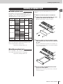 13
13
-
 14
14
-
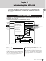 15
15
-
 16
16
-
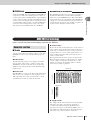 17
17
-
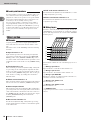 18
18
-
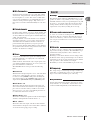 19
19
-
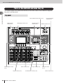 20
20
-
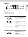 21
21
-
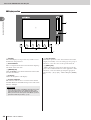 22
22
-
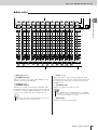 23
23
-
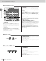 24
24
-
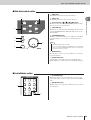 25
25
-
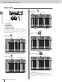 26
26
-
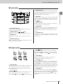 27
27
-
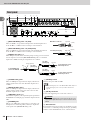 28
28
-
 29
29
-
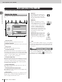 30
30
-
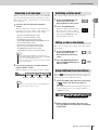 31
31
-
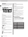 32
32
-
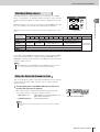 33
33
-
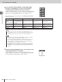 34
34
-
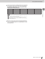 35
35
-
 36
36
-
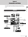 37
37
-
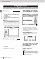 38
38
-
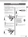 39
39
-
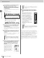 40
40
-
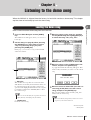 41
41
-
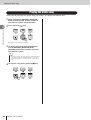 42
42
-
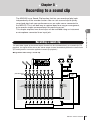 43
43
-
 44
44
-
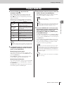 45
45
-
 46
46
-
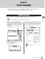 47
47
-
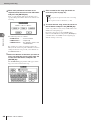 48
48
-
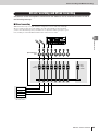 49
49
-
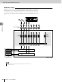 50
50
-
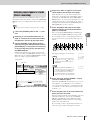 51
51
-
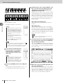 52
52
-
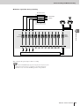 53
53
-
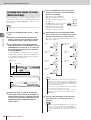 54
54
-
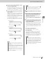 55
55
-
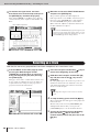 56
56
-
 57
57
-
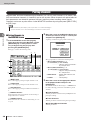 58
58
-
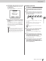 59
59
-
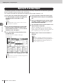 60
60
-
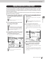 61
61
-
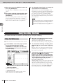 62
62
-
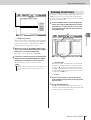 63
63
-
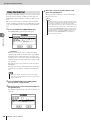 64
64
-
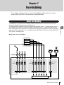 65
65
-
 66
66
-
 67
67
-
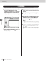 68
68
-
 69
69
-
 70
70
-
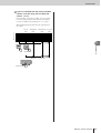 71
71
-
 72
72
-
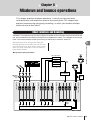 73
73
-
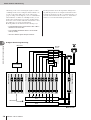 74
74
-
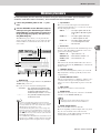 75
75
-
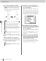 76
76
-
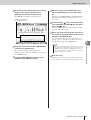 77
77
-
 78
78
-
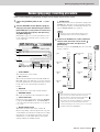 79
79
-
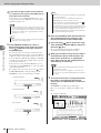 80
80
-
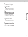 81
81
-
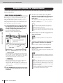 82
82
-
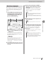 83
83
-
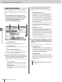 84
84
-
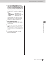 85
85
-
 86
86
-
 87
87
-
 88
88
-
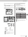 89
89
-
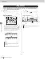 90
90
-
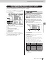 91
91
-
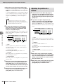 92
92
-
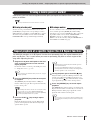 93
93
-
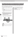 94
94
-
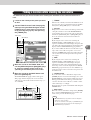 95
95
-
 96
96
-
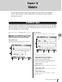 97
97
-
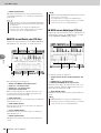 98
98
-
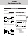 99
99
-
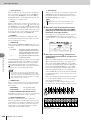 100
100
-
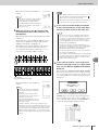 101
101
-
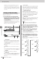 102
102
-
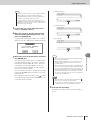 103
103
-
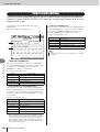 104
104
-
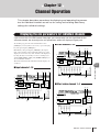 105
105
-
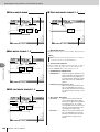 106
106
-
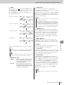 107
107
-
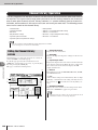 108
108
-
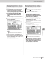 109
109
-
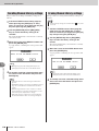 110
110
-
 111
111
-
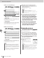 112
112
-
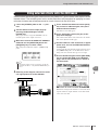 113
113
-
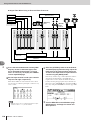 114
114
-
 115
115
-
 116
116
-
 117
117
-
 118
118
-
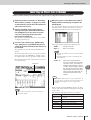 119
119
-
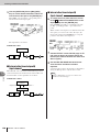 120
120
-
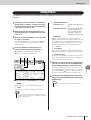 121
121
-
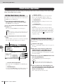 122
122
-
 123
123
-
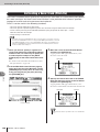 124
124
-
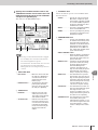 125
125
-
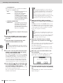 126
126
-
 127
127
-
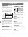 128
128
-
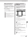 129
129
-
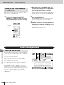 130
130
-
 131
131
-
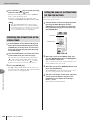 132
132
-
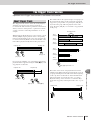 133
133
-
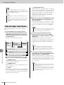 134
134
-
 135
135
-
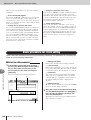 136
136
-
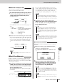 137
137
-
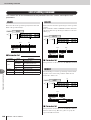 138
138
-
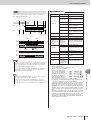 139
139
-
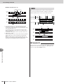 140
140
-
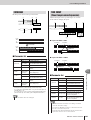 141
141
-
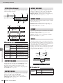 142
142
-
 143
143
-
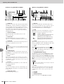 144
144
-
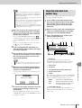 145
145
-
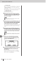 146
146
-
 147
147
-
 148
148
-
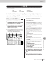 149
149
-
 150
150
-
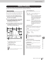 151
151
-
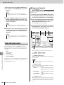 152
152
-
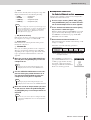 153
153
-
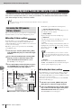 154
154
-
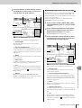 155
155
-
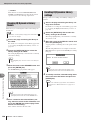 156
156
-
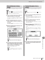 157
157
-
 158
158
-
 159
159
-
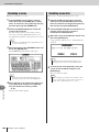 160
160
-
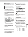 161
161
-
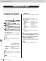 162
162
-
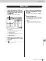 163
163
-
 164
164
-
 165
165
-
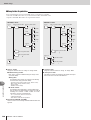 166
166
-
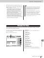 167
167
-
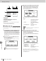 168
168
-
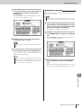 169
169
-
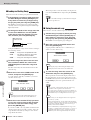 170
170
-
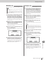 171
171
-
 172
172
-
 173
173
-
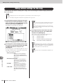 174
174
-
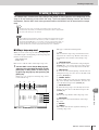 175
175
-
 176
176
-
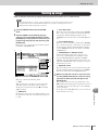 177
177
-
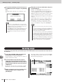 178
178
-
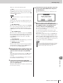 179
179
-
 180
180
-
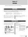 181
181
-
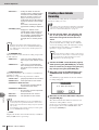 182
182
-
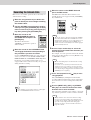 183
183
-
 184
184
-
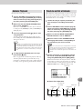 185
185
-
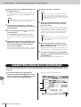 186
186
-
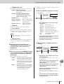 187
187
-
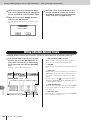 188
188
-
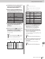 189
189
-
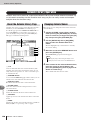 190
190
-
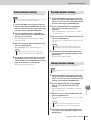 191
191
-
 192
192
-
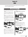 193
193
-
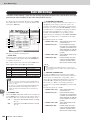 194
194
-
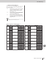 195
195
-
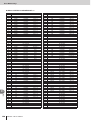 196
196
-
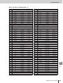 197
197
-
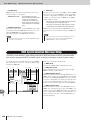 198
198
-
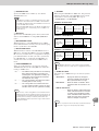 199
199
-
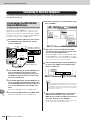 200
200
-
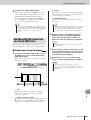 201
201
-
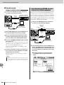 202
202
-
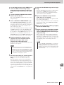 203
203
-
 204
204
-
 205
205
-
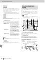 206
206
-
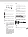 207
207
-
 208
208
-
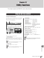 209
209
-
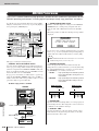 210
210
-
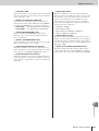 211
211
-
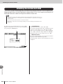 212
212
-
 213
213
-
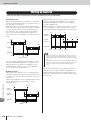 214
214
-
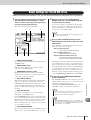 215
215
-
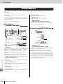 216
216
-
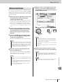 217
217
-
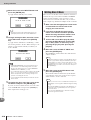 218
218
-
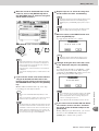 219
219
-
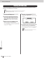 220
220
-
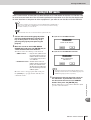 221
221
-
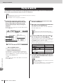 222
222
-
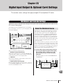 223
223
-
 224
224
-
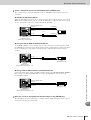 225
225
-
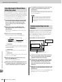 226
226
-
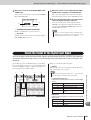 227
227
-
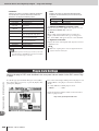 228
228
-
 229
229
-
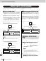 230
230
-
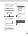 231
231
-
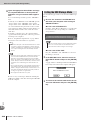 232
232
-
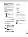 233
233
-
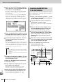 234
234
-
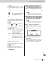 235
235
-
 236
236
-
 237
237
-
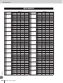 238
238
-
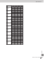 239
239
-
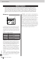 240
240
-
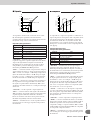 241
241
-
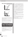 242
242
-
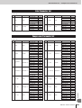 243
243
-
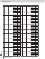 244
244
-
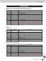 245
245
-
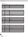 246
246
-
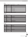 247
247
-
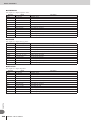 248
248
-
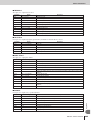 249
249
-
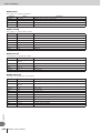 250
250
-
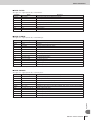 251
251
-
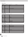 252
252
-
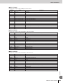 253
253
-
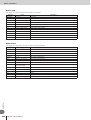 254
254
-
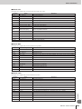 255
255
-
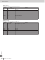 256
256
-
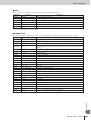 257
257
-
 258
258
-
 259
259
-
 260
260
-
 261
261
-
 262
262
-
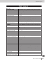 263
263
-
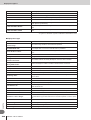 264
264
-
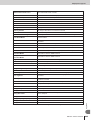 265
265
-
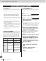 266
266
-
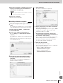 267
267
-
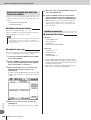 268
268
-
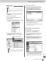 269
269
-
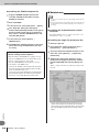 270
270
-
 271
271
-
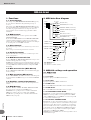 272
272
-
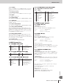 273
273
-
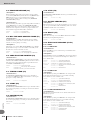 274
274
-
 275
275
-
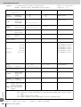 276
276
-
 277
277
-
 278
278
-
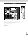 279
279
-
 280
280
-
 281
281
-
 282
282
-
 283
283
-
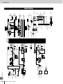 284
284
-
 285
285
-
 286
286
-
 287
287
-
 288
288


in andere talen
- English: Yamaha AW2400 User manual
- italiano: Yamaha AW2400 Manuale utente
- русский: Yamaha AW2400 Руководство пользователя
- français: Yamaha AW2400 Manuel utilisateur
- español: Yamaha AW2400 Manual de usuario
- Deutsch: Yamaha AW2400 Benutzerhandbuch
- português: Yamaha AW2400 Manual do usuário
- dansk: Yamaha AW2400 Brugermanual
- suomi: Yamaha AW2400 Ohjekirja
- čeština: Yamaha AW2400 Uživatelský manuál
- svenska: Yamaha AW2400 Användarmanual
- Türkçe: Yamaha AW2400 Kullanım kılavuzu
- polski: Yamaha AW2400 Instrukcja obsługi
- română: Yamaha AW2400 Manual de utilizare
Gerelateerde papieren
Andere documenten
-
Sony ICD-UX81F Handleiding
-
-
Boss eBand JS-10 de handleiding
-
 Power Dynamics PDM-X Series Music Mixer de handleiding
-
Boss GT-001 de handleiding
-
Creative Live! PLATINUM 5.1 Handleiding
-
Lenco PMX-850 Handleiding
-
SPX SuperCAT 4S Handleiding
-
Radiodetection RD7100 Handleiding
-
Roland VT-3 Handleiding
