
Wallbox Input Closure Interface
OMX-WCI
PELV (Class 2: USA) Devices 24 V 200 mA
R
Chinese
English
Español Français
Português
NederlandsDeutsch Italiano
Overview
The OMX-WCI is for use
with GRAFIK 5000/6000/
7000 series systems. The
OMX-WCI mounts
behind the user-supplied
switch to select or adjust
scenes in up to eight
control units. The
interface provides from
two to seven contact
closure inputs.
Description
• The OMX-WCI provides 7 control inputs to the Lutron
lighting control system.
• The control inputs can be set up to simulate existing
Lutron keypad functionality or custom-configured to
project-specific requirements. Please contact Lutron for
details.
• Provides 1-way interface between Lutron lighting
system and an input switch.
• Mounts behind the user-supplied switch to control the
Lutron lighting control system.
• Works with a PELV (Class 2: USA) low-voltage dry
contact switch that meets the power requirements
found in the Specifications section of this document.
• The power LED provides feedback:
- Flashing indicates a miswire on the communication
link or that the system processor is off-line.
- When the nightlight option is set, the LED will be
steadily lit when polled.
- When the nightlight option bit is cleared, the LED will
not be lit when polled.
• The recommended wallbox depth is 61 mm (2.5 in.).
The wallbox depth requirements vary with the depth of
the switch being used.
• The OMX-WCI uses one address on the communication
link.
• Can be custom-configured for other functions.
Caution: The OMX-WCI is not designed to work
with the line/mains voltage switches. Use with
line/mains voltage switches could result in
premature failure of the switch being used.
Caution: Install in accordance with all local and
national electric codes.
Specifications
Power
• Operating voltage: low-voltage PELV (Class 2: USA),
24 V .
• Input switch or dry contact switch closure must have
solid-state outputs with an on-state saturation voltage
less than 1 V at 1 mA and an off-state leakage
current of less than 1 mA. Outputs must be capable of
switching operating voltage for desired life of system.
• If there is any question as to whether a switch is
compatible with these specifications, contact the
manufacturer of the switch.
Key Design Features
• Meets IEC 801-2. Tested to withstand 15 kV
electrostatic discharge without damage or memory
loss.
System Communications and Capacity
• PELV (Class 2: USA) low-voltage wiring connects
wallstations to control units and other components.
• Link up to 32 wallstations, control units, and/or control
interfaces per wiring link.
Terminals
• Capacity: Accept up to two 1.0 mm
2
(#18 AWG) wires
typical.
Environment
• Ambient operating temperature 0-40 °C (32-104 °F),
0-90% humidity, non-condensing. Indoor use only.
Installation Instructions
Please Read before Installing
Input wiring
harness
Addressing switches
Power
LED
5000TM
6000®
7000TM

2 OMX-WCI Installation Instructions
R
Dimensions
Wallstation Installation
DIP Switches
• Set Address Switches 1-5 to give the wallstation a
unique system address from 1 to 32 (see chart).
12345
ON
12345
ON
12345
ON
12345
ON
1
2
3
4
12345
ON
12345
ON
12345
ON
12345
ON
5
6
7
8
12345
ON
12345
ON
12345
ON
12345
ON
9
10
11
12
12345
ON
12345
ON
12345
ON
12345
ON
13
14
15
16
12345
ON
12345
ON
12345
ON
12345
ON
17
18
19
20
12345
ON
12345
ON
12345
ON
12345
ON
21
22
23
24
12345
ON
12345
ON
12345
ON
12345
ON
25
26
27
28
12345
ON
12345
ON
12345
ON
12345
ON
29
30
31
32
OMX-WCI Addressing
ADDRESS
Contact Closure Wiring
• Connect the desired input(s) and common wires to the
switch provided by others.
• Cap off unused input wires.
Low-Voltage PELV (Class 2: USA) Wiring
Use low-voltage PELV (Class 2: USA) wiring to daisy-
chain the OMX-WCI to the processor panel.
• Use two 2.5 mm
2
(#12 AWG) conductors for common
(terminal 1) and 24 V (terminal 2). These will not fit
into terminals; see opposite for connection details.
• Use one shielded, twisted pair 1.0 mm
2
(#18 AWG) wires
for data link (terminals 3 and 4).
• Connect drain/shield as shown opposite.
- Do not connect ground/earth to OMX-WCI.
- Connect the bare drain wires and cut off the outside
shield.
• Make connections inside the wallbox, in a switchbox, or
in a junction box with a maximum wire length of 2.5 m
(8 feet) from the link to the OMX-WCI.
75 mm
(2 15/16”)
119 mm
(4 11/16”)
75 mm
(2 15/16”)
Front View
Back View
Side View
20 mm (13/16”)
Switch
Common
Input 1

R
Communication
link wiring
OMX-WCI
Wallbox
Mounting
Wiring
To other control interfaces
(2) 2.5 mm
2
(#12 AWG )
(2) 2.5 mm
2
(#12 AWG )
(2) 1.0 mm
2
(#18 AWG)
twisted, shielded pair from
terminals 3 to 3 and 4 to 4
Drain wires
Note: Use appropriate wire connecting devices
as specified by local codes.
4 3 2 1
(2) 1.0 mm
2
(#18 AWG)
OMX-WCI Installation Instructions 3
Low-voltage contact closure
switch provided by others

R
LIMITED WARRANTY
Lutron will, at its option, repair or replace any unit that is defective in materials or manufacture within one year after purchase. For warranty service,
return unit to place of purchase or mail to Lutron at 7200 Suter Rd., Coopersburg, PA 18036-1299, postage pre-paid.
This warranty is in lieu of all other express warranties, and the implied warranty of merchantability is limited to one year from purchase. This warranty
does not cover the cost of installation, removal or reinstallation, or damage resulting from misuse, abuse, or improper or incorrect repair, or damage
from improper wiring or installation. This warranty does not cover incidental or consequential damages. Lutron’s liability on any claim for damages
arising out of or in connection with the manufacture, sale, installation, delivery, or use of the unit shall never exceed the purchase price of the unit.
This warranty gives you specific legal rights, and you may also have other rights which vary from state to state. Some states do not allow limitations on
how long an implied warranty lasts, so the above limitation may not apply to you. Some states do not allow the exclusion or limitation of incidental or
consequential damages, so the above limitation or exclusion may not apply to you.
Lutron, the sunburst logo, GRAFIK Eye, and GRAFIK 6000 are registered trademarks and GRAFIK systems, GRAFIK 5000, and GRAFIK 7000 are
trademarks of Lutron Electronics Co., Inc.
© 2006 Lutron Electronics Co., Inc.
Internet: www.lutron.com
E-mail: [email protected]
WORLD HEADQUARTERS
Lutron Electronics Co., Inc.
7200 Suter Road, Coopersburg, PA 18036-1299
USA
TEL +1.610.282.3800
FAX +1.610.282.1243
Toll-Free 1.888.LUTRON1
Technical Support 1.800.523.9466
EUROPEAN HEADQUARTERS
Lutron EA Ltd.
6 Sovereign Close, London,
E1W 3JF United Kingdom
TEL +44.(0)20.7702.0657
FAX +44.(0)20.7480.6899
FREEPHONE (UK) 0800.282.107
Technical support +44.(0)20.7680.4481
WORLDWIDE OFFICES
Brazil
Lutron BZ do Brasil Ltda.
AV, Brasil, 239, Jardim America,
Sao Paulo-SP, CEP: 01431-000, Brasil
TEL +55.11.3885.5152
FAX +55.11.3887.7138
France
Lutron LTC, S.A.R.L.
90 rue de Villiers, 92300 Levallois-Perret France
TEL +33.(0)1.41.05.42.80
FAX +33.(0)1.41.05.01.80
FREEPHONE 0800.90.12.18
Germany
Lutron Electronics GmbH, Landsberger Allee 201, 13055
Berlin, Germany
TEL +49.(0)30.9710.4590
FAX +49.(0)30.9710.4591
FREEPHONE 00800.5887.6635
Italy
Lutron LDV, S.r.l.
FREEPHONE 800.979.208
Spain, Barcelona
Lutron CC, S.R.L.
Gran Via Carlos III, 84, planta 3a, 08028,
Barcelona, Spain
TEL +34.93.496.57.42
FAX +34.93.496.57.01
FREEPHONE 0900.948.944
Spain, Madrid
Lutron CC, S.R.L.
Calle Orense, 85, 28020 Madrid, Spain
TEL +34.91.567.84.79
FAX +34.91.567.84.78
FREEPHONE 0900.948.944
China, Beijing
Lutron GL Ltd. Beijing Representative Office
5th Floor, China Life Tower, No. 16 Chaowai Street,
Chaoyang District, Beijing 100020 China
TEL +86.10.5877.1818
FAX +86.10.5877.1816
China, Guangzhou
Lutron GL Ltd. Guangzhou Representative Office
Suite A09, 23/F Tower A, Centre Plaza,
161 Lin He Xi Lu, Tian He District, Guangzhou 510620
China
TEL +86.20.2885.8266
FAX +86.20.2885.8366
China, Shanghai
Lutron GL Ltd. Shanghai Representative Office
Suite 07, 39th Floor, Plaza 66,
1266 Nan Jing West Road, Shanghai, 200040 China
TEL +86.21.6288.1473
FAX +86.21.6288.1751
Hong Kong
Lutron GL Ltd.
Room 2808, 28/F, 248 Queen's Road East,
Wanchai, Hong Kong
TEL +852.2104.7733
FAX +852.2104.7633
Japan
Lutron Asuka Co. Ltd.
No. 16 Kowa Building, 4F, 1-9-20, Akasaka,
Minato-ku, Tokyo 107-0052 Japan
TEL +81.3.5575.8411
FAX +81.3.5575.8420
Singapore
Lutron GL Ltd.
15 Hoe Chiang Road, #07-03 Euro Asia Centre,
Singapore 089316
TEL +65.6220.4666
FAX +65.6220.4333
Asia Technical Hotlines
Northern China: 10.800.712.1536
Southern China: 10.800.120.1536
Hong Kong: 800.901.849
Singapore: 800.120.4491
Taiwan: 00.801.137.737
Thailand: 001.800.120.665853
Other Areas: +65.6220.4666
Lutron Electronics Co., Inc.
Made and printed in U.S.A. 2/06
P/N 030-827 Rev. D

Interfaz de entradas de cierre en
cajas de empotrar
OMX-WCI
Dispositivos
PELV (Clase 2: EE.UU.)
de 24 V 200 mA
R
Español
Perspectiva
general
El OMX-WCI es para su
uso con sistemas
GRAFIK de las series
5000/6000/7000. El
OMX-WCI se instala
detrás del interruptor
suministrado para que
el usuario seleccione o
ajuste escenas en hasta
ocho unidades de control. La interfaz proporciona de
dos a siete entradas de cierre de contacto.
Descripción
• El OMX-WCI proporciona 7 entradas de control al
sistema de control de iluminación de Lutron.
• Las entradas de control se pueden configurar para
simular las funciones de teclados Lutron o se pueden
personalizar para requisitos específicos del proyecto.
Consulte con Lutron para más detalles.
• Proporciona una interfaz unidireccional entre el sistema
de control de iluminación de Lutron y un interruptor de
entrada.
• Se monta detrás del interruptor suministrado por el
cliente para controlar el sistema de control de
iluminación de Lutron.
• Funciona con un interruptor PELV (Clase 2: EE.UU.) de
bajo voltaje y contacto seco que cumpla con los
requisitos de potencia que figuran en el apartado
Especificaciones de este documento.
• El LED de alimentación indica lo siguiente:
- El parpadeo indica un cableado incorrecto en el bus
de comunicación o que el procesador del sistema
está fuera de funcionamiento
- Cuando se selecciona la opción de luz nocturna, el
LED se ilumina fijamente al hacer la llamada selectiva
- Cuando se elimina la opción de luz nocturna, el LED
no se ilumina al hacer la llamada selectiva.
• La profundidad recomendada para la caja de empotrar
es de 61 mm. Los requisitos de profundidad de la caja
de montaje pueden variar en función de la profundidad
del interruptor que se esté utilizando.
• El OMX-WCI utiliza una dirección en el bus de
comunicaciones.
• Se puede configurar para otras funciones.
Atención: El OMX-WCI no ha sido diseñado para
su uso con interruptores generales de
alimentación. El uso con estos interruptores puede
producir un fallo prematuro del interruptor
utilizado.
Atención: Instalar de acuerdo con las normas
eléctricas locales y nacionales.
Especificaciones
Alimentación
• Voltaje de servicio: : bajo voltaje PELV (Clase 2:
EE.UU.), 24 V .
• El cierre del interruptor de entrada o del interruptor de
contacto seco debe tener una salida de estado sólido,
con un voltaje de saturación inferior a 1 V a 1 mA y
una corriente de fuga inferior a 1 mA. Las salidas deben
ser capaces de conmutar el voltaje de servicio
requerido en el sistema.
• Consultar al fabricante del dispositivo en caso de
dudas sobre su compatibilidad con estas
especificaciones.
Características principales de diseño
• Cumple la norma IEC 801-2. Se ha probado que resiste
una descarga electrostática de 15 kV sin sufrir daños ni
pérdidas de memoria.
Comunicaciones y capacidad del sistema
• El cableado PELV (Clase 2: EE.UU.) de bajo voltaje
conecta las unidades de control de pared con las
unidades de control y otros componentes.
• Se pueden conectar hasta 32 unidades de control de
pared, unidades de control y/o interfaces de control por
cada enlace.
Terminales
• Capacidad: admite hasta dos cables de 1,0 mm
2
(nº 18
AWG).
Condiciones ambientales
• Temperatura ambiente de funcionamiento 0-40 °C
(32-104 °F), 0-90% de humedad ambiente, sin
condensación. Uso en interiores solamente.
Instrucciones de montaje
Leer antes de la instalación
Cables de
entradas
digitales
Asignación de
direcciones a los
interruptores
LED de
alimentación
5000TM
6000®
7000TM

2 Instrucciones de instalación del OMX-WCI
R
Medidas
Instalación de la unidad de control de
pared
Interruptores DIP
• Configure los interruptores de dirección 1-5 para
asignar una dirección de sistema única entre 1 y 32 a la
unidad de control de pared. (véase cuadro).
12345
ON
12345
ON
12345
ON
12345
ON
1
2
3
4
12345
ON
12345
ON
12345
ON
12345
ON
5
6
7
8
12345
ON
12345
ON
12345
ON
12345
ON
9
10
11
12
12345
ON
12345
ON
12345
ON
12345
ON
13
14
15
16
12345
ON
12345
ON
12345
ON
12345
ON
17
18
19
20
12345
ON
12345
ON
12345
ON
12345
ON
21
22
23
24
12345
ON
12345
ON
12345
ON
12345
ON
25
26
27
28
12345
ON
12345
ON
12345
ON
12345
ON
29
30
31
32
Direccionamiento del OMX-WCI
DIRECCIÓN
Cableado del Contacto
• Conecte las entradas y los cables comunes deseados al
interruptor suministrado por otros fabricantes.
• Corte los cables de entrada no utilizados.
Cableado de bajo voltaje PELV (Clase 2: EE.UU.)
Utilice cableado de bajo voltaje PELV (Clase 2: EE.UU.)
para conectar en cadena el OMX-WCI al procesador.
• Utilice dos conductores de 2,5 mm2 (nº 12 AWG) para
común (terminal 1) y 24 V (terminal 2). Estos no se
pueden acoplar en los terminales; consulte el lado
opuesto de la página para más detalles.
• Utilice un par apantallado y trenzado de 1,0 mm
2
(nº 18 AWG) para bus de datos (terminales 3 y 4).
• Conecte la malla como se indica en el otro lado.
- No conecte la tierra/masa al OMX-WCI.
- Conecte los cables de pantalla sin revestimiento y
corte la malla externa.
• Realice las conexiones en la caja de montaje o en una
caja de conexión o de distribución con una longitud de
cable máxima de 2,5 m desde la conexión al OMX-WCI.
75 mm
(2 15/16”)
119 mm
(4 11/16”)
75 mm
(2 15/16”)
Vista frontal
Vista posterior
Vista lateral
20 mm (13/16”)
Interruptor
Común
Entrada 1

R
Cableado del
bus de
comunicación
OMX-WCI
Montaje
Cableado
A otras interfaces de control
(2) 2,5 mm
2
(nº 12 AWG )
(2) 2,5 mm
2
(nº 12 AWG )
(2) pares trenzados y
apantallados de 1,0 mm
2
(nº 18 AWG) de los
terminales 3 al 3 y del 4 al 4
Cables de
drenaje
Nota: Utilice dispositivos de conexión de cables
adecuados, según se especifica en las normas
locales.
4 3 2 1
(2) 1,0 mm
2
(nº 18 AWG)
Instrucciones de instalación del OMX-WCI 3
Interruptor de cierre de contacto bajo voltaje
suministrado por otros fabricantes
Caja de empotrar

R
GARANTÍA LIMITADA
A su juicio, Lutron procederá a la reparación o a la sustitución de cualquier unidad que presente defectos de material o de fabricación durante un año
a partir de la fecha de compra. Para reclamaciones en garantía deberá devolver la unidad al distribuidor o oficina Lutron donde la haya adquirido o
enviarla por correo a portes pagados a Lutron, 7200 Suter Rd., Coopersburg, PA 18036-1299.
Esta garantía sustituye cualquier otra garantía expresa; la garantía de comercialización que implica está limitada a un año a partir de la fecha de
compra. Esta garantía no cubre los gastos de instalación, desmontaje o reinstalación, los daños que se deriven del mal uso, abuso o de reparaciones
inadecuadas o incorrectas ni los daños ocasionados por el cableado o la instalación no apropiados. Esta garantía no cubre daños fortuitos o
secundarios. En caso de reclamaciones causadas por o en relación con la fabricación, la venta, la instalación, la entrega o el uso de la unidad, la
responsabilidad de Lutron nunca excederá el precio de adquisición de la unidad.
Esta garantía le otorga derechos legales específicos. Sin embargo, puede tener otros derechos que pueden variar de un país a otro. Algunos países
no permiten limitaciones en la duración de la garantía implícita, por lo que la limitación arriba descrita puede no ser aplicable en su caso. Algunos
países no permiten la exclusión o las limitaciones de daños fortuitos o secundarios, por lo que la limitación o exclusión arriba descrita puede no ser
aplicable en su caso.
Lutron, su logotipo, GRAFIK Eye, y GRAFIK 6000 son marcas registradas y GRAFIK systems, GRAFIK 5000, y GRAFIK 7000 son marcas propiedad
de Lutron Electronics Co., Inc.
© 2006 Lutron Electronics Co., Inc.
Internet: www.lutron.com
E-mail: [email protected]
CENTRAL INTERNACIONAL
Lutron Electronics Co., Inc.
7200 Suter Road, Coopersburg, PA 18036
TEL +1.610.282.3800
FAX +1.610.282.1243
Teléfono gratuito 1.888.LUTRON1
Soporte técnico 1.800.523.9466
CENTRAL PARA EUROPA
Lutron EA Ltd.
6 Sovereign Close, London,
E1W 3JF United Kingdom
TEL +44.(0)20.7702.0657
FAX +44.(0)20.7480.6899
TELÉFONO GRATUITO (R.U.) 0800.282.107
Soporte técnico +44.(0)20.7680.4481
DELEGACIONES INTERNACIONALES
Brasil
Lutron BZ do Brasil Ltda.
AV, Brasil, 239, Jardim America,
Sao Paulo-SP, CEP01431-000, Brasil
TEL +55.11.3885.5152
FAX +55.11.3887.7138
Francia
Lutron LTC, S.A.R.L.
90 rue de Villiers, 92300 Levallois-Perret France
TEL +33.(0)1.41.05.42.80
FAX +33.(0)1.41.05.01.80
TELÉFONO GRATUITO 0800.90.12.18
Alemania
Lutron Electronics GmbH, Landsberger Allee 201, 13055
Berlin, Germany
TEL +49.(0)30.9710.4590
FAX +49.(0)30.9710.4591
TELÉFONO GRATUITO 00800.5887.6635
Italia
Lutron LDV S.r.l.
TELÉFONO GRATUITO 800.979.208
España, Barcelona
Lutron CC, S.R.L.
Gran Via del Carlos III, 84, planta 3a, 08028,
Barcelona, Spain
TEL +34.93.496.57.42
FAX +34.93.496.57.01
TELÉFONO GRATUITO 0900.948.944
España, Madrid
Lutron CC, S.R.L.
Calle Orense, 85, 28020 Madrid, España
TEL +34.91.567.84.79
FAX +34.91.567.84.78
TELÉFONO GRATUITO 0900.948.944
China, Pekín
Lutron GL Ltd. Beijing Representative Office
5th Floor, China Life Tower, No. 16 Chaowai Street,
Chaoyang District, Beijing 100020 China
TEL +86.10.5877.1818
FAX +86.10.5877.1816
China, Guangzhou
Lutron GL Ltd. Guangzhou Representative Office
Suite A09, 23/F Tower A, Center Plaza,
161 Lin He Xi Lu, Tian He District, Guangzhou 510620
China
TEL +86.20.2885.8266
FAX +86.20.2885.8366
China, Shanghai
Lutron GL Ltd. Shanghai Representative Office
Suite 07, 39th Floor, Plaza 66,
1266 Nan Jing West Road, Shanghai, 200040 China
TEL +86.21.6288.1473
FAX +86.21.6288.1751
Hong Kong
Lutron GL Ltd.
Room 2808, 28/F, 248 Queen's Road East,
Wanchai, Hong Kong
TEL +852.2104.7733
FAX +852.2104.7633
Japón
Lutron Asuka Co. Ltd.
No. 16 Kowa Building, 4F, 1-9-20, Akasaka,
Minato-ku, Tokyo 107-0052 Japan
TEL +81.3.5575.8411
FAX +81.3.5575.8420
Singapur
Lutron GL Ltd.
15 Hoe Chiang Road, #07-03 Euro Asia Centre, Singapur
089316
TEL +65.6220.4666
FAX +65.6220.4333
Servicio técnico telefónico en Asia
China Norte: 10.800.712.1536
China Sur: 10.800.120.1536
Hong Kong: 800.901.849
Singapur: 800.120.4491
Taiwan: 00.801.137.737
Tailandia: 001.800.120.665853
Otras áreas: +65.6220.4666
Lutron Electronics Co., Inc.
Redactado e impreso en EE.UU. 2/06
P/N 030-827 Rev. D

Tasterschnittstelle für UP-Dosen
OMX-WCI
Schutzkleinspannungsgeräte (Klasse 2: USA)
24 V 200 mA
R
Deutsch
Übersicht
Das OMX-WCI kann in
GRAFIK-Systemen der
Serie 5000/6000/7000
eingesetzt werden. Das
OMX-WCI wird hinter
einem konventionellen
Schalter (für Niedervolt)
montiert, und dient zum
Auswählen oder Steuern
von Lichtszenen in bis zu
acht Steuerstellen. Das Interface stellt dem Lutron-
Lichtsteuersystem zwei bis sieben Steuereingänge zur
Verfügung.
Beschreibung
• Das OMX-WCI stellt dem Lutron-Lichtsteuersystem 7
Steuereingänge zur Verfügung.
• Die Steuereingänge können so eingestellt werden, dass
sie die Funktionalität vorhandener Lutron-Bedienstellen
simulieren, oder sie können nach projektspezifischen
Anforderungen individuell eingestellt werden. Für
Einzelheiten setzen Sie sich bitte mit Lutron in
Verbindung.
• Stellt eine unidirektionale Schnittstelle zwischen Lutron-
Lichtsteuersystemen und einem Schalter dar.
• Wird hinter dem vom Benutzer gelieferten Schalter
montiert, und dient zum Steuern des Lutron-
Lichtsteuersystems.
• Arbeitet mit einem Schutzkleinspannungs-Schalter
(Klasse 2: USA), der den Leistungsanforderungen im
Spezifikationsabschnitt dieses Dokuments entspricht.
• Die Netzspannungs-LED dient zur Rückmeldung:
-Eine blinkende LED zeigt an, dass eine fehlerhafte
Verdrahtung des Kommunikationslinks vorliegt oder
der Systemprozessor offline ist.
-Ist die Nachtlicht-Option aktiviert, bleibt die LED
während der Kommunikation mit dem Prozessor
ständig eingeschaltet.
-Ist die Nachtlicht-Option inaktiv, wird die LED während
der Kommunikation mit dem Prozessor nicht
eingeschaltet.
• Empfohlene Unterputzdosentiefe 61 mm. Die
Unterputzdosentiefe kann je nach der Tiefe des
verwendeten Schalters unterschiedlich sein.
• Das OMX-WCI verwendet eine Adresse auf dem
Kommunikationslink.
• Kann nach Wunsch für andere Funktionen konfiguriert
werden.
Vorsicht: Das OMX-WCI ist nicht für
Netzspannungsschalter bestimmt. Die Benutzung
von Netzspannungsschaltern kann zur vorzeitigen
Beschädigung des benutzten Schalters führen.
Vorsicht: Bei der Installation sind alle geltenden
Verkabelungsvorschriften einzuhalten.
Spezifikationen
Spannung
• Betriebsspannung: Schutzkleinspannung (Klasse 2:
USA), 24 V .
• Der Eingangsschalter bzw. Schalter mit potentialfreien
Kontakten muss über einen Ausgang mit einer
Sättigungsspannung unterhalb von 1 V im
Durchlasszustand bei 1 mA und einem Kriechstrom
unterhalb von 1 mA im Sperrzustand verfügen. Die
Ausgänge müssen die Betriebsspannung während der
gesamten Lebensdauer des Systems schalten können.
• Falls Sie sich nicht sicher sind, ob ein Schalter mit
diesen Daten kompatibel ist, setzen Sie sich bitte mit
dem Gerätehersteller des Schalters in Verbindung.
Wichtigste Designmerkmale
• Entspricht den Anforderungen in IEC 801-2. Kann
elektrostatischen Entladungen von bis zu 15 kV ohne
Beschädigungen oder Speicherverluste widerstehen.
Systemkommunikation und Kapazität
• Die Bedienstellen sind durch Schutzkleinspannungs-
Verkabelung (Klasse 2: USA) mit den Steuerstellen und
anderen Komponenten verbunden.
• In einem Verkabelungs-Link können bis zu 32
Bedienstellen, Steuerstellen und/oder Steuer-
Schnittstellen miteinander verbunden werden.
Anschlussklemmen
• Kapazität: Typischerweise bis zu zwei 1,0-mm
2
-
Leitungen (AWG Nr. 18).
Umgebung
• Zulässige Umgebungstemperatur: 0-40 °C, zulässiger
Feuchtigkeitsgehalt der Luft: 0-90%, nicht
kondensierend. Nur für Innenräume.
Installationsanweisungen
Bitte lesen Sie diese
Anweisungen vor der Installation
Kabelsatz
Eingangsklemmen
Adressenschalter
Netzspannungs-LED
5000TM
6000®
7000TM

2 OMX-WCI Installationsanweisungen
R
Abmessungen
Installation der Bedienstelle
DIP-Schalter
• Stellen Sie Adressen-DIP-Schalter 1-5 so ein, dass die
Bedienstelle eine nur einmal vergebene Systemadresse
von 1 bis 32 erhält (siehe Tabelle).
12345
ON
12345
ON
12345
ON
12345
ON
1
2
3
4
12345
ON
12345
ON
12345
ON
12345
ON
5
6
7
8
12345
ON
12345
ON
12345
ON
12345
ON
9
10
11
12
12345
ON
12345
ON
12345
ON
12345
ON
13
14
15
16
12345
ON
12345
ON
12345
ON
12345
ON
17
18
19
20
12345
ON
12345
ON
12345
ON
12345
ON
21
22
23
24
12345
ON
12345
ON
12345
ON
12345
ON
25
26
27
28
12345
ON
12345
ON
12345
ON
12345
ON
29
30
31
32
OMX-WCI Adressenzuweisung
ADRESSE
Verkabelung der potentialfreien Kontakte
• Den (die) gewünschten Eingang (Eingänge) an den
Schalter (Produkt eines andren Herstellers) anschließen.
• Nicht benutzte Leiter mit einer Klemme versehen oder
abschneiden.
Schutzkleinspannungs-Verkablung (Klasse 2:
USA)
Für den Anschluss zwischen dem OMX-WCI und dem
Prozessorschrank ist eine Schutzkleinspannungs-
Verkabelung (Klasse 2: USA) in Serienschaltung (Daisy-
Chain) zu verlegen.
• Zwei 2,5-mm
2
-Leiter (AWG Nr. 12) für Masse (Klemme 1)
und 24 V (Klemme 2) verwenden. Die Leiter passen
nicht in die Klemmen; siehe Abbildung gegenüber für
Einzelheiten zum Anschluss.
• Ein abgeschirmtes, verdrilltes 1,0-mm
2
-Leitungspaar
(AWG Nr. 18) als Datenverbindung (Klemmen 3 und 4)
verwenden.
• Die Abschirmung wie gegenüber abgebildet
anschließen.
- Das OMX-WCI nicht mit Masse/Erde verbinden.
- Die abisolierten Schirmleitungen anschließen und die
äußere Abschirmung abschneiden.
• Das OMX-WCI muss innerhalb der UP-Dose, in einem
Schaltkasten oder in einer Verteilerdose an die
Busleitung angeschlossen werden, wobei der Abstand
von der Busleitung zum OMX-WCI höchstens 2,5 m
betragen darf.
75 mm
119 mm
75 mm
Vorderansicht
Rückansicht
Seitenansicht
20 mm
Schalter
Korrespondierend
Eingang 1

R
Verkabelung der
Kommunikationsl
inks
OMX-WCI
UP-Dose
Montage
Verdrahtung
An andere Steuer-
Schnittstellen
(2) 2,5 mm
2
(AWG Nr. 12 )
(2) 2,5 mm
2
(AWG Nr. 12 )
2x 1,0 mm
2
(AWG Nr. 18)
verdrillte geschirmte
Doppelleitung von Klemmen
3 an 3 und 4 an 4
Schirmleitungen
Hinweis: Nur den örtlichen Vorschriften
entsprechende, geeignete Kabelverbinder
verwenden.
4 3 2 1
(2) 1,0 mm
2
(AWG Nr. 18)
OMX-WCI Installationsanweisungen 3
Niederspannungsschalter

R
BESCHRÄNKTE GEWÄHRLEISTUNG
Lutron verpflichtet sich, während des ersten Jahres ab Verkauf unentgeltlich etwaige Mängel, die auf Material- oder Fabrikationsfehler zurückzuführen
sind, zu beseitigen oder nach eigener Wahl mangelhafte Teile zu ersetzen oder nachzubessern. Schicken Sie die Einheit im Garantiefall an Ihren
Händler oder an Lutron, 7200 Suter Rd., Coopersburg, PA 18036-1299, portofrei zurück.
Diese Garantie ersetzt jede andere ausdrückliche oder eine Schlussfolgerung zulassende Garantie. Die die Schlussfolgerung zulassende Garantie der
Wiederverkäuflichkeit ist auf ein Jahr ab Kaufdatum begrenzt. Installations-, Demontage- und Reinstallationskosten sowie Beschädigungen infolge
missbräuchlicher oder falscher Verdrahtung und fehlerhafter Isolation sind von der Garantie ausgeschlossen. Unmittelbare oder Folgeschäden sind von
der Garantie ausgeschlossen. Lutrons Haftung für Schäden in Zusammenhang mit der Herstellung, dem Verkauf, der Installation, der Lieferung oder
der Anwendung der Einheit ist auf den Kaufpreis der Einheit beschränkt.
Durch diese Garantie werden Sie mit gewissen Rechten ausgestattet. Außerdem können Sie in diesem Zusammenhang auch andere Rechte haben,
die von Staat zu Staat unterschiedlich sind. In einigen Staaten darf die Zeitdauer einer indirekten Garantie nicht begrenzt werden. In einigen Staaten ist
es unzulässig, unmittelbare oder Folgeschäden auszuschließen oder zu begrenzen. Daher ist es möglich, dass obige Ausnahmen und Begrenzungen
für Sie nicht gültig sind.
Lutron, das Sunburst-Logo, GRAFIK Eye und GRAFIK 6000 sind eingetragene Warenzeichen, und GRAFIK systems, GRAFIK 5000 und GRAFIK 7000
sind Warenzeichen von Lutron Electronics Co., Inc.
© 2006 Lutron Electronics Co., Inc.
Internet: www.lutron.com
E-Mail: [email protected]
WELTWEITE ZENTRALE
Lutron Electronics Co., Inc.
7200 Suter Road, Coopersburg, PA 18036
TEL. +1.610.282.3800
FAX +1.610.282.1243
Gebührenfrei 1.888.LUTRON1
Technische Unterstützung 1.800.523.9466
EUROPAZENTRALE
Lutron EA Ltd.
6 Sovereign Close, London,
E1W 3JF Großbritannien
TEL. +44.(0)20.7702.0657
FAX +44.(0)20.7480.6899
GEBÜHRENFREI (Großbritannien) 0800.282.107
Technische Unterstützung +44.(0)20.7680.4481
BÜROS WELTWEIT
Brasilien
Lutron BZ do Brasil Ltda.
AV, Brasil, 239, Jardim America,
Sao Paulo-SP, CEP01431-000, Brasilien
TEL. +55.11.3885.5152
FAX +55.11.3887.7138
Frankreich
Lutron LTC, S.A.R.L.
90 rue de Villiers, 92300 Levallois-Perret, Frankreich
TEL. +33.(0)1.41.05.42.80
FAX +33.(0)1.41.05.01.80
GEBÜHRENFREI 0800.90.12.18
Deutschland
Lutron Electronics GmbH, Landsberger Allee 201, 13055
Berlin, Deutschland
TEL. +49.(0)30.9710.4590
FAX +49.(0)30.9710.4591
GEBÜHRENFREI 00800.5887.6635
Italien
Lutron LDV, S.r.l.
GEBÜHRENFREI 800.979.208
Spanien, Barcelona
Lutron CC, S.R.L.
Gran Via del Carlos III, 84, planta 3a, 08028,
Barcelona, Spanien
TEL. +34.93.496.57.42
FAX +34.93.496.57.01
GEBÜHRENFREI 0900.948.944
Spanien, Madrid
Lutron CC, S.R.L.
Calle Orense, 85, 28020 Madrid, Spanien
TEL. +34.91.567.84.79
FAX +34.91.567.84.78
GEBÜHRENFREI 0900.948.944
China, Beijing
Lutron GL Ltd. Beijing Representative Office
5th Floor, China Life Tower, No. 16 Chaowai Street,
Chaoyang District, Beijing 100020 China
TEL. +86.10.5877.1818
FAX +86.10.5877.1816
China, Guangzhou
Lutron GL Ltd. Guangzhou Representative Office
Suite A09, 23/F Tower A, Center Plaza,
161 Lin He Xi Lu, Tian He District, Guangzhou 510620
China
TEL. +86.20.2885.8266
FAX +86.20.2885.8366
China, Shanghai
Lutron GL Ltd. Shanghai Representative Office
Suite 07, 39th Floor, Plaza 66,
1266 Nan Jing West Road, Shanghai, 200040 China
TEL. +86.21.6288.1473
FAX +86.21.6288.1751
Hongkong
Lutron GL Ltd.
Room 2808, 28/F, 248 Queen's Road East,
Wanchai, Hongkong
TEL. +852.2104.7733
FAX +852.2104.7633
Japan
Lutron Asuka Co. Ltd.
No. 16 Kowa Building, 4F, 1-9-20, Akasaka,
Minato-ku, Tokyo 107-0052 Japan
TEL. +81.3.5575.8411
FAX +81.3.5575.8420
Singapur
Lutron GL Ltd.
15 Hoe Chiang Road, #07-03 Euro Asia Centre,
Singapore 089316
TEL. +65.6220.4666
FAX +65.6220.4333
Asien, technische Hotlines
Nord-China: 10.800.712.1536
Süd-China: 10.800.120.1536
Hongkong: 800.901.849
Singapur: 800.120.4491
Taiwan: 00.801.137.737
Thailand: 001.800.120.665853
Andere Länder: +65.6220.4666
Lutron Electronics Co., Inc.
Zusammengestellt und gedruckt in den USA 2/06
Bestellnr. 030-827 Rev. D

Interface d’entrée pour boîtier
d’encastrement (WCI)
OMX-WCI
Dispositifs
PELV (classe 2 : É-U) 24 V 200 mA
R
Français
Aperçu
Le système OMX-WCI
doit être utilisé avec les
systèmes de la série
GRAFIK 000/6000/7000.
L’OMX-WCI doit être
installé derrière
l’interrupteur de
l’utilisateur pour
permettre de sélectionner
ou de régler les scènes
de huit unités de commande au maximum. L’interface
assure entre deux et sept entrées à contacts secs.
Description
• L’OMX-WCI dispose de 7 entrées pour le système de
commande d’éclairage Lutron.
• Les entrées de commande peuvent être réglées de
sorte à simuler la fonctionnalité du clavier de
commande Lutron existant ou configurées sur mesure
en fonction des caractéristiques du projet. Prendre
contact avec Lutron pour en savoir plus.
• Forme une interface unidirectionnelle entre le système
d’éclairage Lutron et un interrupteur.
• Il doit être installé derrière l’interrupteur de l’utilisateur
pour commander le système de commande d’éclairage
Lutron.
• Il fonctionne avec un interrupteur de type PELV (classe
2 : É-U) basse tension, à contacts secs correspondant
à la puissance nominale indiquée dans le chapitre des
caractéristiques techniques du présent document.
• La DEL témoin de tension assure un retour d’état :
- Le clignotement indique un mauvais câblage du bus
de communication ou que le processeur du système
n’est pas connecté.
- Lorsque l’option éclairage de nuit est sélectionnée, la
DEL s’allume en permanence une fois émise
- Lorsque le bit de l’option éclairage de nuit est effacé,
la DEL ne s’allume pas une fois émise.
• La profondeur recommandée pour le boîtier
d’encastrement est 61 mm (2,5 pouces). Ces exigences
varient en fonction de la profondeur de l’interrupteur
utilisé.
• L’OMX-WCI utilise une adresse du port de
communication.
• Possibilité de configuration sur mesure pour les autres
fonctions.
Attention : l’OMX-WCI n’est pas conçu pour
fonctionner avec les interrupteurs pour tension
secteur. L’utilisation de ce type d’interrupteurs
risque d’entraîner une panne prématurée de
l’interrupteur utilisé.
Attention : installer les câbles conformément aux
directives électriques locales et nationales.
Caractéristiques
Alimentation
• Tension de fonctionnement : PELV basse tension
(classe 2 : É-U), 24 V .
• L’interrupteur ou le contact sec utilisé doit comporter
des sorties statiques et présenter une tension de
saturation à l’état passant inférieure à 1 V à 1 mA et
un courant de fuite dans l’état bloqué inférieur à 1 mA.
Les sorties doivent pouvoir commuter la tension de
fonctionnement pendant toute la durée de vie souhaitée
du système.
• Pour toute question concernant la compatibilité d’un
interrupteur au regard de ces caractéristiques
techniques, consulter le fabricant.
Principales caractéristiques de conception
• Conforme à la norme IEC 801-2. Après test, résistance
à une décharge électrostatique de 15 kV sans
dommage ni perte de mémoire.
Communication et capacité du système
• Le câblage PELV (classe 2 : É-U) basse tension permet
de raccorder les commandes murales aux unités de
commande et aux autres composants.
• Possibilité de raccorder jusqu’à 32 commandes
murales, unités de commande et/ou interfaces de
commande par liaison de câblage.
Bornes
• Capacité : reçoivent généralement jusqu’à deux fils 1
mm
2
(#18 AWG).
Environnement
• Température de fonctionnement ambiante 0-40 °C.
0 à 90 % d’humidité, sans condensation. Exclusivement
destiné à un usage intérieur.
Instructions d'installation
À lire avant de procéder à
l'installation
Brochage
des câbles
d’entrée
Interrupteurs
d’adressage
DEL
témoin de
tension
5000TM
6000®
7000TM

2 Instructions d’installation de l’OMX-WCI
R
Dimensions
Installation du clavier de commande
murale
Commutateurs DIP
• Régler les interrupteurs d’adressage 1 à 5 pour attribuer
à la commande murale l’adresse unique du système
entre 1 et 32 (Voir tableau).
12345
ON
12345
ON
12345
ON
12345
ON
1
2
3
4
12345
ON
12345
ON
12345
ON
12345
ON
5
6
7
8
12345
ON
12345
ON
12345
ON
12345
ON
9
10
11
12
12345
ON
12345
ON
12345
ON
12345
ON
13
14
15
16
12345
ON
12345
ON
12345
ON
12345
ON
17
18
19
20
12345
ON
12345
ON
12345
ON
12345
ON
21
22
23
24
12345
ON
12345
ON
12345
ON
12345
ON
25
26
27
28
12345
ON
12345
ON
12345
ON
12345
ON
29
30
31
32
Adressage de l’OMX-WCI
ADRESSE
Câblage des contacts à fermeture
• Raccorder la ou les entrées souhaitées et les fils
communs à un interrupteur d’une autre marque.
• Découvrir les câbles d’entrée non utilisés.
Câblage PELV (classe 2 : É-U) basse tension
Utiliser des câbles basse tension PELV (classe 2 : É-U)
pour raccorder en série l’OMX-WCI à l’armoire du
processeur.
• Utiliser deux conducteurs de 2,5 mm
2
(#12 AWG) pour le
commun (borne 1) et 24 V (borne 2). Ces derniers
sont trop gros pour les borniers. Voir les détails de
raccordement en page suivante.
• Utiliser une paire torsadée blindée de fils 1 mm
2
(#18
AWG) pour la liaison de données (bornes 3 et 4).
• Se conformer au schéma ci-contre pour raccorder le
drain/blindage.
- Ne pas raccorder à la masse (terre) ou au OMX-WCI.
- Raccorder les câbles de drain nus et découper le
blindage extérieur.
• Réaliser les raccordements à l’intérieur du boîtier
d’encastrement ou dans une boite de jonction ou de
dérivation avec une longueur maximum de câble de
2,5 m entre le bus de communication et l’OMX-WCI.
75 mm
(2 15/16”)
119 mm
(4 11/16”)
75 mm
(2 15/16”)
Vue de face
Vue arrière
Vue latérale
20 mm (13/16”)
Interrupteur
Commun
Entrée 1

R
Câblage du bus
de
communication
OMX-WCI
Montage
Câblage
Vers d’autres interfaces
de commande
(2) 2,5 mm
2
(#12 AWG )
(2) 2,5 mm
2
(#12 AWG )
2 paires torsadées blindées
de 1,0 mm
2
(#18 AWG) à
partir des bornes 3 à 3 et
4 à 4
Câbles de
drain
Remarque : Utiliser des dispositifs de
raccordement de câble tels que spécifiés par la
réglementation locale.
4 3 2 1
(2) 1,0 mm
2
(#18 AWG)
Instructions d’installation de l’OMX-WCI 3
Interrupteur basse tension à
contacts secs d’une autre marque
Boîtier d’encastrement

R
LIMITATION DE GARANTIE
Lutron choisira de réparer ou de remplacer les unités présentant des défauts de pièces ou de fabrication pendant une période d’un an à compter de la
date d’achat. Pour le service de garantie, renvoyer l’unité au magasin où elle a été achetée ou à Lutron à l’adresse : 7200 Suter Rd., Coopersburg, PA
18036-1299, port prépayé.
Cette garantie remplace toute autre garantie expresse. La garantie implicite de qualité loyale et marchande est limitée à un an à compter de la date
d’achat. Cette garantie ne couvre pas les frais d’installation, de démontage ou de réinstallation, les dommages résultant d’une utilisation incorrecte,
d’abus, de réparation impropre ou incorrecte ni les dommages résultant d’une installation ou d’un câblage incorrect. Cette garantie ne couvre pas non
plus les dommages accidentels ou consécutifs. La responsabilité de Lutron quant à toute réclamation concernant des dommages résultant ou en
relation avec la fabrication, la vente, l’installation, la livraison ou l’utilisation de l’unité ne doit jamais excéder le prix d’achat de l’unité.
Cette garantie vous accorde des droits spécifiques et éventuellement certains autres selon les états. Certains états n’autorisent pas la restriction de la
durée d’une garantie implicite, par conséquent la limitation ci-dessus ne s’applique pas. Certains états n’autorisent pas l’exclusion ni la limitation des
dommages accidentels ou consécutifs, par conséquent la limitation ou l’exclusion ci-dessus ne s’appliquent pas.
Lutron, le logo du Soleil, GRAFIK Eye et GRAFIK 6000 sont des marques déposées tandis que GRAFIK systems, GRAFIK 5000 et GRAFIK 7000 sont
des marques de commerce de Lutron Electronics Co., Inc.
© 2006 Lutron Electronics Co., Inc.
Internet : www.lutron.com
E-mail : [email protected]
SIÈGE MONDIAL
Lutron Electronics Co., Inc.
7200 Suter Road Coopersburg, PA 18036
TÉL : +1.610.282.3800
FAX : +1.610.282.1243
Numéro d’appel gratuit 1.888.LUTRON1
Support technique 1.800.523.9466
SIÈGE POUR L’EUROPE
Lutron EA Ltd.
6 Sovereign Close, Londres,
E1W 3JF Royaume-Uni
TÉL : +44.(0)20.7702.0657
FAX : +44.(0)20.7480.6899
NUMÉRO D'APPEL GRATUIT : 0800.282.107 (R.-U.)
Support technique +44.(0)20.7680.4481
BUREAUX MONDIAUX
Brésil
Lutron BZ do Brasil Ltda.
AV, Brasil, 239, Jardim America,
Sao Paulo-SP, CEP01431-000, Brésil
TÉL : +55.11.3885.5152
FAX : +55.11.3887.7138
France
Lutron LTC, S.A.R.L.
90 rue de Villiers, 92300 Levallois-Perret France
TÉL : +33.(0)1.41.05.42.80
FAX : +33.(0)1.41.05.01.80
NUMÉRO D’APPEL GRATUIT 0800.90.12.18
Allemagne
Lutron Electronics GmbH, Landsberger Allee 201, 13055
Berlin, Allemagne
TÉL : +49.(0)30.9710.4590
FAX : +49.(0)30.9710.4591
NUMÉRO D’APPEL GRATUIT 00800.5887.6635
Italie
Lutron LDV, S.r.l.
NUMÉRO D’APPEL GRATUIT : 800.979.208
Espagne, Barcelone
Lutron CC, S.R.L.
Gran Via del Carlos III, 84, planta 3a, 08028,
Barcelone, Espagne
TÉL : +34.93.496.57.42
FAX : +34.93.496.57.01
NUMÉRO D’APPEL GRATUIT 0900.948.944
Espagne, Madrid
Lutron CC, S.R.L.
Calle Orense, 85, 28020 Madrid, Espagne
TÉL : +34.91.567.84.79
FAX : +34.91.567.84.78
NUMÉRO D’APPEL GRATUIT 0900.948.944
Chine, Pékin
Bureau de représentation Lutron GL Ltd. à Pékin
5th. Floor, China Life Tower, No. 16, Chaowai Street,
Chaoyang District, Beijing 100020 Chine
TÉL : +86.10.5877.1818
FAX : +86.10.5877.1816
Chine, Guangzhou
Bureau de représentation Lutron GL Ltd. à Guangzhou
Suite A09, 23/F Tower A, Center Plaza,
161 Lin He Xi Lu, Tian He District, Guangzhou 510620
Chine
TÉL : +86.20.2885.8266
FAX : +86.20.2885.8366
Chine, Shanghai
Bureau de représentation Lutron GL Ltd. à Shanghai
Suite 07, 39th Floor, Plaza 66,
1266 Nan Jing West Road, Shanghai, 200040 Chine
TÉL : +86.21.6288.1473
FAX : +86.21.6288.1751
Hong Kong
Lutron GL Ltd.
Room 2808, 28/F, 248 Queen's Road East,
Wanchai, Hong Kong
TÉL : +852.2104.7733
FAX : +852.2104.7633
Japon
Lutron Asuka Co. Ltd.
No. 16 Kowa Building, 4F, 1-9-20, Akasaka,
Minato-ku, Tokyo 107-0052 Japon
TÉL : +81.3.5575.8411
FAX : +81.3.5575.8420
Singapour
Lutron GL Ltd.
15 Hoe Chiang Road, #07-03 Euro Asia Centre,
Singapour 089316
TÉL : +65.6220.4666
FAX : +65.6220.4333
Lignes d’assistance technique pour l’Asie
Nord de la Chine : 10.800.712.1536
Sud de la Chine : 10.800.120.1536
Hong Kong : 800.901.849
Singapour : 800.120.4491
Taiwan : 00.801.137.737
Thaïlande : 001.800.120.665853
Autres zones : +65.6220.4666
Lutron Electronics Co., Inc.
Réalisé et imprimé aux États-Unis. 2/06
Réf. 030-827 Rév. D

•
•
•
•
•
•
•
•
•
•
•
•
•
•
•
•
•
®

•
•
•
•
•
•
•


©

Interface de entrada de caixa de
embutir sem tensão
OMX-WCI
Dispositivos
PELV (Classe 2: EUA)
24 V 200 mA
R
Português
Aspectos gerais
O OMX-WCI deve ser
utilizado com sistemas
GRAFIK série 5000, 6000
e 7000. O OMX-WCI é
montado por trás do
interruptor fornecido pelo
utilizador para
seleccionar ou regular
ambientes com o
máximo de oito
unidades de controlo. A interface fornece entre duas a
sete entradas de contactos sem tensão.
Descrição
• O OMX-WCI fornece 7 entradas de controlo ao sistema
de controlo de iluminação da Lutron.
• As entradas de controlo podem ser configuradas para
simular a funcionalidade do teclado já existente da
Lutron ou podem ser personalizadas de acordo com os
requisitos específicos do projecto. Contacte a Lutron
para obter mais detalhes.
• Fornece interface de 1 via entre o sistema de controlo
de iluminação da Lutron e um comutador de entrada.
• Deve ser montado na parte posterior do comutador
fornecido pelo utilizador para controlar o sistema de
controlo de iluminação da Lutron.
• É compatível com o comutador por contacto seco
PELV (Classe 2: EUA) de baixa tensão que está em
conformidade com os requisitos de potência descritos
na secção Especificações do presente documento.
• O LED indicador de energia fornece as informações:
-Quando pisca, indica a existência de má ligação na
ligação para comunicação ou que o processador do
sistema está offline.
-Se a opção de iluminação nocturna se encontrar
definida, o indicador LED ficará aceso, quando
seleccionado
-Se a opção de iluminação nocturna não estiver
seleccionada, o LED indicador ficará apagado, quando
seleccionado.
• A profundidade recomendada para o teclado de parede
é de 61 mm. A profundidade dos teclados de parede
varia em função da profundidade do interruptor
utilizado.
• O OMX-WCI utiliza um endereço na ligação para
comunicação.
• Pode ser personalizado para outras funções.
Atenção: O OMX-WCI não foi concebido para
trabalhar com os comutadores de tensão de
linha/alimentação. A sua utilização com
comutadores de tensão de linha/alimentação
poderá resultar na avaria prematura do comutador
que está a ser utilizado.
Atenção: Efectue as instalações eléctricas em
conformidade com todas as normas eléctricas
locais e nacionais.
Especificações
Potência
• Tensão de funcionamento: PELV (Classe 2: EUA) de
baixa tensão, 24 V .
• O interruptor de entrada ou a entrada do comutador
por contacto seco devem possuir saídas de estado
sólido com uma tensão de saturação, quando ligada,
inferior a 1 V a 1 mA e uma corrente de fuga, quando
desligada, inferior a 1 mA. As saídas devem ser
capazes de comutar a tensão de funcionamento de
acordo com a duração de actividade pretendida do
sistema.
• Caso existam dúvidas acerca da compatibilidade de
um comutador com estas especificações, contacte o
fabricante do comutador.
Características chave de concepção
• Em conformidade com a IEC 801-2. Testado para
suportar descargas electrostáticas de 15 kV, sem que
se verifiquem danos ou perda de memória.
Comunicações do sistema e capacidade
• A cablagem PELV (Classe 2: EUA) de baixa tensão liga
teclados de parede a unidades de controlo e a outros
componentes.
• Pode ligar até um máximo de 32 teclados de parede,
unidades de controlo e/ou interfaces de controlo por
ligação com cablagem.
Terminais
• Capacidade: aceita até dois condutores de 1,0 mm
2
(#18 AWG) típicos.
Condições de ambiente
• Temperatura ambiente de funcionamento 0-40 °C,
0-90% humidade, sem condensação. Apenas para
utilização em interiores.
Instruções de instalação
Ler atentamente antes de
instalar
Cablagem de
entrada.
Comutadores de
endereçamento
LED
indicador
de energia
5000TM
6000®
7000TM

2 Instruções de instalação do OMX-WCI
R
Dimensões
Instalação do teclado de parede
Comutadores DIP
• Defina os comutadores de endereço 1 a 5 de forma a
atribuir ao teclado de parede o endereço exclusivo de
sistema 1 a 32 (consulte a tabela).
12345
ON
12345
ON
12345
ON
12345
ON
1
2
3
4
12345
ON
12345
ON
12345
ON
12345
ON
5
6
7
8
12345
ON
12345
ON
12345
ON
12345
ON
9
10
11
12
12345
ON
12345
ON
12345
ON
12345
ON
13
14
15
16
12345
ON
12345
ON
12345
ON
12345
ON
17
18
19
20
12345
ON
12345
ON
12345
ON
12345
ON
21
22
23
24
12345
ON
12345
ON
12345
ON
12345
ON
25
26
27
28
12345
ON
12345
ON
12345
ON
12345
ON
29
30
31
32
Endereçamento do OMX-WCI
ENDEREÇO
Cablagem do contacto sem tensão
• Ligue a(s) entrada(s) pretendidas e os cabos comuns ao
comutador fornecido por terceiros.
• Cubra os cabos de entrada que não são utilizados.
Cablagem PELV (Classe 2: EUA) de baixa tensão
Utilize cablagem PELV (Classe 2: EUA) de baixa tensão
para ligar o OMX-WCI em daisy-chain ao painel do
processador.
• Utilize dois condutores de 2,5 mm
2
(#12 AWG) para
comum (terminal 1) e 24 V (terminal 2). Estes não
encaixam dentro dos terminais. Ver pormenores de
ligação em frente.
• Utilize um cabo blindado, de par torcido de condutores
de 1,0 mm
2
(#18 AWG) para ligação de dados (terminais
3 e 4).
• Ligue a drenagem/blindagem conforme indicado em
frente.
- Não ligue a massa/terra ao OMX-WCI.
- Ligue os fios de drenagem descarnados e corte a
blindagem exterior.
• Faça todas as ligações dentro do teclado de parede,
caixa de distribuição ou de derivação, com um
comprimento máximo de fio de 2,5 m desde a ligação
até ao OMX-WCI.
75 mm
119 mm
75 mm
Perspectiva
frontal
Perspectiva
posterior
Perspectiva
lateral
20 mm
Comutador
Comum
Entrada 1

R
Cablagem da
ligação para
comunicação
OMX-WCI
Montagem
Cablagem
Para outras interfaces de
controlo
(2) 2,5 mm
2
(#12 AWG )
(2) 2,5 mm
2
(#12 AWG )
(2) cabos blindados, de par
torcido, de 1,0 mm
2
(#18
AWG) dos terminas 3 a 3 e
4 a 4
Fios de
drenagem
Nota: Utilize dispositivos apropriados para
ligação de fios, tal como especificado pelos
regulamentos locais
4 3 2 1
(2) 1,0 mm
2
(#18 AWG)
Instruções de instalação do OMX-WCI 3
Comutador de contacto sem tensão de baixa
tensão fornecido por terceiros
Caixa de embutir

R
GARANTIA LIMITADA
A Lutron tem a opção de reparar ou substituir qualquer unidade que apresente defeitos de materiais ou fabrico no prazo de um ano a contar da data
de aquisição. Para assistência técnica coberta pela garantia, entregue a unidade no ponto de venda onde a adquiriu ou envie-a para a Lutron, na
seguinte morada: 7200 Suter Rd., Coopersburg, PA 18036-1299, portes pré-pagos.
Esta garantia substitui todas as demais garantias expressas e a garantia implícita de comerciabilidade está limitada ao prazo de um ano a contar da
data de aquisição. Esta garantia não cobre o custo de instalação, remoção ou reinstalação, nem danos resultantes de utilização indevida, abuso ou
reparação incorrecta ou inadequada, nem danos resultantes de ligações eléctricas ou instalação incorrectas. Esta garantia não cobre danos
acessórios ou não previstos. A responsabilidade da Lutron relativamente a quaisquer danos reclamados resultantes de ou relacionados com o fabrico,
venda, instalação, entrega ou utilização nunca poderá ultrapassar o preço de aquisição da unidade.
Esta garantia concede-lhe direitos legais específicos e poderá ter ainda outros direitos, que variam consoante a jurisdição. Alguns estados não
permitem a limitação da duração de uma garantia implícita, pelo que a limitação acima indicada poderá não se aplicar ao seu caso. Alguns estados
não permitem a exclusão de ou limitação de danos acessórios ou não previstos, pelo que a limitação ou exclusão acima indicada poderá não se
aplicar ao seu caso.
Lutron, o logótipo do sol, GRAFIK Eye e GRAFIK 6000 são marcas comerciais registadas e GRAFIK systems, GRAFIK 5000 e GRAFIK 7000 são
marcas comerciais da Lutron Electronics Co., Inc.
© 2006 Lutron Electronics Co., Inc.
Internet: www.lutron.com
E-mail: [email protected]
SEDE MUNDIAL
Lutron Electronics Co., Inc.
7200 Suter Road, Coopersburg, PA 18036
TEL. +1.610.282.3800
FAX +1.610.282.1243
Linha azul 1.888.LUTRON1
Assistência Técnica 1.800.523.9466
SEDE EUROPEIA
Lutron EA Ltd.
6 Sovereign Close, Wapping London,
E1W 3JF Reino Unido
TEL. +44.(0)20.7702.0657
FAX +44.(0)20.7480.6899
LINHA VERDE (UK) 0800.282.107
Assistência Técnica +44.(0)20.7680.4481
REPRESENTANTES MUNDIAIS
Brasil
Lutron BZ do Brasil Ltda.
AV, Brasil, 239, Jardim América,
São Paulo-SP, CEP01431-000, Brasil
TEL. +55.11.3885.5152
FAX +55.11.3887.7138
França
Lutron LTC, S.A.R.L.
90 rue de Villiers, 92300 Levallois-Perret, França
TEL. 33.(0)1.41.05.42.80
FAX +33.(0)1.41.05.01.80
LINHA VERDE 0800.90.12.18
Alemanha
Lutron Electronics GmbH, Landsberger Allee 201, 13055
Berlim, Alemanha
TEL. +49.(0)30.9710.4590
FAX +49.(0)30.9710.4591
LINHA VERDE 00800.5887.6635
Itália
Lutron LDV, S.r.l.
LINHA VERDE 800.979.208
Espanha, Barcelona
Lutron CC, S.R.L.
Gran Via del Carlos III, 84, planta 3a, 08028,
Barcelona, Espanha
TEL. +34.93.496.57.42
FAX +34.93.496.57.01
LINHA VERDE 0900.948.944
Espanha, Madrid
Lutron CC, S.R.L.
Calle Orense, 85, 28020 Madrid, Spain
TEL. +34.91.567.84.79
FAX +34.91.567.84.78
LINHA VERDE 0900.948.944
China, Pequim
Lutron GL Ltd. Pequim Representative Office
5th Floor, China Life Tower, No. 16, Chaowai Street,
Chaoyang District, Pequim 100020 China
TEL. +86.10.5877.1818
FAX +86.10.5877.1816
China, Guangzhou
Lutron GL Ltd. Guangzhou Representative Office
Suite A09, 23/F Tower A, Center Plaza,
161 Lin He Xi Lu, Tian He District, Guangzhou 510620
China
TEL. +86.20.2885.8266
FAX +86.20.2885.8366
China, Xangai
Lutron GL Ltd. Xangai Representative Office
Suite 07, 39th. Floor, Plaza 66,
1266 Nan Jing West Road, Xangai, 200040 China
TEL. +86.21.6288.1473
FAX +86.21.6288.1751
Hong Kong
Lutron GL Ltd.
Room 2808, 28/F, 248 Queen's Road East,
Wanchai, Hong-Kong
TEL. +852.2104.7733
FAX +852.2104.7633
Japão
Lutron Asuka Co. Ltd.
No. 16 Kowa Building, 4F, 1-9-20, Akasaka,
Minato-ku, Tóquio 107-0052 Japão
TEL. +81.3.5575.8411
FAX +81.3.5575.8420
Singapura
Lutron GL Ltd.
6A Upper Cross Street, Singapore 058326
TEL. +65.6220.4666
FAX +65.6220.4333
Linhas de apoio técnico na Ásia
Norte da China: 10.800.712.1536
Sul da China: 10.800.120.1536
Hong-Kong: 800.901.849
Singapura: 800.120.4491
Taiwan: 00.801.137.737
Tailândia: 001.800.120.665853
Outras áreas: +65.6220.4666
Lutron Electronics Co., Inc.
Feito e impresso nos E.U.A. 2/06
Ref. 030-827 Rev. D

Interface voor wanddoossluitingangen
OMX-WCI
PELV (Klasse 2: VS) toestellen 24 V 200 mA
R
Nederlands
Overzicht
De OMX-WCI is geschikt
voor gebruik met
systemen uit de GRAFIK
5000/6000/7000 serie.
De OMX-WCI wordt
gemonteerd achter de
schakelaar van de
gebruiker voor het
selecteren of instellen
van scènes in
maximaal acht regeleenheden. De interface biedt twee
tot zeven contactsluitingangen.
Beschrijving
• De OMX-WCI biedt 7 besturingsingangen voor het
Lutron lichtregelsysteem.
• De besturingsingangen kunnen ingesteld worden zodat
de functionaliteit van bestaande Lutron toetsenborden
gesimuleerd wordt of kunnen op maat geconfigureerd
worden volgens specifieke projecteisen. Neem contact
met Lutron.
• Biedt een éénweg-interface tussen het Lutron
lichtregelsysteem en een ingangsschakelaar.
• Wordt achter de schakelaar (geleverd door de
gebruiker) gemonteerd voor het regelen van het
lichtregelsysteem van Lutron.
• Werkt met een laagspannings-droog-contactschakelaar
van PELV (Klasse 2: VS) die voldoet aan de
spanningsvereisten zoals vermeld in de sectie
Specificaties van dit document.
• De voedings-LED levert feedback:
- Knipperen geeft een bedradingsfout in de
communicatieverbinding aan, of dat de
systeemprocessor off-line is.
- Wanneer de nachtverlichting is ingesteld en wordt
aangesproken, brandt de LED continu.
- Wanneer de nachtverlichting is uitgeschakeld en
wordt aangesproken, zal de LED niet branden.
• De aanbevolen wanddoosdiepte is 61 mm. De
benodigde wanddoosdiepte kan verschillen, afhankelijk
van de diepte van de gebruikte schakelaar.
• De OMX-WCI gebruikt één adres op de
communicatieverbinding.
• Kan op maat geconfigureerd worden voor andere
functies.
Pas op: De OMX-WCI is niet bestemd voor
toepassing in combinatie met lijn-
/netspanningsschakelaars. Dit zou kunnen
resulteren in het voortijdig defect raken van de
gebruikte schakelaar.
Pas op: Installeren in overeenstemming met alle
plaatselijk en landelijk geldende elektrotechnische
voorschriften.
Specificaties
Voeding
• Bedrijfsspanning: Laagspanningstype PELV (Klasse 2:
VS), 24 V .
• Ingangsschakelaar of droog-contactschakelaar moet
uitgangen met halfgeleider hebben met een doorlaat-
verzadigingsspanning van minder dan 1 V bij 1 mA
en een sperlekkage van minder dan 1 mA. Uitgangen
moeten bedrijfsspanning kunnen schakelen gedurende
de gewenste levensduur van het systeem.
• Mocht u niet zeker weten of een schakelaar compatibel
is met deze specificaties, neem dan contact op met de
fabrikant van de schakelaar.
Hoofdkenmerken van het ontwerp
• Voldoet aan IEC 801-2. Is blijkens proeven bestand
tegen elektrostatische ontlading van 15 kV zonder
schade of verlies van geheugen.
Systeemcommunicatie en -capaciteit
• PELV (Klasse 2: VS) draden voor laagspanning worden
wandbedieningspanelen aangesloten op regeleenheden
en andere componenten.
• U kunt max. 32 wandstations, regeleenheden en/of
besturingsinterfaces aansluiten per draadverbinding.
Klemmen
• Capaciteit: Geschikt voor max. twee draden 1,0mm
2
(#18 AWG), standaardtype.
Omgeving
• Omgevingstemperatuur bij bedrijf: 0-40 °C.
0-90% vochtigheid, zonder condensatie. Alleen voor
binnen.
Installatievoorschriften
Eerst lezen a.u.b. alvorens tot
installatie over te gaan
Bedradingsbundel
voor ingangsdraden
Adresseerschakelaars
Spanningsindicatie-LED
5000TM
6000®
7000TM

2 OMX-WCI installatie-instructies
R
Afmetingen
Installatie van wandbediening
DIP-switches
• Stel adresschakelaar 1 t/m 5 in om het wandstation een
uniek systeemadres te geven van 1 tot 32 (zie tabel).
12345
ON
12345
ON
12345
ON
12345
ON
1
2
3
4
12345
ON
12345
ON
12345
ON
12345
ON
5
6
7
8
12345
ON
12345
ON
12345
ON
12345
ON
9
10
11
12
12345
ON
12345
ON
12345
ON
12345
ON
13
14
15
16
12345
ON
12345
ON
12345
ON
12345
ON
17
18
19
20
12345
ON
12345
ON
12345
ON
12345
ON
21
22
23
24
12345
ON
12345
ON
12345
ON
12345
ON
25
26
27
28
12345
ON
12345
ON
12345
ON
12345
ON
29
30
31
32
Adresseren van de OMX-WCI
ADRES
Contactsluitbedrading
• Verbind de gewenste ingang(en) en de
gemeenschappelijke draden met de door derden
geleverde schakelaar.
• Dop de ongebruikte ingangsdraden af.
Laagspanningsbedrading PELV (Klasse 2: VS)
Lus de OMX-WCI door naar het processorpaneel met
PELV (Klasse 2: VS) draden voor laagspanning.
• Gebruik twee geleiders 2,5 mm
2
(#12 AWG) voor
gemeenschappelijk (common) (klem 1) en 24 V (klem
2). Deze passen niet in de klemmen; zie hiernaast voor
aansluitgegevens.
• Eén afgeschermd, getwist aderpaar 1,0 mm
2
(#18 AWG)
voor gegevensverbinding (klem 3 en 4).
• Drain/afscherming aansluiten zoals hiernaast afgebeeld.
- Sluit geen aarde aan op de OMX-WCI.
- Sluit de blanke afvoerdraden aan en strip de
buitenafscherming eraf.
• Breng verbindingen tot stand binnen in de schakeldoos
of verdeeldoos met een draadlengte van ten hoogste
2,5 m vanaf de verbinding naar de OMX-WCI.
75 mm
119 mm
75 mm
Vooraanzicht
Achteraanzicht
Zijaanzicht
20 mm
Schakelaar
Gemeenschappelijk
Ingang 1

R
Bedrading
communicatiever
binding
OMX-WCI
Wanddoos
Montage
Bedrading
Naar andere
besturingsinterfaces
(2) 2,5 mm
2
(#12 AWG )
(2) 2,5 mm
2
(#12 AWG )
(2) 1,0 mm
2
(#18 AWG)
gewikkeld, afgeschermd
geleiderspaar van klem 3
naar 3 en 4 naar 4
Drain-draden
Opm.: Gebruik de juiste
draadverbindingsartikelen zoals gespecificeerd
in de ter plaatse geldende reglementering.
4 3 2 1
(2) 1,0 mm
2
(#18 AWG)
OMX-WCI installatie-instructies 3
Door derden te leveren laagspannings-
contactsluitschakelaar

R
BEPERKTE GARANTIE
Lutron zal een eenheid met een materiaal- of fabrieksfout binnen één jaar na aankoop, naar eigen goeddunken, repareren dan wel vervangen. Breng,
om recht te kunnen doen gelden op service op grond van de garantie, de eenheid terug naar het bedrijf waar die gekocht werd of stuur de eenheid op
naar Lutron, 7200 Suter Rd., Coopersburg, PA 18036-1299, met vooruitbetaling van de verzendkosten.
Deze garantie komt in de plaats van alle andere uitdrukkelijke garanties, en de stilzwijgende garantie van verhandelbaarheid blijft beperkt tot één jaar,
gerekend vanaf de aankoopdatum. Onder deze garantie vallen niet de kosten gemoeid met het installeren, verwijderen of opnieuw installeren, of
schade als gevolg van verkeerd gebruik, oneigenlijk gebruik, of ondeugdelijke of onjuiste reparaties, of schade veroorzaakt door ondeugdelijke
bedrading of installatie. Bijkomende schade of gevolgschade is uitgesloten van deze garantie. De aansprakelijkheid van Lutron m.b.t. enige vordering
tot schadevergoeding voortvloeiend uit of in verband met de fabricage, verkoop, installatie, levering of gebruik van de eenheid blijft te allen tijde beperkt
tot ten hoogste het aankoopbedrag van de eenheid.
Op grond van deze garantie hebt u specifieke wettelijke rechten en het kan zijn dat u ook andere rechten heeft, die per staat kunnen verschillen.
Sommige staten staan geen beperking toe wat betreft de duur van een stilzwijgende garantie, derhalve kan het zijn dat bovenbedoelde garantie niet
voor u geldt. Sommige staten staan geen uitsluiting of beperking van bijkomende schade of gevolgschade toe, derhalve kan het zijn dat
bovenbedoelde uitsluiting of beperking niet voor u geldt.
Lutron, het sunburst-logo, GRAFIK Eye en GRAFIK 6000 zijn gedeponeerde handelsmerken, en GRAFIK systems, GRAFIK 5000 en GRAFIK 7000 zijn
handelsmerken van Lutron Electronics Co., Inc.
© 2006 Lutron Electronics Co., Inc.
Internet: www.lutron.com
E-mail: [email protected]
HOOFDKANTOOR WERELDWIJD
Lutron Electronics Co., Inc.
7200 Suter Road, Coopersburg, PA 18036
TEL +1.610.282.3800
FAX +1.610.282.1243
Gratis telefoonnummer 1.888.LUTRON1
Technische ondersteuning 1.800.523.9466
HOOFDKANTOOR VOOR EUROPA
Lutron EA Ltd.
6 Sovereign Close, London,
E1W 3JF Verenigd Koninkrijk
TEL +44.(0)20.7702.0657
FAX +44.(0)20.7480.6899
GRATIS TELEFOON: 0800.282.107 (binnen G.B.)
Technische ondersteuning +44.(0)20.7680.4481
OVERIGE VESTIGINGEN WERELDWIJD
Brazilië
Lutron BZ do Brasil Ltda.
AV, Brasil, 239, Jardim America,
Sao Paulo-SP, CEP01431-000, Brazilië
TEL ++55.11.3885.5152
FAX +55.11.3887.7138
Frankrijk
Lutron LTC, S.A.R.L.
90 rue de Villiers, 92300 Levallois-Perret, Frankrijk
TEL +33.(0)1.41.05.42.80
FAX +33.(0)1.41.05.01.80
GRATIS TELEFOON 0800.90.12.18
Duitsland
Lutron Electronics GmbH, Landsberger Allee 201, 13055
Berlijn, Duitsland
TEL +49.(0)30.9710.4590
FAX +49.(0)30.9710.4591
GRATIS TELEFOON 00800.5887.6635
Italië
Lutron LDV, S.r.l.
GRATIS TELEFOON 800.979.208
Spanje, Barcelona
Lutron CC, S.R.L.
Gran Via del Carlos III, 84, planta 3a, 08028,
Barcelona, Spanje
TEL +34.93.496.57.42
FAX +34.93.496.57.01
GRATIS TELEFOON 0900.948.944
Spanje, Madrid
Lutron CC, S.R.L.
Calle Orense, 85, 28020 Madrid, Spanje
TEL +34.91.567.84.79
FAX +34.91.567.84.78
GRATIS TELEFOON 0900.948.944
China, Beijing
Lutron GL Ltd. Beijing vertegenwoordiging
5th Floor, China Life Tower, No. 16 Chaowai Street,
Chaoyang District, Beijing 100020 China
TEL +86.10.5877.1818
FAX +86.10.5877.1816
China, Guangzhou
Lutron GL Ltd. Guangzhou vertegenwoordiging
Suite A09, 23/F Tower A, Center Plaza,
161 LinHeXiLu, Tianhe District, Guangzhou 510620
China
TEL +86.20.2885.8266
FAX +86.20.2885.8366
China, Shanghai
Lutron GL Ltd. Shanghai vertegenwoordiging
Suite 07, 39th Floor, Plaza 66,
1266 Nan Jing West Road, Shanghai, 200040 China
TEL +86.21.6288.1473
FAX +86.21.6288.1751
Hongkong
Lutron GL Ltd.
Room 2808, 28/F, 248 Queen's Road East,
Wanchai, Hongkong
TEL +852.2104.7733
FAX +852.2104.7633
Japan
Lutron Asuka Co. Ltd.
No. 16 Kowa Building, 4F, 1-9-20, Akasaka,
Minato-ku, Tokyo 107-0052 Japan
TEL +81.3.5575.8411
FAX +81.3.5575.8420
Singapore
Lutron GL Ltd.
15 Hoe Chiang Road, #07-03 Euro Asia Centre,
Singapore 089316
TEL +65.6220.4666
FAX +65.6220.4333
Helpdesk voor technische ondersteuning in Azië
Noord-China: 10.800.712.1536
Zuid-China: 10.800.120.1536
Hongkong: 800.901.849
Singapore: 800.120.4491
Taiwan: 00.801.137.737
Thailand: 001.800.120.665853
Andere gebieden: +65.6220.4666
Lutron Electronics Co., Inc.
Geproduceerd en gedrukt in de V.S. 2/06
P/N 030-827 Rev. D

Interfaccia a contatti per scatola a muro
OMX-WCI
Dispositivi
PELV (Classe 2: USA) 24 V 200 mA
R
Italiano
Informazioni
generali
L'interfaccia OMX-WCI
è adatta all'uso con i
sistemi GRAFIK
5000/6000/7000.
L'interfaccia OMX-WCI
viene installata dietro
l'interruttore fornito
dall'utente per
permettere la selezione
o la regolazione delle
scene in un massimo di otto centraline. L'interfaccia
fornisce da due a sette ingressi a contatti puliti.
Descrizione
• Il OMX-WCI mette a disposizione del sistema di
controllo dell'illuminazione Lutron 7 ingressi di
comando.
• Gli ingressi di comando possono essere impostati per
simulare le funzionalità dei tastierini Lutron esistenti, o
di esigenze personalizzate o di progetto. Contattare
Lutron per i dettagli.
• Funge da interfaccia unidirezionale tra il sistema di
illuminazione Lutron e un interruttore.
• Viene installata dietro l'interruttore fornito dall'utente
per pilotare il sistema di controllo dell'illuminazione
Lutron.
• È adatta all'uso con interruttori a contatti puliti a bassa
tensione, tipo PELV (Classe 2: USA), conformi ai
requisiti di potenza indicati alla sezione Specifiche del
presente documento.
• Il LED alimentazione fornisce informazioni sul
funzionamento:
- Se lampeggiante, indica un cablaggio errato su di un
circuito di comunicazione, oppure segnala che il
processore di sistema non è in rete.
- Quando è impostata la modalità notturna, il LED si
illumina stabilmente se interrogato
- Quando il segnale della modalità notturna non è
presente, il LED non si illumina se interrogato.
• La profondità consigliata della scatola a muro è 61mm
(2,5 in.). La profondità varia in base all'interruttore
utilizzato.
• L’interfaccia OMX-WCI utilizza un indirizzo sul canale di
comunicazione.
• Può essere personalizzata per svolgere altre funzioni.
Attenzione: l'interfaccia OMX-WCI non è
progettata per l'uso con interruttori a tensione di
linea/rete. L'utilizzo con interruttori alimentati a
tensione di linea/rete può provocare guasti precoci
dell'interruttore.
Attenzione: installare in conformità con le
normative elettriche locali e nazionali.
Specifiche
Alimentazione
• Tensione d'esercizio: bassa tensione PELV (Classe 2:
USA), 24 V .
• L'interruttore o il dispositivo a contatti puliti che
fornisce il segnale in ingresso deve avere uscite a stato
solido con una tensione di saturazione allo stato di
conduzione inferiore a 1 V a 1 mA, e una corrente di
dispersione allo stato di interdizione inferiore a 1 mA. Le
uscite devono essere in grado di pilotare la tensione
d'esercizio per tutta la durata del sistema.
• In caso di dubbi sulla compatibilità di un interruttore
con le presenti specifiche, contattare il costruttore.
Caratteristiche principali
• Conforme a IEC 801-2. Testato per resistere a scariche
elettrostatiche da 15 kV senza danni o perdite di
memoria.
Comunicazioni di sistema e dimensioni
• Il cablaggio tra i tastierini, le centraline e gli altri
componenti è di tipo a bassa tensione PELV (Classe 2:
USA).
• È possibile collegare fino a 32 tastierini, centraline e/o
interfacce di controllo su di un circuito.
Morsetti
• Dimensioni tipiche: adatto per due fili con sezione 1,0
mm
2
(nr. 18 AWG)
Condizioni ambientali
• Temperatura operativa ambiente 0-40 °C (32-104 °F),
umidità 0-90%, senza condensa. Solo per l’uso in
ambienti interni.
Istruzioni d'installazione
Leggere attentamente prima di
procedere all’installazione
Cavi di
cablaggio
degli ingressi
DIP switch per
assegnazione
indirizzo
LED
alimentazione
5000TM
6000®
7000TM

2 OMX-WCI - Istruzioni d'installazione
R
Dimensioni
Installazione dei tastierini
DIP switch
• Impostare i DIP switch "Address" 1-5 per assegnare un
indirizzo univoco da 1 a 32 al tastierino (vedi tabella).
12345
ON
12345
ON
12345
ON
12345
ON
1
2
3
4
12345
ON
12345
ON
12345
ON
12345
ON
5
6
7
8
12345
ON
12345
ON
12345
ON
12345
ON
9
10
11
12
12345
ON
12345
ON
12345
ON
12345
ON
13
14
15
16
12345
ON
12345
ON
12345
ON
12345
ON
17
18
19
20
12345
ON
12345
ON
12345
ON
12345
ON
21
22
23
24
12345
ON
12345
ON
12345
ON
12345
ON
25
26
27
28
12345
ON
12345
ON
12345
ON
12345
ON
29
30
31
32
OMX-WCI Assegnazione degli indirizzi
INDIRIZZO
Cablaggio ingressi a relè
• Collegare gli ingressi desiderati e il comune
all'interruttore fornito dall'utente.
• Terminare i cavi di alimentazione inutilizzati.
Bassa tensione PELV (Classe 2: USA)
Collegare in serie (daisy-chain) l'interfaccia OMX-WCI al
quadro del processore, utilizzando il cablaggio a bassa
tensione PELV (Classe 2: USA).
• Utilizzare due conduttori con sezione 2,5 mm
2
(nr. 12
AWG) per il comune (morsetto 1) e 24 V (morsetto 2).
I conduttori non entreranno nei morsetti; vedere la
pagina a fianco per i dettagli dei collegamenti.
• Un doppino schermato intrecciato da 1,0 mm
2
(nr. 18
AWG) per la trasmissione dati (morsetti 3 e 4).
• Collegare la massa/schermatura come mostrato nella
pagina a fianco.
- Non collegare la terra all'interfaccia OMX-WCI.
- Collegare i fili nudi di massa e isolare la schermatura
esterna.
• I collegamenti all'interno di scatole a muro, armadi o
scatole di giunzione devono avere una lunghezza
massima di 2,5 m (8 piedi) dal punto di collegamento
all'OMX-WCI.
75 mm
(2 15/16”)
119 mm
(4 11/16”)
75 mm
(2 15/16”)
Vista lato
frontale
Vista da lato
posteriore
Vista laterale
20 mm (13/16”)
Interruttore
Comune
Ingresso 1

R
Cablaggio
circuito di
comunicazione
OMX-WCI
Montaggio
Cablaggio
Ad altre interfacce di
comando
(2) 2,5 mm
2
(nr. 12 AWG )
(2) 2,5 mm
2
(nr. 12 AWG )
(2) doppini intrecciati
schermati da 1,0 mm
2
(nr.
18 AWG) dal morsetto 3 al 3
e dal 4 al 4
Fili di massa
Nota: utilizzare i dispositivi di collegamento dei
cavi appropriati in conformità con le normative
locali.
4 3 2 1
(2) 1,0 mm
2
(nr. 18 AWG)
OMX-WCI - Istruzioni d'installazione 3
Interruttore a bassa tensione, a chiusura di
contatti, fornito dall'utente
Scatola a muro

R
LIMITAZIONI DI GARANZIA
Lutron potrà, a propria discrezione, riparare o sostituire le unità con difetti di materiale o produzione entro un anno dall’acquisto. Per attivare la
garanzia è necessario far pervenire l’unità al punto di acquisto o spedirla via posta in porto franco alla Lutron, 7200 Suter Rd., Coopersburg, PA 18036-
1299.
La presente garanzia sostituisce tutte le altre garanzie espresse; le garanzie implicite di commerciabilità sono limitate a un anno dall’acquisto. La
presente garanzia non copre i costi di installazione, rimozione, reinstallazione, o eventuali danni risultanti da utilizzo inadeguato, cattivo uso,
riparazione impropria o sbagliata, danni derivanti da cablaggio o installazione inadeguati. La presente garanzia non copre i danni diretti o indiretti. La
responsabilità della Lutron in caso di reclami per danni relativi o collegati alla produzione, vendita, installazione, consegna o utilizzo dell’unità sarà
limitata al valore di acquisto dell’unità stessa.
La presente garanzia fornisce all’acquirente specifici diritti legali. L’acquirente può inoltre godere di eventuali altri diritti concessi dalla normativa
applicabile nel proprio paese. Alcuni stati non prevedono limitazioni sulla durata della garanzia, pertanto la limitazione di cui sopra potrebbe non essere
applicabili a voi. Alcuni stati non prevedono l’esclusione o la limitazione dei danni diretti o indiretti, pertanto la limitazione di cui sopra potrebbe non
essere applicabili a voi.
Lutron, il relativo logo, GRAFIK Eye e GRAFIK 6000 sono marchi registrato, e GRAFIK systems, GRAFIK 5000 e GRAFIK 7000 sono marchi di
fabbrica di Lutron Electronics Co., Inc.
© 2006 Lutron Electronics Co., Inc.
Sito Internet: www.lutron.com
E-mail: [email protected]
SEDE PRINCIPALE
Lutron Electronics Co., Inc.
7200 Suter Road, Coopersburg, PA 18036
TEL +1.610.282.3800
FAX +1.610.282.1243
Numero verde 1.888.LUTRON1
Assistenza tecnica +1.800.523.9466
SEDE IN EUROPA
Lutron EA Ltd.
6 Sovereign Close, Lontra,
E1W 3JF Regno Unito
TEL +44.(0)20.7702.0657
FAX +44.(0)20.7480.6899
NUMERO VERDE (UK) 0800.282.107
Assistenza tecnica +44.(0)20.7680.4481
ALTRE SEDI
Brasile
Lutron BZ do Brasil Ltda.
AV, Brasil, 239, Jardim America,
Sao Paulo-SP, CEP01431-000, Brasile
TEL +55.11.3885.5152
FAX +55.11.3887.7138
Francia
Lutron LTC, S.A.R.L.
90 rue de Villiers, 92300 Levallois-Perret Francia
TEL +33.(0)1.41.05.42.80
FAX +33.(0)1.41.05.01.80
NUMERO VERDE 0800.90.12.18
Germania
Lutron Electronics GmbH, Landsberger Allee 201, 13055
Berlino, Germania
TEL +49.(0)30.9710.4590
FAX +49.(0)30.9710.4591
NUMERO VERDE 00800.5887.6635
Italia
Lutron LDV, S.r.l.
NUMERO VERDE 800.979.208
Spagna, Barcellona
Lutron CC, S.R.L.
Gran Via del Carlos III, 84, planta 3a, 08028,
Barcellona, Spagna
TEL +34.93.496.57.42
FAX +34.93.496.57.01
NUMERO VERDE 0900.948.944
Spagna, Madrid
Lutron CC, S.R.L.
Calle Orense, 85, 28020 Madrid, Spagna
TEL +34.91.567.84.79
FAX +34.91.567.84.78
NUMERO VERDE 0900.948.944
Cina, Pechino
Ufficio di rappresentanza Lutron GL Ltd. Pechino
5th Floor, China Life Tower, No. 16 Chaowai Street,
Chaoyang District, Pechino 100020 Cina
TEL +86.10.5877.1818
FAX +86.10.5877.1816
Cina, Guangzhou
Ufficio di rappresentanza Lutron GL Ltd. Guangzhou
Suite A09, 23/F Tower A, Center Plaza,
161 Lin He Xi Lu, TianHe District, Guangzhou 510620
Cina
TEL +86.20.2885.8266
FAX +86.20.2885.8366
Cina, Shanghai
Ufficio di rappresentanza Lutron GL Ltd. Shanghai
Suite 07, 39th Floor, Plaza 66,
1266 Nan Jing West Road, Shanghai, 200040 Cina
TEL +86.21.6288.1473
FAX +86.21.6288.1751
Hong Kong
Lutron GL Ltd.
Room 2808, 28/F, 248 Queen's Road East,
Wanchai, Hong Kong
TEL +852.2104.7733
FAX +852.2104.7633
Giappone
Lutron Asuka Co. Ltd.
No. 16 Kowa Building, 4F, 1-9-20, Akasaka,
Minato-ku, Tokyo 107-0052 Giappone
TEL +81.3.5575.8411
FAX +81.3.5575.8420
Singapore
Lutron GL Ltd.
15 Hoe Chiang Road, #07-03 Euro Asia Centre,
Singapore 089316
TEL +65.6220.4666
FAX +65.6220.4333
Assistenza Tecnica - Asia
Cina settentrionale: 10.800.712.1536
Cina meridionale: 10.800.120.1536
Hong Kong: 800.901.849
Singapore: 800.120.4491
Taiwan: 00.801.137.737
Tailandia: 001.800.120.665853
Altre regioni: +65.6220.4666
Lutron Electronics Co., Inc.
Realizzato e stampato negli Stati Uniti 2/06
Codice 030-827 Rev. D
Documenttranscriptie
Overview Input wiring harness Power LED Addressing switches • The OMX-WCI uses one address on the communication link. • Can be custom-configured for other functions. Caution: The OMX-WCI is not designed to work with the line/mains voltage switches. Use with line/mains voltage switches could result in premature failure of the switch being used. Caution: Install in accordance with all local and national electric codes. Specifications Français Key Design Features • Meets IEC 801-2. Tested to withstand 15 kV electrostatic discharge without damage or memory loss. Chinese System Communications and Capacity • PELV (Class 2: USA) low-voltage wiring connects wallstations to control units and other components. • Link up to 32 wallstations, control units, and/or control interfaces per wiring link. Terminals • Capacity: Accept up to two 1.0 mm2 (#18 AWG) wires typical. Português • The OMX-WCI provides 7 control inputs to the Lutron lighting control system. • The control inputs can be set up to simulate existing Lutron keypad functionality or custom-configured to project-specific requirements. Please contact Lutron for details. • Provides 1-way interface between Lutron lighting system and an input switch. • Mounts behind the user-supplied switch to control the Lutron lighting control system. • Works with a PELV (Class 2: USA) low-voltage dry contact switch that meets the power requirements found in the Specifications section of this document. • The power LED provides feedback: - Flashing indicates a miswire on the communication link or that the system processor is off-line. - When the nightlight option is set, the LED will be steadily lit when polled. - When the nightlight option bit is cleared, the LED will not be lit when polled. • The recommended wallbox depth is 61 mm (2.5 in.). The wallbox depth requirements vary with the depth of the switch being used. • Operating voltage: low-voltage PELV (Class 2: USA), 24 V . • Input switch or dry contact switch closure must have solid-state outputs with an on-state saturation voltage less than 1 V at 1 mA and an off-state leakage current of less than 1 mA. Outputs must be capable of switching operating voltage for desired life of system. • If there is any question as to whether a switch is compatible with these specifications, contact the manufacturer of the switch. Deutsch Power Description Español The OMX-WCI is for use with GRAFIK 5000/6000/ 7000 series systems. The OMX-WCI mounts behind the user-supplied switch to select or adjust scenes in up to eight control units. The interface provides from two to seven contact closure inputs. 5000TM Wallbox Input Closure Interface 6000® OMX-WCI 200 mA 7000TM PELV (Class 2: USA) Devices 24 V English Installation Instructions Please Read before Installing Environment Nederlands • Ambient operating temperature 0-40 °C (32-104 °F), 0-90% humidity, non-condensing. Indoor use only. Italiano R Dimensions Contact Closure Wiring • Connect the desired input(s) and common wires to the switch provided by others. • Cap off unused input wires. Front View Side View 119 mm (4 11/16”) Switch Common 75 mm (2 15/16”) Input 1 75 mm (2 15/16”) 20 mm (13/16”) Back View Low-Voltage PELV (Class 2: USA) Wiring Wallstation Installation DIP Switches • • Set Address Switches 1-5 to give the wallstation a unique system address from 1 to 32 (see chart). • OMX-WCI Addressing ADDRESS • ON ON 1 9 ON 1 2 3 4 5 1 2 3 4 5 1 2 3 4 5 1 2 3 4 5 2 3 1 2 3 4 5 1 2 3 4 5 1 2 3 4 5 4 1 2 3 4 5 12 1 2 3 4 5 1 2 3 4 5 ON 1 2 3 4 5 ON 1 2 3 4 5 1 2 3 4 1 2 3 4 5 1 2 3 4 5 1 2 3 4 5 2 3 4 2 3 4 1 2 3 4 5 1 2 3 4 5 1 2 3 4 5 1 2 3 4 5 ON 3 4 5 1 2 3 4 5 ON 1 2 3 4 5 1 2 3 4 5 1 2 3 4 5 1 2 3 4 5 1 2 3 4 5 1 2 3 4 5 • ON ON ON 32 24 2 5 31 5 ON 1 4 30 5 ON 1 3 ON 23 ON 2 29 ON 1 1 28 22 ON ON 27 ON 5 16 8 5 21 ON 15 7 4 ON 14 6 3 20 13 ON 2 26 ON ON 5 1 19 ON ON 25 ON 18 ON 11 ON ON 17 ON 10 ON 2 ON Use low-voltage PELV (Class 2: USA) wiring to daisychain the OMX-WCI to the processor panel. Use two 2.5 mm2 (#12 AWG) conductors for common (terminal 1) and 24 V (terminal 2). These will not fit into terminals; see opposite for connection details. Use one shielded, twisted pair 1.0 mm2 (#18 AWG) wires for data link (terminals 3 and 4). Connect drain/shield as shown opposite. - Do not connect ground/earth to OMX-WCI. - Connect the bare drain wires and cut off the outside shield. Make connections inside the wallbox, in a switchbox, or in a junction box with a maximum wire length of 2.5 m (8 feet) from the link to the OMX-WCI. OMX-WCI Installation Instructions R Mounting Wallbox Communication link wiring Low-voltage contact closure switch provided by others OMX-WCI Wiring (2) 1.0 mm2 (#18 AWG) To other control interfaces (2) 2.5 mm2 (#12 AWG ) 4 3 2 1 (2) 2.5 mm2 (#12 AWG ) (2) 1.0 mm2 (#18 AWG) twisted, shielded pair from terminals 3 to 3 and 4 to 4 Drain wires Note: Use appropriate wire connecting devices as specified by local codes. R OMX-WCI Installation Instructions 3 Internet: www.lutron.com E-mail: [email protected] WORLD HEADQUARTERS Lutron Electronics Co., Inc. 7200 Suter Road, Coopersburg, PA 18036-1299 USA TEL +1.610.282.3800 FAX +1.610.282.1243 Toll-Free 1.888.LUTRON1 Technical Support 1.800.523.9466 EUROPEAN HEADQUARTERS Lutron EA Ltd. 6 Sovereign Close, London, E1W 3JF United Kingdom TEL +44.(0)20.7702.0657 FAX +44.(0)20.7480.6899 FREEPHONE (UK) 0800.282.107 Technical support +44.(0)20.7680.4481 Spain, Barcelona Lutron CC, S.R.L. Gran Via Carlos III, 84, planta 3a, 08028, Barcelona, Spain TEL +34.93.496.57.42 FAX +34.93.496.57.01 FREEPHONE 0900.948.944 Spain, Madrid Lutron CC, S.R.L. Calle Orense, 85, 28020 Madrid, Spain TEL +34.91.567.84.79 FAX +34.91.567.84.78 FREEPHONE 0900.948.944 China, Beijing Lutron GL Ltd. Beijing Representative Office 5th Floor, China Life Tower, No. 16 Chaowai Street, Chaoyang District, Beijing 100020 China TEL +86.10.5877.1818 FAX +86.10.5877.1816 WORLDWIDE OFFICES Brazil Lutron BZ do Brasil Ltda. AV, Brasil, 239, Jardim America, Sao Paulo-SP, CEP: 01431-000, Brasil TEL +55.11.3885.5152 FAX +55.11.3887.7138 France Lutron LTC, S.A.R.L. 90 rue de Villiers, 92300 Levallois-Perret France TEL +33.(0)1.41.05.42.80 FAX +33.(0)1.41.05.01.80 FREEPHONE 0800.90.12.18 Germany Lutron Electronics GmbH, Landsberger Allee 201, 13055 Berlin, Germany TEL +49.(0)30.9710.4590 FAX +49.(0)30.9710.4591 FREEPHONE 00800.5887.6635 China, Guangzhou Lutron GL Ltd. Guangzhou Representative Office Suite A09, 23/F Tower A, Centre Plaza, 161 Lin He Xi Lu, Tian He District, Guangzhou 510620 China TEL +86.20.2885.8266 FAX +86.20.2885.8366 Hong Kong Lutron GL Ltd. Room 2808, 28/F, 248 Queen's Road East, Wanchai, Hong Kong TEL +852.2104.7733 FAX +852.2104.7633 Japan Lutron Asuka Co. Ltd. No. 16 Kowa Building, 4F, 1-9-20, Akasaka, Minato-ku, Tokyo 107-0052 Japan TEL +81.3.5575.8411 FAX +81.3.5575.8420 Singapore Lutron GL Ltd. 15 Hoe Chiang Road, #07-03 Euro Asia Centre, Singapore 089316 TEL +65.6220.4666 FAX +65.6220.4333 Asia Technical Hotlines Northern China: 10.800.712.1536 Southern China: 10.800.120.1536 Hong Kong: 800.901.849 Singapore: 800.120.4491 Taiwan: 00.801.137.737 Thailand: 001.800.120.665853 Other Areas: +65.6220.4666 China, Shanghai Lutron GL Ltd. Shanghai Representative Office Suite 07, 39th Floor, Plaza 66, 1266 Nan Jing West Road, Shanghai, 200040 China TEL +86.21.6288.1473 FAX +86.21.6288.1751 Italy Lutron LDV, S.r.l. FREEPHONE 800.979.208 LIMITED WARRANTY Lutron will, at its option, repair or replace any unit that is defective in materials or manufacture within one year after purchase. For warranty service, return unit to place of purchase or mail to Lutron at 7200 Suter Rd., Coopersburg, PA 18036-1299, postage pre-paid. This warranty is in lieu of all other express warranties, and the implied warranty of merchantability is limited to one year from purchase. This warranty does not cover the cost of installation, removal or reinstallation, or damage resulting from misuse, abuse, or improper or incorrect repair, or damage from improper wiring or installation. This warranty does not cover incidental or consequential damages. Lutron’s liability on any claim for damages arising out of or in connection with the manufacture, sale, installation, delivery, or use of the unit shall never exceed the purchase price of the unit. This warranty gives you specific legal rights, and you may also have other rights which vary from state to state. Some states do not allow limitations on how long an implied warranty lasts, so the above limitation may not apply to you. Some states do not allow the exclusion or limitation of incidental or consequential damages, so the above limitation or exclusion may not apply to you. Lutron, the sunburst logo, GRAFIK Eye, and GRAFIK 6000 are registered trademarks and GRAFIK systems, GRAFIK 5000, and GRAFIK 7000 are trademarks of Lutron Electronics Co., Inc. © 2006 Lutron Electronics Co., Inc. R Lutron Electronics Co., Inc. Made and printed in U.S.A. 2/06 P/N 030-827 Rev. D Interfaz de entradas de cierre en cajas de empotrar OMX-WCI Dispositivos PELV (Clase 2: EE.UU.) 5000TM 6000® 7000TM de 24 V Instrucciones de montaje Leer antes de la instalación Perspectiva general Cables de entradas digitales • El OMX-WCI utiliza una dirección en el bus de comunicaciones. • Se puede configurar para otras funciones. Atención: El OMX-WCI no ha sido diseñado para su uso con interruptores generales de alimentación. El uso con estos interruptores puede producir un fallo prematuro del interruptor utilizado. Atención: Instalar de acuerdo con las normas eléctricas locales y nacionales. Especificaciones Alimentación Descripción • El OMX-WCI proporciona 7 entradas de control al sistema de control de iluminación de Lutron. • Las entradas de control se pueden configurar para simular las funciones de teclados Lutron o se pueden personalizar para requisitos específicos del proyecto. Consulte con Lutron para más detalles. • Proporciona una interfaz unidireccional entre el sistema de control de iluminación de Lutron y un interruptor de entrada. • Se monta detrás del interruptor suministrado por el cliente para controlar el sistema de control de iluminación de Lutron. • Funciona con un interruptor PELV (Clase 2: EE.UU.) de bajo voltaje y contacto seco que cumpla con los requisitos de potencia que figuran en el apartado Especificaciones de este documento. • El LED de alimentación indica lo siguiente: - El parpadeo indica un cableado incorrecto en el bus de comunicación o que el procesador del sistema está fuera de funcionamiento - Cuando se selecciona la opción de luz nocturna, el LED se ilumina fijamente al hacer la llamada selectiva - Cuando se elimina la opción de luz nocturna, el LED no se ilumina al hacer la llamada selectiva. • La profundidad recomendada para la caja de empotrar es de 61 mm. Los requisitos de profundidad de la caja de montaje pueden variar en función de la profundidad del interruptor que se esté utilizando. R • Voltaje de servicio: : bajo voltaje PELV (Clase 2: EE.UU.), 24 V . • El cierre del interruptor de entrada o del interruptor de contacto seco debe tener una salida de estado sólido, con un voltaje de saturación inferior a 1 V a 1 mA y una corriente de fuga inferior a 1 mA. Las salidas deben ser capaces de conmutar el voltaje de servicio requerido en el sistema. • Consultar al fabricante del dispositivo en caso de dudas sobre su compatibilidad con estas especificaciones. Características principales de diseño • Cumple la norma IEC 801-2. Se ha probado que resiste una descarga electrostática de 15 kV sin sufrir daños ni pérdidas de memoria. Comunicaciones y capacidad del sistema • El cableado PELV (Clase 2: EE.UU.) de bajo voltaje conecta las unidades de control de pared con las unidades de control y otros componentes. • Se pueden conectar hasta 32 unidades de control de pared, unidades de control y/o interfaces de control por cada enlace. Terminales • Capacidad: admite hasta dos cables de 1,0 mm2 (nº 18 AWG). Condiciones ambientales • Temperatura ambiente de funcionamiento 0-40 °C (32-104 °F), 0-90% de humedad ambiente, sin condensación. Uso en interiores solamente. Español El OMX-WCI es para su uso con sistemas GRAFIK de las series 5000/6000/7000. El OMX-WCI se instala detrás del interruptor LED de suministrado para que alimentación Asignación de direcciones a los el usuario seleccione o interruptores ajuste escenas en hasta ocho unidades de control. La interfaz proporciona de dos a siete entradas de cierre de contacto. 200 mA Medidas Cableado del Contacto Vista frontal • Conecte las entradas y los cables comunes deseados al interruptor suministrado por otros fabricantes. Vista lateral 119 mm (4 11/16”) Interruptor Común 75 mm (2 15/16”) Entrada 1 75 mm (2 15/16”) 20 mm (13/16”) Vista posterior • Corte los cables de entrada no utilizados. Instalación de la unidad de control de pared Cableado de bajo voltaje PELV (Clase 2: EE.UU.) Interruptores DIP • Configure los interruptores de dirección 1-5 para asignar una dirección de sistema única entre 1 y 32 a la unidad de control de pared. (véase cuadro). • Direccionamiento del OMX-WCI DIRECCIÓN • ON ON 1 1 2 3 4 5 1 2 3 4 5 2 3 1 2 3 4 5 1 2 3 4 5 1 2 3 4 5 1 2 3 4 5 4 1 2 3 4 5 1 2 3 4 5 12 1 2 3 4 5 1 2 3 4 5 ON 1 2 3 4 5 ON 1 2 3 4 5 1 2 3 4 1 2 3 4 5 ON 1 2 3 4 5 1 2 3 4 5 2 3 4 2 3 4 1 2 3 4 5 1 2 3 4 5 1 2 3 4 5 1 2 3 4 5 ON 3 4 5 1 2 3 4 5 ON 1 2 3 4 5 1 2 3 4 5 1 2 3 4 5 1 2 3 4 5 1 2 3 4 5 1 2 3 4 5 • ON ON ON 32 24 2 5 31 5 ON 1 4 30 5 ON 1 3 ON 23 ON 2 29 ON 1 1 28 22 ON ON 27 5 16 8 5 21 ON 15 7 4 ON 14 6 3 20 13 ON 2 26 ON ON 5 1 19 ON ON 25 ON 18 ON 11 ON ON 17 ON 10 ON 2 ON 9 ON • Utilice cableado de bajo voltaje PELV (Clase 2: EE.UU.) para conectar en cadena el OMX-WCI al procesador. Utilice dos conductores de 2,5 mm2 (nº 12 AWG) para común (terminal 1) y 24 V (terminal 2). Estos no se pueden acoplar en los terminales; consulte el lado opuesto de la página para más detalles. Utilice un par apantallado y trenzado de 1,0 mm2 (nº 18 AWG) para bus de datos (terminales 3 y 4). Conecte la malla como se indica en el otro lado. - No conecte la tierra/masa al OMX-WCI. - Conecte los cables de pantalla sin revestimiento y corte la malla externa. Realice las conexiones en la caja de montaje o en una caja de conexión o de distribución con una longitud de cable máxima de 2,5 m desde la conexión al OMX-WCI. Instrucciones de instalación del OMX-WCI R Montaje Caja de empotrar Cableado del bus de comunicación Interruptor de cierre de contacto bajo voltaje suministrado por otros fabricantes OMX-WCI Cableado (2) 1,0 mm2 (nº 18 AWG) A otras interfaces de control (2) 2,5 mm2 (nº 12 AWG ) 4 3 2 1 (2) 2,5 mm2 (nº 12 AWG ) (2) pares trenzados y apantallados de 1,0 mm2 (nº 18 AWG) de los terminales 3 al 3 y del 4 al 4 Cables de drenaje Nota: Utilice dispositivos de conexión de cables adecuados, según se especifica en las normas locales. R Instrucciones de instalación del OMX-WCI 3 Internet: www.lutron.com E-mail: [email protected] CENTRAL INTERNACIONAL Lutron Electronics Co., Inc. 7200 Suter Road, Coopersburg, PA 18036 TEL +1.610.282.3800 FAX +1.610.282.1243 Teléfono gratuito 1.888.LUTRON1 Soporte técnico 1.800.523.9466 España, Barcelona Lutron CC, S.R.L. Gran Via del Carlos III, 84, planta 3a, 08028, Barcelona, Spain TEL +34.93.496.57.42 FAX +34.93.496.57.01 TELÉFONO GRATUITO 0900.948.944 CENTRAL PARA EUROPA Lutron EA Ltd. 6 Sovereign Close, London, E1W 3JF United Kingdom TEL +44.(0)20.7702.0657 FAX +44.(0)20.7480.6899 TELÉFONO GRATUITO (R.U.) 0800.282.107 Soporte técnico +44.(0)20.7680.4481 España, Madrid Lutron CC, S.R.L. Calle Orense, 85, 28020 Madrid, España TEL +34.91.567.84.79 FAX +34.91.567.84.78 TELÉFONO GRATUITO 0900.948.944 DELEGACIONES INTERNACIONALES Brasil Lutron BZ do Brasil Ltda. AV, Brasil, 239, Jardim America, Sao Paulo-SP, CEP01431-000, Brasil TEL +55.11.3885.5152 FAX +55.11.3887.7138 Francia Lutron LTC, S.A.R.L. 90 rue de Villiers, 92300 Levallois-Perret France TEL +33.(0)1.41.05.42.80 FAX +33.(0)1.41.05.01.80 TELÉFONO GRATUITO 0800.90.12.18 Alemania Lutron Electronics GmbH, Landsberger Allee 201, 13055 Berlin, Germany TEL +49.(0)30.9710.4590 FAX +49.(0)30.9710.4591 TELÉFONO GRATUITO 00800.5887.6635 China, Pekín Lutron GL Ltd. Beijing Representative Office 5th Floor, China Life Tower, No. 16 Chaowai Street, Chaoyang District, Beijing 100020 China TEL +86.10.5877.1818 FAX +86.10.5877.1816 China, Guangzhou Lutron GL Ltd. Guangzhou Representative Office Suite A09, 23/F Tower A, Center Plaza, 161 Lin He Xi Lu, Tian He District, Guangzhou 510620 China TEL +86.20.2885.8266 FAX +86.20.2885.8366 Hong Kong Lutron GL Ltd. Room 2808, 28/F, 248 Queen's Road East, Wanchai, Hong Kong TEL +852.2104.7733 FAX +852.2104.7633 Japón Lutron Asuka Co. Ltd. No. 16 Kowa Building, 4F, 1-9-20, Akasaka, Minato-ku, Tokyo 107-0052 Japan TEL +81.3.5575.8411 FAX +81.3.5575.8420 Singapur Lutron GL Ltd. 15 Hoe Chiang Road, #07-03 Euro Asia Centre, Singapur 089316 TEL +65.6220.4666 FAX +65.6220.4333 Servicio técnico telefónico en Asia China Norte: 10.800.712.1536 China Sur: 10.800.120.1536 Hong Kong: 800.901.849 Singapur: 800.120.4491 Taiwan: 00.801.137.737 Tailandia: 001.800.120.665853 Otras áreas: +65.6220.4666 China, Shanghai Lutron GL Ltd. Shanghai Representative Office Suite 07, 39th Floor, Plaza 66, 1266 Nan Jing West Road, Shanghai, 200040 China TEL +86.21.6288.1473 FAX +86.21.6288.1751 Italia Lutron LDV S.r.l. TELÉFONO GRATUITO 800.979.208 GARANTÍA LIMITADA A su juicio, Lutron procederá a la reparación o a la sustitución de cualquier unidad que presente defectos de material o de fabricación durante un año a partir de la fecha de compra. Para reclamaciones en garantía deberá devolver la unidad al distribuidor o oficina Lutron donde la haya adquirido o enviarla por correo a portes pagados a Lutron, 7200 Suter Rd., Coopersburg, PA 18036-1299. Esta garantía sustituye cualquier otra garantía expresa; la garantía de comercialización que implica está limitada a un año a partir de la fecha de compra. Esta garantía no cubre los gastos de instalación, desmontaje o reinstalación, los daños que se deriven del mal uso, abuso o de reparaciones inadecuadas o incorrectas ni los daños ocasionados por el cableado o la instalación no apropiados. Esta garantía no cubre daños fortuitos o secundarios. En caso de reclamaciones causadas por o en relación con la fabricación, la venta, la instalación, la entrega o el uso de la unidad, la responsabilidad de Lutron nunca excederá el precio de adquisición de la unidad. Esta garantía le otorga derechos legales específicos. Sin embargo, puede tener otros derechos que pueden variar de un país a otro. Algunos países no permiten limitaciones en la duración de la garantía implícita, por lo que la limitación arriba descrita puede no ser aplicable en su caso. Algunos países no permiten la exclusión o las limitaciones de daños fortuitos o secundarios, por lo que la limitación o exclusión arriba descrita puede no ser aplicable en su caso. Lutron, su logotipo, GRAFIK Eye, y GRAFIK 6000 son marcas registradas y GRAFIK systems, GRAFIK 5000, y GRAFIK 7000 son marcas propiedad de Lutron Electronics Co., Inc. © 2006 Lutron Electronics Co., Inc. R Lutron Electronics Co., Inc. Redactado e impreso en EE.UU. 2/06 P/N 030-827 Rev. D Installationsanweisungen Bitte lesen Sie diese Anweisungen vor der Installation Übersicht Kabelsatz Eingangsklemmen Beschreibung • Das OMX-WCI stellt dem Lutron-Lichtsteuersystem 7 Steuereingänge zur Verfügung. • Die Steuereingänge können so eingestellt werden, dass sie die Funktionalität vorhandener Lutron-Bedienstellen simulieren, oder sie können nach projektspezifischen Anforderungen individuell eingestellt werden. Für Einzelheiten setzen Sie sich bitte mit Lutron in Verbindung. • Stellt eine unidirektionale Schnittstelle zwischen LutronLichtsteuersystemen und einem Schalter dar. • Wird hinter dem vom Benutzer gelieferten Schalter montiert, und dient zum Steuern des LutronLichtsteuersystems. • Arbeitet mit einem Schutzkleinspannungs-Schalter (Klasse 2: USA), der den Leistungsanforderungen im Spezifikationsabschnitt dieses Dokuments entspricht. • Die Netzspannungs-LED dient zur Rückmeldung: -Eine blinkende LED zeigt an, dass eine fehlerhafte Verdrahtung des Kommunikationslinks vorliegt oder der Systemprozessor offline ist. -Ist die Nachtlicht-Option aktiviert, bleibt die LED während der Kommunikation mit dem Prozessor ständig eingeschaltet. -Ist die Nachtlicht-Option inaktiv, wird die LED während der Kommunikation mit dem Prozessor nicht eingeschaltet. • Empfohlene Unterputzdosentiefe 61 mm. Die Unterputzdosentiefe kann je nach der Tiefe des verwendeten Schalters unterschiedlich sein. • Das OMX-WCI verwendet eine Adresse auf dem Kommunikationslink. • Kann nach Wunsch für andere Funktionen konfiguriert werden. Vorsicht: Das OMX-WCI ist nicht für Netzspannungsschalter bestimmt. Die Benutzung von Netzspannungsschaltern kann zur vorzeitigen Beschädigung des benutzten Schalters führen. Vorsicht: Bei der Installation sind alle geltenden Verkabelungsvorschriften einzuhalten. Spezifikationen Spannung • Betriebsspannung: Schutzkleinspannung (Klasse 2: USA), 24 V . • Der Eingangsschalter bzw. Schalter mit potentialfreien Kontakten muss über einen Ausgang mit einer Sättigungsspannung unterhalb von 1 V im Durchlasszustand bei 1 mA und einem Kriechstrom unterhalb von 1 mA im Sperrzustand verfügen. Die Ausgänge müssen die Betriebsspannung während der gesamten Lebensdauer des Systems schalten können. • Falls Sie sich nicht sicher sind, ob ein Schalter mit diesen Daten kompatibel ist, setzen Sie sich bitte mit dem Gerätehersteller des Schalters in Verbindung. Wichtigste Designmerkmale • Entspricht den Anforderungen in IEC 801-2. Kann elektrostatischen Entladungen von bis zu 15 kV ohne Beschädigungen oder Speicherverluste widerstehen. Systemkommunikation und Kapazität • Die Bedienstellen sind durch SchutzkleinspannungsVerkabelung (Klasse 2: USA) mit den Steuerstellen und anderen Komponenten verbunden. • In einem Verkabelungs-Link können bis zu 32 Bedienstellen, Steuerstellen und/oder SteuerSchnittstellen miteinander verbunden werden. Anschlussklemmen • Kapazität: Typischerweise bis zu zwei 1,0-mm2 Leitungen (AWG Nr. 18). Umgebung • Zulässige Umgebungstemperatur: 0-40 °C, zulässiger Feuchtigkeitsgehalt der Luft: 0-90%, nicht kondensierend. Nur für Innenräume. Deutsch Das OMX-WCI kann in GRAFIK-Systemen der Serie 5000/6000/7000 eingesetzt werden. Das OMX-WCI wird hinter einem konventionellen Schalter (für Niedervolt) Adressenschalter montiert, und dient zum Auswählen oder Steuern Netzspannungs-LED von Lichtszenen in bis zu acht Steuerstellen. Das Interface stellt dem LutronLichtsteuersystem zwei bis sieben Steuereingänge zur Verfügung. R Tasterschnittstelle für UP-Dosen 5000TM 6000® OMX-WCI 7000TM Schutzkleinspannungsgeräte (Klasse 2: USA) 24 V 200 mA Abmessungen Verkabelung der potentialfreien Kontakte Vorderansicht • Den (die) gewünschten Eingang (Eingänge) an den Schalter (Produkt eines andren Herstellers) anschließen. • Nicht benutzte Leiter mit einer Klemme versehen oder abschneiden. Seitenansicht 119 mm 75 mm Schalter Korrespondierend Eingang 1 75 mm 20 mm Rückansicht Installation der Bedienstelle Schutzkleinspannungs-Verkablung (Klasse 2: USA) DIP-Schalter • Stellen Sie Adressen-DIP-Schalter 1-5 so ein, dass die Bedienstelle eine nur einmal vergebene Systemadresse von 1 bis 32 erhält (siehe Tabelle). OMX-WCI Adressenzuweisung ADRESSE • ON ON 1 ON 1 2 3 4 5 1 2 3 4 5 1 2 3 4 5 1 2 3 4 5 2 3 ON 1 2 3 4 5 1 2 3 4 5 1 2 3 4 5 4 1 2 3 4 5 12 2 3 4 5 ON 1 2 3 4 5 1 2 3 4 5 ON 1 2 3 4 5 1 2 3 4 5 1 2 3 4 5 1 2 3 4 5 1 2 3 4 5 2 3 4 2 3 4 5 1 2 3 4 3 4 5 1 2 3 4 5 1 2 3 4 5 1 2 3 4 5 1 2 3 4 5 1 2 3 4 5 1 2 3 4 5 1 2 3 4 5 • ON ON 5 1 2 3 4 5 1 2 3 4 5 1 2 3 4 5 • ON ON • ON 32 24 2 5 31 5 ON 1 4 30 ON 1 3 ON 23 ON 2 29 ON 1 1 28 22 ON ON 27 ON 5 16 8 4 21 ON 15 7 3 ON 14 6 2 20 13 1 1 26 ON ON 5 ON ON 19 ON ON 25 18 ON 11 ON ON 17 10 ON 2 ON 9 OMX-WCI Installationsanweisungen Für den Anschluss zwischen dem OMX-WCI und dem Prozessorschrank ist eine SchutzkleinspannungsVerkabelung (Klasse 2: USA) in Serienschaltung (DaisyChain) zu verlegen. Zwei 2,5-mm2-Leiter (AWG Nr. 12) für Masse (Klemme 1) und 24 V (Klemme 2) verwenden. Die Leiter passen nicht in die Klemmen; siehe Abbildung gegenüber für Einzelheiten zum Anschluss. Ein abgeschirmtes, verdrilltes 1,0-mm2-Leitungspaar (AWG Nr. 18) als Datenverbindung (Klemmen 3 und 4) verwenden. Die Abschirmung wie gegenüber abgebildet anschließen. - Das OMX-WCI nicht mit Masse/Erde verbinden. - Die abisolierten Schirmleitungen anschließen und die äußere Abschirmung abschneiden. Das OMX-WCI muss innerhalb der UP-Dose, in einem Schaltkasten oder in einer Verteilerdose an die Busleitung angeschlossen werden, wobei der Abstand von der Busleitung zum OMX-WCI höchstens 2,5 m betragen darf. R Montage UP-Dose Verkabelung der Kommunikationsl inks Niederspannungsschalter OMX-WCI Verdrahtung (2) 1,0 mm2 (AWG Nr. 18) An andere SteuerSchnittstellen (2) 2,5 mm2 (AWG Nr. 12 ) 4 3 2 1 (2) 2,5 mm2 (AWG Nr. 12 ) 2x 1,0 mm2 (AWG Nr. 18) verdrillte geschirmte Doppelleitung von Klemmen 3 an 3 und 4 an 4 Schirmleitungen Hinweis: Nur den örtlichen Vorschriften entsprechende, geeignete Kabelverbinder verwenden. R OMX-WCI Installationsanweisungen 3 Internet: www.lutron.com E-Mail: [email protected] WELTWEITE ZENTRALE Lutron Electronics Co., Inc. 7200 Suter Road, Coopersburg, PA 18036 TEL. +1.610.282.3800 FAX +1.610.282.1243 Gebührenfrei 1.888.LUTRON1 Technische Unterstützung 1.800.523.9466 Spanien, Barcelona Lutron CC, S.R.L. Gran Via del Carlos III, 84, planta 3a, 08028, Barcelona, Spanien TEL. +34.93.496.57.42 FAX +34.93.496.57.01 GEBÜHRENFREI 0900.948.944 EUROPAZENTRALE Lutron EA Ltd. 6 Sovereign Close, London, E1W 3JF Großbritannien TEL. +44.(0)20.7702.0657 FAX +44.(0)20.7480.6899 GEBÜHRENFREI (Großbritannien) 0800.282.107 Technische Unterstützung +44.(0)20.7680.4481 Spanien, Madrid Lutron CC, S.R.L. Calle Orense, 85, 28020 Madrid, Spanien TEL. +34.91.567.84.79 FAX +34.91.567.84.78 GEBÜHRENFREI 0900.948.944 BÜROS WELTWEIT Brasilien Lutron BZ do Brasil Ltda. AV, Brasil, 239, Jardim America, Sao Paulo-SP, CEP01431-000, Brasilien TEL. +55.11.3885.5152 FAX +55.11.3887.7138 Frankreich Lutron LTC, S.A.R.L. 90 rue de Villiers, 92300 Levallois-Perret, Frankreich TEL. +33.(0)1.41.05.42.80 FAX +33.(0)1.41.05.01.80 GEBÜHRENFREI 0800.90.12.18 Deutschland Lutron Electronics GmbH, Landsberger Allee 201, 13055 Berlin, Deutschland TEL. +49.(0)30.9710.4590 FAX +49.(0)30.9710.4591 GEBÜHRENFREI 00800.5887.6635 China, Beijing Lutron GL Ltd. Beijing Representative Office 5th Floor, China Life Tower, No. 16 Chaowai Street, Chaoyang District, Beijing 100020 China TEL. +86.10.5877.1818 FAX +86.10.5877.1816 China, Guangzhou Lutron GL Ltd. Guangzhou Representative Office Suite A09, 23/F Tower A, Center Plaza, 161 Lin He Xi Lu, Tian He District, Guangzhou 510620 China TEL. +86.20.2885.8266 FAX +86.20.2885.8366 Hongkong Lutron GL Ltd. Room 2808, 28/F, 248 Queen's Road East, Wanchai, Hongkong TEL. +852.2104.7733 FAX +852.2104.7633 Japan Lutron Asuka Co. Ltd. No. 16 Kowa Building, 4F, 1-9-20, Akasaka, Minato-ku, Tokyo 107-0052 Japan TEL. +81.3.5575.8411 FAX +81.3.5575.8420 Singapur Lutron GL Ltd. 15 Hoe Chiang Road, #07-03 Euro Asia Centre, Singapore 089316 TEL. +65.6220.4666 FAX +65.6220.4333 Asien, technische Hotlines Nord-China: 10.800.712.1536 Süd-China: 10.800.120.1536 Hongkong: 800.901.849 Singapur: 800.120.4491 Taiwan: 00.801.137.737 Thailand: 001.800.120.665853 Andere Länder: +65.6220.4666 China, Shanghai Lutron GL Ltd. Shanghai Representative Office Suite 07, 39th Floor, Plaza 66, 1266 Nan Jing West Road, Shanghai, 200040 China TEL. +86.21.6288.1473 FAX +86.21.6288.1751 Italien Lutron LDV, S.r.l. GEBÜHRENFREI 800.979.208 BESCHRÄNKTE GEWÄHRLEISTUNG Lutron verpflichtet sich, während des ersten Jahres ab Verkauf unentgeltlich etwaige Mängel, die auf Material- oder Fabrikationsfehler zurückzuführen sind, zu beseitigen oder nach eigener Wahl mangelhafte Teile zu ersetzen oder nachzubessern. Schicken Sie die Einheit im Garantiefall an Ihren Händler oder an Lutron, 7200 Suter Rd., Coopersburg, PA 18036-1299, portofrei zurück. Diese Garantie ersetzt jede andere ausdrückliche oder eine Schlussfolgerung zulassende Garantie. Die die Schlussfolgerung zulassende Garantie der Wiederverkäuflichkeit ist auf ein Jahr ab Kaufdatum begrenzt. Installations-, Demontage- und Reinstallationskosten sowie Beschädigungen infolge missbräuchlicher oder falscher Verdrahtung und fehlerhafter Isolation sind von der Garantie ausgeschlossen. Unmittelbare oder Folgeschäden sind von der Garantie ausgeschlossen. Lutrons Haftung für Schäden in Zusammenhang mit der Herstellung, dem Verkauf, der Installation, der Lieferung oder der Anwendung der Einheit ist auf den Kaufpreis der Einheit beschränkt. Durch diese Garantie werden Sie mit gewissen Rechten ausgestattet. Außerdem können Sie in diesem Zusammenhang auch andere Rechte haben, die von Staat zu Staat unterschiedlich sind. In einigen Staaten darf die Zeitdauer einer indirekten Garantie nicht begrenzt werden. In einigen Staaten ist es unzulässig, unmittelbare oder Folgeschäden auszuschließen oder zu begrenzen. Daher ist es möglich, dass obige Ausnahmen und Begrenzungen für Sie nicht gültig sind. Lutron, das Sunburst-Logo, GRAFIK Eye und GRAFIK 6000 sind eingetragene Warenzeichen, und GRAFIK systems, GRAFIK 5000 und GRAFIK 7000 sind Warenzeichen von Lutron Electronics Co., Inc. © 2006 Lutron Electronics Co., Inc. R Lutron Electronics Co., Inc. Zusammengestellt und gedruckt in den USA 2/06 Bestellnr. 030-827 Rev. D Instructions d'installation À lire avant de procéder à l'installation Aperçu 5000TM 6000® 7000TM Brochage des câbles d’entrée Le système OMX-WCI doit être utilisé avec les systèmes de la série GRAFIK 000/6000/7000. L’OMX-WCI doit être installé derrière l’interrupteur de DEL Interrupteurs l’utilisateur pour témoin de d’adressage permettre de sélectionner tension ou de régler les scènes de huit unités de commande au maximum. L’interface assure entre deux et sept entrées à contacts secs. Description Interface d’entrée pour boîtier d’encastrement (WCI) OMX-WCI Dispositifs PELV (classe 2 : É-U) 24 V 200 mA • L’OMX-WCI utilise une adresse du port de communication. • Possibilité de configuration sur mesure pour les autres fonctions. Attention : l’OMX-WCI n’est pas conçu pour fonctionner avec les interrupteurs pour tension secteur. L’utilisation de ce type d’interrupteurs risque d’entraîner une panne prématurée de l’interrupteur utilisé. Attention : installer les câbles conformément aux directives électriques locales et nationales. Caractéristiques Alimentation • Tension de fonctionnement : PELV basse tension (classe 2 : É-U), 24 V . • L’interrupteur ou le contact sec utilisé doit comporter des sorties statiques et présenter une tension de saturation à l’état passant inférieure à 1 V à 1 mA et un courant de fuite dans l’état bloqué inférieur à 1 mA. Les sorties doivent pouvoir commuter la tension de fonctionnement pendant toute la durée de vie souhaitée du système. • Pour toute question concernant la compatibilité d’un interrupteur au regard de ces caractéristiques techniques, consulter le fabricant. Principales caractéristiques de conception • Conforme à la norme IEC 801-2. Après test, résistance à une décharge électrostatique de 15 kV sans dommage ni perte de mémoire. Communication et capacité du système • Le câblage PELV (classe 2 : É-U) basse tension permet de raccorder les commandes murales aux unités de commande et aux autres composants. • Possibilité de raccorder jusqu’à 32 commandes murales, unités de commande et/ou interfaces de commande par liaison de câblage. Bornes • Capacité : reçoivent généralement jusqu’à deux fils 1 mm2 (#18 AWG). Environnement • Température de fonctionnement ambiante 0-40 °C. 0 à 90 % d’humidité, sans condensation. Exclusivement destiné à un usage intérieur. R Français • L’OMX-WCI dispose de 7 entrées pour le système de commande d’éclairage Lutron. • Les entrées de commande peuvent être réglées de sorte à simuler la fonctionnalité du clavier de commande Lutron existant ou configurées sur mesure en fonction des caractéristiques du projet. Prendre contact avec Lutron pour en savoir plus. • Forme une interface unidirectionnelle entre le système d’éclairage Lutron et un interrupteur. • Il doit être installé derrière l’interrupteur de l’utilisateur pour commander le système de commande d’éclairage Lutron. • Il fonctionne avec un interrupteur de type PELV (classe 2 : É-U) basse tension, à contacts secs correspondant à la puissance nominale indiquée dans le chapitre des caractéristiques techniques du présent document. • La DEL témoin de tension assure un retour d’état : - Le clignotement indique un mauvais câblage du bus de communication ou que le processeur du système n’est pas connecté. - Lorsque l’option éclairage de nuit est sélectionnée, la DEL s’allume en permanence une fois émise - Lorsque le bit de l’option éclairage de nuit est effacé, la DEL ne s’allume pas une fois émise. • La profondeur recommandée pour le boîtier d’encastrement est 61 mm (2,5 pouces). Ces exigences varient en fonction de la profondeur de l’interrupteur utilisé. Dimensions Câblage des contacts à fermeture • Raccorder la ou les entrées souhaitées et les fils communs à un interrupteur d’une autre marque. • Découvrir les câbles d’entrée non utilisés. Vue de face Vue latérale 119 mm (4 11/16”) Interrupteur Commun 75 mm (2 15/16”) Entrée 1 75 mm (2 15/16”) 20 mm (13/16”) Vue arrière Câblage PELV (classe 2 : É-U) basse tension Installation du clavier de commande murale Commutateurs DIP • Régler les interrupteurs d’adressage 1 à 5 pour attribuer à la commande murale l’adresse unique du système entre 1 et 32 (Voir tableau). • • Adressage de l’OMX-WCI • ADRESSE ON ON 1 ON 1 2 3 4 5 1 2 3 4 5 1 2 3 4 5 1 2 3 4 5 2 3 ON 1 2 3 4 5 1 2 3 4 5 1 2 3 4 5 4 1 2 3 4 5 12 2 3 4 5 1 2 3 4 5 ON 1 2 3 4 5 ON 1 2 3 4 5 1 2 3 4 5 1 2 3 4 5 1 2 3 4 5 1 2 3 4 5 2 3 4 2 3 4 1 2 3 4 5 1 2 3 4 5 1 2 3 4 5 1 2 3 4 5 ON 3 4 5 1 2 3 4 5 ON 1 2 3 4 5 1 2 3 4 5 1 2 3 4 5 1 2 3 4 5 1 2 3 4 5 1 2 3 4 5 • ON ON ON 32 24 2 5 31 5 ON 1 4 30 5 ON 1 3 ON 23 ON 2 29 ON 1 1 28 22 ON ON 27 ON 5 16 8 4 21 ON 15 7 3 ON 14 6 2 20 13 1 1 26 ON ON 5 ON ON 19 ON ON 25 18 ON 11 ON ON 17 10 ON 2 ON 9 Utiliser des câbles basse tension PELV (classe 2 : É-U) pour raccorder en série l’OMX-WCI à l’armoire du processeur. Utiliser deux conducteurs de 2,5 mm2 (#12 AWG) pour le commun (borne 1) et 24 V (borne 2). Ces derniers sont trop gros pour les borniers. Voir les détails de raccordement en page suivante. Utiliser une paire torsadée blindée de fils 1 mm2 (#18 AWG) pour la liaison de données (bornes 3 et 4). Se conformer au schéma ci-contre pour raccorder le drain/blindage. - Ne pas raccorder à la masse (terre) ou au OMX-WCI. - Raccorder les câbles de drain nus et découper le blindage extérieur. Réaliser les raccordements à l’intérieur du boîtier d’encastrement ou dans une boite de jonction ou de dérivation avec une longueur maximum de câble de 2,5 m entre le bus de communication et l’OMX-WCI. Instructions d’installation de l’OMX-WCI R Montage Boîtier d’encastrement Câblage du bus de communication Interrupteur basse tension à contacts secs d’une autre marque OMX-WCI Câblage (2) 1,0 mm2 (#18 AWG) Vers d’autres interfaces de commande (2) 2,5 mm2 (#12 AWG ) 4 3 2 1 (2) 2,5 mm2 (#12 AWG ) 2 paires torsadées blindées de 1,0 mm2 (#18 AWG) à partir des bornes 3 à 3 et 4à4 Câbles de drain Remarque : Utiliser des dispositifs de raccordement de câble tels que spécifiés par la réglementation locale. R Instructions d’installation de l’OMX-WCI 3 Internet : www.lutron.com E-mail : [email protected] SIÈGE MONDIAL Lutron Electronics Co., Inc. 7200 Suter Road Coopersburg, PA 18036 TÉL : +1.610.282.3800 FAX : +1.610.282.1243 Numéro d’appel gratuit 1.888.LUTRON1 Support technique 1.800.523.9466 Espagne, Barcelone Lutron CC, S.R.L. Gran Via del Carlos III, 84, planta 3a, 08028, Barcelone, Espagne TÉL : +34.93.496.57.42 FAX : +34.93.496.57.01 NUMÉRO D’APPEL GRATUIT 0900.948.944 SIÈGE POUR L’EUROPE Lutron EA Ltd. 6 Sovereign Close, Londres, E1W 3JF Royaume-Uni TÉL : +44.(0)20.7702.0657 FAX : +44.(0)20.7480.6899 NUMÉRO D'APPEL GRATUIT : 0800.282.107 (R.-U.) Support technique +44.(0)20.7680.4481 Espagne, Madrid Lutron CC, S.R.L. Calle Orense, 85, 28020 Madrid, Espagne TÉL : +34.91.567.84.79 FAX : +34.91.567.84.78 NUMÉRO D’APPEL GRATUIT 0900.948.944 BUREAUX MONDIAUX Brésil Lutron BZ do Brasil Ltda. AV, Brasil, 239, Jardim America, Sao Paulo-SP, CEP01431-000, Brésil TÉL : +55.11.3885.5152 FAX : +55.11.3887.7138 France Lutron LTC, S.A.R.L. 90 rue de Villiers, 92300 Levallois-Perret France TÉL : +33.(0)1.41.05.42.80 FAX : +33.(0)1.41.05.01.80 NUMÉRO D’APPEL GRATUIT 0800.90.12.18 Allemagne Lutron Electronics GmbH, Landsberger Allee 201, 13055 Berlin, Allemagne TÉL : +49.(0)30.9710.4590 FAX : +49.(0)30.9710.4591 NUMÉRO D’APPEL GRATUIT 00800.5887.6635 Chine, Pékin Bureau de représentation Lutron GL Ltd. à Pékin 5th. Floor, China Life Tower, No. 16, Chaowai Street, Chaoyang District, Beijing 100020 Chine TÉL : +86.10.5877.1818 FAX : +86.10.5877.1816 Chine, Guangzhou Bureau de représentation Lutron GL Ltd. à Guangzhou Suite A09, 23/F Tower A, Center Plaza, 161 Lin He Xi Lu, Tian He District, Guangzhou 510620 Chine TÉL : +86.20.2885.8266 FAX : +86.20.2885.8366 Hong Kong Lutron GL Ltd. Room 2808, 28/F, 248 Queen's Road East, Wanchai, Hong Kong TÉL : +852.2104.7733 FAX : +852.2104.7633 Japon Lutron Asuka Co. Ltd. No. 16 Kowa Building, 4F, 1-9-20, Akasaka, Minato-ku, Tokyo 107-0052 Japon TÉL : +81.3.5575.8411 FAX : +81.3.5575.8420 Singapour Lutron GL Ltd. 15 Hoe Chiang Road, #07-03 Euro Asia Centre, Singapour 089316 TÉL : +65.6220.4666 FAX : +65.6220.4333 Lignes d’assistance technique pour l’Asie Nord de la Chine : 10.800.712.1536 Sud de la Chine : 10.800.120.1536 Hong Kong : 800.901.849 Singapour : 800.120.4491 Taiwan : 00.801.137.737 Thaïlande : 001.800.120.665853 Autres zones : +65.6220.4666 Chine, Shanghai Bureau de représentation Lutron GL Ltd. à Shanghai Suite 07, 39th Floor, Plaza 66, 1266 Nan Jing West Road, Shanghai, 200040 Chine TÉL : +86.21.6288.1473 FAX : +86.21.6288.1751 Italie Lutron LDV, S.r.l. NUMÉRO D’APPEL GRATUIT : 800.979.208 LIMITATION DE GARANTIE Lutron choisira de réparer ou de remplacer les unités présentant des défauts de pièces ou de fabrication pendant une période d’un an à compter de la date d’achat. Pour le service de garantie, renvoyer l’unité au magasin où elle a été achetée ou à Lutron à l’adresse : 7200 Suter Rd., Coopersburg, PA 18036-1299, port prépayé. Cette garantie remplace toute autre garantie expresse. La garantie implicite de qualité loyale et marchande est limitée à un an à compter de la date d’achat. Cette garantie ne couvre pas les frais d’installation, de démontage ou de réinstallation, les dommages résultant d’une utilisation incorrecte, d’abus, de réparation impropre ou incorrecte ni les dommages résultant d’une installation ou d’un câblage incorrect. Cette garantie ne couvre pas non plus les dommages accidentels ou consécutifs. La responsabilité de Lutron quant à toute réclamation concernant des dommages résultant ou en relation avec la fabrication, la vente, l’installation, la livraison ou l’utilisation de l’unité ne doit jamais excéder le prix d’achat de l’unité. Cette garantie vous accorde des droits spécifiques et éventuellement certains autres selon les états. Certains états n’autorisent pas la restriction de la durée d’une garantie implicite, par conséquent la limitation ci-dessus ne s’applique pas. Certains états n’autorisent pas l’exclusion ni la limitation des dommages accidentels ou consécutifs, par conséquent la limitation ou l’exclusion ci-dessus ne s’appliquent pas. Lutron, le logo du Soleil, GRAFIK Eye et GRAFIK 6000 sont des marques déposées tandis que GRAFIK systems, GRAFIK 5000 et GRAFIK 7000 sont des marques de commerce de Lutron Electronics Co., Inc. © 2006 Lutron Electronics Co., Inc. R Lutron Electronics Co., Inc. Réalisé et imprimé aux États-Unis. 2/06 Réf. 030-827 Rév. D ® • • • • • • • • • • • • • • • • • 尺寸 触点闭合的接线 前视图 119 毫米 (4 11/16 英寸) 侧视图 • 将所需的输入和共用接线连接到由其他厂家提供的开关上。 • 封盖未使用的输入接线。 开关 75 毫米 (2 15/16 英 共用 输入 1 75 毫米 (2 15/16 英寸) 后视图 20 毫米 (13/16 英寸) 墙 控 站的 安 装 点拨式开关 • 设置地址码开关 1-5,使墙控站拥有从 1 到 32 的唯一系 统地址码(见图表) 。 设定 O M X-W C I 的 地 址码 地址 低 压 PELV (二级: 美国)接线 采用低压 PELV (二级: 美国)接线将 OMX-WCI 与处 理器电柜进行菊链式连接。 • 用两根 2.5 毫米2(12 号 AWG)的导线连接共用端子 (端子 1)和 24 伏(端子2) 。接线端子装不下这些接线; 有关连接详图见下页。 • 用一根 1.0 毫米2(18 号AWG)屏蔽双绞线进行数据联 接(端子 3 和 4) 。 • 请按下一页的图示连接漏极/屏蔽。 -不要将地线连接到 GRX-WCI 上。 -将漏极裸线连接在一起,并切除外层屏蔽。 • 应当在墙盒内连接导线,或者使用开关柜或接线箱,从连 接端到 OMX-WCI 之间的导线最大长度不得超过 2.5 米 (8 英尺)。 2 OMX-WCI 安装说明 网址:www.lutron.com 电子信箱:[email protected] 全 球总 办 事处 Lutron Electronics Co., Inc. 7200 Suter Road, Coopersburg, PA 18036 电话:+1-610-282-3800 传真:+1-610-282-1243 免费电话:1-888-LUTRON1 技术支持: 1-800-523-9466 欧 洲总 办 事处 Lutron EA Ltd. 6 Sovereign Close, Wapping London E1W 3JF United Kingdom 电话:+44-207-702-0657 传真:+44-207-480-6899 免费电话(英国):0800-282-107 技术支持电话:+44-(0)20-7680-4481 全 球办 事 处 巴西 Lutron BZ do Brasil Ltda. AV, Brasil, 239, Jardim America, Sao Paulo-SP, CEP01431-000, Brasil 电话:+55 11 3885-5152 法国 Lutron LTC, S.A.R.L. 90 rue de Villiers, 92300 Levallois-Perret France 电话:+33-(0)1-41-05-42-80 传真:+33-(0)1-41-05-01-80 免费电话:0800-90-12-18 德国 Lutron Electronics GmbH, Landsberger Allee 201, 13055 Berlin, Germany 电话:+49-309-710-4590 传真:+49-309-710-4591 免费电话:00800-5887 6635 西班牙马德里 Lutron CC, S.R.L. Calle Orense, 85, 28020 Madrid, Spain 电话:+34-91-567-84 79 传真:+34-91-567-84 78 免费电话:0900-948-944 香港 路创金域有限公司 Room 2808, 28/F, 248 Queen's Road East, Wanchai, Hong Kong 电话:+852-2104-7733 传真:+852-2104-7633 西班牙巴塞罗那 Lutron CC, S.R.L. Gran Via Carlos III, 84, planta 4a, 08028, Barcelona, Spain 电话:+34-93-496-57 42 传真:+34-93-496-57 01 免费电话:0900-948-944 日本 Lutron Asuka Co. Ltd. No. 16 Kowa Building, 4F, 1-9-20, Akasaka, Minato-ku, Tokyo 107-0052 Japan 电话:+81-3-5575-8411 传真:+81-3-5575-8420 中国北京 路创金域有限公司 中国北京市朝阳区朝外大街 16 号中国人寿大厦 5 层,邮 编:100020 电话:+86-10-5877-1817 传真:+86-10-5877-1816 中国上海 路创金域有限公司 中国上海南京西路 1266 号 恒隆广场 39 层 07 室,邮编:200040 电话:+86-21-6288-1473 传真:+86-21-6288-1751 新加坡 路创金域有限公司 6A Upper Cross Street, Singapore 058326 电话:+65-6220-4666 传真:+65-6220-4333 亚洲技术热线 华北:10-800-712-1536 华南:10-800-120-1536 香港:800-901-849 新加坡:800-120-4491 台湾:00-801-137-737 泰国:001-800-120-665853 其他地区: 800-120-4491 中国广州 路创金域有限公司广州代表处 环亚商务会议中心(广州) 中国广州市天河区林和西路 161 号, 中泰国际广场,A 座,23 层 A09 室,邮编:510620 电话:+86-20-2885-8266 传真:+86-20-2885-8366 意大利 Lutron LDV, S.r.l. 免费电话:800-979-208 有限品质保证 路创有权根据自己的选择决定修理或更换任何自购买后一年内出现材料或工艺缺陷的产品。凡属于品质保证范围内的维修产品,请将产品退回给经销商或 以邮资预付的方式将其寄到路创在美国的地址(7200 Suter Rd., Coopersburg, PA 18036-1299)。 本品质保证取代所有其它明示的保证,而且其适销性默示保证仅限于购买后一年时间内。本品质保证不包括安装、拆除或重新安装的费用,也不包括由于 误用、滥用、修理不当或修理错误所引起的损坏或由于接线或安装不正确所导致的损坏。附带或间接损失不在本品质保证范围内。路创对任何直接或间接 与产品的制造、销售、安装、运送或使用有关的索赔责任,仅承担不超过产品的购买价格。 本品质保证赋予您特定的法律权利,您同时也可享受各州规定的其它权利。有些州不允许限制默示保证的时间长短,那么上述限制可能对您不适用。有些 州不允许对附带损失或间接损失进行排除或限制,那么上述限制或排除可能对您不适用。 Lutron、旭日形标识、GRAFIK Eye 和 GRAFIK 6000 是路创电子公司的注册商标,GRAFIK 系统、GRAFIK 5000 和 GRAFIK 7000 是路创电子公司的商 标。 © 2006 Lutron Electronics Co., Inc. Lutron Electronics Co., Inc. 美国制造和印刷 2/06 P/N 030-827 Rev. D Instruções de instalação Ler atentamente antes de instalar Aspectos gerais 5000TM 6000® 7000TM Cablagem de entrada. O OMX-WCI deve ser utilizado com sistemas GRAFIK série 5000, 6000 e 7000. O OMX-WCI é montado por trás do interruptor fornecido pelo utilizador para Comutadores de seleccionar ou regular LED indicador endereçamento ambientes com o de energia máximo de oito unidades de controlo. A interface fornece entre duas a sete entradas de contactos sem tensão. Interface de entrada de caixa de embutir sem tensão OMX-WCI Dispositivos PELV (Classe 2: EUA) 24 V 200 mA • O OMX-WCI utiliza um endereço na ligação para comunicação. • Pode ser personalizado para outras funções. Atenção: O OMX-WCI não foi concebido para trabalhar com os comutadores de tensão de linha/alimentação. A sua utilização com comutadores de tensão de linha/alimentação poderá resultar na avaria prematura do comutador que está a ser utilizado. Atenção: Efectue as instalações eléctricas em conformidade com todas as normas eléctricas locais e nacionais. Especificações Descrição Potência • Tensão de funcionamento: PELV (Classe 2: EUA) de baixa tensão, 24 V . • O interruptor de entrada ou a entrada do comutador por contacto seco devem possuir saídas de estado sólido com uma tensão de saturação, quando ligada, inferior a 1 V a 1 mA e uma corrente de fuga, quando desligada, inferior a 1 mA. As saídas devem ser capazes de comutar a tensão de funcionamento de acordo com a duração de actividade pretendida do sistema. • Caso existam dúvidas acerca da compatibilidade de um comutador com estas especificações, contacte o fabricante do comutador. Características chave de concepção • Em conformidade com a IEC 801-2. Testado para suportar descargas electrostáticas de 15 kV, sem que se verifiquem danos ou perda de memória. Comunicações do sistema e capacidade • A cablagem PELV (Classe 2: EUA) de baixa tensão liga teclados de parede a unidades de controlo e a outros componentes. • Pode ligar até um máximo de 32 teclados de parede, unidades de controlo e/ou interfaces de controlo por ligação com cablagem. Terminais • Capacidade: aceita até dois condutores de 1,0 mm2 (#18 AWG) típicos. Condições de ambiente • Temperatura ambiente de funcionamento 0-40 °C, 0-90% humidade, sem condensação. Apenas para utilização em interiores. R Português • O OMX-WCI fornece 7 entradas de controlo ao sistema de controlo de iluminação da Lutron. • As entradas de controlo podem ser configuradas para simular a funcionalidade do teclado já existente da Lutron ou podem ser personalizadas de acordo com os requisitos específicos do projecto. Contacte a Lutron para obter mais detalhes. • Fornece interface de 1 via entre o sistema de controlo de iluminação da Lutron e um comutador de entrada. • Deve ser montado na parte posterior do comutador fornecido pelo utilizador para controlar o sistema de controlo de iluminação da Lutron. • É compatível com o comutador por contacto seco PELV (Classe 2: EUA) de baixa tensão que está em conformidade com os requisitos de potência descritos na secção Especificações do presente documento. • O LED indicador de energia fornece as informações: -Quando pisca, indica a existência de má ligação na ligação para comunicação ou que o processador do sistema está offline. -Se a opção de iluminação nocturna se encontrar definida, o indicador LED ficará aceso, quando seleccionado -Se a opção de iluminação nocturna não estiver seleccionada, o LED indicador ficará apagado, quando seleccionado. • A profundidade recomendada para o teclado de parede é de 61 mm. A profundidade dos teclados de parede varia em função da profundidade do interruptor utilizado. Dimensões Cablagem do contacto sem tensão Perspectiva frontal • Ligue a(s) entrada(s) pretendidas e os cabos comuns ao comutador fornecido por terceiros. • Cubra os cabos de entrada que não são utilizados. Perspectiva lateral 119 mm Comutador Comum 75 mm Entrada 1 75 mm 20 mm Perspectiva posterior Cablagem PELV (Classe 2: EUA) de baixa tensão Instalação do teclado de parede Comutadores DIP • Defina os comutadores de endereço 1 a 5 de forma a atribuir ao teclado de parede o endereço exclusivo de sistema 1 a 32 (consulte a tabela). • Endereçamento do OMX-WCI • ENDEREÇO ON ON 1 ON 1 2 3 4 5 1 2 3 4 5 1 2 3 4 5 1 2 3 4 5 2 3 ON 1 2 3 4 5 1 2 3 4 5 1 2 3 4 5 4 1 2 3 4 5 12 1 2 3 4 5 1 2 3 4 5 ON 1 2 3 4 5 ON 1 2 3 4 5 1 2 3 4 5 1 2 3 4 5 1 2 3 4 5 1 2 3 4 5 2 3 4 2 3 4 1 2 3 4 5 1 2 3 4 5 1 2 3 4 5 1 2 3 4 5 ON 3 4 5 1 2 3 4 5 ON 1 2 3 4 5 1 2 3 4 5 1 2 3 4 5 1 2 3 4 5 1 2 3 4 5 1 2 3 4 5 • ON ON ON 32 24 2 5 31 5 ON 1 4 30 5 ON 1 3 ON 23 ON 2 29 ON 1 1 28 22 ON ON 27 ON 5 16 8 4 21 ON 15 7 3 ON 14 6 2 20 13 5 1 26 ON ON ON ON ON 19 ON • 25 18 ON 11 ON ON 17 10 ON 2 ON 9 Utilize cablagem PELV (Classe 2: EUA) de baixa tensão para ligar o OMX-WCI em daisy-chain ao painel do processador. Utilize dois condutores de 2,5 mm2 (#12 AWG) para comum (terminal 1) e 24 V (terminal 2). Estes não encaixam dentro dos terminais. Ver pormenores de ligação em frente. Utilize um cabo blindado, de par torcido de condutores de 1,0 mm2 (#18 AWG) para ligação de dados (terminais 3 e 4). Ligue a drenagem/blindagem conforme indicado em frente. - Não ligue a massa/terra ao OMX-WCI. - Ligue os fios de drenagem descarnados e corte a blindagem exterior. Faça todas as ligações dentro do teclado de parede, caixa de distribuição ou de derivação, com um comprimento máximo de fio de 2,5 m desde a ligação até ao OMX-WCI. Instruções de instalação do OMX-WCI R Montagem Caixa de embutir Cablagem da ligação para comunicação Comutador de contacto sem tensão de baixa tensão fornecido por terceiros OMX-WCI Cablagem (2) 1,0 mm2 (#18 AWG) Para outras interfaces de controlo (2) 2,5 mm2 (#12 AWG ) 4 3 2 1 (2) 2,5 mm2 (#12 AWG ) (2) cabos blindados, de par torcido, de 1,0 mm2 (#18 AWG) dos terminas 3 a 3 e 4a4 Fios de drenagem Nota: Utilize dispositivos apropriados para ligação de fios, tal como especificado pelos regulamentos locais R Instruções de instalação do OMX-WCI 3 Internet: www.lutron.com E-mail: [email protected] SEDE MUNDIAL Lutron Electronics Co., Inc. 7200 Suter Road, Coopersburg, PA 18036 TEL. +1.610.282.3800 FAX +1.610.282.1243 Linha azul 1.888.LUTRON1 Assistência Técnica 1.800.523.9466 Espanha, Barcelona Lutron CC, S.R.L. Gran Via del Carlos III, 84, planta 3a, 08028, Barcelona, Espanha TEL. +34.93.496.57.42 FAX +34.93.496.57.01 LINHA VERDE 0900.948.944 SEDE EUROPEIA Lutron EA Ltd. 6 Sovereign Close, Wapping London, E1W 3JF Reino Unido TEL. +44.(0)20.7702.0657 FAX +44.(0)20.7480.6899 LINHA VERDE (UK) 0800.282.107 Assistência Técnica +44.(0)20.7680.4481 Espanha, Madrid Lutron CC, S.R.L. Calle Orense, 85, 28020 Madrid, Spain TEL. +34.91.567.84.79 FAX +34.91.567.84.78 LINHA VERDE 0900.948.944 REPRESENTANTES MUNDIAIS Brasil Lutron BZ do Brasil Ltda. AV, Brasil, 239, Jardim América, São Paulo-SP, CEP01431-000, Brasil TEL. +55.11.3885.5152 FAX +55.11.3887.7138 França Lutron LTC, S.A.R.L. 90 rue de Villiers, 92300 Levallois-Perret, França TEL. 33.(0)1.41.05.42.80 FAX +33.(0)1.41.05.01.80 LINHA VERDE 0800.90.12.18 Alemanha Lutron Electronics GmbH, Landsberger Allee 201, 13055 Berlim, Alemanha TEL. +49.(0)30.9710.4590 FAX +49.(0)30.9710.4591 LINHA VERDE 00800.5887.6635 China, Pequim Lutron GL Ltd. Pequim Representative Office 5th Floor, China Life Tower, No. 16, Chaowai Street, Chaoyang District, Pequim 100020 China TEL. +86.10.5877.1818 FAX +86.10.5877.1816 China, Guangzhou Lutron GL Ltd. Guangzhou Representative Office Suite A09, 23/F Tower A, Center Plaza, 161 Lin He Xi Lu, Tian He District, Guangzhou 510620 China TEL. +86.20.2885.8266 FAX +86.20.2885.8366 Hong Kong Lutron GL Ltd. Room 2808, 28/F, 248 Queen's Road East, Wanchai, Hong-Kong TEL. +852.2104.7733 FAX +852.2104.7633 Japão Lutron Asuka Co. Ltd. No. 16 Kowa Building, 4F, 1-9-20, Akasaka, Minato-ku, Tóquio 107-0052 Japão TEL. +81.3.5575.8411 FAX +81.3.5575.8420 Singapura Lutron GL Ltd. 6A Upper Cross Street, Singapore 058326 TEL. +65.6220.4666 FAX +65.6220.4333 Linhas de apoio técnico na Ásia Norte da China: 10.800.712.1536 Sul da China: 10.800.120.1536 Hong-Kong: 800.901.849 Singapura: 800.120.4491 Taiwan: 00.801.137.737 Tailândia: 001.800.120.665853 Outras áreas: +65.6220.4666 China, Xangai Lutron GL Ltd. Xangai Representative Office Suite 07, 39th. Floor, Plaza 66, 1266 Nan Jing West Road, Xangai, 200040 China TEL. +86.21.6288.1473 FAX +86.21.6288.1751 Itália Lutron LDV, S.r.l. LINHA VERDE 800.979.208 GARANTIA LIMITADA A Lutron tem a opção de reparar ou substituir qualquer unidade que apresente defeitos de materiais ou fabrico no prazo de um ano a contar da data de aquisição. Para assistência técnica coberta pela garantia, entregue a unidade no ponto de venda onde a adquiriu ou envie-a para a Lutron, na seguinte morada: 7200 Suter Rd., Coopersburg, PA 18036-1299, portes pré-pagos. Esta garantia substitui todas as demais garantias expressas e a garantia implícita de comerciabilidade está limitada ao prazo de um ano a contar da data de aquisição. Esta garantia não cobre o custo de instalação, remoção ou reinstalação, nem danos resultantes de utilização indevida, abuso ou reparação incorrecta ou inadequada, nem danos resultantes de ligações eléctricas ou instalação incorrectas. Esta garantia não cobre danos acessórios ou não previstos. A responsabilidade da Lutron relativamente a quaisquer danos reclamados resultantes de ou relacionados com o fabrico, venda, instalação, entrega ou utilização nunca poderá ultrapassar o preço de aquisição da unidade. Esta garantia concede-lhe direitos legais específicos e poderá ter ainda outros direitos, que variam consoante a jurisdição. Alguns estados não permitem a limitação da duração de uma garantia implícita, pelo que a limitação acima indicada poderá não se aplicar ao seu caso. Alguns estados não permitem a exclusão de ou limitação de danos acessórios ou não previstos, pelo que a limitação ou exclusão acima indicada poderá não se aplicar ao seu caso. Lutron, o logótipo do sol, GRAFIK Eye e GRAFIK 6000 são marcas comerciais registadas e GRAFIK systems, GRAFIK 5000 e GRAFIK 7000 são marcas comerciais da Lutron Electronics Co., Inc. © 2006 Lutron Electronics Co., Inc. R Lutron Electronics Co., Inc. Feito e impresso nos E.U.A. 2/06 Ref. 030-827 Rev. D Installatievoorschriften Eerst lezen a.u.b. alvorens tot installatie over te gaan Overzicht 5000TM 6000® 7000TM Bedradingsbundel voor ingangsdraden De OMX-WCI is geschikt voor gebruik met systemen uit de GRAFIK 5000/6000/7000 serie. De OMX-WCI wordt gemonteerd achter de schakelaar van de Adresseerschakelaars gebruiker voor het selecteren of instellen Spanningsindicatie-LED van scènes in maximaal acht regeleenheden. De interface biedt twee tot zeven contactsluitingangen. Interface voor wanddoossluitingangen OMX-WCI PELV (Klasse 2: VS) toestellen 24 V 200 mA • De OMX-WCI gebruikt één adres op de communicatieverbinding. • Kan op maat geconfigureerd worden voor andere functies. Pas op: De OMX-WCI is niet bestemd voor toepassing in combinatie met lijn/netspanningsschakelaars. Dit zou kunnen resulteren in het voortijdig defect raken van de gebruikte schakelaar. Pas op: Installeren in overeenstemming met alle plaatselijk en landelijk geldende elektrotechnische voorschriften. Specificaties Beschrijving Voeding • Bedrijfsspanning: Laagspanningstype PELV (Klasse 2: VS), 24 V . • Ingangsschakelaar of droog-contactschakelaar moet uitgangen met halfgeleider hebben met een doorlaatverzadigingsspanning van minder dan 1 V bij 1 mA en een sperlekkage van minder dan 1 mA. Uitgangen moeten bedrijfsspanning kunnen schakelen gedurende de gewenste levensduur van het systeem. • Mocht u niet zeker weten of een schakelaar compatibel is met deze specificaties, neem dan contact op met de fabrikant van de schakelaar. Hoofdkenmerken van het ontwerp • Voldoet aan IEC 801-2. Is blijkens proeven bestand tegen elektrostatische ontlading van 15 kV zonder schade of verlies van geheugen. Systeemcommunicatie en -capaciteit • PELV (Klasse 2: VS) draden voor laagspanning worden wandbedieningspanelen aangesloten op regeleenheden en andere componenten. • U kunt max. 32 wandstations, regeleenheden en/of besturingsinterfaces aansluiten per draadverbinding. Klemmen • Capaciteit: Geschikt voor max. twee draden 1,0mm2 (#18 AWG), standaardtype. Omgeving • Omgevingstemperatuur bij bedrijf: 0-40 °C. 0-90% vochtigheid, zonder condensatie. Alleen voor binnen. R Nederlands • De OMX-WCI biedt 7 besturingsingangen voor het Lutron lichtregelsysteem. • De besturingsingangen kunnen ingesteld worden zodat de functionaliteit van bestaande Lutron toetsenborden gesimuleerd wordt of kunnen op maat geconfigureerd worden volgens specifieke projecteisen. Neem contact met Lutron. • Biedt een éénweg-interface tussen het Lutron lichtregelsysteem en een ingangsschakelaar. • Wordt achter de schakelaar (geleverd door de gebruiker) gemonteerd voor het regelen van het lichtregelsysteem van Lutron. • Werkt met een laagspannings-droog-contactschakelaar van PELV (Klasse 2: VS) die voldoet aan de spanningsvereisten zoals vermeld in de sectie Specificaties van dit document. • De voedings-LED levert feedback: - Knipperen geeft een bedradingsfout in de communicatieverbinding aan, of dat de systeemprocessor off-line is. - Wanneer de nachtverlichting is ingesteld en wordt aangesproken, brandt de LED continu. - Wanneer de nachtverlichting is uitgeschakeld en wordt aangesproken, zal de LED niet branden. • De aanbevolen wanddoosdiepte is 61 mm. De benodigde wanddoosdiepte kan verschillen, afhankelijk van de diepte van de gebruikte schakelaar. Afmetingen Contactsluitbedrading • Verbind de gewenste ingang(en) en de gemeenschappelijke draden met de door derden geleverde schakelaar. • Dop de ongebruikte ingangsdraden af. Vooraanzicht Zijaanzicht 119 mm Schakelaar 75 mm Gemeenschappelijk Ingang 1 75 mm 20 mm Achteraanzicht Laagspanningsbedrading PELV (Klasse 2: VS) Installatie van wandbediening DIP-switches • Stel adresschakelaar 1 t/m 5 in om het wandstation een uniek systeemadres te geven van 1 tot 32 (zie tabel). • Adresseren van de OMX-WCI • ADRES ON ON 1 ON 1 2 3 4 5 1 2 3 4 5 1 2 3 4 5 2 3 ON 1 2 3 4 5 1 2 3 4 5 1 2 3 4 5 4 12 1 2 3 4 1 2 3 4 2 3 4 5 1 2 3 4 5 ON 1 2 3 4 5 ON 1 2 3 4 5 1 2 3 4 1 2 3 4 5 1 2 3 4 5 1 2 3 4 2 3 4 2 3 4 1 2 3 4 5 1 2 3 4 5 1 2 3 4 5 1 2 3 4 5 3 4 5 1 2 3 4 5 ON 1 2 3 4 5 1 2 3 4 5 ON 1 2 3 4 5 1 2 3 4 5 1 2 3 4 5 1 2 3 4 5 • ON 5 OMX-WCI installatie-instructies ON 32 24 2 4 31 5 ON 1 3 30 5 ON 1 2 29 ON 1 1 ON 23 ON ON 5 22 ON ON 28 5 16 8 5 21 ON 15 7 4 ON 14 6 3 27 ON 5 13 1 2 26 ON ON 5 1 20 5 ON ON ON 19 ON • 25 18 ON 11 ON ON 17 10 ON 2 ON 9 Lus de OMX-WCI door naar het processorpaneel met PELV (Klasse 2: VS) draden voor laagspanning. Gebruik twee geleiders 2,5 mm2 (#12 AWG) voor gemeenschappelijk (common) (klem 1) en 24 V (klem 2). Deze passen niet in de klemmen; zie hiernaast voor aansluitgegevens. Eén afgeschermd, getwist aderpaar 1,0 mm2 (#18 AWG) voor gegevensverbinding (klem 3 en 4). Drain/afscherming aansluiten zoals hiernaast afgebeeld. - Sluit geen aarde aan op de OMX-WCI. - Sluit de blanke afvoerdraden aan en strip de buitenafscherming eraf. Breng verbindingen tot stand binnen in de schakeldoos of verdeeldoos met een draadlengte van ten hoogste 2,5 m vanaf de verbinding naar de OMX-WCI. R Montage Wanddoos Bedrading communicatiever binding Door derden te leveren laagspanningscontactsluitschakelaar OMX-WCI Bedrading (2) 1,0 mm2 (#18 AWG) Naar andere besturingsinterfaces (2) 2,5 mm2 (#12 AWG ) 4 3 2 1 (2) 2,5 mm2 (#12 AWG ) (2) 1,0 mm2 (#18 AWG) gewikkeld, afgeschermd geleiderspaar van klem 3 naar 3 en 4 naar 4 Drain-draden Opm.: Gebruik de juiste draadverbindingsartikelen zoals gespecificeerd in de ter plaatse geldende reglementering. R OMX-WCI installatie-instructies 3 Internet: www.lutron.com E-mail: [email protected] HOOFDKANTOOR WERELDWIJD Lutron Electronics Co., Inc. 7200 Suter Road, Coopersburg, PA 18036 TEL +1.610.282.3800 FAX +1.610.282.1243 Gratis telefoonnummer 1.888.LUTRON1 Technische ondersteuning 1.800.523.9466 Spanje, Barcelona Lutron CC, S.R.L. Gran Via del Carlos III, 84, planta 3a, 08028, Barcelona, Spanje TEL +34.93.496.57.42 FAX +34.93.496.57.01 GRATIS TELEFOON 0900.948.944 HOOFDKANTOOR VOOR EUROPA Lutron EA Ltd. 6 Sovereign Close, London, E1W 3JF Verenigd Koninkrijk TEL +44.(0)20.7702.0657 FAX +44.(0)20.7480.6899 GRATIS TELEFOON: 0800.282.107 (binnen G.B.) Technische ondersteuning +44.(0)20.7680.4481 Spanje, Madrid Lutron CC, S.R.L. Calle Orense, 85, 28020 Madrid, Spanje TEL +34.91.567.84.79 FAX +34.91.567.84.78 GRATIS TELEFOON 0900.948.944 OVERIGE VESTIGINGEN WERELDWIJD Brazilië Lutron BZ do Brasil Ltda. AV, Brasil, 239, Jardim America, Sao Paulo-SP, CEP01431-000, Brazilië TEL ++55.11.3885.5152 FAX +55.11.3887.7138 Frankrijk Lutron LTC, S.A.R.L. 90 rue de Villiers, 92300 Levallois-Perret, Frankrijk TEL +33.(0)1.41.05.42.80 FAX +33.(0)1.41.05.01.80 GRATIS TELEFOON 0800.90.12.18 Duitsland Lutron Electronics GmbH, Landsberger Allee 201, 13055 Berlijn, Duitsland TEL +49.(0)30.9710.4590 FAX +49.(0)30.9710.4591 GRATIS TELEFOON 00800.5887.6635 China, Beijing Lutron GL Ltd. Beijing vertegenwoordiging 5th Floor, China Life Tower, No. 16 Chaowai Street, Chaoyang District, Beijing 100020 China TEL +86.10.5877.1818 FAX +86.10.5877.1816 China, Guangzhou Lutron GL Ltd. Guangzhou vertegenwoordiging Suite A09, 23/F Tower A, Center Plaza, 161 LinHeXiLu, Tianhe District, Guangzhou 510620 China TEL +86.20.2885.8266 FAX +86.20.2885.8366 Hongkong Lutron GL Ltd. Room 2808, 28/F, 248 Queen's Road East, Wanchai, Hongkong TEL +852.2104.7733 FAX +852.2104.7633 Japan Lutron Asuka Co. Ltd. No. 16 Kowa Building, 4F, 1-9-20, Akasaka, Minato-ku, Tokyo 107-0052 Japan TEL +81.3.5575.8411 FAX +81.3.5575.8420 Singapore Lutron GL Ltd. 15 Hoe Chiang Road, #07-03 Euro Asia Centre, Singapore 089316 TEL +65.6220.4666 FAX +65.6220.4333 Helpdesk voor technische ondersteuning in Azië Noord-China: 10.800.712.1536 Zuid-China: 10.800.120.1536 Hongkong: 800.901.849 Singapore: 800.120.4491 Taiwan: 00.801.137.737 Thailand: 001.800.120.665853 Andere gebieden: +65.6220.4666 China, Shanghai Lutron GL Ltd. Shanghai vertegenwoordiging Suite 07, 39th Floor, Plaza 66, 1266 Nan Jing West Road, Shanghai, 200040 China TEL +86.21.6288.1473 FAX +86.21.6288.1751 Italië Lutron LDV, S.r.l. GRATIS TELEFOON 800.979.208 BEPERKTE GARANTIE Lutron zal een eenheid met een materiaal- of fabrieksfout binnen één jaar na aankoop, naar eigen goeddunken, repareren dan wel vervangen. Breng, om recht te kunnen doen gelden op service op grond van de garantie, de eenheid terug naar het bedrijf waar die gekocht werd of stuur de eenheid op naar Lutron, 7200 Suter Rd., Coopersburg, PA 18036-1299, met vooruitbetaling van de verzendkosten. Deze garantie komt in de plaats van alle andere uitdrukkelijke garanties, en de stilzwijgende garantie van verhandelbaarheid blijft beperkt tot één jaar, gerekend vanaf de aankoopdatum. Onder deze garantie vallen niet de kosten gemoeid met het installeren, verwijderen of opnieuw installeren, of schade als gevolg van verkeerd gebruik, oneigenlijk gebruik, of ondeugdelijke of onjuiste reparaties, of schade veroorzaakt door ondeugdelijke bedrading of installatie. Bijkomende schade of gevolgschade is uitgesloten van deze garantie. De aansprakelijkheid van Lutron m.b.t. enige vordering tot schadevergoeding voortvloeiend uit of in verband met de fabricage, verkoop, installatie, levering of gebruik van de eenheid blijft te allen tijde beperkt tot ten hoogste het aankoopbedrag van de eenheid. Op grond van deze garantie hebt u specifieke wettelijke rechten en het kan zijn dat u ook andere rechten heeft, die per staat kunnen verschillen. Sommige staten staan geen beperking toe wat betreft de duur van een stilzwijgende garantie, derhalve kan het zijn dat bovenbedoelde garantie niet voor u geldt. Sommige staten staan geen uitsluiting of beperking van bijkomende schade of gevolgschade toe, derhalve kan het zijn dat bovenbedoelde uitsluiting of beperking niet voor u geldt. Lutron, het sunburst-logo, GRAFIK Eye en GRAFIK 6000 zijn gedeponeerde handelsmerken, en GRAFIK systems, GRAFIK 5000 en GRAFIK 7000 zijn handelsmerken van Lutron Electronics Co., Inc. © 2006 Lutron Electronics Co., Inc. R Lutron Electronics Co., Inc. Geproduceerd en gedrukt in de V.S. 2/06 P/N 030-827 Rev. D Istruzioni d'installazione Leggere attentamente prima di procedere all’installazione Informazioni generali 5000TM 6000® 7000TM Cavi di cablaggio degli ingressi L'interfaccia OMX-WCI è adatta all'uso con i sistemi GRAFIK 5000/6000/7000. L'interfaccia OMX-WCI viene installata dietro DIP switch per LED l'interruttore fornito assegnazione alimentazione dall'utente per indirizzo permettere la selezione o la regolazione delle scene in un massimo di otto centraline. L'interfaccia fornisce da due a sette ingressi a contatti puliti. Descrizione • Il OMX-WCI mette a disposizione del sistema di controllo dell'illuminazione Lutron 7 ingressi di comando. • Gli ingressi di comando possono essere impostati per simulare le funzionalità dei tastierini Lutron esistenti, o di esigenze personalizzate o di progetto. Contattare Lutron per i dettagli. • Funge da interfaccia unidirezionale tra il sistema di illuminazione Lutron e un interruttore. • Viene installata dietro l'interruttore fornito dall'utente per pilotare il sistema di controllo dell'illuminazione Lutron. • È adatta all'uso con interruttori a contatti puliti a bassa tensione, tipo PELV (Classe 2: USA), conformi ai requisiti di potenza indicati alla sezione Specifiche del presente documento. • Il LED alimentazione fornisce informazioni sul funzionamento: - Se lampeggiante, indica un cablaggio errato su di un circuito di comunicazione, oppure segnala che il processore di sistema non è in rete. - Quando è impostata la modalità notturna, il LED si illumina stabilmente se interrogato - Quando il segnale della modalità notturna non è presente, il LED non si illumina se interrogato. • La profondità consigliata della scatola a muro è 61mm (2,5 in.). La profondità varia in base all'interruttore utilizzato. Interfaccia a contatti per scatola a muro OMX-WCI 200 mA Dispositivi PELV (Classe 2: USA) 24 V • L’interfaccia OMX-WCI utilizza un indirizzo sul canale di comunicazione. • Può essere personalizzata per svolgere altre funzioni. Attenzione: l'interfaccia OMX-WCI non è progettata per l'uso con interruttori a tensione di linea/rete. L'utilizzo con interruttori alimentati a tensione di linea/rete può provocare guasti precoci dell'interruttore. Attenzione: installare in conformità con le normative elettriche locali e nazionali. Specifiche Alimentazione • Tensione d'esercizio: bassa tensione PELV (Classe 2: USA), 24 V . • L'interruttore o il dispositivo a contatti puliti che fornisce il segnale in ingresso deve avere uscite a stato solido con una tensione di saturazione allo stato di conduzione inferiore a 1 V a 1 mA, e una corrente di dispersione allo stato di interdizione inferiore a 1 mA. Le uscite devono essere in grado di pilotare la tensione d'esercizio per tutta la durata del sistema. • In caso di dubbi sulla compatibilità di un interruttore con le presenti specifiche, contattare il costruttore. Caratteristiche principali • Conforme a IEC 801-2. Testato per resistere a scariche elettrostatiche da 15 kV senza danni o perdite di memoria. Comunicazioni di sistema e dimensioni • Il cablaggio tra i tastierini, le centraline e gli altri componenti è di tipo a bassa tensione PELV (Classe 2: USA). • È possibile collegare fino a 32 tastierini, centraline e/o interfacce di controllo su di un circuito. Morsetti • Dimensioni tipiche: adatto per due fili con sezione 1,0 mm2 (nr. 18 AWG) Condizioni ambientali • Temperatura operativa ambiente 0-40 °C (32-104 °F), umidità 0-90%, senza condensa. Solo per l’uso in ambienti interni. Italiano R Dimensioni Cablaggio ingressi a relè Vista lato frontale • Collegare gli ingressi desiderati e il comune all'interruttore fornito dall'utente. • Terminare i cavi di alimentazione inutilizzati. Vista laterale 119 mm (4 11/16”) Interruttore Comune 75 mm (2 15/16”) Ingresso 1 75 mm (2 15/16”) 20 mm (13/16”) Vista da lato posteriore Bassa tensione PELV (Classe 2: USA) Installazione dei tastierini DIP switch • Impostare i DIP switch "Address" 1-5 per assegnare un indirizzo univoco da 1 a 32 al tastierino (vedi tabella). • OMX-WCI Assegnazione degli indirizzi INDIRIZZO • ON ON 1 ON 1 2 3 4 5 1 2 3 4 5 1 2 3 4 5 1 2 3 4 5 2 3 ON 1 2 3 4 5 1 2 3 4 5 1 2 3 4 5 4 1 2 3 4 5 12 1 2 3 4 5 1 2 3 4 5 ON 1 2 3 4 5 ON 1 2 3 4 5 1 2 3 4 5 1 2 3 4 5 1 2 3 4 5 1 2 3 4 5 2 3 4 2 3 4 1 2 3 4 5 1 2 3 4 5 1 2 3 4 5 1 2 3 4 5 ON 3 4 5 1 2 3 4 5 ON 1 2 3 4 5 1 2 3 4 5 ON 1 2 3 4 5 ON 1 2 3 4 5 1 2 3 4 5 1 2 3 4 5 • ON 32 24 2 5 31 5 ON 1 4 30 5 ON 1 3 ON 23 ON 2 29 ON 1 1 28 22 ON ON 27 ON 5 16 8 4 21 ON 15 7 3 ON 14 6 2 20 13 5 1 26 ON ON ON ON ON 19 ON • 25 18 ON 11 ON ON 17 10 ON 2 ON 9 Collegare in serie (daisy-chain) l'interfaccia OMX-WCI al quadro del processore, utilizzando il cablaggio a bassa tensione PELV (Classe 2: USA). Utilizzare due conduttori con sezione 2,5 mm2 (nr. 12 AWG) per il comune (morsetto 1) e 24 V (morsetto 2). I conduttori non entreranno nei morsetti; vedere la pagina a fianco per i dettagli dei collegamenti. Un doppino schermato intrecciato da 1,0 mm2 (nr. 18 AWG) per la trasmissione dati (morsetti 3 e 4). Collegare la massa/schermatura come mostrato nella pagina a fianco. - Non collegare la terra all'interfaccia OMX-WCI. - Collegare i fili nudi di massa e isolare la schermatura esterna. I collegamenti all'interno di scatole a muro, armadi o scatole di giunzione devono avere una lunghezza massima di 2,5 m (8 piedi) dal punto di collegamento all'OMX-WCI. OMX-WCI - Istruzioni d'installazione R Montaggio Scatola a muro Cablaggio circuito di comunicazione Interruttore a bassa tensione, a chiusura di contatti, fornito dall'utente OMX-WCI Cablaggio (2) 1,0 mm2 (nr. 18 AWG) Ad altre interfacce di comando (2) 2,5 mm2 (nr. 12 AWG ) 4 3 2 1 (2) 2,5 mm2 (nr. 12 AWG ) (2) doppini intrecciati schermati da 1,0 mm2 (nr. 18 AWG) dal morsetto 3 al 3 e dal 4 al 4 Fili di massa Nota: utilizzare i dispositivi di collegamento dei cavi appropriati in conformità con le normative locali. R OMX-WCI - Istruzioni d'installazione 3 Sito Internet: www.lutron.com E-mail: [email protected] SEDE PRINCIPALE Lutron Electronics Co., Inc. 7200 Suter Road, Coopersburg, PA 18036 TEL +1.610.282.3800 FAX +1.610.282.1243 Numero verde 1.888.LUTRON1 Assistenza tecnica +1.800.523.9466 Spagna, Barcellona Lutron CC, S.R.L. Gran Via del Carlos III, 84, planta 3a, 08028, Barcellona, Spagna TEL +34.93.496.57.42 FAX +34.93.496.57.01 NUMERO VERDE 0900.948.944 SEDE IN EUROPA Lutron EA Ltd. 6 Sovereign Close, Lontra, E1W 3JF Regno Unito TEL +44.(0)20.7702.0657 FAX +44.(0)20.7480.6899 NUMERO VERDE (UK) 0800.282.107 Assistenza tecnica +44.(0)20.7680.4481 Spagna, Madrid Lutron CC, S.R.L. Calle Orense, 85, 28020 Madrid, Spagna TEL +34.91.567.84.79 FAX +34.91.567.84.78 NUMERO VERDE 0900.948.944 ALTRE SEDI Brasile Lutron BZ do Brasil Ltda. AV, Brasil, 239, Jardim America, Sao Paulo-SP, CEP01431-000, Brasile TEL +55.11.3885.5152 FAX +55.11.3887.7138 Francia Lutron LTC, S.A.R.L. 90 rue de Villiers, 92300 Levallois-Perret Francia TEL +33.(0)1.41.05.42.80 FAX +33.(0)1.41.05.01.80 NUMERO VERDE 0800.90.12.18 Germania Lutron Electronics GmbH, Landsberger Allee 201, 13055 Berlino, Germania TEL +49.(0)30.9710.4590 FAX +49.(0)30.9710.4591 NUMERO VERDE 00800.5887.6635 Cina, Pechino Ufficio di rappresentanza Lutron GL Ltd. Pechino 5th Floor, China Life Tower, No. 16 Chaowai Street, Chaoyang District, Pechino 100020 Cina TEL +86.10.5877.1818 FAX +86.10.5877.1816 Cina, Guangzhou Ufficio di rappresentanza Lutron GL Ltd. Guangzhou Suite A09, 23/F Tower A, Center Plaza, 161 Lin He Xi Lu, TianHe District, Guangzhou 510620 Cina TEL +86.20.2885.8266 FAX +86.20.2885.8366 Hong Kong Lutron GL Ltd. Room 2808, 28/F, 248 Queen's Road East, Wanchai, Hong Kong TEL +852.2104.7733 FAX +852.2104.7633 Giappone Lutron Asuka Co. Ltd. No. 16 Kowa Building, 4F, 1-9-20, Akasaka, Minato-ku, Tokyo 107-0052 Giappone TEL +81.3.5575.8411 FAX +81.3.5575.8420 Singapore Lutron GL Ltd. 15 Hoe Chiang Road, #07-03 Euro Asia Centre, Singapore 089316 TEL +65.6220.4666 FAX +65.6220.4333 Assistenza Tecnica - Asia Cina settentrionale: 10.800.712.1536 Cina meridionale: 10.800.120.1536 Hong Kong: 800.901.849 Singapore: 800.120.4491 Taiwan: 00.801.137.737 Tailandia: 001.800.120.665853 Altre regioni: +65.6220.4666 Cina, Shanghai Ufficio di rappresentanza Lutron GL Ltd. Shanghai Suite 07, 39th Floor, Plaza 66, 1266 Nan Jing West Road, Shanghai, 200040 Cina TEL +86.21.6288.1473 FAX +86.21.6288.1751 Italia Lutron LDV, S.r.l. NUMERO VERDE 800.979.208 LIMITAZIONI DI GARANZIA Lutron potrà, a propria discrezione, riparare o sostituire le unità con difetti di materiale o produzione entro un anno dall’acquisto. Per attivare la garanzia è necessario far pervenire l’unità al punto di acquisto o spedirla via posta in porto franco alla Lutron, 7200 Suter Rd., Coopersburg, PA 180361299. La presente garanzia sostituisce tutte le altre garanzie espresse; le garanzie implicite di commerciabilità sono limitate a un anno dall’acquisto. La presente garanzia non copre i costi di installazione, rimozione, reinstallazione, o eventuali danni risultanti da utilizzo inadeguato, cattivo uso, riparazione impropria o sbagliata, danni derivanti da cablaggio o installazione inadeguati. La presente garanzia non copre i danni diretti o indiretti. La responsabilità della Lutron in caso di reclami per danni relativi o collegati alla produzione, vendita, installazione, consegna o utilizzo dell’unità sarà limitata al valore di acquisto dell’unità stessa. La presente garanzia fornisce all’acquirente specifici diritti legali. L’acquirente può inoltre godere di eventuali altri diritti concessi dalla normativa applicabile nel proprio paese. Alcuni stati non prevedono limitazioni sulla durata della garanzia, pertanto la limitazione di cui sopra potrebbe non essere applicabili a voi. Alcuni stati non prevedono l’esclusione o la limitazione dei danni diretti o indiretti, pertanto la limitazione di cui sopra potrebbe non essere applicabili a voi. Lutron, il relativo logo, GRAFIK Eye e GRAFIK 6000 sono marchi registrato, e GRAFIK systems, GRAFIK 5000 e GRAFIK 7000 sono marchi di fabbrica di Lutron Electronics Co., Inc. © 2006 Lutron Electronics Co., Inc. R Lutron Electronics Co., Inc. Realizzato e stampato negli Stati Uniti 2/06 Codice 030-827 Rev. D-
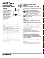 1
1
-
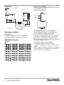 2
2
-
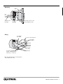 3
3
-
 4
4
-
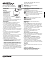 5
5
-
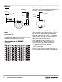 6
6
-
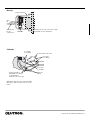 7
7
-
 8
8
-
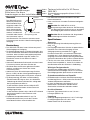 9
9
-
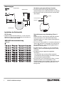 10
10
-
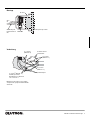 11
11
-
 12
12
-
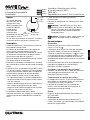 13
13
-
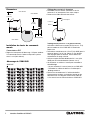 14
14
-
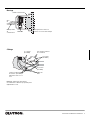 15
15
-
 16
16
-
 17
17
-
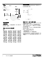 18
18
-
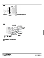 19
19
-
 20
20
-
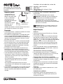 21
21
-
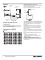 22
22
-
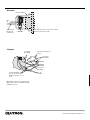 23
23
-
 24
24
-
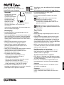 25
25
-
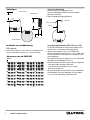 26
26
-
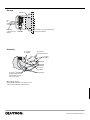 27
27
-
 28
28
-
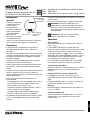 29
29
-
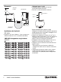 30
30
-
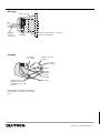 31
31
-
 32
32


Lutron Electronics Grafik 5000 Installation Instructions Manual
- Type
- Installation Instructions Manual
- Deze handleiding is ook geschikt voor
in andere talen
- English: Lutron Electronics Grafik 5000
- italiano: Lutron Electronics Grafik 5000
- français: Lutron Electronics Grafik 5000
- español: Lutron Electronics Grafik 5000
- Deutsch: Lutron Electronics Grafik 5000
- português: Lutron Electronics Grafik 5000
Gerelateerde papieren
-
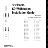 Lutron Electronics SO-2B Installatie gids
-
 Lutron Electronics QS Timeclock Quick Installation And Operation Manual
-
 Lutron Electronics QS Timeclock Handleiding
-
 Lutron Electronics LCP128 Installatie gids
-
 Lutron Electronics PALLADIOM WIN-BC-LWC Series Handleiding
-
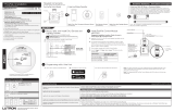 Lutron Electronics PowPak RMKS-DAL4-SZ Installation Instructions Manual
-
Lutron Electronics RRK-SEL-REP2-BL Snelstartgids


Andere documenten
-
Lutron GRX-TVI Gebruikershandleiding
-
Wallbox Commander 2S CMX2-0-2-4-8-S02 Charging Station Handleiding
-
Lutron 041837a Handleiding
-
-
Philips RFX9600/00 Handleiding
-
Logitech LOGI-HARMONY-HUB Installatie gids
-
Bosch Appliances Appliances Home Security System LTC 8540/00 Handleiding
-
-
Laserliner Lan-Check de handleiding