
Owner’s Manual
DIGITAL MULTITRACK RECORDER
00 00 00 00
YAMAHA D24
OVER
READY
0
2
6
10 12
14 20
18 30
20
42
26 60
–dB
OVER
ABS H
LOCK
TIME DISPLAY
CAPTURE ABS/REL
REMAIN
VAR I
SPEED
UTILITY
SETUP
PROJECT
SELECT
LOC MEM
RECALL
LOC MEM
STORE
LOCATEENTERCANCEL
0/-
1
4
7
8
R
7654321
RECORD
READY
SOLO/
SELECT
MONITOR SELECT
PEAK
HOLD
AUTO
INPUT
ALL
INPUT
FORMAT CHASE
L
2
5
8
3
6
9
UNDO/
REDO
EDIT
JOG ON
JOG/DATA SHUTTLE/
CURSOR
PROJECT SEARCH
RTN TO
ZERO
REW FF
STOP PLAY REC
ROLL
BACK
LAST REC
SET
DIGITAL MULTITRACK RECORDER
REPEAT
REHE
PHONES
LEVEL
010
ON
POWER
OFF
PHONES
BA
B
A
AUTO
PUNCH
IN
OUT
INT
24
48K
MASTER
WC
BIT
FS
TC
MSF
READY
0
2
6
12
20
30
42
60
–dB
V. T R A C K
SELECT
E
Keep This Manual For Future Reference.

ADVARSEL!
Lithiumbatteri—Eksplosionsfare ved fejlagtig
håndtering. Udskiftning må kun ske med batteri
af samme fabrikat og type. Levér det brugte
batteri tilbage til leverandoren.
VARNING
Explosionsfara vid felaktigt batteribyte. Använd
samma batterityp eller en ekvivalent typ som
rekommenderas av apparattillverkaren.
Kassera använt batteri enligt fabrikantens
instruktion.
VAROITUS
Paristo voi räjähtää, jos se on virheellisesti
asennettu. Vaihda paristo ainoastaan
laitevalmistajan suosittelemaan tyyppiin. Hävitä
käytetty paristo valmistajan ohjeiden
mukaisesti.
WARNING: THIS APPARATUS MUST BE EARTHED
IMPORTANT
THE WIRES IN THIS MAINS LEAD ARE COLOURED IN
ACCORDANCE WITH THE FOLLOWING CODE:
GREEN-AND-YELLOW : EARTH
BLUE : NEUTRAL
BROWN : LIVE
As the colours of the wires in the mains lead of this apparatus may
not correspond with the coloured markings identifying the terminals in
your plug, proceed as follows:
The wire which is coloured GREEN and YELLOW must be
connected to the terminal in the plug which is marked by the letter E
or by the safety earth symbol or coloured GREEN and YELLOW.
The wire which is coloured BLUE must be connected to the terminal
which is marked with the letter N or coloured BLACK.
The wire which is coloured BROWN must be connected to the
terminal which is marked with the letter L or coloured RED.
* This applies only to products distributed by YAMAHA KEMBLE
MUSIC (U.K.) LTD.
NEDERLAND THE NETHERLANDS
● Dit apparaat bevat een lithium batterij voor geheugen
back-up.
● Raadpleeg uw leverancier over de verwijdering van de
batterij op het moment dat u het apparaat ann het einde
van de levensduur afdankt of de volgende Yamaha Service
Afdeiing:
Yamaha Music Nederland Service Afdeiing
Kanaalweg 18-G, 3526 KL UTRECHT
Tel. 030-2828425
● Gooi de batterij niet weg, maar lever hem in als KCA.
● This apparatus contains a lithium battery for memory
back-up.
● For the removal of the battery at the moment of the
disposal at the end of the service life please consult your
retailer or Yamaha Service Center as follows:
Yamaha Music Nederland Service Center
Address: Kanaalweg 18-G, 3526 KL
UTRECHT
Tel: 030-2828425
● Do not throw away the battery. Instead, hand it in as small
chemical waste.
FCC INFORMATION (U.S.A.)
1. IMPORTANT NOTICE: DO NOT MODIFY THIS UNIT! This product, when installed as indicated in the instructions contained in this manual, meets FCC
requirements. Modifications not expressly approved by Yamaha may void your authority, granted by the FCC, to use the product.
2. IMPORTANT: When connecting this product to accessories and/or another product use only high quality shielded cables. Cable/s supplied with this product MUST
be used. Follow all installation instructions. Failure to follow instructions could void your FCC authorization to use this product in the USA.
3. NOTE: This product has been tested and found to comply with the requirements listed in FCC Regulations, Part 15 for Class “B” digital devices. Compliance with
these requirements provides a reasonable level of assurance that your use of this product in a residential environment will not result in harmful interference with
other electronic devices. This equipment generates/uses radio frequencies and, if not installed and used according to the instructions found in the users manual, may
cause interference harmful to the operation of other electronic devices. Compliance with FCC regulations does not guarantee that interference will not occur in all
installations. If this product is found to be the source of interference, which can be determined by turning the unit “OFF” and “ON”, please try to eliminate the
problem by using one of the following measures: Relocate either this product or the device that is being affected by the interference. Utilize power outlets that are on
different branch (circuit breaker or fuse) circuits or install AC line filter/s. In the case of radio or TV interference, relocate/reorient the antenna. If the antenna lead-in
is 300 ohm ribbon lead, change the lead-in to coaxial type cable. If these corrective measures do not produce satisfactory results, please contact the local retailer
authorized to distribute this type of product. If you can not locate the appropriate retailer, please contact Yamaha Corporation of America, Electronic Service
Division, 6600 Orangethorpe Ave, Buena Park, CA 90620
The above statements apply ONLY to those products distributed by Yamaha Corporation of America or its subsidiaries.

Laser Diode Properties
* Material : AlGaInP
* Wavelength : 675–695 nm
* Emission Duration : Continuous
* Laser Output Power : Less than 44.6 µW
Laser output is measured at a
distance of 20 cm from the object
lens on the optical pick-up head.
(Note)
• These labels are
located on the interior.
• Varningsanvisning för
laserstrålning. Placerad
i apparaten.
This unit is classified as a
Class 1 laser product.
This label is located on the
exterior.
CLASS 1 LASER PRODUCT
LUOKAN 1 LASERLAITE
KLASS 1 LASERAPPARAT
Klassmärkning för Finland.
CAUTION
USE OF CONTROLS OR ADJUSTMENTS OR
PERFORMANCE OF PROCEDURES OTHER
THAN THOSE SPECIFIED HEREIN MAY RESULT
IN HAZARDOUS RADIATION EXPOSURE.
ADVARSEL
Usynlig laserstråling ved åbning. Undgå udsaettelse
for stråling.
VAROITUS
Laitteen käyttäminen muulla kuin tässä käyttöohjeesa
mainitulla tavalla saattaa altistaa käyttäjän
turvallisuusluokan 1 ylittävälle näkymättömälle
lasersäteilylle.
VARNING
Om apparaten används på annat sätt än i denna
bruksanvisning specificerats, kan användaren utsättas
för osynlig laserstrålning, som överskrider gränsen för
laserklass 1.
DANGER
INVISIBLE LASER RADIATION WHEN OPEN.
AVOID DIRECT EXPOSURE TO BEAM.
DANGER
RADIATIONS INVISIBLES DU LASER EN CAS D' OUVERTURE.
EVITER TOUTE EXPOSITION DIRECTE AU FAISCEAU.
VORSICHT
LASERSTRAHLUNG. WENN ABDECKUNG GEÖFFNET
NICHT DEM STRAHL AUSSETZEN.
ADVARSEL
USYNLIG LASERSTRÅLING VED ÅBNING NÅR
SIKKERHEDSAFBRYDERE ER UDE AF FUNKTION.
UNDGÅ UDSAETTELSE FOR STRÅLING.
VARNING
OSYNLIG LASERSTRÅLNING NÄR
DENNA DEL ÄR ÖPPEND. STRÅLEN
ÄR FARLIG.
APL

i
D24—Owner’s Manual
Important Information
Read the Following Before Operating the D24
Warnings
• Do not subject the D24 to extreme temperatures, humidity, direct sunlight, or dust,
which could be a potential fire or electrical shock hazard.
• Connect the D24 power cord to an AC outlet of the type stated in this
Owner’s Manual
or as indicated on the D24. Failure to do so is a fire and electrical shock hazard.
• Do not plug several devices into the same AC outlet. This may overload the AC outlet,
and could be a fire or electrical shock hazard. It may also affect the performance of some
devices.
• Do not place heavy objects on the power cord. A damaged power cord is a potential fire
and electrical shock hazard.
• If the power cord is damaged (e.g., cut or a bare wire is exposed), ask your dealer for a
replacement. Using the D24 with a damaged power cord is a fire and shock hazard.
• Hold the power cord plug when disconnecting from an AC outlet. Never pull the cord.
A power cord damaged through pulling is a potential fire and electrical shock hazard.
• Do not place small metal objects on top of the D24. Metal objects falling inside the D24
is a fire and electrical shock hazard.
• Do not block the D24 ventilation slots. The D24 has ventilation slots at the side and a
cooling fan at the rear to keep the internal components cool. Blocking the ventilation
slots or obstructing the fan’s airflow is a potential fire hazard.
• Do not attempt to modify the D24. This is a potential fire and electrical shock hazard.
• The D24 operating temperature is between 5˚C and 35˚C (41˚F and 95˚F).
Cautions
• Allow enough free space around the unit for normal ventilation. This should be: 10 cm
behind and 20 cm above.
These distances should also be adopted when rack-mounting the unit. For normal ven-
tilation during use, remove the rear of the rack or open a ventilation hole.
If the airflow is not adequate, the unit will heat up inside and may cause a fire.
• Turn off audio devices when connecting them to the D24, and use only the cables spec-
ified in the relevant owner’s manuals.
• If you notice any abnormality—such as smoke, odor, or noise—turn off the D24 imme-
diately. Remove the power cord from the AC outlet. Confirm that the abnormality is no
longer present. Using the D24 in this condition is a potential fire and shock hazard.
Consult your dealer for repair.
• If a foreign object or water gets inside the D24, turn it off immediately. Remove the
power cord from the AC outlet. Using the D24 in this condition is a potential fire and
electrical shock hazard. Consult your dealer for repair.
• If you plan not to use the D24 for a long period of time, remove the power cord from
the AC outlet. Leaving the D24 connected is a potential fire hazard.
• Do not use benzene, thinner, cleaning detergent, or a chemical cloth to clean the D24.
Use only a soft, dry cloth.

ii
D24—Owner’s Manual
MO Disks
• Use only MO disks of the type specified in this manual.
• Store MO disks in a place free from extreme temperatures, humidity, dust, and dirt.
• Do not slide open the MO disk shutter, and never touch the actual disk.
• If an MO disk is stored in a cold place (e.g., overnight in a car), and then moved to a
warmer environment, condensation may form on the disk. In this case, the disk should
be left to acclimatize for about 30 minutes before use.
Interference
The D24 uses high-frequency digital circuits that may cause interference on radio and
television equipment located nearby. If interference is a problem, relocate the affected
equipment.
D24 Exclusion of Certain Responsibility
Manufacturer, importer, or dealer shall not be liable for any incidental damages includ-
ing personal injury or any other damages caused by improper use or operation of the
D24.
Package Contents
The D24 package should contain the following items. Contact your Yamaha dealer if
you are missing an item.
• D24 Digital Multitrack Recorder
• This manual
•Power cord
• MO disk
• Disk eject tool
Trademarks
ADAT MultiChannel Optical Digital Interface is a trademark and ADAT and Alesis are
registered trademarks of Alesis Corporation. Apple and Macintosh are registered trade-
marks of Apple Computer, Inc. Digidesign and OMF are registered trademarks and
Sound Designer II is a trademark of Avid Technology, Inc. Tascam Digital Interface is a
trademark and Tascam and Teac are registered trademarks of Teac Corporation.
MS-DOS is a registered trademark and Windows is a trademark of Microsoft Corpora-
tion. Yamaha is a trademark of Yamaha Corporation. All other trademarks are the prop-
erty of their respective holders and are hereby acknowledged.
Copyright
No part of the D24 software or this
Owner’s Manual
may be reproduced or distributed
in any form or by any means without the prior written authorization of Yamaha Cor-
poration.
© 1999 Yamaha Corporation. All rights reserved.

Contents
iii
D24—Owner’s Manual
Contents
1 Welcome to the D24 . . . . . . . . . . . . . . . . . . . . . . . . 1
Welcome to the D24 . . . . . . . . . . . . . . . . . . . . . . . . . . . . . . . . . . . . . . . . . 2
About this Manual . . . . . . . . . . . . . . . . . . . . . . . . . . . . . . . . . . . . . . . . . . . 3
Installing the D24 . . . . . . . . . . . . . . . . . . . . . . . . . . . . . . . . . . . . . . . . . . . . 3
D24 Features . . . . . . . . . . . . . . . . . . . . . . . . . . . . . . . . . . . . . . . . . . . . . . . . 4
Choosing MO Disks . . . . . . . . . . . . . . . . . . . . . . . . . . . . . . . . . . . . . . . . . . 6
2 Touring the D24 . . . . . . . . . . . . . . . . . . . . . . . . . . . 9
Front Panel . . . . . . . . . . . . . . . . . . . . . . . . . . . . . . . . . . . . . . . . . . . . . . . . 10
Display . . . . . . . . . . . . . . . . . . . . . . . . . . . . . . . . . . . . . . . . . . . . . . . . . . . 10
Transport Controls . . . . . . . . . . . . . . . . . . . . . . . . . . . . . . . . . . . . . . . . . 12
Power Switch & Phones . . . . . . . . . . . . . . . . . . . . . . . . . . . . . . . . . . . . . . 14
Jog/Data & Shuttle/Cursor Controls . . . . . . . . . . . . . . . . . . . . . . . . . . . 15
Function Buttons . . . . . . . . . . . . . . . . . . . . . . . . . . . . . . . . . . . . . . . . . . . 16
Peak, Monitor, Format & Chase Buttons . . . . . . . . . . . . . . . . . . . . . . . 17
Keypad . . . . . . . . . . . . . . . . . . . . . . . . . . . . . . . . . . . . . . . . . . . . . . . . . . . 18
Track Buttons . . . . . . . . . . . . . . . . . . . . . . . . . . . . . . . . . . . . . . . . . . . . . . 19
Rear Panel . . . . . . . . . . . . . . . . . . . . . . . . . . . . . . . . . . . . . . . . . . . . . . . . . 20
3 The Basics . . . . . . . . . . . . . . . . . . . . . . . . . . . . . . . 23
Connecting the Power Cord . . . . . . . . . . . . . . . . . . . . . . . . . . . . . . . . . . 24
Turning On & Off the D24 . . . . . . . . . . . . . . . . . . . . . . . . . . . . . . . . . . . 24
Write Protecting Disks . . . . . . . . . . . . . . . . . . . . . . . . . . . . . . . . . . . . . . 24
Inserting & Ejecting Disks . . . . . . . . . . . . . . . . . . . . . . . . . . . . . . . . . . . . 25
Formatting MO Disks . . . . . . . . . . . . . . . . . . . . . . . . . . . . . . . . . . . . . . . 26
Transport Operation Table . . . . . . . . . . . . . . . . . . . . . . . . . . . . . . . . . . . 27
Indicator Status Tables . . . . . . . . . . . . . . . . . . . . . . . . . . . . . . . . . . . . . . 28
4 Recording . . . . . . . . . . . . . . . . . . . . . . . . . . . . . . . . 29
About Projects . . . . . . . . . . . . . . . . . . . . . . . . . . . . . . . . . . . . . . . . . . . . . 30
Preparing to Record . . . . . . . . . . . . . . . . . . . . . . . . . . . . . . . . . . . . . . . . . 31
Setting the Recording Resolution . . . . . . . . . . . . . . . . . . . . . . . . . . . . . . 32
Recording . . . . . . . . . . . . . . . . . . . . . . . . . . . . . . . . . . . . . . . . . . . . . . . . . 33
Conserving Disk Space . . . . . . . . . . . . . . . . . . . . . . . . . . . . . . . . . . . . . . 35
Undoing a Recording or Edit . . . . . . . . . . . . . . . . . . . . . . . . . . . . . . . . . 35
Rehearsing . . . . . . . . . . . . . . . . . . . . . . . . . . . . . . . . . . . . . . . . . . . . . . . . 36
Extending the Top of a Project . . . . . . . . . . . . . . . . . . . . . . . . . . . . . . . . 37
Checking the Time Remaining . . . . . . . . . . . . . . . . . . . . . . . . . . . . . . . . 38
Metering . . . . . . . . . . . . . . . . . . . . . . . . . . . . . . . . . . . . . . . . . . . . . . . . . . 39
Using Normal & Fine Metering . . . . . . . . . . . . . . . . . . . . . . . . . . . . . . . 40
Using Peak Hold . . . . . . . . . . . . . . . . . . . . . . . . . . . . . . . . . . . . . . . . . . . 41
Monitoring . . . . . . . . . . . . . . . . . . . . . . . . . . . . . . . . . . . . . . . . . . . . . . . . 42
5 General Operation . . . . . . . . . . . . . . . . . . . . . . . . . 45
Using Playback . . . . . . . . . . . . . . . . . . . . . . . . . . . . . . . . . . . . . . . . . . . . . 46
Using Fast Forward & Rewind . . . . . . . . . . . . . . . . . . . . . . . . . . . . . . . . 46
A–B Repeat Playback . . . . . . . . . . . . . . . . . . . . . . . . . . . . . . . . . . . . . . . . 47

iv
Contents
D24—Owner’s Manual
Soloing Tracks . . . . . . . . . . . . . . . . . . . . . . . . . . . . . . . . . . . . . . . . . . . . . 48
Selecting the Solo Outputs . . . . . . . . . . . . . . . . . . . . . . . . . . . . . . . . . . . 48
Using Absolute & Relative Zero . . . . . . . . . . . . . . . . . . . . . . . . . . . . . . . 49
Using Roll-back . . . . . . . . . . . . . . . . . . . . . . . . . . . . . . . . . . . . . . . . . . . . 50
Setting the Roll-back Time . . . . . . . . . . . . . . . . . . . . . . . . . . . . . . . . . . . 50
Using Virtual Tracks . . . . . . . . . . . . . . . . . . . . . . . . . . . . . . . . . . . . . . . . 51
Shuttling . . . . . . . . . . . . . . . . . . . . . . . . . . . . . . . . . . . . . . . . . . . . . . . . . . 52
Nudging the Current Position . . . . . . . . . . . . . . . . . . . . . . . . . . . . . . . . 53
Setting the Nudge Time . . . . . . . . . . . . . . . . . . . . . . . . . . . . . . . . . . . . . . 54
Using Varispeed . . . . . . . . . . . . . . . . . . . . . . . . . . . . . . . . . . . . . . . . . . . . 55
6 Quick Locate . . . . . . . . . . . . . . . . . . . . . . . . . . . . . . 57
Searching for Projects . . . . . . . . . . . . . . . . . . . . . . . . . . . . . . . . . . . . . . . 58
Project Search Confirmation . . . . . . . . . . . . . . . . . . . . . . . . . . . . . . . . . 58
Selecting Projects Directly . . . . . . . . . . . . . . . . . . . . . . . . . . . . . . . . . . . . 59
Returning to Zero . . . . . . . . . . . . . . . . . . . . . . . . . . . . . . . . . . . . . . . . . . 60
Using the A & B Points . . . . . . . . . . . . . . . . . . . . . . . . . . . . . . . . . . . . . . 61
Locating the LAST REC IN & OUT Points . . . . . . . . . . . . . . . . . . . . . . 62
Locating Positions Directly . . . . . . . . . . . . . . . . . . . . . . . . . . . . . . . . . . . 63
Storing Locate Points . . . . . . . . . . . . . . . . . . . . . . . . . . . . . . . . . . . . . . . . 64
Storing Locate Points Automatically . . . . . . . . . . . . . . . . . . . . . . . . . . . 65
Recalling Locate Points . . . . . . . . . . . . . . . . . . . . . . . . . . . . . . . . . . . . . . 66
7 Punch In/Out Recording . . . . . . . . . . . . . . . . . . . . 67
About Punch In/Out Recording . . . . . . . . . . . . . . . . . . . . . . . . . . . . . . . 68
Manual Punch In/Out Rehearsal . . . . . . . . . . . . . . . . . . . . . . . . . . . . . . 69
Manual Punch In/Out Recording . . . . . . . . . . . . . . . . . . . . . . . . . . . . . . 70
Setting the LAST REC IN & OUT Points . . . . . . . . . . . . . . . . . . . . . . . . 71
Auto Punch In/Out Rehearsal . . . . . . . . . . . . . . . . . . . . . . . . . . . . . . . . 72
Auto Punch In/Out Recording . . . . . . . . . . . . . . . . . . . . . . . . . . . . . . . . 73
Setting the Pre-roll Time . . . . . . . . . . . . . . . . . . . . . . . . . . . . . . . . . . . . . 76
Setting the Post-roll Time . . . . . . . . . . . . . . . . . . . . . . . . . . . . . . . . . . . . 76
8 Editing Projects . . . . . . . . . . . . . . . . . . . . . . . . . . . . 77
Copying Projects . . . . . . . . . . . . . . . . . . . . . . . . . . . . . . . . . . . . . . . . . . . 78
Erasing Projects . . . . . . . . . . . . . . . . . . . . . . . . . . . . . . . . . . . . . . . . . . . . 79
Deleting Projects . . . . . . . . . . . . . . . . . . . . . . . . . . . . . . . . . . . . . . . . . . . 80
Titling Projects . . . . . . . . . . . . . . . . . . . . . . . . . . . . . . . . . . . . . . . . . . . . . 81
Protecting Projects . . . . . . . . . . . . . . . . . . . . . . . . . . . . . . . . . . . . . . . . . . 82
Modifying a Project’s Start Time . . . . . . . . . . . . . . . . . . . . . . . . . . . . . . 83
9 Editing Tracks . . . . . . . . . . . . . . . . . . . . . . . . . . . . . 85
Copying Tracks . . . . . . . . . . . . . . . . . . . . . . . . . . . . . . . . . . . . . . . . . . . . 86
Moving Tracks . . . . . . . . . . . . . . . . . . . . . . . . . . . . . . . . . . . . . . . . . . . . . 88
Erasing Tracks . . . . . . . . . . . . . . . . . . . . . . . . . . . . . . . . . . . . . . . . . . . . . 90
Swapping Tracks . . . . . . . . . . . . . . . . . . . . . . . . . . . . . . . . . . . . . . . . . . . 91
Slipping Tracks . . . . . . . . . . . . . . . . . . . . . . . . . . . . . . . . . . . . . . . . . . . . . 93
10 Editing Parts . . . . . . . . . . . . . . . . . . . . . . . . . . . . . . 95
Copying Parts . . . . . . . . . . . . . . . . . . . . . . . . . . . . . . . . . . . . . . . . . . . . . . 96
Moving Parts . . . . . . . . . . . . . . . . . . . . . . . . . . . . . . . . . . . . . . . . . . . . . . 99

Contents
v
D24—Owner’s Manual
Deleting Parts . . . . . . . . . . . . . . . . . . . . . . . . . . . . . . . . . . . . . . . . . . . . . . 102
Erasing Parts . . . . . . . . . . . . . . . . . . . . . . . . . . . . . . . . . . . . . . . . . . . . . . . 104
Inserting Parts . . . . . . . . . . . . . . . . . . . . . . . . . . . . . . . . . . . . . . . . . . . . . 106
Insert Copying Parts . . . . . . . . . . . . . . . . . . . . . . . . . . . . . . . . . . . . . . . . 108
Time Compression . . . . . . . . . . . . . . . . . . . . . . . . . . . . . . . . . . . . . . . . . 111
Pitch Change . . . . . . . . . . . . . . . . . . . . . . . . . . . . . . . . . . . . . . . . . . . . . . 116
11 Wordclocks . . . . . . . . . . . . . . . . . . . . . . . . . . . . . . 121
Wordclocks & the D24 . . . . . . . . . . . . . . . . . . . . . . . . . . . . . . . . . . . . . . 122
Wordclock Connections . . . . . . . . . . . . . . . . . . . . . . . . . . . . . . . . . . . . . 123
Dual AES/EBU Mode . . . . . . . . . . . . . . . . . . . . . . . . . . . . . . . . . . . . . . . 123
Selecting a Wordclock Source . . . . . . . . . . . . . . . . . . . . . . . . . . . . . . . . . 124
Wordclock System Examples . . . . . . . . . . . . . . . . . . . . . . . . . . . . . . . . . 126
Terminating BNC Wordclock Distribution . . . . . . . . . . . . . . . . . . . . . 131
12 Timecode . . . . . . . . . . . . . . . . . . . . . . . . . . . . . . . . 133
Timecode & the D24 . . . . . . . . . . . . . . . . . . . . . . . . . . . . . . . . . . . . . . . . 134
Timecode Connections . . . . . . . . . . . . . . . . . . . . . . . . . . . . . . . . . . . . . . 134
Selecting a Timecode Source . . . . . . . . . . . . . . . . . . . . . . . . . . . . . . . . . . 135
Setting the Timecode Frame Rate . . . . . . . . . . . . . . . . . . . . . . . . . . . . . . 136
Setting a Timecode Offset . . . . . . . . . . . . . . . . . . . . . . . . . . . . . . . . . . . . 137
Chasing External Timecode . . . . . . . . . . . . . . . . . . . . . . . . . . . . . . . . . . 138
Setting the Chase Speed . . . . . . . . . . . . . . . . . . . . . . . . . . . . . . . . . . . . . . 139
Transmitting MTC . . . . . . . . . . . . . . . . . . . . . . . . . . . . . . . . . . . . . . . . . . 139
Timecode Hookup Examples . . . . . . . . . . . . . . . . . . . . . . . . . . . . . . . . . 140
13 Multiple D24s & Video Sync . . . . . . . . . . . . . . . . . 143
Multiple D24s . . . . . . . . . . . . . . . . . . . . . . . . . . . . . . . . . . . . . . . . . . . . . . 144
Expanding the Number of Tracks . . . . . . . . . . . . . . . . . . . . . . . . . . . . . 145
Extending the Recording Time . . . . . . . . . . . . . . . . . . . . . . . . . . . . . . . . 147
Setting the Serial Point . . . . . . . . . . . . . . . . . . . . . . . . . . . . . . . . . . . . . . 149
Using Video Sync . . . . . . . . . . . . . . . . . . . . . . . . . . . . . . . . . . . . . . . . . . . 149
Terminating BNC Video Sync Distribution . . . . . . . . . . . . . . . . . . . . . 150
Connecting a Video Editor . . . . . . . . . . . . . . . . . . . . . . . . . . . . . . . . . . . 151
Video Hookup Example . . . . . . . . . . . . . . . . . . . . . . . . . . . . . . . . . . . . . 151
14 SCSI & External Disk Drives . . . . . . . . . . . . . . . . . . 153
SCSI & the D24 . . . . . . . . . . . . . . . . . . . . . . . . . . . . . . . . . . . . . . . . . . . . 154
Using External Disk Drives . . . . . . . . . . . . . . . . . . . . . . . . . . . . . . . . . . . 154
Certified Disk Drives . . . . . . . . . . . . . . . . . . . . . . . . . . . . . . . . . . . . . . . . 155
Available Recording Time . . . . . . . . . . . . . . . . . . . . . . . . . . . . . . . . . . . . 155
Connecting Disk Drives . . . . . . . . . . . . . . . . . . . . . . . . . . . . . . . . . . . . . 156
Assigning SCSI IDs . . . . . . . . . . . . . . . . . . . . . . . . . . . . . . . . . . . . . . . . . 156
Terminating the SCSI Bus . . . . . . . . . . . . . . . . . . . . . . . . . . . . . . . . . . . . 157
Formatting External Disk Drives . . . . . . . . . . . . . . . . . . . . . . . . . . . . . . 158
Selecting the Work Disk . . . . . . . . . . . . . . . . . . . . . . . . . . . . . . . . . . . . . 161
Duplicating MO Disks . . . . . . . . . . . . . . . . . . . . . . . . . . . . . . . . . . . . . . . 162
Copying Projects Between Disk Drives . . . . . . . . . . . . . . . . . . . . . . . . . 164
Mounting D24 Disks on a Personal Computer . . . . . . . . . . . . . . . . . . . 165
Connecting the D24 to a Personal Computer . . . . . . . . . . . . . . . . . . . . 166

vi
Contents
D24—Owner’s Manual
15 Other Functions . . . . . . . . . . . . . . . . . . . . . . . . . . 169
Setting the Peak Hold Mode . . . . . . . . . . . . . . . . . . . . . . . . . . . . . . . . . . 170
Setting the Fade In/Out Time . . . . . . . . . . . . . . . . . . . . . . . . . . . . . . . . . 170
Setting the Display Brightness . . . . . . . . . . . . . . . . . . . . . . . . . . . . . . . . 171
Setting the Remote ID . . . . . . . . . . . . . . . . . . . . . . . . . . . . . . . . . . . . . . . 171
Recovering Disk Space . . . . . . . . . . . . . . . . . . . . . . . . . . . . . . . . . . . . . . . 172
Physical Formatting for MO Disks . . . . . . . . . . . . . . . . . . . . . . . . . . . . . 173
Ejecting Troublesome Disks (emergency use) . . . . . . . . . . . . . . . . . . . 174
Initializing the D24 . . . . . . . . . . . . . . . . . . . . . . . . . . . . . . . . . . . . . . . . . 175
Checking the Version Number . . . . . . . . . . . . . . . . . . . . . . . . . . . . . . . . 175
Updating the System Software . . . . . . . . . . . . . . . . . . . . . . . . . . . . . . . . 175
16 MIDI . . . . . . . . . . . . . . . . . . . . . . . . . . . . . . . . . . . 177
MIDI & the D24 . . . . . . . . . . . . . . . . . . . . . . . . . . . . . . . . . . . . . . . . . . . . 178
MIDI Ports . . . . . . . . . . . . . . . . . . . . . . . . . . . . . . . . . . . . . . . . . . . . . . . . 178
Using MMC (MIDI Machine Control) . . . . . . . . . . . . . . . . . . . . . . . . . 178
17 Digital Audio I/O . . . . . . . . . . . . . . . . . . . . . . . . . 181
About mini YGDAI Cards . . . . . . . . . . . . . . . . . . . . . . . . . . . . . . . . . . . . 182
Card Specifications . . . . . . . . . . . . . . . . . . . . . . . . . . . . . . . . . . . . . . . . . 183
Choosing Digital I/O Cards . . . . . . . . . . . . . . . . . . . . . . . . . . . . . . . . . . 183
Choosing D24 Slots . . . . . . . . . . . . . . . . . . . . . . . . . . . . . . . . . . . . . . . . . 184
Selecting Slot Inputs . . . . . . . . . . . . . . . . . . . . . . . . . . . . . . . . . . . . . . . . 184
Installing Cards . . . . . . . . . . . . . . . . . . . . . . . . . . . . . . . . . . . . . . . . . . . . 185
Using Dual AES/EBU Mode . . . . . . . . . . . . . . . . . . . . . . . . . . . . . . . . . . 186
Using the Coaxial Digital Input & Output . . . . . . . . . . . . . . . . . . . . . . 187
Assigning the Coaxial Input & Output . . . . . . . . . . . . . . . . . . . . . . . . . 188
Emphasis & the D24 . . . . . . . . . . . . . . . . . . . . . . . . . . . . . . . . . . . . . . . . 188
SCMS & the D24 . . . . . . . . . . . . . . . . . . . . . . . . . . . . . . . . . . . . . . . . . . . 188
Digital I/O & Wordlength . . . . . . . . . . . . . . . . . . . . . . . . . . . . . . . . . . . . 189
Troubleshooting . . . . . . . . . . . . . . . . . . . . . . . . . . . . . 191
Appendix . . . . . . . . . . . . . . . . . . . . . . . . . . . . . . . . . . 193
Setting the SCSI ID of the Internal MO Drive . . . . . . . . . . . . . . . . . . . 193
Error Messages . . . . . . . . . . . . . . . . . . . . . . . . . . . . . . . . . . . . . . . . . . . . . 194
Specifications . . . . . . . . . . . . . . . . . . . . . . . . . . . . . . . . . . . . . . . . . . . . . . 196
Connector Pin Assignments . . . . . . . . . . . . . . . . . . . . . . . . . . . . . . . . . . 199
D24 Dimensions . . . . . . . . . . . . . . . . . . . . . . . . . . . . . . . . . . . . . . . . . . . . 200
Glossary . . . . . . . . . . . . . . . . . . . . . . . . . . . . . . . . . . . 201
Index . . . . . . . . . . . . . . . . . . . . . . . . . . . . . . . . . . . . . . 205
MIDI Implementation Chart . . . . . . . . . . . . . . . . . . . . 211

Welcome to the D24
1
D24—Owner’s Manual
Welcome to the D24
1
In this chapter...
Welcome to the D24 . . . . . . . . . . . . . . . . . . . . . . . . . . . . . . . . . . . . . . . . . . . . . . . . 2
About this Manual . . . . . . . . . . . . . . . . . . . . . . . . . . . . . . . . . . . . . . . . . . . . . . . . . 3
Installing the D24 . . . . . . . . . . . . . . . . . . . . . . . . . . . . . . . . . . . . . . . . . . . . . . . . . . 3
D24 Features . . . . . . . . . . . . . . . . . . . . . . . . . . . . . . . . . . . . . . . . . . . . . . . . . . . . . . 4
Choosing MO Disks . . . . . . . . . . . . . . . . . . . . . . . . . . . . . . . . . . . . . . . . . . . . . . . . 6

2
Chapter 1—Welcome to the D24
D24—Owner’s Manual
Welcome to the D24
Thank you for choosing the Yamaha D24 Digital Multitrack Recorder.
The D24 uses standard 3.5-inch removable MO (Magneto Optical) disks for digital
audio recording and playback. By employing a removable media, backup downtime in
between sessions is eliminated. When one session is complete, simply insert a new disk
and begin recording right away. Random access capability provides instant access to up
to 99 projects per disk, 99 locate memories per project, all without unproductive
rewinding and fast forwarding. Audio data is not compressed, and superb sonic perfor-
mance is achieved using 16-, 20-, or 24-bit recording resolutions and 44.1 kHz, 48 kHz,
88.2 kHz, or 96 kHz sampling rates, all of which can be set on a project-by-project basis.
Overwrite-type 640 MB MO disks offer 8-track simultaneous recording, with a 24-bit
recording resolution and 44.1 kHz or 48 kHz sampling rates, and 4-track simultaneous
recording at the higher sampling rates of 88.2 kHz or 96 kHz. A single 640 MB MO disk
provides a total recording time of 120 track minutes, or 30 minutes for 4 tracks, 15 min-
utes for 8 tracks. In addition to the eight main tracks, each track features up to eight vir-
tual tracks, for a grand total of 64 tracks. Auto punch in/out recording, with multiple
take capability, allows you to choose the best from up to 99 takes. Both manual and auto
punch in/out recording can be rehearsed with automatic playback and input monitor
switching.
Video machine-like shuttle playback makes it easy to locate material, and the current
position can be nudged in sub-frame steps while listening to a small section of the sur-
rounding material. Tracks can be soloed for individual track monitoring. Other fea-
tures include ±6% varispeed, A-B repeat playback, and fast forward or rewind at 8x or
16x normal playback speed.
In addition to the 99 locate memories, the A, B, Last Rec In, and Last Rec Out points
offer additional ways locate specific positions quickly, repeatedly, and accurately. Other
quick locate functions include Project Search, Return to Zero, and Roll Back. Location
points can be specified with sub-frame accuracy.
Additional recording space can be made available, and projects backed up by connect-
ing optional, external hard disk drives or removable media disk drives to the D24’s SCSI
port. The number of tracks available for simultaneous recording and playback can be
expanded in multiples of eight by combining up to eight D24s. The total continuous
recording time can be extended by using two D24s in Serial mode. The D24’s 3U rack
size makes it a drop-in alternative to modular digital multitrack recorders.
Optional mini YGDAI (Yamaha General Digital Audio Interface) cards offer a variety
of analog and digital I/O configurations, with support for all the popular digital audio
interconnect formats: AES/EBU, ADAT, and Tascam TDIF-1. S/PDIF Coaxial I/O
allows digital stereo transfer between 2-channel digital audio equipment, CD players,
DAT decks, and mastering equipment. A front panel phones jack provides convenient
monitoring.
Once recorded, projects, tracks, and parts can be edited using non-destructive editing
functions, such as 50% to 200% time compression and expansion, ideal for
audio-fit-video applications, and pitch change without speed change. Project editing
functions include Copy, Delete, Erase, Title, Protect, and Timecode Modify. Track edit-
ing functions include Copy, Move, Erase, Swap, and Slip. Part editing functions include
Copy, Move, Erase, Insert Space, Insert Copy, and Delete, with single-step undo and
redo. Edit points can be specified with sub-frame accuracy.

About this Manual
3
D24—Owner’s Manual
Tape recorder-like transport controls, and the Large vacuum fluorescent display, with
large, easy to read counter, make operation a breeze. Visual level monitoring is provided
by eight 16-segment track level meters. Selectable normal and fine scales make it easy
to set precise levels when recording reference tones. Also, projects can be titled for easy
identification.
The D24 can generate, or synchronize to either SMPTE/EBU or MTC (MIDI Time-
code) timecode. Timecode synchronization is to 1/10-frame accuracy, and an offset can
be set relative to an external timecode source.
Remote control is possible using MMC (MIDI Machine Control), or video editing
equipment that supports 9-pin protocols.
Other features include Absolute (ABS) and Relative (REL) counter modes, disk dupli-
cation with two D24s, and the ability to mount D24 MO disks on personal computers.
See “D24 Features” on page 4 for a concise rundown of D24 features.
About this Manual
This
Owner’s Manual
contains all the information you need in order to operate your
D24 Digital Multitrack Recorder. Use the table of contents to familiarize yourself with
the organization of this manual and locate topics, and use the index to locate specific
information. A glossary of D24-related jargon is provided on page 201.
The following format is used throughout this
Owner’s Manual
for display messages:
“FORMAT DISK—ARE YOU SURE”. The message before the dash appears on the 1st
line of the display, and the message after the dash appears on the 2nd line.
Installing the D24
The D24 can be used freestanding on a stable surface, somewhere that complies with
the important information at the beginning of this manual, or mounted in a rack.
When mounting the D24 in a rack, remove the D24’s feet and leave adequate ventilation
space around the D24 (at least 10 cm of free space behind). If the D24 is mounted in a
portable rack case, keep the rear of the case open when using the D24, so as not to
obstruct the flow of air from the cooling fan. Do not mount the D24 next to equipment
that produces a lot of heat, such as a power amplifier.

4
Chapter 1—Welcome to the D24
D24—Owner’s Manual
D24 Features
Recording Media
• Standard 3.5-inch MO (Magneto Optical) disks.
• Convenient removable media for quick access to recorded material and sound libraries.
• No backup downtime, loading, or winding.
• Up to 99 projects per disk.
Sonic Performance
• 16/20/24-bit linear recording for superb sonic quality.
• 44.1/48/88.2/96 kHz sampling rates.
• Sampling rate and recording resolution can be set on a project-by-project basis.
Recording
• 8-track simultaneous recording on 640 MB Overwrite-type MO disks, with a 24-bit
recording resolution and 44.1 kHz or 48 kHz sampling rate.
• 4-track simultaneous recording on 640 MB Overwrite-type MO disks, with a 24-bit
recording resolution and 88.2 kHz or 96 kHz sampling rate.
• 120 track minutes (15 minutes for 8 tracks) using 640 MB MO disks (16-bit, 44.1 kHz).
• 8 virtual tracks per main track, for a total of 64 tracks.
• Auto punch in/out recording with multiple take capability—record and choose the best
from up to 99 takes.
• Manual and auto punch in/out recording, with rehearsal.
Playback
• Video machine-like shuttle playback.
• Position nudge, with audio listen.
• Solo function for individual track monitoring.
• ±6% varispeed.
• A-B repeat playback.
Quick Locate
• Up to 99 locate points per project, plus A, B, Last Rec In, and Last Rec Out points.
• Project Search, Return to Zero, and Roll Back functions.
• Location points can be specified with sub-frame accuracy.
• Fast forward or rewind at 8x or 16x normal playback speed.
System Expansion
• SCSI port for connecting external disk drives (hard disks, removable media drives, etc).
• Tracks can be expanded by combining up to eight D24s, for a total of 64-tracks.
• Continuous recording time can be extended by using two D24s in Serial mode.
• 3U rack size for drop-in alternative to tape-based modular digital multitrack recorders.

D24 Features
5
D24—Owner’s Manual
Flexible I/O
• Optional mini YGDAI (Yamaha General Digital Audio Interface) cards offer a variety
of analog and digital I/O configurations, with support for all the popular digital audio
interconnect formats: AES/EBU, ADAT, and Tascam TDIF-1.
• S/PDIF Coaxial I/O.
• Phones.
Editing
• Project editing functions include Copy, Delete, Erase, Title, Protect, and Timecode
Modify.
• Track editing functions include Copy, Move, Erase, Swap, and Slip.
• Part editing functions include Copy, Move, Erase, Insert Space, Insert Copy, and Delete.
• Edit Undo/Redo function.
• Edit points can be specified with sub-frame accuracy.
• 50% to 200% time compression and expansion, for audio-fit-video applications.
• Pitch Change function provides pitch change without speed change.
Easy Operation
• Tape recorder-like transport controls.
• Large vacuum fluorescent display, with large, easy to read counter.
• 16-segment track level meters, with selectable normal and fine scales.
• Projects can be titled for easy identification.
Synchronization
• SMPTE/EBU or MTC (MIDI Timecode) synchronization, with timecode offset.
• Timecode synchronization to 1/10-frame accuracy.
• Wordclock I/O for master/slave operation.
Remote Control
• MMC (MIDI Machine Control).
• 9-pin video editor protocols with video sync.
• Optional RC-D24 Remote Controller.
Others
• Absolute (ABS) and Relative (REL) counter modes.
• Project backup.
• Disk duplication with two D24s.
• Mount D24 MO disks on personal computers.

6
Chapter 1—Welcome to the D24
D24—Owner’s Manual
Choosing MO Disks
The D24’s internal MO disk drive uses removable 3.5-inch MO (Magneto Optical)
disks for recording and playback. Normal or Overwrite-type MO disks in a variety of
sizes can be used, but only 640 MB Overwrite-type disks support 8-track simultaneous
recording with a 24-bit recording resolution. The number of tracks available for simul-
taneous recording depends on the type of MO disk used, its capacity, the selected
recording resolution, and sampling rate. See the following section for more informa-
tion.
Both normal and Overwrite-type MO disks support 8-track simultaneous playback at
sampling rates of 44.1 kHz and 48 kHz, and 4-track simultaneous playback at 88.2 kHz
and 96 kHz.
Overwrite-type disks feature the Overwrite logo shown here.
Tracks Available for Simultaneous Recording
The following table lists the number of tracks available for simultaneous recording with
a variety of normal and Overwrite-type MO disks at each recording resolution and
sampling rate.
For performance reasons, it’s recommended that you do not use 128 MB MO disks.
When tracks that have already been recorded are playing back, depending on the num-
ber and performance of those tracks (i.e., how heavily they’ve been edited), the number
of tracks available for simultaneous recording is reduced. Use the Optimize function to
arrange the recorded sound files for optimum performance. See “Recovering Disk
Space” on page 172 for more information.
Recording Time
The total recording time depends on the disk capacity, recording resolution, and sam-
pling rate. A 640 MB Overwrite-type MO disk, for example, offers a total recording
time of 120 track minutes with a 16-bit recording resolution and 44.1 kHz sampling
rate.
The following table lists the approximate recording times offered by a variety of MO
disk capacities, with a 16-bit recording resolution and 44.1 kHz sampling rate.
Disk Type
44.1, 48 kHz 88.2, 96 kHz
16-bit 20-bit 24-bit 16-bit 20-bit 24-bit
Overwrite
640 MB
888444
230 MB
866433
Normal
640 MB
866433
230 MB
532211
Disk Capacity
Recording Time (16-bit, 44.1 kHz)
Track minutes
(mono)
2 tracks 4 tracks 8 tracks
640 MB
120 min 60 min 30 min 15 min
230 MB
43 min 21 min 10 min 5 min

Choosing MO Disks
7
D24—Owner’s Manual
The following table lists the approximate recording times available using 640 MB MO
disks at a variety of recording resolutions and sampling rates.
Higher recording resolutions and sampling rates offer higher quality, but produce more
data, which reduces the total available recording time. Use the Remain function to
check the available recording time. See “Checking the Time Remaining” on page 38 for
more information.
The number of tracks available for simultaneous recording can be expanded using mul-
tiple D24s. See “Multiple D24s” on page 144 for more information.
The D24’s internal MO disk drive supports 230 MB, 540 MB, and 640 MB MO disks.
See the Yamaha Professional Audio Web site at the address below for up-to-date news
on MO disks.
<http://www.yamaha.co.jp/product/proaudio/homeenglish/>
Preformatted MO Disks
MO disks preformatted for use with PC or Macintosh computers can be used with the
D24, but require formatting before use. See “Formatting MO Disks” on page 26 for
more information.
Calculating the approximate Recording Time
You can calculate the approximate recording time for a given recording resolution,
sampling rate, and disk capacity as follows. First multiple the recording resolution by
the sampling rate to get the number of bits produced per second (e.g., 16
×
44100 =
705,600 bits per second). Then divide that by eight to get the number of bytes per sec-
ond (e.g., 705,600
÷
8 = 88,200 bytes per second). Multiply that by 60 to get the number
of bytes required per minute (e.g., 88,200
×
60 = 5,292,000 bytes per minute, or 5.292
MB/min). Now you know the number of megabytes required to store one minute of
audio data, simply divide the capacity of the disk by that number to get the approximate
number of track minutes (e.g., 640,000,000
÷ 5,292,000 = 120 minutes). Finally, divide
the number of track minutes by two, four, or eight to get the approximate recording
time available for several tracks (e.g., 120 ÷ 8 = 15 minutes for 8-track simultaneous
recording).
Bit
Sampling
Rate
Track minutes
(mono)
2 tracks 4 tracks 8 tracks
16
44.1 kHz
120 min 60 min 30 min 15 min
48 kHz
111 min 55 min 27 min 13 min
88.2 kHz
60 min 30 min 15 min —
96 kHz
55 min 27 min 13 min —
20
44.1 kHz
96 min 48 min 24 min 12 min
48 kHz
88 min 44 min 22 min 11 min
88.2 kHz
48 min 24 min 12 min —
96 kHz
44 min 22 min 11 min —
24
44.1 kHz
80 min 40 min 20 min 10 min
48 kHz
74 min 37 min 18 min 9 min
88.2 kHz
40 min 20 min 10 min —
96 kHz
37 min 18 min 9 min —

Touring the D24 9
D24—Owner’s Manual
Touring the D24
2
In this chapter...
Front Panel . . . . . . . . . . . . . . . . . . . . . . . . . . . . . . . . . . . . . . . . . . . . . . . . . . . . . . 10
Display . . . . . . . . . . . . . . . . . . . . . . . . . . . . . . . . . . . . . . . . . . . . . . . . . . . . . . . . . . 10
Transport Controls . . . . . . . . . . . . . . . . . . . . . . . . . . . . . . . . . . . . . . . . . . . . . . . . 12
Power Switch & Phones . . . . . . . . . . . . . . . . . . . . . . . . . . . . . . . . . . . . . . . . . . . . 14
Jog/Data & Shuttle/Cursor Controls . . . . . . . . . . . . . . . . . . . . . . . . . . . . . . . . . 15
Function Buttons . . . . . . . . . . . . . . . . . . . . . . . . . . . . . . . . . . . . . . . . . . . . . . . . . 16
Peak, Monitor, Format & Chase Buttons . . . . . . . . . . . . . . . . . . . . . . . . . . . . . . 17
Keypad . . . . . . . . . . . . . . . . . . . . . . . . . . . . . . . . . . . . . . . . . . . . . . . . . . . . . . . . . . 18
Track Buttons . . . . . . . . . . . . . . . . . . . . . . . . . . . . . . . . . . . . . . . . . . . . . . . . . . . . 19
Rear Panel . . . . . . . . . . . . . . . . . . . . . . . . . . . . . . . . . . . . . . . . . . . . . . . . . . . . . . . 20

10 Chapter 2—Touring the D24
D24—Owner’s Manual
Front Panel
The D24 front panel is explained in the following sections.
Display
A Level meters
These 16-segment track meters, with Peak Hold function, show playback and input sig-
nal levels from –60 dB to 0 dB. In Fine mode, they display levels from –26 dB to 0 dB.
The OVER indicator lights up when several consecutive audio samples exceed the dig-
ital saturation point. See “Metering” on page 39 for more information.
When the Shuttle, Nudge, Time Compression, or Pitch Change function is used, track
meters 7 and 8 function as stereo meters, and meters 1 through 6 are turned off.
B ABS/REL indicators
These indicators show whether the counter is displaying absolute (ABS) time or relative
(REL) time. See “Using Absolute & Relative Zero” on page 49 for more information.
00 00 00 00
YAMAHA D24
OVER
READY
0
2
6
10 12
14 20
18 30
20
42
26 60
–dB
OVER
ABS H
LOCK
TIME DISPLAY
CAPTURE ABS/REL
REMAIN
VARI
SPEED
UTILITY
SETUP
PROJECT
SELECT
LOC MEM
RECALL
LOC MEM
STORE
LOCATEENTERCANCEL
0/-
1
4
7
8
R
7654321
RECORD
READY
SOLO/
SELECT
MONITOR SELECT
PEAK
HOLD
AUTO
INPUT
ALL
INPUT
FORMAT CHASE
L
2
5
8
3
6
9
UNDO/
REDO
EDIT
JOG ON
JOG/DATA SHUTTLE/
CURSOR
PROJECT SEARCH
RTN TO
ZERO
REW FF
STOP PLAY REC
ROLL
BACK
LAST REC
SET
DIGITAL MULTITRACK RECORDER
REPEAT
REHE
PHONES
LEVEL
010
ON
POWER
OFF
PHONES
BA
B
A
AUTO
PUNCH
IN
OUT
INT
24
48K
MASTER
WC
BIT
FS
TC
MSF
READY
0
2
6
12
20
30
42
60
–dB
V. T R A C K
SELECT
1 2 3
4 9865 J7 K
00 00 00 00
OVER
READY 12345678
0
2
6
10 12
14 20
18 30
20
42
26 60
–dB
OVER
ABS
REL
H
LOCK
R
L
INT EXT
16 20 24
44.1K48K96KVARI
MASTER SLAVE
WC
BIT
FS
TC
CHASE
MSF
READY
0
2
6
12
20
30
42
60
–dB
000000000000
000000000000

Display 11
D24—Owner’s Manual
C Counter
The main counter shows the current position in
hours, minutes, seconds, and frames,
(00:00:00.00), and can display the absolute
(ABS) time or relative (REL) time. See “Using
Absolute & Relative Zero” on page 49 for more
information.
The 2nd line of the message area displays time
information in hours, minutes, seconds, frames,
and sub-frames (00:00:00.00.0). Each sub-frame
is one tenth of a frame, making 10 sub-frames
per frame.
The 2nd line is also used to display the remaining recording time. See “Checking the
Time Remaining” on page 38 for more information.
D READY indicators
These indicators show which tracks are selected for recording. When a track is selected
for recording, the corresponding READY indicator flashes. During recording or
rehearsal, the corresponding indicator lights up continuously. See “Recording” on page
33 for more information.
E Message area
The message area consists of two lines that can each display up to 12 characters, which
typically show the status and operating mode of the D24, function and parameter
names and values, project titles and numbers, locate memory numbers, editing infor-
mation, time values, and so on.
F LOCK indicator
This indicator shows whether or not the D24 is locked to the selected wordclock source.
See “Selecting a Wordclock Source” on page 124 for more information.
G CHASE indicator
This indicator shows whether or not the D24 is synchronized to the external timecode
source. It flashes when the D24 is chasing, and lights up continuously when it’s fully
synchronized. See “Chasing External Timecode” on page 138 for more information.
H WC window
This window shows the selected wordclock source: internal (INT) or external (EXT).
See “Selecting a Wordclock Source” on page 124 for more information.
I BIT window
This window shows the selected recording resolution: 16, 20, or 24. See “Setting the
Recording Resolution” on page 32 for more information.
J FS window
This window shows the selected sampling rate: 44.1 kHz, 48 kHz, 88.2 kHz, or 96 kHz.
When 88.2 kHz is selected, both the 44.1 kHz and 96 kHz indicators light up. See
“Selecting a Wordclock Source” on page 124 for more information.
The “VARI” indicator lights up when the Varispeed function is turned on. See “Using
Varispeed” on page 55 for more information.
K TC window
This window shows the selected timecode source: master or slave. When set to master,
the D24 uses internal timecode, and when set to slave, an external timecode source. See
“Selecting a Timecode Source” on page 135 for more information.
HMSF
STOP
000000000
00 00 00 00
Hour Min Sec fr sub-fr
Hour Min Sec fr

12 Chapter 2—Touring the D24
D24—Owner’s Manual
Transport Controls
The “Transport Operation Table” on page 27 and the “Indicator Status Tables” on
page 28 list how the transport buttons and indicators function in each transport mode.
A A & B buttons & indicators
These buttons are used to set and locate the A and B points. The A and B indicators light
up when the respective A or B point is set. See “Using the A & B Points” on page 61 for
more information.
B ROLL BACK button
This button is used to roll back from the current position in steps of between 1 and 30
seconds, the default being 5 seconds. See “Using Roll-back” on page 50 for more infor-
mation.
C RTN TO ZERO button
This button is used to locate the zero position. See “Returning to Zero” on page 60 for
more information.
D LAST REC IN & OUT buttons & indicators
These buttons are used to set and locate the LAST REC IN and LAST REC OUT points.
The IN and OUT indicators light up when the respective IN or OUT point is set. See
“Setting the LAST REC IN & OUT Points” on page 71 and “Locating the LAST REC IN
& OUT Points” on page 62 for more information.
E PROJECT SEARCH buttons
These buttons are used to search for projects. Pressing the [ ] button selects the top
of the current project. Pressing the [ ] button selects the top of the next project. See
“Searching for Projects” on page 58 for more information.
PROJECT SEARCH
RTN TO
ZERO
REW FF
STOP PLAY REC
ROLL
BACK
LAST REC
REHE
B
A
AUTO
PUNCH
IN
OUT
6 7
3
1
K
L
9
J
8
M N O P Q
4
2
5
REPEAT
BA
SET

Transport Controls 13
D24—Owner’s Manual
F MO disk drive slot
MO disks are loaded into the internal MO drive through this slot. See “Inserting &
Ejecting Disks” on page 25 for more information.
G Manual eject hole
This hole is used when disks cannot be ejected in the normal way. See “Ejecting Trou-
blesome Disks (emergency use)” on page 174 for more information.
H Eject button & activity indicator
This button is used to eject MO disks, but also functions as a drive activity indicator,
lighting up when the disk drive is busy. See “Inserting & Ejecting Disks” on page 25 for
more information.
I AUTO PUNCH button & indicator
This button selects the Auto-Punch In/Out function. The AUTO PUNCH indicator
flashes when this function is on. See “Auto Punch In/Out Recording” on page 68 for
more information.
J SET button
This button is used in conjunction with the LAST REC [IN], LAST REC [OUT], [A],
and [B] buttons to set the LAST REC IN, LAST REC OUT, A, and B points, respectively.
See “Setting the LAST REC IN & OUT Points” on page 71 and “Setting the A & B
Points” on page 61 for more information. It’s also used in conjunction with the [RTN
TO ZERO] button to set the relative zero position. See “Using Absolute & Relative Zero”
on page 49 for more information.
The [SET] button is also used in conjunction with the [ENTER] button for the Auto
Memory Store function, and in conjunction with the [LOCATE] button to set the Key-
pad Timecode Input mode. See “Storing Locate Points Automatically” on page 65 and
“Locating Positions Directly” on page 63 respectively for more information.
K REHE button & indicator
This button is used to engage Rehearsal Standby mode and, when pressed together with
the [PLAY] button, punch in rehearsal. In Rehearsal mode, recording can be practiced,
with automatic playback and input monitor switching at the punch in and out points,
without actually recording anything to disk. The REHE button indicator flashes in
Rehearsal Standby mode, and lights up continuously during rehearsal. See “Rehears-
ing” on page 36, “Manual Punch In/Out Rehearsal” on page 69, and “Auto Punch
In/Out Rehearsal” on page 72 for more information.
L REPEAT button & indicator
This button selects the A–B Repeat playback function. The REPEAT indicator lights up
when this function is on. See “A–B Repeat Playback” on page 47 for more information.
M REW button
This button is used to start rewind. Press it once for rewind at 8x normal play speed, the
REW button indicator flashes. Press it again for rewind at 16x normal play speed, the
REW button indicator lights up continuously. Pressing and holding the REW button
during playback rewinds at 8x normal play speed.
N FF button
This button is used to start fast forward. Press it once for fast forward at 8x normal play
speed, the FF button indicator flashes. Press it again for fast forward at 16x normal play
speed, the FF button indicator lights up continuously. Pressing and holding the FF but-
ton during playback fast forwards at 8x normal play speed.

14 Chapter 2—Touring the D24
D24—Owner’s Manual
O STOP button
This button is used to stop playback, recording, rehearsal, rewind, and fast forward, and
to cancel the Rehearse Standby mode. The STOP button indicator lights up when the
D24 is stopped.
P PLAY button
This button is used to start playback, punch out of recording or rehearsal, and in con-
junction with the [REC] and [REHE] buttons, punch in for recording or rehearsal,
respectively. The PLAY button indicator lights up during playback, recording, and
rehearsal.
Q REC button
This button is used in conjunction with the [PLAY] button to start recording. The REC
button indicator lights up while recording. See “Recording” on page 29 for more infor-
mation.
Power Switch & Phones
A POWER switch
This switch is used to turn on and off the D24. It’s recessed to prevent accidental oper-
ation. See “Turning On & Off the D24” on page 24 for more information.
B PHONES LEVEL control
This control is used to adjust the volume level of the phones. See “Monitoring” on page
42 for more information.
C PHONES jack
A pair of stereo headphones can be connected to this stereo phone jack for monitoring.
See “Monitoring” on page 42 for more information.
The following illustration shows how the PHONES jack is wired.
ON
POWER
OFF
PHONES
1
2
3
PHONES
LEVEL
010
1/4" TRS phone plug
Tip (left)
Ring (right)
Sleeve (ground)

Jog/Data & Shuttle/Cursor Controls 15
D24—Owner’s Manual
Jog/Data & Shuttle/Cursor Controls
A JOG ON button & indicator
This button is used to turn on the Nudge and Shuttle functions. The JOG ON indicator
lights up when these functions are on. See “Nudging the Current Position” on page 53
and “Shuttling” on page 52 for more information.
B JOG/DATA dial
This is a dual-function control, the operation of which depends on the [JOG ON] but-
ton. When [JOG ON] is off, the JOG/DATA dial is typically used for time and data entry
and selecting parameters and functions on the display. Time values can be entered on
the 2nd line of the display using the keypad, and then adjusted up or down in sub-frame
steps using the JOG/DATA dial.
When [JOG ON] is on, the JOG/DATA dial is used to nudge the current position while
auditioning a small section of recorded material. See “Nudging the Current Position”
on page 53 for more information.
When the [VARI SPEED], [UTILITY], [SETUP], [V.TRACK SELECT], or [EDIT] but-
ton is pressed, the JOG/DATA dial is used to select functions and set parameter values.
C SHUTTLE/CURSOR ring
This is a dual-function control, the operation of which depends on the [JOG ON] but-
ton. When [JOG ON] is off, the SHUTTLE/CURSOR ring is used to move the cursor
on the display when selecting virtual tracks, titling projects, setting a timecode offset,
or setting the absolute start time for a new project.
When [JOG ON] is on, the SHUTTLE/CURSOR ring is used to shuttle forwards or
backwards at various speeds while auditioning the recorded material. See “Shuttling”
on page 52 for more information.
JOG ON
1
2
3
JOG/DATA SHUTTLE/
CURSOR

16 Chapter 2—Touring the D24
D24—Owner’s Manual
Function Buttons
A EDIT button & indicator
This button is used to access the edit functions. The EDIT indicator lights up when this
button is pressed. The D24 must be stopped to use the edit functions. See “Editing
Projects” on page 77, “Editing Tracks” on page 85, and “Editing Parts” on page 95 for
more information.
B V. TRACK SELECT button & indicator
This button is used to access the Virtual Track function. The V. TRACK SELECT indi-
cator lights up when the Virtual Track function is on. See “Using Virtual Tracks” on
page 51 for more information.
C UTILITY button & indicator
This button is used to access the utility functions. The UTILITY indicator lights up
when this button is pressed. The D24 must be stopped to use the utility functions.
D VARI SPEED button & indicator
This button is used to access the Varispeed function. The VARI SPEED indicator lights
up when the Varispeed function is on. The Varispeed function can be set while the D24
is stopped or during playback.See “Using Varispeed” on page 55 for more information.
E ABS/REL button
This button is used to set the counter mode to either Absolute (ABS), the default set-
ting, or Relative (REL). See “Using Absolute & Relative Zero” on page 49 for more infor-
mation.
F CAPTURE button
This button is used to capture time positions while the D24 is stopped or during
rewind, fast forward, playback, recording, or rehearsal. Captured values appear on the
2nd line of the display and can then be located or stored. See “Storing Locate Points” on
page 64 for more information.
G REMAIN button & indicator
This button turns on the Remain function, which shows how much recording time is
available. The REMAIN indicator lights up when the Remain function is on. See
“Checking the Time Remaining” on page 38 for more information.
H SETUP button & indicator
This button is used to access the setup functions. The SETUP indicator lights up when
this button is pressed. The D24 must be stopped to use the setup functions.
I UNDO/REDO button & indicator
This button is used to undo or redo the last recording or edit. See “Undoing a Recording
or Edit” on page 35.
TIME DISPLAY
CAPTURE ABS/REL
REMAIN
VARI
SPEED
UTILITY
SETUP
V. TRACK
SELECT
UNDO/
REDO
EDIT
7
8
9
6
5
3
1
4
2

Peak, Monitor, Format & Chase Buttons 17
D24—Owner’s Manual
Peak, Monitor, Format & Chase Buttons
A PEAK HOLD button & indicator
This button is used to turn the Peak Hold function on and off. The Peak Hold indicator
lights up when the Peak Hold function is on. See “Using Peak Hold” on page 41 for
more information.
B AUTO INPUT button & indicator
This button selects the Auto Input function. The Auto Input function works best with
punch in/out recording. The AUTO INPUT indicator lights up when the Auto Input
function is on.
Normally, when a track is selected for recording, its input signal is monitored during
recording. When the Auto Input function is on, however, track monitoring is automat-
ically switches from playback to input signal at the punch-in point, and from input sig-
nal back to playback at the punch-out point. See “Monitoring” on page 42 for more
information.
C ALL INPUT button & indicator
This button selects the All Input function. When the All Input function is on, all track
inputs are monitored regardless of the transport mode, [RECORD READY] buttons.
The ALL INPUT indicator lights up when the All Input function is on. See “Monitor-
ing” on page 42 for more information.
D FORMAT button & indicator
This button selects the Format function. The FORMAT indicator lights up when the
Format function is used. New MO disks and external disk drives must be formatted
before they can be used for recording with the D24. See “Formatting MO Disks” on
page 26 and “Formatting External Disk Drives” on page 158 for more information.
E CHASE button & indicator
This button selects Chase mode, in which the D24 synchronizes to an external timecode
source. The CHASE indicator lights up when the Chase function is on. See “Chasing
External Timecode” on page 138 for more information.
MONITOR SELECT
PEAK
HOLD
AUTO
INPUT
ALL
INPUT
FORMAT CHASE
1 2 3 4 5

18 Chapter 2—Touring the D24
D24—Owner’s Manual
Keypad
A Keypad buttons
The keypad is used with various functions to enter time values, parameter values,
project numbers, locate memory numbers, and so on.
The [0/-] is used to enter the number “0” and to make values plus or minus.
B PROJECT SELECT button & indicator
This button is used to select projects by number. The PROJECT SELECT indicator
lights up when the Project Select function is on. See “Selecting Projects Directly” on
page 59 for more information.
C LOC MEM RECALL button & indicator
This button is used to recall locate memories. The LOC MEM RECALL indicator lights
up when the Locate Memory Recall function is on. See “Recalling Locate Points” on
page 66 for more information.
D LOC MEM STORE button & indicator
This button is used to store locate memories. The LOC MEM STORE indicator lights
up when the Locate Memory Store function is on. See “Storing Locate Points” on page
64 for more information.
E LOCATE button
This button is used to locate the position specified on the 2nd line of the display. See
“Locating Positions Directly” on page 63 and “Recalling Locate Points” on page 66 for
more information.
F CANCEL button
This button is used to cancel functions and reset time values to zero on the 2nd line of
the display.
G ENTER button
This button is used to select, confirm, and execute functions.
PROJECT
SELECT
LOC MEM
RECALL
LOC MEM
STORE
LOCATEENTERCANCEL
0/-
1
4
7
2
5
8
3
6
9
2
3
1
4
5
76

Track Buttons 19
D24—Owner’s Manual
Track Buttons
A RECORD READY buttons 1–8
These buttons are used to select tracks for recording. When a track is selected for
recording, the corresponding READY indicator flashes. During recording or rehearsal,
the corresponding indicator lights up continuously. See “Recording” on page 33 for
more information.
B SOLO/SELECT buttons & indicators 1–8
These buttons are used to solo individual tracks. When a track is soloed, the corre-
sponding SOLO/SELECT indicator lights up. See “Soloing Tracks” on page 48 for more
information.
8
7654321
RECORD
READY
SOLO/
SELECT
1
2

20 Chapter 2—Touring the D24
D24—Owner’s Manual
Rear Panel
A VIDEO OUTPUT connector
This BNC connector transmits the video sync signal received at the VIDEO INPUT
when the VIDEO 75Ω ON/OFF switch is set to OFF. See “Using Video Sync” on page
149 for more information.
B VIDEO INPUT connector
This BNC connector receives video sync signals (black burst or color bar). See “Using
Video Sync” on page 149 for more information.
C VIDEO 75Ω ON/OFF switch
This switch is used to terminate the video signal received at the VIDEO INPUT connec-
tor. When set to OFF, the video sync signal received at the VIDEO INPUT is transmitted
by the VIDEO OUTPUT connector. When set to ON, nothing is transmitted by the
VIDEO OUTPUT connector. See “Terminating BNC Video Sync Distribution” on page
150 for more information.
D WORD CLOCK 75Ω TERM/THRU switch
This switch is used to terminate the wordclock signal received at the WORD CLOCK
INPUT connector. See “Terminating BNC Wordclock Distribution” on page 131 for
more information.
E WORD CLOCK OUTPUT connector
This BNC connector transmits the wordclock signal received at the WORD CLOCK
INPUT when the WORD CLOCK 75Ω TERM/THRU switch is set to THRU, or the
internally generated wordclock signal when this switch is set to TERM. See “Wordclock
Connections” on page 123 for more information.
F WORD CLOCK INPUT connector
This BNC connector receives wordclock signals when the D24 is locked to an external
wordclock source. See “Wordclock Connections” on page 123 for more information.
G MIDI IN, OUT & THRU ports
These are standard MIDI IN, OUT, and THRU ports and are used to connect the D24
to other MIDI equipment for use with MTC (MIDI Timecode) and MMC (MIDI
Machine Control). See “MIDI Ports” on page 178 for more information.
2
3
1
3
12
REMOTE IN/
SYNC IN
SYNC OUT
SLOT 1 (ANALOG IN)
TIME CODE
MODEL D24
DIGITAL MULTITRACK RECORDER
OUTPUT INPUT
OUTPUT INPUT
COAXIAL
STEREO DIGITAL
AC IN
VIDEO
OUTPUT
OUTPUT
INPUT
WORD CLOCK
THRU OUT IN
MIDI
INPUT
75
ON OFF
SERIAL I/OSCSI
75
TERM THRU
KJ9875 6421
L M P Q RON
3
SLOT 2 (ANALOG IN)
SLOT 3 (ANALOG OUT)
SLOT 4 (ANALOG OUT)

Rear Panel 21
D24—Owner’s Manual
H SCSI port
This 50-pin, half-pitch SCSI connector is used to connect external SCSI disk drives and
removable media drives for additional recording space. The SCSI interface supports
Narrow SCSI-2 (FAST-20). A personal computer equipped with SCSI can also be con-
nected, which can then access files on the MO disk in the D24. See “SCSI & the D24”
on page 154 for more information.
I SERIAL I/O port
This 9-pin D-sub connector is used to connect the D24 to a video remote controller or
video editor for control using 9-pin protocols. See “Connecting a Video Editor” on page
151 for more information.
J SYNC OUT port
This 15-pin D-sub connector is used to connect multiple D24s in a synchronized sys-
tem. In addition to various control signals, SYNC connections also carry wordclock
and timecode signals. See “Expanding the Number of Tracks” on page 145 for more
information.
K REMOTE IN/SYNC IN port
This 15-pin D-sub connector is used to connect multiple D24s in a synchronized sys-
tem. It can also be used to connect an optional remote controller. In addition to various
control signals, SYNC connections also carry wordclock and timecode signals. See
“Expanding the Number of Tracks” on page 145 for more information.
L Cooling fan
The cooling fan keeps the internal components cool. See “Installing the D24” on page
3 for more information.
M AC IN connector
This connector is used to connect the D24 to an AC outlet, using the supplied power
cord. See “Connecting the Power Cord” on page 24 for more information.
N TIMECODE OUTPUT connector
This male XLR-3-32 connector (balanced) transmits internally generated SMPTE/EBU
timecode when the D24 is used as the timecode master, or the timecode received at
TIMECODE INPUT when the D24 is used as a timecode slave. See “Timecode Connec-
tions” on page 134 for more information.
O TIMECODE INPUT connector
This female XLR-3-31 connector (balanced) receives SMPTE/EBU timecode when the
D24 is used as a timecode slave. See “Timecode Connections” on page 134 for more
information.
P COAXIAL STEREO DIGITAL OUTPUT connector
This phono jack transmits S/PDIF format, 2-channel digital audio. See “Using the
Coaxial Digital Input & Output” on page 187 for more information.
Q COAXIAL STEREO DIGITAL INPUT connector
This phono jack receives S/PDIF format, 2-channel digital audio. See “Using the Coax-
ial Digital Input & Output” on page 187 for more information.
R SLOTs 1–4
These four slots are for use with optional mini YGDAI cards, which offer various analog
and digital I/O options. See “Digital Audio I/O” on page 181 for more information.

The Basics 23
D24—Owner’s Manual
The Basics
3
In this chapter...
Connecting the Power Cord . . . . . . . . . . . . . . . . . . . . . . . . . . . . . . . . . . . . . . . . 24
Turning On & Off the D24 . . . . . . . . . . . . . . . . . . . . . . . . . . . . . . . . . . . . . . . . . 24
Write Protecting Disks . . . . . . . . . . . . . . . . . . . . . . . . . . . . . . . . . . . . . . . . . . . . . 24
Inserting & Ejecting Disks . . . . . . . . . . . . . . . . . . . . . . . . . . . . . . . . . . . . . . . . . . 25
Formatting MO Disks . . . . . . . . . . . . . . . . . . . . . . . . . . . . . . . . . . . . . . . . . . . . . 26
Transport Operation Table . . . . . . . . . . . . . . . . . . . . . . . . . . . . . . . . . . . . . . . . . 27
Indicator Status Tables . . . . . . . . . . . . . . . . . . . . . . . . . . . . . . . . . . . . . . . . . . . . . 28

24 Chapter 3—The Basics
D24—Owner’s Manual
Connecting the Power Cord
Connect the socket-end of the supplied power cord to the AC IN
socket on the rear panel of the D24, and the plug-end to a suitable
AC wall outlet, one that conforms to the power supply require-
ments stated on the D24 rear panel.
Turning On & Off the D24
To prevent loud clicks and thumps in your loudspeakers, turn on your audio equip-
ment in the following order (reverse this order when turning off your equip-
ment)—sound sources, D24, mixing console, monitor amplifier.
Before turning on the D24, turn on any external disk drives con-
nected to the D24’s SCSI port. Disk drives that are not turned on will
not be recognized by the D24. Drives that you do not intend to use
should be disconnected before turning on the D24. See “Using Exter-
nal Disk Drives” on page 154 for more information.
1 Press the [POWER] switch to turn on the D24.
After several seconds, “NO DISK” appears on the display and the D24
is ready for use.
2 Press the [POWER] switch again to turn off the D24.
Write Protecting Disks
MO disks feature write-protect tabs similar to those found on floppy disks, allowing
you to protect your recordings against accidental overwriting.
When the write-protect tab window is open, the disk is write protected and cannot be
used for recording or editing. When the write-protect tab window is closed, the disk is
unprotected and both recording and editing are possible.
Individual projects can be protected using the Project Edit Protect function. See “Pro-
tecting Projects” on page 82 for more information.
Warning: Turn off all equipment before making any power connections.
AC IN
ON
POWER
OFF

Inserting & Ejecting Disks 25
D24—Owner’s Manual
Inserting & Ejecting Disks
This section explains how to insert and eject MO disks.
1 Insert the MO disk into the disk drive with the shutter facing forward and the
labeled side facing up, as shown below. Push it in until it clicks into place.
The disk should slide easily into the disk drive. If it doesn’t, make sure that you’ve
inserted it the right way around.
When a disk is inserted, “DISK LOADED” appears on the display.
If the disk has already been used for recording in the D24, the number and title of the
first project appear on the display. If the disk has been formatted for use with the D24
but not yet used for recording, “01 NO TITLE” is displayed.
2 To eject a disk, press the eject button, as shown below.
The eject button also functions as a drive activity indicator, lighting up when the disk
drive is busy.
The eject button does not operate during recording and should not be pressed simul-
taneously with another button, as this may cause a malfunction.
P
R
O
J
E
C
T
S
E
A
R
C
H
R
T
N
T
O
Z
E
R
O
R
E
W
F
F
S
T
O
P
P
L
A
Y
R
E
C
R
O
L
L
B
A
C
K
L
A
S
T
R
E
C
S
E
T
R
E
P
E
A
T
R
E
H
E
BA
B
A
A
U
T
O
P
U
N
C
H
IN
O
U
T
P
R
O
J
E
C
T
S
E
A
R
C
H
R
T
N
T
O
Z
E
R
O
R
E
W
F
F
S
T
O
P
P
L
A
Y
R
E
C
R
O
L
L
B
A
C
K
L
A
S
T
R
E
C
S
E
T
R
E
P
E
A
T
R
E
H
E
BA
B
A
A
U
T
O
P
U
N
C
H
IN
O
U
T

26 Chapter 3—The Basics
D24—Owner’s Manual
Formatting MO Disks
New MO disks and MO disks that have been used to store other kinds of data must be
formatted before they can be used in the D24. The formatting process prepares a disk
for storing D24 data. Formatting erases all previously stored data, so if you’re reusing a
disk, make sure that it contains no important data before formatting.
Before formatting a disk, set the sampling rate as required. If the sampling rate is
changed after formatting, project start times other than 00:00:00.00 may change. If the
start time does change, use the TC Modify function to correct it. See “Modifying a
Project’s Start Time” on page 83 for more information.
1 Insert the disk into the D24 disk drive.
If the disk is new or has been formatted for use in a device other than the D24, the mes-
sage “UNFORMATTED” appears on the display.
2 Press the [FORMAT] button.
The FORMAT indicator flashes and “FORMAT DISK—ARE YOU SURE” flashes on
the display.
3 Press the [ENTER] button.
“PRESS—REC + PLAY” appears on the display.
4 Press the [REC] and [PLAY] buttons simultaneously to format the disk, or the
[CANCEL] button to cancel the Format function.
While the disk is being formatted, “FORMATTING” appears on the display.
When formatting is complete, “FINISHED” appears on the display, the FORMAT indi-
cator goes out, and “01 NEW PROJ” appears on the display.
5 If you want to set the absolute start time of project 01 to a time other than
“00:00:00.00,” set it now. See “Recording” on page 33 for more information.
Otherwise, press the [ENTER] button.
The absolute start time for subsequent projects can be specified as and when they are
recorded.
The MO disk is now ready for use.

Transport Operation Table 27
D24—Owner’s Manual
Transport Operation Table
The following table shows the function of each control in each transport mode.
X = no change or invalid
Button
Transport Mode
Stop Play Rew FF Record
Rehearse
Standby
Rehearse
Nudge/
Shuttle
A–B
Repeat
[REW]
Rew (8x)
Rew (8x)
while
pressing
Rew
(16x)
Stop FF
& rew
Stop rec &
rew
Rew
Stop
rehearsal &
rew
Cancel &
rew
Cancel &
rew
1
1. Release button for normal playback.
[FF]
FF (8x)
FF (8x)
while
pressing
Stop rew
& FF
FF
(16x)
Stop rec &
FF
FF
Stop
rehearsal &
FF
Cancel &
FF
Cancel &
FF
1
[STOP]
X Stop play Stop rew Stop FF
Punch out
& stop
Cancel &
stop
Punch out &
stop
Cancel &
stop
Stop play
[PLAY]
Play X
Stop rew
& play
Stop FF
& play
Punch out
& play
Rehearsal
punch in
Punch out &
play
Cancel &
play
X
[REC]
X
REC+PLAY
to start
recording
XXXXXXX
[REHE]
Rehearse
standby
Rehearsal
punch in
X X X Cancel X X
Cancel &
rehearsal
punch in
Eject
Eject X X X X
Cancel &
eject
XXX

28 Chapter 3—The Basics
D24—Owner’s Manual
Indicator Status Tables
The following tables show the status and meaning of the front-panel indicators.
Transport Indicators
● On z Flashing - Off
Other Indicators
● On - Off
Other front-panel indicators typically indicate whether a function is on or off.
Indicator
Transport Mode
Stop Play Rew/FF Record
Rehearse
Standby
Rehearse
Nudge/
Shuttle
A–B
Repeat
REW 8x
--
z
-----
REW 16x
--
●
-----
FF 8x
--
z
-----
FF 16x
--
●
-----
STOP
●
-------
PLAY
-
●
-
●
-
●●●
REC
---
●
----
REHE
----
z
●
--
READY
(REC READY=OFF)
--------
READY
(REC READY=ON)
zzz
●
z
●
zz
Eject
1
1. Indicates drive activity. Lights up continuously when a disk is being loaded or ejected.
-
z
-
z
-
zzz
Indicator Status Condition
LAST REC IN
- LAST REC IN point has not been set
●
LAST REC IN point has been set
LAST REC OUT
- LAST REC OUT point has not been set
●
LAST REC OUT point has been set
A
- A point has not been set
●
A point has been set
B
- B point has not been set
●
B point has been set
UNDO/REDO
- Last record or edit operation has not been undone
●
Last record or edit operation has been undone
SOLO/SELECT
- Track not soloed
●
Track soloed

Recording 29
D24—Owner’s Manual
Recording
4
In this chapter...
About Projects . . . . . . . . . . . . . . . . . . . . . . . . . . . . . . . . . . . . . . . . . . . . . . . . . . . . 30
Preparing to Record . . . . . . . . . . . . . . . . . . . . . . . . . . . . . . . . . . . . . . . . . . . . . . . 31
Setting the Recording Resolution . . . . . . . . . . . . . . . . . . . . . . . . . . . . . . . . . . . . 32
Recording . . . . . . . . . . . . . . . . . . . . . . . . . . . . . . . . . . . . . . . . . . . . . . . . . . . . . . . . 33
Conserving Disk Space . . . . . . . . . . . . . . . . . . . . . . . . . . . . . . . . . . . . . . . . . . . . . 35
Undoing a Recording or Edit . . . . . . . . . . . . . . . . . . . . . . . . . . . . . . . . . . . . . . . . 35
Rehearsing . . . . . . . . . . . . . . . . . . . . . . . . . . . . . . . . . . . . . . . . . . . . . . . . . . . . . . . 36
Extending the Top of a Project . . . . . . . . . . . . . . . . . . . . . . . . . . . . . . . . . . . . . . 37
Checking the Time Remaining . . . . . . . . . . . . . . . . . . . . . . . . . . . . . . . . . . . . . . 38
Metering . . . . . . . . . . . . . . . . . . . . . . . . . . . . . . . . . . . . . . . . . . . . . . . . . . . . . . . . . 39
Using Normal & Fine Metering . . . . . . . . . . . . . . . . . . . . . . . . . . . . . . . . . . . . . 40
Using Peak Hold . . . . . . . . . . . . . . . . . . . . . . . . . . . . . . . . . . . . . . . . . . . . . . . . . . 41
Monitoring . . . . . . . . . . . . . . . . . . . . . . . . . . . . . . . . . . . . . . . . . . . . . . . . . . . . . . 42

30 Chapter 4—Recording
D24—Owner’s Manual
About Projects
D24 recordings are organized as projects, with a typical project consisting of many
sound files and a settings file. Up to 99 projects can be recorded on a single MO or exter-
nal disk drive. The following settings are stored with each project: recording resolution
(BIT), sampling rate (FS), timecode frame rate, absolute start time, project title, virtual
track assignments, relative zero position, up to 99 locate points, and the LAST REC IN,
OUT, A, and B locate points, as shown in the following illustration. The wordclock
source (WC) and timecode source (TC) settings are not stored with each project.
The following illustration shows four example projects and their associated settings.
The recording resolution and sampling rate are set when a new project is created, and
once something has been recorded in a project, cannot be changed. Although a project
can be played with a timecode frame rate different to that used when it was originally
recorded, stored locate memories will be out of sync with the recorded material, so in
addition to the recording resolution and sampling rate, it’s best to set the timecode
frame rate as required before recording each new project.
When an already recorded project is selected, the D24 automatically sets the recording
resolution and timecode frame rate, using the settings stored with that particular
project. If the project’s sampling rate is different to the current setting, the project’s
sampling rate flashes in the FS window and you must use the Wordclock function
(“Selecting a Wordclock Source” on page 124) to set the sampling rate of the D24 to
match that of the project, otherwise, playback will be distorted.
Highlighted settings are stored with each project
WC: INT
TC: MASTER
BIT: 16
FS: 44.1 kHz
Frame rate: 30
Start: 00:00:00.00
Title: POP SONG
Virtual track assignments
Rel: 00:00:00.00
LOC MEM
LAST REC IN, OUT, A, B
Internal or external wordclock source (INT, EXT)
Timecode master or slave (MASTER, SLAVE)
Recording resolution (16, 20, 24)
Sampling rate (44.1 kHz, 48 kHz, 88.2 kHz, 96 kHz)
Timecode frame rate (24, 25, 30D, 30)
Absolute start time of project
Project title
1-1, 2-3, 3-4, 4-4, etc
Relative zero position
Locate points 1–99
IN, OUT, A, & B points
01 PROJECT 02 PROJECT 03 PROJECT 04 PROJECT
00:00:00.00
WC: INT
TC: MASTER
BIT: 16
FS: 44.1 kHz
Frame rate: 30
Start: 00:00:00.00
Title: POP SONG
V.TRK assign: 1-1...
Rel: 00:00:00.00
LOC MEM: 1–99
IN: 00:01:05.12
OUT: 00:01:30.29
A: 00:00:20.00
B: 00:00:45.00
00:10:00.00
WC: INT
TC: MASTER
BIT: 24
FS: 96 kHz
Frame rate: 24
Start: 00:10:00.00
Title: DVD X
V.TRK assign: 1-1...
Rel: 00:00:00.00
LOC MEM: 1–99
IN: 00:11:05.12
OUT: 00:11:30.23
A: 00:10:20.00
B: 00:10:45.00
01:00:00.00
WC: EXT
TC: SLAVE
BIT: 16
FS: 44.1 kHz
Frame rate: 30D
Start: 01:00:00.00
Title: TVCM
V.TRK assign: 1-1...
Rel: 00:00:00.00
LOC MEM: 1–99
IN: 01:01:05.12
OUT: 01:01:30.29
A: 01:00:20.00
B: 01:00:45.00
23:30:00.00
WC: EXT
TC: SLAVE
BIT: 20
FS: 48 kHz
Frame rate: 30D
Start: 23:30:00.00
Title: NEWS
V.TRK assign: 1-1...
Rel: 00:00:00.00
LOC MEM: 1–99
IN: 23:31:05.12
OUT: 23:13:30.29
A: 23:31:20.00
B: 23:31:45.00

Preparing to Record 31
D24—Owner’s Manual
Projects recorded using an external wordclock source can also be played, edited, or
recorded using an internal wordclock source, and vice versa. A project originally
recorded with an external wordclock source running at 44.1 kHz, for example, can also
be used with an internal wordclock of 44.1 kHz.
Projects recorded using an external timecode source can be played, edited, or recorded
using an internal timecode source even at a different frame rate, and vice versa. A
project originally recorded with an external timecode source running at 30 fps, for
example, can also be used with an internal timecode source of 25 fps.
When recording a new project, the counter initially displays 00:00:00.00. If this value is
not changed, it’s used as the absolute start time for the new project. You can, however,
specify a different start time.
New projects are numbered using the next available project number. If the highest
numbered project on disk is 06, for example, the next new project will be 07. Projects
can be titled for easy identification. See “Titling Projects” on page 81 for more informa-
tion.
D24 disks contain sound files and project settings files.
Preparing to Record
This section explains how to prepare for recording.
1 Select a wordclock source.
See “Selecting a Wordclock Source” on page 124 for more information. Although the
wordclock source can be changed after recording, the sampling rate cannot be changed
once something is recorded in a project.
2 If you’re using a brand-new disk, format it.
See “Formatting MO Disks” on page 26 or “Formatting External Disk Drives” on
page 158 for more information.
3 Select a timecode source.
See “Selecting a Timecode Source” on page 135 for more information. The timecode
source can be changed after recording.
4 Set the timecode frame rate.
See “Setting the Timecode Frame Rate” on page 136 for more information.
5 Set the recording resolution.
See “Setting the Recording Resolution” on page 32 for more information. The recording
resolution cannot be changed once something is recorded in a project.
6 Proceed to “Recording” on page 33.
Sound files
Project settings files

32 Chapter 4—Recording
D24—Owner’s Manual
Setting the Recording Resolution
The recording resolution can be set to one of three bit rates: 16, 20, or 24. Once some-
thing has been recorded in a project, the recording resolution cannot be changed, so it’s
important that you set the correct resolution when creating a new project.
1 Press the [SETUP] button.
The SETUP indicator lights up.
2 Use the JOG/DATA dial to select “REC BIT,” and then press the [ENTER] button.
The currently selected recording resolution appears on the display.
3 Use the JOG/DATA dial to select a recording resolution.
The recording resolution can be set to 16, 20, or 24. The default setting is 24.
4 Press the [ENTER] button to activate your selection, or the [CANCEL] button
to cancel the Rec Bit function.
The selected resolution appears in the BIT window on the display, as
shown here.
5 Press the [SETUP] button again to leave setup.
The SETUP indicator goes out.
The following table lists the theoretical dynamic range available with each resolution.
Higher recording resolutions offer improved sonic performance by increasing the
dynamic range, but require more disk space. A 640 MB Overwrite-type MO disk, for
example, can store approximately 120 track minutes of 16-bit, 44.1 kHz digital audio,
compared with 80 track minutes of 24-bit, 44.1 kHz digital audio.
The recording resolution you choose will ultimately depend on your application and
recording system. There’s no point selecting a 20- or 24-bit recording resolution on the
D24 if your digital mixing console’s A/D converters are only 16-bit. If you intend to
deliver your project to a third party, another studio, for example, consult them and
agree on a recording resolution before you start recording on the D24.
In general, 16-bit is the standard for music CDs and MiniDiscs, while 20- and 24-bit are
used for professional recording and mastering applications, although you don’t have to
select the same resolution as that of the final distribution media. In fact, recording, mix-
ing, and mastering at a higher resolution will most likely yield a better result. In a 16-bit
system, for example, it’s necessary to keep recording levels high to make best use of the
96 dB dynamic range and maximize signal-to-noise performance, which restricts head-
room and constrains level setting. In a 24-bit system, levels can be set lower due to the
larger 144 dB dynamic range, providing additional headroom, while maintaining sig-
nal-to-noise performance.
Low-resolution digital audio signals can easily be transferred to higher-resolution sys-
tems, however, the reverse is not true. A 20-bit digital signal recorded on a 16-bit
recorder without digital dither will be truncated, resulting in distortion. See “Digital
I/O & Wordlength” on page 189 for more information.
Recording Resolution Theoretical Dynamic Range
16
96 dB
20
120 dB
24
144 dB
BIT
BIT
BIT
16
20
24

Recording 33
D24—Owner’s Manual
Recording
Before recording a new project, you must first set the wordclock source, timecode
source, timecode frame rate, and recording resolution. See “Preparing to Record” on
page 31 for more information.
The following illustration shows the procedure for recording.
1 Press the [ ] PROJECT SEARCH button repeatedly until “nn NEW PROJ”
appears on the display (“nn” being the number of the new project). If the
disk has just been formatted, this will already be displayed, so you can ignore
this step.
The 2nd line of the display shows “00:00:00.00,” which is the absolute start time for the
new project.
2 If you want to change the absolute start time, use the keypad or JOG/DATA
dial to enter a time.
Use the SHUTTLE/CURSOR ring to move the cursor. Press the [CANCEL] button to
return to the previous value.
3 Press the [ENTER] button.
The absolute start time appears on the main counter.
4 Use the [RECORD READY] buttons to select tracks for recording.
The corresponding READY indicators flash.
5 Set the recording levels in conjunction with the D24 track meters.
See “Metering” on page 39 for more information. Recording levels are typically set
using the group, or bus output faders on the mixing console.
6 Select a monitoring mode.
See “Monitoring” on page 42 for more information.
7 Press the [REC] and [PLAY] buttons simultaneously to start recording.
Recording starts, “nn RECORDING” appears on the display (“nn” being the project
number), and the REC and PLAY button indicators and READY indicators light up
continuously. The LAST REC IN point is set automatically and its indicator lights up.
LAST REC IN
point
Record
LAST REC OUT
point
1
2
3
4
5
6
7
8
1-1
2-1
3-1
4-1
5-1
6-1
7-1
8-1
READY 2
STOPPLAY
REC
2
RECORD
READY

34 Chapter 4—Recording
D24—Owner’s Manual
If the [PLAY] button is pressed while recording, the D24 punches out of recording and
continues with normal playback, in which case the REC button indicator goes out, the
READY indicators flash, and the LAST REC OUT point is set.
8 Press the [STOP] button to stop recording.
The REC and PLAY button indicators go out and the READY indicators flash. The
LAST REC OUT point is set automatically and its indicator lights up.
To audition what you’ve just recorded, press the LAST REC [IN] button to locate the
point at which recording started, and then press the [PLAY] button to start playback.
Recording can be undone using the Undo Function. See “Undoing a Recording or Edit”
on page 35 for more information.
Projects can be titled using the Project Edit Title function. See “Titling Projects” on page
81 for more information. When an untitled project is selected, “NO TITLE” appears on
the display.

Conserving Disk Space 35
D24—Owner’s Manual
Conserving Disk Space
Like all digital audio recorders, the D24 uses up disk space regardless of what’s being
recorded, so recorded silence uses as much disk space as recorded music. A two minute
section of continuous music, for example, will use the same amount of disk space as a
two minute section of silence. Obviously, it’s wasteful to leave the D24 recording silence
longer than necessary.
Disk space can be conserved by recording only when there’s something that actually
needs recording. When recording material with long silent sections, for example, you
could save disk space by punching out of recording during those sections.
The disk space occupied by the recorded silences can be retrieved for additional record-
ing by first deleting the silent sections, using the Part Erase function, see “Erasing Parts”
on page 104, and then optimizing the disk, using the Optimize function, which deletes
unused sound files from disk, thereby freeing up space for additional recording, see
“Recovering Disk Space” on page 172.
Undoing a Recording or Edit
The Undo function can be used to undo the last recording or edit. After recording or
performing an edit, the UNDO/REDO indicator lights up, indicating that the Undo
function can be used.
1 Press the [UNDO/REDO] button.
The last recording or edit is undone and the UNDO/REDO indicator goes out. When
the last recording is undone, the previous recording (i.e., the recording that was over-
written), if any, is restored.
2 Press the [UNDO/REDO] button again to redo the last recording or edit.
The UNDO/REDO indicator lights up.
As well as undoing unneeded recordings or edits, the Undo function provides a conve-
nient way to compare the previous and last recording, or edit.

36 Chapter 4—Recording
D24—Owner’s Manual
Rehearsing
In Rehearsal mode, recording can be practiced, with automatic playback and input
monitor switching at the punch in and out points, without actually recording anything
to disk.
The following illustration shows the procedure for rehearsal.
1 Set wordclock source, timecode source, timecode frame rate, and recording
resolution. See “Preparing to Record” on page 31 for more information.
2 Use the [RECORD READY] buttons to select tracks for recording.
The corresponding READY indicators flash.
3 Set the recording levels in conjunction with the D24 track meters.
See “Metering” on page 39 for more information. Recording levels are typically set
using the group, or bus output faders on the mixing console.
4 Select a monitoring mode.
See “Monitoring” on page 42 for more information.
5 Press the [REHE] button.
The REHE button indicator flashes, indicating Rehearse Standby mode.
To cancel Rehearse Standby mode, press the [STOP] button.
6 Press the [PLAY] button to start rehearsal.
Rehearsal starts and the PLAY button indicator and READY indicators light up contin-
uously. The LAST REC IN point is set automatically and its indicator lights up.
Rehearsal can also be started by pressing the [PLAY] and [REHE] buttons simulta-
neously.
If the [PLAY] button is pressed during rehearsal, the D24 punches out of rehearsal, con-
tinues with normal playback, and sets the LAST REC OUT point.
7 Press the [STOP] button to stop rehearsal.
The REHE and PLAY button indicators go out and the READY indicators flash. The
LAST REC OUT point is set automatically and its indicator lights up.
LAST REC IN
point
Rehearse
Rehearse Standby
LAST REC OUT
point
1
2
3
4
5
6
7
8
1-1
2-1
3-1
4-1
5-1
6-1
7-1
8-1
READY 2
REHE
STOPPLAY
2
RECORD
READY

Extending the Top of a Project 37
D24—Owner’s Manual
Extending the Top of a Project
Since it’s not possible to record before the absolute 00:00:00.00 position of a recorded
project, if you need to record something new at the top of a project, for example, you
need to extend the intro of a song, you must use the Track Slip function to slip forward
the tracks already recorded, and then record the new material. See “Slipping Tracks” on
page 93 for more information.
In the following example, a project’s absolute start time is 00:00:00.00. Using the Track
Slip function, the four recorded tracks are slipped forward eight seconds, so that new
material can be recorded at the top of the project.
Before track slip
Tracks moved
forward 8 seconds
After track slip
00:00:00.00
00:00:08.00
1
2
3
4
1
2
3
4

38 Chapter 4—Recording
D24—Owner’s Manual
Checking the Time Remaining
The Remain function displays how much time is available for additional recording.
1 Press the [REMAIN] button.
The amount of time left for additional recording is displayed on the 2nd line of the dis-
play, as shown below.
The Remain function displays the recording time available relative to the number of
tracks selected for recording. For example, you can check the simultaneous recording
time available for four tracks by pressing four [RECORD READY] buttons, and then
pressing the [REMAIN] button. In the following example, tracks 1 through 4 are
selected for recording and the Remain function displays the recording time available for
four tracks.
When tracks, or parts are erased or deleted, although they can no longer be accessed,
the actual audio data remains on disk as unused sound files, taking up disk space, and
reducing the time available for additional recording. After repeated recording and edit-
ing, there may be a lot of unused sound files on the disk. To delete these unused sound
files and recover the disk space for further recording or editing, use the Optimize func-
tion. See “Recovering Disk Space” on page 172 for more information.
HMSF
R- 006040000
00 00 00 00
HMSF
R- 001510000
00 00 00 00
READY 1 2 3 4 5 6 7 8

Metering 39
D24—Owner’s Manual
Metering
Playback and input signal levels are displayed on the eight 16-segment track meters,
with Peak Hold, and Normal and Fine metering modes.
The 0 dB indicators light up when audio samples reach the maximum digital level. The
OVER indicators light up when several consecutive samples exceed the digital satura-
tion point. When setting recording levels, it’s okay for signals to light the 0 dB indicator.
If the OVER indicator lights up, however, you should back off the input level, as shown
below.
When the Shuttle, Nudge, Time Compression, or Pitch Change function is used, track
meters 7 and 8 function as stereo meters, and meters 1 through 6 are turned off.
OVER
READY
0
2
6
12
20
30
42
60
–dB
OVER
READY
0
2
6
12
20
30
42
60
–dB
R
L
Okay Back off recording level

40 Chapter 4—Recording
D24—Owner’s Manual
Using Normal & Fine Metering
Track meters function in one of two modes: Normal or Fine. In Normal mode, the
meter range is from –60 dB to 0 dB. In Fine mode, it’s from –26 dB to 0 dB.
Fine mode is useful for accurate level setting when recording reference tones at –10,
–14, –18, or –20 dB, but can also be used for precise metering with normal recording.
The normal and fine meter modes are set using the Level Meter function.
1 Press the [UTILITY] button.
The UTILITY indicator lights up.
2 Use the JOG/DATA dial to select “LEVEL METER,” and then press the [ENTER]
button.
The currently selected meter mode appears on the display.
3 Use the JOG/DATA dial to select either “NORMAL” or “FINE.”
4 Press the [ENTER] button to activate your selection, or the [CANCEL] button
to cancel the Level Meter function.
5 Press the [UTILITY] button again to leave utility.
The UTILITY indicator goes out.
OVER
READY
0
2
6
12
20
30
42
60
–dB
OVER
READY
0
2
6
12
20
30
42
60
–dB
R
L
OVER
READY
0
2
6
10 12
14 20
18 30
20
42
26 60
–dB
FINE
OVER
READY
0
2
6
12 10
20 14
30 18
20
42
60 26
–dB
FINE
R
L
Normal
Fine

Using Peak Hold 41
D24—Owner’s Manual
Using Peak Hold
By keeping the highest lit segment of each meter illuminated, the Peak Hold function
provides a convenient way to check for signal peaks.
Peak Hold can be set so that the highest lit segment of each meter remains lit for 800 ms
(MOMENTARY) or continuosuly (PERMANENT). See “Setting the Peak Hold Mode”
on page 170 for more information.
1 Press the [PEAK HOLD] button to turn on the Peak Hold function.
The PEAK HOLD indicator lights up.
2 Press the [PEAK HOLD] button again to turn off the Peak Hold function.
The PEAK HOLD indicator goes out.
To reset the Peak Hold function, turn it off and then on again.
OVER
READY
0
2
6
12
20
30
42
60
–dB
OVER
READY
0
2
6
12
20
30
42
60
–dB
R
L
Peak Hold: Off
Peak Hold: On
OVER
READY
0
2
6
12
20
30
42
60
–dB
OVER
READY
0
2
6
12
20
30
42
60
–dB
R
L
Peak levels

42 Chapter 4—Recording
D24—Owner’s Manual
Monitoring
In a typical D24 multitrack recording system, monitoring is performed at the mixing
console via the tape returns, which are connected to the D24’s track outputs via mini
YGDAI cards (“About mini YGDAI Cards” on page 182). The signal source for each
track output, either playback or input signal, depends on that track’s [RECORD
READY] button setting, the transport mode (e.g., stop, playback, or record), and the
[AUTO INPUT] and [ALL INPUT] MONITOR SELECT buttons, as shown in the fol-
lowing illustrations.
The disk and plug symbols used in the following illustrations are explained below.
In the following illustration, the [AUTO INPUT] and [ALL INPUT] buttons are both
turned off. Tracks not selected for recording don’t output anything during stop, fast for-
ward, or rewind, but output playback signals during playback, recording, or rehearsal.
Tracks selected for recording output the track input signal regardless of the transport
mode.
In the following illustration, the [AUTO INPUT] button is turned on, the default set-
ting. Tracks not selected for recording function as before. Tracks selected for recording,
however, output playback signals during playback, but switch to track input signals
during recording or rehearsal. This setting is convenient for punch in/out recording.
Input signalPlayback
Track output source:
LAST REC IN
point
Recording/
Rehearsal
Playback
LAST REC OUT
point
MONITOR SELECT
AUTO
INPUT
ALL
INPUT
READY 1
READY 1
PlaybackStop/FF/Rew
LAST REC IN
point
Recording/
Rehearsal
Playback
LAST REC OUT
point
MONITOR SELECT
AUTO
INPUT
ALL
INPUT
READY 1
PlaybackStop/FF/Rew
READY 1

Monitoring 43
D24—Owner’s Manual
In the following illustration, the [ALL INPUT] button, which has priority over all other
settings, is turned on and the track outputs output the track input signals regardless of
the transport mode and [RECORD READY] button. All Input is useful when you want
to monitor track inputs regardless of any other settings.
LAST REC IN
point
Recording/
Rehearsal
PlaybackStop/FF/Rew
LAST REC OUT
point
MONITOR SELECT
AUTO
INPUT
ALL
INPUT
READY 1
Playback
READY 1

General Operation 45
D24—Owner’s Manual
General Operation
5
In this chapter...
Using Playback . . . . . . . . . . . . . . . . . . . . . . . . . . . . . . . . . . . . . . . . . . . . . . . . . . . 46
Using Fast Forward & Rewind . . . . . . . . . . . . . . . . . . . . . . . . . . . . . . . . . . . . . . 46
A–B Repeat Playback . . . . . . . . . . . . . . . . . . . . . . . . . . . . . . . . . . . . . . . . . . . . . . 47
Soloing Tracks . . . . . . . . . . . . . . . . . . . . . . . . . . . . . . . . . . . . . . . . . . . . . . . . . . . . 48
Selecting the Solo Outputs . . . . . . . . . . . . . . . . . . . . . . . . . . . . . . . . . . . . . . . . . . 48
Using Absolute & Relative Zero . . . . . . . . . . . . . . . . . . . . . . . . . . . . . . . . . . . . . . 49
Using Roll-back . . . . . . . . . . . . . . . . . . . . . . . . . . . . . . . . . . . . . . . . . . . . . . . . . . . 50
Setting the Roll-back Time . . . . . . . . . . . . . . . . . . . . . . . . . . . . . . . . . . . . . . . . . 50
Using Virtual Tracks . . . . . . . . . . . . . . . . . . . . . . . . . . . . . . . . . . . . . . . . . . . . . . . 51
Shuttling . . . . . . . . . . . . . . . . . . . . . . . . . . . . . . . . . . . . . . . . . . . . . . . . . . . . . . . . . 52
Nudging the Current Position . . . . . . . . . . . . . . . . . . . . . . . . . . . . . . . . . . . . . . . 53
Setting the Nudge Time . . . . . . . . . . . . . . . . . . . . . . . . . . . . . . . . . . . . . . . . . . . . 54
Using Varispeed . . . . . . . . . . . . . . . . . . . . . . . . . . . . . . . . . . . . . . . . . . . . . . . . . . . 55

46 Chapter 5—General Operation
D24—Owner’s Manual
Using Playback
The Playback function is used to play back recorded material.
1 While the D24 is stopped, press the [PLAY] button.
Playback starts and the PLAY button indicator lights up.
2 Press the [STOP] button to stop playback.
Playback stops and the PLAY button indicator goes out.
If the [REW] or [FF] button is pressed and held during playback, the D24 rewinds (8x)
or fast forwards (8x) respectively and returns to normal playback when the button is
released. You can go directly to play from either rewind or fast forward simply by press-
ing the [PLAY] button.
Using Fast Forward & Rewind
The Fast Forward and Rewind functions are used to fast forward and rewind at either
8x or 16x normal play speed.
1 Press the [FF] button to fast forward, or the [REW] button to rewind.
The respective button flashes and fast forward or rewind runs at 8x normal play speed.
2 Press the [FF] or [REW] button again for fast forward or rewind at 16x normal
play speed.
The respective button lights up continuously and fast forward or rewind runs at 16x
normal play speed.
3 Press the [STOP] button to stop fast forward or rewind.
If the [PLAY] button is pressed during fast forward or rewind, the D24 stops, and then
starts playback.
Pressing and holding the [FF] or [REW] button during playback fast forwards or
rewinds respectively at 8x normal play speed. Releasing the [FF] or [REW] button
resumes normal playback.
Note: In Rehearse Standby mode, and during recording and rehearsal, the [PLAY]
button is used to punch in and out of recording. See “Transport Operation Table” on
page 27 for more information.

A–B Repeat Playback 47
D24—Owner’s Manual
A–B Repeat Playback
A–B Repeat playback can be used to repeatedly play a specific part of a project, with
playback cycling between the specified A and B points, as shown below.
To use the A–B Repeat function, you must first set the A and B points, which can be set
while the D24 is stopped or during rewind, fast forward, playback, recording, or
rehearsal, but cannot be changed during A–B repeat playback.
1 While holding down the [SET] button, press the [A] button to set the A point,
and then the [B] button to set the B point.
When a point is set, the corresponding indicator (A or B) lights up and the stored posi-
tion appears on the 2nd line of the display. See “Using the A & B Points” on page 61 for
more information about setting the A and B points.
2 Press the [REPEAT] button.
The REPEAT indicator lights up.
3 Press the [PLAY] button to start repeat playback.
Playback cycles between the A and B points.
Repeat playback can also be started by pressing the [REPEAT] button during playback.
If the [REPEAT] button is pressed during repeat playback, the D24 cancels repeat play-
back and continues with normal playback.
4 Press the [STOP] button to stop playback.
5 Press the [REPEAT] button to cancel A–B Repeat.
The REPEAT indicator goes out.
A–B Repeat playback plays from the lowest point to the highest, so if the B point occurs
before the A point, playback cycles from B to A.
The A and B points for each project are saved to disk automatically.
Repeat playback
A
point
B
point
A
point
B
point
SETSET
A
B

48 Chapter 5—General Operation
D24—Owner’s Manual
Soloing Tracks
Tracks can be monitored individually using the Solo function.
1 To solo a track, press its [SOLO/SELECT] button.
The signal from the soloed track is fed to the outputs selected using the Solo Out func-
tion, and the corresponding SOLO/SELECT indicator lights up.
Several tracks can be soloed at the same time, with odd numbered tracks mixed to the
left channel, and even numbered tracks mixed to the right channel.
2 Press the [SOLO/SELECT] button again to unsolo the track.
The corresponding SOLO/SELECT indicator goes out.
Selecting the Solo Outputs
Solo can be used with all outputs (i.e., PHONES jack, COAXIAL DIGITAL STEREO
OUTPUT, and the tracks outputs), or just the PHONES jack. This setting is made using
the Solo Out function.
1 Press the [UTILITY] button.
The UTILITY indicator lights up.
2 Use the JOG/DATA dial to select “SOLO OUT,” and then press the [ENTER]
button.
The current Solo Out setting appears on the display.
3 Use the JOG/DATA dial to select either “ALL OUTPUTS” or “PHONES.”
The default setting is PHONES.
4 Press the [ENTER] button to activate your selection, or the [CANCEL] button
to cancel the Solo Out function.
5 Press the [UTILITY] button again to leave utility.
The UTILITY indicator goes out.
When Solo Out is set to PHONES, the Solo signal is output only to the PHONES jack,
with odd numbered tracks mixed to the left channel, and even numbered tracks mixed
to the right channel. The COAXIAL DIGITAL STEREO OUTPUT and track outputs
are not affected by the Solo function.
When Solo Out is set to ALL OUTPUTS, the Solo signal is output to the PHONES jack
and COAXIAL DIGITAL OUTPUT, with odd numbered tracks mixed to the left chan-
nel, and even numbered tracks mixed to the right channel. In addition, the track out-
puts of soloed tracks output their respective track signals, and other track outputs are
muted. When track 1 is soloed, for example, track output 1 outputs the track 1 signal,
while track outputs 2 through 8 are muted.

Using Absolute & Relative Zero 49
D24—Owner’s Manual
Using Absolute & Relative Zero
The zero point can be the absolute zero position of a project, or a specified point relative
to it. In Absolute mode (ABS), 00:00:00.00 is typically the top of the project. In Relative
mode (REL), you can set the zero point to any position within the project. Before being
set, the relative zero position is the same as the absolute zero position.
1 To set the Relative zero position, while holding the [SET] button, press the
[RTN TO ZERO] button.
The relative zero position is set at the point at where the [SET] button and [RTN TO
ZERO] buttons are pressed.
In the following example, the relative zero position has been set at the absolute position
of 00:02:00.00.
2 To select Relative counter mode, press the [ABS/REL] button.
The ABS indicator goes out and the REL indicator lights up.
3 To select Absolute counter mode, press the [ABS/REL] button again.
The REL indicator goes out and the ABS indicator lights up.
4 To locate the zero position in either Absolute or Relative mode, press the [RTN
TO ZERO] button.
If the current project doesn’t have a zero position, the Return to Zero function locates
the top of the project.
00:00:00.00 00:02:00.0000:01:00.00 00:03:00.00
23:58:00.00 00:00:00.0023:59:00.00 00:01:00.00
ABS
REL
SET
RTN TO
ZERO

50 Chapter 5—General Operation
D24—Owner’s Manual
Using Roll-back
The Roll Back function rolls back from the current position in steps of between 1 and
30 seconds, the default being 5 seconds.
1 Press the [ROLL BACK] button to roll back by the specified amount.
If the [ROLL BACK] button is pressed during playback, the D24 rolls back by the spec-
ified amount, and then continues playing.
Setting the Roll-back Time
The roll-back time is set using the Roll Back function.
1 Press the [UTILITY] button.
The UTILITY indicator lights up.
2 Use the JOG/DATA dial to select “ROLL BACK,” and then press the [ENTER]
button.
The currently set roll-back time appears on the display.
3 Use the JOG/DATA dial to set the roll-back time from 1 to 30 seconds.
4 Press the [ENTER] button to activate your selection, or the [CANCEL] button
to cancel the Roll Back time setting.
5 Press the [UTILITY] button again to leave utility.
The UTILITY indicator goes out.
Current
position
Roll-back
time
Roll-back
time
ROLL
BACK
ROLL
BACK

Using Virtual Tracks 51
D24—Owner’s Manual
Using Virtual Tracks
Each main track has access to eight virtual tracks, making 64 tracks in all. Virtual tracks
are assigned to their respective main track using the Virtual Track function. Main and
virtual track combinations are identified using the notation 1-1, 1-2, 2-1, etc.,
(main-virtual). For example, “2-3” indicates that virtual track 3 is assigned to main
track 2, as shown in the following illustration.
1 While the D24 is stopped, press the [V. TRACK SELECT] button.
The V. TRACK SELECT indicator lights up and the display shown below appears.
The 1st line of the display shows the main track numbers from 1 through 8. The 2nd
line shows the virtual tracks assigned to those main tracks. Initially, each main track is
assigned its respective virtual track 1.
2 Use the SHUTTLE/CURSOR ring to select a main track.
The number of the virtual track assigned to the selected main track flashes on the 2nd
line of the display.
3 Use the JOG/DATA dial to assign a virtual track to the selected main track.
4 Press the [ENTER] button to apply your virtual track settings.
The V. TRACK SELECT indicator goes out and “FINISHED” appears on the display for
a few seconds.
In the following example, virtual track 5 is assigned to main track 3.
1
2
3
4
5
6
7
8
1-2
2-3
3-1
4-1
5-1
6-1
7-1
8-1
8 main tracks
1-1
1-2
1-3
1-4
1-5
1-6
1-7
1-8
64 virtual tracks
2-1
2-2
2-3
TRK 12345678
VI R 11111111
TRK 12345678
VI R 11511111
Selected main track
Assigned virtual track

52 Chapter 5—General Operation
D24—Owner’s Manual
Shuttling
The Shuttle function can be used to shuttle forwards or backwards at various speeds
while listening to the recorded material.
1 Press the [JOG ON] button.
The JOG ON and [STOP] button indicators light up.
2 Turn the SHUTTLE/CURSOR ring clockwise to shuttle forwards, or counter-
clockwise to shuttle backwards. The further you turn the ring, the faster the
shuttling.
“SHTL” appears on the 1st line of the display.
The center position of the SHUTTLE/CURSOR ring is stop. The following shuttle
speeds are available. The plus or minus sign in front of each value indicates forward or
backward motion, respectively, and 1/1 is normal playback speed.
Forward: +1\16, +1\8, +1\4, +1\2, +1, +2, +4
Backward: –1\16, –1\8, –1\4, –1\2, –1, –2, –4
3 Press the [JOG ON] button again, or any transport button to cancel the Shuttle
function.
The JOG ON and [PLAY] button indicators go off and the [STOP] button indicator
lights up.
The Shuttle function requires a lot of processing power, so for monitoring purposes
only, all tracks are mixed to tracks 7 and 8, with odd-numbered tracks appearing on the
output and meter of track 7, and even-numbered tracks appearing on the output and
meter of track 8. This mix can also be monitored via the PHONES, or if the Coaxial I/O
is assigned to tracks 7 and 8 (see “Assigning the Coaxial Input & Output” on page 188),
the COAXIAL STEREO DIGITAL OUTPUT. Track outputs 1 through 6 do not output
anything when these functions are used. In addition, up to 4 tracks can be monitored
simultaneously at the x2 speed, and up to 2 tracks at the x4 speed.
Forward
shuttle
Stop
+2
+4
–2
–4
+1 (normal speed)
–1 (normal speed)
+1/2
–1/2
+1/4
–1/4
+1/8–1/8
+1/16–1/16
Backward
shuttle

Nudging the Current Position 53
D24—Owner’s Manual
Nudging the Current Position
The Nudge function can be used to nudge the current position backwards or forwards
in sub-frame steps while auditioning a small section of the recorded material after the
current position. This is useful for locating precise positions when editing parts, storing
locate memories, or setting the LAST REC IN and OUT points for auto punch in/out
recording. The length of the section to be auditioned can be set from 25 ms to 100 ms
using the Nudge Time function, the default setting is 50 ms.
1 Press the [JOG ON] button.
The JOG ON and [STOP] button indicators light up.
Playback cycles from the current position for the specified number of milliseconds, as
shown below.
2 Turn the JOG/DATA dial clockwise to nudge for-
wards, or counterclockwise to nudge backwards.
“NUDGE” appears on the 1st line of the display, and the
position, including sub-frame digits, appears on the 2nd
line.
The current position is nudged forwards or backwards in
sub-frame steps.
3 Press the [JOG ON] button again, or any transport
button to cancel the Nudge function.
The JOG ON and [PLAY] button indicators go off and the [STOP] button indicator
lights up.
The Nudge function requires a lot of processing power, so for monitoring purposes
only, all tracks are mixed to tracks 7 and 8, with odd-numbered tracks appearing on the
output and meter of track 7, and even-numbered tracks appearing on the output and
meter of track 8. This mix can also be monitored via the PHONES, or if the Coaxial I/O
is assigned to tracks 7 and 8 (see “Assigning the Coaxial Input & Output” on page 188),
the COAXIAL STEREO DIGITAL OUTPUT. Track outputs 1 through 6 do not output
anything when these functions are used.
Nudge time
Current
position
Forward nudgeBackward nudge
Forward
nudge
Backward
nudge

54 Chapter 5—General Operation
D24—Owner’s Manual
Setting the Nudge Time
The length of the section to be auditioned is set using the Nudge Time function.
1 Press the [UTILITY] button.
The UTILITY indicator lights up.
2 Use the JOG/DATA dial to select “NUDGE TIME,” and then press the [ENTER]
button.
The currently set nudge time appears on the display.
3 Use the JOG/DATA dial to set the nudge time to 20, 50, or 100 ms.
The default setting is 100 ms.
4 Press the [ENTER] button to activate your selection, or the [CANCEL] button
to cancel the Nudge Time function.
5 Press the [UTILITY] button again to leave utility.
The UTILITY indicator goes out.

Using Varispeed 55
D24—Owner’s Manual
Using Varispeed
The Varispeed function can be used to adjust the playback, recording, and rehearsal
speed in 0.05% steps from –6.00% to +6.00% (approximately ±100 cents, or ±1 semi-
tone). Increasing the speed has the effect of raising the pitch, while decreasing it lowers
the pitch. Varispeed can be set while the D24 is stopped or during playback, recording,
or rehearsal.
1 Press the [VARI SPEED] button.
The VARI SPEED indicator lights up and the following display appears.
2 Use the JOG/DATA dial to set the varispeed.
When Varispeed is set to something other than “+0.00,”
“VARI” appears in the FS window on the display, as shown
here.
Playback, recording, and rehearsal will now run at the specified speed.
Varispeed can also be set using the keypad. To enter a value of –2.90%, for example,
press [0/-], [2], [9], [0/-] and then press the [ENTER] button to activate the setting.
3 Press the [VARI SPEED] button again to turn off the Varispeed function.
The Varispeed setting is stored when the Varispeed function is turned off.
You can toggle between varispeed and normal speed by pressing the [VARI SPEED]
button.
In addition to playback speed, varispeed also affects the sampling rate and wordclock
frequency. If the varispeed is set to –1%, for example, the sampling rate and wordclock
frequency decrease by 1%. So with the wordclock source set to internal 44.1 kHz, the
resultant sampling rate would be 43.659 kHz. Anything recorded at this rate will be
sampled at 43.659 kHz, not 44.1 kHz. Equipment that is wordclock synchronized to the
D24 will also be affected, although in most cases this shouldn’t be an issue. Some equip-
ment, however, may have trouble synchronizing to the D24’s wordclock at certain
varispeed settings.
When the D24 is used as a wordclock slave, the Varispeed function cannot be used
because the D24’s sampling rate is locked to the external source.
In a multiple D24 system, slave D24s follow the Varispeed setting made on the master
D24. See “Multiple D24s” on page 144 for more information.
vari speed
+000
44.1K VARI
FS

Quick Locate 57
D24—Owner’s Manual
Quick Locate
6
In this chapter...
Searching for Projects . . . . . . . . . . . . . . . . . . . . . . . . . . . . . . . . . . . . . . . . . . . . . . 58
Project Search Confirmation . . . . . . . . . . . . . . . . . . . . . . . . . . . . . . . . . . . . . . . . 58
Selecting Projects Directly . . . . . . . . . . . . . . . . . . . . . . . . . . . . . . . . . . . . . . . . . . 59
Returning to Zero . . . . . . . . . . . . . . . . . . . . . . . . . . . . . . . . . . . . . . . . . . . . . . . . . 60
Using the A & B Points . . . . . . . . . . . . . . . . . . . . . . . . . . . . . . . . . . . . . . . . . . . . . 61
Locating the LAST REC IN & OUT Points . . . . . . . . . . . . . . . . . . . . . . . . . . . . 62
Locating Positions Directly . . . . . . . . . . . . . . . . . . . . . . . . . . . . . . . . . . . . . . . . . 63
Storing Locate Points . . . . . . . . . . . . . . . . . . . . . . . . . . . . . . . . . . . . . . . . . . . . . . 64
Storing Locate Points Automatically . . . . . . . . . . . . . . . . . . . . . . . . . . . . . . . . . 65
Recalling Locate Points . . . . . . . . . . . . . . . . . . . . . . . . . . . . . . . . . . . . . . . . . . . . . 66

58 Chapter 6—Quick Locate
D24—Owner’s Manual
Searching for Projects
Projects can be selected using the PROJECT SEARCH buttons.
1 Press the [ ] PROJECT SEARCH button to locate the top of the current
project. Press the button again to locate the top of the previous project.
2 Press the [ ] PROJECT SEARCH button to locate the top of the next project.
If the [ ] PROJECT SEARCH button is pressed while the last recorded project is
selected, “nn NEW PROJ” appears on the display. See “Recording” on page 33 for more
information.
Project Search Confirmation
The Project Search Confirmation function is used to prevent accidental project selec-
tion with the PROJECT SEARCH buttons. When set to ON, the message “ARE YOU
SURE” appears when a different project is selected by using the PROJECT SEARCH
buttons, and you must press the [ENTER] button to confirm your selection.
Project search confirmation is turned on or off using the P SERCH CNFM function.
1 Press the [UTILITY] button.
The UTILITY indicator lights up.
2 Use the JOG/DATA dial to select “P SERCH CNFM,” and then press the [ENTER]
button.
The current setting appears on the display.
3 Use the JOG/DATA dial to select either “OFF” or “ON.”
The default setting is OFF.
4 Press the [ENTER] button to activate your selection, or the [CANCEL] button
to cancel the P SERCH CNFM function.
5 Press the [UTILITY] button again to leave utility.
The UTILITY indicator goes out.
01 PROJECT 02 PROJECT 03 PROJECT 04 PROJECT
Current
position
01 PROJECT 02 PROJECT 03 PROJECT 04 PROJECT
Current
position

Selecting Projects Directly 59
D24—Owner’s Manual
Selecting Projects Directly
A project can be selected directly by entering its number using the keypad or
JOG/DATA dial.
1 Press the [PROJECT SELECT] button.
The PROJECT SELECT indicator lights up.
2 Use the keypad or JOG/DATA dial to enter the number of the project.
The number and title of the project appear on the display.
3 Press the [ENTER] button to locate the top of the specified project.
The PROJECT SELECT indicator goes out.
In the following example, project number 4 is selected.
01 PROJECT 02 PROJECT 03 PROJECT 04 PROJECT
Current
position
PROJECT
SELECT
ENTER
4

60 Chapter 6—Quick Locate
D24—Owner’s Manual
Returning to Zero
The Return to Zero function can be used to locate the zero position. In Absolute (ABS)
mode, Return to Zero locates the absolute zero position. In Relative (REL) mode, it
locates the relative zero position. See “Using Absolute & Relative Zero” on page 49 for
more information about the Absolute and Relative modes.
1 Press the [RTN TO ZERO] button to locate the zero position.
When the [RTN TO ZERO] button is pressed during playback, the zero position is
located, and then playback continues.
In the following example, Absolute (ABS) mode is used, so the absolute zero position is
located when the [RTN TO ZERO] button is pressed.
In the following example, Relative (REL) mode is used, so the relative zero position is
located when the [RTN TO ZERO] button is pressed.
If the current project doesn’t have a zero position, for example, the project starts at the
absolute time of 01:00:00.00, the Return to Zero function locates the top of the project.
00:00:00.00 00:02:00.0000:01:00.00 00:03:00.00ABS
RTN TO
ZERO
RTN TO
ZERO
23:58:00.00 00:00:00.0023:59:00.00 00:01:00.00
REL
00:00:00.00)
(ABS

Using the A & B Points 61
D24—Owner’s Manual
Using the A & B Points
The A and B points can be used for quick locate or A–B Repeat playback. See page 47
for more information on A–B repeat playback.
Setting the A & B Points
The A and B points can be set while the D24 is stopped or during rewind, fast forward,
playback, recording, or rehearsal.
1 While holding down the [SET] button, press the [A] button to set the A point,
or the [B] button to set the B point.
When a point is set, the corresponding indicator (A or B) lights up and the stored posi-
tion appears on the 2nd line of the display.
A and B points are set with sub-frame accuracy.
To set the A or B point to a specific position, first locate that position, see “Locating
Positions Directly” on page 63, and then store as explained above.
To set the A or B point to one of the 99 locate memories, first recall the locate memory,
see “Recalling Locate Points” on page 66, and then store as explained above.
The A and B points for each project are saved to disk automatically.
Locating the A & B Points
1 Press the [A] or [B] button to locate the A or B point respectively.
When the [A] or [B] button is pressed during playback, the stored point is located, and
then playback continues.
A
point
B
point
SETSET
A
B
A
point
B
point
Current
position
A
B

62 Chapter 6—Quick Locate
D24—Owner’s Manual
Locating the LAST REC IN & OUT Points
The LAST REC IN and OUT points are typically used to mark the punch-in and
punch-out points for recording and rehearsal, but can also be used as general locate
points.
1 While holding down the [SET] button, press the [IN] button to set the IN
point, or the [OUT] button to set the OUT point.
When a point is set, the corresponding indicator (IN or OUT) lights up. See “Setting
the LAST REC IN & OUT Points” on page 71 for more information about setting the
LAST REC IN and OUT points.
2 Press the LAST REC [IN] or LAST REC [OUT] button to locate the IN or OUT
point respectively.
When the LAST REC [IN] or [OUT] button is pressed during playback, the stored
point is located, and then playback continues.
LAST REC IN
point
LAST REC OUT
point
Current
position
IN
OUT

Locating Positions Directly 63
D24—Owner’s Manual
Locating Positions Directly
Positions can be located directly by entering time values.
1 Use the keypad to enter the position that you want to locate, starting with
hours, minutes, and seconds.
To enter the position 3 minutes and 27 seconds (00:03:27), for example, press [3], [2],
and [7].
The entered value appears on the 2nd line of the display, as shown below.
Press the [CANCEL] button to reset the entered value back to the captured value.
The JOG/DATA dial can be used to finely adjust the entered value.
You can specify the value with sub-frame accuracy by switching the Keypad Timecode
Input mode to hours, minutes, seconds, frames, and sub-frames. To do this, while hold-
ing down the [SET] button, press the [LOCATE] button. Repeat this procedure to
switch the Keypad Timecode Input mode back to hours, minutes, and seconds.
2 Press the [ENTER] button to fix the entered value.
Alternatively, press the [LOCATE] button to locate the specified position straightaway.
3 Press the [LOCATE] button to locate the specified position.
The specified position is located.
In the following example, the position 00:03:00 is located.
HMSF
01 no ti tle
000327
00 00 00 00
00:00:00
Current
position
x2
00:03:00
0/-
3
LOCATEENTER

64 Chapter 6—Quick Locate
D24—Owner’s Manual
Storing Locate Points
Up to 99 locate points can be stored with each project using the Locate Memory Store
function. Locate points can be stored while the D24 is stopped or during rewind, fast
forward, playback, recording, or rehearsal.
1 Display the position that you want to store on the 2nd line of the display.
You can do this by capturing the current position by pressing the [CAPTURE] button,
entering a value by using the keypad or JOG/DATA dial, or recalling the LAST REC IN,
OUT, A, or B point by pressing the corresponding button.
2 Press the [LOC MEM STORE] button.
The LOC MEM STORE indicator lights up, “STORE MEM nn” (the flashing “nn” being
the memory number), and the value already stored in the locate memory appear on the
display. If no value has been stored in the memory, “--:--:--.--.-” is displayed.
3 Use the keypad or JOG/DATA dial to select a locate memory from 1 to 99.
To select locate memory 15, for example, press [1] and then [5].
To cancel your selection and select another locate memory, press the [CANCEL] but-
ton, and then reenter the locate memory number.
4 Press the [ENTER] button to store the locate point.
The stored locate point appears on the 2nd line of the display.
5 Press the [LOC MEM STORE] button to leave the Locate Memory Store func-
tion.
The LOC MEM STORE indicator goes out.
Locate points are stored with sub-frame accuracy. They are saved to disk automatically,
and loaded from disk automatically when a project is selected.
In the following example, the position 00:01:00.00.0 is captured and stored to locate
memory 5.
00:00:00.00.0 00:01:00.00.0
LOC MEM
STORE
ENTER
5
CAPTURE
LOC MEM
STORE

Storing Locate Points Automatically 65
D24—Owner’s Manual
Storing Locate Points Automatically
Locate points can easily be stored on-the-fly by using the Auto Memory Store function,
which automatically selects the next locate memory as each locate point is stored.
1 Press the [LOC MEM STORE] button.
The LOC MEM STORE indicator lights up, “STORE MEM nn” (the flashing “nn” being
the memory number), and the value already stored in the locate memory appear on the
display. If no value has been stored in the memory, “--:--:--.--.-” is displayed.
2 Use the JOG/DATA dial or keypad to select a locate memory from 1 to 99.
3 While holding down the [SET] button, press the [ENTER] button.
The current position is stored to the selected locate memory and the next locate mem-
ory is selected automatically.
4 Repeat step 3 to store further locate points.
Locate points can be stored while the D24 is stopped or during rewind, fast forward,
playback, recording, or rehearsal.
5 Press the [LOC MEM STORE] button to leave the Locate Memory Store func-
tion.
The LOC MEM STORE indicator goes out.
In the following example, the positions 00:01:00.00.0, 00:02:00.00.0, and 00:03:00.00.0
are stored to locate memories 01, 02, and 03 respectively during playback.
00:00:00.00.0 00:01:00.00.0
LOC MEM: 01 LOC MEM: 02 LOC MEM: 03
LOC MEM
STORE
LOC MEM
STORE
SET
00:02:00.00.0 00:03:00.00.0
ENTER
SET
ENTER
SET
ENTER
Playback

66 Chapter 6—Quick Locate
D24—Owner’s Manual
Recalling Locate Points
Stored locate points can be recalled using the Locate Memory Recall function.
1 Press the [LOC MEM RECALL] button.
The LOC MEM RECALL indicator lights up, “RECALL MEM nn” (the flashing “nn”
being the memory number), and the value stored in the locate memory appear on the
display. If no value has been stored in the memory, “--:--:--.--.-” is displayed.
2 Use the keypad or JOG/DATA dial to select a locate memory from 1 to 99.
To enter number 37, for example, press [3] and then [7].
To cancel your selection and select another locate memory, press the [CANCEL] but-
ton, and then reenter the locate memory number.
3 Press the [ENTER] button to fix the selected memory number.
The memory number “nn” stops flashing.
Alternatively, press the [LOCATE] button to locate the selected point straightaway.
4 Press the [LOCATE] button to locate the recalled position.
The specified position is located and the position appears on the main counter, as
shown below.
5 Press the [LOC MEM RECALL] button to leave the Locate Memory Recall func-
tion.
The LOC MEM RECALL indicator goes out.
Locate points are recalled with sub-frame accuracy.
In the following example, locate memory number 5 is recalled and located.
HMSF
rec all mem01
000327000
00 00 00 00
HMSF
rec all mem01
000327000
00 03 27 00
00:00:00.00 00:01:00.00
LOC MEM
RECALL
LOCATE
5
LOC MEM
RECALL
Current
position
ENTER

Punch In/Out Recording 67
D24—Owner’s Manual
Punch In/Out Recording
7
In this chapter...
About Punch In/Out Recording . . . . . . . . . . . . . . . . . . . . . . . . . . . . . . . . . . . . . 68
Manual Punch In/Out Rehearsal . . . . . . . . . . . . . . . . . . . . . . . . . . . . . . . . . . . . 69
Manual Punch In/Out Recording . . . . . . . . . . . . . . . . . . . . . . . . . . . . . . . . . . . . 70
Setting the LAST REC IN & OUT Points . . . . . . . . . . . . . . . . . . . . . . . . . . . . . . 71
Auto Punch In/Out Rehearsal . . . . . . . . . . . . . . . . . . . . . . . . . . . . . . . . . . . . . . . 72
Auto Punch In/Out Recording . . . . . . . . . . . . . . . . . . . . . . . . . . . . . . . . . . . . . . 73
Setting the Pre-roll Time . . . . . . . . . . . . . . . . . . . . . . . . . . . . . . . . . . . . . . . . . . . 76
Setting the Post-roll Time . . . . . . . . . . . . . . . . . . . . . . . . . . . . . . . . . . . . . . . . . . 76

68 Chapter 7—Punch In/Out Recording
D24—Owner’s Manual
About Punch In/Out Recording
The D24 provides both manual and automated punch in/out recording, both of which
can be rehearsed before actually recording anything to disk. The number of tracks avail-
able for simultaneous punch-in recording is the same as that for regular recording. See
“Tracks Available for Simultaneous Recording” on page 6 for more information.
Manual Punch In/Out Recording
Manual punch in/out recording allows you to manually punch in and out of recording
on the tracks selected for recording while monitoring previously recorded tracks.
Auto Punch In/Out Recording
Auto punch in/out recording is used to automatically punch in and out of recording on
the tracks selected for recording while monitoring the previously recorded tracks. The
punch-in point is referred to as the LAST REC IN point, while the punch-out point is
referred to as the LAST REC OUT point. These points are set automatically when you
manually punch in and out of recording or rehearsal, and can also be set manually. See
“Setting the LAST REC IN & OUT Points” on page 71 for more information.
Auto Punch allows you to record up to 99 takes. You can listen to the recorded takes
using the Audition Take function, and pick the take that you want to keep using the Fix
Take function.
Punch In/Out Fade In/Out
When dissimilar sounds are digitally spliced together, the discontinuity and sudden
level change sometimes produces an audible click. To smooth the transition when using
punch in/out recording, a small fade in/out is applied at the punch-in and out points.
See “Setting the Fade In/Out Time” on page 170 for more information.
Monitoring
How you choose to monitor tracks for punch-in/out recording will depend on your
application. The Auto Input monitoring function, which provides automatic playback
and input monitor switching at the LAST REC IN and OUT points, is convenient for
this type of recording. See “Monitoring” on page 42 for more information.
At the punch-out point, the outputs of tracks selected for recording are muted for an
instant as the monitor circuits switch from input to playback. The length of the mute
depends on the number of tracks selected for recording and the type of MO disk being
used, although it’s typically less than one second. Since this affects only the monitoring
circuitry, audio data recorded to disk is not affected and punch outs are seamless.

Manual Punch In/Out Rehearsal 69
D24—Owner’s Manual
Manual Punch In/Out Rehearsal
The Rehearse function allows you to practice manual punch in/out recording without
actually recording anything to disk. With the Auto Input monitoring function turned
on, playback and input monitor switching is performed automatically at the LAST REC
IN and OUT points. See “Monitoring” on page 42 for more information.
The following illustration shows the procedure for manual punch-in/out rehearsal.
1 Use the [RECORD READY] buttons to select tracks for recording.
The corresponding READY indicators flash.
2 Press the [PLAY] button to start playback.
Playback starts and the PLAY button indicator lights up.
3 Press the [REHE] button to punch in.
Rehearsal starts, “REHEARSAL” appears on the display, and the REHE button indicator
and READY indicators light up continuously. The LAST REC IN point is set automat-
ically and its indicator lights up.
4 Press the [PLAY] button to punch out.
The D24 stops rehearsal and continues with normal playback. The LAST REC OUT
point is set automatically and its indicator lights up.
The REHE button indicator goes out and the READY indicators flash.
5 Press the [STOP] button to stop playback.
The PLAY button indicator goes out.
LAST REC IN
point
Rehearse PlayPlay
LAST REC OUT
point
1
2
3
4
5
6
7
8
1-1
2-1
3-1
4-1
5-1
6-1
7-1
8-1
READY 2
REHE
STOPPLAYPLAY
2
RECORD
READY

70 Chapter 7—Punch In/Out Recording
D24—Owner’s Manual
Manual Punch In/Out Recording
This section explains how to perform manual punch in/out recording for real. With the
Auto Input monitoring function turned on, playback and input monitor switching is
performed automatically at the LAST REC IN and OUT points. See “Monitoring” on
page 42 for more information.
The following illustration shows the procedure for manual punch-in/out recording.
1 Use the [RECORD READY] buttons to select tracks for recording.
The corresponding READY indicators flash.
2 Press the [PLAY] button to start playback.
Playback starts and the PLAY button indicator lights up.
3 Press the [REC] and [PLAY] buttons simultaneously to punch in.
Recording starts, “RECORDING” appears on the display, and the REC button indicator
and READY indicators light up continuously. The LAST REC IN point is set automat-
ically and its indicator lights up.
4 Press the [PLAY] button to punch out.
The D24 stops recording and continues with normal playback.
The REC button indicator goes out and the READY indicators flash. The LAST REC
OUT point is set automatically and its indicator lights up.
The transport buttons are inactive for about one second following a punch out, due to
internal processing by the D24.
5 Press the [STOP] button to stop playback.
The PLAY button indicator goes out.
To play back what you’ve just recorded, press the LAST REC [IN] button to locate the
point at which recording started, and then press the [PLAY] button to start playback.
LAST REC IN
point
Record PlayPlay
LAST REC OUT
point
1
2
3
4
5
6
7
8
1-1
2-1
3-1
4-1
5-1
6-1
7-1
8-1
READY 2
STOPPLAYPLAY PLAY
REC
2
RECORD
READY

Setting the LAST REC IN & OUT Points 71
D24—Owner’s Manual
Setting the LAST REC IN & OUT Points
The LAST REC IN and OUT points are set automatically when you manually punch in
and out of recording or rehearsal. They can also be set using the [SET] and LAST REC
[IN] and [OUT] buttons while the D24 is stopped or during rewind, fast forward, play-
back, recording, or rehearsal. When the LAST REC IN or OUT point is set, the corre-
sponding indicator (IN or OUT) lights up.
1 While holding down the [SET] button, press the [IN] button to set the IN
point, or the [OUT] button to set the OUT point.
The LAST REC IN and OUT points are set with sub-frame accuracy.
The LAST REC IN and OUT points can be located using the LAST REC [IN] and
[OUT] buttons respectively. See “Locating the LAST REC IN & OUT Points” on page
62 for more information.
To set the LAST REC IN or OUT point to an A or B point, first locate the A or B point,
see “Using the A & B Points” on page 61, and then set as explained above.
To set the LAST REC IN or OUT point to one of the 99 locate memories, first recall the
locate memory, see “Recalling Locate Points” on page 66, and then set as explained
above.
The LAST REC IN and OUT points for each project are saved to disk automatically.
LAST REC IN
point
LAST REC OUT
point
SET
OUT
SET
IN

72 Chapter 7—Punch In/Out Recording
D24—Owner’s Manual
Auto Punch In/Out Rehearsal
The Rehearse function allows you to practice auto punch-in/out recording without
actually recording anything to disk. With the Auto Input monitoring function turned
on, playback and input monitor switching is performed automatically at the LAST REC
IN and OUT points. See “Monitoring” on page 42 for more information.
The following illustration shows the procedure for auto punch-in/out rehearsal.
1 Set the LAST REC IN and OUT points. See “Setting the LAST REC IN & OUT
Points” on page 71 for more information.
2 Use the [RECORD READY] buttons to select tracks for recording.
The corresponding READY indicators flash.
3 Press the [AUTO PUNCH] button.
The AUTO PUNCH indicator flashes and “AUTO PUNCH—REC TAKE 1” appears on
the display.
4 Press the [REHE] and [PLAY] buttons simultaneously.
The PLAY button indicator lights up, the REHE indicator flashes, and “REC TAKE 1”
disappears from the display. The Pre-roll point is located, and then playback starts. The
Pre-roll time is set using the Pre Roll function. “Setting the Pre-roll Time” on page 76
5 Rehearsal punch in is performed automatically at the LAST REC IN point.
The REHE and READY indicators light up continuously.
6 Rehearsal punch out is performed automatically at the LAST REC OUT point.
The REHE indicator goes out and the READY indicators flash.
Playback continues up to the Post-roll point at which playback stops, the PLAY button
indicator goes out, the Pre-roll point is located, and the D24 waits.
7 Press the [AUTO PUNCH] button to leave Auto Punch In/Out.
The AUTO PUNCH indicator goes out.
LAST REC IN
point
Rehearse
Locate
PlayPlayLocate
LAST REC OUT
point
Pre-roll
point
Post-roll
point
1
2
3
4
5
6
7
8
1-1
2-1
3-1
4-1
5-1
6-1
7-1
8-1
READY 2
REHE
PLAY
AUTO
PUNCH
2
RECORD
READY

Auto Punch In/Out Recording 73
D24—Owner’s Manual
Auto Punch In/Out Recording
This section explains how to perform auto punch in/out recording for real. With the
Auto Input monitoring function turned on, playback and input monitor switching is
performed automatically at the LAST REC IN and OUT points. See “Monitoring” on
page 42 for more information.
The following illustration shows the procedure for auto punch-in/out recording.
1 Set the LAST REC IN and OUT points. See “Setting the LAST REC IN & OUT
Points” on page 71 for more information.
2 Use the [RECORD READY] buttons to select tracks for recording.
The corresponding READY indicators flash.
3 Press the [AUTO PUNCH] button.
The AUTO PUNCH indicator flashes and the following display appears.
4 Press the [REC] and [PLAY] buttons simultaneously.
The PLAY button indicator lights up and the REC indicator flashes. The Pre-roll point
is located, and then playback starts. The Pre-roll time is set using the Pre Roll function.
See “Setting the Pre-roll Time” on page 76 for more information.
5 Record punch in is performed automatically at the LAST REC IN point.
The READY and REC button indicators light up continuously.
6 Record punch out is performed automatically at the LAST REC OUT point.
The REC button indicator goes out and the READY indicators flash
Playback continues up to the Post-roll point at which playback stops, the PLAY button
indicator goes out, the Pre-roll point is located, and the D24 waits. The display shows
“AUTO PUNCH—REC TAKE 2”.
LAST REC IN
point
Record PlayPlayLocate
LAST REC OUT
point
Pre-roll
point
Post-roll
point
1
2
3
4
5
6
7
8
1-1
2-1
3-1
4-1
5-1
6-1
7-1
8-1
READY 2
PLAY
AUTO
PUNCH
REC
2
RECORD
READY
AUTO Punc h
REC take1

74 Chapter 7—Punch In/Out Recording
D24—Owner’s Manual
7 Use the Audition Take function to listen to the take that you’ve just recorded
(see bellow), record additional takes by repeating step 4 (or simply pressing
the [ENTER] button), or leave the Auto Punch In/Out function by pressing the
[AUTO PUNCH] button.
So long as the LAST REC IN and OUT points are not set to new positions, you can con-
tinue recording additional takes in the same place on the same track or on other tracks,
and continue using the Audition and Fix functions. If the LAST REC IN or OUT point
is set to a new position, however, you will not be able to audition or fix the previously
recorded takes, in fact, they will become unused sound files that can no longer accessed.
The disk space occupied by these unused sound files can be retrieved for additional
recording using the Optimize function. See “Recovering Disk Space” on page 172 for
more information.
As each additional take is recorded, the take number increments automatically. When
several takes have been recorded, you must select the one you want to keep using the
Fix Take function. See “Fixing Takes” on page 75 for more information. When only one
take has been recorded, it’s not necessary to use the Fix function, as the take is fixed
automatically when you leave the Auto Punch In/Out function.
If all 99 takes are recorded, the D24 waits at the Pre-roll point and “NO MORE TAKE”
appears on the display, indicating that no more takes can be recorded. In this case, use
the Audition Take and Fix Take functions to select the take that you want to keep.
Auditioning Takes
The Audition Take function is used to audition recorded takes.
In the following example, take 4 is auditioned.
8 Use the JOG/DATA dial to select “AUDITION,” and then press the [ENTER] but-
ton.
“AUDITION—TAKE nn” appears on the display (“nn” being the number of the take to
be auditioned).
Take 0 is the original material and can be auditioned even before any takes are recorded.
Press to
audition
take 4
Select "AUDITION" Select take 4
Audition
2-1
READY 2
ENTER ENTER
Take 0 (original)
Take 1
Take 2
Take 3
Take 4
Take 5
Take 6
Take 7
LAST REC IN
point
LAST REC OUT
point
Pre-roll
point
Post-roll
point

Auto Punch In/Out Recording 75
D24—Owner’s Manual
9 Use the JOG/DATA dial to select the take that you want to audition, and then
press the [ENTER] button.
The D24 plays the selected take along with the seven other main tracks from the Pre-roll
point through to the Post-roll point. Then it locates the Pre-roll point and waits.
Press the [ENTER] button again to audition the selected take again.
10 Use the JOG/DATA dial and [ENTER] button to select and audition other takes.
11 To leave the Audition function, press the [CANCEL] button.
“AUDITION” appears on the display.
12 Use the JOG/DATA dial to select “REC TAKE nn” for additional take recording,
or “FIX TAKE” to fix a take, and then press the [ENTER] button to activate your
selection.
Fixing Takes
The Fix Take function is used to select the take you want to keep.
When only one take has been recorded, it’s not necessary to use the Fix function, as the
take is fixed automatically when you leave the Auto Punch In/Out function.
In the following example, eight takes have been recorded and take 4 is fixed.
13 Use the JOG/DATA dial to select “FIX TAKE,” and then press the [ENTER] button.
“FIX TAKE—TAKE nn” appears on the display (“nn” being the number of the take).
14 Use the JOG/DATA dial to select the take that you want to fix, and then press
the [ENTER] button.
“TAKE nn—ARE YOU SURE” appears on the display.
15 Press the [ENTER] button to fix the take, or the [CANCEL] button to select
another take.
If you press the [ENTER] button, “FIXED” appears on the display for a few seconds, the
selected take is fixed, the Auto Punch In/Out function is cancelled, and the AUTO
PUNCH indicator goes out.
If you press the [CANCEL] button, repeat step 14 to select another take.
LAST REC IN
point
Press to
fix take 4
Select "FIX TAKE" Select take 4
LAST REC OUT
point
2-1
READY 2
ENTER ENTER
Take 0 (original)
Take 1
Take 2
Take 3
Take 4
Take 5
Take 6
Take 7

76 Chapter 7—Punch In/Out Recording
D24—Owner’s Manual
Setting the Pre-roll Time
The pre-roll time can be set from 1 to 30 seconds, the default being 5 seconds.
1 Press the [UTILITY] button.
The UTILITY indicator lights up.
2 Use the JOG/DATA dial to select “PRE ROLL,” and then press the [ENTER] but-
ton.
The currently set pre-roll time appears on the display.
3 Use the JOG/DATA dial to set the pre-roll time from 1 to 30 seconds.
4 Press the [ENTER] button to activate your selection, or the [CANCEL] button
to cancel the Pre Roll function.
5 Press the [UTILITY] button again to leave utility.
The UTILITY indicator goes out.
Setting the Post-roll Time
The post-roll time can be set from 1 to 30 seconds, the default being 5 seconds.
1 Press the [UTILITY] button.
The UTILITY indicator lights up.
2 Use the JOG/DATA dial to select “POST ROLL,” and then press the [ENTER]
button.
The currently set post-roll time appears on the display.
3 Use the JOG/DATA dial to set the post-roll time from 1 to 30 seconds.
4 Press the [ENTER] button to activate your selection, or the [CANCEL] button
to cancel the Post Roll function.
5 Press the [UTILITY] button again to leave utility.
The UTILITY indicator goes out.
LAST REC IN
point
Pre-roll
point
Pre-roll
time
LAST REC OUT
point
Post-roll
point
Post-roll
time

Editing Projects 77
D24—Owner’s Manual
Editing Projects
8
In this chapter...
Copying Projects . . . . . . . . . . . . . . . . . . . . . . . . . . . . . . . . . . . . . . . . . . . . . . . . . . 78
Erasing Projects . . . . . . . . . . . . . . . . . . . . . . . . . . . . . . . . . . . . . . . . . . . . . . . . . . . 79
Deleting Projects . . . . . . . . . . . . . . . . . . . . . . . . . . . . . . . . . . . . . . . . . . . . . . . . . . 80
Titling Projects . . . . . . . . . . . . . . . . . . . . . . . . . . . . . . . . . . . . . . . . . . . . . . . . . . . 81
Protecting Projects . . . . . . . . . . . . . . . . . . . . . . . . . . . . . . . . . . . . . . . . . . . . . . . . 82
Modifying a Project’s Start Time . . . . . . . . . . . . . . . . . . . . . . . . . . . . . . . . . . . . . 83

78 Chapter 8—Editing Projects
D24—Owner’s Manual
Copying Projects
The Project Copy function is used to copy projects.
1 Press the [EDIT] button.
The EDIT indicator lights up.
2 Use the JOG/DATA dial to select “PROJECT EDIT,” and then press the [ENTER]
button.
3 Use the JOG/DATA dial to select “COPY,” and then press the [ENTER] button.
“FROM PROJ nn—project title” appears on the display (“nn” and “project title” being
the number and title of the project to be copied).
4 Use the JOG/DATA dial to select the project that you want to copy, and then
press the [ENTER] button.
“TO NEWPROJ nn—ARE YOU SURE” appears on the display (“nn” being the next
available project number, which is the automatically assigned to the new project).
5 Press the [ENTER] button to copy the selected project, or the [CANCEL] but-
ton to cancel.
The selected project is copied.
When the copy operation is complete, “FINISHED” appears on the display.
To copy another project, press the [ENTER] button to return to step 4.
6 Press the [EDIT] button to leave edit.
The EDIT indicator goes out.
In the following example, project 2 is copied with new project number 4.
01 PROJECT 02 PROJECT
Copied
03 PROJECT
01 PROJECT 02 PROJECT 03 PROJECT 04 PROJECT

Erasing Projects 79
D24—Owner’s Manual
Erasing Projects
The Project Erase function is used to erase the contents of a project. The project num-
ber is kept.
1 Press the [EDIT] button.
The EDIT indicator lights up.
2 Use the JOG/DATA dial to select “PROJECT EDIT,” and then press the [ENTER]
button.
3 Use the JOG/DATA dial to select “ERASE,” and then press the [ENTER] button.
“PROJECT nn—project title” appears on the display (“nn” and “project title” being the
number and title of the project whose contents are to be erased).
4 Use the JOG/DATA dial to select the project whose contents you want to erase,
and then press the [ENTER] button.
“ERASE PROJ nn—ARE YOU SURE” appears on the display.
5 Press the [ENTER] button to erase the contents of the selected project, or the
[CANCEL] button to cancel.
The contents of the selected project are erased.
When the erase operation is complete, “FINISHED” appears on the display.
To erase another project, press the [ENTER] button to return to step 4.
6 Press the [EDIT] button to leave edit.
The EDIT indicator goes out.
In the following example, the contents of project 2 are erased.
When a project’s contents are erased, the time available for additional recording is
increased.
Contents erased
01 PROJECT 02 PROJECT 03 PROJECT 04 PROJECT
01 PROJECT 02 PROJECT 03 PROJECT 04 PROJECT

80 Chapter 8—Editing Projects
D24—Owner’s Manual
Deleting Projects
The Project Delete function is used to delete a project.
1 Press the [EDIT] button.
The EDIT indicator lights up.
2 Use the JOG/DATA dial to select “PROJECT EDIT,” and then press the [ENTER]
button.
3 Use the JOG/DATA dial to select “DELETE,” and then press the [ENTER] button.
“PROJECT nn—project title” appears on the display (“nn” and “project title” being the
number and title of the project to be deleted).
4 Use the JOG/DATA dial to select the project that you want to delete, and then
press the [ENTER] button.
“DEL PROJ nn—ARE YOU SURE” appears on the display.
5 Press the [ENTER] button to delete the selected project, or the [CANCEL] but-
ton to cancel.
The selected project is deleted.
When the delete operation is complete, “FINISHED” appears on the display.
To delete another project, press the [ENTER] button to return to step 4.
6 Press the [EDIT] button to leave edit.
The EDIT indicator goes out.
In the following example, project 2 is deleted.
When a project’s contents are deleted, the time available for additional recording is
increased.
Deleted
01 PROJECT 03 PROJECT 04 PROJECT
01 PROJECT 02 PROJECT 03 PROJECT 04 PROJECT

Titling Projects 81
D24—Owner’s Manual
Titling Projects
Projects can be titled for easy identification, and titles can be up to 12 characters long.
When a titled project is selected, the first nine characters of its title appear on the dis-
play.
1 Select the project that you want to title.
2 Press the [EDIT] button.
The EDIT indicator lights up.
3 Use the JOG/DATA dial to select “PROJECT EDIT,” and then press the [ENTER]
button.
4 Use the JOG/DATA dial to select “TITLE,” and then press the [ENTER] button.
“PROJECT nn—project title” appears on the display (“nn” and “project title” being the
number and title of the project to be titled).
5 Use the JOG/DATA dial to select characters, and the SHUTTLE/CURSOR ring
to move the cursor to the left or right.
The following characters are available:
6 Press the [ENTER] button.
“PROJ TITLE—ARE YOU SURE” appears on the display.
7 Press the [ENTER] button to set the title.
8 Press the [EDIT] button to leave edit.
The EDIT indicator goes out.
0
aEc defghi
i
jklmb
nopqrstuvwx z
123456789
=+-/
[
[
[
[
( = space)

82 Chapter 8—Editing Projects
D24—Owner’s Manual
Protecting Projects
The Project Protect function can be used to protect projects against accidental editing.
When a project is protected, it cannot be edited using the Project, Track, or Part edit
functions, although it can still be copied.
1 Select the project that you want to protect.
2 Press the [EDIT] button.
The EDIT indicator lights up.
3 Use the JOG/DATA dial to select “PROJECT EDIT,” and then press the [ENTER]
button.
4 Use the JOG/DATA dial to select “PROTECT,” and then press the [ENTER] but-
ton.
“PROTECT—PROTECT OFF” appears on the display.
5 Use the JOG/DATA dial to select either “OFF” or “ON.”
The default setting is OFF.
6 Press the [ENTER] button.
“PROJ PROT—ARE YOU SURE” appears on the display.
7 Press the [ENTER] button to confirm your selection, or the [CANCEL] button
to cancel.
When OFF is selected, “UNPROTECTED” appears on the display, and when ON is
selected, “PROTECTED” appears.
8 Press the [EDIT] button to leave edit.
The EDIT indicator goes out.

Modifying a Project’s Start Time 83
D24—Owner’s Manual
Modifying a Project’s Start Time
The TC Modify function is used to modify a project’s start time, which is initially set
when a project is first recorded. See “Recording” on page 33 for more information.
1 Select the project whose start time you want to modify.
2 Press the [EDIT] button.
The EDIT indicator lights up.
3 Use the JOG/DATA dial to select “PROJECT EDIT,” and then press the [ENTER]
button.
4 Use the JOG/DATA dial to select “TC MODIFY,” and then press the [ENTER]
button.
“PROJ TC MOD—00:00:00.00.0” appears on the display.
5 Use the JOG/DATA dial or keypad to enter a new start time.
The default setting is 00:00:00.00.0.
The current position can be captured by pressing the [CAPTURE] button and adjusted
in sub-frame steps using the JOG/DATA dial.
6 Press the [ENTER] button.
“PROJ TC MOD—ARE YOU SURE” appears on the display.
7 Press the [ENTER] button to fix the entered start time.
8 Press the [ENTER] button to modify the start time of the selected project, or
the [CANCEL] button to cancel.
The start time of the selected project is modified.
When the timecode modify operation is complete, “FINISHED” appears on the display.
9 Press the [EDIT] button to leave edit.
The EDIT indicator goes out.
In the following example, the project’s start time is modified from 00:00:00.00 to
00:10:00.00.
00:00:00.00
00:05:00.00
01 PROJECT
00:10:00.00
Timecode modified
to 00:10:00.00
00:15:00.00
01 PROJECT

Editing Tracks 85
D24—Owner’s Manual
Editing Tracks
9
In this chapter...
Copying Tracks . . . . . . . . . . . . . . . . . . . . . . . . . . . . . . . . . . . . . . . . . . . . . . . . . . . 86
Moving Tracks . . . . . . . . . . . . . . . . . . . . . . . . . . . . . . . . . . . . . . . . . . . . . . . . . . . . 88
Erasing Tracks . . . . . . . . . . . . . . . . . . . . . . . . . . . . . . . . . . . . . . . . . . . . . . . . . . . . 90
Swapping Tracks . . . . . . . . . . . . . . . . . . . . . . . . . . . . . . . . . . . . . . . . . . . . . . . . . . 91
Slipping Tracks . . . . . . . . . . . . . . . . . . . . . . . . . . . . . . . . . . . . . . . . . . . . . . . . . . . 93

86 Chapter 9—Editing Tracks
D24—Owner’s Manual
Copying Tracks
The Track Copy function is used to copy tracks. Existing material on the destination
track is overwritten by the Copy function. The source track is unaffected.
1 Press the [EDIT] button.
The EDIT indicator lights up.
2 Use the JOG/DATA dial to select “TRACK EDIT,” and then press the [ENTER]
button.
3 Use the JOG/DATA dial to select “COPY,” and then press the [ENTER] button.
“EDIT COPY—FROM TR nn” appears on the display (“nn” being the number of the
track to be copied).
4 Use the JOG/DATA dial to select the source track.
You can select individual tracks, track pairs, or all tracks: 1–8, 1/2–7/8, or ALL. To copy
a virtual track, assign it to a main track first, and then copy the main track.
5 Press the [ENTER] button.
“COPY TR nn—TO TR nn” appears on the display (“TO TR nn” being the destination
track).
6 Use the JOG/DATA dial to select the destination track.
When FROM is an individual track, TO can be a main track or one of the source’s vir-
tual tracks. When FROM is a pair of tracks, TO can be a pair of main tracks or a pair of
the source’s virtual tracks. When FROM is set to ALL, all tracks can be copied to their
corresponding virtual tracks. The following table lists the FROM and TO options, with
several examples (“TR” stands for “main track,” and “V. TR” for “virtual track”).
7 Press the [ENTER] button.
“TRACK COPY—ARE YOU SURE” appears on the display. If the destination track
contains material, “OVER WRITE” appears instead.
8 Press the [ENTER] button to copy the selected tracks, or the [CANCEL] button
to cancel.
The selected track is copied. When the copy operation is complete, “FINISHED”
appears on the display and the UNDO/REDO indicator lights up, indicating that it can
be undone. See “Undoing a Recording or Edit” on page 35 for more information.
To copy another track, press the [ENTER] button to return to step 4.
Source & Destination Examples
From To From To Result
TR 1–8 TR 1–8, source’s V. TR 1–8
TR 1 TR 2 TR 1 copied to TR 2
TR 1 V. TR 3 TR 1 copied to V. TR 1-3
TR pair
1/2–7/8
TR pair 1/2–7/8, source
pair’s V. TR 1–8
TR 1/2 TR 3/4 TR 1/2 copied to TR 3/4
TR 1/2 V. TR 3 TR 1/2 copied to V. TR 1-3/2-3
ALL Source V. TR 1–8
ALL V. TR 1
TR 1 copied to V. TR 1-1
TR 2 copied to V. TR 2-1
TR 3 copied to V. TR 3-1
etc.
ALL V. TR 3
TR 1 copied to V. TR 1-3
TR 2 copied to V. TR 2-3
TR 3 copied to V. TR 3-3
etc.

Copying Tracks 87
D24—Owner’s Manual
9 Press the [EDIT] button to leave edit.
The EDIT indicator goes out.
The following five examples show how tracks can be copied using a variety of FROM
and TO combinations.
Track 1 copied
to track 2
Track 1 copied
to virtual track 1-3
Tracks 1 and 2
copied to
tracks 3 and 4
Tracks 1 and 2
copied to
virtual tracks
1-3 and 2-3
Tracks 1 through 8
copied to virtual tracks
1-1, 2-1, 3-1, etc.
1
2
3
4
5
6
7
8
1
2
3
4
5
6
7
8
Main tracks
Track Copy
From: 1
To: 2
Main tracks
1
2
3
4
5
6
7
8
Main tracks
Track Copy
From: 1
To: V_TR 3
1-1
1-2
1-3
1-4
1-5
1-6
1-7
1-8
Virtual tracks
1
2
3
4
5
6
7
8
1
2
3
4
5
6
7
8
Main tracks
Track Copy
From: 1/2
To: 3/4
Main tracks
1
2
3
4
5
6
7
8
Main tracks
Track Copy
From: 1/2
To: V_TR 3
1-3
2-3
3-3
4-3
5-3
6-3
7-3
8-3
Virtual tracks
1
2
3
4
5
6
7
8
Main tracks
Track Copy
From: ALL
To: V_TR 1
1-1
2-1
3-1
4-1
5-1
6-1
7-1
8-1
Virtual tracks

88 Chapter 9—Editing Tracks
D24—Owner’s Manual
Moving Tracks
The Track Move function is used to move tracks. Existing material on the destination
track is overwritten by the Move function. The source track is left empty.
1 Press the [EDIT] button.
The EDIT indicator lights up.
2 Use the JOG/DATA dial to select “TRACK EDIT,” and then press the [ENTER]
button.
3 Use the JOG/DATA dial to select “MOVE,” and then press the [ENTER] button.
“EDIT MOVE—FROM TR nn” appears on the display (“nn” being the number of the
track to be moved).
4 Use the JOG/DATA dial to select the source track.
You can select individual tracks, track pairs, or all tracks: 1–8, 1/2–7/8, or ALL. To move
a virtual track, assign it to a main track first, and then move the main track.
5 Press the [ENTER] button.
“MOVE TR nn—TO TR nn” appears on the display (“TO TR nn” being the destination
track).
6 Use the JOG/DATA dial to select the destination track.
When FROM is an individual track, TO can be a main track or one of the source’s vir-
tual tracks. When FROM is a pair of tracks, TO can be a pair of main tracks or a pair of
the source’s virtual tracks. When FROM is set to ALL, all tracks can be moved to their
corresponding virtual tracks. The following table lists the FROM and TO options, with
several examples (“TR” stands for “main track,” and “V. TR” for “virtual track”).
7 Press the [ENTER] button.
“TRACK MOVE—ARE YOU SURE” appears on the display. If the destination track
contains material, “OVER WRITE” appears instead.
8 Press the [ENTER] button to move the selected tracks, or the [CANCEL] button
to cancel.
The selected track is moved. When the move operation is complete, “FINISHED”
appears on the display and the UNDO/REDO indicator lights up, indicating that it can
be undone. See “Undoing a Recording or Edit” on page 35 for more information.
To move another track, press the [ENTER] button to return to step 4.
Source & Destination Examples
From To From To Result
TR 1–8 TR 1–8, source’s V. TR 1–8
TR 1 TR 2 TR 1 moved to TR 2
TR 1 V. TR 3 TR 1 moved to V. TR 1-3
TR pair
1/2–7/8
TR pair 1/2–7/8, source
pair’s V. TR 1–8
TR 1/2 TR 3/4 TR 1/2 moved to TR 3/4
TR 1/2 V. TR 3 TR 1/2 moved to V. TR 1-3/2-3
ALL Source V. TR 1–8
ALL V. TR 1
TR 1 moved to V. TR 1-1
TR 2 moved to V. TR 2-1
TR 3 moved to V. TR 3-1
etc.
ALL V. TR 3
TR 1 moved to V. TR 1-3
TR 2 moved to V. TR 2-3
TR 3 moved to V. TR 3-3
etc.

Moving Tracks 89
D24—Owner’s Manual
9 Press the [EDIT] button to leave edit.
The EDIT indicator goes out.
The following five examples show how tracks can be moved using a variety of FROM
and TO combinations.
1
2
3
4
5
6
7
8
1
2
3
4
5
6
7
8
Main tracks
Track Move
From: 1
To: 2
Main tracks
1
2
3
4
5
6
7
8
Main tracks
Track Move
From: 1
To: V_TR 3
1-1
1-2
1-3
1-4
1-5
1-6
1-7
1-8
Virtual tracks
1
2
3
4
5
6
7
8
1
2
3
4
5
6
7
8
Main tracks
Track Move
From: 1/2
To: 3/4
Main tracks
1
2
3
4
5
6
7
8
Main tracks
Track Move
From: 1/2
To: V_TR 3
1-3
2-3
3-3
4-3
5-3
6-3
7-3
8-3
Virtual tracks
1
2
3
4
5
6
7
8
Main tracks
Track Move
From: ALL
To: V_TR 1
1-1
2-1
3-1
4-1
5-1
6-1
7-1
8-1
Virtual tracks
Track 1 moved
to track 2
Track 1 moved
to virtual track 1-3
Tracks 1 and 2
moved to
tracks 3 and 4
Tracks 1 and 2
moved to
virtual tracks
1-3 and 2-3
Tracks 1 through 8
moved to virtual tracks
1-1, 2-1, 3-1, etc.

90 Chapter 9—Editing Tracks
D24—Owner’s Manual
Erasing Tracks
The Track Erase function is used to erase the contents of a track.
1 Press the [EDIT] button.
The EDIT indicator lights up.
2 Use the JOG/DATA dial to select “TRACK EDIT,” and then press the [ENTER]
button.
3 Use the JOG/DATA dial to select “ERASE,” and then press the [ENTER] button.
“EDIT ERASE—TR nn” appears on the display (“nn” being the number of the track to
be erased).
4 Use the JOG/DATA dial to select the track you want to erase.
You can select individual tracks, track pairs, or all tracks: 1–8, 1/2–7/8, or ALL. To erase
a virtual track, assign it to a main track first, and then erase the main track.
5 Press the [ENTER] button.
“TRACK ERASE—ARE YOU SURE” appears on the display.
6 Press the [ENTER] button to erase the selected track, or the [CANCEL] button
to cancel.
The selected track is erased.
When the erase operation is complete, “FINISHED” appears on the display and the
UNDO/REDO indicator lights up, indicating that it can be undone. See “Undoing a
Recording or Edit” on page 35 for more information.
To erase another track, press the [ENTER] button to return to step 4.
7 Press the [EDIT] button to leave edit.
The EDIT indicator goes out.
In the following example, track 2 is erased.
When a track is erased, although they can no longer be accessed, its sound files remain
on disk as unused files, taking up disk space, and reducing the time remaining for addi-
tional recording. To delete these unused files and recover the disk space, use the Opti-
mize function. See “Recovering Disk Space” on page 172 for more information.
1
2
3
4
5
6
7
8
Main tracks
Track Erase
TR: 2

Swapping Tracks 91
D24—Owner’s Manual
Swapping Tracks
The Track Swap function is used to swap tracks. The material on the source track is
swapped with that on the destination track.
1 Press the [EDIT] button.
The EDIT indicator lights up.
2 Use the JOG/DATA dial to select “TRACK EDIT,” and then press the [ENTER]
button.
3 Use the JOG/DATA dial to select “SWAP,” and then press the [ENTER] button.
“EDIT SWAP—FROM TR nn” appears on the display (“FROM TR nn” being the
source track).
4 Use the JOG/DATA dial to select the source track.
You can select individual tracks, track pairs, or all tracks: 1–8, 1/2–7/8, or ALL. To swap
a virtual track, assign it to a main track first, and then swap the main track.
5 Press the [ENTER] button.
“SWAP TR nn—TO TR nn” appears on the display (“TO TR nn” being the destination
track).
6 Use the JOG/DATA dial to select the destination track.
When FROM is an individual track, TO can be a main track or one of the source’s vir-
tual tracks. When FROM is a pair of tracks, TO can be a pair of main tracks or a pair of
the source’s virtual tracks. When FROM is set to ALL, all tracks can be swapped with
their corresponding virtual tracks. The following table lists the FROM and TO options,
with several examples (“TR” stands for “main track,” and “V. TR” for “virtual track”).
7 Press the [ENTER] button.
“TRACK SWAP—ARE YOU SURE” appears on the display.
8 Press the [ENTER] button to swap the selected tracks, or the [CANCEL] button
to cancel.
The selected tracks are swapped. When the swap operation is complete, “FINISHED”
appears on the display and the UNDO/REDO indicator lights up, indicating that it can
be undone. See “Undoing a Recording or Edit” on page 35 for more information.
To swap other tracks, press the [ENTER] button to return to step 4.
Source & Destination Examples
From To From To Result
TR 1–8 TR 1–8, source’s V. TR 1–8
TR 1 TR 2 TR 1 swapped with TR 2
TR 1 V. TR 3 TR 1 swapped with V. TR 1-3
TR pair
1/2–7/8
TR pair 1/2–7/8, source
pair’s V. TR 1–8
TR 1/2 TR 3/4 TR 1/2 swapped with TR 3/4
TR 1/2 V. TR 3
TR 1/2 swapped with V. TR
1-3/2-3
ALL Source V. TR 1–8
ALL V. TR 1
TR 1 swapped with V. TR 1-1
TR 2 swapped with V. TR 2-1
TR 3 swapped with V. TR 3-1
etc.
ALL V. TR 3
TR 1 swapped with V. TR 1-3
TR 2 swapped with V. TR 2-3
TR 3 swapped with V. TR 3-3
etc.

92 Chapter 9—Editing Tracks
D24—Owner’s Manual
9 Press the [EDIT] button to leave edit.
The EDIT indicator goes out.
The following five examples show how tracks can be swapped using a variety of FROM
and TO combinations.
1
2
3
4
5
6
7
8
1
2
3
4
5
6
7
8
Main tracks
Track Swap
From: 1
To: 2
Main tracks
1
2
3
4
5
6
7
8
Main tracks
Track Swap
From: 1
To: V_TR 3
1-1
1-2
1-3
1-4
1-5
1-6
1-7
1-8
Virtual tracks
1
2
3
4
5
6
7
8
1
2
3
4
5
6
7
8
Main tracks
Track Swap
From: 1/2
To: 3/4
Main tracks
1
2
3
4
5
6
7
8
Main tracks
Track Swap
From: 1/2
To: V_TR 3
1-3
2-3
3-3
4-3
5-3
6-3
7-3
8-3
Virtual tracks
1
2
3
4
5
6
7
8
Main tracks
Track Swap
From: ALL
To: V_TR 1
1-1
2-1
3-1
4-1
5-1
6-1
7-1
8-1
Virtual tracks
Track 1 swapped
with track 2
Track 1 swapped
with virtual track 1-3
Tracks 1 and 2
swapped with
tracks 3 and 4
Tracks 1 and 2
swapped with
virtual tracks
1-3 and 2-3
Tracks 1 through 8
swapped with virtual tracks
1-1, 2-1, 3-1, etc.

Slipping Tracks 93
D24—Owner’s Manual
Slipping Tracks
The Track Slip function is used to modify a track’s start time.
The following points, which can be adjusted in sub-frame steps, can be selected when
specifying a new start time: LAST REC IN, LAST REC OUT, A, B, or a locate memory
from 1 through 99. Note that you must set the point that you intend to use before enter-
ing the Track Slip function. See the Quick Locate Chapter on page 57 for more infor-
mation about setting these points.
For projects whose start time is “00:00:00.00,” the specified point becomes the track’s
new start time. For projects whose start time is not “00:00:00.00,” the track’s new start
time will be its current start time plus the value of the specified point.
1 Press the [EDIT] button.
The EDIT indicator lights up.
2 Use the JOG/DATA dial to select “TRACK EDIT,” and then press the [ENTER]
button.
3 Use the JOG/DATA dial to select “SLIP,” and then press the [ENTER] button.
“EDIT SLIP—TR nn” appears on the display (“nn” being the number of the track to be
slipped).
4 Use the JOG/DATA dial to select the track you want to slip.
You can select individual tracks, track pairs, or all tracks: 1–8, 1/2–7/8, or ALL. To slip
a virtual track, assign it to a main track first, and then slip the main track.
5 Press the [ENTER] button.
“EDIT SLIP—TO MARK” appears on the display.
6 Use the JOG/DATA dial to select one of the following points:
MARK IN—LAST REC IN point
MARK OUT—LAST REC OUT point
MARK A—A point
MARK B—B point
LOC MEM 01–99—a locate memory from 1 through 99
7 Press the [ENTER] button.
“EDIT SLIP—TO 00:00:00.00.0” appears on the display (“00:00:00.00.0” being the
position of the selected point).
8 Use the JOG/DATA dial or keypad to adjust the position, and then press the
[ENTER] button.
“TRACK SLIP—ARE YOU SURE” appears on the display.
9 Press the [ENTER] button to slip the selected track, or the [CANCEL] button
to cancel.
The selected track is slipped.
When the slip operation is complete, “FINISHED” appears on the display and the
UNDO/REDO indicator lights up, indicating that it can be undone. See “Undoing a
Recording or Edit” on page 35 for more information.
To slip another track, press the [ENTER] button to return to step 4.

94 Chapter 9—Editing Tracks
D24—Owner’s Manual
10 Press the [EDIT] button to leave edit.
The EDIT indicator goes out.
In the following example, track 2 is slipped to a new start time.
1
2
3
4
5
6
7
8
Track Slip
TR: 2
Project start time
00:00:00.00
Track slipped to
00:00:30.00

Editing Parts 95
D24—Owner’s Manual
Editing Parts
10
In this chapter...
Copying Parts . . . . . . . . . . . . . . . . . . . . . . . . . . . . . . . . . . . . . . . . . . . . . . . . . . . . 96
Moving Parts . . . . . . . . . . . . . . . . . . . . . . . . . . . . . . . . . . . . . . . . . . . . . . . . . . . . . 99
Deleting Parts . . . . . . . . . . . . . . . . . . . . . . . . . . . . . . . . . . . . . . . . . . . . . . . . . . . 102
Erasing Parts . . . . . . . . . . . . . . . . . . . . . . . . . . . . . . . . . . . . . . . . . . . . . . . . . . . . 104
Inserting Parts . . . . . . . . . . . . . . . . . . . . . . . . . . . . . . . . . . . . . . . . . . . . . . . . . . . 106
Insert Copying Parts . . . . . . . . . . . . . . . . . . . . . . . . . . . . . . . . . . . . . . . . . . . . . . 108
Time Compression . . . . . . . . . . . . . . . . . . . . . . . . . . . . . . . . . . . . . . . . . . . . . . . 111
Pitch Change . . . . . . . . . . . . . . . . . . . . . . . . . . . . . . . . . . . . . . . . . . . . . . . . . . . . 116

96 Chapter 10—Editing Parts
D24—Owner’s Manual
Copying Parts
The Part Copy function is used to copy part of a track. Existing material on the desti-
nation track is overwritten by the Copy function. The source track is unaffected.
The following points, which can be adjusted in sub-frame steps, can be selected when
specifying edit points: LAST REC IN, LAST REC OUT, A, B, or a locate memory from
1 through 99. Note that you must set these points before entering the Part Copy func-
tion. See the Quick Locate Chapter on page 57 for more information about setting
these points.
1 Press the [EDIT] button.
The EDIT indicator lights up.
2 Use the JOG/DATA dial to select “PART EDIT,” and then press the [ENTER] but-
ton.
3 Use the JOG/DATA dial to select “COPY,” and then press the [ENTER] button.
“PART COPY—FROM TR nn” appears on the display (“nn” being the number of the
track from which the part is to be copied).
4 Use the JOG/DATA dial to select the source track.
You can select individual tracks, track pairs, or all tracks: 1–8, 1/2–7/8, or ALL. To copy
part of a virtual track, assign it to a main track first, and then copy.
5 Press the [ENTER] button.
“COPY TR nn—ST MARK IN” appears on the display (“nn” being the number of the
selected track and “ST” being the start point of the part to be copied).
6 Use the JOG/DATA dial to select one of the following points: MARK IN, MARK
OUT, MARK A, MARK B, or a locate memory from 1 through 99.
7 Press the [ENTER] button.
“COPY TR nn—ST 00:00:00.00.0” appears on the display (“00:00:00.00.0” being the
position of the selected point).
8 Use the JOG/DATA dial or keypad to adjust the start position, and then press
the [ENTER] button.
“COPY TR nn—ED MARK IN” appears on the display (“ED” being the end point of
the part to be copied).
9 Use the JOG/DATA dial to select one of the following points: MARK IN, MARK
OUT, MARK A, MARK B, or a locate memory from 1 through 99.
10 Press the [ENTER] button.
If the duration of the specified part is less than 15 milliseconds, the minimum size, the
message “TOO SHORT” appears.
“COPY TR nn—ED 00:00:00.00.0” appears on the display (“00:00:00.00.0” being the
position of the selected point).
11 Use the JOG/DATA dial or keypad to adjust the end position, and then press
the [ENTER] button.
“COPY TR nn—TO TR nn” appears on the display (“TO TR nn” being the destination
track).

Copying Parts 97
D24—Owner’s Manual
12 Use the JOG/DATA dial to select the destination track.
When FROM is an individual track, TO can be a main track or one of the source’s vir-
tual tracks. When FROM is a pair of tracks, TO can be a pair of main tracks or a pair of
the source’s virtual tracks. When FROM is set to ALL, parts from all tracks can be cop-
ied to their corresponding virtual tracks. The following table lists the FROM and TO
options, with several examples (“TR” stands for “main track,” and “V. TR” for “virtual
track”).
13 Press the [ENTER] button.
“COPY TR nn—TO MARK IN” appears on the display (“TO” being the position on
the destination track at which the part is to be copied).
14 Use the JOG/DATA dial to select one of the following points: MARK IN, MARK
OUT, MARK A, MARK B, or a locate memory from 1 through 99.
15 Press the [ENTER] button.
“COPY TR nn—TO 00:00:00.00.0” appears on the display (“00:00:00.00.0” being the
position of the selected point).
16 Use the JOG/DATA dial or keypad to adjust the destination position, and then
press the [ENTER] button.
“EDIT COPY—TIMES 01” appears on the display (“TIMES 01” being the number of
times the part is to be repeated on the destination track).
17 Use the JOG/DATA dial to set the number of times the part is to be repeated.
The part can be repeated from 1 to 99 times. Parts are repeated consecutively, creating
a seamless section of material on the destination track.
18 Press the [ENTER] button.
“EDIT COPY—ARE YOU SURE” appears on the display. If the destination track con-
tains material, “OVER WRITE” appears instead.
Source & Destination Examples
From To From To Result
TR 1–8 TR 1–8, source’s V. TR 1–8
TR 1 TR 2 Part of TR 1 copied to TR 2
TR 1 V. TR 3 Part of TR 1 copied to V. TR 1-3
TR pair
1/2–7/8
TR pair 1/2–7/8, source
pair’s V. TR 1–8
TR 1/2 TR 3/4
Parts from TR 1/2 copied to TR
3/4
TR 1/2 V. TR 3
Parts from TR 1/2 copied to V.
TR 1-3/2-3
ALL Source V. TR 1–8
ALL V. TR 1
Part of TR 1 copied to V. TR 1-1
Part of TR 2 copied to V. TR 2-1
Part of TR 3 copied to V. TR 3-1
etc.
ALL V. TR 3
Part of TR 1 copied to V. TR 1-3
Part of TR 2 copied to V. TR 2-3
Part of TR 3 copied to V. TR 3-3
etc.

98 Chapter 10—Editing Parts
D24—Owner’s Manual
19 Press the [ENTER] button to copy the selected part, or the [CANCEL] button
to cancel.
The specified part is copied.
When the copy operation is complete, “FINISHED” appears on the display and the
UNDO/REDO indicator lights up, indicating that it can be undone. See “Undoing a
Recording or Edit” on page 35 for more information.
To copy another part, press the [ENTER] button to return to step 4.
20 Press the [EDIT] button to leave edit.
The EDIT indicator goes out.
In the following example, the part of track 2 between the ST and ED points is copied to
to track 3 at the TO point and repeated twice.
ST point
00:01:00.00
From TR: 2
TO point
00:00:40.00
To TR: 3
Copy x1 Copy x2
ED point
00:01:15.00

Moving Parts 99
D24—Owner’s Manual
Moving Parts
The Part Move function is used to move part of a track. Existing material on the desti-
nation track is overwritten by the Move function. The part on the source track is left
empty.
The following points, which can be adjusted in sub-frame steps, can be selected when
specifying edit points: LAST REC IN, LAST REC OUT, A, B, or a locate memory from
1 through 99. Note that you must set these points before entering the Part Move func-
tion. See the Quick Locate Chapter on page 57 for more information about setting
these points.
1 Press the [EDIT] button.
The EDIT indicator lights up.
2 Use the JOG/DATA dial to select “PART EDIT,” and then press the [ENTER] but-
ton.
3 Use the JOG/DATA dial to select “MOVE,” and then press the [ENTER] button.
“PART MOVE—FROM TR nn” appears on the display (“nn” being the number of the
track from which the part is to be moved).
4 Use the JOG/DATA dial to select the source track.
You can select individual tracks, track pairs, or all tracks: 1–8, 1/2–7/8, or ALL. To move
part of a virtual track, assign it to a main track first, and then move.
5 Press the [ENTER] button.
“MOVE TR nn—ST MARK IN” appears on the display (“nn” being the number of the
selected track and “ST” being the start point of the part to be moved).
6 Use the JOG/DATA dial to select one of the following points: MARK IN, MARK
OUT, MARK A, MARK B, or a locate memory from 1 through 99.
7 Press the [ENTER] button.
“MOVE TR nn—ST 00:00:00.00.0” appears on the display (“00:00:00.00.0” being the
position of the selected point).
8 Use the JOG/DATA dial or keypad to adjust the start position, and then press
the [ENTER] button.
“MOVE TR nn—ED MARK IN” appears on the display (“ED” being the end point of
the part to be moved).
9 Use the JOG/DATA dial to select one of the following points: MARK IN, MARK
OUT, MARK A, MARK B, or a locate memory from 1 through 99.
10 Press the [ENTER] button.
If the duration of the specified part is less than 15 milliseconds, the minimum size, the
message “TOO SHORT” appears.
“MOVE TR nn—ED 00:00:00.00.0” appears on the display (“00:00:00.00.0” being the
position of the selected point).
11 Use the JOG/DATA dial or keypad to adjust the end position, and then press
the [ENTER] button.
“MOVE TR nn—TO TR nn” appears on the display (“TO TR nn” being the destination
track).

100 Chapter 10—Editing Parts
D24—Owner’s Manual
12 Use the JOG/DATA dial to select the destination track.
When FROM is an individual track, TO can be a main track or one of the source’s vir-
tual tracks. When FROM is a pair of tracks, TO can be a pair of main tracks or a pair of
the source’s virtual tracks. When FROM is set to ALL, parts from all tracks can be
moved to their corresponding virtual tracks. The following table lists the FROM and
TO options, with several examples (“TR” stands for “main track,” and “V. TR” for “vir-
tual track”).
13 Press the [ENTER] button.
“MOVE TR nn—TO MARK IN” appears on the display (“TO” being the position on
the destination track at which the part is to be moved).
14 Use the JOG/DATA dial to select one of the following points: MARK IN, MARK
OUT, MARK A, MARK B, or a locate memory from 1 through 99.
15 Press the [ENTER] button.
“MOVE TR nn—TO 00:00:00.00.0” appears on the display (“00:00:00.00.0” being the
position of the selected point).
16 Use the JOG/DATA dial or keypad to adjust the destination position, and then
press the [ENTER] button.
“EDIT MOVE—TIMES 01” appears on the display (“TIMES 01” being the number of
times the moved part is to be repeated on the destination track).
17 Use the JOG/DATA dial to set the number of times the moved part is to be
repeated.
The moved part can be repeated from 1 to 99 times. Parts are repeated consecutively,
creating a seamless section of material on the destination track.
18 Press the [ENTER] button.
“EDIT MOVE—ARE YOU SURE” appears on the display. If the destination track con-
tains material, “OVER WRITE” appears instead.
Source & Destination Examples
From To From To Result
TR 1–8 TR 1–8, source’s V. TR 1–8
TR 1 TR 2 Part of TR 1 moved to TR 2
TR 1 V. TR 3 Part of TR 1 moved to V. TR 1-3
TR pair
1/2–7/8
TR pair 1/2–7/8, source
pair’s V. TR 1–8
TR 1/2 TR 3/4
Parts from TR 1/2 moved to TR
3/4
TR 1/2 V. TR 3
Parts from TR 1/2 moved to V.
TR 1-3/2-3
ALL Source V. TR 1–8
ALL V. TR 1
Part of TR 1 moved to V. TR 1-1
Part of TR 2 moved to V. TR 2-1
Part of TR 3 moved to V. TR 3-1
etc.
ALL V. TR 3
Part of TR 1 moved to V. TR 1-3
Part of TR 2 moved to V. TR 2-3
Part of TR 3 moved to V. TR 3-3
etc.

Moving Parts 101
D24—Owner’s Manual
19 Press the [ENTER] button to move your selection, or the [CANCEL] button to
cancel.
The specified part is moved.
When the move operation is complete, “FINISHED” appears on the display and the
UNDO/REDO indicator lights up, indicating that it can be undone. See “Undoing a
Recording or Edit” on page 35 for more information.
To move another part, press the [ENTER] button to return to step 4.
20 Press the [EDIT] button to leave edit.
The EDIT indicator goes out.
In the following example, the part of track 2 between the ST and ED points is moved to
to track 3 at the TO point and repeated twice.
ST point
00:01:00.00
From TR: 2
TO point
00:00:40.00
To TR: 3
Move x1 Move x2
ED point
00:01:15.00

102 Chapter 10—Editing Parts
D24—Owner’s Manual
Deleting Parts
The Part Delete function is used to delete part of a track. Subsequent material on the
track is moved forward.
The following points, which can be adjusted in sub-frame steps, can be selected when
specifying edit points: LAST REC IN, LAST REC OUT, A, B, or a locate memory from
1 through 99. Note that you must set these points before entering the Part Delete func-
tion. See the Quick Locate Chapter on page 57 for more information about setting
these points.
1 Press the [EDIT] button.
The EDIT indicator lights up.
2 Use the JOG/DATA dial to select “PART EDIT,” and then press the [ENTER] but-
ton.
3 Use the JOG/DATA dial to select “DELETE,” and then press the [ENTER] button.
“PART DELETE—TR nn” appears on the display (“nn” being the number of the track
from which the part is to be deleted).
4 Use the JOG/DATA dial to select the track.
You can select individual tracks, track pairs, or all tracks: 1–8, 1/2–7/8, or ALL. To delete
part of a virtual track, assign it to a main track first, and then delete.
5 Press the [ENTER] button.
“DEL TR nn—ST MARK IN” appears on the display (“nn” being the number of the
selected track and “ST” being the start point of the part to be deleted).
6 Use the JOG/DATA dial to select one of the following points: MARK IN, MARK
OUT, MARK A, MARK B, or a locate memory from 1 through 99.
7 Press the [ENTER] button.
“DEL TR nn—ST 00:00:00.00.0” appears on the display (“00:00:00.00.0” being the
position of the selected point).
8 Use the JOG/DATA dial or keypad to adjust the start position, and then press
the [ENTER] button.
“DEL TR nn—ED MARK IN” appears on the display (“ED” being the end point of the
part to be deleted).
9 Use the JOG/DATA dial to select one of the following points: MARK IN, MARK
OUT, MARK A, MARK B, or a locate memory from 1 through 99.
10 Press the [ENTER] button.
If the duration of the specified part is less than 15 milliseconds, the minimum size, the
message “TOO SHORT” appears.
“DEL TR nn—ED 00:00:00.00.0” appears on the display (“00:00:00.00.0” being the
position of the selected point).
11 Use the JOG/DATA dial or keypad to adjust the end position, and then press
the [ENTER] button.
“EDIT DELETE—ARE YOU SURE” appears on the display.

Deleting Parts 103
D24—Owner’s Manual
12 Press the [ENTER] button to delete the specified part, or the [CANCEL] button
to cancel.
The part is deleted and subsequent material is moved forward.
When the delete operation is complete, “FINISHED” appears on the display and the
UNDO/REDO indicator lights up, indicating that it can be undone. See “Undoing a
Recording or Edit” on page 35 for more information.
To delete another part, press the [ENTER] button to return to step 4.
13 Press the [EDIT] button to leave edit.
The EDIT indicator goes out.
In the following example, the part between the ST and ED points on track 2 is deleted
and subsequent material is moved forward.
When a part is deleted, although it can no longer be accessed, its sound files remain on
disk as unused files, taking up disk space, and reducing the time remaining for addi-
tional recording. To delete these unused files and recover the disk space, use the Opti-
mize function. See “Recovering Disk Space” on page 172 for more information.
ST point
00:01:00.00
TR 2: Before
ED point
00:01:15.00
TR 2: After
Subsequent material
moved forward
Part to be
deleted

104 Chapter 10—Editing Parts
D24—Owner’s Manual
Erasing Parts
The Part Erase function is used to erase part of a track. The erased part is left empty.
The following points, which can be adjusted in sub-frame steps, can be selected when
specifying edit points: LAST REC IN, LAST REC OUT, A, B, or a locate memory from
1 through 99. Note that you must set these points before entering the Part Erase func-
tion. See the Quick Locate Chapter on page 57 for more information about setting
these points.
1 Press the [EDIT] button.
The EDIT indicator lights up.
2 Use the JOG/DATA dial to select “PART EDIT,” and then press the [ENTER] but-
ton.
3 Use the JOG/DATA dial to select “ERASE,” and then press the [ENTER] button.
“PART ERASE—TR nn” appears on the display (“nn” being the number of the track
from which the part is to be erased).
4 Use the JOG/DATA dial to select the track.
You can select individual tracks, track pairs, or all tracks: 1–8, 1/2–7/8, or ALL. To erase
part of a virtual track, assign it to a main track first, and then erase.
5 Press the [ENTER] button.
“ERS TR nn—ST MARK IN” appears on the display (“nn” being the number of the
selected track and “ST” being the start point of the part to be erased).
6 Use the JOG/DATA dial to select one of the following points: MARK IN, MARK
OUT, MARK A, MARK B, or a locate memory from 1 through 99.
7 Press the [ENTER] button.
“ERS TR nn—ST 00:00:00.00.0” appears on the display (“00:00:00.00.0” being the
position of the selected point).
8 Use the JOG/DATA dial or keypad to adjust the start position, and then press
the [ENTER] button.
“ERS TR nn—ED MARK IN” appears on the display (“ED” being the end point of the
part to be erased).
9 Use the JOG/DATA dial to select one of the following points: MARK IN, MARK
OUT, MARK A, MARK B, or a locate memory from 1 through 99.
10 Press the [ENTER] button.
If the duration of the specified part is less than 15 milliseconds, the minimum size, the
message “TOO SHORT” appears.
“ERS TR nn—ED 00:00:00.00.0” appears on the display (“00:00:00.00.0” being the
position of the selected point).
11 Use the JOG/DATA dial or keypad to adjust the end position, and then press
the [ENTER] button.
“EDIT ERASE—ARE YOU SURE” appears on the display.

Erasing Parts 105
D24—Owner’s Manual
12 Press the [ENTER] button to erase the specified part, or the [CANCEL] button
to cancel.
The part is erased.
When the erase operation is complete, “FINISHED” appears on the display and the
UNDO/REDO indicator lights up, indicating that it can be undone. See “Undoing a
Recording or Edit” on page 35 for more information.
To erase another part, press the [ENTER] button to return to step 4.
13 Press the [EDIT] button to leave edit.
The EDIT indicator goes out.
In the following example, the part between the ST and ED points on track 2 is erased.
When a part is erased, although it can no longer be accessed, its sound files remain on
disk as unused files, taking up disk space, and reducing the time remaining for addi-
tional recording. To delete these unused files and recover the disk space, use the Opti-
mize function. See “Recovering Disk Space” on page 172 for more information.
ST point
00:01:00.00
TR 2: Before
ED point
00:01:15.00
TR 2: After
Part erased

106 Chapter 10—Editing Parts
D24—Owner’s Manual
Inserting Parts
The Part Insert Space function is used to insert an empty part into a track. Existing
material on the track is moved backward.
The following points, which can be adjusted in sub-frame steps, can be selected when
specifying edit points: LAST REC IN, LAST REC OUT, A, B, or a locate memory from
1 through 99. Note that you must set these points before entering the Part Insert Space
function. See the Quick Locate Chapter on page 57 for more information about setting
these points.
1 Press the [EDIT] button.
The EDIT indicator lights up.
2 Use the JOG/DATA dial to select “PART EDIT,” and then press the [ENTER] but-
ton.
3 Use the JOG/DATA dial to select “INSERT SPACE,” and then press the [ENTER]
button.
“PART INSR S—FROM TR nn” appears on the display (“nn” being the number of the
track into which the empty part is to be inserted).
4 Use the JOG/DATA dial to select the track.
You can select individual tracks, track pairs, or all tracks: 1–8, 1/2–7/8, or ALL. To insert
an empty part into a virtual track, assign it to a main track first, and then insert.
5 Press the [ENTER] button.
“INSR TR nn—ST MARK IN” appears on the display (“nn” being the number of the
selected track and “ST” being the start point of the part to be inserted).
6 Use the JOG/DATA dial to select one of the following points: MARK IN, MARK
OUT, MARK A, MARK B, or a locate memory from 1 through 99.
7 Press the [ENTER] button.
“INSR TR nn—ST 00:00:00.00.0” appears on the display (“00:00:00.00.0” being the
position of the selected point).
8 Use the JOG/DATA dial or keypad to adjust the start position, and then press
the [ENTER] button.
“INSR TR nn—ED MARK IN” appears on the display (“ED” being the end point of the
part to be inserted).
9 Use the JOG/DATA dial to select one of the following points: MARK IN, MARK
OUT, MARK A, MARK B, or a locate memory from 1 through 99.
10 Press the [ENTER] button.
If the duration of the specified part is less than 15 milliseconds, the minimum size, the
message “TOO SHORT” appears.
“INSR TR nn—ED 00:00:00.00.0” appears on the display (“00:00:00.00.0” being the
position of the selected point).
11 Use the JOG/DATA dial or keypad to adjust the end position, and then press
the [ENTER] button.
“EDIT INSR S—ARE YOU SURE” appears on the display.

Inserting Parts 107
D24—Owner’s Manual
12 Press the [ENTER] button to insert the specified part, or the [CANCEL] button
to cancel.
An empty part is inserted into the specified track and existing material is moved back-
ward.
When the insert space operation is complete, “FINISHED” appears on the display and
the UNDO/REDO indicator lights up, indicating that it can be undone. See “Undoing
a Recording or Edit” on page 35 for more information.
To insert a part into another track, press the [ENTER] button to return to step 4.
13 Press the [EDIT] button to leave edit.
The EDIT indicator goes out.
In the following example, an empty part is inserted into track 2 between the ST and ED
points and the existing material is moved backward.
ST point
00:01:00.00
TR 2: Before
ED point
00:01:15.00
TR 2: After
Existing material moved backward
Empty part inserted

108 Chapter 10—Editing Parts
D24—Owner’s Manual
Insert Copying Parts
The Part Insert Copy function is used to insert a copied part into a track. Existing mate-
rial on the track is moved backward.
The following points, which can be adjusted in sub-frame steps, can be selected when
specifying edit points: LAST REC IN, LAST REC OUT, A, B, or a locate memory from
1 through 99. Note that you must set these points before entering the Part Insert Copy
function. See the Quick Locate Chapter on page 57 for more information about setting
these points.
1 Press the [EDIT] button.
The EDIT indicator lights up.
2 Use the JOG/DATA dial to select “PART EDIT,” and then press the [ENTER] but-
ton.
3 Use the JOG/DATA dial to select “INSERT COPY,” and then press the [ENTER]
button.
“PART INSR C—FROM TR nn” appears on the display (“nn” being the number of the
track from which the part is to be copied).
4 Use the JOG/DATA dial to select the source track.
You can select individual tracks, track pairs, or all tracks: 1–8, 1/2–7/8, or ALL. To copy
part of a virtual track, assign it to a main track first, and then copy.
5 Press the [ENTER] button.
“INSR TR nn—ST MARK IN” appears on the display (“nn” being the number of the
selected track and “ST” being the start point of the part to be copied).
6 Use the JOG/DATA dial to select one of the following points: MARK IN, MARK
OUT, MARK A, MARK B, or a locate memory from 1 through 99.
7 Press the [ENTER] button.
“INSR TR nn—ST 00:00:00.00.0” appears on the display (“00:00:00.00.0” being the
position of the selected point).
8 Use the JOG/DATA dial or keypad to adjust the start position, and then press
the [ENTER] button.
“INSR TR nn—ED MARK IN” appears on the display (“ED” being the end point of the
part to be copied).
9 Use the JOG/DATA dial to select one of the following points: MARK IN, MARK
OUT, MARK A, MARK B, or a locate memory from 1 through 99.
10 Press the [ENTER] button.
If the duration of the specified part is less than 15 milliseconds, the minimum size, the
message “TOO SHORT” appears.
“INSR TR nn—ED 00:00:00.00.0” appears on the display (“00:00:00.00.0” being the
position of the selected point).
11 Use the JOG/DATA dial or keypad to adjust the end position, and then press
the [ENTER] button.
“INSR TR nn—TO TR nn” appears on the display (“TO TR nn” being the destination
track).

Insert Copying Parts 109
D24—Owner’s Manual
12 Use the JOG/DATA dial to select the destination track.
When FROM is an individual track, TO can be a main track or one of the source’s vir-
tual tracks. When FROM is a pair of tracks, TO can be a pair of main tracks or a pair of
the source’s virtual tracks. When FROM is set to ALL, parts from all tracks can be cop-
ied and inserted into their corresponding virtual tracks. The following table lists the
FROM and TO options, with several examples (“TR” stands for “main track,” and “V.
TR” for “virtual track”).
13 Press the [ENTER] button.
“INSR TR nn—TO MARK IN” appears on the display (“TO” being the position on the
destination track at which the copied part is to be inserted).
14 Use the JOG/DATA dial to select one of the following points: MARK IN, MARK
OUT, MARK A, MARK B, or a locate memory from 1 through 99.
15 Press the [ENTER] button.
“INSR TR nn—TO 00:00:00.00.0” appears on the display (“00:00:00.00.0” being the
position of the selected point).
16 Use the JOG/DATA dial or keypad to adjust the destination position, and then
press the [ENTER] button.
“EDIT INSR C—TIMES 01” appears on the display (“TIMES 01” being the number of
times the copied part is to be inserted on the destination track).
17 Use the JOG/DATA dial to set the number of times the part is to be repeated.
The part can be repeated from 1 to 99 times. Parts are repeated consecutively, creating
a seamless section of material on the destination track.
18 Press the [ENTER] button.
“EDIT INSR C—ARE YOU SURE” appears on the display. If the destination contains
material that will be overwritten when the existing material on the track is moved back-
ward, “OVER WRITE” appears on the display.
Source & Destination Examples
From To From To Result
TR 1–8 TR 1–8, source’s V. TR 1–8
TR 1 TR 2 Part of TR 1 copied to TR 2
TR 1 V. TR 3 Part of TR 1 copied to V. TR 1-3
TR pair
1/2–7/8
TR pair 1/2–7/8, source
pair’s V. TR 1–8
TR 1/2 TR 3/4
Parts from TR 1/2 copied to TR
3/4
TR 1/2 V. TR 3
Parts from TR 1/2 copied to V.
TR 1-3/2-3
ALL Source V. TR 1–8
ALL V. TR 1
Part of TR 1 copied to V. TR 1-1
Part of TR 2 copied to V. TR 2-1
Part of TR 3 copied to V. TR 3-1
etc.
ALL V. TR 3
Part of TR 1 copied to V. TR 1-3
Part of TR 2 copied to V. TR 2-3
Part of TR 3 copied to V. TR 3-3
etc.

110 Chapter 10—Editing Parts
D24—Owner’s Manual
19 Press the [ENTER] button to insert the copied part, or the [CANCEL] button
to cancel.
The specified part is copied and inserted into the destination track. Existing material on
the track is moved backward.
When the copy and insert operation is complete, “FINISHED” appears on the display
and the UNDO/REDO indicator lights up, indicating that it can be undone. See
“Undoing a Recording or Edit” on page 35 for more information.
To insert a copied part into another track, press the [ENTER] button to return to step 4.
20 Press the [EDIT] button to leave edit.
The EDIT indicator goes out.
In the following example, the part of track 2 between the ST and ED points is copied
and inserted into track 3 at the TO point and repeated twice. Existing material on the
track is moved backward.
ST point
00:01:00.00
From TR: 2
To TR: 3
Copy x1 Copy x2
ED point
00:01:15.00
TO point
00:00:40.00
Original TR3
Existing material moved backward

Time Compression 111
D24—Owner’s Manual
Time Compression
The Time Compression function is used to stretch or squeeze recorded material with-
out affecting its pitch. For example, a 34-second section of material could be squeezed
to fit a 30-second video scene.
Individual tracks or a pair of tracks can be processed simultaneously. To process all
eight tracks, Time Compression must be run four times, selecting a different pair of
tracks each time. The selected material is stretched or squeezed and the result is
recorded to the specified virtual track, from which it can be copied or moved to its des-
tination track. The source material is not overwritten.
The following points, which can be adjusted in sub-frame steps, can be selected when
specifying the edit points: LAST REC IN, LAST REC OUT, A, B, or a locate memory
from 1 through 99. Note that you must set these points before entering the Time Com-
pression function. See the Quick Locate Chapter on page 57 for more information
about setting these points.
1 Press the [EDIT] button.
The EDIT indicator lights up.
2 Use the JOG/DATA dial to select “TIME COMP,” and then press the [ENTER]
button.
“TYPE—GENERAL” appears on the display (“GENERAL” being the selected process-
ing algorithm).
3 Use the JOG/DATA dial to select a suitable algorithm.
The following algorithms are available:
GENERAL—suitable for use with a variety of material.
VOCAL—optimized for use with vocals.
RHYTHM—optimized for use with rhythm material, such as drums and percussion.
4 Press the [ENTER] button.
“RATIO—RATIO 100.00” appears on the display (“100.00” being the time compres-
sion ratio expressed as a percentage).
You can calculate the required ratio by dividing the desired length by the current length
and multiplying by 100. For example, to squeeze a 34-second part to 30 seconds, a ratio
of 88.23% is required (e.g., 30 ÷ 34 × 100 = 88.23).
5 Use the JOG/DATA dial or keypad to set the time compression ratio from 50%
to 200% (150% for the RHYTHM algorithm) in 0.01 steps, and then press the
[ENTER] button.
“MODE—TEST PLAY” appears on the display.
6 Use the JOG/DATA dial to select a mode: “TEST PLAY” or “REC.”
Test Play mode allows you to audition the selected track with the specified time com-
pression ratio, while Rec mode is used to perform the actual time compression and
record the result to a virtual track.
When auditioning a track with the VOCAL or RHYTHM algorithm and a compression
ratio of less than 90% or higher than 110%, the audition sound quality is impaired
slightly. The audio quality for recording is not affected.

112 Chapter 10—Editing Parts
D24—Owner’s Manual
Test Play Mode
7 Having selected “TEST PLAY,” press the [ENTER] button.
“TIME COMP—FROM TR nn” appears on the display (“nn” being the source track
containing the material to be processed).
8 Use the JOG/DATA dial to select the source track.
You can select individual tracks or track pairs: 1–8 or 1/2–7/8. To process a virtual track,
assign it to a main track first, and then process the main track.
9 Press the [ENTER] button.
“TIME COMP—ST MARK IN” appears on the display (“ST” being the start point of
the part to be processed).
10 Use the JOG/DATA dial to select one of the following points:
MARK IN—LAST REC IN point
MARK OUT—LAST REC OUT point
MARK A—A point
MARK B—B point
LOC MEM 01–99—a locate memory from 1 through 99
11 Press the [ENTER] button.
“TIME COMP—ST 00:00:00.00.0” appears on the display (“00:00:00.00.0” being the
position of the selected point).
12 Use the JOG/DATA dial or keypad to adjust the start position, and then press
the [ENTER] button.
“PLAY OK—ENTER TO PLY” appears on the display.
13 Press the [ENTER] button to audition the source track.
“TCMP PLAY—ENTER TO STP” appears on the display and playback begins at the
specified start point and continues to the end of the project.
Auditioning the Time Compression function requires a lot of processing power, so for
monitoring purposes only, the source tracks are mixed to tracks 7 and 8, with odd-num-
bered tracks appearing on the output and meter of track 7, and even-numbered tracks
appearing on the output and meter of track 8. This mix can also be monitored via the
PHONES, or if the Coaxial I/O is assigned to tracks 7 and 8 (see “Assigning the Coaxial
Input & Output” on page 188), the COAXIAL STEREO DIGITAL OUTPUT. Track
outputs 1 through 6 do not output anything when these functions are used.
14 Press the [ENTER] button to stop playback.
Use the [ENTER] button to audition the source track again.
15 Press the [CANCEL] button several times to return to the mode selection dis-
play.
“MODE—TEST PLAY” appears on the display, and from here you can select either
“TEST PLAY” or “REC.”

Time Compression 113
D24—Owner’s Manual
The following illustration shows the procedure for auditioning.
Rec Mode
16 Having selected “REC,” press the [ENTER] button.
“TIME COMP—FROM TR nn” appears on the display (“nn” being the source track
containing the material to be processed).
17 Use the JOG/DATA dial to select the source track.
You can select individual tracks or track pairs: 1–8 or 1/2–7/8. To compress a virtual
track, assign it to a main track first, and then compress the main track.
18 Press the [ENTER] button.
“TIME COMP—ST MARK IN” appears on the display (“ST” being the start point of
the part to be processed).
19 Use the JOG/DATA dial to select one of the following points: MARK IN, MARK
OUT, MARK A, MARK B, or a locate memory from 1 through 99.
20 Press the [ENTER] button.
“TIME COMP—ST 00:00:00.00.0” appears on the display (“00:00:00.00.0” being the
position of the selected point).
21 Use the JOG/DATA dial or keypad to adjust the start position, and then press
the [ENTER] button.
“TIME COMP—ED MARK IN” appears on the display (“ED” being the end point of
the part to be processed).
22 Use the JOG/DATA dial to select one of the following points: MARK IN, MARK
OUT, MARK A, MARK B, or a locate memory from 1 through 99.
23 Press the [ENTER] button.
“TIME COMP—ED 00:00:00.00.0” appears on the display (“00:00:00.00.0” being the
position of the selected point).
24 Use the JOG/DATA dial or keypad to adjust the end position, and then press
the [ENTER] button.
If the duration of the specified part is less than 15 milliseconds, the minimum size, the
message “TOO SHORT” appears.
“TIME COMP—TO V_TR nn” appears on the display (“nn” being the virtual track to
which the processed material will be recorded).
ST point
00:01:00.00
Audition
From TR: 2
ENTER ENTER

114 Chapter 10—Editing Parts
D24—Owner’s Manual
25 Use the JOG/DATA dial to select the destination virtual track.
When FROM is an individual track, TO can be one of the source’s virtual tracks. When
FROM is a pair of tracks, TO can be a pair of the source’s virtual tracks. The following
table lists the FROM and TO options, with several examples (“TR” stands for “main
track,” and “V. TR” for “virtual track”).
All the existing data in the destination virtual track is deleted when the data is squeezed.
26 Press the [ENTER] button.
“TIME COMP—TO MARK IN” appears on the display (“TO” being the position on
the virtual track at which the processed part is to be recorded).
27 Use the JOG/DATA dial to select one of the following points: MARK IN, MARK
OUT, MARK A, MARK B, or a locate memory from 1 through 99.
28 Press the [ENTER] button.
“TIME COMP—TO 00:00:00.00.0” appears on the display (“00:00:00.00.0” being the
position of the selected point).
29 Use the JOG/DATA dial or keypad to adjust the destination position, and then
press the [ENTER] button.
“REC OK—ARE YOU SURE” appears on the display.
30 Press the [ENTER] button to process the track, or the [CANCEL] button to can-
cel.
If you press the [ENTER] button, the selected track is processed and the result is
recorded to the specified virtual track.
Use the Virtual Track function to assign the virtual track to a main track (page 51), and
the Track or Part editing functions to copy or move the main track.
When the operation is complete, “FINISHED” appears on the display and the
UNDO/REDO indicator lights up, indicating that it can be undone. See “Undoing a
Recording or Edit” on page 35 for more information.
To stretch or squeeze another part, press the [ENTER] button to return to step 3.
31 Press the [EDIT] button to leave edit.
The EDIT indicator goes out.
In the following example, the 34-second part of track 2 between the ST and ED points
is squeezed by 88.23% and recorded to virtual track 2-1 at the TO point with its new
Source & Destination Examples
From To From To Result
TR 1–8 Source’s V. TR 1–8 TR 1 V. TR 3
Processed part of TR 1
recorded to V. TR 1-3
TR pair
1/2–7/8
Source pair’s V. TR 1–8 TR 1/2 V. TR 3
Processed parts of TR 1/2
recorded to V. TR 1-3/2-3

Time Compression 115
D24—Owner’s Manual
length of 30 seconds, starting at the TO point.
When a part is stretched or squeezed, any stored locate points will be out of sync with
the recorded material.
ST point
00:01:00.00
From TR: 2
ED point
00:01:34.00
TO point
00:01:00.00
To V_TR: 2-1
00:01:30.00
Squeezed 88.23%

116 Chapter 10—Editing Parts
D24—Owner’s Manual
Pitch Change
The Pitch Change function is used to raise or lower the pitch of recorded material with-
out affecting its length. For example, a 15-second section of material could be pitched
by +100 cents and the length would remain the same. The pitch can be changed by up
to ±1,200 cents (±12 semitones, or ±1 octave).
Individual tracks or a pair of tracks can be processed simultaneously. To process all
eight tracks, Pitch Change must be run four times, selecting a different pair of tracks
each time. The pitch of the selected material is raised or lowered and the result is
recorded to the specified virtual track, from which it can be copied or moved to its des-
tination track. The source material is not overwritten.
The following points, which can be adjusted in sub-frame steps, can be selected when
specifying the edit points: LAST REC IN, LAST REC OUT, A, B, or a locate memory
from 1 through 99. Note that you must set these points before entering the Pitch
Change function. See the Quick Locate Chapter on page 57 for more information
about setting these points.
1 Press the [EDIT] button.
The EDIT indicator lights up.
2 Use the JOG/DATA dial to select “PITCH CHANGE,” and then press the
[ENTER] button.
“MODE—RATIO” appears on the display (“RATIO” being the units selected for spec-
ifying the amount of pitch change).
3 Use the JOG/DATA dial to select either “RATIO” or “CENT.”
RATIO—pitch can be specified from 50% to 200%.
CENT—pitch can be specified from –1,200 cents to +1,200 cents.
4 Press the [ENTER] button.
If RATIO was selected, “MODE—RATIO 100.00” appears on the display. If CENT was
selected, “MODE—CENT 0000” appears.
5 Use the JOG/DATA dial or keypad to set the amount of pitch change, and then
press the [ENTER] button.
“MODE—TEST PLAY” appears on the display.
6 Use the JOG/DATA dial to select a mode: “TEST PLAY” or “REC.”
Test Play mode allows you to audition the selected track with the specified pitch change,
while Rec mode is used to perform the actual pitch change and record the result to a
virtual track.
Test Play Mode
7 Having selected “TEST PLAY,” press the [ENTER] button.
“PITCH CHANGE—FROM TR nn” appears on the display (“nn” being the source
track containing the material to be pitched).
8 Use the JOG/DATA dial to select the source track.
You can select individual tracks or track pairs: 1–8 or 1/2–7/8. To pitch a virtual track,
assign it to a main track first, and then pitch the main track.

Pitch Change 117
D24—Owner’s Manual
9 Press the [ENTER] button.
“PITCH CHANGE—ST MARK IN” appears on the display (“ST” being the start point
of the part to be pitched).
10 Use the JOG/DATA dial to select one of the following points:
MARK IN—LAST REC IN point
MARK OUT—LAST REC OUT point
MARK A—A point
MARK B—B point
LOC MEM 01–99—a locate memory from 1 through 99
11 Press the [ENTER] button.
“PITCH CHANGE—ST 00:00:00.00.0” appears on the display (“00:00:00.00.0” being
the position of the selected point).
12 Use the JOG/DATA dial or keypad to adjust the start position, and then press
the [ENTER] button.
“PLAY OK—ENTER TO PLY” appears on the display.
13 Press the [ENTER] button to audition the source track.
“PCHG PLAY—ENTER TO STP” appears on the display and playback begins at the
specified start point and continues to the end of the project.
Auditioning the Pitch Change function requires a lot of processing power, so for mon-
itoring purposes only, the source tracks are mixed to tracks 7 and 8, with odd-num-
bered tracks appearing on the output and meter of track 7, and even-numbered tracks
appearing on the output and meter of track 8. This mix can also be monitored via the
PHONES, or if the Coaxial I/O is assigned to tracks 7 and 8 (see “Assigning the Coaxial
Input & Output” on page 188), the COAXIAL STEREO DIGITAL OUTPUT. Track
outputs 1 through 6 do not output anything when these functions are used.
14 Press the [ENTER] button to stop playback.
Use the [ENTER] button to audition the source track again.
15 Press the [CANCEL] button several times to return to the mode selection dis-
play.
“MODE—TEST PLAY” appears on the display, and from here you can select either
“TEST PLAY” or “REC.”
The following illustration shows the procedure for auditioning.
ST point
00:01:00.00
Audition
From TR: 2
ENTER ENTER

118 Chapter 10—Editing Parts
D24—Owner’s Manual
Rec Mode
16 Having selected “REC,” press the [ENTER] button.
“PITCH CHANGE—FROM TR nn” appears on the display (“nn” being the source
track containing the material to be pitched).
17 Use the JOG/DATA dial to select the source track.
You can select individual tracks or track pairs: 1–8 or 1/2–7/8. To pitch a virtual track,
assign it to a main track first, and then pitch the main track.
18 Press the [ENTER] button.
“PITCH CHANGE—ST MARK IN” appears on the display (“ST” being the start point
of the part to be pitched).
19 Use the JOG/DATA dial to select one of the following points: MARK IN, MARK
OUT, MARK A, MARK B, or a locate memory from 1 through 99.
20 Press the [ENTER] button.
“PITCH CHANGE—ST 00:00:00.00.0” appears on the display (“00:00:00.00.0” being
the position of the selected point).
21 Use the JOG/DATA dial or keypad to adjust the start position, and then press
the [ENTER] button.
“PITCH CHANGE—ED MARK IN” appears on the display (“ED” being the end point
of the part to be pitched).
22 Use the JOG/DATA dial to select one of the following points: MARK IN, MARK
OUT, MARK A, MARK B, or a locate memory from 1 through 99.
23 Press the [ENTER] button.
“PITCH CHANGE—ED 00:00:00.00.0” appears on the display (“00:00:00.00.0” being
the position of the selected point).
24 Use the JOG/DATA dial or keypad to adjust the end position, and then press
the [ENTER] button.
If the duration of the specified part is less than 15 milliseconds, the minimum size, the
message “TOO SHORT” appears.
“PITCH CHANGE—TO V_TR nn” appears on the display (“nn” being the virtual
track to which the pitched material will be recorded).
25 Use the JOG/DATA dial to select the destination virtual track.
When FROM is an individual track, TO can be one of the source’s virtual tracks. When
FROM is a pair of tracks, TO can be a pair of the source’s virtual tracks. The following
table lists the FROM and TO options, with several examples (“TR” stands for “main
track,” and “V. TR” for “virtual track”).
All the existing data in the destination virtual track is deleted when the data is pitched.
From To
Examples
From To Result
TR 1–8 Source’s V. TR 1–8 TR 1 V. TR 3
Pitched part of TR 1 recorded
to V. TR 1-3
TR pair
1/2–7/8
Source pair’s V. TR 1–8 TR 1/2 V. TR 3
Pitched parts of TR 1/2
recorded to V. TR 1-3/2-3

Pitch Change 119
D24—Owner’s Manual
26 Press the [ENTER] button.
“PITCH CHANGE—TO MARK IN” appears on the display (“TO” being the position
on the virtual track at which the pitched part is to be recorded).
27 Use the JOG/DATA dial to select one of the following points: MARK IN, MARK
OUT, MARK A, MARK B, or a locate memory from 1 through 99.
28 Press the [ENTER] button.
“PITCH CHANGE—TO 00:00:00.00.0” appears on the display (“00:00:00.00.0” being
the position of the selected point).
29 Use the JOG/DATA dial or keypad to adjust the destination position, and then
press the [ENTER] button.
“REC OK—ARE YOU SURE” appears on the display.
30 Press the [ENTER] button to process the track, or the [CANCEL] button to can-
cel.
If you press the [ENTER] button, the selected material is pitched and the result is
recorded to the specified virtual track.
Use the Virtual Track function to assign the virtual track to a main track (page 51), and
the Track or Part editing functions to copy or move the main track.
When the pitch change operation is complete, “FINISHED” appears on the display and
the UNDO/REDO indicator lights up, indicating that it can be undone. See “Undoing
a Recording or Edit” on page 35 for more information.
To pitch another part, press the [ENTER] button to return to step 3.
31 Press the [EDIT] button to leave edit.
The EDIT indicator goes out.
In the following example, the part of track 2 between the ST and ED points is pitched
by +100 cents and recorded to virtual track 2-1 at the TO point.
When a part is pitched, any stored locate points will be out of sync with the recorded
material.
ST point
00:01:00.00
From TR: 2
TO point
00:01:00.00
To V_TR: 2-1
00:01:30.00
Pitch changed +100 cents
ED point
00:01:30.00

Wordclocks 121
D24—Owner’s Manual
Wordclocks
11
In this chapter...
Wordclocks & the D24 . . . . . . . . . . . . . . . . . . . . . . . . . . . . . . . . . . . . . . . . . . . . 122
Wordclock Connections . . . . . . . . . . . . . . . . . . . . . . . . . . . . . . . . . . . . . . . . . . . 123
Dual AES/EBU Mode . . . . . . . . . . . . . . . . . . . . . . . . . . . . . . . . . . . . . . . . . . . . . 123
Selecting a Wordclock Source . . . . . . . . . . . . . . . . . . . . . . . . . . . . . . . . . . . . . . 124
Wordclock System Examples . . . . . . . . . . . . . . . . . . . . . . . . . . . . . . . . . . . . . . . 126
Terminating BNC Wordclock Distribution . . . . . . . . . . . . . . . . . . . . . . . . . . . 131

122 Chapter 11—Wordclocks
D24—Owner’s Manual
Wordclocks & the D24
Unlike analog audio equipment, digital audio equipment must be synchronized when
digital audio signals are transferred from one device to another, otherwise, the signal
may not be read correctly and audible noise, glitches, or clicks may occur. Synchroni-
zation is achieved using what’s called a wordclock, which is a clock signal for synchro-
nizing all the digital audio signals in a system. Note that wordclocks are not the same as
SMPTE/EBU timecode or MIDI timecode, which are typically used to synchronize tape
machines, MIDI sequencers, and so on. Wordclock synchronization refers to the syn-
chronization of the digital audio processing circuits inside each digital audio device, so
that signals can be transmitted and received correctly.
In a typical digital audio system, one device operates as the wordclock master, while the
other devices operate as wordclock slaves, synchronizing to the wordclock master. If
you’re connecting to the D24 using only analog inputs and outputs, no special word-
clock settings are required, and the D24 can be set to use its own internally generated
wordclock. Add a digital mixer or DAT recorder, however, and you must decide which
device to use as the wordclock master and which devices to use as slaves. Normally, the
D24 should be used as the wordclock master. For certain applications, however, such as
recording a digital source via the COAXIAL STEREO DIGITAL INPUT, the D24 must
be configured as a wordclock slave.
Wordclock signals can be distributed via dedicated cables, typically BNC cables, or
derived from digital audio connections, which are synchronous and transmit a clock
signal regardless of whether any digital audio signals are present. The D24 can receive
an external wordclock signal via its BNC WORDCLOCK INPUT or derive an external
wordclock signal from the SLOT 1, SLOT 2, or COAXIAL STEREO DIGITAL INPUT
audio connection. In a multiple-unit system, wordclock signals can be distributed via
SYNC IN/OUT connections by setting the timecode source on each slave to REMOTE
IN. See “Selecting a Wordclock Source” on page 124 for more information.
The following block diagram shows three different methods of wordclock distribution.
The first via dedicated BNC wordclock cable, the second via S/PDIF coaxial cable, and
the third via AES/EBU, ADAT, or Tascam TDIF-1 multichannel YGDAI connection.
The D24 can be used as the wordclock master for an entire system, or slaved to an exter-
nal wordclock source of between 41.454 kHz and 50.88 kHz (44.1 kHz –6% to 48 kHz
+6%). With sampling rates of 44.1 kHz and 88.2 kHz, the frequency of the wordclock
signal and digital output signals is 44.1 kHz, and with sampling rates of 48 kHz and
96 kHz, it’s 48 kHz. When using the higher sampling rates of 88.2 kHz and 96 kHz, the
D24 uses what’s known as Dual AES/EBU mode, in which the wordclock frequency is
Wordclock master
Source: Internal
BNC cable
BNC WC output
Coaxial output
Coaxial input
YGDAI slot
YGDAI slot
BNC WC input
S/PDIF coaxial cable
Multichannel AES/EBU,
ADAT, or Tascam TDIF-1
Wordclock slave
Source: BNC input
Wordclock slave
Source: Coaxial input
Wordclock slave
Source: YGDAI slot

Wordclock Connections 123
D24—Owner’s Manual
exactly half that of the sampling rate, and each AES/EBU format digital I/O signal is
split in two, requiring two transmission channels. See “Dual AES/EBU Mode” on page
123 for more information.
In a system where all devices share a common wordclock, it’s important that all devices
be turned on even if they’re not being used. Turn on the wordclock master device first,
and then the slave devices. When shutting down the system, turn off the slaves first, and
then the master. Before recording, make sure that the wordclock slave devices are cor-
rectly locked to the master device. Most devices have front panel indicators, similar to
the LOCK indicator on the D24, to show when they are wordclock synchronized. Refer
to the relevant owner’s manuals for more information.
When the wordclock source or recording resolution is changed, or a project with a dif-
ferent sampling rate or recording resolution is selected, lower the volume of your mon-
itoring system just in case your digital mixer, or another device locked to the D24’s
wordclock, becomes unlocked and produces unpleasant noises.
Wordclock Connections
When the wordclock source is set to WC IN or WC
IN DUAL, the D24 locks to the wordclock signal
received at the WORD CLOCK INPUT connector.
The WORD CLOCK OUTPUT connector trans-
mits the wordclock signal received at the WORD
CLOCK INPUT when the WORD CLOCK 75Ω
TERM/THRU switch is set to THRU, or the inter-
nally generated wordclock signal when it’s set to
TERM.
The WORD CLOCK 75Ω TERM/THRU switch is
used to terminate the wordclock signal connected
to the WORD CLOCK INPUT connector. See
“Terminating BNC Wordclock Distribution” on
page 131 for hookup examples.
Dual AES/EBU Mode
When using the higher sampling rates of 88.2 kHz and 96 kHz, the number of tracks is
reduced from eight to four and the available tracks are 1, 3, 5, and 7. Project, track, and
part editing functions are not available in this mode. For digital I/O, the D24 uses what’s
known as Dual AES/EBU mode, in which the wordclock frequency is exactly half that
of the sampling rate, and each AES/EBU format digital I/O signal is split in two, requir-
ing two transmission channels. Normally, two AES/EBU format signals, for example,
left and right channels of a stereo signal, can be transmitted by a single balanced con-
nection. In Dual AES/EBU mode, however, only one AES/EBU format signal can be
transmitted per connection. See “Using Dual AES/EBU Mode” on page 186 for more
information. Analog I/O is not possible when a Dual mode wordclock source is
selected.
OUTPUT
WORD CLOCK
INPUT
75
TERM THRU
An external wordclock can
also be sourced from SLOT 1,
SLOT 2, REMOTE IN, or
COAXIAL IN.

124 Chapter 11—Wordclocks
D24—Owner’s Manual
Selecting a Wordclock Source
The wordclock source is selected using the Wordclock function. The source setting also
determines the sampling rate, which is set when a new project is created. Once some-
thing has been recorded in a project, the sampling rate cannot be changed, so it’s
important that you set the correct rate when creating a new project. See “About
Projects” on page 30 for more information.
1 Press the [SETUP] button.
The SETUP indicator lights up.
2 Use the JOG/DATA dial to select “WORD CLOCK,” and then press the [ENTER]
button.
The currently selected wordclock source appears on the display.
3 Use the JOG/DATA dial to select a wordclock source.
The following wordclock sources can be selected:
For all non-DUAL sources, the sampling rate is the same as the wordclock frequency.
4 Press the [ENTER] button to activate your selection, or the [CANCEL] button
to cancel the Word Clock function.
The D24 checks the selected source to see if an acceptable wordclock signal
is available. If such a signal exists, the D24 locks to it and the LOCK indi-
cator appears on the display, as shown here.
When an internal wordclock is selected, “INT” appears in the WC win-
dow on the display, and when an external source is selected, “EXT”
appears, as shown here.
The sampling rate appears in the FS window, as shown here.
Source Description
INT 44.1K
Internal 44.1 kHz wordclock
INT 48K
Internal 48 kHz wordclock (default setting).
WC IN
External wordclock via the BNC WORDCLOCK INPUT
(41.454 kHz–50.88 kHz).
SLOT 1
External wordclock via SLOT 1 (41.454 kHz–50.88 kHz).
SLOT 2
External wordclock via SLOT 2 (41.454 kHz–50.88 kHz).
COAXIAL IN
External wordclock via the COAXIAL STEREO DIGITAL INPUT
(41.454 kHz–50.88 kHz).
INT88.2KDUAL
Internal 44.1 kHz wordclock, 88.2 kHz sampling rate, and Dual
AES/EBU mode.
INT96K DUAL
Internal 48 kHz wordclock, 96 kHz sampling rate, and Dual AES/EBU
mode.
WC IN DUAL
External wordclock via the BNC WORDCLOCK INPUT
(41.454 kHz–50.88 kHz) and Dual AES/EBU mode. The sampling rate is
double the wordclock frequency.
SLOT 1 DUAL
External wordclock via SLOT 1 (41.454 kHz–50.88 kHz) and Dual
AES/EBU mode. The sampling rate is double the wordclock frequency.
SLOT 2 DUAL
External wordclock via SLOT 2 (41.454 kHz–50.88 kHz) and Dual
AES/EBU mode. The sampling rate is double the wordclock frequency.
LOCK
WC
WC INT
EXT
44.1K
48K
96K
FS
FS
FS

Selecting a Wordclock Source 125
D24—Owner’s Manual
When the sampling rate is 88.2 kHz, the 44.1K and 96K indi-
cators both appear, as shown here.
If an acceptable wordclock signal is not found, the D24 will not operate and the LOCK
and FS indicators do not appear. In this situation, you must either select another word-
clock source, or correct the selected external wordclock source. This condition also
occurs when the external wordclock is disconnected or the device supplying it is turned
off.
5 Press the [SETUP] button again to leave setup.
The SETUP indicator goes out.
When the timecode source is set to REMOTE IN, the wordclock source is also set to
REMOTE IN (the EXT indicator in the WC window lights up) and the D24 is automat-
ically configured as a wordclock slave. When the timecode source is set to a different
source, the wordclock source reverts to its previous setting. See “Selecting a Timecode
Source” on page 135 for more information.
Higher sampling rates offer improved sonic performance, but require more disk space.
A 640 MB Overwrite-type MO disk, for example, can store approximately 120 track
minutes of 16-bit, 44.1 kHz digital audio, compared with 55 track minutes of 16-bit,
96 kHz digital audio.
The sampling rate you choose will ultimately depend on your application and record-
ing system. In general, 44.1 kHz is used for music CDs and MiniDiscs, 48 kHz for some
professional recording applications, and 88.2 kHz and 96 kHz for professional record-
ing, mastering, and DVD (Digital Versatile Disk) applications. Since all devices in a dig-
ital audio system must be synchronized to a common wordclock, the sampling rate will
be the same for each device. So if the D24 is wordclock master and is running at 48 kHz,
when you mix down to DAT, for example, via a digital connection from the mixing con-
sole, the DAT recording will also be at 48 kHz.
If you intend to burn your own CDs, for example, it’s best to use 44.1 kHz, the standard
for music CDs. If you intend to deliver your project to a third party, a mastering studio,
for example, consult them and agree on a sampling rate before you start recording on
the D24. Although it’s possible to convert between sampling rates, using third-party
sample rate converters, choosing the correct sampling rate in the first place is the best
way to avoid this additional process.
When the Varispeed function is used, the sampling rate also changes. See “Using
Varispeed” on page 55 for more information.
44.1K
96K
FS

126 Chapter 11—Wordclocks
D24—Owner’s Manual
Wordclock System Examples
The following system examples show several wordclock configurations. Timecode con-
nections are not shown.
Basic Recording System
In the following two examples, a single D24 is used in conjunction with a digital mixing
console and DAT deck. In the first example, digital audio is transferred between the D24
and digital mixing console, and from the digital mixing console to the DAT deck, pro-
viding multitrack recording, mixing, and mixdown recording to DAT. The D24 is the
wordclock master and the digital mixing console and DAT deck are wordclock slaves.
In the second example below, digital audio from the DAT deck is transferred to the D24
via the digital mixing console. This requires a different wordclock configuration, and
the DAT deck is the wordclock master and the D24 and digital mixing console are word-
clock slaves.
Wordclock source: INT
Wordclock source: Digital input
Wordclock source: Option I/O Slot
00 00 00 00
YAMAHA D24
OVER
READY
0
2
6
1012
1420
1830
20
42
2660
–dB
OVER
ABS H
LOCK
TIME DISPLAY
CAPTURE ABS/REL
REMAIN
VARI
SPEED
UTILITY
SETUP
PROJECT
SELECT
LOC MEM
RECALL
LOC MEM
STORE
LOCATEENTERCANCEL
0/-
1
4
7
8
R
7654321
RECORD
READY
SOLO/
SELECT
MONITOR SELECT
PEAK
HOLD
AUTO
INPUT
ALL
INPUT
FORMAT CHASE
L
2
5
8
3
6
9
UNDO/
REDO
EDIT
JOG ON
JOG/DATA SHUTTLE/
CURSOR
PROJECT SEARCH
RTN TO
ZERO
REW FF
STOP PLAY REC
ROLL
BACK
LAST REC
SET
DIGITAL MULTITRACK RECORDER
REPEAT
REHE
PHONES
LEVEL
010
ON
POWER
OFF
PHONES
BA
B
A
AUTO
PUNCH
IN
OUT
INT
24
48K
MASTER
WC
BIT
FS
TC
MSF
READY
0
2
6
12
20
30
42
60
–dB
V. TR A C K
SELECT
mYGDAI mYGDAI
AES/EBU
S/PDIF
D24 (wordclock master)
PHANTOM +48V
OFF
ON
PHANTOM +48V
INPUT (BAL)
2TR
PHONES
L
R
IN
LEVEL LEVELGAIN
13/14 15/16 PHONES
MONITOR
OUT
OUT
MONITOR
2TR IN
15/16
2TR IN
13
14
15
16
26dB
1
26dB
2
26dB
3
26dB
4
26dB
5
26dB
6
26dB
7
26dB
8
26dB
9
26dB
10
26dB
11
26dB
12
PAD
DIGITAL MIXING CONSOLE
L STEREO R
CLIP
–3
–6
–9
–12
–15
–18
–24
–30
–36
–42
–48
EQ
SOLO
1 RETURN 2
PARAMETER
HIGH
SELECTED CHANNEL
1 RETURN 2
FUNCTION
MEMORY
HI-MID
LO-MID
LOW
PAN
F
G
PAN
F
G
UTILITY MIDI SETUP VIEW
EFFECT 1 EFFECT 2 OPTION I/O REMOTE
AUX 1
HOME
AUX 2 AUX 3 AUX 4
DYNAMICS EQ/ATT Ø/DELAY
PAN/
ROUTING
SELSEL
MASTER
STEREO
STEREO
MASTER
SEL
SOLO SOLO
MEMORY
ON
–1/DEC
ENTER
+1/INC
CURSOR
ON ON
0
–5
–10
–15
–20
–30
–40
–50
–70
– ∞
15/16
15/16
SEL
SOLO
ON
6
0
5
10
20
40
60
∞
13/14
13/14
SEL
SOLO
ON
6
0
5
10
20
40
60
∞
12
12
SEL
SOLO
ON
6
0
5
10
20
40
60
∞
11
11
SEL
SOLO
ON
6
0
5
10
20
40
60
∞
10
10
SEL
SOLO
ON
6
0
5
10
20
40
60
∞
9
9
SEL
SOLO
ON
6
0
5
10
20
40
60
∞
8
8
SEL
SOLO
ON
6
0
5
10
20
40
60
∞
7
7
SEL
SOLO
ON
6
0
5
10
20
40
60
∞
6
6
SEL
SOLO
ON
6
0
5
10
20
40
60
∞
5
5
SEL
SOLO
ON
6
0
5
10
20
40
60
∞
4
4
SEL
SOLO
ON
6
0
5
10
20
40
60
∞
3
3
SEL
SOLO
ON
6
0
5
10
20
40
60
∞
2
2
SEL
232221201918
SOLO
ON
6
0
5
10
20
40
60
∞
1
1
SEL
17
SOLO
ON
6
0
5
10
20
40
60
∞
17 18 19 20 21 22 23 24
+10 –34
–60–16
GAIN
+10 –34
–60–16
GAIN
+10 –34
–60–16
GAIN
+10 –34
–60–16
GAIN
+10 –34
–60–16
GAIN
+10 –34
–60–16
GAIN
+10 –34
–60–16
GAIN
+10 –34
–60–16
GAIN
+10 –34
–60–16
GAIN
+10 –34
–60–16
GAIN
+10 –34
–60–16
–20+10 100 100
GAIN
–20+10
GAIN
+10 –34
–60–16
GAIN
OFF
ON
FADER MODE
24
–10dBV (UNBAL)
01V (wordclock slave)
DAT
00.00.00.00
DIGITAL STEREO
COAXIAL OUT
Digital input
DAT (wordclock slave)
Wordclock source: SLOT 1
Wordclock source: Internal
Wordclock source: Coaxial Input
00 00 00 00
YAMAHA D24
OVER
READY
0
2
6
1012
1420
1830
20
42
2660
–dB
OVER
ABS H
LOCK
TIME DISPLAY
CAPTURE ABS/REL
REMAIN
VARI
SPEED
UTILITY
SETUP
PROJECT
SELECT
LOC MEM
RECALL
LOC MEM
STORE
LOCATEENTERCANCEL
0/-
1
4
7
8
R
7654321
RECORD
READY
SOLO/
SELECT
MONITOR SELECT
PEAK
HOLD
AUTO
INPUT
ALL
INPUT
FORMAT CHASE
L
2
5
8
3
6
9
UNDO/
REDO
EDIT
JOG ON
JOG/DATA SHUTTLE/
CURSOR
PROJECT SEARCH
RTN TO
ZERO
REW FF
STOP PLAY REC
ROLL
BACK
LAST REC
SET
DIGITAL MULTITRACK RECORDER
REPEAT
REHE
PHONES
LEVEL
010
ON
POWER
OFF
PHONES
BA
B
A
AUTO
PUNCH
IN
OUT
INT
24
48K
MASTER
WC
BIT
FS
TC
MSF
READY
0
2
6
12
20
30
42
60
–dB
V. TR A C K
SELECT
mYGDAI mYGDAI
AES/EBU
S/PDIF
D24 (wordclock slave)
PHANTOM +48V
OFF
ON
PHANTOM +48V
INPUT (BAL)
2TR
PHONES
L
R
IN
LEVEL LEVELGAIN
13/14 15/16 PHONES
MONITOR
OUT
OUT
MONITOR
2TR IN
15/16
2TR IN
13
14
15
16
26dB
1
26dB
2
26dB
3
26dB
4
26dB
5
26dB
6
26dB
7
26dB
8
26dB
9
26dB
10
26dB
11
26dB
12
PAD
DIGITAL MIXING CONSOLE
L STEREO R
CLIP
–3
–6
–9
–12
–15
–18
–24
–30
–36
–42
–48
EQ
SOLO
1 RETURN 2
PARAMETER
HIGH
SELECTED CHANNEL
1 RETURN 2
FUNCTION
MEMORY
HI-MID
LO-MID
LOW
PAN
F
G
PAN
F
G
UTILITY MIDI SETUP VIEW
EFFECT 1 EFFECT 2 OPTION I/O REMOTE
AUX 1
HOME
AUX 2 AUX 3 AUX 4
DYNAMICS EQ/ATT Ø/DELAY
PAN/
ROUTING
SELSEL
MASTER
STEREO
STEREO
MASTER
SEL
SOLO SOLO
MEMORY
ON
–1/DEC
ENTER
+1/INC
CURSOR
ON ON
0
–5
–10
–15
–20
–30
–40
–50
–70
– ∞
15/16
15/16
SEL
SOLO
ON
6
0
5
10
20
40
60
∞
13/14
13/14
SEL
SOLO
ON
6
0
5
10
20
40
60
∞
12
12
SEL
SOLO
ON
6
0
5
10
20
40
60
∞
11
11
SEL
SOLO
ON
6
0
5
10
20
40
60
∞
10
10
SEL
SOLO
ON
6
0
5
10
20
40
60
∞
9
9
SEL
SOLO
ON
6
0
5
10
20
40
60
∞
8
8
SEL
SOLO
ON
6
0
5
10
20
40
60
∞
7
7
SEL
SOLO
ON
6
0
5
10
20
40
60
∞
6
6
SEL
SOLO
ON
6
0
5
10
20
40
60
∞
5
5
SEL
SOLO
ON
6
0
5
10
20
40
60
∞
4
4
SEL
SOLO
ON
6
0
5
10
20
40
60
∞
3
3
SEL
SOLO
ON
6
0
5
10
20
40
60
∞
2
2
SEL
232221201918
SOLO
ON
6
0
5
10
20
40
60
∞
1
1
SEL
17
SOLO
ON
6
0
5
10
20
40
60
∞
17 18 19 20 21 22 23 24
+10 –34
–60–16
GAIN
+10 –34
–60–16
GAIN
+10 –34
–60–16
GAIN
+10 –34
–60–16
GAIN
+10 –34
–60–16
GAIN
+10 –34
–60–16
GAIN
+10 –34
–60–16
GAIN
+10 –34
–60–16
GAIN
+10 –34
–60–16
GAIN
+10 –34
–60–16
GAIN
+10 –34
–60–16
–20+10 100 100
GAIN
–20+10
GAIN
+10 –34
–60–16
GAIN
OFF
ON
FADER MODE
24
–10dBV (UNBAL)
01V (wordclock slave)
DAT
00.00.00.00
DIGITAL STEREO
COAXIAL IN
Digital output
DAT (wordclock master)

Wordclock System Examples 127
D24—Owner’s Manual
Two D24s
In this example, two D24s are used with a digital mixing console. D24-A is wordclock
master, and D24-B and the digital mixing console are wordclock slaves. Since the time-
code source on D24-B is set to REMOTE IN, the wordclock signal is transmitted from
D24-A to D24-B via the 15-pin sync cable. Alternatively, it could be transmitted via the
BNC wordclock connectors and a BNC cable.
Wordclock source: INT
Wordclock source: SLOT 1
00 00 00 00
YAMAHA D24
OVER
READY
0
2
6
1012
1420
1830
20
42
2660
–dB
OVER
ABS H
LOCK
TIME DISPLAY
CAPTURE ABS/REL
REMAIN
VARI
SPEED
UTILITY
SETUP
PROJECT
SELECT
LOC MEM
RECALL
LOC MEM
STORE
LOCATEENTERCANCEL
0/-
1
4
7
8
R
7654321
RECORD
READY
SOLO/
SELECT
MONITOR SELECT
PEAK
HOLD
AUTO
INPUT
ALL
INPUT
FORMAT CHASE
L
2
5
8
3
6
9
UNDO/
REDO
EDIT
JOG ON
JOG/DATA SHUTTLE/
CURSOR
PROJECT SEARCH
RTN TO
ZERO
REW FF
STOP PLAY REC
ROLL
BACK
LAST REC
SET
DIGITAL MULTITRACK RECORDER
REPEAT
REHE
PHONES
LEVEL
010
ON
POWER
OFF
PHONES
BA
B
A
AUTO
PUNCH
IN
OUT
INT
24
48K
MASTER
WC
BIT
FS
TC
MSF
READY
0
2
6
12
20
30
42
60
–dB
V. TR A C K
SELECT
mYGDAI
(SLOT 1)
SYNC OUT
Sync cable
REMOTE IN/
SYNC IN
YGDAI
(SLOT 1)
AES/EBU
mYGDAI
(SLOT 1)
YGDAI
(SLOT 2)
AES/EBU
D24-A (wordclock master)
TC: REMOTE IN
00 00 00 00
YAMAHA D24
OVER
READY
0
2
6
1012
1420
1830
20
42
2660
–dB
OVER
ABS H
LOCK
TIME DISPLAY
CAPTURE ABS/REL
REMAIN
VARI
SPEED
UTILITY
SETUP
PROJECT
SELECT
LOC MEM
RECALL
LOC MEM
STORE
LOCATEENTERCANCEL
0/-
1
4
7
8
R
7654321
RECORD
READY
SOLO/
SELECT
MONITOR SELECT
PEAK
HOLD
AUTO
INPUT
ALL
INPUT
FORMAT CHASE
L
2
5
8
3
6
9
UNDO/
REDO
EDIT
JOG ON
JOG/DATA SHUTTLE/
CURSOR
PROJECT SEARCH
RTN TO
ZERO
REW FF
STOP PLAY REC
ROLL
BACK
LAST REC
SET
DIGITAL MULTITRACK RECORDER
REPEAT
REHE
PHONES
LEVEL
010
ON
POWER
OFF
PHONES
BA
B
A
AUTO
PUNCH
IN
OUT
INT
24
48K
MASTER
WC
BIT
FS
TC
MSF
READY
0
2
6
12
20
30
42
60
–dB
V. TR A C K
SELECT
D24-B (wordclock slave)
02R (wordclock slave)

128 Chapter 11—Wordclocks
D24—Owner’s Manual
Two D24s & Two MDMs
In the following example, two D24s are used in conjunction with two MDM (Modular
Digital Multitrack) recorders and a digital mixing console. D24-A is the wordclock
master, and D24-B, the MDMs, and the digital mixing console are wordclock slaves.
Since the timecode source on D24-B is set to REMOTE IN, the wordclock signal is
transmitted from D24-A to D24-B via the 15-pin sync cable.
Wordclock source: INT
Wordclock source: SLOT 1
00 00 00 00
YAMAHA D24
OVER
READY
0
2
6
1012
1420
1830
20
42
2660
–dB
OVER
ABS H
LOCK
TIME DISPLAY
CAPTURE ABS/REL
REMAIN
VARI
SPEED
UTILITY
SETUP
PROJECT
SELECT
LOC MEM
RECALL
LOC MEM
STORE
LOCATEENTERCANCEL
0/-
1
4
7
8
R
7654321
RECORD
READY
SOLO/
SELECT
MONITOR SELECT
PEAK
HOLD
AUTO
INPUT
ALL
INPUT
FORMAT CHASE
L
2
5
8
3
6
9
UNDO/
REDO
EDIT
JOG ON
JOG/DATA SHUTTLE/
CURSOR
PROJECT SEARCH
RTN TO
ZERO
REW FF
STOP PLAY REC
ROLL
BACK
LAST REC
SET
DIGITAL MULTITRACK RECORDER
REPEAT
REHE
PHONES
LEVEL
010
ON
POWER
OFF
PHONES
BA
B
A
AUTO
PUNCH
IN
OUT
INT
24
48K
MASTER
WC
BIT
FS
TC
MSF
READY
0
2
6
12
20
30
42
60
–dB
V. TR AC K
SELECT
mYGDAI
(SLOT 1)
SYNC OUT
15-pin sync cable
REMOTE IN/SYNC IN
WORD CLOCK OUT
BNC cable
WORD CLOCK OUT
BNC cable
WORD CLOCK IN
WORD CLOCK IN
YGDAI
(SLOT 1)
AES/EBU
AES/EBU
mYGDAI
(SLOT 1)
YGDAI
(SLOT 2)
YGDAI
(SLOT 3)
YGDAI
(SLOT 4)
D24-A (wordclock master)
TC: REMOTE IN
00 00 00 00
YAMAHA D24
OVER
READY
0
2
6
1012
1420
1830
20
42
2660
–dB
OVER
ABS H
LOCK
TIME DISPLAY
CAPTURE ABS/REL
REMAIN
VARI
SPEED
UTILITY
SETUP
PROJECT
SELECT
LOC MEM
RECALL
LOC MEM
STORE
LOCATEENTERCANCEL
0/-
1
4
7
8
R
7654321
RECORD
READY
SOLO/
SELECT
MONITOR SELECT
PEAK
HOLD
AUTO
INPUT
ALL
INPUT
FORMAT CHASE
L
2
5
8
3
6
9
UNDO/
REDO
EDIT
JOG ON
JOG/DATA SHUTTLE/
CURSOR
PROJECT SEARCH
RTN TO
ZERO
REW FF
STOP PLAY REC
ROLL
BACK
LAST REC
SET
DIGITAL MULTITRACK RECORDER
REPEAT
REHE
PHONES
LEVEL
010
ON
POWER
OFF
PHONES
BA
B
A
AUTO
PUNCH
IN
OUT
INT
24
48K
MASTER
WC
BIT
FS
TC
MSF
READY
0
2
6
12
20
30
42
60
–dB
V. TR AC K
SELECT
D24-B (wordclock slave)
* AES/EBU, ADAT, or Tascam TDIF-1
Wordclock source: WC IN
* I/O
* I/O
Wordclock source: WC IN
02R (wordclock slave)
MDM-C (wordclock slave)
MDM-D (wordclock slave)
8-TRACK MDM
8-TRACK MDM

Wordclock System Examples 129
D24—Owner’s Manual
Digital Audio Transfer
In the following example, tracks from an MDM are transferred digitally to the D24. The
MDM is wordclock master, and the D24 is wordclock slave.
In the next example, two tracks from the D24 are transferred digitally to a DAT deck via
coaxial S/PDIF. The D24 is wordclock master, and the DAT deck is wordclock slave.
In the following example, two tracks from the a DAT deck are transferred digitally to
the D24 via coaxial S/PDIF. The DAT deck is wordclock master, and the D24 is word-
clock slave.
00 00 00 00
YAMAHA D24
OVER
READY
0
2
6
1012
1420
1830
20
42
2660
–dB
OVER
ABS H
LOCK
TIME DISPLAY
CAPTURE ABS/REL
REMAIN
VARI
SPEED
UTILITY
SETUP
PROJECT
SELECT
LOC MEM
RECALL
LOC MEM
STORE
LOCATEENTERCANCEL
0/-
1
4
7
8
R
7654321
RECORD
READY
SOLO/
SELECT
MONITOR SELECT
PEAK
HOLD
AUTO
INPUT
ALL
INPUT
FORMAT CHASE
L
2
5
8
3
6
9
UNDO/
REDO
EDIT
JOG ON
JOG/DATA SHUTTLE/
CURSOR
PROJECT SEARCH
RTN TO
ZERO
REW FF
STOP PLAY REC
ROLL
BACK
LAST REC
SET
DIGITAL MULTITRACK RECORDER
REPEAT
REHE
PHONES
LEVEL
010
ON
POWER
OFF
PHONES
BA
B
A
AUTO
PUNCH
IN
OUT
INT
24
48K
MASTER
WC
BIT
FS
TC
MSF
READY
0
2
6
12
20
30
42
60
–dB
V. TR A C K
SELECT
Digital audio transfer
mYGDAI
(SLOT 1)
Digital output
D24 (wordclock slave) MDM (wordclock master)
Wordclock source: SLOT 1
8-TRACK MDM
Wordclock source: Internal
00 00 00 00
YAMAHA D24
OVER
READY
0
2
6
1012
1420
1830
20
42
2660
–dB
OVER
ABS H
LOCK
TIME DISPLAY
CAPTURE ABS/REL
REMAIN
VARI
SPEED
UTILITY
SETUP
PROJECT
SELECT
LOC MEM
RECALL
LOC MEM
STORE
LOCATEENTERCANCEL
0/-
1
4
7
8
R
7654321
RECORD
READY
SOLO/
SELECT
MONITOR SELECT
PEAK
HOLD
AUTO
INPUT
ALL
INPUT
FORMAT CHASE
L
2
5
8
3
6
9
UNDO/
REDO
EDIT
JOG ON
JOG/DATA SHUTTLE/
CURSOR
PROJECT SEARCH
RTN TO
ZERO
REW FF
STOP PLAY REC
ROLL
BACK
LAST REC
SET
DIGITAL MULTITRACK RECORDER
REPEAT
REHE
PHONES
LEVEL
010
ON
POWER
OFF
PHONES
BA
B
A
AUTO
PUNCH
IN
OUT
INT
24
48K
MASTER
WC
BIT
FS
TC
MSF
READY
0
2
6
12
20
30
42
60
–dB
V. TR A C K
SELECT
D24 (wordclock master)
Wordclock source: INT
S/PDIF
Digital In
COAXIAL
OUTPUT
Wordclock source: External
DAT
00.00.00.00
DAT (wordclock slave)
00 00 00 00
YAMAHA D24
OVER
READY
0
2
6
1012
1420
1830
20
42
2660
–dB
OVER
ABS H
LOCK
TIME DISPLAY
CAPTURE ABS/REL
REMAIN
VARI
SPEED
UTILITY
SETUP
PROJECT
SELECT
LOC MEM
RECALL
LOC MEM
STORE
LOCATEENTERCANCEL
0/-
1
4
7
8
R
7654321
RECORD
READY
SOLO/
SELECT
MONITOR SELECT
PEAK
HOLD
AUTO
INPUT
ALL
INPUT
FORMAT CHASE
L
2
5
8
3
6
9
UNDO/
REDO
EDIT
JOG ON
JOG/DATA SHUTTLE/
CURSOR
PROJECT SEARCH
RTN TO
ZERO
REW FF
STOP PLAY REC
ROLL
BACK
LAST REC
SET
DIGITAL MULTITRACK RECORDER
REPEAT
REHE
PHONES
LEVEL
010
ON
POWER
OFF
PHONES
BA
B
A
AUTO
PUNCH
IN
OUT
INT
24
48K
MASTER
WC
BIT
FS
TC
MSF
READY
0
2
6
12
20
30
42
60
–dB
V. TR A C K
SELECT
D24 (wordclock slave)
Wordclock source: COAXIAL IN
S/PDIF
Digital Out
COAXIAL
INTPUT
Wordclock source: Internal
DAT
00.00.00.00
DAT (wordclock master)

130 Chapter 11—Wordclocks
D24—Owner’s Manual
In the next example, tracks from two D24s are transferred to a personal computer, run-
ning audio editing software, via an ADAT I/O card. D24-A is wordclock master, while
D24-B and personal computer are wordclock slaves. Since the timecode source on
D24-B is set to REMOTE IN, the wordclock signal is transmitted from D24-A to D24-B
via the 15-pin sync cable. Alternatively, it could be transmitted via the BNC wordclock
connectors and a BNC cable.
In this final example, tracks from the personal computer are transferred to a pair of
D24s. The personal computer is wordclock master, while the D24s are wordclock slaves.
The wordclock source on D24-A is set to SLOT 1. Since the timecode source on D24-B
is set to REMOTE IN, the wordclock signal is transmitted from D24-A to D24-B via the
15-pin sync cable. Alternatively, it could be transmitted via the BNC wordclock connec-
tors and a BNC cable.
Wordclock source: INT
00 00 00 00
YAMAHA D24
OVER
READY
0
2
6
1012
1420
1830
20
42
2660
–dB
OVER
ABS H
LOCK
TIME DISPLAY
CAPTURE ABS/REL
REMAIN
VARI
SPEED
UTILITY
SETUP
PROJECT
SELECT
LOC MEM
RECALL
LOC MEM
STORE
LOCATEENTERCANCEL
0/-
1
4
7
8
R
7654321
RECORD
READY
SOLO/
SELECT
MONITOR SELECT
PEAK
HOLD
AUTO
INPUT
ALL
INPUT
FORMAT CHASE
L
2
5
8
3
6
9
UNDO/
REDO
EDIT
JOG ON
JOG/DATA SHUTTLE/
CURSOR
PROJECT SEARCH
RTN TO
ZERO
REW FF
STOP PLAY REC
ROLL
BACK
LAST REC
SET
DIGITAL MULTITRACK RECORDER
REPEAT
REHE
PHONES
LEVEL
010
ON
POWER
OFF
PHONES
BA
B
A
AUTO
PUNCH
IN
OUT
INT
24
48K
MASTER
WC
BIT
FS
TC
MSF
READY
0
2
6
12
20
30
42
60
–dB
V. TR A C K
SELECT
mYGDAI
(SLOT 1)
SYNC OUT
Sync cable
REMOTE IN/
SYNC IN
ADAT
ADAT I/O card
mYGDAI
(SLOT 1)
ADAT
D24-A (wordclock master)
TC: REMOTE IN
00 00 00 00
YAMAHA D24
OVER
READY
0
2
6
1012
1420
1830
20
42
2660
–dB
OVER
ABS H
LOCK
TIME DISPLAY
CAPTURE ABS/REL
REMAIN
VARI
SPEED
UTILITY
SETUP
PROJECT
SELECT
LOC MEM
RECALL
LOC MEM
STORE
LOCATEENTERCANCEL
0/-
1
4
7
8
R
7654321
RECORD
READY
SOLO/
SELECT
MONITOR SELECT
PEAK
HOLD
AUTO
INPUT
ALL
INPUT
FORMAT CHASE
L
2
5
8
3
6
9
UNDO/
REDO
EDIT
JOG ON
JOG/DATA SHUTTLE/
CURSOR
PROJECT SEARCH
RTN TO
ZERO
REW FF
STOP PLAY REC
ROLL
BACK
LAST REC
SET
DIGITAL MULTITRACK RECORDER
REPEAT
REHE
PHONES
LEVEL
010
ON
POWER
OFF
PHONES
BA
B
A
AUTO
PUNCH
IN
OUT
INT
24
48K
MASTER
WC
BIT
FS
TC
MSF
READY
0
2
6
12
20
30
42
60
–dB
V. TR A C K
SELECT
D24-B (wordclock slave)
Wordclock source: ADAT input
Personal computer with ADAT I/O
card & audio editing software
Wordclock source: SLOT 1
00 00 00 00
YAMAHA D24
OVER
READY
0
2
6
1012
1420
1830
20
42
2660
–dB
OVER
ABS H
LOCK
TIME DISPLAY
CAPTURE ABS/REL
REMAIN
VARI
SPEED
UTILITY
SETUP
PROJECT
SELECT
LOC MEM
RECALL
LOC MEM
STORE
LOCATEENTERCANCEL
0/-
1
4
7
8
R
7654321
RECORD
READY
SOLO/
SELECT
MONITOR SELECT
PEAK
HOLD
AUTO
INPUT
ALL
INPUT
FORMAT CHASE
L
2
5
8
3
6
9
UNDO/
REDO
EDIT
JOG ON
JOG/DATA SHUTTLE/
CURSOR
PROJECT SEARCH
RTN TO
ZERO
REW FF
STOP PLAY REC
ROLL
BACK
LAST REC
SET
DIGITAL MULTITRACK RECORDER
REPEAT
REHE
PHONES
LEVEL
010
ON
POWER
OFF
PHONES
BA
B
A
AUTO
PUNCH
IN
OUT
INT
24
48K
MASTER
WC
BIT
FS
TC
MSF
READY
0
2
6
12
20
30
42
60
–dB
V. TR A C K
SELECT
mYGDAI
(SLOT 1)
SYNC OUT
Sync cable
REMOTE IN/
SYNC IN
ADAT
mYGDAI
(SLOT 1)
ADAT
D24-A (wordclock slave)
TC: REMOTE IN
00 00 00 00
YAMAHA D24
OVER
READY
0
2
6
1012
1420
1830
20
42
2660
–dB
OVER
ABS H
LOCK
TIME DISPLAY
CAPTURE ABS/REL
REMAIN
VARI
SPEED
UTILITY
SETUP
PROJECT
SELECT
LOC MEM
RECALL
LOC MEM
STORE
LOCATEENTERCANCEL
0/-
1
4
7
8
R
7654321
RECORD
READY
SOLO/
SELECT
MONITOR SELECT
PEAK
HOLD
AUTO
INPUT
ALL
INPUT
FORMAT CHASE
L
2
5
8
3
6
9
UNDO/
REDO
EDIT
JOG ON
JOG/DATA SHUTTLE/
CURSOR
PROJECT SEARCH
RTN TO
ZERO
REW FF
STOP PLAY REC
ROLL
BACK
LAST REC
SET
DIGITAL MULTITRACK RECORDER
REPEAT
REHE
PHONES
LEVEL
010
ON
POWER
OFF
PHONES
BA
B
A
AUTO
PUNCH
IN
OUT
INT
24
48K
MASTER
WC
BIT
FS
TC
MSF
READY
0
2
6
12
20
30
42
60
–dB
V. TR A C K
SELECT
D24-B (wordclock slave)
Wordclock source: Internal
Personal computer with ADAT I/O
card & audio editing software
ADAT I/O card

Terminating BNC Wordclock Distribution 131
D24—Owner’s Manual
Terminating BNC Wordclock Distribution
When a wordclock signal is distributed via BNC cables, it must be terminated correctly.
Termination is typically applied at the last device, although it depends on the distribu-
tion method being used. The D24’s WORD CLOCK 75Ω TERM/THRU switch allows
the D24 to be connected in a variety of ways. The following examples show three ways
in which a wordclock signal can be distributed and how termination should be applied.
Wordclock Distribution Box
In this example, a dedicated wordclock distribution box is used to supply a wordclock
signal to each device individually. Termination is applied at each device.
Bus Distribution
In this example, the wordclock signal is distributed via a common bus. Termination is
applied at the last device only.
Daisy Chain Distribution
In this example, the wordclock signal is distributed in a daisy-chain fashion, with each
device feeding the wordclock signal on to the next device. Termination is applied at the
last device only. This method of distribution is not recommended for larger systems.
Device-A
Termination = ON
Device-B Device-C Device-D
Termination = ON Termination = ON Termination = ON
WC OUT
(BNC)
Wordclock
master
Wordclock
distribution box
Wordclock slave Wordclock slave Wordclock slave Wordclock slave
WC IN (BNC) WC IN (BNC) WC IN (BNC) WC IN (BNC)
Device-A
Termination = ON
Device-B Device-C Device-D
Termination = ON Termination = ON Termination = ON
Wordclock
master
Wordclock slave Wordclock slave Wordclock slave Wordclock slave
WC IN (BNC)
WC OUT (BNC)
WC IN (BNC) WC IN (BNC) WC IN (BNC)
Device-A
Termination = OFF
Device-B Device-C
Termination = OFF Termination = ON
Wordclock
master
Wordclock slave Wordclock slave Wordclock slave
WC IN
(BNC)
WC OUT
(BNC)
WC OUT (BNC)
WC IN
(BNC)
WC IN
(BNC)
WC OUT
(BNC)

Timecode 133
D24—Owner’s Manual
Timecode
12
In this chapter...
Timecode & the D24 . . . . . . . . . . . . . . . . . . . . . . . . . . . . . . . . . . . . . . . . . . . . . 134
Timecode Connections . . . . . . . . . . . . . . . . . . . . . . . . . . . . . . . . . . . . . . . . . . . 134
Selecting a Timecode Source . . . . . . . . . . . . . . . . . . . . . . . . . . . . . . . . . . . . . . . 135
Setting the Timecode Frame Rate . . . . . . . . . . . . . . . . . . . . . . . . . . . . . . . . . . . 136
Setting a Timecode Offset . . . . . . . . . . . . . . . . . . . . . . . . . . . . . . . . . . . . . . . . . 137
Chasing External Timecode . . . . . . . . . . . . . . . . . . . . . . . . . . . . . . . . . . . . . . . . 138
Setting the Chase Speed . . . . . . . . . . . . . . . . . . . . . . . . . . . . . . . . . . . . . . . . . . . 139
Transmitting MTC . . . . . . . . . . . . . . . . . . . . . . . . . . . . . . . . . . . . . . . . . . . . . . . 139
Timecode Hookup Examples . . . . . . . . . . . . . . . . . . . . . . . . . . . . . . . . . . . . . . 140

134 Chapter 12—Timecode
D24—Owner’s Manual
Timecode & the D24
The D24 supports longitudinal timecode (LTC) and the four common SMPTE/EBU
frame rates of 24, 25, 30D (drop-frame), and 30 fps. It can generate its own timecode,
or synchronize to an external timecode source via one the following inputs: TIME
CODE IN or REMOTE IN. In addition, it can synchronize to an external MTC signal
received via the MIDI IN port, and can transmit MTC from the MIDI OUT port even
when it’s synchronized to an external SMPTE/EBU timecode source. An offset relative
to an external timecode source can be set in sub-frame steps. Each sub-frame is one
tenth of a frame, making 10 sub-frames per frame. Timecode is transmitted during
playback, recording, or rehearsal.
Timecode Connections
When the timecode source is set to TIME CODE IN,
the D24 synchronizes to the SMPTE/EBU timecode
signal received at the TIMECODE INPUT.
The TIMECODE OUTPUT connector transmits
internally generated SMPTE/EBU timecode when
the D24 is used as the timecode master, or the time-
code received at TIMECODE INPUT when it’s used
as a timecode slave.
2
3
1
3
12
TIME CODE
OUTPUT INPUT
An external timecode can
also be sourced from the
REMOTE IN connector.

Selecting a Timecode Source 135
D24—Owner’s Manual
Selecting a Timecode Source
The timecode source is selected using the TC Select function. Settings other than MAS-
TER are used when the D24 is synchronized to external timecode. In addition to select-
ing the source, you must also set the frame rate. See “Setting the Timecode Frame Rate”
on page 136 for more information. The TC Select setting is not stored with each project.
See “About Projects” on page 30 for more information.
1 Press the [SETUP] button.
The SETUP indicator lights up.
2 Use the JOG/DATA dial to select “TC SELECT,” and then press the [ENTER]
button.
The currently selected timecode source appears on the display.
3 Use the JOG/DATA dial to select a timecode source.
The following timecode sources can be selected:
4 Press the [ENTER] button to activate your selection, or the [CANCEL] button
to cancel the TC Select function.
When the timecode source is set to MASTER, “MASTER”
appears in the TC window on the display, and when it’s set to
TIME CODE IN, MIDI IN, REMOTE IN, or SERIAL IN,
“SLAVE” appears, as shown here.
5 Press the [SETUP] button again to leave setup.
The SETUP indicator goes out.
When the timecode source is set to REMOTE IN, the wordclock source is also set to
REMOTE IN (the EXT indicator in the WC window lights up) and the D24 is automat-
ically configured as a wordclock slave. When the timecode source is set to a different
source, the wordclock source reverts to its previous setting.
Source Description
MASTER
Internal SMPTE/EBU timecode (default setting).
TIME CODE IN
External SMPTE/EBU timecode via the TIME CODE IN. Used when syn-
chronizing the D24 to external timecode.
MIDI IN
External MTC timecode via the MIDI IN port. Used when synchronizing
the D24 to external timecode.
REMOTE IN
External SMPTE/EBU timecode via the REMOTE IN/SYNC IN. Used when
synchronizing slave D24s to the timecode from the master D24 in a mul-
tiple unit system.
SERIAL IN
External SMPTE/EBU timecode via the TIME CODE IN and command
information via the SERIAL I/O port. Used when synchronizing the D24
to external timecode and controlling via command information received
at the SERIAL I/O port.
TC IN+VIDEO
External SMPTE/EBU timecode via the TIME CODE IN and video sync via
the VIDEO INPUT. Used when synchronizing the D24 to external time-
code and video sync.
TC
TC
MASTER
SLAVE

136 Chapter 12—Timecode
D24—Owner’s Manual
Setting the Timecode Frame Rate
The timecode frame rate, which is stored with each project, can be set to one of four
frame rates: 24, 25, 30D (drop-frame), or 30 fps. When the D24 is synchronized to
external timecode, you must set the frame rate so that it matches that of the external
timecode.
1 Press the [SETUP] button.
The SETUP indicator lights up.
2 Use the JOG/DATA dial to select “FRAME RATE,” and then press the [ENTER]
button.
The currently selected frame rate appears on the display.
3 Use the JOG/DATA dial to select a frame rate.
The following frame rates can be selected:
4 Press the [ENTER] button to activate your selection, or the [CANCEL] button
to cancel the Frame Rate function.
5 Press the [SETUP] button again to leave setup.
The SETUP indicator goes out.
The frame rate you choose will ultimately depend on your application and recording
system. In general, 24 fps is used for film work, 25 fps is used with European mono-
chrome and color PAL/SECAM television systems, 30D fps is used with U.S. and Japa-
nese NTSC color television systems, and 30 fps is used with U.S. monochrome
television systems. For audio-only applications, it’s common to use the frame rate stan-
dard of the country in which you are working—25 fps in Europe, 30 fps in the U.S. and
Japan.
If you intend to deliver your project to a third party, another studio, for example, con-
sult them and agree on a timecode frame rate before you start recording on the D24.
Source Description
24 FRAME
24 fps
25 FRAME
25 fps
30D FRAME
30 fps drop-frame
30 FRAME
30 fps (default setting)

Setting a Timecode Offset 137
D24—Owner’s Manual
Setting a Timecode Offset
A timecode offset relative to the external timecode source can be set using the TC Offset
function. Plus values retard the D24, minus ones advance it. With an offset of
+00:05:00.00.0 (+ 5 minutes), for example, an external timecode value of 01:00:00.00.0
(1 hour) will correspond to 01:05:00.00.0 (1 hour and 5 minutes) on the D24.
1 Press the [SETUP] button.
The SETUP indicator lights up.
2 Use the JOG/DATA dial to select “TC OFFSET,” and then press the [ENTER]
button.
The currently set offset, if any, appears on the display.
3 Use the JOG/DATA dial to specify an offset.
An offset can also be entered using the keypad. Use the [CANCEL] button to revert to
the previous value, and the [0/-] button to toggle between plus and minus values.
The timecode offset can be set from –23:59:59.29.9 to +23:59:59.29.9 (23 hours, 59
minutes, 59 seconds, 29 frames, and 9 sub-frames). The default setting is 00:00:00.00.0.
To use the current time as the offset value, press the [CAPTURE] button to copy it to
the 2nd line of the display.
4 Press the [ENTER] button to activate your selection, or the [CANCEL] button
to cancel the TC Offset function.
5 Press the [SETUP] button again to leave setup.
The SETUP indicator goes out.
The following illustration shows how minus and plus offsets of one minute retard and
advance a project relative to an external timecode source. The project’s absolute start
time is 00:00:00.00 and the timecode frame rate is 30 fps.
00:00:00.00 00:02:00.0000:01:00.00
External
timecode
No
offset
–00:01:00.00
offset
+00:01:00.00
offset
59:59:59.29
Project
Project
Project

138 Chapter 12—Timecode
D24—Owner’s Manual
Chasing External Timecode
The Timecode Chase function is used to synchronize D24s in a multiple-unit system,
or to synchronize a single D24 to an external timecode source. The D24 can chase
SMPTE/EBU timecode received via the TIMECODE INPUT or MTC received via the
MIDI IN. When the Chase function is turned on, the D24 automatically chases and
synchronizes to the selected external timecode source.
1 Set the timecode source to either TIMECODE IN, MIDI IN, or TC IN+VIDEO.
See “Selecting a Timecode Source” on page 135 for more information.
When TC IN+VIDEO is selected, first the D24 chases and synchronizes to the external
timecode, and once chase lock has been achieved, it synchronizes to the incoming video
sync signal.
2 Press the [SETUP] button.
The SETUP indicator lights up.
3 Use the JOG/DATA dial to select “CHASE MODE,” and then press the [ENTER]
button.
The currently set Chase Mode appears on the display.
4 Use the JOG/DATA dial to select a Chase mode.
5 Press the [ENTER] button to activate your selection, or the [CANCEL] button
to cancel the Chase mode function.
6 Press the [SETUP] button again to leave setup.
The SETUP indicator goes out.
7 Press the [CHASE] button.
The CHASE indicator lights up, as shown here.
The D24 will now chase and synchronize to the selected external timecode source.
When the incoming timecode reaches normal playback speed, the D24 automatically
starts playback, and when the incoming timecode stops, the D24 stops.
8 Press the [CHASE] button again to turn off the Chase function.
The CHASE indicator goes out.
Playback can also be stopped by pressing the [CHASE] button.
See “Multiple D24s” on page 144 for details about using multiple D24s, and see “Con-
necting a Video Editor” on page 151 for details about using the SERIAL I/O port.
Mode Description
ALL CHASE
Continuously check the timecode and chase and synchronize as neces-
sary.
FREE CHASE
Chase and synchronize to the external timecode and run freely once
chase lock has been achieved.
RE CHASE1
Chase and synchronize to the external timecode and run freely once
chase lock has been achieved, but relock if the timecode deviates by
more than 1 second.
RE CHASE2
Chase and synchronize to the external timecode but run freely once
chase lock has been achieved, but relock if the timecode deviates by
more than 2 seconds.
CHASE

Setting the Chase Speed 139
D24—Owner’s Manual
Setting the Chase Speed
When the D24 is synchronized to external timecode in Chase mode, devices that are
locked to the D24’s wordclock, such as digital mixers, may become unlocked and pro-
duces unpleasant noises. In this case, you should reduce the D24’s Chase Speed. At
slower Chase Speeds, however, the D24 takes longer to chase and synchronize to exter-
nal timecode.
1 Press the [UTILITY] button.
The UTILITY indicator lights up.
2 Use the JOG/DATA dial to select “CHASE SPEED,” and then press the [ENTER]
button.
The current Chase Speed setting appears on the display.
3 Use the JOG/DATA dial to set the Chase Speed from 01–10.
01 is the slowest speed and 10 is the fastest. The default setting is 08.
4 Press the [ENTER] button to activate your selection, or the [CANCEL] button
to cancel the Chase Speed function.
5 Press the [UTILITY] button again to leave utility.
The UTILITY indicator goes out.
Transmitting MTC
The D24 can transmit MTC from the MIDI OUT port at the specified frame rate
regardless of the selected timecode source, which means that the D24 can transmit
MTC even when it’s synchronized to an external SMPTE/EBU timecode source.
The D24 transmits MTC during rewind, fast forward, playback, recording, or rehearsal.
MTC transmission can be turned on or off using the MTC Transmit function.
1 Press the [UTILITY] button.
The UTILITY indicator lights up.
2 Use the JOG/DATA dial to select “MTC TRANSMIT,” and then press the
[ENTER] button.
The current MTC Transmit setting appears on the display.
3 Use the JOG/DATA dial to select either “OFF” or “ON.”
The default setting is OFF.
4 Press the [ENTER] button to activate your selection, or the [CANCEL] button
to cancel the MTC Transmit function.
5 Press the [UTILITY] button again to leave utility.
The UTILITY indicator goes out.

140 Chapter 12—Timecode
D24—Owner’s Manual
Timecode Hookup Examples
The following system examples show several timecode configurations.
MTC with MIDI Sequencer
In the following example, the D24 is the timecode master and the personal computer
running MIDI sequencing software is the timecode slave. Since the D24 does not sup-
port MMC when it’s configured as a timecode slave, it must be the timecode master (see
“Timecode & the D24” on page 134).
SMPTE/EBU & Two D24s
In this example, two D24s are used with a digital mixing console. D24-A is the timecode
master, and the D24-B and digital mixing console are timecode slaves. The digital mix-
ing console uses the external timecode for automix synchronization. The timecode sig-
nal is transmitted from D24-A to D24-B via the 15-pin sync cable, and to the digital
mixing console via the SMPTE/EBU cable. Alternatively, timecode could be transmit-
ted to the digital mixing console as MTC.
TC source: MASTER
TC source: External MTC
MTC
MIDI OUT
MTC IN
MIDI OUT
MIDI IN
MMC
Personal computer running
MIDI sequencing software
00 00 00 00
YAMAHA D24
OVER
READY
0
2
6
1012
1420
1830
20
42
2660
–dB
OVER
ABS H
LOCK
TIME DISPLAY
CAPTURE ABS/REL
REMAIN
VARI
SPEED
UTILITY
SETUP
PROJECT
SELECT
LOC MEM
RECALL
LOC MEM
STORE
LOCATEENTERCANCEL
0/-
1
4
7
8
R
7654321
RECORD
READY
SOLO/
SELECT
MONITOR SELECT
PEAK
HOLD
AUTO
INPUT
ALL
INPUT
FORMAT CHASE
L
2
5
8
3
6
9
UNDO/
REDO
EDIT
JOG ON
JOG/DATA SHUTTLE/
CURSOR
PROJECT SEARCH
RTN TO
ZERO
REW FF
STOP PLAY REC
ROLL
BACK
LAST REC
SET
DIGITAL MULTITRACK RECORDER
REPEAT
REHE
PHONES
LEVEL
010
ON
POWER
OFF
PHONES
BA
B
A
AUTO
PUNCH
IN
OUT
INT
24
48K
MASTER
WC
BIT
FS
TC
MSF
READY
0
2
6
12
20
30
42
60
–dB
V. TR A C K
SELECT
D24 (timecode master)
WC: INT 44.1K, TC: Master/30 fps
WC: SLOT 1, TC: SMPTE/30 fps
00 00 00 00
YAMAHA D24
OVER
READY
0
2
6
1012
1420
1830
20
42
2660
–dB
OVER
ABS H
LOCK
TIME DISPLAY
CAPTURE ABS/REL
REMAIN
VARI
SPEED
UTILITY
SETUP
PROJECT
SELECT
LOC MEM
RECALL
LOC MEM
STORE
LOCATEENTERCANCEL
0/-
1
4
7
8
R
7654321
RECORD
READY
SOLO/
SELECT
MONITOR SELECT
PEAK
HOLD
AUTO
INPUT
ALL
INPUT
FORMAT CHASE
L
2
5
8
3
6
9
UNDO/
REDO
EDIT
JOG ON
JOG/DATA SHUTTLE/
CURSOR
PROJECT SEARCH
RTN TO
ZERO
REW FF
STOP PLAY REC
ROLL
BACK
LAST REC
SET
DIGITAL MULTITRACK RECORDER
REPEAT
REHE
PHONES
LEVEL
010
ON
POWER
OFF
PHONES
BA
B
A
AUTO
PUNCH
IN
OUT
INT
24
48K
MASTER
WC
BIT
FS
TC
MSF
READY
0
2
6
12
20
30
42
60
–dB
V. TR A C K
SELECT
SMPTE
TIMECODE
INPUT
SMPTE/EBU
TIMECODE OUT
SYNC OUT
Sync cable
REMOTE IN/
SYNC IN
D24-A (WC master, TC master)
WC: REMOTE IN, TC: REMOTE IN/30 fps
00 00 00 00
YAMAHA D24
OVER
READY
0
2
6
1012
1420
1830
20
42
2660
–dB
OVER
ABS H
LOCK
TIME DISPLAY
CAPTURE ABS/REL
REMAIN
VARI
SPEED
UTILITY
SETUP
PROJECT
SELECT
LOC MEM
RECALL
LOC MEM
STORE
LOCATEENTERCANCEL
0/-
1
4
7
8
R
7654321
RECORD
READY
SOLO/
SELECT
MONITOR SELECT
PEAK
HOLD
AUTO
INPUT
ALL
INPUT
FORMAT CHASE
L
2
5
8
3
6
9
UNDO/
REDO
EDIT
JOG ON
JOG/DATA SHUTTLE/
CURSOR
PROJECT SEARCH
RTN TO
ZERO
REW FF
STOP PLAY REC
ROLL
BACK
LAST REC
SET
DIGITAL MULTITRACK RECORDER
REPEAT
REHE
PHONES
LEVEL
010
ON
POWER
OFF
PHONES
BA
B
A
AUTO
PUNCH
IN
OUT
INT
24
48K
MASTER
WC
BIT
FS
TC
MSF
READY
0
2
6
12
20
30
42
60
–dB
V. TR A C K
SELECT
D24-B (WC slave, TC slave)
02R (WC slave, TC slave)

Timecode Hookup Examples 141
D24—Owner’s Manual
SMPTE/EBU Chase
In the following example, a VTR is the timecode master and the D24 and digital mixing
console are timecode slaves. The timecode source on the D24 is set to TIMECODE IN
(SMPTE/EBU). The D24’s Timecode Chase function is turned on, so it automatically
chases and synchronizes to the VTR’s timecode. With ALL CHASE mode, the D24 is
configured as the wordclock master in order to use the Varispeed function.
MTC Chase
In the following example, a recorder with MTC output is the timecode master and the
D24 and digital mixing console are timecode slaves. The timecode source on the D24 is
set to MIDI IN (MTC). The D24’s Timecode Chase function is turned on, so it auto-
matically chases and synchronizes to the recorder’s timecode.
WC: INT 44.1K
TC: TIMECODE IN
Frame rate:30 fps
Chase: On
Chase mode: ALL CHASE
WC: SLOT 1, TC: SMPTE/30 fps
00 00 00 00
YAMAHA D24
OVER
READY
0
2
6
1012
1420
1830
20
42
2660
–dB
OVER
ABS H
LOCK
TIME DISPLAY
CAPTURE ABS/REL
REMAIN
VARI
SPEED
UTILITY
SETUP
PROJECT
SELECT
LOC MEM
RECALL
LOC MEM
STORE
LOCATEENTERCANCEL
0/-
1
4
7
8
R
7654321
RECORD
READY
SOLO/
SELECT
MONITOR SELECT
PEAK
HOLD
AUTO
INPUT
ALL
INPUT
FORMAT CHASE
L
2
5
8
3
6
9
UNDO/
REDO
EDIT
JOG ON
JOG/DATA SHUTTLE/
CURSOR
PROJECT SEARCH
RTN TO
ZERO
REW FF
STOP PLAY REC
ROLL
BACK
LAST REC
SET
DIGITAL MULTITRACK RECORDER
REPEAT
REHE
PHONES
LEVEL
010
ON
POWER
OFF
PHONES
BA
B
A
AUTO
PUNCH
IN
OUT
INT
24
48K
MASTER
WC
BIT
FS
TC
MSF
READY
0
2
6
12
20
30
42
60
–dB
V. TR A C K
SELECT
SMPTE TIMECODE INPUT
SMPTE/EBU
SMPTE/EBU
TIMECODE OUTPUT
TIMECODE
INPUT
Timecode
output
D24 (WC master, TC slave)
02R (WC slave, TC slave)
VTR (TC master)
WC: INT 44.1K
TC: MIDI IN
Frame rate:30 fps
Chase: On
Chase mode: ALL CHASE
WC: SLOT 1, TC: SMPTE/30 fps
00 00 00 00
YAMAHA D24
OVER
READY
0
2
6
1012
1420
1830
20
42
2660
–dB
OVER
ABS H
LOCK
TIME DISPLAY
CAPTURE ABS/REL
REMAIN
VARI
SPEED
UTILITY
SETUP
PROJECT
SELECT
LOC MEM
RECALL
LOC MEM
STORE
LOCATEENTERCANCEL
0/-
1
4
7
8
R
7654321
RECORD
READY
SOLO/
SELECT
MONITOR SELECT
PEAK
HOLD
AUTO
INPUT
ALL
INPUT
FORMAT CHASE
L
2
5
8
3
6
9
UNDO/
REDO
EDIT
JOG ON
JOG/DATA SHUTTLE/
CURSOR
PROJECT SEARCH
RTN TO
ZERO
REW FF
STOP PLAY REC
ROLL
BACK
LAST REC
SET
DIGITAL MULTITRACK RECORDER
REPEAT
REHE
PHONES
LEVEL
010
ON
POWER
OFF
PHONES
BA
B
A
AUTO
PUNCH
IN
OUT
INT
24
48K
MASTER
WC
BIT
FS
TC
MSF
READY
0
2
6
12
20
30
42
60
–dB
V. TR A C K
SELECT
SMPTE TIMECODE INPUT
SMPTE/EBU
MTC
TIMECODE OUTPUT
MIDI IN
MTC output
D24 (WC master, TC slave)
02R (WC slave, TC slave)
Recorder with MTC output
MULTITRACK MD RECORDER
MIC/LINE INPUT
AUX RETURN
STEREO SUB IN STEREO OUT MONITOR OUT TRACK DIRECT OUT
AUX SEND
1234
L R L R L R
L R
1 2 3 4
GAIN
LINE MIC
1 2
3 4
AUX
010
HIGH
–12 +12
MID
–12 +12
LOW
–12 +12
PAN
L
ODD
R
EVEN
PB MIC/
LINE
10
9
8
7
6
5
4
3
2
1
0
GAIN
LINE MIC
1 2
3 4
AUX
010
HIGH
–12 +12
MID
–12 +12
LOW
–12 +12
PAN
L
ODD
R
EVEN
PB MIC/
LINE
10
9
8
7
6
5
4
3
2
1
0
GAIN
LINE MIC
1 2
3 4
AUX
010
HIGH
–12 +12
MID
–12 +12
LOW
–12 +12
PAN
L
ODD
R
EVEN
PB MIC/
LINE
10
9
8
7
6
5
4
3
2
1
0
GAIN
LINE MIC
1 2
3 4
AUX
010
HIGH
–12 +12
MID
–12 +12
LOW
–12 +12
PAN
L
ODD
R
EVEN
PB MIC/
LINE
10
9
8
7
6
5
4
3
2
1
0
1 2 1 2
3 4 3 4
LEVEL
010
MONITOR LEVEL
MIN MAX
LEVEL
010
GROUP ASSIGN
1 3
2 4
GROUP
STEREO
CUE
GROUP ASSIGN
1
2
3
4
010
010
010
010
10
9
8
7
6
5
4
3
2
1
0
123
4
TIME
DISPLAY
REPEAT MEMO A/B
REC SELECT
MARK SEARCH
LAST REC SEARCH
IN OUT
MARKPITCH
ADJUST
UTILITY
CLEAR
ENTER
AUTO
PUNCH I/O
SELECT
DATA– +
SONG
SEARCH
REC
PLAY
PAUSE
REVIEW
FF CUE
STOP
TOC WRITE
1
2
34
MASTER
AUX
RETURN
STEREO
SUB IN
GROUP ASSIGN
GROUP ASSIGN GROUP ASSIGN GROUP ASSIGN
STEREO
PHONES PUNCH I/O
REHE
MONITOR
SELECT
CUE LEVEL

Multiple D24s & Video Sync 143
D24—Owner’s Manual
Multiple D24s & Video Sync
13
In this chapter...
Multiple D24s . . . . . . . . . . . . . . . . . . . . . . . . . . . . . . . . . . . . . . . . . . . . . . . . . . . 144
Expanding the Number of Tracks . . . . . . . . . . . . . . . . . . . . . . . . . . . . . . . . . . . 145
Extending the Recording Time . . . . . . . . . . . . . . . . . . . . . . . . . . . . . . . . . . . . . 147
Setting the Serial Point . . . . . . . . . . . . . . . . . . . . . . . . . . . . . . . . . . . . . . . . . . . . 149
Using Video Sync . . . . . . . . . . . . . . . . . . . . . . . . . . . . . . . . . . . . . . . . . . . . . . . . 149
Terminating BNC Video Sync Distribution . . . . . . . . . . . . . . . . . . . . . . . . . . . 150
Connecting a Video Editor . . . . . . . . . . . . . . . . . . . . . . . . . . . . . . . . . . . . . . . . 151
Video Hookup Example . . . . . . . . . . . . . . . . . . . . . . . . . . . . . . . . . . . . . . . . . . . 151

144 Chapter 13—Multiple D24s & Video Sync
D24—Owner’s Manual
Multiple D24s
Several D24s can be used to expand the number of tracks available for simultaneous
recording and playback, or to extend the total continuous recording time. The number
of tracks can be expanded in multiples of eight by combining up to eight D24s. See
“Expanding the Number of Tracks” on page 145 for more information. The continuous
recording time can extended by using two D24s and the Serial Point function. See
“Extending the Recording Time” on page 147 for more information.
Multiple D24s are connected together
using 15-pin sync cables and the SYNC
OUT and REMOTE IN/SYNC IN con-
nectors. In addition to transport and
function commands, sync connections
also transmit wordclock and timecode.
The SYNC OUT connector on the D24 operating as the wordclock and timecode mas-
ter is connected to the REMOTE IN/SYNC IN connector on the second D24, which in
turn connects to the REMOTE IN/SYNC IN connector on the third D24, and so on, as
shown. Each D24 must be assigned an exclusive Remote ID number, with the master
D24 being assigned ID 1 and slaves being assigned IDs 2 through 8, as shown. See “Set-
ting the Remote ID” on page 171 for more information. All connected D24s must be
turned on, otherwise, normal playback is not possible.
REMOTE IN/
SYNC IN
SYNC OUT
00 00 00 00
YAMAHA D24
OVER
READY
0
2
6
1012
1420
1830
20
42
2660
–dB
OVER
ABS H
LOCK
TIME DISPLAY
CAPTURE ABS/REL
REMAIN
VARI
SPEED
UTILITY
SETUP
PROJECT
SELECT
LOC MEM
RECALL
LOC MEM
STORE
LOCATEENTERCANCEL
0/-
1
4
7
8
R
7654321
RECORD
READY
SOLO/
SELECT
MONITOR SELECT
PEAK
HOLD
AUTO
INPUT
ALL
INPUT
FORMAT CHASE
L
2
5
8
3
6
9
UNDO/
REDO
EDIT
JOG ON
JOG/DATA SHUTTLE/
CURSOR
PROJECT SEARCH
RTN TO
ZERO
REW FF
STOP PLAY REC
ROLL
BACK
LAST REC
SET
DIGITAL MULTITRACK RECORDER
REPEAT
REHE
PHONES
LEVEL
010
ON
POWER
OFF
PHONES
BA
B
A
AUTO
PUNCH
IN
OUT
INT
24
48K
MASTER
WC
BIT
FS
TC
MSF
READY
0
2
6
12
20
30
42
60
–dB
V. TR A C K
SELECT
SYNC OUT
15-pin sync cable
REMOTE IN/SYNC IN
D24-A (master)
00 00 00 00
YAMAHA D24
OVER
READY
0
2
6
1012
1420
1830
20
42
2660
–dB
OVER
ABS H
LOCK
TIME DISPLAY
CAPTURE ABS/REL
REMAIN
VARI
SPEED
UTILITY
SETUP
PROJECT
SELECT
LOC MEM
RECALL
LOC MEM
STORE
LOCATEENTERCANCEL
0/-
1
4
7
8
R
7654321
RECORD
READY
SOLO/
SELECT
MONITOR SELECT
PEAK
HOLD
AUTO
INPUT
ALL
INPUT
FORMAT CHASE
L
2
5
8
3
6
9
UNDO/
REDO
EDIT
JOG ON
JOG/DATA SHUTTLE/
CURSOR
PROJECT SEARCH
RTN TO
ZERO
REW FF
STOP PLAY REC
ROLL
BACK
LAST REC
SET
DIGITAL MULTITRACK RECORDER
REPEAT
REHE
PHONES
LEVEL
010
ON
POWER
OFF
PHONES
BA
B
A
AUTO
PUNCH
IN
OUT
INT
24
48K
MASTER
WC
BIT
FS
TC
MSF
READY
0
2
6
12
20
30
42
60
–dB
V. TR A C K
SELECT
D24-B (slave)
WC: INT, TC: MASTER/30 fps
Chase: Off
Remote ID: 1
TC: REMOTE IN/30 fps
Chase: On
Remote ID: 2
TC: REMOTE IN/30 fps
Chase: On
Remote ID: 3
TC: REMOTE IN/30 fps
Chase: On
Remote ID: 4
Next D24
D24-C (slave)
D24-D (slave)
00 00 00 00
YAMAHA D24
OVER
READY
0
2
6
1012
1420
1830
20
42
2660
–dB
OVER
ABS H
LOCK
TIME DISPLAY
CAPTURE ABS/REL
REMAIN
VARI
SPEED
UTILITY
SETUP
PROJECT
SELECT
LOC MEM
RECALL
LOC MEM
STORE
LOCATEENTERCANCEL
0/-
1
4
7
8
R
7654321
RECORD
READY
SOLO/
SELECT
MONITOR SELECT
PEAK
HOLD
AUTO
INPUT
ALL
INPUT
FORMAT CHASE
L
2
5
8
3
6
9
UNDO/
REDO
EDIT
JOG ON
JOG/DATA SHUTTLE/
CURSOR
PROJECT SEARCH
RTN TO
ZERO
REW FF
STOP PLAY REC
ROLL
BACK
LAST REC
SET
DIGITAL MULTITRACK RECORDER
REPEAT
REHE
PHONES
LEVEL
010
ON
POWER
OFF
PHONES
BA
B
A
AUTO
PUNCH
IN
OUT
INT
24
48K
MASTER
WC
BIT
FS
TC
MSF
READY
0
2
6
12
20
30
42
60
–dB
V. TR A C K
SELECT
SYNC OUT
15-pin sync cable
REMOTE IN/SYNC IN
SYNC OUT
15-pin sync cable
REMOTE IN/SYNC IN
SYNC OUT

Expanding the Number of Tracks 145
D24—Owner’s Manual
Expanding the Number of Tracks
The number of tracks available for simultaneous recording and playback can be
expanded in multiples of eight by combining up to eight D24s.
In the following example, four D24s are used in conjunction with a digital mixing con-
sole, for a 32-track recording system. D24-A is the wordclock and timecode master,
while the other D24s and the digital mixing console are wordclock and timecode slaves.
Wordclock and timecode signals are distributed among the D24s via 15-pin sync cables.
The Chase function is turned on on the slave D24s, which automatically chase and syn-
chronize to the master’s timecode. The digital mixing console’s automix function is
synchronized to the timecode coming from D24-A, for fully automated mixing.
WC: INT 44.1K, TC: Master/30 fps
Chase: Off, Remote ID: 1
Chase: On, Remote ID: 2
Chase: On, Remote ID: 3
Chase: On, Remote ID: 4
WC: SLOT 1, TC: SMPTE/30 fps
D24-A: Tracks 1–8
D24-B: Tracks 9–16
D24-C: Tracks 17–24
D24-D: Tracks 25–32
00 00 00 00
YAMAHA D24
OVER
READY
0
2
6
1012
1420
1830
20
42
2660
–dB
OVER
ABS H
LOCK
TIME DISPLAY
CAPTURE ABS/REL
REMAIN
VARI
SPEED
UTILITY
SETUP
PROJECT
SELECT
LOC MEM
RECALL
LOC MEM
STORE
LOCATEENTERCANCEL
0/-
1
4
7
8
R
7654321
RECORD
READY
SOLO/
SELECT
MONITOR SELECT
PEAK
HOLD
AUTO
INPUT
ALL
INPUT
FORMAT CHASE
L
2
5
8
3
6
9
UNDO/
REDO
EDIT
JOG ON
JOG/DATA SHUTTLE/
CURSOR
PROJECT SEARCH
RTN TO
ZERO
REW FF
STOP PLAY REC
ROLL
BACK
LAST REC
SET
DIGITAL MULTITRACK RECORDER
REPEAT
REHE
PHONES
LEVEL
010
ON
POWER
OFF
PHONES
BA
B
A
AUTO
PUNCH
IN
OUT
INT
24
48K
MASTER
WC
BIT
FS
TC
MSF
READY
0
2
6
12
20
30
42
60
–dB
V. TR A C K
SELECT
SYNC OUT
SYNC OUT
SYNC OUT
15-pin sync cable
15-pin sync cable
15-pin sync cable
REMOTE IN/
SYNC IN
REMOTE IN/
SYNC IN
REMOTE IN/
SYNC IN
D24-A (WC master, TC master)
TC: REMOTE IN/30 fps
00 00 00 00
YAMAHA D24
OVER
READY
0
2
6
1012
1420
1830
20
42
2660
–dB
OVER
ABS H
LOCK
TIME DISPLAY
CAPTURE ABS/REL
REMAIN
VARI
SPEED
UTILITY
SETUP
PROJECT
SELECT
LOC MEM
RECALL
LOC MEM
STORE
LOCATEENTERCANCEL
0/-
1
4
7
8
R
7654321
RECORD
READY
SOLO/
SELECT
MONITOR SELECT
PEAK
HOLD
AUTO
INPUT
ALL
INPUT
FORMAT CHASE
L
2
5
8
3
6
9
UNDO/
REDO
EDIT
JOG ON
JOG/DATA SHUTTLE/
CURSOR
PROJECT SEARCH
RTN TO
ZERO
REW FF
STOP PLAY REC
ROLL
BACK
LAST REC
SET
DIGITAL MULTITRACK RECORDER
REPEAT
REHE
PHONES
LEVEL
010
ON
POWER
OFF
PHONES
BA
B
A
AUTO
PUNCH
IN
OUT
INT
24
48K
MASTER
WC
BIT
FS
TC
MSF
READY
0
2
6
12
20
30
42
60
–dB
V. TR A C K
SELECT
D24-B (WC slave, TC slave)
TC: REMOTE IN/30 fps
TC: REMOTE IN/30 fps
02R (WC slave, TC slave)
D24-C (WC slave, TC slave)
D24-D (WC slave, TC slave)
00 00 00 00
YAMAHA D24
OVER
READY
0
2
6
1012
1420
1830
20
42
2660
–dB
OVER
ABS H
LOCK
TIME DISPLAY
CAPTURE ABS/REL
REMAIN
VARI
SPEED
UTILITY
SETUP
PROJECT
SELECT
LOC MEM
RECALL
LOC MEM
STORE
LOCATEENTERCANCEL
0/-
1
4
7
8
R
7654321
RECORD
READY
SOLO/
SELECT
MONITOR SELECT
PEAK
HOLD
AUTO
INPUT
ALL
INPUT
FORMAT CHASE
L
2
5
8
3
6
9
UNDO/
REDO
EDIT
JOG ON
JOG/DATA SHUTTLE/
CURSOR
PROJECT SEARCH
RTN TO
ZERO
REW FF
STOP PLAY REC
ROLL
BACK
LAST REC
SET
DIGITAL MULTITRACK RECORDER
REPEAT
REHE
PHONES
LEVEL
010
ON
POWER
OFF
PHONES
BA
B
A
AUTO
PUNCH
IN
OUT
INT
24
48K
MASTER
WC
BIT
FS
TC
MSF
READY
0
2
6
12
20
30
42
60
–dB
V. TR A C K
SELECT
SMPTE
TIMECODE
INPUT
SMPTE/EBU
TIMECODE OUT

146 Chapter 13—Multiple D24s & Video Sync
D24—Owner’s Manual
Slave D24 Setup
1 Set the timecode source on each slave to REMOTE IN.
See “Selecting a Timecode Source” on page 135 for more information.
When the timecode source is set to REMOTE IN, the wordclock source is also set to
REMOTE IN (the EXT indicator in the WC window lights up) and the D24 is automat-
ically configured as a wordclock slave. When the timecode source is set to a different
source, the wordclock source reverts to its previous setting.
2 Assign each slave D24 an exclusive Remote ID.
See “Setting the Remote ID” on page 171 for more information.
3 Set the timecode frame rate on each slave to match that of the master D24.
See “Setting the Timecode Frame Rate” on page 136 for more information.
4 Turn on the Chase function on each slave.
See “Chasing External Timecode” on page 138 for more information on the Chase
function.
Slave & Master Operation
• Transport functions initiated on the master D24 are echoed by each slave. When play-
back is initiated on the master D24, for example, the slave D24s also start playback and
chase and synchronize to the master’s timecode.
• While the Chase function is on, the slave’s transport functions are not available. To play
an individual slave, turn off its Chase function.
• Tracks are selected for recording using the [RECORD READY] buttons on each D24.
• Recording and rehearsal should be initiated on the master D24.
• When recording is initiated on the master D24, the slave D24s also start recording, so
make sure that only tracks you actually want to record are selected.
• Functions that are not echoed by the slaves must be set individually on each D24.
• When an optional remote controller is used, it should be connected to the REMOTE
IN/SYNC IN port on the master D24.
Functions initiated on the master D24 that are echoed by the slave D24s include:
Transport functions—Rewind, Fast Forward, Stop, Play, Record, and Rehearsal.
Locate functions—Return to Zero and set and locate of the LAST REC IN, LAST REC
OUT, A and B points.
Other functions—Repeat, Roll Back, Varispeed, Project Search, and Auto Punch.
Functions initiated on the master D24 that are NOT echoed by the slave D24s include:
Project Select, Locate Memory Store, Locate Memory Recall, Locate, Capture, Nudge,
Shuttle, Virtual Track, Solo, Peak Hold, Record Ready, Auto Input, All Input, Format,
Chase on/off, Remain, ABS/REL, Undo/Redo, edit functions, utility functions, and
setup functions. These functions must be set on each slave D24 individually before
turning on the Chase function.

Extending the Recording Time 147
D24—Owner’s Manual
Extending the Recording Time
The total continuous recording time can be extended by using two D24s and the Serial
Point function. The master D24 records the first half of the material, and the slave D24,
which kicks in at the specified serial point, records the second half of the material.
In the following example, two D24s are used in conjunction with a digital mixing con-
sole for extended recording. The Slot Output Select function is set on the digital mixing
console so that both D24s receive the same bus signals. D24-A track outputs feed tape
returns 1–8, while those of D24-B feed tape returns 9–16.
D24-A is the wordclock and timecode master, while D24-B and the digital mixing con-
sole are wordclock and timecode slaves. Wordclock and timecode signals are transmit-
ted from D24-A to D24-B via the 15-pin sync cable.
A single 640 MB Overwrite-type MO disk offers 15 minutes of 8-track, 16-bit, 44.1 kHz
recording, so two D24s offer a combined 8-track recording time of 30 minutes. The
serial point time is set to zero (00:00:00.00) on D24-A, and 14 minutes, 30 seconds
(00:14:30.00) on D24-B, as shown below. The Chase function is turned on on D24-B,
which automatically chases and synchronizes to the master’s timecode at the specified
serial point.
When recording or playback is started on D24-A, the D24 -B waits until the specified
serial point, at which it chases and synchronizes to D24-A’s timecode and then starts
recording or playback. D24-A continues for another 30 seconds and then stops. This 30
second overlap can be used to crossfade between the slave and master D24s during play-
back.
WC: INT 44.1K, TC: Master/30 fps
Chase: Off, Remote ID: 1
Chase: On, Remote ID: 2
Serial point: 00:14:30.00
WC: SLOT 1, TC: SMPTE/30 fps
00 00 00 00
YAMAHA D24
OVER
READY
0
2
6
1012
1420
1830
20
42
2660
–dB
OVER
ABS H
LOCK
TIME DISPLAY
CAPTURE ABS/REL
REMAIN
VARI
SPEED
UTILITY
SETUP
PROJECT
SELECT
LOC MEM
RECALL
LOC MEM
STORE
LOCATEENTERCANCEL
0/-
1
4
7
8
R
7654321
RECORD
READY
SOLO/
SELECT
MONITOR SELECT
PEAK
HOLD
AUTO
INPUT
ALL
INPUT
FORMAT CHASE
L
2
5
8
3
6
9
UNDO/
REDO
EDIT
JOG ON
JOG/DATA SHUTTLE/
CURSOR
PROJECT SEARCH
RTN TO
ZERO
REW FF
STOP PLAY REC
ROLL
BACK
LAST REC
SET
DIGITAL MULTITRACK RECORDER
REPEAT
REHE
PHONES
LEVEL
010
ON
POWER
OFF
PHONES
BA
B
A
AUTO
PUNCH
IN
OUT
INT
24
48K
MASTER
WC
BIT
FS
TC
MSF
READY
0
2
6
12
20
30
42
60
–dB
V. TR A C K
SELECT
SYNC OUT
15-pin sync cable
REMOTE IN/
SYNC IN
D24-A (WC master, TC master)
TC: REMOTE IN/30 fps
00 00 00 00
YAMAHA D24
OVER
READY
0
2
6
1012
1420
1830
20
42
2660
–dB
OVER
ABS H
LOCK
TIME DISPLAY
CAPTURE ABS/REL
REMAIN
VARI
SPEED
UTILITY
SETUP
PROJECT
SELECT
LOC MEM
RECALL
LOC MEM
STORE
LOCATEENTERCANCEL
0/-
1
4
7
8
R
7654321
RECORD
READY
SOLO/
SELECT
MONITOR SELECT
PEAK
HOLD
AUTO
INPUT
ALL
INPUT
FORMAT CHASE
L
2
5
8
3
6
9
UNDO/
REDO
EDIT
JOG ON
JOG/DATA SHUTTLE/
CURSOR
PROJECT SEARCH
RTN TO
ZERO
REW FF
STOP PLAY REC
ROLL
BACK
LAST REC
SET
DIGITAL MULTITRACK RECORDER
REPEAT
REHE
PHONES
LEVEL
010
ON
POWER
OFF
PHONES
BA
B
A
AUTO
PUNCH
IN
OUT
INT
24
48K
MASTER
WC
BIT
FS
TC
MSF
READY
0
2
6
12
20
30
42
60
–dB
V. TR A C K
SELECT
D24-B (WC slave, TC slave)
02R (WC slave, TC slave)
SMPTE
TIMECODE
INPUT
SMPTE/EBU
TIMECODE OUT
mYGDAI
(SLOT 1)
YGDAI
(SLOT 1)
mYGDAI
(SLOT 1)
YGDAI
(SLOT 2)
Slot Output Select
SLOT 1: Bus 1–8
SLOT 2: Bus 1–8
Slot Input Select
SLOT 1: Tape 1–8
SLOT 2: Tape 9–16
00:00:00.00 00:15:00.00
30 second overlap
00:14:30.00
(Serial point)
00:29:30.00
D24-A
D24-B

148 Chapter 13—Multiple D24s & Video Sync
D24—Owner’s Manual
The digital mixing console’s automix function is synchronized to the timecode coming
from the master D24, and an automated crossfade between D24-A and D24-B (i.e., tape
returns 1–8 and tape returns 9–16) is set to occur in the 30 second overlap. This means
that track 1, for example, is processed by tape return 1 for the first half of the material
and tape return 9 for the second half, so channel settings will need to be identical on all
corresponding tape returns.
Setup
1 Set the timecode source on the slave D24 should be set to REMOTE IN.
See “Selecting a Timecode Source” on page 135 for more information.
When the timecode source is set to REMOTE IN, the wordclock source is also set to
REMOTE IN (the EXT indicator in the WC window lights up) and the D24 is automat-
ically configured as a wordclock slave. When the timecode source is set to a different
source, the wordclock source reverts to its previous setting.
2 Assign the slave D24 an exclusive Remote ID.
See “Setting the Remote ID” on page 171 for more information.
3 Set the timecode frame rate on the slave D24 to match that of the master D24.
See “Setting the Timecode Frame Rate” on page 136 for more information.
4 Set the serial point on the slave D24.
See “Setting the Serial Point” on page 149 for more information.
5 Turn on the Chase function on the slave D24.
See “Chasing External Timecode” on page 138 for more information on the Chase
function.
The same input signals must be fed to both the master and slave D24.
Operation
1 Recording or playback is started in the normal way on the master D24.
The slave D24 waits until the specified serial point and its PLAY indicator flashes.
2 At the serial point, the slave D24 chases and synchronizes to the master D24’s
timecode and then starts recording or playback
The slave D24’s PLAY indicator lights up continuously.
3 The master D24 continues for another 30 seconds and then stops.
This 30 second overlap can be used to crossfade between the slave and master D24s dur-
ing playback, a task that can be automated using the automix functions of a digital mix-
ing console.
4 The slave D24 can be stopped either by pressing its [STOP] or [CHASE] button,
and stops automatically when its disk is full.
The slave D24’s CHASE indicator goes out.

Setting the Serial Point 149
D24—Owner’s Manual
Setting the Serial Point
The Serial Point function determines the position at which the slave D24 starts record-
ing or playback, when two D24s are used to extend the continuous recording time. The
serial point can be entered using the keypad, and finely adjusted using the JOG/DATA
dial.
1 Press the [SETUP] button.
The SETUP indicator lights up.
2 Use the JOG/DATA dial to select “SERIAL CHASE,” and then press the [ENTER]
button.
“SERIAL CHASE—OFF” appears on the display.
3 Use the JOG/DATA dial to select “ON,” and then press the [ENTER] button.
4 Use the keypad to enter the serial point position, starting with hours, minutes,
seconds, frames, and sub-frames.
To enter the position 14 minutes and 30 seconds (00:14:30.00.0), for example, press [1],
[4], [3], [0/-], [0/-], [0/-], and then [0/-].
The entered value appears on the 2nd line of the display, as shown below.
Press the [CANCEL] button to revert to the previous value.
5 Use the JOG/DATA dial to finely adjust the entered value.
6 Press the [ENTER] button to activate your selection, or the [CANCEL] button
to cancel the Serial Point function.
7 Press the [SETUP] button again to leave setup.
The SETUP indicator goes out.
Using Video Sync
The VIDEO INPUT connector receives video sync
signals (black burst or color bar), which the D24 uses
as a timecode reference when the timecode source is
set to TC IN+VIDEO. See “Selecting a Timecode
Source” on page 135 for more information.
The VIDEO OUTPUT connector transmits the
video signal received at the VIDEO INPUT when the
VIDEO 75Ω ON/OFF switch is set to OFF.
The VIDEO 75Ω ON/OFF switch is used to terminate the video signal received at the
VIDEO INPUT connector. When set to OFF, the video sync signal received at the
VIDEO INPUT is transmitted by the VIDEO OUTPUT connector. When set to ON,
nothing is transmitted by the VIDEO OUTPUT connector. See “Terminating BNC
Video Sync Distribution” on page 150 for hookup examples.
HMSF
Seri al poi nt
001430000
00 00 00 00
VIDEO
OUTPUT INPUT
75
ON OFF

150 Chapter 13—Multiple D24s & Video Sync
D24—Owner’s Manual
Terminating BNC Video Sync Distribution
When a video sync signal is distributed via BNC cables, it must be terminated correctly.
Normally, termination is applied at the last device connected, although it depends on
the distribution method being used. The D24’s VIDEO 75Ω ON/OFF switch allows the
D24 to be connected in a variety of ways. The following examples show three ways in
which a video sync signal can be distributed and how termination should be applied.
Video Sync Distribution Box
In this example, a dedicated video sync distribution box is used to supply a video sync
signal to each device individually. Termination is applied on each device.
Bus Distribution
In this example, the video sync signal is distributed via a common bus. Termination is
applied at the last device only.
Daisy Chain Distribution
In this example, the video sync signal is distributed in a daisy-chain fashion, with each
device feeding the video sync signal on to the next device. Termination is applied at the
last device only. This method of distribution is not recommended for larger systems.
Device-A
Termination = ON
Device-B Device-C Device-D
Termination = ON Termination = ON Termination = ON
VIDEO OUT
(BNC)
Video sync
master
Video sync
distribution box
Video sync slave Video sync slave Video sync slave Video sync slave
VIDEO IN (BNC) VIDEO IN (BNC) VIDEO IN (BNC) VIDEO IN (BNC)
Device-A
Termination = ON
Device-B Device-C Device-D
Termination = ON Termination = ON Termination = ON
Video sync
master
Video sync slave Video sync slave Video sync slave Video sync slave
VIDEO IN (BNC)
VIDEO OUT (BNC)
VIDEO IN (BNC) VIDEO IN (BNC) VIDEO IN (BNC)
Device-A
Termination = OFF
Device-B Device-C
Termination = OFF Termination = ON
Video sync
master
Video sync slave Video sync slave Video sync slave
VIDEO IN
(BNC)
VIDEO OUT
(BNC)
VIDEO OUT (BNC)
VIDEO IN
(BNC)
VIDEO IN
(BNC)
VIDEO OUT
(BNC)

Connecting a Video Editor 151
D24—Owner’s Manual
Connecting a Video Editor
In a video editing environment, the D24 can be controlled by
connecting a video remote controller or video editor, which
supports 9-pin protocols, to the SERIAL I/O port. With the
timecode source set to SERIAL, the D24 responds to com-
mands from the video remote controller. For sync play opera-
tion, the VTR’s timecode should be fed to the D24 and the
Chase function should be turned on.
Video Hookup Example
In the following example, the D24 provides multitrack recording and playback in a
video editing system. The D24 and VTRs are controlled by the video editor using 9-pin
protocols. Note that not all video editors are supported. The D24’s timecode source is
set to SERIAL and timecode is received from the Record VTR via the TIMECODE
INPUT. If the video editor has timecode outputs, the D24’s timecode can be sourced
from the video editor instead of the Record VTR.
For sync play on the video editor, the D24 responds to transport commands received
from the video editor and automatically chases and synchronizes to the Record VTR’s
timecode when the Chase function is turned on.
SERIAL I/O
00 00 00 00
YAMAHA D24
OVER
READY
0
2
6
1012
1420
1830
20
42
2660
–dB
OVER
ABS H
LOCK
TIME DISPLAY
CAPTURE ABS/REL
REMAIN
VARI
SPEED
UTILITY
SETUP
PROJECT
SELECT
LOC MEM
RECALL
LOC MEM
STORE
LOCATEENTERCANCEL
0/-
1
4
7
8
R
7654321
RECORD
READY
SOLO/
SELECT
MONITOR SELECT
PEAK
HOLD
AUTO
INPUT
ALL
INPUT
FORMAT CHASE
L
2
5
8
3
6
9
UNDO/
REDO
EDIT
JOG ON
JOG/DATA SHUTTLE/
CURSOR
PROJECT SEARCH
RTN TO
ZERO
REW FF
STOP PLAY REC
ROLL
BACK
LAST REC
SET
DIGITAL MULTITRACK RECORDER
REPEAT
REHE
PHONES
LEVEL
010
ON
POWER
OFF
PHONES
BA
B
A
AUTO
PUNCH
IN
OUT
INT
24
48K
MASTER
WC
BIT
FS
TC
MSF
READY
0
2
6
12
20
30
42
60
–dB
V. TR A C K
SELECT
SMPTE
TIMECODE
INPUT
SMPTE/EBU
TIMECODE OUTPUT
SERIAL I/O
TC: SERIAL, Chase: On (for sync play)
9-pin cable
9-pin
AES/EBU
9-pin
TIMECODE INPUT
Timecode output
Record VTR
Monitor
Playback VTR
Video editor
D24
Video house sync

SCSI & External Disk Drives 153
D24—Owner’s Manual
SCSI & External Disk Drives
14
In this chapter...
SCSI & the D24 . . . . . . . . . . . . . . . . . . . . . . . . . . . . . . . . . . . . . . . . . . . . . . . . . . 154
Using External Disk Drives . . . . . . . . . . . . . . . . . . . . . . . . . . . . . . . . . . . . . . . . 154
Certified Disk Drives . . . . . . . . . . . . . . . . . . . . . . . . . . . . . . . . . . . . . . . . . . . . . 155
Available Recording Time . . . . . . . . . . . . . . . . . . . . . . . . . . . . . . . . . . . . . . . . . 155
Connecting Disk Drives . . . . . . . . . . . . . . . . . . . . . . . . . . . . . . . . . . . . . . . . . . . 156
Assigning SCSI IDs . . . . . . . . . . . . . . . . . . . . . . . . . . . . . . . . . . . . . . . . . . . . . . . 156
Terminating the SCSI Bus . . . . . . . . . . . . . . . . . . . . . . . . . . . . . . . . . . . . . . . . . 157
Formatting External Disk Drives . . . . . . . . . . . . . . . . . . . . . . . . . . . . . . . . . . . 158
Selecting the Work Disk . . . . . . . . . . . . . . . . . . . . . . . . . . . . . . . . . . . . . . . . . . . 161
Duplicating MO Disks . . . . . . . . . . . . . . . . . . . . . . . . . . . . . . . . . . . . . . . . . . . . 162
Copying Projects Between Disk Drives . . . . . . . . . . . . . . . . . . . . . . . . . . . . . . 164
Mounting D24 Disks on a Personal Computer . . . . . . . . . . . . . . . . . . . . . . . . 165
Connecting the D24 to a Personal Computer . . . . . . . . . . . . . . . . . . . . . . . . . 166

154 Chapter 14—SCSI & External Disk Drives
D24—Owner’s Manual
SCSI & the D24
Additional recording space can be made available by connecting optional, external
SCSI hard disk drives or removable media drives to the D24’s SCSI port. The SCSI
interface supports Narrow SCSI-2 (FAST-20). The D24’s filing system supports up to
8.4 GB of disk space per disk drive. Larger capacity disk drives can be used, but only the
first 8.4 GB can be accessed by the D24. A list of disk drives certified for use with the
D24 is provided on page 155.
The D24 works with one disk drive at a time, internal MO or external drive, and does
not record across drives. The maximum recording time therefore is dependant on the
capacity of the selected work disk. With five SCSI IDs available, up to five external disk
drives can be connected to the D24 at the same time.
Using External Disk Drives
When using external disk drives, keep the following points in mind:
• Turn off the D24 and the external disk drives before making any connections.
• For reliable operation, use only good-quality SCSI cables.
• Assign an exclusive SCSI ID to each disk drive. See “Assigning SCSI IDs” on page 156
for more information.
• Terminate the SCSI bus correctly. See “Terminating the SCSI Bus” on page 157 for more
information.
• All connected disk drives must be turned on in order to use the D24.
• The D24 checks the SCSI bus for connected devices when it’s turned on. SCSI devices
that are not turned on will not be recognized and may affect performance, so make sure
that all connected drives are turned on before the D24. External disk drives that you do
not intend to use should be disconnected before turning on the D24.
• Never turn off or disconnect an external disk drive while the D24 is on.
• The work disk is selected using the Drive Select function. See “Selecting the Work Disk”
on page 161 for more information.
• New disk drives and drives that have been used to store other kinds of data must be for-
matted before they can be used with the D24. See “Formatting External Disk Drives” on
page 158 for more information.
• The recording time available on an external disk drive can be checked using the Remain
function. The disk drive must be selected as the work disk first. See “Checking the Time
Remaining” on page 38 for more information.
• Drive space occupied by unused sound files can be retrieved for additional recording
using the Optimize function. See “Recovering Disk Space” on page 172 for more infor-
mation.
• When using large external disk drives, we recommend that you backup up your impor-
tant projects to the internal MO disk drive using the Backup function. See “Copying
Projects Between Disk Drives” on page 164 for more information.
• If a SCSI error message appears on the display, see “Error Messages” on page 194 for
more information.

Certified Disk Drives 155
D24—Owner’s Manual
Certified Disk Drives
The following disk drives have been performance tested by Yamaha and are certified for
use with the D24. Other disk drives may work just as well, although performance can-
not be guaranteed. The D24’s SCSI interface supports Narrow SCSI-2 (FAST-20).
See the Yamaha Professional Audio Web site at the address below for an up-to-date list
of certified disk drives.
<http://www.yamaha.co.jp/product/proaudio/homeenglish/>
Available Recording Time
The available recording time depends on the capacity of the selected work disk and the
selected recording resolution and sampling rate. A 1 GB hard disk drive, for example,
offers 188 track minutes of 16-bit, 44.1 kHz recording.
The following table lists the approximate 16-bit, 44.1 kHz recording time offered by a
variety of disk capacities. To calculate the approximate recording time for other disk
capacities, see “Calculating the approximate Recording Time” on page 7, or simply
multiply the time available for a 1 GB disk by the disk capacity. A 6 GB disk, for exam-
ple, can store approximately 1,128 track minutes, or 30 hours of 16-bit, 44.1 kHz digital
audio (e.g., 188 × 6 = 1,128).
Drive Type Manufacturer Model Capacity
Hard disk drive
IBM DDRS-34560U 4.5 GB
Quantum XP34300 4.3 GB
Seagate
ST32430N 2.4 GB
ST34573N 4.5 GB
ST39140N 9.1 GB
Western Digital WDE4550-003 4.3 GB
Removable media drive Iomega Jaz 1 GB
Disk Capacity
Recording Time (16-bit, 44.1 kHz)
Track minutes
(mono)
2 tracks 4 tracks 8 tracks
1 GB
188 min 94 min 47 min 23 min
2 GB
377 min 188 min 94 min 47 min
4.5 GB
850 min 425 min 212 min 106 min
6.5 GB
1,228 min 614 min 307 min 153 min
9.1 GB
1
1. The D24’s filing system supports up to 8.4 GB of disk space per disk drive. Larger
capacity disk drives can be used, but only the first 8.4 GB can be accessed by the D24.
1,587 min 793 min 396 min 198 min

156 Chapter 14—SCSI & External Disk Drives
D24—Owner’s Manual
Connecting Disk Drives
The D24’s SCSI port is a 50-pin, half-pitch SCSI
connector, which accepts 50-pin, half-pitch,
pin-type SCSI plugs.
For reliable operation, use only good-quality SCSI
cables.
The total length of the SCSI bus must not exceed six meters (20 feet). Note that this is
the total length of the bus from the D24 to the last device, not the length of the cables
between individual devices.
In the following example, an external SCSI disk drive is connected to the D24.
Assigning SCSI IDs
Each device on the SCSI bus must be assigned an exclusive identity number called a
SCSI ID. There are eight SCSI IDs in all, however, 7 is reserved for use by personal com-
puters, 6 is used internally by the D24, and 2 is the default setting of the internal MO
disk drive. This leaves SCSI IDs 0, 1, 3, 4, and 5 available for use with external disk
drives.
The following table lists SCSI ID availability.
O = Available X = Unavailable
If two or more devices on the SCSI bus are assigned the same SCSI ID, the system will
not function properly and may hang. If the D24 displays a SCSI ID error message, turn
off all connected devices, and recheck the SCSI ID settings.
For information on setting the SCSI ID on your external SCSI disk drives, refer to the
relevant owner’s manuals.
SCSI ID Availability Description
7 X Typically used by the computer’s SCSI driver.
6 X D24 internal ID.
5O
Available for use with external disk drives.4O
3O
2 X D24 internal MO drive (default setting).
1O
Available for use with external disk drives.
0O
SCSI
SCSI ID settings
D24 internal: 6
D24 MO drive: 2
External hard disk: 1
00 00 00 00
YAMAHA D24
OVER
READY
0
2
6
1012
1420
1830
20
42
2660
–dB
OVER
ABS H
LOCK
TIME DISPLAY
CAPTURE ABS/REL
REMAIN
VARI
SPEED
UTILITY
SETUP
PROJECT
SELECT
LOC MEM
RECALL
LOC MEM
STORE
LOCATEENTERCANCEL
0/-
1
4
7
8
R
7654321
RECORD
READY
SOLO/
SELECT
MONITOR SELECT
PEAK
HOLD
AUTO
INPUT
ALL
INPUT
FORMAT CHASE
L
2
5
8
3
6
9
UNDO/
REDO
EDIT
JOG ON
JOG/DATA SHUTTLE/
CURSOR
PROJECT SEARCH
RTN TO
ZERO
REW FF
STOP PLAY REC
ROLL
BACK
LAST REC
SET
DIGITAL MULTITRACK RECORDER
REPEAT
REHE
PHONES
LEVEL
010
ON
POWER
OFF
PHONES
BA
B
A
AUTO
PUNCH
IN
OUT
INT
24
48K
MASTER
WC
BIT
FS
TC
MSF
READY
0
2
6
12
20
30
42
60
–dB
V. TR A C K
SELECT
SCSI port
SCSI cable
SCSI port
External SCSI disk drive

Terminating the SCSI Bus 157
D24—Owner’s Manual
Terminating the SCSI Bus
Both ends of the SCSI bus must be terminated for correct operation. The D24 takes care
of termination at its end, so all you have to do is make sure that termination is applied
on the last device on the bus. Some SCSI disk drives feature automatic termination,
which automatically terminates the bus as necessary, while others feature termination
switches, which you must set manually. Some drives require you to plug a SCSI termi-
nator into the unused SCSI port. For information on setting SCSI termination on your
external disk drives, refer to the relevant owner’s manuals.
In the following example, two external SCSI disk drives are connected to the D24’s SCSI
port. Disk drive A is set to SCSI ID 0, disk drive B, to SCSI ID 1. Since it’s located at the
end of the SCSI bus, termination is applied on disk drive B.
SCSI ID settings
D24 internal: 6
D24 MO drive: 2
External disk drive A: 0
External disk drive B: 1
00 00 00 00
YAMAHA D24
OVER
READY
0
2
6
1012
1420
1830
20
42
2660
–dB
OVER
ABS H
LOCK
TIME DISPLAY
CAPTURE ABS/REL
REMAIN
VARI
SPEED
UTILITY
SETUP
PROJECT
SELECT
LOC MEM
RECALL
LOC MEM
STORE
LOCATEENTERCANCEL
0/-
1
4
7
8
R
7654321
RECORD
READY
SOLO/
SELECT
MONITOR SELECT
PEAK
HOLD
AUTO
INPUT
ALL
INPUT
FORMAT CHASE
L
2
5
8
3
6
9
UNDO/
REDO
EDIT
JOG ON
JOG/DATA SHUTTLE/
CURSOR
PROJECT SEARCH
RTN TO
ZERO
REW FF
STOP PLAY REC
ROLL
BACK
LAST REC
SET
DIGITAL MULTITRACK RECORDER
REPEAT
REHE
PHONES
LEVEL
010
ON
POWER
OFF
PHONES
BA
B
A
AUTO
PUNCH
IN
OUT
INT
24
48K
MASTER
WC
BIT
FS
TC
MSF
READY
0
2
6
12
20
30
42
60
–dB
V. TR A C K
SELECT
SCSI port
SCSI cable SCSI cable
SCSI port
SCSI port
SCSI port
SCSI disk drives
Disk drive A Disk drive B
SCSI bus termination
is applied on this drive

158 Chapter 14—SCSI & External Disk Drives
D24—Owner’s Manual
Formatting External Disk Drives
New disk drives and drives that have been used to store other kinds of data must be for-
matted before they can be used with the D24. The formatting process prepares a disk
for storing D24 data. Formatting erases all previously stored data, so if you’re reusing a
disk, make sure that it contains no important data before formatting.
The method of formatting depends on the type of external disk drive and whether or
not you want to mount the disk using a personal computer. Three procedures are pro-
vided as follows.
Formatting Hard Disks for Maximum Capacity
This section explains how to format an external hard disk drive in order to use the max-
imum capacity supported by the D24, which is 8.4 GB. The drive must be formatted
using both the Physical Format and front panel [FORMAT] functions. Disk drives for-
matted this way cannot be mounted by a personal computer.
1 Connect the external hard disk drive to the D24.
2 Select the external hard disk drive using the Drive Select function. See “Select-
ing the Work Disk” on page 161.
3 Press the [UTILITY] button.
The UTILITY indicator lights up.
4 Use the JOG/DATA dial to select “PHYS FORMAT,” and then press the [ENTER]
button.
The FORMAT indicator flashes and “ARE YOU SURE” flashes on the display.
5 Press the [ENTER] button to format the disk.
The physical formatting process starts and “FORMATTING” appears on the display.
When the physical formatting process is complete, “FINISHED” appears on the display
and the FORMAT indicator goes out.
6 Press the [FORMAT] button.
The FORMAT indicator flashes and “FORMAT DISK—ARE YOU SURE” flashes on
the display.
7 Press the [ENTER] button.
“PRESS—REC + PLAY” appears on the display.
8 Press the [REC] and [PLAY] buttons simultaneously to format the disk, or the
[CANCEL] button to cancel the Format function.
The logical formatting process starts and “FORMATTING” appears on the display.
When formatting is complete, “FINISHED” appears on the display, the FORMAT indi-
cator goes out, and “01 NEW PROJ” appears on the display.
9 If you want to set the absolute start time of project 01 to a time other than
“00:00:00.00,” set it now. See “Recording” on page 33 for more information.
Otherwise, press the [ENTER] button.
The absolute start time for subsequent projects can be specified as and when they are
recorded.
The hard disk is now ready for use.

Formatting External Disk Drives 159
D24—Owner’s Manual
Formatting Hard Disks for Computer Mounting
This section explains how to format an external hard disk drive so that it can be
mounted by a personal computer. Since the disk drive must first be formatted as a DOS
FAT16 volume on a personal computer, the maximum size of the volume is 2 GB, so
even if you’re using a 4.5 GB hard disk, you’ll only be able to use 2 GB for recording on
the D24.
1 Connect the external hard disk drive to a personal computer and format it as
a DOS FAT16 volume using the MS-DOS “Fdisk” command.
The D24 does not support FAT32 volumes, so be sure to format as FAT16.
2 Connect the external hard disk drive to the D24.
3 Select the external hard disk drive using the Drive Select function. See “Select-
ing the Work Disk” on page 161.
4 Press the [FORMAT] button.
The FORMAT indicator flashes and “FORMAT DISK—ARE YOU SURE” flashes on
the display.
5 Press the [ENTER] button.
“PRESS—REC + PLAY” appears on the display.
6 Press the [REC] and [PLAY] buttons simultaneously to format the disk, or the
[CANCEL] button to cancel the Format function.
The logical formatting process starts and “FORMATTING” appears on the display.
When formatting is complete, “FINISHED” appears on the display, the FORMAT indi-
cator goes out, and “01 NEW PROJ” appears on the display.
7 If you want to set the absolute start time of project 01 to a time other than
“00:00:00.00,” set it now. See “Recording” on page 33 for more information.
Otherwise, press the [ENTER] button.
The absolute start time for subsequent projects can be specified as and when they are
recorded.
The hard disk is now ready for use.

160 Chapter 14—SCSI & External Disk Drives
D24—Owner’s Manual
Formatting External MO Disks
This section explains how to format MO disks in an external MO disk drive. The pro-
cedure for formatting MO disks in the internal MO disk drive is provided on page 26.
1 Connect the external MO disk drive to the D24.
2 Select the external MO disk drive using the Drive Select function. See “Select-
ing the Work Disk” on page 161.
3 Press the [FORMAT] button.
The FORMAT indicator flashes and “FORMAT DISK—ARE YOU SURE” flashes on
the display.
4 Press the [ENTER] button.
“PRESS—REC + PLAY” appears on the display.
5 Press the [REC] and [PLAY] buttons simultaneously to format the disk, or the
[CANCEL] button to cancel the Format function.
The logical formatting process starts and “FORMATTING” appears on the display.
When formatting is complete, “FINISHED” appears on the display, the FORMAT indi-
cator goes out, and “01 NEW PROJ” appears on the display.
6 If you want to set the absolute start time of project 01 to a time other than
“00:00:00.00,” set it now. See “Recording” on page 33 for more information.
Otherwise, press the [ENTER] button.
The absolute start time for subsequent projects can be specified as and when they are
recorded.
The MO disk is now ready for use.

Selecting the Work Disk 161
D24—Owner’s Manual
Selecting the Work Disk
The Drive Select function is used to select the internal MO disk drive or an external disk
drive as the work disk.
1 Press the [UTILITY] button.
The UTILITY indicator lights up.
2 Use the JOG/DATA dial to select “DRIVE SELECT,” and then press the [ENTER]
button.
The current Drive Select setting appears on the display.
3 Use the JOG/DATA dial to select one of the following:
INT MO—internal MO disk drive (i.e., SCSI ID 2).
EXT SCSI-0—external disk drive set to SCSI ID 0.
EXT SCSI-1—external disk drive set to SCSI ID 1.
EXT SCSI-3—external disk drive set to SCSI ID 3.
EXT SCSI-4—external disk drive set to SCSI ID 4.
EXT SCSI-5—external disk drive set to SCSI ID 5.
The default setting is INT MO.
4 Press the [ENTER] button to activate your selection, or the [CANCEL] button
to cancel the Drive Select function.
The D24 mounts the specified disk drive.
5 Press the [UTILITY] button again to leave utility.
The UTILITY indicator goes out.
When the D24 is turned on, the disk drive with the highest SCSI ID is automatically
selected as the work disk. So an external disk drive set to ID 3, 4, or 5 is automatically
selected as the work disk instead of the internal MO disk drive, whose default ID is 2. If
the external disk drive set to ID 0 or 1, the internal MO disk drive is selected, because
its ID is higher.
When you use an external disk drive, make sure that it’s turned on before the D24, oth-
erwise, it won’t be recognized.

162 Chapter 14—SCSI & External Disk Drives
D24—Owner’s Manual
Duplicating MO Disks
MO disks can be duplicated using two D24s and the Duplicate function. In addition to
duplicating disks, this is a convenient way to back up MO disks. The source and desti-
nation MO disks must be of the same capacity: 230 MB, 540 MB, or 640 MB. You can-
not, for example, duplicate a 230 MB disk to a 640 MB disk. The type of disk, however,
is not important, so you can duplicate an Overwrite-type MO disk to a normal MO
disk and vice versa.
Individual projects can be copied between an external disk drive and the internal MO
drive using the Backup function. See “Copying Projects Between Disk Drives” on page
164 for more information.
Setting the SCSI ID of the Internal MO Drive
In order to use the Duplicate function, the internal MO drive of the destination D24
(D24-B) must be set to a higher SCSI ID than the MO drive of the source D24 (D24-A).
Since the default SCSI ID for the internal MO drive is 2, you could set the D24-B to
SCSI ID 3, 4, or 5, or alternatively set D24-A to SCSI ID 0 or 1 (SCSI IDs 6 and 7 are
reserved for other purposes). See “Setting the SCSI ID of the Internal MO Drive” on
page 193 for more information.
Hookup
To hookup the D24s you’ll need a 50-pin, half-pitch SCSI cable (pin type). Data is
transferred from D24-A to D24-B via the SCSI cable. The MO disk in D24-A is dupli-
cated to the MO disk in D24-B. The internal MO drive of D24-B is set to SCSI ID 3.
SCSI cable
SCSI port
SCSI port
00 00 00 00
YAMAHA D24
OVER
READY
0
2
6
1012
1420
1830
20
42
2660
–dB
OVER
ABS H
LOCK
TIME DISPLAY
CAPTURE ABS/REL
REMAIN
VARI
SPEED
UTILITY
SETUP
PROJECT
SELECT
LOC MEM
RECALL
LOC MEM
STORE
LOCATEENTERCANCEL
0/-
1
4
7
8
R
7654321
RECORD
READY
SOLO/
SELECT
MONITOR SELECT
PEAK
HOLD
AUTO
INPUT
ALL
INPUT
FORMAT CHASE
L
2
5
8
3
6
9
UNDO/
REDO
EDIT
JOG ON
JOG/DATA SHUTTLE/
CURSOR
PROJECT SEARCH
RTN TO
ZERO
REW FF
STOP PLAY REC
ROLL
BACK
LAST REC
SET
DIGITAL MULTITRACK RECORDER
REPEAT
REHE
PHONES
LEVEL
010
ON
POWER
OFF
PHONES
BA
B
A
AUTO
PUNCH
IN
OUT
INT
24
48K
MASTER
WC
BIT
FS
TC
MSF
READY
0
2
6
12
20
30
42
60
–dB
V. TR A C K
SELECT
D24-A
The MO disk in D24-A
is duplicated on D24-B
D24-B
SCSI ID settings
D24-A MO drive: 2
D24-B MO drive: 3

Duplicating MO Disks 163
D24—Owner’s Manual
Duplication Procedure
The source and destination MO disks must be the same capacity, and the destination
disk must be formatted beforehand. See “Formatting MO Disks” on page 26 for more
information.
1 Turn off both D24s.
2 Turn on D24-B.
3 Insert the destination MO disk into D24-B.
4 Press the D24-B [UTILITY] button.
The UTILITY indicator lights up.
5 Use the D24-B JOG/DATA dial to select “DUPLICATE,” and then press the
[ENTER] button.
6 Use the D24-B JOG/DATA dial to select “SLAVE,” and then press the [ENTER]
button.
7 Turn on D24-A.
8 Insert the MO disk to be duplicated into D24-A.
9 Press the D24-A [UTILITY] button.
The UTILITY indicator lights up.
10 Use the D24-A JOG/DATA dial to select “DUPLICATE,” and then press the
[ENTER] button.
11 Use the D24-A JOG/DATA dial to select “MASTER,” and then press the [ENTER]
button.
“ARE YOU SURE” flashes on the display.
12 Press the D24-A [ENTER] button again to confirm your selection, or the [CAN-
CEL] button to cancel the Duplicate function.
The duplication process starts and “DUPLICATING” appears on the display.
When the duplication process is complete, “FINISHED” appears on the display.
To duplicate the disk again, insert a new disk into D24-B and repeat step 12.
13 Press the [UTILITY] buttons on both D24s to leave utility.
The UTILITY indicators go out.
Note: When you have finished using the Duplication function and want to use the D24s
for normal operation, disconnect the SCSI cable between them, otherwise, they may mal-
function.

164 Chapter 14—SCSI & External Disk Drives
D24—Owner’s Manual
Copying Projects Between Disk Drives
Individual projects can be copied between disk drives using the Backup function.
1 Turn off the D24 and external disk drives.
2 Connect the external disk drive to the D24 using a SCSI cable.
See “Connecting Disk Drives” on page 156 for more information.
3 Turn on the external disk drive and then the D24.
See “Turning On & Off the D24” on page 24 for more information.
4 Select the disk drive that contains the project that you want to copy as the
work disk.
See “Selecting the Work Disk” on page 161 for more information.
5 Press the [UTILITY] button.
The UTILITY indicator lights up.
6 Use the JOG/DATA dial to select “BACK UP,” and then press the [ENTER] but-
ton.
“FROM PROJ nn—project title” appears on the display (“nn” and “project title” being
the number and title of the project to be copied).
7 Use the JOG/DATA dial to select the project that you want to copy, and then
press the [ENTER] button.
“TO INT MO” appears on the display.
8 Use the JOG/DATA dial to select the destination disk, and then press the
[ENTER] button to mount it.
If you are copying to an external disk drive, “TO EXT m nn—ARE YOU SURE” appears
on the display (“m” being the SCSI ID of the external disk drive and “nn” being the
project number that will be assigned to the copy).
If you are copying to the internal MO disk drive, “TO INT MO nn—ARE YOU SURE”
appears on the display (“nn” being the project number that will be assigned to the
copy).
If the destination disk contains a project with the same number as the project to be cop-
ied, the copy is automatically assigned the next available project number.
9 Press the [ENTER] button to start the copying process.
The copying process starts and “COPYING” appears on the display.
When the copying process is complete, “FINISHED” appears on the display. Press the
[ENTER] or [CANCEL] button to return to step 7 to copy another project.
To copy a project from a different disk drive, select that disk drive as the work disk and
then copy. See “Selecting the Work Disk” on page 161 for more information.
10 Press the [UTILITY] button to leave utility.
The UTILITY indicator goes out.
The Backup function checks the amount of available space on the destination disk
before copying. If there isn’t enough space, the message “DISK FULL” appears.
If an error occurs (e.g., a disk is removed or the power is turned off) while using the
Backup function, the message “DRIVE ERROR” appears on the display.

Mounting D24 Disks on a Personal Computer 165
D24—Owner’s Manual
Mounting D24 Disks on a Personal Computer
The D24 uses the DOS FAT16 filing system to manage files on disk. This means that an
MO disk formatted by the D24 can be mounted on the desktop of a PC running a Win-
dows operating system, or a Macintosh computer that can mount DOS formatted
disks. Obviously, the MO disk drive that you use with your computer must support the
disk type and capacity. You cannot, for example, mount a 640 MB Overwrite-type MO
disk in a normal 640 MB MO disk drive.
External hard disk drives can also be mounted by a personal computer, although this
only applies to disks that were initially formatted as DOS FAT16 volumes using a per-
sonal computer. See “Formatting External Disk Drives” on page 158 for more informa-
tion.
D24 sound files and some of the project settings files appear on the desktop just like any
other file. Since the D24 sound files use a proprietary Yamaha format, they cannot be
played using common audio playback software.
When a D24 disk is mounted by your computer, do not use any disk utilities on the disk,
such as defragmenting software. Doing so may damage the disk or stored data.
The following example shows how a D24 MO disk can be mounted by a personal com-
puter with a compatible MO disk drive.
The following example shows how a SCSI disk drive used for recording on the D24 can
be mounted by a personal computer with a SCSI interface.
Personal computer
3.5" MO disk drive
D24 MO disk
Personal computer
SCSI port
SCSI ID: 4
SCSI cable
SCSI port
SCSI disk drive
formatted by the D24
SCSI bus termination
is applied on this drive

166 Chapter 14—SCSI & External Disk Drives
D24—Owner’s Manual
Connecting the D24 to a Personal Computer
The D24 can be connected to a personal computer via SCSI. The personal computer
can then mount the internal MO disk drive and any connected external MO disk drives.
Since the D24 uses the DOS FAT16 filing system to manage files on disk, MO disks for-
matted on the D24 can be mounted by PC computers running a Windows operating
system, or Macintosh computers that can mount DOS formatted disks. The D24’s
internal MO disk drive appear on the computer’s desktop much like any other drive.
External hard disk drives can also be mounted by a personal computer, although this
only applies to disks that were initially formatted as DOS FAT16 volumes using a per-
sonal computer. See “Formatting External Disk Drives” on page 158 for more informa-
tion.
When the D24 is connected to a personal computer, the SCSI connection between the
D24 and internal MO disk drive must be disconnected temporarily. See “Accessing the
Internal MO Disk Drive” on page 168 for more information.
D24 sound files and some of the project settings files appear on the computer’s desktop
much like any other file. Since the D24 sound files use a proprietary Yamaha format,
you cannot play them using common audio playback software.
When a D24 disk is mounted by your computer, do not use any disk utilities on the disk,
such as defragmenting software. Doing so may damage the disk or stored data.
To connect the D24 to a personal computer, the computer must have a SCSI-1 or
SCSI-2 interface. Since each device on the SCSI bus must be assigned an exclusive ID,
you need to be extra careful that the SCSI IDs used by the D24 and any external disk
drives do not conflict with those used by the computer and any connected peripherals.
PC computers typically use ATA-type internal hard disk drives, which don’t require
SCSI IDs, reducing the risk of an ID conflict. Macintosh computers with built-in SCSI,
on the other hand, typically use SCSI ID 0 for their internal SCSI hard disk drive and
SCSI ID 3 for their internal SCSI CD-ROM drive.
Use the following SCSI ID table as a guide when connecting the D24 to a personal com-
puter. See also “Assigning SCSI IDs” on page 156 and “Setting the SCSI ID of the Inter-
nal MO Drive” on page 193.
To connect the D24 to a personal computer, you’ll need a good-quality SCSI cable. The
end that connects to the D24 must be fitted with a 50-pin, half-pitch SCSI connector
(pin type). The SCSI connector on the other end must match the SCSI port on your
computer. See the owner’s manuals supplied with your computer for more informa-
tion.
Note: Do not attempt to access the D24 MO disk drive or any connected external disk
drives while the D24 is in use. Doing so may seriously affect performance.
SCSI ID Notes
7 Typically used by the computer’s SCSI driver.
6 D24 internal ID.
5 Typically available.
4 Typically available.
3
Macintosh computers with built-in SCSI typically use this ID for their internal
SCSI CD-ROM drive.
2 D24 internal MO drive (default setting).
1 Typically available.
0
Macintosh computers with built-in SCSI typically use this ID for their internal
SCSI hard disk.

Connecting the D24 to a Personal Computer 167
D24—Owner’s Manual
PC Hookup
In the following example, the D24 is connected to a SCSI adapter installed in a PC com-
puter. Since the PC’s internal hard disk drive is an ATA type drive, only SCSI ID 7 is used
on the PC side, and the D24’s internal MO disk drive is set to SCSI ID 2, the default set-
ting.
Macintosh Hookup
In the following example, the D24 is connected to the SCSI port on a Macintosh com-
puter.
For Macintosh computers, in order to mount 640 MB MO disks that do not use 512
bytes/sector, third-party disk mounting software is necessary, such as “DOS Mounter
98” by Software Architects, Inc. <http://www.softarch.com/>.
SCSI port
SCSI ID settings
D24 internal: 6
D24 MO drive: 2
Computer internal: 7
SCSI cable
SCSI port
PC computer
00 00 00 00
YAMAHA D24
OVER
READY
0
2
6
1012
1420
1830
20
42
2660
–dB
OVER
ABS H
LOCK
TIME DISPLAY
CAPTURE ABS/REL
REMAIN
VARI
SPEED
UTILITY
SETUP
PROJECT
SELECT
LOC MEM
RECALL
LOC MEM
STORE
LOCATEENTERCANCEL
0/-
1
4
7
8
R
7654321
RECORD
READY
SOLO/
SELECT
MONITOR SELECT
PEAK
HOLD
AUTO
INPUT
ALL
INPUT
FORMAT CHASE
L
2
5
8
3
6
9
UNDO/
REDO
EDIT
JOG ON
JOG/DATA SHUTTLE/
CURSOR
PROJECT SEARCH
RTN TO
ZERO
REW FF
STOP PLAY REC
ROLL
BACK
LAST REC
SET
DIGITAL MULTITRACK RECORDER
REPEAT
REHE
PHONES
LEVEL
010
ON
POWER
OFF
PHONES
BA
B
A
AUTO
PUNCH
IN
OUT
INT
24
48K
MASTER
WC
BIT
FS
TC
MSF
READY
0
2
6
12
20
30
42
60
–dB
V. TR A C K
SELECT
SCSI port
SCSI ID settings
D24 internal: 6
D24 MO drive: 2
Computer internal: 7
Computer CD-ROM: 3
Computer hard disk drive: 0
SCSI cable
SCSI port
Macintosh computer
00 00 00 00
YAMAHA D24
OVER
READY
0
2
6
1012
1420
1830
20
42
2660
–dB
OVER
ABS H
LOCK
TIME DISPLAY
CAPTURE ABS/REL
REMAIN
VARI
SPEED
UTILITY
SETUP
PROJECT
SELECT
LOC MEM
RECALL
LOC MEM
STORE
LOCATEENTERCANCEL
0/-
1
4
7
8
R
7654321
RECORD
READY
SOLO/
SELECT
MONITOR SELECT
PEAK
HOLD
AUTO
INPUT
ALL
INPUT
FORMAT CHASE
L
2
5
8
3
6
9
UNDO/
REDO
EDIT
JOG ON
JOG/DATA SHUTTLE/
CURSOR
PROJECT SEARCH
RTN TO
ZERO
REW FF
STOP PLAY REC
ROLL
BACK
LAST REC
SET
DIGITAL MULTITRACK RECORDER
REPEAT
REHE
PHONES
LEVEL
010
ON
POWER
OFF
PHONES
BA
B
A
AUTO
PUNCH
IN
OUT
INT
24
48K
MASTER
WC
BIT
FS
TC
MSF
READY
0
2
6
12
20
30
42
60
–dB
V. TR A C K
SELECT

168 Chapter 14—SCSI & External Disk Drives
D24—Owner’s Manual
Accessing the Internal MO Disk Drive
When the D24 is connected to a personal computer, the PC Mode function is used to
temporarily disconnect the SCSI bus between the D24 and internal MO disk drive while
the drive is being accessed.
1 Press the [UTILITY] button.
The UTILITY indicator lights up.
2 Use the JOG/DATA dial to select “PC MODE,” and then press the [ENTER] but-
ton.
The SCSI connection between the D24 and internal MO disk drive is temporarily dis-
connected and all D24 functions are inactive.
The D24’s internal MO disk drive can now be accessed from the connected personal
computer.
3 Press the [UTILITY] button when you’ve finished accessing the internal MO
disk drive.
The UTILITY indicator goes out.
The SCSI connection between the D24 and internal MO disk drive is restored and the
D24 functions as normal.
If the D24 is turned off while the SCSI connection between the D24 and internal MO
disk drive is temporarily disconnected, the SCSI connection is restored automatically,
and the D24 functions as normal the next time it is turned on.

Other Functions 169
D24—Owner’s Manual
Other Functions
15
In this chapter...
Setting the Peak Hold Mode . . . . . . . . . . . . . . . . . . . . . . . . . . . . . . . . . . . . . . . 170
Setting the Fade In/Out Time . . . . . . . . . . . . . . . . . . . . . . . . . . . . . . . . . . . . . . 170
Setting the Display Brightness . . . . . . . . . . . . . . . . . . . . . . . . . . . . . . . . . . . . . . 171
Setting the Remote ID . . . . . . . . . . . . . . . . . . . . . . . . . . . . . . . . . . . . . . . . . . . . 171
Recovering Disk Space . . . . . . . . . . . . . . . . . . . . . . . . . . . . . . . . . . . . . . . . . . . . 172
Physical Formatting for MO Disks . . . . . . . . . . . . . . . . . . . . . . . . . . . . . . . . . . 173
Ejecting Troublesome Disks (emergency use) . . . . . . . . . . . . . . . . . . . . . . . . . 174
Initializing the D24 . . . . . . . . . . . . . . . . . . . . . . . . . . . . . . . . . . . . . . . . . . . . . . . 175
Checking the Version Number . . . . . . . . . . . . . . . . . . . . . . . . . . . . . . . . . . . . . 175
Updating the System Software . . . . . . . . . . . . . . . . . . . . . . . . . . . . . . . . . . . . . 175

170 Chapter 15—Other Functions
D24—Owner’s Manual
Setting the Peak Hold Mode
Peak Hold can be set so that the highest lit segment of each meter remains lit for 800 ms
(MOMENTARY) or continuously (PERMANENT). See “Using Peak Hold” on page 41
for information on using the Peak Hold function.
1 Press the [SETUP] button.
The SETUP indicator lights up.
2 Use the JOG/DATA dial to select “PEAK HOLD,” and then press the [ENTER]
button.
The current setting appears on the display.
3 Use the JOG/DATA dial to select “MOMENTARY” or “PERMANENT.”
The default setting is PERMANENT.
4 Press the [ENTER] button to activate your selection, or the [CANCEL] button
to cancel the Peak Hold function.
5 Press the [SETUP] button again to leave setup.
The SETUP indicator goes out.
Setting the Fade In/Out Time
When dissimilar sounds are digitally spliced together, the discontinuity and sudden
level change sometimes produces an audible click. To smooth the transition between
new and existing material at the punch-in and out points, and the part editing edit
points, a small fade in/out is applied, the length of which can be set to 2, 5, 10, 25, 50,
or 100 ms, the default being 2 ms.
1 Press the [UTILITY] button.
The UTILITY indicator lights up.
2 Use the JOG/DATA dial to select “FADE I/O,” and then press the [ENTER] but-
ton.
The currently set fade in/out time appears on the display.
3 Use the JOG/DATA dial to select a fade in/out time: 2, 5, 10, 25, 50, or 100 ms.
The default setting is 2 ms.
4 Press the [ENTER] button to activate your selection, or the [CANCEL] button
to cancel the Fade I/O function.
5 Press the [UTILITY] button again to leave utility.
The UTILITY indicator goes out.
The Fade I/O setting can be changed at anytime and is applied to punch-in and out
points, and the part editing edit points during playback, not recording.

Setting the Display Brightness 171
D24—Owner’s Manual
Setting the Display Brightness
The brightness of the display can be adjusted using the VFD (Vacuum Florescent Dis-
play) Dimmer function.
1 Press the [SETUP] button.
The SETUP indicator lights up.
2 Use the JOG/DATA dial to select “VFD DIMMER,” and then press the [ENTER]
button.
The currently set brightness value appears on the display.
3 Use the JOG/DATA dial to select a value from 1 through 5.
The default setting is 5.
4 Press the [ENTER] button to activate your selection, or the [CANCEL] button
to cancel the VFD Dimmer function.
5 Press the [SETUP] button again to leave setup.
The SETUP indicator goes out.
Setting the Remote ID
When multiple D24s are synchronized together, each D24 must be assigned an exclu-
sive Remote ID number from 1 through 8.
1 Press the [SETUP] button.
The SETUP indicator lights up.
2 Use the JOG/DATA dial to select “REMOTE ID,” and then press the [ENTER]
button.
The currently set Remote ID number appears on the display.
3 Use the JOG/DATA dial to select a Remote ID number from 1 through 8.
4 Press the [ENTER] button to activate your selection, or the [CANCEL] button
to cancel the Remote ID function.
5 Press the [SETUP] button again to leave setup.
The SETUP indicator goes out.
The D24 can be controlled remotely using an optional remote controller. See your
Yamaha dealer for more information about optional remote controllers. The remote
controller connects to the REMOTE IN/SYNC IN port on the master D24, and in a
multiple D24 system, controls all D24s. By assigning each D24 an exclusive Remote ID
number from 1 through 8, however, D24s can be controlled individually.
See the owner’s manual supplied with your remote controller for more information.

172 Chapter 15—Other Functions
D24—Owner’s Manual
Recovering Disk Space
When tracks and parts are erased or deleted, although they can no longer be accessed,
the actual sound files remain on disk as unused files, occupying disk space, and reduc-
ing the time available for additional recording. Likewise, takes recorded using auto
punch in/out recording remain on disk even after a single take has been fixed. The rea-
son being that if the sound files were deleted from disk each time an edit function was
used, over time files would be fragmented, and new sound files would not be stored to
disk in consecutive sectors, which could affect disk drive performance.
Disk space occupied by unused sound files can be retrieved for additional recording
using the Optimize function, which deletes all unused files from the disk and optimizes
the remaining files for optimum performance.
Since the Optimize function deletes all unused sound files, the Undo function cannot
be used to undo the last recording or edit once the Optimize function has been run.
Unused sound files deleted by the Optimize function cannot be recovered. Other sound
files are not affected.
You can check how much disk space (i.e., recording time) is recovered using the Remain
function to check the available recording time before and after running the Optimize
function. See “Checking the Time Remaining” on page 38 for more information.
The Optimize function operates on the currently selected work disk. See “Selecting the
Work Disk” on page 161 and for more information about selecting disk drives.
1 Press the [UTILITY] button.
The UTILITY indicator lights up.
2 Use the JOG/DATA dial to select “OPTIMIZE,” and then press the [ENTER] but-
ton.
“ARE YOU SURE” flashes on the display.
3 Press the [ENTER] button again to confirm your selection, or the [CANCEL]
button to cancel the Optimize function.
The Optimize process starts and “OPTIMIZING” appears on the display.
When the Optimize process is complete, “FINISHED” appears on the display.
4 Press the [UTILITY] button again to leave utility.
The UTILITY indicator goes out.

Physical Formatting for MO Disks 173
D24—Owner’s Manual
Physical Formatting for MO Disks
The Format function accessed via the front panel [FORMAT] button is all that is
required to prepare new MO disks and MO disks that have been used to store other
kinds of data for use with the D24. This is a logical, or high-level format, which simply
readies the disk for storing D24 data, and takes only a few seconds.
In addition to the logical format function, a physical format function for use with exter-
nal disk drives and damaged MO disks is also available. An MO disk may become dam-
aged when, for example, the D24 is turned off while recording. If the D24 displays a
Drive or Media error, which cannot be remedied by cleaning the MO disk (see “Error
Messages” on page 194), the Physical Format function can be used to reinitialize the
disk. As with the logical formatting function, physical formatting permanently erases
all data on the disk. A physical format, also known as a low-level format, rewrites all the
sector addresses on the disk, and can take several minutes.
1 Insert the damaged MO disk into the D24 disk drive.
To perform a physical format on an MO disk inserted in an external MO disk drive, use
the Drive Select function to select the disk drive. See “Selecting the Work Disk” on
page 161.
2 Press the [UTILITY] button.
The UTILITY indicator lights up.
3 Use the JOG/DATA dial to select “PHYS FORMAT,” and then press the [ENTER]
button.
The FORMAT indicator flashes and “ARE YOU SURE” flashes on the display.
4 Press the [ENTER] button again to confirm your selection, or the [CANCEL]
button to cancel the Physical Format function.
The physical formatting process starts and “FORMATTING” appears on the display.
When the physical formatting process is complete, “FINISHED” appears on the display
and the FORMAT indicator goes out.
The MO disk is now ready for use.
If the D24 displays a media error message even after running the Physical Format func-
tion, the MO disk may be damaged beyond repair.
MO disks formatted using the Physical Format function do not need to be formatted
using the front panel [FORMAT] function.

174 Chapter 15—Other Functions
D24—Owner’s Manual
Ejecting Troublesome Disks (emergency use)
If the D24 is turned off inadvertently, or the disk loading mechanism fails, you may not
be able to eject a disk in the normal way. In this case, the disk can be ejected using the
supplied disk eject tool. Note that this technique should only be used as a last resort, as
frequent use may lead to malfunction.
1 Turn off the D24.
2 Insert the disk eject tool into the manual eject hole, as shown below, and push
gently to eject the disk.
3 The disk ejects.
If the disk cannot be ejected, see your Yamaha dealer.
P
R
O
J
E
C
T
S
E
A
R
C
H
R
T
N
T
O
Z
E
R
O
R
E
W
F
F
S
T
O
P
P
L
A
Y
R
E
C
R
O
L
L
B
A
C
K
L
A
S
T
R
E
C
S
E
T
R
E
P
E
A
T
R
E
H
E
BA
B
A
A
U
T
O
P
U
N
C
H
IN
O
U
T

Initializing the D24 175
D24—Owner’s Manual
Initializing the D24
You can reset the D24 to its initial settings as follows.
1 Turn off the D24.
2 While holding down the [RTN TO ZERO] button, turn on the D24.
The D24 is initialized and “INITIALIZED” appears on the display.
Checking the Version Number
You can check the version number of the D24 system software as follows.
1 Turn off the D24.
2 While holding down the [UTILITY] button, turn on the D24.
The version number appears on the display.
Updating the System Software
See the Yamaha Professional Audio Web site at the address below for information on
system updates.
<http://www.yamaha.co.jp/product/proaudio/homeenglish/>

MIDI 177
D24—Owner’s Manual
MIDI
16
In this chapter...
MIDI & the D24 . . . . . . . . . . . . . . . . . . . . . . . . . . . . . . . . . . . . . . . . . . . . . . . . . 178
MIDI Ports . . . . . . . . . . . . . . . . . . . . . . . . . . . . . . . . . . . . . . . . . . . . . . . . . . . . . . 178
Using MMC (MIDI Machine Control) . . . . . . . . . . . . . . . . . . . . . . . . . . . . . . 178
Turning On MMC Reception . . . . . . . . . . . . . . . . . . . . . . . . . . . . . . . . . . . . . . 178
Supported MMC Commands . . . . . . . . . . . . . . . . . . . . . . . . . . . . . . . . . . . . . . 179
Setting the MMC Device Number . . . . . . . . . . . . . . . . . . . . . . . . . . . . . . . . . . 179
MMC Hookup Examples . . . . . . . . . . . . . . . . . . . . . . . . . . . . . . . . . . . . . . . . . . 180

178 Chapter 16—MIDI
D24—Owner’s Manual
MIDI & the D24
The D24 supports the following MIDI messages:
• MMC (MIDI Machine Control) for remote control with, for example, a MIDI
sequencer—See “Using MMC (MIDI Machine Control)” on page 178.
• MTC (MIDI Timecode) for synchronization with MTC-compatible equipment—See
“Timecode & the D24” on page 134.
MIDI Ports
The MIDI ports are used to connect the D24 to other MIDI equipment for use with
MTC and MMC.
The MIDI IN port receives MIDI messages, the MIDI OUT port transmits them, and
the MIDI THRU port retransmits all MIDI messages received by the MIDI IN port.
Using MMC (MIDI Machine Control)
MMC allows you to control the D24 remotely using a MIDI sequencer or other device
that can transmit MMC commands, so when, for example, you start playback on your
MIDI sequencer, the D24 starts playing as well. Since the D24 does not support MMC
when it’s configured as an MTC or SMPTE/EBU timecode slave, it must be the time-
code master (see “Timecode & the D24” on page 134). Among the D24 functions that
can be controlled via MMC are Stop, Play, Fast Forward, Rewind, and Record. See the
table page 179 for a list of supported commands. The D24 does not transmit MMC
commands.
Turning On MMC Reception
MMC command reception can be turned on or off using the MMC Receive function.
1 Press the [UTILITY] button.
The UTILITY indicator lights up.
2 Use the JOG/DATA dial to select “MMC RECEIVE,” and then press the [ENTER]
button.
The current MMC Receive setting appears on the display.
3 Use the JOG/DATA dial to select either “OFF” or “ON.”
The default setting is OFF.
4 Press the [ENTER] button to activate your selection, or the [CANCEL] button
to cancel the MMC Receive function.
5 Press the [UTILITY] button again to leave utility.
The UTILITY indicator goes out.
THRU OUT IN
MIDI

Using MMC (MIDI Machine Control) 179
D24—Owner’s Manual
Supported MMC Commands
The D24 supports the following MMC commands.
Setting the MMC Device Number
When MMC is used with several MIDI devices, each must be assigned an exclusive
identity number, so that only the intended device responds to the transmitted com-
mands.
1 Press the [UTILITY] button.
The UTILITY indicator lights up.
2 Use the JOG/DATA dial to select “MMC DEVICE,” and then press the [ENTER]
button.
The current MMC Device setting appears on the display.
3 Use the JOG/DATA dial to select a device number from 1 through 127.
The default setting is 1.
4 Press the [ENTER] button to activate your selection, or the [CANCEL] button
to cancel the MMC Device function.
5 Press the [UTILITY] button again to leave utility.
The UTILITY indicator goes out.
Command MMC # Description
Stop 01
The D24 stops recording, rehearsal, playback,
rewind, or fast forward.
Play 02
The D24 starts playback. This command is
ignored during recording or rehearsal.
Play 03
The D24 locates to the specified timecode
address, and then starts playback. This com-
mand is ignored during recording or rehearsal.
Fast Forward 04
The D24 fast forwards. If this command is
received during recording or rehearsal, the
D24 stops recording or rehearsal and fast for-
wards.
Rewind 05
The D24 rewinds. If this command is received
during recording or rehearsal, the D24 stops
recording or rehearsal and rewinds.
Record Strobe 06
If the D24 is stopped, it starts recording. If it’s
playing, it punches in.
Record Exit 07 The D24 stops recording.
MMC Reset 0D
The D24 resets its MMC functions to their ini-
tial values.
Eject OA Ejects the disk.
Write 40
The D24 writes the data to the specified infor-
mation field.
Locate 44
The D24 locates to the timecode address
stored in the specified information field.
REC Mode Information field 4C
Toggles the D24 between Rehearsal and
Record.
Track Record Ready Information field 4F Selects tracks for recording.

180 Chapter 16—MIDI
D24—Owner’s Manual
MMC Hookup Examples
In the following example, the D24 receives MMC commands from the personal com-
puter running MIDI sequencing software. The sequencer is synchronized to the D24
using MTC. The D24 is set to MMC device number 1 and the sequencing software is
set to transmit MMC commands to MMC device number 1. The D24’s timecode
source is set to MASTER. When playback is started on the MIDI sequencer, the D24
also starts playing, and when the MIDI sequencer is stopped, the D24 stops too.
Since the D24 does not support MMC when it’s configured as a timecode slave, it must
be the timecode master (see “Timecode & the D24” on page 134).
In the following example, the D24 receives MMC commands from the 01V Digital Mix-
ing Console, which in addition to basic transport commands, can transmit up to six
user-definable locate points.
MMC device number: 1
Set to transmit MMC commands
to device number 1
MTC
MIDI OUT
MIDI IN
MIDI OUT
MIDI IN
MMC
Personal computer running
MIDI sequencing software
00 00 00 00
YAMAHA D24
OVER
READY
0
2
6
1012
1420
1830
20
42
2660
–dB
OVER
ABS H
LOCK
TIME DISPLAY
CAPTURE ABS/REL
REMAIN
VARI
SPEED
UTILITY
SETUP
PROJECT
SELECT
LOC MEM
RECALL
LOC MEM
STORE
LOCATEENTERCANCEL
0/-
1
4
7
8
R
7654321
RECORD
READY
SOLO/
SELECT
MONITOR SELECT
PEAK
HOLD
AUTO
INPUT
ALL
INPUT
FORMAT CHASE
L
2
5
8
3
6
9
UNDO/
REDO
EDIT
JOG ON
JOG/DATA SHUTTLE/
CURSOR
PROJECT SEARCH
RTN TO
ZERO
REW FF
STOP PLAY REC
ROLL
BACK
LAST REC
SET
DIGITAL MULTITRACK RECORDER
REPEAT
REHE
PHONES
LEVEL
010
ON
POWER
OFF
PHONES
BA
B
A
AUTO
PUNCH
IN
OUT
INT
24
48K
MASTER
WC
BIT
FS
TC
MSF
READY
0
2
6
12
20
30
42
60
–dB
V. TR A C K
SELECT
PHANTOM +48V
OFF
ON
PHANTOM +48V
INPUT (BAL)
2TR
PHONES
L
R
IN
LEVEL LEVELGAIN
13/14 15/16 PHONES
MONITOR
OUT
OUT
MONITOR
2TR IN
15/16
2TR IN
13
14
15
16
26dB
1
26dB
2
26dB
3
26dB
4
26dB
5
26dB
6
26dB
7
26dB
8
26dB
9
26dB
10
26dB
11
26dB
12
PAD
DIGITAL MIXING CONSOLE
L STEREO R
CLIP
–3
–6
–9
–12
–15
–18
–24
–30
–36
–42
–48
EQ
SOLO
1 RETURN 2
PARAMETER
HIGH
SELECTED CHANNEL
1 RETURN 2
FUNCTION
MEMORY
HI-MID
LO-MID
LOW
PAN
F
G
PAN
F
G
UTILITY MIDI SETUP VIEW
EFFECT 1 EFFECT 2 OPTION I/O REMOTE
AUX 1
HOME
AUX 2 AUX 3 AUX 4
DYNAMICS EQ/ATT Ø/DELAY
PAN/
ROUTING
SELSEL
MASTER
STEREO
STEREO
MASTER
SEL
SOLO SOLO
MEMORY
ON
–1/DEC
ENTER
+1/INC
CURSOR
ON ON
0
–5
–10
–15
–20
–30
–40
–50
–70
– ∞
15/16
15/16
SEL
SOLO
ON
6
0
5
10
20
40
60
∞
13/14
13/14
SEL
SOLO
ON
6
0
5
10
20
40
60
∞
12
12
SEL
SOLO
ON
6
0
5
10
20
40
60
∞
11
11
SEL
SOLO
ON
6
0
5
10
20
40
60
∞
10
10
SEL
SOLO
ON
6
0
5
10
20
40
60
∞
9
9
SEL
SOLO
ON
6
0
5
10
20
40
60
∞
8
8
SEL
SOLO
ON
6
0
5
10
20
40
60
∞
7
7
SEL
SOLO
ON
6
0
5
10
20
40
60
∞
6
6
SEL
SOLO
ON
6
0
5
10
20
40
60
∞
5
5
SEL
SOLO
ON
6
0
5
10
20
40
60
∞
4
4
SEL
SOLO
ON
6
0
5
10
20
40
60
∞
3
3
SEL
SOLO
ON
6
0
5
10
20
40
60
∞
2
2
SEL
232221201918
SOLO
ON
6
0
5
10
20
40
60
∞
1
1
SEL
17
SOLO
ON
6
0
5
10
20
40
60
∞
17 18 19 20 21 22 23 24
+10 –34
–60–16
GAIN
+10 –34
–60–16
GAIN
+10 –34
–60–16
GAIN
+10 –34
–60–16
GAIN
+10 –34
–60–16
GAIN
+10 –34
–60–16
GAIN
+10 –34
–60–16
GAIN
+10 –34
–60–16
GAIN
+10 –34
–60–16
GAIN
+10 –34
–60–16
GAIN
+10 –34
–60–16
–20+10 100 100
GAIN
–20+10
GAIN
+10 –34
–60–16
GAIN
OFF
ON
FADER MODE
24
–10dBV (UNBAL)
Set to transmit MMC commands
to device number 1
MMC device number: 1
MIDI OUT
MIDI Machine Control
MIDI IN
01V Digital Mixing Console
00 00 00 00
YAMAHA D24
OVER
READY
0
2
6
1012
1420
1830
20
42
2660
–dB
OVER
ABS H
LOCK
TIME DISPLAY
CAPTURE ABS/REL
REMAIN
VARI
SPEED
UTILITY
SETUP
PROJECT
SELECT
LOC MEM
RECALL
LOC MEM
STORE
LOCATEENTERCANCEL
0/-
1
4
7
8
R
7654321
RECORD
READY
SOLO/
SELECT
MONITOR SELECT
PEAK
HOLD
AUTO
INPUT
ALL
INPUT
FORMAT CHASE
L
2
5
8
3
6
9
UNDO/
REDO
EDIT
JOG ON
JOG/DATA SHUTTLE/
CURSOR
PROJECT SEARCH
RTN TO
ZERO
REW FF
STOP PLAY REC
ROLL
BACK
LAST REC
SET
DIGITAL MULTITRACK RECORDER
REPEAT
REHE
PHONES
LEVEL
010
ON
POWER
OFF
PHONES
BA
B
A
AUTO
PUNCH
IN
OUT
INT
24
48K
MASTER
WC
BIT
FS
TC
MSF
READY
0
2
6
12
20
30
42
60
–dB
V. TR A C K
SELECT

Digital Audio I/O 181
D24—Owner’s Manual
Digital Audio I/O
17
In this chapter...
About mini YGDAI Cards . . . . . . . . . . . . . . . . . . . . . . . . . . . . . . . . . . . . . . . . . 182
Card Specifications . . . . . . . . . . . . . . . . . . . . . . . . . . . . . . . . . . . . . . . . . . . . . . . 183
Choosing Digital I/O Cards . . . . . . . . . . . . . . . . . . . . . . . . . . . . . . . . . . . . . . . . 183
Choosing D24 Slots . . . . . . . . . . . . . . . . . . . . . . . . . . . . . . . . . . . . . . . . . . . . . . 184
Selecting Slot Inputs . . . . . . . . . . . . . . . . . . . . . . . . . . . . . . . . . . . . . . . . . . . . . . 184
Installing Cards . . . . . . . . . . . . . . . . . . . . . . . . . . . . . . . . . . . . . . . . . . . . . . . . . . 185
Using Dual AES/EBU Mode . . . . . . . . . . . . . . . . . . . . . . . . . . . . . . . . . . . . . . . 186
Using the Coaxial Digital Input & Output . . . . . . . . . . . . . . . . . . . . . . . . . . . 187
Assigning the Coaxial Input & Output . . . . . . . . . . . . . . . . . . . . . . . . . . . . . . 188
Emphasis & the D24 . . . . . . . . . . . . . . . . . . . . . . . . . . . . . . . . . . . . . . . . . . . . . . 188
SCMS & the D24 . . . . . . . . . . . . . . . . . . . . . . . . . . . . . . . . . . . . . . . . . . . . . . . . . 188
Digital I/O & Wordlength . . . . . . . . . . . . . . . . . . . . . . . . . . . . . . . . . . . . . . . . . 189

182 Chapter 17—Digital Audio I/O
D24—Owner’s Manual
About mini YGDAI Cards
For analog and digital audio inputs and outputs, the D24 uses optional mini YGDAI
(Yamaha General Digital Audio Interface) cards, which offer several analog I/O options
and digital I/O support for all the popular digital audio interconnect formats:
AES/EBU, ADAT, and Tascam TDIF-1.
The same mini YGDAI cards are also used by the Yamaha 01V Digital Mixing Console.
Note that the single and double slot YGDAI cards used by the 02R and 03D are not
interchangeable with the mini YGDAI cards used by the D24 and 01V Digital Mixing
Console.
The following mini YGDAI cards are currently available. See the Yamaha Professional
Audio Web site at the address below for up-to-date news on mini YGDAI cards.
<http://www.yamaha.co.jp/product/proaudio/homeenglish/>
MY8-AD—8 Analog Inputs
The MY8-AD card provides eight balanced analog inputs via phone jack connectors,
with 20-bit 128-times oversampling A/D converters. One card is required to access the
D24’s eight inputs.
MY4-AD—4 Analog Inputs (available spring ‘99)
The MY4-AD card provides four balanced analog inputs via female XLR connectors,
with 24-bit 128-times oversampling A/D converters. Two cards are required to access
the D24’s eight inputs.
MY4-DA—4 Analog Outputs
The MY4-DA card provides four balanced analog outputs via male XLR connectors,
with 20-bit 128-times oversampling D/A converters. Two cards are required to access
the D24’s eight outputs.
MY8-AT—ADAT
The MY8-AT card provides ADAT format digital I/O via two MultiChannel Optical
Digital Interface connectors, and supports 16-, 20-, and 24-bit wordlengths. One card
is required to access the D24’s eight inputs and outputs.
MY8-AE—AES/EBU
The MY8-AE card provides AES/EBU format digital I/O via a 25-pin D-sub connector,
and supports 16-, 20-, and 24-bit wordlengths. One card is required to access the D24’s
eight inputs and outputs. The MY8-AE can also be used for digital I/O in Dual
AES/EBU mode. See “Using Dual AES/EBU Mode” on page 186 for more information.
MY8-TD—Tascam TDIF-1
The MY8-TD card provides Tascam TDIF-1 format digital I/O via a 25-pin D-sub con-
nector, and supports 16-, 20-, and 24-bit wordlengths. One card is required to access
the D24’s eight inputs and outputs. A BNC connector is provided for wordclock out-
put.
MY8-TD cards feature a device selector switch that should be set to match the device
being connected. EXT: 88 for use with a Tascam DA-88. INT: 38 for use with a Tascam
DA-38 or other device.

Card Specifications 183
D24—Owner’s Manual
Card Specifications
The following table lists the specifications of the various mini YGDAI cards.
Choosing Digital I/O Cards
To connect the D24 to other digital audio equipment, you must determine which digi-
tal interconnect format (AES/EBU, ADAT, or Tascam TDIF-1) the other equipment
supports, and then install the corresponding mini YGDAI card in the D24.
The following table lists which cards to use when connecting the D24 to the Yamaha
02R, 03D, and 01V digital mixing consoles.
To connect the D24 to a Yamaha 02R or 03D Digital Mixing Console, you need to install
a mini YGDAI card in the D24, and the corresponding YGDAI card in the 02R or 03D.
Any of the interconnect formats, AES/EBU, ADAT, or Tascam TDIF-1, can be used and
all support up to 24-bit. To connect the D24 to a Yamaha 01V Digital Mixing Console,
you need to install mini YGDAI cards of the same interconnect format in both the D24
and 01V. For 24-bit operation, use AES/EBU cards.
When ADAT cards are used with certain devices, synchronization can easily be broken,
so it is recommend that you source wordclock signals from other format cards.
When using the MY8-TD Tascam TDIF-1 format card in a D24 or 01V, or the
CD8-TDII Tascam TDIF-1 format card in a 02R or 03D, set the card’s device switch to
INT: 38.
See your Yamaha dealer for more information.
Card Format In Out A/D D/A Wordlength Connectors
MY8-AD Analog input 8 —
20-bit,
128 times
——Phone jack (balanced) x8
MY4-AD Analog input 4 —
24-bit,
128 times
——XLR-3-31 type (balanced) x4
MY4-DA Analog output — 4 —
20-bit,
128 times
— XLR-3-32 type (balanced) x4
MY8-AT ADAT I/O 8 8 ——16, 20, 24 Optical x2
MY8-AE AES/EBU I/O 8 8 ——16, 20, 24
25-pin D-sub
(cable not included)
MY8-TD
Tascam TDIF-1
I/O
88 ——16, 20, 24
25-pin D-sub,
BNC wordclock output
Mixing
Console
Tape
Sends
Tape
Returns
Max.
Number of
Cards
Format Card for Mixer Card for D24
Yamaha 02R 16
16
(plus 16
mic/line
inputs)
4 single,
2 double
ADAT CD8-AT MY8-AT
Tascam TDIF-1 CD8-TDII MY8-TD
AES/EBU CD8-AE or CD8-AE-S MY8-AE
Yamaha 03D 8
81
ADAT CD8-AT MY8-AT
Tascam TDIF-1 CD8-TDII MY8-TD
AES/EBU CD8-AE or CD8-AE-S MY8-AE
Yamaha 01V 8
81
ADAT
1
1. 24-bit I/O not supported when installed in the 01V Digital Mixing Console, only 16- and 20-bit.
MY8-AT MY8-AT
Tascam
TDIF-1
1
MY8-TD MY8-TD
AES/EBU MY8-AE MY8-AE

184 Chapter 17—Digital Audio I/O
D24—Owner’s Manual
Choosing D24 Slots
The D24 has four slots for installing mini YGDAI cards. Slots 1 and 2 are intended for
use with analog input cards or digital I/O cards. Since slot 1 or 2 can be selected as the
wordclock source, it’s best to use these slots when installing digital I/O cards. Slots 3 and
4 are intended for use with analog output cards.
Use the following table as a guide when choosing slots. Also listed are input assignments
for the analog cards and AES/EBU card when using Dual AES/EBU mode. See page 186
for more information on Dual AES/EBU mode.
Selecting Slot Inputs
With the configurations listed in the previous table, the D24 will automatically chose
which slot(s) to use for the track inputs. When two digital I/O cards, two analog input
cards, or a combination of digital I/O and analog input cards are installed in slots 1 and
2, you must select which slot will feed the track inputs, using the Input Select function.
1 Press the [SETUP] button.
The SETUP indicator lights up.
2 Use the JOG/DATA dial to select “INPUT SELECT,” and then press the [ENTER]
button.
The currently selected slot appears on the display.
3 Use the JOG/DATA dial to select either “SLOT 1” or “SLOT 2.”
4 Press the [ENTER] button to activate your selection, or the [CANCEL] button
to cancel the Input Select function.
5 Press the [SETUP] button again to leave setup.
The SETUP indicator goes out.
Card
Recommended Slot
[[
[[
__
__
11
11
__
__
]]
]]
[[
[[
__
__
22
22
__
__
]]
]]
[[
[[
__
__
33
33
__
__
]]
]]
[[
[[
__
__
44
44
__
__
]]
]]
MY8-AD
(8 analog inputs)
Inputs 1–8
———
Dual mode:
Inputs 1–4
MY4-AD
(4 analog inputs)
Inputs 1–4 Inputs 5–8
——
Dual mode:
Inputs 1–4
—
MY4-DA
(4 analog outputs)
——
Outputs 1–4 Outputs 5–8
Dual mode:
Outputs 1–4
—
MY8-AT
(ADAT)
Inputs 1–8
Outputs 1–8
———
MY8-TD
(Tascam)
Inputs 1–8
Outputs 1–8
———
MY8-AE
(AES/EBU)
Inputs 1–8
Outputs 1–8
———
Dual mode:
Inputs 1–4
Outputs 1–4

Installing Cards 185
D24—Owner’s Manual
Installing Cards
This section explains how to install mini YGDAI cards in the D24.
1 Turn off the D24.
2 Undo the two fixing screws and remove the slot cover, as shown below.
Keep the cover and fixing screws in a safe place for future use.
3 Insert the card between the guides and slide it all the way into the slot, as
shown below. You may have to push firmly to plug the card into the internal
D24 connector.
4 Secure the card using the attached thumbscrews. Do not leave the thumb-
screws loose, as the card will not be grounded correctly.
2
3
1
3
1
2
RE
M
O
TE IN
/
SYN
C
IN
SYN
C
O
U
T
S
LO
T
[_1_]
(AN
AL
O
G
IN)
SL
OT
[_2_]
(AN
ALO
G
IN
)
S
LO
T
[_3_]
(A
NA
LO
G
O
U
T
)
S
LO
T
[_4_]
(A
NA
L
O
G
O
U
T)
TIM
E
C
O
DE
O
U
TPU
T
IN
PU
T
O
U
TP
UT
IN
PU
T
C
O
A
XIAL
S
TE
RE
O
D
IG
ITA
L
T
HRU OU
T
IN
M
ID
I
SE
R
IA
L I/O
SC
S
I
2
3
1
3
12
R
E
M
O
T
E
IN
/
S
YN
C
IN
S
Y
N
C
O
U
T
T
IM
E
C
O
D
E
O
U
TP
U
T
IN
P
U
T
O
U
TP
U
T
IN
P
U
T
C
O
A
XIA
L
TH
R
U
O
U
T
IN
M
ID
I
SE
R
IA
L I/O
S
C
S
I
S
TE
R
E
O
D
IG
ITA
L
S
L
O
T
[_1_]
(A
N
A
L
O
G
IN
)
S
LO
T
[_2_]
(A
N
A
LO
G
IN
)
SL
O
T
[_3_]
(A
N
A
LO
G
O
U
T
)
S
L
O
T
[_4_]
(A
N
A
L
O
G
O
U
T
)

186 Chapter 17—Digital Audio I/O
D24—Owner’s Manual
Using Dual AES/EBU Mode
When using the higher sampling rates of 88.2 kHz and 96 kHz, the number of tracks is
reduced from eight to four and the available tracks are 1, 3, 5, and 7. Project, track, and
part editing functions are not available in this mode. For digital I/O, the D24 uses what’s
known as Dual AES/EBU mode, in which the wordclock frequency is exactly half that
of the sampling rate. With a sampling rate of 96 kHz, for example, the wordclock fre-
quency is 48 kHz. Digital I/O in Dual AES/EBU mode is only available with AES/EBU
mini YGDAI cards.
In Dual AES/EBU mode, each AES/EBU format digital I/O signal is split in two, requir-
ing two transmission channels. Normally, two AES/EBU format signals, left and right,
for example, are transmitted by a single balanced connection. In Dual AS/EBU mode,
however, only one AES/EBU format signal can be transmitted per connection.
The following table shows which tracks and AES/EBU inputs and outputs are used in
Dual AES/EBU mode.
The adjacent illustration shows how
external equipment, in this case a
2-channel AD/DA converter that sup-
ports Dual AES/EBU, can be con-
nected to the D24 for Dual AES/EBU
operation. A custom breakout cable is
used to connect the D24 and con-
verter. Each XLR connection handles a
single AES/EBU signal, so 2-track
recording and playback is possible.
The sampling rate is 96 kHz and the
wordclock frequency is 48 kHz.
Shown below is an AES/EBU breakout
cable similar to the one used in this
system.
D24 Track AES/EBU Inputs AES/EBU Outputs
1 1/2 1/2
3 3/4 3/4
5 5/6 5/6
7 7/8 7/8
Sampling rate: 96 kHz
Dual AES/EBU mode I/O
00 00 00 00
YAMAHA D24
OVER
READY
0
2
6
1012
1420
1830
20
42
2660
–dB
OVER
ABS H
LOCK
TIME DISPLAY
CAPTURE ABS/REL
REMAIN
VARI
SPEED
UTILITY
SETUP
PROJECT
SELECT
LOC MEM
RECALL
LOC MEM
STORE
LOCATEENTERCANCEL
0/-
1
4
7
8
R
7654321
RECORD
READY
SOLO/
SELECT
MONITOR SELECT
PEAK
HOLD
AUTO
INPUT
ALL
INPUT
FORMAT CHASE
L
2
5
8
3
6
9
UNDO/
REDO
EDIT
JOG ON
JOG/DATA SHUTTLE/
CURSOR
PROJECT SEARCH
RTN TO
ZERO
REW FF
STOP PLAY REC
ROLL
BACK
LAST REC
SET
DIGITAL MULTITRACK RECORDER
REPEAT
REHE
PHONES
LEVEL
010
ON
POWER
OFF
PHONES
BA
B
A
AUTO
PUNCH
IN
OUT
INT
24
48K
MASTER
WC
BIT
FS
TC
MSF
READY
0
2
6
12
20
30
42
60
–dB
V. TR A C K
SELECT
mYGDAI: AES/EBU
(SLOT 1)
AES/EBU OutAES/EBU In
D24 (wc slave: SLOT 1 DUAL)
AD/DA converter (wc master)
AES/EBU breakout cable
25-pin D-sub connector
Female XLR x4
Male XLR x4
TRK 1 (outputs 1/2)
TRK 3 (outputs 3/4)
TRK 5 (outputs 5/6)
TRK 7 (outputs 7/8)
TRK 1 (inputs 1/2)
TRK 3 (inputs 3/4)
TRK 5 (inputs 5/6)
TRK 7 (inputs 7/8)

Using the Coaxial Digital Input & Output 187
D24—Owner’s Manual
Using the Coaxial Digital Input & Output
The COAXIAL INPUT and OUTPUT phono jacks offer
S/PDIF format, 2-channel digital input and output. They can
be assigned to individual track pairs, all tracks, or turned off,
using the Coaxial I/O function. See “Assigning the Coaxial
Input & Output” on page 188 for more information.
The COAXIAL INPUT supports 16-, 20-, and 24-bit
wordlengths. If the wordlength of the signal being input is
higher than that selected for recording, the extra bits are discarded, resulting in distor-
tion. See “Digital I/O & Wordlength” on page 189 for more information.
When recording via the COAXIAL INPUT, the D24 and the source device must be
locked to the same wordclock. This can be achieved by configuring the D24 as a word-
clock slave, in which case the D24 derives its wordclock from the COAXIAL INPUT, or
by locking the D24 and the source device to a common wordclock source. See “Word-
clock System Examples” on page 126 for more information.
The COAXIAL OUTPUT supports 16-, 20-, and 24-bit wordlengths, and the
wordlength of the signal being output will be the same as the recording resolution of
the selected project.
When a Dual AES/EBU mode wordclock source is selected, the COAXIAL INPUT and
OUTPUT do not function. See “Using Dual AES/EBU Mode” on page 186 for more
information on Dual AES/EBU mode wordclocks.
OUTPUT INPUT
COAXIAL
STEREO DIGITAL

188 Chapter 17—Digital Audio I/O
D24—Owner’s Manual
Assigning the Coaxial Input & Output
The COAXIAL INPUT and OUTPUT can be assigned to track pairs, all tracks, or
turned off, using the Coaxial I/O function.
The COAXIAL INPUT assignment has priority over the slot inputs. When, for exam-
ple, the COAXIAL INPUT is assigned to tracks 1 and 2, signals arriving at slot inputs 1
and 2 are ignored.
1 Press the [SETUP] button.
The SETUP indicator lights up.
2 Use the JOG/DATA dial to select “COAXIAL I/O,” and then press the [ENTER]
button.
The current COAXIAL I/O setting appears on the display.
3 Use the JOG/DATA dial to select an assignment.
The following assignments are available, the default setting is OFF:
TRK 1/2—The COAXIAL INPUT and OUTPUT are assigned to tracks 1 and 2.
TRK 3/4—The COAXIAL INPUT and OUTPUT are assigned to tracks 3 and 4.
TRK 5/6—The COAXIAL INPUT and OUTPUT are assigned to tracks 5 and 6.
TRK 7/8—The COAXIAL INPUT and OUTPUT are assigned to tracks 7 and 8.
ALL —The COAXIAL INPUT and OUTPUT are assigned to all tracks, with odd-num-
bered tracks being assigned to the left-channel, and even-numbered tracks being
assigned to the right-channel. To prevent the possibility of signal clipping when four
output signals are mixed, each signal is attenuated by 12 dB (this attenuation does not
affect the slot outputs).
OFF—The COAXIAL INPUT and OUTPUT are off.
4 Press the [ENTER] button to confirm your selection, or the [CANCEL] button
to cancel the Coaxial I/O function.
5 Press the [SETUP] button again to leave setup.
Emphasis & the D24
The D24 has no functions for adding or removing emphasis information. When a dig-
ital audio signal containing emphasis information (15 µs/50 µs) is input, the D24 auto-
matically detects it and records both the audio and emphasis information. During
playback, the digital audio is output with the same emphasis information.
SCMS & the D24
The D24 does not recognize SCMS (Serial Copy Management System) information.
When a digital audio signal containing SCMS information is input, the SCMS informa-
tion is ignored and only the audio is recorded.

Digital I/O & Wordlength 189
D24—Owner’s Manual
Digital I/O & Wordlength
When a high-resolution digital audio signal is transferred to a lower-resolution system,
care must be taken to ensure that the digital audio samples are truncated correctly.
When a 24-bit signal is transferred directly to a 16-bit DAT recorder, for example,
low-level detail is lost when the eight least-significant bits (LSB) of each audio sample
are discarded, resulting in distortion and a grainy sound. The greater the truncation,
the greater the distortion.
To optimize the truncation process, a technique known as digital dither is applied
before feeding the signal to the lower-resolution system. Digital dither works by com-
paring the output of a special pseudorandom number sequence generator with the low-
est data bit of the shortened audio sample and the unwanted bits. The lowest bit is then
rounded up or down prior to D/A conversion.
Digital dither endows the digital signal with a noise signal (hiss) close to the minimum
theoretical limit, which is around –96 dB for a 16-bit signal, although this is considered
to be less offensive than the distortion caused by truncating without dither. To mini-
mize the noise, some digital audio processors use noise-shaping techniques to shift it
into areas of the audio spectrum where the ear is less sensitive. Unless you have a spe-
cific reason for not using it, digital dither should be used when transferring high-reso-
lution signals to lower-resolution systems.
In the following system, a 24-bit recording resolution is used for multitrack recording
on the D24, and a 16-bit resolution for stereo recording on the DAT. The digital dither
function on the digital mixing console is set accordingly.
Recording resolution: 24-bit
Recording resolution: 16-bit
00 00 00 00
YAMAHA D24
OVER
READY
0
2
6
1012
1420
1830
20
42
2660
–dB
OVER
ABS H
LOCK
TIME DISPLAY
CAPTURE ABS/REL
REMAIN
VARI
SPEED
UTILITY
SETUP
PROJECT
SELECT
LOC MEM
RECALL
LOC MEM
STORE
LOCATEENTERCANCEL
0/-
1
4
7
8
R
7654321
RECORD
READY
SOLO/
SELECT
MONITOR SELECT
PEAK
HOLD
AUTO
INPUT
ALL
INPUT
FORMAT CHASE
L
2
5
8
3
6
9
UNDO/
REDO
EDIT
JOG ON
JOG/DATA SHUTTLE/
CURSOR
PROJECT SEARCH
RTN TO
ZERO
REW FF
STOP PLAY REC
ROLL
BACK
LAST REC
SET
DIGITAL MULTITRACK RECORDER
REPEAT
REHE
PHONES
LEVEL
010
ON
POWER
OFF
PHONES
BA
B
A
AUTO
PUNCH
IN
OUT
INT
24
48K
MASTER
WC
BIT
FS
TC
MSF
READY
0
2
6
12
20
30
42
60
–dB
V. TR A C K
SELECT
mYGDAI YGDAI
(SLOT 1)
AES/EBU (24-bit)
S/PDIF (16-bit)
D24
DAT
00.00.00.00
DIGITAL STEREO
COAXIAL OUT
Digital input
DAT
02R
Slot Output Select
SLOT 1: Bus 1–8
Dither setup
BUS 1–8: 24-bit
Stereo out: 16-bit

190 Chapter 17—Digital Audio I/O
D24—Owner’s Manual
Care must be taken when transferring high-resolution digital audio directly from the
D24’s COAXIAL OUTPUT to a low-resolution device. In the following example, the
20-bit digital audio from the D24 will be truncated by the 16-bit DAT deck, resulting in
distortion and graininess.
If the device receiving the high-resolution signal does not feature digital dither, an
external digital audio processor with digital dither function can be used to truncate the
signal, as shown below.
00 00 00 00
YAMAHA D24
OVER
READY
0
2
6
1012
1420
1830
20
42
2660
–dB
OVER
ABS H
LOCK
TIME DISPLAY
CAPTURE ABS/REL
REMAIN
VARI
SPEED
UTILITY
SETUP
PROJECT
SELECT
LOC MEM
RECALL
LOC MEM
STORE
LOCATEENTERCANCEL
0/-
1
4
7
8
R
7654321
RECORD
READY
SOLO/
SELECT
MONITOR SELECT
PEAK
HOLD
AUTO
INPUT
ALL
INPUT
FORMAT CHASE
L
2
5
8
3
6
9
UNDO/
REDO
EDIT
JOG ON
JOG/DATA SHUTTLE/
CURSOR
PROJECT SEARCH
RTN TO
ZERO
REW FF
STOP PLAY REC
ROLL
BACK
LAST REC
SET
DIGITAL MULTITRACK RECORDER
REPEAT
REHE
PHONES
LEVEL
010
ON
POWER
OFF
PHONES
BA
B
A
AUTO
PUNCH
IN
OUT
INT
24
48K
MASTER
WC
BIT
FS
TC
MSF
READY
0
2
6
12
20
30
42
60
–dB
V. TR A C K
SELECT
D24
Recording resolution: 20-bit
The 4 least-significant bits of each sample are
discarded by the DAT, resulting in distortion.
S/PDIF (20-bit)
Digital In
COAXIAL
OUTPUT
Recording resolution: 16-bit
DAT
00.00.00.00
DAT
00 00 00 00
YAMAHA D24
OVER
READY
0
2
6
1012
1420
1830
20
42
2660
–dB
OVER
ABS H
LOCK
TIME DISPLAY
CAPTURE ABS/REL
REMAIN
VARI
SPEED
UTILITY
SETUP
PROJECT
SELECT
LOC MEM
RECALL
LOC MEM
STORE
LOCATEENTERCANCEL
0/-
1
4
7
8
R
7654321
RECORD
READY
SOLO/
SELECT
MONITOR SELECT
PEAK
HOLD
AUTO
INPUT
ALL
INPUT
FORMAT CHASE
L
2
5
8
3
6
9
UNDO/
REDO
EDIT
JOG ON
JOG/DATA SHUTTLE/
CURSOR
PROJECT SEARCH
RTN TO
ZERO
REW FF
STOP PLAY REC
ROLL
BACK
LAST REC
SET
DIGITAL MULTITRACK RECORDER
REPEAT
REHE
PHONES
LEVEL
010
ON
POWER
OFF
PHONES
BA
B
A
AUTO
PUNCH
IN
OUT
INT
24
48K
MASTER
WC
BIT
FS
TC
MSF
READY
0
2
6
12
20
30
42
60
–dB
V. TR A C K
SELECT
D24
Recording resolution: 20-bit
S/PDIF (20-bit) S/PDIF (16-bit)
Digital In
COAXIAL
OUTPUT
Recording resolution: 16-bit
DAT
00.00.00.00
DAT
Digital audio processor with digital dither function

Troubleshooting 191
D24—Owner’s Manual
Troubleshooting
Symptom Advice
Cannot turn on the D24.
Make sure that the power cord is connected to a suitable AC wall out-
let. See “Connecting the Power Cord” on page 24 for more informa-
tion.
Make sure that the D24 POWER switch is set to the ON position. See
“Turning On & Off the D24” on page 24 for more information.
If you still cannot turn on the D24, contact your Yamaha dealer.
Cannot access the UTILITY, SETUP,
V. TRACK SELECT, or EDIT functions.
These functions cannot be accessed during playback, fast forward,
rewind, recording, or rehearsal. Stop the D24 in order to access these
functions.
Cannot record signals connected to
the slot inputs.
The COAXIAL INPUT assignment has priority over the slot inputs, so
make sure that the COAXIAL INPUT is not assigned to the tracks that
you are trying to record. See “Assigning the Coaxial Input & Output”
on page 188 for more information.
The number of tracks available for
simultaneous recording is less than
expected.
When tracks that have already been recorded are playing back,
depending on the number and performance of those tracks (i.e., how
heavily they’ve been edited), the number of tracks available for simul-
taneous recording may be reduced. Use the Optimize function to
arrange the sound files already recorded for optimum performance.
See “Recovering Disk Space” on page 172 for more information.
Cannot set the recording
resolution.
Once something has been recorded in a project, the recording resolu-
tion cannot be changed. See “Setting the Recording Resolution” on
page 32 for more information.
Cannot record or edit.
Make sure that the disk’s write-protect tabs are not set to protect. See
“Write Protecting Disks” on page 24 for more information.
Check if the project is protected. See “Protecting Projects” on page
82 for more information.
Project, track, and part editing functions are not available with the
higher sampling rates of 88.2 kHz and 96 kHz.
Cannot use the Auto Punch
function.
The LAST REC IN and OUT points must be set to use the Auto Punch
function. See “Auto Punch In/Out Recording” on page 73 for more
information.
Cannot meter or listen to recorded
tracks.
If the All Input function is on, input signals are metered and moni-
tored regardless of any other setting. See “Monitoring” on page 42
for more information.
Recordings playback at the wrong
pitch.
Check the Varispeed setting and adjust as necessary. See “Using
Varispeed” on page 55 for more information.
The Time Remain function indicates
that less time is available than
expected.
When tracks and parts are erased or deleted, the sound files remain
on disk as unused files, occupying disk space, and reducing the time
available for additional recording. Use the Optimize function to delete
the unused sound files and recover the disk space. See “Recovering
Disk Space” on page 172 for more information.
Return to Zero doesn’t locate the
top of a project.
Perhaps zero has been set to a different position using Relative mode.
See “Returning to Zero” on page 60 for more information.
Copied or moved a track or part but
cannot play the result.
If the destination track was a virtual track, you must assign the virtual
track to a main track in order to hear the result. See “Using Virtual
Tracks” on page 51 for more information.

192 Troubleshooting
D24—Owner’s Manual
Processed a part using the Time
Compression or Pitch Change
function, but cannot play the result.
Since the output of the Time Compression and Pitch Change function
is recorded to the specified virtual track, you must assign the virtual
track to a main track in order to play the result. See “Using Virtual
Tracks” on page 51 for more information.
The D24 doesn’t respond to MMC
commands.
The D24 does not support MMC when it’s configured as an MTC or
SMPTE/EBU timecode slave. See “MMC Hookup Examples” on page
180 for more information.
Make sure the D24 is set to the correct MMC device number. See
“Setting the MMC Device Number” on page 179 for more informa-
tion.
Cannot mount an external SCSI disk
drive.
External disk drives must be turned on before the D24, otherwise they
won’t be recognized. See “Using External Disk Drives” on page 154
for more information.
Digitally transferred D24 tracks
sound distorted on another
recorder.
When a high-resolution digital audio signal is transferred to a
lower-resolution system, care must be taken to ensure that the digital
audio samples are truncated correctly. See “Digital I/O &
Wordlength” on page 189 for more information.
The WORD CLOCK OUTPUT doesn’t
transmit the internal wordclock
signal.
The WORD CLOCK OUTPUT transmits the internal wordclock signal
only when the WORD CLOCK 75Ω TERM/THRU switch is set to TERM.
See “Wordclock Connections” on page 123 for more information.
The WORD CLOCK OUTPUT doesn’t
transmit the video signal received
at the WORD CLOCK INPUT.
The WORD CLOCK OUTPUT transmits the wordclock signal received
at the WORD CLOCK INPUT only when the WORD CLOCK 75Ω
TERM/THRU switch is set to THRU. See “Wordclock Connections” on
page 123 for more information.
The timecode source is set to
SERIAL IN, but the D24 does not
respond to the timecode.
When the timecode source is set to SERIAL IN, only command infor-
mation is received via the SERIAL I/O port. A timecode connection
from the timecode source to the D24’s TIMECODE INPUT is also
required. See “Selecting a Timecode Source” on page 135 for more
information.
The D24 doesn’t lock to the selected
wordclock source.
When the timecode source is set to REMOTE IN, the wordclock source
is also set to REMOTE IN and the source selected using the Wordclock
function is ignored. When the timecode source is set to a different
source, the wordclock source reverts to its previous setting. See
“Selecting a Wordclock Source” on page 124 for more information.
The display is difficult to read.
Try adjusting the brightness. See “Setting the Display Brightness” on
page 171 for more information.
Cannot eject a disk.
See “Ejecting Troublesome Disks (emergency use)” on page 174 for
more information.
Symptom Advice

Setting the SCSI ID of the Internal MO Drive 193
D24—Owner’s Manual
Appendix
Setting the SCSI ID of the Internal MO Drive
Setting the SCSI ID of the internal MO disk drive involves removing the D24’s top cover
and setting the DIP switch located on the MO drive’s circuit board.
This procedure should be carried out by a qualified engineer. If in doubt, contact your
Yamaha dealer.
1 Remove the top-cover fixing
screws (11), as shown here.
2 Remove the top cover.
3 Using a small flat-bladed screw-
driver, or something similar, set
DIP switches 1 through 3, as
listed below, to achieve the
required SCSI ID.
SCSI IDs 6 and 7 are not listed, since they are reserved for other purposes.
SCSI ID
DIP switch number
123
5
ON OFF ON
4
ON OFF OFF
3
OFF
ON ON
2 (default)
OFF
ON OFF
1
OFF OFF
ON
0
OFF OFF OFF
12345678
OFF

194 Appendix
D24—Owner’s Manual
Error Messages
If the D24 displays an error message, follow the instructions below.
Message Meaning Remedy
Sync no comm
The slave machine is not con-
nected properly.
Check the connections to the slave
machine.
TC not read
The timecode source cannot be
read properly.
Check the timecode settings.
WC not read
The wordclock source cannot be
read properly.
Check the wordclock settings.
FILE ERROR
The MO disk data is not correct.
Follow the instructions on the display. If
“TURN OFF” is displayed, turn the D24
off and then on again.
DEV CONT ERR
SCSI communication error. Exter-
nal device connection.
Follow the instructions on the display.
SCSI BREAK n
SCSI communication error. Com-
mand break.
Follow the instructions on the display.
FIFO UO ERR n
SCSI communication error. FIFO
under/over.
Follow the instructions on the display.
INVALID COM n
SCSI communication error. Invalid
command.
Follow the instructions on the display.
PARITY ERR n
SCSI communication error. Parity
error.
Follow the instructions on the display.
SCSI OUT n
SCSI communication error. Time
out.
Follow the instructions on the display.
SCSI ERR nn
SCSI error. SCSI error other than
those listed above.
Follow the instructions on the display.
MEDIA ERR nn
Error due to media.
Try the following:
1) Clean the media or disk drive head.
2) Physically reformat the disk. See
“Physical Formatting for MO Disks” on
page 173. If the error persists, change
the media.
DRIVE ERR nn
Error due to media or drive.
Reload the disk. If the error persists,
change the media. If that doesn’t fix it,
the drive may be broken, in which case
you should see your Yamaha dealer.
REC ERROR
An incorrectly recorded track has
been detected and its contents
may be distorted. This message
may appear after recording on a
disk containing heavily edited
tracks and is due to the D24’s disk
drive not been able to keep up
with the excessive workload.
Press the [UNDO] button to undo the
last recording, reduce the number of
tracks selected for simultaneous record-
ing, and try recording again. Temporarily
assigning unused virtual tracks to main
tracks is another way to reduce the D24’s
workload.
TOO SHORT
The interval between the points is
too short.
For part editing, the minimum interval
between the start and end points is 15
ms. For punch in/out recording, the min-
imum interval is 15 ms. Increase the
interval as necessary.
DISK FULL
There is no space available for
storing sound files.
Retrieve some disk space by using the
Optimize function. See “Recovering Disk
Space” on page 172 for more informa-
tion.
Delete or erase an unwanted project.

Error Messages 195
D24—Owner’s Manual
FS DIFFER
Recording is not possible because
the sampling rate of the selected
project is not the same as the cur-
rent D24 setting.
Set the sampling rate on the D24 to
match that of the project. See “Selecting
a Wordclock Source” on page 124 for
more information.
RECCH NOTSEL
No tracks are selected for record-
ing.
Select a track for recording. See “Record-
ing” on page 33 for more information.
MO PROTECT
The disk is write protected.
Turn off the write protection. See “Write
Protecting Disks” on page 24 for more
information.
PROJ PROTECT
The project is write protected.
Turn off the write protection. See “Pro-
tecting Projects” on page 82 for more
information.
DATA FULL
There is no space available for
storing project management files.
Retrieve some disk space by using the
Optimize function. See “Recovering Disk
Space” on page 172 for more informa-
tion.
Delete or erase an unwanted project.
Message Meaning Remedy

196 Appendix
D24—Owner’s Manual
Specifications
Recording medium
3.5" MO disk (ISO/ECMA) (Overwrite and normal
type)
Sound file format
Yamaha proprietary format
Tracks
Main tracks
8
Virtual tracks
64 (8 per main track)
Simultaneous recording
8 tracks (44.1, 48 kHz), 4 tracks (88.2, 96 kHz)
Simultaneous playback
8
Sampling rate
44.1, 48 , 88.2 (Dual AES/EBU), 96 kHz (Dual
AES/EBU)
Recording resolution
16, 20, 24-bit
Maximum recording time
(44.1 kHz, 16-bit, 640 MB MO disks)
15 mins x8 tracks
30 mins x4 tracks
60 mins x2 tracks
120 mins x1 track
Shuttle playback
1/16 to 4x normal playback speed
Pitch control
±6%
Repeat playback
A–B Repeat
Punch in/out
Auto, Manual, Rehearsal
Auto Punch multi-take recording
Up to 99 takes
Locate
Project Select/Search
Locate point set/search
LAST REC IN, LAST REC OUT, A, B
Locate memory
store/recall
99
Return to zero
Roll back
Editing
Undo/Redo, Copy, Insert Copy, Move, Erase, Delete,
Time Comp/Expand, Pitch Change, Optimize
Time Compression/Expansion
50%–200%
Pitch Change
50%–200% (±1,200 cents or ±1 octave)
Display
Type
VFD (Vacuum Fluorescent Display)
Characters
12-character lines x2
Main counter
Hours, minutes, seconds, frames
Counter mode
ABS (Absolute), REL (Relative)
Track level meters
16 segment with OVER indicator x8

Specifications 197
D24—Owner’s Manual
Analog Output
Digital Audio Input
Synchronization
Parallel unit chase (up to 8 units)
Serial unit chase (2 units)
External SMPTE/EBU timecode chase (24, 25, 30D,
30 fps)
External MTC chase
External MMC control
9-pin protocol control
Other
functions
Solo Select
Monitor Select
Auto Input/All input
Peak Hold
On/Off
Power requirements
U.S.A. & Canada 120 V AC, 60 Hz
Europe 230 V AC, 50 Hz
Power consumption
100 W
Dimensions (W
×
H
×
D)
480 × 144 × 383.9 mm (18.9 x 5.7 x 15.1 inches)
Weight
13 kg (28.7 lbs)
Free-air operating temperature range
5˚ C to 35˚ C (41˚ F to 95˚ F)
Relative humidity
10%–95%
Accessories
Power cord, MO disk, disk eject tool
Options
Digital interface card (MY8, MY4 series)
RC-D24 Remote Controller
Connection
For Use With
Nominal
Output Level Connector
PHONES
1
1. 20-bit 8-times oversampling D/A converter
40 Ω phones 60 mW
Stereo phone jack
(unbalanced)
2
2. PHONES stereo phone jack is unbalanced (tip = left, ring = right, sleeve = ground).
Connection Format Wordlength Level Connector
COAXIAL
STEREO DIGITAL
INPUT
IEC-60958 16, 20, 24 bit
0.5 V pp
(75 Ω)
Phono

198 Appendix
D24—Owner’s Manual
Digital Audio Output
Control I/O
Connection Format Wordlength Level Connector
COAXIAL
STEREO DIGITAL
OUTPUT
IEC-60958
1
Consumer Use
1. Channel status
Type: 2 audio channels
Category code: 2 channel PCM encoder/decoder
Copy prohibit: No
Emphasis: No
Sampling rate: depends on internal configuration
16, 20, 24 bit
0.5 V pp
(75 Ω)
Phono
Connection Format Level Connector
VIDEO INPUT
Composite
(black burst or color bar)
— BNC
VIDEO OUTPUT
Composite
(black burst or color bar)
— BNC
WORD CLOCK INPUT
— TTL BNC
WORD CLOCK
OUTPUT
— TTL BNC
MIDI IN
MIDI — 5-pin DIN
MIDI OUT
MIDI — 5-pin DIN
MIDI THRU
MIDI — 5-pin DIN
SCSI
Narrow SCSI-2 (FAST-20) — Half pitch 50-pin
SERIAL I/O
9-pin protocol RS-422 9-pin D-sub
SYNC OUT
— RS-422 15-pin D-sub
REMOTE IN/SYNC IN
— RS-422 15-pin D-sub
TIMECODE INPUT
SMPTE/EBU —
XLR-3-31 type
(balanced)
TIMECODE OUTPUT
SMPTE/EBU —
XLR-3-32 type
(balanced)

Connector Pin Assignments 199
D24—Owner’s Manual
Connector Pin Assignments
REMOTE IN/SYNC IN Port
SYNC OUT Port
SERIAL I/O Port
Pin Signal Pin Signal
1
LINK TC
9
LINK FS
2
LINK DT
10
485BUS B
3
CONNECT ASS
11
N.C.
4
485BUS A
12
N.C.
5
N.C.
13
N.C.
6
GND
14
+12 V
7
+12 V
15
GND
8
GND
Pin Signal Pin Signal
1
LINK TC
9
LINK FS
2
LINK DT
10
485BUS B
3
LINK MF
11
N.C.
4
485BUS A
12
N.C.
5
N.C.
13
N.C.
6
CONNECT SIG
14
N.C.
7
N.C.
15
GND
8
GND
Pin Signal Pin Signal
1
F-GND
6
GND
2
TXD-A
7
TXD-B
3
RXD-B
8
RXD-A
4
GND
9
F-GND
5
N.C.

200 Appendix
D24—Owner’s Manual
D24 Dimensions
Specifications and external appearance subject to change without notice.
For European Model
Purchaser/User Information specified in EN55103-1 and EN55103-2.
Inrush Current: 16A
Conformed Environment: E1, E2, E3 and E4
W: 480
Units: mm
12 132
12.9
4.1
H: 144 D: 383.9
355.1
11.8

Glossary 201
D24—Owner’s Manual
Glossary
A/D converter—An electronic device for converting signals from analog to digital.
Contrast with D/A converter.
ABS—An abbreviation for Absolute. Contrast with REL.
ADAT interconnect format—The digital audio interconnect format typically
found on ADAT-compatible digital audio equipment. Eight channels of digital audio
are carried per fiber-optic connection, using Toslink connectors.
AES/EBU interconnect format—The digital audio interconnect format, estab-
lished by the AES (Audio Engineering Society) and EBU (European Broadcasting
Union), for transferring digital audio data between professional digital audio equip-
ment. Two channels of digital audio (left/odd and right/even) are carried per balanced
line.
Aliasing—A type of signal distortion that occurs during A/D conversion if the sam-
pling rate is less than twice that of the highest audio frequency. To prevent aliasing, A/D
converters employ anti-aliasing filters to remove audio frequencies higher than half the
sampling rate. See also Nyquist Sampling Theorem.
Anti-aliasing—In digital audio, a technique used to prevent aliasing in the form of an
anti-aliasing filter before A/D conversion. This filter removes audio frequencies that are
higher than half the sampling frequency (e.g., for a 32 kHz sampling rate, audio fre-
quencies above 16 kHz are filtered).
Clipping—The distortion that occurs when an audio signal exceeds a circuit’s maxi-
mum signal level handling capability.
caused by inputting too large a signal to an audio circuit.
D/A converter—An electronic device for converting signals from digital to analog.
Contrast with A/D converter.
Digital dither—A technique used to optimize audio sample truncation, when
high-resolution digital audio is transferred to a lower-resolution system. Digital dither
works by comparing the output of a special pseudorandom number sequence genera-
tor with the lowest data bit of the shortened audio sample and the unwanted bits. The
lowest bit is then rounded up or down prior to D/A conversion.
Drop frame—The technique of dropping video frames to compensate the accumu-
lative error between 29.97 fps timecode and real time.
Dual AES/EBU mode—An AES/EBU interconnect mode used with the higher sam-
pling rates of 88.2 kHz and 96 kHz, in which the wordclock frequency is exactly half
that of the sampling rate and each signal is split in two and carried by two channels.
DSP (Digital Signal Processor)—A chip designed specifically for processing large
amounts of data at high speed and in real time, ideal for digital audio processing.
Dynamic range—The difference between the loudest and quietest signal levels in a
system. In an audio device, usually the difference between the maximum output level
and the residual noise floor. In a digital system, the available dynamic range is deter-
mined by the data resolution, about 6 dB per digital bit. Hence, a 16-bit system theo-
retically provides a 96 dB dynamic range.
FF—Abbreviation for fast forward.
Formatting—The process that prepares a disk for data storage.
fps—Abbreviation for frames per second.
FS—Abbreviation for sampling frequency or rate.

202 Glossary
D24—Owner’s Manual
Initial settings—The settings used when a device is first turned on after leaving the
factory. Also known as the default, or factory settings.
Line-Level Signal—A high-level signal in the range from –20 dB to +20 dB. Most
audio equipment outputs signals at line level. Contrast with Low-Level Signal.
Logical formatting—Also known as “high-level formatting,” disk formatting that
simply initializes a disk’s filing system. Contrast with physical formatting.
Low-Level Signal—A signal in the range from –100 dB to –20 dB. Microphone and
electric guitar signals are in this range. Contrast with Line-Level Signal.
LSB (Least Significant Bit)
—The least significant bit of a binary number. Contrast
with MSB.
LTC (Longitudinal Timecode)—Timecode, commonly used in audio applica-
tions, that is recorded throughout the length of the program material, with each 80-bit
timecode word or frame contains sync and time information.
MDM—Abbreviation for modular digital multitrack.
MIDI (Musical Instrument Digital Interface)—The standard digital interface
for remotely controlling electronic musical systems and audio equipment.
MIDI timecode—See MTC.
mini YGDAI (Yamaha General Digital Audio Interface)—The second-gener-
ation YGDAI interface system used on the 01V Digital Mixing Console and D24.
MMC (MIDI Machine Control)— The set of MIDI commands for controlling tape
recorders, video machines, and other studio equipment. Typical MMC commands
include Stop, Play, Rewind, and Pause.
MO (Magneto Optical)—To store data, MO disk technology uses a laser to heat the
storage media to the Curie point, at which the magnetic polarity can be changed by
applying a magnetic field. Reading is performed optically, with reflection variations due
to magnetic polarization being converted into electrical signals.
MSB (Most Significant Bit)
—Thinnest significant bit of a binary number. Contrast
with LSB.
MTC (MIDI Timecode)—An addition to the MIDI Standard that allows the trans-
mission of timing information over MIDI. MTC contains clock and position informa-
tion.
Nominal level—See Operating Level.
Nyquist theorem—The Nyquist theorem states that the sampling rate of a digital
audio system must be at least twice that of the highest audio frequency, otherwise wave-
form distortion know as aliasing will occur. See also Aliasing.
Operating level—This is the signal level at which a piece of audio equipment is
designed to operate. The two most common operating levels are –10 dBV (316 mV),
which is used by semiprofessional equipment, and +4 dBu (1.23 V), which is used by
professional equipment.
Oversampling—A technique used to reduce noise due to quantization errors in
which audio is sampled at a rate much higher than the nominal sampling rate.
Overwrite-type MO disks—MO disks come in two flavors: Normal and Overwrite.
With normal disks, writing is a two-step process requiring two disk revolutions: one to
erase and one to write. With Overwrite-type disks, the erase step is not necessary, so
data can be written in a single revolution, offering write speeds 1.5-times faster than
those of normal disks.
PCM (Pulse Code Modulation)—In the second stage of A/D conversion, the
pulses derived using PAM are converted into binary numbers.

Glossary 203
D24—Owner’s Manual
Physical formatting—Also known as “low-level formatting,” disk formatting that,
in addition to initializing the disk’s filing system, divides tracks into sectors. Contrast
with logical formatting.
REL—An abbreviation for Relative. Contrast with ABS.
Rew—An abbreviation for rewind.
RTZ—An abbreviation for Return To Zero. A recorder function providing a quick way
to locate the zero position.
S/PDIF interconnect format—The digital audio interconnect format, developed
by Sony and Philips, for transferring digital audio between consumer-type digital audio
equipment, such as CD players, consumer DAT decks, and MiniDisc decks. Two chan-
nels of digital audio (left & right) are carried in an unbalanced connection, usually a
phono or optical connector.
Sampling rate — The number of times per second an analog audio signal is sampled
(i.e., measured) during A/D conversion.
SCMS (Serial Copy Management System)—Pronounced “scums,” a protection
system intended to prevent illegal copying of music. SCMS allows one-time serial copy-
ing of copy-protected material. If the source is not copy protected, it’s possible to make
any number of digital-to-digital copies of the material. If the source is copy protected,
however, it’s possible to make a first-generation copy, but further copies cannot be
made from the first-generation copy. SCMS is only effective when copying via digital
connections. Recordings made via analog connections are not affected.
SCSI (Small Computer Systems Interface)—Pronounced “scuzzy.” A parallel
interface for connecting computers and peripherals, such as hard disk drives, remov-
able disk drives, and scanners. Up to eight devices (including the host computer) can
be connected to a single SCSI bus.
SCSI ID—An exclusive identity number assigned to each device on the SCSI bus.
SCSI terminator—A resistive device, installed at both ends of the SCSI bus, to elim-
inate transmission errors.
Signal-to-noise ratio (S/N)—In an audio system, the difference between the oper-
ating signal level and the residual noise floor, expressed as a decibel ratio, and com-
monly used to measure a system’s noise performance.
SMPTE/EBU timecode—SMPTE/EBU timecode is the timecode format approved
for television by the SMPTE (Society of Motion Pictures and Television Engineers) in
the United States and the EBU (European Broadcast Union) in Europe.
Tascam TDIF-1 interconnect format—The Tascam Digital InterFace audio inter-
connect format typically found on Tascam TDIF-1-compatible digital audio equip-
ment. TDIF-1 is a bidirectional, 8-channel format, which uses 25-pin D-sub
connectors.
TC—An abbreviation for timecode.
THD (Total Harmonic Distortion)—The amount of distortion introduced by an
audio system relative to the audio signal, expressed as a percentage. Compared to
third-harmonic distortion, which is the measure of a single harmonic, total harmonic
distortion is the sum of distortions produced at all harmonics.
TR—An abbreviation for track.
Unity gain—A gain of one.
VFD—An abbreviation for vacuum fluorescent display.
Video sync—The black burst or color bar component of a composite video signal
used as a timecode reference with video editing equipment.

204 Glossary
D24—Owner’s Manual
WC—An abbreviation for wordclock.
Wordclock—A clock signal used to synchronize the data processing circuits of all
devices in a digital audio system.
YGDAI (Yamaha General Digital Audio Interface)—The digital audio inter-
face system that offers a range of analog and digital input and output options for
Yamaha digital audio equipment.

Index 205
D24—Owner’s Manual
Index
A
A & B points
buttons 12
indicators 12
locating 61
repeat playback 47
setting 61
A/D converter
definition 201
mini YGDAI cards 182
ABS/REL
button 16
function 49
indicators 10
using 49
Absolute zero 49
AC IN connector 21
ADAT format
definition 201
interface card 182
AES/EBU format
definition 201
Dual mode 123
interface card 182
Aliasing, definition 201
All chase mode 138
All input
button 17
function 42
indicator 17
using 42
Analog I/O cards 182
Anti-aliasing, definition 201
Assigning SCSI IDs 156
Auditioning takes 74
Auto input
button 17
function 42
indicator 17
using 42
Auto memory store function 65
AUTO PUNCH
button 13
indicator 13
Auto punch in/out
about 68
auditioning takes 74
fixing takes 75
recording 73
rehearsal 72
B
Backup function 164
Backward nudge 53
Backward shuttle 52
BIT window 11
Breakout cable, Dual AES/EBU 186
Brightness, display setting 171
Buying MO disks 6
C
Calculating the recording time 7
CANCEL button 18
Cans. See PHONES jack
CAPTURE button 16
Certified disk drives 155
Chase
button 17
indicator 17
mode setting 138
MTC example 141
parallel chase 145
serial chase 147
SMPTE/EBU example 141
speed function 139
using 138
CHASE indicator 11
Chasing external timecode 138
Checking the time remaining 38
Clipping, definition 201
Coaxial
input & output 187
input & output assign 188
wordclock source 124
COAXIAL INPUT connector 21
COAXIAL OUTPUT connector 21
Connecting the power cord 24
Connectors
AC IN 21
COAXIAL INPUT 21
COAXIAL OUTPUT 21
MIDI 20
PHONES 14
pin assignments 199
REMOTE IN/SYNC IN 21
SCSI 21
SERIAL I/O 21
SYNC OUT 21
TIMECODE INPUT 21
TIMECODE OUTPUT 21
VIDEO INPUT 20
VIDEO OUTPUT 20
WORD CLOCK INPUT 20
WORD CLOCK OUTPUT 20
Conserving disk space 35
Controls
A & B buttons 12
ALL INPUT button 17
AUTO INPUT button 17
AUTO PUNCH button 13
CANCEL button 18
CAPTURE button 16
CHASE button 17
EDIT button 16
eject button 13
ENTER button 18
FF button 13
FORMAT button 17
JOG ON button 15
JOG/DATA dial 15
LAST REC IN & OUT buttons
12
LOC MEM RECALL button 18
LOC MEM STORE button 18
LOCATE button 18
PEAK HOLD button 17
PHONES LEVEL control 14
PLAY button 14
POWER switch 14
PROJECT SEARCH buttons 12
PROJECT SELECT button 18
REC button 14
RECORD READY buttons 19
REHE button 13
REMAIN button 16
REPEAT button 13
REW button 13
ROLL BACK button 12
RTN TO ZERO button 12
SET button 13
SETUP button 16
SHUTTLE/CURSOR ring 15
SOLO/SELECT buttons 19
STOP button 14
UNDO/REDO button 16
UTILITY button 16
V. TRACK SELECT button 16
VARI SPEED button 16
VIDEO 75Ω ON/OFF switch 20
WORD CLOCK 75Ω
TERM/THRU switch 20
Copying
parts 96
projects 78
projects between disks 164
tracks 86
Counter 11

206 Index
D24—Owner’s Manual
D
D/A converter
definition 201
mini YGDAI cards 182
phones 197
D24
dimensions 200
features 4
front panel 10
initializing 175
MO disks 6
multiple 144
rear panel 20
turning on and off 24
updating 175
version number 175
Default settings, initialize 175
Deleting
parts 102
projects 80
Device number, MMC 179
Digital dither
definition 201
using 189
Digital I/O
cards 182
coaxial I/O assign 188
coaxial input & output 187
digital dither 189
wordlength 189
Dimensions 200
Disk drive slot 13
Disk drives
certified 155
connecting 156
formatting 158
maximum size 155
optimizing 172
recording time 155
recovering disk space 172
SCSI IDs 156
selecting the work disk 161
terminating 157
using external 154
Disk eject tool, using 174
Display
about 10
brightness 171
counter 11
message area 11
DOS FAT16 filing system 165
Drive activity indicator 13
Drop frame
definition 201
setting 136
DSP, definition 201
Dual AES/EBU
about 123
definition 201
selecting 124
using 186
Duplicating MO disks 162
Dynamic range, definition 201
E
EDIT
button 16
indicator 16
Editing
parts 95
projects 77
tracks 85
undo/redo 35
Eject button 13
Ejecting MO disks 25
Ejecting troublesome disks 174
Emphasis 188
ENTER button 18
Erasing
parts 104
projects 79
tracks 90
Error messages 194
Expanding the number of tracks 145
Extending the recording time 147
Extending the top of a project 37
External
chasing timecode 138
connecting disk drives 156
disk drive formatting 158
disk drive ID 156
disk drives, using 154
timecode 135
timecode offset 137
wordclock 124
F
Factory settings, initialize 175
Fade I/O function 170
Fade in/out, setting 170
Fast forward
FF button 13
function 46
using 46
Fast-20 SCSI 154
FAT16 filing system 165
Features 4
FF button 13
FINE indicator 40
Fine metering 40
Fixing takes 75
FORMAT
button 17
indicator 17
Format function 26
Formatting
definition 201
external disk drives 158
MO disks 26
physical formatting, MO only
173
Forward nudge 53
Forward shuttle 52
fps, definition 201
Frame rate, timecode 136
Free chase mode 138
Front panel 10
FS window 11
FS, definition 201
Functions
A–B Repeat 47
ABS/REL 49
All Input 42
Audition Take 74
Auto Input 42
Auto Punch Record 73
Auto Punch Rehearsal 72
Chase 138
Coaxial I/O 188
Drive Select 161
Duplicate 162
Fade I/O 170
Fast Forward 46
Fix Take 75
Format 26
Frame Rate 136
Input Select 184
Level Meter 40
Locate Memory Recall 66
Locate Memory Store 64
Manual Punch Record 70
Manual Punch Rehearsal 69
MMC Device 179
MMC Receive 178
MTC Transmit 139
Nudge 53
Nudge Time 54
Optimize 172
Part Copy 96
Part Delete 102

Index 207
D24—Owner’s Manual
Part Erase 104
Part Insert Copy 108
Part Insert Space 106
Part Move 99
Peak Hold 41, 170
Physical Format 173
Pitch Change 116
Playback 46
Pre Roll 76
Project Copy 78
Project Delete 80
Project Erase 79
Project Protect 82
Project Select 59
Project Title 81
Rec Bit 32
Record 33
Record, Auto Punch 73
Record, Manual Punch 70
Redo 35
Rehearsal 36
Rehearsal, Auto Punch 72
Rehearsal, Manual Punch 69
Remain 38
Remote ID 171
Return to Zero 60
Rewind 46
Roll Back 50
Serial Point 149
Shuttle 52
Solo Out 48
TC Modify 83
TC Offset 137
TC Select 135
Time Compression 111
Track Copy 86
Track Erase 90
Track Move 88
Track Slip 93
Track Swap 91
Undo 35
Varispeed 55
VFD Dimmer 171
Virtual Track Select 51
Wordclock 124
H
Headphones. See PHONES jack
Home page, Yamaha web site 7
I
Indicator status table 28
Indicators
A & B 12
ABS/REL 10
ALL INPUT 17
AUTO INPUT 17
AUTO PUNCH 13
BIT 11
CHASE 11, 17
drive activity 13
EDIT 16
FINE 40
FORMAT 17
FS 11
JOG ON 15
LAST REC IN & OUT 12
LOC MEM RECALL 18
LOC MEM STORE 18
LOCK 11
PEAK HOLD 17
PROJECT SELECT 18
READY 11
REHE 13
REMAIN 16
REPEAT 13
SETUP 16
SOLO/SELECT 19
TIMECODE 11
UNDO/REDO 16
UTILITY 16
V. TRACK SELECT 16
VARI SPEED 16
WORDCLOCK 11
Initial settings, definition 202
Initializing the D24 175
Inputs, mini YGDAI cards 182
Insert copying parts 108
Inserting MO disks 25
Inserting parts 106
Installation 3
Installing mini YGDAI cards 185
Internal
MO drive ID 193
timecode 135
wordclock 124
J
JOG ON
button 15
indicator 15
JOG/DATA dial 15
K
Keypad 18
Keypad timecode input mode 63
L
LAST REC IN & OUT points
buttons 12
indicators 12
locating 62
setting 71
Level Meter function 40
Level meters
about 10
using 39
Line-level signal, definition 202
Loading MO disks 25
LOC MEM RECALL
button 18
indicator 18
LOC MEM STORE
button 18
indicator 18
LOCATE button 18
Locate memories
recalling 66
storing 64
storing automatically 65
Locate memory recall function 66
Locate memory store function 64
Locating
A & B points 61
LAST REC IN & OUT points 62
positions directly 63
recalling memories 66
searching for projects 58
selecting projects 59
storing memories 64
zero 60
LOCK indicator
about 11
using 124
Logical formatting, definition 202
Longitudinal timecode 134
Low-level formatting MO disks 173
Low-level signal, definition 202
LSB, definition 202
LTC
definition 202
using 134
M
Macintosh
connecting to the D24 166
hookup example 167
mounting D24 disks 165
Main counter 11

208 Index
D24—Owner’s Manual
Mains lead 24
Manual eject hole 13
Manual punch in/out
about 68
recording 70
rehearsal 69
Master
multiple D24s 144
timecode 135
wordclock 124
MDM, definition 202
Message area 11
Metering
about 10
normal & fine 40
peak hold 41
using 39
MIDI
about 178
definition 202
Implementation chart 211
MMC 178
ports 20
selecting MTC 135
transmitting MTC 139
mini YGDAI
card specifications 183
cards 182
choosing digital I/O cards 183
choosing slots 184
definition 202
installing cards 185
selecting slot inputs 184
MMC
definition 202
device number setting 179
hookup example 180
receiving 178
supported commands 179
using 178
MO disks
choosing 6
drive slot 13
duplicating 162
ejecting 25
ejecting troublesome disks 174
formatting 26
inserting 25
mounting on a computer 165
physical formatting 173
preformatted 7
write protection 24
MO, definition 202
Modifying a project’s start time 83
Momentary, peak hold 170
Monitoring
all input 42
auto input 42
punch in/out recording 68
Mounting D24 disks on a computer
165
Moving
parts 99
tracks 88
MSB, definition 202
MTC
chase hookup example 141
definition 202
selecting 135
transmitting 139
multiple D24s 144
MY interface cards 182
N
Naming projects 81
Narrow SCSI-2 154
Nominal Level, definition 202
Normal metering 40
Normal MO disks 6
Nudge
function 53
nudge time function 54
setting 54
using 53
Nyquist theorem, definition 202
O
Offset, timecode 137
Operating level, definition 202
Optimizing disks 172
Outputs, mini YGDAI cards 182
OVER indicator 39
Oversampling, definition 202
Overwrite-type MO disks
choosing 6
definition 202
Owner’s manual, about 3
P
Parallel chase 145
Parts
copying 96
deleting 102
erasing 104
insert copying 108
inserting 106
moving 99
pitch change 116
time compression 111
PC
connecting to the D24 166
hookup example 167
mounting D24 disks 165
PCM, definition 202
Peak hold
button 17
function 41
indicator 17
mode setting 170
using 41
Permanent, peak hold 170
PHONES jack 14
PHONES LEVEL control 14
Physical formatting
definition 203
using 173
Pitch change function 116
Pitch control, varispeed 55
PLAY button 14
Playback
A–B repeat 47
function 46
shuttle 52
using 46
Post roll
time setting 76
using 73
Power cord 24
POWER switch
about 14
using 24
Powering up the D24 24
Pre roll
time setting 76
using 73
Preformatted MO disks 7
Preparing MO disks 26
Problem solving 191
PROJECT SEARCH buttons 12
PROJECT SELECT
button 18
indicator 18
Projects
about 30
copying 78
copying between disks 164
deleting 80
erasing 79
modifying start time 83
protecting 82

Index 209
D24—Owner’s Manual
search confirmation 58
searching 58
selecting 59
stored settings 30
titling 81
Protecting projects 82
Punch in/out recording
about 68
auto 73
fade in/out 68
manual 70
monitoring 68
Purchasing MO disks 6
Q
Quick locate 57
R
Re chase mode 138
READY indicators 11
Rear panel 20
Rec Bit function 32
REC button 14
Recalling locate memories 66
RECORD READY buttons 19
Recording
auto punch in/out 73
available time 6
conserving disk space 35
extending the top of a project 37
manual punch in/out 70
monitoring 42
performing 33
preparing 31
REC button 14
recovering disk space 172
rehearsal 36
simultaneous tracks 6
time remaining 38
undo/redo 35
Recording resolution
BIT window 11
setting 32
Recording time
available 6
calculating 7
extending 147
external disk drives 155
Recovering disk space 172
Redo function 35
REHE
button 13
indicator 13
Rehearsal 36
auto punch in/out 72
manual punch in/out 69
monitoring 42
Relative zero 49
REMAIN
button 16
indicator 16
Remain function 38
Remote ID, setting 171
REMOTE IN/SYNC IN 144
about 21
pin assignments 199
timecode source 135
wordclock source 124
Repairing MO disks 173
REPEAT
button 13
indicator 13
Repeat playback 47
Retrieving disk space 172
Return to zero
function 60
using 60
REW button 13
Rewind
function 46
REW button 13
using 46
Roll back
button 12
function 50
setting 50
using 50
RTN TO ZERO button 12
RTZ, definition 203
S
S/PDIF interconnect format
definition 203
using 187
Sample truncation 189
Sampling rate
definition 203
FS window 11
setting 124
SCMS
D24 188
definition 203
SCSI
about 154
assigning IDs 156
certified disk drives 155
connecting a computer 166
connecting disk drives 156
definition 203
formatting 158
ID, definition 203
MO drive ID setting 193
port 21
selecting the work disk 161
termination 157
terminator, definition 203
using external disk drives 154
Searching for projects 58
Selecting MO disks 6
Selecting projects directly 59
Serial chase 147
SERIAL I/O
about 21
pin assignments 199
timecode source 135
Serial point setting 149
SET button 13
SETUP
button 16
indicator 16
Shuttle 52
function 52
using 52
SHUTTLE/CURSOR ring 15
Signal to noise ratio, definition 203
Slave
multiple D24s 144
timecode 135
wordclock 124
Slipping tracks 93
Slots
choosing 184
choosing digital I/O cards 183
installing cards 185
mini YGDAI cards 182
selecting slot inputs 184
wordclock source 124
SMPTE/EBU timecode
chase hookup example 141
definition 203
selecting 135
Solo
selecting outputs 48
solo out function 48
using 48
SOLO/SELECT
buttons 19
indicators 19
Specifications
analog output 197

210 Index
D24—Owner’s Manual
control I/O 198
digital audio input 197
digital audio output 198
general 196
mini YGDAI cards 183
Squeezing parts 111
STOP button 14
Storing locate memories 64
Stretching parts 111
Swapping tracks 91
Switching on the D24 24
SYNC OUT
about 21
pin assignments 199
using 144
System software
updating 175
version number 175
T
Takes
auditioning 74
fixing 75
Tascam TDIF-1 format
definition 203
interface card 182
TC Offset function 137
TC Select function 135
TC window 11
Terminating
SCSI bus 157
video examples 150
video sync 149
wordclock examples 131
wordclocks 123
THD, definition 203
Time compression 111
Time counter 11
Timecode
about 134
chase 138
CHASE indicator 11
connections 134
counter 11
frame rate setting 136
hookup examples 140
MASTER indicator 135
modifying a project’s start time
83
offset 137
selecting a source 135
SLAVE indicator 135
TIMECODE window 11
TIMECODE INPUT connector 21
TIMECODE OUTPUT connector
21
Titling projects 81
Tracks
coaxial I/O assign 188
copying 86
erasing 90
expanding 145
metering 39
meters 10
monitoring 42
moving 88
simultaneous recording 6
slipping 93
swapping 91
virtual tracks 51
Transmitting MTC 139
Transport controls
about 12
operation table 27
Transport Indicator status table 28
Troubleshooting 191
Truncation, wordlength 189
Turning on the D24 24
U
Undo/Redo
button 16
indicator 16
using 35
Unity gain, definition 203
Unused sound files, deleting 172
Updating the system software 175
UTILITY
button 16
indicator 16
V
V. TRACK SELECT
button 16
indicator 16
Varispeed
button 16
function 55
indicator 16
using 55
Version number, checking 175
VFD dimmer function 171
Video
connecting a video editor 151
hookup example 151
VIDEO 75Ω ON/OFF switch 20
VIDEO INPUT connector 20
VIDEO OUTPUT connector 20
Video sync
definition 203
distribution 150
termination examples 150
timecode source 135
using 149
Virtual tracks
function 51
using 51
W
WC window 11
Web site 7
WORD CLOCK 75Ω TERM/THRU
switch 20
WORD CLOCK INPUT connector
20
WORD CLOCK OUTPUT
connector 20
Wordclocks
about 122
connections 123
definition 204
distribution 131
LOCK indicator 11
selecting a source 124
system examples 126
termination examples 131
varispeed 55
WC window 11
Wordlength
coaxial I/O 187
digital I/O 189
recording resolution 32
Work disk
about 154
selecting 161
Write protection, MO disks 24
Y
YGDAI, definition 204

YAMAHA [Digital Multitrack Recorder] Date:
Model: D24
MIDI Implementation Chart
Version: 1.0
Function... Transmitted Recognized Remarks
Basic
Channel
Default
Changed
X
X
X
X
Mode
Default
Messages
Altered
X
X
**************
X
X
X
Note
Number True Voice
X
**************
X
X
Velocity
Note On
Note Off
X
X
X
X
After
Touch
Keys
Ch’s
X
X
X
X
Pitch bend X X
Control
Change
XX
Prog
Change :True#
X
**************
X
X
System Exclusive X O *1
System
Common
:Song Pos
:Song Sel
:Tune
X
X
X
X
X
X
System
Real Time
:Clock
:Commands
X
X
X
X
Aux
Messages
:Local ON/OFF
:All Notes OFF
:Active Sense
:Reset
X
X
X
X
X
X
X
X
Notes
MTC quarter frame messages are received in MTC Sync slave mode
MTC quarter frame messages are transmitted in MTC Sync master
mode.
*1: MMC
Mode 1: OMNI ON, POLY
Mode 3: OMNI OFF, POLY
Mode 2: OMNI ON, MONO
Mode 4: OMNI OFF, MONO
O: Yes
X: No

99 11 1900 AP Printed in Japan
YAMAHA CORPORATION
Pro Audio Division, #18/3
P.O. Box 3, Hamamatsu, 430-8651, Japan
Documenttranscriptie
DIGITAL MULTITRACK RECORDER Owner’s Manual TIME DISPLAY CAPTURE ABS/REL REMAIN OVER OVER –dB 0 0 –dB 2 2 6 6 10 12 12 14 20 20 18 30 20 42 30 ABS H M S 00 00 00 00 DIGITAL MULTITRACK RECORDER POWER F YAMAHA D24 VARI SPEED UTILITY SETUP V. TRACK SELECT EDIT UNDO/ REDO 42 26 60 60 LOCK READY READY L 1 2 3 4 5 6 7 WC INT BIT 24 FS 48K TC MASTER ON R 8 PROJECT SEARCH 7 8 9 PROJECT SELECT 4 5 6 LOC MEM RECALL LOC MEM STORE JOG ON LAST REC OUT IN SET OFF AUTO PUNCH RECORD READY RTN TO ZERO ROLL BACK A REPEAT A B B REHE 0 10 PHONES LEVEL SOLO/ SELECT 1 2 3 0/- CANCEL ENTER REW PEAK HOLD AUTO INPUT ALL INPUT FORMAT FF STOP PLAY REC CHASE LOCATE PHONES MONITOR SELECT JOG/DATA SHUTTLE/ CURSOR Keep This Manual For Future Reference. E FCC INFORMATION (U.S.A.) 1. IMPORTANT NOTICE: DO NOT MODIFY THIS UNIT! This product, when installed as indicated in the instructions contained in this manual, meets FCC requirements. Modifications not expressly approved by Yamaha may void your authority, granted by the FCC, to use the product. 2. IMPORTANT: When connecting this product to accessories and/or another product use only high quality shielded cables. Cable/s supplied with this product MUST be used. Follow all installation instructions. Failure to follow instructions could void your FCC authorization to use this product in the USA. 3. NOTE: This product has been tested and found to comply with the requirements listed in FCC Regulations, Part 15 for Class “B” digital devices. Compliance with these requirements provides a reasonable level of assurance that your use of this product in a residential environment will not result in harmful interference with other electronic devices. This equipment generates/uses radio frequencies and, if not installed and used according to the instructions found in the users manual, may cause interference harmful to the operation of other electronic devices. Compliance with FCC regulations does not guarantee that interference will not occur in all installations. If this product is found to be the source of interference, which can be determined by turning the unit “OFF” and “ON”, please try to eliminate the problem by using one of the following measures: Relocate either this product or the device that is being affected by the interference. Utilize power outlets that are on different branch (circuit breaker or fuse) circuits or install AC line filter/s. In the case of radio or TV interference, relocate/reorient the antenna. If the antenna lead-in is 300 ohm ribbon lead, change the lead-in to coaxial type cable. If these corrective measures do not produce satisfactory results, please contact the local retailer authorized to distribute this type of product. If you can not locate the appropriate retailer, please contact Yamaha Corporation of America, Electronic Service Division, 6600 Orangethorpe Ave, Buena Park, CA 90620 The above statements apply ONLY to those products distributed by Yamaha Corporation of America or its subsidiaries. WARNING: THIS APPARATUS MUST BE EARTHED IMPORTANT THE WIRES IN THIS MAINS LEAD ARE COLOURED IN ACCORDANCE WITH THE FOLLOWING CODE: GREEN-AND-YELLOW : EARTH BLUE : NEUTRAL BROWN : LIVE As the colours of the wires in the mains lead of this apparatus may not correspond with the coloured markings identifying the terminals in your plug, proceed as follows: The wire which is coloured GREEN and YELLOW must be connected to the terminal in the plug which is marked by the letter E or by the safety earth symbol or coloured GREEN and YELLOW. The wire which is coloured BLUE must be connected to the terminal which is marked with the letter N or coloured BLACK. The wire which is coloured BROWN must be connected to the terminal which is marked with the letter L or coloured RED. ADVARSEL! Lithiumbatteri—Eksplosionsfare ved fejlagtig håndtering. Udskiftning må kun ske med batteri af samme fabrikat og type. Levér det brugte batteri tilbage til leverandoren. VARNING Explosionsfara vid felaktigt batteribyte. Använd samma batterityp eller en ekvivalent typ som rekommenderas av apparattillverkaren. Kassera använt batteri enligt fabrikantens instruktion. VAROITUS Paristo voi räjähtää, jos se on virheellisesti asennettu. Vaihda paristo ainoastaan laitevalmistajan suosittelemaan tyyppiin. Hävitä käytetty paristo valmistajan ohjeiden mukaisesti. * This applies only to products distributed by YAMAHA KEMBLE MUSIC (U.K.) LTD. NEDERLAND THE NETHERLANDS ● Dit apparaat bevat een lithium batterij voor geheugen back-up. ● This apparatus contains a lithium battery for memory back-up. ● Raadpleeg uw leverancier over de verwijdering van de batterij op het moment dat u het apparaat ann het einde van de levensduur afdankt of de volgende Yamaha Service Afdeiing: Yamaha Music Nederland Service Afdeiing Kanaalweg 18-G, 3526 KL UTRECHT Tel. 030-2828425 ● For the removal of the battery at the moment of the disposal at the end of the service life please consult your retailer or Yamaha Service Center as follows: Yamaha Music Nederland Service Center Address: Kanaalweg 18-G, 3526 KL UTRECHT Tel: 030-2828425 ● Gooi de batterij niet weg, maar lever hem in als KCA. ● Do not throw away the battery. Instead, hand it in as small chemical waste. Laser Diode Properties * Material : AlGaInP * Wavelength : 675–695 nm * Emission Duration : Continuous * Laser Output Power : Less than 44.6 µW (Note) Laser output is measured at a distance of 20 cm from the object lens on the optical pick-up head. CLASS 1 LASER PRODUCT LUOKAN 1 LASERLAITE KLASS 1 LASERAPPARAT This unit is classified as a Class 1 laser product. This label is located on the exterior. Klassmärkning för Finland. DANGER APL INVISIBLE LASER RADIATION WHEN OPEN. AVOID DIRECT EXPOSURE TO BEAM. DANGER RADIATIONS INVISIBLES DU LASER EN CAS D' OUVERTURE. EVITER TOUTE EXPOSITION DIRECTE AU FAISCEAU. • These labels are located on the interior. • Varningsanvisning för laserstrålning. Placerad i apparaten. VORSICHT LASERSTRAHLUNG. WENN ABDECKUNG GEÖFFNET NICHT DEM STRAHL AUSSETZEN. ADVARSEL USYNLIG LASERSTRÅLING VED ÅBNING NÅR SIKKERHEDSAFBRYDERE ER UDE AF FUNKTION. UNDGÅ UDSAETTELSE FOR STRÅLING. VARNING OSYNLIG LASERSTRÅLNING NÄR DENNA DEL ÄR ÖPPEND. STRÅLEN ÄR FARLIG. CAUTION USE OF CONTROLS OR ADJUSTMENTS OR PERFORMANCE OF PROCEDURES OTHER THAN THOSE SPECIFIED HEREIN MAY RESULT IN HAZARDOUS RADIATION EXPOSURE. ADVARSEL Usynlig laserstråling ved åbning. Undgå udsaettelse for stråling. VAROITUS Laitteen käyttäminen muulla kuin tässä käyttöohjeesa mainitulla tavalla saattaa altistaa käyttäjän turvallisuusluokan 1 ylittävälle näkymättömälle lasersäteilylle. VARNING Om apparaten används på annat sätt än i denna bruksanvisning specificerats, kan användaren utsättas för osynlig laserstrålning, som överskrider gränsen för laserklass 1. i Important Information Read the Following Before Operating the D24 Warnings • Do not subject the D24 to extreme temperatures, humidity, direct sunlight, or dust, which could be a potential fire or electrical shock hazard. • Connect the D24 power cord to an AC outlet of the type stated in this Owner’s Manual or as indicated on the D24. Failure to do so is a fire and electrical shock hazard. • Do not plug several devices into the same AC outlet. This may overload the AC outlet, and could be a fire or electrical shock hazard. It may also affect the performance of some devices. • Do not place heavy objects on the power cord. A damaged power cord is a potential fire and electrical shock hazard. • If the power cord is damaged (e.g., cut or a bare wire is exposed), ask your dealer for a replacement. Using the D24 with a damaged power cord is a fire and shock hazard. • Hold the power cord plug when disconnecting from an AC outlet. Never pull the cord. A power cord damaged through pulling is a potential fire and electrical shock hazard. • Do not place small metal objects on top of the D24. Metal objects falling inside the D24 is a fire and electrical shock hazard. • Do not block the D24 ventilation slots. The D24 has ventilation slots at the side and a cooling fan at the rear to keep the internal components cool. Blocking the ventilation slots or obstructing the fan’s airflow is a potential fire hazard. • Do not attempt to modify the D24. This is a potential fire and electrical shock hazard. • The D24 operating temperature is between 5˚C and 35˚C (41˚F and 95˚F). Cautions • Allow enough free space around the unit for normal ventilation. This should be: 10 cm behind and 20 cm above. These distances should also be adopted when rack-mounting the unit. For normal ventilation during use, remove the rear of the rack or open a ventilation hole. If the airflow is not adequate, the unit will heat up inside and may cause a fire. • Turn off audio devices when connecting them to the D24, and use only the cables specified in the relevant owner’s manuals. • If you notice any abnormality—such as smoke, odor, or noise—turn off the D24 immediately. Remove the power cord from the AC outlet. Confirm that the abnormality is no longer present. Using the D24 in this condition is a potential fire and shock hazard. Consult your dealer for repair. • If a foreign object or water gets inside the D24, turn it off immediately. Remove the power cord from the AC outlet. Using the D24 in this condition is a potential fire and electrical shock hazard. Consult your dealer for repair. • If you plan not to use the D24 for a long period of time, remove the power cord from the AC outlet. Leaving the D24 connected is a potential fire hazard. • Do not use benzene, thinner, cleaning detergent, or a chemical cloth to clean the D24. Use only a soft, dry cloth. D24—Owner’s Manual ii MO Disks • Use only MO disks of the type specified in this manual. • Store MO disks in a place free from extreme temperatures, humidity, dust, and dirt. • Do not slide open the MO disk shutter, and never touch the actual disk. • If an MO disk is stored in a cold place (e.g., overnight in a car), and then moved to a warmer environment, condensation may form on the disk. In this case, the disk should be left to acclimatize for about 30 minutes before use. Interference The D24 uses high-frequency digital circuits that may cause interference on radio and television equipment located nearby. If interference is a problem, relocate the affected equipment. D24 Exclusion of Certain Responsibility Manufacturer, importer, or dealer shall not be liable for any incidental damages including personal injury or any other damages caused by improper use or operation of the D24. Package Contents The D24 package should contain the following items. Contact your Yamaha dealer if you are missing an item. • D24 Digital Multitrack Recorder • This manual • Power cord • MO disk • Disk eject tool Trademarks ADAT MultiChannel Optical Digital Interface is a trademark and ADAT and Alesis are registered trademarks of Alesis Corporation. Apple and Macintosh are registered trademarks of Apple Computer, Inc. Digidesign and OMF are registered trademarks and Sound Designer II is a trademark of Avid Technology, Inc. Tascam Digital Interface is a trademark and Tascam and Teac are registered trademarks of Teac Corporation. MS-DOS is a registered trademark and Windows is a trademark of Microsoft Corporation. Yamaha is a trademark of Yamaha Corporation. All other trademarks are the property of their respective holders and are hereby acknowledged. Copyright No part of the D24 software or this Owner’s Manual may be reproduced or distributed in any form or by any means without the prior written authorization of Yamaha Corporation. © 1999 Yamaha Corporation. All rights reserved. D24—Owner’s Manual iii Contents Contents 1 Welcome to the D24 . . . . . . . . . . . . . . . . . . . . . . . . 1 Welcome to the D24 . . . . . . . . . . . . . . . . . . . . . . . . . . . . . . . . . . . . . . . . . About this Manual . . . . . . . . . . . . . . . . . . . . . . . . . . . . . . . . . . . . . . . . . . . Installing the D24 . . . . . . . . . . . . . . . . . . . . . . . . . . . . . . . . . . . . . . . . . . . . D24 Features . . . . . . . . . . . . . . . . . . . . . . . . . . . . . . . . . . . . . . . . . . . . . . . . Choosing MO Disks . . . . . . . . . . . . . . . . . . . . . . . . . . . . . . . . . . . . . . . . . . 2 Touring the D24 . . . . . . . . . . . . . . . . . . . . . . . . . . . 9 Front Panel . . . . . . . . . . . . . . . . . . . . . . . . . . . . . . . . . . . . . . . . . . . . . . . . Display . . . . . . . . . . . . . . . . . . . . . . . . . . . . . . . . . . . . . . . . . . . . . . . . . . . Transport Controls . . . . . . . . . . . . . . . . . . . . . . . . . . . . . . . . . . . . . . . . . Power Switch & Phones . . . . . . . . . . . . . . . . . . . . . . . . . . . . . . . . . . . . . . Jog/Data & Shuttle/Cursor Controls . . . . . . . . . . . . . . . . . . . . . . . . . . . Function Buttons . . . . . . . . . . . . . . . . . . . . . . . . . . . . . . . . . . . . . . . . . . . Peak, Monitor, Format & Chase Buttons . . . . . . . . . . . . . . . . . . . . . . . Keypad . . . . . . . . . . . . . . . . . . . . . . . . . . . . . . . . . . . . . . . . . . . . . . . . . . . Track Buttons . . . . . . . . . . . . . . . . . . . . . . . . . . . . . . . . . . . . . . . . . . . . . . Rear Panel . . . . . . . . . . . . . . . . . . . . . . . . . . . . . . . . . . . . . . . . . . . . . . . . . 3 24 24 24 25 26 27 28 Recording . . . . . . . . . . . . . . . . . . . . . . . . . . . . . . . . 29 About Projects . . . . . . . . . . . . . . . . . . . . . . . . . . . . . . . . . . . . . . . . . . . . . Preparing to Record . . . . . . . . . . . . . . . . . . . . . . . . . . . . . . . . . . . . . . . . . Setting the Recording Resolution . . . . . . . . . . . . . . . . . . . . . . . . . . . . . . Recording . . . . . . . . . . . . . . . . . . . . . . . . . . . . . . . . . . . . . . . . . . . . . . . . . Conserving Disk Space . . . . . . . . . . . . . . . . . . . . . . . . . . . . . . . . . . . . . . Undoing a Recording or Edit . . . . . . . . . . . . . . . . . . . . . . . . . . . . . . . . . Rehearsing . . . . . . . . . . . . . . . . . . . . . . . . . . . . . . . . . . . . . . . . . . . . . . . . Extending the Top of a Project . . . . . . . . . . . . . . . . . . . . . . . . . . . . . . . . Checking the Time Remaining . . . . . . . . . . . . . . . . . . . . . . . . . . . . . . . . Metering . . . . . . . . . . . . . . . . . . . . . . . . . . . . . . . . . . . . . . . . . . . . . . . . . . Using Normal & Fine Metering . . . . . . . . . . . . . . . . . . . . . . . . . . . . . . . Using Peak Hold . . . . . . . . . . . . . . . . . . . . . . . . . . . . . . . . . . . . . . . . . . . Monitoring . . . . . . . . . . . . . . . . . . . . . . . . . . . . . . . . . . . . . . . . . . . . . . . . 5 10 10 12 14 15 16 17 18 19 20 The Basics . . . . . . . . . . . . . . . . . . . . . . . . . . . . . . . 23 Connecting the Power Cord . . . . . . . . . . . . . . . . . . . . . . . . . . . . . . . . . . Turning On & Off the D24 . . . . . . . . . . . . . . . . . . . . . . . . . . . . . . . . . . . Write Protecting Disks . . . . . . . . . . . . . . . . . . . . . . . . . . . . . . . . . . . . . . Inserting & Ejecting Disks . . . . . . . . . . . . . . . . . . . . . . . . . . . . . . . . . . . . Formatting MO Disks . . . . . . . . . . . . . . . . . . . . . . . . . . . . . . . . . . . . . . . Transport Operation Table . . . . . . . . . . . . . . . . . . . . . . . . . . . . . . . . . . . Indicator Status Tables . . . . . . . . . . . . . . . . . . . . . . . . . . . . . . . . . . . . . . 4 2 3 3 4 6 30 31 32 33 35 35 36 37 38 39 40 41 42 General Operation . . . . . . . . . . . . . . . . . . . . . . . . . 45 Using Playback . . . . . . . . . . . . . . . . . . . . . . . . . . . . . . . . . . . . . . . . . . . . . 46 Using Fast Forward & Rewind . . . . . . . . . . . . . . . . . . . . . . . . . . . . . . . . 46 A–B Repeat Playback . . . . . . . . . . . . . . . . . . . . . . . . . . . . . . . . . . . . . . . . 47 D24—Owner’s Manual iv Contents Soloing Tracks . . . . . . . . . . . . . . . . . . . . . . . . . . . . . . . . . . . . . . . . . . . . . Selecting the Solo Outputs . . . . . . . . . . . . . . . . . . . . . . . . . . . . . . . . . . . Using Absolute & Relative Zero . . . . . . . . . . . . . . . . . . . . . . . . . . . . . . . Using Roll-back . . . . . . . . . . . . . . . . . . . . . . . . . . . . . . . . . . . . . . . . . . . . Setting the Roll-back Time . . . . . . . . . . . . . . . . . . . . . . . . . . . . . . . . . . . Using Virtual Tracks . . . . . . . . . . . . . . . . . . . . . . . . . . . . . . . . . . . . . . . . Shuttling . . . . . . . . . . . . . . . . . . . . . . . . . . . . . . . . . . . . . . . . . . . . . . . . . . Nudging the Current Position . . . . . . . . . . . . . . . . . . . . . . . . . . . . . . . . Setting the Nudge Time . . . . . . . . . . . . . . . . . . . . . . . . . . . . . . . . . . . . . . Using Varispeed . . . . . . . . . . . . . . . . . . . . . . . . . . . . . . . . . . . . . . . . . . . . 6 Quick Locate . . . . . . . . . . . . . . . . . . . . . . . . . . . . . . 57 Searching for Projects . . . . . . . . . . . . . . . . . . . . . . . . . . . . . . . . . . . . . . . Project Search Confirmation . . . . . . . . . . . . . . . . . . . . . . . . . . . . . . . . . Selecting Projects Directly . . . . . . . . . . . . . . . . . . . . . . . . . . . . . . . . . . . . Returning to Zero . . . . . . . . . . . . . . . . . . . . . . . . . . . . . . . . . . . . . . . . . . Using the A & B Points . . . . . . . . . . . . . . . . . . . . . . . . . . . . . . . . . . . . . . Locating the LAST REC IN & OUT Points . . . . . . . . . . . . . . . . . . . . . . Locating Positions Directly . . . . . . . . . . . . . . . . . . . . . . . . . . . . . . . . . . . Storing Locate Points . . . . . . . . . . . . . . . . . . . . . . . . . . . . . . . . . . . . . . . . Storing Locate Points Automatically . . . . . . . . . . . . . . . . . . . . . . . . . . . Recalling Locate Points . . . . . . . . . . . . . . . . . . . . . . . . . . . . . . . . . . . . . . 7 68 69 70 71 72 73 76 76 Editing Projects . . . . . . . . . . . . . . . . . . . . . . . . . . . . 77 Copying Projects . . . . . . . . . . . . . . . . . . . . . . . . . . . . . . . . . . . . . . . . . . . Erasing Projects . . . . . . . . . . . . . . . . . . . . . . . . . . . . . . . . . . . . . . . . . . . . Deleting Projects . . . . . . . . . . . . . . . . . . . . . . . . . . . . . . . . . . . . . . . . . . . Titling Projects . . . . . . . . . . . . . . . . . . . . . . . . . . . . . . . . . . . . . . . . . . . . . Protecting Projects . . . . . . . . . . . . . . . . . . . . . . . . . . . . . . . . . . . . . . . . . . Modifying a Project’s Start Time . . . . . . . . . . . . . . . . . . . . . . . . . . . . . . 9 58 58 59 60 61 62 63 64 65 66 Punch In/Out Recording . . . . . . . . . . . . . . . . . . . . 67 About Punch In/Out Recording . . . . . . . . . . . . . . . . . . . . . . . . . . . . . . . Manual Punch In/Out Rehearsal . . . . . . . . . . . . . . . . . . . . . . . . . . . . . . Manual Punch In/Out Recording . . . . . . . . . . . . . . . . . . . . . . . . . . . . . . Setting the LAST REC IN & OUT Points . . . . . . . . . . . . . . . . . . . . . . . . Auto Punch In/Out Rehearsal . . . . . . . . . . . . . . . . . . . . . . . . . . . . . . . . Auto Punch In/Out Recording . . . . . . . . . . . . . . . . . . . . . . . . . . . . . . . . Setting the Pre-roll Time . . . . . . . . . . . . . . . . . . . . . . . . . . . . . . . . . . . . . Setting the Post-roll Time . . . . . . . . . . . . . . . . . . . . . . . . . . . . . . . . . . . . 8 48 48 49 50 50 51 52 53 54 55 78 79 80 81 82 83 Editing Tracks . . . . . . . . . . . . . . . . . . . . . . . . . . . . . 85 Copying Tracks . . . . . . . . . . . . . . . . . . . . . . . . . . . . . . . . . . . . . . . . . . . . Moving Tracks . . . . . . . . . . . . . . . . . . . . . . . . . . . . . . . . . . . . . . . . . . . . . Erasing Tracks . . . . . . . . . . . . . . . . . . . . . . . . . . . . . . . . . . . . . . . . . . . . . Swapping Tracks . . . . . . . . . . . . . . . . . . . . . . . . . . . . . . . . . . . . . . . . . . . Slipping Tracks . . . . . . . . . . . . . . . . . . . . . . . . . . . . . . . . . . . . . . . . . . . . . 86 88 90 91 93 10 Editing Parts . . . . . . . . . . . . . . . . . . . . . . . . . . . . . . 95 Copying Parts . . . . . . . . . . . . . . . . . . . . . . . . . . . . . . . . . . . . . . . . . . . . . . 96 Moving Parts . . . . . . . . . . . . . . . . . . . . . . . . . . . . . . . . . . . . . . . . . . . . . . 99 D24—Owner’s Manual v Contents Deleting Parts . . . . . . . . . . . . . . . . . . . . . . . . . . . . . . . . . . . . . . . . . . . . . . Erasing Parts . . . . . . . . . . . . . . . . . . . . . . . . . . . . . . . . . . . . . . . . . . . . . . . Inserting Parts . . . . . . . . . . . . . . . . . . . . . . . . . . . . . . . . . . . . . . . . . . . . . Insert Copying Parts . . . . . . . . . . . . . . . . . . . . . . . . . . . . . . . . . . . . . . . . Time Compression . . . . . . . . . . . . . . . . . . . . . . . . . . . . . . . . . . . . . . . . . Pitch Change . . . . . . . . . . . . . . . . . . . . . . . . . . . . . . . . . . . . . . . . . . . . . . 102 104 106 108 111 116 11 Wordclocks . . . . . . . . . . . . . . . . . . . . . . . . . . . . . . 121 Wordclocks & the D24 . . . . . . . . . . . . . . . . . . . . . . . . . . . . . . . . . . . . . . Wordclock Connections . . . . . . . . . . . . . . . . . . . . . . . . . . . . . . . . . . . . . Dual AES/EBU Mode . . . . . . . . . . . . . . . . . . . . . . . . . . . . . . . . . . . . . . . Selecting a Wordclock Source . . . . . . . . . . . . . . . . . . . . . . . . . . . . . . . . . Wordclock System Examples . . . . . . . . . . . . . . . . . . . . . . . . . . . . . . . . . Terminating BNC Wordclock Distribution . . . . . . . . . . . . . . . . . . . . . 122 123 123 124 126 131 12 Timecode . . . . . . . . . . . . . . . . . . . . . . . . . . . . . . . . 133 Timecode & the D24 . . . . . . . . . . . . . . . . . . . . . . . . . . . . . . . . . . . . . . . . Timecode Connections . . . . . . . . . . . . . . . . . . . . . . . . . . . . . . . . . . . . . . Selecting a Timecode Source . . . . . . . . . . . . . . . . . . . . . . . . . . . . . . . . . . Setting the Timecode Frame Rate . . . . . . . . . . . . . . . . . . . . . . . . . . . . . . Setting a Timecode Offset . . . . . . . . . . . . . . . . . . . . . . . . . . . . . . . . . . . . Chasing External Timecode . . . . . . . . . . . . . . . . . . . . . . . . . . . . . . . . . . Setting the Chase Speed . . . . . . . . . . . . . . . . . . . . . . . . . . . . . . . . . . . . . . Transmitting MTC . . . . . . . . . . . . . . . . . . . . . . . . . . . . . . . . . . . . . . . . . . Timecode Hookup Examples . . . . . . . . . . . . . . . . . . . . . . . . . . . . . . . . . 134 134 135 136 137 138 139 139 140 13 Multiple D24s & Video Sync . . . . . . . . . . . . . . . . . 143 Multiple D24s . . . . . . . . . . . . . . . . . . . . . . . . . . . . . . . . . . . . . . . . . . . . . . Expanding the Number of Tracks . . . . . . . . . . . . . . . . . . . . . . . . . . . . . Extending the Recording Time . . . . . . . . . . . . . . . . . . . . . . . . . . . . . . . . Setting the Serial Point . . . . . . . . . . . . . . . . . . . . . . . . . . . . . . . . . . . . . . Using Video Sync . . . . . . . . . . . . . . . . . . . . . . . . . . . . . . . . . . . . . . . . . . . Terminating BNC Video Sync Distribution . . . . . . . . . . . . . . . . . . . . . Connecting a Video Editor . . . . . . . . . . . . . . . . . . . . . . . . . . . . . . . . . . . Video Hookup Example . . . . . . . . . . . . . . . . . . . . . . . . . . . . . . . . . . . . . 144 145 147 149 149 150 151 151 14 SCSI & External Disk Drives . . . . . . . . . . . . . . . . . . 153 SCSI & the D24 . . . . . . . . . . . . . . . . . . . . . . . . . . . . . . . . . . . . . . . . . . . . Using External Disk Drives . . . . . . . . . . . . . . . . . . . . . . . . . . . . . . . . . . . Certified Disk Drives . . . . . . . . . . . . . . . . . . . . . . . . . . . . . . . . . . . . . . . . Available Recording Time . . . . . . . . . . . . . . . . . . . . . . . . . . . . . . . . . . . . Connecting Disk Drives . . . . . . . . . . . . . . . . . . . . . . . . . . . . . . . . . . . . . Assigning SCSI IDs . . . . . . . . . . . . . . . . . . . . . . . . . . . . . . . . . . . . . . . . . Terminating the SCSI Bus . . . . . . . . . . . . . . . . . . . . . . . . . . . . . . . . . . . . Formatting External Disk Drives . . . . . . . . . . . . . . . . . . . . . . . . . . . . . . Selecting the Work Disk . . . . . . . . . . . . . . . . . . . . . . . . . . . . . . . . . . . . . Duplicating MO Disks . . . . . . . . . . . . . . . . . . . . . . . . . . . . . . . . . . . . . . . Copying Projects Between Disk Drives . . . . . . . . . . . . . . . . . . . . . . . . . Mounting D24 Disks on a Personal Computer . . . . . . . . . . . . . . . . . . . Connecting the D24 to a Personal Computer . . . . . . . . . . . . . . . . . . . . 154 154 155 155 156 156 157 158 161 162 164 165 166 D24—Owner’s Manual vi Contents 15 Other Functions . . . . . . . . . . . . . . . . . . . . . . . . . . 169 Setting the Peak Hold Mode . . . . . . . . . . . . . . . . . . . . . . . . . . . . . . . . . . Setting the Fade In/Out Time . . . . . . . . . . . . . . . . . . . . . . . . . . . . . . . . . Setting the Display Brightness . . . . . . . . . . . . . . . . . . . . . . . . . . . . . . . . Setting the Remote ID . . . . . . . . . . . . . . . . . . . . . . . . . . . . . . . . . . . . . . . Recovering Disk Space . . . . . . . . . . . . . . . . . . . . . . . . . . . . . . . . . . . . . . . Physical Formatting for MO Disks . . . . . . . . . . . . . . . . . . . . . . . . . . . . . Ejecting Troublesome Disks (emergency use) . . . . . . . . . . . . . . . . . . . Initializing the D24 . . . . . . . . . . . . . . . . . . . . . . . . . . . . . . . . . . . . . . . . . Checking the Version Number . . . . . . . . . . . . . . . . . . . . . . . . . . . . . . . . Updating the System Software . . . . . . . . . . . . . . . . . . . . . . . . . . . . . . . . 170 170 171 171 172 173 174 175 175 175 16 MIDI . . . . . . . . . . . . . . . . . . . . . . . . . . . . . . . . . . . 177 MIDI & the D24 . . . . . . . . . . . . . . . . . . . . . . . . . . . . . . . . . . . . . . . . . . . . 178 MIDI Ports . . . . . . . . . . . . . . . . . . . . . . . . . . . . . . . . . . . . . . . . . . . . . . . . 178 Using MMC (MIDI Machine Control) . . . . . . . . . . . . . . . . . . . . . . . . . 178 17 Digital Audio I/O . . . . . . . . . . . . . . . . . . . . . . . . . 181 About mini YGDAI Cards . . . . . . . . . . . . . . . . . . . . . . . . . . . . . . . . . . . . Card Specifications . . . . . . . . . . . . . . . . . . . . . . . . . . . . . . . . . . . . . . . . . Choosing Digital I/O Cards . . . . . . . . . . . . . . . . . . . . . . . . . . . . . . . . . . Choosing D24 Slots . . . . . . . . . . . . . . . . . . . . . . . . . . . . . . . . . . . . . . . . . Selecting Slot Inputs . . . . . . . . . . . . . . . . . . . . . . . . . . . . . . . . . . . . . . . . Installing Cards . . . . . . . . . . . . . . . . . . . . . . . . . . . . . . . . . . . . . . . . . . . . Using Dual AES/EBU Mode . . . . . . . . . . . . . . . . . . . . . . . . . . . . . . . . . . Using the Coaxial Digital Input & Output . . . . . . . . . . . . . . . . . . . . . . Assigning the Coaxial Input & Output . . . . . . . . . . . . . . . . . . . . . . . . . Emphasis & the D24 . . . . . . . . . . . . . . . . . . . . . . . . . . . . . . . . . . . . . . . . SCMS & the D24 . . . . . . . . . . . . . . . . . . . . . . . . . . . . . . . . . . . . . . . . . . . Digital I/O & Wordlength . . . . . . . . . . . . . . . . . . . . . . . . . . . . . . . . . . . . 182 183 183 184 184 185 186 187 188 188 188 189 Troubleshooting . . . . . . . . . . . . . . . . . . . . . . . . . . . . . 191 Appendix . . . . . . . . . . . . . . . . . . . . . . . . . . . . . . . . . . 193 Setting the SCSI ID of the Internal MO Drive . . . . . . . . . . . . . . . . . . . Error Messages . . . . . . . . . . . . . . . . . . . . . . . . . . . . . . . . . . . . . . . . . . . . . Specifications . . . . . . . . . . . . . . . . . . . . . . . . . . . . . . . . . . . . . . . . . . . . . . Connector Pin Assignments . . . . . . . . . . . . . . . . . . . . . . . . . . . . . . . . . . D24 Dimensions . . . . . . . . . . . . . . . . . . . . . . . . . . . . . . . . . . . . . . . . . . . . 193 194 196 199 200 Glossary . . . . . . . . . . . . . . . . . . . . . . . . . . . . . . . . . . . 201 Index . . . . . . . . . . . . . . . . . . . . . . . . . . . . . . . . . . . . . . 205 MIDI Implementation Chart . . . . . . . . . . . . . . . . . . . . 211 D24—Owner’s Manual Welcome to the D24 1 Welcome to the D24 1 In this chapter... Welcome to the D24 . . . . . . . . . . . . . . . . . . . . . . . . . . . . . . . . . . . . . . . . . . . . . . . . About this Manual . . . . . . . . . . . . . . . . . . . . . . . . . . . . . . . . . . . . . . . . . . . . . . . . . Installing the D24 . . . . . . . . . . . . . . . . . . . . . . . . . . . . . . . . . . . . . . . . . . . . . . . . . . D24 Features . . . . . . . . . . . . . . . . . . . . . . . . . . . . . . . . . . . . . . . . . . . . . . . . . . . . . . Choosing MO Disks . . . . . . . . . . . . . . . . . . . . . . . . . . . . . . . . . . . . . . . . . . . . . . . . 2 3 3 4 6 D24—Owner’s Manual 2 Chapter 1—Welcome to the D24 Welcome to the D24 Thank you for choosing the Yamaha D24 Digital Multitrack Recorder. The D24 uses standard 3.5-inch removable MO (Magneto Optical) disks for digital audio recording and playback. By employing a removable media, backup downtime in between sessions is eliminated. When one session is complete, simply insert a new disk and begin recording right away. Random access capability provides instant access to up to 99 projects per disk, 99 locate memories per project, all without unproductive rewinding and fast forwarding. Audio data is not compressed, and superb sonic performance is achieved using 16-, 20-, or 24-bit recording resolutions and 44.1 kHz, 48 kHz, 88.2 kHz, or 96 kHz sampling rates, all of which can be set on a project-by-project basis. Overwrite-type 640 MB MO disks offer 8-track simultaneous recording, with a 24-bit recording resolution and 44.1 kHz or 48 kHz sampling rates, and 4-track simultaneous recording at the higher sampling rates of 88.2 kHz or 96 kHz. A single 640 MB MO disk provides a total recording time of 120 track minutes, or 30 minutes for 4 tracks, 15 minutes for 8 tracks. In addition to the eight main tracks, each track features up to eight virtual tracks, for a grand total of 64 tracks. Auto punch in/out recording, with multiple take capability, allows you to choose the best from up to 99 takes. Both manual and auto punch in/out recording can be rehearsed with automatic playback and input monitor switching. Video machine-like shuttle playback makes it easy to locate material, and the current position can be nudged in sub-frame steps while listening to a small section of the surrounding material. Tracks can be soloed for individual track monitoring. Other features include ±6% varispeed, A-B repeat playback, and fast forward or rewind at 8x or 16x normal playback speed. In addition to the 99 locate memories, the A, B, Last Rec In, and Last Rec Out points offer additional ways locate specific positions quickly, repeatedly, and accurately. Other quick locate functions include Project Search, Return to Zero, and Roll Back. Location points can be specified with sub-frame accuracy. Additional recording space can be made available, and projects backed up by connecting optional, external hard disk drives or removable media disk drives to the D24’s SCSI port. The number of tracks available for simultaneous recording and playback can be expanded in multiples of eight by combining up to eight D24s. The total continuous recording time can be extended by using two D24s in Serial mode. The D24’s 3U rack size makes it a drop-in alternative to modular digital multitrack recorders. Optional mini YGDAI (Yamaha General Digital Audio Interface) cards offer a variety of analog and digital I/O configurations, with support for all the popular digital audio interconnect formats: AES/EBU, ADAT, and Tascam TDIF-1. S/PDIF Coaxial I/O allows digital stereo transfer between 2-channel digital audio equipment, CD players, DAT decks, and mastering equipment. A front panel phones jack provides convenient monitoring. Once recorded, projects, tracks, and parts can be edited using non-destructive editing functions, such as 50% to 200% time compression and expansion, ideal for audio-fit-video applications, and pitch change without speed change. Project editing functions include Copy, Delete, Erase, Title, Protect, and Timecode Modify. Track editing functions include Copy, Move, Erase, Swap, and Slip. Part editing functions include Copy, Move, Erase, Insert Space, Insert Copy, and Delete, with single-step undo and redo. Edit points can be specified with sub-frame accuracy. D24—Owner’s Manual About this Manual 3 Tape recorder-like transport controls, and the Large vacuum fluorescent display, with large, easy to read counter, make operation a breeze. Visual level monitoring is provided by eight 16-segment track level meters. Selectable normal and fine scales make it easy to set precise levels when recording reference tones. Also, projects can be titled for easy identification. The D24 can generate, or synchronize to either SMPTE/EBU or MTC (MIDI Timecode) timecode. Timecode synchronization is to 1/10-frame accuracy, and an offset can be set relative to an external timecode source. Remote control is possible using MMC (MIDI Machine Control), or video editing equipment that supports 9-pin protocols. Other features include Absolute (ABS) and Relative (REL) counter modes, disk duplication with two D24s, and the ability to mount D24 MO disks on personal computers. See “D24 Features” on page 4 for a concise rundown of D24 features. About this Manual This Owner’s Manual contains all the information you need in order to operate your D24 Digital Multitrack Recorder. Use the table of contents to familiarize yourself with the organization of this manual and locate topics, and use the index to locate specific information. A glossary of D24-related jargon is provided on page 201. The following format is used throughout this Owner’s Manual for display messages: “FORMAT DISK—ARE YOU SURE”. The message before the dash appears on the 1st line of the display, and the message after the dash appears on the 2nd line. Installing the D24 The D24 can be used freestanding on a stable surface, somewhere that complies with the important information at the beginning of this manual, or mounted in a rack. When mounting the D24 in a rack, remove the D24’s feet and leave adequate ventilation space around the D24 (at least 10 cm of free space behind). If the D24 is mounted in a portable rack case, keep the rear of the case open when using the D24, so as not to obstruct the flow of air from the cooling fan. Do not mount the D24 next to equipment that produces a lot of heat, such as a power amplifier. D24—Owner’s Manual 4 Chapter 1—Welcome to the D24 D24 Features Recording Media • Standard 3.5-inch MO (Magneto Optical) disks. • Convenient removable media for quick access to recorded material and sound libraries. • No backup downtime, loading, or winding. • Up to 99 projects per disk. Sonic Performance • 16/20/24-bit linear recording for superb sonic quality. • 44.1/48/88.2/96 kHz sampling rates. • Sampling rate and recording resolution can be set on a project-by-project basis. Recording • 8-track simultaneous recording on 640 MB Overwrite-type MO disks, with a 24-bit recording resolution and 44.1 kHz or 48 kHz sampling rate. • 4-track simultaneous recording on 640 MB Overwrite-type MO disks, with a 24-bit recording resolution and 88.2 kHz or 96 kHz sampling rate. • 120 track minutes (15 minutes for 8 tracks) using 640 MB MO disks (16-bit, 44.1 kHz). • 8 virtual tracks per main track, for a total of 64 tracks. • Auto punch in/out recording with multiple take capability—record and choose the best from up to 99 takes. • Manual and auto punch in/out recording, with rehearsal. Playback • Video machine-like shuttle playback. • Position nudge, with audio listen. • Solo function for individual track monitoring. • ±6% varispeed. • A-B repeat playback. Quick Locate • Up to 99 locate points per project, plus A, B, Last Rec In, and Last Rec Out points. • Project Search, Return to Zero, and Roll Back functions. • Location points can be specified with sub-frame accuracy. • Fast forward or rewind at 8x or 16x normal playback speed. System Expansion • SCSI port for connecting external disk drives (hard disks, removable media drives, etc). • Tracks can be expanded by combining up to eight D24s, for a total of 64-tracks. • Continuous recording time can be extended by using two D24s in Serial mode. • 3U rack size for drop-in alternative to tape-based modular digital multitrack recorders. D24—Owner’s Manual D24 Features 5 Flexible I/O • Optional mini YGDAI (Yamaha General Digital Audio Interface) cards offer a variety of analog and digital I/O configurations, with support for all the popular digital audio interconnect formats: AES/EBU, ADAT, and Tascam TDIF-1. • S/PDIF Coaxial I/O. • Phones. Editing • Project editing functions include Copy, Delete, Erase, Title, Protect, and Timecode Modify. • Track editing functions include Copy, Move, Erase, Swap, and Slip. • Part editing functions include Copy, Move, Erase, Insert Space, Insert Copy, and Delete. • Edit Undo/Redo function. • Edit points can be specified with sub-frame accuracy. • 50% to 200% time compression and expansion, for audio-fit-video applications. • Pitch Change function provides pitch change without speed change. Easy Operation • Tape recorder-like transport controls. • Large vacuum fluorescent display, with large, easy to read counter. • 16-segment track level meters, with selectable normal and fine scales. • Projects can be titled for easy identification. Synchronization • SMPTE/EBU or MTC (MIDI Timecode) synchronization, with timecode offset. • Timecode synchronization to 1/10-frame accuracy. • Wordclock I/O for master/slave operation. Remote Control • MMC (MIDI Machine Control). • 9-pin video editor protocols with video sync. • Optional RC-D24 Remote Controller. Others • Absolute (ABS) and Relative (REL) counter modes. • Project backup. • Disk duplication with two D24s. • Mount D24 MO disks on personal computers. D24—Owner’s Manual 6 Chapter 1—Welcome to the D24 Choosing MO Disks The D24’s internal MO disk drive uses removable 3.5-inch MO (Magneto Optical) disks for recording and playback. Normal or Overwrite-type MO disks in a variety of sizes can be used, but only 640 MB Overwrite-type disks support 8-track simultaneous recording with a 24-bit recording resolution. The number of tracks available for simultaneous recording depends on the type of MO disk used, its capacity, the selected recording resolution, and sampling rate. See the following section for more information. Both normal and Overwrite-type MO disks support 8-track simultaneous playback at sampling rates of 44.1 kHz and 48 kHz, and 4-track simultaneous playback at 88.2 kHz and 96 kHz. Overwrite-type disks feature the Overwrite logo shown here. Tracks Available for Simultaneous Recording The following table lists the number of tracks available for simultaneous recording with a variety of normal and Overwrite-type MO disks at each recording resolution and sampling rate. 44.1, 48 kHz Disk Type Overwrite Normal 88.2, 96 kHz 16-bit 20-bit 24-bit 16-bit 20-bit 24-bit 640 MB 8 8 8 4 4 4 230 MB 8 6 6 4 3 3 640 MB 8 6 6 4 3 3 230 MB 5 3 2 2 1 1 For performance reasons, it’s recommended that you do not use 128 MB MO disks. When tracks that have already been recorded are playing back, depending on the number and performance of those tracks (i.e., how heavily they’ve been edited), the number of tracks available for simultaneous recording is reduced. Use the Optimize function to arrange the recorded sound files for optimum performance. See “Recovering Disk Space” on page 172 for more information. Recording Time The total recording time depends on the disk capacity, recording resolution, and sampling rate. A 640 MB Overwrite-type MO disk, for example, offers a total recording time of 120 track minutes with a 16-bit recording resolution and 44.1 kHz sampling rate. The following table lists the approximate recording times offered by a variety of MO disk capacities, with a 16-bit recording resolution and 44.1 kHz sampling rate. Recording Time (16-bit, 44.1 kHz) Disk Capacity D24—Owner’s Manual Track minutes (mono) 2 tracks 4 tracks 8 tracks 640 MB 120 min 60 min 30 min 15 min 230 MB 43 min 21 min 10 min 5 min 7 Choosing MO Disks The following table lists the approximate recording times available using 640 MB MO disks at a variety of recording resolutions and sampling rates. Bit 16 20 24 Sampling Rate Track minutes (mono) 2 tracks 4 tracks 8 tracks 44.1 kHz 120 min 60 min 30 min 15 min 48 kHz 111 min 55 min 27 min 13 min 88.2 kHz 60 min 30 min 15 min — 96 kHz 55 min 27 min 13 min — 44.1 kHz 96 min 48 min 24 min 12 min 48 kHz 88 min 44 min 22 min 11 min 88.2 kHz 48 min 24 min 12 min — 96 kHz 44 min 22 min 11 min — 44.1 kHz 80 min 40 min 20 min 10 min 48 kHz 74 min 37 min 18 min 9 min 88.2 kHz 40 min 20 min 10 min — 96 kHz 37 min 18 min 9 min — Higher recording resolutions and sampling rates offer higher quality, but produce more data, which reduces the total available recording time. Use the Remain function to check the available recording time. See “Checking the Time Remaining” on page 38 for more information. The number of tracks available for simultaneous recording can be expanded using multiple D24s. See “Multiple D24s” on page 144 for more information. The D24’s internal MO disk drive supports 230 MB, 540 MB, and 640 MB MO disks. See the Yamaha Professional Audio Web site at the address below for up-to-date news on MO disks. <http://www.yamaha.co.jp/product/proaudio/homeenglish/> Preformatted MO Disks MO disks preformatted for use with PC or Macintosh computers can be used with the D24, but require formatting before use. See “Formatting MO Disks” on page 26 for more information. Calculating the approximate Recording Time You can calculate the approximate recording time for a given recording resolution, sampling rate, and disk capacity as follows. First multiple the recording resolution by the sampling rate to get the number of bits produced per second (e.g., 16 × 44100 = 705,600 bits per second). Then divide that by eight to get the number of bytes per second (e.g., 705,600 ÷ 8 = 88,200 bytes per second). Multiply that by 60 to get the number of bytes required per minute (e.g., 88,200 × 60 = 5,292,000 bytes per minute, or 5.292 MB/min). Now you know the number of megabytes required to store one minute of audio data, simply divide the capacity of the disk by that number to get the approximate number of track minutes (e.g., 640,000,000 ÷ 5,292,000 = 120 minutes). Finally, divide the number of track minutes by two, four, or eight to get the approximate recording time available for several tracks (e.g., 120 ÷ 8 = 15 minutes for 8-track simultaneous recording). D24—Owner’s Manual Touring the D24 9 Touring the D24 2 In this chapter... Front Panel . . . . . . . . . . . . . . . . . . . . . . . . . . . . . . . . . . . . . . . . . . . . . . . . . . . . . . Display . . . . . . . . . . . . . . . . . . . . . . . . . . . . . . . . . . . . . . . . . . . . . . . . . . . . . . . . . . Transport Controls . . . . . . . . . . . . . . . . . . . . . . . . . . . . . . . . . . . . . . . . . . . . . . . . Power Switch & Phones . . . . . . . . . . . . . . . . . . . . . . . . . . . . . . . . . . . . . . . . . . . . Jog/Data & Shuttle/Cursor Controls . . . . . . . . . . . . . . . . . . . . . . . . . . . . . . . . . Function Buttons . . . . . . . . . . . . . . . . . . . . . . . . . . . . . . . . . . . . . . . . . . . . . . . . . Peak, Monitor, Format & Chase Buttons . . . . . . . . . . . . . . . . . . . . . . . . . . . . . . Keypad . . . . . . . . . . . . . . . . . . . . . . . . . . . . . . . . . . . . . . . . . . . . . . . . . . . . . . . . . . Track Buttons . . . . . . . . . . . . . . . . . . . . . . . . . . . . . . . . . . . . . . . . . . . . . . . . . . . . Rear Panel . . . . . . . . . . . . . . . . . . . . . . . . . . . . . . . . . . . . . . . . . . . . . . . . . . . . . . . 10 10 12 14 15 16 17 18 19 20 D24—Owner’s Manual 10 Chapter 2—Touring the D24 Front Panel TIME DISPLAY CAPTURE ABS/REL REMAIN OVER OVER –dB 0 0 –dB 2 2 6 6 10 12 12 14 20 20 18 30 20 42 30 26 60 60 ABS M H S 00 00 00 00 DIGITAL MULTITRACK RECORDER POWER F YAMAHA D24 VARI SPEED UTILITY SETUP EDIT UNDO/ REDO 42 LOCK READY READY 2 3 4 5 6 24 FS 48K TC MASTER V. TRACK SELECT ON R L 1 WC INT BIT PROJECT SEARCH 8 7 7 8 9 PROJECT SELECT 4 5 6 LOC MEM RECALL 1 2 3 LOC MEM STORE 0/- CANCEL ENTER JOG ON LAST REC OUT IN OFF AUTO PUNCH SET RECORD READY RTN TO ZERO ROLL BACK A REPEAT A B B REHE 0 10 PHONES LEVEL SOLO/ SELECT REW PEAK HOLD AUTO INPUT ALL INPUT FORMAT FF STOP PLAY REC CHASE LOCATE PHONES MONITOR SELECT JOG/DATA SHUTTLE/ CURSOR The D24 front panel is explained in the following sections. Display 1 OVER OVER –dB 0 0 –dB 2 2 6 6 10 12 12 14 20 20 18 30 20 42 30 3 ABS REL 00 00 00 00 H M S F 000000000000 000000000000 42 26 60 READY 2 60 1 2 3 4 5 6 7 L 4 READY 8 LOCK CHASE WC INT EXT BIT 16 20 24 FS 44.1K48K96KVARI TC MASTER SLAVE R 56 7 8 9 J K A Level meters These 16-segment track meters, with Peak Hold function, show playback and input signal levels from –60 dB to 0 dB. In Fine mode, they display levels from –26 dB to 0 dB. The OVER indicator lights up when several consecutive audio samples exceed the digital saturation point. See “Metering” on page 39 for more information. When the Shuttle, Nudge, Time Compression, or Pitch Change function is used, track meters 7 and 8 function as stereo meters, and meters 1 through 6 are turned off. B ABS/REL indicators These indicators show whether the counter is displaying absolute (ABS) time or relative (REL) time. See “Using Absolute & Relative Zero” on page 49 for more information. D24—Owner’s Manual 11 Display C Counter The main counter shows the current position in hours, minutes, seconds, and frames, (00:00:00.00), and can display the absolute (ABS) time or relative (REL) time. See “Using Absolute & Relative Zero” on page 49 for more information. The 2nd line of the message area displays time information in hours, minutes, seconds, frames, and sub-frames (00:00:00.00.0). Each sub-frame is one tenth of a frame, making 10 sub-frames per frame. Hour Min H Sec M fr S 00 00 00 00 F ST OP 000000000 Hour Min Sec fr sub-fr The 2nd line is also used to display the remaining recording time. See “Checking the Time Remaining” on page 38 for more information. D READY indicators These indicators show which tracks are selected for recording. When a track is selected for recording, the corresponding READY indicator flashes. During recording or rehearsal, the corresponding indicator lights up continuously. See “Recording” on page 33 for more information. E Message area The message area consists of two lines that can each display up to 12 characters, which typically show the status and operating mode of the D24, function and parameter names and values, project titles and numbers, locate memory numbers, editing information, time values, and so on. F LOCK indicator This indicator shows whether or not the D24 is locked to the selected wordclock source. See “Selecting a Wordclock Source” on page 124 for more information. G CHASE indicator This indicator shows whether or not the D24 is synchronized to the external timecode source. It flashes when the D24 is chasing, and lights up continuously when it’s fully synchronized. See “Chasing External Timecode” on page 138 for more information. H WC window This window shows the selected wordclock source: internal (INT) or external (EXT). See “Selecting a Wordclock Source” on page 124 for more information. I BIT window This window shows the selected recording resolution: 16, 20, or 24. See “Setting the Recording Resolution” on page 32 for more information. J FS window This window shows the selected sampling rate: 44.1 kHz, 48 kHz, 88.2 kHz, or 96 kHz. When 88.2 kHz is selected, both the 44.1 kHz and 96 kHz indicators light up. See “Selecting a Wordclock Source” on page 124 for more information. The “VARI” indicator lights up when the Varispeed function is turned on. See “Using Varispeed” on page 55 for more information. K TC window This window shows the selected timecode source: master or slave. When set to master, the D24 uses internal timecode, and when set to slave, an external timecode source. See “Selecting a Timecode Source” on page 135 for more information. D24—Owner’s Manual 12 Chapter 2—Touring the D24 Transport Controls 6 PROJECT SEARCH 5 4 3 2 1 RTN TO ZERO ROLL BACK 7 LAST REC OUT IN A SET REPEAT A B B REW FF STOP M N O 8 AUTO PUNCH REHE PLAY REC P Q 9 J K L The “Transport Operation Table” on page 27 and the “Indicator Status Tables” on page 28 list how the transport buttons and indicators function in each transport mode. A A & B buttons & indicators These buttons are used to set and locate the A and B points. The A and B indicators light up when the respective A or B point is set. See “Using the A & B Points” on page 61 for more information. B ROLL BACK button This button is used to roll back from the current position in steps of between 1 and 30 seconds, the default being 5 seconds. See “Using Roll-back” on page 50 for more information. C RTN TO ZERO button This button is used to locate the zero position. See “Returning to Zero” on page 60 for more information. D LAST REC IN & OUT buttons & indicators These buttons are used to set and locate the LAST REC IN and LAST REC OUT points. The IN and OUT indicators light up when the respective IN or OUT point is set. See “Setting the LAST REC IN & OUT Points” on page 71 and “Locating the LAST REC IN & OUT Points” on page 62 for more information. E PROJECT SEARCH buttons These buttons are used to search for projects. Pressing the [ ] button selects the top of the current project. Pressing the [ ] button selects the top of the next project. See “Searching for Projects” on page 58 for more information. D24—Owner’s Manual Transport Controls 13 F MO disk drive slot MO disks are loaded into the internal MO drive through this slot. See “Inserting & Ejecting Disks” on page 25 for more information. G Manual eject hole This hole is used when disks cannot be ejected in the normal way. See “Ejecting Troublesome Disks (emergency use)” on page 174 for more information. H Eject button & activity indicator This button is used to eject MO disks, but also functions as a drive activity indicator, lighting up when the disk drive is busy. See “Inserting & Ejecting Disks” on page 25 for more information. I AUTO PUNCH button & indicator This button selects the Auto-Punch In/Out function. The AUTO PUNCH indicator flashes when this function is on. See “Auto Punch In/Out Recording” on page 68 for more information. J SET button This button is used in conjunction with the LAST REC [IN], LAST REC [OUT], [A], and [B] buttons to set the LAST REC IN, LAST REC OUT, A, and B points, respectively. See “Setting the LAST REC IN & OUT Points” on page 71 and “Setting the A & B Points” on page 61 for more information. It’s also used in conjunction with the [RTN TO ZERO] button to set the relative zero position. See “Using Absolute & Relative Zero” on page 49 for more information. The [SET] button is also used in conjunction with the [ENTER] button for the Auto Memory Store function, and in conjunction with the [LOCATE] button to set the Keypad Timecode Input mode. See “Storing Locate Points Automatically” on page 65 and “Locating Positions Directly” on page 63 respectively for more information. K REHE button & indicator This button is used to engage Rehearsal Standby mode and, when pressed together with the [PLAY] button, punch in rehearsal. In Rehearsal mode, recording can be practiced, with automatic playback and input monitor switching at the punch in and out points, without actually recording anything to disk. The REHE button indicator flashes in Rehearsal Standby mode, and lights up continuously during rehearsal. See “Rehearsing” on page 36, “Manual Punch In/Out Rehearsal” on page 69, and “Auto Punch In/Out Rehearsal” on page 72 for more information. L REPEAT button & indicator This button selects the A–B Repeat playback function. The REPEAT indicator lights up when this function is on. See “A–B Repeat Playback” on page 47 for more information. M REW button This button is used to start rewind. Press it once for rewind at 8x normal play speed, the REW button indicator flashes. Press it again for rewind at 16x normal play speed, the REW button indicator lights up continuously. Pressing and holding the REW button during playback rewinds at 8x normal play speed. N FF button This button is used to start fast forward. Press it once for fast forward at 8x normal play speed, the FF button indicator flashes. Press it again for fast forward at 16x normal play speed, the FF button indicator lights up continuously. Pressing and holding the FF button during playback fast forwards at 8x normal play speed. D24—Owner’s Manual 14 Chapter 2—Touring the D24 O STOP button This button is used to stop playback, recording, rehearsal, rewind, and fast forward, and to cancel the Rehearse Standby mode. The STOP button indicator lights up when the D24 is stopped. P PLAY button This button is used to start playback, punch out of recording or rehearsal, and in conjunction with the [REC] and [REHE] buttons, punch in for recording or rehearsal, respectively. The PLAY button indicator lights up during playback, recording, and rehearsal. Q REC button This button is used in conjunction with the [PLAY] button to start recording. The REC button indicator lights up while recording. See “Recording” on page 29 for more information. Power Switch & Phones POWER 1 ON OFF 2 0 10 PHONES LEVEL 3 PHONES A POWER switch This switch is used to turn on and off the D24. It’s recessed to prevent accidental operation. See “Turning On & Off the D24” on page 24 for more information. B PHONES LEVEL control This control is used to adjust the volume level of the phones. See “Monitoring” on page 42 for more information. C PHONES jack A pair of stereo headphones can be connected to this stereo phone jack for monitoring. See “Monitoring” on page 42 for more information. The following illustration shows how the PHONES jack is wired. Tip (left) 1/4" TRS phone plug Ring (right) Sleeve (ground) D24—Owner’s Manual Jog/Data & Shuttle/Cursor Controls 15 Jog/Data & Shuttle/Cursor Controls JOG ON 1 2 3 JOG/DATA SHUTTLE/ CURSOR A JOG ON button & indicator This button is used to turn on the Nudge and Shuttle functions. The JOG ON indicator lights up when these functions are on. See “Nudging the Current Position” on page 53 and “Shuttling” on page 52 for more information. B JOG/DATA dial This is a dual-function control, the operation of which depends on the [JOG ON] button. When [JOG ON] is off, the JOG/DATA dial is typically used for time and data entry and selecting parameters and functions on the display. Time values can be entered on the 2nd line of the display using the keypad, and then adjusted up or down in sub-frame steps using the JOG/DATA dial. When [JOG ON] is on, the JOG/DATA dial is used to nudge the current position while auditioning a small section of recorded material. See “Nudging the Current Position” on page 53 for more information. When the [VARI SPEED], [UTILITY], [SETUP], [V.TRACK SELECT], or [EDIT] button is pressed, the JOG/DATA dial is used to select functions and set parameter values. C SHUTTLE/CURSOR ring This is a dual-function control, the operation of which depends on the [JOG ON] button. When [JOG ON] is off, the SHUTTLE/CURSOR ring is used to move the cursor on the display when selecting virtual tracks, titling projects, setting a timecode offset, or setting the absolute start time for a new project. When [JOG ON] is on, the SHUTTLE/CURSOR ring is used to shuttle forwards or backwards at various speeds while auditioning the recorded material. See “Shuttling” on page 52 for more information. D24—Owner’s Manual 16 Chapter 2—Touring the D24 Function Buttons TIME DISPLAY CAPTURE ABS/REL REMAIN 6 5 4 3 7 VARI SPEED UTILITY SETUP 8 V. TRACK SELECT EDIT 2 1 UNDO/ REDO 9 A EDIT button & indicator This button is used to access the edit functions. The EDIT indicator lights up when this button is pressed. The D24 must be stopped to use the edit functions. See “Editing Projects” on page 77, “Editing Tracks” on page 85, and “Editing Parts” on page 95 for more information. B V. TRACK SELECT button & indicator This button is used to access the Virtual Track function. The V. TRACK SELECT indicator lights up when the Virtual Track function is on. See “Using Virtual Tracks” on page 51 for more information. C UTILITY button & indicator This button is used to access the utility functions. The UTILITY indicator lights up when this button is pressed. The D24 must be stopped to use the utility functions. D VARI SPEED button & indicator This button is used to access the Varispeed function. The VARI SPEED indicator lights up when the Varispeed function is on. The Varispeed function can be set while the D24 is stopped or during playback.See “Using Varispeed” on page 55 for more information. E ABS/REL button This button is used to set the counter mode to either Absolute (ABS), the default setting, or Relative (REL). See “Using Absolute & Relative Zero” on page 49 for more information. F CAPTURE button This button is used to capture time positions while the D24 is stopped or during rewind, fast forward, playback, recording, or rehearsal. Captured values appear on the 2nd line of the display and can then be located or stored. See “Storing Locate Points” on page 64 for more information. G REMAIN button & indicator This button turns on the Remain function, which shows how much recording time is available. The REMAIN indicator lights up when the Remain function is on. See “Checking the Time Remaining” on page 38 for more information. H SETUP button & indicator This button is used to access the setup functions. The SETUP indicator lights up when this button is pressed. The D24 must be stopped to use the setup functions. I UNDO/REDO button & indicator This button is used to undo or redo the last recording or edit. See “Undoing a Recording or Edit” on page 35. D24—Owner’s Manual Peak, Monitor, Format & Chase Buttons 17 Peak, Monitor, Format & Chase Buttons 1 2 3 PEAK HOLD AUTO INPUT ALL INPUT 4 FORMAT 5 CHASE MONITOR SELECT A PEAK HOLD button & indicator This button is used to turn the Peak Hold function on and off. The Peak Hold indicator lights up when the Peak Hold function is on. See “Using Peak Hold” on page 41 for more information. B AUTO INPUT button & indicator This button selects the Auto Input function. The Auto Input function works best with punch in/out recording. The AUTO INPUT indicator lights up when the Auto Input function is on. Normally, when a track is selected for recording, its input signal is monitored during recording. When the Auto Input function is on, however, track monitoring is automatically switches from playback to input signal at the punch-in point, and from input signal back to playback at the punch-out point. See “Monitoring” on page 42 for more information. C ALL INPUT button & indicator This button selects the All Input function. When the All Input function is on, all track inputs are monitored regardless of the transport mode, [RECORD READY] buttons. The ALL INPUT indicator lights up when the All Input function is on. See “Monitoring” on page 42 for more information. D FORMAT button & indicator This button selects the Format function. The FORMAT indicator lights up when the Format function is used. New MO disks and external disk drives must be formatted before they can be used for recording with the D24. See “Formatting MO Disks” on page 26 and “Formatting External Disk Drives” on page 158 for more information. E CHASE button & indicator This button selects Chase mode, in which the D24 synchronizes to an external timecode source. The CHASE indicator lights up when the Chase function is on. See “Chasing External Timecode” on page 138 for more information. D24—Owner’s Manual 18 Chapter 2—Touring the D24 Keypad 7 8 9 PROJECT SELECT 2 4 5 6 LOC MEM RECALL 3 1 1 2 3 LOC MEM STORE 4 0/- CANCEL ENTER LOCATE 5 6 7 A Keypad buttons The keypad is used with various functions to enter time values, parameter values, project numbers, locate memory numbers, and so on. The [0/-] is used to enter the number “0” and to make values plus or minus. B PROJECT SELECT button & indicator This button is used to select projects by number. The PROJECT SELECT indicator lights up when the Project Select function is on. See “Selecting Projects Directly” on page 59 for more information. C LOC MEM RECALL button & indicator This button is used to recall locate memories. The LOC MEM RECALL indicator lights up when the Locate Memory Recall function is on. See “Recalling Locate Points” on page 66 for more information. D LOC MEM STORE button & indicator This button is used to store locate memories. The LOC MEM STORE indicator lights up when the Locate Memory Store function is on. See “Storing Locate Points” on page 64 for more information. E LOCATE button This button is used to locate the position specified on the 2nd line of the display. See “Locating Positions Directly” on page 63 and “Recalling Locate Points” on page 66 for more information. F CANCEL button This button is used to cancel functions and reset time values to zero on the 2nd line of the display. G ENTER button This button is used to select, confirm, and execute functions. D24—Owner’s Manual Track Buttons 19 Track Buttons 1 1 RECORD READY 2 SOLO/ SELECT 2 3 4 5 6 7 8 A RECORD READY buttons 1–8 These buttons are used to select tracks for recording. When a track is selected for recording, the corresponding READY indicator flashes. During recording or rehearsal, the corresponding indicator lights up continuously. See “Recording” on page 33 for more information. B SOLO/SELECT buttons & indicators 1–8 These buttons are used to solo individual tracks. When a track is soloed, the corresponding SOLO/SELECT indicator lights up. See “Soloing Tracks” on page 48 for more information. D24—Owner’s Manual 20 Chapter 2—Touring the D24 Rear Panel 1 2 3 4 5 6 OUTPUT VIDEO INPUT 7 WORD CLOCK OUTPUT INPUT 75 ON OFF MIDI OUT THRU 8 9 J SCSI SERIAL I/O SYNC OUT IN K REMOTE IN/ SYNC IN 75 TERM THRU MODEL D24 DIGITAL MULTITRACK RECORDER SLOT 3 (ANALOG OUT) SLOT 1 (ANALOG IN) SLOT 4 (ANALOG OUT) SLOT 2 (ANALOG IN) TIME CODE OUTPUT INPUT 1 3 2 2 1 3 AC IN COAXIAL OUTPUT INPUT STEREO DIGITAL L M NO PQ R A VIDEO OUTPUT connector This BNC connector transmits the video sync signal received at the VIDEO INPUT when the VIDEO 75Ω ON/OFF switch is set to OFF. See “Using Video Sync” on page 149 for more information. B VIDEO INPUT connector This BNC connector receives video sync signals (black burst or color bar). See “Using Video Sync” on page 149 for more information. C VIDEO 75Ω ON/OFF switch This switch is used to terminate the video signal received at the VIDEO INPUT connector. When set to OFF, the video sync signal received at the VIDEO INPUT is transmitted by the VIDEO OUTPUT connector. When set to ON, nothing is transmitted by the VIDEO OUTPUT connector. See “Terminating BNC Video Sync Distribution” on page 150 for more information. D WORD CLOCK 75Ω TERM/THRU switch This switch is used to terminate the wordclock signal received at the WORD CLOCK INPUT connector. See “Terminating BNC Wordclock Distribution” on page 131 for more information. E WORD CLOCK OUTPUT connector This BNC connector transmits the wordclock signal received at the WORD CLOCK INPUT when the WORD CLOCK 75Ω TERM/THRU switch is set to THRU, or the internally generated wordclock signal when this switch is set to TERM. See “Wordclock Connections” on page 123 for more information. F WORD CLOCK INPUT connector This BNC connector receives wordclock signals when the D24 is locked to an external wordclock source. See “Wordclock Connections” on page 123 for more information. G MIDI IN, OUT & THRU ports These are standard MIDI IN, OUT, and THRU ports and are used to connect the D24 to other MIDI equipment for use with MTC (MIDI Timecode) and MMC (MIDI Machine Control). See “MIDI Ports” on page 178 for more information. D24—Owner’s Manual Rear Panel 21 H SCSI port This 50-pin, half-pitch SCSI connector is used to connect external SCSI disk drives and removable media drives for additional recording space. The SCSI interface supports Narrow SCSI-2 (FAST-20). A personal computer equipped with SCSI can also be connected, which can then access files on the MO disk in the D24. See “SCSI & the D24” on page 154 for more information. I SERIAL I/O port This 9-pin D-sub connector is used to connect the D24 to a video remote controller or video editor for control using 9-pin protocols. See “Connecting a Video Editor” on page 151 for more information. J SYNC OUT port This 15-pin D-sub connector is used to connect multiple D24s in a synchronized system. In addition to various control signals, SYNC connections also carry wordclock and timecode signals. See “Expanding the Number of Tracks” on page 145 for more information. K REMOTE IN/SYNC IN port This 15-pin D-sub connector is used to connect multiple D24s in a synchronized system. It can also be used to connect an optional remote controller. In addition to various control signals, SYNC connections also carry wordclock and timecode signals. See “Expanding the Number of Tracks” on page 145 for more information. L Cooling fan The cooling fan keeps the internal components cool. See “Installing the D24” on page 3 for more information. M AC IN connector This connector is used to connect the D24 to an AC outlet, using the supplied power cord. See “Connecting the Power Cord” on page 24 for more information. N TIMECODE OUTPUT connector This male XLR-3-32 connector (balanced) transmits internally generated SMPTE/EBU timecode when the D24 is used as the timecode master, or the timecode received at TIMECODE INPUT when the D24 is used as a timecode slave. See “Timecode Connections” on page 134 for more information. O TIMECODE INPUT connector This female XLR-3-31 connector (balanced) receives SMPTE/EBU timecode when the D24 is used as a timecode slave. See “Timecode Connections” on page 134 for more information. P COAXIAL STEREO DIGITAL OUTPUT connector This phono jack transmits S/PDIF format, 2-channel digital audio. See “Using the Coaxial Digital Input & Output” on page 187 for more information. Q COAXIAL STEREO DIGITAL INPUT connector This phono jack receives S/PDIF format, 2-channel digital audio. See “Using the Coaxial Digital Input & Output” on page 187 for more information. R SLOTs 1–4 These four slots are for use with optional mini YGDAI cards, which offer various analog and digital I/O options. See “Digital Audio I/O” on page 181 for more information. D24—Owner’s Manual The Basics 23 The Basics 3 In this chapter... Connecting the Power Cord . . . . . . . . . . . . . . . . . . . . . . . . . . . . . . . . . . . . . . . . Turning On & Off the D24 . . . . . . . . . . . . . . . . . . . . . . . . . . . . . . . . . . . . . . . . . Write Protecting Disks . . . . . . . . . . . . . . . . . . . . . . . . . . . . . . . . . . . . . . . . . . . . . Inserting & Ejecting Disks . . . . . . . . . . . . . . . . . . . . . . . . . . . . . . . . . . . . . . . . . . Formatting MO Disks . . . . . . . . . . . . . . . . . . . . . . . . . . . . . . . . . . . . . . . . . . . . . Transport Operation Table . . . . . . . . . . . . . . . . . . . . . . . . . . . . . . . . . . . . . . . . . Indicator Status Tables . . . . . . . . . . . . . . . . . . . . . . . . . . . . . . . . . . . . . . . . . . . . . 24 24 24 25 26 27 28 D24—Owner’s Manual 24 Chapter 3—The Basics Connecting the Power Cord Warning: Turn off all equipment before making any power connections. Connect the socket-end of the supplied power cord to the AC IN socket on the rear panel of the D24, and the plug-end to a suitable AC wall outlet, one that conforms to the power supply requirements stated on the D24 rear panel. AC IN Turning On & Off the D24 To prevent loud clicks and thumps in your loudspeakers, turn on your audio equipment in the following order (reverse this order when turning off your equipment)—sound sources, D24, mixing console, monitor amplifier. Before turning on the D24, turn on any external disk drives connected to the D24’s SCSI port. Disk drives that are not turned on will not be recognized by the D24. Drives that you do not intend to use should be disconnected before turning on the D24. See “Using External Disk Drives” on page 154 for more information. 1 Press the [POWER] switch to turn on the D24. After several seconds, “NO DISK” appears on the display and the D24 is ready for use. 2 POWER ON OFF Press the [POWER] switch again to turn off the D24. Write Protecting Disks MO disks feature write-protect tabs similar to those found on floppy disks, allowing you to protect your recordings against accidental overwriting. When the write-protect tab window is open, the disk is write protected and cannot be used for recording or editing. When the write-protect tab window is closed, the disk is unprotected and both recording and editing are possible. Individual projects can be protected using the Project Edit Protect function. See “Protecting Projects” on page 82 for more information. D24—Owner’s Manual Inserting & Ejecting Disks 25 Inserting & Ejecting Disks This section explains how to insert and eject MO disks. 1 Insert the MO disk into the disk drive with the shutter facing forward and the labeled side facing up, as shown below. Push it in until it clicks into place. H ARC T SE JEC PRO O AUT CH PUN SET C T RE LAS OUT IN E REH EAT REP B A B A TO RTNRO ZE LL ROC K BA REC Y PLA P STO FF REW The disk should slide easily into the disk drive. If it doesn’t, make sure that you’ve inserted it the right way around. When a disk is inserted, “DISK LOADED” appears on the display. If the disk has already been used for recording in the D24, the number and title of the first project appear on the display. If the disk has been formatted for use with the D24 but not yet used for recording, “01 NO TITLE” is displayed. 2 To eject a disk, press the eject button, as shown below. C T RE LAS OUT H ARC T SE JEC PRO SET O AUT CH PUN IN B EAT REP B A E REH A TO RTNRO ZE LL ROC K BA REC Y PLA P STO FF REW The eject button also functions as a drive activity indicator, lighting up when the disk drive is busy. The eject button does not operate during recording and should not be pressed simultaneously with another button, as this may cause a malfunction. D24—Owner’s Manual 26 Chapter 3—The Basics Formatting MO Disks New MO disks and MO disks that have been used to store other kinds of data must be formatted before they can be used in the D24. The formatting process prepares a disk for storing D24 data. Formatting erases all previously stored data, so if you’re reusing a disk, make sure that it contains no important data before formatting. Before formatting a disk, set the sampling rate as required. If the sampling rate is changed after formatting, project start times other than 00:00:00.00 may change. If the start time does change, use the TC Modify function to correct it. See “Modifying a Project’s Start Time” on page 83 for more information. 1 Insert the disk into the D24 disk drive. If the disk is new or has been formatted for use in a device other than the D24, the message “UNFORMATTED” appears on the display. 2 Press the [FORMAT] button. The FORMAT indicator flashes and “FORMAT DISK—ARE YOU SURE” flashes on the display. 3 Press the [ENTER] button. “PRESS—REC + PLAY” appears on the display. 4 Press the [REC] and [PLAY] buttons simultaneously to format the disk, or the [CANCEL] button to cancel the Format function. While the disk is being formatted, “FORMATTING” appears on the display. When formatting is complete, “FINISHED” appears on the display, the FORMAT indicator goes out, and “01 NEW PROJ” appears on the display. 5 If you want to set the absolute start time of project 01 to a time other than “00:00:00.00,” set it now. See “Recording” on page 33 for more information. Otherwise, press the [ENTER] button. The absolute start time for subsequent projects can be specified as and when they are recorded. The MO disk is now ready for use. D24—Owner’s Manual 27 Transport Operation Table Transport Operation Table The following table shows the function of each control in each transport mode. X = no change or invalid Transport Mode Button Stop Play Rew FF Record Rehearse Standby Rew (8x) Rew (8x) while pressing Rew (16x) Stop FF & rew Stop rec & rew Rew Stop Cancel & Cancel & rehearsal & rew rew1 rew FF (8x) FF (8x) while pressing Stop rew & FF FF (16x) Stop rec & FF FF Stop Cancel & Cancel & rehearsal & FF FF1 FF [STOP] X Stop play Stop rew Stop FF Punch out Cancel & Punch out & Cancel & Stop play & stop stop stop stop [PLAY] Play X Stop rew & play Stop FF & play Punch out Rehearsal Punch out & Cancel & & play punch in play play [REC] X REC+PLAY to start recording X X X X X X X Rehearse standby Rehearsal punch in X X X Cancel X X Cancel & rehearsal punch in Eject X X X X Cancel & eject X X X [REW] [FF] [REHE] Eject Rehearse Nudge/ Shuttle A–B Repeat X 1. Release button for normal playback. D24—Owner’s Manual 28 Chapter 3—The Basics Indicator Status Tables The following tables show the status and meaning of the front-panel indicators. Transport Indicators ● On z Flashing - Off Transport Mode Indicator Rehearse Rehearse Standby Nudge/ Shuttle A–B Repeat - - - - - - - - - - - - ● - - - - - - - - - - - - - ● - ● - ● ● ● REC - - - ● - - - - REHE - - - - z ● - - READY (REC READY=OFF) - - - - - - - - READY (REC READY=ON) z z z ● z ● z z - z - z - z z z Stop Play Rew/FF Record REW 8x - - z - - REW 16x - - ● - FF 8x - - z FF 16x - - STOP ● PLAY Eject1 1. Indicates drive activity. Lights up continuously when a disk is being loaded or ejected. Other Indicators ● On Indicator LAST REC IN LAST REC OUT A B UNDO/REDO SOLO/SELECT - Off Status Condition - LAST REC IN point has not been set ● LAST REC IN point has been set - LAST REC OUT point has not been set ● LAST REC OUT point has been set - A point has not been set ● A point has been set - B point has not been set ● B point has been set - Last record or edit operation has not been undone ● Last record or edit operation has been undone - Track not soloed ● Track soloed Other front-panel indicators typically indicate whether a function is on or off. D24—Owner’s Manual Recording 29 Recording 4 In this chapter... About Projects . . . . . . . . . . . . . . . . . . . . . . . . . . . . . . . . . . . . . . . . . . . . . . . . . . . . Preparing to Record . . . . . . . . . . . . . . . . . . . . . . . . . . . . . . . . . . . . . . . . . . . . . . . Setting the Recording Resolution . . . . . . . . . . . . . . . . . . . . . . . . . . . . . . . . . . . . Recording . . . . . . . . . . . . . . . . . . . . . . . . . . . . . . . . . . . . . . . . . . . . . . . . . . . . . . . . Conserving Disk Space . . . . . . . . . . . . . . . . . . . . . . . . . . . . . . . . . . . . . . . . . . . . . Undoing a Recording or Edit . . . . . . . . . . . . . . . . . . . . . . . . . . . . . . . . . . . . . . . . Rehearsing . . . . . . . . . . . . . . . . . . . . . . . . . . . . . . . . . . . . . . . . . . . . . . . . . . . . . . . Extending the Top of a Project . . . . . . . . . . . . . . . . . . . . . . . . . . . . . . . . . . . . . . Checking the Time Remaining . . . . . . . . . . . . . . . . . . . . . . . . . . . . . . . . . . . . . . Metering . . . . . . . . . . . . . . . . . . . . . . . . . . . . . . . . . . . . . . . . . . . . . . . . . . . . . . . . . Using Normal & Fine Metering . . . . . . . . . . . . . . . . . . . . . . . . . . . . . . . . . . . . . Using Peak Hold . . . . . . . . . . . . . . . . . . . . . . . . . . . . . . . . . . . . . . . . . . . . . . . . . . Monitoring . . . . . . . . . . . . . . . . . . . . . . . . . . . . . . . . . . . . . . . . . . . . . . . . . . . . . . 30 31 32 33 35 35 36 37 38 39 40 41 42 D24—Owner’s Manual 30 Chapter 4—Recording About Projects D24 recordings are organized as projects, with a typical project consisting of many sound files and a settings file. Up to 99 projects can be recorded on a single MO or external disk drive. The following settings are stored with each project: recording resolution (BIT), sampling rate (FS), timecode frame rate, absolute start time, project title, virtual track assignments, relative zero position, up to 99 locate points, and the LAST REC IN, OUT, A, and B locate points, as shown in the following illustration. The wordclock source (WC) and timecode source (TC) settings are not stored with each project. Internal or external wordclock source (INT, EXT) Timecode master or slave (MASTER, SLAVE) Recording resolution (16, 20, 24) Sampling rate (44.1 kHz, 48 kHz, 88.2 kHz, 96 kHz) Timecode frame rate (24, 25, 30D, 30) Absolute start time of project Project title 1-1, 2-3, 3-4, 4-4, etc Relative zero position Locate points 1–99 IN, OUT, A, & B points WC: INT TC: MASTER BIT: 16 FS: 44.1 kHz Frame rate: 30 Start: 00:00:00.00 Title: POP SONG Virtual track assignments Rel: 00:00:00.00 LOC MEM LAST REC IN, OUT, A, B Highlighted settings are stored with each project The following illustration shows four example projects and their associated settings. 00:00:00.00 00:10:00.00 01:00:00.00 23:30:00.00 01 PROJECT 02 PROJECT 03 PROJECT 04 PROJECT WC: INT TC: MASTER BIT: 16 FS: 44.1 kHz Frame rate: 30 Start: 00:00:00.00 Title: POP SONG V.TRK assign: 1-1... Rel: 00:00:00.00 LOC MEM: 1–99 IN: 00:01:05.12 OUT: 00:01:30.29 A: 00:00:20.00 B: 00:00:45.00 WC: INT TC: MASTER BIT: 24 FS: 96 kHz Frame rate: 24 Start: 00:10:00.00 Title: DVD X V.TRK assign: 1-1... Rel: 00:00:00.00 LOC MEM: 1–99 IN: 00:11:05.12 OUT: 00:11:30.23 A: 00:10:20.00 B: 00:10:45.00 WC: EXT TC: SLAVE BIT: 16 FS: 44.1 kHz Frame rate: 30D Start: 01:00:00.00 Title: TVCM V.TRK assign: 1-1... Rel: 00:00:00.00 LOC MEM: 1–99 IN: 01:01:05.12 OUT: 01:01:30.29 A: 01:00:20.00 B: 01:00:45.00 WC: EXT TC: SLAVE BIT: 20 FS: 48 kHz Frame rate: 30D Start: 23:30:00.00 Title: NEWS V.TRK assign: 1-1... Rel: 00:00:00.00 LOC MEM: 1–99 IN: 23:31:05.12 OUT: 23:13:30.29 A: 23:31:20.00 B: 23:31:45.00 The recording resolution and sampling rate are set when a new project is created, and once something has been recorded in a project, cannot be changed. Although a project can be played with a timecode frame rate different to that used when it was originally recorded, stored locate memories will be out of sync with the recorded material, so in addition to the recording resolution and sampling rate, it’s best to set the timecode frame rate as required before recording each new project. When an already recorded project is selected, the D24 automatically sets the recording resolution and timecode frame rate, using the settings stored with that particular project. If the project’s sampling rate is different to the current setting, the project’s sampling rate flashes in the FS window and you must use the Wordclock function (“Selecting a Wordclock Source” on page 124) to set the sampling rate of the D24 to match that of the project, otherwise, playback will be distorted. D24—Owner’s Manual Preparing to Record 31 Projects recorded using an external wordclock source can also be played, edited, or recorded using an internal wordclock source, and vice versa. A project originally recorded with an external wordclock source running at 44.1 kHz, for example, can also be used with an internal wordclock of 44.1 kHz. Projects recorded using an external timecode source can be played, edited, or recorded using an internal timecode source even at a different frame rate, and vice versa. A project originally recorded with an external timecode source running at 30 fps, for example, can also be used with an internal timecode source of 25 fps. When recording a new project, the counter initially displays 00:00:00.00. If this value is not changed, it’s used as the absolute start time for the new project. You can, however, specify a different start time. New projects are numbered using the next available project number. If the highest numbered project on disk is 06, for example, the next new project will be 07. Projects can be titled for easy identification. See “Titling Projects” on page 81 for more information. D24 disks contain sound files and project settings files. Sound files Project settings files Preparing to Record This section explains how to prepare for recording. 1 Select a wordclock source. See “Selecting a Wordclock Source” on page 124 for more information. Although the wordclock source can be changed after recording, the sampling rate cannot be changed once something is recorded in a project. 2 If you’re using a brand-new disk, format it. See “Formatting MO Disks” on page 26 or “Formatting External Disk Drives” on page 158 for more information. 3 Select a timecode source. See “Selecting a Timecode Source” on page 135 for more information. The timecode source can be changed after recording. 4 Set the timecode frame rate. See “Setting the Timecode Frame Rate” on page 136 for more information. 5 Set the recording resolution. See “Setting the Recording Resolution” on page 32 for more information. The recording resolution cannot be changed once something is recorded in a project. 6 Proceed to “Recording” on page 33. D24—Owner’s Manual 32 Chapter 4—Recording Setting the Recording Resolution The recording resolution can be set to one of three bit rates: 16, 20, or 24. Once something has been recorded in a project, the recording resolution cannot be changed, so it’s important that you set the correct resolution when creating a new project. 1 Press the [SETUP] button. The SETUP indicator lights up. 2 Use the JOG/DATA dial to select “REC BIT,” and then press the [ENTER] button. The currently selected recording resolution appears on the display. 3 Use the JOG/DATA dial to select a recording resolution. The recording resolution can be set to 16, 20, or 24. The default setting is 24. 4 Press the [ENTER] button to activate your selection, or the [CANCEL] button to cancel the Rec Bit function. The selected resolution appears in the BIT window on the display, as shown here. BIT 16 BIT 5 Press the [SETUP] button again to leave setup. BIT 20 24 The SETUP indicator goes out. The following table lists the theoretical dynamic range available with each resolution. Recording Resolution Theoretical Dynamic Range 16 96 dB 20 120 dB 24 144 dB Higher recording resolutions offer improved sonic performance by increasing the dynamic range, but require more disk space. A 640 MB Overwrite-type MO disk, for example, can store approximately 120 track minutes of 16-bit, 44.1 kHz digital audio, compared with 80 track minutes of 24-bit, 44.1 kHz digital audio. The recording resolution you choose will ultimately depend on your application and recording system. There’s no point selecting a 20- or 24-bit recording resolution on the D24 if your digital mixing console’s A/D converters are only 16-bit. If you intend to deliver your project to a third party, another studio, for example, consult them and agree on a recording resolution before you start recording on the D24. In general, 16-bit is the standard for music CDs and MiniDiscs, while 20- and 24-bit are used for professional recording and mastering applications, although you don’t have to select the same resolution as that of the final distribution media. In fact, recording, mixing, and mastering at a higher resolution will most likely yield a better result. In a 16-bit system, for example, it’s necessary to keep recording levels high to make best use of the 96 dB dynamic range and maximize signal-to-noise performance, which restricts headroom and constrains level setting. In a 24-bit system, levels can be set lower due to the larger 144 dB dynamic range, providing additional headroom, while maintaining signal-to-noise performance. Low-resolution digital audio signals can easily be transferred to higher-resolution systems, however, the reverse is not true. A 20-bit digital signal recorded on a 16-bit recorder without digital dither will be truncated, resulting in distortion. See “Digital I/O & Wordlength” on page 189 for more information. D24—Owner’s Manual Recording 33 Recording Before recording a new project, you must first set the wordclock source, timecode source, timecode frame rate, and recording resolution. See “Preparing to Record” on page 31 for more information. The following illustration shows the procedure for recording. LAST REC IN point READY 2 1-1 2-1 3-1 4-1 5-1 6-1 7-1 8-1 LAST REC OUT point 1 2 3 4 5 6 7 8 Record 2 REC PLAY STOP RECORD READY 1 Press the [ ] PROJECT SEARCH button repeatedly until “nn NEW PROJ” appears on the display (“nn” being the number of the new project). If the disk has just been formatted, this will already be displayed, so you can ignore this step. The 2nd line of the display shows “00:00:00.00,” which is the absolute start time for the new project. 2 If you want to change the absolute start time, use the keypad or JOG/DATA dial to enter a time. Use the SHUTTLE/CURSOR ring to move the cursor. Press the [CANCEL] button to return to the previous value. 3 Press the [ENTER] button. The absolute start time appears on the main counter. 4 Use the [RECORD READY] buttons to select tracks for recording. The corresponding READY indicators flash. 5 Set the recording levels in conjunction with the D24 track meters. See “Metering” on page 39 for more information. Recording levels are typically set using the group, or bus output faders on the mixing console. 6 Select a monitoring mode. See “Monitoring” on page 42 for more information. 7 Press the [REC] and [PLAY] buttons simultaneously to start recording. Recording starts, “nn RECORDING” appears on the display (“nn” being the project number), and the REC and PLAY button indicators and READY indicators light up continuously. The LAST REC IN point is set automatically and its indicator lights up. D24—Owner’s Manual 34 Chapter 4—Recording If the [PLAY] button is pressed while recording, the D24 punches out of recording and continues with normal playback, in which case the REC button indicator goes out, the READY indicators flash, and the LAST REC OUT point is set. 8 Press the [STOP] button to stop recording. The REC and PLAY button indicators go out and the READY indicators flash. The LAST REC OUT point is set automatically and its indicator lights up. To audition what you’ve just recorded, press the LAST REC [IN] button to locate the point at which recording started, and then press the [PLAY] button to start playback. Recording can be undone using the Undo Function. See “Undoing a Recording or Edit” on page 35 for more information. Projects can be titled using the Project Edit Title function. See “Titling Projects” on page 81 for more information. When an untitled project is selected, “NO TITLE” appears on the display. D24—Owner’s Manual Conserving Disk Space 35 Conserving Disk Space Like all digital audio recorders, the D24 uses up disk space regardless of what’s being recorded, so recorded silence uses as much disk space as recorded music. A two minute section of continuous music, for example, will use the same amount of disk space as a two minute section of silence. Obviously, it’s wasteful to leave the D24 recording silence longer than necessary. Disk space can be conserved by recording only when there’s something that actually needs recording. When recording material with long silent sections, for example, you could save disk space by punching out of recording during those sections. The disk space occupied by the recorded silences can be retrieved for additional recording by first deleting the silent sections, using the Part Erase function, see “Erasing Parts” on page 104, and then optimizing the disk, using the Optimize function, which deletes unused sound files from disk, thereby freeing up space for additional recording, see “Recovering Disk Space” on page 172. Undoing a Recording or Edit The Undo function can be used to undo the last recording or edit. After recording or performing an edit, the UNDO/REDO indicator lights up, indicating that the Undo function can be used. 1 Press the [UNDO/REDO] button. The last recording or edit is undone and the UNDO/REDO indicator goes out. When the last recording is undone, the previous recording (i.e., the recording that was overwritten), if any, is restored. 2 Press the [UNDO/REDO] button again to redo the last recording or edit. The UNDO/REDO indicator lights up. As well as undoing unneeded recordings or edits, the Undo function provides a convenient way to compare the previous and last recording, or edit. D24—Owner’s Manual 36 Chapter 4—Recording Rehearsing In Rehearsal mode, recording can be practiced, with automatic playback and input monitor switching at the punch in and out points, without actually recording anything to disk. The following illustration shows the procedure for rehearsal. LAST REC IN point READY 2 1-1 2-1 3-1 4-1 5-1 6-1 7-1 8-1 LAST REC OUT point 1 2 3 4 5 6 7 8 Rehearse REHE 2 PLAY STOP RECORD READY Rehearse Standby 1 Set wordclock source, timecode source, timecode frame rate, and recording resolution. See “Preparing to Record” on page 31 for more information. 2 Use the [RECORD READY] buttons to select tracks for recording. The corresponding READY indicators flash. 3 Set the recording levels in conjunction with the D24 track meters. See “Metering” on page 39 for more information. Recording levels are typically set using the group, or bus output faders on the mixing console. 4 Select a monitoring mode. See “Monitoring” on page 42 for more information. 5 Press the [REHE] button. The REHE button indicator flashes, indicating Rehearse Standby mode. To cancel Rehearse Standby mode, press the [STOP] button. 6 Press the [PLAY] button to start rehearsal. Rehearsal starts and the PLAY button indicator and READY indicators light up continuously. The LAST REC IN point is set automatically and its indicator lights up. Rehearsal can also be started by pressing the [PLAY] and [REHE] buttons simultaneously. If the [PLAY] button is pressed during rehearsal, the D24 punches out of rehearsal, continues with normal playback, and sets the LAST REC OUT point. 7 Press the [STOP] button to stop rehearsal. The REHE and PLAY button indicators go out and the READY indicators flash. The LAST REC OUT point is set automatically and its indicator lights up. D24—Owner’s Manual Extending the Top of a Project 37 Extending the Top of a Project Since it’s not possible to record before the absolute 00:00:00.00 position of a recorded project, if you need to record something new at the top of a project, for example, you need to extend the intro of a song, you must use the Track Slip function to slip forward the tracks already recorded, and then record the new material. See “Slipping Tracks” on page 93 for more information. In the following example, a project’s absolute start time is 00:00:00.00. Using the Track Slip function, the four recorded tracks are slipped forward eight seconds, so that new material can be recorded at the top of the project. Before track slip 00:00:00.00 1 2 3 4 00:00:08.00 After track slip 1 2 3 4 Tracks moved forward 8 seconds D24—Owner’s Manual 38 Chapter 4—Recording Checking the Time Remaining The Remain function displays how much time is available for additional recording. 1 Press the [REMAIN] button. The amount of time left for additional recording is displayed on the 2nd line of the display, as shown below. H M S 00 00 00 00 F R- 006040000 The Remain function displays the recording time available relative to the number of tracks selected for recording. For example, you can check the simultaneous recording time available for four tracks by pressing four [RECORD READY] buttons, and then pressing the [REMAIN] button. In the following example, tracks 1 through 4 are selected for recording and the Remain function displays the recording time available for four tracks. H M S 00 00 00 00 F R- 001510000 READY 1 2 3 4 5 6 7 8 When tracks, or parts are erased or deleted, although they can no longer be accessed, the actual audio data remains on disk as unused sound files, taking up disk space, and reducing the time available for additional recording. After repeated recording and editing, there may be a lot of unused sound files on the disk. To delete these unused sound files and recover the disk space for further recording or editing, use the Optimize function. See “Recovering Disk Space” on page 172 for more information. D24—Owner’s Manual Metering 39 Metering Playback and input signal levels are displayed on the eight 16-segment track meters, with Peak Hold, and Normal and Fine metering modes. The 0 dB indicators light up when audio samples reach the maximum digital level. The OVER indicators light up when several consecutive samples exceed the digital saturation point. When setting recording levels, it’s okay for signals to light the 0 dB indicator. If the OVER indicator lights up, however, you should back off the input level, as shown below. Okay Back off recording level OVER OVER –dB 0 0 –dB 2 2 6 6 12 12 20 20 30 30 42 42 60 60 READY READY L R When the Shuttle, Nudge, Time Compression, or Pitch Change function is used, track meters 7 and 8 function as stereo meters, and meters 1 through 6 are turned off. D24—Owner’s Manual 40 Chapter 4—Recording Using Normal & Fine Metering Track meters function in one of two modes: Normal or Fine. In Normal mode, the meter range is from –60 dB to 0 dB. In Fine mode, it’s from –26 dB to 0 dB. Normal OVER OVER –dB 0 0 –dB 2 2 6 6 12 12 20 20 30 30 42 42 60 60 READY READY L R OVER OVER –dB 0 FINE 2 0 –dB FINE 2 6 Fine 6 10 12 12 10 14 20 20 14 18 30 20 42 30 18 20 42 26 60 60 26 READY READY L R Fine mode is useful for accurate level setting when recording reference tones at –10, –14, –18, or –20 dB, but can also be used for precise metering with normal recording. The normal and fine meter modes are set using the Level Meter function. 1 Press the [UTILITY] button. The UTILITY indicator lights up. 2 Use the JOG/DATA dial to select “LEVEL METER,” and then press the [ENTER] button. The currently selected meter mode appears on the display. 3 Use the JOG/DATA dial to select either “NORMAL” or “FINE.” 4 Press the [ENTER] button to activate your selection, or the [CANCEL] button to cancel the Level Meter function. 5 Press the [UTILITY] button again to leave utility. The UTILITY indicator goes out. D24—Owner’s Manual 41 Using Peak Hold Using Peak Hold By keeping the highest lit segment of each meter illuminated, the Peak Hold function provides a convenient way to check for signal peaks. Peak Hold can be set so that the highest lit segment of each meter remains lit for 800 ms (MOMENTARY) or continuosuly (PERMANENT). See “Setting the Peak Hold Mode” on page 170 for more information. 1 Press the [PEAK HOLD] button to turn on the Peak Hold function. The PEAK HOLD indicator lights up. 2 Press the [PEAK HOLD] button again to turn off the Peak Hold function. The PEAK HOLD indicator goes out. To reset the Peak Hold function, turn it off and then on again. Peak Hold: Off OVER OVER –dB 0 0 –dB 2 2 6 6 12 12 20 20 30 30 42 42 60 60 READY READY L R Peak levels Peak Hold: On OVER OVER –dB 0 0 –dB 2 2 6 6 12 12 20 20 30 30 42 42 60 60 READY READY L R D24—Owner’s Manual 42 Chapter 4—Recording Monitoring In a typical D24 multitrack recording system, monitoring is performed at the mixing console via the tape returns, which are connected to the D24’s track outputs via mini YGDAI cards (“About mini YGDAI Cards” on page 182). The signal source for each track output, either playback or input signal, depends on that track’s [RECORD READY] button setting, the transport mode (e.g., stop, playback, or record), and the [AUTO INPUT] and [ALL INPUT] MONITOR SELECT buttons, as shown in the following illustrations. The disk and plug symbols used in the following illustrations are explained below. Track output source: Playback Input signal In the following illustration, the [AUTO INPUT] and [ALL INPUT] buttons are both turned off. Tracks not selected for recording don’t output anything during stop, fast forward, or rewind, but output playback signals during playback, recording, or rehearsal. Tracks selected for recording output the track input signal regardless of the transport mode. Stop/FF/Rew AUTO INPUT ALL INPUT MONITOR SELECT READY 1 READY 1 Playback LAST REC OUT LAST REC IN point point Recording/ Playback Rehearsal In the following illustration, the [AUTO INPUT] button is turned on, the default setting. Tracks not selected for recording function as before. Tracks selected for recording, however, output playback signals during playback, but switch to track input signals during recording or rehearsal. This setting is convenient for punch in/out recording. Stop/FF/Rew AUTO INPUT ALL INPUT MONITOR SELECT D24—Owner’s Manual READY 1 READY 1 Playback LAST REC IN LAST REC OUT point point Recording/ Playback Rehearsal Monitoring 43 In the following illustration, the [ALL INPUT] button, which has priority over all other settings, is turned on and the track outputs output the track input signals regardless of the transport mode and [RECORD READY] button. All Input is useful when you want to monitor track inputs regardless of any other settings. Stop/FF/Rew AUTO INPUT ALL INPUT MONITOR SELECT READY 1 READY 1 Playback LAST REC IN LAST REC OUT point point Recording/ Playback Rehearsal D24—Owner’s Manual General Operation 45 General Operation 5 In this chapter... Using Playback . . . . . . . . . . . . . . . . . . . . . . . . . . . . . . . . . . . . . . . . . . . . . . . . . . . Using Fast Forward & Rewind . . . . . . . . . . . . . . . . . . . . . . . . . . . . . . . . . . . . . . A–B Repeat Playback . . . . . . . . . . . . . . . . . . . . . . . . . . . . . . . . . . . . . . . . . . . . . . Soloing Tracks . . . . . . . . . . . . . . . . . . . . . . . . . . . . . . . . . . . . . . . . . . . . . . . . . . . . Selecting the Solo Outputs . . . . . . . . . . . . . . . . . . . . . . . . . . . . . . . . . . . . . . . . . . Using Absolute & Relative Zero . . . . . . . . . . . . . . . . . . . . . . . . . . . . . . . . . . . . . . Using Roll-back . . . . . . . . . . . . . . . . . . . . . . . . . . . . . . . . . . . . . . . . . . . . . . . . . . . Setting the Roll-back Time . . . . . . . . . . . . . . . . . . . . . . . . . . . . . . . . . . . . . . . . . Using Virtual Tracks . . . . . . . . . . . . . . . . . . . . . . . . . . . . . . . . . . . . . . . . . . . . . . . Shuttling . . . . . . . . . . . . . . . . . . . . . . . . . . . . . . . . . . . . . . . . . . . . . . . . . . . . . . . . . Nudging the Current Position . . . . . . . . . . . . . . . . . . . . . . . . . . . . . . . . . . . . . . . Setting the Nudge Time . . . . . . . . . . . . . . . . . . . . . . . . . . . . . . . . . . . . . . . . . . . . Using Varispeed . . . . . . . . . . . . . . . . . . . . . . . . . . . . . . . . . . . . . . . . . . . . . . . . . . . 46 46 47 48 48 49 50 50 51 52 53 54 55 D24—Owner’s Manual 46 Chapter 5—General Operation Using Playback The Playback function is used to play back recorded material. 1 While the D24 is stopped, press the [PLAY] button. Playback starts and the PLAY button indicator lights up. 2 Press the [STOP] button to stop playback. Playback stops and the PLAY button indicator goes out. If the [REW] or [FF] button is pressed and held during playback, the D24 rewinds (8x) or fast forwards (8x) respectively and returns to normal playback when the button is released. You can go directly to play from either rewind or fast forward simply by pressing the [PLAY] button. Note: In Rehearse Standby mode, and during recording and rehearsal, the [PLAY] button is used to punch in and out of recording. See “Transport Operation Table” on page 27 for more information. Using Fast Forward & Rewind The Fast Forward and Rewind functions are used to fast forward and rewind at either 8x or 16x normal play speed. 1 Press the [FF] button to fast forward, or the [REW] button to rewind. The respective button flashes and fast forward or rewind runs at 8x normal play speed. 2 Press the [FF] or [REW] button again for fast forward or rewind at 16x normal play speed. The respective button lights up continuously and fast forward or rewind runs at 16x normal play speed. 3 Press the [STOP] button to stop fast forward or rewind. If the [PLAY] button is pressed during fast forward or rewind, the D24 stops, and then starts playback. Pressing and holding the [FF] or [REW] button during playback fast forwards or rewinds respectively at 8x normal play speed. Releasing the [FF] or [REW] button resumes normal playback. D24—Owner’s Manual A–B Repeat Playback 47 A–B Repeat Playback A–B Repeat playback can be used to repeatedly play a specific part of a project, with playback cycling between the specified A and B points, as shown below. A point B point Repeat playback To use the A–B Repeat function, you must first set the A and B points, which can be set while the D24 is stopped or during rewind, fast forward, playback, recording, or rehearsal, but cannot be changed during A–B repeat playback. 1 While holding down the [SET] button, press the [A] button to set the A point, and then the [B] button to set the B point. A point SET B point A SET B When a point is set, the corresponding indicator (A or B) lights up and the stored position appears on the 2nd line of the display. See “Using the A & B Points” on page 61 for more information about setting the A and B points. 2 Press the [REPEAT] button. The REPEAT indicator lights up. 3 Press the [PLAY] button to start repeat playback. Playback cycles between the A and B points. Repeat playback can also be started by pressing the [REPEAT] button during playback. If the [REPEAT] button is pressed during repeat playback, the D24 cancels repeat playback and continues with normal playback. 4 Press the [STOP] button to stop playback. 5 Press the [REPEAT] button to cancel A–B Repeat. The REPEAT indicator goes out. A–B Repeat playback plays from the lowest point to the highest, so if the B point occurs before the A point, playback cycles from B to A. The A and B points for each project are saved to disk automatically. D24—Owner’s Manual 48 Chapter 5—General Operation Soloing Tracks Tracks can be monitored individually using the Solo function. 1 To solo a track, press its [SOLO/SELECT] button. The signal from the soloed track is fed to the outputs selected using the Solo Out function, and the corresponding SOLO/SELECT indicator lights up. Several tracks can be soloed at the same time, with odd numbered tracks mixed to the left channel, and even numbered tracks mixed to the right channel. 2 Press the [SOLO/SELECT] button again to unsolo the track. The corresponding SOLO/SELECT indicator goes out. Selecting the Solo Outputs Solo can be used with all outputs (i.e., PHONES jack, COAXIAL DIGITAL STEREO OUTPUT, and the tracks outputs), or just the PHONES jack. This setting is made using the Solo Out function. 1 Press the [UTILITY] button. The UTILITY indicator lights up. 2 Use the JOG/DATA dial to select “SOLO OUT,” and then press the [ENTER] button. The current Solo Out setting appears on the display. 3 Use the JOG/DATA dial to select either “ALL OUTPUTS” or “PHONES.” The default setting is PHONES. 4 Press the [ENTER] button to activate your selection, or the [CANCEL] button to cancel the Solo Out function. 5 Press the [UTILITY] button again to leave utility. The UTILITY indicator goes out. When Solo Out is set to PHONES, the Solo signal is output only to the PHONES jack, with odd numbered tracks mixed to the left channel, and even numbered tracks mixed to the right channel. The COAXIAL DIGITAL STEREO OUTPUT and track outputs are not affected by the Solo function. When Solo Out is set to ALL OUTPUTS, the Solo signal is output to the PHONES jack and COAXIAL DIGITAL OUTPUT, with odd numbered tracks mixed to the left channel, and even numbered tracks mixed to the right channel. In addition, the track outputs of soloed tracks output their respective track signals, and other track outputs are muted. When track 1 is soloed, for example, track output 1 outputs the track 1 signal, while track outputs 2 through 8 are muted. D24—Owner’s Manual Using Absolute & Relative Zero 49 Using Absolute & Relative Zero The zero point can be the absolute zero position of a project, or a specified point relative to it. In Absolute mode (ABS), 00:00:00.00 is typically the top of the project. In Relative mode (REL), you can set the zero point to any position within the project. Before being set, the relative zero position is the same as the absolute zero position. 1 To set the Relative zero position, while holding the [SET] button, press the [RTN TO ZERO] button. The relative zero position is set at the point at where the [SET] button and [RTN TO ZERO] buttons are pressed. In the following example, the relative zero position has been set at the absolute position of 00:02:00.00. ABS 00:00:00.00 00:01:00.00 00:02:00.00 00:03:00.00 REL 23:58:00.00 23:59:00.00 00:00:00.00 00:01:00.00 SET 2 RTN TO ZERO To select Relative counter mode, press the [ABS/REL] button. The ABS indicator goes out and the REL indicator lights up. 3 To select Absolute counter mode, press the [ABS/REL] button again. The REL indicator goes out and the ABS indicator lights up. 4 To locate the zero position in either Absolute or Relative mode, press the [RTN TO ZERO] button. If the current project doesn’t have a zero position, the Return to Zero function locates the top of the project. D24—Owner’s Manual 50 Chapter 5—General Operation Using Roll-back The Roll Back function rolls back from the current position in steps of between 1 and 30 seconds, the default being 5 seconds. 1 Press the [ROLL BACK] button to roll back by the specified amount. If the [ROLL BACK] button is pressed during playback, the D24 rolls back by the specified amount, and then continues playing. Current position Roll-back time Roll-back time ROLL BACK ROLL BACK Setting the Roll-back Time The roll-back time is set using the Roll Back function. 1 Press the [UTILITY] button. The UTILITY indicator lights up. 2 Use the JOG/DATA dial to select “ROLL BACK,” and then press the [ENTER] button. The currently set roll-back time appears on the display. 3 Use the JOG/DATA dial to set the roll-back time from 1 to 30 seconds. 4 Press the [ENTER] button to activate your selection, or the [CANCEL] button to cancel the Roll Back time setting. 5 Press the [UTILITY] button again to leave utility. The UTILITY indicator goes out. D24—Owner’s Manual Using Virtual Tracks 51 Using Virtual Tracks Each main track has access to eight virtual tracks, making 64 tracks in all. Virtual tracks are assigned to their respective main track using the Virtual Track function. Main and virtual track combinations are identified using the notation 1-1, 1-2, 2-1, etc., (main-virtual). For example, “2-3” indicates that virtual track 3 is assigned to main track 2, as shown in the following illustration. 64 virtual tracks 1-1 1-2 1-3 1-4 1-5 1-6 1-7 1-8 8 main tracks 1 2 3 4 5 6 7 8 1 1-2 2-3 3-1 4-1 5-1 6-1 7-1 8-1 2-1 2-2 2-3 While the D24 is stopped, press the [V. TRACK SELECT] button. The V. TRACK SELECT indicator lights up and the display shown below appears. T RK 123 4567 8 VI R 11111111 The 1st line of the display shows the main track numbers from 1 through 8. The 2nd line shows the virtual tracks assigned to those main tracks. Initially, each main track is assigned its respective virtual track 1. 2 Use the SHUTTLE/CURSOR ring to select a main track. The number of the virtual track assigned to the selected main track flashes on the 2nd line of the display. 3 Use the JOG/DATA dial to assign a virtual track to the selected main track. 4 Press the [ENTER] button to apply your virtual track settings. The V. TRACK SELECT indicator goes out and “FINISHED” appears on the display for a few seconds. In the following example, virtual track 5 is assigned to main track 3. Selected main track T RK 123 4567 8 VI R 11511111 Assigned virtual track D24—Owner’s Manual 52 Chapter 5—General Operation Shuttling The Shuttle function can be used to shuttle forwards or backwards at various speeds while listening to the recorded material. 1 Press the [JOG ON] button. The JOG ON and [STOP] button indicators light up. 2 Turn the SHUTTLE/CURSOR ring clockwise to shuttle forwards, or counterclockwise to shuttle backwards. The further you turn the ring, the faster the shuttling. “SHTL” appears on the 1st line of the display. The center position of the SHUTTLE/CURSOR ring is stop. The following shuttle speeds are available. The plus or minus sign in front of each value indicates forward or backward motion, respectively, and 1/1 is normal playback speed. Forward: +1\16, +1\8, +1\4, +1\2, +1, +2, +4 Backward: –1\16, –1\8, –1\4, –1\2, –1, –2, –4 –1/16 –1/8 –1/4 –1/2 –1 (normal speed) –2 Backward shuttle –4 3 Stop +1/16 Forward +1/8 shuttle +1/4 +1/2 +1 (normal speed) +2 +4 Press the [JOG ON] button again, or any transport button to cancel the Shuttle function. The JOG ON and [PLAY] button indicators go off and the [STOP] button indicator lights up. The Shuttle function requires a lot of processing power, so for monitoring purposes only, all tracks are mixed to tracks 7 and 8, with odd-numbered tracks appearing on the output and meter of track 7, and even-numbered tracks appearing on the output and meter of track 8. This mix can also be monitored via the PHONES, or if the Coaxial I/O is assigned to tracks 7 and 8 (see “Assigning the Coaxial Input & Output” on page 188), the COAXIAL STEREO DIGITAL OUTPUT. Track outputs 1 through 6 do not output anything when these functions are used. In addition, up to 4 tracks can be monitored simultaneously at the x2 speed, and up to 2 tracks at the x4 speed. D24—Owner’s Manual Nudging the Current Position 53 Nudging the Current Position The Nudge function can be used to nudge the current position backwards or forwards in sub-frame steps while auditioning a small section of the recorded material after the current position. This is useful for locating precise positions when editing parts, storing locate memories, or setting the LAST REC IN and OUT points for auto punch in/out recording. The length of the section to be auditioned can be set from 25 ms to 100 ms using the Nudge Time function, the default setting is 50 ms. 1 Press the [JOG ON] button. The JOG ON and [STOP] button indicators light up. Playback cycles from the current position for the specified number of milliseconds, as shown below. Current position Backward nudge Forward nudge Nudge time 2 Turn the JOG/DATA dial clockwise to nudge forwards, or counterclockwise to nudge backwards. “NUDGE” appears on the 1st line of the display, and the position, including sub-frame digits, appears on the 2nd line. The current position is nudged forwards or backwards in sub-frame steps. 3 Backward nudge Forward nudge Press the [JOG ON] button again, or any transport button to cancel the Nudge function. The JOG ON and [PLAY] button indicators go off and the [STOP] button indicator lights up. The Nudge function requires a lot of processing power, so for monitoring purposes only, all tracks are mixed to tracks 7 and 8, with odd-numbered tracks appearing on the output and meter of track 7, and even-numbered tracks appearing on the output and meter of track 8. This mix can also be monitored via the PHONES, or if the Coaxial I/O is assigned to tracks 7 and 8 (see “Assigning the Coaxial Input & Output” on page 188), the COAXIAL STEREO DIGITAL OUTPUT. Track outputs 1 through 6 do not output anything when these functions are used. D24—Owner’s Manual 54 Chapter 5—General Operation Setting the Nudge Time The length of the section to be auditioned is set using the Nudge Time function. 1 Press the [UTILITY] button. The UTILITY indicator lights up. 2 Use the JOG/DATA dial to select “NUDGE TIME,” and then press the [ENTER] button. The currently set nudge time appears on the display. 3 Use the JOG/DATA dial to set the nudge time to 20, 50, or 100 ms. The default setting is 100 ms. 4 Press the [ENTER] button to activate your selection, or the [CANCEL] button to cancel the Nudge Time function. 5 Press the [UTILITY] button again to leave utility. The UTILITY indicator goes out. D24—Owner’s Manual 55 Using Varispeed Using Varispeed The Varispeed function can be used to adjust the playback, recording, and rehearsal speed in 0.05% steps from –6.00% to +6.00% (approximately ±100 cents, or ±1 semitone). Increasing the speed has the effect of raising the pitch, while decreasing it lowers the pitch. Varispeed can be set while the D24 is stopped or during playback, recording, or rehearsal. 1 Press the [VARI SPEED] button. The VARI SPEED indicator lights up and the following display appears. vari spe e d +000 2 Use the JOG/DATA dial to set the varispeed. When Varispeed is set to something other than “+0.00,” “VARI” appears in the FS window on the display, as shown here. FS 44.1K VARI Playback, recording, and rehearsal will now run at the specified speed. Varispeed can also be set using the keypad. To enter a value of –2.90%, for example, press [0/-], [2], [9], [0/-] and then press the [ENTER] button to activate the setting. 3 Press the [VARI SPEED] button again to turn off the Varispeed function. The Varispeed setting is stored when the Varispeed function is turned off. You can toggle between varispeed and normal speed by pressing the [VARI SPEED] button. In addition to playback speed, varispeed also affects the sampling rate and wordclock frequency. If the varispeed is set to –1%, for example, the sampling rate and wordclock frequency decrease by 1%. So with the wordclock source set to internal 44.1 kHz, the resultant sampling rate would be 43.659 kHz. Anything recorded at this rate will be sampled at 43.659 kHz, not 44.1 kHz. Equipment that is wordclock synchronized to the D24 will also be affected, although in most cases this shouldn’t be an issue. Some equipment, however, may have trouble synchronizing to the D24’s wordclock at certain varispeed settings. When the D24 is used as a wordclock slave, the Varispeed function cannot be used because the D24’s sampling rate is locked to the external source. In a multiple D24 system, slave D24s follow the Varispeed setting made on the master D24. See “Multiple D24s” on page 144 for more information. D24—Owner’s Manual Quick Locate 57 Quick Locate 6 In this chapter... Searching for Projects . . . . . . . . . . . . . . . . . . . . . . . . . . . . . . . . . . . . . . . . . . . . . . Project Search Confirmation . . . . . . . . . . . . . . . . . . . . . . . . . . . . . . . . . . . . . . . . Selecting Projects Directly . . . . . . . . . . . . . . . . . . . . . . . . . . . . . . . . . . . . . . . . . . Returning to Zero . . . . . . . . . . . . . . . . . . . . . . . . . . . . . . . . . . . . . . . . . . . . . . . . . Using the A & B Points . . . . . . . . . . . . . . . . . . . . . . . . . . . . . . . . . . . . . . . . . . . . . Locating the LAST REC IN & OUT Points . . . . . . . . . . . . . . . . . . . . . . . . . . . . Locating Positions Directly . . . . . . . . . . . . . . . . . . . . . . . . . . . . . . . . . . . . . . . . . Storing Locate Points . . . . . . . . . . . . . . . . . . . . . . . . . . . . . . . . . . . . . . . . . . . . . . Storing Locate Points Automatically . . . . . . . . . . . . . . . . . . . . . . . . . . . . . . . . . Recalling Locate Points . . . . . . . . . . . . . . . . . . . . . . . . . . . . . . . . . . . . . . . . . . . . . 58 58 59 60 61 62 63 64 65 66 D24—Owner’s Manual 58 Chapter 6—Quick Locate Searching for Projects Projects can be selected using the PROJECT SEARCH buttons. 1 Press the [ ] PROJECT SEARCH button to locate the top of the current project. Press the button again to locate the top of the previous project. Current position 01 PROJECT 2 Press the [ 02 PROJECT 03 PROJECT 04 PROJECT ] PROJECT SEARCH button to locate the top of the next project. Current position 01 PROJECT 02 PROJECT 03 PROJECT 04 PROJECT If the [ ] PROJECT SEARCH button is pressed while the last recorded project is selected, “nn NEW PROJ” appears on the display. See “Recording” on page 33 for more information. Project Search Confirmation The Project Search Confirmation function is used to prevent accidental project selection with the PROJECT SEARCH buttons. When set to ON, the message “ARE YOU SURE” appears when a different project is selected by using the PROJECT SEARCH buttons, and you must press the [ENTER] button to confirm your selection. Project search confirmation is turned on or off using the P SERCH CNFM function. 1 Press the [UTILITY] button. The UTILITY indicator lights up. 2 Use the JOG/DATA dial to select “P SERCH CNFM,” and then press the [ENTER] button. The current setting appears on the display. 3 Use the JOG/DATA dial to select either “OFF” or “ON.” The default setting is OFF. 4 Press the [ENTER] button to activate your selection, or the [CANCEL] button to cancel the P SERCH CNFM function. 5 Press the [UTILITY] button again to leave utility. The UTILITY indicator goes out. D24—Owner’s Manual Selecting Projects Directly 59 Selecting Projects Directly A project can be selected directly by entering its number using the keypad or JOG/DATA dial. 1 Press the [PROJECT SELECT] button. The PROJECT SELECT indicator lights up. 2 Use the keypad or JOG/DATA dial to enter the number of the project. The number and title of the project appear on the display. 3 Press the [ENTER] button to locate the top of the specified project. The PROJECT SELECT indicator goes out. In the following example, project number 4 is selected. Current position 01 PROJECT PROJECT SELECT 02 PROJECT 4 03 PROJECT 04 PROJECT ENTER D24—Owner’s Manual 60 Chapter 6—Quick Locate Returning to Zero The Return to Zero function can be used to locate the zero position. In Absolute (ABS) mode, Return to Zero locates the absolute zero position. In Relative (REL) mode, it locates the relative zero position. See “Using Absolute & Relative Zero” on page 49 for more information about the Absolute and Relative modes. 1 Press the [RTN TO ZERO] button to locate the zero position. When the [RTN TO ZERO] button is pressed during playback, the zero position is located, and then playback continues. In the following example, Absolute (ABS) mode is used, so the absolute zero position is located when the [RTN TO ZERO] button is pressed. ABS 00:00:00.00 00:01:00.00 00:02:00.00 00:03:00.00 RTN TO ZERO In the following example, Relative (REL) mode is used, so the relative zero position is located when the [RTN TO ZERO] button is pressed. (ABS REL 00:00:00.00) 23:58:00.00 23:59:00.00 00:00:00.00 00:01:00.00 RTN TO ZERO If the current project doesn’t have a zero position, for example, the project starts at the absolute time of 01:00:00.00, the Return to Zero function locates the top of the project. D24—Owner’s Manual Using the A & B Points 61 Using the A & B Points The A and B points can be used for quick locate or A–B Repeat playback. See page 47 for more information on A–B repeat playback. Setting the A & B Points The A and B points can be set while the D24 is stopped or during rewind, fast forward, playback, recording, or rehearsal. 1 While holding down the [SET] button, press the [A] button to set the A point, or the [B] button to set the B point. A point SET B point SET A B When a point is set, the corresponding indicator (A or B) lights up and the stored position appears on the 2nd line of the display. A and B points are set with sub-frame accuracy. To set the A or B point to a specific position, first locate that position, see “Locating Positions Directly” on page 63, and then store as explained above. To set the A or B point to one of the 99 locate memories, first recall the locate memory, see “Recalling Locate Points” on page 66, and then store as explained above. The A and B points for each project are saved to disk automatically. Locating the A & B Points 1 Press the [A] or [B] button to locate the A or B point respectively. A point Current position B point A B When the [A] or [B] button is pressed during playback, the stored point is located, and then playback continues. D24—Owner’s Manual 62 Chapter 6—Quick Locate Locating the LAST REC IN & OUT Points The LAST REC IN and OUT points are typically used to mark the punch-in and punch-out points for recording and rehearsal, but can also be used as general locate points. 1 While holding down the [SET] button, press the [IN] button to set the IN point, or the [OUT] button to set the OUT point. When a point is set, the corresponding indicator (IN or OUT) lights up. See “Setting the LAST REC IN & OUT Points” on page 71 for more information about setting the LAST REC IN and OUT points. 2 Press the LAST REC [IN] or LAST REC [OUT] button to locate the IN or OUT point respectively. LAST REC IN point Current position LAST REC OUT point IN OUT When the LAST REC [IN] or [OUT] button is pressed during playback, the stored point is located, and then playback continues. D24—Owner’s Manual Locating Positions Directly 63 Locating Positions Directly Positions can be located directly by entering time values. 1 Use the keypad to enter the position that you want to locate, starting with hours, minutes, and seconds. To enter the position 3 minutes and 27 seconds (00:03:27), for example, press [3], [2], and [7]. The entered value appears on the 2nd line of the display, as shown below. H M S 00 00 00 00 F 01 no t i t l e 0003 27 Press the [CANCEL] button to reset the entered value back to the captured value. The JOG/DATA dial can be used to finely adjust the entered value. You can specify the value with sub-frame accuracy by switching the Keypad Timecode Input mode to hours, minutes, seconds, frames, and sub-frames. To do this, while holding down the [SET] button, press the [LOCATE] button. Repeat this procedure to switch the Keypad Timecode Input mode back to hours, minutes, and seconds. 2 Press the [ENTER] button to fix the entered value. Alternatively, press the [LOCATE] button to locate the specified position straightaway. 3 Press the [LOCATE] button to locate the specified position. The specified position is located. In the following example, the position 00:03:00 is located. Current position 00:00:00 3 0/- ENTER 00:03:00 LOCATE x2 D24—Owner’s Manual 64 Chapter 6—Quick Locate Storing Locate Points Up to 99 locate points can be stored with each project using the Locate Memory Store function. Locate points can be stored while the D24 is stopped or during rewind, fast forward, playback, recording, or rehearsal. 1 Display the position that you want to store on the 2nd line of the display. You can do this by capturing the current position by pressing the [CAPTURE] button, entering a value by using the keypad or JOG/DATA dial, or recalling the LAST REC IN, OUT, A, or B point by pressing the corresponding button. 2 Press the [LOC MEM STORE] button. The LOC MEM STORE indicator lights up, “STORE MEM nn” (the flashing “nn” being the memory number), and the value already stored in the locate memory appear on the display. If no value has been stored in the memory, “--:--:--.--.-” is displayed. 3 Use the keypad or JOG/DATA dial to select a locate memory from 1 to 99. To select locate memory 15, for example, press [1] and then [5]. To cancel your selection and select another locate memory, press the [CANCEL] button, and then reenter the locate memory number. 4 Press the [ENTER] button to store the locate point. The stored locate point appears on the 2nd line of the display. 5 Press the [LOC MEM STORE] button to leave the Locate Memory Store function. The LOC MEM STORE indicator goes out. Locate points are stored with sub-frame accuracy. They are saved to disk automatically, and loaded from disk automatically when a project is selected. In the following example, the position 00:01:00.00.0 is captured and stored to locate memory 5. 00:00:00.00.0 00:01:00.00.0 CAPTURE D24—Owner’s Manual LOC MEM STORE 5 ENTER LOC MEM STORE Storing Locate Points Automatically 65 Storing Locate Points Automatically Locate points can easily be stored on-the-fly by using the Auto Memory Store function, which automatically selects the next locate memory as each locate point is stored. 1 Press the [LOC MEM STORE] button. The LOC MEM STORE indicator lights up, “STORE MEM nn” (the flashing “nn” being the memory number), and the value already stored in the locate memory appear on the display. If no value has been stored in the memory, “--:--:--.--.-” is displayed. 2 Use the JOG/DATA dial or keypad to select a locate memory from 1 to 99. 3 While holding down the [SET] button, press the [ENTER] button. The current position is stored to the selected locate memory and the next locate memory is selected automatically. 4 Repeat step 3 to store further locate points. Locate points can be stored while the D24 is stopped or during rewind, fast forward, playback, recording, or rehearsal. 5 Press the [LOC MEM STORE] button to leave the Locate Memory Store function. The LOC MEM STORE indicator goes out. In the following example, the positions 00:01:00.00.0, 00:02:00.00.0, and 00:03:00.00.0 are stored to locate memories 01, 02, and 03 respectively during playback. 00:00:00.00.0 00:01:00.00.0 00:02:00.00.0 00:03:00.00.0 Playback LOC MEM STORE SET ENTER LOC MEM: 01 SET ENTER LOC MEM: 02 SET ENTER LOC MEM STORE LOC MEM: 03 D24—Owner’s Manual 66 Chapter 6—Quick Locate Recalling Locate Points Stored locate points can be recalled using the Locate Memory Recall function. 1 Press the [LOC MEM RECALL] button. The LOC MEM RECALL indicator lights up, “RECALL MEM nn” (the flashing “nn” being the memory number), and the value stored in the locate memory appear on the display. If no value has been stored in the memory, “--:--:--.--.-” is displayed. 2 Use the keypad or JOG/DATA dial to select a locate memory from 1 to 99. To enter number 37, for example, press [3] and then [7]. To cancel your selection and select another locate memory, press the [CANCEL] button, and then reenter the locate memory number. 3 Press the [ENTER] button to fix the selected memory number. The memory number “nn” stops flashing. H M S 00 00 00 00 F re c al l me m01 0003 27 000 Alternatively, press the [LOCATE] button to locate the selected point straightaway. 4 Press the [LOCATE] button to locate the recalled position. The specified position is located and the position appears on the main counter, as shown below. H M S 00 03 27 00 F re c al l me m01 0003 27 000 5 Press the [LOC MEM RECALL] button to leave the Locate Memory Recall function. The LOC MEM RECALL indicator goes out. Locate points are recalled with sub-frame accuracy. In the following example, locate memory number 5 is recalled and located. Current position 00:00:00.00 LOC MEM RECALL D24—Owner’s Manual 5 ENTER LOCATE 00:01:00.00 LOC MEM RECALL Punch In/Out Recording 67 Punch In/Out Recording 7 In this chapter... About Punch In/Out Recording . . . . . . . . . . . . . . . . . . . . . . . . . . . . . . . . . . . . . Manual Punch In/Out Rehearsal . . . . . . . . . . . . . . . . . . . . . . . . . . . . . . . . . . . . Manual Punch In/Out Recording . . . . . . . . . . . . . . . . . . . . . . . . . . . . . . . . . . . . Setting the LAST REC IN & OUT Points . . . . . . . . . . . . . . . . . . . . . . . . . . . . . . Auto Punch In/Out Rehearsal . . . . . . . . . . . . . . . . . . . . . . . . . . . . . . . . . . . . . . . Auto Punch In/Out Recording . . . . . . . . . . . . . . . . . . . . . . . . . . . . . . . . . . . . . . Setting the Pre-roll Time . . . . . . . . . . . . . . . . . . . . . . . . . . . . . . . . . . . . . . . . . . . Setting the Post-roll Time . . . . . . . . . . . . . . . . . . . . . . . . . . . . . . . . . . . . . . . . . . 68 69 70 71 72 73 76 76 D24—Owner’s Manual 68 Chapter 7—Punch In/Out Recording About Punch In/Out Recording The D24 provides both manual and automated punch in/out recording, both of which can be rehearsed before actually recording anything to disk. The number of tracks available for simultaneous punch-in recording is the same as that for regular recording. See “Tracks Available for Simultaneous Recording” on page 6 for more information. Manual Punch In/Out Recording Manual punch in/out recording allows you to manually punch in and out of recording on the tracks selected for recording while monitoring previously recorded tracks. Auto Punch In/Out Recording Auto punch in/out recording is used to automatically punch in and out of recording on the tracks selected for recording while monitoring the previously recorded tracks. The punch-in point is referred to as the LAST REC IN point, while the punch-out point is referred to as the LAST REC OUT point. These points are set automatically when you manually punch in and out of recording or rehearsal, and can also be set manually. See “Setting the LAST REC IN & OUT Points” on page 71 for more information. Auto Punch allows you to record up to 99 takes. You can listen to the recorded takes using the Audition Take function, and pick the take that you want to keep using the Fix Take function. Punch In/Out Fade In/Out When dissimilar sounds are digitally spliced together, the discontinuity and sudden level change sometimes produces an audible click. To smooth the transition when using punch in/out recording, a small fade in/out is applied at the punch-in and out points. See “Setting the Fade In/Out Time” on page 170 for more information. Monitoring How you choose to monitor tracks for punch-in/out recording will depend on your application. The Auto Input monitoring function, which provides automatic playback and input monitor switching at the LAST REC IN and OUT points, is convenient for this type of recording. See “Monitoring” on page 42 for more information. At the punch-out point, the outputs of tracks selected for recording are muted for an instant as the monitor circuits switch from input to playback. The length of the mute depends on the number of tracks selected for recording and the type of MO disk being used, although it’s typically less than one second. Since this affects only the monitoring circuitry, audio data recorded to disk is not affected and punch outs are seamless. D24—Owner’s Manual Manual Punch In/Out Rehearsal 69 Manual Punch In/Out Rehearsal The Rehearse function allows you to practice manual punch in/out recording without actually recording anything to disk. With the Auto Input monitoring function turned on, playback and input monitor switching is performed automatically at the LAST REC IN and OUT points. See “Monitoring” on page 42 for more information. The following illustration shows the procedure for manual punch-in/out rehearsal. LAST REC IN point READY 2 1-1 2-1 3-1 4-1 5-1 6-1 7-1 8-1 LAST REC OUT point 1 2 3 4 5 6 7 8 Play 2 PLAY Rehearse REHE Play PLAY STOP RECORD READY 1 Use the [RECORD READY] buttons to select tracks for recording. The corresponding READY indicators flash. 2 Press the [PLAY] button to start playback. Playback starts and the PLAY button indicator lights up. 3 Press the [REHE] button to punch in. Rehearsal starts, “REHEARSAL” appears on the display, and the REHE button indicator and READY indicators light up continuously. The LAST REC IN point is set automatically and its indicator lights up. 4 Press the [PLAY] button to punch out. The D24 stops rehearsal and continues with normal playback. The LAST REC OUT point is set automatically and its indicator lights up. The REHE button indicator goes out and the READY indicators flash. 5 Press the [STOP] button to stop playback. The PLAY button indicator goes out. D24—Owner’s Manual 70 Chapter 7—Punch In/Out Recording Manual Punch In/Out Recording This section explains how to perform manual punch in/out recording for real. With the Auto Input monitoring function turned on, playback and input monitor switching is performed automatically at the LAST REC IN and OUT points. See “Monitoring” on page 42 for more information. The following illustration shows the procedure for manual punch-in/out recording. LAST REC IN point READY 2 1-1 2-1 3-1 4-1 5-1 6-1 7-1 8-1 1 2 3 4 5 6 7 8 Play 2 LAST REC OUT point PLAY Record REC PLAY Play PLAY STOP RECORD READY 1 Use the [RECORD READY] buttons to select tracks for recording. The corresponding READY indicators flash. 2 Press the [PLAY] button to start playback. Playback starts and the PLAY button indicator lights up. 3 Press the [REC] and [PLAY] buttons simultaneously to punch in. Recording starts, “RECORDING” appears on the display, and the REC button indicator and READY indicators light up continuously. The LAST REC IN point is set automatically and its indicator lights up. 4 Press the [PLAY] button to punch out. The D24 stops recording and continues with normal playback. The REC button indicator goes out and the READY indicators flash. The LAST REC OUT point is set automatically and its indicator lights up. The transport buttons are inactive for about one second following a punch out, due to internal processing by the D24. 5 Press the [STOP] button to stop playback. The PLAY button indicator goes out. To play back what you’ve just recorded, press the LAST REC [IN] button to locate the point at which recording started, and then press the [PLAY] button to start playback. D24—Owner’s Manual Setting the LAST REC IN & OUT Points 71 Setting the LAST REC IN & OUT Points The LAST REC IN and OUT points are set automatically when you manually punch in and out of recording or rehearsal. They can also be set using the [SET] and LAST REC [IN] and [OUT] buttons while the D24 is stopped or during rewind, fast forward, playback, recording, or rehearsal. When the LAST REC IN or OUT point is set, the corresponding indicator (IN or OUT) lights up. 1 While holding down the [SET] button, press the [IN] button to set the IN point, or the [OUT] button to set the OUT point. LAST REC IN point SET IN LAST REC OUT point SET OUT The LAST REC IN and OUT points are set with sub-frame accuracy. The LAST REC IN and OUT points can be located using the LAST REC [IN] and [OUT] buttons respectively. See “Locating the LAST REC IN & OUT Points” on page 62 for more information. To set the LAST REC IN or OUT point to an A or B point, first locate the A or B point, see “Using the A & B Points” on page 61, and then set as explained above. To set the LAST REC IN or OUT point to one of the 99 locate memories, first recall the locate memory, see “Recalling Locate Points” on page 66, and then set as explained above. The LAST REC IN and OUT points for each project are saved to disk automatically. D24—Owner’s Manual 72 Chapter 7—Punch In/Out Recording Auto Punch In/Out Rehearsal The Rehearse function allows you to practice auto punch-in/out recording without actually recording anything to disk. With the Auto Input monitoring function turned on, playback and input monitor switching is performed automatically at the LAST REC IN and OUT points. See “Monitoring” on page 42 for more information. The following illustration shows the procedure for auto punch-in/out rehearsal. Pre-roll point READY 2 1-1 2-1 3-1 4-1 5-1 6-1 7-1 8-1 LAST REC IN point LAST REC OUT point Post-roll point 1 2 3 4 5 6 7 8 Locate Play Rehearse Play Locate 2 AUTO PUNCH REHE PLAY RECORD READY 1 Set the LAST REC IN and OUT points. See “Setting the LAST REC IN & OUT Points” on page 71 for more information. 2 Use the [RECORD READY] buttons to select tracks for recording. The corresponding READY indicators flash. 3 Press the [AUTO PUNCH] button. The AUTO PUNCH indicator flashes and “AUTO PUNCH—REC TAKE 1” appears on the display. 4 Press the [REHE] and [PLAY] buttons simultaneously. The PLAY button indicator lights up, the REHE indicator flashes, and “REC TAKE 1” disappears from the display. The Pre-roll point is located, and then playback starts. The Pre-roll time is set using the Pre Roll function. “Setting the Pre-roll Time” on page 76 5 Rehearsal punch in is performed automatically at the LAST REC IN point. The REHE and READY indicators light up continuously. 6 Rehearsal punch out is performed automatically at the LAST REC OUT point. The REHE indicator goes out and the READY indicators flash. Playback continues up to the Post-roll point at which playback stops, the PLAY button indicator goes out, the Pre-roll point is located, and the D24 waits. 7 Press the [AUTO PUNCH] button to leave Auto Punch In/Out. The AUTO PUNCH indicator goes out. D24—Owner’s Manual Auto Punch In/Out Recording 73 Auto Punch In/Out Recording This section explains how to perform auto punch in/out recording for real. With the Auto Input monitoring function turned on, playback and input monitor switching is performed automatically at the LAST REC IN and OUT points. See “Monitoring” on page 42 for more information. The following illustration shows the procedure for auto punch-in/out recording. Pre-roll point READY 2 1-1 2-1 3-1 4-1 5-1 6-1 7-1 8-1 AUTO PUNCH LAST REC OUT point Post-roll point 1 2 3 4 5 6 7 8 Locate 2 LAST REC IN point REC Play Record Play PLAY RECORD READY 1 Set the LAST REC IN and OUT points. See “Setting the LAST REC IN & OUT Points” on page 71 for more information. 2 Use the [RECORD READY] buttons to select tracks for recording. The corresponding READY indicators flash. 3 Press the [AUTO PUNCH] button. The AUTO PUNCH indicator flashes and the following display appears. AUT O Punc h RE C t ake 1 4 Press the [REC] and [PLAY] buttons simultaneously. The PLAY button indicator lights up and the REC indicator flashes. The Pre-roll point is located, and then playback starts. The Pre-roll time is set using the Pre Roll function. See “Setting the Pre-roll Time” on page 76 for more information. 5 Record punch in is performed automatically at the LAST REC IN point. The READY and REC button indicators light up continuously. 6 Record punch out is performed automatically at the LAST REC OUT point. The REC button indicator goes out and the READY indicators flash Playback continues up to the Post-roll point at which playback stops, the PLAY button indicator goes out, the Pre-roll point is located, and the D24 waits. The display shows “AUTO PUNCH—REC TAKE 2”. D24—Owner’s Manual 74 Chapter 7—Punch In/Out Recording Use the Audition Take function to listen to the take that you’ve just recorded (see bellow), record additional takes by repeating step 4 (or simply pressing the [ENTER] button), or leave the Auto Punch In/Out function by pressing the [AUTO PUNCH] button. 7 So long as the LAST REC IN and OUT points are not set to new positions, you can continue recording additional takes in the same place on the same track or on other tracks, and continue using the Audition and Fix functions. If the LAST REC IN or OUT point is set to a new position, however, you will not be able to audition or fix the previously recorded takes, in fact, they will become unused sound files that can no longer accessed. The disk space occupied by these unused sound files can be retrieved for additional recording using the Optimize function. See “Recovering Disk Space” on page 172 for more information. As each additional take is recorded, the take number increments automatically. When several takes have been recorded, you must select the one you want to keep using the Fix Take function. See “Fixing Takes” on page 75 for more information. When only one take has been recorded, it’s not necessary to use the Fix function, as the take is fixed automatically when you leave the Auto Punch In/Out function. If all 99 takes are recorded, the D24 waits at the Pre-roll point and “NO MORE TAKE” appears on the display, indicating that no more takes can be recorded. In this case, use the Audition Take and Fix Take functions to select the take that you want to keep. Auditioning Takes The Audition Take function is used to audition recorded takes. In the following example, take 4 is auditioned. Pre-roll point READY 2 LAST REC IN point LAST REC OUT point Post-roll point Take 0 (original) Take 1 Take 2 Take 3 Take 4 Take 5 Take 6 Take 7 2-1 Audition ENTER Select "AUDITION" 8 ENTER Select take 4 Press to audition take 4 Use the JOG/DATA dial to select “AUDITION,” and then press the [ENTER] button. “AUDITION—TAKE nn” appears on the display (“nn” being the number of the take to be auditioned). Take 0 is the original material and can be auditioned even before any takes are recorded. D24—Owner’s Manual Auto Punch In/Out Recording 9 75 Use the JOG/DATA dial to select the take that you want to audition, and then press the [ENTER] button. The D24 plays the selected take along with the seven other main tracks from the Pre-roll point through to the Post-roll point. Then it locates the Pre-roll point and waits. Press the [ENTER] button again to audition the selected take again. 10 Use the JOG/DATA dial and [ENTER] button to select and audition other takes. 11 To leave the Audition function, press the [CANCEL] button. “AUDITION” appears on the display. 12 Use the JOG/DATA dial to select “REC TAKE nn” for additional take recording, or “FIX TAKE” to fix a take, and then press the [ENTER] button to activate your selection. Fixing Takes The Fix Take function is used to select the take you want to keep. When only one take has been recorded, it’s not necessary to use the Fix function, as the take is fixed automatically when you leave the Auto Punch In/Out function. In the following example, eight takes have been recorded and take 4 is fixed. LAST REC IN point READY 2 LAST REC OUT point Take 0 (original) Take 1 Take 2 Take 3 Take 4 Take 5 Take 6 Take 7 2-1 ENTER ENTER Press to fix take 4 Select "FIX TAKE" Select take 4 13 Use the JOG/DATA dial to select “FIX TAKE,” and then press the [ENTER] button. “FIX TAKE—TAKE nn” appears on the display (“nn” being the number of the take). 14 Use the JOG/DATA dial to select the take that you want to fix, and then press the [ENTER] button. “TAKE nn—ARE YOU SURE” appears on the display. 15 Press the [ENTER] button to fix the take, or the [CANCEL] button to select another take. If you press the [ENTER] button, “FIXED” appears on the display for a few seconds, the selected take is fixed, the Auto Punch In/Out function is cancelled, and the AUTO PUNCH indicator goes out. If you press the [CANCEL] button, repeat step 14 to select another take. D24—Owner’s Manual 76 Chapter 7—Punch In/Out Recording Setting the Pre-roll Time The pre-roll time can be set from 1 to 30 seconds, the default being 5 seconds. Pre-roll point LAST REC IN point Pre-roll time 1 Press the [UTILITY] button. The UTILITY indicator lights up. 2 Use the JOG/DATA dial to select “PRE ROLL,” and then press the [ENTER] button. The currently set pre-roll time appears on the display. 3 Use the JOG/DATA dial to set the pre-roll time from 1 to 30 seconds. 4 Press the [ENTER] button to activate your selection, or the [CANCEL] button to cancel the Pre Roll function. 5 Press the [UTILITY] button again to leave utility. The UTILITY indicator goes out. Setting the Post-roll Time The post-roll time can be set from 1 to 30 seconds, the default being 5 seconds. LAST REC OUT point Post-roll point Post-roll time 1 Press the [UTILITY] button. The UTILITY indicator lights up. 2 Use the JOG/DATA dial to select “POST ROLL,” and then press the [ENTER] button. The currently set post-roll time appears on the display. 3 Use the JOG/DATA dial to set the post-roll time from 1 to 30 seconds. 4 Press the [ENTER] button to activate your selection, or the [CANCEL] button to cancel the Post Roll function. 5 Press the [UTILITY] button again to leave utility. The UTILITY indicator goes out. D24—Owner’s Manual Editing Projects 77 Editing Projects 8 In this chapter... Copying Projects . . . . . . . . . . . . . . . . . . . . . . . . . . . . . . . . . . . . . . . . . . . . . . . . . . Erasing Projects . . . . . . . . . . . . . . . . . . . . . . . . . . . . . . . . . . . . . . . . . . . . . . . . . . . Deleting Projects . . . . . . . . . . . . . . . . . . . . . . . . . . . . . . . . . . . . . . . . . . . . . . . . . . Titling Projects . . . . . . . . . . . . . . . . . . . . . . . . . . . . . . . . . . . . . . . . . . . . . . . . . . . Protecting Projects . . . . . . . . . . . . . . . . . . . . . . . . . . . . . . . . . . . . . . . . . . . . . . . . Modifying a Project’s Start Time . . . . . . . . . . . . . . . . . . . . . . . . . . . . . . . . . . . . . 78 79 80 81 82 83 D24—Owner’s Manual 78 Chapter 8—Editing Projects Copying Projects The Project Copy function is used to copy projects. 1 Press the [EDIT] button. The EDIT indicator lights up. 2 Use the JOG/DATA dial to select “PROJECT EDIT,” and then press the [ENTER] button. 3 Use the JOG/DATA dial to select “COPY,” and then press the [ENTER] button. “FROM PROJ nn—project title” appears on the display (“nn” and “project title” being the number and title of the project to be copied). 4 Use the JOG/DATA dial to select the project that you want to copy, and then press the [ENTER] button. “TO NEWPROJ nn—ARE YOU SURE” appears on the display (“nn” being the next available project number, which is the automatically assigned to the new project). 5 Press the [ENTER] button to copy the selected project, or the [CANCEL] button to cancel. The selected project is copied. When the copy operation is complete, “FINISHED” appears on the display. To copy another project, press the [ENTER] button to return to step 4. 6 Press the [EDIT] button to leave edit. The EDIT indicator goes out. In the following example, project 2 is copied with new project number 4. 01 PROJECT 02 PROJECT 03 PROJECT Copied 01 PROJECT D24—Owner’s Manual 02 PROJECT 03 PROJECT 04 PROJECT Erasing Projects 79 Erasing Projects The Project Erase function is used to erase the contents of a project. The project number is kept. 1 Press the [EDIT] button. The EDIT indicator lights up. 2 Use the JOG/DATA dial to select “PROJECT EDIT,” and then press the [ENTER] button. 3 Use the JOG/DATA dial to select “ERASE,” and then press the [ENTER] button. “PROJECT nn—project title” appears on the display (“nn” and “project title” being the number and title of the project whose contents are to be erased). 4 Use the JOG/DATA dial to select the project whose contents you want to erase, and then press the [ENTER] button. “ERASE PROJ nn—ARE YOU SURE” appears on the display. 5 Press the [ENTER] button to erase the contents of the selected project, or the [CANCEL] button to cancel. The contents of the selected project are erased. When the erase operation is complete, “FINISHED” appears on the display. To erase another project, press the [ENTER] button to return to step 4. 6 Press the [EDIT] button to leave edit. The EDIT indicator goes out. In the following example, the contents of project 2 are erased. 01 PROJECT 02 PROJECT 03 PROJECT 04 PROJECT 03 PROJECT 04 PROJECT Contents erased 01 PROJECT 02 PROJECT When a project’s contents are erased, the time available for additional recording is increased. D24—Owner’s Manual 80 Chapter 8—Editing Projects Deleting Projects The Project Delete function is used to delete a project. 1 Press the [EDIT] button. The EDIT indicator lights up. 2 Use the JOG/DATA dial to select “PROJECT EDIT,” and then press the [ENTER] button. 3 Use the JOG/DATA dial to select “DELETE,” and then press the [ENTER] button. “PROJECT nn—project title” appears on the display (“nn” and “project title” being the number and title of the project to be deleted). 4 Use the JOG/DATA dial to select the project that you want to delete, and then press the [ENTER] button. “DEL PROJ nn—ARE YOU SURE” appears on the display. 5 Press the [ENTER] button to delete the selected project, or the [CANCEL] button to cancel. The selected project is deleted. When the delete operation is complete, “FINISHED” appears on the display. To delete another project, press the [ENTER] button to return to step 4. 6 Press the [EDIT] button to leave edit. The EDIT indicator goes out. In the following example, project 2 is deleted. 01 PROJECT 02 PROJECT 03 PROJECT 04 PROJECT 03 PROJECT 04 PROJECT Deleted 01 PROJECT When a project’s contents are deleted, the time available for additional recording is increased. D24—Owner’s Manual Titling Projects 81 Titling Projects Projects can be titled for easy identification, and titles can be up to 12 characters long. When a titled project is selected, the first nine characters of its title appear on the display. 1 Select the project that you want to title. 2 Press the [EDIT] button. The EDIT indicator lights up. 3 Use the JOG/DATA dial to select “PROJECT EDIT,” and then press the [ENTER] button. 4 Use the JOG/DATA dial to select “TITLE,” and then press the [ENTER] button. “PROJECT nn—project title” appears on the display (“nn” and “project title” being the number and title of the project to be titled). 5 Use the JOG/DATA dial to select characters, and the SHUTTLE/CURSOR ring to move the cursor to the left or right. The following characters are available: ( 6 [ [ [ [ ab E c de f ghi jkl m nopqrst uvwx z 0123 4567 89 = i +- / = space) Press the [ENTER] button. “PROJ TITLE—ARE YOU SURE” appears on the display. 7 Press the [ENTER] button to set the title. 8 Press the [EDIT] button to leave edit. The EDIT indicator goes out. D24—Owner’s Manual 82 Chapter 8—Editing Projects Protecting Projects The Project Protect function can be used to protect projects against accidental editing. When a project is protected, it cannot be edited using the Project, Track, or Part edit functions, although it can still be copied. 1 Select the project that you want to protect. 2 Press the [EDIT] button. The EDIT indicator lights up. 3 Use the JOG/DATA dial to select “PROJECT EDIT,” and then press the [ENTER] button. 4 Use the JOG/DATA dial to select “PROTECT,” and then press the [ENTER] button. “PROTECT—PROTECT OFF” appears on the display. 5 Use the JOG/DATA dial to select either “OFF” or “ON.” The default setting is OFF. 6 Press the [ENTER] button. “PROJ PROT—ARE YOU SURE” appears on the display. 7 Press the [ENTER] button to confirm your selection, or the [CANCEL] button to cancel. When OFF is selected, “UNPROTECTED” appears on the display, and when ON is selected, “PROTECTED” appears. 8 Press the [EDIT] button to leave edit. The EDIT indicator goes out. D24—Owner’s Manual Modifying a Project’s Start Time 83 Modifying a Project’s Start Time The TC Modify function is used to modify a project’s start time, which is initially set when a project is first recorded. See “Recording” on page 33 for more information. 1 Select the project whose start time you want to modify. 2 Press the [EDIT] button. The EDIT indicator lights up. 3 Use the JOG/DATA dial to select “PROJECT EDIT,” and then press the [ENTER] button. 4 Use the JOG/DATA dial to select “TC MODIFY,” and then press the [ENTER] button. “PROJ TC MOD—00:00:00.00.0” appears on the display. 5 Use the JOG/DATA dial or keypad to enter a new start time. The default setting is 00:00:00.00.0. The current position can be captured by pressing the [CAPTURE] button and adjusted in sub-frame steps using the JOG/DATA dial. 6 Press the [ENTER] button. “PROJ TC MOD—ARE YOU SURE” appears on the display. 7 Press the [ENTER] button to fix the entered start time. 8 Press the [ENTER] button to modify the start time of the selected project, or the [CANCEL] button to cancel. The start time of the selected project is modified. When the timecode modify operation is complete, “FINISHED” appears on the display. 9 Press the [EDIT] button to leave edit. The EDIT indicator goes out. In the following example, the project’s start time is modified from 00:00:00.00 to 00:10:00.00. 00:00:00.00 00:05:00.00 01 PROJECT Timecode modified to 00:10:00.00 00:15:00.00 00:10:00.00 01 PROJECT D24—Owner’s Manual Editing Tracks 85 Editing Tracks 9 In this chapter... Copying Tracks . . . . . . . . . . . . . . . . . . . . . . . . . . . . . . . . . . . . . . . . . . . . . . . . . . . Moving Tracks . . . . . . . . . . . . . . . . . . . . . . . . . . . . . . . . . . . . . . . . . . . . . . . . . . . . Erasing Tracks . . . . . . . . . . . . . . . . . . . . . . . . . . . . . . . . . . . . . . . . . . . . . . . . . . . . Swapping Tracks . . . . . . . . . . . . . . . . . . . . . . . . . . . . . . . . . . . . . . . . . . . . . . . . . . Slipping Tracks . . . . . . . . . . . . . . . . . . . . . . . . . . . . . . . . . . . . . . . . . . . . . . . . . . . 86 88 90 91 93 D24—Owner’s Manual 86 Chapter 9—Editing Tracks Copying Tracks The Track Copy function is used to copy tracks. Existing material on the destination track is overwritten by the Copy function. The source track is unaffected. 1 Press the [EDIT] button. The EDIT indicator lights up. 2 Use the JOG/DATA dial to select “TRACK EDIT,” and then press the [ENTER] button. 3 Use the JOG/DATA dial to select “COPY,” and then press the [ENTER] button. “EDIT COPY—FROM TR nn” appears on the display (“nn” being the number of the track to be copied). 4 Use the JOG/DATA dial to select the source track. You can select individual tracks, track pairs, or all tracks: 1–8, 1/2–7/8, or ALL. To copy a virtual track, assign it to a main track first, and then copy the main track. 5 Press the [ENTER] button. “COPY TR nn—TO TR nn” appears on the display (“TO TR nn” being the destination track). 6 Use the JOG/DATA dial to select the destination track. When FROM is an individual track, TO can be a main track or one of the source’s virtual tracks. When FROM is a pair of tracks, TO can be a pair of main tracks or a pair of the source’s virtual tracks. When FROM is set to ALL, all tracks can be copied to their corresponding virtual tracks. The following table lists the FROM and TO options, with several examples (“TR” stands for “main track,” and “V. TR” for “virtual track”). Source & Destination From To TR 1–8 TR 1–8, source’s V. TR 1–8 TR pair 1/2–7/8 TR pair 1/2–7/8, source pair’s V. TR 1–8 Examples From TR 2 TR 1 copied to TR 2 TR 1 V. TR 3 TR 1 copied to V. TR 1-3 TR 1/2 TR 3/4 TR 1/2 copied to TR 3/4 TR 1/2 V. TR 3 TR 1/2 copied to V. TR 1-3/2-3 V. TR 1 TR 1 copied to V. TR 1-1 TR 2 copied to V. TR 2-1 TR 3 copied to V. TR 3-1 etc. V. TR 3 TR 1 copied to V. TR 1-3 TR 2 copied to V. TR 2-3 TR 3 copied to V. TR 3-3 etc. Source V. TR 1–8 ALL 7 Result TR 1 ALL ALL To Press the [ENTER] button. “TRACK COPY—ARE YOU SURE” appears on the display. If the destination track contains material, “OVER WRITE” appears instead. 8 Press the [ENTER] button to copy the selected tracks, or the [CANCEL] button to cancel. The selected track is copied. When the copy operation is complete, “FINISHED” appears on the display and the UNDO/REDO indicator lights up, indicating that it can be undone. See “Undoing a Recording or Edit” on page 35 for more information. To copy another track, press the [ENTER] button to return to step 4. D24—Owner’s Manual Copying Tracks 9 87 Press the [EDIT] button to leave edit. The EDIT indicator goes out. The following five examples show how tracks can be copied using a variety of FROM and TO combinations. Main tracks Main tracks Track Copy From: 1 To: 2 1 2 3 4 5 6 7 8 Track Copy From: 1 To: V_TR 3 1 2 3 4 5 6 7 8 Track 1 copied to track 2 1 2 3 4 5 6 7 8 Virtual tracks Main tracks 1-1 1-2 1-3 1-4 1-5 1-6 1-7 1-8 Track 1 copied to virtual track 1-3 Main tracks Main tracks Track Copy From: 1/2 To: 3/4 1 2 3 4 5 6 7 8 Tracks 1 and 2 copied to tracks 3 and 4 Virtual tracks Main tracks Track Copy From: 1/2 To: V_TR 3 1 2 3 4 5 6 7 8 Tracks 1 and 2 copied to virtual tracks 1-3 and 2-3 Main tracks Track Copy From: ALL To: V_TR 1 1 2 3 4 5 6 7 8 1 2 3 4 5 6 7 8 Tracks 1 through 8 copied to virtual tracks 1-1, 2-1, 3-1, etc. 1-3 2-3 3-3 4-3 5-3 6-3 7-3 8-3 Virtual tracks 1-1 2-1 3-1 4-1 5-1 6-1 7-1 8-1 D24—Owner’s Manual 88 Chapter 9—Editing Tracks Moving Tracks The Track Move function is used to move tracks. Existing material on the destination track is overwritten by the Move function. The source track is left empty. 1 Press the [EDIT] button. The EDIT indicator lights up. 2 Use the JOG/DATA dial to select “TRACK EDIT,” and then press the [ENTER] button. 3 Use the JOG/DATA dial to select “MOVE,” and then press the [ENTER] button. “EDIT MOVE—FROM TR nn” appears on the display (“nn” being the number of the track to be moved). 4 Use the JOG/DATA dial to select the source track. You can select individual tracks, track pairs, or all tracks: 1–8, 1/2–7/8, or ALL. To move a virtual track, assign it to a main track first, and then move the main track. 5 Press the [ENTER] button. “MOVE TR nn—TO TR nn” appears on the display (“TO TR nn” being the destination track). 6 Use the JOG/DATA dial to select the destination track. When FROM is an individual track, TO can be a main track or one of the source’s virtual tracks. When FROM is a pair of tracks, TO can be a pair of main tracks or a pair of the source’s virtual tracks. When FROM is set to ALL, all tracks can be moved to their corresponding virtual tracks. The following table lists the FROM and TO options, with several examples (“TR” stands for “main track,” and “V. TR” for “virtual track”). Source & Destination From To TR 1–8 TR 1–8, source’s V. TR 1–8 TR pair 1/2–7/8 TR pair 1/2–7/8, source pair’s V. TR 1–8 Examples From TR 2 TR 1 moved to TR 2 TR 1 V. TR 3 TR 1 moved to V. TR 1-3 TR 1/2 TR 3/4 TR 1/2 moved to TR 3/4 TR 1/2 V. TR 3 TR 1/2 moved to V. TR 1-3/2-3 V. TR 1 TR 1 moved to V. TR 1-1 TR 2 moved to V. TR 2-1 TR 3 moved to V. TR 3-1 etc. V. TR 3 TR 1 moved to V. TR 1-3 TR 2 moved to V. TR 2-3 TR 3 moved to V. TR 3-3 etc. Source V. TR 1–8 ALL 7 Result TR 1 ALL ALL To Press the [ENTER] button. “TRACK MOVE—ARE YOU SURE” appears on the display. If the destination track contains material, “OVER WRITE” appears instead. 8 Press the [ENTER] button to move the selected tracks, or the [CANCEL] button to cancel. The selected track is moved. When the move operation is complete, “FINISHED” appears on the display and the UNDO/REDO indicator lights up, indicating that it can be undone. See “Undoing a Recording or Edit” on page 35 for more information. To move another track, press the [ENTER] button to return to step 4. D24—Owner’s Manual Moving Tracks 9 89 Press the [EDIT] button to leave edit. The EDIT indicator goes out. The following five examples show how tracks can be moved using a variety of FROM and TO combinations. Main tracks Main tracks Track Move From: 1 To: 2 1 2 3 4 5 6 7 8 Track Move From: 1 To: V_TR 3 1 2 3 4 5 6 7 8 Track 1 moved to track 2 1 2 3 4 5 6 7 8 Virtual tracks Main tracks 1-1 1-2 1-3 1-4 1-5 1-6 1-7 1-8 Track 1 moved to virtual track 1-3 Main tracks Main tracks Track Move From: 1/2 To: 3/4 1 2 3 4 5 6 7 8 Tracks 1 and 2 moved to tracks 3 and 4 Virtual tracks Main tracks Track Move From: 1/2 To: V_TR 3 1 2 3 4 5 6 7 8 Tracks 1 and 2 moved to virtual tracks 1-3 and 2-3 Main tracks Track Move From: ALL To: V_TR 1 1 2 3 4 5 6 7 8 1 2 3 4 5 6 7 8 Tracks 1 through 8 moved to virtual tracks 1-1, 2-1, 3-1, etc. 1-3 2-3 3-3 4-3 5-3 6-3 7-3 8-3 Virtual tracks 1-1 2-1 3-1 4-1 5-1 6-1 7-1 8-1 D24—Owner’s Manual 90 Chapter 9—Editing Tracks Erasing Tracks The Track Erase function is used to erase the contents of a track. 1 Press the [EDIT] button. The EDIT indicator lights up. 2 Use the JOG/DATA dial to select “TRACK EDIT,” and then press the [ENTER] button. 3 Use the JOG/DATA dial to select “ERASE,” and then press the [ENTER] button. “EDIT ERASE—TR nn” appears on the display (“nn” being the number of the track to be erased). 4 Use the JOG/DATA dial to select the track you want to erase. You can select individual tracks, track pairs, or all tracks: 1–8, 1/2–7/8, or ALL. To erase a virtual track, assign it to a main track first, and then erase the main track. 5 Press the [ENTER] button. “TRACK ERASE—ARE YOU SURE” appears on the display. 6 Press the [ENTER] button to erase the selected track, or the [CANCEL] button to cancel. The selected track is erased. When the erase operation is complete, “FINISHED” appears on the display and the UNDO/REDO indicator lights up, indicating that it can be undone. See “Undoing a Recording or Edit” on page 35 for more information. To erase another track, press the [ENTER] button to return to step 4. 7 Press the [EDIT] button to leave edit. The EDIT indicator goes out. In the following example, track 2 is erased. Main tracks Track Erase TR: 2 1 2 3 4 5 6 7 8 When a track is erased, although they can no longer be accessed, its sound files remain on disk as unused files, taking up disk space, and reducing the time remaining for additional recording. To delete these unused files and recover the disk space, use the Optimize function. See “Recovering Disk Space” on page 172 for more information. D24—Owner’s Manual Swapping Tracks 91 Swapping Tracks The Track Swap function is used to swap tracks. The material on the source track is swapped with that on the destination track. 1 Press the [EDIT] button. The EDIT indicator lights up. 2 Use the JOG/DATA dial to select “TRACK EDIT,” and then press the [ENTER] button. 3 Use the JOG/DATA dial to select “SWAP,” and then press the [ENTER] button. “EDIT SWAP—FROM TR nn” appears on the display (“FROM TR nn” being the source track). 4 Use the JOG/DATA dial to select the source track. You can select individual tracks, track pairs, or all tracks: 1–8, 1/2–7/8, or ALL. To swap a virtual track, assign it to a main track first, and then swap the main track. 5 Press the [ENTER] button. “SWAP TR nn—TO TR nn” appears on the display (“TO TR nn” being the destination track). 6 Use the JOG/DATA dial to select the destination track. When FROM is an individual track, TO can be a main track or one of the source’s virtual tracks. When FROM is a pair of tracks, TO can be a pair of main tracks or a pair of the source’s virtual tracks. When FROM is set to ALL, all tracks can be swapped with their corresponding virtual tracks. The following table lists the FROM and TO options, with several examples (“TR” stands for “main track,” and “V. TR” for “virtual track”). Source & Destination From To TR 1–8 TR 1–8, source’s V. TR 1–8 TR pair 1/2–7/8 TR pair 1/2–7/8, source pair’s V. TR 1–8 Examples From TR 2 TR 1 swapped with TR 2 TR 1 V. TR 3 TR 1 swapped with V. TR 1-3 TR 1/2 TR 3/4 TR 1/2 swapped with TR 3/4 V. TR 3 TR 1/2 swapped with V. TR 1-3/2-3 V. TR 1 TR 1 swapped with V. TR 1-1 TR 2 swapped with V. TR 2-1 TR 3 swapped with V. TR 3-1 etc. V. TR 3 TR 1 swapped with V. TR 1-3 TR 2 swapped with V. TR 2-3 TR 3 swapped with V. TR 3-3 etc. TR 1/2 Source V. TR 1–8 ALL 7 Result TR 1 ALL ALL To Press the [ENTER] button. “TRACK SWAP—ARE YOU SURE” appears on the display. 8 Press the [ENTER] button to swap the selected tracks, or the [CANCEL] button to cancel. The selected tracks are swapped. When the swap operation is complete, “FINISHED” appears on the display and the UNDO/REDO indicator lights up, indicating that it can be undone. See “Undoing a Recording or Edit” on page 35 for more information. To swap other tracks, press the [ENTER] button to return to step 4. D24—Owner’s Manual 92 Chapter 9—Editing Tracks 9 Press the [EDIT] button to leave edit. The EDIT indicator goes out. The following five examples show how tracks can be swapped using a variety of FROM and TO combinations. Main tracks Main tracks Track Swap From: 1 To: 2 1 2 3 4 5 6 7 8 Track 1 swapped with track 2 1 2 3 4 5 6 7 8 Virtual tracks Main tracks Track Swap From: 1 To: V_TR 3 1 2 3 4 5 6 7 8 1-1 1-2 1-3 1-4 1-5 1-6 1-7 1-8 Track 1 swapped with virtual track 1-3 Main tracks Main tracks Track Swap From: 1/2 To: 3/4 1 2 3 4 5 6 7 8 Track Swap From: 1/2 To: V_TR 3 1 2 3 4 5 6 7 8 Tracks 1 and 2 swapped with tracks 3 and 4 1 2 3 4 5 6 7 8 Virtual tracks Main tracks Tracks 1 and 2 swapped with virtual tracks 1-3 and 2-3 Main tracks Track Swap From: ALL To: V_TR 1 D24—Owner’s Manual 1 2 3 4 5 6 7 8 Tracks 1 through 8 swapped with virtual tracks 1-1, 2-1, 3-1, etc. 1-3 2-3 3-3 4-3 5-3 6-3 7-3 8-3 Virtual tracks 1-1 2-1 3-1 4-1 5-1 6-1 7-1 8-1 Slipping Tracks 93 Slipping Tracks The Track Slip function is used to modify a track’s start time. The following points, which can be adjusted in sub-frame steps, can be selected when specifying a new start time: LAST REC IN, LAST REC OUT, A, B, or a locate memory from 1 through 99. Note that you must set the point that you intend to use before entering the Track Slip function. See the Quick Locate Chapter on page 57 for more information about setting these points. For projects whose start time is “00:00:00.00,” the specified point becomes the track’s new start time. For projects whose start time is not “00:00:00.00,” the track’s new start time will be its current start time plus the value of the specified point. 1 Press the [EDIT] button. The EDIT indicator lights up. 2 Use the JOG/DATA dial to select “TRACK EDIT,” and then press the [ENTER] button. 3 Use the JOG/DATA dial to select “SLIP,” and then press the [ENTER] button. “EDIT SLIP—TR nn” appears on the display (“nn” being the number of the track to be slipped). 4 Use the JOG/DATA dial to select the track you want to slip. You can select individual tracks, track pairs, or all tracks: 1–8, 1/2–7/8, or ALL. To slip a virtual track, assign it to a main track first, and then slip the main track. 5 Press the [ENTER] button. “EDIT SLIP—TO MARK” appears on the display. 6 Use the JOG/DATA dial to select one of the following points: MARK IN—LAST REC IN point MARK OUT—LAST REC OUT point MARK A—A point MARK B—B point LOC MEM 01–99—a locate memory from 1 through 99 7 Press the [ENTER] button. “EDIT SLIP—TO 00:00:00.00.0” appears on the display (“00:00:00.00.0” being the position of the selected point). 8 Use the JOG/DATA dial or keypad to adjust the position, and then press the [ENTER] button. “TRACK SLIP—ARE YOU SURE” appears on the display. 9 Press the [ENTER] button to slip the selected track, or the [CANCEL] button to cancel. The selected track is slipped. When the slip operation is complete, “FINISHED” appears on the display and the UNDO/REDO indicator lights up, indicating that it can be undone. See “Undoing a Recording or Edit” on page 35 for more information. To slip another track, press the [ENTER] button to return to step 4. D24—Owner’s Manual 94 Chapter 9—Editing Tracks 10 Press the [EDIT] button to leave edit. The EDIT indicator goes out. In the following example, track 2 is slipped to a new start time. Project start time 00:00:00.00 Track Slip TR: 2 1 2 3 4 5 6 7 8 D24—Owner’s Manual Track slipped to 00:00:30.00 Editing Parts 95 Editing Parts 10 In this chapter... Copying Parts . . . . . . . . . . . . . . . . . . . . . . . . . . . . . . . . . . . . . . . . . . . . . . . . . . . . 96 Moving Parts . . . . . . . . . . . . . . . . . . . . . . . . . . . . . . . . . . . . . . . . . . . . . . . . . . . . . 99 Deleting Parts . . . . . . . . . . . . . . . . . . . . . . . . . . . . . . . . . . . . . . . . . . . . . . . . . . . 102 Erasing Parts . . . . . . . . . . . . . . . . . . . . . . . . . . . . . . . . . . . . . . . . . . . . . . . . . . . . 104 Inserting Parts . . . . . . . . . . . . . . . . . . . . . . . . . . . . . . . . . . . . . . . . . . . . . . . . . . . 106 Insert Copying Parts . . . . . . . . . . . . . . . . . . . . . . . . . . . . . . . . . . . . . . . . . . . . . . 108 Time Compression . . . . . . . . . . . . . . . . . . . . . . . . . . . . . . . . . . . . . . . . . . . . . . . 111 Pitch Change . . . . . . . . . . . . . . . . . . . . . . . . . . . . . . . . . . . . . . . . . . . . . . . . . . . . 116 D24—Owner’s Manual 96 Chapter 10—Editing Parts Copying Parts The Part Copy function is used to copy part of a track. Existing material on the destination track is overwritten by the Copy function. The source track is unaffected. The following points, which can be adjusted in sub-frame steps, can be selected when specifying edit points: LAST REC IN, LAST REC OUT, A, B, or a locate memory from 1 through 99. Note that you must set these points before entering the Part Copy function. See the Quick Locate Chapter on page 57 for more information about setting these points. 1 Press the [EDIT] button. The EDIT indicator lights up. 2 Use the JOG/DATA dial to select “PART EDIT,” and then press the [ENTER] button. 3 Use the JOG/DATA dial to select “COPY,” and then press the [ENTER] button. “PART COPY—FROM TR nn” appears on the display (“nn” being the number of the track from which the part is to be copied). 4 Use the JOG/DATA dial to select the source track. You can select individual tracks, track pairs, or all tracks: 1–8, 1/2–7/8, or ALL. To copy part of a virtual track, assign it to a main track first, and then copy. 5 Press the [ENTER] button. “COPY TR nn—ST MARK IN” appears on the display (“nn” being the number of the selected track and “ST” being the start point of the part to be copied). 6 Use the JOG/DATA dial to select one of the following points: MARK IN, MARK OUT, MARK A, MARK B, or a locate memory from 1 through 99. 7 Press the [ENTER] button. “COPY TR nn—ST 00:00:00.00.0” appears on the display (“00:00:00.00.0” being the position of the selected point). 8 Use the JOG/DATA dial or keypad to adjust the start position, and then press the [ENTER] button. “COPY TR nn—ED MARK IN” appears on the display (“ED” being the end point of the part to be copied). 9 Use the JOG/DATA dial to select one of the following points: MARK IN, MARK OUT, MARK A, MARK B, or a locate memory from 1 through 99. 10 Press the [ENTER] button. If the duration of the specified part is less than 15 milliseconds, the minimum size, the message “TOO SHORT” appears. “COPY TR nn—ED 00:00:00.00.0” appears on the display (“00:00:00.00.0” being the position of the selected point). 11 Use the JOG/DATA dial or keypad to adjust the end position, and then press the [ENTER] button. “COPY TR nn—TO TR nn” appears on the display (“TO TR nn” being the destination track). D24—Owner’s Manual Copying Parts 97 12 Use the JOG/DATA dial to select the destination track. When FROM is an individual track, TO can be a main track or one of the source’s virtual tracks. When FROM is a pair of tracks, TO can be a pair of main tracks or a pair of the source’s virtual tracks. When FROM is set to ALL, parts from all tracks can be copied to their corresponding virtual tracks. The following table lists the FROM and TO options, with several examples (“TR” stands for “main track,” and “V. TR” for “virtual track”). Source & Destination From To TR 1–8 TR 1–8, source’s V. TR 1–8 TR pair 1/2–7/8 TR pair 1/2–7/8, source pair’s V. TR 1–8 Examples From Result TR 1 TR 2 Part of TR 1 copied to TR 2 TR 1 V. TR 3 Part of TR 1 copied to V. TR 1-3 TR 1/2 TR 3/4 Parts from TR 1/2 copied to TR 3/4 TR 1/2 V. TR 3 Parts from TR 1/2 copied to V. TR 1-3/2-3 V. TR 1 Part of TR 1 copied to V. TR 1-1 Part of TR 2 copied to V. TR 2-1 Part of TR 3 copied to V. TR 3-1 etc. V. TR 3 Part of TR 1 copied to V. TR 1-3 Part of TR 2 copied to V. TR 2-3 Part of TR 3 copied to V. TR 3-3 etc. ALL ALL To Source V. TR 1–8 ALL 13 Press the [ENTER] button. “COPY TR nn—TO MARK IN” appears on the display (“TO” being the position on the destination track at which the part is to be copied). 14 Use the JOG/DATA dial to select one of the following points: MARK IN, MARK OUT, MARK A, MARK B, or a locate memory from 1 through 99. 15 Press the [ENTER] button. “COPY TR nn—TO 00:00:00.00.0” appears on the display (“00:00:00.00.0” being the position of the selected point). 16 Use the JOG/DATA dial or keypad to adjust the destination position, and then press the [ENTER] button. “EDIT COPY—TIMES 01” appears on the display (“TIMES 01” being the number of times the part is to be repeated on the destination track). 17 Use the JOG/DATA dial to set the number of times the part is to be repeated. The part can be repeated from 1 to 99 times. Parts are repeated consecutively, creating a seamless section of material on the destination track. 18 Press the [ENTER] button. “EDIT COPY—ARE YOU SURE” appears on the display. If the destination track contains material, “OVER WRITE” appears instead. D24—Owner’s Manual 98 Chapter 10—Editing Parts 19 Press the [ENTER] button to copy the selected part, or the [CANCEL] button to cancel. The specified part is copied. When the copy operation is complete, “FINISHED” appears on the display and the UNDO/REDO indicator lights up, indicating that it can be undone. See “Undoing a Recording or Edit” on page 35 for more information. To copy another part, press the [ENTER] button to return to step 4. 20 Press the [EDIT] button to leave edit. The EDIT indicator goes out. In the following example, the part of track 2 between the ST and ED points is copied to to track 3 at the TO point and repeated twice. ST point 00:01:00.00 ED point 00:01:15.00 From TR: 2 Copy x1 Copy x2 To TR: 3 TO point 00:00:40.00 D24—Owner’s Manual Moving Parts 99 Moving Parts The Part Move function is used to move part of a track. Existing material on the destination track is overwritten by the Move function. The part on the source track is left empty. The following points, which can be adjusted in sub-frame steps, can be selected when specifying edit points: LAST REC IN, LAST REC OUT, A, B, or a locate memory from 1 through 99. Note that you must set these points before entering the Part Move function. See the Quick Locate Chapter on page 57 for more information about setting these points. 1 Press the [EDIT] button. The EDIT indicator lights up. 2 Use the JOG/DATA dial to select “PART EDIT,” and then press the [ENTER] button. 3 Use the JOG/DATA dial to select “MOVE,” and then press the [ENTER] button. “PART MOVE—FROM TR nn” appears on the display (“nn” being the number of the track from which the part is to be moved). 4 Use the JOG/DATA dial to select the source track. You can select individual tracks, track pairs, or all tracks: 1–8, 1/2–7/8, or ALL. To move part of a virtual track, assign it to a main track first, and then move. 5 Press the [ENTER] button. “MOVE TR nn—ST MARK IN” appears on the display (“nn” being the number of the selected track and “ST” being the start point of the part to be moved). 6 Use the JOG/DATA dial to select one of the following points: MARK IN, MARK OUT, MARK A, MARK B, or a locate memory from 1 through 99. 7 Press the [ENTER] button. “MOVE TR nn—ST 00:00:00.00.0” appears on the display (“00:00:00.00.0” being the position of the selected point). 8 Use the JOG/DATA dial or keypad to adjust the start position, and then press the [ENTER] button. “MOVE TR nn—ED MARK IN” appears on the display (“ED” being the end point of the part to be moved). 9 Use the JOG/DATA dial to select one of the following points: MARK IN, MARK OUT, MARK A, MARK B, or a locate memory from 1 through 99. 10 Press the [ENTER] button. If the duration of the specified part is less than 15 milliseconds, the minimum size, the message “TOO SHORT” appears. “MOVE TR nn—ED 00:00:00.00.0” appears on the display (“00:00:00.00.0” being the position of the selected point). 11 Use the JOG/DATA dial or keypad to adjust the end position, and then press the [ENTER] button. “MOVE TR nn—TO TR nn” appears on the display (“TO TR nn” being the destination track). D24—Owner’s Manual 100 Chapter 10—Editing Parts 12 Use the JOG/DATA dial to select the destination track. When FROM is an individual track, TO can be a main track or one of the source’s virtual tracks. When FROM is a pair of tracks, TO can be a pair of main tracks or a pair of the source’s virtual tracks. When FROM is set to ALL, parts from all tracks can be moved to their corresponding virtual tracks. The following table lists the FROM and TO options, with several examples (“TR” stands for “main track,” and “V. TR” for “virtual track”). Source & Destination From To TR 1–8 TR 1–8, source’s V. TR 1–8 TR pair 1/2–7/8 TR pair 1/2–7/8, source pair’s V. TR 1–8 Examples From Result TR 1 TR 2 Part of TR 1 moved to TR 2 TR 1 V. TR 3 Part of TR 1 moved to V. TR 1-3 TR 1/2 TR 3/4 Parts from TR 1/2 moved to TR 3/4 TR 1/2 V. TR 3 Parts from TR 1/2 moved to V. TR 1-3/2-3 V. TR 1 Part of TR 1 moved to V. TR 1-1 Part of TR 2 moved to V. TR 2-1 Part of TR 3 moved to V. TR 3-1 etc. V. TR 3 Part of TR 1 moved to V. TR 1-3 Part of TR 2 moved to V. TR 2-3 Part of TR 3 moved to V. TR 3-3 etc. ALL ALL To Source V. TR 1–8 ALL 13 Press the [ENTER] button. “MOVE TR nn—TO MARK IN” appears on the display (“TO” being the position on the destination track at which the part is to be moved). 14 Use the JOG/DATA dial to select one of the following points: MARK IN, MARK OUT, MARK A, MARK B, or a locate memory from 1 through 99. 15 Press the [ENTER] button. “MOVE TR nn—TO 00:00:00.00.0” appears on the display (“00:00:00.00.0” being the position of the selected point). 16 Use the JOG/DATA dial or keypad to adjust the destination position, and then press the [ENTER] button. “EDIT MOVE—TIMES 01” appears on the display (“TIMES 01” being the number of times the moved part is to be repeated on the destination track). 17 Use the JOG/DATA dial to set the number of times the moved part is to be repeated. The moved part can be repeated from 1 to 99 times. Parts are repeated consecutively, creating a seamless section of material on the destination track. 18 Press the [ENTER] button. “EDIT MOVE—ARE YOU SURE” appears on the display. If the destination track contains material, “OVER WRITE” appears instead. D24—Owner’s Manual Moving Parts 101 19 Press the [ENTER] button to move your selection, or the [CANCEL] button to cancel. The specified part is moved. When the move operation is complete, “FINISHED” appears on the display and the UNDO/REDO indicator lights up, indicating that it can be undone. See “Undoing a Recording or Edit” on page 35 for more information. To move another part, press the [ENTER] button to return to step 4. 20 Press the [EDIT] button to leave edit. The EDIT indicator goes out. In the following example, the part of track 2 between the ST and ED points is moved to to track 3 at the TO point and repeated twice. ST point 00:01:00.00 ED point 00:01:15.00 From TR: 2 Move x1 Move x2 To TR: 3 TO point 00:00:40.00 D24—Owner’s Manual 102 Chapter 10—Editing Parts Deleting Parts The Part Delete function is used to delete part of a track. Subsequent material on the track is moved forward. The following points, which can be adjusted in sub-frame steps, can be selected when specifying edit points: LAST REC IN, LAST REC OUT, A, B, or a locate memory from 1 through 99. Note that you must set these points before entering the Part Delete function. See the Quick Locate Chapter on page 57 for more information about setting these points. 1 Press the [EDIT] button. The EDIT indicator lights up. 2 Use the JOG/DATA dial to select “PART EDIT,” and then press the [ENTER] button. 3 Use the JOG/DATA dial to select “DELETE,” and then press the [ENTER] button. “PART DELETE—TR nn” appears on the display (“nn” being the number of the track from which the part is to be deleted). 4 Use the JOG/DATA dial to select the track. You can select individual tracks, track pairs, or all tracks: 1–8, 1/2–7/8, or ALL. To delete part of a virtual track, assign it to a main track first, and then delete. 5 Press the [ENTER] button. “DEL TR nn—ST MARK IN” appears on the display (“nn” being the number of the selected track and “ST” being the start point of the part to be deleted). 6 Use the JOG/DATA dial to select one of the following points: MARK IN, MARK OUT, MARK A, MARK B, or a locate memory from 1 through 99. 7 Press the [ENTER] button. “DEL TR nn—ST 00:00:00.00.0” appears on the display (“00:00:00.00.0” being the position of the selected point). 8 Use the JOG/DATA dial or keypad to adjust the start position, and then press the [ENTER] button. “DEL TR nn—ED MARK IN” appears on the display (“ED” being the end point of the part to be deleted). 9 Use the JOG/DATA dial to select one of the following points: MARK IN, MARK OUT, MARK A, MARK B, or a locate memory from 1 through 99. 10 Press the [ENTER] button. If the duration of the specified part is less than 15 milliseconds, the minimum size, the message “TOO SHORT” appears. “DEL TR nn—ED 00:00:00.00.0” appears on the display (“00:00:00.00.0” being the position of the selected point). 11 Use the JOG/DATA dial or keypad to adjust the end position, and then press the [ENTER] button. “EDIT DELETE—ARE YOU SURE” appears on the display. D24—Owner’s Manual Deleting Parts 103 12 Press the [ENTER] button to delete the specified part, or the [CANCEL] button to cancel. The part is deleted and subsequent material is moved forward. When the delete operation is complete, “FINISHED” appears on the display and the UNDO/REDO indicator lights up, indicating that it can be undone. See “Undoing a Recording or Edit” on page 35 for more information. To delete another part, press the [ENTER] button to return to step 4. 13 Press the [EDIT] button to leave edit. The EDIT indicator goes out. In the following example, the part between the ST and ED points on track 2 is deleted and subsequent material is moved forward. ST point 00:01:00.00 TR 2: Before ED point 00:01:15.00 Part to be deleted Subsequent material moved forward TR 2: After When a part is deleted, although it can no longer be accessed, its sound files remain on disk as unused files, taking up disk space, and reducing the time remaining for additional recording. To delete these unused files and recover the disk space, use the Optimize function. See “Recovering Disk Space” on page 172 for more information. D24—Owner’s Manual 104 Chapter 10—Editing Parts Erasing Parts The Part Erase function is used to erase part of a track. The erased part is left empty. The following points, which can be adjusted in sub-frame steps, can be selected when specifying edit points: LAST REC IN, LAST REC OUT, A, B, or a locate memory from 1 through 99. Note that you must set these points before entering the Part Erase function. See the Quick Locate Chapter on page 57 for more information about setting these points. 1 Press the [EDIT] button. The EDIT indicator lights up. 2 Use the JOG/DATA dial to select “PART EDIT,” and then press the [ENTER] button. 3 Use the JOG/DATA dial to select “ERASE,” and then press the [ENTER] button. “PART ERASE—TR nn” appears on the display (“nn” being the number of the track from which the part is to be erased). 4 Use the JOG/DATA dial to select the track. You can select individual tracks, track pairs, or all tracks: 1–8, 1/2–7/8, or ALL. To erase part of a virtual track, assign it to a main track first, and then erase. 5 Press the [ENTER] button. “ERS TR nn—ST MARK IN” appears on the display (“nn” being the number of the selected track and “ST” being the start point of the part to be erased). 6 Use the JOG/DATA dial to select one of the following points: MARK IN, MARK OUT, MARK A, MARK B, or a locate memory from 1 through 99. 7 Press the [ENTER] button. “ERS TR nn—ST 00:00:00.00.0” appears on the display (“00:00:00.00.0” being the position of the selected point). 8 Use the JOG/DATA dial or keypad to adjust the start position, and then press the [ENTER] button. “ERS TR nn—ED MARK IN” appears on the display (“ED” being the end point of the part to be erased). 9 Use the JOG/DATA dial to select one of the following points: MARK IN, MARK OUT, MARK A, MARK B, or a locate memory from 1 through 99. 10 Press the [ENTER] button. If the duration of the specified part is less than 15 milliseconds, the minimum size, the message “TOO SHORT” appears. “ERS TR nn—ED 00:00:00.00.0” appears on the display (“00:00:00.00.0” being the position of the selected point). 11 Use the JOG/DATA dial or keypad to adjust the end position, and then press the [ENTER] button. “EDIT ERASE—ARE YOU SURE” appears on the display. D24—Owner’s Manual Erasing Parts 105 12 Press the [ENTER] button to erase the specified part, or the [CANCEL] button to cancel. The part is erased. When the erase operation is complete, “FINISHED” appears on the display and the UNDO/REDO indicator lights up, indicating that it can be undone. See “Undoing a Recording or Edit” on page 35 for more information. To erase another part, press the [ENTER] button to return to step 4. 13 Press the [EDIT] button to leave edit. The EDIT indicator goes out. In the following example, the part between the ST and ED points on track 2 is erased. ST point 00:01:00.00 ED point 00:01:15.00 TR 2: Before Part erased TR 2: After When a part is erased, although it can no longer be accessed, its sound files remain on disk as unused files, taking up disk space, and reducing the time remaining for additional recording. To delete these unused files and recover the disk space, use the Optimize function. See “Recovering Disk Space” on page 172 for more information. D24—Owner’s Manual 106 Chapter 10—Editing Parts Inserting Parts The Part Insert Space function is used to insert an empty part into a track. Existing material on the track is moved backward. The following points, which can be adjusted in sub-frame steps, can be selected when specifying edit points: LAST REC IN, LAST REC OUT, A, B, or a locate memory from 1 through 99. Note that you must set these points before entering the Part Insert Space function. See the Quick Locate Chapter on page 57 for more information about setting these points. 1 Press the [EDIT] button. The EDIT indicator lights up. 2 Use the JOG/DATA dial to select “PART EDIT,” and then press the [ENTER] button. 3 Use the JOG/DATA dial to select “INSERT SPACE,” and then press the [ENTER] button. “PART INSR S—FROM TR nn” appears on the display (“nn” being the number of the track into which the empty part is to be inserted). 4 Use the JOG/DATA dial to select the track. You can select individual tracks, track pairs, or all tracks: 1–8, 1/2–7/8, or ALL. To insert an empty part into a virtual track, assign it to a main track first, and then insert. 5 Press the [ENTER] button. “INSR TR nn—ST MARK IN” appears on the display (“nn” being the number of the selected track and “ST” being the start point of the part to be inserted). 6 Use the JOG/DATA dial to select one of the following points: MARK IN, MARK OUT, MARK A, MARK B, or a locate memory from 1 through 99. 7 Press the [ENTER] button. “INSR TR nn—ST 00:00:00.00.0” appears on the display (“00:00:00.00.0” being the position of the selected point). 8 Use the JOG/DATA dial or keypad to adjust the start position, and then press the [ENTER] button. “INSR TR nn—ED MARK IN” appears on the display (“ED” being the end point of the part to be inserted). 9 Use the JOG/DATA dial to select one of the following points: MARK IN, MARK OUT, MARK A, MARK B, or a locate memory from 1 through 99. 10 Press the [ENTER] button. If the duration of the specified part is less than 15 milliseconds, the minimum size, the message “TOO SHORT” appears. “INSR TR nn—ED 00:00:00.00.0” appears on the display (“00:00:00.00.0” being the position of the selected point). 11 Use the JOG/DATA dial or keypad to adjust the end position, and then press the [ENTER] button. “EDIT INSR S—ARE YOU SURE” appears on the display. D24—Owner’s Manual Inserting Parts 107 12 Press the [ENTER] button to insert the specified part, or the [CANCEL] button to cancel. An empty part is inserted into the specified track and existing material is moved backward. When the insert space operation is complete, “FINISHED” appears on the display and the UNDO/REDO indicator lights up, indicating that it can be undone. See “Undoing a Recording or Edit” on page 35 for more information. To insert a part into another track, press the [ENTER] button to return to step 4. 13 Press the [EDIT] button to leave edit. The EDIT indicator goes out. In the following example, an empty part is inserted into track 2 between the ST and ED points and the existing material is moved backward. ST point 00:01:00.00 ED point 00:01:15.00 TR 2: Before Empty part inserted Existing material moved backward TR 2: After D24—Owner’s Manual 108 Chapter 10—Editing Parts Insert Copying Parts The Part Insert Copy function is used to insert a copied part into a track. Existing material on the track is moved backward. The following points, which can be adjusted in sub-frame steps, can be selected when specifying edit points: LAST REC IN, LAST REC OUT, A, B, or a locate memory from 1 through 99. Note that you must set these points before entering the Part Insert Copy function. See the Quick Locate Chapter on page 57 for more information about setting these points. 1 Press the [EDIT] button. The EDIT indicator lights up. 2 Use the JOG/DATA dial to select “PART EDIT,” and then press the [ENTER] button. 3 Use the JOG/DATA dial to select “INSERT COPY,” and then press the [ENTER] button. “PART INSR C—FROM TR nn” appears on the display (“nn” being the number of the track from which the part is to be copied). 4 Use the JOG/DATA dial to select the source track. You can select individual tracks, track pairs, or all tracks: 1–8, 1/2–7/8, or ALL. To copy part of a virtual track, assign it to a main track first, and then copy. 5 Press the [ENTER] button. “INSR TR nn—ST MARK IN” appears on the display (“nn” being the number of the selected track and “ST” being the start point of the part to be copied). 6 Use the JOG/DATA dial to select one of the following points: MARK IN, MARK OUT, MARK A, MARK B, or a locate memory from 1 through 99. 7 Press the [ENTER] button. “INSR TR nn—ST 00:00:00.00.0” appears on the display (“00:00:00.00.0” being the position of the selected point). 8 Use the JOG/DATA dial or keypad to adjust the start position, and then press the [ENTER] button. “INSR TR nn—ED MARK IN” appears on the display (“ED” being the end point of the part to be copied). 9 Use the JOG/DATA dial to select one of the following points: MARK IN, MARK OUT, MARK A, MARK B, or a locate memory from 1 through 99. 10 Press the [ENTER] button. If the duration of the specified part is less than 15 milliseconds, the minimum size, the message “TOO SHORT” appears. “INSR TR nn—ED 00:00:00.00.0” appears on the display (“00:00:00.00.0” being the position of the selected point). 11 Use the JOG/DATA dial or keypad to adjust the end position, and then press the [ENTER] button. “INSR TR nn—TO TR nn” appears on the display (“TO TR nn” being the destination track). D24—Owner’s Manual Insert Copying Parts 109 12 Use the JOG/DATA dial to select the destination track. When FROM is an individual track, TO can be a main track or one of the source’s virtual tracks. When FROM is a pair of tracks, TO can be a pair of main tracks or a pair of the source’s virtual tracks. When FROM is set to ALL, parts from all tracks can be copied and inserted into their corresponding virtual tracks. The following table lists the FROM and TO options, with several examples (“TR” stands for “main track,” and “V. TR” for “virtual track”). Source & Destination From To TR 1–8 TR 1–8, source’s V. TR 1–8 TR pair 1/2–7/8 TR pair 1/2–7/8, source pair’s V. TR 1–8 Examples From Result TR 1 TR 2 Part of TR 1 copied to TR 2 TR 1 V. TR 3 Part of TR 1 copied to V. TR 1-3 TR 1/2 TR 3/4 Parts from TR 1/2 copied to TR 3/4 TR 1/2 V. TR 3 Parts from TR 1/2 copied to V. TR 1-3/2-3 V. TR 1 Part of TR 1 copied to V. TR 1-1 Part of TR 2 copied to V. TR 2-1 Part of TR 3 copied to V. TR 3-1 etc. V. TR 3 Part of TR 1 copied to V. TR 1-3 Part of TR 2 copied to V. TR 2-3 Part of TR 3 copied to V. TR 3-3 etc. ALL ALL To Source V. TR 1–8 ALL 13 Press the [ENTER] button. “INSR TR nn—TO MARK IN” appears on the display (“TO” being the position on the destination track at which the copied part is to be inserted). 14 Use the JOG/DATA dial to select one of the following points: MARK IN, MARK OUT, MARK A, MARK B, or a locate memory from 1 through 99. 15 Press the [ENTER] button. “INSR TR nn—TO 00:00:00.00.0” appears on the display (“00:00:00.00.0” being the position of the selected point). 16 Use the JOG/DATA dial or keypad to adjust the destination position, and then press the [ENTER] button. “EDIT INSR C—TIMES 01” appears on the display (“TIMES 01” being the number of times the copied part is to be inserted on the destination track). 17 Use the JOG/DATA dial to set the number of times the part is to be repeated. The part can be repeated from 1 to 99 times. Parts are repeated consecutively, creating a seamless section of material on the destination track. 18 Press the [ENTER] button. “EDIT INSR C—ARE YOU SURE” appears on the display. If the destination contains material that will be overwritten when the existing material on the track is moved backward, “OVER WRITE” appears on the display. D24—Owner’s Manual 110 Chapter 10—Editing Parts 19 Press the [ENTER] button to insert the copied part, or the [CANCEL] button to cancel. The specified part is copied and inserted into the destination track. Existing material on the track is moved backward. When the copy and insert operation is complete, “FINISHED” appears on the display and the UNDO/REDO indicator lights up, indicating that it can be undone. See “Undoing a Recording or Edit” on page 35 for more information. To insert a copied part into another track, press the [ENTER] button to return to step 4. 20 Press the [EDIT] button to leave edit. The EDIT indicator goes out. In the following example, the part of track 2 between the ST and ED points is copied and inserted into track 3 at the TO point and repeated twice. Existing material on the track is moved backward. ST point 00:01:00.00 ED point 00:01:15.00 From TR: 2 Copy x1 Copy x2 To TR: 3 Existing material moved backward Original TR3 TO point 00:00:40.00 D24—Owner’s Manual Time Compression 111 Time Compression The Time Compression function is used to stretch or squeeze recorded material without affecting its pitch. For example, a 34-second section of material could be squeezed to fit a 30-second video scene. Individual tracks or a pair of tracks can be processed simultaneously. To process all eight tracks, Time Compression must be run four times, selecting a different pair of tracks each time. The selected material is stretched or squeezed and the result is recorded to the specified virtual track, from which it can be copied or moved to its destination track. The source material is not overwritten. The following points, which can be adjusted in sub-frame steps, can be selected when specifying the edit points: LAST REC IN, LAST REC OUT, A, B, or a locate memory from 1 through 99. Note that you must set these points before entering the Time Compression function. See the Quick Locate Chapter on page 57 for more information about setting these points. 1 Press the [EDIT] button. The EDIT indicator lights up. 2 Use the JOG/DATA dial to select “TIME COMP,” and then press the [ENTER] button. “TYPE—GENERAL” appears on the display (“GENERAL” being the selected processing algorithm). 3 Use the JOG/DATA dial to select a suitable algorithm. The following algorithms are available: GENERAL—suitable for use with a variety of material. VOCAL—optimized for use with vocals. RHYTHM—optimized for use with rhythm material, such as drums and percussion. 4 Press the [ENTER] button. “RATIO—RATIO 100.00” appears on the display (“100.00” being the time compression ratio expressed as a percentage). You can calculate the required ratio by dividing the desired length by the current length and multiplying by 100. For example, to squeeze a 34-second part to 30 seconds, a ratio of 88.23% is required (e.g., 30 ÷ 34 × 100 = 88.23). 5 Use the JOG/DATA dial or keypad to set the time compression ratio from 50% to 200% (150% for the RHYTHM algorithm) in 0.01 steps, and then press the [ENTER] button. “MODE—TEST PLAY” appears on the display. 6 Use the JOG/DATA dial to select a mode: “TEST PLAY” or “REC.” Test Play mode allows you to audition the selected track with the specified time compression ratio, while Rec mode is used to perform the actual time compression and record the result to a virtual track. When auditioning a track with the VOCAL or RHYTHM algorithm and a compression ratio of less than 90% or higher than 110%, the audition sound quality is impaired slightly. The audio quality for recording is not affected. D24—Owner’s Manual 112 Chapter 10—Editing Parts Test Play Mode 7 Having selected “TEST PLAY,” press the [ENTER] button. “TIME COMP—FROM TR nn” appears on the display (“nn” being the source track containing the material to be processed). 8 Use the JOG/DATA dial to select the source track. You can select individual tracks or track pairs: 1–8 or 1/2–7/8. To process a virtual track, assign it to a main track first, and then process the main track. 9 Press the [ENTER] button. “TIME COMP—ST MARK IN” appears on the display (“ST” being the start point of the part to be processed). 10 Use the JOG/DATA dial to select one of the following points: MARK IN—LAST REC IN point MARK OUT—LAST REC OUT point MARK A—A point MARK B—B point LOC MEM 01–99—a locate memory from 1 through 99 11 Press the [ENTER] button. “TIME COMP—ST 00:00:00.00.0” appears on the display (“00:00:00.00.0” being the position of the selected point). 12 Use the JOG/DATA dial or keypad to adjust the start position, and then press the [ENTER] button. “PLAY OK—ENTER TO PLY” appears on the display. 13 Press the [ENTER] button to audition the source track. “TCMP PLAY—ENTER TO STP” appears on the display and playback begins at the specified start point and continues to the end of the project. Auditioning the Time Compression function requires a lot of processing power, so for monitoring purposes only, the source tracks are mixed to tracks 7 and 8, with odd-numbered tracks appearing on the output and meter of track 7, and even-numbered tracks appearing on the output and meter of track 8. This mix can also be monitored via the PHONES, or if the Coaxial I/O is assigned to tracks 7 and 8 (see “Assigning the Coaxial Input & Output” on page 188), the COAXIAL STEREO DIGITAL OUTPUT. Track outputs 1 through 6 do not output anything when these functions are used. 14 Press the [ENTER] button to stop playback. Use the [ENTER] button to audition the source track again. 15 Press the [CANCEL] button several times to return to the mode selection dis- play. “MODE—TEST PLAY” appears on the display, and from here you can select either “TEST PLAY” or “REC.” D24—Owner’s Manual Time Compression 113 The following illustration shows the procedure for auditioning. ST point 00:01:00.00 From TR: 2 Audition ENTER ENTER Rec Mode 16 Having selected “REC,” press the [ENTER] button. “TIME COMP—FROM TR nn” appears on the display (“nn” being the source track containing the material to be processed). 17 Use the JOG/DATA dial to select the source track. You can select individual tracks or track pairs: 1–8 or 1/2–7/8. To compress a virtual track, assign it to a main track first, and then compress the main track. 18 Press the [ENTER] button. “TIME COMP—ST MARK IN” appears on the display (“ST” being the start point of the part to be processed). 19 Use the JOG/DATA dial to select one of the following points: MARK IN, MARK OUT, MARK A, MARK B, or a locate memory from 1 through 99. 20 Press the [ENTER] button. “TIME COMP—ST 00:00:00.00.0” appears on the display (“00:00:00.00.0” being the position of the selected point). 21 Use the JOG/DATA dial or keypad to adjust the start position, and then press the [ENTER] button. “TIME COMP—ED MARK IN” appears on the display (“ED” being the end point of the part to be processed). 22 Use the JOG/DATA dial to select one of the following points: MARK IN, MARK OUT, MARK A, MARK B, or a locate memory from 1 through 99. 23 Press the [ENTER] button. “TIME COMP—ED 00:00:00.00.0” appears on the display (“00:00:00.00.0” being the position of the selected point). 24 Use the JOG/DATA dial or keypad to adjust the end position, and then press the [ENTER] button. If the duration of the specified part is less than 15 milliseconds, the minimum size, the message “TOO SHORT” appears. “TIME COMP—TO V_TR nn” appears on the display (“nn” being the virtual track to which the processed material will be recorded). D24—Owner’s Manual 114 Chapter 10—Editing Parts 25 Use the JOG/DATA dial to select the destination virtual track. When FROM is an individual track, TO can be one of the source’s virtual tracks. When FROM is a pair of tracks, TO can be a pair of the source’s virtual tracks. The following table lists the FROM and TO options, with several examples (“TR” stands for “main track,” and “V. TR” for “virtual track”). Source & Destination From To Examples From To Result TR 1–8 Source’s V. TR 1–8 TR 1 V. TR 3 Processed part of TR 1 recorded to V. TR 1-3 TR pair 1/2–7/8 Source pair’s V. TR 1–8 TR 1/2 V. TR 3 Processed parts of TR 1/2 recorded to V. TR 1-3/2-3 All the existing data in the destination virtual track is deleted when the data is squeezed. 26 Press the [ENTER] button. “TIME COMP—TO MARK IN” appears on the display (“TO” being the position on the virtual track at which the processed part is to be recorded). 27 Use the JOG/DATA dial to select one of the following points: MARK IN, MARK OUT, MARK A, MARK B, or a locate memory from 1 through 99. 28 Press the [ENTER] button. “TIME COMP—TO 00:00:00.00.0” appears on the display (“00:00:00.00.0” being the position of the selected point). 29 Use the JOG/DATA dial or keypad to adjust the destination position, and then press the [ENTER] button. “REC OK—ARE YOU SURE” appears on the display. 30 Press the [ENTER] button to process the track, or the [CANCEL] button to can- cel. If you press the [ENTER] button, the selected track is processed and the result is recorded to the specified virtual track. Use the Virtual Track function to assign the virtual track to a main track (page 51), and the Track or Part editing functions to copy or move the main track. When the operation is complete, “FINISHED” appears on the display and the UNDO/REDO indicator lights up, indicating that it can be undone. See “Undoing a Recording or Edit” on page 35 for more information. To stretch or squeeze another part, press the [ENTER] button to return to step 3. 31 Press the [EDIT] button to leave edit. The EDIT indicator goes out. In the following example, the 34-second part of track 2 between the ST and ED points is squeezed by 88.23% and recorded to virtual track 2-1 at the TO point with its new D24—Owner’s Manual Time Compression 115 length of 30 seconds, starting at the TO point. ST point 00:01:00.00 ED point 00:01:34.00 From TR: 2 Squeezed 88.23% To V_TR: 2-1 TO point 00:01:00.00 00:01:30.00 When a part is stretched or squeezed, any stored locate points will be out of sync with the recorded material. D24—Owner’s Manual 116 Chapter 10—Editing Parts Pitch Change The Pitch Change function is used to raise or lower the pitch of recorded material without affecting its length. For example, a 15-second section of material could be pitched by +100 cents and the length would remain the same. The pitch can be changed by up to ±1,200 cents (±12 semitones, or ±1 octave). Individual tracks or a pair of tracks can be processed simultaneously. To process all eight tracks, Pitch Change must be run four times, selecting a different pair of tracks each time. The pitch of the selected material is raised or lowered and the result is recorded to the specified virtual track, from which it can be copied or moved to its destination track. The source material is not overwritten. The following points, which can be adjusted in sub-frame steps, can be selected when specifying the edit points: LAST REC IN, LAST REC OUT, A, B, or a locate memory from 1 through 99. Note that you must set these points before entering the Pitch Change function. See the Quick Locate Chapter on page 57 for more information about setting these points. 1 Press the [EDIT] button. The EDIT indicator lights up. 2 Use the JOG/DATA dial to select “PITCH CHANGE,” and then press the [ENTER] button. “MODE—RATIO” appears on the display (“RATIO” being the units selected for specifying the amount of pitch change). 3 Use the JOG/DATA dial to select either “RATIO” or “CENT.” RATIO—pitch can be specified from 50% to 200%. CENT—pitch can be specified from –1,200 cents to +1,200 cents. 4 Press the [ENTER] button. If RATIO was selected, “MODE—RATIO 100.00” appears on the display. If CENT was selected, “MODE—CENT 0000” appears. 5 Use the JOG/DATA dial or keypad to set the amount of pitch change, and then press the [ENTER] button. “MODE—TEST PLAY” appears on the display. 6 Use the JOG/DATA dial to select a mode: “TEST PLAY” or “REC.” Test Play mode allows you to audition the selected track with the specified pitch change, while Rec mode is used to perform the actual pitch change and record the result to a virtual track. Test Play Mode 7 Having selected “TEST PLAY,” press the [ENTER] button. “PITCH CHANGE—FROM TR nn” appears on the display (“nn” being the source track containing the material to be pitched). 8 Use the JOG/DATA dial to select the source track. You can select individual tracks or track pairs: 1–8 or 1/2–7/8. To pitch a virtual track, assign it to a main track first, and then pitch the main track. D24—Owner’s Manual Pitch Change 9 117 Press the [ENTER] button. “PITCH CHANGE—ST MARK IN” appears on the display (“ST” being the start point of the part to be pitched). 10 Use the JOG/DATA dial to select one of the following points: MARK IN—LAST REC IN point MARK OUT—LAST REC OUT point MARK A—A point MARK B—B point LOC MEM 01–99—a locate memory from 1 through 99 11 Press the [ENTER] button. “PITCH CHANGE—ST 00:00:00.00.0” appears on the display (“00:00:00.00.0” being the position of the selected point). 12 Use the JOG/DATA dial or keypad to adjust the start position, and then press the [ENTER] button. “PLAY OK—ENTER TO PLY” appears on the display. 13 Press the [ENTER] button to audition the source track. “PCHG PLAY—ENTER TO STP” appears on the display and playback begins at the specified start point and continues to the end of the project. Auditioning the Pitch Change function requires a lot of processing power, so for monitoring purposes only, the source tracks are mixed to tracks 7 and 8, with odd-numbered tracks appearing on the output and meter of track 7, and even-numbered tracks appearing on the output and meter of track 8. This mix can also be monitored via the PHONES, or if the Coaxial I/O is assigned to tracks 7 and 8 (see “Assigning the Coaxial Input & Output” on page 188), the COAXIAL STEREO DIGITAL OUTPUT. Track outputs 1 through 6 do not output anything when these functions are used. 14 Press the [ENTER] button to stop playback. Use the [ENTER] button to audition the source track again. 15 Press the [CANCEL] button several times to return to the mode selection dis- play. “MODE—TEST PLAY” appears on the display, and from here you can select either “TEST PLAY” or “REC.” The following illustration shows the procedure for auditioning. ST point 00:01:00.00 From TR: 2 Audition ENTER ENTER D24—Owner’s Manual 118 Chapter 10—Editing Parts Rec Mode 16 Having selected “REC,” press the [ENTER] button. “PITCH CHANGE—FROM TR nn” appears on the display (“nn” being the source track containing the material to be pitched). 17 Use the JOG/DATA dial to select the source track. You can select individual tracks or track pairs: 1–8 or 1/2–7/8. To pitch a virtual track, assign it to a main track first, and then pitch the main track. 18 Press the [ENTER] button. “PITCH CHANGE—ST MARK IN” appears on the display (“ST” being the start point of the part to be pitched). 19 Use the JOG/DATA dial to select one of the following points: MARK IN, MARK OUT, MARK A, MARK B, or a locate memory from 1 through 99. 20 Press the [ENTER] button. “PITCH CHANGE—ST 00:00:00.00.0” appears on the display (“00:00:00.00.0” being the position of the selected point). 21 Use the JOG/DATA dial or keypad to adjust the start position, and then press the [ENTER] button. “PITCH CHANGE—ED MARK IN” appears on the display (“ED” being the end point of the part to be pitched). 22 Use the JOG/DATA dial to select one of the following points: MARK IN, MARK OUT, MARK A, MARK B, or a locate memory from 1 through 99. 23 Press the [ENTER] button. “PITCH CHANGE—ED 00:00:00.00.0” appears on the display (“00:00:00.00.0” being the position of the selected point). 24 Use the JOG/DATA dial or keypad to adjust the end position, and then press the [ENTER] button. If the duration of the specified part is less than 15 milliseconds, the minimum size, the message “TOO SHORT” appears. “PITCH CHANGE—TO V_TR nn” appears on the display (“nn” being the virtual track to which the pitched material will be recorded). 25 Use the JOG/DATA dial to select the destination virtual track. When FROM is an individual track, TO can be one of the source’s virtual tracks. When FROM is a pair of tracks, TO can be a pair of the source’s virtual tracks. The following table lists the FROM and TO options, with several examples (“TR” stands for “main track,” and “V. TR” for “virtual track”). From To Examples From To Result TR 1–8 Source’s V. TR 1–8 TR 1 V. TR 3 Pitched part of TR 1 recorded to V. TR 1-3 TR pair 1/2–7/8 Source pair’s V. TR 1–8 TR 1/2 V. TR 3 Pitched parts of TR 1/2 recorded to V. TR 1-3/2-3 All the existing data in the destination virtual track is deleted when the data is pitched. D24—Owner’s Manual Pitch Change 119 26 Press the [ENTER] button. “PITCH CHANGE—TO MARK IN” appears on the display (“TO” being the position on the virtual track at which the pitched part is to be recorded). 27 Use the JOG/DATA dial to select one of the following points: MARK IN, MARK OUT, MARK A, MARK B, or a locate memory from 1 through 99. 28 Press the [ENTER] button. “PITCH CHANGE—TO 00:00:00.00.0” appears on the display (“00:00:00.00.0” being the position of the selected point). 29 Use the JOG/DATA dial or keypad to adjust the destination position, and then press the [ENTER] button. “REC OK—ARE YOU SURE” appears on the display. 30 Press the [ENTER] button to process the track, or the [CANCEL] button to can- cel. If you press the [ENTER] button, the selected material is pitched and the result is recorded to the specified virtual track. Use the Virtual Track function to assign the virtual track to a main track (page 51), and the Track or Part editing functions to copy or move the main track. When the pitch change operation is complete, “FINISHED” appears on the display and the UNDO/REDO indicator lights up, indicating that it can be undone. See “Undoing a Recording or Edit” on page 35 for more information. To pitch another part, press the [ENTER] button to return to step 3. 31 Press the [EDIT] button to leave edit. The EDIT indicator goes out. In the following example, the part of track 2 between the ST and ED points is pitched by +100 cents and recorded to virtual track 2-1 at the TO point. ST point 00:01:00.00 ED point 00:01:30.00 From TR: 2 Pitch changed +100 cents To V_TR: 2-1 TO point 00:01:00.00 00:01:30.00 When a part is pitched, any stored locate points will be out of sync with the recorded material. D24—Owner’s Manual Wordclocks 121 Wordclocks 11 In this chapter... Wordclocks & the D24 . . . . . . . . . . . . . . . . . . . . . . . . . . . . . . . . . . . . . . . . . . . . Wordclock Connections . . . . . . . . . . . . . . . . . . . . . . . . . . . . . . . . . . . . . . . . . . . Dual AES/EBU Mode . . . . . . . . . . . . . . . . . . . . . . . . . . . . . . . . . . . . . . . . . . . . . Selecting a Wordclock Source . . . . . . . . . . . . . . . . . . . . . . . . . . . . . . . . . . . . . . Wordclock System Examples . . . . . . . . . . . . . . . . . . . . . . . . . . . . . . . . . . . . . . . Terminating BNC Wordclock Distribution . . . . . . . . . . . . . . . . . . . . . . . . . . . 122 123 123 124 126 131 D24—Owner’s Manual 122 Chapter 11—Wordclocks Wordclocks & the D24 Unlike analog audio equipment, digital audio equipment must be synchronized when digital audio signals are transferred from one device to another, otherwise, the signal may not be read correctly and audible noise, glitches, or clicks may occur. Synchronization is achieved using what’s called a wordclock, which is a clock signal for synchronizing all the digital audio signals in a system. Note that wordclocks are not the same as SMPTE/EBU timecode or MIDI timecode, which are typically used to synchronize tape machines, MIDI sequencers, and so on. Wordclock synchronization refers to the synchronization of the digital audio processing circuits inside each digital audio device, so that signals can be transmitted and received correctly. In a typical digital audio system, one device operates as the wordclock master, while the other devices operate as wordclock slaves, synchronizing to the wordclock master. If you’re connecting to the D24 using only analog inputs and outputs, no special wordclock settings are required, and the D24 can be set to use its own internally generated wordclock. Add a digital mixer or DAT recorder, however, and you must decide which device to use as the wordclock master and which devices to use as slaves. Normally, the D24 should be used as the wordclock master. For certain applications, however, such as recording a digital source via the COAXIAL STEREO DIGITAL INPUT, the D24 must be configured as a wordclock slave. Wordclock signals can be distributed via dedicated cables, typically BNC cables, or derived from digital audio connections, which are synchronous and transmit a clock signal regardless of whether any digital audio signals are present. The D24 can receive an external wordclock signal via its BNC WORDCLOCK INPUT or derive an external wordclock signal from the SLOT 1, SLOT 2, or COAXIAL STEREO DIGITAL INPUT audio connection. In a multiple-unit system, wordclock signals can be distributed via SYNC IN/OUT connections by setting the timecode source on each slave to REMOTE IN. See “Selecting a Wordclock Source” on page 124 for more information. The following block diagram shows three different methods of wordclock distribution. The first via dedicated BNC wordclock cable, the second via S/PDIF coaxial cable, and the third via AES/EBU, ADAT, or Tascam TDIF-1 multichannel YGDAI connection. Wordclock master Source: Internal YGDAI slot BNC cable BNC WC output BNC WC input Wordclock slave Source: BNC input Coaxial output S/PDIF coaxial cable Coaxial input Multichannel AES/EBU, ADAT, or Tascam TDIF-1 YGDAI slot Wordclock slave Source: Coaxial input Wordclock slave Source: YGDAI slot The D24 can be used as the wordclock master for an entire system, or slaved to an external wordclock source of between 41.454 kHz and 50.88 kHz (44.1 kHz –6% to 48 kHz +6%). With sampling rates of 44.1 kHz and 88.2 kHz, the frequency of the wordclock signal and digital output signals is 44.1 kHz, and with sampling rates of 48 kHz and 96 kHz, it’s 48 kHz. When using the higher sampling rates of 88.2 kHz and 96 kHz, the D24 uses what’s known as Dual AES/EBU mode, in which the wordclock frequency is D24—Owner’s Manual Wordclock Connections 123 exactly half that of the sampling rate, and each AES/EBU format digital I/O signal is split in two, requiring two transmission channels. See “Dual AES/EBU Mode” on page 123 for more information. In a system where all devices share a common wordclock, it’s important that all devices be turned on even if they’re not being used. Turn on the wordclock master device first, and then the slave devices. When shutting down the system, turn off the slaves first, and then the master. Before recording, make sure that the wordclock slave devices are correctly locked to the master device. Most devices have front panel indicators, similar to the LOCK indicator on the D24, to show when they are wordclock synchronized. Refer to the relevant owner’s manuals for more information. When the wordclock source or recording resolution is changed, or a project with a different sampling rate or recording resolution is selected, lower the volume of your monitoring system just in case your digital mixer, or another device locked to the D24’s wordclock, becomes unlocked and produces unpleasant noises. Wordclock Connections When the wordclock source is set to WC IN or WC IN DUAL, the D24 locks to the wordclock signal received at the WORD CLOCK INPUT connector. The WORD CLOCK OUTPUT connector transmits the wordclock signal received at the WORD CLOCK INPUT when the WORD CLOCK 75Ω TERM/THRU switch is set to THRU, or the internally generated wordclock signal when it’s set to TERM. The WORD CLOCK 75Ω TERM/THRU switch is used to terminate the wordclock signal connected to the WORD CLOCK INPUT connector. See “Terminating BNC Wordclock Distribution” on page 131 for hookup examples. WORD CLOCK OUTPUT INPUT 75 TERM THRU An external wordclock can also be sourced from SLOT 1, SLOT 2, REMOTE IN, or COAXIAL IN. Dual AES/EBU Mode When using the higher sampling rates of 88.2 kHz and 96 kHz, the number of tracks is reduced from eight to four and the available tracks are 1, 3, 5, and 7. Project, track, and part editing functions are not available in this mode. For digital I/O, the D24 uses what’s known as Dual AES/EBU mode, in which the wordclock frequency is exactly half that of the sampling rate, and each AES/EBU format digital I/O signal is split in two, requiring two transmission channels. Normally, two AES/EBU format signals, for example, left and right channels of a stereo signal, can be transmitted by a single balanced connection. In Dual AES/EBU mode, however, only one AES/EBU format signal can be transmitted per connection. See “Using Dual AES/EBU Mode” on page 186 for more information. Analog I/O is not possible when a Dual mode wordclock source is selected. D24—Owner’s Manual 124 Chapter 11—Wordclocks Selecting a Wordclock Source The wordclock source is selected using the Wordclock function. The source setting also determines the sampling rate, which is set when a new project is created. Once something has been recorded in a project, the sampling rate cannot be changed, so it’s important that you set the correct rate when creating a new project. See “About Projects” on page 30 for more information. 1 Press the [SETUP] button. The SETUP indicator lights up. 2 Use the JOG/DATA dial to select “WORD CLOCK,” and then press the [ENTER] button. The currently selected wordclock source appears on the display. 3 Use the JOG/DATA dial to select a wordclock source. The following wordclock sources can be selected: Source Description INT 44.1K Internal 44.1 kHz wordclock INT 48K Internal 48 kHz wordclock (default setting). WC IN External wordclock via the BNC WORDCLOCK INPUT (41.454 kHz–50.88 kHz). SLOT 1 External wordclock via SLOT 1 (41.454 kHz–50.88 kHz). SLOT 2 External wordclock via SLOT 2 (41.454 kHz–50.88 kHz). COAXIAL IN External wordclock via the COAXIAL STEREO DIGITAL INPUT (41.454 kHz–50.88 kHz). INT88.2KDUAL Internal 44.1 kHz wordclock, 88.2 kHz sampling rate, and Dual AES/EBU mode. INT96K DUAL Internal 48 kHz wordclock, 96 kHz sampling rate, and Dual AES/EBU mode. WC IN DUAL External wordclock via the BNC WORDCLOCK INPUT (41.454 kHz–50.88 kHz) and Dual AES/EBU mode. The sampling rate is double the wordclock frequency. SLOT 1 DUAL External wordclock via SLOT 1 (41.454 kHz–50.88 kHz) and Dual AES/EBU mode. The sampling rate is double the wordclock frequency. SLOT 2 DUAL External wordclock via SLOT 2 (41.454 kHz–50.88 kHz) and Dual AES/EBU mode. The sampling rate is double the wordclock frequency. For all non-DUAL sources, the sampling rate is the same as the wordclock frequency. 4 Press the [ENTER] button to activate your selection, or the [CANCEL] button to cancel the Word Clock function. The D24 checks the selected source to see if an acceptable wordclock signal is available. If such a signal exists, the D24 locks to it and the LOCK indicator appears on the display, as shown here. When an internal wordclock is selected, “INT” appears in the WC window on the display, and when an external source is selected, “EXT” appears, as shown here. The sampling rate appears in the FS window, as shown here. WC INT 96K 48K FS 44.1K D24—Owner’s Manual EXT WC FS FS LOCK 125 Selecting a Wordclock Source When the sampling rate is 88.2 kHz, the 44.1K and 96K indicators both appear, as shown here. FS 44.1K 96K If an acceptable wordclock signal is not found, the D24 will not operate and the LOCK and FS indicators do not appear. In this situation, you must either select another wordclock source, or correct the selected external wordclock source. This condition also occurs when the external wordclock is disconnected or the device supplying it is turned off. 5 Press the [SETUP] button again to leave setup. The SETUP indicator goes out. When the timecode source is set to REMOTE IN, the wordclock source is also set to REMOTE IN (the EXT indicator in the WC window lights up) and the D24 is automatically configured as a wordclock slave. When the timecode source is set to a different source, the wordclock source reverts to its previous setting. See “Selecting a Timecode Source” on page 135 for more information. Higher sampling rates offer improved sonic performance, but require more disk space. A 640 MB Overwrite-type MO disk, for example, can store approximately 120 track minutes of 16-bit, 44.1 kHz digital audio, compared with 55 track minutes of 16-bit, 96 kHz digital audio. The sampling rate you choose will ultimately depend on your application and recording system. In general, 44.1 kHz is used for music CDs and MiniDiscs, 48 kHz for some professional recording applications, and 88.2 kHz and 96 kHz for professional recording, mastering, and DVD (Digital Versatile Disk) applications. Since all devices in a digital audio system must be synchronized to a common wordclock, the sampling rate will be the same for each device. So if the D24 is wordclock master and is running at 48 kHz, when you mix down to DAT, for example, via a digital connection from the mixing console, the DAT recording will also be at 48 kHz. If you intend to burn your own CDs, for example, it’s best to use 44.1 kHz, the standard for music CDs. If you intend to deliver your project to a third party, a mastering studio, for example, consult them and agree on a sampling rate before you start recording on the D24. Although it’s possible to convert between sampling rates, using third-party sample rate converters, choosing the correct sampling rate in the first place is the best way to avoid this additional process. When the Varispeed function is used, the sampling rate also changes. See “Using Varispeed” on page 55 for more information. D24—Owner’s Manual 126 Chapter 11—Wordclocks Wordclock System Examples The following system examples show several wordclock configurations. Timecode connections are not shown. Basic Recording System In the following two examples, a single D24 is used in conjunction with a digital mixing console and DAT deck. In the first example, digital audio is transferred between the D24 and digital mixing console, and from the digital mixing console to the DAT deck, providing multitrack recording, mixing, and mixdown recording to DAT. The D24 is the wordclock master and the digital mixing console and DAT deck are wordclock slaves. 01V (wordclock slave) D24 (wordclock master) PHANTOM +48V OVER 0 –dB 2 2 6 6 10 12 ABS H S DIGITAL MULTITRACK RECORDER 60 LOCK READY 1 2 3 4 5 6 7 WC INT 24 BIT FS 48K TC MASTER SETUP EDIT UNDO/ REDO 7 8 9 PROJECT SELECT 4 5 6 LOC MEM RECALL 1 2 3 LOC MEM STORE JOG ON LAST REC OUT IN SET AES/EBU OFF RTN TO ZERO ROLL BACK REW FF A REPEAT A B B 26dB 26dB 26dB 26dB 26dB 26dB 26dB 26dB 26dB 26dB 26dB 26dB –16 –60 +10 GAIN –34 –16 –60 +10 GAIN –34 –16 –60 +10 GAIN –34 –16 –60 +10 GAIN –34 –16 –60 +10 GAIN –34 –16 –60 +10 GAIN –34 –16 –60 +10 GAIN –34 –16 –60 +10 GAIN –34 –16 –60 +10 GAIN –34 –16 –60 +10 GAIN –34 –16 –60 +10 GAIN –34 –16 –60 +10 GAIN –34 1 2 3 4 5 6 7 8 9 10 11 12 ALL INPUT FORMAT CANCEL ENTER GAIN –20 13/14 +10 GAIN OUT MONITOR 2TR IN –20 0 LEVEL 10 0 MONITOR OUT 15/16 LEVEL 10 PHONES 0 10 PHONES LEVEL DIGITAL MIXING CONSOLE STOP PLAY REC CHASE 0/- 15/16 2TR IN +10 REHE SOLO/ SELECT AUTO INPUT –10dBV (UNBAL) L PAD AUTO PUNCH RECORD READY PEAK HOLD 16 PHONES ON PROJECT SEARCH 8 15 14 2TR UTILITY 42 R L 13 IN VARI SPEED V. TRACK SELECT 30 26 60 OFF ON R 20 18 30 20 42 READY PHANTOM +48V POWER F YAMAHA D24 12 14 20 M 00 00 00 00 OFF ON INPUT (BAL) TIME DISPLAY CAPTURE ABS/REL REMAIN OVER –dB 0 LOCATE PHONES MONITOR SELECT JOG/DATA SHUTTLE/ CURSOR mYGDAI mYGDAI L STEREO R EQ HIGH PAN UTILITY MIDI SETUP VIEW DYNAMICS EQ/ATT Ø/DELAY PAN/ ROUTING PAN FUNCTION LO-MID G FADER MODE EFFECT 1 Wordclock source: INT EFFECT 2 OPTION I/O AUX 1 AUX 2 REMOTE AUX 3 CLIP –3 –6 –9 –12 –15 –18 –24 –30 –36 –42 –48 HI-MID F F MEMORY G 1 RETURN 2 LOW SELECTED CHANNEL AUX 4 HOME DAT (wordclock slave) 1 2 3 4 5 6 7 8 17 SEL 18 SEL 19 SEL 20 SEL 21 SEL 22 SEL 23 SEL 24 SEL 9 10 11 12 13/14 15/16 SEL SEL SEL SEL SEL SEL SOLO SOLO SOLO SOLO SOLO SOLO SOLO SOLO SOLO SOLO SOLO SOLO SOLO SOLO ON ON ON ON ON ON ON ON ON ON ON ON ON ON STEREO 1 RETURN 2 MASTER SEL ON SEL SEL SOLO SOLO ON ON SOLO MEMORY –1/DEC +1/INC PARAMETER DAT 00.00.00.00 S/PDIF 6 6 6 6 6 6 6 6 6 6 6 6 6 6 0 0 0 0 0 0 0 0 0 0 0 0 0 0 0 –10 5 5 5 5 5 5 5 5 5 5 5 5 5 5 10 10 10 10 10 10 10 10 10 10 10 10 10 10 20 20 20 20 20 20 20 20 20 20 20 20 20 20 –40 40 60 ∞ 40 60 ∞ 40 60 ∞ 40 60 ∞ 40 60 ∞ 40 60 ∞ 40 60 ∞ 40 60 ∞ 40 60 ∞ 40 60 ∞ 40 60 ∞ 40 60 ∞ 40 60 ∞ 40 60 ∞ –70 –∞ –5 –15 –20 CURSOR –30 –50 DIGITAL STEREO COAXIAL OUT Digital input ENTER 1 2 3 4 5 6 7 8 17 18 19 20 21 22 23 24 9 10 11 12 13/14 15/16 STEREO MASTER Wordclock source: Digital input Wordclock source: Option I/O Slot In the second example below, digital audio from the DAT deck is transferred to the D24 via the digital mixing console. This requires a different wordclock configuration, and the DAT deck is the wordclock master and the D24 and digital mixing console are wordclock slaves. 01V (wordclock slave) D24 (wordclock slave) PHANTOM +48V OVER 0 –dB 2 2 6 6 10 12 12 14 20 20 18 30 20 42 30 ABS M H S 00 00 00 00 DIGITAL MULTITRACK RECORDER 60 YAMAHA D24 LOCK READY L 1 2 3 4 5 6 7 WC INT 24 BIT 8 FS 48K TC MASTER 9 V. TRACK SELECT EDIT ON PROJECT SELECT JOG ON 4 5 6 LOC MEM RECALL 1 2 3 LOC MEM STORE 0/- CANCEL ENTER RTN TO ZERO R LAST REC OUT IN SET AES/EBU OFF FORMAT OUT PAD AUTO PUNCH ROLL BACK A REPEAT A B B 26dB 26dB 26dB 26dB 26dB 26dB 26dB 26dB 26dB 26dB 26dB –16 –60 +10 GAIN –34 –16 –60 +10 GAIN –34 –16 –60 +10 GAIN –34 –16 –60 +10 GAIN –34 –16 –60 +10 GAIN –34 –16 –60 +10 GAIN –34 –16 –60 +10 GAIN –34 –16 –60 +10 GAIN –34 –16 –60 +10 GAIN –34 –16 –60 +10 GAIN –34 –16 –60 +10 GAIN –34 1 2 3 4 5 6 7 8 9 10 11 12 15/16 2TR IN +10 GAIN –20 13/14 +10 GAIN MONITOR 2TR IN –20 15/16 0 LEVEL 10 0 MONITOR OUT LEVEL 10 PHONES REHE 0 10 PHONES LEVEL FF STOP PLAY REC CHASE LOCATE PHONES MONITOR SELECT 26dB –16 –60 +10 GAIN –34 DIGITAL MIXING CONSOLE REW ALL INPUT –10dBV (UNBAL) L PHONES UNDO/ REDO SOLO/ SELECT AUTO INPUT 16 SETUP RECORD READY PEAK HOLD 15 14 2TR UTILITY PROJECT SEARCH 7 13 IN VARI SPEED R 8 OFF ON POWER F 42 26 60 READY PHANTOM +48V OFF ON INPUT (BAL) TIME DISPLAY CAPTURE ABS/REL REMAIN OVER –dB 0 JOG/DATA SHUTTLE/ CURSOR mYGDAI mYGDAI MIDI SETUP VIEW EQ/ATT Ø/DELAY PAN/ ROUTING PAN PAN FUNCTION LO-MID FADER MODE EFFECT 1 EFFECT 2 OPTION I/O AUX 1 AUX 2 REMOTE AUX 3 CLIP –3 –6 –9 –12 –15 –18 –24 –30 –36 –42 –48 HI-MID F F MEMORY G Wordclock source: SLOT 1 L STEREO R EQ HIGH UTILITY DYNAMICS G 1 RETURN 2 LOW SELECTED CHANNEL AUX 4 HOME DAT (wordclock master) 1 2 3 4 5 6 7 8 17 SEL 18 SEL 19 SEL 20 SEL 21 SEL 22 SEL 23 SEL 24 SEL 9 10 11 12 13/14 15/16 SEL SEL SEL SEL SEL SEL SOLO SOLO SOLO SOLO SOLO SOLO SOLO SOLO SOLO SOLO SOLO SOLO SOLO SOLO ON ON ON ON ON ON ON ON ON ON ON ON ON ON STEREO MASTER SEL ON 1 RETURN 2 SEL SEL SOLO SOLO ON ON –1/DEC SOLO MEMORY +1/INC PARAMETER 00.00.00.00 DAT S/PDIF 6 6 6 6 6 6 6 6 6 6 6 6 6 6 0 0 0 0 0 0 0 0 0 0 0 0 0 0 0 –10 5 5 5 5 5 5 5 5 5 5 5 5 5 5 10 10 10 10 10 10 10 10 10 10 10 10 10 10 20 20 20 20 20 20 20 20 20 20 20 20 20 20 –40 40 60 ∞ 40 60 ∞ 40 60 ∞ 40 60 ∞ 40 60 ∞ 40 60 ∞ 40 60 ∞ 40 60 ∞ 40 60 ∞ 40 60 ∞ 40 60 ∞ 40 60 ∞ 40 60 ∞ 40 60 ∞ –70 –∞ –5 –15 –20 CURSOR –30 –50 Digital output DIGITAL STEREO COAXIAL IN ENTER 1 2 3 4 5 6 7 8 17 18 19 20 21 22 23 24 9 10 11 12 13/14 15/16 STEREO MASTER Wordclock source: Internal Wordclock source: Coaxial Input D24—Owner’s Manual Wordclock System Examples 127 Two D24s In this example, two D24s are used with a digital mixing console. D24-A is wordclock master, and D24-B and the digital mixing console are wordclock slaves. Since the timecode source on D24-B is set to REMOTE IN, the wordclock signal is transmitted from D24-A to D24-B via the 15-pin sync cable. Alternatively, it could be transmitted via the BNC wordclock connectors and a BNC cable. D24-A (wordclock master) TIME DISPLAY CAPTURE ABS/REL REMAIN SYNC OUT OVER OVER –dB 0 0 –dB 2 2 6 6 10 12 12 14 20 20 18 30 20 42 ABS H M S 00 00 00 00 02R (wordclock slave) DIGITAL MULTITRACK RECORDER POWER F YAMAHA D24 VARI SPEED UTILITY SETUP V. TRACK SELECT EDIT UNDO/ REDO 30 42 26 60 60 READY LOCK READY L 1 2 3 4 5 6 WC INT 24 BIT FS 48K TC MASTER ON R PROJECT SEARCH 8 7 7 8 9 PROJECT SELECT 4 5 6 LOC MEM RECALL LOC MEM STORE JOG ON LAST REC OUT IN SET OFF AUTO PUNCH AES/EBU RECORD READY RTN TO ZERO ROLL BACK A REPEAT A B B REHE 0 10 PHONES LEVEL SOLO/ SELECT 1 2 3 0/- CANCEL ENTER REW PEAK HOLD AUTO INPUT ALL INPUT FORMAT FF STOP PLAY REC CHASE LOCATE PHONES MONITOR SELECT JOG/DATA SHUTTLE/ CURSOR Wordclock source: INT mYGDAI (SLOT 1) YGDAI (SLOT 1) Sync cable D24-B (wordclock slave) TIME DISPLAY CAPTURE ABS/REL REMAIN OVER OVER –dB 0 0 –dB 2 2 6 6 10 12 12 14 20 20 18 30 20 42 30 26 60 60 ABS H M S 00 00 00 00 DIGITAL MULTITRACK RECORDER POWER F YAMAHA D24 VARI SPEED UTILITY SETUP V. TRACK SELECT EDIT UNDO/ REDO 42 READY LOCK READY L 1 2 3 4 5 6 7 WC INT 24 BIT FS 48K TC MASTER ON R 8 7 8 9 PROJECT SELECT 4 5 6 LOC MEM RECALL PROJECT SEARCH LAST REC OUT IN RTN TO ZERO A JOG ON SET OFF AES/EBU AUTO PUNCH RECORD READY REMOTE IN/ SYNC IN ROLL BACK REPEAT A B B REHE 0 10 PHONES LEVEL SOLO/ SELECT 1 2 3 0/- CANCEL ENTER LOC MEM STORE REW PEAK HOLD AUTO INPUT ALL INPUT FORMAT FF STOP PLAY REC CHASE LOCATE PHONES MONITOR SELECT JOG/DATA SHUTTLE/ CURSOR mYGDAI (SLOT 1) YGDAI (SLOT 2) TC: REMOTE IN Wordclock source: SLOT 1 D24—Owner’s Manual 128 Chapter 11—Wordclocks Two D24s & Two MDMs In the following example, two D24s are used in conjunction with two MDM (Modular Digital Multitrack) recorders and a digital mixing console. D24-A is the wordclock master, and D24-B, the MDMs, and the digital mixing console are wordclock slaves. Since the timecode source on D24-B is set to REMOTE IN, the wordclock signal is transmitted from D24-A to D24-B via the 15-pin sync cable. D24-A (wordclock master) TIME DISPLAY CAPTURE ABS/REL REMAIN SYNC OUT OVER OVER –dB 0 0 –dB 2 2 6 6 10 12 12 14 20 20 18 30 20 42 30 ABS H M S 00 00 00 00 02R (wordclock slave) DIGITAL MULTITRACK RECORDER POWER F YAMAHA D24 VARI SPEED UTILITY SETUP V. TRACK SELECT EDIT UNDO/ REDO AES/EBU 42 26 60 60 LOCK READY READY L 1 2 3 4 5 6 WC INT 24 BIT FS 48K TC MASTER ON R 8 7 7 8 9 PROJECT SELECT 4 5 6 LOC MEM RECALL PROJECT SEARCH LAST REC OUT IN RTN TO ZERO A JOG ON SET OFF AUTO PUNCH RECORD READY ROLL BACK REPEAT A B B REHE 0 10 PHONES LEVEL SOLO/ SELECT 2 1 LOC MEM STORE 3 REW PEAK HOLD AUTO INPUT ALL INPUT FORMAT FF STOP PLAY CHASE 0/- CANCEL ENTER LOCATE PHONES MONITOR SELECT JOG/DATA SHUTTLE/ CURSOR Wordclock source: INT mYGDAI (SLOT 1) AES/EBU 15-pin sync cable YGDAI (SLOT 2) D24-B (wordclock slave) TIME DISPLAY CAPTURE ABS/REL REMAIN OVER OVER –dB 0 0 –dB 2 2 6 ABS H M S 00 00 00 00 12 DIGITAL MULTITRACK RECORDER POWER F YAMAHA D24 6 10 12 VARI SPEED UTILITY SETUP V. TRACK SELECT EDIT UNDO/ REDO 20 14 20 30 18 30 20 42 REMOTE IN/SYNC IN YGDAI (SLOT 1) REC 42 60 26 60 READY LOCK READY L 1 2 3 4 5 6 7 WC INT 24 BIT FS 48K TC MASTER ON R 8 PROJECT SEARCH 7 8 9 PROJECT SELECT 4 5 6 LOC MEM RECALL JOG ON LAST REC OUT IN SET OFF AUTO PUNCH RECORD READY WORD CLOCK OUT RTN TO ZERO ROLL BACK A REPEAT A B B REHE 0 10 PHONES LEVEL SOLO/ SELECT 1 2 3 0/- CANCEL ENTER LOC MEM STORE REW PEAK HOLD AUTO INPUT ALL INPUT FORMAT FF STOP PLAY REC CHASE LOCATE PHONES MONITOR SELECT JOG/DATA SHUTTLE/ CURSOR mYGDAI (SLOT 1) YGDAI (SLOT 3) TC: REMOTE IN BNC cable YGDAI (SLOT 4) MDM-C (wordclock slave) Wordclock source: SLOT 1 * I/O WORD CLOCK IN WORD CLOCK OUT * AES/EBU, ADAT, or Tascam TDIF-1 8-TRACK MDM Wordclock source: WC IN BNC cable MDM-D (wordclock slave) * I/O WORD CLOCK IN 8-TRACK MDM Wordclock source: WC IN D24—Owner’s Manual Wordclock System Examples 129 Digital Audio Transfer In the following example, tracks from an MDM are transferred digitally to the D24. The MDM is wordclock master, and the D24 is wordclock slave. D24 (wordclock slave) MDM (wordclock master) TIME DISPLAY CAPTURE ABS/REL REMAIN OVER OVER –dB 0 0 –dB 2 ABS 2 6 M S 12 DIGITAL MULTITRACK RECORDER POWER F YAMAHA D24 6 10 12 14 20 H 00 00 00 00 VARI SPEED UTILITY SETUP V. TRACK SELECT EDIT UNDO/ REDO 20 18 30 20 42 30 Digital audio transfer 42 26 60 LOCK 60 READY READY L 1 2 3 4 5 6 WC INT 24 BIT FS 48K TC MASTER ON R PROJECT SEARCH 8 7 7 8 PROJECT SELECT 9 JOG ON LAST REC OUT IN SET OFF AUTO PUNCH RECORD READY 4 5 LOC MEM RECALL 6 RTN TO ZERO ROLL BACK REW FF A REPEAT A B B REHE 0 10 PHONES LEVEL SOLO/ SELECT PEAK HOLD AUTO INPUT ALL INPUT FORMAT 1 2 3 0/- CANCEL ENTER LOC MEM STORE STOP PLAY REC CHASE LOCATE PHONES MONITOR SELECT JOG/DATA SHUTTLE/ CURSOR mYGDAI (SLOT 1) Digital output 8-TRACK MDM Wordclock source: Internal Wordclock source: SLOT 1 In the next example, two tracks from the D24 are transferred digitally to a DAT deck via coaxial S/PDIF. The D24 is wordclock master, and the DAT deck is wordclock slave. DAT (wordclock slave) D24 (wordclock master) TIME DISPLAY CAPTURE ABS/REL REMAIN OVER OVER –dB 0 0 –dB 2 ABS 2 6 M S 12 DIGITAL MULTITRACK RECORDER POWER F YAMAHA D24 6 10 12 14 20 H 00 00 00 00 VARI SPEED UTILITY SETUP V. TRACK SELECT EDIT UNDO/ REDO S/PDIF 20 18 30 20 42 30 42 26 60 LOCK 60 READY READY L 1 2 3 4 5 6 WC INT 24 BIT FS 48K TC MASTER ON R 8 7 7 8 9 PROJECT SELECT 4 5 6 LOC MEM RECALL PROJECT SEARCH LAST REC OUT IN RTN TO ZERO ROLL BACK A REW FF JOG ON SET OFF 00.00.00.00 DAT AUTO PUNCH RECORD READY REPEAT A B B REHE 0 10 PHONES LEVEL SOLO/ SELECT PEAK HOLD AUTO INPUT ALL INPUT FORMAT 1 2 3 0/- CANCEL ENTER LOC MEM STORE STOP PLAY REC CHASE LOCATE PHONES MONITOR SELECT JOG/DATA SHUTTLE/ CURSOR COAXIAL OUTPUT Digital In Wordclock source: External Wordclock source: INT In the following example, two tracks from the a DAT deck are transferred digitally to the D24 via coaxial S/PDIF. The DAT deck is wordclock master, and the D24 is wordclock slave. DAT (wordclock master) D24 (wordclock slave) TIME DISPLAY CAPTURE ABS/REL REMAIN OVER OVER –dB 0 0 –dB 2 2 6 6 10 12 12 14 20 ABS M H S 00 00 00 00 DIGITAL MULTITRACK RECORDER POWER F YAMAHA D24 VARI SPEED UTILITY SETUP V. TRACK SELECT EDIT UNDO/ REDO S/PDIF 20 18 30 20 42 30 42 26 60 60 LOCK READY READY L 1 2 3 4 5 6 7 WC INT 24 BIT FS 48K TC MASTER ON R 8 7 8 9 PROJECT SELECT 4 5 6 LOC MEM RECALL PROJECT SEARCH LAST REC OUT IN RTN TO ZERO ROLL BACK A REW FF JOG ON SET OFF 00.00.00.00 DAT AUTO PUNCH RECORD READY REPEAT A B B REHE 0 10 PHONES LEVEL SOLO/ SELECT PEAK HOLD AUTO INPUT ALL INPUT FORMAT 1 2 3 0/- CANCEL ENTER LOC MEM STORE STOP PLAY REC CHASE LOCATE PHONES MONITOR SELECT JOG/DATA SHUTTLE/ CURSOR Wordclock source: COAXIAL IN COAXIAL INTPUT Digital Out Wordclock source: Internal D24—Owner’s Manual 130 Chapter 11—Wordclocks In the next example, tracks from two D24s are transferred to a personal computer, running audio editing software, via an ADAT I/O card. D24-A is wordclock master, while D24-B and personal computer are wordclock slaves. Since the timecode source on D24-B is set to REMOTE IN, the wordclock signal is transmitted from D24-A to D24-B via the 15-pin sync cable. Alternatively, it could be transmitted via the BNC wordclock connectors and a BNC cable. Personal computer with ADAT I/O card & audio editing software D24-A (wordclock master) TIME DISPLAY CAPTURE ABS/REL REMAIN OVER OVER –dB 0 0 –dB 2 6 S DIGITAL MULTITRACK RECORDER POWER F YAMAHA D24 12 14 20 M H 00 00 00 00 6 10 12 SYNC OUT ABS 2 VARI SPEED UTILITY SETUP V. TRACK SELECT EDIT UNDO/ REDO 20 18 30 20 42 30 42 26 60 60 LOCK READY READY L 1 2 3 4 5 6 WC INT 24 BIT FS 48K TC MASTER ON R 8 7 7 8 9 PROJECT SELECT 4 5 6 LOC MEM RECALL PROJECT SEARCH LAST REC OUT IN RTN TO ZERO ROLL BACK A REW FF JOG ON SET OFF AUTO PUNCH RECORD READY REPEAT A B B 0 10 PHONES LEVEL SOLO/ SELECT PEAK HOLD AUTO INPUT ALL INPUT FORMAT 1 2 3 0/- CANCEL ENTER LOC MEM STORE STOP PLAY ADAT REHE REC CHASE LOCATE PHONES MONITOR SELECT JOG/DATA SHUTTLE/ CURSOR mYGDAI (SLOT 1) Wordclock source: INT Sync cable D24-B (wordclock slave) TIME DISPLAY CAPTURE ABS/REL REMAIN OVER OVER –dB 0 0 –dB 2 2 6 6 10 12 12 14 20 20 18 30 20 42 30 ABS M H S 00 00 00 00 ADAT DIGITAL MULTITRACK RECORDER POWER F YAMAHA D24 VARI SPEED UTILITY SETUP V. TRACK SELECT EDIT UNDO/ REDO 42 26 60 60 LOCK READY READY L 1 2 3 4 5 6 WC INT 24 BIT FS 48K TC MASTER ON R PROJECT SEARCH 8 7 7 8 9 PROJECT SELECT 4 5 6 LOC MEM RECALL JOG ON LAST REC OUT IN SET OFF AUTO PUNCH RECORD READY RTN TO ZERO ROLL BACK A REPEAT A B B REHE 0 10 PHONES LEVEL SOLO/ SELECT REMOTE IN/ SYNC IN 1 2 LOC MEM STORE 3 REW PEAK HOLD AUTO INPUT ALL INPUT FORMAT STOP FF PLAY REC mYGDAI (SLOT 1) Wordclock source: ADAT input CHASE 0/- CANCEL ENTER LOCATE PHONES MONITOR SELECT JOG/DATA SHUTTLE/ CURSOR TC: REMOTE IN ADAT I/O card In this final example, tracks from the personal computer are transferred to a pair of D24s. The personal computer is wordclock master, while the D24s are wordclock slaves. The wordclock source on D24-A is set to SLOT 1. Since the timecode source on D24-B is set to REMOTE IN, the wordclock signal is transmitted from D24-A to D24-B via the 15-pin sync cable. Alternatively, it could be transmitted via the BNC wordclock connectors and a BNC cable. Personal computer with ADAT I/O card & audio editing software D24-A (wordclock slave) TIME DISPLAY CAPTURE ABS/REL REMAIN OVER OVER –dB 0 0 –dB 2 2 6 S DIGITAL MULTITRACK RECORDER POWER F YAMAHA D24 12 14 20 M H 00 00 00 00 6 10 12 SYNC OUT ABS VARI SPEED UTILITY SETUP V. TRACK SELECT EDIT UNDO/ REDO 20 18 30 20 42 30 42 26 60 60 LOCK READY READY L 1 2 3 4 5 6 WC INT 24 BIT FS 48K TC MASTER ON R 8 7 7 8 9 PROJECT SELECT 4 5 6 LOC MEM RECALL PROJECT SEARCH LAST REC OUT IN RTN TO ZERO ROLL BACK A REW FF JOG ON SET OFF AUTO PUNCH RECORD READY REPEAT A B B 0 10 PHONES LEVEL SOLO/ SELECT PEAK HOLD AUTO INPUT ALL INPUT FORMAT 1 2 3 0/- CANCEL ENTER LOC MEM STORE STOP PLAY ADAT REHE REC CHASE LOCATE PHONES MONITOR SELECT JOG/DATA SHUTTLE/ CURSOR mYGDAI (SLOT 1) Wordclock source: SLOT 1 Sync cable D24-B (wordclock slave) TIME DISPLAY CAPTURE ABS/REL REMAIN OVER OVER –dB 0 0 –dB 2 2 6 6 10 12 12 14 20 20 18 30 20 42 30 ABS H M S 00 00 00 00 ADAT DIGITAL MULTITRACK RECORDER POWER F YAMAHA D24 VARI SPEED UTILITY SETUP V. TRACK SELECT EDIT UNDO/ REDO 42 26 60 60 LOCK READY READY L 1 2 3 4 5 6 7 WC INT 24 BIT FS 48K TC MASTER ON R 8 7 8 9 PROJECT SELECT 4 5 6 LOC MEM RECALL PROJECT SEARCH LAST REC OUT IN RTN TO ZERO A JOG ON SET OFF AUTO PUNCH RECORD READY REMOTE IN/ SYNC IN ROLL BACK REPEAT A B B REHE 0 10 PHONES LEVEL SOLO/ SELECT 1 2 3 0/- CANCEL ENTER LOC MEM STORE REW PEAK HOLD AUTO INPUT ALL INPUT FORMAT FF STOP PLAY REC mYGDAI (SLOT 1) Wordclock source: Internal CHASE LOCATE PHONES MONITOR SELECT JOG/DATA SHUTTLE/ CURSOR TC: REMOTE IN ADAT I/O card D24—Owner’s Manual Terminating BNC Wordclock Distribution 131 Terminating BNC Wordclock Distribution When a wordclock signal is distributed via BNC cables, it must be terminated correctly. Termination is typically applied at the last device, although it depends on the distribution method being used. The D24’s WORD CLOCK 75Ω TERM/THRU switch allows the D24 to be connected in a variety of ways. The following examples show three ways in which a wordclock signal can be distributed and how termination should be applied. Wordclock Distribution Box In this example, a dedicated wordclock distribution box is used to supply a wordclock signal to each device individually. Termination is applied at each device. WC OUT (BNC) Wordclock master WC IN (BNC) Wordclock distribution box WC IN (BNC) WC IN (BNC) WC IN (BNC) Device-A Device-B Device-C Device-D Termination = ON Termination = ON Termination = ON Termination = ON Wordclock slave Wordclock slave Wordclock slave Wordclock slave Bus Distribution In this example, the wordclock signal is distributed via a common bus. Termination is applied at the last device only. Wordclock master WC OUT (BNC) WC IN (BNC) WC IN (BNC) WC IN (BNC) WC IN (BNC) Device-A Device-B Device-C Device-D Termination = ON Termination = ON Termination = ON Termination = ON Wordclock slave Wordclock slave Wordclock slave Wordclock slave Daisy Chain Distribution In this example, the wordclock signal is distributed in a daisy-chain fashion, with each device feeding the wordclock signal on to the next device. Termination is applied at the last device only. This method of distribution is not recommended for larger systems. Wordclock master WC OUT (BNC) WC IN (BNC) WC OUT (BNC) WC IN (BNC) WC OUT (BNC) WC IN (BNC) Device-A Device-B Device-C Termination = OFF Termination = OFF Termination = ON Wordclock slave Wordclock slave Wordclock slave D24—Owner’s Manual Timecode 133 Timecode 12 In this chapter... Timecode & the D24 . . . . . . . . . . . . . . . . . . . . . . . . . . . . . . . . . . . . . . . . . . . . . Timecode Connections . . . . . . . . . . . . . . . . . . . . . . . . . . . . . . . . . . . . . . . . . . . Selecting a Timecode Source . . . . . . . . . . . . . . . . . . . . . . . . . . . . . . . . . . . . . . . Setting the Timecode Frame Rate . . . . . . . . . . . . . . . . . . . . . . . . . . . . . . . . . . . Setting a Timecode Offset . . . . . . . . . . . . . . . . . . . . . . . . . . . . . . . . . . . . . . . . . Chasing External Timecode . . . . . . . . . . . . . . . . . . . . . . . . . . . . . . . . . . . . . . . . Setting the Chase Speed . . . . . . . . . . . . . . . . . . . . . . . . . . . . . . . . . . . . . . . . . . . Transmitting MTC . . . . . . . . . . . . . . . . . . . . . . . . . . . . . . . . . . . . . . . . . . . . . . . Timecode Hookup Examples . . . . . . . . . . . . . . . . . . . . . . . . . . . . . . . . . . . . . . 134 134 135 136 137 138 139 139 140 D24—Owner’s Manual 134 Chapter 12—Timecode Timecode & the D24 The D24 supports longitudinal timecode (LTC) and the four common SMPTE/EBU frame rates of 24, 25, 30D (drop-frame), and 30 fps. It can generate its own timecode, or synchronize to an external timecode source via one the following inputs: TIME CODE IN or REMOTE IN. In addition, it can synchronize to an external MTC signal received via the MIDI IN port, and can transmit MTC from the MIDI OUT port even when it’s synchronized to an external SMPTE/EBU timecode source. An offset relative to an external timecode source can be set in sub-frame steps. Each sub-frame is one tenth of a frame, making 10 sub-frames per frame. Timecode is transmitted during playback, recording, or rehearsal. Timecode Connections When the timecode source is set to TIME CODE IN, the D24 synchronizes to the SMPTE/EBU timecode signal received at the TIMECODE INPUT. The TIMECODE OUTPUT connector transmits internally generated SMPTE/EBU timecode when the D24 is used as the timecode master, or the timecode received at TIMECODE INPUT when it’s used as a timecode slave. D24—Owner’s Manual TIME CODE OUTPUT INPUT 1 3 2 2 1 3 An external timecode can also be sourced from the REMOTE IN connector. Selecting a Timecode Source 135 Selecting a Timecode Source The timecode source is selected using the TC Select function. Settings other than MASTER are used when the D24 is synchronized to external timecode. In addition to selecting the source, you must also set the frame rate. See “Setting the Timecode Frame Rate” on page 136 for more information. The TC Select setting is not stored with each project. See “About Projects” on page 30 for more information. 1 Press the [SETUP] button. The SETUP indicator lights up. 2 Use the JOG/DATA dial to select “TC SELECT,” and then press the [ENTER] button. The currently selected timecode source appears on the display. 3 Use the JOG/DATA dial to select a timecode source. The following timecode sources can be selected: Source 4 Description MASTER Internal SMPTE/EBU timecode (default setting). TIME CODE IN External SMPTE/EBU timecode via the TIME CODE IN. Used when synchronizing the D24 to external timecode. MIDI IN External MTC timecode via the MIDI IN port. Used when synchronizing the D24 to external timecode. REMOTE IN External SMPTE/EBU timecode via the REMOTE IN/SYNC IN. Used when synchronizing slave D24s to the timecode from the master D24 in a multiple unit system. SERIAL IN External SMPTE/EBU timecode via the TIME CODE IN and command information via the SERIAL I/O port. Used when synchronizing the D24 to external timecode and controlling via command information received at the SERIAL I/O port. TC IN+VIDEO External SMPTE/EBU timecode via the TIME CODE IN and video sync via the VIDEO INPUT. Used when synchronizing the D24 to external timecode and video sync. Press the [ENTER] button to activate your selection, or the [CANCEL] button to cancel the TC Select function. When the timecode source is set to MASTER, “MASTER” appears in the TC window on the display, and when it’s set to TIME CODE IN, MIDI IN, REMOTE IN, or SERIAL IN, “SLAVE” appears, as shown here. 5 TC MASTER TC SLAVE Press the [SETUP] button again to leave setup. The SETUP indicator goes out. When the timecode source is set to REMOTE IN, the wordclock source is also set to REMOTE IN (the EXT indicator in the WC window lights up) and the D24 is automatically configured as a wordclock slave. When the timecode source is set to a different source, the wordclock source reverts to its previous setting. D24—Owner’s Manual 136 Chapter 12—Timecode Setting the Timecode Frame Rate The timecode frame rate, which is stored with each project, can be set to one of four frame rates: 24, 25, 30D (drop-frame), or 30 fps. When the D24 is synchronized to external timecode, you must set the frame rate so that it matches that of the external timecode. 1 Press the [SETUP] button. The SETUP indicator lights up. 2 Use the JOG/DATA dial to select “FRAME RATE,” and then press the [ENTER] button. The currently selected frame rate appears on the display. 3 Use the JOG/DATA dial to select a frame rate. The following frame rates can be selected: Source Description 24 FRAME 24 fps 25 FRAME 25 fps 30D FRAME 30 fps drop-frame 30 FRAME 30 fps (default setting) 4 Press the [ENTER] button to activate your selection, or the [CANCEL] button to cancel the Frame Rate function. 5 Press the [SETUP] button again to leave setup. The SETUP indicator goes out. The frame rate you choose will ultimately depend on your application and recording system. In general, 24 fps is used for film work, 25 fps is used with European monochrome and color PAL/SECAM television systems, 30D fps is used with U.S. and Japanese NTSC color television systems, and 30 fps is used with U.S. monochrome television systems. For audio-only applications, it’s common to use the frame rate standard of the country in which you are working—25 fps in Europe, 30 fps in the U.S. and Japan. If you intend to deliver your project to a third party, another studio, for example, consult them and agree on a timecode frame rate before you start recording on the D24. D24—Owner’s Manual Setting a Timecode Offset 137 Setting a Timecode Offset A timecode offset relative to the external timecode source can be set using the TC Offset function. Plus values retard the D24, minus ones advance it. With an offset of +00:05:00.00.0 (+ 5 minutes), for example, an external timecode value of 01:00:00.00.0 (1 hour) will correspond to 01:05:00.00.0 (1 hour and 5 minutes) on the D24. 1 Press the [SETUP] button. The SETUP indicator lights up. 2 Use the JOG/DATA dial to select “TC OFFSET,” and then press the [ENTER] button. The currently set offset, if any, appears on the display. 3 Use the JOG/DATA dial to specify an offset. An offset can also be entered using the keypad. Use the [CANCEL] button to revert to the previous value, and the [0/-] button to toggle between plus and minus values. The timecode offset can be set from –23:59:59.29.9 to +23:59:59.29.9 (23 hours, 59 minutes, 59 seconds, 29 frames, and 9 sub-frames). The default setting is 00:00:00.00.0. To use the current time as the offset value, press the [CAPTURE] button to copy it to the 2nd line of the display. 4 Press the [ENTER] button to activate your selection, or the [CANCEL] button to cancel the TC Offset function. 5 Press the [SETUP] button again to leave setup. The SETUP indicator goes out. The following illustration shows how minus and plus offsets of one minute retard and advance a project relative to an external timecode source. The project’s absolute start time is 00:00:00.00 and the timecode frame rate is 30 fps. 59:59:59.29 00:00:00.00 00:01:00.00 00:02:00.00 External timecode No offset –00:01:00.00 offset +00:01:00.00 offset Project Project Project D24—Owner’s Manual 138 Chapter 12—Timecode Chasing External Timecode The Timecode Chase function is used to synchronize D24s in a multiple-unit system, or to synchronize a single D24 to an external timecode source. The D24 can chase SMPTE/EBU timecode received via the TIMECODE INPUT or MTC received via the MIDI IN. When the Chase function is turned on, the D24 automatically chases and synchronizes to the selected external timecode source. 1 Set the timecode source to either TIMECODE IN, MIDI IN, or TC IN+VIDEO. See “Selecting a Timecode Source” on page 135 for more information. When TC IN+VIDEO is selected, first the D24 chases and synchronizes to the external timecode, and once chase lock has been achieved, it synchronizes to the incoming video sync signal. 2 Press the [SETUP] button. The SETUP indicator lights up. 3 Use the JOG/DATA dial to select “CHASE MODE,” and then press the [ENTER] button. The currently set Chase Mode appears on the display. 4 Use the JOG/DATA dial to select a Chase mode. Mode Description ALL CHASE Continuously check the timecode and chase and synchronize as necessary. FREE CHASE Chase and synchronize to the external timecode and run freely once chase lock has been achieved. RE CHASE1 Chase and synchronize to the external timecode and run freely once chase lock has been achieved, but relock if the timecode deviates by more than 1 second. RE CHASE2 Chase and synchronize to the external timecode but run freely once chase lock has been achieved, but relock if the timecode deviates by more than 2 seconds. 5 Press the [ENTER] button to activate your selection, or the [CANCEL] button to cancel the Chase mode function. 6 Press the [SETUP] button again to leave setup. The SETUP indicator goes out. 7 Press the [CHASE] button. The CHASE indicator lights up, as shown here. CHASE The D24 will now chase and synchronize to the selected external timecode source. When the incoming timecode reaches normal playback speed, the D24 automatically starts playback, and when the incoming timecode stops, the D24 stops. 8 Press the [CHASE] button again to turn off the Chase function. The CHASE indicator goes out. Playback can also be stopped by pressing the [CHASE] button. See “Multiple D24s” on page 144 for details about using multiple D24s, and see “Connecting a Video Editor” on page 151 for details about using the SERIAL I/O port. D24—Owner’s Manual Setting the Chase Speed 139 Setting the Chase Speed When the D24 is synchronized to external timecode in Chase mode, devices that are locked to the D24’s wordclock, such as digital mixers, may become unlocked and produces unpleasant noises. In this case, you should reduce the D24’s Chase Speed. At slower Chase Speeds, however, the D24 takes longer to chase and synchronize to external timecode. 1 Press the [UTILITY] button. The UTILITY indicator lights up. 2 Use the JOG/DATA dial to select “CHASE SPEED,” and then press the [ENTER] button. The current Chase Speed setting appears on the display. 3 Use the JOG/DATA dial to set the Chase Speed from 01–10. 01 is the slowest speed and 10 is the fastest. The default setting is 08. 4 Press the [ENTER] button to activate your selection, or the [CANCEL] button to cancel the Chase Speed function. 5 Press the [UTILITY] button again to leave utility. The UTILITY indicator goes out. Transmitting MTC The D24 can transmit MTC from the MIDI OUT port at the specified frame rate regardless of the selected timecode source, which means that the D24 can transmit MTC even when it’s synchronized to an external SMPTE/EBU timecode source. The D24 transmits MTC during rewind, fast forward, playback, recording, or rehearsal. MTC transmission can be turned on or off using the MTC Transmit function. 1 Press the [UTILITY] button. The UTILITY indicator lights up. 2 Use the JOG/DATA dial to select “MTC TRANSMIT,” and then press the [ENTER] button. The current MTC Transmit setting appears on the display. 3 Use the JOG/DATA dial to select either “OFF” or “ON.” The default setting is OFF. 4 Press the [ENTER] button to activate your selection, or the [CANCEL] button to cancel the MTC Transmit function. 5 Press the [UTILITY] button again to leave utility. The UTILITY indicator goes out. D24—Owner’s Manual 140 Chapter 12—Timecode Timecode Hookup Examples The following system examples show several timecode configurations. MTC with MIDI Sequencer In the following example, the D24 is the timecode master and the personal computer running MIDI sequencing software is the timecode slave. Since the D24 does not support MMC when it’s configured as a timecode slave, it must be the timecode master (see “Timecode & the D24” on page 134). Personal computer running MIDI sequencing software D24 (timecode master) TIME DISPLAY CAPTURE ABS/REL REMAIN OVER OVER –dB 0 0 –dB 2 2 6 6 10 12 12 14 20 20 18 30 20 42 30 ABS M H S 00 00 00 00 DIGITAL MULTITRACK RECORDER VARI SPEED UTILITY SETUP V. TRACK SELECT EDIT UNDO/ REDO 42 26 60 LOCK 60 WC INT 24 BIT READY READY 2 3 4 5 6 FS 48K TC MASTER ON R L 1 PROJECT SEARCH 8 7 8 7 MTC POWER F YAMAHA D24 9 PROJECT SELECT 6 LOC MEM RECALL LAST REC OUT IN JOG ON SET OFF MTC IN MIDI OUT AUTO PUNCH RECORD READY 5 4 RTN TO ZERO ROLL BACK REW FF A REPEAT A B B REHE PEAK HOLD AUTO INPUT ALL INPUT FORMAT LOC MEM STORE 1 2 3 0/- CANCEL ENTER STOP PLAY MMC 0 10 PHONES LEVEL SOLO/ SELECT REC CHASE LOCATE PHONES MONITOR SELECT JOG/DATA SHUTTLE/ CURSOR MIDI IN MIDI OUT TC source: MASTER TC source: External MTC SMPTE/EBU & Two D24s In this example, two D24s are used with a digital mixing console. D24-A is the timecode master, and the D24-B and digital mixing console are timecode slaves. The digital mixing console uses the external timecode for automix synchronization. The timecode signal is transmitted from D24-A to D24-B via the 15-pin sync cable, and to the digital mixing console via the SMPTE/EBU cable. Alternatively, timecode could be transmitted to the digital mixing console as MTC. D24-A (WC master, TC master) TIME DISPLAY CAPTURE ABS/REL REMAIN OVER OVER –dB 0 0 –dB 2 2 6 6 10 12 SYNC OUT ABS 14 20 M H S 00 00 00 00 DIGITAL MULTITRACK RECORDER 02R (WC slave, TC slave) POWER F YAMAHA D24 12 VARI SPEED UTILITY SETUP V. TRACK SELECT EDIT UNDO/ REDO 20 18 30 20 42 30 42 26 60 60 LOCK READY READY L 1 2 3 4 5 6 WC INT 24 BIT FS 48K TC MASTER ON R PROJECT SEARCH 8 7 7 8 9 PROJECT SELECT 4 5 6 LOC MEM RECALL JOG ON LAST REC OUT IN SET OFF AUTO PUNCH RECORD READY RTN TO ZERO ROLL BACK A REPEAT A B B REHE 0 10 PHONES LEVEL SOLO/ SELECT 1 2 3 0/- CANCEL ENTER LOC MEM STORE REW PEAK HOLD AUTO INPUT ALL INPUT FORMAT FF STOP PLAY REC CHASE LOCATE PHONES MONITOR SELECT JOG/DATA SHUTTLE/ CURSOR WC: INT 44.1K, TC: Master/30 fps TIMECODE OUT Sync cable SMPTE/EBU D24-B (WC slave, TC slave) TIME DISPLAY CAPTURE ABS/REL REMAIN OVER OVER –dB 0 0 –dB 2 2 6 6 10 12 12 14 20 20 18 30 20 42 30 26 60 60 ABS M H S 00 00 00 00 DIGITAL MULTITRACK RECORDER POWER F YAMAHA D24 VARI SPEED UTILITY SETUP EDIT UNDO/ REDO SMPTE TIMECODE INPUT 42 LOCK READY READY L 1 2 3 4 5 6 7 WC INT 24 BIT FS 48K TC MASTER V. TRACK SELECT ON R 8 7 8 9 PROJECT SELECT 4 5 6 LOC MEM RECALL PROJECT SEARCH LAST REC OUT IN RTN TO ZERO ROLL BACK A REW FF JOG ON SET OFF AUTO PUNCH RECORD READY REMOTE IN/ SYNC IN REPEAT A B B REHE 0 10 PHONES LEVEL SOLO/ SELECT PEAK HOLD AUTO INPUT ALL INPUT FORMAT 1 2 3 0/- CANCEL ENTER LOC MEM STORE STOP PLAY REC CHASE LOCATE PHONES MONITOR SELECT JOG/DATA SHUTTLE/ CURSOR WC: REMOTE IN, TC: REMOTE IN/30 fps D24—Owner’s Manual WC: SLOT 1, TC: SMPTE/30 fps Timecode Hookup Examples 141 SMPTE/EBU Chase In the following example, a VTR is the timecode master and the D24 and digital mixing console are timecode slaves. The timecode source on the D24 is set to TIMECODE IN (SMPTE/EBU). The D24’s Timecode Chase function is turned on, so it automatically chases and synchronizes to the VTR’s timecode. With ALL CHASE mode, the D24 is configured as the wordclock master in order to use the Varispeed function. VTR (TC master) 02R (WC slave, TC slave) SMPTE/EBU Timecode output D24 (WC master, TC slave) TIME DISPLAY CAPTURE ABS/REL REMAIN OVER OVER –dB 0 0 –dB 2 2 6 6 10 12 12 14 20 20 18 30 20 42 30 26 60 60 ABS M H S 00 00 00 00 DIGITAL MULTITRACK RECORDER POWER F YAMAHA D24 VARI SPEED UTILITY SETUP EDIT UNDO/ REDO 42 LOCK READY READY L 1 2 3 4 5 6 FS 48K TC MASTER V. TRACK SELECT ON R 8 7 WC INT 24 BIT 7 8 9 PROJECT SELECT 4 5 6 LOC MEM RECALL PROJECT SEARCH LAST REC OUT IN RTN TO ZERO A JOG ON OFF AUTO PUNCH SET RECORD READY TIMECODE INPUT ROLL BACK REPEAT A B B REHE 0 10 PHONES LEVEL SOLO/ SELECT LOC MEM STORE 1 2 3 0/- CANCEL ENTER REW PEAK HOLD AUTO INPUT ALL INPUT FORMAT STOP FF PLAY REC CHASE LOCATE PHONES MONITOR SELECT JOG/DATA SHUTTLE/ CURSOR WC: INT 44.1K TC: TIMECODE IN Frame rate:30 fps Chase: On Chase mode: ALL CHASE TIMECODE OUTPUT SMPTE/EBU SMPTE TIMECODE INPUT WC: SLOT 1, TC: SMPTE/30 fps MTC Chase In the following example, a recorder with MTC output is the timecode master and the D24 and digital mixing console are timecode slaves. The timecode source on the D24 is set to MIDI IN (MTC). The D24’s Timecode Chase function is turned on, so it automatically chases and synchronizes to the recorder’s timecode. Recorder with MTC output L R L STEREO SUB IN R L STEREO OUT 1 R 1 1 2 L 4 4 R AUX RETURN 3 GAIN 3 TRACK DIRECT OUT 3 MIC/LINE INPUT GAIN 2 MONITOR OUT 2 GAIN AUX RETURN LINE HIGH MIC LINE HIGH MIC LINE HIGH MIC LINE HIGH MIC 1 2 GROUP ASSIGN 3 –12 MID MULTITRACK MD RECORDER MASTER 4 GAIN AUX SEND +12 –12 MID +12 –12 MID +12 –12 MID +12 –12 LOW +12 –12 LOW +12 –12 LOW +12 –12 LOW +12 –12 AUX +12 –12 AUX +12 –12 AUX +12 –12 AUX +12 4 STEREO SUB IN 1 2 GROUP ASSIGN 3 4 LEVEL 0 LEVEL 10 MONITOR SELECT 1 0 02R (WC slave, TC slave) 10 CUE LEVEL 1 3 GROUP MTC 2 0 10 1 0 2 1 GROUP ASSIGN 3 10 0 2 3 0 2 1 GROUP ASSIGN 4 PAN 10 1 GROUP ASSIGN 4 PAN 3 10 4 0 10 0 10 0 10 0 10 2 STEREO 2 GROUP ASSIGN 4 3 PAN CUE 3 4 PAN MONITOR LEVEL 4 MTC output L ODD PB R EVEN L ODD MIC/ LINE PB R EVEN L ODD MIC/ LINE PB R EVEN L ODD MIC/ LINE PB R EVEN MIN MAX TIME DISPLAY 10 9 8 7 6 5 4 3 2 1 0 10 9 8 7 6 5 4 3 2 1 0 1 MIC/ LINE 10 9 8 7 6 5 4 3 2 1 0 2 REPEAT MEMO A/B STEREO 10 9 8 7 6 5 4 3 2 1 0 PITCH 10 9 8 7 6 5 4 3 2 1 0 3 4 REC SELECT MARK MARK SEARCH CLEAR SELECT ADJUST LAST REC SEARCH UTILITY – DATA + IN OUT ENTER AUTO PUNCH I/O REHE SONG SEARCH PLAY REC REVIEW PAUSE FF CUE STOP TOC WRITE PHONES PUNCH I/O D24 (WC master, TC slave) TIME DISPLAY CAPTURE ABS/REL REMAIN OVER OVER –dB 0 0 –dB 2 2 6 6 10 12 12 14 20 ABS H M S 00 00 00 00 DIGITAL MULTITRACK RECORDER POWER F YAMAHA D24 VARI SPEED UTILITY SETUP V. TRACK SELECT EDIT UNDO/ REDO 20 18 30 20 42 30 42 26 60 60 LOCK READY READY L 1 2 3 4 5 6 7 WC INT 24 BIT FS 48K TC MASTER ON R 8 7 8 9 PROJECT SELECT 4 5 6 LOC MEM RECALL PROJECT SEARCH LAST REC OUT IN RTN TO ZERO A JOG ON SET OFF AUTO PUNCH RECORD READY MIDI IN ROLL BACK REPEAT A B B REHE 0 10 PHONES LEVEL SOLO/ SELECT 1 2 3 0/- CANCEL ENTER LOC MEM STORE REW PEAK HOLD AUTO INPUT ALL INPUT FORMAT FF STOP PLAY REC CHASE LOCATE PHONES MONITOR SELECT WC: INT 44.1K TC: MIDI IN Frame rate:30 fps Chase: On Chase mode: ALL CHASE JOG/DATA SHUTTLE/ CURSOR TIMECODE OUTPUT SMPTE/EBU SMPTE TIMECODE INPUT WC: SLOT 1, TC: SMPTE/30 fps D24—Owner’s Manual Multiple D24s & Video Sync 143 Multiple D24s & Video Sync 13 In this chapter... Multiple D24s . . . . . . . . . . . . . . . . . . . . . . . . . . . . . . . . . . . . . . . . . . . . . . . . . . . Expanding the Number of Tracks . . . . . . . . . . . . . . . . . . . . . . . . . . . . . . . . . . . Extending the Recording Time . . . . . . . . . . . . . . . . . . . . . . . . . . . . . . . . . . . . . Setting the Serial Point . . . . . . . . . . . . . . . . . . . . . . . . . . . . . . . . . . . . . . . . . . . . Using Video Sync . . . . . . . . . . . . . . . . . . . . . . . . . . . . . . . . . . . . . . . . . . . . . . . . Terminating BNC Video Sync Distribution . . . . . . . . . . . . . . . . . . . . . . . . . . . Connecting a Video Editor . . . . . . . . . . . . . . . . . . . . . . . . . . . . . . . . . . . . . . . . Video Hookup Example . . . . . . . . . . . . . . . . . . . . . . . . . . . . . . . . . . . . . . . . . . . 144 145 147 149 149 150 151 151 D24—Owner’s Manual 144 Chapter 13—Multiple D24s & Video Sync Multiple D24s Several D24s can be used to expand the number of tracks available for simultaneous recording and playback, or to extend the total continuous recording time. The number of tracks can be expanded in multiples of eight by combining up to eight D24s. See “Expanding the Number of Tracks” on page 145 for more information. The continuous recording time can extended by using two D24s and the Serial Point function. See “Extending the Recording Time” on page 147 for more information. Multiple D24s are connected together using 15-pin sync cables and the SYNC OUT and REMOTE IN/SYNC IN connectors. In addition to transport and function commands, sync connections also transmit wordclock and timecode. SYNC OUT REMOTE IN/ SYNC IN The SYNC OUT connector on the D24 operating as the wordclock and timecode master is connected to the REMOTE IN/SYNC IN connector on the second D24, which in turn connects to the REMOTE IN/SYNC IN connector on the third D24, and so on, as shown. Each D24 must be assigned an exclusive Remote ID number, with the master D24 being assigned ID 1 and slaves being assigned IDs 2 through 8, as shown. See “Setting the Remote ID” on page 171 for more information. All connected D24s must be turned on, otherwise, normal playback is not possible. D24-A (master) TIME DISPLAY CAPTURE ABS/REL REMAIN OVER OVER –dB 0 0 –dB 2 2 6 6 10 12 12 14 20 20 18 30 20 42 30 26 60 60 ABS H M S 00 00 00 00 DIGITAL MULTITRACK RECORDER POWER F YAMAHA D24 VARI SPEED UTILITY SETUP V. TRACK SELECT EDIT UNDO/ REDO 42 READY LOCK READY L 1 2 3 4 5 6 FS 48K TC MASTER ON R PROJECT SEARCH 8 7 WC INT 24 BIT 7 8 9 PROJECT SELECT 4 5 6 LOC MEM RECALL JOG ON LAST REC OUT IN SET OFF AUTO PUNCH RECORD READY RTN TO ZERO ROLL BACK A REPEAT A B B REHE 0 10 PHONES LEVEL SOLO/ SELECT 1 2 3 0/- CANCEL ENTER LOC MEM STORE REW PEAK HOLD AUTO INPUT ALL INPUT FORMAT FF STOP PLAY REC CHASE LOCATE PHONES MONITOR SELECT JOG/DATA WC: INT, TC: MASTER/30 fps Chase: Off Remote ID: 1 SHUTTLE/ CURSOR SYNC OUT 15-pin sync cable D24-B (slave) REMOTE IN/SYNC IN TIME DISPLAY CAPTURE ABS/REL REMAIN OVER OVER –dB 0 0 –dB 2 2 6 6 10 12 12 14 20 20 18 30 20 42 30 26 60 60 ABS H M S 00 00 00 00 DIGITAL MULTITRACK RECORDER POWER F YAMAHA D24 VARI SPEED UTILITY SETUP V. TRACK SELECT EDIT UNDO/ REDO 42 READY LOCK READY L 1 2 3 4 5 6 FS 48K TC MASTER ON R 8 7 WC INT 24 BIT 7 8 9 PROJECT SELECT 4 5 6 LOC MEM RECALL PROJECT SEARCH LAST REC OUT IN RTN TO ZERO A JOG ON SET OFF AUTO PUNCH RECORD READY ROLL BACK REPEAT A B B REHE 0 10 PHONES LEVEL SOLO/ SELECT 1 2 3 0/- CANCEL ENTER LOC MEM STORE REW PEAK HOLD AUTO INPUT ALL INPUT FORMAT FF STOP PLAY REC CHASE LOCATE PHONES MONITOR SELECT JOG/DATA TC: REMOTE IN/30 fps Chase: On Remote ID: 2 SHUTTLE/ CURSOR SYNC OUT 15-pin sync cable D24-C (slave) REMOTE IN/SYNC IN TIME DISPLAY CAPTURE ABS/REL REMAIN OVER OVER –dB 0 0 –dB 2 2 6 6 10 12 12 14 20 20 18 30 20 42 30 26 60 60 ABS H M S 00 00 00 00 DIGITAL MULTITRACK RECORDER POWER F YAMAHA D24 VARI SPEED UTILITY SETUP V. TRACK SELECT EDIT UNDO/ REDO 42 READY LOCK READY L 1 2 3 4 5 6 FS 48K TC MASTER ON R 8 7 WC INT 24 BIT 7 8 9 PROJECT SELECT 4 5 6 LOC MEM RECALL PROJECT SEARCH LAST REC OUT IN RTN TO ZERO A JOG ON SET OFF AUTO PUNCH RECORD READY ROLL BACK REPEAT A B B REHE 0 10 PHONES LEVEL SOLO/ SELECT 1 2 3 0/- CANCEL ENTER LOC MEM STORE REW PEAK HOLD AUTO INPUT ALL INPUT FORMAT FF STOP PLAY REC CHASE LOCATE PHONES MONITOR SELECT JOG/DATA SHUTTLE/ CURSOR TC: REMOTE IN/30 fps Chase: On Remote ID: 3 SYNC OUT 15-pin sync cable D24-D (slave) REMOTE IN/SYNC IN TIME DISPLAY CAPTURE ABS/REL REMAIN OVER OVER –dB 0 0 –dB 2 2 6 6 10 12 12 14 20 20 18 30 20 42 30 26 60 60 ABS H M S 00 00 00 00 DIGITAL MULTITRACK RECORDER POWER F YAMAHA D24 VARI SPEED UTILITY SETUP V. TRACK SELECT EDIT UNDO/ REDO 42 READY LOCK READY L 1 2 3 4 5 6 7 WC INT 24 BIT FS 48K TC MASTER ON R 8 7 8 9 PROJECT SELECT 4 5 6 LOC MEM RECALL PROJECT SEARCH LAST REC OUT IN RTN TO ZERO A JOG ON SET OFF AUTO PUNCH RECORD READY ROLL BACK REPEAT A B B REHE 0 10 PHONES LEVEL SOLO/ SELECT 1 2 3 0/- CANCEL ENTER LOC MEM STORE REW PEAK HOLD AUTO INPUT ALL INPUT FORMAT FF STOP PLAY REC CHASE LOCATE PHONES MONITOR SELECT JOG/DATA SHUTTLE/ CURSOR SYNC OUT Next D24 D24—Owner’s Manual TC: REMOTE IN/30 fps Chase: On Remote ID: 4 Expanding the Number of Tracks 145 Expanding the Number of Tracks The number of tracks available for simultaneous recording and playback can be expanded in multiples of eight by combining up to eight D24s. In the following example, four D24s are used in conjunction with a digital mixing console, for a 32-track recording system. D24-A is the wordclock and timecode master, while the other D24s and the digital mixing console are wordclock and timecode slaves. Wordclock and timecode signals are distributed among the D24s via 15-pin sync cables. The Chase function is turned on on the slave D24s, which automatically chase and synchronize to the master’s timecode. The digital mixing console’s automix function is synchronized to the timecode coming from D24-A, for fully automated mixing. D24-A (WC master, TC master) TIME DISPLAY CAPTURE ABS/REL REMAIN OVER OVER –dB 0 0 –dB 2 2 6 6 10 12 14 20 M H S 00 00 00 00 DIGITAL MULTITRACK RECORDER 02R (WC slave, TC slave) POWER F YAMAHA D24 VARI SPEED UTILITY SETUP V. TRACK SELECT EDIT UNDO/ REDO 20 18 30 20 42 30 42 26 60 60 LOCK READY READY L 1 SYNC OUT ABS 12 2 3 4 5 6 WC INT 24 BIT FS 48K TC MASTER ON R 8 7 7 8 9 PROJECT SELECT 4 5 6 LOC MEM RECALL PROJECT SEARCH LAST REC OUT IN RTN TO ZERO A JOG ON SET OFF AUTO PUNCH RECORD READY ROLL BACK REPEAT A B B REHE 0 10 PHONES LEVEL SOLO/ SELECT 1 2 3 0/- CANCEL ENTER LOC MEM STORE REW PEAK HOLD AUTO INPUT ALL INPUT FORMAT FF STOP PLAY REC CHASE LOCATE PHONES MONITOR SELECT JOG/DATA SHUTTLE/ CURSOR WC: INT 44.1K, TC: Master/30 fps Chase: Off, Remote ID: 1 TIMECODE OUT SMPTE/EBU 15-pin sync cable D24-B (WC slave, TC slave) TIME DISPLAY CAPTURE ABS/REL REMAIN REMOTE IN/ SYNC IN OVER OVER –dB 0 0 –dB 2 2 6 6 10 12 12 14 20 20 18 30 20 42 30 26 60 60 ABS H M S 00 00 00 00 DIGITAL MULTITRACK RECORDER POWER F YAMAHA D24 VARI SPEED UTILITY SETUP V. TRACK SELECT EDIT UNDO/ REDO SMPTE TIMECODE INPUT 42 READY LOCK READY L 1 2 3 4 5 6 FS 48K TC MASTER ON R 8 7 WC INT 24 BIT 7 8 9 PROJECT SELECT 4 5 6 LOC MEM RECALL PROJECT SEARCH LAST REC OUT IN RTN TO ZERO A JOG ON SET OFF AUTO PUNCH RECORD READY ROLL BACK REPEAT A B B REHE 0 10 PHONES LEVEL SOLO/ SELECT 1 2 3 0/- CANCEL ENTER LOC MEM STORE REW PEAK HOLD AUTO INPUT ALL INPUT FORMAT FF STOP PLAY REC CHASE LOCATE PHONES MONITOR SELECT JOG/DATA SYNC OUT SHUTTLE/ CURSOR TC: REMOTE IN/30 fps Chase: On, Remote ID: 2 WC: SLOT 1, TC: SMPTE/30 fps 15-pin sync cable D24-C (WC slave, TC slave) TIME DISPLAY CAPTURE ABS/REL REMAIN OVER OVER –dB 0 2 6 M H S 00 00 00 00 12 DIGITAL MULTITRACK RECORDER POWER F YAMAHA D24 6 14 20 REMOTE IN/ SYNC IN ABS 0 –dB 2 10 12 VARI SPEED UTILITY SETUP V. TRACK SELECT EDIT UNDO/ REDO 20 18 30 20 42 30 42 26 60 60 LOCK READY READY L 1 2 3 4 5 6 8 7 WC INT 24 BIT FS 48K TC MASTER ON R 7 8 9 PROJECT SELECT 4 5 6 LOC MEM RECALL PROJECT SEARCH LAST REC OUT IN RTN TO ZERO A JOG ON SET OFF AUTO PUNCH RECORD READY ROLL BACK REPEAT A B B REHE 0 10 PHONES LEVEL SOLO/ SELECT 1 2 3 0/- CANCEL ENTER LOC MEM STORE REW PEAK HOLD AUTO INPUT ALL INPUT FORMAT FF STOP PLAY REC CHASE LOCATE PHONES MONITOR SELECT JOG/DATA SYNC OUT SHUTTLE/ CURSOR TC: REMOTE IN/30 fps Chase: On, Remote ID: 3 D24-A: Tracks 1–8 D24-B: Tracks 9–16 D24-C: Tracks 17–24 D24-D: Tracks 25–32 15-pin sync cable D24-D (WC slave, TC slave) TIME DISPLAY CAPTURE ABS/REL REMAIN OVER OVER –dB 0 0 –dB 2 2 6 6 10 12 12 14 20 20 18 30 20 42 30 26 60 60 ABS H M S 00 00 00 00 DIGITAL MULTITRACK RECORDER POWER F YAMAHA D24 VARI SPEED UTILITY SETUP V. TRACK SELECT EDIT UNDO/ REDO 42 READY LOCK READY L 1 2 3 4 5 6 7 WC INT 24 BIT FS 48K TC MASTER ON R 8 7 8 9 PROJECT SELECT 4 5 6 LOC MEM RECALL PROJECT SEARCH LAST REC OUT IN RTN TO ZERO A JOG ON SET OFF AUTO PUNCH RECORD READY REMOTE IN/ SYNC IN ROLL BACK REPEAT A B B REHE 0 10 PHONES LEVEL SOLO/ SELECT 1 2 3 0/- CANCEL ENTER LOC MEM STORE REW PEAK HOLD AUTO INPUT ALL INPUT FORMAT FF STOP PLAY REC CHASE LOCATE PHONES MONITOR SELECT JOG/DATA SHUTTLE/ CURSOR TC: REMOTE IN/30 fps Chase: On, Remote ID: 4 D24—Owner’s Manual 146 Chapter 13—Multiple D24s & Video Sync Slave D24 Setup 1 Set the timecode source on each slave to REMOTE IN. See “Selecting a Timecode Source” on page 135 for more information. When the timecode source is set to REMOTE IN, the wordclock source is also set to REMOTE IN (the EXT indicator in the WC window lights up) and the D24 is automatically configured as a wordclock slave. When the timecode source is set to a different source, the wordclock source reverts to its previous setting. 2 Assign each slave D24 an exclusive Remote ID. See “Setting the Remote ID” on page 171 for more information. 3 Set the timecode frame rate on each slave to match that of the master D24. See “Setting the Timecode Frame Rate” on page 136 for more information. 4 Turn on the Chase function on each slave. See “Chasing External Timecode” on page 138 for more information on the Chase function. Slave & Master Operation • Transport functions initiated on the master D24 are echoed by each slave. When playback is initiated on the master D24, for example, the slave D24s also start playback and chase and synchronize to the master’s timecode. • While the Chase function is on, the slave’s transport functions are not available. To play an individual slave, turn off its Chase function. • Tracks are selected for recording using the [RECORD READY] buttons on each D24. • Recording and rehearsal should be initiated on the master D24. • When recording is initiated on the master D24, the slave D24s also start recording, so make sure that only tracks you actually want to record are selected. • Functions that are not echoed by the slaves must be set individually on each D24. • When an optional remote controller is used, it should be connected to the REMOTE IN/SYNC IN port on the master D24. Functions initiated on the master D24 that are echoed by the slave D24s include: Transport functions—Rewind, Fast Forward, Stop, Play, Record, and Rehearsal. Locate functions—Return to Zero and set and locate of the LAST REC IN, LAST REC OUT, A and B points. Other functions—Repeat, Roll Back, Varispeed, Project Search, and Auto Punch. Functions initiated on the master D24 that are NOT echoed by the slave D24s include: Project Select, Locate Memory Store, Locate Memory Recall, Locate, Capture, Nudge, Shuttle, Virtual Track, Solo, Peak Hold, Record Ready, Auto Input, All Input, Format, Chase on/off, Remain, ABS/REL, Undo/Redo, edit functions, utility functions, and setup functions. These functions must be set on each slave D24 individually before turning on the Chase function. D24—Owner’s Manual Extending the Recording Time 147 Extending the Recording Time The total continuous recording time can be extended by using two D24s and the Serial Point function. The master D24 records the first half of the material, and the slave D24, which kicks in at the specified serial point, records the second half of the material. In the following example, two D24s are used in conjunction with a digital mixing console for extended recording. The Slot Output Select function is set on the digital mixing console so that both D24s receive the same bus signals. D24-A track outputs feed tape returns 1–8, while those of D24-B feed tape returns 9–16. D24-A is the wordclock and timecode master, while D24-B and the digital mixing console are wordclock and timecode slaves. Wordclock and timecode signals are transmitted from D24-A to D24-B via the 15-pin sync cable. D24-A (WC master, TC master) TIME DISPLAY CAPTURE ABS/REL REMAIN OVER OVER –dB 0 0 –dB 2 2 6 6 10 12 12 14 20 20 18 30 20 42 H M S 00 00 00 00 DIGITAL MULTITRACK RECORDER POWER F YAMAHA D24 VARI SPEED UTILITY SETUP V. TRACK SELECT EDIT UNDO/ REDO 30 42 26 60 LOCK 60 READY READY L 1 SYNC OUT ABS 2 3 4 5 6 WC INT 24 BIT FS 48K TC MASTER ON R PROJECT SEARCH 8 7 7 8 9 PROJECT SELECT 4 5 6 LOC MEM RECALL JOG ON LAST REC OUT IN SET OFF mYGDAI (SLOT 1) YGDAI (SLOT 1) AUTO PUNCH RECORD READY RTN TO ZERO ROLL BACK REW FF A REPEAT A B B REHE 0 10 PHONES LEVEL SOLO/ SELECT PEAK HOLD AUTO INPUT ALL INPUT FORMAT 1 2 3 0/- CANCEL ENTER LOC MEM STORE STOP PLAY REC Slot Output Select SLOT 1: Bus 1–8 SLOT 2: Bus 1–8 CHASE LOCATE PHONES MONITOR SELECT JOG/DATA SHUTTLE/ CURSOR WC: INT 44.1K, TC: Master/30 fps Chase: Off, Remote ID: 1 TIMECODE OUT SMPTE/EBU 15-pin sync cable SMPTE TIMECODE INPUT D24-B (WC slave, TC slave) TIME DISPLAY CAPTURE ABS/REL REMAIN REMOTE IN/ SYNC IN 02R (WC slave, TC slave) OVER OVER –dB 0 0 –dB 2 2 6 6 10 12 12 14 20 20 18 30 20 42 30 26 60 60 ABS M H S 00 00 00 00 DIGITAL MULTITRACK RECORDER POWER F YAMAHA D24 VARI SPEED UTILITY SETUP V. TRACK SELECT EDIT UNDO/ REDO Slot Input Select SLOT 1: Tape 1–8 SLOT 2: Tape 9–16 42 LOCK READY READY L 1 2 3 4 5 6 7 WC INT 24 BIT FS 48K TC MASTER ON R 8 7 8 9 PROJECT SELECT 4 5 6 LOC MEM RECALL PROJECT SEARCH LAST REC OUT IN RTN TO ZERO ROLL BACK A REW FF JOG ON SET OFF AUTO PUNCH RECORD READY REPEAT A B B REHE 0 10 PHONES LEVEL SOLO/ SELECT PEAK HOLD AUTO INPUT ALL INPUT FORMAT 1 2 3 0/- CANCEL ENTER LOC MEM STORE STOP PLAY REC CHASE LOCATE PHONES MONITOR SELECT JOG/DATA SHUTTLE/ CURSOR mYGDAI (SLOT 1) YGDAI (SLOT 2) TC: REMOTE IN/30 fps Chase: On, Remote ID: 2 Serial point: 00:14:30.00 WC: SLOT 1, TC: SMPTE/30 fps A single 640 MB Overwrite-type MO disk offers 15 minutes of 8-track, 16-bit, 44.1 kHz recording, so two D24s offer a combined 8-track recording time of 30 minutes. The serial point time is set to zero (00:00:00.00) on D24-A, and 14 minutes, 30 seconds (00:14:30.00) on D24-B, as shown below. The Chase function is turned on on D24-B, which automatically chases and synchronizes to the master’s timecode at the specified serial point. 00:00:00.00 00:15:00.00 D24-A 30 second overlap D24-B 00:14:30.00 (Serial point) 00:29:30.00 When recording or playback is started on D24-A, the D24 -B waits until the specified serial point, at which it chases and synchronizes to D24-A’s timecode and then starts recording or playback. D24-A continues for another 30 seconds and then stops. This 30 second overlap can be used to crossfade between the slave and master D24s during playback. D24—Owner’s Manual 148 Chapter 13—Multiple D24s & Video Sync The digital mixing console’s automix function is synchronized to the timecode coming from the master D24, and an automated crossfade between D24-A and D24-B (i.e., tape returns 1–8 and tape returns 9–16) is set to occur in the 30 second overlap. This means that track 1, for example, is processed by tape return 1 for the first half of the material and tape return 9 for the second half, so channel settings will need to be identical on all corresponding tape returns. Setup 1 Set the timecode source on the slave D24 should be set to REMOTE IN. See “Selecting a Timecode Source” on page 135 for more information. When the timecode source is set to REMOTE IN, the wordclock source is also set to REMOTE IN (the EXT indicator in the WC window lights up) and the D24 is automatically configured as a wordclock slave. When the timecode source is set to a different source, the wordclock source reverts to its previous setting. 2 Assign the slave D24 an exclusive Remote ID. See “Setting the Remote ID” on page 171 for more information. 3 Set the timecode frame rate on the slave D24 to match that of the master D24. See “Setting the Timecode Frame Rate” on page 136 for more information. 4 Set the serial point on the slave D24. See “Setting the Serial Point” on page 149 for more information. 5 Turn on the Chase function on the slave D24. See “Chasing External Timecode” on page 138 for more information on the Chase function. The same input signals must be fed to both the master and slave D24. Operation 1 Recording or playback is started in the normal way on the master D24. The slave D24 waits until the specified serial point and its PLAY indicator flashes. 2 At the serial point, the slave D24 chases and synchronizes to the master D24’s timecode and then starts recording or playback The slave D24’s PLAY indicator lights up continuously. 3 The master D24 continues for another 30 seconds and then stops. This 30 second overlap can be used to crossfade between the slave and master D24s during playback, a task that can be automated using the automix functions of a digital mixing console. 4 The slave D24 can be stopped either by pressing its [STOP] or [CHASE] button, and stops automatically when its disk is full. The slave D24’s CHASE indicator goes out. D24—Owner’s Manual Setting the Serial Point 149 Setting the Serial Point The Serial Point function determines the position at which the slave D24 starts recording or playback, when two D24s are used to extend the continuous recording time. The serial point can be entered using the keypad, and finely adjusted using the JOG/DATA dial. 1 Press the [SETUP] button. The SETUP indicator lights up. 2 Use the JOG/DATA dial to select “SERIAL CHASE,” and then press the [ENTER] button. “SERIAL CHASE—OFF” appears on the display. 3 Use the JOG/DATA dial to select “ON,” and then press the [ENTER] button. 4 Use the keypad to enter the serial point position, starting with hours, minutes, seconds, frames, and sub-frames. To enter the position 14 minutes and 30 seconds (00:14:30.00.0), for example, press [1], [4], [3], [0/-], [0/-], [0/-], and then [0/-]. The entered value appears on the 2nd line of the display, as shown below. H M S 00 00 00 00 F Se ri al poi nt 00143 0000 Press the [CANCEL] button to revert to the previous value. 5 Use the JOG/DATA dial to finely adjust the entered value. 6 Press the [ENTER] button to activate your selection, or the [CANCEL] button to cancel the Serial Point function. 7 Press the [SETUP] button again to leave setup. The SETUP indicator goes out. Using Video Sync The VIDEO INPUT connector receives video sync signals (black burst or color bar), which the D24 uses as a timecode reference when the timecode source is set to TC IN+VIDEO. See “Selecting a Timecode Source” on page 135 for more information. OUTPUT VIDEO INPUT 75 ON OFF The VIDEO OUTPUT connector transmits the video signal received at the VIDEO INPUT when the VIDEO 75Ω ON/OFF switch is set to OFF. The VIDEO 75Ω ON/OFF switch is used to terminate the video signal received at the VIDEO INPUT connector. When set to OFF, the video sync signal received at the VIDEO INPUT is transmitted by the VIDEO OUTPUT connector. When set to ON, nothing is transmitted by the VIDEO OUTPUT connector. See “Terminating BNC Video Sync Distribution” on page 150 for hookup examples. D24—Owner’s Manual 150 Chapter 13—Multiple D24s & Video Sync Terminating BNC Video Sync Distribution When a video sync signal is distributed via BNC cables, it must be terminated correctly. Normally, termination is applied at the last device connected, although it depends on the distribution method being used. The D24’s VIDEO 75Ω ON/OFF switch allows the D24 to be connected in a variety of ways. The following examples show three ways in which a video sync signal can be distributed and how termination should be applied. Video Sync Distribution Box In this example, a dedicated video sync distribution box is used to supply a video sync signal to each device individually. Termination is applied on each device. VIDEO OUT (BNC) Video sync master VIDEO IN (BNC) Video sync distribution box VIDEO IN (BNC) VIDEO IN (BNC) VIDEO IN (BNC) Device-A Device-B Device-C Device-D Termination = ON Termination = ON Termination = ON Termination = ON Video sync slave Video sync slave Video sync slave Video sync slave Bus Distribution In this example, the video sync signal is distributed via a common bus. Termination is applied at the last device only. Video sync master VIDEO OUT (BNC) VIDEO IN (BNC) VIDEO IN (BNC) VIDEO IN (BNC) VIDEO IN (BNC) Device-A Device-B Device-C Device-D Termination = ON Termination = ON Termination = ON Termination = ON Video sync slave Video sync slave Video sync slave Video sync slave Daisy Chain Distribution In this example, the video sync signal is distributed in a daisy-chain fashion, with each device feeding the video sync signal on to the next device. Termination is applied at the last device only. This method of distribution is not recommended for larger systems. Video sync master VIDEO OUT (BNC) VIDEO IN (BNC) D24—Owner’s Manual VIDEO OUT (BNC) VIDEO IN (BNC) VIDEO OUT (BNC) VIDEO IN (BNC) Device-A Device-B Device-C Termination = OFF Termination = OFF Termination = ON Video sync slave Video sync slave Video sync slave Connecting a Video Editor 151 Connecting a Video Editor In a video editing environment, the D24 can be controlled by connecting a video remote controller or video editor, which supports 9-pin protocols, to the SERIAL I/O port. With the timecode source set to SERIAL, the D24 responds to commands from the video remote controller. For sync play operation, the VTR’s timecode should be fed to the D24 and the Chase function should be turned on. SERIAL I/O Video Hookup Example In the following example, the D24 provides multitrack recording and playback in a video editing system. The D24 and VTRs are controlled by the video editor using 9-pin protocols. Note that not all video editors are supported. The D24’s timecode source is set to SERIAL and timecode is received from the Record VTR via the TIMECODE INPUT. If the video editor has timecode outputs, the D24’s timecode can be sourced from the video editor instead of the Record VTR. For sync play on the video editor, the D24 responds to transport commands received from the video editor and automatically chases and synchronizes to the Record VTR’s timecode when the Chase function is turned on. Record VTR Video house sync Timecode output Monitor Video editor 9-pin Playback VTR 9-pin 9-pin cable D24 AES/EBU SERIAL I/O TIME DISPLAY CAPTURE ABS/REL REMAIN OVER OVER –dB 0 0 –dB 2 2 6 6 10 12 12 14 20 TIMECODE INPUT ABS M H S 00 00 00 00 DIGITAL MULTITRACK RECORDER POWER F YAMAHA D24 VARI SPEED UTILITY SETUP V. TRACK SELECT EDIT UNDO/ REDO 20 18 30 20 42 30 42 60 26 60 LOCK READY READY L 1 2 3 4 5 6 7 WC INT 24 BIT FS 48K TC MASTER ON R 8 7 8 9 PROJECT SELECT 4 5 6 LOC MEM RECALL PROJECT SEARCH LAST REC OUT IN RTN TO ZERO A JOG ON SET OFF AUTO PUNCH RECORD READY ROLL BACK REPEAT A B B REHE 0 10 PHONES LEVEL SOLO/ SELECT 1 2 3 0/- CANCEL ENTER LOC MEM STORE REW PEAK HOLD AUTO INPUT ALL INPUT FORMAT FF STOP PLAY REC CHASE LOCATE PHONES MONITOR SELECT JOG/DATA SHUTTLE/ CURSOR TC: SERIAL, Chase: On (for sync play) TIMECODE OUTPUT SMPTE/EBU SMPTE TIMECODE INPUT D24—Owner’s Manual SCSI & External Disk Drives 153 SCSI & External Disk Drives 14 In this chapter... SCSI & the D24 . . . . . . . . . . . . . . . . . . . . . . . . . . . . . . . . . . . . . . . . . . . . . . . . . . Using External Disk Drives . . . . . . . . . . . . . . . . . . . . . . . . . . . . . . . . . . . . . . . . Certified Disk Drives . . . . . . . . . . . . . . . . . . . . . . . . . . . . . . . . . . . . . . . . . . . . . Available Recording Time . . . . . . . . . . . . . . . . . . . . . . . . . . . . . . . . . . . . . . . . . Connecting Disk Drives . . . . . . . . . . . . . . . . . . . . . . . . . . . . . . . . . . . . . . . . . . . Assigning SCSI IDs . . . . . . . . . . . . . . . . . . . . . . . . . . . . . . . . . . . . . . . . . . . . . . . Terminating the SCSI Bus . . . . . . . . . . . . . . . . . . . . . . . . . . . . . . . . . . . . . . . . . Formatting External Disk Drives . . . . . . . . . . . . . . . . . . . . . . . . . . . . . . . . . . . Selecting the Work Disk . . . . . . . . . . . . . . . . . . . . . . . . . . . . . . . . . . . . . . . . . . . Duplicating MO Disks . . . . . . . . . . . . . . . . . . . . . . . . . . . . . . . . . . . . . . . . . . . . Copying Projects Between Disk Drives . . . . . . . . . . . . . . . . . . . . . . . . . . . . . . Mounting D24 Disks on a Personal Computer . . . . . . . . . . . . . . . . . . . . . . . . Connecting the D24 to a Personal Computer . . . . . . . . . . . . . . . . . . . . . . . . . 154 154 155 155 156 156 157 158 161 162 164 165 166 D24—Owner’s Manual 154 Chapter 14—SCSI & External Disk Drives SCSI & the D24 Additional recording space can be made available by connecting optional, external SCSI hard disk drives or removable media drives to the D24’s SCSI port. The SCSI interface supports Narrow SCSI-2 (FAST-20). The D24’s filing system supports up to 8.4 GB of disk space per disk drive. Larger capacity disk drives can be used, but only the first 8.4 GB can be accessed by the D24. A list of disk drives certified for use with the D24 is provided on page 155. The D24 works with one disk drive at a time, internal MO or external drive, and does not record across drives. The maximum recording time therefore is dependant on the capacity of the selected work disk. With five SCSI IDs available, up to five external disk drives can be connected to the D24 at the same time. Using External Disk Drives When using external disk drives, keep the following points in mind: • Turn off the D24 and the external disk drives before making any connections. • For reliable operation, use only good-quality SCSI cables. • Assign an exclusive SCSI ID to each disk drive. See “Assigning SCSI IDs” on page 156 for more information. • Terminate the SCSI bus correctly. See “Terminating the SCSI Bus” on page 157 for more information. • All connected disk drives must be turned on in order to use the D24. • The D24 checks the SCSI bus for connected devices when it’s turned on. SCSI devices that are not turned on will not be recognized and may affect performance, so make sure that all connected drives are turned on before the D24. External disk drives that you do not intend to use should be disconnected before turning on the D24. • Never turn off or disconnect an external disk drive while the D24 is on. • The work disk is selected using the Drive Select function. See “Selecting the Work Disk” on page 161 for more information. • New disk drives and drives that have been used to store other kinds of data must be formatted before they can be used with the D24. See “Formatting External Disk Drives” on page 158 for more information. • The recording time available on an external disk drive can be checked using the Remain function. The disk drive must be selected as the work disk first. See “Checking the Time Remaining” on page 38 for more information. • Drive space occupied by unused sound files can be retrieved for additional recording using the Optimize function. See “Recovering Disk Space” on page 172 for more information. • When using large external disk drives, we recommend that you backup up your important projects to the internal MO disk drive using the Backup function. See “Copying Projects Between Disk Drives” on page 164 for more information. • If a SCSI error message appears on the display, see “Error Messages” on page 194 for more information. D24—Owner’s Manual Certified Disk Drives 155 Certified Disk Drives The following disk drives have been performance tested by Yamaha and are certified for use with the D24. Other disk drives may work just as well, although performance cannot be guaranteed. The D24’s SCSI interface supports Narrow SCSI-2 (FAST-20). Drive Type Manufacturer IBM DDRS-34560U Quantum Hard disk drive Seagate Removable media drive Model Capacity 4.5 GB XP34300 4.3 GB ST32430N 2.4 GB ST34573N 4.5 GB ST39140N 9.1 GB Western Digital WDE4550-003 4.3 GB Iomega Jaz 1 GB See the Yamaha Professional Audio Web site at the address below for an up-to-date list of certified disk drives. <http://www.yamaha.co.jp/product/proaudio/homeenglish/> Available Recording Time The available recording time depends on the capacity of the selected work disk and the selected recording resolution and sampling rate. A 1 GB hard disk drive, for example, offers 188 track minutes of 16-bit, 44.1 kHz recording. The following table lists the approximate 16-bit, 44.1 kHz recording time offered by a variety of disk capacities. To calculate the approximate recording time for other disk capacities, see “Calculating the approximate Recording Time” on page 7, or simply multiply the time available for a 1 GB disk by the disk capacity. A 6 GB disk, for example, can store approximately 1,128 track minutes, or 30 hours of 16-bit, 44.1 kHz digital audio (e.g., 188 × 6 = 1,128). Recording Time (16-bit, 44.1 kHz) Disk Capacity Track minutes (mono) 2 tracks 4 tracks 8 tracks 1 GB 188 min 94 min 47 min 23 min 2 GB 377 min 188 min 94 min 47 min 4.5 GB 850 min 425 min 212 min 106 min 6.5 GB 1,228 min 614 min 307 min 153 min 1,587 min 793 min 396 min 198 min 1 9.1 GB 1. The D24’s filing system supports up to 8.4 GB of disk space per disk drive. Larger capacity disk drives can be used, but only the first 8.4 GB can be accessed by the D24. D24—Owner’s Manual 156 Chapter 14—SCSI & External Disk Drives Connecting Disk Drives The D24’s SCSI port is a 50-pin, half-pitch SCSI connector, which accepts 50-pin, half-pitch, pin-type SCSI plugs. SCSI For reliable operation, use only good-quality SCSI cables. The total length of the SCSI bus must not exceed six meters (20 feet). Note that this is the total length of the bus from the D24 to the last device, not the length of the cables between individual devices. In the following example, an external SCSI disk drive is connected to the D24. External SCSI disk drive TIME DISPLAY CAPTURE ABS/REL REMAIN OVER OVER –dB 0 0 –dB 2 2 6 6 10 12 12 14 20 20 18 30 20 42 30 26 60 60 ABS M H S 00 00 00 00 DIGITAL MULTITRACK RECORDER POWER F YAMAHA D24 VARI SPEED UTILITY SETUP V. TRACK SELECT EDIT UNDO/ REDO SCSI cable 42 LOCK READY READY L 1 2 3 4 5 6 7 WC INT 24 BIT FS 48K TC MASTER ON R 8 7 8 9 PROJECT SELECT 4 5 6 LOC MEM RECALL PROJECT SEARCH LAST REC OUT IN RTN TO ZERO ROLL BACK A REW FF JOG ON SET OFF AUTO PUNCH RECORD READY REPEAT A B B REHE 0 10 PHONES LEVEL SOLO/ SELECT PEAK HOLD AUTO INPUT ALL INPUT FORMAT 1 2 3 0/- CANCEL ENTER LOC MEM STORE STOP PLAY SCSI port REC CHASE LOCATE SCSI port PHONES MONITOR SELECT JOG/DATA SHUTTLE/ CURSOR SCSI ID settings D24 internal: 6 D24 MO drive: 2 External hard disk: 1 Assigning SCSI IDs Each device on the SCSI bus must be assigned an exclusive identity number called a SCSI ID. There are eight SCSI IDs in all, however, 7 is reserved for use by personal computers, 6 is used internally by the D24, and 2 is the default setting of the internal MO disk drive. This leaves SCSI IDs 0, 1, 3, 4, and 5 available for use with external disk drives. The following table lists SCSI ID availability. O = Available X = Unavailable SCSI ID Availability 7 X Typically used by the computer’s SCSI driver. 6 X D24 internal ID. 5 O 4 O 3 O 2 X 1 O 0 O Description Available for use with external disk drives. D24 internal MO drive (default setting). Available for use with external disk drives. If two or more devices on the SCSI bus are assigned the same SCSI ID, the system will not function properly and may hang. If the D24 displays a SCSI ID error message, turn off all connected devices, and recheck the SCSI ID settings. For information on setting the SCSI ID on your external SCSI disk drives, refer to the relevant owner’s manuals. D24—Owner’s Manual Terminating the SCSI Bus 157 Terminating the SCSI Bus Both ends of the SCSI bus must be terminated for correct operation. The D24 takes care of termination at its end, so all you have to do is make sure that termination is applied on the last device on the bus. Some SCSI disk drives feature automatic termination, which automatically terminates the bus as necessary, while others feature termination switches, which you must set manually. Some drives require you to plug a SCSI terminator into the unused SCSI port. For information on setting SCSI termination on your external disk drives, refer to the relevant owner’s manuals. In the following example, two external SCSI disk drives are connected to the D24’s SCSI port. Disk drive A is set to SCSI ID 0, disk drive B, to SCSI ID 1. Since it’s located at the end of the SCSI bus, termination is applied on disk drive B. SCSI disk drives Disk drive A TIME DISPLAY CAPTURE ABS/REL REMAIN OVER OVER –dB 0 0 –dB 2 2 6 6 10 12 12 14 20 ABS M H S 00 00 00 00 DIGITAL MULTITRACK RECORDER Disk drive B POWER F YAMAHA D24 VARI SPEED UTILITY SETUP V. TRACK SELECT EDIT UNDO/ REDO 20 18 30 20 42 30 42 26 60 60 LOCK READY READY L 1 2 3 4 5 6 7 WC INT 24 BIT FS 48K TC MASTER ON R 8 PROJECT SEARCH 7 8 9 PROJECT SELECT 4 5 6 LOC MEM RECALL JOG ON LAST REC OUT IN SET OFF SCSI cable SCSI cable AUTO PUNCH RECORD READY RTN TO ZERO ROLL BACK A REPEAT A B B REHE 0 10 PHONES LEVEL SOLO/ SELECT 1 2 3 0/- CANCEL ENTER LOC MEM STORE REW PEAK HOLD AUTO INPUT ALL INPUT FORMAT FF STOP PLAY REC CHASE LOCATE PHONES MONITOR SELECT JOG/DATA SCSI port SCSI port SCSI port SCSI port SHUTTLE/ CURSOR SCSI ID settings D24 internal: 6 D24 MO drive: 2 External disk drive A: 0 External disk drive B: 1 SCSI bus termination is applied on this drive D24—Owner’s Manual 158 Chapter 14—SCSI & External Disk Drives Formatting External Disk Drives New disk drives and drives that have been used to store other kinds of data must be formatted before they can be used with the D24. The formatting process prepares a disk for storing D24 data. Formatting erases all previously stored data, so if you’re reusing a disk, make sure that it contains no important data before formatting. The method of formatting depends on the type of external disk drive and whether or not you want to mount the disk using a personal computer. Three procedures are provided as follows. Formatting Hard Disks for Maximum Capacity This section explains how to format an external hard disk drive in order to use the maximum capacity supported by the D24, which is 8.4 GB. The drive must be formatted using both the Physical Format and front panel [FORMAT] functions. Disk drives formatted this way cannot be mounted by a personal computer. 1 Connect the external hard disk drive to the D24. 2 Select the external hard disk drive using the Drive Select function. See “Selecting the Work Disk” on page 161. 3 Press the [UTILITY] button. The UTILITY indicator lights up. 4 Use the JOG/DATA dial to select “PHYS FORMAT,” and then press the [ENTER] button. The FORMAT indicator flashes and “ARE YOU SURE” flashes on the display. 5 Press the [ENTER] button to format the disk. The physical formatting process starts and “FORMATTING” appears on the display. When the physical formatting process is complete, “FINISHED” appears on the display and the FORMAT indicator goes out. 6 Press the [FORMAT] button. The FORMAT indicator flashes and “FORMAT DISK—ARE YOU SURE” flashes on the display. 7 Press the [ENTER] button. “PRESS—REC + PLAY” appears on the display. 8 Press the [REC] and [PLAY] buttons simultaneously to format the disk, or the [CANCEL] button to cancel the Format function. The logical formatting process starts and “FORMATTING” appears on the display. When formatting is complete, “FINISHED” appears on the display, the FORMAT indicator goes out, and “01 NEW PROJ” appears on the display. 9 If you want to set the absolute start time of project 01 to a time other than “00:00:00.00,” set it now. See “Recording” on page 33 for more information. Otherwise, press the [ENTER] button. The absolute start time for subsequent projects can be specified as and when they are recorded. The hard disk is now ready for use. D24—Owner’s Manual Formatting External Disk Drives 159 Formatting Hard Disks for Computer Mounting This section explains how to format an external hard disk drive so that it can be mounted by a personal computer. Since the disk drive must first be formatted as a DOS FAT16 volume on a personal computer, the maximum size of the volume is 2 GB, so even if you’re using a 4.5 GB hard disk, you’ll only be able to use 2 GB for recording on the D24. 1 Connect the external hard disk drive to a personal computer and format it as a DOS FAT16 volume using the MS-DOS “Fdisk” command. The D24 does not support FAT32 volumes, so be sure to format as FAT16. 2 Connect the external hard disk drive to the D24. 3 Select the external hard disk drive using the Drive Select function. See “Selecting the Work Disk” on page 161. 4 Press the [FORMAT] button. The FORMAT indicator flashes and “FORMAT DISK—ARE YOU SURE” flashes on the display. 5 Press the [ENTER] button. “PRESS—REC + PLAY” appears on the display. 6 Press the [REC] and [PLAY] buttons simultaneously to format the disk, or the [CANCEL] button to cancel the Format function. The logical formatting process starts and “FORMATTING” appears on the display. When formatting is complete, “FINISHED” appears on the display, the FORMAT indicator goes out, and “01 NEW PROJ” appears on the display. 7 If you want to set the absolute start time of project 01 to a time other than “00:00:00.00,” set it now. See “Recording” on page 33 for more information. Otherwise, press the [ENTER] button. The absolute start time for subsequent projects can be specified as and when they are recorded. The hard disk is now ready for use. D24—Owner’s Manual 160 Chapter 14—SCSI & External Disk Drives Formatting External MO Disks This section explains how to format MO disks in an external MO disk drive. The procedure for formatting MO disks in the internal MO disk drive is provided on page 26. 1 Connect the external MO disk drive to the D24. 2 Select the external MO disk drive using the Drive Select function. See “Selecting the Work Disk” on page 161. 3 Press the [FORMAT] button. The FORMAT indicator flashes and “FORMAT DISK—ARE YOU SURE” flashes on the display. 4 Press the [ENTER] button. “PRESS—REC + PLAY” appears on the display. 5 Press the [REC] and [PLAY] buttons simultaneously to format the disk, or the [CANCEL] button to cancel the Format function. The logical formatting process starts and “FORMATTING” appears on the display. When formatting is complete, “FINISHED” appears on the display, the FORMAT indicator goes out, and “01 NEW PROJ” appears on the display. 6 If you want to set the absolute start time of project 01 to a time other than “00:00:00.00,” set it now. See “Recording” on page 33 for more information. Otherwise, press the [ENTER] button. The absolute start time for subsequent projects can be specified as and when they are recorded. The MO disk is now ready for use. D24—Owner’s Manual Selecting the Work Disk 161 Selecting the Work Disk The Drive Select function is used to select the internal MO disk drive or an external disk drive as the work disk. 1 Press the [UTILITY] button. The UTILITY indicator lights up. 2 Use the JOG/DATA dial to select “DRIVE SELECT,” and then press the [ENTER] button. The current Drive Select setting appears on the display. 3 Use the JOG/DATA dial to select one of the following: INT MO—internal MO disk drive (i.e., SCSI ID 2). EXT SCSI-0—external disk drive set to SCSI ID 0. EXT SCSI-1—external disk drive set to SCSI ID 1. EXT SCSI-3—external disk drive set to SCSI ID 3. EXT SCSI-4—external disk drive set to SCSI ID 4. EXT SCSI-5—external disk drive set to SCSI ID 5. The default setting is INT MO. 4 Press the [ENTER] button to activate your selection, or the [CANCEL] button to cancel the Drive Select function. The D24 mounts the specified disk drive. 5 Press the [UTILITY] button again to leave utility. The UTILITY indicator goes out. When the D24 is turned on, the disk drive with the highest SCSI ID is automatically selected as the work disk. So an external disk drive set to ID 3, 4, or 5 is automatically selected as the work disk instead of the internal MO disk drive, whose default ID is 2. If the external disk drive set to ID 0 or 1, the internal MO disk drive is selected, because its ID is higher. When you use an external disk drive, make sure that it’s turned on before the D24, otherwise, it won’t be recognized. D24—Owner’s Manual 162 Chapter 14—SCSI & External Disk Drives Duplicating MO Disks MO disks can be duplicated using two D24s and the Duplicate function. In addition to duplicating disks, this is a convenient way to back up MO disks. The source and destination MO disks must be of the same capacity: 230 MB, 540 MB, or 640 MB. You cannot, for example, duplicate a 230 MB disk to a 640 MB disk. The type of disk, however, is not important, so you can duplicate an Overwrite-type MO disk to a normal MO disk and vice versa. Individual projects can be copied between an external disk drive and the internal MO drive using the Backup function. See “Copying Projects Between Disk Drives” on page 164 for more information. Setting the SCSI ID of the Internal MO Drive In order to use the Duplicate function, the internal MO drive of the destination D24 (D24-B) must be set to a higher SCSI ID than the MO drive of the source D24 (D24-A). Since the default SCSI ID for the internal MO drive is 2, you could set the D24-B to SCSI ID 3, 4, or 5, or alternatively set D24-A to SCSI ID 0 or 1 (SCSI IDs 6 and 7 are reserved for other purposes). See “Setting the SCSI ID of the Internal MO Drive” on page 193 for more information. Hookup To hookup the D24s you’ll need a 50-pin, half-pitch SCSI cable (pin type). Data is transferred from D24-A to D24-B via the SCSI cable. The MO disk in D24-A is duplicated to the MO disk in D24-B. The internal MO drive of D24-B is set to SCSI ID 3. D24-A TIME DISPLAY CAPTURE ABS/REL REMAIN OVER OVER –dB 0 0 –dB 2 2 6 6 10 12 12 14 20 20 18 30 20 42 30 ABS M H S 00 00 00 00 DIGITAL MULTITRACK RECORDER POWER F YAMAHA D24 VARI SPEED UTILITY SETUP V. TRACK SELECT EDIT UNDO/ REDO 42 26 60 LOCK 60 READY READY L 1 2 3 4 5 6 FS 48K TC MASTER ON R 8 7 WC INT 24 BIT 7 8 9 PROJECT SELECT 4 5 6 LOC MEM RECALL PROJECT SEARCH LAST REC OUT IN RTN TO ZERO ROLL BACK A REW FF JOG ON SET OFF AUTO PUNCH RECORD READY REPEAT A B B REHE 0 10 PHONES LEVEL SOLO/ SELECT PEAK HOLD AUTO INPUT ALL INPUT FORMAT 1 2 3 0/- CANCEL ENTER LOC MEM STORE STOP PLAY REC CHASE LOCATE PHONES MONITOR SELECT JOG/DATA SHUTTLE/ CURSOR SCSI port The MO disk in D24-A is duplicated on D24-B SCSI cable D24-B SCSI port TIME DISPLAY CAPTURE ABS/REL REMAIN OVER OVER –dB 0 0 –dB 2 2 6 6 10 12 12 14 20 20 18 30 20 42 30 ABS M H S 00 00 00 00 DIGITAL MULTITRACK RECORDER POWER F YAMAHA D24 VARI SPEED UTILITY SETUP V. TRACK SELECT EDIT UNDO/ REDO 42 26 60 60 LOCK WC INT BIT 24 7 8 READY READY L 1 2 3 4 5 6 7 FS 48K TC MASTER ON R 8 PROJECT SEARCH 9 PROJECT SELECT JOG ON LAST REC OUT IN SET OFF AUTO PUNCH RECORD READY 4 5 6 LOC MEM RECALL RTN TO ZERO ROLL BACK REW FF A REPEAT A B B REHE 0 10 PHONES LEVEL SOLO/ SELECT PEAK HOLD AUTO INPUT ALL INPUT FORMAT 1 2 3 0/- CANCEL ENTER LOC MEM STORE STOP PLAY REC CHASE LOCATE PHONES MONITOR SELECT JOG/DATA SHUTTLE/ CURSOR SCSI ID settings D24-A MO drive: 2 D24-B MO drive: 3 D24—Owner’s Manual Duplicating MO Disks 163 Duplication Procedure The source and destination MO disks must be the same capacity, and the destination disk must be formatted beforehand. See “Formatting MO Disks” on page 26 for more information. 1 Turn off both D24s. 2 Turn on D24-B. 3 Insert the destination MO disk into D24-B. 4 Press the D24-B [UTILITY] button. The UTILITY indicator lights up. 5 Use the D24-B JOG/DATA dial to select “DUPLICATE,” and then press the [ENTER] button. 6 Use the D24-B JOG/DATA dial to select “SLAVE,” and then press the [ENTER] button. 7 Turn on D24-A. 8 Insert the MO disk to be duplicated into D24-A. 9 Press the D24-A [UTILITY] button. The UTILITY indicator lights up. 10 Use the D24-A JOG/DATA dial to select “DUPLICATE,” and then press the [ENTER] button. 11 Use the D24-A JOG/DATA dial to select “MASTER,” and then press the [ENTER] button. “ARE YOU SURE” flashes on the display. 12 Press the D24-A [ENTER] button again to confirm your selection, or the [CAN- CEL] button to cancel the Duplicate function. The duplication process starts and “DUPLICATING” appears on the display. When the duplication process is complete, “FINISHED” appears on the display. To duplicate the disk again, insert a new disk into D24-B and repeat step 12. 13 Press the [UTILITY] buttons on both D24s to leave utility. The UTILITY indicators go out. Note: When you have finished using the Duplication function and want to use the D24s for normal operation, disconnect the SCSI cable between them, otherwise, they may malfunction. D24—Owner’s Manual 164 Chapter 14—SCSI & External Disk Drives Copying Projects Between Disk Drives Individual projects can be copied between disk drives using the Backup function. 1 Turn off the D24 and external disk drives. 2 Connect the external disk drive to the D24 using a SCSI cable. See “Connecting Disk Drives” on page 156 for more information. 3 Turn on the external disk drive and then the D24. See “Turning On & Off the D24” on page 24 for more information. 4 Select the disk drive that contains the project that you want to copy as the work disk. See “Selecting the Work Disk” on page 161 for more information. 5 Press the [UTILITY] button. The UTILITY indicator lights up. 6 Use the JOG/DATA dial to select “BACK UP,” and then press the [ENTER] button. “FROM PROJ nn—project title” appears on the display (“nn” and “project title” being the number and title of the project to be copied). 7 Use the JOG/DATA dial to select the project that you want to copy, and then press the [ENTER] button. “TO INT MO” appears on the display. 8 Use the JOG/DATA dial to select the destination disk, and then press the [ENTER] button to mount it. If you are copying to an external disk drive, “TO EXT m nn—ARE YOU SURE” appears on the display (“m” being the SCSI ID of the external disk drive and “nn” being the project number that will be assigned to the copy). If you are copying to the internal MO disk drive, “TO INT MO nn—ARE YOU SURE” appears on the display (“nn” being the project number that will be assigned to the copy). If the destination disk contains a project with the same number as the project to be copied, the copy is automatically assigned the next available project number. 9 Press the [ENTER] button to start the copying process. The copying process starts and “COPYING” appears on the display. When the copying process is complete, “FINISHED” appears on the display. Press the [ENTER] or [CANCEL] button to return to step 7 to copy another project. To copy a project from a different disk drive, select that disk drive as the work disk and then copy. See “Selecting the Work Disk” on page 161 for more information. 10 Press the [UTILITY] button to leave utility. The UTILITY indicator goes out. The Backup function checks the amount of available space on the destination disk before copying. If there isn’t enough space, the message “DISK FULL” appears. If an error occurs (e.g., a disk is removed or the power is turned off) while using the Backup function, the message “DRIVE ERROR” appears on the display. D24—Owner’s Manual Mounting D24 Disks on a Personal Computer 165 Mounting D24 Disks on a Personal Computer The D24 uses the DOS FAT16 filing system to manage files on disk. This means that an MO disk formatted by the D24 can be mounted on the desktop of a PC running a Windows operating system, or a Macintosh computer that can mount DOS formatted disks. Obviously, the MO disk drive that you use with your computer must support the disk type and capacity. You cannot, for example, mount a 640 MB Overwrite-type MO disk in a normal 640 MB MO disk drive. External hard disk drives can also be mounted by a personal computer, although this only applies to disks that were initially formatted as DOS FAT16 volumes using a personal computer. See “Formatting External Disk Drives” on page 158 for more information. D24 sound files and some of the project settings files appear on the desktop just like any other file. Since the D24 sound files use a proprietary Yamaha format, they cannot be played using common audio playback software. When a D24 disk is mounted by your computer, do not use any disk utilities on the disk, such as defragmenting software. Doing so may damage the disk or stored data. The following example shows how a D24 MO disk can be mounted by a personal computer with a compatible MO disk drive. Personal computer 3.5" MO disk drive D24 MO disk The following example shows how a SCSI disk drive used for recording on the D24 can be mounted by a personal computer with a SCSI interface. Personal computer SCSI disk drive formatted by the D24 SCSI cable SCSI port SCSI port SCSI ID: 4 SCSI bus termination is applied on this drive D24—Owner’s Manual 166 Chapter 14—SCSI & External Disk Drives Connecting the D24 to a Personal Computer The D24 can be connected to a personal computer via SCSI. The personal computer can then mount the internal MO disk drive and any connected external MO disk drives. Since the D24 uses the DOS FAT16 filing system to manage files on disk, MO disks formatted on the D24 can be mounted by PC computers running a Windows operating system, or Macintosh computers that can mount DOS formatted disks. The D24’s internal MO disk drive appear on the computer’s desktop much like any other drive. External hard disk drives can also be mounted by a personal computer, although this only applies to disks that were initially formatted as DOS FAT16 volumes using a personal computer. See “Formatting External Disk Drives” on page 158 for more information. When the D24 is connected to a personal computer, the SCSI connection between the D24 and internal MO disk drive must be disconnected temporarily. See “Accessing the Internal MO Disk Drive” on page 168 for more information. D24 sound files and some of the project settings files appear on the computer’s desktop much like any other file. Since the D24 sound files use a proprietary Yamaha format, you cannot play them using common audio playback software. Note: Do not attempt to access the D24 MO disk drive or any connected external disk drives while the D24 is in use. Doing so may seriously affect performance. When a D24 disk is mounted by your computer, do not use any disk utilities on the disk, such as defragmenting software. Doing so may damage the disk or stored data. To connect the D24 to a personal computer, the computer must have a SCSI-1 or SCSI-2 interface. Since each device on the SCSI bus must be assigned an exclusive ID, you need to be extra careful that the SCSI IDs used by the D24 and any external disk drives do not conflict with those used by the computer and any connected peripherals. PC computers typically use ATA-type internal hard disk drives, which don’t require SCSI IDs, reducing the risk of an ID conflict. Macintosh computers with built-in SCSI, on the other hand, typically use SCSI ID 0 for their internal SCSI hard disk drive and SCSI ID 3 for their internal SCSI CD-ROM drive. Use the following SCSI ID table as a guide when connecting the D24 to a personal computer. See also “Assigning SCSI IDs” on page 156 and “Setting the SCSI ID of the Internal MO Drive” on page 193. SCSI ID Notes 7 Typically used by the computer’s SCSI driver. 6 D24 internal ID. 5 Typically available. 4 Typically available. 3 Macintosh computers with built-in SCSI typically use this ID for their internal SCSI CD-ROM drive. 2 D24 internal MO drive (default setting). 1 Typically available. 0 Macintosh computers with built-in SCSI typically use this ID for their internal SCSI hard disk. To connect the D24 to a personal computer, you’ll need a good-quality SCSI cable. The end that connects to the D24 must be fitted with a 50-pin, half-pitch SCSI connector (pin type). The SCSI connector on the other end must match the SCSI port on your computer. See the owner’s manuals supplied with your computer for more information. D24—Owner’s Manual Connecting the D24 to a Personal Computer 167 PC Hookup In the following example, the D24 is connected to a SCSI adapter installed in a PC computer. Since the PC’s internal hard disk drive is an ATA type drive, only SCSI ID 7 is used on the PC side, and the D24’s internal MO disk drive is set to SCSI ID 2, the default setting. PC computer TIME DISPLAY CAPTURE ABS/REL REMAIN OVER OVER –dB 0 0 –dB 2 2 6 6 10 12 12 14 20 20 18 30 20 42 30 26 60 60 ABS M H S 00 00 00 00 DIGITAL MULTITRACK RECORDER POWER F YAMAHA D24 VARI SPEED UTILITY SETUP V. TRACK SELECT EDIT UNDO/ REDO 42 LOCK WC INT 24 BIT READY READY 2 3 4 5 6 ON R L 1 FS 48K TC MASTER 8 7 7 8 9 PROJECT SELECT 4 5 6 LOC MEM RECALL PROJECT SEARCH LAST REC OUT IN RTN TO ZERO ROLL BACK A REW FF JOG ON SET OFF AUTO PUNCH SCSI cable RECORD READY REPEAT A B B REHE 0 10 PHONES LEVEL SOLO/ SELECT PEAK HOLD AUTO INPUT ALL INPUT FORMAT LOC MEM STORE 1 2 3 0/- CANCEL ENTER STOP PLAY REC CHASE LOCATE PHONES MONITOR SELECT JOG/DATA SCSI port SCSI port SHUTTLE/ CURSOR SCSI ID settings D24 internal: 6 D24 MO drive: 2 Computer internal: 7 Macintosh Hookup In the following example, the D24 is connected to the SCSI port on a Macintosh computer. Macintosh computer TIME DISPLAY CAPTURE ABS/REL REMAIN OVER OVER –dB 0 0 –dB 2 2 6 6 10 12 12 14 20 20 18 30 20 42 30 ABS M H S 00 00 00 00 DIGITAL MULTITRACK RECORDER POWER F YAMAHA D24 VARI SPEED UTILITY SETUP V. TRACK SELECT EDIT UNDO/ REDO 42 26 60 60 LOCK READY READY L 1 2 3 4 5 6 7 WC INT 24 BIT FS 48K TC MASTER ON R 8 PROJECT SEARCH 7 8 9 PROJECT SELECT 6 LOC MEM RECALL JOG ON LAST REC OUT IN SET OFF AUTO PUNCH SCSI cable RECORD READY 4 5 RTN TO ZERO ROLL BACK A REPEAT A B B REHE 0 10 PHONES LEVEL SOLO/ SELECT 1 2 3 0/- CANCEL ENTER LOC MEM STORE REW PEAK HOLD AUTO INPUT ALL INPUT FORMAT FF STOP PLAY REC CHASE LOCATE PHONES MONITOR SELECT JOG/DATA SHUTTLE/ CURSOR SCSI port SCSI port SCSI ID settings D24 internal: 6 D24 MO drive: 2 Computer internal: 7 Computer CD-ROM: 3 Computer hard disk drive: 0 For Macintosh computers, in order to mount 640 MB MO disks that do not use 512 bytes/sector, third-party disk mounting software is necessary, such as “DOS Mounter 98” by Software Architects, Inc. <http://www.softarch.com/>. D24—Owner’s Manual 168 Chapter 14—SCSI & External Disk Drives Accessing the Internal MO Disk Drive When the D24 is connected to a personal computer, the PC Mode function is used to temporarily disconnect the SCSI bus between the D24 and internal MO disk drive while the drive is being accessed. 1 Press the [UTILITY] button. The UTILITY indicator lights up. 2 Use the JOG/DATA dial to select “PC MODE,” and then press the [ENTER] button. The SCSI connection between the D24 and internal MO disk drive is temporarily disconnected and all D24 functions are inactive. The D24’s internal MO disk drive can now be accessed from the connected personal computer. 3 Press the [UTILITY] button when you’ve finished accessing the internal MO disk drive. The UTILITY indicator goes out. The SCSI connection between the D24 and internal MO disk drive is restored and the D24 functions as normal. If the D24 is turned off while the SCSI connection between the D24 and internal MO disk drive is temporarily disconnected, the SCSI connection is restored automatically, and the D24 functions as normal the next time it is turned on. D24—Owner’s Manual Other Functions 169 Other Functions 15 In this chapter... Setting the Peak Hold Mode . . . . . . . . . . . . . . . . . . . . . . . . . . . . . . . . . . . . . . . Setting the Fade In/Out Time . . . . . . . . . . . . . . . . . . . . . . . . . . . . . . . . . . . . . . Setting the Display Brightness . . . . . . . . . . . . . . . . . . . . . . . . . . . . . . . . . . . . . . Setting the Remote ID . . . . . . . . . . . . . . . . . . . . . . . . . . . . . . . . . . . . . . . . . . . . Recovering Disk Space . . . . . . . . . . . . . . . . . . . . . . . . . . . . . . . . . . . . . . . . . . . . Physical Formatting for MO Disks . . . . . . . . . . . . . . . . . . . . . . . . . . . . . . . . . . Ejecting Troublesome Disks (emergency use) . . . . . . . . . . . . . . . . . . . . . . . . . Initializing the D24 . . . . . . . . . . . . . . . . . . . . . . . . . . . . . . . . . . . . . . . . . . . . . . . Checking the Version Number . . . . . . . . . . . . . . . . . . . . . . . . . . . . . . . . . . . . . Updating the System Software . . . . . . . . . . . . . . . . . . . . . . . . . . . . . . . . . . . . . 170 170 171 171 172 173 174 175 175 175 D24—Owner’s Manual 170 Chapter 15—Other Functions Setting the Peak Hold Mode Peak Hold can be set so that the highest lit segment of each meter remains lit for 800 ms (MOMENTARY) or continuously (PERMANENT). See “Using Peak Hold” on page 41 for information on using the Peak Hold function. 1 Press the [SETUP] button. The SETUP indicator lights up. 2 Use the JOG/DATA dial to select “PEAK HOLD,” and then press the [ENTER] button. The current setting appears on the display. 3 Use the JOG/DATA dial to select “MOMENTARY” or “PERMANENT.” The default setting is PERMANENT. 4 Press the [ENTER] button to activate your selection, or the [CANCEL] button to cancel the Peak Hold function. 5 Press the [SETUP] button again to leave setup. The SETUP indicator goes out. Setting the Fade In/Out Time When dissimilar sounds are digitally spliced together, the discontinuity and sudden level change sometimes produces an audible click. To smooth the transition between new and existing material at the punch-in and out points, and the part editing edit points, a small fade in/out is applied, the length of which can be set to 2, 5, 10, 25, 50, or 100 ms, the default being 2 ms. 1 Press the [UTILITY] button. The UTILITY indicator lights up. 2 Use the JOG/DATA dial to select “FADE I/O,” and then press the [ENTER] button. The currently set fade in/out time appears on the display. 3 Use the JOG/DATA dial to select a fade in/out time: 2, 5, 10, 25, 50, or 100 ms. The default setting is 2 ms. 4 Press the [ENTER] button to activate your selection, or the [CANCEL] button to cancel the Fade I/O function. 5 Press the [UTILITY] button again to leave utility. The UTILITY indicator goes out. The Fade I/O setting can be changed at anytime and is applied to punch-in and out points, and the part editing edit points during playback, not recording. D24—Owner’s Manual Setting the Display Brightness 171 Setting the Display Brightness The brightness of the display can be adjusted using the VFD (Vacuum Florescent Display) Dimmer function. 1 Press the [SETUP] button. The SETUP indicator lights up. 2 Use the JOG/DATA dial to select “VFD DIMMER,” and then press the [ENTER] button. The currently set brightness value appears on the display. 3 Use the JOG/DATA dial to select a value from 1 through 5. The default setting is 5. 4 Press the [ENTER] button to activate your selection, or the [CANCEL] button to cancel the VFD Dimmer function. 5 Press the [SETUP] button again to leave setup. The SETUP indicator goes out. Setting the Remote ID When multiple D24s are synchronized together, each D24 must be assigned an exclusive Remote ID number from 1 through 8. 1 Press the [SETUP] button. The SETUP indicator lights up. 2 Use the JOG/DATA dial to select “REMOTE ID,” and then press the [ENTER] button. The currently set Remote ID number appears on the display. 3 Use the JOG/DATA dial to select a Remote ID number from 1 through 8. 4 Press the [ENTER] button to activate your selection, or the [CANCEL] button to cancel the Remote ID function. 5 Press the [SETUP] button again to leave setup. The SETUP indicator goes out. The D24 can be controlled remotely using an optional remote controller. See your Yamaha dealer for more information about optional remote controllers. The remote controller connects to the REMOTE IN/SYNC IN port on the master D24, and in a multiple D24 system, controls all D24s. By assigning each D24 an exclusive Remote ID number from 1 through 8, however, D24s can be controlled individually. See the owner’s manual supplied with your remote controller for more information. D24—Owner’s Manual 172 Chapter 15—Other Functions Recovering Disk Space When tracks and parts are erased or deleted, although they can no longer be accessed, the actual sound files remain on disk as unused files, occupying disk space, and reducing the time available for additional recording. Likewise, takes recorded using auto punch in/out recording remain on disk even after a single take has been fixed. The reason being that if the sound files were deleted from disk each time an edit function was used, over time files would be fragmented, and new sound files would not be stored to disk in consecutive sectors, which could affect disk drive performance. Disk space occupied by unused sound files can be retrieved for additional recording using the Optimize function, which deletes all unused files from the disk and optimizes the remaining files for optimum performance. Since the Optimize function deletes all unused sound files, the Undo function cannot be used to undo the last recording or edit once the Optimize function has been run. Unused sound files deleted by the Optimize function cannot be recovered. Other sound files are not affected. You can check how much disk space (i.e., recording time) is recovered using the Remain function to check the available recording time before and after running the Optimize function. See “Checking the Time Remaining” on page 38 for more information. The Optimize function operates on the currently selected work disk. See “Selecting the Work Disk” on page 161 and for more information about selecting disk drives. 1 Press the [UTILITY] button. The UTILITY indicator lights up. 2 Use the JOG/DATA dial to select “OPTIMIZE,” and then press the [ENTER] button. “ARE YOU SURE” flashes on the display. 3 Press the [ENTER] button again to confirm your selection, or the [CANCEL] button to cancel the Optimize function. The Optimize process starts and “OPTIMIZING” appears on the display. When the Optimize process is complete, “FINISHED” appears on the display. 4 Press the [UTILITY] button again to leave utility. The UTILITY indicator goes out. D24—Owner’s Manual Physical Formatting for MO Disks 173 Physical Formatting for MO Disks The Format function accessed via the front panel [FORMAT] button is all that is required to prepare new MO disks and MO disks that have been used to store other kinds of data for use with the D24. This is a logical, or high-level format, which simply readies the disk for storing D24 data, and takes only a few seconds. In addition to the logical format function, a physical format function for use with external disk drives and damaged MO disks is also available. An MO disk may become damaged when, for example, the D24 is turned off while recording. If the D24 displays a Drive or Media error, which cannot be remedied by cleaning the MO disk (see “Error Messages” on page 194), the Physical Format function can be used to reinitialize the disk. As with the logical formatting function, physical formatting permanently erases all data on the disk. A physical format, also known as a low-level format, rewrites all the sector addresses on the disk, and can take several minutes. 1 Insert the damaged MO disk into the D24 disk drive. To perform a physical format on an MO disk inserted in an external MO disk drive, use the Drive Select function to select the disk drive. See “Selecting the Work Disk” on page 161. 2 Press the [UTILITY] button. The UTILITY indicator lights up. 3 Use the JOG/DATA dial to select “PHYS FORMAT,” and then press the [ENTER] button. The FORMAT indicator flashes and “ARE YOU SURE” flashes on the display. 4 Press the [ENTER] button again to confirm your selection, or the [CANCEL] button to cancel the Physical Format function. The physical formatting process starts and “FORMATTING” appears on the display. When the physical formatting process is complete, “FINISHED” appears on the display and the FORMAT indicator goes out. The MO disk is now ready for use. If the D24 displays a media error message even after running the Physical Format function, the MO disk may be damaged beyond repair. MO disks formatted using the Physical Format function do not need to be formatted using the front panel [FORMAT] function. D24—Owner’s Manual 174 Chapter 15—Other Functions Ejecting Troublesome Disks (emergency use) If the D24 is turned off inadvertently, or the disk loading mechanism fails, you may not be able to eject a disk in the normal way. In this case, the disk can be ejected using the supplied disk eject tool. Note that this technique should only be used as a last resort, as frequent use may lead to malfunction. 1 Turn off the D24. 2 Insert the disk eject tool into the manual eject hole, as shown below, and push gently to eject the disk. C T RE LAS OUT H ARC T SE JEC PRO SET O AUT CH PUN IN B EAT REP B A E REH A TO RTNRO ZE LL ROC K BA REC Y PLA P STO FF REW 3 The disk ejects. If the disk cannot be ejected, see your Yamaha dealer. D24—Owner’s Manual Initializing the D24 175 Initializing the D24 You can reset the D24 to its initial settings as follows. 1 Turn off the D24. 2 While holding down the [RTN TO ZERO] button, turn on the D24. The D24 is initialized and “INITIALIZED” appears on the display. Checking the Version Number You can check the version number of the D24 system software as follows. 1 Turn off the D24. 2 While holding down the [UTILITY] button, turn on the D24. The version number appears on the display. Updating the System Software See the Yamaha Professional Audio Web site at the address below for information on system updates. <http://www.yamaha.co.jp/product/proaudio/homeenglish/> D24—Owner’s Manual MIDI 177 MIDI 16 In this chapter... MIDI & the D24 . . . . . . . . . . . . . . . . . . . . . . . . . . . . . . . . . . . . . . . . . . . . . . . . . MIDI Ports . . . . . . . . . . . . . . . . . . . . . . . . . . . . . . . . . . . . . . . . . . . . . . . . . . . . . . Using MMC (MIDI Machine Control) . . . . . . . . . . . . . . . . . . . . . . . . . . . . . . Turning On MMC Reception . . . . . . . . . . . . . . . . . . . . . . . . . . . . . . . . . . . . . . Supported MMC Commands . . . . . . . . . . . . . . . . . . . . . . . . . . . . . . . . . . . . . . Setting the MMC Device Number . . . . . . . . . . . . . . . . . . . . . . . . . . . . . . . . . . MMC Hookup Examples . . . . . . . . . . . . . . . . . . . . . . . . . . . . . . . . . . . . . . . . . . 178 178 178 178 179 179 180 D24—Owner’s Manual 178 Chapter 16—MIDI MIDI & the D24 The D24 supports the following MIDI messages: • MMC (MIDI Machine Control) for remote control with, for example, a MIDI sequencer—See “Using MMC (MIDI Machine Control)” on page 178. • MTC (MIDI Timecode) for synchronization with MTC-compatible equipment—See “Timecode & the D24” on page 134. MIDI Ports The MIDI ports are used to connect the D24 to other MIDI equipment for use with MTC and MMC. THRU MIDI OUT IN The MIDI IN port receives MIDI messages, the MIDI OUT port transmits them, and the MIDI THRU port retransmits all MIDI messages received by the MIDI IN port. Using MMC (MIDI Machine Control) MMC allows you to control the D24 remotely using a MIDI sequencer or other device that can transmit MMC commands, so when, for example, you start playback on your MIDI sequencer, the D24 starts playing as well. Since the D24 does not support MMC when it’s configured as an MTC or SMPTE/EBU timecode slave, it must be the timecode master (see “Timecode & the D24” on page 134). Among the D24 functions that can be controlled via MMC are Stop, Play, Fast Forward, Rewind, and Record. See the table page 179 for a list of supported commands. The D24 does not transmit MMC commands. Turning On MMC Reception MMC command reception can be turned on or off using the MMC Receive function. 1 Press the [UTILITY] button. The UTILITY indicator lights up. 2 Use the JOG/DATA dial to select “MMC RECEIVE,” and then press the [ENTER] button. The current MMC Receive setting appears on the display. 3 Use the JOG/DATA dial to select either “OFF” or “ON.” The default setting is OFF. 4 Press the [ENTER] button to activate your selection, or the [CANCEL] button to cancel the MMC Receive function. 5 Press the [UTILITY] button again to leave utility. The UTILITY indicator goes out. D24—Owner’s Manual Using MMC (MIDI Machine Control) 179 Supported MMC Commands The D24 supports the following MMC commands. Command MMC # Description Stop 01 The D24 stops recording, rehearsal, playback, rewind, or fast forward. Play 02 The D24 starts playback. This command is ignored during recording or rehearsal. Play 03 The D24 locates to the specified timecode address, and then starts playback. This command is ignored during recording or rehearsal. Fast Forward 04 The D24 fast forwards. If this command is received during recording or rehearsal, the D24 stops recording or rehearsal and fast forwards. Rewind 05 The D24 rewinds. If this command is received during recording or rehearsal, the D24 stops recording or rehearsal and rewinds. Record Strobe 06 If the D24 is stopped, it starts recording. If it’s playing, it punches in. Record Exit 07 The D24 stops recording. MMC Reset 0D The D24 resets its MMC functions to their initial values. Eject OA Ejects the disk. Write 40 The D24 writes the data to the specified information field. Locate 44 The D24 locates to the timecode address stored in the specified information field. REC Mode Information field 4C Toggles the D24 between Rehearsal and Record. Track Record Ready Information field 4F Selects tracks for recording. Setting the MMC Device Number When MMC is used with several MIDI devices, each must be assigned an exclusive identity number, so that only the intended device responds to the transmitted commands. 1 Press the [UTILITY] button. The UTILITY indicator lights up. 2 Use the JOG/DATA dial to select “MMC DEVICE,” and then press the [ENTER] button. The current MMC Device setting appears on the display. 3 Use the JOG/DATA dial to select a device number from 1 through 127. The default setting is 1. 4 Press the [ENTER] button to activate your selection, or the [CANCEL] button to cancel the MMC Device function. 5 Press the [UTILITY] button again to leave utility. The UTILITY indicator goes out. D24—Owner’s Manual 180 Chapter 16—MIDI MMC Hookup Examples In the following example, the D24 receives MMC commands from the personal computer running MIDI sequencing software. The sequencer is synchronized to the D24 using MTC. The D24 is set to MMC device number 1 and the sequencing software is set to transmit MMC commands to MMC device number 1. The D24’s timecode source is set to MASTER. When playback is started on the MIDI sequencer, the D24 also starts playing, and when the MIDI sequencer is stopped, the D24 stops too. Since the D24 does not support MMC when it’s configured as a timecode slave, it must be the timecode master (see “Timecode & the D24” on page 134). Personal computer running MIDI sequencing software TIME DISPLAY CAPTURE ABS/REL REMAIN OVER OVER –dB 0 0 –dB 2 2 6 6 10 12 12 14 20 20 18 30 20 42 30 ABS M H S 00 00 00 00 DIGITAL MULTITRACK RECORDER 26 60 LOCK 60 WC INT 24 BIT READY READY VARI SPEED UTILITY SETUP 2 3 4 5 6 FS 48K TC MASTER V. TRACK SELECT EDIT UNDO/ REDO ON R L 1 PROJECT SEARCH 8 7 8 7 MMC POWER F YAMAHA D24 42 9 PROJECT SELECT 6 LOC MEM RECALL LAST REC OUT IN JOG ON SET OFF MIDI OUT MIDI IN AUTO PUNCH RECORD READY 5 4 RTN TO ZERO ROLL BACK REW FF A REPEAT A B B REHE PEAK HOLD AUTO INPUT ALL INPUT FORMAT LOC MEM STORE 1 2 3 0/- CANCEL ENTER STOP PLAY MTC 0 10 PHONES LEVEL SOLO/ SELECT REC CHASE LOCATE PHONES MONITOR SELECT JOG/DATA SHUTTLE/ CURSOR MIDI OUT MIDI IN MMC device number: 1 Set to transmit MMC commands to device number 1 In the following example, the D24 receives MMC commands from the 01V Digital Mixing Console, which in addition to basic transport commands, can transmit up to six user-definable locate points. 01V Digital Mixing Console PHANTOM +48V PHANTOM +48V OFF ON OFF ON INPUT (BAL) 13 15 14 16 –10dBV (UNBAL) L R IN OUT 2TR PHONES PAD 26dB 26dB 26dB 26dB 26dB 26dB 26dB 26dB 26dB 26dB 26dB 26dB –16 –60 +10 GAIN –34 –16 –60 +10 GAIN –34 –16 –60 +10 GAIN –34 –16 –60 +10 GAIN –34 –16 –60 +10 GAIN –34 –16 –60 +10 GAIN –34 –16 –60 +10 GAIN –34 –16 –60 +10 GAIN –34 –16 –60 +10 GAIN –34 –16 –60 +10 GAIN –34 –16 –60 +10 GAIN –34 –16 –60 +10 GAIN –34 1 2 3 4 5 6 7 8 9 10 11 12 15/16 2TR IN +10 GAIN –20 13/14 +10 GAIN MONITOR 2TR IN –20 15/16 0 LEVEL 10 0 MONITOR OUT LEVEL 10 PHONES DIGITAL MIXING CONSOLE L STEREO R EQ HIGH UTILITY MIDI SETUP VIEW DYNAMICS EQ/ATT Ø/DELAY PAN/ ROUTING PAN PAN FUNCTION TIME DISPLAY CAPTURE ABS/REL REMAIN OVER OVER –dB 0 0 –dB 2 2 6 6 10 12 12 14 20 ABS M H S 00 00 00 00 DIGITAL MULTITRACK RECORDER FADER MODE YAMAHA D24 EFFECT 1 VARI SPEED UTILITY SETUP V. TRACK SELECT EDIT UNDO/ REDO 30 42 26 60 60 LOCK READY L 1 2 3 4 5 6 7 WC INT 24 BIT FS 48K TC MASTER ON R 8 PROJECT SEARCH 7 8 9 PROJECT SELECT 4 5 6 LOC MEM RECALL EFFECT 2 OPTION I/O AUX 1 20 18 30 20 42 READY LO-MID G F JOG ON LAST REC OUT IN SET OFF MIDI Machine Control REMOTE AUX 2 AUX 3 AUX 4 2 3 4 CLIP –3 –6 –9 –12 –15 –18 –24 –30 –36 –42 –48 HI-MID F F MEMORY POWER G 1 RETURN 2 LOW SELECTED CHANNEL HOME 1 AUTO PUNCH 5 6 7 8 9 10 11 12 13/14 15/16 17 SEL 18 SEL 19 SEL 20 SEL 21 SEL 22 SEL 23 SEL 24 SEL SEL SEL SEL SEL SEL SEL SOLO SOLO SOLO SOLO SOLO SOLO SOLO SOLO SOLO SOLO SOLO SOLO SOLO SOLO ON ON ON ON ON ON ON ON ON ON ON ON ON ON STEREO MASTER SEL 1 RETURN 2 SEL SEL SOLO SOLO ON ON SOLO RECORD READY RTN TO ZERO ROLL BACK A REPEAT A B B REHE 0 10 PHONES LEVEL SOLO/ SELECT 1 2 3 LOC MEM STORE REW PEAK HOLD AUTO INPUT ALL INPUT FORMAT FF STOP PLAY REC MIDI IN MIDI OUT ON MEMORY CHASE 0/- CANCEL ENTER LOCATE –1/DEC PHONES MONITOR SELECT JOG/DATA +1/INC PARAMETER SHUTTLE/ CURSOR 6 6 6 6 6 6 6 6 6 6 6 6 6 6 0 0 0 0 0 0 0 0 0 0 0 0 0 0 0 –10 5 5 5 5 5 5 5 5 5 5 5 5 5 5 10 10 10 10 10 10 10 10 10 10 10 10 10 10 20 20 20 20 20 20 20 20 20 20 20 20 20 20 –40 40 60 ∞ 40 60 ∞ 40 60 ∞ 40 60 ∞ 40 60 ∞ 40 60 ∞ 40 60 ∞ 40 60 ∞ 40 60 ∞ 40 60 ∞ 40 60 ∞ 40 60 ∞ 40 60 ∞ 40 60 ∞ –70 –∞ –5 –15 MMC device number: 1 –20 CURSOR –30 –50 ENTER 1 2 3 4 5 6 7 8 17 18 19 20 21 22 23 24 9 10 11 12 13/14 15/16 STEREO MASTER Set to transmit MMC commands to device number 1 D24—Owner’s Manual Digital Audio I/O 181 Digital Audio I/O 17 In this chapter... About mini YGDAI Cards . . . . . . . . . . . . . . . . . . . . . . . . . . . . . . . . . . . . . . . . . Card Specifications . . . . . . . . . . . . . . . . . . . . . . . . . . . . . . . . . . . . . . . . . . . . . . . Choosing Digital I/O Cards . . . . . . . . . . . . . . . . . . . . . . . . . . . . . . . . . . . . . . . . Choosing D24 Slots . . . . . . . . . . . . . . . . . . . . . . . . . . . . . . . . . . . . . . . . . . . . . . Selecting Slot Inputs . . . . . . . . . . . . . . . . . . . . . . . . . . . . . . . . . . . . . . . . . . . . . . Installing Cards . . . . . . . . . . . . . . . . . . . . . . . . . . . . . . . . . . . . . . . . . . . . . . . . . . Using Dual AES/EBU Mode . . . . . . . . . . . . . . . . . . . . . . . . . . . . . . . . . . . . . . . Using the Coaxial Digital Input & Output . . . . . . . . . . . . . . . . . . . . . . . . . . . Assigning the Coaxial Input & Output . . . . . . . . . . . . . . . . . . . . . . . . . . . . . . Emphasis & the D24 . . . . . . . . . . . . . . . . . . . . . . . . . . . . . . . . . . . . . . . . . . . . . . SCMS & the D24 . . . . . . . . . . . . . . . . . . . . . . . . . . . . . . . . . . . . . . . . . . . . . . . . . Digital I/O & Wordlength . . . . . . . . . . . . . . . . . . . . . . . . . . . . . . . . . . . . . . . . . 182 183 183 184 184 185 186 187 188 188 188 189 D24—Owner’s Manual 182 Chapter 17—Digital Audio I/O About mini YGDAI Cards For analog and digital audio inputs and outputs, the D24 uses optional mini YGDAI (Yamaha General Digital Audio Interface) cards, which offer several analog I/O options and digital I/O support for all the popular digital audio interconnect formats: AES/EBU, ADAT, and Tascam TDIF-1. The same mini YGDAI cards are also used by the Yamaha 01V Digital Mixing Console. Note that the single and double slot YGDAI cards used by the 02R and 03D are not interchangeable with the mini YGDAI cards used by the D24 and 01V Digital Mixing Console. The following mini YGDAI cards are currently available. See the Yamaha Professional Audio Web site at the address below for up-to-date news on mini YGDAI cards. <http://www.yamaha.co.jp/product/proaudio/homeenglish/> MY8-AD—8 Analog Inputs The MY8-AD card provides eight balanced analog inputs via phone jack connectors, with 20-bit 128-times oversampling A/D converters. One card is required to access the D24’s eight inputs. MY4-AD—4 Analog Inputs (available spring ‘99) The MY4-AD card provides four balanced analog inputs via female XLR connectors, with 24-bit 128-times oversampling A/D converters. Two cards are required to access the D24’s eight inputs. MY4-DA—4 Analog Outputs The MY4-DA card provides four balanced analog outputs via male XLR connectors, with 20-bit 128-times oversampling D/A converters. Two cards are required to access the D24’s eight outputs. MY8-AT—ADAT The MY8-AT card provides ADAT format digital I/O via two MultiChannel Optical Digital Interface connectors, and supports 16-, 20-, and 24-bit wordlengths. One card is required to access the D24’s eight inputs and outputs. MY8-AE—AES/EBU The MY8-AE card provides AES/EBU format digital I/O via a 25-pin D-sub connector, and supports 16-, 20-, and 24-bit wordlengths. One card is required to access the D24’s eight inputs and outputs. The MY8-AE can also be used for digital I/O in Dual AES/EBU mode. See “Using Dual AES/EBU Mode” on page 186 for more information. MY8-TD—Tascam TDIF-1 The MY8-TD card provides Tascam TDIF-1 format digital I/O via a 25-pin D-sub connector, and supports 16-, 20-, and 24-bit wordlengths. One card is required to access the D24’s eight inputs and outputs. A BNC connector is provided for wordclock output. MY8-TD cards feature a device selector switch that should be set to match the device being connected. EXT: 88 for use with a Tascam DA-88. INT: 38 for use with a Tascam DA-38 or other device. D24—Owner’s Manual Card Specifications 183 Card Specifications The following table lists the specifications of the various mini YGDAI cards. Card Format In Out A/D D/A Wordlength Connectors MY8-AD Analog input 8 — 20-bit, 128 times — — Phone jack (balanced) x8 MY4-AD Analog input 4 — 24-bit, 128 times — — XLR-3-31 type (balanced) x4 MY4-DA Analog output — 4 — 20-bit, 128 times — XLR-3-32 type (balanced) x4 MY8-AT ADAT I/O 8 8 — — 16, 20, 24 Optical x2 MY8-AE AES/EBU I/O 8 8 — — 16, 20, 24 25-pin D-sub (cable not included) MY8-TD Tascam TDIF-1 I/O 8 8 — — 16, 20, 24 25-pin D-sub, BNC wordclock output Choosing Digital I/O Cards To connect the D24 to other digital audio equipment, you must determine which digital interconnect format (AES/EBU, ADAT, or Tascam TDIF-1) the other equipment supports, and then install the corresponding mini YGDAI card in the D24. The following table lists which cards to use when connecting the D24 to the Yamaha 02R, 03D, and 01V digital mixing consoles. Mixing Console Yamaha 02R Yamaha 03D Yamaha 01V Tape Sends Tape Returns Max. Number of Cards 16 16 (plus 16 mic/line inputs) 4 single, 2 double 8 1 8 8 8 1 Format Card for Mixer Card for D24 ADAT CD8-AT MY8-AT Tascam TDIF-1 CD8-TDII MY8-TD AES/EBU CD8-AE or CD8-AE-S MY8-AE ADAT CD8-AT MY8-AT Tascam TDIF-1 CD8-TDII MY8-TD AES/EBU CD8-AE or CD8-AE-S MY8-AE ADAT1 MY8-AT MY8-AT Tascam TDIF-11 MY8-TD MY8-TD AES/EBU MY8-AE MY8-AE 1. 24-bit I/O not supported when installed in the 01V Digital Mixing Console, only 16- and 20-bit. To connect the D24 to a Yamaha 02R or 03D Digital Mixing Console, you need to install a mini YGDAI card in the D24, and the corresponding YGDAI card in the 02R or 03D. Any of the interconnect formats, AES/EBU, ADAT, or Tascam TDIF-1, can be used and all support up to 24-bit. To connect the D24 to a Yamaha 01V Digital Mixing Console, you need to install mini YGDAI cards of the same interconnect format in both the D24 and 01V. For 24-bit operation, use AES/EBU cards. When ADAT cards are used with certain devices, synchronization can easily be broken, so it is recommend that you source wordclock signals from other format cards. When using the MY8-TD Tascam TDIF-1 format card in a D24 or 01V, or the CD8-TDII Tascam TDIF-1 format card in a 02R or 03D, set the card’s device switch to INT: 38. See your Yamaha dealer for more information. D24—Owner’s Manual 184 Chapter 17—Digital Audio I/O Choosing D24 Slots The D24 has four slots for installing mini YGDAI cards. Slots 1 and 2 are intended for use with analog input cards or digital I/O cards. Since slot 1 or 2 can be selected as the wordclock source, it’s best to use these slots when installing digital I/O cards. Slots 3 and 4 are intended for use with analog output cards. Use the following table as a guide when choosing slots. Also listed are input assignments for the analog cards and AES/EBU card when using Dual AES/EBU mode. See page 186 for more information on Dual AES/EBU mode. Card MY8-AD (8 analog inputs) MY4-AD (4 analog inputs) MY4-DA (4 analog outputs) Recommended Slot [_1_] [_2_] [_3_] [_4_] Dual mode: Inputs 1–4 — — — Inputs 1–4 Inputs 5–8 Dual mode: Inputs 1–4 — — — Outputs 1–4 Outputs 5–8 Inputs 1–8 — — Dual mode: Outputs 1–4 — MY8-AT (ADAT) Inputs 1–8 Outputs 1–8 — — — MY8-TD (Tascam) Inputs 1–8 Outputs 1–8 — — — — — — MY8-AE (AES/EBU) Inputs 1–8 Outputs 1–8 Dual mode: Inputs 1–4 Outputs 1–4 Selecting Slot Inputs With the configurations listed in the previous table, the D24 will automatically chose which slot(s) to use for the track inputs. When two digital I/O cards, two analog input cards, or a combination of digital I/O and analog input cards are installed in slots 1 and 2, you must select which slot will feed the track inputs, using the Input Select function. 1 Press the [SETUP] button. The SETUP indicator lights up. 2 Use the JOG/DATA dial to select “INPUT SELECT,” and then press the [ENTER] button. The currently selected slot appears on the display. 3 Use the JOG/DATA dial to select either “SLOT 1” or “SLOT 2.” 4 Press the [ENTER] button to activate your selection, or the [CANCEL] button to cancel the Input Select function. 5 Press the [SETUP] button again to leave setup. The SETUP indicator goes out. D24—Owner’s Manual Installing Cards 185 Installing Cards This section explains how to install mini YGDAI cards in the D24. 1 Turn off the D24. 2 Undo the two fixing screws and remove the slot cover, as shown below. TH RU MID OU I T IN OU TIM TP E C UT OD E INP 1 UT 3 SC SI SL OT [_3 _] 2 2 3 1 CO OU AXIA TP L UT INP UT ST ER EO SL OT [_4 _] DIG ITA L (A NA LO G SE RIA L OU T) I/O SY NC OU T (A NA LO G SL OT [_1 _] OU T) SL OT [_2 _] RE M SYOTE NC IN IN / (A NA LO G (A NA LO G IN) IN) Keep the cover and fixing screws in a safe place for future use. 3 Insert the card between the guides and slide it all the way into the slot, as shown below. You may have to push firmly to plug the card into the internal D24 connector. TH RU MID OU I T IN OU TIM TP E C UT OD E INP 1 UT 3 SC SI SL OT [_3 _] 2 2 3 1 CO OU AXIA TP L UT INP UT ST ER EO DIG ITA L SL OT [_4 _] (A NA LO G OU T) SE RIA L I/O SY NC OU T (A NA LO G OU T) SL OT [_1 _] SL OT [_2 _] 4 RE M SYOTE NC IN IN / (A NA LO G (A NA LO G IN) IN) Secure the card using the attached thumbscrews. Do not leave the thumbscrews loose, as the card will not be grounded correctly. D24—Owner’s Manual 186 Chapter 17—Digital Audio I/O Using Dual AES/EBU Mode When using the higher sampling rates of 88.2 kHz and 96 kHz, the number of tracks is reduced from eight to four and the available tracks are 1, 3, 5, and 7. Project, track, and part editing functions are not available in this mode. For digital I/O, the D24 uses what’s known as Dual AES/EBU mode, in which the wordclock frequency is exactly half that of the sampling rate. With a sampling rate of 96 kHz, for example, the wordclock frequency is 48 kHz. Digital I/O in Dual AES/EBU mode is only available with AES/EBU mini YGDAI cards. In Dual AES/EBU mode, each AES/EBU format digital I/O signal is split in two, requiring two transmission channels. Normally, two AES/EBU format signals, left and right, for example, are transmitted by a single balanced connection. In Dual AS/EBU mode, however, only one AES/EBU format signal can be transmitted per connection. The following table shows which tracks and AES/EBU inputs and outputs are used in Dual AES/EBU mode. D24 Track AES/EBU Inputs AES/EBU Outputs 1 1/2 1/2 3 3/4 3/4 5 5/6 5/6 7 7/8 7/8 The adjacent illustration shows how external equipment, in this case a 2-channel AD/DA converter that supports Dual AES/EBU, can be connected to the D24 for Dual AES/EBU operation. A custom breakout cable is used to connect the D24 and converter. Each XLR connection handles a single AES/EBU signal, so 2-track recording and playback is possible. The sampling rate is 96 kHz and the wordclock frequency is 48 kHz. D24 (wc slave: SLOT 1 DUAL) TIME DISPLAY CAPTURE ABS/REL REMAIN OVER OVER –dB 0 0 –dB 2 2 6 6 10 12 12 14 20 20 18 30 20 42 30 26 60 60 ABS H M S 00 00 00 00 DIGITAL MULTITRACK RECORDER LOCK READY L 1 2 3 4 5 6 7 WC INT 24 BIT FS 48K TC MASTER VARI SPEED UTILITY SETUP V. TRACK SELECT EDIT UNDO/ REDO ON R 8 7 8 9 PROJECT SELECT 4 5 6 LOC MEM RECALL PROJECT SEARCH LAST REC OUT IN RTN TO ZERO A JOG ON SET OFF AUTO PUNCH RECORD READY ROLL BACK REPEAT A B B REHE 0 10 PHONES LEVEL SOLO/ SELECT 1 2 3 0/- CANCEL ENTER LOC MEM STORE REW PEAK HOLD AUTO INPUT ALL INPUT FORMAT FF STOP PLAY REC CHASE LOCATE PHONES MONITOR SELECT JOG/DATA SHUTTLE/ CURSOR mYGDAI: AES/EBU (SLOT 1) AES/EBU In Shown below is an AES/EBU breakout cable similar to the one used in this system. POWER F YAMAHA D24 42 READY AES/EBU Out AD/DA converter (wc master) Sampling rate: 96 kHz Dual AES/EBU mode I/O Female XLR x4 TRK 1 (outputs 1/2) TRK 3 (outputs 3/4) TRK 5 (outputs 5/6) TRK 7 (outputs 7/8) 25-pin D-sub connector TRK 1 (inputs 1/2) TRK 3 (inputs 3/4) TRK 5 (inputs 5/6) TRK 7 (inputs 7/8) AES/EBU breakout cable Male XLR x4 D24—Owner’s Manual Using the Coaxial Digital Input & Output 187 Using the Coaxial Digital Input & Output The COAXIAL INPUT and OUTPUT phono jacks offer S/PDIF format, 2-channel digital input and output. They can be assigned to individual track pairs, all tracks, or turned off, using the Coaxial I/O function. See “Assigning the Coaxial Input & Output” on page 188 for more information. COAXIAL OUTPUT INPUT STEREO DIGITAL The COAXIAL INPUT supports 16-, 20-, and 24-bit wordlengths. If the wordlength of the signal being input is higher than that selected for recording, the extra bits are discarded, resulting in distortion. See “Digital I/O & Wordlength” on page 189 for more information. When recording via the COAXIAL INPUT, the D24 and the source device must be locked to the same wordclock. This can be achieved by configuring the D24 as a wordclock slave, in which case the D24 derives its wordclock from the COAXIAL INPUT, or by locking the D24 and the source device to a common wordclock source. See “Wordclock System Examples” on page 126 for more information. The COAXIAL OUTPUT supports 16-, 20-, and 24-bit wordlengths, and the wordlength of the signal being output will be the same as the recording resolution of the selected project. When a Dual AES/EBU mode wordclock source is selected, the COAXIAL INPUT and OUTPUT do not function. See “Using Dual AES/EBU Mode” on page 186 for more information on Dual AES/EBU mode wordclocks. D24—Owner’s Manual 188 Chapter 17—Digital Audio I/O Assigning the Coaxial Input & Output The COAXIAL INPUT and OUTPUT can be assigned to track pairs, all tracks, or turned off, using the Coaxial I/O function. The COAXIAL INPUT assignment has priority over the slot inputs. When, for example, the COAXIAL INPUT is assigned to tracks 1 and 2, signals arriving at slot inputs 1 and 2 are ignored. 1 Press the [SETUP] button. The SETUP indicator lights up. 2 Use the JOG/DATA dial to select “COAXIAL I/O,” and then press the [ENTER] button. The current COAXIAL I/O setting appears on the display. 3 Use the JOG/DATA dial to select an assignment. The following assignments are available, the default setting is OFF: TRK 1/2—The COAXIAL INPUT and OUTPUT are assigned to tracks 1 and 2. TRK 3/4—The COAXIAL INPUT and OUTPUT are assigned to tracks 3 and 4. TRK 5/6—The COAXIAL INPUT and OUTPUT are assigned to tracks 5 and 6. TRK 7/8—The COAXIAL INPUT and OUTPUT are assigned to tracks 7 and 8. ALL —The COAXIAL INPUT and OUTPUT are assigned to all tracks, with odd-numbered tracks being assigned to the left-channel, and even-numbered tracks being assigned to the right-channel. To prevent the possibility of signal clipping when four output signals are mixed, each signal is attenuated by 12 dB (this attenuation does not affect the slot outputs). OFF—The COAXIAL INPUT and OUTPUT are off. 4 Press the [ENTER] button to confirm your selection, or the [CANCEL] button to cancel the Coaxial I/O function. 5 Press the [SETUP] button again to leave setup. Emphasis & the D24 The D24 has no functions for adding or removing emphasis information. When a digital audio signal containing emphasis information (15 µs/50 µs) is input, the D24 automatically detects it and records both the audio and emphasis information. During playback, the digital audio is output with the same emphasis information. SCMS & the D24 The D24 does not recognize SCMS (Serial Copy Management System) information. When a digital audio signal containing SCMS information is input, the SCMS information is ignored and only the audio is recorded. D24—Owner’s Manual Digital I/O & Wordlength 189 Digital I/O & Wordlength When a high-resolution digital audio signal is transferred to a lower-resolution system, care must be taken to ensure that the digital audio samples are truncated correctly. When a 24-bit signal is transferred directly to a 16-bit DAT recorder, for example, low-level detail is lost when the eight least-significant bits (LSB) of each audio sample are discarded, resulting in distortion and a grainy sound. The greater the truncation, the greater the distortion. To optimize the truncation process, a technique known as digital dither is applied before feeding the signal to the lower-resolution system. Digital dither works by comparing the output of a special pseudorandom number sequence generator with the lowest data bit of the shortened audio sample and the unwanted bits. The lowest bit is then rounded up or down prior to D/A conversion. Digital dither endows the digital signal with a noise signal (hiss) close to the minimum theoretical limit, which is around –96 dB for a 16-bit signal, although this is considered to be less offensive than the distortion caused by truncating without dither. To minimize the noise, some digital audio processors use noise-shaping techniques to shift it into areas of the audio spectrum where the ear is less sensitive. Unless you have a specific reason for not using it, digital dither should be used when transferring high-resolution signals to lower-resolution systems. In the following system, a 24-bit recording resolution is used for multitrack recording on the D24, and a 16-bit resolution for stereo recording on the DAT. The digital dither function on the digital mixing console is set accordingly. 02R D24 TIME DISPLAY CAPTURE ABS/REL REMAIN OVER OVER –dB 0 0 –dB 2 2 6 6 10 12 12 14 20 20 18 30 20 42 30 26 60 60 ABS H M S 00 00 00 00 DIGITAL MULTITRACK RECORDER POWER F YAMAHA D24 VARI SPEED UTILITY SETUP V. TRACK SELECT EDIT UNDO/ REDO AES/EBU (24-bit) 42 READY LOCK READY L 1 2 3 4 5 6 7 WC INT 24 BIT FS 48K TC MASTER ON R 8 PROJECT SEARCH 7 8 9 PROJECT SELECT 4 5 6 LOC MEM RECALL JOG ON LAST REC OUT IN SET OFF AUTO PUNCH RECORD READY RTN TO ZERO ROLL BACK A REPEAT A B B REHE 0 10 PHONES LEVEL SOLO/ SELECT 1 2 3 0/- CANCEL ENTER LOC MEM STORE REW PEAK HOLD AUTO INPUT ALL INPUT FORMAT FF STOP PLAY REC CHASE LOCATE PHONES MONITOR SELECT JOG/DATA SHUTTLE/ CURSOR mYGDAI YGDAI (SLOT 1) Recording resolution: 24-bit Dither setup BUS 1–8: 24-bit Stereo out: 16-bit DAT 00.00.00.00 DAT Slot Output Select SLOT 1: Bus 1–8 S/PDIF (16-bit) Digital input DIGITAL STEREO COAXIAL OUT Recording resolution: 16-bit D24—Owner’s Manual 190 Chapter 17—Digital Audio I/O Care must be taken when transferring high-resolution digital audio directly from the D24’s COAXIAL OUTPUT to a low-resolution device. In the following example, the 20-bit digital audio from the D24 will be truncated by the 16-bit DAT deck, resulting in distortion and graininess. DAT D24 TIME DISPLAY CAPTURE ABS/REL REMAIN OVER OVER –dB 0 0 –dB 2 ABS 2 6 S 12 DIGITAL MULTITRACK RECORDER POWER F YAMAHA D24 6 10 12 14 20 M H 00 00 00 00 VARI SPEED UTILITY SETUP V. TRACK SELECT EDIT UNDO/ REDO 20 18 30 20 42 30 42 26 60 LOCK 60 READY READY L 1 2 3 4 5 6 WC INT 24 BIT FS 48K TC MASTER ON R 8 7 7 8 9 PROJECT SELECT 4 5 6 LOC MEM RECALL PROJECT SEARCH LAST REC OUT IN RTN TO ZERO ROLL BACK A REW FF JOG ON SET OFF S/PDIF (20-bit) 00.00.00.00 DAT AUTO PUNCH RECORD READY REPEAT A B B REHE 0 10 PHONES LEVEL SOLO/ SELECT PEAK HOLD AUTO INPUT ALL INPUT FORMAT 1 2 3 0/- CANCEL ENTER LOC MEM STORE STOP PLAY REC CHASE LOCATE PHONES MONITOR SELECT JOG/DATA SHUTTLE/ CURSOR COAXIAL OUTPUT Digital In Recording resolution: 16-bit Recording resolution: 20-bit The 4 least-significant bits of each sample are discarded by the DAT, resulting in distortion. If the device receiving the high-resolution signal does not feature digital dither, an external digital audio processor with digital dither function can be used to truncate the signal, as shown below. DAT D24 TIME DISPLAY CAPTURE ABS/REL REMAIN OVER OVER –dB 0 0 –dB 2 2 6 6 10 12 12 14 20 ABS M H S 00 00 00 00 DIGITAL MULTITRACK RECORDER POWER F YAMAHA D24 VARI SPEED UTILITY SETUP V. TRACK SELECT EDIT UNDO/ REDO 20 18 30 20 42 30 42 60 26 60 LOCK READY READY L 1 2 3 4 5 6 7 WC INT 24 BIT FS 48K TC MASTER ON R 8 PROJECT SEARCH 7 8 9 PROJECT SELECT JOG ON LAST REC OUT IN SET OFF AUTO PUNCH COAXIAL OUTPUT 00.00.00.00 Digital In DAT RECORD READY 4 5 6 LOC MEM RECALL RTN TO ZERO ROLL BACK REW FF A REPEAT A B B REHE 0 10 PHONES LEVEL SOLO/ SELECT PEAK HOLD AUTO INPUT ALL INPUT FORMAT 1 2 3 0/- CANCEL ENTER LOC MEM STORE STOP PLAY REC CHASE LOCATE PHONES MONITOR SELECT JOG/DATA SHUTTLE/ CURSOR Recording resolution: 16-bit Recording resolution: 20-bit S/PDIF (20-bit) S/PDIF (16-bit) Digital audio processor with digital dither function D24—Owner’s Manual Troubleshooting 191 Troubleshooting Symptom Advice Make sure that the power cord is connected to a suitable AC wall outlet. See “Connecting the Power Cord” on page 24 for more information. Cannot turn on the D24. Make sure that the D24 POWER switch is set to the ON position. See “Turning On & Off the D24” on page 24 for more information. If you still cannot turn on the D24, contact your Yamaha dealer. Cannot access the UTILITY, SETUP, V. TRACK SELECT, or EDIT functions. These functions cannot be accessed during playback, fast forward, rewind, recording, or rehearsal. Stop the D24 in order to access these functions. Cannot record signals connected to the slot inputs. The COAXIAL INPUT assignment has priority over the slot inputs, so make sure that the COAXIAL INPUT is not assigned to the tracks that you are trying to record. See “Assigning the Coaxial Input & Output” on page 188 for more information. The number of tracks available for simultaneous recording is less than expected. When tracks that have already been recorded are playing back, depending on the number and performance of those tracks (i.e., how heavily they’ve been edited), the number of tracks available for simultaneous recording may be reduced. Use the Optimize function to arrange the sound files already recorded for optimum performance. See “Recovering Disk Space” on page 172 for more information. Cannot set the recording resolution. Once something has been recorded in a project, the recording resolution cannot be changed. See “Setting the Recording Resolution” on page 32 for more information. Make sure that the disk’s write-protect tabs are not set to protect. See “Write Protecting Disks” on page 24 for more information. Cannot record or edit. Check if the project is protected. See “Protecting Projects” on page 82 for more information. Project, track, and part editing functions are not available with the higher sampling rates of 88.2 kHz and 96 kHz. Cannot use the Auto Punch function. The LAST REC IN and OUT points must be set to use the Auto Punch function. See “Auto Punch In/Out Recording” on page 73 for more information. Cannot meter or listen to recorded tracks. If the All Input function is on, input signals are metered and monitored regardless of any other setting. See “Monitoring” on page 42 for more information. Recordings playback at the wrong pitch. Check the Varispeed setting and adjust as necessary. See “Using Varispeed” on page 55 for more information. The Time Remain function indicates that less time is available than expected. When tracks and parts are erased or deleted, the sound files remain on disk as unused files, occupying disk space, and reducing the time available for additional recording. Use the Optimize function to delete the unused sound files and recover the disk space. See “Recovering Disk Space” on page 172 for more information. Return to Zero doesn’t locate the top of a project. Perhaps zero has been set to a different position using Relative mode. See “Returning to Zero” on page 60 for more information. Copied or moved a track or part but cannot play the result. If the destination track was a virtual track, you must assign the virtual track to a main track in order to hear the result. See “Using Virtual Tracks” on page 51 for more information. D24—Owner’s Manual 192 Troubleshooting Symptom Advice Processed a part using the Time Compression or Pitch Change function, but cannot play the result. Since the output of the Time Compression and Pitch Change function is recorded to the specified virtual track, you must assign the virtual track to a main track in order to play the result. See “Using Virtual Tracks” on page 51 for more information. The D24 doesn’t respond to MMC commands. The D24 does not support MMC when it’s configured as an MTC or SMPTE/EBU timecode slave. See “MMC Hookup Examples” on page 180 for more information. Make sure the D24 is set to the correct MMC device number. See “Setting the MMC Device Number” on page 179 for more information. Cannot mount an external SCSI disk drive. External disk drives must be turned on before the D24, otherwise they won’t be recognized. See “Using External Disk Drives” on page 154 for more information. Digitally transferred D24 tracks sound distorted on another recorder. When a high-resolution digital audio signal is transferred to a lower-resolution system, care must be taken to ensure that the digital audio samples are truncated correctly. See “Digital I/O & Wordlength” on page 189 for more information. The WORD CLOCK OUTPUT doesn’t transmit the internal wordclock signal. The WORD CLOCK OUTPUT transmits the internal wordclock signal only when the WORD CLOCK 75Ω TERM/THRU switch is set to TERM. See “Wordclock Connections” on page 123 for more information. The WORD CLOCK OUTPUT doesn’t transmit the video signal received at the WORD CLOCK INPUT. The WORD CLOCK OUTPUT transmits the wordclock signal received at the WORD CLOCK INPUT only when the WORD CLOCK 75Ω TERM/THRU switch is set to THRU. See “Wordclock Connections” on page 123 for more information. The timecode source is set to SERIAL IN, but the D24 does not respond to the timecode. When the timecode source is set to SERIAL IN, only command information is received via the SERIAL I/O port. A timecode connection from the timecode source to the D24’s TIMECODE INPUT is also required. See “Selecting a Timecode Source” on page 135 for more information. The D24 doesn’t lock to the selected wordclock source. When the timecode source is set to REMOTE IN, the wordclock source is also set to REMOTE IN and the source selected using the Wordclock function is ignored. When the timecode source is set to a different source, the wordclock source reverts to its previous setting. See “Selecting a Wordclock Source” on page 124 for more information. The display is difficult to read. Try adjusting the brightness. See “Setting the Display Brightness” on page 171 for more information. Cannot eject a disk. See “Ejecting Troublesome Disks (emergency use)” on page 174 for more information. D24—Owner’s Manual Setting the SCSI ID of the Internal MO Drive 193 Appendix Setting the SCSI ID of the Internal MO Drive Setting the SCSI ID of the internal MO disk drive involves removing the D24’s top cover and setting the DIP switch located on the MO drive’s circuit board. This procedure should be carried out by a qualified engineer. If in doubt, contact your Yamaha dealer. 2 Remove the top cover. 3 Using a small flat-bladed screwdriver, or something similar, set DIP switches 1 through 3, as listed below, to achieve the required SCSI ID. SCSI ID 78 56 34 12 F Remove the top-cover fixing screws (11), as shown here. OF 1 DIP switch number 1 2 3 5 ON OFF ON 4 ON OFF OFF 3 OFF ON ON 2 (default) OFF ON OFF 1 OFF OFF ON 0 OFF OFF OFF SCSI IDs 6 and 7 are not listed, since they are reserved for other purposes. D24—Owner’s Manual 194 Appendix Error Messages If the D24 displays an error message, follow the instructions below. Message Meaning Remedy Sync no comm The slave machine is not connected properly. Check the connections to the slave machine. TC not read The timecode source cannot be read properly. Check the timecode settings. WC not read The wordclock source cannot be read properly. Check the wordclock settings. FILE ERROR The MO disk data is not correct. Follow the instructions on the display. If “TURN OFF” is displayed, turn the D24 off and then on again. DEV CONT ERR SCSI communication error. External device connection. Follow the instructions on the display. SCSI BREAK n SCSI communication error. Command break. Follow the instructions on the display. FIFO UO ERR n SCSI communication error. FIFO under/over. Follow the instructions on the display. INVALID COM n SCSI communication error. Invalid Follow the instructions on the display. command. PARITY ERR n SCSI communication error. Parity error. Follow the instructions on the display. SCSI OUT n SCSI communication error. Time out. Follow the instructions on the display. SCSI ERR nn SCSI error. SCSI error other than those listed above. Follow the instructions on the display. Error due to media. Try the following: 1) Clean the media or disk drive head. 2) Physically reformat the disk. See “Physical Formatting for MO Disks” on page 173. If the error persists, change the media. DRIVE ERR nn Error due to media or drive. Reload the disk. If the error persists, change the media. If that doesn’t fix it, the drive may be broken, in which case you should see your Yamaha dealer. REC ERROR An incorrectly recorded track has been detected and its contents may be distorted. This message may appear after recording on a disk containing heavily edited tracks and is due to the D24’s disk drive not been able to keep up with the excessive workload. Press the [UNDO] button to undo the last recording, reduce the number of tracks selected for simultaneous recording, and try recording again. Temporarily assigning unused virtual tracks to main tracks is another way to reduce the D24’s workload. TOO SHORT For part editing, the minimum interval between the start and end points is 15 The interval between the points is ms. For punch in/out recording, the mintoo short. imum interval is 15 ms. Increase the interval as necessary. MEDIA ERR nn DISK FULL There is no space available for storing sound files. Retrieve some disk space by using the Optimize function. See “Recovering Disk Space” on page 172 for more information. Delete or erase an unwanted project. D24—Owner’s Manual Error Messages Message 195 Meaning Remedy FS DIFFER Recording is not possible because the sampling rate of the selected project is not the same as the current D24 setting. Set the sampling rate on the D24 to match that of the project. See “Selecting a Wordclock Source” on page 124 for more information. RECCH NOTSEL No tracks are selected for recording. Select a track for recording. See “Recording” on page 33 for more information. MO PROTECT The disk is write protected. Turn off the write protection. See “Write Protecting Disks” on page 24 for more information. PROJ PROTECT The project is write protected. Turn off the write protection. See “Protecting Projects” on page 82 for more information. DATA FULL Retrieve some disk space by using the Optimize function. See “Recovering Disk There is no space available for Space” on page 172 for more informastoring project management files. tion. Delete or erase an unwanted project. D24—Owner’s Manual 196 Appendix Specifications Recording medium 3.5" MO disk (ISO/ECMA) (Overwrite and normal type) Sound file format Yamaha proprietary format Main tracks 8 Virtual tracks 64 (8 per main track) Simultaneous recording 8 tracks (44.1, 48 kHz), 4 tracks (88.2, 96 kHz) Simultaneous playback 8 Tracks Sampling rate 44.1, 48 , 88.2 (Dual AES/EBU), 96 kHz (Dual AES/EBU) Recording resolution 16, 20, 24-bit Maximum recording time (44.1 kHz, 16-bit, 640 MB MO disks) 15 mins x8 tracks 30 mins x4 tracks 60 mins x2 tracks 120 mins x1 track Shuttle playback 1/16 to 4x normal playback speed Pitch control ±6% Repeat playback A–B Repeat Punch in/out Auto, Manual, Rehearsal Auto Punch multi-take recording Up to 99 takes Project Select/Search Locate Locate point set/search LAST REC IN, LAST REC OUT, A, B Locate memory store/recall 99 Return to zero Roll back Editing Undo/Redo, Copy, Insert Copy, Move, Erase, Delete, Time Comp/Expand, Pitch Change, Optimize Time Compression/Expansion 50%–200% Pitch Change 50%–200% (±1,200 cents or ±1 octave) Display D24—Owner’s Manual Type VFD (Vacuum Fluorescent Display) Characters 12-character lines x2 Main counter Hours, minutes, seconds, frames Counter mode ABS (Absolute), REL (Relative) Track level meters 16 segment with OVER indicator x8 Specifications 197 Parallel unit chase (up to 8 units) Serial unit chase (2 units) External SMPTE/EBU timecode chase (24, 25, 30D, 30 fps) Synchronization External MTC chase External MMC control 9-pin protocol control Solo Select Other functions Monitor Select Auto Input/All input Peak Hold On/Off Power requirements U.S.A. & Canada 120 V AC, 60 Hz Europe 230 V AC, 50 Hz Power consumption 100 W Dimensions (W × H × D) 480 × 144 × 383.9 mm (18.9 x 5.7 x 15.1 inches) Weight 13 kg (28.7 lbs) Free-air operating temperature range 5˚ C to 35˚ C (41˚ F to 95˚ F) Relative humidity 10%–95% Accessories Power cord, MO disk, disk eject tool Options Digital interface card (MY8, MY4 series) RC-D24 Remote Controller Analog Output Connection PHONES1 For Use With Nominal Output Level 40 Ω phones 60 mW Connector Stereo phone jack (unbalanced)2 1. 20-bit 8-times oversampling D/A converter 2. PHONES stereo phone jack is unbalanced (tip = left, ring = right, sleeve = ground). Digital Audio Input Connection Format Wordlength Level Connector COAXIAL STEREO DIGITAL INPUT IEC-60958 16, 20, 24 bit 0.5 V pp (75 Ω) Phono D24—Owner’s Manual 198 Appendix Digital Audio Output Connection Format Wordlength Level Connector COAXIAL STEREO DIGITAL OUTPUT IEC-609581 Consumer Use 16, 20, 24 bit 0.5 V pp (75 Ω) Phono 1. Channel status Type: 2 audio channels Category code: 2 channel PCM encoder/decoder Copy prohibit: No Emphasis: No Sampling rate: depends on internal configuration Control I/O Connection Format Level Connector VIDEO INPUT Composite (black burst or color bar) — BNC VIDEO OUTPUT Composite (black burst or color bar) — BNC WORD CLOCK INPUT — TTL BNC WORD CLOCK OUTPUT — TTL BNC MIDI IN MIDI — 5-pin DIN MIDI OUT MIDI — 5-pin DIN MIDI THRU MIDI — 5-pin DIN Narrow SCSI-2 (FAST-20) — Half pitch 50-pin SERIAL I/O 9-pin protocol RS-422 9-pin D-sub SYNC OUT — RS-422 15-pin D-sub REMOTE IN/SYNC IN — RS-422 15-pin D-sub TIMECODE INPUT SMPTE/EBU — XLR-3-31 type (balanced) TIMECODE OUTPUT SMPTE/EBU — XLR-3-32 type (balanced) SCSI D24—Owner’s Manual Connector Pin Assignments 199 Connector Pin Assignments REMOTE IN/SYNC IN Port Pin Signal Pin Signal 1 LINK TC 9 LINK FS 2 LINK DT 10 485BUS B 3 CONNECT ASS 11 N.C. 4 485BUS A 12 N.C. 5 N.C. 13 N.C. 6 GND 14 +12 V 7 +12 V 15 GND 8 GND SYNC OUT Port Pin Signal Pin Signal 1 LINK TC 9 LINK FS 2 LINK DT 10 485BUS B 3 LINK MF 11 N.C. 4 485BUS A 12 N.C. 5 N.C. 13 N.C. 6 CONNECT SIG 14 N.C. 7 N.C. 15 GND 8 GND SERIAL I/O Port Pin Signal Pin Signal 1 F-GND 6 GND 2 TXD-A 7 TXD-B 3 RXD-B 8 RXD-A 4 GND 9 F-GND 5 N.C. D24—Owner’s Manual 200 Appendix 4.1 12.9 355.1 D: 383.9 11.8 D24 Dimensions W: 480 12 Specifications and external appearance subject to change without notice. For European Model Purchaser/User Information specified in EN55103-1 and EN55103-2. Inrush Current: 16A Conformed Environment: E1, E2, E3 and E4 D24—Owner’s Manual H: 144 132 Units: mm Glossary 201 Glossary A/D converter—An electronic device for converting signals from analog to digital. Contrast with D/A converter. ABS—An abbreviation for Absolute. Contrast with REL. ADAT interconnect format—The digital audio interconnect format typically found on ADAT-compatible digital audio equipment. Eight channels of digital audio are carried per fiber-optic connection, using Toslink connectors. AES/EBU interconnect format—The digital audio interconnect format, established by the AES (Audio Engineering Society) and EBU (European Broadcasting Union), for transferring digital audio data between professional digital audio equipment. Two channels of digital audio (left/odd and right/even) are carried per balanced line. Aliasing—A type of signal distortion that occurs during A/D conversion if the sampling rate is less than twice that of the highest audio frequency. To prevent aliasing, A/D converters employ anti-aliasing filters to remove audio frequencies higher than half the sampling rate. See also Nyquist Sampling Theorem. Anti-aliasing—In digital audio, a technique used to prevent aliasing in the form of an anti-aliasing filter before A/D conversion. This filter removes audio frequencies that are higher than half the sampling frequency (e.g., for a 32 kHz sampling rate, audio frequencies above 16 kHz are filtered). Clipping—The distortion that occurs when an audio signal exceeds a circuit’s maximum signal level handling capability. caused by inputting too large a signal to an audio circuit. D/A converter—An electronic device for converting signals from digital to analog. Contrast with A/D converter. Digital dither—A technique used to optimize audio sample truncation, when high-resolution digital audio is transferred to a lower-resolution system. Digital dither works by comparing the output of a special pseudorandom number sequence generator with the lowest data bit of the shortened audio sample and the unwanted bits. The lowest bit is then rounded up or down prior to D/A conversion. Drop frame—The technique of dropping video frames to compensate the accumulative error between 29.97 fps timecode and real time. Dual AES/EBU mode—An AES/EBU interconnect mode used with the higher sampling rates of 88.2 kHz and 96 kHz, in which the wordclock frequency is exactly half that of the sampling rate and each signal is split in two and carried by two channels. DSP (Digital Signal Processor)—A chip designed specifically for processing large amounts of data at high speed and in real time, ideal for digital audio processing. Dynamic range—The difference between the loudest and quietest signal levels in a system. In an audio device, usually the difference between the maximum output level and the residual noise floor. In a digital system, the available dynamic range is determined by the data resolution, about 6 dB per digital bit. Hence, a 16-bit system theoretically provides a 96 dB dynamic range. FF—Abbreviation for fast forward. Formatting—The process that prepares a disk for data storage. fps—Abbreviation for frames per second. FS—Abbreviation for sampling frequency or rate. D24—Owner’s Manual 202 Glossary Initial settings—The settings used when a device is first turned on after leaving the factory. Also known as the default, or factory settings. Line-Level Signal—A high-level signal in the range from –20 dB to +20 dB. Most audio equipment outputs signals at line level. Contrast with Low-Level Signal. Logical formatting—Also known as “high-level formatting,” disk formatting that simply initializes a disk’s filing system. Contrast with physical formatting. Low-Level Signal—A signal in the range from –100 dB to –20 dB. Microphone and electric guitar signals are in this range. Contrast with Line-Level Signal. LSB (Least Significant Bit)—The least significant bit of a binary number. Contrast with MSB. LTC (Longitudinal Timecode)—Timecode, commonly used in audio applications, that is recorded throughout the length of the program material, with each 80-bit timecode word or frame contains sync and time information. MDM—Abbreviation for modular digital multitrack. MIDI (Musical Instrument Digital Interface)—The standard digital interface for remotely controlling electronic musical systems and audio equipment. MIDI timecode—See MTC. mini YGDAI (Yamaha General Digital Audio Interface)—The second-generation YGDAI interface system used on the 01V Digital Mixing Console and D24. MMC (MIDI Machine Control)— The set of MIDI commands for controlling tape recorders, video machines, and other studio equipment. Typical MMC commands include Stop, Play, Rewind, and Pause. MO (Magneto Optical)—To store data, MO disk technology uses a laser to heat the storage media to the Curie point, at which the magnetic polarity can be changed by applying a magnetic field. Reading is performed optically, with reflection variations due to magnetic polarization being converted into electrical signals. MSB (Most Significant Bit)—Thinnest significant bit of a binary number. Contrast with LSB. MTC (MIDI Timecode)—An addition to the MIDI Standard that allows the transmission of timing information over MIDI. MTC contains clock and position information. Nominal level—See Operating Level. Nyquist theorem—The Nyquist theorem states that the sampling rate of a digital audio system must be at least twice that of the highest audio frequency, otherwise waveform distortion know as aliasing will occur. See also Aliasing. Operating level—This is the signal level at which a piece of audio equipment is designed to operate. The two most common operating levels are –10 dBV (316 mV), which is used by semiprofessional equipment, and +4 dBu (1.23 V), which is used by professional equipment. Oversampling—A technique used to reduce noise due to quantization errors in which audio is sampled at a rate much higher than the nominal sampling rate. Overwrite-type MO disks—MO disks come in two flavors: Normal and Overwrite. With normal disks, writing is a two-step process requiring two disk revolutions: one to erase and one to write. With Overwrite-type disks, the erase step is not necessary, so data can be written in a single revolution, offering write speeds 1.5-times faster than those of normal disks. PCM (Pulse Code Modulation)—In the second stage of A/D conversion, the pulses derived using PAM are converted into binary numbers. D24—Owner’s Manual Glossary 203 Physical formatting—Also known as “low-level formatting,” disk formatting that, in addition to initializing the disk’s filing system, divides tracks into sectors. Contrast with logical formatting. REL—An abbreviation for Relative. Contrast with ABS. Rew—An abbreviation for rewind. RTZ—An abbreviation for Return To Zero. A recorder function providing a quick way to locate the zero position. S/PDIF interconnect format—The digital audio interconnect format, developed by Sony and Philips, for transferring digital audio between consumer-type digital audio equipment, such as CD players, consumer DAT decks, and MiniDisc decks. Two channels of digital audio (left & right) are carried in an unbalanced connection, usually a phono or optical connector. Sampling rate — The number of times per second an analog audio signal is sampled (i.e., measured) during A/D conversion. SCMS (Serial Copy Management System)—Pronounced “scums,” a protection system intended to prevent illegal copying of music. SCMS allows one-time serial copying of copy-protected material. If the source is not copy protected, it’s possible to make any number of digital-to-digital copies of the material. If the source is copy protected, however, it’s possible to make a first-generation copy, but further copies cannot be made from the first-generation copy. SCMS is only effective when copying via digital connections. Recordings made via analog connections are not affected. SCSI (Small Computer Systems Interface)—Pronounced “scuzzy.” A parallel interface for connecting computers and peripherals, such as hard disk drives, removable disk drives, and scanners. Up to eight devices (including the host computer) can be connected to a single SCSI bus. SCSI ID—An exclusive identity number assigned to each device on the SCSI bus. SCSI terminator—A resistive device, installed at both ends of the SCSI bus, to eliminate transmission errors. Signal-to-noise ratio (S/N)—In an audio system, the difference between the operating signal level and the residual noise floor, expressed as a decibel ratio, and commonly used to measure a system’s noise performance. SMPTE/EBU timecode—SMPTE/EBU timecode is the timecode format approved for television by the SMPTE (Society of Motion Pictures and Television Engineers) in the United States and the EBU (European Broadcast Union) in Europe. Tascam TDIF-1 interconnect format—The Tascam Digital InterFace audio interconnect format typically found on Tascam TDIF-1-compatible digital audio equipment. TDIF-1 is a bidirectional, 8-channel format, which uses 25-pin D-sub connectors. TC—An abbreviation for timecode. THD (Total Harmonic Distortion)—The amount of distortion introduced by an audio system relative to the audio signal, expressed as a percentage. Compared to third-harmonic distortion, which is the measure of a single harmonic, total harmonic distortion is the sum of distortions produced at all harmonics. TR—An abbreviation for track. Unity gain—A gain of one. VFD—An abbreviation for vacuum fluorescent display. Video sync—The black burst or color bar component of a composite video signal used as a timecode reference with video editing equipment. D24—Owner’s Manual 204 Glossary WC—An abbreviation for wordclock. Wordclock—A clock signal used to synchronize the data processing circuits of all devices in a digital audio system. YGDAI (Yamaha General Digital Audio Interface)—The digital audio interface system that offers a range of analog and digital input and output options for Yamaha digital audio equipment. D24—Owner’s Manual Index Index A A & B points buttons 12 indicators 12 locating 61 repeat playback 47 setting 61 A/D converter definition 201 mini YGDAI cards 182 ABS/REL button 16 function 49 indicators 10 using 49 Absolute zero 49 AC IN connector 21 ADAT format definition 201 interface card 182 AES/EBU format definition 201 Dual mode 123 interface card 182 Aliasing, definition 201 All chase mode 138 All input button 17 function 42 indicator 17 using 42 Analog I/O cards 182 Anti-aliasing, definition 201 Assigning SCSI IDs 156 Auditioning takes 74 Auto input button 17 function 42 indicator 17 using 42 Auto memory store function 65 AUTO PUNCH button 13 indicator 13 Auto punch in/out about 68 auditioning takes 74 fixing takes 75 recording 73 rehearsal 72 B Backup function 164 Backward nudge 53 Backward shuttle 52 BIT window 11 Breakout cable, Dual AES/EBU 186 Brightness, display setting 171 Buying MO disks 6 C Calculating the recording time 7 CANCEL button 18 Cans. See PHONES jack CAPTURE button 16 Certified disk drives 155 Chase button 17 indicator 17 mode setting 138 MTC example 141 parallel chase 145 serial chase 147 SMPTE/EBU example 141 speed function 139 using 138 CHASE indicator 11 Chasing external timecode 138 Checking the time remaining 38 Clipping, definition 201 Coaxial input & output 187 input & output assign 188 wordclock source 124 COAXIAL INPUT connector 21 COAXIAL OUTPUT connector 21 Connecting the power cord 24 Connectors AC IN 21 COAXIAL INPUT 21 COAXIAL OUTPUT 21 MIDI 20 PHONES 14 pin assignments 199 REMOTE IN/SYNC IN 21 SCSI 21 SERIAL I/O 21 SYNC OUT 21 TIMECODE INPUT 21 TIMECODE OUTPUT 21 VIDEO INPUT 20 VIDEO OUTPUT 20 WORD CLOCK INPUT 20 205 WORD CLOCK OUTPUT 20 Conserving disk space 35 Controls A & B buttons 12 ALL INPUT button 17 AUTO INPUT button 17 AUTO PUNCH button 13 CANCEL button 18 CAPTURE button 16 CHASE button 17 EDIT button 16 eject button 13 ENTER button 18 FF button 13 FORMAT button 17 JOG ON button 15 JOG/DATA dial 15 LAST REC IN & OUT buttons 12 LOC MEM RECALL button 18 LOC MEM STORE button 18 LOCATE button 18 PEAK HOLD button 17 PHONES LEVEL control 14 PLAY button 14 POWER switch 14 PROJECT SEARCH buttons 12 PROJECT SELECT button 18 REC button 14 RECORD READY buttons 19 REHE button 13 REMAIN button 16 REPEAT button 13 REW button 13 ROLL BACK button 12 RTN TO ZERO button 12 SET button 13 SETUP button 16 SHUTTLE/CURSOR ring 15 SOLO/SELECT buttons 19 STOP button 14 UNDO/REDO button 16 UTILITY button 16 V. TRACK SELECT button 16 VARI SPEED button 16 VIDEO 75Ω ON/OFF switch 20 WORD CLOCK 75Ω TERM/THRU switch 20 Copying parts 96 projects 78 projects between disks 164 tracks 86 Counter 11 D24—Owner’s Manual 206 Index D D/A converter definition 201 mini YGDAI cards 182 phones 197 D24 dimensions 200 features 4 front panel 10 initializing 175 MO disks 6 multiple 144 rear panel 20 turning on and off 24 updating 175 version number 175 Default settings, initialize 175 Deleting parts 102 projects 80 Device number, MMC 179 Digital dither definition 201 using 189 Digital I/O cards 182 coaxial I/O assign 188 coaxial input & output 187 digital dither 189 wordlength 189 Dimensions 200 Disk drive slot 13 Disk drives certified 155 connecting 156 formatting 158 maximum size 155 optimizing 172 recording time 155 recovering disk space 172 SCSI IDs 156 selecting the work disk 161 terminating 157 using external 154 Disk eject tool, using 174 Display about 10 brightness 171 counter 11 message area 11 DOS FAT16 filing system 165 Drive activity indicator 13 Drop frame D24—Owner’s Manual definition 201 setting 136 DSP, definition 201 Dual AES/EBU about 123 definition 201 selecting 124 using 186 Duplicating MO disks 162 Dynamic range, definition 201 E EDIT button 16 indicator 16 Editing parts 95 projects 77 tracks 85 undo/redo 35 Eject button 13 Ejecting MO disks 25 Ejecting troublesome disks 174 Emphasis 188 ENTER button 18 Erasing parts 104 projects 79 tracks 90 Error messages 194 Expanding the number of tracks 145 Extending the recording time 147 Extending the top of a project 37 External chasing timecode 138 connecting disk drives 156 disk drive formatting 158 disk drive ID 156 disk drives, using 154 timecode 135 timecode offset 137 wordclock 124 F Factory settings, initialize 175 Fade I/O function 170 Fade in/out, setting 170 Fast forward FF button 13 function 46 using 46 Fast-20 SCSI 154 FAT16 filing system 165 Features 4 FF button 13 FINE indicator 40 Fine metering 40 Fixing takes 75 FORMAT button 17 indicator 17 Format function 26 Formatting definition 201 external disk drives 158 MO disks 26 physical formatting, MO only 173 Forward nudge 53 Forward shuttle 52 fps, definition 201 Frame rate, timecode 136 Free chase mode 138 Front panel 10 FS window 11 FS, definition 201 Functions A–B Repeat 47 ABS/REL 49 All Input 42 Audition Take 74 Auto Input 42 Auto Punch Record 73 Auto Punch Rehearsal 72 Chase 138 Coaxial I/O 188 Drive Select 161 Duplicate 162 Fade I/O 170 Fast Forward 46 Fix Take 75 Format 26 Frame Rate 136 Input Select 184 Level Meter 40 Locate Memory Recall 66 Locate Memory Store 64 Manual Punch Record 70 Manual Punch Rehearsal 69 MMC Device 179 MMC Receive 178 MTC Transmit 139 Nudge 53 Nudge Time 54 Optimize 172 Part Copy 96 Part Delete 102 Index Part Erase 104 Part Insert Copy 108 Part Insert Space 106 Part Move 99 Peak Hold 41, 170 Physical Format 173 Pitch Change 116 Playback 46 Pre Roll 76 Project Copy 78 Project Delete 80 Project Erase 79 Project Protect 82 Project Select 59 Project Title 81 Rec Bit 32 Record 33 Record, Auto Punch 73 Record, Manual Punch 70 Redo 35 Rehearsal 36 Rehearsal, Auto Punch 72 Rehearsal, Manual Punch 69 Remain 38 Remote ID 171 Return to Zero 60 Rewind 46 Roll Back 50 Serial Point 149 Shuttle 52 Solo Out 48 TC Modify 83 TC Offset 137 TC Select 135 Time Compression 111 Track Copy 86 Track Erase 90 Track Move 88 Track Slip 93 Track Swap 91 Undo 35 Varispeed 55 VFD Dimmer 171 Virtual Track Select 51 Wordclock 124 A & B 12 ABS/REL 10 ALL INPUT 17 AUTO INPUT 17 AUTO PUNCH 13 BIT 11 CHASE 11, 17 drive activity 13 EDIT 16 FINE 40 FORMAT 17 FS 11 JOG ON 15 LAST REC IN & OUT 12 LOC MEM RECALL 18 LOC MEM STORE 18 LOCK 11 PEAK HOLD 17 PROJECT SELECT 18 READY 11 REHE 13 REMAIN 16 REPEAT 13 SETUP 16 SOLO/SELECT 19 TIMECODE 11 UNDO/REDO 16 UTILITY 16 V. TRACK SELECT 16 VARI SPEED 16 WORDCLOCK 11 Initial settings, definition 202 Initializing the D24 175 Inputs, mini YGDAI cards 182 Insert copying parts 108 Inserting MO disks 25 Inserting parts 106 Installation 3 Installing mini YGDAI cards 185 Internal MO drive ID 193 timecode 135 wordclock 124 J Headphones. See PHONES jack Home page, Yamaha web site 7 JOG ON button 15 indicator 15 JOG/DATA dial 15 I K Indicator status table 28 Indicators Keypad 18 Keypad timecode input mode 63 H 207 L LAST REC IN & OUT points buttons 12 indicators 12 locating 62 setting 71 Level Meter function 40 Level meters about 10 using 39 Line-level signal, definition 202 Loading MO disks 25 LOC MEM RECALL button 18 indicator 18 LOC MEM STORE button 18 indicator 18 LOCATE button 18 Locate memories recalling 66 storing 64 storing automatically 65 Locate memory recall function 66 Locate memory store function 64 Locating A & B points 61 LAST REC IN & OUT points 62 positions directly 63 recalling memories 66 searching for projects 58 selecting projects 59 storing memories 64 zero 60 LOCK indicator about 11 using 124 Logical formatting, definition 202 Longitudinal timecode 134 Low-level formatting MO disks 173 Low-level signal, definition 202 LSB, definition 202 LTC definition 202 using 134 M Macintosh connecting to the D24 166 hookup example 167 mounting D24 disks 165 Main counter 11 D24—Owner’s Manual 208 Index Mains lead 24 Manual eject hole 13 Manual punch in/out about 68 recording 70 rehearsal 69 Master multiple D24s 144 timecode 135 wordclock 124 MDM, definition 202 Message area 11 Metering about 10 normal & fine 40 peak hold 41 using 39 MIDI about 178 definition 202 Implementation chart 211 MMC 178 ports 20 selecting MTC 135 transmitting MTC 139 mini YGDAI card specifications 183 cards 182 choosing digital I/O cards 183 choosing slots 184 definition 202 installing cards 185 selecting slot inputs 184 MMC definition 202 device number setting 179 hookup example 180 receiving 178 supported commands 179 using 178 MO disks choosing 6 drive slot 13 duplicating 162 ejecting 25 ejecting troublesome disks 174 formatting 26 inserting 25 mounting on a computer 165 physical formatting 173 preformatted 7 write protection 24 MO, definition 202 Modifying a project’s start time 83 D24—Owner’s Manual Momentary, peak hold 170 Monitoring all input 42 auto input 42 punch in/out recording 68 Mounting D24 disks on a computer 165 Moving parts 99 tracks 88 MSB, definition 202 MTC chase hookup example 141 definition 202 selecting 135 transmitting 139 multiple D24s 144 MY interface cards 182 N Naming projects 81 Narrow SCSI-2 154 Nominal Level, definition 202 Normal metering 40 Normal MO disks 6 Nudge function 53 nudge time function 54 setting 54 using 53 Nyquist theorem, definition 202 O Offset, timecode 137 Operating level, definition 202 Optimizing disks 172 Outputs, mini YGDAI cards 182 OVER indicator 39 Oversampling, definition 202 Overwrite-type MO disks choosing 6 definition 202 Owner’s manual, about 3 P Parallel chase 145 Parts copying 96 deleting 102 erasing 104 insert copying 108 inserting 106 moving 99 pitch change 116 time compression 111 PC connecting to the D24 166 hookup example 167 mounting D24 disks 165 PCM, definition 202 Peak hold button 17 function 41 indicator 17 mode setting 170 using 41 Permanent, peak hold 170 PHONES jack 14 PHONES LEVEL control 14 Physical formatting definition 203 using 173 Pitch change function 116 Pitch control, varispeed 55 PLAY button 14 Playback A–B repeat 47 function 46 shuttle 52 using 46 Post roll time setting 76 using 73 Power cord 24 POWER switch about 14 using 24 Powering up the D24 24 Pre roll time setting 76 using 73 Preformatted MO disks 7 Preparing MO disks 26 Problem solving 191 PROJECT SEARCH buttons 12 PROJECT SELECT button 18 indicator 18 Projects about 30 copying 78 copying between disks 164 deleting 80 erasing 79 modifying start time 83 protecting 82 Index search confirmation 58 searching 58 selecting 59 stored settings 30 titling 81 Protecting projects 82 Punch in/out recording about 68 auto 73 fade in/out 68 manual 70 monitoring 68 Purchasing MO disks 6 Q Quick locate 57 R Re chase mode 138 READY indicators 11 Rear panel 20 Rec Bit function 32 REC button 14 Recalling locate memories 66 RECORD READY buttons 19 Recording auto punch in/out 73 available time 6 conserving disk space 35 extending the top of a project 37 manual punch in/out 70 monitoring 42 performing 33 preparing 31 REC button 14 recovering disk space 172 rehearsal 36 simultaneous tracks 6 time remaining 38 undo/redo 35 Recording resolution BIT window 11 setting 32 Recording time available 6 calculating 7 extending 147 external disk drives 155 Recovering disk space 172 Redo function 35 REHE button 13 indicator 13 Rehearsal 36 auto punch in/out 72 manual punch in/out 69 monitoring 42 Relative zero 49 REMAIN button 16 indicator 16 Remain function 38 Remote ID, setting 171 REMOTE IN/SYNC IN 144 about 21 pin assignments 199 timecode source 135 wordclock source 124 Repairing MO disks 173 REPEAT button 13 indicator 13 Repeat playback 47 Retrieving disk space 172 Return to zero function 60 using 60 REW button 13 Rewind function 46 REW button 13 using 46 Roll back button 12 function 50 setting 50 using 50 RTN TO ZERO button 12 RTZ, definition 203 S S/PDIF interconnect format definition 203 using 187 Sample truncation 189 Sampling rate definition 203 FS window 11 setting 124 SCMS D24 188 definition 203 SCSI about 154 assigning IDs 156 certified disk drives 155 209 connecting a computer 166 connecting disk drives 156 definition 203 formatting 158 ID, definition 203 MO drive ID setting 193 port 21 selecting the work disk 161 termination 157 terminator, definition 203 using external disk drives 154 Searching for projects 58 Selecting MO disks 6 Selecting projects directly 59 Serial chase 147 SERIAL I/O about 21 pin assignments 199 timecode source 135 Serial point setting 149 SET button 13 SETUP button 16 indicator 16 Shuttle 52 function 52 using 52 SHUTTLE/CURSOR ring 15 Signal to noise ratio, definition 203 Slave multiple D24s 144 timecode 135 wordclock 124 Slipping tracks 93 Slots choosing 184 choosing digital I/O cards 183 installing cards 185 mini YGDAI cards 182 selecting slot inputs 184 wordclock source 124 SMPTE/EBU timecode chase hookup example 141 definition 203 selecting 135 Solo selecting outputs 48 solo out function 48 using 48 SOLO/SELECT buttons 19 indicators 19 Specifications analog output 197 D24—Owner’s Manual 210 Index control I/O 198 digital audio input 197 digital audio output 198 general 196 mini YGDAI cards 183 Squeezing parts 111 STOP button 14 Storing locate memories 64 Stretching parts 111 Swapping tracks 91 Switching on the D24 24 SYNC OUT about 21 pin assignments 199 using 144 System software updating 175 version number 175 T Takes auditioning 74 fixing 75 Tascam TDIF-1 format definition 203 interface card 182 TC Offset function 137 TC Select function 135 TC window 11 Terminating SCSI bus 157 video examples 150 video sync 149 wordclock examples 131 wordclocks 123 THD, definition 203 Time compression 111 Time counter 11 Timecode about 134 chase 138 CHASE indicator 11 connections 134 counter 11 frame rate setting 136 hookup examples 140 MASTER indicator 135 modifying a project’s start time 83 offset 137 selecting a source 135 SLAVE indicator 135 TIMECODE window 11 D24—Owner’s Manual TIMECODE INPUT connector 21 TIMECODE OUTPUT connector 21 Titling projects 81 Tracks coaxial I/O assign 188 copying 86 erasing 90 expanding 145 metering 39 meters 10 monitoring 42 moving 88 simultaneous recording 6 slipping 93 swapping 91 virtual tracks 51 Transmitting MTC 139 Transport controls about 12 operation table 27 Transport Indicator status table 28 Troubleshooting 191 Truncation, wordlength 189 Turning on the D24 24 U Undo/Redo button 16 indicator 16 using 35 Unity gain, definition 203 Unused sound files, deleting 172 Updating the system software 175 UTILITY button 16 indicator 16 V V. TRACK SELECT button 16 indicator 16 Varispeed button 16 function 55 indicator 16 using 55 Version number, checking 175 VFD dimmer function 171 Video connecting a video editor 151 hookup example 151 VIDEO 75Ω ON/OFF switch 20 VIDEO INPUT connector 20 VIDEO OUTPUT connector 20 Video sync definition 203 distribution 150 termination examples 150 timecode source 135 using 149 Virtual tracks function 51 using 51 W WC window 11 Web site 7 WORD CLOCK 75Ω TERM/THRU switch 20 WORD CLOCK INPUT connector 20 WORD CLOCK OUTPUT connector 20 Wordclocks about 122 connections 123 definition 204 distribution 131 LOCK indicator 11 selecting a source 124 system examples 126 termination examples 131 varispeed 55 WC window 11 Wordlength coaxial I/O 187 digital I/O 189 recording resolution 32 Work disk about 154 selecting 161 Write protection, MO disks 24 Y YGDAI, definition 204 YAMAHA [Digital Multitrack Recorder] Date: MIDI Implementation Chart Model: D24 Function... Transmitted Recognized Basic Channel Default Changed X X X X Mode Default Messages Altered X X ************** X X X True Voice X ************** X X Note Number Velocity Note On Note Off X X X X After Touch Keys Ch’s X X X X Pitch bend X X Control Change X X X ************** X X X O Prog Change :True# System Exclusive System Common :Song Pos :Song Sel :Tune X X X X X X System Real Time :Clock :Commands X X X X Aux Messages :Local ON/OFF :All Notes OFF :Active Sense :Reset X X X X X X X X Notes Mode 1: OMNI ON, POLY Mode 3: OMNI OFF, POLY Version: 1.0 Remarks *1 MTC quarter frame messages are received in MTC Sync slave mode MTC quarter frame messages are transmitted in MTC Sync master mode. *1: MMC Mode 2: OMNI ON, MONO Mode 4: OMNI OFF, MONO O: Yes X: No YAMAHA CORPORATION Pro Audio Division, #18/3 P.O. Box 3, Hamamatsu, 430-8651, Japan 99 11 1900 AP Printed in Japan-
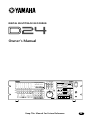 1
1
-
 2
2
-
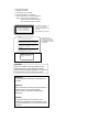 3
3
-
 4
4
-
 5
5
-
 6
6
-
 7
7
-
 8
8
-
 9
9
-
 10
10
-
 11
11
-
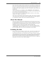 12
12
-
 13
13
-
 14
14
-
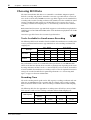 15
15
-
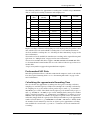 16
16
-
 17
17
-
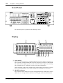 18
18
-
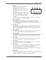 19
19
-
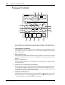 20
20
-
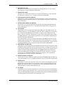 21
21
-
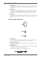 22
22
-
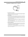 23
23
-
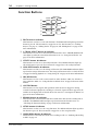 24
24
-
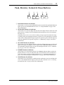 25
25
-
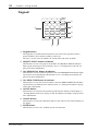 26
26
-
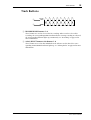 27
27
-
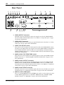 28
28
-
 29
29
-
 30
30
-
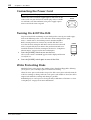 31
31
-
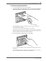 32
32
-
 33
33
-
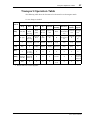 34
34
-
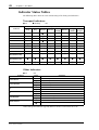 35
35
-
 36
36
-
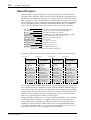 37
37
-
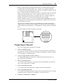 38
38
-
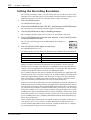 39
39
-
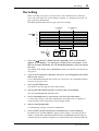 40
40
-
 41
41
-
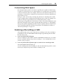 42
42
-
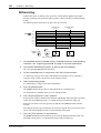 43
43
-
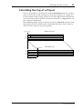 44
44
-
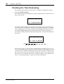 45
45
-
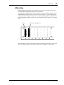 46
46
-
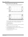 47
47
-
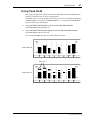 48
48
-
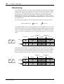 49
49
-
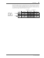 50
50
-
 51
51
-
 52
52
-
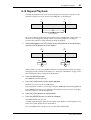 53
53
-
 54
54
-
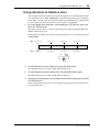 55
55
-
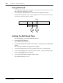 56
56
-
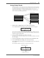 57
57
-
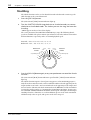 58
58
-
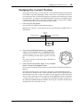 59
59
-
 60
60
-
 61
61
-
 62
62
-
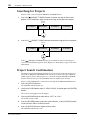 63
63
-
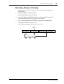 64
64
-
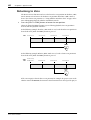 65
65
-
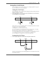 66
66
-
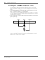 67
67
-
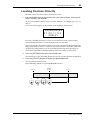 68
68
-
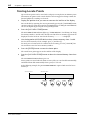 69
69
-
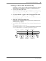 70
70
-
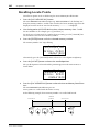 71
71
-
 72
72
-
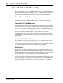 73
73
-
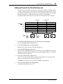 74
74
-
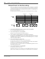 75
75
-
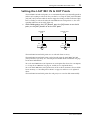 76
76
-
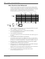 77
77
-
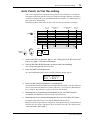 78
78
-
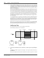 79
79
-
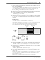 80
80
-
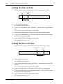 81
81
-
 82
82
-
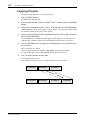 83
83
-
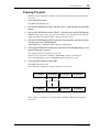 84
84
-
 85
85
-
 86
86
-
 87
87
-
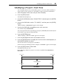 88
88
-
 89
89
-
 90
90
-
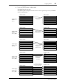 91
91
-
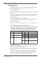 92
92
-
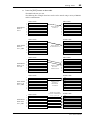 93
93
-
 94
94
-
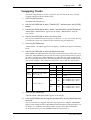 95
95
-
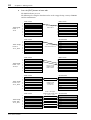 96
96
-
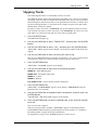 97
97
-
 98
98
-
 99
99
-
 100
100
-
 101
101
-
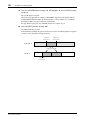 102
102
-
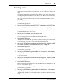 103
103
-
 104
104
-
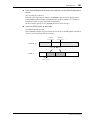 105
105
-
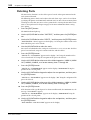 106
106
-
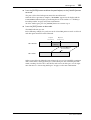 107
107
-
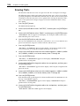 108
108
-
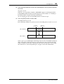 109
109
-
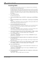 110
110
-
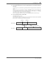 111
111
-
 112
112
-
 113
113
-
 114
114
-
 115
115
-
 116
116
-
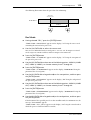 117
117
-
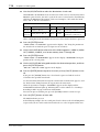 118
118
-
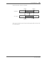 119
119
-
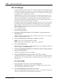 120
120
-
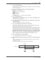 121
121
-
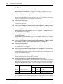 122
122
-
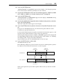 123
123
-
 124
124
-
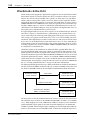 125
125
-
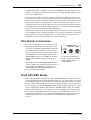 126
126
-
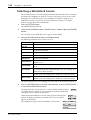 127
127
-
 128
128
-
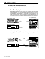 129
129
-
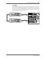 130
130
-
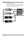 131
131
-
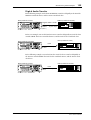 132
132
-
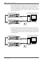 133
133
-
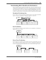 134
134
-
 135
135
-
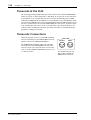 136
136
-
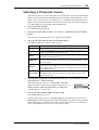 137
137
-
 138
138
-
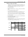 139
139
-
 140
140
-
 141
141
-
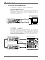 142
142
-
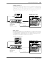 143
143
-
 144
144
-
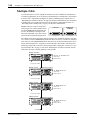 145
145
-
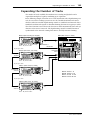 146
146
-
 147
147
-
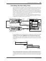 148
148
-
 149
149
-
 150
150
-
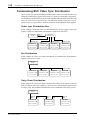 151
151
-
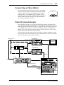 152
152
-
 153
153
-
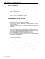 154
154
-
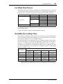 155
155
-
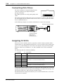 156
156
-
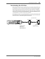 157
157
-
 158
158
-
 159
159
-
 160
160
-
 161
161
-
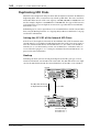 162
162
-
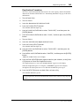 163
163
-
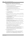 164
164
-
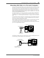 165
165
-
 166
166
-
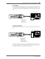 167
167
-
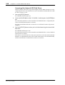 168
168
-
 169
169
-
 170
170
-
 171
171
-
 172
172
-
 173
173
-
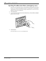 174
174
-
 175
175
-
 176
176
-
 177
177
-
 178
178
-
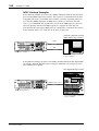 179
179
-
 180
180
-
 181
181
-
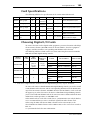 182
182
-
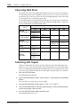 183
183
-
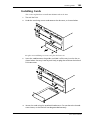 184
184
-
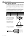 185
185
-
 186
186
-
 187
187
-
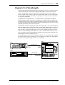 188
188
-
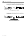 189
189
-
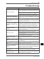 190
190
-
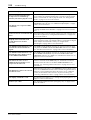 191
191
-
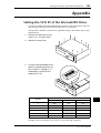 192
192
-
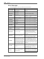 193
193
-
 194
194
-
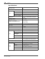 195
195
-
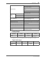 196
196
-
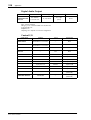 197
197
-
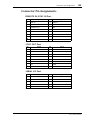 198
198
-
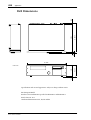 199
199
-
 200
200
-
 201
201
-
 202
202
-
 203
203
-
 204
204
-
 205
205
-
 206
206
-
 207
207
-
 208
208
-
 209
209
-
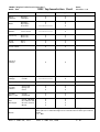 210
210
-
 211
211


in andere talen
- English: Yamaha D24 User manual
- italiano: Yamaha D24 Manuale utente
- русский: Yamaha D24 Руководство пользователя
- français: Yamaha D24 Manuel utilisateur
- español: Yamaha D24 Manual de usuario
- Deutsch: Yamaha D24 Benutzerhandbuch
- português: Yamaha D24 Manual do usuário
- dansk: Yamaha D24 Brugermanual
- čeština: Yamaha D24 Uživatelský manuál
- svenska: Yamaha D24 Användarmanual
- Türkçe: Yamaha D24 Kullanım kılavuzu
- polski: Yamaha D24 Instrukcja obsługi
- română: Yamaha D24 Manual de utilizare