STIEBEL ELTRON SBB 751-1001 Operation Instruction
- Type
- Operation Instruction

BEDIENUNG UND INSTALLATION
OPERATION AND INSTALLATION
UTILISATION ET INSTALLATION
BEDIENING EN INSTALLATIE
USO E INSTALLAZIONE
OBSLUHA A INSTALACE
KÄYTTÖ JA ASENNUS
BETJENING OG INSTALLATION
Warmwasser-Standspeicher | Floorstanding DHW cylinder | Ballon ECS sur pied |
Staande warmwaterboiler | Acqua calda - Caldaia verticale | Stacionární zásobník
teplé vody | Lattiamallinen käyttövesivaraaja | Fritstående varmtvandsbeholder
» SBB 751
» SBB 1001
» SBB 751 SOL
» SBB 1001 SOL
290889-40263-9263_SBB_751-1001_de_en_fr_nl_it_cs_fi_da.indb 1 26.09.2017 13:45:03

2 | SBB 751-1001 | SBB 751-1001 SOL www.stiebel-eltron.COM
Inhalt | Bedienung
Allgemeine Hinweise
BEDIENUNG
1. Allgemeine Hinweise ����������������������������������������2
1.1 Sicherheitshinweise ��������������������������������������������� 2
1.2 Andere Markierungen in dieser Dokumentation ���������� 3
1.3 Maßeinheiten ����������������������������������������������������� 3
2. Sicherheit �����������������������������������������������������3
2.1 Bestimmungsgemäße Verwendung ������������������������� 3
2.2 Allgemeine Sicherheitshinweise ������������������������������ 3
3. Gerätebeschreibung �����������������������������������������3
4. Reinigung, Pflege und Wartung ����������������������������4
5. Problembehebung �������������������������������������������4
INSTALLATION
6. Sicherheit �����������������������������������������������������4
6.1 Allgemeine Sicherheitshinweise ������������������������������ 4
6.2 Vorschriften, Normen und Bestimmungen ����������������� 4
7. Gerätebeschreibung �����������������������������������������4
7.1 Lieferumfang ����������������������������������������������������� 4
7.2 Zubehör ������������������������������������������������������������ 4
8. Vorbereitungen �����������������������������������������������5
8.1 Montageort ������������������������������������������������������� 5
8.2 Transport ���������������������������������������������������������� 5
9. Montage �������������������������������������������������������5
9.1 Gegebenenfalls Wärmedämmung montieren �������������� 5
9.2 Signalanode montieren����������������������������������������� 5
9.3 Thermometer und Temperaturfühler montieren ���������� 5
9.4 Gegebenenfalls Ladestation montieren ��������������������� 5
9.5 Gegebenenfalls Elektroheizflansch montieren ������������� 5
9.6 Wasseranschluss und Sicherheitsgruppe montieren ����� 6
9.7 Heizungs- bzw. Solarinstallation ����������������������������� 6
10. Inbetriebnahme ����������������������������������������������7
10.1 Erstinbetriebnahme ��������������������������������������������� 7
10.2 Wiederinbetriebnahme ����������������������������������������� 7
11. Außerbetriebnahme �����������������������������������������7
12. Störungsbeseitigung ����������������������������������������� 7
13. Wartung �������������������������������������������������������7
13.1 Sicherheitsventil überprüfen ���������������������������������� 7
13.2 Gerät entleeren �������������������������������������������������� 7
13.3 Signalanode austauschen �������������������������������������� 7
14. Technische Daten ��������������������������������������������� 8
14.1 Maße und Anschlüsse ������������������������������������������ 8
14.2 Störfallbedingungen �������������������������������������������12
14.3 Datentabelle �����������������������������������������������������13
KUNDENDIENST UND GARANTIE
UMWELT UND RECYCLING
BEDIENUNG
1. Allgemeine Hinweise
Das Kapitel „Bedienung“ richtet sich an den Gerätebenutzer und
den Fachhandwerker.
Das Kapitel „Installation“ richtet sich an den Fachhandwerker.
Hinweis
Lesen Sie diese Anleitung vor dem Gebrauch sorgfältig
durch und bewahren Sie sie auf.
Geben Sie die Anleitung gegebenenfalls an einen nach-
folgenden Benutzer weiter.
1.1 Sicherheitshinweise
1.1.1 Aufbau von Sicherheitshinweisen
!
SIGNALWORT Art der Gefahr
Hier stehen mögliche Folgen bei Nichtbeachtung des Si-
cherheitshinweises.
Hier stehen Maßnahmen zur Abwehr der Gefahr.
1.1.2 Symbole, Art der Gefahr
Symbol Art der Gefahr
Verletzung
Stromschlag
Verbrennung
(Verbrennung, Verbrühung)
1.1.3 Signalworte
SIGNALWORT Bedeutung
GEFAHR Hinweise, deren Nichtbeachtung schwere Verletzungen
oder Tod zur Folge haben.
WARNUNG Hinweise, deren Nichtbeachtung schwere Verletzungen
oder Tod zur Folge haben kann.
VORSICHT Hinweise, deren Nichtbeachtung zu mittelschweren oder
leichten Verletzungen führen kann.
!
290889-40263-9263_SBB_751-1001_de_en_fr_nl_it_cs_fi_da.indb 2 26.09.2017 13:45:05

Bedienung
Sicherheit
DEUTSCH
www.stiebel-eltron.com SBB 751-1001 | SBB 751-1001 SOL | 3
1.2 Andere Markierungen in dieser Dokumentation
Hinweis
Allgemeine Hinweise werden mit dem nebenstehenden
Symbol gekennzeichnet.
Lesen Sie die Hinweistexte sorgfältig durch.
Symbol Bedeutung
Sachschaden
(Geräte-, Folge-, Umweltschaden)
Geräteentsorgung
Dieses Symbol zeigt Ihnen, dass Sie etwas tun müssen.
Die erforderlichen Handlungen werden Schritt für Schritt
beschrieben.
1.3 Maßeinheiten
Hinweis
Wenn nicht anders angegeben, sind alle Maße in Milli-
meter.
2. Sicherheit
2.1 Bestimmungsgemäße Verwendung
Das Gerät dient zur Erwärmung und Speicherung von Trinkwas-
ser bei Wärmepumpenbetrieb mit großer Wärmepumpenleistung.
Die Trinkwassererwärmung und Speicherbeladung erfolgt durch
die Kombination mit den als Zubehör erhältlichen Ladestationen
WTS.
Geeig nete Elektro-Heizflan sche können vom Fachhandwerker
eingebaut werden.
Eine andere oder darüber hinausgehende Benutzung gilt als nicht
bestimmungsgemäß. Zum bestimmungsgemäßen Gebrauch ge-
hört auch das Beachten dieser Anleitung sowie der Anleitungen
für eingesetztes Zubehör.
2.2 Allgemeine Sicherheitshinweise
WARNUNG Verbrennung
Bei Auslauftemperaturen größer 43°C besteht Verbrü-
hungsgefahr.
!
WARNUNG Verletzung
Sollten Kinder oder Personen mit eingeschränkten kör-
perlichen, sensorischen oder geistigen Fähigkeiten das
Gerät bedienen, stellen Sie sicher, dass dies nur unter
Aufsicht oder nach entsprechender Einweisung durch
eine für ihre Sicherheit zuständige Person geschieht.
Beaufsichtigen Sie Kinder, um sicherzustellen, dass sie
nicht an dem Gerät spielen!
Hinweis
Das Gerät steht unter Druck.
Während des Aufheizens tropft das Ausdehnungswasser
aus dem Sicherheitsventil. Tropft nach Beendigung des
Aufheizens Wasser, informieren Sie Ihren Fachhandwer-
ker.
3. Gerätebeschreibung
Der Stahl-Innenbehälter ist mit Spezial-Direktemail „anticor
®
“
und einer Signalanode zum Schutz des Innenbehälters vor Kor-
rosion ausgerüstet.
SBB 751 SOL und SBB 1001 SOL
Die Gerätetypen enthalten zusätzlich einen Wärmeübertrager zur
solaren Erwärmung.
!
290889-40263-9263_SBB_751-1001_de_en_fr_nl_it_cs_fi_da.indb 3 26.09.2017 13:45:05

Bedienung
4 | SBB 751-1001 | SBB 751-1001 SOL www.stiebel-eltron.COM
4. Reinigung, Pflege und Wartung
Lassen Sie die das Gerät, die Sicherheitsgruppe und das
eingebaute Zubehör regelmäßig von einem Fachhandwerker
prüfen.
Verwenden Sie keine scheuernden oder anlösenden Reini-
gungsmittel! Zur Pflege und Reinigung der Kunststoffteile
genügt ein feuchtes Tuch.
Schutzanode
!
Sachschaden
Wenn die Verbrauchsanzeige von der weißen auf eine
rote Färbung umgeschlagen ist, lassen Sie die Signalano-
de von einem Fachhandwerker kontrollieren und gege-
benenfalls austauschen.
1
2
26�03�01�1345
Verbrauchsanzeige Signalanode
1 weiß = Anode ok
2 rot = Kontrolle vom Fachhandwerker notwendig
Verkalkung
Fast jedes Wasser scheidet bei hohen Temperaturen Kalk aus.
Dieser setzt sich im Gerät ab und beeinflusst die Funktion
und Lebensdauer des Gerätes. Die Wärmeübertrager und das
eingebaute Zubehör müssen deshalb von Zeit zu Zeit entkalkt
werden. Der Fachhandwerker, der die örtliche Wasserqualität
kennt, wird Ihnen den Zeitpunkt für die nächste Wartung
nennen.
5. Problembehebung
Rufen Sie den Fachhandwerker.
Zur besseren und schnelleren Hilfe teilen Sie ihm die Nummer
vom Typenschild mit (000000-0000-000000):
26�03�01�1353
INSTALLATION
6. Sicherheit
Die Installation, Inbetriebnahme sowie Wartung und Reparatur
des Gerätes darf nur von einem Fachhandwerker durchgeführt
werden.
6.1 Allgemeine Sicherheitshinweise
Wir gewährleisten eine einwandfreie Funktion und Betriebssicher-
heit nur, wenn die für das Gerät bestimmten originalen Ersatzteile
verwendet werden.
6.2 Vorschriften, Normen und Bestimmungen
Hinweis
Beachten Sie alle nationalen und regionalen Vorschriften
und Bestimmungen.
7. Gerätebeschreibung
7.1 Lieferumfang
Mit dem Gerät werden geliefert:
- Signalanode
- Temperaturfühler
- Wärmeleitpaste
- Thermometer
- zusätzliches Typenschild
- Aufkleber „Hinweis Signal-Anode“
7.2 Zubehör
7.2.1 SVGW-geprüftes Zubehör
Ladestationen
Ladestationen nehmen mit einem Platten-Wärmeübertrager Wär-
meenergie des Heizkreises auf. Die Wärmeenergie wird für die
Erwärmung von Trinkwasser in den Speicherladekreis übertra-
gen. Die Ladestationen sind für beide Vorgänge mit jeweils einer
Umwälzpumpe ausgestattet.
7.2.2 Weiteres Zubehör
Sicherheitsgruppen und Druckminderventile
In Abhängigkeit vom Ruhedruck sind Sicherheitsgruppen und
Druckminderventile erhältlich. Diese bauartgeprüften Sicher-
heitsgruppen schützen das Gerät vor unzulässigen Drucküber-
schreitungen.
Elektroheizflansche und Wärmedämmung
Als Zubehör sind außerdem Elektroheizflansche und eine Wär-
medämmung erhältlich.
290889-40263-9263_SBB_751-1001_de_en_fr_nl_it_cs_fi_da.indb 4 26.09.2017 13:45:06

DEUTSCH
www.stiebel-eltron.com SBB 751-1001 | SBB 751-1001 SOL | 5
Installation
Vorbereitungen
8. Vorbereitungen
8.1 Montageort
Montieren Sie das Gerät immer in einem frostfreien Raum in
der Nähe der Entnahmestelle.
Beachten Sie Tragfähigkeit und Ebenheit des Bodens
sowie die Raumhöhe (siehe Kapitel „Technische Daten /
Datentabelle“).
Mindestabstände
≥400 ≥175
≥600≥200
≥800
D0000057344
Die seitlichen Mindestabstände können nach rechts oder links
getauscht werden.
Halten Sie die Mindestabstände ein.
8.2 Transport
Zum Transport können Sie die Transportösen oben am Gerät nut-
zen.
9. Montage
9.1 Gegebenenfalls Wärmedämmung montieren
Platzieren Sie das Gerät an seinem Standort.
Montieren Sie die Wärmedämmung entsprechend der Bei-
lage. Achten Sie hierzu auf ausreichende Montagefreiheit.
Anschließend können Sie das Gerät in die Heizungs- und
Warmwasseranlage einbinden.
9.2 Signalanode montieren
!
Sachschaden
Beim Betrieb ohne Verbrauchsanzeige muss der Stopfen
in der Verschraubung bleiben.
26�02�09�0031
Ziehen Sie den Verschlussstopfen heraus indem Sie gleich-
zeitig den Druckring niederdrücken.
Schieben Sie das offene Rohrende der Verbrauchsanzeige in
die Anodenöffnung.
9.3 Thermometer und Temperaturfühler montieren
Stecken Sie das Thermometer bis zum Anschlag ein und rich-
ten es aus.
Stecken Sie den Temperaturfühler bis zum Anschlag in das
Fühlerrohr. Benutzen Sie die Wärmeleitpaste.
9.4 Gegebenenfalls Ladestation montieren
Installieren Sie die Ladestation entsprechend der beiliegen-
den Bedienungs- und Installationsanleitung.
9.5 Gegebenenfalls Elektroheizflansch montieren
Demontieren Sie die Blindflansche, um Elektroheizflansche
entsprechend der beiliegenden Bedienungs- und Installa-
tionsanleitungen zu installieren. Halten Sie die galvanische
Trennung zum Behälter ein.
290889-40263-9263_SBB_751-1001_de_en_fr_nl_it_cs_fi_da.indb 5 26.09.2017 13:45:07

6 | SBB 751-1001 | SBB 751-1001 SOL www.stiebel-eltron.COM
Installation
Montage
9.6 Wasseranschluss und Sicherheitsgruppe
montieren
9.6.1 Sicherheitshinweise
Hinweis
Führen Sie alle Wasseranschluss- und Installationsarbei-
ten nach Vorschrift aus.
!
Sachschaden
Beim gleichzeitigen Einsatz von Kunststoff-Rohrsystemen
und dem Einbau eines Elektro-Heizflansches beachten Sie
das Kapitel „Technische Daten/ Störfallbedingungen“.
!
Sachschaden
Das Gerät muss mit Druck-Armaturen betrieben werden.
Kaltwasserleitung
Als Werkstoffe sind Kupfer, Stahl oder Kunststoff-Rohrsysteme
zugelassen.
!
Sachschaden
Ein Sicherheitsventil ist erforderlich.
Warmwasserleitung
Als Werkstoffe sind Kupfer oder Kunststoff-Rohrsysteme zuge-
lassen.
9.6.2 Wasseranschluss
Spülen Sie die Leitung gut durch.
Installieren Sie eine Sicherheitsgruppe. Beachten Sie dabei,
dass Sie in Abhängigkeit von dem Ruhedruck eventuell zu-
sätzlich ein Druckminderventil benötigen.
Montieren Sie die Warmwasser Auslaufleitung und die Kalt-
wasser Zulaufleitung. Schließen Sie die hydraulischen An-
schlüsse flachdichtend an.
Dimensionieren Sie die Abflussleitung so, dass bei voll ge-
öffnetem Sicher heitsventil das Wasser ungehindert ablaufen
kann. Die Abblase öffnung des Sicherheitsventils muss zur
Atmosphäre hin geöffnet bleiben.
Montieren Sie die Abblaseleitung der Sicherheitsgruppe mit
einer stetigen Abwärtsneigung.
Berücksichtigen Sie die Hinweise in der Installationsanwei-
sung der Sicherheitsgruppe.
9.7 Heizungs- bzw. Solarinstallation
9.7.1 Wasserbeschaffenheit Solarkreis
Ein Glykol-Wasser-Gemisch bis 60% ist für Wärmeübertrager im
Solarkreis zugelassen, falls in der gesamten Installation nur ent-
zinkungsbeständige Metalle, glykolbeständige Dichtungen und für
Glykol geeignete Membran-Druckausdehnungsgefäße verwendet
werden.
9.7.2 Sauerstoffdiffusion
!
Sachschaden
Vermeiden Sie offene Heizungsanlagen und sauerstoff-
diffusionsundichte Kunststoffrohr-Fußbodenheizungen.
Bei sauerstoffdiffusionsundichten Kunststoffrohr-Fußbodenhei-
zungen oder offenen Heizungsanlagen kann durch eindiffun-
dierten Sauerstoff an den Stahlteilen der Heizungsanlage Korro-
sion auftreten (z.B. am Wärmeübertrager des Warmwasserspei-
chers, an Pufferspeichern, Stahlheizkörpern oder Stahlrohren).
!
Sachschaden
Die Korrosionsprodukte (z.B. Rostschlamm) können sich
in den Komponenten der Heizungsanlage absetzen und
durch Querschnittsverengung Leistungsverluste oder
Störabschaltungen bewirken.
!
Sachschaden
Vermeiden Sie offene Solaranlagen und sauerstoffdiffusi-
onsundichte Kunststoffrohre.
Bei sauerstoffdiffusionsundichten Kunststoffrohren kann durch
eindiffundierten Sauerstoff an den Stahlteilen der Solaranlage
Korrosion auftreten (z.B. am Wärmeübertrager des Warmwas-
serspeichers).
290889-40263-9263_SBB_751-1001_de_en_fr_nl_it_cs_fi_da.indb 6 26.09.2017 13:45:07

DEUTSCH
www.stiebel-eltron.com SBB 751-1001 | SBB 751-1001 SOL | 7
Installation
Inbetriebnahme
10. Inbetriebnahme
10.1 Erstinbetriebnahme
Öffnen Sie eine Entnahmestelle so lange, bis das Gerät gefüllt
und das Leitungsnetz luftfrei ist.
Stellen Sie die Durchflussmenge ein. Beachten Sie dabei
die maximal zulässige Durchflussmenge bei voll geöffneter
Armatur (siehe Kapitel „Technische Daten / Datentabelle“).
Reduzieren Sie gegebenenfalls die Durchflussmenge an der
Drossel der Sicherheitsgruppe.
Führen Sie eine Dichtheitskontrolle durch.
Schalten Sie gegebenenfalls die Netzspannung ein.
Prüfen Sie die Arbeitsweise des eingebauten Zubehörs.
Überprüfen Sie die Funktionsfähigkeit der Sicherheitsgruppe.
SBB 751 SOL und SBB 1001 SOL
Spülen Sie vor Anschluss der Solaranlage den Wärmeüber-
trager gründlich mit Wasser durch.
10.1.1 Übergabe des Gerätes
Erklären Sie dem Benutzer die Funktion des Gerätes und ma-
chen Sie ihn mit dem Gebrauch des Gerätes vertraut.
Weisen Sie den Benutzer auf mögliche Gefahren hin, speziell
die Verbrühungsgefahr.
Übergeben Sie diese Anleitung.
10.2 Wiederinbetriebnahme
Siehe Kapitel „Erstinbetriebnahme“.
11. Außerbetriebnahme
Entleeren Sie das Gerät. Siehe Kapitel „Wartung / Gerät
entleeren“.
12. Störungsbeseitigung
Störung Ursache Behebung
Das Sicherheitsventil
tropft bei ausgeschalteter
Heizung.
Der Ventilsitz ist ver-
schmutzt.
Reinigen Sie den Ven-
tilsitz.
13. Wartung
WARNUNG Stromschlag
Führen Sie alle elektrischen Anschluss- und Installati-
onsarbeiten nach Vorschrift aus.
WARNUNG Stromschlag
Trennen Sie vor allen Arbeiten das Gerät allpolig von der
Netzspannung.
Wenn Sie das Gerät entleeren müssen, beachten Sie das Kapitel
„Gerät entleeren“.
13.1 Sicherheitsventil überprüfen
Lüften Sie das Sicherheitsventil an der Sicherheitsgruppe re-
gelmäßig an, bis der volle Wasserstrahl ausläuft.
13.2 Gerät entleeren
WARNUNG Verbrennung
Beim Entleeren kann heißes Wasser austreten.
Falls das Gerät für Wartungsarbeiten oder bei Frostgefahr zum
Schutz der gesamten Installation entleert werden muss, müssen
Sie folgendermaßen vorgehen:
Schließen Sie das Absperrventil in der Kaltwasser
Zulaufleitung.
Öffnen Sie die Warmwasserventile aller Entnahmestel len.
Entleeren Sie das Gerät über den Rücklauf der Ladestation
(siehe Kapitel „Technische Daten / Abmaße und Anschlüsse“).
Beachten Sie, dass Restwasser im Gerät verbleibt.
13.3 Signalanode austauschen
Tauschen Sie die Signalanode aus, wenn sie verbraucht ist.
Beachten Sie dabei den maximalen Übergangswiderstand
zwischen Anode und Behälter von 0,3 Ω.
290889-40263-9263_SBB_751-1001_de_en_fr_nl_it_cs_fi_da.indb 7 26.09.2017 13:45:07

8 | SBB 751-1001 | SBB 751-1001 SOL www.stiebel-eltron.COM
Installation
Technische Daten
14. Technische Daten
14.1 Maße und Anschlüsse
SBB 751
i18
c06
d21
c01
c10
d22
h43
i03
h06
h06
h06
i02
d35
d24
d36
1490
h05
D0000020368
SBB 751
c01 Kaltwasser Zulauf Außengewinde G 2 A
c06 Warmwasser Auslauf Außengewinde G 2 A
c10 Zirkulation Außengewinde G 1 A
d21 Ladestation Vorlauf Außengewinde G 2 A
d22 Ladestation Rücklauf Außengewinde G 2 A
d24 Ladestation Rücklauf opt. Außengewinde G 2 A
d35 Wärmeerzeuger Vorlauf opt. Außengewinde G 2 A
d36 Wärmeerzeuger Rücklauf opt. Außengewinde G 2 A
h05 Fühler WP Warmwasser Durchmesser mm 9,5
h06 Fühler WP Warmwasser opt. Durchmesser mm 9,5
h43 Thermometer Durchmesser mm 14,5
i02 Flansch I
Durchmesser mm 280
Lochkreisdurchmesser mm 245
Schrauben M 14
Anzugsdrehmoment Nm 80
i03 Flansch II
Durchmesser mm 280
Lochkreisdurchmesser mm 245
Schrauben M 14
Anzugsdrehmoment Nm 80
i18 Schutzanode Innengewinde G 1 1/4
290889-40263-9263_SBB_751-1001_de_en_fr_nl_it_cs_fi_da.indb 8 26.09.2017 13:45:08

DEUTSCH
www.stiebel-eltron.com SBB 751-1001 | SBB 751-1001 SOL | 9
Installation
Technische Daten
SBB 1001
c06
c01
d22
d36
c10
h43
h06
i03
h06
h06
i02
d21
d24
d35
i18
i18
1820
h05
D0000017401
SBB 1001
c01 Kaltwasser Zulauf Außengewinde G 2 A
c06 Warmwasser Auslauf Außengewinde G 2 A
c10 Zirkulation Außengewinde G 1 A
d21 Ladestation Vorlauf Außengewinde G 2 A
d22 Ladestation Rücklauf Außengewinde G 2 A
d24 Ladestation Rücklauf opt. Außengewinde G 2 A
d35 Wärmeerzeuger Vorlauf opt. Außengewinde G 2 A
d36 Wärmeerzeuger Rücklauf opt. Außengewinde G 2 A
h05 Fühler WP Warmwasser Durchmesser mm 9,5
h06 Fühler WP Warmwasser opt. Durchmesser mm 9,5
h43 Thermometer Durchmesser mm 14,5
i02 Flansch I
Durchmesser mm 280
Lochkreisdurchmesser mm 245
Schrauben M 14
Anzugsdrehmoment Nm 80
i03 Flansch II
Durchmesser mm 280
Lochkreisdurchmesser mm 245
Schrauben M 14
Anzugsdrehmoment Nm 80
i18 Schutzanode Innengewinde G 1 1/4
290889-40263-9263_SBB_751-1001_de_en_fr_nl_it_cs_fi_da.indb 9 26.09.2017 13:45:08

10 | SBB 751-1001 | SBB 751-1001 SOL www.stiebel-eltron.COM
Installation
Technische Daten
SBB 751 SOL
i18
h43
h06
i03
h06
h06
h28
i02
d21
c06
d26
d22
c01
d25
c10
1490
h05
i18
D0000017355
SBB 751 SOL
c01 Kaltwasser Zulauf Außengewinde G 2 A
c06 Warmwasser Auslauf Außengewinde G 2 A
c10 Zirkulation Außengewinde G 1 A
d21 Ladestation Vorlauf Außengewinde G 2 A
d22 Ladestation Rücklauf Außengewinde G 2 A
d25 Solar Vorlauf Innengewinde G 1
d26 Solar Rücklauf Innengewinde G 1
h05 Fühler WP Warmwasser Durchmesser mm 9,5
h06 Fühler WP Warmwasser opt. Durchmesser mm 9,5
h28 Fühler Solar Speicher Durchmesser mm 9,5
h43 Thermometer Durchmesser mm 14,5
i02 Flansch I
Durchmesser mm 280
Lochkreisdurchmesser mm 245
Schrauben M 14
Anzugsdrehmoment Nm 80
i03 Flansch II
Durchmesser mm 280
Lochkreisdurchmesser mm 245
Schrauben M 14
Anzugsdrehmoment Nm 80
i18 Schutzanode Innengewinde G 1 A
290889-40263-9263_SBB_751-1001_de_en_fr_nl_it_cs_fi_da.indb 10 26.09.2017 13:45:09

DEUTSCH
www.stiebel-eltron.com SBB 751-1001 | SBB 751-1001 SOL | 11
Installation
Technische Daten
SBB 1001 SOL
c06
c01
h43
h06
i03
h06
h06
i02
d21
h28
d26
d25
c10
i18
i18
d22
1820
h05
D0000017403
SBB 1001 SOL
c01 Kaltwasser Zulauf Außengewinde G 2 A
c06 Warmwasser Auslauf Außengewinde G 2 A
c10 Zirkulation Außengewinde G 1 A
d21 Ladestation Vorlauf Außengewinde G 2 A
d22 Ladestation Rücklauf Außengewinde G 2 A
d25 Solar Vorlauf Innengewinde G 1
d26 Solar Rücklauf Innengewinde G 1
h05 Fühler WP Warmwasser Durchmesser mm 9,5
h06 Fühler WP Warmwasser opt. Durchmesser mm 9,5
h28 Fühler Solar Speicher Durchmesser mm 9,5
h43 Thermometer Durchmesser mm 14,5
i02 Flansch I
Durchmesser mm 280
Lochkreisdurchmesser mm 245
Schrauben M 14
Anzugsdrehmoment Nm 80
i03 Flansch II
Durchmesser mm 280
Lochkreisdurchmesser mm 245
Schrauben M 14
Anzugsdrehmoment Nm 80
i18 Schutzanode Innengewinde G 1 1/4
290889-40263-9263_SBB_751-1001_de_en_fr_nl_it_cs_fi_da.indb 11 26.09.2017 13:45:09

12 | SBB 751-1001 | SBB 751-1001 SOL www.stiebel-eltron.COM
Installation
Technische Daten
Geräteschnitt SBB 751 SOL | SBB 1001 SOL
c06
c01
d26
d25
c10
h43
i03
i02
26�03�01�1371
h06
h06
h06
d21
h28
d22
h05
26�03�01�1375
14.2 Störfallbedingungen
In Abhängigkeit von den eingesetzten Wärmeerzeugern können
im Störfall Temperaturen bis 95°C bei 1,0MPa auftreten.
alte BI:
SBB 751 SBB 1001 SBB 751 SOL SBB 1001 SOL
229292 229293 229294
229295
Hydraulische Daten
Nenninhalt l 750 1000 750
1000
Inhalt Wärmeübertrager unten l 18,8
24,4
Fläche Wärmeübertrager unten m² 3
3,9
Druckverlust bei 1,0 m³/h Wärmeübertrager unten hPa 39
52
Mischwassermenge 40 °C (15 °C/60 °C) l 1264 1650 1230
1599
Einsatzgrenzen
Max. zulässiger Druck MPa 1 1 1
1
Prüfdruck MPa 1,5 1,5 1,5
1,5
Max. zulässige Temperatur °C 95 95 95
95
Max. Durchflussmenge l/min 90 90 90
90
Max. empfohlene Kollektoraperturfläche m² 15
20
Dimensionen
Höhe mm 1777 2277 1777
2277
Durchmesser mm 790 790 790
790
Durchmesser mit Wärmedämmung mm 1010 1010 1010
1010
Kippmaß mm 1840 2335 1840
2335
Gewichte
Gewicht gefüllt kg 960 1267 971
1262
Gewicht leer kg 210 267 242
296
290889-40263-9263_SBB_751-1001_de_en_fr_nl_it_cs_fi_da.indb 12 26.09.2017 13:45:10

DEUTSCH
www.stiebel-eltron.com SBB 751-1001 | SBB 751-1001 SOL | 13
Installation
Technische Daten
14.3 Datentabelle
SBB 751 SBB 1001 SBB 751 SOL SBB 1001 SOL
229292 229293 229294 229295
Hydraulische Daten
Nenninhalt l 763 1004 736 971
Inhalt Wärmeübertrager unten l 20,5 25,2
Fläche Wärmeübertrager unten m² 3 4,0
Druckverlust bei 1,0 m³/h Wärmeübertrager unten hPa 39 52
Mischwassermenge 40 °C (15 °C/60 °C) l 1264 1650 1230 1599
Einsatzgrenzen
Max. zulässiger Druck MPa 1 1 1 1
Prüfdruck MPa 1,5 1,5 1,5 1,5
Max. zulässige Temperatur °C 95 95 95 95
Max. Durchflussmenge l/min 90 90 90 90
Max. empfohlene Kollektoraperturfläche m² 15 20
Dimensionen
Höhe mm 1777 2277 1777 2277
Durchmesser mm 790 790 790 790
Durchmesser mit Wärmedämmung mm 1010 1010 1010 1010
Kippmaß mm 1840 2335 1840 2335
Gewichte
Gewicht gefüllt kg 960 1267 971 1296
Gewicht leer kg 210 267 242 296
290889-40263-9263_SBB_751-1001_de_en_fr_nl_it_cs_fi_da.indb 13 26.09.2017 13:45:10

14 | SBB 751-1001 | SBB 751-1001 SOL www.stiebel-eltron.COM
Kundendienst und Garantie
Erreichbarkeit
Sollte einmal eine Störung an einem unserer Produkte auftre-
ten, stehen wir Ihnen natürlich mit Rat und Tat zur Seite.
Rufen Sie uns an:
05531 702-111
oder schreiben Sie uns:
Stiebel Eltron GmbH & Co. KG
- Kundendienst -
Fürstenberger Straße 77, 37603 Holzminden
E-Mail: kundendienst@stiebel-eltron.de
Fax: 05531 702-95890
Weitere Anschriften sind auf der letzten Seite aufgeführt.
Unseren Kundendienst erreichen Sie telefonisch rund um die
Uhr, auch an Samstagen und Sonntagen sowie an Feiertagen.
Kundendiensteinsätze erfolgen während unserer Geschäftszei-
ten (von 7.15 bis 18.00 Uhr, freitags bis 17.00 Uhr). Als Sonder-
service bieten wir Kundendiensteinsätze bis 21.30 Uhr. Für die-
sen Sonderservice sowie Kundendiensteinsätze an Wochenen-
den und Feiertagen werden höhere Preise berechnet.
Garantiebedingungen
Diese Garantiebedingungen regeln zusätzliche Garantieleistun-
gen von uns gegenüber dem Endkunden. Sie treten neben die
gesetzlichen Gewährleistungsansprüche des Kunden. Die ge-
setzlichen Gewährleistungsansprüche gegenüber den sonsti-
gen Vertragspartnern sind nicht berührt.
Diese Garantiebedingungen gelten nur für solche Geräte, die
vom Endkunden in der Bundesrepublik Deutschland als Neuge-
räte erworben werden. Ein Garantievertrag kommt nicht zu-
stande, soweit der Endkunde ein gebrauchtes Gerät oder ein
neues Gerät seinerseits von einem anderen Endkunden erwirbt.
Inhalt und Umfang der Garantie
Die Garantieleistung wird erbracht, wenn an unseren Geräten
ein Herstellungs- und/oder Materialfehler innerhalb der Garan-
tiedauer auftritt. Die Garantie umfasst jedoch keine Leistungen
für solche Geräte, an denen Fehler, Schäden oder Mängel auf-
grund von Verkalkung, chemischer oder elektrochemischer
Einwirkung, fehlerhafter Aufstellung bzw. Installation sowie
unsachgemäßer Einregulierung, Bedienung oder unsachgemä-
ßer Inanspruchnahme bzw. Verwendung auftreten. Ebenso
ausgeschlossen sind Leistungen aufgrund mangelhafter oder
unterlassener Wartung, Witterungseinflüssen oder sonstigen
Naturerscheinungen.
Die Garantie erlischt, wenn am Gerät Reparaturen, Eingriffe oder
Abänderungen durch nicht von uns autorisierte Personen vor-
genommen wurden.
Die Garantieleistung umfasst die sorgfältige Prüfung des Gerä-
tes, wobei zunächst ermittelt wird, ob ein Garantieanspruch
besteht. Im Garantiefall entscheiden allein wir, auf welche Art
der Fehler behoben wird. Es steht uns frei, eine Reparatur des
Gerätes ausführen zu lassen oder selbst auszuführen. Etwaige
ausgewechselte Teile werden unser Eigentum.
Für die Dauer und Reichweite der Garantie übernehmen wir
sämtliche Material- und Montagekosten.
Soweit der Kunde wegen des Garantiefalles aufgrund gesetzli-
cher Gewährleistungsansprüche gegen andere Vertragspartner
Leistungen erhalten hat, entfällt eine Leistungspflicht von uns.
Soweit eine Garantieleistung erbracht wird, übernehmen wir
keine Haftung für die Beschädigung eines Gerätes durch Dieb-
stahl, Feuer, Aufruhr oder ähnliche Ursachen.
Über die vorstehend zugesagten Garantieleistungen hinausge-
hend kann der Endkunde nach dieser Garantie keine Ansprüche
wegen mittelbarer Schäden oder Folgeschäden, die durch das
Gerät verursacht werden, insbesondere auf Ersatz außerhalb des
Gerätes entstandener Schäden, geltend machen. Gesetzliche
Ansprüche des Kunden uns gegenüber oder gegenüber Dritten
bleiben unberührt.
Garantiedauer
Für im privaten Haushalt eingesetzte Geräte beträgt die Garan-
tiedauer 24 Monate; im Übrigen (zum Beispiel bei einem Einsatz
der Geräte in Gewerbe-, Handwerks- oder Industriebetrieben)
beträgt die Garantiedauer 12 Monate.
Die Garantiedauer beginnt für jedes Gerät mit der Übergabe des
Gerätes an den Kunden, der das Gerät zum ersten Mal einsetzt.
Garantieleistungen führen nicht zu einer Verlängerung der
Garantiedauer. Durch die erbrachte Garantieleistung wird keine
neue Garantiedauer in Gang gesetzt. Dies gilt für alle erbrachten
Garantieleistungen, insbesondere für etwaig eingebaute Ersatz-
teile oder für die Ersatzlieferung eines neuen Gerätes.
Inanspruchnahme der Garantie
Garantieansprüche sind vor Ablauf der Garantiedauer, innerhalb
von zwei Wochen, nachdem der Mangel erkannt wurde, bei uns
anzumelden. Dabei müssen Angaben zum Fehler, zum Gerät
und zum Zeitpunkt der Feststellung gemacht werden. Als Ga-
rantienachweis ist die Rechnung oder ein sonstiger datierter
Kaufnachweis beizufügen. Fehlen die vorgenannten Angaben
oder Unterlagen, besteht kein Garantieanspruch.
Garantie für in Deutschland erworbene, jedoch außer-
halb Deutschlands eingesetzte Geräte
Wir sind nicht verpflichtet, Garantieleistungen außerhalb der
Bundesrepublik Deutschland zu erbringen. Bei Störungen eines
im Ausland eingesetzten Gerätes ist dieses gegebenenfalls auf
Gefahr und Kosten des Kunden an den Kundendienst in
Deutschland zu senden. Die Rücksendung erfolgt ebenfalls auf
Gefahr und Kosten des Kunden. Etwaige gesetzliche Ansprüche
des Kunden uns gegenüber oder gegenüber Dritten bleiben
auch in diesem Fall unberührt.
Außerhalb Deutschlands erworbene Geräte
Für außerhalb Deutschlands erworbene Geräte gilt diese Garan-
tie nicht. Es gelten die jeweiligen gesetzlichen Vorschriften und
gegebenenfalls die Lieferbedingungen der Ländergesellschaft
bzw. des Importeurs.
KUNDENDIENST UND GARANTIE
290889-40263-9263_SBB_751-1001_de_en_fr_nl_it_cs_fi_da.indb 14 26.09.2017 13:45:11

DEUTSCH
www.stiebel-eltron.com SBB 751-1001 | SBB 751-1001 SOL | 15
Umwelt und Recycling
Entsorgung von Transport- und
Verkaufsverpackungsmaterial
Damit Ihr Gerät unbeschädigt bei Ihnen ankommt, haben wir
es sorgfältig verpackt. Bitte helfen Sie, die Umwelt zu schützen,
und entsorgen Sie das Verpackungsmaterial des Gerätes sach-
gerecht. Wir beteiligen uns gemeinsam mit dem Großhandel
und dem Fachhandwerk/ Fachhandel in Deutschland an einem
wirksamen Rücknahme- und Entsorgungskonzept für die um-
weltschonende Aufarbeitung der Verpackungen.
Überlassen Sie die Transportverpackung dem Fachhandwerker
beziehungsweise dem Fachhandel.
Entsorgen Sie Verkaufsverpackungen über eines der Dualen
Systeme in Deutschland.
Entsorgung von Altgeräten in Deutschland
Geräteentsorgung
Die mit diesem Symbol gekennzeichneten Geräte dür-
fen nicht mit dem Hausmüll entsorgt werden.
Als Hersteller sorgen wir im Rahmen der Produktverantwor-
tung für eine umweltgerechte Behandlung und Verwertung
der Altgeräte. Weitere Informationen zur Sammlung und Ent-
sorgung erhalten Sie über Ihre Kommune oder Ihren Fach-
handwerker/ Fachhändler.
Bereits bei der Entwicklung neuer Geräte achten wir auf eine
hohe Recyclingfähigkeit der Materialien.
Über das Rücknahmesystem werden hohe Recyclingquoten
der Materialien erreicht, um Deponien und die Umwelt zu ent-
lasten. Damit leisten wir gemeinsam einen wichtigen Beitrag
zum Umweltschutz.
Entsorgung außerhalb Deutschlands
Entsorgen Sie dieses Gerät fach- und sachgerecht nach den
örtlich geltenden Vorschriften und Gesetzen.
UMWELT UND RECYCLING
290889-40263-9263_SBB_751-1001_de_en_fr_nl_it_cs_fi_da.indb 15 26.09.2017 13:45:11

16 | SBB 751-1001 | SBB 751-1001 SOL WWW.STIEBEL-ELTRON.COM
CONTENTS | OPERATION
GENERAL INFORMATION
OPERATION
1. General information ��������������������������������������� 16
1.1 Safety instructions ����������������������������������������������16
1.2 Other symbols in this documentation ���������������������� 17
1.3 Units of measurement ����������������������������������������� 17
2. Safety �������������������������������������������������������� 17
2.1 Intended use ����������������������������������������������������� 17
2.2 General safety instructions ����������������������������������� 17
3. Appliance description ������������������������������������� 17
4. Cleaning, care and maintenance ������������������������� 18
5. Troubleshooting �������������������������������������������� 18
INSTALLATION
6. Safety �������������������������������������������������������� 18
6.1 General safety instructions ����������������������������������� 18
6.2 Regulations, standards and instructions ������������������� 18
7. Appliance description ������������������������������������� 18
7.1 Standard delivery ����������������������������������������������� 18
7.2 Accessories ������������������������������������������������������� 18
8. Preparations ������������������������������������������������ 19
8.1 Installation site �������������������������������������������������� 19
8.2 Transport ��������������������������������������������������������� 19
9. Preparing for installation ��������������������������������� 19
9.1 Fitting the thermal insulation, if appropriate ������������� 19
9.2 Fitting the signal anode ��������������������������������������� 19
9.3 Fitting the thermometer and temperature sensor ������� 19
9.4 Fitting the heat transfer station, if appropriate ���������� 19
9.5 Fitting the flanged immersion heater, if appropriate ��� 19
9.6 Fitting the water connection and the safety assembly ��20
9.7 Heating or solar installation ����������������������������������20
10. Commissioning ��������������������������������������������� 21
10.1 Commissioning �������������������������������������������������� 21
10.2 Recommissioning ����������������������������������������������� 21
11. Shutting down ���������������������������������������������� 21
12. Troubleshooting �������������������������������������������� 21
13. Maintenance ������������������������������������������������ 21
13.1 Checking the safety valve ������������������������������������� 21
13.2 Draining the appliance ���������������������������������������� 21
13.3 Replacing the signal anode ����������������������������������� 21
14. Specification ������������������������������������������������ 22
14.1 Dimensions and connections ��������������������������������� 22
14.2 Fault conditions �������������������������������������������������26
14.3 Data table �������������������������������������������������������� 27
GUARANTEE
ENVIRONMENT AND RECYCLING
OPERATION
1. General information
The chapter “Operation” is intended for appliance users and heat-
ing contractors.
The chapter “Installation” is intended for heating contractors.
Note
Read these instructions carefully before using the appli-
ance and retain them for future reference.
Pass on the instructions to a new user if required.
1.1 Safety instructions
1.1.1 Structure of safety instructions
!
KEYWORD Type of risk
Here, possible consequences are listed that may result
from failure to observe the safety instructions.
Steps to prevent the risk are listed.
1.1.2 Symbols, type of risk
Symbol Type of risk
Injury
Electrocution
Burns
(burns, scalding)
1.1.3 Keywords
KEYWORD Meaning
DANGER Failure to observe this information will result in serious
injury or death.
WARNING Failure to observe this information may result in serious
injury or death.
CAUTION Failure to observe this information may result in non-
serious or minor injury.
!
290889-40263-9263_SBB_751-1001_de_en_fr_nl_it_cs_fi_da.indb 16 26.09.2017 13:45:12

OPERATION
SAFETY
ENGLISH
WWW.STIEBEL-ELTRON.COM SBB 751-1001 | SBB 751-1001 SOL | 17
1.2 Other symbols in this documentation
Note
General information is identified by the symbol shown
on the left.
Read these texts carefully.
Symbol Meaning
Material damage
(Appliance and consequential losses, environmental pol-
lution)
Appliance disposal
This symbol indicates that you have to do something. The ac-
tion you need to take is described step by step.
1.3 Units of measurement
Note
All measurements are given in mm unless stated oth-
erwise.
2. Safety
2.1 Intended use
The appliance is intended for heating and storing potable water
when operating a heat pump with a high output. The DHW and
cylinder are heated in combination with the WTS charging station
available as an accessory.
Suitable flanged immersion heaters can be fitted by a heating
contractor.
Any other use beyond that described shall be deemed inappropri-
ate. Observation of these instructions and of instructions for any
accessories used is also part of the correct use of this appliance.
2.2 General safety instructions
WARNING Burns
There is a risk of scalding at outlet temperatures in ex-
cess of 43 °C.
!
WARNING Injury
Where children or persons with limited physical, sensory
or mental abilities are allowed to control this appliance,
ensure that this will only happen under supervision or
after appropriate instruction by a person responsible
for their safety.
Children should be supervised to ensure that they never
play with the appliance!
Note
The appliance is under pressure.
During the heat-up process, expansion water will drip
from the safety valve. If water continues to drip when
the heat-up process is completed, please inform your
qualified contractor.
3. Appliance description
The internal steel cylinder is coated in “anticor
®
” enamel and is
equipped with a signal anode to protect the inside of the cylinder
against corrosion.
SBB 751 SOL and SBB 1001 SOL
These appliance types are additionally equipped with an indirect
coil for heating with solar energy.
!
290889-40263-9263_SBB_751-1001_de_en_fr_nl_it_cs_fi_da.indb 17 26.09.2017 13:45:12

OPERATION
CLEANING, CARE AND MAINTENANCE
18 | SBB 751-1001 | SBB 751-1001 SOL WWW.STIEBEL-ELTRON.COM
4. Cleaning, care and maintenance
Have a contractor regularly check the appliance, the safety
assembly and all fitted accessories.
Never use abrasive or corrosive cleaning agents. A damp
cloth is sufficient for cleaning all plastic parts.
Protective anode
!
Material damage
If the consumption indicator changes colour from white to
red, have the signal anode checked by a heating contrac-
tor and if necessary replaced.
1
2
26�03�01�1345
Signal anode consumption indicator
1 white = anode OK
2 Red = check by heating contractor required
Scaling
Almost every type of water deposits limescale at high tem-
peratures. This settles inside the appliance and affects both
the performance and service life. The indirect coils and fitted
accessories should therefore be descaled from time to time.
A heating contractor who knows the local water quality will
tell you when the next service is due.
5. Troubleshooting
Telephone your contractor.
To facilitate and speed up your enquiry, please provide the serial
number from the type plate (000000-0000-000000):
26�03�01�1353
INSTALLATION
6. Safety
Only a qualified contractor should carry out installation, commis-
sioning, maintenance and repair of the appliance.
6.1 General safety instructions
We can only guarantee trouble-free function and operational reli-
ability if original spare parts intended for the appliance are used.
6.2 Regulations, standards and instructions
Note
Observe all applicable national and regional regulations
and instructions.
7. Appliance description
7.1 Standard delivery
Delivered with the appliance:
- Signal anode
- Temperature sensors
- Heat conducting paste
- Thermometer
- additional type plate
- Label “Signal anode information”
7.2 Accessories
7.2.1 SVGW-approved accessories
Charging station
Heat transfer stations absorb heating circuit energy by means
of a plate heat exchanger. Heating energy for DHW heating is
transferred into the cylinder primary circuit. The heat transfer
stations are equipped with one circulation pump for each of these
circumstances.
7.2.2 Further accessories
Safety assemblies and pressure reducing valves
Depending on the static pressure, safety assemblies and pressure
reducing valves are available. These type-tested safety assemblies
protect the appliance against unacceptable excess pressure.
Flanged immersion heaters and thermal insulation
In addition, flanged immersion heaters and thermal insulation are
available as accessories.
290889-40263-9263_SBB_751-1001_de_en_fr_nl_it_cs_fi_da.indb 18 26.09.2017 13:45:12

ENGLISH
WWW.STIEBEL-ELTRON.COM SBB 751-1001 | SBB 751-1001 SOL | 19
INSTALLATION
PREPARATIONS
8. Preparations
8.1 Installation site
Always install the appliance in a room free from the risk of
frost and near the draw-off point.
Ensure that the floor is even and has sufficient load bear-
ing capacity and check the height of the room (see chapter
“Specification / Data table”).
Minimum clearances
≥400 ≥175
≥600≥200
≥800
D0000057344
The minimum side clearances can be swapped to left or right.
Observe minimum distances.
8.2 Transport
Use the lifting eyes at the top of the appliance to assist handling.
9. Preparing for installation
9.1 Fitting the thermal insulation, if appropriate
Position the appliance in its intended site.
Fit the thermal insulation according to the instructions sup-
plied. For this, ensure that there is enough space for the
installation task. You can then link the appliance into the
heating and DHW system.
9.2 Fitting the signal anode
!
Material damage
When operating the cylinder without consumption indica-
tor, leave the plug in the threaded hole.
26�02�09�0031
Pull the plug out by simultaneously pushing the pressure
ring down.
Push the open pipe end of the consumption indicator into the
aperture of the anode.
9.3 Fitting the thermometer and temperature
sensor
Insert the thermometer as far as it will go and align it.
Insert the temperature sensor into the sensor pipe as far as it
will go. Apply heat conducting paste.
9.4 Fitting the heat transfer station, if appropriate
Install the charging station in accordance with the operating
and installation instructions supplied.
9.5 Fitting the flanged immersion heater, if
appropriate
Remove the dummy flanges to install flanged immersion
heaters in accordance with the operating and installation in-
structions supplied. Maintain the DC separation towards the
cylinder.
290889-40263-9263_SBB_751-1001_de_en_fr_nl_it_cs_fi_da.indb 19 26.09.2017 13:45:12

20 | SBB 751-1001 | SBB 751-1001 SOL WWW.STIEBEL-ELTRON.COM
INSTALLATION
PREPARING FOR INSTALLATION
9.6 Fitting the water connection and the safety
assembly
9.6.1 Safety instructions
Note
Carry out all water connection and installation work in
accordance with regulations.
!
Material damage
If a flanged immersion heater is fitted and plastic pipe-
work is used at the same time, observe chapter “Speci-
fication/ Fault conditions”.
!
Material damage
Operate the appliance only with pressure-tested taps and
valves.
Cold water line
Copper, steel or plastic pipework are approved materials.
!
Material damage
A safety valve is required.
DHW line
Copper or plastic pipework are approved materials.
9.6.2 Water connection
Flush the line thoroughly.
Install a type-tested safety assembly. Bear in mind that, de-
pending on the static pressure, you may also need a pressure
reducing valve.
Connect the DHW outlet line and the cold water inlet line.
Connect the hydraulic connections with flat gaskets.
Size the drain so that water can drain off unimpeded when
the safety valve is fully opened. The blow-off aperture of the
safety valve must remain open to the atmosphere.
Fit the blow-off line of the safety assembly with a constant
slope.
Observe the information in the installation instructions of the
safety assembly.
9.7 Heating or solar installation
9.7.1 Water quality, solar circuit
A glycol/water mixture of up to 60% is permitted for the indirect
coil in the solar circuit if only dezincification-resistant metals,
glycol-resistant gaskets and diaphragm expansion vessels suitable
for glycol are used throughout the installation.
9.7.2 Oxygen diffusion
!
Material losses
Avoid open heating systems and plastic pipes in under-
floor heating systems which are permeable to oxygen.
In underfloor heating systems with plastic pipes that are per-
meable to oxygen and in open vented heating systems, oxygen
diffusion may lead to corrosion on the steel components of the
heating system (e.g. on the indirect coil of the DHW cylinder, on
buffer cylinders, steel heating elements or steel pipes).
!
Material losses
The products of corrosion (e.g. rusty sludge) can settle in
the heating system components and can result in a lower
output or fault shutdowns due to reduced cross-sections.
!
Material losses
Avoid open vented solar thermal systems and plastic
pipes which are permeable to oxygen.
With plastic pipes that are permeable to oxygen, oxygen diffusion
may lead to corrosion on the steel components of the solar thermal
system (e.g. on the indirect coil of the DHW cylinder).
290889-40263-9263_SBB_751-1001_de_en_fr_nl_it_cs_fi_da.indb 20 26.09.2017 13:45:12

ENGLISH
WWW.STIEBEL-ELTRON.COM SBB 751-1001 | SBB 751-1001 SOL | 21
INSTALLATION
COMMISSIONING
10. Commissioning
10.1 Commissioning
Open a draw-off point until the appliance has filled up and
the pipework is free of air.
Adjust the flow rate. For this, observe the maximum permis-
sible flow rate with a fully opened tap (see chapter “Specifi-
cation / Data table”). If necessary reduce the flow rate at the
butterfly valve of the safety assembly.
Carry out a tightness check.
Switch the mains power ON if required.
Check the function of the fitted accessories.
Check the function of the safety assembly.
SBB 751 SOL | SBB 1001 SOL
Thoroughly flush the indirect coil with water before connect-
ing the solar thermal system.
10.1.1 Appliance handover
Explain the appliance function to users and familiarise them
with its operation.
Make users aware of potential dangers, especially the risk of
scalding.
Hand over these instructions.
10.2 Recommissioning
See chapter “Commissioning”.
11. Shutting down
Drain the appliance. See chapter “Maintenance / Draining the
appliance”.
12. Troubleshooting
Fault Cause Remedy
The safety valve drips
when the heating is
switched off.
The valve seat is con-
taminated.
Clean the valve seat.
13. Maintenance
WARNING Electrocution
Carry out all electrical connection and installation work
in accordance with relevant regulations.
WARNING Electrocution
Before any work on the appliance, disconnect all poles
of the appliance from the power supply.
If you need to drain the appliance, observe chapter “Draining the
appliance”.
13.1 Checking the safety valve
Regularly vent the safety valve on the safety assembly until a
full water jet is discharged.
13.2 Draining the appliance
WARNING Burns
Hot water may escape during the draining process.
If the appliance needs to be drained for maintenance or to protect
the whole installation when there is a risk of frost, proceed as
follows:
Close the shut-off valve in the cold water inlet pipe.
Open the hot water taps on all draw-off points.
Drain the appliance via the charging station return (see chap-
ter “Specification / Dimensions and connections”). Please
note that residual water remains in the appliance.
13.3 Replacing the signal anode
Replace the signal anode if it becomes depleted. Observe
the maximum permissible transition resistance between the
anode and the cylinder 0.3 Ω.
290889-40263-9263_SBB_751-1001_de_en_fr_nl_it_cs_fi_da.indb 21 26.09.2017 13:45:12

22 | SBB 751-1001 | SBB 751-1001 SOL WWW.STIEBEL-ELTRON.COM
INSTALLATION
SPECIFICATION
14. Specification
14.1 Dimensions and connections
SBB 751
i18
c06
d21
c01
c10
d22
h43
i03
h06
h06
h06
i02
d35
d24
d36
1490
h05
D0000020368
SBB 751
c01 Cold water inlet Male thread G 2 A
c06 DHW outlet Male thread G 2 A
c10 DHW circulation Male thread G 1 A
d21 Charging station flow Male thread G 2 A
d22 Charging station return Male thread G 2 A
d24 Charging station return opt. Male thread G 2 A
d35 Heat source flow optional Male thread G 2 A
d36 Heat source return optional Male thread G 2 A
h05 Sensor heat pump DHW Diameter mm 9.5
h06 Sensor heat pump DHW optional Diameter mm 9.5
h43 Thermometer Diameter mm 14.5
i02 Flange 1
Diameter mm 280
Pitch circle diameter mm 245
Screws M 14
Torque Nm 80
i03 Flange2
Diameter mm 280
Pitch circle diameter mm 245
Screws M 14
Torque Nm 80
i18 Protective anode Female thread G 1 1/4
290889-40263-9263_SBB_751-1001_de_en_fr_nl_it_cs_fi_da.indb 22 26.09.2017 13:45:12

ENGLISH
WWW.STIEBEL-ELTRON.COM SBB 751-1001 | SBB 751-1001 SOL | 23
INSTALLATION
SPECIFICATION
SBB 1001
c06
c01
d22
d36
c10
h43
h06
i03
h06
h06
i02
d21
d24
d35
i18
i18
1820
h05
D0000017401
SBB 1001
c01 Cold water inlet Male thread G 2 A
c06 DHW outlet Male thread G 2 A
c10 DHW circulation Male thread G 1 A
d21 Charging station flow Male thread G 2 A
d22 Charging station return Male thread G 2 A
d24 Charging station return opt. Male thread G 2 A
d35 Heat source flow optional Male thread G 2 A
d36 Heat source return optional Male thread G 2 A
h05 Sensor heat pump DHW Diameter mm 9.5
h06 Sensor heat pump DHW optional Diameter mm 9.5
h43 Thermometer Diameter mm 14.5
i02 Flange 1
Diameter mm 280
Pitch circle diameter mm 245
Screws M 14
Torque Nm 80
i03 Flange2
Diameter mm 280
Pitch circle diameter mm 245
Screws M 14
Torque Nm 80
i18 Protective anode Female thread G 1 1/4
290889-40263-9263_SBB_751-1001_de_en_fr_nl_it_cs_fi_da.indb 23 26.09.2017 13:45:13

24 | SBB 751-1001 | SBB 751-1001 SOL WWW.STIEBEL-ELTRON.COM
INSTALLATION
SPECIFICATION
SBB 751 SOL
i18
h43
h06
i03
h06
h06
h28
i02
d21
c06
d26
d22
c01
d25
c10
1490
h05
i18
D0000017355
SBB 751 SOL
c01 Cold water inlet Male thread G 2 A
c06 DHW outlet Male thread G 2 A
c10 DHW circulation Male thread G 1 A
d21 Charging station flow Male thread G 2 A
d22 Charging station return Male thread G 2 A
d25 Solar flow Female thread G 1
d26 Solar return Female thread G 1
h05 Sensor heat pump DHW Diameter mm 9.5
h06 Sensor heat pump DHW optional Diameter mm 9.5
h28 Sensor solar cylinder Diameter mm 9.5
h43 Thermometer Diameter mm 14.5
i02 Flange 1
Diameter mm 280
Pitch circle diameter mm 245
Screws M 14
Torque Nm 80
i03 Flange2
Diameter mm 280
Pitch circle diameter mm 245
Screws M 14
Torque Nm 80
i18 Protective anode Female thread G 1 1/4
290889-40263-9263_SBB_751-1001_de_en_fr_nl_it_cs_fi_da.indb 24 26.09.2017 13:45:13

ENGLISH
WWW.STIEBEL-ELTRON.COM SBB 751-1001 | SBB 751-1001 SOL | 25
INSTALLATION
SPECIFICATION
SBB 1001 SOL
c06
c01
h43
h06
i03
h06
h06
i02
d21
h28
d26
d25
c10
i18
i18
d22
1820
h05
D0000017403
SBB 1001 SOL
c01 Cold water inlet Male thread G 2 A
c06 DHW outlet Male thread G 2 A
c10 DHW circulation Male thread G 1 A
d21 Charging station flow Male thread G 2 A
d22 Charging station return Male thread G 2 A
d25 Solar flow Female thread G 1
d26 Solar return Female thread G 1
h05 Sensor heat pump DHW Diameter mm 9.5
h06 Sensor heat pump DHW optional Diameter mm 9.5
h28 Sensor solar cylinder Diameter mm 9.5
h43 Thermometer Diameter mm 14.5
i02 Flange 1
Diameter mm 280
Pitch circle diameter mm 245
Screws M 14
Torque Nm 80
i03 Flange2
Diameter mm 280
Pitch circle diameter mm 245
Screws M 14
Torque Nm 80
i18 Protective anode Female thread G 1 1/4
290889-40263-9263_SBB_751-1001_de_en_fr_nl_it_cs_fi_da.indb 25 26.09.2017 13:45:13

26 | SBB 751-1001 | SBB 751-1001 SOL WWW.STIEBEL-ELTRON.COM
INSTALLATION
SPECIFICATION
Appliance cross-section SBB 751 SOL | SBB 1001 SOL
c06
c01
d26
d25
c10
h43
i03
i02
26�03�01�1371
h06
h06
h06
d21
h28
d22
h05
26�03�01�1375
14.2 Fault conditions
In the event of a fault, temperatures of up to 95 °C at 1.0 MPa can
occur depending on the type of heart source used.
290889-40263-9263_SBB_751-1001_de_en_fr_nl_it_cs_fi_da.indb 26 26.09.2017 13:45:13

ENGLISH
WWW.STIEBEL-ELTRON.COM SBB 751-1001 | SBB 751-1001 SOL | 27
GUARANTEE
ENVIRONMENT AND RECYCLING
14.3 Data table
SBB 751 SBB 1001 SBB 751 SOL SBB 1001 SOL
229292 229293 229294 229295
Hydraulic data
Nominal capacity l 763 1004 736 971
Capacity, lower indirect coil l 20.5 25.2
Surface area, lower indirect coil m² 3 4.0
Pressure drop at 1.0 m³/h, lower indirect coil hPa 39 52
Mixed water volume at 40°C (15°C/60°C) l 1264 1650 1230 1599
Application limits
Max. permissible pressure MPa 1 1 1 1
Test pressure MPa 1.5 1.5 1.5 1.5
Max. permissible temperature °C 95 95 95 95
Max. flow rate l/min 90 90 90 90
Max. recommended collector aperture area m² 15 20
Dimensions
Height mm 1777 2277 1777 2277
Diameter mm 790 790 790 790
Diameter incl. thermal insulation mm 1010 1010 1010 1010
Height when tilted mm 1840 2335 1840 2335
Weights
Weight, full kg 960 1267 971 1296
Weight, empty kg 210 267 242 296
INSTALLATION | GUARANTEE | ENVIRONMENT AND RECYCLING
SPECIFICATION
GUARANTEE
ENVIRONMENT AND RECYCLING
Guarantee
The guarantee conditions of our German companies do not
apply to appliances acquired outside of Germany. In countries
where our subsidiaries sell our products a guarantee can only
be issued by those subsidiaries. Such guarantee is only grant-
ed if the subsidiary has issued its own terms of guarantee. No
other guarantee will be granted.
We shall not provide any guarantee for appliances acquired in
countries where we have no subsidiary to sell our products.
This will not aect warranties issued by any importers.
Environment and recycling
We would ask you to help protect the environment. After use,
dispose of the various materials in accordance with national
regulations.
290889-40263-9263_SBB_751-1001_de_en_fr_nl_it_cs_fi_da.indb 27 26.09.2017 13:45:14

28 | SBB 751-1001 | SBB 751-1001 SOL WWW.STIEBEL-ELTRON.COM
TABLE DES MATIÈRES | UTILISATION
REMARQUES GÉNÉRALES
UTILISATION
1. Remarques générales ������������������������������������� 28
1.1 Consignes de sécurité ������������������������������������������ 28
1.2 Autres repérages utilisés dans cette documentation ���� 29
1.3 Unités de mesure ����������������������������������������������� 29
2. Sécurité ����������������������������������������������������� 29
2.1 Utilisation conforme ������������������������������������������� 29
2.2 Consignes de sécurité générales ���������������������������� 29
3. Description de l‘appareil ���������������������������������� 29
4. Nettoyage, entretien et maintenance �������������������� 30
5. Aide au dépannage ���������������������������������������� 30
INSTALLATION
6. Sécurité ����������������������������������������������������� 30
6.1 Consignes de sécurité générales ����������������������������30
6.2 Prescriptions, normes et directives ������������������������� 30
7. Description de l‘appareil. ��������������������������������� 30
7.1 Fourniture ��������������������������������������������������������30
7.2 Accessoires �������������������������������������������������������30
8. Travaux préparatoires ������������������������������������� 31
8.1 Lieu d‘implantation ��������������������������������������������� 31
8.2 Transport ��������������������������������������������������������� 31
9. Montage ����������������������������������������������������� 31
9.1 Installer le cas échéant l‘isolation thermique ������������� 31
9.2 Montage de l‘anode de signalisation ����������������������� 31
9.3 Montage du thermomètre et de la sonde de
température ����������������������������������������������������� 31
9.4 Installer le cas échéant la station de charge �������������� 31
9.5 Installer le cas échéant la résistance électrique���������� 31
9.6 Montage du raccordement hydraulique et du groupe
de sécurité ������������������������������������������������������� 32
9.7 Installation de chauffage ou solaire ������������������������ 32
10. Mise en service ��������������������������������������������� 33
10.1 Première mise en service �������������������������������������33
10.2 Remise en marche ����������������������������������������������33
11. Mise hors service ������������������������������������������ 33
12. Dépannage �������������������������������������������������� 33
13. Maintenance ������������������������������������������������ 33
13.1 Contrôle de la soupape de sécurité ������������������������� 33
13.2 Vidange de l‘appareil ������������������������������������������ 33
13.3 Remplacement de l‘anode de signalisation ��������������� 33
14. Données techniques ��������������������������������������� 34
14.1 Cotes et raccordements ����������������������������������������34
14.2 Conditions de pannes ������������������������������������������ 38
14.3 Tableau de données �������������������������������������������� 39
GARANTIE
ENVIRONNEMENT ET RECYCLAGE
UTILISATION
1. Remarques générales
Le chapitre Utilisation s‘adresse aux utilisateurs de l‘appareil et
aux installateurs.
Le chapitre Installation s‘adresse aux installateurs.
Remarque.
Veuillez lire attentivement cette notice avant utilisation
et conservez-la.
Remettez cette notice au nouvel utilisateur le cas échéant.
1.1 Consignes de sécurité
1.1.1 Structure des consignes de sécurité
!
MENTION D‘AVERTISSEMENT Nature du danger
Sont indiqués ici les risques éventuellement encourus en
cas de non-respect de la consigne de sécurité.
Sont indiquées ici les mesures permettant de pallier
au danger.
1.1.2 Symboles, nature du danger
Symbole Nature du danger
Blessure
Électrocution
Brûlure
(brûlure, ébouillantement)
1.1.3 Mentions d‘avertissement
MENTIONS D‘AVER-
TISSEMENT
Signification
DANGER Caractérise des remarques dont le non-respect en-
traîne de graves lésions, voire la mort.
AVERTISSEMENT Caractérise des remarques dont le non-respect peut
entraîner de graves lésions, voire la mort.
ATTENTION Caractérise des remarques dont le non-respect peut
entraîner des lésions légères ou moyennement graves.
!
290889-40263-9263_SBB_751-1001_de_en_fr_nl_it_cs_fi_da.indb 28 26.09.2017 13:45:14

UTILISATION
SÉCURITÉ
WWW.STIEBEL-ELTRON.COM SBB 751-1001 | SBB 751-1001 SOL | 29
FRANÇAIS
1.2 Autres repérages utilisés dans cette
documentation
Remarque.
Le symbole ci-contre caractérise des remarques géné-
rales.
Lisez attentivement les textes de remarque.
Symbole Signification
Dommages matériels
(Dégâts induits, dommages causés à l’appareil, à l’envi-
ronnement)
Recyclage de l‘appareil
Ce symbole vous indique que vous devez agir. Les actions
nécessaires sont décrites étape par étape.
1.3 Unités de mesure
Remarque.
Sauf indication contraire, toutes les cotes sont indiquées
en millimètres.
2. Sécurité
2.1 Utilisation conforme
L’appareil sert à chauffer et à stocker l’eau ECS en fonctionnement
de pompe à chaleur de grande puissance. Le chauffage de l’eau
ECS et la charge du ballon sont réalisés par la combinaison avec
des stations de charge disponibles en accessoires.
Des résistances chauffantes électriques appropriées peuvent être
intégrées par un artisan professionnel.
Tout emploi sortant de ce cadre est considéré comme non
conforme. Fait aussi partie d’une utilisation conforme le respect
de cette notice. Toute garantie expire en cas de modifications ou
de transformations apportées à cet appareil.
2.2 Consignes de sécurité générales
AVERTISSEMENT Brûlure
Risque de brûlure à des températures de sortie supé-
rieures à 43°C.
!
AVERTISSEMENT Blessure
À moins d‘être supervisées ou d‘avoir reçu les instruc-
tions d‘usage de la personne responsable de leur sécu-
rité, les personnes (y compris les enfants) aux capacités
physiques, sensorielles ou mentales réduites ne doivent
pas utiliser cet appareil.
Surveillez les enfants pour vous assurer qu‘ils ne jouent
pas avec l‘appareil !
Remarque.
L‘appareil est soumis à la pression de l‘eau.
Pendant l‘échauffement, de l‘eau s‘écoule du groupe de
sécurité. Si de l‘eau coule lorsque la chauffe est terminée,
contacter un installateur.
3. Description de l‘appareil
Le réservoir intérieur en acier a un revêtement spécial émail direct
anticor
®
et possède une anode témoin servant à protéger le réser-
voir intérieur.
SBB 751 SOL | SBB 1001 SOL
Ces modèles comportent en plus un échangeur de chaleur pour
le chauffage solaire.
!
290889-40263-9263_SBB_751-1001_de_en_fr_nl_it_cs_fi_da.indb 29 26.09.2017 13:45:14

UTILISATION
NETTOYAGE, ENTRETIEN ET MAINTENANCE
30 | SBB 751-1001 | SBB 751-1001 SOL WWW.STIEBEL-ELTRON.COM
4. Nettoyage, entretien et
maintenance
Faîtes contrôler régulièrement l’appareil, le groupe de sécu-
rité et les accessoires intégrés par un artisan professionne.
N‘utilisez ni produit de nettoyage abrasif ni solvant ! Un
chiffon humide suffit pour le nettoyage et l’entretien de
l’appareil.
Anode de protection
!
Dommages matériels
Si l’indicateur d’usure se colore du blanc au rouge, de-
mandez à votre artisan professionnel de contrôler l’anode
témoin et de la remplacer le cas échéant.
1
2
26�03�01�1345
Indicateur d‘usure de l‘anode de signalisation
1 blanc = anode ok
2 rouge = un installateur doit effectuer un contrôle
Entartrage
Presque toutes les eaux déposent du calcaire à des tem-
pératures élevées. Ce calcaire se dépose dans l’appareil et
influence le fonctionnement et la durée de vie de l’appareil.
L’échangeur de chaleur et les accessoires intégrés devront
donc être détartrés de temps à autres. L‘installateur qui
connaît la qualité de l‘eau locale vous dira quand il convien-
dra de faire la prochaine maintenance.
5. Aide au dépannage
Appelez l‘installateur.
Donnez-lui le numéro indiqué sur la plaque signalétique pour qu’il
puisse vous aider plus rapidement et plus efficacement (000000-
0000-000000).
26�03�01�1353
INSTALLATION
6. Sécurité
L‘installation, la mise en service, la maintenance et les répara-
tions de cet équipement ne doivent être effectuées que par un
installateur.
6.1 Consignes de sécurité générales
Nous ne garantissons un bon fonctionnement et en toute sécurité
de l’appareil que si les accessoires d’origine qui lui sont destinés
sont employés.
6.2 Prescriptions, normes et directives
Remarque.
Prenez en compte la législation et les prescriptions natio-
nales et locales.
7. Description de l‘appareil.
7.1 Fourniture
Sont fournis avec l‘appareil :
- Anode témoin
- Sonde de température
- Pâte de conductibilité thermique
- Thermomètre
- une plaque signalétique supplémentaire
- Autocollant « Indication anode témoin »
7.2 Accessoires
7.2.1 Accessoires testés par le SSIGE (Société suisse des
industrie du gaz et des eaux)
Stations de charge
Les stations de charge récupèrent l‘énergie calorifique du circuit
de chauffage par l‘intermédiaire d‘un échangeur de chaleur à
plaques. L‘énergie calorifique est transférée dans le circuit de
stockage en vue du chauffage de l‘ECS. Les station de charge sont
équipées d‘un circulateur pour chacun des deux processus.
7.2.2 Autres accessoires
Groupes de sécurité et réducteurs de pression
Des groupes de sécurité et des réducteurs de pression sont dis-
ponibles en fonction de la pression au repos. Ces groupes de
sécurité homologués protègent l‘appareil des excès de pression
non autorisés.
Résistance électrique et isolation thermique
La gamme des accessoires comprend également une résistance
électrique et une isolation thermique.
290889-40263-9263_SBB_751-1001_de_en_fr_nl_it_cs_fi_da.indb 30 26.09.2017 13:45:14

WWW.STIEBEL-ELTRON.COM SBB 751-1001 | SBB 751-1001 SOL | 31
FRANÇAIS
INSTALLATION
TRAVAUX PRÉPARATOIRES
8. Travaux préparatoires
8.1 Lieu d‘implantation
Toujours monter l’appareil dans un local hors gel près du
point de prélèvement.
Il faut veiller à une portée suffisante du sol et à sa planéité
ainsi qu’à la hauteur du local (voir le chapitre Données tech-
niques / Tableau de données).
Distances minimales
≥400 ≥175
≥600≥200
≥800
D0000057344
Les distances minimales peuvent être appliquées indifféremment
côté droit ou côté gauche.
Respectez les distances minimales.
8.2 Transport
On peut utiliser les œillets de transport en haut sur l’appareil
pour le transporter.
9. Montage
9.1 Installer le cas échéant l‘isolation thermique
Placez l’appareil sur son emplacement définitif.
Poser l’isolation thermique comme décrit dans l’annexe. en
prévoyant un dégagement suffisant pour le montage. Vous
pouvez ensuite raccorder l’appareil à l’installation de chauf-
fage et de production d’eau chaude sanitaire.
9.2 Montage de l‘anode de signalisation
!
Dommages matériels
En cas de fonctionnement sans indicateur d‘usure, le
bouchon doit rester dans le raccord vissé.
26�02�09�0031
Retirez le bouchon de fermeture tout en abaissant la bague
de pression.
Insérez l‘extrémité du tube libre de l‘indicateur d‘usure dans
l‘ouverture de l‘anode.
9.3 Montage du thermomètre et de la sonde de
température
Insérez le thermomètre jusqu‘en butée puis orientez-le.
Insérez la sonde dans le doigt de gant jusqu‘en butée. Utili-
sez de la pâte de conductibilité thermique.
9.4 Installer le cas échéant la station de charge
Installez la station de charge conformément aux instructions
d’utilisation et d’installation fournies.
9.5 Installer le cas échéant la résistance électrique
Déposez la fausse bride pour installer la résistance chauf-
fante électrique conformément aux instructions d’utilisation
et d’installation fournies. Respectez la séparation galvanique
par rapport au réservoir.
290889-40263-9263_SBB_751-1001_de_en_fr_nl_it_cs_fi_da.indb 31 26.09.2017 13:45:15

32 | SBB 751-1001 | SBB 751-1001 SOL WWW.STIEBEL-ELTRON.COM
INSTALLATION
MONTAGE
9.6 Montage du raccordement hydraulique et du
groupe de sécurité
9.6.1 Consignes de sécurité
Remarque.
Exécutez tous les travaux de raccordement et d‘installa-
tion hydrauliques suivant les prescriptions.
!
Dommages matériels
Si vous utilisez une tuyauterie en matière synthétique en
même temps qu’une résistance chauffante, reportez-vous
au chapitre Données techniques / Conditions de pannes.
!
Dommages matériels
Cet appareil doit être utilisé avec des robinetteries à
pression.
Conduite d‘eau froide
Les systèmes de tuyauterie en cuivre ou matière plastique sont
autorisés.
!
Dommages matériels
Un groupe de sécurité est requis.
Conduite d‘eau chaude
Les matériaux autorisés sont le cuivre et les matières synthétiques.
9.6.2 Raccord hydraulique
Rincez soigneusement la conduite.
Installez un groupe de sécurité. Notez qu‘en fonction de la
pression au repos, un réducteur de pression sera éventuelle-
ment requis en supplément.
Montez les conduites de sortie d’eau chaude sanitaire et
d’arrivée d’eau froide. Étanchéifiez les raccordements hy-
drauliques avec des joints plats.
La conduite d‘évacuation doit être conçue de telle sorte
que l‘eau puisse s‘écouler librement lorsque la soupape de
sécurité est entièrement ouverte. L‘ouverture de purge de la
soupape de sécurité doit être ouverte et mener vers le champ
libre.
Installez la conduite de purge du groupe de sécurité avec une
inclinaison constante vers le bas.
Prenez en compte les remarques mentionnées dans les ins-
tructions d‘installation du groupe de sécurité.
9.7 Installation de chauffage ou solaire
9.7.1 Qualité de l’eau circuit solaire
Un mélange eau-glycol jusqu’à 60% n’est admissible pour l’échan-
geur de chaleur dans l’installation solaire que si des métaux anti-
dézincification, des joints résistant au glycol et des vases d’expan-
sion à membrane compatibles avec le glycol sont mis en œuvre.
9.7.2 Diffusion d’oxygène
!
Dommages matériels
Évitez les installations de chauffage à circuits ouverts ou
les chauffages par le sol constitués de conduites en ma-
tière synthétique non étanches à la diffusion d’oxygène.
Dans le cas de chauffages par le sol constitués de conduites en ma-
tière synthétique non étanches à la diffusion d’oxygène ou d’ins-
tallations de chauffage à circuits ouverts, une corrosion causée
par l’oxygène diffusé peut apparaitre sur les pièces en acier (par
ex. au niveau de l’échangeur de chaleur du ballon d’eau chaude,
du ballon tampon, de radiateurs en acier ou de tubes acier).
!
Dommages matériels
Les résidus de corrosion (par ex. boues de rouille)
peuvent se déposer dans les composants de l’installation
de chauffage et provoquer des pertes de performances
par réduction des sections de passage ou bien des pannes
de fonctionnement.
!
Dommages matériels
Évitez les installations solaires à circuits ouverts ou les
tubes en matière synthétique non étanche à la diffusion
d’oxygène.
Dans le cas de tubes en matière synthétique non étanche à la
diffusion d’oxygène, une corrosion causée par l’oxygène diffusé
peut apparaitre sur les pièces en acier de l’installation solaire (par
ex. au niveau de l’échangeur de chaleur du ballon d’eau chaude).
290889-40263-9263_SBB_751-1001_de_en_fr_nl_it_cs_fi_da.indb 32 26.09.2017 13:45:15

WWW.STIEBEL-ELTRON.COM SBB 751-1001 | SBB 751-1001 SOL | 33
FRANÇAIS
INSTALLATION
MISE EN SERVICE
10. Mise en service
10.1 Première mise en service
Ouvrez un point de soutirage jusqu’à ce que l’appareil soit
rempli et qu’il n’y ait plus d’air dans les conduites.
Réglez le débit. Notez le débit maximal admissible pour la
robinetterie ouverte au maximum (voir le chapitre Données
techniques/Tableau de données). Réduisez, si nécessaire, le
débit au niveau du restricteur sur le groupe de sécurité.
Effectuez un contrôle de l‘étanchéité.
Branchez la tension secteur éventuellement.
Contrôlez le fonctionnement des accessoires intégrés.
Vérifiez le bon fonctionnement du groupe de sécurité.
SBB 751 SOL | SBB 1001 SOL
Avant de raccorder l’installation solaire, il faut effectuer un
rinçage soigné de l’échangeur de chaleur.
10.1.1 Remise de l‘appareil
Expliquez les différentes fonctions à l‘utilisateur puis familia-
risez-le avec l‘emploi de l‘appareil.
Indiquez à l‘utilisateur les risques encourus, notamment les
risques de brûlure.
Remettez-lui cette notice.
10.2 Remise en marche
Voir le chapitre Première mise en service.
11. Mise hors service
Videz l‘appareil. Voir le chapitre Maintenance/Vidange de
l‘appareil.
12. Dépannage
Panne Cause Comment y remédier
De l‘eau s‘écoule de la
soupape de sécurité
lorsque le chauffage est
arrêté.
Le siège de la
soupape est sale.
Nettoyez le siège de la soupape.
13. Maintenance
AVERTISSEMENT Électrocution
Exécutez tous les travaux de raccordement et d‘installa-
tion électriques suivant les prescriptions.
AVERTISSEMENT Électrocution
Coupez l’appareil sur tous les pôles du réseau d’alimen-
tation avant toute intervention.
Observez les consignes du chapitre Vidange de l‘appareil lorsque
vous devez vider l‘appareil.
13.1 Contrôle de la soupape de sécurité
Purgez régulièrement la soupape de sécurité sur le groupe
de sécurité jusqu‘à ce que l‘eau sorte en jet fort.
13.2 Vidange de l‘appareil
AVERTISSEMENT Brûlure
L‘eau sortant lors de la vidange peut être très chaude.
Il faut procéder comme suit si l’appareil doit être vidangé pour les
travaux de maintenance ou en cas de risque de gel afin de protéger
l’ensemble de l’installation.
Fermez le robinet d‘arrêt de l‘arrivée d‘eau froide.
Ouvrez les robinets d‘eau chaude sanitaire de tous les points
de soutirage.
Vidangez l’appareil par le retour de la station de charge (voir
le chapitre Données techniques / Cotes et connexions) Notez
qu’il y a un reste d’eau dans l’appareil.
13.3 Remplacement de l‘anode de signalisation
Remplacez l‘anode de signalisation lorsqu‘elle est usée.
Remplacez l’anode témoin lorsqu’elle est usée. Il faut veiller
à respecter la résistance de passage maximale entre l’anode
et le réservoir (0,3 Ω).
290889-40263-9263_SBB_751-1001_de_en_fr_nl_it_cs_fi_da.indb 33 26.09.2017 13:45:15

34 | SBB 751-1001 | SBB 751-1001 SOL WWW.STIEBEL-ELTRON.COM
INSTALLATION
DONNÉES TECHNIQUES
14. Données techniques
14.1 Cotes et raccordements
SBB 751
i18
c06
d21
c01
c10
d22
h43
i03
h06
h06
h06
i02
d35
d24
d36
1490
h05
D0000020368
SBB 751
c01 Eau froide arrivée Filetage mâle G 2 A
c06 ECS sortie Filetage mâle G 2 A
c10 Circulation Filetage mâle G 1 A
d21 Station de charge départ Filetage mâle G 2 A
d22 Station de charge retour Filetage mâle G 2 A
d24 Station de charge retour opt. Filetage mâle G 2 A
d35 Générateur de chaleur départ opt. Filetage mâle G 2 A
d36 Générateur de chaleur retour opt. Filetage mâle G 2 A
h05 Sonde PAC ECS Diamètre mm 9,5
h06 Sonde PAC ECS opt. Diamètre mm 9,5
h43 Thermomètre Diamètre mm 14,5
i02 Bride 1
Diamètre mm 280
Diamètre permettant le perçage des pieds mm 245
Vis M 14
Couple de serrage Nm 80
i03 Bride 2
Diamètre mm 280
Diamètre permettant le perçage des pieds mm 245
Vis M 14
Couple de serrage Nm 80
i18 Anode de protection Filetage femelle G 1 1/4
290889-40263-9263_SBB_751-1001_de_en_fr_nl_it_cs_fi_da.indb 34 26.09.2017 13:45:15

WWW.STIEBEL-ELTRON.COM SBB 751-1001 | SBB 751-1001 SOL | 35
FRANÇAIS
INSTALLATION
DONNÉES TECHNIQUES
SBB 1001
c06
c01
d22
d36
c10
h43
h06
i03
h06
h06
i02
d21
d24
d35
i18
i18
1820
h05
D0000017401
SBB 1001
c01 Eau froide arrivée Filetage mâle G 2 A
c06 ECS sortie Filetage mâle G 2 A
c10 Circulation Filetage mâle G 1 A
d21 Station de charge départ Filetage mâle G 2 A
d22 Station de charge retour Filetage mâle G 2 A
d24 Station de charge retour opt. Filetage mâle G 2 A
d35 Générateur de chaleur départ opt. Filetage mâle G 2 A
d36 Générateur de chaleur retour opt. Filetage mâle G 2 A
h05 Sonde PAC ECS Diamètre mm 9,5
h06 Sonde PAC ECS opt. Diamètre mm 9,5
h43 Thermomètre Diamètre mm 14,5
i02 Bride 1
Diamètre mm 280
Diamètre permettant le perçage des pieds mm 245
Vis M 14
Couple de serrage Nm 80
i03 Bride 2
Diamètre mm 280
Diamètre permettant le perçage des pieds mm 245
Vis M 14
Couple de serrage Nm 80
i18 Anode de protection Filetage femelle G 1 1/4
290889-40263-9263_SBB_751-1001_de_en_fr_nl_it_cs_fi_da.indb 35 26.09.2017 13:45:15

36 | SBB 751-1001 | SBB 751-1001 SOL WWW.STIEBEL-ELTRON.COM
INSTALLATION
DONNÉES TECHNIQUES
SBB 751 SOL
i18
h43
h06
i03
h06
h06
h28
i02
d21
c06
d26
d22
c01
d25
c10
1490
h05
i18
D0000017355
SBB 751 SOL
c01 Eau froide arrivée Filetage mâle G 2 A
c06 ECS sortie Filetage mâle G 2 A
c10 Circulation Filetage mâle G 1 A
d21 Station de charge départ Filetage mâle G 2 A
d22 Station de charge retour Filetage mâle G 2 A
d25 Solaire départ Filetage femelle G 1
d26 Solaire retour Filetage femelle G 1
h05 Sonde PAC ECS Diamètre mm 9,5
h06 Sonde PAC ECS opt. Diamètre mm 9,5
h28 Sonde solaire ballon Diamètre mm 9,5
h43 Thermomètre Diamètre mm 14,5
i02 Bride 1
Diamètre mm 280
Diamètre permettant le perçage des pieds mm 245
Vis M 14
Couple de serrage Nm 80
i03 Bride 2
Diamètre mm 280
Diamètre permettant le perçage des pieds mm 245
Vis M 14
Couple de serrage Nm 80
i18 Anode de protection Filetage femelle G 1 1/4
290889-40263-9263_SBB_751-1001_de_en_fr_nl_it_cs_fi_da.indb 36 26.09.2017 13:45:15

WWW.STIEBEL-ELTRON.COM SBB 751-1001 | SBB 751-1001 SOL | 37
FRANÇAIS
INSTALLATION
DONNÉES TECHNIQUES
SBB 1001 SOL
c06
c01
h43
h06
i03
h06
h06
i02
d21
h28
d26
d25
c10
i18
i18
d22
1820
h05
D0000017403
SBB 1001 SOL
c01 Eau froide arrivée Filetage mâle G 2 A
c06 ECS sortie Filetage mâle G 2 A
c10 Circulation Filetage mâle G 1 A
d21 Station de charge départ Filetage mâle G 2 A
d22 Station de charge retour Filetage mâle G 2 A
d25 Solaire départ Filetage femelle G 1
d26 Solaire retour Filetage femelle G 1
h05 Sonde PAC ECS Diamètre mm 9,5
h06 Sonde PAC ECS opt. Diamètre mm 9,5
h28 Sonde solaire ballon Diamètre mm 9,5
h43 Thermomètre Diamètre mm 14,5
i02 Bride 1
Diamètre mm 280
Diamètre permettant le perçage
des pieds
mm 245
Vis M 14
Couple de serrage Nm 80
i03 Bride 2
Diamètre mm 280
Diamètre permettant le perçage
des pieds
mm 245
Vis M 14
Couple de serrage Nm 80
i18 Anode de protection Filetage femelle G 1 1/4
290889-40263-9263_SBB_751-1001_de_en_fr_nl_it_cs_fi_da.indb 37 26.09.2017 13:45:15

38 | SBB 751-1001 | SBB 751-1001 SOL WWW.STIEBEL-ELTRON.COM
INSTALLATION
DONNÉES TECHNIQUES
Coupe de l’appareil SBB 751 SOL | SBB 1001 SOL
c06
c01
d26
d25
c10
h43
i03
i02
26�03�01�1371
h06
h06
h06
d21
h28
d22
h05
26�03�01�1375
14.2 Conditions de pannes
En cas de panne, la température peut atteindre 95 °C à 1,0MPa
en fonction du générateur de chaleur mis en place.
290889-40263-9263_SBB_751-1001_de_en_fr_nl_it_cs_fi_da.indb 38 26.09.2017 13:45:16

WWW.STIEBEL-ELTRON.COM SBB 751-1001 | SBB 751-1001 SOL | 39
FRANÇAIS
14.3 Tableau de données
SBB 751 SBB 1001 SBB 751 SOL SBB 1001 SOL
229292 229293 229294 229295
Données hydrauliques
Capacité nominale l 763 1004 736 971
Contenance de l’échangeur de chaleur inférieur l 20,5 25,2
Surface de l’échangeur de chaleur inférieur m² 3 4,0
Perte de charge échangeur de chaleur inférieur à 1,0 m³/h hPa 39 52
Quantité d’eau mélangée à 40 °C (15 °C / 60 °C) l 1264 1650 1230 1599
Limites d’utilisation
Pression maximale admissible MPa 1 1 1 1
Pression d’essai MPa 1,5 1,5 1,5 1,5
Température maxi admissible °C 95 95 95 95
Débit maximal l/min 90 90 90 90
Surface maxi d’entrée de capteur recommandée m² 15 20
Dimensions
Hauteur mm 1777 2277 1777 2277
Diamètre mm 790 790 790 790
Diamètre avec isolation thermique mm 1010 1010 1010 1010
Hauteur de basculement mm 1840 2335 1840 2335
Poids
Poids, ballon rempli kg 960 1267 971 1296
Poids à vide kg 210 267 242 296
INSTALLATION | GARANTIE | ENVIRONNEMENT ET RECYCLAGE
DONNÉES TECHNIQUES
GARANTIE
ENVIRONNEMENT ET RECYCLAGE
Garantie
Les conditions de garantie de nos sociétés allemandes ne
s’appliquent pas aux appareils achetés hors d’Allemagne. Au
contraire, c’est la liale chargée de la distribution de nos pro-
duits dans le pays qui est seule habilitée à accorder une garan-
tie. Une telle garantie ne pourra cependant être accordée que
si la liale a publié ses propres conditions de garantie. Il ne sera
accordé aucune garantie par ailleurs.
Nous n’accordons aucune garantie pour les appareils achetés
dans des pays où aucune liale de notre société ne distribue
nos produits. D’éventuelles garanties accordées par l’importa-
teur restent inchangées.
Environnement et recyclage
Merci de contribuer à la préservation de notre environnement.
Après usage, procédez à l’élimination des matériaux conformé-
ment à la réglementation nationale.
290889-40263-9263_SBB_751-1001_de_en_fr_nl_it_cs_fi_da.indb 39 26.09.2017 13:45:16

40 | SBB 751-1001 | SBB 751-1001 SOL WWW.STIEBEL-ELTRON.COM
INHOUD|BEDIENING
BEDIENING
1. Algemene aanwijzingen ����������������������������������� 40
1.1 Veiligheidsaanwijzingen ��������������������������������������40
1.2 Andere aandachtspunten in deze documentatie ��������� 41
1.3 Meeteenheden �������������������������������������������������� 41
2. Veiligheid ��������������������������������������������������� 41
2.1 Voorgeschreven gebruik �������������������������������������� 41
2.2 Algemene veiligheidsaanwijzingen ������������������������� 41
3. Toestelbeschrijving ���������������������������������������� 41
4. Reiniging, verzorging en onderhoud ��������������������� 42
5. Problemen oplossen ��������������������������������������� 42
INSTALLATIE
6. Veiligheid ��������������������������������������������������� 42
6.1 Algemene veiligheidsaanwijzingen �������������������������42
6.2 Voorschriften, normen en bepalingen����������������������42
7. Toestelbeschrijving ���������������������������������������� 42
7.1 Leveringsomvang �����������������������������������������������42
7.2 Toebehoren ������������������������������������������������������ 42
8. Voorbereidingen ������������������������������������������� 43
8.1 Montageplaats �������������������������������������������������� 43
8.2 Transport ��������������������������������������������������������� 43
9. Montage ����������������������������������������������������� 43
9.1 Eventueel isolatie monteren ���������������������������������� 43
9.2 Signaalanode monteren ��������������������������������������� 43
9.3 Thermometer en temperatuursensor monteren����������43
9.4 Eventueel laadstation monteren �����������������������������43
9.5 Eventueel elektrische verwarmingsflens monteren ����� 43
9.6 Wateraansluiting en veiligheidsgroep monteren ���������44
9.7 Verwarmings- of zonne-installatie ��������������������������44
10. Ingebruikname ��������������������������������������������� 45
10.1 Eerste ingebruikneming ��������������������������������������� 45
10.2 Opnieuw in gebruik nemen ����������������������������������� 45
11. Buiten werking stellen ������������������������������������ 45
12. Storingen verhelpen ��������������������������������������� 45
13. Onderhoud �������������������������������������������������� 45
13.1 Veiligheidsklep testen ������������������������������������������ 45
13.2 Het toestel aftappen�������������������������������������������� 45
13.3 Signaalanode vervangen �������������������������������������� 45
14. Technische gegevens��������������������������������������� 46
14.1 Afmetingen en aansluitingen��������������������������������� 46
14.2 Storingssituaties ������������������������������������������������50
14.3 Gegevenstabel ��������������������������������������������������� 51
GARANTIE
MILIEU EN RECYCLING
BEDIENING
1. Algemene aanwijzingen
Het hoofdstuk “Bediening” is bedoeld voor de gebruiker van het
toestel en voor de installateur.
Het hoofdstuk “Installatie” is bestemd voor de installateur.
Aanwijzing
Lees deze handleiding voor gebruik zorgvuldig door en
bewaar deze op een veilige plaats.
Overhandig de handleiding in voorkomende gevallen aan
een volgende gebruiker.
1.1 Veiligheidsaanwijzingen
1.1.1 Structuur veiligheidsaanwijzingen
!
TREFWOORD Soort gevaar
Hier staan mogelijke gevolgen wanneer de veiligheids-
aanwijzing wordt genegeerd.
Hier staan maatregelen om het gevaar af te wen-
den.
1.1.2 Symbolen, soort gevaar
Symbool Soort gevaar
Letsel
Elektrische schok
Verbranding
(Verbranding, verschroeiing)
1.1.3 Trefwoorden
TREFWOORD Betekenis
GEVAAR Aanwijzingen die leiden tot zwaar letsel of overlijden,
wanneer deze niet in acht worden genomen.
WAARSCHUWING Aanwijzingen die kunnen leiden tot zwaar letsel of overlij-
den, wanneer deze niet in acht worden genomen.
VOORZICHTIG Aanwijzingen die kunnen leiden tot middelmatig zwaar of
licht letsel, wanneer deze niet in acht worden genomen.
!
290889-40263-9263_SBB_751-1001_de_en_fr_nl_it_cs_fi_da.indb 40 26.09.2017 13:45:17

BEDIENING
VEILIGHEID
WWW.STIEBEL-ELTRON.COM SBB 751-1001 | SBB 751-1001 SOL | 41
NEDERLANDS
1.2 Andere aandachtspunten in deze documentatie
Aanwijzing
Algemene aanwijzingen worden aangeduid met het sym-
bool dat hiernaast staat.
Lees de aanwijzingsteksten grondig door.
Symbool Betekenis
Materiële schade
(toestel-, gevolg-, milieuschade)
Het toestel afdanken
Dit symbool geeft aan dat u iets moet doen. De vereiste han-
delingen worden stapsgewijs beschreven.
1.3 Meeteenheden
Aanwijzing
Tenzij anders wordt vermeld, worden alle maten in mil-
limeter aangegeven.
2. Veiligheid
2.1 Voorgeschreven gebruik
Het toestel is bestemd voor het verwarmen en opslaan van tapwa-
ter bij de werking van een warmtepomp met een groot vermogen.
De tapwateropwarming en de opslag in het reservoir worden uit-
gevoerd door de combinatie met het als toebehoren verkrijgbare
laadstation WTS.
De vakman kan geschikte elektrische verwarmingsflenzen mon-
teren.
Elk ander gebruik geldt niet als gebruik conform de voorschriften.
Als gebruik conform de voorschriften hoort ook het in acht nemen
van deze handleiding evenals de handleidingen voor het gebruikte
toebehoren.
2.2 Algemene veiligheidsaanwijzingen
WAARSCHUWING Verbranding
Bij uitlooptemperaturen van meer dan 43°C bestaat er
gevaar voor brandwonden.
!
WAARSCHUWING letsel
Als kinderen of personen met beperkte lichamelijke,
zintuiglijke of geestelijke vermogens het toestel moeten
bedienen, moet ervoor worden gezorgd dat dit alleen
gebeurt onder toezicht of na degelijke instructies door
een persoon die voor hun veiligheid verantwoordelijk is.
Houd altijd toezicht op kinderen en zorg ervoor dat ze
nooit in de buurt van het toestel spelen!
Aanwijzing
het toestel staat onder druk.
Het expansiewater druppelt uit de veiligheidsklep tijdens
het verwarmen. Waarschuw uw vakman, als er na het
verwarmen nog water nadruppelt.
3. Toestelbeschrijving
Het stalen binnenreservoir is voorzien van speciaal direct email
“anticor
®
” en van een signaalanode om het binnenreservoir te
beschermen tegen corrosie.
SBB 751 SOL | SBB 1001 SOL
De toesteltypen omvatten bovendien een warmtewisselaar voor
verwarming door zonne-energie.
!
290889-40263-9263_SBB_751-1001_de_en_fr_nl_it_cs_fi_da.indb 41 26.09.2017 13:45:17

BEDIENING
42 | SBB 751-1001 | SBB 751-1001 SOL WWW.STIEBEL-ELTRON.COM
4. Reiniging, verzorging en onderhoud
Laat het toestel, de veiligheidsgroep en het ingebouwde toe-
behoren regelmatig door een vakman controleren.
Gebruik nooit schurende reinigingsmiddelen of reinigings-
middelen met oplosmiddelen! Een vochtige doek volstaat om
het toestel te onderhouden en te reinigen.
Veiligheidsanode
!
Materiële schade
Als de kleur van de verbruiksindicator is gewijzigd van
wit in rood, moet de signaalanode door een installateur
worden gecontroleerd en eventueel worden vervangen.
1
2
26�03�01�1345
Verbruiksindicator signaalanode
1 wit = anode ok
2 rood = controle door installateur vereist
Verkalking
Bijna al het water geeft kalk af bij hoge temperaturen. De
kalk slaat neer in het toestel en beïnvloedt de werking en de
levensduur van het toestel. De warmwaterleidingen en de in-
gebouwde speciale componenten moeten daarom van tijd tot
tijd worden ontkalkt. De installateur die op de hoogte is van
de plaatselijke waterkwaliteit, zal u meedelen wanneer het
volgende onderhoud moet uitgevoerd worden.
5. Problemen oplossen
Waarschuw de vakman.
Om u nog sneller en beter te kunnen helpen, deelt u hem het
nummer op het typeplaatje mee (000000-0000-000000):
26�03�01�1353
INSTALLATIE
6. Veiligheid
Installatie, ingebruikneming, evenals onderhoud en reparatie van
het toestel mogen alleen door een gekwalificeerde installateur
uitgevoerd worden.
6.1 Algemene veiligheidsaanwijzingen
Wij waarborgen de goede werking en de bedrijfszekerheid uit-
sluitend bij gebruik van originele onderdelen voor het toestel.
6.2 Voorschriften, normen en bepalingen
Aanwijzing
Neem alle nationale en regionale voorschriften en be-
palingen in acht.
7. Toestelbeschrijving
7.1 Leveringsomvang
Bij het toestel wordt het volgende geleverd:
- Signaalanode
- Temperatuursensor
- Warmtegeleidende pasta
- Thermometer
- bijkomend typeplaatje
- Sticker “Aanwijzing signaalanode”
7.2 Toebehoren
7.2.1 Door SVGW gekeurd toebehoren
Laadstations
Laadstations nemen met een plaatwarmtewisselaar warmte-
energie op van het verwarmingscircuit. De warmte-energie wordt
overgedragen voor het verwarmen van tapwater in het laadcircuit
van de boiler. De laadstations zijn voor beide processen telkens
voorzien van een circulatiepomp.
7.2.2 Overige accessoires
Veiligheidsgroepen en reduceerafsluiters
Afhankelijk van de statische druk zijn veiligheidsgroepen en redu-
ceerafsluiters verkrijgbaar. Deze typegekeurde veiligheidsgroepen
beschermen het toestel tegen een verboden drukoverschrijding.
Elektrische verwarmingsflenzen en isolatie
Als toebehoren zijn bovendien een elektrische verwarmingsflens
en isolatie verkrijgbaar.
290889-40263-9263_SBB_751-1001_de_en_fr_nl_it_cs_fi_da.indb 42 26.09.2017 13:45:17

WWW.STIEBEL-ELTRON.COM SBB 751-1001 | SBB 751-1001 SOL | 43
NEDERLANDS
INSTALLATIE
VOORBEREIDINGEN
8. Voorbereidingen
8.1 Montageplaats
Monteer het toestel altijd in een vorstvrije ruimte en in de
buurt van het tappunt.
Let daarbij op het draagvermogen en de effenheid van de
vloer, evenals op de hoogte van het vertrek (zie hoofdstuk
“Technische gegevens/gegevenstabel”).
Minimumafstanden
≥400 ≥175
≥600≥200
≥800
D0000057344
De minimale afstanden aan de zijkant kunnen naar rechts of links
worden omgewisseld.
Neem de minimumafstanden in acht.
8.2 Transport
Het is voor transport mogelijk de transportogen bovenop het toe-
stel te gebruiken.
9. Montage
9.1 Eventueel isolatie monteren
Plaats het toestel op zijn locatie.
Monteer de isolatie overeenkomstig de bijlage. Zorg daartoe
voor voldoende montageruimte. Vervolgens kunt u het toe-
stel integreren in de verwarmings- en warmwaterinstallatie.
9.2 Signaalanode monteren
!
Materiële schade
Bij gebruik zonder verbruiksindicator moet de dop in de
schroefkoppeling blijven.
26�02�09�0031
Trek de afsluitdop uit door tegelijk de drukring omlaag te
duwen.
Schuif het open buisuiteinde van de verbruiksindicator in de
opening van de anode.
9.3 Thermometer en temperatuursensor monteren
Steek de thermometer tot aan de aanslag in en lijn hem uit.
Steek de temperatuursensor tot aan de aanslag in de sensor-
buis. Gebruik de warmtegeleidende pasta.
9.4 Eventueel laadstation monteren
Installeer het laadstation, zoals beschreven in de meegele-
verde Bedienings- en installatiehandleiding.
9.5 Eventueel elektrische verwarmingsflens
monteren
Demonteer de blinde flens om de elektrische verwarmings-
flens in overeenstemming met de instructies in de bijgevoeg-
de Bedienings- en installatiehandleiding te monteren. Houd
rekening met de galvanische scheiding t.o.v. het reservoir.
290889-40263-9263_SBB_751-1001_de_en_fr_nl_it_cs_fi_da.indb 43 26.09.2017 13:45:17

44 | SBB 751-1001 | SBB 751-1001 SOL WWW.STIEBEL-ELTRON.COM
INSTALLATIE
MONTAGE
9.6 Wateraansluiting en veiligheidsgroep monteren
9.6.1 Veiligheidsaanwijzingen
Aanwijzing
Voer alle werkzaamheden voor wateraansluiting en in-
stallatie uit conform de voorschriften.
!
Materiële schade
Neem het hoofdstuk “Technische gegevens/storingssitua-
ties” in acht bij het gelijktijdig gebruik van kunststofbui-
zen en de inbouw van een elektrische verwarmingsflens.
!
Materiële schade
Het toestel moet met drukkranen worden gebruikt.
Koudwaterleiding
Als materiaal zijn koperen of kunststofbuizen toegestaan.
!
Materiële schade
Een veiligheidsklep is verplicht.
Warmwaterleiding
Als materiaal zijn koperen of kunststof buizen toegestaan.
9.6.2 Wateraansluiting
Spoel de leiding grondig door.
Installeer een veiligheidsgroep. Let er dan op dat daarvoor,
afhankelijk van de statische druk, eventueel ook een redu-
ceerafsluiter nodig is.
Monteer de warmwater-uitloopleiding en de koudwater-
toevoerleiding. Sluit de hydraulische aansluitingen met een
vlakke afdichting aan.
Dimensioneer de afvoerleiding op een wijze dat het water bij
volledig geopende veiligheidsklep ongehinderd kan worden
afgevoerd. De afblaasopening van de veiligheidsklep moet
geopend blijven in de richting van de atmosfeer.
Monteer de afblaasleiding van de veiligheidsgroep met een
constante afwaartse helling.
Houd rekening met de instructies in de installatiehandleiding
van de veiligheidsgroep.
9.7 Verwarmings- of zonne-installatie
9.7.1 Watertoestand zonnecircuit
Een glycol-watermengsel tot 60% is toegelaten voor warmtewis-
selaars in het zonnecircuit, als in de volledige installatie alleen
ontzinkingsbestendige metalen, tegen glycol bestendige dichtin-
gen en voor glycol geschikte membraan-drukexpansievaten ge-
bruikt worden.
9.7.2 Zuurstofdiffusie
!
Materiële schade
Voorkom open verwarmingsinstallaties en vloerverwar-
mingen met niet-zuurstofdiffusiedichte kunststof leidin-
gen.
Bij vloerverwarmingen met niet-zuurstofdiffusiedichte kunststof-
leidingen of open verwarmingsinstallaties kan door gediffundeer-
de zuurstof corrosie optreden aan de stalen delen (bijv. aan de
warmtewisselaar van de warmwaterboiler, aan bufferreservoirs,
stalen verwarmingselementen of stalen buizen).
!
Materiële schade
De corrosieproducten (bijv. roestslib) kunnen in de com-
ponenten van de verwarmingsinstallatie neerslaan en
door vernauwing van de doorsnede vermogensverlies of
storingsuitschakelingen veroorzaken.
!
Materiële schade
Voorkom open zonne-installaties en niet-zuurstofdiffu-
siedichte kunststofleidingen.
Bij niet-zuurstofdiffusiedichte kunststofleidingen kan door gedif-
fundeerde zuurstof corrosie optreden aan de stalen delen van de
zonne-installatie (bijv. aan de warmtewisselaar van de warmwa-
terboiler).
290889-40263-9263_SBB_751-1001_de_en_fr_nl_it_cs_fi_da.indb 44 26.09.2017 13:45:17

WWW.STIEBEL-ELTRON.COM SBB 751-1001 | SBB 751-1001 SOL | 45
NEDERLANDS
INSTALLATIE
INGEBRUIKNAME
10. Ingebruikname
10.1 Eerste ingebruikneming
Open een tappunt tot het toestel is gevuld en het leidingnet
luchtvrij is.
stel de doorstroomcapaciteit in. Let daarbij op het maximaal
toegelaten doorstroomvolume bij een volledig geopende
kraan (zie hoofdstuk “Technische gegevens / Gegevensta-
bel”). Reduceer, indien gewenst, de doorstroomcapaciteit op
de smoorklep van de veiligheidsgroep.
Voer een dichtheidscontrole uit.
Schakel eventueel de netspanning in.
Controleer de werkmodus van het het ingebouwde
toebehoren.
controleer de goede werking van de veiligheidsgroep.
SBB 751 SOL | SBB 1001 SOL
Spoel voor het aansluiten van de zonne-installatie de warm-
tewisselaar grondig door met water.
10.1.1 Overdracht van het toestel
Leg aan de gebruiker de werking van het toestel uit en maak
hem vertrouwd met het gebruik ervan.
Wijs de gebruiker op mogelijk gevaar, met name
verbrandingsgevaar.
Overhandig deze handleiding.
10.2 Opnieuw in gebruik nemen
Zie hoofdstuk “Eerste ingebruikname”.
11. Buiten werking stellen
Tap het toestel af. Zie hoofdstuk “Onderhoud / toestel
aftappen”.
12. Storingen verhelpen
Storing Oorzaak Oplossing
De veiligheidsklep drup-
pelt na, wanneer de
verwarming is uitge-
schakeld.
De klepzitting is vuil.
Reinig de klepzitting.
13. Onderhoud
WAARSCHUWING elektrische schok
Voer alle werkzaamheden voor elektriciteitsaansluitin-
gen en montage uit conform de voorschriften.
WAARSCHUWING elektrische schok
Scheid alle polen van het toestel van de netspanning voor
aanvang van alle werkzaamheden.
Wanneer het toestel moet worden afgetapt, raadpleeg dan het
hoofdstuk “Toestel aftappen”.
13.1 Veiligheidsklep testen
Zet de veiligheidsklep op de veiligheidsgroep regelmatig
open tot de volle waterstraal uitloopt.
13.2 Het toestel aftappen
WAARSCHUWING Verbranding
Tijdens het leegmaken kan er heet water uitlopen.
Indien het toestel voor onderhoudswerkzaamheden of bij vorstge-
vaar moet worden afgetapt voor de bescherming van de volledige
installatie, moet u als volgt te werk gaan:
Sluit de afsluitklep in de koudwateraanvoerleiding.
open de warmwaterklep van alle aftappunten;
Maak het toestel leeg via de retourleiding van het laadstation
(zie hoofdstuk “Technische gegevens/afmetingen en aan-
sluitingen”). Houd er rekening mee dat er restwater in het
toestel achterblijft.
13.3 Signaalanode vervangen
Vervang de signaalanode als deze is versleten. Let daarbij op
de maximale overgangsweerstand tussen anode en reservoir
(0,3 Ω).
290889-40263-9263_SBB_751-1001_de_en_fr_nl_it_cs_fi_da.indb 45 26.09.2017 13:45:17

46 | SBB 751-1001 | SBB 751-1001 SOL WWW.STIEBEL-ELTRON.COM
INSTALLATIE
TECHNISCHE GEGEVENS
14. Technische gegevens
14.1 Afmetingen en aansluitingen
SBB 751
i18
c06
d21
c01
c10
d22
h43
i03
h06
h06
h06
i02
d35
d24
d36
1490
h05
D0000020368
SBB 751
c01 Koudwatertoevoer Buitendraad G 2 A
c06 Warmwateruitloop Buitendraad G 2 A
c10 Circulatie Buitendraad G 1 A
d21 Laadstation aanvoer Buitendraad G 2 A
d22 Laadstation retour Buitendraad G 2 A
d24 Laadstation retourleiding opt. Buitendraad G 2 A
d35 Warmtegenerator aanvoer opt. Buitendraad G 2 A
d36 Warmtegenerator retour opt. Buitendraad G 2 A
h05 Voeler WP-warm water Diameter mm 9,5
h06 Voeler WP-warm water opt. Diameter mm 9,5
h43 Thermometer Diameter mm 14,5
i02 Flens 1
Diameter mm 280
Hartcirkeldiameter mm 245
Schroeven M 14
Aanzetkoppel Nm 80
i03 Flens 2
Diameter mm 280
Hartcirkeldiameter mm 245
Schroeven M 14
Aanzetkoppel Nm 80
i18 Veiligheidsanode Binnendraad G 1 1/4
290889-40263-9263_SBB_751-1001_de_en_fr_nl_it_cs_fi_da.indb 46 26.09.2017 13:45:17

WWW.STIEBEL-ELTRON.COM SBB 751-1001 | SBB 751-1001 SOL | 47
NEDERLANDS
INSTALLATIE
TECHNISCHE GEGEVENS
SBB 1001
c06
c01
d22
d36
c10
h43
h06
i03
h06
h06
i02
d21
d24
d35
i18
i18
1820
h05
D0000017401
SBB 1001
c01 Koudwatertoevoer Buitendraad G 2 A
c06 Warmwateruitloop Buitendraad G 2 A
c10 Circulatie Buitendraad G 1 A
d21 Laadstation aanvoer Buitendraad G 2 A
d22 Laadstation retour Buitendraad G 2 A
d24 Laadstation retourleiding opt. Buitendraad G 2 A
d35 Warmtegenerator aanvoer opt. Buitendraad G 2 A
d36 Warmtegenerator retour opt. Buitendraad G 2 A
h05 Voeler WP-warm water Diameter mm 9,5
h06 Voeler WP-warm water opt. Diameter mm 9,5
h43 Thermometer Diameter mm 14,5
i02 Flens 1
Diameter mm 280
Hartcirkeldiameter mm 245
Schroeven M 14
Aanzetkoppel Nm 80
i03 Flens 2
Diameter mm 280
Hartcirkeldiameter mm 245
Schroeven M 14
Aanzetkoppel Nm 80
i18 Veiligheidsanode Binnendraad G 1 1/4
290889-40263-9263_SBB_751-1001_de_en_fr_nl_it_cs_fi_da.indb 47 26.09.2017 13:45:18

48 | SBB 751-1001 | SBB 751-1001 SOL WWW.STIEBEL-ELTRON.COM
INSTALLATIE
TECHNISCHE GEGEVENS
SBB 751 SOL
i18
h43
h06
i03
h06
h06
h28
i02
d21
c06
d26
d22
c01
d25
c10
1490
h05
i18
D0000017355
SBB 751 SOL
c01 Koudwatertoevoer Buitendraad G 2 A
c06 Warmwateruitloop Buitendraad G 2 A
c10 Circulatie Buitendraad G 1 A
d21 Laadstation aanvoer Buitendraad G 2 A
d22 Laadstation retour Buitendraad G 2 A
d25 Zonne-energie aanvoer Binnendraad G 1
d26 Zonne-energie retour Binnendraad G 1
h05 Voeler WP-warm water Diameter mm 9,5
h06 Voeler WP-warm water opt. Diameter mm 9,5
h28 Voeler zonne-energieboiler Diameter mm 9,5
h43 Thermometer Diameter mm 14,5
i02 Flens 1
Diameter mm 280
Hartcirkeldiameter mm 245
Schroeven M 14
Aanzetkoppel Nm 80
i03 Flens 2
Diameter mm 280
Hartcirkeldiameter mm 245
Schroeven M 14
Aanzetkoppel Nm 80
i18 Veiligheidsanode Binnendraad G 1 1/4
290889-40263-9263_SBB_751-1001_de_en_fr_nl_it_cs_fi_da.indb 48 26.09.2017 13:45:18

WWW.STIEBEL-ELTRON.COM SBB 751-1001 | SBB 751-1001 SOL | 49
NEDERLANDS
INSTALLATIE
TECHNISCHE GEGEVENS
SBB 1001 SOL
c06
c01
h43
h06
i03
h06
h06
i02
d21
h28
d26
d25
c10
i18
i18
d22
1820
h05
D0000017403
SBB 1001 SOL
c01 Koudwatertoevoer Buitendraad G 2 A
c06 Warmwateruitloop Buitendraad G 2 A
c10 Circulatie Buitendraad G 1 A
d21 Laadstation aanvoer Buitendraad G 2 A
d22 Laadstation retour Buitendraad G 2 A
d25 Zonne-energie aanvoer Binnendraad G 1
d26 Zonne-energie retour Binnendraad G 1
h05 Voeler WP-warm water Diameter mm 9,5
h06 Voeler WP-warm water opt. Diameter mm 9,5
h28 Voeler zonne-energieboiler Diameter mm 9,5
h43 Thermometer Diameter mm 14,5
i02 Flens 1
Diameter mm 280
Hartcirkeldiameter mm 245
Schroeven M 14
Aanzetkoppel Nm 80
i03 Flens 2
Diameter mm 280
Hartcirkeldiameter mm 245
Schroeven M 14
Aanzetkoppel Nm 80
i18 Veiligheidsanode Binnendraad G 1 1/4
290889-40263-9263_SBB_751-1001_de_en_fr_nl_it_cs_fi_da.indb 49 26.09.2017 13:45:18

50 | SBB 751-1001 | SBB 751-1001 SOL WWW.STIEBEL-ELTRON.COM
INSTALLATIE
TECHNISCHE GEGEVENS
Toesteldoorsnede SBB 751 SOL | SBB 1001 SOL
c06
c01
d26
d25
c10
h43
i03
i02
26�03�01�1371
h06
h06
h06
d21
h28
d22
h05
26�03�01�1375
14.2 Storingssituaties
Afhankelijk van de gebruikte warmtegeneratoren is het in geval
van storingen mogelijk dat er bij 1,0 MPa temperaturen tot 95 °C
optreden.
290889-40263-9263_SBB_751-1001_de_en_fr_nl_it_cs_fi_da.indb 50 26.09.2017 13:45:18

WWW.STIEBEL-ELTRON.COM SBB 751-1001 | SBB 751-1001 SOL | 51
NEDERLANDS
GARANTIE
MILIEU EN RECYCLING
14.3 Gegevenstabel
SBB 751 SBB 1001 SBB 751 SOL SBB 1001 SOL
229292 229293 229294 229295
Hydraulische gegevens
Nominale inhoud l 763 1004 736 971
Inhoud warmtewisselaar onder l 20,5 25,2
Oppervlakte warmtewisselaar onder m² 3 4,0
Drukverlies bij 1,0 m³/h warmtewisselaar onder hPa 39 52
Mengwatervolume van 40°C (15°C/60°C) l 1264 1650 1230 1599
Werkingsgebied
Max. toegelaten druk MPa 1 1 1 1
Testdruk MPa 1,5 1,5 1,5 1,5
Max. toegelaten temperatuur °C 95 95 95 95
Max. debiet l/min 90 90 90 90
Max. aanbevolen collectorapertuuroppervlak m² 15 20
Afmetingen
Hoogte mm 1777 2277 1777 2277
Diameter mm 790 790 790 790
Diameter met isolatie mm 1010 1010 1010 1010
kantelmaat mm 1840 2335 1840 2335
Gewichten
Gevuld gewicht kg 960 1267 971 1296
Leeg gewicht kg 210 267 242 296
INSTALLATIE | GARANTIE | MILIEU EN RECYCLING
TECHNISCHE GEGEVENS
GARANTIE
MILIEU EN RECYCLING
Garantie
Voor toestellen die buiten Duitsland zijn gekocht, gelden de
garantievoorwaarden van onze Duitse ondernemingen niet.
Bovendien kan in landen waar één van onze dochtermaat-
schappijen verantwoordelijk is voor de verkoop van onze
producten, alleen garantie worden verleend door deze doch-
termaatschappij. Een dergelijk garantie wordt alleen verstrekt,
wanneer de dochtermaatschappij eigen garantievoorwaarden
heeft gepubliceerd. In andere situaties wordt er geen garantie
verleend.
Voor toestellen die in landen worden gekocht waar wij geen
dochtermaatschappijen hebben die onze producten verkopen,
verlenen wij geen garantie. Een eventueel door de importeur
verzekerde garantie blijft onverminderd van kracht.
Milieu en recycling
Wij verzoeken u ons te helpen ons milieu te beschermen. Doe
de materialen na het gebruik weg overeenkomstig de natio-
nale voorschriften.
290889-40263-9263_SBB_751-1001_de_en_fr_nl_it_cs_fi_da.indb 51 26.09.2017 13:45:19

52 | SBB 751-1001 | SBB 751-1001 SOL WWW.STIEBEL-ELTRON.COM
INDICE | USO
USO
1. Avvertenze generali���������������������������������������� 52
1.1 Avvertenze di sicurezza���������������������������������������� 52
1.2 Altre segnalazioni utilizzate in questo documento ������ 53
1.3 Unità di misura �������������������������������������������������� 53
2. Sicurezza ���������������������������������������������������� 53
2.1 Uso conforme ���������������������������������������������������� 53
2.2 Avvertenze di sicurezza generali ���������������������������� 53
3. Descrizione dell‘apparecchio. ����������������������������� 53
4. Pulizia, cura e manutenzione ����������������������������� 54
5. Eliminazione dei problemi �������������������������������� 54
INSTALLAZIONE
6. Sicurezza ���������������������������������������������������� 54
6.1 Avvertenze di sicurezza generali ����������������������������54
6.2 Disposizioni, norme e direttive ������������������������������ 54
7. Descrizione dell‘apparecchio. ����������������������������� 54
7.1 Fornitura ���������������������������������������������������������54
7.2 Accessori ��������������������������������������������������������� 54
8. Operazioni preliminari������������������������������������� 55
8.1 Luogo di montaggio �������������������������������������������� 55
8.2 Trasporto ��������������������������������������������������������� 55
9. Montaggio �������������������������������������������������� 55
9.1 Eventuale montaggio dell‘isolamento termico �����������55
9.2 Montare l‘anodo segnale �������������������������������������� 55
9.3 Montaggio di termometro e sensore di temperatura ��� 55
9.4 Eventuale montaggio della stazione di carico ������������ 55
9.5 Eventuale montaggio del riscaldatore elettrico ���������� 55
9.6 Montare il gruppo di sicurezza e l‘allacciamento
acqua. ������������������������������������������������������������� 56
9.7 Sistema di riscaldamento o solare �������������������������� 56
10. Messa in funzione ������������������������������������������ 57
10.1 Prima messa in funzione �������������������������������������� 57
10.2 Nuova messa in funzione �������������������������������������57
11. Messa fuori servizio ��������������������������������������� 57
12. Eliminazione dei problemi �������������������������������� 57
13. Manutenzione ���������������������������������������������� 57
13.1 Verifica della valvola di sicurezza ��������������������������� 57
13.2 Svuotamento dell‘apparecchio �������������������������������57
13.3 Sostituzione dell‘anodo segnale ����������������������������� 57
14. Dati tecnici �������������������������������������������������� 58
14.1 Misure e allacciamenti ����������������������������������������� 58
14.2 Condizioni di guasto ������������������������������������������� 62
14.3 Tabella dati ������������������������������������������������������� 63
GARANZIA
AMBIENTE E RICICLAGGIO
USO
1. Avvertenze generali
Il capitolo “Uso” si rivolge all’utilizzatore finale e al tecnico spe-
cializzato.
Il capitolo “Installazione” si rivolge al tecnico specializzato.
Avvertenza
Leggere attentamente queste istruzioni per l’uso e con-
servarle per riferimento futuro.
Consegnare le istruzioni all’eventuale utilizzatore suc-
cessivo.
1.1 Avvertenze di sicurezza
1.1.1 Struttura delle avvertenze di sicurezza
!
TERMINE SEGNALAZIONE Tipo di pericolo
Qui sono indicate le conseguenze possibili in caso di
mancata osservanza dell’avvertenza di sicurezza.
Qui si trovano le misure da adottare per evitare i
pericoli.
1.1.2 Simboli, tipo di pericolo
Simbolo Tipo di pericolo
Lesione
Scarica elettrica
Ustione
(ustione, scottatura)
1.1.3 Termini di segnalazione
TERMINE SE-
Significato
PERICOLO Avvertenze che, se non osservate, causano lesioni gravi o
addirittura letali.
AVVERTENZA Avvertenze che, se non osservate, possono causare lesioni
gravi o addirittura letali.
CAUTELA Avvertenze che, se non osservate, possono causare lesioni
medio-gravi o lievi.
!
290889-40263-9263_SBB_751-1001_de_en_fr_nl_it_cs_fi_da.indb 52 26.09.2017 13:45:20

USO
WWW.STIEBEL-ELTRON.COM SBB 751-1001 | SBB 751-1001 SOL | 53
ITAL IA NO
1.2 Altre segnalazioni utilizzate in questo
documento
Avvertenza
Le avvertenze generali sono contrassegnate dal simbolo
indicato qui a fianco.
Leggere con attenzione i testi delle avvertenze.
Simbolo Significato
Danni materiali
(danni all’apparecchio, danni conseguenti e danni am-
bientali)
Smaltimento dell’apparecchio
Questo simbolo indica che si deve intervenire. Le operazioni
necessarie vengono descritte punto per punto.
1.3 Unità di misura
Avvertenza
Quando non specificato altrimenti, tutte le dimensioni
sono indicate in millimetri.
2. Sicurezza
2.1 Uso conforme
L‘apparecchio serve per il riscaldamento e l‘accumulo di acqua
potabile nell‘esercizio di pompe di calore ad alto rendimento. È
il riscaldamento dell‘acqua potabile e il caricamento dell‘accu-
mulatore avviene in combinazione con le stazioni di carico WTS
disponibili come accessorio speciale.
Il tecnico specializzato può montare delle frange elettriche di ri-
scaldamento adeguate.
Un utilizzo diverso o che oltrepassi quanto specificato non è con-
forme. Nell’uso conforme rientra anche il completo rispetto di
queste istruzioni, nonché delle istruzioni degli accessori utilizzati.
2.2 Avvertenze di sicurezza generali
AVVERTENZA Ustione
Con temperature di uscita superiori a 43 °C sussiste il
pericolo di scottature.
!
AVVERTENZA Pericolo di lesione
Nel caso in cui l’apparecchio dovesse essere azionato da
bambini o persone con limiti fisici, sensoriali o psichici,
è necessario assicurarsi che ciò avvenga solo dopo che
adeguata istruzione sia stata fornita da una persona re-
sponsabile per la loro sicurezza.
Tenere i bambini sotto controllo, per essere sicuri che
non giochino con l‘apparecchio.
Avvertenza
L‘apparecchio è sotto pressione.
Durante il riscaldamento, dell’acqua di espansione goc-
ciola dalla valvola di sicurezza. Se al termine del riscal-
damento si nota gocciolamento d’acqua, informare il
proprio tecnico specializzato.
3. Descrizione dell‘apparecchio.
Il contenitore interno di acciaio è dotato di una smaltatura diretta
speciale “anticor
®
” e di un anodo segnale per la protezione dei
contenitori erano dalla corrosione.
SBB 751 SOL | SBB 1001 SOL
Questi modelli di apparecchiatura dispongono inoltre di uno scam-
biatore di calore per il riscaldamento solare.
!
290889-40263-9263_SBB_751-1001_de_en_fr_nl_it_cs_fi_da.indb 53 26.09.2017 13:45:20

USO
54 | SBB 751-1001 | SBB 751-1001 SOL WWW.STIEBEL-ELTRON.COM
4. Pulizia, cura e manutenzione
A far eseguire, da un tecnico specializzato, regolarmente un
controllo dell‘apparecchio, del gruppo di sicurezza e degli
accessori integrati.
Non usare detergenti aggressivi o diluenti! Per la cura del
rivestimento è sufficiente un panno umido.
Anodo di protezione
!
Danni materiali
Quando l‘indicatore di usura passa dalla colorazione
bianca alla colorazione rossa, far controllare l‘anodo
segnale da un tecnico specializzato e se necessario so-
stituire.
1
2
26�03�01�1345
Indicazione usura anodo segnale
1 bianco = Anodo ok
2 rosso = È necessario un controllo da parte del tecnico
specializzato
Formazione di calcare
In quasi ogni acqua a causa delle temperature elevate si
formano incrostazioni calcaree. Queste si depositano nell‘ap-
parecchio ed influenzano il funzionamento e la durata di
esercizio dell‘apparecchio stesso. Lo scambiatore di calore e
gli accessori integrati devono essere decalcificati periodica-
mente per questo motivo. Il tecnico specializzato, che cono-
sce la qualità dell‘acqua locale, potrà comunicare l‘intervallo
per la manutenzione successiva.
5. Eliminazione dei problemi
Chiamate il tecnico specializzato.
Per ottenere un supporto migliore e più veloce comunicategli il
numero della targhetta identificativa (000000-0000-000000):
26�03�01�1353
6. Sicurezza
L’installazione, messa in servizio come pure la manutenzione e
le riparazioni devono essere eseguite solo da un tecnico specia-
lizzato.
6.1 Avvertenze di sicurezza generali
Garantiamo un funzionamento senza problemi e sicurezza di eser-
cizio solo se per l’apparecchio vengono utilizzati ricambi originali.
6.2 Disposizioni, norme e direttive
Avvertenza
Osservare tutte le normative e le disposizioni nazionali
e regionali in vigore.
7. Descrizione dell‘apparecchio.
7.1 Fornitura
Con l’apparecchio vengono forniti:
- Anodo segnale
- Sensore temperatura
- Pasta termo conduttiva
- Termometro
- Targhetta identificativa aggiuntiva
- Adesivo “Avvertenza Anodo di segnalazione”
7.2 Accessori
7.2.1 Accessori omologati SVGW
Stazioni di carico
Le stazioni di carico assorbono energia termica dell‘impianto di
riscaldamento mediante uno scambiatore di calore a lastre. L‘e-
nergia termica viene trasportata nel circuito primario cilindro per
il riscaldamento dell‘acqua potabile. Per entrambi i processi, le
stazioni di carico sono dotate ciascuna di una pompa di circola-
zione
7.2.2 Altri accessori
Gruppi di sicurezza e valvole di riduzione della pressione
Sono disponibili gruppi di sicurezza e valvole riduttrici di pressio-
ne idonei alla pressione statica esistente. Questi gruppi di sicu-
rezza di tipo omologato proteggono l‘apparecchio da superamenti
non ammessi della pressione.
Riscaldatori elettrici e isolamento termico
Come accessori si possono acquistare riscaldatori elettrici ed un
isolamento termico.
290889-40263-9263_SBB_751-1001_de_en_fr_nl_it_cs_fi_da.indb 54 26.09.2017 13:45:20

WWW.STIEBEL-ELTRON.COM SBB 751-1001 | SBB 751-1001 SOL | 55
ITAL IA NO
8. Operazioni preliminari
8.1 Luogo di montaggio
Installare l’apparecchiatura sempre in un ambiente esente da
gelo vicino al punto di prelievo.
Prendere nota della capacità di carico e regolarità del piano
del pavimento come pure dell‘altezza dell‘ambiente ( vedere
il capitolo “Dati tecnici | tabella dati”).
Distanze minime
≥400 ≥175
≥600≥200
≥800
D0000057344
Le distanze laterali minime indicate sono intercambiabili tra si-
nistra e destra.
Rispettare le distanze minime.
8.2 Trasporto
Per il trasporto dell‘apparecchiatura potete utilizzare i golfari di
trasporto posti sulla parte superiore dell‘apparecchiatura.
9. Montaggio
9.1 Eventuale montaggio dell‘isolamento termico
Posizionare l’apparecchio nella sua sede.
Montare l’isolamento termico come descritto nell’allegato.
Accertarsi che vi sia una libertà di movimento sufficiente per
eseguire questa operazione. Ora è possibile collegare l’appa-
recchio al sistema di riscaldamento e dell’acqua calda.
9.2 Montare l‘anodo segnale
!
Danni materiali
Nel caso di esercizio senza indicatore di usura il tappo
deve rimanere inserito nella chiusura a vite.
26�02�09�0031
Estrarre il tappo di chiusura premendo contemporaneamente
verso il basso l‘anello di pressione.
Inserire l‘estremità aperta del tubo dell‘indicatore di usura
nell‘apertura dell‘anodo.
9.3 Montaggio di termometro e sensore di
temperatura
Infilare il termometro fino all‘arresto e regolarlo in posizione.
Inserire il sensore della temperatura fino all‘arresto nel tubo
del sensore. Utilizzare pasta conduttrice di calore.
9.4 Eventuale montaggio della stazione di carico
installare la stazione di carico come indicato nelle istruzioni
d‘uso e installazione.
9.5 Eventuale montaggio del riscaldatore elettrico
Smontare la flangia cieca per installare la flangia elettrica di
riscaldamento come indicato nelle istruzioni d’uso e installa-
zione. Rispettare la separazione galvanica del contenitore.
290889-40263-9263_SBB_751-1001_de_en_fr_nl_it_cs_fi_da.indb 55 26.09.2017 13:45:20

56 | SBB 751-1001 | SBB 751-1001 SOL WWW.STIEBEL-ELTRON.COM
MONTAGGIO
9.6 Montare il gruppo di sicurezza e
l‘allacciamento acqua.
9.6.1 Avvertenze di sicurezza
Avvertenza
Eseguire tutti gli allacci delle condutture dell‘acqua e i
lavori di installazione come da normativa.
!
Danni materiali
Quando si adottano tubazioni di plastica osservare quanto
riportato nel capitolo “Dati tecnici / condizioni di guasto”.
!
Danni materiali
L’apparecchiatura deve essere utilizzata con accessori
idraulici per l’utilizzo sotto pressione.
Tubazione acqua fredda
Per le tubazioni, come materiale, sono ammessi rame, acciaio o
plastica.
!
Danni materiali
È necessaria una valvola di sicurezza.
Tubazione acqua calda
Come materiali per le tubazioni sono ammessi rame o plastica.
9.6.2 Allaccio acqua
Sciacquare bene la conduttura.
Installare un gruppo di sicurezza. Si fa qui notare che a se-
conda della pressione statica può essere necessario montare
una valvola supplementare di riduzione della pressione.
Montare la conduttura di uscita dell‘acqua calda e la condut-
tura di mandata dell‘acqua fredda. Collegare gli allacci idrau-
lici con guarnizioni piatte.
Dimensionare la conduttura di scarico in modo che con la
valvola di sicurezza completamente aperta, l‘acqua possa
defluire senza ostacoli. L‘apertura di sfiato della valvola di
sicurezza deve rimanere aperta verso l‘esterno.
Montare la conduttura di sfiato del gruppo di sicurezza con
una inclinazione discendente costante.
Tenere di conto le avvertenze riportate nelle istruzioni di in-
stallazione del gruppo di sicurezza.
9.7 Sistema di riscaldamento o solare
9.7.1 Qualità dell’acqua per il circuito solare
Una miscela di acqua e glicole fino al 60% è ammessa per scam-
biatori di calore del circuito solare, se nell’installazione com-
plessiva sono utilizzati solo metalli resistenti alla dezincazione,
guarnizioni resistenti al glicole e vasi di espansione pressurizzati
a membrana compatibili con il glicole.
9.7.2 Diffusione di ossigeno
!
Danni materiali
Evitare impianti di riscaldamento aperti e riscaldamenti a
pavimento con tubi di plastica non a tenuta di diffusione
di ossigeno.
L’ossigeno diffuso sui componenti di acciaio di impianti di riscal-
damento a pavimento con tubi di plastica non a tenuta di diffu-
sione di ossigeno o impianti di riscaldamento aperti può causare
fenomeni di corrosione nell’impianto di riscaldamento (ad es.
corrosione sullo scambiatore di calore del serbatoio acqua calda,
sui serbatoi tampone, sui radiatori di acciaio o sui tubi di acciaio).
!
Danni materiali
I prodotti di corrosione (ad es. fanghiglia di ruggine)
possono depositarsi nei componenti dell'impianto di ri-
scaldamento causando una restrizione della sezione dei
tubi e di conseguenza perdite di potenza o spegnimenti
per guasto.
!
Danni materiali
Evitare impianti solari aperti e tubi di plastica non a te-
nuta di diffusione di ossigeno.
L’ossigeno diffuso nei tubi di plastica non a tenuta di diffusione di
ossigeno può causare fenomeni di corrosione sui componenti di
acciaio dell’impianto solare (ad es. corrosione sullo scambiatore
di calore del serbatoio acqua calda).
290889-40263-9263_SBB_751-1001_de_en_fr_nl_it_cs_fi_da.indb 56 26.09.2017 13:45:20

WWW.STIEBEL-ELTRON.COM SBB 751-1001 | SBB 751-1001 SOL | 57
ITAL IA NO
10. Messa in funzione
10.1 Prima messa in funzione
Aprire la valvola di presa collegata in serie quanto basta per
riempire l’apparecchio e lasciare la rete di tubazioni priva
d’aria.
Impostare la portata. Per eseguire questa operazione rispet-
tare la portata massima ammissibile con la rubinetteria com-
pletamente aperta (vedere il capitolo “Dati tecnici / tabella
dati tecnici”). Se necessario ridurre la portata tramite lo spil-
lo di regolazione del flusso del gruppo di sicurezza.
Eseguire un controllo della tenuta.
Se necessario attivare la tensione di rete.
Verificare il funzionamento degli accessori integrati.
Verificare la capacità di funzionamento del gruppo di
sicurezza.
SBB 751 SOL | SBB 1001 SOL
Sciacquare a fondo lo scambiatore di calore con acqua prima
di allacciare all’impianto solare.
10.1.1 Consegna dell’apparecchio
Spiegare all’utente finale il funzionamento dell’apparecchio e
aiutarlo a familiarizzare con l’uso dell’apparecchio.
Avvertire l‘utente dei possibili pericoli, in particolare il peri-
colo di scottature.
Consegnare queste istruzioni.
10.2 Nuova messa in funzione
Vedere il capitolo “Prima messa in funzione”.
11. Messa fuori servizio
Svuotare l‘apparecchio. Vedere il capitolo “Manutenzione /
Svuotamento dell‘apparecchio”
12. Eliminazione dei problemi
Guasto Causa Eliminazione
La valvola di sicurezza
gocciola con il riscalda-
mento spento.
La sede della valvola è
sporca.
Pulire la sede della
valvola.
13. Manutenzione
AVVERTENZA Scarica elettrica
Eseguire tutti gli allacci elettrici e lavori di installazione
come da normativa.
AVVERTENZA Scarica elettrica
Quando si eseguono interventi sugli accessori integrati,
staccare sempre tutti i poli dalla rete.
Quando si deve svuotare l‘apparecchio, osservare quanto indicato
dal capitolo “Svuotamento apparecchio”.
13.1 Verifica della valvola di sicurezza
Spurgare regolarmente la valvola di sicurezza del gruppo di
sicurezza fino alla fuoriuscita del getto d‘acqua pieno.
13.2 Svuotamento dell‘apparecchio
AVVERTENZA Ustione
Durante lo svuotamento può fuoriuscire acqua bollente.
Nel caso l’accumulatore debba essere svuotato per lavori di ma-
nutenzione o pericolo di gelo, procedere come segue:
Chiudere la valvola di intercettazione della conduttura
dell’acqua fredda.
Aprire le valvole dell‘acqua calda in tutti i punti di presa.
Svuotare l‘apparecchio tramite il ritorno della stazione di
carico (vedere il capitolo “Dati tecnici | Dimensioni e quote
di allacciamento”). Osservare che acqua residua rimane
nell‘apparecchio.
13.3 Sostituzione dell‘anodo segnale
Sostituire l‘anodo segnale quando è usurato. Rispettare con
questa operazione la resistenza di transizione tra anodo e
contenitore (0,3 Ω).
290889-40263-9263_SBB_751-1001_de_en_fr_nl_it_cs_fi_da.indb 57 26.09.2017 13:45:20

58 | SBB 751-1001 | SBB 751-1001 SOL WWW.STIEBEL-ELTRON.COM
DATI TECNICI
14. Dati tecnici
14.1 Misure e allacciamenti
SBB 751
i18
c06
d21
c01
c10
d22
h43
i03
h06
h06
h06
i02
d35
d24
d36
1490
h05
D0000020368
SBB 751
c01 Acqua fredda mandata Manicotto maschio G 2 A
c06 Acqua calda uscita Manicotto maschio G 2 A
c10 Circolo Manicotto maschio G 1 A
d21 Stazione carica mandata Manicotto maschio G 2 A
d22 Stazione carica ritorno Manicotto maschio G 2 A
d24 Stazione carica ritorno opz. Manicotto maschio G 2 A
d35 Generatore calore mandata opz. Manicotto maschio G 2 A
d36 Generatore calore ritorno opz. Manicotto maschio G 2 A
h05 Sensore PC acqua calda Diametro mm 9,5
h06 Sensore PC acqua calda opz. Diametro mm 9,5
h43 Termometro Diametro mm 14,5
i02 Flangia 1
Diametro mm 280
Diametro circonferenza foro mm 245
Viti M 14
Coppia di serraggio Nm 80
i03 Flangia 2
Diametro mm 280
Diametro circonferenza foro mm 245
Viti M 14
Coppia di serraggio Nm 80
i18 Anodo di protezione Connettore femmina G 1 1/4
290889-40263-9263_SBB_751-1001_de_en_fr_nl_it_cs_fi_da.indb 58 26.09.2017 13:45:20

WWW.STIEBEL-ELTRON.COM SBB 751-1001 | SBB 751-1001 SOL | 59
ITAL IA NO
DATI TECNICI
SBB 1001
c06
c01
d22
d36
c10
h43
h06
i03
h06
h06
i02
d21
d24
d35
i18
i18
1820
h05
D0000017401
SBB 1001
c01 Acqua fredda mandata Manicotto maschio G 2 A
c06 Acqua calda uscita Manicotto maschio G 2 A
c10 Circolo Manicotto maschio G 1 A
d21 Stazione carica mandata Manicotto maschio G 2 A
d22 Stazione carica ritorno Manicotto maschio G 2 A
d24 Stazione carica ritorno opz. Manicotto maschio G 2 A
d35 Generatore calore mandata opz. Manicotto maschio G 2 A
d36 Generatore calore ritorno opz. Manicotto maschio G 2 A
h05 Sensore PC acqua calda Diametro mm 9,5
h06 Sensore PC acqua calda opz. Diametro mm 9,5
h43 Termometro Diametro mm 14,5
i02 Flangia 1
Diametro mm 280
Diametro circonferenza foro mm 245
Viti M 14
Coppia di serraggio Nm 80
i03 Flangia 2
Diametro mm 280
Diametro circonferenza foro mm 245
Viti M 14
Coppia di serraggio Nm 80
i18 Anodo di protezione Connettore femmina G 1 1/4
290889-40263-9263_SBB_751-1001_de_en_fr_nl_it_cs_fi_da.indb 59 26.09.2017 13:45:21

60 | SBB 751-1001 | SBB 751-1001 SOL WWW.STIEBEL-ELTRON.COM
DATI TECNICI
SBB 751 SOL
i18
h43
h06
i03
h06
h06
h28
i02
d21
c06
d26
d22
c01
d25
c10
1490
h05
i18
D0000017355
SBB 751 SOL
c01 Acqua fredda mandata Manicotto maschio G 2 A
c06 Acqua calda uscita Manicotto maschio G 2 A
c10 Circolo Manicotto maschio G 1 A
d21 Stazione carica mandata Manicotto maschio G 2 A
d22 Stazione carica ritorno Manicotto maschio G 2 A
d25 Solare mandata Connettore femmina G 1
d26 Solare ritorno Connettore femmina G 1
h05 Sensore PC acqua calda Diametro mm 9,5
h06 Sensore PC acqua calda opz. Diametro mm 9,5
h28 Sensore solare accumulatore Diametro mm 9,5
h43 Termometro Diametro mm 14,5
i02 Flangia 1
Diametro mm 280
Diametro circonferenza foro mm 245
Viti M 14
Coppia di serraggio Nm 80
i03 Flangia 2
Diametro mm 280
Diametro circonferenza foro mm 245
Viti M 14
Coppia di serraggio Nm 80
i18 Anodo di protezione Connettore femmina G 1 1/4
290889-40263-9263_SBB_751-1001_de_en_fr_nl_it_cs_fi_da.indb 60 26.09.2017 13:45:21

WWW.STIEBEL-ELTRON.COM SBB 751-1001 | SBB 751-1001 SOL | 61
ITAL IA NO
DATI TECNICI
SBB 1001 SOL
c06
c01
h43
h06
i03
h06
h06
i02
d21
h28
d26
d25
c10
i18
i18
d22
1820
h05
D0000017403
SBB 1001 SOL
c01 Acqua fredda mandata Manicotto maschio G 2 A
c06 Acqua calda uscita Manicotto maschio G 2 A
c10 Circolo Manicotto maschio G 1 A
d21 Stazione carica mandata Manicotto maschio G 2 A
d22 Stazione carica ritorno Manicotto maschio G 2 A
d25 Solare mandata Connettore femmina G 1
d26 Solare ritorno Connettore femmina G 1
h05 Sensore PC acqua calda Diametro mm 9,5
h06 Sensore PC acqua calda opz. Diametro mm 9,5
h28 Sensore solare accumulatore Diametro mm 9,5
h43 Termometro Diametro mm 14,5
i02 Flangia 1
Diametro mm 280
Diametro circonferenza foro mm 245
Viti M 14
Coppia di serraggio Nm 80
i03 Flangia 2
Diametro mm 280
Diametro circonferenza foro mm 245
Viti M 14
Coppia di serraggio Nm 80
i18 Anodo di protezione Connettore femmina G 1 1/4
290889-40263-9263_SBB_751-1001_de_en_fr_nl_it_cs_fi_da.indb 61 26.09.2017 13:45:21

62 | SBB 751-1001 | SBB 751-1001 SOL WWW.STIEBEL-ELTRON.COM
DATI TECNICI
Sezione dell’apparecchio SBB 751 SOL | SBB 1001 SOL
c06
c01
d26
d25
c10
h43
i03
i02
26�03�01�1371
h06
h06
h06
d21
h28
d22
h05
26�03�01�1375
14.2 Condizioni di guasto
Dipendendo dai generatori di calore impiegati nel caso di guasto
si possono verificare temperature fino a 95°C con 1,0MPa.
290889-40263-9263_SBB_751-1001_de_en_fr_nl_it_cs_fi_da.indb 62 26.09.2017 13:45:21

WWW.STIEBEL-ELTRON.COM SBB 751-1001 | SBB 751-1001 SOL | 63
ITAL IA NO
14.3 Tabella dati
SBB 751 SBB 1001 SBB 751 SOL SBB 1001 SOL
229292 229293 229294 229295
Dati idraulici
Volume nominale l 763 1004 736 971
Volume scambiatore di calore, in basso l 20,5 25,2
Superficie scambiatore di calore, in basso m² 3 4,0
Perdita di pressione a 1,0 m³/h scambiatore di calore, in basso hPa 39 52
Quantità acqua miscelata a 40 °C (15 °C/60 °C) l 1264 1650 1230 1599
Limiti di applicazione
Pressione max. consentita MPa 1 1 1 1
Pressione di prova MPa 1,5 1,5 1,5 1,5
Temperatura max. consentita °C 95 95 95 95
Portata max. l/min 90 90 90 90
Superficie max. consigliata per apertura collettore m² 15 20
Misure
Altezza mm 1777 2277 1777 2277
Diametro mm 790 790 790 790
Diametro con isolamento termico mm 1010 1010 1010 1010
Quota ribaltamento mm 1840 2335 1840 2335
Pesi
Peso a pieno kg 960 1267 971 1296
Peso a vuoto kg 210 267 242 296
DATI TECNICI
AMBIENTE E RICICLAGGIO
Garanzia
Per apparecchi acquistati non in Germania, valgono le condi-
zioni di garanzia delle nostre società tedesche. Nei paesi in cui
una delle nostre aliate distribuisce i nostri prodotti, la garan-
zia può essere prestata solo da tale aliata. Questa garanzia
può essere prestata solo se l’aliata ha rilasciato condizioni di
garanzia proprie. Per quant’altro, non viene prestata alcuna
garanzia.
Non prestiamo alcuna garanzia per apparecchi acquistati in
paesi in cui nessuna delle nostre aliate distribuisce i nostri
prodotti. Restano invariate eventuali garanzie prestate dall’im-
portatore.
Ambiente e riciclaggio
Aiutateci a salvaguardare il nostro ambiente. Dopo l’uso, smal-
tire i materiali in conformità con le prescrizioni nazionali in vi-
gore.
290889-40263-9263_SBB_751-1001_de_en_fr_nl_it_cs_fi_da.indb 63 26.09.2017 13:45:22

64 | SBB 751-1001 | SBB 751-1001 SOL WWW.STIEBEL-ELTRON.COM
OBSAH | OBSLUHA
VŠEOBECNÉ POKYNY
OBSLUHA
1. Všeobecné pokyny ����������������������������������������� 64
1.1 Bezpečnostní pokyny ������������������������������������������64
1.2 Jiné symboly použité vtéto dokumentaci ������������������ 65
1.3 Měrné jednotky ������������������������������������������������� 65
2. Bezpečnost �������������������������������������������������� 65
2.1 Použití vsouladu súčelem������������������������������������ 65
2.2 Všeobecné bezpečnostní pokyny ���������������������������� 65
3. Popis přístroje ���������������������������������������������� 65
4. Čištění, péče a údržba ������������������������������������� 66
5. Odstranění problémů �������������������������������������� 66
INSTALACE
6. Bezpečnost �������������������������������������������������� 66
6.1 Všeobecné bezpečnostní pokyny ����������������������������66
6.2 Předpisy, normy a ustanovení �������������������������������66
7. Popis přístroje ���������������������������������������������� 66
7.1 Rozsah dodávky ������������������������������������������������� 66
7.2 Příslušenství �����������������������������������������������������66
8. Příprava ����������������������������������������������������� 67
8.1 Místo montáže ��������������������������������������������������� 67
8.2 Přeprava ���������������������������������������������������������� 67
9. Montហ������������������������������������������������������ 67
9.1 Případně instalujte tepelnou izolaci ������������������������ 67
9.2 Namontujte signalizační anodu ������������������������������67
9.3 Montáž teploměru a snímače teploty ����������������������� 67
9.4 Případně instalujte ohřívací stanici ������������������������� 67
9.5 Případně instalujte elektrickou topnou přírubu ���������� 67
9.6 Namontujte vodovodní přípojku a bezpečnostní
skupinu ����������������������������������������������������������� 68
9.7 Instalace topení nebo solárního systému ������������������68
10. Uvedení do provozu ���������������������������������������� 69
10.1 První uvedení do provozu ������������������������������������� 69
10.2 Opětovné uvedení do provozu�������������������������������� 69
11. Uvedení mimo provoz ������������������������������������� 69
12. Odstraňování poruch a závad ����������������������������� 69
13. Údržba ������������������������������������������������������� 69
13.1 Kontrola pojistného ventilu ����������������������������������� 69
13.2 Vyprázdnění přístroje ������������������������������������������ 69
13.3 Výměna ochranné anody �������������������������������������� 69
14. Technické údaje �������������������������������������������� 70
14.1 Rozměry a přípojky��������������������������������������������� 70
14.2 Podmínky vpřípadě poruchy ��������������������������������� 74
14.3 Tabulka údajů ���������������������������������������������������75
ZÁRUKA
ŽIVOTNÍ PROSTŘEDÍ A RECYKLACE
OBSLUHA
1. Všeobecné pokyny
Kapitola „Obsluha“ je určena uživatelům přístroje a instalačním
technikům.
Kapitola „Instalace“ je určena instalačním technikům.
Upozornění
Dříve, než zahájíte provoz, si pozorně přečtěte tento
návod a pečlivě jej uschovejte.
Případně předejte návod dalšímu uživateli.
1.1 Bezpečnostní pokyny
1.1.1 Struktura bezpečnostních pokynů
!
UVOZUJÍCÍ SLOVO - Druh nebezpečí
Zde jsou uvedeny možné následky nedodržení bezpeč-
nostních pokynů.
Zde jsou uvedena opatření kodvrácení nebezpečí.
1.1.2 Symboly, druh nebezpečí
Symbol
Úraz
Úraz elektrickým proudem
Popálení
(popálení, opaření)
1.1.3 Uvozující slova
Význam
NEBEZPEČÍ Pokyny, jejichž nedodržení má za následek vážné nebo
smrtelné úrazy.
VÝSTRAHA Pokyny, jejichž nedodržení může mít za následek vážné
nebo smrtelné úrazy.
POZOR Pokyny, jejichž nedodržení může mít za následek střed-
ně vážné nebo lehké úrazy.
!
290889-40263-9263_SBB_751-1001_de_en_fr_nl_it_cs_fi_da.indb 64 26.09.2017 13:45:22

OBSLUHA
WWW.STIEBEL-ELTRON.COM SBB 751-1001 | SBB 751-1001 SOL | 65
ČEšTINA
1.2 Jiné symboly použité vtéto dokumentaci
Upozornění
Obecné pokyny jsou označeny symbolem zobrazeným
vedle.
Texty upozornění čtěte pečlivě.
Symbol Význam
Věcné škody
(poškození přístroje, následné škody, poškození životního
prostředí)
Likvidace přístroje
Tento symbol vás vyzývá k určitému jednání. Potřebné úkony
jsou popsány krok za krokem.
1.3 Měrné jednotky
Upozornění
Pokud není uvedeno jinak, jsou všechny rozměry uvedeny
vmilimetrech.
2. Bezpečnost
2.1 Použití vsouladu súčelem
Přístroj slouží k ohřevu a uchovávání pitné vody při provozu s
tepelným čerpadlem vysokého výkonu. Ohřev pitné vody a plnění
zásobníku probíhá díky kombinaci s ohřívacími stanicemi WTS
dodávanými jako příslušenství.
O instalaci vhodných topných přírub můžete požádat specializo-
vaného pracovníka.
Jiné použití nebo použití nad rámec daného rozsahu je považo-
váno za použití vrozporu súčelem. K použití v souladu s určením
patří také dodržování tohoto návodu a návodů k používanému
příslušenství.
2.2 Všeobecné bezpečnostní pokyny
VÝSTRAHA Popálení
Pokud jsou výstupní teploty vyšší než 43 °C hrozí nebez-
pečí opaření.
!
VÝSTRAHA - úraz
Pokud budou přístroj obsluhovat děti nebo osoby some-
zenými tělesnými, motorickými nebo duševními schop-
nostmi, musíte zajistit, aby byla obsluha vždy provedena
výhradně pod dohledem nebo po příslušném zaškolení
osobou, která je odpovědná za bezpečnost těchto osob.
Děti musejí být pod dohledem tak, aby si spřístrojem
nehrály!
Upozornění
Přístroj je pod tlakem.
Během ohřevu odkapává z pojistného ventilu přebytečná
voda. Pokud voda kape i po ukončení ohřevu vody, infor-
mujte příslušného odborníka.
3. Popis přístroje
Vnitřní ocelový zásobník je opatřen speciální povrchovou úpra-
vou „anticor
®
“ a ochrannou anodou zajišťující ochranu vnitřního
zásobníku před korozí.
SBB 751 SOL | SBB 1001 SOL
Přístroje jsou dodatečně vybaveny tepelným výměníkem pro so-
lární ohřev.
!
290889-40263-9263_SBB_751-1001_de_en_fr_nl_it_cs_fi_da.indb 65 26.09.2017 13:45:22

OBSLUHA
66 | SBB 751-1001 | SBB 751-1001 SOL WWW.STIEBEL-ELTRON.COM
4. Čištění, péče a údržba
Zajistěte pravidelnou kontrolu přístroje, bezpečnostní sestavy
a vestavěného příslušenství odborným technikem.
Nepoužívejte abrazivní čisticí prostředky nebo prostředky s
obsahem rozpouštědla! K ošetřování a údržbě přístroje stačí
vlhká textilie.
Ochranná anoda
!
Věcné škody
Pokud se informace o opotřebování změní z bílé barvy
na červenou, požádejte odborného technika o kontrolu
a případně výměnu ochranné anody.
1
2
26�03�01�1345
Informace o opotřebování ochranné anody
1 bílá = anoda je v pořádku
2 červená = nezbytná kontrola odborným technikem
Vodní kámen
Téměř v jakékoliv vodě se při vyšších teplotách odlučuje váp-
ník. Ten se v přístroji usazuje a ovlivňuje funkci a životnost
přístroje. Tepelný výměníka vestavěné příslušenství je proto
třeba pravidelně zbavovat vodního kamene. Odborný technik,
který zná kvalitu místní vody, stanoví termín další údržby.
5. Odstranění problémů
Kontaktujte servis nebo specializovaného technika.
K získání lepší a rychlejší pomoci si připravte číslo (č. 000000-
0000-000000), které je uvedeno na typovém štítku:
26�03�01�1353
INSTALACE
6. Bezpečnost
Instalaci, uvedení do provozu, údržbu a opravy přístroje smí pro-
vádět pouze odborník.
6.1 Všeobecné bezpečnostní pokyny
Řádnou funkci a spolehlivý provoz můžeme zaručit pouze vpří-
padě použití originálních náhradních dílů, určených pro tento
přístroj.
6.2 Předpisy, normy a ustanovení
Upozornění
Dodržujte všechny národní a místní předpisy a ustano-
vení.
7. Popis přístroje
7.1 Rozsah dodávky
Spolu s přístrojem dodáváme:
- Signalizační anoda
- Teplotní čidlo
- Tepelně vodivá pasta
- Teploměr
- Další typový štítek
- Etiketa „Upozornění k signalizační anodě“
7.2 Příslušenství
7.2.1 Příslušenství kontrolované institutem SVGW
Ohřívací stanice
Ohřívací stanice odbírají tepelnou energii ztopného okruhu po-
mocí deskových výměníků. Tepelná energie je přenášena kohřevu
pitné vody do akumulačního ohřívacího okruhu. Ohřívací stanice
jsou vybaveny koběma procesům vždy jedním oběhovým čerpa-
dlem.
7.2.2 Další příslušenství
Bezpečnostní skupiny a tlakové redukční ventily
V závislosti na klidovém tlaku jsou k dostání bezpečnostní skupiny
a tlakové redukční ventily. Tyto bezpečnostní skupiny s ověřeným
konstrukčním vzorem chrání přístroj před nedovoleným překro-
čením tlaku.
Elektrické topné příruby a tepelná izolace
Formou příslušenství jsou navíc dostupné elektrické šroubovací
topné příruby a tepelná izolace.
290889-40263-9263_SBB_751-1001_de_en_fr_nl_it_cs_fi_da.indb 66 26.09.2017 13:45:23

WWW.STIEBEL-ELTRON.COM SBB 751-1001 | SBB 751-1001 SOL | 67
ČEšTINA
INSTALACE
8. Příprava
8.1 Místo montáže
Přístroj namontujte vždy v prostorách, ve kterých nedochází k
poklesu teploty pod bod mrazu, v blízkosti odběrného místa.
Pamatujte na nosnost a rovnost podlahy, jakož i na výšku
místnosti (viz kapitola „Technické údaje / Tabulka údajů“).
Minimální vzdálenosti
≥400 ≥175
≥600≥200
≥800
D0000057344
Boční minimální vzdálenosti lze mírně měnit doprava nebo doleva.
Dodržte minimální vzdálenosti.
8.2 Přeprava
Pro přepravu můžete využít transportní závěsná oka přístroje.
9. Montáž
9.1 Případně instalujte tepelnou izolaci
Umístěte přístroj vmístě jeho instalace.
Namontujte tepelnou izolaci podle přílohy. Pamatujte přitom
na dostatek volného místa kprovedení montáže. Následně
můžete přístroj zapojit do topného zařízení a zařízení kpří-
pravě teplé vody.
9.2 Namontujte signalizační anodu
!
Věcné škody
Při provozu bez informace o spotřebě musí zůstat zátka
ve šroubení.
26�02�09�0031
Vytáhněte uzavírací zátku tak, že současně stisknete přítlačný
kroužek.
Otevřený konec potrubí snímače opotřebení vsuňte do otvoru
anody.
9.3 Montáž teploměru a snímače teploty
Zaveďte teploměr až na doraz a upravte jeho polohu.
Nasaďte čidlo teploty do jímky čidla až na doraz. Použijte te-
pelně vodivou pastu.
9.4 Případně instalujte ohřívací stanici
Ohřívací stanici instalujte podle přiloženého návodu k insta-
laci a obsluze.
9.5 Případně instalujte elektrickou topnou přírubu
Odmontujte záslepky, abyste mohli provést montáž elektric-
kých topných přírub podle přiloženého návodu k instalaci a
obsluze. Dodržte galvanické oddělení od zásobníku.
290889-40263-9263_SBB_751-1001_de_en_fr_nl_it_cs_fi_da.indb 67 26.09.2017 13:45:23

68 | SBB 751-1001 | SBB 751-1001 SOL WWW.STIEBEL-ELTRON.COM
INSTALACE
9.6 Namontujte vodovodní přípojku a bezpečnostní
skupinu
9.6.1 Bezpečnostní pokyny
Upozornění
Veškeré vodovodní přípojky a instalace provádějte podle
předpisů.
!
Věcné škody
V případě použití plastových potrubních systémů si pře-
čtěte kapitolu „Technické údaje / Podmínky v případě
poruchy“.
!
Věcné škody
Přístroj je nutno provozovat v kombinaci s tlakovými ar-
maturami.
Rozvod studené vody
Přípustnými materiály potrubních systémů je měď, ocel nebo plast.
!
Věcné škody
Je nezbytné použití pojistného ventilu.
Rozvod teplé vody
Přípustnými materiály potrubních systémů je měď nebo plast.
9.6.2 Vodovodní přípojka
Přívod řádně propláchněte.
Instalujte bezpečnostní skupinu. Nezapomeňte, že v závislosti
na klidovém tlaku budete případně navíc potřebovat také tla-
kový redukční ventil.
Namontujte odtok teplé vody a přítok studené vody. Hydrau-
lické přípojky připojte s plochým těsněním.
Odtok dimenzujte tak, aby v případě zcela otevřeného pojist-
ného ventilu mohla voda plynule odtékat. Vypouštěcí otvor
pojistného ventilu musí zůstat směrem k atmosféře otevřený.
Namontujte odtok bezpečnostní skupiny s plynulým sklonem.
Dbejte pokynů v návodu k instalaci bezpečnostní skupiny.
9.7 Instalace topení nebo solárního systému
9.7.1 Kvalita vody v solárním okruhu
Směs glykolu a vody je povolená pro výměník tepla v solárním
okruhu až do obsahu 60%, pokud jsou v celé instalaci použity
kovy odolné proti odzinkování, těsnění odolná proti glykolu a pro
glykol vhodné membránové tlakové expanzní nádoby.
9.7.2 Difuze kyslíku
!
Věcné škody
Nepoužívejte otevřená topná zařízení a podlahová topení
s plastovými trubkami, neutěsněná proti difuzím kyslíku.
U podlahového topení s plastovými rozvody, neutěsněného proti
difuzím kyslíku, se může při difúzi kyslíku objevit na ocelových
částech topného zařízení koroze (např. na výměníku tepla zásob-
níku teplé vody, na akumulačních zásobnících, ocelových topných
tělesech nebo ocelových rozvodech).
!
Věcné škody
Zbytky koroze (např. usazeniny rzi) se mohou usazovat
v komponentech topného zařízení, zúžit průřezy a způ-
sobit tak ztráty výkonu nebo způsobit vypnutí z důvodu
poruchy.
!
Věcné škody
Nepoužívejte otevřené solární systémy a plastové trubičky
neutěsněné proti difuzím kyslíku.
U plastových trubiček neutěsněných proti difuzím kyslíku se může
při difúzi kyslíku objevit na ocelových částech solárního zařízení
koroze (např. na výměníku tepla zásobníku teplé vody).
290889-40263-9263_SBB_751-1001_de_en_fr_nl_it_cs_fi_da.indb 68 26.09.2017 13:45:23

WWW.STIEBEL-ELTRON.COM SBB 751-1001 | SBB 751-1001 SOL | 69
ČEšTINA
INSTALACE
10. Uvedení do provozu
10.1 První uvedení do provozu
Odběrné místo otevřete po dobu, dokud nebude přístroj na-
plněn a rozvodné potrubí odvzdušněno.
Nastavte průtokové množství. Přitom dbejte na maximální
přípustné průtokové množství při zcela otevřené armatuře
(viz kapitola „Technické údaje / Tabulka údajů“). Průtokové
množství případně snižte pomocí škrtícího ventilu bezpeč-
nostní skupiny.
Proveďte kontrolu těsnosti.
Případně zapněte síťové napětí.
Zkontrolujte funkci vestavěného příslušenství.
Zkontrolujte funkčnost bezpečnostní skupiny.
SBB 751 SOL | SBB 1001 SOL
Před připojením solárního zařízení tepelný výměník důkladně
propláchněte vodou.
10.1.1 Předání přístroje
Vysvětlete uživateli funkci přístroje a seznamte ho se způso-
bem jeho užívání.
Upozorněte uživatele na možná rizika, především na nebez-
pečí opaření.
Předejte tento návod.
10.2 Opětovné uvedení do provozu
Viz kapitola „Prvotní uvedení do provozu“.
11. Uvedení mimo provoz
Vypusťte přístroj. Viz kapitola „Údržba / Vyprázdnění
přístroje“.
12. Odstraňování poruch a závad
Pojistný ventil kape při
vypnutém topení.
Sedlo ventilu je znečiš-
těné.
Vyčistěte sedlo ventilu.
13. Údržba
VÝSTRAHA - Úraz elektrickým proudem
Veškerá elektrická zapojení a instalace provádějte podle
předpisů.
VÝSTRAHA - Úraz elektrickým proudem
Při všech činnostech odpojte přístroj na všech pólech
od sítě.
Pokud musíte přístroj vyprázdnit, prostudujte si kapitolu „Vyprázd-
nění přístroje“.
13.1 Kontrola pojistného ventilu
Ventil bezpečnostní skupiny plynule uvolňujte, dokud voda
nevytéká plným proudem.
13.2 Vyprázdnění přístroje
VÝSTRAHA Popálení
Při vypouštění může vytékat horká voda.
Pokud je nutno přístroj z důvodu údržby nebo při nebezpečí za-
mrznutí z důvodu ochrany kompletní instalace vyprázdnit, postu-
pujte takto:
Uzavřete ventil napřívodu studené vody.
Otevřete teplovodní ventily všech odběrných míst.
Vyprázdněte přístroj přes zpětný tok ohřívací stanice (viz ka-
pitola „Technické údaje / Rozměry a přípojky“). Nezapomeň-
te, že v přístroji zůstává zbytková voda.
13.3 Výměna ochranné anody
Vyměňte ochrannou anodu, je-li opotřebovaná. Dbejte při-
tom na maximální přechodový odpor mezi anodou a zásob-
níkem (0,3 Ω).
290889-40263-9263_SBB_751-1001_de_en_fr_nl_it_cs_fi_da.indb 69 26.09.2017 13:45:23

70 | SBB 751-1001 | SBB 751-1001 SOL WWW.STIEBEL-ELTRON.COM
INSTALACE
14. Technické údaje
14.1 Rozměry a přípojky
SBB 751
i18
c06
d21
c01
c10
d22
h43
i03
h06
h06
h06
i02
d35
d24
d36
1490
h05
D0000020368
SBB 751
c01 Přítok studené vody Vnější závit G 2 A
c06 Výtok teplé vody Vnější závit G 2 A
c10 Cirkulace Vnější závit G 1 A
d21 Ohř. stanice vst.strana Vnější závit G 2 A
d22 Ohř.stanice vrat.tok Vnější závit G 2 A
d24 Ohř. stanice vrat. strana - přísl. Vnější závit G 2 A
d35 Zdroj tepla vstup.strana vol. Vnější závit G 2 A
d36 Zdroj tepla vrat.tok vol. Vnější závit G 2 A
h05 Čidlo tep.čerp.tep.voda Průměr mm 9,5
h06 Čidlo tep.čerp.tep.voda vol. Průměr mm 9,5
h43 Teploměr Průměr mm 14,5
i02 Příruba 1
Průměr mm 280
Průměr roztečné kružnice mm 245
Šrouby M 14
Utahovací moment Nm 80
i03 Příruba 2
Průměr mm 280
Průměr roztečné kružnice mm 245
Šrouby M 14
Utahovací moment Nm 80
i18 Ochranná anoda Vnitřní závit G 1 1/4
290889-40263-9263_SBB_751-1001_de_en_fr_nl_it_cs_fi_da.indb 70 26.09.2017 13:45:23

WWW.STIEBEL-ELTRON.COM SBB 751-1001 | SBB 751-1001 SOL | 71
ČEšTINA
INSTALACE
SBB 1001
c06
c01
d22
d36
c10
h43
h06
i03
h06
h06
i02
d21
d24
d35
i18
i18
1820
h05
D0000017401
SBB 1001
c01 Přítok studené vody Vnější závit G 2 A
c06 Výtok teplé vody Vnější závit G 2 A
c10 Cirkulace Vnější závit G 1 A
d21 Ohř. stanice vst.strana Vnější závit G 2 A
d22 Ohř.stanice vrat.tok Vnější závit G 2 A
d24 Ohř. stanice vrat. strana - přísl. Vnější závit G 2 A
d35 Zdroj tepla vstup.strana vol. Vnější závit G 2 A
d36 Zdroj tepla vrat.tok vol. Vnější závit G 2 A
h05 Čidlo tep.čerp.tep.voda Průměr mm 9,5
h06 Čidlo tep.čerp.tep.voda vol. Průměr mm 9,5
h43 Teploměr Průměr mm 14,5
i02 Příruba 1
Průměr mm 280
Průměr roztečné kružnice mm 245
Šrouby M 14
Utahovací moment Nm 80
i03 Příruba 2
Průměr mm 280
Průměr roztečné kružnice mm 245
Šrouby M 14
Utahovací moment Nm 80
i18 Ochranná anoda Vnitřní závit G 1 1/4
290889-40263-9263_SBB_751-1001_de_en_fr_nl_it_cs_fi_da.indb 71 26.09.2017 13:45:23

72 | SBB 751-1001 | SBB 751-1001 SOL WWW.STIEBEL-ELTRON.COM
INSTALACE
SBB 751 SOL
i18
h43
h06
i03
h06
h06
h28
i02
d21
c06
d26
d22
c01
d25
c10
1490
h05
i18
D0000017355
SBB 751 SOL
c01 Přítok studené vody Vnější závit G 2 A
c06 Výtok teplé vody Vnější závit G 2 A
c10 Cirkulace Vnější závit G 1 A
d21 Ohř. stanice vst.strana Vnější závit G 2 A
d22 Ohř.stanice vrat.tok Vnější závit G 2 A
d25 Solar vst.strana Vnitřní závit G 1
d26 Solar.vratný tok Vnitřní závit G 1
h05 Čidlo tep.čerp.tep.voda Průměr mm 9,5
h06 Čidlo tep.čerp.tep.voda vol. Průměr mm 9,5
h28 Čidlo solární zásobník Průměr mm 9,5
h43 Teploměr Průměr mm 14,5
i02 Příruba 1
Průměr mm 280
Průměr roztečné kružnice mm 245
Šrouby M 14
Utahovací moment Nm 80
i03 Příruba 2
Průměr mm 280
Průměr roztečné kružnice mm 245
Šrouby M 14
Utahovací moment Nm 80
i18 Ochranná anoda Vnitřní závit G 1 1/4
290889-40263-9263_SBB_751-1001_de_en_fr_nl_it_cs_fi_da.indb 72 26.09.2017 13:45:23

WWW.STIEBEL-ELTRON.COM SBB 751-1001 | SBB 751-1001 SOL | 73
ČEšTINA
INSTALACE
SBB 1001 SOL
c06
c01
h43
h06
i03
h06
h06
i02
d21
h28
d26
d25
c10
i18
i18
d22
1820
h05
D0000017403
SBB 1001 SOL
c01 Přítok studené vody Vnější závit G 2 A
c06 Výtok teplé vody Vnější závit G 2 A
c10 Cirkulace Vnější závit G 1 A
d21 Ohř. stanice vst.strana Vnější závit G 2 A
d22 Ohř.stanice vrat.tok Vnější závit G 2 A
d25 Solar vst.strana Vnitřní závit G 1
d26 Solar.vratný tok Vnitřní závit G 1
h05 Čidlo tep.čerp.tep.voda Průměr mm 9,5
h06 Čidlo tep.čerp.tep.voda vol. Průměr mm 9,5
h28 Čidlo solární zásobník Průměr mm 9,5
h43 Teploměr Průměr mm 14,5
i02 Příruba 1
Průměr mm 280
Průměr roztečné kružnice mm 245
Šrouby M 14
Utahovací moment Nm 80
i03 Příruba 2
Průměr mm 280
Průměr roztečné kružnice mm 245
Šrouby M 14
Utahovací moment Nm 80
i18 Ochranná anoda Vnitřní závit G 1 1/4
290889-40263-9263_SBB_751-1001_de_en_fr_nl_it_cs_fi_da.indb 73 26.09.2017 13:45:24

74 | SBB 751-1001 | SBB 751-1001 SOL WWW.STIEBEL-ELTRON.COM
INSTALACE
Řez přístrojem SBB 751 SOL | SBB 1001 SOL
c06
c01
d26
d25
c10
h43
i03
i02
26�03�01�1371
h06
h06
h06
d21
h28
d22
h05
26�03�01�1375
14.2 Podmínky vpřípadě poruchy
V závislosti na použitých tepelných zdrojích může v případě poru-
chy dojít k zahřátí až na teplotu 95 °C při tlaku 1,0 MPa.
290889-40263-9263_SBB_751-1001_de_en_fr_nl_it_cs_fi_da.indb 74 26.09.2017 13:45:24

WWW.STIEBEL-ELTRON.COM SBB 751-1001 | SBB 751-1001 SOL | 75
ČEšTINA
14.3 Tabulka údajů
SBB 751 SBB 1001 SBB 751 SOL SBB 1001 SOL
229292 229293 229294 229295
Údaje ohydraulickém systému
Jmenovitý objem l 763 1004 736 971
Objem - výměník dole l 20,5 25,2
Plocha - výměník dole m² 3 4,0
Tlakové ztráty při 1,0m³/h - tepelný výměník dole hPa 39 52
Množství smíšené vody 40 °C (15 °C/60°C) l 1264 1650 1230 1599
Meze použitelnosti
Max. dovolený tlak MPa 1 1 1 1
Zkušební tlak MPa 1,5 1,5 1,5 1,5
Maximální dovolená teplota °C 95 95 95 95
Max. průtok l/min. 90 90 90 90
Max. doporučená aperturní plocha kolektoru m² 15 20
Rozměry
Výška mm 1777 2277 1777 2277
Průměr mm 790 790 790 790
Průměr s tepelnou izolací mm 1010 1010 1010 1010
Transportní výška mm 1840 2335 1840 2335
Hmotnosti
Hmotnost při naplnění kg 960 1267 971 1296
Vlastní hmotnost kg 210 267 242 296
|
Záruka
Pro přístroje nabyté mimo území Německa neplatí záruční
podmínky poskytované našimi rmami vNěmecku. Vzemích,
ve kterých některá znašich dceřiných společností distribuuje
naše výrobky, poskytuje záruku jenom tato dceřiná společnost.
Takovou záruku lze poskytnout pouze tehdy, pokud dceřiná
společnost vydala vlastní záruční podmínky. Jinak nelze záruku
poskytnout.
Na přístroje zakoupené vzemích, ve kterých nejsou naše vý-
robky distribuovány žádnou zdceřiných společností, nepo-
skytujeme žádnou záruku. Případné záruky závazně přislíbené
dovozcem zůstávají proto nedotčené.
Životní prostředí a recyklace
Pomozte nám chránit naše životní prostředí. Materiály po pou-
žití zlikvidujte v souladu s platnými národními předpisy.
290889-40263-9263_SBB_751-1001_de_en_fr_nl_it_cs_fi_da.indb 75 26.09.2017 13:45:25

76 | SBB 751-1001 | SBB 751-1001 SOL WWW.STIEBEL-ELTRON.COM
SISÄLTÖ | KÄYTTÖ
KÄYTTÖ
1. Yleisohjeet �������������������������������������������������� 76
1.1 Turvallisuusohjeet ���������������������������������������������� 76
1.2 Muut tässä dokumentissa käytetyt merkinnät ������������ 77
1.3 Mittayksiköt ������������������������������������������������������ 77
2. Turvallisuus ������������������������������������������������� 77
2.1 Määräystenmukainen käyttö ���������������������������������77
2.2 Yleiset turvallisuusohjeet ������������������������������������� 77
3. Laitteen kuvaus �������������������������������������������� 77
4. Puhdistus, ylläpito ja huolto ������������������������������ 78
5. Vianmääritys ����������������������������������������������� 78
ASENNUS
6. Turvallisuus ������������������������������������������������� 78
6.1 Yleiset turvallisuusohjeet ������������������������������������� 78
6.2 Lait, normit ja määräykset ������������������������������������ 78
7. Laitteen kuvaus �������������������������������������������� 78
7.1 Toimituksen sisältö ��������������������������������������������� 78
7.2 Lisätarvikkeet ���������������������������������������������������� 78
8. Valmistelut �������������������������������������������������� 79
8.1 Asennuspaikka ��������������������������������������������������79
8.2 Kuljetus ����������������������������������������������������������� 79
9. Asennus ����������������������������������������������������� 79
9.1 Lämmöneristyksen asennus tarvittaessa ������������������79
9.2 Signaalianodin asennus ��������������������������������������� 79
9.3 Lämpömittarin ja lämpötila-anturin asennus ������������� 79
9.4 Lisätarvikkeet asennus tarvittaessa ������������������������� 79
9.5 Vesiliitännän ja varolaiteryhmän asennus �����������������80
9.6 Lämmitys- ja/tai aurinkoenergiajärjestelmän asennus � 80
10. Käyttöönotto ������������������������������������������������ 81
10.1 Ensimmäinen käyttöönotto ����������������������������������� 81
10.2 Uudelleenkäyttöönotto ���������������������������������������� 81
11. Käytöstäpoisto ���������������������������������������������� 81
12. Häiriönpoisto ����������������������������������������������� 81
13. Huolto ������������������������������������������������������� 81
13.1 Varoventtiilin tarkastus ���������������������������������������� 81
13.2 Laitteen tyhjennys ���������������������������������������������� 81
13.3 Signaalianodin vaihto ������������������������������������������ 81
14. Teknisiä tietoja ��������������������������������������������� 82
14.1 Mitat ja liitännät ������������������������������������������������82
14.2 Olosuhteet häiriötilanteissa ����������������������������������86
14.3 Taulukko ����������������������������������������������������������87
TAKUU
YMPÄRISTÖ JA KIERRÄTYS
KÄYTTÖ
1. Yleisohjeet
Luku ”Käyttö” on tarkoitettu laitteen käyttäjille ja ammattiasen-
tajille.
Luku ”Asennus” on tarkoitettu ammattiasentajille.
Ohje
Lue tämä käyttöopas huolellisesti ennen käyttöä ja säi-
lytä opas.
Mikäli laite luovutetaan eteenpäin, anna käyttöopas seu-
raavalle käyttäjälle.
1.1 Turvallisuusohjeet
1.1.1 Turvallisuusohjeiden rakenne
!
HUOMIOSANA Vaaran tyyppi
Turvallisuusohjeiden laiminlyöntien mahdolliset seura-
ukset.
Vaarojen torjunta.
1.1.2 Symbolit, vaaran tyyppi
Symboli Vaaran tyyppi
Loukkaantuminen
Sähköisku
Palovamma
(palovamma, nesteen aiheuttama palovamma)
1.1.3 Huomiosanat
HUOMIOSANA Merkitys
VAARA Ohjeet, joiden noudattamatta jättäminen aiheuttaa vakavia
vammoja tai kuoleman.
VAROITUS Ohjeet, joiden noudattamatta jättäminen voi aiheuttaa va-
kavia vammoja tai kuoleman.
VARO Ohjeet, joiden noudattamatta jättäminen voi aiheuttaa
keskivakavia tai lieviä vammoja.
!
290889-40263-9263_SBB_751-1001_de_en_fr_nl_it_cs_fi_da.indb 76 26.09.2017 13:45:25

KÄYTTÖ
TURVALLISUUS
WWW.STIEBEL-ELTRON.COM SBB 751-1001 | SBB 751-1001 SOL | 77
SUOMI
1.2 Muut tässä dokumentissa käytetyt merkinnät
Ohje
Yleisohjeet on merkitty viereisellä symbolilla.
Lue ohjetekstit huolellisesti.
Symboli Merkitys
Aineelliset vahingot
(laitevauriot, epäsuorat vahingot, ympäristöhaitat)
Laitteen hävittäminen
Tämä symboli kertoo, että tarvitaan toimenpiteitä. Tarvittavat
toimenpiteet kuvaillaan vaihe vaiheelta.
1.3 Mittayksiköt
Ohje
Ellei toisin ole ilmoitettu, mittayksikkönä on aina milli-
metri.
2. Turvallisuus
2.1 Määräystenmukainen käyttö
Laite on tarkoitettu käyttöveden lämmitykseen ja varastointiin
lämpöpumppukäytössä suurella lämpöpumpputeholla. Käyttö-
veden lämmitys ja varaajan täyttö toteutetaan yhdistämällä lait-
teeseen lisätarvikkeet saatavana olevia WTS-latausyksiköitä.
Ammattiasentaja voi integroida järjestelmään sopivia sähkövas-
tuksia.
Muunlainen käyttö on kielletty. Tämän käyttöoppaan määräyksiä
sekä lisävarustekohtaisia ohjeita on ehdottomasti noudatettava.
2.2 Yleiset turvallisuusohjeet
VAROITUS Palovamma
Kun veden lämpötila on yli 43°C, on olemassa palovam-
mavaara.
!
VAROITUS Loukkaantuminen
Mikäli laitetta käyttävät lapset, tai henkilöt, joilla on fyy-
sisiä, henkisiä tai aistitoimintoihin liittyviä rajoitteita, on
aina huolehdittava toiminnan riittävästä valvonnasta ja/
tai asianmukaisesta perehdytyksestä.
Älä anna lasten leikkiä laitteella!
Ohje
Laite on paineenalainen.
Lämmityksen aikana varoventtiilistä tippuu paisuntavet-
tä. Mikäli vettä tippuu lämmityksen päättymisen jälkeen,
ota yhteys ammattiasentajaan.
3. Laitteen kuvaus
Teräksinen sisäsäiliö, jota suojaavat ruostumiselta erikoispinta
”anticor
®
” ja signaalianodi.
SBB 751 SOL ja SBB 1001 SOL
Näissä malleissa on myös lämmönsiirrin aurinkoenergiajärjes-
telmää varten.
!
290889-40263-9263_SBB_751-1001_de_en_fr_nl_it_cs_fi_da.indb 77 26.09.2017 13:45:25

78 | SBB 751-1001 | SBB 751-1001 SOL WWW.STIEBEL-ELTRON.COM
KÄYTTÖ
4. Puhdistus, ylläpito ja huolto
Anna laite, varolaiteryhmä ja integroidut lisätarvikkeet sään-
nöllisesti ammattilaisen tarkastettavaksi.
Älä käytä hankaavia tai liuottimia sisältäviä puhdistusaineita!
Muoviosia voidaan hoitaa ja puhdistaa kostealla liinalla.
Suoja-anodi
!
Aineelliset vahingot
Kun kulumisnäyttö muuttuu valkoisesta punaiseksi, anna
signaalianodi ammattiasentajan tarkastettavaksi, ja tar-
vittaessa vaihdettavaksi.
1
2
26�03�01�1345
Signaalianodin kulumisnäyttö
1 valkoinen = anodi kunnossa
2 Punainen = ammattiasentajan on tarkastettava anodi
Kalkin kerääntyminen
Vedestä irtoaa korkeissa lämpötiloissa kalkkia. Kalkkiker-
rostumat heikentävät laitteen toimintaa ja lyhentävät sen
käyttöikää. Lämmönsiirtimelle ja asennetuille lisätarvikkeille
on suoritettava aika ajoin kalkinpoisto. Paikallisen veden-
laadun tunteva asiantuntija voi määrittää seuraavan huollon
ajankohdan.
5. Vianmääritys
Ota yhteys ammattiasentajaan.
Nopeutat ja helpotat palvelua, kun kerrot hänelle arvokilvessä
olevan numeron (000000-0000-000000):
26�03�01�1353
ASENNUS
6. Turvallisuus
Laitteen asennus-, käyttöönotto-, huolto- ja korjaustyöt saa suo-
rittaa vain ammattiasentaja.
6.1 Yleiset turvallisuusohjeet
Valmistaja takaa laitteen moitteettoman toiminnan ja käyttötur-
vallisuuden vain, jos laitteessa käytetään siihen tarkoitettuja al-
kuperäisiä varaosia.
6.2 Lait, normit ja määräykset
Ohje
Noudata kaikkia asiaankuuluvia sääntöjä ja määräyksiä.
7. Laitteen kuvaus
7.1 Toimituksen sisältö
Laitteen mukana toimitetaan:
- Signaalianodi
- Lämpötila-anturi
- Lämmönjohtotahna
- Lämpömittari
- Ylimääräinen arvokilpi
- Tarra ”Huomautus, signaalianodi”
7.2 Lisätarvikkeet
7.2.1 Muut lisätarvikkeet
Varolaiteryhmät ja paineenalennusventtiilit on valittava
lepopaineen mukaisesti. Nämä tyyppitestatut varolaiteryhmät
suojaavat laitetta liian suurilta paineenylityksiltä.
Saatavana on myös sähkötoimisia uppokuumentimia, latausyksi-
köt ja lämmöneristystarvikkeita.
290889-40263-9263_SBB_751-1001_de_en_fr_nl_it_cs_fi_da.indb 78 26.09.2017 13:45:25

WWW.STIEBEL-ELTRON.COM SBB 751-1001 | SBB 751-1001 SOL | 79
SUOMI
ASENNUS
VALMISTELUT
8. Valmistelut
8.1 Asennuspaikka
Asenna laite aina pakkaselta suojattuun tilaan käyttövesipis-
teen lähelle.
Kiinnitä huomiota lattian kantavuuteen ja tasaisuuteen sekä
huonekorkeuteen (katso luku ”Tekniset tiedot / Taulukko”).
Minimivälit
≥400 ≥175
≥600≥200
≥800
D0000057344
Vähimmäissivuetäisyyksiä voidaan vaihtaa oikealle tai vasemmal-
le.
Noudata vähimmäisetäisyyksiä.
8.2 Kuljetus
Kuljetusta varten voidaan käyttää laitteen yläosassa olevia kul-
jetuslenkkejä.
9. Asennus
9.1 Lämmöneristyksen asennus tarvittaessa
Sijoita laite käyttöpaikkaansa.
Asenna lämmöneristys liitteen mukaisesti. Varmista, että
asennustila on riittävä. Liitä sen jälkeen laite lämmitys- ja
käyttövesijärjestelmään.
9.2 Signaalianodin asennus
!
Aineelliset vahingot
Jos laitetta käytetään ilman kulumisnäyttöä, kierreliitok-
seen on jätettävä tulppa.
26�02�09�0031
Vedä kaikki sulkutulpat irti painamalla samanaikaisesti kiris-
tysrengasta alas.
Työnnä kulumisnäytön avoin putkenpää anodireikään.
9.3 Lämpömittarin ja lämpötila-anturin asennus
Kytke lämpömittari vasteeseen saakka ja suorista se.
Käytä lämpömittareille tarkoitettua lämmönjohtotahnaa.
9.4 Lisätarvikkeet asennus tarvittaessa
Asenna latausyksikkö oheisen käyttö- ja asennusohjeen
mukaisesti.
Pura umpilaippa ja asenna sähkövastus. Noudata oheista
käyttö- ja asennusohjetta. Huolehdi säiliön galvaanisesta
erotuksesta.
290889-40263-9263_SBB_751-1001_de_en_fr_nl_it_cs_fi_da.indb 79 26.09.2017 13:45:25

80 | SBB 751-1001 | SBB 751-1001 SOL WWW.STIEBEL-ELTRON.COM
ASENNUS
ASENNUS
9.5 Vesiliitännän ja varolaiteryhmän asennus
9.5.1 Turvallisuusohjeet
Ohje
Kaikki vesiliitäntä- ja asennustyöt on tehtävä määräysten
mukaisesti.
!
Aineelliset vahingot
Jos muoviputkijärjestelmiä ja sähkövastusta käytetään
samanaikaisesti, noudata luvussa ”Tekniset tiedot/ Olo-
suhteet häiriötilanteissa” annettuja ohjeita.
!
Aineelliset vahingot
Laitteen kanssa on käytettävä painehanoja.
Kylmävesijohto
Sallittuja putkistomateriaaleja ovat kupari, teräs tai muovi.
!
Aineelliset vahingot
Järjestelmässä on oltava varoventtiili.
Lämminvesijohto
Sallittuja putkistomateriaaleja ovat kupari tai muovi.
9.5.2 Vesiliitäntä
Huuhtele putki hyvin.
Asenna varolaiteryhmä. Huomaa, että lepopaineesta
riippuen järjestelmä saattaa mahdollisesti vaatia myös
paineenalennusventtiilin.
Asenna lämpimän veden laskuputki ja kylmän veden tuloput-
ki. Liitä hydrauliliitännät tasotiivistyksellä.
Mitoita poistoputki siten, että vesi voi virrata esteettä varo-
venttiilin ollessa kokonaan auki. Varoventtiilin tyhjennysau-
kon on avauduttava ulkoilmaa kohti.
Suuntaa varolaiteryhmän tyhjennysputki aina alaspäin.
Huomioi varolaiteryhmän asennusohjeessa olevat
huomautukset.
9.6 Lämmitys- ja/tai aurinkoenergiajärjestelmän
asennus
9.6.1 Aurinkopiirin veden laatu
60%:n glykoli-vesi-seos on sallittu aurinkopiirin lämmönsiirti-
mille, jos koko järjestelmässä käytetään vain sinkkikadon kestäviä
metalleja, glykolia kestäviä tiivisteitä sekä glykolin kanssa yhteen-
sopivia kalvotoimisia paisunta-astioita.
9.6.2 Happidiffuusio
!
Aineelliset vahingot
Vältä avoimia lämmitysjärjestelmiä ja ei-happidiffuusio-
tiiviitä muoviputkilla toteutettuja lattialämmitysjärjes-
telmiä.
Ei-happidiffuusiotiiviillä muoviputkilla toteutetuissa lattialäm-
mitysjärjestelmissä tai avoimissa lämmitysjärjestelmissä happi-
diffuusio voi aiheuttaa lämmitysjärjestelmän teräsosien (esim.
käyttövesivaraajan lämmönsiirtimen, puskurivaraajien, teräksis-
ten lämmityselementtien tai teräsputkien) ruostumista.
!
Aineelliset vahingot
Korroosiotuotteet (kuten ruostesakka) voivat saostua
lämmitysjärjestelmän osiin ja aiheuttaa poikkipinta-alan
ahtautumisen takia tehohäviöitä tai häiriösammutuksia.
!
Aineelliset vahingot
On vältettävä avoimia aurinkoenergialaitteistoja ja ei-
happidiffuusiotiiviitä muoviputkia.
Kun kyseessä ovat ei-happidiffuusiotiiviit muoviputket, happidif-
fuusio saattaa aiheuttaa aurinkoenergiajärjestelmän teräsosien
ruostumista (esimerkiksi käyttövesivaraajan lämmönsiirtimen).
290889-40263-9263_SBB_751-1001_de_en_fr_nl_it_cs_fi_da.indb 80 26.09.2017 13:45:26

WWW.STIEBEL-ELTRON.COM SBB 751-1001 | SBB 751-1001 SOL | 81
SUOMI
ASENNUS
KÄYTTÖÖNOTTO
10. Käyttöönotto
10.1 Ensimmäinen käyttöönotto
Avaa käyttövesipiste ja pidä sitä auki, kunnes laite on täynnä
ja putkisto on ilmaton.
Säädä läpivirtausmäärä. Varmista, että sallittu maksimiläpi-
virtausmäärä ei ylity hanan ollessa kokonaan auki (katso luku
”Tekniset tiedot / Taulukko”). Alenna tarvittaessa läpivirtaus-
määrää varolaiteryhmän kuristusventtiilillä.
Tee tiiviystarkastus.
Kytke tarvittaessa verkkovirta.
Tarkasta asennettujen lisätarvikkeiden toimivuus.
Tarkasta varolaiteryhmän toimintavarmuus.
SBB 751 SOL ja SBB 1001 SOL
Huuhtele lämmönsiirrin perusteellisesti vedellä ennen aurin-
koenergiajärjestelmän liitäntää.
10.1.1 Laitteen luovuttaminen
Selvitä käyttäjälle laitteen toiminta ja perehdytä hänet lait-
teen käyttöön.
Huomauta käyttäjälle mahdollisista vaaroista, erityisesti nes-
teiden aiheuttamasta palovammojen vaarasta.
Luovuta hänelle tämä käyttöohje.
10.2 Uudelleenkäyttöönotto
Katso luku ”Ensimmäinen käyttöönotto”.
11. Käytöstäpoisto
Tyhjennä laite. Katso luku ”Huolto / Laitteen tyhjennys”.
12. Häiriönpoisto
Häiriö Syy Vianpoisto
Varoventtiilistä tippuu
pisaroita lämmityksen
ollessa sammutettuna.
Venttiilinistukka on li-
kainen.
Puhdista venttiilinis-
tukka.
13. Huolto
VAROITUS Sähköisku
Kaikki sähköliitäntä- ja asennustyöt on tehtävä määrä-
ysten mukaisesti.
VAROITUS Sähköisku
Kytke laitteen kaikki navat irti verkkojännitteestä ennen
laitteen parissa työskentelyä.
Jos laite on tyhjennettävä, katso luku ”Laitteen tyhjennys”.
13.1 Varoventtiilin tarkastus
Ilmaa varolaiteryhmän varoventtiili säännöllisesti, kunnes
täysi vesisuihku virtaa ulos.
13.2 Laitteen tyhjennys
VAROITUS Palovamma
Tyhjennyksen aikana laitteesta voi tulla ulos kuumaa
vettä.
Jos laite on tyhjennettävä huoltotöitä varten tai koko järjestelmän
suojaamiseksi jäätymisvaaran uhatessa, toimi seuraavasti:
Sulje kylmäveden tuloventtiili.
Avaa kaikkien käyttövesipisteiden lämminvesiventtiilit.
Tyhjennä laite latausyksikön paluuputken kautta (katso luku
”Tekniset tiedot / Mitat ja liitännät”). Tarkista, jääkö laittee-
seen vettä.
13.3 Signaalianodin vaihto
Vaihda loppuun kulunut signaalianodi. Huomioi anodin ja
säiliön välinen suurin sallittu ylimenovastus 0,3 Ω.
290889-40263-9263_SBB_751-1001_de_en_fr_nl_it_cs_fi_da.indb 81 26.09.2017 13:45:26

82 | SBB 751-1001 | SBB 751-1001 SOL WWW.STIEBEL-ELTRON.COM
ASENNUS
14. Teknisiä tietoja
14.1 Mitat ja liitännät
SBB 751
i18
c06
d21
c01
c10
d22
h43
i03
h06
h06
h06
i02
d35
d24
d36
1490
h05
D0000020368
SBB 751
c01 Kylmä vesi sisääntulo Ulkokierre G 2 A
c06 Lämminvesi ulostulo Ulkokierre G 2 A
c10 Kierto Ulkokierre G 1 A
d21 Latausyksikkö menovirtaus Ulkokierre G 2 A
d22 Latausyksikkö paluuvirtaus Ulkokierre G 2 A
d24 Latausyksikkö paluuvirtaus val. Ulkokierre G 2 A
d35 Lämmöntuottaja menovirtaus val. Ulkokierre G 2 A
d36 Lämmöntuottaja paluuvirtaus val. Ulkokierre G 2 A
h05 Anturi lämpöpumppu lämminvesi Halkaisija mm 9,5
h06 Anturi lämpöpumppu lämminvesi val. Halkaisija mm 9,5
h43 Lämpömittari Halkaisija mm 14,5
i02 Laippa 1
Halkaisija mm 280
Reiän halkaisija mm 245
Ruuvit M 14
Kiristysmomentti Nm 80
i03 Laippa 2
Halkaisija mm 280
Reiän halkaisija mm 245
Ruuvit M 14
Kiristysmomentti Nm 80
i18 Suoja-anodi Sisäkierre G 1 1/4
290889-40263-9263_SBB_751-1001_de_en_fr_nl_it_cs_fi_da.indb 82 26.09.2017 13:45:26

WWW.STIEBEL-ELTRON.COM SBB 751-1001 | SBB 751-1001 SOL | 83
SUOMI
ASENNUS
SBB 1001
c06
c01
d22
d36
c10
h43
h06
i03
h06
h06
i02
d21
d24
d35
i18
i18
1820
h05
D0000017401
SBB 1001
c01 Kylmä vesi sisääntulo Ulkokierre G 2 A
c06 Lämminvesi ulostulo Ulkokierre G 2 A
c10 Kierto Ulkokierre G 1 A
d21 Latausyksikkö menovirtaus Ulkokierre G 2 A
d22 Latausyksikkö paluuvirtaus Ulkokierre G 2 A
d24 Latausyksikkö paluuvirtaus val. Ulkokierre G 2 A
d35 Lämmöntuottaja menovirtaus val. Ulkokierre G 2 A
d36 Lämmöntuottaja paluuvirtaus val. Ulkokierre G 2 A
h05 Anturi lämpöpumppu lämminvesi Halkaisija mm 9,5
h06 Anturi lämpöpumppu lämminvesi val. Halkaisija mm 9,5
h43 Lämpömittari Halkaisija mm 14,5
i02 Laippa 1
Halkaisija mm 280
Reiän halkaisija mm 245
Ruuvit M 14
Kiristysmomentti Nm 80
i03 Laippa 2
Halkaisija mm 280
Reiän halkaisija mm 245
Ruuvit M 14
Kiristysmomentti Nm 80
i18 Suoja-anodi Sisäkierre G 1 1/4
290889-40263-9263_SBB_751-1001_de_en_fr_nl_it_cs_fi_da.indb 83 26.09.2017 13:45:26

84 | SBB 751-1001 | SBB 751-1001 SOL WWW.STIEBEL-ELTRON.COM
ASENNUS
SBB 751 SOL
i18
h43
h06
i03
h06
h06
h28
i02
d21
c06
d26
d22
c01
d25
c10
1490
h05
i18
D0000017355
SBB 751 SOL
c01 Kylmä vesi sisääntulo Ulkokierre G 2 A
c06 Lämminvesi ulostulo Ulkokierre G 2 A
c10 Kierto Ulkokierre G 1 A
d21 Latausyksikkö menovirtaus Ulkokierre G 2 A
d22 Latausyksikkö paluuvirtaus Ulkokierre G 2 A
d25 Aurinkopiiri menovirtaus Sisäkierre G 1
d26 Aurinkopiiri paluuvirtaus Sisäkierre G 1
h05 Anturi lämpöpumppu lämminvesi Halkaisija mm 9,5
h06 Anturi lämpöpumppu lämminvesi val. Halkaisija mm 9,5
h28 Anturi aurinkovaraaja Halkaisija mm 9,5
h43 Lämpömittari Halkaisija mm 14,5
i02 Laippa 1
Halkaisija mm 280
Reiän halkaisija mm 245
Ruuvit M 14
Kiristysmomentti Nm 80
i03 Laippa 2
Halkaisija mm 280
Reiän halkaisija mm 245
Ruuvit M 14
Kiristysmomentti Nm 80
i18 Suoja-anodi Sisäkierre G 1 1/4
290889-40263-9263_SBB_751-1001_de_en_fr_nl_it_cs_fi_da.indb 84 26.09.2017 13:45:26

WWW.STIEBEL-ELTRON.COM SBB 751-1001 | SBB 751-1001 SOL | 85
SUOMI
ASENNUS
SBB 1001 SOL
c06
c01
h43
h06
i03
h06
h06
i02
d21
h28
d26
d25
c10
i18
i18
d22
1820
h05
D0000017403
SBB 1001 SOL
c01 Kylmä vesi sisääntulo Ulkokierre G 2 A
c06 Lämminvesi ulostulo Ulkokierre G 2 A
c10 Kierto Ulkokierre G 1 A
d21 Latausyksikkö menovirtaus Ulkokierre G 2 A
d22 Latausyksikkö paluuvirtaus Ulkokierre G 2 A
d25 Aurinkopiiri menovirtaus Sisäkierre G 1
d26 Aurinkopiiri paluuvirtaus Sisäkierre G 1
h05 Anturi lämpöpumppu lämminvesi Halkaisija mm 9,5
h06 Anturi lämpöpumppu lämminvesi val. Halkaisija mm 9,5
h28 Anturi aurinkovaraaja Halkaisija mm 9,5
h43 Lämpömittari Halkaisija mm 14,5
i02 Laippa 1
Halkaisija mm 280
Reiän halkaisija mm 245
Ruuvit M 14
Kiristysmomentti Nm 80
i03 Laippa 2
Halkaisija mm 280
Reiän halkaisija mm 245
Ruuvit M 14
Kiristysmomentti Nm 80
i18 Suoja-anodi Sisäkierre G 1 1/4
290889-40263-9263_SBB_751-1001_de_en_fr_nl_it_cs_fi_da.indb 85 26.09.2017 13:45:26

86 | SBB 751-1001 | SBB 751-1001 SOL WWW.STIEBEL-ELTRON.COM
ASENNUS
Geräteschnitt SBB 751 SOL | SBB 1001 SOL
c06
c01
d26
d25
c10
h43
i03
i02
26�03�01�1371
h06
h06
h06
d21
h28
d22
h05
26�03�01�1375
14.2 Olosuhteet häiriötilanteissa
Käytössä olevista lämmöntuottajista riippuen häiriötilanteissa
saattaa ilmetä enintään 95°C lämpötiloja, kun paine on 1,0MPa.
290889-40263-9263_SBB_751-1001_de_en_fr_nl_it_cs_fi_da.indb 86 26.09.2017 13:45:26

WWW.STIEBEL-ELTRON.COM SBB 751-1001 | SBB 751-1001 SOL | 87
SUOMI
ASENNUS
14.3 Taulukko
SBB 751 SBB 1001 SBB 751 SOL SBB 1001 SOL
229292 229293 229294 229295
Hydrauliikkatiedot
Nimellistilavuus l 763 1004 736 971
Tilavuus, lämmönsiirrin, alhaalla l 20,5 25,2
Pinta-ala, lämmönsiirrin, alhaalla m² 3 4,0
Painehäviö, kun 1,0 m³/h, lämmönsiirrin, alhaalla hPa 39 52
Sekoitusvesimäärä 40 °C (15 °C/60 °C) l 1264 1650 1230 1599
Käyttörajat
Suurin sallittu paine MPa 1 1 1 1
Koestuspaine MPa 1,5 1,5 1,5 1,5
Suurin sallittu lämpötila °C 95 95 95 95
Maks. läpivirtausmäärä l/min 90 90 90 90
Kerääjän läpinäkyvän osan suurin suositeltava pinta-ala m² 15 20
Mitat
Korkeus mm 1777 2277 1777 2277
Halkaisija mm 790 790 790 790
Halkaisija lämmöneristyksen kera mm 1010 1010 1010 1010
Mitta kallistettuna mm 1840 2335 1840 2335
Painotiedot
Paino täynnä kg 960 1267 971 1296
Tyhjäpaino kg 210 267 242 296
TAKUU
Takuu
Saksan ulkopuolella hankittuihin laitteisiin ei sovelleta Saksan
yritystemme takuuehtoja. Maissa, joissa tuotteitamme mark-
kinoi tytäryrityksemme, takuun voi myöntää vain kyseinen ty-
täryritys. Takuu myönnetään vain, jos tytäryritys on julkaissut
omat takuuehdot. Tämän lisäksi ei myönnetä muuta takuuta.
Emme myönnä takuuta laitteille, jotka on hankittu maissa,
joissa tytäryrityksemme ei markkinoi tuotteitamme. Tämä ei
vaikuta maahantuojan mahdollisesti myöntämiin takuisiin.
Ympäristö ja kierrätys
Auta ympäristömme suojelussa. Hävitä käytetyt materiaalit
kansallisten määräysten mukaisesti.
290889-40263-9263_SBB_751-1001_de_en_fr_nl_it_cs_fi_da.indb 87 26.09.2017 13:45:27

88 | SBB 751-1001 | SBB 751-1001 SOL WWW.STIEBEL-ELTRON.COM
GENERELLE HENVISNINGER
BETJENING
1. Generelle henvisninger ������������������������������������ 88
1.1 Sikkerhedsanvisninger �����������������������������������������88
1.2 Andre markeringer i denne dokumentation �������������� 89
1.3 Målenheder ������������������������������������������������������89
2. Sikkerhed ��������������������������������������������������� 89
2.1 Hensigtsmæssig anvendelse ��������������������������������� 89
2.2 Generelle sikkerhedsforskrifter ������������������������������89
3. Apparatbeskrivelse ���������������������������������������� 89
4. Rengøring, pleje og vedligeholdelse ��������������������� 90
5. Problemafhjælpning ��������������������������������������� 90
INSTALLATION
6. Sikkerhed ��������������������������������������������������� 90
6.1 Generelle sikkerhedsforskrifter ������������������������������ 90
6.2 Forskrifter, standarder og bestemmelser ������������������90
7. Apparatbeskrivelse ���������������������������������������� 90
7.1 Leveringsomfang �����������������������������������������������90
7.2 Tilbehør �����������������������������������������������������������90
8. Forberedelser ���������������������������������������������� 91
8.1 Monteringssted ������������������������������������������������� 91
8.2 Transport ��������������������������������������������������������� 91
9. Montage ����������������������������������������������������� 91
9.1 Eventuel montering af varmeisolering ��������������������� 91
9.2 Montage af signal-anode�������������������������������������� 91
9.3 Montage af termometer og temperatursensoren �������� 91
9.4 Montage af tilbehør �������������������������������������������� 91
9.5 Montage af vandtilslutning og sikkerhedsgruppe ��������92
9.6 Varme- eller solvarmeinstallation ���������������������������92
10. Idriftsættelse ����������������������������������������������� 93
10.1 Første idriftsættelse �������������������������������������������� 93
10.2 Fornyet idriftsættelse ������������������������������������������ 93
11. Nedlukning �������������������������������������������������� 93
12. Fejlafhjælpning ��������������������������������������������� 93
13. Vedligeholdelse �������������������������������������������� 93
13.1 Kontrol af sikkerhedsventilen �������������������������������� 93
13.2 Tømning af apparatet ������������������������������������������ 93
13.3 Udskift signal-anode ������������������������������������������� 93
14. Tekniske data ����������������������������������������������� 94
14.1 Mål og tilslutninger �������������������������������������������� 94
14.2 Fejltilstandsbetingelser ����������������������������������������98
14.3 Datatabel ��������������������������������������������������������� 99
GARANTI
MILJØ OG GENBRUG
1. Generelle henvisninger
Kapitlet Betjening henvender sig både til apparatets bruger og
fagmanden.
Kapitlet Installation henvender sig til fagmanden.
Info:
Læs denne vejledning omhyggeligt inden brug og op-
bevar den.
Giv i givet fald vejledningen videre til den efterfølgende
bruger.
1.1 Sikkerhedsanvisninger
1.1.1 Opbygningen af sikkerhedsanvisningerne
!
SIGNALORD Faretype
Her angives mulige følger, hvis sikkerhedsanvisningerne
ikke overholdes.
Her anføres foranstaltninger til at afværge faren.
1.1.2 Symboler, faretype
Symbol Faretype
Personskade
Elektrisk stød
Forbrænding
(Fare forbrænding, skoldning)
1.1.3 Signalord
SIGNALORD Betydning
FARE Anvisninger, som medfører alvorlige personskader eller
dødsfald, hvis de ikke overholdes.
ADVARSEL Anvisninger, som kan medføre alvorlige personskader eller
dødsfald, hvis de ikke overholdes.
FORSIGTIG Anvisninger, som kan medføre middelsvære eller lettere
personskader, hvis de ikke overholdes.
!
290889-40263-9263_SBB_751-1001_de_en_fr_nl_it_cs_fi_da.indb 88 26.09.2017 13:45:27

SIKKERHED
WWW.STIEBEL-ELTRON.COM SBB 751-1001 | SBB 751-1001 SOL | 89
DANSK
1.2 Andre markeringer i denne dokumentation
Info:
Generelle henvisninger kendetegnes med symbolet, der
vises her ved siden af.
Læs henvisningsteksten omhyggeligt igennem.
Symbol Betydning
Aineelliset vahingot
(laitevauriot, epäsuorat vahingot, ympäristöhaitat)
Bortskaffelse af apparater
Dette symbol gør opmærksom på, at du skal gøre noget. De
nødvendige handlinger beskrives trin for trin.
1.3 Målenheder
Info:
Hvis ikke andet er angivet, er alle mål i millimeter.
2. Sikkerhed
2.1 Hensigtsmæssig anvendelse
Apparatet bruges til opvarmning og opbevaring af drikkevand ved
varmepumpedrift med stor varmepumpeydelse. Drikkevandsop-
varmningen og beholderladningen sker via kombinationen med
ladestationen WTS, der fås som specialtilbehør.
Passende el-varmeflange kan monteres af fagmanden.
Enhver anden eller afvigende form for brug regnes som værende i
strid med formålsbestemt anvendelse. Til formålsbestemt anven-
delse hører også iagttagelse og overholdelse af denne vejledning
samt vejledninger til det anvendte tilbehør.
2.2 Generelle sikkerhedsforskrifter
ADVARSEL Forbrænding
Ved afløbstemperaturer over 43°C er der fare for skold-
ning/forbrænding.
!
FARE personskade
Hvis apparatet skal betjenes af børn eller af personer
med begrænsede fysiske, sensoriske eller åndelige
evner, skal man sikre sig, at dette kun sker under opsyn
eller efter behørig undervisning forestået af en person,
der er ansvarlig for sikkerheden.
Børn skal holdes under opsyn for at sikre, at de ikke
leger med apparatet!
Info:
Apparatet står under tryk.
Under opvarmning drypper der pga. varmeekspansionen
vand ud af sikkerhedsventilen. Drypper der vand ud efter
opvarmningen, underrettes en fagmand.
3. Apparatbeskrivelse
Den indvendige stålbeholder er forsynet med special-emalje
”anticor
®
” og en signalanode til beskyttelse af den indvendige
beholder mod korrosion.
SBB 751 SOL | SBB 1001 SOL
Apparattyperne har desuden en varmeveksler til solar opvarm-
ning.
!
290889-40263-9263_SBB_751-1001_de_en_fr_nl_it_cs_fi_da.indb 89 26.09.2017 13:45:28

90 | SBB 751-1001 | SBB 751-1001 SOL WWW.STIEBEL-ELTRON.COM
4. Rengøring, pleje og vedligeholdelse
Se til, at apparatet, sikkerhedsgruppen og det monterede
specialtilbehør regelmæssigt kontrolleres af en fagmand.
Der må ikke anvendes skurende eller opløsende rengørings-
midler! Til pleje og rengøring af apparatet er det tilstrække-
ligt at aftørre det med en fugtig klud.
Beskyttelsesanode
!
Aineelliset vahingot
Hvis forbrugsindikatoren er slået om fra den hvide til en
rød farve, skal man lade signalanoden kontrollere og i
givet fald udskifte af en fagmand.
1
2
26�03�01�1345
Forbrugsindikator signalanode
1 hvid = anode ok
2 rød = Kontrol forestået af fagmand nødvendig
Kalkaflejring
Næsten alt vand udskiller kalk ved høje temperaturer. Kalken
afsætter sig i apparatet og påvirker funktionen og levetiden
af apparatet. Varmeveksleren og det monterede specialtil-
behør skal derfor afkalkes fra tid til anden. Fagmanden, som
kender den lokale vandkvalitet, kan informere dig om tids-
punktet for den næste vedligeholdelse.
5. Problemafhjælpning
Ring til fagmanden.
For at opnå bedre og hurtigere hjælp skal man oplyse fagmanden
om nummeret (000000-0000-000000) på typeskiltet.
26�03�01�1353
INSTALLATION
6. Sikkerhed
Installation, idriftsættelse samt vedligeholdelse og reparation af
apparatet må kun forestås af en fagmand.
6.1 Generelle sikkerhedsforskrifter
Vi kan kun garantere fejlfri funktion og driftssikkerhed, hvis der
anvendes originalt tilbehør til apparatet samt originale reserve-
dele.
6.2 Forskrifter, standarder og bestemmelser
Info:
Alle nationale og regionale forskrifter og bestemmelser
skal overholdes.
7. Apparatbeskrivelse
7.1 Leveringsomfang
Følgende leveres sammen med anlægget:
- Signalanode
- Temperatursensor
- Varmeledepasta
- Termometer
- ekstra typeskilt
- Mærkat ”Bemærk signal-anode”
7.2 Tilbehør
Ladestationer
7.2.1 Yderligere tilbehør
Afhængigt af hviletrykket fås der sikkerhedsgrupper og trykreduk-
tionsventiler. Disse typegodkendte sikkerhedsgrupper beskytter
apparatet imod utilladelige trykoverskridelser.
El-varmeflange, ladestationer og varmeisolering kan fås som til-
behør.
290889-40263-9263_SBB_751-1001_de_en_fr_nl_it_cs_fi_da.indb 90 26.09.2017 13:45:28

WWW.STIEBEL-ELTRON.COM SBB 751-1001 | SBB 751-1001 SOL | 91
DANSK
INSTALLATION
FORBEREDELSER
8. Forberedelser
8.1 Monteringssted
Montér altid apparatet i et frostfrit rum i nærheden af
udtagningsstedet.
Vær opmærksom på gulvets bæreevne og planhed samt rum-
højden (se kapitel ”Tekniske data / datatabel”).
Mindsteafstande
≥400 ≥175
≥600≥200
≥800
D0000057344
Mindsteafstandene i siderne kan ombyttes højre/venstre.
Overhold mindsteafstandene.
8.2 Transport
Til transport kan man anvende transportøjerne foroven på ap-
paratet.
9. Montage
9.1 Eventuel montering af varmeisolering
Placér apparatet, hvor det skal monteres. Sørg for, at der er
tilstrækkelig montagefrihed.
Montér varmeisoleringen. Herefter kan du forbinde apparatet
med varmeanlægget.
9.2 Montage af signal-anode
!
Aineelliset vahingot
Ved drift uden forbrugsindikator skal proppen blive sid-
dende i forskruningen.
26�02�09�0031
Lukkeproppen trækkes ud, ved at man samtidigt presser
trykringen ind.
Skub forbrugsindikatorens åbne rørende ind i
anodeåbningen.
9.3 Montage af termometer og temperatursensoren
Sæt termometret helt ind, og indjustér det.
Sæt temperatursensoren helt ind i beskyttelsesrøret. Benyt
varmeledepasta til temperatursensoren.
9.4 Montage af tilbehør
Ladestationen installeres i henhold til den medfølgende be-
tjenings- og installationsvejledning.
Blindflangen demonteres, så det bliver muligt at installere
elvarmeflangen i henhold til den medfølgende betjenings- og
installationsvejledning. Sørg for at etablere galvanisk adskil-
lelse til beholderen.
290889-40263-9263_SBB_751-1001_de_en_fr_nl_it_cs_fi_da.indb 91 26.09.2017 13:45:28

92 | SBB 751-1001 | SBB 751-1001 SOL WWW.STIEBEL-ELTRON.COM
INSTALLATION
MONTAGE
9.5 Montage af vandtilslutning og
sikkerhedsgruppe
9.5.1 Sikkerhedsanvisninger
Info:
Udfør alle vandtilslutnings- og installationsarbejder efter
forskrifterne.
!
Aineelliset vahingot
Ved samtidig anvendelse af plastrørsystemer og mon-
tering af en el-varmeflange skal man iagttage kapitlet
”Tekniske data / fejltilstandsbetingelser”.
!
Aineelliset vahingot
Apparatet skal køre med trykarmaturer.
Koldtvandsledning
Kobber, stål og kunststof er godkendte materialer til rørsystemer.
!
Aineelliset vahingot
Der kræves en sikkerhedsventil.
Varmtvandsledning
Som materiale tillader vi kobber- eller plastrørsystemer.
9.5.2 Vandtilslutning
Gennemskyl ledningen grundigt.
Installér en sikkerhedsgruppe. Vær i denne forbindelse op-
mærksom på, at det afhængigt af hviletrykket eventuelt også
er nødvendigt at montere en trykreduktionsventil.
Montér varmtvands-udløbsledningen og koldtvands-tilløbs-
ledningen. Sørg for at udføre vandtilslutningen med fladpak-
ning for at beskytte mod korrosion.
Dimensionér afløbsledningen sådan, at vandet kan strømme
uhindret ud ved fuldt åbnet sikkerhedsventil. Sikkerheds-
ventilens udblæsningsåbning skal forblive åben mod
omgivelsesluften.
Montér sikkerhedsgruppens udblæsningsledning med en
konstant nedadgående hældning.
Bemærk anvisningerne i installationsvejledningen for
sikkerhedsgruppen.
9.6 Varme- eller solvarmeinstallation
9.6.1 Vandbeskaffenhed solvarmekredsløb
En glykol-vand-blanding på op til 60% er tilladt for varmeveks-
lere i solvarmekredsløbet, hvis der i den samlede installation kun
avendes afzinkningsbestandige metaller, glykolresistente tætnin-
ger og glykol-kompatible-trykekspansionsbeholdere.
9.6.2 Iltdiffusion
!
Materielle skader
Undgå åbne varmesystemer og iltdiffusions-utætte pla-
strør-gulvvarmesystemer.
Ved iltdiffusions-utætte plastrør-gulvvarmesystemer eller åbne
varmesystemer kan der dannes korrosion pga. inddiffunderet ilt
til varmesystemets ståldele (fx på varmtvandsbeholderens varme-
veksler, på bufferbeholdere, stålradiatorer eller stålrør).
!
Materielle skader
Korrosionsprodukterne (fx rustslam) kan aflejre sig i var-
mesystemets komponenter og via tværsnitsindsnævring
forårsage effekttab eller fejlafbrydelser.
!
Materielle skader
Undgå åbne solvarmeanlæg og iltdiffusions-utætte pla-
strør.
Ved iltdiffusions-utætte plastrør kan der dannes korrosion pga.
inddiffunderet ilt til solvarmeanlæggets ståldele (fx på varmt-
vandsbeholderens varmeveksler).
290889-40263-9263_SBB_751-1001_de_en_fr_nl_it_cs_fi_da.indb 92 26.09.2017 13:45:28

WWW.STIEBEL-ELTRON.COM SBB 751-1001 | SBB 751-1001 SOL | 93
DANSK
INSTALLATION
IDRIFTSÆTTELSE
10. Idriftsættelse
10.1 Første idriftsættelse
Åbn et udtagningssted, indtil apparatet er fyldt og lednings-
nettet er luftfrit.
Indstil gennemstrømsmængden. Vær i den forbindelse op-
mærksom på den max tilladte gennemstrømsmængde ved
helt åbnet armatur (se kapitel ”Tekniske data / datatabel”).
Reducér evt. gennemstrømsmængden på sikkerhedsgrup-
pens drosselventil.
Udfør en tæthedskontrol.
Tilslut evt. netspændingen.
Udfør funktionstest af det indbyggede specialtilbehør.
Udfør funktionstest af sikkerhedsgruppen.
SBB 751 SOL | SBB 1001 SOL
Inden tilslutning af solaranlægget skal varmeveksleren skyl-
les grundigt igennem med vand.
10.1.1 Overdragelse af apparatet
Forklar apparatets funktion for brugeren, og sørg for at gøre
ham/hende fortrolig med det.
Gør brugeren opmærksom på mulige farer, specielt faren for
skoldning.
Overdrag denne vejledning.
10.2 Fornyet idriftsættelse
Se kapitlet Første idriftsættelse.
11. Nedlukning
Tøm apparatet. Se kapitlet Vedligeholdelse / Tømning af
apparat.
12. Fejlafhjælpning
Fejl Årsag ” Afhjælpning
Sikkerhedsventilen
drypper ved frakoblet
opvarmning.
Ventilsædet er snavset.
Rengør ventilsædet.
13. Vedligeholdelse
ADVARSEL elektrisk stød
Udfør alle el-tilslutnings- og installationsarbejder efter
forskrifterne.
ADVARSEL elektrisk stød
Ved alt arbejde skal apparatet adskilles fra lysnettet på
alle poler.
Vær opmærksom på kapitlet Tømning af apparatet, når apparatet
skal tømmes.
13.1 Kontrol af sikkerhedsventilen
Udluft sikkerhedsventilen på sikkerhedsgruppen jævnligt, til
den fulde vandstråle udløber.
13.2 Tømning af apparatet
ADVARSEL Forbrænding
Ved tømning kan der løbe varmt vand ud.
Hvis apparatet skal tømmes af hensyn til vedligeholdelsesarbejde
eller på grund af frostfare, skal det foregå på følgende måde:
Luk afspærringsventilen i koldtvandstilløbet.
Åbn varmtvandsventilerne ved alle udtagningssteder.
Tøm apparatet via ladestationens returløb (se kapitel ”Tekni-
ske data / dimensioner og tilslutninger”). Sørg for, at der er
restvand tilbage i apparatet.
13.3 Udskift signal-anode
Udskift signal-anoden, når den er udslidt. Vær i den forbin-
delse opmærksom på den maksimale overgangsmodstand
mellem anode og beholder (se kapitel ”Tekniske data /
datatabel”).
290889-40263-9263_SBB_751-1001_de_en_fr_nl_it_cs_fi_da.indb 93 26.09.2017 13:45:28

94 | SBB 751-1001 | SBB 751-1001 SOL WWW.STIEBEL-ELTRON.COM
INSTALLATION
TEKNISKE DATA
14. Tekniske data
14.1 Mål og tilslutninger
SBB 751
i18
c06
d21
c01
c10
d22
h43
i03
h06
h06
h06
i02
d35
d24
d36
1490
h05
D0000020368
SBB 751
c01 Koldt vand tilførsel Udvendigt gevind G 2 A
c06 Varmt vand udløb Udvendigt gevind G 2 A
c10 Cirkulation Udvendigt gevind G 1 A
d21 Ladestation fremløb Udvendigt gevind G 2 A
d22 Ladestation returløb Udvendigt gevind G 2 A
d24 Ladestation returløb option Udvendigt gevind G 2 A
d35 Varmeveksler fremløb opt. Udvendigt gevind G 2 A
d36 Varmeveksler returløb opt. Udvendigt gevind G 2 A
h05 Sensor VP varmt vand Diameter mm 9,5
h06 Sensor VP varmt vand opt. Diameter mm 9,5
h43 Termometer Diameter mm 14,5
i02 Flange 1
Diameter mm 280
Hulkredsdiameter mm 245
Skruer M 14
Tilspændingsmoment Nm 80
i03 Flange 2
Diameter mm 280
Hulkredsdiameter mm 245
Skruer M 14
Tilspændingsmoment Nm 80
i18 Beskyttelsesanode Indvendigt gevind G 1 1/4
290889-40263-9263_SBB_751-1001_de_en_fr_nl_it_cs_fi_da.indb 94 26.09.2017 13:45:28

WWW.STIEBEL-ELTRON.COM SBB 751-1001 | SBB 751-1001 SOL | 95
DANSK
INSTALLATION
TEKNISKE DATA
SBB 1001
c06
c01
d22
d36
c10
h43
h06
i03
h06
h06
i02
d21
d24
d35
i18
i18
1820
h05
D0000017401
SBB 1001
c01 Koldt vand tilførsel Udvendigt gevind G 2 A
c06 Varmt vand udløb Udvendigt gevind G 2 A
c10 Cirkulation Udvendigt gevind G 1 A
d21 Ladestation fremløb Udvendigt gevind G 2 A
d22 Ladestation returløb Udvendigt gevind G 2 A
d24 Ladestation returløb option Udvendigt gevind G 2 A
d35 Varmeveksler fremløb opt. Udvendigt gevind G 2 A
d36 Varmeveksler returløb opt. Udvendigt gevind G 2 A
h05 Sensor VP varmt vand Diameter mm 9,5
h06 Sensor VP varmt vand opt. Diameter mm 9,5
h43 Termometer Diameter mm 14,5
i02 Flange 1
Diameter mm 280
Hulkredsdiameter mm 245
Skruer M 14
Tilspændingsmoment Nm 80
i03 Flange 2
Diameter mm 280
Hulkredsdiameter mm 245
Skruer M 14
Tilspændingsmoment Nm 80
i18 Beskyttelsesanode Indvendigt gevind G 1 1/4
290889-40263-9263_SBB_751-1001_de_en_fr_nl_it_cs_fi_da.indb 95 26.09.2017 13:45:28

96 | SBB 751-1001 | SBB 751-1001 SOL WWW.STIEBEL-ELTRON.COM
INSTALLATION
TEKNISKE DATA
SBB 751 SOL
i18
h43
h06
i03
h06
h06
h28
i02
d21
c06
d26
d22
c01
d25
c10
1490
h05
i18
D0000017355
SBB 751 SOL
c01 Koldt vand tilførsel Udvendigt gevind G 2 A
c06 Varmt vand udløb Udvendigt gevind G 2 A
c10 Cirkulation Udvendigt gevind G 1 A
d21 Ladestation fremløb Udvendigt gevind G 2 A
d22 Ladestation returløb Udvendigt gevind G 2 A
d25 Solar fremløb Indvendigt gevind G 1
d26 Solar returløb Indvendigt gevind G 1
h05 Sensor VP varmt vand Diameter mm 9,5
h06 Sensor VP varmt vand opt. Diameter mm 9,5
h43 Termometer Diameter mm 14,5
h28 Sensor solar beholder Diameter mm 9,5
i02 Flange 1
Diameter mm 280
Hulkredsdiameter mm 245
Skruer M 14
Tilspændingsmoment Nm 80
i03 Flange 2
Diameter mm 280
Hulkredsdiameter mm 245
Skruer M 14
Tilspændingsmoment Nm 80
i18 Beskyttelsesanode Indvendigt gevind G 1 1/4
290889-40263-9263_SBB_751-1001_de_en_fr_nl_it_cs_fi_da.indb 96 26.09.2017 13:45:29

WWW.STIEBEL-ELTRON.COM SBB 751-1001 | SBB 751-1001 SOL | 97
DANSK
INSTALLATION
TEKNISKE DATA
SBB 1001 SOL
c06
c01
h43
h06
i03
h06
h06
i02
d21
h28
d26
d25
c10
i18
i18
d22
1820
h05
D0000017403
SBB 1001 SOL
c01 Koldt vand tilførsel Udvendigt gevind G 2 A
c06 Varmt vand udløb Udvendigt gevind G 2 A
c10 Cirkulation Udvendigt gevind G 1 A
d21 Ladestation fremløb Udvendigt gevind G 2 A
d22 Ladestation returløb Udvendigt gevind G 2 A
d25 Solar fremløb Indvendigt gevind G 1
d26 Solar returløb Indvendigt gevind G 1
h05 Sensor VP varmt vand Diameter mm 9,5
h06 Sensor VP varmt vand opt. Diameter mm 9,5
h43 Termometer Diameter mm 14,5
h28 Sensor solar beholder Diameter mm 9,5
i02 Flange 1
Diameter mm 280
Hulkredsdiameter mm 245
Skruer M 14
Tilspændingsmoment Nm 80
i03 Flange 2
Diameter mm 280
Hulkredsdiameter mm 245
Skruer M 14
Tilspændingsmoment Nm 80
i18 Beskyttelsesanode Indvendigt gevind G 1 1/4
290889-40263-9263_SBB_751-1001_de_en_fr_nl_it_cs_fi_da.indb 97 26.09.2017 13:45:29

98 | SBB 751-1001 | SBB 751-1001 SOL WWW.STIEBEL-ELTRON.COM
INSTALLATION
TEKNISKE DATA
SBB 751 SOL | SBB 1001 SOL
c06
c01
d26
d25
c10
h43
i03
i02
26�03�01�1371
h06
h06
h06
d21
h28
d22
h05
26�03�01�1375
14.2 Fejltilstandsbetingelser
Alt efter de anvendte varmegeneratorer kan der i fejltilstand op-
træde temperaturer op til 95°C ved 1,0MPa.
290889-40263-9263_SBB_751-1001_de_en_fr_nl_it_cs_fi_da.indb 98 26.09.2017 13:45:29

WWW.STIEBEL-ELTRON.COM SBB 751-1001 | SBB 751-1001 SOL | 99
DANSK
INSTALLATION
TEKNISKE DATA
14.3 Datatabel
SBB 751 SBB 1001 SBB 751 SOL SBB 1001 SOL
229292 229293 229294 229295
Hydrauliske data
Nominelt indhold l 763 1004 736 971
Indhold varmeveksler nede l 20,5 25,2
Flade varmeveksler nede m² 3 4,0
Tryktab ved 1,0 m³/h varmeveksler nede hPa 39 52
Shunt-vandmængde 40 °C (15 °C/60 °C) l 1264 1650 1230 1599
Anvendelsesbegrænsninger
Max. tilladt tryk MPa 1 1 1 1
Kontroltryk MPa 1,5 1,5 1,5 1,5
Max. tilladt temperatur °C 95 95 95 95
Max. gennemstrømsmængde l/min 90 90 90 90
Max. anbefalet kollektorflade m² 15 20
Dimensioner
Højde mm 1777 2277 1777 2277
Diameter mm 790 790 790 790
Diameter med varmeisolering mm 1010 1010 1010 1010
Vippemål mm 1840 2335 1840 2335
Vægtangivelser
Vægt fyldt kg 960 1267 971 1296
Vægt tom kg 210 267 242 296
Garanti
Garantivilkårene for vores tyske datterselskaber gælder ikke
for apparater købt uden for Tyskland. Tværtimod er det sådan,
at i lande, hvor vores datterselskaber sælger vores produkter,
kan en garanti kun gives af det pågældende datterselskab. En
sådan garanti gives kun, hvis datterselskabet har udarbejdet
egne garantivilkår. Derudover gives der ingen garanti.
For apparater, som købes i lande, hvor ingen af vores datter-
selskaber sælger vores produkter, giver vi ingen garanti. Even-
tuelle garantier, som er blevet lovet af importøren, forbliver
uændrede.
Miljø og genbrug
Hjælp venligst med at skåne miljøet. Efter brug skal materia-
lerne bortskaes i henhold til gældende nationale forskrifter.
GARANTI
290889-40263-9263_SBB_751-1001_de_en_fr_nl_it_cs_fi_da.indb 99 26.09.2017 13:45:30

Deutschland
STIEBEL ELTRON GmbH & Co. KG
Dr.-Stiebel-Straße 33 | 37603 Holzminden
Tel. 05531 702-0 | Fax 05531 702-480
www.stiebel-eltron.de
Verkauf Tel. 05531 702-110 | Fax 05531 702-95108 | [email protected]
Kundendienst Tel. 05531 702-111 | Fax 05531 702-95890 | [email protected]
Ersatzteilverkauf Tel. 05531 702-120 | Fax 05531 702-95335 | [email protected]
Irrtum und technische Änderungen vorbehalten! | Subject to errors and technical changes! | Sous réserve
d‘erreurs et de modifications techniques! | Onder voorbehoud van ver
g
issin
g
en en technische wi
j
zi
g
in
g
en! |
Salvo error o modificación técnica! | Excepto erro ou alteração técnica | Zastrzeżone zmian
y
techniczne i
ewentualne błędy | Omyly a technické změny jsou vyhrazeny! | A muszaki változtatások és tévedések
j
o
g
át
fenntartjuk! |
Отсутствие ошибок не гарантируется. Возможны технические изменения.
| Ch
y
b
y
a
technické zmeny sú vyhradené! Stand 9147
Australia
STIEBEL ELTRON Australia Pty. Ltd.
6 Prohasky Street | Port Melbourne VIC 3207
Tel. 03 9645-1833 | Fax 03 9645-4366
www.stiebel.com.au
Austria
STIEBEL ELTRON Ges.m.b.H.
Gewerbegebiet Neubau-Nord
Margaritenstraße 4 A | 4063 Hörsching
Tel. 07221 74600-0 | Fax 07221 74600-42
www.stiebel-eltron.at
Belgium
STIEBEL ELTRON bvba/sprl
't Hofveld 6 - D1 | 1702 Groot-Bijgaarden
Tel. 02 42322-22 | Fax 02 42322-12
www.stiebel-eltron.be
China
STIEBEL ELTRON (Guangzhou) Electric
Appliance Co., Ltd.
Rm 102, F1, Yingbin-Yihao Mansion, No. 1
Yingbin Road
Panyu District | 511431 Guangzhou
Tel. 020 39162209 | Fax 020 39162203
info@stiebeleltron.cn
www.stiebeleltron.cn
Czech Republic
STIEBEL ELTRON spol. s r.o.
K Hájům 946 | 155 00 Praha 5 - Stodůlky
Tel. 251116-111 | Fax 235512-122
www.stiebel-eltron.cz
Finland
STIEBEL ELTRON OY
Kapinakuja 1 | 04600 Mäntsälä
Tel. 020 720-9988
www.stiebel-eltron.fi
France
STIEBEL ELTRON SAS
7-9, rue des Selliers
B.P 85107 | 57073 Metz-Cédex 3
Tel. 0387 7438-88 | Fax 0387 7468-26
www.stiebel-eltron.fr
Hungary
STIEBEL ELTRON Kft.
Gyár u. 2 | 2040 Budaörs
Tel. 01 250-6055 | Fax 01 368-8097
www.stiebel-eltron.hu
Japan
NIHON STIEBEL Co. Ltd.
Kowa Kawasaki Nishiguchi Building 8F
66-2 Horikawa-Cho
Saiwai-Ku | 212-0013 Kawasaki
Tel. 044 540-3200 | Fax 044 540-3210
www.nihonstiebel.co.jp
Netherlands
STIEBEL ELTRON Nederland B.V.
Daviottenweg 36 | 5222 BH 's-Hertogenbosch
Tel. 073 623-0000 | Fax 073 623-1141
www.stiebel-eltron.nl
Poland
STIEBEL ELTRON Polska Sp. z O.O.
ul. Działkowa 2 | 02-234 Warszawa
Tel. 022 60920-30 | Fax 022 60920-29
www.stiebel-eltron.pl
Russia
STIEBEL ELTRON LLC RUSSIA
Urzhumskaya street 4,
building 2 | 129343 Moscow
Tel. 0495 7753889 | Fax 0495 7753887
www.stiebel-eltron.ru
Slovakia
TATRAMAT - ohrievače vody s.r.o.
Hlavná 1 | 058 01 Poprad
Tel. 052 7127-125 | Fax 052 7127-148
www.stiebel-eltron.sk
Switzerland
STIEBEL ELTRON AG
Industrie West
Gass 8 | 5242 Lupfig
Tel. 056 4640-500 | Fax 056 4640-501
www.stiebel-eltron.ch
Thailand
STIEBEL ELTRON Asia Ltd.
469 Moo 2 Tambol Klong-Jik
Amphur Bangpa-In | 13160 Ayutthaya
Tel. 035 220088 | Fax 035 221188
info@stiebeleltronasia.com
www.stiebeleltronasia.com
United Kingdom and Ireland
STIEBEL ELTRON UK Ltd.
Unit 12 Stadium Court
Stadium Road | CH62 3RP Bromborough
Tel. 0151 346-2300 | Fax 0151 334-2913
www.stiebel-eltron.co.uk
United States of America
STIEBEL ELTRON, Inc.
17 West Street | 01088 West Hatfield MA
Tel. 0413 247-3380 | Fax 0413 247-3369
www.stiebel-eltron-usa.com
A 290889-40263-9263
4<AMHCMN=jaiijb>
290889-40263-9263_SBB_751-1001_de_en_fr_nl_it_cs_fi_da.indb 100 26.09.2017 13:45:31
-
 1
1
-
 2
2
-
 3
3
-
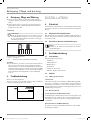 4
4
-
 5
5
-
 6
6
-
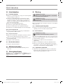 7
7
-
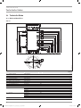 8
8
-
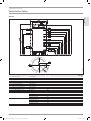 9
9
-
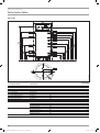 10
10
-
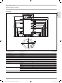 11
11
-
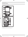 12
12
-
 13
13
-
 14
14
-
 15
15
-
 16
16
-
 17
17
-
 18
18
-
 19
19
-
 20
20
-
 21
21
-
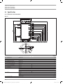 22
22
-
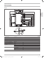 23
23
-
 24
24
-
 25
25
-
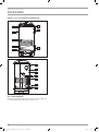 26
26
-
 27
27
-
 28
28
-
 29
29
-
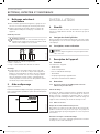 30
30
-
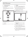 31
31
-
 32
32
-
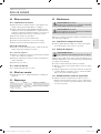 33
33
-
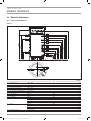 34
34
-
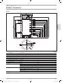 35
35
-
 36
36
-
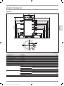 37
37
-
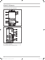 38
38
-
 39
39
-
 40
40
-
 41
41
-
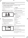 42
42
-
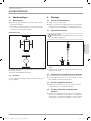 43
43
-
 44
44
-
 45
45
-
 46
46
-
 47
47
-
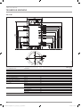 48
48
-
 49
49
-
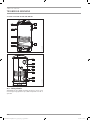 50
50
-
 51
51
-
 52
52
-
 53
53
-
 54
54
-
 55
55
-
 56
56
-
 57
57
-
 58
58
-
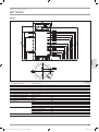 59
59
-
 60
60
-
 61
61
-
 62
62
-
 63
63
-
 64
64
-
 65
65
-
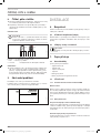 66
66
-
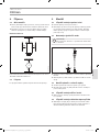 67
67
-
 68
68
-
 69
69
-
 70
70
-
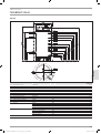 71
71
-
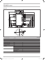 72
72
-
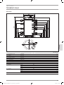 73
73
-
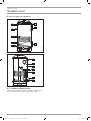 74
74
-
 75
75
-
 76
76
-
 77
77
-
 78
78
-
 79
79
-
 80
80
-
 81
81
-
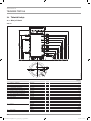 82
82
-
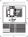 83
83
-
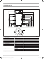 84
84
-
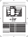 85
85
-
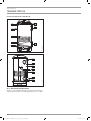 86
86
-
 87
87
-
 88
88
-
 89
89
-
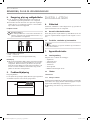 90
90
-
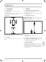 91
91
-
 92
92
-
 93
93
-
 94
94
-
 95
95
-
 96
96
-
 97
97
-
 98
98
-
 99
99
-
 100
100


STIEBEL ELTRON SBB 751-1001 Operation Instruction
- Type
- Operation Instruction
in andere talen
- italiano: STIEBEL ELTRON SBB 751-1001
- français: STIEBEL ELTRON SBB 751-1001
- Deutsch: STIEBEL ELTRON SBB 751-1001
- dansk: STIEBEL ELTRON SBB 751-1001
- eesti: STIEBEL ELTRON SBB 751-1001
Gerelateerde papieren
-
STIEBEL ELTRON SB 1002 AC Operation Instruction
-
-
-
STIEBEL ELTRON SHW 200 S Installatie gids
-
-
-
-
-
-