363511
Video Kit
Manuale installatore • Installation manual
LE09435AC-1PC-20W01

2
Attenzione: le operazioni di installazione, configurazione, messa in servizio e manutenzione devono
essere effettuate da personale qualificato.
Caution: installation, configuration, starting-up and maintenance must be performed by qualified personnel.
Attention: les opérations d’installation, de configuration, de mise en service et d’entretien doivent
être confiées à un personnel qualifié.
Achtung: die Installation, Konfiguration, Inbetriebnahme und Wartung dürfen nur von qualifizierten
Fachleuten vorgenommen werden.
Atención: las operaciones de instalación, configuración, puesta en servicio y mantenimiento han de
ser efectuadas por personal cualificado.
Opgelet: laat de installatie, de configuratie, de inbedrijfstelling en het onderhoud door gekwalificeerd
personeel verrichten.
Atenção: As operações de instalação, configuração, colocação em serviço e manutenção devem ser
realizadas por pessoal qualificado.

Video Kit
3
230 Vac 12 V
230 Vac
230 Vac 12 V
230 Vac
*
• Vecchio impianto a campanello
Impianto esistente con 3 fili e sola chiamata.
• Old system with bell
Existing system with 3 wires and just call.
• Ancienne installation a sonnette
Installation existante à 3 fils et un seul appel.
• Alte klingelanlage
Vorhandene 3-Leiter Anlage nur mit Ruffunktion.
• Vieja instalación con timbre
Instalación existente con 3 hilos y una llamada.
• Oude deurbelinstallatie
Bestaande 3-aderige installatie met alleen een
oproepfunctie.
• Antiga instalação em campaínha
Instalação existente com 3 fios e somente
chamada.
• Nuovo impianto citofonico
Impianto realizzato senza modifiche ai 2 fili
esistenti: chiamata, videocitofono e serratura.
• New door entry system
System made without modifications to the 2 existing
wires; call, video handset and electric door lock.
• Nouvelle installation phonique
Installation réalisée sans modifications sur les 2 fils
existants: appel, vidéophone, et serrure électrique.
• Neue haustelefonanlage
Anlage ohne Änderungen an den vorhandenen
2 Leiter: Ruffunktion, Gegensprechanlage und
elektrisches Schloss.
• Nueva instalación interfónica
Instalación realizada sin las modificaciones a los 2
hilos existentes: llamada, videoportero y cerradura
eléctrica.
• Nieuwe deurtelefooninstallatie
Installatie aangelegd zonder wijzigingen aan de
2 bestaande aders: oproep, beeldhuistelefoon en
elektrisch deurslot.
• Nova instalação do intercomunicador
Instalação realizada sem modificar os 2 fios
existentes: chamada, intercomunicador vídeo e
fechadura eléctrica.
* Acquistabile separatamente
* Can be purchased separately
* Vendu séparément
* Auf Anfrage getrennt erhältlich
* A la venta por separado
* Apart verkrijgbaar
* Adquirível separadamente

4
D
B C
A
>0,2 mm
2
BTicino
L4669
0,35 mm
2
0,28 mm
2
BTicino
C9881U/5E
AWG24 UTP5
BTicino
336904
One PTT
278 TP
0,28 mm
2
OneSYT
+ Digital
TP
5/10
OneSYT
+ Num
TP
5/10
GIGA TW
CAT5E
AWG24
One SYT
+ Num TP
8/10
Cable
ARB.6060-1
6/10
Cable
EV6R
6/10
1
mm
2
A 50 m 140 m 145 m 200 m 200 m 145 m 200 m 50 m –
B 50 m 115 m 80 m 200 m 115 m 80 m 200 m 50 m –
C 50 m 100 m 65 m 200 m 100 m 65 m 200 m 50 m –
D 30 m 30 m – 50 m 30 m – – –
100
m
• Cavi e distanze (mm
2
)
• Cables and distances (mm
2
)
• Câbles et distances (mm
2
)
• Kabeln und Abstände (mm
2
)
• Cables y distancias (mm
2
)
• Kabels en afstanden (mm
2
)
• Cabos e distâncias (mm
2
)

Video Kit
5
N
= –
= –
T = –
S = –
P
= –
–
=
ON
OFF
P
= –
= –
= –
= –
M
J2
J1
N
= –
= –
2
1
BUS
PL S+
S-
A
B
BUS5M 21 1
Bifamiliare - Two family
Monofamiliare - One family
•
Schema monofamiliare
•
One-family diagram
•
Schéma mono-familial
•
Schema Einfamilienhaus
•
Esquema monofamiliar
•
Schema eensgezins
•
Esquema monofamiliar
• A Pulsante locale apertura serratura.
B Chiamata al piano.
S+ S- 18 V; 4 A impulsivi. 250 mA mantenimento (30 Ω max).
• A Door lock release local pushbutton.
B Floor call.
S+ S- 18 V; 4 A impulsive. 250 mA holding current (30 Ω max).
• A Bouton local ouverture serrure.
B Appel à l’étage.
S+ S- 18 V; 4 A impulsifs. 250 mA entretien (30 Ω max).
• A Lokale Schlossöffnungstaste.
B Etagenruf.
S+ S- 18 V; 4 A impulsstrom. 250 mA Haltestrom (30 Ω max).
• A Pulsador local apertura cerradura.
B Llamada al piso.
S+ S- 18 V; 4 A por impulsos. 250 mA mantenimiento (30 Ω max).
• A Lokale knop opening slot.
B Oproep aan verdieping.
S+ S- 18 V; 4 A impulsief; 250 mA onderhoud (30 Ω max).
• A Botão local de abertura da fechadura.
B Chamada ao piso.
S+ S- 18 V; 4 A instantâneos. 250 mA continuos (30 Ω max).

6
ON
OFF
ON
OFF
P
= –
= –
= –
= –
M
J2
J1
N
= –
= *1
P
= –
= –
= –
= –
M
J2
J1
N
= –
= –
BUS
PL S+
S-
N
= –
= –
T = –
S = –
P
= –
–
=
2
1
A
B
BUS5M 21 1
B
BUS5M 21 1
* • Il secondo posto interno ed il configuratore 3501/1 devono essere acquistati separatemente.
• The second internal unit and the 3501/1 configurator must be purchased separately.
• Le deuxième poste interne et le configurateur 3501/1 doivent être achetés séparément.
• Die zweite Hausstation und der Konfigurator 3501/1 werden getrennt verkauft.
• La segunda unidad interior y el configurador 3501/1 se han de comprar por separado.
• De tweede binnenpost en de configurator 3501/1 moeten apart worden gekocht.
• A segunda unidade interna e o configurador 3501/1 devem ser adquiridos separadamente.
*
Bifamiliare - Two family
Monofamiliare - One family
• Schema bifamiliare
• Two-family diagram
• Schéma bi-familiale
• Schema
Zweifamilienhaus
• Esquema bifamiliar
• Schema tweegezins
• Esquema bifamiliar
• A Pulsante locale apertura serratura.
B Chiamata al piano.
S+ S- 18 V; 4 A impulsivi. 250 mA mantenimento (30 Ω max).
• A Door lock release local pushbutton.
B Floor call.
S+ S- 18 V; 4 A impulsive. 250 mA holding current (30 Ω max).
• A Bouton local ouverture serrure.
B Appel à l’étage.
S+ S- 18 V; 4 A impulsifs. 250 mA entretien (30 Ω max).
• A Lokale Schlossöffnungstaste.
B Etagenruf.
S+ S- 18 V; 4 A impulsstrom. 250 mA Haltestrom (30 Ω max).
• A Pulsador local apertura cerradura.
B Llamada al piso.
S+ S- 18 V; 4 A por impulsos. 250 mA mantenimiento (30 Ω max).
• A Lokale knop opening slot.
B Oproep aan verdieping.
S+ S- 18 V; 4 A impulsief; 250 mA onderhoud (30 Ω max).
• A Botão local de abertura da fechadura.
B Chamada ao piso.
S+ S- 18 V; 4 A instantâneos. 250 mA continuos (30 Ω max).

Video Kit
7
BUS
PL S+
S-
ON
OFF
ON
OFF
P
= –
= –
= –
= –
M
J2
J1
N
= –
= *1
P
= –
= –
= –
= –
M
J2
J1
N
= –
= –
N
= –
= –
T = –
S = –
P
= –
–
=
2
1
A
B
BUS5M 21 1
B
BUS5M
2
1
1
*
Bifamiliare - Two family
Monofamiliare - One family
* • Il secondo posto interno ed il configuratore 3501/1 devono essere acquistati separatemente.
• The second internal unit and the 3501/1 configurator must be purchased separately.
• Le deuxième poste interne et le configurateur 3501/1 doivent être achetés séparément.
• Die zweite Hausstation und der Konfigurator 3501/1 werden getrennt verkauft.
• La segunda unidad interior y el configurador 3501/1 se han de comprar por separado.
• De tweede binnenpost en de configurator 3501/1 moeten apart worden gekocht.
• A segunda unidade interna e o configurador 3501/1 devem ser adquiridos separadamente.
• Schema bifamiliare 2
• Two-family diagram 2
• Schéma bi-familiale 2
• Schema
Zweifamilienhaus 2
• Esquema bifamiliar 2
• Schema tweegezins 2
• Esquema bifamiliar 2

8
BUSPL S+
S-
N
= –
= –
T = –
S = –
P
= –
–
=
8 A cosφ = 1
4 A cosφ = 0,7
3 A cosφ = 0,4
24 Vdc; 24 Vac
24 Vac
24 Vac
NO
NC
C
346250 (*)
S-
S+
C
NC
NO
A
* • Fornito a corredo.
• Supplied.
• Fourni.
• Wird mitgeliefert.
• En dotación.
• Standaard meegeleverd.
• Fornecido no equipamento base.
• Opzione serratura a relè
• Relay door lock option
• Option serrure à relais
• Option Relais-Schloss
• Opción cerradura de relé
• Optie relaisslot
• Opção trinco de relê
• A Pulsante locale apertura serratura.
S+ S- 18 V; 4 A impulsivi. 250 mA mantenimento (30 Ω max).
• A Door lock release local pushbutton.
S+ S- 18 V; 4 A impulsive. 250 mA holding current (30 Ω max).
• A Bouton local ouverture serrure.
S+ S- 18 V; 4 A impulsifs. 250 mA entretien (30 Ω max).
• A Lokale Schlossöffnungstaste.
S+ S- 18 V; 4 A impulsstrom. 250 mA Haltestrom (30 Ω max).
• A Pulsador local apertura cerradura.
S+ S- 18 V; 4 A por impulsos. 250 mA mantenimiento (30 Ω max).
• A Lokale knop opening slot.
S+ S- 18 V; 4 A impulsief; 250 mA onderhoud (30 Ω max).
• A Botão local de abertura da fechadura.
S+ S- 18 V; 4 A instantâneos. 250 mA continuos (30 Ω max).

Video Kit
9
194 mm
162 mm
25 mm
100 mm
190 mm
26 mm
• Altezza consigliata salvo diversa normativa vigente.
• Recommended height, unless different regulations are specified.
• Hauteur conseillée sauf autre norme en vigueur.
• Empfohlene Höhe falls die gesetzlichen Vorschriften nichts anderes vorschreiben.
• Altura recomendada salvo normativa vigente diferente.
• Aanbevolen hoogte behoudens andere normen in voege.
• Altura aconselhada a não ser se a norma em vigor for diferente.
160 – 165 cm
90–130 cm
• Dati dimensionali
• Dimensional data
• Données dimensionnelles
• Maße
• Datos dimensionales
• Formaatgegevens
• Dados dimensionais
• Campo di ripresa
• Field of view
• Éclairage cadrage caméra
• Aufnahmebereich
• Campo de filmación
• Campo de filmagem
• Opnameveld
50 cm
105°
140 cm
80°
115 cm
50cm

10
1
2
3
4
4
5
6
15
14
13
11
12
10
9
8
7
1 - Telecamera
2 - LED illuminazione campo di ripresa
3 - Morsetti di collegamento
4 - Pulsanti di chiamata
5 - LED connessione attiva
6 - LED indicazione porta aperta
7 - Microfono
8 - Regolazione microfono
9 - Regolazione altoparlante
10 - Switch mono/bifamiliare
11 - Pulsante programmazione badge/Reset
12 - Pannello LED per illuminazione pulsante di
chiamata
13 - Sede dei configuratori
14 - Sensore di luminosità per retroilluminazione
notturna
15 - Altoparlante
1 - Caméra
2 - Voyant éclairage champ de cadrage
3 - Bornes de branchement
4 - Boutons d’appel
5 - Voyant connexion active
6 - Voyant indication porte ouverte
7 - Micro
8 - Réglage micro
9 - Réglage haut-parleur
10 - Commutateur mono/bi-familial
11 - Bouton de programmation badge/Reset
12 - Panneau Voyant d’éclairage bouton d’appel
13 - Logement des configurateurs
14 - Capteur de luminosité pour rétro-éclairage
nocturne
15 - Haut-parleur
1 - Camera
2 - Viewing field lighting LED
3 - Connection clamps
4 - Call pushbuttons
5 - Active connection LED
6 - Open door notification LED
7 - Microphone
8 - Microphone adjustment
9 - Loudspeaker adjustment
10 - One-family/two-family switch
11 - Key card programming pushbutton / Reset
12 - LED panel for call pushbutton lighting
13 - Configurator socket
14 - Brightness sensor for night backlighting
15 - Loudspeaker
• Posto esterno
• Entrance panel
• Poste extérieur
• Türstation
• Placa exterior
• Externe plaats
• Unidade externa

Video Kit
11
1 - Camera
2 - Led verlichting camerabereik
3 - Aansluitklemmen
4 - Oproepknoppen
5 - LED verbinding geactiveerd
6 - LED aanduiding deur geopend
7 - Microfoon
8 - Regeling microfoon
9 - Regeling luidspreker
10 - Schakelaar een-/tweegezins
11 - Knop badgeprogrammering/reset
12 - LED paneel voor verlichting oproepknop
13 - Plaats van de configuratoren
14 - Lichtsensor voor achtergrondverlichting ‘s
nachts
15 - Luidspreker
1 - Kamera
2 - LED Beleuchtung des Aufnahmefelds
3 - Anschlussklemmen
4 - Ruftasten
5 - LED Verbindung aktiv
6 - LED Anzeige Tür offen
7 - Mikrophon
8 - Einstellung des Mikrophons
9 - Einstellung des Lautsprechers
10 - Switch Ein-/Zweifamilienhaus
11 - Programmierungstaste Badge/Reset
12 - LED-Tafel zur Beleuchtung der Ruftaste
13 - Sitz der Konfiguratoren
14 - Helligkeitssensor zur nächtlichen
Rückbeleuchtung
15 - Lautsprecher
1 - Câmara de vídeo
2 - LED de iluminação do campo de filmagem
3 - Bornes de conexão
4 - Botões de chamada
5 - LED de conexão ativa
6 - LED indicação de porta aberta
7 - Microfone
8 - Regulação do microfone
9 - Regulação do altifalante
10 - Interruptor mono/bifamiliar
11 - Botão de programação do Crachá/Rearme
12 - Painel LED para iluminação do botão de
chamada
13 - Sede dos configuradores
14 - Sensor de luminosidade para retroiluminação
noturna
15 - Altifalante
1 - Telecámara
2 - LED iluminación campo de grabación
3 - Bornes de conexión
4 - Pulsadores de llamada
5 - LED conexión activada
6 - LED indicación puerta abierta
7 - Micrófono
8 - Regulación del micrófono
9 - Regulación del altavoz
10 - Switch mono/bifamiliar
11 - Pulsador de programación credencial/Reset
12 - Panel LED para iluminación pulsador de
llamada
13 - Alojamiento de los configuradores
14 - Sensor de luminosidad para retroiluminación
nocturna
15 - Altavoz

12
• Posto interno
• Handset
• Poste interne
• Hausstation
• Unidad interior
• Intern punt
• Unidade interna
1 2 3 4 5 6
14
13
15
891011128
7 16
19
20
21
21
18
22232425
17
L’immagine rappresenta il dispositivo con tutte le funzioni abilitate. Verifica sul manuale installatore come
abilitare le funzioni. I manuali completi sono disponibili sul sito: www.bticino.com
1 - Display 7” (16 : 9)
2 - Tasto spegnimento
3 - Data e ora
4 - Esclusione suoneria
5 - Attivazione Studio professionale
6 - Microfono
7 - Azioni rapide
8 - Guide tattili per non vedenti
9 - Tasto connessione:
l’accensione del led verde lampeggiante indica
una chiamata in arrivo
l’accensione del led verde fisso indica la
comunicazione in corso
10 - Autoaccensione/Ciclamento:
alla pressione del tasto il LED rosso si accende
11 - Tasto Preferiti:
alla pressione del tasto il LED rosso si accende
(Configurazione base = LUCE SCALE. Per una
diversa configurazione fare riferimento alla tabella
della configurazione fisica alle pagine successive.)
12 - Tasto apertura serratura:
alla pressione del tasto il LED rosso si accende
13 - Stato presenza note:
Led rosso lampeggiante = nuova/e note non lette
14 - Stato Esclusione chiamata:
Led rosso acceso = Suoneria chiamata disattivata
15 - Funzioni (compaiono solo le icone delle funzioni
configurate)
16 - Sede dei configuratori
17 - Configuratore J1: estrai per alimentazione
supplementare
18 - Configuratore J2: Master/Slave, estrai per Slave
19 - Microinterruttore ON/OFF di terminazione di tratta
20 - Presa mini USB per aggiornamento Firmware
dispositivo
21 - Altoparlante
22 - Morsetti (1 - 2) per alimentazione supplementare
23 - Morsetti per il collegamento al BUS SCS 2 FILI
24 - Morsetti ( ) per il collegamento di un pulsante
esterno di chiamata al piano
25 - Morsetti (1 - 5M) per il collegamento di una suoneria
supplementare. Devi effettuare il collegamento
punto - punto sui morsetti delle suonerie
supplementari

Video Kit
13
The image shows the device with all its functions enabled. Check on the Installer Manual how to enable the
functions. The complete manuals are available on the website: www.bticino.com
1 - 7” (16 : 9) display
2 - OFF key
3 - Date and time
4 - Bell exclusion
5 - Office activation
6 - Microphone
7 - Quick actions
8 - Tactile guides for the blinds
9 - Connection key:
The green LED flashes to indicate an incoming call
The green LED comes on steady to indicate that
there is an active call
10 - Auto-switching on/Cycling:
The red LED turns on when the key is pressed
11 - Favorites Key:
The red LED turns on when the key is pressed
(Basic configuration = STAIRCASE LIGHT. For
a different configuration refer to the physical
configuration table in the following pages.)
12 - Door lock release key:
The red LED turns on when the key is pressed
13 - Message status:
Red LED flashing = new unread note/s
14 - Call Exclusion Status:
Red LED on = Call bell disabled
15 - Functions (only the icons for the configured
functions are displayed)
16 - Configurator seat
17 - Configurator J1: remove for additional power
supply
18 - J2 configurator: Master/Slave, remove for Slave
19 - Line termination ON/OFF micro-switch
20 - Mini USB socket for device Firmware update
21 - Loudspeaker
22 - Additional power supply clamps (1 - 2)
23 - 2 WIRE SCS/BUS connection clamps
24 - Clamps ( ) for the connection of an external
call to the floor pushbutton
25 - Additional bell connection clamps (1 - 5M) Point-
to-Point connections are required on the clamps
of the additional bells
1 -
Écran 7” (16:9)
2 -
Touche d’extinction
3 -
Date et heure
4 -
Exclusion sonneries
5 -
Activation Bureau
6 -
Micro
7 -
Actions rapides
8 -
Guides tactiles pour non-voyants
9 -
Touche connexion :
l’allumage du voyant vert clignotant indique la
présence d’un appel entrant
l’allumage du voyant vert fixe indique la
communication en cours
10 -
Auto-allumage/Cyclage :
à la pression sur la touche le VOYANT rouge s’allume
11 -
Touche Favoris :
à la pression sur la touche le VOYANT rouge s’allume
(Configuration de base = LUMIÈRE ESCALIER. Pour une
configuration différente, faire référence au tableau de
la configuration physique dans les pages suivantes.)
12 -
Touche d’ouverture serrure:
à la pression sur la touche le VOYANT rouge s’allume
13 -
État présence notes :
Voyant rouge clignotant = nouvelle(s) note(s) non lue(s)
14 -
État Exclusion appel:
Voyant rouge allumé = Sonnerie appel désactivée
15 -
Fonctions (seules les icônes des fonctions
configurées s’affichent)
16 -
Logement configurateurs
17 -
Configurateur J1 : extraire pour alimentation
supplémentaire
18 -
Configurateur J2: Master/Slave, extraire pour Slave
19 -
Microinterrupteur ON/OFF de terminaison de ligne
20 -
Prise miniUSB de mise à jour Firmware dispositif
21 -
Haut-parleur
22 -
Bornes (1 – 2) d’alimentation supplémentaire
23 -
Bornes de branchement au BUS SCS 2 FILS
24 -
Bornes ( ) de branchement d’un bouton externe
d’appel à l’étage
25 -
Bornes (1 - 5M) de branchement d’une sonnerie
supplémentaire Le branchement doit être
effectué point - point sur les bornes des sonneries
supplémentaires
L’image représente le dispositif avec toutes les fonctions activées. Vérifier dans le Manuel Installateur le
mode d’activation des fonctions. Les manuels complets sont disponibles sur le site: www.bticino.com

14
Das Bild stellt eine Vorrichtung mit allen aktivierten Funktionen dar. Sehen Sie im Installationshandbuch
nach, wie die Funktionen aktiviert werden. Die vollständigen Handbücher können von dieser Webseite
herunter geladen werden: www.bticino.com
1 - Display 7” (16 : 9)
2 - Ausschalttaste
3 - Datum und Uhrzeit
4 - Ausschluss des Läutwerks
5 - Freigabe Büro-Funktion
6 - Mikrofon
7 - Schnellfunktionen
8 - Taktile Hilfe für Sehbehinderte
9 - Anschlusstaste:
Das Blinken der grünen Led meldet einen eintref-
fenden Anruf
Das Aufleuchten der grünen Led meldet Gespräch
im Gang
10 - Selbstschaltung/Taktierung:
Durch Drücken der Taste, leuchtet die rote LED auf
11 - Taste Favoriten:
Durch Drücken der Taste, leuchtet die rote LED
auf (Basis-Konfiguration = TREPPENLICHT. Um die
Konfiguration zu ändern, siehe Tabelle der physi-
schen Konfiguration auf der nachfolgenden Seite.)
12 - Taste Schlossöffner:
Durch Drücken der Taste, leuchtet die rote LED auf
13 - Status Nachrichten vorhanden:
Rote Led blinkt = neue nicht gelesene Nachricht/en
14 - Status Ausschluss des Anrufs:
Rote Led leuchtet = Anrufklingel deaktiviert
15 - Funktionen (es werden nur die Symbole der konfi-
gurierten Funktionen angezeigt)
16 - Sitz der Konfiguratoren
17 - Konfigurator J1: für eine zusätzliche Stromversor-
gung abziehen
18 - Konfigurator J2: Master/Slave, abziehen für Slave
19 - Mikroschalter ON/OFF fur den Streckenabschluss
20 - Mini-USB-Steckbuchse zur Aktualisierung der
Firmware der Vorrichtung
21 - Lautsprecher
22 -
Klemmen (1 -2) für eine zusätzliche Stromversorgung
23 - Klemmen zum Anschluss an BUS, SCS, 2-DRAHT
24 - Klemmen ( ) zum Anschluss an eine externe
Etagenruftaste
25 - Klemmen (1 - 5M) zum Anschluss an ein zusätzliches
Läutwerk Der Anschluss muss Punkt zu Punkt an den
Klemmen des zusätzlichen Läutwerks erfolgen
1 2 3 4 5 6
14
13
15
891011128
7 16
19
20
21
21
18
22232425
17

Video Kit
15
1 - Pantalla 7” (16 : 9)
2 - Tecla apagado
3 - Fecha y hora
4 - Exclusión timbre
5 - Activación Oficina Profesional
6 - Micrófono
7 - Acciones rápidas
8 - Guías táctiles para invidentes
9 - Tecla conexión:
el encendido del led verde parpadeante indica
una llamada entrante
el encendido del led verde fijo indica la comunica-
ción en curso
10 - Autoencendido/Visualización cíclica:
al presionar la tecla el LED rojo se enciende
11 - Tecla Favoritos:
al presionar la tecla el LED rojo se enciende
(Configuración base = LUZ ESCALERAS. Para una
configuración distinta, consulte la tabla de la con-
figuración física en las páginas sucesivas.)
12 - Tecla apertura cerradura:
al presionar la tecla el LED rojo se enciende
13 - Estado presencia notas:
Led rojo parpadeante = nueva/s notas no leída/s
14 - Estado Exclusión llamada:
Led rojo encendido = Timbre llamada desactivado
15 - Funciones (aparecen solamente los iconos de las
funciones configuradas)
16 - Alojamiento configuradores
17 - Configurador J1: extraiga para alimentación adi-
cional
18 - Configurador J2: Master/Slave, extraiga para Slave
19 - Microinterruptor ON/OFF terminal de tramo
20 - Toma mini USB para actualización del firmware del
dispositivo
21 - Altavoz
22 - Bornes (1 - 2) para alimentación adicional
23 - Bornes para la conexión al BUS SCS 2 HILOS
24 - Bornes ( ) para la conexión de un pulsador
externo de llamada a la planta
25 - Bornes (1 - 5M) para la conexión de un timbre adi-
cional. Ha de efectuar la conexión punto - punto
en los bornes de los timbres adicionales
La imagen representa el dispositivo con todas las funciones habilitadas. Busque en el manual del instalador
cómo habilitar las funciones. Los manuales completos están disponibles en la web: www.bticino.com
1 - Display 7” (16 : 9)
2 - Uitschakeltoets
3 - Datum en tijd
4 - Uitsluiting beltoon
5 - Activering professionele studio
6 - Microfoon
7 - Sneltoetsen
8 - Tastgeleiders voor blinden
9 - Toets verbinding:
de groene led knippert om een binnenkomende
oproep aan te geven
de groene led brandt om een lopend gesprek aan
te geven
10 - Automatische inschakeling/cyclische weergave:
bij een druk op de toets gaat de rode led branden
11 -
Toets Favorieten:
bij een druk op de toets gaat de rode led branden
(Standaardconfiguratie = TRAPHUISVERLICHTING.
Voor een andere configuratie raadpleeg de tabel met
de fysieke configuratie op de volgende pagina’s.)
12 - Toets slotontgrendeling:
bij een druk op de toets gaat de rode led branden
13 - Status notities aanwezig:
Rode led knippert = nieuwe notitie(s)
14 - Status uitsluiting oproep:
Rode led brandt = Beltoon oproep gedeactiveerd
15 - Functies (uitsluitend de iconen van de geconfigu-
reerde functies worden weergegeven)
16 - Plaats van de configuratiemodules
17 - Configurator J1: uitnemen voor extra voeding
18 - Configurator J2: Master/Slave, uitnemen voor Slave
19 - Microschakelaar ON/OFF van beëindiging traject
20 - Mini-UBS-aansluiting voor de update van de firm-
ware van het apparaat
21 - Luidspreker
22 - Aansluitklemmen (1 - 2) voor extra voeding
23 - Aansluitklemmen voor de verbinding met de SCS
2-DRAADS BUS
24 - Morsetti ( ) voor de verbinding van een ex-
terne knop op de etage
25 - Aansluitklemmen (1 - 5M) voor de verbinding
van een extra beltoon. Verricht een punt - punt
verbinding op de aansluitklemmen van de extra
beltonen
De afbeelding toont het apparaat met ingeschakelde functies. Raadpleeg de installatiehandleiding voor de
inschakeling van de functies. De complete handleidingen zijn verkrijgbaar op de website: www.bticino.com

16
1 - Ecrã 7” (16 : 9)
2 - Botão de desligar
3 - Data e hora
4 - Exclusão da campainha
5 - Ativação do Estúdio profissional
6 - Microfone
7 - Ações rápidas
8 - Guias táteis para não videntes
9 - Botão de ligar:
o acendimento do led verde intermitente indica
uma chamada em chegada
o acendimento do led verde fixo indica a comuni-
cação em andamento
10 - Autoacendimento e Ciclamento:
ao carregar no botão acende-se o LED vermelho
11 - Botão Preferido:
ao carregar no botão acende-se o LED vermelho
(Configuração básica = LUZ DAS ESCADAS. Para
uma configuração diferente, roga-se consultar a ta-
bela da configuração física nas próximas páginas.)
12 - Botão de abertura da fechadura:
ao carregar no botão acende-se o LED vermelho
13 - Estado de presença de notas:
Led vermelho intermitente = nova (s) nota (s) não
lida (s)
14 - Estado de Exclusão de chamada:
Led vermelho aceso = Campainha de chamada
desativada
15 - Funções (aparecem apenas os ícones das funções
configuradas)
16 - Alojamento configurador
17 - Configurador J1: extrai para alimentação adicional
18 - Configurador J2: Master/Slave, extrai para Slave
19 - Microinterruptor ON/OFF de término de trecho
20 - Tomada mini USB para atualização do Firmware
do dispositivo
21 - Altifalante
22 - Bornes (1 - 2) para alimentação adicional
23 - Bornes para a conexão ao BUS SCS DE 2 FIOS
24 - Bornes ( ) para a conexão de um botão exter-
no de chamada no piso
25 - Bornes (1 - 5M) para a conexão de uma campainha
adicional. Você deverá fazer a conexão – ponto a
ponto - nos bornes das campainhas adicionais
A imagem representa o dispositivo com todas as funções ativadas. Verifique no manual do instalador como
ativar as funções Os manuais completos estão disponíveis no sítio: www.bticino.com
1 2 3 4 5 6
14
13
15
891011128
7 16
19
20
21
21
18
22232425
17

Video Kit
17
4
3
5
** Prima dell’installazione assicurarsi che la vite sia completamente avvitata.
** Before installing make sure that the screw is completely tightened.
** Avant l’installation, s’assurer que la vis soit complètement vissée.
** Vor der Installation sicherstellen, dass die Schraube richtig festgeschraubt ist.
** Antes de la instalación, compruebe que el tornillo esté completamente
enroscado.
** Vóór de installatie controleren of de schroef volledig vastgedraaid is.
** Antes da instalação vericar se o parafuso está completamente atarraxado.
* Per garantire l’impermeabilità montare le guarnizioni a corredo.
* To guarantee water tightness make sure to t the seals supplied.
* Pour garantir l’imperméabilité, monter les joints fournis à cet eet.
* Um die Abdichtung sicherzustellen, montieren Sie die mitgelieferten Dichtungen.
* Montar las juntas de la dotación para garantizar la impermeabilidad.
* Monteer de geleverde pakkingen om de waterdichtheid te waarborgen.
* Para garantir a impermeabilidade, montar as vedações fornecidas juntamente.
**
2
*
*
1
• Installazione posto esterno
• Entrance panel installation
•
Installation du poste extérieur
• Installation der Türstation
•
Instalación de la placa exterior
• Installatie externe plaats
•
Instalação da unidade externa

18
1
2
3
4
5
• Die Kamera darf nicht vor starken Lichtquellen oder an Orten installiert werden, wo das Subjekt sich im Gegenlicht befindet. Farbkameras besitzen bei schlechter Beleuchtung
eine geringere Empfindlichkeit als Schwarz/Weiß Kameras. Wir empfehlen daher eine zusätzliche Beleuchtungsquelle vorzusehen.
• La telecámara no debe ser instalada delante de fuentes luminosas grande en lugares en donde el individuo filmado se encuentre demasiado en contraluz. Las
telecámaras en colores presentan, en condiciones de escasa luminosidad, una sensibilidad inferior respecto a las telecámaras en blanco/negro. Por lo tanto es
aconsejable en ambientes escasamente iluminados prever una fuente de iluminación extra.
• Installeer de camera niet tegenover grote lichtbronnen of op plaatsen waar de opname van het onderwerp door sterk tegenlicht wordt gestoord. Camera’s met zijn bij een
zwakke verlichting minder gevoelig dan zwart-wit camera’s. Daarom is het raadzaam om zwak verlichte omgevingen van extra verlichting te voorzien.
• A câmara não deve ser montada diante de fortes fontes de luz, ou então em lugares onde o elemento que deve ser filmado fique muito em contraluz. As câmaras em
cores apresentam, quando há pouca luminosidade, uma sensibilidade inferior em relação às câmaras em branco e preto. Portanto, recomenda-se, quando os ambientes
forem pouco iluminados providenciar uma fonte de iluminação adicional.
• La telecamera non deve essere installata di fronte a grandi sorgenti
luminose, oppure in luoghi dove il soggetto ripreso rimanga molto
in controluce. Le telecamere a colori presentano, in condizioni di
scarsa luminosità, una sensibilità inferiore rispetto alle telecamere
in bianco/nero. Si consiglia pertanto, in ambienti poco illuminati di
prevedere una fonte di illuminazione aggiuntiva.
• The camera must not be installed in front of large light sources, or in
places where the subject viewed remains in deep shadow. In poor
lighting conditions colour cameras are less sensitive than black/white
cameras. An extra lighting source should be added in poorly lit rooms.
• La télécaméra ne doit pas être installée en face de fortes sources
lumineuses, ou bien dans des endroits où le sujet pris reste très
à contre-jour. Les télécaméras couleurs présentent, dans des
conditions de faible luminosité, une sensibilité inférieure aux
télécaméras noir/blanc. Il est donc conseillé, dans des milieux peu
éclairés, de prévoir une source de lumière supplémentaire.

Video Kit
19
• Se si manifestasse il disturbo del fischio, (effetto Larsen), ridurre prima la potenza del microfono , agendo con un cacciavite sul potenziometro
corrispondente, fino ad un livello accettabile. Qualora il fenomeno persista, agire sul potenziometro dell’altoparlante
in modo da eliminare l’incon-
veniente. Se il volume è troppo basso, aumentare prima il volume dell’altoparlante ed eventualmente anche quello del microfono, tenendo presente che è
preferibile una trasmissione chiara e priva di disturbi, che una al limite dell’innesco (Larsen).
• In case of a whistle (Larsen effect), first reduce the microphones
power, adjusting the corresponding potentiometers with a screw driver, until an
acceptable level is reached. Should the whistle persist, adjust the loudspeakers
volume in order to eliminate the trouble. If the volume is too low level
then, increase first the potentiometer of the loudspeaker and secondly the one for the microphone, bearing in mind that a clear and noise free reception is
preferable than one just before whistling (Larsen).
• Lors de sifflement (effet de Larsen), reduire d’abord la puissance du micro sur le potentiomètre correspondant, à l’aide d’un tournevis, jusqu’à
l’obtention d’un niveau satisfaisant. Si le sifflement persiste, régler le potentiomètre du hautparleur
jusqu’à l’élimination de celui-ci. Si le volume
est trop bas, augmenter d’abord la puissance du haut-parleur et éventuellement celle du micro, en considérant qu’une réception claire et sans parasite est
préférable à une communication à la limite de l’accrochage (effet de Larsen).
• Beim etwaigen Auftreten eines Pfeiftones (Larsen-Effekt), zuerst die Lautstärke des Mikrophones bis auf einen annehmbaren Wert herabsetzen, indem
man das entsprechende Potentiometer mit einem Schraubendreher einstellt. Sollte die Störung weiterhin bestehen, dann das Potentiometer des Lautsprechers
bis zur Beseitigung des Pfeiftones einstellen. Ist die Lautstärke nun zu niedrig, dann zuerst die des Lautsprechers und erst danach evtl. auch die des
Mikrophones erhohen, wobei ein deutlicher und störungsfreier Empfang einem an der Störungsgrenze liegendem (Larsen-Effekt) vorzuziehen ist.
• Si se manifesta el silbido de acoplamiento, (efecto Larsen), reducir primero la potencia del micrófono , girando con un destornillador el potenciómetro
correspondiente, hasta obtener un nivel aceptable. Si el fenómeno persistiera, regular el potenciómetro del altavoz
hasta eliminar la interferencia. Si
el volumen es demasiado bajo, aumentar primero el volumen del altavoz y eventualmente también el del micrófono, teniendo en cuenta que es preferible
una transmissión clara y limpia de interferencias, que una al limite del acoplo (Larsen).
• Als er een fluittoon hoorbaar is (effect van Larsen): verminder eerst het vermogen van de microfoon met behulp van een schroevendraaier zijn
stroomregelaar zo te regelen dat de geluidssterkte van het gefluit aanvaardbaar is. Als het verschijnsel niet verdwijnt, dan moet u ook de stroomregelaar
van de luidspreker bijstellen. Als de geluidssterkte nu te klein is, verhoog dan eerst de geluidssterkte van de luidspreker en daarna eventueel ook die
van de microfoon, en denk er bij het bijstellen aan dat een duidelijk hoorbaar en ongestoord geluid beter is dan een harder geluid op de grens van het
Larsen effect.
• Se se manifestar uma interferência no som (efeito de Larsen), começar por diminuir a potência do microfone , rodando o potenciómetro correspon-
dente com uma chave de parafusos, até obter um nível aceitável. Se o fenómeno persistir, regular o potenciómetro do altifalante
de modo a eliminar
o problema. Se o volume estiver demasiado baixo, começar por aumentar o volume do altifalante e depois, se necessário, o do microfone, tendo presente
que é melhor ter uma transmissão clara e sem interferências, que uma no limiar de início de efeitos Larsen.

20
• Configurazione posto esterno
• Entrance panel configuration
• Configuration poste extérieur
• Konfiguration Türstation
• Configuración placa exterior
• Configuratie externe plaats
•
Configuração unidade externa
P T S N
P
- Possono non essere configurati.
- They do not need to be configured.
- Ils peuvent ne pas être configurés
- Brauchen nicht konfiguriert zu werden.
- Pueden no precisar configuración.
- Kunnen niet worden geconfigureerd.
- Podem não serconfigurados.
N
S
T
- Temporizzatore serratura (vedi tabella).
- Door lock timer relay (see table).
- Temporisation serrure (voir tableau).
- Zeitgeber schlossrelaiscerradura (siehe Tabelle).
- Temporizador relé cerradura (véase la tabla).
- Timer deurslotrelais (zie de tabel).
- Temporizador do relé da fechadura (veja a tabela).
– 1 2 3 4 5 6 7
4 s 1 s 2 s 3 s
*
6 s 8 s 10 s
* Funzionamento come pulsante per max. 10 sec. dopodichè entra in stand-by.
Per estendere tale funzionamento oltre i 10 sec. utilizzare l’attuatore 346210 configurato con MOD=5.
* Operation as pushbutton for 10 sec. max after which it goes in stand-by.
In order to extend this type of operation over 10 seconds, use the actuator, item 346210 configured with MOD=5.
* Fonctionnement comme bouton pendant 10 sec. max., ensuite passe en stand-by.
Pour étendre ce fonctionnement au-delà de 10 sec., utiliser l’actionneur 346210 configuré sur MOD=5.
* Die Tastenfunktion dauert max. 10 sec.; danach schaltet sie auf Standby. Um diese Funktion zu verlängern und mehr als 10 sec. dauern zu lassen, den Aktor 346210
verwenden und mit MOD=5 konfigurieren.
* Funcionamiento como pulsador durante al máx.10 s. después se pone en standby.
Para ampliar dicho funcionamiento a más de 10 s., use el actuador art. 346210 configurado con MOD = 5.
* 10 sec. lange werking als knop, vervolgens vindt de overschakeling naar stand-by plaats.
Laat deze functie langer dan 10 sec. duren met behulp van de actuator 346210 die als MOD=5 is geconfigureerd.
* Funcionamento como botão por um máximo de 10 segundos, depois disto dispõe-se em standby. Para prolongar este funcionamento por mais de 10 segundos,
utilizar o atuador 346210 configurado com MOD=5.
• Tutte le volte che si modifica la configurazione è necessario togliere e ridare l’alimentazione all’impianto, attendendo circa 1 minuto.
• Every time the configuration is altered the system must be switched off and back on again, waiting for about 1 minute.
• Chaque fois que l’on modifie la configuration, il faut retirer, puis redonner l’alimentation à l’installation, après avoir attendu environ 1 minute.
• Jedes Mal, wenn die Konfiguration geändert wird, den Strom abschalten, etwa 1 Minute warten und dann wieder einschalten.
• Cada vez que modifica la configuración, es necesario cortar y volver a dar alimentación a la instalación, después de esperar aproximadamente 1 minuto.
• Na iedere wijziging in de configuratie moet de installatie ongeveer 1 minuut van het elektriciteitsnet worden afgesloten.
• Todas as vezes que se modificar a configuração é necessário ligar e desligar a instalação da energia eléctrica, esperando cerca de 1 minuto.

Video Kit
21
• Installazione del posto interno
• Handset installation
• Installation du poste interne
• Installation der Hausstation
• Instalación de la unidad interior
• Installatie van het intern punt
• Instalação da unidade interna
1
2
3
4

22
• Installazione con base da tavolo 344632
• Installation with table-top base 344632
• Installation avec base de table 344632
• Installation auf Tischhalterung 344632
• Instalación con una base de mesa 344632
• Installatie op tafelsteun 344632
• Instalação com uma base de mesa 344632
• È possibile installare il dispositivo su base da tavolo (344632) acquistabile separatamente.
• It is possible to install the device on table-top base (344632) to be purchased separately.
• Il est possible d’installer le dispositif sur base de table (344632) vendue séparément.
• Das Gerät kann auf eine separat zu erwerbende Tischunterlage (344632) installiert werden.
• El dispositivo se puede instalar sobre una base de sobremesa (344632) en venta por separado.
• Het apparaat kan geïnstalleerd worden op de apart te bestellen tafelsteun (344632).
• É possível instalar o dispositivo em uma base para mesa (344632) adquirível separadamente.

Video Kit
23
• Configurazione posto interno
• Internal unit configuration
• Configuration poste interne
• Konfiguration einer Hausstation
• Configuración de la unidad interior
• Het interne punt configureren
•
Configuração da unidade interna
J1 J2 N
P M
J1 = Estrai se è presente l’alimentazione
supplementare (morsetto 1 & 2)
J2 = Master/Slave (estrai per slave)
NN = Indirizzo del dispositivo
PP = Indirizzo del PE di cui apri la Serratura con PI a
riposo e a cui indirizzi l’autoaccensione
MM = Modalità di funzionamento secondo le tabelle
alle pagine seguenti.
J1 = Extraire en présence de l’alimentation
supplémentaire (bornes 1 et 2)
J2 = Master/Slave (extraire pour Slave)
NN = Adresse du dispositif
PP = Adresse du PE dont la serrure est ouverte
avec PI au repos et auquel est adressé l’auto-
allumage
MM = Modalité de fonctionnement conformément
aux tableaux des pages suivantes.
J1 = Extraiga con presencia de la alimentación
adicional (borne 1 & 2)
J2 = Master/Slave (extraiga para slave)
NN = Dirección del dispositivo
PP = Dirección PE de la que abre la Cerradura
con UI en reposo y a la que dirige el
autoencendido
MM = Modo de funcionamiento según las tablas de
las páginas siguientes.
J1 = Extrai caso esteja presente a alimentação
adicional (borne 1 & 2)
J2 = Master/Slave (extrai para Slave)
NN = Endereço do dispositivo
PP = Endereço da UE através da qual você abre
a fechadura com a UI em repouso e àqual
endereça o autoacendimento
MM = Modalidade de funcionamento segundo as
tabelas das próximas páginas.
J1 = Remove if the additional power supply is present
(clamp 1 and 2)
J2 = Master/Slave (remove for slave)
NN = Device address
PP = Address of the EP of which you can open the
Door Lock with Handset idle, and to which you
can send the auto-on command
MM = Mode of operation according to the tables on
the following pages
J1 = Abziehen, wenn ein zusätzliche
Stromversorgung vorhanden ist (Klemme 1&2)
J2 = Master/Slave (abziehen für Slave)
NN = Adresse der Vorrichtung
PP = Adresse der TS mit dem zu öffnenden Schloss,
mit HS im Ruhestand, der die Selbstschaltung
bestimmt ist
MM = Funktionsmodus laut Tabellen in den
nachfolgenden Seiten
J1 = Uitnemen als een extra voeding aanwezig is
(aansluitklem 1 & 2)
J2 = Master/Slave (uitnemen voor slave)
NN = Adres van het apparaat
PP = Adres van buitenpost waar het slot van wordt
ontgrendeld met binnenpost in ruststand en waar
de automatische inschakeling naar wordt gestuurd
MM = Functioneringswijze volgens de tabellen op de
volgende pagina’s

24
• Configurazione fisica
• Physical configuration
• Configuration physique
• Physische Konfiguration
• Configuración física
• Fysieke configuratie
• Configuração física
MM =
0
• Comando Luce Scale
• Staircase Light Control
• Commande Lumières Escaliers
• Steuerung Treppenlicht
• Mando Luz Escaleras
• Bediening traphuisverlichting
• Comando da Luz das Escadas
MM =
1
• Comando diretto Serratura del P+1
• Direct control of P+1 Door lock
• Commande directe Serrure du P+1
• Direkte Schlosssteuerung der P+1
• Mando directo Cerradura del P+1
• Directe bediening slot P+1
• Comando direto da Fechadura do P+1
P
+1
MOD=9
P
+1
P
+2
MOD=9
P
+2
P
+1
MOD=5
P
+1
P
+1
2
3
1 32
346210
1
P
+2
MOD=5
P
+2
P
+2
2
3
1 32
346210
1
P
+3
MOD=5
P
+3
P
+3
2
3
1 32
346210
1
P
+3
MOD=9
P
+3
MM =
2
• Comando diretto Serratura del P+2
• Direct control of P+2 Door lock
• Commande directe Serrure du P+2
• Direkte Schlosssteuerung der P+2
• Mando directo Cerradura del P+2
• Directe bediening slot P+2
• Comando direto da Fechadura do P+2
P
+1
MOD=9
P
+1
P
+2
MOD=9
P
+2
P
+1
MOD=5
P
+1
P
+1
2
3
1 32
346210
1
P
+2
MOD=5
P
+2
P
+2
2
3
1 32
346210
1
P
+3
MOD=5
P
+3
P
+3
2
3
1 32
346210
1
P
+3
MOD=9
P
+3
MM =
3
• Comando diretto Serratura del P+3
• Direct control of P+3 Door lock
• Commande directe Serrure du P+3
• Direkte Schlosssteuerung der P+3
• Mando directo Cerradura del P+3
• Directe bediening slot P+3
• Comando direto da Fechadura do P+3
P
+1
MOD=9
P
+1
P
+2
MOD=9
P
+2
P
+1
MOD=5
P
+1
P
+1
2
3
1 32
346210
1
P
+2
MOD=5
P
+2
P
+2
2
3
1 32
346210
1
P
+3
MOD=5
P
+3
P
+3
2
3
1 32
346210
1
P
+3
MOD=9
P
+3
MM =
4
• Autoaccensione diretta del P+1
• P+1 direct auto-switching on
• Auto-allumage direct du P+1
• Direkte Selbstschaltung der P+1
• Autoencendido directo del P+1
• Directe automatische P+1
• Autoacendimento direto do P+1
P
+1
MOD=9
P
+1
P
2
3
1 32
346210
1
P
+2
MOD=9
P
+2
2
3
1 32
346210
1
P
+3
MOD=9
P
+3
2
3
1 32
346210
1
MM =
5
• Autoaccensione diretta del P+2
• P+2 direct auto-switching on
• Auto-allumage direct du P+2
• Direkte Selbstschaltung der P+2
• Autoencendido directo del P+2
• Directe automatische P+2
• Autoacendimento direto do P+2
P
+1
MOD=9
P
+1
P
2
3
1 32
346210
1
P
+2
MOD=9
P
+2
2
3
1 32
346210
1
P
+3
MOD=9
P
+3
2
3
1 32
346210
1
• Le funzioni che puoi attribure al tasto Preferiti ( ) in modo fisico (tramite
configuratore inserito nella sede MM-(unità)) sono le seguenti:
• The functions that can be attributed to the Preferred key (
) using the physical
procedure (configurator inserted in the MM - (units) socket) are the following:
J1 J2 N
P M
• Les fonctions qu’il est possible d’attribuer à la touche Favoris ( ) en mode physique (à travers le
configurateur placé dans le logement MM-(unité) sont les suivantes :
• Die Funktionen, die der Taste Favoriten (
) physisch zugeordnet werden können (Konfigurator im Sitz MM-
(Einheit)) sind folgende:
• Las funciones a las que puede atribuir la tecla Favoritos (
) físicamente (mediante un configurador en el
alojamiento MM-(unidad)) son las siguientes:
• De volgende functies kunnen op fysieke wijze aan de toets Favorieten (
) worden toegekend (met de
configuratie in MM-(eenheden)):
• As funções que você pode atribuir ao botão Preferidos (
) em modo físico (por meio de configurador
inserido no alojamento MM [unidade]) são as seguintes:

Video Kit
25
MM =
6
• Autoaccensione diretta del P+3
• P+3 direct auto-switching on
• Auto-allumage direct du P+3
• Direkte Selbstschaltung der P+3
• Autoencendido directo del P+3
• Directe automatische P+3
• Autoacendimento direto do P+3
P
+1
MOD=9
P
+1
P
2
3
1 32
346210
1
P
+2
MOD=9
P
+2
2
3
1 32
346210
1
P
+3
MOD=9
P
+3
2
3
1 32
346210
1
MM =
7
• Cercapersone
• Paging
• Cherche-personnes
• Personensuche
• Buscapersonas
• Buzzer
• Procura pessoas
MM =
8
• Intercom su se stesso
• Internal intercom
• Intercom sur soi-même
• Intercom auf sich selbst
• Intercomunicación en sí misma
• Intercom op zich
• Intercom sobre si mesmo
MM =
9
• Attivazione/Disattivazione studio
professionale
• Enabling/disabling Office function
• Activation/Désactivation Bureau
• Büro-Funktion aktivieren/deaktivieren
• Activación/Desactivación Oficina
Profesional
• Activering/Deactivering professionele
studio
• Ativação/Desativação do Estúdio
profissional
J1 J2 N
P M
• Il configuratore fisico MM – (decine) decide quali sono le 4 icone di AZIONI
RAPIDE che compaiono sulla HOME PAGE e che puoi attivare dal touch del
display. Ti riportiamo le possibili configurazioni nella tabella seguente.
• The MM - (tenths) physical configurator decides which are the 4 QUICK ACTIONS
icons that appear on the HOME PAGE, and can be activated by touching the
display. The possible configurations are shown in the following table.
• Le configurateur physique MM – (dizaines) établit quelles sont les 4 icônes d’ACTIONS RAPIDE qui s’affiche
sur la PAGE D’ACCUEIL et qu’il est possible d’activer depuis l’écran tactile. Dans le tableau suivant sont
indiquées les différentes configurations possibles.
• Der physische Konfigurator MM - (Zehner) entscheidet welche 4 Symbole der SCHNELLFUNKTIONEN auf der
HOMEPAGE angezeigt werden und über den Touchscreen aktiviert werden können. In nachstehender Tabelle sind
die möglichen Konfigurationen zusammengefasst.
• El configurador físico MM – (decenas) decide los 4 iconos de las ACCIONES RÁPIDAS que aparecen en la Página
de Inicio y que puede activar en la pantalla táctil. La tabla siguiente contiene las configuraciones posibles.
• De fysieke configurator MM – (tienden) bepaalt welke 4 iconen van de SNELTOETSEN op de HOMEPAGINA worden
weergegeven en op het touchscreen geactiveerd kunnen worden.
• O configurador físico MM - (dezenas) decide quais são os quatro ícones de AÇÕES RÁPIDAS que aparecem
na HOME PAGE e que você pode ativar mediante o toque do display. De volgende tabel bevat de mogelijke
configuraties.

26
IT - Legenda EN - Legend FR - Légende
P
+1
MOD=9
P
+1
P
+2
MOD=9
P
+2
P
P
+1
MOD=5
P
+1
P
+1
2
3
1 32
346210
1
P
+2
MOD=5
P
+2
P
+2
2
3
1 32
346210
1
P
+3
MOD=5
P
+3
P
+3
2
3
1 32
346210
1
P
+4
MOD=5
P
+4
P
+4
2
3
1 32
346210
1
1–+ 23 4
P
+3
MOD=9
P
+3
1–+ 23 4
2
3
1 32
346210
1
Attivazione del PE (confi-
gurato con P+1) in mo do
di ret to sen za la chia mata
op pu re at tivazione at tua to re
346200/346210 (con fi gu rato
con P+1 e MOD=9)
Activating the EP (configured
with P+1) directly without
the call or ac ti va ting actuator
346200/346210 (con fi gured
with P+1 and MOD=9)
Activation du PE (con fi guré
avec P+1) en mode direct
sans l’appel ou activation
actionneur 346200/346210
(configuré avec P+1 et
MOD=9)
P
+1
MOD=9
P
+1
P
+2
MOD=9
P
+2
P
P
+1
MOD=5
P
+1
P
+1
2
3
1 32
346210
1
P
+2
MOD=5
P
+2
P
+2
2
3
1 32
346210
1
P
+3
MOD=5
P
+3
P
+3
2
3
1 32
346210
1
P
+4
MOD=5
P
+4
P
+4
2
3
1 32
346210
1
1–+ 23 4
1–+ 23 4
P
+3
MOD=9
P
+3
1–+ 23 4
Apertura serratura del PE
(con fi gurato con P+1) in mo-
do di retto senza la chia mata
op pu re at ti va zione attua-
tore.346200/346210 (con-
figurato con P+1 e MOD=5)
op pu re at ti va zione attuatore
346230 (con figurato con P+1)
Door lock opening of EP
(con figured with P+1)
directly without the call
or activating the actuator
346200/346210 (con figured
with P+1 and MOD=5) or ac-
tivating the actuator 346230
(configured with P+1)
Ouverture serrure du PE (con-
fi gu ré avec P+1) en mode di-
rect sans l’appel ou ac ti vation
ac tion neur 346200/346210
(con fi gu ré avec P+1 et
MOD=5) ou ac ti va tion ac-
tion neur 346230 (con fi gu ré
avec P+1)
P
+1
MOD=9
P
+1
P
+2
MOD=9
P
+2
P
P
+1
MOD=5
P
+1
P
+1
2
3
1 32
346210
1
P
+2
MOD=5
P
+2
P
+2
2
3
1 32
346210
1
P
+3
MOD=5
P
+3
P
+3
2
3
1 32
346210
1
P
+4
MOD=5
P
+4
P
+4
2
3
1 32
346210
1
1–+ 23 4
1–+ 23 4
P
+3
MOD=9
P
+3
1–+ 23 4
Apertura serratura del PE
(con fi gurato con P+2) in mo-
do di retto senza la chia mata
op pu re at ti va zione attuatore
346200/346210 (con figurato
con P+2 e MOD=5) op pu re
at ti va zione attuatore 346230
(con figurato con P+2)
Door lock opening of EP
(con figured with P+2)
directly without the call
or activating the actuator
346200 (con figured with P+2
and MOD=5) or activating
the actuator 346230 (config-
ured with P+2)
Ouverture serrure du PE (con-
fi gu ré avec P+2) en mode di-
rect sans l’appel ou ac ti vation
ac tion neur 346200 (con fi gu ré
avec P+2 et MOD=5) ou
ac ti va tion ac tion neur 346230
(con fi gu ré avec P+2)
P
+1
MOD=9
P
+1
P
+2
MOD=9
P
+2
P
P
+1
MOD=5
P
+1
P
+1
2
3
1 32
346210
1
P
+2
MOD=5
P
+2
P
+2
2
3
1 32
346210
1
P
+3
MOD=5
P
+3
P
+3
2
3
1 32
346210
1
P
+4
MOD=5
P
+4
P
+4
2
3
1 32
346210
1
1–+ 23 4
1–+ 23 4
P
+3
MOD=9
P
+3
1–+ 23 4
Apertura serratura del PE
(con fi gurato con P+3) in mo-
do di retto senza la chia mata
op pu re at ti va zione attua-
tore346200/346210 (con-
figurato con P+3 e MOD=5)
op pu re at ti va zione attuatore
346230 (con figurato con P+3)
Door lock opening of EP
(con figured with P+3)
directly without the call
or activating the actuator
346200/346210 (con figured
with P+3 and MOD=5) or ac-
tivating the actuator 346230
(configured with P+3)
Ouverture serrure du PE (con-
fi gu ré avec P+3) en mode di-
rect sans l’appel ou ac ti vation
ac tion neur 346200/346210
(con fi gu ré avec P+3 et
MOD=5) ou ac ti va tion ac-
tion neur 346230 (con fi gu ré
avec P+3)
P
+1
MOD=9
P
+1
P
+2
MOD=9
P
+2
P
P
+1
MOD=5
P
+1
P
+1
2
3
1 32
346210
1
P
+2
MOD=5
P
+2
P
+2
2
3
1 32
346210
1
P
+3
MOD=5
P
+3
P
+3
2
3
1 32
346210
1
P
+4
MOD=5
P
+4
P
+4
2
3
1 32
346210
1
1–+ 23 4
1–+ 23 4
P
+3
MOD=9
P
+3
1–+ 23 4
Apertura serratura del PE
(con fi gurato con P+4) in mo-
do di retto senza la chia mata
op pu re at ti va zione attuatore
346200/346210 (con figurato
con P+4 e MOD=5) op pu re
at ti va zione attuatore 346230
(con figurato con P+4)
Door lock opening of EP
(con figured with P+4)
directly without the call
or activating the actuator
346200/346210 (con figured
with P+4 and MOD=5) or ac-
tivating the actuator 346230
(configured with P+4)
Ouverture serrure du PE (con-
fi gu ré avec P+4) en mode di-
rect sans l’appel ou ac ti vation
ac tion neur 346200/346210
(con fi gu ré avec P+4 et
MOD=5) ou ac ti va tion ac-
tion neur 346230 (con fi gu ré
avec P+4)

Video Kit
27
DE - Erläuterung ES - Leyenda NL - Legende PT - Legenda
Aktivierung der Türstation
(mit P+1 konfiguriert) auf
direkte Weise ohne Ruf
oder Aktivierung über den
Aktivator 346200/346210
(mit P+1 und MOD=9)
Activación del PE (con-
figurado con P+1) en
modo directo sin lla ma da
o activación del actuador
346200/346210 (configura-
do con P+1 y MOD=9)
Rechtstreekse activering van
het deur station (als P+1 ge-
con fi gu reerd) zonder oproep
of ac ti ve ring van het toestel
346200/346210 (ge con-
fi gureerd als P+1 en MOD = 9)
Ligação da UE (con figurada
com P+1) de maneira
directa sem a cha ma da ou
então ligação do ac tua dor
346200/346210 (configura-
do com P+1 e MOD=9).
Türöffnung der Türstation
(mit P+1 konfiguriert)
oder Aktivierung über den
Aktivator 346200/346210
(mit P+1 und MOD=5)
oder Aktivierung über den
Aktivato 346230 (mit P+1
konfiguriert)
Apertura cerradura del PE
(con figurado con P +1) en
modo directo sin llamada
o activación del actuador
346200/346210 (con fi gurado
con P+1 y MOD=5) o ac ti-
vación del actuador 346230
(con fi gu rado con P+1)
Rechtstreekse opening van
het deurslot van het als P+1
ge con figureerde deurstation,
zonder oproep of activering
van het to e stel 346200/346210
(ge con fi gu re erd als P+1 en
MOD=5) of ac ti ve ring van
het toestel 346230 (ge con-
figureerd als P+1)
Abertura da fechadura da
UE (configurada com P+1)
de ma nei ra directa sem a
chamada ou então ligação
do actuador 346200/346210
(configurado com P+1 e
MOD=5) ou então ligação
do actuador 346230 (con fi-
gu ra do com P+1).
Türöffnung der Türstation
(mit P+2 konfiguriert)
oder Aktivierung über den
Aktivator 346200/346210
(mit P+2 und MOD=5)
oder Aktivierung über den
Aktivator 346230 (mit P+2
konfiguriert)
Apertura cerradura del PE
(con figurado con P+2) en
modo di recto sin llamada
o activación del actuador
346200/346210 (con fi gurado
con P+2 y MOD=5) o ac ti-
vación del actuador 346230
(con fi gu rado con P+2)
Rechtstreekse opening
van het deurslot van het
als P+2 ge con figureerde
deurstation, zonder oproep
of activering van het to e stel
346200/346210 (ge con fi gu re-
erd als P+2 en MOD=5) of ac ti-
ve ring van het toestel 346230
(ge con figureerd als P+2)
Abertura da fechadura da
UE (configurada com P+2)
de ma nei ra directa sem a
chamada ou então ligação
do actuador 346200/346210
(configurado com P+2 e
MOD=5) ou então ligação do
actuador 346230 (con fi gu ra-
do com P+2)
Türöffnung der Türstation
(mit P+3 konfiguriert)
oder Aktivierung über den
Aktivator 346200/346210
(mit P+3 und MOD=5)
oder Aktivierung über den
Aktivator 346230 (mit P+3
konfiguriert)
Apertura cerradura del PE
(con figurado con P+3) en
modo di recto sin llamada
o activación del actuador
346200/346210 (con fi gurado
con P+3 y MOD=5) o ac ti-
vación del actuador 346230
(con fi gu rado con P+3)
Rechtstreekse opening
van het deurslot van het
als P+3 ge con figureerde
deurstation, zonder oproep
of activering van het to e stel
346200/346210 (ge con fi gu re-
erd als P+3 en MOD=5) of ac ti-
ve ring van het toestel 346230
(ge con figureerd als P+3)
Abertura da fechadura da
UE (configurada com P+3)
de ma nei ra directa sem a
chamada ou então ligação
do actuador 346200/346210
(configurado com P+3 e
MOD=5) ou então ligação
do actuador 346230 (con fi-
gu ra do com P+3)
Türöffnung der Türstation
(mit P+4 konfiguriert)
oder Aktivierung über den
Aktivator 346200/346210
(mit P+4 und MOD=5)
oder Aktivierung über den
Aktivator 346230 (mit P+4
konfiguriert)
Apertura cerradura del PE
(con figurado con P+4) en
modo di recto sin llamada
o activación del actuador
346200/346210 (con fi-
gurado con P+4 y MOD=5)
o ac ti vación del actuador
346230 (con fi gu rado con
P+4)
Rechtstreekse opening
van het deurslot van het
als P+4 ge con figureerde
deurstation, zonder oproep
of activering van het to e stel
346200/346210 (ge con fi gu re-
erd als P+4 en MOD=5) of ac-
ti ve ring van het toeste 346230
(ge con figureerd als P+4)
Abertura da fechadura da
UE (configurada com P+4)
de ma nei ra directa sem a
chamada ou então ligação
do actuador 346200/346210
(configurado com P+4 e
MOD=5) ou então ligação
do actuador 346230 (con fi-
gu ra do com P+4)

28
IT - Legenda EN - Legend FR - Légende
Intercom tra appartamenti in
impianti con interfaccia da
appartamento 346850.
Intercommunicability be-
tween apartments in systems
with
apartment interface 346850.
Intercommunication
entre appartements sur
installations avec interface
d’appartement 346850.
Intercom all’interno dell’ap-
partamento in impianti con
interfaccia di appartamento
346850; oppure intercom
tra appartamenti in impianti
senza interfaccia di appar-
tamento.
Intercommunicability inside
an apartment in systems with
apartment interface 346850
or intercommunicability be-
tween apartments in systems
without apartment interface.
Intercommunication à l’inté-
rieur de l’appartement sur
installations avec interface
d’appartement 346850
ou intercommunication
entre appartements sur
installations sans interface
d’appartement.
Intercom su se stesso, invia la
chiamata a tutti gli apparecchi
con uguale indirizzo
Intercom on itself, sends the
call to all the devices with the
same address.
Intercom sur lui-même,
envoie l’appel à tous les
appareils ayant une adresse
identique.
Cercapersone, effettua una
intercom generale, invia
una chiamata a tutti gli
apparecchi dell’impianto.
Paging, it makes general
intercom and sends a call to all
the handsets of the system.
Cherche-personne, effectue
une intercom générale,
envoie un appel à tous les
appareils de l’installation.

Video Kit
29
DE - Erläuterung ES - Leyenda NL - Legende PT - Legenda
Gegenseitige Kommunika-
tion zwischen Wohnungen
für Anlagen mit Wohnungs-
schnittstelle 346850.
Intercomunicación entre
apartamentos en instalacio-
nes con interfaz de departa-
mento 346850.
Intercom tussen apparte-
menten in installaties met
interface van appartement
346850.
Intercom entre apartamen-
tos em instalações com
interface de apartamento
346850.
Gegenseitige Kommunikation
innerhalb der Wohnung für
Anlagen mit Wohnungsschnitt
-
stelle 346850 oder gegenseiti-
ge Kommunikation zwischen
Wohnungen für Anlagen ohne
Wohnungsschnittstelle.
Intercomunicación en el
apartamento en insta-
laciones con interfaz de
apartamento 346850
o intercomunicación
entre apartamentos en
instalaciones sin interfaz de
apartamento.
Intercom binnen in het ap-
partement in installaties met
interface van appartement
346850 ofwel intercom
tussen appartementen in
installaties zonder interface
van appartement.
Intercom dentro do aparta-
mento em instalações com
interface de apartamento
art. 346850 ou então inter-
com entre apartamentos em
instalações sem interface de
apartamento.
Intercom mit einseitiger Funk-
tion: sendet den Ruf an alle
Geräte mit derselben Adresse.
Intercomunicación hacia los
aparatos iguales, envía la
llamada a todos los aparatos
con igual dirección
Intercom op zichzelf,
verstuurt de oproep naar
alle toestellen met hetzelfde
adres
Intercomunicador sobre si
mesmo, envia a chamada
a todos os aparelhos com
endereço igual
Personenrufgerät, Intercom mit
allgemeiner Funktion, sendet den
Ruf an alle Geräte der Anlage
Busca, realiza una intercom
general, envía una llamada
a todos los aparatos del
sistema.
Personenzoeksysteem,
verricht een algemene
intercom, stuurt een oproep
naar alle apparaten van de
installatie.
Localizador, efetua uma
intercomunicação geral,
envia uma chamada a todas
as unidades da instalação.

30
• In caso di riconfigurazione dell’apparecchio attendere un minuto prima di riconnetterlo all’impianto.
• When configuring the device, wait one minute before connecting it to the system again.
• En cas de nouvelle configuration de l’appareil, laisser s’écouler une minute avant de le rebrancher à l’installation.
• Falls das Gerät neu konfiguriert werden soll, eine Minute warten bevor es an die Anlage geschlossen wird.
P
+1
MOD=9
P
+1
2
3
1 32
346210
1
P
+1
MOD=9
P
+1
2
3
1 32
346210
1
N=2
N=1
N=1
N=2
P
+1
MOD=5
P
+1
P
+1
2
3
1 32
346210
1
P
+1
MOD=5
P
+1
P
+1
2
3
1 32
346210
1
P
+1
MOD=9
P
+1
2
3
1 32
346210
1
P
+2
MOD=5
P
+2
P
+2
2
3
1 32
346210
1
P
+2
MOD=5
P
+2
P
+2
2
3
1 32
346210
1
P
+1
MOD=5
P
+1
P
+1
2
3
1 32
346210
1
N=3
N=2
N=1
N=3
N=1
N=2
N=2
N=1
N=3
P
+1
MOD=5
P
+1
P
+1
2
3
1 32
346210
1
P
+2
MOD=5
P
+2
P
+2
2
3
1 32
346210
1
N=1
N=2
N=3
N=2
N=1
N=3
N=3
N=1
N=2
P
+1
MOD=5
P
+1
P
+1
2
3
1 32
346210
1
P
+2
MOD=5
P
+2
P
+2
2
3
1 32
346210
1
MOD = MM
1 2 3 4 5

Video Kit
31
MOD = MM
6 7 8 9
N=2 N=3
N=4 N=5
N=1
N=1 N=4
N=3 N=5
N=2
N=1 N=4
N=2 N=5
N=3
N=1 N=3
N=2 N=5
N=4
N=1 N=3
N=2 N=4
N=5
P
+1
MOD=9
P
+1
2
3
1 32
346210
1
P
+1
MOD=5
P
+1
P
+1
2
3
1 32
346210
1
N=2
N=1
N=1
N=2
P
+2
MOD=5
P
+2
P
+2
2
3
1 32
346210
1
P
+1
MOD=5
P
+1
P
+1
2
3
1 32
346210
1
P
+3
MOD=5
P
+3
P
+3
2
3
1 32
346210
1
P
+2
MOD=5
P
+2
P
+2
2
3
1 32
346210
1
P
+4
MOD=5
P
+4
P
+4
2
3
1 32
346210
1
N=2 N=3
N=4 N=5
N=1
N=1 N=4
N=3 N=5
N=2
N=1 N=4
N=2 N=5
N=3
N=1 N=3
N=2 N=5
N=4
N=1 N=3
N=2 N=4
N=5
• En caso de reconfiguración del aparato, espere un minuto antes de volverlo a conectar a la instalación.
• In geval van een herconfiguratie van het toestel een minuut wachten voordat men het terug aansluit op de installatie.
• Se o aparelho for configurado novamente esperar um minuto antes de conectá-lo de novo com o sistema.

32
• Questa funzione segnala lo stato della serratura (solo se l’impianto è predisposto mediante apposito
attuatore). Se è aperta il “led serratura” lampeggia, se è chiusa rimane spento. La funzione non è attivabile
contemporaneamente alla funzione Studio Professionale.
• This function indicates the status of the door lock (only for systems preset with appropriate actuator). If open the
„door lock LED“ flashes, and if closed, the LED stays off. The function cannot be activated together with the Office
function.
• Cette fonction signale l’état de la serrure (uniquement si l’installation est prévue à cet effet avec actionneur).
Si elle est ouverte, le “Voyant serrure” clignote, si elle est fermée, il reste éteint. La fonction ne peut pas être
activée conjointement à la fonction Bureau.
• Diese Funktion meldet den Status des Schlosses (nur wenn die Anlage mit entsprechendem Aktor versehen ist).
Wenn geöffnet, blinkt die „Led Schloss“; wenn geschlossen bleibt die Led ausgeschaltet. Die Funktion kann nicht
gleichzeitig mit der Büro-Funktion aktiviert werden.
• Esta función indica el estado de la cerradura (solamente con el sistema predispuesto mediante el actuador
correspondiente). Si está abierta, el “led cerradura” parpadea y si está cerrada permanece apagado. La
función no se puede activar al mismo tiempo que la función Oficina Profesional.
• Deze functie geeft de status van het slot (uitsluitend als de installatie daarvoor is voorbereid met de specifieke
actuator). De „led slot“ knippert als het slot ontgrendeld is. De led is uit als het slot vergrendeld is. Deze functie en
de functie Professionele studio kunnen niet tegelijkertijd worden geactiveerd.
• Esta função indica o estado da fechadura (apenas se a instalação estiver predisposta mediante expresso
atuador). Se estiver aberta o “led fechadura” resulta intermitente, se estiver fechada, permanece desligado.
A função não pode ser ativada simultaneamente à função Estúdio profissional.
• Funzione Stato porta
• Door state function
• Fonction État porte
• Funktion Türzustand
• Función Estado
puerta
• Staat deur
• Função Estado porta
• La funzione Studio Professionale ti permette di impostare l’apertura automatica della serratura in caso di
chiamata dal Posto Esterno, non puoi attivarla contemporaneamente alla funzione Stato Porta. Il lampeggio
del tasto serratura (
) indica che la funzione è attivata.
• The Office function gives the possibility of setting the automatic opening of the door lock in case of call from the
Entrance Panel. It cannot be activated at the same time as the Door Status function. The door lock key flashing
(
) indicates that the functions is active.
• La fonction Bureau permet de programmer l’ouverture automatique de la serrure en cas d’appel depuis le
Poste Externe ; elle n’est pas activable conjointement à la fonction État Porte. Le clignotement de la touche
serrure (
) indique que la fonction est activée.
• Mit der Büro-Funktion kann das Schloss nach einem Ruf von der Türstation automatisch geöffnet werden; diese
Funktion kann nicht gleichzeitig mit der Funktion Tür-Status aktiviert werden. Das Blinken der Schlosstaste
(
) meldet, dass die Funktion aktiv ist.
• La función Oficina Profesional le permite configurar la apertura automática de la cerradura al recibir una
llamada de la PE pero no la puede activar al mismo tiempo que la función Estado Puerta. El parpadeo de la
tecla cerradura (
) indica la activación de la función.
• Met de functie Professionele studio kunt u de automatische ontgrendeling van het slot bij een oproep vanaf de
buitenpost instellen. Deze functie en de functie Status deur kunnen niet tegelijkertijd worden geactiveerd. De
toets slot (
) knippert om aan te geven dat de functie geactiveerd is.
• A função Estúdio profissional permite-lhe definir a abertura automática da fechadura em caso de chamada
da Unidade Externa, não pode ativá-la simultaneamente à função Estado da Porta. A intermitência do botão
da fechadura (
) indica que a função está ativada.
• Funzione Studio
Professionale
• Office function
• Fonction Bureau
• Funktion Büro
• Función Oficina Profesional
• Functie professionele studio
• Função Escritório profissional

Video Kit
33
• Questa funzione permette di diffondere un messaggio vocale, dettato al microfono del dispositivo, tramite
gli altoparlanti dell’impianto Diffusione sonora. L’attivazione avviene premendo brevemente il tasto
“Connessione” con il dispositivo in stato di riposo, il led verde acceso indica che la funzione è attiva. Per
terminare la funzione premere nuovamente il tasto “Connessione”.
• This function plays a voice message, spoken at the device microphone, through the Sound system loudspeakers.
It is activated by pressing the “Connection” key with the device in rest state. The ON green LED indicates that the
function is active. To end the function press the “Connection” key again.
• Cette fonction permet de diffuser un message vocal dicté au micro du dispositif par l’intermédiaire des haut-
parleurs du système de Diffusion sonore. L’activation est obtenue en appuyant brièvement sur la touche
“Connexion” quand le dispositif est au repos; allumé, le voyant vert indique que la fonction est active. Pour
désactiver la fonction, appuyer à nouveau sur la touche “Connexion”.
• Mit dieser Funktion kann man eine Audiomeldung durch das Mikrophon der Vorrichtung über die Lautsprecher
der Schalldiffusionsanlage aussenden. Die Aktivierung erfolgt durch einen kurzen Druck der Taste „Verbindung“
wenn die Vorrichtung auf Ruhestand geschaltet ist. Die grüne eingeschaltete Leuchte meldet dass die Funktion
aktiv ist. Um die Funktion auszuschalten, die Taste „Verbindung“ nochmals drücken.
• Esta función permite difundir un mensaje vocal, dictado al micrófono del dispositivo, por medio de los
altavoces del sistema de difusión sonora. La activación se realiza pulsando brevemente la tecla “Conexión”
con el dispositivo en el estado de reposo; el led verde encendido indica que la función está activada. Para
terminar la función, presione de nuevo la tecla “Conexión”.
• Deze functie staat toe een vocale boodschap te verspreiden, gedicteerd aan de microfoon van de inrichting,
middels de luidsprekers van de installatie Geluidsdiffusie. De activering geschiedt door te drukken op de toets
“Aansluiting” met de inrichting in de ruststand, de brandende groene led wijst erop dat de functie actief is. Om de
functie te beëindigen, opnieuw drukken op de toets “Aansluiting”.
• Esta função permite difundir uma mensagem vocal, ditada ao microfone do dispositivo, por meio de
altifalantes do sistema de Difusão sonora. A activação realiza-se premindo brevemente a tecla “Conexão”
com o dispositivo em espera, o indicador luminoso verde aceso indica que a função está activada. Para
cessar a função pressionar novamente a tecla “Conexão”.
• Funzione Cerca persone
• Paging function
• Fonction cherche-personnes
• Funktion Personensuche
• Función buscapersonas
• Functie buzzer
• Função de procura pessoas

34
• Per un corretto accoppiamento magnetico tra PI ed apparecchio acustico ti consigliamo di posizionarti
frontalmente al dispositivo ad una distanza di 25 – 35 cm.
Ti ricordiamo che la presenza di metallo e rumore di fondo generato da apparecchiature elettriche/
elettroniche (es. computer), può compromettere la qualità e le perfomace del dispositivo di accoppiamento.
• To ensure correct magnetic coupling between the IU and the acoustic device, we recommend a position in front of
the device, at a distance of 25 – 35 cm.
It is reminded that the presence of metal and background noise generated by electric/electronic devices (e.g.
computer) may compromise the performance and the quality of the coupling device.
• Pour garantir un bon accouplement magnétique entre PI et appareil acoustique, il est recommandé de se
placer face au dispositif à une distance de 25 – 35 cm.
Il est rappelé que la présence de métal et de bruit de fond généré par des appareillages électriques/
électroniques (ex. ordinateurs) peut compromettre la qualité et les performances du dispositif
d’accouplement.
Zur richtigen magnetischen Kopplung zwischen TS und akustisches Gerät, empfehlen wir, sich vor das Gerät in
einem Abstand von 25 – 35 cm zu stellen.
Bitte beachten Sie, das Metallgegenstände und Grundgeräusche elektrischer/elektronischer Geräte (z.B. PC) die
Qualität und Leistung der Kopplungsvorrichtung beeinträchtigen können.
• Para un correcto acoplamiento magnético entre la UI y el aparato acústico, le aconsejamos situarse en frente
del dispositivo a una distancia aproximada de 25 – 35 cm.
Recuerde que la presencia de metal y ruido de fondo generado por aparatos eléctricos/electrónicos (por
ejemplo un PC) puede comprometer la calidad y la eciencia del dispositivo de acoplamiento.
Voor een correcte magnetische koppeling tussen de binnenpost en het akoestische apparaat raden we aan om op
circa 25 – 35 cm voor het apparaat te gaan staan.
Onthoud dat de aanwezigheid van metaal en achtergrondgeluid veroorzaakt door elektrische/elektronische
apparatuur (bijv. computer) de kwaliteit en de prestaties van het koppelapparaat kunnen beïnvloeden.
• Para um correto acoplamento magnético entre a Unidade Interna e o aparelho acústico sugerimos-lhe
posicionar-se frontalmente ao dispositivo numa distância de 25 – 35 cm.
Lembramos-lhe que a presença de metal e ruído de fundo, gerado por equipamentos elétricos/eletrônicos
(por exemplo: computador), pode afetar a qualidade e o desempenho do dispositivo de acoplamento..
• Commuta l’apparecchio acustico in posizione T
• Switch the acoustic device to the T position
• Commuter l’appareil acoustique sur la position T
• Umschalten des akustischen Geräts auf Position T
• Conmuta el aparato acústico a la posición T
• Schakelt het akoestische apparaat in positie T om
• Comuta o aparelho acústico em posição T
• Utilizzo teleloop
• Inductive loop use
• Utilisation teleloop
• Gebrauch des
Teleloops
• Uso del teleloop
• Gebruik teleloop
• Utilização teleloop
2
5
-35
c
m
4
0
cm

Video Kit
35
• Comando luci scale
• Staircase light control
• Commande lumières escaliers
• Treppenlichtsteuerung
• Mando luces escaleras
• Bediening lichten trapzaal
• Comando das luzes da escada
A
BUS5M 21 1
BUS
PL S+
S-
ON = 3’
OFF
ON
2
3
1 32
346210
1
C
NO
NC
230V
2A
cos =0,5
6A
M
230 Vac
MOD
= –
M
= –
= –
N/P
= –
= –
T = –
346210
P
= –
= –
N
= –
= –
T = –
S = –
P
= –
= –
J2
J1
N
= –
= –
M
= –
= –

36
• Suoneria
supplementare
• Additional bell
• Sonnerie
supplémentaire
• Zusätzliche Läutwerk
• Timbre adicional
• Supplementaire
beltoon
• Toque suplementar
230 Vac
BUS
PL S+
S-
1 5M
OFF
ON
A
BUS5M 21 1
P
= –
= –
N
= –
= –
T = –
S = –
P
= –
= –
J2
J1
N
= –
= –
M
= –
= –
336910
336992
336993
336994

Video Kit
37
Leggere attentamente prima dell’uso e conservare per un riferimento futuro
Divieto di toccare le unità con le mani bagnate
Divieto di utilizzo di pulitori liquidi o aerosol
Divieto di occludere le aperture di ventilazione
Diveto di modificare i dispositivi
Divieto di rimuovere parti di protezione dai dispositivi
Divieto di installare le unità in prossimità di liquidi e polveri
Divieto di installare le unità in prossimità di fonti di calore
Divieto di installare le unità in prossimità di gas nocivi, polveri metalliche o simili
Divieto di fissaggio delle unità su superfici non adatte
Pericolo di shock elettrico
Rischio caduta dei dispositivi a causa di cedimento della superficie su cui
sono installati o installazione inappropriata
Togliere l’alimentazione prima di ogni intervento sull’impianto
Attenzione: le operazioni di installazione, configurazione, messa in servizio e
manutenzione devono essere effettuate esclusivamente da personale qualifi-
cato. Assicurarsi che l’installazione a parete sia effettuata correttamente
Effettuare la posa dei cavi rispettando le normative vigenti
Collegare i cavi di alimentazione secondo le indicazioni
Per eventuali espansioni di impianto utilizzare solo gli articoli indicati
nelle specifiche tecniche
Read carefully before use and keep for future reference
Touching the units with wet hands is forbidden
Using liquid cleaners or aerosols is forbidden
Blocking the ventilation openings is forbidden
Modifying the devices is forbidden
Removing protective parts from the devices is forbidden
Installing the units near liquids and powders is forbidden
Installing the units near heat sources is forbidden
Installing the units near harmful gases, metal dusts or similar is forbidden
Fastening the units on unsuitable surfaces is forbidden
Danger of electrical shock
Risk of devices falling because the surface on which they are installed
collapses or inappropriate installation
Switch the power supply OFF before any work on the system
Caution: Installation, configuration, starting-up and maintenance must
be performed exclusively by qualified personnel.
Check that the wall installation has been carried out correctly
Lay out the wires respecting the standards in force
Connect the power supply wires as indicated
Use only the items indicated in the technical specifications for any
system expansions
Lire attentivement avant toute utilisation et installation de nos produits
et conserver pour toute consultation en cas de besoin.
Interdiction de toucher les unités avec les mains mouillées.
Interdiction d’utiliser des produits de nettoyage liquides ou des aérosols.
Interdiction de boucher les ouvertures de ventilation.
Interdiction de modifier les dispositifs.
Interdiction des retirer les parties de protection des dispositifs.
Interdiction d’installer les unités à proximité de liquides et poudres/
poussières.
Interdiction d’installer les unités à proximité de sources de chaleur.
Interdiction d’installer les unités à proximité de gaz nocifs, de poudres
métalliques ou autres matières semblables.
Interdiction de fixer les unités sur des surfaces non appropriées.
Risque d’électrocution
Risque de chute des dispositifs en cas de rupture de la surface sur
laquelle ils sont installés ou mauvaise installation.
Couper l’alimentation avant toute intervention sur l’installation.
Attention: les opérations d’installation, de configuration, de mise en
service et d’entretien doivent être confiées à un personnel qualifié.
S’assurer que l’installation murale est correctement effectuée.
Effectuer la pose des câbles dans le respect des normes en vigueur.
Brancher les câbles d’alimentation dans le respect des indications fournies.
Pour les éventuelles extensions de l’installation, utiliser uniquement les
articles indiqués dans les caractéristiques techniques.
Vor Gebrauch, die Hinweise aufmerksam durchlesen und sorgfältig auf-
bewahren, um sie auch in Zukunft nachschlagen zu können.
Verbot, die Einheiten mit nassen Händen zu berühren
Verbot, Flüssigreiniger oder Aerosol zu benutzen
Verbot, die Belüftungsschlitze abzudecken
Verbot, die Vorrichtungen zu ändern
Verbot, die Schutzbleche von den Vorrichtungen abzunehmen
Verbot, die Einheit in der Nähe von Flüssigkeiten und Staub zu in-
stallieren
Verbot, die Einheit in der Nähe von Wärmequellen zu installieren
Verbot, die Einheit in der Nähe von giftigem Gas, Metallstaub o. ä. zu in-
stallieren
Verbot, die Einheit an ungeeignete Flächen zu befestigen
Stromschlaggefahr
Risiko des Herabfallens der Vorrichtungen durch Nachlassen der Aufla-
gefläche oder wegen falscher Installation
Die Stromversorgung abtrennen, bevor an der Anlage gearbeitet wird.
Achtung: die Installation, Konfiguration, Inbetriebnahme und Wartung
dürfen nur von qualifizierten Fachleuten vorgenommen werden.
Sicherstellen, dass die Wandmontage richtig vorgenommen wird
Die Kabeln gemäß geltenden Normen verlegen
Die Stromkabeln gemäß Anweisungen anschließen
Bei eventuellen Anlagenerweiterungen ausschließlich die Artikel
verwenden, die in den technischen Spezifikationen angegeben sind
• Avvertenze e diritti del consumatore
• Warnings and consumer rights
• Avertissements et droits du consommateur
• Hinweise und Rechte der Verbraucher
• Advertencias y derechos del consumidor
• Waarschuwingen en rechten van de consument
• Advertências e direitos do consumidor

38
Lea detenidamente antes del uso y conserve la documentación para
consultas futuras
Se prohíbe tocar las unidades con las manos mojadas
Se prohíbe el uso de limpiadores líquidos o aerosoles
Se prohíbe tapar las aperturas de ventilación
Se prohíbe modificar los dispositivos
Se prohíbe desmontar las partes de protección de los dispositivos
Se prohíbe instalar las unidades cerca de líquidos y polvo
Se prohíbe instalar las unidades cerca de fuentes de calor
Se prohíbe instalar las unidades cerca de gases nocivos, polvo metálico
o productos similares
Se prohíbe fijar las unidades en superficies no aptas
Peligro de descarga eléctrica
Riesgo de caída de los dispositivos por hundimiento de la superficie de
montaje o instalación inadecuada
Corte la alimentación antes de intervenir en el sistema
Atención: Las operaciones de instalación, configuración, puesta en
servicio y mantenimiento han de ser efectuadas exclusivamente por
personal cualificado. Asegúrese de que la instalación se haya efectuado
correctamente.
La colocación de los cables ha de cumplir las normativas vigentes
Conecte los cables de alimentación según las indicaciones
Para posibles expansiones del sistema, use solamente los artículos indi-
cados en las especificaciones técnicas
Vóór het gebruik doorlezen en voor naslag bewaren
Het is verboden het apparaat met natte handen aan te raken
Het is verboden vloeibare reinigers of verstuivers te gebruiken
Het is verboden de ventilatie-openingen af te sluiten
Het is verboden het apparaat te wijzigen
Het is verboden om beschermende onderdelen van het apparaat te
verwijderen
Het is verboden de apparaten te installeren in de buurt van vloei-
stoffen en stof
Het is verboden de apparaten te installeren in de buurt van warmtebronnen
Het is verboden de apparaten te installeren in de buurt van schadelijke
gassen, metaalstof of soortgelijke materialen
Het is verboden de units te bevestigen aan ongeschikte oppervlakken
Gevaar voor elektrische schokken
Gevaar voor vallen van de apparaten als het oppervlak waarop ze geïn-
stalleerd zijn instort of wegens een verkeerde installatie
Verwijder de spanning alvorens werkzaamheden aan de installatie te
verrichten
Opgelet: laat de installatie, de configuratie, de inbedrijfstelling en het
onderhoud uitsluitend verrichten door gekwalificeerd personeel.
Controleer of de installatie aan de muur correct is verricht
Breng de kabels aan volgens de toepasselijke normen
Sluit de voedingskabels aan volgens de aanwijzingen
Gebruik uitsluitend de artikelen die in de technische specificaties zijn
gegeven voor de eventuele uitbreiding van de installatie
Ler atentamente antes do uso e guardar para qualquer futura referência
Proibição de tocar as unidades com as mãos molhadas
Proibição da utilização de produtos de limpeza líquidos ou aerossóis
Proibição de obstruir as aberturas de ventilação
Proibição de alterar os dispositivos
Proibição de remover peças de proteção dos dispositivos
Proibição de instalar as unidades em proximidade de líquidos e pós
Proibição de instalar as unidades em proximidade de fontes de calor
Proibição de instalar as unidades em proximidade de gases nocivos, pós
metálicos ou similares
Proibição de fixação das unidades sobre superfícies não adequadas
Perigo de choque eléctrico
Risco de queda dos dispositivos, devido a desabamento da superfície em
que estão instalados ou instalação inadequada
Tirar a alimentação elétrica antes de qualquer intervenção sobre a instalação
Atenção: as operações de instalação, configuração, colocação em serviço e
manutenção devem ser realizadas exclusivamente por pessoal qualificado.
Certificar-se de que a instalação de parede seja realizada corretamente
Proceder à colocação dos cabos atendo-se escrupulosamente às normas
vigentes.
Conectar os cabos de alimentação de acordo com as prescrições
Face a eventuais extensões de instalações utilizar exclusivamente os
artigos listados nas especificações técnicas
• Puoi scaricare i manuali completi dei dispositivi dal sito
www.homesystems-legrandgroup.com
• The complete manuals of the devices can be downloaded
from the website www.homesystems-legrandgroup.com
• Vous pouvez télécharger le manuel complet des disposi-
tifs sur le site www.homesystems-legrandgroup.com
• Sie können die vollständigen Handbücher von der Website
www.homesystems-legrandgroup.com herunterladen.
• Puede bajarse los manuales completos de los dispositi-
vos en la web de www.homesystems-legrandgroup.com
• Puede bajarse los manuales completos de los dispositivos
en la web de www.homesystems-legrandgroup.com
• É possível baixar os manuais completos do sítio
www.homesystems-legrandgroup.com

Video Kit
39

BTicino SpA
Viale Borri, 231
21100 Varese - Italy
www.bticino.com
BTicino SpA si riserva il diritto di variare in qualsiasi momento i contenuti illustrati nel presente stampato e di
comunicare, in qualsiasi forma e modalità, i cambiamenti apportati.
BTicino SpA reserves at any time the right to modify the contents of this booklet and
to comunicate in any form and modality, the charges brought to the same.
Timbro installatore
Installer stamp
-
 1
1
-
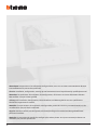 2
2
-
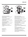 3
3
-
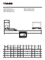 4
4
-
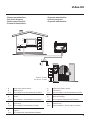 5
5
-
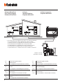 6
6
-
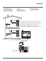 7
7
-
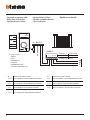 8
8
-
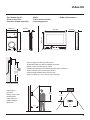 9
9
-
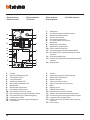 10
10
-
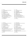 11
11
-
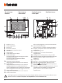 12
12
-
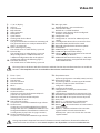 13
13
-
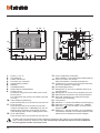 14
14
-
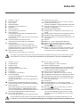 15
15
-
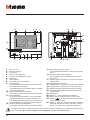 16
16
-
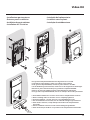 17
17
-
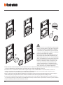 18
18
-
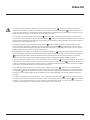 19
19
-
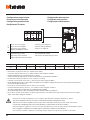 20
20
-
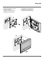 21
21
-
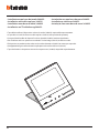 22
22
-
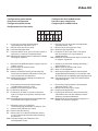 23
23
-
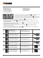 24
24
-
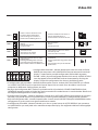 25
25
-
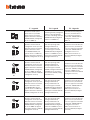 26
26
-
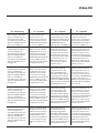 27
27
-
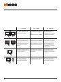 28
28
-
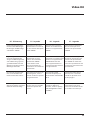 29
29
-
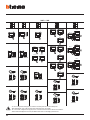 30
30
-
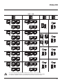 31
31
-
 32
32
-
 33
33
-
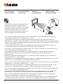 34
34
-
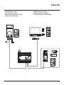 35
35
-
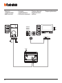 36
36
-
 37
37
-
 38
38
-
 39
39
-
 40
40


in andere talen
- English: Bticino 363511 Operating instructions
- italiano: Bticino 363511 Istruzioni per l'uso
- français: Bticino 363511 Mode d'emploi
- español: Bticino 363511 Instrucciones de operación
- Deutsch: Bticino 363511 Bedienungsanleitung
- português: Bticino 363511 Instruções de operação